
PIPING COURSE MATERIAL
43
AVENIR ENGINEERING TRAINING ACADEMY PIPING COURSE MATERIAL
-
Upload
independent -
Category
Documents
-
view
3 -
download
0
Transcript of PIPING COURSE MATERIAL

AVENIR ENGINEERING TRAINING ACADEMY
PIPING COURSE MATERIAL

AVENIR
ENGINEERING
TRAINING ACADEMY
TITLE:
PIPING COURSE MATERIAL
2
TABLE OF CONTENTS
1. INTRODUCTION TO PIPING……………………………… 03
2. PIPING SHAPES………………………………………………… 04
3. PIPING MATERIALS………………………………………….. 05
4. SELECTION OF WALL THICKNESS………………………. 08
5. FLUIDS AND PRESSURE DROP…………………………… 09
6. PIPING INSULATION…………………………………………… 10
7. METHODS OF JOINING PIPE……………………………….. 11
8. PIPE FITTINGS…………………………………………………….. 12
9. FLANGES……………………………………………………………. 14
10. VALVES ………………………………………………………………. 20
11. STRESS ANALYSIS FOR PIPING…………………………….. 24
12. SUPPORT & RESTRAINTS…………………………………… 31
13. EXPANSION LOOP……………………………………………. 34
14. EXPANSION JOINTS…………………………………………… 35
15. TEN DOS AND DON’TS………………………………………… 36
16. PIPING AND INSTRUMENT DIAGRAM………………… 37
17. PROCESS AND FLOW DIAGRAM…………………………. 41

AVENIR
ENGINEERING
TRAINING ACADEMY
TITLE:
PIPING COURSE MATERIAL
3
1. INTRODUCTION TO PIPING
Pipe is a pressure tight cylinder used to convey a fluid or to transmit a fluid pressure,
ordinarily designated pipe in applicable material specifications. Materials designated
tube or tubing in the specifications are treated as pipe when intended for pressure
service.
Piping is an assembly of piping components used to convey, distribute, mix, separate,
discharge, meter, control or snub fluid flows. Piping also includes pipe-supporting
elements but does not include support structures, such as building frames, bents,
foundations, or any equipment excluded from Code definitions.
Piping components are mechanical elements suitable for joining or assembly into
pressure-tight fluid containing piping systems. Components include pipe, tubing, fittings,
flanges, gaskets, bolting, valves and devices such as expansion joints, flexible joints,
pressure hoses, traps, strainers, in-line portions of instruments and separators.
Piping is used in industry for conveying fluids and heat transfer. Pipes are generally
hollow cylindrical in shape.
Nominal pipe size (NPS)
The Nominal Pipe Size in an ASME method of indicating the approximate method outside
diameter of the connected pipe in inches.
Pipes
• The nominal dimension of pipe is inside diameter-ID. A 2” pipe has approximately
a 2inches inside diameter.
• Outside diameter depends on the “schedule”, the thickness, of the pipe. The
schedule and actual thickness vary with the size of the pipe.
• Pipe can be defined by Nominal Pipe Size (NPS) under American standards
classifications.
• Nominal bore may be specified under British standards classification along with a
schedule (wall thickness).
• Looser tolerances compared with tubes
• Less expensive to produce than tubes.

AVENIR
ENGINEERING
TRAINING ACADEMY
TITLE:
PIPING COURSE MATERIAL
4
Tubes
• The nominal dimension of pipe is outside diameter-OD. A 2” pipe has
approximately 2 inches outside diameter.
• Inside diameter depends on the thickness of the tube. The thickness is common
described as gauge.
• Higher tolerance compared with pipes
• More expensive to produce than pipes.
The Figure Showing Relation between ID, OD and Wall Thickness
ID = OD – (2 x Wall thickness)
2. PIPING SHAPES
The shape of pipe is hollow-cylindrical. Hollow cylindrical shape leads to economic
design. Hollow square pipes are used in cases where space restriction is predominant.
The pipes used for structural application are usually hollow rectangular. The thickness
required for hollow cylindrical shape is the minimum among various shapes. As per
ASME sec I, thickness of more than one half of the internal radius is considered as a thick
cylinder.

AVENIR
ENGINEERING
TRAINING ACADEMY
TITLE:
PIPING COURSE MATERIAL
5
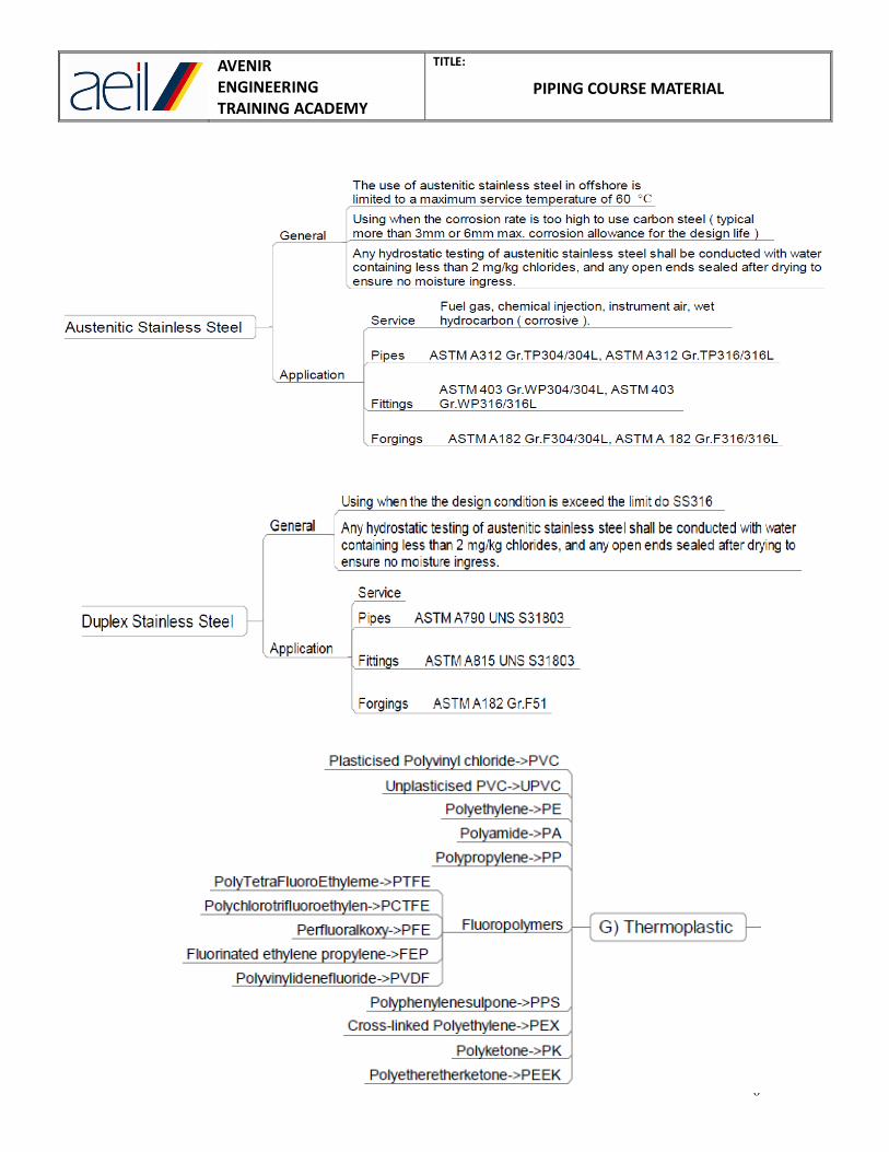
3. PIPING MATERIALS
AVENIR
ENGINEERING
TRAINING ACADEMY
TITLE:
PIPING COURSE MATERIAL
6

AVENIR
ENGINEERING
TRAINING ACADEMY
TITLE:
PIPING COURSE MATERIAL
7
AVENIR
ENGINEERING
TRAINING ACADEMY
TITLE:
PIPING COURSE MATERIAL
8
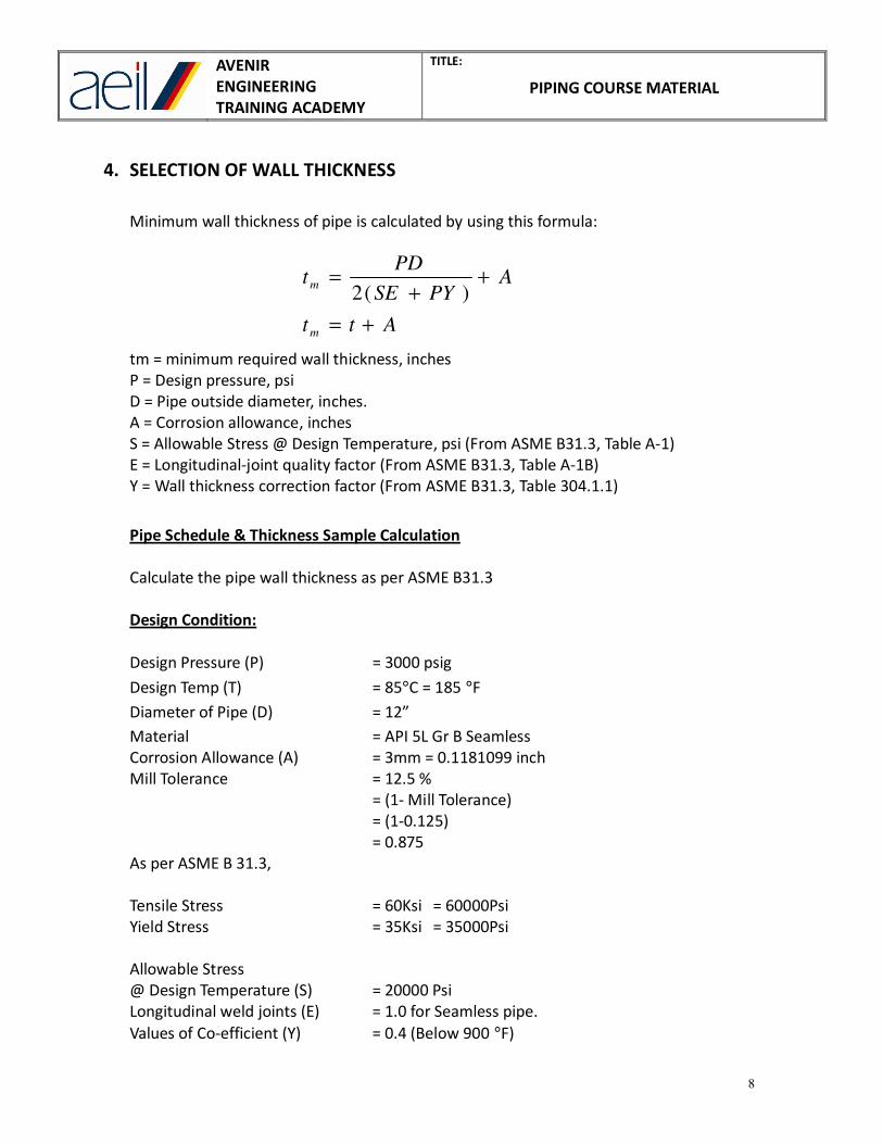
4. SELECTION OF WALL THICKNESS
Minimum wall thickness of pipe is calculated by using this formula:
tm = minimum required wall thickness, inches
P = Design pressure, psi
D = Pipe outside diameter, inches.
A = Corrosion allowance, inches
S = Allowable Stress @ Design Temperature, psi (From ASME B31.3, Table A-1)
E = Longitudinal-joint quality factor (From ASME B31.3, Table A-1B)
Y = Wall thickness correction factor (From ASME B31.3, Table 304.1.1)
Pipe Schedule & Thickness Sample Calculation
Calculate the pipe wall thickness as per ASME B31.3
Design Condition:
Design Pressure (P) = 3000 psig
Design Temp (T) = 85°C = 185 °F
Diameter of Pipe (D) = 12”
Material = API 5L Gr B Seamless
Corrosion Allowance (A) = 3mm = 0.1181099 inch
Mill Tolerance = 12.5 %
= (1- Mill Tolerance)
= (1-0.125)
= 0.875
As per ASME B 31.3,
Tensile Stress = 60Ksi = 60000Psi
Yield Stress = 35Ksi = 35000Psi
Allowable Stress
@ Design Temperature (S) = 20000 Psi
Longitudinal weld joints (E) = 1.0 for Seamless pipe.
Values of Co-efficient (Y) = 0.4 (Below 900 °F)
Att
APYSE
PDt
m
m
+=
++
=)(2

AVENIR
ENGINEERING
TRAINING ACADEMY
TITLE:
PIPING COURSE MATERIAL
9
Design Formula: tm = [PD / 2 (SE + PY)] + A
t = (3000 x 12) / 2 [(20000 x 1) + (3000 x 0.4)]
= 36000 / 42400
t = 0.849056 inch
t m = t + C
= 0.849056 + 0.1181099
= 0.96716 inch
t nom = 0.96716 / 0.875
= 1.1053 inch
t nom = 28.07462 mm (As per Design)
Minimum Thickness Required = Sch 140 (28.58 mm)
5. PRESSURE DROP
The piping can carry a single phase fluid or two phase fluid or three phase fluid. The
following fluids are conveyed by the piping,
1. Liquid
2. Gas
3. Liquid-Solid slurry
4. Gas-solid mixture
5. Liquid-gas mixture
6. Gas-Liquid-solid mixture
In a maze of piping, flow distribution plays a major role in piping design. The following
formulas are commonly used to calculate the Pressure drop and the pumping power
required for a hollow cylindrical horizontal pipe carrying a liquid.
The following formula we have been used to find out the pressure drop,
Pressure Drop ∆P (Kg/m2) = W ((fxLxV
2/ 2gd) + (Z x V
2/ 2g))
Where,
W - Mean Specific weight of the fluid (Kg/m3)
V - Mean Velocity of the fluid (m/Sec)
g - Gravitational constant (Friction factor)
f - co-efficient of friction
L - Sum of straight pipe Lengths of same size (m)
D - Bore of pipe (m)
Z - Sum of Co-efficient of fluid resistance of each fitting such as bend,
elbow, tee, reducer, valve, etc.

AVENIR
ENGINEERING
TRAINING ACADEMY
TITLE:
PIPING COURSE MATERIAL
10
Reynolds’s number
It is a dimensionless number representing the ration of inertial and viscous forces
governing a flow
Re = (103
x ρ x V x d) / µ
Where,
V - Mean Velocity of the fluid (m/Sec)
D - Bore of pipe (m)
ρ - The density of the fluid, (kg/m3)
µ - Dynamic viscosity (Centipoise)
When the Reynold’s number for a flow through closed conduit is less than 2000 the
flow is said to be LAMINAR. When the Reynold’s number exceeds 4000, the flow is
called TURBULENT. In between the values of 2000 and 4000, the flow could be either
laminar or turbulent depending upon several factors. Such as flows are called
TRANSIENT flows.
6. PIPING INSULATION
Insulation is the material, which resist the heat flow from one medium to other.
List of insulation material:
• Lightly bonded wool mattress
o Rock wool
o Slag wool
o Glass wool
• Pourable insulation
• Calcium silicate
• Insulating Bricks
• Asbestos mill board
• Asbestos rope
• Preformed pipe section
o Calcium silicate pipe section
o Mineral fiber wool pipe section

AVENIR
ENGINEERING
TRAINING ACADEMY
TITLE:
PIPING COURSE MATERIAL
11
7. METHODS OF JOINING PIPE
BUTT WELDED PIPE
Two pipes are joined by butt welding. Ends are beveled (tapered edge).
Ends are having tapered edge.
SCREWED OR THREADED CONNECTION:
Two pipes are joined by using thread. Tapered grooves are also prepared.
SOCKET WELDED CONNECTION:
Two pipes are joined by using SOCKET and then welding.
COLLAR is also used.

AVENIR
ENGINEERING
TRAINING ACADEMY
TITLE:
PIPING COURSE MATERIAL
12
8. PIPE FITTINGS
BENDS
Bends are used to change the direction of flow of fluid in pipes. Bends are usually made,
using a bending machine, from straight pipes.
ELBOWS
Elbows are made using a pressing machine or a forging machine, from a straight pipe.
Elbows are of the following types:
45° elbow, 90° elbow and 180° elbow.
Elbows of the following types are also available:
22.5 °elbow and 11.25° elbow.
REDUCER
The purpose of the reducer is to reduce the diameter of straight run of pipe.
There are about two types of reducers. They are:
• Concentric reducer
• Eccentric reducer.

AVENIR
ENGINEERING
TRAINING ACADEMY
TITLE:
PIPING COURSE MATERIAL
13
CONCENTRIC REDUCER
Concentric reducer will be having common Centre line.
Concentric reducer will be used for vertical and Pump Discharge Piping.
ECCENTRIC REDUCER
Eccentric reducer will be having offset centerline between inlet pipe and exit pipe.
Eccentric reducer will be used for horizontal and Pump Suction Piping.
For horizontal piping, flat on Bottom for maintaining the elevation in the Rack Piping.
For Pump Suction, flat on top to avoid the cavitation.
TEES
Tees are used to distribute to collect flow. Tees are of the following types: formed
tees, forged and machined tees, unequal tees and pregnant tees.
BRANCHES
Branches are similar to tees. Branches are made from straight pipes by machining
and welding.
Y-PIECES
Y-pieces are rarely used. The y are used to collect and distribute flow. The pressure
drop in a y-piece is less than that of a comparable tee.
END COVERS
End covers are of the following types: flat end cover, hemi-spherical end cover,
tori-spherical end cover, semi -ellipsoidal end cover and tori-conical end cover.
SAFETY VALVE STUBS
Safety valve stubs are used to attach safety valves to the pipes. Safety valve stubs are
designed to with stand the bending moments imposed on them by safety valve
blowing jet reaction, over and above the internal pressure load.
RADIOGRAPHIC PLUG
Radiographic plugs are used to facilitate insertion of radioactive substance for doing
radiographic test of butt weld on the pipes.
AVENIR
ENGINEERING
TRAINING ACADEMY
TITLE:
PIPING COURSE MATERIAL
14
END CONNECTIONS
The following end connections are popularly used butt welding, flanged
connection ,screwed connection, screwed and flanged connection ,socket welded
connection, slip-on type of connection, thrust block connection and mechanical type
of connection.
VALVES, FLOW MEASURING DEVICES AND INSTRUMENTS
Valves, flow measuring devices and instruments are used to stop, direct, check,
measure and control flow, temperature, pressure, level and quality of fluid in the
piping.
9. FLANGES:
A flange will be consisting of 2 flanges with gasket in between them.
FLANGE RATING AND CLASS
• Based on ASME B16.5
• Acceptable pressure/temperature combinations
• Seven classes (150, 300, 400, 600, 900,1500,2500)
• Flange strength increases with class number
• Material and design temperature combinations without pressure indicated not
acceptable
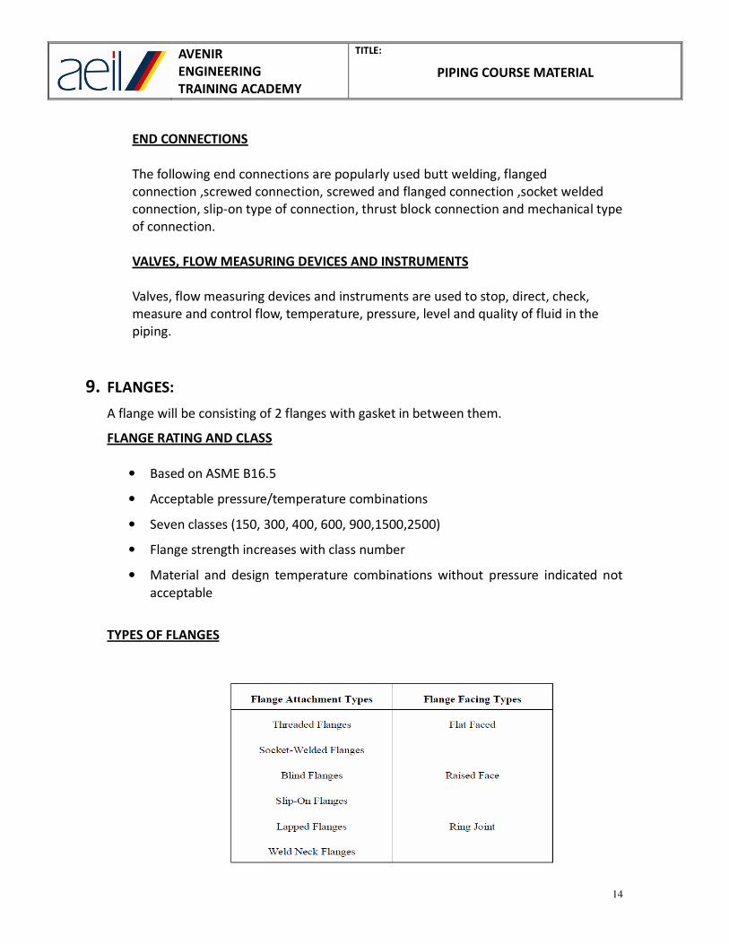
TYPES OF FLANGES

AVENIR
ENGINEERING
TRAINING ACADEMY
TITLE:
PIPING COURSE MATERIAL
15
WELD NECK FLANGE
• Weld Neck Flange This flange is designed to be joined to a piping system by butt
welding.
• It is relatively expensive because of its long neck, but is preferred for high stress
applications.
• The neck, or hub, transmits stresses to the pipe, reducing stress concentrations at
the base of the flange.
• The gradual transition of thickness from the base of the hub to the wall thickness
at the butt weld provides important reinforcement of the flange.
SLIP ON FLANGE
Slip on Weld Flange The flange is slipped over the pipe and
• Welded (usually both inside and outside) to provide strength and prevent
leakage.
• These flanges are at the low cost end of the scale, and do not require high
accuracy when cutting the pipe to length.
• They can sometimes have a boss or hub, and can be made with a bore to suit
either pipe or tube.

AVENIR
ENGINEERING
TRAINING ACADEMY
TITLE:
PIPING COURSE MATERIAL
16
LAP JOINT FLANGE
• Lap Joint Flange This is again similar to a slip-on flange, but it has a radius at the
intersection of the bore and the flange face, and no raised face, to accommodate
a lap joint stub end.
• The face on the stub end forms the gasket face of the flange.
• This type of flange is used in applications where sections of piping systems need
to be dismantled quickly and easily for inspection or replacement, because the
stub end is welded to the pipe, not the flange.
THREADED FLANGE
• Threaded Flange this is similar to a slip-on flange in outline, but the bore is
threaded, thus enabling assembly without welding.
• This obviously limits its application to relatively low pressure piping systems.
• The flange may be welded around
• The joint after assembly, but this is not considered a satisfactory method of
increasing its pressure applications.

AVENIR
ENGINEERING
TRAINING ACADEMY
TITLE:
PIPING COURSE MATERIAL
17
SOCKET-WELD FLANGE
• It is used in small diameter high pressure piping systems.
• The pipe is inserted into the socket and then welded.
BLIND FLANGE
• It has a function similar to plug or cap.
• This is used to terminate the end of piping system.
• This flange does not have a bored center or hub.
• This can be used to seal a nozzle opening in pressure vessel.
ORIFICE FLANGE
The function of orifice flange is to measure the rate of flow of commodity through
piping system.

AVENIR
ENGINEERING
TRAINING ACADEMY
TITLE:
PIPING COURSE MATERIAL
18
• They have a hole drilled to the face of flange.
• They have additional set of bolts called as jackscrews. Jack screw is used to
separate the flanges so inspection/replacement of orifice plate can be
performed.
• Orifice flange union is composed of two orifice flanges, an orifice plate, bolts,
nuts, jack screws, and two gaskets. Orifice flange is used to measure the amount
of pressure drop through the orifice plate.
• The length of pipe where orifice flanges are installed and where measurements
are recorded is known as meter run.
• The orifice plate is similar to large ring washer with handle attached.
• Orifice plate is sandwiched between the two orifice flanges.
• Valve taps are inserted into the pressure holes that allow for attachment of field
monitoring equipment so accurate measurements can be recorded.
• Orifice flanges can be either weld-neck, slip-on or threaded.
• Weld neck and threaded - 300# pound and larger ratings
• Slip-on - 300# pound rating.
FLAT FACE FLANGE
Flat face flange has flat, level connecting surface. There will be two flanges with
gasket in between them. The external or mating surface for two flanges will be flat
face.
Using a flat face flange will assure full surface contact, thereby reducing the
possibility of cracking the softer cast iron.

AVENIR
ENGINEERING
TRAINING ACADEMY
TITLE:
PIPING COURSE MATERIAL
19
RAISED FACE FLANGE
This flange face has raised surface. With shallow grooves attached into raised
surface, this flange face assures a positive grip with the gasket.
RING TYPE JOINT FLANGE
It does not use a gasket to form a seal between connecting flanges.
Instead a round metallic ring is used that rests in a deep groove cut into the flange
face.
The donut-shaped ring can be oval or octagonal in design. As the bolts are tightened,
the metal ring is compressed, creating a tight seal.
The ring and groove design actually uses internal pressures to enhance the sealing
capacity of the connecting flanges.
AVENIR
ENGINEERING
TRAINING ACADEMY
TITLE:
PIPING COURSE MATERIAL
20
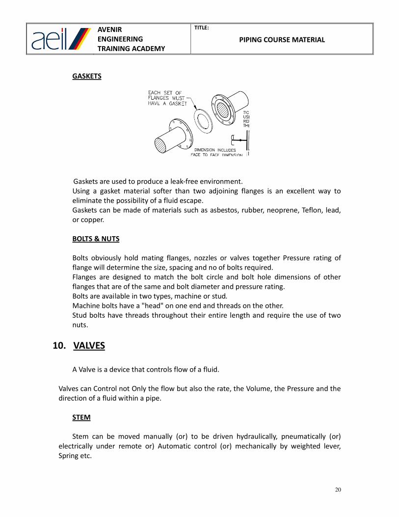
GASKETS
Gaskets are used to produce a leak-free environment.
Using a gasket material softer than two adjoining flanges is an excellent way to
eliminate the possibility of a fluid escape.
Gaskets can be made of materials such as asbestos, rubber, neoprene, Teflon, lead,
or copper.
BOLTS & NUTS
Bolts obviously hold mating flanges, nozzles or valves together Pressure rating of
flange will determine the size, spacing and no of bolts required.
Flanges are designed to match the bolt circle and bolt hole dimensions of other
flanges that are of the same and bolt diameter and pressure rating.
Bolts are available in two types, machine or stud.
Machine bolts have a "head" on one end and threads on the other.
Stud bolts have threads throughout their entire length and require the use of two
nuts.
10. VALVES
A Valve is a device that controls flow of a fluid.
Valves can Control not Only the flow but also the rate, the Volume, the Pressure and the
direction of a fluid within a pipe.
STEM
Stem can be moved manually (or) to be driven hydraulically, pneumatically (or)
electrically under remote or) Automatic control (or) mechanically by weighted lever,
Spring etc.

AVENIR
ENGINEERING
TRAINING ACADEMY
TITLE:
PIPING COURSE MATERIAL
21
Valve Action Explanation
ON / OFF - Starting Flow / Stopping Flow
Regulating - Varying the rate of Flow
Checking - Permitting Flow in one direction only
Switching - Switching Flow Along different Router
Discharging - Discharging fluid from a system.
SELECTION OF VALVE
• Fluid properties
• Service
• Valve size – design
• Pressure losses/friction losses
• Temperature and pressure
• End connection Flanged Medium pressure
Butt High pressure
Socket
Threaded Commercial
END CONNECTIONS
FUNCTION OF VALVE
FLANGED WELDED SCREWED
• Low and medium
Pressure valve <500°c
• Easily dismantling repair
and replacement of parts at
site with least possible delay
• High pressure & temperature
• long service
• Dismantling then for maintenance
Purpose is frequent
• Low pressure system
for gas and water
service
ISOLATION REGULATING NON-RETURN SPECIAL PUROSE VALVE
• Gate valve
• Ball valve
• Plug valve
• Piston valve
• Butterfly valve
• Globe valve
• Needle valve
• Butterfly valve
• Piston valve
• Lift check valve
• Swing check valve
• Multi-port valve
• Float valve
• Line blind valve

AVENIR
ENGINEERING
TRAINING ACADEMY
TITLE:
PIPING COURSE MATERIAL
22
SPECIAL PURPOSE VALVE
Valves that perform duties other than the two - way isolation control and check are
called special purpose valve.
SAFETY VALVE
Automatic in action and having released the undue pressure should close down and
remain closed until such time as it is again required to perform its design function.

AVENIR
ENGINEERING
TRAINING ACADEMY
TITLE:
PIPING COURSE MATERIAL
23
VALVE SYMBOLS

AVENIR
ENGINEERING
TRAINING ACADEMY
TITLE:
PIPING COURSE MATERIAL
24
11. STRESS ANALYSIS FOR PIPING
INTRODUCTION TO STRESS - STRAIN RELATIONSHIP
STRESS: Stress of a material is the internal resistance per unit area to the
deformation caused by applied load.
STRAIN: Strain is unit deformation under applied load.
STRESS –STRAIN CURVE: It is a curve in which unit load or stress is plotted against
unit elongation, technically known as strain.
• O– A represents the stress is directly proportional to strain, and point A is known
proportional limit.
• Point B represents elastic limit beyond which the material will not return to its
original shape when unloaded but will retain a permanent deformation called
permanent set.
• Point C is called yield point and is the point at which there is an appreciable
elongation or yielding of the material without any corresponding increases of
load.
• Point D is ultimate stress or ultimate strength of material.
• Point E is the stress at failure known as rupture strength.
WHAT IS STRESS ANALYSIS?
Piping Stress analysis is a term applied to calculations, which address the static and
dynamic loading resulting from the effects of gravity, temperature changes, internal
and external pressures, changes in fluid flow rate and seismic activity. Codes and
standards establish the minimum requirements of stress analysis.
AVENIR
ENGINEERING
TRAINING ACADEMY
TITLE:
PIPING COURSE MATERIAL
25
PURPOSE OF PIPING STRESS ANALYSIS
Purpose of piping stress analysis is to ensure:
• Safety of piping and piping components
• Safety of connected equipment and supporting structure
• Piping deflections are within the limits.
ASME B31 PIPING CODES
Piping codes developed by the American Society of Mechanical Engineers:
• B31.1 Power Piping
Piping typically found in electric power generating stations, in industrial and
Institutional plants, geothermal heating systems and central and district heating
and cooling plants.
• B31.3 Process Piping
Piping typically found in petroleum refineries, chemical, pharmaceutical, textile,
semiconductor and cryogenic plants and related processing plants and terminals.
• B31.4 Pipeline Transportation Systems for Liquid Hydrocarbons and Other
Liquids
Piping transporting products which are predominately quid between plants and
terminals and within terminals, pumping, regulating, and metering stations
• B31.5 Refrigeration Piping
Piping for refrigerants and secondary coolants
• B31.8 Gas Transportation and Distribution Piping Systems
Piping transporting products which are predominately gas between sources and
terminals including compressor, regulating and metering stations, gas gathering
pipelines
• B31.9 Building Services Piping
Piping typically found in industrial, institutional, commercial and public buildings
and in multi-unit residences which does not require the range of sizes, pressures
and temperatures covered in B311.1
• B31.11 Slurry Transportation Piping Systems
Piping transporting aqueous slurries between plants and terminals within
terminals, pumping and regulating stations

AVENIR
ENGINEERING
TRAINING ACADEMY
TITLE:
PIPING COURSE MATERIAL
26
HOW PIPING AND COMPONENTS FAIL (MODES OF FAILURES)
There are various failure modes, which could affect a piping system. The piping
engineers can provide protection against some of these failure modes by performing
stress analysis according to piping codes.
• FAILURE BY GERNRAL YIELDING: Failure is due to excessive plastic deformation.
o Yielding at Sub Elevated temperature: Body undergoes plastic deformation
under slip action of grains
o Yielding at Elevated temperature: After slippage, material re-crystallizes and
hence yielding continues without increasing load. This phenomenon is known
as creep.
• FAILURE BY FRACTURE: Body fails without undergoing yielding.
o Brittle fracture: Occurs in brittle materials.
o Fatigue: Due to cyclic loading initially a small crack is developed which grows
after each cycle and results in sudden failure.
WHEN PIPING AND COMPONENTS FAIL (THEORIES OF FAILURE)
Various theories of failure have been proposed, their purpose being to establish the
point at which failure will occur under any type of combined loading.
The failure theories most commonly used in describing the strength of piping
systems are:
• Maximum principal stress theory
This theory states that yielding in a piping component occurs when the
magnitude of any of the three mutually perpendicular principle stresses exceeds
the yield point strength of the material.
• Maximum shear stress theory
This theory states that failure of a piping component occurs when the maximum
shear stress exceeds the shear stress at the yield point in a tensile test.
In the tensile test, at yield, S1=Sy (yield stress), S2=S3=0.So yielding in the
components occurs When,
Maximum Shear stress =τmax=S1-S2 / 2=Sy / 2
The maximum principal stress theory forms the basis for piping systems governed by
ASME B31.3.
Note: maximum or minimum normal stress is called principal stress.

AVENIR
ENGINEERING
TRAINING ACADEMY
TITLE:
PIPING COURSE MATERIAL
27
STRESS CATEGORIES
The major stress categories are primary, Secondary and peak.
• PRIMARY STRESSES:
These are developed by the imposed loading and are necessary to satisfy the
equilibrium between external and internal forces and moments of the piping
system. Primary stresses are not self-limiting.
• SECONDARY STRESSES:
These are developed by the constraint of displacements of a structure. These
displacements can be caused either by thermal expansion or by outwardly
imposed restraint and anchor point movements. Secondary stresses are
self-limiting.
• PEAK STRESSES:
Unlike loading condition of secondary stress which causes distortion, peak
stresses cause no significant distortion. Peak stresses are the highest stresses in
the region under consideration and are responsible for causing fatigue failure.
BASIC STRESSES IN PIPING:
• LONGITUDINAL STRESS
Longitudinal stress or axial stress is the normal stress acting parallel to the
longitudinal axis of the pipe.
SL = (Fa / A) + (P A i / A) + (M b C / I)
There are a total of three components that make up the longitudinal stress:
I. The stress caused by an internal force axially within the pipe
SL = Fa / A
Where:
SL = longitudinal stress (Pa)
Fa= internal axial force (N)
A = metal cross sectional area of pipe (m2)
II. The longitudinal stress due to internal pressure.
SL = P A i / A
Where:
P = design pressure (Pa)
A i = internal area of pipe (m2)

AVENIR
ENGINEERING
TRAINING ACADEMY
TITLE:
PIPING COURSE MATERIAL
28
• BENDING STRESS
Bending stress is the third component of the axial stress. Bending stress is zero at
the neutral axis of the pipe.
SL = M b C / I
Where:
M b = Bending moment (N-m)
C = distance of point of interest from neutral axis of cross section (m)
I = moment of inertia of cross section (m4)
• HOOP STRESS
This stress is mainly caused by internal pressure, the hoop stress acts in a
direction parallel to the pipe circumference – in a way such that the pipe is split
into two halves. The hoop stress varies throughout the pipe wall.
SH = P do / 2 t
Where:
SH = hoop stress due to pressure (Pa)
P = pressure force (Pa)
do = pipe outer diameter (m)
t = pipe wall thickness (m)
• RADIAL STRESS
Radial stresses which are caused by internal pressure at the pipe’s inner surface.
SR = P (ri2 – ri
2 ro
2 / r
2 ) / ( ro
2 - ri
2 )
Where:
SR = radial stress due to pressure (Pa)
ri = inner radius of pipe (m)
ro = outer radius of pipe (m)
• SHEAR STRESS
Shear stresses are applied in a direction parallel to the face of the plane of the
pipe. Shear Stresses tend to cause adjacent planes of the pipe slip against each
other.
Ssh = MT C / R
Where:
Ssh = maximum shear stress (Pa)
MR = torsion resistance of cross section (m4)
R = torsion resistance of cross section (m4)

AVENIR
ENGINEERING
TRAINING ACADEMY
TITLE:
PIPING COURSE MATERIAL
29
CLASSCIFICATION OF LOADS
• PRIMARY LOADS: These can be divided into two categories based on the
duration of loading.
o Sustained loads: These loads are expected to be present throughout the
plant operation. E.g. pressure and weight.
o Occasional loads: These loads are present at infrequent intervals during plant
operation. E.g. earthquake, wind, etc.
• EXPANSION LOADS: These are loads due to displacements of piping. e,g .thermal
expansion, seismic anchor movements, and building settlement.
REQUIRMENTS OF ASME B31.3 (PROCESS PIPING CODE)
This code governs all piping within the property limits of facilities engaged in the
processing or handling of chemical, petroleum or related products. Examples are a
chemical plant, petroleum refinery, loading terminal, natural gas processing plant,
bulk plant, compounding plant and tank farm.
The loadings required to be considered are pressure, weight (live and dead loads),
impact, wind, earthquake-induced horizontal forces, vibration discharge reactions,
thermal expansion and contraction, temperature gradients, anchor movements.
The governing equations are as follows:
• STRESSES DUE TO SUSTAINED LOADS.
SL < Sh
SL = (PD/4t) + Sb
Sh = Basic allowable stress at maximum metal temperature.
The thickness of the pipe used in calculating SL shall be the nominal thickness
minus mechanical, corrosion, and erosion allowance.
• STRESSES DUE TO OCCASIONAL LOADS.
The sum of the longitudinal loads due pressure, weight and other sustained
loads and of stresses produced by occasional loads such as earthquake or wind
shall not exceed 1.33Sh.
• STRESS RANGE DUE TO EXPANSION LOADS.
The displacement stress range SE shall not exceed SA:
SE < SA
Where,
SE = (Sb2 + 4St
2)
½
Sb = resultant bending stress, psi
= [(IiMi) 2 + (IoMo) 2] / Z

AVENIR
ENGINEERING
TRAINING ACADEMY
TITLE:
PIPING COURSE MATERIAL
30
Mi = in-plane bending moment, in.lb
Mo = out-plane bending moment, in.lb
Ii = in- plane stress intensification factor obtained from appendix of B31.3
Io = out- plane stress intensification factor obtained from appendix of B31.3
St = Torsional stress, psi
= Mt / (2Z)
Mt = Torsional moment, in.lb
SA = Allowable displacement stress range:
(Allowable stress) cold = Sc = (2 / 3) Syc ⇒ Syc = (3/2) Sc
(Allowable stress) hot = Sh = (2 / 3) Syh ⇒ Syh = (3/2) Sh
Where,
Syc = yield point stress at cold temperature
Syh = yield point stress at hot temperature
Allowable stress =Syc + Syh
=3/2 (Sc + Sh)
= 1.5 (Sc + Sh)
= 1.25(Sc + Sh) after dividing with F.O.S
Final allowable stress = [(1.25(Sc + Sh) – SL]
SA = f [(1.25(Sc + Sh) – SL]
Sc = basic allowable stress at minimum metal temperature
f = stress range reduction factor from table 302.2.5 of B31.3
AVENIR
ENGINEERING
TRAINING ACADEMY
TITLE:
PIPING COURSE MATERIAL
31
12. SUPPORTS & RESTRAINTS
SUPPORTS
Supports are provided to the piping to resist various loads. The loads can be
classified into three categories.
They are primary loads, secondary loads and occasional loads. The response of the
piping to various loads is different. The primary load is also known as sustained load.
The primary loads are due to self-weight of the piping, its contents, insulation,
refractory, inner casing, outer casing, internal pressure and external pressure. The
secondary loads are due to temperature change and relative settlement of
foundations. The occasional loads are due to wind, earth quake, water hammer,
steam hammer, safety valves blowing jet reactions, surge load, blast load and
accidental loads.
If the piping is not provided with adequate supports, it will be over-stressed and
excessively deform. Over-stressing will cause premature failure. Excessive
deformation will impair the performance of piping.
RESTRAINTS
A device which prevents resists or limits the free thermal movement of pipe
restraints can be either directional, rotational or a combination of both.
SUPPORT AND RESTRAINT SELECTION FACTORS
• Weight load
• Available attachment clearance
• Availability of structural steel
• Direction of loads and/or movement
• Design temperature
• Vertical thermal movement at supports

AVENIR
ENGINEERING
TRAINING ACADEMY
TITLE:
PIPING COURSE MATERIAL
32
ANCHOR
This is an anchor type support; it restricts the pipe’s movements in all six degrees of
freedom.
GUIDE
This is a guide type support. Even though, it allows the horizontally mounted pipe to
move vertically, it prevents the vertically and horizontally mounted pipe from any side
movements.
REST
This is a support in the vertical direction only (upwards), it represents the support
under the Flanges and valves.

AVENIR
ENGINEERING
TRAINING ACADEMY
TITLE:
PIPING COURSE MATERIAL
33
SPRING HANGERS
These are used to support a piping system that is subjected to vertical thermal
movements. Variable effort spring hangers are usually incorporated for vertical
thermal movements up to approximately 50 mm, the variation between the preset
and operating loads should be no more than 25% of the operating load. Constant
effort spring hangers are usually incorporated for vertical thermal movements in
excess of 50mm.
• Variable Load Hanger is special type of hanger, which accommodate the vertical
thermal movements, while carrying the vertical load. Usually variable load
hangers are made of helical springs. The load varies from cold condition to hot
condition.
• Constant Load Hanger is a special type of hanger, similar to the variable load
hanger. There are several types of constant load hangers. The load variation in
the constant load hanger from cold to hot is limited to 0 %.

AVENIR
ENGINEERING
TRAINING ACADEMY
TITLE:
PIPING COURSE MATERIAL
34
13. EXPANSION LOOPS
Loops provide the necessary leg op piping in a perpendicular direction to absorb the
thermal expansion. They are safer when compare with expansion joints but take
more space. Expansion loops may be symmetrical or non-symmetrical. Symmetrical
loops are advantageous to use because leg is used efficiently to absorb an equal
amount of expansion from both directions.
GUIDELINES FOR LOOP SIZING
1. The Expansion loop is usually located on the side of the hottest line.
2. The Expansion loop, as a rule, should be located in the center of the distance
between two anchors.
3. The height of the expansion loop is normally twice the width.
The formula for calculating thermal expansion:
ΔL = C x L x (Tf - Tg) x 12in./ ft.
Where,
Coefficient of thermal expansion (C):
Steel (C) = 6.5 x 10⁻⁶ in./ in.°F
Copper (C) = 9.2 x 10⁻⁶ in./ in.°F
Distance between fixed points (L) in feet.
Temperature of fluid (Tf)
Temperature of ground (Tg)

AVENIR
ENGINEERING
TRAINING ACADEMY
TITLE:
PIPING COURSE MATERIAL
35
14. EXPANSION JOINTS:
This is used to control thermal expansion of a pipeline. Bellow joints are tubular
metal conduits with thin walled toriodal convolutes, which greatly reduce the axial
stiffness of the conduit.
Bellows are intended to control the pipe stresses and strains caused by the natural
thermal expansion of material as it changes from ambient temperature to steady
state temperature during start up and in reverse direction during shut down. Pipe
axial stresses and strains are controlled by bellows. The change in bellow length is
met with relatively little existing force because of the inherent flexibility of toroidal
convolutes. The flexibility is expressed as a spring constant over the applicable range
of axial compression for the specific bellow configuration.
Bellows can absorb very limited amount of lateral bending. A Bellow joint does not
have the capability to absorb torsional strains, rotations about the pipe axis in the
plane of pipe cross section.
Types of bellow type expansion joints:
• Simple Expansion Joint.
• Universal Expansion Joint.
• Pressure Balanced Expansion Joint.
• Hinged Expansion Joint.
• Gimbal Expansion Joint.
FLANGE LEAKAGE TEST
The flange leakage test is conducted in piping stress analysis. The flange leakage test
is performed by using various parameters
• Inadequate pressure rating
• Poor gasket selection
• Insufficient bolt loading
• Temperature gradient
• Bolt stress relaxation
• Piping forces and moments.
Equivalent pressure can be calculated using this formula:
Peq = (4Fx/ΠG2) + (192Mz/ΠG
3)
P eq = Equivalent pressure due to pipe loading,
F x = Axial force acting on flange
Mz = bending moment acting at flange
G = Diameter of gasket load reaction
Peq + PDesign = PTOTAL

AVENIR
ENGINEERING
TRAINING ACADEMY
TITLE:
PIPING COURSE MATERIAL
36
15. TEN DOS
The following leads to a good engineering practice.
• Use minimum number of supports.
• Limit the use of flexible supports.
• Provide supports near the already provided columns and beams.
• Provide necessary clearance for thermal movement.
• Consider all the primary, secondary and occasional loads in the design.
• Provide access for valves and fittings.
• Provide additional loops to satisfy flexible requirements.
• Provide guides to resist occasional loads like wind and earth quake.
• Provide an ergonomically acceptable design.
• Provide supports for vents, drains, start up vents and silencers.
TEN DON'TS
• Avoid the following in design.
• Avoid too many anchors
• Avoid too long a span
• Avoid too thin a pipe
• Avoid large local stresses
• Avoid too many fittings
• Avoid too many flexible supports
• Avoid supports on horizontal bends
• Avoid supports on pipes inclined to vertical
• Avoid bunching of too many pipes
• Avoid large vertical or horizontal loops.

AVENIR
ENGINEERING
TRAINING ACADEMY
TITLE:
PIPING COURSE MATERIAL
37
16. PIPING AND INSTRUMENT DIAGRAM
The design of piping involves preparation of the Piping and Instrumentation Diagram (P
& ID). The P & ID is prepared by the process designer, in consultation with Controls and
Instrumentation engineer. For a given process two different designers can prepare two
different P & ID. The P & ID is a single line diagram.
The P & ID indicates the following
• Location of equipment
• Tag numbers of equipment
• Tag number of lines
• Tag number of valves
• Tag number of instruments
• Tag number of motors
• Location of vents and drains
• Type of valves
• Type of Instruments
• Purpose of Instruments
• Output signal from instruments
• Flow measuring devices
• Level Indicating devices
• Equipment interfaces
• Scope of suppliers
The intelligent P & ID used in process industry indicates the complete particulars of
different components and piping. A Piping and Instrumentation Diagram – P & ID, is a
schematic illustration of functional relationship of piping, instrumentation and system
equipment components P & ID shows all of piping including the physical sequence of
branches, reducers, valves, equipment, instrumentation and control interlocks.
The P&ID are used to operate the process system.
A P & ID should include: Instrumentation and designations
• Mechanical equipment with names and numbers
• All valves and their identifications
• Process piping, sizes and identification
• Miscellaneous – vents, drains, special fittings, sampling lines,
reducers, increasers and swages

AVENIR
ENGINEERING
TRAINING ACADEMY
TITLE:
PIPING COURSE MATERIAL
38
• Permanent start-up and flush lines
• Flow directions
• Interconnections references
• Control inputs and outputs, interlocks
• Interfaces for class changes
• Seismic category
• Quality level
• Annunciation inputs
• Computer control system input
• Vendor and contractor interfaces
• Identification of components and subsystems delivered by others
• Intended physical sequence of the equipment
A P&ID should not include:
• Instrument root valves
• Control relays
• Manual switches
• Equipment rating or capacity
• Primary instrument tubing and valves
• Pressure temperature and flow data
• Elbow, tees and similar standard fittings
• Extensive explanatory notes
The P & I diagram (Engineering Line Diagram) allows the design to progress from the
“Process Flow Sheet / System and Piping diagram” to the final system design and
installation stage. The P & ID are definitive and comprehensive diagrams showing all of
the equipment, piping, valves and instrumentation. All items to be identified using
standard numbering systems. This normally entails having a unique plant item number
for each item of equipment, valve, instrument and line. Ideally the line number should
include a size, material and fluid contents identifier to enable the anyone reading the
drawing to obtain this information without having to refer to other documents.
An Engineering line should include
• Mechanical equipment with names and numbers
• Instruments with identification and necessary interfaces with
control loops
AVENIR
ENGINEERING
TRAINING ACADEMY
TITLE:
PIPING COURSE MATERIAL
39
• Interconnecting piping, sizes and identification
• Valves with identifications
• Vents, drains, special fittings, sampling lines, reducers and
increasers
• Flow directions
• Interface tags to other ELD’s
• Control interfaces, inputs and outputs.
• Main plant interlocks.
• Identification of symbols used
• Reference list including identification of relevant PFD’s
The symbols used to be in accordance with identified standards and should clearly
indicate the type of component, the method of connection (screwed, flanged etc.) and
the status (Valves – Normally Closed, Normally Open). The method of operating
equipment items should be clearly identified (electric motor, pneumatic actuator). It is
not generally necessary to identify services and electrical supplies to the operators.
A ‘piping and instrumentation diagram / drawing (P & ID)’ is defined by the Institute of
Instrumentation and Control as follows:
A diagram which shows the interconnection of process equipment and the
instrumentation used to control the process. In the process industry, a standard set of
symbols is used to prepare drawings of processes.
The primary schematic drawing used for laying out a process control installation

AVENIR
ENGINEERING
TRAINING ACADEMY
TITLE:
PIPING COURSE MATERIAL
40
P & ID SAMPLE DRAWING

AVENIR
ENGINEERING
TRAINING ACADEMY
TITLE:
PIPING COURSE MATERIAL
41
17. PROCESS FLOW DIAGRAM
Piping design involves preparation of process flow diagram (PFD). The process flow
diagram indicates the following parameters in a single line diagram:
• Flowing fluid
• Fluid temperature
• Fluid pressure
• Fluid mass flow rate
• Direction of fluid flow
The following additional data can also be shown in the PFD:
• Pipe diameter
• Pipe thickness
• Pipe material
• Pipe design code
• Pipe material specification
• Fluid flow velocity
• Fluid properties
The PFD gives the particulars of the processes. The PFD is prepared by the process
designer. Preparation of PFD requires thorough understanding of the process. The
PFD usually indicates the Maximum Continuous Rating parameters (MCR).
The process flow diagram- PFD, a schematic illustration of the system
A Process Flow Diagram- PFD - shows the relationships between the major
components in the system. PFD also tabulate process design values for components
in different operating modes, typical minimum, normal and maximum. A PFD does
not show minor components, piping systems, piping ratings and designations.
A PFD should include
• Process piping
• Major equipment symbols, names and identification numbers
• Control, valves and valves that affect operation of the system
• Interconnection with other systems
• Major bypass and recirculation lines
• System ratings and operational values as minimum, normal and
maximum flow, temperature and pressure
• Composition of fluids

AVENIR
ENGINEERING
TRAINING ACADEMY
TITLE:
PIPING COURSE MATERIAL
42
System flow diagrams should not include
• Pipe class
• Pipe line numbers
• Minor bypass lines
• Isolation and shut off valves
• Maintenance vents and drains
• Relief and safety valve
• Code class information
• Seismic class information
The flow diagram shows all the essential parts pf the process and items of equipment in
sufficient detail to enable the analysis and calculation of the physical characteristics of
the system to be undertaken.
A process flow diagram is a diagram of a fluid flow system showing the equipment items
connected by the major process pipes and containing data on the essential process
control circuits or major process requirements. The drawing is not to scale and the
equipment items are represented by symbols. The main equipment items and flow
streams should be identified and included in tables which identify process requirements
in sufficient detail to enable production of Piping and Instrumentation Diagrams
(Engineering Line Drawings)

AVENIR
ENGINEERING
TRAINING ACADEMY
TITLE:
PIPING COURSE MATERIAL
43
PFD SAMPLE DRAWING