pressurized dual mechanical seals supporting piping plan ...
Upload
independentCategory
view
6download
0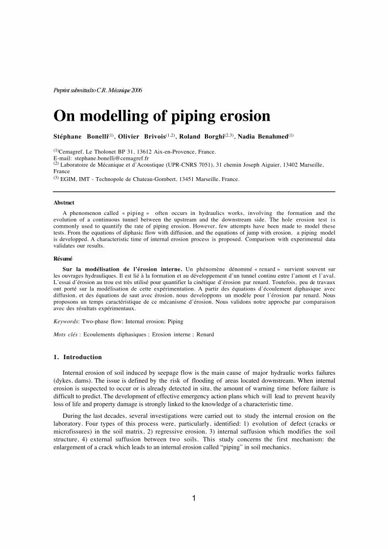
1
Preprint submitted to C.R. Mécanique 2006
On modelling of piping erosionStéphane Bonelli(1), Olivier Brivois(1,2), Roland Borghi(2,3), Nadia Benahmed(1)
(1)Cemagref, Le Tholonet BP 31, 13612 Aix-en-Provence, France.E-mail: [email protected](2) Laboratoire de Mécanique et d’Acoustique (UPR-CNRS 7051), 31 chemin Joseph Aiguier, 13402 Marseille,France(3) EGIM, IMT - Technopole de Chateau-Gombert, 13451 Marseille, France.
Abstract
A phenomenon called « piping » often occurs in hydraulics works, involving the formation and theevolution of a continuous tunnel between the upstream and the downstream side. The hole erosion test i scommonly used to quantify the rate of piping erosion. However, few attempts have been made to model thesetests. From the equations of diphasic flow with diffusion, and the equations of jump with erosion, a piping modelis developped. A characteristic time of internal erosion process is proposed. Comparison with experimental datavalidates our results.
Résumé
Sur la modélisation de l’érosion interne. Un phénomène dénommé « renard » survient souvent surles ouvrages hydrauliques. Il est lié à la formation et au développement d’un tunnel continu entre l’amont et l’aval.L’essai d’érosion au trou est très utilisé pour quantifier la cinétique d’érosion par renard. Toutefois, peu de travauxont porté sur la modélisation de cette expérimentation. A partir des équations d’écoulement diphasique avecdiffusion, et des équations de saut avec érosion, nous developpons un modèle pour l’érosion par renard. Nousproposons un temps caractéristique de ce mécanisme d’érosion. Nous validons notre approche par comparaisonavec des résultats expérimentaux.
Keywords: Two-phase flow; Internal erosion; Piping
Mots clés : Ecoulements diphasiques ; Erosion interne ; Renard
1. Introduction
Internal erosion of soil induced by seepage flow is the main cause of major hydraulic works failures(dykes, dams). The issue is defined by the risk of flooding of areas located downstream. When internalerosion is suspected to occur or is already detected in situ, the amount of warning time before failure isdifficult to predict. The development of effective emergency action plans which will lead to prevent heavilyloss of life and property damage is strongly linked to the knowledge of a characteristic time.
During the last decades, several investigations were carried out to study the internal erosion on thelaboratory. Four types of this process were, particularly, identified: 1) evolution of defect (cracks ormicrofissures) in the soil matrix, 2) regressive erosion, 3) internal suffusion which modifies the soilstructure, 4) external suffusion between two soils. This study concerns the first mechanism: theenlargement of a crack which leads to an internal erosion called “piping” in soil mechanics.
2
Numerous experimental methods have been performed in order to reproduce the internal erosion processin the laboratory and different types of equipment were developed with particular attention focussed on thehole erosion tests [2], [6], [7]. However, few attempts have been made to model these tests. The purpose ofthis paper is to propose a useful model for the interpretation of the hole erosion test.
On the first part, equations of diphasic flow and equations of jump with erosion are presented. On thesecond part, a model is developed by spatial integration of simplified equations obtained from asymptoticdevelopments in the case of a circular hole. Some comparison of modelling with experiments are finallyshown on the third part.
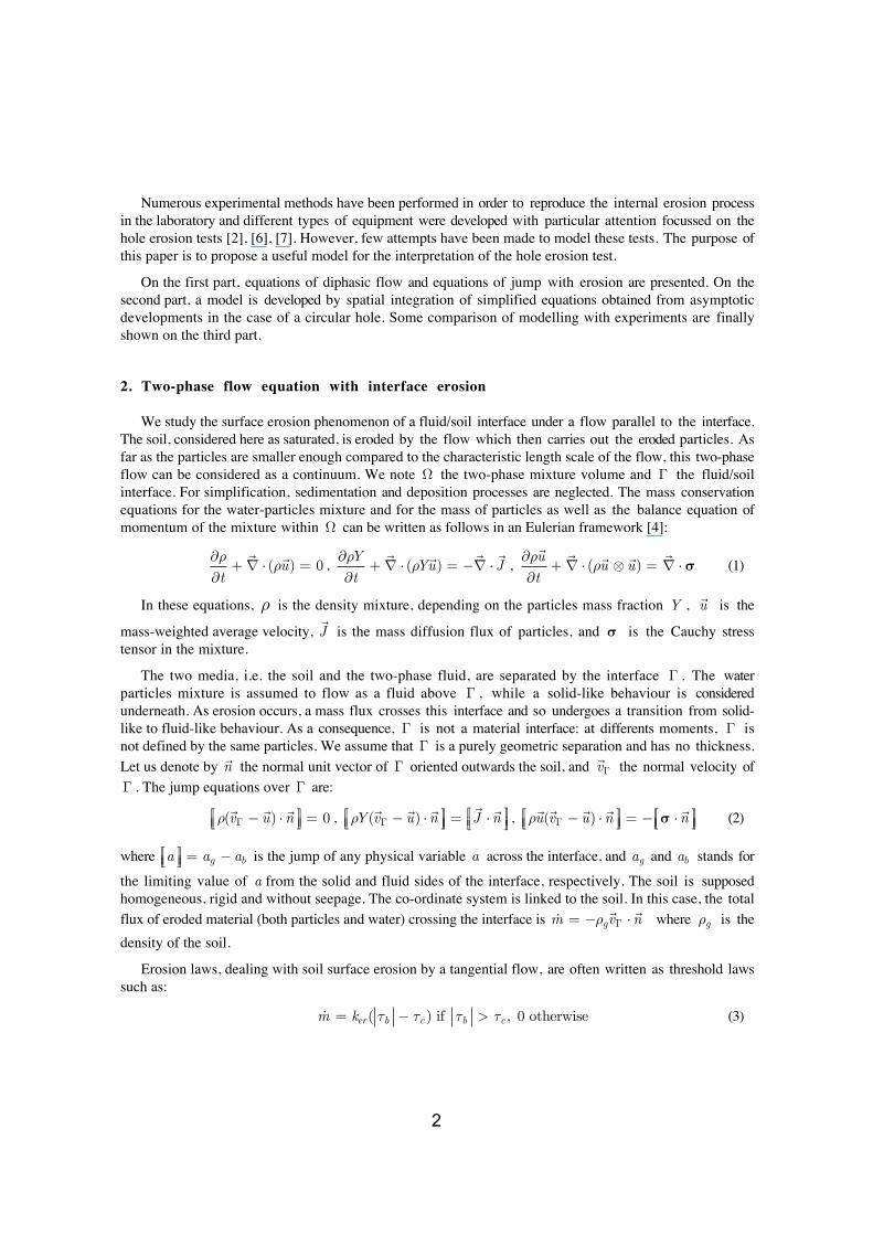
2. Two-phase flow equation with interface erosion
We study the surface erosion phenomenon of a fluid/soil interface under a flow parallel to the interface.The soil, considered here as saturated, is eroded by the flow which then carries out the eroded particles. Asfar as the particles are smaller enough compared to the characteristic length scale of the flow, this two-phaseflow can be considered as a continuum. We note Ω the two-phase mixture volume and Γ the fluid/soilinterface. For simplification, sedimentation and deposition processes are neglected. The mass conservationequations for the water-particles mixture and for the mass of particles as well as the balance equation ofmomentum of the mixture within Ω can be written as follows in an Eulerian framework [4]:
∂ρ∂t
+∇ ⋅ (ρ
u) = 0 ,
∂ρY∂t
+∇ ⋅ (ρY
u) = −
∇ ⋅J ,
∂ρu∂t
+∇ ⋅ (ρ
u ⊗
u) =
∇ ⋅ σ (1)
In these equations, ρ is the density mixture, depending on the particles mass fraction Y , u is the
mass-weighted average velocity, J is the mass diffusion flux of particles, and σ is the Cauchy stress
tensor in the mixture.
The two media, i.e. the soil and the two-phase fluid, are separated by the interface Γ . The waterparticles mixture is assumed to flow as a fluid above Γ , while a solid-like behaviour is consideredunderneath. As erosion occurs, a mass flux crosses this interface and so undergoes a transition from solid-like to fluid-like behaviour. As a consequence, Γ is not a material interface: at differents moments, Γ isnot defined by the same particles. We assume that Γ is a purely geometric separation and has no thickness.Let us denote by
n the normal unit vector of Γ oriented outwards the soil, and
vΓ the normal velocity of
Γ . The jump equations over Γ are:
ρ(vΓ −
u) ⋅n = 0 ,
ρY(vΓ −
u) ⋅n =
J ⋅n ,
ρu(vΓ −
u) ⋅n = − σ ⋅
n (2)
where a = ag − ab is the jump of any physical variable a across the interface, and ag and ab stands for
the limiting value of a from the solid and fluid sides of the interface, respectively. The soil is supposedhomogeneous, rigid and without seepage. The co-ordinate system is linked to the soil. In this case, the totalflux of eroded material (both particles and water) crossing the interface is m = −ρg
vΓ ⋅n where ρg is the
density of the soil.
Erosion laws, dealing with soil surface erosion by a tangential flow, are often written as threshold lawssuch as:
m = ker( τb − τc ) if τb > τc , 0 otherwise (3)
3
where τb = (σ ⋅
n)2 − (
n ⋅ σ ⋅
n)2
b is the tangential shear stress at the interface, τc is the critical
(threshold) shear stress for erosion and ker is the coefficient of soil erosion.
This complete set of equations (1-3) were already used to study different situations of permanent flow(boundary layer and free surface flow) over an erodable soil [1]. Here, these equations can be extended to thestudy of internal erosion by mean of a spatial integration over Ω .
3. Application to piping erosion
We consider a cylinder Ω of length L and radius R (with initial value R0 ) (figure 1). Referencevelocity is Vfl = Qfl / πR0
2 where Qfl is the initial entrance flow, and flow time is tfl = R0 /Vfl . Byassuming an axisymmetrical flow, we eliminate one momentum equation. We introduce the smallparameter Re
−1 to symplify the dimensionless equations in a boundary layer theory spirit [5], withReynolds number Re = VflR0 / ν f assumed to be large, where ν f is the kinematic viscosity. Navier-
Stokes equations are written with the time scaled by tfl , the axial coordinate by R0Re , the radial coordinate
by R0 , the axial velocity by Vfl , the radial velocity by Vfl / Re , and stresses by ρ fVfl
2 . Supposing
turbulent stress viscosity and diffusivity, we make regular asymptotic expansion of unknown and weneglect the terms of order Ο(Re
−1) in (1) and (2) (as in [1]). As a result, we have now only one momentumequation, and the pressure is uniform across a section.
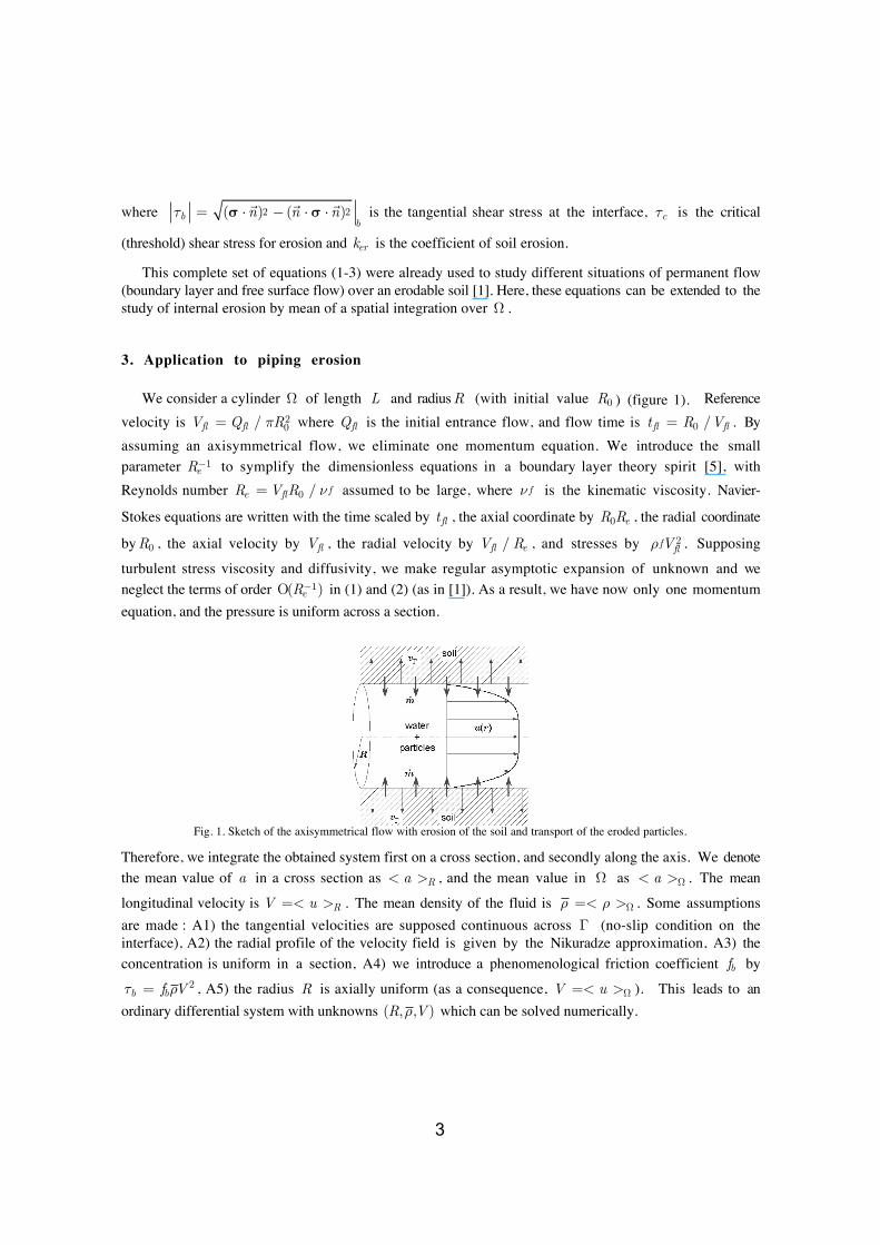
Fig. 1. Sketch of the axisymmetrical flow with erosion of the soil and transport of the eroded particles.
Therefore, we integrate the obtained system first on a cross section, and secondly along the axis. We denotethe mean value of a in a cross section as < a >R , and the mean value in Ω as < a >Ω . The mean
longitudinal velocity is V =< u >R . The mean density of the fluid is ρ =< ρ >Ω . Some assumptionsare made : A1) the tangential velocities are supposed continuous across Γ (no-slip condition on theinterface), A2) the radial profile of the velocity field is given by the Nikuradze approximation, A3) theconcentration is uniform in a section, A4) we introduce a phenomenological friction coefficient fb by
τb = fbρV 2 , A5) the radius R is axially uniform (as a consequence, V =< u >Ω ). This leads to anordinary differential system with unknowns (R,ρ,V ) which can be solved numerically.
4
If the erosional time scale is chosen, dimensionnal analysis reveals that the four basic parameters of thesystem are:
aφ =
αR0ρg2fbLρ f
,
bφ =< u2 >Ω< u >Ω2
− 1⎛
⎝⎜⎜⎜⎜
⎞
⎠⎟⎟⎟⎟⎟
1−ρ f
ρg
⎛
⎝⎜⎜⎜⎜
⎞
⎠⎟⎟⎟⎟⎟
,
kref =kerVfl
1 + kerVfl, τc =
τcPfl
The stress Pfl = R0(pin − pout ) / 2L represents the hydraulic gradient and depends on the input and output
pressures, respectively pin and pout . The positive dimensionless number α = (ρout − ρf ) / (ρ − ρf )
represents the fact that the input fluid is pure water, while the output fluid is a two-phase mixture( ρf < ρ < ρout ).
The erosional velocity appears to be Ver = kerPfl / (1 + kerVfl )ρg . The eroded flow is thus
Qer = 2πR0LVer and the erosional time is ter = R0 /Ver . As a consequence, the erosional flow scale
ratio is Qer /Qfl = αkref aφ−1 , the erosional time scale ratio is tfl / ter = kref fbρ f / ρg and the maximum
volumic concentration is cref = (1− n) / (1 + aφkref−1) where n is the porosity of the soil.
Now we assume that aφ ≥ Ο(1) and bφ ≈ Ο(1) , which is the case in the experiments described below.
We call kref the kinetics of erosion (dimensionless) number. If
kref 1 is a small parameter, thenasymptotic analysis leads to important conclusions: 1) the concentration is low andbecomes a secondaryunknown as it does not influence the density, the inertia, the velocity or the stress, 2) the flow isquasisteady, 3) the interface velocity is low and does not contribute to inertia. We call this case, whicharises when ker Vfl
−1 , the situation of low kinetics of erosion.
Starting from initial condition (R(0) = R0,V(0) = 0) , and under constant hydraulic gradient Pfl > τc ,the solution of the system can be written as:
R(t)R0
= 1 + 1−τcPfl
⎛
⎝⎜⎜⎜⎜
⎞
⎠⎟⎟⎟⎟⎟
expt
ter
⎛
⎝⎜⎜⎜⎜⎞
⎠⎟⎟⎟⎟− 1
⎡
⎣⎢⎢
⎤
⎦⎥⎥ ,
V(t)Vfl
=R(t)R0
(4)
with ter = 2Lρg / ker(pin − pout ) . The shear stress at the interface is τb(t) = PflR(t) / R0 , and the flow
is Q(t) = Qfl(R(t) / R0)5/2 .
It is important to note that the limiting case kref → 1 (corresponding to ker → ∞ ) may be of
interest. In this case, the concentration can be high, and even more close to the compacity of the soil
cref = (1− n) / (1 + aφ) . The erosional law (3) leads to τb = τc , but the rheological law dependsstrongly upon the concentration [3] (assumption A4 has to be modified) so the velocity remains unknown.Moreover, the concentration influences most probably the velocity profil: assumptions A2 and A4 are notrelevant anymore. To our knowledge, radial profil of concentration in pipe flow with erosion remains to beinvestigated.
5
4. Comparison with experiment
According to the logic of the derivation given above, the obtained scaling laws (4) should hold in allpast and future experiments performed in erosional pipe flow with constant pressure drop, in the situationof low kinetics of erosion. The ultimate justification is a comparison with experiment.
The Hole Erosion Test has been designed to reproduce piping flow erosion in a hole [2]. The soilspecimen is compacted inside a standard mould used for the Standard Compaction Test. A hole is drilledalong the longitudinal axis of the soil sample. An eroding fluid is driven through the soil sample to initiateerosion of the soil along the pre-formed hole. The test result is described by the flow rate versus time curveunder constant pressure drop. For further details on this test, see [2], [6], [7].
The predicted scaling law (4) is now compared to avalaible data produced by [2]. Simulations wereperformed on 17 tests, concerning 10 different soils (clay, sandy clay, clayey sand or silty sand). The rangeof soil density
ρg / ρ f were 1.78 to 2.35. The range of initial water content were 8% to 38.7%. The initial
radius and the length of the pipe were R0 =3 mm and L =117 mm. The range of Reynolds numbers were
2000 to 8800. The comparison between characteristic values are given in table 1. The range of aφ numbers
is 2.37 to 4.82, and the range of ker numbers is 7.54 10-5 to 1.19 10-2, so all cases correspond to the
situation of low kinetics of erosion. The range of coefficient of erosion ker is 3.50 10-5 to 1.47 10-2 s/mand the range of critical stress is 6.41 to 128.22 Pa.
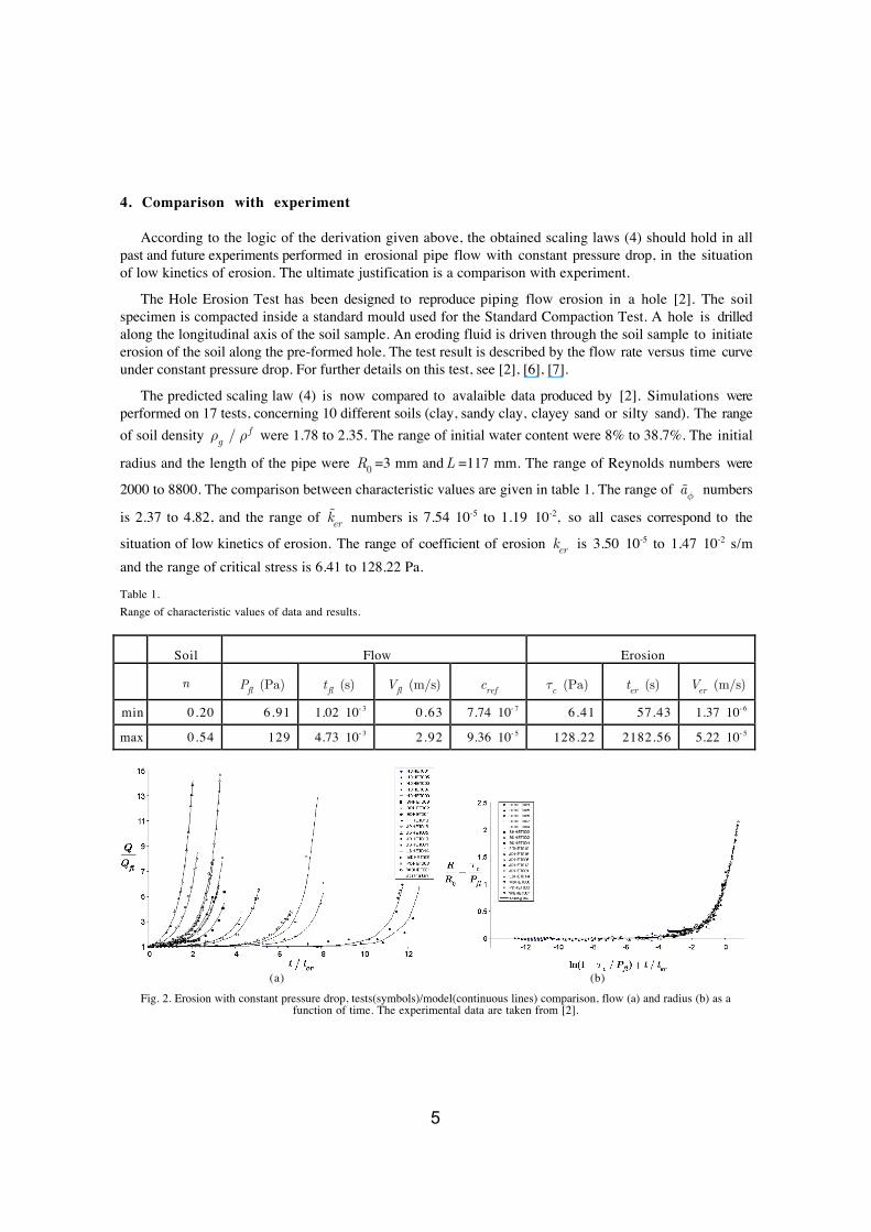
Table 1.Range of characteristic values of data and results.
Soil Flow Erosion
n Pfl (Pa)
tfl (s)
Vfl (m/s) cref
τc (Pa) ter (s)
Ver (m/s)
min 0.20 6.91 1.02 10- 3 0.63 7.74 10- 7 6.41 57.43 1.37 10- 6
max 0.54 129 4.73 10- 3 2.92 9.36 10- 5 128.22 2182.56 5.22 10- 5
(a) (b)
Fig. 2. Erosion with constant pressure drop, tests(symbols)/model(continuous lines) comparison, flow (a) and radius (b) as afunction of time. The experimental data are taken from [2].
6
Figure 2(a) shows the increase of the flow in Q ∝ R5/2 and shows that the use of ter leads to anefficient dimensionless scaling. In figure 2(b), we plot the experimental data of [2] in the
R(t) / R0 − τc / Pfl( ), t / ter + ln(1− τc / Pfl )( ) plane. We observe that all the data except for few fall
on a single curve. Taking into account the many simplifying assumptions, the agreement with the scalinglaw (4) speaks for itself: in spite of the large range of ker (three orders of magnitude), no furthermanipulation is needed to bring its consequences into line with the experimental data.
5. Conclusion
Many laboratory tests are commonly used to study internal erosion in a soil. One of them, the holeerosion test appears to be efficient and simple to quantify the rate of piping erosion, but few attempts havebeen made to model this test. We started from the field equations of diphasic flow with diffusion, and theequations of jump with erosion. After many simplifying assumptions, from asymptotic developments anddimensionnal analysis, we proposed some characteristic numbers, among which the two most significantare the kinetics of erosion dimensionless number and the erosional time. We defined a particular case: thesituation of low kinetics of erosion. This situation arises when kinetics of erosion is much small than one.In this case, the influence of both concentration and inertial effects can be neglected. We obtained ananalytical scaling law for the interpretation of the hole erosion test with constant pressure drop. We madecomparison with available experimental data on seventeen tests concerning nine different soils. Thiscomparison has confirmed the validity of our scaling law, which can be used for the interpretation of thehole erosion test. More research works are needed to investigate if this characteristic time could be used inpractical situations to predict the developpement of internal erosion on hydraulic works.
Acknowledgements
This project was sponsored by the Région Provence Alpes Côte d’Azur. This research effort iscontinuing under the sponsorship of the French National Research Agency under grant 0594C0115(ERINOH). The authors wish to thanks Pr. Robin Fell and Dr. Chi Fai Wan for their valuableexperimental data.
References[1] Brivois O ., Contribution à la modélisation de l'érosion de fortes pentes par un écoulement turbulent diphasique, Thèse
Université Aix-Marseille II, 2005.[2] Fell R., Wan C.F., Investigation of internal erosion and piping of soils in embankment dams by the slot erosion test and the hole
erosion test UNICIV Report No R-412, The University of New South Wales Sydney ISSN 0077 880X, 2002.[3] Julien P.Y., Erosion and Sedimentation, Cambridge University Press, 1995.[4] Nigmatulin R.I., Dynamics of multiphase media, Book News, Inc. Portland, 1990.[5] Schlichting H., Boundary layer theory , 7th ed Mc Graw Hill, New York, 1987.[6] Wan C.F., Fell R. Investigation of rate of erosion of soils in embankment dams, Journal of Geotechnical and Geoenvironmental
Engineering, 30(4) (2004) 373-380.[7] Wan C.F., Fell R. Laboratory Tests on the Rate of Piping Erosion of Soils in Embankment Dams, Journal of Geotechnical
Testing Journal, 27(3) (2004).
Copyright © 2022 FDOKUMEN