Laboratory tests of thermoplastic piping assemblies subjected ...
Upload
khangminh22Category
view
1download
0
VALVE AND PIPING SYSTEMS
AV-V-001-E
201420142014

1
1. ASAHI AV VALVES2. ASAHI AV AUTOMATIC VALVES & SENSOR AND FLOW METERS3. ASAHI AV PIPE, FITTING AND OTHERS4. HIGH PURITY SERIES5. AV PIPE & FITTINGS (FRP-Reinforced Composite PVC Pipes)6. PP PIPES & FITTINGS7. ENGINEERING8. TECHNICAL DATA9. PRODUCT WARRANTY10. PRECAUTIONS FOR USE11. CONTACT US
Table of Contents3
77131149169179190191218220220

Abbreviations for Major Materials Used For Asahi AV Products
2
Symbol DescriptionPVC “PVC” is an abbreviation for “polyvinyl chloride.”
C-PVC The fi rst letter “C” stands for “chlorinated.”“C-PVC” refers to “chlorinated polyvinyl chloride,” or heat-resistant polyvinyl chloride.
HI-PVC The fi rst lettering “HI” means “high impact.” “HI-PVC” refers to “high impact resist polyvinyl chloride.”
PP “PP” is an abbreviation for “polypropylene.”
PVDF “PVDF” is an abbreviation for “polyvinylidene fl uoride.”
FRP “FRP” is an abbreviation for “fi ber reinforced plastics.”
ABS “ABS” is an abbreviation for “acrylonitrile butadiene styrene.”
PPS “PPS” is an abbreviation for “polyphenylenesulfi de.”
PEEK “PEEK” is an abbreviation for “polyether ether ketone.”
PTFE “PTFE” is an abbreviation for “poly tetra fl uoro ethylene.”
PDCPD “PDCPD” is an abbreviation for “polydicyclo pentadiene.”
UHMWPE “UHMWPE” is an abbreviation for “ultra high molecular weight polyethylene.”
EPDM “EPDM” is an abbreviation for “ethylene propylene diene rubber.”
FKM “FKM” is an abbreviation for “fl uorocarbon rubber.”
Vifl on F,C(FKM-F, FKM-C)
“Vifl on” is Trade Mark of ASAHI ORGANIC CHEMICALS INDUSTRY CO., LTD. of the Terpolymerization Fluorocarbon Elastomers.
SBR “SBR” is an abbreviation for “styrene butadiene rubber.”
NBR “NBR” is an abbreviation for “acrylonitorile butadiene rubber.”
IIR “IIR” is an abbreviation for “isobtylen isopren rubber.”
CSM “CSM” is an abbreviation for “chlorosulphonated polyethlene.”
PPG “PPG” is an abbreviation for “Glass Fiber Reinforced Polypropylene.”
PC “PC” is an abbreviation for “Polycarbonate.”
HP-PVC The fi rst letter “HP” means “High Purity”“HP-PVC” reters to “high purity polyvinyl chloride.”
3
BUTTERFLY VALVE TYPE 57TL (LUG STYLE) 39 • 40BUTTERFLY VALVE TYPE 57L - IS 41 • 42BUTTERFLY VALVE TYPE 55 43 • 44PDCPD BUTTERFLY VALVE 45 • 46ROTARY DAMPER 47 - 50SWING CHECK VALVE 51 • 52WAFER CHECK VALVE 53BALL CHECK AND BALL FOOT VALVE 54 - 57STOP VALVE (GLOBE VALVE) 58 - 60GAUGE VALVE 61GATE VALVE 62 - 66AUTOMATIC WATER FEEDING VALVE 67ROTARY ANGLE VALVE 68ALFALFA VALVE TYPE 82 68CONSTANT FLOW VALVE 69 - 71NEEDLE VALVE 72Y-SEDIMENT STRAINER 73 • 74AIR RELEASE VALVE 75 • 76
ASAHI AV VALVESPHOTOS 4 • 5TYPES OF ASAHI AV PRODUCTS 6 • 7ASAHI AV PRODUCTS MODEL CODE 8 • 9DIAPHRAGM VALVE TYPE 14 10 • 11TRUE UNION DIAPHRAGM VALVE TYPE 14 12 • 13DIAPHRAGM VALVE TYPE 15 14 • 15DIAPHRAGM VALVE TYPE 72 16 - 18BALL VALVE TYPE 21・21α 19 - 21WATER BV 223-WAY BALL VALVE TYPE 23 23 - 243-WAY BALL VALVE TYPE 23H 25 - 26COMPACT BALL VALVE 27 LAB COCK 28 - 30BUTTERFLY VALVE TYPE 57 31 • 32BUTTERFLY VALVE TYPE 56, TYPE 75 33 • 34BUTTERFLY VALVE TYPE 56D, 75D 35 • 36BUTTERFLY VALVE TYPE 57L (LUG STYLE) 37 • 38
ASAHI AV VALVESThe specifications in this brochure are subject to change without prior notice due to improvements and modifications.
DIAP
HRAG
M VA
LVE
BALL
VAL
VEBU
TTER
FLY
VALV
ESW
ING
CHEC
K VA
LVE
BALL
CHECK
, BALL
FOOT
VALV
EST
OP V
ALVE
GAUG
E VA
LVE
GATE
VAL
VEAU
TOMA
TIC W
ATER
FE
EDIN
G VA
LVE
ROTA
RY A
NGLE
VA
LVE
ALFA
LFA
VALV
ECO
NSTA
NT FL
OW
VALV
ENE
EDLE
VALV
EY-
SEDI
MENT
ST
RAIN
ERAI
R RE
LEAS
E VA
LVE

Asahi AV Products Make Your Systems More Sophisticated.
To meet your specific requirements, Asahi AV Valves are made of wide variety of materials
and are available in various types and sizes.
You are surely making the best choice for your systems when selecting Asahi AV products.
4 5
DIAPHRAGM VALVE TYPE14
(Page 10 • 11)
TRUE UNION DIAPHRAGM VALVE TYPE14
(Page 12 • 13)
DIAPHRAGM VALVE TYPE15
(Page 14 • 15)
DIAPHRAGM VALVE TYPE72
(Page 16 - 18)
BALL VALVE TYPE21
(Page 19 - 21)
3-WAY BALL VALVETYPE23H
(Page 25 • 26)
LAB COCK
(Page 28 - 30)
BUTTERFLY VALVE TYPE57
(Page 31 • 32)
BUTTERFLY VALVE TYPE56・TYPE75
(Page 33 • 34)
BUTTERFLY VALVE TYPE55
(Page 43 • 44)
PDCPD BUTTERFLY VALVE
(Page 45 • 46)
SWING CHECK VALVE
(Page 51 • 52)
BALL CHECK AND BALL FOOT VALVE(Page 54 - 57)
STOP VALVE(GLOBE VALVE)
(Page 58 - 60)
GAUGE VALVE
(Page 61)
GATE VALVE (TYPE-C)
(Page 62 - 66)
AUTOMATIC WATER FEEDING VALVE(Page 67)
ROTARY ANGLE VALVE
(Page 68)
CONSTANT FLOW VALVE
(Page 69 - 71)
NEEDLE VALVE
(Page 72)
Y-SEDIMENT STRAINER
(Page 73 • 74)
AIR RELEASE VALVE
(Page 75 • 76)
COMPACT BALL VALVE
(Page 27)
ROTARY DAMPER
(Page 47 - 50)
ALFALFA VALVE® TYPE82
(Page 68)
BUTTERFLY VALVE TYPE 56D,75D
(Page 35 • 36)
BUTTERFLY VALVE TYPE57L(LUG STYLE)
(Page 37 • 38)
BUTTERFLY VALVE TYPE57L - IS
(Page 41 • 42)
WATER BV
(Page 22)
3-WAY BALL VALVETYPE23
(Page 23 • 24)
BUTTERFLY VALVE TYPE57TL(LUG STYLE)
(Page 39 • 40)
BALL CHECK AND BALL FOOT VALVE
(Page 53)

6 7
Type WAFER CHECK VALVEBody Materials PVC
End Connectors Wafer
Nom
inal
S
ize
mm inch100 4 ○150 6 ○200 8 ○250 10 ○300 12 ○Page 53
Range of Nominal Size and Materials
Type BALL CHECK VALVE AND BALL FOOT VALVE STOP VALVE (GLOBE VALVE)Body Materials PVC C-PVC PP PVDF PVC PPEnd Connectors Flanged Threaded Socket Flanged Threaded Socket Threaded Socket
(welded) Spigot Threaded Socket※(welded) Spigot Flanged Threaded Socket Flanged Threaded
Nom
inal
Siz
e
mm inch15 1/2 ○ ○ ○ ○ ○ ○ ○ ○ ○ ○ ○ ○ ○ ○ ○ ○ ○20 3/4 ○ ○ ○ ○ ○ ○ ○ ○ ○ ○ ○ ○ ○ ○ ○ ○ ○25 1 ○ ○ ○ ○ ○ ○ ○ ○ ○ ○ ○ ○ ○ ○ ○ ○ ○32 1 1/4 - - - - - - - - - - - - ○ ○ - - -40 1 1/2 ○ ○ ○ ○ ○ ○ ○ ○ ○ ○ ○ ○ ○ ○ - ○ -50 2 ○ ○ ○ ○ ○ ○ ○ ○ ○ ○ ○ ○ ○ ○ - ○ -65 2 1/2 - - - - - - - - - - - - ○ - - ○ -80 3 ○ ○ ○ ○ ○ ○ ○ ○ ○ ○ ○ ○ ○ - - ○ -
100 4 ○ ○ ○ ○ ○ ○ ○ ○ ○ ○ ○ ○ ○ - - ○ -Page 54 - 57 58 - 60
Type DIAPHRAGM VALVE TYPE 14 TRUE UNION DIAPHRAGM VALVE TYPE 14Body Materials PVC, C-PVC, PP, PVDF PVC C-PVC PP PVDFEnd Connectors
Flanged Threaded Socket Threaded Socket Threaded Socket(welded) Threaded Socket
(welded) Spigot
Nom
inal
Siz
e
mm inch15 1/2 ○ ○ ○ ○ ○ ○ ○ ○ ○ ○20 3/4 ○ ○ ○ ○ ○ ○ ○ ○ ○ ○25 1 ○ ○ ○ ○ ○ ○ ○ ○ ○ ○32 1 1/4 ○ ○ ○ ○ ○ ○ ※○ ○ ○ ○40 1 1/2 ○ ○ ○ ○ ○ ○ ○ ○ ○ ○50 2 ○ ○ ○ ○ ○ ○ ○ ○ ○ ○65 2 1/2 ○ - - - - - - - - -80 3 ○ - - - - - - - - -
100 4 ○ - - - - - - - - -Page 10 - 11 12 - 13
Type DIAPHRAGM VALVE TYPE 15Body Materials PVC, PP, PVDFEnd Connectors Flanged
Nominal Size
mm inch125 5 ○150 6 ○
Page 14 - 15
Type DIAPHRAGM VALVE TYPE 72Body Materials PVC, PP, PVDFEnd Connectors Flanged
Nominal Size
mm inch200 8 ○250 10 ○
Page 16 - 18
Type BALL VALVE TYPE 21 WATER BVBody Materials PVC C-PVC PP PVDF PVCEnd Connectors Flanged Threaded Socket Flanged Threaded Socket Flanged Threaded Socket
(welded) Flanged Threaded Socket(welded) Spigot Threaded Socket
Nom
inal
Siz
e
mm inch15 1/2 ○ ○ ○ ○ ○ ○ ○ ○ ○ ○ ○ ○ ○ ○ ○20 3/4 ○ ○ ○ ○ ○ ○ ○ ○ ○ ○ ○ ○ ○ ○ ○25 1 ○ ○ ○ ○ ○ ○ ○ ○ ○ ○ ○ ○ ○ ○ ○32 1 1/4 ○ ○ ○ ○ ○ ○ ○ ○ ※○ ○ ○ ○ ○ ○ ○40 1 1/2 ○ ○ ○ ○ ○ ○ ○ ○ ○ ○ ○ ○ ○ ○ ○50 2 ○ ○ ○ ○ ○ ○ ○ ○ ○ ○ ○ ○ ○ ○ ○65 2 1/2 ○ ○ ○ ○ ○ ○ ○ ○ ○ ○ ○ ○ ○ - -80 3 ○ ○ ○ ○ ○ ○ ○ ○ ○ ○ ○ ○ ○ - -
100 4 ○ ○ ○ ○ ○ ○ ○ ○ ○ ○ ○ ○ ○ - -Page 19 - 21 22
Type LAB COCK
Body Materials PVC
End Connectors
Male Thread, Female Thread, Hose
Nominal Size
Male Thread1/4 1/2
Female Thread1/4 3/8
Page 28 - 29
Type 3-WAY BALL VALVE TYPE 23 3-WAY BALL VALVE TYPE 23H COMPACT BALL VALVEBody Materials PVC C-PVC PP PVDF PP PVC C-PVCEnd Connectors Flanged Threaded Socket Flanged Threaded Socket Threaded Socket
(welded) Flanged Threaded Socket(welded) Flanged Threaded Socket
(welded) Spigot Threaded Socket Threaded Socket
Nom
inal
Siz
e
mm inch13 3/8 - - - - - - - - - - - - - - - ○ ○ ○ ○15 1/2 ○ ○ ○ ○ ○ ○ ○ ○ ○ ○ ○ - - - - ○ ○ ○ ○20 3/4 ○ ○ ○ ○ ○ ○ ○ ○ ○ ○ ○ - - - - ○ ○ ○ ○25 1 ○ ○ ○ ○ ○ ○ ○ ○ ○ ○ ○ ○ ○ ○ ○ ○ ○ ○ ○32 1 1/4 ○ ○ ○ ○ ○ ○ ○ ○ ○ ○ ○ ○ ○ ○ ○ ○ ○ ○ ○40 1 1/2 ○ ○ ○ ○ ○ ○ ○ ○ ○ ○ ○ ○ ○ ○ ○ ○ ○ ○ ○50 2 ○ ○ ○ ○ ○ ○ ○ ○ ○ ○ ○ - - - - ○ ○ ○ ○65 2 1/2 - - - - - - - - - - - - - - - - - - -80 3 ○ ○ ○ ○ ○ ○ ○ ○ ○ ○ ○ - - - - ○ ○ ○ ○
100 4 ○ ○ ○ ○ ○ ○ ○ ○ ○ ○ ○ - - - - - - - -Page 23 - 24 25 - 26 27
Type BUTTERFLY VALVE TYPE 57 BUTTERFLY VALVE TYPE 56
BUTTERFLY VALVE TYPE 75
BUTTERFLY VALVETYPE 56D, 75D
BUTTERFLY VALVE TYPE 57L, 57TL(Lug Style)
BUTTERFLY VALVE TYPE 57L-IS ROTARY DAMPER BUTTERFLY
VALVE TYPE 55
Body Materials PVC PP PVDF PP PVDF PP PVDF PDCPD PDCPD PVC PVC PVC(PP DISC) PP PVDF FCD-S
End Connectors Wafer Wafer Wafer Wafer Wafer Wafer Wafer Wafer Wafer Wafer Wafer Wafer Wafer Wafer Wafer
Nom
inal
Siz
e
mm inch40 1 1/2 ○ ○ ○ - - - - - - - - ○ ○ ○ -50 2 ○ ○ ○ - - - - - - - - ○ ○ ○ ○65 2 1/2 ○ ○ ○ - - - - - - - - ○ ○ ○ -80 3 ○ ○ ○ - - - - - ○ ○ ○ ○ ○ ○ ○
100 4 ○ ○ ○ - - - - - ○ ○ ○ ○ ○ ○ ○125 5 ○ ○ ○ - - - - - ○ - - ○ ○ ○ ○150 6 ○ ○ ○ - - - - - ○ ○ ○ ○ ○ ○ ○200 8 ○ ○ ○ - - - - - ○ ○ ○ ○ ○ ○ ○250 10 ○ ○ ○ - - - - - ○ ○ - ○ ○ ○ ○300 12 ○ ○ ○ - - - - - - ○ - ○ ○ ○ -350 14 ○ ○ ○ - - - - - - - - ○ ○ ○ -400 16 - - - ○ ○ - - ○ - - - - ○ ○ -450 18 - - - - - ○ ○ ○ - - - - ○ ○ -500 20 - - - - - ○ ○ ○ - - - - ○ ○ -600 24 - - - - - ○ ○ ○ - - - - ○ ○ -
Page 31 - 32 33 34 35-36 37 - 40 41-42 47 - 50 42-44
TypePDCPD
BUTTERFLY VALVE
Body Materials PDCPDModels Wafer
Nom
inal
Siz
e
mm inch700 28 ○800 32 ○850 34 ○900 36 ○
1000 40 ○1100 44 ○1200 48 ○
Page 45 - 46
Type GATE VALVE〈Internally Threaded〉
RISING STEM
Body Materials HI-PVC HI-PVCEnd Connectors Flanged Threaded Wafer Flanged
Nom
inal
Siz
e
mm inch40 1 1/2 ○ ○ ○ ○50 2 ○ ○ ○ ○65 2 1/2 ○ - ○ ○
80(75) 3 ○ - ○ ○100 4 ○ - ○ ○125 5 ○ - ○ ○150 6 ○ - ○ ○200 8 ○ - - ○250 10 ○ - - -300 12 ○ - - -350 14 ○ - - -
Page 62 - 661. We produce resilent seal type GATE VALVES with Threaded Connection which are up to 200 mm in nominal size.
2. RISING STEM and JWWA GATE VALVES are available in resilieht seal type only.
Type SWING CHECK VALVEBody Materials HI-PVC PP PVDFEnd Connectors Flanged Flanged Flanged
Nom
inal
Siz
e
mm inch15 1/2 ○ ○ ○20 3/4 ○ ○ ○25 1 ○ ○ ○32 1 1/4 ○ ○ ○40 1 1/2 ○ ○ ○50 2 ○ ○ ○65 2 1/2 ○ ○ ○80 3 ○ ○ ○
100 4 ○ ○ ○125 5 ○ ○ ○150 6 ○ ○ ○200 8 ○ ○ ○
Page 51 - 52
Type GAUGE VALVEBody Materials PVC PP
End Connectors Flanged Flanged
Nom
inal
Si
ze
mm inch20 3/4 ○ ○25 1 ○ ○
Page 611. Flanged elbows are available in a nominal size of 25 mm(1inch) only.
Type TRUE UNION BALL CHECK VALVEBody Materials PVC C-PVC PP PVDFEnd Connectors Flanged Threaded Socket Flanged Threaded Socket Threaded Socket
(welded) Threaded Socket (welded)
Nom
inal
Siz
e mm inch15 1/2 ○ ○ ○ ○ ○ ○ ○ ○ ○ ○20 3/4 ○ ○ ○ ○ ○ ○ ○ ○ ○ ○25 1 ○ ○ ○ ○ ○ ○ ○ ○ ○ ○32 1 1/4 - - - - - - - - - -40 1 1/2 ○ ○ ○ ○ ○ ○ ○ ○ ○ ○50 2 ○ ○ ○ ○ ○ ○ ○ ○ ○ ○Page 56
Type AIR RELEASE VALVE
AUTOMATIC WATER FEEDING VALVE ALFALFA VALVE ROTARY ANGLE VALVE
Body Materials PDCPD HI-PVC PVC PVCEnd Connectors Flanged Flanged Threaded Socket Flanged Socket Flanged Threaded Socket
Nom
inal
Siz
e mm inch25 1 ○ - - - - - - - -50 2 - ○ ○ ○ ○ ○ ○ ○ ○65 2 1/2 - - - - - - - - -80 3 ○ ○ ○ ○ ○ ○ ○ ○ ○
100 4 ○ - - - ○ ○ - - -150 6 ○ - - - - - - - -
Page 75 - 76 67 68 68
Type CONSTANT FLOW VALVE NEEDLE VALVE STRAINER(Y)Body Materials PVC PVC PVC(Clear)End Connectors Flanged Flanged Flanged Threaded Flanged
Nom
inal
Siz
e
mm inch15 1/2 ○ ○ ○ ○ ○20 3/4 ○ ○ ○ ○ ○25 1 ○ ○ ○ ○ ○32 1 1/4 - - ○ ○ ○40 1 1/2 - - ○ ○ ○50 2 ○ - ○ ○ ○65 2 1/2 - - ○ ○ ○80 3 ○ - ○ ○ ○100 4 ○ - ○ ○ ○
Page 69 - 71 72 73 - 74
※※
※ ※
※
※

8 9
DIGIT 1 2,3 4,5
DESCRIPTIONS Valve Abbr VALVE NAME Abbr OPERATION AbbrManual V DIAPHRAGM VALVE TYPE14 14 LEVER LV
Actuated A TRUE UNION DIAPHRAGM VALVE T1 MANUAL HANDLE MH
DIAPHRAGM VALVE TYPE15 15 T STYLE HANDLE TH
DIAPHRAGM VALVE TYPE72 72 SIDE GEAR SG
DIAPHRAGM VALVE TYPE16 16 SIDE GEAR WITH SQUARE CAP SC
BALL VALVE TYPE21 21 TOP GEAR TG
WATER BV WB TOP GEAR WITH SQUARE CAP TC
LABCOCK LC O-RING TYPE FOR SWING CHECK VALVE OR
COMPACT BALL VALVE Cb PLASTIC STEM FOR GATE VALVE MJ
3 WAY BALL VALVE TYPE23 23 SS STEM FOR CLOCKWISE OPENING MR
3 WAY BALL VALVE TYPE23H 3H SS STEM FOR UNCLOCKWISE OPENING ML
BUTTERFLY VALVE TYPE57 57 TOP GEAR WITH CAP FOR GATE VALVE CLOCKWISE OPENING CR
BUTTERFLY VALVE TYPE56 56 TOP GEAR WITH CAP FOR GATE VALVE UNCLOCKWISE OPENING CL
BUTTERFLY VALVE TYPE75 75 A TYPE FOR CONSTANT FLOW / NEEDLE VALVE AT
BUTTERFLY VALVE TYP55 55 B TYPE FOR CONSTANTFLOW /NEEDLE VALVE BT
LUG BUTTERFLY VALVE LG C TYPE FOR CONSTANT FLOW VALVE CT
PDCPD BUTTERFLY VALVE PD D TYPE FOR CONSTANT FLOW VALVE DT
ROTARY DAMPER 57 STYLE D7 20 MESH PVC SCREEN 2U
ROTARY DAMPER 56 STYLE D6 30 MESH PVC SCREEN 3U
SWING CHECK VALVE SC 40 MESH PVC SCREEN 4U
BALL CHECK VALVE BC 60 MESH PVC SCREEN 6U
BALL FOOT VALVE FT 20 MESH SS 304 SCREEN 2S
TRUE UNION BALL CHECK VALVE TC 30 MESH SS 304 SCREEN 3S
STOP VALVE (GLOBE) ST 40 MESH SS 304 SCREEN 4S
GAUGE VALVE GE 60 MESH SS 304 SCREEN 6S
AUTOMATIC WATER FEEDING VALVE AW TYPE T (ELECTRIC) AC100V T1
ALFALFA VALVE TYPE82 AF TYPE T (ELECTRIC) AC200V T2
ROTARY ANGLE VALVE AG TYPE T (ELECTRIC) DC24V TD
CONSTANT FLOW VALVE CF TYPE H (ELECTRIC) AC100V H1
NEEDLE VALVE ND TYPE H (ELECTRIC) AC200V H2
Y-SEDIMENT STRAINER YS TYPE S (ELECTRIC) SINGLE AC100V S1
AIR RELEASE VALVE AR TYPE S (ELECTRIC) SINGLE AC200V S2
ISOLATED VALVE FOR AIR RELEASE VALVE IS TYPE S (ELECTRIC) THREE AC200V S3
CONTROL VALVE CV TYPE S (ELECTRIC) THREE AC400V S4
GATE VALVE P TYPE W/PLUG CG TYPE M (ELECTRIC) AC100V M1
GATE VALVE TYPE66 S6 TYPE M (ELECTRIC) AC200V M2
GATE VALVE S TYPE TG TYPE M (ELECTRIC) DC24V MD
DIAPHRAGM VALVE TYPE AI DA TYPE K (ELECTRIC) AC100V P1
TRUE UNION DIAPHRAGM VALVE TYPE AI TA TYPE K (ELECTRIC) AC200V P2
WAFER CHECK VALVE WC TYPE K (PNEUMATIC) DOUBLE ACTING KF
TYPE K (PNEUMATIC) Air to Open KG
TYPE K (PNEUMATIC) Air to Close KS
PRISMA (PNEUMATIC) DOUBLE ACTING AF
PRISMA (PNEUMATIC) Air to Open AG
PRISMA (PNEUMATIC) Air to Close AS
TYPE AN (PNEUMATIC) DOUBLE ACTING NF
TYPE AN (PNEUMATIC) Air to Open NG
TYPE AN (PNEUMATIC) Air to Close NS
TYPE AV (PNEUMATIC) DOUBLE ACTING VF
TYPE AV (PNEUMATIC) Air to Open VG
TYPE AV (PNEUMATIC) Air to Close VS
TYPE AI (PNEUMATIC) DOUBLE ACTING IF
TYPE AI (PNEUMATIC) Air to Open IG
TYPE AI (PNEUMATIC) Air to Close IS
TYPE AD (PNEUMATIC) DOUBLE ACTING DF
TYPE AD (PNEUMATIC) Air to Open DG
OTHERS ZZ
ASAHI AV PRODUCTS MODEL CODECOMMON CODE FOR MANUAL AND ACTUATED VALVES
DIGIT 6 7 8, 9 10,11 & 12
DESCRIPTIONS BODY MATERIAL Abbr SEAL MATERIAL Abbr END CONNECTOR Abbr NOMINAL SIZE Abbr
U-PVC U EPDM E FLANGED END JIS10K F1 10mm 010
C-PVC C FKM V FLANGED END JIS5K F5 13mm 013
PP P VIFLON-F F FLANGED END JWWA FW 15mm 015
PVDF F VIFLON-C C FLANGED END ANSI CLASS150 FA 20mm 020
HI-PVC I SBR S FLANGED END ANSI CLASS150 (A-STANDARD) FJ 25mm 025
FCD-S S NBR N FLANGED END DIN FD 32mm(30mm) 032(030)
PDCPD D PTFE T WAFER JIS10K W1 40mm 040
FRP R PTFE W/PA-TI D WAFER JIS2K W2 50mm 050
PVDF+PPG G EL-PTFE L WAFER JIS5K W5 65mm 065
EL-PVDF Y PTFE+PVDF GAS BARRIER 0 WAFER JWWA WW 80mm(75mm) 080(075)
U-PVC (WHITE) W PTFE/EPDM 1 WAFER ANSI CLASS150 WA 100mm 100
EL-PVDF+PPG X PTFE/FKM 2 WAFER DIN WD 125mm 125
OTHERS Z PTFE/VIFLON-F 3 SOCKET END JIS SJ 150mm 150
PTFE/VIFLON-C 4 SOCKET END ASTM SCH40 S4 200mm 200
PTFE+PVDF GAS BARRIER W/EPDM 5 SOCKET END ASTM SCH80 S8 250mm 250
PTFE+PVDF GAS BARRIER W/FKM 6 SOCKET DIN SD 300mm 300
PTFE+PVDF GAS BARRIER W/VIFLON-F 7 SOCKET END BS (BS4346) SB 350mm 350
PTFE+PVDF GAS BARRIER W/VIFLON-C 8 SOCKET END IPS SI 400mm 400
NONE OR OTHER Z THREADED END RC NJ 450mm 450
THREADED END NPT NA 500mm 500
THREADED END RP ND 600mm 600
THREADED END R NR 700mm 700
SPIGOT END JIS PJ 800mm 800
SPIGOT END DIN PD 900mm 900
PE STYLE ISO EI 1000mm A00
PE STYLE JIS EJ 1100mm A10
NONE END AND STD ZZ 1200mm A20
OTHERS ZZ
COMMON CODE FOR MANUAL AND ACTUATED VALVES
DIGIT 8 9, 10, 11 & 12
DESCRIPTIONS END CONNECTOR Abbr DESCRIPITION Abbr
JIS J 1/4 MALE X 1/4 MALE O4O4
ANSI A 1/2 MALE X 1/4 MALE O2O4
DIN D 1/2 MALE X 1/2 MALE O2O2
OTHERS Z 1/4 FEMALE X 1/4 FEMALE N4N4
3/8 FEMALE X 1/4 FAMALE N8N4
3/8 FEMALE X 3/8 FEMALE N8N8
HOSE X HOSE H0H0
1/4 MALE X 1/4 FEMALE O4N4
1/4 MALE X 3/8 FEMALE O4N8
1/2 MALE X 1/4 FEMALE O2N4
1/2 MALE X 3/8 FEMALE O2N8
1/4 MALE X HOSE O4H0
1/2 MALE X HOSE O2H0
1/4 FEMALE X HOSE N4H0
3/8 FEMALE X HOSE N8H0
1/2 MALE X ELBOW O2L0
LABCOCK CODE

10 11
2011
10
18
2
1
211213141615
17
3a
89 2
1
4
3
67
3
20
11
10
18
88
8a
13
14121615
17
89
943a
1a
90
8
9
6
3
PTFE Diaphragm Bottom Stand Bottom Stand
2-φS1 DepthS22-φS1 DepthS2
L Lt t4-φhn-φh
S S
HH1
HH1
H2
H2
φD2
φD1
φD2
φD1
ℓ1 ℓ1
φd
φD
φP.C.D.C
φd
φD
φP.C.D.C
DIAPHRAGM VALVE TYPE 14 15mm - 100mm(1/2inch - 4inch)
■ Excellent Sealing PropertyThe DIAPHRAGM VALVE TYPE 14 uses a high quality rubber material, exhibiting lower compressive strain, for its diaphragm and cushion, resulting in optimum sealing performance.
■ Tight Seal at Low TorqueUsing dynamic analysis by CAE, DIAPHRAGM VALVE TYPE 14 is designed so that pressure is distributed evenly.This design allows the hand wheel torque be reduced and maintain shut off at low torque.
■ Built-in Travel StopDIAPHRAGM VALVE TYPE 14 contains a revolutionary travel stop mechanism protecting the diaphragm.
■ Visual IndicatorA color indicator clearly shows whether the valve is fully-opened, half-opened, or fully-closed. Because the indicator enters the handle, going out of view when the valve is fully-closed, the operator would know at glance of valve position valve is fully-opened, half-opened.
■ Easier MaintenanceA bayonet mechanism, provided between the diaphragm and compressor, allows the diaphragm to be replaced easily.
■ Bottom Stand for Easy SupportHaving a new bottom stand with an insert hole, DIAPHRAGM VALVE TYPE 14 helps support the piping. The valve is also provided with a flange stand to increase installation safety.
●15mm(1/2inch) - 50mm(2inch)
● 65mm(21/2inch) - 100mm(4inch)
FEATURES
MATERIAL AND WORKING TEMPERATURE
BodyMaterial
Nominal Sizemm(inch)
WorkingTemperature ℃(˚F)
Max. Working Pressure at 20℃(70 F゚)MPa{kgf/cm2}[PSI] End
Connectors15mm - 100mm(1/2inch - 4inch)
PVC 15 - 100(1/2 - 4)
0 - 60(30 - 140) 1.0{10.2}[150] Flanged End
C-PVC 15 - 100(1/2 - 4)
0 - 90(30 - 195) 1.0{10.2}[150] Flanged End
PP 15 - 100(1/2 - 4)
-20 - 90(-5 - 195) 1.0{10.2}[150] Flanged End
PVDF 15 - 100(1/2 - 4)
-40 - 120(-40 - 250) 1.0{10.2}[150] Flanged End
DIMENSION●15mm(1/2inch) - 50mm(2inch) ● 65mm(21/2inch) - 100mm(4inch)
PARTS & MATERIALS
Note. 1) Used for PTFE diaphragm2) Used for 15mm(1/2inch)-50mm(2inch) 3) Used for size 65mm(2 1/2inch)-100mm(4inch)
No. DESCRIPTION Pcs. MATERIAL No. DESCRIPTION Pcs. MATERIAL① BODY 1 BODY/BONNET,
PVC/PVC,C-PVC/PP,PP/PP,PVDF/PPG,PVDF/PVDF⑬ RETAINING RING-C TYPE 1 STAINLESS STEEL304
② BONNET 1 ⑭ O-RING(A) 1 EPDM
③ DIAPHRAGM 1 EPDM,IIR,NBR,CSM,CPE,FKM VIFLON C(FKM-C), VIFLON F(FKM-F), PTFE⑮ O-RING(B) 1 EPDM⑯ THRUST RING(A) 1 UHMWPE
○3a INSERTED METAL OF DIAPHRAGM 1 STAINLESS STEEL304 ⑰ THRUST RING(B) 1 UHMWPE④ CUSHION 1 EPDM1) ⑱ BOLT・NUT 4 STAINLESS STEEL304⑤ PVDF GAS BARRIER(OPTION) 1 PVDF ⑳ STOPPER 1 COPPER ALLOY2), STAINLESS STEEL3)304⑥ COMPRESSOR 1 PVDF ○21 SCREW2) 1 SCM435⑦ JOINT2) 1 STAINLESS STEEL304 ○88 GREASE NIPPLE3) 1 COPPER ALLOY(C3604)⑧ STEM 1 COPPER ALLOY ○89 COMPRESSOR PIN3) 1 STAINLESS STEEL304○8a INDICATOR ROD2) 1 STAINLESS STEEL304 ○90 STUD BOLT・NUT3) 4 STAINLESS STEEL304⑨ SLEEVE 1 COPPER ALLOY(C3604) ○94 METAL OF COMPRESSOR 1 STAINLESS STEEL304⑩ HAND WHEEL 1 PP
○1a INSERTED NUT3) 4 COPPER ALLOY(C3604) STAINLESS STEEL304⑪ GAUGE COVER 1 POLYCARBONATE⑫ NAME PLATE 1 PVC
DIMENSIONS TABLE
Note. 1) The shape and appearance of the valve differ a little with nominal size compared to the drawing.2) Diaphragms are available in FKM, FKM-C, FKM-F, CPE, CSM, NBR, IIR and as required.
JIS Unit:mm
Nominal Sized
JIS 10KD1 D2
ℓ1(LIFT) L
tH H1 H2 S S1 S2
mm inch D C n h PVCC-PVC
PPPVDF
15 1/2 16 95 70 4 15 54×66 100 10 110 12 12 104 86 19.5 25 7 1320 3/4 20 100 75 4 15 54×66 100 10 120 13 13 106 88 17.5 25 7 1325 1 25 125 90 4 19 67×80 100 12 130 13 13 111 93 18.5 25 7 1332 1 1/4 32 135 100 4 19 67×80 100 12 142 16 16 116 97 22.5 25 7 1340 1 1/2 40 140 105 4 19 108×108 156 21 180 16 16 177 144 27.5 45 9 1550 2 52 155 120 4 19 123×123 156 25 210 20 20 191 158 36 45 9 1565 2 1/2 67 175 140 4 19 175 220 34 250 22 23 266 188 61 85 11 2080 3 78 185 150 8 19 201 220 42 280 22 23 280 202 63 100 15 28100 4 100 210 175 8 19 241 257 50 340 22 24 329 241 78 120 15 28
DIN Unit:mm
Nominal Sized
DIN 2501 PN10D1 D2
ℓ1(LIFT) L
tH H1 H2 S S1 S2
mm inch D C n h PVCC-PVC
PPPVDF
15 1/2 16 95 65 4 14 54×66 100 10 130 12 12 104 86 19.5 25 7 1320 3/4 20 105 75 4 14 54×66 100 10 150 13 13 106 88 17.5 25 7 1325 1 25 115 85 4 14 67×80 100 12 160 13 13 111 93 18.5 25 7 1332 1 1/4 32 140 100 4 18 67×80 100 12 180 16 16 116 97 22.5 25 7 1340 1 1/2 40 150 110 4 18 108×108 156 21 200 20 20 177 144 27.5 45 9 1550 2 52 165 125 4 18 123×123 156 25 230 22 22 191 158 36 45 9 1565 2 1/2 67 185 145 4 18 175 220 34 290 22 22 266 188 61 85 11 2080 3 78 200 160 8 18 201 220 42 310 24 24 280 202 63 100 15 28100 4 100 220 180 8 18 241 257 50 350 24 26 329 241 78 120 15 28
ANSI Unit:inch
Nominal Sized
ANSI CLASS 150D1 D2
ℓ1(LIFT)
L tH H1 H2 S S1 S2
inch mm D C n h G-STANDARD A-STANDARD PVCC-PVC
PPPVDF
1/2 15 0.63 3.50 2.38 4 0.62 2.13×2.60 3.94 0.39 4.25 4.33 0.43 0.43 4.09 3.39 0.77 0.98 0.28 0.513/4 20 0.79 3.88 2.75 4 0.62 2.13×2.60 3.94 0.39 5.88 4.72 0.51 0.51 4.17 3.46 0.69 0.98 0.28 0.511 25 0.98 4.25 3.12 4 0.62 2.64×3.15 3.94 0.47 5.88 5.12 0.59 0.59 4.37 3.66 0.73 0.98 0.28 0.511 1/4 32 1.26 4.62 3.50 4 0.62 2.64×3.15 3.94 0.47 6.38 - 0.63 0.63 4.57 3.82 0.89 0.98 0.28 0.511 1/2 40 1.57 5.00 3.88 4 0.62 4.25×4.25 6.14 0.83 6.94 7.09 0.63 0.63 6.97 5.67 1.08 1.77 0.35 0.592 50 2.05 6.00 4.75 4 0.75 4.84×4.84 6.14 0.98 7.94 8.27 0.79 0.79 7.52 6.22 1.42 1.77 0.35 0.592 1/2 65 2.64 7.00 5.50 4 0.75 6.89 8.66 1.34 - 9.84 0.87 0.91 10.47 7.40 2.40 3.35 0.43 0.793 80 3.07 7.50 6.00 4 0.75 7.91 8.66 1.65 10.37 11.02 0.87 0.91 11.02 7.95 2.48 3.94 0.59 1.104 100 3.94 9.00 7.50 8 0.75 9.49 10.12 1.97 12.93 13.39 0.87 0.94 12.95 9.49 3.07 4.72 0.59 1.10
WORKING PRESSURE VS. TEMPERATURE
{10.2}1.0
0.5
0.0
{5.1}
12060 80 100
{10.2}[150]
[70]
[150]
[70]
1.0
0.5
0 200.0
-40 -20
{5.1}
40(250)(140) (175) (210)(30) (90)(-40) (-5) (105)
PVDF
PVC
C-PVC
PPPVC
PVDF
PP
C-PVC
PVDF
PVC
PP PVDF
PP
C-PVC
C-PVC
PVC
12060 80 1000 20-40 -20 40(250)(140) (175) (210)(30) (90)(-40) (-5) (105)
Max Working Pressure MPa{kgf/cm2 }[PSI]
Max Working Pressure MPa{kgf/cm2 }[PSI]
Temperature℃( F゚)
Temperature℃( F゚)
15mm(1/2inch) - 50mm(2inch)
Type14
65mm(21/2inch) - 100mm(4inch)
Type14
Material Examples
Body PVCBonnet PVC
Body C-PVCBonnet PP
Body PPBonnet PP
Body PVDFBonnet PVDF
※ PPG Bonnet is also available.
DIAP
HRAG
M VA
LVE
BALL
VAL
VEBU
TTER
FLY
VALV
ESW
ING
CHEC
K VA
LVE
BALL
CHECK
, BALL
FOOT
VALV
EST
OP V
ALVE
GAUG
E VA
LVE
GATE
VAL
VEAU
TOMA
TIC W
ATER
FE
EDIN
G VA
LVE
ROTA
RY A
NGLE
VA
LVE
ALFA
LFA
VALV
ECO
NSTA
NT FL
OW
VALV
ENE
EDLE
VAL
VEY-
SEDI
MENT
ST
RAIN
ERAI
R RE
LEAS
E VA
LVE
DIAP
HRAG
M VA
LVE
BALL
VAL
VEBU
TTER
FLY
VALV
ESW
ING
CHEC
K VA
LVE
BALL
CHECK
, BALL
FOOT
VALV
EST
OP V
ALVE
GAUG
E VA
LVE
GATE
VAL
VEAU
TOMA
TIC W
ATER
FE
EDIN
G VA
LVE
ROTA
RY A
NGLE
VA
LVE
ALFA
LFA
VALV
ECO
NSTA
NT FL
OW
VALV
ENE
EDLE
VAL
VEY-
SEDI
MENT
ST
RAIN
ERAI
R RE
LEAS
E VA
LVE
WEF
ER C
HECK
VALV
E
WEF
ER C
HECK
VALV
E

12 13
TRUE UNION DIAPHRAGM VALVE TYPE 14 15mm - 50mm(1/2inch - 2inch)
SOCKET END
φD2
D1
H1
H2 φd1φd2
φD
φd
H
L
Bottom Stand
ℓ
C Taper/1 T
φd1
φD
φd1φD
t
φd
φd
L
L
ℓ
ℓ
S
2-φS1 Depth S2
89
67
3
2112131416
15
176
2011
10
18
3
1
4
26 27 25
3a
MATERIAL AND WORKING TEMPERATURE
Body Material Nominal Szemm(inch)
WorkingTemperature ℃(˚F)
Max. Working Pressure at 20℃(70 F゚)
MPa{kgf/cm2}[PSI]End Connectors
Unplasticized Polyvinyl Chloride(PVC) 15 - 50(1/2 - 2) 0 - 50(30 - 120) 1.0{10.2}[150] Socket End. Threaded End Chlorinated Polyvinyl Chloride(C-PVC) 15 - 50(1/2 - 2) 0 - 90(30 - 195) 1.0{10.2}[150] Socket End. Threaded End Polypropylene(PP) 15 - 50(1/2 - 2) -20 - 80(-5 - 175) 1.0{10.2}[150] Socket End. Threaded End Polyvinylidene Fluoride(PVDF) 15 - 50(1/2 - 2) -20 - 100(-5 - 210) 1.0{10.2}[150] Socket End. Threaded End. Spiqot End
■ Easy MaintenanceThe valve body can be removed from the pipe line by loosening the union nuts at both ends.
FEATURES
PARTS & MATERIALSNo. DESCRIPTION Pcs. MATERIAL No. DESCRIPTION Pcs. MATERIAL
① BODY1
BODY/BONNET PVC/PVC C-PVC/PP PP/PP PVDF/PPG PVDF/PVDF
⑪ GAUGE COVER 1 PC⑫ NAME PLATE 1 PVC
② BONNET⑬ RETAINING RING-C TYPE 1 STAINLESS STEEL304⑭ O-RING(A) 1 EPDM
③ DIAPHRAGM 1
EPDM IIR NBR,CSM CPE,FKM VIFLON C(FKM-C) VIFLON F(FKM-F) PTFE
⑮ O-RING(B) 1 EPDM⑯ THRUST RING(A) 1 UHMWPE⑰ THRUST RING(B) 1 UHMWPE⑱ BOLT・NUT 4 STAINLESS STEEL304
○3a INSERTED METAL OF DIAPHRAGM 1 STAINLESS STEEL304
⑳ STOPPER 1 COPPER ALLOY(C3604)○21 SCREW 1 STAINLESS STEEL304
④ CUSHION 1 EPDM*○25 ENDCONNECTOR 2
PVC C-PVC PP PVDF
⑥ COMPRESSOR 1 PVDF⑦ JOINT 1 STAINLESS STEEL304 ○26 UNION NUT 2⑧ STEM 1 COPPER ALLOY(C3604)
○27 O-RING(C) 2 EPDM FKM Others
⑨ SLEEVE 1 COPPER ALLOY(C3604)⑩ HAND WHEEL 1 PP
DIMENSION
DIAPHRAGM VALVE TYPE 14
EPDM Rubber Cushion
PVDF Gas Barrier Reinforcing Fabric
PTFE Diaphragm
Rubber Diaphragm3.0{31}
5.0{51}
3.0{31}
5.0{51}
5.0{51}
8.0{82}
5.0{51}
8.0{82}
12.0{122}
15.0{153}
15.0{153}
20.0{204}
13.0{133}
15.0{153}
18.0{184}
20.0{204}
35.0{357}
40.0{408}
PTFE Diaphragm
15(1/2)
20(3/4)
25(1)
32(11/4)
40(11/2)
50(2)
65(21/2)
80(3)
100(4)
Nominal Size
Materialmm(inch)
▼ Tightening Torque for Diaphragm Valve Bonnet for TYPE 14
・ We recommend that a PVDF Gas Barrier should be installed with PTFE DIAPHRAGM VALVE if it is used in an application that has corrosive gas.・ Temperature variations during operation or long periods of storage may cause the diaphragm to settle. In this case, it is recommended to check bonnet bolt torque,prior to installation(See the table below).
Unit:N・m{kgf・cm}
DIMENSIONS TABLEJIS Unit:mm
Nominal Size d
Socket End Threaded EndD D1 D2
C(LIFT)
H H1 H2 S S1 S2PVC, C-PVC PP JIS B 0203 Lmm inch d1 ℓ 1/T L d1 d2 ℓ L d1 ℓ PVC, C-PVC PP, PVDF15 1/2 16 22.11 20 1/34 134 21.2 20.2 20 134 Rc 1/2 15 128 128 48 54×66 100 10 104 86 19.5 25 7 1320 3/4 20 26.13 24 1/34 156 26.2 25.2 23 154 Rc 3/4 17 148 148 60 54×66 100 10 106 88 17.5 25 7 1325 1 25 32.16 27 1/34 186 33.0 32.0 25 182 Rc 1 20 172 172 70 67×80 100 12 111 93 18.5 25 7 1332 11/4 32 38.19 30 1/34 200 - - - - Rc 11/4 22 188 188 82 67×80 100 12 116 97 22.5 25 7 1340 11/2 40 48.21 37 1/37 271 47.0 46.0 28 253 Rc 11/2 25 245 245 100 108×108 156 21 177 144 27.5 45 9 1550 2 52 60.25 42 1/37 303 59.0 58.0 28 275 Rc 2 28 281 278 106 123×123 156 25 191 158 36 45 9 15
DIN Unit:mm
Nominal Size d
Socket End Threaded End Spigot End
D D1 D2C(LIFT)
H H1 H2 S S1 S2PVC, C-PVC PP, PVDF
DIN 2999 LPVC PP, PVDF
DIN 8063LDIN 16962(PP)
LDIN 3441
LDIN 3442 PP PVDF
Lmm inch d1 ℓ d1 d2 ℓ d1 ℓ PVC, C-PVC PP, PVDF d1 ℓ d1 ℓ t t15 1/2 16 20 16 128 19.5 19.3 14.5 125 Rp 1/2 15 128 128 20 18.5 150 20 18.5 2.5 1.9 150 48 54×66 100 10 104 86 19.5 25 7 1320 3/4 20 25 19 147 24.5 24.3 16 141 Rp 3/4 17 148 148 25 24 172 25 22 2.7 1.9 172 60 54×66 100 10 106 88 17.5 25 7 1325 1 25 32 22 172 31.5 31.3 18 164 Rp 1 20 172 172 32 24.5 195 32 22.5 3.0 2.4 195 70 67×80 100 12 111 93 18.5 25 7 1332 11/4 32 40 26 188 39.45 39.2 20.5 177 Rp 11/4 22 188 188 40 28 212 40 26 3.7 2.4 212 82 67×80 100 12 116 97 22.5 25 7 1340 11/2 40 50 31 246 49.45 49.2 23.5 231 Rp 11/2 25 245 245 50 34 276 50 32 4.6 3.0 276100 108×108 156 21 177144 27.5 45 9 1550 2 52 63 38 294 62.5 62.1 27.5 274 Rp 2 28 281 278 63 38.5 308 63 36 5.8 3.0 307106 123×123 156 25 191158 36 45 9 15
ANSI Unit:inch
Nominal Size d
Socket End Threaded End
D D1 D2C(LIFT)
H H1 H2 S S1 S2PVC, C-PVC PP, PVDF(IPS)
ANSI/ASMEB1・20・1
LASTM SCH80
L d1 ℓ Linch mm d1 d2 ℓ d1 ℓ PVC, C-PVC PP, PVDF1/2 15 0.63 0.848 0.836 0.875 5.47 0.83 0.87 5.43 1/2-14NPT 0.59 5.04 5.04 1.89 2.13×2.60 3.94 0.39 4.09 3.39 0.77 0.98 0.28 0.513/4 20 0.79 1.058 1.046 1.000 6.18 1.03 1.00 6.09 3/4-14NPT 0.67 5.83 5.83 2.36 2.13×2.60 3.94 0.39 4.17 3.46 0.69 0.98 0.28 0.511 25 0.98 1.325 1.310 1.125 7.32 1.30 1.13 7.24 1-111/2NPT 0.79 6.77 6.77 2.76 2.64×3.15 3.94 0.47 4.37 3.66 0.73 0.98 0.28 0.5111/4 32 1.26 1.670 1.655 1.250 7.95 1.65 1.25 7.80 11/4-111/2NPT 0.87 7.40 7.40 3.23 2.64×3.15 3.94 0.47 4.57 3.82 0.89 0.98 0.28 0.5111/2 40 1.57 1.912 1.894 1.375 10.47 1.89 1.37 10.28 11/2-111/2NPT 0.98 9.65 9.65 3.94 4.25×4.25 6.14 0.83 6.97 5.67 1.08 1.77 0.35 0.592 50 2.05 2.387 2.369 1.500 11.54 2.36 1.50 11.54 2-111/2NPT 1.10 11.06 10.95 4.17 4.84×4.84 6.14 0.98 7.52 6.22 1.42 1.77 0.35 0.59
■ Bottom Stand for Easy SupportHaving a new bottom stand with an insert hole, DIAPHRAGM VALVE TYPE 14 helps support the piping. The valve is also provided with a flange stand to increase installation safety.
WORKING PRESSURE VS. TEMPERATURE
[150]
[70]
{10.2}1.0
0.5
0.0
{5.1}
PVDF PV
CC-PVC
PP PVC
PVDF
PP
C-PVC
12060 80 1000 20-40 -20 40(250)(140) (175) (210)(30) (90)(-40) (-5) (105)
Max Working Pressure MPa{kgf/cm2 }[PSI]
Temperature℃( F゚)
15mm(1/2inch) - 50mm(2inch)
True Union Type14
BS Unit:mm
Nominal Size d
Socket EndD D1 D2
C(LIFT)
H H1 H2 S S1 S2PVCmm inch d1 ℓ L15 1/2 16 21.4 17 128 48 54×66 100 10 104 86 19.5 25 7 1320 3/4 20 26.8 20 147 60 54×66 100 10 106 88 17.5 25 7 1325 1 25 33.6 23 172 70 67×80 100 12 111 93 18.5 25 7 1332 11/4 32 42.3 27.5 188 82 67×80 100 12 116 97 22.5 25 7 1340 11/2 40 48.3 30.5 246 100 108×108 156 21 177 144 27.5 45 9 1550 2 52 60.4 36.5 299 106 123×123 156 25 191 158 36 45 9 15
DIAP
HRAG
M VA
LVE
BALL
VAL
VEBU
TTER
FLY
VALV
ESW
ING
CHEC
K VA
LVE
BALL
CHECK
, BALL
FOOT
VALV
EST
OP V
ALVE
GAUG
E VA
LVE
GATE
VAL
VEAU
TOMA
TIC W
ATER
FE
EDIN
G VA
LVE
ROTA
RY A
NGLE
VA
LVE
ALFA
LFA
VALV
ECO
NSTA
NT FL
OW
VALV
ENE
EDLE
VAL
VEY-
SEDI
MENT
ST
RAIN
ERAI
R RE
LEAS
E VA
LVE
DIAP
HRAG
M VA
LVE
BALL
VAL
VEBU
TTER
FLY
VALV
ESW
ING
CHEC
K VA
LVE
BALL
CHECK
, BALL
FOOT
VALV
EST
OP V
ALVE
GAUG
E VA
LVE
GATE
VAL
VEAU
TOMA
TIC W
ATER
FE
EDIN
G VA
LVE
ROTA
RY A
NGLE
VA
LVE
ALFA
LFA
VALV
ECO
NSTA
NT FL
OW
VALV
ENE
EDLE
VAL
VEY-
SEDI
MENT
ST
RAIN
ERAI
R RE
LEAS
E VA
LVE
WEF
ER C
HECK
VALV
E
WEF
ER C
HECK
VALV
E

14 15
Flanged End type●125mm(5inch)・150mm(6inch)
LIFT
With PTFE Diaphragm
φD2
φD1
Lt
n-φh
φd
φD
HH1
P.C.D.C
ℓ
2
1
3
4
8
21
15
13
9756
3
2019
18171614111210
3a
1a
23
24
MATERIAL AND WORKING TEMPERATUREBody material
Nominal sizemm(inch)
WorkingTemperature ℃(˚F)
Max. Working Pressure at 20℃(70 F゚) MPa{kgf/cm2}[PSI]Rubber Diaphragm PTFE Diaphragm
125mm(5inch) 150mm(6inch) 125mm(5inch) 150mm(6inch)PVC 125(5)・150(6) 0 - 60(30 - 140) 0.8{8.2}[115] 0.8{8.2}[115] 0.7{7.1}[100] 0.5{5.1}[70]PP 125(5)・150(6) -20 - 90(-5 - 195) 0.8{8.2}[115] 0.8{8.2}[115] 0.7{7.1}[100] 0.5{5.1}[70]PVDF 125(5)・150(6) -40 - 120(-40 - 250) 0.8{8.2}[115] 0.8{8.2}[115] 0.7{7.1}[100] 0.5{5.1}[70]
■ Improved outside sealing abilityBy means of 3D CAD/CAE analysis, Type 15 diaphragm valve has increased body thickness. ln addition, using the elastomer that has high impact resilience, the sealing ability of valve is improved against high temperature changes.
■ Easier to operateIn order to reduce frictional force, material and shape of sliding parts are redesigned.Also improved hand wheel design which allows for easy operation.
FEATURES
DIMENSION
DIAPHRAGM VALVE TYPE 15 125mm, 150mm(5inch, 6inch)
DIAPHRAGM VALVE TYPE 15
EPDM Rubber Cushion
PVDF Gas Barrier Reinforcing Fabric
PTFE Diaphragm・ We recommend that a PVDF gas barrier should be installed with PTFE DIAPHRAGM VALVE if it is used in an application that has corrosive gas.・ Temperature variations during operation or long periods of storage may cause the diaphragm to settle. In this case, it is recommended to check bonnet bolt torque,prior to installation(See the table below).
Rubber Diaphragm45.0{459}
45.0{459}
45.0{459}
45.0{459}
PTFE Diaphragm
125(5)
150(6)
Nominal Size
Materialmm(inch)
▼ Tightening Torque for Diaphragm Valve Bonnet for TYPE 15
Unit:N・m{kgf・cm}
PARTS & MATERIALS
Note : 1) Used for PTFE diaphragm2) Used for PVC,PP Body3) Used for PVDF Body
No. DESCRIPTION Pcs. MATERIAL No. DESCRIPTION Pcs. MATERIAL
① BODY 1 BODY/BONNET PVC/PVC PP/PP PVDF/PPG PVDF/PVDF
⑪ O-RING(A) 1 NBR⑫ GREASE NIPPLE 1 COPPER ALLOY(C3604)
② BONNET 1⑬ HAND WHEEL 1 PP⑭ NAME PLATE 1 PVC
③ DIAPHRAGM 1 EPDM,PTFE,FKM,NBR VIFLON F(FKM-F) VIFLON C(FKM-C)
⑮ CAP 1 PP⑯ SHEET GASKET(A) 1 EPDM⑰ SHEET RING 1 STAINLESS STEEL304
○3a INSERTED METAL OF DIAPHRAGM 1 STAINLESS STEEL304 Others⑱ STOPPER 1 Chromized STEEL(SS400)⑲ SPRING WASHER 1 STAINLESS STEEL304
④ CUSION1) 1 EPDM ⑳ SET NUT 1 STAINLESS STEEL304⑤ COMPRESSOR 1 PVDF ○21 GAUGE COVER 1 POLYCARBONATE⑥ COMPRESSOR NUT 1 COPPER ALLOY(C3604) ○23 STUD BOLT・NUT 4 STAINLESS STEEL304⑦ COMPRESSOR PIN 1 STAINLESS STEEL304 ○24 BOLT・NUT - STAINLESS STEEL304⑧ STEM 1 COPPER ALLOY
○1a INSERTED NUT 4 COPPER ALLOY2)
STAINLESS STEEL3043)⑨ SLEEVE(A) 1 COPPER ALLOY
⑩ THRUST BEARING(A) 1 HIGH CARBON CHROMIUM BEARING(SUJ2)
DIMENSIONS TABLEJIS Unit:mm
Nominal Sized
JIS 10KL
tD1 D2 ℓ H H1
mm inch D C n h PVC PP,PVDF125 5 125 250 210 8 23 410 22 24 320 300 60 420 308150 6 148 280 240 8 23 480 24 27 385 410 70 476 334
DIN Unit:mm
Nominal Sized
DIN 2501 PN10L
tD1 D2 ℓ H H1
mm inch D C n h PVC PP,PVDF125 5 125 250 210 8 18 400 22 23 320 300 60 420 308150 6 148 285 240 8 22 480 24 27 385 410 70 476 334
Notes : The shape and appearance of the valve differ a little with nominal size compared to this drawing.
ANSI Unit:inch
Nominal Sized
ANSI CLASS 150L
tD1 D2 ℓ H H1
inch mm D C n h PVC PP,PVDF5 125 4.92 10.00 8.50 8 0.88 16.14 0.87 0.94 12.60 11.81 2.36 16.54 12.136 150 5.83 11.00 9.50 8 0.88 18.90 0.94 1.06 15.16 16.14 2.76 18.74 13.15
WORKING PRESSURE VS. TEMPERATURE
[150]
[70]
[150]
[70]
[150]
[70]
[150]
[70]
{10.2}1.0
0.5
0.0
{5.1}
{10.2}1.0
0.5
0.0
{5.1}
{10.2}1.0
0.5
0.0
{5.1}
{10.2}1.0
0.5
0.0
{5.1}
PVDF
PVCPP PV
CPVDF
PP
PVDF
PVCPP PV
CPVDF
PPPVDF
PVCPP PV
CPVDF
PP
PVDF
PVCPP PV
CPVDF
PP
12060 80 1000 20-40 -20 40(250)(140) (175) (210)(30) (90)(-40) (-5) (105)
12060 80 1000 20-40 -20 40(250)(140) (175) (210)(30) (90)(-40) (-5) (105)
12060 80 1000 20-40 -20 40(250)(140) (175) (210)(30) (90)(-40) (-5) (105)
12060 80 1000 20-40 -20 40(250)(140) (175) (210)(30) (90)(-40) (-5) (105)
Max Working Pressure MPa{kgf/cm2 }[PSI]
Max Working Pressure MPa{kgf/cm2 }[PSI]
Max Working Pressure MPa{kgf/cm2 }[PSI]
Max Working Pressure MPa{kgf/cm2 }[PSI]
Temperature℃( F゚) Temperature℃( F゚) Temperature℃( F゚) Temperature℃( F゚)
Rubber Diaphragm 125mm(5inch)
Type15Rubber Diaphragm 150mm(6inch)
Type15PTFE 125mm(5inch)
Type15PTFE 150mm(6inch)
Type15
DIAP
HRAG
M VA
LVE
BALL
VAL
VEBU
TTER
FLY
VALV
ESW
ING
CHEC
K VA
LVE
BALL
CHECK
, BALL
FOOT
VALV
EST
OP V
ALVE
GAUG
E VA
LVE
GATE
VAL
VEAU
TOMA
TIC W
ATER
FE
EDIN
G VA
LVE
ROTA
RY A
NGLE
VA
LVE
ALFA
LFA
VALV
ECO
NSTA
NT FL
OW
VALV
ENE
EDLE
VAL
VEY-
SEDI
MENT
ST
RAIN
ERAI
R RE
LEAS
E VA
LVE
DIAP
HRAG
M VA
LVE
BALL
VAL
VEBU
TTER
FLY
VALV
ESW
ING
CHEC
K VA
LVE
BALL
CHECK
, BALL
FOOT
VALV
EST
OP V
ALVE
GAUG
E VA
LVE
GATE
VAL
VEAU
TOMA
TIC W
ATER
FE
EDIN
G VA
LVE
ROTA
RY A
NGLE
VA
LVE
ALFA
LFA
VALV
ECO
NSTA
NT FL
OW
VALV
ENE
EDLE
VAL
VEY-
SEDI
MENT
ST
RAIN
ERAI
R RE
LEAS
E VA
LVE
WEF
ER C
HECK
VALV
E
WEF
ER C
HECK
VALV
E

16 17
●200mm(8inch) ・ 250mm(10inch)
(LIFT)
With PTFE Diaphragm
L
H
φD
φd
P.C.D.C
H1
φD2
φD1
ℓ
t n-φh
3
3
4
5
98
1a
1
72
24
1213
21
23
10
1114151617181920
3a
MATERIAL AND WORKING TEMPERATUREBody material
Nominal sizemm(inch)
WorkingTemperature ℃( F゚)
Max. Working Pressure at 20℃(70 F゚) MPa{kgf/cm2}[PSI]Rubber Diaphragm PTFE Diaphragm
200mm(8inch) 250mm(10inch) 200mm(8inch) 250mm(10inch)PVC 200(8)・250(10) 0 - 60(30 - 140) 0.3{3.1}[40] 0.3{3.1}[40] 0.2{2.0}[30] 0.2{2.0}[30]PP 200(8)・250(10) -20 - 90(-5 - 195) 0.5{5.1}[70] 0.45{4.6}[65] 0.4{4.1}[55] 0.4{4.1}[55]PVDF 200(8)・250(10) -40 - 120(-40 - 250) 0.5{5.1}[70] 0.45{4.6}[65] 0.4{4.1}[55] 0.4{4.1}[55]
■ Sealed BonnetHaving a sealed bonnet with an O-ring, prevents rain water or external atmosphere from entering the bonnet, DIAPHRAGM VALVE TYPE 72 can be safely used outdoors.
■ Sealed IndicatorBecause a clear indicator gauge protects the exposed metallic part on top of the stem against atmosphere, corrosive gas or fluid does not of the valve.
■ Position IndicationThe position indicator also shows the degree of the valve position.
FEATURES
DIMENSION
DIAPHRAGM VALVE TYPE 72 200mm, 250mm(8inch, 10inch)
PARTS & MATERIALS
Note : 1) Used for PTFE Diaphragm2) Used for PVC,PP Body3) Used for PVDF Body
No. DESCRIPTION Pcs. MATERIAL No. DESCRIPTION Pcs. MATERIAL
① BODY 1BODY/BONNETPVC/PVCPP/PPPVDF/PPGPVDF/PVDF
⑪ O-RING(A) 1 NBR⑫ GREASE NIPPLE 1 COPPER ALLOY(C3604)
② BONNET 1⑬ HAND WHEEL 1 PP⑭ NAME PLATE 1 PVC
③ DIAPHRAGM 1EPDM,PTFE,FKM,NBRVIFLON F(FKM-F)VIFLON C(FKM-C)
⑮ CAP 1 PP⑯ SEAT GASKET(A) 1 EPDM⑰ SEAT RING 1 STAINLESS STEEL304
④ CUSION1) 1 EPDM ⑱ STOPPER 1 CHROMIZED STEEL(SS400)⑤ COMPRESSOR 1 GRAY IRON CASTING ⑲ SPRING WASHER 1 STAINLESS STEEL304⑥ COMPRESSOR NUT 1 COPPER ALLOY(C3604) ⑳ SET NUT 1 STAINLESS STEEL304⑦ COMPRESSOR PIN 1 STAINLESS STEEL304 ○21 GAUGE COVER 1 POLYCARBONATE⑧ STEM 1 SUM23 ○23 STUD BOLT・NUT - STAINLESS STEEL304⑨ SLEEVE(A) 1 GRAY IRON CASTING ○24 BOLT・NUT - STAINLESS STEEL304
⑩ THRUST BEARING(A) 1 HIGH CARBON CHROMIUM
BEARING(SUJ2) ○1a INSERTED NUT - COPPER ALLOY(C3604)2)STAINLESS STEEL3043)
○3a INSERTEDMETAL OF DIAPHRAGM 1 STAINLESS STEEL304
Others
SPEC. A(Standard)
SPEC. B(Special)
Body Material:PVCDiaphragm Material : Rubbers or PTFE
Nut
Bolt
Body Material:PPDiaphragm Material : Rubbers or PTFE
Bolt
Nut Bonnet Liner
Body Liner
Body Material:PVDFDiaphragm Material : Rubbers or PTFE
Bolt
NutSpringWasher
SpringWasher
Bonnet Liner
Body Liner
Body Material:PVCDiaphragm Material : Rubbers or PTFE
Bolt
NutBonnet Liner
Body Liner
Body Material:PPDiaphragm Material : Rubbers or PTFE
U-Bolt
Nut Bonnet Liner
Body Liner
SpringWasher
Body Material:PVDFDiaphragm Material : PTFE
U-Bolt
Nut Bonnet Liner
Body Liner
MATERIAL AND WORKING TEMPERATURE (SPEC. B-Special)Body material
Nominal sizemm(inch)
WorkingTemperature ℃(˚F)
Max. Working Pressure at 20℃(70 F゚) MPa{kgf/cm2}[PSI]Rubber Diaphragm PTFE Diaphragm
200mm(8inch) 250mm(10inch) 200mm(8inch) 250mm(10inch)PVC 200(8)・250(10) 0 - 60(30 - 140) 0.5{5.1}[70] 0.45{4.6}[65] 0.4{4.1}[55] 0.4{4.1}[55]PP 200(8)・250(10) -20 - 90(-5 - 195) 0.5{5.1}[70] 0.45{4.6}[65] 0.4{4.1}[55] 0.4{4.1}[55]PVDF 200(8)・250(10) -40 - 120(-40 - 250) - - 0.4{4.1}[55] 0.4{4.1}[55]
DIAPHRAGM VALVE TYPE 72
EPDM Rubber Cushion
PVDF Gas Barrier Reinforcing Fabric
PTFE Diaphragm・ We recommend that a PVDF Gas Barrier should be installed with PTFE DIAPHRAGM VALVE if it is used in an application that has corrosive gas.・ Temperature variations during operation or long periods of storage may cause the diaphragm to settle. In this case, it is recommended to check bonnet bolt torque,prior to installation(See the table below).
Rubber Diaphragm25.0{255}
25.0{255}
25.0{255}
25.0{255}
PTFE Diaphragm
200(8)
250(10)
Nominal Size
Materialmm(inch)
▼ Tightening Torque for Diaphragm Valve Bonnet for TYPE 72
Unit:N・m{kgf・cm}
DIMENSIONS TABLE
※……Standard dimensions based on PVC material
JIS Unit:mm
Nominal Sized
JIS 10KD1 D2 ℓ L
tH1 H
mm inch C D h n PVC PP,PVDF200 8 196 290 330 23 12 430 410 95 570 28 32 419 627250 10 247 355 400 25 12 540 560 128 680 30 37 510 778
※
※
※ ※
※……Standard dimensions based on PVC material
DIN Unit:mm
Nominal Sized
DIN 2501 PN10D1 D2 ℓ L
tH1 H
mm inch C D h n PVC PP,PVDF200 8 196 295 340 22 8 430 410 95 600 30 34 419 627250 10 247 350 395 22 12 540 560 128 730 34 36 510 778
※
※
※ ※
※……Standard dimensions based on PVC material
ANSI Unit:inch
Nominal Sized
ANSI CLASS 150D1 D2 ℓ L
tH1 H
inch mm C D h n PVC,PP,PVDF8 200 7.72 11.75 13.50 0.88 8 16.93 16.14 3.74 22.44 1.26 16.50 24.6910 250 9.72 14.25 16.00 1.00 12 21.26 22.05 5.04 26.77 1.46 20.08 30.63
※
※
※ ※
WORKING PRESSURE VS. TEMPERATURE
[150]
[70]
[150]
[70]
[150]
[70]
[150]
[70]
[150]
[70]
[150]
[70]
[150]
[70]
[150]
[70]
{10.2}
0.5
1.0
0.0
{5.1}
1.0{10.2}
0.5{5.1}
0.0
1.0{10.2}
0.5
0.0
{5.1}
1.0{10.2}
0.5{5.1}
0.0
1.0
0.5{5.1}
{10.2}
0.0
1.0
{5.1}0.5
{10.2}
0.0
1.0
{5.1}0.5
{10.2}
0.0
1.0
{5.1}0.5
{10.2}
0.0
PVDF
PPPVCPPPVDF PVC PPPVCPP PVC
PP PVDFPVCPVCPPPV
DF
PPPVCPVCPPPPPVCPVCPP PVDF
PVDF
PVDFPVC PPPPPV
DF PVC PVDFPVC PPPPPV
DF PVC PVDFPVC PPPPPV
DF PVC
12060 80 1000 20-40 -20 40(250)(140) (175) (210)(30) (90)(-40) (-5) (105)
12060 80 1000 20-40 -20 40(250)(140) (175) (210)(30) (90)(-40) (-5) (105)
12060 80 1000 20-40 -20 40(250)(140) (175) (210)(30) (90)(-40) (-5) (105)
12060 80 1000 20-40 -20 40(250)(140) (175) (210)(30) (90)(-40) (-5) (105)
12060 80 1000 20-40 -20 40(250)(140) (175) (210)(30) (90)(-40) (-5) (105)
12060 80 1000 20-40 -20 40(250)(140) (175) (210)(30) (90)(-40) (-5) (105)
12060 80 1000 20-40 -20 40(250)(140) (175) (210)(30) (90)(-40) (-5) (105)
12060 80 1000 20-40 -20 40(250)(140) (175) (210)(30) (90)(-40) (-5) (105)
Max Working Pressure MPa{kgf/cm2 }[PSI]
Max Working Pressure MPa{kgf/cm2 }[PSI]
Max Working Pressure MPa{kgf/cm2 }[PSI]
Max Working Pressure MPa{kgf/cm2 }[PSI]
Max Working Pressure MPa{kgf/cm2 }[PSI]
Max Working Pressure MPa{kgf/cm2 }[PSI]
Max Working Pressure MPa{kgf/cm2 }[PSI]
Max Working Pressure MPa{kgf/cm2 }[PSI]
Temperature℃( F゚) Temperature℃( F゚) Temperature℃( F゚) Temperature℃( F゚)
Temperature℃( F゚) Temperature℃( F゚) Temperature℃( F゚) Temperature℃( F゚)
Rubber Diaphragm 200mm(8inch)
Spec.A:StandardType72
PTFE 200mm(8inch)
Spec.A:StandardType72PTFE 250mm(10inch)
Spec.A:StandardType72PTFE 250mm(10inch)
Spec.B:SpecialType72
Rubber Diaphragm 200mm(8inch)
Spec.B:Special Spec.B:SpecialType72
PTFE 200mm(8inch)
Spec.B:SpecialType72
Rubber Diaphragm 250mm(10inch)
Spec.A:StandardType72Rubber Diaphragm 250mm(10inch)
Type72
DIAP
HRAG
M VA
LVE
BALL
VAL
VEBU
TTER
FLY
VALV
ESW
ING
CHEC
K VA
LVE
BALL
CHECK
, BALL
FOOT
VALV
EST
OP V
ALVE
GAUG
E VA
LVE
GATE
VAL
VEAU
TOMA
TIC W
ATER
FE
EDIN
G VA
LVE
ROTA
RY A
NGLE
VA
LVE
ALFA
LFA
VALV
ECO
NSTA
NT FL
OW
VALV
ENE
EDLE
VAL
VEY-
SEDI
MENT
ST
RAIN
ERAI
R RE
LEAS
E VA
LVE
DIAP
HRAG
M VA
LVE
BALL
VAL
VEBU
TTER
FLY
VALV
ESW
ING
CHEC
K VA
LVE
BALL
CHECK
, BALL
FOOT
VALV
EST
OP V
ALVE
GAUG
E VA
LVE
GATE
VAL
VEAU
TOMA
TIC W
ATER
FE
EDIN
G VA
LVE
ROTA
RY A
NGLE
VA
LVE
ALFA
LFA
VALV
ECO
NSTA
NT FL
OW
VALV
ENE
EDLE
VAL
VEY-
SEDI
MENT
ST
RAIN
ERAI
R RE
LEAS
E VA
LVE
WEF
ER C
HECK
VALV
E
WEF
ER C
HECK
VALV
E

18 19
Parts
SpecificationBody PTFE
Diaphragm
Inserted Metal for PTFE Diaphragm
PVDFCushionCover
Remark
EL Spec. EL-PVDF EL-PTFE Special Alloy Equipped c/w Body/Bonnet Liner and Conical Spring Washer
C/A Spec. PVDF PTFE Special Alloy Equipped c/w Body/Bonnet Liner and Conical Spring Washer
Note : Please contact us for further information.
PVDF Cushion Cover(Gas Barrier)
(PVDF)
※PVDF Cushion cover is installed between diaphragm and EPDM cushion.
PTFE Diaphragm
(EL-PTFE)
Body (EL-PVDF)
U-Bolt (for reinforcement)
※Equipped for 65mm and above.
Body/Bonnet Liner
(for reinforcement)
Inserted Metal for Diaphragm
(High corrosion resistant special alloy)
EL-PVDF/No blister is observed
PVDF/Blister is observed
※ PP and PVDF ball valves of the Socket End type and PVDF ball valves of the Spigot End type are welded valves.Notes : 1. There is a dead space in a ball valve. Volatile liquids, such as a hydrogen peroxide(H2O2)and Sodium hypochlorite (NaClO) may vaporize in the dead space, thus causing an abnormal pressure increase in the valve. (Important: Gas is compressible. Thus if pressure rises abnormally, the valve can burst ejecting dangerous fragments.)
⑬※ See drawings on page 16 (only for flanged end type)
■ Easy to Be Automated (No Modification Required)Featuring a new integral molded top flange. The BALL VALVE TYPE 21 can easily be converted from the manual to automatic without replacing the body.
■ Simple Installation on Panel PipingNew bottom stand with an insert hole allows the valve to be secured on bench or panel only by inserting a metallic insert.
■ Double-O-ringThe stem uses a double-O-ring, sealing arrangement improving durability sealing performance. The upper O-ring groove is deeper than the lower O-ring groove. Because of this design, the stem would break first at the upper O-ring groove, acting as a back up seal.
■ Multi Functional HandleRemoving the handle and placing the raised lugsinto the carrier allow for easy disassembly of the valve.
*The handle has other colors.(blue, white, yellow)(Option)
FEATURES
BALL VALVE TYPE 21・21α 15mm - 100mm(1/2inch - 4inch)
MATERIAL AND WORKING TEMPERATUREBody Material
WorkingTemperature ℃(˚F)
Max.WorkingPressure(at R.T.)MPa{kgf/cm2}[PSI]
End Connecters
Socket End Threaded End Flanged End Spigot End
Unplasticized Polyvinyl Chloride(PVC) 0 - 50( 30 - 120) 1.6{16.3}[230] ○ ○ ○ - Chlorinated Polyvinyl Chloride(C-PVC) 0 - 90( 30 - 195) 1.6{16.3}[230] ○ ○ ○ - Polypropylene(PP) -20 - 80(-5 - 175) 1.0{10.2}[150] ○ ○ ○ ○ Polyvinylidene Fluoride(PVDF) -20 - 100(-5 - 210) 1.6{16.3}[230] ○ ○ ○ ○
PARTS & MATERIALS
No. DESCRIPTION Pcs. MATERIAL No. DESCRIPTION Pcs. MATERIAL
① BODY 1 PVC、C-PVC、PP、PVDF ⑨ O-RING(B) 1 EPDM、FKM、etc
② BALL 1 PVC、C-PVC、PP、PVDF ⑩ O-RING(C) 2 EPDM、FKM、etc
③ CARRIER 1 PVC、C-PVC、PP、PVDF ⑪ O-RING(D) 1 EPDM、FKM、etc
④ END CONNECTOR 2 PVC、C-PVC、PP、PVDF ⑫ O-RING(E) 1 EPDM、FKM、etc
⑤ UNION NUT 2 PVC、C-PVC、PP、PVDF ⑬ STOP RING 2 PVDF(used for flanged End)
⑥ STEM 1 PVC、C-PVC、PP、PVDF ⑭ HANDLE 1 ABS
⑦ SEAT 2 PTFE
⑧ O-RING(A) 2 EPDM、FKM、etc
No. DESCRIPTION Pcs. MATERIAL No. DESCRIPTION Pcs. MATERIAL
① BODY 1 PVC、C-PVC、PP、PVDF ⑨ O-RING(B) 2 EPDM、FKM、etc② BALL 1 PVC、C-PVC、PP、PVDF ⑩ CUSHION 2 EPDM、FKM、etc③ CARRIER 2 PVC、C-PVC、PP、PVDF ⑪ O-RING(D) 1 EPDM、FKM、etc
④ END CONNECTOR 2 PVC、C-PVC、PP、PVDF ⑫ O-RING(E) 1 EPDM、FKM、etc
⑤ UNION NUT 2 PVC、C-PVC、PP、PVDF ⑬ STOP RING 2 PVDF(used for flanged End)
⑥ STEM 1 PVC、C-PVC、PP、PVDF ⑭ HANDLE 1 ABS
⑦ SEAT 2 PTFE ⑮ SCREW 1 STAINLESS STEEL(304)⑧ O-RING(A) 2 EPDM、FKM、etc
●15mm(1/2inch) - 50mm(2inch) ● 65mm(21/2inch) - 100mm(4inch)
As a solution for blister or crack problem on the surface of the valve body or the diaphragm in the severe working conditions especially for Chlor/Brine application, we prepared a special specification “EL-Specification”.The “EL-Specification”, which has EL-PVDF body and EL-PTFE diaphragm, provides excellent chemical resistance and longer product life.According to the result of our field tests, it is confirmed that the “EL-Specification” has 2 to 5 times longer product life than standard “C/A Specification” in the same working condition.
③ EL-SpecificationFeature: To prevent the generation of blister and crack by applying special material.
Medium: High temperature brine, Sodium hypochlorite, Hydrofluoric acid and so on.
Countermeasure:for blister, crack, peeling-off and so on.
Parts:EL-PVDF(Body) and EL-PTFE(Diaphragm)
Target: Chlor/Alkali industry, pulp & paper industry, steel industry and so on.
Reference: Many factories especially in Electrolysis plants in world wide.
FEATURES
DIAPHRAGM VALVE/Chlor-Alkali Specification & EL Specification
■ Contents of EL-Specification ■ Field Test Result
Electrolysis Plant/ Return Brine88℃, 0.3MPa, after 5years service〔 〕
15mm (1/2inch) - 100mm (4inch)
■ Size
■ Comparison table between EL-Specification and Chlor/Alkali specification
■ Locking Device (Option)The handle lock can be done by full-open (close)
■ NSF ProductNSF("NSF/ANSI STANDARD 61" Drinking Water System Components-Health Effects)Product.:BALL VALVE TYPE 21・21 α (Mater ial:PVC+EPDM,FKM) *Certified products bear an NSF Certification Mark.
Cushion(EPDM)
PTFE Diaphragm
Diaphragm Inserted Metal(Stainless Steel 304)
PVDF Cushion (Gas Barrier) Cover
Diaphragm Inserted Metal(High corrosion resistant special alloy)
Cushion(EPDM)
PTFE Diaphragm
PVDF Cushion (Gas Barrier) Cover
① PVDF Cushion Cover (Gas Barrier)Specification for corrosive gas
②Chlor-Alkali Specification for Cl2 gas
DIAP
HRAG
M VA
LVE
BALL
VAL
VEBU
TTER
FLY
VALV
ESW
ING
CHEC
K VA
LVE
BALL
CHECK
, BALL
FOOT
VALV
EST
OP V
ALVE
GAUG
E VA
LVE
GATE
VAL
VEAU
TOMA
TIC W
ATER
FE
EDIN
G VA
LVE
ROTA
RY A
NGLE
VA
LVE
ALFA
LFA
VALV
ECO
NSTA
NT FL
OW
VALV
ENE
EDLE
VAL
VEY-
SEDI
MENT
ST
RAIN
ERAI
R RE
LEAS
E VA
LVE
DIAP
HRAG
M VA
LVE
BALL
VAL
VEBU
TTER
FLY
VALV
ESW
ING
CHEC
K VA
LVE
BALL
CHECK
, BALL
FOOT
VALV
EST
OP V
ALVE
GAUG
E VA
LVE
GATE
VAL
VEAU
TOMA
TIC W
ATER
FE
EDIN
G VA
LVE
ROTA
RY A
NGLE
VA
LVE
ALFA
LFA
VALV
ECO
NSTA
NT FL
OW
VALV
ENE
EDLE
VAL
VEY-
SEDI
MENT
ST
RAIN
ERAI
R RE
LEAS
E VA
LVE
WEF
ER C
HECK
VALV
E
WEF
ER C
HECK
VALV
E

20 21
A
BS
S12-φS2DepthS3
φd
φD
HH1
H4
φD1
φd3
φD1
φd1
φd1'
t1
LL
1/TTaper
ℓ
ℓ φD1
φd2
L
ℓ
φD1
φd3
φD1
φd1
φd1'
t1
LL
1/TTaper
ℓ
ℓ φD1
φd2
L
ℓ
H2
H5
H3
φD4
φD3
φD2
P.C.D.C1e
φP.C.D.C
B
B-B
B-B
L t n-φh
A
B
φd
φd'
φD
HH1φP.C.D.C
B
Lt n-φh
(Top Flange)
(Top Flange)
Bottom Stand
Bottom Stand
Socket End Spigot EndThreaded End
Socket End Spigot EndThreaded End
S1
S2
H2H3
H5
H4
S3
φD3S
φD4 φD2
P.C.D.C1e
614
4a
12
2 9 3 5 8 4
4 4 4
4 44
1 7 10 13
11
6
14
1512
2 9 3 5 8 41 7 10 13
11
Note : Pay attention that the following chemicals such as Hydrogen Peroxide (H2O2)and Sodium hypochlorite (NaClO) are adapted will cause the abnormal pressure rising due to their vaporization nature.
DIMENSION●15mm(1/2inch) - 50mm(2inch) Flanged End
● 65mm(21/2inch) - 100mm(4inch) Flanged End
DIMENSIONS TABLE
ANSI Unit:inch
Nominal Size d d' D1 D2 D3 D4 C1 H H1 H2 H3 H4 H5 A S S1 S2 S3 e
inch mm1/2 15 0.59 ─ 1.89 1.65 0.98 0.53 1.42 2.03 1.14 1.18 0.24 0.12 0.31 3.62 0.41 0.75 0.29 0.43 0.223/4 20 0.79 ─ 2.36 1.65 0.98 0.59 1.42 2.34 1.38 1.44 0.24 0.12 0.39 3.94 0.43 0.75 0.29 0.43 0.221 25 0.98 ─ 2.76 1.65 0.98 0.59 1.42 2.68 1.54 1.71 0.24 0.12 0.39 4.33 0.43 0.75 0.29 0.43 0.2211/4 32 1.26 ─ 3.23 1.89 1.18 0.75 1.65 3.17 1.85 2.07 0.31 0.12 0.39 4.76 0.59 1.18 0.35 0.59 0.2211/2 40 1.57 ─ 3.94 2.24 1.38 0.91 1.97 3.50 2.17 2.40 0.39 0.12 0.47 5.16 0.71 1.18 0.35 0.59 0.262 50 2.01 ─ 4.96 2.24 1.38 0.91 1.97 4.04 2.60 2.85 0.39 0.12 0.47 6.26 0.71 1.18 0.35 0.59 0.2621/2 65 2.56 2.28 5.24 3.19 2.17 1.18 2.76 4.96 2.83 3.35 0.51 0.12 0.63 7.87 0.94 1.89 0.35 0.24 0.353 80 3.07 2.70 5.98 3.19 2.17 1.18 2.76 5.51 3.35 3.70 0.51 0.12 0.75 9.45 0.94 2.17 0.43 0.28 0.354 100 3.94 3.54 8.27 4.57 2.76 1.57 4.02 7.01 4.33 4.96 0.63 0.12 0.91 11.81 1.34 2.56 0.43 0.31 0.43
Nominal Size
Flanged End Socket End (IPS) Threaded End
ANSI CLASS 150 L
t
PVC, C-PVC PP, PVDF
d2 ℓ
L
D C n hPVC, C-PVC
PP PVDFASTM SCH40
LASTM SCH80
L d1 ℓL PVC,
C-PVCPP PVDF
inch mm d1 d1' ℓ d1 d1' ℓ PP PVDF1/2 15 3.50 2.38 4 0.62 5.63 5.63 5.63 0.47 ─ ─ ─ ─ 0.848 0.836 0.875 4.45 0.83 0.87 4.45 4.45 1/2-14 NPT 0.59 4.02 4.02 4.023/4 20 3.88 2.75 4 0.62 6.77 6.77 6.77 0.55 ─ ─ ─ ─ 1.058 1.046 1.000 5.08 1.03 1.00 5.08 5.08 3/4-14 NPT 0.67 4.72 4.72 4.721 25 4.25 3.12 4 0.62 7.36 7.36 7.36 0.55 ─ ─ ─ ─ 1.325 1.310 1.125 5.75 1.30 1.13 5.75 5.75 1-111/2NPT 0.79 5.16 5.16 5.1611/4 32 4.62 3.50 4 0.62 7.48 7.48 7.48 0.63 ─ ─ ─ ─ 1.670 1.655 1.250 6.46 1.65 1.25 6.46 6.46 11/4-111/2NPT 0.87 5.91 5.91 5.9111/2 40 5.00 3.88 4 0.62 8.35 8.35 8.35 0.63 ─ ─ ─ ─ 1.912 1.894 1.375 7.24 1.89 1.37 7.24 7.24 11/2-111/2NPT 0.98 6.42 6.42 6.422 50 6.00 4.75 4 0.75 9.21 9.21 9.21 0.63 ─ ─ ─ ─ 2.387 2.369 1.500 8.23 2.36 1.50 8.23 8.23 2-111/2NPT 1.10 7.76 7.76 7.7621/2 65 7.00 5.50 4 0.75 10.20 10.12 10.08 0.71 ─ ─ ─ ─ 2.889 2.868 1.750 9.45 2.880 1.752 9.37 9.33 1/2-8 NPT 1.26 8.46 8.39 8.353 80 7.50 6.00 4 0.75 12.05 12.01 11.89 0.71 ─ ─ ─ ─ 3.516 3.492 1.875 11.14 3.480 1.874 11.10 10.98 3-8 NPT 1.38 10.43 10.39 10.284 100 9.00 7.50 8 0.75 14.72 14.72 14.53 0.71 4.518 4.491 2.000 13.86 ─ ─ ─ ─ 4.480 2.252 14.37 14.13 4-8 NPT 1.77 14.25 14.25 14.06
JIS Unit:mm
Nominal Size d d' D1 D2 D3 D4 C1 H H1 H2 H3 H4 H5 A S S1 S2 S3 e
mm inch
15 1/2 15 ─ 48 42 25 13.5 36 51.5 29 30 6 3 8 92 10.5 19 7.3 11 5.5
20 3/4 20 ─ 60 42 25 15 36 59.5 35 36.5 6 3 10 100 11 19 7.3 11 5.5
25 1 25 ─ 70 42 25 15 36 68 39 43.5 6 3 10 110 11 19 7.3 11 5.5
32 11/4 32 ─ 82 48 30 19 42 80.5 47 52.5 8 3 10 121 15 30 9 15 5.5
40 11/2 40 ─ 100 57 35 23 50 89 55 61 10 3 12 131 18 30 9 15 6.5
50 2 51 ─ 126 57 35 23 50 102.5 66 72.5 10 3 12 159 18 30 9 15 6.5
65 21/2 65 58 133 81 55 30 70 126 72 85 13 3 16 200 24 48 9 6 9
80 3 78 68.5 152 81 55 30 70 140 85 94 13 3 19 240 24 55 11 7 9
100 4 100 90 210 116 70 40 102 178 110 126 16 3 23 300 34 65 11 8 11
Nominal Size
Flanged End Socket End Threaded EndJIS 5K JIS 10K L
tPVC, C-PVC PP
d2 ℓL
D C n h D C n hPVCC-PVC
PP PVDF d1 ℓ 1/T L d1 d1' ℓ LPVCC-PVC
PP PVDFmm inch
15 1/2 80 60 4 12 95 70 4 15 143 143 143 12 22.11 20 1/34 108 21.2 20.2 20 108 Rc1/2 15 102 100 100
20 3/4 85 65 4 12 100 75 4 15 172 172 172 14 26.13 24 1/34 128 26.2 25.2 23 126 Rc3/4 17 120 119 119
25 1 95 75 4 12 125 90 4 19 187 187 187 14 32.16 27 1/34 145 33.0 32.0 25 141 Rc1 20 131 130 130
32 11/4 115 90 4 15 135 100 4 19 190 190 190 16 38.19 30 1/34 162 ─ ─ ─ ─ Rc11/4 22 150 146 146
40 11/2 120 95 4 15 140 105 4 19 212 212 212 16 48.21 37 1/37 189 47.0 46.0 28 171 Rc11/2 25 163 160 160
50 2 130 105 4 15 155 120 4 19 234 234 234 16 60.25 42 1/37 220 59.0 58.0 28 192 Rc2 28 197 194 194
65 21/2 155 130 4 15 175 140 4 19 261 257 256 18 76.60 61 1/48 273 75.0 73.0 35 219 Rc21/2 32 215 213 212
80 3 180 145 4 19 185 150 8 19 306 305 302 18 89.60 64 1/49 316 88.0 86.0 35 257 Rc3 35 265 264 261
100 4 200 165 8 19 210 175 8 19 374 374 369 18 114.70 84 1/56 419 113.0 111.0 45 341 Rc4 45 362 362 357
DIN Unit:mm
Nominal Size d d' D1 D2 D3 D4 C1 H H1 H2 H3 H4 H5 A S S1 S2 S3 e
mm inch10 3/8 13 ─ 46 ─ ─ ─ ─ 43.5 ─ ─ ─ ─ ─ 80 ─ ─ ─ ─ ─15 1/2 15 ─ 48 42 25 13.5 36 51.5 29 30 6 3 8 92 10.5 19 7.3 11 5.520 3/4 20 ─ 60 42 25 15 36 59.5 35 36.5 6 3 10 100 11 19 7.3 11 5.525 1 25 ─ 70 42 25 15 36 68 39 43.5 6 3 10 110 11 19 7.3 11 5.532 11/4 32 ─ 82 48 30 19 42 80.5 47 52.5 8 3 10 121 15 30 9 15 5.540 11/2 40 ─ 100 57 35 23 50 89 55 61 10 3 12 131 18 30 9 15 6.550 2 51 ─ 126 57 35 23 50 102.5 66 72.5 10 3 12 159 18 30 9 15 6.565 21/2 65 58 133 81 55 30 70 126 72 85 13 3 16 200 24 48 9 6 980 3 78 68.5 152 81 55 30 70 140 85 94 13 3 19 240 24 55 11 7 9100 4 100 90 210 116 70 40 102 178 110 126 16 3 23 300 34 65 11 8 11
Nominal Size
Flanged End Socket End Threaded End Spigot EndDIN PN10/16
t
PVC、C-PVC PP、PVDF
d2 ℓ
L PVC PP、PVDFL
D C n hL
d1 ℓ L d1 d1' ℓL PVC
C-PVC PP PVDF d3 d3' ℓ d3 ℓt
mm inch PVCC-PVC PP PVDF PP PVDF PP PVDF PP PVDF
10 3/8 90 60 4 14 120 119 119 12 16 14 99 15.5 15.4 13 96 96 Rp3/8 15 99 98 98 16 13 16 ─ ─ ─ ─ 114 11415 1/2 95 65 4 14 130 130 130 12 20 16 102 19.5 19.3 14.5 99 99 Rp1/2 15 102 100 100 20 15 18.5 20 18.5 2.5 1.9 124 12420 3/4 105 75 4 14 150 150 150 14 25 19 120 24.5 24.3 16 113 113 Rp3/4 17 120 119 119 25 20 24 25 22 2.7 1.9 144 14425 1 115 85 4 14 160 160 160 14 32 22 131 31.5 31.3 18 123 123 Rp1 20 131 130 130 32 25 24.5 32 22.5 3.0 2.4 154 15432 11/4 140 100 4 18 180 180 180 16 40 26 150 39.45 39.2 20.5 139 139 Rp11/4 22 150 146 146 40 31 28 40 26 3.7 2.4 174 17440 11/2 150 110 4 18 200200200 16 50 31 163 49.45 49.2 23.5149 149 Rp11/2 25 163 160 160 50 40 34 50 32 4.6 3.0 194 19450 2 165 125 4 18 230230230 16 63 38 197 62.5 62.1 27.5 176 176 Rp2 28 197 194 194 63 51 38 63 36 5.8 3.0 224 22465 21/2 185 145 4 18 290288287 18 75 44 233 74.25 73.95 31 205 204 Rp21/2 32 215 213 212 75 65 44 75 38 6.9 3.6 245 24480 3 200 160 8 18 312 311 308 21 90 51 284 89.2 88.85 35.5252 249 Rp3 35 265 264 261 90 80 51 90 38 8.2 4.3 296 293100 4 220 180 8 18 352 352347 18 110 61 351 109.05 108.65 41.5 312 307 Rp4 45 340 340335 110 93.6 46 110 44.5 10.0 5.3 355 350
WORKING PRESSURE VS. TEMPERATURE
1.0
1.2
1.4
1.6
0.6
0.8
0.2
0.4
0.012060 80 1000 20-20 40
Temperature(℃)
1.0
1.2
1.4
1.6
0.6
0.8
0.2
0.4
0.012060 80 1000 20-20 40
Temperature(℃)
1.0
1.2
1.4
1.6
0.6
0.8
0.2
0.4
0.012060 80 1000 20-20 40
Temperature(℃)
1.0
1.2
1.4
1.6
0.6
0.8
0.2
0.4
0.012060 80 1000 20-20 40
Temperature(℃)
PVDF
PVDF
PVDF
PVDF
PVDF
PVDF
PVDF
PVDFPP
PPPP
PPPP PP
PP
PP PP
C-PVC
C-PVC C-P
VC
C-PVC
C-PVC
C-PVC
C-PVC
C-PVC
C-PVC
PVC
PVC
PVC
PVC
PVC
PVC
PVC
PVC
15mm(1/2inch) - 50mm(2inch)
Type21Working Pressure MPa
65mm(21/2inch)
Type21
Working Pressure MPa
80mm(3inch)
Type21
Working Pressure MPa
100mm(4inch)
Type21
Working Pressure MPa
BS Unit:mm
Nominal Size
Socket End
d d1 D1 D2 D3 D4 C1 H H1 H2 H3 H4 H5 A S S1 S2 S3 e ℓ Lmm inch15 1/2 15 21.4 48 42 25 13.5 36 51.5 29 30 6 3 8 92 10.5 19 7.3 11 5.5 17 10220 3/4 20 26.8 60 42 25 15 36 59.5 35 36.5 6 3 10 100 11 19 7.3 11 5.5 20 11925 1 25 33.6 70 42 25 15 36 68 39 43.5 6 3 10 110 11 19 7.3 11 5.5 23 13132 11/4 32 42.3 82 48 30 19 42 80.5 47 52.5 8 3 10 121 15 30 9 15 5.5 27.5 15040 11/2 40 48.3 100 57 35 23 50 89 55 61 10 3 12 131 18 30 9 15 6.5 30.5 16450 2 51 60.4 126 57 35 23 50 102.5 66 72.5 10 3 12 159 18 30 9 15 6.5 36.5 197
DIAP
HRAG
M VA
LVE
BALL
VAL
VEBU
TTER
FLY
VALV
ESW
ING
CHEC
K VA
LVE
BALL
CHECK
, BALL
FOOT
VALV
EST
OP V
ALVE
GAUG
E VA
LVE
GATE
VAL
VEAU
TOMA
TIC W
ATER
FE
EDIN
G VA
LVE
ROTA
RY A
NGLE
VA
LVE
ALFA
LFA
VALV
ECO
NSTA
NT FL
OW
VALV
ENE
EDLE
VAL
VEY-
SEDI
MENT
ST
RAIN
ERAI
R RE
LEAS
E VA
LVE
DIAP
HRAG
M VA
LVE
BALL
VAL
VEBU
TTER
FLY
VALV
ESW
ING
CHEC
K VA
LVE
BALL
CHECK
, BALL
FOOT
VALV
EST
OP V
ALVE
GAUG
E VA
LVE
GATE
VAL
VEAU
TOMA
TIC W
ATER
FE
EDIN
G VA
LVE
ROTA
RY A
NGLE
VA
LVE
ALFA
LFA VA
LVE
CONS
TANT
FLOW
VA
LVE
NEED
LE VA
LVE
Y-SE
DIME
NT
STRA
INER
AIR
RELE
ASE
VALV
EW
EFER
CHE
CKVA
LVE
WEF
ER C
HECK
VALV
E

22 23
L Port(Standard Valve)
Changing the ball allows for standard valve to be converted.(only 15mm(1/2inch)~50mm(2inch))
*Available at the size of 15mm up to 50mm.
Cross Port(Available on Reguest)
Double L Port(Available on Reguest)
710 19
2
83 413
11 512
614
φd
HH
1
φD
LA
φ
CP.C.D.
n- h
d'
t
4 44 4a L
φd '
φD3
φd31
L
1
φd
φD2 1
L
φd '1
φdφD1 1
t
ℓ
T1
SOCKET END THREADED END SPIGOT END
TAPER
ℓℓ
*
* JIS and DIN Standard only.
(Top view of the handle.)NOTE. The shape and appearance of assembly differ a little with nominal size compared to this drawing.
15 10
80,100mm
3-WAY BALL VALVE TYPE 23 15mm - 100mm(1/2inch - 4inch)
FEATURES■ Compact and Economic
The 3-WAY BALL VALVES allows two flow patterns, using one valve. The valve is suitable for a pipeline which requires two ball valves and a tee. That is, the 3-WAY BALL VALVES is economic because it makes piping compact and saves space.
■ Reversible Flow DirectionThe 3-WAY BALL VALVE is based on the Asahi true union ball valve design which can be installed or removed just by tightening or loosening its union nut. The 3-WAY BALL VALVES has a L-shaped fluid channel and a handle which can be rotated 360°. The arrow on top of the handle indicates the flow direction.
■ Equipped ISO Mounting FlangeThe feature provides for easier mounting of actuators on valves.
■ Interchangeable with Ball Valve Type21The face to face dimensions, as well as the connecting parts, end connectors and union nuts, are the same as the ball valve Type21.
■ Other Special Features- Double O-ring seal on stem for an added protection. - W-L port ball and *Cross port ball are available upon request. *Note: Cross port ball is available at the size of 15mm (1/2inch) up to 50mm (2inch).- Built-in spanner wrench on the handle for valve disassembly and assembly.
MATERIAL AND WORKING TEMPERATURE
Body MaterialWorking
Temperature ℃(˚F)
Max.WorkingPressure(at R.T.)MPa{kgf/cm2}[PSI]
End Connectors
Socket End
Threaded End
Flanged End
SpigotEnd
Unplasticized Polyvinyl Chloride(PVC) 0 - 50( 30 - 120) 1.0{10.2}[150] ○ ○ ○ ○ Chlorinated Polyvinyl Chloride(C-PVC) 0 - 90( 30 - 195) 1.0{10.2}[150] ○ ○ ○ ○ Polypropylene(PP) -20 - 80(-5 - 175) 1.0{10.2}[150] ○ ○ ○ ○ Polyvinylidene Fluoride(PVDF) -20 - 100(-5 - 210) 1.0{10.2}[150] ○ ○ ○ ○
※
* PP and PVDF 3-WAY BALL VALVES of the Socket End are welded valves.Note : 1. There is a dead space in a ball valve. Volatile liquids, such as a hydrogen peroxide
(H2O2) and Sodium hypochlorite (NaClO) may vaporize in the dead space, thus causing an abnormal pressure increase in the valve. (lmportant: Gas is compressible. Thus if its pressure rises abnormally, the valve can burst ejecting dangerous fragments.
※
Note : The stop ring (⑫) is used for Flanged End valves only.The ring (○4a) is used for 15,20,and 25mm C-PVC valves.
PARTS & MATERIALSNo. DESCRIPTION Pcs. MATERIAL No. DESCRIPTION Pcs. MATERIAL① BODY 1 PVC,PP,C-PVC,PVDF ⑨ O-RING(B) 2 EPDM,FKM,others② BALL 1 PVC,PP,C-PVC,PVDF ⑩ O-RING(C), CUSHION 2 EPDM,FKM,others③ CARRIER 2 PVC,PP,C-PVC,PVDF ⑪ O-RING(D) 1 EPDM,FKM,others④ END CONNECTOR 3 PVC,PP,C-PVC,PVDF ⑫ O-RING(E) 1 EPDM,FKM,others⑤ UNION NUT 3 PVC,PP,C-PVC,PVDF ⑬ STOP RING 3 PVDF(Used for Flanged End)⑥ STEM 1 PVC,PP,C-PVC,PVDF ⑭ HANDLE 1 ABS⑦ SEAT 2 PTFE ⑮ TAPPING SCREW(A) 1 STAINLESS STEEL304⑧ O-RING(A) 3 EPDM,FKM,others ○4a RING 3 STAINLESS STEEL304
DIMENSION
■ NSF ProductNSF("NSF/ANSI STANDARD 61" Drinking Water System Components-Health Effects)Product.:3-WAY BALL VALVE TYPE 23(Material:PVC+EPDM,FKM) *Certified products bear an NSF Certification Mark.
WORKING PRESSURE VS. TEMPERATURE
{10.2}1.0
0.5
0.0
{5.1}
12060 80 100
[150]
[70]
0 20-40 -20 40(250)(140) (175) (210)(30) (90)(-40) (-5) (105)
Temperature℃( F゚)
PVDF
PVDF
PP
PP
C-PVC
C-PVC
PVC
PVC
Max Working Pressure MPa{kgf/cm2 }[PSI]
15mm(1/2inch) - 50mm(2inch)
3-Way Ball Valve Type 23
{10.2}1.0
0.5
0.0
{5.1}
12060 80 100
[150]
[70]
0 20-40 -20 40(250)(140) (175) (210)(30) (90)(-40) (-5) (105)
Temperature℃( F゚)
PVDF
PVDF
PP
PP
C-PVC
C-PVC
PVC
PVC
Max Working Pressure MPa{kgf/cm2 }[PSI]
65mm(21/2inch) - 100mm(4inch)
3-Way Ball Valve Type 23
■ Easy to Be Automated (No Modification Required)Featuring a new integral molded top flange. The WATER BV can easily be converted from the manual to automatic without replacing the body.
■ Double-O-ringThe stem uses a double-O-ring, sealing arrangement improving durability sealing performance. The upper O-ring groove is deeper than the lower O-ring groove. Because of this design, the stem would break first at the upper O-ring groove, acting as a back up seal.
■ Multi Functional HandleRemoving the handle and placing the raised lugsinto the carrier allow for easy disassembly of the valve.
FEATURES
WATER BV 15mm - 50mm(1/2inch - 2inch)
MATERIAL AND WORKING TEMPERATURE
Body Material
WorkingTemperature ℃(˚F)
Max.WorkingPressure(at R.T.)MPa{kgf/cm2}[PSI]
End Connecters
Socket End Threaded End
Unplasticized Polyvinyl Chloride(PVC) 0 - 50( 30 - 120) 1.0{10.2}[150] ○ ○
PARTS & MATERIALSNo. DESCRIPTION Pcs. MATERIAL No. DESCRIPTION Pcs. MATERIAL
① BODY 1 PVC ⑦ SEAT 2 PTFE
② BALL 1 PVC ⑧ O-RING(A) 2 EPDM
③ CARRIER 1 PVC ⑨ O-RING(B) 1 EPDM
④ END CONNECTOR 2 PVC ⑩ O-RING(C) 2 EPDM
⑤ UNION NUT 2 PVC ⑫ O-RING(E) 2 EPDM
⑥ STEM 1 PVC ⑭ HANDLE 1 ABS
■ Most suitable valve for waterWater BV can be used for water, seawater and therefore have reasonable price.(This valve is not recommended for chemical fruid.)
L
φD
φd2
φd
φd 1
H
H1
H2
C2
S2
C1
S 1
S 4-φS3 Depth S4
H3
φD
φD1
φD2
L
ASOCKET ENDTHREADED END
T1TAPER
ℓ
ℓ
4
8359721 410
12614
DIMENSION
DIMENSIONS TABLE JIS Unit:mm
Nominal Size
Socket End Threaded End
d D D1 D2 H H1 H2 H3 A S C1 C2 S1 S2 S3 S4d1 ℓ 1/T L d2 ℓ L
mm inch
15 1/2 22.11 20 1/34 104 Rc 1/2 15 98 15 48 24 13.5 54 25 6 7.5 92 10.5 40 25 31.5 15 3.5 12
20 3/4 26.13 24 1/34 128 Rc 3/4 17 119 20 60 27 15 62 31 8 10 100 11 45 29 35 19 3.5 12
25 1 32.16 27 1/34 145 Rc 1 20 135 25 70 28 15 69 38 8 10 100 11 45 29 35 19 3.5 12
32 11/4 38.19 30 1/34 162 Rc 11/4 22 150 30 80 34 19 79 43 10 10 121 15 58.5 38 45.5 25 4.5 15
40 11/2 48.21 37 1/37 189 Rc 11/2 25 170 40 96 38 23 88 50 10 12 131 18 58.5 38 45.5 25 4.5 15
50 2 60.25 42 1/37 220 Rc 2 28 198 51 120 40 23 102 56 12 12 159 18 60 40 47 27 4.5 15
DIAP
HRAG
M VA
LVE
BALL
VAL
VEBU
TTER
FLY
VALV
ESW
ING
CHEC
K VA
LVE
BALL
CHECK
, BALL
FOOT
VALV
EST
OP V
ALVE
GAUG
E VA
LVE
GATE
VAL
VEAU
TOMA
TIC W
ATER
FE
EDIN
G VA
LVE
ROTA
RY A
NGLE
VA
LVE
ALFA
LFA
VALV
ECO
NSTA
NT FL
OW
VALV
ENE
EDLE
VAL
VEY-
SEDI
MENT
ST
RAIN
ERAI
R RE
LEAS
E VA
LVE
DIAP
HRAG
M VA
LVE
BALL
VAL
VEBU
TTER
FLY
VALV
ESW
ING
CHEC
K VA
LVE
BALL
CHECK
, BALL
FOOT
VALV
EST
OP V
ALVE
GAUG
E VA
LVE
GATE
VAL
VEAU
TOMA
TIC W
ATER
FE
EDIN
G VA
LVE
ROTA
RY A
NGLE
VA
LVE
ALFA
LFA
VALV
ECO
NSTA
NT FL
OW
VALV
ENE
EDLE
VALV
EY-
SEDI
MENT
ST
RAIN
ERAI
R RE
LEAS
E VA
LVE
WEF
ER C
HECK
VALV
E
WEF
ER C
HECK
VALV
E

24 25
L1
L
ℓ
ℓ
ℓ
L
L
n-φh
L2
H1
H2H3
H5
H4
H
φd’
φd1’
φd1
φd2
φd3
φd3’
φD1
φD2
P.C.D.C1φD4
φD3
φD1
t1
φD1
φd
φD
P.C.D.C
A
S
S1
0°(360°) 90° 180° 270°
Port(Ⅰ)
Port(Ⅱ)
Port(Ⅲ)
S2
S3
e
B
B
SOCKET END
FLANGED END
THREADED END
SPIGOT END
(Detail of port.)
B-B
4
710
1
9
2
83
413
11
5 126
14
4
4
DIMENSIONS TABLE JIS Unit:mm
Nominal Size
Flanged End Socket End Threaded Endd d' D1 D2 D3 D4 C1 H H2 H3 H4 H5 A S eJIS 5K JIS 10K
L t H1PVC , C-PVC PP
d2 ℓ L H1mm inch D C n h D C n h d1 ℓ 1/T L H1 d1 d1' ℓ L H115 1/2 80 60 4 12 95 70 4 15 143 12 94 22.11 20 1/34 108 77 21.2 20.2 20 108 77 Rc 1/2 15 102 74 15 15 48 42 25 13.5 36 51.5 30 6 3 8 92 10.5 5.5
20 3/4 85 65 4 12 100 75 4 15 172 14 115 26.13 24 1/34 128 93 26.2 25.2 23 126 92 Rc 3/4 17 120 89 20 20 60 42 25 15 36 59.5 36.5 6 3 10 100 11 5.5
25 1 95 75 4 12 125 90 4 19 187 14 133 32.16 27 1/34 145 112 33.0 32.0 25 141 110 Rc 1 20 131 105 25 25 70 42 25 15 36 68 43.5 6 3 10 110 11 5.5
32 11/4 115 90 4 15 135 100 4 19 212 16 165 38.19 30 1/34 174 146.5 ― ― ― ― ― Rc 11/4 22 163 141 40 32 100 57 35 23 50 89 61 10 3 12 131 18 6.5
40 11/2 120 95 4 15 140 105 4 19 212 16 165 48.21 37 1/37 189 154 47.0 46.0 28 171 145 Rc 11/2 25 163 141 40 32 100 57 35 23 50 89 61 10 3 12 131 18 6.5
50 2 130 105 4 15 155 120 4 19 234 16 187 60.25 42 1/37 220 180 59.0 58.0 28 192 166 Rc 2 28 197 168 51 43 126 57 35 23 50 102.5 72.5 10 3 12 159 18 6.5
65 21/2 155 130 4 15 175 140 4 19 304 18 256 76.60 61 1/48 316 261 75.0 73.0 35 264 235 Rc 21/2 32 264 235 78 58 152 81 55 30 70 140 94 13 3 19 240 24 9
80 3 180 145 4 19 185 150 8 19 304 18 256 89.60 64 1/49 316 261 88.0 86.0 35 258 232 Rc 3 35 264 235 78 68.5 152 81 55 30 70 140 94 13 3 19 240 24 9
100 4 200 165 8 19 210 175 8 19 372 18 305 114.70 84 1/56 418 328 113.0 111.0 45 340 289 Rc 4 45 338 299 100 90 210 116 70 40 102 178 126 16 3 23 300 34 11
ANSI Unit:inch
Nominal Size
Flanged End Socket End Threaded End
d d' D1 D2 D3 D4 C1 H H2 H3 H4 H5 A S eASTM Class 150
L t H1PVC , C-PVC PP, PVDF
d2 ℓ L H1D C n hASTM SCH40
LASTM SCH80
L H1 d1 ℓ L H1inch mm d1 d1' ℓ d1 d1' ℓ1/2 15 3.50 2.38 4 0.62 5.63 0.47 3.70 ― ― ― ― 0.848 0.836 0.875 4.45 3.08 0.83 0.870 4.45 3.09 1/2- 14 NPT 0.59 4.02 2.89 0.59 0.59 1.89 1.65 0.98 0.53 1.42 2.03 1.18 0.24 0.12 0.31 3.62 0.41 0.223/4 20 3.88 2.75 4 0.62 6.77 0.55 4.50 ― ― ― ― 1.058 1.046 1.000 5.08 3.56 1.03 1.000 5.08 3.61 3/4- 14 NPT 0.67 4.72 3.48 0.79 0.79 2.36 1.65 0.98 0.59 1.42 2.34 1.44 0.24 0.12 0.39 3.94 0.43 0.22
1 25 4.25 3.12 4 0.62 7.36 0.55 5.24 ― ― ― ― 1.325 1.310 1.125 5.75 4.32 1.30 1.130 5.75 4.37 1- 111/2 NPT 0.79 5.16 4.13 0.98 0.98 2.76 1.65 0.98 0.59 1.42 2.68 1.71 0.24 0.12 0.39 4.33 0.43 0.22
32 11/4 4.62 3.50 4 0.62 8.35 0.63 6.50 ― ― ― ― 1.670 1.655 1.250 6.85 5.51 1.65 1.250 7.04 5.75 11/4- 111/2 NPT 0.87 6.42 5.53 1.57 1.26 3.94 2.24 1.38 0.91 1.97 3.50 2.40 0.39 0.12 0.47 5.16 0.71 0.26
11/2 40 5.00 3.88 4 0.62 8.35 0.63 6.50 ― ― ― ― 1.912 1.894 1.375 7.24 5.71 1.89 1.370 7.24 5.85 11/2- 111/2 NPT 0.98 6.42 5.53 1.57 1.26 3.94 2.24 1.38 0.91 1.97 3.50 2.40 0.39 0.12 0.47 5.16 0.71 0.26
2 50 6.00 4.75 4 0.75 9.21 0.63 7.34 ― ― ― ― 2.387 2.369 1.500 8.23 6.66 2.36 1.500 8.23 6.76 2- 111/2 NPT 1.10 7.76 6.61 2.01 1.69 4.96 2.24 1.38 0.91 1.97 4.04 2.85 0.39 0.12 0.47 6.26 0.71 0.26
65 21/2 7.00 5.50 4 0.75 11.97 0.71 10.06 ― ― ― ― 2.889 2.868 1.750 11.21 9.65 2.88 1.752 11.21 9.65 21/2- 8 NPT 1.26 10.39 9.25 3.07 2.28 5.98 3.19 2.17 1.18 2.76 5.51 3.70 0.51 0.12 0.75 9.45 0.94 0.35
3 80 7.50 6.00 4 0.75 11.97 0.71 10.06 ― ― ― ― 3.516 3.492 1.875 11.10 9.59 3.48 1.874 11.10 11.10 3- 8 NPT 1.38 10.39 9.25 3.07 2.70 5.98 3.19 2.17 1.18 2.76 5.51 3.70 0.51 0.12 0.75 9.45 0.94 0.35
4 100 9.00 7.50 8 0.75 14.65 0.71 12.01 4.518 4.491 2.000 13.90 ― ― ― ― 11.58 4.48 2.252 14.37 14.37 4- 8 NPT 1.77 14.1711.77 3.94 3.54 8.27 4.57 2.76 1.57 4.02 7.01 4.96 0.63 0.12 0.91 11.81 1.34 0.43
DIN Unit:mm
Nominal Size
Flanged End Socket End Threaded End Spigot EndDIN PN10
L t H1PVC , C-PVC PP, PVDF
d2 ℓ L H1PVC PP, PVDF
mm inch D C n h d1 ℓ L H1 d1 d1' ℓ L H1 d3 d3' ℓ H1 d3 ℓt
L H1PP PVDF15 1/2 95 65 4 14 130 12 88 20 16 102 72 19.50 19.30 14.5 99 71 Rp 1/2 15 102 74 20 15 18.5 83 20 18.5 2.5 1.9 124 83
20 3/4 105 75 4 14 150 14 104 25 19 120 85 24.50 24.30 16 114 83 Rp 3/4 17 120 89 25 20 24 99 25 22 2.7 1.9 144 99
25 1 115 85 4 14 160 14 120 32 22 131 104 31.50 31.30 18 123 100 Rp 1 20 131 105 32 25 24.5 115 32 22.5 3.0 2.4 154 115
32 11/4 140 100 4 16 212 16 165 40 26 173 147 39.45 39.2 20.5 148 131 Rp 11/4 22 163 141 ― ― ― ― ― ― ― ― ― ―
40 11/2 150 110 4 18 200 16 159 50 31 163 142 49.45 49.20 23.5 148 131 Rp 11/2 25 163 141 50 40 34 153 50 32 4.6 3.0 194 153
50 2 165 125 4 18 230 16 185 63 38 197 170 62.50 62.10 27.5 176 154 Rp 2 28 197 168 63 51 38 178 63 36 5.8 3.0 224 178
65 21/2 185 145 4 18 304 18 256 75 44 282 245 74.25 73.95 31 256 227 Rp 21/2 32 264 235 ― ― ― ― ― ― ― ― ― ―
80 3 200 160 8 18 310 21 259 90 51 282 245 89.20 88.85 35.5 251 224 Rp 3 35 264 235 90 80 51 252 90 38 8.2 4.3 295 246
100 4 220 180 8 18 350 18 305 110 61 349 305 109.05 108.65 41.5 310 279 Rp 4 45 338 299 110 93.6 61 308 110 44.5 10.0 5.3 353 301
Nominal Size d d' D1 D2 D3 D4 C1 H H2 H3 H4 H5 A S emm inch15 1/2 15 15 48 42 25 13.5 36 51.5 30 6 3 8 92 10.5 5.5
20 3/4 20 20 60 42 25 15 36 59.5 36.5 6 3 10 100 11 5.5
25 1 25 25 70 42 25 15 36 68 43.5 6 3 10 110 11 5.5
32 11/4 40 32 100 57 35 23 50 89 61 10 3 12 131 18 6.5
40 11/2 40 32 100 57 35 23 50 89 61 10 3 12 131 18 6.5
50 2 51 43 126 57 35 23 50 102.5 72.5 10 3 12 159 18 6.5
65 21/2 78 58 152 81 55 30 70 140 94 13 3 19 240 24 9
80 3 78 68,5 152 81 55 30 70 140 94 13 3 19 240 24 9
100 4 100 90 210 116 70 40 102 178 126 16 3 23 300 34 11
3-WAY BALL VALVE TYPE 23H 25mm - 40mm(1inch - 11/2inch)
FEATURES■ Horizontal Model
The 3-WAY BALL VALVE TYPE 23H is horizontal model(T port).
■ Same Features as TYPE23a) Compact and Economicb) Reversible Flow Directionc) Equipped ISO Mounting Flanged) Interchangeable with Ball Valve Type21
MATERIAL AND WORKING TEMPERATURE
Body MaterialWorking
Temperature ℃(˚F)
Max.WorkingPressure(at R.T.)MPa{kgf/cm2}[PSI]
End Connectors
Socket End
Threaded End
Flanged End
SpigotEnd
Polypropylene(PP) -20 - 80(-5 - 175) 1.0{10.2}[150] ○ ○ ○ ○※
* PP 3-WAY BALL VALVES of the Socket End are welded valves.Note : 1. There is a dead space in a ball valve. Volatile liquids, such as a hydrogen peroxide
(H2O2) and Sodium hypochlorite (NaClO) may vaporize in the dead space, thus causing an abnormal pressure increase in the valve. (lmportant: Gas is compressible. Thus if its pressure rises abnormally, the valve can burst ejecting dangerous fragments.
PARTS & MATERIALSNo. DESCRIPTION Pcs. MATERIAL No. DESCRIPTION Pcs. MATERIAL① BODY 1 PP ⑧ O-RING(A) 3 EPDM,FKM,others② BALL 1 PP (T Port) ⑨ O-RING(B) 3 EPDM,FKM,others③ CARRIER 3 PP ⑩ O-RING(C) 3 EPDM,FKM,others④ END CONNECTOR 3 PP ⑪ O-RING(D) 1 EPDM,FKM,others⑤ UNION NUT 3 PPG ⑫ O-RING(E) 1 EPDM,FKM,others⑥ STEM 1 PP ⑬ STOP RING 3 PVDF(Used for Flanged End)⑦ SEAT 4 PTFE ⑭ HANDLE 1 ABS
DIMENSION
BS Unit:mm
Nominal Size
Socket End
d1 ℓ L H1 d d' D1 D2 D3 D4 C1 H H2 H3 H4 H5 A S einch mm15 1/2 21.4 17 102 72 15 15 48 42 25 13.5 36 51.5 30 6 3 8 92 10.5 5.5
20 3/4 26.8 20 120 85 20 20 60 42 25 15 36 59.5 36.5 6 3 10 100 11 5.5
25 1 33.6 23 131 104 25 25 70 42 25 15 36 68 43.5 6 3 10 110 11 5.5
32 11/4 42.3 27.5 173 147 40 32 100 57 35 23 50 89 61 10 3 12 131 18 6.5
40 11/2 48.3 30.5 163 142 40 32 100 57 35 23 50 89 61 10 3 12 131 18 6.5
50 2 60.4 36.5 197 170 51 43 126 57 35 23 50 102.5 72.5 10 3 12 159 18 6.5
65 21/2 75.1 43.5 282 245 78 58 152 81 55 30 70 140 94 13 3 19 240 24 9
80 3 88.8 50.5 287 248 78 58 152 81 55 30 70 140 94 13 3 19 240 24 9100 4 114.2 60.3 353 307 100 78 210 116 70 40 102 178 126 16 3 23 300 34 11
DIAP
HRAG
M VA
LVE
BALL
VAL
VEBU
TTER
FLY
VALV
ESW
ING
CHEC
K VA
LVE
BALL
CHECK
, BALL
FOOT
VALV
EST
OP V
ALVE
GAUG
E VA
LVE
GATE
VAL
VEAU
TOMA
TIC W
ATER
FE
EDIN
G VA
LVE
ROTA
RY A
NGLE
VA
LVE
ALFA
LFA
VALV
ECO
NSTA
NT FL
OW
VALV
ENE
EDLE
VALV
EY-
SEDI
MENT
ST
RAIN
ERAI
R RE
LEAS
E VA
LVE
DIAP
HRAG
M VA
LVE
BALL
VAL
VEBU
TTER
FLY
VALV
ESW
ING
CHEC
K VA
LVE
BALL
CHECK
, BALL
FOOT
VALV
EST
OP V
ALVE
GAUG
E VA
LVE
GATE
VAL
VEAU
TOMA
TIC W
ATER
FE
EDIN
G VA
LVE
ROTA
RY A
NGLE
VA
LVE
ALFA
LFA
VALV
ECO
NSTA
NT FL
OW
VALV
ENE
EDLE
VAL
VEY-
SEDI
MENT
ST
RAIN
ERAI
R RE
LEAS
E VA
LVE
WEF
ER C
HECK
VALV
E
WEF
ER C
HECK
VALV
E

26 27
▼SOCKET END
▼ THREADED END
・ Features such as compact, light weight and assembly of a reduced number of parts, the COMPACT BALL VALVES can easily be installed in a small space.
FEATURES
COMPACT BALL VALVE 13mm - 80mm(3/8inch - 3inch)
Notes : 1. There is a dead space in a ball valve. Volatile liquids, such as a hydrogen peroxide (H2O2) and sodium hypochlorite (NaClO) may vaporize in the dead space, thus causing an abnormal pressure increase in the valve. (Important: Gas is compressible. Thus if its pressure rises abnormally, the valve can burst ejectng dangerous fragments.)
MATERIAL AND WORKING TEMPERATUREBody material
WorkingTemperature ℃(˚F)
Max.WorkingPressure(at R.T.)MPa{kgf/cm2}[PSI]
End Connectors Color
Unplasticized Polyvinyl Chloride(PVC) 0-50(30-120) 1.0{10.2}[150] Socket End Threaded End Dark gray
Chlorinated Polyvinyl Chloride(C-PVC) 0-90(30-195) 1.0{10.2}[150] Socket End Threaded End
Brown or Light gray
PARTS & MATERIALS
Note : The ring (○3a)is used for C-PVC valves 13mm~ 25mm in nominal size.
No. DESCRIPTION Pcs. MATERIAL① BODY 1 PVC、C-PVC② BALL 1 PVC、C-PVC③ END CONNECTOR 1 PVC、C-PVC④ STEM 1 PVC、C-PVC⑤ SEAT 2 PTFE⑥ CUSHION 2 EPDM、FKM⑦ O-RING 1 EPDM、FKM⑧ HANDLE 1 ABS○3a RING※ 2 STAINLESS STEEL304
DIMENSIONS TABLEJIS Unit:mm
NominalSize d
Socket End Threaded EndD H A
d1 ℓ 1/T LJIS B 0203
Lmm inch d1 ℓ13 3/8 13 18.20 17 1/30 67 Rc 1/2 15 67 35 42 6015 1/2 15 22.20 21 1/34 79 - - - 39 44 7020 3/4 20 26.25 28 1/34 102 Rc 3/4 17 102 48 55 8025 1 25 32.30 31.5 1/34 114 Rc 1 20 114 58 60 8032 11/4 31 38.28 33 1/34 127 Rc 11/4 22 127 66 70 9540 11/2 35 48.43 42 1/37 152 Rc 11/2 25 152 72.5 76 11050 2 45 60.50 49 1/37 176 Rc 2 28 176 88.5 85 11080 3 68.5 89.60 64 1/49 236 Rc 3 35 236 130 124 200
DIN Unit:mm
NominalSize d
Socket End Threaded EndD H A
d1 ℓ LDIN 2999
Lmm inch d1 ℓ13 3/8 13 16 14 85 Rp 3/8 15 85 35 42 6015 1/2 15 20 16 97 Rp 1/2 15 97 39 44 7020 3/4 20 25 19 102 Rp 3/4 17 102 48 55 8025 1 25 32 22 114 Rp 1 20 114 58 60 8032 11/4 31 40 26 127 Rp 11/4 22 127 66 70 9540 11/2 35 50 31 152 Rp 11/2 25 152 72.5 76 11050 2 45 63 38 176 Rp 2 28 176 88.5 85 11080 3 68.5 90 51 236 Rp 3 35 236 130 124 200
ANSI Unit:inch
NominalSize d
Socket End Threaded EndD H AASTM SCH40
LANSI/ASME B1.20.1
Linch mm d1 d2 ℓ d1 ℓ1/2 13 0.51 0.848 0.836 0.69 3.35 1/2 -14NPT 0.59 3.35 1.38 1.65 2.363/4 20 0.79 1.058 1.046 0.72 4.02 3/4 -14NPT 0.67 4.02 1.89 2.17 3.151 25 0.98 1.325 1.310 0.87 4.49 1 -111/2NPT 0.79 4.49 2.28 2.36 3.1511/4 32 1.22 1.670 1.655 0.94 5.00 11/4-111/2NPT 0.87 5.00 2.60 2.76 3.7411/2 40 1.38 1.912 1.894 1.09 5.98 11/2-111/2NPT 0.98 5.98 2.85 2.99 4.332 50 1.77 2.387 2.369 1.16 6.93 2-111/2NPT 1.10 6.93 3.48 3.31 4.333 80 2.70 3.516 3.492 1.87 9.29 3-8NPT 1.17 9.29 5.12 4.88 7.87
A
L
S
φd1
φd Tape T1
φD
H
O
ℓ26 5 1 3
7
4
8
l
■ NSF ProductNSF("NSF/ANSI STANDARD 61" Drinking Water System Components-Health Effects)Product.:Compact BALL VALVE (Material:PVC+EPDM) *Certified products bear an NSF Certification Mark.
WORKING PRESSURE VS. TEMPERATURE
{10.2}1.0
0.5
0.0
{5.1}
{10.2}1.0
0.5
0.0
{5.1}
12060 80 100
[150]
[70]
0 20-40 -20 40(250)(140) (175) (210)(30) (90)(-40) (-5) (105)
Temperature℃( F゚)
12060 80 100
[150]
[70]
0 20-40 -20 40(250)(140) (175) (210)(30) (90)(-40) (-5) (105)
Temperature℃( F゚)
C-PVC
C-PVC
C-PVC
C-PVC
PVC
PVC
PVC
PVC
15mm(1/2inch) - 50mm(2inch)
Max Working Pressure MPa{kgf/cm2 }[PSI]
Max Working Pressure MPa{kgf/cm2 }[PSI]
Compact Ball Valve80mm(3inch)
Compact Ball Valve
DIMENSIONS TABLE
DIN Unit:mm
Nominal Size
Flanged End Socket End Threaded End Spigot EndDIN PN10
t L1 L2 d1 d1' ℓ L1 L2 d2 ℓ L1 L2 d3 ℓ t L1 L2mm inch D C n h25 1 115 85 4 14 14 189 94.5 31.5 31.3 18 152 76 Rp 1 20 159 79.5 32 22.5 3.0 183 91.5
32 11/4 140 100 4 16 16 260 130 39.45 39.2 20.5 197 98.5 Rp 11/4 22 208 104 ― ― ― ― ―
40 11/2 150 110 4 16 16 248 124 49.45 49.2 23.5 197 98.5 Rp 11/2 25 208 104 50 32 4.6 242 121
Nominal Size d d' D1 D2 D3 D4 C1 H H1 H2 H3 H4 H5 A S S1 S2 S3 emm inch25 1 25 22 70 42 25 15 36 68 39 43.5 6 3 10 110 11 19 7.3 11 5.5
32 11/4 40 34 100 57 35 23 50 89 55 61 10 3 12 131 18 30 9 15 6.5
40 11/2 40 34 100 57 35 23 50 89 55 61 10 3 12 131 18 30 9 15 6.5
JIS Unit:mm
Nominal Size
Flanged End Socket End Threaded EndJIS PN10
t L1 L2 d1 d1' ℓ L1 L2 d2 ℓ L1 L2mm inch D C n h25 1 125 90 4 19 14 216 108 33.0 32.0 25 170 85 Rc 1 20 159 79.5
32 11/4 135 100 4 19 16 260 130 ― ― ― ― ― Rc 11/4 22 208 104
40 11/2 140 105 4 19 16 260 130 47.0 46.0 28 219 109.5 Rc 11/2 25 208 104
Nominal Size d d' D1 D2 D3 D4 C1 H H1 H2 H3 H4 H5 A S S1 S2 S3 emm inch25 1 25 22 70 42 25 15 36 68 39 43.5 6 3 10 110 11 19 7.3 11 5.5
32 11/4 40 34 100 57 35 23 50 89 55 61 10 3 12 131 18 30 9 15 6.5
40 11/2 40 34 100 57 35 23 50 89 55 61 10 3 12 131 18 30 9 15 6.5
ANSI Unit:mm
Nominal Size
Flanged End Socket End Threaded EndANSI Class150
t L1 L2 d1 ℓ L1 L2 d2 ℓ L1 L2mm inch D C n h25 1 4.25 3.13 4 0.62 0.55 8.50 4.25 1.30 1.13 6.77 3.39 1-11 1/2NPT 0.79 6.26 3.13
32 11/4 4.62 3.50 4 0.62 0.63 10.24 5.12 1.65 1.25 8.74 4.37 11/4-11 1/2NPT 0.87 8.19 4.09
40 11/2 5.00 3.88 4 0.62 0.63 10.24 5.12 1.89 1.37 8.94 4.47 11/2-11 1/2NPT 0.98 8.19 4.09
Nominal Size d d' D1 D2 D3 D4 C1 H H1 H2 H3 H4 H5 A S S1 S2 S3 emm inch25 1 0.98 0.87 2.76 1.65 0.98 0.59 1.42 2.68 1.54 1.71 0.24 0.12 0.39 4.33 0.43 0.75 0.29 0.43 0.22
32 11/4 1.57 1.34 3.94 2.24 1.38 0.91 1.97 3.50 2.17 2.40 0.39 0.12 0.47 5.16 0.71 1.18 0.35 0.59 0.26
40 11/2 1.57 1.34 3.94 2.24 1.38 0.91 1.97 3.50 2.17 2.40 0.39 0.12 0.47 5.16 0.71 1.18 0.35 0.59 0.26
DIAP
HRAG
M VA
LVE
BALL
VAL
VEBU
TTER
FLY
VALV
ESW
ING
CHEC
K VA
LVE
BALL
CHECK
, BALL
FOOT
VALV
EST
OP V
ALVE
GAUG
E VA
LVE
GATE
VAL
VEAU
TOMA
TIC W
ATER
FE
EDIN
G VA
LVE
ROTA
RY A
NGLE
VA
LVE
ALFA
LFA
VALV
ECO
NSTA
NT FL
OW
VALV
ENE
EDLE
VAL
VEY-
SEDI
MENT
ST
RAIN
ERAI
R RE
LEAS
E VA
LVE
DIAP
HRAG
M VA
LVE
BALL
VAL
VEBU
TTER
FLY
VALV
ESW
ING
CHEC
K VA
LVE
BALL
CHECK
, BALL
FOOT
VALV
EST
OP V
ALVE
GAUG
E VA
LVE
GATE
VAL
VEAU
TOMA
TIC W
ATER
FE
EDIN
G VA
LVE
ROTA
RY A
NGLE
VA
LVE
ALFA
LFA
VALV
ECO
NSTA
NT FL
OW
VALV
ENE
EDLE
VALV
EY-
SEDI
MENT
ST
RAIN
ERAI
R RE
LEAS
E VA
LVE
WEF
ER C
HECK
VALV
E
WEF
ER C
HECK
VALV
E

28 29
35
L
L L
L
L
L
ℓ1
ℓ1 ℓ1
ℓ1 ℓ2
ℓ1 ℓ2ℓ2ℓ2
ℓ1 ℓ2ℓ2
d1
φd1
d1
d1
d1
d1
d2
φd2
φd2
φd2
d2
d2φ6
φ6
30(1.18)
(1.38)7
46
3 1 2 5
FEMALE THREAD× FEMALE THREAD HOSE× HOSE
FEMALE THREAD× HOSE
MALE THREAD× HOSE
MALE THREAD×MALE THREAD
MALE THREAD×FEMALE THREAD
・ The LAB COCK is a compact, light weight plastic valve which is highly corrosion-resistant, in durable.
FEATURES
LAB COCK
MATERIAL AND WORKING TEMPERATUREBody material Unplasticized Polyvinyl Chloride(PVC) Working Temperature 0℃ - 50℃(30゜F - 120゜F) Max.Working Pressure 1.0MPa{10.2kgf/cm2}[150PSI] End Connectors Hose, Male thread, Female thread
Nominal Size ●Hose:12 to 15mm(standard hose inner diameter) ●Male thread:1/4,1/2 ●Female thread:1/4,3/8
PARTS & MATERIALSNo. DESCRIPTION Pcs. MATERIAL① BODY 1 PVC② BALL&STEM 1 PVC③ END CONNECTOR 2 PVC④ GLAND 1 PVC⑤ SEAT 2 EPDM, PTFE, others⑥ O-RING 1 EPDM, others⑦ HANDLE 1 ABS
DIMENSION
DIMENSIONS TABLEJIS Unit:mm
d1 d2 ℓ1 ℓ2 L d1 d2 ℓ1 ℓ2 L
FEMALE THREAD ×FEMALE THREAD
Rc 1/4 Rc 1/4 15 15 71 MALE THREAD ×HOSE
R 1/4 10 13 30.5 88.5Rc 3/8 Rc 1/4 15 15 71 R 1/2 10 15 30.5 91Rc 3/8 Rc 3/8 15 15 71
MALE THREAD ×MALE THREAD
R 1/4 R 1/4 13 13 66 HOSE×HOSE 10 10 30.5 30.5 111 R 1/2 R 1/4 15 13 68.5 FEMALE THREAD ×HOSE
Rc 1/4 10 15 30.5 91 R 1/2 R 1/2 15 15 71Rc 3/8 10 15 30.5 91
MALE THREAD ×FEMALE THREAD
R 1/4 Rc 1/4 13 15 68.5R 1/4 Rc 3/8 13 15 68.5R 1/2 Rc 1/4 15 15 71R 1/2 Rc 3/8 15 15 71
■ NSF ProductNSF("NSF/ANSI STANDARD 61" Drinking Water System Components-Health Effects)Product.:LAB COCK(Material:PVC+EPDM) *Certified products bear an NSF Certification Mark.
WORKING PRESSURE VS. TEMPERATURE
{10.2}1.0
0.5
0.0
{5.1}
12060 80 100
[150]
[70]
0 20-40 -20 40(250)(140) (175) (210)(30) (90)(-40) (-5) (105)
Temperature℃( F゚)
PVC
Max Working Pressure MPa{kgf/cm2 }[PSI]
Lab Cock
15
φ23
32
35
φ16
φ6
R1/2
35.5 57.5
93
41
7
4
6
3b 3c1 2 5 8
■ LAB COCK 1/2inch MALE THREAD× ELBOW16mm
Body material Unplasticized Polyvinyl Chloride(PVC)
Working Temperature 0℃ - 50℃(30゜F - 120゜F) Max.Working Pressure 1.0MPa{10.2kgf/cm2}[150PSI]
End Connectors R1/2inch Male thread×Elbow16mm
MATERIAL AND WORKING TEMPERATURE
PARTS & MATERIALSNo. DESCRIPTION Pcs. MATERIAL① BODY 1 PVC② BALL&STEM 1 PVC3b END CONNECTOR 1 PVC3c END CONNECTOR 1 PVC④ GLAND 1 PVC⑤ SEAT 2 PTFE⑥ O-RING 1 EPDM, Others⑦ HANDLE 1 ABS⑧ ELBOW 1 PVC
DIN Unit:mm
d1 d2 ℓ1 ℓ2 L d1 d2 ℓ1 ℓ2 L
① FEMALE THREAD ×FEMALE THREAD
Rp 1/4 Rp 1/4 15 15 71④ MALE THREAD
×HOSER 1/4 10 13 30.5 88.5
Rp 3/8 Rp 1/4 15 15 71 R 1/2 10 15 30.5 91Rp 3/8 Rp 3/8 15 15 71
⑤ MALE THREAD ×MALE THREAD
R 1/4 R 1/4 13 13 66② HOSE×HOSE 10 10 30.5 30.5 111 R 1/2 R 1/4 15 13 68.5
③ FEMALE THREAD ×HOSE
Rp 1/4 10 15 30.5 91 R 1/2 R 1/2 15 15 71Rp 3/8 10 15 30.5 91
⑥ MALE THREAD ×FEMALE THREAD
R 1/4 Rp 1/4 13 15 68.5R 1/4 Rp 3/8 13 15 68.5R 1/2 Rp 1/4 15 15 71R 1/2 Rp 3/8 15 15 71
ANSI Unit:inch
d1 d2 ℓ1 ℓ2 L d1 d2 ℓ1 ℓ2 L
① FEMALE THREAD ×FEMALE THREAD
1/4-18NPT 1/4-18NPT 0.51 0.51 2.80④ MALE THREAD
×HOSE
1/4-18NPT 0.39 0.51 1.20 3.483/8-18NPT 1/4-18NPT 0.59 0.51 2.80 1/2-14NPT 0.39 0.59 1.20 3.583/8-18NPT 3/8-18NPT 0.59 0.59 2.80
⑤ MALE THREAD ×MALE THREAD
1/4-18NPT 1/4-18NPT 0.51 0.51 2.60② HOSE×HOSE 0.39 0.39 1.20 1.20 4.37 1/2-14NPT 1/4-18NPT 0.59 0.51 2.70
③ FEMALE THREAD ×HOSE
1/4-18NPT 0.39 0.51 1.20 3.58 1/2-14NPT 1/2-14NPT 0.59 0.59 2.803/8-18NPT 0.39 0.59 1.20 3.58
⑥ MALE THREAD ×FEMALE THREAD
1/4-18NPT 1/4-18NPT 0.51 0.51 2.701/4-18NPT 3/8-18NPT 0.51 0.59 2.701/2-14NPT 1/4-18NPT 0.59 0.51 2.801/2-14NPT 3/8-18NPT 0.59 0.59 2.80
⑦ MALE THREAD ×ELBOW
1/2-14NPT 0.63 0.59 1.26 3.66
DIAP
HRAG
M VA
LVE
BALL
VAL
VEBU
TTER
FLY
VALV
ESW
ING
CHEC
K VA
LVE
BALL
CHECK
, BALL
FOOT
VALV
EST
OP V
ALVE
GAUG
E VA
LVE
GATE
VAL
VEAU
TOMA
TIC W
ATER
FE
EDIN
G VA
LVE
ROTA
RY A
NGLE
VA
LVE
ALFA
LFA
VALV
ECO
NSTA
NT FL
OW
VALV
ENE
EDLE
VAL
VEY-
SEDI
MENT
ST
RAIN
ERAI
R RE
LEAS
E VA
LVE
DIAP
HRAG
M VA
LVE
BALL
VAL
VEBU
TTER
FLY
VALV
ESW
ING
CHEC
K VA
LVE
BALL
CHECK
, BALL
FOOT
VALV
EST
OP V
ALVE
GAUG
E VA
LVE
GATE
VAL
VEAU
TOMA
TIC W
ATER
FE
EDIN
G VA
LVE
ROTA
RY A
NGLE
VA
LVE
ALFA
LFA
VALV
ECO
NSTA
NT FL
OW
VALV
ENE
EDLE
VALV
EY-
SEDI
MENT
ST
RAIN
ERAI
R RE
LEAS
E VA
LVE
WEF
ER C
HECK
VALV
E
WEF
ER C
HECK
VALV
E

30
Panel Mounting
Nominal Size mm(inch) S1 S2 S315mm - 32mm(1/2 - 11/4)
25(0.98)
7(0.28)
13(0.51)
40mm, 50mm(11/2, 2)
45(1.8)
9(0.35)
15(0.59)
65mm(21/2)
85(3.35)
11(0.43)
20(0.79)
80mm(3)
100(3.94)
15(0.59)
28(1.10)
100mm(4)
120(4.72)
15(0.59)
28(1.10)
■Fixation of Bottom Stand with PanelNominal size 15 - 50mm(1/2inch - 2inch)
Washer
Bolt
Panel
Bottom Stand
Body
Inserted Metal
Panel
Bottom Stand
Body
Bolt
Washer
Panel
Washer
Nut
Bottom Stand
Body
Panel
Bottom Stand
Body
Before Fixation
●Diaphragm Valve Type14 15mm - 100mm(1/2inch - 4inch)●Ball Valve Type21 15mm - 100mm(1/2inch - 4inch)
Before Fixation
After Fixation
After Fixation
Nominal size 65 - 100mm(2 1/2inch - 4inch)
▲▲
■Procedure Refer to the User's Manual for Metal Insert (Ensat) by the Maker.
■Bottom Stand DimensionDiaphragm Valve Type14
Nominal Size mm(inch) S1 S2 S315mm - 25mm(1/2 - 1)
19(0.75)
7.3(0.29)
11(0.43)
32mm - 50mm(11/4 - 2)
30(1.18)
9(0.35)
15(0.59)
65mm(21/2)
48(1.89)
9(0.35)
6(0.24)
80mm(3)
55(2.17)
11(0.43)
7(0.28)
100mm(4)
65(2.56)
11(0.43)
8(0.31)
Ball Valve Type21
Unit:mm(inch)
Unit:mm(inch)
S1
S2
2-φS2 DepthS3
S3
S1
Diaphragm Valve Type14: 15mm - 100mm (1/2inch - 4inch)Ball Valve Type21: 15mm - 50mm (1/2inch - 2inch)
Ball Valve Type21: 65mm - 100mm (2 1/2inch - 4inch)
DIAP
HRAG
M VA
LVE
BALL
VAL
VEBU
TTER
FLY
VALV
ESW
ING
CHEC
K VA
LVE
BALL
CHECK
, BALL
FOOT
VALV
EST
OP V
ALVE
GAUG
E VA
LVE
GATE
VAL
VEAU
TOMA
TIC W
ATER
FE
EDIN
G VA
LVE
ROTA
RY A
NGLE
VA
LVE
ALFA
LFA
VALV
ECO
NSTA
NT FL
OW
VALV
ENE
EDLE
VALV
EY-
SEDI
MENT
ST
RAIN
ERAI
R RE
LEAS
E VA
LVE
WEF
ER C
HECK
VALV
E

31
BUTTERFLY VALVE TYPE 57 40mm - 350mm(11/2inch - 14inch)
FEATURES■ Excellent Sealing Performance
Sealing performance has been improved due to its specially designed seat "PAT pending".
■ Lowered Operating TorqueRequired operating torque has been reduced by applying specially designed seat.
■ Protection for Over Tightening of Mating FlangeThe valve body acts as a protector against over tightening to avoid breakage or deformation of the seat. (Please refer to sketch of below)
■ Spherical Design DiscSpherical design disc provides superior durability and improved Cv value.
■ Stem RetainerStem retainer allows field automation or accessories preventing the stem from being removed.■ Plastic Gear Box
Corrosion resistant plastic gear box provides a broader range of applications.
■Wetted Part Lubricants Free(SPECIAL)
Type57Body
Flange
Body contacts flanges to protect the seat from deformation and to avoid increased operating torque.
Stem Retainer
Superior corrosion resistance allows applications such as severe chemicals and sea waters.
NAMUR standard is applied on the gear box housing.
Highly visible from a distance.
Corrosion resistance gripping design allows easy operation.
●Plastic Gear Box Housing
●NAMUR Mounting Dimension
●Highly Visilble Position Indicator
●Plastic Hand Wheel●Stainless Steel Trim and Hardware
Note:Long stem type and chain drive type are available on special request.
SPECIFICATIONS
Body material WorkingTemperature ℃(˚F)
Max. Working Pressure MPa{kgf/cm2}[PSI]
40mm-250mm(11/2inch~10inch) 300mm・350mm(12inch・14inch)
Polyvinyl Chloride(PVC) 0 - 50 (30 - 120) 1.0{10.2}[150] 0.75{7.7}[110]
Polypropylene(PP) -20 - 80 (20 - 175) 1.0{10.2}[150] 0.75{7.7}[110]
Polyvinylidene Fluoride(PVDF) -20 - 120(20 - 250) 1.0{10.2}[150] 0.75{7.7}[110]
WORKING PRESSURE VS. TEMPERATURE
{10.2}1.0
0.5
0.0
{5.1}
{10.2}1.0
0.5
0.0
{5.1}
{10.2}1.0
0.5
0.0
{5.1}
12060 80 100
[150]
[70]
0 20-40 -20 40(250)(140) (175) (210)(30)
0(30)(70)(-40) (-5) (105)
Temperature℃( F゚)
12060 80 100
[150]
[70]
20-40 -20 40(250)(140) (175) (210)(70)(-40) (-5) (105)
Temperature℃( F゚)
12060 80 100
[150]
[70]
0 20-40 -20 40(250)(140) (175) (210)(30) (70)(-40) (-5) (105)
Temperature℃( F゚)
PVC
PVC
PVDF
PVDF
PVDF
PVDF
PVDF
PVDF
PP
PP
PP PP PP
PP
40mm(11/2inch) - 150mm(6inch)Type57 200mm(8inch) - 250mm(10inch)Type57 300mm(12inch)-350mm(14inch)Type57
Max Working Pressure MPa{kgf/cm2 }[PSI]
Max Working Pressure MPa{kgf/cm2 }[PSI]
Max Working Pressure MPa{kgf/cm2 }[PSI]
PVC
PVC
PVC
PVC
12060 80 1000 20-40 -20 40(250)(140) (175) (210)(30) (70)(-40) (-5) (105)
EPDM
FKM
NBR
ⅡR
CSM
FKM-F FKM-C
12060 80 1000 20-40 -20 40(250)(140) (175) (210)(30) (70)(-40) (-5) (105)
EPDM
FKM
NBR
ⅡR
CSM
FKM-F FKM-C
12060 80 1000 20-40 -20 40(250)(140) (175) (210)(30) (70)(-40) (-5) (105)
EPDM
FKM
NBR
ⅡR
CSM
FKM-F FKM-C
■ Locking OperationLocking device of Gear type is available on special request.
Lever type Gear type
DIAP
HRAG
M VA
LVE
BALL
VAL
VEBU
TTER
FLY
VALV
ESW
ING
CHEC
K VA
LVE
BALL
CHECK
, BALL
FOOT
VALV
EST
OP V
ALVE
GAUG
E VA
LVE
GATE
VAL
VEAU
TOMA
TIC W
ATER
FE
EDIN
G VA
LVE
ROTA
RY A
NGLE
VA
LVE
ALFA
LFA
VALV
ECO
NSTA
NT FL
OW
VALV
ENE
EDLE
VAL
VEY-
SEDI
MENT
ST
RAIN
ERAI
R RE
LEAS
E VA
LVE
WEF
ER C
HECK
VALV
E

32 33
■ Easy Transformation of Operation DevicesApplication of modular design on top flange provides the valve with flexible and easy change of operation types, and from manual to automatic and so on.
n-φh
φd
φD
L
H3
H2
P.C.D.C
H1
232
A
H
(188)
2452 A2
φD2
φD3
φD1
n1-M
I
2526
28
7
45
2
3
1
6
1a1b
BUTTERFLY VALVE TYPE 56 400mm(16inch)
FEATURES
Long stem type and chain drive type are avai lab le on specia l request.
■Option
※R.T.…Room Temperature
Body material
Nominal sizemm(inch)
WorkingTemperature ℃(˚F)
Max.Working Pressure (at R.T.) MPa{kgf/cm2}[PSI]
400mm(16inch)
PP 400(16) -20 - 80(-5 - 175) 0.6{6.1}[87]PVDF 400(16) -20 - 120(-5 - 250) 0.6{6.1}[87]
SPECIFICATIONS
PARTS & MATERIALS
Note: 1 ) Used for PP body: with epoxy powder coat2 ) Used for JIS 10K400mm(16inch)
No. DESCRIPTION Pcs. MATERIAL
① BODY 1 BODY/DISC PP/PP PVDF/PVDF
② DISC 1
③ STEM SEAT 1 EPDM,FKM,OTHERS
④ O-RING(A) 2 EPDM,FKM,OTHERS
⑤ O-RING(B) 2 EPDM,FKM,OTHERS
⑥ O-RING(C) 1 EPDM,FKM,OTHERS
⑦ STEM 1 STAINLESS STEEL(SUS403)
○25 GEAR BOX 1 PLASTIC etc.
○28 BOLT(C) 1 STAINLESS STEEL304
○1a RING1) 2 STEEL(SS400)
○1b INSERTED METAL OF BODY 2) 4 COPPER ALLOY(C3604)
DETAIL OF INSERTED NUTS
n1-M
dφD
1b
1a
ℓ1ℓ3
P.C.D.C※JIS 10K 400mm(16inch)only
NOM.SIZE
MBOLTHOLESn
Q"TY OFINSERTED NUT
ℓ1 ℓ3mm inch UPPER TOTAL(2×n1)
400 16 M24 14 2×2 4 52 24
DIMENSIONS TABLEJIS Unit:mmNominal Size
dJIS 10K
D D1 D2 D3 L H H1 H2 H3 I A A2Numder of
handle rotationmm inch C n h n1 M400 16 406 510 14 27 2 24 600 470 235 300 169 390 300 350 108 540 272 99.2 9.5
DIN Unit:mmNominal Size
dDIN PN 10
D D1 D2 D3 L H H1 H2 H3 I A A2Numder of
handle rotationmm inch C n h400 16 406 515 16 26 600 470 235 300 169 390 300 350 108 540 272 99.2 9.5
ANSI Unit:inchNominal Size
dANSI Class 150
D D1 D2 D3 L H H1 H2 H3 I A A2Numder of
handle rotationinch mm C n h16 400 15.98 21.25 16 1.12 23.62 18.50 9.25 11.81 6.65 15.35 11.81 13.78 4.25 21.26 10.71 3.91 9.5
WORKING PRESSURE VS. TEMPERATURE
{10.2}1.0
0.5
0.0
{5.1}
12060 80 100
[150]
[70]
0 20-40 -20 40(250)(140) (175) (210)(30) (70)(-40) (-5) (105)
Temperature℃( F゚)
PVDF PV
DF
PP
PP
400mm(16inch)Type56
Max Working Pressure MPa{kgf/cm2 }[PSI]
12060 80 1000 20-40 -20 40(250)(140) (175) (210)(30) (70)(-40) (-5) (105)
EPDM
FKM
NBR
ⅡR
CSM
FKM-F FKM-C
Lever Type ●40mm(11/2inch) - 200mm(8inch) PARTS & MATERIALS
17 1819 16
1
2
16a
183185
184
182
73
8
6157
2322
2421186
A
φ8.2(Key Hole Diameter for HANDLE LOCK)
n-φh
L
P.C.D.C
φdφD
H1
H2
H3
H
φD1
DIMENSIONS TABLE
Note. The shape and appearance of the actual assembly may differ slightly in nominal size as compared with this drawing.
Gear Type ●40mm(11/2inch) - 350mm(14inch)PARTS & MATERIALSDetail of ring
Note. Used for size 250~350㎜(Used for PP,PVDF Body)
1a
28
157
1588
25
183
185
1847
1
3
2
6
H3
H2
H1
P.C.D.C
n-φh
φDφdφd
D2A1
φD3
H
L
I
φD1
A2
JIS Unit:mmNominal Size d
JIS 5K JIS 10KD D1 D2 D3 L
HH1
H2 H3 I A A1 A2Number of handle wheel rotationmm inch C n h C n h LEVER GEAR LEVER GEAR LEVER GEAR
40 11/2 45 95 4 15 105 4 19 150 71 122 160 39 156 130 75 100 95 56 92 210 220 167 64
9.5
50 2 56 105 4 15 120 4 19 165 81 122 160 42 166 140 83 110 105 56 92 220 220 167 6465 21/2 69 130 4 15 140 4 19 185 95 122 160 46 176 150 93 120 115 56 92 230 220 167 6480 3 77 145 4 19 150 8 19 211 105 122 160 46 191 165 106 135 130 56 92 245 250 167 64100 4 102 165 8 19 175 8 19 238 134 122 160 56 206 180 119 150 145 56 92 260 250 167 64125 5 129 200 8 19 210 8 23 263 169 122 160 66 237 195 132 168 160 69 92 275 320 167 64150 6 150 230 8 19 240 8 23 285 190 122 160 71 252 210 143 183 175 69 92 290 320 167 64200 8 195 280 8 23 290 12 23 340 242 122 160 87 283 241 170 214 206 69 92 321 400 167 64250 10 250 345 12 23 355 12 25 421 302 122 160 112 - 276 211 - 241 - 92 356 - 167 64300 12 303 390 12 23 400 16 25 488 360 188 300 129 - 340 244 - 298 - 108 490 - 272 99350 14 351 435 12 23 445 16 25 539 393 188 300 129 - 367 270 - 325 - 108 517 - 272 99
DIN Unit:mmNominal Size d
DIN PN 10D D1 D2 D3 L
HH1
H2 H3 I A A1 A2Number of handle wheel rotationmm inch C n h LEVER GEAR LEVER GEAR LEVER GEAR
40 11/2 45 110 4 18 150 71 122 160 39 156 130 75 100 95 56 92 210 220 167 64
9.5
50 2 56 125 4 18 165 81 122 160 42 166 140 83 110 105 56 92 220 220 167 6465 21/2 69 145 4 18 185 95 122 160 46 176 150 93 120 115 56 92 230 220 167 6480 3 77 160 8 18 211 105 122 160 46 191 165 106 135 130 56 92 245 250 167 64100 4 102 180 8 18 238 134 122 160 56 206 180 119 150 145 56 92 260 250 167 64125 5 129 210 8 18 263 169 122 160 66 237 195 132 168 160 69 92 275 320 167 64150 6 150 240 8 22 285 190 122 160 71 252 210 143 183 175 69 92 290 320 167 64200 8 195 295 8 22 340 242 122 160 87 283 241 170 214 206 69 92 321 400 167 64250 10 250 350 12 22 421 302 122 160 112 - 276 211 - 241 - 92 356 - 167 64300 12 303 400 12 22 488 360 188 300 129 - 340 244 - 298 - 108 490 - 272 99350 14 351 460 16 22 539 393 188 300 129 - 367 270 - 325 - 108 517 - 272 99
ANSI Unit:inchNominal Size d
ANSI CLASS 150 D D1 D2 D3 L
HH1
H2 H3 I A A1 A2Number of handle wheel rotationinch mm C n h LEVER GEAR LEVER GEAR LEVER GEAR
11/2 40 1.77 3.88 4 0.62 5.91 2.80 4.80 6.30 1.54 6.14 5.12 2.95 3.94 3.74 2.20 3.62 8.27 8.66 6.57 2.52
9.5
2 50 2.20 4.75 4 0.75 6.50 3.19 4.80 6.30 1.65 6.54 5.51 3.25 4.33 4.13 2.20 3.62 8.66 8.66 6.57 2.5221/2 65 2.72 5.50 4 0.75 7.28 3.74 4.80 6.30 1.81 6.93 5.91 3.64 4.72 4.53 2.20 3.62 9.06 8.66 6.57 2.523 80 3.03 6.00 4 0.75 8.31 4.13 4.80 6.30 1.81 7.52 6.50 4.15 5.31 5.12 2.20 3.62 9.65 9.84 6.57 2.524 100 4.02 7.50 8 0.75 9.37 5.28 4.80 6.30 2.20 8.11 7.09 4.69 5.91 5.71 2.20 3.62 10.24 9.84 6.57 2.525 125 5.08 8.50 8 0.88 10.35 6.65 4.80 6.30 2.60 9.33 7.68 5.20 6.61 6.30 2.72 3.62 10.8312.60 6.57 2.526 150 5.91 9.50 8 0.88 11.22 7.48 4.80 6.30 2.80 9.92 8.27 5.61 7.20 6.89 2.72 3.62 11.4212.60 6.57 2.528 200 7.68 11.75 8 0.88 13.39 9.53 4.80 6.30 3.43 11.14 9.49 6.69 8.43 8.11 2.72 3.62 12.6415.75 6.57 2.5210 250 9.84 14.25 12 1.00 16.5711.89 4.80 6.30 4.41 - 10.87 8.31 - 9.49 - 3.62 14.02 - 6.57 2.5212 300 11.9317.00 12 1.00 19.2114.17 7.40 11.81 5.08 - 13.39 9.61 - 11.73 - 4.25 19.29 - 10.71 3.9014 350 13.8218.75 12 1.12 21.2215.47 7.40 11.81 5.08 - 14.45 10.63 - 12.80 - 4.25 20.35 - 10.71 3.90
No. DESCRIPTION Pcs. MATERIAL No. DESCRIPTION Pcs. MATERIAL
① BODY 1BODY/DISC・
SEAT BUSHPVC/PPPP/PPPVDF/PVDF
⑰ HANDLE LEVER 1 PPG
② DISC 1 ⑱ PIN 1 PPG183 SEAT BUSH(A) 1 ⑲ SPRING 1 STAINLESS STEEL(SUS 304)
184 SEAT BUSH(B) 1 ○21 BOLT(B) 1 STAINLESS STEEL(SUS 304)
③ SEAT 1EPDMFKMOthers
○22 LOCKING PLATE 1 PPG⑥ O-RING(C) 1 ○23 SCREW(B) 4 STAINLESS STEEL(SUS 304)
185 O-RING(I) 4 ○24 CAP(A) 1 PP
⑦ STEM 1 STAINLESS STEEL(SUS 403)STAINLESS STEEL(SUS 316)
157 SCREW(F) 4 STAINLESS STEEL(SUS 304)
⑧ STEM HOLER(A) 1 PP 182 O-RING(H) 1 EPDM
⑯ HANDLE(A) 1 PP186 RUBBER+WASHER 1 STAINLESS STEEL304
+EPDM○16a HANDLEINSERTED METAL 1 STAINLESS STEEL(SUS 316L)
No. DESCRIPTION Pcs. MATERIAL No. DESCRIPTION Pcs. MATERIAL
① BODY 1BODY/DISC・
SEAT BUSHPVC/PPPP/PPPVDF/PVDF
⑧ STEM RETAINER(A) 1 PP
② DISC 1 ○25 GEAR BOX 1 PLASTIC etc.
183 SEAT BUSH(A) 1 ○28 BOLT(C) 4 STAINLESS STEEL(SUS 304)
184 SEAT BUSH(B) 1 157 SCREW(F) 4 STAINLESS STEEL(SUS 304)
③ SEAT 1EPDMFKMOthers
158 GASKET(L)1 EPDM
⑥ O-RING(C) 1
○1a RING 2
STEEL400(Unichrome coated)PP,PVDF Bodyused for size250mm-350mm
185 O-RING(I) 4
⑦ STEM 1 STAINLESS STEEL(SUS 403)STAINLESS STEEL(SUS 316)
DIAP
HRAG
M VA
LVE
BALL
VAL
VEBU
TTER
FLY
VALV
ESW
ING
CHEC
K VA
LVE
BALL
CHECK
, BALL
FOOT
VALV
EST
OP V
ALVE
GAUG
E VA
LVE
GATE
VAL
VEAU
TOMA
TIC W
ATER
FE
EDIN
G VA
LVE
ROTA
RY A
NGLE
VA
LVE
ALFA
LFA
VALV
ECO
NSTA
NT FL
OW
VALV
ENE
EDLE
VAL
VEY-
SEDI
MENT
ST
RAIN
ERAI
R RE
LEAS
E VA
LVE
DIAP
HRAG
M VA
LVE
BALL
VAL
VEBU
TTER
FLY
VALV
ESW
ING
CHEC
K VA
LVE
BALL
CHECK
, BALL
FOOT
VALV
EST
OP V
ALVE
GAUG
E VA
LVE
GATE
VAL
VEAU
TOMA
TIC W
ATER
FE
EDIN
G VA
LVE
ROTA
RY A
NGLE
VA
LVE
ALFA
LFA
VALV
ECO
NSTA
NT FL
OW
VALV
ENE
EDLE
VAL
VEY-
SEDI
MENT
ST
RAIN
ERAI
R RE
LEAS
E VA
LVE
WEF
ER C
HECK
VALV
E
WEF
ER C
HECK
VALV
E

34 35
■ Easy Transformation of Operation DevicesApplication of modular design on top flange provides the valve with flexible and easy change of operation types, and from manual to automatic and so on.
H
H₂
H₁
H₄
φD₂
A₁A
φd
φD
P.C.D.C
n₁-M
n-φh
φD₃
H₅
209
207208 25
7a7b
28
6
φD₁
L
1
A₂
54
7
2
3
2a
216
(188)
232
H₄
25
26
A₂A
φD₃
GEAR BOX (400mm) Detail of Inserted Nuts
ℓ₁ℓ₂
(Upper Part)
(Lower Part)
ℓ₁ℓ₂
1b
n₁-M
BUTTERFLY VALVE TYPE 56D,75D Type56D:400mm(16inch)Type75D:450mm - 600mm(18inch - 24inch)
FEATURES
Long stem type and chain drive type are avai lab le on specia l request.
■Option
※R.T.…Room Temperature
Body material
Disc material
Nominal sizemm(inch)
WorkingTemperature ℃(˚F) Max.Working Pressure (at R.T.) MPa{kgf/cm2}[PSI]
PDCPDPP 400(16)~600(24) 0 - 90(30 - 195) 0.75{7.7}[110]PVDF 400(16)~600(24) 0 - 100(30 - 210) 0.75{7.7}[110]
SPECIFICATIONS
PARTS & MATERIALS
No. DESCRIPTION Pcs. MATERIAL REMARKS
① BODY 1 PDCPD
○1b INSERTED METAL OF BODY
4 COPPER ALLOY(C3604) 400mm(used for JIS10K)
8 COPPER ALLOY(C3604) 450mm~600mm(used for JIS10K)
② DISC 1 PP,PVDF
○2a DISC INSERT 1 AC4C 450mm~600mm
③ SEAT 1
EPDM,FKM,Others④ O-RING(A) 2
⑤ O-RING(B) 2
⑥ O-RING(C) 1
⑦ STEM 1 STAINLESS STEEL(SUS403)
○7a KEY(A) 1 CARBON STEEL(S45C)
○7b SNAP RING 1 STAINLESS STEEL(SUS304) 450mm
○25 GEAR BOX 1PLASTIC etc. 400mmCAST IRON (FC250)etc. (Polyurethane Coot.)
(ROTORK) 450mm~600mm
○26 GASKET(A) 1 EPDM 400mm
○28 BOLT(C) 4 STAINLESS STEEL(SUS304)
○207 HANDLE(C) 1 CAST IRON (FC250) Pdyurethane Coot.
○208 HANDLE GRIP 1 NYLON etc.
○209 SPRING PIN 1 STAINLESS STEEL(SUS304)
○216 SCALE PLATE 1 STAINLESS STEEL(SUS304)
NOM.SIZE
MBOLTHOLESn
Q"TY OFINSERTED NUT
ℓ1 ℓ2mm inch UPPER LOWER TOTAL(2×n1)
400 16 M24 14 2×2 ― 4 36 24
450 18 M24 16 2×2 2×2 8 36 24
500 20 M24 16 2×2 2×2 8 36 24
600 24 M30 20 2×2 2×2 8 43 30
●Detail of Inserted Nuts
BUTTERFLY VALVE TYPE 75 450mm - 600mm(18inch - 24inch)
●450mm(18inch) -
600mm(24inch)
※R.T.…Room Temperature
Body material
Nominal sizemm(inch)
WorkingTemperature ℃(˚F)
Max.Working Pressure (at R.T.) MPa{kgf/cm2}[PSI]
450mm(18inch) 500mm(20inch) 600mm(24inch)
PP 450 - 600(18 - 24) -20 - 80(-5 - 175) 0.5 {5.1}[73] 0.35{3.6}[51] 0.35{3.6}[51]PVDF 450 - 600(18 - 24) -20 - 120(-5 - 250) 0.5 {5.1}[73] 0.35{3.6}[51] 0.35{3.6}[51]
SPECIFICATIONS
φD₂
H
H₂
H₁
H₄
A₁A
φD₃
H₅
φd
φDP.C
.D.C
n-φh
n₁-M
216
209207
208
257a7b
28
6
5
4
φD₁
L
7
2
3
1a
1
A₂
n₁-M
ℓ₂ℓ₃
ℓ₃ℓ₁
ℓ₃
(Upper Part)
(Lower Part)
1b
PARTS & MATERIALS
1 ) Used only for JIS 10K.
No. DESCRIPTION Pcs. MATERIAL No. DESCRIPTION Pcs. MATERIAL① BODY 1 BODY / DISC
PP / PP○7b SNAP RING 1 STAINLESS STEEL(SUS304)
② DISC 1 ○25 GEAR BOX 1 CAST IRON(FC250)etc.③ SEAT 1
EPDM FKM others
○28 BOLT(C) 4 STAINLESS STEEL(SUS304)④ O-RING(A) 2 ○207 HANDLE(C) 1 CAST IRON(FC250)⑤ O-RING(B) 2 ○208 HANDLE GRIP 1 NYLON etc.⑥ O-RING(C) 1 ○209 SPRING PIN 1 STAINLESS STEEL(SUS304)⑦ STEM 1 STAINLESS STEEL(SUS403) ○216 SCALE PLATE 1 STAINLESS STEEL(SUS304)○7a KEY(A) 1 CARBON STEEL(S45C) ○1a RING 2 CHROMIZED STEEL(SS400)
with Epoxy Powder Coot.
DIMENSIONS TABLE
JIS Unit:mmNominal Size d
JIS 10K DD1 D2 D3 L H H1 H2 H4 H5 A A1 A2
Numderof
handlerotation
GEAR BOXTYPEmm inch C n h n1 M PP PVDF
450 18 452 565 16 27 4 M24 633 630 525 340 400 179 497 315 370 127 443 326 75.5 104.5 13.75AB1250N500 20 502 620 16 27 4 M24 683 680 575 340 400 190 527 350 400 127 473 326 75.5 104.5 13.75
600 24 603 730 20 33 4 M30 793 790 686 340 400 209 592 424 465 127 538 326 75.5 104.5 13.75
Nominal Size M BOLT HOLES
nQ'TY OF INSERTED NUT
ℓ1 ℓ2 ℓ3mm inch UPPER LOWER TOTAL(2×n1)
450 18 M24 16 2×2 2×2 8 49 54 24500 20 M24 16 2×2 2×2 8 49 59 24600 24 M30 20 2×2 2×2 8 64 64 30
DIN Unit:mmNominal Size d
DIN 2501 PN10 DD1 D2 D3 L H H1 H2 H4 H5 A A1 A2
Numderof
handlerotation
GEAR BOXTYPEmm inch C n h PP PVDF
450 18 452 565 20 26 633 630 525 340 400 179 497 315 370 127 443 326 75.5 104.5 13.75AB1250N500 20 502 620 20 26 683 680 575 340 400 190 527 350 400 127 473 326 75.5 104.5 13.75
600 24 603 725 20 30 793 790 686 340 400 209 592 424 465 127 538 326 75.5 104.5 13.75
ANSINominal Size d
ANSI Class150 DD1 D2 D3 L H H1 H2 H4 H5 A A1 A2
Numderof
handlerotation
GEAR BOXTYPEinch mm C n h PP PVDF
18 450 17.80 22.75 16 1.25 24.92 24.80 20.67 13.39 15.75 7.05 19.57 12.40 14.57 5.00 17.44 12.83 2.97 4.11 13.75AB1250N20 500 19.76 25.00 20 1.25 26.89 26.77 22.64 13.39 15.75 7.48 20.75 13.78 15.75 5.00 18.62 12.83 2.97 4.11 13.75
24 600 23.74 29.50 20 1.38 31.22 31.10 27.01 13.39 15.75 8.23 23.31 16.69 18.31 5.00 21.18 102.83 2.97 4.11 13.75
Long stem type and chain drive type are available on special request.
■Option
WORKING PRESSURE VS. TEMPERATURE
{10.2}1.0
0.5
0.0
{5.1}
{10.2}1.0
0.5
0.0
{5.1}
12060 80 100
[150]
[70]
0 20-40 -20 40(250)(140) (175) (210)(30) (70)(-40) (-5) (105)
Temperature℃( F゚)
12060 80 100
[150]
[70]
0 20-40 -20 40(250)(140) (175) (210)(30) (70)(-40) (-5) (105)
Temperature℃( F゚)
PVDF
PVDF
PVDF PV
DF
PP PPPP PP
Type75
Max Working Pressure MPa{kgf/cm2 }[PSI]
Max Working Pressure MPa{kgf/cm2 }[PSI]
450mm(18inch) Type75 500mm(20inch),600mm(24inch)
12060 80 1000 20-40 -20 40(250)(140) (175) (210)(30) (70)(-40) (-5) (105)
EPDM
FKM
NBR
ⅡR
CSM
FKM-F FKM-C
12060 80 1000 20-40 -20 40(250)(140) (175) (210)(30) (70)(-40) (-5) (105)
EPDM
FKM
NBR
ⅡR
CSM
FKM-F FKM-C
DIAP
HRAG
M VA
LVE
BALL
VAL
VEBU
TTER
FLY
VALV
ESW
ING
CHEC
K VA
LVE
BALL
CHECK
, BALL
FOOT
VALV
EST
OP V
ALVE
GAUG
E VA
LVE
GATE
VAL
VEAU
TOMA
TIC W
ATER
FE
EDIN
G VA
LVE
ROTA
RY A
NGLE
VA
LVE
ALFA
LFA
VALV
ECO
NSTA
NT FL
OW
VALV
ENE
EDLE
VAL
VEY-
SEDI
MENT
ST
RAIN
ERAI
R RE
LEAS
E VA
LVE
DIAP
HRAG
M VA
LVE
BALL
VAL
VEBU
TTER
FLY
VALV
ESW
ING
CHEC
K VA
LVE
BALL
CHECK
, BALL
FOOT
VALV
EST
OP V
ALVE
GAUG
E VA
LVE
GATE
VAL
VEAU
TOMA
TIC W
ATER
FE
EDIN
G VA
LVE
ROTA
RY A
NGLE
VA
LVE
ALFA
LFA
VALV
ECO
NSTA
NT FL
OW
VALV
ENE
EDLE
VAL
VEY-
SEDI
MENT
ST
RAIN
ERAI
R RE
LEAS
E VA
LVE
WEF
ER C
HECK
VALV
E
WEF
ER C
HECK
VALV
E

36 37
■ Easy Piping MaintenanceIt is not necessary to remove fluid from the pipe line.
■ Strong In Pulsating Pressure 3 Times Stronger than a Major Competitor.■ Same Features as Type57 a) Protection for Over-Tightening Constant Stem Torque. b) New Designed Disc and Seat (Liner). ・ Longer Life ・ Lower Sealing Torque ・ Higher Cv Value c) Plastic Gear Box. ・ Extremely Corrosion Resistant ・ Easy Operation d) Stem Retainer (Safety device). ・ Prevention of Removal of Stem under Pressure (Safe Installation of Accessories)
BUTTERFLY VALVE TYPE 57L (Lug Style)FEATURES
SPECIFICATIONS
Body material Standard Working Temperature ℃(°F) Max. Working Pressure MPa{kgf/cm2}[PSI}
80mm - 250mm (3inch - 10inch)Poly dieyclo penta diene (PDCPD) JIS, DIN -5 - 100 (20 - 210) 1.0MPa{10.2kgf/cm2}[150PSI]
WORKING PRESSURE VS. TEMPERATURE
1.0
0.5
0.0-5
(20)12060 80 100
[150]
[70]
0 20-40 -20 40(250)(140) (175) (210)(30) (70)(-40) (-5) (105)
Temperature℃( F゚)
PDCPD
/PVDF
PDCPD
/PVDF
PDCPD
/PP
PDCPD
/PP
LUG-BUTTERFLY VALVE TYPE57L(WAFER)
Nominal Size:80mm(3inch) - 250mm(10inch)
Working Pressure MPa[PSI]
{10.2}
{5.1}
12060 80 1000 20-40 -20 40(250)(140) (175) (210)(30) (70)(-40) (-5) (105)
EPDM
FKM
NBR
ⅡR
CSM
FKM-F FKM-C
●PDCPD
- JIS and DIN Standard
DIMENSIONS TABLEJIS Unit:mmNominal Size d
JIS 10KD D1 D2 D3 L H H1 H2 H4 H5 A A1 A2
Numberof handlerotation
GEAR BOXTYPEmm inch C n h n1 M
400 16 406 510 14 27 2 M24 620 470 235 300 169 458 315 350 108 390 272 ― 99.2 9.5 TYPE3450 18 452 565 16 27 4 M24 665 525 340 400 179 497 335 370 127 443 326 75.5 104.5 13.75
AB1250N500 20 502 620 16 27 4 M24 720 575 340 400 190 527 365 400 127 473 326 75.5 104.5 13.75600 24 603 730 20 33 4 M30 813 686 340 400 209 592 424 465 127 538 326 75.5 104.5 13.75
DIN Unit:mmNominal Size d
DIN PN 10D D1 D2 D3 L H H1 H2 H4 H5 I A A1 A2
Numberof handlerotation
GEAR BOXTYPEmm inch C n h
400 16 406 515 16 26 620 470 235 300 169 458 315 350 108 390 540 272 ― 99.2 9.5 TYPE3450 18 452 565 20 26 665 525 340 400 179 497 335 370 127 443 650 326 75.5 104.5 13.75
AB1250N500 20 502 620 20 26 720 575 340 400 190 527 365 400 127 473 680 326 75.5 104.5 13.75600 24 603 725 20 30 813 686 340 400 209 592 424 465 127 538 745 326 75.5 104.5 13.75
ANSI Unit:inchNominal Size d
ANSI Class 150D D1 D2 D3 L H H1 H2 H4 H5 A A1 A2
Numberof handlerotation
GEAR BOXTYPEinch mm C n h
16 400 15.98 21.26 16 1.12 24.41 18.50 9.25 11.81 6.65 18.03 12.40 13.78 4.25 15.35 10.71 ― 3.91 9.5 TYPE318 450 17.80 22.76 20 1.26 26.18 20.67 13.39 15.75 7.05 19.57 13.19 14.57 5.00 17.44 12.83 2.97 4.11 13.75
AB1250N20 500 19.76 25.00 20 1.26 28.35 22.64 13.39 15.75 7.48 20.75 14.37 15.75 5.00 18.62 12.83 2.97 4.11 13.7524 600 23.74 29.53 20 1.38 32.01 27.01 13.39 15.75 8.23 23.31 16.69 18.31 5.00 21.18 12.83 2.97 4.11 13.75
WORKING PRESSURE VS. TEMPERATURE
{10.2}1.0
0.5
0.0
{5.1}
12060 80 100
[150]
[70]
0 20-40 -20 40(250)(140) (175) (210)(30) (70)(-40) (-5) (105)
Temperature℃( F゚)
PDCPD/PVDF
PDCPD/PVDF
PDCPD/PP
PDCPD/PP
Type56D,Type75D
Max Working Pressure MPa{kgf/cm2 }[PSI]
EPDM:upto90℃,Other:Up to 100℃
12060 80 1000 20-40 -20 40(250)(140) (175) (210)(30) (70)(-40) (-5) (105)
EPDM
FKM
NBR
ⅡR
CSM
FKM-F FKM-C
DIAP
HRAG
M VA
LVE
BALL
VAL
VEBU
TTER
FLY
VALV
ESW
ING
CHEC
K VA
LVE
BALL
CHECK
, BALL
FOOT
VALV
EST
OP V
ALVE
GAUG
E VA
LVE
GATE
VAL
VEAU
TOMA
TIC W
ATER
FE
EDIN
G VA
LVE
ROTA
RY A
NGLE
VA
LVE
ALFA
LFA
VALV
ECO
NSTA
NT FL
OW
VALV
ENE
EDLE
VAL
VEY-
SEDI
MENT
ST
RAIN
ERAI
R RE
LEAS
E VA
LVE
DIAP
HRAG
M VA
LVE
BALL
VAL
VEBU
TTER
FLY
VALV
ESW
ING
CHEC
K VA
LVE
BALL
CHECK
, BALL
FOOT
VALV
EST
OP V
ALVE
GAUG
E VA
LVE
GATE
VAL
VEAU
TOMA
TIC W
ATER
FE
EDIN
G VA
LVE
ROTA
RY A
NGLE
VA
LVE
ALFA
LFA
VALV
ECO
NSTA
NT FL
OW
VALV
ENE
EDLE
VAL
VEY-
SEDI
MENT
ST
RAIN
ERAI
R RE
LEAS
E VA
LVE
WEF
ER C
HECK
VALV
E
WEF
ER C
HECK
VALV
E

38 39
■ ANSI Standard type
BUTTERFLY VALVE TYPE 57TL (Lug Style)FEATURES
SPECIFICATIONS
WORKING PRESSURE VS. TEMPERATURELUG-BUTTERFLY VALVE TYPE57TL(WAFER)
1.0
0.5
0.012060 80 100
[150]
[70]
0 20-40 -20 40(250)(140) (175) (210)(30) (70)(-40) (-5) (105)
Temperature℃( F゚)
U-PVC
U-PVC
Nominal Size:80mm(3inch) - 150mm(6inch)
Working Pressure MPa[PSI]
{10.2}
{5.1}
12060 80 1000 20-40 -20 40(250)(140) (175) (210)(30) (70)(-40) (-5) (105)
EPDM
FKM
NBR
ⅡR
CSM
FKM-F FKM-C
LUG-BUTTERFLY VALVE TYPE57TL(WAFER)
1.0
0.5
0.012060 80 100
[150]
[70]
0 20-40 -20 40(250)(140) (175) (210)(30) (70)(-40) (-5) (105)
Temperature℃( F゚)
Nominal Size:300mm(12inch)
Working Pressure MPa[PSI]
{10.2}
{5.1}
12060 80 1000 20-40 -20 40(250)(140) (175) (210)(30) (70)(-40) (-5) (105)
EPDM
FKM
NBR
ⅡR
CSM
FKM-F FKM-C
U-PVC
U-PVC
Body material Standard Working Temperature ℃(°F) Max. Working Pressure MPa{kgf/cm2}[PSI}
80mm - 250mm (3inch -10inch) 300mm (12inch)Polyvinyl Chioride (PVC) ANSI 0 - 50 (30 - 120) 1.0MPa{10.2kgf/cm2}[150PSI] 0.75MPa{7.7kgf/cm2}[110PSI]
- ANSI Standard
●PVC
■ Same Features as Type57L
DIMENSIONS TABLELever Type
PARTS & MATERIALS
A
A
φ8.2
●80mm(3inch)-150mm(6inch)
●200mm(8inch)
P.C.D.C
P.C.D.C
φd
φd
n-t
n-t
W
W
φ8.2(Key Hole Diameter for HANDLE LOCK)
x
x
x
x
H3
H2
H1
H3
H2
H1
H
H
φD1
φh
L
φD1
L
t
T
X-X
①
⑦
○1e
○1g
○24○21○186
○22○23
⑲⑰ ⑯⑱○157
○182
○183○185
○184
○16a
⑥
⑧
②③
①
⑦
○1g
○1g
○24○21○16a○22○23
○186
○157
○182
○183○185
○184
⑥
⑧
②
③
Gear TypeDIMENSION DIMENSIONS TABLE
DINNominal Size
d DIN PN10 D1 D2 D3 L H H1 H2 H3 I A1 A2 W T tNumber of handlewheel rotation
GEAR BOXTYPEmm inch C n h
80 3 77 160 8 18 105 122 160 46 165 94 130 92 245 167 64 193 40 M16×40 width across fat 24
9.5 TYPE1
100 4 102 180 8 18 134 122 160 56 180 105 145 92 260 167 64 217 40 M16×40 width across fat 24
125 5 129 210 8 18 169 122 160 66 195 124 160 92 275 167 64 247 50 M16×50 width across fat 24
150 6 150 240 8 23 190 122 160 71 210 138 175 92 290 167 64 285 50 M20×50 width across fat 30
200 8 195 295 8 23 242 122 160 87 241 173 206 92 321 167 64 345 60 M20×60 width across fat 30
250 10 250 350 12 23 302 122 160 112 276 208 241 92 356 167 64 415 70 M20×70 width across fat 30
PARTS & MATERIALSNo. DESCRIPTION Pcs. MATERIAL REMARKS① BODY 1 PDCPD
○1e LUG-INSERT 8 STAINLESS STEEL(SUS304)(Antiscoring coat)
used for 80-150,250mm4 used for 200mm
○1g BODY-INSERT 1 STAINLESS STEEL(SUS304) used for 125,150mm2 STAINLESS STEEL(SCS13) used for 200,250mm
② DISC 1 PP,PVDF③ SEAT 1
EPDM,FKM,FKM-F,FKM-C ⑥ O-RING(C) 1○185 O-RING(I)⑦ STEM 1 STAINLESS STEEL(SUS403)⑧ STEM HOLDER(A) 1 PP○25 GEAR BOX 1 PLASTIC etc.○28 BOLT(C) 4 STAINLESS STEEL(SUS403)○157 SCREW(F) 4 STAINLESS STEEL(SUS403)○158 GASKET(L) 1 EPDM○183 SEAT BUSH(A) 1 PP,PVDF○184 SEAT BUSH(B) 1
NOTE. The shape and appearance of assembly differ little with nominal size compared to this drawing.
A1A2
xx
P.C.D.C
φd
n-tX-X
t
LT
W
D2
φD3
φD1
φh
HI
H1
H2
H3
A1A2
xx
P.C.D.C
P.C.D.C
φd
n-t
LW
D2
φD3
φD1
HI
H1
H2
H3
●80mm(3inch)-150mm(6inch) ●200mm(8inch),250mm(10inch)
①⑦
○1e
○1g
○25
○28
○185
○184
○183○157
○158
⑥
⑧
②③
①⑦
○185
○184
○183
②③
○1g
○1g
○25
○28○157
○158
⑥
⑧
DIMENSIONUnit:mm
Nominal Sized JIS 10K D1 L H H1 H2 H3 A W T tmm inch C n h
80 3 77 150 8 19 105 46 191 94 135 56 250 193 40 M16×40 width across fat 24
100 4 102 175 8 19 134 56 206 105 150 56 250 217 40 M16×40 width across fat 24
125 5 129 210 8 23 169 66 237 124 168 69 320 247 50 M20×50 width across fat 30
150 6 150 240 8 23 190 71 252 138 183 69 320 285 50 M20×50 width across fat 30
200 8 195 290 12 23 242 87 283 173 214 69 400 345 60 M20×60 width across fat 30Unit:mm
Nominal Sized DIN PN10 D1 L H H1 H2 H3 A W T tmm inch C n h
80 3 77 160 8 18 105 46 191 94 135 56 250 193 40 M16×40 width across fat 24
100 4 102 180 8 18 134 56 206 105 150 56 250 217 40 M16×40 width across fat 24
125 5 129 210 8 18 169 66 237 124 168 69 320 247 50 M20×50 width across fat 30
150 6 150 240 8 23 190 71 252 138 183 69 320 285 50 M20×50 width across fat 30
200 8 195 295 8 23 242 87 283 173 214 69 400 345 60 M20×50 width across fat 30
No. DESCRIPTION Pcs. MATERIAL REMARKS No. DESCRIPTION Pcs. MATERIAL REMARKS① BODY 1 PDCPD ○17 HANDLE LEVER 1 PPG
○1e LUG-INSERT 8 STAINLESS STEEL(SUS304)(Antiscoring coat)
used for 80-150mm ⑱ PIN 1 PPG4 used for 200mm ⑲ SPRING 1 STAINLESS STEEL(SUS304)
○1g BODY-INSERT 1 STAINLESS STEEL(SUS304) used for 125,150mm ○21 BOLT(B) 1 STAINLESS STEEL(SUS304)2 STAINLESS STEEL(SCS13) used for 200mm ○22 LOCKING PLATE 1 PPG
② DISC 1 PP,PVDF ○23 SCREW(B) 4 STAINLESS STEEL(SUS304)③ SEAT 1
EPDM,FKM,FKM-F,FKM-C ○24 CAP(A) 1 PP
⑥ O-RING(C) 1 ○157 SCREW(F) 4 STAINLESS STEEL(SUS304)○185 O-RING(I) ○182 O-RING(H) 1 EPDM⑦ STEM 1 STAINLESS STEEL(SUS403) ○183 SEAT BUSH(A) 1 PP,PVDF⑧ STEM HOLDER(A) 1 PP ○184 SEAT BUSH(B) 1⑯ HANDLE(A) 1 PP ○186 RUBBER+WASHER 1 STAINLESS STEEL(SUS304) +EPDM○16a HANDLE INSERTED METAL 1 STAINLESS STEEL(SUS316L)
JISNominal Size
d JIS 10K D1 D2 D3 L H H1 H2 H3 I A1 A2 W T tNumber of handlewheel rotation
GEAR BOXTYPEmm inch C n h
80 3 77 150 8 19 105 122 160 46 165 94 130 92 245 167 64 193 40 M16×40 width across fat 24
9.5 TYPE1
100 4 102 175 8 19 134 122 160 56 180 105 145 92 260 167 64 217 40 M16×40 width across fat 24
125 5 129 210 8 23 169 122 160 66 195 124 160 92 275 167 64 247 50 M20×50 width across fat 30
150 6 150 240 8 23 190 122 160 71 210 138 175 92 290 167 64 285 50 M20×50 width across fat 30
200 8 195 295 12 23 242 122 160 87 241 173 206 92 321 167 64 345 60 M20×60 width across fat 30
250 10 250 350 12 25 302 122 160 112 276 208 241 92 356 167 64 415 70 M22×70 width across fat 32
■ Both Directional Installation allowed
DIAP
HRAG
M VA
LVE
BALL
VAL
VEBU
TTER
FLY
VALV
ESW
ING
CHEC
K VA
LVE
BALL
CHECK
, BALL
FOOT
VALV
EST
OP V
ALVE
GAUG
E VA
LVE
GATE
VAL
VEAU
TOMA
TIC W
ATER
FE
EDIN
G VA
LVE
ROTA
RY A
NGLE
VA
LVE
ALFA
LFA
VALV
ECO
NSTA
NT FL
OW
VALV
ENE
EDLE
VAL
VEY-
SEDI
MENT
ST
RAIN
ERAI
R RE
LEAS
E VA
LVE
DIAP
HRAG
M VA
LVE
BALL
VAL
VEBU
TTER
FLY
VALV
ESW
ING
CHEC
K VA
LVE
BALL
CHECK
, BALL
FOOT
VALV
EST
OP V
ALVE
GAUG
E VA
LVE
GATE
VAL
VEAU
TOMA
TIC W
ATER
FE
EDIN
G VA
LVE
ROTA
RY A
NGLE
VA
LVE
ALFA
LFA
VALV
ECO
NSTA
NT FL
OW
VALV
ENE
EDLE
VAL
VEY-
SEDI
MENT
ST
RAIN
ERAI
R RE
LEAS
E VA
LVE
WEF
ER C
HECK
VALV
E
WEF
ER C
HECK
VALV
E

40 41
■ Short Face-to-Face DimensionThe Valves are Designed to Comply ISO5752 Short Face –to-Face dimension and allowed Replacement of Common Metal Valves.
■ Easy Piping MaintenanceIt is not necessary to remove fluid from the pipe line.
■ Same Features as Type57L
BUTTERFLY VALVE TYPE 57L-IS
FEATURES
SPECIFICATIONS
Body material Standard Working Temperature ℃(°F) Max. Working Pressure MPa{kgf/cm2}[PSI}
Polyvinyl Chloride(PVC) ANSI 0~50 (30~120) 1.0MPa{10.2kgf/cm2}[150PSI]
DIMENSIONS TABLE
Lever TypePARTS & MATERIALS
A
P.C.D.Cφd
φD
n-t
φ8.2 (Key hole diameter for HANDLE LOCK)
W
x
x
H3
H2
H1
H
φD1
φh
L2L1
tT
X-X
①
⑦
○1e
○24○21○20
○22○23
⑲⑰ ⑯⑱
○156
○157
○16a
⑥⑧
②③
DIMENSIONNo. DESCRIPTION QTY. MATERIAL
① BODY 1 PVC
○1e LUG-INSERT STAINLESS STEEL(SUS304) (STANDARD) STAINLESS STEEL(SUS316)
② DISC 1 PP③ SEAT 1
EPDM,FKM,NBR,Others ⑥ O-RING(C) 1
⑦ STEM 1 STAINLESS STEEL(SUS403)⑧ STEM RETAINER(A) 1 PP⑯ HANDLE(A) 1 PP○16a HANDLE INSERTED METAL 1 STAINLESS STEEL(SUS316L)○17 HANDLE LEVER 1 PPG⑱ PIN 1 PPG⑲ SPRING 1 STAINLESS STEEL(SUS304)○20 WASHER(A) 1 STAINLESS STEEL(SUS304)○21 BOLT(B) 1 STAINLESS STEEL(SUS304)○22 LOCKING PLATE 1 PPG○23 SCREW(B) 4 STAINLESS STEEL(SUS304)○24 CAP(A) 1 PP○156 RETAINING RING 2 STAINLESS STEEL(SCS13)○157 SCREW(F) 4 STAINLESS STEEL(SUS304)
ANSI UNIT: inch
Nominal Sized
ANSI150lbD D1 L1 L2 H H1 H2 H3 A W T t
inch mm C n h
3 80 3.03 6.00 4 0.75 7.28 4.13 1.73 1.81 7.52 3.82 5.31 2.20 9.84 7.09 1.26 5/8-11 UNC
4 100 4.02 7.50 8 0.75 8.27 5.28 2.05 2.20 8.11 4.41 5.91 2.20 9.84 8.50 1.52 5/8-11 UNC
6 150 5.91 9.50 8 0.87 10.63 7.48 2.20 2.40 9.92 5.55 7.20 2.72 12.60 10.67 1.57 3/4-10 UNC
8 200 7.68 11.75 8 0.87 12.60 9.53 2.36 2.66 11.14 6.61 8.43 2.72 15.75 12.76 1.57 3/4-10 UNC
Unit:inchNominal Size
d ANSI 150lb D D1 L H H1 H2 H3 A W T tmm inch C n h80 3 3.03 6.00 4 0.75 7.28 4.13 1.81 7.52 3.82 5.31 2.20 9.84 7.09 1.37 5/8-11 UNC
100 4 4.02 7.50 8 0.75 8.27 5.28 2.20 8.11 4.41 5.91 2.20 9.84 8.50 1.37 5/8-11 UNC
150 6 5.91 9.50 8 0.87 10.63 7.48 2.80 9.92 5.55 7.20 2.72 12.60 10.67 2.15 3/4-10 UNC
200 8 7.68 11.75 8 0.87 12.60 9.53 3.43 11.14 6.61 8.43 2.72 15.75 12.76 2.15 3/4-10 UNC
Note : The shape and appearance of assembly differ alittle with nominal size compared to this drawing.
DIMENSIONS TABLELever Type
PARTS & MATERIALS
A
P.C.D.Cφd
φD
n-t
W
φ0.32(Key Hole Diameter for HANDLE LOCK)
x
x
H3
H2
H1
H
φD1
φh
L
t T
X-X
①
⑦
○1e
○24○21○186
○22
○23⑲⑰ ⑯⑱
○157
○182
○156
○16a
⑥
⑧
②③
Gear TypeDIMENSION DIMENSIONS TABLE
PARTS & MATERIALSNo. DESCRIPTION Pcs. MATERIAL① BODY 1 PVC○1e LUG-INSERT - STAINLESS STEEL(SUS316)② DISC 1 PP③ SEAT 1
EPDM,FKM,NBR ⑥ O-RING(C) 1
⑦ STEM 1 STAINLESS STEEL(SUS403)⑧ STEM HOLDER(A) 1 PP○25 GEAR BOX 1 PLASTIC etc.○28 BOLT(C) 4 STAINLESS STEEL(SUS304)○156 RETAINING RING 2 STAINLESS STEEL(SCS13)○157 SCREW(F) 4 STAINLESS STEEL(SUS304)○158 GASKET(L) 1 EPDM
Unit:inch
Nominal Sized ANSI 150lb D D1 D2 D3 L H H1 H2 H3 I A1 A2 W T t
Number of handlewheel rotation
GEAR BOXTYPEmm inch C n h
80 3 3.03 6.00 4 0.75 7.28 4.13 4.80 6.30 1.81 6.50 3.82 5.12 3.62 9.65 6.57 2.52 7.09 1.37 5/8-11 UNC
9.5TYPE1
100 4 4.02 7.50 8 0.75 8.27 5.28 4.80 6.30 2.20 7.09 4.41 5.71 3.62 10.24 6.57 2.52 8.50 1.37 5/8-11 UNC
150 6 5.91 9.50 8 0.87 10.63 7.48 4.80 6.30 2.80 8.27 5.55 6.89 3.62 11.42 6.57 2.52 10.67 2.15 3/4-10 UNC
200 8 7.68 11.75 8 0.87 12.60 9.53 4.80 6.30 3.43 9.49 6.61 8.11 3.62 12.64 6.57 2.52 12.76 2.15 3/4-10 UNC
250 10 9.84 14.25 12 0.98 15.75 11.89 4.80 6.30 4.4110.87 7.95 9.49 3.62 14.02 6.57 2.52 15.91 3.14 7/8- 9 UNC
300 12 11.93 17.01 12 0.98 18.31 14.17 7.40 11.81 5.0813.39 9.2911.73 4.25 19.29 9.53 3.90 18.54 3.14 7/8- 9 UNC TYPE3
NOTE. The shape and appearance of assembly differ little with nominal size compared to this drawing.
A1 A2
x
x
P.C.D.C
φd
φD
n-t
X-X
tL
TW
D2
φD3
φD1
φh
HI
H1
H2
H3
①⑦
○1e
○25
○28
○185
○157
○158
⑥
⑧
②③
DIMENSION
No. DESCRIPTION Pcs. MATERIAL No. DESCRIPTION Pcs. MATERIAL① BODY 1 PVC ⑲ SPRING 1 STAINLESS STEEL(SUS304)○1e LUG-INSERT - STAINLESS STEEL(SUS316) ○21 BOLT(B) 1 STAINLESS STEEL(SUS304)② DISC 1 PP ○22 LOCKING PLATE 1 PPG③ SEAT 1
EPDM,FKM,NBR ○23 SCREW(B) 4 STAINLESS STEEL(SUS304)
⑥ O-RING(C) 1 ○24 CAP(A) 1 PP⑦ STEM 1 STAINLESS STEEL(SUS403) ○156 RETAINING RING 2 STAINLESS STEEL(SCS13)⑧ STEM HOLDER(A) 1 PP ○157 SCREW(F) 4 STAINLESS STEEL(SUS304)⑯ HANDLE(A) 1 PP ○182 O-RING(H) 1 EPDM○16a HANDLE INSERTED METAL 1 STAINLESS STEEL(SUS316L)
○186 RUBBER+WASHER 1 STAINLESS STEEL(SUS304) +EPDM○17 HANDLE LEVER 1 PPG
⑱ PIN 1 PPG
DIAP
HRAG
M VA
LVE
BALL
VAL
VEBU
TTER
FLY
VALV
ESW
ING
CHEC
K VA
LVE
BALL
CHECK
, BALL
FOOT
VALV
EST
OP V
ALVE
GAUG
E VA
LVE
GATE
VAL
VEAU
TOMA
TIC W
ATER
FE
EDIN
G VA
LVE
ROTA
RY A
NGLE
VA
LVE
ALFA
LFA
VALV
ECO
NSTA
NT FL
OW
VALV
ENE
EDLE
VAL
VEY-
SEDI
MENT
ST
RAIN
ERAI
R RE
LEAS
E VA
LVE
DIAP
HRAG
M VA
LVE
BALL
VAL
VEBU
TTER
FLY
VALV
ESW
ING
CHEC
K VA
LVE
BALL
CHECK
, BALL
FOOT
VALV
EST
OP V
ALVE
GAUG
E VA
LVE
GATE
VAL
VEAU
TOMA
TIC W
ATER
FE
EDIN
G VA
LVE
ROTA
RY A
NGLE
VA
LVE
ALFA
LFA
VALV
ECO
NSTA
NT FL
OW
VALV
ENE
EDLE
VAL
VEY-
SEDI
MENT
ST
RAIN
ERAI
R RE
LEAS
E VA
LVE
WEF
ER C
HECK
VALV
E
WEF
ER C
HECK
VALV
E

42 43
■ Extreme Corrosion ResistanceAll of the wetted parts are completely covered with PTFE, which can result in excellent performance against a highly corrosive media.Therefore BUTTERFLY VALVE TYPE 55 is the most suitable valve for lines of highly corrosive media in factories of Soda electrolysis, Chemicals and Agricultural chemicals.
■ Improved Cv ValueThinner disc makes the area of flow passage wider and the Cv value is improved as a result.
■ Excellent resistibility to high and low temperature.BUTTERFLY VALVE TYPE 55 can be used continuously at the range from -20℃ to 100℃ (-5°F to 210°F)
■ Simple Structure for Stem SealingSimple structure for stem sealing offers high reliability and also allows for easy maintenance.
Electrolytic soda, agricultural chemicals, chemicals, steel, aluminum refining exhaust fumes dischargers,desulfurizers, erosive and corrosive solution lines
φ8.2 (Key hole diameter for HANDLE LOCK)
7
13 15 14 12
5
3
2
6
111716
1819
2a
51
41
3a
12a
Lever
BUTTERFLY VALVE TYPE 55 50mm - 250mm(2inch - 10inch)
FEATURES
APPLICATIONS
SPECIFICATIONS
Body material DUCTILE CAST IRON (FCD-S)[with epoxy powder coat] Nominal size mm(inch) 50(2), 80(3), 100(4), 125(5) 150(6), 200(8), 250(10)
Disc・Seat material PTFE Max. Working Pressure 1.0MPa{10.2kgf/cm2}[150PS1] Working Temperature -20℃ - 100℃(-5゜F - 210゜F)
DIMENSION
PARTS & MATERIALSNo. DESCRIPTION QTY. MATERIAL REMARKS
① BODY 1 DUCTILE CAST IRON (FCD-S) epoxy powder coat② DISC 1 PTFE○2a INSERTED METAL OF DISC 1 STAINLESS STEEL (SUS304)③ SEAT 1 PTFE○3a SEAT CUSHION 1 CR④ STEM 1 STAINLESS STEEL (SUS304)⑤ BUSH 2 STAINLESS STEEL (SUS304)⑥ O-RING(A) 2 EPDM⑦ BOLT(A) 2 STAINLESS STEEL (SUS304)⑪ CAP 1 PP⑫ HANDLE 1 PP○12a HANDLE INSERTED METAL 1 STAINLESS STEEL (SUS304)⑬ HANDLE LEVER 1 PPG⑭ PIN 1 PPG⑮ SPRING 1 STAINLESS STEEL (SUS304)⑯ WASHER 1 STAINLESS STEEL (SUS304)⑰ BOLT(C) 1 STAINLESS STEEL (SUS304)⑱ LOCKING PLATE 1 PPG⑲ SCREW 4 STAINLESS STEEL (SUS304)○51 O-RING(B) 1 NBR
JIS Unit:mmNominal Size
dJIS 10K
D L H H1 H2 H3 W Amm inch C n h50 2 55 120 2(4) 19 90 44 161 61 105 56 116 22080 3 80 150 4(8) 19 125 54 180 95 124 56 152 250100 4 100 175 4(8) 19 154 59 196 99 140 56 174 250125 5 125 210 4(8) 23 181 64 235 120 166 69 206 320
DIMENSIONS TABLE
DIN Unit:mmNominal Size
dDIN PN 10
D L H H1 H2 H3 W Amm inch C n h50 2 55 125 2(4) 18 90 44 161 61 105 56 116 22080 3 80 160 4(8) 18 125 54 180 95 124 56 152 250100 4 100 180 4(8) 18 154 59 196 99 140 56 174 250125 5 125 210 4(8) 18 181 64 235 120 166 69 206 320
ANSI Unit:inch
Nominal Sized
ANSI Class 150, ANSI Class 125 D L H H1 H2 H3 W A
inch mm C n h2 50 2.17 4.75 2 (4) 0.75 3.54 1.73 6.43 2.40 4.13 2.20 4.57 8.663 80 3.15 6.00 -(4) 0.75 4.92 2.13 7.09 3.74 4.88 2.20 5.98 9.844 100 3.94 7.50 4 (8) 0.75 6.06 2.32 7.72 3.90 5.51 2.20 6.85 9.845 125 4.92 8.50 4 (8) 0.88 7.13 2.52 9.25 4.72 6.54 2.72 8.11 12.60
WORKING PRESSURE VS. TEMPERATURE
{10.2}1.0
0.5
0.0
{5.1}
12060 80 100
[150]
[70]
0 20-40 -20 40(250)(140) (175) (210)(30) (90)(-40) (-5) (105)
Temperature℃( F゚)
FCD-SFCD
-S
Max Working Pressure MPa{kgf/cm2 }[PSI]
Type5550mm(2inch) - 250mm(10inch)
Gear Type
ANSI UNIT: inch
Nominal Sized
ANSI 150lbD D1 D2 D3 L1 L2 H H1 H2 H3 I A1 A2 W T t
Number of handle
wheel rotationGEAR BOXTYPEinch mm C n h
3 80 3.03 6.00 4 0.75 7.28 4.13 4.80 6.30 1.73 1.81 6.50 3.82 5.12 3.62 9.65 6.57 2.52 7.09 1.26 5/8-11 UNC
9.5 TYPE14 100 4.02 7.50 8 0.75 8.27 5.28 4.80 6.30 2.05 2.20 7.09 4.41 5.71 3.62 10.24 6.57 2.52 8.50 1.52 5/8-11 UNC
6 150 5.91 9.50 8 0.87 10.63 7.48 4.80 6.30 2.20 2.40 8.27 5.55 6.89 3.62 11.42 6.57 2.52 10.67 1.57 3/4-10 UNC
8 200 7.68 11.75 8 0.87 12.60 6.53 4.80 6.30 2.36 2.66 9.49 6.61 8.11 3.62 12.64 6.57 2.52 12.76 1.57 3/4-10 UNC
DIMENSIONS TABLE
PARTS & MATERIALSA1 A2
x
x
P.C.D.C
φd
φD
n-t
X-X
t
L1L2
T
W
D2
φD3
φD1
φh
HI
H1
H2
H3
①⑦
○1e
○25○28
○156○157
○158
⑥
⑧
②
③
DIMENSIONNo. DESCRIPTION QTY. MATERIAL
① BODY 1 PVC
○1e LUG-INSERT STAINLESS STEEL(SUS304) (STNDARD) STAINLESS STEEL(SUS316)
② DISC 1 PP③ SEAT 1
EPDM,FKM,NBR,Others ⑥ O-RING(C) 1
⑦ STEM 1 STAINLESS STEEL(SUS316)⑧ STEM RETAINER(A) 1 PP○25 GEAR BOX 1 PLASTIC etc.○28 BOLT(C) 4 STAINLESS STEEL(SUS304)○156 RETAINING RING 2 STAINLESS STEEL(SCS13)○157 SCREW(F) 4 STAINLESS STEEL(SUS304)○158 GASKET(L) 1 EPDM
DIAP
HRAG
M VA
LVE
BALL
VAL
VEBU
TTER
FLY
VALV
ESW
ING
CHEC
K VA
LVE
BALL
CHECK
, BALL
FOOT
VALV
EST
OP V
ALVE
GAUG
E VA
LVE
GATE
VAL
VEAU
TOMA
TIC W
ATER
FE
EDIN
G VA
LVE
ROTA
RY A
NGLE
VA
LVE
ALFA
LFA
VALV
ECO
NSTA
NT FL
OW
VALV
ENE
EDLE
VAL
VEY-
SEDI
MENT
ST
RAIN
ERAI
R RE
LEAS
E VA
LVE
DIAP
HRAG
M VA
LVE
BALL
VAL
VEBU
TTER
FLY
VALV
ESW
ING
CHEC
K VA
LVE
BALL
CHECK
, BALL
FOOT
VALV
EST
OP V
ALVE
GAUG
E VA
LVE
GATE
VAL
VEAU
TOMA
TIC W
ATER
FE
EDIN
G VA
LVE
ROTA
RY A
NGLE
VA
LVE
ALFA
LFA
VALV
ECO
NSTA
NT FL
OW
VALV
ENE
EDLE
VAL
VEY-
SEDI
MENT
ST
RAIN
ERAI
R RE
LEAS
E VA
LVE
WEF
ER C
HECK
VALV
E
WEF
ER C
HECK
VALV
E

44 45
Detail of part A
φD
φd
P.C.D.C
A6
n1-MB(Screw Depth)
n-φh
Through-hole
A5A
A
A2A43.62
φd2
φD1
H2
H1
HI
L
171611
18
3a128
10
32
2a
11a
1514
913
57
46
■ High Corrosion ResistanceThe body and disc are made of PDCPD.And the corrosion-resistant resin, covering the whole contact surface, makes the valve highly resistant against chemical and sea water.
■ Light WeightPDCPD having 1/4 or less the specific gravity of iron, the PDCPD BUTTERFLY VALVE is significantly lighter than a metallic butterfly valve.
■ Tight SealA seat made of a synthetic rubber, makes the valve highly water-tight.
■ Excellent Flow CharacteristicsBeing concentric and streamlined, the disc gives small resistance to a flow, thus allowing it to be laminar. The seat is kept clean, since it is integrated with the entire internal wall of the body.
■ Easy to InstallThe seat is flanged, so that it needs no gasket. The PDCPD BUTTERFLY VALVE is so light that it is easy install.
■ EconomicsBecause of its high corrosion resistance, the PDCPD BUTTERFLY VALVE remains easy to operate after prolonged periods of use and needs little maintenance. Its light weight reduces piping costs.
Irrigation facilities, water supply and sewerage systems, heat accumulators, seawater, air pipelines, etc.
Nominal Size700mm- 1200mm(28inch - 48inch)
PDCPD BUTTERFLY VALVE 700mm - 1200mm(28inch - 48inch)
FEATURES
APPLICATIONS
SPECIFICATIONS Body material Body & Disc=PDCPD. Seat=EPDMetc.
Nominal Size 700mm(28inch) - 1200mm(48inch) Max. Working Pressure 0.75Mpa{7.7kgf/cm2}[110PSI]
Working Temperature 70 - 1000mm(28inch - 40inch) 0 - 80℃(30 F゚ - 176 F゚) 1100, 1200mm(44inch - 48inch) 0 - 60℃(30 F゚ - 140 F゚)
PARTS & MATERIALSNo. DESCRIPTION Pcs. MATERIAL① BODY 1 PDCPD② DISC 1 PDCPD③ SEAT 1
EPDM④ O-RING (A) 11⑤ O-RING (B) 3⑥ O-RING (C) 1 NBR⑦ O-RING (D) 1 NBR⑧ STEM (A) 1 STAINLESS STEEL (SUS403)⑨ STEM (B) 1 STAINLESS STEEL (SUS403)⑩ KEY (A) 1 CARBON STEEL (S45C)⑪ KEY (B) 1 CARBON STEEL (S45C)⑫ BUSH 2 BRONZE CAST (BC6)⑬ GASKET (A) 1 NONAS SHEET⑭ STEM HOLDER 1 STAINLESS STEEL (SUS304)⑮ BOLT (A) 6 STAINLESS STEEL (SUS304)⑯ GEAR BOX 1 CASTIRON (FC200) etc.⑰ GASKET (B) 1 NONAS SHEET⑱ BOLT (B) 8 STAINLESS STEEL (SUS304)○21 STEM 1 STAINLESS STEEL (SUS304)○22 THRUST 1 BRONZE CAST (BC6)○23 BUSH (A) 1 BRONZE CAST (BC6)○24 BUSH (B) 1 BRONZE CAST (BC6)○1a INSERT METAL OF BODY 1 CAST IRON (FCD450)○2a INSERT METAL OF DISC 1 CAST IRON (FCD450)○3a INSERT METAL OF RING 2 STAINLESS STEEL (SUS304)
DIMENSION
φDφdP.C.D.C
H3
A5A
H2
H1
HI
n1-M
n-φh
3.62
φd2
DETAIL OF SEALING PART
A2A4A3
L
BφD1
16
18
1117
221
2a10
a3a1
15
1
3
14
6
424
57
22
23
13
●700mm- 1000mm(28inch - 40inch)
● 1100mm,1200mm(44inch,48inch)
WORKING PRESSURE VS. TEMPERATURE
{10.2}1.0
0.5
0.0
{5.1}
12060 80 100
[150]
[70]
0 20-40 -20 40(250)(140) (175) (210)(30) (90)(-40) (-5) (105)
Temperature℃( F゚)
{10.2}1.0
0.5
0.0
{5.1}
12060 80 100
[150]
[70]
0 20-40 -20 40(250)(140) (175) (210)(30) (90)(-40) (-5) (105)
Temperature℃( F゚)
PDCPD
PDCPD
PDCPD
PDCPD
Max Working Pressure MPa{kgf/cm2 }[PSI]
700mm(28inch) - 1000mm(40inch)PDCPD
Max Working Pressure MPa{kgf/cm2 }[PSI]
1100mm(44inch),1200mm(48inch)PDCPD
H1
hn-
d
2H D
3H
A 2
L
D 2
A 1
H3
φD
W
CP.C.D.
④
○51
①
⑦
○2a
○3a
⑤
②
③
○48⑨
⑧
⑥
GearDIMENSION
DIMENSIONS TABLEJIS Unit:mmNominal Size d
JIS 5K JIS 10KD D2 D3 L H H1 H2 H3 I W A1 A2
Number of handlerotation
GEAR BOXMODEL No.mm inch C n h C n h
50 2" 55 105 2(4) 15 120 2(4) 19 90 122 160 44 135 61 100 92 215 116 167 64
9.5 TYPE1
80 3 80 145 -(4) 19 150 4(8) 19 125 122 160 54 154 95 119 92 234 152 167 64
100 4 100 165 4(8) 19 175 4(8) 19 154 122 160 59 170 99 135 92 250 174 167 64
125 5 125 200 4(8) 19 210 4(8) 23 181 122 160 64 193 120 158 92 273 206 167 64
150 6 150 230 4(8) 19 240 4(8) 23 211 122 160 75 210 137 175 92 290 236 167 64
200 8 191 280 4(8) 23 290 4(12) 23 265 122 160 85 240 163 205 92 320 282 167 64
250 10 245 345 4(12) 23 355 4(12) 25 325 122 160 96 275 200 240 92 355 341 167 64
NOTE. The shape and appearance of assembly differ little with nominal size compared to this drawing.
ANSI Unit:mmNominal Size d
ANSI Class 150,ANSI Class 125 D D2 D3 L H H1 H2 H3 I W A1 A2
Number of handlerotation
GEAR BOXMODEL No.mm inch C n h
50 2" 2.17 4.75 2(4) 0.75 3.54 4.80 6.30 1.73 5.31 2.40 3.94 3.62 8.46 4.57 6.57 2.52
9.5 TYPE1
80 3 3.15 6.00 -(4) 0.75 4.92 4.80 6.30 2.13 6.06 3.74 4.69 3.62 9.21 5.98 6.57 2.52
100 4 3.94 7.50 4(8) 0.75 6.06 4.80 6.30 2.32 6.69 3.90 5.31 3.62 9.84 6.85 6.57 2.52
125 5 4.92 8.50 4(8) 0.88 7.13 4.80 6.30 2.52 7.60 4.72 6.22 3.62 10.75 8.11 6.57 2.52
150 6 5.91 9.50 4(8) 0.88 8.31 4.80 6.30 2.95 8.27 5.39 6.89 3.62 11.42 9.29 6.57 2.52
200 8 7.52 11.75 4(8) 0.88 10.43 4.80 6.30 3.35 9.45 6.42 8.07 3.62 12.6011.10 6.57 2.52
250 10 9.65 14.25 4(12) 1.00 12.80 4.80 6.30 3.78 10.83 7.87 9.45 3.62 13.9813.43 6.57 2.52
NOTE. The shape and appearance of assembly differ little with nominal size compared to this drawing.
DIN Unit:mmNominal Size d
DIN 2501 PN10D D2 D3 L H H1 H2 H3 I W A1 A2
Number of handlerotation
GEAR BOXMODEL No.mm inch C n h
50 2" 55 125 2(4) 18 90 122 160 44 135 61 100 92 215 116 167 64
9.5 TYPE1
80 3 80 160 -(4) 18 125 122 160 54 154 95 119 92 234 152 167 64
100 4 100 180 4(8) 18 154 122 160 59 170 99 135 92 250 174 167 64
125 5 125 210 4(8) 18 181 122 160 64 193 120 158 92 273 206 167 64
150 6 150 240 4(8) 22 211 122 160 75 210 137 175 92 290 236 167 64
200 8 191 295 4(8) 22 265 122 160 85 240 163 205 92 320 282 167 64
250 10 245 350 4(12) 22 325 122 160 96 275 200 240 92 355 341 167 64
NOTE. The shape and appearance of assembly differ little with nominal size compared to this drawing.
PARTS & MATERIALSNo. DESCRIPTION QTY. MATERIAL REMARKS No. DESCRIPTION QTY. MATERIAL REMARKS
① BODY 1 DUCTILE CAST IRON (FCD-S) epoxy powder coat ⑥ O-RING(A) 2 EPDM② DISC 1 PTFE
⑦ BOLT(A) - STAINLESS STEEL (SUS304) Used for size 50~125mm:2 150 over :4○2a INSERTED METAL OF DISC 1 STAINLESS STEEL (SUS304)
③ SEAT 1 PTFE ⑧ GEAR BOX 1 Plastic.etc○3a SEAT CUSHION 1 CR ⑨ BOLT(B) 4 PPG④ STEM 1 STAINLESS STEEL (SUS304) ○48 GASKET(C) 1 STAINLESS STEEL (SUS304)⑤ BUSH 2 STAINLESS STEEL (SUS304) ○51 O-RING(B) 1 NBR
DIAP
HRAG
M VA
LVE
BALL
VAL
VEBU
TTER
FLY
VALV
ESW
ING
CHEC
K VA
LVE
BALL
CHECK
, BALL
FOOT
VALV
EST
OP V
ALVE
GAUG
E VA
LVE
GATE
VAL
VEAU
TOMA
TIC W
ATER
FE
EDIN
G VA
LVE
ROTA
RY A
NGLE
VA
LVE
ALFA
LFA
VALV
ECO
NSTA
NT FL
OW
VALV
ENE
EDLE
VAL
VEY-
SEDI
MENT
ST
RAIN
ERAI
R RE
LEAS
E VA
LVE
DIAP
HRAG
M VA
LVE
BALL
VAL
VEBU
TTER
FLY
VALV
ESW
ING
CHEC
K VA
LVE
BALL
CHECK
, BALL
FOOT
VALV
EST
OP V
ALVE
GAUG
E VA
LVE
GATE
VAL
VEAU
TOMA
TIC W
ATER
FE
EDIN
G VA
LVE
ROTA
RY A
NGLE
VA
LVE
ALFA
LFA
VALV
ECO
NSTA
NT FL
OW
VALV
ENE
EDLE
VAL
VEY-
SEDI
MENT
ST
RAIN
ERAI
R RE
LEAS
E VA
LVE
WEF
ER C
HECK
VALV
E
WEF
ER C
HECK
VALV
E

46 47
●PVC
■ DAMPER STYLE is Designed for Flow Control.Note : DAMPER STYLE is not a tight shut off valve.
Consult factory for Leakage rates.
A
2×n1M
n- h
P.C.D.C
D
H3
H2
HH1
D1
d1
L
9
1a
131
●PVC、PP 40mm- 200mm(11/2inch - 8inch)
250mm- 400mm(10inch - 16inch)
ROTARY DAMPER (PVC,PP) 40mm - 600mm(11/2inch - 24inch)
FEATURES
SPECIFICATIONS
Bodymaterial
Nominal sizemm(inch)
WorkingTemperature℃(B ˚F)
Max. Working Pressure (at R.T.)MPa{kgf/cm2}[PSI]
40(1/2inch)~200(8inch)
250(10inch)~350(14inch)
400(16inch)~600(24inch)
PVC40 - 350(11/2 - 14)
0 - 50(30 - 120)
0.1{1.0}[15]
0.05{0.5}[7]
-
PP40 - 600(11/2- 24)
-20 - 80(-5 - 175)
0.1{1.0}[15]
0.05{0.5}[7]
0.05{0.5}[7]
PVDF40 - 600(11/2 - 24)
-20 - 120(-5 - 250)
0.1{1.0}[15]
0.05{0.5}[7]
0.05{0.5}[7]
φD
n-φh
A
H3
H2 H
H1
φD1φd
P.C.D. C
17191816
2
6
8
7
1
22
157
16a23
2021
24
n- h
P.C.D.P.C.D.CP.C.D.C
DD
H3
H2
H
A
H1
D2
D1
d
L
1
2
7
6
8
129
20
21
2223
17 19 18 16
450mm- 600mm(16inch - 24inch)
PARTS & MATERIALSNo. DESCRIPTION Pcs. MATERIAL REMARKS① BODY 1 BODY/DISC/STEM
PVC/PP/PVC PP/PP/PP
② DISC 1⑦ STEM 1⑥ O-RING(C) 1 EPDM, FKM, OTHERS
⑧ STEM HOLDER(A) 1 STAINLESS STEEL304 40mm - 200mm PP 450mm - 600mm
⑨ BOLT(A) 3 STAINLESS STEEL304 250mm - 400mm⑯ HANDLE(A) 1 PP ○16a INSERTED METAL OF HANDLE 1 STAINLESS STEEL316 40mm - 400mm
⑰ HANDLE LEVER 1 PPG 40mm - 400mm STAINLESS STEEL304 450mm - 600mm
⑱ PIN 1 PPG 40mm - 400mm STAINLESS STEEL304 450mm - 600mm
⑲ SPRING 1 STAINLESS STEEL304 ⑳ WASHER(A) 1 STAINLESS STEEL304
○21BOLT(B) 1 STAINLESS STEEL304 40mm - 400mmNUT(B) 1 STAINLESS STEEL304 450mm - 600mm
○22 LOCKING PLATE 1 PPG 40mm - 400mm STAINLESS STEEL304 450mm - 600mm
○23 SCREW(B)4 STAINLESS STEEL304 40mm - 400mm3 STAINLESS STEEL304 450mm - 600mm
○24 CAP(A) 1 PP 40mm - 400mm129 BOLT・NUT(N) 3 STAINLESS STEEL304 450mm - 600mm131 STEM HOLDER(C) 1 PPG 250mm - 400mm○1a INSERTED METAL OF BODY 4 COPPER ALLOY(C3604) 10k400mm - 600mm
WORKING PRESSURE VS. TEMPERATURE
{1.02}0.1
0.05
0.0
{0.51}
{1.02}0.1
0.05
0.0
{0.51}
12060 80 100
[15]
[7]
0 20-40 -20 40(250)(140) (175) (210)(30) (70)(-40) (-5) (105)
Temperature℃( F゚)
12060 80 100
[15]
[7]
0 20-40 -20 40(250)(140) (175) (210)(30) (70)(-40) (-5) (105)
Temperature℃( F゚)
PVC
PVC
PVC
PVCPV
DF PVDF
PVDF PV
DF
PP PP PP PP
Max Working Pressure MPa{kgf/cm2 }[PSI]
Max Working Pressure MPa{kgf/cm2 }[PSI]
40mm(11/2inch)-200mm(8inch)ROTARY DAMPER (PLASTIC STEM) ROTARY DAMPER (PLASTIC STEM)
250mm(10inch)-600mm(24inch)
12060 80 1000 20-40 -20 40(250)(140) (175) (210)(30) (70)(-40) (-5) (105)
EPDM
FKM
NBR
ⅡR
CSM
FKM-F FKM-C
12060 80 1000 20-40 -20 40(250)(140) (175) (210)(30) (70)(-40) (-5) (105)
EPDM
FKM
NBR
ⅡR
CSM
FKM-F FKM-C
LIST OF FLANGE STANDARDSNominal Size mm(inch)
FLANGE STANDARDS Max.Working Pressure
JIS 10K ANSI Class 150 DIN PN10 MPa {kgf/cm2} [PSI]
700(28) ○ ○ ○ 0.75 {7.7} [110]
800(32) ○ ○ ○ 0.75 {7.7} [110]
900(36) ○ - ○ 0.75 {7.7} [110]
1000(40) ○ ○ ○ 0.75 {7.7} [110]
1100(44) ○ ○ - 0.75 {7.7} [110]
1200(48) ○ ○ ○ 0.75 {7.7} [110]
JIS Unit:mm
Nominal Size d
JIS 10K JWWA
D D1 D2 L H I H1 H2 A A2 A4 A5 A6Gear box Model No.C h N n
n1M B C h N n
n1M B
mm inch /side /total /side /total
700 28 670 840 33 24 20 4 8 M30 35 854 33 16 16 - - - - 928 760 350 206 685 897 589 590 194 286 158 403 296 BRL-10
800 32 770 950 33 28 24 4 8 M30 35 960 33 20 16 4 8 M30 35 1034 870 350 240 715 927 619 620 194 286 158 403 296 BRL-10
900 36 870 1050 33 28 24 4 8 M30 35 1073 33 20 16 4 8 M30 35 1168 978 350 240 800 1112 704 705 194 286 158 403 296 BRL-10
1000 40 970 1160 39 28 24 4 8 M36 35 1179 33 24 20 4 8 M30 35 1262 1080 460 300 845 1157 749 750 229 242 210 565 323 BRL-20
1100 44 1080 1270 39 28 24 4 8 M36 42 1283 33 24 20 4 8 M30 35 1380 1195 460 300 942 1260 780 840 229 242 210 565 323 BRL-20
1200 48 1170 1380 39 32 28 4 8 M36 42 1387 33 28 24 4 8 M30 35 1488 1300 460 350 992 1310 850 890 229 242 210 565 323 BRL-20
Nominal Size mm(inch) 700(28) 800(32) 900(36) 1000(40) 1100(44) 1200(48)
Stem Torque N・m {kgf・cm} 4,500{45,900}
5,900{60,200}
7,500{76,500}
10,200{104,000}
13,000{132,600}
15,000{153,000}
Hand Wheel operatingforce N{kgf}
339{35}
444{45}
565{58}
326{33}
415{42}
479{49}
Number of Handle Rotation 60 60 60 137 137 137
Gear Box Model BRL-10 BRL-10 BRL-10 BRL-20 BRL-20 BRL-20
DIMENSIONS TABLE
DIN Unit:mm
Nominal Size d
DIN PN 10
D D1 D2 L H I H1 H2 A A2 A4 A5 A6Gear box Model No.C h N n
n1M B
mm inch /side /total
700 28 670 840 33 24 20 4 8 M27 35 928 760 350 206 685 897 589 590 194 286 158 403 296 BRL-10
800 32 770 950 33 28 20 4 8 M30 35 1034 870 350 240 715 927 619 620 194 286 158 403 296 BRL-10
900 36 870 1050 33 28 24 4 8 M30 35 1168 978 350 240 800 1112 704 705 194 286 158 403 296 BRL-10
1000 40 970 1160 39 28 24 4 8 M33 42 1262 1080 460 300 845 1157 749 750 229 242 210 565 323 BRL-20
1200 48 1170 1380 39 32 28 4 8 M36 42 1488 1300 460 350 992 1310 850 890 229 242 210 565 323 BRL-20
ANSI Unit:mm
Nominal Size d
ANSI Class 125 ANSI Class 150
D D1 D2 L H I H1 H2 A A2 A4 A5 A6Gear box Model No.C h N n
n1M B C h N n
n1M B
mm inch /side /total /side /total
700 28 26.38 - - - - - - - - 34.00 1.38 28 24 4 8 11/4 1.38 36.54 29.92 17.13 8.11 29.41 37.99 23.19 23.23 7.64 11.26 6.22 15.87 11.65 BRL-10
800 32 30.31 - - - - - - - - 38.50 1.62 28 24 4 8 11/2 1.38 41.34 34.25 17.13 9.45 30.59 39.17 24.37 24.41 7.64 11.26 6.22 15.87 11.65 BRL-10
900 36 34.25 47.25 1.62 36 32 4 8 11/2 1.38 - - - - - - - - 45.98 38.50 25.00 9.45 33.94 46.46 27.72 27.76 7.64 11.26 6.22 15.87 11.65 BRL-10
1000 40 38.19 - - - - - - - - 47.25 1.62 36 32 4 8 11/2 1.38 50.00 42.52 25.00 11.81 36.30 48.82 29.49 29.53 9.02 9.53 8.27 22.24 12.72 BRL-20
1100 44 42.52 - - - - - - - - 51.75 1.62 40 36 4 8 11/2 1.77 54.33 47.05 25.00 11.81 39.84 52.36 30.71 33.07 9.02 9.53 8.27 22.24 12.72 BRL-20
1200 48 46.06 56.00 1.62 44 40 4 8 11/2 1.77 56.00 1.62 44 40 4 8 11/2 1.77 58.58 51.18 25.00 13.78 41.81 54.33 33.46 35.04 9.02 9.53 8.27 22.24 12.72 BRL-20
DIAP
HRAG
M VA
LVE
BALL
VAL
VEBU
TTER
FLY
VALV
ESW
ING
CHEC
K VA
LVE
BALL
CHECK
, BALL
FOOT
VALV
EST
OP V
ALVE
GAUG
E VA
LVE
GATE
VAL
VEAU
TOMA
TIC W
ATER
FE
EDIN
G VA
LVE
ROTA
RY A
NGLE
VA
LVE
ALFA
LFA
VALV
ECO
NSTA
NT FL
OW
VALV
ENE
EDLE
VAL
VEY-
SEDI
MENT
ST
RAIN
ERAI
R RE
LEAS
E VA
LVE
DIAP
HRAG
M VA
LVE
BALL
VAL
VEBU
TTER
FLY
VALV
ESW
ING
CHEC
K VA
LVE
BALL
CHECK
, BALL
FOOT
VALV
EST
OP V
ALVE
GAUG
E VA
LVE
GATE
VAL
VEAU
TOMA
TIC W
ATER
FE
EDIN
G VA
LVE
ROTA
RY A
NGLE
VA
LVE
ALFA
LFA
VALV
ECO
NSTA
NT FL
OW
VALV
ENE
EDLE
VAL
VEY-
SEDI
MENT
ST
RAIN
ERAI
R RE
LEAS
E VA
LVE
WEF
ER C
HECK
VALV
E
WEF
ER C
HECK
VALV
E

48 49
●PVDF
P.C.D.P.C.D.CP.C.D.C
H3
H2
H
A
H1
L
B
φD2
φD1
φd
n-φh
φD
14 16 15 13
3
2
1
12
10
17
18
192013a
●PVDF 40mm- 200mm(11/2inch - 8inch) 250mm- 600mm(10inch - 24inch)
Consalt us more details
A
H3
H2
φD1
H1
H
n-φh
P.C.D.C
φD φd
L
9
2
7
1
8
13
2223
2016a
2124
1012
14
1516181917
7
45
6
Part"B"
■ DAMPER STYLE is Designed for Flow Control.・DAMPER STYLE is not atight shut off valve. Consult us for Leakage rates.
ROTARY DAMPER (PVDF) 40mm - 600mm(11/2inch - 24inch)
FEATURES
PARTS & MATERIALSNo. DESCRIPTION Pcs. MATERIAL REMARKS① BODY 1 PVDF② DISC 1 PVDF⑦ STEM 1 PVDF⑧ STEM HOLDER(A) 1 STAINLESS STEEL304 40mm - 300mm(11/2"-14")⑨ BOLT(A) 4 STAINLESS STEEL304
⑩ BUSH(A)1 PTFE 40mm - 350mm(11/2"-14")1 PVDF 400mm - 600mm(16"-24")
⑫ V-PACKING 1 PTFE⑬ SPECER(A) 1set C-PVC ⑭ GLAND 1set PVDF⑮ SCREW(A) 1 STAINLESS STEEL304⑯ HANDLE(A) 1 PP○16a HANDLE INSERTED METAL 1 STAINLESS STEEL304⑰ HANDLE LEVER 1 PPG⑱ PIN 1 PPG⑲ SPRING 1 STAINLESS STEEL304⑳ WASHER(A) 1 STAINLESS STEEL304○21 BOLT(B) 1 STAINLESS STEEL304○22 LOCKING PLATE 1 PPG○23 SCREW(B) 2 STAINLESS STEEL304○24 CAP(A) 1 PP○131 STEM HOLDER(C) 1 PP 300mm - 400mm(12"-16")○1b BODY INSERTED METAL 4 COPPER ALLOY
ℓ1ℓ3
ℓ3ℓ2
(UPPER PART)
(LOWER PART)
INSERTED NUTOF BODY
n1-M
1a
Note : The shape and appearance of the valve differ a little with nominal size compared to the drawing.
DIMENSIONS TABLE
JIS Unit:mmNominal Size
dJIS 10K D1 D L H H1 H2 H3 A
mm inch C n h n1 M PVC,PP40 11/2 47 105 4 19 - - 86 150 32 156 75 100 56 22050 2 58 120 4 19 - - 96 165 35 166 83 110 56 22065 21/2 71 140 4 19 - - 116 185 37 176 93 120 56 22080 3 79 150 8 19 - - 120 211 37 191 106 135 56 250100 4 104 175 8 19 - - 152 238 47 206 119 150 56 250125 5 131 210 8 23 - - 190 264 57 237 132 168 69 320150 6 152 240 8 23 - - 208 285 62 252 143 183 69 320200 8 197 290 12 23 - - 264 340 76 283 170 214 69 400250 10 247 355 12 25 - - 321 406 96 342 203 273 69 400300 12 298 400 16 25 - - 370 483 116 399 242 330 69 400350 14 347 445 16 25 - - 420 520 116 426 260 338 69 400400 16 394 510 14 27 2 M24 470 600 157 451 300 382 69 400450 18 441 565 16 27 4 M24 525 630 167 496 315 370 126 323500 20 488 620 16 27 4 M24 575 699 177 526 350 400 126 323600 24 600 730 20 33 4 M30 686 813 197 591 424 465 126 323
1) PP, body : used for 400(16inch)~600mm(24inch)〈JIS 10K〉only
JIS Unit:mm
Nominal Size
MBOLTHOLESn
Q'TY OF INSERTED NUTℓ1 ℓ2 ℓ3
mm inch UPPER LOWER TOTAL(2×n1)
400 16 M24 14 2×2 - 4 46 - 24450 18 M24 16 2×2 2×2 8 43 48 24500 20 M24 16 2×2 2×2 8 43 53 24600 24 M30 20 2×2 2×2 8 58 58 30
DIN Unit:mmNominal Size
dDIN PN 10 D1 D L H H1 H2 H3 A
mm inch C n h PVC,PP40 11/2 47 110 4 18 86 150 32 156 75 100 56 22050 2 58 125 4 18 96 165 35 166 83 110 56 22065 21/2 71 145 4 18 116 185 37 176 93 120 56 22080 3 79 160 8 18 120 211 37 191 106 135 56 250100 4 104 180 8 18 152 238 47 206 119 150 56 250125 5 131 210 8 18 190 264 57 237 132 168 69 320150 6 152 240 8 22 208 285 62 252 143 183 69 320200 8 197 295 8 22 264 340 76 283 170 214 69 400250 10 247 350 12 23 321 406 96 342 203 273 69 400300 12 298 400 12 23 370 483 116 399 242 330 69 400350 14 347 460 16 23 420 520 116 426 260 338 69 400400 16 394 515 16 27 470 600 157 451 300 382 69 400450 18 441 565 20 27 525 630 167 496 315 370 126 323500 20 488 620 20 27 575 699 177 526 350 400 126 323600 24 600 725 20 30 686 813 197 591 424 465 126 323
ANSI Unit:inchNominal Size
dANSI Class 150 D1 D L H H1 H2 H3 A
inch mm C n h PVC,PP11/2 40 1.83 3.68 4 0.63 3.39 5.91 1.26 6.14 2.95 3.94 2.20 8.662 50 2.26 4.74 4 0.75 3.78 6.50 1.38 6.54 3.25 4.33 2.20 8.6621/2 65 2.78 5.49 4 0.75 4.57 7.28 1.46 6.93 3.64 4.72 2.20 8.663 80 3.09 6.00 4 0.75 4.72 8.31 1.46 7.52 4.15 5.31 2.20 9.844 100 4.07 7.50 8 0.75 5.98 9.37 1.85 8.11 4.69 5.91 2.20 9.845 125 5.14 8.50 8 0.87 7.48 10.39 2.24 9.33 5.20 6.61 2.72 12.606 150 5.96 9.51 8 0.87 8.19 11.22 2.44 9.92 5.61 7.20 2.72 12.608 200 7.76 11.75 8 0.87 10.39 13.39 2.99 11.14 6.69 8.43 2.72 15.7510 250 9.72 14.25 12 0.98 12.64 15.98 3.78 13.46 7.99 10.75 2.72 15.7512 300 11.73 17.01 12 0.98 14.57 19.02 4.57 15.71 9.53 12.99 2.72 15.7514 350 13.66 18.74 12 1.14 16.54 20.47 4.57 16.77 10.24 13.31 2.72 15.7516 400 15.51 21.24 16 1.14 18.50 23.62 6.18 17.76 11.81 15.04 2.72 15.7518 450 17.36 22.76 16 1.26 20.67 24.80 6.57 19.53 12.40 14.57 4.69 12.7220 500 19.21 25.00 20 1.26 22.64 27.52 6.97 20.71 13.78 15.75 4.96 12.7224 600 23.62 29.51 20 1.38 27.01 32.01 7.76 23.27 16.69 18.31 4.96 12.72
DETAIL OF INSERTED NUTS
・Low Leakage Model ;PVDF Body / PVDF Disc / Ti-Stem also available as a special for 40mm(11/2") through 350mm(14").
DIAP
HRAG
M VA
LVE
BALL
VAL
VEBU
TTER
FLY
VALV
ESW
ING
CHEC
K VA
LVE
BALL
CHECK
, BALL
FOOT
VALV
EST
OP V
ALVE
GAUG
E VA
LVE
GATE
VAL
VEAU
TOMA
TIC W
ATER
FE
EDIN
G VA
LVE
ROTA
RY A
NGLE
VA
LVE
ALFA
LFA
VALV
ECO
NSTA
NT FL
OW
VALV
ENE
EDLE
VAL
VEY-
SEDI
MENT
ST
RAIN
ERAI
R RE
LEAS
E VA
LVE
DIAP
HRAG
M VA
LVE
BALL
VAL
VEBU
TTER
FLY
VALV
ESW
ING
CHEC
K VA
LVE
BALL
CHECK
, BALL
FOOT
VALV
EST
OP V
ALVE
GAUG
E VA
LVE
GATE
VAL
VEAU
TOMA
TIC W
ATER
FE
EDIN
G VA
LVE
ROTA
RY A
NGLE
VA
LVE
ALFA
LFA
VALV
ECO
NSTA
NT FL
OW
VALV
ENE
EDLE
VAL
VEY-
SEDI
MENT
ST
RAIN
ERAI
R RE
LEAS
E VA
LVE
WEF
ER C
HECK
VALV
E
WEF
ER C
HECK
VALV
E

50
DIMENSIONS TABLE
1) PP, body : used for 400(16inch)~600mm(24inch)〈JIS 10K〉only
JIS Unit:mm
Nominal Size
MBOLTHOLESn
Q'TY OF INSERTED NUTℓ1 ℓ2 ℓ3
mm inch UPPER LOWER TOTAL(2×n1)
400 16 M24 14 2×2 - 4 46 - 24450 18 M24 16 2×2 2×2 8 43 48 24500 20 M24 16 2×2 2×2 8 43 53 24600 24 M30 20 2×2 2×2 8 58 58 30
ℓ1ℓ3
ℓ3ℓ2
(UPPER PART)
(LOWER PART)
INSERTED NUTOF BODY
n1-M
1a
Note : The shape and appearance of the valve differ a little with nominal size compared to the drawing.
JIS Unit:mmNominal Size
dJIS 10K D1 D L H H1 H2 H3 A
mm inch C n h n1 M PVDF40 11/2 46 105 4 19 - - 86 150 32 179 75 123 56 22050 2 57 120 4 19 - - 96 165 35 189 83 133 56 22065 21/2 70 140 4 19 - - 116 185 37 199 93 143 56 22080 3 78 150 8 19 - - 120 211 37 214 106 157 56 250100 4 103 175 8 19 - - 152 238 47 229 119 173 56 250125 5 130 210 8 23 - - 190 264 57 257 132 188 69 320150 6 150 240 8 23 - - 208 285 62 272 143 203 69 320200 8 197 290 12 23 - - 264 340 76 303 170 234 69 400250 10 247 355 12 25 - - 321 406 96 358 203 240 118 323300 12 298 400 16 25 - - 370 483 116 419 242 297 122 323350 14 347 445 16 25 - - 420 520 116 422 260 300 122 323400 16 394 510 14 27 2 M24 470 600 157 472 300 350 122 323450 18 441 565 16 27 4 M24 525 630 167 516 315 370 126 323500 20 488 620 16 27 4 M24 575 699 177 546 350 400 126 323600 24 600 730 20 33 4 M30 686 813 197 611 424 465 126 323
DIN Unit:mmNominal Size
dDIN PN 10 D1 D L H H1 H2 H3 A
mm inch C n h PVDF40 11/2 46 110 4 18 86 150 32 179 75 123 56 22050 2 57 125 4 18 96 165 35 189 83 133 56 22065 21/2 70 145 4 18 116 185 37 199 93 143 56 22080 3 78 160 8 18 120 211 37 214 106 157 56 250100 4 103 180 8 18 152 238 47 229 119 173 56 250125 5 130 210 8 18 190 264 57 257 132 188 69 320150 6 150 240 8 22 208 285 62 272 143 203 69 320200 8 197 295 8 22 264 340 76 303 170 234 69 400250 10 247 350 12 23 321 406 96 358 203 240 118 323300 12 298 400 12 23 370 483 116 419 242 297 122 323350 14 347 460 16 23 420 520 116 422 260 300 122 323400 16 394 515 16 27 470 600 157 472 300 350 122 323450 18 441 565 20 27 525 630 167 516 315 370 126 323500 20 488 620 20 27 575 699 177 546 350 400 126 323600 24 600 725 20 30 686 813 197 611 424 465 126 323
ANSI Unit:inchNominal Size
dANSI Class 150 D1 D L H H1 H2 H3 A
inch mm C n h PVDF11/2 40 1.81 3.88 4 0.62 3.39 5.91 1.26 7.05 2.95 4.84 2.20 8.662 50 2.24 4.75 4 0.75 3.78 6.50 1.38 7.44 3.27 5.24 2.20 8.6621/2 65 2.76 5.50 4 0.75 4.57 7.28 1.46 7.83 3.66 5.63 2.20 8.663 80 3.07 6.00 4 0.75 4.72 8.31 1.46 8.43 4.17 6.22 2.20 9.844 100 4.06 7.50 8 0.75 5.98 9.37 1.85 9.02 4.69 6.81 2.20 9.845 125 5.12 8.50 8 0.88 7.48 10.39 2.24 10.12 5.20 7.40 2.72 12.606 150 5.91 9.50 8 0.88 8.19 11.22 2.44 10.71 5.63 7.99 2.72 12.608 200 7.76 11.75 8 0.88 10.39 13.39 3.23 11.93 6.69 9.21 2.72 15.7510 250 9.72 14.25 12 0.98 12.20 15.98 3.78 14.09 7.99 9.45 4.65 12.7212 300 11.73 17.01 12 0.98 14.57 19.02 4.57 16.50 9.53 11.69 4.80 12.7214 350 13.66 18.74 12 1.14 16.54 20.47 4.57 16.61 10.24 11.81 4.80 12.7216 400 15.51 21.24 16 1.14 18.50 23.62 6.18 18.58 11.81 13.78 4.80 12.7218 450 17.36 22.76 16 1.26 20.67 24.80 6.57 20.31 12.40 14.57 4.96 12.7220 500 19.21 25.00 20 1.26 22.64 27.52 6.97 21.50 13.78 15.75 4.96 12.7224 600 23.62 29.51 20 1.38 27.01 32.01 7.76 24.06 16.69 18.31 4.96 12.72
DETAIL OF INSERTED NUTS
DIAP
HRAG
M VA
LVE
BALL
VAL
VEBU
TTER
FLY
VALV
ESW
ING
CHEC
K VA
LVE
BALL
CHECK
, BALL
FOOT
VALV
EST
OP V
ALVE
GAUG
E VA
LVE
GATE
VAL
VEAU
TOMA
TIC W
ATER
FE
EDIN
G VA
LVE
ROTA
RY A
NGLE
VA
LVE
ALFA
LFA
VALV
ECO
NSTA
NT FL
OW
VALV
ENE
EDLE
VAL
VEY-
SEDI
MENT
ST
RAIN
ERAI
R RE
LEAS
E VA
LVE
WEF
ER C
HECK
VALV
E

51
・The SWING CHECK VALVE prevents backflow, thus protecting equipment, such as a pump.
・Being of a swing arm type, the valve gives little resistance to flow.
・The SWING CHECK VALVE is highly resistant to corrosive chemicals, acid and alkaline, because of its plastic construction.
・To maintain the SWING CHECK VALVE, only the bonnet lid has to be removed, without taking the body out of pipeline.
φD1The opposite side 36mm(1.42inch)
H
φd
φD
P.C.D.C
L
t n-φh
φD1
H
φd
φD
P.C.D.C
Lt n-φh
4
7
3
8
2
1
8
2
1
9
5c 5b 5j 5a 5e 5d 5g 5f
5b5i 5j 5a
1a
5k 5h
●15mm(1/2inch) ・ 20mm(3/4inch)
● 25mm(1inch) - 200mm(8inch)
15mm(1/2inch),20mm(3/4inch) 25mm(1inch) - 200mm(8inch)
SWING CHECK VALVE 15mm - 200mm(1/2inch - 8inch)
FEATURES
MATERIAL AND WORKING TEMPERATURE RANGES
Body materialWorking
Temperature ℃( F゚)Max. Working Pressure (at R.T.)MPa{kgf/cm2}[PSI]
15(1/2inch) - 80(3inch) 100(4inch) - 150(6inch) 200(8inch)HI-PVC 0 - 50(30 - 120) 1.0{10.2}[150] 0.7{7.1}[100] 0.5{5.1}[70]PP -20 - 80(-5 - 175) 1.0{10.2}[150] 0.7{7.1}[100] 0.5{5.1}[70]PVDF -20 - 100(-5 - 210) 1.0{10.2}[150] 0.7{7.1}[100] 0.5{5.1}[70]
PARTS & MATERIALS O-ring Type
Note : 1)○1a Body-ring is available for PP Body 15mm(1/2inch)・20mm(3/4inch).
No. DESCRIPTION Pcs. MATERIAL REMARKS① BODY 1 PP② BONNET 1 PP③ SHAFT 1 PP④ PLUG 1 PP
⑤
○5a DISC 1 PVDF○5b SEAT HOLDER 1 PP○5c BOLT(A) - PP Used for Size 25~200mm○5d ARM 1 PP Used for Size 25~200mm○5e WASHER 1 PP Used for Size 25~200mm○5f NUT(A) 1 PVDF Used for Size 25~200mm○5g PIN 1 PVDF In Case Material is PVDF, Used for Size 65~200mm○5h BOLT(B) 1 PP Used for Size 15,20mm○5i NUT(B) 1 PP Used for Size 15,20mm○5j SEAT 1 GASKET,SEAT,
O-RING(A)/O-RING(B)EPDM/EPDMFKM/FKMPTFE/FKM-F※2
PTFE/PFA※1※2
○5k O-RING(A) 1 Used for Size 15,20mm
⑦ GASKET(B) 1
⑧ O-RING(B) 1※1 FKM Covered at PFA※2 Special request
⑨ BOLT・NUT - STAINLESS STEEL(SUS304) Used for Size 25~200mm○1a BODY RING - STAINLESS STEEL(SUS304) Used for Size 15,20mm
●PP
● HI-PVC,PVDFNo. DESCRIPTION Pcs. MATERIAL REMARKS① BODY 1 HI-PVC,PVDF② BONNET 1 HI-PVC,PVDF③ SHAFT 1 HI-PVC,PVDF④ PLUG 1 HI-PVC,PVDF
⑤
○5a DISC 1 HI-PVC,PVDF○5b SEAT HOLDER 1 HI-PVC,PVDF○5c BOLT(A) - HI-PVC,PVDF Used for Size 25~200mm○5d ARM 1 HI-PVC,PVDF Used for Size 25~200mm○5e WASHER 1 HI-PVC,PVDF Used for Size 25~200mm○5f NUT(A) 1 HI-PVC,PVDF Used for Size 25~200mm○5g PIN 1 HI-PVC,PVDF In Case Material is PVDF, Used for Size 65~200mm○5h BOLT(B) 1 HI-PVC,PVDF Used for Size 15,20mm○5i NUT(B) 1 HI-PVC,PVDF Used for Size 15,20mm○5j SEAT 1 GASKET,SEAT,
O-RING(A)/O-RING(B)EPDM/EPDMFKM/FKMPTFE/PFA※1PTFE/FKM-F※2PTFE/FKM-C※2
○5k O-RING(A) 1 Used for Size 15,20mm
⑦ GASKET(B) 1※1 FKM Covered at PFA
⑧ O-RING(B) 1※2 Special request
⑨ BOLT・NUT - STAINLESS STEEL(SUS304) Used for Size 25~200mm
DIAP
HRAG
M VA
LVE
BALL
VAL
VEBU
TTER
FLY
VALV
ESW
ING
CHEC
K VA
LVE
BALL
CHECK
, BALL
FOOT
VALV
EST
OP V
ALVE
GAUG
E VA
LVE
GATE
VAL
VEAU
TOMA
TIC W
ATER
FE
EDIN
G VA
LVE
ROTA
RY A
NGLE
VA
LVE
ALFA
LFA
VALV
ECO
NSTA
NT FL
OW
VALV
ENE
EDLE
VAL
VEY-
SEDI
MENT
ST
RAIN
ERAI
R RE
LEAS
E VA
LVE
WEF
ER C
HECK
VALV
E

52 53
DIMENSIONS TABLEJIS Unit:mmNominal Size
dJIS 5K JIS 10K
D1 Lt
Hmm inch D C n h D C n h HI-PVC PP PVDF
15 1/2 20 80 60 4 12 95 70 4 15 86 140 15 15 15 8720 3/4 20 85 65 4 12 100 75 4 15 86 140 15 15 15 8725 1 25 95 75 4 12 125 90 4 19 130 160 16 16 16 11732 11/4 40 - - - - 135 100 4 19 145 180 18 17 18 13540 11/2 40 120 95 4 15 140 105 4 19 145 180 18 17 18 13550 2 50 130 105 4 15 155 120 4 19 180 200 20 20 21 16165 21/2 65 155 130 4 15 175 140 4 19 200 240 22 22 23 16580 3 80 180 145 4 19 185 150 8 19 205 260 22 22 23 168100 4 100 200 165 8 19 210 175 8 19 265 300 24 24 26 210125 5 125 235 200 8 19 250 210 8 23 330 350 24 25 26 245150 6 150 265 230 8 19 280 240 8 23 370 400 25 26 27 280200 8 200 320 280 8 23 330 290 12 23 425 500 30 31 33 333
DIN Unit:mmNominal Size
dDIN PN10
D1 Lt
Hmm inch D C n h HI-PVC PP PVDF
15 1/2 20 95 65 4 14 86 140 15 15 15 8720 3/4 20 105 75 4 14 86 140 15 15 15 8725 1 25 115 85 4 14 130 160 16 16 16 11732 11/4 40 140 100 4 18 145 180 18 17 18 13540 11/2 40 150 110 4 18 145 180 18 17 18 13550 2 50 165 125 4 18 180 200 20 20 21 16165 21/2 65 185 145 4 18 200 240 22 22 23 16580 3 80 200 160 8 18 205 260 22 22 23 168100 4 100 220 180 8 18 265 300 24 24 26 210125 5 125 250 210 8 18 330 350 24 25 26 245150 6 150 285 240 8 22 370 400 25 26 27 280200 8 200 340 295 8 22 425 500 30 31 33 333
ANSI Unit:inchNominal Size
dANSI CLASS 150
D1 Lt
Hinch mm D C n h HI-PVC PP PVDF1/2 15 0.79 3.50 2.38 4 0.62 3.39 5.51 0.59 0.59 0.59 3.433/4 20 0.79 3.88 2.75 4 0.62 3.39 5.51 0.59 0.59 0.59 3.431 25 0.98 4.25 3.12 4 0.62 5.12 6.30 0.63 0.63 0.63 4.6111/4 32 - - - - - - - - - - - 11/2 40 1.57 5.00 3.88 4 0.62 5.71 7.09 0.71 0.67 0.71 5.322 50 1.97 6.00 4.75 4 0.75 7.09 7.87 0.79 0.79 0.83 6.3421/2 65 2.56 7.00 5.50 4 0.75 7.87 9.45 0.87 0.87 0.91 6.503 80 3.15 7.50 6.00 4 0.75 8.07 10.24 0.87 0.87 0.91 6.624 100 3.94 9.00 7.50 8 0.75 10.43 11.81 0.94 0.94 1.02 8.275 125 4.92 10.00 8.50 8 0.88 12.99 13.78 0.94 0.98 1.02 9.656 150 5.91 11.00 9.50 8 0.88 14.57 15.75 0.98 1.02 1.06 11.038 200 7.87 13.50 11.75 8 0.88 16.73 19.69 1.18 1.22 1.30 13.11
* Important: The swing check valve can be used in both vertical and horizontal pipelines. However, when installing the valve, be sure to make the direction of the arrow embossed on the valve agree with that of flow.* Swing check valves 15mm(1/2inch) and 30mm(11/4inch) mm in nominal size are made out of those in 20mm(3/4inch) and 40mm(11/2inch) in nominal size, respectively.Note : For pressure limits by fluid temperature ranges and materials, see “WORKING PRESSURE VS. TEMPERATURE" in this catalog.
WORKING PRESSURE VS. TEMPERATURE
{10.2}1.0
0.5
0.0
{5.1}
{10.2}1.0
0.5
0.0
{5.1}
{10.2}1.0
0.5
0.0
{5.1}
12060 80 100
[150]
[70]
0 20-40 -20 40(250)(140) (175) (210)(30) (90)(-40) (-5) (105)
Temperature℃( F゚)12060 80 100
[150]
[70]
0 20-40 -20 40(250)(140) (175) (210)(30) (90)(-40) (-5) (105)
Temperature℃( F゚)
12060 80 100
[150]
[70]
0 20-40 -20 40(250)(140) (175) (210)(30) (90)(-40) (-5) (105)
Temperature℃( F゚)
PVDF PV
DFPVDF
PVDF
PVDF
PVDF
PP PP
PP
PP
PP
PP
HI-PVC
HI-PVC
HI-PVC
HI-PVCHI-P
VC
HI-PVC
Max Working Pressure MPa{kgf/cm2 }[PSI]
Max Working Pressure MPa{kgf/cm2 }[PSI]
Max Working Pressure MPa{kgf/cm2 }[PSI]
100mm(4inch) - 150mm(6inch) 200mm(8inch)15mm(1/2inch) - 80mm(3inch)
SWING CHECK VALVE O-ring Type WAFER CHECK VALVE 100mm - 300mm(4inch - 12inch)
FEATURESTo Solve various problems by existing stainless steel or plastic check valves.Slim profile permits easy installation. (Wafer style fits between 2-mating flanges.)Horizontal or vertical valve installation. (The space ring not required.)No bolt pattern permits installation using DIN, ANSI and JIS mating flanges.No pipe interference with disc and no external shaft.
SPECIFICATIONSBody material Unplasticized Polyvinyl Chloride (PVC)
Nominal Size 100mm(4 inch) ‒ 300mm(12 inch)
Working Temperature PVC:0℃- 50℃ (30°F - 120°F)
Max. Working Pressure 100mm(4 inch) ‒ 300mm(12 inch)
WORKING PRESSURE VS. TEMPERATURE
{10.2}1.0
0.5
0.0
{5.1}
{10.2}1.0
0.5
0.0
{5.1}
PVC
PVC
12060 80 100
[150]
[70]
0 20-40 -20 40(250)(140) (175) (210)(30) (70)(-40) (-5) (105)
Temperature℃( F゚)
12060 80 100
[150]
[70]
0 20-40 -20 40(250)(140) (175) (210)(30) (70)(-40) (-5) (105)
Temperature℃( F゚)
PVC
PVC
Nominal Size100mm-200mm(4-8inch)
Working Pressure MPa{kgf/cm2 }[PSI]
Working Pressure MPa{kgf/cm2 }[PSI]
Nominal Size250mm-300mm(10-12inch)
Note : *No8 Spring is an option, not standard.
PARTS & MATERIALSNo. DESCRIPTION Pcs. MATERIAL REMARKS① BODY 1
PVC
② DISC 1③ STOPPER 1④ SHAFT 1⑤ SHAFT PLUG 1⑥ BOLT 2⑦ I BOLT 1 CHROMZED STEEL (SS400) Unichrome⑧ SPRING 1 SWP-B ETFE Coating⑨ O-RING (A) 3
EPDMFKM
⑩ O-RING (B) 1⑪ O-RING (C) 1
DIMENSIONS TABLEJIS Unit:mmNominal Size JIS 10K
d D L ℓmm inch C n
100 4 175 8 52 175 70 31.6150 6 240 8 92 220 82 59.7200 8 290 12 132 279 101 86.7250 10 355 12 177 333 114 120.5300 12 400 16 217 378 115 155.5
DIN Unit:mmNominal Size DIN PN10
d D L ℓmm inch C n
100 4 180 8 52 175 70 31.6150 6 240 8 92 220 82 59.7200 8 295 8 132 279 101 86.7250 10 350 12 177 330 114 120.5300 12 400 12 217 380 115 155.5
ANSI Unit:mmNominal Size ANSI Class 150
d D L ℓmm inch C n
100 4 7.50 8 2.05 6.89 2.76 1.24150 6 9.51 8 3.62 8.74 3.23 2.35200 8 11.75 8 5.20 10.98 3.98 3.41250 10 14.25 12 6.97 13.39 4.49 4.74300 12 17.01 16 8.54 12.99 4.53 6.12
MINIMUM SEAL PERFORMANCE
DIUnit: kPa {gf/cm2} [PSI]
Nominal Size Vertical Piping Horizontal Piping
mm inch Shut the Disc Open the Disc Shut the Disc Open the Disc
Standard 100-300 4-12 7.0 {70.0} [1.0] 0.7 {7.0} [0.1] 7.0 {70.0} [1.0] 0.07 {0.7} [0.01]
Spring Type 100-300 4-12 7.0 {70.0} [1.0] 1.4 {14.0} [0.2] 7.0 {70.0} [1.0] 0.07 {0.7} [0.01]
Note: Data mentioned in the table above is reference only.
DIMENSIONS
n
E-E
CP.C.D.
64 11 5
150mm(6”)&250mm(10”)&300mm(12”)
LℓE
Flange CenterPath Center
FLOW
Flange Center
φd(Path Center)
φD(Flange Center)
7
9
1
8
10
2
3
n
CP.C.D.
100mm(4”)&200mm(8”)
DIAP
HRAG
M VA
LVE
BALL
VAL
VEBU
TTER
FLY
VALV
ESW
ING
CHEC
K VA
LVE
BALL
CHECK
, BALL
FOOT
VALV
EST
OP V
ALVE
GAUG
E VA
LVE
GATE
VAL
VEAU
TOMA
TIC W
ATER
FE
EDIN
G VA
LVE
ROTA
RY A
NGLE
VA
LVE
ALFA
LFA
VALV
ECO
NSTA
NT FL
OW
VALV
ENE
EDLE
VAL
VEY-
SEDI
MENT
ST
RAIN
ERAI
R RE
LEAS
E VA
LVE
DIAP
HRAG
M VA
LVE
BALL
VAL
VEBU
TTER
FLY
VALV
ESW
ING
CHEC
K VA
LVE
BALL
CHECK
, BALL
FOOT
VALV
EST
OP V
ALVE
GAUG
E VA
LVE
GATE
VAL
VEAU
TOMA
TIC W
ATER
FE
EDIN
G VA
LVE
ROTA
RY A
NGLE
VA
LVE
ALFA
LFA
VALV
ECO
NSTA
NT FL
OW
VALV
ENE
EDLE
VAL
VEY-
SEDI
MENT
ST
RAIN
ERAI
R RE
LEAS
E VA
LVE
WEF
ER C
HECK
VALV
E
WEF
ER C
HECK
VALV
E

54 55
Note : The shape and appearance of the valve differ a little with nominal size compared to the drawing.
DIMENSIONS TABLEJIS Unit:mm
Nominal Size d D1
Flanged End
JIS 5K JIS 10K Lt1 t2
mm inch D C n h D C n h PVC,C-PVC15 1/2 15 48 80 60 4 12 95 70 4 15 131 12 1420 3/4 20 60 85 65 4 12 100 75 4 15 156 14 1525 1 25 70 95 75 4 12 125 90 4 19 169 14 1540 11/2 40 96 120 95 4 15 140 105 4 19 214 16 1650 2 51 106 130 105 4 15 155 120 4 19 244 16 2080 3 78 152 180 145 4 19 185 150 8 19 310 18 22100 4 100 210 200 165 8 19 210 175 8 19 397 18 22
Nominal Size
Socket End Threaded End
PVC,C-PVC PP JIS B 0203 L
mm inch d1 ℓ 1/T L d1 d2 ℓ L d1 ℓ U-PVC,C-PVC PP,PVDF15 1/2 22.11 20 1/34 89 21.2 20.2 22 93 Rc 1/2 15 80 7820 3/4 26.13 24 1/34 106 26.2 25.2 23 104 Rc 3/4 17 95 9225 1 32.16 27 1/34 117 33.0 32.0 25 113 Rc 1 20 105 10240 11/2 48.21 37 1/37 162 47.0 46.0 28 144 Rc11/2 25 141 13750 2 60.25 42 1/37 189 59.0 58.0 28 162 Rc 2 28 164 16080 3 89.60 64 1/49 277 88.0 86.0 35 219 Rc 3 35 222 216100 4 114.70 84 1/56 376 113.0 111.0 45 298 Rc 4 45 308 301
DIN Unit:mm
Nominal Size d D1
Socket End Threaded End Spigot End
PVC, C-PVC PP,PVDF DIN 2999 DIN 3442
DIN 8063L
DIN 16962L d1 ℓ
Ld3
t1ℓ L
mm inch d1 ℓ d1 d2 ℓ U-PVC,C-PVC PP,PVDF PP PVDF15 1/2 15 48 20 16 81 19.50 19.30 14 78 Rp 1/2 15 80 78 20 2.5 1.9 19.0 10020 3/4 20 60 25 19 96 24.50 24.30 16 90 Rp 3/4 17 95 92 25 2.7 1.9 19.0 11025 1 25 70 32 22 107 31.50 31.30 18 99 Rp 1 20 105 102 32 3.0 2.4 19.0 11640 11/2 40 96 50 31 150 49.45 49.20 23 135 Rp11/2 25 141 137 50 4.6 2.9 19.0 14250 2 51 106 63 38 181 62.50 62.10 27 160 Rp 2 28 164 160 63 5.8 3.0 19.0 15780 3 78 152 90 51 248 89.20 88.85 35 217 Rp 3 35 222 216 90 8.2 4.3 38.0 256100 4 100 210 110 61 330 109.05 108.65 41 291 Rp 4 45 308 301 110 10.0 5.3 44.5 333
ANSI Unit:inch
Nominal Size d D1
Flanged End Socket End Threaded End
ANSI Class 150 Lt1 t2
PVC, C-PVCPVDF, PP ANSI/ASME B
1.20.1 LASTM SCH40
Linch mm D C n h PVC d1 d2 ℓ d1 d2 ℓ L d1 ℓ PVC PP,PVDF1/2 15 0.59 1.89 3.50 2.38 4 0.63 5.16 0.47 0.55 0.848 0.836 0.688 3.35 0.825 - 0.874 3.82 1/2-14 NPT 0.59 3.15 3.073/4 20 0.79 2.36 3.86 2.75 4 0.63 6.14 0.55 0.59 1.058 1.046 0.719 3.74 1.030 - 1.000 4.41 3/4-14 NPT 0.67 3.74 3.621 25 0.98 2.76 4.25 3.12 4 0.63 6.65 0.55 0.59 1.325 1.310 0.875 4.33 1.300 - 1.126 4.88 1-111/2 NPT 0.79 4.13 4.0211/2 40 1.57 3.78 5.00 3.88 4 0.63 8.43 0.63 0.63 1.912 1.894 1.094 5.71 1.890 - 1.374 5.79 11/2-111/2 NPT 0.98 5.55 5.392 50 2.01 4.17 5.98 4.75 4 0.75 9.61 0.63 0.79 2.387 2.369 1.156 6.50 2.360 - 1.500 6.89 2-111/2 NPT 1.10 6.46 6.303 80 3.07 5.98 7.52 6.00 4 0.75 12.20 0.71 0.87 3.516 3.492 1.875 9.57 3.480 - 1.874 9.57 3-8 NPT 1.38 8.74 8.504 100 3.94 8.27 9.02 7.50 8 0.75 15.63 0.71 0.87 4.518 4.491 2.000 12.20 4.480 - 2.252 12.68 4-8 NPT 1.77 12.13 11.85
The measurement of the min imum pressure for opening & closing the valve with air or gas on Asahi Ball Check Valve.
UNIT:MPa{kgf/cm2}
Test Items Vertical Piping Horizontal PipingNominal Size Min. Air Pressure to Min. Air Pressure to Min. Air Pressure to Min. Air Pressure tomm inch open the valve shut the Disc perfectly open the valve shut the Disc perfectly15 1/2 0.005{0.05} 0.02 {0.2} 0.001{0.01} 0.02 {0.2}20 3/4 0.005{0.05} 0.03 {0.3} 0.001{0.01} 0.03 {0.3}25 1 0.005{0.05} 0.03 {0.3} 0.001{0.01} 0.03 {0.3}40 11/2 0.01 {0.1 } 0.03 {0.3} 0.002{0.02} 0.03 {0.3}50 2 0.01 {0.1 } 0.03 {0.3} 0.002{0.02} 0.03 {0.3}80 3 0.01 {0.1 } 0.02 {0.2} 0.002{0.02} 0.02 {0.2}100 4 0.01 {0.1 } 0.02 {0.2} 0.002{0.02} 0.02 {0.2}
* By replacing some of its parts, the ball check valve can be switched to the ball foot valve, with a slight change in dimensions.
WORKING PRESSURE VS. TEMPERATURE
{10.2}1.0
0.5
0.0
{5.1}
{10.2}1.0
0.5
0.0
{5.1}
12060 80 100
[150]
[70]
0 20-40 -20 40(250)(140) (175) (210)(30) (90)(-40) (-5) (105)
Temperature℃( F゚)
12060 80 100
[150]
[70]
0 20-40 -20 40(250)(140) (175) (210)(30) (90)(-40) (-5) (105)
Temperature℃( F゚)
PVC
PVC PV
CPVC
PVDF PV
DF PVDF
PVDF
PVDF
PP PPPP PP
C-PVC
C-PVC
C-PVC
Max Working Pressure MPa{kgf/cm2 }[PSI]
Max Working Pressure MPa{kgf/cm2 }[PSI]
80mm(3inch), 100mm(4inch)15mm(1/2inch) - 50mm(2inch)BALL CHECK VALVE
■ Backflow PreventionThe valves prevent backflow in horizontal or vertical lines. They require minimal back pressure to seat completely.
■ Compact and LightThe BALL CHECK and BALL FOOT VALVES are so compact and light that they can be installed in a limited space. They are also easy to maintain, because of minimal internal parts.
●SINGLE UNION BALL CHECK VALVE
3 8 4 9 5 1 2 3 4 9 5 1 2 3 44a 9 5 1 27 6 4a
L L L
ℓℓ ℓ ℓ
L
t1 t2 n~φhn~φh
φD
φD1
φd
P.C.D.C
φD1
φd1
φD1
φd1
φd1
φd1
φd2
φd2
φd
φd φd
φd
P.C.D.C
Note : 1): used for C-PVC Body, threaded end 15mm(1/2inch) - 25mm(1inch)2):used for Flanged End3):DIN Flanged End is not available.
● FLANGED END ● SOCKET END ● THREADED END
BALL CHECK AND BALL FOOT VALVE 15mm - 100mm(1/2inch - 4inch)
FEATURES
SPECIFICATIONS
Body material Unplasticized Polyvinyl Chloride(PVC), Chlorinated Polyvinyl Chloride(C-PVC) Polyvinylidene Fluoride(PVDF), Polypropylene(PP)
End ConnectorsSocket End, Threaded End, Flanged End, Spigot End ※PVDF Flanged End and PP Flanged End are not available.
Nominal Size 15mm(1/2inch) - 100mm(4inch)
Working Temperature PVC:0℃ - 50℃(30°F - 120°F) C-PVC:0℃ - 90℃(30°F - 195°F)PVDF :-20℃ - 100℃(-5°F - 210°F) PP:-20℃ - 80℃(-5°F - 175°F)
Max. Working Pressure 1.0MPa{10.2kgf/cm2}[150PSI](at R.T)……15mm(1/2inch) - 50mm(2inch)0.7MPa{7.1kgf/cm2}[100PSI](at R.T)……80mm(3inch) - 100mm(4inch)
DIMENSIONS
PARTS & MATERIALSNo. DESCRIPTION Pcs. MATERIAL① BODY 1 PVC, C-PVC, PP, PVDF
② BALL 1 PVC, C-PVC, PP, PVDF
③ END CONNECTOR 1 PVC, C-PVC, PP, PVDF
④ UNION NUT 1 PVC, C-PVC, PP, PVDF
⑤ STOP RING(A) 1 PVC, C-PVC, PP, PVDF
⑥ TS FLANGE2) 1 PVC, C-PVC
⑦ PIPE2) 1 PVC, C-PVC
⑧ STOP RING(B)2) 1 PVDF
⑨ SEAT 1 EPDM,FKM,Others
○4a RING1) 1 STAINLESS STEEL304
■ NSF ProductNSF("NSF/ANSI STANDARD 61" Dr inking Water Sys tem Components-Health Effects)Product.:Ball CHECK VALVE (Material:PVC+EPDM,FKM) *Certified products bear an NSF Certification Mark.
φD₁
φd₃
t₁
ℓ
L
φd
ℓ
t₁φd₃
3 4 9 5 1 2
●SPIGOT END
DIAP
HRAG
M VA
LVE
BALL
VAL
VEBU
TTER
FLY
VALV
ESW
ING
CHEC
K VA
LVE
BALL
CHECK
, BALL
FOOT
VALV
EST
OP V
ALVE
GAUG
E VA
LVE
GATE
VAL
VEAU
TOMA
TIC W
ATER
FE
EDIN
G VA
LVE
ROTA
RY A
NGLE
VA
LVE
ALFA
LFA
VALV
ECO
NSTA
NT FL
OW
VALV
ENE
EDLE
VAL
VEY-
SEDI
MENT
ST
RAIN
ERAI
R RE
LEAS
E VA
LVE
DIAP
HRAG
M VA
LVE
BALL
VAL
VEBU
TTER
FLY
VALV
ESW
ING
CHEC
K VA
LVE
BALL
CHECK
, BALL
FOOT
VALV
EST
OP V
ALVE
GAUG
E VA
LVE
GATE
VAL
VEAU
TOMA
TIC W
ATER
FE
EDIN
G VA
LVE
ROTA
RY A
NGLE
VA
LVE
ALFA
LFA
VALV
ECO
NSTA
NT FL
OW
VALV
ENE
EDLE
VAL
VEY-
SEDI
MENT
ST
RAIN
ERAI
R RE
LEAS
E VA
LVE
WEF
ER C
HECK
VALV
E
WEF
ER C
HECK
VALV
E

56 57
●BALL FOOT VALVE
Note : 1): Used for C-PVC body, threaded end 15mm(1/2inch) - 25mm(1inch)
2):Used for Flanged End
THREADED ENDFLANGED END
L
ℓ
φd1’
φd1
SOCKET END
L
φd2
ℓ
L
n-φh
φD1
φD
φd
t
P.C.D.C
67215948 215948 1 4a
R.T.;Room Temperature
SPECIFICATIONSBody material Unplasticized Polyvinyl Chloride(PVC), Chlorinated Polyvinyl Chloride(C-PVC)
Polyvinylidene Fluoride(PVDF),Polypropylene(PP)End Connectors Socket End, Threaded End, Flanged End
Nominal Size 15 mm(1/2inch) - 100 mm(4inch)
Working Temperature
PVC:0℃ - 50℃(30°F - 120°F) C-PVC:0℃ - 90℃(30°F - 195°F)PVDF:-20℃ - 100℃(-5°F - 210°F) PP:-20℃ - 80℃(-5°F - 175°F)
Max. Working Pressure
1.0MPa{10.2kgf/cm2}[150PSI](at R.T)……15mm(1/2inch) - 50mm(2inch)0.7MPa{7.1kgf/cm2}[100PSI](at R.T)……80mm(3inch) - 100mm(4inch)
DIMENSIONS PARTS & MATERIALSNo. DESCRIPTION QTY. MATERIAL① BODY 1 PVC,C-PVC,PP,PVDF
② BALL 1 PVC,C-PVC,PP,PVDF
④ UNION NUT 1 PVC,C-PVC,PP,PVDF
⑤ STOP RING(A) 1 PVC,C-PVC,PP,PVDF
⑥ FLANGE 2) 1 PVC,C-PVC
⑦ PIPE 2) 1 PVC,C-PVC
⑧ SCREEN 1 PVC,C-PVC,PP,PVDF
⑨ SEAT 1 EPDM,FKM,Others
○4a RING 1) 1 STAINLESS STEEL (SUS304)
DIMENSIONS TABLEJIS Unit:mmNominal Size D1
Flanged End Socket End Threaded EndJIS 5K JIS 10K L
d tPVC,C-PVC PP
d1 ℓL
mm inch D C n h D C n h PVC C-PVC d1 ℓ 1/T L d1 d2 ℓ L PVC
C-PVCPVDF PP
15 1/2 48 80 60 4 12 95 70 4 15 130 18 14 22.11 20 1/34 95 21.2 20.2 22 97 Rc 1/2 15 90 8820 3/4 60 85 65 4 12 100 75 4 15 150 22 15 26.13 24 1/34 110 26.2 25.2 23 108 Rc 3/4 17 103 10125 1 70 95 75 4 12 125 90 4 19 167 25 15 32.16 27 1/34 121 33.0 32.0 25 118 Rc 1 20 114 11140 11/2 96 120 95 4 15 140 105 4 19 246 41 16 48.21 37 1/37 184 47.0 46.0 28 174 Rc11/2 25 172 16950 2 106 130 105 4 15 155 120 4 19 274 52 20 60.25 42 1/37 203 59.0 58.0 28 188 Rc 2 28 189 18580 3 152 180 145 4 19 185 150 8 19 396 78 22 89.60 64 1/49 324 88.0 86.0 35 293 Rc 3 35 294 289100 4 210 200 165 8 19 210 175 8 19 506 100 22 114.70 84 1/56 413 113.0 111.0 45 372 Rc 4 45 374 367
DIN Unit:mm
Nominal Size D1
Socket End Threaded EndPVC, C-PVC PP, PVDF
d2 ℓL
d1 ℓ L d1 d1' ℓ L PVCC-PVC
PVDFPPmm inch
15 1/2 48 20 16 91 19.50 19.30 14.5 89 Rp 1/2 15 90 8820 3/4 60 25 19 105 24.50 24.30 16 101 Rp 3/4 17 103 10125 1 70 32 22 116 31.50 31.30 18 111 Rp 1 20 114 11140 11/2 96 50 31 178 49.45 49.20 23.5 169 Rp11/2 25 172 16950 2 106 63 38 199 62.50 62.10 27.5 187 Rp 2 28 189 18480 3 152 90 51 310 89.20 38.85 35.5 293 Rp 3 35 294 288100 4 210 110 61 390 109.05 108.65 41.5 368 Rp 4 45 374 366
ANSI Unit:mm
Nominal Size d D1
Flanged End Socket End Threaded End
D C n hL
t d1 d1' ℓ L d2 ℓL
PVCC-PVC
PVCC-PVC
PVDFPPinch mm
1/2 15 0.71 1.89 3.50 2.38 4 0.62 5.55 0.47 0.848 0.836 0.69 3.74 1/2- 14 NPT 0.59 3.54 3.463/4 20 0.87 2.36 3.86 2.76 4 0.62 6.42 0.51 1.058 1.046 0.72 4.17 3/4- 14 NPT 0.67 4.06 3.981 25 0.98 2.76 4.25 3.13 4 0.62 6.73 0.59 1.325 1.310 0.87 4.76 1- 111/2 NPT 0.79 4.49 4.3711/2 40 1.61 3.78 5.00 3.88 4 0.62 9.80 0.63 1.912 1.894 1.09 6.97 11/2- 111/2 NPT 0.98 6.77 6.652 50 2.05 4.17 5.98 4.74 4 0.75 10.91 0.79 2.387 2.369 1.16 7.60 2- 111/2 NPT 1.10 7.44 7.243 80 3.07 5.98 7.52 6.00 4 0.75 16.10 0.87 3.516 3.492 1.87 12.09 3- 8 NPT 1.38 11.57 11.344 100 3.94 8.27 9.02 7.50 8 0.75 20.41 0.87 4.518 4.491 2.00 14.96 4- 8 NPT 1.77 14.72 14.41
WORKING PRESSURE VS. TEMPERATURE
{10.2}1.0
0.5
0.0
{5.1}
{10.2}1.0
0.5
0.0
{5.1}
12060 80 100
[150]
[70]
0 20-40 -20 40(250)(140) (175) (210)(30) (90)(-40) (-5) (105)
Temperature℃( F゚)12060 80 100
[150]
[70]
0 20-40 -20 40(250)(140) (175) (210)(30) (90)(-40) (-5) (105)
Temperature℃( F゚)
PVC
PVC PV
C
PVC
PVDF PV
DF
PVDF
PVDF
PP PP
PP
PP
C-PVC
C-PVC
C-PVC
C-PVC
Max Working Pressure MPa{kgf/cm2 }[PSI]
Max Working Pressure MPa{kgf/cm2 }[PSI]
80mm(3inch), 100mm(4inch)15mm(1/2inch) - 50mm(2inch)
BALL FOOT VALVE
Ln~ h
D D1
d
t
P.C.D.C
3 8 4 9 5 1 2 10
The valve body can be removed from the pipe line by loosening the union nuts at its both ends.
● TRUE UNION BALL CHECK VALVE
15mm(1/2inch) - 50mm(2inch)
● FLANGED END ● SOCKET END ● THREADED END
Note : 1): used for C-PVC body. threaded end 15mm(1/2inch) - 25mm(1inch)2):used for flanged end
d1D1 d2 d
3 4 9 5 1 2 10
L
d1
D1 d
4a 3 4 9 5 1 2 10
L
FEATURES
SPECIFICATIONS
Body material Unplasticized Polyvinyl Chloride(PVC), Chlorinated Polyvinyl Chloride(C-PVC) Polyvinylidene Fluoride(PVDF)
End Connectors Socket End, Threaded End, Flanged End, Spigot End
Nominal Size 15mm(1/2inch) - 50mm(2inch)
DIMENSIONS
PARTS & MATERIALSNo. DESCRIPTION Pcs. MATERIAL① BODY 1 PVC,C-PVC,PP,PVDF
② BALL 1 PVC,C-PVC,PP,PVDF
③ END CONNECTOR 2 PVC,C-PVC,PP,PVDF
④ UNION NUT 2 PVC,C-PVC,PP,PVDF
⑤ STOP RING(A) 1 PVC,C-PVC,PP,PVDF
⑧ STOP RING(B) 2) 2 PVDF
⑨ SEAT 1 EPDM,FKM,Others
⑩ O-RING 1 EPDM,FKM,Others
○4a RING 1) 2 STAINLESS STEEL304
DIMENSIONS TABLEDIN
Nominal Size d D1
Flanged End Socket End
d3
Spigot End Threaded End
DIN PN10 L
t
PVC, C-PVC PVDF,PP PVC PP PVDF DIN 2999 L
D C n hPVCC-PVC
PPDIN 8063 L DIN 16962
LDIN 3442
d1 ℓPVCC-PVC
PPPVDFmm inch d1 ℓ d1 d2 ℓ t ℓ L t ℓ L t ℓ L
15 1/2 15 48 95 65 4 14 130 128 12 20 16 84 19.50 19.30 14 79 20 2.5 16 113 2.5 19 102 1.9 19 102 Rp 1/2 15 86 83
20 3/4 20 60 105 75 4 14 155 154 14 25 19 100 24.50 24.30 16 93 25 2.5 18.5127 2.7 19 110 1.9 19 110 Rp 3/4 17 103 98
25 1 25 70 115 85 4 14 165 163 14 32 22 113 31.50 31.30 18 103 32 3.5 22 132 3 19 118 2.4 19 118 Rp 1 20 113 109
40 11/2 40 96 150 110 4 18 192 190 16 50 31 158 49.45 49.20 23 141 50 5 31 174 4.6 19 145 2.9 19 145 Rp 1/2 25 151 147
50 2 51 106 165 125 4 18 214 211 16 63 38 190 62.50 62.10 27 167 63 6.5 37.5204 5.8 19 164 3 19 164 Rp 2 28 177 171
Note : The shape and appearance of the valve differ a little with nominal size compared to the drawing.
ANSI Unit:inch
Nominal Size d D1
Flanged End Socket End(IPS) Threaded End
ANSI Class 150L
t1
PVC, C-PVC PVDF, PP ANSI/ASME B1.20.1 L
PVCC-PVC
PPASTM SCH40
L d1 d1' ℓ L d1 ℓPVCC-PVC
PPPVDFinch mm D C n h d1 d2 ℓ
1/2 15 0.59 1.89 3.50 2.38 4 0.62 5.12 5.04 0.47 0.848 0.836 0.688 3.43 0.831 - 0.630 3.23 1/2- 14 NPT 0.59 3.39 3.27
3/4 20 0.79 2.36 3.88 2.75 4 0.62 6.10 6.06 0.55 1.058 1.046 0.719 3.86 1.041 - 1.000 4.37 3/4- 14 NPT 0.67 4.06 3.86
1 25 0.98 2.76 4.25 3.12 4 0.62 6.50 6.42 0.55 1.325 1.310 0.875 4.37 1.305 - 0.827 4.29 1- 111/2 NPT 0.79 4.45 4.29
11/2 40 1.57 3.78 5.00 3.88 4 0.62 7.56 7.48 0.63 1.912 1.894 1.094 5.94 1.889 - 1.260 6.22 11/2- 111/2 NPT 0.98 5.94 5.792 50 2.01 4.17 6.00 4.75 4 0.75 8.43 8.31 0.63 2.387 2.369 1.156 6.77 2.364 - 1.260 6.93 2- 111/2 NPT 1.10 6.97 6.73
■ NSF ProductNSF("NSF/ANSI STANDARD 61" Drinking Water System Components-Health Effects)Product.:TRUE UNION BALL CHECK VALVE (Material:PVC+EPDM,FKM) *Certified products bear an NSF Certification Mark.
●SPIGOT END
φD₁
φd₃t
φd
ℓ
L
33a 4 9 5 2 101
DIAP
HRAG
M VA
LVE
BALL
VAL
VEBU
TTER
FLY
VALV
ESW
ING
CHEC
K VA
LVE
BALL
CHECK
, BALL
FOOT
VALV
EST
OP V
ALVE
GAUG
E VA
LVE
GATE
VAL
VEAU
TOMA
TIC W
ATER
FE
EDIN
G VA
LVE
ROTA
RY A
NGLE
VA
LVE
ALFA
LFA
VALV
ECO
NSTA
NT FL
OW
VALV
ENE
EDLE
VAL
VEY-
SEDI
MENT
ST
RAIN
ERAI
R RE
LEAS
E VA
LVE
DIAP
HRAG
M VA
LVE
BALL
VAL
VEBU
TTER
FLY
VALV
ESW
ING
CHEC
K VA
LVE
BALL
CHECK
, BALL
FOOT
VALV
EST
OP V
ALVE
GAUG
E VA
LVE
GATE
VAL
VEAU
TOMA
TIC W
ATER
FE
EDIN
G VA
LVE
ROTA
RY A
NGLE
VA
LVE
ALFA
LFA
VALV
ECO
NSTA
NT FL
OW
VALV
ENE
EDLE
VAL
VEY-
SEDI
MENT
ST
RAIN
ERAI
R RE
LEAS
E VA
LVE
WEF
ER C
HECK
VALV
E
WEF
ER C
HECK
VALV
E

58 59
φD1
d
H
φ
DCP.C.D. φ
L
t
C (Lift)
n~φh
Taper 1/T
D1
C (Lift)
H
Ll
φd1 φd2
DIMENSIONS TABLEJIS Unit:mm
Nominal Size d
JIS 10KL t Lift
CH
D1Working Press. at R.T. MPa{kgf/cm2}[PSI]
mm inch D C n h Shut Open PVC PP15 1/2 18 95 70 4 15 85 12 8 124 132 66 1.0{10.2}[150] 0.75{7.7}[110]20 3/4 24 100 75 4 15 95 14 8 132 140 66 1.0{10.2}[150] 0.75{7.7}[110]25 1 28 125 90 4 19 110 14 11 150 161 91 1.0{10.2}[150] 0.75{7.7}[110]32 11/4 37 135 100 4 19 135 16 13 154 167 91 1.0{10.2}[150] 0.75{7.7}[110]40 11/2 41 140 105 4 19 190 16 20 210 230 135 1.0{10.2}[150] 0.75{7.7}[110]50 2 52 155 120 4 19 200 16 24 228 252 135 1.0{10.2}[150] 0.75{7.7}[110]65 21/2 67 175 140 4 19 220 18 35 310 345 185 0.75{7.7}[110] 0.75{7.7}[110]80 3 78 185 150 8 19 240 18 35 324 359 185 0.75{7.7}[110] 0.75{7.7}[110]100 4 100 210 175 8 19 290 18 40 379 419 185 0.75{7.7}[110] 0.75{7.7}[110]
DIN Unit:mm
Nominal Size d
DIN PN10L t Lift
CH
D1Working Press. at R.T. MPa{kgf/cm2}[PSI]
mm inch D C n h Shut Open PVC PP15 1/2 18 95 65 4 14 85 12 8 124 132 66 1.0{10.2}[150] 0.75{7.7}[110]20 3/4 24 105 75 4 14 95 14 8 132 140 66 1.0{10.2}[150] 0.75{7.7}[110]25 1 28 115 85 4 14 110 14 11 150 161 91 1.0{10.2}[150] 0.75{7.7}[110]32 11/4 37 140 100 4 18 135 16 13 154 167 91 1.0{10.2}[150] -40 11/2 41 150 110 4 18 190 16 20 210 230 135 1.0{10.2}[150] 0.75{7.7}[110]50 2 52 165 125 4 18 200 16 24 228 252 135 1.0{10.2}[150] 0.75{7.7}[110]65 21/2 67 185 145 4 18 220 18 35 310 345 185 0.75{7.7}[110] 0.75{7.7}[110]80 3 78 200 160 8 18 240 18 35 324 359 185 0.75{7.7}[110] 0.75{7.7}[110]100 4 100 220 180 8 18 290 18 40 379 419 185 0.75{7.7}[110] 0.75{7.7}[110]
ANSI Unit:inch
Nominal Size d
ANSI CLASS 150L t Lift
CH
D1Working Press. at R.T. MPa{kgf/cm2}[PSI]
inch mm D C n h Shut Open PVC PP1/2 15 0.71 3.50 2.38 4 0.63 3.35 0.47 0.32 4.88 5.20 2.60 1.0{10.2}[150] 0.75{7.7}[110]3/4 20 0.94 3.86 2.76 4 0.63 3.74 0.55 0.32 5.20 5.51 2.60 1.0{10.2}[150] 0.75{7.7}[110]1 25 1.10 4.25 3.13 4 0.63 4.33 0.55 0.43 5.91 6.34 3.58 1.0{10.2}[150] 0.75{7.7}[110]11/4 32 1.46 4.61 3.50 4 0.63 5.31 0.63 0.51 6.06 6.57 3.58 1.0{10.2}[150] -11/2 40 1.61 5.00 3.88 4 0.63 7.48 0.63 0.79 8.27 9.06 5.31 1.0{10.2}[150] 0.75{7.7}[110]2 50 2.05 5.98 4.74 4 0.75 7.87 0.63 0.95 8.98 9.92 5.31 1.0{10.2}[150] 0.75{7.7}[110]21/2 65 2.64 7.01 5.49 4 0.75 8.66 0.71 1.38 12.2013.58 7.28 0.75{7.7}[110] 0.75{7.7}[110]3 80 3.07 7.52 6.00 4 0.75 9.45 0.71 1.38 12.7514.13 7.28 0.75{7.7}[110] 0.75{7.7}[110]4 100 3.94 9.02 7.50 8 0.75 11.42 0.71 1.57 14.9216.50 7.28 0.75{7.7}[110] 0.75{7.7}[110]
DIMENSIONS TABLEJIS Unit:mm
Nominal Size d2 d1 ℓ L Taper
1/TLiftC
H Working Press. at R.T. MPa{kgf/cm2}[PSI]
mm inch Shut Open PVC
15 1/2 22.4 ±0.2 15 30 110 1/34 8 124 132 1.0{10.2}[150]20 3/4 26.45±0.2 18 35 130 1/34 8 132 140 1.0{10.2}[150]25 1 32.55±0.25 25 40 150 1/34 11 150 161 1.0{10.2}[150]
DIN Unit:mm
Nominal Size d2 d1 ℓ L Lift
CH Working Press. at R.T.
MPa{kgf/cm2}[PSI]
mm inch Shut Open PVC
15 1/2 20 15 16 82 8 124 132 1.0{10.2}[150]20 3/4 25 18 19 98 8 132 140 1.0{10.2}[150]25 1 32 25 22 114 11 150 161 1.0{10.2}[150]
ANSI Unit:inch
Nominal Size d2 d1 ℓ L Taper
1/TLiftC
H Working Press. at R.T. MPa{kgf/cm2}[PSI]
mm inch Shut Open PVC
15 1/2 0.848 0.59 1.18 4.33 1/34 0.32 4.88 5.20 1.0{10.2}[150]20 3/4 1.058 0.71 1.38 5.12 1/34 0.32 5.20 5.51 1.0{10.2}[150]25 1 1.325 0.98 1.58 5.91 1/34 0.43 5.91 6.34 1.0{10.2}[150]
● FLANGED END
● SOCKET END
●15mm(1/2inch)-30mm(11/4inch)
A175
15
17
5
15141920
1516
11
10134
7
26
18
93
1812
・The STOP VALVE is compact and economical.・Used for efficient throttling of flow.・Positive shut-off.・Displas excellent flow regulating character-istics throughout the entire
lift of the disc.
STOP VALVE (GLOBE VALVE) 15mm - 100mm(1/2inch - 4inch)
FEATURES
SPECIFICATIONSBody material Unplasticized Polyvinyl Chloride(PVC) Polypropylene(PP)
End ConnectorsSocket End :15mm(1/2inch) - 25mm(1inch)Threaded End :15mm(1/2inch) - 50mm(2inch)Flanged End :15mm(1/2inch) - 100mm(4inch)
Working Temperature PVC:0℃ - 50℃(30°F - 120°F) PP:-20℃ - 80℃(-5°F - 175°F)
Max. Working Pressure 1.0MPa{10.2kgf/cm2}[150PSI](at R.T)……15mm(1/2inch) - 50mm(2inch)0.7MPa{7.1kgf/cm2}[100PSI](at R.T)……65mm(21/2inch) - 100mm(4inch)
DIMENSIONS●40mm(11/2inch)-50mm(2inch) ●65mm(21/2inch)-100mm(4inch)
DETAIL OF PART A65㎜(21/2”)~ 100㎜(4”)
PARTS & MATERIALS
※When the body is made of PP, it uses an Stainless Steel 304 reinforcing ring.
No. DESCRIPTION Pcs. MATERIAL No. DESCRIPTION Pcs. MATERIAL① BODY 1 PVC, PP ⑪ BOLT・NUT 4 STAINLESS STEEL 304 65mm(21/2inch) and over② BONNET 1 PVC, PP ⑫ STUD BOLT・NUT 2 STAINLESS STEEL 304 65mm(21/2inch) and over③ STEM 1 PVC, PP ⑬ SUPPORT OF STEM 1 PP 65mm(21/2inch) and over④ GLAND 1 PVC, PP ⑭ HAND WHEEL 1 PP
⑤ GLAND NUT 1 PVC, PPUp to 50mm(2inch) ⑮ NUT(A)
1 PVC Up to 50mm(2inch)2 STAINLESS STEEL 304 65mm(21/2inch) and over
⑥ SHEET GASKET 1 EPDM, Others ⑯ WASHER 1PVC Up to 50mm(2inch)STAINLESS STEEL 304 65mm(21/2inch) and over
⑦ GLAND PACKIKG 2 EPDM, Others ⑰ RING FOR REINFORCING※ 1 STAINLESS STEEL PP Body 15mm(1/2inch)~50mm(2inch)⑧ DISC 1 PP ⑱ INSERTED NUT 1 COPPER ALLOY(C3604) 65mm(21/2inch) and over⑨ STEM HOLDER 1 PP ⑲ INSERTED METAL OF STEM 1 STEEL(SS400)65mm(21/2inch) and over
⑩ STEM WTH TRAPEZOID SCREW 1 COPPER ALLOY(C3604)
65mm(21/2inch) and over⑳ INSERTED METAL 1 BRONZE(BC6)65mm(21/2inch) and over
WORKING PRESSURE VS. TEMPERATURESTOP VALVE
{10.2}1.0
0.5
0.0
{5.1}
{10.2}1.0
0.5
0.0
{5.1}
{10.2}1.0
0.5
0.0
{5.1}
{10.2}1.0
0.5
0.0
{5.1}
12060 80 100
[150]
[70]
0 20-40 -20 40(250)(140) (175) (210)(30) (90)(-40) (-5) (105)
Temperature℃( F゚)
12060 80 100
[150]
[70]
0 20-40 -20 40(250)(140) (175) (210)(30) (90)(-40) (-5) (105)
Temperature℃( F゚)
12060 80 100
[150]
[70]
0 20-40 -20 40(250)(140) (175) (210)(30) (90)(-40) (-5) (105)
Temperature℃( F゚)
12060 80 100
[150]
[70]
0 20-40 -20 40(250)(140) (175) (210)(30) (90)(-40) (-5) (105)
Temperature℃( F゚)
PVC
PVC
PVC
PVC
PVC
PVC
PVC
PVC
PP PP PP PP PP PP PP PP
Max Working Pressure MPa{kgf/cm2 }[PSI]
Max Working Pressure MPa{kgf/cm2 }[PSI]
Max Working Pressure MPa{kgf/cm2 }[PSI]
Max Working Pressure MPa{kgf/cm2 }[PSI]15mm(1/2inch) - 40mm(11/2inch) 50mm(2inch) 65mm(21/2inch), 80mm(3inch) 100mm(4inch)
DIAP
HRAG
M VA
LVE
BALL
VAL
VEBU
TTER
FLY
VALV
ESW
ING
CHEC
K VA
LVE
BALL
CHECK
, BALL
FOOT
VALV
EST
OP V
ALVE
GAUG
E VA
LVE
GATE
VAL
VEAU
TOMA
TIC W
ATER
FE
EDIN
G VA
LVE
ROTA
RY A
NGLE
VA
LVE
ALFA
LFA
VALV
ECO
NSTA
NT FL
OW
VALV
ENE
EDLE
VAL
VEY-
SEDI
MENT
ST
RAIN
ERAI
R RE
LEAS
E VA
LVE
DIAP
HRAG
M VA
LVE
BALL
VAL
VEBU
TTER
FLY
VALV
ESW
ING
CHEC
K VA
LVE
BALL
CHECK
, BALL
FOOT
VALV
EST
OP V
ALVE
GAUG
E VA
LVE
GATE
VAL
VEAU
TOMA
TIC W
ATER
FE
EDIN
G VA
LVE
ROTA
RY A
NGLE
VA
LVE
ALFA
LFA
VALV
ECO
NSTA
NT FL
OW
VALV
ENE
EDLE
VAL
VEY-
SEDI
MENT
ST
RAIN
ERAI
R RE
LEAS
E VA
LVE
WEF
ER C
HECK
VALV
E
WEF
ER C
HECK
VALV
E
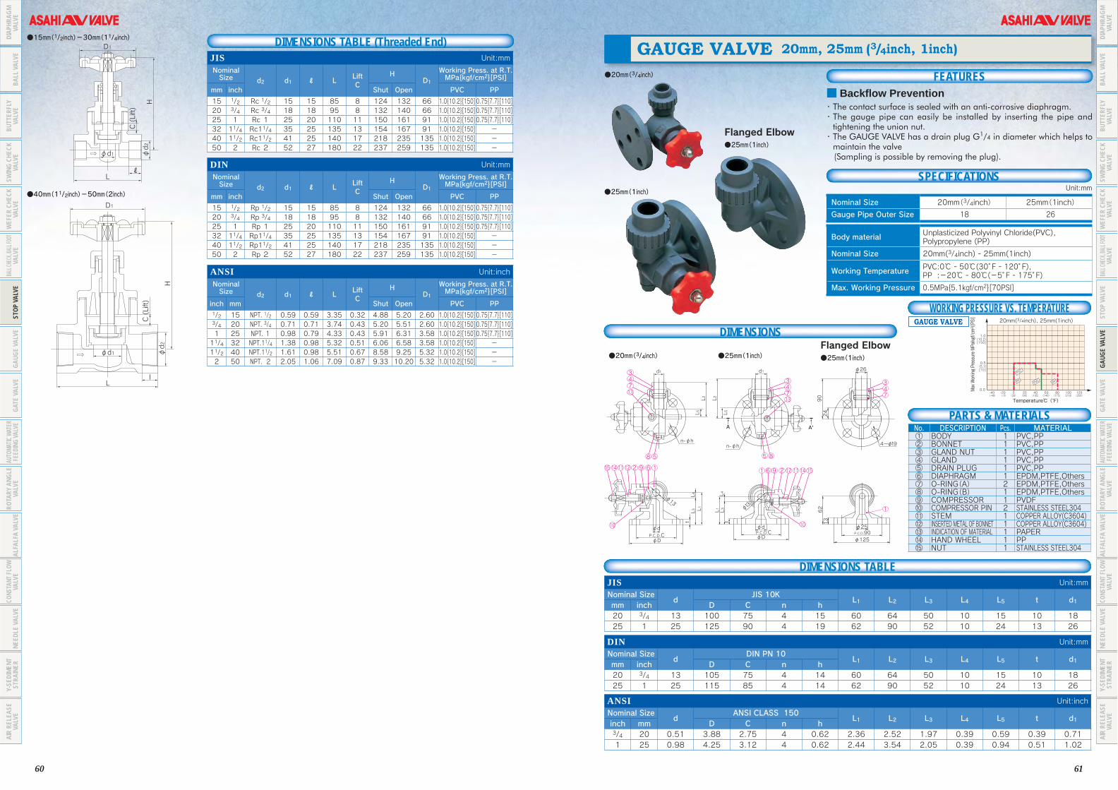
60 61
●20mm(3/4inch)
Flanged Elbow●25mm(1inch)
●25mm(1inch)
■ Backflow Prevention・The contact surface is sealed with an anti-corrosive diaphragm.・ The gauge pipe can easily be installed by inserting the pipe and
tightening the union nut.・ The GAUGE VALVE has a drain plug G1/4 in diameter which helps to
maintain the valve (Sampling is possible by removing the plug).
GAUGE VALVE 20mm, 25mm (3/4inch, 1inch)
FEATURES
SPECIFICATIONS
Body material Unplasticized Polyvinyl Chloride(PVC), Polypropylene (PP)
Nominal Size 20mm(3/4inch) - 25mm(1inch)
Working Temperature PVC:0℃ - 50℃(30°F - 120°F),PP :-20℃ - 80℃(-5°F - 175°F)
Max. Working Pressure 0.5MPa{5.1kgf/cm2}[70PSI]
Nominal Size 20mm(3/4inch) 25mm(1inch)
Gauge Pipe Outer Size 18 26
Unit:mm
24
90
1362
4~ 19
125
25P.C.D.90
26d1d1
n-φhn-φh
L2L2L1 L1L3 L3
t t
L4 L4L5L5
φdP.C.D.CφD
φdP.C.D.CφD
φ13
φ13
A A'
13743
58
15 14 11 12 2 9 6 1
10
34713
85
1 6 9 2 12 11 14 15
10
347
1
●20mm(3/4inch)
DIMENSIONS
No. DESCRIPTION Pcs. MATERIAL① BODY 1 PVC,PP② BONNET 1 PVC,PP③ GLAND NUT 1 PVC,PP④ GLAND 1 PVC,PP⑤ DRAIN PLUG 1 PVC,PP⑥ DIAPHRAGM 1 EPDM,PTFE,Others⑦ O-RING(A) 2 EPDM,PTFE,Others⑧ O-RING(B) 1 EPDM,PTFE,Others⑨ COMPRESSOR 1 PVDF⑩ COMPRESSOR PIN 2 STAINLESS STEEL304⑪ STEM 1 COPPER ALLOY(C3604)⑫ INSERTED METAL OF BONNET 1 COPPER ALLOY(C3604)⑬ INDICATION OF MATERIAL 1 PAPER⑭ HAND WHEEL 1 PP⑮ NUT 1 STAINLESS STEEL304
●25mm(1inch)Flanged Elbow●25mm(1inch)
PARTS & MATERIALS
DIMENSIONS TABLEJIS Unit:mm
Nominal Sized
JIS 10KL1 L2 L3 L4 L5 t d1
mm inch D C n h20 3/4 13 100 75 4 15 60 64 50 10 15 10 1825 1 25 125 90 4 19 62 90 52 10 24 13 26
DIN Unit:mm
Nominal Sized
DIN PN 10L1 L2 L3 L4 L5 t d1
mm inch D C n h20 3/4 13 105 75 4 14 60 64 50 10 15 10 1825 1 25 115 85 4 14 62 90 52 10 24 13 26
ANSI Unit:inch
Nominal Sized
ANSI CLASS 150L1 L2 L3 L4 L5 t d1
inch mm D C n h3/4 20 0.51 3.88 2.75 4 0.62 2.36 2.52 1.97 0.39 0.59 0.39 0.711 25 0.98 4.25 3.12 4 0.62 2.44 3.54 2.05 0.39 0.94 0.51 1.02
WORKING PRESSURE VS. TEMPERATUREGAUGE VALVE
{10.2}1.0
0.5
0.0
{5.1}
12060 80 100
[150]
[70]
0 20-40 -20 40(250)(140) (175) (210)(30) (90)(-40) (-5) (105)
Temperature℃( F゚)
PVC
PVCPP PP
Max Working Pressure MPa{kgf/cm2 }[PSI]
20mm(3/4inch), 25mm(1inch)
ℓ
D1
H
L
φd2
C (Lift)
φd1
D1
C (Lift)
H
Ll
φd1 φd2
●15mm(1/2inch)-30mm(11/4inch)
●40mm(11/2inch)-50mm(2inch)
DIMENSIONS TABLE (Threaded End)JIS Unit:mm
Nominal Size d2 d1 ℓ L
LiftC
HD1
Working Press. at R.T. MPa{kgf/cm2}[PSI]
mm inch Shut Open PVC PP
15 1/2 Rc 1/2 15 15 85 8 124 132 66 1.0{10.2}[150] 0.75{7.7}[110]20 3/4 Rc 3/4 18 18 95 8 132 140 66 1.0{10.2}[150] 0.75{7.7}[110]25 1 Rc 1 25 20 110 11 150 161 91 1.0{10.2}[150] 0.75{7.7}[110]32 11/4 Rc11/4 35 25 135 13 154 167 91 1.0{10.2}[150] -40 11/2 Rc11/2 41 25 140 17 218 235 135 1.0{10.2}[150] -50 2 Rc 2 52 27 180 22 237 259 135 1.0{10.2}[150] -
DIN Unit:mm
Nominal Size d2 d1 ℓ L
LiftC
HD1
Working Press. at R.T. MPa{kgf/cm2}[PSI]
mm inch Shut Open PVC PP
15 1/2 Rp 1/2 15 15 85 8 124 132 66 1.0{10.2}[150] 0.75{7.7}[110]20 3/4 Rp 3/4 18 18 95 8 132 140 66 1.0{10.2}[150] 0.75{7.7}[110]25 1 Rp 1 25 20 110 11 150 161 91 1.0{10.2}[150] 0.75{7.7}[110]32 11/4 Rp11/4 35 25 135 13 154 167 91 1.0{10.2}[150] -40 11/2 Rp11/2 41 25 140 17 218 235 135 1.0{10.2}[150] -50 2 Rp 2 52 27 180 22 237 259 135 1.0{10.2}[150] -
ANSI Unit:inch
Nominal Size d2 d1 ℓ L
LiftC
HD1
Working Press. at R.T. MPa{kgf/cm2}[PSI]
inch mm Shut Open PVC PP1/2 15 NPT. 1/2 0.59 0.59 3.35 0.32 4.88 5.20 2.60 1.0{10.2}[150] 0.75{7.7}[110]3/4 20 NPT. 3/4 0.71 0.71 3.74 0.43 5.20 5.51 2.60 1.0{10.2}[150] 0.75{7.7}[110]1 25 NPT. 1 0.98 0.79 4.33 0.43 5.91 6.31 3.58 1.0{10.2}[150] 0.75{7.7}[110]11/4 32 NPT.11/4 1.38 0.98 5.32 0.51 6.06 6.58 3.58 1.0{10.2}[150] -11/2 40 NPT.11/2 1.61 0.98 5.51 0.67 8.58 9.25 5.32 1.0{10.2}[150] -2 50 NPT. 2 2.05 1.06 7.09 0.87 9.33 10.20 5.32 1.0{10.2}[150] -
DIAP
HRAG
M VA
LVE
BALL
VAL
VEBU
TTER
FLY
VALV
ESW
ING
CHEC
K VA
LVE
BALL
CHECK
, BALL
FOOT
VALV
EST
OP V
ALVE
GAUG
E VA
LVE
GATE
VAL
VEAU
TOMA
TIC W
ATER
FE
EDIN
G VA
LVE
ROTA
RY A
NGLE
VA
LVE
ALFA
LFA
VALV
ECO
NSTA
NT FL
OW
VALV
ENE
EDLE
VAL
VEY-
SEDI
MENT
ST
RAIN
ERAI
R RE
LEAS
E VA
LVE
DIAP
HRAG
M VA
LVE
BALL
VAL
VEBU
TTER
FLY
VALV
ESW
ING
CHEC
K VA
LVE
BALL
CHECK
, BALL
FOOT
VALV
EST
OP V
ALVE
GAUG
E VA
LVE
GATE
VAL
VEAU
TOMA
TIC W
ATER
FE
EDIN
G VA
LVE
ROTA
RY A
NGLE
VA
LVE
ALFA
LFA
VALV
ECO
NSTA
NT FL
OW
VALV
ENE
EDLE
VAL
VEY-
SEDI
MENT
ST
RAIN
ERAI
R RE
LEAS
E VA
LVE
WEF
ER C
HECK
VALV
E
WEF
ER C
HECK
VALV
E

62 63
Gate valves 125mm or more in nominal size have a reduced flow channel.
●40mm(11/2inch)- 150mm(6inch) ● 200mm(8inch)- 350mm(14inch)
GATE VALVE TYPE-P(Plug) 40mm - 350mm(11/2inch - 14inch)
(Lift)
H1
H2
H
P.C.D.
L tn-φh
2φD
ℓ1
CφD
φd
H3
φA
2374
292822
31
2421
26
2527
2c8596
φd
φd'
125、150mmDetail of flange 350mm(14inch)
n- hMn -1 1a
ℓ2
20186168
19
745931
CAP2018111714
168
19
56473
9
CAP
L
φD2
A
t n-φh
φdφd'
φD
H2
H3
HH1
P.C.D. C
1
28
245
1417169
84
31
2c
(Lift)
ℓ
106
7
22
29
23
11
15
252726
PARTS & MATERIALS
DIMENSIONS TABLEJIS Unit:mmNominal Size d d'
FLANGE END THREAD ENDD2 ℓ1 H H1 H2 H3 AJIS 10K d2 ℓ Lmm inch D C n h n1 M L t
32 11/4 40 30 135 100 4 19 - - 165 22 Rc11/4 22 115 120 49 239 50 107 132 12040 11/2 40 40 140 105 4 19 - - 165 22 Rc11/2 25 115 120 49 239 50 107 132 12050 2 50 50 155 120 4 19 - - 180 23 Rc2 28 130 130 60 270 58 134 136 13065 21/2 65 - 175 140 4 19 - - 190 24 - - - 155 75 302 68 152 150 15580 3 75 - 185 150 8 19 - - 200 25 - - - 170 85 325 77 170 155 170100 4 100 - 210 175 8 19 - - 230 27 - - - 195 110 370 89 207 163 195125 5 125 110 250 210 8 23 - - 260 27 - - - 235 117 407 89 227 180 235150 6 150 130 280 240 8 23 - - 270 28 - - - 270 138 445 102 263 182 270200 8 196 168 330 290 10 23 2 M20 290 28 - - - 310 180 577 143 240 337 310250 10 247 210 400 355 12 25 一 一 380 30 - - - 360 226 690 175 270 420 360300 12 298 255 445 400 14 25 2 M22 400 31 - - - 410 273 800 195 320 480 410350 14 348 297 490 445 12 25 4 M22 430 32 - - - 440 319 910 230 310 600 455
DIN Unit:mmNominal Size d d' d'2
FLANGE END THREAD ENDD2 ℓ1 H H1 H2 H3 ADIN PN 10 d2 ℓ Lmm inch D C n h n1 M L t
40 11/2 40 - 40 150 110 4 18 - - 165 22 Rp11/2 25 115 120 49 239 50 107 132 12050 2 50 - 50 165 125 4 18 - - 180 23 Rp2 28 130 130 60 270 58 134 136 13065 21/2 65 - 一 185 145 4 18 - - 210 24 - - 一 155 75 302 68 152 150 15580 3 75 - 一 200 160 8 18 - - 240 25 - - 一 170 85 325 77 170 155 170100 4 100 - 一 220 180 8 18 - - 250 27 - - 一 195 110 370 89 207 163 195125 5 125 110 一 250 210 8 18 - - 260 27 - - 一 235 117 407 89 227 180 235150 6 150 130 一 285 240 8 22 - - 280 27 - - 一 270 138 445 102 263 182 270200 8 196 168 一 340 295 6 22 2 M20 300 28 - - 一 310 180 577 143 240 337 310250 10 247 210 一 395 350 12 22 一 一 380 30 - - 一 360 226 690 175 270 420 360300 12 298 255 一 445 400 10 22 2 一 400 31 - - 一 410 273 800 195 320 480 410350 14 348 297 一 505 460 12 22 4 一 430 32 - - 一 440 319 910 230 310 600 455
ANSI Unit:inchNominal Size d d'
FLANGE END THREAD ENDD2 ℓ1 H H1 H2 H3 AANSI Class 150 d2 ℓ Linch mm D C n h n1 M L t
11/2 40 1.57 1.57 5.00 3.88 4 0.62 一 一 6.50 0.87 11/2-111/2NPT 0.98 4.53 4.72 1.93 9.41 2.48 4.21 5.20 4.722 50 1.97 1.97 6.00 4.75 4 0.75 一 一 7.00 0.91 2-111/2NPT 1.10 5.12 5.12 2.36 10.63 2.80 5.28 5.35 5.1221/2 65 2.56 - 7.00 5.50 4 0.75 一 一 7.50 0.94 - - - 6.10 2.95 11.89 3.19 5.98 5.91 6.103 80 2.95 - 7.00 6.00 4 0.75 一 一 8.00 0.98 - - - 6.69 3.35 12.80 3.54 6.69 6.10 6.694 100 3.94 - 9.00 7.50 8 0.75 一 一 9.00 1.06 - - - 7.68 4.33 14.57 4.02 8.15 6.42 7.685 125 4.92 4.33 10.00 8.50 8 0.88 一 一 10.24 1.06 - - - 9.25 4.61 16.02 4.17 8.94 7.09 9.256 150 5.91 5.12 11.00 9.50 8 0.88 一 一 10.50 1.06 - - - 10.63 5.43 17.52 4.69 10.35 7.17 10.638 200 7.72 6.61 13.50 11.75 6 0.88 2 W3/4 11.50 1.30 - - - 12.2 7.09 22.72 6.3 9.45 13.27 12.210 250 9.72 8.27 16.00 14.25 12 1.00 一 一 14.96 1.18 - - - 14.17 8.9 27.17 7.56 10.63 16.54 14.1712 300 11.73 10.04 19.00 17.00 10 1.00 2 W7/8 15.75 1.22 - - - 16.14 10.75 31.5 8.35 12.6 18.9 16.1414 350 13.70 11.69 21.00 18.75 8 1.12 4 W1 16.93 1.26 - - - 17.32 12.56 35.83 9.72 12.21 23.62 17.91
No. DESCRIPTION Pcs. MATERIAL No. DESCRIPTION Pcs. MATERIAL No. DESCRIPTION Pcs. MATERIAL① BODY 1 HI‐PVC ⑨ O-RING(C) 2 EPDM, Others ○23 INDICATING COVER 1 PC
○1a INSERTED METAL OF STEM ー COPPER ALLOY(C3604) ⑩ BUSHING(A) 1 PP ○24 INDICATING RING 1 PVC
○2c GATE(A) 1 PP ⑪ BUSHING(B) 1 PP ○25 GUIDE PIN 1 STAINLESS STEEL304③ STEM 1 PVC ⑭ O-RING(E) 1 EPDM, Others ○26 GUIDE PIN HOLDER 1 PVC④ BONNET(A) 1 HI‐PVC ⑮ O-RING(F) 1 EPDM, Others ○27 O-RING(G) 1 EPDM⑤ BONNET(B) 1 HI‐PVC ⑯ O-RING(D) 1 EPDM, Others ○28 WASHER 1 PVC⑥ THRUST RING 1set PP、SUJ2 ⑰ SET SCREW(A) 1 STAINLESS STEEL304 ○29 BOX NUT 1 STAINLESS STEEL304⑦ BOLT・NUT ー STAINLESS STEEL304 ○21 PACKING 1 EPDM⑧ O-RING(B) 1 EPDM, Others ○22 HAND WHEEL 1 PP
Hand wheel Model
Cap(Square Nut)
Rising Stem
Threaded Body
Stem Extension
GATE VALVEFEATURES
■ High Corrosion and Impact-resistanceAll wet sections are made of corrosion-resistant material, thus preventing corrosion and turbid water due to rust, The GATE VALVE, made of high impact polyvinyl chloride, can be used for water supply and drainage.
■ Light and Rugged StructureBeing made of synthetic resin, the ASAHI AV GATE VALVE is about 1/5 the weight of a cast iron gate valve. However, the ASAHI AV GATE VALVE gives the same torque strength as a cast iron gate valve, so it endures high torque.
■ Flexibility Covering Flow VariationsThe gate valve is so flexible in covering many flow variations with tight shut-
off.
■ Easy MaintenanceThe stem sealed with an O-ring, prevents external leaks and is easy to
replace.
SPECIFICATIONS Body material Valve:High Impact Polyvinyl Chloride(HI-PVC)
Gate materialTYPE-P :32mm(11/4inch) to 350mm(14inch) …PPTYPE-SSoft seals:32mm(11/4inch) to 150mm(6inch) ……HI-PVC+SBR 65mm(21/2inch), 125mm(5inch) ………C-PVC+SBR
Nominal size Popular series (Type P):40 to 350mm(11/2inch to 14inch)Resilient series(Type S):40 to 200mm(11/2inch to 8inch)
Working Temperature -10℃ - 50℃(15°F - 120°F)
Max. Working Pressure
40mm(11/2inch) - 200mm(8inch) 1.0Mpa{10.2kgf/cm2} [150PSI] 250mm(10inch) 0.75Mpa{7.7kgf/cm2} [110PSI]300mm(12inch), 350mm(14inch) 0.5Mpa{5.1kgf/cm2} [70PSI]
End Connectors Flanged EndThreaded Type(40mm,50mm)are available.
Mechanism Round Handle, Cap (Square Nut), Stem Extension
■ NSF ProductNSF("NSF/ANSI STANDARD 61" Drinking Water System Components-Health Effects)Product.:GATE VALVE TYPE P(Plug) (Material:PVC+EPDM,FKM) *Certified products bear an NSF Certification Mark.
WORKING PRESSURE VS. TEMPERATUREGATE VALVE
{10.2}1.0
0.5
0.0
{5.1}
{10.2}1.0
0.5
0.0
{5.1}
{10.2}1.0
0.5
0.0
{5.1}
HI-PVC
HI-PVC
HI-PVC
12060 80 100
[150]
[70]
0 20-40 -20 40(250)(140) (175) (210)(30) (90)(-40) (-5) (105)
Temperature℃( F゚)
12060 80 100
[150]
[70]
0 20-40 -20 40(250)(140) (175) (210)(30) (90)(-40) (-5) (105)
Temperature℃( F゚)
12060 80 100
[150]
[70]
0 20-40 -20 40(250)(140) (175) (210)(30) (90)(-40) (-5) (105)
Temperature℃( F゚)
40mm(11/2inch) - 200mm(8inch)
Max Working Pressure MPa{kgf/cm2 }[PSI]
Max Working Pressure MPa{kgf/cm2 }[PSI]
Max Working Pressure MPa{kgf/cm2 }[PSI]
Gate Valve TypeP, Type S
250mm(10inch)
Gate Valve TypeP, Type S
300mm(12inch),350mm(14inch)
Gate Valve TypeP, Type S
DIAP
HRAG
M VA
LVE
BALL
VAL
VEBU
TTER
FLY
VALV
ESW
ING
CHEC
K VA
LVE
BALL
CHECK
, BALL
FOOT
VALV
EST
OP V
ALVE
GAUG
E VA
LVE
GATE
VAL
VEAU
TOMA
TIC W
ATER
FE
EDIN
G VA
LVE
ROTA
RY A
NGLE
VA
LVE
ALFA
LFA
VALV
ECO
NSTA
NT FL
OW
VALV
ENE
EDLE
VAL
VEY-
SEDI
MENT
ST
RAIN
ERAI
R RE
LEAS
E VA
LVE
DIAP
HRAG
M VA
LVE
BALL
VAL
VEBU
TTER
FLY
VALV
ESW
ING
CHEC
K VA
LVE
BALL
CHECK
, BALL
FOOT
VALV
EST
OP V
ALVE
GAUG
E VA
LVE
GATE
VAL
VEAU
TOMA
TIC W
ATER
FE
EDIN
G VA
LVE
ROTA
RY A
NGLE
VA
LVE
ALFA
LFA
VALV
ECO
NSTA
NT FL
OW
VALV
ENE
EDLE
VAL
VEY-
SEDI
MENT
ST
RAIN
ERAI
R RE
LEAS
E VA
LVE
WEF
ER C
HECK
VALV
E
WEF
ER C
HECK
VALV
E

64 65
■ Reliable Watertightness The rubber valve seat, a soft seal type, offers reliable shut-off.
■ Provides Smooth FlowBeing free of cavities, the valve body has no sand or foreign matter build up in it, thus providing a smooth flow.※ Threaded End Type (40mm, 50mm)are available.
FEATURES
n~φh
H3
H2
H1
H
ℓ1
cap
t
CP.C.D.
L
70
3
□32
□38
φD1
(Lift)
φd
φD
19
1820
19
2k
3
8
1666
12b2c
31
2j
7 46
5
9
32
Cap(square Nut) Model
●32mm(11/4inch) - 150mm(6inch)(basides 65mm(21/2inch), 125mm(5inch))
● 65mm(21/2inch), 125mm(5inch))
PARTS & MATERIALS
DIMENSIONS TABLEJIS Unit:mmNominal Size d d1
JIS 10K L t D1 A ℓ H H1 H2mm inch D C n h n1-M 50 2 50 - 155 120 4 19 - 180 23 130 130 52 293 58 134 65 21/2 65 - 175 140 4 19 - 210 24 155 155 67 302 68 152 80 3 75 - 185 150 8 19 - 240 25 170 170 77 350 77 170 100 4 100 - 210 175 8 19 - 250 27 195 195 102 410 89 207 125 5 125 110 250 210 8 23 - 260 27 235 235 112 407 89 227 150 6 150 130 280 240 8 23 - 280 28 270 270 132 487 117 263 200 8 196 168 330 290 10 23 2-M20 290 28 310 310 175 577 143 240
DIN Unit:mmNominal Size d d1
DIN PN10 L t D1 A ℓ H H1 H2mm inch D C n h n1-M 50 2 50 - 165 125 4 18 - 180 23 130 130 52 293 58 134 65 21/2 65 - 185 145 4 18 - 210 24 155 155 67 302 68 152 80 3 75 - 200 160 8 18 - 240 25 170 170 77 350 77 170 100 4 100 - 220 180 8 18 - 250 27 195 195 102 410 89 207 125 5 125 110 250 210 8 18 - 260 27 235 235 112 407 89 227 150 6 150 130 285 240 8 23 - 280 28 270 270 132 487 117 263 200 8 196 168 340 295 6 23 2-M20 290 28 310 310 175 577 143 240
ANSI Unit:inchNominal Size d d1
ANSI CLASS 150 L t D1 A ℓ H H1 H2inch mm D C n h n1-M 2 50 1.97 - 5.98 4.74 4 0.75 - 7.01 0.91 5.12 5.12 2.05 10.63 5.28 5.3521/2 65 2.56 - 7.01 5.49 4 0.75 - 7.48 0.94 6.10 6.10 2.64 11.89 5.98 5.913 80 2.95 - 7.52 6.00 4 0.75 - 7.99 0.98 6.69 6.69 3.03 12.79 6.69 6.104 100 3.94 - 9.02 7.50 8 0.75 - 9.02 1.06 7.68 7.68 4.02 14.57 8.15 6.425 125 4.92 4.33 10.00 8.50 8 0.87 - 10.24 1.06 9.25 9.25 4.41 16.03 8.94 7.096 150 5.91 5.12 10.98 9.51 8 0.87 - 10.51 1.06 10.63 10.63 5.20 17.52 10.35 7.178 200 7.72 6.61 13.50 11.75 6 0.87 2-W3/4 11.50 1.10 12.20 12.20 6.89 22.72 9.45 13.27
H3
H2
H1
H
φD2
L tn-φh
φdφd'
C
φD
P.C.D.
n -M1
1(Lift)
ℓ
5
14
17
16
84
3
1
6
7
11
2e
2g
2f1a
2d
9
2c
2b
19
1820
19
20
■ Built-in StopperFeeling in the shut, posision.
●200mm(8inch)
No. DESCRIPTION Pcs. MATERIAL No. DESCRIPTION Pcs. MATERIAL No. DESCRIPTION Pcs. MATERIAL① BODY 1 HI‐PVC ○2k FEMALE SCREW HOLDER 1 HI‐PVC ⑯ O-RING(D) 1 EPDM, Others○1a INSERTED METAL OF BODY 4 COPPER ALLOY(C3604) ③ STEM 1 SUS304, Others ⑩ BUSH(A) 1 PP○2b SEAT 1 SBR、NBR ④ BONNET(A) 1 HI‐PVC ⑪ BUSH(B) 1 PP○2c GATE(A) 1 C‐PVC ⑤ BONNET(B) 1 HI‐PVC ⑰ SET SCREW(A) 1 STAINLESS STEEL304○2d INSERTED METAL OF GATE(A) 1 BC6 ⑥ THRUST RING 2 PP ⑱ DUST SEAL 1 EPDM○2e GATE(B) 1 PP ⑦ BOLT・NUT ー STAINLESS STEEL304
⑲ CAP(A) 1 FCD450, FC200(65,125,200mm)○2f INSERTED METAL OF GATE(B) 4 COPPER ALLOY(C3604) ⑧ O-RING(B) 1 EPDM, Others
○2g BOLT(A) 4 STAINLESS STEEL304 ⑨ O-RING(C) 1・2 EPDM, Others ⑳ SET SCREW(B) 1 STAINLESS STEEL304○2j FEMALE SCREW METAL 1 COPPER ALLOY(C3604) ⑭ O-RING(E) 2 EPDM, Others ○66 O-RING(H) 2 EPDM
H3
H2
H1
H
φD2
φd
φD
ℓ
P.C.D.
L n-φht
C
1 Lift
2b1
32c92d
164
58
76
20
1918
66
φdd'
φ
150mm(6inch)
GATE VALVE TYPE-S (Soft Seal) 50mm - 200mm(2inch - 8inch)
■ Reliable Watertightness The rubber valve seat, a soft seal type, offers reliable shut-off.
■ Provides Smooth FlowBeing free of cavities, the valve body has no sand or foreign matter build up in it, thus providing a smooth flow.※ Threaded End Type (40mm, 50mm)are available.
GATE VALVE TYPE-S (Soft Seal) 50mm - 200mm(2inch - 8inch)
FEATURESHand Wheel
PARTS & MATERIALS
DIMENSIONS TABLEJIS Unit:mmNominal Size
d d1JIS 10K
L t D1 A ℓ H H1 H2mm inch D C n h n1-M 50 2 50 - 155 120 4 19 - 180 23 130 130 52 293 58 134 65 21/2 65 - 175 140 4 19 - 210 24 155 155 67 302 68 152 80 3 75 - 185 150 8 19 - 240 25 170 170 77 350 77 170 100 4 100 - 210 175 8 19 - 250 27 195 195 102 410 89 207 125 5 125 110 250 210 8 23 - 260 27 235 235 112 407 89 227 150 6 150 130 280 240 8 23 - 280 28 270 270 132 487 117 263 200 8 196 168 330 290 10 23 2-M20 290 28 310 310 175 577 143 240
DIN Unit:mmNominal Size
d d1DIN PN10
L t D1 A ℓ H H1 H2mm inch D C n h n1-M 50 2 50 - 165 125 4 18 - 180 23 130 130 52 293 58 134 65 21/2 65 - 185 145 4 18 - 210 24 155 155 67 302 68 152 80 3 75 - 200 160 8 18 - 240 25 170 170 77 350 77 170 100 4 100 - 220 180 8 18 - 250 27 195 195 102 410 89 207 125 5 125 110 250 210 8 18 - 260 27 235 235 112 407 89 227 150 6 150 130 285 240 8 23 - 280 28 270 270 132 487 117 263 200 8 196 168 340 295 6 23 2-M20 290 28 310 310 175 577 143 240
ANSI Unit:inchNominal Size
d d1ANSI CLASS 150
L t D1 A ℓ H H1 H2inch mm D C n h n1-M 2 50 1.97 - 5.98 4.74 4 0.75 - 7.01 0.91 5.12 5.12 2.05 10.63 5.28 5.3521/2 65 2.56 - 7.01 5.49 4 0.75 - 7.48 0.94 6.10 6.10 2.64 11.89 5.98 5.913 80 2.95 - 7.52 6.00 4 0.75 - 7.99 0.98 6.69 6.69 3.03 12.79 6.69 6.104 100 3.94 - 9.02 7.50 8 0.75 - 9.02 1.06 7.68 7.68 4.02 14.57 8.15 6.425 125 4.92 4.33 10.00 8.50 8 0.87 - 10.24 1.06 9.25 9.25 4.41 16.03 8.94 7.096 150 5.91 5.12 10.98 9.51 8 0.87 - 10.51 1.06 10.63 10.63 5.20 17.52 10.35 7.178 200 7.72 6.61 13.50 11.75 6 0.87 2-W3/4 11.50 1.10 12.20 12.20 6.89 22.72 9.45 13.27
No. DESCRIPTION Pcs. MATERIAL No. DESCRIPTION Pcs. MATERIAL No. DESCRIPTION Pcs. MATERIAL① BODY 1 HI-PVC ⑥ THRUST RING 2 PP、SUJ2 ⑰ SET SCREW(A) 1 STAINLESS STEEL304○1a INSERTED METAL OF BODY 4 COPPER ALLOY(C3604) ⑦ BOLT・NUT ー STAINLESS STEEL304 ○21 PACKING 1 EPDM○2b SEAT 1 SBR、NBR ○2h O-RING(A) 1 EPDM, Others ○22 HAND WHEEL 1 PP○2c GATE(A) 1 HI-PVC、C-PVC ⑧ O-RING(B) 1 EPDM, Others ○23 INDICATING COVER 1 PC○2e GATE(B) 1 PP ⑨ O-RING(C) 2・3 EPDM, Others ○24 INDICATING RING 1 PVC○2f INSERTED METAL OF GATE(A) 4 COPPER ALLOY(C3604) ⑭ O-RING(E) 1 EPDM, Others ○25 GUIDE PIN 1 STAINLESS STEEL304○2g BOLT(A) 4 STAINLESS STEEL304 ⑮ O-RING(F) 1 EPDM, Others ○26 GUIDE PIN HOLDER 1 PVC③ STEM 1 PVC ⑯ O-RING(D) 1 EPDM, Others ○27 O-RING(G) 1 EPDM④ BONNET(A) 1 HI-PVC ⑩ BUSH(A) 1 PP ○28 WASHER 1 PVC⑤ BONNET(B) 1 HI-PVC ⑪ BUSH(B) 1 PP ○29 BOX NUT 1 STAINLESS STEEL304
●50mm(2inch)~150mm(6inch)〈STEM:PVC〉 ●200mm(8inch)〈STEM:PVC〉φA
Lt
ℓ(Lift)H
H3
H2
H1
φD1φd
φD
dd'd' dφ φ
P.C.D.C
n-φh
22
27
25
21
2c
2b
6
9
8
3
1
5
4 7
24
23
26
28
29 65mm(21/2inch),125mm(5inch)
150mm(6inch)
L
D2
A
t n-φh
φd
φd' C
φD
P.C.D.
H2
H3
H
n -M1
H1
1
28
245
1417169
8
4
3
1
(Lift)
ℓ
10
6
7
22
29
23
11
15
2527
26
2e
2g2f
2h1a
2c
2b
DIAP
HRAG
M VA
LVE
BALL
VAL
VEBU
TTER
FLY
VALV
ESW
ING
CHEC
K VA
LVE
BALL
CHECK
, BALL
FOOT
VALV
EST
OP V
ALVE
GAUG
E VA
LVE
GATE
VAL
VEAU
TOMA
TIC W
ATER
FE
EDIN
G VA
LVE
ROTA
RY A
NGLE
VA
LVE
ALFA
LFA
VALV
ECO
NSTA
NT FL
OW
VALV
ENE
EDLE
VAL
VEY-
SEDI
MENT
ST
RAIN
ERAI
R RE
LEAS
E VA
LVE
DIAP
HRAG
M VA
LVE
BALL
VAL
VEBU
TTER
FLY
VALV
ESW
ING
CHEC
K VA
LVE
BALL
CHECK
, BALL
FOOT
VALV
EST
OP V
ALVE
GAUG
E VA
LVE
GATE
VAL
VEAU
TOMA
TIC W
ATER
FE
EDIN
G VA
LVE
ROTA
RY A
NGLE
VA
LVE
ALFA
LFA
VALV
ECO
NSTA
NT FL
OW
VALV
ENE
EDLE
VAL
VEY-
SEDI
MENT
ST
RAIN
ERAI
R RE
LEAS
E VA
LVE
WEF
ER C
HECK
VALV
E
WEF
ER C
HECK
VALV
E

66 67
Eliminating human interventionThe AV AUTOMATIC WATER FEEDING VALVE is designed as follows.Its sensor compares the water level with upper and lower water level limits for rice plant growth which are set on the sensor. Based on the results of the comparison, the sensor controls the AUTOMATIC WATER FEEDING VALVE as required through a tube connected with the body to automatically feed or stop water.
FLOW RATE REGULATING HANDLE
SWITCHOVER KNOB
CAP NUT
ELBOW
AIR VALVE
MANUAL SWITCHOVER VALVE
To SENSORForm SENSOR
FLUSHING PISTON
ROUND-HEADSCREWBONNET
SPRING
SENSOR CASE
WATER INLET
Level reading zero,indicated by whiteline, corresponds topaddy field surface
SENSOR CASE LID
SECURED FRAME
SCALE
LOWER FLOAT STOPPER
FLOAT
UPPER FLOAT STOPPER
AUTOMATIC CHANGE-OVER VALVE
DIAPHRAGM
BONNET MID. SECTION
BODY
FILTER
CAP NUT
RUBBER SEAT
From VALVE
To VALVE
UPPER WATER LEVEL LIMIT ADJUSTING SCREW LOWER WATER
LEVEL LIMIT ADJUSTING SCREW
・ The AUTOMATIC WATER FEEDING VALVE saves irrigation water, thus relieving water shortage.・ The valve properly controls water supply and reduces labor. This in turn means that working hours are shortened.・The valve can manually be operated to water fields, orchards, etc.・ The valve can be used in various of applications, such as intermittent irrigation, cold-weather damage prevention, and so on.・ The valve operates on water pressure from a pipeline without electric power.・ The valve prevents a fertilizer and agricultural chemical agent from flowing out of fields, thus inhibiting pollution of lakes and ponds.
▼Valve body ▼ Sensor
Note : The connection of the AUTOMATIC WATER FEEDING VALVE comes in three types:
Threaded End, Socket End, Flanged End (City Water and JIS standards).
AUTOMATIC WATER FEEDING VALVE 50mm, 80mm(2inch, 3inch)
FEATURES
SPECIFICATIONSBody material Valve body: High impact Polyvinyl Chloride(HI-PVC) Nominal Size 50mm(2inch) 80mm(3inch)
Operating Pressure 0.02 - 0.75MPa{0.2 - 7.7kgf/cm2}
Type A 0.015 - 0.5MPa{0.15 - 5.1kgf/cm2}Type B 0.03 - 0.75MPa{0.3 - 7.7kgf/cm2}
Max. Working Pressure 1.0MPa{10.2kgf/cm2}
Type A 0.5MPa{5.1kgf/cm2}Type B 1.0MPa{10.2kgf/cm2}
Water Level Adjustment -6cm - 12cm
End Connectors Threaded End, Socket End Flanged End(conforming to City Water Standards and JIS)
WORKING PRESSURE VS. TEMPERATUREAUTOMATIC WATER FEEDING VALVE
{10.2}1.0
0.5
0.0
{5.1}
{10.2}1.0
0.5
0.0
{5.1}
12060 80 100
[150]
[70]
0 20-40 -20 40(250)(140) (175) (210)(30) (90)(-40) (-5) (105)
Temperature℃( F゚)
12060 80 100
[150]
[70]
0 20-40 -20 40(250)(140) (175) (210)(30) (90)(-40) (-5) (105)
Temperature℃( F゚)
HI-PVC
HI-PVC
Max Working Pressure MPa{kgf/cm2 }[PSI]
Max Working Pressure MPa{kgf/cm2 }[PSI]50mm(2inch), 80mm(3inch) Type B 80mm(3inch) Type A
GATE VALVE (Rising Stem) 40mm - 200mm(11/2 inch - 8inch)
FEATURES
φD1
ℓ1
φd
P.C.D.C
φD
H1
H2
H3
HH
(Lift)
tL
φ φdd'
d'φdφ
φD2150mm
65mm、125mm
2d
3422
33
2k
2c
2b
2j
18b
6
98
1
32
537
4
2c
2b
l1(Lift)
n- h
H1
t
P.C.D.C d' Dd
3H
H
D1
D2
L
H2
H
n -M1 1a
34
2e87
5164
622
2d
2f
2c2b
2g
31
33
352g
32
918a
18b
●40mm(11/2inch) - 150mm(6inch)(besides 65mm(21/2inch), 125mm(5inch))
● 200mm(8inch)
・ Externally threaded stem and straight flow channel prevent foreign matter deposits and restrictions through.
●65mm(21/2inch), 125mm(5inch)
PARTS & MATERIALSNo. DESCRIPTION Pcs. MATERIAL No. DESCRIPTION Pcs. MATERIAL No. DESCRIPTION Pcs. MATERIAL① BODY 1 HI-PVC ○2k FEMALE SCREW HOLDER 1 HI-PVC、PVC ○18a DUST SEAL(A) 1 EPDM, Others○1a INSERTED METAL OF BODY 4 COPPER ALLOY(C3604) ③ STEM 1 STAINLESS STEEL304 18b DUST SEAL(B) 1 NBR○2b SEAT 1 SBR、NBR ④ BONNET(A) 1 HI-PVC ○22 HAND WHEEL 1 PP○2c GATE(A) 1 HI-PVC、C-PVC ⑤ BONNET(B) 1 HI-PVC、PP ○32 PIN(A) 1 STAINLESS STEEL304○2d INSERTED METAL OF GATE(A) 1 BC6 ⑥ THRUST RING 2 PP ○33 SLEEVE 1 COPPER ALLOY(C3604), BC6○2e GATE(B) 1 HI-PVC ⑦ BOLT・NUT ー STAINLESS STEEL304 ○34 NUT 1 COPPER ALLOY(C3604), BC6○2f INSERTED METAL OF GATE(B) 4 COPPER ALLOY(C3604) ⑧ O-RING(B) 1 EPDM, Others ○35 INSERTED METAL OF BONNET 4 COPPER ALLOY(C3604)○2g BOLT(A) 4 STAINLESS STEEL304 ⑨ O-RING(C) 2・1 EPDM, Others○2j FEMALE SCREW METAL 1 COPPER ALLOY(C3604) ⑯ O-RING(D) 2 EPDM, Others
DIMENSIONS TABLEJIS Unit:mmNominal Size
d d1JIS 10K
L t D1 D2 ℓ H H1 H2mm inch D C n h n1-M40 11/2 40 - 140 105 4 19 - 165 22 120 120 42 295 107 25350 2 50 - 155 120 4 19 - 180 23 130 130 52 343 134 29165 21/2 65 - 175 140 4 19 - 190 24 155 155 67 407 152 34080 3 75 - 185 150 8 19 - 200 25 170 170 77 450 170 373100 4 100 - 210 175 8 19 - 230 27 195 195 102 564 207 462125 5 125 110 250 210 8 23 - 260 27 235 235 112 593 227 481150 6 150 130 280 240 8 23 - 270 28 270 270 132 690 263 558200 8 196 168 330 290 10 23 2-M20 290 28 310 310 175 877 240 702
DIN Unit:mmNominal Size
d d1DIN PN10
L t D1 D2 ℓ H H1 H2mm inch D C n h n1-M40 11/2 40 - 150 110 4 18 - 165 22 120 120 42 295 107 25350 2 50 - 165 125 4 18 - 180 23 130 130 52 343 134 29165 21/2 65 - 185 145 4 18 - 190 24 155 155 67 407 152 34080 3 75 - 200 160 8 18 - 200 25 170 170 77 450 170 373100 4 100 - 200 180 8 18 - 230 27 195 195 102 564 207 462125 5 125 110 250 210 8 18 - 260 27 235 235 112 593 227 481150 6 150 130 285 240 8 23 - 270 28 270 270 132 690 263 558200 8 196 168 340 295 6 23 2-M20 290 28 310 310 175 877 240 702
Note : The shape and appearance of the valve differ a little with nominal size compared to the drawing.
ANSI Unit:inchNominal Size
d d1ANSI Class 150
L t D1 D2 ℓ H H1 H2inch mm D C n h n1-M11/2 40 1.57 - 5.00 3.88 4 0.63 - 6.50 0.87 4.72 4.72 1.65 11.61 4.21 9.962 50 1.97 - 5.98 4.47 4 0.75 - 7.01 0.91 5.12 5.12 2.05 13.50 5.28 11.4621/2 65 2.56 - 7.01 5.49 4 0.75 - 7.48 0.94 6.10 6.10 2.64 16.02 5.98 13.393 80 2.95 - 7.52 6.00 4 0.75 - 7.99 0.98 6.69 6.69 3.03 17.72 6.69 14.694 100 3.94 - 9.02 7.50 8 0.75 - 9.02 1.06 7.68 7.68 4.02 22.20 8.15 18.195 125 4.92 4.33 10.00 8.50 8 0.87 - 10.24 1.06 9.25 9.25 4.41 23.35 8.94 18.946 150 5.91 5.12 10.98 9.51 8 0.87 - 10.51 1.06 10.63 10.63 5.20 27.17 10.35 21.978 200 7.72 6.61 13.50 11.75 6 0.87 2-W3/4 11.50 1.10 12.20 12.20 6.89 34.53 9.45 27.64
DIAP
HRAG
M VA
LVE
BALL
VAL
VEBU
TTER
FLY
VALV
ESW
ING
CHEC
K VA
LVE
BALL
CHECK
, BALL
FOOT
VALV
EST
OP V
ALVE
GAUG
E VA
LVE
GATE
VAL
VEAU
TOMA
TIC W
ATER
FE
EDIN
G VA
LVE
ROTA
RY A
NGLE
VA
LVE
ALFA
LFA
VALV
ECO
NSTA
NT FL
OW
VALV
ENE
EDLE
VAL
VEY-
SEDI
MENT
ST
RAIN
ERAI
R RE
LEAS
E VA
LVE
DIAP
HRAG
M VA
LVE
BALL
VAL
VEBU
TTER
FLY
VALV
ESW
ING
CHEC
K VA
LVE
BALL
CHECK
, BALL
FOOT
VALV
EST
OP V
ALVE
GAUG
E VA
LVE
GATE
VAL
VEAU
TOMA
TIC W
ATER
FE
EDIN
G VA
LVE
ROTA
RY A
NGLE
VA
LVE
ALFA
LFA
VALV
ECO
NSTA
NT FL
OW
VALV
ENE
EDLE
VAL
VEY-
SEDI
MENT
ST
RAIN
ERAI
R RE
LEAS
E VA
LVE
WEF
ER C
HECK
VALV
E
WEF
ER C
HECK
VALV
E

68 69
●15mm(1/2inch) ・ 20mm(3/4inch)
● 25mm(1inch) - 100mm(4inch)
AV CONSTANT FLOW VALVE keeps the flow rate constant.
FLOW
FLOW
FLOW
FLOW
Type-A 25mm(1inch) - 80mm(3inch)
Type-B 15mm(1/2inch) - 80mm(3inch)
Type-C 15mm(1/2inch) - 100mm(4inch)
Type-D 80mm(3inch) - 100mm(4inch)
The fluid flow path is suitable for semi-conductor industry.(Ultra pure water line)
The flow rate setting range is large(Covers small and large flow rates)
The range of working differential pressure is large(For lines with large pressure differential between upstream & downstream)
A large flow rate can be set
CONSTANT FLOW VALVE 15mm - 100mm(1/2inch - 4inch)
FEATURES■ High Accuracy
The CONSTANT FLOW VALVE accurately controls the flow rate to within ±6% of the full scale value and offers high rangeability (set value for maximum flow rate/set value for minimum flow rate).
■ Flexible Flow RateUsing the handle, the flow rate setting on the valve can be changed at will. The CONSTANT FLOW VALVE can also be used as shut off valve because it cmpletely shuts off the flow.
■ Opening Degree IndicatorThe CONSTANT FLOW VALVE has indicator showing opening degree which reads the flow rate (m3/hour).
■ High Durability and Resistance to ChemicalsThe CONSTANT FLOW VALVE uses a spring made of Stainless Steel coated with PCTFE (Polychloro-frifluoro-ethylene). The spring is highly durable and chemical-resistant, it has high cycle life.
APPLICATION●Ultra-pure water lines at semiconductor factories●Chemical injection lines at chemical plants●Lines supplying water to swimming pools●Seawater supply lines for fish cultivation●Cooling tower and scrubber blow water supply lines●Anti-foaming equipment
SPECIFICATIONS
Body material Unplasticized Polyvinyl Chloride (PVC) ※We also produce C-PVC CONSTANT FLOW VALVE 25(1inch) and 50(2inch)mm in nominal size on reguest.
Nominal Size 15mm(1/2inch)、20mm(3/4inch)、25mm(1inch)、50mm(2inch)、80mm(3inch)、100mm(4inch)End Connectors Flanged EndWorking Temperature 0℃ - 50℃(30°F - 120°F)
Upstream Working Pressure range 0.25MPa or less {2.6kgf/cm2}・0.25 to 0.5 MPa {2.6 - 5.1kgf/cm2} 0.5 to 0.75MPa {5.1 - 7.7kgf/cm2}・0.75 to 1.0 MPa {7.7 - 10.2kgf/cm2}
Accuracy Full scale value ±6%(reference: water at ambient temperature)
WORKING PRESSURE VS. TEMPERATUREUnit:MPa{kgf/cm2}
0~50(30~120)
A B C Dmm inch15 1/2 - 0.25{2.7} - 0.5{5.1} 0.5{5.1} - 0.75{7.7} -20 3/4 - 0.25{2.7} - 0.5{5.1} 0.5{5.1} - 0.75{7.7} -25 1 0.25{2.7}Under 0.25{2.7} - 0.5{5.1} 0.5{5.1} - 0.75{7.7} -50 2 0.25{2.7}Under 0.25{2.7} - 0.5{5.1} 0.5{5.1} - 0.75{7.7} -80 3 0.25{2.7}Under 0.25{2.7} - 0.5{5.1} 0.5{5.1} - 0.75{7.7} 0.75{7.7} - 1.0{10.2}100 4 - - 0.5{5.1} - 0.75{7.7} 0.75{7.7} - 1.0{10.2}
Temp.℃(°F)Type Nominal Size
Secured handle type T-shaped handle type
T-shaped handle type Secured handle type
●80mm(3inch)ROTARY ANGLE VALVE (Threaded End)
1
T1
2
1
1φdφD
Taper
φD
φd
t
n-φh
H
1
φd
φD
Lift
φD3□E
Flanged Type
Hand Wheel
H
H
ℓℓ
H
P.C.D.C
ROTARY ANGLE VALVE 50mm, 80mm(2inch, 3inch)
・ The ASAHI ROTARY ANGLE VALVE is more compact than conventional angle valves. Because the ROTARY ANGLE VALVE uses a Machino, elbow, or hose socket type receptacle, it can be installed in a small valve box. Only by replacing its attachment, the valve can easilly be switched between paddy field and field types.
FEATURES
SPECIFICATIONS Body material PVC Nominal size 50mm(2inch)、80mm(3inch) Max. Working Pressure 0.75MPa{7.7kgf/cm2} Attachment Angle 90°(45°・straight)
Type of Attachment Machino:40,50,65,80mm(standard) Paddy fields:50,80mm(special elbow) Fields:50,80mm(hose joint)
End Connectors Socket End, Flanged End, Threaded End Operation T-shaped handle, Secured handle
ALFALFA VALVE TYPE 82 50mm - 100mm(2inch - 4inch)
・ Taking every effort to obtain satisfactory appearance, watertightness and strength, we have innovatively designed ALFALFA VALVE TYPE 82 to prevent water scattering and damage to surrounding rice plants. TYPE 82 can easily be disassembled at a site because it consists of a reduced number of parts. If foreign material clogs the valve, it can easily be eliminated only by closing the valve, loosening the thumbscrew and removing the cover (the pump does not need to be stopped).
FEATURES
SPECIFICATIONS Body material PVC Nominal size 50mm(2inch)、80mm(3inch)、100mm(4inch) Max. Working Pressure 1.0MPa{10.2kgf/cm2} End Connectors Socket End, Flanged End Operation T-shaped handle, Secured handle
DIMENSIONS TABLENominal Size d
Flanged Type Socket Type
D1 D2 D3 E ℓ1
H H(full opened)
JIS 10Kt d1 1/T ℓ
Socket End Flanged End Socket End Flanged End
D C n h T-shapedhandle
Securedhandle
T-shapedhandle
Securedhandle
T-shapedhandle
Securedhandle
T-shapedhandle
Securedhandlemm inch
50 2 52 155 120 4 19 16 60.80 1/37 63 70 160 75 11 25 162 163 178 179 187 188 203 204
80 3 78 185 150 8 19 18 89.80 1/43 72 101 190 110 11 35 196 209 214 227 231 244 249 262
100 4 100 210 175 8 19 18 115.00 1/44 92 129 220 110 11 45 246 261 264 279 291 306 309 324
WORKING PRESSURE VS. TEMPERATUREROTARY ANGLE VALVE
WORKING PRESSURE VS. TEMPERATUREALFALFA VALVE
{10.2}1.0
0.5
0.0
{5.1}
12060 80 100
[150]
[70]
0 20-40 -20 40(250)(140) (175) (210)(30) (90)(-40) (-5) (105)
Temperature℃( F゚)
PVC
Max Working Pressure MPa{kgf/cm2 }[PSI]
50mm(2inch), 80mm(3inch)
{10.2}1.0
0.5
0.0
{5.1}
12060 80 100
[150]
[70]
0 20-40 -20 40(250)(140) (175) (210)(30) (90)(-40) (-5) (105)
Temperature℃( F゚)
PVC
Max Working Pressure MPa{kgf/cm2 }[PSI] 50mm(2inch) - 100mm(4inch)
DIAP
HRAG
M VA
LVE
BALL
VAL
VEBU
TTER
FLY
VALV
ESW
ING
CHEC
K VA
LVE
BALL
CHECK
, BALL
FOOT
VALV
EST
OP V
ALVE
GAUG
E VA
LVE
GATE
VAL
VEAU
TOMA
TIC W
ATER
FE
EDIN
G VA
LVE
ROTA
RY A
NGLE
VA
LVE
ALFA
LFA
VALV
ECO
NSTA
NT FL
OW
VALV
ENE
EDLE
VAL
VEY-
SEDI
MENT
ST
RAIN
ERAI
R RE
LEAS
E VA
LVE
DIAP
HRAG
M VA
LVE
BALL
VAL
VEBU
TTER
FLY
VALV
ESW
ING
CHEC
K VA
LVE
BALL
CHECK
, BALL
FOOT
VALV
EST
OP V
ALVE
GAUG
E VA
LVE
GATE
VAL
VEAU
TOMA
TIC W
ATER
FE
EDIN
G VA
LVE
ROTA
RY A
NGLE
VA
LVE
ALFA
LFA
VALV
ECO
NSTA
NT FL
OW
VALV
ENE
EDLE
VAL
VEY-
SEDI
MENT
ST
RAIN
ERAI
R RE
LEAS
E VA
LVE
WEF
ER C
HECK
VALV
E
WEF
ER C
HECK
VALV
E

70 71
●25mm(1inch)
1) Regardless of horizontal installation or vertical installation, the strainer with the 60-mesh screen should be installed in the up stream side of the valve in order to avoid the malfunction possibly caused by clogging of foreign particles.
Install the valve as shown in the drawing, because malfunctioned.
2) Every type of valve has its own flow direction across the valve. Make sure that the flow direction is consistent with the arrow-mark indicated on the valve body when installing.
Note : ×Not Recommend
PARTS & MATERIALSNo. DESCRIPTION Pcs. MATERIAL No. DESCRIPTION Pcs. MATERIAL
① BODY 1 PVC ⑭ SLEEVE 1 COPPER ALLOY(C3604)
② BONNET 1 PVC ⑮ CAP 1 PVC
③ CYLINDER 1 PVC ⑯ KEY 2 PVC
④ PISTON 1 PVC ⑲ THRUST RING 1 PP
⑤ PLUG 1 PVC ⑳ SPRING(A) 1 STAINLESS STEEL304 (With PCTFE Coated)
⑥ SPRING BASE 1 PVC ○21 SPRING(B) 1 STAINLESS STEEL304 (With PCTFE Coated)⑦ STOP RING 1 PVDF ○22 WASHER(A) 1 PVC
⑧ ORIFICE 1 EPDM ○23 WASHER(B) 1 PVC
⑨ SEAT 1 EPDM, Others ○27 HAND WHEEL 1 PP
⑩ O-RING(A) 2 EPDM, Others ○28 MACHINE SCREW 4 COPPER ALLOY(C3604)
⑪ O-RING(B) 1 EPDM ○29 LIFT INDICATOR 1set PVC
⑫ O-RING(C) 1 EPDM
DIMENSIONS TABLEJIS Unit:mmNominal Size
dJIS 10K
L L1 E t A B Hmm inch D C n h25 1 25 125 90 4 19 160 40 150 14 272 201 21850 2 52 155 120 4 19 230 55 210 20 390 309 30780 3 78 185 150 8 19 280 70 210 22 484 387 377100 4 100 210 175 8 19 410 85 250 22 623 483 446
DIN Unit:mmNominal Size
dDIN PN10
L L1 E t A B Hmm inch D C n h25 1 25 115 85 4 14 160 40 150 14 272 201 21850 2 52 165 125 4 18 230 55 210 20 390 309 30780 3 78 200 160 8 18 280 70 210 22 484 387 377100 4 100 220 180 8 18 400 85 250 22 623 483 446
ANSI Unit:inchNominal Size
dANSI CLASS 150
L L1 E t A B Hinch mm D C n h1 25 0.98 4.25 3.13 4 0.63 6.30 1.58 5.91 0.55 10.71 7.91 8.582 50 2.05 5.98 4.74 4 0.75 9.06 2.17 8.27 0.79 15.35 12.17 12.093 80 3.07 7.25 6.00 4 0.75 11.02 2.75 8.27 0.89 19.06 15.24 14.844 100 3.94 8.66 7.50 8 0.75 15.74 3.35 9.84 0.87 24.50 19.00 17.56
Note : The shape and appearance of assembly differ a little with nominal size compared to this drawing.25mm-100mm(FKM)can't shut totally.
●50mm - 100mm(2 - 4inch)
1
12
2
1016
2719
28
1415
29
H
89
76
421
2220 E
3
A
5
B
23
n- h
CD
L1 LL
2
dP.C.D.
Type B,C
Type A
FLOW
t
n- h tL1
dCDP.C.D.
L
Type B,C,D
Type A
AB
E
H
FLOW
9576
4
2321
2220
12
22719
28
1415
29
1016
1
30
8
3
φA
φD
P.C.D.C
H1
H2
H
LW t
n-φh
φd
4
23
15
12
3
8
2
5
6
7
1
9
19
24
22
17
21
13
16
18
20
14
10
11
[Notes to users as to selection of the type.]The Possible preset range of the flow rate and the range of the working differential pressure differs from type to type among A, B, C and D. The right type, therefore, should be selected from the above table in accordance with the working conditions.
Nominal Size TYPEFlow rate
RangeabilityWorking differential pressure
GAL/min m3/hr PSI MPa{kgf/cm2}
15mm (1/2inch)TYPE B 000.176-003.52 00.04 - 00.8 20:1 2.85 - 14.22 0.02-0.10{0.2-1.0}TYPE C 000.350-003.52 00.08 - 00.8 10:1 4.27 - 28.45 0.03-0.20{0.3-2.0}
20mm (3/4inch)TYPE B 000.260-005.28 00.06 - 01.2 20:1 2.85 - 14.22 0.02-0.10{0.2-1.0}TYPE C 000.530-005.28 00.12 - 01.2 10:1 4.27 - 28.45 0.03-0.20{0.3-2.0}
25mm (1inch)TYPE A 002.200-008.81 00.50 - 02.0 04:1 2.85 - 14.22 0.02-0.10{0.2-1.0}TYPE B 000.441-008.81 00.10 - 02.0 20:1 2.85 - 14.22 0.02-0.10{0.2-1.0}TYPE C 000.881-008.81 00.20 - 02.0 10:1 4.27 - 28.45 0.03-0.20{0.3-2.0}
50mm (2inch)TYPE A 008.810-035.22 02.00 - 08.0 04:1 2.85 - 14.22 0.02-0.10{0.2-1.0}TYPE B 001.760-035.22 00.40 - 08.0 20:1 2.85 - 14.22 0.02-0.10{0.2-1.0}TYPE C 003.520-035.22 00.80 - 08.0 10:1 4.27 - 28.45 0.03-0.20{0.3-2.0}
80mm (3inch)
TYPE A 022.020-088.07 05.00 - 20.0 04:1 4.85 - 14.22 0.02-0.10{0.2-1.0}TYPE B 004.403-088.07 01.00 - 20.0 20:1 2.85 - 14.22 0.02-0.10{0.2-1.0}TYPE C 008.810-088.07 02.00 - 20.0 10:1 4.27 - 28.45 0.03-0.20{0.3-2.0}TYPE D 066.040-132.1 15.00 - 30.0 02:1 4.27 - 21.33 0.03-0.15{0.3-1.5}
100mm (4inch)TYPE C 044.030-264.2 10.00 - 60.0 06:1 4.27 - 28.45 0.03-0.20{0.3-2.0}TYPE D 132.100-264.2 30.00 - 60.0 02:1 2.85 - 21.33 0.02-0.15{0.2-1.5}
Range for preset flow rate and working differential pressure
●15mm(1/2inch)・20mm(3/4inch) PARTS & MATERIALSNo. DESCRIPTION Pcs. MATERIAL No. DESCRIPTION Pcs. MATERIAL
① BODY 1 PVC ⑬ SPRING(A) 1 STAINLESS STEEL304 (With PCTFE Coated)
② BONNET 1 PVC ⑭ SPRING(B) 1 STAINLESS STEEL304 (With PCTFE Coated)③ CYLINDER 1 PVC ⑮ NUT 1 PVC④ PISTON 1 PVC ⑯ O-RING(A) 1 EPDM, Others⑤ PLUG 1 PVC ⑰ O-RING(B) 1 EPDM, Others⑥ ORIFICE 1 PVC ⑱ O-RING(C) 1 EPDM⑦ SEAT 1 EPDM ⑲ O-RING(D) 1 EPDM⑧ CAP NUT 1 PVC ⑳ KEY 2 PP⑨ CAP 1 PVC ○21 THRUST RING 1 PP⑩ SPRING BASE 1 PVC ○22 HANDLE BASE 1 PVC⑪ STOP RING 1 PVDF ○23 HANDLE COVER 1 PC⑫ SLEEVE 1 COPPER ALLOY(C3604) ○24 SCREW 4 STAINLESS STEEL304
DIMENSIONS TABLEJIS Unit:mmNominal Size
dJIS 10K
t L W A H1 H2 Hmm inch D C n h15 1/2 16 95 70 4 15 12 160 82×82 103 51 129 19720 3/4 20 100 75 4 15 13 160 82×82 103 53 127 197
DIN Unit:mmNominal Size
dDIN PN10
t L W A H1 H2 Hmm inch D C n h15 1/2 16 95 65 4 14 12 160 82×82 103 51 129 19720 3/4 20 100 75 4 14 13 160 82×82 103 53 127 197
ANSI Unit:inchNominal Size
dANSI CLASS 150
t L W A H1 H2 Hinch mm D C n h1/2 15 0.63 3.50 2.38 4 0.63 0.47 6.30 3.23×3.23 4.06 2.01 5.08 7.763/4 20 0.79 3.86 2.76 4 0.63 0.51 6.30 3.23×3.23 4.06 2.09 5.08 7.76
DIAP
HRAG
M VA
LVE
BALL
VAL
VEBU
TTER
FLY
VALV
ESW
ING
CHEC
K VA
LVE
BALL
CHECK
, BALL
FOOT
VALV
EST
OP V
ALVE
GAUG
E VA
LVE
GATE
VAL
VEAU
TOMA
TIC W
ATER
FE
EDIN
G VA
LVE
ROTA
RY A
NGLE
VA
LVE
ALFA
LFA
VALV
ECO
NSTA
NT FL
OW
VALV
ENE
EDLE
VAL
VEY-
SEDI
MENT
ST
RAIN
ERAI
R RE
LEAS
E VA
LVE
DIAP
HRAG
M VA
LVE
BALL
VAL
VEBU
TTER
FLY
VALV
ESW
ING
CHEC
K VA
LVE
BALL
CHECK
, BALL
FOOT
VALV
EST
OP V
ALVE
GAUG
E VA
LVE
GATE
VAL
VEAU
TOMA
TIC W
ATER
FE
EDIN
G VA
LVE
ROTA
RY A
NGLE
VA
LVE
ALFA
LFA
VALV
ECO
NSTA
NT FL
OW
VALV
ENE
EDLE
VAL
VEY-
SEDI
MENT
ST
RAIN
ERAI
R RE
LEAS
E VA
LVE
WEF
ER C
HECK
VALV
E
WEF
ER C
HECK
VALV
E

72 73
・ Because of its plastic body, the sediment STRAINER (Y) is higly corrosion chemical and wear resistant.・ The body is transparent, so that flow through the STRAINER can easily be checked.・ The sediment STRAINER is easy to disassemble and reassemble to clean or replace its screen.
Note : Volatile l iquids such as a hydrogen peroxide (H2O2) and sodium hypochlorite (NaCIO) medium, may vaporize, thus causing an abnormal pressure increase in the valve. (Important: Gas is compressible. Thus if its pressure rises abnormally, gas may break a valve into pieces, which in turn violently scatter in all directions.)
・ Store the Sediment Strainer in an indoor place free of direct sunlight.・Do not store the Sediment Strainer in a hot place.・ Install the Sediment Strainer in a place free of direct sunlight.
4
φD1
φD1
H1
(Space for screen removal)
H2
φd1
L
H
T1Taper
ℓ
FLOW
Y-SEDIMENT STRAINER 15mm - 100mm(1/2inch - 4inch)
FEATURES
Body material Unplasticized Polyvinyl Chloride (PVC) (The body is only made of transparent PVC.)
Nominal Size15mm(1/2inch),20mm(3/4inch),25mm(1inch),40mm(11/inch),50mm(2inch),80mm(3inch),100mm(4inch)
End Connectors Socket End, Threaded End, Flanged End
Working Temperature 0 - 50℃(30 F゚ - 120 F゚)Mesh 20 mesh (30,40 & 60 Mesh Available)
Max. Working Pressure 1.0MPa{10.2kgf/cm2}[150PSI]…15 - 50mm(1/2inch - 2inch) 0.6MPa{6.1kgf/cm2}[85PSI] …80、100mm(3inch - 4inch)
SPECIFICATIONS
PARTS & MATERIALS
1)Used for Flanged End
No. DESCRIPTION Pcs. MATERIAL
① BODY 1 PVC ⑥ RETAINING RING 1 PVC
② FILTER SCREEN 1 PVC ⑦ SPLIT RING 1 PVC
③ SCREEN SUPPORT 1 PVC ⑧ O-RING(A) 2 EPDM,FKM,Others
④ END CONNECTOR 2 PVC ⑨ O-RING(B) 1 EPDM,FKM,Others
⑤ UNION NUT 3 PVC ⑩ STOP RING1) 2 PVDF
DIMENSIONS TABLE (Socket End)JIS Unit:mmNominal Size d d1 ℓ 1/T D1 L H H1 H2mm inch 15 1/2 15 22.11 20 1/34 48 172 97 78 134 20 3/4 20 26.13 24 1/34 60 210 120 98 168 25 1 25 32.16 27 1/34 70 238 133 111 189 32 11/4 40 38.19 30 1/34 100 298 177 149 256 40 11/2 40 48.21 37 1/37 100 313 177 149 256 50 2 51 60.25 42 1/37 106 346 190 160 277 65 21/2 78 76.60 61 1/48 140 487 271 234 399 80 3 78 89.60 64 1/49 152 487 271 234 399100 4 100 114.70 84 1/56 210 653 361 316 537
DIN 8063 Unit:mmNominal Size d d1 ℓ D1 L H H1mm inch 15 1/2 15 20 16 48 165 97 78 20 3/4 20 25 19 60 201 120 98 25 1 25 32 22 70 224 133 111 32 11/4 40 40 26 96 298 177 149 40 11/2 40 50 31 96 288 177 149 50 2 51 63 38 106 337 190 160 65 21/2 78 75 44 152 455 271 234 80 3 78 90 51 152 457 271 234100 4 100 110 61 210 607 361 316
ANSI ASTM SCH80 Unit:inchNominal Size d d1 d1' ℓ D1 L H H1 H2inch mm1/2 15 0.59 0.848 0.836 0.875 1.89 6.93 3.82 3.07 5.283/4 20 0.79 1.058 1.046 1.000 2.36 8.31 4.72 3.86 6.611 25 0.98 1.325 1.310 1.125 2.76 9.37 5.24 4.37 7.4411/4 32 1.57 1.670 1.655 1.250 3.94 11.73 6.97 5.87 10.0811/2 40 1.57 1.912 1.894 1.375 3.94 12.13 6.97 5.87 10.082 50 2.01 2.387 2.369 1.500 4.17 13.31 7.48 6.30 10.9121/2 65 3.07 2.889 2.868 1.752 5.98 17.95 10.67 9.21 15.713 80 3.07 3.516 3.492 1.875 5.98 17.83 10.67 9.21 15.714※ 100 3.94 4.518 4.491 2.000 8.27 23.07 14.21 12.44 21.14
DIMENSIONS (Socket End)
■ NSF ProductNSF("NSF/ANSI STANDARD 61" Drinking Water System Components-Health Effects)Product.:Y-SEDIMENT STRAINER TYPE-Y (Material:PVC+EPDM,FKM) *Certified products bear an NSF Certification Mark.
WORKING PRESSURE VS. TEMPERATURESTRAINER(Y)
{10.2}1.0
0.5
0.0
{5.1}
12060 80 100
[150]
[70]
0 20-40 -20 40(250)(140) (175) (210)(30) (90)(-40) (-5) (105)
Temperature℃( F゚)
PVC
Max Working Pressure MPa{kgf/cm2 }[PSI]
80mm(3inch), 100mm(4inch)
※ only ASTM SCH40
{10.2}1.0
0.5
0.0
{5.1}
12060 80 100
[150]
[70]
0 20-40 -20 40(250)(140) (175) (210)(30) (90)(-40) (-5) (105)
Temperature℃( F゚)
PVC
Max Working Pressure MPa{kgf/cm2 }[PSI]
15mm(1/2inch) - 65mm(21/2inch)
BS Unit:mmNominal Size d d1 ℓ D1 L H H1 H2mm inch 15 1/2 15 21.4 17 48 165 97 78 134 20 3/4 20 26.8 20 60 201 120 98 168 25 1 25 33.6 23 70 224 133 111 189 32 11/4 40 42.3 27.5 96 298 177 149 256 40 11/2 40 48.3 30.5 96 288 177 149 256 50 2 51 60.4 36.5 106 337 190 160 277 65 21/2 78 75.1 43.5 152 455 271 234 399 80 3 78 88.8 50.5 152 455 271 234 399100 4 100 114.2 63 210 607 361 316 537
Nominal Size 15mm(1/2inch), 20mm(3/4inch) 25mm(1inch)Port Size(mm) 6 15 6 15Maximum CV Value 0.7 4.5 0.7 6.0End Connectors Flanged EndType of Rubber EPDM, OthersBody material PVCMax. Working Pressure 1.0MPa{10.2kgf/cm2}[150PSI]Working Temperature 0 - 50℃(30°F - 120°F)
●15mm(1/2inch) ~ 20mm(3/4inch)
・ A shut-off valve and the rubber seat completely seals the fluid.・ Being independent of a shut-off valve, the NEEDLE VALVE exercises highly accurate control for a long time.・ The NEEDLE VALVE uses an unique plug in a special shape, thus offering accurate flow control.・ With its piping intact, the NEEDLE VALVE can be inspected or cleaned inside only by removing its bonnet (valves in 15 and 20mm in nominal size)
φD3
WL
tn-φh
φD
HH2
H1
φd
50°
LL2L1
t
H
φD
φd
P.C.D.C
B
φEA
n-φh
●25mm(1inch)
100
90
80
70
60
50
40
30
20
10
0
Valve opening degree(%)
1 2 3 4 5 6Cv Value
(15mm,20mm,25mm)0.7(Port6mm)
(15mm,20mm)4.5(Port15mm)
(25mm)6.0(Port15mm)
NEEDLE VALVE 15mm - 25mm(1/2inch - 1inch)
FEATURES
SPECIFICATIONS
SPECIFICATIONS
DIMENSIONS TABLEJIS Unit:mmNominal Size
dJIS 10K
L t W D3 H1 H2 Hmm inch D C n h15 1/2 16 95 70 4 15 160 12 82×82 103 51 129 19720 3/4 20 100 75 4 15 160 13 82×82 103 53 127 197
DIN Unit:mmNominal Size
dDIN
L t W D3 H1 H2 Hmm inch D C n h15 1/2 16 95 65 4 14 160 12 82×82 103 51 129 19720 3/4 20 105 75 4 14 160 13 82×82 103 53 127 197
ANSI Unit:inchNominal Size
dANSI 150 lbs
L t W D3 H1 H2 Hinch mm D C n h1/2 15 0.63 3.50 2.38 4 0.63 6.30 0.47 3.23×3.23 4.06 2.01 5.08 7.763/4 20 0.79 3.86 2.76 4 0.63 6.30 0.51 3.23×3.23 4.06 2.09 5.00 7.76
DIMENSIONS TABLEJIS Unit:mmNominal Size
dJIS 10K
L1 L2 L t A B H Emm inch D C n h25 1 25 125 90 4 19 40 120 160 14 272 201 218 150
DIN Unit:mmNominal Size
dDIN
L1 L2 L t A B H Emm inch D C n h25 1 25 115 85 4 14 40 120 160 14 272 201 218 150
ANSI Unit:inchNominal Size
dANSI 150 lbs
L1 L2 L t A B H Einch mm D C n h1 25 0.98 4.25 3.13 4 0.63 1.57 4.72 6.30 0.55 10.71 7.91 8.58 5.91
WORKING PRESSURE VS. TEMPERATURENEEDLE VALVE
{10.2}1.0
0.5
0.0
{5.1}
12060 80 100
[150]
[70]
0 20-40 -20 40(250)(140) (175) (210)(30) (90)(-40) (-5) (105)
Temperature℃( F゚)
PVC
Max Working Pressure MPa{kgf/cm2 }[PSI]
15mm(1/2inch) - 25mm(1inch)
DIAP
HRAG
M VA
LVE
BALL
VAL
VEBU
TTER
FLY
VALV
ESW
ING
CHEC
K VA
LVE
BALL
CHECK
, BALL
FOOT
VALV
EST
OP V
ALVE
GAUG
E VA
LVE
GATE
VAL
VEAU
TOMA
TIC W
ATER
FE
EDIN
G VA
LVE
ROTA
RY A
NGLE
VA
LVE
ALFA
LFA
VALV
ECO
NSTA
NT FL
OW
VALV
ENE
EDLE
VAL
VEY-
SEDI
MENT
ST
RAIN
ERAI
R RE
LEAS
E VA
LVE
DIAP
HRAG
M VA
LVE
BALL
VAL
VEBU
TTER
FLY
VALV
ESW
ING
CHEC
K VA
LVE
BALL
CHECK
, BALL
FOOT
VALV
EST
OP V
ALVE
GAUG
E VA
LVE
GATE
VAL
VEAU
TOMA
TIC W
ATER
FE
EDIN
G VA
LVE
ROTA
RY A
NGLE
VA
LVE
ALFA
LFA
VALV
ECO
NSTA
NT FL
OW
VALV
ENE
EDLE
VAL
VEY-
SEDI
MENT
ST
RAIN
ERAI
R RE
LEAS
E VA
LVE
WEF
ER C
HECK
VALV
E
WEF
ER C
HECK
VALV
E

74 75
AIR RELEASE VALVE 25mm,80mm,100mm,150mm,200mm (1inch,3inch,4inch,6inch,8inch)
FEATURES■ Light Weight
75% Lighter than Cast Iron Type
■ Compact10 to 40% Smaller than Cast Iron Type by Volume Ratio
■ Superior Exhaust Performance1.5 Times Larger than Cast Iron Type
■Works at Low PressureHalf of Minimum Pressure of Cast Iron Type
■ Superior Cold and Heat ResistanceWide Temperature Range -40˚C (-40˚F) to 50˚C (122˚F).
■ Excellent Corrosion and Impact ResistancePDCPD Material
■ Top Bonnet EntryEasy Inline Access to Internal Parts
Float
DirtGuide
φD1
H
n-φh
φDP.C.D.C
Y
90゜Open Shut
φd
tf
Z
X
Side View
■25mm (1inch)
●Flanged
φD1
H
R11/4
Y
90゜
Open Shut
φd●Threaded
DIMENSION TABLENominal Size 25mm (1inch) Unit:mm(inch)Nominal Size End
Connectors D1 H d D n-φh P.C.D.C f t X Y ZWeight
mm inch kg Lb
25 1
Flanged(JIS 10K)
200 298 25 211 4-φ19 168 3 22 112 178 150 8.8 19.4
(7.87 (11.73) (0.98) (8.31) (4-φ0.75inch) (6.61) (0.12) (0.87) (4.41) (7.01) (5.91)
Male Threaded200 281 25
R1 1/43 22 112 178 150
3.8 8.4(7.87) (11.06) (0.98) (0.12) (0.87) (4.41) (7.01) (5.91)
Nominal sizeEnd Connectors
Working Pressure(at R.T.)MPa{kgf/cm2}[PSI]
Max. Working PressureMPa{kgf/cm2}[PSI]
Body material Isalating ValveMaterialmm inch
25 1Flanged
0.75 {7.7} 1.3 {13.3}[109] PDCPD C3771BEMale Threaded
SPECIFICATIONS
4
φD1
φD1
H1
(Space for screen removal)
H2
φd1
L
H
ℓ
FLOW
105 8 41
26
3
97
P.C.D. C
φD
n-φh
H
L
φd
H1
H2
tFLOW
φD1
(Space for screen removal)
・Observe flow direction before installation. (Direction arrow mark is embossed on body.)・Screen should be cleaned periodically.・Avoid direct sunlight.・ Caution : the following, chemicals such as Hydrogen Peroxide (H2O2). Sodium Hypochlorite(NaClO) are capable of generating will cause the abnormal pressure due to their vaporization nature.
Recommendations for use
DIMENSIONS (Threaded End)
JIS B0203 Unit:mmNominal Size
d d2 ℓ D1 L H H1 H2mm inch 15 1/2 15 Rc 1/2 15 48 165 97 78 134 20 3/4 20 Rc 3/4 17 60 202 120 98 168 25 1 25 Rc 1 20 70 224 133 111 189 32 11/4 40 Rc 11/4 22 100 287 177 149 256 40 11/2 40 Rc 11/2 25 100 287 177 149 256 50 2 51 Rc 2 28 106 324 190 160 277 65 21/2 78 Rc 21/2 32 152 436 271 234 399 80 3 78 Rc 3 35 152 436 271 234 399100 4 100 Rc 4 45 210 596 361 316 537
DIMENSIONS TABLE (Threaded End)
DIN 2999 Unit:mmNominal Size
d d1 ℓ D1 L H H1 H2mm inch 15 1/2 15 Rp 1/2 15 48 165 97 78 134 20 3/4 20 Rp 3/4 17 60 202 120 98 168 25 1 25 Rp 1 20 70 224 133 111 189 32 11/4 40 Rp 11/4 22 96 287 177 149 256 40 11/2 40 Rp 11/2 25 96 287 177 149 256 50 2 51 Rp 2 28 106 324 190 160 277 65 21/2 78 Rp 21/2 32 152 436 271 234 399 80 3 78 Rp 3 35 152 436 271 234 399100 4 100 Rp 4 45 210 596 361 316 537
ANSI/ASME BI.20.1 Unit:inchNominal Size
d d2 ℓ D1 L H H1 H2inch mm1/2 15 0.59 1/2-14 NPT 0.59 1.89 6.50 3.82 3.07 5.283/4 20 0.79 3/4-14 NPT 0.67 2.36 7.95 4.72 3.86 6.611 25 0.98 1-111/2 NPT 0.79 2.76 8.82 5.24 4.37 7.4411/4 32 1.57 11/4-111/2 NPT 0.87 3.94 11.30 6.97 5.87 10.0811/2 40 1.57 11/2-111/2 NPT 0.98 3.94 11.30 6.97 5.87 10.082 50 2.01 2-111/2 NPT 1.10 4.17 12.76 7.48 6.30 10.9121/2 65 3.07 21/2-8 NPT 1.26 5.98 17.17 10.67 9.21 15.713 80 3.07 3-8 NPT 1.38 5.98 17.17 10.67 9.21 15.714 100 3.94 4-8 NPT 1.77 8.27 23.46 14.21 12.44 21.14
DIMENSIONS (Flanged End)
DIN 2501 Unit:mmNominal Size
d C D n h D1 L H H1 H2mm inch 15 1/2 15 65 95 4 14 48 193 97 78 134 20 3/4 20 75 105 4 14 60 232 120 98 168 25 1 25 85 115 4 14 70 253 133 111 189 32 11/4 40 100 140 4 16 96 336 177 149 256 40 11/2 40 110 150 4 18 96 324 177 149 256 50 2 51 125 165 4 18 106 361 190 160 277 65 21/2 78 145 185 4 18 152 477 271 234 399 80 3 78 160 200 8 18 152 483 271 234 399100 4 100 180 220 8 18 210 608 361 316 537
JIS 10K Unit:mmNominal Size
d C D n h D1 L H H1 H2mm inch 15 1/2 15 70 95 4 15 48 206 97 78 134 20 3/4 20 75 100 4 15 60 254 120 98 168 25 1 25 90 125 4 19 70 280 133 111 189 32 11/4 40 100 135 4 19 100 336 177 149 256 40 11/2 40 105 140 4 19 100 336 177 149 256 50 2 51 120 155 4 19 106 361 190 160 277 65 21/2 78 140 175 4 19 152 477 271 234 399 80 3 78 150 185 8 19 152 477 271 234 399100 4 100 175 210 8 19 210 608 361 316 537
DIMENSIONS TABLE (Flanged End)ANSI 150 lbs. Unit:inchNominal Size
d C D n h D1 L t H H1 H2inch mm1/2 15 0.59 2.38 3.50 4 0.62 1.89 8.11 0.47 3.82 3.07 5.283/4 20 0.79 2.75 3.88 4 0.62 2.36 10.00 0.55 4.72 3.86 6.611 25 0.98 3.12 4.25 4 0.62 2.76 11.02 0.55 5.24 4.37 7.4411/4 32 1.57 3.50 4.61 4 0.63 3.94 13.23 0.63 6.97 5.87 10.0811/2 40 1.57 3.88 5.00 4 0.62 3.94 13.23 0.63 6.97 5.87 10.082 50 2.01 4.75 6.00 4 0.75 4.17 14.21 0.63 7.48 6.30 10.9121/2 65 3.07 5.49 7.01 4 0.75 5.98 18.78 0.71 10.67 9.21 15.713 80 3.07 6.00 7.50 4 0.75 5.98 18.78 0.71 10.67 9.21 15.714 100 3.94 7.50 9.00 8 0.75 8.27 23.94 0.71 14.21 12.44 21.14
DIAP
HRAG
M VA
LVE
BALL
VAL
VEBU
TTER
FLY
VALV
ESW
ING
CHEC
K VA
LVE
BALL
CHECK
, BALL
FOOT
VALV
EST
OP V
ALVE
GAUG
E VA
LVE
GATE
VAL
VEAU
TOMA
TIC W
ATER
FE
EDIN
G VA
LVE
ROTA
RY A
NGLE
VA
LVE
ALFA
LFA
VALV
ECO
NSTA
NT FL
OW
VALV
ENE
EDLE
VAL
VEY-
SEDI
MENT
ST
RAIN
ERAI
R RE
LEAS
E VA
LVE
DIAP
HRAG
M VA
LVE
BALL
VAL
VEBU
TTER
FLY
VALV
ESW
ING
CHEC
K VA
LVE
BALL
CHECK
, BALL
FOOT
VALV
EST
OP V
ALVE
GAUG
E VA
LVE
GATE
VAL
VEAU
TOMA
TIC W
ATER
FE
EDIN
G VA
LVE
ROTA
RY A
NGLE
VA
LVE
ALFA
LFA
VALV
ECO
NSTA
NT FL
OW
VALV
ENE
EDLE
VAL
VEY-
SEDI
MENT
ST
RAIN
ERAI
R RE
LEAS
E VA
LVE
WEF
ER C
HECK
VALV
E
WEF
ER C
HECK
VALV
E

76
φD1
φd
φD
H
n-MP.C.D.C
Nominal sizeEnd Connectors
Working Pressure(at R.T.)MPa{kgf/cm2}[PSI]
Max. Working PressureMPa{kgf/cm2}[PSI]
Body materialmm inch
80 3Flanged(JIS 10K)
1.0 {10.2}[150] 1.4 {14.3}[203] PDCPD
100 4Flanged(JIS 10K)
1.0 {10.2}[150] 1.4 {14.3}[203] PDCPD
150 6Flanged(JIS 10K)
1.0 {10.2}[150] 1.4 {14.3}[203] PDCPD
200 8Flanged(JIS 10K)
1.0 {10.2}[150] 1.4 {14.3}[203] PDCPD
■80mm(3inch)~200mm(8inch)
DIMENSIONS TABLENominal Size 80mm - 200mm (3inch - 8inch) Unit:mm(inch)
Nominal SizeD1 H d D
JWWA JIS 10K Weight
mm inch P.C.D.C n-φh P.C.D.C n-φh kg Lb
80 3238 230 80 211 168
4-M16 150 8-M16 6.9 15.2(9.37) (9.06) (3.15) (8.31) (6.62)
100 4260 288 100 238 195
4-M16 175 8-M16 10.3 22.7(10.24) (11.34) (3.94) (9.37) (7.68)
150 6341 393 150 290 247
6-M16 240 8-M20 20.7 45.6(13.43) (15.48) (5.91) (11.42) (9.73)
200 8440 526 200 342 299
8-M16 290 12-M20 41.0 90.2(17.33) (20.71) (7.88) (13.47) (11.77)
SPECIFICATIONS
DIAP
HRAG
M VA
LVE
BALL
VAL
VEBU
TTER
FLY
VALV
ESW
ING
CHEC
K VA
LVE
BALL
CHECK
, BALL
FOOT
VALV
EST
OP V
ALVE
GAUG
E VA
LVE
GATE
VAL
VEAU
TOMA
TIC W
ATER
FE
EDIN
G VA
LVE
ROTA
RY A
NGLE
VA
LVE
ALFA
LFA
VALV
ECO
NSTA
NT FL
OW
VALV
ENE
EDLE
VAL
VEY-
SEDI
MENT
ST
RAIN
ERAI
R RE
LEAS
E VA
LVE
WEF
ER C
HECK
VALV
E

77
ASAHI AV AUTOMATIC VALVES &
SENSOR AND FLOW METERSThe specifications in this brochure are subject to change without prior notice due to improvements and modifications.
3-Way Ball True Union Ball Valve Type 23, Pneumatic Actuated Model Type TA 106Butterfl y Valve Type 57, Electric Actuated Model Type T 108Butterfl y Valve Type 57, Electric Actuated Model Type S 109Butterfl y Valve Type 56, Electric Actuated Model Type S (400mm) 110Butterfl y Valve Type 75, Electric Actuated Model Type S (450 - 600mm) 111PDCPD Butterfl y Valve, Electric Actuated Model Type S (700 - 1200mm) 112Butterfl y Valve Type 55, Electric Actuated Model Type T 113Butterfl y Valve Type 55, Electric Actuated Model Type S 114Butterfl y Valve Type 57,56, Pneumatic Actuated Model Type TA 115Butterfl y Valve Type 75, Pneumatic Actuated Model Type TW 116Butterfl y Valve Type 55, Pneumatic Actuated Model Type TA 117Rotary Damper Type 57,56, Electric Actuated Model Type T 118Rotary Damper, Electric Actuated Model Type S 119Rotary Damper Type 57, Pneumatic Actuated Model TA 120Control Valve, Electric Actuated Model Type M 121Control Valve, Pneumatic Actuated Model Type AV 123Asahi AV sensorUltra Sonic Voltex Flow meter 126Inpella Flow meter 128
Asahi AV Automatic ValvesAV automatic valve products table 82 • 83Outline of AV Automatic Valves 84 • 85Diaphragm Valve Type 14, Electric Actuated Model Type H 86True Union Diaphragm Valve Type 14, Electric Actuated Model Type H 87Diaphragm Valve Type 15 Electric Actuated Model Type H(125 - 150mm) 88Diaphragm Valve Type 15, 72, Electric Actuated Model Type S 89Diaphragm Valve Type 14, Pneumatic Actuated Model Type AN 90Diaphragm Valve Type 14, Pneumatic Actuated Model Type AV 91True Union Diaphragm Valve Type 14, Pneumatic Actuated Model Type AN 92Diaphragm Valve Type 15, 72, Pneumatic Actuated Model Type AV 93Diaphragm Valve Type AI, Pneumatic Actuated Type AI 94True Union Diaphragm Valve Type AI, Pneumatic Actuated Type AI 95Diaphragm Valve Type 16, Pneumatic Actuated Model Type AD 96Ball Valve Type 21, Electric Actuated Model Type T (15~50mm) 98Ball Valve Type 21, Electric Actuated Model Type T (65~ 100mm) 993-Way Ball True Union Ball Valve Type 23, Electric Actuated Model Type T 100Ball Valve Type 21, Pneumatic Actuated Model Type TA 102Ball Valve Type 21, Pneumatic Actuated Model Type AA 104
BUTT
ERFL
Y VA
LVE
ROTA
LYDA
MPER
DIAP
HRAG
M V
ALVE
BALL
VAL
VECO
NTRO
LL V
ALVE
ULTR
A SO
NIC
VOLTE
X FLO
WMET
ERIM
PERA
FLOW
METE
RUL
TRA
SONI
CFL
OWME
TER
DATA

Features
Actuators
◆ Light-Weight and Compact ◆Reduced piping space and less labor for installation.
◆ Simple Construction ◆High structural reliability, less maintenance and inspection.
◆ Appropriate Output Torque ◆Energy saving by providing output that meets torque requirements for valve operation the best.
Valve Body
◆ Superior Corrosion and Chemical Resistance ◆Usable even with strong acids or alkalis due to monobloc structure of synthetic resin.
◆ Light Weight ◆1/5 weight of metallic valves, easy to handle.
◆ Less Flow Resistance, Higher Wear Resistance ◆Less flow resistance and good anti-abrasion property due to use of synthetic resin materials.
Application
Recommended for factory automation of piping lines for various types of plants such as Chemical, Steel, Food, Fishery, Marine,
Hot spring, Water, Sewage, Irrigation, Semi-Conductor, Bio-chemical, Pharmaceutical and so on.
ASAHI AV AUTOMATIC VALVES are ideal monobloc valves that combine light-weight,
compact and rigid actuators with valve body made of thermo plastic with superior corrosion
and chemical resistance. Opening adjustment and proportional control are possible by use of
positioners. Various optional equipments are available and can be combined to suit your
piping applications.
BallValve
DiaphragmValve
Type 57
Type TType S
Type S
Type T
Type TW
Type TA
Type 75
Type 21
3-WayType 23
Type 14
Type 15Type 72
Type 16
Electric
Pneumatic
Type 56Type S
Type TA
RotaryDamper
Type TA
Type 55Type S
Type TA
PDCPD Type S
Asahi AVAutomatic Valve
*Note) Type H is available only with single-phase source. Ball Valve Electric Actuated Type T is available only with single-phase source. Type TW are available only as double acting model. Butterfly Valve and Diaphragm Valve of the electric actuated type S are available only with three-phase source.
Classification Valve TypeValve Name Actuator TypeDriving Method
ButterflyValve
Type T
Type H
Type HType S
Type M
Type TA
Type TA
Type ANType AV
Type AV
Type AD
Type AV
Type AA
Type TType S
ControlValve
Electric
Pneumatic
Electric
Pneumatic
Electric
Electric
Pneumatic
Electric
Pneumatic
Electric
Pneumatic
Electric
Pneumatic
Electric
Pneumatic
Electric
Electric
Pneumatic
Pneumatic
Type A IPneumatic
Pneumatic
7978

80 81
Butterfly Valve Type 57, Electric Actuated Model Type T (Page 108)
Butterfly Valve Type 57, Electric Actuated Model Type S (Page 109)
PDCPD Butterfly Valve, Electric A c t u a t e d M o d e l Ty p e S (700-1200mm) (Page 112)
True Union Diaphragm Valve Type 14, Electric Actuated Model Type H (Page 87)
Ball Valve Type 21, Pneumatic Actuated Model Type TA (Page 102)
True Union Diaphragm Valve Type 14, Pneumatic Actuated Model Type AN (Page 92)
Ball Valve Type 21, Pneumatic Actuated Model Type AA (Page 104)
Inpella Flowmeter
(Page 128)
Rotary Damper Type 57, Electric Actuated Model Type S (Page 119)
Butterfly Valve Type 75, Pneumatic Actuated Model Type TW (Page 116)
Ultra Sonic Voltex Flowmeter
(Page 126)
Butterfly Valve Type 56, Electric Actuated Model Type S (400mm)(Page 110)
B u t t e r f l y Va l v e Ty p e 7 5 , Electric Actuated Model Type S (450-600mm) (Page 110)
Butterfly Valve Type 57, Pneumatic Actuated Model Type TA (Page 115)
Butterfly Valve Type 55, Electric Actuated Model Type S (Page 114)
Butterfly Valve Type 55, Pneumatic Actuated Model Type TA (Page 117)
Diaphragm Valve Type 14, Electric Actuated Model Type H (Page 86)
Diaphragm Valve Type 14, Pneumatic Actuated Model Type AN (Page 90)
Diaphragm Valve Type 14, Pneumatic Actuated Model Type AV (Page 91)
3-Way Ball True Union Ball Valve Type 23, Pneumatic Actuated Model Type TA (Page 106)
True Union Diaphragm Valve Type AI, Pneumatic Actuated Model Type AI (Page 95)
Ball Valve Type 21, Electric Actuated Model Type T (65- 100mm) (Page 99)
Control Valve, Pneumatic Actuated Model Type AV
(Page 123)
Diaphragm Valve Type 15, 72, Pneumat ic Ac tuated Model Type AV (Page 93)
Diaphragm Valve Type 15, 72, Electric Actuated Model Type S (Page 89)
Control Valve, Electric Actuated Model Type M
(Page 121)
Control Valve, Electr ic Actuated Model Type M
(Page 122)
Rotary Damper Type 57, Pneumatic Actuated Actuated Model TA (Page 120)
3-Way Ball True Union Ball Valve Type 23, Electric Actuated Model Type T (Page 100)
Rotary Damper Type 57, Electric Actuated Model Type T (Page 118)
Diaphragm Valve Type AI, Pneumatic Actuated Model Type AI (Page 94)
Diaphragm Va lve Type 15, Electric Actuated Model Type H(125-150mm) (Page 88)
Butterfly Valve Type 55, Electric Actuated Model Type T (Page 113)
Ball Valve Type 21, Electric Ac t ua t ed Mode l Type T (15-50mm) (Page 98)
Diaphragm Valve Type 16, Pneumatic Actuated Model Type AD (Page 96)

82 83
Product Table Product Table■Butterfly ValvesValve Type Type 57 Type 56
Driving Method
Electric Actuator Pneumatic Actuator Electric Actuator Pneumatic Actuator
1 φAC100V/AC200V
3φAC200V/AC400V
Double ActingAir to OpenAir to Close
3 φAC200V/AC400V
Double ActingAir to OpenAir to Close
Actuator Type Type T Type S Type TA Type S Type TABody Material PVC PP PVDF PVC PP PVDF PVC PP PVDF PP PVDF PP PVDFDisc Material PP PP PVDF PP PP PVDF PP PP PVDF PP PVDF PP PVDF
Nominal Size mm (inch)
40 (1 1/2) ○ ○ ○ ○ ○ ○ ○ ○ ○ - - - -50 (2) ○ ○ ○ ○ ○ ○ ○ ○ ○ - - - -65 (2 1/2) ○ ○ ○ ○ ○ ○ ○ ○ ○ - - - -80 (3) ○ ○ ○ ○ ○ ○ ○ ○ ○ - - - -100 (4) ○ ○ ○ ○ ○ ○ ○ ○ ○ - - - -125 (5) ○ ○ ○ ○ ○ ○ ○ ○ ○ - - - -150 (6) ○ ○ ○ ○ ○ ○ ○ ○ ○ - - - -200 (8) ○ ○ ○ ○ ○ ○ ○ ○ ○ - - - -250 (10) ○ ○ ○ ○ ○ ○ ○ ○ ○ - - - -300 (12) ○ ○ ○ ○ ○ ○ ○ ○ ○ - - - -350 (14) ○ ○ ○ ○ ○ ○ ○ ○ ○ - - - -400 (16) - - - - - - - - - ○ ○ ○ ○450 (18) - - - - - - - - - - - - -500 (20) - - - - - - - - - - - - -600 (24) - - - - - - - - - - - - -Page 108 109 115 110 115
Valve Type Type 75 Type 55
Driving Method
Electric Actuator Pneumatic Actuator Electric Actuator Pneumatic Actuator3 φ
AC200V/AC400V
Double Acting1 φ
AC100V/AC200V
3φAC200V/AC400V
Double ActingAir to OpenAir to Close
Actuator Type Type S Type TW Type T Type S Type TABody Material PP PVDF PP PVDF FCD-SDisc Material PP PVDF PP PVDF PTFE
Nominal Size mm (inch)
40 (1 1/2) - - - - - - -50 (2) - - - - ○ ○ ○65 (2 1/2) - - - - - - -80 (3) - - - - ○ ○ ○100 (4) - - - - ○ ○ ○125 (5) - - - - ○ ○ ○150 (6) - - - - ○ ○ ○200 (8) - - - - ○ ○ ○250 (10) - - - - ○ ○ ○300 (12) - - - - - - -350 (14) - - - - - - -400 (16) - - - - - - -450 (18) ○ ○ ○ ○ - - -500 (20) ○ ○ ○ ○ - - -600 (24) ○ ○ ○ ○ - - -Page 110 116 113 114 117
Valve Type Rotary Damper
Driving Method
Electric Actuator Pneumatic Actuator
1 φAC100V/AC200V
3φAC200V/AC400V
Double ActingAir to OpenAir to Close
Actuator Type Type T Type S Type TABody Material PVC PP PVDF PVC PP PVDF PVC PP PVDFDisc Material PP PP PVDF PP PP PVDF PP PP PVDF
Nominal Size mm (inch)
40 (1 1/2) ○ ○ ○ ○ ○ ○ ○ ○ ○50 (2) ○ ○ ○ ○ ○ ○ ○ ○ ○65 (2 1/2) ○ ○ ○ ○ ○ ○ ○ ○ ○80 (3) ○ ○ ○ ○ ○ ○ ○ ○ ○100 (4) ○ ○ ○ ○ ○ ○ ○ ○ ○125 (5) ○ ○ ○ ○ ○ ○ ○ ○ ○150 (6) ○ ○ ○ ○ ○ ○ ○ ○ ○200 (8) ○ ○ ○ ○ ○ ○ ○ ○ ○250 (10) ○ ○ ○ ○ ○ ○ ○ ○ ○300 (12) ○ ○ ○ ○ ○ ○ ○ ○ ○350 (14) ○ ○ ○ ○ ○ ○ ○ ○ ○400 (16) - - - - ○ ○ - ○ ○450 (18) - - - - ○ ○ - ○ ○500 (20) - - - - ○ ○ - ○ ○600 (24) - - - - ○ ○ - ○ ○Page 118 119 120
Valve Type PDCPD Butterfl y Valve
Driving MethodElectric Actuator
3 φAC200V/AC400V
Actuator Type Type SBody Material PDCPDDisc Material PDCPD
Nominal Size mm (inch)
700 (28) ○800 (32) ○900 (36) ○1000 (40) ○1100 (44) ○1200 (48) ○Page 112 Note : Single Phase = 1φ/Three Phase = 3φ
■Diaphragm ValvesValve Type Type 14 True Union Type 14 Type 15, Type 72
Driving Method
Electric Actuator Pneumatic Actuator Electric Actuator Electric Actuator Pneumatic Actuator Electric Actuator Pneumatic Actuator1 φ
AC100V/AC200V
Double ActingAir to OpenAir to Close
1 φAC100V/AC200V
3φAC200V/AC400V
Double ActingAir to OpenAir to Close
1 φAC100V/AC200V
3φAC200V/AC400V
Double ActingAir to OpenAir to Close
Actuator Type Type H Type AN Type AV Type H Type H Type AN Type H Type S Type AV Type AVBody Material PVC, C-PVC, PP, PVDF PVC, C-PVC, PP, PVDF PVC, C-PVC, PP, PVDF PVC, C-PVC, PP, PVDF PVC, C-PVC, PP, PVDF PVC, C-PVC, PP, PVDF PVC, PP, PVDF PVC, PP, PVDF PVC, PP, PVDF PVC, PP, PVDFDisc Material Rubber PTFE Rubber PTFE Rubber PTFE Rubber PTFE Rubber PTFE Rubber PTFE Rubber PTFE Rubber PTFE Rubber PTFE Rubber PTFE
Nominal Size mm (inch)
15 (1/2) ○ ○ ○ ○ - - ○ ○ ○ ○ ○ ○ - - - - - - - -20 (3/4) ○ ○ ○ ○ - - ○ ○ ○ ○ ○ ○ - - - - - - - -25 (1) ○ ○ ○ ○ - - ○ ○ ○ ○ ○ ○ - - - - - - - -32 (1 1/4) ○ ○ ○ ○ - - ○ ○ ○ ○ ○ ○ - - - - - - - -40 (1 1/2) ○ ○ ○ ○ - - ○ ○ ○ ○ ○ ○ - - - - - - - -50 (2) ○ ○ ○ ○ - - ○ ○ ○ ○ ○ ○ - - - - - - - -65 (2 1/2) ○ ○ - - ○ ○ - - - - - - - - - - - - - -80 (3) ○ ○ - - ○ ○ - - - - - - - - - - - - - -100 (4) ○ ○ - - ○ ○ - - - - - - - - - - - - - -125 (5)※1 - - - - - - - - - - - - ○ ○ ○ ○ ○ ○ ○ ○150 (6)※1 - - - - - - - - - - - - ○ ○ ○ ○ ○ ○ ○ ○200 (8)※2 - - - - - - - - - - - - - - ○ ○ ○ ○250 (10)※2 - - - - - - - - - - - - - - ○ ○ ○ ○ - -Page 86 90 91 87 87 92 88 89 93 93
■Diaphragm ValvesValve Type Type AI True Union Type AI Type 16
Driving MethodPneumatic Actuator Pneumatic Actuator Pneumatic Actuator
Double ActingAir to Open Air to Close
Double ActingAir to Open Air to Close
Double ActingAir to Open
Actuator Type Type AI Type AI Type AD
Type of Connection
Flanged End Threaded EndSocket End
Flanged EndThreaded EndSocket End
Body Material PVC, C-PVC, PP, PVDF PVC, C-PVC, PP, PVDF PVC
Nominal Size
mm (inch)
15 (1/2) ○ ○ ○20 (3/4) ○ ○ ○25 (1) ○ ○ ○40 (1 1/2) ○ ○ ○50 (2) ○ ○ ○Page 94 95 96・97
Note : ※1 is Diaphragm valve Type 15. ※2 is Diaphragm valve Type 72.
■Ball Valves Type 21Driving Method
Electric Actuator Pneumatic Actuator Pneumatic Actuator1 φ AC100V/AC200V Double Acting Air to Open ・ Air to Close Double Acting Air to Open ・ Air to Close
Actuator Type Type T Type TA Type AA
Type of Connection
Flanged EndThreaded End
Socket EndFlanged EndThreaded End
Socket EndFlanged EndThreaded End
Socket EndFlanged EndThreaded End
Socket EndFlanged EndThreaded End
Socket End
Body materialPVC, C-PVC, PP, PVDF
PVC, C-PVC, PVDF
PPPVC, C-PVC, PP, PVDF
PVC, C-PVC, PVDF
PPPVC, C-PVC, PP, PVDF
PVC, C-PVC, PVDF
PPPVC, C-PVC, PP, PVDF
PVC, C-PVC, PVDF
PPPVC, C-PVC, PP, PVDF
PVC, C-PVC, PVDF
PP
Nominal Size mm (inch) 15 (1/2) ○ ○ ○ ○ ○ ○ ○ ○ ○ ○ ○ ○ ○ ○ ○
20 (3/4) ○ ○ ○ ○ ○ ○ ○ ○ ○ ○ ○ ○ ○ ○ ○25 (1) ○ ○ ○ ○ ○ ○ ○ ○ ○ ○ ○ ○ ○ ○ ○32 (1 1/4) ○ ○ - ○ ○ - ○ ○ - ○ ○ - ○ ○ -40 (1 1/2) ○ ○ ○ ○ ○ ○ ○ ○ ○ ○ ○ ○ ○ ○ ○50 (2) ○ ○ ○ ○ ○ ○ ○ ○ ○ ○ ○ ○ ○ ○ ○65 (2 1/2) ○ ○ ○ ○ ○ ○ ○ ○ ○ ○ ○ ○ - - -80 (3) ○ ○ ○ ○ ○ ○ ○ ○ ○ ○ ○ ○ - - -100 (4) ○ ○ ○ ○ ○ ○ ○ ○ ○ ○ ○ ○ - - -Page 98・99 102・103 104・105
■3-Way Ball Valves Type 23
Driving Method
Electric Actuator Pneumatic Actuator
1 φ AC100V/AC200VDouble ActingAir to OpenAir to Close
Actuator Type Type T Type TA
Type of Connection
Flanged EndThreaded EndSocket End
Flanged EndThreaded EndSocket End
Body Material PVC, C-PVC, PP, PVDF PVC, C-PVC, PP, PVDF
Nominal Size mm (inch) 15 (1/2) ○ ○
20 (3/4) ○ ○25 (1) ○ ○32 (1 1/4) - -40 (1 1/2) ○ ○50 (2) ○ ○65 (2 1/2) - -80 (3) ○ ○100 (4) ○ ○Page 100・101 106・107
■Control Valves
Driving Method
Electric Actuator Pneumatic Actuator
1 φAC100V/
AC200V/DC24V
Air to Open/Double Acting
Actuator Type Type M Type AV
Type of Connection
Flanged End Flanged End
Body Material PVC PVDF PVC PVDF
Nominal Size
mm (inch) 15 (
1/2) ○ ○ ○ ○25 (1) ○ ○ ○ ○50 (2) ○ - ○ -80 (3) ○ - ○ -100 (4) ○ - ○ -
Page 121・122 123・124
Note : Single Phase = 1φ,Three Phase = 3φ

84 85
メンテナンスについてメンテナンスについて
Applicable electric actuated valves…Type T, Type S, Type H,
Type M
Reason…… Unless all electric actuated valves are fully opened or closed simultaneously, current will flow through the condensers, which will generate hunting or keep the current flowing without actuating the limit switch and thus heat up the motors.
■Sample Installation with Support
※……… Indicates the current flow when electric actuated valve B is not fully opened due to failure.
[Figure-2]Incorrect Example
[Figure-1]Correct Example
PRECAUTIONS FOR PIPING WORKS
① Install AV Automatic valve with valve supports.
Otherwise, valves may be damaged due to
application of excess force.
② Use AV gasket to prevent leakage from flange
surfaces
③ Do not use electrical connections that enable
simultaneous operation of multiple electric actuated
valves arranged in parallel using one on/off switch(or
contact relay)(See Figure-2). Provide on/off switches(or
contact relays)for each valve(See Figure-1).
④ Asahi AV automatic valves are not of the
immersion type. They cannot be used in locations
where they may be immersed in water.
⑤ Keep sufficient space for maintenance and
manual operation.
⑥ If piping is installed out-door, prepare the roof to
prevent rain from penetrating the valves
⑦ For other details of valve installation, please refer
to "Mounting Procedure for Asahi AV Products"
and "Technical information on Asahi AV Valves"
MAINTENANCE
① Asahi AV automatic valves need regular inspection at least once a year to ensure accurate operation and long life. Please refer to the provided Operation Manual.② Do not disassemble the actuator. We are unable to assume any responsibility in the case that human injury or property damage is caused due to disassemble or repair of an actuator conducted without our consent. Therefore, if any abnormality is found, please consult us.
SPECIAL SPECIFICATIONS
① We select the correct materials for valve body, diaphragm, seat, O-ring etc. depending on the operating conditions.Please indicate the operating conditions including type of fluid, temperature, pressure and slurry.② Asahi AV automatic valves can be provided to meet other special specifications than those specified in this catalog.
Rubber Sheet
Stand
Electric Actuator(A) Electric Actuator(B)
X1-b X1-a X2-b X2-aON:OpenOFF:Shut
M
C
X1 X2
S O
M
C S O
On・Off Switch
Electric Actuator(A) Electric Actuator(B)
M
C S O
M
C S O
Outline of Asahi AV Valve
*Photo shows Type TA
*Photo Shows Type S
▲Solenoid ValveChanges supp ly d i rec t ion of the air by use of electric signals and controls open & close action of the actuator.
▲Filter RegulatorRemoves dust and moisture in compressed air and reduces the pressure to the operating pressure level.
▲Speed ControllerAdjusts the open/close speed of the valve.
① ② ③
▲Limit Switch BoxDetects the open & c lose position of the valve, turns on display lamps for the control system and actuates other actions by relay.
▲PositionerControls the opening degree of the valve in response to the air signal or electric signal.
▲Manual OverrideProvided on regular/reverse operat ion actuators. I f the compressed a i r supp l y i s suspended, enables open & close valve operation to be performed manually.
④ ⑥
▲ Adjustment Mechanism for Opening Position
Adjusts the opening position.
▲Special PaintingProtects the actuator f rom causticity atmosphere.
⑦ ⑧
▲PotentiometerConverts the degree of valve opening into a resistance value, which is fed back to an electrically operated positioner etc.
▲E-E PositionerProvided on valves used as control valves for temperature, flow rate, PH etc. Receives resistance value from the potentiometer.
▲Space HeaterUsed to prevent the actuator from freezing.
① ②
③
▲Output Contact Limit SwitchesFitted in addition to the ordinary limit switch. Picks up the signal and actuates other operations.
④
For Pneumatic Actuated Valves
For Electric Actuated Valves
Outline of Asahi AV Valve
⑤
× (Reference)

86 87
BUTT
ERFL
Y VA
LVE
ROTA
LYDA
MPER
DIAP
HRAG
M VA
LVE
BALL
VAL
VECO
NTRO
LL V
ALVE
ULTR
A SO
NIC
VOLTE
X FLO
WMET
ERIM
PERA
FLOW
METE
RUL
TRA
SONI
CFL
OWME
TER
BUTT
ERFL
Y VA
LVE
ROTA
LYDA
MPER
DIAP
HRAG
M VA
LVE
BALL
VAL
VECO
NTRO
LL V
ALVE
ULTR
A SO
NIC
VOLTE
X FLO
WMET
ERIM
PERA
FLOW
METE
RUL
TRA
SONI
CFL
OWME
TER
JIS, ANSI, DINNominal Size 15
(1/2)20(3/4)
25(1)
32(1 1/4)
40(1 1/2)
50(2)
65(2 1/2)
80(3)
100(4)
L
JIS 110(4.33)
120(4.72)
130(5.12)
142(5.59)
180(7.09)
210(8.27)
250(9.84)
280(11.02)
340(13.39)
DIN 130 (5.12)
150 (5.91)
160 (6.3)
180 (7.09)
200 (7.87)
230 (9.06)
290 (11.42)
310 (12.2)
350 (13.78)
ANSIA Standard 110
(4.33)120
(4.72)130
(5.12)--
180 (7.09)
210 (8.27)
250 (9.84)
280 (11.02)
340 (13.39)
G Standard 108 (4.25)
149 (5.88)
149 (5.88)
213 (8.38)
176 (6.94)
202 (7.94)
--
263 (10.37)
328 (12.93)
H 284 (11.18)
286 (11.26)
291 (11.46)
294.5 (11.59)
302.2 (11.90)
311.2 (12.25)
371 (14.61)
388 (15.28)
418 (16.46)
W 210 (8.27)
210 (8.27)
210 (8.27)
210 (8.27)
210 (8.27)
210 (8.27)
240 (9.45)
240 (9.45)
240 (9.45)
P 164 (6.46)
164 (6.46)
164 (6.46)
164 (6.46)
164 (6.46)
164 (6.46)
184 (7.24)
184 (7.24)
184 (7.24)
Unit:mm(inch)
Diaphragm Valve Type14 (Electric Actuated Type H)15mm-100mm(1/2inch-4inch)
■ In addition to the ordinary Open/Close Limit Switches, additional limit Switch is built in for double safety.
■ Large Opening Indicator is easy to read.
FEATURES
OPTIONAL EQUIPMENT
ACTUATOR SPECIFICATION
DIMENSIONS FIGURE
Shut Open
Thermal protectorWIRING DIAGRAM
Switching Chart
ACTUATOR
CRed
Blue
Open
Shut
SW3
SW5(Open)
SW6(Shut)
SW1
SW4 SW20
S
MSelect switch
Open
Shut
Shut
Unusual
L1
L2
L3
C
White
Brown
Yellow
※Two motors only for ED-30H
Black
Space heater(standard equipment)
Potentiometer(Optional)
Yellow White
Green White
H1
H2
P1
P2
P3
P1
P2
P3
P4
P5
P6
Output contactlimit switches(standard equipment)
Open
Red White
Blue White
Black White
Gray
Green
Pink
Purple
Orange
Sky Blue
OFF by full open
OFF by full shut
Overrun OFF
Overrun OFF
NOTE. This circuit diagram shows that the position of
SW1
SW3
SW5
SW6
SW4
SW2
Open limit
Open contact
Shut limit
Shut contact
the opening action has come to an end.
Open Double Safety
Shut Double Safety
ON by full openbetween P1 and P3
ON by full shutbetween P4 and P6
※)In case of with potentiometer, the output contact limit switches isn't on.
SCHEMATIC DIAGRAM
DIMENSIONS TABLE
Body MaterialPVCC-PVCPPPVDF
Diaphragm MaterialPTFEEPDMFKMVifl on C (FKM-C)Vifl on F (FKM-F)
Connection StandardJIS 10KANSI CLASS150DIN PN10
Power SourceSingle-PhaseAC100V/200V
EquipmentManual Operation Mechanism(Handle is sold separately.)Space HeaterOutput Contact Limit SwitchesIndicator
Nominal Size mm(inch) 15(1/2inch)
20(3/4inch)
25(1inch)
32(11/4inch)
40(11/2inch)
50(2inch)
65(21/2inch)
80(3inch)
100(4inch)
Actuator Type ED-11H ED-21HCycle Time 50/60Hz(seconds) 20/16 24/20 43/3651/4338/3247/3956/47
Motor Output(W) 20 60Motor Starting
Current(A) 50/60Hz100V 0.69/0.7 2.3/2.2200V 0.3/0.3 1.15/1.1
Motor Rated Current(A) 50/60Hz
100V 0.5/0.5 1.5/1.8200V 0.25/0.25 0.8/0.8
Number of revolutions of manual operating handle 21 25 44 50 76 94 112Limit Switch Capacity AC 250V 10AProtective Structure JIS C 0920 Waterjet-proof Type
Cable Connector Nominal Size 2-G 3/4Motor Pole(P) 4Motor Insulation E Class
Motor Time Rating(minute) 30
Combination No. 1Space Heater ●Output Contact Limit Swiches ●
* for the actuator with lubricant free valves with a positioner or a potentiometer consult near Asahi dealer.
JIS, ANSI, DINNominal Size 15(1/2) 20(3/4) 25(1) 32(11/4) 40(11/2) 50(2) Nominal Size 15(1/2) 20(3/4) 25(1) 32(11/4) 40(11/2) 50(2)
Threaded End
L
PVC, C-PVC
JIS 128(5.04)
148(5.83)
172(6.77)
188(7.4)
245(9.65)
281(11.06)
Socket End L
PP
JIS 134(5.28)
154(6.06)
182(7.17)
--
253(9.96)
275(10.83)
DIN 128 (5.04)
148 (5.83)
172 (6.77)
188 (7.4)
245 (9.65)
281 (11.06) DIN 125
(4.92)141
(5.55)164
(6.46)177
(6.97)231
(9.09)274
(10.79)
ANSI 128 (5.04)
148 (5.83)
172 (6.77)
188 (7.4)
245 (9.65)
281 (11.06) ANSI 138
(5.43)155
(6.09)184
(7.24)198
(7.80)261
(10.28)293
(11.54)
PP, PVDF
JIS 128(5.04)
148(5.83)
172(6.77)
188(7.4)
245(9.65)
278(10.95) PVDF
DIN 125 (4.92)
141 (5.55)
164 (6.46)
177 (6.97)
231 (9.09)
274 (10.79)
DIN 128 (5.04)
148 (5.83)
172 (6.77)
188 (7.4)
245 (9.65)
278(10.95) ANSI 138
(5.43)155
(6.09)184
(7.24)198
(7.80)261
(10.28)293
(11.54)
ANSI 128 (5.04)
148 (5.83)
172 (6.77)
188 (7.4)
245 (9.65)
278(10.95)
Common
H 284 (11.18)
286 (11.26)
291 (11.46)
295 (11.59)
302.2 (11.90)
311.2 (12.25)
Socket End
PVC, C-PVC
JIS 134(5.28)
156(6.14)
186(7.32)
200(7.87)
271(10.67)
303(11.93) W 210
(8.27)210
(8.27)210
(8.27)210
(8.27)210
(8.27)210
(8.27)
DIN 128 (5.04)
147 (5.79)
172 (6.77)
188 (7.4)
246 (9.69)
294 (11.57) P 164
(6.46)164
(6.46)164
(6.46)164
(6.46)164
(6.46)164
(6.46)
ANSI 139 (5.47)
157 (6.18)
186 (7.32)
202 (7.95)
266 (10.47)
293 (11.54)
Unit:mm(inch)
True Union Diaphragm Valve Type14 (Electric Actuated Type H)15mm-50mm(1/2inch-2inch)
■ In addition to the ordinary On-Off Limit Switch, additional Limit Switch is built in for safety.
■ Manual Operating Handle is provided as a Standard Equipment.The Handle cannot be turned during electric operation due to the planetary Gear Mechanism.
FEATURES
OPTIONAL EQUIPMENT
ACTUATOR SPECIFICATION
DIMENSIONS FIGURE
Shut Open
Thermal protectorWIRING DIAGRAM
Switching Chart
ACTUATOR
CRed
Blue
Open
Shut
SW3
SW5(Open)
SW6(Shut)
SW1
SW4 SW20
S
MSelect switch
Open
Shut
Shut
Unusual
L1
L2
L3
C
White
Brown
Yellow
※Two motors only for ED-30H
Black
Space heater(standard equipment)
Potentiometer(Optional)
Yellow White
Green White
H1
H2
P1
P2
P3
P1
P2
P3
P4
P5
P6
Output contactlimit switches(standard equipment)
Open
Red White
Blue White
Black White
Gray
Green
Pink
Purple
Orange
Sky Blue
OFF by full open
OFF by full shut
Overrun OFF
Overrun OFF
NOTE. This circuit diagram shows that the position of
SW1
SW3
SW5
SW6
SW4
SW2
Open limit
Open contact
Shut limit
Shut contact
the opening action has come to an end.
Open Double Safety
Shut Double Safety
ON by full openbetween P1 and P3
ON by full shutbetween P4 and P6
※)In case of with potentiometer, the output contact limit switches isn't on.
SCHEMATIC DIAGRAM
DIMENSIONS TABLE
Body MaterialPVCC-PVCPPPVDF
Diaphragm MaterialPTFEEPDMFKMVifl on C (FKM-C)Vifl on F (FKM-F)
Connection StandardSocket End JISSocket End ASTM SCH80Socket End DINThreaded End RcThreaded End NPTThreaded End Rp
Power SourceSingle-PhaseAC100V/200V
EquipmentManual Operation Mechanism(Handle is sold separately.)Space HeaterOutput Contact Limit SwitchesIndicator
Nominal Size mm(inch) 15(1/2inch)
20(3/4inch)
25(1inch)
32(11/4inch)
40(11/2inch)
50(2inch)
Actuator Type ED-11HCycle Time 50/60Hz(seconds) 20/16 24/20 43/36 51/43
Motor Output(W) 20Motor Starting
Current(A) 50/60Hz100V 0.69/0.7200V 0.3/0.3
Motor Rated Current(A) 50/60Hz
100V 0.5/0.5200V 0.25/0.25
Number of revolutions of manual operating handle 21 25 44 50Limit Switch Capacity AC 250V 10AProtective Structure JIS C 0920 Waterjet-proof Type
Cable Connector Nominal Size 2-G 3/4Motor Pole(P) 4Motor Insulation E Class
Motor Time Rating(minute) 30
Combination No. 1Space Heater ●Output Contact Limit Swiches ●
* for the actuator with lubricant free valves with a positioner or a potentiometer consult near Asahi dealer.
WORKING PRESSURE VS.TEMPERATURE WORKING PRESSURE VS.TEMPERATURE
[150]
[70]
{10.2}1.0
0.5
0.0
{5.1}
PVDF C-P
VC
PP
PVDF
PP
C-PVC
12060 80 1000 20-40 -20 40(250)(140) (175) (210)(30) (90)(-40) (-5) (105)
Max Working Pressure MPa{kgf/cm2 }[PSI]
Temperature℃( F゚)
PVC
PVC
15mm(1/2inch) - 50mm(2inch)ELECTRICK ACTUATED TYPE:RUBBER・PTFE
{10.2}1.0
0.5
0.0
{5.1}
12060 80 100
{10.2}[150]
[70]
[150]
[70]
1.0
0.5
0 200.0
-40 -20
{5.1}
40(250)(140) (175) (210)(30) (90)(-40) (-5) (105)
PVDF
C-PVC
PP PVDF
PP
C-PVC
PVDF
PP PVDF
PP
C-PVC
C-PVC
12060 80 1000 20-40 -20 40(250)(140) (175) (210)(30) (90)(-40) (-5) (105)
Max Working Pressure MPa{kgf/cm2 }[PSI]
Max Working Pressure MPa{kgf/cm2 }[PSI]
Temperature℃( F゚) Temperature℃( F゚)
{10.2}1.0
0.5
0.0
{5.1}
12060 80 100
{10.2}[150]
[70]
[150]
[70]
1.0
0.5
0 200.0
-40 -20
{5.1}
40(250)(140) (175) (210)(30) (90)(-40) (-5) (105)
PVDF
C-PVCPP
PVDF
PP
C-PVCPV
DF
PP
PVDF
PP
C-PVC
C-PVC
PVC
PVC
12060 80 1000 20-40 -20 40(250)(140) (175) (210)(30) (90)(-40) (-5) (105)
Max Working Pressure MPa{kgf/cm2 }[PSI]
Max Working Pressure MPa{kgf/cm2 }[PSI]
Temperature℃( F゚) Temperature℃( F゚)
PVC PV
C
PVC
PVC
PVC
PVC
15mm(1/2inch) - 50mm(2inch)ELECTRICK ACTUATED TYPE:RUBBER・PTFE ELECTRICK ACTUATED TYPE:RUBBER・PTFE
65mm(21/2inch)
80mm(3inch)ELECTRICK ACTUATED TYPE:RUBBER・PTFE ELECTRICK ACTUATED TYPE:RUBBER・PTFE
100mm(4inch)

88 89
BUTT
ERFL
Y VA
LVE
ROTA
LYDA
MPER
DIAP
HRAG
M VA
LVE
BALL
VAL
VECO
NTRO
LL V
ALVE
ULTR
A SO
NIC
VOLTE
X FLO
WMET
ERIM
PERA
FLOW
METE
RUL
TRA
SONI
CFL
OWME
TER
BUTT
ERFL
Y VA
LVE
ROTA
LYDA
MPER
DIAP
HRAG
M VA
LVE
BALL
VAL
VECO
NTRO
LL V
ALVE
ULTR
A SO
NIC
VOLTE
X FLO
WMET
ERIM
PERA
FLOW
METE
RUL
TRA
SONI
CFL
OWME
TER
JIS, ANSI, DINNominal Size
125(5)
150(6)
L
JIS 410(16.14)
480 (18.90)
DIN 400 (15.75)
480 (18.90)
ANSI 410(16.14)
480 (18.90)
H 510 (20.08)
550 (21.65)
W 310 (12.20)
310 (12.20)
P 254 (10.00)
254 (10.00)
Unit:mm(inch)
Diaphragm Valve Type15 (Electric Actuated Type H)125mm,150mm(5inch,6inch)
■ In addition to the ordinary On-Off Limit Switch, additional Limit Switch is built in for safety.
■ Manual Operating Handle is provided as a Standard Equipment.The Handle cannot be turned during electric operation due to the planetary Gear Mechanism.
FEATURES
OPTIONAL EQUIPMENT
ACTUATOR SPECIFICATION
DIMENSIONS FIGURE
Shut Open
Thermal protectorWIRING DIAGRAM
Switching Chart
ACTUATOR
CRed
Blue
Open
Shut
SW3
SW5(Open)
SW6(Shut)
SW1
SW4 SW20
S
MSelect switch
Open
Shut
Shut
Unusual
L1
L2
L3
C
White
Brown
Yellow
※Two motors only for ED-30H
Black
Space heater(standard equipment)
Potentiometer(Optional)
Yellow White
Green White
H1
H2
P1
P2
P3
P1
P2
P3
P4
P5
P6
Output contactlimit switches(standard equipment)
Open
Red White
Blue White
Black White
Gray
Green
Pink
Purple
Orange
Sky Blue
OFF by full open
OFF by full shut
Overrun OFF
Overrun OFF
NOTE. This circuit diagram shows that the position of
SW1
SW3
SW5
SW6
SW4
SW2
Open limit
Open contact
Shut limit
Shut contact
the opening action has come to an end.
Open Double Safety
Shut Double Safety
ON by full openbetween P1 and P3
ON by full shutbetween P4 and P6
※)In case of with potentiometer, the output contact limit switches isn't on.
SCHEMATIC DIAGRAM
DIMENSIONS TABLE
Body MaterialPVCPPPVDF
Diaphragm MaterialPTFEEPDMFKM
Connection StandardJIS 10K・JIS 5KANSI CLASS150DIN PN10
Power SourceSingle-PhaseAC100V/110V/200V/220V
EquipmentManual Operation MechanismSpace HeaterOutput Contact Limit SwitchesIndicator
Nominal Size mm(inch) 125(5inch) 150(6inch)Actuator Type ED-30H
Cycle Time 50/60Hz(seconds) 48/40Motor Output(W) 140
Motor Starting Current(A) 50/60Hz
100V 5.00/4.80110V 1.40/1.46200V 2.50/2.40220V 0.70/0.70
Motor Rated Current(A) 50/60Hz
100V 3.00/3.00110V 2.63/2.40200V 1.50/1.50220V 1.10/1.10
Number of revolutions of manual operating handle 128Limit Switch Capacity AC 250V 3AProtective Structure JIS C 0920 drip-proof type
Cable Connector Nominal Size 4-G 3/4Motor Pole(P) 4Motor Insulation E Class
Motor Time Rating(minute) 30
Combination No. 1Space Heater ●Output Contact Limit Swiches ●●Standard Equipment
PW
L
H
S
N AM UA L
O
OS
JIS, ANSI, DINNominal Size 125
(5)150(6)
200(8)
250(10)
L
JIS 410(16.14)
480(18.90)
570(22.44)
680(26.77)
DIN 400 (15.75)
480(18.90)
600 (23.62)
730 (28.74)
ANSI 410 (16.14)
480(18.90)
570 (22.44)
680 (26.77)
H 590 (23.23)
714 (28.11)
802 (31.57)
969 (38.15)
W 430 (16.93)
635 (25.00)
635 (25.00)
675 (26.57)
P 395 (15.55)
522 (20.55)
522 (20.55)
557 (21.93)
Unit:mm(inch)
Diaphragm Valve Type 15,72(Electric Actuated Type S)
■ Standard Torque Switch protects valves from Overload.
■ Automatic return does not require Clutch Operation after Manual Operation.
FEATURES
OPTIONAL EQUIPMENT
ACTUATOR SPECIFICATION
DIMENSIONS FIGURE
Shut Open
Thermal protectorWIRING DIAGRAM
Switching Chart
ACTUATOR
CRed
Blue
Open
Shut
SW3
SW5(Open)
SW6(Shut)
SW1
SW4 SW20
S
MSelect switch
Open
Shut
Shut
Unusual
L1
L2
L3
C
White
Brown
Yellow
※Two motors only for ED-30H
Black
Space heater(standard equipment)
Potentiometer(Optional)
Yellow White
Green White
H1
H2
P1
P2
P3
P1
P2
P3
P4
P5
P6
Output contactlimit switches(standard equipment)
Open
Red White
Blue White
Black White
Gray
Green
Pink
Purple
Orange
Sky Blue
OFF by full open
OFF by full shut
Overrun OFF
Overrun OFF
NOTE. This circuit diagram shows that the position of
SW1
SW3
SW5
SW6
SW4
SW2
Open limit
Open contact
Shut limit
Shut contact
the opening action has come to an end.
Open Double Safety
Shut Double Safety
ON by full openbetween P1 and P3
ON by full shutbetween P4 and P6
※)In case of with potentiometer, the output contact limit switches isn't on.
SCHEMATIC DIAGRAM
DIMENSIONS TABLE
Body MaterialPVCPPPVDF
Diaphragm MaterialPTFEEPDMFKM
Connection StandardJIS 10K・JIS 5KANSI CLASS150DIN PN10
Power SourceThree-PhaseAC200V/400V
EquipmentManual Operation Mechanism(Handle is sold separately.)Torque SwichesSpace HeaterIndicator
OptionOutput Contact Limit SwichesPotentiometerE-E PositionerR/I Transmitter
Nominal Size mm(inch) 125(5inch)
150(6inch)
200(8inch)
250(10inch)
Actuator Type LTRM-01 LTMD-01 LTMD-02Cycle Time 50/60Hz(seconds) 29/24 54/46.5 75.5/63 90/75
Motor Output(W) 400 400 750Motor Starting
Current(A) 50/60Hz200V 8.8/8.3 8.0/7.4 15.6/15.2400V 4.4/4.1 4.0/3.7 7.8/7.6
Motor Rated Current(A) 50/60Hz
200V 3.0/2.4 2.5/2.2 4.4/4.0400V 1.5/1.2 1.3/1.1 2.2/2.0
Number of revolutions of manual operating handle 10 10 16 18Limit Switch Capacity AC 250V 5AProtective Structure IP55
Cable Connector Nominal Size 2-G1 Operating circuit:2G1 Motor circuit:G3/4Motor Pole(P) 4Motor Insulation E Class
Motor Time Rating(minute) 15
Combination No. 1 2 3 4Space Heater ● ● ● ●Output Contact Limit Swiches ○ - - -Potentiometer - ○ ○ ○R-I Transmitter - - ○ ○E-E Positioner - - - ○
●Standard Equipment※Actuator Type is to be changed.
L
PW
H
Type15:125mm,150mm(5inch,6inch)Type72:200mm,250mm(8inch,10inch)
※In the case of Actuator with Electric Positioner, the model number is followed by "Z".
WORKING PRESSURE VS.TEMPERATURE WORKING PRESSURE VS.TEMPERATURE
[150]
[70]
[150]
[70]
[150]
[70]
[150]
[70]
[150]
[70]
{10.2}1.0
0.5
0.0
{5.1}
{10.2}1.0
0.5
0.0
{5.1}
{10.2}1.0
0.5
0.0
{5.1}
{10.2}1.0
0.5
0.0
{5.1}
{10.2}
0.5
1.0
0.0
{5.1}
PVDF
PP PVDF
PP
PP PP
PP PVC
PVC
PVC
PVC
PP
PVDF
PP PVDF
PP
PPPP
12060 80 1000 20-40 -20 40(250)(140) (175) (210)(30) (90)(-40) (-5) (105)
12060 80 1000 20-40 -20 40(250)(140) (175) (210)(30) (90)(-40) (-5) (105)
12060 80 1000 20-40 -20 40(250)(140) (175) (210)(30) (90)(-40) (-5) (105)
12060 80 1000 20-40 -20 40(250)(140) (175) (210)(30) (90)(-40) (-5) (105)
12060 80 1000 20-40 -20 40(250)(140) (175) (210)(30) (90)(-40) (-5) (105)
Max Working Pressure MPa{kgf/cm2 }[PSI]
Max Working Pressure MPa{kgf/cm2 }[PSI]
Max Working Pressure MPa{kgf/cm2 }[PSI]
Max Working Pressure MPa{kgf/cm2 }[PSI]
Max Working Pressure MPa{kgf/cm2 }[PSI]
Temperature℃( F゚) Temperature℃( F゚)
Temperature℃( F゚) Temperature℃( F゚)
Temperature℃( F゚)
PVC
PVC
PVC
PVC
PVC
PVC
Rubber 125mm(5inch) Rubber 200mm(8inch)・250mm(10inch)Rubber 150mm(6inch)
PTFE 125mm(5inch)・150mm(6inch) PTFE 200mm(8inch)・250mm(10inch)
[150]
[70]
[150]
[70]
[150]
[70]
{10.2}1.0
0.5
0.0
{5.1}
{10.2}1.0
0.5
0.0
{5.1}
{10.2}1.0
0.5
0.0
{5.1}
PVDF
PP PVDF
PP
PP PPPP PP
12060 80 1000 20-40 -20 40(250)(140) (175) (210)(30) (90)(-40) (-5) (105)
12060 80 1000 20-40 -20 40(250)(140) (175) (210)(30) (90)(-40) (-5) (105)
12060 80 1000 20-40 -20 40(250)(140) (175) (210)(30) (90)(-40) (-5) (105)
Max Working Pressure MPa{kgf/cm2 }[PSI]
Max Working Pressure MPa{kgf/cm2 }[PSI]
Max Working Pressure MPa{kgf/cm2 }[PSI]
Temperature℃( F゚) Temperature℃( F゚) Temperature℃( F゚)
PVC
PVC PV
CPVC
PVC PV
C
Rubber Diaphragm 125mm(5inch) Rubber Diaphragm 150mm(6inch) PTFE 125mm(5inch)・150mm(6inch)

90 91
BUTT
ERFL
Y VA
LVE
ROTA
LYDA
MPER
DIAP
HRAG
M VA
LVE
BALL
VAL
VECO
NTRO
LL V
ALVE
ULTR
A SO
NIC
VOLTE
X FLO
WMET
ERIM
PERA
FLOW
METE
RUL
TRA
SONI
CFL
OWME
TER
BUTT
ERFL
Y VA
LVE
ROTA
LYDA
MPER
DIAP
HRAG
M VA
LVE
BALL
VAL
VECO
NTRO
LL V
ALVE
ULTR
A SO
NIC
VOLTE
X FLO
WMET
ERIM
PERA
FLOW
METE
RUL
TRA
SONI
CFL
OWME
TER
JIS, ANSI, DINNominal Size 15(1/2) 20(3/4) 25(1) 32(1 1/4) 40(1 1/2) 50(2)
L
JIS 110(4.33) 120(4.72) 130(5.12) 142(5.59) 180(7.09) 210(8.27)DIN 130 (5.12) 150 (5.91) 160 (6.30) 180 (7.09) 200 (7.87) 230 (9.06)
ANSIA Standard 110 (4.33) 120 (4.72) 130 (5.12) - - 180 (7.09) 210 (8.27)G Standard 108 (4.25) 149 (5.88) 149 (5.88) 213 (6.38) 176 (6.94) 202 (7.94)
H 186 (7.32) 188 (7.4) 193 (7.6) 197 (7.76) 293 (11.54) 302 (11.89)W 130 (5.12) 130 (5.12) 130 (5.12) 130 (5.12) 174 (6.85) 174 (6.85)P 133 (5.24) 133 (5.24) 133 (5.24) 133 (5.24) 179 (7.05) 179 (7.05)
Unit:mm(inch)
JIS, ANSI, DINNominal Size 65
(2 1/2)80(3)
100(4) Nominal Size 65
(2 1/2)80(3)
100(4)
Commom L
JIS 250(9.84)
280(11.02)
340(13.39)
Air to Open
H 473 (18.62)
550 (21.65)
601 (23.66)
DIN 290 (11.42)
310 (12.2)
350 (13.78) W 280
(11.02)305
(12.01)385
(15.16)
ANSI
A Standard
250 (9.84)
280 (11.02)
340 (13.39) P 280
(11.02)305
(12.01)385
(15.16)G
Standard--
263 (10.37)
328 (12.93)
Air to Close
H 423 (16.65)
455 (17.91)
509 (20.04)
Double Acting
H 323 (12.72)
354 (13.94)
417 (16.42) W 280
(11.02)305
(12.01)385
(15.16)
W 208 (8.19)
208 (8.19)
250 (9.84) P 280
(11.02)305
(12.01)385
(15.16)
P 208 (8.19)
208 (8.19)
250 (9.84)
Unit:mm(inch)
Diaphragm Valve Type 14 (Pneumatic Actuated Type AN)15mm-50mm(1/2inch-2inch)
■ The Actuator made of resin is Light and Compact.
■ NAMUR Standard is applied for Air Piping.
■ All optional Equipment (except positioner) can easily be added or removed in the field.
■ A Closing Travel Stop Mechanism is Standard.
FEATURES
OPTIONAL EQUIPMENT
ACTUATOR SPECIFICATION [Double Acting]
Body MaterialPVCC-PVCPPPVDF
Diaphragm MaterialPTFEEPDMFKMVifl on C (FKM-C)Vifl on F (FKM-F)
Connection StandardJIS 10KANSI CLASS150DIN PN10
ActionDouble ActingAir to OpenAir to Close
EquipmentIndicator
Option・Filter Regulator・Solenoid Valve・Limit Switch※1・Speed Controller・Manual Override(for only air to open)・Positioner※1:Working Pressurt with
Limit Switch is 0.6MPa at maximum.
Combination No. 1 2 3 4 5 6 7 8 9Solenoid Valve ※ ○ - - ○ ○ - ○ - -Filter Regulator - - - ○ - - ○ - ○Speed Controller ◎ ○ - ◎ ◎ ○ ◎ - -Limit Switch - - ○ - ○ ○ ○ - -Positioner (electric-air, air-air) - - - - - - - ○ ○
◎Indicates specialized for Solenoid Valve.※With built-in speed controller and bypass valve.
Nominal Size mm(inch) 15(1/2inch) 20(3/4inch) 25(1inch) 32(11/4inch) 40(11/2inch) 50(2inch)Actuator Type AN-1DA AN-2DA AN-3DA AN-4DA
Operating Pressure MPa{kgf/cm2} 0.4{4.1} - 0.6{6.1}Air Consumption Nl /open & close (at operating pressure 0.4MPa) 2.6 2.6 2.7 2.7 9.6 9.8
Air Supply Bore Rc 1/4
Nominal Size mm(inch) 15(1/2inch) 20(3/4inch) 25(1inch) 32(11/4inch) 40(11/2inch) 50(2inch)Actuator Type AN-1AO AN-2AO AN-3AO AN-4AO
Operating Pressure MPa{kgf/cm2} 0.4{4.1} - 0.6{6.1}Air Consumption Nl /open & close (at operating pressure 0.4MPa) 0.8 0.8 0.8 0.8 3.4 3.4
Air Supply Bore Rc 1/4
Nominal Size mm(inch) 15(1/2inch) 20(3/4inch) 25(1inch) 32(11/4inch) 40(11/2inch) 50(2inch)Actuator Type AN-1AS AN-2AS AN-3AS AN-4AS
Operating Pressure MPa{kgf/cm2} 0.4{4.1} - 0.6{6.1}Air Consumption Nl /open & close (at operating pressure 0.4MPa) 1.8 1.8 1.9 1.9 6.1 6.3
Air Supply Bore Rc 1/4
ACTUATOR SPECIFICATION [Air to Open]
54.54
3.53
2.52
1.51
0.50
Operating Pressure kgf/cm
2
Operating Pressure kgf/cm
2
Operating Pressure kgf/cm
2
Working Pressure kgf/cm2 Working Pressure kgf/cm2 Working Pressure kgf/cm2
Double Acting
-1 0 1 2 3 4 5 6 7 8 9 10
5.55
4.54
3.53
2.52
1.51
0.50
Air to Close
-1 0 1 2 3 4 5 6 7 8 9 10
5.55
4.54
3.53
2.52
1.51
0.50
Air to Open
-1 0 1 2 3 4 5 6 7 8 9 10
50mm(Rubber)
50mm(PTFE)
15,20mm25,32mm40mm50mm
OPERATION PRESSURE vs WORKING PRESSURE
DIMENSIONS TABLE
ACTUATOR SPECIFICATION [Air to Close]
DIMENSIONS FIGURE
DIMENSIONS TABLE
Diaphragm Valve Type 14 (Pneumatic Actuated Type AV)65mm-100mm(21/2inch-4inch)
■ A Closing Travel Stop mechanism is standard.
■ NAMUR Standard is applied for air piping.
FEATURES
OPTIONAL EQUIPMENT
ACTUATOR SPECIFICATION [Double Acting]
Body MaterialPVCC-PVCPPPVDF
Diaphragm MaterialPTFEEPDMFKMVifl on C (FKM-C)Vifl on F (FKM-F)
Connection StandardJIS 10KANSI CLASS150DIN PN10
ActionDouble ActingAir to OpenAir to Close
EquipmentIndicator
Option・Filter Regulator・Solenoid Valve・Limit Switch・Speed Controller・Manual Override※ for air to open・Positioner
Combination No. 1 2 3 4 5 6 7 8 9Solenoid Valve ※ ○ - - ○ ○ - ○ - -Filter Regulator - - - ○ - - ○ - ○Speed Controller ○ ○ - ○ ○ ○ ○ - -Limit Switch - - ○ - ○ ○ ○ - -Positioner (Electric-Air, Air-Air) - - - - - - - ○ ○
Nominal Size mm(inch) 65(21/2inch) 80(3inch) 100(4inch)Actuator Type - - -
Operating Pressure MPa{kgf/cm2} 0.4{4.1} - 0.6{6.1}Air Consumption Nl /open & close (at operating pressure 0.4MPa) 10.3 11.9 20.7
Air Supply Bore Rc 1/4
Nominal Size mm(inch) 65(21/2inch) 80(3inch) 100(4inch)Actuator Type - - -
Operating Pressure MPa{kgf/cm2} 0.4{4.1} - 0.6{6.1}Air Consumption Nl /open & close (at operating pressure 0.4MPa) 10.6 15.9 34.3
Air Supply Bore Rc 1/4
Nominal Size mm(inch) 65(21/2inch) 80(3inch) 100(4inch)Actuator Type - - -
Operating Pressure MPa{kgf/cm2} 0.4{4.1} - 0.6{6.1}Air Consumption Nl /open & close (at operating pressure 0.4MPa) 9.4 11.7 26.5
Air Supply Bore Rc 1/4
ACTUATOR SPECIFICATION [Air to Open]
ACTUATOR SPECIFICATION [Air to Close]
DIMENSIONS FIGUREDouble Acting Air to Open Air to Close* for the actuator with lubricant free valves consult near Asahi dealer.
WORKING PRESSURE VS.TEMPERATUREDouble ActingNominal size:65mm
Double ActingNominal size:80,100mm
Single ActingNominal size:65~100mm
PVDF
C-PVC
U-PVC
U-PVC
PP
PVDF
PP
C-PVC
PVDF
C-PVC
U-PVC
U-PVC
PPPVDF
PP
C-PVC
PVDF
C-PVC
U-PVC
U-PVC
PP
PVDF
PP
C-PVC
[150]
[70]
{10.2}1.0
0.5
0.0
{5.1}
12060 80 1000 20-40 -20 40(250)(140) (175) (210)(30) (90)(-40) (-5) (105)
12060 80 1000 20-40 -20 40(250)(140) (175) (210)(30) (90)(-40) (-5) (105)
Working Pressure MPa{kgf/cm2 }[PSI]
Temperature℃( F゚)
EPDM
FKM
NBR
CSM
IIR
viflon®
PTFE
[150]
[70]
{10.2}1.0
0.5
0.0
{5.1}
12060 80 1000 20-40 -20 40(250)(140) (175) (210)(30) (90)(-40) (-5) (105)
12060 80 1000 20-40 -20 40(250)(140) (175) (210)(30) (90)(-40) (-5) (105)
Working Pressure MPa{kgf/cm2 }[PSI]
Temperature℃( F゚)
[150]
[70]
{10.2}1.0
0.5
0.0
{5.1}
12060 80 1000 20-40 -20 40(250)(140) (175) (210)(30) (90)(-40) (-5) (105)
12060 80 1000 20-40 -20 40(250)(140) (175) (210)(30) (90)(-40) (-5) (105)
Working Pressure MPa{kgf/cm2 }[PSI]
Temperature℃( F゚)
EPDM
FKM
NBR
CSM
IIR
viflon®
PTFE
EPDM
FKM
NBR
CSM
IIR
viflon®
PTFE
WORKING PRESSURE VS.TEMPERATURE
PVDF C-P
VC
U-PVC
U-PVC
U-PVC
U-PVC
U-PVC
PP
PVDF
PP
C-PVC
PVDF
C-PVCPP
PVDF
PP
C-PVC
PVDF C-P
VC
PP
PVDF
PP
C-PVCU-P
VC
FLANGE double action, air to shut 15~50mmFLANGE air to open 15~40mmFLANGE air to open 50mm(spec.maxmam working pressure 1.0MPa) FLANGE air to open 50mm PTFE FLANGE air to open 50mm rubbers
[150]
[70]
{10.2}1.0
0.5
0.0
{5.1}
12060 80 1000 20-40 -20 40(250)(140) (175) (210)(30) (90)(-40) (-5) (105)
12060 80 1000 20-40 -20 40(250)(140) (175) (210)(30) (90)(-40) (-5) (105)
Working Pressure MPa{kgf/cm2 }[PSI]
Temperature℃( F゚)
EPDM
FKM
NBR
CSM
IIR
viflon®
PTFE
[150]
[70]
{10.2}1.0
0.5
0.0
{5.1}
12060 80 1000 20-40 -20 40(250)(140) (175) (210)(30) (90)(-40) (-5) (105)
12060 80 1000 20-40 -20 40(250)(140) (175) (210)(30) (90)(-40) (-5) (105)
Working Pressure MPa{kgf/cm2 }[PSI]
Temperature℃( F゚)
[150]
[70]
{10.2}1.0
0.5
0.0
{5.1}
12060 80 1000 20-40 -20 40(250)(140) (175) (210)(30) (90)(-40) (-5) (105)
12060 80 1000 20-40 -20 40(250)(140) (175) (210)(30) (90)(-40) (-5) (105)
Working Pressure MPa{kgf/cm2 }[PSI]
Temperature℃( F゚)
PTFEEPDM
FKM
NBR
CSM
IIR
viflon®
PTFE

92 93
BUTT
ERFL
Y VA
LVE
ROTA
LYDA
MPER
DIAP
HRAG
M VA
LVE
BALL
VAL
VECO
NTRO
LL V
ALVE
ULTR
A SO
NIC
VOLTE
X FLO
WMET
ERIM
PERA
FLOW
METE
RUL
TRA
SONI
CFL
OWME
TER
BUTT
ERFL
Y VA
LVE
ROTA
LYDA
MPER
DIAP
HRAG
M VA
LVE
BALL
VAL
VECO
NTRO
LL V
ALVE
ULTR
A SO
NIC
VOLTE
X FLO
WMET
ERIM
PERA
FLOW
METE
RUL
TRA
SONI
CFL
OWME
TER
JIS, ANSI, DINNominal Size 15(1/2) 20(3/4) 25(1) 32(11/4) 40(11/2) 50(2) Nominal Size 15(1/2) 20(3/4) 25(1) 32(11/4) 40(11/2) 50(2)
Threaded End
L
PVC, C-PVC
JIS 128(5.04)
148(5.83)
172(6.77)
188(7.4)
245(9.65)
281(11.06)
Socket End L
PP
JIS 134(5.28)
154(6.06)
182(7.17)
--
253(9.96)
275(10.83)
DIN 128 (5.04)
148 (5.83)
172 (6.77)
188 (7.4)
245 (9.65)
281 (11.06) DIN 125
(4.92)141
(5.55)164
(6.46)177
(6.97)231
(9.09)274
(10.79)
ANSI 128 (5.04)
148 (5.83)
172 (6.77)
188 (7.4)
245 (9.65)
281 (11.06) ANSI 138
(5.43)155
(6.09)184
(7.24)198
(7.80)261
(10.28)293
(11.54)
PP, PVDF
JIS 128(5.04)
148(5.83)
172(6.77)
188(7.4)
245(9.65)
278(10.95)
PVDFDIN 125
(4.92)141
(5.55)164
(6.46)177
(6.97)231
(9.09)274
(10.79)
DIN 128 (5.04)
148 (5.83)
172 (6.77)
188 (7.4)
245 (9.65)
278(10.95) ANSI 138
(5.43)155
(6.09)184
(7.24)198
(7.80)261
(10.28)293
(11.54)
ANSI 128 (5.04)
148 (5.83)
172 (6.77)
188 (7.4)
245 (9.65)
278(10.95)
Common
H 186 (7.32)
188 (7.4)
193 (7.6)
197 (7.76)
293 (11.54)
302 (11.89)
Socket End
PVC, C-PVC
JIS 134(5.28)
156(6.14)
186(7.32)
200(7.87)
271(10.67)
303(11.93) W 130
(5.12)130
(5.12)130
(5.12)130
(5.12)174
(6.85)174
(6.85)
DIN 128 (5.04)
147 (5.79)
172 (6.77)
188 (7.4)
246 (9.69)
294 (11.57) P 133
(5.24)133
(5.24)133
(5.24)133
(5.24)179
(7.05)179
(7.05)
ANSI 139 (5.47)
157 (6.18)
186 (7.32)
202 (7.95)
266 (10.47)
293 (11.54)
Unit:mm(inch)
L
W P
H
54.54
3.53
2.52
1.51
0.50
Operating Pressure kgf/cm
2
Operating Pressure kgf/cm
2
Operating Pressure kgf/cm
2
Working Pressure kgf/cm2 Working Pressure kgf/cm2 Working Pressure kgf/cm2
Double Acting
-1 0 1 2 3 4 5 6 7 8 9 10
5.55
4.54
3.53
2.52
1.51
0.50
Air to Close
-1 0 1 2 3 4 5 6 7 8 9 10
5.55
4.54
3.53
2.52
1.51
0.50
Air to Open
-1 0 1 2 3 4 5 6 7 8 9 10
50mm(Rubber)
50mm(PTFE)
15,20mm25,32mm40mm50mm
OPERATION PRESSURE vs WORKING PRESSUREDIMENSIONS FIGURE
DIMENSIONS TABLE
True Union Diaphragm Valve Type14 (Pneumatic Actuated Type AN)15mm-50mm(1/2inch-2inch)
■ The Actuator made of Resin is Light and Compact.
■ NAMUR Standard is applied for air piping.
■ All Optional Equipment(except positioner) can easily be added or removed in the Field.
■ A Closing Travel Stop mechanism is standard.
FEATURES
OPTIONAL EQUIPMENT
ACTUATOR SPECIFICATION [Double Acting]
Body MaterialPVCC-PVCPPPVDF
Diaphragm MaterialPTFEEPDMFKMVifl on C (FKM-C)Vifl on F (FKM-F)
Connection StandardSocket End JISSocket End ASTM SCH80Socket End DINThreaded End RcThreaded End NPTThreaded End Rp
ActionDouble ActingAir to OpenAir to Close
EquipmentIndicator
Option・Filter Regulator・Solenoid Valve・Limit Switch・Speed Controller・Manual Override※ for air to open・Positioner
Combination No. 1 2 3 4 5 6 7 8 9Solenoid Valve ※ ○ - - ○ ○ - ○ - -Filter Regulator - - - ○ - - ○ - ○Speed Controller ◎ ○ - ◎ ◎ ○ ◎ - -Limit Switch - - ○ - ○ ○ ○ - -Positioner (Electric-Air, Air-Air) - - - - - - - ○ ○
◎Indicates specialized for Solenoid Valve.※With built-in speed controller and bypass valve.
Nominal Size mm(inch) 15(1/2inch) 20(3/4inch) 25(1inch) 32(11/4inch) 40(11/2inch) 50(2inch)Actuator Type AN-1DA AN-2DA AN-3DA AN-4DA
Operating Pressure MPa{kgf/cm2} 0.4{4.1} - 0.6{6.1}Air Consumption Nl /Open & Close (at operating pressure 0.4MPa) 2.6 2.6 2.7 2.7 9.6 9.8
Air Supply Bore Rc 1/4
Nominal Size mm(inch) 15(1/2inch) 20(3/4inch) 25(1inch) 32(11/4inch) 40(11/2inch) 50(2inch)Actuator Type AN-1AO AN-2AO AN-3AO AN-4AO
Operating Pressure MPa{kgf/cm2} 0.4{4.1} - 0.6{6.1}Air Consumption Nl /Open & Close (at operating pressure 0.4MPa) 0.8 0.8 0.8 0.8 3.4 3.4
Air Supply Bore Rc 1/4
Nominal Size mm(inch) 15(1/2inch) 20(3/4inch) 25(1inch) 32(11/4inch) 40(11/2inch) 50(2inch)Actuator Type AN-1AS AN-2AS AN-3AS AN-4AS
Operating Pressure MPa{kgf/cm2} 0.4{4.1} - 0.6{6.1}Air Consumption Nl /Open & Close (at operating pressure 0.4MPa) 1.8 1.8 1.9 1.9 6.1 6.3
Air Supply Bore Rc 1/4
ACTUATOR SPECIFICATION [Air to Open]
ACTUATOR SPECIFICATION [Air to Close]
* for the actuator with lubricant free valves consult near Asahi dealer.
DIMENSIONS TABLE
Diaphragm Valve Type 15,72(Pneumatic Actuated Type AV)
■ Stopper provided to adjust to Fully-Closed position.
FEATURES
OPTIONAL EQUIPMENT
ACTUATOR SPECIFICATION [Double Acting]
Body MaterialPVCPPPVDF
Diaphragm MaterialPTFEEPDMFKM
Connection StandardJIS 10K・JIS 5KANSI CLASS150DIN PN10
ActionDouble ActingAir to OpenAir to Close
EquipmentOpening Indicator(Gauge Cover)
Option・Filter Regulator・Solenoid Valve・Speed Controller・Positioner
Combination No. 1 2 3 4 5 6 7 8 9 10 11 12 13
Solenoid Valve ※ ○ - - ○ ○ ○ - ○ ○ ○ ○ - -
Filter Regulator - - - ○ - - - ○ ○ - ○ - ○
Speed Controller - ○ - - ○ - ○ ○ - ○ ○ - -
Limit Switch - - ○ - - ○ ○ - ○ ○ ○ - -
Positioner (Electric-Air, Air-Air) - - - - - - - - - - - ○ ○
Nominal Size mm(inch) 125(5inch) 150(6inch) 200(8inch) 250(10inch)Actuator Type - - - -
Operating Pressure MPa{kgf/cm2} 0.4{4.1} - 0.6{6.1}Air Consumption Nl /Open & Close (at operating pressure 0.4MPa) 36.6 67.3 87.3 214
Air Supply Bore Rc 3/8
Nominal Size mm(inch) 125(5inch) 150(6inch)Actuator Type - -
Operating Pressure MPa{kgf/cm2} 0.4{4.1} - 0.6{6.1}Air Consumption Nl /Open & Close (at operating pressure 0.4MPa) 55.6 84.2
Air Supply Bore Rc 3/8
Nominal Size mm(inch) 125(5inch) 150(6inch)Actuator Type - -
Operating Pressure MPa{kgf/cm2} 0.4{4.1} - 0.6{6.1}Air Consumption Nl /Open & Close (at operating pressure 0.4MPa) 38.4 60.5
Air Supply Bore Rc 3/8
ACTUATOR SPECIFICATION [Air to Open]
ACTUATOR SPECIFICATION [Air to Close]
DIMENSIONS FIGURE
JIS, ANSI, DINNominal Size 125 (5) 150 (6) 200 (8) 250 (10)
Common LJIS 410 (16.14) 480(18.90) 570(22.44) 680(26.77)DIN 400 (15.75) 480 (18.90) 600 (23.62) 730 (28.74)ANSI 410 (16.14) 480 (18.90) 570 (22.44) 680 (26.77)
Double Acting
H 508 (20.00) 566 (22.28) 742 (29.21) 890 (35.04)W 305 (12.01) 385 (15.16) 387.5 (15.26) 520 (20.47)P 302.5 (11.91) 387.5 (15.26) 385 (15.16) 520 (20.47)
Air to OpenH 690 (27.17) 790 (31.10) - - - -W 455 (17.91) 520 (20.47) - - - -P 455 (17.91) 520 (20.47) - - - -
Air to CloseH 653 (25.71) 722 (28.43) - - - -W 455 (17.91) 520 (20.47) - - - -P 455 (17.91) 520 (20.47) - - - -
Unit:mm(inch)
L
H
W P
L
H
W P
H
W
L
P
Type15:125mm,150mm(5inch,6inch)Type72:200mm,250mm(8inch,10inch)
WORKING PRESSURE VS.TEMPERATURE
PVDF
C-PVC
U-PVC U-P
VCU-PVC
U-PVC
PP
PVDF
PP
C-PVC PV
DF C-PVC
PP
PVDF
PPC-PVC
PVDF C-P
VC
PP
PVDF
PPC-PVC
U-PVC
TRUE UNION double action, air to shut 15~50mmTRUE UNION air to open 15~40mmTRUE UNION air to open 50mm(spec.maxmam working pressure 1.0MPa) TRUE UNION air to open 50mm PTFE
TRUE UNION air to open 50mm rubbers
[150]
[70]
{10.2}1.0
0.5
0.0
{5.1}
12060 80 1000 20-40 -20 40(250)(140) (175) (210)(30) (90)(-40) (-5) (105)
12060 80 1000 20-40 -20 40(250)(140) (175) (210)(30) (90)(-40) (-5) (105)
Working Pressure MPa{kgf/cm2 }[PSI]
Temperature℃( F゚)
EPDM
FKM
NBR
CSM
IIR
viflon®
PTFE
[150]
[70]
{10.2}1.0
0.5
0.0
{5.1}
12060 80 1000 20-40 -20 40(250)(140) (175) (210)(30) (90)(-40) (-5) (105)
12060 80 1000 20-40 -20 40(250)(140) (175) (210)(30) (90)(-40) (-5) (105)
Working Pressure MPa{kgf/cm2 }[PSI]
Temperature℃( F゚)
[150]
[70]
{10.2}1.0
0.5
0.0
{5.1}
12060 80 1000 20-40 -20 40(250)(140) (175) (210)(30) (90)(-40) (-5) (105)
12060 80 1000 20-40 -20 40(250)(140) (175) (210)(30) (90)(-40) (-5) (105)
Working Pressure MPa{kgf/cm2 }[PSI]
Temperature℃( F゚)
PTFE
EPDM
FKM
NBR
CSM
IIR
viflon®
PTFE
U-PVC
Double Acting
Air to Open
Air to Close
WORKING PRESSURE VS.TEMPERATURE
[150]
[70]
1.0{10.2}
0.5
0.0
{5.1}
PPPVC PVC
PPPVDFPV
DF
12060 80 1000 20-40 -20 40(250)(140) (175) (210)(30) (90)(-40) (-5) (105)
Max Working Pressure MPa{kgf/cm2 }[PSI]
Temperature℃( F゚)
[150]
[70]
1.0{10.2}
0.5
0.0
{5.1}
PPPVC PVCPP
12060 80 1000 20-40 -20 40(250)(140) (175) (210)(30) (90)(-40) (-5) (105)
Max Working Pressure MPa{kgf/cm2 }[PSI]
Temperature℃( F゚)
[150]
[70]
1.0{10.2}
0.5
0.0
{5.1}
PPPVC PVCPP
12060 80 1000 20-40 -20 40(250)(140) (175) (210)(30) (90)(-40) (-5) (105)
Max Working Pressure MPa{kgf/cm2 }[PSI]
Temperature℃( F゚)
[150]
[70]
1.0{10.2}
0.5
0.0
{5.1}
PPPVC PVCPP PVDF
PVDF
12060 80 1000 20-40 -20 40(250)(140) (175) (210)(30) (90)(-40) (-5) (105)
Max Working Pressure MPa{kgf/cm2 }[PSI]
Temperature℃( F゚)
[150]
[70]
1.0{10.2}
0.5
0.0
{5.1}
PPPVC PVCPP
PVDF
PVDF
12060 80 1000 20-40 -20 40(250)(140) (175) (210)(30) (90)(-40) (-5) (105)
Max Working Pressure MPa{kgf/cm2 }[PSI]
Temperature℃( F゚)
[150]
[70]
1.0{10.2}
0.5
0.0
{5.1}
PPPVC PVCPP
12060 80 1000 20-40 -20 40(250)(140) (175) (210)(30) (90)(-40) (-5) (105)
Max Working Pressure MPa{kgf/cm2 }[PSI]
Temperature℃( F゚)
DOUBLE ACTING:PTFENomal size:125mm
DOUBLE ACTING:PTFENomal size:150mm
DOUBLE ACTING:RUBBERNomal size:125mm
DOUBLE ACTING:RUBBERNomal size:150mm
DOUBLE ACTING:PTFENomal size:200・250mm
AIR TO OPEN・AIR TO CLOSE:RUBBERNomal size:125・150mm
AIR TO OPEN・AIR TO CLOSE:PTFENomal size:125・150mm
DOUBLE ACTING:RUBBERNomal size:200~250mm

94 95
BUTT
ERFL
Y VA
LVE
ROTA
LYDA
MPER
DIAP
HRAG
M VA
LVE
BALL
VAL
VECO
NTRO
LL V
ALVE
ULTR
A SO
NIC
VOLTE
X FLO
WMET
ERIM
PERA
FLOW
METE
RUL
TRA
SONI
CFL
OWME
TER
BUTT
ERFL
Y VA
LVE
ROTA
LYDA
MPER
DIAP
HRAG
M VA
LVE
BALL
VAL
VECO
NTRO
LL V
ALVE
ULTR
A SO
NIC
VOLTE
X FLO
WMET
ERIM
PERA
FLOW
METE
RUL
TRA
SONI
CFL
OWME
TER
JIS, ANSI, DINNominal Size 15(1/2) 20(3/4) 25(1) 32(11/4) 40(11/2) 50(2)
DJIS,DIN 91 91 100 100 184 184ANSI 3.58 3.58 3.94 3.94 7.24 7.24
AJIS,DIN 55 55 60 60 85 85ANSI 2.17 2.17 2.36 2.36 3.35 3.35
HJIS,DIN 145 153 161 165 238 254ANSI 5.71 6.02 6.34 6.50 9.37 10.00
L
JIS 110 120 130 142 180 210DIN 130 150 160 180 200 230
ANSIA Standard 4.33 4.72 5.12 - 7.09 8.27G Standard 4.25 5.88 5.88 6.38 6.94 7.94
Unit:mm(JIS,DIN) inch(ANSI)
D
AH
L
⦆D
AH
L
Diaphragm Valve Type AI (Pneumatic Actuated Type AI)15mm-50mm(1/2inch-2inch)
FEATURES
OPTIONAL EQUIPMENT
ACTUATOR SPECIFICATION [Double Acting]
Body MaterialPVCC-PVCPPPVDF
Diaphragm MaterialPTFEEPDMFKMVifl on C (FKM-C)Vifl on F (FKM-F)
Connection StandardJIS 10KANSI CLASS150DIN PN10
ActionDouble ActingAir to OpenAir to Close
EquipmentIndicator
Option・Filter Regulator・Solenoid Valve・Limit Switch・Speed Controller・Positioner
Combination No. 1 2 3 4 5 6 7 8 9Solenoid Valve ※ ○ - - ○ ○ - ○ - -Filter Regulator - - - ○ - - ○ - ○Speed Controller ◎ ○ - ◎ ◎ ○ ◎ - -Limit Switch - - ○ - ○ ○ ○ - -Positioner (electric-air, ait-air) - - - - - - - ○ ○
◎Indicates specialized for Solenoid Valve.※With built-in speed controller and bypass valve.
Nominal Size mm(inch) 15(1/2inch) 20(3/4inch) 25(1inch) 32(11/4inch) 40(11/2inch) 50(2inch)Operating Pressure MPa{kgf/cm2} 0.4{4.1} - 0.6{6.1}
Air Consumption Nl /open & close (at operating pressure 0.4MPa) 0.89 0.89 1.29 1.29 4.35 4.80Air Supply Bore Rc 1/4
Nominal Size mm(inch) 15(1/2inch) 20(3/4inch) 25(1inch) 32(11/4inch) 40(11/2inch) 50(2inch)Operating Pressure MPa{kgf/cm2} 0.4{4.1} - 0.6{6.1}
Air Consumption Nl /open & close (at operating pressure 0.4MPa) 0.35 0.35 0.49 0.49 1.73 1.98Air Supply Bore Rc 1/4
Nominal Size mm(inch) 15(1/2inch) 20(3/4inch) 25(1inch) 32(11/4inch) 40(11/2inch) 50(2inch)Operating Pressure MPa{kgf/cm2} 0.4{4.1} - 0.6{6.1}
Air Consumption Nl /open & close (at operating pressure 0.4MPa) 0.54 0.54 0.79 0.79 2.63 2.82Air Supply Bore Rc 1/4
ACTUATOR SPECIFICATION [Air to Open]
DIMENSIONS TABLE
ACTUATOR SPECIFICATION [Air to Close]
DIMENSIONS FIGURE
* for the actuator with lubricant free valves consult near Asahi dealer.
WORKING PRESSURE VS.TEMPERATURE
[150]
[70]
{10.2}1.0
0.5
0.0
{5.1}PVDF
C-PVC
PP PVC PV
C
PVDF
PP
C-PVC
12060 80 1000 20-40 -20 40(250)(140) (175) (210)(30) (90)(-40) (-5) (105)
12060 80 1000 20-40 -20 40(250)(140) (175) (210)(30) (90)(-40) (-5) (105)
Working Pressure MPa{kgf/cm2 }[PSI]
Temperature℃( F゚)
EPDM
FKM FKM-F FKM-C
PTFE
Nomal size:15~50mm
JIS, ANSI, DINNominal Size 15(1/2) 20(3/4) 25(1) 32(11/4) 40(11/2) 50(2) Nominal Size 15(1/2) 20(3/4) 25(1) 32(11/4) 40(11/2) 50(2)
D Common
JIS,DIN 91 91 100 100 184 184
L
ThreadedEnd
PP, PVDF
DIN 128 148 172 188 245 278
ANSI 3.58 3.58 3.94 3.94 7.24 7.24 ANSI 5.04 5.83 6.77 7.40 9.65 10.95
A Common
JIS,DIN 55 55 60 60 85 85
Socket End
PVC, C-PVC
JIS 134 156 186 200 271 303
ANSI 2.17 2.17 2.36 2.36 3.35 3.35 DIN 128 147 172 188 246 294
H Common
JIS,DIN 145 153 161 165 238 254 ANSI 5.47 6.18 7.32 7.95 10.47 11.54
ANSI 5.71 6.02 6.34 6.50 9.37 10.00 PP JIS 134 154 182 - 253 275
L ThreadedEnd
PVC, C-PVC
JIS 128 148 172 188 245 281 PP, PVDF(15~32㎜) DIN 125 141 164 177 231 274
DIN 128 148 172 188 245 281 PP,PVDF ANSI 5.43 6.09 7.24 7.80 10.28 11.54
ANSI 5.04 5.83 6.77 7.40 9.65 11.06 Spigot End
PVCDIN
150 172 195 212 276 308
PP,PVDF JIS 128 148 172 188 245 278 PP,
PVDF 150 172 195 212 276 307
Unit:mm(JIS,DIN) inch(ANSI)
D
AH
L
⦆D
AH
L
DIMENSIONS FIGURE
DIMENSIONS TABLE
True Union Diaphragm Valve Type AI (Pneumatic Actuated Type AI)15mm-50mm(1/2inch-2inch)
■ Excellent DurabilityMore than 500,000 times Open and Close.
■ Compact DesignLight Weight and Minimal Overall Height.
■ Excellent Corrosion ResistanceAll Wetted Parts are made of Corrosion Resistant Thermoplastics.
FEATURES
OPTIONAL EQUIPMENT
ACTUATOR SPECIFICATION [Double Acting]
Body MaterialPVCC-PVCPPPVDF
Diaphragm MaterialPTFEEPDMFKMVifl on C (FKM-C)Vifl on F (FKM-F)
Connection StandardSocket End JISSocket End ASTM SCH80Socket End DINThreaded End RcThreaded End NPTThreaded End Rp
ActionDouble ActingAir to OpenAir to Close
EquipmentIndicator
Option・Filter Regulator・Solenoid Valve・Limit Switch・Speed Controller・Positioner
Combination No. 1 2 3 4 5 6 7 8 9Solenoid Valve ※ ○ - - ○ ○ - ○ - -Filter Regulator - - - ○ - - ○ - ○Speed Controller ◎ ○ - ◎ ◎ ○ ◎ - -Limit Switch - - ○ - ○ ○ ○ - -Positioner (Electric-Air, Air-Air) - - - - - - - ○ ○
◎Indicates specialized for Solenoid Valve.※With built-in speed controller and bypass valve.
Nominal Size mm(inch) 15(1/2inch) 20(3/4inch) 25(1inch) 32(11/4inch) 40(11/2inch) 50(2inch)Operating Pressure MPa{kgf/cm2} 0.4{4.1} - 0.6{6.1}
Air Consumption Nl /Open & Close (at operating pressure 0.4MPa) 0.89 0.89 1.29 1.29 4.35 4.80Air Supply Bore Rc 1/4
Nominal Size mm(inch) 15(1/2inch) 20(3/4inch) 25(1inch) 32(11/4inch) 40(11/2inch) 50(2inch)Operating Pressure MPa{kgf/cm2} 0.4{4.1} - 0.6{6.1}
Air Consumption Nl /Open & Close (at operating pressure 0.4MPa) 0.35 0.35 0.49 0.49 1.73 1.98Air Supply Bore Rc 1/4
Nominal Size mm(inch) 15(1/2inch) 20(3/4inch) 25(1inch) 32(11/4inch) 40(11/2inch) 50(2inch)Operating Pressure MPa{kgf/cm2} 0.4{4.1} - 0.6{6.1}
Air Consumption Nl /Open & Close (at operating pressure 0.4MPa) 0.54 0.54 0.79 0.79 2.63 2.82Air Supply Bore Rc 1/4
ACTUATOR SPECIFICATION [Air to Open]
ACTUATOR SPECIFICATION [Air to Close]
* for the actuator with lubricant free valves consult near Asahi dealer.
WORKING PRESSURE VS.TEMPERATURE
[150]
[70]
{10.2}1.0
0.5
0.0
{5.1}PVDF C-P
VC
PPPVC PV
C
PVDF
PP
C-PVC
12060 80 1000 20-40 -20 40(250)(140) (175) (210)(30) (90)(-40) (-5) (105)
Working Pressure MPa{kgf/cm2 }[PSI]
Temperature℃( F゚)
Nomal size:15~50mm
12060 80 1000 20-40 -20 40(250)(140) (175) (210)(30) (90)(-40) (-5) (105)
EPDM
FKM FKM-F FKM-C
PTFE
■ Excellent DurabilityMore than 500,000 times Open and Close.
■ Compact DesignLight Weight and Minimal Overall Height.
■ Excellent Corrosion ResistanceAll Wetted Parts are made of Corrosion Resistant Thermoplastics.

96 97
BUTT
ERFL
Y VA
LVE
ROTA
LYDA
MPER
DIAP
HRAG
M VA
LVE
BALL
VAL
VECO
NTRO
LL V
ALVE
ULTR
A SO
NIC
VOLTE
X FLO
WMET
ERIM
PERA
FLOW
METE
RUL
TRA
SONI
CFL
OWME
TER
BUTT
ERFL
Y VA
LVE
ROTA
LYDA
MPER
DIAP
HRAG
M VA
LVE
BALL
VAL
VECO
NTRO
LL V
ALVE
ULTR
A SO
NIC
VOLTE
X FLO
WMET
ERIM
PERA
FLOW
METE
RUL
TRA
SONI
CFL
OWME
TER
Diaphragm Valve Type 16 (Pneumatic Actuated Type AD) 15mm-50mm(1/2inch-2inch)
■ Compact & Light WeightThe most suitable for limited piping space or parallel piping lines.
■ Excellent corrosion resistanceAll parts are made of thermoplastics and rubber.
■ Excellent Durability.More than 1 million times open and close.
※ Type16 Diaphragm Valve is only arailable with lubricant free.
FEATURES
ACTUATOR SPECIFICATION
Body MaterialPVC
Diaphragm MaterialPTFEEPDM
Connection StandardSocket End JISSocket End ASTM SCH80Socket End DINThreaded End RcThreaded End NPTThreaded End RpFlanged End JIS 10KFlanged End ANSI CLASS150Flanged End DIN PN10
ActionDouble ActingAir to Open
OptionSpeed ControllerFull Opening Adjustment MechanismIndicator
Nominal Size mm(inch) 15(1/2inch)
20(3/4inch)
25(1inch)
40(1 1/2inch)
50(2inch)
Action Air to Open, Double Acting
Fluid Pure water, Chemical
Fluid Temperature 0-50℃(30-122 F゚)
Working Pressure Range 0-0.5MPa [72.5PSI] 0-0.4MPa [58PSI]
Back Pressure Range 0-0.2MPa [29PSI]
Ambient Temperature 0-50℃(30-122 F゚)
Frequency of Opening and Closing With in 20 times/min With in 15 times/min
Connection Socket End, Threaded End, Flange End
Standard JIS, DIN, ANSI
Orifice Diameter 16mm(0.63inch) 22mm(0.87inch) 22mm(0.87inch) 40mm(1.57inch) 50mm(1.97inch)
Cv Value 4.8 8 9.5 26 44
Operating PressureAir to Open 0.4-0.5MPa [58-72.5PSI]
Double Acting 0.3-0.4MPa [43.5-58PSI]
Air Supply Port Size Rc1/8
Installation Direction Any direction
OPTIONAL EQUIPMENTCombination No. 1 2 3 4 5※ 6※
Speed Controller - ○ - ○ - ○Full Opening Adjustment Mechanism - - ○ ○ ○ ○Indicator ● ● - - ◎ ◎●Standard Equipment◎Special Indicator※Nominal Size 15mm(1/2"), 25mm(1") Only
▲Speed Controller ▲Full Opening Adjustment Mechanism ▲Full Opening Adjustment Mechanism ・Indicator
note: Pay attention to Fluid temperature & Working pressure range.
■Working Pressure vs. Operating Pressure
0.5{5.1}
0.4{4.1}
0.3{3.1}
0.2{2.1}
0.1{1.1}
0.00.1{1.1}
0.2{2.1}
0.3{3.1}
0.4{4.1}
0.5{5.1}
40mm50mm
Double Acting:15mm~25mm Double Acting:40mm・50mm Air to Open:40mm・50mm
0.5{5.1}
0.4{4.1}
0.3{3.1}
0.2{2.1}
0.1{1.1}
0.0
Operating Pressure(MPa)kgf/cm
2
Working Pressure(MPa)kgf/cm2 Working Pressure(MPa)kgf/cm2 Working Pressure(MPa)kgf/cm2 Working Pressure(MPa)kgf/cm2
0.1{1.1}
0.2{2.1}
0.3{3.1}
0.4{4.1}
0.5{5.1}
20,25mm15mm20,25mm15mm 0.5
{5.1}
0.4{4.1}
0.3{3.1}
0.2{2.1}
0.1{1.1}
0.00.1{1.1}
0.2{2.1}
0.3{3.1}
0.4{4.1}
0.5{5.1}
40mm50mm0.5
{5.1}
0.4{4.1}
0.3{3.1}
0.2{2.1}
0.1{1.1}
0.00.1{1.1}
0.2{2.1}
0.3{3.1}
0.4{4.1}
0.5{5.1}
20,25mm15mm20,25mm15mm
Operating Pressure(MPa)kgf/cm
2
Operating Pressure(MPa)kgf/cm
2
Operating Pressure(MPa)kgf/cm
2
Air to Open:15mm~25mm
Nominal Size 15(1/2) 20(3/4) 25(1) 40(1 1/2) 50(2)
Flanged End
L
JIS 158.0(6.22) 191.0(7.52) 205.5(8.09) 264.0(10.39) 297.0(11.69)
ANSI 158.0(6.22) 191.0(7.52) 205.5(8.09) 263.9(10.39) 296.9(11.69)
DIN 145.0(5.71) 169.0(6.65) 178.5(7.03) 252.0(9.92) 293.0(11.54)
Threaded End
JIS 117.0(4.61) 139.0(5.47) 149.0(5.87) 215.0(8.46) 260.0(10.24)
ANSI 117.0(4.61) 139.0(5.47) 149.0(5.87) 215.0(8.46) 260.0(10.24)
DIN 117.0(4.61) 139.0(5.47) 149.0(5.87) 215.0(8.46) 260.0(10.24)
Socket End
JIS 118.0(4.65) 138.0(5.43) 149.5(5.89) 216.0(8.50) 260.0(10.24)
ANSI 118.0(4.65) 138.0(5.43) 149.5(5.89) 216.0(8.50) 260.0(10.24)
DIN 118.0(4.65) 138.0(5.43) 149.5(5.89) 216.0(8.50) 260.0(10.24)
Common
H - 79.0(3.11) 108.0(4.25) 109.0(4.29) 161.5(6.36) 188.5(7.42)
W - 50.0(1.97) 60.0(2.36) 60.0(2.36) 95.0(3.74) 115.0(4.53)
P - 63.0(2.48) 73.0(2.87) 73.0(2.87) 107.5(4.23) 128.0(5.04)
Unit:mm(inch)
W
H
L
P
DIMENSIONS FIGURE
DIMENSIONS TABLE
MODEL SELECTION TABLE
Acting
A16 U
DG
DF
Nominal Size015
020
025
040
050
15mm(1/2")
20mm(3/4")
25mm(1")
40mm(11/2")
50mm(2")
Air Supply Position1
2
3
4
Sheet / O-ring Material1
2
3
E
PTFE/EPDM
PTFE/FKM
PTFE/Vifron®F
EPDM/EPDM
Connection StandardSJ
S8
SD
NJ
NA
ND
F1
FA
FD
Socket End JIS
Socket End ASTM SCH80
Socket End DIN
Threaded End Rc
Threaded End NPT
Threaded End Rp
Flanged End JIS10K
Flanged End ANSI CLASS150
Flanged End DIN PN10
Option1
2
3
4
5※
6※
Body MaterialU PVC
Flow direction Pilot port direction
①②
③
④
No Option
Speed Controller
Travel Stop
Travel Stop Speed Controller
Travel StopIndicator
Travel StopSpeed ControllerIndicator
※:Nominal Size 40mm and 50mm are not available.
Air to Open
Double Acting
WORKING PRESSURE VS.TEMPERATURE
12060 80 100
{10.2}1.0
0.5
0 200.0
-40 -20
{5.1}
40 12060 80 100
{10.2}1.0
0.5
0 200.0
-40 -20
{5.1}
40
PVC
PVC
0.1
0.0
0.5
0.3
0.2
0.4
{5.1}
{4.1}
{3.1}
{2.1}
{1.1}
0.20.1 0.3 0.4 0.5{5.1}{4.1}{3.1}{2.1}{1.1}
0~40℃
50℃0.1
0.0
0.5
0.3
0.2
0.4
{5.1}
{4.1}
{3.1}
{2.1}
{1.1}
0.20.1 0.3 0.4 0.5{5.1}{4.1}{3.1}{2.1}{1.1}
0~40℃
50℃
Working Pressure MPa{kgf/cm2 }
Working Pressure MPa{kgf/cm2 }
Back Pressure MPa{kgf/cm2 }
Back Pressure MPa{kgf/cm2 }
Working Pressure MPa{kgf/cm2} Working Pressure MPa{kgf/cm2}
Temperature℃( F゚) Temperature℃( F゚)
Nomal size:15~25mm Nomal size:40・50mm
Nomal size:15~25mm Nomal size:40・50mm
PVC
PVC

98 99
BUTT
ERFL
Y VA
LVE
ROTA
LYDA
MPER
DIAP
HRAG
M V
ALVE
BALL
VAL
VECO
NTRO
LL V
ALVE
ULTR
A SO
NIC
VOLTE
X FLO
WMET
ERIM
PERA
FLOW
METE
RUL
TRA
SONI
CFL
OWME
TER
BUTT
ERFL
Y VA
LVE
ROTA
LYDA
MPER
DIAP
HRAG
M VA
LVE
BALL
VAL
VECO
NTRO
LL V
ALVE
ULTR
A SO
NIC
VOLTE
X FLO
WMET
ERIM
PERA
FLOW
METE
RUL
TRA
SONI
CFL
OWME
TER
Ball Valve Type 21(Electric actuated Type T) 65mm - 100mm(21/2inch - 4inch)
■ Motor is built into the body. Light-Qeight and Compact with High Torque.
■ Stopper enables adjustment of an angle of ±5 degree at fully-Opened or Fully-Closed position.
■ Opening Indicator is easy to read.
FEATURES
OPTIONAL EQUIPMENT
L
P
W
HA
Space for cover removal
L
THREADED END
L
SOCKET ENDFLANGED END
Body MaterialPVCC-PVCPPPVDF
O-ring MaterialEPDMFKM
Connection StandardSocket End JISSocket End ASTM SCH80Socket End DINThreaded End RcThreaded End NPTThreaded End RpFlanged End JIS10KFlanged End ANSI CLASS150Flanged End DIN PN10
Power SourceSingle-PhaseAC100VAC200V
EquipmentManual Operation MechanismSpace HeaterOutput Contact Limit SwitchesIndicator
Option・Intermediate Limit Switch(no-volt)・Speed Controller・Potentiometer・E-E Positioner
Combination No. 1 2 3 4 5 6 7Space Heater ● ● ○ ● ○ ● ○Output Contact Limit Switches ● ● ● - ● - ●Potentiometer - ○ - - - ○ ○E-E positioner - - ○ - - - -Intermediate Limit Switch (no-Volt) - - - ○ - ○ -Speed Controller - ○ - - ○ - ○
ACTUATOR SPECIFICATIONNominal Size mm(inch) 65 - 100 (21/2inch - 4inch)
Actuator Type AOC-0Cycle Time 50/60Hz(seconds) 25/20
Motor Output(W) 8
Motor Starting Current(A) 50/60Hz
100V 1.2/1.2110V 1.4/1.4200V 0.5/0.5220V 0.7/0.7
Motor Rated Current(A) 50/60Hz
100V 0.5/0.5110V 0.6/0.6200V 0.25/0.25220V 0.3/0.3
Number of Revolutions of Manual Operating Handle 6.7Limit Switch Capacity AC 250V 10A (Min 0.1A)Protective Structure JIS C 0920 Waterjet-proof type IP65
Cable Connector Nominal Size G1/2Motor Pole(P) 4Motor Insulation E Class
Motor Time Rating(minute) 30
DIMENSIONS FIGUREWIRING DIAGRAM
Switching Chart
Shut Open
off by full openon by full open
off by full shut
on by full shut
open-contact
shut-contact
SLS-1
SLS-2shut limit
OLS-2
open limitOLS-1
SCHEMATIC DIAGRAM
DIMENSIONS TABLEJIS, ANSI, DIN
Nominal Size 65(2 1/2) 80(3) 100(4) Nominal Size 65(2 1/2) 80(3) 100(4)
Flanged End
L
PVC, C-PVC
JIS 261(10.28) 306(12.05) 374(14.72) Socket End
L
PVDFDIN 204(8.03) 249(9.80) 307(12.09)
DIN 290(11.42) 312(12.28) 352(13.86) ANSI 237(9.33) 279(10.98) 359(14.13)ANSI 259(10.20) 306(12.05) 374(14.72)
Threaded End
PVC, C-PVC
JIS 215(8.46) 265(10.43) 362(14.25)
PPJIS 257(10.12) 305(12.01) 374(14.72) DIN 215(8.46) 265(10.43) 340(13.39)DIN 288(11.34) 311(12.24) 352(13.86) ANSI 215(8.46) 265(10.43) 362(14.25)ANSI 257(10.12) 306(12.05) 374(14.72)
PPJIS 213(8.39) 264(10.39) 362(14.25)
PVDFJIS 256(10.08) 302(11.89) 369(14.53) DIN 213(8.39) 264(10.39) 340(13.39)DIN 287(11.30) 308(12.13) 347(13.60) ANSI 213(8.39) 264(10.39) 362(14.25)ANSI 256(10.08) 302(11.89) 369(14.53)
PVDFJIS 212(8.35) 261(10.28) 357(14.06)
Socket End
PVC, C-PVC
JIS 273(10.75) 316(12.44) 419(16.50) DIN 212(8.35) 261(10.28) 335(13.19)DIN 233(9.17) 284(11.18) 351(13.82) ANSI 212(8.35) 261(10.28) 357(14.06)ANSI 240(9.45) 283(11.14) 352(13.86)
Common
H 280(11.03) 289(11.38) 327(12.88)
PPJIS 219(8.62) 257(10.12) 341(13.43) W 202(7.95) 202(7.95) 202(7.95)DIN 205(8.07) 252(9.92) 312(12.28) P 138.8(5.47) 138.8(5.47) 138.8(5.47)ANSI 238(9.37) 282(11.10) 365(14.37) A 100(3.94) 100(3.94) 100(3.94)
Unit:mm(inch)
* for the actuator with lubricant free valves consult near Asahi dealer.
Ball Valve Type 21 (Electric actuated Type T) 15mm - 50mm(1/2 inch - 2inch)
■ Motor is built into the body. Light-weight and Compact with high torque.
■ Stopper enables adjustment of an angle of ±5 degree at fully-Opened or Fully-Closed position.
■ Opening Indicator is easy to read.
FEATURES
OPTIONAL EQUIPMENT
P
FLANGED END
L
THREADED END
L
SOCKET ENDW
L
HA
Manual operation shaft(The opposite side 5)
Space for switch cover removal
Body MaterialPVCC-PVCPPPVDF
O-ring MaterialEPDMFKM
Connection StandardSocket End JISSocket End ASTM SCH80Socket End DINThreaded End RcThreaded End NPTThreaded End RpFlanged End JIS10KFlanged End ANSI CLASS150Flanged End DIN PN10
Power SourceSingle-PhaseAC100VAC200V
EquipmentManual Operation MechanismOutput Contact Limit SwitchesIndicator
Option・Space heater
Combination No. 1 2 3Space Heater ○ ― ○Manual Operation Mechanism ― ○ ○
ACTUATOR SPECIFICATIONNominal Size mm(inch) 15 - 50(1/2inch - 2inch)
Actuator Type AOC-00Cycle Time 50/60Hz(seconds) 10/8
Motor Output(W) 8
Motor Starting Current(A) 50/60Hz
100V 0.80/0.80110V 1.0/1.0200V 0.5/0.5220V 0.7/0.7
Motor Rated Current(A) 50/60Hz
100V 0.4/0.4110V 0.5/0.5200V 0.25/0.25220V 0.3/0.3
Number of Revolutions of Manual Operating Handle 7.5Limit Switch Capacity AC 250V 5A (Min.0.1A)Protective Structure JIS C 0920 Waterjet-proof type
Cable Connector Nominal Size G1/2Motor Pole(P) 4Motor Insulation E Class
Motor Time Rating(minute) 30
DIMENSIONS FIGURE SCHEMATIC DIAGRAM
DIMENSIONS TABLEJIS, ANSI, DIN
Nominal Size 15(1/2) 20(3/4) 25(1) 32(1 1/4) 40(1 1/2) 50(2)
Flanged End
L
Common
JIS 143(5.63) 172(6.77) 187(7.36) 190(7.48) 212(8.35) 234(9.21)DIN 130(5.12) 150(5.91) 160(6.30) 180(7.09) 200(7.87) 230(9.06)ANSI 143(5.63) 172(6.77) 187(7.36) 190(7.48) 212(8.35) 234(9.21)
Threaded End
JIS 102(4.02) 120(4.72) 131(5.16) 150(5.91) 163(6.42) 197(7.76)DIN 102(4.02) 120(4.72) 131(5.16) 150(5.91) 163(6.42) 197(7.76)ANSI 113(4.45) 129(5.08) 146(5.75) 164(6.46) 184(7.24) 209(8.23)
Socket End
PVC, C-PVC
JIS 108(4.25) 128(5.04) 145(5.71) 162(6.38) 189(7.44) 220(8.66)DIN 102(4.02) 120(4.72) 131(5.16) 150(5.91) 163(6.42) 197(7.76)ANSI 113(4.45) 129(5.08) 146(5.75) 164(6.46) 184(7.24) 209(8.23)
PPJIS 108(4.25) 126(4.96) 141(5.55) - 171(6.73) 192(7.56)DIN 99(3.90) 114(4.49) 123(4.84) 139(5.47) 148(5.83) 176(6.93)ANSI 113(4.45) 129(5.08) 146(5.75) 164(6.46) 184(7.24) 209(8.23)
PVDF DIN 99(3.90) 114(4.49) 123(4.84) 139(5.47) 148(5.83) 176(6.93)ANSI 113(4.45) 129(5.08) 146(5.75) 164(6.46) 184(7.24) 209(8.23)
Common
H 169.5(6.67) 176(6.93) 183(7.21) 192(7.56) 200.5(7.89) 212(8.35)W 154.5(6.08) 154.5(6.08) 154.5(6.08) 154.5(6.08) 154.5(6.08) 154.5(6.08)P 99(3.90) 99(3.90) 99(3.90) 99(3.90) 99(3.90) 99(3.90)A 100(3.94) 100(3.94) 100(3.94) 100(3.94) 100(3.94) 100(3.94)
Unit:mm(inch)
* for the actuator with lubricant free valves consult near Asahi dealer.
WIRING DIAGRAM
Switching Chart
Shut Open
off by full openon by full open
off by full shut
on by full shut
open-contact
shut-contact
SLS-1
SLS-2shut limit
OLS-2
open limitOLS-1
MC
SLS-1
OLS-1
5
7
6
4
3
2
OLS-2
SLS-2
1
ACTUATOR
shut
open
stop
shut
openopen limit switch(no-volt)
shut limit switch(no-volt)
thermal protector
space heater(Optional)
MC
open limit switch
SLS-2
OLS-2
SLS-1
OLS-1
20
16
15
shut
14
13
12
11
4
6
5
3
2
open
shut
openstop
space heaterthermal protector
ActuatorEXAMPLE CONNECTION
1
(no-volt)
shut limit switch(no-volt)
WORKING PRESSURE VS.TEMPERATURE
{10.2}1.0
0.5
0.0
{5.1}
12060 80 100
[150]
[70]
0 20-40 -20 40(250)(140) (175) (210)(30) (90)(-40) (-5) (105)
Temperature℃( F゚)
PVDF
PVDF
PP
PP
C-PVC
C-PVC
PVC
PVC
15mm(1/2inch) - 50mm(2inch)
Max Working Pressure MPa{kgf/cm2 }[PSI]
WORKING PRESSURE VS.TEMPERATURE
{10.2}1.0
0.5
0.0
{5.1}
{10.2}1.0
0.5
0.0
{5.1}
12060 80 100
[150]
[70]
0 20-40 -20 40(250)(140) (175) (210)(30) (90)(-40) (-5) (105)
Temperature℃( F゚)
12060 80 100
[150]
[70]
0 20-40 -20 40(250)(140) (175) (210)(30) (90)(-40) (-5) (105)
Temperature℃( F゚)
PVDF
PVDF
PVDF
PVDF
PPPP
PP
PP
C-PVC
C-PVC
C-PVC
C-PVC
PVC
PVC
PVC
PVC
65mm(21/2inch)
80mm(3inch), 100mm(4inch)
Max Working Pressure MPa{kgf/cm2 }[PSI]
Max Working Pressure MPa{kgf/cm2 }[PSI]

100 101
BUTT
ERFL
Y VA
LVE
ROTA
LYDA
MPER
DIAP
HRAG
M V
ALVE
BALL
VAL
VECO
NTRO
LL V
ALVE
ULTR
A SO
NIC
VOLTE
X FLO
WMET
ERIM
PERA
FLOW
METE
RUL
TRA
SONI
CFL
OWME
TER
BUTT
ERFL
Y VA
LVE
ROTA
LYDA
MPER
DIAP
HRAG
M VA
LVE
BALL
VAL
VECO
NTRO
LL V
ALVE
ULTR
A SO
NIC
VOLTE
X FLO
WMET
ERIM
PERA
FLOW
METE
RUL
TRA
SONI
CFL
OWME
TER
3-Way Ball Valve Type 23(Electric actuated Type T)15mm-100mm(1/2inch-4inch)
■ Motor is built into the body. Light-Weight and Compact with high Torque.
■ Stopper enables adjustment of an angle of ±5 degree at Full-Right Open or Full Left Open position on right/left side.
■ Opening Indicator is easy to read.
FEATURES
L
L
Socket End
H1
H1
Threaded End
Body MaterialPVCC-PVCPPPVDF
O-ring MaterialEPDMFKM
Connection StandardSocket End JISSocket End ASTM SCH80Socket End DINThreaded End RcThreaded End NPTThreaded End RpFlanged End JIS10KFlanged End ANSI CLASS150Flanged End DIN PN10
Power SourceSingle-PhaseAC100V/110VAC200V/220V
Equipment〈AOC-00〉Manual Operation MechanismOutput Contact Limit SwitchesIndicator〈AOC-0〉Manual Operation MechanismSpace HeaterOutput Contact Limit SwitchesIndicator
Option〈AOC-00〉Space Heater〈AOC-0〉Intermediate Limit Switch(no-volt)Space HeaterPotentiometerE-E Positioner
ACTUATOR SPECIFICATIONNominal Size mm(inch) 15-50 (1/2inch - 2inch) 65-100 (21/2inch - 4inch)
Actuator Type AOC-00 AOC-0
Cycle Time 50/60Hz(seconds) 10/8 25/20
Motor Output(W) 8 8
Motor Starting Current(A) 50/60Hz
100V 0.8/0.8 1.2/1.2
110V 1.0/1.0 1.4/1.4
200V 0.5/0.5 0.5/0.5
220V 0.7/0.7 0.7/0.7
Motor Rated Current(A) 50/60Hz
100V 0.4/0.4 0.5/0.5
110V 0.5/0.5 0.6/0.6
200V 0.25/0.25 0.25/0.25
220V 0.30/0.30 0.3/0.3
Number of Revolutions of Manual Operating Handle 7.5 6.7
Limit Switch Capacity AC 250V 5A AC 250V 10A
Protective Structure JIS C 0920 Waterjet proof type (IP65)
Cable Connector Nominal Size G1/2
Motor Pole(P) 4
Motor Insulation E Class
Motor Time Rating(minute) 30
DIMENSIONS FIGURE
Switching Chart
Left side open Right side openMiddle position
off by full openon by full open
off by full shut
on by full shut
open-contact
shut-contact
SLS-1
SLS-2shut limit
OLS-2
open limitOLS-1
SCHEMATIC DIAGRAM
Right Side Open
Middle Position
Left Side Open
DIMENSIONS TABLEJIS, ANSI, DIN
Nominal Size 15 (1/2) 20 (3/4) 25 (1) 32 (1 1/4) 40 (1 1/2) 50 (2) 65 (2 1/2) 80 (3) 100 (4)
Flanged End
L
Common
JIS 143 (5.63) 172(6.77) 187(7.36) 212(8.35) 212(8.35) 234(9.21) 304(11.97) 304(11.97) 372(14.65)DIN 130(5.12) 150(5.91) 160(6.3) 212(8.35) 200(7.87) 230(9.06) 304(11.97) 310(12.2) 350(13.78)ANSI 143(5.63) 172(6.77) 187(7.36) 212(8.35) 212(8.35) 234(9.21) 304(11.97) 304(11.97) 372(14.65)
H1
JIS 94(3.7) 115(4.53) 133(5.24) 165(6.5) 165(6.5) 187(7.36) 256(10.08) 256(10.08) 305(12.01)DIN 88 (3.46) 104(4.09) 120 (4.72) 165(6.5) 159(6.26) 185(7.28) 256(10.08) 259(10.2) 305(12.01)ANSI 94(3.7) 114(4.5) 133(5.24) 165(6.5) 165(6.5) 186(7.34) 256(10.06) 256(10.06) 305(12.01)
Threaded End
L
Common
JIS 102(4.02) 120(4.72) 131(5.16) 163(6.42) 163(6.42) 197(7.76) 264(10.39) 264(10.39) 360(14.17)DIN 102 (4.02) 120 (4.72) 131 (5.16) 163(6.42) 163 (6.42) 197 (7.76) 264(10.39) 264(10.39) 338(13.31)ANSI 102 (4.02) 120 (4.72) 131 (5.16) 163(6.42) 163 (6.42) 197 (7.76) 264(10.39) 264(10.39) 360(14.17)
H1
JIS 74(2.91) 89(3.5) 105(4.13) 141 (5.55) 141 (5.55) 168(6.61) 235(9.25) 235(9.25) 299(11.77)DIN 74 (2.91) 89 (3.5) 105 (4.13) 141 (5.55) 141 (5.55) 168 (6.61) 235 (9.25) 235 (9.25) 299(11.77)ANSI 73 (2.89) 88 (3.48) 105 (4.13) 140 (5.53) 140 (5.53) 168 (6.61) 235 (9.25) 235 (9.25) 299(11.77)
Socket End
L
PVC, C-PVC
JIS 108(4.25) 128(5.04) 145(5.71) 174(6.85) 189(7.44) 220 (8.66) 316(12.44) 316(12.44) 418(16.46)DIN 102 (4.02) 120 (4.72) 131 (5.16) 173(6.81) 163 (6.42) 197 (7.76) 282 (11.1) 282 (11.1) 349(13.74)ANSI 113 (4.45) 129 (5.08) 146 (5.75) 174(6.85) 184 (7.24) 209 (8.23) 285 (11.21) 282 (11.1) - ( - )
PPJIS 108(4.25) 124(4.88) 139(5.47) - ( - ) 171(6.73) 196(7.72) 264(10.40) 260(10.24) 332(13.07)DIN 99 (3.9) 114 (4.49) 123 (4.84) 148 (5.83) 148 (5.83) 176 (6.93) 256 (10.08) 251 (9.88) 310 (12.2)ANSI 113 (4.45) 129 (5.08) 146 (5.75) 179 (7.04) 184 (7.24) 209 (8.23) 285 (11.21) 282 (11.1) 365(14.37)
PVDFDIN 99 (3.9) 114 (4.49) 123 (4.84) 148 (5.83) 148 (5.83) 176 (6.93) 256 (10.08) 251 (9.88) 310 (12.2)ANSI 113 (4.45) 129 (5.08) 146 (5.75) 179 (7.04) 184 (7.24) 209 (8.23) 285 (11.21) 282 (11.1) 365(14.37)
H1
PVC, C-PVC
JIS 77(3.03) 90(3.54) 110(4.33)146.5(5.77)145(5.71) 169(6.65) 261(10.28)244(9.61) 294(11.57)DIN 72 (2.83) 85 (3.35) 104 (4.09) 147 (5.80) 142 (5.59) 170 (6.69) 245 (9.65) 245 (9.65) 305(12.01)ANSI 78(3.07) 129 (5.08) 146 (5.75) 140(5.51) 184 (7.24) 209 (8.23) 245 (9.65) 282 (11.1) - ( - )
PPJIS 77(3.03) 92 (3.62) 110(4.33) - ( - ) 145(5.71) 166(6.54) 235(9.25) 232(9.13) 289(11.38)DIN 71 (2.80) 83 (3.27) 100 (3.94) 131 (5.16) 131 (5.16) 154 (6.06) 227 (8.94) 224 (8.82) 279(10.98)ANSI 78(3.07) 92 (3.62) 111 (4.37) 146 (5.75) 149 (5.87) 172 (6.77) 245(9.65) 282(11.10) 365(14.37)
PVDFDIN 71 (2.80) 83 (3.27) 100 (3.94) 131 (5.16) 131 (5.16) 154 (6.06) 227 (8.94) 224 (8.82) 279(10.98)ANSI 78(3.07) 92 (3.62) 111 (4.37) 146 (5.75) 149 (5.87) 172 (6.77) 245(9.65) 282(11.10) 365(14.37)
Common
H 169.5(6.67) 176 (6.93) 183 (7.21) 200.5 (7.89)200.5(7.89) 212 (8.35) 289(11.38) 289(11.38) 327(12.88)A 84 (3.31) 84 (3.31) 84 (3.31) 84 (3.31) 84 (3.31) 84 (3.31) 100 (3.94) 100 (3.94) 100 (3.94)A1 70.5 (2.78) 70.5 (2.78) 70.5 (2.78) 70.5 (2.78) 70.5 (2.78) 70.5 (2.78) 102 (4.02) 102 (4.02) 102 (4.02)A2 41 (1.61) 41 (1.61) 41 (1.61) 41 (1.61) 41 (1.61) 41 (1.61) 53.8 (2.12) 53.8 (2.12) 53.8 (2.12)A3 58 (2.28) 58 (2.28) 58 (2.28) 58 (2.28) 58 (2.28) 58 (2.28) 85 (3.35) 85 (3.35) 85 (3.35)
Unit:mm(inch)
FLANGED END
A
100
Terminal No. and flow direction.A1
A3A2 TERMINAL No.2-3 EXCITING
Manual operation shaft
used for size 80,100mm
space for switch cover removal
Manual operation shaftThe opposite side 5
2-G 1/2Coble entrance
The opposite side 5
1-G 1/2Coble entrance
TERMINAL No.2-4 EXCITING
space for switch cover removal
Port(Ⅰ)
Port(Ⅱ)
Port(Ⅲ)
Port(Ⅰ)
Port(Ⅱ)
Port(Ⅲ)
HH1 100
L
MC
SLS-1
OLS-1
5
7
6
4
3
2
OLS-2
SLS-2
1
limit switchesOutput contact
Full open at right
Full open at left
Open at right
Open at left
Stop
Space heaer
Thermal Protector
Inside Actuator
limit switchesOutput contact(Open at left)
(Open at right)
(Option)
MC
limit switchesOutput contact
SLS-2
OLS-2
SLS-1
OLS-1
20
16
15Full open at right
14
13
12
11
4
6
5
3
2
Full open at left
Open at right
Open at left
Stop
Space heaerThermal Protector
Inside Actuator
1
limit switchesOutput contact
(Open at left)
(Open at right)
15mm-50mm 65mm-100mm
WORKING PRESSURE VS.TEMPERATURE
{10.2}1.0
0.5
0.0
{5.1}
{10.2}1.0
0.5
0.0
{5.1}
12060 80 100
[150]
[70]
0 20-40 -20 40(250)(140) (175) (210)(30) (90)(-40) (-5) (105)
Temperature℃( F゚)
12060 80 100
[150]
[70]
0 20-40 -20 40(250)(140) (175) (210)(30) (90)(-40) (-5) (105)
Temperature℃( F゚)
PVDF
PVDF
PVDF
PVDF
PP
PP
PP
PP
C-PVC
C-PVC
C-PVC
C-PVC
PVC
PVC
PVC
PVC
Max Working Pressure MPa{kgf/cm2 }[PSI]
Max Working Pressure MPa{kgf/cm2 }[PSI]
15mm(1/2inch) - 50mm(2inch) 65mm(21/2inch) - 100mm(4inch)
WIRING DIAGRAM

102 103
BUTT
ERFL
Y VA
LVE
ROTA
LYDA
MPER
DIAP
HRAG
M V
ALVE
BALL
VAL
VECO
NTRO
LL V
ALVE
ULTR
A SO
NIC
VOLTE
X FLO
WMET
ERIM
PERA
FLOW
METE
RUL
TRA
SONI
CFL
OWME
TER
BUTT
ERFL
Y VA
LVE
ROTA
LYDA
MPER
DIAP
HRAG
M VA
LVE
BALL
VAL
VECO
NTRO
LL V
ALVE
ULTR
A SO
NIC
VOLTE
X FLO
WMET
ERIM
PERA
FLOW
METE
RUL
TRA
SONI
CFL
OWME
TER
Ball Valve Type 21 (Pneumatic actuated Type TA)15mm - 100mm(1/2inch - 2inch)
■ Horizontal Type Actuator saves piping space.
■ Spring unit for Air to Open & Close is detachable so that changeover between Double-Acting and Air to Open & Close can be done easily.
■ Various options can be easily installed or removed and can be mounted later(except positioners).
■ Stopper enables adjustment of an angle of ±5 degree at fully-Opened or Fully-Closed position. (for valve sizes larger than 40mm)
FEATURES
OPTIONAL EQUIPMENT
ACTUATOR SPECIFICATION [Double Acting]
Body MaterialPVCC-PVCPPPVDF
O-ring MaterialEPDMFKM
Connection StandardSocket End JISSocket End ASTM SCH80Socket End DINThreaded End RcThreaded End NPTThreaded End RpFlanged End JIS10KFlanged End ANSI CLASS150Flanged End DIN PN10
ActionDouble ActingAir to OpenAir to Close
EquipmentOpening Adjustment Stopper( ± 5 degree)Indicator
Option・Filter Regulator・Solenoid Valve・Limit Switch・Speed Controller・Manual Operation Mechanism※only for Air to Open & Close・Full Opening Adjustment Mechanism・Positioner
Combination No. 1 2 3 4 5 6 7 8 9Solenoid Valve ※ ○ - - ○ ○ - ○ - -Filter Regulator - - - ○ - - ○ - ○Speed Controller ◎ ○ - ◎ ◎ ○ ◎ - -Limit Switch - - ○ - ○ ○ ○ - -Positioner (Electric-Air, Air-Air) - - - - - - - ○ ○
◎Indicates specialized for Solenoid Valve.※With built-in speed controller and bypass valve.
Nominal Size mm(inch) 15 - 32(1/2inch - 11/4inch)
40・50(11/2inch・2inch)
65・80(21/2inch・3inch)
100(4inch)
Actuator Type TA2A-0402D TA2A-050D TA2A-063D TA2A-080DOperating Pressure MPa{kgf/cm2} 0.4{4.1} - 0.7{7.1}
Air Consumption Nl /Open & Close (at operating pressure 0.4MPa) 0.5 0.9 1.7 3.2
Air Supply Bore Rc 1/8 Rc 1/4
Nominal Size mm(inch) 15 - 32(1/2inch - 11/4inch)
40・50(11/2inch・2inch)
65・80(21/2inch・3inch)
100(4inch)
Actuator Type TA2A-0402R TA2A-050R TA2A-063R TA2A-080ROperating Pressure MPa{kgf/cm2} 0.4{4.1} - 0.7{7.1}
Air Consumption Nl /Open & Close (at operating pressure 0.4MPa) 0.8 1.7 3.3 6.1
Air Supply Bore Rc 1/4
ACTUATOR SPECIFICATION [Air to Open,Air to Close]
DIMENSIONS FIGURE
(65mm - 100mm)
(40mm - 50mm)
W
H
L
P
Flanged End
W
L
L
L
H
P
Flanged End
Threaded End
Socket End
L
L
Threaded End
Socket End
(15mm - 32mm)
Double Acting Air to Open, Air to Close
* for the actuator with lubricant free valves consult near Asahi dealer.
DIMENSIONS TABLEJIS, ANSI, DIN
Nominal Size 15(1/2)
20(3/4)
25(1)
32(1 1/4)
40(1 1/2)
50(2)
65(2 1/2)
80(3)
100(4)
Flanged End
L
PVC, C-PVC
JIS 143(5.63)
172(6.77)
187(7.36)
190(7.48)
212(8.35)
234(9.21)
261(10.28)
306(12.05)
374(14.72)
DIN 130 (5.12)
150 (5.91)
160 (6.3)
180 (7.09)
200 (7.87)
230 (9.06)
290 (11.42)
312 (12.28)
352 (13.86)
ANSI 143 (5.63)
172 (6.77)
187 (7.36)
190 (7.48)
212 (8.35)
234 (9.21)
259 (10.20)
306 (12.05)
374 (14.72)
PP
JIS 143(5.63)
172(6.77)
187(7.36)
190(7.48)
212(8.35)
234(9.21)
257(10.12)
305(12.01)
374(14.72)
DIN 130 (5.12)
150 (5.91)
160 (6.30)
180 (7.09)
200 (7.87)
230 (9.06)
288 (11.34)
311 (12.24)
352 (13.86)
ANSI 143 (5.63)
172 (6.77)
187 (7.36)
190 (7.48)
212 (8.35)
234 (9.21)
257 (10.12)
306 (12.05)
374 (14.72)
PVDF
JIS 143(5.63)
172(6.77)
187(7.36)
190(7.48)
212(8.35)
234(9.21)
256(10.08)
302(11.89)
369(14.53)
DIN 130 (5.12)
150 (5.91)
160 (6.30)
180 (7.09)
200 (7.87)
230 (9.06)
287 (11.30)
308 (12.13)
347 (13.66)
ANSI 143 (5.63)
172 (6.77)
187 (7.36)
190 (7.48)
212 (8.35)
234 (9.21)
256 (10.08)
302 (11.89)
369 (14.53)
Socket End
PVC, C-PVC
JIS 108(4.25)
128(5.04)
145(5.71)
162(6.38)
189(7.44)
220(8.66)
273(10.75)
316(12.44)
419(16.50)
DIN 102 (4.02)
120 (4.72)
131 (5.16)
150 (5.91)
163 (6.42)
197 (7.76)
233 (9.17)
284 (11.18)
351 (13.82)
ANSI 113.0 (4.45)
129.0 (5.08)
146.1 (5.75)
164.1 (6.46)
184 (7.24)
209 (8.23)
240 (9.45)
283 (11.14)
352 (13.86)
PP
JIS 108(4.25)
126(4.96)
141(5.55)
--
171(6.73)
192(7.56)
219(8.62)
257(10.12)
341(13.43)
DIN 99 (3.90)
114 (4.49)
123 (4.84)
139 (5.47)
148 (5.83)
176 (6.93)
205 (8.07)
252 (9.92)
312 (12.28)
ANSI 113 (4.45)
129 (5.08)
146 (5.75)
164 (6.46)
184 (7.24)
209 (8.23)
238 (9.37)
282 (11.10)
365 (14.37)
PVDFDIN 99
(3.90)114
(4.49)123
(4.84)139
(5.47)148
(5.83)176
(6.93)204
(8.03)249
(9.80)307
(12.09)
ANSI 113 (4.45)
129 (5.08)
146 (5.75)
164 (6.46)
184 (7.24)
209 (8.23)
237 (9.33)
279 (10.98)
359 (14.13)
Threaded End
PVC, C-PVC
JIS 102(4.02)
120(4.72)
131(5.16)
150(5.91)
163(6.42)
197(7.76)
215(8.46)
265(10.43)
362(14.25)
DIN 102 (4.02)
120 (4.72)
131 (5.16)
150 (5.91)
163 (6.42)
197 (7.76)
215 (8.46)
265 (10.43)
340 (13.39)
ANSI 102 (4.02)
120 (4.72)
131 (5.16)
150 (5.91)
163 (6.42)
197 (7.76)
215 (8.46)
265 (10.43)
362 (14.25)
PP
JIS 102(4.02)
120(4.72)
131(5.16)
150(5.91)
163(6.42)
197(7.76)
213(8.39)
264(10.39)
362(14.25)
DIN 102 (4.02)
120 (4.72)
131 (5.16)
150 (5.91)
163 (6.42)
197 (7.76)
213 (8.39)
264 (10.39)
340 (13.39)
ANSI 102 (4.02)
120 (4.72)
131 (5.16)
150 (5.91)
163 (6.42)
197 (7.76)
213 (8.39)
264 (10.39)
362 (14.25)
PVDF
JIS 102(4.02)
120(4.72)
131(5.16)
150(5.91)
163(6.42)
197(7.76)
212(8.35)
261(10.28)
357(14.06)
DIN 102 (4.02)
120 (4.72)
131 (5.16)
150 (5.91)
163 (6.42)
197 (7.76)
212 (8.35)
261 (10.28)
335 (13.19)
ANSI 102 (4.02)
120 (4.72)
131 (5.16)
150 (5.91)
163 (6.42)
197 (7.76)
212 (8.35)
261 (10.28)
357 (14.06)
Spigot End
PPDIN
124 (4.84)
144 (5.62)
154 (6.01)
174 (6.79)
194 (7.57)
224 (8.74)
245 (9.56)
296 (11.54)
355 (13.85)
PVDF 124 (4.84)
144 (5.62)
154 (6.01)
174 (6.79)
194 (7.57)
224 (8.74)
245 (9.56)
293 (11.43)
350 (13.65)
Common H 159.5 (6.28)
166 (6.54)
173 (6.81)
182 (7.17)
224 (8.82)
235.5 (9.27)
268 (10.55)
277 (10.91)
348(13.70)
Double ActingW 110
(4.33)110
(4.33)110
(4.33)110
(4.33)210
(8.27)210
(8.27)250
(9.84)250
(9.84)292
(11.50)
P 57 (2.24)
57 (2.24)
57 (2.24)
57 (2.24)
82 (3.23)
82 (3.23)
95 (3.74)
95 (3.74)
116 (4.57)
Air to Open,Air to Close
W 249 (9.81)
249 (9.81)
249 (9.81)
249 (9.81)
345 (13.58)
345 (13.58)
413 (16.26)
413 (16.26)
487 (19.17)
P 92 (3.62)
92 (3.62)
92 (3.62)
92 (3.62)
103 (4.06)
103 (4.06)
119 (4.69)
119 (4.69)
141.5 (5.57)
Unit:mm(inch)
WORKING PRESSURE VS.TEMPERATURE
{10.2}1.0
0.5
0.0
{5.1}
{10.2}1.0
0.5
0.0
{5.1}
{10.2}1.0
0.5
0.0
{5.1}
12060 80 100
[150]
[70]
0 20-40 -20 40(250)(140) (175) (210)(30) (90)(-40) (-5) (105)
Temperature℃( F゚)
12060 80 100
[150]
[70]
0 20-40 -20 40(250)(140) (175) (210)(30) (90)(-40) (-5) (105)
Temperature℃( F゚)
12060 80 100
[150]
[70]
0 20-40 -20 40(250)(140) (175) (210)(30) (90)(-40) (-5) (105)
Temperature℃( F゚)
PVDF
PVDF
PVDF
PVDF
PVDF
PVDF
PP
PP
PPPP
PP
PP
C-PVC
C-PVC
C-PVC
C-PVC
C-PVC
C-PVC
PVCPV
C
PVC
PVC
PVC
PVC
15mm(1/2inch) - 50mm(2inch) 65mm(21/2inch) 80mm(3inch), 100mm(4inch)
Max Working Pressure MPa{kgf/cm2 }[PSI]
Max Working Pressure MPa{kgf/cm2 }[PSI]
Max Working Pressure MPa{kgf/cm2 }[PSI]

104 105
BUTT
ERFL
Y VA
LVE
ROTA
LYDA
MPER
DIAP
HRAG
M V
ALVE
BALL
VAL
VECO
NTRO
LL V
ALVE
ULTR
A SO
NIC
VOLTE
X FLO
WMET
ERIM
PERA
FLOW
METE
RUL
TRA
SONI
CFL
OWME
TER
BUTT
ERFL
Y VA
LVE
ROTA
LYDA
MPER
DIAP
HRAG
M VA
LVE
BALL
VAL
VECO
NTRO
LL V
ALVE
ULTR
A SO
NIC
VOLTE
X FLO
WMET
ERIM
PERA
FLOW
METE
RUL
TRA
SONI
CFL
OWME
TER
Ball Valve Type 21 (Pneumatic actuated Type AA) 15mm - 50mm(1/2inch - 2inch)
■ Actuator made of resin is Light and Compact.
■ NAMUR Standard is applied for air piping.
FEATURES
OPTIONAL EQUIPMENT
ACTUATOR SPECIFICATION [Double Acting]
Body MaterialPVCC-PVCPPPVDF
O-ring MaterialEPDMFKM
Connection StandardSocket End JISSocket End ASTM SCH80Socket End DINThreaded End RcThreaded End NPTThreaded End RpFlanged End JIS10KFlanged End ANSI CLASS150Flanged End DIN PN10
ActionDouble ActingAir to OpenAir to Close
EquipmentIndicator
Option・Filter Regulator・Solenoid Valve・Limit Switch・Speed Controller・Manual Operation Mechanism※only for Air to Open & Close・Full Opening Adjustment Mechanism・Positioner
Combination No. 1 2 3 4 5 6 7 8 9Solenoid Valve ※ ○ - - ○ ○ - ○ - -Filter Regulator - - - ○ - - ○ - ○Speed Controller ◎ ○ - ◎ ◎ ○ ◎ - -Limit Switch - - ○ - ○ ○ ○ - -Positioner (Electric-Air, Air-Air) - - - - - - - ○ ○
◎Indicates specialized for Solenoid Valve.※With built-in speed controller and bypass valve.
Nominal Size mm(inch) 15 - 32(1/2inch - 11/4inch)
40・50(11/2inch・2inch)
Actuator Type PPW PP00Operating Pressure MPa{kgf/cm2} 0.4{4.1} - 0.6{6.1}
Air Consumption Nl /Open & Close (at operating pressure 0.4MPa) 0.6 1.3
Air Supply Bore Rc 1/4
Nominal Size mm(inch) 15 - 32(1/2inch - 11/4inch)
40・50(11/2inch・2inch)
Actuator Type PP00S PP10SOperating Pressure MPa{kgf/cm2} 0.4{4.1} - 0.6{6.1}
Air Consumption Nl /Open & Close (at operating pressure 0.4MPa) 0.7 1.7
Air Supply Bore Rc 1/4
ACTUATOR SPECIFICATION [Air to Open,Air to Close]
Air to Open
Double Acting
Double Acting Air to CloseAir to Open
W
L
P
H
Flanged End
W
L
P
H
Flanged EndW
L
P
H
Flanged End
L
L
Threaded End
Socket End
DIMENSIONS FIGURE
* for the actuator with lubricant free valves consult near Asahi dealer.
JIS, ANSI, DINNominal Size 15
(1/2)20(3/4)
25(1)
32(1 1/4)
40(1 1/2)
50(2)
Flanged End
L
PVC, C-PVC
JIS 143(5.63)
172(6.77)
187(7.36)
190(7.48)
212(8.35)
234(9.21)
DIN 130 (5.12)
150 (5.91)
160 (6.30)
180 (7.09)
200 (7.87)
230 (9.06)
ANSI 143 (5.63)
172 (6.77)
187 (7.36)
190 (7.48)
212 (8.35)
234 (9.21)
PP
JIS 143(5.63)
172(6.77)
187(7.36)
190(7.48)
212(8.35)
234(9.21)
DIN 130 (5.12)
150 (5.91)
160 (6.30)
180 (7.09)
200 (7.87)
230 (9.06)
ANSI 143 (5.63)
172 (6.77)
187 (7.36)
190 (7.48)
212 (8.35)
234 (9.21)
PVDF
JIS 143(5.63)
172(6.77)
187(7.36)
190(7.48)
212(8.35)
234(9.21)
DIN 130 (5.12)
150 (5.91)
160 (6.30)
180 (7.09)
200 (7.87)
230 (9.06)
ANSI 143 (5.63)
172 (6.77)
187 (7.36)
190 (7.48)
212 (8.35)
234 (9.21)
Socket End
PVC, C-PVC
JIS 108(4.25)
128(5.04)
145(5.71)
162(6.38)
189(7.44)
220(8.66)
DIN 102 (4.02)
120 (4.72)
131 (5.16)
150 (5.91)
163 (6.42)
197 (7.76)
ANSI 113.0 (4.45)
129.0 (5.08)
146.1 (5.75)
164.1 (6.46)
184 (7.24)
209 (8.23)
PP
JIS 108(4.25)
126(4.96)
141(5.55)
--
171(6.73)
192(7.56)
DIN 99 (3.90)
114 (4.49)
123 (4.84)
139 (5.47)
148 (5.83)
176 (6.93)
ANSI 113 (4.45)
129 (5.08)
146 (5.75)
164 (6.46)
184 (7.24)
209 (8.23)
PVDFDIN 99
(3.90)114
(4.49)123
(4.84)139
(5.47)148
(5.83)176
(6.93)
ANSI 113 (4.45)
129 (5.08)
146 (5.75)
164 (6.46)
184 (7.24)
209 (8.23)
Threaded End
PVC, C-PVC
JIS 102(4.02)
120(4.72)
131(5.16)
150(5.91)
163(6.42)
197(7.76)
DIN 102 (4.02)
120 (4.72)
131 (5.16)
150 (5.91)
163 (6.42)
197 (7.76)
ANSI 102 (4.02)
120 (4.72)
131 (5.16)
150 (5.91)
163 (6.42)
197 (7.76)
PP
JIS 102(4.02)
120(4.72)
131(5.16)
150(5.91)
163(6.42)
197(7.76)
DIN 102 (4.02)
120 (4.72)
131 (5.16)
150 (5.91)
163 (6.42)
197 (7.76)
ANSI 102 (4.02)
120 (4.72)
131 (5.16)
150 (5.91)
163 (6.42)
197 (7.76)
PVDF
JIS 102(4.02)
120(4.72)
131(5.16)
150(5.91)
163(6.42)
197(7.76)
DIN 102 (4.02)
120 (4.72)
131 (5.16)
150 (5.91)
163 (6.42)
197 (7.76)
ANSI 102 (4.02)
120 (4.72)
131 (5.16)
150 (5.91)
163 (6.42)
197 (7.76)
Double Acting
H 155 (6.1)
162 (6.38)
169 (6.65)
178 (7.01)
211 (8.31)
223 (8.78)
W 107 (4.21)
107 (4.21)
107 (4.21)
107 (4.21)
125 (4.92)
125 (4.92)
P 69 (2.72)
69 (2.72)
69 (2.72)
69 (2.72)
80 (3.15)
80 (3.15)
Air to Open
H 180 (7.09)
187 (7.36)
194 (7.64)
203 (7.99)
228 (8.98)
240 (9.45)
W 149 (5.87)
149 (5.87)
149 (5.87)
149 (5.87)
222 (8.74)
222 (8.74)
P 89 (3.50)
89 (3.50)
89 (3.50)
89 (3.50)
106 (4.17)
106 (4.17)
Air to Close
H 180 (7.09)
187 (7.36)
194 (7.64)
203 (7.99)
228 (8.98)
240 (9.45)
W 89 (3.50)
89 (3.50)
89 (3.50)
89 (3.50)
106 (4.17)
106 (4.17)
P 149 (5.87)
149 (5.87)
149 (5.87)
149 (5.87)
222 (8.74)
222 (8.74)
Unit:mm(inch)
DIMENSIONS TABLE
WORKING PRESSURE VS.TEMPERATURE
{10.2}1.0
0.5
0.0
{5.1}
12060 80 100
[150]
[70]
0 20-40 -20 40(250)(140) (175) (210)(30) (90)(-40) (-5) (105)
Temperature℃( F゚)
PVDF
PVDF
PP
PP
C-PVC
C-PVC
PVCPV
C
15mm(1/2inch) - 50mm(2inch)
Max Working Pressure MPa{kgf/cm2 }[PSI]

106 107
BUTT
ERFL
Y VA
LVE
ROTA
LYDA
MPER
DIAP
HRAG
M V
ALVE
BALL
VAL
VECO
NTRO
LL V
ALVE
ULTR
A SO
NIC
VOLTE
X FLO
WMET
ERIM
PERA
FLOW
METE
RUL
TRA
SONI
CFL
OWME
TER
BUTT
ERFL
Y VA
LVE
ROTA
LYDA
MPER
DIAP
HRAG
M VA
LVE
BALL
VAL
VECO
NTRO
LL V
ALVE
ULTR
A SO
NIC
VOLTE
X FLO
WMET
ERIM
PERA
FLOW
METE
RUL
TRA
SONI
CFL
OWME
TER
DIMENSIONS TABLEJIS, ANSI, DIN
Nominal Size 15(1/2)
20(3/4)
25(1)
32(1 1/4)
40(1 1/2)
50(2)
65(2 1/2)
80(3)
100(4)
Flanged End
L
Common
JIS 143(5.63)
172(6.77)
187(7.36)
212(8.35)
212(8.35)
234(9.21)
304(11.97)
304(11.97)
372(14.65)
DIN 130 (5.12)
150 (5.91)
160 (6.3)
212(8.35)
200 (7.87)
230 (9.06)
304(11.97)
310 (12.2)
350 (13.78)
ANSI 143 (5.63)
172 (6.77)
187 (7.36)
212 (8.35)
212 (8.35)
234 (9.21)
304 (11.97)
304 (11.97)
372 (14.65)
H1
JIS 94(3.7)
115(4.53)
133(5.24)
165(6.5)
165(6.5)
187(7.36)
256(10.08)
256(10.08)
305(12.01)
DIN 88 (3.46)
104 (4.09)
120 (4.72)
165(6.5)
159 (6.26)
185 (7.28)
256(10.08)
259 (10.2)
305 (12.01)
ANSI 94 (3.7)
114 (4.5)
133 (5.24)
165 (6.5)
165 (6.5)
186 (7.34)
256 (10.06)
256 (10.06)
305 (12.01)
Threaded End
L
Common
JIS 102(4.02)
120(4.72)
131(5.16)
163(6.42)
163(6.42)
197(7.76)
264(10.39)
264(10.39)
360(14.17)
DIN 102 (4.02)
120 (4.72)
131 (5.16)
163 (6.42)
163 (6.42)
197 (7.76)
264 (10.39)
264 (10.39)
338 (13.31)
ANSI 102 (4.02)
120 (4.72)
131 (5.16)
163 (6.42)
163 (6.42)
197 (7.76)
264 (10.39)
264 (10.39)
360 (14.17)
H1
JIS 74(2.91)
89(3.5)
105(4.13)
141(5.55)
141(5.55)
168(6.61)
235(9.25)
235(9.25)
299(11.77)
DIN 74 (2.91)
89 (3.5)
105 (4.13)
141 (5.55)
141 (5.55)
168 (6.61)
235 (9.25)
235 (9.25)
299 (11.77)
ANSI 73 (2.89)
88 (3.48)
105 (4.13)
141 (5.55)
140 (5.53)
168 (6.61)
235 (9.25)
235 (9.25)
299 (11.77)
Socket End
L
PVC, C-PVC
JIS 108(4.25)
128(5.04)
145(5.71)
174(6.85)
189(7.44)
220(8.66)
316(12.44)
316(12.44)
418(16.46)
DIN 102 (4.02)
120 (4.72)
131 (5.16)
173 (6.81)
163 (6.42)
197 (7.76)
282 (11.1)
282 (11.1)
349 (13.74)
ANSI 113 (4.45)
129 (5.08)
146 (5.75)
174(6.85)
184 (7.24)
209 (8.23)
285 (11.23)
282 (11.1)
--
PP
JIS 108(4.25)
126(4.96)
141(5.55)
--
171(6.73)
192(7.56)
264(10.40)
258(10.16)
340(13.39)
DIN 99 (3.9)
114 (4.49)
123 (4.84)
148 (5.83)
148 (5.83)
176 (6.93)
256 (10.08)
251 (9.88)
310 (12.2)
ANSI 113 (4.45)
129 (5.08)
146 (5.75)
179 (7.05)
184 (7.24)
209 (8.23)
285 (11.23)
282 (11.1)
365 (14.37)
PVDFDIN 99
(3.9)114
(4.49)123
(4.84)148
(5.83)148
(5.83)176
(6.93)256
(10.08)251
(9.88)310
(12.2)
ANSI 113 (4.45)
129 (5.08)
146 (5.75)
179 (7.05)
184 (7.24)
209 (8.23)
285 (11.23)
282 (11.1)
365 (14.37)
H1
PVC, C-PVC
JIS 77(3.03)
90(3.54)
110 (4.33)
146.5(5.77)
145(5.71)
169(6.65)
261(10.28)
244(9.61)
294(11.57)
DIN 72 (2.83)
85 (3.35)
104 (4.09)
147 (5.80)
142 (5.59)
170 (6.69)
245 (9.65)
245 (9.65)
305 (12.01)
ANSI 78(3.07)
129 (5.08)
146 (5.75)
140 (5.51)
184 (7.24)
209 (8.23)
246 (9.69)
282 (11.1)
--
PP
JIS 77(3.03)
92(3.62)
110(4.33)
--
145(5.71)
166(6.54)
235(9.26)
232(9.13)
289(11.38)
DIN 71 (2.80)
83 (3.27)
100 (3.94)
--
131 (5.16)
154 (6.06)
227 (8.94)
224 (8.82)
279 (10.98)
ANSI 78(3.07)
92 (3.62)
111 (4.37)
147 (5.80)
149 (5.87)
172 (6.77)
246 (9.69)
282 (11.10)
365 (14.37)
PVDF
JIS 78(3.07)
90(3.54)
108(4.25)
--
142(5.59)
166(6.54)
--
233(9.17)
285(11.22)
DIN 71 (2.80)
83 (3.27)
100 (3.94)
131 (5.16)
131 (5.16)
154 (6.06)
227 (8.94)
224 (8.82)
279 (10.98)
ANSI 78(3.07)
92 (3.62)
111 (4.37)
147 (5.80)
149 (5.87)
172 (6.77)
246 (9.69)
282 (11.10)
365 (14.37)
Common H 159.5 (6.28)
166 (6.54)
173 (6.81)
224 (8.82)
224 (8.82)
235.5 (9.27)
277 (10.91)
277 (10.91)
348(13.7)
Double ActingW 110
(4.33)110
(4.33)110
(4.33)210
(8.27)210
(8.27)210
(8.27)250
(9.84)250
(9.84)292
(11.5)
P 57 (2.24)
57 (2.24)
57 (2.24)
82 (3.23)
82 (3.23)
82 (3.23)
95 (3.74)
95 (3.74)
116 (4.57)
Air to Open,Air to Close
W 249 (9.8)
249 (9.8)
249 (9.8)
345 (13.58)
345 (13.58)
345 (13.58)
413 (16.26)
413 (16.26)
487 (19.17)
P 92 (3.62)
92 (3.62)
92 (3.62)
103 (4.06)
103 (4.06)
103 (4.06)
119 (4.69)
119 (4.69)
141.5 (5.57)
Unit:mm(inch)3-Way Ball Valve Type 23(Pneumatic actuated Type TA)15mm-100mm(1/2inch-4inch)
■ Horizontal Type Actuator saves piping space.
■ Spring unit for Air to Open & Close is detachable so that change-over between Double-Acting and Air to Open & Close can be done easily.
■ Various options can be easily installed or removed and can be mounted later(except positioners).
■ Stopper enables adjustment of angle of ±5 degree at fully-Opened or Fully-Closed position.
FEATURES
OPTIONAL EQUIPMENT
ACTUATOR SPECIFICATION [Double Acting]
Body MaterialPVCC-PVCPPPVDF
O-ring MaterialEPDMFKM
Connection StandardFlanged End(JIS, ANSI, DIN)Threaded EndSocket End
ActionDouble ActingAir to OpenAir to Close
EquipmentOpening Adjustment Stopper ( ± 5 degree)Indicator
Option・Filter Regulator・Solenoid Valve・Limit Switch ・Speed Controller・Full Opening Adjustment Mechanism・Positioner
Combination No. 1 2 3 4 5 6 7 8 9Solenoid Valve ※ ○ - - ○ ○ - ○ - -Filter Regulator - - - ○ - - ○ - ○Speed Controller ◎ ○ - ◎ ◎ ○ ◎ - -Limit Switch - - ○ - ○ ○ ○ - -Positioner (Electric-Air, Air-Air) - - - - - - - ○ ○
◎Indicates specialized for Solenoid Valve.※With built-in speed controller and bypass valve.
Nominal Size mm(inch) 15 - 25(1/2inch - 1inch)
32 - 50(11/4inch・2inch)
65, 80(21/2inch,3inch)
100(4inch)
Actuator Type TA2A-0402D TA2A-050D TA2A-063D TA2A-080DOperating Pressure MPa{kgf/cm2} 0.4{4.1} - 0.7{7.1}
Air Consumption Nl /Open & Close (at operating pressure 0.4MPa) 0.5 0.9 1.7 3.2
Air Supply Bore Rc 1/8 Rc 1/4
Nominal Size mm(inch) 15 - 25(1/2inch - 1inch)
32 - 50(11/4inch・2inch)
65, 80(21/2inch,3inch)
100(4inch)
Actuator Type TA2A-0402R TA2A-050R TA2A-063R TA2A-080ROperating Pressure MPa{kgf/cm2} 0.4{4.1} - 0.7{7.1}
Air Consumption Nl /Open & Close (at operating pressure 0.4MPa) 0.8 1.7 3.3 6.1
Air Supply Bore Rc 1/4
ACTUATOR SPECIFICATION [Air to Open,Air to Close]
Double Acting Air to Open, Air to Close
DIMENSIONS FIGURE
Double Acting
Air to Open, Air to Close
Threaded End
Flanged End
L
L
L
H1 H1
H1
H
P W Socket EndFlanged End
Threaded End
LL
L
H1
H1
P W Socket End
H1
H
Right Side Open
Middle Position
Left Side Open
* for the actuator with lubricant free valves consult near Asahi dealer.
WORKING PRESSURE VS.TEMPERATURE
{10.2}1.0
0.5
0.0
{5.1}
{10.2}1.0
0.5
0.0
{5.1}
12060 80 100
[150]
[70]
0 20-40 -20 40(250)(140) (175) (210)(30) (90)(-40) (-5) (105)
Temperature℃( F゚)
12060 80 100
[150]
[70]
0 20-40 -20 40(250)(140) (175) (210)(30) (90)(-40) (-5) (105)
Temperature℃( F゚)
PVDF
PVDF
PVDF
PVDF
PP
PP
PP
PP
C-PVC
C-PVC
C-PVC
C-PVC
PVC
PVC
PVC
PVC
Max Working Pressure MPa{kgf/cm2 }[PSI]
Max Working Pressure MPa{kgf/cm2 }[PSI]
15mm(1/2inch) - 50mm(2inch) 65mm(21/2inch) - 100mm(4inch)

108 109
BUTT
ERFL
Y VA
LVE
ROTA
LYDA
MPER
DIAP
HRAG
M VA
LVE
BALL
VAL
VECO
NTRO
LL V
ALVE
ULTR
A SO
NIC
VOLTE
X FLO
WMET
ERIM
PERA
FLOW
METE
RUL
TRA
SONI
CFL
OWME
TER
BUTT
ERFL
Y VA
LVE
ROTA
LYDA
MPER
DIAP
HRAG
M VA
LVE
BALL
VAL
VECO
NTRO
LL V
ALVE
ULTR
A SO
NIC
VOLTE
X FLO
WMET
ERIM
PERA
FLOW
METE
RUL
TRA
SONI
CFL
OWME
TER
Butterfly Valve Type 57(Electric Actuated Type T)40mm-350mm(11/2inch-14inch)
■ Lightweight and Compact with High-Torque
■ Manual Operation Handle is equipped normally and operativeness has improved.
■ Indicator can be seen easily.
FEATURES
OPTIONAL EQUIPMENT
H
W P
L
Body MaterialPVCPPPVDF
Seat & O-ring MaterialEPDMFKM
Connection StandardJIS 10K・JIS 5KANSI CLASS150DIN PN10
Power SourceSingle-phaseAC100V/110V/200V/220V
EquipmentSpace HeaterOutput Contact Limit SwitchesIndicatorManual Operation Mechanism
OptionE-E PositionerIntermediate Limit Swirch (no-volt)Speedcontrol Unit
Combination No. 1 2 3 4 5 6 7Space Heater ● ● ○ ● ○ ● ○Output Contact Limit Swiches ● ● ● - ● - ●Potentiometer - ○ - - - ○ ○E-E Positioner - - ○ - - - -Intermediate Limit Swirch (no-volt) - - - ○ - ○ -Speedcontrol Unit - - - - ○ - ○
ACTUATOR SPECIFICATIONNominal Size mm(inch) 40-100(11/2inch-4inch) 125(5inch) 150(6inch) 200(8inch) 250-350(10inch-14inch)
Actuator Type AOC-0 AOC-1 AOC-2 AOC-2.5 AOC-3Cycle Time 50/60Hz(seconds) 25/20 37/30 55/50
Motor Output(W) 8 20 30 90
Motor Starting Current(A) 50/60Hz
100V 1.20/1.20 1.60/1.40 2.40/2.40 5.1/4.8110V 1.40/1.40 1.70/1.70 2.50/2.50 6.1/6.6200V 0.50/0.50 0.70/0.70 1.10/1.10 2.6/2.4220V 0.70/0.70 0.80/0.90 1.20/1.20 3.1/3.0
Motor Rated Current(A) 50/60Hz
100V 0.50/0.50 0.70/0.60 0.90/1.20 1.60/1.70110V 0.60/0.60 0.90/0.70 1.00/1.20 1.70/1.80200V 0.25/0.25 0.40/0.30 0.50/0.80 0.80/1.00220V 0.30/0.30 0.50/0.40 0.60/0.80 0.90/1.00
Number of revolutions of Manual Operating Handle 6.7 16.5Limit Switch Capacity AC 250V 10AProtective Structure JIS C 0920 Waterjet-proof type (IEC IP65)
Cable Connector Nominal Size 2-G1/2Motor Pole(P) 4Motor Insulation E Class
Motor Time Rating(minute) 30Space Heater Output(W) 5
DIMENSIONS FIGURE
WIRING DIAGRAM
by a little before full open
off by full shut
by a little before full shut⑭-⑯ ON
off by full open
open no-volt
shut no-volt
SLS-1
SLS-2shut limit
OLS-2
open limitOLS-1
Switching ChartShut Open
20
16
Shut Limit Switch(no-volt)
Open Limit Switch(no-volt)
SLS-2
15
14
13
OLS-2
12
11
6
Shut
Open
Thermal Protector
Actuator
MCOLS-1
SLS-1
5
4
3
Space Heater
2
1
Open
ShutStop
⑪-⑬ ON
SCHEMATIC DIAGRAM
DIMENSIONS TABLE
Butterfly Valve Type 57(Electric Actuated Type S)40mm-350mm(11/2inch-14inch)
■ Speedy, exact operation by motor with direct current brake.
■ Standard torque switch protects valves from overload.
■ Stopper enables adjustment of an angle of ±5degree when fully-opened or fully-closed.
FEATURES
OPTIONAL EQUIPMENT
ACTUATOR SPECIFICATION
DIMENSIONS FIGURE
Full Open
Full Shut
Stop
Potentiometer
thermalprotector
Space heater standard accessory
Off by full open
On by full open
Off by full shut
On by full shut
Off by over torqueof open direction
Off by over torqueof shut direction
Optional
fuse
abnormality
source
On by over torqueof open direction
On by over torqueof shut direction
M
F
U
V
W
NFBRST
8
R 4
R
F
F
R
R1
T1
OTLS-1
STLS-1
31
10
32
27
28
29
R
F
OLS-1
SLS-1
OLS-2
SLS-2
THP 2
5
9
17
13THP
1
NFB
ShutOpen Inside of Actuator
Inside of Actuator
Shut limit
Shut a" contact point
STLS-1Shut torque
OTLS-1Open torque
SLS
"
-2
Open a" contact point
-1OLS
-2OLS
SLS -1
"
Open limit
Switching chart
Shut Open
power circuit
operation circuit
OTLS-2
STLS-218
14
STLS-2
OTLS-2Open torque
Shut torque
6
WIRING DIAGRAM
SCHEMATIC DIAGRAM
DIMENSIONS TABLE
P W
H
L
JIS, ANSI, DIN
Nominal Size 40(1 1/2)
50(2)
65(2 1/2)
80(3)
100(4)
125(5)
150(6)
200(8)
250(10)
300(12)
350(14)
L 39(1.54)
42(1.65)
46(1.81)
46(1.81)
56(2.20)
66(2.60)
71(2.80)
87(3.43)
112(4.40)
129(5.08)
129(5.08)
H 290(11.42)
300(11.81)
310(12.20)
325(12.80)
340(13.39)
376(14.80)
424(16.69)
455(17.91)
541(1.61)
598(23.54)
625(24.61)
W 138.8(5.47)
138.8(5.47)
138.8(5.47)
138.8(5.47)
138.8(5.47)
191(7.52)
239(9.41)
239(9.41)
381.5(15.02)
381.5(15.02)
381.5(15.02)
P 202(7.95)
202(7.95)
202(7.95)
202(7.95)
202(7.95)
252(9.92)
310(12.20)
310(12.20)
388(15.28)
388(15.28)
388(15.28)
Unit:mm(inch)
Body MaterialPVCPPPVDF
Seat & O-ring MaterialEPDMFKM
Connection StandardJIS 10K・JIS 5KANSI CLASS150DIN PN10
Power SourceThree-phaseAC200V/220V/400V/440V
EquipmentManual Operation MechanismTorque SwitchesOutput Contact-Limit SwitchesSpace HeaterIndicator
OptionPotentiometerR/I TransmitterE-E Positioner
Combination No. 1 2 3Space Heater ● ● ●Output Contact Limit Swiches ● ● ●Potentiometer ○ ○ ○R-I Transmitter - ○ ○E-E Positioner - - ○
JIS, ANSI, DINNominal Size 40(1 1/2) 50(2) 65(2 1/2) 80(3) 100(4) 125(5) 150(6) 200(8) 250(10) 300(12) 350(14)
L 39(1.54) 42(1.65) 46(1.81) 46(1.81) 56(2.21) 66(2.60) 71(2.80) 87(3.43) 112(4.41) 129(5.08) 129(5.08)
H 313(12.32)323(12.72)333(13.11)348(13.70)363(14.29)398(15.67)413(16.26)441(17.36)476(18.74) 666(26.22)693(27.29)
W 99(3.90) 390(15.36)390(15.36)390(15.36)390(15.36)390(15.36)390(15.36)460(18.11)460(18.11)516(20.32)516(20.32)
P 100(3.94) 353(13.90)353(13.90)353(13.90)353(13.90)353(13.90)353(13.90)393(15.47)393(15.47)430(16.93)430(16.93)
Unit:mm(inch)
●Standard Equipment
●Standard Equipment
Nominal Size mm(inch) 40-100(11/2inch-4inch) 125・150(5inch,6inch) 200・250(8inch,10inch) 300・350(12inch,14inch)Actuator Type SRJ-010 SRJ-020 SRJ-060 LTRM-01/BRL-1
Cycle Time 50/60Hz(seconds) 18/15 36/30 36/30 42/36Motor Output(W) 40 40 100 200
Motor Starting
Current(A)
50/60Hz
200V 0.58/0.57 0.58/0.57 1.20/1.10 6.08/5.56220V 0.64/0.61 0.64/0.61 1.20/1.10 5.30/6.10400V 0.30/0.26 0.30/0.26 0.47/0.44 3.04/2.78440V 0.33/0.29 0.33/0.29 0.51/0.48 2.70/3.05
Motor Rated
Current(A)
50/60Hz
200V 0.42/0.35 0.42/0.35 0.70/0.55 1.80/1.40220V 0.50/0.39 0.50/0.39 0.90/0.63 1.96/1.50400V 0.19/0.15 0.19/0.15 0.35/0.27 0.90/0.70440V 0.23/0.18 0.23/0.18 0.45/0.32 1.00/0.77
Number of revolutions of manual operating handle 21 21 26 15Limit Switch Capacity AC 250V 2A AC 250V 5AProtective Structure IP68 IP55
Cable Connector Nominal Size 3-G1 2-G1Motor Pole(P) 4 4Motor Insulation B Class E Class
Motor Time Rating(minute) 15 15
Stop
Potentiometer
Potentiometer(Optional)
Off by full open
On by full open
Off by full shut
On by full shut
Off by over torqueof open direction
Off by over torqueof shut direction
fusesource
R/I converter (Optional)
Space heater(standard accessory)
M
F
NFBRST
THR
R
R
F
F
R
OLS
SLS
THR
R1T1
OTLS
STLS
R
F
NFB
R1 T1A1 A2 A B C
A4~20 mA DC
ShutOpenInside of Actuator
Inside of Actuator
STLSShut torque
OTLSOpen torque
Open"a"contact pointOLS
Shut limitSLS
OLSOpen limit
Output signal
Power Circuit
Operation Circuit
SLSShut"a"contact point
UVW
Full Open
Full Shut
abnormality
WIRING DIAGRAM
2 1
5
10
1211
139
6
3 4
87
C
B
H1 H2
T1R1
A1
A2
A
Switching Chart
shut open
L
H
PW
●SRJ ●LTRM-01
WIRING DIAGRAM WIRING DIAGRAM
●40mm-250mm(11/2inch-10inch)
●300mm,350mm(12inch,14inch)
* for the actuator with lubricant free valves consult near Asahi dealer.
WORKING PRESSURE VS.TEMPERATURE
{10.2}1.0
0.5
0.0
{5.1}
{10.2}1.0
0.5
0.0
{5.1}
{10.2}1.0
0.5
0.0
{5.1}
{10.2}1.0
0.5
0.0
{5.1}
12060 80 100
[150]
[70]
0 20-40 -20 40(250)(140) (175) (210)(30)
-5(20)
-5(20)
-5(20)
0(30)
-5(20)(90)(-40) (-5) (105)
Temperature℃( F゚)
12060 80 100
[150]
[70]
20-40 -20 40(250)(140) (175) (210)(90)(-40) (-5) (105)
Temperature℃( F゚)
12060 80 100
[150]
[70]
0 20-40 -20 40(250)(140) (175) (210)(30) (90)(-40) (-5) (105)
Temperature℃( F゚)
12060 80 100
[150]
[70]
0 20-40 -20 40(250)(140) (175) (210)(30) (90)(-40) (-5) (105)
Temperature℃( F゚)
PVC
PVC
PVC
PVC
PVC
PVC
PVC
PVC
PVDF
PVDF
PVDF
PVDF
PVDF
PVDF
PVDF
PVDF
PP PP PP PP
PP PP
PP PP
40mm(11/2inch) - 150mm(6inch) 200mm(8inch) - 250mm(10inch)
300mm(12inch) 350mm(14inch)
Max Working Pressure MPa{kgf/cm2 }[PSI]
Max Working Pressure MPa{kgf/cm2 }[PSI]
Max Working Pressure MPa{kgf/cm2 }[PSI]
Max Working Pressure MPa{kgf/cm2 }[PSI]

110 111
BUTT
ERFL
Y VA
LVE
ROTA
LYDA
MPER
DIAP
HRAG
M VA
LVE
BALL
VAL
VECO
NTRO
LL V
ALVE
ULTR
A SO
NIC
VOLTE
X FLO
WMET
ERIM
PERA
FLOW
METE
RUL
TRA
SONI
CFL
OWME
TER
BUTT
ERFL
Y VA
LVE
ROTA
LYDA
MPER
DIAP
HRAG
M VA
LVE
BALL
VAL
VECO
NTRO
LL V
ALVE
ULTR
A SO
NIC
VOLTE
X FLO
WMET
ERIM
PERA
FLOW
METE
RUL
TRA
SONI
CFL
OWME
TER
JIS, ANSI, DIN
Nominal Size 400(16)
L 169(6.65)
H 689(27.13)
W 592(23.31)
P 430(16.93)
Unit:mm(inch)
Butterfly Valve Type 56 (Electric Actuated Type S) 400mm(16inch)
■ Standard Torque Switch protects Valves from Overload.
■ Automatic Return does not require Clutch Operation after Manual Operation.
■ Stopper enables Adjustment of an Angle of ±5 degree at fully-Opened or Fully-Closed position.
FEATURES
OPTIONAL EQUIPMENT
ACTUATOR SPECIFICATION [Double acting]Nominal Size mm(inch) 400(16)
Actuator Type LTRM-01/BRL-3Cycle Time 50/60Hz(seconds) 43/36
Motor Output(W) 400
Motor Starting Current(A) 50/60Hz
200V 8.8/8.3400V 4.4/4.1
Motor Rated Current(A) 50/60Hz
200V 3.0/2.4400V 1.5/1.2
Number of revolutions of manual operating handle 15Limit Switch Capacity AC 250V 5AProtective Structure IP55
Cable Connector Nominal Size 2-G1Motor Pole(P) 4Motor Insulation E Class
Motor Time Rating(minute) 15min.
Combination No. 1 2 3 4Space Heater ● ● ● ●Output Contact Limit Swiches ○ - - -Potentiometer - ○ ○ ○R-I Transmitter - - ○ ○E-E Positioner - - - ○
Body MaterialPPPVDF
Seat & O-ring MaterialEPDMFKM
Connection StandardJIS 10K・JIS 5KANSI CLASS150DIN PN10
Power SourceThree-PhaseAC200V/220V/400V/440V
EquipmentManual Operation Mechanism(with handle)Torque SwitchesSpace HeaterIndicator
OptionOutput Contact Limit SwitchesPotentiometerR/I TransmitterE-E Positioner※Actuator type is to be changed
※ In the case of actuator with electric positioner, the model number is changed to LTMD-01Z/BRL-1, LTMD-01Z/BRL-3
●Standard Equipment※Actuator type is to be changed.
Stop
Potentiometer
Potentiometer(Optional)
Off by full open
On by full open
Off by full shut
On by full shut
Off by over torqueof open direction
Off by over torqueof shut direction
fusesource
R/I converter (Optional)
Space heater(standard accessory)
M
F
NFBRST
THR
R
R
F
F
R
OLS
SLS
THR
R1T1
OTLS
STLS
R
F
NFB
R1 T1A1 A2 A B C
A4~20 mA DC
ShutOpenInside of Actuator
Inside of Actuator
STLSShut torque
OTLSOpen torque
Open"a"contact pointOLS
Shut limitSLS
OLSOpen limit
Output signal
Power Circuit
Operation Circuit
SLSShut"a"contact point
UVW
Full Open
Full Shut
abnormality
WIRING DIAGRAM
2 1
5
10
1211
139
6
3 4
87
C
B
H1 H2
T1R1
A1
A2
A
Switching Chart
shut open
SCHEMATIC DIAGRAMDIMENSIONS FIGURE
W
L
P
H
DIMENSIONS TABLE
JIS, ANSI, DINNominal Size 450
(18)500(20)
600(24)
L 179(7.05)
190(7.48)
209(8.23)
H 750(29.53)
780(30.71)
845(33.27)
W 592(23.31)
592(23.31)
592(23.31)
P 464(18.27)
464(18.27)
464(18.27)
Unit:mm(inch)
Butterfly Valve Type 75 (Electric Actuated Type S) 450mm - 600mm(18inch - 24inch)
■ Standard Torque Switch protects Valves from Overload.
■ Automatic return does not require Clutch Operation after Manual Operation.
■ Stopper enables Adjustment of Angle of ±5 degree at fully-Opened or Fully-Closed position.
FEATURES
OPTIONAL EQUIPMENT
ACTUATOR SPECIFICATION [Double acting]Nominal Size mm(inch) 450 - 600(18inch - 24inch)
Actuator Type LTRM-01/BRL-3Cycle Time 50/60Hz(seconds) 43/36
Motor Output(W) 400
Motor Starting Current(A) 50/60Hz
200V 8.8/8.3220V 8.0/9.1400V 4.4/4.1440V 4.0/4.5
Motor Rated Current(A) 50/60Hz
200V 3.0/2.4220V 2.7/2.5400V 1.5/1.2440V 1.4/1.3
Number of revolutions of manual operating handle 15Limit Switch Capacity AC 250V 5AProtective Structure IP55
Cable Connector Nominal Size 2-G1Motor Pole(P) 4Motor Insulation E Class
Motor Time Rating(minute) 15min.
Combination No. 1 2 3 4Space Heater ● ● ● ●Output Contact Limit Swiches ○ - - -Potentiometer - ○ ○ ○R-I Transmitter - - ○ ○E-E Positioner - - - ○
Body MaterialPPPVDF
Seat & O-ring MaterialEPDMFKM
Connection StandardJIS 10KANSI CLASS150DIN PN10
Power SourceThree-PhaseAC200V/220V/400V/440V
EquipmentManual Operation Mechanism(with handle)Torque SwitchesSpace HeaterIndicator
OptionOutput Contact Limit SwitchesPotentiometerR/I TransmitterE-E Positioner※Actuator type is to be changed
※ In the case of actuator with electric positioner, the model number is changed to LTMD-01Z/BRL-3
●Standard Equipment※Actuator Type is to be changed.
SCHEMATIC DIAGRAMDIMENSIONS FIGURE
HL
PW
DIMENSIONS TABLE WORKING PRESSURE VS.TEMPERATURE
{10.2}1.0
0.5
0.0
{5.1}
{10.2}1.0
0.5
0.0
{5.1}
12060 80 100
[150]
[70]
0 20-40 -20 40(250)(140) (175) (210)(30) (90)(-40) (-5) (105)
Temperature℃( F゚)
12060 80 100
[150]
[70]
0 20-40 -20 40(250)(140) (175) (210)(30) (90)(-40) (-5) (105)
Temperature℃( F゚)
PVDF PV
DF
PVDF PV
DF
PP PP PP PPMax Working Pressure MPa{kgf/cm2 }[PSI]
Max Working Pressure MPa{kgf/cm2 }[PSI]
450mm(18inch) 500mm(20inch),600mm(24inch)
WORKING PRESSURE VS.TEMPERATURE
{10.2}1.0
0.5
0.0
{5.1}
12060 80 100
[150]
[70]
0 20-40 -20 40(250)(140) (175) (210)(30) (90)(-40) (-5) (105)
Temperature℃( F゚)
PVDF PV
DF
PP
PP
400mm(16inch)
Max Working Pressure MPa{kgf/cm2 }[PSI]
Stop
Potentiometer
Potentiometer(Optional)
Off by full open
On by full open
Off by full shut
On by full shut
Off by over torqueof open direction
Off by over torqueof shut direction
fusesource
R/I converter (Optional)
Space heater(standard accessory)
M
F
NFBRST
THR
R
R
F
F
R
OLS
SLS
THR
R1T1
OTLS
STLS
R
F
NFB
R1 T1A1 A2 A B C
A4~20 mA DC
ShutOpenInside of Actuator
Inside of Actuator
STLSShut torque
OTLSOpen torque
Open"a"contact pointOLS
Shut limitSLS
OLSOpen limit
Output signal
Power Circuit
Operation Circuit
SLSShut"a"contact point
UVW
Full Open
Full Shut
abnormality
WIRING DIAGRAM
2 1
5
10
1211
139
6
3 4
87
C
B
H1 H2
T1R1
A1
A2
A
Switching Chart
shut open

112 113
BUTT
ERFL
Y VA
LVE
ROTA
LYDA
MPER
DIAP
HRAG
M VA
LVE
BALL
VAL
VECO
NTRO
LL V
ALVE
ULTR
A SO
NIC
VOLTE
X FLO
WMET
ERIM
PERA
FLOW
METE
RUL
TRA
SONI
CFL
OWME
TER
BUTT
ERFL
Y VA
LVE
ROTA
LYDA
MPER
DIAP
HRAG
M VA
LVE
BALL
VAL
VECO
NTRO
LL V
ALVE
ULTR
A SO
NIC
VOLTE
X FLO
WMET
ERIM
PERA
FLOW
METE
RUL
TRA
SONI
CFL
OWME
TER
JIS, ANSI, DINNominal Size 700
(28)800(32)
900(36)
1000(40)
1100(44)
1200(48)
L 206(8.11)
240(9.45)
240(9.45)
300(11.81)
300(11.81)
350(13.78)
H 1075(42.32)
1155(45.47)
1240(48.82)
1300(51.18)
1429(56.26)
1479(58.23)
W 852(33.54)
952(37.48)
952(37.48)
989(38.94)
1079(42.48)
1079(42.48)
P 722(28.43)
897(35.31)
897(35.31)
1007(39.65)
1072(42.20)
1072(42.20)
Unit:mm(inch)
PW
H
L
PDCPD Butterfly Valve (Electric Actuated Type S) 700mm - 1200mm(28inch - 48inch)
■ As the Specific Qravity of PDCPD is less than 1/4 that of Iron the Valve Weighs Significantly lighter than Metal Butterfly Valves.
■ Superior Watertightness using Seat Packing made of Synthetic Rubber.
■ Standard Torque Switch protects Valves from Overload.
■ Automatic Return does not require Clutch Operation after Manual Operation.
■ Stopper enables Adjustment of an angle of ±5 degree at fully-Opened or Fully-Closed position.
FEATURES
OPTIONAL EQUIPMENTCombination No. 1 2 3 4
Space Heater ● ● ● ●Output Contact Limit Swiches ○ - - -Potentiometer - ○ ○ ○R-I Transmitter - - ○ ○E-E Positioner - - - ○
Body MaterialPDCPD
Seat & O-ring MaterialEPDM
Connection StandardJIS 10KANSI CLASS150DIN PN10
Power SourceThree-PhaseAC200V/400V
EquipmentManual Operation Mechanism(with handle)Torque SwitchesSpace HeaterIndicator
OptionOutput Contact Limit SwitchesPotentiometerR/I TransmitterE-E Positioner※Actuator type is to be changed
●Standard Equipment ※Actuator Type is to be changed.
ApplicationsI rr igat ion water, c i ty wa te r and sewage , thermal accumulators in bui ldings, various pipings such as for sea water, chemicals and air, and so on.
Stop
Potentiometer
Potentiometer(Optional)
Off by full open
On by full open
Off by full shut
On by full shut
Off by over torqueof open direction
Off by over torqueof shut direction
fusesource
R/I converter (Optional)
Space heater(standard accessory)
M
F
NFBRST
THR
R
R
F
F
R
OLS
SLS
THR
R1T1
OTLS
STLS
R
F
NFB
R1 T1A1 A2 A B C
A4~20 mA DC
ShutOpenInside of Actuator
Inside of Actuator
STLSShut torque
OTLSOpen torque
Open"a"contact pointOLS
Shut limitSLS
OLSOpen limit
Output signal
Power Circuit
Operation Circuit
SLSShut"a"contact point
UVW
Full Open
Full Shut
abnormality
WIRING DIAGRAM
2 1
5
10
1211
139
6
3 4
87
C
B
H1 H2
T1R1
A1
A2
A
Switching Chart
shut open
SCHEMATIC DIAGRAMDIMENSIONS FIGURE
DIMENSIONS TABLE
ACTUATOR SPECIFICATIONNominal Size mm 700(28inch) 800・900(32inch・36inch) 1000(40inch) 1100 - 1200(44inch - 48inch)Actuator Type LTMD-02/BRL-10 LTMD-05/BRL-10 LTMD-1/BRL-20 LTMD-1/BRL-20
Cycle Time 50/60Hz(seconds) 74/61 71/75 46/51 59/59Motor Output(W) 750 750 2200 2200
Motor Starting Current(A) 50/60Hz
200V 15.6/15.2 15.6/15.2 49.0/45.0 49.0/45.0400V 7.8/7.6 7.8/7.6 24.5/22.5 24.5/22.5
Motor Rated Current(A) 50/60Hz
200V 4.4/4.0 4.4/4.0 11.4/10.4 11.4/10.4400V 2.2/2.0 2.2/2.0 5.7/5.2 5.7/5.2
Number of revolutions of manual operating handle 15 333 333 618Limit Switch Capacity AC 250V 5AProtective Structure IP55
Cable Connector Nominal Size Operation Circuit: 2-G1 Motor Circuit: G3/4Motor Pole(P) 4Motor Insulation E Class
Motor Time Rating(minute) 15min.
※In the case of actuator with electric positioner, the model number is followed by "Z". Example:LTMD-02Z/BRL-10
※1100mm(44inch) DIN not Available.
Butterfly Valve Type 55 (Electric Actuated Type T) 50mm - 250mm(2inch - 10inch)Body Material
FCD-S
Seat & O-ring MaterialPTFE(Cushion:CR)
Connection StandardJIS 10KANSI CLASS150DIN PN10
Power SourceSingle-PhaseAC100V/110V/200V/220V
EquipmentSpace HeaterOutput Contact Limit SwitchesManual Operation MechanismIndicator
OptionE-E PositionerIntermediate Limit Switch(no-volt)Speedcontrol Unit
■ Lightweight and Compact with High-Torque
■ Manual Operation Handle is equipped normally and operativeness has improved.
■ Indicator that can be seen easily.
FEATURES
OPTIONAL EQUIPMENT
L
H
W P
Combination No. 1 2 3 4 5 6 7Space Heater ● ● ○ ● ○ ● ○Output Contact Limit Swiches ● ● ● - ● - ●Potentiometer - ○ - - - ○ ○E-E Positioner - - ○ - - - -Intermediate Limit Swirch (no-volt) - - - ○ - ○ -Speedcontrol Unit - - - - ○ - ○
ACTUATOR SPECIFICATIONNominal Size mm(inch) 50-100(2inch-4inch) 125(5inch) 150(6inch) 200(8inch) 250(10inch)
Actuator Type AOC-0 AOC-1 AOC-2 AOC-2.5 AOC-3Cycle Time 50/60Hz(seconds) 25/20 37/30 55/50
Motor Output(W) 8 20 30 90
Motor Starting Current(A) 50/60Hz
100V 1.20/1.20 1.60/1.40 2.40/2.40 5.1/4.8110V 1.40/1.40 1.70/1.70 2.50/2.50 6.1/6.6200V 0.50/0.50 0.70/0.70 1.10/1.10 2.6/2.4220V 0.70/0.70 0.80/0.90 1.20/1.20 3.1/3.0
Motor Rated Current(A) 50/60Hz
100V 0.50/0.50 0.70/0.60 0.90/1.20 1.60/1.70110V 0.60/0.60 0.90/0.70 1.00/1.20 1.70/1.80200V 0.25/0.25 0.40/0.30 0.50/0.80 0.80/1.00220V 0.30/0.30 0.50/0.40 0.60/0.80 0.90/1.00
Number of revolutions of Manual Operating Handle 6.7 16.5Limit Switch Capacity AC 250V 10AProtective Structure JIS C 0920 Waterjet-proof type (IEC IP65)
Cable Connector Nominal Size G1/2Motor Pole(P) 4Motor Insulation E Class
Motor Time Rating(minute) 30Space Heater Output(W) 5
DIMENSIONS FIGUREWIRING DIAGRAM
by a little before full open
off by full shut
by a little before full shut⑭-⑯ ON
off by full open
open no-volt
shut no-volt
SLS-1
SLS-2shut limit
OLS-2
open limitOLS-1
Switching ChartShut Open
20
16
Shut Limit Switch(no-volt)
Open Limit Switch(no-volt)
SLS-2
15
14
13
OLS-2
12
11
6
Shut
Open
Thermal Protector
Actuator
MCOLS-1
SLS-1
5
4
3
Space Heater
2
1
Open
ShutStop
⑪-⑬ ON
SCHEMATIC DIAGRAM
DIMENSIONS TABLEJIS, ANSI, DIN
Nominal Size 50(2)
80(3)
100(4)
125(5)
150(6)
200(8)
250(10)
L 44(1.74)
54(2.13)
59(2.33)
64(2.52)
75(2.96)
85(3.35)
96(3.78)
H 295(11.7)
314(12.4)
330(13.0)
374(14.8)
424(16.7)
445(17.5)
540(21.3)
W 138.8(5.47)
138.8(5.47)
138.8(5.47)
191(7.52)
239(9.41)
239(9.41)
381.5(15.02)
P 202(7.95)
202(7.95)
202(7.95)
252(9.92)
310(12.20)
310(12.20)
388(15.28)
Unit:mm(inch)
●Standard Equipment
WORKING PRESSURE VS.TEMPERATURE
{10.2}1.0
0.5
0.0
{5.1}
12060 80 100
[150]
[70]
0 20-40 -20 40(250)(140) (175) (210)(30) (90)(-40) (-5) (105)
Temperature℃( F゚)
{10.2}1.0
0.5
0.0
{5.1}
12060 80 100
[150]
[70]
0 20-40 -20 40(250)(140) (175) (210)(30) (90)(-40) (-5) (105)
Temperature℃( F゚)
PDCPD
PDCPD
PDCPD
PDCPD
Max Working Pressure MPa{kgf/cm2 }[PSI]
700mm(28inch) - 1000mm(40inch)
Max Working Pressure MPa{kgf/cm2 }[PSI]
1100mm(44inch),1200mm(48inch)
WORKING PRESSURE VS.TEMPERATURE
{10.2}1.0
0.5
0.0
{5.1}
12060 80 100
[150]
[70]
0 20-40 -20 40(250)(140) (175) (210)(30) (90)(-40) (-5) (105)
Temperature℃( F゚)
FCD-SFCD
-S
Max Working Pressure MPa{kgf/cm2 }[PSI]
50mm(2inch) - 250mm(10inch)

114 115
BUTT
ERFL
Y VA
LVE
ROTA
LYDA
MPER
DIAP
HRAG
M VA
LVE
BALL
VAL
VECO
NTRO
LL V
ALVE
ULTR
A SO
NIC
VOLTE
X FLO
WMET
ERIM
PERA
FLOW
METE
RUL
TRA
SONI
CFL
OWME
TER
BUTT
ERFL
Y VA
LVE
ROTA
LYDA
MPER
DIAP
HRAG
M VA
LVE
BALL
VAL
VECO
NTRO
LL V
ALVE
ULTR
A SO
NIC
VOLTE
X FLO
WMET
ERIM
PERA
FLOW
METE
RUL
TRA
SONI
CFL
OWME
TER
Butterfly Valve Type 57,56 (Pneumatic Actuated Type TA)40mm-400mm(11/2inch-16inch)
■ Horizontal Type Actuator saves Piping Space.
■ Spring unit for Air to Open & Close is detachable so Change-Over between Double-acting and Air to Open & Close can be done Easily.
■ Various Options can be Easily installed or removed, and can be mounted later (except Positioners).
■ Stopper enables Adjustment of ±5 Degree at fully-Opened or Fully-Closed position.
FEATURES
OPTIONAL EQUIPMENT
ACTUATOR SPECIFICATION [Double Acting]
Body MaterialPVCPPPVDF
Seat & O-ring MaterialEPDMFKMOthers
Connection StandardJIS 10K・JIS 5KANSI CLASS150DIN PN10
ActionDouble ActingAir to OpenAir to Close
Equipment・Opening Adjustment Stopper ( ± 5 degree)・Indicator
Option・Filter Regulator・Solenoid Valve※ with built-in specialized speed contro l le r and bypass valve.
・Limit Switch・Speed Controller・Manual Operation Mechanism※ Only for air to open & close.・ Full Opening Adjustment Mechanism・Positioner
Combination No. 1 2 3 4 5 6 7 8 9Solenoid Valve ※ ○ - - ○ ○ - ○ - -Filter Regulator - - - ○ - - ○ - ○Speed Controller ◎ ○ - ◎ ◎ ○ ◎ - -Limit Switch - - ○ - ○ ○ ○ - -Positioner (Electric-Air, Air-Air) - - - - - - - ○ ○
◎Indicates specialized for Solenoid Valve.※With built-in speed controller and bypass valve.
Nominal Size mm(inch) 40・50(11/2inch,2inch) 65・80(21/2inch・3inch) 100(4inch) 125-150(5inch-6inch) 200(8inch) 200・300(10inch・12inch) 350(14inch) 400(16inch)
Actuator Type TA2A-050D TA2A-063D TA2A-080D TA2A-100D TA2A-125D TA2A-160D TA-200D TA-200D
Operating Pressure MPa{kgf/cm2} 0.4{4.1} - 0.7{7.1}Air Consumption Nl /Open & Close (at Operating Pressure 0.4MPa) 0.9 1.7 3.2 6.6 13.3 27.1 56.8 56.8
Air Supply Bore Rc 1/4 Rc 3/8 Rc 3/8
Nominal Size mm(inch) 40・50(11/2inch,2inch) 65・80(21/2inch・3inch) 100(4inch) 125-150(5inch-6inch) 200(8inch) 200・300(10inch・12inch) 350(14inch) 400(16inch)
Actuator Type TA2A-050R TA2A-063R TA2A-080R TA2A-100R2 TA2A-125R2 TA2A-160R2 TA-200R TA-200R
Operating Pressure MPa{kgf/cm2} 0.4{4.1} - 0.7{7.1}Air Consumption Nl /Open & Close (at Operating Pressure 0.4MPa) 1.7 3.3 6.1 12.8 21.6 42.7 68.4 56.8
Air Supply Bore Rc 1/4 Rc 3/8 Rc 3/8
DIMENSIONS FIGURE
H
W
L
P
H
W
L
P
DIMENSIONS TABLEJIS, ANSI, DIN
Nominal Size 40(1 1/2)
50(2)
65(2 1/2)
80(3)
100(4)
125(5)
150(6)
200(8)
250(10)
300(12)
350(14)
400(16)
CommonL 39(1.54)
42(1.65)
46(1.81)
46(1.81)
56(2.20)
66(2.60)
71(2.80)
87(3.43)
112(4.40)
129(5.08)
129(5.08)
169(6.65)
H 263(10.35)
273(10.75)
298(11.73)
313(12.32)
361(14.21)
382(15.04)
428(16.85)
493(19.41)
541(1.61)
598(23.54)
625(24.61)
751(29.57)
Double ActingW 82
(3.23)82(3.23)
95(3.74)
95(3.74)
116(4.57)
116(4.57)
143(5.63)
150(5.90)
181(7.13)
181(7.13)
224(8.82)
214(8.43)
P 210(8.27)
210(8.27)
250(9.84)
250(9.84)
292(11.50)
292(11.50)
362(14.25)
440(17.32)
532(20.94)
532(20.94)
664(26.14)
664(26.14)
Air to Open, Air to Close
W 103(4.06)
103(4.06)
119(4.69)
119(4.69)
142(5.59)
142(5.59)
174(6.86)
193(7.60)
231(9.09)
231(9.09)
292(11.50)
292(11.50)
P 345(13.58)
345(13.58)
413(16.26)
413(16.26)
487(19.18)
487(19.18)
598(23.55)
762(30.00)
924(36.38)
924(36.38)
1275(50.20)
1275(50.20)
Unit:mm(inch)
ACTUATOR SPECIFICATION [Air to Open, Air to Close]
Air to OpenAir to Close
Double Acting
Double Acting
Air to OpenAir to Close
* for the actuator with lubricant free valves consult near Asahi dealer.
JIS, ANSI, DIN
Nominal Size 50(2)
80(3)
100(4)
125(5)
150(6)
200(8)
250(10)
L 44(1.73)
54(2.13)
59(2.32)
64(2.52)
75(2.95)
85(3.35)
96(3.78)
H 318(12.52)
337(13.27)
353(13.90)
396(15.59)
413(16.26)
440(17.33)
475(18.70)
W 390(15.36)
390(15.36)
390(15.36)
390(15.36)
390(15.36)
460(18.11)
460(18.11)
P 353(13.90)
353(13.90)
353(13.90)
353(13.90)
353(13.90)
393(15.47)
393(15.47)
Unit:mm(inch)
Butterfly Valve Type 55 (Electric Actuated Type S) 50mm・80mm - 250mm(2・3inch - 10inch)
■ Speedy, exact operation due to a Motor with Direct Current Brake.
■ Standard Torque Switch protects Valves from Overload.
■ Stopper enables Adjustment of an angle of ±5 degree at fully-Opened or Fully-Closed position.
FEATURES
OPTIONAL EQUIPMENT
ACTUATOR SPECIFICATION
DIMENSIONS FIGURE
Full Open
Full Shut
Stop
Potentiometer
thermalprotector
Space heater standard accessory
Off by full open
On by full open
Off by full shut
On by full shut
Off by over torqueof open direction
Off by over torqueof shut direction
Optional
fuse
abnormality
source
On by over torqueof open direction
On by over torqueof shut direction
M
F
U
V
W
NFBRST
8
R 4
R
F
F
R
R1
T1
OTLS-1
STLS-1
31
10
32
27
28
29
R
F
OLS-1
SLS-1
OLS-2
SLS-2
THP 2
5
9
17
13THP
1
NFB
ShutOpen Inside of Actuator
Inside of Actuator
Shut limit
Shut a" contact point
STLS-1Shut torque
OTLS-1Open torque
SLS
"
-2
Open a" contact point
-1OLS
-2OLS
SLS -1
"
Open limit
Switching chart
Shut Open
power circuit
operation circuit
OTLS-2
STLS-218
14
STLS-2
OTLS-2Open torque
Shut torque
6
WIRING DIAGRAM
SCHEMATIC DIAGRAM
DIMENSIONS TABLE
Body MaterialFCD-S
Seat & O-ring MaterialPTFE(Cushion:CR)
Connection StandardJIS 10KANSI CLASS150DIN PN10
Power SourceThree-PhaseAC200V/400V
EquipmentManual Operation MechanismTorque SwitchesOutput Contact-Limit SwitchesSpace HeaterIndicator
OptionPotentiometerR/I TransmitterE-E Positioner
Nominal Size mm(inch) 50-100(2inch-4inch) 125・150(5inch・6inch) 200・250(8inch・10inch)Actuator Type SRJ-010 SRJ-020 SRJ-060
Cycle Time 50/60Hz(seconds) 18/15 36/30 36/30Motor Output(W) 40 40 100
Motor Starting Current(A) 50/60Hz
200V 1.27/1.19 1.27/1.19 1.89/1.77400V 0.63/0.58 0.63/0.58 0.94/0.90
Motor Rated Current(A) 50/60Hz
200V 0.53/0.45 0.53/0.45 0.74/0.67400V 0.26/0.22 0.26/0.22 0.37/0.34
Number of revolutions of manual operating handle 21 21 26Limit Switch Capacity AC 250V 2AProtective Structure IP68
Cable Connector Nominal Size 3-G1Motor Pole(P) 4Motor Insulation B Class
Motor Time Rating(minute) 15
Combination No. 1 2 3Space Heater ● ● ●Output Contact Limit Swiches ● ● ●Potentiometer ○ ○ ○R-I Transmitter - ○ ○E-E Positioner - - ○
●Standard Equipments
P W
H
L
Type 57:40mm-350mm(11/2inch-16inch),Type 56:400mm(16inch)
WORKING PRESSURE VS.TEMPERATURE
{10.2}1.0
0.5
0.0
{5.1}
12060 80 100
[150]
[70]
0 20-40 -20 40(250)(140) (175) (210)(30) (90)(-40) (-5) (105)
Temperature℃( F゚)
FCD-SFCD
-S
Max Working Pressure MPa{kgf/cm2 }[PSI]
50mm(2inch) - 250mm(10inch)
WORKING PRESSURE VS.TEMPERATURE
{10.2}1.0
0.5
0.0
{5.1}
{10.2}1.0
0.5
0.0
{5.1}
{10.2}1.0
0.5
0.0
{5.1}
{10.2}1.0
0.5
0.0
{5.1}
{10.2}1.0
0.5
0.0
{5.1}
12060 80 100
[150]
[70]
0 20-40 -20 40(250)(140) (175) (210)(30)
-5(20)
-5(20)
-5(20)
0(30)
-5(20)(90)(-40) (-5) (105)
Temperature℃( F゚)
12060 80 100
[150]
[70]
20-40 -20 40(250)(140) (175) (210)(90)(-40) (-5) (105)
Temperature℃( F゚)
12060 80 100
[150]
[70]
0 20-40 -20 40(250)(140) (175) (210)(30) (90)(-40) (-5) (105)
Temperature℃( F゚)
12060 80 100
[150]
[70]
0 20-40 -20 40(250)(140) (175) (210)(30) (90)(-40) (-5) (105)
Temperature℃( F゚)
12060 80 100
[150]
[70]
0 20-40 -20 40(250)(140) (175) (210)(30) (90)(-40) (-5) (105)
Temperature℃( F゚)
PVC
PVC
PVC
PVC
PVC
PVC
PVC
PVC
PVDF
PVDF
PVDF PV
DFPVDF
PVDF
PVDF PV
DF PVDF
PVDF
PP PP PP PP PP PP
PP PPPP
PP
40mm(11/2inch) - 150mm(6inch) 200mm(8inch) - 250mm(10inch) 300mm(12inch)
350mm(14inch) 400mm(16inch)
Max Working Pressure MPa{kgf/cm2 }[PSI]
Max Working Pressure MPa{kgf/cm2 }[PSI]
Max Working Pressure MPa{kgf/cm2 }[PSI]
Max Working Pressure MPa{kgf/cm2 }[PSI]
Max Working Pressure MPa{kgf/cm2 }[PSI]

116 117
BUTT
ERFL
Y VA
LVE
ROTA
LYDA
MPER
DIAP
HRAG
M VA
LVE
BALL
VAL
VECO
NTRO
LL V
ALVE
ULTR
A SO
NIC
VOLTE
X FLO
WMET
ERIM
PERA
FLOW
METE
RUL
TRA
SONI
CFL
OWME
TER
BUTT
ERFL
Y VA
LVE
ROTA
LYDA
MPER
DIAP
HRAG
M VA
LVE
BALL
VAL
VECO
NTRO
LL V
ALVE
ULTR
A SO
NIC
VOLTE
X FLO
WMET
ERIM
PERA
FLOW
METE
RUL
TRA
SONI
CFL
OWME
TER
JIS, ANSI, DIN
Nominal Size 450(18)
500(20)
600(24)
L 179(7.05)
190(7.48)
209(8.23)
H 825(32.48)
855(33.66)
920(36.22)
W 384(15.12)
384(15.12)
384(15.12)
P 987(38.86)
987(38.86)
987(38.86)
Unit:mm(inch)
Butterfly Valve Type 75 (Pneumatic Actuated Type TW)450mm - 600mm(18inch - 24inch)
■ Horizontal Type Actuator saves Piping Space.
■ Stopper enables Adjustment of an Angle of ±5 degree at fully-Opened or Fully-Closed position.
FEATURES
OPTIONAL EQUIPMENT
ACTUATOR SPECIFICATION [Double acting]
Body MaterialPPPVDF
Seat & O-ring MaterialEPDMFKMOthers
Connection StandardJIS 10KANSI CLASS150DIN PN10
ActionDouble Acting
Equipment・Opening Adjustment Stopper ( ± 5 degree)・Indicator
Option・Filter Regulator・Solenoid Valve※ with built-in specialized speed contro l le r and bypass valve.
・Limit Switch・Speed Controller・Manual Operation Mechanism※ for air to open & close only.・ Full Opening Adjustment Mechanism・Positioner
Combination No. 1 2 3 4 5 6 7 8 9Solenoid Valve ※ ○ - - ○ ○ - ○ - -Filter Regulator - - - ○ - - ○ - ○Speed Controller ◎ ○ - ◎ ◎ ○ ◎ - -Limit Switch - - ○ - ○ ○ ○ - -Positioner (electric-air, ait-air) - - - - - - - ○ ○
◎Indicates specialized for Solenoid Valve.※With built-in speed controller and bypass valve.
Nominal Size mm(inch) 450 - 600(18inch - 24inch)Actuator Type TW-250D
Operating Pressure Mpa{kgf/cm2} 0.4{4.1} - 0.7{7.1}Air Consumption Nl /open & close (at operating pressure 0.4MPa) 99
Air Supply Bore Rc 3/8
DIMENSIONS FIGURE
H
PW
L
DIMENSIONS TABLE
JIS, ANSI, DINNominal Size 50
(2)80(3)
100(4)
125(5)
150(6)
200(8)
250(10)
CommonL 44
(1.73)54(2.13)
59(2.32)
64(2.52)
75(2.95)
85(3.35)
96(3.78)
H 268(10.55)
302(11.89)
346(13.62)
375(14.76)
428(16.85)
502(19.76)
583(22.95)
Double actingW 82
(3.23)95(3.74)
116(4.57)
116(4.57)
142.5(5.61)
150(5.90)
181(7.13)
P 210(8.27)
250(9.84)
292(11.50)
292(11.50)
362(14.25)
440(17.32)
532(20.94)
Air to open, Air to close
W 103(4.06)
118.5(4.67)
141.5(5.57)
141.5(5.57)
174(6.86)
192.5(7.58)
231(9.10)
P 345(13.58)
413(16.26)
487(19.17)
487(19.17)
598(23.54)
762(30.00)
924(36.38)
Unit:mm(inch)
Butterfly Valve Type 55 (Pneumatic Actuated Type TA)50mm・80mm - 250mm(2・3inch - 10inch)
■ Horizontal Type Actuator saves Piping Space.
■ Spring unit for Air to Open & Shut is detachable so that Change-over between Double-Acting and Air to Open & Shut can be done easily.
■ Various Options can be easily installed or removed and can be mounted later(except Positioners).
■ Stopper enables Adjustment of angle of ±5 degree at fully-Opened or Fully-Closed position.
FEATURES
OPTIONAL EQUIPMENT
ACTUATOR SPECIFICATION [Double Acting]
Body MaterialFCD-S
Seat & O-ring MaterialPTFE(Cushion:CR)
Connection StandardJIS 10KANSI CLASS150DIN PN10
ActionDouble ActingAir to OpenAir to Close
Equipment・Opening Adjustment Stopper ( ± 5 degree)・Indicator
Option・Filter Regulator・Solenoid Valve※ with built-in specialized speed contro l le r and bypass valve.
・Limit Switch・Speed Controller・Manual Operation Mechanism※ Only for air to open & close.・ Full Opening Adjustment Mechanism・Positioner
Combination No. 1 2 3 4 5 6 7 8 9Solenoid Valve ※ ○ - - ○ ○ - ○ - -Filter Regulator - - - ○ - - ○ - ○Speed Controller ◎ ○ - ◎ ◎ ○ ◎ - -Limit Switch - - ○ - ○ ○ ○ - -Positioner (Electric-Air, Air-Air) - - - - - - - ○ ○
◎Indicates specialized for Solenoid Valve.※With built-in speed controller and bypass valve.
Nominal Size mm(inch) 50(2inch) 80(3inch) 100・125(4inch・5inch) 150(6inch) 200(8inch) 250(10inch)
Actuator Type TA2A-050D TA2A-063D TA2A-080D TA2A-100D TA2A-125D TA2A-160DOperating Pressure MPa{kgf/cm2} 0.4{4.1} - 0.7{7.1}Air Consumption Nl /open & close (at operating pressure 0.4MPa) 0.9 1.7 3.2 6.6 13.3 27.1
Air Supply Bore Rc 1/4
Nominal Size mm(inch) 50(2inch) 80(3inch) 100・125(4inch・5inch) 150(6inch) 200(8inch) 250(10inch)
Actuator Type TA2A-050R TA2A-063R TA2A-080R TA2A-100R TA2A-125R TA2A-160ROperating Pressure MPa{kgf/cm2} 0.4{4.1} - 0.7{7.1}Air Consumption Nl /open & close (at operating pressure 0.4MPa) 1.7 3.3 6.1 12.8 21.6 42.7
Air Supply Bore Rc 1/4
DIMENSIONS FIGURE
DIMENSIONS TABLE
Double Acting
H
W
L
P W
H
L
P
Double Acting
Air to OpenAir to Close ACTUATOR SPECIFICATION [Air to Open, Air to Close]
Air to OpenAir to CloseWORKING PRESSURE VS.TEMPERATURE
{10.2}1.0
0.5
0.0
{5.1}
12060 80 100
[150]
[70]
0 20-40 -20 40(250)(140) (175) (210)(30) (90)(-40) (-5) (105)
Temperature℃( F゚)
PVDF
PVDF
PPPPM
ax Working Pressure MPa{kgf/cm2 }[PSI]
450mm(18inch)-600mm(24inch) WORKING PRESSURE VS.TEMPERATURE
{10.2}1.0
0.5
0.0
{5.1}
12060 80 100
[150]
[70]
0 20-40 -20 40(250)(140) (175) (210)(30) (90)(-40) (-5) (105)
Temperature℃( F゚)
FCD-SFCD
-S
Max Working Pressure MPa{kgf/cm2 }[PSI]
50mm(2inch) - 250mm(10inch)

118 119
BUTT
ERFL
Y VA
LVE
ROTA
LYDA
MPER
DIAP
HRAG
M VA
LVE
BALL
VAL
VECO
NTRO
LL V
ALVE
ULTR
A SO
NIC
VOLTE
X FLO
WMET
ERIM
PERA
FLOW
METE
RUL
TRA
SONI
CFL
OWME
TER
BUTT
ERFL
Y VA
LVE
ROTA
LYDA
MPER
DIAP
HRAG
M VA
LVE
BALL
VAL
VECO
NTRO
LL V
ALVE
ULTR
A SO
NIC
VOLTE
X FLO
WMET
ERIM
PERA
FLOW
METE
RUL
TRA
SONI
CFL
OWME
TER
Rotary Damper Type 57,56 (Electric Actuated Type T) 40mm - 400mm(11/2inch - 16inch)
FEATURES
OPTIONAL EQUIPMENT
L
H
W P
Body MaterialPVCPPPVDF
O-ring MaterialEPDMFKM
Connection StandardJIS 10K・JIS 5KANSI CLASS150DIN PN10
Power SourceSingle-PhaseAC100V/110V/200V/220V
EquipmentSpace HeaterOutput Contact Limit SwitchesIndicatorManual Operation- Mechanism
OptionE-E PositionerIntermediate Limit Switch (no-volt)Speedcontrol Unit
Combination No. 1 2 3 4 5 6 7Space Heater ● ● ○ ● ○ ● ○Output Contact Limit Swiches ● ● ● - ● - ●Potentiometer - ○ - - - ○ ○E-E Positioner - - ○ - - - -Intermediate Limit Swirch (no-volt) - - - ○ - ○ -Speedcontrol Unit - - - - ○ - ○
ACTUATOR SPECIFICATIONNominal Size mm(inch) 40-150(11/2inch-6inch) 200-350(8inch-14inch) 400(16inch)
Actuator Type AOC-0 AOC-2 AOC-3Cycle Time 50/60Hz(seconds) 25/20 55/50
Motor Output(W) 8 30 90
Motor Starting Current(A) 50/60Hz
100V 1.20/1.20 2.40/2.40 5.1/4.8110V 1.40/1.40 2.50/2.50 6.1/6.6200V 0.50/0.50 1.10/1.10 2.6/2.4220V 0.70/0.70 1.20/1.20 3.1/3.0
Motor Rated Current(A) 50/60Hz
100V 0.50/0.50 0.90/1.20 1.6/1.7110V 0.60/0.60 1.00/1.20 1.7/1.8200V 0.25/0.25 0.50/0.80 0.8/1.0220V 0.30/0.30 0.60/0.80 0.9/1.0
Number of revolutions of manual operating handle 6.7 16.5 16.5Limit Switch Capacity AC 250V 10AProtective Structure JIS C 0920 Waterjet-proof type (IEC IP65)
Cable Connector Nominal Size G1/2Motor Pole(P) 4Motor Insulation E Class
Motor Time Rating(minute) 30Space Heater Output(W) 5
DIMENSIONS FIGUREWIRING DIAGRAM
by a little before full open
off by full shut
by a little before full shut⑭-⑯ ON
off by full open
open no-volt
shut no-volt
SLS-1
SLS-2shut limit
OLS-2
open limitOLS-1
Switching ChartShut Open
20
16
Shut Limit Switch(no-volt)
Open Limit Switch(no-volt)
SLS-2
15
14
13
OLS-2
12
11
6
Shut
Open
Thermal Protector
Actuator
MCOLS-1
SLS-1
5
4
3
Space Heater
2
1
Open
ShutStop
⑪-⑬ ON
SCHEMATIC DIAGRAM
DIMENSIONS TABLE
●Standard Equipment
■ Damper Style is Designed for Flow Control.(Damper Style is not a tight off Valve.)
■ Lightweight and Compact with High-Torque.
■ Manual Operation Handle is equipped normally and operativeness has improved.
■ Indicator that can be seen easily.
JIS, ANSI, DINNominal Size 40
(1 1/2)50(2)
65(2 1/2)
80(3)
100(4)
125(5)
150(6)
200(8)
250(10)
300(12)
350(14)
400(16)
L 32 35 37 37 47 57 62 76 96 116 116 157(1.26) (1.38) (1.46) (1.46) (1.85) (2.24) (2.44) (2.99) (3.78) (4.57) (4.57) (6.12)
HPVC, PP 290 300 310 325 340 361 376 455 490 566 593 650
(11.42) (11.81) (12.20) (12.80) (13.39) (14.21) (14.80) (17.91) (19.29) (22.28) (23.37) (25.35)
PVDF 310 320 330 345 360 381 396 475 510 586 613 670(12.20) (12.60) (12.99) (13.58) (14.17) (15.00) (15.59) (18.70) (20.08) (23.07) (24.13) (26.13)
W 138.8 138.8 138.8 138.8 138.8 138.8 138.8 239 239 239 239 381.5(5.47) (5.47) (5.47) (5.47) (5.47) (5.47) (5.47) (9.42) (9.42) (9.42) (9.42) (14.88)
P 202 202 202 202 202 202 202 310 310 310 310 388(7.96) (7.96) (7.96) (7.96) (7.95) (7.96) (7.96) (12.20) (12.20) (12.20) (12.20) (15.13)
Unit:mm(inch)
Rotary Damper (Electric Actuated Type S) 40mm - 600mm(11/2inch - 24inch)
■ Speedy, exact operation by Motor with Direct Current Brake.
■ Standard Torque Switch protects Valves from overload.
■ Stopper enables Adjustment of an angle of ±5degree when fully-opened or fully-closed.
FEATURES
OPTIONAL EQUIPMENT
ACTUATOR SPECIFICATION
DIMENSIONS FIGURE
Full Open
Full Shut
Stop
Potentiometer
thermalprotector
Space heater standard accessory
Off by full open
On by full open
Off by full shut
On by full shut
Off by over torqueof open direction
Off by over torqueof shut direction
Optional
fuse
abnormality
source
On by over torqueof open direction
On by over torqueof shut direction
M
F
U
V
W
NFBRST
8
R 4
R
F
F
R
R1
T1
OTLS-1
STLS-1
31
10
32
27
28
29
R
F
OLS-1
SLS-1
OLS-2
SLS-2
THP 2
5
9
17
13THP
1
NFB
ShutOpen Inside of Actuator
Inside of Actuator
Shut limit
Shut a" contact point
STLS-1Shut torque
OTLS-1Open torque
SLS
"
-2
Open a" contact point
-1OLS
-2OLS
SLS -1
"
Open limit
Switching chart
Shut Open
power circuit
operation circuit
OTLS-2
STLS-218
14
STLS-2
OTLS-2Open torque
Shut torque
6
WIRING DIAGRAM
SCHEMATIC DIAGRAM
DIMENSIONS TABLE
Body MaterialPVCPPPVDF
Seat & O-ring MaterialEPDMFKM
Connection StandardJIS 10K・JIS 5KANSI CLASS150DIN PN10
Power SourceThree-PhaseAC200V/220V/400V/440V
EquipmentManual Operation MechanismTorque SwitchesOutput ContactLimit SwitchesSpace HeaterIndicator
OptionPotentiometerR/I TransmitterE-E Positioner
Nominal Size mm(inch) 40-150(11/2inch-6inch) 200-350(8inch-14inch) 400(16inch) 450-600(18inch-24inch)Valve Type Type 57 Type 56 Type 75Actuator Type SRJ-010 SRJ-020 SRJ-060
Cycle Time 50/60Hz(seconds) 18/15 36/30 36/30Motor Output(W) 40 100
Motor Starting Current(A) 50/60Hz
200V 1.27/1.19 1.89/1.77400V 0.63/0.58 0.94/0.90
Motor Rated Current(A) 50/60Hz
200V 0.53/0.45 0.74/0.67400V 0.26/0.22 0.37/0.34
Number of revolutions of manual operating handle 21 26Limit Switch Capacity AC 250V 2AProtective Structure IP68
Cable Connector Nominal Size 3-G1Motor Pole(P) 4Motor Insulation B Class
Motor Time Rating(minute) 15
Combination No. 1 2 3Space Heater ● ● ●Output Contact Limit Swiches ● ● ●Potentiometer ○ ○ ○R-I Transmitter - ○ ○E-E Positioner - - ○
JIS, ANSI, DINNominal Size 40
(1 1/2)50(2)
65(2 1/2)
80(75)(3)
100(4)
125(5)
150(6)
200(8)
250(10)
300(12)
350(14)
400(16)
450(18)
500(20)
600(24)
L 32 35 37 37 47 57 62 76 96 116 116 157 167 177 197 (1.26) (1.38) (1.46) (1.46) (1.85) (2.24) (2.44) (2.99) (3.78) (4.57) (4.57) (6.18) (6.58) (6.97) (7.76)
HU-PVC, PP 313 323 333 348 363 398 413 444 486 543 570 612 623 653 717
(12.32) (12.72) (13.11) (13.70) (14.29) (15.67) (16.26) (17.48) (19.14) (21.38) (22.44) (24.10) (24.53) (25.71) (28.23)
PVDF 333 343 353 368 383 418 433 464 506 563 590 632 648 678 742(13.11) (13.51) (13.90) (14.49) (15.08) (16.46) (17.05) (18.27) (19.92) (22.17) (23.23) (24.89) (25.52) (26.70) (29.22)
W 390 390 390 390 390 390 390 390 390 390 390 460 460 460 460(15.36) (15.36) (15.36) (15.36) (15.36) (15.36) (15.36) (15.36) (15.36) (15.36) (15.36) (18.11) (18.11) (18.11) (18.11)
P 353 353 353 353 353 353 353 353 353 353 353 393 393 393 393(13.90) (13.90) (13.90) (13.90) (13.90) (13.90) (13.90) (13.90) (13.90) (13.90) (13.90) (15.47) (15.47) (15.47) (15.47)
Unit:mm(inch)
●Standard Equipment
P W
H
L
Type57:40-350mm(11/2inch-14inch),Type56:400mm(16inch)
WORKING PRESSURE VS.TEMPERATURE
{10.2}1.0
0.5
0.0
{5.1}
{10.2}1.0
0.5
0.0
{5.1}
12060 80 100
[150]
[70]
0 20-40 -20 40(250)(140) (175) (210)(30)
-5(20)
-5(20)(90)(-40) (-5) (105)
Temperature℃( F゚)
12060 80 100
[150]
[70]
0 20-40 -20 40(250)(140) (175) (210)(30) (90)(-40) (-5) (105)
Temperature℃( F゚)
PVC
PVC
PVC
PVC
PVDF
PVDF
PVDF
PVDF
PP
PP
PP PP
40mm(11/2inch) - 200mm(8inch) 250mm(10inch)-400mm(16inch)
Max Working Pressure MPa{kgf/cm2 }[PSI]
Max Working Pressure MPa{kgf/cm2 }[PSI]
WORKING PRESSURE VS.TEMPERATURE
{10.2}1.0
0.5
0.0
{5.1}
{10.2}1.0
0.5
0.0
{5.1}
12060 80 100
[150]
[70]
0 20-40 -20 40(250)(140) (175) (210)(30)
-5(20)
-5(20)
(90)(-40) (-5) (105)
Temperature℃( F゚)
12060 80 100
[150]
[70]
0 20-40 -20 40(250)(140) (175) (210)(30) (90)(-40) (-5) (105)
Temperature℃( F゚)
PVC
PVC
PVC
PVC
PVDF
PVDF
PVDF
PVDF
PP
PP
PP PP
40mm(11/2inch) - 200mm(8inch)
250mm(10inch)-600mm(24inch)
Max Working Pressure MPa{kgf/cm2 }[PSI]
Max Working Pressure MPa{kgf/cm2 }[PSI]

120
BUTT
ERFL
Y VA
LVE
ROTA
LYDA
MPER
DIAP
HRAG
M VA
LVE
BALL
VAL
VECO
NTRO
LL V
ALVE
ULTR
A SO
NIC
VOLTE
X FLO
WMET
ERIM
PERA
FLOW
METE
RUL
TRA
SONI
CFL
OWME
TER
WORKING PRESSURE VS.TEMPERATURE
{10.2}1.0
0.5
0.0
{5.1}
{10.2}1.0
0.5
0.0
{5.1}
12060 80 100
[150]
[70]
0 20-40 -20 40(250)(140) (175) (210)(30)
-5(20)
-5(20)
(90)(-40) (-5) (105)
Temperature℃( F゚)
12060 80 100
[150]
[70]
0 20-40 -20 40(250)(140) (175) (210)(30) (90)(-40) (-5) (105)
Temperature℃( F゚)
PVC
PVC
PVC
PVC
PVDF
PVDF
PVDF
PVDF
PP
PP
PP PP
40mm(11/2inch) - 200mm(8inch)
250mm(10inch)-600mm(24inch)
Max Working Pressure MPa{kgf/cm2 }[PSI]
Max Working Pressure MPa{kgf/cm2 }[PSI]
Rotary Damper (Pneumatic Actuated Type TA)40mm - 600mm(11/2inch - 24inch)
■ Horizontal Type Actuator saves Piping Space.
■ Spring unit for Air to Open & Close is detachable so Change-Over between Double-Acting and Air to Open & Close can be done easily.
■ Various Options can be easily installed or removed, and can be mounted later (except positioners).
■ Stopper enables Adjustment of ±5 degree at fully-Opened or Fully-Closed position.
FEATURES
OPTIONAL EQUIPMENT
ACTUATOR SPECIFICATION [Double Acting]
Body MaterialPVCPPPVDF
Seat & O-ring MaterialEPDMFKM
Connection StandardJIS 10K・JIS 5KANSI CLASS150DIN PN10
ActionDouble ActingAir to OpenAir to Close
Equipment・Opening Adjustment Stopper ( ± 5 degree)・Indicator・Speed Controller
Option・Filter Regulator・Solenoid Valve※ with built-in specialized speed contro l le r and bypass valve.
・Limit Switch・Manual Operation Mechanism※ Only for air to open & close.・ Full Opening Adjustment Mechanism・Positioner
Combination No. 1 2 3 4 5 6 7 8 9Solenoid Valve ※ ○ - - ○ ○ - ○ - -Filter Regulator - - - ○ - - ○ - ○Speed Controller ◎ ○ - ◎ ◎ ○ ◎ - -Limit Switch - - ○ - ○ ○ ○ - -Positioner (Electric-Air, Air-Air) - - - - - - - ○ ○
◎Indicates specialized for Solenoid Valve.※With built-in speed controller and bypass valve.
Nominal Size mm(inch) 40~100(11/2inch~4inch) 125・150(5inch・6inch) 200・300(8inch・12inch) 350(14inch) 400-600(16inch-24inch)
Actuator Type TA2A-050D TA2A-080D TA2A-100D TA2A-125D TA2A-160DOperating Pressure MPa{kgf/cm2} 0.4{4.1} - 0.7{7.1}Air Consumption Nl /open & close (at operating pressure 0.4MPa) 0.9 3.2 6.6 13.3 27.1
Air Supply Bore Rc 1/4
Nominal Size mm(inch) 40~100(11/2inch~4inch) 125・150(5inch・6inch) 200・300(8inch・12inch) 350(14inch) 400-600(16inch-24inch)
Actuator Type TA2A-050R TA2A-080R TA2A-100R2 TA2A-125R2 TA2A-160R2Operating Pressure MPa{kgf/cm2} 0.4{4.1} - 0.7{7.1}Air Consumption Nl /open & close (at operating pressure 0.4MPa) 1.7 6.1 12.8 21.6 42.7
Air Supply Bore Rc 1/4
DIMENSIONS FIGURE
DIMENSIONS TABLEJIS, ANSI, DINNominal Size 40
(1 1/2)50(2)
65(2 1/2)
80(3)
100(4)
125(5)
150(6)
200(8)
250(10)
300(12)
350(14)
400(16)
450(18)
500(20)
600(24)
LPVC,PP 32(1.26) 35(1.38) 37(1.46) 37(1.46) 47(1.85) 57(2.24) 62(2.44) 76(2.99) 96(3.78) 116(4.57) 116(4.57) 157(6.18) 167(6.57) 177(6.97) 197(7.76)
PVDF 32(1.26) 35(1.38) 37(1.46) 37(1.46) 47(1.85) 57(2.24) 62(2.44) 82(3.23) 96(3.78) 116(4.57) 116(4.57) 153(6.02) 167(6.57) 177(6.97) 197(7.76)
HPVC,PP 270(10.63) 280(11.02) 290(11.42) 306(12.05) 321(12.64) 395(15.55) 410(16.14) 470(18.50) 503(19.83) 570(22.47) 603(23.77) 693(27.28) 671(26.42) 701(27.60) 766(30.16)
PVDF 283(11.14) 293(11.54) 303(11.93) 318(12.52) 333(13.11) 402(15.83) 417(16.42) 448(17.64) 508(20.02) 580(22.86) 614(24.20) 709(27.91) 680(26.77) 709(27.91) 772(30.39)
Double acting
W 130(5.12) 130(5.12) 130(5.12) 130(5.12) 130(5.12) 164(6.46) 164(6.46) 191(7.52) 191(7.53) 191(7.53) 198(7.80) 229(9.02) 229(9.02) 229(9.02) 229(9.02)
P 210(8.27) 210(8.27) 210(8.27) 210(8.27) 210(8.27) 292(11.50) 292(11.50) 362(14.25) 362(14.27) 362(14.27) 440(17.34) 532(20.94) 532(20.94) 532(20.94) 532(20.94)
Air to Open, Air to Close
W 151(5.94) 151(5.94) 151(5.94) 151(5.94) 151(5.94) 192(7.56) 192(7.56) 222(8.74) 222(8.75) 222(8.75) 241(9.50) 279(10.98) 279(10.98) 279(10.98) 279(10.98)
P 345(13.58) 345(13.58) 345(13.58) 345(13.58) 345(13.58) 487(19.17) 487(19.17) 598(23.54) 598(23.57) 598(23.57) 752(29.64) 924(36.38) 924(36.38) 924(36.38) 924(36.38)
Unit:mm(inch)
Double Acting
ACTUATOR SPECIFICATION [Air to Open, Air to Close]
H
W
L L
P
H
W P
Air to OpenAir to Close
Type57:40mm-350mm(11/2inch-14inch),Type56:400mm(16inch),Type75:450-600mm(18inch-24inch)

121
BUTT
ERFL
Y VA
LVE
ROTA
LYDA
MPER
DIAP
HRAG
M VA
LVE
BALL
VAL
VECO
NTRO
LL V
ALVE
ULTR
A SO
NIC
VOLTE
X FLO
WMET
ERIM
PERA
FLOW
METE
RUL
TRA
SONI
CFL
OWME
TER
100
50
0
L
H
W P
(PVC)
(PVDF)
Control Valve (Electric actuated Type M) 15mm, 25mm(1/2inch, 3/4inch)
■ This Valve provides High-Precision Flow Control by applying original unique shaped plug less affected by Fluid Viscosity.
■ Application of Electronic Servo-Actuator with High Performance.
■ Electronic limiter and Overload Protection Circuit at fully-Opened or Fully-Closed position are built into the valve.
FEATURESBody MaterialPVCPVDF
Seat & O-ring MaterialEPDMFKMVifl on C(FKM-C)Vifl on F(FKM-F)
Connection StandardJIS10K, DIN, ANSI
ActionSingle-PhaseAC100VAC200VDC24V
EquipmentIndicatorOpening Output SignalE-E Positioner
ACTUATOR SPECIFICATIONNominal Size mm(inch) 15(1/2inch) 25(2inch)
Actuator Type MSP-6Cycle Time 50/60Hz(seconds) 8 15
Motor Output(W) 3.8Motor Rated Current(A) 50/60Hz
AC100V 0.24AC200V 0.15DC24V 0.36
Protective Structure Outdoor drop-proof TypeCable Connector Nominal Size G1/2 (Cable accessory)
Motor Pole(P) 5Motor Insulation E ClassMotor Time Rating Continuous
DIMENSIONS FIGURE
M
Inside Actuator
Power source
Potentio-meter
E・E Positioner
~
Black U or +
White V or -
Green -(COM)
Red +
Yellow +
Input signal
Position signal
WIRING DIAGRAM
SCHEMATIC DIAGRAM
DIMENSIONS TABLEJIS, ANSI, DIN
Nominal Size 15(1/2)
25(1)
L 160(6.30)
184(7.24)
HPVC 335
(13.19)354
(13.94)
PVDF 372.5(14.67)
366(14.41)
W 145(5.71)
145(5.71)
P 110(4.33)
110(4.33)
Unit:mm(inch)
WORKING PRESSURE VS.TEMPERATURE
{10.2}1.0
0.5
0.0
{5.1}
12060 80 100
[150]
[70]
0 20-40 -20 40(250)(140) (175) (210)(30) (90)(-40) (-5) (105)
Temperature℃( F゚)
PVC
PVDF
Max Working Pressure MPa{kgf/cm2 }[PSI]
15mm(1/2inch) - 25mm(1inch)
Equal Percentage LinearNominal Size (mm)
2515
Poat Size (mm) 6 8 10 15 20 25Cv 0.7 1.5 3 5 10 14
Range Ability 20:1 30:1 40:1 50:1 50:1 50:1Stroke(mm)
15mm 17 16 17 18 - -25mm 16.5 16 16 16 22 24
Nominal Size (mm)
2515
Poat Size (mm) 6 8 10 15 20 25Cv 0.7 1.5 2.5 4 8 14
Range Ability 20:1 25:1 30:1 40:1 40:1 50:1Stroke(mm)
15mm 16 16 15 16 - -25mm 16 16 14 15 19.5 25
Nominal Size (mm) 15Kind of Poat No.1 No.2
Cv 0.08 0.16Range Ability 20:1 20:1Stroke(mm) 16 16
LinearNominal Size (mm) 15Kind of Poat No.1 No.2 No.3 No.4
Cv 0.0088 0.023 0.074 0.33Range Ability 15:1 15:1 15:1 20:1Stroke(mm) 16 16 16 16
Equal Percentage
100
90
80
70
60
50
40
30
20
10
00.01 0.1 1 10 20
Opening Degree(%)
Cv Value
Poart size(mm)
▲
60.7
81.5
103155
20102514
0 1 2 3 4 5 6 7 8 9 10 11 12 13 14
Opening Degree(%)
100
90
80
70
60
50
40
30
20
10
0
Cv Value
Poart size(mm)
▲
60.781.5
102.5
154
208
2514
0.001 0.20.01 0.1
100
90
80
70
60
50
40
30
20
10
0
Opening Degree(%)
Cv Value
Kind of poart
▲
No.10.08
No.20.16
0 0.05 0.1 0.20.15 0.25 0.3 0.35Opening Degree(%)
100
90
80
70
60
50
40
30
20
10
0
Cv Value
Kind of poart
▲
No.10.0088
No.20.023
No.30.074
No.40.33
■ General flow control ■ Precise flow control※PVDF body has only JIS10k TYPE.

122 123
BUTT
ERFL
Y VA
LVE
ROTA
LYDA
MPER
DIAP
HRAG
M VA
LVE
BALL
VAL
VECO
NTRO
LL V
ALVE
ULTR
A SO
NIC
VOLTE
X FLO
WMET
ERIM
PERA
FLOW
METE
RUL
TRA
SONI
CFL
OWME
TER
BUTT
ERFL
Y VA
LVE
ROTA
LYDA
MPER
DIAP
HRAG
M VA
LVE
BALL
VAL
VECO
NTRO
LL V
ALVE
ULTR
A SO
NIC
VOLTE
X FLO
WMET
ERIM
PERA
FLOW
METE
RUL
TRA
SONI
CFL
OWME
TER
H
H
P
P
W
L L
W
Control Valve (Electric actuated Type M) 50mm - 100mm(2inch - 4inch)
■ This valve provides High-Precision flow control by applying original unique shaped plug less affected by fluid viscosity.
■ Application of electronic Servo-Actuator with high performance.
■ Electronic limiter and Overload Protection circuit at fully-Opened or Fully-Closed position are built into the valve.
FEATURESBody MaterialPVC
Seat & O-ring MaterialEPDMFKMVifl on C(FKM-C)Vifl on F(FKM-F)
Connection StandardJIS10K, ANSI
ActionSingle-PhaseAC100VAC200VDC24V
EquipmentIndicatorOpening Output SignalE-E Positioner
ACTUATOR SPECIFICATIONNominal Size mm(inch) 50(2inch) 80(3inch) 100(4inch)
Actuator Type PSN1 PSN3Cycle Time 50/60Hz(seconds) 5 15 28 - 32Protective Structure IP55
Cable Connector Nominal Size 3.0Motor Pole(P) 67 72 77Motor Insulation G1/2×2Motor Time Rating E Class
DIMENSIONS FIGURE
9Full Open
Full Shut
Unusual
COM211
12
10
COM1
COM1
+
V(-)
U(+)
6Open
Shut 7
+
8
5
4
3
2
1
PU2□
~
DC30V100mA or less
Inside ofActuator
(R)※1
Sequence signal
Source
※2
※1 Input resistor attached for a current input.※2 A modular jack is not usually used.
WIRING DIAGRAM
Input signal
Output signal
modular jackForcedopen/closecommand
SCHEMATIC DIAGRAM
JIS, ANSI
Nominal Size 50(2)
80(3)
100(4)
L 200(7.87)
240(9.45)
290(11.42)
H 433.5(17.07)
450.5(17.74)
503.5(19.82)
W 182(7.17)
182(7.17)
200(7.87)
P 140(5.51)
140(5.51)
150(5.91)
Unit:mm(inch)
DIMENSIONS TABLE
L
W P
H
0
100
50
JIS, ANSI, DINNominal Size 15(1/2) 25(1)
L 160 (6.30) 184 (7.24)
Double ActingH
PVC 337(13.27) 368(14.49)PVDF 325(12.80) 354(13.94)W 389(15.32) 389(15.32)P 220 (8.66) 220 (8.66)
Air to OpenH
PVC 438(17.25) 475(18.70)PVDF 426(16.77) 461(18.15)W 323(12.72) 323(12.72)P 240 (9.45) 240 (9.45)
Unit:mm(inch)
DIMENSIONS TABLE
Control Valve (Pneumatic actuated Type AV) 15mm, 25mm(1/2inch, 3/4inch)
■ This Valve provides High-Precision Flow Control by applying original unique sraped plug less affected by Fluid Viscosity.
FEATURES
OPTIONAL EQUIPMENT
ACTUATOR SPECIFICATION [Double Acting]
Body MaterialPVCPVDF
Seat & O-ring MaterialEPDMFKMVifl on C(FKM-C)Vifl on F(FKM-F)
Connection StandardJIS10K, DIN, ANSI
ActionDouble ActingAir to Open
EquipmentE-A positionerA-A positioner
OptionFilter Regulator
Combination No. 1 2Positioner (Electric-Air) ● -Positioner (Air-Air) - ●Filter Regulator ○ ○
● Standard Equipment
Nominal Size mm(inch) 15(1/2inch)
25(1inch)
Actuator Type - -Operating Pressure MPa{kgf/cm2} 0.4{4.1} - 0.6{6.1}Air Consumption Nl /Open & Close (at operating pressure 0.4MPa) 0.6 0.7
Air Supply Bore Rc 1/4
Nominal Size mm(inch) 15(1/2inch)
25(1inch)
Actuator Type - -Operating Pressure MPa{kgf/cm2} 0.4{4.1} - 0.6{6.1}Air Consumption Nl /Open & Close (at operating pressure 0.4MPa) 1.3 1.5
Air Supply Bore Rc 1/4
ACTUATOR SPECIFICATION [Air to Open]
Double Acting Air to Open
DIMENSIONS FIGURE
WORKING PRESSURE VS.TEMPERATURE
{10.2}1.0
0.5
0.0
{5.1}
{10.2}1.0
0.5
0.0
{5.1}
12060 80 100
[150]
[70]
0 20-40 -20 40(250)(140) (175) (210)(30) (90)(-40) (-5) (105)
Temperature℃( F゚)12060 80 100
[150]
[70]
0 20-40 -20 40(250)(140) (175) (210)(30) (90)(-40) (-5) (105)
Temperature℃( F゚)
PVC
PVC
Max Working Pressure MPa{kgf/cm2 }[PSI]
Max Working Pressure MPa{kgf/cm2 }[PSI]
50mm(2inch) 80mm(3inch), 100mm(4inch)
WORKING PRESSURE VS.TEMPERATURE
{10.2}1.0
0.5
0.0
{5.1}
12060 80 100
[150]
[70]
0 20-40 -20 40(250)(140) (175) (210)(30) (90)(-40) (-5) (105)
Temperature℃( F゚)
PVC
PVDF
Max Working Pressure MPa{kgf/cm2 }[PSI]
15mm(1/2inch) - 25mm(1inch)
■ Cv Value
Nominal Size mm(inch) 50(2″) 80(3″) 100(4″)
Kind of Poat S L S L S L
Cv 14 28 28 56 56 88
Range Ability 50:1 50:1 50:1 50:1 50:1 50:1
Stroke(mm) 26 28 30 28 32 28
50mm14
50・80mm28
80・100mm56100mm
88100
90
80
70
60
50
40
30
20
10
00.1 1 10 100
Nominal Size
▲
Cv Value
▲
Opening Degree(%)
Cv Value
Equal Percentage
Equal Percentage LinearNominal Size (mm)
2515
Poat Size (mm) 6 8 10 15 20 25Cv 0.7 1.5 3 5 10 14
Range Ability 20:1 30:1 40:1 50:1 50:1 50:1Stroke(mm)
15mm 17 16 17 18 - -25mm 16.5 16 16 16 22 24
Nominal Size (mm)
2515
Poat Size (mm) 6 8 10 15 20 25Cv 0.7 1.5 2.5 4 8 14
Range Ability 20:1 25:1 30:1 40:1 40:1 50:1Stroke(mm)
15mm 16 16 15 16 - -25mm 16 16 14 15 19.5 25
Nominal Size (mm) 15Kind of Poat No.1 No.2
Cv 0.08 0.16Range Ability 20:1 20:1Stroke(mm) 16 16
LinearNominal Size (mm) 15Kind of Poat No.1 No.2 No.3 No.4
Cv 0.0088 0.023 0.074 0.33Range Ability 15:1 15:1 15:1 20:1Stroke(mm) 16 16 16 16
Equal Percentage
100
90
80
70
60
50
40
30
20
10
00.01 0.1 1 10 20
Opening Degree(%)
Cv Value
Poart size(mm)
▲
60.7
81.5
103155
20102514
0 1 2 3 4 5 6 7 8 9 10 11 12 13 14
Opening Degree(%)
100
90
80
70
60
50
40
30
20
10
0
Cv Value
Poart size(mm)
▲
60.781.5
102.5
154
208
2514
0.001 0.20.01 0.1
100
90
80
70
60
50
40
30
20
10
0
Opening Degree(%)
Cv Value
Kind of poart
▲
No.10.08
No.20.16
0 0.05 0.1 0.20.15 0.25 0.3 0.35
Opening Degree(%)
100
90
80
70
60
50
40
30
20
10
0
Cv Value
Kind of poart
▲
No.10.0088
No.20.023
No.30.074
No.40.33
■ General flow control ■ Precise flow control
※PVDF body has only JIS10k TYPE.

124 125
BUTT
ERFL
Y VA
LVE
ROTA
LYDA
MPER
DIAP
HRAG
M VA
LVE
BALL
VAL
VECO
NTRO
LL V
ALVE
ULTR
A SO
NIC
VOLTE
X FLO
WMET
ERIM
PERA
FLOW
METE
RUL
TRA
SONI
CFL
OWME
TER
BUTT
ERFL
Y VA
LVE
ROTA
LYDA
MPER
DIAP
HRAG
M VA
LVE
BALL
VAL
VECO
NTRO
LL V
ALVE
ULTR
A SO
NIC
VOLTE
X FLO
WMET
ERIM
PERA
FLOW
METE
RUL
TRA
SONI
CFL
OWME
TER
H
L
WP
H
L
WP
ACTUATOR SPECIFICATION [Double Acting]Nominal Size mm(inch) 50(2inch) 80(3inch) 100(4inch)
Actuator Type - - -Operating Pressure MPa{kgf/cm2} 0.4{4.1} - 0.6{6.1}
Air Consumption Nl /Open & Close (at operating pressure 0.4MPa) 2.1 2.1 6.3
Air Supply Bore Rc 1/4
Nominal Size mm(inch) 50(2inch) 80(3inch) 100(4inch)
Actuator Type - - -Operating Pressure MPa{kgf/cm2} 0.4{4.1} - 0.6{6.1}
Air Consumption Nl /Open & Close (at operating pressure 0.4MPa) 2.7 5.5 7.9
Air Supply Bore Rc 1/4
ACTUATOR SPECIFICATION [Air to Open]
DIMENSIONS TABLEJIS, ANSINominal Size 50(2) 80(3) 100(4)
L 200 (7.87) 240 (9.45)290(11.42)
Double Acting
H 381 (15) 420(16.54)477(18.78)W 256(10.08) 261(10.28)266(10.48)P 229 (9.02) 230 (9.06)230( 9.06)
Air to Open
H 469(18.47) 562(22.13)611(24.06)W 256(10.08) 261(10.28)266(10.48)P 229 (9.02) 230 (9.06)230( 9.06)
Unit:mm(inch)
Control Valve (Pneumatic actuated Type AV) 50mm - 100mm(2inch - 4inch)
■ This Valve provides High-Precision Flow Control by applying Original unique sraped plug less affected by Fluid Viscosity.
FEATURES
OPTIONAL EQUIPMENT
Body MaterialPVC
Seat & O-ring MaterialEPDMFKMVifl on C(FKM-C)Vifl on F(FKM-F)
Connection StandardJIS10K, ANSI
ActionDouble ActingAir to Open
EquipmentE-A PositionerA-A Positioner
Option・Filter Regulator
Combination No. 1 2Positioner (Electric-Air) ● -Positioner (Air-Air) - ●Filter Regulator ○ ○
● Standard Equipment
Double Acting Air to Open
DIMENSIONS FIGURE
Model Number Type of ConnectionMeasure NameClassificationClassification
VaneInpellaMethod
ASIP81
ASIP82
Karman Vortex
UltrasonicMethod
Ultrasonic-Vortex
Flow Meter
InpellaFlow Meter
ASUSV
ASSPX Threded
Socket / Flange
Wafer / Flange
Socket / Flange
Asahi AVFlow Meter
Asahi AV Sensor and Flow Meter
Ultrasonic-Vortex Flow Meter• ASUSV Series
Inpella Flow Meter• ASIP80 Series
• ASSPX Series
• Flow Indicator
WORKING PRESSURE VS.TEMPERATURE
{10.2}1.0
0.5
0.0
{5.1}
{10.2}1.0
0.5
0.0
{5.1}
12060 80 100
[150]
[70]
0 20-40 -20 40(250)(140) (175) (210)(30) (90)(-40) (-5) (105)
Temperature℃( F゚)12060 80 100
[150]
[70]
0 20-40 -20 40(250)(140) (175) (210)(30) (90)(-40) (-5) (105)
Temperature℃( F゚)
PVC
PVC
PVDF
Max Working Pressure MPa{kgf/cm2 }[PSI]
Max Working Pressure MPa{kgf/cm2 }[PSI]
50mm(2inch) 80mm(3inch), 100mm(4inch)
■ Cv Value
Nominal Size mm(inch) 50(2″) 80(3″) 100(4″)
Kind of Poat S L S L S L
Cv 14 28 28 56 56 88
Range Ability 50:1 50:1 50:1 50:1 50:1 50:1
Stroke(mm) 26 28 30 28 32 28
50mm14
50・80mm28
80・100mm56100mm
88100
90
80
70
60
50
40
30
20
10
00.1 1 10 100
Nominal Size
▲
Cv Value
▲
Opening Degree(%)
Cv Value
Equal Percentage

126 127
BUTT
ERFL
Y VA
LVE
ROTA
LYDA
MPER
DIAP
HRAG
M VA
LVE
BALL
VAL
VECO
NTRO
LL V
ALVE
ULTR
A SO
NIC
VOLTE
X FLO
WMET
ERIM
PERA
FLOW
METE
RUL
TRA
SONI
CFL
OWME
TER
BUTT
ERFL
Y VA
LVE
ROTA
LYDA
MPER
DIAP
HRAG
M V
ALVE
BALL
VAL
VECO
NTRO
LL V
ALVE
ULTR
A SO
NIC
VOLTE
X FLO
WMET
ERIM
PERA
FLOW
METE
RUL
TRA
SONI
CFL
OWME
TER
AV GASKET
Flowmeter Body
Tubing Flange
Nut, Washer
Stud Bolt
Collar(Centering jig)(4pcs)
Nominal Size mm(inch) 20(3/4) 25(1) 40(1 1/2) 50(2) 80(3) 100(4)
P V C 15 15 20 25 30 30
P V D F 15 15 20 25 30 30
N・m{kgf-cm}RECOMMENDED TIGHTENING TORQUE
Ultrasonic-Vortex Flow Meter ASUSV Series
■ No Corrosion (All Plastic)
■ Suitable for Diw & Mixed Acids Compared to Magnetic Flowmeters Prone to Corrosion or Leachables
■ Light Weight 1/2 - 1/4 The Weight of Metallics
■ High Accuracy (±1.0%RD) Compare to other Vortex Designs (±1.0-3.0%)
FEATURES
INSTALLATION METHODL2
L1
W1
Cable Connector2-G1/2
W2 W3
H
φD2
φd
φD1
L2
L1
W1
Cable Connector2-G1/2
W2 W3
H
φD2
n-φd
P.C.D.CφD
1
φd
Nominal Size(mm)
Min. Flowrate(m3/h)Max.Flowrate(m3/h)
Kinematic Viscosity×10-6 m2/s(cst)
1 2 3 4 5
20 0.9 1.8 2.7 3.6 4.5 5.4
25 1.4 2.8 4.2 5.6 7.0 8.5
40 3.6 7.2 10.8 14.4 18.0 22.0
50 5.9 11.8 17.7 23.6 29.5 34.0
80 13.4 26.8 40.2 53.6 67.0 88.0
100 22.6 45.2 67.8 90.4 113.0 137.0
Flowrate 0.8m/sec 1.6m/sec 2.4m/sec 3.2m/sec 4.0m/sec 5.0m/sec
SPECIFICATIONSDiameter & Tubing connection Wafer : 20-100mm(3/4″-4″)
Flange : 20-50mm (3/4″-2″)Measuring range About 0.5 to 5m/sec(For more details, see [Range of Flowrate Measurement] on page 4.)Measurement accuracy ±1%R.D. (±0.5% R.D. also accommodated)Wetted material Wafer : PVC, PVDF Flange : PVDFFluid temperature 0 to 55℃ (PVC), - 10 to 100℃ (PVDF)Ambient temperature 0 to 55℃ (PVC), - 10 to 60℃ (PVDF)Maximum working fluid pressure 1.0MPa
DisplayTotal integrating/Instantaneous fl owrate/% fl owrate/reset integrating fl owrate(The display mode is externally selectable using the accessory magnet.)
Unit, Equipment alarmAnalog output 4-20 mA two-wire load resistance up to 300 Ω
Pulse outputOpen collector output: One-shot width
20A 25A 40A 50A 80A 100A1.3ms 1.82ms 2.86ms 3.90ms 5.98ms 9.62ms
Alarm output Open collector output: Upper and lower limit output/alarm outputOpen collector output concurrently with pulse output is not available, though.
Case material PCSupply voltage 24VDC±10%Protective structure IP66 equivalent (avoid exposure to direct sunlight)
FLOW RATE
Nominal SizeL2 W1 W2 W3 φD2
Wafer Flange (JIS 10K)mm inch L1 H φD1 φd L1 H φD1 φd C n e
20 3/464.5 138 62.5 75.5 144 85 187.5 53 19 200 180 100 19 75
4
15(2.54) (5.43) (2.46) (2.97) (5.67) (3.35) (7.38) (2.09) (0.75) (7.87) (7.08) (3.94) (0.75) (2.95) (0.59)
25 164.5 138 62.5 75.5 144 93 190 62 24 200 190 125 24 90 19(2.54) (5.43) (2.46) (2.97) (5.67) (3.66) (7.48) (2.44) (0.94) (7.87) (7.48) (4.92) (0.94) (3.54) (0.75)
40 11/264.5 138 62.5 75.5 144 106 197.5 77 38.5 200 197 140 38.5 105 19(2.54) (5.43) (2.46) (2.97) (5.67) (4.17) (7.77) (3.03) (1.52) (7.87) (7.75) (5.51) (1.52) (4.13) (0.75)
50 264.5 138 62.5 75.5 144 120 202.5 96.5 48.5 200 204 155 48.5 120 19(2.54) (5.43) (2.46) (2.97) (5.67) (4.72) (7.97) (3.80) (1.91) (7.87) (8.03) (6.10) (1.91) (4.72) (0.75)
80 364.5 138 62.5 75.5 144 160 225 127 72.5
― ― ― ― ― ― ―(2.54) (5.43) (2.46) (2.97) (5.67) (6.30) (8.86) (5.00) (2.85)
100 464.5 138 62.5 75.5 144 180 239.5 155.5 94
― ― ― ― ― ― ―(2.54) (5.43) (2.46) (2.97) (5.67) (7.08) (9.43) (6.12) (3.70)
DIMENSIONS TABLEUnit:mm(inch)
DIMENSIONS TABLE

128 129
BUTT
ERFL
Y VA
LVE
ROTA
LYDA
MPER
DIAP
HRAG
M VA
LVE
BALL
VAL
VECO
NTRO
LL V
ALVE
ULTR
A SO
NIC
VOLTE
X FLO
WMET
ERIM
PERA
FLOW
METE
RUL
TRA
SONI
CFL
OWME
TER
BUTT
ERFL
Y VA
LVE
ROTA
LYDA
MPER
DIAP
HRAG
M V
ALVE
BALL
VAL
VECO
NTRO
LL V
ALVE
ULTR
A SO
NIC
VOLTE
X FLO
WMET
ERIM
PERA
FLOW
METE
RUL
TRA
SONI
CFL
OWME
TER
*1. Calculate the Maximum Frequency of Each Size by the Following Calculation method. Maximam Frequency(Hz) = Maximam Flow Rate(cc/s) / K-Factor(cc/Pulse)
Nominal SizeSocket End Flanged End
PVC/HI-PVC C-PVCL H
JIS10K JIS5Kmm inch L H D L H D D d t n e D d t n e15 1/2 164 119 57 150 119 56 500 119 95 70 14 4 15 80 60 9 4 1220 3/4 164 121 57 150 121 56 500 121 100 75 15 4 15 85 65 10 4 1225 1 164 121 57 150 121 56 500 121 125 90 15 4 19 95 75 10 4 1232 11/4 164 122 57 150 122 56 500 122 135 100 16 4 19 115 90 12 4 1540 11/2 164 125 57 150 125 56 500 125 140 105 16 4 19 120 95 12 4 1550 2 180 128 70 164 128 69 500 128 155 120 20 4 19 130 105 14 4 1565 21/2 190 133 87 190 133 87 500 133 175 140 22 4 19 155 130 14 4 1580 3 200 136 102 200 136 102 500 136 185 150 22 8 19 180 145 14 4 19100 4 250 168 130 250 168 130 700 168 210 175 22 8 19 200 165 16 8 19125 5 322 176 157 - - - 700 176 250 210 24 8 23 235 200 16 8 19150 6 390 182 186 - - - 700 182 280 240 26 8 23 265 230 18 8 19
*1. Piping Condition: Straight pipe of at least ten times the diameter upstream of the meter, and five diameters down stream are strongly recommended.
Wiring Condition: Use the Shield line when you extend wiring.*2. When flowing quantity is displayed, the Special Indicator is needed.*3. Some externals and the shape of the Flow meter are different according to the diameter.
●Flanged End
Inpella Flow Meter ASIP80 Series
■ The ASIP80 Series is a Flow Meter of the Insertion Type that uses a Special Fitting.
■ No Corrosion (All Plastic)
FEATURES
SPECIFICATIONSModel ASIP81(P/Y/K) ASIP82(P/Y/K)Nominal Size 15mm(1/2")-80mm(3") 100mm(4")-150mm(6")Type of Connection Socket, Flange
Material
Body
Working Temperature℃ (°F)
HI-PVC: 50℃(120°F)PP : 60℃(140°F)PVDF : 90℃(194°F)
Max. Working Pressure(at r.t.) MPa{kgf/cm2}[PSI]
1.0MPa (10.2kgf/cm2)[150]
Inpella PVDFShaft Zirconium, Silicon-CarbideBearing RubyO-ring FKM (EPDM)Special Fitting PVC, HI-PVC, C-PVC
Measurement fl uid Fluid (High viscosity fl uid and slurry is excluded.)Max. Working Temperature 0-90℃(32-194°F)Flowrate 0.2-9 m/sRange Ability 1 : 45Measurement accuracy ±1.5% (FS)Power Source DC6V-24V (Current Consumption: 8mA)
Output Signal Current Sinking Pulse (NPN)20mA maximum
Cable 3-con (3.6m)
Fitting Installation
Straight pipe of at least ten times the diameter upstream of the meter, and five diameters down stream are strongly recommended.
Tempera-ture (℃)
Pressure MPa(kgf/cm2)[PSI]
PVC, HI-PVC C-PVC
15mm-150mm(1/2"-6")
15mm-50mm(1/2"-2")
65mm-150mm(2 1/2"-6")
20 1.0(10.2)[150] 1.0(10.2)[150] 1.0(10.2)[150]
30 0.9(9.8)[130] 1.0(10.2)[150] 0.8(8.2)[115]
40 0.7(7.1)[100] 1.0(10.2)[150] 0.8(8.2)[115]
50 0.3(3.1)[45] 0.6(6.1)[90] 0.6(6.1)[90]
60 - 0.6(6.1)[90] 0.6(6.1)[90]
70 - 0.4(4.1)[60] 0.4(4.1)[60]
80 - 0.2(2.0)[30] 0.2(2.0)[30]
90 - 0.2(2.9)[30] 0.2(2.9)[30]
Nominal Size Flow Rate(m3/h) K-Factor
mm inch Min - Max (cc/Pulse)
15 1/2 0.14 - 6.51 7.1
20 3/4 0.23 - 10.18 10.9
25 1 0.35 - 15.89 16.1
32 1 1/4 0.54 - 24.44 26.8
40 1 1/2 0.90 - 40.69 47.2
50 2 1.47 - 66.16 66.2
65 2 1/2 2.54 - 114.17 102.2
80 3 3.35 - 150.80 139.7
100 4 5.65 - 254.34 213.0
125 5 8.83 - 397.40 355.4
150 6 12.05 - 542.15 465.0
Figure. 1 Max.Working Pressure and Working Temprerature of Special Fitting.
Figure. 2 Flow Rate and K-Factor
DIMENSIONS TABLEUnit:mm
Nominal SizeCommon PTFE
L H D D1RC3/8 104 56 54 3.0RC1/2 104 56 54 3.0RC3/4 104 56 54 3.0RC1 104 56 54 3.0
Inch Screw NC10×4(PP)φ4.5×4(PTFE)
φ8.5, 7.0×4φ8.0, 5.0×4
A-1 PTFE
Direction of Flow
Inpella Flow Meter ASSPX Series
■ The ASSPX Series excelled in corrosion resistance, and the flow meter for low flowing quantity.
■ The best for piping in the device because of its compact design.
FEATURES
Model ASSPX-3/8inch ASSPX-1/2inch ASSPX-3/4inch ASSPX-1inchType of Connection Rc 3/8 Rc 1/2 Rc 3/4 Rc 1
Material
Body PP, PTFECover PP, PTFERotor PVDFShaft Zirconium, Silicon-CarbideBearing RubyO-ring FKM (EPDM)
Measurement fluid Fluid (High viscosity fluid and slurry is excluded.)Max. Working Temperature -10-70℃(14-158°F)Max. Working Pressure MPa{kgf/cm2}[PSI] 1.0(10.2)[150]
Flowrate See Fig.1Measurement Accuracy ±1.5% (FS)Power Source DC6V-24V (Current Consumption: 8mA)Output Signal Current Sinking Pulse (NPN) 20mA maximumCable 3-con (3.6m)
SPECIFICATIONSFigure. 1 Flow Rate and K-Factor
Type of connection andNominal Size
Installation Posture
Flow Rate(m3/h)Range Ability K-Factor
(cc/Pulse)Min - Max
3/8 inchPiping is horizontal and Shaft is vertical 0.2 - 20 1 : 100
1.122The Others 0.4 - 20 1 : 50
1/2 inchPiping is horizontal and Shaft is vertical 0.4 - 40 1 : 100
2.133The Others 0.6 - 40 1 : 65
3/4 inchPiping is horizontal and Shaft is vertical 0.8 - 80 1 : 100
2.871The Others 1.2 - 80 1 : 65
1 inchPiping is horizontal and Shaft is vertical 2.0 - 200 1 : 100
5.287The Others 3.0 - 300 1 : 65
*1. Calculate the Maximum Frequency of Each Size by the Following Calculation method. Maximam Frequency(Hz) = Maximam Flow Rate(cc/s) / K-Factor(cc/Pulse)
DIMENSIONS TABLEUnit:mm
*1. Use the Shield line when you extend wiring.*2. When flowing quantity is displayed, the Special Indicator is needed.
SPECIFICATIONS
Inpella Flow Meter Flow Indicator
FT415 Specifications
*1. The Mount Type can install only IP80 Series.
Model ASFT415-W(with Wall Mount Brackets Type)
ASFT415-M(Sensor-Mount Type)
DisplayRate 6-digit autorange, 1/2inch charater heightTatal 8-digit, 5/16inch charater height
Temperature 0-70℃(32-158°F)
Pulse Output・0.1 second solid state relay (scaled)
・sensor pulse (unscaled)Battery Type Lithium "C", 3V, replaceableNominal Battery Life 3-5 yearsEnvironmental NEMA 4X (Correspondance of IP66)

130

ASAHI AV PIPES AND FITTINGSPVC PIPE AND FITTINGS 132TS FITTINGS 133PVC LARGE-SIZE FITTINGS 136C-PVC PIPE AND FITTINGS 137COLORED PIPE AND FITTINGS 139AIR-CONDITIONING DRAIN PIPE AND FITTINGS 139PREFAB JOINT(UNION) 140EXPANSION JOINTS 141BOLT•NUT•WASHER 142SADDLE 142AV FLANGE 143AV GASKET 145DV FITTINGS 147CEMENT 147RR-MF JOINT 148FRP FLOOR STAND 148
131
ASAHI AV PIPE FITTING AND OTHERSThe specifications in this brochure are subject to change without prior notice due to improvements and modifications.
PIPE
SJO
INTS
BOLT
, NUT
,W
ASHE
RFL
ANGE
SFI
TTIN
GCE
MENT
OTHE
R

132 133
●Unplasticized Polyviny Chloride Pipes
VP JIS K6741VU JIS K6741
VP-Straight Pipe
HI-VP-Straight Pipe
Single-adhesion receptacle straight Pipe Single-rubber ring receptacle straight Pipe
Notes:1. The maximum outer diameter (minimum outer diameter) is the largest(smallest) of outer diameter measurement at a location.
2. The average outer diameter is the average for outer diameter measurements made in a direction other than two parallel directions or a circumference measurement divided by 3.142.
3. The mass per unit length (m) in the table, which was calculated using a specific gravity of 1.43, is only for information, not part of the standards.
4.The length tolerance is ± 10mm.5. Pipe VM350 400mm long conforms to the AS24 stan-dard.
6.Pipe HI-VP conform to the JIS K6742 standard.
※ Water Pipes (JIS K6742) are available.
PVC PIPE
●VP (JIS K6741) Pipe Unit:mm
Nominal Size(mm)
Identification
Outer diameter ThicknessApproximateInner diameter Length
CalculatedWeight(kg/m)
HI-VPPIPE
BasicDimension(mm)
Max. Min.Tolerance
AverageTolerance
Min.Dimension Tolerance
13 VP 13 18 ±0.2 ±0.2 2.2 ±0.6 13 4,000 0.174 ● 16 VP 16 22 ±0.2 ±0.2 2.7 ±0.6 16 4,000 0.256 ● 20 VP 20 26 ±0.2 ±0.2 2.7 ±0.6 20 4,000 0.310 ● 25 VP 25 32 ±0.2 ±0.2 3.1 ±0.8 25 4,000 0.448 ● 30 VP 30 38 ±0.3 ±0.2 3.1 ±0.8 31 4,000 0.542 ● 40 VP 40 48 ±0.3 ±0.2 3.6 ±0.8 40 4,000 0.791 ● 50 VP 50 60 ±0.4 ±0.2 4.1 ±0.8 51 4,000 1.122 ● 65 VP 65 76 ±0.5 ±0.3 4.1 ±0.8 67 4,000 1.445 ● 75 VP 75 89 ±0.5 ±0.3 5.5 ±0.8 77 4,000 2.202 ●100 VP100 114 ±0.6 ±0.4 6.6 ±1.0 100 4,000 3.409 ●125 VP125 140 ±0.8 ±0.5 7.0 ±1.0 125 4,000 4.464 ●150 VP150 165 ±1.0 ±0.5 8.9 ±1.4 146 4,000 6.701 ●200 VP200 216 ±1.3 ±0.7 10.3 ±1.4 194 4,000 10.129 ●250 VP250 267 ±1.6 ±0.9 12.7 ±1.8 240 4,000 15.481 ●300 VP300 318 ±1.9 ±1.0 15.1 ±2.2 286 4,000 21.962 ●350 VM350 370 ±1.2 14.3 ±2.0 339 4,000 24.378 -400 VM400 420 ±1.3 16.2 ±2.2 385 4,000 31.294 -
●VU (JIS K6741) Pipe Unit:mm
Nominal Size(mm)
Identification
Outer diameter ThicknessApproximateInner diameter Length
CalculatedWeight(kg/m)
BasicDimension(mm)
AverageTolerance
Min.Dimension Tolerance
40 VU 40 48 ±0.2 1.8 ±0.4 44 4,000 0.413 50 VU 50 60 ±0.2 1.8 ±0.4 56 4,000 0.521 65 VU 65 76 ±0.3 2.2 ±0.6 71 4,000 0.825 75 VU 75 89 ±0.3 2.7 ±0.6 83 4,000 1.159100 VU100 114 ±0.4 3.1 ±0.8 107 4,000 1.737125 VU125 140 ±0.5 4.1 ±0.8 131 4,000 2.739150 VU150 165 ±0.5 5.1 ±0.8 154 4,000 3.941200 VU200 216 ±0.7 6.5 ±1.0 202 4,000 6.572250 VU250 267 ±0.9 7.8 ±1.2 250 4,000 9.758300 VU300 318 ±1.0 9.2 ±1.4 298 4,000 13.701350 VU350 370 ±1.2 10.5 ±1.4 348 4,000 18.051400 VU400 420 ±1.3 11.8 ±1.6 395 4,000 23.059450 VU450 470 ±1.5 13.2 ±1.8 442 4,000 28.875500 VU500 520 ±1.6 14.6 ±2.0 489 4,000 35.346
● TS FITTING(JIS K6743) (PVC:13 to 150mm,HI-PVC:13 to150mm)
TS FITTINGS
SPECIFICATIONSElbow (L) 13 - 150mm
Tee (T) 13 - 150×125mmWater Feeding Elbow (FL) 13 - 25mmMetal-containing Water Feeding Elbow 13 - 25mmWater Feeding Socket (FS) 13 - 25mmMetal-containing Water Feeding Socket 13 - 25mmWater Feeding Tee (FT) 13 - 25×20mmMetal-containing Water Feeding Tee 13 - 25×20mmValve Socket (VS) 13 - 150mmUnion Socket (US) 13 - 50mmSocket (S) 13 - 150×125mm
Cap (C) 13 - 150mm
Dd1
Taper1/T
DT
ℓ
dd D
ℓ
Taper1/T
d1
DT
Nomal Size13mm~50mm Nomal Size 65mm~150mm
(Unit:mm)
●HIH
D
t
H
Nomal Size 13mm~50mm
H
H
D
t
Nomal Size 65mm~150mm
Nomal Size 13mm~50mm
D
L
Nomal Size 65mm~150mm
L
D
Nomal Size 13mm~50mm
L
t1t
D D1
Nomal Size 65mm~150mm
D D1
L
t1t
Nomal Size 13mm~50mm
D
D
H H
H1
t
Nomal Size 65mm~150mm
D
D
H H
H1
t
Nominal Size d1 d1(Tolerance) ℓ+4 -0.5 1/T D DT D,DT(Tolerance) d(Min) P,PeOD
※10 15.40 ±0.20 22.0 1/25 21.0 21.0 -0.5 10 1513 18.40 ±0.20 26.0 1/30 24.0 24.0 -0.6 13 1816 22.40 ±0.20 30.0 1/34 29.0 29.0 -0.7 16 2220 26.45 ±0.20 35.0 1/34 33.0 33.0 -0.8 20 2625 32.55 ±0.25 40.0 1/34 40.0 40.0 -1.0 25 3230 38.60 ±0.25 44.0 1/34 46.0 46.0 -1.0 31 3840 48.70 ±0.30 55.0 1/37 57.0 57.0 -1.2 40 4850 60.80 ±0.30 63.0 1/37 70.0 70.0 -1.5 51 60※65 76.60 ±0.30 61.0 1/48 87.0 88.5 -1.5 67 7675 89.60 ±0.30 64.0 1/49 102.0 104.5 -1.5 77 89100 114.70 ±0.30 84.0 1/56 130.0 133.5 -1.8 100 114※125 140.80 ±0.30 104.0 1/58 157.0 161.0 -1.8 125 140150 166.00 ±0.40 132.0 1/63 186.0 190.0 -2.0 146 165
※AS-Standard
(Unit:mm)
Nominal Size D t H +5.0 -1.0
13 24.0 3.0 36 ● 16 29.0 3.5 43 ●20 33.0 3.5 50 ●25 40.0 4.0 58 ●30 46.0 4.0 65 ●40 57.0 4.5 82 ●50 70.0 5.0 96 ●
※ 65 87.0 6.6 110 ●※ 75 102.0 8.0 120 ●※100 130.0 10.0 153 ●※125 157.0 11.0 188 ●※150 186.0 13.0 230 ●
Nominal Size D t H +5.0 -1.0 H113 24.0 3.0 36 36 ●16 29.0 3.5 43 43 ●20 33.0 3.5 50 50 ●25 40.0 4.0 58 58 ●30 46.0 4.0 65 65 ●40 57.0 4.5 82 82 ●50 70.0 5.0 96 96 ●※65 87.0 6.6 110 110 ●75 102.0 8.0 120 120 ●100 130.0 10.0 152 152 ●※125 157.0 11.0 187 187 ●150 186.0 13.0 230 230 ●
● Socket
● Reducing Socket
● Tee● Elbow
Nominal Size D t D1 t1 L ±4.0
16×13 29.0 3.5 24.0 3.0 61 ●20×13 33.0 3.5 24.0 3.0 68 ●20×16 33.0 3.5 29.0 3.5 71 ●25×13 40.0 4.0 24.0 3.0 86 ●25×16 40.0 4.0 29.0 3.5 85 ●25×20 40.0 4.0 33.0 3.5 84 ●30×20 46.0 4.0 33.0 3.5 93 ●30×25 46.0 4.0 40.0 4.0 93 ●※40×20 57.0 4.5 33.0 3.5 113 ●40×25 57.0 4.5 40.0 4.0 114 ●40×30 57.0 4.5 46.0 4.0 114 ●※50×20 70.0 5.0 33.0 3.5 116 ●※50×25 70.0 5.0 40.0 4.0 140 ●50×30 70.0 5.0 46.0 4.0 136 ●50×40 70.0 5.0 57.0 4.5 136 ●※65×40 87.0 6.6 57.0 4.5 145 ●※65×50 87.0 6.6 70.0 5.0 149 ●※75×40 102.0 8.0 57.0 5.0 153 ●75×50 102.0 8.0 70.0 5.0 165 ●※75×65 102.0 8.0 87.0 6.6 159 ●100×75 130.0 10.0 102.0 8.0 190 ●
※125×100 157.0 11.0 130.0 10.0 229 ●150×100 186.0 13.0 130.0 10.0 295 ●※150×125 186.0 13.0 157.0 11.0 272 ●※AS-Standard
Nominal Size D L ±4.0
13 24.0 57 ●16 29.0 67 ●20 33.0 77 ●25 40.0 87 ●30 46.0 95 ●40 57.0 117 ●50 70.0 133 ●※65 87.0 145 ●75 102.0 155 ●100 130.0 200 ●※125 157.0 240 ●150 186.0 300 ●※AS-Standard
●HI
●HI
●HI
●HI(Unit:mm)
●HI
(Unit:mm)
(Unit:mm)
●HI
●HI
PIPE
SFI
TTIN
GJO
INTS
BOLT
, NUT
,W
ASHE
RFL
ANGE
SCE
MENT
OTHE
R
PIPE
SFI
TTIN
GJO
INTS
BOLT
, NUT
,W
ASHE
RFL
ANGE
SCE
MENT
OTHE
R

134 135
●HI
●HI
Nomal Size 65mm~150mm
H H
D1H1
t
D
H1
H
D1
D2
D
T
t
ℓ1ℓ2
(Unit:mm)
Nominal Size D t H D1 H1
16×13 29.0 3.5 41 24.0 38 ●
20×13 33.0 3.5 46 24.0 40 ●
20×16 33.0 3.5 48 29.0 45 ●
25×13 40.0 4.0 51 24.0 43 ●
25×16 40.0 4.0 53 29.0 48 ●
25×20 40.0 4.0 55 33.0 53 ●
30×13 46.0 4.0 55 24.0 46 ●
30×16 46.0 4.0 57 29.0 51 ●
30×20 46.0 4.0 59 33.0 56 ●
30×25 46.0 4.0 62 40.0 61 ●
40×13 57.0 4.5 66 24.0 52 ●
40×16 57.0 4.5 68 29.0 57 ●
40×20 57.0 4.5 70 33.0 62 ●
40×25 57.0 4.5 73 40.0 67 ●
40×30 57.0 4.5 76 46.0 71 ●
50×13 70.0 5.0 74 24.0 58 ●
50×16 70.0 5.0 76 29.0 63 ●
50×20 70.0 5.0 78 33.0 68 ●
50×25 70.0 5.0 81 40.0 73 ●
50×30 70.0 5.0 84 46.0 77 ●
50×40 70.0 5.0 90 57.0 88 ●
●HI
Nominal Size D t H +5.0 -1.0 D1 H1 +5.0 -1.0
※65× 40 87.0 6.6 100 57.0 95 ●
※65× 50 87.0 6.6 101 70.0 104 ●
75× 25 102.0 8.0 93 40.0 88 ●
75× 40 102.0 8.0 100 57.0 102 ●
75× 50 102.0 8.0 105 70.0 110 ●
※75× 65 102.0 8.0 113 87.0 117 ●
100× 50 130.0 10.0 125 75.0 122 ●
100× 75 130.0 10.0 140 102.0 132 ●
※125× 75 157.0 11.0 160 102.0 147 ●
※125×100 157.0 11.0 173 130.0 167 ●
150× 75 186.0 13.0 195 102.0 158 ●
150×100 186.0 13.0 208 130.0 182 ●
※150×125 186.0 13.0 217 157.0 201 ●※AS-Standerd
●HI(Unit:mm)
(Unit:mm)
Nominal Size D t D1 D2 ℓ1 +5.0 -1.0 ℓ2 +5.0 -1.0 T H +5.0 -1.0 H1 +5.0 -1.0
Fevale THD Size
□13 24.0 3.0 30 34 17 14 4 38 29 Rp1/2 ●
□16 29.0 3.5 30 34 17 14 4 43 32 Rp1/2 ●
□20 33.0 3.5 37 42 19 16 4 51 36 Rp3/4 ●
□25 40.0 4.0 46 52 21 18 5 59 40 Rp1 ●
●HI
Copper Alloy H1ℓ1ℓ2
T
D
D1
D2
H
t
●HI
D2D1
H H
D t
H1ℓ2ℓ1
T
●HI
●HI
t
D
H
H
45°
●HI
TS FITTINGS
● Faucet Tee (with Metal Insert)
● Reducing Tee
● 45 Elbow
● Faucet Elbow
● Faucet Tee
● Faucet Elbow (with Metal Insert)
Nominal Size D t D1 D2 ℓ1 +5.0 -1.0 ℓ2 +5.0 -1.0 T H +5.0 -1.0 H1 +5.0 -1.0
Fevale THD Size
13 24.0 3.0 30 34 17 14 4 38 29 Rp1/2 ●20 33.0 3.5 37 42 19 16 4 51 36 Rp3/4 ●25 40.0 4.0 46 52 21 18 5 59 42 Rp1 ●
16×13 29.0 3.5 30 34 17 14 4 43 32 Rp1/2 ●20×13 33.0 3.5 30 34 17 14 4 47 34 Rp1/2 ●25×13 40.0 4.0 30 34 17 14 4 52 38 Rp1/2 ●25×20 40.0 4.0 37 42 19 16 4 56 40 Rp3/4 ●
●HI(Unit:mm)
Nominal Size D t D1 D2 ℓ1 +5.0 -1.0 ℓ2 +5.0 -1.0 T H +5.0 -1.0 H1 +5.0 -1.0
Fevale THD Size
□ 13 24.0 3.0 30 34 17 14 4 38 29 Rp1/2 ●□ 20 33.0 3.5 37 42 19 16 4 51 36 Rp3/4 ●□ 25 40.0 4.0 46 52 21 18 5 59 42 Rp1 ●□16×13 29.0 3.5 30 34 17 14 4 43 32 Rp1/2 ●□20×13 33.0 3.5 30 34 17 14 4 47 34 Rp1/2 ●□25×13 40.0 4.0 30 34 17 14 4 52 38 Rp1/2 ●□25×20 40.0 4.0 37 42 19 16 4 56 40 Rp3/4 ●
●HI(Unit:mm)
Nominal Size D t D1 D2 ℓ1 +5.0 -1.0 ℓ2 +5.0 -1.0 T H +5.0 -1.0 H1 +5.0 -1.0
Fevale THD Size
13 24.0 3.0 30 34 17 14 4 38 29 Rp1/2 ●
16×13 29.0 3.0 30 34 17 14 4 43 32 Rp1/2 ●
20 33.0 3.5 37 42 19 16 4 51 36 Rp3/4 ●
25 40.0 4.0 46 52 21 18 5 59 40 Rp1 ●
20×13 33.0 3.5 30 34 17 14 4 47 33 Rp1/2 ●
●HI(Unit:mm)
Nominal Size D t H +5.0 -1.0
20 33.0 3.5 44 ●
25 40.0 4.0 51 ●
●HI(Unit:mm)
●HI
L
D1
W
tD
●
●HI
HI
Nomal Size 13~50mm
Nomal Size 65~150mm
L
D t
R
L
t
D
R
●HI
Lℓ1ℓ2
T
D1
D2 D
Copper Alloy
● Faucet Socket
● Union Socket
● Valve Socket
● Cap
● Faucet Socket (with Metal Insert)
Nominal Size D D1 D2 ℓ1 ℓ2±1.0 T L +5.0 -1.0 Fenale THD Size□13 24.0 30 34 17 14 4 47 Rp1/2 ●□16 29.0 30 34 17 14 4 52 Rp1/2 ●□20 33.0 37 42 19 16 4 59 Rp3/4 ●□25 40.0 46 52 21 18 5 68 Rp1 ●
□ASAHI AV Standard
●HI(Unit:mm)
Nominal Size D D1 D2 ℓ1 ℓ2±1.0 T L +5.0
-1.0 Fenale THD Size13 24.0 30 34 17 14 4 47 Rp1/2 ●
16×13 29.0 30 34 17 14 4 52 Rp1/2 ●20 33.0 37 42 19 16 4 59 RD3/4 ●25 40.0 46 52 21 18 5 68 Rp1 ●
20×13 33.0 30 36 17 14 4 57 Rp1/2 ●
●HI(Unit:mm)
Nominal Size D t D1 W L +5.0
-1.0
13 18.0 2.5 23.0 5 80 ●16 22.0 3.0 27.5 5 85 ●20 26.0 3.0 29.5 6 90 ●25 32.0 3.5 36.5 7 100 ●30 38.0 3.5 42.0 8 110 ●40 48.0 4.0 53.0 8 120 ●50 60.0 4.5 71.0 9 130 ●
●HI(Unit:mm)
Nominal Size D t L +5.0
-1.0
13 24.0 3.0 29.0 ●16 29.0 3.5 33.5 ●20 33.0 3.5 38.5 ●25 40.0 4.0 44.0 ●30 46.0 4.0 48.0 ●40 57.0 4.5 59.5 ●50 70.0 5.0 68.0 ●※65 87.0 6.6 96.0 ●75 102.0 8.0 105.0 ●100 130.0 10.0 138.0 ●150 186.0 13.0 205.0 ●
(Unit:mm)
●HI
Nominal Size D d
Male THD Size
Gauge DimentionD1
Number of threads(Per 25.4mm)
Position of gauge diameterℓ1
ℓ2(Min) T L
+5.0 -1.0 B
※ 10 21.0 10 3/8 16.662 19 6.35 12 6 43 21 ー13 24.0 13 1/2 20.955 14 8.16 13.16 6 50 24 ●16 29.0 13 1/2 20.955 14 8.20 15 6 54 29 ●20 33.0 18 3/4 26.441 14 9.53 14.53 8 64 33 ●25 40.0 23 1 33.249 11 10.39 16.79 8 71 40 ●30 46.0 31 11/4 41.910 11 12.70 19.10 10 80 46 ●40 57.0 37 11/2 47.803 11 12.70 19.10 10 92 57 ●50 70.0 48 2 59.614 11 15.88 23.38 12 106 70 ●
□ 65 87.0 62 21/2 75.184 11 17.46 30 15 118 87 ●□ 75 102.0 72 3 87.884 11 20.64 34 16 127 102 ●□100 130.0 96 4 113.030 11 25.40 40 18 157 130 ●□125 157.0 119 5 138.430 11 28.58 44 20 186 157 ー□150 186.0 140 6 163.830 11 28.58 44 25 220 186 ー□ASAHI AV Standard
(Unit:mm)
●HI
●HI
● 90。 AV Bend
t
R
φd
φd2
φD2
φd1
φD1
L
ℓ
φd
L
L
Zℓ
t
Z
ℓ
φd2
φd1
φD
φD1
R
Nominal Size d1 d2 ℓ D1 D2 d t L R
75 89.80 88.13 72 101 104 78 6 137 65 ー100 115.00 112.89 92 129 132 100 7.3 172 80 ー125 141.20 138.72 112 156 160 125 7.7 237 125 ー150 166.50 163.39 140 185 189 148 9.8 260 120 ー
(単位:mm)
●HI
● 45。 AV Bend
Nominal Size d1 d2 ℓ D D1 d t Z L R
40 48.70 47.21 55 57 60 40 4.5 14 69 20 ●50 60.80 59.10 63 70 73 51 5 17 80 25.5 ●65 76.60 75.33 61 87 90 67 6.6 20 81 34 ●75 89.80 88.13 72 101 104 78 6 25 97 39 ●100 115.00 112.89 92 129 132 100 7.3 30 122 50 ●125 141.20 138.71 112 156 160 125 7.7 37 149 62.5 ●150 166.50163.39 140 185 189 148 10 44 184 74 ●
(単位:mm)
●HI
PIPE
SFI
TTIN
GJO
INTS
BOLT
, NUT
,W
ASHE
RFL
ANGE
SCE
MENT
OTHE
R
PIPE
SFI
TTIN
GJO
INTS
BOLT
, NUT
,W
ASHE
RFL
ANGE
SCE
MENT
OTHE
R

136 137
● JIS K 6776 (pipe),JIS K 6777 (fittings) and AV standard.■ High Heat Resistance
Being made of C-PVC,the super pipe and fitting withstand high tem-peratures up to 90℃ . (195 F゚)
■ High Chemical ResistanceBeing made of C-PVC,the super pipe and fitting are highly resistant to chemicals.
■ Easy to InstallThe super pipe and fitting are easy to install because the Socket method can be used for connecting.
■ Available in Various Types of Fittings
・Being highly heat and chemical resis-tant and offering high heat insulation performance, c-pvc pipe and fitting are suitable for piping for water supply, air-condit ioning, hot springs and chemical media.
C-PVC PIPE & FITTINGSFEATURES
APPLICATIONSMPa{kgf/cm2}
WORKING PRESSURE VS. TEMPERATURENominal Sizemm (inch) 5 - 30℃ 31 - 40℃ 41 - 60℃ 61 - 70℃ 71 - 80℃ 81 - 90℃13 - 50 (3/8 - 2) 1.0{10.2} 0.6{6.1} 0.4{4.1} 0.2{2.0} 0.2{2.0}65 - 150 (21/2 - 3) 1.0{10.2} 0.8{8.2} 0.6{6.1} 0.4{4.1} 0.2{2.1} 0.2{2.0} 200 (8) 0.7{7.1} 0.4{4.1} 0.2{2.0} 0.1{1.0} 0.05{0.5}
45° AV Bend
AV Short Elbow
AV Socket
AV Tee
90° AV Bend
AV Reduced Socket
AV Reduced Tee
LL
φd
tR
90゜
φd2
φd1φD
ZL
φd
φd2
φd1φD
t
L
LL
φd1φD
φdφd 2
L
L
φd2
φd
t
R
45゜
φDφd1
L
L
t
RD1
90゜
φd
φD
φd1
φd2
1L
2
φd2φD1
φd1
φd3φD2
LH1
H2
H1
t2
1
φd3
φd2
φd1
φd
φD1
φD2
φD4
φD5
PVC LARGE-SIZE FITTINGS
Unit:mm
Nominal Size(mm)
d1 d2 ℓ D d t L R PVC HI-PVC
200 217.00 214.10 145 240 196 15 193 98 ● ●
250 268.20 265.00 155 293 247 16 213 123.5 ● ●
300 318.70 315.88 155 337 298 10 225 149 ● ●
Unit:mm
Nominal Size(mm)
d1 d2 ℓ D d t L R PVC HI-PVC
200 217.0 214.1 145 240 196 15 265 190 ● ●
250 268.2 265.0 155 295 247 16 310 235 ● ●
300 319.6 315.5 175 347 298 18 350 170 ● ●
Unit:mm
Nominal Size(mm)
d1 d2 ℓ D D1 d t L R PVC HI-PVC
200 217.00 214.10 145 240 216 196 15 341 196 ● ●
250 268.20 265.00 155 293 267 247 16 402 247 ● ●
300 318.70 315.88 155 337 318 298 10 395 240 ● ●
Unit:mm
Nominal Size(mm)
d1 d2 ℓ D d Z L PVC HI-PVC
200 217.0 214.10 145 238 202 10 300 ● ●
250 268.2 265.00 155 295 247 43 353 ● ●
300 319.6 315.52 175 336 298 10 360 ● ●
Unit:mm
Nominal Size(mm)
d1 d2 ℓ1 D1 d3 ℓ2 D2 L PVC HI-PVC
200×150 146 166.0 132 188 217.0 145 240 356 ● ●
250×200 194 217.0 145 240 268.2 155 293 380 ● ●
300×250 247 268.2 155 295 319.6 175 347 405 ● ●
Unit:mm
Nominal Size(mm)
d1 d2 ℓ D d t L PVC HI-PVC
200 217.0 214.10 145 240 196 15 266 ● ●
250 268.2 265.00 155 295 247 16 331 ● ●
300 319.6 315.52 175 337 298 10 340 ● ●
We also produce LARGE-SIZE VU FITTINGS.
Unit:mm
Nominal Size(mm)
d1 d2 ℓ1 d3 d4 ℓ2 D1 D2 d d5 t L H1 H2 PVC HI-PVC
200×75 217.0 214.1 145 89.60 88.29 64 240102194 77 15 402201180 ● ●
200×100 217.0 214.1 145 114.70 113.20 84 240130194100 15 430215200 ● ●
200×150 217.0 214.1 145 166.00 163.91 132240188194146 15 476238253 ● ●
250×75 268.20 265.00 155 89.60 88.29 64 295108247 77 16 452226210 ● ●
250×100 268.20 265.00 155 114.70 113.20 84 295136247100 16 492246225 ● ●
250×200 268.20 265.00 155 217.00 214.10 200295245247194 16 608304310 ● ●
300×75 320.70 314.70 300 89.60 88.29 64 343102298 77 17 722361236 ● ●
Unit:MPa{Kgf/cm2}
・The pressure limit includes water hammer pressure. Do not exceed the limit.
Items
Nominal SizeAV90°Bends AV45°Bends AV Short
Elbows AV Sockets AV ReducedSockets AV Tees AV Reduced
Tees
200mm 0.75{7.7} 0.75{7.7} 0.75{7.7} 0.75{7.7} 0.75{7.7} 0.75{7.7} 0.75{7.7}
250mm 0.5{5.1} 0.5{5.1} 0.5{5.1} 0.5{5.1} 0.5{5.1} 0.5{5.1} 0.5{5.1}300mm 0.4{4.1} 0.4{4.1} 0.6{6.1} 0.6{6.1} 0.6{6.1} 0.4{4.1} 0.4{4.1}
Max. Working Pressure
NominalSize
D t L dWeight(kg / m)OD
OD Thickness LengthApproximateInner DiameterMax
Min Average BasicDimension Tolerance
BasicDimension Tolerance
☆ 13 18 ± 0.20 ± 0.20 2.5 ± 0.2
4000
± 30
- 10
13 0.180 ☆ 16 22 ± 0.20 ± 0.20 3.0 ± 0.3 16 0.265 ☆ 20 26 ± 0.20 ± 0.20 3.0 ± 0.3 20 0.321 ☆ 25 32 ± 0.20 ± 0.20 3.5 ± 0.3 25 0.464 ☆ 30 38 ± 0.30 ± 0.20 3.5 ± 0.3 31 0.561 ☆ 40 48 ± 0.30 ± 0.20 4.0 ± 0.3 40 0.818 ☆ 50 60 ± 0.40 ± 0.20 4.5 ± 0.4 51 1.161 65 76 ± 0.50 ± 0.30 4.5 ± 0.4
± 10
67 1.506 75 89 ± 0.50 ± 0.30 5.9 ± 0.4 77 2.294 100 114 ± 0.60 ± 0.40 7.1 ± 0.5 100 3.552 125 140 ± 0.80 ± 0.50 7.5 ± 0.5 125 4.651 150 165 ± 1.00 ± 0.50 9.6 ± 0.7 146 6.982● 200 216 ± 1.30 ± 0.70 11.0 ± 0.7 194 10.554☆ JIS K 6776 ● Special Fitting Dimension
NominalSize
d11/ T
ℓ d2dMin
DBasicDimension
ToleranceBasicDimension
ToleranceBasicDimension
ToleranceBasicDimension
Tolerance
13 18.30 ± 0.20 ̶ 22 ± 4 17.55 ±0.25 14 26 - 016 22.35 ± 0.20 ̶ 27 ± 4 21.55 ±0.25 17 29 - 020 26.35 ± 0.20 ̶ 33 ± 4 25.50 ±0.25 21 34 - 025 32.50 ± 0.30 ̶ 38 ± 4 31.40 ±0.35 26 41 - 030 38.50 ± 0.30 ̶ 42 ± 4 37.45 ±0.35 34 46 - 040 48.50 ± 0.30 ̶ 47 ± 4 47.45 ±0.35 40 56 - 050 60.50 ± 0.30 ̶ 52 ± 4 59.45 ±0.35 50 69 - 065 76.60 ± 0.30 1/48 61 +4
- 0.5 ̶ ̶ 67 87 -1.575 89.60 ± 0.30 1/49 64 +4
- 0.5 ̶ ̶ 77 102 -1.5100 114.70 ± 0.30 1/56 84 +4
- 0.5 ̶ ̶ 100 130 -1.8125 140.80 ± 0.30 1/58 104 +4
- 0.5 ̶ ̶ 125 157 -1.8150 166.00 ± 0.40 1/63 132 +4
- 0.5 ̶ ̶ 146 186 - 2
Unit:mm
Unit:mm
Nominal Size D L☆ 13 26 49☆ 16 29 59☆ 20 34 71☆ 25 41 82☆ 30 46 89☆ 40 56 99☆ 50 69 109 65 87 145 75 102 155 100 130 200 125 157 231 150 186 300● 200 236 300
Nominal Size D D1 L Nomal Size D D1 L☆ 16× 13 29 26 53.0 ・ 65 × 30 87 46 194.0☆ 20× 13 34 26 61.5 ・ 65 × 40 87 57 205.0☆ 20× 16 34 29 66.0 65 × 50 87 70 149.0☆ 25× 13 41 26 73.0 ・ 75 × 40 102 57 221.0☆ 25× 16 41 29 76.0 75 × 50 102 70 165.0☆ 25× 20 41 34 80.5 75 × 65 102 87 163.0☆ 30× 13 46 26 75.0 ・100× 40 130 57 246.0☆ 30× 20 46 34 85.0 ・100× 50 130 70 252.0☆ 30× 25 46 41 90.0 ・100× 65 134 87 250.0☆ 40× 20 56 34 98.0 100 × 75 134 102 190.0☆ 40× 25 56 41 100.0 ・125× 75 157 102 296.0☆ 40× 30 56 46 97.0 ・125× 100 157 130 316.0☆ 50× 25 69 41 110.0 ・150× 75 186 102 365.0☆ 50× 30 69 46 110.0 ・150× 100 186 130 385.0☆ 50× 40 69 56 110.0 ・150× 125 186 157 404.0
● Pipes ● Socket
Taper Taper
Unit:mm
Unit:mm
● Reducing Socket
☆ JIS K 6777 ● Special Fitting Dimension
☆ JIS K 6777 ・Combination Type
PIPE
SFI
TTIN
GJO
INTS
BOLT
, NUT
,W
ASHE
RFL
ANGE
SCE
MENT
OTHE
R
PIPE
SFI
TTIN
GJO
INTS
BOLT
, NUT
,W
ASHE
RFL
ANGE
SCE
MENT
OTHE
R

138 139
PIPE
FITTING
VP
90°Elbows
Tees
Sockets
16 - 40mm
16 - 40mm
16 - 40mm
16 - 40mm
VU
45°Elbows
Reducing tees
Reducing sockets
20 - 25mm
20 - 40mm
25× 20 - 40 × 30mm
20× 16 - 40 × 30mm
Color Munsell value
Ivory white 5Y9/07
No Color Munsell value
1 White
1 Light ivory 2.5Y8/2
1 Silver gray 2.5Y7.5/1
・Being made of PVC, the colored pipe and fitting are light and easy to install.
・The colored pipe and fitting, using high quality pigment,are colorful and hamonious with buildings. The pipe and fitting are available in three colors: silver gray, light ivory and white.
・VP and VU pipes and DV sockets ranging in nominal diameter from 40mm(11/2inch) to 150mm(6inch) and pipe holddown bands are also available.
・Piping for the chemical industry, water supply,building. (rainwater drainage, water supply and sewage), interior, ventilation, etc.
・Being made of PVC,the colored pipe and fitting are light and easy to install.
・The colored pipe and fitting, using high quality pigment are colorful and hamonious with buildings.
・We have VP pipes ranging in nominal size from 16 to 40mm, VU pipes 20 and 25mm in nominal size and various fittings.
※ Silver gray: Designated as a standard color by the Japanese Housing Corporation.
N9.5
COLOR PIPE & FITTINGSFEATURES
APPLICATIONS
AIR-CONDITIONING DRAIN PIPE & FITTINGSFEATURES
NominalSize D H☆ 13 26 34☆ 16 29 41☆ 20 34 53☆ 25 41 58☆ 30 46 64☆ 40 56 75☆ 50 69 87 65 87 110 75 102 120 100 130 152 125 157 187 150 186 230
☆ JIS K 6777
NominalSize D D1 H H1 NomalSize D D1 H H1☆ 16× 13 29 26 39 36 ・ 65 × 16 87 29 100 137☆ 20× 13 34 26 45 38 ・ 65 × 20 87 33 100 142☆ 20× 16 34 29 47 43 ・ 65 × 25 87 40 100 147☆ 25× 13 41 26 49 41 ・ 65 × 30 87 46 100 150☆ 25× 16 41 29 52 46 65 × 40 87 57 95 95☆ 25× 20 41 34 54 52 65 × 50 87 70 100 105☆ 30× 13 46 26 54 44 ・ 75 × 20 102 33 105 147☆ 30× 16 46 29 56 49 75 × 25 102 40 93 88☆ 30× 20 46 34 58 55 ・ 75 × 30 102 46 105 155☆ 35× 25 46 41 60 60 75 × 40 102 56 100 102☆ 40× 13 56 26 62 49 75 × 50 102 70 105 110☆ 40× 16 56 29 63 54 ・100× 20 130 33 125 159☆ 40× 20 56 34 65 60 ・100× 25 130 40 125 164☆ 40× 25 56 41 68 65 ・100× 30 130 46 125 167☆ 40× 30 56 46 72 69 ・100× 40 130 57 125 178☆ 50× 13 69 26 69 55 100× 50 130 75 125 122☆ 50× 16 69 29 70 60 100× 75 130 102 140 132☆ 50× 20 69 34 72 70 125× 75 157 102 161 147☆ 50× 25 69 41 75 75 125× 100 157 130 175 167☆ 50× 30 69 46 79 75 150× 75 186 102 195 158☆ 50× 40 69 56 82 80 150× 100 186 130 208 182 65× 13 87 24 100 135 150× 125 186 157 218 202 ☆ JIS K 6777
NominalSize DMin H Thd D1 H1
☆ 13 26 35 Rp1/2 35 29☆ 16 29 42 Rp1/2 35 33☆ 20 34 51 Rp3/4 44 36☆ 25 41 60 Rp1 54 4020×13 33 47 Rp1/2 34 33
☆ JIS K 6777
NominalSize DMin Thd L D1
Min
☆13× 1/2 26 R 1/2 64 34 ☆16× 1/2 29 R 1/2 70 34 ☆20× 3/4 34 R 3/4 85 40 ☆25× 1 41 R 1 99 45 ☆30×11/4 46 R11/4 109 62 ☆40×11/2 56 R11/2 114 68 ☆50× 2 69 R 2 132 84 ☆ JIS K 6777
Unit:mm
NominalSize DMin Thd D1 L
☆ 13 26 Rp1/2 35 47☆ 16 29 Rp1/2 35 52☆ 20 34 Rp3/4 44 61☆ 25 41 Rp1 54 6920×13 33 Rp1/2 34 57
☆ JIS K 6777
NominalSize D H ☆ 13 26 34 ☆ 16 29 41 ☆ 20 34 53 ☆ 25 41 58 ☆ 30 46 64 ☆ 40 56 74 ☆ 50 69 85 65 87 110 75 102 120 100 130 155 125 157 188 150 186 228 ● 200 236 265 ☆ JIS K 6777
・2mm×Single・3mm×Single・3mm×Double
● Tee
● Valve Socket
● Faucet Elbow
● Welding Rod
● Reducing Tee
● Faucet Socket
● Elbow
Unit:mm
Unit:mm
Unit:mm
Unit:mm
Unit:mm
● Special Fitting Dimension
・ Combination Type
Insert
Insert
Insert
PIPE
SFI
TTIN
GJO
INTS
BOLT
, NUT
,W
ASHE
RFL
ANGE
SCE
MENT
OTHE
R
PIPE
SFI
TTIN
GJO
INTS
BOLT
, NUT
,W
ASHE
RFL
ANGE
SCE
MENT
OTHE
R

140 141
D d1 d
d1
L
TAPER1/T
TAPER1/T
2 3 4 1
・The PREFAB JOINT can be installed easily, fast and securely.・The PREFAB JOINT, when placed in a pipeline, facilitates the cleaning of the
pipeline.・The body of the PREFAB JOINT can be removed from a pipeline only by
loosening its union nut. Thus it is suitable for pipelines which are frequently disconnected, such as temporary pipelines and slurry pipelines.
Socket End
● Type B (one-side union)
13mm(3/8inch) - 100mm(4inch)
● Pipes can be disconnected onlyloosening the union nut.
D d1 d1d
L
2 3 4 1THREADED END
Note : The shape and appearane of the valve differ a little with nominal size compared to the drawing.
DIMENSIONS TABLEJIS
Nominal Size d
Socket End Threaded End
DPVC, C-PVC PVC
d1 ℓ 1/T LJIS B 0203
mm inch d1 ℓ L
13 3/8 13 18.13 18 1/30 46 Rc 3/8 15 43 48
16 1/2 15 22.11 20 1/34 46 Rc 1/2 15 43 48
20 3/4 20 26.13 24 1/34 61 Rc 3/4 17 57 60
25 1 25 32.16 27 1/34 70 Rc 1 20 63 70
30 11/4 31 38.19 30 1/34 77 Rc11/4 22 71 82
40 11/2 40 48.21 37 1/37 95 Rc11/2 25 82 100
50 2 51 60.25 42 1/37 107 Rc 2 28 96 106
65 21/2 65 76.60 61 1/48 164 ─ ─ ─ 133
75 3 77 89.60 64 1/49 189.5 ─ ─ ─ 152
100 4 100 114.70 84 1/56 245 ─ ─ ─ 210
PARTS & MATERIALSNo. DISCRIPTION Pcs. MATERIAL
① BODY 1 PVC,C-PVC
② END CONNECTOR 1 PVC,C-PVC
③ UNION NUT 1 PVC,C-PVC
④ O-RING 1 EPDM,FKM,Others
PREFAB JOINT (UNION)FEATURES
SPECIFICATIONS Type Type B (Single union)
MaterialUnplasticized Polyvinyl Chloride(PVC)Chlorinated Polyvinyl Chloride(C-PVC)
Nominal SizeSocket End 13mm(3/8inch) - 100mm(4inch)Spigot End 13mm(3/8inch) - 50mm(2inch)Threaded End 13mm(3/8inch) - 50mm(2inch)
Temperature RangePVC=0℃ - 50℃(30°F - 120°F)C-PVC=0℃ - 90℃(30°F - 195°F)
Max. Working Pressure 1.0MPa{10.2kgf/cm2} [150PSI]
DIMENSIONS
20mm(3/4inch) ~ 50mm(2inch)
65mm(21/2inch) ~ 100mm(4inch)L
ℓ1
φD1
φD2
φd2
φd 1
ℓ2
L
ℓ1
φD1
φD2
φd2
φd1
ℓ2
☆Volume of thermal expansion on C-PVC pipe and PVC pipe
First supports on both side of AV Expansion joint should be located within 0.5m from the middle of this joint.(Setting of first supports at the location beyond 0.5m could cause pipeline to bend by internal pressure and AV Expansion joints do not work properlly.)
A;Dimension of pipe lineB;Temperature
Caution
● PVC, C-PVC 20- 100mm (3/4 inch - 4 inch)
within 0.5m within 0.5m
Expansion joint First support
・Thermal stress of pipe line is to be absorbed due to its sufficient allowable axial movement on elongation and contraction.
・With union type end connection, it allows fast disassembly, loosening the union nut only.
・With simplified design, it requires minimum, systems space in the piping sys-tems, and there is no need of expansion U-bend.
・Earthquake resistant design; Allowable axial movement-Elongation contraction.・Internal stop design prevents the expansion portion from being removed.
EXPANSION JOINT 20mm - 100mm (3/4 inch - 4inch)
FEATURES
SPECIFICATIONSMaterial Working
TemperatureMax. Working Pressure
MPa{kgf/cm2}[PSI]End Connectors
Unplasticized Polyvinyl Chloride(PVC)
0℃ - 50℃(30 F゚ - 120 F゚) 1.0{10.2}[150] Socket End
Chlorinated Polyvinyl Chloride(C-PVC)
0℃ - 90℃(30 F゚ - 195 F゚) 1.0{10.2}[150] Socket End
DIMENSIONS TABLEJIS Unit:mm
Nominal Size d1 d2 ℓ1 1/T D1 D2
Lℓ2
mm inch Max Min
20 3/4 20 26.13 24 1/34 35 60 243 163 80
25 1 25 32.16 27 1/34 43 70 250 170 80
30 11/4 31 38.19 30 1/34 50 82 258 178 80
40 11/2 40 48.21 37 1/37 59 100 272 192 80
50 2 51 60.25 42 1/37 72 106 285 205 80
65 21/2 65 76.60 61 1/48 88 133 314 234 80
75 3 78 89.60 64 1/49 105 152 330 250 80
100 4 100 114.70 84 1/56 132 210 422 322 100
Unit:mm
AB
5m
10m
20m
30m
40m
50m
60m
70m
80m
10℃ 4 7 14 21 28 35 42 49 56
20℃ 7 14 28 42 56 70 84 98 112
30℃ 11 21 42 63 84 105 126 147 168
40℃ 14 28 56 84 112 140 168 196 224
50℃ 18 35 70 105 140 175 210 245 280
60℃ 21 42 84 126 168 210 252 294 336
70℃ 25 49 98 147 196 245 294 343 392
80℃ 28 56 112 168 224 280 336 392 448
PVC C-PVC
0 - 50(30 - 120)
0 - 50(30 - 120)
51 - 60(121 - 140)
61 - 80(141 - 175)
81 - 90(176 - 195)mm inch
13 3/8 1.0{10.2} 1.0{10.2} 0.8{8.2} 0.6{6.1} 0.4{4.1}16 1/2 1.0{10.2} 1.0{10.2} 0.8{8.2} 0.6{6.1} 0.4{4.1}20 3/4 1.0{10.2} 1.0{10.2} 0.8{8.2} 0.6{6.1} 0.4{4.1}25 1 1.0{10.2} 1.0{10.2} 0.8{8.2} 0.6{6.1} 0.4{4.1}30 11/4 1.0{10.2} 1.0{10.2} 0.8{8.2} 0.6{6.1} 0.4{4.1}40 11/2 1.0{10.2} 1.0{10.2} 0.8{8.2} 0.6{6.1} 0.4{4.1}50 2 1.0{10.2} 1.0{10.2} 0.8{8.2} 0.6{6.1} 0.4{4.1}65 21/2 1.0{10.2} 1.0{10.2} 0.8{8.2} 0.6{6.1} 0.4{4.1}75 3 1.0{10.2} 1.0{10.2} 0.6{6.1} 0.4{4.1} 0.3{3.1}100 4 1.0{10.2} 1.0{10.2} 0.6{6.1} 0.4{4.1} 0.3{3.1}
Material
Temp.℃(°F) Nominal Size
Unit:MPa{kgf/cm2}
PREFAB JOINT PVC C-PVC
0 - 40(30 - 105)
41 - 50(106 - 120)
5 - 40(40 - 105)
41 - 60(106 - 140)
61 - 70(141 - 160)
71 - 90(161 - 195)mm inch
20 - 100 3/4 - 4 1.0{10.2} 0.6{6.1} 1.0{10.2} 0.6{6.1} 0.4{4.1} 0.2{2.0}
Material
Temp.℃(°F) Nominal Size
EXPANSION JOINT Unit:MPa{kgf/cm2}
PIPE
SFI
TTIN
GJO
INTS
BOLT
, NUT
,W
ASHE
RFL
ANGE
SCE
MENT
OTHE
R
PIPE
SFI
TTIN
GJO
INTS
BOLT
, NUT
,W
ASHE
RFL
ANGE
SCE
MENT
OTHE
R

142 143
●PVCNominal Size:16mm(1/2inch) - 200mm(8inch)
● PVCNominal Size : M8 to M20
● Bolt and Nut
●Washer
Se L
R
M
BH
t
φB
φA
HT
e
C
t
φD1
t
0.5R
B
φD
BOLT & NUT and WASHERUnit:mm
Nominal Size M8
Nominal Size M10
Nominal Size M12
Nominal Size M16
Nominal Size M20
Lmm Smm Lmm Smm Lmm Smm Lmm Smm Lmm Smm
20 16 14 10 25 21 40 36 55 4625 22 20 16 30 26 45 38 65 4632 22 25 21 36 30 50 38 75 4638 22 28 24 40 30 55 38 80 4650 22 30 26 45 30 60 38 85 4655 22 32 26 50 30 65 38 90 46
36 26 56 30 70 3840 26 60 30 75 3845 26 65 30 80 3850 26 70 30 85 3855 26 95 3860 2665 26
Pitch 1.25 Pitch 1.50 Pitch 1.75 Pitch 2.00 Pitch 2.50H 6.5mm H 8mm H 10mm H 13mm H 16mmB 13 B 17 B 19 B 24 B 30M 8 M 10 M 12 M 16 M 20e 5.5 e 7 e 8 e 10 e 13R 0.2r R 0.2r R 0.3r R 0.4r R 0.4r
Unit:mmNominal Size A B t
M 8 18.2 00.8 8.4 +0.40 2
M10 22.0 00.8 10.5 +0.40 2
M12 26.0 01.0 13.5 +0.50 3
M16 32.0 01.0 17.0 +0.50 3
M20 40.0 01.0 21.0 +0.60 3
SADDLE
DIMENSIONS TABLEUnit:mm
Nominal SizeD D1 C H T t B e
mm inch16 1/2 22 24 42 11 5 3 15 5.820 3/4 26 29 48 13 5 3 18 5.825 1 32 35 54 16 6 3 18 5.830 11/4 38 41 66 19 7 3.5 20 735 11/4 42 46 70 21 8 3.5 22 740 11/2 48 52 90 24 9 4 24 1050 2 60 64 97 30 9 4 28 1065 21/2 76 81 114 38 10 4 30 1075 3 89 94 134 44.5 11 4 38 12100 4 114 120 160 57 12 4.5 42 12125 5 140 150 192 70 12 5 46 12150 6 165 177 238 82.5 14 8 50 17200 8 216 236 316 108 20 10 70 19
● TS FLANGES(PVC,HI-PVC,C-PVC)
PVC HI-PVC C-PVC
D3
D1
d1
d2
TAPER1T
n- eRib
P.C.D.D2
T
H
AV FLANGE
DIMENSIONS TABLE
Note : Dimensions shown as D2,D3,n,e are accordance with JIS 10K and JIS 5K. Dimeter sizes of bolt holes for 5K 300mm(12inch)are different from JIS 5K.
JIS Unit:mm
Nominal Sized1
d2 Taper 1/T ℓ D1 D2 D3 n e T H
10K 5K 10K 5K 10K 5K 10K 5K 10K 5K 10K 5K 10K 5K 10K 5K 10K 5K 10K 5Kmm inch13 3/8 15 18.40 1/30 26 25.5 24 65 55 90 75 4 4 15 12 14 9 30 30
15 1/2 18 22.40 1/34 30 31 29 70 60 95 80 4 4 15 12 14 9 35 35
20 3/4 22 26.45 1/34 35 35 33 75 65 100 85 4 4 15 12 15 10 40 40
25 1 25 32.55 1/34 40 42.5 40 90 75 125 95 4 4 19 12 15 10 46 45
32 11/4 30 38.60 1/34 44 48.5 46 100 90 135 115 4 4 19 15 16 12 50.5 50
40 11/2 41 48.70 1/37 55 60.5 59 105 95 140 120 4 4 19 15 16 12 61.5 61
50 2 52 60.80 1/37 63 73 70 120 105 155 130 4 4 19 15 20 14 71 72
65 21/2 67 76.60 76.80 1/48 1/41 61 69 90 86 140 130 175 155 4 4 19 15 22 14 70 76
80 3 78 89.60 89.80 1/49 1/43 64 72 105 101 150 145 185 180 8 4 19 19 22 14 73 80
100 4 100 114.70 115.00 1/56 1/44 84 92 131 129 175 165 210 200 8 8 19 19 22 16 93 105
125 5 125 140.85 141.20 1/58 1/45 104 112 158 156 210 200 250 235 8 8 23 19 24 16 114 126
150 6 146 166.00 166.50 1/63 1/45 132 140 185 185 240 230 280 265 8 8 23 19 26 18 142 150
200 8 196 217.00 1/50 145 238 238 290 280 330 320 12 8 23 23 28 28 156 156
250 10 247 268.00 1/55 155 289 289 355 345 400 385 12 12 25 23 30 30 167 167
300 12 298 318.70 1/55 155 341 341 400 390 445 430 16 12 25 23 30 30 167 167
350 14 348 371.00 1/60 230 398 398 445 435 490 480 16 12 25 23 34 34 300 300
AV TS FLANGES PVC JIS 10K 13mm - 350mm(3/8inch - 14inch) JIS 5K 13mm - 350mm(3/8inch - 14inch)HI-PVC JIS 10K 13mm - 300mm(3/8inch - 12inch) JIS 5K 13mm - 150mm(3/8inch - 6inch)
Note : Dimension shown as D2,D3,n,e are accordance with JIS 10K and JIS 5K.
JIS Unit:mm
Nominal Sized1 d2
Taper 1/T
ℓD1 D2 D3 n e T H
10K 5K 10K 5K 10K 5K 10K 5K 10K 5K 10K 5K 10K 5Kmm inch13 3/8 15 18.40 1/30 26 28 24 65 55 90 75 4 4 15 12 14 9 30 30
15 1/2 18 22.40 1/34 30 33 31 70 60 95 80 4 4 15 12 14 9 35 35
20 3/4 22 26.45 1/34 35 36 33 75 65 100 85 4 4 15 12 14 10 40 40
25 1 25 32.55 1/34 40 43 43 90 75 125 95 4 4 19 12 16 10 50 45
32 11/4 30 38.60 1/34 44 51 51 100 90 135 115 4 4 19 15 16 12 50.5 50
40 11/2 41 48.70 1/37 55 65 65 105 95 140 120 4 4 19 15 16 12 65 61
50 2 52 60.80 1/37 63 76 76 120 105 155 130 4 4 19 15 20 14 74 72
65 21/2 67 76.80 1/41 69 92 86 140 130 175 155 4 4 19 15 22 14 82 76
80 3 78 89.80 1/43 72 108 ─ 150 ─ 185 ─ 8 ─ 19 ─ 22 ─ 86 ─
100 4 100 115.00 1/44 92 138 ─ 175 ─ 210 ─ 8 ─ 19 ─ 22 ─ 105 ─
125 5 125 141.20 1/45 112 165 ─ 210 ─ 250 ─ 8 ─ 23 ─ 22 ─ 126 ─
150 6 146 166.00 1/63 132 185 ─ 240 ─ 280 ─ 8 ─ 23 ─ 26 ─ 142 ─
AV TS FLANGES C-PVC JIS 10K 13mm - 150mm(3/8inch - 6inch), JIS 5K 13mm - 65mm(3/8inch - 21/2inch)
PIPE
SFI
TTIN
GJO
INTS
BOLT
, NUT
,W
ASHE
RFL
ANGE
SCE
MENT
OTHE
R
PIPE
SFI
TTIN
GJO
INTS
BOLT
, NUT
,W
ASHE
RFL
ANGE
SCE
MENT
OTHE
R

144 145
Note :Dimension shown as D2,D3,n,e are accordance with ANSI/ASME B 16.5 CLASS 150. Dimension shown as d1. R, taper 1/T are accordance with JIS K 6743.
●AV FLANGES(PVC,PP)
Ⓙ FLANGES Ⓢ FLANGES Ⓟ FLANGES Ⓠ FLANGES
Nominal Size 13mm(3/8inch) - 300mm(12inch)※ The figure described by broken(dashed) line shows shape of Q-flanges applied for dead end service of piping. 15(1/2inch) - 150mm(6inch)
Note : Dimension shown as D2,D3,n,e are accordance with JIS 10K and JIS 5K.
Ⓙ and Ⓢ are welded flanges.Ⓟ and Ⓠ are blind flanges.
D3D2d1
D3D3d1C
1C2
T
45゜
D3D2
TT
n- e n- e
C1
C2
T
ANSI Unit:inch
Nominal Sized1 d2 Taper 1/T ℓ D1
ANSI CLASS 150T H
mm inch D2 D3 n e15 1/2 0.71 0.88 1/34 1.61 1.22 2.38 3.50 4 0.62 0.47 1.18
20 3/4 0.87 1.04 1/34 1.89 1.38 2.75 3.88 4 0.62 0.51 2.09
25 1 0.98 1.28 1/34 1.57 1.67 3.12 4.25 4 0.62 0.59 1.97
32 11/4 1.18 1.52 1/34 1.73 1.91 3.50 4.62 4 0.62 0.63 2.13
40 11/2 1.61 1.92 1/37 2.17 2.38 3.88 5.00 4 0.62 0.71 2.56
50 2 2.05 2.39 1/37 2.48 2.87 4.75 6.00 4 0.75 0.79 2.91
65 21/2 2.64 3.02 1/41 2.72 3.54 5.50 7.00 4 0.75 0.91 3.23
80 3 3.07 3.54 1/43 2.83 4.13 6.00 7.50 4 0.75 0.94 3.39
100 4 3.94 4.53 1/44 3.62 5.16 7.50 9.00 8 0.75 0.94 4.21
125 5 4.92 5.56 1/45 4.41 6.22 8.50 10.00 8 0.88 0.94 5.12
150 6 5.75 6.54 1/63 5.20 7.28 9.50 11.00 8 0.88 1.02 5.59
200 8 7.72 8.54 1/50 5.71 9.37 11.75 13.50 8 0.88 1.10 6.14
250 10 9.72 10.56 1/55 6.10 11.81 14.25 16.00 12 1.00 1.18 6.57
300 12 11.73 12.55 1/55 6.10 13.43 17.00 19.00 12 1.00 1.18 6.57
AV TS FLANGES PVC ANSI 1/2 inch - 12inch(15mm - 300mm)
Unit:mm
Nominal Sized1
D2 D3 n e TC1 C2
10K 5K 10K 5K 10K 5K 10K 5K 10K 5Kmm inch13 3/8 18 65 55 90 75 4 4 15 12 12 9 3 3
15 1/2 22 70 60 95 80 4 4 15 12 12 9 3 3
20 3/4 26 75 65 100 85 4 4 15 12 14 10 3 3
25 1 32 90 75 125 95 4 4 19 12 14 10 3 3
32 11/4 38 100 90 135 115 4 4 19 15 16 12 3 3
40 11/2 48 105 95 140 120 4 4 19 15 16 12 3 3
50 2 60 120 105 155 130 4 4 19 15 16 14 3 4
65 21/2 76 140 130 175 155 4 4 19 15 18 14 3 4
80 3 89 150 145 185 180 8 4 19 19 18 14 3 4
100 4 114 175 165 210 200 8 8 19 19 18 16 3 4
125 5 140 210 200 250 235 8 8 23 19 20 16 4 4
150 6 165 240 230 280 265 8 8 23 19 22 18 4 4
200 8 216 290 280 330 320 12 8 23 23 22 20 4 4
250 10 267 355 345 400 385 12 12 25 23 24 22 4 4
300 12 318 400 390 445 430 16 12 25 23 24 22 4 4
AV Ⓙ ,Ⓢ ,Ⓟ ,Ⓠ , FLANGES
DIMENSIONS TABLEPVC JIS 10K 13mm - 300mm(3/8inch - 12inch) JIS 5K 13mm - 300mm(3/8inch - 12inch)PP JIS 10K 13mm - 300mm(3/8inch - 12inch) JIS 5K 13mm - 300mm(3/8inch - 12inch)
Full face Type Rubber Gasket
Ring Type Gasket(JIS ouly)
PTFE coated PVDF coated
・AV GASKETS offer Similar sealing performance with 1/3 bolt tightening torque, compared to flat or envelope style gaskets.
・Uniform dimension, fine surface, suitable hardness.・Long service life.・Unique Convex Design.
●MATERIAL:EPDM, PTFE, PVDF, CSM, FKM, IIR, Viflon F, C
φd2φd1
P.C.D.D2φD3
φD1
Prodact NamePart“A” Part“A”
Part“C”
Part“C”
Part“D”
Part“D”
Part“B” Part“B”Material
Standard
Lot No.<Year & Month>
Nominal Size
AV Mark
Part“E”
Part“E”
20
2510
t
13
1
25
20
10
25
20
R2.5EPDM
PTFE COATED 0.3~0.4t
10
25
20
10
Front Back
n-φe
3mm
φD2
φD1φd1φd2
AV GASKET
FEATURES
Working temperature is different depending on type of fluid.Voflon-F has superior resistance to inorganic acids such as HNO3, HF and HCl.Voflon-C has superior resistance to chlorine containing media such as Chlorine Water, NaCl and ClO2.
SPECIFICATIONSMaterial Working
TemperatureSIZE AVAILABILITY BY STANDARD
JIS ANSI DINEPDM -40℃ - 90℃ (-40°F - 195°F) 15mm - 350mm 1/2inch - 16inch 15mm - 350mmPTFE -40℃ - 120℃ (-40°F - 250°F) 15mm - 300mm 1/2inch - 12inch 15mm - 400mmPVDF -40℃ - 120℃ (-40°F - 250°F) 15mm - 300mm 1/2inch - 10inch 15mm - 300mm
VIFLON -5℃ - 150℃ (-5°F - 280°F) 15mm - 200mm - -
DIMENSIONS
Type Nominal Size Thickness
PTFE 15mm(1/2inch) to 400mm(16inch) 0.3-0.4mm(0.012-0.016inch)
PVDF15mm(1/2inch) to 65mm(21/2inch)80mm(3inch) to 300mm(12inch)
0.4-0.5mm(0.016-0.020inch)
*1 14inch, 16inch:FLAT FULL FACE*2 Except for 11/4inch and 21/2inch
*1
*2
PIPE
SFI
TTIN
GJO
INTS
BOLT
, NUT
,W
ASHE
RFL
ANGE
SCE
MENT
OTHE
R
PIPE
SFI
TTIN
GJO
INTS
BOLT
, NUT
,W
ASHE
RFL
ANGE
SCE
MENT
OTHE
R

146 147
DIMENSIONS TABLE Full-Face Type (JIS 10K) Unit:mm
Nominal SizeD1 D2 D3 n e d1 d2
mm inch13 3/8 15 65 88 4 15 22 37
15 1/2 18 70 93 4 15 26 41
20 3/4 22 75 98 4 15 32 47
25 1 30 90 123 4 19 38 53
32 11/4 37 100 133 4 19 50 65
40 11/2 43 105 138 4 19 54 69
50 2 54 120 153 4 19 68 83
65 21/2 69 140 173 4 19 86 101
80(75) 3 80 150 183 8 19 98 112
100 4 102 175 208 8 19 120 138
125 5 127 210 248 8 23 145 166
150 6 150 240 278 8 23 168 190
200 8 198 290 328 12 23 216 247
250 10 249 355 398 12 25 270 306
300 12 300 400 443 16 25 324 352
350 14 350 445 488 16 25 370 390
Ring Type (JIS 10K) Unit:mm
Nominal SizeD1 D2 d1 d2
mm inch15 1/2 18 54 26 41
20 3/4 22 59 32 47
25 1 30 70 38 53
32 11/4 37 80 50 65
40 11/2 43 85 54 69
50 2 54 100 68 83
65 21/2 69 120 86 101
80(75) 3 80 130 98 112
100 4 102 155 120 138
125 5 127 187 145 166
150 6 150 217 168 190
200 8 198 267 216 247
250 10 249 329 270 306
300 12 300 374 324 352
Full-Face Type (DIN 2501) Unit:mm
Nominal SizeD1 D2 D3 n e d1 d2
mm inch15 1/2 18 65 93 4 14 26 41
20 3/4 22 75 103 4 14 32 47
25 1 30 85 113 4 14 38 53
32 11/4 37 100 138 8 18 50 65
40 11/2 43 110 148 4 18 54 69
50 2 54 125 163 4 18 68 83
65 21/2 69 145 183 4 18 86 101
80(75) 3 80 160 198 8 18 98 112
100 4 102 180 218 8 18 120 138
125 5 127 210 248 8 18 145 166
150 6 150 240 283 8 23 168 190
200 8 198 295 338 8 23 216 247
250 10 249 350 393 12 23 270 306
300 12 300 400 443 12 23 324 352
350 14 350 460 503 16 25 370 390
400 16 407 515 563 16 26 442 472
Full-Face Type (ANSI CLASS150) Unit:inch
Nominal SizeD1 D2 D3 n e d1 d2
inch mm1/2 15 0.7 2.4 3.4 4 0.6 1.0 1.63/4 20 0.9 2.8 3.8 4 0.6 1.3 1.9
1 25 1.2 3.1 4.2 4 0.6 1.5 2.1
11/4 32 1.5 3.5 4.5 4 0.6 2.0 2.6
11/2 40 1.7 3.9 4.9 4 0.6 2.1 2.7
2 50 2.1 4.7 5.9 4 0.8 2.7 3.3
21/2 65 2.7 5.5 6.9 4 0.8 3.4 4.0
3 80(75) 3.2 6.0 7.4 4 0.8 3.9 4.4
4 100 4.0 7.5 8.9 8 0.8 4.7 5.4
5 125 5.0 8.5 9.9 8 0.9 5.7 6.5
6 150 5.9 9.5 10.9 8 0.9 6.6 7.5
8 200 7.8 11.8 13.4 8 0.9 8.5 9.7
10 250 9.8 14.3 15.9 12 1.0 10.6 12.1
12 300 11.8 17.0 18.9 12 1.0 12.8 13.9
14 350 13.9 18.7 20.9 12 1.14 14.6 15.4
16 400 15.6 21.2 23.4 16 1.14 17.3 18.5
mm(inch) N・m FT-LB mm(inch) N・m FT-LB mm(inch) N・m FT-LB
15 (1/2) 17.5 13 65 (21/2) 22.5 16 200 (8) 55 40
20 (3/4) 17.5 13 80 (3) 30 22 250(10) 55 40
25 (1) 20 14 100(4) 30 22 300(12) 60 43
40 (11/2) 20 14 125(5) 40 29 350(14) 60 43
50 (2) 22.5 16 150(6) 45 32 400(16) 80 58
*1 14inch, 16inch:FLAT FULL FACE
●DV FITTING(JIS K6739) (Nominal Size:40 to 150mm)
※We also produce VU FITTINGS
AV Cement No.32(Blue Can)
100g・500g・1kg
AV Cement No.52(Red Can)500g
AV Cement No.62(Yellow Can)
1kg
AV HI Cement No.90(Dark blue Can)500g・1kg
AV Cement No.88(Brown Can)250g・500g
・AV Cement No.32 and No.52 are suitable for small AV TS flanges and FITTINGS.
・AV Cement No.62 is suitable for large AV FITTINGS and AV DV FITTINGS.・AV Cement No.100 and No.102 are suitable for AV HI-PVC and HP-PVC
FITTINGS.
※ These adhesives are classified under Dangerous Substance Class 4,the First Oil-Based Material specif ied in Article 2 of the Japanese Fire Prevention Act. Use utmost care when storing the adhesives.
Standard Quantity of“AV CEMENT" required for connecting“PVC PIPE" with“PVC FITTINGS."
DV FITTINGS
CEMENT
SPECIFICATIONS90°Elbow (DL) 30 - 150mm
90°Large-curvature Elbow (LL) 40 - 150mm45°Elbow (45L) 30 - 150mm90°Y (DT) 30 - 150×100mm90°Large-curvature Y 40 - 150×125mm90°Large-curvature Both-sided Y (WLT) 65 - 125×100mm45°Y (Y) 40 - 150×100mmSocket (DS) 40 - 150mm
Increase (IN) 40×30 - 150×125mm
RECOMMENDED TIGHTENING TORQUE〈ALL MATERIALS / FULL FACE TYPE〉
FEATURES
SPECIFICATIONSItems Feature Color of
CanViscosity(cp)
Reductionby drying(%)
Cementing Strength(kgf/cm2)After 15min. After 2 hours
AV No.32 Low viscosity,quick drying Blue 100 - 250 30 - 50 over 12.5 over 25AV No.52 High viscosity,quick drying Red 800 - 1,500 30 - 50 over 12.5 over 25AV No.62 High viscosity,slow drying Yellow 500 - 1,500 10 - 30 ─ over 15AV No.88 Low viscosity,quick drying Brown 200 - 700 ─ ─ ─AV No.90 Low viscosity,quick drying Dark blue 500 - 800 30 - 50 over 12.5 over 25AV No.100 Low viscosity,quick drying Light blue 500 - 800 30 - 50 over 12.5 over 25AV No.102 High viscosity,slow drying Dark green 400 - 1,000 10 - 30 ─ over 15
Unit:g
Nominal Size(mm) 13 16 20 25 30 40 50 65 75 100 125 150 200 250 300
Applying Quantity at one point 0.9 1.2 1.7 2.0 3.1 5.0 7.1 9.9 12.0 20 30 44 59 78 104
Application ● No. 32 or No. 52 or No. 90 or No. 100 ● No. 62 or No. 102
AV HI Cement No.100White Cement
(Light Blue Can)1kg
AV HI Cement No.102White Cement
(Dark Green Can)1kg(no brush)
Items 1min 3min 5min 10min 15min 30min 1hr 2hr 3hr 6hr 12hr 24hr
●AV No.32 55kg(4kgf/cm2)
135kg(10kgf/cm2)
160kg(12kgf/cm2)
205kg(15kgf/cm2)
230kg(17kgf/cm2)
290kg(21kgf/cm2)
340kg(25kgf/cm2)
380kg(28kgf/cm2)
410kg(30kgf/cm2)
465kg(34kgf/cm2) Cracked ―
● AV No.52 128kg(9kgf/cm2)
180kg(13kgf/cm2)
220kg(16kgf/cm2)
256kg(19kgf/cm2)
285kg(21kgf/cm2)
340kg(25kgf/cm2)
380kg(28kgf/cm2)
420kg(31kgf/cm2)
445kg(33kgf/cm2)
490kg(36kgf/cm2) Cracked ―
● AV No.62 ― ― ― 42kg(3kgf/cm2)
82kg(6kgf/cm2)
135kg(10kgf/cm2)
219kg(16kgf/cm2)
280kg(21kgf/cm2)
310kg(23kgf/cm2)
396kg(29kgf/cm2)
455kg(34kgf/cm2) Cracked
ADHESIVE STRENGTH BASED ON PASSING TIME 13mm 20℃ MAX stretching loading.
PIPE
SFI
TTIN
GJO
INTS
BOLT
, NUT
,W
ASHE
RFL
ANGE
SCE
MENT
OTHE
R
PIPE
SFI
TTIN
GJO
INTS
BOLT
, NUT
,W
ASHE
RFL
ANGE
SCE
MENT
OTHE
R

148
●RR-MF JOINT
● RR-MF JOINT(FRP)
●RR-N-MF JOINT(Fabricated)
φ32
Handle(PP)
Body(FRP)
Stem(STAINLESS STEEL403)
165
4-φ19(M16Bolt)
□23
□23
28
φD
165
35
105
170
700
605
(500:Added
to order)
RR-MF JOINTS
FRP FLOOR STAND
SPECIFICATIONS
SPECIFICATIONS Nominal Size 40mm(11/2inch) - 150mm(2inch)
Material Body:HI-PVC、PVC Rubber ring:SBR
Nominal Size 350mm(14inch) - 500mm(20inch)
Material Body:FRP Rubber ring:SBR Ring:STAINLESS STEEL 403
※Only joints conforming to the JWWA standards are available.
※ joints conforming to the JWWA (JAPAN WATER WORKS ASSOCIATION) standards range in nominal size from 200 to 300mm(8inch to 12inch)
SPECIFICATIONS Nominal Size 40mm(11/2inch) - 150mm(6inch)
Material Body:HI-PVC、PVC Rubber ring:SBR
Nominal Size 200mm(8inch) - 350mm(14inch)
Material Body:PVC Rubber ring:SBR
SPECIFICATIONS Nominal Size 50mm - 350mm(2inch - 14inch)
MaterialBody:FRPSpindle:Stem STAINLESS STEEL403Handle:PP
PIPE
SFI
TTIN
GJO
INTS
BOLT
, NUT
,W
ASHE
RFL
ANGE
SCE
MENT
OTHE
R

149
Asahi AV HIGH PURITY SERIESTRUE UNION DIAPHRAGM VALVE TYPE14 (LF) 152BALL VALVE TYPE21 (LF) 154LAB COCK (LF) 158HP-PVC PIPE & FITTINGS 160HP-PVC FITTINGS 160AV PREFAB JOINT<UNION> 165AV FLANGE<HP-PVC> 165MULTI-JOINT 166AV GASKET 167
ASAHI AV HIGH PURITY SERIES(HP-PVC)
The specifications in this brochure are subject to change without prior notice due to improvements and modifications.
*LF : Lubricant Free
TRUE
UNION
DIAP
HRAG
MVA
LVE T
YPE1
4BA
LL V
ALVE
TYP
E21
PANE
L MO
UNTI
NGLA
B CO
CKHP
-PVC
PIP
ES&
FITT
INGS
HP-P
VC F
ITTI
NGS
AV P
REFA
B JO
INT
AV F
LANG
EMU
LTI-J
OINT
AV G
ASKE
T
149

Recently along with the increasingly high integration of semiconductors, stricter cleanliness is required of wafer surfaces from the viewpoint of product yield. Consequently, the role of cleaning processes is becoming more and more important.
Since the final washing of wafers of waters uses ultrapure water the cleanliness of wafers depends heavily on the quality of the ultrapure water. There fore, it is essential to improve the process lines used for the production of ultrapure water. We have an assortment of plastic piping materials that elute fewer metal ions and TOC and have finer inner surfaces. They fully accommodate the requirements of semicon-ductor manufacture, such as for 1MD-RAM, 4MD-RAM, and 16MD-RAM.
Ultrapure Water
High Purity SeriesHigh Purity Series
FEATURESFEATURESFEATURES• Minimized Leachable.• Mirror-smooth inner surfaces.• Dead space minimized to prevent residence of liquid.• Purified articles controlled under strict rules: degreasing and washing,
forced drying with nitrogen, assembly, and packaging are carried out in a clean room.
• Easy, dependable installation and removal. Easy to maintain and clean.
• Unrivaled mechanical strength and reliabillity.
Range of Nominal Size and Materials
Type TRUE UNION DIAPHRAGM VALVE TYPE 14Body Materials PVC C-PVC PP PVDFEnd Connectors
Threaded Socket Threaded Socket(welded) Threaded Socket Threaded Socket
(welded) Spigot
Nom
inal
Siz
e mm inch15 1/2 ○ ○ ○ ○ ○ ○ ○ ○ ○20 3/4 ○ ○ ○ ○ ○ ○ ○ ○ ○25 1 ○ ○ ○ ○ ○ ○ ○ ○ ○32 1 1/4 ○ ○ ○ ○ ○ ※○ ○ ○ ○40 1 1/2 ○ ○ ○ ○ ○ ○ ○ ○ ○50 2 ○ ○ ○ ○ ○ ○ ○ ○ ○Page 152 - 153
Type BALL VALVE TYPE 21Body Materials PVC C-PVC PP PVDFEnd Connectors Flanged Threaded Socket Flanged Threaded Socket
(welded) Flanged Threaded Socket Flanged Threaded Socket(welded) Spigot
Nom
inal
Siz
e
mm inch15 1/2 ○ ○ ○ ○ ○ ○ ○ ○ ○ ○ ○ ○ ○20 3/4 ○ ○ ○ ○ ○ ○ ○ ○ ○ ○ ○ ○ ○25 1 ○ ○ ○ ○ ○ ○ ○ ○ ○ ○ ○ ○ ○32 1 1/4 ○ ○ ○ ○ ○ ○ ○ ○ ○※ ○ ○ ○ ○40 1 1/2 ○ ○ ○ ○ ○ ○ ○ ○ ○ ○ ○ ○ ○50 2 ○ ○ ○ ○ ○ ○ ○ ○ ○ ○ ○ ○ ○65 2 1/2 ○ ○ ○ ○ ○ ○ ○ ○ ○ ○ ○ ○ ○80 3 ○ ○ ○ ○ ○ ○ ○ ○ ○ ○ ○ ○ ○
100 4 ○ ○ ○ ○ ○ ○ ○ ○ ○ ○ ○ ○ ○Page 154 - 157
Type LAB COCKBody
Materials PVC
End Connectors
Male Thread, Female Thread, Hose
Nominal Size
Male Thread1/4 1/2
Female Thread1/4 3/8
Page 158 - 159
Nom
inal
Siz
e
mm inch Pipe Elbow(L)
90°AV Bend
45°Elbow (45L)
45°AV Bend
Socket(S) Tee(T) Faucet
Elbow(FL)Valve
Socket(VS)Faucet
Socket(FS)Cap(C)
13 1 1/2 ○ ○ ○ - - - - ○ ○ ○ -16 2 ○ ○ ○ - - - - ○ ○ ○ ○20 2 1/2 ○ ○ ○ - - - - ○ ○ ○ -25 3 ○ ○ ○ - - - - ○ ○ ○ ○30 4 ○ ○ ○ - - - - ○ ○ ○ ○40 5 ○ ○ ○ - - - - ○ ○ ○ ○50 6 ○ ○ ○ - - - - ○ ○ ○ ○65 8 ○ ○ ○ - - - - ○ ○ ○ ○75 10 ○ ○ ○ - - - - ○ ○ ○ ○
100 12 ○ ○ ○ - - - - ○ ○ ○ -125 14 ○ ○ ○ - - - - ○ ○ ○ -150 16 - - - ○ ○ - - - ○ ○ -200 18 - - - - - ○ ○ - ○ ○ -250 20 - - - - - ○ ○ - ○ ○ -
Page 160 161 162-163 164
※Except for JIS standard.
※ ※
※ ※※
●AV Valves
●Pipe & Fittings
Nom
inal
Siz
e
mm ReducingSocket(RS)
ReducingTee(RT)
16×13 ○20×13 ○ ○20×16 ○ ○25×13 ○ ○25×16 ○ ○25×20 ○ ○30×16 ○30×25 ○ ○40×13 ○40×20 ○ ○40×25 ○ ○40×30 ○ ○50×13 ○50×20 ○ ○50×25 ○ ○50×40 ○ ○65×40 ○65×50 ○ ○75×25 ○75×40 ○75×50 ○ ○75×65 ○
100×75 ○ ○125×75 ○
125×100 ○ ○150×75 ○
150×100 ○150×125 ○ ○200×75 ○
200×100 ○200×150 ○ ○250×75 ○
250×100 ○250×100 ○ ○Page 162 163
151150

152
HIGH PURITY SERIES
153
HIGH PURITY SERIES
TRUE UNION DIAPHRAGM VALVE TYPE 14 15mm - 50mm(1/2inch - 2inch)
(For details, refer to 〈CHEMICAL RESISTANCE ON ASAHI AV VALVE〉T-001
MATERIAL AND WORKING TEMPERATURE
Body material Nominal sizemm(inch)
WorkingTemperature ℃(˚F)
Max. Working Pressure at 20℃(70 F゚)
MPa{kgf/cm2}[PSI]End Connectors
Unplasticized Polyvinyl Chloride(PVC) 15 - 50(1/2 - 2) 0 - 50(30 - 120) 1.0{10.2}[150] Socket End. Threaded End Chlorinated Polyvinyl Chloride(C-PVC) 15 - 50(1/2 - 2) 0 - 90(30 - 195) 1.0{10.2}[150] Socket End. Threaded End Polypropylene(PP) 15 - 50(1/2 - 2) -20 - 80(-5 - 175) 1.0{10.2}[150] Socket End. Threaded End Polyvinylidene Fluoride(PVDF) 15 - 50(1/2 - 2) -20 - 100(-5 - 210) 1.0{10.2}[150] Socket End. Threaded End. Spiqot End
■ Easy MaintenanceThe valve body can be removed from the pipe line by loosening the union nuts at both its ends.
FEATURES
PARTS & MATERIALS
*With PTFE Diaphragm
No. DESCRIPTION Pcs. MATERIAL No. DESCRIPTION Pcs. MATERIAL
① BODY1
BODY/BONNET PVC/PVC C-PVC/PP PP/PP PVDF/PPG PVDF/PVDF
⑪ GAUGE COVER 1 PC⑫ NAME PLATE 1 PVC
② BONNET⑬ RETAINING RING-C TYPE 1 STAINLESS STEEL304⑭ O-RING(A) 1 EPDM
③ DIAPHRAGM 1
EPDM IIR NBR,CSM CPE,FKM VIFLON C(FKM-C) VIFLON F(FKM-F) PTFE
⑮ O-RING(B) 1 EPDM⑯ THRUST RING(A) 1 UHMWPE⑰ THRUST RING(B) 1 UHMWPE⑱ BOLT・NUT 4 STAINLESS STEEL304
○3a INSERTED METAL OF DIAPHRAGM 1 STAINLESS STEEL304
⑳ STOPPER 1 COPPER ALLOY(C3604)○21 SCREW 1 STAINLESS STEEL304
④ CUSHION 1 EPDM*○25 ENDCONNECTOR 2
PVC C-PVC PP PVDF
⑥ COMPRESSOR 1 PVDF⑦ JOINT 1 STAINLESS STEEL304 ○26 UNION NUT 2⑧ STEM 1 COPPER ALLOY(C3604)
○27 O-RING(C) 2 EPDM FKM Others
⑨ SLEEVE 1 COPPER ALLOY(C3604)⑩ HAND WHEEL 1 PP
DIMENTIONS TABLEJIS Unit:mm
Nominal Size d
Socket End Threaded End Spigot End
D D1 D2C(LIFT)
H H1 H2 S S1 S2PVC, C-PVC PP PVDF JIS B 0203 L PVDF
mm inch d1 ℓ 1/T L d1 d2 ℓ L d1 d2 ℓ L d1 ℓ PVC, C-PVC PP, PVDF d1 t ℓ L
15 1/2 16 22.11 20 1/34 134 21.2 20.2 20 134 21.50 21.30 20 134 Rc 1/2 15 128 128 22 1.9 20 173 48 54×66 100 10 104 86 19.5 25 7 13
20 3/4 20 26.13 24 1/34 156 26.2 25.2 23 154 25.50 25.30 22 152 Rc 3/4 17 148 148 26 1.9 20 193 60 54×66 100 10 106 88 17.5 25 7 13
25 1 25 32.16 27 1/34 186 33.0 32.0 25 182 31.50 31.30 24 180 Rc 1 20 172 172 32 2.4 20 218 70 67×80 100 12 111 93 18.5 25 7 13
32 11/4 32 38.19 30 1/34 200 - - - - 37.45 37.20 25 190 Rc 11/4 22 188 188 38 2.4 20 229 82 67×80 100 12 116 97 22.5 25 7 13
40 11/2 40 48.21 37 1/37 271 47.0 46.0 28 253 47.45 47.20 28 253 Rc 11/2 25 245 245 48 3 20 286100 108×108 156 21 177144 27.5 45 9 15
50 2 52 60.25 42 1/37 303 59.0 58.0 28 275 59.45 59.10 30 279 Rc 2 28 281 278 60 3 20 311106 123×123 156 25 191158 36 45 9 15
DIN Unit:mm
Nominal Size d
Socket End Threaded End Spigot End
D D1 D2C(LIFT)
H H1 H2 S S1 S2PVC, C-PVC PP, PVDF
DIN 2999 LPVC PP, PVDF
DIN 8063LDIN 16962(PP)
LDIN 3441
LDIN 3442 PP PVDF
Lmm inch d1 ℓ d1 d2 ℓ d1 ℓ PVC, C-PVC PP, PVDF d1 ℓ d1 ℓ t t15 1/2 16 20 16 128 19.5 19.3 14.5 125 Rp 1/2 15 128 128 20 18.5 150 20 18.5 2.5 1.9 150 48 54×66 100 10 104 86 19.5 25 7 13
20 3/4 20 25 19 147 24.5 24.3 16 141 Rp 3/4 17 148 148 25 24 172 25 22 2.7 1.9 172 60 54×66 100 10 106 88 17.5 25 7 13
25 1 25 32 22 172 31.5 31.3 18 164 Rp 1 20 172 172 32 24.5 195 32 22.5 3.0 2.4 195 70 67×80 100 12 111 93 18.5 25 7 13
32 11/4 32 40 26 188 39.45 39.2 20.5 177 Rp 11/4 22 188 188 40 28 212 40 26 3.7 2.4 212 82 67×80 100 12 116 97 22.5 25 7 13
40 11/2 40 50 31 246 49.45 49.2 23.5 231 Rp 11/2 25 245 245 50 34 276 50 32 4.6 3.0 276100 108×108 156 21 177144 27.5 45 9 15
50 2 52 63 38 294 62.5 62.1 27.5 274 Rp 2 28 281 278 63 38.5 308 63 36 5.8 3.0 307106 123×123 156 25 191158 36 45 9 15
Note : 1. The shape and appearance of the valve differ a little with nominal size compared to the drawing.
ANSI Unit:inch
Nominal Size d
Socket End Threaded End
D D1 D2C(LIFT)
H H1 H2 S S1 S2
PVC, C-PVC PP, PVDF(IPS)ANSI/ASMEB1・20・1
LASTM SCH80
L d1 ℓ L
inch mm d1 d2 ℓ d1 ℓ PVC, C-PVC PP, PVDF1/2 15 0.63 0.848 0.836 0.875 5.47 0.83 0.87 5.43 1/2-14NPT 0.59 5.04 5.04 1.89 2.13×2.60 3.94 0.39 4.09 3.39 0.77 0.98 0.28 0.513/4 20 0.79 1.058 1.046 1.000 6.18 1.03 1.00 6.09 3/4-14NPT 0.67 5.83 5.83 2.36 2.13×2.60 3.94 0.39 4.17 3.46 0.69 0.98 0.28 0.51
1 25 0.98 1.325 1.310 1.125 7.32 1.30 1.13 7.24 1-111/2NPT 0.79 6.77 6.77 2.76 2.64×3.15 3.94 0.47 4.37 3.66 0.73 0.98 0.28 0.51
11/4 32 1.26 1.670 1.655 1.250 7.95 1.65 1.25 7.80 11/4-111/2NPT 0.87 7.40 7.40 3.23 2.64×3.15 3.94 0.47 4.57 3.82 0.89 0.98 0.28 0.51
11/2 40 1.57 1.912 1.894 1.375 10.47 1.89 1.37 10.28 11/2-111/2NPT 0.98 9.65 9.65 3.94 4.25×4.25 6.14 0.83 6.97 5.67 1.08 1.77 0.35 0.59
2 50 2.05 2.387 2.369 1.500 11.54 2.36 1.50 11.54 2-111/2NPT 1.10 11.06 10.95 4.17 4.84×4.84 6.14 0.98 7.52 6.22 1.42 1.77 0.35 0.59
■ Bottom Stand for Easy SupportHaving a new bottom stand with an insert hole, DIAPHRAGM VALVE TYPE 14 helps support the piping. The valve is also provided with a flange stand to increase installation safety.
SOCKET END
φD2
D1
H1
H2 φd1φd2
φD
φd
H
L
Bottom Stand
ℓ
C Taper/1 T
φd1φD
φd1φD
t
φd
φd
L L
ℓ
ℓ
S
2-φS1 Deptj S2
89
67
3
2112131416
15
176
2011
10
18
3
1
4
26 27 25
3a
[150]
[70]
{10.2}1.0
0.5
0.0
{5.1}
PVDF PV
CC-PVC
PP PVC
PVDF
PP
C-PVC
12060 80 1000 20-40 -20 40(250)(140) (175) (210)(30) (90)(-40) (-5) (105)
Max Working Pressure MPa{kgf/cm2 }[PSI]
Temperature℃( F゚)
15mm(1/2inch) - 50mm(2inch)
True Union Type14
DIMENSION
WORKING PRESSURE VS. TEMPERATURE
TRUE
UNION
DIAP
HRAG
MVA
LVE T
YPE1
4BA
LL V
ALVE
TYP
E21
PANE
L MO
UNTI
NGLA
B CO
CKHP
-PVC
PIP
ES&
FITT
INGS
HP-P
VC F
ITTI
NGS
AV P
REFA
B JO
INT
AV F
LANG
EMU
LTI-J
OINT
AV G
ASKE
T
TRUE
UNION
DIAP
HRAG
MVA
LVE T
YPE1
4BA
LL V
ALVE
TYP
E21
PANE
L MO
UNTI
NGLA
B CO
CKHP
-PVC
PIP
ES&
FITT
INGS
HP-P
VC F
ITTI
NGS
AV P
REFA
B JO
INT
AV F
LANG
EMU
LTI-J
OINT
AV G
ASKE
T
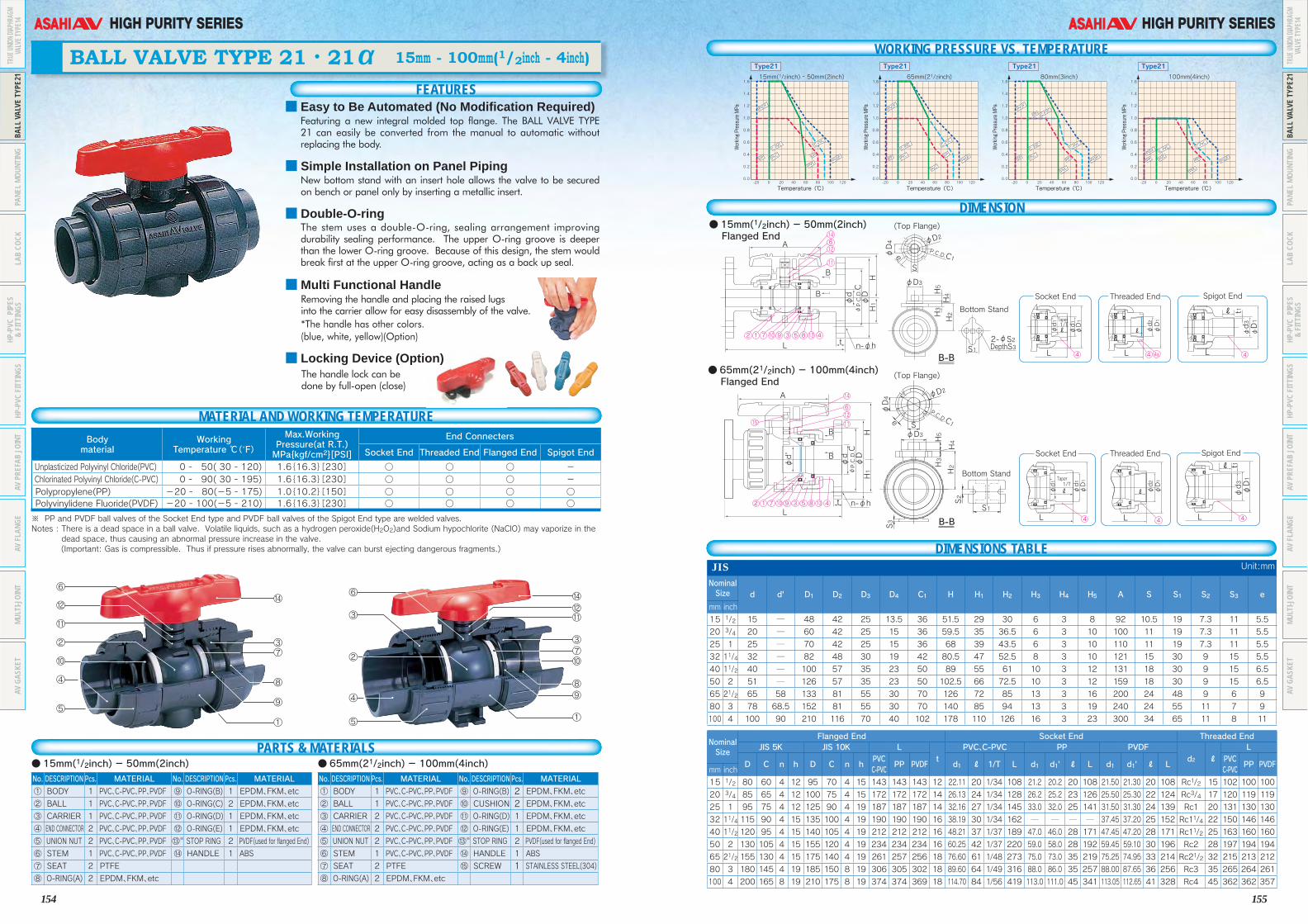
154
HIGH PURITY SERIES
155
HIGH PURITY SERIES
※ PP and PVDF ball valves of the Socket End type and PVDF ball valves of the Spigot End type are welded valves.Notes : There is a dead space in a ball valve. Volatile liquids, such as a hydrogen peroxide(H2O2)and Sodium hypochlorite (NaClO) may vaporize in the
dead space, thus causing an abnormal pressure increase in the valve. (Important: Gas is compressible. Thus if pressure rises abnormally, the valve can burst ejecting dangerous fragments.)
⑬※ See drawings on page 16 (only for flanged end type)
FEATURES
BALL VALVE TYPE 21・21α 15mm - 100mm(1/2inch - 4inch)
MATERIAL AND WORKING TEMPERATUREBody material
WorkingTemperature ℃(˚F)
Max.WorkingPressure(at R.T.)MPa{kgf/cm2}[PSI]
End Connecters
Socket End Threaded End Flanged End Spigot End
Unplasticized Polyvinyl Chloride(PVC) 0 - 50( 30 - 120) 1.6{16.3}[230] ○ ○ ○ - Chlorinated Polyvinyl Chloride(C-PVC) 0 - 90( 30 - 195) 1.6{16.3}[230] ○ ○ ○ - Polypropylene(PP) -20 - 80(-5 - 175) 1.0{10.2}[150] ○ ○ ○ ○ Polyvinylidene Fluoride(PVDF) -20 - 100(-5 - 210) 1.6{16.3}[230] ○ ○ ○ ○
No. DESCRIPTION Pcs. MATERIAL No. DESCRIPTION Pcs. MATERIAL
① BODY 1 PVC、C-PVC、PP、PVDF ⑨ O-RING(B) 1 EPDM、FKM、etc
② BALL 1 PVC、C-PVC、PP、PVDF ⑩ O-RING(C) 2 EPDM、FKM、etc
③ CARRIER 1 PVC、C-PVC、PP、PVDF ⑪ O-RING(D) 1 EPDM、FKM、etc
④ END CONNECTOR 2 PVC、C-PVC、PP、PVDF ⑫ O-RING(E) 1 EPDM、FKM、etc
⑤ UNION NUT 2 PVC、C-PVC、PP、PVDF ⑬※ STOP RING 2 PVDF(used for flanged End)
⑥ STEM 1 PVC、C-PVC、PP、PVDF ⑭ HANDLE 1 ABS
⑦ SEAT 2 PTFE
⑧ O-RING(A) 2 EPDM、FKM、etc
No. DESCRIPTION Pcs. MATERIAL No. DESCRIPTION Pcs. MATERIAL
① BODY 1 PVC、C-PVC、PP、PVDF ⑨ O-RING(B) 2 EPDM、FKM、etc② BALL 1 PVC、C-PVC、PP、PVDF ⑩ CUSHION 2 EPDM、FKM、etc③ CARRIER 2 PVC、C-PVC、PP、PVDF ⑪ O-RING(D) 1 EPDM、FKM、etc
④ END CONNECTOR 2 PVC、C-PVC、PP、PVDF ⑫ O-RING(E) 1 EPDM、FKM、etc
⑤ UNION NUT 2 PVC、C-PVC、PP、PVDF ⑬※ STOP RING 2 PVDF(used for flanged End)
⑥ STEM 1 PVC、C-PVC、PP、PVDF ⑭ HANDLE 1 ABS
⑦ SEAT 2 PTFE ⑮ SCREW 1 STAINLESS STEEL(304)⑧ O-RING(A) 2 EPDM、FKM、etc
●15mm(1/2inch) - 50mm(2inch) ● 65mm(21/2inch) - 100mm(4inch)
WORKING PRESSURE VS. TEMPERATURE
●15mm(1/2inch) - 50mm(2inch) Flanged End
● 65mm(21/2inch) - 100mm(4inch) Flanged End
DIMENSIONS TABLEJIS Unit:mm
Nominal Size d d' D1 D2 D3 D4 C1 H H1 H2 H3 H4 H5 A S S1 S2 S3 e
mm inch
15 1/2 15 ─ 48 42 25 13.5 36 51.5 29 30 6 3 8 92 10.5 19 7.3 11 5.5
20 3/4 20 ─ 60 42 25 15 36 59.5 35 36.5 6 3 10 100 11 19 7.3 11 5.5
25 1 25 ─ 70 42 25 15 36 68 39 43.5 6 3 10 110 11 19 7.3 11 5.5
32 11/4 32 ─ 82 48 30 19 42 80.5 47 52.5 8 3 10 121 15 30 9 15 5.5
40 11/2 40 ─ 100 57 35 23 50 89 55 61 10 3 12 131 18 30 9 15 6.5
50 2 51 ─ 126 57 35 23 50 102.5 66 72.5 10 3 12 159 18 30 9 15 6.5
65 21/2 65 58 133 81 55 30 70 126 72 85 13 3 16 200 24 48 9 6 9
80 3 78 68.5 152 81 55 30 70 140 85 94 13 3 19 240 24 55 11 7 9
100 4 100 90 210 116 70 40 102 178 110 126 16 3 23 300 34 65 11 8 11
Nominal Size
Flanged End Socket End Threaded EndJIS 5K JIS 10K L
tPVC、C-PVC PP PVDF
d2 ℓL
D C n h D C n hPVCC-PVC
PP PVDF d1 ℓ 1/T L d1 d1' ℓ L d1 d1' ℓ LPVCC-PVC
PP PVDFmm inch
15 1/2 80 60 4 12 95 70 4 15 143 143 143 12 22.11 20 1/34 108 21.2 20.2 20 108 21.50 21.30 20 108 Rc1/2 15 102 100 100
20 3/4 85 65 4 12 100 75 4 15 172 172 172 14 26.13 24 1/34 128 26.2 25.2 23 126 25.50 25.30 22 124 Rc3/4 17 120 119 119
25 1 95 75 4 12 125 90 4 19 187 187 187 14 32.16 27 1/34 145 33.0 32.0 25 141 31.50 31.30 24 139 Rc1 20 131 130 130
32 11/4 115 90 4 15 135 100 4 19 190 190 190 16 38.19 30 1/34 162 ─ ─ ─ ─ 37.45 37.20 25 152 Rc11/4 22 150 146 146
40 11/2 120 95 4 15 140 105 4 19 212 212 212 16 48.21 37 1/37 189 47.0 46.0 28 171 47.45 47.20 28 171 Rc11/2 25 163 160 160
50 2 130 105 4 15 155 120 4 19 234 234 234 16 60.25 42 1/37 220 59.0 58.0 28 192 59.45 59.10 30 196 Rc2 28 197 194 194
65 21/2 155 130 4 15 175 140 4 19 261 257 256 18 76.60 61 1/48 273 75.0 73.0 35 219 75.25 74.95 33 214 Rc21/2 32 215 213 212
80 3 180 145 4 19 185 150 8 19 306 305 302 18 89.60 64 1/49 316 88.0 86.0 35 257 88.00 87.65 36 256 Rc3 35 265 264 261
100 4 200 165 8 19 210 175 8 19 374 374 369 18 114.70 84 1/56 419 113.0 111.0 45 341 113.05 112.65 41 328 Rc4 45 362 362 357
A
BS
S12-φS2DepthS3
φd
φD
HH1
H4
φD1
φd3
φD1
φd1
φd1'
t1
LL
1/TTaper
ℓ
ℓ φD1
φd2
L
ℓ
φD1
φd3
φD1
φd1
φd1'
t1
LL
1/TTaper
ℓ
ℓ φD1
φd2
L
ℓ
H2
H5
H3
φD4
φD3
φD2
P.C.D.C1e
φP.C.D.C
B
B-B
B-B
L t n-φh
A
B
φd
φd'
φD
HH1φP.C.D.C
B
Lt n-φh
(Top Flange)
(Top Flange)
Bottom Stand
Bottom Stand
Socket End Spigot EndThreaded End
Socket End Spigot EndThreaded End
S1
S2
H2H3
H5
H4
S3
φD3S
φD4 φD2
P.C.D.C1e
614
4a
12
2 9 3 5 8 4
4 4 4
4 44
1 7 10 13
11
6
14
1512
2 9 3 5 8 41 7 10 13
11
1.0
1.2
1.4
1.6
0.6
0.8
0.2
0.4
0.012060 80 1000 20-20 40
Temperature(℃)
1.0
1.2
1.4
1.6
0.6
0.8
0.2
0.4
0.012060 80 1000 20-20 40
Temperature(℃)
1.0
1.2
1.4
1.6
0.6
0.8
0.2
0.4
0.012060 80 1000 20-20 40
Temperature(℃)
1.0
1.2
1.4
1.6
0.6
0.8
0.2
0.4
0.012060 80 1000 20-20 40
Temperature(℃)
PVDF
PVDF
PVDF
PVDF
PVDF
PVDF
PVDF
PVDFPP
PPPP
PPPP PP
PP
PP PP
C-PVC
C-PVC C-P
VC
C-PVC
C-PVC
C-PVC
C-PVC
C-PVC
C-PVC
PVC
PVC
PVC
PVC
PVC
PVC
PVC
PVC
15mm(1/2inch) - 50mm(2inch)
Type21
Working Pressure MPa
65mm(21/2inch)
Type21
Working Pressure MPa
80mm(3inch)
Type21
Working Pressure MPa
100mm(4inch)
Type21
Working Pressure MPa
DIMENSION
■ Easy to Be Automated (No Modification Required)Featuring a new integral molded top flange. The BALL VALVE TYPE 21 can easily be converted from the manual to automatic without replacing the body.
■ Simple Installation on Panel PipingNew bottom stand with an insert hole allows the valve to be secured on bench or panel only by inserting a metallic insert.
■ Double-O-ringThe stem uses a double-O-ring, sealing arrangement improving durability sealing performance. The upper O-ring groove is deeper than the lower O-ring groove. Because of this design, the stem would break first at the upper O-ring groove, acting as a back up seal.
■ Multi Functional HandleRemoving the handle and placing the raised lugsinto the carrier allow for easy disassembly of the valve.
*The handle has other colors.(blue, white, yellow)(Option)
■ Locking Device (Option)The handle lock can be done by full-open (close)
PARTS & MATERIALS
TRUE
UNION
DIAP
HRAG
MVA
LVE T
YPE1
4BA
LL V
ALVE
TYP
E21
PANE
L MO
UNTI
NGLA
B CO
CKHP
-PVC
PIP
ES&
FITT
INGS
HP-P
VC F
ITTI
NGS
AV P
REFA
B JO
INT
AV F
LANG
EMU
LTI-J
OINT
AV G
ASKE
T
TRUE
UNION
DIAP
HRAG
MVA
LVE T
YPE1
4BA
LL V
ALVE
TYP
E21
PANE
L MO
UNTI
NGLA
B CO
CKHP
-PVC
PIP
ES&
FITT
INGS
HP-P
VC F
ITTI
NGS
AV P
REFA
B JO
INT
AV F
LANG
EMU
LTI-J
OINT
AV G
ASKE
T

156
HIGH PURITY SERIES
157
HIGH PURITY SERIES
Note : Pay attention that the follwing chemicals such as Hydrgen Peroxide (H2O2)and Sodium hypochlorite (NaClO) are adapt to be occured the abnormal pressure rising due to their vaporization nature.
ANSI Unit:inch
Nominal Size d d' D1 D2 D3 D4 C1 H H1 H2 H3 H4 H5 A S S1 S2 S3 e
inch mm1/2 15 0.59 ─ 1.89 1.65 0.98 0.53 1.42 2.03 1.14 1.18 0.24 0.12 0.31 3.62 0.41 0.75 0.29 0.43 0.223/4 20 0.79 ─ 2.36 1.65 0.98 0.59 1.42 2.34 1.38 1.44 0.24 0.12 0.39 3.94 0.43 0.75 0.29 0.43 0.22
1 25 0.98 ─ 2.76 1.65 0.98 0.59 1.42 2.68 1.54 1.71 0.24 0.12 0.39 4.33 0.43 0.75 0.29 0.43 0.22
11/4 32 1.26 ─ 3.23 1.89 1.18 0.75 1.65 3.17 1.85 2.07 0.31 0.12 0.39 4.76 0.59 1.18 0.35 0.59 0.22
11/2 40 1.57 ─ 3.94 2.24 1.38 0.91 1.97 3.50 2.17 2.40 0.39 0.12 0.47 5.16 0.71 1.18 0.35 0.59 0.26
2 50 2.01 ─ 4.96 2.24 1.38 0.91 1.97 4.04 2.60 2.85 0.39 0.12 0.47 6.26 0.71 1.18 0.35 0.59 0.26
21/2 65 2.56 2.28 5.24 3.19 2.17 1.18 2.76 4.96 2.83 3.35 0.51 0.12 0.63 7.87 0.94 1.89 0.35 0.24 0.35
3 80 3.07 2.70 5.98 3.19 2.17 1.18 2.76 5.51 3.35 3.70 0.51 0.12 0.75 9.45 0.94 2.17 0.43 0.28 0.35
4 100 3.94 3.54 8.27 4.57 2.76 1.57 4.02 7.01 4.33 4.96 0.63 0.12 0.91 11.81 1.34 2.56 0.43 0.31 0.43
Nominal Size
Flanged End Socket End (IPS) Threaded End
ANSI CLASS 150 L
t
PVC, C-PVC PP, PVDF
d2 ℓ
L
D C n hPVC, C-PVC
PP PVDFASTM SCH40
LASTM SCH80
L d1 ℓL PVC,
C-PVCPP PVDF
inch mm d1 d1' ℓ d1 d1' ℓ PP PVDF1/2 15 3.50 2.38 4 0.62 5.63 5.63 5.63 0.47 ─ ─ ─ ─ 0.848 0.836 0.875 4.45 0.83 0.87 4.45 4.45 1/2-14 NPT 0.59 4.02 4.02 4.023/4 20 3.88 2.75 4 0.62 6.77 6.77 6.77 0.55 ─ ─ ─ ─ 1.058 1.046 1.000 5.08 1.03 1.00 5.08 5.08 3/4-14 NPT 0.67 4.72 4.72 4.72
1 25 4.25 3.12 4 0.62 7.36 7.36 7.36 0.55 ─ ─ ─ ─ 1.325 1.310 1.125 5.75 1.30 1.13 5.75 5.75 1-111/2NPT 0.79 5.16 5.16 5.16
11/4 32 4.62 3.50 4 0.62 7.48 7.48 7.48 0.63 ─ ─ ─ ─ 1.670 1.655 1.250 6.46 1.65 1.25 6.46 6.46 11/4-111/2NPT 0.87 5.91 5.91 5.91
11/2 40 5.00 3.88 4 0.62 8.35 8.35 8.35 0.63 ─ ─ ─ ─ 1.912 1.894 1.375 7.24 1.89 1.37 7.24 7.24 11/2-111/2NPT 0.98 6.42 6.42 6.42
2 50 6.00 4.75 4 0.75 9.21 9.21 9.21 0.63 ─ ─ ─ ─ 2.387 2.369 1.500 8.23 2.36 1.50 8.23 8.23 2-111/2NPT 1.10 7.76 7.76 7.76
21/2 65 7.00 5.50 4 0.75 10.20 10.12 10.08 0.71 ─ ─ ─ ─ 2.889 2.868 1.750 9.45 2.880 1.752 9.37 9.33 1/2-8 NPT 1.26 8.46 8.39 8.35
3 80 7.50 6.00 4 0.75 12.05 12.01 11.89 0.71 ─ ─ ─ ─ 3.516 3.492 1.875 11.14 3.480 1.874 11.10 10.98 3-8 NPT 1.38 10.43 10.39 10.28
4 100 9.00 7.50 8 0.75 14.72 14.72 14.53 0.71 4.518 4.491 2.000 13.86 ─ ─ ─ ─ 4.480 2.252 14.37 14.13 4-8 NPT 1.77 14.25 14.25 14.06
DIN Unit:mm
Nominal Size d d' D1 D2 D3 D4 C1 H H1 H2 H3 H4 H5 A S S1 S2 S3 e
mm inch
10 3/8 13 ─ 46 ─ ─ ─ ─ 43.5 ─ ─ ─ ─ ─ 80 ─ ─ ─ ─ ─
15 1/2 15 ─ 48 42 25 13.5 36 51.5 29 30 6 3 8 92 10.5 19 7.3 11 5.5
20 3/4 20 ─ 60 42 25 15 36 59.5 35 36.5 6 3 10 100 11 19 7.3 11 5.5
25 1 25 ─ 70 42 25 15 36 68 39 43.5 6 3 10 110 11 19 7.3 11 5.5
32 11/4 32 ─ 82 48 30 19 42 80.5 47 52.5 8 3 10 121 15 30 9 15 5.5
40 11/2 40 ─ 100 57 35 23 50 89 55 61 10 3 12 131 18 30 9 15 6.5
50 2 51 ─ 126 57 35 23 50 102.5 66 72.5 10 3 12 159 18 30 9 15 6.5
65 21/2 65 58 133 81 55 30 70 126 72 85 13 3 16 200 24 48 9 6 9
80 3 78 68.5 152 81 55 30 70 140 85 94 13 3 19 240 24 55 11 7 9
100 4 100 90 210 116 70 40 102 178 110 126 16 3 23 300 34 65 11 8 11
Nominal Size
Flanged End Socket End Threaded End Spigot EndDIN PN10
t
PVC、C-PVC PP、PVDF
d2 ℓ
L PVC PP、PVDFL
D C n hL
d1 ℓ L d1 d1' ℓL PVC
C-PVC PP PVDF d3 d3' ℓ d3 lt
mm inch PVCC-PVC PP PVDF PP PVDF PP PVDF PP PVDF
10 3/8 90 60 4 14 120 119 119 12 16 14 99 15.5 15.4 13 96 96 Rp3/8 15 99 98 98 16 13 16 ─ ─ ─ ─ 114 114
15 1/2 95 65 4 14 130 130 130 12 20 16 102 19.5 19.3 14.5 99 99 Rp1/2 15 102 100 100 20 15 18.5 20 18.5 2.5 1.9 124 124
20 3/4 105 75 4 14 150 150 150 14 25 19 120 24.5 24.3 16 113 113 Rp3/4 17 120 119 119 25 20 24 25 22 2.7 1.9 144 144
25 1 115 85 4 14 160 160 160 14 32 22 131 31.5 31.3 18 123 123 Rp1 20 131 130 130 32 25 24.5 32 22.5 3.0 2.4 154 154
32 11/4 140 100 4 18 180 180 180 16 40 26 150 39.45 39.2 20.5 139 139 Rp11/4 22 150 146 146 40 31 28 40 26 3.7 2.4 174 174
40 11/2 150 110 4 18 200200200 16 50 31 163 49.45 49.2 23.5149 149 Rp11/2 25 163 160 160 50 40 34 50 32 4.6 3.0 194 194
50 2 165 125 4 18 230230230 16 63 38 197 62.5 62.1 27.5 176 176 Rp2 28 197 194 194 63 51 38 63 36 5.8 3.0 224 224
65 21/2 185 145 4 18 290288287 18 75 44 233 74.25 73.95 31 205 204 Rp21/2 32 215 213 212 75 65 44 75 38 6.9 3.6 245 244
80 3 200 160 8 18 312 311 308 21 90 51 284 89.2 88.85 35.5252 249 Rp3 35 265 264 261 90 80 51 90 38 8.2 4.3 296 293
100 4 220 180 8 18 352 352347 18 110 61 351 109.05 108.65 41.5 312 307 Rp4 45 340 340335 110 93.6 46 110 44.5 10.0 5.3 355 350
Note : The shape and appearance of the valve differ a little with nominal size compared to the drawing.
Panel Mounting
Nominal Size mm(inch) S1 S2 S315mm - 32mm(1/2 - 11/4)
25(0.98)
7(0.28)
13(0.51)
40mm, 50mm(11/2, 2)
45(1.8)
9(0.35)
15(0.59)
■Fixation of Bottom Stand with PanelNominal size 15 - 50mm(1/2inch - 2inch)
Washer
Bolt
Panel
Bottom Stand
Body
Inserted Metal
Panel
Bottom Stand
Body
Bolt
Washer
Panel
Washer
Nut
Bottom Stand
Body
Panel
Bottom Stand
Body
Before the Fixation
●Diaphragm Valve Type14 15mm - 050mm(1/2inch - 2inch)●Ball Valve Type21 15mm - 100mm(1/2inch - 4inch)
Before the Fixation
After the Fixation
After the Fixation
Nominal size 65 - 100mm(2 1/2inch - 4inch)
▲▲
■Proceduce Refer to the User's Manual for Metal Insert (Ensat) by the Maker.
■Bottom Stand DimensionDiaphragm Valve Type14
Nominal Size mm(inch) S1 S2 S315mm - 25mm(1/2 - 1)
19(0.75)
7.3(0.29)
11(0.43)
32mm - 50mm(11/4 - 2)
30(1.18)
9(0.35)
15(0.59)
65mm(21/2)
48(1.89)
9(0.35)
6(0.24)
80mm(3)
55(2.17)
11(0.43)
7(0.28)
100mm(4)
65(2.56)
11(0.43)
8(0.31)
Ball Valve Type21
Unit:mm(inch)
Unit:mm(inch)
S1
S2
2-φS2 DepthS3
S3
S1
Diaphragm Valve Type14: 15mm - 50mm (1/2inch - 2inch)Ball Valve Type21: 15mm - 50mm (1/2inch - 2inch)
Ball Valve Type21: 65mm - 100mm (2 1/2inch - 4inch)
TRUE
UNION
DIAP
HRAG
MVA
LVE T
YPE1
4BA
LL V
ALVE
TYP
E21
PANE
L MO
UNTI
NGLA
B CO
CKHP
-PVC
PIP
ES&
FITT
INGS
HP-P
VC F
ITTI
NGS
AV P
REFA
B JO
INT
AV F
LANG
EMU
LTI-J
OINT
AV G
ASKE
T
TRUE
UNION
DIAP
HRAG
MVA
LVE T
YPE1
4BA
LL V
ALVE
TYP
E21
PANE
L MO
UNTI
NGLA
B CO
CKHP
-PVC
PIP
ES&
FITT
INGS
HP-P
VC F
ITTI
NGS
AV P
REFA
B JO
INT
AV F
LANG
EMU
LTI-J
OINT
AV G
ASKE
T

158
HIGH PURITY SERIES
159
HIGH PURITY SERIES
15
φ23
32
35
φ16
φ6
R1/2
35.5 57.5
93
41
7
4
6
3b 3c1 2 5 8
■ LAB COCK 1/2inch MALE THREAD× ELBOW16mm
Body material Unplasticized Polyvinyl Chloride(PVC)
Working Temperature 0℃ - 50℃(30゜F - 120゜F) Max.Working Pressure 1.0MPa{10.2kgf/cm2}[150PSI]
End Connectors R1/2inch Male thread×Elbow16mm
MATERIAL AND WORKING TEMPERATURE
PARTS & MATERIALSNo. DESCRIPTION Pcs. MATERIAL① BODY 1 PVC② BALL&STEM 1 PVC3b END CONNECTOR 1 PVC3c END CONNECTOR 1 PVC④ GLAND 1 PVC⑤ SEAT 2 PTFE⑥ O-RING 1 EPDM, Others⑦ HANDLE 1 ABS⑧ ELBOW 1 PVC
DIN Unit:mm
d1 d2 ℓ1 ℓ2 L d1 d2 ℓ1 ℓ2 L
① FEMALE THREAD ×FEMALE THREAD
Rp 1/4 Rp 1/4 15 15 71④ MALE THREAD
×HOSER 1/4 10 13 30.5 88.5
Rp 3/8 Rp 1/4 15 15 71 R 1/2 10 15 30.5 91Rp 3/8 Rp 3/8 15 15 71
⑤ MALE THREAD ×MALE THREAD
R 1/4 R 1/4 13 13 66② HOSE×HOSE 10 10 30.5 30.5 111 R 1/2 R 1/4 15 13 68.5
③ FEMALE THREAD ×HOSE
Rp 1/4 10 15 30.5 91 R 1/2 R 1/2 15 15 71Rp 3/8 10 15 30.5 91
⑥ MALE THREAD ×FEMALE THREAD
R 1/4 Rp 1/4 13 15 68.5R 1/4 Rp 3/8 13 15 68.5R 1/2 Rp 1/4 15 15 71R 1/2 Rp 3/8 15 15 71
ANSI Unit:inch
d1 d2 ℓ1 ℓ2 L d1 d2 ℓ1 ℓ2 L
① FEMALE THREAD ×FEMALE THREAD
1/4-18NPT 1/4-18NPT 0.51 0.51 2.80④ MALE THREAD
×HOSE
1/4-18NPT 0.39 0.51 1.20 3.483/8-18NPT 1/4-18NPT 0.59 0.51 2.80 1/2-14NPT 0.39 0.59 1.20 3.583/8-18NPT 3/8-18NPT 0.59 0.59 2.80
⑤ MALE THREAD ×MALE THREAD
1/4-18NPT 1/4-18NPT 0.51 0.51 2.60② HOSE×HOSE 0.39 0.39 1.20 1.20 4.37 1/2-14NPT 1/4-18NPT 0.59 0.51 2.70
③ FEMALE THREAD ×HOSE
1/4-18NPT 0.39 0.51 1.20 3.58 1/2-14NPT 1/2-14NPT 0.59 0.59 2.803/8-18NPT 0.39 0.59 1.20 3.58
⑥ MALE THREAD ×FEMALE THREAD
1/4-18NPT 1/4-18NPT 0.51 0.51 2.701/4-18NPT 3/8-18NPT 0.51 0.59 2.701/2-14NPT 1/4-18NPT 0.59 0.51 2.801/2-14NPT 3/8-18NPT 0.59 0.59 2.80
⑦ MALE THREAD ×ELBOW
1/2-14NPT 0.63 0.59 1.26 3.66
FEATURES
LAB COCK
MATERIAL AND WORKING TEMPERATURE
WORKING PRESSURE VS. TEMPERATURE
DIMENSION
DIMENSIONS TABLE
35
L
L L
L
L
L
ℓ1
ℓ1 ℓ1
ℓ1 ℓ2
ℓ1 ℓ2ℓ2ℓ2
ℓ1 ℓ2ℓ2
d1
φd1
d1
d1
d1
d1
d2
φd2
φd2
φd2
d2
d2φ6
φ6
30(1.18)
(1.38)7
46
3 1 2 5
FEMALE THREAD× FEMALE THREAD HOSE× HOSE
FEMALE THREAD× HOSE
MALE THREAD× HOSE
MALE THREAD×MALE THREAD
・ The LAB COCK is a compact, light weight plastic valve which is highly corrosion-resistant, in durable.
Body material Unplasticized Polyvinyl Chloride(PVC) Working Temperature 0℃ - 50℃(30゜F - 120゜F) Max.Working Pressure 1.0MPa{10.2kgf/cm2}[150PSI] End Connectors Hose, Male thread, Female thread
Nominal Size ●Hose:12 to 15mm(standard hose inner diameter) ●Male thread:1/4,1/2 ●Female thread:1/4,3/8
No. DESCRIPTION Pcs. MATERIAL① BODY 1 PVC② BALL&STEM 1 PVC③ END CONNECTOR 2 PVC④ GLAND 1 PVC⑤ SEAT 2 EPDM, PTFE, others⑥ O-RING 1 EPDM, others⑦ HANDLE 1 ABS
JIS Unit:mm
d1 d2 ℓ1 ℓ2 L d1 d2 ℓ1 ℓ2 L
FEMALE THREAD ×FEMALE THREAD
Rc 1/4 Rc 1/4 15 15 71 MALE THREAD ×HOSE
R 1/4 10 13 30.5 88.5Rc 3/8 Rc 1/4 15 15 71 R 1/2 10 15 30.5 91Rc 3/8 Rc 3/8 15 15 71
MALE THREAD ×MALE THREAD
R 1/4 R 1/4 13 13 66 HOSE×HOSE 10 10 30.5 30.5 111 R 1/2 R 1/4 15 13 68.5 FEMALE THREAD ×HOSE
Rc 1/4 10 15 30.5 91 R 1/2 R 1/2 15 15 71Rc 3/8 10 15 30.5 91
MALE THREAD ×FEMALE THREAD
R 1/4 Rc 1/4 13 15 68.5R 1/4 Rc 3/8 13 15 68.5R 1/2 Rc 1/4 15 15 71R 1/2 Rc 3/8 15 15 71
■ NSF ProductNSF("NSF/ANSI STANDARD 61" Drinking Water System Components-Health Effects)Product.:LAB COCK(Material:PVC+EPDM) *Certified products bear an NSF Certification Mark.
{10.2}1.0
0.5
0.0
{5.1}
12060 80 100
[150]
[70]
0 20-40 -20 40(250)(140) (175) (210)(30) (90)(-40) (-5) (105)
Temperature℃( F゚)
PVC
Max Working Pressure MPa{kgf/cm2 }[PSI]
Lab Cock
PARTS & MATERIALS
TRUE
UNION
DIAP
HRAG
MVA
LVE T
YPE1
4BA
LL V
ALVE
TYP
E21
PANE
L MO
UNTI
NGLA
B CO
CKHP
-PVC
PIP
ES&
FITT
INGS
HP-P
VC F
ITTI
NGS
AV P
REFA
B JO
INT
AV F
LANG
EMU
LTI-J
OINT
AV G
ASKE
T
TRUE
UNION
DIAP
HRAG
MVA
LVE T
YPE1
4BA
LL V
ALVE
TYP
E21
PANE
L MO
UNTI
NGLA
B CO
CKHP
-PVC
PIP
ES&
FITT
INGS
HP-P
VC F
ITTI
NGS
AV P
REFA
B JO
INT
AV F
LANG
EMU
LTI-J
OINT
AV G
ASKE
T

160
HIGH PURITY SERIES
161
HIGH PURITY SERIES
HP-PVC PIPE & FITTINGS HP-PVC PIPE & FITTINGS
●Elbow(L) Unit:mm
Nominal Size (mm) D t H
13 24 3.0 3616 29 3.5 4320 33 3.5 5025 40 4.0 5830 46 4.0 6540 57 4.5 8250 70 5.0 96
※ 65 87 6.6 110※ 75 102 8.0 120※ 100 130 10.0 153※ 125 157 11.0 188※ 150 186 13.0 230
□ 200 240 15.0 265□ 250 295 16.0 310
300 347 18.0 350(Note)1.The tolerances on H are +5/-1mm.2.The Nominal Size marked with ※ conform to the JPPFA standard.3.The Nominal Size marked with □ conform to the AV standard.
●HP-PVC Pipe <CLASS VP:JIS K6741> Unit:mm
Nominal Size(mm)
D t d LOuter diameter Wall Thickness
ApproximateI.D.
(for reference)LengthBasic
Dimension(mm)
Maximum and Minimumtolerances
Averagetolerances Minimum Tolerance
13 18 ±0.2 ±0.2 2.2 +0.6 13 4,000±1016 22 ±0.2 ±0.2 2.7 +0.6 16 4,000±1020 26 ±0.2 ±0.2 2.7 +0.6 20 4,000±1025 32 ±0.2 ±0.2 3.1 +0.8 25 4,000±1030 38 ±0.3 ±0.2 3.1 +0.8 31 4,000±1040 48 ±0.3 ±0.2 3.0 +0.8 40 4,000±1050 60 ±0.4 ±0.2 4.1 +0.8 51 4,000±1065 76 ±0.5 ±0.3 4.1 +0.8 67 4,000±1075 89 ±0.5 ±0.3 5.5 +0.8 77 4,000±10100 114 ±0.6 ±0.4 6.6 +1.0 100 4,000±10125 140 ±0.8 ±0.5 7.0 +1.0 125 4,000±10150 165 ±1.0 ±0.5 8.9 +1.4 146 4,000±10200 216 ±1.3 ±0.7 10.3 +1.4 194 4,000±10250 267 ±1.6 ±0.9 12.7 +1.8 240 4,000±10300 318 ±1.9 ±1.0 15.1 ±2.2 286 4,000±10
(Note)1.The tolerances of lengths are ± 10mm.2. The maximum and minimum tolerances on outside diameters are the tolerances on O.D. measurements taken at randomly selected spots.
3. The average tolerances on outside diameters are the tolerances on the arithmetical mean of O.D. measurements taken at randomly selected spots in two directions at a right angle to each other.
HP-PVC Pipe <CLASS VP:JIS K6741>
●Dimensions Commom All of AV TS Socket. JIS K6743 Unit:mmNominal Size(mm)
d1Toleranceon d1
d2 ℓ 1/T D DTToleranceon
D&DT
d(minimumvalue)
Pipe O.D.
13 18.40 ±0.20 - 26 1/30 24 24.0 -0.6 13 1816 22.40 ±0.20 - 30 1/34 29 29.0 -0.7 16 2220 26.45 ±0.20 - 35 1/34 33 33.0 -0.8 20 2625 32.55 ±0.25 - 40 1/34 40 40.0 -1.0 25 3230 38.60 ±0.25 - 44 1/34 46 46.0 -1.0 31 3840 48.70 ±0.30 - 55 1/37 57 57.0 -1.2 40 4850 60.80 ±0.30 - 63 1/37 70 70.0 -1.5 51 60
※ 65 76.60 ±0.30 - 61 1/48 87 88.5 -1.5 67 7675 89.60 ±0.30 - 64 1/49 102 104.5 -1.5 77 89100 114.70 ±0.30 - 84 1/56 130 133.5 -1.8 100 114※125 140.85 ±0.35 - 104 1/58 157 161.0 -1.8 125 140150 166.00 ±0.40 - 132 1/63 186 190.0 -2.0 146 165※200 217.00 - 214.10 145 - 240 - - 194 216※250 268.20 - 265.00 155 - 295 - - 247 267※300 319.6 - 315.50 175 - 347 - - 298 318(Note)1.The tolerances on l are +4/-0.5mm.2.The Nominal Size marked with ※ conform to the AV standard and the JPPFA standard.
Fittings in size 200, 250mm are available on request by FRP reinforcement. Max working pressure 200mm : 1.0MPa{10.2kgf/cm2} at 20℃ 250mm : 1.0MPa{10.2kgf/cm2} at 20℃
ℓ ℓ
Taper 1/T φd1
φd
φD
φd1φD
φDT
φd2
φd
H
D
H
t
H
H
D
t
▼13mm - 50mm
▼65mm - 300mm
t
L
φd
φD
▼13mm - 150mm ▼200mm - 300mm
Working Pressure with Temperature
Temp.Nom. Size 20℃ 30℃ 40℃ 50℃
13mm - 300mm 1.0{10.2}0.9{9.2} 0.7{7.1} 0.3{3.1}
MPa{kgf/cm2}
Note:This data is applicable for ultrapure water.
Working Pressure with Temperature
Temp.Nom. Size 20℃ 30℃ 40℃ 50℃
13mm - 150mm 1.0{10.2}0.9{9.2} 0.7{7.1} 0.3 {3.1}200mm 0.75{7.7}0.6{6.1} 0.5{5.1}0.25{2.6}250mm 0.6{6.1} 0.5{5.1} 0.4{4.1} 0.2{2.0}
300mm Elbow, Reducing Socket, Socket 0.6{6.1} 0.5{5.1} 0.4{4.1} 0.2{2.1}300mm Other Fitting 0.4{4.1} 0.4{4.1} 0.3{3.1} 0.1{1.1}
MPa{kgf/cm2}
Note:This data is applicable for ultrapure water.
Dimensions Common All of AV TS Socket. JIS K6743
Elbow(L)
●90゜AV Bend Unit:mm
Nominal Size(mm) D t H
□ 200 240 15 341
□ 250 293 16 402
300 337 10 395(Note)1.The Nominal Size marked with □ conform to the AV standard.
●45゜Elbow(45L) Unit:mm
Nominal Size(mm) D t H
20 33 3.5 44
25 40 4.0 51
●45゜AV Bend Unit:mm
Nominal Size(mm) D t H
40 57 4.5 69
50 70 5.0 80
65 87 6.0 81
□ 75 101 6.6 97
□ 100 129 7.3 122
□ 125 156 7.7 149
□ 150 185 10.0 184
□ 200 240 15.0 193
□ 250 293 16.0 213
300 337 10.0 225(Note)1.The Nominal Size marked with □ conform to the AV standard.
t
HφD
H
D
t
H
45°
H
H
t
φD
90˚ AV Bend
45˚ Elbow(45L)
45˚ AV Bend
TRUE
UNION
DIAP
HRAG
MVA
LVE T
YPE1
4BA
LL V
ALVE
TYP
E21
PANE
L MO
UNTI
NGLA
B CO
CKHP
-PVC
PIP
ES&
FITT
INGS
HP-P
VC F
ITTI
NGS
AV P
REFA
B JO
INT
AV F
LANG
EMU
LTI-J
OINT
AV G
ASKE
T
TRUE
UNION
DIAP
HRAG
MVA
LVE T
YPE1
4BA
LL V
ALVE
TYP
E21
PANE
L MO
UNTI
NGLA
B CO
CKHP
-PVC
PIP
ES&
FITT
INGS
HP-P
VC F
ITTI
NGS
AV P
REFA
B JO
INT
AV F
LANG
EMU
LTI-J
OINT
AV G
ASKE
T

162
HIGH PURITY SERIES
163
HIGH PURITY SERIES
●Socket(S) Unit:mm
Nominal Size (mm) D L
13 24 57
16 29 67
20 33 77
25 40 87
30 46 95
40 57 117
50 70 133
※ 65 87 145
75 102 155
100 130 200
※ 125 157 240
150 186 300
□ 200 238 305
□ 250 295 352
300 336 360(Note)1.The tolerances on L are ±4mm.2.The Nominal Size marked with ※ conform to the JPPFA standard.3.The Nominal Size marked with □ conform to the AV standard.
●Reducing Socket(RS) Unit:mm
Nominal Size (mm) D D1 L
20×13 33 24 68
20×16 33 29 71
25×13 40 24 86
25×16 40 29 85
25×20 40 33 84
○ 30×13 48.2 28.2 73.2
○ 30×20 48.2 36.2 83
30×25 46 40 93
※ 40×20 57 33 113
40×25 57 40 114
40×30 57 46 114
※ 50×20 70 33 116
※ 50×25 70 40 140
50×40 70 57 136
※ 65×50 87 70 149
75×50 102 70 165
※ 75×65 102 87 159
100×75 130 102 190
※ 125×100 157 130 229
※ 150×125 186 157 272
□ 200×150 240 188 356
□ 250×200 293 240 380
300×250 347 295 405(Note)1.The tolerances on L are ±4.0mm.2.The Nominal Size marked with ※ conform to the JPPFA standard.3.The Nominal Size marked with □ conform to the AV standard.4.○ There sizes are not in accordance with JISK 6743 and therefore welding arrangement is not available.
L
DD
L
▼13mm~50mm
▼65mm~300mm
D D1
L
D 1D
L
▼13mm - 50mm
▼65mm - 300mm
HP-PVC FITTINGS HP-PVC FITTINGSSocket(S) Tee(T)
Reducing Socket(RS)
●Tee(T) Unit:mm
Nominal Size (mm) D t H H1
13 24 3.0 36 36
16 29 3.5 43 43
20 33 3.5 50 50
25 40 4.0 58 58
30 46 4.0 65 65
40 57 4.5 82 82
50 70 5.0 96 96
※ 65 87 6.6 110 110
75 102 8.0 120 120
100 130 10.0 152 152
※ 125 157 11.0 187 187
150 186 13.0 230 230
□ 200 240 15.0 266 266
□ 250 295 16.0 331 331
300 337 10.0 340 340(Note)1.The tolerances on H are +5/-1mm.2.The Nominal Size marked with ※ conform to the JPPFA standard.3.The Nominal Size marked with □ conform to the AV standard.
●Reducing Tee(RT) Unit:mm
Nominal Size (mm) D t H D1 H1
16× 13 29 3.5 41 24 38
20× 13 33 3.5 46 24 40
20× 16 33 3.5 48 29 45
25× 13 40 4.0 51 24 43
25× 16 40 4.0 53 29 48
25× 20 40 4.0 55 33 53
○30× 13 48.2 6.5 54.7 28.2 44
30× 16 46 4.0 57 29 51
30× 20 46 4.0 59 33 56
30× 25 46 4.0 62 40 61
40× 13 57 4.5 66 24 52
○40× 16 58.4 5.2 62.4 30.9 52.5
40× 20 57 4.5 70 33 62
40× 25 57 4.5 73 40 67
40× 30 57 4.5 76 46 71
50× 13 70 5.0 74 24 58
50× 16 70 5.0 76 29 63
50× 20 70 5.0 78 33 68
50× 25 70 5.0 81 40 73
50× 30 70 5.0 84 46 77
50× 40 70 5.0 90 57 88
※ 65× 40 87 6.6 100 57 95
※ 65× 50 87 6.6 101 70 104
75× 25 102 8.0 93 40 88
75× 40 102 8.0 100 57 102
75× 50 102 8.0 105 70 110
100× 50 130 10.0 125 75 122
100× 75 130 10.0 140 102 132
※ 125× 75 157 11.0 160 102 147
※ 125×100 157 11.0 173 130 167
150× 75 186 13.0 195 102 158
150×100 186 13.0 208 130 182
※ 150×125 186 13.0 217 157 201
□ 200× 75 240 15.0 201 102 180
□ 200×100 240 15.0 215 130 200
□ 200×150 240 15.0 238 188 253
□ 250× 75 295 16.0 226 108 210
□ 250×100 295 16.0 246 136 225
□ 250×200 295 16.0 304 245 310
□ 300× 75 343 17.0 361 102 236
▼13mm - 50mm
D
1H
D
H H
t
▼65mm - 300mm
D
H
t
H1
D
H
▼13mm - 50mm
1D
1H
D
H H
t
▼65mm - 300mm
D
H
t
H1
D1
H
Reducing Tee(RT)
(Note)1.The tolerances on H are +5/-1mm.2.The Nominal Size marked with ※ conform to the JPPFA standard.3.The Nominal Size marked with □ conform to the AV standard.4.○ There sizes are not in accordance with JISK 6743 and therefore welding arrangement is not available.
TRUE
UNION
DIAP
HRAG
MVA
LVE T
YPE1
4BA
LL V
ALVE
TYP
E21
PANE
L MO
UNTI
NGLA
B CO
CKHP
-PVC
PIP
ES&
FITT
INGS
HP-P
VC F
ITTI
NGS
AV P
REFA
B JO
INT
AV F
LANG
EMU
LTI-J
OINT
AV G
ASKE
T
TRUE
UNION
DIAP
HRAG
MVA
LVE T
YPE1
4BA
LL V
ALVE
TYP
E21
PANE
L MO
UNTI
NGLA
B CO
CKHP
-PVC
PIP
ES&
FITT
INGS
HP-P
VC F
ITTI
NGS
AV P
REFA
B JO
INT
AV F
LANG
EMU
LTI-J
OINT
AV G
ASKE
T

164
HIGH PURITY SERIES
165
HIGH PURITY SERIES
●Faucet Elbow(FL) Unit:mm
Nominal Size (mm) D t D1 D2 ℓ1 ℓ2 T H
H1 Nominal size of female threadsS形
□ 13 24 3.0 30 34 17 14 4 38 29 Rp1/2□ 16 29 3.5 30 34 17 14 4 43 32 Rp1/2□ 20 33 3.5 37 42 19 16 4 51 36 Rp3/4□ 25 40 4.0 46 52 21 18 5 59 40 Rp1
(Note)1. The threaded portions employ parallel female threads specified in JIS B 0203(Taper Pipe Threads).
2.The tolerances on H are +5/-2mm.3.The tolerances on H1 are +5/-2mm.4.The Nominal Size marked with □ conform to the AV standard.5.The tolerances on ℓ2 are ±1mm.
●Valve Socket(VS) Unit:mm
Nominal Size (mm) D d
O.D. of basic form D1
Number of threads per inch
Location of basic diameterℓ1
ℓ2(Minimun)
T L B
13×1/2 24 13 20.955 14 8.16 13.16 6 50 24
16×1/2 29 13 20.955 14 8.20 15 6 54 29
20×3/4 33 18 26.441 14 9.53 14.53 8 64 33
25×1 40 23 33.249 11 10.39 16.79 8 71 40
30×11/4 46 31 41.910 11 12.70 19.10 10 80 46
40×11/2 57 37 47.803 11 12.70 19.10 10 92 57
50×2 70 48 59.614 11 15.88 23.38 12 106 70
□ 65×21/2 87 62 75.184 11 17.46 26 14 118 87
□ 75×3 102 72 87.884 11 20.64 30 16 128 102
□ 100×4 130 96 113.030 11 25.40 36 18 157 130(Note)1. The threaded portions employ parallel female threads specified in JIS B 0203(Taper Pipe Threads).
2.The tolerances on L are +5/-2mm.3.The Nominal Size marked with ※ conform to the JPPFA standard.4.The Nominal Size marked with □ conform to the AV standard.
●Faucet Socket(FS) Unit:mm
Nominal Size (mm) D D1 D2 ℓ1 ℓ2 T L
Nominal size of female threads
□ 13 24 30 34 17 14 4 47 Rp1/2□ 16 29 30 34 17 24 4 52 Rp1/2□ 20 33 37 42 19 16 4 59 Rp3/4□ 25 40 46 52 21 18 5 68 Rp1
(Note)1. The threaded portions employ parallel female threads specified in JIS B 0203(Taper Pipe Threads).
2.The tolerances on L are +5/-1mm.3.The tolerances on ℓ2 are ±1mm.4.The Nominal Size marked with □ conform to the AV standard.
●Cap(C) Unit:mm
Nominal Size (mm) D t L
13 24 3.0 29.0
16 29 3.5 33.5
20 33 3.5 38.5
25 40 4.0 44.0
40 57 4.5 59.5
50 70 5.0 68.0
※ 65 87 6.6 96.0
75 102 8.0 105.0
100 130 10.0 138.0 (Note)1.The tolerances on L are +5/-20mm.2.The Nominal Size marked with ※ conform to the JPPFA standard.3.R is 1 to 5mm
Precautions in use・when connecting threaded portions, use both sealing tape and gaskets jointly.・Do not use HP-PVC Faucet Elbows to connect steel pipes and PVC pipes.・Secure the elbows with fixtures.
ℓℓ12
1H
H
φD
φD1
φD2
T
t
T
L
φD1
φD φd
Bℓ2ℓ1
L
T
φD
φD1
φD2
ℓ1ℓ2
L
D
t
R
L
t
D
R
▼13mm - 50mm
▼65mm - 100mm
HP-PVC FITTINGS AV PREFAB JOINT <UNION>Faucet Elbow(FL)
AV TS FLANGE(JIS 10K 13mm - 300mm)
Valve Socket(VS)
Precautions in use・Do not repeat screw-in and removal.・when connecting threaded portions, use sealing tape.
Faucet Socket(FS)
Precautions in use・when connecting threaded portions, use both sealing tape and gaskets jointly.・Do not use HP-PVC Faucet Elbows to connect steel pipes and PVC pipes.・Secure the elbows with fixtures.
Cap(C)
AV FLANGE <HP-PVC>AV Q FLANGE(JIS 10K 15mm - 150mm)
Unit:mm
Nominal Size d
Socket End Threaded EndDU‐PVC、C‐PVC U‐PVC
mm inch d1 ℓ 1/T L d1 ℓ L13 3/8 13 18.13 18 1/34 46.0 RC3/8 15 43 48
16 1/2 15 22.11 20 1/34 46.0 Rc1/2 15 43 48
20 3/4 20 26.13 24 1/34 61.0 RC3/4 17 57 60
25 1 25 32.16 27 1/34 70.0 Rc1 20 63 70
30 11/4 31 38.19 30 1/34 77.0 Rc11/4 22 71 82
40 11/2 40 48.21 37 1/37 95.0 Rc11/2 25 82 100
50 2 51 60.25 42 1/37 107.0 Rc2 28 96 106
65 21/2 65 76.60 61 1/48 164.0 ― ― ― 133
75 3 77 89.60 64 1/49 189.5 ― ― ― 152
100 4 100 114.70 84 1/56 245.0 ― ― ― 210
Unit:mm
Nominal Size d
JIS 10Kd1 Taper
1/T D1 t T ℓ+4.0-0.5 L
mm inch D C n h13 3/8 15 90 65 4 15 18.40±0.20 1/30 25.5 14 - 26 30.0 15 1/2 18 95 70 4 15 22.40±0.20 1/34 31.0 14 12 30 35.0 20 3/4 22 100 75 4 15 26.45±0.20 1/34 35.0 15 14 35 40.0 25 1 25 125 90 4 19 32.55±0.25 1/34 42.5 15 14 40 46.0 32 11/4 30 135 100 4 19 38.60±0.25 1/34 48.5 16 16 44 50.5 40 11/2 41 140 105 4 19 48.70±0.30 1/37 60.5 16 16 55 61.5 50 2 52 155 120 4 19 60.80±0.30 1/37 73.0 20 16 63 71.0 65 21/2 67 175 140 4 19 76.60±0.30 1/48 90.0 22 18 61 70.0
80(75) 3 78 185 150 8 19 89.60±0.30 1/49 105.0 22 18 64 73.0 100 4 100 210 175 8 19 114.70±0.30 1/56 131.0 22 18 84 93.0 125 5 125 250 210 8 23 140.85±0.35 1/58 158.0 24 20 104 114.0 150 6 146 280 240 8 23 166.00±0.40 1/63 185.0 26 22 132 142.0 200 8 196 330 290 12 23 217.00±1.00 1/50 238.0 28 - 145 156.0 250 10 247 400 355 12 25 268.00±1.50 1/55 300.0 30 - 155 167.0 300 12 298 445 400 16 25 318.70±1.80 1/55 341.0 30 - 155 167.0 (Note)1.For detaols of AV Flanges, refer to the individual catalogs of appropriate AV Flanges.2.Products compliant with the clean water standard or ANSI standard are also avaliable.
(Note)For pressure limits by working temperature ranges and materials, see "WORKING PRESSURE VS. TEMPERATURE" in this catalog.
※ The figure described by broken (dashed) line shows shape of Q-flange applied for dead end service of piping.
2 3 4 12 3 4 1Socket End Threaded End
L
φD
φD
L
φd φd1
φd2
ℓ ℓ ℓ ℓ
φdφd1
φd2
Taper1/T
Taper1/T
φD1
P.C.D.Cn~φh
φD
φd
φd1
L ℓ
TaperT1
t
P.C.D.CφD
T
n~φh
SPECIFICATIONSMaterial Working
temperatureWorking pressureMPa{kgf/cm2}
Nominal Size (mm) Connection
Unplasticized Polyvinyl Chloride (U-PVC)
O℃~50℃ 1.0{10.2}13~100 Socket End
13~50 Threaded End
Chlorinated Polyvinyl Chloride (C-PVC)
O℃~90℃ 1.0{10.2} 13~100 Socket End
No. DESCRIPTION Pcs. MATERIAL① BODY 1 U-PVC, C‐PVC② END CONNECTOR 1 U-PVC, C‐PVC③ UNION NUT 1 U-PVC, C‐PVC④ O-RING 1 EPDM, FKM, others
PARTS & MATERIALS
TRUE
UNION
DIAP
HRAG
MVA
LVE T
YPE1
4BA
LL V
ALVE
TYP
E21
PANE
L MO
UNTI
NGLA
B CO
CKHP
-PVC
PIP
ES&
FITT
INGS
HP-P
VC F
ITTI
NGS
AV P
REFA
B JO
INT
AV F
LANG
EMU
LTI-J
OINT
AV G
ASKE
T
TRUE
UNION
DIAP
HRAG
MVA
LVE T
YPE1
4BA
LL V
ALVE
TYP
E21
PANE
L MO
UNTI
NGLA
B CO
CKHP
-PVC
PIP
ES&
FITT
INGS
HP-P
VC F
ITTI
NGS
AV P
REFA
B JO
INT
AV F
LANG
EMU
LTI-J
OINT
AV G
ASKE
T

166
HIGH PURITY SERIES
167
HIGH PURITY SERIES
■ High Safety Factor By A Molding(Multi-Joint Type "L" with Female connection 40mm - 150mm) They are produced by "Injection molding" which provides customers with complete reliability and durability.
■ SpecificationsTypes : Type "L", Type"T"Sizes : 20mm - 200mm (JIS standard)Connection : Both types are classified by female and socket connection respectively, which enable users to have multiple selections in connection with sensors, sampling valves, etc.
■ Designed By CAE AnalysisMulti-Joint is designed in a way to optimize many factors relating to piping stress by "CAE Hydromechanical Analysis".
MULTI-JOINTFEATURES
SPECIFICATIONS Body material High purity polyvinyl chloride
End Connectors Threaded, Socket Nominal Size 20mm - 200mm Working Temperature 50℃
Max. Working Pressure 1.0MPa
■ High PerformanceSuch unique design as above gives customers not only high pressure resistance in short term but also resistance against periodic pressure change in long term.And the Multi-Joint made by machining are all passed through tough tests in our factory and then delivered to our customers.
■ Chemical Resistance & High PuritySince the material is "High Purity PVC", the "Joint" has excellent chemical resistance and extremely low leaching performance.And almost all the processes are controlled in our clean room to keep their performance as perfect as possible.
THREADED Type LNominal Size(mm)
Rc NPT
1/4 3/8 1/2 3/4 1/4 3/8 1/2 3/420× 20 ○ ○ - - ○ ○ - -25× 25 ○ ○ - - ○ ○ - -30× 30 ○ ○ - - ○ ○ - -40× 40 ○ ○ ○ ○ ○ ○ ○ ○50× 50 ○ ○ ○ ○ ○ ○ ○ ○65× 65 ○ ○ ○ ○ ○ ○ ○ ○75× 75 ○ ○ ○ ○ ○ ○ ○ ○100× 100 ○ ○ ○ ○ ○ ○ ○ ○125× 125 ○ ○ ○ ○ ○ ○ ○ ○150× 150 ○ ○ ○ ○ ○ ○ ○ ○200× 200 ○ ○ ○ ○ ○ ○ ○ ○
THREADED Type TNominal Size(mm)
Rc NPT
1/4 3/8 1/2 3/4 1/4 3/8 1/2 3/420× 20 ○ ○ - - ○ ○ - -25× 25 ○ ○ - - ○ ○ - -30× 30 ○ ○ - - ○ ○ - -40× 40 ○ ○ ○ ○ ○ ○ ○ ○50× 40 ○ ○ ○ ○ ○ ○ ○ ○65× 40 ○ ○ ○ ○ ○ ○ ○ ○75× 40 ○ ○ ○ ○ ○ ○ ○ ○100× 75 ○ ○ ○ ○ ○ ○ ○ ○125× 75 ○ ○ ○ ○ ○ ○ ○ ○150× 75 ○ ○ ○ ○ ○ ○ ○ ○200× 75 ○ ○ ○ ○ ○ ○ ○ ○
SOCKET Type L . TNominal Size(mm) 16 20 25 40 50 65 75 100 125
Type
40L ○ ○ ○T ○ ● ●
50L ○ ○ ○T ● ● ●
65L ○ ○ ○ ○T ○ ○ ○ ●
75L ○ ○ ○ ○ ○T ○ ○ ● ● ●
100L ○ ○ ○ ○ ○ ○T ○ ○ ○ ○ ● ○
125L ○ ○ ○ ○ ○ ○ ○T ○ ○ ○ ○ ○ ○ ●
150L ○ ○ ○ ○ ○ ○ ○ ○T ○ ○ ○ ○ ○ ○ ● ●
200L ○ ○ ○ ○ ○ ○ ○ ○ ○T ○ ○ ○ ○ ○ ○ ● ● ○
THREADED TYPE L THREADED TYPE T SOCKET TYPE L SOCKET TYPE T
AV GASKET
※ ● This product can correspomd with ASAHI AV TS FITTINGS.
Full face Type Rubber Gasket
PTFE coated PVDF coated
・AV GASKETS offer Similar sealing performance with 1/3 bolt tightening torque, compared to flat or envelope style gaskets.
・Uniform dimension, fine surface, suitable hardness.・Long service life.・Unique Convex Design.
●MATERIAL:EPDM, PTFE, PVDF, CSM, FKM, IIR, Viflon F, C
FEATURES
Working temperature is different depending on type of fluid.Voflon-F has superior resistance to inorganic acids such as HNO3, HF and HCl.Voflon-C has superior resistance to chlorine containing media such as Chlorine Water, NaCl and ClO2.
SPECIFICATIONSMaterial Working
TemperatureSIZE AVAILABILITY BY STANDARD
JIS ANSI DINEPDM -40℃ - 90℃ (-40°F - 195°F) 15mm - 350mm 1/2inch - 14inch 15mm - 350mmPTFE -40℃ - 120℃ (-40°F - 250°F) 15mm - 300mm 1/2inch - 12inch 15mm - 400mmPVDF -40℃ - 120℃ (-40°F - 250°F) 15mm - 300mm 1/2inch - 10inch 15mm - 300mm
VIFLON -5℃ - 150℃ (-5°F - 280°F) 15mm - 200mm - -
DIMENSIONS
Type Nominal Size Thickness
PTFE 15mm(1/2inch) to 400mm(16inch) 0.3-0.4mm(0.012-0.016inch)
PVDF15mm(1/2inch) to 65mm(21/2inch)80mm(3inch) to 300mm(12inch)
0.4-0.5mm(0.016-0.020inch)
*1 Except for 11/4inch and 21/2inc
*1
φd2φd1
P.C.D.D2
φD3
φD1
Prodact NamePart“A” Part“A”
Part“C”
Part“C”
Part“D”
Part“D”
Part“B” Part“B”Material
Standard
Lot No.<Year & Month>
Nominal Size
AV Mark
Part“E”
Part“E”
20
2510
t
13
1
25
20
10
25
20
R2.5EPDM
PTFE COATED 0.3~0.4t
10
25
20
10
Front Back
n-φe
3mm
φD2
φD1φd1φd2
TRUE
UNION
DIAP
HRAG
MVA
LVE T
YPE1
4BA
LL V
ALVE
TYP
E21
PANE
L MO
UNTI
NGLA
B CO
CKHP
-PVC
PIP
ES&
FITT
INGS
HP-P
VC F
ITTI
NGS
AV P
REFA
B JO
INT
AV F
LANG
EMU
LTI-J
OINT
AV G
ASKE
T
TRUE
UNION
DIAP
HRAG
MVA
LVE T
YPE1
4BA
LL V
ALVE
TYP
E21
PANE
L MO
UNTI
NGLA
B CO
CKHP
-PVC
PIP
ES&
FITT
INGS
HP-P
VC F
ITTI
NGS
AV P
REFA
B JO
INT
AV F
LANG
EMU
LTI-J
OINT
AV G
ASKE
T
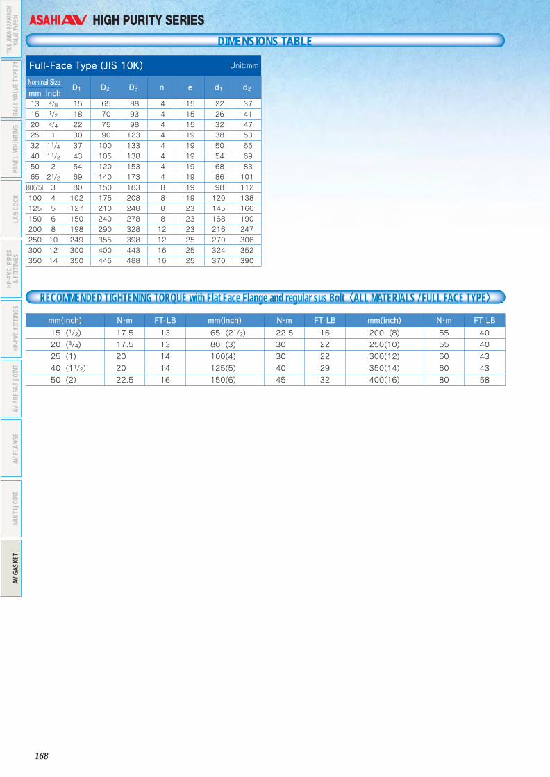
168
HIGH PURITY SERIESDIMENSIONS TABLE
Full-Face Type (JIS 10K) Unit:mm
Nominal SizeD1 D2 D3 n e d1 d2
mm inch13 3/8 15 65 88 4 15 22 37
15 1/2 18 70 93 4 15 26 41
20 3/4 22 75 98 4 15 32 47
25 1 30 90 123 4 19 38 53
32 11/4 37 100 133 4 19 50 65
40 11/2 43 105 138 4 19 54 69
50 2 54 120 153 4 19 68 83
65 21/2 69 140 173 4 19 86 101
80(75) 3 80 150 183 8 19 98 112
100 4 102 175 208 8 19 120 138
125 5 127 210 248 8 23 145 166
150 6 150 240 278 8 23 168 190
200 8 198 290 328 12 23 216 247
250 10 249 355 398 12 25 270 306
300 12 300 400 443 16 25 324 352
350 14 350 445 488 16 25 370 390
mm(inch) N・m FT-LB mm(inch) N・m FT-LB mm(inch) N・m FT-LB
15 (1/2) 17.5 13 65 (21/2) 22.5 16 200 (8) 55 40
20 (3/4) 17.5 13 80 (3) 30 22 250(10) 55 40
25 (1) 20 14 100(4) 30 22 300(12) 60 43
40 (11/2) 20 14 125(5) 40 29 350(14) 60 43
50 (2) 22.5 16 150(6) 45 32 400(16) 80 58
RECOMMENDED TIGHTENING TORQUE with Flat Face Flange and regular sus Bolt〈ALL MATERIALS / FULL FACE TYPE〉
TRUE
UNION
DIAP
HRAG
MVA
LVE T
YPE1
4BA
LL V
ALVE
TYP
E21
PANE
L MO
UNTI
NGLA
B CO
CKHP
-PVC
PIP
ES&
FITT
INGS
HP-P
VC F
ITTI
NGS
AV P
REFA
B JO
INT
AV F
LANG
EMU
LTI-J
OINT
AV G
ASKE
T

169
Asahi AV AV Pipe & FittingsFeatures 171Structure 171Types 172Special Fabrication on Customer’s Request 172Pipes 173Fittings 174Flanges 178
ASAHI AV AV PIPE & FITTINGS
FRP-REINFORCED COMPOSITE PVCThe specifications in this brochure are subject to change without prior notice due to improvements and modifications.

170
PIPE & FITTINGS
171
PIPE & FITTINGS
1. Excellent chemical resistance
Since the inner anticorrosion layer is made of rigid PVC, AV Pipes excel in corrosion resistance and are ideally suited for plants that handle acids, alkalis, and halogens.
2. Great mechanical strength
Since the external surfaces are reinforced with FRP, AV Pipes have great pressure resistance and excellent impact resistance.
3. Good heat resistance
Since the external surfaces are reinforced with FRP, AV Pipes are capable of long service at high temperature.
4. Low coefficient of expansion
Since the PVC and FRP are integrated by special technology,the adhesive strength between the PVC and FRP is high, making the coeffi cient of linear expansion 1/2 that of PVC.
5. No worry about external or electrolytic corrosion
Since the external layer employs FRP, AV Pipe can be used without anxiety even under corrosive environments. Besides, it is a perfact insulator, eliminating any worry about electrolytic corrosion.
6. Lightweight
Made of plastic, AV Pipe is far lighter than metal pipes, which makes piping work at high elevations easier.
7. Ease of installation
TS joining of PVC can be used for on-site installation. FRP lamination can be formed easily at the junctions.
(1) Rigid PVC pipeThe residual stress in the pipe has been removed by a special method unique to AV Pipes.
(2) Surhface-treated portionThe surfaces of the pipe have been treated specially to enhance the adhesive effect of the primer.
(3) Special primerA special primer is used to bond the rigid PVC pipe and FRP layer.
(4) FRP layerA reinforced layer consisting of a lamination of glass fiber impregnated with polyester resin.
(5) Finished surface layerA layer finished with anticorrosion polyester resin.
AV Pipe(SU type) AV Pipe(GU type)
① ② ③ ④ ⑤ ① ② ③ ④ ⑤
PIPE & FITTINGSFRP-REINFORCED COMPOSITE PVC
INFORMATION
As an all-around maker of plastic piping materials, Asahi Organic Chemicals Industry has been developing and marketing AV Pipes since 1963. As PVC pipes whose external surfaces are reinforced with FRP, AV Pipes have been enjoying great popularity.
With the rapid advance of chemical technologies, piping conditions at various types of plants are becoming increasingly sophisticated. Pipes are required to withstand higher temperature and highly corrosive chemicals are used more frequently. To meet these needs, we have made improvements to our products for many years. And we now produce AV pipes that are capable of service at temperature up to 95℃ with higher durability, safety, and reliability to satisfy diverse needs of the customers.
We hope you will favor our AV Pipes, AV valves and Vinyl Pipes with your continued patronage for your piping needs in various fields.
170
Features
Structure

172
PIPE & FITTINGS
173
PIPE & FITTINGS
F.R.P
dD
t
ℓ ℓL
1 1
■Pipe(Plane end type)(Unit:mm)
SizeL ℓ1 D d t
mm inch13 3/8 4000 45 18 13 2.515 1/2 4000 50 22 16 3.020 3/4 4000 55 26 20 3.025 1 4000 60 32 25 3.530 11/4 4000 65 38 31 3.540 11/2 4000 80 48 40 4.050 2 4000 90 60 51 4.565 21/2 4000 95 76 67 4.575 3 4000 100 89 77 6.0100 4 4000 120 114 100 7.0125 5 4000 150 140 125 7.5150 6 4000 180 165 146 9.5200 8 4000 190 216 196 10.0250 10 4000 200 267 247 10.0
*300(SU) 12 4000 200 318 298 10.0*300(GU) 12 4000 200 318 286 16.0350 14 4000 330 370 347 11.5400 16 4000 370 420 394 13.0450 18 4000 400 470 441 14.5500 20 4000 410 520 488 16.0600 24 4000 480 630 592 19.0
■Pipe(Sleeve type) (Unit:mm)
SizeL ℓ1 ℓ d1 1/T D d t
mm inch13 3/8 4000 45 26 18.40 1/30 18 13 2.515 1/2 4000 50 30 22.40 1/34 22 16 3.020 3/4 4000 55 35 26.45 1/34 26 20 3.025 1 4000 60 40 32.55 1/34 32 25 3.530 11/4 4000 65 44 38.60 1/34 38 31 3.540 11/2 4000 80 55 48.70 1/37 48 40 4.050 2 4000 90 63 60.80 1/37 60 51 4.565 21/2 4000 95 61 76.60 1/48 76 67 4.575 3 4000 100 64 89.60 1/49 89 77 6.0100 4 4000 120 84 114.70 1/56 114 100 7.0125 5 4000 150 104 140.80 1/58 140 125 7.5150 6 4000 180 132 166.00 1/63 165 146 9.5200 8 4000 190 145 217.00 1/50 216 196 10.0250 10 4000 200 155 267.70 1/55 267 247 10.0
*300(SU) 12 4000 200 155 318.70 1/55 318 298 10.0*300(GU) 12 4000 200 155 318.70 1/55 318 286 16.0350 14 4000 330 280 373.00 1/43 370 347 11.5400 16 4000 370 320 423.00 1/48 420 394 13.0450 18 4000 400 350 474.00 1/45 470 441 14.5500 20 4000 410 350 524.50 1/50 520 488 16.0600 24 4000 480 410 630.00 ― 630 592 19.0
F.R.P
d d1D
t
ℓ ℓL
1
Taper1/T
SU type
GU type
SU type
GU type
Note: The dimensions of "d" and "t" are different between "SU Type" and "GU Type"at norminal size 300mm.
Note: The dimensions of "d" and "t" are different between "SU Type" and "GU Type"at norminal size 300mm.
Types
Special Fabrication on Customer’s Request
Standard
SU Type(Max Working Temperature : 80℃)
GU Type(Max Working Temperature : 95℃)
※Color is changable on customer’s requests.※Applicable sizes are different in types.
※PP+FRP piping system can be provided by only fabrication.
AV PIPE & FITTINGS
This is a reinforced compound pipe consisting of a PVC pipe and joint that are wound continuously with glass fiber impregnated with polyester resin.
This is an AV pipe upgraded for use at high temperature (95℃) and high pressure by replacing the pr imer layer with a heat resistant primer and reinforcing the FRP layer.
【SU Type】〈Outer Color〉Gray
〈Application〉Regular chemical lineSea water
【PP series】〈Outer Color〉Ivory
〈Application〉Iron IndustryCaustic Soda line
【GU Type】〈Outer Color〉Dark Blue
〈Application〉Chlor Alkali Plant(Cl2 Gas)Iron Industry
【GU-N Type】〈Outer Color〉Purple
〈Application〉Chlor Alkali Plant(Caustic Soda line)
Inner materiall : PVC Inner material : PP
【High Purity Type】〈Outer Color〉Green
〈Application〉High Purity water
PP series(Max Working Temperature : 100℃)
PIPE
SFI
TTIN
GFL
ANGE
S

174
PIPE & FITTINGS
175
PIPE & FITTINGS
Common Dimensions for AV-TS Fittings(Unit:mm)
SizeD d ℓ 1/T
mm inch13 3/8 24 18.40 26 1/3015 1/2 29 22.40 30 1/3420 3/4 33 26.45 35 1/3425 1 40 32.55 40 1/3430 11/4 46 38.60 44 1/3440 11/2 57 48.70 55 1/3750 2 70 60.80 63 1/3765 21/2 87 76.60 61 1/4875 3 102 89.60 64 1/49100 4 130 114.70 84 1/56125 5 157 140.80 104 1/58150 6 186 166.00 132 1/63200 8 236 217.00 145 1/50250 10 287 267.70 155 1/55300 12 337 318.70 155 1/55
■Elbow(90 )゚, Bend(90 )゚
Elbow(Unit:mm)
SizeL ℓ Z D d
mm inch
13 3/8 36 26 10 24 18.40
15 1/2 43 30 13 29 22.40
20 3/4 50 35 15 33 26.45
25 1 58 40 18 40 32.55
30 11/4 65 44 21 46 38.60
40 11/2 82 55 27 57 48.70
50 2 96 63 33 70 60.80
65 21/2 110 61 49 87 76.60
75 3 120 64 56 102 89.60
100 4 153 84 69 130 114.70
125 5 187 104 83 157 140.80
150 6 230 132 98 186 166.00
200 8 265 145 120 240 217.00
250 10 280 140 140 287 267.00
Bend(Unit:mm)
SizeL ℓ Z D d
mm inch
75 3 137 72 65 101 89.80
100 4 172 92 80 129 115.00
125 5 237 112 125 156 141.20
150 6 260 140 120 185 166.50
200 8 341 145 196 236 217.00
250 10 402 155 247 287 267.00
300 12 385 155 230 337 318.00
Lℓ
Z
d D
F.R.P
Taper1/T
d D
L
ℓZ
■Elbow, Bend(45 )゚
Elbow 20~25mm(Unit:mm)
SizeL ℓ Z D d
mm inch
20 3/4 44 35 9 33 26.45
25 1 51 40 11 40 32.55
■Tee(Unit:mm)
SizeL ℓ Z D d
mm inch13 3/8 36 26 10 24 18.4015 1/2 43 30 13 29 22.4020 3/4 50 35 15 33 26.4525 1 58 40 18 40 32.5530 11/4 65 44 21 46 38.6040 11/2 82 55 27 57 48.7050 2 96 63 33 70 60.8065 21/2 110 61 49 87 76.6075 3 120 64 56 102 89.60100 4 152 84 68 130 114.70125 5 187 104 83 157 140.80150 6 230 132 98 166 166.00200 8 266 145 121 240 217.00250 10 295 155 140 287 267.70300 12 340 175 165 337 318.70
45°
d
ℓ
LZ
F.R.P
D
F.R.P
d D
Z ℓ
L L
L
ℓZ
SU type
GU type
SU type
GU type
SU type
GU type
SU type
GU type
Note: The ℓ dimensions of some fittings differ. Please refer to individual dimension table for each fittings.
Bend 40~300mm(Unit:mm)
SizeL ℓ Z D d
mm inch
40 11/2 69 55 14 57 48.70
50 2 80 63 17 70 60.80
65 21/2 81 61 20 87 76.60
75 3 97 72 25 101 89.80
100 4 122 92 30 129 115.00
125 5 149 112 37 156 141.20
150 6 184 140 44 185 166.50
200 8 196 145 51 240 217.00
250 10 213 155 58 287 267.00
300 12 225 155 70 337 318.00
Elbow
Elbow
Bend
Bend
F.R.P
Taper1/T
ℓ
d D
1)ONE SHOT MOLDING PRODUCT
(13mm~300mm)
PIPE
SFI
TTIN
GFL
ANGE
S
PIPE
SFI
TTIN
GFL
ANGE
S

176
PIPE & FITTINGS
177
PIPE & FITTINGS
d1.d2.1/T1 . 1/ T2寸法はチーズの寸法表参照ください。
■Reducing Tee
F.R.P
Z ℓ
Z'
ℓ'
d'
D'
d D
L L
L'
■Socket
■Reducing Socket
L
Z
F.R.P
dD d' D'
ℓ'ℓ
d1.d2.1/T1 . 1/ T2寸法はソケットの寸法表参照ください。
SU type
GU type
SU type
GU type
SU type
GU type
LZ
dD
ℓ
1/TTaper
(Unit:mm)
SizeL ℓ Z D d L' ℓ' Z' D' d'
mm inch15× 13 1/2×3/8 41 30 11 29 22.40 38 26 12 24 18.4020× 13 3/4×3/8 46 35 11 33 26.45 40 26 14 24 18.4020× 15 3/4×1/2 48 35 13 33 26.45 45 30 15 29 22.4025× 13 1×3/8 51 40 11 40 32.55 43 26 17 24 18.4025× 15 1×1/2 53 40 13 40 32.55 48 30 18 29 22.4025× 20 1×3/4 55 40 15 40 32.55 53 35 18 33 26.4530× 13 11/4×3/8 55 44 11 46 38.60 46 26 20 24 18.4030× 15 11/4×1/2 57 44 13 46 38.60 51 30 21 29 22.4030× 20 11/4×3/4 59 44 15 46 38.60 56 35 21 33 26.4530× 25 11/4×1 62 44 18 46 38.60 61 40 21 40 32.5540× 13 11/2×3/8 66 55 11 57 48.70 52 26 26 24 18.4040× 15 11/2×1/2 68 55 13 57 48.70 57 30 27 29 22.4040× 20 11/2×3/4 70 55 15 57 48.70 62 35 27 33 26.4540× 25 11/2×1 73 55 18 57 48.70 67 40 27 40 32.5540× 30 11/2×11/4 76 55 21 57 48.70 71 44 27 46 38.6050× 13 2×3/8 74 63 11 70 60.80 58 26 32 24 18.4050× 15 2×1/2 76 63 13 70 60.80 63 30 33 29 22.4050× 20 2×3/4 78 63 15 70 60.80 68 35 33 33 26.4550× 25 2×1 81 63 18 70 60.80 73 40 33 40 32.5550× 30 2×11/4 84 63 21 70 60.80 77 44 33 46 38.6050× 40 2×11/2 90 63 27 70 60.80 88 55 33 57 48.7065× 40 21/2×11/2 100 61 39 87 76.60 95 55 40 57 48.7065× 50 21/2×2 101 61 40 87 76.60 104 63 41 70 60.8075× 25 3×1 93 64 29 102 89.6 88 40 48 40 32.5575× 40 3×11/2 100 64 36 102 89.6 102 55 47 57 48.7075× 50 3×2 105 64 41 102 89.6 110 63 47 70 60.8075× 65 3×21/2 113 64 49 102 89.6 117 61 56 87 76.60100× 50 4×2 125 84 41 130 114.7 122 63 59 70 60.80100× 75 4×3 140 84 56 130 114.7 132 64 68 102 89.60125×100 5×4 173 104 69 157 140.8 167 84 83 130 114.70150× 75 6×3 195 132 63 186 166.0 158 64 94 102 89.60150×100 6×4 208 132 76 186 166.0 182 84 98 130 114.70150×125 6×5 217 132 85 186 166.0 201 104 97 157 140.80200× 75 8×3 201 145 56 240 217.0 180 64 116 102 89.60200×100 8×4 215 145 70 240 217.0 200 84 116 130 114.70200×150 8×6 238 145 93 240 217.0 253 132 121 186 166.00250× 75 10×3 227 155 72 295 269.3 213 65 148 108 89.60250×100 10×4 246.5 155 91.5 295 269.3 226 84 142 136 114.70250×200 10×8 305 155 150 295 269.3 310 146.5 163.5 246 217.90300× 75 12×3 361 300 60 343 320.7 236 64 172 102 89.60
(Unit:mm)
SizeL ℓ Z D d
mm inch13 3/8 57 26 5 24 18.4015 1/2 67 30 7 29 22.4020 3/4 77 35 7 33 26.4525 1 87 40 7 40 32.5530 11/4 95 44 7 46 38.6040 11/2 117 55 7 57 48.7050 2 133 63 7 70 60.8065 21/2 145 61 23 87 76.6075 3 155 64 27 102 89.60100 4 200 84 32 130 114.70125 5 231 104 23 157 140.80150 6 300 132 36 186 166.00200 8 300 145 10 236 217.00250 10 353 155 43 295 267.00300 12 360 175 10 337 318.00
(Unit:mm)
SizeL ℓ D d ℓ' D' d' Z
mm inch15×13 1/2×3/8 61 30 29 22.40 26 24 18.40 520×13 3/4×3/8 68 35 33 26.45 26 24 18.40 720×15 3/4×1/2 71 35 33 26.45 30 29 22.40 625×13 1×3/8 86 40 40 32.55 26 24 18.40 2025×15 1×1/2 85 40 40 32.55 30 29 22.40 1525×20 1×3/4 84 40 40 32.55 35 33 26.45 930×20 11/4×3/4 93 44 46 38.60 35 33 26.45 1430×25 11/4×1 93 44 46 38.60 40 40 32.55 940×20 11/2×3/4 113 55 57 48.70 35 33 26.45 2340×25 11/2×1 114 55 57 48.70 40 40 32.55 1940×30 11/2×11/4 114 55 57 48.70 44 46 38.60 1550×20 2×3/4 116 63 70 60.80 35 33 26.45 1850×25 2×1 140 63 70 60.80 40 40 32.55 3750×30 2×11/4 136 63 70 60.80 44 46 38.60 2950×40 2×11/2 136 63 70 60.80 55 57 48.70 1865×40 21/2×11/2 145 61 87 76.60 55 57 48.70 2965×50 21/2×2 149 61 87 76.60 63 70 60.80 2575×40 3×11/2 153 64 102 89.60 55 57 48.70 3475×50 3×2 165 64 102 89.60 63 70 60.80 3875×65 3×21/2 159 64 102 89.60 61 87 76.60 34100×75 4×3 190 84 130 114.70 64 102 89.60 42125×100 5×4 229 104 157 140.80 84 130 114.70 41150×100 6×4 295 132 186 166.00 84 130 114.70 79150×125 6×5 272 132 186 166.00 104 157 140.80 36200×150 8×6 356 145 240 217.00 132 186 166.00 79250×200 10×8 383 155 295 269.30 146 240 217.00 82
PIPE
SFI
TTIN
GFL
ANGE
S
PIPE
SFI
TTIN
GFL
ANGE
S

178
PIPE & FITTINGS
179
Additional notesWe can also deliver products prefabricated at our factory.Consider this method for piping with complex shapes.Detailed technical data and installation instructions are available.
■TS Flanges(JIS 10kgf/cm2 Type)(Unit:mm)
SizeL ℓ Z O.D C.D D d T1
T2N-φe
mm inch SU GU13 3/8 30.0 26 4.0 90 65 25.5 18.40 14 2 2.0 4-1515 1/2 35.0 30 5.0 95 70 31.0 22.40 14 5 5.0 4-1520 3/4 40.0 35 5.0 100 75 35.0 26.45 15 5 5.0 4-1525 1 46.0 40 6.0 125 90 42.5 32.55 15 5 5.0 4-1930 11/4 50.5 44 6.5 135 100 48.5 38.60 16 5 5.0 4-1940 11/2 61.5 55 6.5 140 105 60.5 48.70 16 6 6.0 4-1950 2 71.0 63 8.0 155 120 73.0 60.80 20 8 8.0 4-1965 21/2 70.0 61 9.0 175 140 90.0 76.60 22 8 8.0 4-1975 3 73.0 64 9.0 185 150 105.0 89.60 22 8 8.0 8-19100 4 93.0 84 9.0 210 175 131.0 114.7 22 10 10.0 8-19125 5 114.0 104 10.0 250 210 158.0 140.8 24 12 12.0 8-23150 6 142.0 132 10.0 280 240 185.0 166.0 26 2 3.5 8-23200 8 156.0 145 11.0 330 290 238.0 217.0 28 2 3.5 12-23250 10 167.0 155 12.0 400 355 289.0 268.0 30 2 3.5 12-25300 12 167.0 155 12.0 445 400 341.0 318.7 30 2 4.3 16-25
■Flanges(JIS 10kgf/cm2 Type)(Unit:mm)
SizeO.D C.D
T1 T2N-φe
mm inch SU GU SU GU13 3/8 90 65 12 12 2.5 3 4-1515 1/2 95 70 12 12 2.5 3 4-1520 3/4 100 75 14 14 2.5 3 4-1525 1 125 90 14 14 2.5 3 4-1930 11/4 135 100 16 16 2.5 3 4-1940 11/2 140 105 16 16 2.5 3 4-1950 2 155 120 16 16 2.5 3 4-1965 21/2 175 140 18 18 2.5 3 4-1975 3 185 150 18 18 2.5 3 8-19100 4 210 175 18 18 2.5 5 8-19125 5 250 210 20 20 3.0 6 8-23150 6 280 240 22 22 4.0 8 8-23200 8 330 290 22 22 5.0 10 12-23250 10 400 355 24 24 7.0 13 12-25300 12 445 400 24 24 9.0 15 16-25350 14 490 445 25 20 13.0 25 16-25400 16 560 510 25 20 13.0 25 16-27450 18 620 565 25 20 13.0 25 20-27500 20 675 620 25 20 15.0 25 20-27600 24 795 730 30 20 15.0 30 24-33
O.D
C.D d
ZT1 T2
ℓL
N-φeF.R.P
D
T1T2
O,D
C,D
F.R.PN-φe
SU type
GU type
SU type
GU type
GU type
SU type
13A~125A
13A~125A
150A~300A
150A~300A
Note: Products conforming to the JIS 5K and ANSI 150 LBS are also available.
Note: Products conforming to the JIS 5K and ANSI 150 LBS are also available.
ASAHI AV PP PIPE & FITTINGS
The specifications in this brochure are subject to change without prior notice due to improvements and modifications.
・Low leaching into medium.
・High corrosion resistance to acid/alkali application.
・High temperature resistance up to 90℃ .
・Due to superior impact resistance at low temperature, PP piping material is suitable piping material to low temperature application.
・Since PP piping material has small specific gravity (0.91) and simple welding procedure, it provides easier field work at site.
・No dioxin is generated at waste procedure even it would be burnt.
FEATURES
PIPE
SFI
TTIN
GFL
ANGE
S

180
PP SERIES
181
PP SERIES
Range of Nominal Size
Nominal Size(mm)
Indication
Pipe
Socket 90°Elbow
45°Elbow Tee Reducer
Bushing End CapSocketFlange
FlangeAdapter
LooseFlangePN10 PN4
15 d20 ◎ - ◎ ◎ ◎ ◎ - ◎ ◎ ◎ ◎
20 d25 ◎ - ◎ ◎ ◎ ◎ 15 ◎ ◎ ◎ ◎
25 d32 ◎ - ◎ ◎ ◎ ◎ 1520 ◎ ◎ ◎ ◎
32 d40 ◎ - ◎ ◎ ◎ ◎152025
◎ ◎ ◎ ◎
40 d50 ◎ - ◎ ◎ ◎ ◎
15202532
◎ ◎ ◎ ◎
50 d63 ◎ - ◎ ◎ ◎ ◎
20253240
◎ ◎ ◎ ◎
65 d75 ◎ - ◎ ◎ ◎ ◎ 50 ◎ ◎ ◎ ◎
80 d90 ◎ - ◎ ◎ ◎ ◎ 5065 ◎ ◎ ◎ ◎
100 d110 ◎ - ◎ ◎ ◎ ◎ 80 ◎ ◎ ◎ ◎
125 d140 ◎ ◎ ◎ ◎ ◎ ◎ 100 - - ◎ ◎
150 d180 ◎ ◎ ◎ ◎ ◎ ◎ 125 - - ◎ ◎
200 d225 ◎ ◎ ◎ ◎ ◎ ◎ 150 - - ◎ ◎
Nominal Size(mm)
Indication
Welded Flange Blind Flange Prefab JointMale Adapter
Female Adapter
EF-SocketⒿ Ⓟ Ⓠ PP-PP PP×PVC PP×
C-PVC
15 d20 ◎ ◎ ◎ ◎ ◎ ◎ ◎ ◎ ◎
20 d25 ◎ ◎ ◎ ◎ ◎ ◎ ◎ ◎ ◎
25 d32 ◎ ◎ ◎ ◎ ◎ ◎ ◎ ◎ ◎
32 d40 ◎ ◎ ◎ ◎ ◎ ◎ ◎ ◎ ◎
40 d50 ◎ ◎ ◎ ◎ ◎ ◎ ◎ ◎ ◎
50 d63 ◎ ◎ ◎ ◎ ◎ ◎ ◎ ◎ ◎
65 d75 ◎ ◎ ◎ - - - - - ◎
80 d90 ◎ ◎ ◎ - - - - - ◎
100 d110 ◎ ◎ ◎ - - - - - ◎
125 d140 ◎ ◎ ◎ - - - - - ◎
150 d180 ◎ ◎ ◎ - - - - - ◎
200 d225 ◎ ◎ ◎ - - - - - ◎
Welding R
od
Shape Diameter Unit
Single
32kg(Stick type1m)4kg(Scroll type)
42kg(Stick type1m)4kg(Scroll type)
52kg(Stick type1m)4kg(Scroll type)
Double 3 2kg(Stick type1m)
PP PIPE PN10
PP PIPE PN4
SOCKET
45 E゚LBOW
90 E゚LBOW
TEE
END CAP
LOOSE FLANGE
SOCKET FLANGE
FLANGE ADAPTER
FLANGE ADAPTER
WELDED FLANGE
Ⓙ
BLIND FLANGE(P)
Ⓟ
BLIND FLANGE(Q)
Ⓠ
REDUCER BUSHING
PREFAB JOINT
MALE ADAPTER
FEMALE ADAPTER
EF-SOCKET
WELDING ROD

182
PP SERIES
183
PP SERIES
L
tφD
(Unit:mm)
PN10/SDR11
NominalSize(mm)
ProductIndication
D t ApprooximateI.D.
(for reference)
LWeight(kg/m)Basic
Dimension
AverageO.D.Tolerances
BasicDimension Tolerance Basic
Dimension Tolerance
15 d20 20 +0.30 1.9 +0.4
0 16.2
4000 ±10
0.11020 d25 25 +0.3
0 2.3 +0.50 20.4 0.166
25 d32 32 +0.30 3.0 +0.5
0 26.2 0.27132 d40 40 +0.4
0 3.7 +0.60 32.6 0.421
40 d50 50 +0.50 4.6 +0.7
0 40.8 0.64950 d63 63 +0.6
0 5.8 +0.80 51.4 1.028
65 d75 75 +0.70 6.9 +0.9
0 61.4 1.44780 d90 90 +0.9
0 8.2 +1.10 73.6 2.083
100 d110 110 +1.00 10.0 +1.2
0 90.0 3.099125 d140 140 +1.3
0 12.8 +1.50 114.6 5.008
150 d180 180 +1.70 16.4 +1.9
0 147.2 8.250200 d225 225 +2.1
0 20.5 +2.30 184.0 12.864
■ PPpipe(PN10/SDR11)■ PPpipe(PN4/SDR26)
PN4/SDR26
NominalSize(mm)
ProductIndication
D t ApprooximateI.D.
(for reference)
LWeight(kg/m)Basic
Dimension
AverageO.D.Tolerances
BasicDimension Tolerance Basic
Dimension Tolerance
125 d140 140 +1.30 5.4 +0.8
0 129.24000 ±10
2.224150 d180 180 +1.7
0 7.0 +1.00 166.0 3.697
200 d225 225 +2.10 8.7 +1.1
0 207.6 5.702(Note)1.15mm~200mm:DIN8077
2.SDR(Standard Dimension Ratio):(D/t)3.PN10:Working Pressure 1.0MPa(20℃ )4.PN4:Working Pressure 0.4MPa(20℃ )
PPpipe(PN10/SDR11)
tφD
L
PPpipe(PN4/SDR26)
NominalSize(mm)
ProductIndication
d1 d2 ℓ
ℓ1ℓ2
(for reference)BasicDimension
AverageI.D.Tolerances
Circulality(Max)
BasicDimension
AverageI.D.Tolerances
Circulality(Max)(minimum)
15 d20 19.3 0-0.3 0.4 19.5 0
-0.3 0.4 14.5 - -20 d25 24.3 0
-0.4 0.4 24.5 0-0.3 0.4 16 - -
25 d32 31.3 0-0.4 0.5 31.5 0
-0.4 0.5 18 - -32 d40 39.2 0
-0.4 0.5 39.45 0-0.4 0.5 20.5 - -
40 d50 49.2 0-0.5 0.6 49.45 0
-0.5 0.6 23.5 - -50 d63 62.1 0
-0.5 0.6 62.5 0-0.6 0.6 27.5 - -
65 d75 73.95 0-0.5 1 74.25 0
-0.5 1 31 - -80 d90 88.85 0
-0.6 1 89.2 0-0.6 1 35.5 - -
100 d110 108.65 0-0.6 1 109.05 0
-0.6 1 41.5 - -125 d140 139.1 0
-2.0 2.0 139.4 0-2.0 2.0 - 41.5 32.7
150 d180 178.7 0-2.0 2.0 179.1 0
-2.0 2.0 - 50.5 41.7200 d225 223.2 0
-2.0 2.0 223.7 0-2.0 2.0 - 61.0 52.3
(Note)1.15mm~100mm:DIN16962 typeB2.125mm~200mm:AV Standard3. Circulality:The dimension of Max I.D.-Min I.D.
(Unit:mm)
φd1
φd2
ℓ
■ PP Fitting Dimension Common
φd1
φd2
(ℓ2)
ℓ1
15mm~100mm(d20~d110)
125mm~200mm(d140~d225)
■ Socket
■ 90°Elbow
15mm~100mm(d20~d110) 125mm~200mm(d140~d225)
φD
Lz
L
φD
z
NominalSize(mm)
ProductIndication D L z Weight(kg)
15 d20 30.5 35 6 0.01520 d25 35.5 39 7 0.01925 d32 43.5 43 7 0.03032 d40 53.5 48 7 0.04740 d50 66 55 8 0.07950 d63 82 62 7 0.13165 d75 92.5 70 8 0.16180 d90 110 81 10 0.253100 d110 134 96 13 0.431125 d140 172 116 33 0.821150 d180 221 140 39 1.562200 d225 276 167 45 2.820
(Note)1.15mm~100mm:DIN16962-82.125mm~200mm:AV Standard
(Unit:mm)
z90°
L
Lz
φD
NominalSize(mm)
ProductIndication D L z Weight(kg)
15 d20 30.5 28 13.5 0.02320 d25 35.5 32 16 0.03225 d32 43.5 38 20 0.05232 d40 53.5 44 23.5 0.08440 d50 66 51 27.5 0.13650 d63 82 62 34.5 0.25065 d75 92.5 75.5 44.5 0.34080 d90 110 88 52.5 0.526100 d110 134 106 64.5 0.953125 d140 172 142 100.5 1.922150 d180 221 179 128.5 4.058200 d225 276 220 159.0 7.618
(Note)1.15mm~100mm:DIN16962-62.125mm~200mm:AV Standard
(Unit:mm)
125mm~200mm(d140~d225)15mm~100mm(d20~d110)
z
z
90°
L
L
φD

184
PP SERIES
185
PP SERIES
65mm,80mm,100mm(d75,d90,d110)
H
zL
φD
φDz
z
15mm~100mm(d20~d110)
z
z H
L
φD
125mm~200mm(d140~d225)
NominalSize(mm)
ProductIndication D L H z Weight(kg)
15 d20 30.5 57 28.5 14 0.02920 d25 35.5 65 32.5 16.5 0.04125 d32 43.5 76 38 20 0.06032 d40 55 88 44 23.5 0.10840 d50 66 103 51.5 28 0.16350 d63 82 126 63 35.5 0.29265 d75 92.5 152 76 45 0.35880 d90 111 176 88 52.5 0.625100 d110 135 213 106.5 65 1.030125 d140 172 284 142 100.5 1.317150 d180 221 358 179 128.5 4.902200 d225 276 440 220 159.0 9.300
(Note)1.15mm~100mm:DIN16962-72.125mm~200mm:AV Standard
(Unit:mm)
65mm,80mm,100mm(d75,d90,d110)
z
45°
L
Lz φD
φD
125mm~200mm(d140~d225)15mm~100mm(d20~d110)
NominalSize(mm)
ProductIndication D L z Weight(kg)
15 d20 31 21.5 7 0.01820 d25 36 24.5 8.5 0.02525 d32 44 28 10 0.03732 d40 55 34 13.5 0.07040 d50 66 37 13.5 0.10250 d63 82 48 20.5 0.18065 d75 92 51.5 20.5 0.20380 d90 111 59 23.5 0.340100 d110 135.5 69 27.5 0.605125 d140 172 92 50.5 1.299150 d180 221 114 63.5 2.662200 d225 276 140 79.0 4.939
(Note)1.15mm~100mm:DIN16962-62.125mm~200mm:AV Standard
(Unit:mm)
45°
L
L
z
z
φD
■ 45°Elbow
■ Tee
■ Reducer Bushing
■ End Cap
z
L
φD
φd
φd
L
φD z
φD
φd
z
L
20mm×15mm~100mm×80mm(d25×d20~d110×d90)
125mm×100mm~200mm×150mm(d140×d110~d225×d180)
NominalSize(mm)
ProductIndication D d L Z Weight
(kg)
● 20×15 d25×d20 30 25 35 20.5 0.01125×15 d32×d20 30 32 43 28.5 0.016
● 25×20 d32×d25 35 32 38 22 0.01632×15 d40×d20 30 40 50 35.5 0.02232×20 d40×d25 35 40 50 34 0.024
● 32×25 d40×d32 43 40 48 30 0.02940×15 d50×d20 31 50 54 39.5 0.03440×20 d50×d25 36 50 54 38 0.03540×25 d50×d32 43 50 54 36 0.035
● 40×32 d50×d40 54 50 54 33.5 0.05050×20 d63×d25 37 63 65 49 0.05850×25 d63×d32 43 63 65 47 0.05650×32 d63×d40 54 63 64 43.5 0.068
● 50×40 d63×d50 66 63 64 40.5 0.085● 65×50 d75×d63 81 75 61 33.5 0.10580×50 d90×d63 81 90 89 61.5 0.171
● 80×65 d90×d75 92.5 90 70 39 0.148●100×80 d110×d90 112 110 81 45.5 0.267125×100 d140×d110 135.5 140 110 68.5 0.502150×125 d180×d140 172 180 130 88.5 0.971200×150 d225×d180 221 225 160 109.5 1.868
(Note)1.20mm×15mm~100mm×80mm:DIN 16962-92.125mm×100mm~200mm×150mm:AV Standard
(Unit:mm)
NominalSize(mm)
ProductIndication D1 d Z T L
JIS 10KWeight(kg)D C n h
15 d20 30.5 16 15.5 14 30 95 70 4 15 0.09020 d25 35.5 21 15.0 15 31 100 75 4 15 0.10525 d32 43.5 28 13.0 15 31 125 90 4 19 0.16132 d40 53.5 36 12.5 16 33 135 100 4 19 0.19840 d50 66.0 45 10.5 16 34 140 105 4 19 0.21550 d63 82.0 57 9.5 20 37 155 120 4 19 0.31765 d75 92.5 69 23.0 22 54 175 140 4 19 0.45280 d90 110.0 84 18.5 22 54 185 150 8 19 0.473100 d110 134.5 102 12.5 22 54 210 175 8 19 0.613
(Note)Flange Standard is available only JIS 10K.
(Unit:mm)LT
n-φh
z
φd
φD1
φD
P.C.D.C
NominalSize(mm)
ProductIndication D L z Weight
(kg)
15 d20 30 27 12.5 0.01320 d25 36 30 14 0.01925 d32 44 32 14 0.02832 d40 55 36 15.5 0.03940 d50 66 43 19.5 0.07650 d63 85 47 19.5 0.12965 d75 92 63 32 0.16580 d90 111 74 38.5 0.296100 d110 133.5 91 49.5 0.430(Note)DIN16962-8
(Unit:mm)
16mm~40mm(d20~d50) (d63~d110)
50mm~100mm
L
φD
L
φD
z
z
15mm~100mm(d20~d110)
15mm~50mm(d20~d63)
(Note)●markedsize's shape
■ Socket Flange

186
PP SERIES
187
PP SERIES
tφD1
φD2
φD3
ℓe
L
tφD1
φD2
φD3
ℓe
L
φd
30°
NominalSize(mm)
ProductIndication D1 t D2
D3(for reference) e ℓ L±2 d Weight
(kg)
125 d140 140 12.8 182 155 25 105(Minimum) 195 125 5.7150 d180 180 16.4 211 180 30 265(for reference) 350 - 6.9200 d225 225 20.5 262 235 32 250(for reference) 370 200 11.3
(Note)The dimension of "D1""t"are based on DIN8077(PIN10/SDR11)
(unit:mm)
for BUTTERFLY VALVE
φD1
eH
z
φD2
NominalSize(mm)
ProductIndication D1 D2 e H z Weight
(kg)
15 d20 27.5 45 10 21.5 7 0.01520 d25 33.5 56 10 22 6 0.02325 d32 41.5 62 10 24.5 6.5 0.02932 d40 50 74 11 28.5 8 0.04440 d50 61 78 12 32 8.5 0.05250 d63 76 93 14 36 8.5 0.08165 d75 90 106 10.5 35 4 0.09180 d90 109 125 11 43 7.5 0.156100 d110 131 150 12.5 51 9.5 0.254
(Note)DIN16962-12
(unit:mm)
NominalSize(mm)
ProductIndication d
JIS 10Kt Weight
(kg)D C n h
15 d20 28 95 70 4 15 12 0.24320 d25 34 100 75 4 15 12 0.30525 d32 42 125 90 4 19 16 0.47032 d40 51 135 100 4 19 18 0.70840 d50 62 140 105 4 19 18 0.78550 d63 78 155 120 4 19 18 0.89565 d75 92 175 140 4 19 18 1.16580 d90 110 185 150 8 19 20 1.360100 d110 133 210 175 8 19 20 1.695125 d140 158 250 210 8 23 24 2.335150 d180 183 280 240 8 23 24 3.220200 d225 240 330 290 12 23 24 4.230
(Note)1.material : STEEL+PPG lining.2.Products conforming to the DIN and ANSI are also available.
(unit:mm)
φdP.C.D.CφD
t
n-φh
125mm~200mm(d140~d225)
15mm~100mm(d20~d110)
15mm~200mm(d20~d225)
■ Flange Adapter
■ Flange Adapter
■ Loose Flange
φd
P.C.D.CφD
C1C2
T
n-φh
P.C.D.CφD
T
n-φh
Nominal Size(mm)
ProductIndication d
JIS 10 KC1 C2 T
C D n h15 d20 20 70 95 4 15 3 3 1220 d25 25 75 100 4 15 3 3 1425 d32 32 90 125 4 19 3 3 1432 d40 40 100 135 4 19 3 3 1640 d50 50 105 140 4 19 3 3 1650 d63 63 120 155 4 19 3 4 1665 d75 75 140 175 4 19 3 4 1880 d90 90 150 185 8 19 3 4 18100 d110 110 175 210 8 19 3 4 18125 d140 140 210 250 8 23 4 4 20150 d180 180 240 280 8 23 4 4 22200 d225 225 290 330 12 23 4 4 22250 d250 250 355 400 12 25 4 4 24300 d315 315 400 445 16 25 4 4 24
(Note)The dimension of "d" is based on DIN8077 PP pipe O.D.
(unit:mm)
Ⓙ
ⓆⓅ
NominalSize(mm)
DIN Socket(PP) JIS Socket(U-PVC, C-PVC)
d1 d2 ℓ1L±1.5 Z d3 ℓ2 1/T
16(15)19.3 19.50 14.5 41.5 7 22.11 20 1/3420 24.3 24.50 16.0 53.0 13 26.13 24 1/3425 31.3 31.50 18.0 59.0 14 32.16 27 1/34
30(32)39.2 39.45 20.5 65.5 15 38.19 30 1/3440 49.2 49.45 23.5 74.5 14 48.21 37 1/3750 62.1 62.50 27.5 92.0 22.5 60.25 42 1/37
(Note)The dimension of "d1" "d2" "ℓ1"are based on DIN16962.
(unit:mm)
φd1
φD
ℓ1 ℓ2
φd3
z
L
Taper1/T
φd2
2 3 4 1
2 3 4 1
φD
φd2
φd2 φd1
φd1
φd
L
zℓ ℓ
16mm~50mm(d20~d63)
NominalSize(mm)
ProductIndication d d1 d2 ℓ D L z Weight
(kg)
16(15) d20 15 19.3 19.5 14.5 46 40 11 0.03020 d25 20 24.3 24.5 16 57 52 20 0.05625 d32 25 31.3 31.5 18 67 58 22 0.089
30(32) d40 31 39.2 39.45 20.5 79 65 24 0.13340 d50 40 49.2 49.45 23.5 95 74 27 0.21650 d63 51 62.1 62.5 27.5 104 90.5 35.5 0.262
(Note)The dimension of "d1" "d2" "ℓ"are based on DIN16962.
(unit:mm)
No. Discription Pcs. Materials
① BODY 1 PP
② END CONNECTOR 1 PP
③ UNION NUT 1 PP
④ O-RING 1 EPDM、FKM
No. Discription Pcs. Materials
① BODY 1 U-PVC、C-PVC
② END CONNECTOR 1 PP
③ UNION NUT 1 U-PVC、C-PVC
④ O-RING 1 EPDM、FKM
15mm~50mm
■ Welded Flange
■ Blind Flange
■ Prefab Joint (21type) DIN Socket
■ Prefab Joint (21type) DIN- JIS Socket
Parts & Materials
Parts & Materials

188
PP SERIES
189
PP SERIES
φd
H
φD
L
NominalSize(mm)
ProductIndication d D H L Weight
(kg)
15 d20 20 30 36 70 0.04220 d25 25 36 39 78 0.05125 d32 32 44 41 80 0.07132 d40 40 53 46 92 0.09840 d50 50 64 51 104 0.13750 d63 63 80 58 118 0.22465 d75 75 96 64 132 0.34280 d90 90 120 75 146 0.491100 d110 110 137 82 162 0.801125 d140 140 171 100 184 1.344150 d180 180 220 123 212 2.481200 d225 225 273 149 212 3.870
(unit:mm)
NominalSize(mm)
ProductIndication D t d R L ℓ1 ℓ2 Z Weight
(kg)
15 d20 20 1.9 13 R1/2 60 37 15 24 0.00920 d25 25 2.3 18 R3/4 62 40 15 27 0.01225 d32 32 3.0 23 R1 70 44 19 36 0.02132 d40 40 3.7 29 R11/4 76 49 20 46 0.03740 d50 50 4.6 34 R11/2 84 55 21 55 0.05750 d63 63 5.8 45 R2 93 63 22 65 0.095
(Note)1.R:tapere pipe male threads.2.Used for only PP pipe not steel pipe.
(unit:mm)
NominalSize(mm)
ProductIndication D t Rp L ℓ1 ℓ2 Z Weight
(kg)
15 d20 20 1.9 Rp1/2 58 37 16 30 0.01620 d25 25 2.3 Rp3/4 63 40 18 36 0.02225 d32 32 3.0 Rp1 71 44 21 46 0.03932 d40 40 3.7 Rp11/4 79 49 23 55 0.05640 d50 50 4.6 Rp11/2 84 55 24 60 0.07850 d63 63 5.8 Rp2 97 63 29 75 0.138
(Note)1.Rp:Paralle pipe female threads.2.Used for only PP pipe not steel pipe.
(unit:mm)
RpZ
Lℓ1ℓ2
tφD
15mm~50mm(d20~d63)
15mm~50mm(d20~d63)
15mm~200mm(d20~d225)
Variety diameter package unit
Single
32kg(1m rod)4kg(roll type)
42kg(1m rod)4kg(roll type)
52kg(1m rod)4kg(roll type)
Double 3 2kg(1m rod)
■ Male Adapter
■ Female Adapter
■ EF-Socket
■ Welding Rod

190 191
Our engineering department designs, produces and installs pipelines which consist of
valves, regular pipes and composite pipes and equipment such as towers and ducts made
of plastics.
The department has been engaged in piping of many projects for chemical Factories, Steel
mills, Aquariums, Cultivation Sites, Semiconductor Factories, Soda Electrolysis, Swimming
Pools, Sewerage, etc. throughout the world.
Many users are satisfied with our experienced know-how in piping and reliable,
advanced technology.
It is our pleasure to respond to your inquiries including prefabricated products at any
time.
ENGINEERING
191
ASAHI AV TECHNICAL DATAThe specifications in this brochure are subject to change without prior notice due to improvements and modifications.
TECHNICAL DATA FOR ASAHI AV VALVESFLOW CHARACTERISTICS 192WEIGHT LIST 196TECHNICAL DATA TS Method of “ Asahi AV” PVC Pipes 206TECHNICAL DATA FOR AV PIPESInstallation Method 211Intervals between Supports for AV PIPE Type SU and Type GU 212
Conversion Table for Pressure Units 213
PIPE
SJO
INTS
BOLT
, NUT
,W
ASHE
RFL
ANGE
SFI
TTIN
GCE
MENT
OTHE
R

192 193
1. CAPACITY COEFFICIENT 1. 1 Cv VALUEThe Cv value is a coeffi cient that expresses quantitatively (in a numerical value) how much fl uid fl ows through a specifi c value. The concept of the Cv value was fi rst developed by the Fluid Control Institution, USA, in 1958. There are other coeffi cients (absolute numbers) based on a concept similar to that of the Cv value. They are the Av value and the Kv value. On the mainstream in Japan is the Cv value. Since the Kv value was announced in Germany in 1960, there have been trends toward the international unifi cation of these values into a single one. The Cv value is becoming part of the mainstream not only in Japan but internationally as well, at ISO international conferences.
The concept of the capacity coeffi cient can be expressed by the following equation:
[General Equation] C = Q ρ/△P ………………………(1) C;Capacity coeffi cient Q;Flow rate △ P;Diff erential pressure ρ ,G;Specifi c gravityCv value = 1 means that:The diff erential pressure (pressure loss) across the valve is 1PSI{1lb/in2}(about 0.07kgf/cm2) and clean water (concentration ρ= 1) at 60° F (about 15.5℃ ) fl ows at a fl owrate of 1USgal/min (about 0.2271m3/hr). That is,the relationship between fl ow rate and diff erential pressure (pressure loss) is determined by the Cv value. In Japan, diff erential pressure (pressure loss) is expressed in kgf/cm2 instead of PSI. When the fl owrate is expressed in m3/hr, Equation (1) for the capacity coeffi cient becomes something like the following:
Cv = 1.17Q G/ △ P ………………………(2) Cv;Capacity coeffi cient Q; Flowrate (m3/hr) △ P; Diff erential pressure (kgf/cm2) G; Specifi c gravity
1. 2 HOW TO MEASURE Cv VALUEA method of measurement is now available as the standard applicable in JIS B 2005 and IEC 534. An example is outlined below.
Set the diff erential pressure across the sample valve to 0.75kgf/cm2 and measure the rate of fl ow at that time. Then, adjust the diff erential pressure in step from 0.75kgf/cm2 to 0.07kgf/cm2 ( = 1PSI = 1lbf/in2), and measure the fl ow rate(in m3/hr). For large - diameter valves, it is very diffi cult (impossible) to set their diff erential pressure to 0.75kgf/cm2 * 2, begin at the point where the pressure is adjusted progressively, and take measurements up to 0.07kgf/cm2. Substitute the value at that time in equation (2) shown on the last page, then determine the Cv value. This is a "table of Cv values when Asahi AV valves are fully open”Also shown is a "table of Cv values by fl ow qty% us valve opening to" (and subsequent pages), which presents data necessary for valves used for control. The Cv value represent the fl ow characteristics of each valve.
WaterStorageTank
P
<Descriptive sketch>
Pump UpstreamThrottle Valve
Flow Meter Sample Valve
Downstream Throttle Valve
Pressure Tap
Q P1 P2
TECHNICAL DATA FLOW CHARACTERISTICS
1. 3 TABLE Cv VALUE OF "ASAHI AV VALVE" FULLY OPEN
Valve
Nominal Size mm (inch)
13[10]
(3/8)
15
(1/2)
20
(3/4)
25(1)30[32]
(11/4)
40
(11/2)
50(2)
65
(21/2)
80(3)
100
(4)
125
(5)
150
(6)
200
(8)
250
(10)
300
(12)
350
(14)
400
(16)
450
(18)
500
(20)
600
(24)
DIAPHRAGM VALVE TYPE 72 and 15
300
400
700
1000
DIAPHRAGM VALVE TYPE 14
4.8
5.3
8.5
11
26
43
85
115
185
BALL VALVE TYPE 21
7.7
14
29
47
72
155
190
365
410
680
3-WAY BALL VALVE (L-port)
7.4
10
23
43
59
130
260
3-WAY BALL VALVE (Double-L-port)
6.3
8.5
20
36
45
99
200
3-WAY BALL VALVE (Closs-port)
7.8
13
23
65
98
COMPACT BALL VALVE
7.7
14
29
47
72
140
185
410
BUTTERFLY VALVE TYPE 57, 56 and 75
71
120
250
300
470
830
110025003860570064408340108901406018500
BUTTERFLY VALVE TYPE 57L (Lug Style)
300
470
1100
BUTTERFLY VALVE TYPE 55
100
285
600
940
150025004200
STOP VALVE "GLOVE VALVE"
4.1
6.4
9.7
18
22
29
57
78
115
STOP VALVE "GLOVE VALVE"(needle type)
3.3
5.2
7.5
19
28
58
85
109
GATE VALVE (P-type)
130
180
415
470
690
100014002900370052007000
GATE VALVE (S-type)
130
180
415
470
690
1000140029003700
BALL CHECK VALVE
6.5
17
25
86
130
280
500
SWING CHECK VALVE
14
24
81
140
250
280
510
750
11001900
STRAINER (Y)
5.2
7.5
14
34
50
110
165
BALL FOOT VALVE
6.5
17
25
86
130
280
500
Valve
Nominal Size (mm)
1/4, 1/2, 3/8
15
(6mm)
15
(15mm)
20
(6mm)
20
(15mm)
25
(6mm)
25
(15mm)
LAB COCK
1.6
--
--
--
NEEDLE VALVE
-0.7
4.5
0.7
4.5
0.7
6
PDCPD BUTTERFLY VALVE
Valve (inch)
700(28)
800(32)
900(36)
1,000(40)
1,100(44)
1,200(48)
Cv Value
32,000
43,000
55,000
70,000
86,000
100,000

194 195
Diaphragm Valve
A→B
A→B, A→C Valve travel(%)A→C
A-BA-C
C→A
C→A
C-A
L-port(180 )゚0゜ 90゜ 180゜
Double-L-port(90 )゚0゜ 45゜ 90゜
Closs port0゜ 45゜ 90゜
Closs port0゜
A B
C
A B
C
90゜45゜
Cv Value (%)
Opening Degree (%)
Cv Value (%)
Opening Degree (%)
Cv Value (%)
Opening Degree (%)
Cv Value (%)
Opening Degree (%)
Cv Value (%)
Opening Degree (%)
Cv Value (%)
Opening Degree (%) Opening Degree (%)
Cv Value (%)
3-WAY BALL VALVE TYPE 23(L-port)
BALL VALVE TYPE 21 COMPACT BALL VALVE
3-WAY BALL VALVE TYPE 23(Double-L-port)
3-WAY BALL VALVE TYPE 23(Closs-port)
LAB COCK
3-WAY BALL VALVE TYPE 23(Closs-port)
Ball Valve
DIAPHRAGM VALVE TYPE 14
Cv Value (%)
Opening Degree (%)
Cv Value (%)
Opening Degree (%)
DIAPHRAGM VALVE TYPE 15,72
Nom size 15mm~50mm
Nom size 65mm~100mm
BUTTERFLY VALVE TYPE 56, 75
Cv Value (%)
Butterfly Valve
Gate Valve
GATE VALVE (P-Type)
Cv Value (%)
Opening Degree (%)
GATE VALVE (S-Type)
Cv Value (%)
Opening Degree (%)
BUTTERFLY VALVE TYPE 57,TYPE 57L (Lug Style)
Cv Value (%)
PDCPD BUTTERFLY VALVE
Cv Value (%)
Opening Degree (%)
BUTTERFLY VALVE TYPE 55
Cv Value (%)
Opening Degree (%)

196 197
Flanged Unit:kg, Lb
Body PVC C-PVC PP PVDF PVDFTypeBonnet PVC PP PP PPG PVDF
Unit kg Lb kg Lb kg Lb kg Lb kg Lb
Nominal Size
15 1/2 0.7 1.5 0.7 1.5 0.6 1.3 0.8 1.8 0.8 1.8
14
20 3/4 0.8 1.8 0.8 1.8 0.6 1.3 0.9 2.0 0.9 2.025 1 1.1 2.4 1.1 2.4 0.8 1.8 1.2 2.6 1.3 2.932 11/4 1.4 3.1 1.4 3.1 1.0 2.2 1.5 3.3 1.6 3.540 11/2 2.8 6.2 2.7 6.0 2.2 4.9 2.9 6.4 3.1 6.850 2 3.6 7.9 3.5 7.7 2.8 6.2 3.9 8.6 4.1 9.065 21/2 5.6 12.3 5.3 11.7 4.2 9.3 6.0 13.2 6.5 14.380 3 7.4 16.3 7.2 15.9 5.4 11.9 7.4 16.3 8.4 18.5100 4 11.5 25.4 12.6 27.8 8.3 18.3 12.5 27.5 13.1 28.9125 5 22.0 48.5 ― ― 19.5 43.0 23.5 51.8 26.3 58.0
15150 6 34.5 76.1 ― ― 30.5 67.3 35.5 78.3 40.7 89.7200 8 52.6 116.0 ― ― 45.0 99.2 57.3 126.3 62.3 137.4
72250 12 93.3 205.7 ― ― 77.3 170.4 97.6 215.2 110.2 243.0
True Union (Socket) Unit:kg, Lb
Body PVC C-PVC PP PVDF PVDFTypeBonnet PVC PP PP PPG PVDF
Unit kg Lb kg Lb kg Lb kg Lb kg Lb
Nominal Size
15 1/2 0.5 1.1 0.5 1.1 0.4 0.9 0.6 1.3 0.6 1.3
True Union14
20 3/4 0.6 1.3 0.6 1.3 0.5 1.1 0.7 1.5 0.7 1.525 1 0.9 2.0 0.9 2.0 0.7 1.5 1.0 2.2 1.1 2.432 11/4 1.1 2.4 1.1 2.4 0.8 1.8 1.2 2.6 1.3 2.940 11/2 2.6 5.7 2.5 5.5 2.0 4.4 2.7 6.0 2.9 6.450 2 2.9 6.4 2.8 6.2 2.3 5.1 3.1 6.8 3.3 7.3
mm inch
mm inch
DIAPHRAGM VALVE
TECHNICAL DATA WEIGHT LIST
Type 21 Unit:kg, Lb
Type Flanged Threaded Socket・Spigot
MaterialNominal Size
PVC C-PVC PP PVDF PVC C-PVC PP PVDF PVC C-PVC PP PVDFkg Lb kg Lb kg Lb kg Lb kg Lb kg Lb kg Lb kg Lb kg Lb kg Lb kg Lb kg Lb
15mm 1/2 inch 0.4 0.9 0.4 0.9 0.3 0.7 0.5 1.1 0.2 0.4 0.2 0.4 0.2 0.4 0.2 0.4 0.2 0.4 0.2 0.4 0.2 0.4 0.2 0.4
20 3/4 0.6 1.3 0.7 1.5 0.5 1.1 0.7 1.5 0.3 0.7 0.3 0.7 0.3 0.7 0.4 0.9 0.3 0.7 0.3 0.7 0.3 0.7 0.3 0.7
25 1 0.8 1.8 0.9 2.0 0.7 1.5 1.0 2.2 0.4 0.9 0.5 1.1 0.4 0.9 0.5 1.1 0.5 1.1 0.5 1.1 0.4 0.9 0.5 1.1
32 11/4 1.2 2.6 1.3 2.9 0.9 2.0 1.5 3.3 0.7 1.5 0.7 1.5 0.6 1.3 0.8 1.8 0.7 1.5 0.7 1.5 0.5 1.1 0.7 1.5
40 11/2 1.7 3.7 1.8 4.0 1.2 2.6 2.0 4.4 1.1 2.4 1.2 2.6 0.7 1.5 1.3 2.9 1.0 2.2 1.0 2.2 0.8 1.8 1.2 2.6
50 2 2.5 5.5 2.7 6.0 1.8 4.0 3.7 8.2 1.8 4.0 2.0 4.4 1.2 2.6 2.2 4.9 1.8 3.9 1.8 4.0 1.2 2.6 2.0 4.4
65 21/2 3.3 7.3 3.5 7.7 2.4 5.3 4.0 8.8 2.3 5.1 2.5 5.5 1.7 3.7 2.8 6.2 2.4 5.3 2.6 5.7 1.7 3.7 2.8 6.2
80 3 4.9 10.8 5.5 12.1 3.4 7.5 5.7 12.6 3.7 8.2 4.0 8.8 2.5 5.5 4.5 9.9 3.8 8.4 4.1 9.0 2.4 5.3 4.4 9.7
100 4 10.5 23.2 10.6 23.4 7.0 15.4 12.1 26.7 8.8 19.4 9.9 21.8 6.0 13.2 11.3 24.9 9.2 20.3 9.9 21.8 6.0 13.2 10.8 23.8
Compact Ball Valve Unit:kg, Lb
Type Socket・Threaded
MaterialNominal Size
PVC C-PVCkg Lb kg Lb
13 1/2 0.10 0.2 0.10 0.2
15 1/2 0.12 0.3 0.15 0.3
20 3/4 0.21 0.5 0.25 0.6
25 1 0.32 0.7 0.40 0.9
32 11/4 0.50 1.1 0.55 1.2
40 11/2 0.57 1.3 0.60 1.3
50 2 0.86 1.9 1.00 2.2
80 3 2.50 5.5 3.00 6.6
3-Way Ball Valve Type 23 Unit:kg, Lb
Type Flanged Socket Threaded
MaterialNominal Size
PVC C-PVC PP PVDF PVC C-PVC PP PVDF PVC C-PVC PP PVDFkg Lb kg Lb kg Lb kg Lb kg Lb kg Lb kg Lb kg Lb kg Lb kg Lb kg Lb kg Lb
15mm 1/2 inch 0.5 1.1 0.5 1.1 0.3 0.7 0.6 1.3 0.2 0.4 0.2 0.4 0.1 0.2 0.2 0.4 0.2 0.4 0.3 0.7 0.2 0.4 0.4 0.9
20 3/4 0.8 1.8 0.9 2.0 0.5 1.1 0.9 2.0 0.4 0.9 0.4 0.9 0.2 0.4 0.4 0.9 0.4 0.9 0.4 0.9 0.2 0.4 0.4 0.9
25 1 1.3 2.9 1.4 3.1 0.8 1.8 1.5 3.3 0.6 1.3 0.6 1.3 0.4 0.9 0.7 1.5 0.6 1.3 0.6 1.3 0.4 0.9 0.7 1.5
32 11/4 2.2 4.9 2.4 5.3 1.4 3.1 2.6 5.7 1.3 2.9 1.4 3.1 0.8 1.8 1.5 3.3 1.4 3.1 1.5 3.3 0.9 2.0 1.7 3.7
40 11/2 2.2 4.9 2.4 5.3 1.4 3.1 2.6 5.7 1.3 2.9 1.4 3.1 0.8 1.8 1.5 3.3 1.4 3.1 1.5 3.3 0.9 2.0 1.7 3.7
50 2 3.5 7.7 3.7 8.2 2.2 4.9 4.0 8.8 2.5 5.5 2.7 6.0 1.6 3.5 2.9 6.4 2.6 5.7 2.8 6.2 1.7 3.7 3.1 6.8
65 21/2 7.0 15.4 7.5 16.5 4.4 9.7 8.5 18.7 5.8 12.9 5.8 12.9 3.5 7.7 6.8 15.0 5.5 12.1 6.0 13.2 3.5 7.7 6.5 14.3
80 3 7.0 15.4 7.5 16.5 4.4 9.7 8.5 18.7 6.0 13.2 6.0 13.2 3.6 7.9 7.0 15.4 5.5 12.1 6.0 13.2 3.5 7.7 6.5 14.3
100 4 14.0 30.9 15.0 33.1 9.0 19.8 16.5 36.4 13.5 29.8 14.0 30.9 8.5 18.7 15.5 34.2 13.0 28.7 14.0 30.9 8.5 18.7 15.5 34.2
Lab Cock Unit:g, Lb
Material
Connection Standard
PVC
g Lb
1/4inch Male Thread×1/4inch Male Thread 25 0.061/2inch Male Thread×1/2inch Male Thread 30 0.071/4inch Female Thread×1/4inch Female Thread 30 0.073/8inch Female Thread×3/8inch Female Thread 30 0.071/4inch Hose×1/4inch Hose 25 0.061/2inch Male Thread×Elbow 16mm 55 0.12
mm inch
BALL VALVE
UnitUnit
Unit
Unit

198 199
LEVER TYPE/GEAR TYPE Unit:kg, Lb
Type 57, 56, 75 Type 56D, 75D Type 57L(Lug Style) Type 55 Damper Style
PVC/PP PP/PP PVDF/PVDF PDCPD PDCPD FCD-S PVC/PP PP/PP PVDF/PVDF
LEVER GEAR LEVER GEAR LEVER GEAR GEAR LEVER GEAR LEVER GEAR LEVER GEAR LEVER GEAR LEVER GEAR
kg Lb kg Lb kg Lb kg Lb kg Lb kg Lb kg Lb kg Lb kg Lb kg Lb kg Lb kg Lb kg Lb kg Lb kg Lb kg Lb kg Lb
40 11/2 1.3 2.9 3.4 7.5 1.1 2.4 3.1 6.8 1.4 3.1 3.5 7.7 ̶ ̶ ̶ ̶ ̶ ̶ ̶ 1.1 2.4 3.1 6.9 0.9 2.0 3.0 6.6 1.4 3.1 3.3 7.3
50 2 1.5 3.3 3.5 7.7 1.2 2.6 3.3 7.3 1.7 3.7 3.8 8.4 ̶ ̶ ̶ ̶ ̶ ̶ 3.0 6.6 5.0 11.0 1.3 2.9 3.3 7.3 1.0 2.2 3.1 6.9 1.7 3.7 3.6 8.0
65 21/2 1.7 3.7 3.8 8.4 1.4 3.1 3.4 7.5 1.9 4.2 4.0 8.8 ̶ ̶ ̶ ̶ ̶ ̶ ̶ 1.5 3.3 3.5 7.8 1.2 2.6 3.3 7.3 2.0 4.4 3.7 8.1
80 3 1.9 4.2 3.9 8.6 1.6 3.5 3.6 7.9 2.2 4.9 4.2 9.3 ̶ ̶ 2.8 6.2 4.9 10.8 4.5 9.9 6.5 14.3 1.7 3.7 3.7 8.2 1.3 2.9 3.4 7.5 2.3 5.1 4.0 8.8
100 4 2.5 5.5 4.5 9.9 2.0 4.4 4.0 8.8 2.9 6.4 4.9 10.8 ̶ ̶ 3.5 7.7 5.6 12.4 6.0 13.2 8.0 17.6 2.2 4.9 4.2 9.3 1.7 3.7 3.8 8.4 3.1 6.9 4.8 10.6
125 5 4.9 10.8 6.5 14.3 4.0 8.8 5.6 12.3 5.7 12.6 7.3 16.1 ̶ ̶ 6.9 15.2 9.0 19.9 10.5 23.2 11.5 25.4 4.4 9.7 6.0 13.2 3.5 7.7 5.1 11.3 5.3 11.7 6.9 15.3
150 6 5.8 12.8 7.4 16.3 4.6 10.1 6.2 13.7 6.9 15.2 8.5 18.7 ̶ ̶ 8.1 17.9 9.6 21.2 ̶ 14.5 32.0 5.3 11.7 6.9 15.2 4.2 9.3 5.8 12.8 6.6 14.6 8.1 17.9
200 8 9.3 20.5 10.7 23.6 7.4 16.3 8.9 19.6 11.0 24.3 12.5 27.6 ̶ ̶ 15.0 33.2 16.5 36.5 ̶ 23.0 50.7 8.4 18.5 9.9 21.8 6.6 14.5 8.1 17.9 10.1 22.3 12.0 26.5
250 10 ̶ 14.7 32.4 ̶ 12.2 26.9 ̶ 18.6 41.0 ̶ ̶ ̶ ̶ 22.7 50.2 ̶ 32.9 72.6 11.2 24.7 13.7 30.2 8.0 17.6 10.5 23.2 22.5 49.6 25.0 55.1
300 12 ̶ 28.0 61.7 ̶ 24.0 52.9 ̶ 34.5 76.1 ̶ ̶ ̶ ̶ ̶ ̶ ̶ 17.0 37.5 22.5 49.6 15.0 33.1 20.5 45.2 32.7 72.1 38.2 84.2
350 14 ̶ 30.2 66.6 ̶ 26.3 58.0 ̶ 36.8 81.1 ̶ ̶ ̶ ̶ ̶ ̶ ̶ 19.0 41.9 24.5 54.0 16.0 35.3 21.5 47.4 35.2 77.6 40.7 89.7
400 16 ̶ ̶ 36.0 79.4 ̶ 46.0 101.4 47 103 ̶ ̶ ̶ ̶ ̶ ̶ 22.0 48.5 27.5 60.6 48.5 106.9 54.0 119.1
450 18 ̶ ̶ 63.5 140.0 ̶ 103.0 227.1 100 221 ̶ ̶ ̶ ̶ ̶ ̶ 28.0 61.7 33.5 73.9 50.0 110.3 55.5 122.4
500 20 ̶ ̶ 77.0 169.8 ̶ 124.0 273.1 114 252 ̶ ̶ ̶ ̶ ̶ ̶ 36.0 79.4 41.5 91.5 57.5 126.8 63.0 138.9
600 24 ̶ ̶ 114.0 251.4 ̶ 157.0 346.2 140 309 ̶ ̶ ̶ ̶ ̶ ̶ 66.0 145.5 71.5 157.7 79.0 174.2 84.5 186.3
Unit:kg, Lb
Type 40mm(11/2inch)
50mm(2inch)
65mm(21/2inch)
80mm(3inch)
100mm(4inch)
125mm(5inch)
150mm(6inch)
200mm(8inch)
250mm(10inch)
300mm(12inch)
350mm(14inch)
Unit kg Lb kg Lb kg Lb kg Lb kg Lb kg Lb kg Lb kg Lb kg Lb kg Lb kg Lb
TYPE-P Non-Rising
Hand Wheel 2.5 5.5 3.5 7.7 5.5 12.1 7.0 15.4 8.5 18.7 13.5 29.8 19.5 43.0 29.5 65.0 42.0 92.6 68.0 149.9 81.5 179.7
Cap 3.5 7.7 4.5 9.9 6.0 13.2 8.0 17.6 9.5 20.9 14.5 32.0 20.0 44.1 30.0 66.2 43.0 94.8 68.5 151.0 82.0 180.8
TYPE-S
Non-Rising
Hand Wheel 3.0 6.6 4.0 8.8 5.5 12.1 8.0 17.6 12.5 27.6 15.0 33.1 22.5 49.6 31.5 69.5 ー ー ー
Cap 4.0 8.8 5.0 11.0 6.0 13.2 9.0 19.8 13.0 28.7 15.5 34.2 23.0 50.7 32.0 70.6 ー ー ー
RisingHand Wheel 3.2 7.1 4.5 9.9 7.5 16.5 8.3 18.3 12.6 27.8 24.0 52.9 24.8 54.7 44.5 98.1 71.0 156.6 ー ー
Cap ー ー ー ー 13.0 28.7 ー 25.7 56.7 35.0 77.2 60.0 132.3 ー ー
Flanged
BUTTERFLY VALVE
Nominal Sizemm(inch)
Material
Name
GATE VALVE
Nominal Size ㎜(inch)
Name
700(28) 800(32) 900(36) 1000(40) 1100(44) 1200(48)
kg Lb kg Lb kg Lb kg Lb kg Lb kg Lb
PDCPD(Manual) 380 839 460 1013 550 1213 830 1830 1000 2205 1100 2425
Unit:kg, Lb
Unit
Unit
Flanged Unit:kg, Lb
SWINGCHECK VALVE
Unit:kg, Lb
BALLCHECK VALVE
Unit:kg, Lb
Y-SEDIMENT STRAINER
MaterialNominal Size
HI-PVC PP PVDFkg Lb kg Lb kg Lb
15mm 1/2 inch 0.8 1.8 0.6 1.3 1 2.2 20 3/4 0.9 2.0 0.6 1.3 1 2.2 25 1 1.7 3.7 1.2 2.6 2 4.4 32 11/4 2.6 5.7 1.7 3.7 3 6.6 40 11/2 2.6 5.7 1.7 3.7 3 6.6 50 2 4 8.8 2.7 6.0 4.6 10.1 65 21/2 5.5 12.1 3.5 7.7 6.5 14.3 80 3 6 13.2 4 8.8 7.5 16.5 100 4 10.5 23.2 7 15.4 12 26.5 125 5 16 35.3 12 26.5 20 44.1 150 6 22 48.5 16 35.3 27 59.5 200 8 34.5 76.1 24.5 54.0 42 92.6
Type Flanged Threaded Socket, Spigot
MaterialNominal Size
U-PVC C-PVC PVDF U-PVC C-PVC PP PVDF U-PVC C-PVC PP PVDFkg Lb kg Lb kg Lb kg Lb kg Lb kg Lb kg Lb kg Lb kg Lb kg Lb kg Lb
15mm 1/2 inch 0.3 0.6 0.3 0.7 0.3 0.7 0.1 0.2 0.1 0.2 0.1 0.1 0.1 0.2 0.1 0.2 0.1 0.2 0.1 0.1 0.1 0.2 20 3/4 0.4 0.8 0.4 0.9 0.5 1.0 0.2 0.3 0.2 0.4 0.1 0.2 1.2 2.6 0.2 0.4 0.2 0.4 0.1 0.2 0.2 0.4 25 1 0.6 1.3 0.7 1.4 0.7 1.5 0.3 0.6 0.3 0.6 0.2 0.4 0.3 0.7 0.3 0.6 0.3 0.6 0.2 0.3 0.3 0.7 40 11/2 1.1 2.4 1.1 2.4 1.3 2.9 0.6 1.3 0.7 1.4 0.4 0.9 0.7 1.5 0.6 1.3 0.6 1.4 0.3 0.7 0.7 1.5 50 2 1.8 3.9 1.6 3.5 1.8 4.0 0.8 1.9 0.9 1.9 0.6 1.3 1 2.2 0.8 1.8 0.9 1.9 0.5 1.1 1.1 2.4 80 3 4 8.8 4.3 9.5 4.9 10.8 2.2 4.9 2.4 5.3 1.5 3.3 2.9 6.4 2.4 5.3 2.6 5.7 1.5 3.3 2.8 6.2 100 4 7.2 15.9 11.0 24.3 12 26.5 5.8 12.8 6.2 13.7 3.7 8.2 7 15.4 5.9 13.0 6.1 13.4 3 6.6 6.5 14.3
Type Flanged Threaded SocketMaterial
Nominal SizeU-PVC U-PVC U-PVCkg Lb kg Lb kg Lb
15mm 1/2 inch 0.5 1.1 0.3 0.6 0.3 0.6 20 3/4 0.8 1.8 0.5 1.1 0.5 1.0 25 1 1.2 2.6 0.8 1.7 0.7 1.5 32 11/4 2.5 5.5 2.0 4.4 2.0 4.4 40 11/2 2.2 4.9 1.6 3.5 1.5 3.3 50 2 2.8 6.2 1.9 4.2 1.8 4.0 65 21/2 6.3 13.9 5.3 11.7 5.4 11.9 80 3 6.5 14.3 6.0 13.2 5.4 11.9 100 4 20.5 45.2 19.5 43.0 18.0 39.7
Unit:kg, Lb
CONSTANT FLOW VALVE
Type FlangedMaterial
Nominal SizeU-PVC
kg Lb15mm 1/2 inch 1.4 30.920 3/4 1.5 3325 1 1.5 3350 2 5 110.380 3 8.5 187.4100 4 16.5 363.8

200 201
TECHNICAL DATA AUTOMATIC VALVES WEIGHT LIST
Type 21Driving Method Pneumatic Actuator
Actuator TypeType TA
Air to Open, Air to Close
Type of Connection Flanged End Threaded End Socket End
Body Material PVC C-PVC PP PVDF PVC C-PVC PP PVDF PVC C-PVC PP PVDF
Unit kg Lb kg Lb kg Lb kg Lb kg Lb kg Lb kg Lb kg Lb kg Lb kg Lb kg Lb kg Lb
Nominal Size (mm)
15 3.5 7.7 3.5 7.7 3.5 7.7 3.5 7.7 3.5 7.7 3.5 7.7 3.5 7.7 3.5 7.7 3.5 7.7 3.5 7.7 3.5 7.7 3.5 7.720 4.0 8.8 4.0 8.8 3.5 7.7 4.0 8..8 3.5 7.7 3.5 7.7 3.5 7.7 3.5 7.7 3.5 7.7 3.5 7.7 3.5 7.7 3.5 7.7
25 4.0 8.8 4.0 8.8 4.0 8.8 4.0 8.8 3.5 7.7 3.5 7.7 3.5 7.7 3.5 7.7 3.5 7.7 4.0 8.8 3.5 7.7 3.5 7.7
32 4.5 9.9 4.5 9.9 4.0 8.8 4.5 9.9 4.0 8.8 4.0 8.8 3.5 7.7 4.0 8.8 4.0 8.8 4.0 8.8 ― 4.0 8.8
40 5.0 11.0 5.5 12.1 4.5 9.9 5.5 12.1 4.5 9.9 4.5 9.9 4.0 8.8 5.0 11.0 4.5 9.9 4.5 9.9 4.0 8.8 4.5 9.9
50 6.0 13.2 6.0 13.2 5.0 11.0 6.0 13.2 5.5 12.1 5.5 12.1 4.5 9.9 5.5 12.1 5.0 11.0 5.0 11.0 4.5 9.9 5.5 12.1
65 9.5 20.9 9.5 20.9 8.5 18.7 10.0 22.1 8.5 18.7 8.5 18.7 8.0 17.6 9.0 19.8 8.5 18.7 8.5 18.7 8.0 17.6 9.0 19.8
80 14.5 32.0 15.0 33.1 13.0 28.7 15.5 34.2 13.5 29.8 14.0 30.9 12.0 26.5 14.5 32.0 14.0 30.9 14.0 30.9 12.5 27.6 14.5 32.0100 20.0 44.1 21.0 46.3 17.0 37.5 22.0 48.5 19.5 43.0 20.0 44.1 16.5 36.4 21.0 46.3 20.0 44.1 20.0 44.1 16.5 36.4 21.0 46.3
Unit:kg, Lb
BALL VALVE
Type 21Driving Method Pneumatic Actuator
Actuator TypeType AA
Double Acting
Type of Connection Flanged End Threaded End Socket End
Body Material PVC C-PVC PP PVDF PVC C-PVC PP PVDF PVC C-PVC PP PVDF
Unit kg Lb kg Lb kg Lb kg Lb kg Lb kg Lb kg Lb kg Lb kg Lb kg Lb kg Lb kg Lb
Nominal Size (mm) 15 1.0 2.2 1.0 2.2 0.9 2.0 1.1 2.4 0.8 1.8 0.8 1.8 0.7 1.5 0.8 1.8 0.8 1.8 0.8 1.8 0.7 1.5 0.7 1.5
20 1.2 2.6 1.2 2.6 1.0 2.2 1.2 2.6 0.9 2.0 0.9 2.0 0.9 2.0 1.0 2.2 1.1 2.4 0.9 2.0 0.7 1.5 0.9 2.0
25 1.5 3.3 1.6 3.5 1.2 2.6 1.5 3.3 1.0 2.2 1.1 2.4 0.9 2.0 1.1 2.4 1.3 2.9 1.2 2.6 0.8 1.8 1.0 2.2
32 1.9 4.2 2.0 4.4 1.4 3.1 2.0 4.4 1.3 2.9 1.3 2.9 1.0 2.2 1.5 3.3 2.0 4.4 1.3 2.9 ― 1.2 2.6
40 2.6 5.7 2.7 6.0 2.0 4.4 2.7 6.0 1.9 4.2 2.0 4.4 1.6 3.5 2.2 4.9 2.5 5.5 1.9 4.2 1.5 3.3 2.0 4.450 3.4 7.5 3.6 7.9 2.5 5.5 3.6 7.9 2.7 6.0 2.8 6.2 2.0 4.4 3.1 6.8 2.8 6.2 2.6 5.7 1.9 4.2 2.8 6.2
Unit:kg, Lb
Type 21Driving Method Electric Actuator
Actuator Type Type T
Type of Connection Flanged End Threaded End Socket End
Body Material PVC C-PVC PP PVDF PVC C-PVC PP PVDF PVC C-PVC PP PVDF
Unit kg Lb kg Lb kg Lb kg Lb kg Lb kg Lb kg Lb kg Lb kg Lb kg Lb kg Lb kg Lb
Nominal Size (mm)
15 2.5 5.5 2.5 5.5 2.5 5.5 2.5 5.5 2.5 5.5 2.5 5.5 2.5 5.5 2.5 5.5 2.5 5.5 2.5 5.5 2.5 5.5 2.5 5.520 3.0 6.6 3.0 6.6 2.5 5.5 3.0 6.6 2.5 5.5 2.5 5.5 2.5 5.5 2.5 5.5 2.5 5.5 2.5 5.5 2.5 5.5 2.5 5.5
25 3.0 6.6 3.0 6.6 3.0 6.6 3.0 6.6 2.5 5.5 2.5 5.5 2.5 5.5 3.0 6.6 2.5 5.5 2.5 5.5 2.5 5.5 3.0 6.6
32 3.0 6.6 3.5 7.7 3.0 6.6 3.5 7.7 3.0 6.6 3.0 6.6 ― ― 3.0 6.6 3.0 6.6 3.0 6.6 2.5 5.5 3.0 6.6
40 3.5 7.7 3.5 7.7 3.0 6.6 4.0 8.8 3.0 6.6 3.5 7.7 3.0 6.6 3.5 7.7 3.0 6.6 3.5 7.7 3.0 6.6 3.5 7.7
50 4.0 8.8 4.5 9.9 3.5 7.7 4.5 9.9 4.0 8.8 4.0 8.8 3.5 7.7 4.0 8.8 4.0 8.8 4.0 8.8 3.5 7.7 4.0 8.8
65 7.0 15.4 7.0 15.4 6.0 13.2 7.5 16.5 6.0 13.2 6.5 15.4 6.0 13.2 6.5 14.3 6.0 13.2 6.5 14.3 6.0 13.2 6.5 14.3
80 8.0 17.6 8.0 17.6 6.5 14.3 8.5 18.7 7.0 15.4 7.5 19.8 6.0 13.2 7.5 16.5 7.0 15.4 7.5 16.5 6.5 14.3 7.5 16.5100 11.5 25.4 12.0 26.5 9.0 19.8 12.5 27.6 11.0 24.3 11.0 33.1 8.5 18.7 12.0 26.5 11.0 24.3 11.0 24.3 8.5 18.7 12.0 26.5
Unit:kg, Lb
Type 21Driving Method Pneumatic Actuator
Actuator TypeType TA
Double Acting
Type of Connection Flanged End Threaded End Socket End
Body Material PVC C-PVC PP PVDF PVC C-PVC PP PVDF PVC C-PVC PP PVDF
Unit kg Lb kg Lb kg Lb kg Lb kg Lb kg Lb kg Lb kg Lb kg Lb kg Lb kg Lb kg Lb
Nominal Size (mm)
15 2.0 4.4 2.0 4.4 1.5 3.3 2.0 4.4 1.5 3.3 1.5 3.3 1.5 3.3 1.5 3.3 1.5 3.3 1.5 3.3 1.5 3.3 1.5 3.320 2.0 4.4 2.0 4.4 2.0 4.4 2.0 4.4 1.5 3.3 1.5 3.3 1.5 3.3 2.0 4.4 2.0 4.4 1.5 3.3 1.5 3.3 1.5 3.3
25 2.5 5.5 2.5 5.5 2.0 4.4 2.5 5.5 2.0 4.4 2.0 4.4 1.5 3.3 2.0 4.4 2.0 4.4 2.0 4.4 1.5 3.3 2.0 4.4
32 2.5 5.5 3.0 6.6 2.0 4.4 3.0 6.6 2.0 4.4 2.0 4.4 2.0 4.4 2.5 5.5 2.0 4.4 2.0 4.4 ― 2.0 4.4
40 3.5 7.7 3.5 7.7 3.0 6.6 3.5 7.7 3.0 6.6 3.0 6.6 2.5 5.5 3.0 6.6 3.0 6.6 3.0 6.6 2.5 5.5 3.0 6.6
50 4.5 9.9 4.5 9.9 3.5 7.7 4.5 9.9 3.5 7.7 3.5 7.7 3.0 6.6 4.0 8.8 3.5 7.7 3.5 7.7 3.0 6.6 3.5 7.7
65 6.5 14.3 6.5 14.3 5.5 12.1 7.0 15.4 5.5 12.1 5.5 12.1 5.0 11.0 6.0 13.2 5.5 12.1 5.5 12.1 5.0 11.0 6.0 13.2
80 9.5 20.9 10.0 22.1 8.0 17.6 10.5 23.2 8.5 18.7 9.0 19.8 7.0 15.4 9.5 20.9 8.5 18.7 9.0 19.8 7.5 16.5 9.5 20.9100 15.0 33.1 16.0 35.3 12.0 26.5 17.0 37.5 14.5 32.0 15.0 33.1 12.0 26.5 16.0 35.3 14.5 32.0 15.0 33.1 12.0 26.5 16.0 35.3
Unit:kg, Lb
BALL VALVE
3-Way Ball ValveDriving Method Pneumatic Actuator
Actuator TypeType TA
Double Acting
Type of Connection Flanged End Threaded End Socket End
Body Material PVC C-PVC PP PVDF PVC C-PVC PP PVDF PVC C-PVC PP PVDF
Unit kg Lb kg Lb kg Lb kg Lb kg Lb kg Lb kg Lb kg Lb kg Lb kg Lb kg Lb kg Lb
Nominal Size (mm)
15 2.0 4.4 2.0 4.4 1.8 4.0 2.0 4.4 2.0 4.4 2.0 4.4 2.0 4.4 2.0 4.4 2.0 4.4 2.0 4.4 2.0 4.4 2.0 4.420 2.5 5.5 2.5 5.5 2.3 5.1 2.5 5.5 2.0 4.4 2.0 4.4 2.0 4.4 2.0 4.4 2.0 4.4 2.0 4.4 2.0 4.4 2.0 4.4
25 3.0 6.6 3.0 6.6 2.5 5.5 3.0 6.6 2.0 4.4 2.0 4.4 2.0 4.4 2.5 5.5 2.0 4.4 2.0 4.4 2.0 4.4 2.5 5.5
32 4.0 8.8 4.5 9.9 3.2 7.0 5.0 11.0 3.5 7.7 3.5 7.7 3.0 6.6 3.5 7.7 3.5 7.7 3.5 7.7 3.0 6.6 3.5 7.7
40 4.0 8.8 4.5 9.9 3.2 7.0 5.0 11.0 3.5 7.7 3.5 7.7 3.0 6.6 3.5 7.7 3.5 7.7 3.5 7.7 3.0 6.6 3.5 7.7
50 5.0 11.0 5.5 12.1 3.7 8.1 5.5 12.1 4.0 8.8 4.0 8.8 3.1 6.8 4.5 9.9 4.0 8.8 4.5 9.9 3.1 6.8 4.5 9.9
65 12.0 26.4 12.5 27.5 9.4 20.7 13.5 29.7 10.8 23.8 11.0 24.2 8.5 18.7 12.0 26.4 10.8 23.8 10.8 23.8 8.4 18.5 11.3 24.9
80 12.0 26.5 12.5 27.6 9.4 20.7 13.5 29.8 10.5 23.2 11.0 24.3 8.5 18.7 12.0 26.5 11.0 24.3 11.0 24.3 8.5 18.7 11.5 25.4100 20.0 44.1 21.0 46.3 15.0 33.1 23.0 50.7 19.0 41.9 19.5 43.0 14.0 30.8 21.5 47.4 19.0 41.9 19.5 43.0 14.0 30.8 21.0 46.3
Unit:kg, Lb
Driving Method Pneumatic Actuator
Actuator TypeType TA
Air to Open, Air to Close
Type of Connection Flanged End Threaded End Socket End
Body Material PVC C-PVC PP PVDF PVC C-PVC PP PVDF PVC C-PVC PP PVDF
Unit kg Lb kg Lb kg Lb kg Lb kg Lb kg Lb kg Lb kg Lb kg Lb kg Lb kg Lb kg Lb
Nominal Size (mm)
15 4.0 8.8 4.0 8.8 3.8 8.4 4.0 8.8 3.5 7.7 3.5 7.7 3.5 7.7 3.5 7.7 3.5 7.7 3.5 7.7 3.4 7.5 3.5 7.720 4.0 8.8 4.5 9.9 3.8 8.4 4.5 9.9 4.0 8.8 4.0 8.8 3.8 8.4 4.0 8.8 4.0 8.8 4.0 8.8 3.8 8.4 4.0 8.8
25 4.5 9.9 5.0 11.0 4.0 8.8 5.0 11.0 4.0 8.8 4.0 8.8 3.8 8.4 4.0 8.8 4.0 8.8 4.0 8.8 3.8 8.4 4.0 8.8
32 6.0 13.2 6.0 13.2 5.2 11.4 6.5 14.3 5.0 11.0 5.0 11.0 4.5 9.9 5.5 12.1 5.0 11.0 5.0 11.0 4.5 9.9 5.5 12.1
40 6.0 13.2 6.0 13.2 5.2 11.4 6.5 14.3 5.0 11.0 5.0 11.0 4.5 8.8 9.9 12.1 5.0 11.0 5.0 11.0 4.5 9.9 5.5 12.1
50 6.5 14.3 7.0 15.4 5.7 12.5 7.5 16.5 5.5 12.1 6.0 13.2 4.6 8.8 10.1 13.2 5.5 12.1 6.0 13.2 4.6 10.1 6.0 13.2
65 17.0 37.4 17.0 37.4 14.4 31.7 18.5 40.7 15.3 33.7 16.0 35.2 13.5 29.7 17.0 37.4 15.8 34.8 15.8 34.8 13.5 29.7 16.3 35.9
80 17.0 37.5 17.5 38.6 14.4 31.8 18.5 40.8 15.5 34.2 16.0 35.3 13.5 32.0 29.8 37.5 16.0 35.3 16.0 35.3 13.5 29.8 16.5 36.4100 25.0 55.1 26.0 57.3 20.0 44.1 28.0 61.7 24.0 52.9 24.5 54.0 19.5 45.2 43.0 58.4 24.0 52.9 24.5 54.0 19.0 41.9 26.0 57.3
Unit:kg, Lb
Type 21Driving Method Pneumatic Actuator
Actuator TypeType AA
Air to Open, Air to Close
Type of Connection Flanged End Threaded End Socket End
Body Material PVC C-PVC PP PVDF PVC C-PVC PP PVDF PVC C-PVC PP PVDF
Unit kg Lb kg Lb kg Lb kg Lb kg Lb kg Lb kg Lb kg Lb kg Lb kg Lb kg Lb kg Lb
Nominal Size (mm) 15 1.6 3.5 1.6 3.5 1.5 3.3 1.7 3.7 1.4 3.1 1.4 3.1 1.3 2.9 1.4 3.1 1.4 3.1 1.4 3.1 1.3 2.9 1.4 3.1
20 1.8 4.0 1.8 4.0 1.6 3.5 1.8 4.0 1.5 3.3 1.5 3.3 1.5 3.3 1.6 3.5 1.7 3.7 1.5 3.3 1.4 3.1 1.5 3.3
25 2.1 4.6 2.2 4.9 1.8 4.0 2.1 4.6 1.6 3.5 1.7 3.7 1.5 3.3 1.7 3.7 1.7 3.7 1.8 4.0 1.5 3.3 1.7 3.7
32 2.5 5.5 2.6 5.7 2.0 4.4 2.6 5.7 1.9 4.2 1.9 4.2 1.6 3.5 2.1 4.6 1.9 4.2 1.9 4.2 ― 1.9 4.2
40 4.0 8.8 4.1 9.0 3.4 7.5 4.1 9.0 3.3 7.3 3.4 7.5 3.0 6.6 3.6 7.9 3.3 7.3 3.3 7.3 2.9 6.4 3.4 7.550 4.8 10.6 5.0 11.0 3.9 8.6 5.0 11.0 4.1 9.0 4.2 9.3 3.4 7.5 4.5 9.9 3.9 8.6 4.0 8.8 3.3 7.3 4.2 9.3
Unit:kg, Lb
3-Way Ball ValveDriving Method Electric Actuator
Actuator Type Type T
Type of Connection Flanged End Threaded End Socket End
Body Material PVC C-PVC PP PVDF PVC C-PVC PP PVDF PVC C-PVC PP PVDF
Unit kg Lb kg Lb kg Lb kg Lb kg Lb kg Lb kg Lb kg Lb kg Lb kg Lb kg Lb kg Lb
Nominal Size (mm)
15 3.0 6.6 3.0 6.6 2.5 5.5 3.0 6.6 2.5 5.5 2.5 5.5 2.5 5.5 3.0 6.6 2.5 5.5 2.0 4.4 2.5 5.5 2.5 5.5
20 3.0 6.6 3.5 7.7 3.0 6.6 3.5 7.7 3.0 6.6 3.0 6.6 2.5 5.5 3.0 6.6 3.0 6.6 3.0 6.6 2.5 5.5 3.0 6.6
25 3.5 7.7 4.0 8.8 3.0 6.6 4.0 8.8 3.0 6.6 3.0 6.6 3.0 6.6 3.0 6.6 3.0 6.6 3.0 6.6 3.0 6.6 3.0 6.6
32 4.5 9.9 5.0 11.0 4.0 8.8 5.0 11.0 3.5 7.7 4.0 8.8 3.0 6.6 4.0 8.8 4.0 8.8 4.0 8.8 3.5 7.7 4.0 8.8
40 4.5 9.9 5.0 11.0 4.0 8.8 5.0 11.0 4.0 8.8 4.0 8.8 3.5 7.7 4.0 8.8 3.5 7.7 4.0 8.8 3.0 6.6 4.0 8.8
50 6.0 13.2 6.0 13.2 4.5 9.9 6.5 14.3 5.0 11.0 5.0 11.0 4.0 8.8 5.5 12.1 5.0 11.0 5.0 11.0 4.0 8.8 5.5 12.1
65 11.5 25.3 12.0 26.4 9.0 19.8 13.0 28.6 10.3 22.7 10.3 22.7 7.9 17.4 11.3 24.9 10.0 22.0 10.5 23.1 8.0 17.6 11.0 24.2
80 11.5 25.4 12.0 26.5 9.0 19.8 13.0 28.7 10.0 22.1 10.5 23.2 8.0 17.6 11.0 24.3 10.5 23.2 10.5 23.2 8.0 17.6 11.5 25.4 100 18.5 40.8 19.5 43.0 13.5 29.8 21.0 46.3 17.5 38.6 18.5 40.8 13.0 28.7 20.0 44.1 18.0 39.7 18.5 40.8 13.0 28.7 20.0 44.1
Unit:kg, Lb

202 203
DIAPHRAGM VALVEDiaphragm Valve Type 14Driving Method Electric Actuator Pneumatic Actuator
Actuator Type Type HType AN, Type AV
Double Acting Air to Open
Body Material PVC C-PVC PP PVDF PVC C-PVC PP PVDF PVC C-PVC PP PVDF
Unit kg Lb kg Lb kg Lb kg Lb kg Lb kg Lb kg Lb kg Lb kg Lb kg Lb kg Lb kg Lb
Nominal Size (mm)
15 8.0 17.6 8.0 17.6 7.5 16.5 8.0 17.6 2.5 5.5 2.5 5.5 2.0 4.4 2.5 5.5 3.0 6.6 3.0 6.6 2.5 5.5 3.0 6.620 8.0 17.6 8.0 17.6 7.5 16.5 8.0 17.6 2.5 5.5 2.5 5.5 2.0 4.4 2.5 5.5 3.0 6.6 3.0 6.6 2.5 5.5 3.0 6.6
25 8.0 17.6 8.0 17.6 8.0 17.6 8.5 18.7 2.5 5.5 2.5 5.5 2.5 5.5 3.0 6.6 3.0 6.6 3.0 6.6 3.0 6.6 3.5 7.7
32 8.5 18.7 8.5 18.7 8.0 17.6 8.5 18.7 3.0 6.6 3.0 6.6 2.5 5.5 3.0 6.6 3.5 7.7 3.5 7.7 3.0 6.6 3.5 7.7
40 9.5 20.9 9.5 20.9 9.0 19.8 9.5 20.9 5.5 12.1 5.5 12.1 5.0 11.0 5.5 12.1 7.0 15.4 7.0 15.4 6.5 14.3 7.0 15.4
50 10.5 23.2 10.5 23.2 9.5 20.9 10.5 23.2 6.5 14.3 6.5 14.3 5.5 12.1 6.5 14.3 8.0 17.6 8.0 17.6 7.0 15.4 8.0 17.6
65 15.0 33.1 15.0 33.1 14.0 30.9 15.5 34.2 10.0 22.1 10.0 22.1 9.0 19.8 10.5 23.2 22.5 49.6 22.5 49.6 21.5 47.4 23.0 50.7
80 16.5 36.4 16.5 36.4 15.0 33.1 17.0 37.5 12.0 26.5 12.0 26.5 10.5 23.2 12.5 27.6 34.5 76.1 34.5 76.1 33.0 72.8 35.0 77.2100 19.5 43.0 19.5 43.0 17.0 37.5 20.0 44.1 19.0 41.9 19.0 41.9 16.5 36.4 19.5 43.0 61.0 134.5 61.0 134.5 58.5 129.0 61.5 135.6
Unit:kg, Lb
Driving Method Pneumatic Actuator
Actuator TypeType AN, Type AV
Air to Close
Body Material PVC C-PVC PP PVDF
Unit kg Lb kg Lb kg Lb kg Lb
Nominal Size (mm)
15 2.6 5.7 2.6 5.7 2.1 4.6 2.6 5.720 2.6 5.7 2.6 5.7 2.1 4.6 2.6 5.7
25 2.6 5.7 2.6 5.7 2.6 5.7 3.1 6.8
32 3.1 6.8 3.1 6.8 2.6 5.7 3.1 6.8
40 5.7 12.6 5.7 12.6 5.2 11.5 5.7 12.6
50 6.7 14.8 6.7 14.8 5.7 12.6 6.7 14.8
65 17.0 37.5 17.0 37.5 16.0 35.3 17.5 38.6
80 24.5 54.0 24.5 54.0 23.0 50.7 25.0 55.1100 45.5 100.3 45.5 100.3 43.0 94.8 46.0 101.4
Unit:kg, Lb
* 15mm - 50mm(1/2inch - 2inch) for Type-AN, 65mm - 100mm for Type-AV
True Union Diaphragm Valve Type 14Driving Method Electric Actuator Pneumatic Actuator
Actuator Type Type HType AN
Double Acting Air to Open
Body Material PVC C-PVC PP PVDF PVC C-PVC PP PVDF PVC C-PVC PP PVDF
Unit kg Lb kg Lb kg Lb kg Lb kg Lb kg Lb kg Lb kg Lb kg Lb kg Lb kg Lb kg Lb
Nominal Size (mm) 15 8.0 17.6 8.0 17.6 7.5 17.6 8.0 18.0 2.3 5.1 2.3 5.1 1.8 4.0 2.3 5.1 2.3 5.1 2.8 6.2 2.3 5.1 2.8 6.2
20 8.0 17.6 8.0 17.6 7.5 17.6 8.0 18.0 2.3 5.1 2.3 5.1 1.9 4.2 2.3 5.1 2.8 6.2 2.8 6.2 2.4 5.3 2.8 6.2
25 8.0 17.6 8.0 17.6 8.0 17.6 8.5 19.0 2.3 5.1 2.3 5.1 2.4 5.3 2.8 6.2 2.8 6.2 2.8 6.2 2.9 6.4 2.8 6.2
32 8.5 18.7 8.5 18.7 8.0 18.7 8.5 19.0 2.7 6.0 2.7 6.0 2.4 5.3 2.8 6.2 3.2 7.1 3.2 7.1 2.9 6.4 3.2 7.1
40 9.5 20.9 9.5 20.9 9.0 20.0 9.5 20.0 5.3 11.7 5.3 11.7 4.8 10.6 5.3 11.7 6.3 13.9 6.8 15.0 6.3 13.9 6.8 15.0
50 10.5 23.2 10.5 23.2 9.5 21.0 10.5 21.0 5.8 12.8 5.8 12.8 5.0 11.0 5.7 12.6 6.8 15.0 6.8 15.0 6.5 14.3 7.2 15.9
Unit:kg, Lb
Driving Method Pneumatic Actuator
Actuator TypeType AN
Air to Close
Body Material PVC C-PVC PP PVDF
Unit kg Lb kg Lb kg Lb kg Lb
Nominal Size (mm) 15 2.3 5.1 2.4 5.3 1.9 4.2 2.4 5.3
20 2.3 5.1 2.4 5.3 2.0 4.4 2.4 5.3
25 2.3 5.1 2.4 5.3 2.5 5.5 2.9 6.4
32 2.7 6.0 2.7 6.0 2.5 5.5 2.9 6.4
40 5.5 12.1 5.5 12.1 5.0 11.0 5.5 12.1
50 6.0 13.2 6.0 13.2 5.2 11.5 5.9 13.0
Unit:kg, Lb
Diaphragm Valve Type 15, Type 72Driving Method Electric Actuator Pneumatic Actuator
Actuator Type Type H Type SType AV
Double Acting Air to Open
Body Material PVC PP PVDF PVC PP PVDF PVC PP PVDF PVC PP PVDF
Unit kg Lb kg Lb kg Lb kg Lb kg Lb kg Lb kg Lb kg Lb kg Lb kg Lb kg Lb kg Lb
Nominal Size
(mm)
125 45.0 99.2 42.5 93.7 47.0 103.6 62.5 137.8 60.0 132.3 64.5 142.2 31.0 68.4 28.5 62.8 33.0 72.8 138.0 304.3 136.0 299.9 141.0 310.9150 54.5 120.2 50.5 111.4 57.0 125.7 94.5 208.4 90.5 199.6 97.5 215.0 82.5 181.9 78.5 173.1 85.0 187.4 158.0 348.4 154.0 339.6 160.0 352.8
200 一 一 一 118.0 一 113.0 一 123.0 一 113.0 249.2 107.0 235.9 118.0 260.2 一 一 一250 一 一 一 177.0 一 167.0 一 185.0 一 183.0 403.5 173.0 381.5 190.0 419.0 一 一 一
Unit:kg, Lb
Driving Method Pneumatic Actuator
Actuator TypeType AV
Air to Close
Body Material PVC PP PVDF
Unit kg Lb kg Lb kg Lb
Nominal Size
(mm)
*1125 73.0 161.0 70.5 155.5 75.0 165.4*1150 87.5 192.9 83.5 184.1 90.0 198.5*2200 一 一 一*2250 一 一 一
Unit:kg, Lb
Control ValveDriving Method Electric Actuator
Pneumatic Actuator
Double Acting Air to Open
Body Material PVC PVDF PVC PVDF PVC PVDF
Unit kg Lb kg Lb kg Lb kg Lb kg Lb kg Lb
Nominal Size
(mm)
15 4.5 9.9 6.3 13.9 6.1 13.5 6.4 14.1 7.9 17.4 8.2 18.125 5.5 12.1 7.4 16.3 7.3 16.1 7.1 15.7 9.8 21.6 10.0 22.1
50 16.0 35.3 一 10.0 22.1 一 15.0 33.1 一
80 19.0 41.9 一 14.0 30.9 一 24.0 52.9 一100 22.0 48.5 一 19.0 41.9 一 34.0 75.0 一
CONTROL VALVE
Unit:kg, Lb
*1 Type 15*2 Type 72
DIAPHRAGM VALVE
Diaphragm Valve Type AIDriving Method Pneumatic Actuator
Actuator TypeType AI
Double Acting Air to Open Air to Close
Body Material PVC C-PVC PP PVDF PVC C-PVC PP PVDF PVC C-PVC PP PVDF
Unit kg Lb kg Lb kg Lb kg Lb kg Lb kg Lb kg Lb kg Lb kg Lb kg Lb kg Lb kg Lb
Nominal Size (mm) 15 1.0 2.2 1.1 2.4 0.9 2.0 1.1 2.4 1.2 2.7 1.3 2.9 1.0 2.2 1.3 2.9 1.1 2.4 1.2 2.7 1.0 2.2 1.2 2.7
20 1.3 2.9 1.3 2.9 1.1 2.4 1.4 3.1 1.4 3.1 1.5 3.3 1.3 2.9 1.6 3.5 1.3 2.9 1.4 3.1 1.2 2.7 1.5 3.3
25 1.5 3.3 1.7 3.8 1.3 2.9 1.7 3.8 1.8 4.0 1.9 4.2 1.6 3.5 1.9 4.2 1.6 3.5 1.7 3.8 1.4 3.1 1.8 4.0
32 1.8 4.0 1.9 4.2 1.5 3.3 2.0 4.4 2.0 4.4 2.2 4.9 1.7 3.8 2.2 4.9 1.9 4.2 2.0 4.4 1.6 3.5 2.1 4.6
40 4.0 8.8 4.2 9.3 3.6 8.0 4.3 9.5 4.9 10.8 5.1 11.3 4.5 9.9 5.2 11.5 4.4 9.7 4.6 10.2 4.0 8.8 4.7 10.450 4.8 10.6 5.1 11.3 4.1 9.1 5.2 11.5 5.7 12.6 6.0 13.3 5.1 11.3 6.2 13.7 5.2 11.5 5.5 12.2 4.6 10.2 5.7 12.6
Unit:kg, Lb
True Union Diaphragm Valve Type AIDriving Method Pneumatic Actuator
Actuator TypeType AI
Double Acting Air to Open Air to Close
Body Material PVC C-PVC PP PVDF PVC C-PVC PP PVDF PVC C-PVC PP PVDF
Unit kg Lb kg Lb kg Lb kg Lb kg Lb kg Lb kg Lb kg Lb kg Lb kg Lb kg Lb kg Lb
Nominal Size (mm) 15 0.9 2.0 0.9 2.0 0.8 1.8 0.9 2.0 1.1 2.4 1.1 2.4 0.9 2.0 1.1 2.4 1.0 2.2 1.0 2.2 0.9 2.0 1.0 2.2
20 1.1 2.4 1.2 2.7 1.0 2.2 1.2 2.7 1.3 2.9 1.4 3.1 1.2 2.7 1.4 3.1 1.2 2.7 1.3 2.9 1.1 2.4 1.3 2.9
25 1.4 3.1 1.4 3.1 1.2 2.7 1.5 3.3 1.6 3.5 1.7 3.8 1.5 3.3 1.7 3.8 1.4 3.1 1.5 3.3 1.3 2.9 1.6 3.5
32 1.6 3.5 1.7 3.8 1.4 3.1 1.8 4.0 1.8 4.0 1.9 4.2 1.6 3.5 2.0 4.4 1.7 3.8 1.8 4.0 1.5 3.3 1.8 4.0
40 3.7 8.2 3.8 8.4 3.4 7.5 3.9 8.6 4.6 10.2 4.8 10.6 4.3 9.5 4.9 10.8 4.1 9.1 4.3 9.5 3.8 8.4 4.4 9.750 4.5 9.9 4.6 10.2 3.9 8.6 4.7 10.4 5.4 11.9 5.5 12.2 4.8 10.6 5.6 12.4 5.0 11.1 5.0 11.1 4.3 9.5 5.1 11.3
Unit:kg, Lb

204 205
BUTTERFLY VALVEButterfly ValveValve Type Type 57
Driving Method Electric Actuator Pneumatic Actuator
ActuatorType Type T Type S
Type TA
Double Acting Air to Open, Air to Close
Body Material PVC PP PVDF PVC PP PVDF PVC PP PVDF PVC PP PVDF
Unit kg Lb kg Lb kg Lb kg Lb kg Lb kg Lb kg Lb kg Lb kg Lb kg Lb kg Lb kg Lb
Nominal Size (mm)
40 5.7 12.6 5.5 12.1 5.9 13.0 15.5 34.2 15.3 33.7 15.7 34.6 2.8 6.2 2.6 5.7 3.0 6.6 4.5 9.9 4.3 9.5 4.7 10.450 5.9 13.0 5.6 12.3 6.1 13.5 15.7 34.6 15.4 33.9 15.9 35.0 3.0 6.6 2.7 6.0 3.2 7.1 4.7 10.4 4.4 9.7 4.9 10.8
65 6.1 13.5 5.8 12.8 6.4 14.1 15.9 35.0 15.6 34.4 16.2 35.7 4.0 8.8 3.7 8.2 4.3 9.5 6.8 15.0 6.5 14.3 7.1 15.7
80 6.3 13.9 6.0 13.2 6.6 14.6 16.1 35.5 15.8 34.8 16.4 36.1 4.2 9.3 3.9 8.6 4.5 9.9 7.0 15.4 6.7 14.8 7.3 16.1
100 6.9 15.2 6.4 14.1 7.4 16.3 16.7 36.8 16.2 35.7 17.2 37.9 6.1 13.5 5.6 12.3 6.6 14.6 11.2 24.7 10.7 23.6 11.7 25.8
125 11.0 24.3 10.2 22.5 12.1 26.7 18.6 41.0 17.8 39.2 19.7 43.4 11.1 24.4 10.3 22.8 12.2 26.8 21.0 46.3 20.2 44.5 22.1 48.7
150 16.6 36.6 15.7 34.6 18.0 39.7 19.4 42.8 18.5 40.8 20.8 45.8 11.9 26.2 11.0 24.3 13.3 29.3 21.8 81.7 20.9 46.1 23.2 51.1
200 20.0 44.1 18.4 40.6 22.5 49.6 27.8 61.3 26.2 57.8 30.3 66.8 18.6 41.0 17.0 37.5 21.1 46.5 36.8 81.1 35.2 77.7 39.3 86.6
250 38.5 84.9 35.9 79.2 42.1 92.8 32.5 71.7 29.9 65.9 36.1 79.6 32.5 71.7 29.9 65.9 36.1 79.6 64.5 142.2 62.9 138.7 69.1 152.4
300 47.2 104.1 43.0 94.8 53.0 116.9 94.3 207.9 90.1 198.7 100.1 220.7 41.7 91.9 37.5 82.7 47.5 104.7 74.7 164.7 70.5 155.5 80.5 177.5
350 49.9 110.0 45.4 100.1 57.0 125.7 97.0 213.9 92.5 204.0 104.1 229.5 96.1 211.9 91.6 202.0 103.2 227.6 196.1 432.4 191.6 422.5 203.2 448.1
400 ― ― ― ― ― ― ― ― ― ― ― ―
450 ― ― ― ― ― ― ― ― ― ― ― ―
500 ― ― ― ― ― ― ― ― ― ― ― ―600 ― ― ― ― ― ― ― ― ― ― ― ―
Valve Type Type 56
Driving Method Electric Actuator Pneumatic Actuator
ActuatorType Type H Type S
Type TA
Double Acting Air to Open, Air to Close
Body Material PVC PP PVDF PVC PP PVDF PVC PP PVDF PVC PP PVDF
Unit kg Lb kg Lb kg Lb kg Lb kg Lb kg Lb kg Lb kg Lb kg Lb kg Lb kg Lb kg Lb
Nominal Size (mm)
40 ― ― ― ― ― ― ― ― ― ― ― ―50 ― ― ― ― ― ― ― ― ― ― ― ―
65 ― ― ― ― ― ― ― ― ― ― ― ―
80 ― ― ― ― ― ― ― ― ― ― ― ―
100 ― ― ― ― ― ― ― ― ― ― ― ―
125 ― ― ― ― ― ― ― ― ― ― ― ―
150 ― ― ― ― ― ― ― ― ― ― ― ―
200 ― ― ― ― ― ― ― ― ― ― ― ―
400 ― ― ― ― 122.0 269.0 154.0 339.6 ― 106.0 233.7 138.0 304.3 ― 206.0 454.2 238.0 524.8
450 ― ― ― ― ― ― ― ― ― ― ― ―
500 ― ― ― ― ― ― ― ― ― ― ― ―600 ― ― ― ― ― ― ― ― ― ― ― ―
Unit:kg, Lb
Valve Type Type 75 Type 55
Driving Method Electric Actuator Pneumatic Actuator Electric Actuator Pneumatic Actuator
ActuatorType Type S
Type TWType H Type S
Type TA
Double Acting Double Acting Air to Open, Air to Close
Body Material PP PVDF PP PVDF FCD-S FCD-S FCD-S FCD-S
Unit kg Lb kg Lb kg Lb kg Lb kg Lb kg Lb kg Lb kg Lb
Nominal Size (mm)
40 ― ― ― ― ― ― ― ―50 ― ― ― ― 7.5 16.5 16.0 35.3 4.5 9.9 6.0 13.2
65 ― ― ― ― ― ― ― ―
80 ― ― ― ― 9.0 19.8 17.5 38.6 7.0 15.4 9.5 20.9
100 ― ― ― ― 10.7 23.6 19.0 41.9 10.0 22.1 15.0 33.1
125 ― ― ― ― 17.0 37.5 23.5 51.8 14.0 30.9 19.0 41.9
150 ― ― ― ― 26.2 57.8 27.0 59.5 20.5 45.2 30.1 66.4
200 ― ― ― ― 34.1 75.2 41.5 91.5 33.5 73.9 50.6 111.6
250 ― ― ― ― 55.7 122.8 49.5 109.1 52.0 114.7 84.7 186.8
300 ― ― ― ― ― ― ― ―
350 ― ― ― ― ― ― ― ―
400 ― ― ― ― ― ― ― ―
450 137.0 302.1 177.0 390.3 146.0 321.9 185.0 407.9 ― ― ― ―
500 150.0 330.8 201.0 443.2 158.0 348.4 209.0 460.8 ― ― ― ―600 178.0 392.5 254.0 560.1 186.0 410.1 263.0 579.9 ― ― ― ―
Unit:kg, Lb
Unit:kg, Lb
BUTTERFLY VALVERotary DamperValve Type Rotary Damper
Driving Method Electric Actuator Pneumatic Actuator
ActuatorType Type T Type S
Type TA
Double Acting Air to Open, Air to Close
Body Material PVC PP PVDF PVC PP PVDF PVC PP PVDF PVC PP PVDF
Unit kg Lb kg Lb kg Lb kg Lb kg Lb kg Lb kg Lb kg Lb kg Lb kg Lb kg Lb kg Lb
Nominal Size (mm)
40 5.6 12.3 5.1 11.2 5.5 12.1 15.4 34.0 15.2 33.5 15.6 34.4 2.4 5.3 2.1 4.6 2.5 5.5 4.1 9.0 3.8 8.4 4.2 9.350 5.7 12.6 5.2 11.5 5.6 12.3 15.6 34.4 15.3 33.7 15.8 34.8 2.5 5.5 2.2 4.9 2.7 6.0 4.2 9.3 3.9 8.6 4.4 9.7
65 6.0 13.2 5.3 11.7 5.9 13.0 15.8 34.8 15.5 34.2 16.1 35.5 2.8 6.2 2.4 5.3 3.0 6.6 4.5 9.9 4.1 9.0 4.7 10.4
80 6.1 13.5 5.4 11.9 6.0 13.2 15.9 35.1 15.6 34.4 16.2 35.7 2.9 6.4 2.6 5.7 3.2 7.1 4.6 10.1 4.3 9.5 4.9 10.8
100 6.7 14.8 5.8 12.8 6.8 15.0 16.4 36.2 15.9 35.1 16.9 37.3 3.5 7.7 3.0 6.6 4.0 8.8 5.2 11.5 4.7 10.4 5.7 12.6
125 9.0 19.8 7.1 15.7 9.0 19.8 18.2 40.1 17.4 38.4 19.3 42.6 7.2 15.9 6.3 13.9 8.2 18.2 12.3 27.1 11.4 25.1 13.3 29.3
150 10.5 23.2 8.3 18.3 10.7 23.6 18.8 41.5 17.9 39.5 20.2 44.5 8.2 18.1 6.9 15.2 9.3 20.5 13.3 29.3 12.0 26.5 14.4 31.8
200 21.1 46.5 17.3 38.1 21.4 47.2 28.0 61.7 26.4 58.2 30.5 67.3 13.8 30.4 11.9 26.2 16.0 35.3 24.1 53.1 22.2 49.0 26.3 58.0
250 26.9 59.3 21.9 48.3 29.7 65.5 29.8 65.7 27.2 60.0 33.4 73.6 21.4 47.2 18.1 39.9 26.0 57.3 31.7 69.9 28.4 62.6 36.3 80.0
300 35.6 78.5 25.9 57.1 37.8 83.3 39.2 86.4 35.5 42.4 39.5 87.1 26.1 57.6 21.7 47.8 33.6 74.1 36.4 80.3 32.0 70.6 43.9 96.8
350 38.3 84.5 27.9 61.5 41.9 92.4 44.6 98.3 42.6 93.9 42.2 93.1 32.7 72.1 27.8 61.3 41.8 92.2 50.5 111.4 45.6 100.5 59.6 131.4
400 ― 46.5 102.5 64.7 142.7 ― 49.0 108.0 59.0 ― 51.8 114.2 83.8 184.8 ― 84.8 187.0 116.8 257.5
450 ― ― ― ― 61.1 134.7 100.1 ― 59.3 130.8 98.3 216.8 ― 97.2 214.3 136.2 300.3
500 ― ― ― ― 72.1 159.0 123.1 ― 70.3 155.0 121.3 267.5 ― 109.2 240.8 160.2 353.2600 ― ― ― ― 99.2 218.7 176.2 ― 97.4 214.8 174.4 384.6 ― 137.2 302.5 214.2 472.3
Unit:kg, Lb
PDCPD Butterfly Valve Driving Method Electric Actuator
Actuator Type Type S
Body Material PDCPD
Unit kg Lb
Nominal Size
(mm)
700 330 727.9800 460 1014.4900 530 1168.31000 730 1610.41100 1045 2305.31200 1290 2843.5
Unit:kg, Lb
●The Number of Turns open/close
Gate Valve
Valve Type
Gate Valve
Type P Type SRising Stem(Type S)
CAP Hand Wheel CAP Hand Wheel Hand Wheel
SUS stem PVC stem SUS stem SUS stem PVC stem SUS stem SUS stem
Nominal Size (mm)
32 16 1/4 5 16 1/4 12 1/4 ― 12 1/4 12 1/440 16 1/4 5 16 1/4 14 ― 14 14
50 15 6 15 13 1/4 5 1/4 13 1/4 13
65 15 6 1/4 15 13 1/2 5 1/2 13 1/2 13 1/2
80 17 6 17 15 1/2 5 1/2 15 1/2 15 1/2
100 18 1/4 7 3/4 18 1/4 17 7 1/4 17 17
125 23 1/2 7 1/4 23 1/2 22 1/2 7 22 1/2 22 1/2
150 19 3/4 8 3/4 19 3/4 18 3/4 8 1/4 18 3/4 18 3/4
200 25 3/4 18 25 3/4 25 17 1/2 25 25
250 25 18 3/4 25 ― ― ― 24 1/4
300 30 1/4 22 3/4 30 1/4 ― ― ― ―350 35 1/2 26 1/2 35 1/2 ― ― ― ―
Stop ValveValve Type Stop Valve
Nominal Size (mm)
15 1/2 3.2520 3/4 3.75
25 1 3.5
32 11/4 3.25
40 11/2 3.25
50 2 3.75
65 21/2 7
80 3 7.25100 4 8.25
Diaphrangm ValveValve Type
Diaphrangm ValveType14 Type15 Type72
Nominal Size (mm)
15 1/2 5 ― ―20 3/4 5 ― ―
25 1 6 ― ―
32 11/4 6 ― ―
40 11/2 5 ― ―
50 2 6 ― ―
65 21/2 8 ― ―
80 3 10 ― ―
100 4 10 ― ―
125 5 ― 10 ―
150 6 ― 11 ―
200 8 ― ― 19250 12 ― ― 25
mm inch

206 207
Ⅰ. PrincipleTS method has been widely used in Japan for joining PVC pipes with TS fittings, which utilizes the elasticity of PVC wall and
the swelling of PVC surface by solvent cement.
Refer to Appendix (A) for details of principle.
Ⅱ. Attention Required During Installation(1) The worker should use clean tools and wear clean gloves when handling PVC pipe and fittings so as to prevent from
sticking foreign materials, such as dust and oils, on both internal and external surfaces.
(2) “Asahi AV” Solvent Cement should be used for joining Asahi AV PVC pipes with TS fittings. Also, it’s type should be
properly selected depend on surrounding condition (Temperature etc.), material (PVC, HI-PVC or C-PVC) and Nominal
Size (refer to Ⅲ. Preparation of Tools).
(3) To prevent the solvent cement from coming out onto both external and internal surfaces of pipes and fittings, the
worker should strictly follow the procedures described below.
(4) If the solvent cement is not applied directly on PVC surfaces of the joining part, the adhesion of pipes and fittings shall
not be attained properly. Therefore, the joining portion should be cleaned with acetone-impregnated gauze, and chips/
dust of cutting and chamfering (beveling) should be removed completely prior to applying the solvent cement.
Ⅲ. Preparation of Tools
Tools Uses
Pipe-Cutter Cutting of pipe
Chamfering Tool or Knife Chamfering of pipe edge
Felt-Tipped Pen (Tapered) Marking of guideline, cutting line etc.
Tape Scribing of cutting line
Ruler Measuring of dimensions
Gauze Cleaning
Acetone Cleaning
Solvent cement- AV #32- AV #52- AV #62- AV #90- AV #88
Cementing- Low Viscosity, Quick Dry, for PVC, in Blue Can- High Viscosity, Quick Dry, for PVC, in Red Can- High Viscosity, Slow Dry, for PVC, in Yellow Can- for HI-PVC, in Dark Blue Can- for C-PVC, in Brown Can
Brush Applying solvent cement
Gloves Protection of hands, prevention sticking of oil on pipe and fitting
Waste Cloth Wiping off of solvent cement
Insertion Tool Insertion of pipe (For Size of 65㎜ and above, Puller or Lever-Block is required)
TECHNICAL DATA TS Method of “ Asahi AV” PVC Pipes
Solvent Welding for PVC, HI-PVC and C-PVC
Ⅳ. Solvent Welding Procedures
Name ofOperation Description of Operation Notes
1)Cutting of Pipe
Winding the tape around the pipe at right angleto the central axis of the pipe, and draw a cutting line along the tape with the felt-tipped pen.
Cut the pipe along the cutting line.
It is necessary for cutting the pipe at right angle to the central axis of the pipe and also without irregularity.
2)Chamfering(Beveling)
Chamfer the edge of outer surface (at the end of the pipe to be inserted) appropriately in a small R.
Be sure to keep chips out both inside and outside the pipe.
3)ConfirmingInsertion Length
(a)
Insert the pipe lightly into the socket of the fitting and mark a zero point (Lo : from the end of pipe).Confirm that Lo is within a range of 1/3 - 2/3 of total socket-length (socket-depth) (Ls).
For the size of 40A and below: go next step.
4)Confirming ofInsertion Length
(b)
Measure the socket-length and draw the guide line (L) on the pipe with the felt-tipped pen.
For the size of 13A to 40A, L is same as Ls.L = LsFor the size of 50A and above, please add following figures (Li) on the Lo.L = Lo + LiLength to be added on Lo.
Size 13 16 20 25 30 40
Ls 26 30 35 40 44 55
Size 50 65 75 100 125 150
Ls 63 61 64 84 104 132
Socket-Length of TS Fittings Unit: mm
Size 50 65 75 100 125 150
Li 20 20 25 30 35 45
Unit: mm

208 209
Name ofOperation Description of Operation Notes
5)Cleaning
In case any foreign materials are stuck on both internal and external surface of the pipe, remove them with acetone-impregnated gauze.
Clean the cementing surfaces.(The external surface of the pipe and internal surface of the socket of the fitting).[Wipe off dust, foreign materials etc. with acetone-impregnated gauze.]
Be sure not to cause any secondary contamination.
Clean surfaces thoroughly and remove any water, foreignmaterials etc. if on the surfaces, where solvent is applied, prior to proceeding to the next step.
6)ApplyingSolvent Cement(Socket ofFitting)
Applying the solvent cement on the internal surface of the socket of the fitting.
Apply the solvent cement on the surface a little thin and uniformly so that no excess solvent cement flows onto the portion where media contact.
7)ApplyingSolvent Cement(Pipe)
Then, applying the solvent cement on external surface of the pipe from the end to the uidelinedirection.
Select type of solvent cement (#32, #52, 62,#90 & #88) properly depending on Temperature,Nom. Size and Material.
Quantity of solvent cement applied on the pipe and on the fitting:Standard Ratio = 7 : 3
Refer to "Cement" Page for the standard quantity of the solvent cement per each joint and by each Nom. Size.
Name ofOperation Description of Operation Notes
8)Insertion /Holding
Immediately after applying the solvent cement, insert the pipe into the socket in a stroke.
After complete insertion, hold the pipe and fitting to prevent from coming out.
* In case of the Nom. Size of 65A and above,use the insertion tool such as Puller, Lever-Block etc.
Insert watching the guideline as a guide.Don’t strike the pipe into the socket with a hammer, or the like.Don’t twist but insert the pipe straight.Hold the pipe for 1 minute and more in summer, or for 2 minutes and more in winter,because the taper of socket may cause the pipe coming out from the socket.
9)Wiping Off
Wipe off the excess solvent cement pressed out from the joined portion.
Use waste cloth.
10)Curing
Cure the piping for 24 hours and more in thesummer or 72 hours and more in the winterwithout loading on the joined portion.
Good ventilation on the welded portion is desirable for complete evaporation of the solvent in the solvent cement [to avoid ossible solvent cracking].

210 211
• Solvent cements for pipes and fi ttings are fl ammable. Extinguish all fl ames or other ignition sources in
working or storage areas.
• Be sure to work only in a well-ventilated space.
• Avoid any contact with all types of solvent cements on eye and skin. Ingestion or intentional inhalation
of solvent vapors can be harmful or fatal to your health.
• For best results, installation should not be done at the temperature 5oC or lower.
• Be sure to use only Asahi AV adhesive.
• Apply adhesive equally with proper amount otherwise evaporation of solvent vapors cause attack inter-
nal components.
• After insertion, surfaces of the pipe and fi tting should be cleaned by rag.
• After fi nishing installation of piping, inlet and outlet of piping should be free and open to release evapo-
ration of solvent vapors.
• Don’t move the pipe and fi tting just after jointing. Please leave them free from any stress or impact at
least 15 minutes after the installation.
• Any extraordinary stress must be removed from the pipe and fi tting when they are installed.
• The piping must be cured more than 24 hours prior to actual operation.
【Precaution for use】
Cautions
• Be sure that the laying depth under concrete is less than 1m.
• The surface of the pipe will be whitened slightly after long time service under the working temperature range of
80℃ to 90℃ . This phenomenon does not cause any fail of the performance in mechanically.
【Precaution for use (only C-PVC products)】
Cut the pipe to the required length, mark the
external surface of the pipe with reference
lines, and cut circumferential and helical
notches with a saw or the like.
Heat the pipe uniformly with a propane gas
burner until the FRP layer softens a little.
Peel off the FRP layer by pinching it
with pliers or the like.
Finish the stripped surface with sand paper
or the like, chamfer the end to 45°, and
apply adhesive uniformly to the mating
surfaces of the pipe and fitting.
Insert the pipe into the fitting with a lever block or
the like.
Wipe off any adhesie sticking out, and weld the
parts.
21
43
65
Installation Method
TECHNICAL DATA FOR AV PIPES

212 213
After applying the primer, fill in Q-coat
putty which preliminarily well pug with
1-2% volume ratio of hardener, and apply
it to the junction to a smooth finish with
spatula.
Add a curing agent to polyester resin,
apply them to the junction with a spatula or
roller, and build a lamination of glass fiber
impregnated with polyester resin.
Mixing Ratios and Setting Times(Volume ratios to 100 of polyester resin)
Outside air temperatureCuring agent
0.5% 1% 2%
10℃ - 42min 14min20℃ 45min 20min 7min30℃ 20min 7min -40℃ 5min - -
It is recommended that piping supports are installed in the straight runs. Refer to the table below to determine the proper spacing distance.
AV Pipe - Type SUUnit:m
Size
Temperature
13mm~25mm
30mm~50mm
65mm~100mm
125mm~150mm
200mm~300mm
350mm~400mm
450mm~500mm
600mm~700mm
20℃ 1.0 1.5 2.0 2.25 2.5 2.75 3.0 3.5
50℃ 1.0 1.5 1.75 2.0 2.25 2.5 2.75 3.0
80℃ 1.0 1.25 1.5 1.75 2.0 2.25 2.5 2.75
AV Pipe - Type GUUnit:m
Size
Temperature
13mm~25mm
30mm~40mm
50mm~65mm
80mm~125mm
150mm~250mm
300mm~350mm
400mm~500mm
600mm~700mm
20℃ 1.0 1.5 2.0 2.25 2.75 2.75 3.0 3.5
60℃ 1.0 1.25 1.75 2.0 2.5 2.5 2.75 3.25
95℃ 1.0 1.25 1.5 1.75 2.0 2.0 2.75 3.0
87
Intervals between Supports for AV PIPE Type SU and Type GU
Conversion Table for Pressure Units
The parameters shown in the table are approximate values for only reference.
Units MPa KPa Kgf/cm2 barpsi
(Lbf/in2)mmH2O
mmHg(Torr)
atm
1MPa 1000 KPa
1.0197×10 kgf/cm2
10 bar
145.04 psi
1.0197×10⁵ mmH2O
7.5006×10³ mmHg
9.8692 atm
1KPa 1.0×10⁻³ MPa
1.0197×10⁻³ kgf/cm2
1.0×10⁻² bar
0.14504 psi
1.0197×10² mmH2O
7.5006 mmHg
9.8692×10⁻³ atm
1Kgf/cm2 9.8067×10⁻² MPa
98.067 KPa
0.98067 bar
14.223 psi
1×10⁴ mmH2O
7.3556×10² mmHg
9.6784×10⁻¹ atm
1bar 0.1 MPa
100 KPa
1.0197 kgf/cm2
14.504 psi
1.0197×10⁴ mmH2O
7.5006×10² mmHg
0.98692 atm
1psi (Lbf/in2)
6.8948×10⁻³ MPa
6.8948 KPa
7.0307×10⁻² kgf/cm2
6.8948×10⁻² bar
7.0306×10² mmH2O
51.715 mmHg
6.8046×10⁻² atm
1mmH2O 9.8067×10⁻⁶ MPa
9.8067×10⁻³ KPa
1×10⁻⁵ kgf/cm2
9.8067×10⁻⁵ bar
1.4224 psi
7.3556×10⁻² mmHg
9.6784×10⁻⁵ atm
1mmHg (Torr)
1.3332×10⁻⁴ MPa
1.3332×10⁻¹ KPa
1.3595×10⁻³ kgf/cm2
1.3332×10⁻³ bar
1.9337×10⁻² psi
13.595 mmH2O
1.3158×10⁻³ atm
1atm 1.0133×10⁻¹ MPa
1.0133×10⁻² KPa
1.0333 kgf/cm2
1.0133 bar
14.697 psi
1.0333×10⁴ mmH2O
7.6004×10² mmHg
JIS 10K ANSI CLASS 125/150 DIN PN10 TABLE-D
Size JIS B 2238 ASME B16.5 DIN 2501 BS10
d d D P.C.D.C h n Bolt D P.C.D.C h n Bolt D P.C.D.C h n Bolt D P.C.D.C h n Bolt
mm Inch mm mm mm - - Inch mm Inch mm Inch mm - - mm mm mm - - Inch mm Inch mm Inch mm - -
10mm 3/8" 90 65 15 4 M12 - - - - - - - - - - - - - - - - - - - - -15mm 1/2" 95 70 15 4 M12 3.5 89 2.4 60 0.6 16 4 UNC1/2 95 65 14 4 M12 3.8 95 2.6 67 0.5 13 4 -20mm 3/4" 100 75 15 4 M12 3.9 98 2.8 70 0.6 16 4 UNC1/2 105 75 14 4 M12 4 102 2.9 73 0.5 13 4 -25mm 1" 125 90 19 4 M16 4.3 108 3.1 79 0.6 16 4 UNC1/2 115 85 14 4 M12 4.5 114 3.3 83 0.5 13 4 -32mm 1-1/4" 135 100 19 4 M16 4.6 117 3.5 89 0.6 16 4 UNC1/2 140 100 18 4 M16 4.8 121 3.4 87 0.5 13 4 -40mm 1-1/2" 140 105 19 4 M16 5 127 3.9 98 0.6 16 4 UNC1/2 150 110 18 4 M16 5.3 133 3.9 98 0.5 13 4 -50mm 2" 155 120 19 4 M16 6 152 4.8 121 0.8 19 4 UNC5/8 165 125 18 4 M16 6 152 4.5 114 0.6 16 4 -65mm 2-1/2" 175 140 19 4 M16 7 178 5.5 140 0.8 19 4 UNC5/8 185 145 18 4 M16 6.5 165 5 127 0.6 16 4 -80mm 3" 185 150 19 8 M16 7.5 191 6 152 0.8 19 4 UNC5/8 200 160 18 8 M16 7.3 184 5.8 146 0.6 16 4 -100mm 4" 210 175 19 8 M16 9 229 7.5 191 0.8 19 8 UNC5/8 220 180 18 8 M16 8.5 216 7 178 0.6 16 4 -125mm 5" 250 210 23 8 M20 10 254 8.5 216 0.9 22 8 UNC3/4 250 210 18 8 M16 10 254 8.3 210 0.6 16 8 -150mm 6" 280 240 23 8 M20 11 279 9.5 241 0.9 22 8 UNC3/4 285 240 22 8 M20 11 279 9.3 235 0.6 16 8 -200mm 8" 330 290 23 12 M20 13.5 343 11.8 298 0.9 22 8 UNC3/4 340 295 22 8 M20 13.3 337 11.5 292 0.6 16 8 -250mm 10" 400 355 25 12 M22 16 406 14.3 362 1 25 12 UNC7/8 395 350 22 12 M20 16 406 14 356 0.8 19 8 -300mm 12" 445 400 25 16 M22 19 483 17 432 1 25 12 UNC7/8 445 400 22 12 M20 18 457 16 406 0.8 19 12 -350mm 14" 490 445 25 16 M22 21 533 18.8 476 1.1 29 12 UNC1 505 460 22 16 M20 20.8 527 18.5 470 0.9 22 12 -400mm 16" 560 510 27 16 M24 23.5 597 21.3 540 1.1 29 16 UNC1 565 515 26 16 M24 22.8 578 20.5 521 0.9 22 12 -450mm 18" 620 565 27 20 M24 25 635 22.8 578 1.3 32 16 UNC1-1/8 615 565 26 20 M24 25.3 641 23 584 0.9 22 12 -500mm 20" 675 620 27 20 M24 27.5 699 25 635 1.3 32 20 UNC1-1/8 670 620 26 20 M24 27.8 705 25.3 641 0.9 22 16 -600mm 24" 795 730 33 24 M30 32 813 29.5 749 1.4 35 20 UNC1-1/4 780 725 30 20 M27 32.5 826 29.8 756 1 25 16 -700mm 28" 905 840 33 24 M30 36.5 927 34 864 1.4 35 28 - 895 840 30 24 M27 - - - - - - - -800mm 32" 1020 950 33 28 M30 41.8 1060 38.5 978 1.6 41 28 - 1015 950 33 24 M30 - - - - - - - -900mm 36" 1120 1050 33 28 M30 46 1168 42.8 1086 1.6 41 32 - 1115 1050 33 28 M30 46.3 1175 43 1092 1.3 32 24 -1,000mm 40" 1235 1160 39 28 M36 50.8 1289 47.3 1200 1.6 41 36 - 1230 1160 36 28 M33 - - - - - - - -1,100mm 44" - - - - - 55.3 1403 51.8 1314 1.6 41 40 - - - - - - - - - - - - - -1,200mm 48" - - - - - 59.5 1511 56 1422 1.6 41 44 - 1455 1380 39 32 M36 58.8 1492 55.5 1410 1.3 32 32 -
Comparison of Flanged End (JIS, ANSI, DIN and BS)
n-φh
φdP.C.D.C
φD

214 215
BS21 Thread
1 2 3 4 5 6 7 8 9 10 11 12 13 14 15 16 17 18
SizeNumber of
Threadsin25.4 mm
PitchDepth of
Thread
Basic Diameters at Gauge Plane Gauge Length (See Note1) Minimum Length of Useful Thread on Pipe End (See Note1)
FittingAllowance(See Note1)
WrenchingAllowance(See Note1)
Toleranceon Positionof GaugePlaneRelativeto Face ofInternallyThreadedParts
(See Note1)
DiametralToleranceon
ParallelInternalThreads
R/RcMajor(Gauge Diameter)
Pitch Minor Basic Tolerance Maximum MinimumBasicGaugeLength
MaxGaugeLength
MinimumGauge Length
inch mm P h d d2 d1 T1/2(+/-) T1/2(+/-) (+/-)1/4 19 1.337 0.856 13.157 12.301 11.445 6.0 1.3 7.3 4.7 9.7 11.0 8.4 3.7 2.0 1.7 0.1043/8 13 19 1.337 0.856 16.662 15.806 14.950 6.4 1.3 7.7 5.1 10.1 11.4 8.8 3.7 2.0 1.7 0.1041/2 15 14 1.814 1.162 20.955 19.793 18.631 8.2 1.8 10.0 6.4 13.2 15.0 11.4 5.0 2.7 2.3 0.1423/4 20 14 1.814 1.162 26.441 25.279 24.117 9.5 1.8 11.3 7.7 14.5 16.3 12.7 5.0 2.7 2.3 0.1421 25 11 2.309 1.479 33.249 31.770 30.291 10.4 2.3 12.7 8.1 16.8 19.1 14.5 6.4 3.5 2.9 0.180
1-1/4 32 11 2.309 1.479 41.910 40.431 38.952 12.7 2.3 15.0 10.4 19.1 21.4 16.8 6.4 3.5 2.9 0.1801-1/2 40 11 2.309 1.479 47.803 46.324 44.845 12.7 2.3 15.0 10.4 19.1 21.4 16.8 6.4 3.5 2.9 0.180 2 50 11 2.309 1.479 59.614 58.135 56.656 15.9 2.3 18.2 13.6 23.4 25.7 21.1 7.5 4.6 2.9 0.180
2-1/2 65 11 2.309 1.479 75.184 73.705 72.226 17.5 3.5 21.0 14.0 26.7 30.2 23.2 9.2 5.8 3.5 0.2163 80 11 2.309 1.479 87.884 86.405 84.926 20.6 3.5 24.1 17.1 29.8 33.3 26.3 9.2 5.8 3.5 0.2164 100 11 2.309 1.479 113.030 111.551 110.072 25.4 3.5 28.9 21.9 35.8 39.3 32.3 10.4 6.9 3.5 0.216
Note.1; Basic gauge length and limits of size are expressed in turns of threads. Liner equivalents are given in parentheses and are rounded to 0.1mm. Tolerance and fitting allowance are expressed in number of turns of thread and in millimeters.
Unit: mm
Comparison of JIS Threads and BS Threads
JIS B 0203 Thread
1 2 3 4 5 6 7 8 9 10 11 12 13 14 15 16
Size
Number of
Threadsin 25.4 mm
Pitch Hight ofThread
Radius ofRounded Crestsand Roots
Gauge Diameter Gauge Plane
Tolerance of
ParallelInternalThreads
Minimum Length of Useful Thread
R/RcBasicMajorDiameter
BasicPitchDiameter
BasicMinorDiameter
GaugeLength(Male Thread)
Tolerance(Male Thread)
Tolerance(Female Thread)
FittingAllowance(Male Thread)
IncompleteTaperThreadLength(Female Thread)
IncompleteParallelThreadLength(Female Thread)
CompleteParallel andTaperThreadLength(Female Thread)
inch mm n P h r or r' d or D d2 or D2 d1 or D1 a b (+/-) c (+/-) (+/-) f l I' t1/4 19 1.337 0.856 0.18 13.157 12.301 11.445 6.01 1.34 1.67 0.104 3.7 9.4 11.0 6.73/8 13 19 1.337 0.856 0.18 16.662 15.806 14.950 6.35 1.34 1.67 0.104 3.7 9.7 11.4 7.01/2 15 14 1.814 1.162 0.25 20.955 19.793 18.631 8.16 1.81 2.27 0.142 5.0 12.7 15.0 9.13/4 20 14 1.814 1.162 0.32 26.441 25.279 24.117 9.53 1.81 2.27 0.142 5.0 14.1 16.3 10.21 25 11 2.309 1.479 0.32 33.249 31,770 30.291 10.39 2.31 2.89 0.181 6.4 16.2 19.1 11.6
1-1/4 32 11 2.309 1.479 0.32 41.910 40.431 38.952 12.70 2.31 2.89 0.181 6.4 18.5 21.4 13.41-1/2 40 11 2.309 1.479 0.32 47.803 46.324 44.845 12.70 2.31 2.89 0.181 6.4 18.5 21.4 13.42 50 11 2.309 1.479 0.32 59.614 58.135 56.656 15.88 2.31 2.89 0.181 7.5 22.8 25.7 16.9
2-1/2 65 11 2.309 1.479 0.32 75.184 73.705 72.226 17.46 3.46 3.46 0.216 9.2 26.7 30.1 18.63 80 11 2.309 1.479 0.32 87.884 86.405 84.926 20.64 3.46 3.46 0.216 9.2 29.8 33.3 21.14 100 11 2.309 1.479 0.32 113.030 111.551 110.072 25.40 3.46 3.46 0.216 10.4 35.8 39.3 25.9
Note; Pursuant to ISO 7-1: 1994, Pipe threads where pressure tight joints are made on the threads - Part1: Dimensions, Tolerance and Designation.
Unit: mm
Size
IPS PVC PIPE AND FITTING
PVC Pipe (Sch80) ASTM D 1785 Fitting(Sch80):ASTM D 2467
Outside Diameter Wall Thickness Socket ID
Length
Base OD
Ave OD Tolerance (+/-)
Max Out-Of-Roundness
Min OD
Max OD
Min Thk
Tolerance(+)
Socket Entrance Diameter Socket Bottom DiameterA
Min Enter ID
Max Enter ID
BMin Bottom ID
Max Bottom ID
C
inch mm Base ID Tolerance
Max Out-Of-Roundness
Base ID Tolerance
Max Out-Of-Roundness
Min
1/8 - 10.29 0.10 0.41 10.19 10.39 2.41 0.51 10.59 0.10 0.41 10.49 10.69 10.18 0.10 0.41 10.08 10.28 12.70 1/4 - 13.72 0.10 0.41 13.62 13.82 3.20 0.51 14.02 0.10 0.41 13.92 14.12 13.61 0.10 0.41 13.51 13.71 15.88 3/8 13 17.14 0.10 0.41 17.04 17.24 3.20 0.51 17.45 0.10 0.41 17.35 17.55 17.04 0.10 0.41 16.94 17.14 19.05 1/2 15 21.34 0.10 0.41 21.24 21.44 3.73 0.51 21.54 0.10 0.41 21.44 21.64 21.23 0.10 0.41 21.13 21.33 22.22 3/4 20 26.67 0.10 0.51 26.57 26.77 3.91 0.51 26.87 0.10 0.51 26.77 26.97 26.57 0.10 0.51 26.47 26.67 25.40 1 25 33.40 0.13 0.51 33.27 33.53 4.55 0.53 33.65 0.13 0.51 33.52 33.78 33.27 0.13 0.51 33.14 33.40 28.58
1 1/4 32 42.16 0.13 0.61 42.03 42.29 4.85 0.58 42.42 0.13 0.61 42.29 42.55 42.04 0.13 0.61 41.91 42.17 31.75 1 1/2 40 48.26 0.15 0.61 48.11 48.41 5.08 0.61 48.56 0.15 0.61 48.41 48.71 48.11 0.15 0.61 47.96 48.26 34.93 2 50 60.32 0.15 0.61 60.17 60.47 5.54 0.66 60.63 0.15 0.61 60.48 60.78 60.17 0.15 0.61 60.02 60.32 38.10
2 1/2 65 73.02 0.18 0.76 72.84 73.20 7.01 0.84 73.38 0.18 0.76 73.20 73.56 72.85 0.18 0.76 72.67 73.03 44.45 3 80 88.90 0.20 0.76 88.70 89.10 7.62 0.91 89.31 0.20 0.76 89.11 89.51 88.70 0.20 0.76 88.50 88.90 47.63
3 1/2 - 101.60 0.20 0.76 101.40 101.80 8.08 1.96 102.10 0.20 0.76 101.90 102.30 101.40 0.20 0.76 101.20 101.60 53.98 4 100 114.30 0.23 0.76 114.07 114.53 8.56 1.02 114.76 0.23 0.76 114.56 114.99 114.10 0.23 0.76 113.87 114.33 57.15 5 125 141.30 0.25 1.52 141.05 141.55 9.52 1.14 141.81 0.25 1.52 141.56 142.06 141.00 0.25 1.52 140.75 141.25 66.68 6 150 168.28 0.28 1.78 168.00 168.56 10.97 1.32 168.83 0.28 1.52 168.55 169.11 168.00 0.28 1.52 167.72 168.28 76.20 7 - - - - - - - - - - - - - - - - - - -8 200 219.08 0.38 3.81 218.70 219.46 12.70 1.52 219.84 0.38 2.29 219.46 220.22 218.70 0.38 2.29 218.32 219.08 101.60 9 - - - - - - - - - - - - - - - - - - -10 250 273.05 0.38 3.81 272.67 273.43 15.06 1.80 273.81 0.38 2.54 273.43 274.19 272.67 0.38 2.54 272.29 273.05 127.00 12 300 323.85 0.38 3.81 323.47 324.23 17.45 2.08 324.61 0.38 3.05 324.23 324.99 323.47 0.38 3.05 323.09 323.85 152.40
Note: 65, 125mm Pipe & Fittings are not standardized on JIS, adhere AS-21by Japan-PVC-Piping Association. 200mm is based on AOC Standard
Comparison of JIS PVC, ASTM PVC, BS PVC, DIN PVC Pipe & Fittings
Size
JIS PVC PIPE AND FITTING
Pipe (VP) JIS K 6741 Fitting JIS K 6743
Outside Diameter Wall Thickness Socket ID
Base OD
Max&Min OD Tolerance (+/-)
Ave OD Tolerance (+/-)
Min OD
Ave Min OD
Max OD
Ave Max OD
Min Tolerance (+)
Approx ID
Socket Entrance Diameter Max
Enter ID
Taper (1/T)
Socket Bottom Diameter Min
Bottom ID
LengthMin Bottom ID
LengthS.B.D.
LengthS.B.D.
d1 d2 LMin Length
Max Lengthinch mm Base ID Tolerance
(+/-)Base ID
Tolerance (+/-)
(+4, -0.5)
Min ID
Min ID
1/8 - - - - - - - - - - - - - - - - - - - - -1/4 - - - - - - - - - - - - - - - - - - - - -3/8 13 18.0 0.2 0.2 17.8 17.8 18.2 18.2 2.2 0.6 13 18.4 0.2 18.6 30 - - - 26.0 17.5 25.5 17.5 30.0 17.4 1/2 15 22.0 0.2 0.2 21.8 21.8 22.2 22.2 2.7 0.6 16 22.4 0.2 22.6 34 - - - 30.0 21.5 29.5 21.5 34.0 21.4 3/4 20 26.0 0.2 0.2 25.8 25.8 26.2 26.2 2.7 0.6 20 26.4 0.2 26.6 34 - - - 35.0 25.4 34.5 25.4 39.0 25.3 1 25 32.0 0.2 0.2 31.8 31.8 32.2 32.2 3.1 0.8 25 32.5 0.3 32.8 34 - - - 40.0 31.4 39.5 31.4 44.0 31
1 1/4 32 38.0 0.3 0.2 37.7 37.8 38.3 38.2 3.1 0.8 31 38.6 0.3 38.9 34 - - - 44.0 37.3 43.5 37.3 48.0 37.2 1 1/2 40 48.0 0.3 0.2 47.7 47.8 48.3 48.2 3.6 0.8 40 48.7 0.3 49.0 37 - - - 55.0 47.2 54.5 47.2 59.0 47.1 2 50 60.0 0.4 0.2 59.6 59.8 60.4 60.2 4.1 0.8 51 60.8 0.3 61.1 37 - - - 63.0 59.1 62.5 59.1 67.0 59.0
2 1/2 65 76.0 0.5 0.3 75.5 75.7 76.5 76.3 4.1 0.8 67 76.6 0.3 76.9 48 - - - 61.0 75.3 60.5 75.3 65.0 75.2 3 80 89.0 0.5 0.3 88.5 88.7 89.5 89.3 5.5 0.8 77 89.6 0.3 89.9 49 - - - 64.0 88.3 63.5 88.3 68.0 88.2
3 1/2 - - - - - - - - - - - - - - - - - - - - - - - -4 100 114.0 0.6 0.4 113.4 113.6 114.6 114.4 6.6 1.0 100 114.7 0.3 115.0 56 - - - 84.0 113.2 83.5 113.2 88.0 113.1 5 125 140.0 0.8 0.5 139.2 139.5 140.8 140.5 7.0 1.0 125 140.8 0.3 141.1 58 - - - 104.0 139.0 103.5 139.0 108.0 138.9 6 150 165.0 1.0 0.5 164.0 164.5 166.0 165.5 8.9 1.4 146 166.0 0.4 166.4 63 - - - 132.0 163.9 131.5 163.9 136.0 163.8 7 - - - - - - - - - - - - - - - - - - - - - - - -8 200 216.0 1.3 0.7 214.7 215.3 217.3 216.7 10.3 1.4 194 217.0 1.0 218.0 - 214.1 1.0 215.1 145.0 - 144.5 - 149.0 -9 - - - - - - - - - - - - - - - - - - - - - - - -10 250 267.0 1.6 0.9 265.4 266.1 268.6 267.9 12.7 1.8 240 267.7 1.0 268.7 - 264.9 1.0 265.9 155.0 - 154.5 - 159.0 -12 300 318.0 1.9 1.0 316.1 317.0 319.9 319.0 15.1 2.2 286 318.7 1.0 319.7 - 315.5 1.0 316.5 175.0 - 174.5 - 179.0 -

216 217
Size
BS PIPE AND FITTING
Pipe BS 3506 Fitting BS 4346
Outside Diameter Wall Thickness Socket ID Min SocketDepth
Taper
Min OD
Max OD Variance
Averaged Value(Max)
Individual Value(Min)
Individual Value(Max)
Socket Mouth Diameter Socket Root DiameterMin Max
d1 Mid ID
RoundnessTolerance
d2 Mid ID
RoundnessTolerance
Linch mm Min ID Max ID Variance Min ID Max ID Variance Length1/8 - - - - - - - - - - - - - - - - - - - -1/4 - 13.6 13.9 0.3 1.7 1.3 1.7 - - - - - - - - - - - - -3/8 13 17.0 17.3 0.3 1.9 1.5 1.9 17.1 17.3 0.2 17.2 0.3 16.8 17.3 0.5 17.1 0.3 14.5 0.0 0.0 1/2 15 21.2 21.5 0.3 2.1 1.7 2.1 21.3 21.5 0.2 21.4 0.4 21.0 21.5 0.5 21.3 0.4 16.5 0.0 0.0 3/4 20 26.6 26.9 0.3 2.5 1.9 2.5 26.7 26.9 0.2 26.8 0.5 26.4 26.9 0.5 26.7 0.5 19.5 0.0 0.0 1 25 33.4 33.7 0.3 2.7 2.2 2.7 33.5 33.7 0.2 33.6 0.7 33.2 33.7 0.5 33.5 0.7 22.5 0.0 0.0
1 1/4 32 42.1 42.4 0.3 3.2 2.7 3.2 42.2 42.5 0.3 42.4 0.8 41.9 42.4 0.5 42.2 0.8 27.0 0.0 0.0 1 1/2 40 48.1 48.4 0.3 3.7 3.1 3.7 48.3 48.5 0.2 48.4 1.0 47.9 48.4 0.5 48.2 1.0 30.0 0.0 0.0 2 50 60.2 60.5 0.3 4.5 3.9 4.5 60.4 60.7 0.3 60.5 1.2 60.0 60.6 0.6 60.3 1.2 36.0 0.0 0.0
2 1/2 65 75.0 75.3 0.3 5.5 4.8 5.5 75.3 75.6 0.3 75.4 1.5 75.0 75.5 0.5 75.3 1.5 43.5 0.0 0.0 3 80 88.7 89.1 0.4 6.5 5.7 6.6 89.0 89.3 0.3 89.2 1.8 88.6 88.9 0.3 88.8 1.8 50.5 0.0 0.0
3 1/2 - - - - - - - - - - - - - - - - - - - -4 100 114.1 114.5 0.4 8.3 7.3 8.4 114.4 114.8 0.4 114.6 2.3 113.9 114.3 0.4 114.1 2.3 63.0 0.0 0.0 5 125 140.0 140.4 0.4 10.1 9.0 10.4 140.3 140.7 0.4 140.5 2.8 139.9 140.2 0.3 140.1 2.8 76.0 0.0 0.0 6 150 168.0 168.5 0.5 12.1 10.8 12.5 168.4 168.8 0.4 168.6 3.4 167.8 168.3 0.5 168.1 3.4 90.0 0.0 0.0 7 - 193.5 194.0 0.5 13.9 12.4 14.3 193.9 194.3 0.4 194.1 3.9 193.3 193.8 0.5 193.6 3.9 103.0 0.0 0.0 8 200 218.8 219.4 0.6 14.1 12.6 14.5 219.3 219.9 0.6 219.6 4.4 218.7 219.1 0.4 218.9 4.4 115.5 0.0 0.0 9 - 244.1 244.8 0.7 15.8 14.1 16.3 244.7 245.3 0.6 245.0 4.9 244.0 244.5 0.5 244.3 4.9 128.0 0.0 0.0 10 250 272.6 273.4 0.8 17.5 15.7 18.1 273.3 273.8 0.5 273.6 5.5 272.6 273.0 0.4 272.8 5.5 142.5 0.0 0.0 12 300 323.4 324.3 0.9 20.8 18.7 21.6 324.2 324.7 0.5 324.4 6.5 323.4 323.9 0.5 323.7 6.5 168.0 0.0 0.0
Size
DIN PVC PIPE AND FITTING
PVC Pipe (DIN) DIN 8062 -Metric- PN10 Fitting(DIN):DIN 8063
Outside Diameter Wall Thickness Socket ID
Length
Base ODd
Max OD Tolerance (+)
Min OD Tolerance (+)
Min OD
Max OD
Min Thk
Tolerance (+)
Socket Entrance Diameter Socket Bottom DiameterA
Min Enter ID
Max Enter ID
BMin Bottom ID
Max Bottom ID
C
inch DNmm
Base ID
Max Tolerance(+)
Min Tolerance(-)
Base ID Tolerance
MaxOut-Of-Roundness
Min12mm
1/8 - 10 0.2 0.0 10.0 10.2 - - 10 0.3 0.1 10.1 10.3 10 0.3 0.1 10.1 10.3 12 1/4 - 12 0.2 0.0 12.0 12.2 - - 12 0.3 0.1 12.1 12.3 12 0.3 0.1 12.1 12.3 12 3/8 13 16 0.2 0.0 16.0 16.2 - - 16 0.3 0.1 16.1 16.3 16 0.3 0.1 16.1 16.3 14 1/2 15 20 0.2 0.0 20.0 20.2 - - 20 0.3 0.1 20.1 20.3 20 0.3 0.1 20.1 20.3 16 3/4 20 25 0.2 0.0 25.0 25.2 1.5 0.4 25 0.3 0.1 25.1 25.3 25 0.3 0.1 25.1 25.3 19 1 25 32 0.2 0.0 32.0 32.2 1.8 0.4 32 0.3 0.1 32.1 32.3 32 0.3 0.1 32.1 32.3 22
1 1/4 32 40 0.2 0.0 40.0 40.2 1.9 0.4 40 0.3 0.1 40.1 40.3 40 0.3 0.1 40.1 40.3 26 1 1/2 40 50 0.2 0.0 50.0 50.2 2.4 0.5 50 0.3 0.1 50.1 50.3 50 0.3 0.1 50.1 50.3 31 2 50 63 0.2 0.0 63.0 63.2 3 0.5 63 0.3 0.1 63.1 63.3 63 0.3 0.1 63.1 63.3 38
2 1/2 65 75 0.3 0.0 75.0 75.3 3.6 0.6 75 0.3 0.1 75.1 75.3 75 0.3 0.1 75.1 75.3 44 3 80 90 0.3 0.0 90.0 90.3 4.3 0.6 90 0.3 0.1 90.1 90.3 90 0.3 0.1 90.1 90.3 51
3 1/2 - 110 0.3 0.0 110.0 110.3 5.3 0.8 110 0.4 0.1 110.1 110.4 110 0.4 0.1 110.1 110.4 61 4 100 125 0.3 0.0 125.0 125.3 6.0 0.8 - - - - - - - - - - -5 125 140 0.3 0.0 140.0 140.3 6.7 0.9 140 0.5 0.2 140.2 140.5 140 0.5 0.2 140.2 140.5 76 6 150 160 0.3 0.0 160.0 160.3 7.7 1.0 160 0.5 0.2 160.2 160.5 160 0.5 0.2 160.2 160.5 86 7 - 180 0.3 0.0 180.0 180.3 8.6 1.1 - - - - - - - - - - -8 200 225 0.5 0.0 225.0 225.5 10.8 1.3 225 0.6 0.3 225.3 225.6 225 0.6 0.3 225.3 225.6 119 9 - 250 0.5 0.0 250.0 250.5 11.9 1.4 - - - - - - - - - - -10 250 280 0.6 0.0 280.0 280.6 13.4 1.6 - - - - - - - - - - -12 300 315 0.6 0.0 315.0 315.6 15 1.7 - - - - - - - - - - -
General operating instructions
- Using a positive-pressure gas with our plastic piping may pose a dangerous condition due to the repellent force par-
ticular to compressible fl uids even when the gas is under similar pressures used for liquids. Therefore, be sure to
take the necessary safety precautions such as covering the piping with protective material. For inquiries, please con-
tact us. For conducting a leak test on newly installed piping, be sure to check for leaks under water pressure. If ab-
solutely necessary to use a gas in testing, please consult your nearest service station beforehand.
- Do not step on or apply excessive weight on valve. (It can be damaged.)
- Do not use the valve in conditions where the fl uid may have crystallized.
(The valve will not operate properly.)
- Keep the valve away from excessive heat or fi re. (It can be damaged, or destroyed.)
- Always operate the valve within the pressure vs. temperature range.
(The valve can be damaged or deformed by operating beyond the allowable range.)
- Allow suffi cient space for maintenance and inspection.
- Select a valve material that is compatible with the media.
- Keep the valve out of direct sunlight, water and dust. Use cover to shield the valve.
(The valve will not operate properly.)
- Perform periodic maintenance. (Leakage may develop due to temperature changes or periods of prolonged storage,
rest, or operation.)
- The travel stop may have to be adjusted if media leakage is detected between the upstream & downstream sides of
the valve.
- Bonnet bolt torque should be checked before installation, as they may become loose after long-term storage.
- A periodic check of the valve condition as well as bonnet & fl ange bolt torque should be made part of preventative
maintenance program properly re-tightening the bolts as necessary.
It is especially important to re-tighten all bolts during the fi rst shutdown.
General instructions for transportation, unpacking and storage
- When suspending and supporting a valve, take care and do not stand under a suspended valve.
- This valve is not designed to handle impacts of any kind. Avoid throwing or dropping the valve.
- Avoid scratching the valve with any sharp object.
- Do not over-stack cardboard shipping boxes. Excessively stacked packages may collapse.
- Avoid contact with any coal tar creosote, insecticides, vermicides or paint.
(These chemicals may cause damage to the valve.)
- Store products in their corrugated cardboard boxes. Avoid exposing products to direct unlight, and store them in-
doors (at room temperature). Also avoid storing products in areas with excessive temperatures. (Corrugated card-
board packages become weaker as they become wet with water or other liquid. Take care in storage and handling.)
- After unpacking the products, check that they are defect-free and meet the specifi cations.

218
・ Always observe the specifi cations of and the precautions and instructions on using our product.
・ We always strive to improve product quality and reliability, but cannot guarantee perfection. Therefore, should you in-
tend to use this product with any equipment or machinery that may pose the risk of serious or even fatal injury, or
property damage, ensure an appropriate safety design or take other measures with suffi cient consideration given to
possible problems. We shall assume no responsibility for any inconvenience stemming from any action on your part
without our written consent in the form of specifi cations or other documented approval.
・ The related technical documents, operation manuals, and/or other documentation prescribe precautions on select-
ing, constructing, installing, operating, maintaining, and servicing our products. For details, consult with our near-
est distributor or agent.
・ Our product warranty extends for one and a half years after the product is shipped from our factory or one year after
the product is installed, whichever comes fi rst. Any product abnormality that occurs during the warranty period or
which is reported to us will be investigated immediately to identify its cause. Should our product be deemed defec-
tive, we shall assume the responsibility to repair or replace it free of charge.
・ Any repair or replacement needed after the warranty period ends shall be charged to the customer.
・The warranty does not cover the following cases:
(1) Using our product under any condition not covered by our defi ned scope of warranty.
(2) Failure to observe our defined precautions or instructions regarding the construction, installation, handling,
maintenance, or servicing of our product.
(3) Any inconvenience caused by any product other than ours.
(4) Remodeling or otherwise modifying our product by anyone other than us.
(5) Using any part of our product for anything other than the intended use of the product.
(6) Any abnormality that occurs due to a natural disaster, accident, or other incident not stemming from something
inside our product.
【Precautions】
*Using a positive-pressure gas with our plastic piping may pose a dangerous condition due to the repellent force pe-
culiar to compressed fl uids, even when the gas is under the same pressure as water. Therefore, be sure to take the
necessary safety precautions such as covering the piping with protective material. For inquiries, please contact us.
For conducting a leak test on newly installed piping, be sure to check for leaks under water pressure.
If absolutely necessary to use gas in testing, please consult your nearest service station beforehand.
*Wrap the threaded joints on our plastic piping with sealing tape.
*Using a liquid sealing agent or liquid gasket may cause stress cracks (environmental stress cracking). Our product
warranty shall not apply in case of said use, even when said use is unavoidable.
【Export Control】
In an eff ort to remain compliant with international agreements on security, many countries have instituted export con-
trols for advanced goods and technologies which may be used for the proliferation of weapons of mass destruction.
Even in Japan we are sanctioned by the International Export Control Regime and the Chemical Weapons Convention
to meet current regulations at home and in countries where we sell our goods and technologies.
In meeting this social and legal obligation, we are asking for your cooperation in providing us information relating to
the intended use of our products. Information such as copies of agreements, company organization chart and affi da-
vits of end-use may be required for export permission.
Your cooperation in this endeavor is greatly appreciated and our sales or Asahi distributor people are committed to
working with you to continue to provide the best products and services Asahi has to off er.
Be sure to read the following description of our product warranty
PRODUCT WARRANTY

Nobeoka Head Office : 2-5955,Nakanose-cho,Nobeoka-City,Miyazaki-Pref.,Japan 882-8688
Tokyo Head Office : World Trade Center Bldg., 20F, 4-1 Hamamatsu-cho 2-chome, Minato-ku, Tokyo, Japan 105-6120
Bangkok Representative Office : 323 United Center Building, Unit 2101, 21st Floor, Silom Road, Silom, Bangrak, Bangkok 10500 THAILAND
Europe Representative Office : Kaiser-Friedrich-Promenade 61,61348 Bad Homburg,Germany
Asahi Organic Chemicals Trading (Shanghai) CO.,LTD : RM.405. East Tower, Sun Plaza No.88 Xianxia Road, Changning District, Shanghai, China 200336
Asahi/America, lnc. : 35 Green Street P.O. Box 653, Malden Massachusetts, 02148 U.S.A
Contents in this catalog are subject to change without any notice in advance.
PRECAUTIONS FOR USE
CONTACT US...
Printed in Japan. 2014. 1. 2,000 Ⓜ -8
- For installation and maintenance procedure refer to the appropriate manual for the
product being used.
- Do not drop or toss pipe and fitting material.
- Do not step on a valve.
- Do not put anything heavy on a valve.
- Do not put anything burning or hot near a valve.
- Do not scratch or thrust a valve with anything sharp (such as a knife and a hanger).
- Avoid contacting with any coal tar creosote (antiseptic for wood), termite insecticide,
vermicides, or paint.
- Secure sufficient space for maintenance and inspection.
- Select pipe and fitting material suitable for your specific needs, using "Chemical
Resistance On Asahi AV Valve," as a guide. If you have any questions, please feel free to
contach your nearest Asahi dealer.
- Be sure to use water pressure when testing a pipeline including AV pipe and
fitting material.
It is extremely dangerous to use air pressure for testing the pipeline.
- The pressure limit includes water hammer pressure. Do not exceed the limit.
- In discarding a valve, be sure to ask a waste service company.
- Valve should not be used with compressed air or gas.
ISO9001:2000V A LV E & P IP I N G S Y S T E M S
ADMINISTRATION is complying
with the requirements of the
above Quality Management
system standard.
ISO14001:2004Nobeoka Head Office,Nobeoka
Works,Engineering Development,
Kitakata Factory, Phisical
D i s t r i b u t i o n C o n t r o l
Department(Nobeoka Physical
Distribution Center), Aichi
Plant, Tochigi Plant and
Hiroshima Plant are complying
with the requirements of the
above Environmental Management
System Standard.
20142014
Copyright © 2022 FDOKUMEN