Uponor Hydronic Piping Design Assistance Manual (HPDAM)
177
Uponor Hydronic Piping Design Assistance Manual (HPDAM)
-
Upload
khangminh22 -
Category
Documents
-
view
0 -
download
0
Transcript of Uponor Hydronic Piping Design Assistance Manual (HPDAM)

Uponor Hydronic Piping Design Assistance Manual (HPDAM)

Hydronic Piping Design Assistance Manual
is published by
Uponor, Inc. 5925 148th Street West Apple Valley, MN 55124 USA Tel: 800.321.4739 Fax: 952.891.2008 uponorpro.com uponorengineering.com
Uponor Ltd. 2000 Argentia Rd., Plaza 1, Ste. 200 Mississauga, ON L5N 1W1 CANADA Tel: 888.994.7726 Fax: 800.638.9517 uponorpro.com uponorengineering.com
© 2016 Uponor All rights reserved.
Second Edition First Printing February 2015 Printed in the United States of America
Uponor has used reasonable efforts in collecting, preparing and providing quality information and material in this manual. However, system enhancements may result in modification of features or specifications without notice.
Uponor is not liable for installation practices that deviate from this manual or are not acceptable practices within the mechanical trades.

Hydronic Piping Design Assistance Manual | Table of contents l i
Table of contentsHydronic Piping Design Assistance Manual
Foreword . . . . . . . . . . . . . . . . . . . . . . . . . . . . . . . . . . . . . . . . . . . . . . . . . . . . . . . . iv
Chapter 1: Uponor PEX properties . . . . . . . . . . . . . . . . . . . . . . . . . . . . . . . . . . . . . . . . . . . 1Uponor PEX properties . . . . . . . . . . . . . . . . . . . . . . . . . . . . . . . . . . . . . . . . . . . . . . . . . . . . . . . . . 1PEX-a distinctions . . . . . . . . . . . . . . . . . . . . . . . . . . . . . . . . . . . . . . . . . . . . . . . . . . . . . . . . . . . . 1Stress resistance. . . . . . . . . . . . . . . . . . . . . . . . . . . . . . . . . . . . . . . . . . . . . . . . . . . . . . . . . . . . . 1Ultraviolet (UV) resistance . . . . . . . . . . . . . . . . . . . . . . . . . . . . . . . . . . . . . . . . . . . . . . . . . . . . . . . 2Chemical resistance . . . . . . . . . . . . . . . . . . . . . . . . . . . . . . . . . . . . . . . . . . . . . . . . . . . . . . . . . . . 2Oxygen diffusion . . . . . . . . . . . . . . . . . . . . . . . . . . . . . . . . . . . . . . . . . . . . . . . . . . . . . . . . . . . . 2Standard dimension ratio (SDR). . . . . . . . . . . . . . . . . . . . . . . . . . . . . . . . . . . . . . . . . . . . . . . . . . . . . 3Temperature and pressure ratings . . . . . . . . . . . . . . . . . . . . . . . . . . . . . . . . . . . . . . . . . . . . . . . . . . . 3Hydrostatic temperature and pressure ratings . . . . . . . . . . . . . . . . . . . . . . . . . . . . . . . . . . . . . . . . . . . . . 4Interpolation method . . . . . . . . . . . . . . . . . . . . . . . . . . . . . . . . . . . . . . . . . . . . . . . . . . . . . . . . . . . 4Excessive temperature and pressure capability . . . . . . . . . . . . . . . . . . . . . . . . . . . . . . . . . . . . . . . . . . . . . 4ProPEX® fittings . . . . . . . . . . . . . . . . . . . . . . . . . . . . . . . . . . . . . . . . . . . . . . . . . . . . . . . . . . . . . 5Uponor ProPEX engineered polymer (EP) fittings . . . . . . . . . . . . . . . . . . . . . . . . . . . . . . . . . . . . . . . . . . . 5The strength of Uponor EP . . . . . . . . . . . . . . . . . . . . . . . . . . . . . . . . . . . . . . . . . . . . . . . . . . . . . . . 6Uponor ProPEX lead-free (LF) brass and brass fittings . . . . . . . . . . . . . . . . . . . . . . . . . . . . . . . . . . . . . . . . 6Fittings by others . . . . . . . . . . . . . . . . . . . . . . . . . . . . . . . . . . . . . . . . . . . . . . . . . . . . . . . . . . . . 6
Chapter 2: Making ProPEX connections . . . . . . . . . . . . . . . . . . . . . . . . . . . . . . . . . . . . . . . . 7Distance between fittings . . . . . . . . . . . . . . . . . . . . . . . . . . . . . . . . . . . . . . . . . . . . . . . . . . . . . . . . 7General ProPEX connection tips . . . . . . . . . . . . . . . . . . . . . . . . . . . . . . . . . . . . . . . . . . . . . . . . . . . . 7Making ProPEX connections with Milwaukee® M12™ or M18™ ProPEX Expansion Tools . . . . . . . . . . . . . . . . . . . . . . 8Making ProPEX connections with the Milwaukee M18™ FORCELOGIC™ ProPEX Expansion Tool . . . . . . . . . . . . . . . . 10Making ProPEX connections with the ProPEX 201 Corded Expander Tool . . . . . . . . . . . . . . . . . . . . . . . . . . . . . 12Making ProPEX connections with the ProPEX Hand Expander Tool . . . . . . . . . . . . . . . . . . . . . . . . . . . . . . . . . 14Making ⅜" ProPEX connections. . . . . . . . . . . . . . . . . . . . . . . . . . . . . . . . . . . . . . . . . . . . . . . . . . . . 16Proper expander tool and head maintenance . . . . . . . . . . . . . . . . . . . . . . . . . . . . . . . . . . . . . . . . . . . . . 16Disconnecting a ProPEX brass fitting . . . . . . . . . . . . . . . . . . . . . . . . . . . . . . . . . . . . . . . . . . . . . . . . . 17Troubleshooting ProPEX connections . . . . . . . . . . . . . . . . . . . . . . . . . . . . . . . . . . . . . . . . . . . . . . . . . 18
Chapter 3: Fire-resistant construction . . . . . . . . . . . . . . . . . . . . . . . . . . . . . . . . . . . . . . . . 19Wood-frame wall assemblies . . . . . . . . . . . . . . . . . . . . . . . . . . . . . . . . . . . . . . . . . . . . . . . . . . . . . 19Wood-frame floor/ceiling assemblies . . . . . . . . . . . . . . . . . . . . . . . . . . . . . . . . . . . . . . . . . . . . . . . . . 19Steel/concrete wall assemblies . . . . . . . . . . . . . . . . . . . . . . . . . . . . . . . . . . . . . . . . . . . . . . . . . . . . 20Steel/concrete floor/ceiling assemblies . . . . . . . . . . . . . . . . . . . . . . . . . . . . . . . . . . . . . . . . . . . . . . . . 20Concrete assemblies detail (U.S.) . . . . . . . . . . . . . . . . . . . . . . . . . . . . . . . . . . . . . . . . . . . . . . . . . . . 21Wood-frame assemblies detail (U.S.) . . . . . . . . . . . . . . . . . . . . . . . . . . . . . . . . . . . . . . . . . . . . . . . . . 22Concrete assemblies detail (Canada) . . . . . . . . . . . . . . . . . . . . . . . . . . . . . . . . . . . . . . . . . . . . . . . . . 23Wood-frame assemblies detail (Canada) . . . . . . . . . . . . . . . . . . . . . . . . . . . . . . . . . . . . . . . . . . . . . . . 24ASTM E814 or CAN/ULC-S115 . . . . . . . . . . . . . . . . . . . . . . . . . . . . . . . . . . . . . . . . . . . . . . . . . . . . 25Fire stopping solutions . . . . . . . . . . . . . . . . . . . . . . . . . . . . . . . . . . . . . . . . . . . . . . . . . . . . . . . . . 25Cast-in-place sleeves . . . . . . . . . . . . . . . . . . . . . . . . . . . . . . . . . . . . . . . . . . . . . . . . . . . . . . . . . 27ASTM E84 — surface burning characteristics. . . . . . . . . . . . . . . . . . . . . . . . . . . . . . . . . . . . . . . . . . . . . 28CAN/ULC-S102.2 — surface burning characteristics . . . . . . . . . . . . . . . . . . . . . . . . . . . . . . . . . . . . . . . . . 30Underwriters laboratories (UL) 2846. . . . . . . . . . . . . . . . . . . . . . . . . . . . . . . . . . . . . . . . . . . . . . . . . . 33

ii | uponorengineering.com
Chapter 4: Pipe sizing . . . . . . . . . . . . . . . . . . . . . . . . . . . . . . . . . . . . . . . . . . . . . . . . . 35Sizing an Uponor PEX hydronic piping system . . . . . . . . . . . . . . . . . . . . . . . . . . . . . . . . . . . . . . . . . . . . 35Standard dimension ratio (SDR). . . . . . . . . . . . . . . . . . . . . . . . . . . . . . . . . . . . . . . . . . . . . . . . . . . . 35Temperature and pressure ratings . . . . . . . . . . . . . . . . . . . . . . . . . . . . . . . . . . . . . . . . . . . . . . . . . . 35Online pipe sizing calculator . . . . . . . . . . . . . . . . . . . . . . . . . . . . . . . . . . . . . . . . . . . . . . . . . . . . . . 36Friction loss with Uponor PEX piping . . . . . . . . . . . . . . . . . . . . . . . . . . . . . . . . . . . . . . . . . . . . . . . . . 37Darcy-Weisbach method. . . . . . . . . . . . . . . . . . . . . . . . . . . . . . . . . . . . . . . . . . . . . . . . . . . . . . . . 37Hazen-Williams method . . . . . . . . . . . . . . . . . . . . . . . . . . . . . . . . . . . . . . . . . . . . . . . . . . . . . . . . 40Comparing Darcy-Weisbach and Hazen-Williams. . . . . . . . . . . . . . . . . . . . . . . . . . . . . . . . . . . . . . . . . . . 41Friction loss of fittings . . . . . . . . . . . . . . . . . . . . . . . . . . . . . . . . . . . . . . . . . . . . . . . . . . . . . . . . . 41The Cv method for calculating friction loss . . . . . . . . . . . . . . . . . . . . . . . . . . . . . . . . . . . . . . . . . . . . . . 42The Uponor hydronic piping design process . . . . . . . . . . . . . . . . . . . . . . . . . . . . . . . . . . . . . . . . . . . . . 43
Chapter 5: System design . . . . . . . . . . . . . . . . . . . . . . . . . . . . . . . . . . . . . . . . . . . . . . . 47The Uponor advantage . . . . . . . . . . . . . . . . . . . . . . . . . . . . . . . . . . . . . . . . . . . . . . . . . . . . . . . . 47Thermal conductivity . . . . . . . . . . . . . . . . . . . . . . . . . . . . . . . . . . . . . . . . . . . . . . . . . . . . . . . . . . 47Dew point and condensation . . . . . . . . . . . . . . . . . . . . . . . . . . . . . . . . . . . . . . . . . . . . . . . . . . . . . 47Insulating piping . . . . . . . . . . . . . . . . . . . . . . . . . . . . . . . . . . . . . . . . . . . . . . . . . . . . . . . . . . . . 48International Energy Conservation Code (IECC) . . . . . . . . . . . . . . . . . . . . . . . . . . . . . . . . . . . . . . . . . . . 48Types of insulation . . . . . . . . . . . . . . . . . . . . . . . . . . . . . . . . . . . . . . . . . . . . . . . . . . . . . . . . . . . 48Pre-insulated Uponor PEX pipe . . . . . . . . . . . . . . . . . . . . . . . . . . . . . . . . . . . . . . . . . . . . . . . . . . . . 48Insulating requirements for ASTM E84 . . . . . . . . . . . . . . . . . . . . . . . . . . . . . . . . . . . . . . . . . . . . . . . . 48Expansion and contraction. . . . . . . . . . . . . . . . . . . . . . . . . . . . . . . . . . . . . . . . . . . . . . . . . . . . . . . 49Free-body coefficient. . . . . . . . . . . . . . . . . . . . . . . . . . . . . . . . . . . . . . . . . . . . . . . . . . . . . . . . . . 49Test validation . . . . . . . . . . . . . . . . . . . . . . . . . . . . . . . . . . . . . . . . . . . . . . . . . . . . . . . . . . . . . 49Above-ground and suspended applications . . . . . . . . . . . . . . . . . . . . . . . . . . . . . . . . . . . . . . . . . . . . . . 50Controlling expansion in horizontal piping . . . . . . . . . . . . . . . . . . . . . . . . . . . . . . . . . . . . . . . . . . . . . . . 50Expansion and contraction in risers . . . . . . . . . . . . . . . . . . . . . . . . . . . . . . . . . . . . . . . . . . . . . . . . . . 52Expansion arm . . . . . . . . . . . . . . . . . . . . . . . . . . . . . . . . . . . . . . . . . . . . . . . . . . . . . . . . . . . . . 52Expansion loops . . . . . . . . . . . . . . . . . . . . . . . . . . . . . . . . . . . . . . . . . . . . . . . . . . . . . . . . . . . . 52Hydronic piping riser detail. . . . . . . . . . . . . . . . . . . . . . . . . . . . . . . . . . . . . . . . . . . . . . . . . . . . . . . 53
Chapter 6: Installation methods. . . . . . . . . . . . . . . . . . . . . . . . . . . . . . . . . . . . . . . . . . . . 55 Local codes . . . . . . . . . . . . . . . . . . . . . . . . . . . . . . . . . . . . . . . . . . . . . . . . . . . . . . . . . . . . . . 55Uponor piping products . . . . . . . . . . . . . . . . . . . . . . . . . . . . . . . . . . . . . . . . . . . . . . . . . . . . . . . . 55Supporting Uponor PEX pipe . . . . . . . . . . . . . . . . . . . . . . . . . . . . . . . . . . . . . . . . . . . . . . . . . . . . . 56Supporting fittings and valves . . . . . . . . . . . . . . . . . . . . . . . . . . . . . . . . . . . . . . . . . . . . . . . . . . . . . 57Uponor PEX-a Pipe Support. . . . . . . . . . . . . . . . . . . . . . . . . . . . . . . . . . . . . . . . . . . . . . . . . . . . . . 59General requirements for Uponor PEX Pipe Support . . . . . . . . . . . . . . . . . . . . . . . . . . . . . . . . . . . . . . . . . 60Strapping requirements for PEX Pipe Support . . . . . . . . . . . . . . . . . . . . . . . . . . . . . . . . . . . . . . . . . . . . 62Expansion and contraction control with PEX-a Pipe Support . . . . . . . . . . . . . . . . . . . . . . . . . . . . . . . . . . . . . 62ASTM E84 requirements for PEX Pipe Support. . . . . . . . . . . . . . . . . . . . . . . . . . . . . . . . . . . . . . . . . . . . 62Expansion-compensating devices . . . . . . . . . . . . . . . . . . . . . . . . . . . . . . . . . . . . . . . . . . . . . . . . . . . 63Anchor points . . . . . . . . . . . . . . . . . . . . . . . . . . . . . . . . . . . . . . . . . . . . . . . . . . . . . . . . . . . . . 63Expansion arm . . . . . . . . . . . . . . . . . . . . . . . . . . . . . . . . . . . . . . . . . . . . . . . . . . . . . . . . . . . . . 63Expansion loop. . . . . . . . . . . . . . . . . . . . . . . . . . . . . . . . . . . . . . . . . . . . . . . . . . . . . . . . . . . . . 63Hydronic piping riser detail. . . . . . . . . . . . . . . . . . . . . . . . . . . . . . . . . . . . . . . . . . . . . . . . . . . . . . . 64Pipe labels . . . . . . . . . . . . . . . . . . . . . . . . . . . . . . . . . . . . . . . . . . . . . . . . . . . . . . . . . . . . . . . 65Under-slab and below-grade installation . . . . . . . . . . . . . . . . . . . . . . . . . . . . . . . . . . . . . . . . . . . . . . . 65Under-slab and below-grade fittings . . . . . . . . . . . . . . . . . . . . . . . . . . . . . . . . . . . . . . . . . . . . . . . . . . 65

Hydronic Piping Design Assistance Manual | Table of contents l iii
Installation recommendations . . . . . . . . . . . . . . . . . . . . . . . . . . . . . . . . . . . . . . . . . . . . . . . . . . . . . 65Pre-insulated Uponor PEX piping . . . . . . . . . . . . . . . . . . . . . . . . . . . . . . . . . . . . . . . . . . . . . . . . . . . 65Trace wire . . . . . . . . . . . . . . . . . . . . . . . . . . . . . . . . . . . . . . . . . . . . . . . . . . . . . . . . . . . . . . . 65Piping embedment . . . . . . . . . . . . . . . . . . . . . . . . . . . . . . . . . . . . . . . . . . . . . . . . . . . . . . . . . . . 65Trench preparation. . . . . . . . . . . . . . . . . . . . . . . . . . . . . . . . . . . . . . . . . . . . . . . . . . . . . . . . . . . 65Installation . . . . . . . . . . . . . . . . . . . . . . . . . . . . . . . . . . . . . . . . . . . . . . . . . . . . . . . . . . . . . . . 66Handling and repairs. . . . . . . . . . . . . . . . . . . . . . . . . . . . . . . . . . . . . . . . . . . . . . . . . . . . . . . . . . 66Recessed light fixtures . . . . . . . . . . . . . . . . . . . . . . . . . . . . . . . . . . . . . . . . . . . . . . . . . . . . . . . . . 66Horizontal directional drilling (HDD) . . . . . . . . . . . . . . . . . . . . . . . . . . . . . . . . . . . . . . . . . . . . . . . . . . 66Criteria for Uponor PEX piping in HDD applications . . . . . . . . . . . . . . . . . . . . . . . . . . . . . . . . . . . . . . . . . 66Joining methods and fittings . . . . . . . . . . . . . . . . . . . . . . . . . . . . . . . . . . . . . . . . . . . . . . . . . . . . . . 66Pressure testing . . . . . . . . . . . . . . . . . . . . . . . . . . . . . . . . . . . . . . . . . . . . . . . . . . . . . . . . . . . . 67Maximum temperature/pressure ratings . . . . . . . . . . . . . . . . . . . . . . . . . . . . . . . . . . . . . . . . . . . . . . . . 67Importance of conditioning PEX-a pipe . . . . . . . . . . . . . . . . . . . . . . . . . . . . . . . . . . . . . . . . . . . . . . . . 67Conditioning and sustained pressure testing procedure . . . . . . . . . . . . . . . . . . . . . . . . . . . . . . . . . . . . . . . 67Insulation . . . . . . . . . . . . . . . . . . . . . . . . . . . . . . . . . . . . . . . . . . . . . . . . . . . . . . . . . . . . . . . . 68Icynene® spray foam insulation . . . . . . . . . . . . . . . . . . . . . . . . . . . . . . . . . . . . . . . . . . . . . . . . . . . . 68Closed-cell spray foams . . . . . . . . . . . . . . . . . . . . . . . . . . . . . . . . . . . . . . . . . . . . . . . . . . . . . . . . 68Bending PEX. . . . . . . . . . . . . . . . . . . . . . . . . . . . . . . . . . . . . . . . . . . . . . . . . . . . . . . . . . . . . . 69Reforming kinked piping . . . . . . . . . . . . . . . . . . . . . . . . . . . . . . . . . . . . . . . . . . . . . . . . . . . . . . . . 69Thawing frozen piping . . . . . . . . . . . . . . . . . . . . . . . . . . . . . . . . . . . . . . . . . . . . . . . . . . . . . . . . . 69Storing and handling PEX . . . . . . . . . . . . . . . . . . . . . . . . . . . . . . . . . . . . . . . . . . . . . . . . . . . . . . . 70Termiticides/pesticides . . . . . . . . . . . . . . . . . . . . . . . . . . . . . . . . . . . . . . . . . . . . . . . . . . . . . . . . . 71Supporting research . . . . . . . . . . . . . . . . . . . . . . . . . . . . . . . . . . . . . . . . . . . . . . . . . . . . . . . . . . 71
Appendix A: Fluid properties . . . . . . . . . . . . . . . . . . . . . . . . . . . . . . . . . . . . . . . . . . . . . 73
Appendix B: Uponor PEX friction loss tables . . . . . . . . . . . . . . . . . . . . . . . . . . . . . . . . . . . . 75
Appendix C: Fitting Cv data . . . . . . . . . . . . . . . . . . . . . . . . . . . . . . . . . . . . . . . . . . . . . . 87
Appendix D: ProPEX fitting dimensions . . . . . . . . . . . . . . . . . . . . . . . . . . . . . . . . . . . . . . . 93
Appendix E: Expansion arm and loop calculations . . . . . . . . . . . . . . . . . . . . . . . . . . . . . . . . 103
Appendix F: Pipe heat loss and surface temperature . . . . . . . . . . . . . . . . . . . . . . . . . . . . . . . 133

iv | uponorengineering.com
ForewordThis design assistance manual is published for architects, building officials, engineers and mechanical contractors interested in Uponor hydronic piping systems. It describes general installation recommendations that use Uponor PEX piping products. Refer to local codes for additional requirements.
Uponor made reasonable efforts to collect, prepare and provide quality information and material in this manual. However, system enhancements may result in modification of features or specifications without notice.
Uponor is not liable for installation practices that deviate from this manual or are not acceptable practices within the mechanical trades, codes or standards of practice.
Direct any questions regarding the suitability of an application or a specific design to a local Uponor representative by calling toll free 888.594.7726 (United States) or 888.994.7726 (Canada).
To download or order copies of this manual, go to uponorpro.com.


Hydronic Piping Design Assistance Manual | Chapter 1 – Uponor PEX properties l 1
Chapter 1Uponor PEX properties
Uponor PEX propertiesPEX is an acronym for crosslinked polyethylene. The “PE” refers to the raw material used to make polyethylene; the “X” refers to the crosslinking of the polyethylene across its molecular chains.
The molecular chains are linked into a three-dimensional network that makes PEX remarkably durable within a wide range of temperatures and pressures.
Currently, three methods exist for producing PEX.
• Engel or peroxide method (PEX-a)
• Silane method (PEX-b)• Electron beam (e-beam) or
radiation method (PEX-c)
All three processes generate pipe that is crosslinked to various degrees and is acceptable for use in hydronic piping applications according to ASTM F876 and F877 standards.
Uponor manufactures Engel-method PEX-a pipe. The PEX industry considers this pipe superior because the crosslinking is done during the manufacturing process when the polyethylene is in its amorphic state (above
the crystalline melting point). Accordingly, the degree of crosslinking reaches more than 80 percent, resulting in a more uniform product with no weak links in the molecular chain.
PEX-a distinctionsThe properties of PEX-a pipe make it the most flexible PEX on the market. This flexibility allows the tightest bend radius available — six times the outside diameter of the pipe. Its flexibility also greatly reduces instances of kinked pipe. And in the rare instance of a kink, the thermal memory of PEX-a allows kink repair with a simple shot of heat from a heat gun.
The pipe’s shape memory also offers the unique opportunity for ProPEX® fitting connections. Shape memory allows PEX-a to expand and then shrink back to normal size — creating strong, durable and reliable fitting connections.
Finally, PEX-a pipe offers more resistance to crack propagation (how a crack grows) than PEX-b or PEX-c pipe. A crack that occurs in PEX-a pipe is the least likely to grow over time and cause leaks or damage.
Stress resistancePipe installed in hydronic piping applications must be capable of withstanding the stresses that result from installation within commercial buildings.
Typical stresses include:
• Expansion and contraction that result from repeated heating and subsequent cooling of the heat- transfer fluid
• Mechanical abrasion, shearing and stretching that occurs as a result of installation, normal structural movement and heating and cooling from seasonal weather changes
Uponor PEX provides the durability and reliability that is needed for these applications and currently holds the unofficial world record for long-term testing at elevated temperature and pressure. From 1973 to 2009, the pipe was subjected to ongoing testing at 203°F (95°C) at 175 psi by Studvik in Sweden and BASF in Germany.
Figure 1-1: PEX-a (Engel) 80%+ crosslinked
Figure 1-2: PEX-b (Silane) 65-70% crosslinked
Figure 1-3: PEX-c (Radiation) 70-75% crosslinked

2 | uponorengineering.com
Ultraviolet (UV) resistance The test method for evaluating UV resistance as required by ASTM F876 is ASTM F2657 Test Method for Outdoor Weathering Exposure of Cross-linked Polyethylene (PEX). According to ASTM F876, PEX piping must bear a four-digit code to signify the requirements it meets. The second digit in the code references the minimum ultraviolet (UV) resistance of the piping. For example, piping with a 5106 marking has a “1” as the second digit, which indicates the piping meets minimum UV resistance requirements for a period of 1 month. Piping with a “2” as the second digit indicates a resistance period of 3 months.
Chemical resistance Crosslinked polyethylene has greatly enhanced resistance to chemical-dissolving agents. The unique molecular structure is stable, inert and unaffected by chemicals commonly found in plumbing and heating systems. PEX is also resistant to many other chemical-dissolving agents, making it suitable for many applications. Please contact Uponor at 888.594.7726 (U.S.) or 888.994.7726 (Canada) with questions about specific chemical resistance.
Oxygen diffusion Oxygen in a heating system can cause corrosion problems. All non-metallic (plastic or rubber) pipe is permeable to the passage of dissolved oxygen molecules through its walls. Permeability allows these dissolved oxygen molecules to enter an otherwise closed hydronic heating system.
In any new hydronic heating installation, dissolved oxygen molecules exist in the new, fresh water. The large bubbles are purged from the system prior to initial startup. The dissolved oxygen, however, remains. This dissolved oxygen is not visible in the form of bubbles, and cannot be eliminated by the use of an air vent or scoop.
As the heating system brings the water up to temperature, these dissolved oxygen molecules increasingly bond with ferrous components in the system. The result is corrosion or rust. After a few years of operation, a layer of rust on all ferrous components becomes apparent.
In a typical hydronic system using metallic pipe, almost all dissolved oxygen molecules are used up and cause a non-aggressive rust called “ferrous oxide” usually within the first 72 hours, and that is the end of the corrosion process.
In a non-metallic system, however, using plastic or rubber pipe, oxygen continues to enter the system through the permeable pipe, and the corrosion process continues. Left unchecked, this corrosion will cause considerable damage to the ferrous components of the heating system.
Damage may include:
• Circulator failures • Pinhole leaks at
expansion tanks• A red, sludgy build-up
inside the system pipe (reducing flow)
• Eventual boiler failure (if using a cast-iron or steel boiler)
Using PEX in hydronic piping systems is acceptable when using one of the following options:
Option 1: Use Uponor Wirsbo hePEX™ or Uponor Multi-layer Composite (MLC) (PEX-AL-PEX) pipe which limits the oxygen diffusion into the heat-transfer fluid to a level consistent with established standards.
Option 2: Isolate the heat-transfer fluid from components likely to corrode (e.g., cast-iron pumps, boilers, expansion tanks, etc.) with a non-ferrous heat exchanger. Uponor AquaPEX® pipe, which does not have an oxygen-diffusion barrier, is available for systems that isolate the heating loops from the heat plant and circulator components. All other components (e.g., expansion tanks, circulators and piping) on the floor heating side of the heat exchanger must be made of a non-ferrous material as well.
Option 3: Use Uponor AquaPEX pipe and eliminate all corrosive ferrous components from the system (e.g., use bronze pumps, copper tube boilers with bronze headers, etc.).
Option 4: Treat all heat-transfer fluid with corrosion inhibitors. Corrosion inhibitors require regular maintenance from the heat plant manager to maintain the correct inhibitor level. In the event the system mixture is allowed to lapse, corrosion damage may occur. For these reasons, Uponor does not recommend the use of corrosion inhibitors to counter the effects of oxygen diffusion.

Hydronic Piping Design Assistance Manual | Chapter 1 – Uponor PEX properties l 3
Standard dimension ratio (SDR)Standard dimension ratio (SDR) is a term used in describing the size of PEX piping — it’s the conceptual equivalent of a pipe schedule. Dimension ratio (DR) is the average outside diameter (OD) of PEX piping divided by its minimum wall thickness.
Temperature and pressure ratings Temperature and pressure ratings for PEX piping are determined by the Plastics Pipe Institute (PPI) as required by the ASTM F876 standard. The minimum burst pressure per F876 is 480 psi at 73.4°F (23°C) for ½" PEX and 475 psi at 73.4°F (23°C) for ¾" and larger PEX.
Note that Uponor PEX can withstand burst pressures up to 770 psi at 73°F (22.7°C), 290 psi at 180°F (82.2°C) and 240 psi at 200°F (93.3°C) without failure, so designers can feel comfortable designing Uponor PEX up to its maximum temperature and pressure limits.
To start the evaluation, pipes of all sizes are empirically tested to ASTM D2837 to determine the hydrostatic design basis (HDB). This test method is used for all polyethylene-based piping. Multiply that data by 0.5 design factor to determine the hydrostatic design stress (HDS). The HDS is then run through an ISO equation (ISO R-161-1690) to determine the temperature and pressure limits of the pipe.
Dimensions and physical characteristics of SDR9 PEX pipeNominal pipe size
Pipe I.D.
Weight of pipe only lbs/ft (kg/m)
Contents of pipe gal/ft (l/m)
Weight of pipe and water lbs/ft (kg/m)
¼" 0.241 0.04 (0.06) 0.0024 (0.03) 0.06 (0.089)
⅜" 0.35 0.05 (0.074) 0.005 (0.062) 0.09 (0.136)
½" 0.475 0.06 (0.089) 0.0092 (0.114) 0.14 (0.203)
¾" 0.671 0.1 (0.149) 0.0184 (0.229) 0.25 (0.377)
1" 0.862 0.2 (0.298) 0.0303 (0.376) 0.45 (0.673)
1¼" 1.054 0.34 (0.506) 0.0453 (0.563) 0.72 (1.071)
1½" 1.244 0.44 (0.655) 0.0632 (0.785) 0.96 (1.428)
2" 1.629 0.682 (1.015) 0.1083 (1.345) 1.58 (2.351)
2½" 2.011 0.93 (1.384) 0.1649 (2.048) 2.3 (3.423)
3" 2.4 1.28 (1.905) 0.2351 (2.92) 3.24 (4.821)
Table 1-2: Dimensions and physical characteristics of SDR9 PEX pipe
ASTM F876 temperature and pressure ratings for SDR9 PEX
Rated temperature
Hydrostatic design stress
(HDS) psiPressure rating
for water psi
73.4°F/23°C 630 160
180°F/82°C 400 100
200°F/93°C 315 80
Table 1-1: Hydrostatic temperature and pressure ratings for Uponor PEX pipingThese listings are published in PPI TR-4, a culmination report of the listings that are maintained with PPI.

4 | uponorengineering.com
Hydrostatic temperature and pressure ratingsThrough scientific research and historical experience, hydrostatic design basis (HDB) ratings have been shown to be useful indicators of relative long-term strength of thermoplastic materials when tested under the conditions specified in test method ASTM D2837.
The HDB is used to determine the temperature and pressure ratings of a specific material. These temperature and pressure ratings are based on an extrapolated life of 50 years.
Standard PPI TR-3 defines the policies and procedures for developing HDB ratings for thermoplastic piping materials or pipe.
Uponor maintains standard-grade ratings for Uponor PEX piping as tested in accordance with PPI TR-3. Wirsbo hePEX carries the temperature and pressure ratings shown in Table 1-3.
Note: Uponor engineered polymer (EP), lead-free (LF) brass and brass fittings carry the same temperature and pressure ratings as Wirsbo hePEX pipe.
Interpolation method Pressure ratings at different temperatures are determined by using a linear relationship between the standard-grade ratings. See Table 1-3 for interpolated temperature and pressure ratings.
Excessive temperature and pressure capabilityIn accordance with ASTM F876 Standard Specification for Crosslinked Polyethylene (PEX) Piping, the excessive temperature and pressure capability of Wirsbo hePEX is 210°F at 150 psi (99°C at 10 bar).
This standard requires that Wirsbo hePEX piping maintain its integrity for a period of 720 hours (30 days) at 210°F (99°C) at 150 psi (10 bar). If installed as directed, Wirsbo hePEX will withstand these conditions.
Note: Excessive temperature and pressure requirements are always subject to approval by local building codes (e.g., temperature and pressure valves).
Uponor PEX-a Pipe Support is available in ½", ¾", 1", 1¼", 1½", 2", 2½", 3" and 3½" sizes.
Uponor PEX-a Pipe Support
Temperature and pressure ratings°F/°C PSI/bar
200.0/93.3 80/5.5
190.0/87.8 90/6.2
180.0/82.2 100/6.9
170.0/76.7 106/7.3
160.0/71.1 111/7.7
150.0/65.6 117/8.0
140.0/60.0 123/8.5
130.0/54.4 128/8.8
120.0/48.9 139/9.6
100.0/37.8 145/10.0
90.0/32.2 151/10.4
80.0/26.7 156/10.8
73.4/23.0 160/11.0
60.0/15.6 168/11.6
50.0/10.0 173/11.9
40.0/4.4 179/12.3
Table 1-3: Interpolated hydrostatic temperature and pressure ratings for Uponor PEX piping

Hydronic Piping Design Assistance Manual | Chapter 1 – Uponor PEX properties l 5
Elbows
Tees
Plugs
Couplings
ProPEX brass ball valves
ProPEX® fittingsUponor ProPEX® fittings are available in engineered polymer (EP), brass and lead-free (LF) brass and are tested and listed to:
• ASTM F1960 Standard Specification for Cold Expansion Fittings with PEX Reinforcing Rings for Use With Cross-linked Polyethylene (PEX) Piping
• CAN/CSA B137.5 Crosslinked Polyethylene (PEX) Piping Systems for Pressure Applications
Uponor ProPEX engineered polymer (EP) fittingsAccessibility
Based on Uponor’s review of the International Plumbing Code (IPC), National Plumbing Code of Canada (NPCC) and Uniform Plumbing Code (UPC), there are no requirements for direct access to Uponor ProPEX fittings (i.e., ASTM F1960 and CAN/CSA B137.5). Thus, ProPEX fittings may be placed behind drywall or other coverings without the need for openings or similar means of direct access to the fittings. However, codes require that an operating valve must be accessible. Thus, a valve or similar operable component that incorporates Uponor ProPEX connections must be accessible.
Performance
EP is a high-performance thermoplastic material that has superior mechanical, chemical and thermal properties which provide dimensional stability in demanding applications, including areas of high stress, heat and moisture.
Uponor EP fittings comply with NSF/ANSI Standard 61 health effects requirements when tested at temperatures up to and including 180°F/82.2°C (i.e., commercial hot water).
Durable
Resistant to corrosion, pitting and scaling, Uponor EP products are designed for any plumbing or hydronic heating or cooling application, whether residential or commercial.
Note: Do not expose EP fittings to direct sunlight for more than 30 days.
Lead free
EP fittings are the ideal solution to lead-free requirements and are even approved for direct burial in soil, making installation options endless.
Cost effective
Uponor EP is a more cost-effective option because it offers a stable material cost and is not subject to the wide price fluctuations of metal.
Engineered polymer (EP) fittingsProPEX brass and LF brass fittings
ProPEX brass fittings and valves
6 | uponorengineering.com
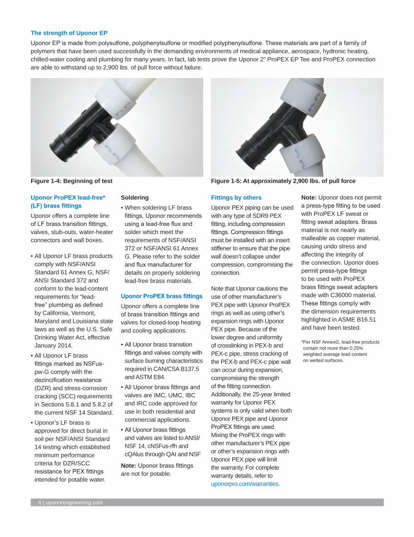
The strength of Uponor EPUponor EP is made from polysulfone, polyphenylsulfone or modified polyphenylsulfone. These materials are part of a family of polymers that have been used successfully in the demanding environments of medical appliance, aerospace, hydronic heating, chilled-water cooling and plumbing for many years. In fact, lab tests prove the Uponor 2" ProPEX EP Tee and ProPEX connection are able to withstand up to 2,900 lbs. of pull force without failure.
Uponor ProPEX lead-free* (LF) brass fittingsUponor offers a complete line of LF brass transition fittings, valves, stub-outs, water-heater connectors and wall boxes.
• All Uponor LF brass products comply with NSF/ANSI Standard 61 Annex G, NSF/ANSI Standard 372 and conform to the lead-content requirements for “lead-free” plumbing as defined by California, Vermont, Maryland and Louisiana state laws as well as the U.S. Safe Drinking Water Act, effective January 2014.
• All Uponor LF brass fittings marked as NSFus-pw-G comply with the dezincification resistance (DZR) and stress-corrosion cracking (SCC) requirements in Sections 5.8.1 and 5.8.2 of the current NSF 14 Standard.
• Uponor’s LF brass is approved for direct burial in soil per NSF/ANSI Standard 14 testing which established minimum performance criteria for DZR/SCC resistance for PEX fittings intended for potable water.
Soldering• When soldering LF brass
fittings, Uponor recommends using a lead-free flux and solder which meet the requirements of NSF/ANSI 372 or NSF/ANSI 61 Annex G. Please refer to the solder and flux manufacturer for details on properly soldering lead-free brass materials.
Uponor ProPEX brass fittingsUponor offers a complete line of brass transition fittings and valves for closed-loop heating and cooling applications.
• All Uponor brass transition fittings and valves comply with surface burning characteristics required in CAN/CSA B137.5 and ASTM E84.
• All Uponor brass fittings and valves are IMC, UMC, IBC and IRC code approved for use in both residential and commercial applications.
• All Uponor brass fittings and valves are listed to ANSI/NSF 14, cNSFus-rfh and cQAlus through QAI and NSF
Note: Uponor brass fittings are not for potable.
Fittings by othersUponor PEX piping can be used with any type of SDR9 PEX fitting, including compression fittings. Compression fittings must be installed with an insert stiffener to ensure that the pipe wall doesn’t collapse under compression, compromising the connection.
Note that Uponor cautions the use of other manufacturer’s PEX pipe with Uponor ProPEX rings as well as using other’s expansion rings with Uponor PEX pipe. Because of the lower degree and uniformity of crosslinking in PEX-b and PEX-c pipe, stress cracking of the PEX-b and PEX-c pipe wall can occur during expansion, compromising the strength of the fitting connection. Additionally, the 25-year limited warranty for Uponor PEX systems is only valid when both Uponor PEX pipe and Uponor ProPEX fittings are used. Mixing the ProPEX rings with other manufacturer’s PEX pipe or other’s expansion rings with Uponor PEX pipe will limit the warranty. For complete warranty details, refer to uponorpro.com/warranties.
Note: Uponor does not permit a press-type fitting to be used with ProPEX LF sweat or fitting sweat adapters. Brass material is not nearly as malleable as copper material, causing undo stress and affecting the integrity of the connection. Uponor does permit press-type fittings to be used with ProPEX brass fittings sweat adapters made with C36000 material. These fittings comply with the dimension requirements highlighted in ASME B16.51 and have been tested.
* Per NSF AnnexG, lead-free products contain not more than 0.25% weighted average lead content on wetted surfaces.
Figure 1-4: Beginning of test Figure 1-5: At approximately 2,900 lbs. of pull force

Hydronic Piping Design Assistance Manual | Chapter 2 – Making ProPEX connections l 7
Chapter 2:: Making ProPEX connections
Uponor ProPEX ASTM F1960 and CAN/CSA B137.5 cold-expansion fittings make solid, permanent, manufactured connections without the need for torches, glues, solder, flux or gauges. The unique shape memory of Uponor PEX piping forms a tight seal around the fitting, creating a strong, reliable connection.
This document shows how to make proper ProPEX connections using one of the following tools.
• Milwaukee® M12™ or M18™ ProPEX Expansion Tools• Milwaukee M18 FORCELOGIC™ ProPEX Expansion Tool• ProPEX 201 Corded Expander Tool• ProPEX Hand Expander Tool
Distance between fittingsUponor requires a minimum distance between ProPEX fittings to avoid damaging the fittings during installation and to protect against elevated stress on the pipe and fittings. Refer to Table 2-1 for the minimum distance between fittings, which is expressed as cut length of pipe.
General ProPEX connection tips• If the fitting does not slide into
the piping all the way to the stop, immediately remove it from the piping and expand the piping one final time.
Note: To avoid over-expanding the piping, do not hold the piping in the expanded position.
• Table 2-2 shows the recommended number of expansions. Experience, technique and weather conditions influence the actual number of expansions. Fewer expansions may be necessary under certain conditions. The correct number of expansions is the amount necessary for the piping and the shoulder of the fitting to fit snugly together.
• Ensure the ProPEX Ring rests snugly against the fitting shoulder. If there is more than 1⁄16" (1mm) between the ring and the shoulder of the fitting, the connection must be replaced. Square cut the piping 2" away from the fitting for ½" to 1" pipe, 3" away for 1¼" to 2" pipe and 5" away for 2½" and 3" pipe prior to making the new connection.
• Brass ProPEX fittings can be disconnected and reused. EP fittings must be discarded. Be sure to follow the recommended minimum distance between ProPEX fittings shown in Table 2-1.
Piping size
Milwaukee ProPEX tool Uponor ProPEX tool
M12 M18 FORCELOGIC Manual 100/150 2013/8" 8 9 — 5 7 —½" 5 6 — 4 4 —¾" 9 8 — 9 9H —1" 12 5 — 14 7H —
1¼" — 7 — — 7H —1½" — 6 — — 8H —2" — — 4 — — 5H
2½" — — 5 — — —3" — — 7 — — —
Table 2-2: Recommended number of expansions for ⅜" to 3" piping at 73.4ºF (23ºC)
Note: “H” in the table refers to Uponor H-series expander heads.
Nominal fitting size
Cut length of pipe
½" 2"
¾" 3"
1" 3½"
1¼" 4½"
1½" 4½"
2" 6"
2½" 7½"
3" 9"
Table 2-1: Minimum distance between ProPEX fittings
Cut length of pipe

8 | uponorengineering.com
Important! Making expansions are slightly different when using a tool that features auto rotation. When making a ProPEX connection, be sure to follow the guidelines for the tool you are using in your application.
1. Square cut the PEX piping perpendicular to the length of the piping. Remove all excess material or burrs that might affect the fitting connection.
2. Slide the ProPEX Ring over the end of the piping until it reaches the stop edge. If using a ProPEX Ring without a stop edge, extend the ring over the end of the piping no more than 1⁄16" (1mm).
Important! If making a ⅜" ProPEX Connection, you must first expand each side of the ring before placing it on the piping. Refer to the “Making ⅜" ProPEX Connections” instructions on page 16 for further information.
3⁄8" and 1⁄2" Milwaukee expansion head
3⁄4" to 3" Milwaukee expansion heads
Making ProPEX connections with Milwaukee M12 or M18 ProPEX expansion tools
Note: All standard Uponor expander heads are compatible with the M12 and M18 tools. Uponor expander heads will not auto-rotate on the Milwaukee tools (only Milwaukee expansion heads will auto-rotate on the M12 and M18). H-heads are not compatible with Milwaukee tools and Milwaukee heads are not compatible with Uponor tools. Milwaukee heads are easily distinguished by color coding and the Milwaukee logo.
Shoulder
Shoulder
1 2 3, 5 4
Expansion with Milwaukee M12 ProPEX Expansion Tool
With auto rotation (standard Milwaukee heads)3. Milwaukee ProPEX Expansion Tools come with built-in auto
rotation. If using a Milwaukee expansion head, simply hold the piping and tool in place while holding the trigger to expand the piping. The head will automatically rotate to ensure the piping is evenly expanded. Continue expanding until the piping and ring are snug against the shoulder on the expander head. See Table 2-2 for the recommended number of expansions for each piping size.
Note: Do not force the pipe onto the expander head. Ensure the expander head is rotating during each expansion.
Without auto rotation (standard Uponor heads)4. Press the trigger to expand the piping.
5. Release the trigger, remove the head from the piping, rotate it ⅛ turn and slide the head back into the piping. Continue expanding and rotating until the piping and ring are snug against the shoulder on the expander head. See Table 2-2 for the recommended number of expansions.
Important! Rotating the tool between expansions will provide smooth, even expansion of the piping. Failure to rotate the tool will cause deep grooves in the piping which can result in potential leak paths.

Hydronic Piping Design Assistance Manual | Chapter 2 – Making ProPEX connections l 9
6d
6b
6e
6c6a
3, 5 4 4
6. After the final expansion, immediately remove the tool and insert the fitting. Ensure the piping and ring seat against the shoulder of the fitting.
Insert ProPEX fitting into ½" Uponor PEX piping.
Shoulder
Shoulder
Insert ProPEX fitting into 1" Uponor PEX piping.
ProPEX coupling
ProPEX tee
Expansion with Milwaukee M18 ProPEX Expansion Tool
Important! Only perform the necessary number of expansions. DO NOT over expand the pipe. You should feel some resistance as the fitting goes into the piping. If you do not feel any resistance, the piping may be over expanded and will require additional time to shrink over the fitting.

10 | uponorengineering.com
FORCELOGIC expansion head installationThe Milwaukee M18 FORCELOGIC ProPEX Expansion Tool for 2", 2 1⁄2" and 3" Uponor PEX pipe features an auto-rotating head with specially designed alignment cogs. This requires slightly different head installation than the M12 and M18 ProPEX expansion tools for 3⁄8" to 1 1⁄2" pipe sizes.
1. Remove the battery pack and place the FORCELOGIC tool in the upright position (cone up).
2. Verify the expansion cone is fully retracted.
3. Screw the head onto the tool (clockwise). Hand-tighten securely. Do not over tighten. Ensure the expansion head fits flush against the tool.
4. Check the installation.
a. Ensure the head segments do not “flower” (see image 4a).
b. If the head flowers, correct the installation by loosening the head slightly and rotating the segments until they engage in the cogs. Re-tighten the head.
c. Rotate the six expansion segments in the clockwise direction. They will rotate freely. They should not rotate counter clockwise.
d. The expansion head collar will fit flush against the tool.
Making ProPEX connections with the Milwaukee M18 FORCELOGIC ProPEX Expansion Tool
1
Correct expansion head alignment
4b
Incorrect expansion head “flowering”
4a

Hydronic Piping Design Assistance Manual | Chapter 2 – Making ProPEX connections l 11
Making a ProPEX connection 1. Square cut the PEX piping perpendicular
to the length of the piping. Remove all excess material or burs that might affect the fitting connection.
2. Slide the ProPEX Ring over the end of the piping until it reaches the stop edge.
3. The Milwaukee tool comes with built-in auto rotation, meaning the head will automatically rotate to ensure the piping is evenly expanded.
Note: To cancel the expansion process quickly, pull and release the trigger.
4. Press the trigger to initiate the rotation of the head. A green light will turn on and the work light will blink. Insert the pipe and ring and release the trigger. When the expansion head has reached its maximum diameter, it will retract.
Important! Do not force the pipe and ring on the head during any expansion.
5. After the tool has retracted, the green indicator light blinks three times. Press the trigger and repeat the expansion process.
6. Repeat the process until the pipe and ring are snug against the shoulder of the expansion head. Repeat the expansion one or two more times depending on the ambient temperature.
Note: Fewer expansions are required in colder temperatures.
7. After final expansion, immediately remove the tool and insert the fitting.
6
1
7b
4
2a 2b

12 | uponorengineering.com
1. Square cut the PEX piping perpendicular to the length of the piping. Remove all excess material or burrs that might affect the fitting connection.
2. Slide the ProPEX Ring over the end of the piping until it reaches the stop edge. If using a ProPEX Ring without a stop edge, extend the ring over the end of the piping no more than 1⁄16" (1mm).
3. Slide the expander head into the piping until it stops. Full expansions are necessary to make a proper connection.
4. Press the trigger to expand the piping.
Making ProPEX connections with the ProPEX 201 Corded Expander Tool
1
3
4
5a
2

Hydronic Piping Design Assistance Manual | Chapter 2 – Making ProPEX connections l 13
5. Release the trigger, remove the head from the piping, rotate it ⅛ turn and slide the head back into the piping. Continue expanding and rotating until the piping and ring are snug against the shoulder on the expander head. See Table 2-2 for the recommended number of expansions.
Important! Rotating the tool between expansions will provide smooth, even expansion of the piping. Failure to rotate the tool will cause deep grooves in the piping which can result in potential leak paths.
6. After the final expansion, immediately remove the tool and insert the fitting. Ensure the piping and ring seat against the shoulder of the fitting.
5b
6c
ProPEX EP tee connection ProPEX brass coupling connection
Insert ProPEX fitting into 2" Uponor PEX piping
6a
6b

14 | uponorengineering.com
1. Square cut the PEX piping perpendicular to the length of the piping. Remove all excess material or burrs that might affect the fitting connection.
2. Slide the ProPEX Ring over the end of the piping until it reaches the stop edge. If using a ProPEX Ring without a stop edge, extend the ring over the end of the piping no more than 1⁄16" (1mm).
Important! If making a ⅜" ProPEX Connection, you must first expand each side of the ring before placing it on the piping. Refer to the “Making ⅜" ProPEX Connections” instructions on page 16 for further information.
3. Brace the free handle of the tool against your hip, or place one hand on each handle. Fully separate the handles and slide the expander head into the piping until it stops. Full expansions are necessary to make a proper connection. Bring the handles together to expand. Separate the handles, remove the head from the piping, rotate it ⅛ turn and slide the head back into the piping. Continue
expanding and rotating until the piping and ring are snug against the shoulder on the expander head. See Table 2-2 for the recommended number of expansions for each piping size.
Important! Rotating the tool between expansions will provide smooth, even expansion of the piping. Failure to rotate the tool will cause deep grooves in the piping which can result in potential leak paths.
Making ProPEX Connections with the ProPEX Hand Expander Tool
1 2 3a
ProPEX Hand Expander Tool

Hydronic Piping Design Assistance Manual | Chapter 2 – Making ProPEX connections l 15
4. After the final expansion, immediately remove the tool and insert the fitting. Ensure the piping and ring seat against the shoulder of the fitting.
Important! You should feel some resistance as the fitting goes into the piping. If you do not feel any resistance, the piping may be over expanded and will require additional time to shrink over the fitting.
3b
3c
ProPEX Hand Expander Tool
4b 4c4a
Insert ProPEX fitting into Uponor PEX piping.

16 | uponorengineering.com
Making 3⁄8" ProPEX connectionsThe ⅜" ProPEX Ring must be expanded once on each side to properly fit over the piping. Refer to the following instructions to make a ⅜" ProPEX connection.
1. Square cut the PEX piping perpendicular to the length of the piping. Remove all excess material or burrs that might affect the fitting connection.
2. Expand each side of the ⅜" ProPEX Ring once.
3. Slide the expanded ring over the end of the piping. Extend the end of the ring over the end of the piping no more than 1⁄16" (1mm).
4. After the ring is on the piping, continue with the regular steps for making a proper connection with your specific tool.
Proper expander tool and head maintenance• Use a lint-free cloth to apply
a light coat of lubricant to the cone prior to making any ProPEX connections.
• If used regularly, apply the lubricant daily to the cone of the ProPEX Expander Tool (manual, air or battery) as well as the ProPEX Auto Rotation Adapter. Failure to keep these tools lubricated may result in improper connections.
• The handles of the ProPEX Hand Expander Tool will open and close smoothly if properly lubricated.
Caution: Excessive lubrication may result in improper connections. Only use a small amount of lubrication to keep the tool working properly.
• Keep all other parts of the tool free from lubricant.
• Once a month, soak the heads in degreasing agent to remove any grease from between the segments. Clean the cone using a clean, dry cloth.
Important tips for a proper ⅜" ProPEX connection
• The thicker ⅜" ProPEX Ring shrinks over the fitting faster than larger-sized rings.
• When the temperature is below 40°F (4.4°C), fewer expansions are required.
B
A
A
B
2
1
E6081128 pipe cutter (plastic)
3
Max. 1⁄16

Hydronic Piping Design Assistance Manual | Chapter 2 – Making ProPEX connections l 17
4a
4c
5 6
4b
2
3
Disconnecting a ProPEX brass fittingProPEX brass and EP fittings are manufactured connections that can be concealed in walls, ceilings and floors. When necessary, ProPEX brass fittings can be disconnected.
Important! EP fittings cannot be reclaimed.
Refer to the following guidelines for disconnecting a ProPEX brass fitting.
1. Ensure the system is not pressurized.
2. Use a utility knife to carefully cut through the ProPEX Ring.
Important! Do not heat the ring prior to cutting it. Take care to cut only the ring and not the piping or fitting. Gouges in the fitting may result in leaks. If you accidentally damage the fitting, you must discard it.
3. Remove the ProPEX Ring from the piping.
4. After removing the ring, apply heat directly around the fitting and piping connection. Do not use open flame. Gently work the piping back and forth while pulling slightly away from the fitting until the piping separates from the fitting.
5. After removing the fitting, measure:
• 2" (50.8mm) minimum for ⅜" to 1" pipe• 3" (76.2mm) minimum for 1¼" to 2" pipe• 5" (127mm) minimum for 2½" and 3" pipe
6. Square cut the piping at the proper marking.
7. Allow the fitting to cool before making the new connection.
8. Use a new ProPEX Ring and follow the steps to make a new connection.

18 | uponorengineering.com
Troubleshooting ProPEX connectionsTrouble-free ProPEX installations begin with a tool that is maintained in proper working condition. If the tool or segment fingers are damaged, it is very difficult to make a proper connection. Refer to the following guidelines to assist with challenges in the field.
Fittings won’t seal
• Make sure the expander head is securely tightened onto the tool.
• Ensure the segment fingers are not bent. If the head does not completely close when the drive unit is fully retracted or the handles of the manual tool are open, replace the head.
• Examine the tool for excess grease on the segment fingers. Remove excess grease prior to making connections.
• Check the fitting for damage. Nicks and gouges will cause the fitting to leak.
• Make sure the internal driver cone is not damaged or bent.
• Make sure the last expansion is not held in the expanded position before the fitting is inserted. You should feel some resistance as the fitting goes into the piping. If you do not feel any resistance, the piping may be over expanded and will require additional time to shrink over the fitting.
• Be sure to rotate the tool ⅛ turn after each expansion to avoid deep grooves in the piping which can result in potential leak paths.
Expansion is difficult
• Make sure the internal cone is properly greased.
Expansion head slips out of piping when making expansions
• Ensure the piping and ProPEX Ring are dry.
• Make sure that grease is not getting into the piping.
• Examine the segment fingers to ensure they are not damaged or bent.
ProPEX Ring slides down piping during expansion
• Ensure your hands are clean while handling the piping. Any sweat or oils on your hands can act as a lubricant. Due to the smoothness of PEX, any form of lubricant can cause the ProPEX Ring to slide down the piping during expansion.
• If you anticipate the ProPEX Ring may possibly slide down, position the ring slightly farther over the end of the piping and make the first couple of expansions slowly. Once the ring and the piping begin to expand together, continue with the normal number and type of expansions.
• Place your thumb against the ProPEX Ring to help support it and feel for any movement. If caught early, you can slide the ring up the piping and expand as described in the previous bullet point.
More than the recommended number of expansions are needed to make a connection
• Ensure the head is hand-tightened to the expander tool.
• Examine the segment fingers for damage.
• Be sure to completely cycle the tool on each expansion (i.e., close the manual tool handle or release the trigger).
Cold-weather expansions
• Temperatures affect the time required for the piping and ring to shrink onto the fitting. The colder the temperature, the slower the contraction time.
• Warming ProPEX fittings and ProPEX Rings reduces contraction time. Put fittings and rings in your pockets prior to installation to keep them warm.
• Fewer expansions are necessary in temperatures below 40ºF (4.4ºC).
Note: Do not use a heat gun on EP fittings to speed up the contraction time as this could result in damage to the fitting.
Expansion with proper rotation
Expansion without proper rotation

Hydronic Piping Design Assistance Manual | Chapter 3 – Fire-resistant construction l 19
Chapter 3::Fire-resistant construction
Wood-frame wall assembliesWood-frame wall assemblies complying with ASTM E119 and CAN/ULC-S101 have the following requirements.
Building elements
• Studs: Nominal wood 2x4 spaced 16" O.C.
• Gypsum wallboard: Minimum one layer of ⅝" thick Type X gypsum wallboard
Pipe and fittings
• Pipe: Maximum density of Uponor PEX pipe is 4.85 lbs/ft (7.22 kg/m) of stud cavity. Approved Uponor PEX pipes include: - Uponor AquaPEX White (up to 3")
- Uponor AquaPEX Red (up to 1")
- Uponor AquaPEX Blue (up to 1")
- Uponor AquaPEX Reclaimed Water (up to 1")
- Pre-insulated Uponor AquaPEX (up to 2" pipe with 1½" thick insulation)
- Wirsbo hePEX (up to 4")
• Fittings: Maximum density of Uponor ProPEX brass or EP fittings is 3.33 lbs (1.51 kg) per stud cavity.
Note: See assembly details for more information.
Assembly numbers
ITS Design No. UW/WA 60-02• 1-hour• Up to 2" PEX
QAI Design No. P321-1B• 1-hour• Up to 4" PEX
QAI Design No. P321-1H• 2-hour• Up to 4" PEX
UL Design No. U372 • 1-hour• Up to 2" PEXNote: Maximum size is available through QAI.
Wood-frame floor/ceiling assembliesWood-frame floor/ceiling assemblies complying with ASTM E119 and CAN/ULC-S101 have the following requirements.
Building elements
• Joists: Nominal 2x10 solid sawn wood, open web wood or wood I-joist (10" to 24" depth) installed at 24" O.C. maximum
• Subfloor: Minimum ⅝" plywood; if using optional topping, subfloor may be ⅝" oriented strand board (OSB)
• Gypsum wallboard: - Minimum one layer of 5⁄8" Type X gypsum wallboard when using solid sawn wood joists
- Minimum two layers of ½" Type X gypsum wallboard when using wood I-joists (10" to 24" depth)
Pipe and fittings
• Pipe: One or more Uponor PEX piping runs ½" to 2"; weight of PEX piping not to exceed 0.63 lbs/ft. (0.94 kg/m) of joist cavity. Support pipe with metal clips 16" O.C. for piping up to 1" diameter or metal clips 24" O.C. for piping larger than 1" diameter.
• Fittings: Brass or engineered polymer (EP) fittings with a weight not exceeding 0.1 lbs/ft. (0.15 kg/m) per joist cavity
Note: See assembly details for more information.
Assembly numbers
ITS Design No. UW/FC 60-01• 1-hour• Up to 2" PEX
ITS Design No. UW/WA 60-02• 1-hour• Up to 2" PEX
QAI Design No. P321-1F• 1-hour• Up to 2" PEX
UL Design No. L557• 1-hour• Up to 2" PEX
ASTM E119 (ANSI/UL 263) or CAN/ULC-S101 listings
Fire-resistive assembly ratings (ASTM E119/ANSI/UL 263 and CAN/ULC-S101)
Construction type Assembly type UL design no. Intertek QAI
Non-combustable concrete/steel
Floor/ceiling
K913 UW/FCA 120-01/-02 P321-1D (2-hr)
G524 - P321-1E (2-hr)
G573 - P321-1C (2-hr)
WallsV444 UW/WA 60-01 P321-1A (1-hr)
- - P321-1G (2-hr)
Wood frame construction
Floor/Ceiling L557 UW/FCA 60-01 P321-1F (1-hr)
WallsU372 UW/FCA 60-02 P321-1B (1-hr)
- - P321-1H (2-hr)
Table 3-1: ASTM E119 and CAN/ULC-S101 listings

20 | uponorengineering.com
Steel/concrete wall assembliesSteel/concrete wall assemblies complying with ASTM E119 and CAN/ULC-S101 have the following requirements.
Building elements
Studs: 3⅝" steel studs spaced maximum 24" O.C.
• Gypsum wallboard: Minimum one layer of ⅝" thick Type X gypsum wallboard
Pipe and fittings
• Pipe: Maximum density of Uponor PEX pipe is 4.85 lbs/ft (7.22 kg/m) of stud cavity. Approved Uponor PEX pipes include: - Uponor AquaPEX White (up to 3") - Uponor AquaPEX Red (up to 1") - Uponor AquaPEX Blue (up to 1") - Uponor AquaPEX Reclaimed Water (up to 1") - Pre-insulated Uponor AquaPEX (up to 2" pipe with 1½" thick insulation)
- Wirsbo hePEX (up to 4")
• Fittings: Maximum density of Uponor ProPEX brass or EP fittings is 3.33 lbs (1.51 kg) per stud cavity.
Note: See assembly details for more information.
Assembly numbers
QAI Design No. P321-1A• 1-hour• Up to 4" PEX
QAI Design No. P321-1G• 2-hour• Up to 4" PEX
UL Design No. V444• 1-hour• Up to 4" PEXNote: Maximum size is available through QAI.
Steel/concrete floor/ceiling assembliesSteel/concrete floor/ceiling assemblies complying with ASTM E119 or CAN/ULC-S101 have the following requirements.
Building elements
• Concrete floor: Minimum slab thickness of 6½"• Steel Reinforcement: Various sized Grade 40 or 60 steel bars
located as required by ACI-318• Steel Joists: Minimum nominal depth of 10" spaced maximum
of 6'-0" O.C.• Steel Floor: Minimum 1½" depth, 22 gauge uncoated or
galvanized fluted
Pipe and fittings
• Pipe: Maximum volume of Uponor PEX pipe is 14 cubic inches per 1 cubic foot (8101 cubic centimeters per 1 cubic meter). Approved Uponor PEX pipes include: - Uponor AquaPEX White (up to 2") - Uponor AquaPEX Red (up to 1") - Uponor AquaPEX Blue (up to 1") - Uponor AquaPEX Reclaimed Water (up to 1") - Pre-insulated Uponor AquaPEX (up to 1" pipe) - Wirsbo hePEX (up to 2")
Note: See assembly details for more information.
Assembly numbers
ITS Design No. UW/FCA 120-01• 1-hour• Up to 2" PEX
ITS Design No. UW/FCA 120-02• 2-hour• Up to 2" PEX
QAI Design No. P321-1C• 2-hour• Up to 2" PEX
QAI Design No. P321-1D• 2-hour• Up to 2" PEX
QAI Design No. P321-1E• 2-hour• Up to 2" PEX
UL Design No. K913• 2-hour• Up to 2" PEX
UL Design No. G524• 2-hour• Up to 2" PEX
UL Design No. G573• 2-hour• Up to 2" PEX

Hydronic Piping Design Assistance Manual | Chapter 3 – Fire-resistant construction l 21
Non-rated wall or non-load bearing fire-rated wall assembly with Uponor PEX pipe installed per (ASTM E119) (refer to Table 3-1 for applicable design no.)
Uponor AquaPEX (white, red, blue) nominal up to 3" pipe; Pre-insulated PEX nominal up to 1" pipe; Wirsbo hePEX nominal up to 4" pipe; Uponor AquaPEX Reclaimed Water nominal up to 1" pipe; Installed to a max. of 4.85 lbs. per linear ft. of cavity. Pipe shall be supported on steel or wood cross-bracing spaced at max. 48" OC.
Steel stud
Firestop listed to ASTM E814(must be Uponor PEX pipe compatible)Riser clamp (See riser detail
in Chapters 5 and 6)Slab listed with nominal up to 2" UponorPEX pipe only (refer to UL design no. K913)
Mid-story guide
Concrete floor/ceiling assembly (UL design no. K913/ITS design no. UW/FCA 120-01/-02/QAI design no. P321-1D) steel-stud wall assembly (UL design no. V444/ITS design no. UW/WA 60-01/QAI design no. P321-1A/P321-1G)
Concrete assemblies detail (U.S.)
Figure 3-1: Concrete assemblies detail (U.S.)

22 | uponorengineering.com
Non-rated wall or load-bearing fire-rated wallassembly with Uponor PEX pipe installed (ASTM E119) (refer to Table 3-1 for applicable design no.)
Up to 2" Uponor PEX pipe (refer to UL design no. L557)
Wood stud
Firestop listed to ASTM E814 requirements (must be Uponor PEX pipe compatible)
Metal support clips required up to 2" Uponor PEX pipe (clip spacing every 32")
Riser clamp (see riser detail in Chapters 5 and 6)
Optional concrete top pour Subfloor
Mid-story guide
Wood-frame floor/ceiling assembly (UL design no. L557/ITS design no. UW/FCA 60-01/QAI design no. P321-1F) wood-frame wall assembly (UL design no. U372/ITS design no. UW/WA 60-02/QAI design no. P321-1B/P321-1H)
Wood-frame assemblies detail (U.S.)
Figure 3-2: Wood-frame assemblies detail (U.S.)

Hydronic Piping Design Assistance Manual | Chapter 3 – Fire-resistant construction l 23
Concrete assemblies detail (Canada)
Non-rated wall or non-load bearing fire-rated wall assembly with Uponor PEX pipe installed(refer to Table 3-1 for applicable design no.)For CAN/ULC-S101 steel-stud rated walls maximumUponor PEX pipe weight of 1.3 lbs./ft. and not toexceed total weight per stud cavity of 3.65 lbs.
Uponor AquaPEX (white, red, blue) nominal up to 3" pipe; Pre-insulated PEX nominal up to 1" pipe; Wirsbo hePEX (natural) nominal up to 4" pipe; Uponor AquaPEX Reclaimed Water nominal up to 1" pipe; Installed to a max. of 4.85 lbs. per linear ft. of cavity. Pipe shall be supported on steel or wood cross-bracing spaced at max. 48" OC.
Steel stud
Approved firestop system per CAN/ULC-S115 based on local code requirementRiser clamp (See riser detail
in Chapters 5 and 6)CAN/ULC-S101 fire-rated concrete assembly Minimum 6½" concrete slab (CAN/ULC-S101used with Uponor PEX pipe only) (refer toITS design nos. UW/FCA 120-01 and 120-02)
Mid-story guide (Uponor recommended; not required by code)
Concrete floor/ceiling assembly (UL design no. K913/ITS design no. UW/FCA 120-01/-02/QAI P321-1D)steel-stud wall assembly (UL design no. V444/ITS design no. UW/WA 60-01/QAI P321-1A/P321-1G)
Figure 3-3: Concrete assemblies detail (Canada)

24 | uponorengineering.com
Non-rated wall assembly or CAN/ULC-S101fire-rated wall installed with Uponor PEX pipe (refer to Table 3-1 for applicable design no.)
Up to 2" Uponor PEX pipe (refer to ITS design no. UW/FCA 60-01)
Wood stud
Approved firestop system per CAN/ULC-S115
Metal support clips required.
Up to 1" Uponor PEX pipe: clip spacing every 16"
1¼" to 2" Uponor PEX pipe: clip spacing every 24"
Riser clamp (see riser detailin Chapters 5 and 6)
Optional concrete top pour Subfloor
Mid-story guide (Uponor recommended; not required by code)
Wood-frame floor/ceiling assembly (UL design no. L557/ITS design no. UW/FCA 60-01/QAI design no. P321-1F)
wood-frame wall assembly (UL design no. U372/ITS design no. UW/WA 60-02/QAI design no. P321-1B/P321-1H)
Wood-frame assemblies detail (Canada)
Figure 3-4: Wood-frame assemblies detail (Canada)

Hydronic Piping Design Assistance Manual | Chapter 3 – Fire-resistant construction l 25
The steps below show an example of how to research and find a listed fire stop assembly for PEX pipe.
Step one
Choose a fire stop solution manufacturer and consult their website or search the UL Online Certifications Directory for applicable listings. (See Figure 3-5.)
Step two
Select the desired and specified features of the through penetration system. Defining the country of use, assembly type, penetrating item, fire stopping product and F rating of the system may help refine search results. (See Figure 3-6.)
Step three
Review the system matches for accuracy and consider all available options. In regards to fire listings for pressure pipe applications, domestic water piping (Division 22, section 22 11 16) and hydronic piping (Division 23, section 23 21 13) may be defined as being “closed” or “pressure” type systems. (See Figure 3-7 on the following page.)
ASTM E814 or CAN/ULC-S115Combustible and non-combustible pipes penetrating a wall or floor/ceiling fire-rated assembly must include a code-compliant means of passive fire protection. The function of a passive fire protection system, such as fire stopping, is to contain the fire within the area in which it started by preventing the products of combustion (smoke, hot gasses and flames) from spreading throughout the structure.
Effective fire stopping requires accurate adherence to a specific combination of conditions that have been tested and listed as a system per ASTM E814, CAN/ULC-S115 or ANSI/UL 1479. Listed fire stop components include the penetrated substrates, penetrating item, penetration hole, insulating materials, sealants and installation method. Deviation from the listed fire assembly documentation severely compromises the
effectiveness of the fire stop system.
Fire assembly documentation and listings shall be obtained from the selected fire stop solution manufacturer. Most of the fire stop manufacturers have system selector tools or navigators on their websites to easily research and find a listing that matches the specified type of construction.
Fire stopping solutions There is a wide range of fire stopping solutions that have been tested and listed with PEX pipe; including intumescent caulks, wrap strips, pass-through devices, collars and cast-in-place sleeves. Some fire stop manufacturers include, but are not limited to, 3M™, Hilti®, RectorSeal®, Passive Fire Protection Partners, Specified Technologies Inc., Holdrite® and ProSet Systems®.
Figure 3-5: UL Online Certifications Directory
Figure 3-6: Select appropriate features

26 | uponorengineering.com
Product Support Line 1-800-328-1687
WL
Gypsum
2000 SeriesN
on-M
etallic P
ipes
Through Penetrations
3Fire Protection Products 3m.com/firestop
Product Support Line 1-800-328-1687W-L-2547 • 1 of 1
1. Wall assembly – The 1 and 2 hr fire rated gypsum board/stud wall assemblies shall be constructed of the materials and in the manner specified in the individual U300, U400 or V400 Series Wall and Partition Designs in the UL Fire Resistance Directory and shall include the following construction features:
A. Studs – Wall framing may consist of either wood studs or steel channel studs. Wood studs to consist of nom 2 by 4 in. (51 by 102 mm) lumber spaced 16 in. (406 mm) OC. Steel studs to be min 3-1/2 in. (89 mm) wide and spaced max 24 in. (610 mm) OC.
B. Gypsum board* – Thickness, type, number of layers and fasteners as required in the individual Wall and Partition Design. Diameter of opening shall be 1-1/2 in. (38 mm) larger than the outside diam of tubing (Items 2).
The hourly F Rating of the firestop system is equal to the hourly fire rating of the wall assembly in which it is installed. The hourly T Rating is 0 and 1-3/4 hr for 1 and 2 hr rated assemblies, respectively.
2. Crosslink polyethylene (PEX) tubing – Nom 2 in. (51 mm) diam (or smaller) SDR 9 PEX tubing for use in closed (process or supply) piping system. Tubing installed concentrically or eccentrically within opening. Annular space between tubing and edge of opening to be min 0 in. to max 1-1/2 in. (38 mm). Tubing to be rigidly supported on both sides of wall assembly.
3. Fill, void or cavity materials* – caulk or sealant – Min 5/8 in. (16 mm) thickness of fill material applied within the annulus, flush with both surfaces of wall assembly. An additional min 1/2 in. (13 mm) bead of fill material applied at the tubing/gypsum board interface at point contact location on both surfaces of wall assembly.
3M COMPANY3M FIRE PROTECTION PRODUCTS – CP 25WB+, IC 15WB+ or FB-3000 WT
*Bearing the UL classification mark
Reprinted from the online certifications directory with permission from Underwriters Laboratories Inc. Copyright © 2010 Underwriters Laboratories Inc.®
System no. W-L-2547August 04, 2009
F Ratings – 1 and 2 Hr (See item 1)T Ratings – 0 and 1-3/4 Hr (See item 1)
Step four
Ensure the selected fire assembly document matches:
• Type of construction• F rating of assembly• Through penetrant defined
as crosslinked polyethylene pipe or PEX pipe
• Range of pipe size being installed
• Penetration hole size and shape
• Fire stop solution availability(See Figures 3-8, 3-9 and 3-10.)
Note: It may be desirable to select a fire stop product that can be used for other MEP system penetrations such as drain, waste and
vent (DWV) and conduit applications. This can help ease coordination on the jobsite during the fire stop installation.
Refer to the respective firestop manufacturer for more information pertaining to the appropriate application of their products. Be mindful
of information stated in the published listings to ensure compliance during installation.
Product Support Line 1-800-328-1687
WL
Gypsum
2000 SeriesN
on-M
etallic P
ipes
Through Penetrations
3Fire Protection Products 3m.com/firestop
Product Support Line 1-800-328-1687W-L-2547 • 1 of 1
1. Wall assembly – The 1 and 2 hr fire rated gypsum board/stud wall assemblies shall be constructed of the materials and in the manner specified in the individual U300, U400 or V400 Series Wall and Partition Designs in the UL Fire Resistance Directory and shall include the following construction features:
A. Studs – Wall framing may consist of either wood studs or steel channel studs. Wood studs to consist of nom 2 by 4 in. (51 by 102 mm) lumber spaced 16 in. (406 mm) OC. Steel studs to be min 3-1/2 in. (89 mm) wide and spaced max 24 in. (610 mm) OC.
B. Gypsum board* – Thickness, type, number of layers and fasteners as required in the individual Wall and Partition Design. Diameter of opening shall be 1-1/2 in. (38 mm) larger than the outside diam of tubing (Items 2).
The hourly F Rating of the firestop system is equal to the hourly fire rating of the wall assembly in which it is installed. The hourly T Rating is 0 and 1-3/4 hr for 1 and 2 hr rated assemblies, respectively.
2. Crosslink polyethylene (PEX) tubing – Nom 2 in. (51 mm) diam (or smaller) SDR 9 PEX tubing for use in closed (process or supply) piping system. Tubing installed concentrically or eccentrically within opening. Annular space between tubing and edge of opening to be min 0 in. to max 1-1/2 in. (38 mm). Tubing to be rigidly supported on both sides of wall assembly.
3. Fill, void or cavity materials* – caulk or sealant – Min 5/8 in. (16 mm) thickness of fill material applied within the annulus, flush with both surfaces of wall assembly. An additional min 1/2 in. (13 mm) bead of fill material applied at the tubing/gypsum board interface at point contact location on both surfaces of wall assembly.
3M COMPANY3M FIRE PROTECTION PRODUCTS – CP 25WB+, IC 15WB+ or FB-3000 WT
*Bearing the UL classification mark
Reprinted from the online certifications directory with permission from Underwriters Laboratories Inc. Copyright © 2010 Underwriters Laboratories Inc.®
System no. W-L-2547August 04, 2009
F Ratings – 1 and 2 Hr (See item 1)T Ratings – 0 and 1-3/4 Hr (See item 1)
Figure 3-8: Fire assembly document Figure 3-9: Assembly drawing
1. Wall Assembly — The 1 and 2 hr fire rated gypsum board/stud wall assemblies shall be constructed of the materials and in the manner specified in the individuals U300, U400 or V400 Series Wall and Partition Designs in the UL Fire Resistance Directory and shall include the following construction features:A. Studs — Wall framing may consist of either wood studs or steel channel studs. Wood studs to consist of nom 2 by 4 in. (51 by 102 mm) lumber spaced 16 in. (406 mm) OC. Steel studs to be min
3-1/2 in. (89 mm) wide and spaced max 24 in. (610 mm) OC.
B. Gypsum Board* —Thickness, type, number of layers and fasteners as required in the individuals Wall and Partition Design. Diameter of opening shall be 1-1/2 in. (38 mm) larger than the outside diameter of tubing (Items 2).
The hourly F Rating of the firestop system is equal to the hourly fire rating of the wall assembly in which it is install. The hourly T Rating is 0 and 1-3/4 hr for 1 and 2 hr rated assemblies, respectively.
2. Crosslink Polyethylene (PEX) Tubing — Nom 2 in. (51 mm) diameter (or smaller) SDR 9 PEX tubing for use in closed (process or supply) piping system. Tubing installed concentrically or eccentrically within opening. Annular space between tubing and edge of opening to be min 0 in. to max 1-1/2 in. (38 mm). Tubing to be rigidly supported on both sides of wall assembly.
3. Fill, Void or Cavity Materials* — Caulk or Sealant — Min 5/8 in. (16 mm) thickness of fill materials applied within the annulus, flush with both surfaces of wall assembly. An additional min 1/2 in. (13 mm) bead of fill material applied at the tubing/gypsum board interface at point contact location on both surfaces of wall assembly.
3M COMPANY3M FIRE PROTECTION PRODUCTS — CP25WB+, IC15WB+ OR FB-3000WT
*Bearing the UL Classification Mark
Reprinted from the Online Certifications Directory with permission from Underwriters Laboratories Inc.Copyright © 2010 Underwriters Laboratories Inc. ®
Figure 3-10: Assembly criteria
Figure 3-7: Search results
WL2547 3M™ Fire Barrier Sealant CP 25WB+1, 2 3M™ Fire Barrier Sealant IC 15WB+ 3M™ Fire Barrier Water tight Sealant 3000 WT
Max 2" SDR 9 PEX (closed only). U300, U400, or V400 series gypsum wallboard assemblies. Max. diameter of opening 11⁄2" larger than OD of penetrant. Point contact to max. 11⁄2" annular space. Concentric or eccentric installations. 1 & 2 hour F rating. No mineral wool required.
UL
Hydronic Piping Design Assistance Manual | Chapter 3 – Fire-resistant construction l 27
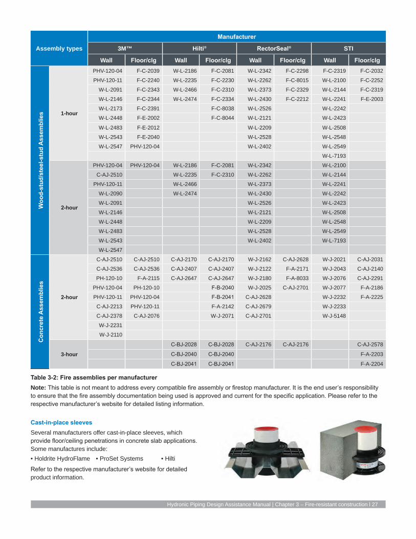
Cast-in-place sleevesSeveral manufacturers offer cast-in-place sleeves, which provide floor/ceiling penetrations in concrete slab applications. Some manufactures include:• Holdrite HydroFlame • ProSet Systems • Hilti
Refer to the respective manufacturer’s website for detailed product information.
Assembly types
Manufacturer
3M™ Hilti® RectorSeal® STI
Wall Floor/clg Wall Floor/clg Wall Floor/clg Wall Floor/clg
Woo
d-st
ud/s
teel
-stu
d A
ssem
blie
s 1-hour
PHV-120-04 F-C-2039 W-L-2186 F-C-2081 W-L-2342 F-C-2298 F-C-2319 F-C-2032
PHV-120-11 F-C-2240 W-L-2235 F-C-2230 W-L-2262 F-C-8015 W-L-2100 F-C-2252
W-L-2091 F-C-2343 W-L-2466 F-C-2310 W-L-2373 F-C-2329 W-L-2144 F-C-2319
W-L-2146 F-C-2344 W-L-2474 F-C-2334 W-L-2430 F-C-2212 W-L-2241 F-E-2003
W-L-2173 F-C-2391 F-C-8038 W-L-2526 W-L-2242
W-L-2448 F-E-2002 F-C-8044 W-L-2121 W-L-2423
W-L-2483 F-E-2012 W-L-2209 W-L-2508
W-L-2543 F-E-2040 W-L-2528 W-L-2548
W-L-2547 PHV-120-04 W-L-2402 W-L-2549
W-L-7193
2-hour
PHV-120-04 PHV-120-04 W-L-2186 F-C-2081 W-L-2342 W-L-2100
C-AJ-2510 W-L-2235 F-C-2310 W-L-2262 W-L-2144
PHV-120-11 W-L-2466 W-L-2373 W-L-2241
W-L-2090 W-L-2474 W-L-2430 W-L-2242
W-L-2091 W-L-2526 W-L-2423
W-L-2146 W-L-2121 W-L-2508
W-L-2448 W-L-2209 W-L-2548
W-L-2483 W-L-2528 W-L-2549
W-L-2543 W-L-2402 W-L-7193
W-L-2547
Con
cret
e A
ssem
blie
s
2-hour
C-AJ-2510 C-AJ-2510 C-AJ-2170 C-AJ-2170 W-J-2162 C-AJ-2628 W-J-2021 C-AJ-2031
C-AJ-2536 C-AJ-2536 C-AJ-2407 C-AJ-2407 W-J-2122 F-A-2171 W-J-2043 C-AJ-2140
PH-120-10 F-A-2115 C-AJ-2647 C-AJ-2647 W-J-2180 F-A-8033 W-J-2076 C-AJ-2291
PHV-120-04 PH-120-10 F-B-2040 W-J-2025 C-AJ-2701 W-J-2077 F-A-2186
PHV-120-11 PHV-120-04 F-B-2041 C-AJ-2628 W-J-2232 F-A-2225
C-AJ-2213 PHV-120-11 F-A-2142 C-AJ-2679 W-J-2233
C-AJ-2378 C-AJ-2076 W-J-2071 C-AJ-2701 W-J-5148
W-J-2231
W-J-2110
3-hour
C-BJ-2028 C-BJ-2028 C-AJ-2176 C-AJ-2176 C-AJ-2578
C-BJ-2040 C-BJ-2040 F-A-2203
C-BJ-2041 C-BJ-2041 F-A-2204
Table 3-2: Fire assemblies per manufacturerNote: This table is not meant to address every compatible fire assembly or firestop manufacturer. It is the end user’s responsibility to ensure that the fire assembly documentation being used is approved and current for the specific application. Please refer to the respective manufacturer’s website for detailed listing information.

28 | uponorengineering.com
ASTM E84 — surface burning characteristicsAs defined by the
International Building Code (IBC), combustible piping may be installed in areas required to be of noncombustible construction, provided the piping is installed in a wall or concrete-floor slab or the pipe has a flame-spread index (FS) rating of not more than 25 and a smoke-developed index (SD) rating of not more than 50 when tested in accordance with ASTM E84.
Uponor PEX-a piping systems comprised of Uponor PEX-a piping, Uponor ProPEX Rings, Uponor EP fittings, Uponor LF brass and brass fittings and Uponor PEX-a Pipe Support products are listed for installation in return-air plenums as tested in accordance with ASTM E84.
The below listings apply to Uponor PEX-a piping systems installed in either horizontal or vertical orientations in the field. Refer to Table 3-3 for installation requirements.
QAI P321-1
½" to ¾" Uponor PEX-a (uninsulated)
Adjacent runs of uninsulated ½" to ¾" Uponor PEX-a piping in a return-air plenum must be separated by 18".
QAI P321-2
Up to and including 3" Uponor PEX-a supported with Uponor PEX-a Pipe Support
See Chapter 6 for installation details. Uponor PEX-a piping manufactured with a maximum nominal outside diameter (OD) of 3" and supported with Uponor PEX-a Pipe Support. Pipe or fitting sections without PEX-a Pipe Support must be covered with a rated insulation per Table 3-5. There is no minimum length of PEX-a Pipe Support segments. There are also no spacing limitations between adjacent runs of this pipe.
QAI P321-1
Up to and Including 3" Uponor PEX-a (insulated)
Uponor PEX-a piping manufactured with a maximum nominal OD of 3" and encased in a minimum ½" thick insulation in accordance with Table 3-5 shall have no limitation on spacing.
Classified as to surface burning characteristics
ASTM E84 Flame spread Smoke developed Limitations
Nominal 1⁄2" to 3⁄4" size 25 or less 50 or less Adjacent pipe runs shall be located at least 18" apart.
3" maximum nominal size Uponor PEX-a supported with Uponor PEX-a Pipe Support
25 or less 50 or less Pipe or fitting sections without PEX-a Pipe Support must be covered with a rated insulation per Table 3-5. There is no minimum length of PEX-a Pipe Support segments.
3" maximum nominal size Uponor PEX-a with 1⁄2" insulation
25 or less 50 or less 1⁄2" minimum thickness insulation as specified in Table 3-5.
Table 3-3: Uponor PEX ASTM E84 requirements

Hydronic Piping Design Assistance Manual | Chapter 3 – Fire-resistant construction l 29
United States — ASTM E84
Minimum 18"Clamp
½" through ¾" Uponor PEX pipe
No limitation Clamp
Minimum ½" 25/50rated insulation
½" through 3" Uponor PEX pipe
No limitation Clamp
½" through 3" Uponor PEX pipe
Uponor PEX-aPipe Support
Guidelines: ½" through ¾" (uninsulated) Limitations: Adjacent runs shall be located at least 18" apart.
Guidelines: ½" through 3" (insulated) Limitations: ½" minimum thickness insulation as specified in Table 3-3
Guidelines: ½" through 3" (PEX-a Pipe Support) Pipe or fitting sections without PEX-a Pipe Support must be covered with a rated insulation per Table 3-5. There is no minimum length of PEX-a Pipe Support segments.
Figure 3-11: QAI P321-1
Figure 3-12: QAI P321-1
Figure 3-13: QAI P321-2

30 | uponorengineering.com
CAN/ULC-S102.2 — surface burning characteristicsAs defined by the
National Building Code of Canada (NBCC), combustible piping may be installed in areas required to be of noncombustible construction, provided the piping is installed in a wall or concrete-floor slab or the pipe has a flame-spread index (FS) rating of not more than 25 and a smoke-developed index (SD) rating of not more than 50 when tested in accordance with CAN/ULC-S102.2.
Uponor PEX-a piping systems comprised of Uponor PEX-a piping, Uponor ProPEX Rings, Uponor EP fittings, Uponor LF brass and brass fittings and Uponor PEX-a Pipe Support products are listed for installation in return-air plenums as tested in accordance with CAN/ULC-S102.2.
The below listings apply to Uponor PEX-a Piping Systems installed in either horizontal or vertical orientations in the field. Refer to Table 3-4 for installation requirements.
QAI P321-1
½" Uponor PEX-a (uninsulated)
Adjacent runs of un-insulated ½" Uponor PEX-a piping in a return-air plenum have no spacing limitations.
¾" and 1" Uponor PEX-a (uninsulated)
Adjacent runs of uninsulated 3⁄4" and 1" Uponor PEX-a piping must be separated by 18".
QAI P321-1
Up to and including 3" Uponor PEX-a (insulated)
Uponor PEX-a piping manufactured with a maximum nominal OD of 3" and encased in ½" insulation in accordance with Table 3-4 shall have no limitation on spacing.
QAI P321-3
Up to and including 2" Uponor PEX-a (water-filled, uninsulated)
Adjacent runs of water-filled, uninsulated piping in a return-air plenum have a no spacing limitations.
Classified as to surface burning characteristics
CAN/ULC S102.2 Flame spread Smoke developed Limitations
1⁄2" nominal size 25 or less 50 or less No spacing limitations.
3⁄4" and 1" nominal sizes 25 or less 50 or less Adjacent pipe runs shall be located at least 18" apart.
2" maximum nominal size (water-filled)
25 or less 50 or less No spacing limitations.
3" maximum nominal size Uponor PEX-a with 1⁄2" insulation
25 or less 50 or less 1⁄2" minimum thickness insulation as specified in Table 3-5.
Table 3-4: Uponor PEX CAN/ULC-S102.2 requirements

Hydronic Piping Design Assistance Manual | Chapter 3 – Fire-resistant construction l 31
Canada — CAN/ULC-S102.2
½" Uponor PEXpipe (uninsulated)
ClampNo limitation
¾" and 1"Uponor PEX pipe(uninsulated)
ClampMinimum 18"
½" through 2"Uponor PEX pipe(water-filled,uninsulated)
ClampNo limitation
Guidelines: ½" (uninsulated)Limitations: No spacing limitations.
Guidelines: 3⁄4" and 1" (uninsulated) Limitations: Adjacent pipe runs shall be located at least 18" apart.
Guidelines: ½" through 2" (water-filled)Limitations: No spacing limitations
Figure 3-14: QAI P321-1
Figure 3-15: QAI P321-1
Figure 3-16: QAI P321-3

32 | uponorengineering.com
No limitationClamp
½" through 3" Uponor PEX pipe(insulated)
Minimum ½" 25/50rated insulation
Canada — CAN/ULC-S102.2
Guidelines: ½" through 3" (insulated) Limitations: ½" minimum thickness insulation as specified in Table 3-5
Figure 3-17: QAI P321-1

Hydronic Piping Design Assistance Manual | Chapter 3 – Fire-resistant construction l 33
Underwriters laboratories (UL) 2846 Until recently, piping materials were to be tested under the ASTM E84 method, which was originally developed to test building construction components. The UL 2846 test method was developed specifically for plastic piping materials to test flame and smoke development.
Uponor PEX piping (up to 4") carries the UL 2846 Standard for Fire Test of Plastic Water Distribution Plumbing Pipe for Visible Flame and Smoke Characteristics.
Approved Uponor PEX pipes include:• Uponor AquaPEX (up to 3")• Wirsbo hePEX (up to 4")
Installation Criteria
Piping must be covered with a minimum ½" thick, UL-classified pipe and equipment covering material as described on the marking.
Specifications for pipe insulations in ASTM E84 and CAN/ULC-S102.2 applications
Products (minimum thickness)ASTM E84 and CAN/ULC-S102.2 Density of
insulationFlame spread Smoke developed1⁄2" Manson Alley-K Fiberglass Pipe Insulation 25 or less 50 or less 4.0 pcf1⁄2" Armaflex Composite Pipe Insulation 25 or less 50 or less 3.0 pcf1⁄2" Johns Manville Micro-Lok Fiberglass Pipe Insulation 25 or less 50 or less 3.3 pcf1⁄2" Johns Manville Micro-Lok HP 25 or less 50 or less 3.5 pcf1⁄2" Owens Corning VaporWick Pipe Insulation 25 or less 50 or less 4.0 pcf1⁄2" Owens Corning Fiberglass Pipe Insulation 25 or less 50 or less 3.5 pcf1⁄2" Knauf Earthwool Redi-Klad Pipe Insulation 25 or less 50 or less 3.8 pcf1⁄2" GLT Pipe and Tank Insulation 25 or less 50 or less 4.5 pcf1⁄2" Nomalock Pipe Insulation* 25 or less 50 or less 4.0 pcf
Table 3-5: Specifications for pipe insulations in ASTM E84 and CAN/ULC-S102.2 applications
*Check the rated grade of Nomalock insulations for plenum use.

34 | uponorengineering.com

Hydronic Piping Design Assistance Manual | Chapter 4 – Pipe sizing l 35
Chapter 4Pipe sizing
Sizing an Uponor PEX hydronic piping systemWirsbo hePEX pipe is manufactured to have an outside diameter (OD) equal to copper tube size (CTS) dimensions and a wall thickness with a standard dimension ratio (SDR) of 9 (i.e., wall thickness is one-ninth the pipe OD).
Due to the thickness of PEX, which provides superior noise insulation and durability characteristics, the inside diameter (ID) of Wirsbo hePEX is slightly smaller than that of copper pipe. However, Wirsbo hePEX is three times smoother than new copper pipe. This smoothness means systems may be designed at higher velocities, thus reducing the difference in flow and friction loss characteristics between PEX-a and copper (resulting from PEX-a’s smaller ID).
Standard dimension ratio (SDR)Standard dimension ratio (SDR) is a term used to describe the size of PEX piping — it is the conceptual equivalent of a pipe schedule. Dimension ratio (DR) is the average outside diameter (OD) of PEX piping divided by its minimum wall thickness.
ISO Equation 2S/P = R - 1 Where S = HDS, P = psi, R = SDR
Temperature and pressure ratings The Plastics Pipe Institute (PPI) determines the temperature and pressure ratings for PEX piping as required by the ASTM F876 standard. The minimum burst pressure per ASTM F876 is 480 psi at 73.4°F (23°C) for ½" PEX and 475 psi at 73.4°F (23°C) for ¾" and larger PEX.
Note that Uponor PEX can withstand burst pressures up to 770 psi at 73°F (22.7°C), 290 psi at 180°F (82.2°C)
and 240 psi at 200°F (93.3°C) without failure, so designers can feel comfortable designing Uponor PEX up to its maximum temperature and pressure limits.
To start the evaluation, pipes of all sizes are empirically tested to ASTM D2837 to determine the hydrostatic design basis (HDB); this test method is used for all polyethylene-based piping. That data is then multiplied by 0.5 design factor to determine the hydrostatic design stress
(HDS). The HDS is then run through an ISO equation (ISO R-161-1690) to determine the temperature and pressure limits of the pipe.
While Wirsbo hePEX can handle velocities up to 10 feet per second (fps) (which is typical for Uponor AquaPEX pipe in Uponor plumbing systems), best practices for designing hydronic systems typically keep the velocities below 8 fps due to head-loss constraints from pumping requirements.
ASTM F876 temperature and pressure ratings for SDR9 PEX
Hydrostatic design
stress (psi)
Pressure rating for
water (psi)
Pressure rating for
water (psi)73.4 630 160
180 400 100
200 315 80
Table 4-1: ASTM F876 temperature and pressure ratings for SDR9 PEX
Minimum and maximum design velocityMinimum Maximum
Main 1.5 fps 8 fps
Riser 1.5 fps 8 fps
Long branch 1.5 fps 8 fps
Short branch (< 50 ft.) 1.0 fps 8 fps
Table 4-2: Minimum and maximum design velocity
s
D
SDR = D/sD = Outside

36 | uponorengineering.com
Online pipe sizing calculatorUponor offers an online hydronic pipe sizing calculator that is capable of generating flow tables for hydronic piping systems based on user-specified inputs. This calculator allows the user to quickly create tables that accurately assist in hydronic system design. The calculator also contains sections for sizing radiant heating and cooling systems and plumbing systems. This feature allows the user to enter basic fluid information to generate flow tables using common design methodology. The calculator will create flow tables with maximum and minimum flow rates based on friction loss per 100 ft. of pipe as well as the specified velocity inputs for various piping materials. Access the Uponor online pipe sizing calculator at uponorpro.com/calculator.
Enter the information into the calculator and it will output a table for each water temperature with a gallons-per- minute (gpm) range for each pipe size. Figure 4-2 shows the water size table created for Water Temp. 1.
Figure 4-1: Uponor pipe sizing calculator example
Figure 4-2: Water size table for Water Temp. 1

Hydronic Piping Design Assistance Manual | Chapter 4 – Pipe sizing l 37
The calculator also determines the head loss created in a distribution line, including pipe and fittings. Piping is calculated using the Darcy-Weisbach equation and fittings are calculated using their respective Cv values.
Friction loss with Uponor PEX pipingThere are two commonly accepted methods to calculate head loss or friction loss in hydronic piping systems. The first method, which is preferred and will be discussed in this manual, is the Darcy-Weisbach methodology. The second method is the Hazen-Williams methodology.
Darcy-Weisbach methodThe Darcy-Weisbach equation is a phenomenological equation, which is directly related to empirical test data. This method relates friction in piping to the roughness of the pipe, fluid velocity, fluid density (water temperature) and fluid viscosity without leveraging correction factors. This is the same for systems using different concentrations of fluids (e.g., propylene glycol).
The following shows a Darcy-Weisbach equation
hƒ = ƒ l V2
• — • — D 2g
Where,
hƒ = head loss due to friction (ft)
ƒ = dimensionless friction factor
l = length of pipe (ft)
D = internal pipe diameter (ft)
V = average velocity (ft/sec)
g = acceleration due to gravity
All the parameters in the equation are functions of system design and layout except for the dimensionless friction factor, ƒ. The friction factor ƒ is derived using the Colebrook formula which represents ƒ implicitly.
1= -2. log [ E/D 2.51 ]—– —–– + ——–
√—ƒ 3.7 Re √—ƒ
Where,
ƒ = dimensionless friction factor
D = internal pipe diameter (ft)
E = internal roughness (ft)
The roughness of Uponor PEX-a pipe is 1.58 × 10⁻⁶ ft.
Re = Reynolds Number
Where,
D = internal pipe diameter (ft)
p = fluid density
V = average velocity (ft/sec)
μ = dynamic viscosity
(ft
)—— sec 2
=pVD——
µ
(lb
)—–— ft 3
(lb • sec
)—–––––––— ft 2
Figure 4-3: Head loss calculations

38 | uponorengineering.com
Since the Colebrook formula is an implicit formula, many approximations have been derived to explicitly represent the friction factor. Using the Manadilli approximation yields a very small error with respect to the Colebrook equation. In fact, the maximum error is up to 2.06 percent. The Manadilli approximation shown below is used for all Uponor pipe head loss calculations.
ƒ = [ 1 1 ] 2 -2•log ( E + 95 – 96.82 )3.7•D Re0.983 Re
The friction factor can also be found by using a standard Moody Diagram. The Moody Diagram is a function of the Reynolds number and the ratio between pipe roughness and internal diameter. Below is a Moody Diagram created for PEX pipe.
Figure 4-4: Moody diagram for ASTM PEX by pipe size
0.001
0.01
0.21E+03 1E+04 1E+05 1E+06 1E+07 1E+08
Fric
tion
Fact
or -
f
Reynolds Number - Re
Moody Diagram for ASTM PEX by Pipe Size — Manadilli Approximation
¼"5⁄16"
⅜"
½"
⅝"
¾"
1"
1¼"
1½"
2"
2½"

Hydronic Piping Design Assistance Manual | Chapter 4 – Pipe sizing l 39
After finding the friction factor, incorporate it into the Darcy-Weisbach equation to calculate head loss in the pipe. This calculation method yields less than 1 percent error when compared to NSF empirical test data. The following graph shows the correlation between Uponor PEX friction loss using the Darcy-Weisbach method versus the NSF test data.
When using fluids other than water, it is important to note that the outcome from the Darcy-Weisbach equation will be feet of head with respect to the fluid analyzed. For example, if the system has 30 percent propylene glycol and the values used in the
formulas for density and viscosity are for that mixture of water and glycol, then the output in feet of head will be a column of water with 30 percent propylene glycol.
Since head loss for designing is needed as 100 percent
water for pump sizing and system analysis, it is important to convert the results back to 100 percent water. This can be done by taking the density of the fluid analyzed and dividing it by the density of 100 percent water. This will yield a value that can be
multiplied by the result from the Darcy-Weisbach equation to get a value for head loss represented in a 100 percent water column. See the example below:
Figure 4-5: Friction loss comparing Darcy-Weisbach vs. NSF test data
0
1
2
3
4
5
6
7
8
9
10
0.25 0.50 0.75 1.00 1.25 1.50 1.75 2.00 2.25 2.50 2.75 3.00
Pres
sure
diff
eren
tial -
ft
Pipe size - nominal
Pressure differential
NSF Test P (ft)
P (ft)Calculated
ƒ = [ 1 1 ] 2= [ 1 1 ] 2
= 0.0266 -2•log ( E + 95 – 96.82 ) -2•log ( 1.58 x 10 -6 ft + 95 – 96.82 )––––– –––– ––––– –––––––––––– –––––––– ––––––3.7•D Re0.983 Re 3.7•0.072 ft 17,980 0.983 17,980
Example 1
Assume a fan coil unit requires a supply water temperature of 160°F (71.1°C) at a flow rate of 4.0 gpm. The design specifies 1" PEX. The system will also contain a mixture of 30 percent propylene glycol for freeze protection. Determine the pipe head loss for a 100-ft. run of piping.
To calculate the Reynolds number, first determine the velocity. D = 0.862 in
V = 0.4084 • GPM = 0.4084 • 4.0 GPM = 2.2ft/secD 2 0.862in 2Now that the velocity is known, find the Reynolds number.
μ = 5.50 x 10 -4 lb • sec ft 2
p= 62.43 lb ft 3D = 0.072ft
Re = pVD =
62.43 lb •2.2 ft/sec • 0.072 ft =
17,980ft 3________ _______________________________________________μ 5.50 x 10 -4 lb •sec
ft 2
With the Reynolds number known, determine the friction factor ƒ.E = 1.58 x 10⁻⁶ ft

40 | uponorengineering.com
Find the pipe head loss using the Darcy-Weisbach equation. Remember, the result of this calculation will be represented as a column of water containing 30 percent propylene glycol.
g = 32.2 ft sec 2
l V 2 100ft (2.2ft/sec)2
hƒ = ƒ•––– • ––– = 0.0266 • ( ––----------– ) • ( ––----------–--------------- ) = 2.78ft
D 2g 0.072ft 2 • 32.2 ft sec2
To convert the value above to a 100 percent column of water, complete the following calculation.
Pglycol = 62.43 lb ft 3
Pwater = 60.99 lbft 3
lb62.42 –––Pglycol ft 3hƒ100% water = –––––––– • hƒ
= –––––––––– • 2.78 ft = 2.85 ft
Pwater lb60.99 –––ft 3
The resulting head loss for the given example is 2.85 feet of head for the 100-ft. run of 1" PEX piping.
The following equation shows the Hazen-Williams method.
100 1.852 q1.852
hƒ= 0.2083 •( ––––– ) • –––––––––C D4.8655
Where,
ftwaterhƒ = head loss due to friction per 100 ft ( ––––––––––––– )100 ftpipe
C = Hazen-Williams roughness constant
The Hazen-Williams roughness constant for Uponor PEX-a is 163.
q = volumetric flow rate (gpm)
D = internal pipe diameter (in)
Hazen-Williams methodThe Hazen-Williams method is another method for sizing PEX. However, it is not preferred by Uponor (especially for heating and cooling system sizing). Like the Darcy-Weisbach formula, this formulation is also based on empirical relationships with water flowing through pipes.
However, correlation with test data is much more limited. This formulation set was derived for fire sprinkler design and large water supply networks with 3" and larger piping. It is also strictly for 100 percent water and does not account for temperature and fluid viscosity.
Since its development, additional temperature correction and fluid correction factors have been established. However, results can show significant error when compared to test data.

Hydronic Piping Design Assistance Manual | Chapter 4 – Pipe sizing l 41
Comparing Darcy-Weisbach and Hazen-WilliamsNSF performed testing to calculate the friction loss of Uponor PEX-a pipe and Uponor ProPEX fittings. The testing allowed Uponor to analyze empirical test data and compare it with the Darcy-Weisbach and Hazen-Williams methods.
The following graph illustrates the comparison.
Friction loss of fittings There are two commonly accepted methods when analyzing pressure loss or head loss of fittings. The first and preferred method uses Cv values to precisely calculate fitting losses. The Cv value represents how many gallons per minute (gpm) can flow through a fitting at 1 psi pressure drop.
For example, a fitting with a Cv of 5.0 would flow 5.0 gpm at a 1 psi pressure drop across the fitting. Since Cv is a function of flow rate versus pressure drop, it yields an accurate representation of fitting friction loss.
The second method uses equivalent lengths. Uponor has created charts for both
equivalent length and Cv. The equivalent lengths were developed using a flow velocity of 8 fps which yields higher-than-actual fitting losses since it is rare to see velocities this high in a hydronic piping system.
Figure 4-6: Darcy-Weisbach and Hazen-Williams comparisonThe Y axis represents the percent error from the test data; the X axis represents nominal pipe size. The graph shows the average error when using the Darcy-Weisbach method is less than 1 percent when compared to the test data. The Hazen-Williams method, however, yields an 18 percent average error compared to the test data.
Note: The test was performed with 70°F (21.1°C), 100 percent water.
-10%-5%0%5%
10%15%20%25%30%
0.0 0.5 1.0 1.5 2.0 2.5 3.0
Pipe size - nominal
Percent error from test data
Darcy-Weisbach % difference from test
Darcy-Weisbach average error from test
Hazen-Williams % difference from test
Hazen-Williams average error from test

42 | uponorengineering.com
The Cv method for calculating friction lossCv is a function of flow rate versus pressure drop across the fitting. It also accounts for the density of the fluid.Refer to the following friction loss calculation using the Cv method.
Pƒ F2
∆P = ( –––– ) ( –––– )Pw Cv
Where,∆P = pressure drop across the fitting (psi)
lbPƒ = fluid density ( –––– )ft 3
lbPw = density of water at 60°F ( –––– )ft 3
The density of water at 60°F (15.6°C) is 62.38 pounds per cubic foot.F = volumetric flow rate through the fitting (gpm)Cv = known Cv rating of the fittingThis calculation yields a value in pounds per square inch which, for hydronic sizing, needs to be converted to feet of head as 100 percent water.The conversion to feet of water is shown below.
144in 2 • ∆Phƒ = ––––––––––––––––1ft 3• Pƒ
Where,hƒ = head loss due to friction across the fitting (ft)
lbPƒ = fluid denisty ( –––– )ft 3
∆P = pressure drop across the fitting (psi)This value can be cumulatively added to the values from the other fittings in the distribution line to calculate the total loss for the fittings in the system.Example 2
For a given elbow with a Cv of 6.7 and a flow rate of 3.5 gpm at a water temperature of 160°F (71.1°C), what is the friction loss of the fitting (in feet)?Assuming the fluid is 100 percent water, here is the calculation.
lbPƒ = 60.99 ––––ft 3
F = 3.5 gpmCv = 6.7
lb60.99 –––Pƒ F2
ft 3 3.5 gpm
2
∆P = ( ––– ) (––– ) = (–––––––––– ) ( –––––––– ) = 0.267 psiPw Cw lb 6.762.38 –– –ft 3
Note: To make the units work in the Cv formula, it must be assumed the Cv has the units of gpm and the result multiplied by 1 psi.With the pressure differential known, the value found can be converted to head loss in feet as seen below.
144in 2 • ∆P 144in 2 • 0.267 psihƒ = –––––––––––– = ––––––––––––––––––––= 0.63 ft1ft 2 • Pƒ lb1ft 2 •60.99 –– – ft 3

Hydronic Piping Design Assistance Manual | Chapter 4 – Pipe sizing l 43
The Uponor hydronic piping design processThe Uponor Design Services team can be a great asset when it comes to designing a PEX-based hydronic piping system. When designers begin a new PEX-based hydronic piping system design, they first calculate the system flow and head loss requirements of the original specified piping material (copper, CPVC, steel or polypropylene).
Once the system head loss and flow rates are known, the designer identifies the path of most resistance and uses that as a boundary condition to convert the system into a PEX design. This reduces the amount of piping upsized with PEX and optimizes the remaining branches and mains. This design strategy has many advantages.
Uponor designs typically offer pipe-for-pipe sizing compared to copper for the majority of the system and, in many cases, can reduce pipe sizing on branches without affecting pumping requirements. This design process normalizes the differential pressures across the system and reduces cost (pipe, fittings, insulation, hangers and labor).
Figure 4-7 highlights the path of most resistance. The maximum head loss in the heating lines is 24.2 ft. and the system requires 20.6 gpm.
2"20.60 [gpm]2.1 [ft/s]
2 1/2"46.50 [gpm]3.1 [ft/s]
1 1/4"11.70 [gpm]3.0 [ft/s]
2"23.00 [gpm]2.4 [ft/s]1 1/4"
7.80 [gpm]2.0 [ft/s]1 1/2"15.70 [gpm]2.8 [ft/s]
1"6.60 [gpm]2.6 [ft/s]
1 1/2"13.70 [gpm]2.5 [ft/s]
1"5.40 [gpm]2.1 [ft/s]
1 1/2"12.70 [gpm]2.3 [ft/s]
1 1/4"11.70 [gpm]3.0 [ft/s]
1"6.60 [gpm]2.6 [ft/s]
3/4"0.60 [gpm]0.4 [ft/s]
3/4"1.00 [gpm]0.7 [ft/s]
2"21.00 [gpm]2.2 [ft/s]
1"6.10 [gpm]2.4 [ft/s]
2"16.10 [gpm]1.7 [ft/s]
1 1/2"15.10 [gpm]2.7 [ft/s]
1"4.00 [gpm]1.6 [ft/s]
1 1/2"9.60 [gpm]1.7 [ft/s]
1"3.40 [gpm]1.3 [ft/s]
1"7.60 [gpm]3.0 [ft/s]
3/4"1.90 [gpm]1.3 [ft/s]
1"3.90 [gpm]1.5 [ft/s]
1"4.10 [gpm]1.6 [ft/s]
3/4"1.40 [gpm]0.9 [ft/s]
3/4"3.20 [gpm]2.1 [ft/s]
3/4"1.10 [gpm]0.7 [ft/s]
3/4"1.40 [gpm]0.9 [ft/s]
1"4.80 [gpm]1.9 [ft/s]
1 1/4"8.90 [gpm]2.3 [ft/s]
1"7.20 [gpm]2.8 [ft/s]
1"6.00 [gpm]2.3 [ft/s]
3/4"1.40 [gpm]0.9 [ft/s]
1"6.70 [gpm]2.6 [ft/s]
1"5.50 [gpm]2.1 [ft/s]
3/4"2.80 [gpm]1.9 [ft/s]
1 1/2"18.90 [gpm]3.4 [ft/s]
1 1/2"14.70 [gpm]2.7 [ft/s]
3/4"2.80 [gpm]1.9 [ft/s]
2"22.00 [gpm]2.3 [ft/s]
2"17.10 [gpm]1.8 [ft/s]
1"8.60 [gpm]3.3 [ft/s]
1"3.40 [gpm]1.3 [ft/s]
1 1/4"9.20 [gpm]2.3 [ft/s]
1 1/4"8.60 [gpm]2.2 [ft/s]
3/4"1.40 [gpm]0.9 [ft/s]
2"27.60 [gpm]2.9 [ft/s]
HW GPM = 20.60HW FT.HD = 24.214CW GPM = 46.50CW FT.HD =16.256
SHEET DESCRIPTION
SHEET NUMBER
DRAW
N B
Y:CH
ECKED
BY:
PLO
T D
ATE
:SH
EET
SCALE
:
PRO
JECT
NU
MBER
:
SIZE
AN
D T
UBE
TYP
E:O
.C.
SPA
CIN
G:
SQ
UARE
FEET
:
REV
ISIO
NS
NO
.D
ATE
DES
CRIP
TIO
N
TECH
NIC
AL
SER
VIC
ES -
DES
IGN
DEP
ARTM
ENT
5925
148
th S
tree
t w
est,
APP
LE V
ALL
EY,
MN
551
24T 8
88.5
94.7
726
F
952.
997.
1731
TEC
HN
ICAL.
SER
VIC
ES@
UPO
NO
R.C
OM
WEB
WW
W.U
PON
OR-U
SA.C
OM
DIS
CLA
IMER
SALE
S R
EP:
THIS
SER
IES O
F D
RAW
ING
S H
AS B
EEN
PREP
ARED
BY
UPO
NO
R,
INC.
TECH
NIC
AL
SER
VIC
ES -
DES
IGN
DEP
ARTM
ENT
AS A
N I
NIT
IAL
DES
IGN
FO
R P
LUM
BIN
G,
HEA
TIN
G A
ND
13D
FIR
E SU
PPRES
SIO
N S
YSTE
MS F
OR Y
OU
R U
SE
IN T
HE
SPE
CIF
ICATI
ON
, BID
DIN
G A
ND
SALE
OF
SU
CH
SYS
TEM
S.
TH
EY H
AVE
BEE
N P
REP
ARED
TO
PRO
FESSIO
NAL
STA
ND
ARD
SO
F D
ESIG
N A
ND
CO
NSTR
UCTI
ON
BASED
UPO
N I
NFO
RM
ATI
ON
PRO
VID
ED B
Y YO
U.
BEF
ORE
STA
RTI
NG
AN
Y W
ORK A
SSO
CIA
TED
WIT
H T
HIS
DES
IGN
, IT
IS M
AN
DATO
RY
THAT
YOU
(A)
MAKE
A C
AREF
UL
CH
ECK O
F PI
PE S
IZE,
CALC
ULA
TIO
NS,
MATE
RIA
LS,
PLU
MBIN
G A
ND
/OR F
IRE
CO
DES
USED
AN
D (
B)
HAVE
THE
INIT
IAL
DES
IGN
REV
IEW
ED B
YA P
RO
FESSIO
NAL
ENG
INEE
R A
ND
M
ARKED
O
R S
TAM
PED
“FI
NAL”
BY
YOU
RPR
OFE
SSIO
NAL
ENG
INEE
R.
YO
U M
UST
REP
ORT
AN
Y ER
RO
RS A
ND
/OR D
ESIG
N C
HAN
GES
TO U
PON
OR,
INC.
TECH
NIC
AL
SER
VIC
ES -
DES
IGN
DEP
ARTM
ENT
TO D
ETER
MIN
E IF
TH
ED
ESIG
N R
EQU
IRES
REV
ISIO
N.
UPO
NO
R,
INC.
DIS
CLA
IMS A
NY
LIABIL
ITY
OR
RES
PON
SIB
ILIT
Y FO
R T
HE
DES
IGN
AN
D S
PECIF
ICALL
Y D
ISCLA
IMS A
NY
WARRAN
TIES
WIT
H R
EGARD
TO
TH
E D
ESIG
N O
R I
TS U
SE.
ALL
DES
IGN
S A
RE
PRO
VID
ED “
AS I
S”.
I
TSH
ALL
BE
YOU
R S
OLE
RES
PON
SIB
ILIT
Y T
O E
NSU
RE
THE
SYS
TEM
WIL
L FU
NCTI
ON
IN
ACCO
RD
AN
CE
WIT
H A
LL A
PPLI
CABLE
CO
DES
AN
D T
O S
PECIF
ICATI
ON
S.
PRO
JECT
NAM
ESTR
EET
AD
DRES
SCIT
Y, S
TATE
ZIP
CO
DE
M201AREA B
DISTRIBUTION PIPE
XXX
XXX
MM
/DD
/YY
1/4"
= 1
'-0"
YYM
MD
D-N
N#
##
# S
Q.
FT.
5/8"
heP
EX T
ubin
g12
" O
.C.
C:\
Use
rs\j
acob
.sev
eliu
s\D
eskt
op\H
ydro
nics
\Gra
nite
\Des
ignc
oppe
r(st
otko
).dw
g 1
0/28
/14
- 9:
02 a
m
1M201
AREA B1/8" = 1'-0"
Figure 4-7: Original piping system traced and hydraulic parameters identifiedOnce the system head loss and flow rates are known, the path of most resistance is identified and used as a boundary condition to convert the system into a PEX design.

44 | uponorengineering.com
2-1/2"20.60 [gpm]2.1 [ft/s]
3-1/2"46.50 [gpm]2.5 [ft/s]
2"9.80 [gpm]1.5 [ft/s]
2"11.70 [gpm]1.8 [ft/s]
1-1/4"6.60 [gpm]2.4 [ft/s]
2"9.60 [gpm]1.5 [ft/s]
1-1/4"3.40 [gpm]1.3 [ft/s]
3/4"1.90 [gpm]1.7 [ft/s]
1"3.90 [gpm]2.1 [ft/s]
1"4.10 [gpm]2.3 [ft/s]
3/4"1.40 [gpm]1.3 [ft/s]
1-1/4"4.80 [gpm]1.8 [ft/s]
2"7.80 [gpm]1.2 [ft/s]
1-1/4"6.60 [gpm]2.4 [ft/s]
1-1/4"5.40 [gpm]2.0 [ft/s]
1-1/4"6.10 [gpm]2.2 [ft/s]
1-1/4"4.00 [gpm]1.5 [ft/s]
3/4"1.40 [gpm]1.3 [ft/s]
2"15.70 [gpm]2.4 [ft/s]
2"13.70 [gpm]2.1 [ft/s]
2-1/2"21.00 [gpm]2.1 [ft/s]
2-1/2"16.10 [gpm]1.6 [ft/s]
1-1/4"7.60 [gpm]2.8 [ft/s]
2"8.60 [gpm]1.3 [ft/s]
2-1/2"23.00 [gpm]2.3 [ft/s]
2"12.70 [gpm]2.0 [ft/s]
3/4"2.80 [gpm]2.5 [ft/s]
2-1/2"27.60 [gpm]2.8 [ft/s]
2-1/2"22.00 [gpm]2.2 [ft/s]
2-1/2"17.10 [gpm]1.7 [ft/s]
2"15.10 [gpm]2.3 [ft/s]
1-1/4"8.60 [gpm]3.2 [ft/s]
1-1/4"6.00 [gpm]2.2 [ft/s]
3/4"1.40 [gpm]1.3 [ft/s]
2"11.70 [gpm]1.8 [ft/s]
2"9.20 [gpm]1.4 [ft/s]
1-1/4"6.70 [gpm]2.5 [ft/s]
1-1/4"5.50 [gpm]2.0 [ft/s]
3/4"2.80 [gpm]2.5 [ft/s]
3/4"1.40 [gpm]1.3 [ft/s]
2"14.70 [gpm]2.3 [ft/s]
1-1/4"7.20 [gpm]2.7 [ft/s]
HW GPM = 20.60HW FT.HD = 23.609CW GPM = 46.50CW FT.HD = 16.294
SHEET DESCRIPTION
SHEET NUMBER
DRAW
N B
Y:CH
ECKED
BY:
PLO
T D
ATE
:SH
EET
SCALE
:
PRO
JECT
NU
MBER
:
SIZE
AN
D T
UBE
TYP
E:O
.C.
SPA
CIN
G:
SQ
UARE
FEET
:
REV
ISIO
NS
NO
.D
ATE
DES
CRIP
TIO
N
TECH
NIC
AL
SER
VIC
ES -
DES
IGN
DEP
ARTM
ENT
5925
148
th S
tree
t w
est,
APP
LE V
ALL
EY,
MN
551
24T 8
88.5
94.7
726
F
952.
997.
1731
TEC
HN
ICAL.
SER
VIC
ES@
UPO
NO
R.C
OM
WEB
WW
W.U
PON
OR-U
SA.C
OM
DIS
CLA
IMER
SALE
S R
EP:
THIS
SER
IES O
F D
RAW
ING
S H
AS B
EEN
PREP
ARED
BY
UPO
NO
R,
INC.
TECH
NIC
AL
SER
VIC
ES -
DES
IGN
DEP
ARTM
ENT
AS A
N I
NIT
IAL
DES
IGN
FO
R P
LUM
BIN
G,
HEA
TIN
G A
ND
13D
FIR
E SU
PPRES
SIO
N S
YSTE
MS F
OR Y
OU
R U
SE
IN T
HE
SPE
CIF
ICATI
ON
, BID
DIN
G A
ND
SALE
OF
SU
CH
SYS
TEM
S.
TH
EY H
AVE
BEE
N P
REP
ARED
TO
PRO
FESSIO
NAL
STA
ND
ARD
SO
F D
ESIG
N A
ND
CO
NSTR
UCTI
ON
BASED
UPO
N I
NFO
RM
ATI
ON
PRO
VID
ED B
Y YO
U.
BEF
ORE
STA
RTI
NG
AN
Y W
ORK A
SSO
CIA
TED
WIT
H T
HIS
DES
IGN
, IT
IS M
AN
DATO
RY
THAT
YOU
(A)
MAKE
A C
AREF
UL
CH
ECK O
F PI
PE S
IZE,
CALC
ULA
TIO
NS,
MATE
RIA
LS,
PLU
MBIN
G A
ND
/OR F
IRE
CO
DES
USED
AN
D (
B)
HAVE
THE
INIT
IAL
DES
IGN
REV
IEW
ED B
YA P
RO
FESSIO
NAL
ENG
INEE
R A
ND
M
ARKED
O
R S
TAM
PED
“FI
NAL”
BY
YOU
RPR
OFE
SSIO
NAL
ENG
INEE
R.
YO
U M
UST
REP
ORT
AN
Y ER
RO
RS A
ND
/OR D
ESIG
N C
HAN
GES
TO U
PON
OR,
INC.
TECH
NIC
AL
SER
VIC
ES -
DES
IGN
DEP
ARTM
ENT
TO D
ETER
MIN
E IF
TH
ED
ESIG
N R
EQU
IRES
REV
ISIO
N.
UPO
NO
R,
INC.
DIS
CLA
IMS A
NY
LIABIL
ITY
OR
RES
PON
SIB
ILIT
Y FO
R T
HE
DES
IGN
AN
D S
PECIF
ICALL
Y D
ISCLA
IMS A
NY
WARRAN
TIES
WIT
H R
EGARD
TO
TH
E D
ESIG
N O
R I
TS U
SE.
ALL
DES
IGN
S A
RE
PRO
VID
ED “
AS I
S”.
I
TSH
ALL
BE
YOU
R S
OLE
RES
PON
SIB
ILIT
Y T
O E
NSU
RE
THE
SYS
TEM
WIL
L FU
NCTI
ON
IN
ACCO
RD
AN
CE
WIT
H A
LL A
PPLI
CABLE
CO
DES
AN
D T
O S
PECIF
ICATI
ON
S.
PRO
JECT
NAM
ESTR
EET
AD
DRES
SCIT
Y, S
TATE
ZIP
CO
DE
M201AREA B
DISTRIBUTION PIPE
XXX
XXX
MM
/DD
/YY
1/4"
= 1
'-0"
YYM
MD
D-N
N#
##
# S
Q.
FT.
5/8"
heP
EX T
ubin
g12
" O
.C.
C:\
Use
rs\j
acob
.sev
eliu
s\D
eskt
op\H
ydro
nics
\Gra
nite
\Des
ignc
oppe
rtoP
EX.d
wg
10/
28/1
4 -
9:02
am
1M201
AREA B1/8" = 1'-0"
Figure 4-8: Piping system converted to PEX while upholding hydraulic parametersNow that the piping system is laid out in PEX, much of the piping can be downsized until it starts to impact the hydraulic parameters. This reduces the amount of piping upsized with PEX and optimizes the remaining branches and mains.

Hydronic Piping Design Assistance Manual | Chapter 4 – Pipe sizing l 45
2"20.60 [gpm]3.2 [ft/s]
2"46.50 [gpm]7.2 [ft/s]
2"27.60 [gpm]4.2 [ft/s]
1-1/2"11.70 [gpm]3.1 [ft/s]
1-1/2"9.20 [gpm]2.4 [ft/s]
2"22.00 [gpm]3.4 [ft/s]
1-1/4"8.60 [gpm]3.2 [ft/s]
2"21.00 [gpm]3.2 [ft/s]
1"6.70 [gpm]3.7 [ft/s]
2"17.10 [gpm]2.6 [ft/s]
1"6.10 [gpm]3.4 [ft/s]
2"16.10 [gpm]2.5 [ft/s]
1-1/2"15.10 [gpm]4.0 [ft/s]
1"5.50 [gpm]3.0 [ft/s]
3/4"3.40 [gpm]3.1 [ft/s]
1"8.60 [gpm]4.7 [ft/s]
1"4.80 [gpm]2.6 [ft/s]
3/4"1.40 [gpm]1.3 [ft/s]
1-1/2"9.60 [gpm]2.5 [ft/s]
1-1/4"8.90 [gpm]3.3 [ft/s]
1-1/2"18.90 [gpm]5.0 [ft/s]
1-1/4"7.80 [gpm]2.9 [ft/s]
1-1/2"15.70 [gpm]4.2 [ft/s]
1"7.20 [gpm]4.0 [ft/s]
1-1/2"14.70 [gpm]3.9 [ft/s]
1-1/2"13.70 [gpm]3.6 [ft/s]
1"6.60 [gpm]3.6 [ft/s]
1-1/2"12.70 [gpm]3.4 [ft/s]
1"6.00 [gpm]3.3 [ft/s]
1-1/4"11.70 [gpm]4.3 [ft/s]
1"5.40 [gpm]3.0 [ft/s]
1"4.00 [gpm]2.2 [ft/s]
1-1/4"7.60 [gpm]2.8 [ft/s]
3/4"3.40 [gpm]3.1 [ft/s]
1"6.60 [gpm]3.6 [ft/s]
3/4"1.40 [gpm]1.3 [ft/s]
3/4"2.80 [gpm]2.5 [ft/s]
3/4"2.80 [gpm]2.5 [ft/s]
3/4"2.80 [gpm]2.5 [ft/s]
1"4.00 [gpm]2.2 [ft/s]
FC-B
FC-AFC-AFC-A
FC-AFC-A
FC-A
FC-A
FC-A
FC-B
FC-BFC-6
FC-7
FC-A
FC-AFC-9
FC-A
FC-A
FC-A
FC-10
FC-A
FC-A
FC-BFC-A
FC-B
UNLESS OTHERWISE NOTED UNIT CONNECTIONS ARE 3/4"
1"5.50 [gpm]3.0 [ft/s]
HW GPM = 20.60HW FT.HD = 27.599CW GPM = 46.50CW FT.HD = 18.731
SHEET DESCRIPTION
SHEET NUMBER
DRAW
N B
Y:CH
ECKED
BY:
PLO
T D
ATE
:SH
EET
SCALE
:
PRO
JECT
NU
MBER
:
SIZE
AN
D T
UBE
TYP
E:O
.C.
SPA
CIN
G:
SQ
UARE
FEET
:
REV
ISIO
NS
NO
.D
ATE
DES
CRIP
TIO
N
TECH
NIC
AL
SER
VIC
ES -
DES
IGN
DEP
ARTM
ENT
5925
148
th S
tree
t w
est,
APP
LE V
ALL
EY,
MN
551
24T 8
88.5
94.7
726
F
952.
997.
1731
TEC
HN
ICAL.
SER
VIC
ES@
UPO
NO
R.C
OM
WEB
WW
W.U
PON
OR-U
SA.C
OM
DIS
CLA
IMER
SALE
S R
EP:
THIS
SER
IES O
F D
RAW
ING
S H
AS B
EEN
PREP
ARED
BY
UPO
NO
R,
INC.
TECH
NIC
AL
SER
VIC
ES -
DES
IGN
DEP
ARTM
ENT
AS A
N I
NIT
IAL
DES
IGN
FO
R P
LUM
BIN
G,
HEA
TIN
G A
ND
13D
FIR
E SU
PPRES
SIO
N S
YSTE
MS F
OR Y
OU
R U
SE
IN T
HE
SPE
CIF
ICATI
ON
, BID
DIN
G A
ND
SALE
OF
SU
CH
SYS
TEM
S.
TH
EY H
AVE
BEE
N P
REP
ARED
TO
PRO
FESSIO
NAL
STA
ND
ARD
SO
F D
ESIG
N A
ND
CO
NSTR
UCTI
ON
BASED
UPO
N I
NFO
RM
ATI
ON
PRO
VID
ED B
Y YO
U.
BEF
ORE
STA
RTI
NG
AN
Y W
ORK A
SSO
CIA
TED
WIT
H T
HIS
DES
IGN
, IT
IS M
AN
DATO
RY
THAT
YOU
(A)
MAKE
A C
AREF
UL
CH
ECK O
F PI
PE S
IZE,
CALC
ULA
TIO
NS,
MATE
RIA
LS,
PLU
MBIN
G A
ND
/OR F
IRE
CO
DES
USED
AN
D (
B)
HAVE
THE
INIT
IAL
DES
IGN
REV
IEW
ED B
YA P
RO
FESSIO
NAL
ENG
INEE
R A
ND
M
ARKED
O
R S
TAM
PED
“FI
NAL”
BY
YOU
RPR
OFE
SSIO
NAL
ENG
INEE
R.
YO
U M
UST
REP
ORT
AN
Y ER
RO
RS A
ND
/OR D
ESIG
N C
HAN
GES
TO U
PON
OR,
INC.
TECH
NIC
AL
SER
VIC
ES -
DES
IGN
DEP
ARTM
ENT
TO D
ETER
MIN
E IF
TH
ED
ESIG
N R
EQU
IRES
REV
ISIO
N.
UPO
NO
R,
INC.
DIS
CLA
IMS A
NY
LIABIL
ITY
OR
RES
PON
SIB
ILIT
Y FO
R T
HE
DES
IGN
AN
D S
PECIF
ICALL
Y D
ISCLA
IMS A
NY
WARRAN
TIES
WIT
H R
EGARD
TO
TH
E D
ESIG
N O
R I
TS U
SE.
ALL
DES
IGN
S A
RE
PRO
VID
ED “
AS I
S”.
I
TSH
ALL
BE
YOU
R S
OLE
RES
PON
SIB
ILIT
Y T
O E
NSU
RE
THE
SYS
TEM
WIL
L FU
NCTI
ON
IN
ACCO
RD
AN
CE
WIT
H A
LL A
PPLI
CABLE
CO
DES
AN
D T
O S
PECIF
ICATI
ON
S.
GRAN
ITE
FALL
SM
AN
OR
GRAN
ITE
FALL
S,
MN
562
41
M201AREA B
DISTRIBUTION PIPE
JAS
AK
9/22
/201
41/
8" =
1'-
0"
1575
9H D
45,5
36 S
Q.
FT.
C:\
Use
rs\j
acob
.sev
eliu
s\D
eskt
op\H
ydro
nics
\Gra
nite
\Des
ign(
stot
ko).
dwg
10/
28/1
4 -
9:03
am
1M201
AREA B1/8" = 1'-0"
Figure 4-9: Piping system now optimized using Uponor PEXNote: In this example, 114 linear feet was downsized and 40 linear feet was upsized compared to the original copper system. There was a slight increase in head pressure in both the chilled water and heating hot water to keep the system entirely PEX. In cases like this, we work with the designer to ensure any changes in hydraulic performance are approved.
Uponor designs come complete with sized drawings, critical paths identified and a comprehensive bill of materials and are a free service for all commercial projects. For more information about an Uponor hydronic piping design, please contact Uponor Design Services at [email protected] (U.S.), [email protected] (Canada)or visit uponorengineering.com.

46 | uponorengineering.com

Hydronic Piping Design Assistance Manual | Chapter 5 – System design l 47
Chapter 5 System design
This section profiles hydronic piping design for commercial buildings, generally referred to as fire-resistant construction buildings, where both mechanical and building codes apply.
The Uponor advantage Designing a building’s hydronic piping system with Uponor PEX piping and ProPEX fittings delivers a system with many advantages: reliability, enhanced system performance, longevity, cost effectiveness and code compliance.
Additional qualities such as a resistance to freeze damage, heat-kink reparability, stable material costs, superior thermal and acoustical properties and a 25-year limited warranty give designers additional confidence in choosing Uponor PEX.
Thermal conductivityUponor PEX pipe has a very low coefficient of thermal conductivity, 2.628 Btu·in/(hr·ft²·°F); whereas copper has a coefficient of thermal conductivity between 2,080 and 2,773 Btu·in/(hr·ft²·°F) depending where the data is extracted.
Therefore, Uponor PEX pipe does not sweat like copper. Uponor PEX has superior insulating qualities when compared to copper in the same application. Even though the difference in R-value is relatively small, the higher R-value with Uponor PEX pipe will always result in
less heat loss when compared to the same nominal-size copper pipe.
See Table 5-1 for a heat loss comparison for Uponor PEX and copper.
Dew point and condensationUponor recommends insulating all hydronic supply and return pipes (heating/chilled) to meet code requirements, conserve energy and maintain desired fluid temperature. Uponor also recommends insulating any piping installed in an unconditioned space or poorly ventilated areas with excessive moisture content.
Insulation also provides protection from condensation on pipes and fittings. Condensation is the conversion of a vapor (or gas) to a liquid.
Dew point is the point at which water vapor changes to liquid (which is what causes condensation on surfaces). There are multiple factors that can influence condensation on surfaces.
The key environment conditions that can help determine potential condensation include the following factors.
• Ambient air temperature • Relative humidity (rh)• Water vapor pressure• Surface temperature of
object(s) within a spaceWhen the ambient air temperature or objects are at or below dew point, the water vapor condenses on the surfaces because the air near the surface cannot hold any more water.
Uponor PEX vs. copper heat loss comparison — Btu/(hr•ft)
Delta T (°F) 80 100
Insulation thickness (K=0.24) 0" 1⁄2" 1" 11⁄2" 0" 1⁄2" 1" 11⁄2"
Nom
inal
pip
e si
zes
1⁄2"Uponor PEX 21.78 8.87 6.51 5.47 27.22 11.09 8.13 6.84
Type L Copper 23.03 8.95 6.53 5.48 28.79 11.18 8.16 6.85
3⁄4"Uponor PEX 29.92 10.94 7.78 6.43 37.40 13.67 9.73 8.03
Type L Copper 32.25 11.07 7.83 6.45 40.31 13.84 9.78 8.06
1"Uponor PEX 37.69 12.93 8.99 7.33 47.11 16.17 11.24 9.16
Type L Copper 41.46 13.15 9.06 7.36 51.82 16.44 11.33 9.20
11⁄4"Uponor PEX 45.16 14.88 10.17 8.19 56.45 18.60 12.71 10.24
Type L Copper 50.67 15.20 10.27 8.24 63.34 19.00 12.84 10.30
11⁄2"Uponor PEX 52.30 16.79 11.31 9.03 65.38 20.99 14.14 11.28
Type L Copper 59.89 17.23 11.45 9.10 74.86 21.53 14.32 11.37
2"Uponor PEX 65.85 20.54 13.55 10.65 82.31 25.67 16.94 13.32
Type L Copper 78.31 21.25 13.78 10.77 97.89 26.57 17.23 13.46
3"Uponor PEX 90.14 27.76 17.86 13.77 112.68 34.70 22.33 17.22
Type L Copper 115.16 29.24 18.35 14.01 143.95 36.55 22.93 17.51
1. All calculations based on cylindrical thermal resistance methodology (ASPE/ASHRAE). 2. Based on fluid velocity of 8 ft./sec. at 160°F/71.1°C (maximizing heat transfer from 100% water). 3. Pipe convection set to be 1.761 Btu/hr•ft²•°F (based on standard value for free convection of air). 4. This heat loss comparison uses 0.24 Btu•in/(hr•ft2•°F) as the insulation thermal conductivity.
This is a standard value for fiberglass pipe insulation at a 100°F/37.8°C mean temperature.
Table 5-1: Uponor PEX vs. copper heat loss comparison

48 | uponorengineering.com
Insulating pipingSome local codes require insulation of chilled-water piping due to condensation that can occur on the outside of the piping. This is a requirement for any piping material, including copper, CPVC, PEX, steel and polypropylene.
PEX piping has a very low coefficient of thermal conductivity of 2.628 Btu·in/(hr·ft²·°F), whereas copper has a coefficient of thermal conductivity between 2,080 and 2,773 Btu·in/(hr·ft²·°F).
It is important to note that if the surface temperature of the pipe or insulation is less than the design dew point temperature in the cavity, the pipe or insulation surface will condense.
Table 5-2 yields surface temperature of the outermost layer with respect to water temperature, insulation thickness and ambient air temperature. Use this data to ensure condensation will not occur. See Appendix F.
ExampleA nominal 1" (25mm) PEX pipe with ½" insulation carrying 40°F (4.4°C)
water would have a 69.5°F (20.83°C) insulation surface temperature given an 80°F (26.6°C) ambient temperature. Assuming a relative humidity of 60 percent at an 80°F (26.6°C) ambient temperature, the dew point temperature would be 65°F (18.3°C). Since the dew point temperature is 4.5°F (2.5°C) lower than the surface temperature, there is no concern for condensation on the piping system.
If the surface temperature is lower than or equal to the dew point temperature, a higher level of insulation is necessary. If the surface temperature is 1 to 2 degrees higher than the dew point temperature of the piping system, a higher level of insulation is recommended.
International Energy Conservation Code (IECC)All piping serving as part of a heating or chilled-water system shall be thermally insulated in accordance with Table C403.2.8 of the 2012 IECC or local/state codes where applicable. See Table 5-3.
Types of insulationUponor PEX pipe conforms to ASTM F876, and has a standard dimension ratio (SDR) of 9 and a copper tube size (CTS) controlled outside diameter. This allows the use of most CTS insulation products. For fitting insulation kits, standard CTS fiberglass tee and elbow kits will work with Uponor ProPEX fittings.
Pre-insulated Uponor PEX PipeWirsbo hePEX and Uponor AquaPEX are available
pre-insulated with insulation thicknesses of ½", 1", 1½" and 2". The pre-insulated pipes are approved for direct burial, however Uponor recommends the use of the 1" insulation for direct-burial applications due to soil compression forces. Visit uponorpro.com for more information about these pre-insulated piping products.
Insulating requirements for ASTM E84 Wirsbo hePEX and Uponor AquaPEX are approved for use in applications requiring ASTM E84 and/or CAN/ULC S102.2 certification. For full installation requirements, refer to Chapter 3: Fire-resistant construction.
Table 5-4 shows different types of insulation that meet ASTM E84.
Notes: 1. Assumes SDR9 PEX and Type L copper pipe. 2. Insulation conductivity of 0.25 (Btu·in)/(hr·ft²·°F). 3. Assumes natural convection at a rate of 1 Btu/(hr·ft²·°F); 0.88-3.53 are standard values for
natural convection. 4. Calculations based on standard cylindrical thermal resistance calculations.
Fluid operating temperature range
and usage (ºF)
Insulation conductivity Nominal pipe or tube size (inches)Conductivity
Btu•in./(h•ft²•ºF)Mean rating
temperature, ºF < 1 1 to < 1½ 1½ to < 4
141-200 0.25-0.29 125 1.5 1.5 2.0
105-140 0.21-0.28 100 1.0 1.0 1.5
40-60 0.21-0.27 75 0.5 0.5 1.0
< 40 0.20-0.26 75 0.5 1.0 1.0
Table 5-3: Minimum pipe insulation thickness (in inches)
Water
temp. (°F)
Copper no insulation
PEX no insulation
PEX ½" insulation
PEX 1" insulation
PEX 1½" insulation
PEX 2" insulation
Surface temperature (°F)
30 30.0 32.9 66.9 73.4 75.8 77.0
40 40.0 42.3 69.5 74.7 76.7 77.6
50 50.0 51.8 72.1 76.0 77.5 78.2
60 60.0 61.2 74.8 77.4 78.3 78.8
70 70.0 70.6 77.4 78.7 79.2 79.4
80 80.0 80.0 80.0 80.0 80.0 80.0
Table 5-2: PEX-a vs. copper surface temperature comparison at 80°F (26.6°C) ambient temperature

Hydronic Piping Design Assistance Manual | Chapter 5 – System design l 49
Expansion and contractionAll piping systems expand and contract at different rates depending on material characteristics. PEX piping systems exhibit a higher expansion and contraction rate when subjected to changes in temperature as compared to metallic piping systems. Because of its lower modulus of elasticity, PEX is less rigid than metallic piping and develops less force than metallic pipe when exposed to temperature changes.
According to Plastics Pipe Institute (PPI) TR-21 Thermal Expansion and Contraction in Plastics Piping Systems, the design and installation of a plastic piping system often requires special attention to thermal expansion and contraction. For this reason, it is important to restrain Uponor PEX by installing Uponor PEX-a Pipe Support. With proper strapping (included with the product), PEX-a Pipe Support can lessen the need for numerous directional changes and expansion loops as the pipe will absorb much of the expansion stresses. PEX-a Pipe Support used in conjunction with PEX pipe reduces the expansion rate up to 93% and as little as 89% versus the free-body expansion rate of PEX and yields similar expansion rates as copper piping.
Allowing for controlled expansion and contraction
in multiple parts of a piping system is an accepted means of preventing added stresses in other parts of the system that could compromise system performance, damage the structural integrity of the piping components or damage the structure that support the piping. Including design elements to address changes in pipe length will redistribute the stresses that would otherwise result in uncontrolled thermal movement.
Free-body coefficient The free-body coefficient of expansion is a calculated, theoretical value in which all the surfaces would be free of friction and contain no end or branch connections. The free-body coefficient
of expansion for PEX-a piping is 1.1"/10˚F ΔT/100 ft. (27.94mm/5.56°C ΔT/30.48m).
For a given change in temperature, the theoretical expansion and contraction can be easily calculated for a given length of piping. In practice, the free-body condition for installed piping is unlikely as all surfaces would need to be free of friction.
Installation of piping in the field requires supports, strapping and bracing that inherently apply friction to the pipe surfaces, therefore restraining pipe movement. In addition, it takes much more time for PEX-a piping to reach temperature equilibrium due to its coefficient of thermal conductivity and wall thickness.
Thermal expansion in PEX-a piping is more likely to occur in the middle temperature range than at the extremes produced by operating water temperatures. Therefore the free-body coefficient is a very conservative means of calculating pipe movements in installed conditions.
Test validation Uponor has tested a variety of suspended PEX-a piping assemblies to determine which type of expansion solution works best for most applications. The results strongly support the use of PEX-a Pipe Support in conjunction with anchor points positioned every 65 ft. for heating hot-water piping and every 65 ft. for chilled-water piping systems.
Effects of thermal expansion with PEX-a Pipe Support
Scenario Water temperature (°F)
Delta T (°F)
Support spacing
Anchor Spacing
Linear Expansion
Expansion rate (inches per 100' per 10°F ΔT)
Reduction vs. Free
body
Strut and strut clamps 180 105 96" 65' ½" 0.08 93%
Loops and clevis 175 100 96" 65' ¾" 0.12 89%
Table 5-5: Thermal expansion test results for Uponor PEX pipe with Uponor PEX-a Pipe Support
Specifications for approved pipe insulations in ASTM E84 and CAN/ULC-S102.2 applications
Products
ASTM E84 and CAN/ULC-S102.2 Density of
insulationFlame spread
Smoke developed
1⁄2" Manson Alley-K fiberglass pipe insulation 25 or less 50 or less 4.0 pcf1⁄2" Armaflex composite pipe insulation 25 or less 50 or less 3.0 pcf1⁄2" Johns Manville Micro-Lok fiberglass pipe insulation 25 or less 50 or less 3.3 pcf1⁄2" Johns Manville Micro-Lok HP 25 or less 50 or less 3.5 pcf1⁄2" Owens Corning VaporWick pipe insulation 25 or less 50 or less 4.0 pcf1⁄2" Owens Corning fiberglass pipe insulation 25 or less 50 or less 3.5 pcf1⁄2" Knauf Earthwool Redi-Klad pipe insulation 25 or less 50 or less 3.8 pcf1⁄2" GLT pipe and tank insulation 25 or less 50 or less 4.5 pcf1⁄2" Nomalock 25 or less 50 or less 4.0 pcf
Table 5-4: Specifications for pipe insulations in ASTM E84 and CAN/ULC-S102.2

50 | uponorengineering.com
The two scenarios outlined in Table 5-5 detail the installation of these pipe runs. The strut and strut clamps experienced the most reduction in expansion (93 percent) because of the snug grip and increased friction from pipe clamps yielding an effective expansion rate of 0.08"/10°F ΔT/100 ft; clevis hangers or loops offered an 89 percent reduction yielding an effective expansion rate of 0.12"/10°F ΔT/100 ft. The thermal expansion rate for copper is 0.11"/10°F ΔT/100 ft so using PEX-a Pipe Support with Uponor PEX makes the piping system perform very similarly to copper with respect to thermal expansion.
The highest force measured at anchor points during these tests was 173 lbs., which is much less than the guided force of metallic piping. Properly braced anchor points and commonly specified drop-in anchors, beam clamps or similar fastening components for metallic piping are of sufficient strength to support the install.
Given the flexible nature of PEX-a pipe, a slight snaking pattern may occur even when using PEX-a Pipe Support to control expansion. This is normal and does not affect the integrity of the system. Pipe insulation is not affected and can help minimize the aesthetics of a slight snake in the pipe run.
Ensure that the piping layout, including anchors, adequately isolates joints, fittings and connections from high thrust or bending forces.
Uponor ProPEX connections have a very high resistance to pull-out forces when compared to other joint types. The best solution for absorbing expansion and contraction in PEX-a piping systems is proper support and suitable flexibility.
In applications where long piping runs may be exposed to large temperature changes, the resulting expansion and contraction must be absorbed by additional means such as expansion loops, arms and offsets or by restraining the pipe in a continuous run of PEX-a Pipe Support.
Piping runs between anchors and expansion-compensating devices must be periodically supported, at a spacing defined by code, with hangers or supports that allow for movement of the piping. The compensating device relieves axial stress in a straight run of piping by transferring it into a moderate bending stress, thereby absorbing the expansion stress.
Above-ground and suspended applications In single-family and low-rise commercial applications, thermal expansion is generally not an issue due to the use of smaller-diameter piping that absorbs expansion and contraction forces due to the routing, supporting methods and flexible nature of PEX-a piping.
Smaller diameter (1⁄2" to 1") pipe runs require an extra 1⁄8" to 3⁄16" of longitudinal clearance per foot of run. Do not allow piping to dip excessively between supports and do not pull piping tight during installation.
Larger suspended commercial systems are often designed to include a number of changes in direction. These directional changes can be a beneficial aspect in the piping system by creating a spring-like effect, which safely absorbs and controls thermal expansion and contraction.
Controlling expansion in horizontal pipingBest practice for controlling expansion forces is to continuously restrain the pipe with Uponor PEX-a Pipe Support. Install PEX-a Pipe Support in accordance with the installation guidelines in Chapter 6: Installation methods.
For best results, ensure PEX-a Pipe Support segments terminate only at fitting locations. Refer to the minimum distance to ProPEX fittings table in Chapter 6: Installation methods.
Proper use of strapping is critical when using this technique. Strapping shall be:
• A minimum 300-lb. tensile strength
• Rated for operating temperature ranges, including high temperatures
• UV-resistant to withstand expected life of the piping system
Note: Uponor recommends the use of nylon-coated, stainless-steel strapping which is included with the Uponor PEX-a Pipe Support product.
To account for expansion, use fixed anchor points to restrict piping movement as shown in Figure 5-1.
Anchor points shall be:
• Installed every 65 ft. (19.8m) • Constructed with materials
that provide rigidity • Used with a pipe clamp that
will restrain piping material• Installed within 18" of a
fire-rated wall penetration as shown in Figure 5-3

Hydronic Piping Design Assistance Manual | Chapter 5 – System design l 51
Figure 5-1: Uponor PEX fixed anchor point illustration
Figure 5-2: Uponor PEX fixed anchor point installation
Two hole open short angle
Steel strut
All-threaded rod
Two hole open short angle
Strut clamp
Uponor PEX pipe
Steel strut or otherapproved device
Figure 5-3: Fixed anchor point near fire-rated wall penetration
Fixed anchor point
Fire-rated wall penetration
18" Max.

52 | uponorengineering.com
Expansion and contraction in risers Vertical piping runs must comply with support spacing as defined by code. Best practice for controlling expansion and contraction is to use the floor/ceiling assembly as an anchor point by means of riser clamps as shown in Figure 5-6.
Expansion arm Expansion arms can be used to control expansion or contraction in PEX piping systems (see Figure 5-4). Ensure the flexible arm is long enough to prevent damage and place support clamps far enough from the wall to allow for longitudinal thermal expansion (see Figure 5-4).
Use the formulas below to calculate the minimum length of the expansion arm.
________ LB = C √D • ∆L
Where,LB = flexible arm length (inches)C = material constant
The material constant for PEX is 12 D = outside diameter of the piping (inches) ∆L = thermal expansion length (inches)
Figure 5-4: Expansion arm
Fixed anchor point
Fixed anchor point
LB
L ∆L
Where, ∆L = EPEX • ∆T • L
L = total distance of piping run from a fixed point to a corner, or in the case of an expansion loop, from a fixed point to a fixed point (ft)
∆T = temperature differential from ambient to operating (°F)
EPEX = expansion rate for PEX
• PEX with PEX-a Pipe Support, strut and strut clamps has a thermal expansion rate of 0.08"/10°F ΔT/100 ft. (2.03mm/5.56°C ΔT/30.48m).
• PEX with PEX-a Pipe Support and clevis hangers or loops has a thermal expansion rate of 0.12/10°F ΔT/100 ft. (3.05mm/5.56°C ΔT/30.48m).
• PEX has a free-body thermal expansion rate of 1.1"/10°F ΔT/100 ft. (27.94mm/5.56°C ΔT/30.48m).
See Appendix E: Expansion arm and loop calculations.
Example 1
Using 1½" Wirsbo hePEX running a continuous length of 75 ft. with 180°F (82.2°C) heating water and ambient temperature of 75°F (23.9°C), calculate the length of the flexible arm.
∆L = EPEX • ∆T • L = 1.1in––––––––––––––––105°F • 75ft = 8.7in10°F • 100ft
D = 1.625in________ __________
LB = C √D • ∆L = 12 √1.625in • 8.7in = 45in
Expansion loopsExpansion loops can also be used to control expansion or contraction in PEX piping systems (see Figure 5-5). The same equation to attain the length LB applies for expansion loops. However, instead of using LB to size the loop, it is instead used to find the loop lengths size.
See the equations below.LBL1 = –––––5
L2 = 2 • L1
Example 2: Using the value for LB from Example 1, calculate the dimensions for an expansion loop.
LB 45inL1 = ––––– = –––––-- = 9in5 5L2 = 2 • L1 = 2 • 9in = 18in
Fixed anchor point Fixed anchor pointL2 L2
L1
L∆L/2 ∆L/2
Figure 5-5: Expansion loop
Application Anchor points
Horizontal piping 65 ft. (19.8m)
Fire-rated wall penetration
18 in. (0.46m) of penetration
Risers Riser clamp at floor and ceiling of every floor
Table 5-6: Summary of hydronic anchor points

Hydronic Piping Design Assistance Manual | Chapter 5 – System design l 53
Hydronic piping riser detail
Figure 5-6: Riser detail with anchors
Wirsbo hePEX hot and chilled watersupply and return risers
Appropriate fire-stop material(must be Wirsbo hePEX compatible)
Fan coil unit (FCU)
FCU
ProPEX transitionfitting for valve assembly
ProPEX transitionfitting for valve assembly
Note: Other terminal units,such as heat pumps, radiators,VAV boxes and chillded beamscan be supplied through similar means
Riser clamp required at the top of each floor
ProPEX EP tee
Plastic bend support
Mid-story guide required between each floor
Wall-framing member
Use appropriate wall assembly per code
Riser clamp required at the base of each floor
Riser clamp required at the top of each floor
ProPEX EP tee
Plastic bend support
Mid-story guide required between each floor
Refer to appropriate fire assembly listingfor penetration requirements
Riser clamp required at the base of each floor
Riser clamp required at the top of each floor

54 | uponorengineering.com

Hydronic Piping Design Assistance Manual | Chapter 6 – Installation methods l 55
Chapter 6 Installation methods
This section profiles hydronic piping installation methods that are typical for commercial buildings, generally referred to as fire-resistant construction buildings, to which both fire and building codes apply or hydronic piping systems using PEX-a piping materials. Each method includes a detailed illustration with notes for installing a PEX hydronic piping system in fire-resistant construction buildings.
For specific fire-assembly details, refer to Chapter 3: Fire-resistant construction.
Local codesThe Uponor ProPEX fitting system is listed to ASTM F1960 Standard Specification for Cold Expansion Fittings with PEX Reinforcing Rings for Use with Cross-linked Polyethylene (PEX) Tubing.
The ProPEX fitting system has been tested with various components provided by Uponor, including PEX-a pipe, ProPEX Ring and ProPEX fitting, and the assembly is listed to CSA. The testing program included sustained pressure testing, bent-tube pressure testing, excessive
temperature and pressure capability testing as well as several other tests with weekly and yearly follow-up procedures.
Uponor’s unique ProPEX cold-expansion fitting system is highly reliant on the elastic memory of PEX-a pipe and the unique material properties in its formulation. CSA will only provide a system certification if warranted; properties of each component are proven to be required to form a fully functional system.
Uponor piping productsUponor offers the following piping products for distribution and supply and return mains for use in radiant heating and cooling installations.
• Distribution — Wirsbo hePEX, Uponor AquaPEX, Multi-layer Composite (MLC) (formerly Multicor®) and Ecoflex® pre-insulated pipe system
• Supply and return mains — Large-dimension Wirsbo hePEX, large-dimension Uponor AquaPEX, high-density polyethylene (HDPE) and Ecoflex
Figure 6-1: Typical Uponor PEX hydronic piping installation with a fixed anchor point

56 | uponorengineering.com
Supporting Uponor PEX pipeSuspended runs of Uponor PEX pipe can be supported by the same conventional means as metallic pipe, using copper tube size (CTS) hangers and supports. However, support spacing will vary depending on local code requirements.
Note: Uponor recommends using hangers and supports designed for use with plastic piping.
Nominal pipe size
Spacing for bare PEX (dimension A) Spacing with PEX-a Pipe Support (dimension B)
International Plumbing
Code (IMC)
Uniform Plumbing
Code (UMC)
National Plumbing Code of Canada
(NPCC)
International Plumbing
Code (IMC)
Uniform Plumbing
Code (UMC)
National Plumbing Code of Canada
(NPCC)1⁄2" 32" 32" 32" 6'-0" 6'-0" 6'-0"3⁄4" 32" 32" 32" 6'-0" 6'-0" 6'-0"
1" 32" 32" 32" 8'-0" 8'-0" 8'-0"
1 1⁄4" 32" 48" 32" 8'-0" 8'-0" 8'-0"
1 1⁄2" 32" 48" 32" 8'-0" 8'-0" 8'-0"
2" 32" 48" 32" 8'-0" 8'-0" 8'-0"
2 1⁄2" 32" 48" 32" 8'-0" 8'-0" 8'-0"
3" 32" 48" 32" 8'-0" 8'-0" 8'-0"
Table 6-1: Horizontal support spacing requirements for Uponor PEX pipe
Figure 6-3: Maximum allowable support spacing for PEX pipe with PEX-a Pipe Support
Figure 6-2: Maximum allowable support spacing for bare-PEX pipe
Uponor PEX pipeA
Uponor PEX pipe
Uponor PEX-a Pipe Support
Stainless-steel strapping
B

Hydronic Piping Design Assistance Manual | Chapter 6 – Installation methods l 57
AA
Figure 6-4: Support requirements for fittings
Supporting fittings and valvesSections of pipe with in-line fittings, such as tees, couplings and valves, must be supported per local code requirements. Note: Uponor PEX-a Pipe Support cannot be used to increase hanger spacing of these pipe sections.
If distance "A/2" is not attainable in Figure 6-5, an additional support is required as shown in Figure 6-6.
Nominal pipe size
Spacing for bare PEX (dimension A)
International Plumbing Code (IMC) Uniform Plumbing Code (UMC) National Plumbing Code of Canada (NPCC)1⁄2" 32" 32" 32"3⁄4" 32" 32" 32"
1" 32" 32" 32"
1 1⁄4" 32" 48" 32"
1 1⁄2" 32" 48" 32"
2" 32" 48" 32"
2 1⁄2" 32" 48" 32"
3" 32" 48" 32"
Table 6-2: Support requirements for fittings
Figure 6-5: Support requirements for fittings at corners
Figure 6-6: Additional support requirements for fittings at corners
A/2
A/2
Additional support
H
G
H
G
Distance G = 16" Total distance for segment G = 32" (16 + 16) Distance H = >16" Total distance for segment H = >32"
Figure 6-7: Corner support example

58 | uponorengineering.com
When distance “B” in the above example is not attainable, additional support of the valve is required as shown in Figure 6-10.
Figure 6-8: Supporting 1¼" to 2" ball valves
Figure 6-9: Supporting 2½" to 3" butterfly valves
Figure 6-10: Additional support for butterfly valves
ProPEX ball valve
B
A
BA
Butterfly valveProPEX flange adapter
ProPEX ring
BA
Butterfly valveProPEX Flange Adapter
ProPEX Ring
Nominal pipe size
Spacing for bare PEX (dimension A) Dimension B
International Plumbing Code (IMC)
Uniform Plumbing Code (UMC)
National Plumbing Code of Canada (NPCC) All codes
1⁄2" 32" 32" 32" -3⁄4" 32" 32" 32" -
1" 32" 32" 32" -
1 1⁄4" 32" 48" 32" 18"1
1 1⁄2" 32" 48" 32" 18"1
2" 32" 48" 32" 18"1
2 1⁄2" 32" 48" 32" 7"2
3" 32" 48" 32" 7"2
Table 6-3: Support requirements for valves
1. Based on a ProPEX Ball Valve or similar 2. Based on ductile-iron butterfly valves or similar 3. Place ½" to 1" ball valves anywhere within Dimension A.

Hydronic Piping Design Assistance Manual | Chapter 6 – Installation methods l 59
Uponor PEX-a Pipe SupportUponor PEX-a Pipe Support is a 23-ga. galvanized-steel channel for PEX piping with a CTS (copper tube size) controlled outside diameter. It features a profile that is over half-round, making it self-gripping. It provides continuous, uninterrupted support of PEX piping, allowing increased hanger spacing over bare PEX.
Product offering
Uponor PEX-a Pipe Support is available in 9-foot (3m) lengths in the following sizes:• ½"• ¾"• 1"
• 1¼"• 1½"• 2"
• 2½"• 3"• 3½"
Nylon-coated stainless-steel straps
Each bundle of Uponor PEX-a Pipe Support includes a package of stainless-steel straps. The straps carry a 300-lb. tensile rating and are tested for the appropriate applications.
Insulating Uponor PEX-a Pipe Support
The low profile of PEX-a Pipe Support allows insulation with typical CTS pipe insulation.
Important tips for installing Uponor PEX-a Pipe Support
• Always follow local code for general piping support requirements.
• All pieces of Uponor PEX-a Pipe Support must have a minimum of two supports/hangers.
• Use the included 300-lb., tensile-rated, stainless-steel straps to secure the support channel to the pipe. If the included straps are misplaced, use a stainless-steel strap of equal or greater strength.
• Due to expansion characteristics of Uponor PEX piping, it is important to use a minimum 300-lb., stainless-steel cable tie or equivalent for securing Uponor PEX-a Pipe Support to the piping.
Tips for cutting Uponor PEX-a Pipe Support
• Always cut the PEX-a Pipe Support starting from the round side.
• When using a reciprocating or band saw to cut the PEX-a Pipe Support, either place the support flat-side down to make a clean cut or place a scrap piece of pipe into the support before cutting.
• When using a hand tool, such as a tin snips, to cut the PEX-a Pipe Support, place the support flat-side down and mark a line on the support to follow.
• When cutting a support, take care not to bend it.
• After cutting PEX-a Pipe Support, taper and smooth any sharp edges.
Hanger and support layouts with PEX-a Pipe Support
In general, the use of Uponor PEX-a Pipe Support will allow for increased hanger and support spacing over bare PEX pipe. However, because PEX-a Pipe Support is a secondary-support material that is added to the outside of the pipe, the introduction of fittings or joints will interrupt the use of the pipe support, resulting in staggered hanger spacing scenarios.
Designing hanger and support layouts
Uponor recommends detailed hanger and support layouts utilizing the methods outlined on pages 60 through 62.
Figure 6-11: Uponor PEX-a Pipe Support with nylon-coated, stainless-steel strapping

60 | uponorengineering.com
Scenario 1: No fittings
The following scenario involves Uponor PEX pipe from a coil with PEX-a Pipe Support and no fittings.
• Maximum hanger spacing is 6' to 8' for all pipe segments (per Dimension B in above table).
Scenario 2: Segments with fittings
The following scenario features Uponor PEX pipe with PEX-a Pipe Support and fittings.
• Maximum hanger spacing is 6' to 8' for full-length pipe segments with PEX-a Pipe Support (per Dimension B in above table).• Hanger spacing changes to Dimension A for fitting segment (spacing for area with no PEX-a Pipe Support).Note: Uponor recommends detailed hanger and support layouts using the above methods for PEX pipe.
Note: Simply placing hangers at a consistent on-center distance (e.g., 6'-0", 6'-0"…) will not provide the full-benefits of PEX-a Pipe Support when using fittings.
• Using the recommended installation methods will allow for the maximum benefit of PEX-a Pipe Support because the designer is able to stagger hanger locations based on the PEX-a Pipe Support lengths.
Nominal pipe size
Spacing for bare PEX (dimension A) Spacing with PEX-a Pipe Support (dimension B)
International Plumbing
Code (IMC)
Uniform Plumbing
Code (UPC)
National Plumbing Code of Canada
(NPCC)
International Plumbing Code
(IMC)
Uniform Plumbing Code (UPC)
National Plumbing Code of
Canada (NPCC)1⁄2" 32" 32" 32" 6'-0" 6'-0" 6'-0"3⁄4" 32" 32" 32" 6'-0" 6'-0" 6'-0"
1" 32" 32" 32" 8'-0" 8'-0" 8'-0"
1 1⁄4" 32" 48" 32" 8'-0" 8'-0" 8'-0"
1 1⁄2" 32" 48" 32" 8'-0" 8'-0" 8'-0"
2" 32" 48" 32" 8'-0" 8'-0" 8'-0"
2 1⁄2" 32" 48" 32" 8'-0" 8'-0" 8'-0"
3" 32" 48" 32" 8'-0" 8'-0" 8'-0"
Table 6-4: Maximum allowable support spacing for PEX pipe
B B
Figure 6-12: PEX-a Pipe Support without fittings
Figure 6-13: PEX-a Pipe Support with fittings
AB B
General requirements for Uponor PEX-a Pipe Support• Uponor PEX-a Pipe Support can be used to achieve greater spans than those shown in Dimension A in the table below.• Segments of PEX-a Pipe Support that are greater than the distances in Dimension A in the table below require a minimum
of two supports.

Hydronic Piping Design Assistance Manual | Chapter 6 – Installation methods l 61
Nominal pipe size
Maximum support spacing (A)
Maximum cantilever (B)
Minimum overlap (C)
Minimum distance to fitting (D)
Minimum overhang (E)
1⁄2"6'-0"
18" 6"
1¼"
1"
3⁄4" 1¾"
1"
8'-0"
2¼"
1 1⁄4" 2¾"
1 1⁄2" 3"
2" 4"
2 1⁄2" 5½"
3" 6½"
Table 6-5: Uponor PEX-a Pipe Support minimum and maximum spacing requirements
Figure 6-14: Maximum support spacing
Figure 6-17: Minimum distance to fitting
Figure 6-18: Minimum overhang
Figure 6-15: Maximum cantilever
Figure 6-16: Minimum overlap
E
B
A
C
D
Figure 6-19: Typical Uponor PEX hydronic piping installation with Uponor PEX-a Pipe Support

62 | uponorengineering.com
Strapping requirements for PEX-a Pipe SupportUponor requires PEX-a Pipe Support be strapped with a minimum 300-lb., tensile-rated, stainless-steel strap that is suitable for the application (i.e. UV, high temperature).
Note: Uponor includes required stainless-steel straps with the PEX-a Pipe Support. If the included straps are misplaced, use a stainless-steel strap of equal or greater strength.
Expansion and contraction control with PEX-a Pipe SupportWhen properly installed, Uponor PEX-a Pipe Support can reduce linear expansion and contraction by up to 93 percent when compared to bare-PEX pipe. For more information, refer to Table 5-5 on page 49.
Refer to the following requirements.• 300-lb., tensile-rated, stainless-steel
straps (included)• Fixed anchor points installed every 65 ft. for
domestic hot-water applications (ΔT>40°F)• Fixed anchor points installed every 65 ft. for
chilled-water applications (ΔT>40°F)
ASTM E84 requirements for PEX-a Pipe SupportUponor PEX-a Pipe Support has been tested and approved for use in ASTM E84 applications. To meet the requirements, PEX-a Pipe Support must be installed per the following requirements:
• Pipe or fittings without PEX-a Pipe Support shall be covered with a minimum ½" thick insulation.
• There is no minimum segment length of PEX-a Pipe Support.
When installed per the above requirements, there are no spacing limitations between parallel piping runs.
Note: The above requirements also apply to PEX-a Pipe Support installed in a vertical position for ASTM E84 applications.
Note: Exposed sections of ½" and ¾" Uponor PEX pipe can be installed un-insulated if the pipe runs are separated by a minimum of 18".
Application Maximum distance
Clamps Greater than 48" = 1 strap mid-span
Hangers• Less than 48" = 2 straps equally spaced
• Greater than 48" = 3 straps (1 mid-span and 1 on each end placed 2" from end of support)
Table 6-6: Strapping requirements for clamps and hangers
Figure 6-20: Strapping for systems using strut-type clamps or equivalent
Figure 6-21: Strapping for systems using clevis or loop-type hangers or equivalent
Strap within 1" of hangerStrap at mid-spanClevis or loop hangerPEX-a Pipe Support
Strap at mid-spanStrut clampPEX-a Pipe Support
Figure 6-22: PEX-a Pipe Support installations in ASTM E84 applications
Rated insulationProPEX fittingUponor PEX pipeUponor PEX-a Pipe Support
Exposed section must be insulated

Hydronic Piping Design Assistance Manual | Chapter 6 – Installation methods l 63
Expansion-compensating devices As a generally accepted practice, an expansion-controlling device with fixed anchor points or a continuous run of PEX-a Pipe Support with fixed anchor points is installed every 65 ft. of straight-length piping in a hydronic system. Always install the device at the mid-point of two fixed points as shown in Figure 6-23.
Fixed anchor points To account for expansion, anchor points must be used to restrict piping movement. Fixed anchor points shall be constructed with materials that will provide rigidity to the support system and utilize a pipe clamp that will restrain the specific piping material.
When utilizing a strut-type hanger system, Uponor recommends the use of rubber-lined strut clamps to aid in the restriction of movement.
Expansion arm The expansion arm should be long enough to prevent damage, and support clamps should be placed far enough from the wall to allow for longitudinal thermal expansion.
Expansion loop The same applies for an expansion loop. However, the arm length (LB) must be divided into three sections.
For expansion arm and loop calculations, refer to Appendix E.
Two hole open short angle
Steel strut
All-threaded rod
Two hole open short angle
Strut clamp
Uponor PEX pipe
Steel strut or otherapproved device
Figure 6-23: Fixed anchor point — triangulated strut system
Figure 6-24: Expansion arm
Fixed anchor point
Fixed anchor point
LB
L ∆L
Figure 6-25: Expansion loop
Fixed anchor point Fixed anchor pointL2 L2
L1
L∆L/2 ∆L/2

64 | uponorengineering.com
Hydronic piping riser detail
Figure 6-26: Hydronic piping riser detail
Wirsbo hePEX hot and chilled watersupply and return risers
Appropriate fire-stop material(must be Wirsbo hePEX compatible)
Fan coil unit (FCU)
FCU
ProPEX transitionfitting for valve assembly
ProPEX transitionfitting for valve assembly
Note: Other terminal units,such as heat pumps, radiators,VAV boxes and chillded beamscan be supplied through similar means
Riser clamp required at the top of each floor
ProPEX EP tee
Plastic bend support
Mid-story guide required between each floor
Wall-framing member
Use appropriate wall assembly per code
Riser clamp required at the base of each floor
Riser clamp required at the top of each floor
ProPEX EP tee
Plastic bend support
Mid-story guide required between each floor
Refer to appropriate fire assembly listingfor penetration requirements
Riser clamp required at the base of each floor
Riser clamp required at the top of each floor

Hydronic Piping Design Assistance Manual | Chapter 6 – Installation methods l 65
Pipe labels Some local codes may require pipe labels to be affixed to uninsulated Uponor PEX pipe. Uponor approves the installation of permanent, flexible, vinyl labels with pressure-sensitive acrylic adhesive to be directly applied to Uponor PEX pipe. Consult local code for proper placement and requirements regarding pipe labelling.
Under-slab and below-grade Installation An alternative method to overhead piping is under-slab or below-grade piping. In this installation, the pipe is laid in a trench and routed to the desired locations. The piping system is pressurized (usually 20 psi above working pressure) and buried.
Because PEX piping is available in long, continuous lengths, it is an ideal material for running below grade without fittings. (Refer to the trench preparation section below for proper installation methods.)
Under-slab and below-grade fittings Uponor engineered polymer (EP) and lead-free (LF) brass fittings are all approved for use in direct-burial applications.
Uponor’s LF brass is approved for direct burial in soil per NSF/ANSI Standard 14 testing which established minimum performance criteria for dezincification resistance (DZR) and stress-corrosion cracking (SCC) resistance for PEX fittings intended for hydronic piping.
Installation recommendations Uponor PEX piping for heating and chilled-water distribution is approved for installation directly within or below concrete slabs where soil termiticide/pesticide treatment is required. This is especially useful in slab-on-grade construction.
Pre-insulated Uponor PEX piping Pre-insulated Uponor PEX piping is approved for use in direct-burial applications. However, due to the static load exerted by the soil, Uponor recommends increasing the insulation to the next larger size to compensate for soil compaction.
When passing piping through a concrete slab, ensure it is protected and allowed to move to compensate for expansion and contraction. Minimum wall thickness of protective material shall be 0.025" (0.064mm).
Approved protective material includes HDPE wrapping, closed-cell pipe insulation, PVC elbows and sleeves, or equivalent. Ensure proper placement where piping exits the slab. These products are described as slab-penetration protection devices.
Trace wire Uponor recommends the use of trace wire to facilitate the detection of underground pipe systems. Trace wire should be 14-gauge minimum solid copper with thermoplastic insulation suitable for direct burial. Refer to local code for further requirements.
Piping embedment Proper soil selection, placement and compaction are essential in the area around the piping. Backfill around the piping with sand or gravel that has a maximum particle size of ¾".
Compact the initial backfill around the piping to provide adequate piping support and prevent settling. It is particularly important to adequately compact the soil around the tap connection. It is recommended to pressurize the piping prior to backfilling to reveal any damage. In heavy vehicular traffic areas, compact backfill to 90% of maximum soil density.
Uponor PEX piping
Undisturbed soil
Excavation level
Uponor PEX piping
Undisturbed soilFill levelExcavation level
Trench preparationTo achieve a satisfactory installation, it is essential that the soil provides stable and continuous support for the piping.
Figure 6-27: Good soil conditions — If the trench is dug smoothly, install the piping directly on the prepared bottom. The bottom must be flat with no hollows, lumps or rocks.
Figure 6-28: Poor soil conditions — With rocky, clay, muddy or other poor soil conditions, it may be necessary to prepare the trench bottom using granular material of such size and grading to provide a stable base. See local code for additional requirements.

66 | uponorengineering.com
Do not use highly plastic clays, silts, organic materials, or sharp or large rocks as backfill in the immediate vicinity of the piping. Compact the backfill from the subgrade to a level per local code that will cover the piping four to six inches to provide protection around the piping and to prevent settling that puts stress on the fittings and the piping.
For additional information about the proper installation practices of PEX piping in water-service applications, refer to AWWA C904.
Installation Install Uponor PEX piping underground in a manner that ensures external loads will not subsequently cause a decrease in the vertical dimension of the cross section of the piping that exceeds 5 percent of the outside diameter.
Install Uponor PEX piping in a snaking pattern with sufficient slack in the line to allow for contraction of the line due to temperature change prior to backfilling. The linear expansion rate for Uponor PEX piping is approximately 1.1" per 10ºF temperature change per 100 ft. of piping (27.94mm per 5.56ºC temperature change per 30.48m of piping).
Note: Do not use blocking to support the piping or change the piping grade.
Caution: Do not install Uponor PEX
piping in soil environments contaminated with solvents, fuels, organic compounds, pesticides or other detrimental materials that may cause permeation, corrosion, degradation or structural failure of the piping. Where such conditions are suspected, perform a chemical analysis of the soil or groundwater to ascertain the acceptability of Uponor PEX piping for the specific installation. Check local codes for additional requirements.
Handling and repairs Although Uponor PEX piping is highly resistant to kinking and abrasion, take care while handling and installing the piping to prevent damage and possible failure of the piping. If damage occurs during installation, the area should be cut out and repaired before backfilling.
To reform kinked piping, see Reforming kinked piping on page 69. If the piping is damaged beyond its thermal-memory capacity, use a ProPEX Coupling. Do not reuse or reclaim EP fittings.
Recessed light fixtures Uponor PEX-a shall not be installed within 12" of any recessed lighting fixtures unless the piping is protected with a suitable insulation* or the light fixture is Insulation Contact (I.C.) rated. In an application using I.C.-rated light fixtures, there is no minimum clearance to the PEX piping, regardless of pipe insulation.
* Suitable insulations include closed-cell polyurethane, polyethylene and polyolefin-based products.
Horizontal directional drilling (HDD) Horizontal directional drilling is used when trenching or excavation is not practical. A surface launched drilling rig provides a steerable, trenchless method of installing underground pipes along a shallow arc bore path, resulting in minimal impact to surrounding areas. It is suitable for a variety of soil conditions.
HDD is further categorized into the following types: • Mini-HDD distances less
than 600 ft. • Depths up to 15 ft. • Pipe diameters up to 12" • Equipment pullback
capability of up to 20,000 lbs. and torque less than 950 ft.-lbs.
• Maxi-HDD distances greater than 600 ft.
• Depths up to 200 ft. • Pipe diameters up to 48" • Equipment pullback
capability of up to 100,000 lbs. and torque up to 80,000 ft.-lbs.
Criteria for Uponor PEX piping in HDD applications 1. Only use Uponor PEX pipe
as the “follow pipe”.
2. Take precautionary steps to ensure piping does not come in contact with sharp objects.
3. Do not exceed minimum bend radius of 6 times the O.D. of the piping.
4. Pressure test installed piping after installation to ensure the piping’s integrity has not been compromised.
5. Reference the Plastics Pipe Institute (PPI) Technical Report (TR) 46 Guidelines for use of Mini-Horizontal Directional Drilling for Placement of High Density Polyethylene Pipe for HDD applications using Uponor PEX piping.
Joining methods and fittings Use ProPEX or approved compression fittings to connect piping to itself or to applicable piping, equipment, etc.
When using compression fittings with Uponor PEX piping, a plastic or stainless-steel insert stiffener is required on the inside of the piping at the connection.
For applications requiring direct burial, use Uponor ProPEX EP or LF brass fittings for large-dimension Uponor PEX piping up to 3".

Hydronic Piping Design Assistance Manual | Chapter 6 – Installation methods l 67
Pressure testing Because hydronic piping is installed in areas such as slabs, walls or ceilings (making it hard to access the pipe after the project is complete), it is important to properly pressure test the system to check for leaks when the pipe is easily accessible.
There are several options to pressure test a system, including air and water. However, air provides a much more rigorous test compared to water at the same pressure. Plus, pressure testing with water can provide challenges during winter months with below-freezing temperatures.
The following procedure is acceptable for testing with air, water or a mixture of both for Uponor PEX pipe and hydronic piping system components.
Maximum temperature/ pressure ratings
The test pressure applied to the system must meet Uponor’s pressure testing requirements (or local codes if higher), but cannot be lower than the system operating pressure. In hydronic systems, Uponor recommends a test pressure of 3 times the operating pressure, or at least 40 psi.
If testing with water, the test pressure and temperature cannot exceed the following pipe listings.• 73.4°F (23°C) at 160 psi• 180°F (82.2°C) at 100 psi• 200°F (93.3°C) at 80 psi
Note: The pressure with air must not exceed 120 psi.
If pressures higher than 80 psi are required by local code, and are maintained through the testing process, install a safety device, such as a pressure-relief valve (PRV) to protect the pipe and concrete slab. Failure to install a safety device can result in damage to the piping due to over pressurization.
Importance of conditioning PEX-a pipe
Uponor recommends conditioning the system at 1.5 times the test pressure, or 60 psi. The following conditioning procedure is unique to PEX-a due to the high degree of crosslinking and associated thermal and elastic properties of the pipe.
When pressure is applied against the inner wall of PEX-a, the internal diameter (ID) of the pipe will slightly increase, causing the pressure to drop while the system equalizes. After a period of 30 minutes, the PEX-a piping will be sufficiently conditioned to start the pressure test.
Conditioning and sustained pressure testing procedure
1. Visually confirm all connections are properly made per Uponor’s installation guidelines.
2. Ensure that all components and equipment not rated for the test pressure are isolated from the test system.
3. Fill the system with the test media: air, water or a mixture of both.
4. Condition the system at 1.5 times the required test pressure for 30 minutes.
Note: During the conditioning process, it will be necessary to add additional pressure once the pressure has dropped 5 psi.
5. After conditioning the system for 30 minutes, relieve excess pressure to achieve the desired test pressure.
Note: Uponor recommends a test pressure of 40 psi (unless local code dictates higher pressures).
6. Once the pressure has reduced to the appropriate test pressure, confirm a stabilization or slight rise in pressure (0 to 5 psi).
7. Visually check for leakage and monitor the pressure for the duration specified by local code. (A typical pressure test can range from 2 to 24 hours.)
8. If there is no reduction in pressure, the system is regarded as leak tight.
Note: Slight fluctuations of pressure are normal due to ambient temperature changes and curing temperatures in concrete. Once the concrete has been poured and has started to set without a significant pressure drop (15% of test pressure), the pressure can be removed from the radiant loops.
Important! If using water to pressure test the system, purge all water from the system prior to the ambient air temperatures falling to 32°F (0°C). Failing to remove the water from the system can result in damage to the piping and associated equipment.
Pressure testing graph
60
70
80
90
100
110
120
130
140
0 10 20 30 40 50 60 70 80 90 100 110 120
Pres
sure
(psi
)
Time (min.)
Pressure testing graph System pressure
System Test Pressure
Definitions
Operating pressure — The static pressure of the hydronic system (typically 12-15 psi)
Test pressure — The sustained pressure to test the system for leaks (set at 3X the operating pressure or at least 40 psi)
Conditioning pressure — The pressure required to acclimate the pipe (1.5X test pressure)Figure 6-29: Pressure Testing Graph

68 | uponorengineering.com
Insulation Some local codes require that chilled-water lines be insulated due to condensation that can occur on the outside of piping. This is more or less specific to metallic piping. PEX piping has a very low coefficient of thermal conductivity (0.219), whereas copper has a coefficient of thermal conductivity around 173-231. PEX piping does not sweat like copper piping does. The thicker walls of PEX piping act as an insulator whereas the heat transfer from copper piping is much greater than with PEX.
Best practice is to insulate all hydronic piping to conserve energy and maintain desired fluid temperature. Uponor also recommends insulating any piping installed in an unconditioned space or poorly ventilated areas with excessive moisture content. Always comply with local, state and energy codes.
Icynene® spray foam insulation Direct contact with Icynene® LD-C-50™ and MD-C-200™ spray foam insulation will not compromise the performance of Uponor PEX-a piping or EP fittings. Icynene LD-C-50 is a light-density, open-celled, flexible and 100% water-blown polyurethane foam insulation. The spray formula has a nominal 0.5 lbs/ft³ density and is a free-rise material. Icynene MD-C-200 is a medium-density, open-celled, flexible and 100% water-blown polyurethane foam insulation. The spray formula has a nominal 2 lbs/ft³ density and is a free-rise material.
Successful chemical compatibility testing has been performed on all Uponor PEX piping as well as all Uponor EP fitting materials, including polysulfone GF-120, polysulfone P-1700, modified polyphenylsulfone 22000 and polyphenylsulfone 5100. The compatibility evaluation showed no signs of cracking, crazing or reduction in ductility.
Icynene LD-C-50 and MD-C-200 must be installed by an Icynene-licensed dealer and factory-trained installer. For further information, refer to the Icynene installer’s manual or contact Uponor Technical Services.
Closed-cell spray foams Closed-cell spray foam insulation will not compromise the performance of the Uponor PEX or brass fittings, nor will it void the warranty on Uponor PEX as long as a maximum temperature of 250°F (121.1°C) is not exceeded during the chemical reaction process of installation.
The majority of closed-cell spray foams on the market today are polyurethane-based. Polyurethane, the harshest of all bases, is chemically compatible with both Uponor PEX piping and brass fittings.
The primary concern in using spray foams with Uponor PEX-a piping is the temperature limitations of the piping relative to the temperature outputs of the chemical reaction during application of the spray foam. Table 6-7 shows temperatures with relation to the lift or depth of foam and the associated board foot accumulated per set.
Table 6-7 shows an application of 1" of foam creates maximums of 130°F (54.4°C) and 3,800 bdft per set of material. As the material is applied more generously, the reaction temperature increases as well as the output of the material per set. If more than 2" of lift is required, Uponor recommends using a two-lift application. Apply the first layer, 2" or less. Wait 15 minutes (the time required for the heat from a 2" lift to dissipate). Then, apply the second layer.
Note: Place an initial layer of spray foam over the PEX piping prior to the entirety of the foaming to insulate the lines from the heat generated by the chemicals.
Closed-cell insulation is recommended for use with Uponor PEX piping and brass fittings. EP fittings require an overwrap of 4 to 6 mil poly or other suitable waterproof protection where contact is possible.
Depth of lift Temp.
1" 130ºF/54.4ºC
2" 200ºF/93.3ºC
3" 320ºF/160ºC
Table 6-7: Closed-cell spray foam temperatures in relation to depth of lift

Hydronic Piping Design Assistance Manual | Chapter 6 – Installation methods l 69
Bending PEXThe minimum bend radius of Uponor PEX piping is six (6) times the outside diameter. Bend supports are available for 3⁄8", ½", ¾" and 1" piping and may be used to facilitate 90-degree rigid bends. Large-diameter PVC conduit can be used to facilitate 90-degree bends in larger-diameter Uponor PEX piping. (See Table 6-8).
To alleviate stress on ProPEX connections and fittings, follow minimum distance requirements from penetrations and supports. Note: When minimum distance cannot be achieved with a bend support, use a ProPEX elbow.
Reforming kinked piping If the piping is kinked and hinders flow, repairs can be made easily.
1. Make sure the system is not pressurized.
2. Straighten the kinked portion of the piping.
3. Heat the kinked area to approximately 265ºF (129.4ºC) with an electric heat gun (approximately 450 watts of power). Apply the heat evenly until the piping returns to its original size and shape. Do not use an open flame.
4. Let the repaired piping cool undisturbed to room temperature. When the piping returns to its opaque appearance, the repair is complete.
Caution: Temperature of the piping surface must not exceed 338ºF (170ºC). Do not apply direct flame to the piping. Uponor PEX piping repaired according to these recommendations will return to its original shape and strength. If the piping is sliced, punctured or otherwise damaged beyond the capacity of the crosslinked memory,
install a ProPEX coupling. PEX piping cannot be welded or repaired with adhesives.
Thawing frozen piping Uponor PEX piping can withstand extreme freeze/thaw cycles better than other piping. The crosslinking of the piping allows it to expand and absorb much of the expansion energy from the freezing process. No piping product is freeze-proof, but Uponor PEX piping is extremely resistant to freeze damage.
If freezing occurs, the contractor should advise the end user to correct the lack of insulation or heat to eliminate the problem from reoccurring. Should Uponor PEX piping experience an ice blockage, thaw the piping using these methods:
1. Pour hot water over the piping’s affected area.
2. Wrap hot towels around the piping’s affected area.
3. Place a small portable heating unit in the area to heat the space and thaw the ice blockage from the piping.
4. Slowly heat the affected area with a heat gun. Rub a hand over the area while heating to ensure the piping does not get too hot.
Figure 6-32: CPVC freeze cracking vs. Uponor PEX pipe
Figure 6-31: Reforming kinked piping
Minimum distances with bend support
Minimum distances without bend support
A B C D E1⁄2" R 2.5 5" 5" 10" 6"3⁄4" R 3.8 8" 8" 16" 12"
1" n/a n/a n/a 22" 18"
Table 6-8: Min. distances with and without bend support
Figure 6-30: Min. distances with and without bend support
A
C
B
D
E

70 | uponorengineering.com
Storing and handling PEX Although not comprehensive, the following highlights the most common guidelines when storing and handling Uponor PEX pipe.
• Do not store PEX piping outdoors.
• Keep the piping in the original packaging until time of installation.
• Install Uponor systems according to the installation instructions. Failure to follow the instructions and installation guidelines in this manual can result in the failure of Uponor systems.
• Do not use Uponor PEX piping where temperatures and pressures exceed ratings.
• Do not use or store Uponor PEX piping where it will be exposed to direct sunlight for more than 30 days.
• Do not weld, glue or use adhesives or adhesive tape with Uponor PEX piping.
Note: You may temporarily affix adhesive tape to Uponor PEX piping during installation. However, to protect the integrity of the system, the tape should not be permanent. Remove the tape and residual adhesive after completing the installation.
• Do not apply open flame to Uponor PEX piping.
• Do not install Uponor PEX piping within six inches of any gas appliance vents. One exception is double-wall B-vents, which have a minimum clearance of one inch.
• Do not install Uponor PEX piping within 12" of any recessed light fixture unless the PEX piping line is protected with suitable insulation or the can light is Insulation Contact (I.C.) rated.
• Do not install Uponor PEX within 5 ft. of direct view from fluorescent lighting without sleeving the pipe with a UV-blocking material.
• Do not use Uponor PEX piping to convey natural gas.
• Do not solder, braze, weld or fusion-weld within 18" of any Uponor PEX piping in the same water line. Make any heat-related connections prior to making the ProPEX connection.
• Do not use Uponor PEX piping for an electrical ground.
• Do not spray on or allow organic chemicals, strong acids or strong bases to come into contact with Uponor PEX piping.
• Do not use petroleum or solvent-based paints, greases or sealants on Uponor PEX piping.
• Use only approved and appropriate firestop materials with Uponor PEX piping.
• Do not allow rodents, insects or other pests to come into contact with Uponor PEX piping.
• Do not subject Uponor PEX piping to blunt impact.
• Do not install Uponor PEX piping in soil environments contaminated with solvents, fuels, organic compounds, pesticides or other detrimental materials that may cause permeation, corrosion, degradation or structural failure of the piping. Where such conditions are suspected, perform a chemical analysis of the soil or groundwater to ascertain the acceptability of Uponor PEX piping for the specific installation. Check local codes for additional requirements.
• Do not press ProPEX brass fittings (i.e., copper press).
• Do not install Uponor PEX pipe in steel-stud applications without the use of grommets to protect the pipe from abrasion.
Note: When transitioning from PEX to other piping materials, follow the appropriate installation instructions for that product.

Hydronic Piping Design Assistance Manual | Chapter 6 – Installation methods l 71
Termiticides/pesticides Liquid termiticides/pesticides are often applied to treat the soil below the concrete slabs of slab-on-grade structures. The treatment creates a barrier to prevent termites and pests from infiltrating the floor of the structure. Uponor PEX piping is often installed in trenches under slabs below the soil that is treated. Liquid termiticides/pesticides use a liquid solvent to carry the active ingredients. These solvents can be categorized as one of two types: organic solvent-based (also known as petroleum solvent-based) and water-based (water solvent-based).
The type of solvent used in a termiticide/pesticide will affect its ability to permeate through various materials. Organic-based termiticides/pesticides have largely disappeared from the North American marketplace for this application, and the majority of products available today are water-based. Water-based products are generally safer for the environment and pose less risk of infiltration into PEX piping.
Available data indicates the solvents used in liquid termiticides/pesticides will soak into the ground and/or evaporate before they can pass through the wall of polyethylene piping. The data also indicates these solvents are prevented from passing through the wall of polyethylene piping because of the large size of the water- or organic-solvent molecules, relative to the size of the molecules in the piping itself. Once liquid solvents have dissipated or evaporated, the solids that remain behind
cannot permeate through the walls of polyethylene or PEX piping because of the molecular size.
Additional research shows that water-based termiticides/pesticides are of sufficiently large molecular size to completely prevent permeation through polyethylene and PEX piping. Instances of water-based termiticides/pesticides permeating through polyethylene or PEX piping are not known. Pesticides have not been found to be corrosive or have polymer degradation.
Although all research data and anecdotal evidence strongly suggest that there are no permeation issues with water-based termiticides/ pesticides and PEX, caution is required to ensure safe installation of PEX piping and to prevent misapplication of the liquid termiticides/pesticides, especially to prevent pooling or puddling of these chemicals around Uponor PEX piping.
Supporting research A study done in 2001 in Australia, titled “Investigating the Possible Permeation of Organic Chemicals Commonly Used in Termiticide Barrier Treatments through Polyethylene Water Pipes,” indicated that “migration of pesticide constituents and their associated solvents, through the polyethylene pipe, did not occur, indicating that the concentration of solvents (even in the saturated soil) was not high enough to cause permeation of the solvents through the polyethylene pipe wall (within the 16-week period of study).”
The study also stated that “this indicates that the concentration of these constituents in the soil in contact with the pipes was not high enough to develop a positive diffusion pressure and cause the constituents to be detected in the water.”
The study was conducted using organic solvent-based pesticides, which are known to be more aggressive than water-based pesticides. Therefore, the results are valid for organic solvent- based pesticides and water-based pesticides.
Research conducted by Dr. Michael R. Hoffman of the California Institute of Technology (2005) indicates that the ability of a chemical compound to permeate a material is correlated directly with the octanol-water partition coefficients of the individual organic chemicals.
The octanol-water partition coefficient is a relative measure of the hydrophobic nature of the organic compounds. In spite of a measurable tendency to partition into plastic material, the ability of these compounds is retarded substantially given the low measured diffusion coefficients for selected chemicals.
For example, a PEX piping wall thickness of 5mm and a typical diffusion coefficient for organic compound migration of 1.0 x 10⁻¹² cm2/s, the time to permeate through the walls, would be 2.5 x 1,011 seconds or approximately 8,000 years. If the wall thickness was reduced to 2mm, then the time to permeate completely through the pipe wall would be reduced to 1,300 years.
Note: PEX piping is assumed to behave similarly to polyethylene water piping.

72 | uponorengineering.com

Hydronic Piping Design Assistance Manual | Appendix A – Fluid properties l 73
Appendix AFluid properties
100% Water
Temperature °F (°C)
Density (lbm/ft3)
Dynamic viscosity
[lbm/(ft•sec)]ρ µ
40 (4.44) 62.42 1.31E-03
45 (7.22) 62.42 1.09E-03
50 (10) 62.41 8.78E-04
55 (12.78) 62.39 8.16E-04
60 (15.56) 62.36 7.54E-04
65 (18.33) 62.33 7.05E-04
70 (21.11) 62.30 6.56E-04
80 (26.67) 62.22 5.76E-04
90 (32.22) 62.12 5.12E-04
100 (37.77) 62.00 4.58E-04
110 (43.33) 61.86 4.13E-04
120 (48.89) 61.71 3.74E-04
130 (54.44) 61.55 3.42E-04
140 (60) 61.38 3.14E-04
150 (65.56) 61.19 2.89E-04
160 (71.11) 60.99 2.68E-04
170 (76.67) 60.79 2.48E-04
180 (82.22) 60.57 2.32E-04
190 (87.78) 60.35 2.17E-04
200 (93.33) 60.12 2.04E-04
30% Propylene glycol
Temperature °F (°C)
Density (lbm/ft3)
Dynamic viscosity
[lbm/(ft•sec)]Feet of water conversion
ρ µ
40 (4.44) 64.67 3.86E-03 1.0360
45 (7.22) 64.60 3.45E-03 1.0350
50 (10) 64.53 3.04E-03 1.0340
55 (12.78) 64.46 2.73E-03 1.0333
60 (15.56) 64.39 2.43E-03 1.0326
65 (18.33) 64.32 2.20E-03 1.0318
70 (21.11) 64.24 1.98E-03 1.0311
80 (26.67) 64.08 1.63E-03 1.0299
90 (32.22) 63.91 1.37E-03 1.0288
100 (37.77) 63.73 1.16E-03 1.0279
110 (43.33) 63.54 1.00E-03 1.0272
120 (48.89) 63.33 8.72E-04 1.0263
130 (54.44) 63.12 7.67E-04 1.0255
140 (60) 62.90 6.78E-04 1.0248
150 (65.56) 62.67 6.11E-04 1.0242
160 (71.11) 62.43 5.50E-04 1.0236
170 (76.67) 62.18 4.97E-04 1.0229
180 (82.22) 61.92 4.56E-04 1.0223
190 (87.78) 61.65 4.17E-04 1.0215
200 (93.33) 61.37 3.89E-04 1.0208

74 | uponorengineering.com
40% Propylene glycol
Temperature °F (°C)
Density (lbm/ft3)
Dynamic viscosity
[lbm/(ft•sec)]Feet of water conversion
ρ µ
40 (4.44) 65.21 6.45E-03 1.0360
45 (7.22) 65.14 5.65E-03 1.0350
50 (10) 65.06 4.84E-03 1.0340
55 (12.78) 64.98 4.29E-03 1.0333
60 (15.56) 64.90 3.74E-03 1.0326
65 (18.33) 64.82 3.34E-03 1.0318
70 (21.11) 64.73 2.94E-03 1.0311
80 (26.67) 64.55 2.37E-03 1.0299
90 (32.22) 64.36 1.94E-03 1.0288
100 (37.77) 64.16 1.61E-03 1.0279
110 (43.33) 63.95 1.36E-03 1.0272
120 (48.89) 63.74 1.16E-03 1.0263
130 (54.44) 63.51 1.01E-03 1.0255
140 (60) 63.27 8.81E-04 1.0248
150 (65.56) 63.02 7.81E-04 1.0242
160 (71.11) 62.76 7.00E-04 1.0236
170 (76.67) 62.49 6.25E-04 1.0229
180 (82.22) 62.22 5.72E-04 1.0223
190 (87.78) 61.93 5.17E-04 1.0215
200 (93.33) 61.63 4.78E-04 1.0208
50% Propylene glycol
Temperature °F (°C)
Density (lbm/ft3)
Dynamic viscosity
[lbm/(ft•sec)]Feet of water conversion
ρ µ
40 (4.44) 65.67 9.54E-03 1.0521
45 (7.22) 65.59 8.33E-03 1.0508
50 (10) 65.50 7.12E-03 1.0495
55 (12.78) 65.42 6.28E-03 1.0486
60 (15.56) 65.33 5.44E-03 1.0476
65 (18.33) 65.24 4.84E-03 1.0466
70 (21.11) 65.14 4.24E-03 1.0456
80 (26.67) 64.95 3.37E-03 1.0439
90 (32.22) 64.74 2.73E-03 1.0422
100 (37.77) 64.53 2.24E-03 1.0408
110 (43.33) 64.30 1.88E-03 1.0394
120 (48.89) 64.06 1.59E-03 1.0381
130 (54.44) 63.82 1.36E-03 1.0369
140 (60) 63.57 1.18E-03 1.0357
150 (65.56) 63.30 1.03E-03 1.0345
160 (71.11) 63.03 9.08E-04 1.0334
170 (76.67) 62.74 8.06E-04 1.0321
180 (82.22) 62.45 7.19E-04 1.0310
190 (87.78) 62.14 6.53E-04 1.0297
200 (93.33) 61.83 5.92E-04 1.0284

Hydronic Piping Design Assistance Manual | Appendix B – Uponor PEX friction loss tables l 75
Appendix BUponor PEX friction loss tables½" Uponor PEX (100% water)Feet of head per 100 ft. of PEX
Velocity (ft/s) GPM 40°F
4°C45°F 7°C
50°F 10°C
55°F 13°C
60°F 16°C
65°F 18°C
70°F 21°C
80°F 27°C
90°F 32°C
100°F 38°C
110°F 43°C
120°F 49°C
130°F 54°C
140°F 60°C
150°F 66°C
160°F 71°C
170°F 77°C
180°F 82°C
190°F 88°C
200°F 93°C
1.0 0.55 1.98 1.87 1.74 1.70 1.66 1.63 1.60 1.54 1.49 1.44 1.40 1.36 1.33 1.30 1.27 1.25 1.22 1.20 1.18 1.17
1.2 0.66 2.69 2.54 2.37 2.32 2.27 2.22 2.18 2.10 2.03 1.97 1.92 1.87 1.82 1.78 1.75 1.71 1.68 1.65 1.63 1.60
1.4 0.77 3.48 3.30 3.09 3.02 2.95 2.90 2.84 2.74 2.65 2.57 2.50 2.44 2.38 2.33 2.28 2.24 2.20 2.16 2.13 2.10
1.6 0.88 4.36 4.13 3.88 3.80 3.71 3.64 3.57 3.44 3.33 3.24 3.15 3.07 3.00 2.94 2.88 2.83 2.78 2.73 2.69 2.65
1.8 0.99 5.33 5.05 4.74 4.64 4.54 4.46 4.37 4.22 4.09 3.97 3.87 3.77 3.69 3.61 3.54 3.48 3.41 3.36 3.31 3.26
2.0 1.10 6.38 6.05 5.68 5.57 5.44 5.35 5.24 5.06 4.91 4.77 4.65 4.53 4.43 4.34 4.26 4.18 4.11 4.04 3.98 3.93
2.2 1.22 7.50 7.12 6.69 6.56 6.42 6.30 6.18 5.97 5.79 5.63 5.49 5.35 5.24 5.13 5.03 4.94 4.86 4.78 4.71 4.65
2.4 1.33 8.70 8.27 7.78 7.62 7.46 7.33 7.19 6.95 6.74 6.55 6.39 6.23 6.10 5.98 5.86 5.76 5.66 5.57 5.49 5.42
2.6 1.44 9.98 9.49 8.93 8.75 8.57 8.41 8.26 7.99 7.75 7.53 7.35 7.17 7.02 6.88 6.75 6.63 6.52 6.42 6.33 6.24
2.8 1.55 11.33 10.77 10.15 9.95 9.74 9.57 9.39 9.09 8.82 8.58 8.36 8.17 7.99 7.84 7.69 7.56 7.43 7.32 7.21 7.12
3.0 1.66 12.76 12.13 11.43 11.21 10.98 10.79 10.59 10.25 9.95 9.68 9.44 9.22 9.03 8.85 8.68 8.53 8.39 8.27 8.15 8.04
3.2 1.77 14.25 13.56 12.79 12.54 12.28 12.07 11.85 11.47 11.13 10.84 10.57 10.33 10.11 9.91 9.73 9.57 9.41 9.27 9.14 9.02
3.4 1.88 15.82 15.06 14.20 13.93 13.65 13.41 13.17 12.75 12.38 12.05 11.76 11.49 11.25 11.03 10.83 10.65 10.48 10.32 10.18 10.04
3.6 1.99 17.46 16.63 15.68 15.39 15.08 14.82 14.55 14.09 13.69 13.32 13.00 12.71 12.45 12.21 11.98 11.78 11.59 11.42 11.26 11.12
3.8 2.10 19.17 18.26 17.23 16.91 16.56 16.28 15.99 15.49 15.05 14.65 14.30 13.98 13.69 13.43 13.19 12.97 12.76 12.57 12.40 12.24
4.0 2.21 20.94 19.95 18.84 18.49 18.12 17.81 17.49 16.95 16.47 16.04 15.65 15.30 14.99 14.71 14.44 14.20 13.98 13.77 13.59 13.41
4.2 2.32 22.79 21.72 20.51 20.13 19.73 19.40 19.05 18.46 17.94 17.47 17.06 16.68 16.34 16.03 15.75 15.49 15.24 15.02 14.82 14.63
4.4 2.43 24.69 23.54 22.24 21.83 21.40 21.04 20.67 20.03 19.47 18.97 18.52 18.11 17.74 17.41 17.10 16.82 16.56 16.32 16.10 15.89
4.6 2.54 26.67 25.43 24.03 23.59 23.13 22.74 22.34 21.66 21.05 20.51 20.03 19.59 19.20 18.84 18.51 18.20 17.92 17.66 17.43 17.20
4.8 2.65 28.71 27.39 25.89 25.41 24.91 24.50 24.08 23.34 22.69 22.11 21.59 21.12 20.70 20.32 19.96 19.64 19.33 19.06 18.80 18.56
5.0 2.76 30.82 29.40 27.80 27.29 26.76 26.32 25.86 25.08 24.38 23.76 23.21 22.71 22.25 21.84 21.46 21.11 20.79 20.49 20.22 19.97
5.2 2.87 32.99 31.48 29.77 29.23 28.66 28.20 27.71 26.87 26.13 25.47 24.88 24.34 23.86 23.42 23.01 22.64 22.29 21.98 21.69 21.42
5.4 2.98 35.22 33.62 31.80 31.23 30.63 30.13 29.61 28.72 27.93 27.23 26.60 26.03 25.51 25.04 24.61 24.22 23.85 23.51 23.20 22.91
5.6 3.09 37.52 35.82 33.89 33.28 32.64 32.12 31.57 30.62 29.78 29.03 28.37 27.76 27.21 26.72 26.26 25.84 25.44 25.09 24.76 24.45
5.8 3.20 39.88 38.08 36.04 35.40 34.72 34.16 33.58 32.57 31.69 30.89 30.19 29.55 28.97 28.44 27.95 27.51 27.09 26.71 26.36 26.04
6.0 3.31 42.31 40.40 38.25 37.57 36.85 36.26 35.64 34.58 33.64 32.81 32.06 31.38 30.77 30.21 29.69 29.22 28.78 28.38 28.01 27.67
6.2 3.42 44.79 42.79 40.51 39.79 39.03 38.41 37.76 36.64 35.65 34.77 33.98 33.26 32.61 32.02 31.48 30.99 30.52 30.10 29.71 29.34
6.4 3.54 47.34 45.23 42.83 42.07 41.28 40.62 39.93 38.75 37.71 36.78 35.95 35.19 34.51 33.89 33.32 32.79 32.30 31.86 31.45 31.06
6.6 3.65 49.95 47.73 45.21 44.41 43.57 42.88 42.16 40.92 39.82 38.84 37.97 37.17 36.45 35.80 35.20 34.65 34.13 33.66 33.23 32.82
6.8 3.76 52.62 50.29 47.64 46.80 45.92 45.20 44.44 43.14 41.99 40.96 40.04 39.20 38.44 37.76 37.12 36.55 36.00 35.51 35.06 34.63
7.0 3.87 55.35 52.90 50.13 49.25 48.33 47.57 46.77 45.41 44.20 43.12 42.15 41.28 40.48 39.76 39.10 38.49 37.92 37.41 36.93 36.48
7.2 3.98 58.14 55.58 52.67 51.75 50.79 49.99 49.16 47.73 46.46 45.33 44.32 43.40 42.57 41.81 41.12 40.48 39.88 39.35 38.84 38.38
7.4 4.09 60.99 58.31 55.27 54.31 53.30 52.47 51.60 50.10 48.77 47.59 46.53 45.57 44.70 43.91 43.18 42.52 41.89 41.33 40.80 40.31
7.6 4.20 63.90 61.10 57.93 56.92 55.87 55.00 54.09 52.52 51.14 49.90 48.79 47.79 46.88 46.05 45.29 44.60 43.94 43.35 42.81 42.29
7.8 4.31 66.87 63.95 60.64 59.59 58.49 57.58 56.63 54.99 53.55 52.26 51.10 50.05 49.11 48.24 47.45 46.72 46.04 45.42 44.85 44.32
8.0 4.42 69.89 66.85 63.40 62.31 61.16 60.21 59.22 57.52 56.01 54.66 53.46 52.37 51.38 50.48 49.65 48.89 48.18 47.54 46.94 46.38
Note: For systems with glycol or velocities outside this range, please visit Uponor’s online calculator available at uponorpro.com/calculator.

76 | uponorengineering.com
Uponor PEX friction loss tables⅝" Uponor PEX (100% water)Feet of head per 100 ft. of PEX
Velocity (ft/s) GPM 40°F
4°C45°F 7°C
50°F 10°C
55°F 13°C
60°F 16°C
65°F 18°C
70°F 21°C
80°F 27°C
90°F 32°C
100°F 38°C
110°F 43°C
120°F 49°C
130°F 54°C
140°F 60°C
150°F 66°C
160°F 71°C
170°F 77°C
180°F 82°C
190°F 88°C
200°F 93°C
1.0 0.81 1.54 1.46 1.36 1.33 1.30 1.28 1.25 1.20 1.16 1.13 1.10 1.07 1.05 1.02 1.00 0.98 0.96 0.95 0.93 0.92
1.2 0.97 2.09 1.98 1.86 1.82 1.78 1.74 1.71 1.65 1.59 1.55 1.51 1.47 1.43 1.40 1.37 1.35 1.32 1.30 1.28 1.26
1.4 1.13 2.72 2.58 2.42 2.37 2.31 2.27 2.23 2.15 2.08 2.02 1.97 1.92 1.87 1.84 1.80 1.77 1.73 1.71 1.68 1.66
1.6 1.29 3.41 3.23 3.04 2.98 2.91 2.86 2.80 2.71 2.62 2.55 2.48 2.42 2.37 2.32 2.27 2.23 2.19 2.16 2.13 2.10
1.8 1.45 4.17 3.96 3.72 3.64 3.57 3.50 3.43 3.32 3.22 3.13 3.05 2.97 2.91 2.85 2.79 2.74 2.70 2.65 2.62 2.58
2.0 1.61 4.99 4.74 4.46 4.37 4.28 4.20 4.12 3.98 3.86 3.76 3.66 3.57 3.50 3.43 3.36 3.30 3.25 3.20 3.15 3.11
2.2 1.77 5.87 5.58 5.26 5.15 5.04 4.95 4.86 4.70 4.56 4.44 4.33 4.22 4.13 4.05 3.97 3.90 3.84 3.78 3.73 3.68
2.4 1.94 6.82 6.49 6.11 5.99 5.86 5.76 5.66 5.47 5.31 5.17 5.04 4.92 4.82 4.72 4.63 4.55 4.48 4.41 4.35 4.29
2.6 2.10 7.83 7.44 7.02 6.88 6.74 6.62 6.50 6.29 6.11 5.94 5.80 5.66 5.54 5.44 5.33 5.24 5.16 5.08 5.01 4.94
2.8 2.26 8.89 8.46 7.98 7.83 7.67 7.53 7.40 7.16 6.95 6.77 6.60 6.45 6.32 6.19 6.08 5.98 5.88 5.79 5.71 5.64
3.0 2.42 10.01 9.53 8.99 8.82 8.64 8.50 8.34 8.08 7.85 7.64 7.45 7.29 7.13 7.00 6.87 6.75 6.65 6.55 6.46 6.37
3.2 2.58 11.19 10.66 10.06 9.87 9.67 9.51 9.34 9.05 8.79 8.56 8.35 8.16 8.00 7.84 7.70 7.57 7.45 7.34 7.24 7.15
3.4 2.74 12.43 11.84 11.18 10.97 10.75 10.57 10.38 10.06 9.77 9.52 9.29 9.09 8.90 8.73 8.57 8.43 8.30 8.18 8.06 7.96
3.6 2.90 13.72 13.08 12.35 12.12 11.88 11.68 11.48 11.12 10.81 10.53 10.28 10.05 9.85 9.66 9.49 9.33 9.18 9.05 8.93 8.81
3.8 3.07 15.06 14.36 13.57 13.32 13.06 12.84 12.62 12.23 11.89 11.58 11.31 11.06 10.83 10.63 10.44 10.27 10.11 9.97 9.83 9.71
4.0 3.23 16.46 15.70 14.84 14.57 14.28 14.05 13.80 13.38 13.01 12.68 12.38 12.11 11.87 11.64 11.44 11.25 11.08 10.92 10.77 10.64
4.2 3.39 17.92 17.09 16.16 15.87 15.56 15.30 15.04 14.58 14.18 13.82 13.49 13.20 12.94 12.70 12.48 12.27 12.08 11.91 11.75 11.60
4.4 3.55 19.42 18.54 17.53 17.21 16.88 16.61 16.32 15.82 15.39 15.00 14.65 14.34 14.05 13.79 13.55 13.33 13.13 12.94 12.77 12.61
4.6 3.71 20.98 20.03 18.95 18.61 18.25 17.95 17.64 17.11 16.64 16.23 15.85 15.51 15.20 14.92 14.67 14.43 14.21 14.01 13.83 13.65
4.8 3.87 22.59 21.57 20.42 20.05 19.66 19.35 19.02 18.45 17.94 17.49 17.09 16.73 16.40 16.10 15.82 15.57 15.33 15.12 14.92 14.73
5.0 4.03 24.26 23.17 21.93 21.54 21.13 20.79 20.43 19.82 19.29 18.80 18.38 17.98 17.63 17.31 17.01 16.75 16.49 16.26 16.05 15.85
5.2 4.19 25.97 24.81 23.49 23.07 22.63 22.27 21.89 21.24 20.67 20.16 19.70 19.28 18.91 18.56 18.25 17.96 17.69 17.44 17.22 17.00
5.4 4.36 27.74 26.50 25.10 24.65 24.19 23.80 23.40 22.71 22.10 21.55 21.06 20.62 20.22 19.85 19.52 19.21 18.92 18.66 18.42 18.19
5.6 4.52 29.55 28.24 26.75 26.28 25.78 25.38 24.95 24.22 23.57 22.99 22.47 22.00 21.57 21.18 20.83 20.50 20.19 19.92 19.66 19.42
5.8 4.68 31.42 30.03 28.45 27.95 27.43 27.00 26.54 25.77 25.08 24.46 23.91 23.41 22.96 22.55 22.17 21.83 21.50 21.21 20.94 20.68
6.0 4.84 33.33 31.87 30.20 29.67 29.12 28.66 28.18 27.36 26.63 25.98 25.40 24.87 24.39 23.96 23.56 23.19 22.85 22.54 22.25 21.98
6.2 5.00 35.30 33.75 31.99 31.43 30.85 30.37 29.86 28.99 28.22 27.54 26.92 26.37 25.86 25.40 24.98 24.59 24.23 23.90 23.60 23.31
6.4 5.16 37.31 35.68 33.83 33.24 32.62 32.12 31.58 30.67 29.86 29.14 28.49 27.90 27.37 26.89 26.44 26.03 25.65 25.30 24.98 24.68
6.6 5.32 39.38 37.66 35.71 35.09 34.44 33.91 33.35 32.39 31.54 30.77 30.09 29.47 28.91 28.41 27.94 27.51 27.10 26.74 26.40 26.08
6.8 5.49 41.49 39.68 37.64 36.99 36.31 35.75 35.16 34.15 33.25 32.45 31.74 31.09 30.50 29.96 29.47 29.02 28.59 28.21 27.86 27.52
7.0 5.65 43.65 41.76 39.61 38.93 38.21 37.63 37.01 35.95 35.01 34.17 33.42 32.74 32.12 31.56 31.04 30.57 30.12 29.72 29.35 29.00
7.2 5.81 45.85 43.87 41.63 40.91 40.16 39.55 38.90 37.79 36.81 35.93 35.14 34.42 33.78 33.19 32.64 32.15 31.68 31.26 30.87 30.51
7.4 5.97 48.11 46.04 43.69 42.94 42.16 41.51 40.83 39.67 38.64 37.72 36.90 36.15 35.47 34.86 34.29 33.77 33.28 32.84 32.43 32.05
7.6 6.13 50.41 48.25 45.79 45.01 44.19 43.52 42.81 41.59 40.52 39.56 38.70 37.91 37.21 36.56 35.97 35.42 34.91 34.45 34.03 33.63
7.8 6.29 52.76 50.50 47.94 47.13 46.27 45.57 44.83 43.56 42.44 41.43 40.53 39.71 38.98 38.30 37.68 37.12 36.58 36.10 35.65 35.24
8.0 6.45 55.16 52.80 50.13 49.28 48.39 47.66 46.89 45.56 44.39 43.34 42.41 41.55 40.78 40.08 39.43 38.84 38.29 37.78 37.32 36.88
Note: For systems with glycol or velocities outside this range, please visit Uponor’s online calculator available at uponorpro.com/calculator.

Hydronic Piping Design Assistance Manual | Appendix B – Uponor PEX friction loss tables l 77
Uponor PEX friction loss tables¾" Uponor PEX (100% water)Feet of head per 100 ft. of PEX
Velocity (ft/s) GPM 40°F
4°C45°F 7°C
50°F 10°C
55°F 13°C
60°F 16°C
65°F 18°C
70°F 21°C
80°F 27°C
90°F 32°C
100°F 38°C
110°F 43°C
120°F 49°C
130°F 54°C
140°F 60°C
150°F 66°C
160°F 71°C
170°F 77°C
180°F 82°C
190°F 88°C
200°F 93°C
1.0 1.10 1.25 1.19 1.11 1.09 1.06 1.04 1.02 0.99 0.95 0.93 0.90 0.88 0.86 0.84 0.82 0.81 0.79 0.78 0.77 0.76
1.2 1.32 1.71 1.62 1.52 1.49 1.45 1.43 1.40 1.35 1.31 1.27 1.24 1.20 1.18 1.15 1.13 1.11 1.09 1.07 1.06 1.04
1.4 1.54 2.22 2.10 1.98 1.94 1.89 1.86 1.82 1.76 1.71 1.66 1.61 1.58 1.54 1.51 1.48 1.45 1.43 1.40 1.38 1.36
1.6 1.76 2.79 2.64 2.49 2.44 2.38 2.34 2.30 2.22 2.15 2.09 2.04 1.99 1.95 1.91 1.87 1.84 1.80 1.78 1.75 1.73
1.8 1.98 3.41 3.24 3.05 2.99 2.92 2.87 2.82 2.72 2.64 2.57 2.50 2.44 2.39 2.34 2.30 2.26 2.22 2.19 2.15 2.13
2.0 2.20 4.08 3.88 3.65 3.58 3.51 3.45 3.38 3.27 3.17 3.09 3.01 2.94 2.88 2.82 2.77 2.72 2.67 2.63 2.60 2.56
2.2 2.43 4.81 4.57 4.31 4.23 4.14 4.07 3.99 3.86 3.75 3.65 3.56 3.48 3.40 3.34 3.27 3.22 3.16 3.12 3.07 3.03
2.4 2.65 5.58 5.31 5.01 4.91 4.81 4.73 4.64 4.50 4.37 4.25 4.15 4.05 3.97 3.89 3.82 3.75 3.69 3.64 3.59 3.54
2.6 2.87 6.41 6.10 5.76 5.65 5.53 5.44 5.34 5.17 5.02 4.89 4.77 4.66 4.57 4.48 4.40 4.32 4.25 4.19 4.13 4.08
2.8 3.09 7.28 6.94 6.55 6.43 6.30 6.19 6.08 5.89 5.72 5.57 5.44 5.32 5.21 5.11 5.01 4.93 4.85 4.78 4.71 4.65
3.0 3.31 8.20 7.82 7.38 7.25 7.10 6.98 6.86 6.65 6.46 6.29 6.14 6.00 5.88 5.77 5.67 5.57 5.48 5.40 5.33 5.26
3.2 3.53 9.17 8.75 8.26 8.11 7.95 7.82 7.68 7.44 7.23 7.05 6.88 6.73 6.59 6.47 6.35 6.25 6.15 6.06 5.98 5.90
3.4 3.75 10.19 9.72 9.19 9.02 8.84 8.69 8.54 8.28 8.05 7.84 7.66 7.49 7.34 7.20 7.07 6.96 6.85 6.75 6.66 6.58
3.6 3.97 11.25 10.73 10.15 9.96 9.77 9.61 9.44 9.15 8.90 8.67 8.47 8.29 8.12 7.97 7.83 7.70 7.58 7.48 7.38 7.28
3.8 4.19 12.36 11.79 11.16 10.95 10.74 10.57 10.38 10.07 9.79 9.54 9.32 9.12 8.94 8.77 8.62 8.48 8.35 8.23 8.12 8.02
4.0 4.41 13.51 12.90 12.20 11.98 11.75 11.56 11.36 11.02 10.72 10.45 10.21 9.99 9.79 9.61 9.44 9.29 9.15 9.02 8.90 8.79
4.2 4.63 14.71 14.04 13.29 13.05 12.80 12.60 12.38 12.01 11.68 11.39 11.13 10.89 10.68 10.48 10.30 10.14 9.98 9.84 9.71 9.59
4.4 4.85 15.95 15.23 14.42 14.16 13.89 13.67 13.44 13.04 12.68 12.37 12.09 11.83 11.60 11.39 11.19 11.01 10.85 10.70 10.56 10.43
4.6 5.07 17.23 16.46 15.59 15.31 15.02 14.78 14.53 14.10 13.72 13.38 13.08 12.80 12.55 12.32 12.11 11.92 11.74 11.58 11.43 11.29
4.8 5.29 18.56 17.73 16.80 16.50 16.19 15.93 15.66 15.20 14.79 14.43 14.10 13.81 13.54 13.30 13.07 12.87 12.67 12.50 12.34 12.18
5.0 5.51 19.93 19.05 18.05 17.73 17.40 17.12 16.83 16.34 15.90 15.51 15.16 14.85 14.56 14.30 14.06 13.84 13.63 13.45 13.27 13.11
5.2 5.73 21.34 20.40 19.33 19.00 18.64 18.35 18.04 17.51 17.05 16.63 16.26 15.92 15.61 15.34 15.08 14.84 14.62 14.42 14.24 14.07
5.4 5.95 22.79 21.79 20.66 20.30 19.92 19.61 19.28 18.72 18.23 17.78 17.39 17.03 16.70 16.40 16.13 15.88 15.65 15.43 15.24 15.05
5.6 6.17 24.29 23.23 22.03 21.64 21.24 20.91 20.56 19.97 19.44 18.97 18.55 18.17 17.82 17.51 17.21 16.95 16.70 16.47 16.26 16.07
5.8 6.39 25.83 24.70 23.43 23.02 22.60 22.25 21.88 21.25 20.69 20.19 19.75 19.34 18.97 18.64 18.33 18.05 17.78 17.54 17.32 17.11
6.0 6.61 27.41 26.22 24.87 24.44 23.99 23.62 23.23 22.57 21.98 21.45 20.97 20.54 20.16 19.80 19.48 19.18 18.90 18.64 18.41 18.19
6.2 6.83 29.03 27.77 26.35 25.90 25.42 25.03 24.62 23.92 23.29 22.74 22.24 21.78 21.37 21.00 20.65 20.34 20.04 19.78 19.53 19.29
6.4 7.05 30.69 29.37 27.87 27.39 26.89 26.48 26.05 25.30 24.65 24.06 23.53 23.05 22.62 22.23 21.86 21.53 21.22 20.94 20.67 20.43
6.6 7.28 32.39 31.00 29.42 28.92 28.39 27.96 27.50 26.72 26.03 25.41 24.86 24.35 23.90 23.48 23.10 22.75 22.42 22.13 21.85 21.59
6.8 7.50 34.13 32.67 31.01 30.49 29.93 29.48 29.00 28.18 27.45 26.80 26.22 25.69 25.21 24.77 24.37 24.00 23.66 23.35 23.06 22.79
7.0 7.72 35.91 34.38 32.64 32.09 31.51 31.03 30.53 29.67 28.90 28.22 27.61 27.06 26.55 26.10 25.67 25.29 24.92 24.60 24.29 24.01
7.2 7.94 37.73 36.13 34.31 33.73 33.12 32.62 32.09 31.19 30.39 29.67 29.04 28.45 27.93 27.45 27.00 26.60 26.22 25.88 25.56 25.26
7.4 8.16 39.59 37.91 36.01 35.40 34.77 34.24 33.69 32.75 31.91 31.16 30.49 29.88 29.33 28.83 28.36 27.94 27.54 27.18 26.85 26.54
7.6 8.38 41.49 39.74 37.75 37.11 36.45 35.90 35.33 34.34 33.46 32.68 31.98 31.34 30.77 30.24 29.76 29.31 28.90 28.52 28.17 27.85
7.8 8.60 43.43 41.60 39.52 38.86 38.17 37.59 36.99 35.96 35.05 34.23 33.50 32.83 32.23 31.68 31.18 30.72 30.28 29.89 29.52 29.18
8.0 8.82 45.40 43.50 41.33 40.64 39.92 39.32 38.70 37.62 36.67 35.81 35.05 34.36 33.73 33.16 32.63 32.15 31.69 31.28 30.90 30.55
Note: For systems with glycol or velocities outside this range, please visit Uponor’s online calculator available at uponorpro.com/calculator.

78 | uponorengineering.com
Uponor PEX friction loss tables1" Uponor PEX (100% water)Feet of head per 100 ft. of PEX
Velocity (ft/s) GPM 40°F
4°C45°F 7°C
50°F 10°C
55°F 13°C
60°F 16°C
65°F 18°C
70°F 21°C
80°F 27°C
90°F 32°C
100°F 38°C
110°F 43°C
120°F 49°C
130°F 54°C
140°F 60°C
150°F 66°C
160°F 71°C
170°F 77°C
180°F 82°C
190°F 88°C
200°F 93°C
1.5 2.73 1.81 1.72 1.62 1.58 1.55 1.52 1.49 1.45 1.40 1.36 1.33 1.30 1.27 1.25 1.22 1.20 1.18 1.16 1.15 1.13
1.6 2.91 2.02 1.92 1.81 1.77 1.73 1.70 1.67 1.62 1.57 1.53 1.49 1.45 1.42 1.40 1.37 1.35 1.32 1.30 1.28 1.27
1.8 3.27 2.47 2.35 2.21 2.17 2.13 2.09 2.05 1.99 1.93 1.88 1.83 1.79 1.75 1.72 1.68 1.66 1.63 1.60 1.58 1.56
2.0 3.64 2.96 2.82 2.66 2.61 2.56 2.51 2.47 2.39 2.32 2.26 2.20 2.15 2.11 2.07 2.03 2.00 1.96 1.93 1.91 1.88
2.2 4.00 3.49 3.32 3.14 3.08 3.02 2.97 2.91 2.82 2.74 2.67 2.61 2.55 2.49 2.45 2.40 2.36 2.32 2.29 2.26 2.23
2.4 4.37 4.06 3.87 3.65 3.58 3.51 3.45 3.39 3.29 3.19 3.11 3.04 2.97 2.91 2.85 2.80 2.76 2.71 2.67 2.64 2.60
2.6 4.73 4.66 4.44 4.20 4.12 4.04 3.97 3.90 3.78 3.68 3.58 3.50 3.42 3.35 3.29 3.23 3.18 3.13 3.08 3.04 3.00
2.8 5.09 5.30 5.05 4.78 4.69 4.60 4.52 4.44 4.31 4.19 4.08 3.99 3.90 3.82 3.75 3.68 3.62 3.57 3.52 3.47 3.42
3.0 5.46 5.97 5.70 5.39 5.29 5.19 5.11 5.02 4.87 4.73 4.61 4.50 4.41 4.32 4.24 4.16 4.10 4.03 3.98 3.92 3.87
3.2 5.82 6.68 6.38 6.03 5.93 5.81 5.72 5.62 5.45 5.30 5.17 5.05 4.94 4.84 4.75 4.67 4.60 4.53 4.46 4.40 4.35
3.4 6.19 7.42 7.09 6.71 6.59 6.46 6.36 6.25 6.07 5.90 5.75 5.62 5.50 5.39 5.29 5.20 5.12 5.04 4.97 4.91 4.85
3.6 6.55 8.20 7.83 7.42 7.29 7.15 7.03 6.91 6.71 6.53 6.37 6.22 6.09 5.97 5.86 5.76 5.67 5.58 5.51 5.43 5.37
3.8 6.91 9.01 8.61 8.16 8.01 7.86 7.74 7.61 7.38 7.18 7.01 6.85 6.70 6.57 6.45 6.34 6.25 6.15 6.07 5.99 5.91
4.0 7.28 9.85 9.42 8.93 8.77 8.60 8.47 8.33 8.08 7.87 7.67 7.50 7.34 7.20 7.07 6.95 6.84 6.74 6.65 6.56 6.48
4.2 7.64 10.73 10.26 9.72 9.55 9.38 9.23 9.08 8.81 8.58 8.37 8.18 8.01 7.86 7.72 7.59 7.47 7.36 7.26 7.16 7.08
4.4 8.00 11.64 11.13 10.55 10.37 10.18 10.02 9.85 9.57 9.31 9.09 8.89 8.70 8.54 8.38 8.24 8.12 8.00 7.89 7.79 7.69
4.6 8.37 12.58 12.03 11.41 11.22 11.01 10.84 10.66 10.35 10.08 9.83 9.62 9.42 9.24 9.08 8.93 8.79 8.66 8.54 8.43 8.33
4.8 8.73 13.55 12.97 12.30 12.09 11.87 11.68 11.49 11.16 10.87 10.61 10.37 10.16 9.97 9.79 9.63 9.48 9.34 9.22 9.10 8.99
5.0 9.10 14.56 13.93 13.22 12.99 12.75 12.56 12.35 12.00 11.69 11.41 11.16 10.93 10.72 10.54 10.36 10.20 10.05 9.92 9.80 9.68
5.2 9.46 15.59 14.93 14.17 13.92 13.67 13.46 13.24 12.86 12.53 12.23 11.96 11.72 11.50 11.30 11.12 10.95 10.79 10.64 10.51 10.39
5.4 9.82 16.66 15.95 15.14 14.88 14.61 14.39 14.16 13.76 13.40 13.08 12.80 12.54 12.30 12.09 11.89 11.71 11.54 11.39 11.25 11.12
5.6 10.19 17.76 17.00 16.14 15.87 15.59 15.35 15.10 14.67 14.30 13.96 13.66 13.38 13.13 12.90 12.69 12.50 12.32 12.16 12.01 11.87
5.8 10.55 18.89 18.09 17.18 16.89 16.58 16.33 16.07 15.62 15.22 14.86 14.54 14.25 13.98 13.74 13.52 13.32 13.13 12.95 12.79 12.64
6.0 10.92 20.05 19.20 18.24 17.93 17.61 17.35 17.07 16.59 16.17 15.79 15.45 15.14 14.86 14.60 14.37 14.15 13.95 13.77 13.60 13.44
6.2 11.28 21.24 20.34 19.33 19.00 18.66 18.38 18.09 17.58 17.14 16.74 16.38 16.05 15.76 15.49 15.24 15.01 14.80 14.61 14.43 14.26
6.4 11.64 22.46 21.51 20.44 20.10 19.74 19.45 19.14 18.61 18.14 17.71 17.34 16.99 16.68 16.40 16.13 15.89 15.67 15.47 15.28 15.10
6.6 12.01 23.71 22.71 21.59 21.23 20.85 20.54 20.22 19.66 19.16 18.71 18.32 17.95 17.63 17.33 17.05 16.80 16.56 16.35 16.15 15.96
6.8 12.37 24.98 23.94 22.76 22.38 21.99 21.66 21.32 20.73 20.21 19.74 19.32 18.94 18.59 18.28 17.99 17.73 17.48 17.25 17.04 16.84
7.0 12.73 26.29 25.20 23.96 23.56 23.15 22.81 22.45 21.83 21.28 20.79 20.35 19.95 19.59 19.26 18.95 18.68 18.41 18.18 17.96 17.75
7.2 13.10 27.63 26.49 25.18 24.77 24.34 23.98 23.60 22.95 22.38 21.86 21.40 20.98 20.60 20.26 19.94 19.65 19.37 19.12 18.89 18.68
7.4 13.46 29.00 27.80 26.44 26.01 25.55 25.17 24.78 24.10 23.50 22.96 22.48 22.04 21.64 21.28 20.95 20.64 20.35 20.09 19.85 19.63
7.6 13.83 30.39 29.14 27.72 27.27 26.79 26.40 25.98 25.28 24.65 24.08 23.58 23.12 22.70 22.33 21.98 21.66 21.36 21.08 20.83 20.60
7.8 14.19 31.82 30.51 29.03 28.55 28.06 27.65 27.22 26.47 25.82 25.23 24.70 24.22 23.79 23.39 23.03 22.70 22.38 22.10 21.83 21.59
8.0 14.55 33.27 31.91 30.36 29.87 29.35 28.92 28.47 27.70 27.01 26.40 25.85 25.35 24.90 24.49 24.10 23.76 23.43 23.13 22.86 22.60
Note: For systems with glycol or velocities outside this range, please visit Uponor’s online calculator available at uponorpro.com/calculator.

Hydronic Piping Design Assistance Manual | Appendix B – Uponor PEX friction loss tables l 79
Uponor PEX friction loss tables1¼" Uponor PEX (100% water)Feet of head per 100 ft. of PEX
Velocity (ft/s) GPM 40°F
4°C45°F 7°C
50°F 10°C
55°F 13°C
60°F 16°C
65°F 18°C
70°F 21°C
80°F 27°C
90°F 32°C
100°F 38°C
110°F 43°C
120°F 49°C
130°F 54°C
140°F 60°C
150°F 66°C
160°F 71°C
170°F 77°C
180°F 82°C
190°F 88°C
200°F 93°C
1.5 4.08 1.39 1.33 1.25 1.23 1.20 1.18 1.16 1.12 1.09 1.06 1.03 1.01 0.99 0.97 0.95 0.94 0.92 0.91 0.89 0.88
1.6 4.35 1.56 1.48 1.40 1.37 1.34 1.32 1.30 1.26 1.22 1.19 1.16 1.13 1.11 1.09 1.07 1.05 1.03 1.02 1.00 0.99
1.8 4.90 1.91 1.82 1.72 1.69 1.65 1.62 1.59 1.54 1.50 1.46 1.43 1.39 1.36 1.34 1.31 1.29 1.27 1.25 1.24 1.22
2.0 5.44 2.29 2.18 2.06 2.02 1.98 1.95 1.92 1.86 1.81 1.76 1.72 1.68 1.64 1.61 1.58 1.56 1.53 1.51 1.49 1.47
2.2 5.98 2.70 2.58 2.44 2.39 2.34 2.31 2.27 2.20 2.13 2.08 2.03 1.99 1.95 1.91 1.88 1.84 1.82 1.79 1.77 1.74
2.4 6.53 3.14 3.00 2.84 2.78 2.73 2.69 2.64 2.56 2.49 2.42 2.37 2.32 2.27 2.23 2.19 2.15 2.12 2.09 2.06 2.04
2.6 7.07 3.61 3.45 3.26 3.20 3.14 3.09 3.04 2.95 2.87 2.79 2.73 2.67 2.62 2.57 2.52 2.48 2.44 2.41 2.38 2.35
2.8 7.62 4.11 3.92 3.71 3.65 3.58 3.52 3.46 3.36 3.27 3.18 3.11 3.04 2.98 2.93 2.88 2.83 2.79 2.75 2.71 2.68
3.0 8.16 4.63 4.43 4.19 4.12 4.04 3.98 3.91 3.79 3.69 3.60 3.52 3.44 3.37 3.31 3.26 3.20 3.16 3.11 3.07 3.03
3.2 8.70 5.19 4.96 4.69 4.61 4.53 4.45 4.38 4.25 4.14 4.03 3.94 3.86 3.78 3.72 3.65 3.60 3.54 3.49 3.45 3.40
3.4 9.25 5.76 5.51 5.22 5.13 5.04 4.96 4.87 4.73 4.60 4.49 4.39 4.30 4.22 4.14 4.07 4.01 3.95 3.89 3.84 3.80
3.6 9.79 6.37 6.09 5.77 5.67 5.57 5.48 5.39 5.23 5.10 4.97 4.86 4.76 4.67 4.59 4.51 4.44 4.37 4.31 4.26 4.21
3.8 10.34 7.00 6.70 6.35 6.24 6.13 6.03 5.93 5.76 5.61 5.47 5.35 5.24 5.14 5.05 4.97 4.89 4.82 4.75 4.69 4.63
4.0 10.88 7.66 7.33 6.95 6.83 6.71 6.60 6.49 6.31 6.14 6.00 5.86 5.74 5.63 5.53 5.44 5.36 5.28 5.21 5.14 5.08
4.2 11.42 8.34 7.98 7.58 7.45 7.31 7.20 7.08 6.88 6.70 6.54 6.40 6.26 6.15 6.04 5.94 5.85 5.76 5.69 5.61 5.55
4.4 11.97 9.05 8.66 8.22 8.08 7.94 7.82 7.69 7.47 7.28 7.10 6.95 6.81 6.68 6.56 6.46 6.36 6.27 6.18 6.10 6.03
4.6 12.51 9.79 9.37 8.90 8.75 8.59 8.46 8.32 8.08 7.88 7.69 7.52 7.37 7.23 7.11 6.99 6.89 6.79 6.70 6.61 6.53
4.8 13.06 10.55 10.10 9.59 9.43 9.26 9.12 8.97 8.72 8.50 8.29 8.12 7.95 7.80 7.67 7.55 7.43 7.32 7.23 7.14 7.05
5.0 13.60 11.33 10.85 10.31 10.13 9.95 9.80 9.65 9.38 9.14 8.92 8.73 8.55 8.40 8.25 8.12 8.00 7.88 7.78 7.68 7.59
5.2 14.14 12.14 11.63 11.05 10.86 10.67 10.51 10.34 10.05 9.80 9.57 9.36 9.18 9.01 8.85 8.71 8.58 8.46 8.35 8.24 8.15
5.4 14.69 12.97 12.43 11.81 11.61 11.41 11.24 11.06 10.75 10.48 10.23 10.02 9.82 9.64 9.47 9.32 9.18 9.05 8.93 8.83 8.72
5.6 15.23 13.83 13.25 12.60 12.39 12.17 11.99 11.80 11.47 11.18 10.92 10.69 10.48 10.29 10.11 9.95 9.80 9.67 9.54 9.42 9.31
5.8 15.78 14.71 14.10 13.40 13.18 12.95 12.76 12.56 12.21 11.90 11.63 11.38 11.16 10.95 10.77 10.60 10.44 10.30 10.16 10.04 9.92
6.0 16.32 15.62 14.97 14.23 14.00 13.75 13.55 13.34 12.97 12.65 12.36 12.09 11.86 11.64 11.45 11.27 11.10 10.94 10.80 10.67 10.55
6.2 16.86 16.54 15.86 15.09 14.84 14.58 14.36 14.14 13.75 13.41 13.10 12.83 12.58 12.35 12.14 11.95 11.78 11.61 11.46 11.32 11.19
6.4 17.41 17.50 16.78 15.96 15.70 15.43 15.20 14.96 14.55 14.19 13.87 13.58 13.31 13.07 12.85 12.65 12.47 12.29 12.14 11.99 11.85
6.6 17.95 18.47 17.72 16.86 16.58 16.29 16.05 15.81 15.38 14.99 14.65 14.35 14.07 13.82 13.59 13.37 13.18 13.00 12.83 12.68 12.53
6.8 18.49 19.47 18.68 17.77 17.48 17.18 16.93 16.67 16.22 15.82 15.46 15.14 14.84 14.58 14.34 14.11 13.91 13.72 13.54 13.38 13.23
7.0 19.04 20.50 19.66 18.71 18.41 18.09 17.83 17.55 17.08 16.66 16.28 15.94 15.64 15.36 15.10 14.87 14.65 14.45 14.27 14.10 13.94
7.2 19.58 21.54 20.67 19.67 19.36 19.02 18.75 18.46 17.96 17.52 17.12 16.77 16.45 16.16 15.89 15.64 15.42 15.21 15.02 14.84 14.67
7.4 20.13 22.61 21.70 20.65 20.32 19.97 19.68 19.38 18.86 18.40 17.99 17.62 17.28 16.97 16.69 16.44 16.20 15.98 15.78 15.59 15.42
7.6 20.67 23.70 22.75 21.66 21.31 20.95 20.64 20.33 19.78 19.30 18.87 18.48 18.13 17.81 17.52 17.25 17.00 16.77 16.56 16.36 16.18
7.8 21.21 24.82 23.82 22.68 22.32 21.94 21.62 21.29 20.72 20.22 19.77 19.36 18.99 18.66 18.36 18.07 17.82 17.57 17.35 17.15 16.96
8.0 21.76 25.95 24.91 23.73 23.35 22.95 22.62 22.28 21.68 21.16 20.69 20.26 19.88 19.53 19.21 18.92 18.65 18.40 18.17 17.96 17.76
Note: For systems with glycol or velocities outside this range, please visit Uponor’s online calculator available at uponorpro.com/calculator.

80 | uponorengineering.com
Uponor PEX friction loss tables1½" Uponor PEX (100% water)Feet of head per 100 ft. of PEX
Velocity (ft/s) GPM 40°F
4°C45°F 7°C
50°F 10°C
55°F 13°C
60°F 16°C
65°F 18°C
70°F 21°C
80°F 27°C
90°F 32°C
100°F 38°C
110°F 43°C
120°F 49°C
130°F 54°C
140°F 60°C
150°F 66°C
160°F 71°C
170°F 77°C
180°F 82°C
190°F 88°C
200°F 93°C
1.5 5.68 1.13 1.08 1.01 1.00 0.98 0.96 0.94 0.91 0.89 0.86 0.84 0.82 0.81 0.79 0.78 0.76 0.75 0.74 0.73 0.72
1.6 6.06 1.26 1.20 1.14 1.11 1.09 1.07 1.05 1.02 0.99 0.97 0.94 0.92 0.90 0.89 0.87 0.86 0.84 0.83 0.82 0.81
1.8 6.82 1.55 1.48 1.39 1.37 1.34 1.32 1.30 1.26 1.22 1.19 1.16 1.14 1.11 1.09 1.07 1.05 1.04 1.02 1.01 1.00
2.0 7.58 1.86 1.77 1.68 1.64 1.61 1.59 1.56 1.51 1.47 1.43 1.40 1.37 1.34 1.32 1.29 1.27 1.25 1.23 1.22 1.20
2.2 8.34 2.19 2.09 1.98 1.94 1.91 1.88 1.84 1.79 1.74 1.69 1.66 1.62 1.59 1.56 1.53 1.51 1.48 1.46 1.44 1.42
2.4 9.09 2.55 2.44 2.31 2.26 2.22 2.18 2.15 2.08 2.03 1.98 1.93 1.89 1.85 1.82 1.79 1.76 1.73 1.71 1.68 1.66
2.6 9.85 2.93 2.80 2.65 2.61 2.56 2.52 2.47 2.40 2.33 2.28 2.23 2.18 2.14 2.10 2.06 2.03 2.00 1.97 1.94 1.92
2.8 10.61 3.34 3.19 3.02 2.97 2.91 2.87 2.82 2.74 2.66 2.60 2.54 2.48 2.44 2.39 2.35 2.32 2.28 2.25 2.22 2.19
3.0 11.37 3.76 3.60 3.41 3.35 3.29 3.24 3.18 3.09 3.01 2.93 2.87 2.81 2.76 2.71 2.66 2.62 2.58 2.54 2.51 2.48
3.2 12.12 4.21 4.03 3.82 3.75 3.68 3.63 3.57 3.46 3.37 3.29 3.22 3.15 3.09 3.04 2.99 2.94 2.90 2.86 2.82 2.79
3.4 12.88 4.68 4.48 4.25 4.18 4.10 4.04 3.97 3.86 3.76 3.67 3.58 3.51 3.44 3.38 3.33 3.28 3.23 3.18 3.14 3.11
3.6 13.64 5.18 4.95 4.70 4.62 4.54 4.47 4.39 4.27 4.16 4.06 3.97 3.89 3.81 3.75 3.69 3.63 3.58 3.53 3.48 3.44
3.8 14.40 5.69 5.45 5.17 5.08 4.99 4.92 4.84 4.70 4.58 4.47 4.37 4.28 4.20 4.13 4.06 4.00 3.94 3.89 3.84 3.79
4.0 15.16 6.23 5.96 5.66 5.57 5.47 5.38 5.30 5.15 5.01 4.90 4.79 4.69 4.60 4.52 4.45 4.38 4.32 4.26 4.21 4.16
4.2 15.91 6.79 6.50 6.17 6.07 5.96 5.87 5.78 5.61 5.47 5.34 5.22 5.12 5.02 4.94 4.86 4.78 4.72 4.65 4.60 4.54
4.4 16.67 7.36 7.05 6.70 6.59 6.47 6.37 6.27 6.10 5.94 5.80 5.68 5.56 5.46 5.37 5.28 5.20 5.13 5.06 5.00 4.94
4.6 17.43 7.96 7.63 7.25 7.13 7.00 6.90 6.79 6.60 6.43 6.28 6.15 6.02 5.91 5.81 5.72 5.63 5.55 5.48 5.41 5.35
4.8 18.19 8.58 8.22 7.82 7.69 7.55 7.44 7.32 7.12 6.94 6.78 6.63 6.50 6.38 6.27 6.17 6.08 6.00 5.92 5.85 5.78
5.0 18.94 9.22 8.84 8.40 8.26 8.12 8.00 7.87 7.66 7.46 7.29 7.14 6.99 6.87 6.75 6.64 6.55 6.45 6.37 6.29 6.22
5.2 19.70 9.88 9.47 9.01 8.86 8.70 8.58 8.44 8.21 8.00 7.82 7.65 7.50 7.37 7.24 7.13 7.02 6.93 6.84 6.75 6.68
5.4 20.46 10.56 10.13 9.63 9.47 9.31 9.17 9.03 8.78 8.56 8.37 8.19 8.03 7.88 7.75 7.63 7.52 7.41 7.32 7.23 7.15
5.6 21.22 11.26 10.80 10.27 10.11 9.93 9.78 9.63 9.37 9.14 8.93 8.74 8.57 8.42 8.28 8.15 8.03 7.92 7.81 7.72 7.63
5.8 21.98 11.98 11.49 10.93 10.76 10.57 10.42 10.25 9.98 9.73 9.51 9.31 9.13 8.96 8.82 8.68 8.55 8.43 8.33 8.23 8.13
6.0 22.73 12.72 12.20 11.61 11.42 11.23 11.06 10.89 10.60 10.34 10.10 9.89 9.70 9.53 9.37 9.22 9.09 8.96 8.85 8.75 8.65
6.2 23.49 13.48 12.93 12.31 12.11 11.90 11.73 11.55 11.24 10.96 10.71 10.49 10.29 10.11 9.94 9.79 9.64 9.51 9.39 9.28 9.18
6.4 24.25 14.26 13.68 13.02 12.81 12.59 12.41 12.22 11.89 11.60 11.34 11.11 10.89 10.70 10.52 10.36 10.21 10.07 9.95 9.83 9.72
6.6 25.01 15.05 14.45 13.76 13.54 13.30 13.11 12.91 12.57 12.26 11.98 11.74 11.51 11.31 11.12 10.95 10.80 10.65 10.52 10.39 10.27
6.8 25.76 15.87 15.23 14.51 14.27 14.03 13.83 13.62 13.26 12.93 12.64 12.38 12.15 11.93 11.74 11.56 11.39 11.24 11.10 10.97 10.85
7.0 26.52 16.70 16.04 15.27 15.03 14.78 14.56 14.34 13.96 13.62 13.32 13.05 12.80 12.57 12.37 12.18 12.01 11.84 11.70 11.56 11.43
7.2 27.28 17.56 16.86 16.06 15.81 15.54 15.32 15.08 14.68 14.33 14.01 13.72 13.46 13.23 13.01 12.82 12.63 12.46 12.31 12.16 12.03
7.4 28.04 18.43 17.70 16.86 16.60 16.32 16.08 15.84 15.42 15.05 14.72 14.42 14.15 13.90 13.67 13.47 13.28 13.10 12.93 12.78 12.64
7.6 28.79 19.32 18.56 17.68 17.40 17.11 16.87 16.61 16.18 15.79 15.44 15.13 14.84 14.58 14.35 14.13 13.93 13.74 13.57 13.42 13.27
7.8 29.55 20.24 19.43 18.52 18.23 17.92 17.67 17.40 16.95 16.54 16.18 15.85 15.55 15.28 15.04 14.81 14.60 14.41 14.23 14.06 13.91
8.0 30.31 21.16 20.33 19.38 19.07 18.75 18.49 18.21 17.73 17.31 16.93 16.59 16.28 16.00 15.74 15.50 15.29 15.08 14.90 14.73 14.56
Note: For systems with glycol or velocities outside this range, please visit Uponor’s online calculator available at uponorpro.com/calculator.

Hydronic Piping Design Assistance Manual | Appendix B – Uponor PEX friction loss tables l 81
Uponor PEX friction loss tables2" Uponor PEX (100% water)Feet of head per 100 ft. of PEX
Velocity (ft/s) GPM 40°F
4°C45°F 7°C
50°F 10°C
55°F 13°C
60°F 16°C
65°F 18°C
70°F 21°C
80°F 27°C
90°F 32°C
100°F 38°C
110°F 43°C
120°F 49°C
130°F 54°C
140°F 60°C
150°F 66°C
160°F 71°C
170°F 77°C
180°F 82°C
190°F 88°C
200°F 93°C
1.5 9.75 0.80 0.76 0.72 0.71 0.70 0.68 0.67 0.65 0.63 0.62 0.60 0.59 0.58 0.57 0.56 0.55 0.54 0.53 0.52 0.52
1.6 10.39 0.90 0.86 0.81 0.79 0.78 0.77 0.75 0.73 0.71 0.69 0.68 0.66 0.65 0.64 0.62 0.61 0.60 0.60 0.59 0.58
1.8 11.69 1.10 1.05 0.99 0.98 0.96 0.94 0.93 0.90 0.87 0.85 0.83 0.81 0.80 0.78 0.77 0.76 0.75 0.74 0.73 0.72
2.0 12.99 1.32 1.26 1.20 1.17 1.15 1.13 1.11 1.08 1.05 1.03 1.00 0.98 0.96 0.95 0.93 0.91 0.90 0.89 0.88 0.87
2.2 14.29 1.56 1.49 1.41 1.39 1.36 1.34 1.32 1.28 1.25 1.22 1.19 1.16 1.14 1.12 1.10 1.08 1.07 1.05 1.04 1.03
2.4 15.59 1.82 1.74 1.65 1.62 1.59 1.56 1.54 1.49 1.45 1.42 1.39 1.36 1.33 1.31 1.29 1.27 1.25 1.23 1.21 1.20
2.6 16.89 2.09 2.00 1.90 1.86 1.83 1.80 1.77 1.72 1.68 1.64 1.60 1.57 1.54 1.51 1.48 1.46 1.44 1.42 1.40 1.38
2.8 18.19 2.38 2.28 2.16 2.12 2.09 2.05 2.02 1.96 1.91 1.87 1.82 1.79 1.75 1.72 1.69 1.67 1.64 1.62 1.60 1.58
3.0 19.49 2.69 2.57 2.44 2.40 2.36 2.32 2.28 2.22 2.16 2.11 2.06 2.02 1.98 1.95 1.92 1.89 1.86 1.84 1.81 1.79
3.2 20.79 3.01 2.88 2.74 2.69 2.64 2.60 2.56 2.49 2.42 2.37 2.32 2.27 2.23 2.19 2.15 2.12 2.09 2.06 2.04 2.01
3.4 22.09 3.35 3.21 3.05 2.99 2.94 2.90 2.85 2.77 2.70 2.64 2.58 2.53 2.48 2.44 2.40 2.36 2.33 2.30 2.27 2.24
3.6 23.39 3.70 3.55 3.37 3.31 3.25 3.21 3.16 3.07 2.99 2.92 2.86 2.80 2.75 2.70 2.66 2.62 2.58 2.55 2.52 2.49
3.8 24.69 4.07 3.90 3.71 3.65 3.58 3.53 3.47 3.38 3.29 3.22 3.15 3.09 3.03 2.98 2.93 2.89 2.85 2.81 2.77 2.74
4.0 25.99 4.46 4.27 4.06 3.99 3.92 3.87 3.81 3.70 3.61 3.52 3.45 3.38 3.32 3.26 3.21 3.17 3.12 3.08 3.04 3.01
4.2 27.29 4.86 4.66 4.43 4.36 4.28 4.22 4.15 4.04 3.94 3.85 3.77 3.69 3.62 3.56 3.51 3.46 3.41 3.36 3.32 3.28
4.4 28.59 5.27 5.06 4.81 4.73 4.65 4.58 4.51 4.39 4.28 4.18 4.09 4.01 3.94 3.87 3.81 3.76 3.70 3.66 3.61 3.57
4.6 29.89 5.70 5.47 5.20 5.12 5.03 4.96 4.88 4.75 4.63 4.53 4.43 4.35 4.27 4.20 4.13 4.07 4.01 3.96 3.92 3.87
4.8 31.18 6.15 5.90 5.61 5.52 5.43 5.35 5.27 5.12 5.00 4.88 4.78 4.69 4.61 4.53 4.46 4.40 4.33 4.28 4.23 4.18
5.0 32.48 6.61 6.34 6.04 5.94 5.84 5.75 5.66 5.51 5.38 5.26 5.15 5.05 4.96 4.88 4.80 4.73 4.67 4.61 4.55 4.50
5.2 33.78 7.08 6.80 6.47 6.37 6.26 6.17 6.07 5.91 5.77 5.64 5.52 5.42 5.32 5.23 5.15 5.08 5.01 4.95 4.89 4.83
5.4 35.08 7.57 7.27 6.92 6.81 6.69 6.60 6.50 6.32 6.17 6.03 5.91 5.80 5.69 5.60 5.52 5.44 5.36 5.29 5.23 5.17
5.6 36.38 8.07 7.75 7.38 7.27 7.14 7.04 6.93 6.75 6.59 6.44 6.31 6.19 6.08 5.98 5.89 5.81 5.73 5.65 5.59 5.53
5.8 37.68 8.59 8.25 7.86 7.74 7.60 7.50 7.38 7.19 7.01 6.86 6.72 6.59 6.48 6.37 6.27 6.19 6.10 6.03 5.96 5.89
6.0 38.98 9.12 8.76 8.35 8.22 8.08 7.97 7.85 7.64 7.45 7.29 7.14 7.01 6.88 6.77 6.67 6.58 6.49 6.41 6.33 6.26
6.2 40.28 9.67 9.29 8.85 8.71 8.57 8.45 8.32 8.10 7.91 7.73 7.58 7.43 7.30 7.19 7.08 6.98 6.88 6.80 6.72 6.65
6.4 41.58 10.23 9.83 9.37 9.22 9.07 8.94 8.81 8.57 8.37 8.19 8.02 7.87 7.73 7.61 7.50 7.39 7.29 7.20 7.12 7.04
6.6 42.88 10.80 10.38 9.90 9.74 9.58 9.45 9.30 9.06 8.85 8.65 8.48 8.32 8.18 8.05 7.92 7.81 7.71 7.61 7.53 7.44
6.8 44.18 11.39 10.95 10.44 10.28 10.10 9.96 9.82 9.56 9.33 9.13 8.95 8.78 8.63 8.49 8.36 8.25 8.14 8.04 7.95 7.86
7.0 45.48 11.99 11.53 10.99 10.82 10.64 10.49 10.34 10.07 9.83 9.62 9.43 9.25 9.09 8.95 8.81 8.69 8.58 8.47 8.38 8.28
7.2 46.78 12.61 12.12 11.56 11.38 11.19 11.04 10.87 10.59 10.34 10.12 9.92 9.73 9.57 9.42 9.28 9.15 9.03 8.92 8.81 8.72
7.4 48.08 13.24 12.73 12.14 11.95 11.76 11.59 11.42 11.13 10.87 10.63 10.42 10.23 10.05 9.89 9.75 9.61 9.49 9.37 9.26 9.16
7.6 49.38 13.88 13.35 12.73 12.54 12.33 12.16 11.98 11.67 11.40 11.15 10.93 10.73 10.55 10.38 10.23 10.09 9.96 9.84 9.72 9.62
7.8 50.68 14.54 13.98 13.34 13.13 12.92 12.74 12.55 12.23 11.95 11.69 11.46 11.25 11.06 10.88 10.72 10.58 10.44 10.31 10.19 10.09
8.0 51.97 15.21 14.62 13.95 13.74 13.52 13.33 13.14 12.80 12.50 12.23 11.99 11.77 11.58 11.39 11.23 11.07 10.93 10.80 10.68 10.56
Note: For systems with glycol or velocities outside this range, please visit Uponor’s online calculator available at uponorpro.com/calculator.

82 | uponorengineering.com
Uponor PEX friction loss tables2½" Uponor PEX (100% water)Feet of head per 100 ft. of PEX
Velocity (ft/s) GPM 40°F
4°C45°F 7°C
50°F 10°C
55°F 13°C
60°F 16°C
65°F 18°C
70°F 21°C
80°F 27°C
90°F 32°C
100°F 38°C
110°F 43°C
120°F 49°C
130°F 54°C
140°F 60°C
150°F 66°C
160°F 71°C
170°F 77°C
180°F 82°C
190°F 88°C
200°F 93°C
1.5 14.85 0.61 0.59 0.56 0.55 0.53 0.53 0.52 0.50 0.49 0.48 0.47 0.46 0.45 0.44 0.43 0.42 0.42 0.41 0.41 0.40
1.6 15.84 0.69 0.66 0.62 0.61 0.60 0.59 0.58 0.56 0.55 0.53 0.52 0.51 0.50 0.49 0.48 0.48 0.47 0.46 0.46 0.45
1.8 17.82 0.84 0.81 0.76 0.75 0.74 0.73 0.71 0.69 0.67 0.66 0.64 0.63 0.62 0.61 0.60 0.59 0.58 0.57 0.56 0.55
2.0 19.80 1.01 0.97 0.92 0.90 0.89 0.87 0.86 0.83 0.81 0.79 0.77 0.76 0.74 0.73 0.72 0.71 0.70 0.69 0.68 0.67
2.2 21.78 1.20 1.15 1.09 1.07 1.05 1.03 1.02 0.99 0.96 0.94 0.92 0.90 0.88 0.87 0.85 0.84 0.83 0.82 0.81 0.80
2.4 23.76 1.40 1.34 1.27 1.25 1.22 1.21 1.19 1.15 1.12 1.10 1.07 1.05 1.03 1.01 1.00 0.98 0.97 0.95 0.94 0.93
2.6 25.74 1.61 1.54 1.46 1.44 1.41 1.39 1.37 1.33 1.29 1.26 1.24 1.21 1.19 1.17 1.15 1.13 1.12 1.10 1.09 1.07
2.8 27.72 1.83 1.75 1.67 1.64 1.61 1.59 1.56 1.52 1.48 1.44 1.41 1.38 1.36 1.33 1.31 1.29 1.27 1.26 1.24 1.23
3.0 29.70 2.07 1.98 1.88 1.85 1.82 1.79 1.76 1.71 1.67 1.63 1.60 1.57 1.54 1.51 1.49 1.46 1.44 1.42 1.41 1.39
3.2 31.68 2.32 2.22 2.11 2.08 2.04 2.01 1.98 1.92 1.87 1.83 1.79 1.76 1.72 1.70 1.67 1.64 1.62 1.60 1.58 1.56
3.4 33.66 2.58 2.47 2.35 2.31 2.27 2.24 2.20 2.14 2.09 2.04 2.00 1.96 1.92 1.89 1.86 1.83 1.81 1.78 1.76 1.74
3.6 35.64 2.85 2.73 2.60 2.56 2.51 2.48 2.44 2.37 2.31 2.26 2.21 2.17 2.13 2.09 2.06 2.03 2.00 1.98 1.95 1.93
3.8 37.62 3.14 3.01 2.86 2.82 2.77 2.73 2.69 2.61 2.55 2.49 2.44 2.39 2.35 2.31 2.27 2.24 2.21 2.18 2.15 2.13
4.0 39.60 3.43 3.29 3.14 3.09 3.03 2.99 2.94 2.86 2.79 2.73 2.67 2.62 2.57 2.53 2.49 2.46 2.42 2.39 2.36 2.34
4.2 41.58 3.74 3.59 3.42 3.37 3.31 3.26 3.21 3.12 3.05 2.98 2.92 2.86 2.81 2.76 2.72 2.68 2.65 2.61 2.58 2.55
4.4 43.57 4.06 3.90 3.72 3.66 3.59 3.54 3.49 3.40 3.31 3.24 3.17 3.11 3.06 3.01 2.96 2.92 2.88 2.84 2.81 2.78
4.6 45.55 4.40 4.22 4.02 3.96 3.89 3.84 3.78 3.68 3.59 3.51 3.44 3.37 3.31 3.26 3.21 3.16 3.12 3.08 3.04 3.01
4.8 47.53 4.74 4.55 4.34 4.27 4.20 4.14 4.08 3.97 3.87 3.79 3.71 3.64 3.57 3.52 3.46 3.41 3.37 3.33 3.29 3.25
5.0 49.51 5.10 4.90 4.67 4.59 4.51 4.45 4.38 4.27 4.17 4.07 3.99 3.92 3.85 3.79 3.73 3.67 3.63 3.58 3.54 3.50
5.2 51.49 5.46 5.25 5.00 4.93 4.84 4.77 4.70 4.58 4.47 4.37 4.28 4.20 4.13 4.06 4.00 3.94 3.89 3.84 3.80 3.76
5.4 53.47 5.84 5.61 5.35 5.27 5.18 5.11 5.03 4.90 4.78 4.68 4.58 4.50 4.42 4.35 4.28 4.22 4.17 4.12 4.07 4.02
5.6 55.45 6.23 5.99 5.71 5.62 5.53 5.45 5.37 5.23 5.11 4.99 4.89 4.80 4.72 4.64 4.57 4.51 4.45 4.40 4.35 4.30
5.8 57.43 6.63 6.38 6.08 5.99 5.89 5.80 5.72 5.57 5.44 5.32 5.21 5.12 5.03 4.95 4.87 4.81 4.74 4.68 4.63 4.58
6.0 59.41 7.05 6.77 6.46 6.36 6.25 6.17 6.08 5.92 5.78 5.65 5.54 5.44 5.35 5.26 5.18 5.11 5.04 4.98 4.92 4.87
6.2 61.39 7.47 7.18 6.85 6.74 6.63 6.54 6.45 6.28 6.13 6.00 5.88 5.77 5.67 5.58 5.50 5.42 5.35 5.29 5.23 5.17
6.4 63.37 7.90 7.60 7.25 7.14 7.02 6.92 6.82 6.65 6.49 6.35 6.23 6.11 6.01 5.91 5.83 5.75 5.67 5.60 5.54 5.48
6.6 65.35 8.35 8.03 7.66 7.54 7.42 7.32 7.21 7.03 6.86 6.71 6.58 6.46 6.35 6.25 6.16 6.07 6.00 5.92 5.86 5.79
6.8 67.33 8.80 8.47 8.08 7.96 7.83 7.72 7.61 7.41 7.24 7.09 6.95 6.82 6.70 6.60 6.50 6.41 6.33 6.25 6.18 6.12
7.0 69.31 9.27 8.92 8.51 8.38 8.24 8.13 8.01 7.81 7.63 7.47 7.32 7.19 7.07 6.95 6.85 6.76 6.67 6.59 6.52 6.45
7.2 71.29 9.75 9.37 8.95 8.81 8.67 8.55 8.43 8.22 8.03 7.85 7.70 7.56 7.43 7.32 7.21 7.11 7.02 6.94 6.86 6.79
7.4 73.27 10.23 9.85 9.40 9.26 9.11 8.99 8.86 8.63 8.43 8.25 8.09 7.95 7.81 7.69 7.58 7.48 7.38 7.29 7.21 7.13
7.6 75.25 10.73 10.33 9.86 9.71 9.56 9.43 9.29 9.06 8.85 8.66 8.49 8.34 8.20 8.07 7.96 7.85 7.75 7.65 7.57 7.49
7.8 77.23 11.24 10.82 10.33 10.17 10.01 9.88 9.73 9.49 9.27 9.08 8.90 8.74 8.59 8.46 8.34 8.23 8.12 8.03 7.94 7.85
8.0 79.21 11.76 11.32 10.81 10.65 10.48 10.34 10.19 9.93 9.70 9.50 9.32 9.15 9.00 8.86 8.73 8.61 8.50 8.40 8.31 8.22
Note: For systems with glycol or velocities outside this range, please visit Uponor’s online calculator available at uponorpro.com/calculator.

Hydronic Piping Design Assistance Manual | Appendix B – Uponor PEX friction loss tables l 83
Uponor PEX friction loss tables3" Uponor PEX (100% water)Feet of head per 100 ft. of PEX
Velocity (ft/s) GPM 40°F
4°C45°F 7°C
50°F 10°C
55°F 13°C
60°F 16°C
65°F 18°C
70°F 21°C
80°F 27°C
90°F 32°C
100°F 38°C
110°F 43°C
120°F 49°C
130°F 54°C
140°F 60°C
150°F 66°C
160°F 71°C
170°F 77°C
180°F 82°C
190°F 88°C
200°F 93°C
1.5 21.12 0.49 0.47 0.45 0.44 0.43 0.42 0.42 0.40 0.39 0.38 0.37 0.37 0.36 0.35 0.35 0.34 0.34 0.33 0.33 0.32
1.6 22.53 0.55 0.53 0.50 0.49 0.48 0.47 0.47 0.45 0.44 0.43 0.42 0.41 0.40 0.40 0.39 0.38 0.38 0.37 0.37 0.36
1.8 25.34 0.68 0.65 0.61 0.60 0.59 0.58 0.57 0.56 0.54 0.53 0.52 0.51 0.50 0.49 0.48 0.47 0.47 0.46 0.45 0.45
2.0 28.16 0.81 0.78 0.74 0.73 0.71 0.70 0.69 0.67 0.65 0.64 0.63 0.61 0.60 0.59 0.58 0.57 0.56 0.56 0.55 0.54
2.2 30.97 0.96 0.92 0.88 0.86 0.85 0.83 0.82 0.80 0.78 0.76 0.74 0.73 0.71 0.70 0.69 0.68 0.67 0.66 0.65 0.64
2.4 33.79 1.12 1.07 1.02 1.00 0.99 0.97 0.96 0.93 0.91 0.88 0.87 0.85 0.83 0.82 0.80 0.79 0.78 0.77 0.76 0.75
2.6 36.60 1.29 1.24 1.18 1.16 1.14 1.12 1.10 1.07 1.04 1.02 1.00 0.98 0.96 0.94 0.93 0.92 0.90 0.89 0.88 0.87
2.8 39.42 1.47 1.41 1.34 1.32 1.30 1.28 1.26 1.22 1.19 1.16 1.14 1.12 1.10 1.08 1.06 1.05 1.03 1.02 1.00 0.99
3.0 42.24 1.66 1.59 1.52 1.49 1.47 1.44 1.42 1.38 1.35 1.32 1.29 1.26 1.24 1.22 1.20 1.18 1.17 1.15 1.14 1.13
3.2 45.05 1.86 1.79 1.70 1.67 1.64 1.62 1.60 1.55 1.51 1.48 1.45 1.42 1.39 1.37 1.35 1.33 1.31 1.29 1.28 1.26
3.4 47.87 2.07 1.99 1.89 1.86 1.83 1.80 1.78 1.73 1.69 1.65 1.61 1.58 1.55 1.53 1.51 1.48 1.46 1.44 1.43 1.41
3.6 50.68 2.29 2.20 2.10 2.06 2.03 2.00 1.97 1.92 1.87 1.83 1.79 1.75 1.72 1.69 1.67 1.64 1.62 1.60 1.58 1.56
3.8 53.50 2.52 2.42 2.31 2.27 2.23 2.20 2.17 2.11 2.06 2.01 1.97 1.93 1.90 1.87 1.84 1.81 1.79 1.77 1.74 1.72
4.0 56.31 2.76 2.65 2.53 2.49 2.45 2.41 2.38 2.31 2.26 2.21 2.16 2.12 2.08 2.05 2.02 1.99 1.96 1.94 1.91 1.89
4.2 59.13 3.01 2.90 2.76 2.72 2.67 2.63 2.59 2.52 2.46 2.41 2.36 2.31 2.27 2.24 2.20 2.17 2.14 2.12 2.09 2.07
4.4 61.95 3.27 3.14 3.00 2.95 2.90 2.86 2.82 2.74 2.68 2.62 2.57 2.52 2.47 2.43 2.40 2.36 2.33 2.30 2.27 2.25
4.6 64.76 3.54 3.40 3.24 3.19 3.14 3.10 3.05 2.97 2.90 2.84 2.78 2.73 2.68 2.64 2.60 2.56 2.53 2.49 2.47 2.44
4.8 67.58 3.82 3.67 3.50 3.45 3.39 3.34 3.29 3.21 3.13 3.06 3.00 2.94 2.89 2.85 2.80 2.77 2.73 2.69 2.66 2.63
5.0 70.39 4.11 3.95 3.77 3.71 3.65 3.60 3.54 3.45 3.37 3.30 3.23 3.17 3.12 3.07 3.02 2.98 2.94 2.90 2.87 2.84
5.2 73.21 4.40 4.23 4.04 3.98 3.91 3.86 3.80 3.70 3.61 3.54 3.47 3.40 3.34 3.29 3.24 3.20 3.15 3.12 3.08 3.05
5.4 76.02 4.71 4.53 4.32 4.25 4.18 4.13 4.07 3.96 3.87 3.79 3.71 3.64 3.58 3.52 3.47 3.42 3.38 3.34 3.30 3.26
5.6 78.84 5.02 4.83 4.61 4.54 4.47 4.40 4.34 4.23 4.13 4.04 3.96 3.89 3.82 3.76 3.71 3.66 3.61 3.56 3.52 3.49
5.8 81.66 5.35 5.14 4.91 4.83 4.76 4.69 4.62 4.50 4.40 4.31 4.22 4.14 4.07 4.01 3.95 3.90 3.84 3.80 3.76 3.72
6.0 84.47 5.68 5.47 5.22 5.14 5.05 4.99 4.91 4.79 4.68 4.58 4.49 4.41 4.33 4.26 4.20 4.14 4.09 4.04 3.99 3.95
6.2 87.29 6.02 5.79 5.53 5.45 5.36 5.29 5.21 5.08 4.96 4.86 4.76 4.67 4.60 4.52 4.46 4.40 4.34 4.29 4.24 4.19
6.4 90.10 6.37 6.13 5.86 5.77 5.67 5.60 5.52 5.38 5.25 5.14 5.04 4.95 4.87 4.79 4.72 4.66 4.60 4.54 4.49 4.44
6.6 92.92 6.73 6.48 6.19 6.09 6.00 5.92 5.83 5.68 5.55 5.44 5.33 5.23 5.15 5.07 4.99 4.93 4.86 4.80 4.75 4.70
6.8 95.73 7.10 6.83 6.53 6.43 6.33 6.24 6.15 6.00 5.86 5.74 5.63 5.52 5.43 5.35 5.27 5.20 5.13 5.07 5.02 4.96
7.0 98.55 7.48 7.20 6.88 6.77 6.67 6.58 6.48 6.32 6.17 6.05 5.93 5.82 5.73 5.64 5.56 5.48 5.41 5.35 5.29 5.23
7.2 101.37 7.86 7.57 7.23 7.13 7.01 6.92 6.82 6.65 6.50 6.36 6.24 6.13 6.03 5.93 5.85 5.77 5.70 5.63 5.57 5.51
7.4 104.18 8.26 7.95 7.60 7.48 7.37 7.27 7.16 6.99 6.83 6.68 6.56 6.44 6.33 6.24 6.15 6.06 5.99 5.92 5.85 5.79
7.6 107.00 8.66 8.34 7.97 7.85 7.73 7.62 7.52 7.33 7.16 7.01 6.88 6.76 6.65 6.55 6.45 6.37 6.28 6.21 6.14 6.08
7.8 109.81 9.07 8.74 8.35 8.23 8.10 7.99 7.88 7.68 7.51 7.35 7.21 7.08 6.97 6.86 6.76 6.67 6.59 6.51 6.44 6.37
8.0 112.63 9.49 9.14 8.74 8.61 8.47 8.36 8.24 8.04 7.86 7.70 7.55 7.42 7.29 7.18 7.08 6.99 6.90 6.82 6.74 6.68
Note: For systems with glycol or velocities outside this range, please visit Uponor’s online calculator available at uponorpro.com/calculator.

84 | uponorengineering.com
Uponor PEX friction loss tables3½" Uponor PEX (100% water)Feet of head per 100 ft. of PEX
Velocity (ft/s) GPM 40°F
4°C45°F 7°C
50°F 10°C
55°F 13°C
60°F 16°C
65°F 18°C
70°F 21°C
80°F 27°C
90°F 32°C
100°F 38°C
110°F 43°C
120°F 49°C
130°F 54°C
140°F 60°C
150°F 66°C
160°F 71°C
170°F 77°C
180°F 82°C
190°F 88°C
200°F 93°C
1.5 28.46 0.41 0.39 0.37 0.36 0.36 0.35 0.35 0.34 0.33 0.32 0.31 0.31 0.30 0.29 0.29 0.29 0.28 0.28 0.27 0.27
1.6 30.36 0.46 0.44 0.42 0.41 0.40 0.39 0.39 0.38 0.37 0.36 0.35 0.34 0.34 0.33 0.32 0.32 0.32 0.31 0.31 0.30
1.8 34.16 0.56 0.54 0.51 0.50 0.49 0.49 0.48 0.46 0.45 0.44 0.43 0.42 0.42 0.41 0.40 0.40 0.39 0.38 0.38 0.37
2.0 37.95 0.68 0.65 0.62 0.61 0.59 0.59 0.58 0.56 0.55 0.53 0.52 0.51 0.50 0.49 0.48 0.48 0.47 0.46 0.46 0.45
2.2 41.75 0.80 0.77 0.73 0.72 0.70 0.69 0.68 0.66 0.65 0.63 0.62 0.61 0.59 0.58 0.57 0.57 0.56 0.55 0.54 0.54
2.4 45.54 0.93 0.89 0.85 0.84 0.82 0.81 0.80 0.77 0.76 0.74 0.72 0.71 0.69 0.68 0.67 0.66 0.65 0.64 0.64 0.63
2.6 49.34 1.07 1.03 0.98 0.96 0.95 0.93 0.92 0.89 0.87 0.85 0.83 0.82 0.80 0.79 0.78 0.76 0.75 0.74 0.74 0.73
2.8 53.13 1.22 1.17 1.12 1.10 1.08 1.06 1.05 1.02 0.99 0.97 0.95 0.93 0.92 0.90 0.89 0.87 0.86 0.85 0.84 0.83
3.0 56.93 1.38 1.33 1.26 1.24 1.22 1.20 1.19 1.15 1.13 1.10 1.08 1.06 1.04 1.02 1.00 0.99 0.98 0.96 0.95 0.94
3.2 60.72 1.55 1.49 1.42 1.39 1.37 1.35 1.33 1.29 1.26 1.23 1.21 1.19 1.16 1.15 1.13 1.11 1.10 1.08 1.07 1.06
3.4 64.52 1.73 1.66 1.58 1.55 1.53 1.50 1.48 1.44 1.41 1.38 1.35 1.32 1.30 1.28 1.26 1.24 1.22 1.21 1.19 1.18
3.6 68.31 1.91 1.83 1.75 1.72 1.69 1.67 1.64 1.60 1.56 1.53 1.49 1.47 1.44 1.42 1.39 1.37 1.36 1.34 1.32 1.31
3.8 72.11 2.10 2.02 1.92 1.89 1.86 1.84 1.81 1.76 1.72 1.68 1.65 1.62 1.59 1.56 1.54 1.52 1.50 1.48 1.46 1.44
4.0 75.90 2.30 2.21 2.11 2.08 2.04 2.01 1.98 1.93 1.88 1.84 1.81 1.77 1.74 1.71 1.69 1.66 1.64 1.62 1.60 1.58
4.2 79.70 2.51 2.41 2.30 2.26 2.23 2.20 2.16 2.11 2.06 2.01 1.97 1.93 1.90 1.87 1.84 1.82 1.79 1.77 1.75 1.73
4.4 83.49 2.73 2.62 2.50 2.46 2.42 2.39 2.35 2.29 2.24 2.19 2.14 2.10 2.07 2.04 2.00 1.98 1.95 1.93 1.90 1.88
4.6 87.29 2.95 2.84 2.71 2.66 2.62 2.58 2.55 2.48 2.42 2.37 2.32 2.28 2.24 2.21 2.17 2.14 2.11 2.09 2.06 2.04
4.8 91.08 3.18 3.06 2.92 2.88 2.83 2.79 2.75 2.68 2.62 2.56 2.51 2.46 2.42 2.38 2.35 2.31 2.28 2.26 2.23 2.21
5.0 94.88 3.42 3.29 3.14 3.09 3.04 3.00 2.96 2.88 2.81 2.75 2.70 2.65 2.61 2.56 2.53 2.49 2.46 2.43 2.40 2.38
5.2 98.67 3.67 3.53 3.37 3.32 3.26 3.22 3.17 3.09 3.02 2.96 2.90 2.84 2.80 2.75 2.71 2.68 2.64 2.61 2.58 2.55
5.4 102.47 3.93 3.78 3.61 3.55 3.49 3.45 3.40 3.31 3.23 3.16 3.10 3.05 2.99 2.95 2.90 2.86 2.83 2.79 2.76 2.73
5.6 106.26 4.19 4.03 3.85 3.79 3.73 3.68 3.63 3.53 3.45 3.38 3.31 3.25 3.20 3.15 3.10 3.06 3.02 2.98 2.95 2.92
5.8 110.06 4.46 4.29 4.10 4.04 3.97 3.92 3.86 3.76 3.68 3.60 3.53 3.47 3.41 3.36 3.31 3.26 3.22 3.18 3.15 3.11
6.0 113.85 4.74 4.56 4.35 4.29 4.22 4.16 4.10 4.00 3.91 3.83 3.75 3.69 3.62 3.57 3.52 3.47 3.42 3.38 3.35 3.31
6.2 117.65 5.02 4.83 4.62 4.55 4.48 4.42 4.35 4.24 4.15 4.06 3.98 3.91 3.85 3.79 3.73 3.68 3.63 3.59 3.55 3.51
6.4 121.45 5.32 5.12 4.89 4.82 4.74 4.68 4.61 4.49 4.39 4.30 4.22 4.14 4.07 4.01 3.95 3.90 3.85 3.81 3.76 3.72
6.6 125.24 5.62 5.41 5.17 5.09 5.01 4.94 4.87 4.75 4.64 4.55 4.46 4.38 4.31 4.24 4.18 4.12 4.07 4.02 3.98 3.94
6.8 129.04 5.92 5.70 5.45 5.37 5.29 5.22 5.14 5.01 4.90 4.80 4.71 4.62 4.55 4.48 4.41 4.35 4.30 4.25 4.20 4.16
7.0 132.83 6.24 6.01 5.74 5.66 5.57 5.49 5.42 5.28 5.16 5.06 4.96 4.87 4.79 4.72 4.65 4.59 4.53 4.48 4.43 4.38
7.2 136.63 6.56 6.32 6.04 5.95 5.86 5.78 5.70 5.56 5.43 5.32 5.22 5.13 5.04 4.97 4.90 4.83 4.77 4.72 4.66 4.62
7.4 140.42 6.89 6.64 6.35 6.25 6.15 6.07 5.99 5.84 5.71 5.59 5.49 5.39 5.30 5.22 5.15 5.08 5.02 4.96 4.90 4.85
7.6 144.22 7.23 6.96 6.66 6.56 6.46 6.37 6.28 6.13 5.99 5.87 5.76 5.66 5.56 5.48 5.40 5.33 5.27 5.20 5.15 5.09
7.8 148.01 7.57 7.29 6.98 6.87 6.77 6.68 6.58 6.42 6.28 6.15 6.04 5.93 5.83 5.75 5.66 5.59 5.52 5.46 5.40 5.34
8.0 151.81 7.92 7.63 7.30 7.19 7.08 6.99 6.89 6.72 6.57 6.44 6.32 6.21 6.11 6.02 5.93 5.85 5.78 5.71 5.65 5.60
Note: For systems with glycol or velocities outside this range, please visit Uponor’s online calculator available at uponorpro.com/calculator.

Hydronic Piping Design Assistance Manual | Appendix B – Uponor PEX friction loss tables l 85
Uponor PEX friction loss tables4" Uponor PEX (100% water)Feet of head per 100 ft. of PEX
Velocity (ft/s) GPM 40°F
4°C45°F 7°C
50°F 10°C
55°F 13°C
60°F 16°C
65°F 18°C
70°F 21°C
80°F 27°C
90°F 32°C
100°F 38°C
110°F 43°C
120°F 49°C
130°F 54°C
140°F 60°C
150°F 66°C
160°F 71°C
170°F 77°C
180°F 82°C
190°F 88°C
200°F 93°C
1.5 36.88 0.35 0.33 0.32 0.31 0.30 0.30 0.29 0.29 0.28 0.27 0.27 0.26 0.26 0.25 0.25 0.24 0.24 0.24 0.23 0.23
1.6 39.34 0.39 0.37 0.35 0.35 0.34 0.34 0.33 0.32 0.31 0.31 0.30 0.29 0.29 0.28 0.28 0.27 0.27 0.27 0.26 0.26
1.8 44.26 0.48 0.46 0.44 0.43 0.42 0.41 0.41 0.40 0.39 0.38 0.37 0.36 0.35 0.35 0.34 0.34 0.33 0.33 0.32 0.32
2.0 49.17 0.58 0.55 0.52 0.52 0.51 0.50 0.49 0.48 0.47 0.45 0.45 0.44 0.43 0.42 0.41 0.41 0.40 0.40 0.39 0.39
2.2 54.09 0.68 0.65 0.62 0.61 0.60 0.59 0.58 0.57 0.55 0.54 0.53 0.52 0.51 0.50 0.49 0.48 0.48 0.47 0.47 0.46
2.4 59.01 0.79 0.76 0.73 0.71 0.70 0.69 0.68 0.66 0.65 0.63 0.62 0.61 0.59 0.58 0.57 0.57 0.56 0.55 0.54 0.54
2.6 63.93 0.92 0.88 0.84 0.82 0.81 0.80 0.78 0.76 0.74 0.73 0.71 0.70 0.69 0.67 0.66 0.65 0.65 0.64 0.63 0.62
2.8 68.84 1.04 1.00 0.95 0.94 0.92 0.91 0.90 0.87 0.85 0.83 0.81 0.80 0.78 0.77 0.76 0.75 0.74 0.73 0.72 0.71
3.0 73.76 1.18 1.13 1.08 1.06 1.04 1.03 1.01 0.99 0.96 0.94 0.92 0.90 0.89 0.87 0.86 0.85 0.84 0.82 0.82 0.81
3.2 78.68 1.32 1.27 1.21 1.19 1.17 1.15 1.14 1.11 1.08 1.06 1.03 1.01 1.00 0.98 0.97 0.95 0.94 0.93 0.92 0.91
3.4 83.60 1.47 1.41 1.35 1.33 1.30 1.29 1.27 1.23 1.20 1.18 1.15 1.13 1.11 1.09 1.08 1.06 1.05 1.03 1.02 1.01
3.6 88.51 1.63 1.57 1.49 1.47 1.44 1.42 1.40 1.37 1.33 1.30 1.28 1.25 1.23 1.21 1.19 1.18 1.16 1.15 1.13 1.12
3.8 93.43 1.79 1.72 1.64 1.62 1.59 1.57 1.55 1.51 1.47 1.44 1.41 1.38 1.36 1.34 1.32 1.30 1.28 1.27 1.25 1.24
4.0 98.35 1.96 1.89 1.80 1.77 1.74 1.72 1.69 1.65 1.61 1.58 1.55 1.52 1.49 1.47 1.45 1.42 1.41 1.39 1.37 1.36
4.2 103.27 2.14 2.06 1.97 1.94 1.90 1.88 1.85 1.80 1.76 1.72 1.69 1.66 1.63 1.60 1.58 1.56 1.54 1.52 1.50 1.48
4.4 108.18 2.33 2.24 2.14 2.10 2.07 2.04 2.01 1.96 1.91 1.87 1.84 1.80 1.77 1.74 1.72 1.69 1.67 1.65 1.63 1.61
4.6 113.10 2.52 2.42 2.31 2.28 2.24 2.21 2.18 2.12 2.07 2.03 1.99 1.95 1.92 1.89 1.86 1.84 1.81 1.79 1.77 1.75
4.8 118.02 2.72 2.61 2.50 2.46 2.42 2.39 2.35 2.29 2.24 2.19 2.15 2.11 2.07 2.04 2.01 1.98 1.96 1.93 1.91 1.89
5.0 122.94 2.92 2.81 2.69 2.64 2.60 2.57 2.53 2.47 2.41 2.36 2.31 2.27 2.23 2.20 2.16 2.14 2.11 2.08 2.06 2.04
5.2 127.85 3.13 3.02 2.88 2.84 2.79 2.75 2.71 2.65 2.59 2.53 2.48 2.44 2.40 2.36 2.32 2.29 2.26 2.24 2.21 2.19
5.4 132.77 3.35 3.23 3.08 3.04 2.99 2.95 2.91 2.83 2.77 2.71 2.66 2.61 2.57 2.53 2.49 2.46 2.42 2.40 2.37 2.34
5.6 137.69 3.58 3.44 3.29 3.24 3.19 3.15 3.10 3.02 2.96 2.89 2.84 2.79 2.74 2.70 2.66 2.62 2.59 2.56 2.53 2.50
5.8 142.60 3.81 3.67 3.50 3.45 3.40 3.35 3.30 3.22 3.15 3.08 3.02 2.97 2.92 2.88 2.83 2.80 2.76 2.73 2.70 2.67
6.0 147.52 4.05 3.90 3.72 3.67 3.61 3.56 3.51 3.42 3.35 3.28 3.21 3.16 3.11 3.06 3.01 2.97 2.94 2.90 2.87 2.84
6.2 152.44 4.29 4.13 3.95 3.89 3.83 3.78 3.73 3.63 3.55 3.48 3.41 3.35 3.30 3.25 3.20 3.16 3.12 3.08 3.05 3.01
6.4 157.36 4.54 4.37 4.18 4.12 4.06 4.00 3.95 3.85 3.76 3.68 3.61 3.55 3.49 3.44 3.39 3.34 3.30 3.26 3.23 3.19
6.6 162.27 4.80 4.62 4.42 4.35 4.29 4.23 4.17 4.07 3.98 3.89 3.82 3.75 3.69 3.64 3.58 3.54 3.49 3.45 3.41 3.38
6.8 167.19 5.06 4.88 4.66 4.59 4.52 4.46 4.40 4.29 4.20 4.11 4.03 3.96 3.90 3.84 3.78 3.73 3.69 3.65 3.61 3.57
7.0 172.11 5.33 5.14 4.91 4.84 4.77 4.70 4.64 4.52 4.42 4.33 4.25 4.18 4.11 4.05 3.99 3.94 3.89 3.84 3.80 3.76
7.2 177.03 5.61 5.40 5.17 5.09 5.01 4.95 4.88 4.76 4.65 4.56 4.47 4.40 4.32 4.26 4.20 4.14 4.09 4.05 4.00 3.96
7.4 181.94 5.89 5.67 5.43 5.35 5.27 5.20 5.13 5.00 4.89 4.79 4.70 4.62 4.55 4.48 4.41 4.36 4.30 4.25 4.21 4.16
7.6 186.86 6.18 5.95 5.70 5.61 5.53 5.45 5.38 5.25 5.13 5.03 4.93 4.85 4.77 4.70 4.63 4.57 4.52 4.47 4.42 4.37
7.8 191.78 6.47 6.24 5.97 5.88 5.79 5.72 5.64 5.50 5.38 5.27 5.17 5.08 5.00 4.93 4.86 4.80 4.74 4.68 4.63 4.58
8.0 196.70 6.77 6.53 6.25 6.16 6.06 5.98 5.90 5.76 5.63 5.52 5.42 5.32 5.24 5.16 5.09 5.02 4.96 4.90 4.85 4.80
Note: For systems with glycol or velocities outside this range, please visit Uponor’s online calculator available at uponorpro.com/calculator.

86 | uponorengineering.com
Uponor PEX friction loss tables110mm Uponor PEX (100% water)Feet of head per 100 ft. of PEX
Velocity (ft/s) GPM 40°F
4°C45°F 7°C
50°F 10°C
55°F 13°C
60°F 16°C
65°F 18°C
70°F 21°C
80°F 27°C
90°F 32°C
100°F 38°C
110°F 43°C
120°F 49°C
130°F 54°C
140°F 60°C
150°F 66°C
160°F 71°C
170°F 77°C
180°F 82°C
190°F 88°C
200°F 93°C
1.5 2.73 1.81 1.72 1.62 1.58 1.55 1.52 1.49 1.45 1.40 1.36 1.33 1.30 1.27 1.25 1.22 1.20 1.18 1.16 1.15 1.13
1.6 2.91 2.02 1.92 1.81 1.77 1.73 1.70 1.67 1.62 1.57 1.53 1.49 1.45 1.42 1.40 1.37 1.35 1.32 1.30 1.28 1.27
1.8 3.27 2.47 2.35 2.21 2.17 2.13 2.09 2.05 1.99 1.93 1.88 1.83 1.79 1.75 1.72 1.68 1.66 1.63 1.60 1.58 1.56
2.0 3.64 2.96 2.82 2.66 2.61 2.56 2.51 2.47 2.39 2.32 2.26 2.20 2.15 2.11 2.07 2.03 2.00 1.96 1.93 1.91 1.88
2.2 4.00 3.49 3.32 3.14 3.08 3.02 2.97 2.91 2.82 2.74 2.67 2.61 2.55 2.49 2.45 2.40 2.36 2.32 2.29 2.26 2.23
2.4 4.37 4.06 3.87 3.65 3.58 3.51 3.45 3.39 3.29 3.19 3.11 3.04 2.97 2.91 2.85 2.80 2.76 2.71 2.67 2.64 2.60
2.6 4.73 4.66 4.44 4.20 4.12 4.04 3.97 3.90 3.78 3.68 3.58 3.50 3.42 3.35 3.29 3.23 3.18 3.13 3.08 3.04 3.00
2.8 5.09 5.30 5.05 4.78 4.69 4.60 4.52 4.44 4.31 4.19 4.08 3.99 3.90 3.82 3.75 3.68 3.62 3.57 3.52 3.47 3.42
3.0 5.46 5.97 5.70 5.39 5.29 5.19 5.11 5.02 4.87 4.73 4.61 4.50 4.41 4.32 4.24 4.16 4.10 4.03 3.98 3.92 3.87
3.2 5.82 6.68 6.38 6.03 5.93 5.81 5.72 5.62 5.45 5.30 5.17 5.05 4.94 4.84 4.75 4.67 4.60 4.53 4.46 4.40 4.35
3.4 6.19 7.42 7.09 6.71 6.59 6.46 6.36 6.25 6.07 5.90 5.75 5.62 5.50 5.39 5.29 5.20 5.12 5.04 4.97 4.91 4.85
3.6 6.55 8.20 7.83 7.42 7.29 7.15 7.03 6.91 6.71 6.53 6.37 6.22 6.09 5.97 5.86 5.76 5.67 5.58 5.51 5.43 5.37
3.8 6.91 9.01 8.61 8.16 8.01 7.86 7.74 7.61 7.38 7.18 7.01 6.85 6.70 6.57 6.45 6.34 6.25 6.15 6.07 5.99 5.91
4.0 7.28 9.85 9.42 8.93 8.77 8.60 8.47 8.33 8.08 7.87 7.67 7.50 7.34 7.20 7.07 6.95 6.84 6.74 6.65 6.56 6.48
4.2 7.64 10.73 10.26 9.72 9.55 9.38 9.23 9.08 8.81 8.58 8.37 8.18 8.01 7.86 7.72 7.59 7.47 7.36 7.26 7.16 7.08
4.4 8.00 11.64 11.13 10.55 10.37 10.18 10.02 9.85 9.57 9.31 9.09 8.89 8.70 8.54 8.38 8.24 8.12 8.00 7.89 7.79 7.69
4.6 8.37 12.58 12.03 11.41 11.22 11.01 10.84 10.66 10.35 10.08 9.83 9.62 9.42 9.24 9.08 8.93 8.79 8.66 8.54 8.43 8.33
4.8 8.73 13.55 12.97 12.30 12.09 11.87 11.68 11.49 11.16 10.87 10.61 10.37 10.16 9.97 9.79 9.63 9.48 9.34 9.22 9.10 8.99
5.0 9.10 14.56 13.93 13.22 12.99 12.75 12.56 12.35 12.00 11.69 11.41 11.16 10.93 10.72 10.54 10.36 10.20 10.05 9.92 9.80 9.68
5.2 9.46 15.59 14.93 14.17 13.92 13.67 13.46 13.24 12.86 12.53 12.23 11.96 11.72 11.50 11.30 11.12 10.95 10.79 10.64 10.51 10.39
5.4 9.82 16.66 15.95 15.14 14.88 14.61 14.39 14.16 13.76 13.40 13.08 12.80 12.54 12.30 12.09 11.89 11.71 11.54 11.39 11.25 11.12
5.6 10.19 17.76 17.00 16.14 15.87 15.59 15.35 15.10 14.67 14.30 13.96 13.66 13.38 13.13 12.90 12.69 12.50 12.32 12.16 12.01 11.87
5.8 10.55 18.89 18.09 17.18 16.89 16.58 16.33 16.07 15.62 15.22 14.86 14.54 14.25 13.98 13.74 13.52 13.32 13.13 12.95 12.79 12.64
6.0 10.92 20.05 19.20 18.24 17.93 17.61 17.35 17.07 16.59 16.17 15.79 15.45 15.14 14.86 14.60 14.37 14.15 13.95 13.77 13.60 13.44
6.2 11.28 21.24 20.34 19.33 19.00 18.66 18.38 18.09 17.58 17.14 16.74 16.38 16.05 15.76 15.49 15.24 15.01 14.80 14.61 14.43 14.26
6.4 11.64 22.46 21.51 20.44 20.10 19.74 19.45 19.14 18.61 18.14 17.71 17.34 16.99 16.68 16.40 16.13 15.89 15.67 15.47 15.28 15.10
6.6 12.01 23.71 22.71 21.59 21.23 20.85 20.54 20.22 19.66 19.16 18.71 18.32 17.95 17.63 17.33 17.05 16.80 16.56 16.35 16.15 15.96
6.8 12.37 24.98 23.94 22.76 22.38 21.99 21.66 21.32 20.73 20.21 19.74 19.32 18.94 18.59 18.28 17.99 17.73 17.48 17.25 17.04 16.84
7.0 12.73 26.29 25.20 23.96 23.56 23.15 22.81 22.45 21.83 21.28 20.79 20.35 19.95 19.59 19.26 18.95 18.68 18.41 18.18 17.96 17.75
7.2 13.10 27.63 26.49 25.18 24.77 24.34 23.98 23.60 22.95 22.38 21.86 21.40 20.98 20.60 20.26 19.94 19.65 19.37 19.12 18.89 18.68
7.4 13.46 29.00 27.80 26.44 26.01 25.55 25.17 24.78 24.10 23.50 22.96 22.48 22.04 21.64 21.28 20.95 20.64 20.35 20.09 19.85 19.63
7.6 13.83 30.39 29.14 27.72 27.27 26.79 26.40 25.98 25.28 24.65 24.08 23.58 23.12 22.70 22.33 21.98 21.66 21.36 21.08 20.83 20.60
7.8 14.19 31.82 30.51 29.03 28.55 28.06 27.65 27.22 26.47 25.82 25.23 24.70 24.22 23.79 23.39 23.03 22.70 22.38 22.10 21.83 21.59
8.0 14.55 33.27 31.91 30.36 29.87 29.35 28.92 28.47 27.70 27.01 26.40 25.85 25.35 24.90 24.49 24.10 23.76 23.43 23.13 22.86 22.60
Note: For systems with glycol or velocities outside this range, please visit Uponor’s online calculator available at uponorpro.com/calculator.

Hydronic Piping Design Assistance Manual | Appendix C – Fitting Cv data l 87
EP tees Flow/port Avg. Cv Eq. length (ft)
1⁄2 x 1⁄2 x 1⁄2Through 7.7 1.0
Branch 3.4 6.3
3⁄4 x 3⁄4 x 3⁄4Through 15.7 1.5
Branch 5.4 15.6
1 x 1 x 1Through 30.5 1.3
Branch 11.3 12.7
11⁄4 x 11⁄4 x 11⁄4Through 34.0 3.8
Branch 23.9 8.6
11⁄2 x 11⁄2 x 11⁄2Through 63.7 1.8
Branch 31.0 10.6
2 x 2 x 2Through 150.7 0.8
Branch 52.5 15.5
21⁄2 x 21⁄2 x 21⁄2Through 197.2 2.7
Branch 81.5 22.3
3 x 3 x 3Through 286.6 2.8
Branch 122.8 23.9
The resulting friction loss across the fitting is 0.63 feet. This calculation must be done for the remaining fittings in the distribution line under analysis and added together to calculate the total fitting losses. Reference the following tables for equivalent length comparisons.
Appendix C Fitting Cv data
EP reducing tees Flow/port Avg. Cv Eq. length (ft)1⁄2 x 1⁄2 x 3⁄4 Branch 3.8 4.1
3⁄4 x 1⁄2 x 1⁄2Through 4.6 3.5
Branch 3.4 6.4
3⁄4 x 1⁄2 x 3⁄4Through 5.4 2.3
Branch 5.4 16.1
3⁄4 x 3⁄4 x 1⁄2Through 14.2 2.0
Branch 3.1 7.63⁄4 x 3⁄4 x 1 Branch 8.7 5.7
1 x 3⁄4 x 3⁄4Through 12.8 2.4
Branch 5.3 16.7
1 x 3⁄4 x 1Through 12.9 2.4
Branch 10.5 15.1
1 x 1 x 1⁄2Through 32.2 1.2
Branch 3.4 6.5
1 x 1 x 3⁄4Through 27.8 1.7
Branch 8.2 6.4
EP reducing tees Flow/port Avg. Cv Eq. length (ft)
11⁄4 x 11⁄4 x 1⁄2Through 45.2 1.9
Branch 4.1 3.9
11⁄4 x 11⁄4 x 3⁄4Through 43.4 2.3
Branch 8.9 5.7
11⁄4 x 11⁄4 x 1Through 33.0 4.2
Branch 15.8 6.3
11⁄2 x 1 x 3⁄4Through 19.5 4.0
Branch 9.3 5.1
11⁄2 x 1 x 1Through 18.9 4.3
Branch 15.6 6.5
11⁄2 x 1 x 11⁄2Through 19.1 4.2
Branch 26.5 14.9
11⁄2 x 11⁄4 x 3⁄4Through 33.1 4.2
Branch 6.3 11.3
11⁄2 x 11⁄4 x 1Through 36.4 3.1
Branch 11.2 13.1
11⁄2 x 11⁄4 x 11⁄4Through 45.4 2.0
Branch 17.0 17.7
11⁄2 x 11⁄2 x 1⁄2Through 60.5 2.4
Branch 3.4 6.3
11⁄2 x 11⁄2 x 3⁄4Through 56.0 2.9
Branch 9.0 5.4
11⁄2 x 11⁄2 x 1Through 53.8 3.1
Branch 15.3 6.9
11⁄2 x 11⁄2 x 11⁄4Through 54.3 3.2
Branch 33.7 4.1
2 x 11⁄2 x 3⁄4Through 43.5 4.9
Branch 8.4 6.2
2 x 11⁄2 x 1Through 42.4 5.5
Branch 13.9 8.4
2 x 11⁄2 x 11⁄4Through 41.8 5.6
Branch 22.0 10.3
2 x 11⁄2 x 11⁄2Through 42.1 5.4
Branch 28.5 13.0
2 x 11⁄2 x 2Through 38.6 6.6
Branch 51.8 16.1
2 x 2 x 1⁄2Through 111.1 2.7
Branch 4.3 4.0
2 x 2 x 3⁄4Through 115.0 2.7
Branch 8.2 6.8

88 | uponorengineering.com
EP reducing tees Nominal size (in) Flow path Avg. Cv Eq. length (ft)
2 x 2 x 1Through 119.7 2.4
Branch 13.8 8.5
2 x 2 x 11⁄4Through 107.0 3.1
Branch 23.6 8.8
2 x 2 x 11⁄2Through 115.8 2.5
Branch 29.9 11.7
21⁄2 x 2 x 11⁄2Through 80.4 5.9
Branch 30.2 11.2
21⁄2 x 2 x 2Through 79.5 5.7
Branch 51.8 16.0
21⁄2 x 21⁄2 x 3⁄4Through 209.6 2.0
Branch 8.5 6.0
21⁄2 x 21⁄2 x 1Through 202.0 2.4
Branch 17.5 5.0
21⁄2 x 21⁄2 x 11⁄4Through 198.8 2.5
Branch 22.4 9.7
21⁄2 x 21⁄2 x 11⁄2Through 200.0 2.5
Branch 29.8 11.5
21⁄2 x 21⁄2 x 2Through 193.2 2.7
Branch 53.6 14.7
3 x 2 x 2Through 69.9 8.1
Branch 52.8 15.3
3 x 21⁄2 x 11⁄2Through 132.5 7.5
Branch 29.2 12.0
3 x 21⁄2 x 2Through 133.2 7.4
Branch 51.7 16.4
3 x 3 x 3⁄4Through 294.9 2.7
Branch 8.5 6.0
3 x 3 x 1Through 291.4 2.8
Branch 14.8 7.3
3 x 3 x 11⁄4Through 290.4 3.0
Branch 22.8 9.3
3 x 3 x 11⁄2Through 290.5 2.9
Branch 29.9 11.3
3 x 3 x 2Through 287.6 3.0
Branch 53.8 14.6
3 x 3 x 21⁄2Through 288.3 3.0
Branch 82.2 22.2

Hydronic Piping Design Assistance Manual | Appendix C – Fitting Cv data l 89
45º elbows Nominal size (in) Flow path Avg. Cv Eq. length (ft)
11⁄2 Through 33.1 9.3
2 Through 68.9 8.8
21⁄2 Through 136.8 6.9
3 Through 195.5 8.3
EP coupling Nominal size (in) Flow path Avg. Cv Eq. length (ft)1⁄2 x 1⁄2 Through 8.3 0.83⁄4 x 1⁄2 Through 5.2 2.63⁄4 x 3⁄4 Through 19.0 0.91 x 3⁄4 Through 12.5 2.71 x 1 Through 33.8 0.9
11⁄4 x 3⁄4 Through 10.9 3.611⁄4 x 1 Through 22.3 2.6
11⁄4 x 11⁄4 Through 53.3 1.111⁄2 x 3⁄4 Through 10.8 3.511⁄2 x 1 Through 19.0 4.3
11⁄2 x 11⁄4 Through 33.9 3.711⁄2 x 11⁄2 Through 69.5 1.42 x 11⁄2 Through 45.2 4.62 x 2 Through 107.8 2.7
21⁄2 x 11⁄4 Through 29.3 5.421⁄2 x 11⁄2 Through 35.9 7.521⁄2 x 2 Through 82.6 5.4
21⁄2 x 21⁄2 Through 219.1 1.73 x 2 Through 73.4 7.2
3 x 21⁄2 Through 136.2 7.13 x 3 Through 320.6 1.9
90º elbows Nominal size (in) Flow path Avg. Cv Eq. length (ft)1⁄2 Through 2.6 10.43⁄4 Through 6.7 10.8
1 Through 11.9 11.5
11⁄4 Through 22.2 10.0
11⁄2 Through 29.7 11.5
2 Through 50.2 17.1
21⁄2 Through 86.0 20.0
3 Through 125.0 23.2

90 | uponorengineering.com
Sweat adapters Nominal size (in) Flow path Avg. Cv Eq. length (ft)1⁄2 PEX x 1⁄2 Copper Through 5.7 2.01⁄2 PEX x 3⁄4 Copper Through 5.1 2.73⁄4 PEX x 1⁄2 Copper Through 8.8 1.43⁄4 PEX x 3⁄4 Copper Through 13.4 2.13⁄4 PEX x 1 Copper Through 10.9 3.7
1 PEX x 1 Copper Through 22.1 2.4
11⁄4 PEX x 11⁄4 Copper Through 34.0 3.9
11⁄2 PEX x 11⁄2 Copper Through 45.5 4.3
2 PEX x 2 Copper Through 83.6 5.3
21⁄2 PEX x 21⁄2 Copper Through 136.2 6.9
3 PEX x 3 Copper Through 189.1 8.8
Fitting adapters Nominal size (in) Flow path Avg. Cv Eq. length (ft)1⁄2 PEX x 1⁄2 Copper Through 7.7 1.01⁄2 PEX x 3⁄4 Copper Cu to PEX 5.6 2.23⁄4 PEX x 1⁄2 Copper PEX to Cu 8.8 1.53⁄4 PEX x 3⁄4 Copper Through 15.7 1.53⁄4 PEX x 1 Copper Cu to PEX 11.4 3.1
1 PEX x 1 Copper Through 30.5 1.3
11⁄4 PEX x 11⁄4 Copper Through 34.0 3.8
11⁄2 PEX x 11⁄2 Copper Through 63.7 1.8
2 PEX x 2 Copper Through 150.7 0.8
Male adapters Nominal size (in) Flow path Avg. Cv Eq. length (ft)1⁄2 PEX x 1⁄2 MNPT Through 5.0 2.31⁄2 PEX x 3⁄4 MNPT NPT to PEX 6.2 1.83⁄4 PEX x 3⁄4 MNPT Through 11.3 2.73⁄4 PEX x 1 MNPT NPT to PEX 10.9 3.4
1 PEX x 3⁄4 MNPT PEX to NPT 17.8 1.2
1 PEX x 1 MNPT Through 19.9 3.2
11⁄4 PEX x 11⁄4 MNPT Through 32.4 4.2
11⁄2 PEX x 11⁄2 MNPT Through 39.3 5.5
2 PEX x 2 MNPT Through 78.6 5.6
21⁄2 PEX x 21⁄2 MNPT Through 227.3 1.5
3 PEX x 3 MNPT Through 187.5 9.1

Hydronic Piping Design Assistance Manual | Appendix C – Fitting Cv data l 91
Female adapters Nominal size (in) Flow path Avg. Cv Eq. length (ft)1⁄2 PEX x 1⁄2 FNPT Through 4.8 2.51⁄2 PEX x 3⁄4 FNPT NPT to PEX 5.1 2.73⁄4 PEX x 3⁄4 FNPT Through 12.0 2.3
3⁄4 PEX x 1 NPT NPT to PEX 10.8 3.6
1 PEX x 1 FNPT Through 19.7 3.8
11⁄4 PEX x 11⁄4 FNPT Through 30.8 4.8
11⁄2 PEX x 11⁄2 FNPT Through 40.9 5.1
2 PEX x 2 FNPT Through 77.7 5.7
Brass ball valves (full port) Nominal size (in) Avg. Cv Eq. length (ft)3⁄4" 13.5 2.2
1" 22.3 2.8
Brass ball valves (large bore) Nominal size (in) Avg. Cv Eq. length (ft)1⁄2" 7.2 1.23⁄4" 10.7 3.6
ProPEX brass ball valves (full port) Nominal size (in) Avg. Cv Eq. length (ft)
1⁄2 PEX x 1⁄2 PEX 7.0 2.753⁄4 PEX x 3⁄4 PEX 18.7 3.25
1 PEX x 1 PEX 29.0 4.27
1 1⁄4 PEX x 1 1⁄4 PEX 54.7 4.75
1 1⁄2 PEX x 1 1⁄2 PEX 68.2 5.68
2 PEX x 2 PEX 132.2 7.125

92 | uponorengineering.com

Hydronic Piping Design Assistance Manual | Appendix D – ProPEX fitting dimensions l 93
ProPEX reducing teesEdge
to stopO.C. to
stop + ringO.C. to
stop + ringEdge
to stopO.C. to
stop + ringA B C D E
Description Part no. in/mm in/mm in/mm in/mm in/mm
½" PEX x ½" PEX x ¾" PEX Q47555750.719 0.790 0.790 0.719 0.600
18 20 20 18 15
¾" PEX x ½" PEX x ½" PEX Q47575550.955 0.640 0.770 0.719 0.620
24 16 20 18 16
¾" PEX x ½" PEX x ¾" PEX Q47575570.955 0.620 0.780 0.719 0.620
24 16 20 18 16
¾" PEX x ¾" PEX x 5⁄8" PEX Q47575630.955 0.640 0.790 0.955 0.620
24 16 20 24 16
¾" PEX x ¾" PEX x ½" PEX Q47575500.955 0.640 0.790 0.955 0.620
24 16 20 24 16
¾" PEX x ¾" PEX x 1" PEX Q47577100.955 0.790 0.965 0.955 0.830
24 20 25 24 21
1" PEX x ¾" PEX x ¾" PEX Q47517751.191 0.830 0.965 0.955 0.790
31 21 25 24 20
1" PEX x ¾" PEX x 1" PEX Q47517511.191 0.830 0.965 0.955 0.830
31 21 25 24 21
1" PEX x 1" PEX x ½" PEX Q47511501.191 0.830 1.005 1.191 0.770
31 21 26 31 20
1" PEX x 1" PEX x ¾" PEX Q47511751.191 0.830 1.005 1.191 0.790
31 21 26 31 20
1¼" PEX x 1" PEX x ¾" PEX Q47513171.445 1.070 1.105 1.191 1.030
37 27 28 31 26
1¼" PEX x 1" PEX x 1" PEX Q47513111.445 1.070 1.105 1.191 1.070
37 27 28 31 27
1¼" PEX x 1¼" PEX x ½" PEX Q47513501.445 0.870 0.890 1.445 0.810
37 22 23 37 21
1¼" PEX x 1¼" PEX x ¾" PEX Q47513371.445 0.890 1.040 1.445 0.850
37 23 27 37 22
1¼" PEX x 1¼" PEX x 1" PEX Q47513311.445 1.070 1.105 1.445 1.070
37 27 28 37 27
1½" PEX x 1" PEX x ¾" PEX Q47515171.714 1.250 1.310 1.191 1.210
44 32 34 31 31
1½" PEX x 1" PEX x 1" PEX Q47515111.714 1.250 1.310 1.191 1.250
44 32 34 31 32
A DB C
E
Appendix DProPEX fitting dimensions

94 | uponorengineering.com
ProPEX reducing teesEdge
to stopO.C. to
stop + ringO.C. to
stop + ringEdge
to stopO.C. to
stop + ringA B C D E
Description Part no. in/mm in/mm in/mm in/mm in/mm
1½" PEX x 1" PEX x 1½" PEX Q47515051.714 1.250 1.390 1.191 1.080
44 32 36 31 28
1½" PEX x 1¼" PEX x ¾" PEX Q47515371.714 1.150 1.290 1.445 1.000
44 29 33 37 26
1½" PEX x 1¼" PEX x 1" PEX Q47515311.714 1.150 1.290 1.445 1.040
44 29 33 37 27
1½" PEX x 1¼" PEX x 1¼" PEX Q47515331.714 1.150 1.290 1.445 1.040
44 29 33 37 27
1½" PEX x 1½" PEX x ½" PEX Q47515501.714 0.750 0.890 1.714 0.910
44 19 23 44 23
1½" PEX x 1½" PEX x ¾" PEX Q47515571.714 1.170 1.310 1.714 1.210
44 30 34 44 31
1½" PEX x 1½" PEX x 1" PEX Q47515511.714 1.170 1.310 1.714 1.250
44 30 34 44 32
1½" PEX x 1½" PEX x 1¼" PEX Q47515531.714 1.170 1.310 1.714 1.250
44 30 34 44 32
2" PEX x 1½" PEX x ¾" PEX Q47525752.157 1.320 1.460 1.714 1.405
55 34 37 44 36
2" PEX x 1½" PEX x 1" PEX Q47520512.157 1.320 1.460 1.714 1.445
55 34 37 44 37
2" PEX x 1½" PEX x 1¼" PEX Q47520532.157 1.375 1.515 1.714 1.445
55 35 39 44 37
2" PEX x 1½" PEX x 1½" PEX Q47520552.157 1.375 1.515 1.714 1.445
55 35 39 44 37
2" PEX x 1½" PEX x 2" PEX Q47521522.157 1.750 1.890 1.714 1.210
55 45 48 44 31
2" PEX x 2" PEX x ½" PEX Q47522502.157 0.750 0.950 2.157 1.120
55 19 24 55 29
2" PEX x 2" PEX x ¾" PEX Q47522752.157 1.320 1.520 2.157 1.405
55 34 39 55 36
2" PEX x 2" PEX x 1" PEX Q47522102.157 1.320 1.520 2.157 1.445
55 34 39 55 37
2" PEX x 2" PEX x 1¼" PEX Q47522132.157 1.320 1.520 2.157 1.445
55 34 39 55 37
2" PEX x 2" PEX x 1½" PEX Q47522152.157 1.320 1.520 2.157 1.445
55 34 39 55 37
A DB C
E
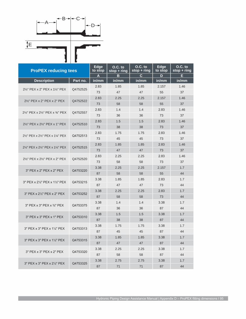
Hydronic Piping Design Assistance Manual | Appendix D – ProPEX fitting dimensions l 95
A DB C
E
ProPEX reducing teesEdge
to stopO.C. to
stop + ringO.C. to
stop + ringEdge
to stopO.C. to
stop + ringA B C D E
Description Part no. in/mm in/mm in/mm in/mm in/mm
2½" PEX x 2" PEX x 1½" PEX Q47525252.83 1.85 1.85 2.157 1.46
73 47 47 55 37
2½" PEX x 2" PEX x 2" PEX Q47525222.83 2.25 2.25 2.157 1.46
73 58 58 55 37
2½" PEX x 2½" PEX x ¾" PEX Q47525572.83 1.4 1.4 2.83 1.46
73 36 36 73 37
2½" PEX x 2½" PEX x 1" PEX Q47525102.83 1.5 1.5 2.83 1.46
73 38 38 73 37
2½" PEX x 2½" PEX x 1¼" PEX Q47525132.83 1.75 1.75 2.83 1.46
73 45 45 73 37
2½" PEX x 2½" PEX x 1½" PEX Q47525152.83 1.85 1.85 2.83 1.46
73 47 47 73 37
2½" PEX x 2½" PEX x 2" PEX Q47525202.83 2.25 2.25 2.83 1.46
73 58 58 73 37
3" PEX x 2" PEX x 2" PEX Q47532203.38 2.25 2.25 2.157 1.7
87 58 58 55 44
3" PEX x 2½" PEX x 1½" PEX Q47532153.38 1.85 1.85 2.83 1.7
87 47 47 73 44
3" PEX x 2½" PEX x 2" PEX Q47532523.38 2.25 2.25 2.83 1.7
87 58 58 73 44
3" PEX x 3" PEX x ¾" PEX Q47533753.38 1.4 1.4 3.38 1.7
87 36 36 87 44
3" PEX x 3" PEX x 1" PEX Q47533103.38 1.5 1.5 3.38 1.7
87 38 38 87 44
3" PEX x 3" PEX x 1¼" PEX Q47533133.38 1.75 1.75 3.38 1.7
87 45 45 87 44
3" PEX x 3" PEX x 1½" PEX Q47533153.38 1.85 1.85 3.38 1.7
87 47 47 87 44
3" PEX x 3" PEX x 2" PEX Q47533203.38 2.25 2.25 3.38 1.7
87 58 58 87 44
3" PEX x 3" PEX x 2½" PEX Q47533253.38 2.75 2.75 3.38 1.7
87 71 71 87 44

96 | uponorengineering.com
ProPEX teesEdge to
pipe stopO.C. to pipe stop + ring
O.C. to pipe stop + ring
A B CDescription Part no. in/mm in/mm in/mm
½" PEX x ½" PEX x ½" PEX Q47550500.72 0.660 0.48
18 17 12
¾" PEX x ¾" PEX x ¾" PEX Q47575750.96 0.790 0.65
24 20
1" PEX x 1" PEX x 1" PEX Q47510101.19 1.005 0.83
31 26 21
1¼" PEX x 1¼" PEX x 1¼" PEX Q4751313
1.45 1.105 1.07
37 28 27
1½" PEX x 1½" PEX x 1½" PEX Q4751515
1.71 1.310 1.25
44 34 32
2" PEX x 2" PEX x 2" PEX Q47520002.16 1.770 1.80
55 45 46
½" PEX x ½" PEX x ½" PEX LF47050500.71 0.630 0.380
18 1 1
¾" PEX x ¾" PEX x ¾" PEX LF47075750.95 0.789 0.460
24 20 12
1" PEX x 1" PEX x 1" PEX LF47010101.18 1.005 0.699
30 26 18
2½" PEX x 2½" PEX x 2½" PEX Q4752500
2.83 2.7 1.46
73 69 37
3" PEX x 3" PEX x 3" PEX Q47530003.38 2.75 1.7
87 71 44
AB
C
ProPEX 45 elbowsEdge to
pipe stopO.C. to pipe stop + ring
O.C. to pipe stop
A B CDescription Part no. in/mm in/mm in/mm
1½" PEX x 1½" PEX 45 Elbow Q47615152.314 0.74 1.714
59 19 44
2" PEX x 2" PEX 45 Elbow Q47620202.907 0.95 2.157
75 24 55
2½" PEX x 2½" PEX 45 Elbow Q47625253.83 1.25 2.83
98 32 73
3" PEX x 3" PEX 45 Elbow Q47630304.48 1.35 3.38
115 35 87
C
B
B
DimA
AC

Hydronic Piping Design Assistance Manual | Appendix D – ProPEX fitting dimensions l 97
ProPEX elbowsEdge to
pipe stopO.C. to pipe stop + ring
O.C. to pipe stop + ring
A B CDescription Part no. in/mm in/mm in/mm
½" PEX x ½" PEX EP Elbow Q47605001.269 0.63 0.719
33 16 18
¾" PEX x ¾" PEX EP Elbow Q47607501.63 0.775 0.955
42 20 24
1" PEX x 1" PEX EP Elbow Q47610002.051 1 1.191
53 26 31
1¼" PEX x 1¼" PEX EP Elbow Q47612502.445 1.14 1.445
63 29 37
1½" PEX x 1½" PEX EP Elbow Q47615002.77 1.34 1.714
71 34 44
2" PEX x 2" PEX EP Elbow Q47620003.757 1.8 2.157
96 46 55
¾" PEX x ¾" PEX Brass Elbow LF47107501.64 0.795 0.955
42 20 24
1" PEX x 1" PEX Brass Elbow LF47110002.06 1.02 1.191
53 26 31
2½" PEX x 2½" PEX Elbow Q47625004.93 2.35 2.83
126 60 73
3" PEX x 3" PEX Elbow Q47630005.88 2.75 3.38
151 71 87
C
B
B
DimA
AC
ProPEX couplingsEdge to
pipe stopO.C. to pipe stop + ring chamfer
A BDescription Part no. in/mm in/mm
½" PEX x ½" PEX Q47750500.72 0.14
18 4
¾" PEX x ¾" PEX Q47775750.96 0.16
25 4
1" PEX x 1" PEX Q47710101.19 0.20
31 5
1¼" PEX x 1¼" PEX Q47713131.45 0.22
37 6
1½" PEX x 1½" PEX Q47715151.72 0.22
44 6
2" PEX x 2" PEX Q47720202.16 0.33
55 8
B
A
ProPEX couplingsEdge to
pipe stopO.C. to pipe stop + ring chamfer
A BDescription Part no. in/mm in/mm
½" PEX x ½" PEX LF45450500.65 0.21
17
¾" PEX x ¾" PEX LF45475750.95 0.16
24 4
1" PEX x 1" PEX LF45410101.18 0.20
30 5
2½" PEX x 2½" PEX Q47725252.83 0.375
73 10
3" PEX x 3" PEX Q47730303.38 0.375
87 10

98 | uponorengineering.com
ProPEX reducing couplingsEdge to
pipe stop O.C. to pipe stop + ring chamfer
Edge to pipe stop
O.C. to pipe stop + ring chamfer
A B C DDescription Part no. in/mm in/mm in/mm in/mm
½" PEX x ¾" PEX Q47750750.96 0.1425 0.72 0.1625
25 2 18 4
¾" PEX x 1" PEX Q47775100.96 0.1625 1.19 0.2025
25 2 31 5
1¼" PEX x ¾" PEX Q47713070.96 0.215 1.45 0.175
25 2 37 4
1¼" PEX x 1" PEX Q47713101.20 0.215 1.45 0.215
31 2 37 6
1½" PEX x ¾" PEX Q47715070.75 0.215 1.72 0.175
19 2 44 4
1½" PEX x 1" PEX Q47715101.20 0.215 1.72 0.215
31 2 44 6
1½" PEX x 1¼" PEX Q47715131.45 0.215 1.72 0.215
37 2 44 6
2" PEX x 1½" PEX Q47720151.77 0.325 2.16 0.265
3 3 55 7
¾" PEX x 1" PEX LF45475100.95 0.1625 1.16 0.2025
24 2 30 5
2½" PEX x 1¼" PEX Q47725132.83 0.375 1.458 0.125
73 10 37 3
2½" PEX x 1½" PEX Q47725152.83 0.375 1.715 0.125
73 10 44 3
2½" PEX x 2" PEX Q47725202.83 0.375 2.16 0.125
73 10 55 3
3" PEX x 2" PEX Q47730203.38 0.375 2.159 0.125
87 10 55 3
3" PEX x 2½" PEX Q47730253.38 0.375 2.83 0.125
87 10 73 3
A
B
D
C
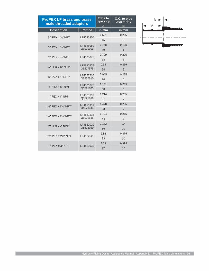
Hydronic Piping Design Assistance Manual | Appendix D – ProPEX fitting dimensions l 99
ProPEX LF brass and brass male threaded adapters
Edge to pipe stop
O.C. to pipe stop + ring
A BDescription Part no. in/mm in/mm
⅜" PEX x ½" NPT LF45238500.591 0.205
15 5
½" PEX x ½" NPT LF4525050 Q5525050
0.748 0.195
19 5
½" PEX x ¾" NPT LF45250750.709 0.205
18 5
¾" PEX x ¾" NPT* LF4527575 Q5527575
0.93 0.215
24 6
¾" PEX x 1" NPT* LF4527510 Q5527510
0.945 0.225
24 6
1" PEX x ¾" NPT LF4521075 Q5521075
1.181 0.265
30 6
1" PEX x 1" NPT* LF4521010 Q5521010
1.214 0.255
31 7
1¼" PEX x 1¼" NPT* LF4521313 Q5521313
1.478 0.255
38 7
1½" PEX x 1½" NPT* LF4521515 Q5521515
1.704 0.265
44 7
2" PEX x 2" NPT* LF4522020 Q5522020
2.172 0.4
56 10
2½" PEX x 2½" NPT LF45225252.83 0.375
73 10
3" PEX x 3" NPT LF45230303.38 0.375
87 10
B
A

100 | uponorengineering.com
ProPEX LF brass and brass female threaded adapters
Edge to pipe stop
O.C. to pipe stop + ring
A BDescription Part no. in/mm in/mm
½" PEX x ½" NPT LF4575050 Q5575050
0.709 0.155
18 4
½" PEX x ¾" NPT LF45750750.709 0.155
18 4
¾" PEX x ¾" NPT* LF4577575 Q5577575
0.945 0.175
24 4
¾" PEX x 1" NPT LF4577510 Q5577510
0.945 0.205
24 5
1" PEX x 1" NPT* LF4571010 Q5571010
1.181 0.245
30 6
1¼" PEX x 1¼" NPT* LF4571313 Q5571313
1.445 0.24
37 6
1½" PEX x 1½" NPT LF4571515 Q5571515
1.704 0.24
44 6
2" PEX x 2" NPT* LF4572020 Q5572020
2.146 0.3
55 8
ProPEX LF copper straight stubs
Edge to pipe stop
O.C. to pipe stop + ring
A BDescription Part no. in/mm in/mm
2½" x 2½" LF29625252.83 0.475
73 12
3" x 2" LF29630303 0.5
87 13
BA
AB

Hydronic Piping Design Assistance Manual | Appendix D – ProPEX fitting dimensions l 101
ProPEX LF brass and brass sweat adapters*
Edge to pipe stop
O.C. to pipe stop + ring
A BDescription Part no. in/mm in/mm
3⁄8" PEX x ½" Copper LF45138500.591 0.1425
15 4
½" PEX x ½" Copper LF4515050 Q5515050
0.709 0.1425
18 4
½" PEX x ¾" Copper LF45150750.709 0.1425
18 4
¾" PEX x ½" Copper LF4517550 Q5517550
0.945 0.1625
24 4
¾" PEX x ¾" NPT* LF4517575 Q5517575
0.945 0.1625
24 4
¾" PEX x 1" NPT LF4517510 Q5517510
0.945 0.1625
24 4
1" PEX x 1" NPT* LF4511010 Q5511010
1.181 0.2025
30 5
1¼" PEX x 1¼" NPT* LF4511313 Q5511313
1.4455 0.2025
37 5
1½" PEX x 1½" NPT LF4511515 Q5511515
1.704 0.2025
44 5
2" PEX x 2" NPT* LF4512020 Q5512020
2.147 0.3
55 8
2½" PEX x 2½" NPT LF45125252.83 0.125
73 3
3" PEX x 3" NPT LF45130303.38 0.125
87 3
*Sweated onto copper stub
ProPEX LF brass and brass fitting adapters*
Edge to pipe stop
O.C. to pipe stop + ring
A BDescription Part no. in/mm in/mm
½" PEX x ½" Copper LF4505050 Q5505050
0.709 0.1425
18 4
½" PEX x ¾" Copper LF45050750.709 0.1425
18 4
¾" PEX x ½" Copper LF4507550 Q5507550
0.945 0.1625
24 4
¾" PEX x ¾" NPT* LF4507575 Q5507575
0.9455 0.1625
24 4
¾" PEX x 1" NPT LF4507510 Q5507510
0.9455 0.1625
24 4
1" PEX x 1" NPT* LF4501010 Q5501010
1.181 0.2025
30 5
1¼" PEX x 1¼" NPT* LF4501313 Q5501313
1.4455 0.2025
37 5
1½" PEX x 1½" NPT LF4501515 Q5501515
1.704 0.2025
44 5
2" PEX x 2" NPT* LF4502020 Q5502020
2.147 0.325
55 8
*Sweated into hub-end of fitting
B
A
B
A

102 | uponorengineering.com
ProPEX brass R32 manifold elbows
O.C. to pipe stop + ring
Edge to pipe stop
A BDescription Part no. in/mm in/mm
R32 x ¾" ProPEX Elbow Q41532751.00 0.945
26 24
R32 x 1" ProPEX Elbow Q41532101.04 1.181
27 30
R32 x 1 ¼" ProPEX Elbow Q41532130.99 1.445
25 37
R32 x 1 ½" ProPEX Elbow Q41532150.99 1.704
25 44
ProPEX brass R32 manifold fittings
Edge to pipe stop
O.C. to pipe stop + ring
A BDescription Part no. in/mm in/mm
R32 x ¾" ProPEX Q41432750.95 0.275
24 7
R32 x 1" ProPEX Q41432101.18 0.315
30 8
R32 x 1¼" ProPEX Q41432131.45 0.315
37 8
R32 x 1½" ProPEX Q41432151.70 0.315
44 8
A
B
B
A
ProPEX ringsDelta A & B
ADescription Part no. in/mm
½" ProPEX Ring with Stop Q4690512 0.08
¾" ProPEX Ring with Stop Q4690756 0.1
1" ProPEX Ring with Stop Q4691000 0.14
1¼" ProPEX Ring with Stop Q4691250 0.14
1½" ProPEX Ring with Stop Q4691500 0.14
2" ProPEX Ring with Stop Q4692000 0.2
A
B

Hydronic Piping Design Assistance Manual | Appendix E – Expansion arm and loop calculations l 103
PEX with PEX-a Pipe Support, strut and strut clamps has a thermal expansion rate of 0.08"/10°F ΔT/100 ft (2.03mm/5.56°C ΔT/30.48m) – see pages 101 to 110.
Thermal expansion in underground applications For direct-burial applications, mitigate the effects of thermal expansion with a proper installation that provides adequate resistance to axial stress. Per PPI TR-21 Thermal Expansion and Contraction in Plastics Piping Systems,
restrain a buried or concrete-encased pipe from both lateral and axial movement with surrounding embedment material. The magnitude of the frictional restraining force is dependent on the nature of the soil and on installation and operating conditions.
For example, the extent of compaction near the pipe can affect the quality of contact between the pipe and surrounding soil. The anchoring or restraining effect of surrounding soil on pipe movement can be significantly augmented by external pipe geometry. Tees, lateral
connections and changes in direction all help to anchor a pipe in the surrounding soil.
Appendix E Expansion arm and loop calculations
½" PEX pipe expansion armDelta T
(ΔT)Run (ft)
Delta L (in)
Flexible arm length (in)
L1 (in)
L2 (in)
PEX with PEX-a Pipe Support, strut and strut clam
ps has a therm
al expansion rate of 0.08"/10°F ΔT/100 ft (2.03mm
/5.56°C ΔT/30.48m
).
10
50 0.04 1.90 0.38 0.7660 0.048 2.08 0.42 0.8370 0.056 2.24 0.45 0.9080 0.064 2.40 0.48 0.9690 0.072 2.55 0.51 1.02
100 0.08 2.68 0.54 1.07
20
50 0.08 2.68 0.54 1.0760 0.096 2.94 0.59 1.1870 0.112 3.17 0.63 1.2780 0.128 3.39 0.68 1.3690 0.144 3.60 0.72 1.44
100 0.16 3.79 0.76 1.52
30
50 0.12 3.29 0.66 1.3160 0.144 3.60 0.72 1.4470 0.168 3.89 0.78 1.5680 0.192 4.16 0.83 1.6690 0.216 4.41 0.88 1.76
100 0.24 4.65 0.93 1.86
40
50 0.16 3.79 0.76 1.5260 0.192 4.16 0.83 1.6670 0.224 4.49 0.90 1.8080 0.256 4.80 0.96 1.9290 0.288 5.09 1.02 2.04
100 0.32 5.37 1.07 2.15
½" PEX pipe expansion armDelta T
(ΔT)Run (ft)
Delta L (in)
Flexible arm length (in)
L1 (in)
L2 (in)
PEX with PEX-a Pipe Support, strut and strut clam
ps has a therm
al expansion rate of 0.08"/10°F ΔT/100 ft (2.03mm
/5.56°C ΔT/30.48m
).
50
50 0.2 4.24 0.85 1.7060 0.24 4.65 0.93 1.8670 0.28 5.02 1.00 2.0180 0.32 5.37 1.07 2.1590 0.36 5.69 1.14 2.28
100 0.4 6.00 1.20 2.40
60
50 0.24 4.65 0.93 1.8660 0.288 5.09 1.02 2.0470 0.336 5.50 1.10 2.2080 0.384 5.88 1.18 2.3590 0.432 6.24 1.25 2.49
100 0.48 6.57 1.31 2.63
70
50 0.28 5.02 1.00 2.0160 0.336 5.50 1.10 2.2070 0.392 5.94 1.19 2.3880 0.448 6.35 1.27 2.5490 0.504 6.73 1.35 2.69
100 0.56 7.10 1.42 2.84
80
50 0.32 5.37 1.07 2.1560 0.384 5.88 1.18 2.3570 0.448 6.35 1.27 2.5480 0.512 6.79 1.36 2.7290 0.576 7.20 1.44 2.88
100 0.64 7.59 1.52 3.04
Table E-1: PEX pipe expansion arm calculations ½" to 3"

104 | uponorengineering.com
½" PEX pipe expansion armDelta T
(ΔT)Run (ft)
Delta L (in)
Flexible arm length (in)
L1 (in)
L2 (in)
PEX with PEX-a Pipe Support, strut and strut clam
ps has a therm
al expansion rate of 0.08"/10°F ΔT/100 ft (2.03mm
/5.56°C ΔT/30.48m
).
90
50 0.36 5.69 1.14 2.2860 0.432 6.24 1.25 2.4970 0.504 6.73 1.35 2.6980 0.576 7.20 1.44 2.8890 0.648 7.64 1.53 3.05
100 0.72 8.05 1.61 3.22
100
50 0.4 6.00 1.20 2.4060 0.48 6.57 1.31 2.6370 0.56 7.10 1.42 2.8480 0.64 7.59 1.52 3.0490 0.72 8.05 1.61 3.22
100 0.8 8.49 1.70 3.39
110
50 0.44 6.29 1.26 2.5260 0.528 6.89 1.38 2.7670 0.616 7.45 1.49 2.9880 0.704 7.96 1.59 3.1890 0.792 8.44 1.69 3.38
100 0.88 8.90 1.78 3.56
120
50 0.48 6.57 1.31 2.6360 0.576 7.20 1.44 2.8870 0.672 7.78 1.56 3.1180 0.768 8.31 1.66 3.3390 0.864 8.82 1.76 3.53
100 0.96 9.30 1.86 3.72
130
50 0.52 6.84 1.37 2.7460 0.624 7.49 1.50 3.0070 0.728 8.09 1.62 3.2480 0.832 8.65 1.73 3.4690 0.936 9.18 1.84 3.67
100 1.04 9.67 1.93 3.87
140
50 0.56 7.10 1.42 2.8460 0.672 7.78 1.56 3.1170 0.784 8.40 1.68 3.3680 0.896 8.98 1.80 3.5990 1.008 9.52 1.90 3.81
100 1.12 10.04 2.01 4.02
150
50 0.6 7.35 1.47 2.9460 0.72 8.05 1.61 3.2270 0.84 8.69 1.74 3.4880 0.96 9.30 1.86 3.7290 1.08 9.86 1.97 3.94
100 1.2 10.39 2.08 4.16
Table E-1: PEX pipe expansion arm calculations ½" to 3"
½" PEX pipe expansion armDelta T
(ΔT)Run (ft)
Delta L (in)
Flexible arm length (in)
L1 (in)
L2 (in)
160
50 0.64 7.59 1.52 3.0460 0.768 8.31 1.66 3.3370 0.896 8.98 1.80 3.5980 1.024 9.60 1.92 3.8490 1.152 10.18 2.04 4.07
100 1.28 10.73 2.15 4.29
¾" PEX pipe expansion armDelta T
(ΔT)Run (ft)
Delta L (in)
Flexible arm length (in)
L1 (in)
L2 (in)
PEX with PEX-a Pipe Support, strut and strut clam
ps has a therm
al expansion rate of 0.08"/10°F ΔT/100 ft (2.03mm
/5.56°C ΔT/30.48m
). 10
50 0.04 2.24 0.45 0.9060 0.048 2.46 0.49 0.9870 0.056 2.66 0.53 1.0680 0.064 2.84 0.57 1.1490 0.072 3.01 0.60 1.20
100 0.08 3.17 0.63 1.27
20
50 0.08 3.17 0.63 1.2760 0.096 3.48 0.70 1.3970 0.112 3.76 0.75 1.5080 0.128 4.02 0.80 1.6190 0.144 4.26 0.85 1.70
100 0.16 4.49 0.90 1.80
30
50 0.12 3.89 0.78 1.5660 0.144 4.26 0.85 1.7070 0.168 4.60 0.92 1.8480 0.192 4.92 0.98 1.9790 0.216 5.22 1.04 2.09
100 0.24 5.50 1.10 2.20
40
50 0.16 4.49 0.90 1.8060 0.192 4.92 0.98 1.9770 0.224 5.31 1.06 2.1380 0.256 5.68 1.14 2.2790 0.288 6.02 1.20 2.41
100 0.32 6.35 1.27 2.54
50
50 0.2 5.02 1.00 2.0160 0.24 5.50 1.10 2.2070 0.28 5.94 1.19 2.3880 0.32 6.35 1.27 2.5490 0.36 6.73 1.35 2.69
100 0.4 7.10 1.42 2.84
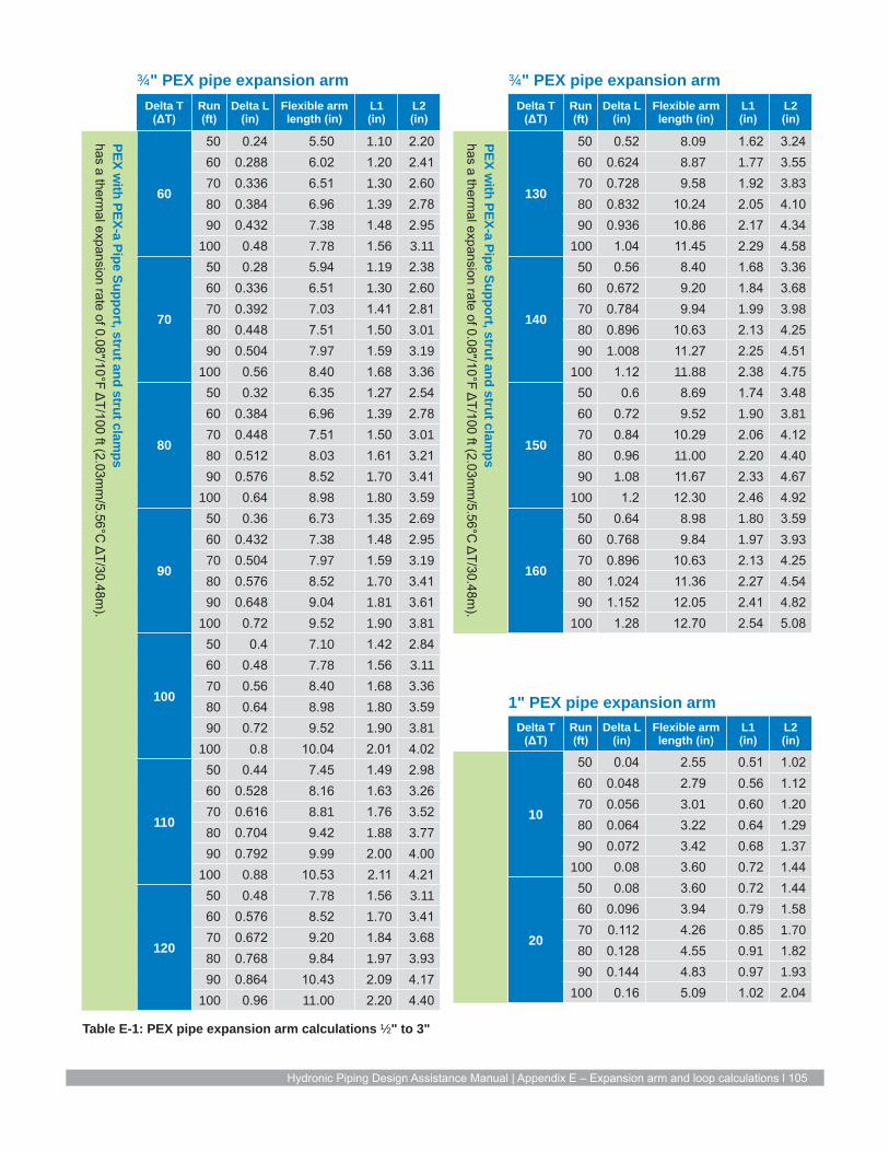
Hydronic Piping Design Assistance Manual | Appendix E – Expansion arm and loop calculations l 105
Table E-1: PEX pipe expansion arm calculations ½" to 3"
¾" PEX pipe expansion armDelta T
(ΔT)Run (ft)
Delta L (in)
Flexible arm length (in)
L1 (in)
L2 (in)
PEX with PEX-a Pipe Support, strut and strut clam
ps has a therm
al expansion rate of 0.08"/10°F ΔT/100 ft (2.03mm
/5.56°C ΔT/30.48m
).
60
50 0.24 5.50 1.10 2.2060 0.288 6.02 1.20 2.4170 0.336 6.51 1.30 2.6080 0.384 6.96 1.39 2.7890 0.432 7.38 1.48 2.95
100 0.48 7.78 1.56 3.11
70
50 0.28 5.94 1.19 2.3860 0.336 6.51 1.30 2.6070 0.392 7.03 1.41 2.8180 0.448 7.51 1.50 3.0190 0.504 7.97 1.59 3.19
100 0.56 8.40 1.68 3.36
80
50 0.32 6.35 1.27 2.5460 0.384 6.96 1.39 2.7870 0.448 7.51 1.50 3.0180 0.512 8.03 1.61 3.2190 0.576 8.52 1.70 3.41
100 0.64 8.98 1.80 3.59
90
50 0.36 6.73 1.35 2.6960 0.432 7.38 1.48 2.9570 0.504 7.97 1.59 3.1980 0.576 8.52 1.70 3.4190 0.648 9.04 1.81 3.61
100 0.72 9.52 1.90 3.81
100
50 0.4 7.10 1.42 2.8460 0.48 7.78 1.56 3.1170 0.56 8.40 1.68 3.3680 0.64 8.98 1.80 3.5990 0.72 9.52 1.90 3.81
100 0.8 10.04 2.01 4.02
110
50 0.44 7.45 1.49 2.9860 0.528 8.16 1.63 3.2670 0.616 8.81 1.76 3.5280 0.704 9.42 1.88 3.7790 0.792 9.99 2.00 4.00
100 0.88 10.53 2.11 4.21
120
50 0.48 7.78 1.56 3.1160 0.576 8.52 1.70 3.4170 0.672 9.20 1.84 3.6880 0.768 9.84 1.97 3.9390 0.864 10.43 2.09 4.17
100 0.96 11.00 2.20 4.40
¾" PEX pipe expansion armDelta T
(ΔT)Run (ft)
Delta L (in)
Flexible arm length (in)
L1 (in)
L2 (in)
PEX with PEX-a Pipe Support, strut and strut clam
ps has a therm
al expansion rate of 0.08"/10°F ΔT/100 ft (2.03mm
/5.56°C ΔT/30.48m
).
130
50 0.52 8.09 1.62 3.2460 0.624 8.87 1.77 3.5570 0.728 9.58 1.92 3.8380 0.832 10.24 2.05 4.1090 0.936 10.86 2.17 4.34
100 1.04 11.45 2.29 4.58
140
50 0.56 8.40 1.68 3.3660 0.672 9.20 1.84 3.6870 0.784 9.94 1.99 3.9880 0.896 10.63 2.13 4.2590 1.008 11.27 2.25 4.51
100 1.12 11.88 2.38 4.75
150
50 0.6 8.69 1.74 3.4860 0.72 9.52 1.90 3.8170 0.84 10.29 2.06 4.1280 0.96 11.00 2.20 4.4090 1.08 11.67 2.33 4.67
100 1.2 12.30 2.46 4.92
160
50 0.64 8.98 1.80 3.5960 0.768 9.84 1.97 3.9370 0.896 10.63 2.13 4.2580 1.024 11.36 2.27 4.5490 1.152 12.05 2.41 4.82
100 1.28 12.70 2.54 5.08
1" PEX pipe expansion armDelta T
(ΔT)Run (ft)
Delta L (in)
Flexible arm length (in)
L1 (in)
L2 (in)
10
50 0.04 2.55 0.51 1.0260 0.048 2.79 0.56 1.1270 0.056 3.01 0.60 1.2080 0.064 3.22 0.64 1.2990 0.072 3.42 0.68 1.37
100 0.08 3.60 0.72 1.44
20
50 0.08 3.60 0.72 1.4460 0.096 3.94 0.79 1.5870 0.112 4.26 0.85 1.7080 0.128 4.55 0.91 1.8290 0.144 4.83 0.97 1.93
100 0.16 5.09 1.02 2.04

106 | uponorengineering.com
Table E-1: PEX pipe expansion arm calculations ½" to 3"
1" PEX pipe expansion armDelta T
(ΔT)Run (ft)
Delta L (in)
Flexible arm length (in)
L1 (in)
L2 (in)
PEX with PEX-a Pipe Support, strut and strut clam
ps has a therm
al expansion rate of 0.08"/10°F ΔT/100 ft (2.03mm
/5.56°C ΔT/30.48m
).
30
50 0.12 4.41 0.88 1.7660 0.144 4.83 0.97 1.9370 0.168 5.22 1.04 2.0980 0.192 5.58 1.12 2.2390 0.216 5.92 1.18 2.37
100 0.24 6.24 1.25 2.49
40
50 0.16 5.09 1.02 2.0460 0.048 2.79 0.56 1.1270 0.056 3.01 0.60 1.2080 0.064 3.22 0.64 1.2990 0.072 3.42 0.68 1.37
100 0.08 3.60 0.72 1.44
50
50 0.2 5.69 1.14 2.2860 0.24 6.24 1.25 2.4970 0.28 6.73 1.35 2.6980 0.32 7.20 1.44 2.8890 0.36 7.64 1.53 3.05
100 0.4 8.05 1.61 3.22
60
50 0.24 6.24 1.25 2.4960 0.288 6.83 1.37 2.7370 0.336 7.38 1.48 2.9580 0.384 7.89 1.58 3.1590 0.432 8.37 1.67 3.35
100 0.48 8.82 1.76 3.53
70
50 0.28 6.73 1.35 2.6960 0.336 7.38 1.48 2.9570 0.392 7.97 1.59 3.1980 0.448 8.52 1.70 3.4190 0.504 9.04 1.81 3.61
100 0.56 9.52 1.90 3.81
80
50 0.32 7.20 1.44 2.8860 0.384 7.89 1.58 3.1570 0.448 8.52 1.70 3.4180 0.512 9.11 1.82 3.6490 0.576 9.66 1.93 3.86
100 0.64 10.18 2.04 4.07
90
50 0.04 2.55 0.51 1.0260 0.048 2.79 0.56 1.1270 0.056 3.01 0.60 1.2080 0.064 3.22 0.64 1.2990 0.072 3.42 0.68 1.37
100 0.08 3.60 0.72 1.44
1" PEX pipe expansion armDelta T
(ΔT)Run (ft)
Delta L (in)
Flexible arm length (in)
L1 (in)
L2 (in)
PEX with PEX-a Pipe Support, strut and strut clam
ps has a therm
al expansion rate of 0.08"/10°F ΔT/100 ft (2.03mm
/5.56°C ΔT/30.48m
).
100
50 0.08 3.60 0.72 1.4460 0.096 3.94 0.79 1.5870 0.112 4.26 0.85 1.7080 0.128 4.55 0.91 1.8290 0.144 4.83 0.97 1.93
100 0.16 5.09 1.02 2.04
110
50 0.44 8.44 1.69 3.3860 0.528 9.25 1.85 3.7070 0.616 9.99 2.00 4.0080 0.704 10.68 2.14 4.2790 0.792 11.33 2.27 4.53
100 0.88 11.94 2.39 4.78
120
50 0.48 8.82 1.76 3.5360 0.576 9.66 1.93 3.8670 0.672 10.43 2.09 4.1780 0.768 11.15 2.23 4.4690 0.864 11.83 2.37 4.73
100 0.96 12.47 2.49 4.99
130
50 0.52 9.18 1.84 3.6760 0.624 10.05 2.01 4.0270 0.728 10.86 2.17 4.3480 0.832 11.61 2.32 4.6490 0.936 12.31 2.46 4.93
100 1.04 12.98 2.60 5.19
140
50 0.56 9.52 1.90 3.8160 0.672 10.43 2.09 4.1770 0.784 11.27 2.25 4.5180 0.896 12.05 2.41 4.8290 1.008 12.78 2.56 5.11
100 1.12 13.47 2.69 5.39
150
50 0.6 9.86 1.97 3.9460 0.72 10.80 2.16 4.3270 0.84 11.67 2.33 4.6780 0.96 12.47 2.49 4.9990 1.08 13.23 2.65 5.29
100 1.2 13.94 2.79 5.58
160
50 0.64 10.18 2.04 4.0760 0.768 11.15 2.23 4.4670 0.896 12.05 2.41 4.8280 1.024 12.88 2.58 5.1590 1.152 13.66 2.73 5.46
100 1.28 14.40 2.88 5.76

Hydronic Piping Design Assistance Manual | Appendix E – Expansion arm and loop calculations l 107
Table E-1: PEX pipe expansion arm calculations ½" to 3"
1¼" PEX pipe expansion armDelta T
(ΔT)Run (ft)
Delta L (in)
Flexible arm length (in)
L1 (in)
L2 (in)
PEX with PEX-a Pipe Support, strut and strut clam
ps has a therm
al expansion rate of 0.08"/10°F ΔT/100 ft (2.03mm
/5.56°C ΔT/30.48m
).
10
50 0.04 2.81 0.56 1.1360 0.048 3.08 0.62 1.2370 0.056 3.33 0.67 1.3380 0.064 3.56 0.71 1.4290 0.072 3.78 0.76 1.51
100 0.08 3.98 0.80 1.59
20
50 0.08 3.98 0.80 1.5960 0.096 4.36 0.87 1.7470 0.112 4.71 0.94 1.8880 0.128 5.03 1.01 2.0190 0.144 5.34 1.07 2.14
100 0.16 5.63 1.13 2.25
30
50 0.12 4.87 0.97 1.9560 0.144 5.34 1.07 2.1470 0.168 5.77 1.15 2.3180 0.192 6.17 1.23 2.4790 0.216 6.54 1.31 2.62
100 0.24 6.89 1.38 2.76
40
50 0.16 5.63 1.13 2.2560 0.192 6.17 1.23 2.4770 0.224 6.66 1.33 2.6680 0.256 7.12 1.42 2.8590 0.288 7.55 1.51 3.02
100 0.32 7.96 1.59 3.18
50
50 0.2 6.29 1.26 2.5260 0.24 6.89 1.38 2.7670 0.28 7.45 1.49 2.9880 0.32 7.96 1.59 3.1890 0.36 8.44 1.69 3.38
100 0.4 8.90 1.78 3.56
60
50 0.24 6.89 1.38 2.7660 0.288 7.55 1.51 3.0270 0.336 8.16 1.63 3.2680 0.384 8.72 1.74 3.4990 0.432 9.25 1.85 3.70
100 0.48 9.75 1.95 3.90
70
50 0.28 7.45 1.49 2.9860 0.336 8.16 1.63 3.2670 0.392 8.81 1.76 3.5280 0.448 9.42 1.88 3.7790 0.504 9.99 2.00 4.00
100 0.56 10.53 2.11 4.21
1¼" PEX pipe expansion armDelta T
(ΔT)Run (ft)
Delta L (in)
Flexible arm length (in)
L1 (in)
L2 (in)
PEX with PEX-a Pipe Support, strut and strut clam
ps has a therm
al expansion rate of 0.08"/10°F ΔT/100 ft (2.03mm
/5.56°C ΔT/30.48m
).
80
50 0.32 7.96 1.59 3.1860 0.384 8.72 1.74 3.4970 0.448 9.42 1.88 3.7780 0.512 10.07 2.01 4.0390 0.576 10.68 2.14 4.27
100 0.64 11.26 2.25 4.50
90
50 0.36 8.44 1.69 3.3860 0.432 9.25 1.85 3.7070 0.504 9.99 2.00 4.0080 0.576 10.68 2.14 4.2790 0.648 11.33 2.27 4.53
100 0.72 11.94 2.39 4.78
100
50 0.4 8.90 1.78 3.5660 0.48 9.75 1.95 3.9070 0.56 10.53 2.11 4.2180 0.64 11.26 2.25 4.5090 0.72 11.94 2.39 4.78
100 0.8 12.59 2.52 5.03
110
50 0.44 9.33 1.87 3.7360 0.528 10.22 2.04 4.0970 0.616 11.04 2.21 4.4280 0.704 11.81 2.36 4.7290 0.792 12.52 2.50 5.01
100 0.88 13.20 2.64 5.28
120
50 0.48 9.75 1.95 3.9060 0.576 10.68 2.14 4.2770 0.672 11.53 2.31 4.6180 0.768 12.33 2.47 4.9390 0.864 13.08 2.62 5.23
100 0.96 13.79 2.76 5.51
130
50 0.52 10.15 2.03 4.0660 0.624 11.12 2.22 4.4570 0.728 12.01 2.40 4.8080 0.832 12.83 2.57 5.1390 0.936 13.61 2.72 5.45
100 1.04 14.35 2.87 5.74
140
50 0.56 10.53 2.11 4.2160 0.672 11.53 2.31 4.6170 0.784 12.46 2.49 4.9880 0.896 13.32 2.66 5.3390 1.008 14.13 2.83 5.65
100 1.12 14.89 2.98 5.96

108 | uponorengineering.com
Table E-1: PEX pipe expansion arm calculations ½" to 3"
1½" PEX pipe expansion armDelta T
(ΔT)Run (ft)
Delta L (in)
Flexible arm length (in)
L1 (in)
L2 (in)
PEX with PEX-a Pipe Support, strut and strut clam
ps has a therm
al expansion rate of 0.08"/10°F ΔT/100 ft (2.03mm
/5.56°C ΔT/30.48m
).
10
50 0.04 3.06 0.61 1.2260 0.048 3.35 0.67 1.3470 0.056 3.62 0.72 1.4580 0.064 3.87 0.77 1.5590 0.072 4.10 0.82 1.64
100 0.08 4.33 0.87 1.73
20
50 0.08 4.33 0.87 1.7360 0.096 4.74 0.95 1.9070 0.112 5.12 1.02 2.0580 0.128 5.47 1.09 2.1990 0.144 5.80 1.16 2.32
100 0.16 6.12 1.22 2.45
30
50 0.12 5.30 1.06 2.1260 0.144 5.80 1.16 2.3270 0.168 6.27 1.25 2.5180 0.192 6.70 1.34 2.6890 0.216 7.11 1.42 2.84
100 0.24 7.49 1.50 3.00
40
50 0.16 6.12 1.22 2.4560 0.192 6.70 1.34 2.6870 0.224 7.24 1.45 2.9080 0.256 7.74 1.55 3.1090 0.288 8.21 1.64 3.28
100 0.32 8.65 1.73 3.46
1½" PEX pipe expansion armDelta T
(ΔT)Run (ft)
Delta L (in)
Flexible arm length (in)
L1 (in)
L2 (in)
PEX with PEX-a Pipe Support, strut and strut clam
ps has a therm
al expansion rate of 0.08"/10°F ΔT/100 ft (2.03mm
/5.56°C ΔT/30.48m
).
50
50 0.2 6.84 1.37 2.7460 0.24 7.49 1.50 3.0070 0.28 8.09 1.62 3.2480 0.32 8.65 1.73 3.4690 0.36 9.18 1.84 3.67
100 0.4 9.67 1.93 3.87
60
50 0.24 7.49 1.50 3.0060 0.288 8.21 1.64 3.2870 0.336 8.87 1.77 3.5580 0.384 9.48 1.90 3.7990 0.432 10.05 2.01 4.02
100 0.48 10.60 2.12 4.24
70
50 0.28 8.09 1.62 3.2460 0.336 8.87 1.77 3.5570 0.392 9.58 1.92 3.8380 0.448 10.24 2.05 4.1090 0.504 10.86 2.17 4.34
100 0.56 11.45 2.29 4.58
80
50 0.32 8.65 1.73 3.4660 0.384 9.48 1.90 3.7970 0.448 10.24 2.05 4.1080 0.512 10.95 2.19 4.3890 0.576 11.61 2.32 4.64
100 0.64 12.24 2.45 4.90
90
50 0.36 9.18 1.84 3.6760 0.432 10.05 2.01 4.0270 0.504 10.86 2.17 4.3480 0.576 11.61 2.32 4.6490 0.648 12.31 2.46 4.93
100 0.72 12.98 2.60 5.19
100
50 0.4 9.67 1.93 3.8760 0.48 10.60 2.12 4.2470 0.56 11.45 2.29 4.5880 0.64 12.24 2.45 4.9090 0.72 12.98 2.60 5.19
100 0.8 13.68 2.74 5.47
110
50 0.44 10.15 2.03 4.0660 0.528 11.12 2.22 4.4570 0.616 12.01 2.40 4.8080 0.704 12.83 2.57 5.1390 0.792 13.61 2.72 5.45
100 0.88 14.35 2.87 5.74
1¼" PEX pipe expansion armDelta T
(ΔT)Run (ft)
Delta L (in)
Flexible arm length (in)
L1 (in)
L2 (in)
150
50 0.6 10.90 2.18 4.3660 0.72 11.94 2.39 4.7870 0.84 12.90 2.58 5.1680 0.96 13.79 2.76 5.5190 1.08 14.62 2.92 5.85
100 1.2 15.41 3.08 6.17
160
50 0.64 11.26 2.25 4.5060 0.768 12.33 2.47 4.9370 0.896 13.32 2.66 5.3380 1.024 14.24 2.85 5.7090 1.152 15.10 3.02 6.04
100 1.28 15.92 3.18 6.37

Hydronic Piping Design Assistance Manual | Appendix E – Expansion arm and loop calculations l 109
1½" PEX pipe expansion armDelta T
(ΔT)Run (ft)
Delta L (in)
Flexible arm length (in)
L1 (in)
L2 (in)
PEX with PEX-a Pipe Support, strut and strut clam
ps has a therm
al expansion rate of 0.08"/10°F ΔT/100 ft (2.03mm
/5.56°C ΔT/30.48m
).
120
50 0.48 10.60 2.12 4.2460 0.576 11.61 2.32 4.6470 0.672 12.54 2.51 5.0280 0.768 13.41 2.68 5.3690 0.864 14.22 2.84 5.69
100 0.96 14.99 3.00 6.00
130
50 0.52 11.03 2.21 4.4160 0.624 12.08 2.42 4.8370 0.728 13.05 2.61 5.2280 0.832 13.95 2.79 5.5890 0.936 14.80 2.96 5.92
100 1.04 15.60 3.12 6.24
140
50 0.56 11.45 2.29 4.5860 0.672 12.54 2.51 5.0270 0.784 13.54 2.71 5.4280 0.896 14.48 2.90 5.7990 1.008 15.36 3.07 6.14
100 1.12 16.19 3.24 6.48
150
50 0.6 11.85 2.37 4.7460 0.72 12.98 2.60 5.1970 0.84 14.02 2.80 5.6180 0.96 14.99 3.00 6.0090 1.08 15.90 3.18 6.36
100 1.2 16.76 3.35 6.70
160
50 0.64 12.24 2.45 4.9060 0.768 13.41 2.68 5.3670 0.896 14.48 2.90 5.7980 1.024 15.48 3.10 6.1990 1.152 16.42 3.28 6.57
100 1.28 17.31 3.46 6.92
Table E-1: PEX pipe expansion arm calculations ½" to 3"
2" PEX pipe expansion armDelta T
(ΔT)Run (ft)
Delta L (in)
Flexible arm length (in)
L1 (in)
L2 (in)
10
50 0.04 3.50 0.70 1.4060 0.048 3.83 0.77 1.5370 0.056 4.14 0.83 1.6680 0.064 4.43 0.89 1.7790 0.072 4.69 0.94 1.88
100 0.08 4.95 0.99 1.98
2" PEX pipe expansion armDelta T
(ΔT)Run (ft)
Delta L (in)
Flexible arm length (in)
L1 (in)
L2 (in)
PEX with PEX-a Pipe Support, strut and strut clam
ps has a therm
al expansion rate of 0.08"/10°F ΔT/100 ft (2.03mm
/5.56°C ΔT/30.48m
).
20
50 0.08 4.95 0.99 1.9860 0.096 5.42 1.08 2.1770 0.112 5.85 1.17 2.3480 0.128 6.26 1.25 2.5090 0.144 6.64 1.33 2.66
100 0.16 7.00 1.40 2.80
30
50 0.12 6.06 1.21 2.4260 0.144 6.64 1.33 2.6670 0.168 7.17 1.43 2.8780 0.192 7.66 1.53 3.0790 0.216 8.13 1.63 3.25
100 0.24 8.57 1.71 3.43
40
50 0.16 7.00 1.40 2.8060 0.192 7.66 1.53 3.0770 0.224 8.28 1.66 3.3180 0.256 8.85 1.77 3.5490 0.288 9.39 1.88 3.76
100 0.32 9.90 1.98 3.96
50
50 0.2 7.82 1.56 3.1360 0.24 8.57 1.71 3.4370 0.28 9.26 1.85 3.7080 0.32 9.90 1.98 3.9690 0.36 10.50 2.10 4.20
100 0.4 11.06 2.21 4.43
60
50 0.24 8.57 1.71 3.4360 0.288 9.39 1.88 3.7670 0.336 10.14 2.03 4.0680 0.384 10.84 2.17 4.3490 0.432 11.50 2.30 4.60
100 0.48 12.12 2.42 4.85
70
50 0.28 9.26 1.85 3.7060 0.336 10.14 2.03 4.0670 0.392 10.95 2.19 4.3880 0.448 11.71 2.34 4.6890 0.504 12.42 2.48 4.97
100 0.56 13.09 2.62 5.24
80
50 0.32 9.90 1.98 3.9660 0.384 10.84 2.17 4.3470 0.448 11.71 2.34 4.6880 0.512 12.52 2.50 5.0190 0.576 13.28 2.66 5.31
100 0.64 13.99 2.80 5.60

110 | uponorengineering.com
Table E-1: PEX pipe expansion arm calculations ½" to 3"
2" PEX pipe expansion armDelta T
(ΔT)Run (ft)
Delta L (in)
Flexible arm length (in)
L1 (in)
L2 (in)
PEX with PEX-a Pipe Support, strut and strut clam
ps has a therm
al expansion rate of 0.08"/10°F ΔT/100 ft (2.03mm
/5.56°C ΔT/30.48m
).
90
50 0.36 10.50 2.10 4.2060 0.432 11.50 2.30 4.6070 0.504 12.42 2.48 4.9780 0.576 13.28 2.66 5.3190 0.648 14.08 2.82 5.63
100 0.72 14.84 2.97 5.94
100
50 0.4 11.06 2.21 4.4360 0.48 12.12 2.42 4.8570 0.56 13.09 2.62 5.2480 0.64 13.99 2.80 5.6090 0.72 14.84 2.97 5.94
100 0.8 15.65 3.13 6.26
110
50 0.44 11.60 2.32 4.6460 0.528 12.71 2.54 5.0870 0.616 13.73 2.75 5.4980 0.704 14.68 2.94 5.8790 0.792 15.57 3.11 6.23
100 0.88 16.41 3.28 6.56
120
50 0.48 12.12 2.42 4.8560 0.576 13.28 2.66 5.3170 0.672 14.34 2.87 5.7480 0.768 15.33 3.07 6.1390 0.864 16.26 3.25 6.50
100 0.96 17.14 3.43 6.86
130
50 0.52 12.61 2.52 5.0560 0.624 13.82 2.76 5.5370 0.728 14.93 2.99 5.9780 0.832 15.96 3.19 6.3890 0.936 16.92 3.38 6.77
100 1.04 17.84 3.57 7.14
140
50 0.56 13.09 2.62 5.2460 0.672 14.34 2.87 5.7470 0.784 15.49 3.10 6.2080 0.896 16.56 3.31 6.6290 1.008 17.56 3.51 7.03
100 1.12 18.51 3.70 7.41
150
50 0.6 13.55 2.71 5.4260 0.72 14.84 2.97 5.9470 0.84 16.03 3.21 6.4180 0.96 17.14 3.43 6.8690 1.08 18.18 3.64 7.27
100 1.2 19.16 3.83 7.66
2" PEX pipe expansion armDelta T
(ΔT)Run (ft)
Delta L (in)
Flexible arm length (in)
L1 (in)
L2 (in)
160
50 0.64 13.99 2.80 5.6060 0.768 15.33 3.07 6.1370 0.896 16.56 3.31 6.6280 1.024 17.70 3.54 7.0890 1.152 18.78 3.76 7.51
100 1.28 19.79 3.96 7.92
2½" PEX pipe expansion armDelta T
(ΔT)Run (ft)
Delta L (in)
Flexible arm length (in)
L1 (in)
L2 (in)
PEX with PEX-a Pipe Support, strut and strut clam
ps has a therm
al expansion rate of 0.08"/10°F ΔT/100 ft (2.03mm
/5.56°C ΔT/30.48m
). 10
50 0.04 3.89 0.78 1.5660 0.048 4.26 0.85 1.7070 0.056 4.60 0.92 1.8480 0.064 4.92 0.98 1.9790 0.072 5.22 1.04 2.09
100 0.08 5.50 1.10 2.20
20
50 0.08 5.50 1.10 2.2060 0.096 6.02 1.20 2.4170 0.112 6.51 1.30 2.6080 0.128 6.96 1.39 2.7890 0.144 7.38 1.48 2.95
100 0.16 7.78 1.56 3.11
30
50 0.12 6.73 1.35 2.6960 0.144 7.38 1.48 2.9570 0.168 7.97 1.59 3.1980 0.192 8.52 1.70 3.4190 0.216 9.04 1.81 3.61
100 0.24 9.52 1.90 3.81
40
50 0.16 7.78 1.56 3.1160 0.192 8.52 1.70 3.4170 0.224 9.20 1.84 3.6880 0.256 9.84 1.97 3.9390 0.288 10.43 2.09 4.17
100 0.32 11.00 2.20 4.40
50
50 0.2 8.69 1.74 3.4860 0.24 9.52 1.90 3.8170 0.28 10.29 2.06 4.1280 0.32 11.00 2.20 4.4090 0.36 11.67 2.33 4.67
100 0.4 12.30 2.46 4.92

Hydronic Piping Design Assistance Manual | Appendix E – Expansion arm and loop calculations l 111
Table E-1: PEX pipe expansion arm calculations ½" to 3"
2½" PEX pipe expansion armDelta T
(ΔT)Run (ft)
Delta L (in)
Flexible arm length (in)
L1 (in)
L2 (in)
PEX with PEX-a Pipe Support, strut and strut clam
ps has a therm
al expansion rate of 0.08"/10°F ΔT/100 ft (2.03mm
/5.56°C ΔT/30.48m
).
60
50 0.24 9.52 1.90 3.8160 0.288 10.43 2.09 4.1770 0.336 11.27 2.25 4.5180 0.384 12.05 2.41 4.8290 0.432 12.78 2.56 5.11
100 0.48 13.47 2.69 5.39
70
50 0.28 10.29 2.06 4.1260 0.336 11.27 2.25 4.5170 0.392 12.17 2.43 4.8780 0.448 13.01 2.60 5.2190 0.504 13.80 2.76 5.52
100 0.56 14.55 2.91 5.82
80
50 0.32 11.00 2.20 4.4060 0.384 12.05 2.41 4.8270 0.448 13.01 2.60 5.2180 0.512 13.91 2.78 5.5690 0.576 14.76 2.95 5.90
100 0.64 15.55 3.11 6.22
90
50 0.36 11.67 2.33 4.6760 0.432 12.78 2.56 5.1170 0.504 13.80 2.76 5.5280 0.576 14.76 2.95 5.9090 0.648 15.65 3.13 6.26
100 0.72 16.50 3.30 6.60
100
50 0.4 12.30 2.46 4.9260 0.48 13.47 2.69 5.3970 0.56 14.55 2.91 5.8280 0.64 15.55 3.11 6.2290 0.72 16.50 3.30 6.60
100 0.8 17.39 3.48 6.96
110
50 0.44 12.90 2.58 5.1660 0.528 14.13 2.83 5.6570 0.616 15.26 3.05 6.1080 0.704 16.31 3.26 6.5390 0.792 17.30 3.46 6.92
100 0.88 18.24 3.65 7.30
120
50 0.48 13.47 2.69 5.3960 0.576 14.76 2.95 5.9070 0.672 15.94 3.19 6.3880 0.768 17.04 3.41 6.8290 0.864 18.07 3.61 7.23
100 0.96 19.05 3.81 7.62
2½" PEX pipe expansion armDelta T
(ΔT)Run (ft)
Delta L (in)
Flexible arm length (in)
L1 (in)
L2 (in)
PEX with PEX-a Pipe Support, strut and strut clam
ps has a therm
al expansion rate of 0.08"/10°F ΔT/100 ft (2.03mm
/5.56°C ΔT/30.48m
).
130
50 0.52 14.02 2.80 5.6160 0.624 15.36 3.07 6.1470 0.728 16.59 3.32 6.6480 0.832 17.73 3.55 7.0990 0.936 18.81 3.76 7.52
100 1.04 19.83 3.97 7.93
140
50 0.56 14.55 2.91 5.8260 0.672 15.94 3.19 6.3870 0.784 17.21 3.44 6.8980 0.896 18.40 3.68 7.3690 1.008 19.52 3.90 7.81
100 1.12 20.58 4.12 8.23
150
50 0.6 15.06 3.01 6.0260 0.72 16.50 3.30 6.6070 0.84 17.82 3.56 7.1380 0.96 19.05 3.81 7.6290 1.08 20.20 4.04 8.08
100 1.2 21.30 4.26 8.52
160
50 0.64 15.55 3.11 6.2260 0.768 17.04 3.41 6.8270 0.896 18.40 3.68 7.3680 1.024 19.67 3.93 7.8790 1.152 20.87 4.17 8.35
100 1.28 22.00 4.40 8.80
3" PEX pipe expansion armDelta T
(ΔT)Run (ft)
Delta L (in)
Flexible arm length (in)
L1 (in)
L2 (in)
10
50 0.04 4.24 0.85 1.7060 0.048 4.65 0.93 1.8670 0.056 5.02 1.00 2.0180 0.064 5.37 1.07 2.1590 0.072 5.69 1.14 2.28
100 0.08 6.00 1.20 2.40
20
50 0.08 6.00 1.20 2.4060 0.096 6.57 1.31 2.6370 0.112 7.10 1.42 2.8480 0.128 7.59 1.52 3.0490 0.144 8.05 1.61 3.22
100 0.16 8.49 1.70 3.39

112 | uponorengineering.com
3" PEX pipe expansion armDelta T
(ΔT)Run (ft)
Delta L (in)
Flexible arm length (in)
L1 (in)
L2 (in)
PEX with PEX-a Pipe Support, strut and strut clam
ps has a therm
al expansion rate of 0.08"/10°F ΔT/100 ft (2.03mm
/5.56°C ΔT/30.48m
).
30
50 0.12 7.35 1.47 2.9460 0.144 8.05 1.61 3.2270 0.168 8.69 1.74 3.4880 0.192 9.30 1.86 3.7290 0.216 9.86 1.97 3.94
100 0.24 10.39 2.08 4.16
40
50 0.16 8.49 1.70 3.3960 0.192 9.30 1.86 3.7270 0.224 10.04 2.01 4.0280 0.256 10.73 2.15 4.2990 0.288 11.38 2.28 4.55
100 0.32 12.00 2.40 4.80
50
50 0.2 9.49 1.90 3.7960 0.24 10.39 2.08 4.1670 0.28 11.22 2.24 4.4980 0.32 12.00 2.40 4.8090 0.36 12.73 2.55 5.09
100 0.4 13.42 2.68 5.37
60
50 0.24 10.39 2.08 4.1660 0.288 11.38 2.28 4.5570 0.336 12.30 2.46 4.9280 0.384 13.15 2.63 5.2690 0.432 13.94 2.79 5.58
100 0.48 14.70 2.94 5.88
70
50 0.28 11.22 2.24 4.4960 0.336 12.30 2.46 4.9270 0.392 13.28 2.66 5.3180 0.448 14.20 2.84 5.6890 0.504 15.06 3.01 6.02
100 0.56 15.87 3.17 6.35
80
50 0.32 12.00 2.40 4.8060 0.384 13.15 2.63 5.2670 0.448 14.20 2.84 5.6880 0.512 15.18 3.04 6.0790 0.576 16.10 3.22 6.44
100 0.64 16.97 3.39 6.79
90
50 0.36 12.73 2.55 5.0960 0.432 13.94 2.79 5.5870 0.504 15.06 3.01 6.0280 0.576 16.10 3.22 6.4490 0.648 17.08 3.42 6.83
100 0.72 18.00 3.60 7.20
3" PEX pipe expansion armDelta T
(ΔT)Run (ft)
Delta L (in)
Flexible arm length (in)
L1 (in)
L2 (in)
PEX with PEX-a Pipe Support, strut and strut clam
ps has a therm
al expansion rate of 0.08"/10°F ΔT/100 ft (2.03mm
/5.56°C ΔT/30.48m
).
100
50 0.4 13.42 2.68 5.3760 0.48 14.70 2.94 5.8870 0.56 15.87 3.17 6.3580 0.64 16.97 3.39 6.7990 0.72 18.00 3.60 7.20
100 0.8 18.97 3.79 7.59
110
50 0.44 14.07 2.81 5.6360 0.528 15.41 3.08 6.1770 0.616 16.65 3.33 6.6680 0.704 17.80 3.56 7.1290 0.792 18.88 3.78 7.55
100 0.88 19.90 3.98 7.96
120
50 0.48 14.70 2.94 5.8860 0.576 16.10 3.22 6.4470 0.672 17.39 3.48 6.9680 0.768 18.59 3.72 7.4490 0.864 19.72 3.94 7.89
100 0.96 20.78 4.16 8.31
130
50 0.52 15.30 3.06 6.1260 0.624 16.76 3.35 6.7070 0.728 18.10 3.62 7.2480 0.832 19.35 3.87 7.7490 0.936 20.52 4.10 8.21
100 1.04 21.63 4.33 8.65
140
50 0.56 15.87 3.17 6.3560 0.672 17.39 3.48 6.9670 0.784 18.78 3.76 7.5180 0.896 20.08 4.02 8.0390 1.008 21.30 4.26 8.52
100 1.12 22.45 4.49 8.98
150
50 0.6 16.43 3.29 6.5760 0.72 18.00 3.60 7.2070 0.84 19.44 3.89 7.7880 0.96 20.78 4.16 8.3190 1.08 22.05 4.41 8.82
100 1.2 23.24 4.65 9.30
160
50 0.64 16.97 3.39 6.7960 0.768 18.59 3.72 7.4470 0.896 20.08 4.02 8.0380 1.024 21.47 4.29 8.5990 1.152 22.77 4.55 9.11
100 1.28 24.00 4.80 9.60
Table E-1: PEX pipe expansion arm calculations ½" to 3"

Hydronic Piping Design Assistance Manual | Appendix E – Expansion arm and loop calculations l 113
Table E-2: PEX pipe expansion arm calculations ½" to 3"
½" PEX pipe expansion armDelta T
(ΔT)Run (ft)
Delta L (in)
Flexible arm length (in)
L1 (in)
L2 (in)
PEX with PEX-a Pipe Support and clevis hangers or loops
has a thermal expansion rate of 0.12/10°F ΔT/100 ft (3.05m
m/5.56°C
ΔT/30.48m).
10
50 0.06 2.32 0.46 0.9360 0.072 2.55 0.51 1.0270 0.084 2.75 0.55 1.1080 0.096 2.94 0.59 1.1890 0.108 3.12 0.62 1.25
100 0.12 3.29 0.66 1.31
20
50 0.12 3.29 0.66 1.3160 0.144 3.60 0.72 1.4470 0.168 3.89 0.78 1.5680 0.192 4.16 0.83 1.6690 0.216 4.41 0.88 1.76
100 0.24 4.65 0.93 1.86
30
50 0.18 4.02 0.80 1.6160 0.216 4.41 0.88 1.7670 0.252 4.76 0.95 1.9080 0.288 5.09 1.02 2.0490 0.324 5.40 1.08 2.16
100 0.36 5.69 1.14 2.28
40
50 0.24 4.65 0.93 1.8660 0.288 5.09 1.02 2.0470 0.336 5.50 1.10 2.2080 0.384 5.88 1.18 2.3590 0.432 6.24 1.25 2.49
100 0.48 6.57 1.31 2.63
50
50 0.3 5.20 1.04 2.0860 0.36 5.69 1.14 2.2870 0.42 6.15 1.23 2.4680 0.48 6.57 1.31 2.6390 0.54 6.97 1.39 2.79
100 0.6 7.35 1.47 2.94
60
50 0.36 5.69 1.14 2.2860 0.432 6.24 1.25 2.4970 0.504 6.73 1.35 2.6980 0.576 7.20 1.44 2.8890 0.648 7.64 1.53 3.05
100 0.72 8.05 1.61 3.22
½" PEX pipe expansion armDelta T
(ΔT)Run (ft)
Delta L (in)
Flexible arm length (in)
L1 (in)
L2 (in)
PEX with PEX-a Pipe Support and clevis hangers or loops
has a thermal expansion rate of 0.12/10°F ΔT/100 ft (3.05m
m/5.56°C
ΔT/30.48m).
70
50 0.42 6.15 1.23 2.4660 0.504 6.73 1.35 2.6970 0.588 7.27 1.45 2.9180 0.672 7.78 1.56 3.1190 0.756 8.25 1.65 3.30
100 0.84 8.69 1.74 3.48
80
50 0.48 6.57 1.31 2.6360 0.576 7.20 1.44 2.8870 0.672 7.78 1.56 3.1180 0.768 8.31 1.66 3.3390 0.864 8.82 1.76 3.53
100 0.96 9.30 1.86 3.72
90
50 0.54 6.97 1.39 2.7960 0.648 7.64 1.53 3.0570 0.756 8.25 1.65 3.3080 0.864 8.82 1.76 3.5390 0.972 9.35 1.87 3.74
100 1.08 9.86 1.97 3.94
100
50 0.6 7.35 1.47 2.9460 0.72 8.05 1.61 3.2270 0.84 8.69 1.74 3.4880 0.96 9.30 1.86 3.7290 1.08 9.86 1.97 3.94
100 1.2 10.39 2.08 4.16
110
50 0.66 7.71 1.54 3.0860 0.792 8.44 1.69 3.3870 0.924 9.12 1.82 3.6580 1.056 9.75 1.95 3.9090 1.188 10.34 2.07 4.14
100 1.32 10.90 2.18 4.36
120
50 0.72 8.05 1.61 3.2260 0.864 8.82 1.76 3.5370 1.008 9.52 1.90 3.8180 1.152 10.18 2.04 4.0790 1.296 10.80 2.16 4.32
100 1.44 11.38 2.28 4.55
PEX with PEX-a Pipe Support and clevis hangers or loops has a thermal expansion rate of 0.12/10°F ΔT/100 ft (3.05mm/5.56°C ΔT/30.48m) – see pages 111 to 120.

114 | uponorengineering.com
Table E-2: PEX pipe expansion arm calculations ½" to 3"
¾" PEX pipe expansion armDelta T
(ΔT)Run (ft)
Delta L (in)
Flexible arm length (in)
L1 (in)
L2 (in)
10
50 0.06 2.75 0.55 1.1060 0.072 3.01 0.60 1.2070 0.084 3.25 0.65 1.3080 0.096 3.48 0.70 1.3990 0.108 3.69 0.74 1.48
100 0.12 3.89 0.78 1.56
20
50 0.12 3.89 0.78 1.5660 0.144 4.26 0.85 1.7070 0.168 4.60 0.92 1.8480 0.192 4.92 0.98 1.9790 0.216 5.22 1.04 2.09
100 0.24 5.50 1.10 2.20
½" PEX pipe expansion armDelta T
(ΔT)Run (ft)
Delta L (in)
Flexible arm length (in)
L1 (in)
L2 (in)
PEX with PEX-a Pipe Support and clevis hangers or loops
has a thermal expansion rate of 0.12/10°F ΔT/100 ft (3.05m
m/5.56°C
ΔT/30.48m).
130
50 0.78 8.38 1.68 3.3560 0.936 9.18 1.84 3.6770 1.092 9.91 1.98 3.9780 1.248 10.60 2.12 4.2490 1.404 11.24 2.25 4.50
100 1.56 11.85 2.37 4.74
140
50 0.84 8.69 1.74 3.4860 1.008 9.52 1.90 3.8170 1.176 10.29 2.06 4.1280 1.344 11.00 2.20 4.4090 1.512 11.67 2.33 4.67
100 1.68 12.30 2.46 4.92
150
50 0.9 9.00 1.80 3.6060 1.08 9.86 1.97 3.9470 1.26 10.65 2.13 4.2680 1.44 11.38 2.28 4.5590 1.62 12.07 2.41 4.83
100 1.8 12.73 2.55 5.09
160
50 0.96 9.30 1.86 3.7260 1.152 10.18 2.04 4.0770 1.344 11.00 2.20 4.4080 1.536 11.76 2.35 4.7090 1.728 12.47 2.49 4.99
100 1.92 13.15 2.63 5.26
¾" PEX pipe expansion armDelta T
(ΔT)Run (ft)
Delta L (in)
Flexible arm length (in)
L1 (in)
L2 (in)
PEX with PEX-a Pipe Support and clevis hangers or loops
has a thermal expansion rate of 0.12/10°F ΔT/100 ft (3.05m
m/5.56°C
ΔT/30.48m).
30
50 0.18 4.76 0.95 1.9060 0.216 5.22 1.04 2.0970 0.252 5.63 1.13 2.2580 0.288 6.02 1.20 2.4190 0.324 6.39 1.28 2.56
100 0.36 6.73 1.35 2.69
40
50 0.24 5.50 1.10 2.2060 0.288 6.02 1.20 2.4170 0.336 6.51 1.30 2.6080 0.384 6.96 1.39 2.7890 0.432 7.38 1.48 2.95
100 0.48 7.78 1.56 3.11
50
50 0.3 6.15 1.23 2.4660 0.36 6.73 1.35 2.6970 0.42 7.27 1.45 2.9180 0.48 7.78 1.56 3.1190 0.54 8.25 1.65 3.30
100 0.6 8.69 1.74 3.48
60
50 0.36 6.73 1.35 2.6960 0.432 7.38 1.48 2.9570 0.504 7.97 1.59 3.1980 0.576 8.52 1.70 3.4190 0.648 9.04 1.81 3.61
100 0.72 9.52 1.90 3.81
70
50 0.42 7.27 1.45 2.9160 0.504 7.97 1.59 3.1970 0.588 8.61 1.72 3.4480 0.672 9.20 1.84 3.6890 0.756 9.76 1.95 3.90
100 0.84 10.29 2.06 4.12
80
50 0.48 7.78 1.56 3.1160 0.576 8.52 1.70 3.4170 0.672 9.20 1.84 3.6880 0.768 9.84 1.97 3.9390 0.864 10.43 2.09 4.17
100 0.96 11.00 2.20 4.40
90
50 0.54 8.25 1.65 3.3060 0.648 9.04 1.81 3.6170 0.756 9.76 1.95 3.9080 0.864 10.43 2.09 4.1790 0.972 11.07 2.21 4.43
100 1.08 11.67 2.33 4.67

Hydronic Piping Design Assistance Manual | Appendix E – Expansion arm and loop calculations l 115
¾" PEX pipe expansion armDelta T
(ΔT)Run (ft)
Delta L (in)
Flexible arm length (in)
L1 (in)
L2 (in)
PEX with PEX-a Pipe Support and clevis hangers or loops
has a thermal expansion rate of 0.12/10°F ΔT/100 ft (3.05m
m/5.56°C
ΔT/30.48m).
100
50 0.6 8.69 1.74 3.4860 0.72 9.52 1.90 3.8170 0.84 10.29 2.06 4.1280 0.96 11.00 2.20 4.4090 1.08 11.67 2.33 4.67
100 1.2 12.30 2.46 4.92
110
50 0.66 9.12 1.82 3.6560 0.792 9.99 2.00 4.0070 0.924 10.79 2.16 4.3280 1.056 11.53 2.31 4.6190 1.188 12.23 2.45 4.89
100 1.32 12.90 2.58 5.16
120
50 0.72 9.52 1.90 3.8160 0.864 10.43 2.09 4.1770 1.008 11.27 2.25 4.5180 1.152 12.05 2.41 4.8290 1.296 12.78 2.56 5.11
100 1.44 13.47 2.69 5.39
130
50 0.78 9.91 1.98 3.9760 0.936 10.86 2.17 4.3470 1.092 11.73 2.35 4.6980 1.248 12.54 2.51 5.0290 1.404 13.30 2.66 5.32
100 1.56 14.02 2.80 5.61
140
50 0.84 10.29 2.06 4.1260 1.008 11.27 2.25 4.5170 1.176 12.17 2.43 4.8780 1.344 13.01 2.60 5.2190 1.512 13.80 2.76 5.52
100 1.68 14.55 2.91 5.82
150
50 0.9 10.65 2.13 4.2660 1.08 11.67 2.33 4.6770 1.26 12.60 2.52 5.0480 1.44 13.47 2.69 5.3990 1.62 14.29 2.86 5.71
100 1.8 15.06 3.01 6.02
160
50 0.96 11.00 2.20 4.4060 1.152 12.05 2.41 4.8270 1.344 13.01 2.60 5.2180 1.536 13.91 2.78 5.5690 1.728 14.76 2.95 5.90
100 1.92 15.55 3.11 6.22
Table E-2: PEX pipe expansion arm calculations ½" to 3"
1" PEX pipe expansion armDelta T
(ΔT)Run (ft)
Delta L (in)
Flexible arm length (in)
L1 (in)
L2 (in)
PEX with PEX-a Pipe Support and clevis hangers or loops
has a thermal expansion rate of 0.12/10°F ΔT/100 ft (3.05m
m/5.56°C
ΔT/30.48m).
10
50 0.06 3.12 0.62 1.2560 0.072 3.42 0.68 1.3770 0.084 3.69 0.74 1.4880 0.096 3.94 0.79 1.5890 0.108 4.18 0.84 1.67
100 0.12 4.41 0.88 1.76
20
50 0.12 4.41 0.88 1.7660 0.144 4.83 0.97 1.9370 0.168 5.22 1.04 2.0980 0.192 5.58 1.12 2.2390 0.216 5.92 1.18 2.37
100 0.24 6.24 1.25 2.49
30
50 0.18 5.40 1.08 2.1660 0.216 5.92 1.18 2.3770 0.252 6.39 1.28 2.5680 0.288 6.83 1.37 2.7390 0.324 7.24 1.45 2.90
100 0.36 7.64 1.53 3.05
40
50 0.24 6.24 1.25 2.4960 0.072 3.42 0.68 1.3770 0.084 3.69 0.74 1.4880 0.096 3.94 0.79 1.5890 0.108 4.18 0.84 1.67
100 0.12 4.41 0.88 1.76
50
50 0.3 6.97 1.39 2.7960 0.36 7.64 1.53 3.0570 0.42 8.25 1.65 3.3080 0.48 8.82 1.76 3.5390 0.54 9.35 1.87 3.74
100 0.6 9.86 1.97 3.94
60
50 0.36 7.64 1.53 3.0560 0.432 8.37 1.67 3.3570 0.504 9.04 1.81 3.6180 0.576 9.66 1.93 3.8690 0.648 10.25 2.05 4.10
100 0.72 10.80 2.16 4.32
70
50 0.42 8.25 1.65 3.3060 0.504 9.04 1.81 3.6170 0.588 9.76 1.95 3.9080 0.672 10.43 2.09 4.1790 0.756 11.07 2.21 4.43
100 0.84 11.67 2.33 4.67

116 | uponorengineering.com
Table E-2: PEX pipe expansion arm calculations ½" to 3"
1¼" PEX pipe expansion armDelta T
(ΔT)Run (ft)
Delta L (in)
Flexible arm length (in)
L1 (in)
L2 (in)
PEX with PEX-a Pipe Support and clevis hangers or loops
has a thermal expansion rate of 0.12/10°F ΔT/100 ft (3.05m
m/5.56°C
ΔT/30.48m).
10
50 0.06 3.45 0.69 1.3860 0.072 3.78 0.76 1.5170 0.084 4.08 0.82 1.6380 0.096 4.36 0.87 1.7490 0.108 4.62 0.92 1.85
100 0.12 4.87 0.97 1.95
20
50 0.12 4.87 0.97 1.9560 0.144 5.34 1.07 2.1470 0.168 5.77 1.15 2.3180 0.192 6.17 1.23 2.4790 0.216 6.54 1.31 2.62
100 0.24 6.89 1.38 2.76
30
50 0.18 5.97 1.19 2.3960 0.216 6.54 1.31 2.6270 0.252 7.06 1.41 2.8380 0.288 7.55 1.51 3.0290 0.324 8.01 1.60 3.20
100 0.36 8.44 1.69 3.38
40
50 0.24 6.89 1.38 2.7660 0.288 7.55 1.51 3.0270 0.336 8.16 1.63 3.2680 0.384 8.72 1.74 3.4990 0.432 9.25 1.85 3.70
100 0.48 9.75 1.95 3.90
1" PEX pipe expansion armDelta T
(ΔT)Run (ft)
Delta L (in)
Flexible arm length (in)
L1 (in)
L2 (in)
PEX with PEX-a Pipe Support and clevis hangers or loops
has a thermal expansion rate of 0.12/10°F ΔT/100 ft (3.05m
m/5.56°C
ΔT/30.48m).
80
50 0.48 8.82 1.76 3.5360 0.576 9.66 1.93 3.8670 0.672 10.43 2.09 4.1780 0.768 11.15 2.23 4.4690 0.864 11.83 2.37 4.73
100 0.96 12.47 2.49 4.99
90
50 0.06 3.12 0.62 1.2560 0.072 3.42 0.68 1.3770 0.084 3.69 0.74 1.4880 0.096 3.94 0.79 1.5890 0.108 4.18 0.84 1.67
100 0.12 4.41 0.88 1.76
100
50 0.12 4.41 0.88 1.7660 0.144 4.83 0.97 1.9370 0.168 5.22 1.04 2.0980 0.192 5.58 1.12 2.2390 0.216 5.92 1.18 2.37
100 0.24 6.24 1.25 2.49
110
50 0.66 10.34 2.07 4.1460 0.792 11.33 2.27 4.5370 0.924 12.23 2.45 4.8980 1.056 13.08 2.62 5.2390 1.188 13.87 2.77 5.55
100 1.32 14.62 2.92 5.85
120
50 0.72 10.80 2.16 4.3260 0.864 11.83 2.37 4.7370 1.008 12.78 2.56 5.1180 1.152 13.66 2.73 5.4690 1.296 14.49 2.90 5.80
100 1.44 15.27 3.05 6.11
130
50 0.78 11.24 2.25 4.5060 0.936 12.31 2.46 4.9370 1.092 13.30 2.66 5.3280 1.248 14.22 2.84 5.6990 1.404 15.08 3.02 6.03
100 1.56 15.90 3.18 6.36
140
50 0.84 11.67 2.33 4.6760 1.008 12.78 2.56 5.1170 1.176 13.80 2.76 5.5280 1.344 14.76 2.95 5.9090 1.512 15.65 3.13 6.26
100 1.68 16.50 3.30 6.60
1" PEX pipe expansion armDelta T
(ΔT)Run (ft)
Delta L (in)
Flexible arm length (in)
L1 (in)
L2 (in)
150
50 0.9 12.07 2.41 4.8360 1.08 13.23 2.65 5.2970 1.26 14.29 2.86 5.7180 1.44 15.27 3.05 6.1190 1.62 16.20 3.24 6.48
100 1.8 17.08 3.42 6.83
160
50 0.96 12.47 2.49 4.9960 1.152 13.66 2.73 5.4670 1.344 14.76 2.95 5.9080 1.536 15.77 3.15 6.3190 1.728 16.73 3.35 6.69
100 1.92 17.64 3.53 7.05

Hydronic Piping Design Assistance Manual | Appendix E – Expansion arm and loop calculations l 117
Table E-2: PEX pipe expansion arm calculations ½" to 3"
1¼" PEX pipe expansion armDelta T
(ΔT)Run (ft)
Delta L (in)
Flexible arm length (in)
L1 (in)
L2 (in)
PEX with PEX-a Pipe Support and clevis hangers or loops
has a thermal expansion rate of 0.12/10°F ΔT/100 ft (3.05m
m/5.56°C
ΔT/30.48m).
50
50 0.3 7.71 1.54 3.0860 0.36 8.44 1.69 3.3870 0.42 9.12 1.82 3.6580 0.48 9.75 1.95 3.9090 0.54 10.34 2.07 4.14
100 0.6 10.90 2.18 4.36
60
50 0.36 8.44 1.69 3.3860 0.432 9.25 1.85 3.7070 0.504 9.99 2.00 4.0080 0.576 10.68 2.14 4.2790 0.648 11.33 2.27 4.53
100 0.72 11.94 2.39 4.78
70
50 0.42 9.12 1.82 3.6560 0.504 9.99 2.00 4.0070 0.588 10.79 2.16 4.3280 0.672 11.53 2.31 4.6190 0.756 12.23 2.45 4.89
100 0.84 12.90 2.58 5.16
80
50 0.48 9.75 1.95 3.9060 0.576 10.68 2.14 4.2770 0.672 11.53 2.31 4.6180 0.768 12.33 2.47 4.9390 0.864 13.08 2.62 5.23
100 0.96 13.79 2.76 5.51
90
50 0.54 10.34 2.07 4.1460 0.648 11.33 2.27 4.5370 0.756 12.23 2.45 4.8980 0.864 13.08 2.62 5.2390 0.972 13.87 2.77 5.55
100 1.08 14.62 2.92 5.85
100
50 0.6 10.90 2.18 4.3660 0.72 11.94 2.39 4.7870 0.84 12.90 2.58 5.1680 0.96 13.79 2.76 5.5190 1.08 14.62 2.92 5.85
100 1.2 15.41 3.08 6.17
110
50 0.66 11.43 2.29 4.5760 0.792 12.52 2.50 5.0170 0.924 13.53 2.71 5.4180 1.056 14.46 2.89 5.7890 1.188 15.34 3.07 6.13
100 1.32 16.17 3.23 6.47
1¼" PEX pipe expansion armDelta T
(ΔT)Run (ft)
Delta L (in)
Flexible arm length (in)
L1 (in)
L2 (in)
PEX with PEX-a Pipe Support and clevis hangers or loops
has a thermal expansion rate of 0.12/10°F ΔT/100 ft (3.05m
m/5.56°C
ΔT/30.48m).
120
50 0.72 11.94 2.39 4.7860 0.864 13.08 2.62 5.2370 1.008 14.13 2.83 5.6580 1.152 15.10 3.02 6.0490 1.296 16.02 3.20 6.41
100 1.44 16.89 3.38 6.75
130
50 0.78 12.43 2.49 4.9760 0.936 13.61 2.72 5.4570 1.092 14.70 2.94 5.8880 1.248 15.72 3.14 6.2990 1.404 16.67 3.33 6.67
100 1.56 17.57 3.51 7.03
140
50 0.84 12.90 2.58 5.1660 1.008 14.13 2.83 5.6570 1.176 15.26 3.05 6.1080 1.344 16.31 3.26 6.5390 1.512 17.30 3.46 6.92
100 1.68 18.24 3.65 7.30
150
50 0.9 13.35 2.67 5.3460 1.08 14.62 2.92 5.8570 1.26 15.79 3.16 6.3280 1.44 16.89 3.38 6.7590 1.62 17.91 3.58 7.16
100 1.8 18.88 3.78 7.55
160
50 0.96 13.79 2.76 5.5160 1.152 15.10 3.02 6.0470 1.344 16.31 3.26 6.5380 1.536 17.44 3.49 6.9890 1.728 18.50 3.70 7.40
100 1.92 19.50 3.90 7.80
1½" PEX pipe expansion armDelta T
(ΔT)Run (ft)
Delta L (in)
Flexible arm length (in)
L1 (in)
L2 (in)
10
50 0.06 3.75 0.75 1.5060 0.072 4.10 0.82 1.6470 0.084 4.43 0.89 1.7780 0.096 4.74 0.95 1.9090 0.108 5.03 1.01 2.01
100 0.12 5.30 1.06 2.12

118 | uponorengineering.com
Table E-2: PEX pipe expansion arm calculations ½" to 3"
1½" PEX pipe expansion armDelta T
(ΔT)Run (ft)
Delta L (in)
Flexible arm length (in)
L1 (in)
L2 (in)
PEX with PEX-a Pipe Support and clevis hangers or loops
has a thermal expansion rate of 0.12/10°F ΔT/100 ft (3.05m
m/5.56°C
ΔT/30.48m).
20
50 0.12 5.30 1.06 2.1260 0.144 5.80 1.16 2.3270 0.168 6.27 1.25 2.5180 0.192 6.70 1.34 2.6890 0.216 7.11 1.42 2.84
100 0.24 7.49 1.50 3.00
30
50 0.18 6.49 1.30 2.6060 0.216 7.11 1.42 2.8470 0.252 7.68 1.54 3.0780 0.288 8.21 1.64 3.2890 0.324 8.71 1.74 3.48
100 0.36 9.18 1.84 3.67
40
50 0.24 7.49 1.50 3.0060 0.288 8.21 1.64 3.2870 0.336 8.87 1.77 3.5580 0.384 9.48 1.90 3.7990 0.432 10.05 2.01 4.02
100 0.48 10.60 2.12 4.24
50
50 0.3 8.38 1.68 3.3560 0.36 9.18 1.84 3.6770 0.42 9.91 1.98 3.9780 0.48 10.60 2.12 4.2490 0.54 11.24 2.25 4.50
100 0.6 11.85 2.37 4.74
60
50 0.36 9.18 1.84 3.6760 0.432 10.05 2.01 4.0270 0.504 10.86 2.17 4.3480 0.576 11.61 2.32 4.6490 0.648 12.31 2.46 4.93
100 0.72 12.98 2.60 5.19
70
50 0.42 9.91 1.98 3.9760 0.504 10.86 2.17 4.3470 0.588 11.73 2.35 4.6980 0.672 12.54 2.51 5.0290 0.756 13.30 2.66 5.32
100 0.84 14.02 2.80 5.61
80
50 0.48 10.60 2.12 4.2460 0.576 11.61 2.32 4.6470 0.672 12.54 2.51 5.0280 0.768 13.41 2.68 5.3690 0.864 14.22 2.84 5.69
100 0.96 14.99 3.00 6.00
1½" PEX pipe expansion armDelta T
(ΔT)Run (ft)
Delta L (in)
Flexible arm length (in)
L1 (in)
L2 (in)
PEX with PEX-a Pipe Support and clevis hangers or loops
has a thermal expansion rate of 0.12/10°F ΔT/100 ft (3.05m
m/5.56°C
ΔT/30.48m).
90
50 0.54 11.24 2.25 4.5060 0.648 12.31 2.46 4.9370 0.756 13.30 2.66 5.3280 0.864 14.22 2.84 5.6990 0.972 15.08 3.02 6.03
100 1.08 15.90 3.18 6.36
100
50 0.6 11.85 2.37 4.7460 0.72 12.98 2.60 5.1970 0.84 14.02 2.80 5.6180 0.96 14.99 3.00 6.0090 1.08 15.90 3.18 6.36
100 1.2 16.76 3.35 6.70
110
50 0.66 12.43 2.49 4.9760 0.792 13.61 2.72 5.4570 0.924 14.70 2.94 5.8880 1.056 15.72 3.14 6.2990 1.188 16.67 3.33 6.67
100 1.32 17.57 3.51 7.03
120
50 0.72 12.98 2.60 5.1960 0.864 14.22 2.84 5.6970 1.008 15.36 3.07 6.1480 1.152 16.42 3.28 6.5790 1.296 17.41 3.48 6.97
100 1.44 18.36 3.67 7.34
130
50 0.78 13.51 2.70 5.4060 0.936 14.80 2.96 5.9270 1.092 15.99 3.20 6.3980 1.248 17.09 3.42 6.8490 1.404 18.13 3.63 7.25
100 1.56 19.11 3.82 7.64
140
50 0.84 14.02 2.80 5.6160 1.008 15.36 3.07 6.1470 1.176 16.59 3.32 6.6480 1.344 17.73 3.55 7.0990 1.512 18.81 3.76 7.52
100 1.68 19.83 3.97 7.93
150
50 0.9 14.51 2.90 5.8060 1.08 15.90 3.18 6.3670 1.26 17.17 3.43 6.8780 1.44 18.36 3.67 7.3490 1.62 19.47 3.89 7.79
100 1.8 20.52 4.10 8.21

Hydronic Piping Design Assistance Manual | Appendix E – Expansion arm and loop calculations l 119
Table E-2: PEX pipe expansion arm calculations ½" to 3"
2" PEX pipe expansion armDelta T
(ΔT)Run (ft)
Delta L (in)
Flexible arm length (in)
L1 (in)
L2 (in)
PEX with PEX-a Pipe Support and clevis hangers or loops
has a thermal expansion rate of 0.12/10°F ΔT/100 ft (3.05m
m/5.56°C
ΔT/30.48m).
10
50 0.06 4.28 0.86 1.7160 0.072 4.69 0.94 1.8870 0.084 5.07 1.01 2.0380 0.096 5.42 1.08 2.1790 0.108 5.75 1.15 2.30
100 0.12 6.06 1.21 2.42
20
50 0.12 6.06 1.21 2.4260 0.144 6.64 1.33 2.6670 0.168 7.17 1.43 2.8780 0.192 7.66 1.53 3.0790 0.216 8.13 1.63 3.25
100 0.24 8.57 1.71 3.43
30
50 0.18 7.42 1.48 2.9760 0.216 8.13 1.63 3.2570 0.252 8.78 1.76 3.5180 0.288 9.39 1.88 3.7690 0.324 9.96 1.99 3.98
100 0.36 10.50 2.10 4.20
40
50 0.24 8.57 1.71 3.4360 0.288 9.39 1.88 3.7670 0.336 10.14 2.03 4.0680 0.384 10.84 2.17 4.3490 0.432 11.50 2.30 4.60
100 0.48 12.12 2.42 4.85
50
50 0.3 9.58 1.92 3.8360 0.36 10.50 2.10 4.2070 0.42 11.34 2.27 4.5380 0.48 12.12 2.42 4.8590 0.54 12.85 2.57 5.14
100 0.6 13.55 2.71 5.42
1½" PEX pipe expansion armDelta T
(ΔT)Run (ft)
Delta L (in)
Flexible arm length (in)
L1 (in)
L2 (in)
160
50 0.96 14.99 3.00 6.0060 1.152 16.42 3.28 6.5770 1.344 17.73 3.55 7.0980 1.536 18.96 3.79 7.5890 1.728 20.11 4.02 8.04
100 1.92 21.20 4.24 8.48
2" PEX pipe expansion armDelta T
(ΔT)Run (ft)
Delta L (in)
Flexible arm length (in)
L1 (in)
L2 (in)
PEX with PEX-a Pipe Support and clevis hangers or loops
has a thermal expansion rate of 0.12/10°F ΔT/100 ft (3.05m
m/5.56°C
ΔT/30.48m).
60
50 0.36 10.50 2.10 4.2060 0.432 11.50 2.30 4.6070 0.504 12.42 2.48 4.9780 0.576 13.28 2.66 5.3190 0.648 14.08 2.82 5.63
100 0.72 14.84 2.97 5.94
70
50 0.42 11.34 2.27 4.5360 0.504 12.42 2.48 4.9770 0.588 13.41 2.68 5.3780 0.672 14.34 2.87 5.7490 0.756 15.21 3.04 6.08
100 0.84 16.03 3.21 6.41
80
50 0.48 12.12 2.42 4.8560 0.576 13.28 2.66 5.3170 0.672 14.34 2.87 5.7480 0.768 15.33 3.07 6.1390 0.864 16.26 3.25 6.50
100 0.96 17.14 3.43 6.86
90
50 0.54 12.85 2.57 5.1460 0.648 14.08 2.82 5.6370 0.756 15.21 3.04 6.0880 0.864 16.26 3.25 6.5090 0.972 17.25 3.45 6.90
100 1.08 18.18 3.64 7.27
100
50 0.6 13.55 2.71 5.4260 0.72 14.84 2.97 5.9470 0.84 16.03 3.21 6.4180 0.96 17.14 3.43 6.8690 1.08 18.18 3.64 7.27
100 1.2 19.16 3.83 7.66
110
50 0.66 14.21 2.84 5.6860 0.792 15.57 3.11 6.2370 0.924 16.81 3.36 6.7380 1.056 17.98 3.60 7.1990 1.188 19.07 3.81 7.63
100 1.32 20.10 4.02 8.04
120
50 0.72 14.84 2.97 5.9460 0.864 16.26 3.25 6.5070 1.008 17.56 3.51 7.0380 1.152 18.78 3.76 7.5190 1.296 19.91 3.98 7.97
100 1.44 20.99 4.20 8.40

120 | uponorengineering.com
Table E-2: PEX pipe expansion arm calculations ½" to 3"
2" PEX pipe expansion armDelta T
(ΔT)Run (ft)
Delta L (in)
Flexible arm length (in)
L1 (in)
L2 (in)
PEX with PEX-a Pipe Support and clevis hangers or loops
has a thermal expansion rate of 0.12/10°F ΔT/100 ft (3.05m
m/5.56°C
ΔT/30.48m).
130
50 0.78 15.45 3.09 6.1860 0.936 16.92 3.38 6.7770 1.092 18.28 3.66 7.3180 1.248 19.54 3.91 7.8290 1.404 20.73 4.15 8.29
100 1.56 21.85 4.37 8.74
140
50 0.84 16.03 3.21 6.4160 1.008 17.56 3.51 7.0370 1.176 18.97 3.79 7.5980 1.344 20.28 4.06 8.1190 1.512 21.51 4.30 8.60
100 1.68 22.67 4.53 9.07
150
50 0.9 16.60 3.32 6.6460 1.08 18.18 3.64 7.2770 1.26 19.64 3.93 7.8580 1.44 20.99 4.20 8.4090 1.62 22.26 4.45 8.91
100 1.8 23.47 4.69 9.39
160
50 0.96 17.14 3.43 6.8660 1.152 18.78 3.76 7.5170 1.344 20.28 4.06 8.1180 1.536 21.68 4.34 8.6790 1.728 22.99 4.60 9.20
100 1.92 24.24 4.85 9.70
2½" PEX pipe expansion armDelta T
(ΔT)Run (ft)
Delta L (in)
Flexible arm length (in)
L1 (in)
L2 (in)
10
50 0.06 4.76 0.95 1.9060 0.072 5.22 1.04 2.0970 0.084 5.63 1.13 2.2580 0.096 6.02 1.20 2.4190 0.108 6.39 1.28 2.56
100 0.12 6.73 1.35 2.69
20
50 0.12 6.73 1.35 2.6960 0.144 7.38 1.48 2.9570 0.168 7.97 1.59 3.1980 0.192 8.52 1.70 3.4190 0.216 9.04 1.81 3.61
100 0.24 9.52 1.90 3.81
2½" PEX pipe expansion armDelta T
(ΔT)Run (ft)
Delta L (in)
Flexible arm length (in)
L1 (in)
L2 (in)
PEX with PEX-a Pipe Support and clevis hangers or loops
has a thermal expansion rate of 0.12/10°F ΔT/100 ft (3.05m
m/5.56°C
ΔT/30.48m).
30
50 0.18 8.25 1.65 3.3060 0.216 9.04 1.81 3.6170 0.252 9.76 1.95 3.9080 0.288 10.43 2.09 4.1790 0.324 11.07 2.21 4.43
100 0.36 11.67 2.33 4.67
40
50 0.24 9.52 1.90 3.8160 0.288 10.43 2.09 4.1770 0.336 11.27 2.25 4.5180 0.384 12.05 2.41 4.8290 0.432 12.78 2.56 5.11
100 0.48 13.47 2.69 5.39
50
50 0.3 10.65 2.13 4.2660 0.36 11.67 2.33 4.6770 0.42 12.60 2.52 5.0480 0.48 13.47 2.69 5.3990 0.54 14.29 2.86 5.71
100 0.6 15.06 3.01 6.02
60
50 0.36 11.67 2.33 4.6760 0.432 12.78 2.56 5.1170 0.504 13.80 2.76 5.5280 0.576 14.76 2.95 5.9090 0.648 15.65 3.13 6.26
100 0.72 16.50 3.30 6.60
70
50 0.42 12.60 2.52 5.0460 0.504 13.80 2.76 5.5270 0.588 14.91 2.98 5.9680 0.672 15.94 3.19 6.3890 0.756 16.90 3.38 6.76
100 0.84 17.82 3.56 7.13
80
50 0.48 13.47 2.69 5.3960 0.576 14.76 2.95 5.9070 0.672 15.94 3.19 6.3880 0.768 17.04 3.41 6.8290 0.864 18.07 3.61 7.23
100 0.96 19.05 3.81 7.62
90
50 0.54 14.29 2.86 5.7160 0.648 15.65 3.13 6.2670 0.756 16.90 3.38 6.7680 0.864 18.07 3.61 7.2390 0.972 19.17 3.83 7.67
100 1.08 20.20 4.04 8.08
Table E-2: PEX pipe expansion arm calculations ½" to 3"

Hydronic Piping Design Assistance Manual | Appendix E – Expansion arm and loop calculations l 121
2½" PEX pipe expansion armDelta T
(ΔT)Run (ft)
Delta L (in)
Flexible arm length (in)
L1 (in)
L2 (in)
PEX with PEX-a Pipe Support and clevis hangers or loops
has a thermal expansion rate of 0.12/10°F ΔT/100 ft (3.05m
m/5.56°C
ΔT/30.48m).
100
50 0.6 15.06 3.01 6.0260 0.72 16.50 3.30 6.6070 0.84 17.82 3.56 7.1380 0.96 19.05 3.81 7.6290 1.08 20.20 4.04 8.08
100 1.2 21.30 4.26 8.52
110
50 0.66 15.79 3.16 6.3260 0.792 17.30 3.46 6.9270 0.924 18.69 3.74 7.4880 1.056 19.98 4.00 7.9990 1.188 21.19 4.24 8.48
100 1.32 22.34 4.47 8.93
120
50 0.72 16.50 3.30 6.6060 0.864 18.07 3.61 7.2370 1.008 19.52 3.90 7.8180 1.152 20.87 4.17 8.3590 1.296 22.13 4.43 8.85
100 1.44 23.33 4.67 9.33
130
50 0.78 17.17 3.43 6.8760 0.936 18.81 3.76 7.5270 1.092 20.32 4.06 8.1380 1.248 21.72 4.34 8.6990 1.404 23.04 4.61 9.21
100 1.56 24.28 4.86 9.71
140
50 0.84 17.82 3.56 7.1360 1.008 19.52 3.90 7.8170 1.176 21.08 4.22 8.4380 1.344 22.54 4.51 9.0290 1.512 23.91 4.78 9.56
100 1.68 25.20 5.04 10.08
150
50 0.9 18.44 3.69 7.3860 1.08 20.20 4.04 8.0870 1.26 21.82 4.36 8.7380 1.44 23.33 4.67 9.3390 1.62 24.75 4.95 9.90
100 1.8 26.08 5.22 10.43
160
50 0.96 19.05 3.81 7.6260 1.152 20.87 4.17 8.3570 1.344 22.54 4.51 9.0280 1.536 24.10 4.82 9.6490 1.728 25.56 5.11 10.22
100 1.92 26.94 5.39 10.78
3" PEX pipe expansion armDelta T
(ΔT)Run (ft)
Delta L (in)
Flexible arm length (in)
L1 (in)
L2 (in)
PEX with PEX-a Pipe Support and clevis hangers or loops
has a thermal expansion rate of 0.12/10°F ΔT/100 ft (3.05m
m/5.56°C
ΔT/30.48m).
10
50 0.06 5.20 1.04 2.0860 0.072 5.69 1.14 2.2870 0.084 6.15 1.23 2.4680 0.096 6.57 1.31 2.6390 0.108 6.97 1.39 2.79
100 0.12 7.35 1.47 2.94
20
50 0.12 7.35 1.47 2.9460 0.144 8.05 1.61 3.2270 0.168 8.69 1.74 3.4880 0.192 9.30 1.86 3.7290 0.216 9.86 1.97 3.94
100 0.24 10.39 2.08 4.16
30
50 0.18 9.00 1.80 3.6060 0.216 9.86 1.97 3.9470 0.252 10.65 2.13 4.2680 0.288 11.38 2.28 4.5590 0.324 12.07 2.41 4.83
100 0.36 12.73 2.55 5.09
40
50 0.24 10.39 2.08 4.1660 0.288 11.38 2.28 4.5570 0.336 12.30 2.46 4.9280 0.384 13.15 2.63 5.2690 0.432 13.94 2.79 5.58
100 0.48 14.70 2.94 5.88
50
50 0.3 11.62 2.32 4.6560 0.36 12.73 2.55 5.0970 0.42 13.75 2.75 5.5080 0.48 14.70 2.94 5.8890 0.54 15.59 3.12 6.24
100 0.6 16.43 3.29 6.57
60
50 0.36 12.73 2.55 5.0960 0.432 13.94 2.79 5.5870 0.504 15.06 3.01 6.0280 0.576 16.10 3.22 6.4490 0.648 17.08 3.42 6.83
100 0.72 18.00 3.60 7.20
70
50 0.42 13.75 2.75 5.5060 0.504 15.06 3.01 6.0270 0.588 16.27 3.25 6.5180 0.672 17.39 3.48 6.9690 0.756 18.44 3.69 7.38
100 0.84 19.44 3.89 7.78
Table E-2: PEX pipe expansion arm calculations ½" to 3"

122 | uponorengineering.com
3" PEX pipe expansion armDelta T
(ΔT)Run (ft)
Delta L (in)
Flexible arm length (in)
L1 (in)
L2 (in)
PEX with PEX-a Pipe Support and clevis hangers or loops
has a thermal expansion rate of 0.12/10°F ΔT/100 ft (3.05m
m/5.56°C
ΔT/30.48m).
80
50 0.48 14.70 2.94 5.8860 0.576 16.10 3.22 6.4470 0.672 17.39 3.48 6.9680 0.768 18.59 3.72 7.4490 0.864 19.72 3.94 7.89
100 0.96 20.78 4.16 8.31
90
50 0.54 15.59 3.12 6.2460 0.648 17.08 3.42 6.8370 0.756 18.44 3.69 7.3880 0.864 19.72 3.94 7.8990 0.972 20.91 4.18 8.37
100 1.08 22.05 4.41 8.82
100
50 0.6 16.43 3.29 6.5760 0.72 18.00 3.60 7.2070 0.84 19.44 3.89 7.7880 0.96 20.78 4.16 8.3190 1.08 22.05 4.41 8.82
100 1.2 23.24 4.65 9.30
110
50 0.66 17.23 3.45 6.8960 0.792 18.88 3.78 7.5570 0.924 20.39 4.08 8.1680 1.056 21.80 4.36 8.7290 1.188 23.12 4.62 9.25
100 1.32 24.37 4.87 9.75
120
50 0.72 18.00 3.60 7.2060 0.864 19.72 3.94 7.8970 1.008 21.30 4.26 8.5280 1.152 22.77 4.55 9.1190 1.296 24.15 4.83 9.66
100 1.44 25.46 5.09 10.18
130
50 0.78 18.73 3.75 7.4960 0.936 20.52 4.10 8.2170 1.092 22.17 4.43 8.8780 1.248 23.70 4.74 9.4890 1.404 25.14 5.03 10.05
100 1.56 26.50 5.30 10.60
140
50 0.84 19.44 3.89 7.7860 1.008 21.30 4.26 8.5270 1.176 23.00 4.60 9.2080 1.344 24.59 4.92 9.8490 1.512 26.08 5.22 10.43
100 1.68 27.50 5.50 11.00
3" PEX pipe expansion armDelta T
(ΔT)Run (ft)
Delta L (in)
Flexible arm length (in)
L1 (in)
L2 (in)
150
50 0.9 20.12 4.02 8.0560 1.08 22.05 4.41 8.8270 1.26 23.81 4.76 9.5280 1.44 25.46 5.09 10.1890 1.62 27.00 5.40 10.80
100 1.8 28.46 5.69 11.38
160
50 0.96 20.78 4.16 8.3160 1.152 22.77 4.55 9.1170 1.344 24.59 4.92 9.8480 1.536 26.29 5.26 10.5290 1.728 27.89 5.58 11.15
100 1.92 29.39 5.88 11.76
Table E-2: PEX pipe expansion arm calculations ½" to 3"

Hydronic Piping Design Assistance Manual | Appendix E – Expansion arm and loop calculations l 123
½" PEX pipe expansion armDelta T
(ΔT)Run (ft)
Delta L (in)
Flexible arm length (in)
L1 (in)
L2 (in)
PEX has a free-body thermal expansion rate of
1.1"/10°F ΔT/100 ft. (27.94mm
/5.56°C ΔT/30.48m
).
10
50 0.55 7.04 1.41 2.8160 0.66 7.71 1.54 3.0870 0.77 8.32 1.66 3.3380 0.88 8.90 1.78 3.5690 0.99 9.44 1.89 3.78
100 1.1 9.95 1.99 3.98
20
50 1.1 9.95 1.99 3.9860 1.32 10.90 2.18 4.3670 1.54 11.77 2.35 4.7180 1.76 12.59 2.52 5.0390 1.98 13.35 2.67 5.34
100 2.2 14.07 2.81 5.63
30
50 1.65 12.19 2.44 4.8760 1.98 13.35 2.67 5.3470 2.31 14.42 2.88 5.7780 2.64 15.41 3.08 6.1790 2.97 16.35 3.27 6.54
100 3.3 17.23 3.45 6.89
40
50 2.2 14.07 2.81 5.6360 2.64 15.41 3.08 6.1770 3.08 16.65 3.33 6.6680 3.52 17.80 3.56 7.1290 3.96 18.88 3.78 7.55
100 4.4 19.90 3.98 7.96
50
50 2.75 15.73 3.15 6.2960 3.3 17.23 3.45 6.8970 3.85 18.61 3.72 7.4580 4.4 19.90 3.98 7.9690 4.95 21.11 4.22 8.44
100 5.5 22.25 4.45 8.90
60
50 3.3 17.23 3.45 6.8960 3.96 18.88 3.78 7.5570 4.62 20.39 4.08 8.1680 5.28 21.80 4.36 8.7290 5.94 23.12 4.62 9.25
100 6.6 24.37 4.87 9.75
½" PEX pipe expansion armDelta T
(ΔT)Run (ft)
Delta L (in)
Flexible arm length (in)
L1 (in)
L2 (in)
PEX has a free-body thermal expansion rate of
1.1"/10°F ΔT/100 ft. (27.94mm
/5.56°C ΔT/30.48m
).
70
50 3.85 18.61 3.72 7.4560 4.62 20.39 4.08 8.1670 5.39 22.02 4.40 8.8180 6.16 23.55 4.71 9.4290 6.93 24.97 4.99 9.99
100 7.7 26.32 5.26 10.53
80
50 4.4 19.90 3.98 7.9660 5.28 21.80 4.36 8.7270 6.16 23.55 4.71 9.4280 7.04 25.17 5.03 10.0790 7.92 26.70 5.34 10.68
100 8.8 28.14 5.63 11.26
90
50 4.95 21.11 4.22 8.4460 5.94 23.12 4.62 9.2570 6.93 24.97 4.99 9.9980 7.92 26.70 5.34 10.6890 8.91 28.32 5.66 11.33
100 9.9 29.85 5.97 11.94
100
50 5.5 22.25 4.45 8.9060 6.6 24.37 4.87 9.7570 7.7 26.32 5.26 10.5380 8.8 28.14 5.63 11.2690 9.9 29.85 5.97 11.94
100 11 31.46 6.29 12.59
110
50 6.05 23.33 4.67 9.3360 7.26 25.56 5.11 10.2270 8.47 27.61 5.52 11.0480 9.68 29.52 5.90 11.8190 10.89 31.31 6.26 12.52
100 12.1 33.00 6.60 13.20
120
50 6.6 24.37 4.87 9.7560 7.92 26.70 5.34 10.6870 9.24 28.84 5.77 11.5380 10.56 30.83 6.17 12.3390 11.88 32.70 6.54 13.08
100 13.2 34.47 6.89 13.79
Table E-3: PEX pipe expansion arm calculations ½" to 3"
PEX has a free-body thermal expansion rate of 1.1"/10°F ΔT/100 ft. (27.94mm/5.56°C ΔT/30.48m) – see pages 121 to 130.

124 | uponorengineering.com
Table E-3: PEX pipe expansion arm calculations ½" to 3"
Table E-3: PEX pipe expansion arm calculations ½" to 3"
¾" PEX pipe expansion armDelta T
(ΔT)Run (ft)
Delta L (in)
Flexible arm length (in)
L1 (in)
L2 (in)
PEX has a free-body thermal expansion rate of
1.1"/10°F ΔT/100 ft. (27.94mm
/5.56°C ΔT/30.48m
).
30
50 1.65 14.42 2.88 5.7760 1.98 15.79 3.16 6.3270 2.31 17.06 3.41 6.8280 2.64 18.24 3.65 7.3090 2.97 19.34 3.87 7.74
100 3.3 20.39 4.08 8.16
40
50 2.2 16.65 3.33 6.6660 2.64 18.24 3.65 7.3070 3.08 19.70 3.94 7.8880 3.52 21.06 4.21 8.4290 3.96 22.34 4.47 8.93
100 4.4 23.55 4.71 9.42
50
50 2.75 18.61 3.72 7.4560 3.3 20.39 4.08 8.1670 3.85 22.02 4.40 8.8180 4.4 23.55 4.71 9.4290 4.95 24.97 4.99 9.99
100 5.5 26.32 5.26 10.53
60
50 3.3 20.39 4.08 8.1660 3.96 22.34 4.47 8.9370 4.62 24.13 4.83 9.6580 5.28 25.79 5.16 10.3290 5.94 27.36 5.47 10.94
100 6.6 28.84 5.77 11.53
70
50 3.85 22.02 4.40 8.8160 4.62 24.13 4.83 9.6570 5.39 26.06 5.21 10.4280 6.16 27.86 5.57 11.1490 6.93 29.55 5.91 11.82
100 7.7 31.15 6.23 12.46
80
50 4.4 23.55 4.71 9.4260 5.28 25.79 5.16 10.3270 6.16 27.86 5.57 11.1480 7.04 29.78 5.96 11.9190 7.92 31.59 6.32 12.64
100 8.8 33.30 6.66 13.32
90
50 4.95 24.97 4.99 9.9960 5.94 27.36 5.47 10.9470 6.93 29.55 5.91 11.8280 7.92 31.59 6.32 12.6490 8.91 33.51 6.70 13.40
100 9.9 35.32 7.06 14.13
½" PEX pipe expansion armDelta T
(ΔT)Run (ft)
Delta L (in)
Flexible arm length (in)
L1 (in)
L2 (in)
PEX has a free-body thermal expansion rate of
1.1"/10°F ΔT/100 ft. (27.94mm
/5.56°C ΔT/30.48m
).
130
50 7.15 25.37 5.07 10.1560 8.58 27.79 5.56 11.1270 10.01 30.01 6.00 12.0180 11.44 32.09 6.42 12.8390 12.87 34.03 6.81 13.61
100 14.3 35.87 7.17 14.35
140
50 7.7 26.32 5.26 10.5360 9.24 28.84 5.77 11.5370 10.78 31.15 6.23 12.4680 12.32 33.30 6.66 13.3290 13.86 35.32 7.06 14.13
100 15.4 37.23 7.45 14.89
150
50 8.25 27.25 5.45 10.9060 9.9 29.85 5.97 11.9470 11.55 32.24 6.45 12.9080 13.2 34.47 6.89 13.7990 14.85 36.56 7.31 14.62
100 16.5 38.54 7.71 15.41
160
50 8.8 28.14 5.63 11.2660 10.56 30.83 6.17 12.3370 12.32 33.30 6.66 13.3280 14.08 35.60 7.12 14.2490 15.84 37.76 7.55 15.10
100 17.6 39.80 7.96 15.92
¾" PEX pipe expansion armDelta T
(ΔT)Run (ft)
Delta L (in)
Flexible arm length (in)
L1 (in)
L2 (in)
10
50 0.55 8.32 1.66 3.3360 0.66 9.12 1.82 3.6570 0.77 9.85 1.97 3.9480 0.88 10.53 2.11 4.2190 0.99 11.17 2.23 4.47
100 1.1 11.77 2.35 4.71
20
50 1.1 11.77 2.35 4.7160 1.32 12.90 2.58 5.1670 1.54 13.93 2.79 5.5780 1.76 14.89 2.98 5.9690 1.98 15.79 3.16 6.32
100 2.2 16.65 3.33 6.66

Hydronic Piping Design Assistance Manual | Appendix E – Expansion arm and loop calculations l 125
Table E-3: PEX pipe expansion arm calculations ½" to 3"
¾" PEX pipe expansion armDelta T
(ΔT)Run (ft)
Delta L (in)
Flexible arm length (in)
L1 (in)
L2 (in)
PEX has a free-body thermal expansion rate of
1.1"/10°F ΔT/100 ft. (27.94mm
/5.56°C ΔT/30.48m
).
100
50 5.5 26.32 5.26 10.5360 6.6 28.84 5.77 11.5370 7.7 31.15 6.23 12.4680 8.8 33.30 6.66 13.3290 9.9 35.32 7.06 14.13
100 11 37.23 7.45 14.89
110
50 6.05 27.61 5.52 11.0460 7.26 30.24 6.05 12.1070 8.47 32.67 6.53 13.0780 9.68 34.92 6.98 13.9790 10.89 37.04 7.41 14.82
100 12.1 39.05 7.81 15.62
120
50 6.6 28.84 5.77 11.5360 7.92 31.59 6.32 12.6470 9.24 34.12 6.82 13.6580 10.56 36.48 7.30 14.5990 11.88 38.69 7.74 15.48
100 13.2 40.78 8.16 16.31
130
50 7.15 30.01 6.00 12.0160 8.58 32.88 6.58 13.1570 10.01 35.51 7.10 14.2180 11.44 37.97 7.59 15.1990 12.87 40.27 8.05 16.11
100 14.3 42.45 8.49 16.98
140
50 7.7 31.15 6.23 12.4660 9.24 34.12 6.82 13.6570 10.78 36.85 7.37 14.7480 12.32 39.40 7.88 15.7690 13.86 41.79 8.36 16.72
100 15.4 44.05 8.81 17.62
150
50 8.25 32.24 6.45 12.9060 9.9 35.32 7.06 14.1370 11.55 38.15 7.63 15.2680 13.2 40.78 8.16 16.3190 14.85 43.26 8.65 17.30
100 16.5 45.60 9.12 18.24
160
50 8.8 33.30 6.66 13.3260 10.56 36.48 7.30 14.5970 12.32 39.40 7.88 15.7680 14.08 42.12 8.42 16.8590 15.84 44.67 8.93 17.87
100 17.6 47.09 9.42 18.84
1" PEX pipe expansion armDelta T
(ΔT)Run (ft)
Delta L (in)
Flexible arm length (in)
L1 (in)
L2 (in)
PEX has a free-body thermal expansion rate of
1.1"/10°F ΔT/100 ft. (27.94mm
/5.56°C ΔT/30.48m
).
10
50 0.55 9.44 1.89 3.7860 0.66 10.34 2.07 4.1470 0.77 11.17 2.23 4.4780 0.88 11.94 2.39 4.7890 0.99 12.66 2.53 5.07
100 1.1 13.35 2.67 5.34
20
50 1.1 13.35 2.67 5.3460 1.32 14.62 2.92 5.8570 1.54 15.79 3.16 6.3280 1.76 16.89 3.38 6.7590 1.98 17.91 3.58 7.16
100 2.2 18.88 3.78 7.55
30
50 1.65 16.35 3.27 6.5460 1.98 17.91 3.58 7.1670 2.31 19.34 3.87 7.7480 2.64 20.68 4.14 8.2790 2.97 21.93 4.39 8.77
100 3.3 23.12 4.62 9.25
40
50 2.2 18.88 3.78 7.5560 0.66 10.34 2.07 4.1470 0.77 11.17 2.23 4.4780 0.88 11.94 2.39 4.7890 0.99 12.66 2.53 5.07
100 1.1 13.35 2.67 5.34
50
50 2.75 21.11 4.22 8.4460 3.3 23.12 4.62 9.2570 3.85 24.97 4.99 9.9980 4.4 26.70 5.34 10.6890 4.95 28.32 5.66 11.33
100 5.5 29.85 5.97 11.94
60
50 3.3 23.12 4.62 9.2560 3.96 25.33 5.07 10.1370 4.62 27.36 5.47 10.9480 5.28 29.25 5.85 11.7090 5.94 31.02 6.20 12.41
100 6.6 32.70 6.54 13.08
70
50 3.85 24.97 4.99 9.9960 4.62 27.36 5.47 10.9470 5.39 29.55 5.91 11.8280 6.16 31.59 6.32 12.6490 6.93 33.51 6.70 13.40
100 7.7 35.32 7.06 14.13

126 | uponorengineering.com
Table E-3: PEX pipe expansion arm calculations ½" to 3"
1" PEX pipe expansion armDelta T
(ΔT)Run (ft)
Delta L (in)
Flexible arm length (in)
L1 (in)
L2 (in)
PEX has a free-body thermal expansion rate of
1.1"/10°F ΔT/100 ft. (27.94mm
/5.56°C ΔT/30.48m
).
80
50 4.4 26.70 5.34 10.6860 5.28 29.25 5.85 11.7070 6.16 31.59 6.32 12.6480 7.04 33.77 6.75 13.5190 7.92 35.82 7.16 14.33
100 8.8 37.76 7.55 15.10
90
50 0.55 9.44 1.89 3.7860 0.66 10.34 2.07 4.1470 0.77 11.17 2.23 4.4780 0.88 11.94 2.39 4.7890 0.99 12.66 2.53 5.07
100 1.1 13.35 2.67 5.34
100
50 1.1 13.35 2.67 5.3460 1.32 14.62 2.92 5.8570 1.54 15.79 3.16 6.3280 1.76 16.89 3.38 6.7590 1.98 17.91 3.58 7.16
100 2.2 18.88 3.78 7.55
110
50 6.05 31.31 6.26 12.5260 7.26 34.29 6.86 13.7270 8.47 37.04 7.41 14.8280 9.68 39.60 7.92 15.8490 10.89 42.00 8.40 16.80
100 12.1 44.27 8.85 17.71
120
50 6.6 32.70 6.54 13.0860 7.92 35.82 7.16 14.3370 9.24 38.69 7.74 15.4880 10.56 41.36 8.27 16.5490 11.88 43.87 8.77 17.55
100 13.2 46.24 9.25 18.50
130
50 7.15 34.03 6.81 13.6160 8.58 37.28 7.46 14.9170 10.01 40.27 8.05 16.1180 11.44 43.05 8.61 17.2290 12.87 45.66 9.13 18.26
100 14.3 48.13 9.63 19.25
140
50 7.7 35.32 7.06 14.1360 9.24 38.69 7.74 15.4870 10.78 41.79 8.36 16.7280 12.32 44.67 8.93 17.8790 13.86 47.38 9.48 18.95
100 15.4 49.95 9.99 19.98
1" PEX pipe expansion armDelta T
(ΔT)Run (ft)
Delta L (in)
Flexible arm length (in)
L1 (in)
L2 (in)
150
50 8.25 36.56 7.31 14.6260 9.9 40.05 8.01 16.0270 11.55 43.26 8.65 17.3080 13.2 46.24 9.25 18.5090 14.85 49.05 9.81 19.62
100 16.5 51.70 10.34 20.68
160
50 8.8 37.76 7.55 15.1060 10.56 41.36 8.27 16.5470 12.32 44.67 8.93 17.8780 14.08 47.76 9.55 19.1090 15.84 50.66 10.13 20.26
100 17.6 53.40 10.68 21.36
1¼" PEX pipe expansion armDelta T
(ΔT)Run (ft)
Delta L (in)
Flexible arm length (in)
L1 (in)
L2 (in)
PEX has a free-body thermal expansion rate of
1.1"/10°F ΔT/100 ft. (27.94mm
/5.56°C ΔT/30.48m
).
10
50 0.55 10.44 2.09 4.1760 0.66 11.43 2.29 4.5770 0.77 12.35 2.47 4.9480 0.88 13.20 2.64 5.2890 0.99 14.00 2.80 5.60
100 1.1 14.76 2.95 5.90
20
50 0.55 10.44 2.09 4.1760 0.66 11.43 2.29 4.5770 0.77 12.35 2.47 4.9480 0.88 13.20 2.64 5.2890 0.99 14.00 2.80 5.60
100 1.1 14.76 2.95 5.90
30
50 1.1 14.76 2.95 5.9060 1.32 16.17 3.23 6.4770 1.54 17.46 3.49 6.9880 1.76 18.67 3.73 7.4790 1.98 19.80 3.96 7.92
100 2.2 20.87 4.17 8.35
40
50 1.65 18.07 3.61 7.2360 1.98 19.80 3.96 7.9270 2.31 21.39 4.28 8.5580 2.64 22.86 4.57 9.1590 2.97 24.25 4.85 9.70
100 3.3 25.56 5.11 10.22

Hydronic Piping Design Assistance Manual | Appendix E – Expansion arm and loop calculations l 127
Table E-3: PEX pipe expansion arm calculations ½" to 3"
1¼" PEX pipe expansion armDelta T
(ΔT)Run (ft)
Delta L (in)
Flexible arm length (in)
L1 (in)
L2 (in)
PEX has a free-body thermal expansion rate of
1.1"/10°F ΔT/100 ft. (27.94mm
/5.56°C ΔT/30.48m
).
50
50 2.2 20.87 4.17 8.3560 2.64 22.86 4.57 9.1570 3.08 24.69 4.94 9.8880 3.52 26.40 5.28 10.5690 3.96 28.00 5.60 11.20
100 4.4 29.52 5.90 11.81
60
50 2.75 23.33 4.67 9.3360 3.3 25.56 5.11 10.2270 3.85 27.61 5.52 11.0480 4.4 29.52 5.90 11.8190 4.95 31.31 6.26 12.52
100 5.5 33.00 6.60 13.20
70
50 3.85 27.61 5.52 11.0460 4.62 30.24 6.05 12.1070 5.39 32.67 6.53 13.0780 6.16 34.92 6.98 13.9790 6.93 37.04 7.41 14.82
100 7.7 39.05 7.81 15.62
80
50 4.4 29.52 5.90 11.8160 5.28 32.33 6.47 12.9370 6.16 34.92 6.98 13.9780 7.04 37.34 7.47 14.9390 7.92 39.60 7.92 15.84
100 8.8 41.74 8.35 16.70
90
50 4.95 31.31 6.26 12.5260 5.94 34.29 6.86 13.7270 6.93 37.04 7.41 14.8280 7.92 39.60 7.92 15.8490 8.91 42.00 8.40 16.80
100 9.9 44.27 8.85 17.71
100
50 5.5 33.00 6.60 13.2060 6.6 36.15 7.23 14.4670 7.7 39.05 7.81 15.6280 8.8 41.74 8.35 16.7090 9.9 44.27 8.85 17.71
100 11 46.67 9.33 18.67
110
50 6.05 34.61 6.92 13.8460 7.26 37.91 7.58 15.1770 8.47 40.95 8.19 16.3880 9.68 43.78 8.76 17.5190 10.89 46.44 9.29 18.57
100 12.1 48.95 9.79 19.58
1¼" PEX pipe expansion armDelta T
(ΔT)Run (ft)
Delta L (in)
Flexible arm length (in)
L1 (in)
L2 (in)
PEX has a free-body thermal expansion rate of
1.1"/10°F ΔT/100 ft. (27.94mm
/5.56°C ΔT/30.48m
).
120
50 6.6 36.15 7.23 14.4660 7.92 39.60 7.92 15.8470 9.24 42.77 8.55 17.1180 10.56 45.73 9.15 18.2990 11.88 48.50 9.70 19.40
100 13.2 51.12 10.22 20.45
130
50 7.15 37.63 7.53 15.0560 8.58 41.22 8.24 16.4970 10.01 44.52 8.90 17.8180 11.44 47.59 9.52 19.0490 12.87 50.48 10.10 20.19
100 14.3 53.21 10.64 21.28
140
50 7.7 39.05 7.81 15.6260 9.24 42.77 8.55 17.1170 10.78 46.20 9.24 18.4880 12.32 49.39 9.88 19.7690 13.86 52.39 10.48 20.95
100 15.4 55.22 11.04 22.09
150
50 8.25 40.42 8.08 16.1760 9.9 44.27 8.85 17.7170 11.55 47.82 9.56 19.1380 13.2 51.12 10.22 20.4590 14.85 54.22 10.84 21.69
100 16.5 57.16 11.43 22.86
160
50 8.8 41.74 8.35 16.7060 10.56 45.73 9.15 18.2970 12.32 49.39 9.88 19.7680 14.08 52.80 10.56 21.1290 15.84 56.00 11.20 22.40
100 17.6 59.03 11.81 23.61
1½" PEX pipe expansion armDelta T
(ΔT)Run (ft)
Delta L (in)
Flexible arm length (in)
L1 (in)
L2 (in)
10
50 0.55 11.34 2.27 4.5460 0.66 12.43 2.49 4.9770 0.77 13.42 2.68 5.3780 0.88 14.35 2.87 5.7490 0.99 15.22 3.04 6.09
100 1.1 16.04 3.21 6.42

128 | uponorengineering.com
Table E-3: PEX pipe expansion arm calculations ½" to 3"
1½" PEX pipe expansion armDelta T
(ΔT)Run (ft)
Delta L (in)
Flexible arm length (in)
L1 (in)
L2 (in)
PEX has a free-body thermal expansion rate of
1.1"/10°F ΔT/100 ft. (27.94mm
/5.56°C ΔT/30.48m
).
20
50 1.1 16.04 3.21 6.4260 1.32 17.57 3.51 7.0370 1.54 18.98 3.80 7.5980 1.76 20.29 4.06 8.1290 1.98 21.52 4.30 8.61
100 2.2 22.69 4.54 9.08
30
50 1.65 19.65 3.93 7.8660 1.98 21.52 4.30 8.6170 2.31 23.25 4.65 9.3080 2.64 24.85 4.97 9.9490 2.97 26.36 5.27 10.54
100 3.3 27.79 5.56 11.12
40
50 2.2 22.69 4.54 9.0860 2.64 24.85 4.97 9.9470 3.08 26.85 5.37 10.7480 3.52 28.70 5.74 11.4890 3.96 30.44 6.09 12.18
100 4.4 32.09 6.42 12.83
50
50 2.75 25.37 5.07 10.1560 3.3 27.79 5.56 11.1270 3.85 30.01 6.00 12.0180 4.4 32.09 6.42 12.8390 4.95 34.03 6.81 13.61
100 5.5 35.87 7.17 14.35
60
50 3.3 27.79 5.56 11.1260 3.96 30.44 6.09 12.1870 4.62 32.88 6.58 13.1580 5.28 35.15 7.03 14.0690 5.94 37.28 7.46 14.91
100 6.6 39.30 7.86 15.72
70
50 3.85 30.01 6.00 12.0160 4.62 32.88 6.58 13.1570 5.39 35.51 7.10 14.2180 6.16 37.97 7.59 15.1990 6.93 40.27 8.05 16.11
100 7.7 42.45 8.49 16.98
80
50 4.4 32.09 6.42 12.8360 5.28 35.15 7.03 14.0670 6.16 37.97 7.59 15.1980 7.04 40.59 8.12 16.2490 7.92 43.05 8.61 17.22
100 8.8 45.38 9.08 18.15
1½" PEX pipe expansion armDelta T
(ΔT)Run (ft)
Delta L (in)
Flexible arm length (in)
L1 (in)
L2 (in)
PEX has a free-body thermal expansion rate of
1.1"/10°F ΔT/100 ft. (27.94mm
/5.56°C ΔT/30.48m
).
90
50 4.95 34.03 6.81 13.6160 5.94 37.28 7.46 14.9170 6.93 40.27 8.05 16.1180 7.92 43.05 8.61 17.2290 8.91 45.66 9.13 18.26
100 9.9 48.13 9.63 19.25
100
50 5.5 35.87 7.17 14.3560 6.6 39.30 7.86 15.7270 7.7 42.45 8.49 16.9880 8.8 45.38 9.08 18.1590 9.9 48.13 9.63 19.25
100 11 50.73 10.15 20.29
110
50 6.05 37.63 7.53 15.0560 7.26 41.22 8.24 16.4970 8.47 44.52 8.90 17.8180 9.68 47.59 9.52 19.0490 10.89 50.48 10.10 20.19
100 12.1 53.21 10.64 21.28
120
50 6.6 39.30 7.86 15.7260 7.92 43.05 8.61 17.2270 9.24 46.50 9.30 18.6080 10.56 49.71 9.94 19.8890 11.88 52.72 10.54 21.09
100 13.2 55.58 11.12 22.23
130
50 7.15 40.90 8.18 16.3660 8.58 44.81 8.96 17.9270 10.01 48.40 9.68 19.3680 11.44 51.74 10.35 20.7090 12.87 54.88 10.98 21.95
100 14.3 57.85 11.57 23.14
140
50 7.7 42.45 8.49 16.9860 9.24 46.50 9.30 18.6070 10.78 50.22 10.04 20.0980 12.32 53.69 10.74 21.4890 13.86 56.95 11.39 22.78
100 15.4 60.03 12.01 24.01
150
50 8.25 43.94 8.79 17.5760 9.9 48.13 9.63 19.2570 11.55 51.99 10.40 20.7980 13.2 55.58 11.12 22.2390 14.85 58.95 11.79 23.58
100 16.5 62.14 12.43 24.85

Hydronic Piping Design Assistance Manual | Appendix E – Expansion arm and loop calculations l 129
1½" PEX pipe expansion armDelta T
(ΔT)Run (ft)
Delta L (in)
Flexible arm length (in)
L1 (in)
L2 (in)
160
50 8.8 45.38 9.08 18.1560 10.56 49.71 9.94 19.8870 12.32 53.69 10.74 21.4880 14.08 57.40 11.48 22.9690 15.84 60.88 12.18 24.35
100 17.6 64.17 12.83 25.67
Table E-3: PEX pipe expansion arm calculations ½" to 3"
2" PEX pipe expansion armDelta T
(ΔT)Run (ft)
Delta L (in)
Flexible arm length (in)
L1 (in)
L2 (in)
PEX has a free-body thermal expansion rate of
1.1"/10°F ΔT/100 ft. (27.94mm
/5.56°C ΔT/30.48m
).
10
50 0.55 12.97 2.59 5.1960 0.66 14.21 2.84 5.6870 0.77 15.35 3.07 6.1480 0.88 16.41 3.28 6.5690 0.99 17.41 3.48 6.96
100 1.1 18.35 3.67 7.34
20
50 1.1 18.35 3.67 7.3460 1.32 20.10 4.02 8.0470 1.54 21.71 4.34 8.6880 1.76 23.21 4.64 9.2890 1.98 24.61 4.92 9.85
100 2.2 25.95 5.19 10.38
30
50 1.65 22.47 4.49 8.9960 1.98 24.61 4.92 9.8570 2.31 26.59 5.32 10.6380 2.64 28.42 5.68 11.3790 2.97 30.15 6.03 12.06
100 3.3 31.78 6.36 12.71
40
50 2.2 25.95 5.19 10.3860 2.64 28.42 5.68 11.3770 3.08 30.70 6.14 12.2880 3.52 32.82 6.56 13.1390 3.96 34.81 6.96 13.92
100 4.4 36.69 7.34 14.68
50
50 2.75 29.01 5.80 11.6060 3.3 31.78 6.36 12.7170 3.85 34.32 6.86 13.7380 4.4 36.69 7.34 14.6890 4.95 38.92 7.78 15.57
100 5.5 41.02 8.20 16.41
2" PEX pipe expansion armDelta T
(ΔT)Run (ft)
Delta L (in)
Flexible arm length (in)
L1 (in)
L2 (in)
PEX has a free-body thermal expansion rate of
1.1"/10°F ΔT/100 ft. (27.94mm
/5.56°C ΔT/30.48m
).
60
50 3.3 31.78 6.36 12.7160 3.96 34.81 6.96 13.9270 4.62 37.60 7.52 15.0480 5.28 40.20 8.04 16.0890 5.94 42.63 8.53 17.05
100 6.6 44.94 8.99 17.98
70
50 3.85 34.32 6.86 13.7360 4.62 37.60 7.52 15.0470 5.39 40.61 8.12 16.2480 6.16 43.42 8.68 17.3790 6.93 46.05 9.21 18.42
100 7.7 48.54 9.71 19.42
80
50 4.4 36.69 7.34 14.6860 5.28 40.20 8.04 16.0870 6.16 43.42 8.68 17.3780 7.04 46.41 9.28 18.5790 7.92 49.23 9.85 19.69
100 8.8 51.89 10.38 20.76
90
50 4.95 38.92 7.78 15.5760 5.94 42.63 8.53 17.0570 6.93 46.05 9.21 18.4280 7.92 49.23 9.85 19.6990 8.91 52.22 10.44 20.89
100 9.9 55.04 11.01 22.02
100
50 5.5 41.02 8.20 16.4160 6.6 44.94 8.99 17.9870 7.7 48.54 9.71 19.4280 8.8 51.89 10.38 20.7690 9.9 55.04 11.01 22.02
100 11 58.02 11.60 23.21
110
50 6.05 43.03 8.61 17.2160 7.26 47.13 9.43 18.8570 8.47 50.91 10.18 20.3680 9.68 54.42 10.88 21.7790 10.89 57.73 11.55 23.09
100 12.1 60.85 12.17 24.34
120
50 6.6 44.94 8.99 17.9860 7.92 49.23 9.85 19.6970 9.24 53.17 10.63 21.2780 10.56 56.85 11.37 22.7490 11.88 60.29 12.06 24.12
100 13.2 63.55 12.71 25.42

130 | uponorengineering.com
Table E-3: PEX pipe expansion arm calculations ½" to 3"
Table E-3: PEX pipe expansion arm calculations ½" to 3"
2" PEX pipe expansion armDelta T
(ΔT)Run (ft)
Delta L (in)
Flexible arm length (in)
L1 (in)
L2 (in)
PEX has a free-body thermal expansion rate of
1.1"/10°F ΔT/100 ft. (27.94mm
/5.56°C ΔT/30.48m
).
130
50 7.15 46.77 9.35 18.7160 8.58 51.24 10.25 20.5070 10.01 55.34 11.07 22.1480 11.44 59.17 11.83 23.6790 12.87 62.76 12.55 25.10
100 14.3 66.15 13.23 26.46
140
50 7.7 48.54 9.71 19.4260 9.24 53.17 10.63 21.2770 10.78 57.43 11.49 22.9780 12.32 61.40 12.28 24.5690 13.86 65.12 13.02 26.05
100 15.4 68.65 13.73 27.46
150
50 8.25 50.24 10.05 20.1060 9.9 55.04 11.01 22.0270 11.55 59.45 11.89 23.7880 13.2 63.55 12.71 25.4290 14.85 67.41 13.48 26.96
100 16.5 71.06 14.21 28.42
160
50 8.8 51.89 10.38 20.7660 10.56 56.85 11.37 22.7470 12.32 61.40 12.28 24.5680 14.08 65.64 13.13 26.2690 15.84 69.62 13.92 27.85
100 17.6 73.39 14.68 29.35
2½" PEX pipe expansion armDelta T
(ΔT)Run (ft)
Delta L (in)
Flexible arm length (in)
L1 (in)
L2 (in)
10
50 0.55 14.42 2.88 5.7760 0.66 15.79 3.16 6.3270 0.77 17.06 3.41 6.8280 0.88 18.24 3.65 7.3090 0.99 19.34 3.87 7.74
100 1.1 20.39 4.08 8.16
20
50 1.1 20.39 4.08 8.1660 1.32 22.34 4.47 8.9370 1.54 24.13 4.83 9.6580 1.76 25.79 5.16 10.3290 1.98 27.36 5.47 10.94
100 2.2 28.84 5.77 11.53
2½" PEX pipe expansion armDelta T
(ΔT)Run (ft)
Delta L (in)
Flexible arm length (in)
L1 (in)
L2 (in)
PEX has a free-body thermal expansion rate of
1.1"/10°F ΔT/100 ft. (27.94mm
/5.56°C ΔT/30.48m
).
30
50 1.65 24.97 4.99 9.9960 1.98 27.36 5.47 10.9470 2.31 29.55 5.91 11.8280 2.64 31.59 6.32 12.6490 2.97 33.51 6.70 13.40
100 3.3 35.32 7.06 14.13
40
50 2.2 28.84 5.77 11.5360 2.64 31.59 6.32 12.6470 3.08 34.12 6.82 13.6580 3.52 36.48 7.30 14.5990 3.96 38.69 7.74 15.48
100 4.4 40.78 8.16 16.31
50
50 2.75 32.24 6.45 12.9060 3.3 35.32 7.06 14.1370 3.85 38.15 7.63 15.2680 4.4 40.78 8.16 16.3190 4.95 43.26 8.65 17.30
100 5.5 45.60 9.12 18.24
60
50 3.3 35.32 7.06 14.1360 3.96 38.69 7.74 15.4870 4.62 41.79 8.36 16.7280 5.28 44.67 8.93 17.8790 5.94 47.38 9.48 18.95
100 6.6 49.95 9.99 19.98
70
50 3.85 38.15 7.63 15.2660 4.62 41.79 8.36 16.7270 5.39 45.14 9.03 18.0680 6.16 48.25 9.65 19.3090 6.93 51.18 10.24 20.47
100 7.7 53.95 10.79 21.58
80
50 4.4 40.78 8.16 16.3160 5.28 44.67 8.93 17.8770 6.16 48.25 9.65 19.3080 7.04 51.59 10.32 20.6390 7.92 54.72 10.94 21.89
100 8.8 57.67 11.53 23.07
90
50 4.95 43.26 8.65 17.3060 5.94 47.38 9.48 18.9570 6.93 51.18 10.24 20.4780 7.92 54.72 10.94 21.8990 8.91 58.03 11.61 23.21
100 9.9 61.17 12.23 24.47

Hydronic Piping Design Assistance Manual | Appendix E – Expansion arm and loop calculations l 131
Table E-3: PEX pipe expansion arm calculations ½" to 3"
3" PEX pipe expansion armDelta T
(ΔT)Run (ft)
Delta L (in)
Flexible arm length (in)
L1 (in)
L2 (in)
PEX has a free-body thermal expansion rate of
1.1"/10°F ΔT/100 ft. (27.94mm
/5.56°C ΔT/30.48m
).
10
50 0.55 15.73 3.15 6.2960 0.66 17.23 3.45 6.8970 0.77 18.61 3.72 7.4580 0.88 19.90 3.98 7.9690 0.99 21.11 4.22 8.44
100 1.1 22.25 4.45 8.90
20
50 1.1 22.25 4.45 8.9060 1.32 24.37 4.87 9.7570 1.54 26.32 5.26 10.5380 1.76 28.14 5.63 11.2690 1.98 29.85 5.97 11.94
100 2.2 31.46 6.29 12.59
30
50 1.65 27.25 5.45 10.9060 1.98 29.85 5.97 11.9470 2.31 32.24 6.45 12.9080 2.64 34.47 6.89 13.7990 2.97 36.56 7.31 14.62
100 3.3 38.54 7.71 15.41
40
50 2.2 31.46 6.29 12.5960 2.64 34.47 6.89 13.7970 3.08 37.23 7.45 14.8980 3.52 39.80 7.96 15.9290 3.96 42.21 8.44 16.89
100 4.4 44.50 8.90 17.80
50
50 2.75 35.18 7.04 14.0760 3.3 38.54 7.71 15.4170 3.85 41.62 8.32 16.6580 4.4 44.50 8.90 17.8090 4.95 47.20 9.44 18.88
100 5.5 49.75 9.95 19.90
60
50 3.3 38.54 7.71 15.4160 3.96 42.21 8.44 16.8970 4.62 45.60 9.12 18.2480 5.28 48.74 9.75 19.5090 5.94 51.70 10.34 20.68
100 6.6 54.50 10.90 21.80
70
50 3.85 41.62 8.32 16.6560 4.62 45.60 9.12 18.2470 5.39 49.25 9.85 19.7080 6.16 52.65 10.53 21.0690 6.93 55.84 11.17 22.34
100 7.7 58.86 11.77 23.55
2½" PEX pipe expansion armDelta T
(ΔT)Run (ft)
Delta L (in)
Flexible arm length (in)
L1 (in)
L2 (in)
PEX has a free-body thermal expansion rate of
1.1"/10°F ΔT/100 ft. (27.94mm
/5.56°C ΔT/30.48m
).
100
50 5.5 45.60 9.12 18.2460 6.6 49.95 9.99 19.9870 7.7 53.95 10.79 21.5880 8.8 57.67 11.53 23.0790 9.9 61.17 12.23 24.47
100 11 64.48 12.90 25.79
110
50 6.05 47.82 9.56 19.1360 7.26 52.39 10.48 20.9570 8.47 56.58 11.32 22.6380 9.68 60.49 12.10 24.2090 10.89 64.16 12.83 25.66
100 12.1 67.63 13.53 27.05
120
50 6.6 49.95 9.99 19.9860 7.92 54.72 10.94 21.8970 9.24 59.10 11.82 23.6480 10.56 63.18 12.64 25.2790 11.88 67.01 13.40 26.80
100 13.2 70.64 14.13 28.25
130
50 7.15 51.99 10.40 20.7960 8.58 56.95 11.39 22.7870 10.01 61.51 12.30 24.6080 11.44 65.76 13.15 26.3090 12.87 69.75 13.95 27.90
100 14.3 73.52 14.70 29.41
140
50 7.7 53.95 10.79 21.5860 9.24 59.10 11.82 23.6470 10.78 63.83 12.77 25.5380 12.32 68.24 13.65 27.3090 13.86 72.38 14.48 28.95
100 15.4 76.30 15.26 30.52
150
50 8.25 55.84 11.17 22.3460 9.9 61.17 12.23 24.4770 11.55 66.07 13.21 26.4380 13.2 70.64 14.13 28.2590 14.85 74.92 14.98 29.97
100 16.5 78.97 15.79 31.59
160
50 8.8 57.67 11.53 23.0760 10.56 63.18 12.64 25.2770 12.32 68.24 13.65 27.3080 14.08 72.95 14.59 29.1890 15.84 77.38 15.48 30.95
100 17.6 81.56 16.31 32.63

132 | uponorengineering.com
3" PEX pipe expansion armDelta T
(ΔT)Run (ft)
Delta L (in)
Flexible arm length (in)
L1 (in)
L2 (in)
PEX has a free-body thermal expansion rate of
1.1"/10°F ΔT/100 ft. (27.94mm
/5.56°C ΔT/30.48m
).
80
50 4.4 44.50 8.90 17.8060 5.28 48.74 9.75 19.5070 6.16 52.65 10.53 21.0680 7.04 56.28 11.26 22.5190 7.92 59.70 11.94 23.88
100 8.8 62.93 12.59 25.17
90
50 4.95 47.20 9.44 18.8860 5.94 51.70 10.34 20.6870 6.93 55.84 11.17 22.3480 7.92 59.70 11.94 23.8890 8.91 63.32 12.66 25.33
100 9.9 66.75 13.35 26.70
100
50 5.5 49.75 9.95 19.9060 6.6 54.50 10.90 21.8070 7.7 58.86 11.77 23.5580 8.8 62.93 12.59 25.1790 9.9 66.75 13.35 26.70
100 11 70.36 14.07 28.14
110
50 6.05 52.18 10.44 20.8760 7.26 57.16 11.43 22.8670 8.47 61.74 12.35 24.6980 9.68 66.00 13.20 26.4090 10.89 70.00 14.00 28.00
100 12.1 73.79 14.76 29.52
120
50 6.6 54.50 10.90 21.8060 7.92 59.70 11.94 23.8870 9.24 64.48 12.90 25.7980 10.56 68.93 13.79 27.5790 11.88 73.12 14.62 29.25
100 13.2 77.07 15.41 30.83
130
50 7.15 56.72 11.34 22.6960 8.58 62.14 12.43 24.8570 10.01 67.12 13.42 26.8580 11.44 71.75 14.35 28.7090 12.87 76.10 15.22 30.44
100 14.3 80.22 16.04 32.09
140
50 7.7 58.86 11.77 23.5560 9.24 64.48 12.90 25.7970 10.78 69.65 13.93 27.8680 12.32 74.46 14.89 29.7890 13.86 78.97 15.79 31.59
100 15.4 83.25 16.65 33.30
3" PEX pipe expansion armDelta T
(ΔT)Run (ft)
Delta L (in)
Flexible arm length (in)
L1 (in)
L2 (in)
150
50 8.25 60.93 12.19 24.3760 9.9 66.75 13.35 26.7070 11.55 72.09 14.42 28.8480 13.2 77.07 15.41 30.8390 14.85 81.75 16.35 32.70
100 16.5 86.17 17.23 34.47
160
50 8.8 62.93 12.59 25.1760 10.56 68.93 13.79 27.5770 12.32 74.46 14.89 29.7880 14.08 79.60 15.92 31.8490 15.84 84.43 16.89 33.77
100 17.6 88.99 17.80 35.60
Table E-3: PEX pipe expansion arm calculations ½" to 3"

Hydronic Piping Design Assistance Manual | Appendix F – Pipe heat loss and surface temperature l 133
Appendix F Pipe heat loss and surface temperature
½" Uponor PEX surface temperature at 50°F ambient
Water temp. (ºF)
Surface temperature (°F)
No insulation
½" insulation
1" insulation
1½" insulation
2" insulation
30 30.7 45.2 47.7 48.6 49.0
40 40.4 47.6 48.8 49.3 49.5
50 50.0 50.0 50.0 50.0 50.0
60 59.6 52.4 51.2 50.7 50.5
70 69.3 54.8 52.3 51.4 51.0
80 78.9 57.1 53.5 52.1 51.5
90 88.6 59.5 54.6 52.9 52.0
100 98.2 61.9 55.8 53.6 52.5
110 107.9 64.3 56.9 54.3 53.0
120 117.5 66.7 58.1 55.0 53.5
130 127.2 69.0 59.2 55.7 54.0
140 136.8 71.4 60.4 56.4 54.5
150 146.5 73.8 61.5 57.2 55.1
160 156.1 76.2 62.7 57.9 55.6
170 165.8 78.6 63.8 58.6 56.1
180 175.4 81.0 65.0 59.3 56.6
190 185.1 83.3 66.1 60.0 57.1
200 194.7 85.7 67.3 60.7 57.6
½" Uponor PEX heat loss at 50°F ambient
Water temp. (ºF)
Heat loss (Btu/hr·ft)
No insulation
½" insulation
1" insulation
1½" insulation
2" insulation
30 -3.2 -2.0 -1.6 -1.4 -1.2
40 -1.6 -1.0 -0.8 -0.7 -0.6
50 0.0 0.0 0.0 0.0 0.0
60 1.6 1.0 0.8 0.7 0.6
70 3.2 2.0 1.6 1.4 1.2
80 4.7 3.0 2.4 2.0 1.8
90 6.3 4.1 3.2 2.7 2.4
100 7.9 5.1 4.0 3.4 3.1
110 9.5 6.1 4.7 4.1 3.7
120 11.1 7.1 5.5 4.8 4.3
130 12.6 8.1 6.3 5.4 4.9
140 14.2 9.1 7.1 6.1 5.5
150 15.8 10.1 7.9 6.8 6.1
160 17.4 11.1 8.7 7.5 6.7
170 18.9 12.2 9.5 8.2 7.3
180 20.5 13.2 10.3 8.8 8.0
190 22.1 14.2 11.1 9.5 8.6
200 23.7 15.2 11.9 10.2 9.2
1. All calculations based on cylindrical thermal resistance methodology (ASHRAE).
2. Based on fluid velocity of 8 ft./sec. at 160°F (maximizing heat transfer from 100% water).
3. Pipe convection set to be 1.00 Btu/hr•ft²•°F (based on standard value for free convection of air).
4. This heat loss comparison uses 0.25 Btu•in/(hr•ft²•°F) as the insulation thermal conductivity. This is a standard value for fiberglass pipe insulation at a 100°F mean temperature.

134 | uponorengineering.com
Pipe heat loss and surface temperature
⅝" Uponor PEX surface temperature at 50°F ambient
Water temp. (ºF)
Surface temperature (°F)
No insulation
½" insulation
1" insulation
1½" insulation
2" insulation
30 30.8 45.1 47.6 48.5 48.9
40 40.4 47.5 48.8 49.2 49.5
50 50.0 50.0 50.0 50.0 50.0
60 59.6 52.5 51.2 50.8 50.5
70 69.2 54.9 52.4 51.5 51.1
80 78.8 57.4 53.6 52.3 51.6
90 88.4 59.8 54.8 53.0 52.1
100 98.0 62.3 56.0 53.8 52.7
110 107.6 64.8 57.2 54.5 53.2
120 117.2 67.2 58.4 55.3 53.7
130 126.8 69.7 59.6 56.0 54.3
140 136.4 72.2 60.8 56.8 54.8
150 146.0 74.6 62.1 57.5 55.3
160 155.6 77.1 63.3 58.3 55.9
170 165.2 79.5 64.5 59.0 56.4
180 174.8 82.0 65.7 59.8 56.9
190 184.4 84.5 66.9 60.5 57.4
200 194.0 86.9 68.1 61.3 58.0
⅝" Uponor PEX heat loss at 50°F ambient
Water temp. (ºF)
Heat loss (Btu/hr·ft)
No insulation
½" insulation
1" insulation
1½" insulation
2" insulation
30 -3.8 -2.3 -1.7 -1.5 -1.3
40 -1.9 -1.1 -0.9 -0.7 -0.7
50 0.0 0.0 0.0 0.0 0.0
60 1.9 1.1 0.9 0.7 0.7
70 3.8 2.3 1.7 1.5 1.3
80 5.7 3.4 2.6 2.2 2.0
90 7.5 4.5 3.5 3.0 2.6
100 9.4 5.6 4.3 3.7 3.3
110 11.3 6.8 5.2 4.4 4.0
120 13.2 7.9 6.1 5.2 4.6
130 15.1 9.0 6.9 5.9 5.3
140 17.0 10.2 7.8 6.7 6.0
150 18.9 11.3 8.7 7.4 6.6
160 20.7 12.4 9.5 8.1 7.3
170 22.6 13.5 10.4 8.9 7.9
180 24.5 14.7 11.3 9.6 8.6
190 26.4 15.8 12.1 10.4 9.3
200 28.3 16.9 13.0 11.1 9.9
1. All calculations based on cylindrical thermal resistance methodology (ASHRAE).
2. Based on fluid velocity of 8 ft./sec. at 160°F (maximizing heat transfer from 100% water).
3. Pipe convection set to be 1.00 Btu/hr•ft²•°F (based on standard value for free convection of air).
4. This heat loss comparison uses 0.25 Btu•in/(hr•ft²•°F) as the insulation thermal conductivity. This is a standard value for fiberglass pipe insulation at a 100°F mean temperature.

Hydronic Piping Design Assistance Manual | Appendix F – Pipe heat loss and surface temperature l 135
Pipe heat loss and surface temperature
¾" Uponor PEX surface temperature at 50°F ambient
Water temp. (ºF)
Surface temperature (°F)
No insulation
½" insulation
1" insulation
1½" insulation
2" insulation
30 30.9 45.0 47.5 48.4 48.9
40 40.5 47.5 48.7 49.2 49.4
50 50.0 50.0 50.0 50.0 50.0
60 59.5 52.5 51.3 50.8 50.6
70 69.1 55.0 52.5 51.6 51.1
80 78.6 57.6 53.8 52.4 51.7
90 88.2 60.1 55.0 53.1 52.2
100 97.7 62.6 56.3 53.9 52.8
110 107.3 65.1 57.5 54.7 53.3
120 116.8 67.7 58.8 55.5 53.9
130 126.3 70.2 60.0 56.3 54.4
140 135.9 72.7 61.3 57.1 55.0
150 145.4 75.2 62.5 57.8 55.6
160 155.0 77.8 63.8 58.6 56.1
170 164.5 80.3 65.0 59.4 56.7
180 174.1 82.8 66.3 60.2 57.2
190 183.6 85.3 67.5 61.0 57.8
200 193.1 87.9 68.8 61.8 58.3
¾" Uponor PEX heat loss at 50°F ambient
Water temp. (ºF)
Heat loss (Btu/hr·ft)
No insulation
½" insulation
1" insulation
1½" insulation
2" insulation
30 -4.4 -2.5 -1.9 -1.6 -1.4
40 -2.2 -1.2 -0.9 -0.8 -0.7
50 0.0 0.0 0.0 0.0 0.0
60 2.2 1.2 0.9 0.8 0.7
70 4.4 2.5 1.9 1.6 1.4
80 6.6 3.7 2.8 2.4 2.1
90 8.7 5.0 3.8 3.2 2.8
100 10.9 6.2 4.7 4.0 3.5
110 13.1 7.4 5.6 4.8 4.3
120 15.3 8.7 6.6 5.6 5.0
130 17.5 9.9 7.5 6.4 5.7
140 19.7 11.2 8.5 7.2 6.4
150 21.9 12.4 9.4 8.0 7.1
160 24.0 13.6 10.4 8.8 7.8
170 26.2 14.9 11.3 9.6 8.5
180 28.4 16.1 12.2 10.3 9.2
190 30.6 17.4 13.2 11.1 9.9
200 32.8 18.6 14.1 11.9 10.6
1. All calculations based on cylindrical thermal resistance methodology (ASHRAE).
2. Based on fluid velocity of 8 ft./sec. at 160°F (maximizing heat transfer from 100% water).
3. Pipe convection set to be 1.00 Btu/hr•ft²•°F (based on standard value for free convection of air).
4. This heat loss comparison uses 0.25 Btu•in/(hr•ft²•°F) as the insulation thermal conductivity. This is a standard value for fiberglass pipe insulation at a 100°F mean temperature.

136 | uponorengineering.com
Pipe heat loss and surface temperature
1" Uponor PEX surface temperature at 50°F ambient
Water temp. (ºF)
Surface temperature (°F)
No insulation
½" insulation
1" insulation
1½" insulation
2" insulation
30 31.2 44.8 47.4 48.3 48.8
40 40.6 47.4 48.7 49.2 49.4
50 50.0 50.0 50.0 50.0 50.0
60 59.4 52.6 51.3 50.8 50.6
70 68.8 55.2 52.6 51.7 51.2
80 78.3 57.9 54.0 52.5 51.8
90 87.7 60.5 55.3 53.3 52.4
100 97.1 63.1 56.6 54.2 53.0
110 106.5 65.7 57.9 55.0 53.6
120 115.9 68.3 59.3 55.9 54.2
130 125.3 70.9 60.6 56.7 54.8
140 134.8 73.6 61.9 57.5 55.3
150 144.2 76.2 63.2 58.4 55.9
160 153.6 78.8 64.6 59.2 56.5
170 163.0 81.4 65.9 60.0 57.1
180 172.4 84.0 67.2 60.9 57.7
190 181.9 86.7 68.5 61.7 58.3
200 191.3 89.3 69.8 62.6 58.9
1" Uponor PEX heat loss at 50°F ambient
Water temp. (ºF)
Heat loss (Btu/hr·ft)
No insulation
½" insulation
1" insulation
1½" insulation
2" insulation
30 -5.5 -2.9 -2.2 -1.8 -1.6
40 -2.8 -1.5 -1.1 -0.9 -0.8
50 0.0 0.0 0.0 0.0 0.0
60 2.8 1.5 1.1 0.9 0.8
70 5.5 2.9 2.2 1.8 1.6
80 8.3 4.4 3.2 2.7 2.4
90 11.1 5.8 4.3 3.6 3.2
100 13.9 7.3 5.4 4.5 4.0
110 16.6 8.7 6.5 5.4 4.8
120 19.4 10.2 7.6 6.3 5.6
130 22.2 11.7 8.7 7.2 6.4
140 25.0 13.1 9.7 8.1 7.2
150 27.7 14.6 10.8 9.0 8.0
160 30.5 16.0 11.9 9.9 8.8
170 33.3 17.5 13.0 10.8 9.6
180 36.1 18.9 14.1 11.8 10.4
190 38.8 20.4 15.2 12.7 11.2
200 41.6 21.8 16.2 13.6 12.0
1. All calculations based on cylindrical thermal resistance methodology (ASHRAE).
2. Based on fluid velocity of 8 ft./sec. at 160°F (maximizing heat transfer from 100% water).
3. Pipe convection set to be 1.00 Btu/hr•ft²•°F (based on standard value for free convection of air).
4. This heat loss comparison uses 0.25 Btu•in/(hr•ft²•°F) as the insulation thermal conductivity. This is a standard value for fiberglass pipe insulation at a 100°F mean temperature.

Hydronic Piping Design Assistance Manual | Appendix F – Pipe heat loss and surface temperature l 137
Pipe heat loss and surface temperature
1¼" Uponor PEX surface temperature at 50°F ambient
Water temp. (ºF)
Surface temperature (°F)
No insulation
½" insulation
1" insulation
1½" insulation
2" insulation
30 31.4 44.6 47.2 48.2 48.7
40 40.7 47.3 48.6 49.1 49.4
50 50.0 50.0 50.0 50.0 50.0
60 59.3 52.7 51.4 50.9 50.6
70 68.6 55.4 52.8 51.8 51.3
80 77.9 58.1 54.1 52.6 51.9
90 87.2 60.7 55.5 53.5 52.5
100 96.5 63.4 56.9 54.4 53.1
110 105.8 66.1 58.3 55.3 53.8
120 115.1 68.8 59.7 56.2 54.4
130 124.4 71.5 61.0 57.0 55.0
140 133.7 74.2 62.4 57.9 55.6
150 143.0 76.8 63.8 58.8 56.3
160 152.3 79.5 65.2 59.7 56.9
170 161.6 82.2 66.6 60.6 57.5
180 170.9 84.9 67.9 61.4 58.2
190 180.2 87.6 69.3 62.3 58.8
200 189.5 90.3 70.7 63.2 59.4
1¼" Uponor PEX heat loss at 50°F ambient
Water temp. (ºF)
Heat loss (Btu/hr·ft)
No insulation
½" insulation
1" insulation
1½" insulation
2" insulation
30 -6.7 -3.3 -2.4 -2.0 -1.8
40 -3.3 -1.7 -1.2 -1.0 -0.9
50 0.0 0.0 0.0 0.0 0.0
60 3.3 1.7 1.2 1.0 0.9
70 6.7 3.3 2.4 2.0 1.8
80 10.0 5.0 3.7 3.0 2.6
90 13.4 6.7 4.9 4.0 3.5
100 16.7 8.3 6.1 5.0 4.4
110 20.1 10.0 7.3 6.0 5.3
120 23.4 11.7 8.5 7.1 6.2
130 26.8 13.3 9.8 8.1 7.1
140 30.1 15.0 11.0 9.1 7.9
150 33.5 16.7 12.2 10.1 8.8
160 36.8 18.4 13.4 11.1 9.7
170 40.2 20.0 14.6 12.1 10.6
180 43.5 21.7 15.9 13.1 11.5
190 46.9 23.4 17.1 14.1 12.4
200 50.2 25.0 18.3 15.1 13.2
1. All calculations based on cylindrical thermal resistance methodology (ASHRAE).
2. Based on fluid velocity of 8 ft./sec. at 160°F (maximizing heat transfer from 100% water).
3. Pipe convection set to be 1.00 Btu/hr•ft²•°F (based on standard value for free convection of air).
4. This heat loss comparison uses 0.25 Btu•in/(hr•ft²•°F) as the insulation thermal conductivity. This is a standard value for fiberglass pipe insulation at a 100°F mean temperature.

138 | uponorengineering.com
Pipe heat loss and surface temperature
1½" Uponor PEX surface temperature at 50°F ambient
Water temp. (ºF)
Surface temperature (°F)
No insulation
½" insulation
1" insulation
1½" insulation
2" insulation
30 31.6 44.5 47.1 48.2 48.7
40 40.8 47.3 48.6 49.1 49.3
50 50.0 50.0 50.0 50.0 50.0
60 59.2 52.7 51.4 50.9 50.7
70 68.4 55.5 52.9 51.8 51.3
80 77.5 58.2 54.3 52.7 52.0
90 86.7 60.9 55.7 53.7 52.6
100 95.9 63.7 57.1 54.6 53.3
110 105.1 66.4 58.6 55.5 53.9
120 114.2 69.1 60.0 56.4 54.6
130 123.4 71.8 61.4 57.3 55.2
140 132.6 74.6 62.8 58.2 55.9
150 141.8 77.3 64.3 59.1 56.5
160 151.0 80.0 65.7 60.1 57.2
170 160.1 82.8 67.1 61.0 57.9
180 169.3 85.5 68.5 61.9 58.5
190 178.5 88.2 70.0 62.8 59.2
200 187.7 91.0 71.4 63.7 59.8
1 ½" Uponor PEX heat loss at 50°F ambient
Water temp. (ºF)
Heat loss (Btu/hr·ft)
No insulation
½" insulation
1" insulation
1½" insulation
2" insulation
30 -7.8 -3.8 -2.7 -2.2 -1.9
40 -3.9 -1.9 -1.4 -1.1 -1.0
50 0.0 0.0 0.0 0.0 0.0
60 3.9 1.9 1.4 1.1 1.0
70 7.8 3.8 2.7 2.2 1.9
80 11.7 5.6 4.1 3.3 2.9
90 15.6 7.5 5.4 4.4 3.9
100 19.5 9.4 6.8 5.5 4.8
110 23.4 11.3 8.1 6.6 5.8
120 27.3 13.1 9.5 7.8 6.7
130 31.2 15.0 10.8 8.9 7.7
140 35.1 16.9 12.2 10.0 8.7
150 39.0 18.8 13.5 11.1 9.6
160 43.0 20.6 14.9 12.2 10.6
170 46.9 22.5 16.2 13.3 11.6
180 50.8 24.4 17.6 14.4 12.5
190 54.7 26.3 18.9 15.5 13.5
200 58.6 28.1 20.3 16.6 14.5
1. All calculations based on cylindrical thermal resistance methodology (ASHRAE).
2. Based on fluid velocity of 8 ft./sec. at 160°F (maximizing heat transfer from 100% water).
3. Pipe convection set to be 1.00 Btu/hr•ft²•°F (based on standard value for free convection of air).
4. This heat loss comparison uses 0.25 Btu•in/(hr•ft²•°F) as the insulation thermal conductivity. This is a standard value for fiberglass pipe insulation at a 100°F mean temperature.

Hydronic Piping Design Assistance Manual | Appendix F – Pipe heat loss and surface temperature l 139
Pipe heat loss and surface temperature
2" Uponor PEX surface temperature at 50°F ambient
Water temp. (ºF)
Surface temperature (°F)
No insulation
½" insulation
1" insulation
1½" insulation
2" insulation
30 32.1 44.4 47.0 48.1 48.6
40 41.0 47.2 48.5 49.0 49.3
50 50.0 50.0 50.0 50.0 50.0
60 59.0 52.8 51.5 51.0 50.7
70 67.9 55.6 53.0 51.9 51.4
80 76.9 58.4 54.5 52.9 52.1
90 85.8 61.2 56.0 53.9 52.8
100 94.8 64.0 57.5 54.9 53.5
110 103.7 66.8 59.0 55.8 54.2
120 112.7 69.5 60.5 56.8 54.9
130 121.7 72.3 61.9 57.8 55.6
140 130.6 75.1 63.4 58.7 56.3
150 139.6 77.9 64.9 59.7 57.0
160 148.5 80.7 66.4 60.7 57.7
170 157.5 83.5 67.9 61.6 58.4
180 166.4 86.3 69.4 62.6 59.1
190 175.4 89.1 70.9 63.6 59.8
200 184.3 91.9 72.4 64.6 60.5
2" Uponor PEX heat loss at 50°F ambient
Water temp. (ºF)
Heat loss (Btu/hr·ft)
No insulation
½" insulation
1" insulation
1½" insulation
2" insulation
30 -10.0 -4.6 -3.2 -2.6 -2.2
40 -5.0 -2.3 -1.6 -1.3 -1.1
50 0.0 0.0 0.0 0.0 0.0
60 5.0 2.3 1.6 1.3 1.1
70 10.0 4.6 3.2 2.6 2.2
80 14.9 6.9 4.8 3.9 3.4
90 19.9 9.1 6.4 5.2 4.5
100 24.9 11.4 8.1 6.5 5.6
110 29.9 13.7 9.7 7.8 6.7
120 34.9 16.0 11.3 9.1 7.8
130 39.9 18.3 12.9 10.4 9.0
140 44.8 20.6 14.5 11.7 10.1
150 49.8 22.8 16.1 13.0 11.2
160 54.8 25.1 17.7 14.3 12.3
170 59.8 27.4 19.3 15.6 13.5
180 64.8 29.7 21.0 16.9 14.6
190 69.8 32.0 22.6 18.2 15.7
200 74.7 34.3 24.2 19.5 16.8
1. All calculations based on cylindrical thermal resistance methodology (ASHRAE).
2. Based on fluid velocity of 8 ft./sec. at 160°F (maximizing heat transfer from 100% water).
3. Pipe convection set to be 1.00 Btu/hr•ft²•°F (based on standard value for free convection of air).
4. This heat loss comparison uses 0.25 Btu•in/(hr•ft²•°F) as the insulation thermal conductivity. This is a standard value for fiberglass pipe insulation at a 100°F mean temperature.

140 | uponorengineering.com
Pipe heat loss and surface temperature
2½" Uponor PEX surface temperature at 50°F ambient
Water temp. (ºF)
Surface temperature (°F)
No insulation
½" insulation
1" insulation
1½" insulation
2" insulation
30 32.5 44.3 46.9 48.0 48.5
40 41.3 47.2 48.5 49.0 49.3
50 50.0 50.0 50.0 50.0 50.0
60 58.7 52.8 51.5 51.0 50.7
70 67.5 55.7 53.1 52.0 51.5
80 76.2 58.5 54.6 53.0 52.2
90 85.0 61.3 56.2 54.0 52.9
100 93.7 64.1 57.7 55.1 53.7
110 102.4 67.0 59.2 56.1 54.4
120 111.2 69.8 60.8 57.1 55.1
130 119.9 72.6 62.3 58.1 55.9
140 128.7 75.4 63.9 59.1 56.6
150 137.4 78.3 65.4 60.1 57.3
160 146.1 81.1 66.9 61.1 58.1
170 154.9 83.9 68.5 62.1 58.8
180 163.6 86.7 70.0 63.2 59.5
190 172.3 89.6 71.6 64.2 60.3
200 181.1 92.4 73.1 65.2 61.0
2 ½" Uponor PEX heat loss at 50°F ambient
Water temp. (ºF)
Heat loss (Btu/hr·ft)
No insulation
½" insulation
1" insulation
1½" insulation
2" insulation
30 -12.0 -5.4 -3.7 -3.0 -2.5
40 -6.0 -2.7 -1.9 -1.5 -1.3
50 0.0 0.0 0.0 0.0 0.0
60 6.0 2.7 1.9 1.5 1.3
70 12.0 5.4 3.7 3.0 2.5
80 18.0 8.0 5.6 4.5 3.8
90 24.0 10.7 7.5 6.0 5.1
100 30.0 13.4 9.3 7.5 6.4
110 36.0 16.1 11.2 8.9 7.6
120 42.0 18.8 13.1 10.4 8.9
130 48.0 21.5 14.9 11.9 10.2
140 54.1 24.1 16.8 13.4 11.5
150 60.1 26.8 18.6 14.9 12.7
160 66.1 29.5 20.5 16.4 14.0
170 72.1 32.2 22.4 17.9 15.3
180 78.1 34.9 24.2 19.4 16.5
190 84.1 37.5 26.1 20.9 17.8
200 90.1 40.2 28.0 22.4 19.1
1. All calculations based on cylindrical thermal resistance methodology (ASHRAE).
2. Based on fluid velocity of 8 ft./sec. at 160°F (maximizing heat transfer from 100% water).
3. Pipe convection set to be 1.00 Btu/hr•ft²•°F (based on standard value for free convection of air).
4. This heat loss comparison uses 0.25 Btu•in/(hr•ft²•°F) as the insulation thermal conductivity. This is a standard value for fiberglass pipe insulation at a 100°F mean temperature.

Hydronic Piping Design Assistance Manual | Appendix F – Pipe heat loss and surface temperature l 141
Pipe heat loss and surface temperature
3" Uponor PEX surface temperature at 50°F ambient
Water temp. (ºF)
Surface temperature (°F)
No insulation
½" insulation
1" insulation
1½" insulation
2" insulation
30 32.9 44.3 46.9 47.9 48.5
40 41.5 47.2 48.4 49.0 49.2
50 50.0 50.0 50.0 50.0 50.0
60 58.5 52.8 51.6 51.0 50.8
70 67.1 55.7 53.1 52.1 51.5
80 75.6 58.5 54.7 53.1 52.3
90 84.2 61.4 56.3 54.2 53.0
100 92.7 64.2 57.9 55.2 53.8
110 101.3 67.1 59.4 56.3 54.6
120 109.8 69.9 61.0 57.3 55.3
130 118.3 72.8 62.6 58.4 56.1
140 126.9 75.6 64.2 59.4 56.9
150 135.4 78.4 65.7 60.4 57.6
160 144.0 81.3 67.3 61.5 58.4
170 152.5 84.1 68.9 62.5 59.1
180 161.0 87.0 70.5 63.6 59.9
190 169.6 89.8 72.0 64.6 60.7
200 178.1 92.7 73.6 65.7 61.4
3" Uponor PEX heat loss at 50°F ambient
Water temp. (ºF)
Heat loss (Btu/hr·ft)
No insulation
½" insulation
1" insulation
1½" insulation
2" insulation
30 -14.0 -6.1 -4.2 -3.3 -2.8
40 -7.0 -3.1 -2.1 -1.7 -1.4
50 0.0 0.0 0.0 0.0 0.0
60 7.0 3.1 2.1 1.7 1.4
70 14.0 6.1 4.2 3.3 2.8
80 21.0 9.2 6.3 5.0 4.3
90 28.0 12.3 8.5 6.7 5.7
100 34.9 15.4 10.6 8.4 7.1
110 41.9 18.4 12.7 10.0 8.5
120 48.9 21.5 14.8 11.7 9.9
130 55.9 24.6 16.9 13.4 11.4
140 62.9 27.6 19.0 15.1 12.8
150 69.9 30.7 21.1 16.7 14.2
160 76.9 33.8 23.2 18.4 15.6
170 83.9 36.9 25.4 20.1 17.0
180 90.8 39.9 27.5 21.8 18.5
190 97.8 43.0 29.6 23.4 19.9
200 104.8 46.1 31.7 25.1 21.3
1. All calculations based on cylindrical thermal resistance methodology (ASHRAE).
2. Based on fluid velocity of 8 ft./sec. at 160°F (maximizing heat transfer from 100% water).
3. Pipe convection set to be 1.00 Btu/hr•ft²•°F (based on standard value for free convection of air).
4. This heat loss comparison uses 0.25 Btu•in/(hr•ft²•°F) as the insulation thermal conductivity. This is a standard value for fiberglass pipe insulation at a 100°F mean temperature.

142 | uponorengineering.com
Pipe heat loss and surface temperature
3 ½" Uponor PEX surface temperature at 50°F ambient
Water temp. (ºF)
Surface temperature (°F)
No insulation
½" insulation
1" insulation
1½" insulation
2" insulation
30 33.3 44.3 46.8 47.9 48.4
40 41.6 47.1 48.4 48.9 49.2
50 50.0 50.0 50.0 50.0 50.0
60 58.4 52.9 51.6 51.1 50.8
70 66.7 55.7 53.2 52.1 51.6
80 75.1 58.6 54.8 53.2 52.4
90 83.4 61.4 56.4 54.3 53.1
100 91.8 64.3 58.0 55.3 53.9
110 100.1 67.1 59.6 56.4 54.7
120 108.5 70.0 61.2 57.5 55.5
130 116.8 72.8 62.8 58.6 56.3
140 125.2 75.7 64.4 59.6 57.1
150 133.5 78.5 66.0 60.7 57.8
160 141.9 81.4 67.6 61.8 58.6
170 150.2 84.2 69.2 62.8 59.4
180 158.6 87.1 70.8 63.9 60.2
190 166.9 89.9 72.4 65.0 61.0
200 175.3 92.8 74.0 66.0 61.8
3 ½" Uponor PEX heat loss at 50°F ambient
Water temp. (ºF)
Heat loss (Btu/hr·ft)
No insulation
½" insulation
1" insulation
1½" insulation
2" insulation
30 -15.9 -6.9 -4.7 -3.7 -3.1
40 -7.9 -3.5 -2.4 -1.9 -1.6
50 0.0 0.0 0.0 0.0 0.0
60 7.9 3.5 2.4 1.9 1.6
70 15.9 6.9 4.7 3.7 3.1
80 23.8 10.4 7.1 5.6 4.7
90 31.7 13.8 9.4 7.4 6.3
100 39.6 17.3 11.8 9.3 7.8
110 47.6 20.7 14.1 11.1 9.4
120 55.5 24.2 16.5 13.0 11.0
130 63.4 27.6 18.9 14.8 12.5
140 71.3 31.1 21.2 16.7 14.1
150 79.3 34.5 23.6 18.5 15.7
160 87.2 38.0 25.9 20.4 17.2
170 95.1 41.5 28.3 22.3 18.8
180 103.0 44.9 30.6 24.1 20.3
190 111.0 48.4 33.0 26.0 21.9
200 118.9 51.8 35.3 27.8 23.5
1. All calculations based on cylindrical thermal resistance methodology (ASHRAE).
2. Based on fluid velocity of 8 ft./sec. at 160°F (maximizing heat transfer from 100% water).
3. Pipe convection set to be 1.00 Btu/hr•ft²•°F (based on standard value for free convection of air).
4. This heat loss comparison uses 0.25 Btu•in/(hr•ft²•°F) as the insulation thermal conductivity. This is a standard value for fiberglass pipe insulation at a 100°F mean temperature.

Hydronic Piping Design Assistance Manual | Appendix F – Pipe heat loss and surface temperature l 143
Pipe heat loss and surface temperature
4" Uponor PEX surface temperature at 50°F ambient
Water temp. (ºF)
Surface temperature (°F)
No insulation
½" insulation
1" insulation
1½" insulation
2" insulation
30 33.7 44.3 46.8 47.8 48.4
40 41.8 47.1 48.4 48.9 49.2
50 50.0 50.0 50.0 50.0 50.0
60 58.2 52.9 51.6 51.1 50.8
70 66.3 55.7 53.2 52.2 51.6
80 74.5 58.6 54.9 53.3 52.4
90 82.7 61.4 56.5 54.4 53.2
100 90.8 64.3 58.1 55.4 54.0
110 99.0 67.1 59.7 56.5 54.8
120 107.2 70.0 61.3 57.6 55.6
130 115.3 72.8 63.0 58.7 56.4
140 123.5 75.7 64.6 59.8 57.2
150 131.7 78.5 66.2 60.9 58.0
160 139.8 81.4 67.8 62.0 58.8
170 148.0 84.3 69.4 63.1 59.6
180 156.2 87.1 71.1 64.2 60.4
190 164.3 90.0 72.7 65.3 61.2
200 172.5 92.8 74.3 66.3 62.0
4" Uponor PEX heat loss at 50°F ambient
Water temp. (ºF)
Heat loss (Btu/hr·ft)
No insulation
½" insulation
1" insulation
1½" insulation
2" Insulation
30 -17.6 -7.7 -5.2 -4.1 -3.4
40 -8.8 -3.8 -2.6 -2.0 -1.7
50 0.0 0.0 0.0 0.0 0.0
60 8.8 3.8 2.6 2.0 1.7
70 17.6 7.7 5.2 4.1 3.4
80 26.5 11.5 7.8 6.1 5.1
90 35.3 15.3 10.4 8.1 6.8
100 44.1 19.1 13.0 10.2 8.5
110 52.9 23.0 15.6 12.2 10.2
120 61.7 26.8 18.2 14.2 12.0
130 70.6 30.6 20.8 16.3 13.7
140 79.4 34.5 23.4 18.3 15.4
150 88.2 38.3 26.0 20.3 17.1
160 97.0 42.1 28.6 22.4 18.8
170 105.8 46.0 31.2 24.4 20.5
180 114.7 49.8 33.8 26.4 22.2
190 123.5 53.6 36.4 28.5 23.9
200 132.3 57.4 38.9 30.5 25.6
1. All calculations based on cylindrical thermal resistance methodology (ASHRAE).
2. Based on fluid velocity of 8 ft./sec. at 160°F (maximizing heat transfer from 100% water).
3. Pipe convection set to be 1.00 Btu/hr•ft²•°F (based on standard value for free convection of air).
4. This heat loss comparison uses 0.25 Btu•in/(hr•ft²•°F) as the insulation thermal conductivity. This is a standard value for fiberglass pipe insulation at a 100°F mean temperature.

144 | uponorengineering.com
Pipe heat loss and surface temperature
½" Uponor PEX surface temperature at 70°F ambient
Water temp. (ºF)
Surface temperature (°F)
No insulation
½" insulation
1" insulation
1½" insulation
2" insulation
30 31.4 60.5 65.4 67.1 68.0
40 41.1 62.9 66.5 67.9 68.5
50 50.7 65.2 67.7 68.6 69.0
60 60.4 67.6 68.8 69.3 69.5
70 70.0 70.0 70.0 70.0 70.0
80 79.6 72.4 71.2 70.7 70.5
90 89.3 74.8 72.3 71.4 71.0
100 98.9 77.1 73.5 72.1 71.5
110 108.6 79.5 74.6 72.9 72.0
120 118.2 81.9 75.8 73.6 72.5
130 127.9 84.3 76.9 74.3 73.0
140 137.5 86.7 78.1 75.0 73.5
150 147.2 89.0 79.2 75.7 74.0
160 156.8 91.4 80.4 76.4 74.5
170 166.5 93.8 81.5 77.2 75.1
180 176.1 96.2 82.7 77.9 75.6
190 185.8 98.6 83.8 78.6 76.1
200 195.4 101.0 85.0 79.3 76.6
½" Uponor PEX heat loss at 70°F ambient
Water temp. (ºF)
Heat loss (Btu/hr·ft)
No insulation
½" insulation
1" insulation
1½" insulation
2" insulation
30 -6.3 -4.1 -3.2 -2.7 -2.4
40 -4.7 -3.0 -2.4 -2.0 -1.8
50 -3.2 -2.0 -1.6 -1.4 -1.2
60 -1.6 -1.0 -0.8 -0.7 -0.6
70 0.0 0.0 0.0 0.0 0.0
80 1.6 1.0 0.8 0.7 0.6
90 3.2 2.0 1.6 1.4 1.2
100 4.7 3.0 2.4 2.0 1.8
110 6.3 4.1 3.2 2.7 2.4
120 7.9 5.1 4.0 3.4 3.1
130 9.5 6.1 4.7 4.1 3.7
140 11.1 7.1 5.5 4.8 4.3
150 12.6 8.1 6.3 5.4 4.9
160 14.2 9.1 7.1 6.1 5.5
170 15.8 10.1 7.9 6.8 6.1
180 17.4 11.1 8.7 7.5 6.7
190 18.9 12.2 9.5 8.2 7.3
200 20.5 13.2 10.3 8.8 8.0
1. All calculations based on cylindrical thermal resistance methodology (ASHRAE).
2. Based on fluid velocity of 8 ft./sec. at 160°F (maximizing heat transfer from 100% water).
3. Pipe convection set to be 1.00 Btu/hr•ft²•°F (based on standard value for free convection of air).
4. This heat loss comparison uses 0.25 Btu•in/(hr•ft²•°F) as the insulation thermal conductivity. This is a standard value for fiberglass pipe insulation at a 100°F mean temperature.

Hydronic Piping Design Assistance Manual | Appendix F – Pipe heat loss and surface temperature l 145
Pipe heat loss and surface temperature
⅝" Uponor PEX surface temperature at 70°F ambient
Water temp. (ºF)
Surface temperature (°F)
No insulation
½" insulation
1" insulation
1½" insulation
2" insulation
30 31.6 60.2 65.2 67.0 67.9
40 41.2 62.6 66.4 67.7 68.4
50 50.8 65.1 67.6 68.5 68.9
60 60.4 67.5 68.8 69.2 69.5
70 70.0 70.0 70.0 70.0 70.0
80 79.6 72.5 71.2 70.8 70.5
90 89.2 74.9 72.4 71.5 71.1
100 98.8 77.4 73.6 72.3 71.6
110 108.4 79.8 74.8 73.0 72.1
120 118.0 82.3 76.0 73.8 72.7
130 127.6 84.8 77.2 74.5 73.2
140 137.2 87.2 78.4 75.3 73.7
150 146.8 89.7 79.6 76.0 74.3
160 156.4 92.2 80.8 76.8 74.8
170 166.0 94.6 82.1 77.5 75.3
180 175.6 97.1 83.3 78.3 75.9
190 185.2 99.5 84.5 79.0 76.4
200 194.8 102.0 85.7 79.8 76.9
⅝" Uponor PEX heat loss at 70°F ambient
Water temp. (ºF)
Heat loss (Btu/hr·ft)
No insulation
½" insulation
1" insulation
1½" insulation
2" insulation
30 -7.5 -4.5 -3.5 -3.0 -2.6
40 -5.7 -3.4 -2.6 -2.2 -2.0
50 -3.8 -2.3 -1.7 -1.5 -1.3
60 -1.9 -1.1 -0.9 -0.7 -0.7
70 0.0 0.0 0.0 0.0 0.0
80 1.9 1.1 0.9 0.7 0.7
90 3.8 2.3 1.7 1.5 1.3
100 5.7 3.4 2.6 2.2 2.0
110 7.5 4.5 3.5 3.0 2.6
120 9.4 5.6 4.3 3.7 3.3
130 11.3 6.8 5.2 4.4 4.0
140 13.2 7.9 6.1 5.2 4.6
150 15.1 9.0 6.9 5.9 5.3
160 17.0 10.2 7.8 6.7 6.0
170 18.9 11.3 8.7 7.4 6.6
180 20.7 12.4 9.5 8.1 7.3
190 22.6 13.5 10.4 8.9 7.9
200 24.5 14.7 11.3 9.6 8.6
1. All calculations based on cylindrical thermal resistance methodology (ASHRAE).
2. Based on fluid velocity of 8 ft./sec. at 160°F (maximizing heat transfer from 100% water).
3. Pipe convection set to be 1.00 Btu/hr•ft²•°F (based on standard value for free convection of air).
4. This heat loss comparison uses 0.25 Btu•in/(hr•ft²•°F) as the insulation thermal conductivity. This is a standard value for fiberglass pipe insulation at a 100°F mean temperature.

146 | uponorengineering.com
Pipe heat loss and surface temperature
¾" Uponor PEX surface temperature at 70°F ambient
Water temp. (ºF)
Surface temperature (°F)
No insulation
½" insulation
1" insulation
1½" insulation
2" insulation
30 31.8 59.9 65.0 66.9 67.8
40 41.4 62.4 66.2 67.6 68.3
50 50.9 65.0 67.5 68.4 68.9
60 60.5 67.5 68.7 69.2 69.4
70 70.0 70.0 70.0 70.0 70.0
80 79.5 72.5 71.3 70.8 70.6
90 89.1 75.0 72.5 71.6 71.1
100 98.6 77.6 73.8 72.4 71.7
110 108.2 80.1 75.0 73.1 72.2
120 117.7 82.6 76.3 73.9 72.8
130 127.3 85.1 77.5 74.7 73.3
140 136.8 87.7 78.8 75.5 73.9
150 146.3 90.2 80.0 76.3 74.4
160 155.9 92.7 81.3 77.1 75.0
170 165.4 95.2 82.5 77.8 75.6
180 175.0 97.8 83.8 78.6 76.1
190 184.5 100.3 85.0 79.4 76.7
200 194.1 102.8 86.3 80.2 77.2
¾" Uponor PEX heat loss at 70°F ambient
Water temp. (ºF)
Heat loss (Btu/hr·ft)
No insulation
½" insulation
1" insulation
1½" insulation
2" insulation
30 -8.7 -5.0 -3.8 -3.2 -2.8
40 -6.6 -3.7 -2.8 -2.4 -2.1
50 -4.4 -2.5 -1.9 -1.6 -1.4
60 -2.2 -1.2 -0.9 -0.8 -0.7
70 0.0 0.0 0.0 0.0 0.0
80 2.2 1.2 0.9 0.8 0.7
90 4.4 2.5 1.9 1.6 1.4
100 6.6 3.7 2.8 2.4 2.1
110 8.7 5.0 3.8 3.2 2.8
120 10.9 6.2 4.7 4.0 3.5
130 13.1 7.4 5.6 4.8 4.3
140 15.3 8.7 6.6 5.6 5.0
150 17.5 9.9 7.5 6.4 5.7
160 19.7 11.2 8.5 7.2 6.4
170 21.9 12.4 9.4 8.0 7.1
180 24.0 13.6 10.4 8.8 7.8
190 26.2 14.9 11.3 9.6 8.5
200 28.4 16.1 12.2 10.3 9.2
1. All calculations based on cylindrical thermal resistance methodology (ASHRAE).
2. Based on fluid velocity of 8 ft./sec. at 160°F (maximizing heat transfer from 100% water).
3. Pipe convection set to be 1.00 Btu/hr•ft²•°F (based on standard value for free convection of air).
4. This heat loss comparison uses 0.25 Btu•in/(hr•ft²•°F) as the insulation thermal conductivity. This is a standard value for fiberglass pipe insulation at a 100°F mean temperature.

Hydronic Piping Design Assistance Manual | Appendix F – Pipe heat loss and surface temperature l 147
Pipe heat loss and surface temperature
1" Uponor PEX surface temperature at 70°F ambient
Water temp. (ºF)
Surface temperature (°F)
No insulation
½" insulation
1" insulation
1½" insulation
2" insulation
30 32.3 59.5 64.7 66.7 67.6
40 41.7 62.1 66.0 67.5 68.2
50 51.2 64.8 67.4 68.3 68.8
60 60.6 67.4 68.7 69.2 69.4
70 70.0 70.0 70.0 70.0 70.0
80 79.4 72.6 71.3 70.8 70.6
90 88.8 75.2 72.6 71.7 71.2
100 98.3 77.9 74.0 72.5 71.8
110 107.7 80.5 75.3 73.3 72.4
120 117.1 83.1 76.6 74.2 73.0
130 126.5 85.7 77.9 75.0 73.6
140 135.9 88.3 79.3 75.9 74.2
150 145.3 90.9 80.6 76.7 74.8
160 154.8 93.6 81.9 77.5 75.3
170 164.2 96.2 83.2 78.4 75.9
180 173.6 98.8 84.6 79.2 76.5
190 183.0 101.4 85.9 80.0 77.1
200 192.4 104.0 87.2 80.9 77.7
1" Uponor PEX heat loss at 70°F ambient
Water temp. (ºF)
Heat loss (Btu/hr·ft)
No insulation
½" insulation
1" insulation
1½" insulation
2" insulation
30 -11.1 -5.8 -4.3 -3.6 -3.2
40 -8.3 -4.4 -3.2 -2.7 -2.4
50 -5.5 -2.9 -2.2 -1.8 -1.6
60 -2.8 -1.5 -1.1 -0.9 -0.8
70 0.0 0.0 0.0 0.0 0.0
80 2.8 1.5 1.1 0.9 0.8
90 5.5 2.9 2.2 1.8 1.6
100 8.3 4.4 3.2 2.7 2.4
110 11.1 5.8 4.3 3.6 3.2
120 13.9 7.3 5.4 4.5 4.0
130 16.6 8.7 6.5 5.4 4.8
140 19.4 10.2 7.6 6.3 5.6
150 22.2 11.7 8.7 7.2 6.4
160 25.0 13.1 9.7 8.1 7.2
170 27.7 14.6 10.8 9.0 8.0
180 30.5 16.0 11.9 9.9 8.8
190 33.3 17.5 13.0 10.8 9.6
200 36.1 18.9 14.1 11.8 10.4
1. All calculations based on cylindrical thermal resistance methodology (ASHRAE).
2. Based on fluid velocity of 8 ft./sec. at 160°F (maximizing heat transfer from 100% water).
3. Pipe convection set to be 1.00 Btu/hr•ft²•°F (based on standard value for free convection of air).
4. This heat loss comparison uses 0.25 Btu•in/(hr•ft²•°F) as the insulation thermal conductivity. This is a standard value for fiberglass pipe insulation at a 100°F mean temperature.

148 | uponorengineering.com
Pipe heat loss and surface temperature
1 ¼" Uponor PEX surface temperature at 70°F ambient
Water temp. (ºF)
Surface temperature (°F)
No insulation
½" insulation
1" insulation
1½" insulation
2" insulation
30 32.8 59.3 64.5 66.5 67.5
40 42.1 61.9 65.9 67.4 68.1
50 51.4 64.6 67.2 68.2 68.7
60 60.7 67.3 68.6 69.1 69.4
70 70.0 70.0 70.0 70.0 70.0
80 79.3 72.7 71.4 70.9 70.6
90 88.6 75.4 72.8 71.8 71.3
100 97.9 78.1 74.1 72.6 71.9
110 107.2 80.7 75.5 73.5 72.5
120 116.5 83.4 76.9 74.4 73.1
130 125.8 86.1 78.3 75.3 73.8
140 135.1 88.8 79.7 76.2 74.4
150 144.4 91.5 81.0 77.0 75.0
160 153.7 94.2 82.4 77.9 75.6
170 163.0 96.8 83.8 78.8 76.3
180 172.3 99.5 85.2 79.7 76.9
190 181.6 102.2 86.6 80.6 77.5
200 190.9 104.9 87.9 81.4 78.2
1 ¼" Uponor PEX heat loss at 70°F ambient
Water temp. (ºF)
Heat loss (Btu/hr·ft)
No insulation
½" insulation
1" insulation
1½" insulation
2" insulation
30 -13.4 -6.7 -4.9 -4.0 -3.5
40 -10.0 -5.0 -3.7 -3.0 -2.6
50 -6.7 -3.3 -2.4 -2.0 -1.8
60 -3.3 -1.7 -1.2 -1.0 -0.9
70 0.0 0.0 0.0 0.0 0.0
80 3.3 1.7 1.2 1.0 0.9
90 6.7 3.3 2.4 2.0 1.8
100 10.0 5.0 3.7 3.0 2.6
110 13.4 6.7 4.9 4.0 3.5
120 16.7 8.3 6.1 5.0 4.4
130 20.1 10.0 7.3 6.0 5.3
140 23.4 11.7 8.5 7.1 6.2
150 26.8 13.3 9.8 8.1 7.1
160 30.1 15.0 11.0 9.1 7.9
170 33.5 16.7 12.2 10.1 8.8
180 36.8 18.4 13.4 11.1 9.7
190 40.2 20.0 14.6 12.1 10.6
200 43.5 21.7 15.9 13.1 11.5
1. All calculations based on cylindrical thermal resistance methodology (ASHRAE).
2. Based on fluid velocity of 8 ft./sec. at 160°F (maximizing heat transfer from 100% water).
3. Pipe convection set to be 1.00 Btu/hr•ft²•°F (based on standard value for free convection of air).
4. This heat loss comparison uses 0.25 Btu•in/(hr•ft²•°F) as the insulation thermal conductivity. This is a standard value for fiberglass pipe insulation at a 100°F mean temperature.

Hydronic Piping Design Assistance Manual | Appendix F – Pipe heat loss and surface temperature l 149
Pipe heat loss and surface temperature
1 ½" Uponor PEX surface temperature at 70°F ambient
Water temp. (ºF)
Surface temperature (°F)
No insulation
½" insulation
1" insulation
1½" insulation
2" insulation
30 33.3 59.1 64.3 66.3 67.4
40 42.5 61.8 65.7 67.3 68.0
50 51.6 64.5 67.1 68.2 68.7
60 60.8 67.3 68.6 69.1 69.3
70 70.0 70.0 70.0 70.0 70.0
80 79.2 72.7 71.4 70.9 70.7
90 88.4 75.5 72.9 71.8 71.3
100 97.5 78.2 74.3 72.7 72.0
110 106.7 80.9 75.7 73.7 72.6
120 115.9 83.7 77.1 74.6 73.3
130 125.1 86.4 78.6 75.5 73.9
140 134.2 89.1 80.0 76.4 74.6
150 143.4 91.8 81.4 77.3 75.2
160 152.6 94.6 82.8 78.2 75.9
170 161.8 97.3 84.3 79.1 76.5
180 171.0 100.0 85.7 80.1 77.2
190 180.1 102.8 87.1 81.0 77.9
200 189.3 105.5 88.5 81.9 78.5
1 ½" Uponor PEX heat loss at 70°F ambient
Water temp. (ºF)
Heat loss (Btu/hr·ft)
No insulation
½" insulation
1" insulation
1½" insulation
2" insulation
30 -15.6 -7.5 -5.4 -4.4 -3.9
40 -11.7 -5.6 -4.1 -3.3 -2.9
50 -7.8 -3.8 -2.7 -2.2 -1.9
60 -3.9 -1.9 -1.4 -1.1 -1.0
70 0.0 0.0 0.0 0.0 0.0
80 3.9 1.9 1.4 1.1 1.0
90 7.8 3.8 2.7 2.2 1.9
100 11.7 5.6 4.1 3.3 2.9
110 15.6 7.5 5.4 4.4 3.9
120 19.5 9.4 6.8 5.5 4.8
130 23.4 11.3 8.1 6.6 5.8
140 27.3 13.1 9.5 7.8 6.7
150 31.2 15.0 10.8 8.9 7.7
160 35.1 16.9 12.2 10.0 8.7
170 39.0 18.8 13.5 11.1 9.6
180 43.0 20.6 14.9 12.2 10.6
190 46.9 22.5 16.2 13.3 11.6
200 50.8 24.4 17.6 14.4 12.5
1. All calculations based on cylindrical thermal resistance methodology (ASHRAE).
2. Based on fluid velocity of 8 ft./sec. at 160°F (maximizing heat transfer from 100% water).
3. Pipe convection set to be 1.00 Btu/hr•ft²•°F (based on standard value for free convection of air).
4. This heat loss comparison uses 0.25 Btu•in/(hr•ft²•°F) as the insulation thermal conductivity. This is a standard value for fiberglass pipe insulation at a 100°F mean temperature.

150 | uponorengineering.com
Pipe heat loss and surface temperature
2" Uponor PEX surface temperature at 70°F ambient
Water temp. (ºF)
Surface temperature (°F)
No insulation
½" insulation
1" insulation
1½" insulation
2" insulation
30 34.2 58.8 64.0 66.1 67.2
40 43.1 61.6 65.5 67.1 67.9
50 52.1 64.4 67.0 68.1 68.6
60 61.0 67.2 68.5 69.0 69.3
70 70.0 70.0 70.0 70.0 70.0
80 79.0 72.8 71.5 71.0 70.7
90 87.9 75.6 73.0 71.9 71.4
100 96.9 78.4 74.5 72.9 72.1
110 105.8 81.2 76.0 73.9 72.8
120 114.8 84.0 77.5 74.9 73.5
130 123.7 86.8 79.0 75.8 74.2
140 132.7 89.5 80.5 76.8 74.9
150 141.7 92.3 81.9 77.8 75.6
160 150.6 95.1 83.4 78.7 76.3
170 159.6 97.9 84.9 79.7 77.0
180 168.5 100.7 86.4 80.7 77.7
190 177.5 103.5 87.9 81.6 78.4
200 186.4 106.3 89.4 82.6 79.1
2" Uponor PEX heat loss at 70°F ambient
Water temp. (ºF)
Heat loss (Btu/hr·ft)
No insulation
½" insulation
1" insulation
1½" insulation
2" insulation
30 -19.9 -9.1 -6.4 -5.2 -4.5
40 -14.9 -6.9 -4.8 -3.9 -3.4
50 -10.0 -4.6 -3.2 -2.6 -2.2
60 -5.0 -2.3 -1.6 -1.3 -1.1
70 0.0 0.0 0.0 0.0 0.0
80 5.0 2.3 1.6 1.3 1.1
90 10.0 4.6 3.2 2.6 2.2
100 14.9 6.9 4.8 3.9 3.4
110 19.9 9.1 6.4 5.2 4.5
120 24.9 11.4 8.1 6.5 5.6
130 29.9 13.7 9.7 7.8 6.7
140 34.9 16.0 11.3 9.1 7.8
150 39.9 18.3 12.9 10.4 9.0
160 44.8 20.6 14.5 11.7 10.1
170 49.8 22.8 16.1 13.0 11.2
180 54.8 25.1 17.7 14.3 12.3
190 59.8 27.4 19.3 15.6 13.5
200 64.8 29.7 21.0 16.9 14.6
1. All calculations based on cylindrical thermal resistance methodology (ASHRAE).
2. Based on fluid velocity of 8 ft./sec. at 160°F (maximizing heat transfer from 100% water).
3. Pipe convection set to be 1.00 Btu/hr•ft²•°F (based on standard value for free convection of air).
4. This heat loss comparison uses 0.25 Btu•in/(hr•ft²•°F) as the insulation thermal conductivity. This is a standard value for fiberglass pipe insulation at a 100°F mean temperature.

Hydronic Piping Design Assistance Manual | Appendix F – Pipe heat loss and surface temperature l 151
Pipe heat loss and surface temperature
2 ½" Uponor PEX surface temperature at 70°F ambient
Water temp. (ºF)
Surface temperature (°F)
No insulation
½" insulation
1" insulation
1½" insulation
2" insulation
30 35.0 58.7 63.8 66.0 67.1
40 43.8 61.5 65.4 67.0 67.8
50 52.5 64.3 66.9 68.0 68.5
60 61.3 67.2 68.5 69.0 69.3
70 70.0 70.0 70.0 70.0 70.0
80 78.7 72.8 71.5 71.0 70.7
90 87.5 75.7 73.1 72.0 71.5
100 96.2 78.5 74.6 73.0 72.2
110 105.0 81.3 76.2 74.0 72.9
120 113.7 84.1 77.7 75.1 73.7
130 122.4 87.0 79.2 76.1 74.4
140 131.2 89.8 80.8 77.1 75.1
150 139.9 92.6 82.3 78.1 75.9
160 148.7 95.4 83.9 79.1 76.6
170 157.4 98.3 85.4 80.1 77.3
180 166.1 101.1 86.9 81.1 78.1
190 174.9 103.9 88.5 82.1 78.8
200 183.6 106.7 90.0 83.2 79.5
2 ½" Uponor PEX heat loss at 70°F ambient
Water temp. (ºF)
Heat loss (Btu/hr·ft)
No insulation
½" insulation
1" insulation
1½" insulation
2" insulation
30 -24.0 -10.7 -7.5 -6.0 -5.1
40 -18.0 -8.0 -5.6 -4.5 -3.8
50 -12.0 -5.4 -3.7 -3.0 -2.5
60 -6.0 -2.7 -1.9 -1.5 -1.3
70 0.0 0.0 0.0 0.0 0.0
80 6.0 2.7 1.9 1.5 1.3
90 12.0 5.4 3.7 3.0 2.5
100 18.0 8.0 5.6 4.5 3.8
110 24.0 10.7 7.5 6.0 5.1
120 30.0 13.4 9.3 7.5 6.4
130 36.0 16.1 11.2 8.9 7.6
140 42.0 18.8 13.1 10.4 8.9
150 48.0 21.5 14.9 11.9 10.2
160 54.1 24.1 16.8 13.4 11.5
170 60.1 26.8 18.6 14.9 12.7
180 66.1 29.5 20.5 16.4 14.0
190 72.1 32.2 22.4 17.9 15.3
200 78.1 34.9 24.2 19.4 16.5
1. All calculations based on cylindrical thermal resistance methodology (ASHRAE).
2. Based on fluid velocity of 8 ft./sec. at 160°F (maximizing heat transfer from 100% water).
3. Pipe convection set to be 1.00 Btu/hr•ft²•°F (based on standard value for free convection of air).
4. This heat loss comparison uses 0.25 Btu•in/(hr•ft²•°F) as the insulation thermal conductivity. This is a standard value for fiberglass pipe insulation at a 100°F mean temperature.
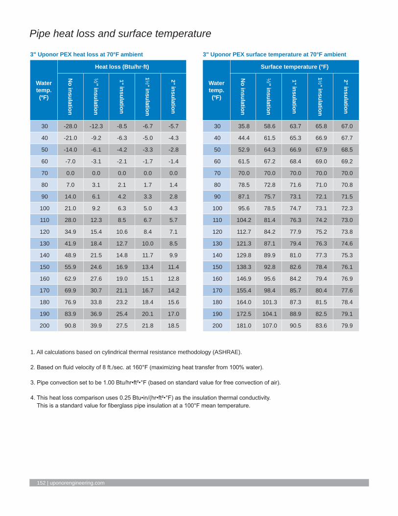
152 | uponorengineering.com
Pipe heat loss and surface temperature
3" Uponor PEX surface temperature at 70°F ambient
Water temp. (ºF)
Surface temperature (°F)
No insulation
½" insulation
1" insulation
1½" insulation
2" insulation
30 35.8 58.6 63.7 65.8 67.0
40 44.4 61.5 65.3 66.9 67.7
50 52.9 64.3 66.9 67.9 68.5
60 61.5 67.2 68.4 69.0 69.2
70 70.0 70.0 70.0 70.0 70.0
80 78.5 72.8 71.6 71.0 70.8
90 87.1 75.7 73.1 72.1 71.5
100 95.6 78.5 74.7 73.1 72.3
110 104.2 81.4 76.3 74.2 73.0
120 112.7 84.2 77.9 75.2 73.8
130 121.3 87.1 79.4 76.3 74.6
140 129.8 89.9 81.0 77.3 75.3
150 138.3 92.8 82.6 78.4 76.1
160 146.9 95.6 84.2 79.4 76.9
170 155.4 98.4 85.7 80.4 77.6
180 164.0 101.3 87.3 81.5 78.4
190 172.5 104.1 88.9 82.5 79.1
200 181.0 107.0 90.5 83.6 79.9
3" Uponor PEX heat loss at 70°F ambient
Water temp. (ºF)
Heat loss (Btu/hr·ft)
No insulation
½" insulation
1" insulation
1½" insulation
2" insulation
30 -28.0 -12.3 -8.5 -6.7 -5.7
40 -21.0 -9.2 -6.3 -5.0 -4.3
50 -14.0 -6.1 -4.2 -3.3 -2.8
60 -7.0 -3.1 -2.1 -1.7 -1.4
70 0.0 0.0 0.0 0.0 0.0
80 7.0 3.1 2.1 1.7 1.4
90 14.0 6.1 4.2 3.3 2.8
100 21.0 9.2 6.3 5.0 4.3
110 28.0 12.3 8.5 6.7 5.7
120 34.9 15.4 10.6 8.4 7.1
130 41.9 18.4 12.7 10.0 8.5
140 48.9 21.5 14.8 11.7 9.9
150 55.9 24.6 16.9 13.4 11.4
160 62.9 27.6 19.0 15.1 12.8
170 69.9 30.7 21.1 16.7 14.2
180 76.9 33.8 23.2 18.4 15.6
190 83.9 36.9 25.4 20.1 17.0
200 90.8 39.9 27.5 21.8 18.5
1. All calculations based on cylindrical thermal resistance methodology (ASHRAE).
2. Based on fluid velocity of 8 ft./sec. at 160°F (maximizing heat transfer from 100% water).
3. Pipe convection set to be 1.00 Btu/hr•ft²•°F (based on standard value for free convection of air).
4. This heat loss comparison uses 0.25 Btu•in/(hr•ft²•°F) as the insulation thermal conductivity. This is a standard value for fiberglass pipe insulation at a 100°F mean temperature.

Hydronic Piping Design Assistance Manual | Appendix F – Pipe heat loss and surface temperature l 153
Pipe heat loss and surface temperature
3 ½" Uponor PEX surface temperature at 70°F ambient
Water temp. (ºF)
Surface temperature (°F)
No insulation
½" insulation
1" insulation
1½" insulation
2" insulation
30 36.6 58.6 63.6 65.7 66.9
40 44.9 61.4 65.2 66.8 67.6
50 53.3 64.3 66.8 67.9 68.4
60 61.6 67.1 68.4 68.9 69.2
70 70.0 70.0 70.0 70.0 70.0
80 78.4 72.9 71.6 71.1 70.8
90 86.7 75.7 73.2 72.1 71.6
100 95.1 78.6 74.8 73.2 72.4
110 103.4 81.4 76.4 74.3 73.1
120 111.8 84.3 78.0 75.3 73.9
130 120.1 87.1 79.6 76.4 74.7
140 128.5 90.0 81.2 77.5 75.5
150 136.8 92.8 82.8 78.6 76.3
160 145.2 95.7 84.4 79.6 77.1
170 153.5 98.5 86.0 80.7 77.8
180 161.9 101.4 87.6 81.8 78.6
190 170.2 104.2 89.2 82.8 79.4
200 178.6 107.1 90.8 83.9 80.2
3 ½" Uponor PEX heat loss at 70°F ambient
Water temp. (ºF)
Heat loss (Btu/hr·ft)
No insulation
½" insulation
1" insulation
1½" insulation
2" insulation
30 -31.7 -13.8 -9.4 -7.4 -6.3
40 -23.8 -10.4 -7.1 -5.6 -4.7
50 -15.9 -6.9 -4.7 -3.7 -3.1
60 -7.9 -3.5 -2.4 -1.9 -1.6
70 0.0 0.0 0.0 0.0 0.0
80 7.9 3.5 2.4 1.9 1.6
90 15.9 6.9 4.7 3.7 3.1
100 23.8 10.4 7.1 5.6 4.7
110 31.7 13.8 9.4 7.4 6.3
120 39.6 17.3 11.8 9.3 7.8
130 47.6 20.7 14.1 11.1 9.4
140 55.5 24.2 16.5 13.0 11.0
150 63.4 27.6 18.9 14.8 12.5
160 71.3 31.1 21.2 16.7 14.1
170 79.3 34.5 23.6 18.5 15.7
180 87.2 38.0 25.9 20.4 17.2
190 95.1 41.5 28.3 22.3 18.8
200 103.0 44.9 30.6 24.1 20.3
1. All calculations based on cylindrical thermal resistance methodology (ASHRAE).
2. Based on fluid velocity of 8 ft./sec. at 160°F (maximizing heat transfer from 100% water).
3. Pipe convection set to be 1.00 Btu/hr•ft²•°F (based on standard value for free convection of air).
4. This heat loss comparison uses 0.25 Btu•in/(hr•ft²•°F) as the insulation thermal conductivity. This is a standard value for fiberglass pipe insulation at a 100°F mean temperature.

154 | uponorengineering.com
Pipe heat loss and surface temperature
4" Uponor PEX surface temperature at 70°F ambient
Water temp. (ºF)
Surface temperature (°F)
No insulation
½" insulation
1" insulation
1½" insulation
2" insulation
30 37.3 58.6 63.5 65.6 66.8
40 45.5 61.4 65.1 66.7 67.6
50 53.7 64.3 66.8 67.8 68.4
60 61.8 67.1 68.4 68.9 69.2
70 70.0 70.0 70.0 70.0 70.0
80 78.2 72.9 71.6 71.1 70.8
90 86.3 75.7 73.2 72.2 71.6
100 94.5 78.6 74.9 73.3 72.4
110 102.7 81.4 76.5 74.4 73.2
120 110.8 84.3 78.1 75.4 74.0
130 119.0 87.1 79.7 76.5 74.8
140 127.2 90.0 81.3 77.6 75.6
150 135.3 92.8 83.0 78.7 76.4
160 143.5 95.7 84.6 79.8 77.2
170 151.7 98.5 86.2 80.9 78.0
180 159.8 101.4 87.8 82.0 78.8
190 168.0 104.3 89.4 83.1 79.6
200 176.2 107.1 91.1 84.2 80.4
4" Uponor PEX heat loss at 70°F ambient
Water temp. (ºF)
Heat loss (Btu/hr·ft)
No insulation
½" insulation
1" insulation
1½" insulation
2" insulation
30 -35.3 -15.3 -10.4 -8.1 -6.8
40 -26.5 -11.5 -7.8 -6.1 -5.1
50 -17.6 -7.7 -5.2 -4.1 -3.4
60 -8.8 -3.8 -2.6 -2.0 -1.7
70 0.0 0.0 0.0 0.0 0.0
80 8.8 3.8 2.6 2.0 1.7
90 17.6 7.7 5.2 4.1 3.4
100 26.5 11.5 7.8 6.1 5.1
110 35.3 15.3 10.4 8.1 6.8
120 44.1 19.1 13.0 10.2 8.5
130 52.9 23.0 15.6 12.2 10.2
140 61.7 26.8 18.2 14.2 12.0
150 70.6 30.6 20.8 16.3 13.7
160 79.4 34.5 23.4 18.3 15.4
170 88.2 38.3 26.0 20.3 17.1
180 97.0 42.1 28.6 22.4 18.8
190 105.8 46.0 31.2 24.4 20.5
200 114.7 49.8 33.8 26.4 22.2
1. All calculations based on cylindrical thermal resistance methodology (ASHRAE).
2. Based on fluid velocity of 8 ft./sec. at 160°F (maximizing heat transfer from 100% water).
3. Pipe convection set to be 1.00 Btu/hr•ft²•°F (based on standard value for free convection of air).
4. This heat loss comparison uses 0.25 Btu•in/(hr•ft²•°F) as the insulation thermal conductivity. This is a standard value for fiberglass pipe insulation at a 100°F mean temperature.

Hydronic Piping Design Assistance Manual | Appendix F – Pipe heat loss and surface temperature l 155
Pipe heat loss and surface temperature
½" Uponor PEX surface temperature at 90°F ambient
Water temp. (ºF)
Surface temperature (°F)
No insulation
½" insulation
1" insulation
1½" insulation
2" insulation
30 32.1 75.7 83.1 85.7 87.0
40 41.8 78.1 84.2 86.4 87.5
50 51.4 80.5 85.4 87.1 88.0
60 61.1 82.9 86.5 87.9 88.5
70 70.7 85.2 87.7 88.6 89.0
80 80.4 87.6 88.8 89.3 89.5
90 90.0 90.0 90.0 90.0 90.0
100 99.6 92.4 91.2 90.7 90.5
110 109.3 94.8 92.3 91.4 91.0
120 118.9 97.1 93.5 92.1 91.5
130 128.6 99.5 94.6 92.9 92.0
140 138.2 101.9 95.8 93.6 92.5
150 147.9 104.3 96.9 94.3 93.0
160 157.5 106.7 98.1 95.0 93.5
170 167.2 109.0 99.2 95.7 94.0
180 176.8 111.4 100.4 96.4 94.5
190 186.5 113.8 101.5 97.2 95.1
200 196.1 116.2 102.7 97.9 95.6
½" Uponor PEX heat loss at 90°F ambient
Water temp. (ºF)
Heat loss (Btu/hr·ft)
No insulation
½" insulation
1" insulation
1½" insulation
2" insulation
30 -9.5 -6.1 -4.7 -4.1 -3.7
40 -7.9 -5.1 -4.0 -3.4 -3.1
50 -6.3 -4.1 -3.2 -2.7 -2.4
60 -4.7 -3.0 -2.4 -2.0 -1.8
70 -3.2 -2.0 -1.6 -1.4 -1.2
80 -1.6 -1.0 -0.8 -0.7 -0.6
90 0.0 0.0 0.0 0.0 0.0
100 1.6 1.0 0.8 0.7 0.6
110 3.2 2.0 1.6 1.4 1.2
120 4.7 3.0 2.4 2.0 1.8
130 6.3 4.1 3.2 2.7 2.4
140 7.9 5.1 4.0 3.4 3.1
150 9.5 6.1 4.7 4.1 3.7
160 11.1 7.1 5.5 4.8 4.3
170 12.6 8.1 6.3 5.4 4.9
180 14.2 9.1 7.1 6.1 5.5
190 15.8 10.1 7.9 6.8 6.1
200 17.4 11.1 8.7 7.5 6.7
1. All calculations based on cylindrical thermal resistance methodology (ASHRAE).
2. Based on fluid velocity of 8 ft./sec. at 160°F (maximizing heat transfer from 100% water).
3. Pipe convection set to be 1.00 Btu/hr•ft²•°F (based on standard value for free convection of air).
4. This heat loss comparison uses 0.25 Btu•in/(hr•ft²•°F) as the insulation thermal conductivity. This is a standard value for fiberglass pipe insulation at a 100°F mean temperature.

156 | uponorengineering.com
Pipe heat loss and surface temperature
⅝" Uponor PEX surface temperature at 90°F ambient
Water temp. (ºF)
Surface temperature (°F)
No insulation
½" insulation
1" insulation
1½" insulation
2" insulation
30 32.4 75.2 82.8 85.5 86.8
40 42.0 77.7 84.0 86.2 87.3
50 51.6 80.2 85.2 87.0 87.9
60 61.2 82.6 86.4 87.7 88.4
70 70.8 85.1 87.6 88.5 88.9
80 80.4 87.5 88.8 89.2 89.5
90 90.0 90.0 90.0 90.0 90.0
100 99.6 92.5 91.2 90.8 90.5
110 109.2 94.9 92.4 91.5 91.1
120 118.8 97.4 93.6 92.3 91.6
130 128.4 99.8 94.8 93.0 92.1
140 138.0 102.3 96.0 93.8 92.7
150 147.6 104.8 97.2 94.5 93.2
160 157.2 107.2 98.4 95.3 93.7
170 166.8 109.7 99.6 96.0 94.3
180 176.4 112.2 100.8 96.8 94.8
190 186.0 114.6 102.1 97.5 95.3
200 195.6 117.1 103.3 98.3 95.9
⅝" Uponor PEX heat loss at 90°F ambient
Water temp. (ºF)
Heat loss (Btu/hr·ft)
No insulation
½" insulation
1" insulation
1½" insulation
2" insulation
30 -11.3 -6.8 -5.2 -4.4 -4.0
40 -9.4 -5.6 -4.3 -3.7 -3.3
50 -7.5 -4.5 -3.5 -3.0 -2.6
60 -5.7 -3.4 -2.6 -2.2 -2.0
70 -3.8 -2.3 -1.7 -1.5 -1.3
80 -1.9 -1.1 -0.9 -0.7 -0.7
90 0.0 0.0 0.0 0.0 0.0
100 1.9 1.1 0.9 0.7 0.7
110 3.8 2.3 1.7 1.5 1.3
120 5.7 3.4 2.6 2.2 2.0
130 7.5 4.5 3.5 3.0 2.6
140 9.4 5.6 4.3 3.7 3.3
150 11.3 6.8 5.2 4.4 4.0
160 13.2 7.9 6.1 5.2 4.6
170 15.1 9.0 6.9 5.9 5.3
180 17.0 10.2 7.8 6.7 6.0
190 18.9 11.3 8.7 7.4 6.6
200 20.7 12.4 9.5 8.1 7.3
1. All calculations based on cylindrical thermal resistance methodology (ASHRAE).
2. Based on fluid velocity of 8 ft./sec. at 160°F (maximizing heat transfer from 100% water).
3. Pipe convection set to be 1.00 Btu/hr•ft²•°F (based on standard value for free convection of air).
4. This heat loss comparison uses 0.25 Btu•in/(hr•ft²•°F) as the insulation thermal conductivity. This is a standard value for fiberglass pipe insulation at a 100°F mean temperature.

Hydronic Piping Design Assistance Manual | Appendix F – Pipe heat loss and surface temperature l 157
Pipe heat loss and surface temperature
¾" Uponor PEX surface temperature at 90°F ambient
Water temp. (ºF)
Surface temperature (°F)
No insulation
½" insulation
1" insulation
1½" insulation
2" insulation
30 32.7 74.9 82.5 85.3 86.7
40 42.3 77.4 83.7 86.1 87.2
50 51.8 79.9 85.0 86.9 87.8
60 61.4 82.4 86.2 87.6 88.3
70 70.9 85.0 87.5 88.4 88.9
80 80.5 87.5 88.7 89.2 89.4
90 90.0 90.0 90.0 90.0 90.0
100 99.5 92.5 91.3 90.8 90.6
110 109.1 95.0 92.5 91.6 91.1
120 118.6 97.6 93.8 92.4 91.7
130 128.2 100.1 95.0 93.1 92.2
140 137.7 102.6 96.3 93.9 92.8
150 147.3 105.1 97.5 94.7 93.3
160 156.8 107.7 98.8 95.5 93.9
170 166.3 110.2 100.0 96.3 94.4
180 175.9 112.7 101.3 97.1 95.0
190 185.4 115.2 102.5 97.8 95.6
200 195.0 117.8 103.8 98.6 96.1
¾" Uponor PEX heat loss at 90°F ambient
Water temp. (ºF)
Heat loss (Btu/hr·ft)
No insulation
½" insulation
1" insulation
1½" insulation
2" insulation
30 -13.1 -7.4 -5.6 -4.8 -4.3
40 -10.9 -6.2 -4.7 -4.0 -3.5
50 -8.7 -5.0 -3.8 -3.2 -2.8
60 -6.6 -3.7 -2.8 -2.4 -2.1
70 -4.4 -2.5 -1.9 -1.6 -1.4
80 -2.2 -1.2 -0.9 -0.8 -0.7
90 0.0 0.0 0.0 0.0 0.0
100 2.2 1.2 0.9 0.8 0.7
110 4.4 2.5 1.9 1.6 1.4
120 6.6 3.7 2.8 2.4 2.1
130 8.7 5.0 3.8 3.2 2.8
140 10.9 6.2 4.7 4.0 3.5
150 13.1 7.4 5.6 4.8 4.3
160 15.3 8.7 6.6 5.6 5.0
170 17.5 9.9 7.5 6.4 5.7
180 19.7 11.2 8.5 7.2 6.4
190 21.9 12.4 9.4 8.0 7.1
200 24.0 13.6 10.4 8.8 7.8
1. All calculations based on cylindrical thermal resistance methodology (ASHRAE).
2. Based on fluid velocity of 8 ft./sec. at 160°F (maximizing heat transfer from 100% water).
3. Pipe convection set to be 1.00 Btu/hr•ft²•°F (based on standard value for free convection of air).
4. This heat loss comparison uses 0.25 Btu•in/(hr•ft²•°F) as the insulation thermal conductivity. This is a standard value for fiberglass pipe insulation at a 100°F mean temperature.

158 | uponorengineering.com
Pipe heat loss and surface temperature
1" Uponor PEX surface temperature at 90°F ambient
Water temp. (ºF)
Surface temperature (°F)
No insulation
½" insulation
1" insulation
1½" insulation
2" insulation
30 33.5 74.3 82.1 85.0 86.4
40 42.9 76.9 83.4 85.8 87.0
50 52.3 79.5 84.7 86.7 87.6
60 61.7 82.1 86.0 87.5 88.2
70 71.2 84.8 87.4 88.3 88.8
80 80.6 87.4 88.7 89.2 89.4
90 90.0 90.0 90.0 90.0 90.0
100 99.4 92.6 91.3 90.8 90.6
110 108.8 95.2 92.6 91.7 91.2
120 118.3 97.9 94.0 92.5 91.8
130 127.7 100.5 95.3 93.3 92.4
140 137.1 103.1 96.6 94.2 93.0
150 146.5 105.7 97.9 95.0 93.6
160 155.9 108.3 99.3 95.9 94.2
170 165.3 110.9 100.6 96.7 94.8
180 174.8 113.6 101.9 97.5 95.3
190 184.2 116.2 103.2 98.4 95.9
200 193.6 118.8 104.6 99.2 96.5
1" Uponor PEX heat loss at 90°F ambient
Water temp. (ºF)
Heat loss (Btu/hr·ft)
No insulation
½" insulation
1" insulation
1½" insulation
2" insulation
30 -16.6 -8.7 -6.5 -5.4 -4.8
40 -13.9 -7.3 -5.4 -4.5 -4.0
50 -11.1 -5.8 -4.3 -3.6 -3.2
60 -8.3 -4.4 -3.2 -2.7 -2.4
70 -5.5 -2.9 -2.2 -1.8 -1.6
80 -2.8 -1.5 -1.1 -0.9 -0.8
90 0.0 0.0 0.0 0.0 0.0
100 2.8 1.5 1.1 0.9 0.8
110 5.5 2.9 2.2 1.8 1.6
120 8.3 4.4 3.2 2.7 2.4
130 11.1 5.8 4.3 3.6 3.2
140 13.9 7.3 5.4 4.5 4.0
150 16.6 8.7 6.5 5.4 4.8
160 19.4 10.2 7.6 6.3 5.6
170 22.2 11.7 8.7 7.2 6.4
180 25.0 13.1 9.7 8.1 7.2
190 27.7 14.6 10.8 9.0 8.0
200 30.5 16.0 11.9 9.9 8.8
1. All calculations based on cylindrical thermal resistance methodology (ASHRAE).
2. Based on fluid velocity of 8 ft./sec. at 160°F (maximizing heat transfer from 100% water).
3. Pipe convection set to be 1.00 Btu/hr•ft²•°F (based on standard value for free convection of air).
4. This heat loss comparison uses 0.25 Btu•in/(hr•ft²•°F) as the insulation thermal conductivity. This is a standard value for fiberglass pipe insulation at a 100°F mean temperature.

Hydronic Piping Design Assistance Manual | Appendix F – Pipe heat loss and surface temperature l 159
Pipe heat loss and surface temperature
1 ¼" Uponor PEX surface temperature at 90°F ambient
Water temp. (ºF)
Surface temperature (°F)
No insulation
½" insulation
1" insulation
1½" insulation
2" insulation
30 34.2 73.9 81.7 84.7 86.2
40 43.5 76.6 83.1 85.6 86.9
50 52.8 79.3 84.5 86.5 87.5
60 62.1 81.9 85.9 87.4 88.1
70 71.4 84.6 87.2 88.2 88.7
80 80.7 87.3 88.6 89.1 89.4
90 90.0 90.0 90.0 90.0 90.0
100 99.3 92.7 91.4 90.9 90.6
110 108.6 95.4 92.8 91.8 91.3
120 117.9 98.1 94.1 92.6 91.9
130 127.2 100.7 95.5 93.5 92.5
140 136.5 103.4 96.9 94.4 93.1
150 145.8 106.1 98.3 95.3 93.8
160 155.1 108.8 99.7 96.2 94.4
170 164.4 111.5 101.0 97.0 95.0
180 173.7 114.2 102.4 97.9 95.6
190 183.0 116.8 103.8 98.8 96.3
200 192.3 119.5 105.2 99.7 96.9
1 ¼" Uponor PEX heat loss at 90°F ambient
Water temp. (ºF)
Heat loss (Btu/hr·ft)
No insulation
½" insulation
1" insulation
1½" insulation
2" insulation
30 -20.1 -10.0 -7.3 -6.0 -5.3
40 -16.7 -8.3 -6.1 -5.0 -4.4
50 -13.4 -6.7 -4.9 -4.0 -3.5
60 -10.0 -5.0 -3.7 -3.0 -2.6
70 -6.7 -3.3 -2.4 -2.0 -1.8
80 -3.3 -1.7 -1.2 -1.0 -0.9
90 0.0 0.0 0.0 0.0 0.0
100 3.3 1.7 1.2 1.0 0.9
110 6.7 3.3 2.4 2.0 1.8
120 10.0 5.0 3.7 3.0 2.6
130 13.4 6.7 4.9 4.0 3.5
140 16.7 8.3 6.1 5.0 4.4
150 20.1 10.0 7.3 6.0 5.3
160 23.4 11.7 8.5 7.1 6.2
170 26.8 13.3 9.8 8.1 7.1
180 30.1 15.0 11.0 9.1 7.9
190 33.5 16.7 12.2 10.1 8.8
200 36.8 18.4 13.4 11.1 9.7
1. All calculations based on cylindrical thermal resistance methodology (ASHRAE).
2. Based on fluid velocity of 8 ft./sec. at 160°F (maximizing heat transfer from 100% water).
3. Pipe convection set to be 1.00 Btu/hr•ft²•°F (based on standard value for free convection of air).
4. This heat loss comparison uses 0.25 Btu•in/(hr•ft²•°F) as the insulation thermal conductivity. This is a standard value for fiberglass pipe insulation at a 100°F mean temperature.

160 | uponorengineering.com
Pipe heat loss and surface temperature
1 ½" Uponor PEX surface temperature at 90°F ambient
Water temp. (ºF)
Surface temperature (°F)
No insulation
½" insulation
1" insulation
1½" insulation
2" insulation
30 34.9 73.6 81.4 84.5 86.1
40 44.1 76.3 82.9 85.4 86.7
50 53.3 79.1 84.3 86.3 87.4
60 62.5 81.8 85.7 87.3 88.0
70 71.6 84.5 87.1 88.2 88.7
80 80.8 87.3 88.6 89.1 89.3
90 90.0 90.0 90.0 90.0 90.0
100 99.2 92.7 91.4 90.9 90.7
110 108.4 95.5 92.9 91.8 91.3
120 117.5 98.2 94.3 92.7 92.0
130 126.7 100.9 95.7 93.7 92.6
140 135.9 103.7 97.1 94.6 93.3
150 145.1 106.4 98.6 95.5 93.9
160 154.2 109.1 100.0 96.4 94.6
170 163.4 111.8 101.4 97.3 95.2
180 172.6 114.6 102.8 98.2 95.9
190 181.8 117.3 104.3 99.1 96.5
200 191.0 120.0 105.7 100.1 97.2
1 ½" Uponor PEX heat loss at 90°F ambient
Water temp. (ºF)
Heat loss (Btu/hr·ft)
No insulation
½" insulation
1" insulation
1½" insulation
2" insulation
30 -23.4 -11.3 -8.1 -6.6 -5.8
40 -19.5 -9.4 -6.8 -5.5 -4.8
50 -15.6 -7.5 -5.4 -4.4 -3.9
60 -11.7 -5.6 -4.1 -3.3 -2.9
70 -7.8 -3.8 -2.7 -2.2 -1.9
80 -3.9 -1.9 -1.4 -1.1 -1.0
90 0.0 0.0 0.0 0.0 0.0
100 3.9 1.9 1.4 1.1 1.0
110 7.8 3.8 2.7 2.2 1.9
120 11.7 5.6 4.1 3.3 2.9
130 15.6 7.5 5.4 4.4 3.9
140 19.5 9.4 6.8 5.5 4.8
150 23.4 11.3 8.1 6.6 5.8
160 27.3 13.1 9.5 7.8 6.7
170 31.2 15.0 10.8 8.9 7.7
180 35.1 16.9 12.2 10.0 8.7
190 39.0 18.8 13.5 11.1 9.6
200 43.0 20.6 14.9 12.2 10.6
1. All calculations based on cylindrical thermal resistance methodology (ASHRAE).
2. Based on fluid velocity of 8 ft./sec. at 160°F (maximizing heat transfer from 100% water).
3. Pipe convection set to be 1.00 Btu/hr•ft²•°F (based on standard value for free convection of air).
4. This heat loss comparison uses 0.25 Btu•in/(hr•ft²•°F) as the insulation thermal conductivity. This is a standard value for fiberglass pipe insulation at a 100°F mean temperature.

Hydronic Piping Design Assistance Manual | Appendix F – Pipe heat loss and surface temperature l 161
Pipe heat loss and surface temperature
2" Uponor PEX surface temperature at 90°F ambient
Water temp. (ºF)
Surface temperature (°F)
No insulation
½" insulation
1" insulation
1½" insulation
2" insulation
30 36.3 73.2 81.0 84.2 85.8
40 45.2 76.0 82.5 85.1 86.5
50 54.2 78.8 84.0 86.1 87.2
60 63.1 81.6 85.5 87.1 87.9
70 72.1 84.4 87.0 88.1 88.6
80 81.0 87.2 88.5 89.0 89.3
90 90.0 90.0 90.0 90.0 90.0
100 99.0 92.8 91.5 91.0 90.7
110 107.9 95.6 93.0 91.9 91.4
120 116.9 98.4 94.5 92.9 92.1
130 125.8 101.2 96.0 93.9 92.8
140 134.8 104.0 97.5 94.9 93.5
150 143.7 106.8 99.0 95.8 94.2
160 152.7 109.5 100.5 96.8 94.9
170 161.7 112.3 101.9 97.8 95.6
180 170.6 115.1 103.4 98.7 96.3
190 179.6 117.9 104.9 99.7 97.0
200 188.5 120.7 106.4 100.7 97.7
2" Uponor PEX heat loss at 90°F ambient
Water temp. (ºF)
Heat loss (Btu/hr·ft)
No insulation
½" insulation
1" insulation
1½" insulation
2" insulation
30 -29.9 -13.7 -9.7 -7.8 -6.7
40 -24.9 -11.4 -8.1 -6.5 -5.6
50 -19.9 -9.1 -6.4 -5.2 -4.5
60 -14.9 -6.9 -4.8 -3.9 -3.4
70 -10.0 -4.6 -3.2 -2.6 -2.2
80 -5.0 -2.3 -1.6 -1.3 -1.1
90 0.0 0.0 0.0 0.0 0.0
100 5.0 2.3 1.6 1.3 1.1
110 10.0 4.6 3.2 2.6 2.2
120 14.9 6.9 4.8 3.9 3.4
130 19.9 9.1 6.4 5.2 4.5
140 24.9 11.4 8.1 6.5 5.6
150 29.9 13.7 9.7 7.8 6.7
160 34.9 16.0 11.3 9.1 7.8
170 39.9 18.3 12.9 10.4 9.0
180 44.8 20.6 14.5 11.7 10.1
190 49.8 22.8 16.1 13.0 11.2
200 54.8 25.1 17.7 14.3 12.3
1. All calculations based on cylindrical thermal resistance methodology (ASHRAE).
2. Based on fluid velocity of 8 ft./sec. at 160°F (maximizing heat transfer from 100% water).
3. Pipe convection set to be 1.00 Btu/hr•ft²•°F (based on standard value for free convection of air).
4. This heat loss comparison uses 0.25 Btu•in/(hr•ft²•°F) as the insulation thermal conductivity. This is a standard value for fiberglass pipe insulation at a 100°F mean temperature.

162 | uponorengineering.com
Pipe heat loss and surface temperature
2 ½" Uponor PEX surface temperature at 90°F ambient
Water temp. (ºF)
Surface temperature (°F)
No insulation
½" insulation
1" insulation
1½" insulation
2" insulation
30 37.6 73.0 80.8 83.9 85.6
40 46.3 75.9 82.3 84.9 86.3
50 55.0 78.7 83.8 86.0 87.1
60 63.8 81.5 85.4 87.0 87.8
70 72.5 84.3 86.9 88.0 88.5
80 81.3 87.2 88.5 89.0 89.3
90 90.0 90.0 90.0 90.0 90.0
100 98.7 92.8 91.5 91.0 90.7
110 107.5 95.7 93.1 92.0 91.5
120 116.2 98.5 94.6 93.0 92.2
130 125.0 101.3 96.2 94.0 92.9
140 133.7 104.1 97.7 95.1 93.7
150 142.4 107.0 99.2 96.1 94.4
160 151.2 109.8 100.8 97.1 95.1
170 159.9 112.6 102.3 98.1 95.9
180 168.7 115.4 103.9 99.1 96.6
190 177.4 118.3 105.4 100.1 97.3
200 186.1 121.1 106.9 101.1 98.1
2 ½" Uponor PEX heat loss at 90°F ambient
Water temp. (ºF)
Heat loss (Btu/hr·ft)
No insulation
½" insulation
1" insulation
1½" insulation
2" insulation
30 -36.0 -16.1 -11.2 -8.9 -7.6
40 -30.0 -13.4 -9.3 -7.5 -6.4
50 -24.0 -10.7 -7.5 -6.0 -5.1
60 -18.0 -8.0 -5.6 -4.5 -3.8
70 -12.0 -5.4 -3.7 -3.0 -2.5
80 -6.0 -2.7 -1.9 -1.5 -1.3
90 0.0 0.0 0.0 0.0 0.0
100 6.0 2.7 1.9 1.5 1.3
110 12.0 5.4 3.7 3.0 2.5
120 18.0 8.0 5.6 4.5 3.8
130 24.0 10.7 7.5 6.0 5.1
140 30.0 13.4 9.3 7.5 6.4
150 36.0 16.1 11.2 8.9 7.6
160 42.0 18.8 13.1 10.4 8.9
170 48.0 21.5 14.9 11.9 10.2
180 54.1 24.1 16.8 13.4 11.5
190 60.1 26.8 18.6 14.9 12.7
200 66.1 29.5 20.5 16.4 14.0
1. All calculations based on cylindrical thermal resistance methodology (ASHRAE).
2. Based on fluid velocity of 8 ft./sec. at 160°F (maximizing heat transfer from 100% water).
3. Pipe convection set to be 1.00 Btu/hr•ft²•°F (based on standard value for free convection of air).
4. This heat loss comparison uses 0.25 Btu•in/(hr•ft²•°F) as the insulation thermal conductivity. This is a standard value for fiberglass pipe insulation at a 100°F mean temperature.

Hydronic Piping Design Assistance Manual | Appendix F – Pipe heat loss and surface temperature l 163
Pipe heat loss and surface temperature
3" Uponor PEX surface temperature at 90°F ambient
Water temp. (ºF)
Surface temperature (°F)
No insulation
½" insulation
1" insulation
1½" insulation
2" insulation
30 38.7 72.9 80.6 83.7 85.4
40 47.3 75.8 82.1 84.8 86.2
50 55.8 78.6 83.7 85.8 87.0
60 64.4 81.5 85.3 86.9 87.7
70 72.9 84.3 86.9 87.9 88.5
80 81.5 87.2 88.4 89.0 89.2
90 90.0 90.0 90.0 90.0 90.0
100 98.5 92.8 91.6 91.0 90.8
110 107.1 95.7 93.1 92.1 91.5
120 115.6 98.5 94.7 93.1 92.3
130 124.2 101.4 96.3 94.2 93.0
140 132.7 104.2 97.9 95.2 93.8
150 141.3 107.1 99.4 96.3 94.6
160 149.8 109.9 101.0 97.3 95.3
170 158.3 112.8 102.6 98.4 96.1
180 166.9 115.6 104.2 99.4 96.9
190 175.4 118.4 105.7 100.4 97.6
200 184.0 121.3 107.3 101.5 98.4
3" Uponor PEX heat loss at 90°F ambient
Water temp. (ºF)
Heat loss (Btu/hr·ft)
No insulation
½" insulation
1" insulation
1½" insulation
2" insulation
30 -41.9 -18.4 -12.7 -10.0 -8.5
40 -34.9 -15.4 -10.6 -8.4 -7.1
50 -28.0 -12.3 -8.5 -6.7 -5.7
60 -21.0 -9.2 -6.3 -5.0 -4.3
70 -14.0 -6.1 -4.2 -3.3 -2.8
80 -7.0 -3.1 -2.1 -1.7 -1.4
90 0.0 0.0 0.0 0.0 0.0
100 7.0 3.1 2.1 1.7 1.4
110 14.0 6.1 4.2 3.3 2.8
120 21.0 9.2 6.3 5.0 4.3
130 28.0 12.3 8.5 6.7 5.7
140 34.9 15.4 10.6 8.4 7.1
150 41.9 18.4 12.7 10.0 8.5
160 48.9 21.5 14.8 11.7 9.9
170 55.9 24.6 16.9 13.4 11.4
180 62.9 27.6 19.0 15.1 12.8
190 69.9 30.7 21.1 16.7 14.2
200 76.9 33.8 23.2 18.4 15.6
1. All calculations based on cylindrical thermal resistance methodology (ASHRAE).
2. Based on fluid velocity of 8 ft./sec. at 160°F (maximizing heat transfer from 100% water).
3. Pipe convection set to be 1.00 Btu/hr•ft²•°F (based on standard value for free convection of air).
4. This heat loss comparison uses 0.25 Btu•in/(hr•ft²•°F) as the insulation thermal conductivity. This is a standard value for fiberglass pipe insulation at a 100°F mean temperature.

164 | uponorengineering.com
Pipe heat loss and surface temperature
3 ½" Uponor PEX surface temperature at 90°F ambient
Water temp. (ºF)
Surface temperature (°F)
No insulation
½" insulation
1" insulation
1½" insulation
2" insulation
30 39.9 72.9 80.4 83.6 85.3
40 48.2 75.7 82.0 84.7 86.1
50 56.6 78.6 83.6 85.7 86.9
60 64.9 81.4 85.2 86.8 87.6
70 73.3 84.3 86.8 87.9 88.4
80 81.6 87.1 88.4 88.9 89.2
90 90.0 90.0 90.0 90.0 90.0
100 98.4 92.9 91.6 91.1 90.8
110 106.7 95.7 93.2 92.1 91.6
120 115.1 98.6 94.8 93.2 92.4
130 123.4 101.4 96.4 94.3 93.1
140 131.8 104.3 98.0 95.3 93.9
150 140.1 107.1 99.6 96.4 94.7
160 148.5 110.0 101.2 97.5 95.5
170 156.8 112.8 102.8 98.6 96.3
180 165.2 115.7 104.4 99.6 97.1
190 173.5 118.5 106.0 100.7 97.8
200 181.9 121.4 107.6 101.8 98.6
3 ½" Uponor PEX heat loss at 90°F ambient
Water temp. (ºF)
Heat loss (Btu/hr·ft)
No insulation
½" insulation
1" insulation
1½" insulation
2" insulation
30 -47.6 -20.7 -14.1 -11.1 -9.4
40 -39.6 -17.3 -11.8 -9.3 -7.8
50 -31.7 -13.8 -9.4 -7.4 -6.3
60 -23.8 -10.4 -7.1 -5.6 -4.7
70 -15.9 -6.9 -4.7 -3.7 -3.1
80 -7.9 -3.5 -2.4 -1.9 -1.6
90 0.0 0.0 0.0 0.0 0.0
100 7.9 3.5 2.4 1.9 1.6
110 15.9 6.9 4.7 3.7 3.1
120 23.8 10.4 7.1 5.6 4.7
130 31.7 13.8 9.4 7.4 6.3
140 39.6 17.3 11.8 9.3 7.8
150 47.6 20.7 14.1 11.1 9.4
160 55.5 24.2 16.5 13.0 11.0
170 63.4 27.6 18.9 14.8 12.5
180 71.3 31.1 21.2 16.7 14.1
190 79.3 34.5 23.6 18.5 15.7
200 87.2 38.0 25.9 20.4 17.2
1. All calculations based on cylindrical thermal resistance methodology (ASHRAE).
2. Based on fluid velocity of 8 ft./sec. at 160°F (maximizing heat transfer from 100% water).
3. Pipe convection set to be 1.00 Btu/hr•ft²•°F (based on standard value for free convection of air).
4. This heat loss comparison uses 0.25 Btu•in/(hr•ft²•°F) as the insulation thermal conductivity. This is a standard value for fiberglass pipe insulation at a 100°F mean temperature.

Hydronic Piping Design Assistance Manual | Appendix F – Pipe heat loss and surface temperature l 165
Pipe heat loss and surface temperature
4" Uponor PEX surface temperature at 90°F ambient
Water temp. (ºF)
Surface temperature (°F)
No insulation
½" insulation
1" insulation
1½" insulation
2" insulation
30 41.0 72.9 80.3 83.5 85.2
40 49.2 75.7 81.9 84.6 86.0
50 57.3 78.6 83.5 85.6 86.8
60 65.5 81.4 85.1 86.7 87.6
70 73.7 84.3 86.8 87.8 88.4
80 81.8 87.1 88.4 88.9 89.2
90 90.0 90.0 90.0 90.0 90.0
100 98.2 92.9 91.6 91.1 90.8
110 106.3 95.7 93.2 92.2 91.6
120 114.5 98.6 94.9 93.3 92.4
130 122.7 101.4 96.5 94.4 93.2
140 130.8 104.3 98.1 95.4 94.0
150 139.0 107.1 99.7 96.5 94.8
160 147.2 110.0 101.3 97.6 95.6
170 155.3 112.8 103.0 98.7 96.4
180 163.5 115.7 104.6 99.8 97.2
190 171.7 118.5 106.2 100.9 98.0
200 179.8 121.4 107.8 102.0 98.8
4" Uponor PEX heat loss at 90°F ambient
Water temp. (ºF)
Heat loss (Btu/hr·ft)
No insulation
½" insulation
1" insulation
1½" insulation
2" insulation
30 -52.9 -23.0 -15.6 -12.2 -10.2
40 -44.1 -19.1 -13.0 -10.2 -8.5
50 -35.3 -15.3 -10.4 -8.1 -6.8
60 -26.5 -11.5 -7.8 -6.1 -5.1
70 -17.6 -7.7 -5.2 -4.1 -3.4
80 -8.8 -3.8 -2.6 -2.0 -1.7
90 0.0 0.0 0.0 0.0 0.0
100 8.8 3.8 2.6 2.0 1.7
110 17.6 7.7 5.2 4.1 3.4
120 26.5 11.5 7.8 6.1 5.1
130 35.3 15.3 10.4 8.1 6.8
140 44.1 19.1 13.0 10.2 8.5
150 52.9 23.0 15.6 12.2 10.2
160 61.7 26.8 18.2 14.2 12.0
170 70.6 30.6 20.8 16.3 13.7
180 79.4 34.5 23.4 18.3 15.4
190 88.2 38.3 26.0 20.3 17.1
200 97.0 42.1 28.6 22.4 18.8
1. All calculations based on cylindrical thermal resistance methodology (ASHRAE).
2. Based on fluid velocity of 8 ft./sec. at 160°F (maximizing heat transfer from 100% water).
3. Pipe convection set to be 1.00 Btu/hr•ft²•°F (based on standard value for free convection of air).
4. This heat loss comparison uses 0.25 Btu•in/(hr•ft²•°F) as the insulation thermal conductivity. This is a standard value for fiberglass pipe insulation at a 100°F mean temperature.

166 | uponorengineering.com
Notes

Hydronic Piping Design Assistance Manual l 167
Notes

168 | uponorengineering.com
Notes

Uponor, Inc. 5925 148th Street West Apple Valley, MN 55124 USA
T 800.321.4739 F 952.891.2008
Uponor Ltd. 2000 Argentia Rd., Plaza 1, Ste. 200 Mississauga, ON L5N 1W1 CANADA
T 888.994.7726 F 800.638.9517
HPDAM_Manual_68699_0617, Copyright © 2017 Uponor. Printed in the United States. uponorpro.com

Hydronic Piping D
esign Assistance Manual (H
PDAM
) Second Edition