
PIPING & DESIGNING HYDRONIC SYSTEMS G S - Peerless ...
80
FULL-COLOR TRAINING GUIDE SERIES The of Water PIPING & DESIGNING HYDRONIC SYSTEMS
-
Upload
khangminh22 -
Category
Documents
-
view
3 -
download
0
Transcript of PIPING & DESIGNING HYDRONIC SYSTEMS G S - Peerless ...

FULL-COLOR TRAINING GUIDE SERIESFULL-COLOR TRAINING GUIDE SERIES
CHHS796 R3 (5/03-1M)
The
of
WaterPIPING & DESIGNINGHYDRONIC SYSTEMS
PIPING & DESIGNINGHYDRONIC SYSTEMS
©2004


4
Piping & Designing Hydronic Systems
Hydronic systems heat the outside walls. Radiant floor systems heat all of the room contents.
This raises the mean radiant temperature in the room – the average temperature of all surfaces.
So the range of comfort is much wider for a hydronic system than a warm air system.

5
Piping & Designing Hydronic Systems
Hydronic systems provide a better temperature distribution in the room.
The Ideal is warm feet and cool head.
Radiant floor systems provide the best results. The temperature map almost exactly matchesthe Ideal Heating Curve.

6
Piping & Designing Hydronic Systems
Hydronic heating is comfortable, quiet and efficient.
Warm air heating cannot equal the performance of a hydronic system.

7
Piping & Designing Hydronic Systems
Hydronic heating is the best choice for comfort and efficiency.

8
Piping & Designing Hydronic Systems
This heat load calculation is courtesy of Amtrol, developed by their training group.
The advantage of this approach is that you don’t have to reference any additional charts andgraphs to do it.

9
Piping & Designing Hydronic Systems
Take measurements on the house and fill in the blanks.
The thicknesses, tCEILING and tWALLS, above are thickness of the insulation only.

10
Piping & Designing Hydronic Systems
Calculate the Areas, Volume and R Factors and write in the numbers above.
AREAS AND VOLUMES
R FACTORS
A WALL , Ft = Total Wall Area, Ft2 2
R WALL
R CEILING
A NETWALL , Ft = Net Wall Area, Ft2 2
VHOUSE , Ft = Volume of House, Ft3 3
x
+
+
x
x
x
x
x
-
=
=
=
=
=
P
4
4
3
3
C
tWALL
tCEILING
C
N
N
A WALL , Ft2
R WALL
R CEILING
A WALL
A CEILING
A WINDOWS A NETWALL , Ft2
VHOUSE , Ft3
(
(
)
)

11
Piping & Designing Hydronic Systems
Calculate the heat losses and write in the numbers above.

12
Piping & Designing Hydronic Systems
Apply these guidelines for baseboard systems and radiant panel systems.

13
Piping & Designing Hydronic Systems
Use these rules of thumb for high volume systems and gravity return systems.

14
Piping & Designing Hydronic Systems
Use these charts to figure the total heating surface of all cast iron radiation in the home.
The output from the radiation will be 150 Btuh per square foot when the average water temperature in the radiation is 170° F.

15
Piping & Designing Hydronic Systems
These rules of thumb provide a quick way of sizing the piping and the circulator.

16
Piping & Designing Hydronic Systems
For trial calculations and for rule of thumb (small systems only), multiply the longest run of piping times 1.5 to determine the Total Equivalent Length.
Use this chart to calculate the actual TEL for the system. Apply the TEL in the pressure drop formula to calculate the pressure drop.
TOTAL EQUIVALENTLENGTH OF PIPINGTOTAL EQUIVALENTLENGTH OF PIPING
PipeSize
11.251.52
2.5345681012
Elbow90 Stdo
1.31.82.22.93.44.35.67.28.811.714.617.3
Elbow90 LRo
1.31.71.92.32.73.24
4.85.57
8.29.4
Elbow45o
0.71
1.21.51.82.33.34.15.27.49.311.5
ReturnBend, Std
1.31.82.22.93.44.35.67.28.811.714.615.1
ReturnBend, LR
1.31.71.92.32.63.24
4.85.56.58.29.4
TeeThrough
0.81.11.31.51.72.22.73.23.74.45.35.8
TeeBranch
34.24.96.37.59.6
12.614.918.2253136
GlobeValve
395254677688116143172247331409
GateValve
2.62.62.82.92.42.83.53.53.6
AngleValve
14.316.116.118.721.72838506491
122151
SwingCheck
68.710.715
18.92536486187
116144
PipeSize1/23/41
1¼1½2
2½34
Elbow90 Stdo
33.64.55.76.57.58.110.112.6
Elbow90 LRo
22.42.92.93.23.43.94.3
Elbow45o
0.60.81.11.51.82.42.93.75.1
ReturnBend
33.64.55.76.57.58.110.112.6
TeeThrough
1.32
2.73.94.96.88.511.316.1
TeeBranch
3.54.55.47.48.6
10.512.315.119.7
GlobeValve
2021273743526275102
GateValve
0.50.60.81
1.11.31.61.82.2
AngleValve
1313.715.615.515.715.116.417.9
SwingCheck
7.87.98.911.713.417.2212736
TEL = Total Equivalent Length (of Piping)= Total Length of Piping + Equivalent Lengths of Fittings
TEL = Total Equivalent Length (of Piping)= Total Length of Piping + Equivalent Lengths of Fittings
Ruleof
Thumb
Ruleof
Thumb
Ruleof
Thumb
For trial calculations and for most residential and small systems,
figure the TEL as 1.5 times the measured length of piping.
For trial calculations and for most residential and small systems,
figure the TEL as 1.5 times the measured length of piping.
Equivalent Length, Feet for Threaded Pipe Fittings and Valves
Equivalent Length, Feet for Flanged Pipe Fittings and Valves

17
Piping & Designing Hydronic Systems
Select the pipe size.
Then read across the chart to find “a” and “b” for that pipe size.
Calculate the pressure drop with the formula at the top.
Pipe SizeInches
1/23/41
1 1/41 1/2
22 1/2
34
Pipe ODInches
0.6250.8751.1251.3751.6252.1252.6253.1254.125
Type LWall
0.0400.0450.0500.0550.0600.0700.0800.0900.110
Pipe IDInches
0.5450.7851.0251.2651.5051.9852.4652.9453.905
Velocity =GPM x
1.37540.66300.38880.25530.18040.10370.067230.047100.02679
MinimumRecomm.
GPM0.51.42.95.18.217.331.150.2107
MinimumVelocity
feet per sec0.70.91.11.31.51.82.12.42.9
MaximumRecomm.
GPM1.43.98.014.222.647.684.9137290
MaximumVelocity
feet per sec2.02.63.13.64.14.95.76.47.8
a2.41350.42750.1186
0.042800.018360.0047270.0016266.742E-041.660E-04
b1.7091.7311.7461.7561.7641.7761.7841.7911.801
Note: Some "a" numbers above are in engineering notation. 3.415E-07 = .0000003415, for example
MinimumRecomm.
GPM
Pipe SizeInches
1/23/41
1 1/41 1/2
22 1/2
345681012
Pipe ODInches
0.8401.0501.3151.6601.9002.3752.8753.5004.5005.5636.6258.62510.75012.750
Sch 40Wall
0.1090.1130.1330.1400.1450.1540.2030.2160.2370.2590.2800.3220.3650.375
Pipe IDInches
0.6220.8241.0491.3801.6102.0672.4693.0684.0265.0456.0657.981
10.02012.000
Velocity =GPM x
1.055950.601690.371260.214520.157610.095620.067020.043400.025200.016050.01111
0.0064140.0040690.002837
MinimumVelocity
feet per sec
0.70.91.11.31.51.82.02.32.83.23.64.35.05.6
MaximumRecomm.
GPM
1.94.17.916254878138284515836172131265013
MaximumVelocity
feet per sec
2.02.52.93.53.94.65.26.07.28.39.3
11.012.714.2
a1.413930.355280.106820.026850.012280.0034210.001371
0.00044520.00010813.318E-051.260E-052.962E-068.886E-073.415E-07
b1.7751.7951.8111.8281.8371.8511.8601.8711.8831.8931.9001.9101.9181.924
0.71.52.96.29.418.4305311020032667412291977
PRESSURE DROP(FEET PER HUNDRED FEET PIPING)
Total Pressure Drop, Feet=
x a GPMxbTotal Equivalent Length
100
Type L Copper Pipe Pressure Drop InformationHead Loss, Feet per 100 Feet of Pipe, = a x GPMb
Schedule 40 Steel Pipe Pressure Drop InformationHead Loss, Feet per 100 Feet of Pipe, = a x GPMb

18
Piping & Designing Hydronic Systems
Centrifugal pumps rotate as shown above.
Water flows into the eye of the impeller.
The pump raises the pressure of the water as it moves from the impeller eye through theimpeller vanes.
Impe
ller ro
tatio
n
CENTRIFUGALPUMPS

19
Piping & Designing Hydronic Systems
Water flows into the eye of the impeller.
The pump volute directs the flow of the water to the discharge.

20
Piping & Designing Hydronic Systems
The Taco 007 is a typical water lubricated circulator.
System water actually flows through the shaft into the rotor chamber.

21
Piping & Designing Hydronic Systems
These are the pump curves for the Taco 00 series circulators.
The curve layout is similar to that used by other circulator manufacturers for in-line pumps andcirculators.

22
Piping & Designing Hydronic Systems
Use this chart to select the Taco circulator based on heat load and pipe size used.
Similar charts are available from other circulator manufacturers.

23
Piping & Designing Hydronic Systems
This is a typical base mounted end suction pump.
These pumps are also offered in direct-coupled configurations.

24
Piping & Designing Hydronic Systems
Pump curves are usually shown in Head (feet of water) vs Flow (GPM).

25
Piping & Designing Hydronic Systems
This graph compares a typical in-line pump curve to a family of curves for an end-suction pump.

26
Piping & Designing Hydronic Systems
Water Horsepower is the power delivered to the water.
The Brake Horsepower required for the motor is higher because of the efficiency of the motorand the pump.

27
Piping & Designing Hydronic Systems
The cost of operating a large pump can be high.
Consider parallel or series pumping and speed control options to reduce pump energy consumption.

28
Piping & Designing Hydronic Systems
NPSH is a measure of the pressure available to prevent water from flashing to steam in thepump.
°

29
Piping & Designing Hydronic Systems
Use this chart to determine whether the NPSH available is high enough to prevent cavitation.

30
Piping & Designing Hydronic Systems
This graph shows a family of pumps curves with a system curve drawn over it.
The system curve allows a correct pump selection for the system and is particularly helpful indetermining the size to which the impeller should be machined for the best performance.

31
Piping & Designing Hydronic Systems
Draw the design point on the pump graph.
Make a system curve by calculating pressure drops for other flow rates, using the square law ora system sizing aid or the pressure drop formula in this book.

32
Piping & Designing Hydronic Systems
Use these equations to predict pump performance and power requirements at different conditions.

33
Piping & Designing Hydronic Systems
You can use standard in-line pumps instead of larger, special machined impeller end suctionpumps by piping the pumps in parallel.
The flow at any pressure is twice the flow for a single pump at that pressure. Draw a parallelpump curve to select the correct pump.

34
Piping & Designing Hydronic Systems
Placing the pump in the right position in the system will help air removal.

35
Piping & Designing Hydronic Systems
Packaged residential boilers will often be supplied with the pump installed on the return line.This is acceptable for low head circulators (though not as effective for air removal).
Always pipe high head circulators as shown, with the expansion tank at the pump suction side.

36
Piping & Designing Hydronic Systems
Locate the expansion tank and fill line at the pump suction side of a return line mountedcirculator.
Pipe the automatic air vent at the top of the boiler or on a supply line mounted air separator.
Never pipe a high head circulator on the return line.

37
Piping & Designing Hydronic Systems
Pipe a compression tank off of the top of the boiler on packaged boilers with return line mounted circulators.
Never use automatic air vents on systems with compression tanks.
Never mount a high head circulator on the return line.

38
Piping & Designing Hydronic Systems
The expansion tank or compression tank must be large enough to allow the water to expandwithout causing excessive pressure in the system.
° °

39
Piping & Designing Hydronic Systems
Use these guidelines to calculate the system volume.
For firebox boilers or other large volume boilers, make sure to use the boiler manufacturer’sdata for the volume instead of the rule of thumb given above.
°
°
°

40
Piping & Designing Hydronic Systems
Install an in-line air separator in the supply line for best removal of the air.

41
Piping & Designing Hydronic Systems
Quick selector charts like this are an easy way of sizing expansion tanks and compression tanks.

42
Piping & Designing Hydronic Systems
This formula provides for a minimum pressure of 5 psig at the top of the system.
You can find the density of water at different temperatures in the NPSH table earlier in thisbook.
DIAPHRAGMEXPANSION
TANK SIZING
DIAPHRAGMEXPANSION
TANK SIZING
PfillPfill== xx ++-- 55DcoldDcoldHsystemHsystem HtankHtank
144144
VV == VsystemVsystem xx xx-- 11DcoldDcold
DhotDhot P - P - 5rel valve chargeP - P - 5rel valve charge
P + 9.7rel valveP + 9.7rel valve
V = Minimum Required Tank Volume
V = Volume of System, Gallons
D = Density of System Water at Fill Temp
D = Density of System Water at Op Temp
P = Diaphragm Tank Chargel Pressure, psig
P = Relief Valve Pressure Setting, psig
H = Height of Highest System Component
H = Height of Compression Tank Inlet
system
cold
hot
charge
rel valve
system
tank
P = Fill Pressure, psigfill

43
Piping & Designing Hydronic Systems
The water and air are separated by a rubber diaphragm in this type of tank.
Make sure to charge the tank (disconnected from system) to the desired fill pressure, usually 12psig on residential systems.

44
Piping & Designing Hydronic Systems
This formula provides a minimum of 5 psig at the top of the system.
You can find the density of water at different temperatures in the NPSH table earlier in thisbook.

45
Piping & Designing Hydronic Systems
Always use a tank fitting, such as the B & G type shown, with compression tanks.
The tank fitting prevents gravity circulation of the water down to the piping. This would carryair down to the system.
Never use automatic air vents on systems with compression tanks.

46
Piping & Designing Hydronic Systems
The supply temperature to baseboard units on series loops drops from unit to unit. This cancause heating problems if the later units are not sized for a lower average water temperature.

47
Piping & Designing Hydronic Systems
Split loop systems are an improvement over series loop systems because the pressure drop islower and the reduction in supply temperature to the baseboard units is not as severe.

48
Piping & Designing Hydronic Systems
Baseboard output for a single unit won’t drop much as flow rate is reduced.
But it may cause problems with other units in series because they will receive cooler supplywater.
CHANGE IN BASEBOARD OUTPUTwith
FLOW RATE
Rati
o o
f O
utp
ut
to R
ati
ng
for
200
F A
vera
ge T
em
pera
ture
o
Flow Rate, Fraction of Rated Flow
(Based on typical baseboard heater sized for 210 F Inlet and 20 F Drop)o o
0.4
0.2
0.6
0.8
1.0
1.2
00 0.5 1 1.5 2 2.5

49
Piping & Designing Hydronic Systems
The leaving temperature of a baseboard unit drops as the flow is reduced. This can effect outputfrom other units in series.
CHANGE IN LEAVING TEMPERATUREwith
FLOW RATE
Outl
et
Wate
r Te
mpera
ture
wit
h 2
10
F E
nte
ring B
ase
board
o
Flow Rate, Fraction of Rated Flow
(Based on typical baseboard heater sized for 210 F Inlet and 20 F Drop)o o
0.5 1 1.5 2 2.50
0
20
40
60
80
100
120
140
160
180
200

50
Piping & Designing Hydronic Systems
Baseboard output drops quickly with reduced average temperature.
CHANGE IN BASEBOARD OUTPUTWITH
AVERAGE TEMPERATURE
(Average Water Temp minus 65 )o
135
Rati
o o
f O
utp
ut
to 2
00
F R
ati
ng
o
(Based on typical baseboard heater sized for 200 F and 20 F Drop)o o
0.5 1 1.500
0.20.4
0.60.8
1
1.2
1.4

51
Piping & Designing Hydronic Systems
Baseboard output drops quickly with entering temperature reduction.
CHANGE IN BASEBOARD OUTPUTWITH
ENTERING TEMPERATURE
Rati
o o
f O
utp
ut
to 2
00
F R
ati
ng
o
Entering Water Temperature
(Based on typical baseboard heater sized for 210 F Inlet and 20 F Drop)o o
0.2
0.4
0.6
0.8
1.2
1.4
1
060 90 120 150 180 210 240

52
Piping & Designing Hydronic Systems
Diverter tees are used on one pipe systems to regulate flow through radiation. Use the teemanufacturer’s sizing information for the best selection.
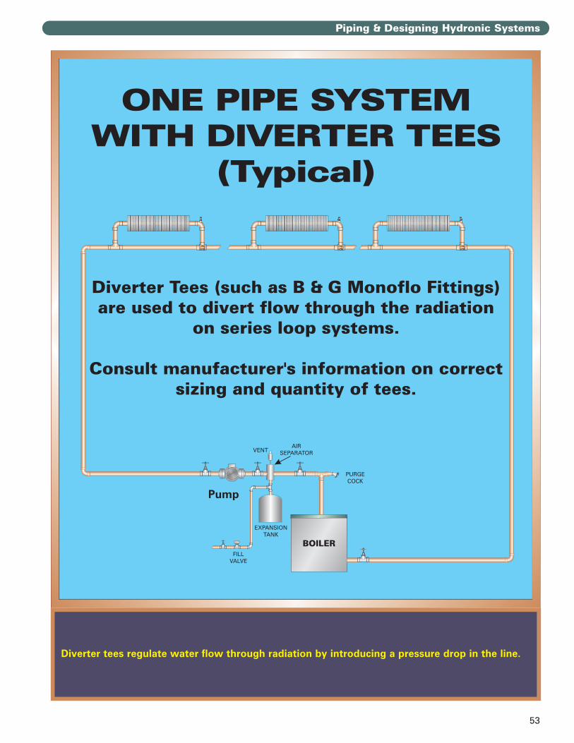
53
Piping & Designing Hydronic Systems
Diverter tees regulate water flow through radiation by introducing a pressure drop in the line.

54
Piping & Designing Hydronic Systems
Two pipe systems provide the same supply temperature to each radiation unit.
Direct return systems are likely to have flow balance problems because the furthest radiationpiping is longer than for closer units. This causes large differences in pressure drops in thebranches.

55
Piping & Designing Hydronic Systems
Two pipe systems provide the same supply temperature to each radiation unit.
Reverse return systems are easier to balance because each branch has about the same length ofpiping. So all pressure drops are about the same.

56
Piping & Designing Hydronic Systems
The boiler is operated by the end switches on the zone valves.
When a zone calls for heat its zone valve opens and trips the valve switch. The boiler then fires,providing heat as long as the valve is open.
Make sure when using three wire zone valves to check the electrical connections to the boiler.If the valves are correctly connected there should never be a voltage on the leads to the boiler.

57
Piping & Designing Hydronic Systems
Zoning with circulators assures adequate flow through each zone while still allowing the use oflow head circulators.
Circulators must be wired to circulator relays. Some circulator manufacturers now supply zoning circulators. These have the relay mechanism built in, allowing much simpler wiring.

58
Piping & Designing Hydronic Systems
Always pipe a purge valve (boiler cock) on the boiler supply piping to allow purging the air fromthe system.

59
Piping & Designing Hydronic Systems
On converted gravity return systems and other high volume residential systems, pipe a bypassline as shown.
The bypass line causes less water to flow through the boiler. This causes a higher temperaturerise through the boiler, increasing the average temperature inside.

60
Piping & Designing Hydronic Systems
Two pipe systems are the most common design for commercial boiler applications. Direct returnsystems are harder to balance because the more remote branches have longer piping runs andhigher pressure drop than the close branches.
Make sure to use a by-pass pressure regulator. This prevents the pump from building excesspressure as control valves close. It also prevents cavitation in the pump due to low flow.

61
Piping & Designing Hydronic Systems
Two-pipe reverse return systems are easier to balance because all branches have about thesame length of piping, thus the same pressure drop.
Make sure to use a by-pass pressure regulator. This prevents the pump from building excesspressure as control valves close. It also prevents cavitation in the pump due to low flow.

62
Piping & Designing Hydronic Systems
A series primary/secondary system requires high flow rates. This is because the supply tempera-ture to the branches drops as the water proceeds around the loop. To assure high enough watersupply to the later branches the temperature drop for the system must be low, so the flow ishigh.

63
Piping & Designing Hydronic Systems
Two pipe primary/secondary piping allows low flow rate (high temperature drop) through themain loop because all branches receive supply water at the same temperature.

64
Piping & Designing Hydronic Systems
Primary/secondary piping is the best choice for multiple boilers. It assures better control of thereturn water temperature and prevents flow of hot system water through idle boilers.

65
Piping & Designing Hydronic Systems
Pipe the chiller into the system as shown to prevent chilled water from flowing through theboiler.

66
Piping & Designing Hydronic Systems
For heat pump applications and most radiant floor applications or where the water temperaturewill always be low, you can use a fixed bypass as shown. This mixes hot boiler supply waterwith the cool return water so the return water to the boiler is high enough to prevent condensation.
If the return water temperature will be higher at some times during the season a fixed bypasswill not work. This would cause the boiler to trip on high limit frequently. Use the piping forvariable low temperature operation.

67
Piping & Designing Hydronic Systems
For heat pump applications and most radiant floor applications or where the water temperaturewill always be low, you can use a fixed bypass as shown. This mixes hot boiler supply water withthe cool return water so the return water to the boiler is high enough to prevent condensation.
If the return water temperature will be higher at some times during the season a fixed bypasswill not work. This would cause the boiler to trip on high limit frequently. Use the piping forvariable low temperature operation.

68
Piping & Designing Hydronic Systems
For systems which use outdoor reset temperature control, high volume systems, or systemswhich use night or weekend setback, install a mixing valve on the boiler return line as shown.
This mixing valve automatically controls the return water to the boiler, keeping it above theflue gas dewpoint temperature at all times. No additional controls will be needed to protect the boiler from condensation.

69
Piping & Designing Hydronic Systems
Always pipe the system to prevent condensation. This system, designed for all conditions oflow operating temperature, assures that the boiler will never be exposed to cold return temperatures.

70
Piping & Designing Hydronic Systems
Water vapor and carbon dioxide are formed when fuels are burned.
The level of carbon dioxide in the flue gases can tell us how much air is being used.
The water vapor in the flue products makes it necessary to consider the possibility of condensa-tion in the boiler and/or the vent system. Design the piping and the vent appropriately.
When fuel and air are ignited . . .Carbon and Hydrogen combine with Oxygen . . .Forming Carbon Dioxide and Water Vapor . . .Giving Off . . . . . .H E A T
COMBUSTIONCOMBUSTION
OO
O
O O
O O
C H
H
H
H
CH
H
H
H
CH
H
H
H
CH
H
H
H
Water Vapor, H O2Carbon Dioxide, CO2
Oxygen in Air, O2
FUELSuch as MethaneCH4
O
HH
O
HH
O
HH
O O
C
O O
C
HEAT

71
Piping & Designing Hydronic Systems
Large quantities of water vapor and formed in combustion.
Natural gas makes the most, with fuel oil making the least. This is because the ratio of hydrogento carbon in the fuel is highest for natural gas.

72
Piping & Designing Hydronic Systems
The water vapor dewpoint is higher for natural gas than for propane or fuel oil.
For fuel oil, the main concern in preventing condensation is the sulfuric acid dewpoint. Thehigher the amount of sulfur in the fuel, the higher the dewpoint will be. For most cases, though,with #2 fuel oil, the dewpoint will be around 150° F.

73
Piping & Designing Hydronic Systems
Prevent flue gas condensation in the boiler through proper piping design. Condensation willquickly corrode the heating surfaces of the boiler and can damage other components (such asthe burner) as well.

74
Piping & Designing Hydronic Systems
Combustion requires a lot of air. Make sure the air openings are adequate and that the boilerroom is never under a negative pressure.
The term “scfh” used above means Standard Cubic Feet per Hour, the amount of air that wouldflow at standard temperature and pressure, 60 oF and 14.7 psi atmospheric pressure. Actualcubic feet per hour, “acfh”, would be calculated based on actual pressure and temperature ofthe air.

75
Piping & Designing Hydronic Systems
The differences in efficiency numbers, for the most part, depend on whether jacket losses andstand-by losses are deducted.
AFUE (Annual Fuel Utilization Efficiency) is the standardized efficiency rating introduced withthe 1992 energy regulations (National Appliance Energy Conservation Act). It applies only toboilers under 300 MBH (residential size).

76
Piping & Designing Hydronic Systems
The vent categories describe the likelihood of the flue gases to condense in the vent systemand whether the vent system will be pressurized or gravity.
Appliances which have a combustion efficiency higher than 83% under ANSI test conditions arerated as Condensing and will fall under Category II or IV.
ONLY Category I appliances may use B vent.
II IIII
IIIIII IVIV
CombustionEfficiency83% or Less
CombustionEfficiency83% or Less
CombustionEfficiencyOver 83%
CombustionEfficiencyOver 83%
(Per ANSI Z21.13/CSA 4.9)(Per ANSI Z21.13/CSA 4.9)

77
Piping & Designing Hydronic Systems
Follow the appliance manufacturer’s instructions on venting carefully. The venting must besuitable for the flue gases it has to handle.

78
Piping & Designing Hydronic Systems
Part load efficiency represents the effective efficiency under loads less than the boiler output.At below 50% the part load efficiency drops off sharply. This is because the standby losses fora warm boiler become a larger percentage of the total energy input.
Increase part load efficiency by using multiple boilers or multi-stage or modulating boilers.

79
Piping & Designing Hydronic Systems
Remember to check the inhibitor level and glycol concentration at least annually to make sure itis still correct.
GLYCOL DATAGLYCOL DATARule
ofThumb
Ruleof
Thumb
Ruleof
Thumb
USE ONLY INHIBITED PROPYLENEGLYCOL – NOT ETHYLENE GLYCOL.ETHYLENE GLYCOL IS TOXIC ANDWILL ATTACK RUBBER GASKETSAND MEMBRANES IN THE SYSTEM.
Increase the size of expansion tanks by 20% for mostsystems because glycol/water expands more.Increase the size of expansion tanks by 20% for mostsystems because glycol/water expands more.
�
�
�
�
�
�
�
�
inthe system. The coating reactswith the glycol.
preferably with trisodiumphosphate or another chemicalcleaner.
Use manual fill only.This way a leak will show upas a drop in system pressure.The glycol is diluted whenfresh water is added, reducingits level of protection.
The chromatereacts with glycol.
Packinggland seals leak easily withglycol in the water.
To get the same heat transferwith glycol as with water,
formost systems operatingbetween 180 and 220 F.o
At the 14% higher flow rateto get the same heat transfer,the
Do not use galvanized pipe
Clean the system before filling,
Do not use an automatic fillvalve.
Do not use chromate watertreatment.
Use pumps with onlymechanical seals.
increase the flow rate for50/50 glycol water to 14%higher than water alone
pressure drop for 50/50glycol water is 23% higherthan water.
For a given flow rate, thepressure drop for 50/50 glycolwater will be equal to thepressure drop for water at140°F. From 140°F to 220°F, thepressure drop continues todecrease. At 220°F thepressure drop of 50/50 glycolwater is 10% less than thepressure drop for water.

FULL-COLOR TRAINING GUIDE SERIESFULL-COLOR TRAINING GUIDE SERIES
CHHS796 R5 (5/08-2M)
The
of
WaterPIPING & DESIGNINGHYDRONIC SYSTEMS
PIPING & DESIGNINGHYDRONIC SYSTEMS
©2008