VOLUME I: PRESSURE PIPING SYSTEMS DESIGN - IPEX
86
Blue Brute ® Piping Systems Bionax ® Piping Systems White Bionax ® Sewer Pressure Piping Systems IPEX Centurion ® Piping Systems IPEX Fusible TM Pipe TerraBrute ® CR Piping Systems CycleTough ® Piping Systems Blue904 ® Water Service Tubing Gold901 TM Water Service Tubing Q-Line ® Water Service Tubing We Build Tough Products for Tough Environments ® VOLUME I: PRESSURE PIPING SYSTEMS DESIGN Municipal Technical Manual Series MUNICIPAL PRESSURE PIPING SYSTEMS
-
Upload
khangminh22 -
Category
Documents
-
view
0 -
download
0
Transcript of VOLUME I: PRESSURE PIPING SYSTEMS DESIGN - IPEX

Blue Brute® Piping SystemsBionax® Piping SystemsWhite Bionax® Sewer Pressure Piping SystemsIPEX Centurion® Piping SystemsIPEX FusibleTM PipeTerraBrute® CR Piping SystemsCycleTough® Piping SystemsBlue904® Water Service TubingGold901TM Water Service TubingQ-Line® Water Service Tubing
We Build Tough Products for Tough Environments®
VOLUME I:PRESSURE PIPING SYSTEMS DESIGN
Municipal Technical Manual Series
M U N I C I P A L P R E S S U R E P I P I N G S Y S T E M S

© 2021 by IPEX. All rights reserved. No part of this book may be used or reproduced in any manner whatsoever without prior written permission. For information contact: IPEX Management Inc., 1425 North Service Road East, Unit 3, Oakville, Ontario, Canada, L6H 1A7.
The information contained here within is based on current information and product design at the time of publication and is subject to change without notification. IPEX does not guarantee or warranty the accuracy, suitability for particular applications, or results to be obtained therefrom.
IPEX Pressure Piping Systems Design
Municipal Technical Manual Series, Vol. 1

ABOUT IPEX
At IPEX, we have been manufacturing non-metallic pipe and fittings since 1951. We formulate our own compounds and maintain strict quality control during production. Our products are made available for customers thanks to a network of regional stocking locations throughout North America. We offer a wide variety of systems including complete lines of piping, fittings, valves and custom-fabricated items.
More importantly, we are committed to meeting our customers’ needs. As a leader in the plastic piping industry, IPEX continually develops new products, modernizes manufacturing facilities and acquires innovative process technology. In addition, our staff take pride in their work, making available to customers their extensive thermoplastic knowledge and field experience. IPEX personnel are committed to improving the safety, reliability and performance of thermoplastic materials. We are involved in several standards committees and are members of and/or comply with the organizations listed on this page.
For specific details about any IPEX product, contact our customer service department (contact information is listed on the back cover).
Pressure Piping Systems Design Manual Overview . . . . . . . . . . . . . . . . . . . . . . . . . . . . . . . . . . . . . . . . . . . . . . . . . . . . . . . . . . . . . . . . . 1
Section One: Product Information Introduction . . . . . . . . . . . . . . . . . . . . . . . . . . . . . . . . . . . . . . . . . . . . . . . . . . . . . . . . . . . . . 3 Summary of Pressure Pipe and Fittings Testing . . . . . . . . . . . . . . . . . . . . . . . . . . . . 4 Blue Brute® Piping Systems . . . . . . . . . . . . . . . . . . . . . . . . . . . . . . . . . . . . . . . . . . . . . . . 5 Bionax® Piping Systems . . . . . . . . . . . . . . . . . . . . . . . . . . . . . . . . . . . . . . . . . . . . . . . . . . 11 White Bionax® PVCO pipe . . . . . . . . . . . . . . . . . . . . . . . . . . . . . . . . . . . . . . . . . . . . . . . . 12 IPEX Centurion® Piping Systems . . . . . . . . . . . . . . . . . . . . . . . . . . . . . . . . . . . . . . . . . . . 13 IPEX FusibleTM PVC Pipe for Trenchless Applications . . . . . . . . . . . . . . . . . . . . . . . . 18 TerraBrute®CR Restrained Joint Pipe . . . . . . . . . . . . . . . . . . . . . . . . . . . . . . . . . . . . . 22 CycleTough® Piping Systems . . . . . . . . . . . . . . . . . . . . . . . . . . . . . . . . . . . . . . . . . . . . 26 Blue904® PEX Water Service Tubing . . . . . . . . . . . . . . . . . . . . . . . . . . . . . . . . . . . . . . 34 Gold901TM Water Service Tubing . . . . . . . . . . . . . . . . . . . . . . . . . . . . . . . . . . . . . . . . . 36 Q-Line® Water Service Tubing . . . . . . . . . . . . . . . . . . . . . . . . . . . . . . . . . . . . . . . . . . . 38 Standards for PVC Pressure Systems . . . . . . . . . . . . . . . . . . . . . . . . . . . . . . . . . . . . . . 41
Section Two: Properties of PVC Pressure Pipe and Pressure System Design Introduction . . . . . . . . . . . . . . . . . . . . . . . . . . . . . . . . . . . . . . . . . . . . . . . . . . . . . . . . . . . . 43
Material Properties of PVC . . . . . . . . . . . . . . . . . . . . . . . . . . . . . . . . . . . . . . . . . . . . . . 43
Design Life . . . . . . . . . . . . . . . . . . . . . . . . . . . . . . . . . . . . . . . . . . . . . . . . . . . . . . . . . . . . . 43
Design Strength . . . . . . . . . . . . . . . . . . . . . . . . . . . . . . . . . . . . . . . . . . . . . . . . . . . . . . . . 44
Chemical Permeation and Installation of PVC Pipe in Contaminated Soils . . 44
UV Resistance . . . . . . . . . . . . . . . . . . . . . . . . . . . . . . . . . . . . . . . . . . . . . . . . . . . . . . . . . . 45
Thermal Effects - Pressure Derating. . . . . . . . . . . . . . . . . . . . . . . . . . . . . . . . . . . . . . 45
Thermal Effects - Expansion and Contraction . . . . . . . . . . . . . . . . . . . . . . . . . . . . 45
Design Calculations
Calculating a Pressure/Class Rating . . . . . . . . . . . . . . . . . . . . . . . . . . . . . . . . . . . . . 46
Calculating Friction Headloss . . . . . . . . . . . . . . . . . . . . . . . . . . . . . . . . . . . . . . . . . . . 46
Calculating Surge Pressures . . . . . . . . . . . . . . . . . . . . . . . . . . . . . . . . . . . . . . . . . . . . . 47
Calculating Wave Velocity . . . . . . . . . . . . . . . . . . . . . . . . . . . . . . . . . . . . . . . . . . . . . . 48
Air Entrapment in Pipelines . . . . . . . . . . . . . . . . . . . . . . . . . . . . . . . . . . . . . . . . . . . . . . 48
Cyclic Design for PVC Pipes . . . . . . . . . . . . . . . . . . . . . . . . . . . . . . . . . . . . . . . . . . . . . 50
Thrust Restraint in Gasketed Piping Systems . . . . . . . . . . . . . . . . . . . . . . . . . . . . . . 52
Assembly, Installation and Testing of PVC Pressure Pipe Systems . . . . . . . . . . . 53
Section Three: Design Examples #1: Sewage Forcemain – AWWA C900 PVC Pipe . . . . . . . . . . . . . . . . . . . . . . . . . . 55
#2: Sewage Forcemain – ASTM F1483 PVCO Bionax Pipe . . . . . . . . . . . . . . . . . . 59
#3: Transmission Pipe . . . . . . . . . . . . . . . . . . . . . . . . . . . . . . . . . . . . . . . . . . . . . . . . . . . 62
Section Four: Appendices Appendix A: References . . . . . . . . . . . . . . . . . . . . . . . . . . . . . . . . . . . . . . . . . . . . . . . . 69
Appendix B: Reference Tables and Conversion Charts . . . . . . . . . . . . . . . . . . . . 70
Appendix C: Useful Formulas . . . . . . . . . . . . . . . . . . . . . . . . . . . . . . . . . . . . . . . . . . . . 75
Appendix D: Abbreviations . . . . . . . . . . . . . . . . . . . . . . . . . . . . . . . . . . . . . . . . . . . . . . 78
Appendix E: Tables and Figures . . . . . . . . . . . . . . . . . . . . . . . . . . . . . . . . . . . . . . . . . 79
i
CONTENTS
Pressure Piping Systems Design

IPEX Pressure Piping Systems Designii
NOTES

1IPEX Pressure Piping Systems Design 1IPEX Pressure Piping Systems Design
OVERVIEW
IPEX is one of the largest manufacturers of plastic piping systems in North America. IPEX manufactures piping systems for many different applications, including:
• Sewer collection and transmission • Water supply • Electrical and communications systems • Plumbing systems • Industrial piping systems
This design manual covers the technical aspects of designing pressure pipe systems with PVC pipe. More specifically, municipal potable water systems, as well as irrigation and sewer force main systems are described.
The manual is organized into three sections:
Section 1 deals with specific products and includes detailed information on applications, dimensions and applicable standards for each system.
Section 2 deals with general design issues associated with PVC systems such as hydraulics, cyclic design and other topics that are applicable to all the products described in the manual.
Section 3 consists of design examples that apply the concepts from the first two sections.
This manual is designed for Engineers, Technologists and other municipal infrastructure professionals who require a deeper understanding of municipal piping systems than can be gleaned from the more general overview literature available from IPEX.

2 IPEX Pressure Piping Systems Design2 IPEX Pressure Piping Systems Design
NOTES

3IPEX Pressure Piping Systems Design
PRO
DU
CT IN
FOR
MA
TION
3IPEX Pressure Piping Systems Design
PRO
DU
CT IN
FOR
MA
TION
IPEX offers a number of different pressure piping systems that are used for various applications. While they are all plastic systems, they vary in outside diameter configurations and in available pressure ratings.
The products offered are:
INTRODUCTION
SECTION 1: PRODUCT INFORMATION
Blue Brute® and IPEX Centurion® Piping Systems
Cast-iron outside diameter (CIOD) pipe and fittings
Bionax Pipe® Cast-iron outside diameter (CIOD)
IPEX FusibleTM
Fusible BruteTM (CIOD) is available in sizes ranging from 100mm (4”) to 750mm (30”) while Fusible Series™ (IPS) pipe is available from 100mm (4”) to 600mm (24”).
TerraBrute®CR PipeCIOD pipe modified for use for trenchless installation methods such as directional drilling or pipe bursting or above-ground usage such as bridge crossings.
CycleTough® Piping Systems
Iron Pipe Size outside diameter (IPSOD) pipe and fittings
Blue904® PEX Water Service Tubing
3/4” through 2” PEX pipe designed for underground water service connections made to copper tube size (CTS) outside diameter.
Gold901 Water Service Tubing
3/4” - 2” High-Density Polyethylene (HDPE) pipe designed for use on both the municipal and private-side of a project.
Q-Line® Water Service Tubing
3/4” & 1” composite pipe designed for use underground water service connections, made to metric outside diameters.

PRO
DU
CT
INFO
RM
ATI
ON
4 IPEX Pressure Piping Systems Design
SUMMARY OF PRESSURE PIPE AND FITTINGS TESTINGAll IPEX pressure pipes and fittings are manufactured to standards from various recognized organizations such as AWWA, CSA, ASTM and others. As a result, all pressure pipe products undergo a variety of testing and quality procedures.
CIOD Pipe: Blue Brute, IPEX Centurion, Bionax, Fusible Brute and TerraBrute CR Piping Systems
These piping systems are manufactured under various AWWA standards, including AWWA C900 (Blue Brute, IPEX Centurion and TerraBrute CR), and C909 (Bionax). Fittings are manufactured C907 (molded) or C900 (fabricated standards).
Each length of Blue Brute, IPEX Centurion, Bionax and TerraBrute CR CIOD pipe is hydrostatically tested in order to verify the pressure capabilities of each pipe as dictated by AWWA C900 or C909. In addition, burst tests are carried out regularly to verify the integrity of the pipe and joint system. It should be remembered that the hydrostatic test is done using the pipe’s own gasket, which means that both the pipe and the joining system are being checked. AWWA and CSA standards also require a number of other performance tests.
TerraBrute CR pipe does not strictly comply with AWWA C900 standard because of the dimensional change imposed by the grooving procedure, however it is tested using the same procedures as conventional Blue Brute and IPEX Centurion. The hydrostatic proof test is carried out on each length of TerraBrute CR to the same pressures and durations as for standard Blue Brute or IPEX Centurion.
In addition to Standard requirements, Certifications require very stringent testing and QA/QC procedures. For example, joint assemblies are regularly tested for full vacuum pressure .
The CSA Certification program also requires impact testing to be carried out at 0ºC (32ºF) to simulate more challenging cold weather conditions.
In addition to pressure and impact testing, finished PVC pipe is tested by using acetone immersion tests and heat reversion tests. Both tests are used to check that the proper degree of fusion has occurred during the extrusion process.
The dimensional characteristics of each pipe and fitting are checked constantly during the extrusion and molding processes, and samples are taken for detailed dimensional analysis during each extrusion or molding run.
IPSOD Pipe: CycleTough and Fusible Series
CycleTough pipe undergoes testing identical to that of Blue Brute and IPEX Centurion pipe with the exception of the hydrostatic proof test of each length of pipe. This does not mean that the pipe is of any lesser quality than Blue Brute or IPEX Centurion pipe – it only means that it is manufactured under a different standard (ASTM D2241) that does not require the every-length hydrostatic proof test.
In addition to performance and dimensional checks, National Sanitation Foundation (NSF) requirements mean that all products are thoroughly tested to ensure they are suitable to convey potable water.
To summarize – There are many standards governing the manufacture and design of IPEX pressure pipes and fittings. IPEX also has internal testing standards that are often well in excess of published requirements to ensure acceptable performance on the jobsite.

5IPEX Pressure Piping Systems Design
PRO
DU
CT IN
FOR
MA
TION
BLUE BRUTE® PIPING SYSTEMS
Blue Brute is one of the most well known names in municipal water supply, as it has built up an enviable reputation for performance and reliability over the years. Blue Brute pipe and fittings eliminate the threat of corrosion, while providing reliable long-term service. While Blue Brute pipe is compatible with iron fittings, IPEX recommends the use of Blue Brute fittings as they are made to match the pipe, and eliminate the “Achilles heel” of many systems – corroding iron fittings.
It is advisable to specify pipe and fittings from the same manufacturer in order to ensure a completely matched system. Only by specifying Blue Brute fittings can you ensure that the fittings have the same long term strength as the pipe itself.
Applications:
Municipal water distribution systems and fire lines.Irrigation, sewage forcemains, industrial lines.
Gasket Options For Contaminated Soils
Blue Brute pipe and fittings have removable gaskets. This allows oil resistant (nitrile) gaskets to be easily substituted when installing piping systems in contaminated soils. Please refer to Section 2 – Chemical Permeation and Resistance for more information on this topic.
Standards:
Blue Brute Pipe:
AWWA C900, CSA B137.3 certified, FM 1612 approved, UL 1285 listed, NSF 61 certified, Certified to NQ 36240-250
Blue Brute Fittings:
AWWA C907, CSA B137.2 (100mm – 300mm) certified, AWWA C900, CSA B137.3 (250mm – 300mm) certified, FM 1612 approved, UL 1285 listed
stelai
Highlight

PRO
DU
CT
INFO
RM
ATI
ON
6 IPEX Pressure Piping Systems Design
Short Form Specifications
General
Blue Brute pipe shall be certified to CSA B137.3 “Rigid Polyvinyl Chloride PVC Pipe for Pressure Applications” and shall conform to AWWA C900 “Polyvinyl Chloride (PVC) Pressure Pipe, 4” – 60” for Water Transmission and Distribution.” Blue Brute DR25 pipe shall have a pressure class/rating of 1120 kPa (165 psi). DR18 pipe shall have a pressure class/rating of 1620 kPa (235 psi). DR14 pipe shall have a pressure class/rating of 2100 kPa (305 psi).
Material
Blue Brute pipe shall be made from PVC compound conforming to ASTM D1784 cell class 12454.
Product
Pipe shall be suitable for use at maximum hydrostatic working pressure equal to the pressure class/rating at 23°C (73°F). Laying lengths shall be 6.1 metres (20 feet). Pipe shall have cast-iron outside diameters. Each length of pipe must be proof-tested at two times the pressure class.
Joining
The gasket shall be carefully fitted to the bell groove if not already factory installed. Both bell and spigot shall be clean and free of debris before approved lubricant is
applied. The pipe and/or fittings shall be joined by pushing the spigot into the bell to the depth line marked on the spigot. When pipe has been cut in the field, the end shall be made square and beveled to a 15º chamfer. All insertion lines should be re-drawn, according to the IPEX Pressure Pipe Installation Guide.
Molded Fittings
Blue Brute fittings shall conform to AWWA C907 “Polyvinyl Chloride (PVC) Pressure Fittings for Water (4” through 12”)” and be certified to CSA B137.2 “PVC Injection Molded Gasketed Fittings for Pressure Applications.” They shall also be UL Listed and FM approved.
Fabricated Fittings
Fabricated fittings shall be made from segments of AWWA C900 PVC pipe. Segements are bonded together and may be over-wrapped with fibreglass-reinforced polyester. The pressure class must match the pipe. The fittings must meet the requirements of CSA B137.3.
Lubricant
Pipe must be assembled with IPEX non-toxic, water soluble lubricant listed by the National Sanitation Foundation.
BLUE BRUTE® PIPING SYSTEMS
Size
DR 25 Class 165 AWWA pressure class 165 psi CSA pressure rating 1,130 kPa
DR 18 Class 235 AWWA pressure class 235 psi CSA pressure rating 1,620 kPa
DR 14 Class 305 AWWA pressure class 305 psi CSA pressure rating 2,130 kPa
Avg. ID Min. Wall Thickness Avg. OD Avg. ID Min. Wall
Thickness Avg. OD Avg. ID Min. Wall Thickness Avg. OD
in mm in mm in mm in mm in mm in mm in mm in mm in mm in mm
4 100 4.42 112 0.192 4.88 4.80 122 4.27 108 0.267 6.78 4.80 122 4.11 104 0.343 8.71 4.80 122
6 150 6.35 161 0.276 7.01 6.90 175 6.13 155 0.383 9.73 6.90 175 5.91 149 0.493 12.52 6.90 175
8 200 8.33 212 0.362 9.20 9.05 230 8.05 204 0.502 12.80 9.05 230 7.76 198 0.646 16.42 9.05 230
10 250 10.21 260 0.444 11.30 11.10 282 9.87 250 0.616 15.70 11.10 282 9.51 242 0.793 20.14 11.10 282
12 300 12.15 309 0.527 13.41 13.20 335 11.73 297 0.733 18.62 13.20 335 11.31 287 0.943 23.95 13.20 335
Dimensions:
Blue Brute pipes and fittings are manufactured with cast-iron outside diameters (CIOD), which means that they are compatible with much of the existing infrastructure of older iron pipes. This means that no special transition fittings are needed with Blue Brute.

7IPEX Pressure Piping Systems Design
PRO
DU
CT IN
FOR
MA
TION
BLUE BRUTE® PIPING SYSTEMS
L1
L1
Size L1in mm in mm4 100 2.6 676 150 4.3 1088 200 5.5 14010 250 6.7 17112 300 7.7 195
Size Minimum Maximumin mm in mm in mm4 100 5.44 138 5.61 1426 150 7.84 199 8.03 2048 200 10.29 261 10.55 26810 250 12.63 322 12.96 32912 300 15.07 383 15.46 39314 350 17.28 439 17.73 45016 400 19.64 448 20.17 512
Bell OD for Joint Restraint Selection
Size L1in mm in mm4 100 1.3 336 150 1.8 468 200 2.2 5610 250 2.7 7012 300 3.2 82
45° Elbow
L1
L1
Size L1in mm in mm4 100 3.0 756 150 0.8 208 200 0.9 23
11-1/4° Elbow
L1
L1Size L1
in mm in mm6 150 1.0 258 200 1.1 2810 250 1.7 4312 300 1.9 48
22-1/2° Elbow
OD
Note: Other DR’s and sizes up to 60” (1500mm) are available on request.
90° Elbow
L1
L1
*Sizes 10” and 12” have external lugs to assist in pry-bar assemblies.

PRO
DU
CT
INFO
RM
ATI
ON
8 IPEX Pressure Piping Systems Design
BLUE BRUTE® PIPING SYSTEMS
L2
L1 Size L1 L2in mm in mm in mm
6 x 4 150 x 100 5.6 141 4.3 1088 x 6 200 x 150 6.5 165 5.7 14510 x 8 250 x 200 7.0 178 5.8 14712 x 10 300 x 250 7.9 202 6.6 167
Reducing Adapter Spigot x Bell
L1
Size L1in mm in mm4 100 0.2 56 150 0.3 88 200 0.3 710 250 0.5 1312 300 0.5 13
Coupling (available w/o center stop as a Repair Coupling)
Tee
Hammer Tee
L2
L1
L1
Hydrant Tee
L1
L1
L2
Nominal Size L1 L2 L3 L4in mm in mm in mm in mm in mm
4 x 4 x 4 100 x 100 x 100 2.6 67 2.6 67 - - - -6 x 6 x 4 150 x 150 x 100 4.0 102 3.3 87 - - - -6 x 6 x 6 150 x 150 x 150 4.3 108 4.3 108 - - - -8 x 8 x 4 200 x 200 x 100 5.1 130 3.6 91 - - - -8 x 8 x 6 200 x 200 x 150 5.3 136 4.7 120 - - - -8 x 8 x 8 200 x 200 x 200 5.6 143 5.8 148 - - - -
10 x 10 x 4 250 x 250 x 100 6.7 171 6.7 171 11.2 284 27.3 69310 x 10 x 6 250 x 250 x 150 6.7 171 6.7 171 12.0 305 27.3 69310 x 10 x 8 250 x 250 x 200 6.7 171 6.7 171 12.8 325 27.3 69310 x 10 x 10 250 x 250 x 250 6.7 171 6.7 171 13.7 348 27.3 69312 x 12 x 4 300 x 300 x 100 7.7 195 7.7 195 12.1 307 30.5 77512 x 12 x 6 300 x 300 x 150 7.7 195 7.7 195 12.9 328 30.5 77512 x 12 x 8 300 x 300 x 200 7.7 195 7.7 195 13.7 348 30.5 77512 x 12 x 10 300 x 300 x 250 7.7 195 7.7 195 14.6 371 30.5 77512 x 12 x 12 300 x 300 x 300 7.7 195 7.7 195 15.3 389 30.5 775
Nominal Size L1 L2 L3 L4
in mm in mm in mm in mm in mm
12 x 12 x 6 300 x 300 x 150 7.7 195 7.7 195 12.9 328 30.5 775
Nominal Size L1 L2 L3 L4
in mm in mm in mm in mm in mm
6 x 6 x 6 150 x 150 x 150 4.5 114 3.8 96 11.5 292 17.0 457
8 x 8 x 6 200 x 200 x 150 5.8 148 5.2 132 12.8 312 22.4 569
10 x 10 x 6 250 x 250 x 150 7.0 178 6.7 171 14.0 356 27.3 693
12 x 12 x 6 300 x 300 x 150 8.1 206 7.7 195 15.1 384 30.5 775
L1
L3
L2
L4

9IPEX Pressure Piping Systems Design
PRO
DU
CT IN
FOR
MA
TION
BLUE BRUTE® PIPING SYSTEMS
A L
A B L
Size A L1
in mm in mm in mm
4 x 4 x 3/4 100 x 100 x 20 3/4 20 2 50
4 x 4 x 1 100 x 100 x 25 1 25 2 50
6 x 6 x 3/4 150 x 150 x 20 3/4 20 3 76
6 x 6 x 1 150 x 150 x 25 1 25 3 76
6 x 6 x 1-1/4 150 x 150 x 32 1-1/4 32 3 76
6 x 6 x 1-1/2 150 x 150 x 40 1-1/2 40 3 76
6 x 6 x 2 150 x 150 x 50 2 50 3 76
8 x 8 x 3/4 200 x 200 x 20 3/4 20 3 76
8 x 8 x 1 200 x 200 x 25 1 25 3 76
8 x 8 x 1-1/4 200 x 200 x 32 1-1/4 32 3 76
8 x 8 x 1-1/2 200 x 200 x 40 1-1/2 40 3 76
8 x 8 x 2 200 x 200 x 50 2 50 3 76
10 x 10 x 3/4 250 x 250 x 20 3/4 20 3 76
10 x 10 x 1 250 x 250 x 25 1 25 3 76
12 x 12 x 3/4 300 x 300 x 20 3/4 20 3 76
12 x 12 x 1 300 x 300 x 25 1 25 3 76
Single Tapped Coupling
Size A B L
in mm in mm in mm in mm
6 x 3/4 x 3/4 150 x 20 x 20 3/4 20 3/4 20 3 76
6 x 1 x 3/4 150 x 25 x 20 3/4 20 1 25 3 76
6 x 1 x 1 150 x 25 x 25 1 25 1 25 3 76
6 x 1-1/4 x 3/4 150 x 32 x 20 3/4 20 1-1/4 32 3 76
6 x 1-1/4 x 1 150 x 32 x 25 1 25 1-1/4 32 3 76
6 x 1-1/2 x 3/4 150 x 40 x 20 3/4 20 1-1/2 40 3 76
6 x 1-1/2 x 1 150 x 40 x 25 1 25 1-1/2 40 3 76
6 x 2 x 3/4 150 x 50 x 20 3/4 20 2 50 3 76
6 x 2 x 1 150 x 50 x 25 1 25 2 50 3 76
8 x 3/4 x 3/4 200 x 20 x 20 3/4 20 3/4 20 3 76
8 x 1 x 3/4 200 x 25 x 20 3/4 20 1 25 3 76
8 x 1 x 1 200 x 25 x 25 1 25 1 25 3 76
8 x 1-1/4 x 3/4 200 x 32 x 20 3/4 20 1-1/4 32 3 76
8 x 1-1/4 x 1 200 x 32 x 25 1 25 1-1/4 32 3 76
8 x 1-1/2 x 3/4 200 x 40 x 20 3/4 20 1-1/2 40 3 76
8 x 1-1/2 x 1 200 x 40 x 25 1 25 1-1/2 40 3 76
8 x 2 x 3/4 200 x 50 x 20 3/4 20 2 50 3 76
8 x 2 x 1 200 x 50 x 25 1 25 2 50 3 76
Double Tapped Coupling
Note: 3/4” (20mm) Taps to 2” (50mm). Taps: AWWA Thread
Note: 3/4” (20mm) Taps to 2” (50mm). Taps: AWWA Thread
PRO
DU
CT
INFO
RM
ATI
ON
10 IPEX Pressure Piping Systems Design
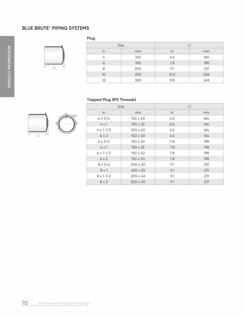
BLUE BRUTE® PIPING SYSTEMS
L1
Size L1
in mm in mm
4 100 6.5 164
6 150 7.8 198
8 200 9.1 231
10 250 10.2 258
12 300 9.8 249
Plug
L1
Thread
Size L1
in mm in mm
4 x 3/4 100 x 20 6.5 164
4 x 1 100 x 25 6.5 164
4 x 1-1/2 100 x 40 6.5 164
4 x 2 100 x 50 6.5 164
6 x 3/4 150 x 20 7.8 198
6 x 1 150 x 25 7.8 198
6 x 1-1/2 150 x 40 7.8 198
6 x 2 150 x 50 7.8 198
8 x 3/4 200 x 20 9.1 231
8 x 1 200 x 25 9.1 231
8 x 1-1/2 200 x 40 9.1 231
8 x 2 200 x 50 9.1 231
Tapped Plug (IPS Threads)

11IPEX Pressure Piping Systems Design
PRO
DU
CT IN
FOR
MA
TION
BIONAX® PIPING SYSTEMS
Bionax PVCO pipe and Blue Brute PVC fittings eliminate corrosion and provide a reliable long-term piping system. Although Bionax is compatible with iron fittings, IPEX recommends the use of Blue Brute fittings since they result in an all-plastic system that prevents corroding iron fittings.
It is advisable to specify pipe and fittings from the same manufacturer to ensure a completely matched system. If Bionax pipe is specified with Blue Brute fittings, the pipe and fittings will provide matched pressure capacities.
Applications:
Municipal water distribution systems
Sewage forcemains*, industrial process piping
Pressure Class/Rating
Bionax CIOD pipe has a Pressure Rating (CSA) or a Pressure Class (AWWA) of 165 psi or 235 psi. Pressure Class 305 psi will soon be available.
Surge Pressure Capacity
Bionax has tremendous ability to withstand short-term pressure surges. The short term ratings for Bionax are
PC 165 - 264psi PC 235 - 376psi PC 305 - 488psi
Standards
Bionax pipe:
ANSI/NSF Standard 14, ANSI/NSF Standard 61
ASTM D3139, F477 and F1483
NSF-certified to AWWA C909 and ASTM F1483, CSA-certified to B137.3.1 and FM-approved to FM1612.
NQ3660-950
* White Bionax PVCO pipe for sewage forcemains

PRO
DU
CT
INFO
RM
ATI
ON
12 IPEX Pressure Piping Systems Design
BIONAX® PIPING SYSTEMS
Size Pressure Class/Rating 235 psi @ 73°F (1,620 kPa @ 23°C)Average OD Min Wall Thickness Average ID
in mm in mm in mm in mm4 100 4.8 122 0.2 3.9 4.5 1146 150 6.9 175 0.2 5.6 6.4 1648 200 9.1 230 0.3 7.34 8.5 21510 250 11.1 282 0.4 9.0 10.4 26312 300 13.2 335 0.4 10.7 12.3 31314 350 15.3 389 0.5 12.5 14.3 36416 400 17.4 442 0.6 14.7 16.3 41418 450 19.5 495 0.6 15.9 18.2 46320 500 21.6 549 0.7 17.6 20.7 51224 600 25.8 655 0.8 21.0 24.0 61030 750 32.0 813 1.0 26.0 29.8 758
Size Pressure Class/Rating 165 psi @ 73°F (1,135 kPa @ 23°C)Average OD Min Wall Thickness Average ID
in mm in mm in mm in mm14 350 15.3 389 0.4 8.8 14.8 37016 400 17.4 442 0.4 10.0 16.8 42118 450 19.5 495 0.4 11.3 18.5 47120 500 21.6 549 0.5 12.7 20.6 52324 600 25.8 655 0.6 14.9 24.5 62330 750 32.0 813 0.7 18.4 30.4 773
Size Pressure Class/Rating 305 psi @ 73°F (2,100 kPa @ 23°C)Average OD Min Wall Thickness Average ID
in mm in mm in mm in mm14 350 15.3 389 0.4 8.8 14.0 35416 400 17.4 442 0.4 10.0 15.9 40318 450 19.5 495 0.4 11.3 17.8 45220 500 21.6 549 0.9 22.6 19.7 50124 600 25.8 655 1.1 27.0 23.5 59830 750 32.0 813 1.3 33.4 29.2 742
Dimensions of Bionax PVCO Pressure Pipes with CIODs
Short Form Specifications
General Bionax CIOD pipe shall be certified to AWWA C909 “Molecularly Oriented Polyvinyl Chloride (PVCO) Pressure Pipe 4 inch and larger for Water, Wastewater, and Reclaimed Water Service” and certified to CSA B137.3.1 “Molecularly oriented polyvinylchloride (PVCO) pipe for pressure applications.” Bionax shall have a pressure class (AWWA) or pressure rating (CSA) of 165 psi or 235 psi.
MaterialPVCO pipe shall be manufactured from rigid polyvinyl chloride (PVC) compound meeting the requirements of ASTM D1784 cell class 12454.
Gaskets shall meet ASTM F477 for high-head applications.
Product Finished PVCO pipe shall have an HDB of 7100 psi. Laying lengths shall be 6.1 meters (20 feet). Pipe shall have cast-iron outside diameters. Every length must be proof-tested at two times the pressure class.
FittingsBionax piping systems shall include IPEX Blue Brute molded and fabricated fittings.
LubricantPipe must be assembled with IPEX water-soluble lubricant listed to NSF Standard 61.
Color CodingCIOD pipe shall be color coded blue.
JoiningThe gasket shall be carefully fitted to the bell groove if not already factory-installed. Both bell and spigot shall be clean and free of debris before lubricant is applied. The pipe shall be joined by push-fitting bell and spigot joint to the depth line marked on the spigot. When pipe has been cut in the field, the end shall be made square and bevelled to a 10-degree chamfer and the insertion line shall be redrawn per IPEX’s Pressure Pipe Installation Guide.

13IPEX Pressure Piping Systems Design
PRO
DU
CT IN
FOR
MA
TION
WHITE BIONAX® PVCO PIPE
Dimensions of White Bionax PVCO Pressure Pipes with CIODs
Short Form Specifications
General White Bionax CIOD pipe shall be certified to AWWA C909 “Molecularly Oriented Polyvinyl Chloride (PVCO) Pressure Pipe 4 inch and larger for Water, Wastewater, and Reclaimed Water Service” and certified to CSA B137.3.1 “Molecularly oriented polyvinylchloride (PVCO) pipe for pressure applications.” Bionax shall have a pressure class (AWWA) or pressure rating (CSA) of 165 psi or 235 psi.
MaterialPVCO pipe shall be manufactured from rigid polyvinyl chloride (PVC) compound meeting the requirements of ASTM D1784 cell class 12454.
Gaskets shall meet ASTM F477 for high-head applications.
Product Finished PVCO pipe shall have an HDB of 7100 psi. Laying lengths shall be 6.1 meters (20 feet). Pipe shall have cast-iron outside diameters. Every length must be proof-tested at two times the pressure class.
FittingsBionax piping systems shall include IPEX Blue Brute molded and fabricated fittings.
Color CodingCIOD pipe shall be color coded white.
Print Line“SEWER PRESSURE/ NON-POTABLE” shall be printed on white Bionax pipe for easy differentiation from a water pressure pipe.
JoiningThe gasket shall be carefully fitted to the bell groove if not already factory-installed. Both bell and spigot shall be clean and free of debris before lubricant is applied. The pipe shall be joined by push-fitting bell and spigot joint to the depth line marked on the spigot. When pipe has been cut in the field, the end shall be made square and bevelled to a 10-degree chamfer and the insertion line shall be redrawn per IPEX’s Pressure Pipe Installation Guide.
SizePressure Class/Rating 165 psi @ 73°F (1,135 kPa @ 23°C)
Average OD Min Wall Thickness Average ID
in mm in mm in mm in mm
16 400 17.4 442 0.4 10.0 16.8 421
18 450 19.5 495 0.4 11.3 18.5 471
SizePressure Class/Rating 235 psi @ 73°F (1,620 kPa @ 23°C)
Average OD Min Wall Thickness Average ID
in mm in mm in mm in mm
6 150 6.9 175 0.2 5.6 6.4 164
8 200 9.1 230 0.3 7.34 8.5 215
10 250 11.1 282 0.4 9.0 10.4 263
12 300 13.2 335 0.4 10.7 12.3 313
14 350 15.3 389 0.5 12.5 14.3 364
16 400 17.4 442 0.6 14.7 16.3 414
18 450 19.5 495 0.6 15.9 18.2 463

PRO
DU
CT
INFO
RM
ATI
ON
14 IPEX Pressure Piping Systems Design
IPEX CENTURION® PIPING SYSTEMS
IPEX Centurion extends the benefits of Blue Brute to larger diameters of pipe and new applications. The versatility and ease of installation of IPEX Centurion is unmatched – and costly and difficult to install corrosion protection is eliminated. In addition, unlike HDPE or concrete pressure pipe, every length of IPEX Centurion is tested to double its pressure rating.
Applications:
Water transmission lines, forcemains.
Irrigation, gravity lines, industrial lines
Standards:
AWWA C900, CSA B137.3, BNQ 3624-250, NSF 61
Factory Mutual FM 1612:DR18 is FM approved to 24” (600mm diameter)
Underwriter’s Laboratories UL 1285:DR18 is listed to 24” (600mm diameter) DR25 is listed to 30” (750mm diameter)

15IPEX Pressure Piping Systems Design
PRO
DU
CT IN
FOR
MA
TION
Color Coding
Water pipe and fittings shall be color coded blue.
Pressure Ratings
IPEX Centurion can withstand extremely high short term pressures, in addition to lower levels of long-term pressure. As a result, AWWA C900 standard includes both long term pressure ratings (LTR) and short term ratings (STR).
DRSurge Pressure
psi kPa
51 10.8 75
41 11.4 79
32.5 12.8 88
25 14.7 101
18 17.4 120
14 19.8 137
Bionax (PC235) 14.1 97
DRShort Term Rating Long Term Rating
psi kPa psi kPa
51 128 880 80 550
41 160 100 100 690
32.5 200 1,380 125 860
25 264 1,820 165 1,140
18 376 2,590 235 1,620
14 488 3,370 305 2,100
IPEX CENTURION® PIPING SYSTEMS
Short Form Specifications
General
Pipe must conform to AWWA C900 and be certified to CSA B137.3 “Rigid polyvinyl chloride (PVC) pipe for pressure applications.” DR51, 41, 32.5, 25, 18, and 14 pipe must have the following pressure/class ratings: 80 psi (550 kPa), 100 psi (690 kPa), 125 psi (860 kPa), 165 psi (1,140 kPa), 235 psi (1,620 kPa) and 305 psi (2,100 kPa). For pressure applications, each length of pipe must be hydro-tested at twice the rating and a short-term pressure test must be conducted once per production run. Pipe to be IPEX Centurion or approved equal.
Surge Pressures
Transient pressures in pipelines occur as a result of the fluid velocity changing over a relatively short time. The method for approximating a surge pressure is described in section 2. However it should be noted that for most large diameter pipelines, a formal transient analysis should be carried out by a qualified person in order to fully understand the effects of transients in any given system. The method shown in section 2 is certainly appropriate for initial design purposes however.
The table below shows the surge pressure generated assuming an instantaneous stoppage of a flow moving at 0.3 m/s (1 ft/s).
Fabricated Fittings
Fabricated fittings shall be made from segments of AWWA C900 pipe that are butt-fused or bonded together. Some fittings are over-wrapped with fiberglass-reinforced polyester. The fittings must always meet or exceed the pressure/class rating of the pipe system.

PRO
DU
CT
INFO
RM
ATI
ON
16 IPEX Pressure Piping Systems Design
IPEX CENTURION® PIPING SYSTEMS
1. Deflection values shown include effect of H20 live load and dead load.
2. External loading based upon a prism load of soil weight of 120 lbs. per cubic foot (1 900 kg/m3).
3. Bedding classifications correspond to ASTM D2321.
4. The deflection lag factor is 1.0 for a prism load.
Table 1 – Percent (%) Deflection for IPEX Centurion Pressure Pipe
ASTM EMBEDMENT MATERIAL
CLASSIFICATION
DENSITY (PROCTOR) AASHO T-99
E’ psi (kPa) DR
DEPTH OF COVER
ft 1 2 4 6 8 10 15 20 25 30 35 40 45 50
m 0.3 0.6 1.2 1.8 2.4 3.0 4.6 6.1 7.6 9.1 10.7 12.2 13.7 15.2
Manufactured Granular Angular
CLASS I 90% 3,000 (20 700)
51 n/r 0.5 0.3 0.4 0.4 0.5 0.7 0.9 1.1 1.4 1.6 1.8 2.0 2.3
41 n/r 0.5 0.3 0.4 0.4 0.4 0.7 0.9 1.1 1.3 1.6 1.8 2.0 2.2
32.5 0.7 0.5 0.3 0.3 0.4 0.4 0.7 0.9 1.1 1.3 1.5 1.7 2.0 2.2
25 0.7 0.5 0.3 0.3 0.4 0.4 0.6 0.8 1.0 1.2 1.4 1.6 1.9 2.1
Clean Sand & Gravel CLASS II
90% 2,000 (13 000)
51 n/r 0.7 0.5 0.5 0.6 0.7 1.0 1.3 1.7 2.0 2.3 2.7 3.0 3.4
41 n/r 0.7 0.5 0.5 0.6 0.7 1.0 1.3 1.7 2.0 2.3 2.6 3.0 3.3
32.5 1.0 0.7 0.5 0.5 0.5 0.6 1.0 1.3 1.6 1.9 2.2 2.6 2.9 3.2
25 1.0 0.7 0.4 0.5 0.5 0.6 0.9 1.2 1.5 1.8 2.1 2.4 2.7 2.9
80% 1,000 (7 000)
51 n/r 1.5 1.0 1.1 1.1 1.3 2.0 2.6 3.3 4.0 4.6 5.3 5.9 6.6
41 n/r 1.4 1.0 1.0 1.1 1.3 1.9 2.6 3.2 3.8 4.5 5.1 5.8 6.4
32.5 2.0 1.3 0.9 1.0 1.0 1.2 1.8 2.4 3.0 3.6 4.2 4.8 5.4 6.0
25 1.7 1.1 0.8 0.8 0.9 1.0 1.6 2.1 2.6 3.1 3.6 4.2 4.7 5.2
Sand & Gravel with
FinesCLASS III
90% 1,000 (7 000)
51 n/r 1.5 1.0 1.1 1.1 1.3 2.0 2.6 3.3 4.0 4.6 5.3 5.9 6.6
41 n/r 1.4 1.0 1.0 1.1 1.3 1.9 2.6 3.2 3.8 4.5 5.1 5.8 6.4
32.5 2.0 1.3 0.9 1.0 1.0 1.2 1.8 2.4 3.0 3.6 4.2 4.8 5.4 6.0
25 1.7 1.1 0.8 0.8 0.9 1.0 1.6 2.1 2.6 3.1 3.6 4.2 4.7 5.2
85% 500 (3 500)
51 n/r n/r 1.9 2.0 2.2 2.6 3.8 5.1 6.4 7.7 8.9 10.2 11.5 12.8
41 n/r n/r 1.8 1.9 2.1 2.4 3.6 4.8 6.0 7.2 8.4 9.6 10.8 12.0
32.5 n/r 2.4 1.6 1.7 1.8 2.1 3.2 4.3 5.3 6.4 7.5 8.5 9.6 10.7
25 n/r 1.9 1.3 1.3 1.4 1.7 2.5 3.3 4.2 5.0 5.9 6.7 7.5 8.4
Silt & Clay CLASS IV 85%400
(2 760)
51 n/r n/r 2.4 2.5 2.7 3.1 4.7 6.3 7.9 9.4 11.0 12.6 14.1 15.7
41 n/r n/r 2.2 2.3 2.5 2.9 4.4 5.8 7.3 8.8 10.2 11.7 13.1 14.6
32.5 n/r 2.8 1.9 2.0 2.2 2.5 3.8 5.1 6.3 7.6 8.9 10.1 11.4 12.7
25 n/r 2.1 1.4 1.5 1.6 1.9 2.9 3.8 4.8 5.7 6.7 7.6 8.6 9.5
IPEX Centurion for Gravity Applications
With its pressure rated joints and non-corroding construction, IPEX Centurion is a natural choice for gravity flow lines. When designing any flexible conduit application, the ring deflection should be calculated for the applicable loading conditions. The table below shows the ring deflections for a variety of different DRs based on depth of bury and H20 loading. For more information on how to calculate ring deflections for PVC pipe, please refer to the IPEX Sewer Design Manual.
5. DR18 & DR 14 deflections have not been shown because they are insignificant in most cases.
6. Recommended maximum deflection is 7.5%.
Contact IPEX for applications where greater deflections are anticipated.
7. n/r - not recommended for H20 live load \ (ok with dead load)

17IPEX Pressure Piping Systems Design
PRO
DU
CT IN
FOR
MA
TION
IPEX CENTURION® PIPING SYSTEMS
PR/PC 80 (SDR51) PR/PC 100 (SDR41) PR/PC 125 (SDR32.5)
Size Avg. ID Min. Wall Thickness Avg. OD Avg. ID Min. Wall
Thickness Avg. OD Avg. ID Min. Wall Thickness Avg. OD
in mm in mm in mm in mm in mm in mm in mm in mm in mm in mm
14 350 - - - - 15.3 388.6 14.6 369.7 0.37 9.5 15.3 388.6 14.4 364.7 0.47 12.0 15.3 388.6
16 400 16.7 423.7 0.36 9.19 17.4 442.0 16.6 420.4 0.43 10.8 17.4 442.0 16.3 414.5 0.54 13.6 17.4 442.0
18 450 18.7 475.9 0.38 9.71 19.5 495.3 18.5 471.1 0.48 12.1 19.5 495.3 18.3 464.8 0.60 15.2 19.5 495.3
20 500 20.8 527.0 0.42 10.80 21.6 548.6 20.5 521.8 0.53 13.4 21.6 548.6 20.3 514.6 0.67 16.9 21.6 548.6
24 600 24.8 629.6 0.50 12.90 25.8 655.3 24.5 623.3 0.63 16.0 25.8 655.3 24.2 615.0 0.80 20.2 25.8 655.3
30 750 30.7 780.9 0.63 15.93 32.0 812.8 30.4 773.2 0.78 19.8 32.0 812.8 30.0 762.8 0.98 25.0 32.0 812.8
36 900 36.8 934.7 0.75 19.10 38.3 972.8 36.4 925.3 0.93 23.7 38.3 972.8 35.9 912.9 1.18 29.9 38.3 972.8
42 1050 42.6 1082.8 0.87 22.20 44.5 1130.3 42.2 1071.4 1.09 27.5 44.5 1130.3 41.6 1056.6 1.37 34.8 44.5 1130.3
48 1200 48.7 1236.2 1.00 25.30 50.8 1290.3 48.2 1223.0 1.24 31.5 50.8 1290.3 47.4 1211.1 1.56 39.6 50.8 1290.3
54 1350 55.3 1404.6 1.13 28.7 57.6 1462.0 54.8 1391.9 1.40 35.7 57.6 1462.0 54.1 1374.1 1.77 45.0 57.6 1462.0
60 1500 59.2 1503.2 1.21 30.7 61.6 1564.9 58.6 1488.4 1.50 38.1 61.6 1564.9 - - - - - -
Dimensions
IPEX Centurion is manufactured with a cast-iron outside diameter (CIOD) so it is compatible with much of the existing older infrastructure of iron pipes. In addition, IPEX Centurion can be field-cut, which means unexpected changes in the field can be accommodated quickly, without having to wait for new shop drawings.
IPEX Centurion Fittings are manufactured using sections of AWWA C900 pipe that are fused or bonded together. Some fittings are overwrapped with a layer of fibre reinforced plastic (FRP). While IPEX Centurion is compatible with iron fittings, IPEX recommends the use of IPEX Centurion fittings exclusively with IPEX Centurion pipe.
PR/PC 165 (DR25) PR/PC 235 (DR18) PR/PC 305 (DR14)
Size Avg. ID Min. Wall Thickness Avg. OD Avg. ID Min. Wall
Thickness Avg. OD Avg. ID Min. Wall Thickness Avg. OD
in mm in mm in mm in mm in mm in mm in mm in mm in mm in mm
14 350 14.1 357.5 0.61 15.60 15.3 388.6 13.6 345.4 0.85 21.6 15.3 388.6 13.1 333.0 1.09 27.8 15.3 388.6
16 400 16.0 406.6 0.70 17.70 17.4 442.0 15.5 392.9 0.97 24.6 17.4 442.0 14.9 378.8 1.24 31.6 17.4 442.0
18 450 17.9 455.7 0.78 19.81 19.5 495.3 17.3 440.3 1.08 27.5 19.5 495.3 - - - - - -
20 500 19.9 504.7 0.86 22.00 21.6 548.6 19.2 487.6 1.20 30.5 21.6 548.6 - - - - - -
24 600 23.7 602.9 1.03 26.21 25.8 655.3 22.9 582.5 1.43 36.4 25.8 655.3 - - - - - -
30 750 29.4 747.8 1.28 32.51 32.0 812.8 28.4 722.4 1.78 45.2 32.0 812.8 - - - - - -
36 900 35.2 895.0 1.53 38.91 38.3 972.8 34.0* 863.6* 2.13* 54.1* 38.3* 972.8* - - - - - -
42 1050 40.9* 1039.9* 1.78* 45.2* 44.5* 1130.3* 39.6* 1004.8* 2.47* 62.8* 44.5* 1130.3* - - - - - -
48 1200 46.7* 1187.2* 2.03* 51.6* 50.*8 1290.3* - - - - - - - - - - -
54 1350 - - - - - - - - - - - - - - - - - -
60 1500 - - - - - - - - - - - - - - - - -
* Coming Soon

PRO
DU
CT
INFO
RM
ATI
ON
18 IPEX Pressure Piping Systems Design
IPEX FUSIBLETM PVC PIPE FOR TRENCHLESS APPLICATIONS
By combining the mechanical properties of PVC with an innovative, patented butt fusion process, IPEX provides the only available method of installing a continuous, monolithic, fully restrained PVC pipe system. Capable of being used in a variety of trenchless or conventional direct bury applications, Fusible PVCTM pipe systems have been installed at numerous sites throughout the United States, Canada and Mexico for both pressure and non-pressure installations in the water and sewer industries.
Fusible Brute (CIOD) and Fusible Series (IPS) pipes are available in sizes ranging from 100mm (4”) to 750mm (30”) with larger sizes in development. The proprietary PVC formulation, fusion process as well as our licensing and training program allow for the consistent, reliable fusion of Fusible Brute and Fusible Series pipes to create piping systems of unparalleled strength.
Applications:
Water mains, sanitary sewers, process and raw water, reclaimed water and storm drains.
Installations:
• Slip Lining
• Pipe Bursting
• Direct Bury
• Horizontal Directional Drilling
Standards:
AWWA C900, CSA B137.3, NSF 61 and ASTM cell classification 12454.
Pipe used in IPEX Fusible BruteTM and Fusible SeriesTM product lines Certified to CSA B137.3.
IPEX Fusible BruteTM products meet the AWWA C900 standard.
IPEX Fusible BruteTM and Fusible SeriesTM products are marked with NSF 61 when used for potable service.

19IPEX Pressure Piping Systems Design
PRO
DU
CT IN
FOR
MA
TION
Minimum Bend Radius
Minimum bend radii are independent of DR.
Bend Radius calculations are based on the assumption that a fitting or flange is present/to be installed in the bend. The Bend Radius for PVC includes a safety factor of 2.5 [Unibell Handbook of PVC, 4th Edition, Equation 8.6].
Effect of Temperature
Critical Buckling Pressure & Grout Pressure
– Initiates deformation of pipe through external pressure – Important to backfilling and grouting – Maximum recommended pressure:
Critical Buckling Pressures are calculated using a Long Term Modulus of Elasticity (400,000 PSI for PVC), and published Poisson’s Ratio [Unibell Handbook of PVC, 4th Edition, equation 7.13]. No safety factor is included in the calculation for Critical Buckling Pressures.
Note: These maximum pressures are based on the temperature in the wall of the pipe not exceeding 73ºF (23ºC)
Maximum grouting pressures must be reduced with increased wall temperatures.
See the IPEX Pressure Pipe Installation Guide for more details.
IPEX FUSIBLETM PVC PIPE FOR TRENCHLESS APPLICATIONS
Short Form SpecificationsFusible PVC Pipe
IPEX pipe used in Fusible applications is certified to CSA B137.3 and NSF61, and conforms to AWWA C900. Testing shall be in accordance with CSA B137.3 and AWWA standards for all pipe types.
TemperaturePressure Rating Factor
Tensile Factor (Pull
Force)
Modulus of Elasticity Factor
(Bend Radius)
ºF ºC % % %
73.4 23 100 100 100
80 26.7 88 95 98
90 32.2 75 87 94
100 37.8 62 78 88
120 48.9 40 63 78
140 60 22 58 70
DR
Critical Buckling Pressure Grout Pressure
psi psi
14 426 213
18 190 85
25 67 33.5
32.5 27 13.5
41 14.6 7.3
51 7.4 3.7
Pipe Size Bend Radius
inches mm ft m
4 100 328 30.5
6 150 492 43.7
8 200 656 57.5
10 250 820 70.4
12 300 984 83.7
14 350 1148 97.1
16 400 1312 110.4
Fusion Technician Requirements
The PVC Fusion contractor must be identified in the tender documents and the Fusion Technician shall be fully qualified by IPEX to fuse Fusible PVC pipe of the type(s) and size(s) being used. Qualification shall be current as of the actual date of the tender and of fusion on the project.

PRO
DU
CT
INFO
RM
ATI
ON
20 IPEX Pressure Piping Systems Design
IPEX FUSIBLETM PVC PIPE FOR TRENCHLESS APPLICATIONS
Nominal SizeDR
Avg. O.D. Min. Wall Avg. I.D. Safe Pulling Force
Pressure Rating
Critical Buckling Pressure
Min. Allowable Bend Radius
(in) (mm) (mm) (mm) (mm) (lbf) (psi) (psi) (m)
4 100 14 122.0 8.7 104.0 13,877 305 426 30.5
6 150 14 175.0 12.5 149.0 28,736 305 426 43.7
8 200 14 230.0 16.4 198.0 46,720 305 426 57.5
10 250 14 282.0 20.1 242.0 71,499 305 426 70.4
12 300 14 335.0 24.0 287.0 101,846 305 426 83.7
4 100 18 122.0 6.8 108.0 10,984 235 190 30.5
6 150 18 175.0 9.7 155.0 22,514 235 190 43.7
8 200 18 230.0 12.8 204.0 38,492 235 190 57.5
10 250 18 282.0 15.7 250.0 58,073 235 190 70.4
12 300 18 335.0 18.6 297.0 81,924 235 190 83.7
14 350 18 388.6 21.6 345.4 108,166 235 190 97.1
16 400 18 442.0 24.6 392.9 139,838 235 190 110.4
18 450 18 495.3 27.5 440.3 175,535 235 190 123.7
20 500 18 548.6 30.5 487.6 215,617 235 190 137.1
24 600 18 655.3 36.4 582.5 307,392 235 190 163.7
4 100 25 122.0 4.9 112.0 7,982 165 67 30.5
6 150 25 175.0 7.0 161.0 15,518 165 67 43.7
8 200 25 230.0 9.2 212.0 26,616 165 67 57.5
10 250 25 282.0 11.3 260.0 40,438 165 67 70.4
12 300 25 335.0 13.4 309.0 57,247 165 67 83.7
14 350 25 388.6 15.6 357.5 77,491 165 67 97.1
16 400 25 442.0 17.7 406.6 99,719 165 67 110.4
18 450 25 495.3 19.8 455.7 125,284 165 67 123.7
20 500 25 548.6 22.0 504.7 153,768 165 67 137.1
24 600 25 655.3 26.2 602.9 218,545 165 67 163.7
30 750 25 812.8 32.5 747.8 335,507 165 67 203.1
36 900 25 972.8 38.9 895.0 480,557 165 67 243.0
20 500 32.5 548.6 16.9 512.8 118,256 125 30 137.1
24 600 32.5 655.3 20.2 615.0 168,551 125 30 163.7
IPEX Fusible Brute Pipe Data CIOD

21IPEX Pressure Piping Systems Design
PRO
DU
CT IN
FOR
MA
TION
IPEX FUSIBLETM PVC PIPE FOR TRENCHLESS APPLICATIONS
Nominal Size DR
Avg. O.D. Min. Wall Avg. I.D. Safe Pulling Force
Pressure Rating
Critical Buckling Pressure
Min. Allowable Bend Radius
(in) (mm) (mm) (mm) (mm) (lbf) (psi) (psi) (m)
4 100 21 114.3 5.4 102.8 7,783 200 117 28.6
6 150 21 168.3 8.0 151.3 16,931 200 117 42.0
8 200 21 219.1 10.4 197.0 28,612 200 117 54.7
10 250 21 273.1 13.0 245.5 44,887 200 117 68.2
12 300 21 323.9 15.4 291.3 63,280 200 117 80.9
14 350 21 355.6 16.9 319.8 76,343 200 117 88.8
16 400 21 406.4 19.4 365.3 99,895 200 117 101.5
18 450 21 457.2 21.8 411.0 126,646 200 117 114.2
20 500 21 508.0 24.2 456.7 155,897 200 117 126.9
24 600 21 609.6 29.0 548.1 223,407 200 117 152.3
4 100 26 114.3 4.4 105.0 6,255 160 60 28.6
6 150 26 168.3 6.5 154.6 13,694 160 60 42.0
8 200 26 219.1 8.4 201.2 23,166 160 60 54.7
10 250 26 273.1 10.5 250.8 36,328 160 60 68.2
12 300 26 323.9 12.4 297.6 51,146 160 60 80.9
14 350 26 355.6 13.7 326.6 62,091 160 60 88.8
16 400 26 406.4 15.6 373.3 80,612 160 60 101.5
18 450 26 457.2 17.6 419.9 102,675 160 60 114.2
20 500 26 508.0 19.6 466.5 126,725 160 60 126.9
24 600 26 609.6 23.5 559.78 181,538 160 60 152.3
Notes:
1 PVC safe pull stress of 7,000 psi is based on the published value of 7,000-8,000 PSI for short term tensile strength and a safety factor of 2.5 [Unibell Handbook of PVC, 4th Edition].
2 PVC safe pull forces are based on minimum wall thickness and the safe pull stresses as calculated per Note 1.
3Critical Buckling Pressures are calculated using a Long Term Modulus of Elasticity (400,000 PSI for PVC), and published Poisson’s Ratio [Unibell Handbook of PVC, 4th Edition, equation 7.13]. No safety factor is included in the calculation for Critical Buckling Pressures.
4 Pressure Ratings are per AWWA C900, AWWA C900 at 73° F.
5Bend Radius calculations are based on the assumption that a fitting or flange is present/to be installed in the bend. The Bend Radius for PVC includes a safety factor of 2.5 [Unibell Handbook of PVC, 4th Edition, Equation 8.6].
IPEX Fusible Series Pipe Data IPS

PRO
DU
CT
INFO
RM
ATI
ON
22 IPEX Pressure Piping Systems Design
TERRABRUTE® CR RESTRAINED JOINT PIPE
TerraBrute CR is a modified AWWA C900 pipe that has been specifically designed for use with trenchless installation techniques like horizontal directional drilling (HDD) and pipe bursting. Using an innovative system of rings and pins, TerraBrute CR can withstand higher pull forces than any other mechanically restrained plastic piping system, while simultaneously being able to bend and flex in a borehole.
In addition to trenchless installations, TerraBrute CR’s versatile joint is perfect for above ground installations like bridge crossings where there may be significant temperature extremes. Where other piping systems require costly and maintenance intensive expansion joints, the wide groove in each TerraBrute CR joint allows expansion and contraction of each pipe.
Another key attribute of the TerraBrute CR joint is that it allows pipe rotation without damage. This can be an issue in seismic zones where piping systems are subjected to a wide variety of soil induced stresses during earthquake events.
External Pressures
Drilling fluids are used under many different soil conditions both to keep the borehole open and to remove the spoil from drilling and reaming operations. This drilling fluid is pressurized, and as a result, it is important that a pipe joint be able to withstand these external pressures without leaking fluid into the pipe string. IPEX has tested fully deflected joints to well over 100 psi external pressure with zero leakage.
Applications:
HDD, pipe bursting, bridge crossings, seismic zones, casing installations and steep slopes.
Standards
AWWA C900
TerraBrute CR is made with pipe conforming to AWWA C900. However once the pipe is grooved on the spigot end its dimensions do not match those published in the C900 standard. Because of this small dimensional difference the pipe, once grooved, does not strictly conform to the C900 standard. It is important to note however, that TerraBrute CR is subjected to the same testing program as IPEX’s Blue Brute (C900) pipe.
CSA B137.3
TerraBrute CR is certified to CSA B137.3.
NQ 3624-250
Factory Mutual and Underwriter’s Laboratories
TerraBrute CR is made from starting stock that is Factory Mutual approved, and ULC and ULI listed.
stelai
Highlight

23IPEX Pressure Piping Systems Design
PRO
DU
CT IN
FOR
MA
TION
TERRABRUTE® CR RESTRAINED JOINT PIPE
Short Form Specifications
PVC pipe used for horizontal directional drilling (HDD) or other trenchless installation methods shall be manufactured with a cast iron outside diameter (CIOD) and shall be made with starting stock certified to CSA B137.3 for 100mm - 300mm (4” - 12”) diameters. Pipe will meet the requirements of AWWA C900, must be Factory Mutual approved, and listed by ULC or UL.
The maximum allowable pulling force shall be the ultimate tensile capacity of the piping system divided by a safety factor of 2, as shown in the adjacent table.
PVC pipe must be manufactured with an integral bell, and must have removable gaskets to allow the use of oil-resistant (nitrile) gaskets in contaminated soils.
Dimensions
TerraBrute CR is virtually identical to Blue Brute dimensionally. It has a slightly shorter laying length, as a result of the extended bell, as well as a groove cut into the spigot end of the pipe.
One key dimension that must be remembered when planning pre-ream operations is the absolute maximum outside diameter of the pipe. The table below shows the maximum outside diameter of each size.
Due to the extended bell configuration, TerraBrute CR has slightly shorter laying length than standard Blue Brute pipe:
Nominal Size Maximum Allowable Pulling Force
mm Inches kN Lbs.
100 4 50 11200
150 6 110 24700
200 8 115 25800
250 10 187 42100
300 12 275 61800
Nominal SizeMaximum Outside Diameter
(Outside Ring)
mm Inches mm Inches
100 4 160 6.3
150 6 230 9.1
200 8 290 11.4
250 10 350 14.2
300 12 415 16.3
Nominal Size Laying Lengths
mm Inches m Feet/Inches
100 4 6.04 19’ 10”
150 6 6.03 19’ 9”
200 8 6.01 19’ 9”
250 10 6.01 19’ 9”
300 12 6.01 19’ 9”

PRO
DU
CT
INFO
RM
ATI
ON
24 IPEX Pressure Piping Systems Design
TERRABRUTE® CR RESTRAINED JOINT PIPE
Pulling Forces
The magnitude of pulling force exerted on a pipe string during pulled-in-place type installation methods depends on a number of factors, including:
• The length of the pull
• The diameter of the pipe
• The type of soil
• Selection of drilling fluid.
TerraBrute CR has been designed to withstand extremely high pulling forces in order to perform under even the toughest conditions. While most projects will use only a fraction of the ultimate strength of TerraBrute CR, the extra strength acts as an “insurance policy” against unexpected conditions.
TerraBrute CR’s ultimate pull strength has been verified by laboratory tests, and can be calculated using a semiempirical design method derived by researchers at the University of Western Ontario (UWO). The following table shows both the ultimate pulling capacity of the product (no safety factor) as well as the recommended maximum pulling capacity (2:1 safety factor).
Nominal SizeRecommended
Pulling Limit
Ultimate Pulling Capacity
(Straight Pull)mm Inches kN lbs kN Lbs.
100 4 50 11200 100 22400
150 6 110 24700 220 49500
200 8 115 25800 230 51700
250 10 187 42100 375 84300
300 12 275 61800 550 123600
Nominal Size
Allowable Joint Deflection
Allowable Pipe Bending
Minimum Allowable Radius
mm in (degrees) (degrees) meters Feet
100 4 8.5 5.7 24.2 79.4
150 6 8.5 4 27.5 90.2
200 8 7.5 3 32.7 107.4
250 10 5 2.5 45.8 150.3
300 12 5 2.1 48.4 158.8
Bending Forces
PVC pipe is much stiffer than the pipe material most commonly used for HDD and other trenchless methods – HDPE pipe. This has led some designers to wonder if PVC is too rigid to be used for these types of applications. In fact, stiffness and flexibility are two different properties. It is possible for a material to be very stiff and strong but still quite flexible. TerraBrute CR is flexible enough for virtually any HDD or pipe bursting operation, and can be installed to a much tighter radius than other PVC products. In fact, since TerraBrute CR is more flexible than the drilling rods, there is virtually no way to “over bend” the pipe. In addition, the high stiffness of the material means that there is very little deformation of the pipe string during pulling operations. As a result, appurtenances such as services and hydrant leads can be installed immediately after pulling operations are completed.
One of the most important characteristics of the TerraBrute CR joint is that it allows significant joint deflection. A significant portion of the bending is taken up by the joints, which reduces the amount of stress exerted on the pipe bell from bending. This allows TerraBrute CR to be installed to a much tighter radius than other PVC products.
The table below shows how much TerraBrute CR can be deflected at the joint during pullback operations, as well as how much the pipe barrel itself can be bent. Most projects will involve both pipe bending and joint deflection, often at the same time.

25IPEX Pressure Piping Systems Design
PRO
DU
CT IN
FOR
MA
TION
TERRABRUTE® CR RESTRAINED JOINT PIPE
Joint Assembly
Insert spigot up to the insertion line, aligning the internal ring and the pin holes.
Line up the pins on the external half ring with the holes in the bell so that the half ring covers either the left or right side of the pipe
** SAFETY GLASSES MUST BE WORN DURING PIN INSTALLATION.
3
Lubricate and assemble joint as for standard PVC pressure pipe.1
2
One Ring at a time, place ring over pin holes and tap pins in until they bottom out on the inner groove.4

PRO
DU
CT
INFO
RM
ATI
ON
26 IPEX Pressure Piping Systems Design
CYCLETOUGH® PIPING SYSTEMS
CycleTough piping systems are specially designed for applications where pressures are expected to cycle up and down repeatedly, such as sewage forcemains, irrigation systems and other applications. One of the most important things to remember with CycleTough systems is that the fittings are made with PVC compound that has the same hydrostatic design basis (HDB) as the pipe. Always specify a complete system of pipes and fittings from the same manufacturer to ensure matching fittings.
Applications:
Sewage forcemains, irrigation. Rural water supply, water distribution and transmission.
Standards
CycleTough Pipe
CSA B137.3 – Rigid Poly (Vinyl Chloride) (PVC) Pipe for Pressure Applications
ASTM D2241 – Poly (Vinyl Chloride) (PVC) Plastic Pipe (SDR-PR) PVC, ASTM D2241.
NSF-61-G listed for potable water
BNQ 3660-950
CycleTough Fittings
CSA B137.2
ASTM 3139
Pressure Ratings
CycleTough pipe is available in long term pressure ratings from 100 to 200 psi.
For more information on how these ratings are calculated, please refer to section 3.
SDRLong Term Rating (LTR) Short Term Rating (STR)
psi kPa psi kPa
41 100 690 160 1,100
32.5 125 860 200 1,380
26 160 1,100 256 1,770
21 200 1,380 320 2,210

27IPEX Pressure Piping Systems Design
PRO
DU
CT IN
FOR
MA
TION
CYCLETOUGH® PIPING SYSTEMS
Dimensions
CycleTough pipe and fittings are manufactured with an Iron Pipe Size outside diameter (IPSOD). This outside diameter configuration is consistent with that used for Schedule piping (Sch. 40 and 80) as well as steel pipe sizes.
Series 100 (SDR41) Series 125 (SDR32.5)
Size Avg. ID Min. Wall Thickness Avg. OD Avg. ID Min. Wall Thickness Avg. OD
in mm in mm in mm in mm in mm in mm in mm
4 100 4.28 108 0.11 2.78 4.50 114 4.21 107 0.14 3.50 4.50 114
6 150 6.28 160 0.16 4.12 6.63 168 6.19 157 0.20 5.18 6.63 168
8 200 8.18 208 0.21 5.32 8.62 219 8.06 205 0.27 6.72 8.62 219
10 250 10.19 259 0.26 6.66 10.75 273 10.05 255 0.33 8.40 10.75 273
12 300 12.09 307 0.31 7.90 12.75 324 11.92 303 0.39 9.96 12.75 324
14 350 13.28 337 0.34 8.66 14.00 356 13.09 333 0.43 10.9 14.00 356
16 400 15.17 385 0.39 9.90 16.00 406 14.96 380 0.49 12.5 16.00 406
18 450 17.07 434 0.44 11.1 18.00 457 16.82 427 0.56 14.1 18.00 457
20 500 18.99 482 0.49 12.4 20.00 508 18.70 475 0.61 15.6 20.00 508
24 600 22.76 578 0.59 14.9 24.00 610 22.43 570 0.74 18.8 24.00 610
Series 160 (SDR26) Series 200 (SDR21)
Size Avg. ID Min. Wall Thickness Avg. OD Avg. ID Min. Wall Thickness Avg. OD
in mm in mm in mm in mm in mm in mm in mm
1-1/2 40 1.73 44.0 0.08 2.02 1.90 48.3 1.71 43.0 0.09 2.28 1.90 48.3
2 50 2.18 55.5 0.09 2.30 2.38 60.4 2.14 54.0 0.11 2.86 2.38 60.4
2-1/2 65 2.64 67.1 0.11 2.78 2.87 73.0 2.58 66.0 0.14 3.48 2.87 73.0
3 75 3.22 81.7 0.14 3.42 3.50 88.9 3.15 80.0 0.17 4.24 3.50 88.9
4 100 4.13 105 0.17 4.38 4.50 114 4.05 103 0.21 5.44 4.50 114
6 150 6.09 155 0.26 6.48 6.63 168 5.96 151 0.32 8.02 6.63 168
8 200 7.92 201 0.33 8.42 8.62 219 7.76 197 0.41 10.4 8.62 219
10 250 9.87 251 0.41 10.5 10.78 273 9.67 246 0.51 13.0 10.75 273
12 300 11.72 298 0.49 12.4 12.75 324 11.47 291 0.61 15.4 12.75 324
14 350 12.86 327 0.54 13.7 14.00 356 12.59 312 0.67 16.9 14.00 356
16 400 14.70 373 0.61 15.6 16.00 406 14.38 365 0.76 19.4 16.00 406
18 450 16.53 420 0.69 17.6 18.00 457 16.18 411 0.86 21.8 18.00 457
20 500 18.36 466 0.77 19.6 20.00 508 17.98 457 0.95 24.2 20.00 508
24 600 22.04 560 0.93 23.5 24.00 610 21.58 548 1.14 29.0 24.00 610
Short Form Specifications
Pipes
IPSOD PVC pipe shall be manufactured from PVC compound with ASTM D1784 cell class 12454. PVC pipe will have a minimum hydrostatic design basis (HDB) of 4000 psi and a short-term strength of 6400 psi. Pipe shall be certified to CSA B137.3 and conform to ASTM B2241.
Fittings
Injection-molded PVC fittings shall be made from PVC compound with a minimum HDB of 4000 psi and have a pressure rating of 200 psi.
Fabricated fittings shall be made from sections of pipe certified to CSA B137.3 and fittings shall also be certified to CSA B137.3.
All pipes and fittings shall be listed to NSF Standard 61 and shall be color coded white.

PRO
DU
CT
INFO
RM
ATI
ON
28 IPEX Pressure Piping Systems Design
Size L R
in mm in mm in mm
2 50 1.18 29.5 0.75 18.8
2-1/2 65 1.80 45.0 1.00 25.0
3 75 2.00 50.0 1.00 25.0
4 100 2.20 55.0 1.00 25.0
6 150 2.80 70.0 1.25 31.3
8 200 4.87 121.8 1.50 37.5
90° Elbow G x G
Size L R
in mm in mm in mm
2 50 0.60 15.0 0.75 18.8
2-1/2 65 1.80 45.0 1.00 25.0
3 75 1.12 28.0 1.00 25.0
4 100 1.10 27.5 1.00 25.0
6 150 1.60 40.0 1.25 31.3
8 200 2.40 60.0 1.50 37.5
45° Elbow G x G
Size C H L
in mm in mm in mm in mm
2 50 1.30 32.5 1.10 27.5 8.20 208.3
2-1/2 65 1.67 41.8 1.63 40.8 10.10 256.5
3 75 1.99 49.8 1.99 49.8 11.40 289.6
4 100 2.57 64.3 2.65 66.3 13.10 332.7
6 150 3.76 94.0 3.77 94.3 15.50 394.7
8 200 4.91 122.8 4.91 122.8 22.25 565.2
Tee G x G x G
CYCLETOUGH® PIPING SYSTEMS
29IPEX Pressure Piping Systems Design
PRO
DU
CT IN
FOR
MA
TION
CYCLETOUGH® PIPING SYSTEMS
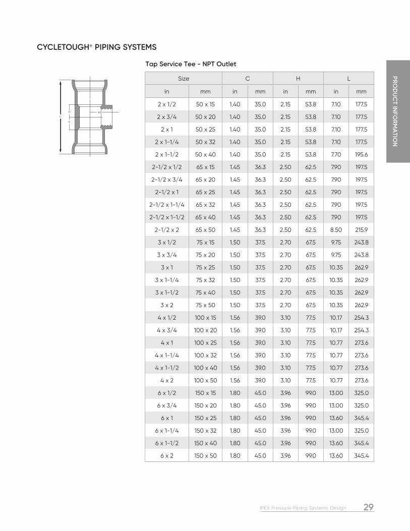
Size C H L
in mm in mm in mm in mm
2 x 1/2 50 x 15 1.40 35.0 2.15 53.8 7.10 177.5
2 x 3/4 50 x 20 1.40 35.0 2.15 53.8 7.10 177.5
2 x 1 50 x 25 1.40 35.0 2.15 53.8 7.10 177.5
2 x 1-1/4 50 x 32 1.40 35.0 2.15 53.8 7.10 177.5
2 x 1-1/2 50 x 40 1.40 35.0 2.15 53.8 7.70 195.6
2-1/2 x 1/2 65 x 15 1.45 36.3 2.50 62.5 7.90 197.5
2-1/2 x 3/4 65 x 20 1.45 36.3 2.50 62.5 7.90 197.5
2-1/2 x 1 65 x 25 1.45 36.3 2.50 62.5 7.90 197.5
2-1/2 x 1-1/4 65 x 32 1.45 36.3 2.50 62.5 7.90 197.5
2-1/2 x 1-1/2 65 x 40 1.45 36.3 2.50 62.5 7.90 197.5
2-1/2 x 2 65 x 50 1.45 36.3 2.50 62.5 8.50 215.9
3 x 1/2 75 x 15 1.50 37.5 2.70 67.5 9.75 243.8
3 x 3/4 75 x 20 1.50 37.5 2.70 67.5 9.75 243.8
3 x 1 75 x 25 1.50 37.5 2.70 67.5 10.35 262.9
3 x 1-1/4 75 x 32 1.50 37.5 2.70 67.5 10.35 262.9
3 x 1-1/2 75 x 40 1.50 37.5 2.70 67.5 10.35 262.9
3 x 2 75 x 50 1.50 37.5 2.70 67.5 10.35 262.9
4 x 1/2 100 x 15 1.56 39.0 3.10 77.5 10.17 254.3
4 x 3/4 100 x 20 1.56 39.0 3.10 77.5 10.17 254.3
4 x 1 100 x 25 1.56 39.0 3.10 77.5 10.77 273.6
4 x 1-1/4 100 x 32 1.56 39.0 3.10 77.5 10.77 273.6
4 x 1-1/2 100 x 40 1.56 39.0 3.10 77.5 10.77 273.6
4 x 2 100 x 50 1.56 39.0 3.10 77.5 10.77 273.6
6 x 1/2 150 x 15 1.80 45.0 3.96 99.0 13.00 325.0
6 x 3/4 150 x 20 1.80 45.0 3.96 99.0 13.00 325.0
6 x 1 150 x 25 1.80 45.0 3.96 99.0 13.60 345.4
6 x 1-1/4 150 x 32 1.80 45.0 3.96 99.0 13.00 325.0
6 x 1-1/2 150 x 40 1.80 45.0 3.96 99.0 13.60 345.4
6 x 2 150 x 50 1.80 45.0 3.96 99.0 13.60 345.4
Tap Service Tee - NPT Outlet

PRO
DU
CT
INFO
RM
ATI
ON
30 IPEX Pressure Piping Systems Design
CYCLETOUGH® PIPING SYSTEMS
Size C H L
in mm in mm in mm in mm
2 x 1-1/2 50 x 40 1.30 32.5 1.10 27.5 8.20 208.3
2-1/2 x 2 65 x 50 1.67 41.8 1.63 40.8 10.10 256.5
3 x 1-1/2 75 x 40 1.85 46.3 1.60 40.0 11.40 289.6
3 x 2 75 x 50 1.85 46.3 1.60 40.0 11.40 289.6
3 x 2-1/2 75 x 65 1.90 47.5 1.60 40.0 11.40 289.6
4 x 2 100 x 50 1.90 47.5 2.00 50.0 11.90 302.3
4 x 2-1/2 100 x 65 1.90 47.5 2.00 50.0 11.90 302.3
4 x 3 100 x 75 1.90 47.5 2.00 50.0 11.90 302.3
6 x 2 150 x 50 2.40 60.0 2.80 70.0 15.50 393.7
6 x 2-1/2 150 x 65 2.40 60.0 2.80 70.0 15.50 393.7
6 x 3 150 x 75 2.40 60.0 2.80 70.0 15.50 393.7
6 x 4 150 x 100 2.40 60.0 2.80 70.0 15.50 393.7
8 x 2 200 x 50 3.85 96.3 4.87 121.8 20.10 510.5
8 x 3 200 x 75 3.85 96.3 4.87 121.8 20.10 510.5
8 x 4 200 x 100 3.85 96.3 4.88 122.0 20.10 510.5
8 x 6 200 x 150 3.85 96.3 4.88 122.0 20.10 510.5
Reducing Tee - G x G x G
Size C H L
in mm in mm in mm in mm
4 100 4.00 100.0 4.00 100.0 13.10 332.7
6 150 4.50 112.5 4.50 112.5 16.60 421.6
Cross G x G x G x G
Size L D
in mm in mm in mm
2 50 8.25 209.6 3.35 83.8
2-1/2 65 9.00 228.6 4.15 103.8
3 75 9.50 241.3 5.00 125.0
4 100 11.00 279.4 6.13 153.3
6 150 12.00 304.8 8.73 218.3
8 200 12.30 307.5 10.62 265.5
Stop Coupling G x G

31IPEX Pressure Piping Systems Design
PRO
DU
CT IN
FOR
MA
TION
CYCLETOUGH® PIPING SYSTEMS
Size L D
in mm in mm in mm
2 50 8.25 209.6 3.35 83.8
2-1/2 65 9.00 228.6 4.15 103.8
3 75 9.50 241.3 5.00 125.0
4 100 11.00 279.4 6.13 153.3
6 150 12.00 304.8 8.73 218.3
8 200 12.30 307.5 10.62 265.5
Repair Coupling G x G
Size L
in mm in mm
1-1/2 40 2.50 62.5
2 50 2.50 62.5
2-1/2 65 3.50 87.5
3 75 3.50 87.5
4 100 3.75 93.8
6 150 4.50 112.5
Permanent Plug Spigot
Size L C
in mm in mm in mm
1-1/2 x 2 40 x 50 2.40 60.0 0.20 5.0
2 x 2-1/2 50 x 65 2.40 60.0 0.20 5.0
2 x 3 50 x 75 3.40 85.0 0.55 13.8
2-1/2 x 3 65 x 75 3.40 85.0 0.38 9.5
2 x 4 50 x 100 3.00 75.0 0.40 10.0
2-1/2 x 4 65 x 100 3.00 75.0 0.40 10.0
3 x 4 75 x 100 3.00 75.0 0.40 10.0
2 x 6 50 x 150 4.30 107.5 0.50 12.5
2-1/2 x 6 65 x 150 4.30 107.5 0.50 12.5
3 x 6 75 x 150 4.30 107.5 0.50 12.5
4 x 6 100 x 150 4.30 107.5 0.50 12.5
4 x 8 100 x 200 5.10 127.5 0.60 15.0
6 x 8 150 x 200 5.10 127.5 0.60 15.0
Increaser Bushing - G x Sp

PRO
DU
CT
INFO
RM
ATI
ON
32 IPEX Pressure Piping Systems Design
CYCLETOUGH® PIPING SYSTEMS
Size C D L
in mm in mm in mm in mm
1-1/2 40 3.85 96.3 5.00 125.0 4.25 106.3
2 50 4.75 118.8 6.00 150.0 4.75 118.8
2-1/2 65 5.50 137.5 7.00 175.0 5.75 143.8
3 75 6.00 150.0 7.50 187.5 6.50 162.5
4 100 7.48 187.0 9.02 225.5 10.52 263.0
6 150 9.55 238.8 10.97 274.3 13.48 337.0
8 200 11.75 293.8 13.50 337.5 12.00 300.0
Adapter - Flange x Gasket Bell
Size L
in mm in mm
1-1/2 40 1.50 37.5
2 50 1.80 45.0
2-1/2 65 2.00 50.0
3 75 2.10 52.5
4 100 2.30 57.5
6 150 3.10 77.5
Spigot Adapter G x Sp
Size L
in mm in mm
1-1/2 40 1.05 26.3
2 50 1.20 30.0
2-1/2 65 1.55 38.8
3 75 2.10 52.5
4 100 2.25 56.3
6 150 2.50 62.5
Male Adapter G x Male Pipe Thread

33IPEX Pressure Piping Systems Design
PRO
DU
CT IN
FOR
MA
TION
CYCLETOUGH® PIPING SYSTEMS
Size L
in mm in mm
1-1/2 40 2.60 65.0
2 50 3.00 75.0
2-1/2 65 3.80 95.0
3 75 4.10 102.5
4 100 4.40 110.0
6 150 5.40 135.0
Adapter Bell x Female IPT
Size L C
in mm in mm in mm
3 75 4.30 107.5 2.00 50.0
4 100 4.40 110.0 2.25 56.3
6 150 5.90 147.5 2.50 62.5
Adapter - PE (Plain End) x Male Pipe Thread
PRO
DU
CT
INFO
RM
ATI
ON
34 IPEX Pressure Piping Systems Design
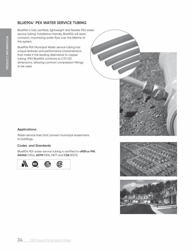
BLUE904® PEX WATER SERVICE TUBING
Blue904 is fully certified, lightweight and flexible PEX water service tubing. Installation friendly, Blue904 will resist corrosion, maximizing water flow over the lifetime of the system.
Blue904 PEX Municipal Water service tubing has unique features and performance characteristics that make it the leading alternative to copper tubing. IPEX Blue904 conforms to CTS OD dimensions, allowing common compression fittings to be used.
Applications:
Water service lines that connect municipal watermains to buildings.
Codes and Standards
Blue904 PEX water service tubing is certified to cNSFus-PW, AWWA C904, ASTM F876, F877 and CSA B137.5.
35IPEX Pressure Piping Systems Design
PRO
DU
CT IN
FOR
MA
TION
BLUE904® PEX WATER SERVICE TUBING
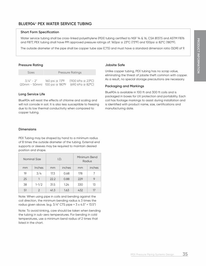
Pressure Rating
Long Service Life
Blue904 will resist the effects of chlorine and scaling and will not corrode in soil. It is also less susceptible to freezing due to its low thermal conductivity when compared to copper tubing.
Jobsite Safe
Unlike copper tubing, PEX tubing has no scrap value, eliminating the threat of jobsite theft common with copper. As a result, no special storage precautions are necessary.
Packaging and Markings
Blue904 is available in 100 ft and 300 ft coils and is packaged in boxes for UV protection and portability. Each coil has footage markings to assist during installation and is identified with product name, size, certifications and manufacturing date.
Short Form Specification
Water service tubing shall be cross-linked polyethylene (PEX) tubing certified to NSF 14 & 16, CSA B137.5 and ASTM F876 and F877, PEX tubing shall have PPI approved pressure ratings of: 160psi @ 23ºC (73ºF) and 100psi @ 82ºC (180ºF).
The outside diameter of the pipe shall be copper tube size (CTS) and must have a standard dimension ratio (SDR) of 9.
PEX Tubing may be shaped by hand to a minimum radius of 8 times the outside diameter of the tubing. External end supports or sleeves may be required to maintain desired position and shape.
Note: When using pipe in coils and bending against the coil direction, the minimum bending radius is 3 times the radius given above. (e.g. 3/4” CTS pipe = 3 x 4.5” = 13.5”)
Note: To avoid kinking, care should be taken when bending the tubing in sub-zero temperatures. For bending in cold temperatures, use a minimum bend radius of 2 times that listed in the chart.
Dimensions
Nominal Size I.D.Minimum Bend
Radius
mm Inches mm inches mm inches
19 3/4 17.3 0.68 178 7
25 1 22.2 0.88 229 9
38 1-1/2 31.5 1.24 330 13
51 2 41.3 1.63 432 17
Sizes Pressure Ratings
3/4” - 2”(20mm - 50mm)
160 psi @ 73ºF (1100 kPa @ 23ºC) 100 psi @ 180ºF (690 kPa @ 82ºC)

PRO
DU
CT
INFO
RM
ATI
ON
36 IPEX Pressure Piping Systems Design
GOLD901TM WATER SERVICE TUBING
Gold901TM is a lightweight, easy to install, 200 psi rated water service tubing that can be used on both the municipal and private-side of a project.
Gold901 is conveniently available in both coils and reels and is available in 3/4” to 2”.
Applications:
Water service tubing
Codes and Standards
Gold901 is manufactured to Copper Tube Size (CTS) from High-Density Polyethylene (HDPE) and is third-party certified and listed to AWWA C901, CSA B137.1, and NSF 61.
Canadian Standards Association
American Water Works Association
NSF Standards 14 & 61, Uniform Plumbing Code
American Society for Testing and Materials

37IPEX Pressure Piping Systems Design
PRO
DU
CT IN
FOR
MA
TION
GOLD901TM WATER SERVICE TUBING
Dimensions
Nominal Size Coil Length Product Code
O.D. I.D. Min. Bend Radius (in)in mm feet Avg (in) Avg. (in)
3/4 20
100 121402
0.875 0.671 19
200 121403
400 121404
500 121405
3000 121406
1 25
100 121407
1.125 0.863 23
150 121408
200 121409
300 121410
500 121411
1000 121412
1500 121413
1-1/4 32100 121414
1.375 1.055 30300 121415
1-1/2 40
100 121416
1.625 1.245 34250 121417
400 121418
1000 121419
2 50
100 121420
2.125 1.629 44200 121421
500 121422
Note: Custom coil and reel sizes may be available upon request.
Advantages
Non-Corroding Resistant to corrosive soils, aggressive water, stray electrical currents and moist environments
LightweightA 200 foot coil of 3/4” Gold901 weighs 20 lbs
Sequential MarkingsEvery 2 or 5 feet
Superior FlowHazen Williams C-Factor = 150
High PressureRated at 200 psi at 73°F (1380 kPa at 23°C)

38 IPEX Pressure Piping Systems Design
Q-Line is a composite pipe made with a layer of aluminum sealed between two layers of a special thermoplastic designed for use as water service tubing. The result is a pipe with all the advantages of both materials, and none of the weaknesses. It has the strength of metal service tubing and will never corrode as the metal is sealed in plastic. It rolls out flat like a metal pipe, but it is lightweight like a plastic pipe.
Non-Conductor
Roughly 370 serious electric shock incidents occur in the U.S. water utility industry every year1. While the AWWA has opposed the practice of grounding to the water system for over 80 years, it is still routinely done, despite the availability of grounding rods and plates. Since Q-Line is a non-conductor, it eliminates the risk of electric shock from stray currents. Specifying Q-Line helps to eliminate the risk to municipal workers.
Effective Permeation Barrier
Chemical permeation is a real issue with small diameter service tubing made of PE. Q-Line’s aluminum core is an effective barrier and has been tested against the most aggressive contaminants such as termiticides.
Zero Scrap Value
The high scrap value of copper pipe has resulted in significant pilferage problems on job sites across North America. This has resulted in storage problems as all copper pipe must be properly secured each day.
Applications:
Water service lines, reclaimed water lines (purple pipe available)
Q-LINE® WATER SERVICE TUBING
Codes and Standards
Q-Line water service tubing is certified to cNSFus-PW, ASTM F1282 and certified to CSA B137.9, and meets AWWA C903 requirements.

39IPEX Pressure Piping Systems Design
PRO
DU
CT IN
FOR
MA
TION
Q-LINE® WATER SERVICE TUBING
Pressure Ratings
Q-Line is rated at 200 psi working pressure at 23ºC (73ºF). In addition, Q-Line is rated at 100 psi at 82ºC (180ºF). Since most water services operate at between 40 and 70 psi, even a back-up of hot water from the building into the water service will not compromise Q-Line.
Flow Rates
Q-Line has larger inside diameters than CTS PE piping and a better flow coefficient than copper pipe (C = 150 for Q-Line versus only 100 for copper pipe.) This gives Q-Line the best flow rates in the industry. And unlike copper pipe, Q-Line does not corrode or allow build-up of flow-constricting deposits on the ID of the pipe.
Flow Rate (U.S. gpm)
Head Loss (psi/100 ft) Velocity (fps) Flow Rate (I/s)
Head Loss (kPa/100m) Velocity (m/s)
3/4” 1” 3/4” 1” 20mm 25mm 20mm 25mm
1.0 .1 0.0 .7 0.4 0.1 7.2 2.4 0.3 0.2
2.0 .5 0.2 1.3 0.8 0.2 26.1 8.8 0.6 0.4
3.0 1.0 0.4 2.0 1.3 0.3 55.3 18.7 1.0 0.6
4.0 1.8 0.6 2.6 1.7 0.4 94.2 31.8 1.3 0.8
5.0 2.7 0.9 3.3 2.1 0.5 142.4 48.1 1.6 1.0
6.0 3.8 1.3 4.0 2.5 0.6 199.6 97.4 1.9 1.2
7.0 5.0 1.7 4.6 3.0 0.7 265.5 89.7 2.2 1.4
8.0 6.4 2.2 5.3 3.4 0.8 340.0 114.8 2.6 1.6
9.0 8.0 2.7 5.9 3.8 0.9 422.9 142.8 2.9 1.8
10.0 9.7 3.3 6.6 4.2 1.0 514.0 173.6 3.2 2.0
11.0 11.6 3.9 7.2 4.6 1.1 613.3 207.1 3.5 2.2
12.0 13.6 4.6 7.9 5.0 1.2 720.5 243.3 3.8 2.5
13.0 15.7 5.3 8.5 5.5 1.3 835.7 282.2 4.1 2.7
14.0 18.0 6.1 9.2 5.9 1.4 958.6 323.7 4.5 2.9
15.0 20.5 6.9 9.9 6.3 1.5 1089.2 367.8 4.8 3.1
16.0 23.1 7.8 10.5 6.7 1.6 1227.5 414.5 5.1 3.3
17.0 25.8 8.7 11.2 7.1 1.7 1373.4 463.8 5.4 3.5
18.0 28.7 9.7 11.8 7.6 1.8 1526.8 515.5 5.7 3.7
19.0 31.7 10.7 12.5 8.0 1.9 1687.5 569.8 6.1 3.9
20.0 34.9 11.8 13.2 8.4 2.0 855.7 616.6 6.4 4.1
21.0 38.2 12.9 13.8 8.9
22.0 41.7 14.1 14.5 9.2
23.0 45.2 15.3 15.1 9.7
24.0 - 16.5 - 10.1
25.0 - 17.8 - 10.5
26.0 - 19.2 - 11.0
27.0 - 20.6 - 11.4
28.0 - 22.0 - 11.8
29.0 - 23.5 - 12.2
30.0 - 25.0 - 12.7
Table 2 – Q-Line Flow Rates
Short Form Specifications
Water service tubing shall be composite PERT-AL-PERT tubing manufactured in accordance with the requirements of AWWA C903 and certified to CSA B137.9 and ASTM F1282. It shall have a long term pressure rating of 1380kPa at 23ºC (200 psi at 73ºF) and 690kPa at 82ºC (100 psi at 180ºF). The pipe shall be third-party tested and certified to comply with NSF-PW potable water and NSF CL-TD chlorine resistance requirements. The service tubing shall be color coded light blue as manufactured by IPEX under the trade name “Q-Line” or approved equal.
Fittings for composite PERT-AL-PERT tubing shall be brass water service fittings conforming to AWWA C800.

PRO
DU
CT
INFO
RM
ATI
ON
40 IPEX Pressure Piping Systems Design
Q-LINE® WATER SERVICE TUBING
Dimensions
Q-Line has unique inside and outside diameters that are different both from copper and conventional PE service tubing. Easily installed adapters that allow Q-line to be used with standard brass fittings are widely available. Unlike PE pipe, Q-line does not require a stiffening insert to be used.
Nominal Size Avg. IDMin. Wall Thickness
Avg. OD Weight VolumeMin. Bending
Radius
in mm in mm in mm in mm lbs/100ft kg/100m U.S. gal/ft l/m in mm
3/4 20 .79 20 .10 2.5 .98 25 12.4 18.4 .025 .314 5.0 125
1 25 .98 25 .14 3.2 1.26 32 21.0 31.2 .040 .500 6.3 160

41IPEX Pressure Piping Systems Design
PRO
DU
CT IN
FOR
MA
TION
STANDARDS FOR PVC AND PVCO PRESSURE SYSTEMS
Standards and Certifications
There are two main classes of standards governing PVC piping systems, those which define products that are certified by a third party and those which define products that are non-policed. While non-policed standards can be very useful in a specification, the standards that are certified by a third party offer the customer an additional level of quality assurance. Third-party certification means that an independent organization has scrutinized the manufacturing process and QA/QC procedures for the products in question, and has verified that they meet the minimum requirements for approval. Compliance with a non-policed standard requires the customer to take the manufacturer at his word that his product conforms to the standard. Most manufacturers perform accurate in-house testing and are honest and up front, and if they state that their products meet a certain standard, you can be quite certain that they do. There is no question however, that certification by a third party provides a much higher degree of assurance that the products in question in fact meet the applicable standard and that they will perform as stated.
Third-Party Certified Standards
Canadian Standards Association (CSA)
CSA B137.0 CSA B137.1 CSA B137.2 CSA B137.3 CSA B137.3.1 CSA B137.5 CSA B137.9
CSA staff visit all IPEX plants producing certified product several times each year. In addition to witnessing manufacturing and QA/QC procedures, CSA staff also inspect records, and select product samples for independent testing. The CSA standards refer to a wide variety of external standards (such as ASTM standards) for items such as testing methods. As a result, certifying the product to a CSA standard often has the effect of indirectly certifying the product to other standards as well.
Factory Mutual (FM)
FM 1612
This third-party-certified standard is often required whenever the piping system is going to be used as a fire-protection line. In the case of FM, insurance regulations sometimes dictate the standard to be used. The certification methods are similar to those used by the CSA.
National Sanitation Foundation (NSF)
NSF 14 NSF 61
Both of these standards are third-party-certified. The NSF 14 standard includes two major areas: material testing for potability and product testing for performance. Listing to
this standard means that the pipe/fitting material will have no adverse effect on water quality and that the pipe/fitting product will meet the performance requirements of the standard. NSF 61 includes the potability testing portion of NSF 14.
Underwriters Laboratories (UL, ULI, ULC)
UL 1285
This standard is also third-party-certified and is often required when the pipeline is used in fire-protection applications. Certification methods are similar to those employed by CSA.
Accreditation of Standards Labs and Organizations
While the standards discussed above are normally certified by a third party, that third party can sometimes be a separate organization. For example, Intertek Warnock-Hersey is a laboratory accredited by the Standards Council of Canada, and as a result, it is capable of certifying products to standards. It is common for Intertek Warnock-Hersey to certify a product to a CSA standard, and NSF also has this capability.
Non-Certified Standards
American Water Works Association AWWA C900 AWWA C901 AWWA C903 AWWA C904 AWWA C907 AWWA C909 certified by NSF for Bionax
C900 and C907 deal with PVC pressure pipe and fittings. C909 covers PVCO pressure pipe (Bionax) and C903 is for composite service piping (Q-line). C901 is for water service tubing (Gold901) and C904 is for PEX water service tubing (Blue904). AWWA standards are used when specifying water transmission or service piping.
ASTM Standards (Various standards)
ASTM Standards are referenced by all the above standards. They cover everything from materials to manufacturing to testing to installation, which is why there are so many different ASTM standards associated with our products.
Design and Installation Standards
AWWA C605
This standard provides guidance and instruction for underground installation of PVC/PVCO piping systems.
AWWA Manual M23
The M23 Manual includes information for proper design and installation of PVC and PVCO pipe.

42 IPEX Pressure Piping Systems Design
NOTES

43IPEX Pressure Piping Systems Design
PRO
PERTIES O
F PV
C PR
ESSUR
E PIPE & D
ESIGN
Properly designed and installed PVC piping systems will last virtually forever. Recent research has unearthed PVC systems that were installed in the 1930’s that exhibit virtually no reduction in serviceability. This section focuses on the physical properties of PVC pipes and fittings, as well as how to approach some of the conditions likely to be encountered during a project.
Various design issues will also be addressed including;
SECTION 2: PROPERTIES OF PVC PRESSURE PIPE AND PRESSURE SYSTEM DESIGN
INTRODUCTION
2 Hulsmann, Nowack,”70 Years of Experience with PVC Pipes” Conference Paper, Plastic Pipes XII, Milan, April 2004
MATERIAL PROPERTIES OF PVC
Design Life
Designers should use a minimum 100 year design life when carrying out lifecycle costing calculations for PVC systems. This is backed up both by research and real world installations.
Current Research
PVC pressure pipes have been in service for over 70 years in Europe2. Samples of 70 year old pipe have been excavated and have exhibited no reduction in serviceability. PVC pipe’s installed history in North America is approaching 50 years, with a similar record for excellent service. The single most destructive force attacking our municipal water and sewer infrastructure is corrosion. By using materials that are immune to electrolytic corrosion or chemical attack, designers eliminate the single most common problem associated with buried infrastructure.
Research dealing with the longevity of PVC pipe in various conditions is on-going, however there have been a number of notable research papers presented over the years, including:
• AWWA Research Foundation – “Quantifying Future Rehabilitation and Replacement Needs of Watermains”, 1998
This study used a highly specialized computer model to estimate the life of various materials based on past performance. In the one North American city studied with a significant amount of PVC pipe installed, PVC was rated at a minimum 100 years while concrete and ductile iron were rated at 85 and 60 years respectively.
• “PVC Pipe Study – Performance of PVC Water Main Pipe installed in the City of Edmonton between 1977 and 1994”
A comprehensive study of PVC pipe used in the City’s water distribution system rated its service life at a minimum of 88 years with minimal maintenance.
Case Studies from Europe and North America including:
• Dallas, Texas – A PVC sewer pipe installed in 1973 was excavated and subjected to each of the tests outlined in ASTM D3034. The results show that the excavated pipe still met all the standards applicable to new pipe
• Denmark – A PVC Sewer pipe installed in 1963 was excavated and testing results show that the pipe has the same material properties as newly produced pipe. Most of the pipes installed were directly into native soil without bedding, and have performed acceptably for over 40 years.
These research papers are available upon request from your IPEX marketing representative at [email protected] or visit the IPEX website at ipexna.com.
• The hydrostatic design basis (HDB) of PVC pipe
• Calculating pressure ratings
• Hydraulics and headloss calculations
• Restraint design
• Installation in contaminated soils
• Surge pressures in PVC pipe
• Air entrapment and proper location of air release valves
• Thermal effects
• Design for cyclic fatigue
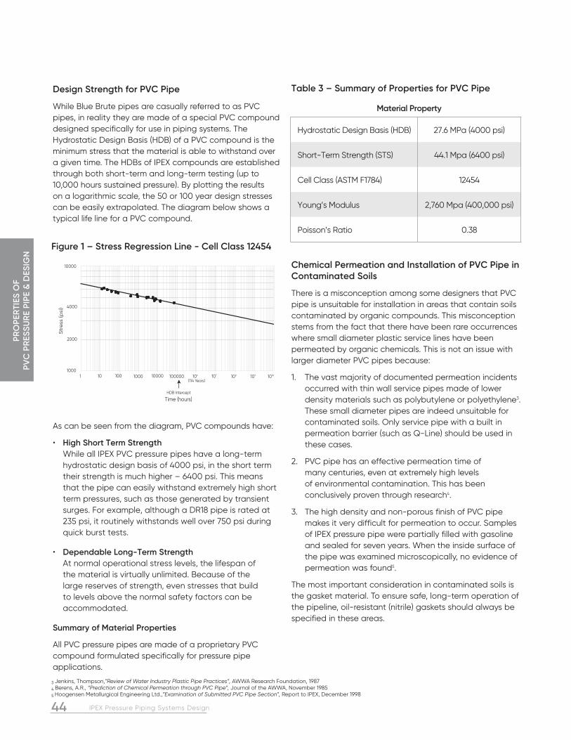
44 IPEX Pressure Piping Systems Design
PRO
PER
TIES
OF
PVC
PR
ESSU
RE
PIPE
& D
ESIG
N
Table 3 – Summary of Properties for PVC Pipe
Chemical Permeation and Installation of PVC Pipe in Contaminated Soils
There is a misconception among some designers that PVC pipe is unsuitable for installation in areas that contain soils contaminated by organic compounds. This misconception stems from the fact that there have been rare occurrences where small diameter plastic service lines have been permeated by organic chemicals. This is not an issue with larger diameter PVC pipes because:
1. The vast majority of documented permeation incidents occurred with thin wall service pipes made of lower density materials such as polybutylene or polyethylene3. These small diameter pipes are indeed unsuitable for contaminated soils. Only service pipe with a built in permeation barrier (such as Q-Line) should be used in these cases.
2. PVC pipe has an effective permeation time of many centuries, even at extremely high levels of environmental contamination. This has been conclusively proven through research4.
3. The high density and non-porous finish of PVC pipe makes it very difficult for permeation to occur. Samples of IPEX pressure pipe were partially filled with gasoline and sealed for seven years. When the inside surface of the pipe was examined microscopically, no evidence of permeation was found5.
The most important consideration in contaminated soils is the gasket material. To ensure safe, long-term operation of the pipeline, oil-resistant (nitrile) gaskets should always be specified in these areas.
Design Strength for PVC Pipe
While Blue Brute pipes are casually referred to as PVC pipes, in reality they are made of a special PVC compound designed specifically for use in piping systems. The Hydrostatic Design Basis (HDB) of a PVC compound is the minimum stress that the material is able to withstand over a given time. The HDBs of IPEX compounds are established through both short-term and long-term testing (up to 10,000 hours sustained pressure). By plotting the results on a logarithmic scale, the 50 or 100 year design stresses can be easily extrapolated. The diagram below shows a typical life line for a PVC compound.
As can be seen from the diagram, PVC compounds have:
• High Short Term Strength While all IPEX PVC pressure pipes have a long-term hydrostatic design basis of 4000 psi, in the short term their strength is much higher – 6400 psi. This means that the pipe can easily withstand extremely high short term pressures, such as those generated by transient surges. For example, although a DR18 pipe is rated at 235 psi, it routinely withstands well over 750 psi during quick burst tests.
• Dependable Long-Term Strength At normal operational stress levels, the lifespan of the material is virtually unlimited. Because of the large reserves of strength, even stresses that build to levels above the normal safety factors can be accommodated.
Summary of Material Properties
All PVC pressure pipes are made of a proprietary PVC compound formulated specifically for pressure pipe applications.
Material Property
Hydrostatic Design Basis (HDB) 27.6 MPa (4000 psi)
Short-Term Strength (STS) 44.1 Mpa (6400 psi)
Cell Class (ASTM F1784) 12454
Young’s Modulus 2,760 Mpa (400,000 psi)
Poisson’s Ratio 0.38
10000
4000
2000
10001 10 100 1000 10000 100000 106 107 108 109 1010
HDB Intercept
Time (hours)
Str
ess
(psi
)
(114 Years)
3 Jenkins, Thompson,”Review of Water Industry Plastic Pipe Practices”, AWWA Research Foundation, 1987
4 Berens, A.R., “Prediction of Chemical Permeation through PVC Pipe”, Journal of the AWWA, November 1985
5 Hoogensen Metallurgical Engineering Ltd.,”Examination of Submitted PVC Pipe Section”, Report to IPEX, December 1998
Figure 1 – Stress Regression Line - Cell Class 12454

45IPEX Pressure Piping Systems Design
PRO
PERTIES O
F PV
C PR
ESSUR
E PIPE & D
ESIGN
DESIGN CALCULATIONSHow to Calculate Pressure Capacity
The ISO Equation for thermoplastics makes calculating required dimension ratios and pressure capacities very simple.
While it is referred to as the ISO Equation, it was actually developed in 1852 for use with all sorts of pressure vessels, and has been used ever since. The derivation is simple.
Referring to the figure, we can see that the force in the pipe wall is:
Therefore, the maximum stress in the pipe wall is:
The conservative design procedure of PVC and PVCO pipe requires that a safety factor be applied to the Hydrostatic Design Basis (HDB) in order to arrive at a hydrostatic design Stress (S). This design stress then becomes the maximum allowable stress in the material. It is important to note that the short and long term strengths of each material are different and, therefore, the short-term and long-term design stresses will be different.
The safety factors for all PVC/PVCO pressure pipes in North America have traditionally been either 2.0 or 2.5, depending on the application and the standard governing the design. The new standards now use a safety factor of 2.0 for all cases.
This form of the equation allows the pressure capabilities of a given dimension ratio to be quickly and easily calculated.
PRO
DU
CT
INFO
RM
ATI
ON
45IPEX Pressure Piping Systems Design
UV Resistance
PVC pipe can become discolored when exposed to direct sunlight for a long period of time. This discoloration affects only the surface of the material (to a depth of 0.003 inches), and does not appreciably affect the performance of the pipe. A slight reduction in the impact strength of the pipe occurs, while the tensile strength and the modulus of elasticity are unaffected. If gasketed PVC pressure piping will be used in an exposed location, painting the surface of the pipe with a latex-based paint, or covering it with an opaque barrier will eliminate the effects of U.V. exposure.
The vast majority of gasketed pressure piping is installed underground, eliminating the issue of UV exposure.
Thermal Effects – Pressure Derating
PVC is a thermoplastic, which means its mechanical properties change with temperature. The pressure rating for PVC pipe (and most other thermoplastic piping materials) is calculated at 73ºF (23ºC). Above that temperature, the tensile strength of the material decreases, and the pressure rating must be de-rated by the factors shown in the table below. The maximum recommended service temperature for Blue Brute and Centurion PVC pressure pipe is 140ºF (60ºC). Bionax pipe uses the same table with the exception that the maximum recommended temperature is 130ºF (54ºC).
Table 4 – Temperature Effects on PVC Pressure Pipe
Thermal Effects – Expansion and Contraction
While buried applications seldom involve significant temperature variations, applications such as bridge crossings or casing installations can have temperature variations. When considering the use of unrestrained joints or TerraBrute CR joints, expansion and contraction should be calculated per length of pipe. If the joints are restrained using conventional restrainers, or a solvent cemented joint is used, expansion and contraction should be calculated using the full length of restrained pipe.
ºC ºF Multiply the pressure rating by these factors
32 90 0.7538 100 0.6243 110 0.5049 120 0.4054 130 0.3060 140 0.22
MaterialExpansion Coefficient
in/in/ºF
Expansion Coefficient
in/100ft/10ºF
Expansion Coefficient
mm/mm/ºC
Expansion Coefficient
mm/10m/10ºCPVC 3.0 x 10⁻⁵ 0.36 5.4 x 10⁻⁵ 5.4
PVCO 3.1 x 10⁻⁵ 0.36 5.4 x 10⁻⁵ 5.4
HDPE 12.0 x 10⁻⁵ 1.44 14 x 10-5 21.6
Ductile Iron 0.62 x 10⁻⁵ 0.07 1.1 x 10⁻⁵ 1.1
Concrete 0.55 x 10⁻⁵ 0.07 1.0 x 10⁻⁵ 1.0
Steel 0.65 x 10⁻⁵ 0.08 1.2 x 10⁻⁵ 1.2
smax SF S =
P(DR – 1) 2S 2 (DR – 1) S = \ P =
PiD 2 Force = ( (
PiD 2t smax =
, where D = the average diameter of the pipe
Pi(Do – t) 2t
D = Do – t \ smax =
Do P1(DR –1) t 2 But since DR = , then smax =
PiD2
PiD
PiD2

46 IPEX Pressure Piping Systems Design
PRO
PER
TIES
OF
PVC
PR
ESSU
RE
PIPE
& D
ESIG
N
The table below shows both the LTR and the STR for various thicknesses of PVC pipe:
Calculating Friction Headloss in PVC Piping Systems
One of the advantages in using PVC pipe is that its smooth inside finish dramatically reduces friction headloss when compared to other materials. As a result, pumping costs are lower and flows are higher when considering the same nominal diameter between materials.
The Hazen-Williams equation is one of the most commonly used methods for calculating friction headloss in a pipeline. It allows the friction headloss to be easily calculated for any piping system using flow coefficients that reflect the roughness of the piping material. Research has established that the Hazen-Williams flow coefficient for PVC pipe can vary between 155 to 165 for both new and previously used PVC pipe6. Therefore, a conservative coefficient of 150 is appropriate for all design situations. This value is also recommended by the AWWA M23 Design Manual.
V = 1.318Cr0.63S0.54 in USCS Units
V = 0.8492Cr0.63S0.54 in SI Units
Where:
V = average pipe velocity, ft/s (m/s)
C = Hazen-Williams Friction factor (150 for PVC Pipe)
R = Hydraulic radius (D/4 for a full pipe), ft (m)
S = Hydraulic gradient or frictional head loss per unit length of pipe, ft/ft, (m/m)
IPEX Pressure Piping Systems Design
Calculating a Pressure Rating (CSA) or Class (AWWA)
There are two ratings for every PVC pipe – a long term pressure rating (LTR) which is used for evaluating working pressure capacity, and a short term pressure rating (STR) designed for evaluating surge and pressure capability.
To calculate an STR, simply apply the ISO equation using the short term strength:
Recall that:
For short term stresses, AWWA standards set the safety factor (SF) = 2.0. Using the s hort term strength gives:
Therefore for DR41 pipe, the STR is given by
For long term stresses, the safety factor is also set at 2.0: Using the HDB gives:
Applying the ISO Equation:
SDRLong Term Rating LTR* (2:1 S.F.) (psi)
Short Term Rating STR (2:1 S.F.) (psi)
51 80 128
41 100 160
32.5 125 200
26 160 256
25 165 264
18 235 376
14 305 488
smax SF S =
6400 2.0 S str = = 3200 psi
2(3200) (41 – 1) STR = = 160 psi
4000 2 S ltr = = 2000 psi
2(2000) (41 – 1) LTR = = 100 psi
6 Uni-Bell PVC Pipe Association, “Handbook of PVC Pipe – Design and Construction”, fourth edition, (August 2001)
46

47IPEX Pressure Piping Systems Design
PRO
PERTIES O
F PV
C PR
ESSUR
E PIPE & D
ESIGN
Comparing Headloss Among Various Piping Materials
For any given nominal diameter of pipe, there are two factors which will largely dictate the headloss per unit length:
1. Internal diameter – It is the internal diameter of the pipe that should be used for hydraulic calculations, not the nominal diameter. A larger internal diameter promotes a greater fluid flow and therefore a lower headloss.
2. Internal friction coefficient – While internal diameter is important, the influence of the pipeline’s internal finish should not be neglected. While PVC and other plastics can sustain a smooth inside surface indefinitely, other materials tend to become rougher as a result of corrosion by-products forming over the long term. As a result, older iron pipes have been shown to have friction factors less than 100.
While experimental data has shown that the “C” factor can be as high as 155-165 for both new and used PVC pipe, AWWA M23 Manual recommends a “C” factor of 150 for PVC7.
Table 5 – Hazen-Williams “C”-Factors
Comparing various materials it can be seen that PVC pipe has a much lower headloss at any given flow than other non-plastic piping materials:
• Class 52 iron pipe has a slightly larger inside diameter than DR18 PVC, but its low long-term C factor of 100 or less results in poor flow characteristics.
• SDR9 HDPE has a high C factor of 150, however it has a much thicker pipe wall and thus has a much smaller inside diameter than PVC DR18.
Material “C” Factor
Plastic (PVC, PVCO & HDPE) 150
Iron (new) 130
Iron (20 yrs old) 100
SDR9 HDPE
0
0.001
0.002
0.003
0.004
0.005
0.006
Pipe Material
Hea
dlo
ss, m
/m DR18 PVC
CL52 DI
Headloss - 200 mm Pipe at 25 L/s
7 AWWA Manual M23, 2nd Edition – PVC Pipe – Design and Installation, 2002, American Water Works Association 8 “Pump Handbook – Third Edition” – Karassik, messina, Cooper & Heald, pp.8.36
Figure 2 – Pipe Material
Calculating Surge Pressures – PVC Pipe
Surge pressures (water hammer) are generated in a piping system whenever the fluid flowing in that system changes velocity. These changes in velocity can be caused by many things, including:
• The operation of valves and pumps
• Entrapped air being expelled
• Changes in demand
There are two main types of surge pressures - transient surges that occur as the system moves from one steady state condition to another (ie: the closing of a single valve), and cyclic surges, that occur as part of the normal operation of some types of pipelines. A good example of this is a sewage forcemain, where a pump is activated each time the level in a wet well reaches a certain point.
The magnitude of pressure surges is dependent upon a number of things, including the type of fluid being pumped, the magnitude of the velocity change, and also the type of pipe material. Rigid piping materials typically generate much higher surge pressures than flexible systems, which are able to absorb much more of the shock generated by a surge. In addition, the high short term strength of PVC allows it to have a much higher safety factor against short term pressures than other piping materials.
The calculation of transient effects in a large piping system (regardless of the piping material) is a complicated procedure requiring considerable expertise. Fortunately, there are many engineering firms that are highly qualified to undertake this type of analysis. IPEX has worked closely with some of these experts, and we would be happy to refer interested designers to them. We highly recommend that detailed transient analysis be performed on all systems, particularly large diameter systems.
While a detailed analysis can be beneficial, it is possible to calculate the magnitude of individual surges in a pipeline using the elastic wave theory of surge analysis. The magnitude of the surge pressure caused by a rapidly closing valve, for example, is related to the rate of change of the flow, while the rate of travel of the pressure wave is related to the speed of sound in the fluid (modified by the piping material).

48 IPEX Pressure Piping Systems Design
PRO
PER
TIES
OF
PVC
PR
ESSU
RE
PIPE
& D
ESIG
N
Calculating Wave Velocity – Pipe
Where:
a = Wave velocity, ft/s
K = Bulk fluid modulus (300,000 psi for water)
E = Modulus of Elasticity for the pipe (400,000 psi for PVC and 500,000 psi for PVCO)
Surge Pressure – PVC Pipe
Once the wave speed has been calculated, the maximum pressure surge can be calculated using the equation:
Where:
a = wavespeed (ft/s)
DV = maximum velocity change (ft/s)
g = acceleration due to gravity (32.2 ft/s2)
P = maximum pressure surge (psi)
Applying the equations to all DRs of PVC pipe, a ssuming a 1 ft/s (0.3 m/s) stoppage, gives the results in the table below:
Vacuum Pressures
While pipe joints are tested to –10.8 psi to meet CSA Standards, IPEX has simulated negative pressures far in excess of full vacuum (–14.7 psi) by applying external pressures in excess of 100 psi. This proves conclusively that IPEX pipe joints can easily withstand full vacuum pressures.
SDR PVC Surge Pressure (psi)
51 10.8
41 11.4
32.5 12.8
26 14.5
25 14.7
18 17.4
14 19.8
a = 4,660 (1+ (k/E) (DR – 2)
P = a(DV) (2.31) g
Calculating Surge Pressures – PVCO Pipe
For PVCO pipe, DR is not used. Instead, Do/t is the dimension based variable for calculating wave velocity. The modulus of elasticity for calculating surge pressures is 500,000 psi. Using the equations above and the PVCO values, the surge pressure for a velocity change of 0.3 m/s (1.0 fps) in PC 235 PVCO pipe is 14.6 psi.
Air Entrapment in Pipelines
Air in pipelines can cause significant difficulties in any pipeline system, and should be avoided wherever possible. This can be accomplished by careful design of the pump or gravity inlet, employing proper filling and testing procedures, laying the pipe to grade wherever possible and by properly siting and sizing air release valves.
Some of the problems caused by air entrapment include:
1. Air pockets can reduce the amount of cross sectional area available for fluid flow at some points in the pipeline. This can result in higher headloss and fluctuations in flow rates caused by air movement
2. Flow fluctuations can cause surge pressures in the pipeline
3. Release or venting of the air can cause extremely high surge pressures.
Sources of Air in Pipelines
The most common air sources are:
• Entrapment of air during filling operations
• Entrapment at the pump or gravity inlet
• Release of dissolved air from the fluid in the pipeline
• Air intake from air release valves
Problems Associated with Air Entrapment
The key problem with air entrapment is that at some point the air may be vented in an uncontrolled way. As an air pocket travels along a pipeline, it may reach an area where it can be vented. This could be at an air release valve (good) or perhaps at a gasketed joint (bad). The gasketing systems in most pipelines are designed to work with water, not air. While in most cases the gasket will hold back a high pressure air pocket, at some point the gasket may be blown out of the joint, causing a rapid release of air. Since the air can be vented extremely quickly, the air pocket collapses at an extremely high rate. The water surges toward the orifice created by the blown gasket, but cannot be expelled at the same velocity as the air due to its much higher density. The result is a rapid deceleration of the flow and a huge transient shock wave – sometimes at a magnitude that can cause pipe failure.

49IPEX Pressure Piping Systems Design
PRO
PERTIES O
F PV
C PR
ESSUR
E PIPE & D
ESIGN
Air Release Valves
Air release valves are designed to exhaust air under various different pressure conditions in the pipeline, while restricting the flow of liquid. Air release valves are different from Air/Vacuum release valves in that Air/Vacuum release valves have a much larger orifice and are designed to exhaust or intake very large volumes of air, such as during the filling or draining process. The orifice size for an air release valve is generally between 1/16” and 1/4” diameter, while air/vacuum release valves can be between 1” and 8”.
A third type of valve combines the two functions, and is called a combination air/vacuum release valve. It contains both a large and a small orifice, the larger being open during filling and draining operations, and the smaller being open continuously to exhaust any air that might collect during normal operation of a pipeline.
Automatic air release valves with a riser diameter to main pipe ratio, d/D, in the order of 0.01 should be used when untrained personnel fill or test the pipeline. Air release valves in this size range tend to limit the passage of air and allow time for the water to slow down before reaching the vent.
Hydrants are not useful for the venting of air from pipelines. The reason is that hydrant leads typically are located at the 3 o’clock or 9 o’clock position on a pipeline. Air vents must be located at high points (ie at 12 o’clock) to be effective.
Pipeline Testing and Air Entrapment
The initial filling and testing of a pipeline is one of the most critical events in the lifetime of a pipeline system. The reason is that the potential for air entrapment is highest during this period. As a result, Design Engineers should include details and procedures covering filling and testing in their project specifications:
1. Pipelines should be installed at a grade which results in a minimum of high points. Abrupt transitions and sharp peaks should be avoided.
2. Automatic air and vacuum release valves should be properly sized and installed at all high points or other areas where air could be expected to accumulate
3. The average water velocity when filling the pipeline should not exceed 1 ft/s (0.3 m/s)
4. All air should be purged from the pipeline before checking for leaks or performing pressure or acceptance tests on the system
5. If a large quantity of water is needed to increase the pressure during testing, then entrapped air or a leak is possible. Testing should be discontinued until the source of the problem is identified
Nominal Size Max Filling Rate
In mm gpm L/s
4 100 40 2.5
6 150 87 5.5
8 200 157 9.9
10 250 245 15
12 300 353 22
14 350 480 30
16 400 627 39
18 450 793 50
20 500 979 61
24 600 1410 89
30 750 2203 139
36 900 3173 200
42 1050 4318 272
48 1200 5640 355
54 1350 7342 465
60 1500 8405 532
Further References:
Perhaps the most easily accessible work on the subject of air entrapment in pipelines was a film produced in the late 1960’s at Colorado State University. It was commissioned by a major pipe manufacturer and clearly shows the effect of air entrapment in pipelines and the importance of properly sizing and situating air release valves.
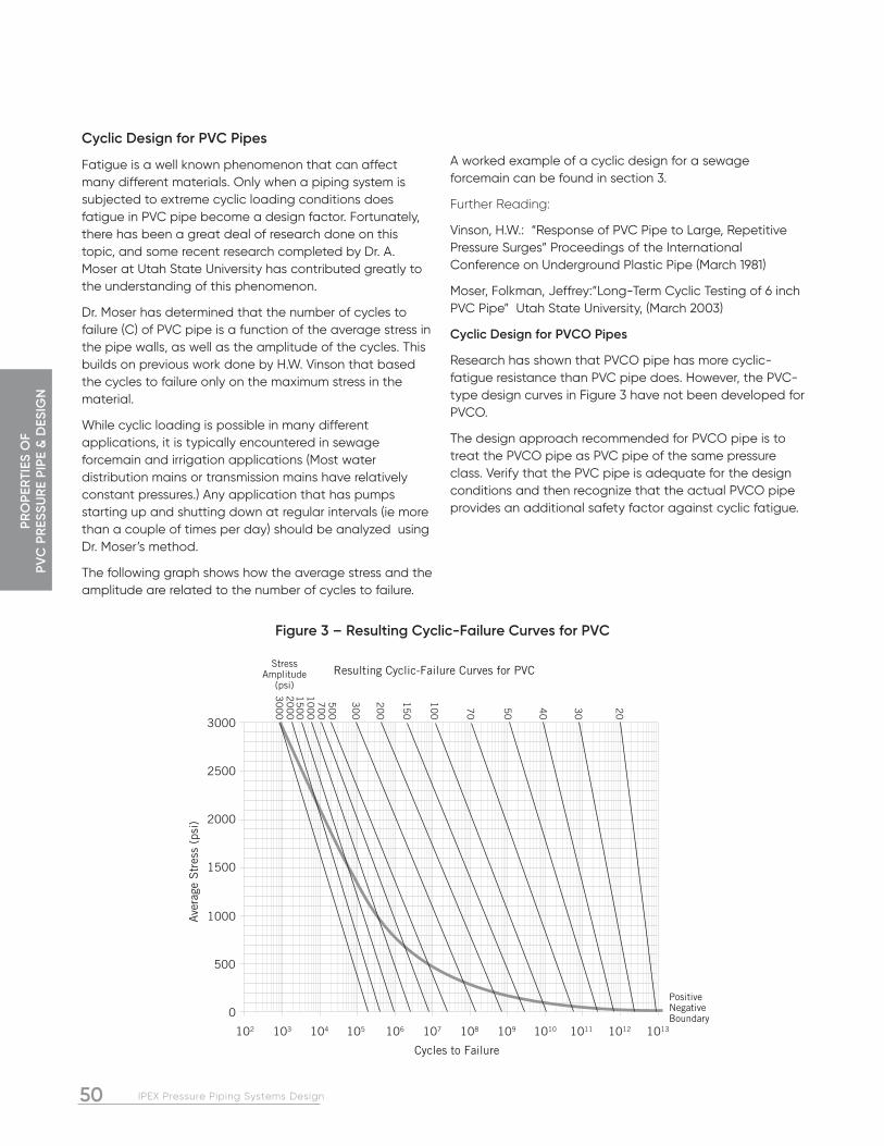
50 IPEX Pressure Piping Systems Design
PRO
PER
TIES
OF
PVC
PR
ESSU
RE
PIPE
& D
ESIG
N
Cyclic Design for PVC Pipes
Fatigue is a well known phenomenon that can affect many different materials. Only when a piping system is subjected to extreme cyclic loading conditions does fatigue in PVC pipe become a design factor. Fortunately, there has been a great deal of research done on this topic, and some recent research completed by Dr. A. Moser at Utah State University has contributed greatly to the understanding of this phenomenon.
Dr. Moser has determined that the number of cycles to failure (C) of PVC pipe is a function of the average stress in the pipe walls, as well as the amplitude of the cycles. This builds on previous work done by H.W. Vinson that based the cycles to failure only on the maximum stress in the material.
While cyclic loading is possible in many different applications, it is typically encountered in sewage forcemain and irrigation applications (Most water distribution mains or transmission mains have relatively constant pressures.) Any application that has pumps starting up and shutting down at regular intervals (ie more than a couple of times per day) should be analyzed using Dr. Moser’s method.
The following graph shows how the average stress and the amplitude are related to the number of cycles to failure.
PositiveNegativeBoundary
3000
2500
2000
1500
1000
500
0
102 103 104 105 106 107 108 109 1010 1011 1012 1013
Ave
rage
Str
ess
(psi
)
Cycles to Failure
Resulting Cyclic-Failure Curves for PVC
20
30
40
50
70
10
0
15
0
20
0
30
0
50
07
00
10
00
15
00
20
00
30
00
StressAmplitude
(psi)
Figure 3 – Resulting Cyclic-Failure Curves for PVC
A worked example of a cyclic design for a sewage forcemain can be found in section 3.
Further Reading:
Vinson, H.W.: “Response of PVC Pipe to Large, Repetitive Pressure Surges” Proceedings of the International Conference on Underground Plastic Pipe (March 1981)
Moser, Folkman, Jeffrey:”Long-Term Cyclic Testing of 6 inch PVC Pipe” Utah State University, (March 2003)
Cyclic Design for PVCO Pipes
Research has shown that PVCO pipe has more cyclic-fatigue resistance than PVC pipe does. However, the PVC-type design curves in Figure 3 have not been developed for PVCO.
The design approach recommended for PVCO pipe is to treat the PVCO pipe as PVC pipe of the same pressure class. Verify that the PVC pipe is adequate for the design conditions and then recognize that the actual PVCO pipe provides an additional safety factor against cyclic fatigue.

51IPEX Pressure Piping Systems Design
PRO
PERTIES O
F PV
C PR
ESSUR
E PIPE & D
ESIGN
Thrust Restraint in Gasketed Piping Systems
Resisting Thrust at Fittings and Valves
At many locations in a pressurized pipeline, an imbalance in hydrostatic forces may occur as a result of the pipeline configuration. These unbalanced forces are called thrust forces. Thrust forces can occur at any point in a piping system where the direction or the cross-sectional area of the waterway changes. Pipeline installers must balance these forces by means of thrust blocks or mechanical restraint. Three areas that require restraint are described below.
• at valves
All valves must be anchored. This includes valves installed in a chamber or in line with the pipe, whether it is operated frequently or only once a year.
Install anchor rods around the valve body or through the mounting lugs and embed the rods in a concrete pour beneath the valve. Valves installed in chambers must also be anchored in this fashion. The critical time for restraint of valves is during opening or closing.
• at changes in direction (vertical or horizontal)
Fittings such as elbows, tees, or dead ends, must be restrained since they involve a significant directional change for the fluid.
• at reductions in size
The thrust component at reductions in size will depend on the amount of the reduction, and must be adequately restrained.
Concrete Thrust Blocks
At each point in the line where thrust forces will develop, pour a concrete block between the fitting and undisturbed native soil at the side of the trench. Use plywood sheets to form the block and control the pour so that the area of contact with the undisturbed trench will provide the necessary support.
Bearing Strength of Undisturbed Soils
Organic Material (such as Peat, etc.) . . . . . . . . . 0 psf Soft Clay . . . . . . . . . . . . . . . . . . . . . . . . . . . . . . . . .500 psf Sand . . . . . . . . . . . . . . . . . . . . . . . . . . . . . . . . . . . 1000 psf Sand and Gravel . . . . . . . . . . . . . . . . . . . . . . . . 1500 psf Sand & Gravel with Clay . . . . . . . . . . . . . . . . 2000 psf Sand & Gravel Cemented with Clay . . . . . 4000 psf Hard Pan . . . . . . . . . . . . . . . . . . . . . . . . . . . . . . . 5000 psf
These soil bearing capacities are approximate and conservative. For greater design precision, IPEX recommends that soil bearing tests be carried out by a competent soils engineer.
The recommended bearing area to be established by the concrete pour may be given by the engineer. The area (ft.²) may also be calculated by determining the total thrust generated at the fitting. Simply divide the bearing strength of the soil into the thrust developed (lbs force), as found in the accompanying table. The result is the area of the soil required to resist the thrust (A). The area calculated will be for the area of concrete up against the trench wall (i.e. the back side of the block).
Thrust Force Bearing Strength of Soil
area A =

52 IPEX Pressure Piping Systems Design
PRO
PER
TIES
OF
PVC
PR
ESSU
RE
PIPE
& D
ESIG
N
Resisting Vertical Thrust
Where the pipeline will change direction downwards to pass under a creek bed or roadway, etc., upward thrust will be developed at the fitting. Anchor the fitting as though it were a valve, and ensure that the concrete base is keyed into undisturbed soil.
Table 6 – Thrust Developed per 100 psi Pressure (lbs. force)
Note: Pre-cast thrust blocks should not be placed directly against PVC fittings. Resisting Thrust in Very Poor Soils
Where the pipeline passes through soils having little or no bearing strength, thrust forces may be restrained by the encasement of the fitting in concrete and the extension of this pour to form a monolith having sufficient inertia to resist the thrusts. It may also be possible to loop tie rods around the fitting and anchor the tie rods into an upstream concrete pour across the trench in more stable soils. Mechanical thrust restraints may also be used in these cases.
Pipe Diameter in mm
Valves & Dend Ends,
Tees
90º Bends
45º Bends
22½º Bends
11¼º Bends
4 100 1810 2560 1390 635 320
6 150 3740 5290 2860 1370 690
8 200 6430 9100 4920 2320 1170
10 250 9680 13680 7410 3610 1820
12 300 13690 19350 10470 5080 2550
14 350 18380 25990 14100 6100 3080
16 400 23780 33630 18280 7960 4020
18 450 29860 42230 22970 10060 5080
20 500 36640 51820 28180 12440 6280
24 600 52280 73930 40200 17940 9060
30 750 80425 113737 61557 31500 15800
36 900 115200 162929 88181 45000 22600
42 1050 155500 219950 119000 60700 30500
48 1200 202700 286700 155200 79000 39800
54 1350 260100 367696 199059 101979 50985
60 1500 298000 421393 228056 116262 58412
Typical thrust block locations
Trim the trench bearing area using hand tools to be sure of undisturbed soil.
This type of hydrant foundation acts as a thrust block, as an anchorage against frost heave and eliminates washouts from wastewater drain.
Straps should be 2 inches (50 mm) wide or greater.

53IPEX Pressure Piping Systems Design
PRO
PERTIES O
F PV
C PR
ESSUR
E PIPE & D
ESIGN
IPEX Pressure Piping Systems Design
Holding Pipe to Steep Slopes
Normal bedding practices for pipelines installed up a hill will be sufficient to prevent backsliding and decoupling. When the height of cover is less than 6 feet (1.8 m), and the soil conditions are marginal, and where the slope is greater than 20° (36% slope), a special anchoring method may be desirable. One recommended procedure is to lay the pipe with the bells facing uphill and pour a concrete block behind the bells and keyed into the undisturbed trench sidewalls. Usually every third length of pipe will need to be anchored in this fashion to achieve a stable condition. The use of solvent welded joints for short sections of the pipeline may also be considered on steep slopes.
Mechanical Thrust Restraints
Several mechanical thrust restraint devices are available which clamp to the wall of the pipe and tie back to a mating collar on the fitting or the pipe bell. The use of these devices may provide the entire thrust restraint necessary at the fitting, in sizes up to 60 inches (1500 mm). The use of several thrust restraints to tie together two or three lengths of pipe on either side of the fitting may be desirable to enlist the clamping effect of the backfill around the pipe barrel.
When a thrust restraint device is used, the maximum pressure in the pipeline (usually the test pressure) must not exceed the pressure rating of the restraint device.
It is important to use restraints that are specifically tested and approved for use with PVC and/or PVCO pipe. Also, it is essential that the bolt-torque values provided by the restraint manufacturer be complied with by the installer.
53
Assembly, Installation and testing of PVC Pressure Pipe Systems
Detailed information on how to install IPEX pressure pipes and fittings can be found in IPEX’s Installation Guide for PVC Pressure Pipe and Fittings. This guide contains complete information on:
• Receiving and handling pipe shipments
• Trench preparation
• Lowering pipe into the trench
• Assembling joints
• Curvature of the pipeline.
• Assembling to valves and appurtenances
• Machining and chamfering the pipe
• Tapping, flanges and sleeves
• Outside diameter considerations
• Backfilling and installing bedding
• Pressure testing the pipeline
• Installing the pipeline through a casing
• Lubricant usage tables.
The Guide is available from your IPEX rep. or visit our technical library at ipexna.com.

54 IPEX Pressure Piping Systems Design54 IPEX Pressure Piping Systems Design
NOTES

55IPEX Pressure Piping Systems Design
DESIG
N EXA
MPLES
55IPEX Pressure Piping Systems Design
INTRODUCTIONS
SECTION 3 – DESIGN EXAMPLES
Three design examples are presented in this section:
1. PVC sewage forcemain – this example shows the design method for a low-pressure line that is subjected to significant recurring surges. Cyclic fatigue controls the design.
2. Large-diameter PVC transmission line – this example illustrates the concept of changing the DR of the pipes in the pipeline as system pressures allow. Four different DRs are included.
3. High-velocity PVCO pipeline experiencing extreme change in velocity. This line undergoes significant occasional surge pressure, but the ability of plastic pipe to withstand short-term loads means that occasional surge does not control the design.
Design Example #1: Sewage Forcemain – AWWA C900 PVC Pipe
Select the appropriate pipe size and pressure rating for a sewage forcemain with the following characteristics:
Peak Flow = 450 L/s (7130 gpm)Elevation Change (static head): 30 meters (98 feet)Length: 3000 meters (9850 feet) Average pump cycles per day: 36System peak pressure during controlled pump operations: 500 kPa (73 psi)Minimum pressure during controlled pump operations: 200 kPa (29 psi)
Minimum design life: 50 years
Step 1 – Select an initial nominal pipe size and pressure rating
A maximum velocity of 1.5 m/s (5 ft/s) is typical in forcemain design.
Q = vA ··· A = Q
v Where,
A = required pipe cross sectional area, m2
V = fluid velocity, m/s
Q = Flow, m3/s
A = 0.450m3/s = 0.3m2
1.5m/s
Required diameter:
a = pD2 ··· D = 4a = 4(0.3) = 0.618m = 618mm is the required diameter
4 p p
Static pressure is 298 kPa (43 psi). Therefore select 600mm (24”) nominal diameter SDR51 (pressure rated 80 psi) for initial calculations.
600mm SDR51 Inside Diameter = 630 mm (24.8”).
Note: The purpose of these initial calculations is to select a nominal pipe size and pressure rating, so the required diameter numbers do not have to match. It is more important to select the proper pipe that corresponds with the initial system static head. This will give a basis for further calculations of dynamic head and surge pressures in the next steps

DES
IGN
EXA
MPL
ES
56 IPEX Pressure Piping Systems Design
Step 2 – Calculate dynamic head (friction and minor losses) and total system head
In this step the Hazen-Williams equation is used to calculate the friction losses in the system. For this example we will neglect the minor losses through fittings and valves. For systems with large numbers of fittings, the minor losses should be calculated as they can be significant. Note that the appropriate “C” factor for PVC pipe is 150.
Hazen-Williams Equation:
hf = 10.654 Q 1 L = 10.654 0.450m3/s 1 3000m = 6.5m
C D4.87
150 (0.630m)4.87
The headloss due to friction is 6.5 meters of head or 63 kPa (9 psi). This friction head is added to the static head to get the total system head Note: When using the Hazen-Williams equation with imperial units use the proper imperial form of the equation shown in section 2.
hsys = 30m + 6.5m = 36.5m or 358kPa (52 psi)
Therefore, SDR51 with a pressure rating (PR) of 80 psi is adequate for the working pressure requirements of this system.
Step 3 – Calculate the short term (surge) requirements of the system
In section 2 a method to calculate the surge pressure for a given velocity change in a PVC pipe system was shown. The results of those calculations will be used here without reproducing the actual calculations again. To see exactly how these numbers were determined, refer to “Calculating Surge Pressures” in Section 2.
First calculate the actual maximum velocity of a 450 L/s flow in 600mm SDR51:
Q = va ··· Q = .450m
3/s
= 1.44m/s a p (0.630m)2
4
For every 0.3 m/s change in velocity, the surge pressure generated in SDR51 is 75 kPa (10.8psi).
Ps = 1.44m/s 75kPa = 361kPa (52.3 psi)
0.3
From Section 2 – the short term rating (STR) of SDR51 is 880 kPa (128psi)
Short term requirements of the system: 358 kPa + 361 kPa = 719 kPa (104 psi)
In this case SDR51 is slightly under designed for the short term rating, so we reiterate the design using SDR41 with an STR of 130 psi. Since the I.D. is slightly different and the surge generated slightly higher – we re-calculate steps 1 to 3 to obtain the following results:
hsys = 30m + 7.1m = 37.1m or 364 kPa (52.8 psi)
Ps = 1.48m/s 79 = 389kPa (56.4 psi)
0.3
Short term requirements of the system: 364 kPa + 389kPa = 753 kPa (109 psi)
STR of SDR41 = 130 psi (>109 psi) therefore adequate for long-term and short-term requirements
56 IPEX Pressure Piping Systems Design
( )
( )
( )
1 0.54
1 0.54( ) ( ) ( ) ( )

57IPEX Pressure Piping Systems Design
DESIG
N EXA
MPLES
57IPEX Pressure Piping Systems Design
Step 4 – Cyclic Analysis
Recent research by Dr. A. Moser at Utah State University with respect to cyclic fatigue in PVC pipes has both simplified and improved the accuracy of cyclic calculations. Note that the pressures used for the cyclic analysis are those that will occur during controlled start-up and shut down operations. The majority of today’s pumping systems are equipped with soft start/stop capabilities, thus minimizing system shocks. The short-term system peak pressure (in this case 108 psi) is often not appropriate for cyclic analysis as it is the peak pressure that would be attained only during uncontrolled events (ie: a power outage), and is not cyclic in nature.
It was given that there are 36 cycles a day which means 36 startups and 36 shut downs for a total of 72 surge events per day.
Controlled max system pressure: 500 kPa (73 psi) {given}
Controlled minimum pressure: 200 kPa (29 psi) {given}
Calculate the average system stress:
savg = (Pmax + Pmin) (DR–1) = (500 kPa + 200 kPa)(41–1) = 7000 kPa (1020 psi) 4 4
Calculate the stress amplitude:
samp = (Pmax – Pmin) (DR–1) = (500 kPa – 200 kPa)(41–1) = 3000 kPa (438 psi) 4 4

DES
IGN
EXA
MPL
ES
58 IPEX Pressure Piping Systems Design58 IPEX Pressure Piping Systems Design
Determine the predicted number of cycles to failure using Moser’s curves. From the figure above, the predicted cycles to failure are roughly 3 x 10⁶ or 3,000,000 cyclic life pump starts/stops.
Calculate cyclic life:
Number of events: 72 per day x 365days/year = 26,280 per year
Events to failure: 3,000,000
Cyclic life = 3,000,000/26280 = 152 years
Safety factor = 152 years / 100-year design life = 1.52 < 2.0 required
SDR51 is slightly under-designed for cyclic fatigue, so the next thicker pipe (SDR41) is analysed. Using the same method, the following results are obtained:
Average stress = 6 200 kPa (900 psi)
Stress amplitude = 2 200 kPa (320 psi)
Predicted cycles to failure are approximately 18,000,000.
Cyclic life = 680 years
This provides a safety factor against cyclic failure of 6.8, which exceeds the required safety factor of 2.0.
Therefore, SDR41 is adequate for the design conditions.
3x10⁶
997
PositiveNegativeBoundary
3000
2500
2000
1500
1000
500
0
102 103 104 105 106 107 108 109 1010 1011 1012 1013
Ave
rage
Str
ess
(psi
)
Cycles to Failure
Resulting Cyclic-Failure Curves for PVC
20
30
40
50
70
10
0
15
0
20
0
30
0
50
07
00
10
00
15
00
20
00
30
00
StressAmplitude
(psi)
Figure 3 – Resulting Cyclic-Failure Curves for PVC

59IPEX Pressure Piping Systems Design
DESIG
N EXA
MPLES
Design Example #2: Sewage Forcemain – ASTM F1483 PVCO Bionax Pipe
Select the appropriate pipe size and pressure rating for a sewage forcemain with the following characteristics:
Peak Flow = 100 L/s (1590 gpm)Static Pressure: 400 kPa (58 psi)Length: 5000 meters (16400 feet) Average pump cycles per day: 36System peak pressure during controlled pump operations: 620 kPa (90 psi)Minimum pressure during controlled pump operations: 180 kPa (26 psi)
Minimum design life: 100 years
Step 1 – Select an initial nominal pipe size and pressure rating
A maximum velocity of 1.5 m/s (5 ft/s) is typical in forcemain design.
Q = vA ··· A = Q
v Where,
A = required pipe cross sectional area, m2
V = fluid velocity, m/s
Q = Flow, m3/s
A = 0.100m3/s = 0.067m2
1.5m/s
Required diameter:
a = pD2 ··· D = 4a = 4(0.067) = 0.291m = 291mm is the required diameter
4 p p
Static pressure is 400 kPa (58 psi). Therefore select 6300mm (12”) nominal diameter PR160 (pressure rated 160 psi) for initial calculations.
300mm PR160 Inside Diameter = 309 mm (12.2”).
Note: The purpose of these initial calculations is to select a nominal pipe size and pressure rating, so the required diameter numbers do not have to match. It is more important to select the proper pipe that corresponds with the initial system static head. This will give a basis for further calculations of dynamic head and surge pressures in the next steps
Step 2 – Calculate dynamic head (friction and minor losses) and total system head
In this step the Hazen-Williams equation is used to calculate the friction losses in the system. For this example we will neglect the minor losses through fittings and valves. For systems with large numbers of fittings, the minor losses should be calculated as they can be significant. Note that the appropriate “C” factor for PVC pipe is 150.
Hazen-Williams Equation:
hf = 10.654 Q 1 L = 10.654 0.100m3/s 1 5000m = 21.3m = 209 kPa
C D4.87
150 (0.309m)4.87
The loss due to friction is 209 kPa (30 psi). This friction head is added to the static head to get the total system head Note: When using the Hazen-Williams equation with imperial units use the proper imperial form of the equation shown in section 2.
hf = 400 kPa + 209 kPa = 609 kPa (88 psi)
Therefore, PR160 Bionax pipe with a pressure rating (PR) of 160 psi is adequate for the working pressure requirements of this system.
1 0.54 1
0.54( ) ( ) ( ) ( )
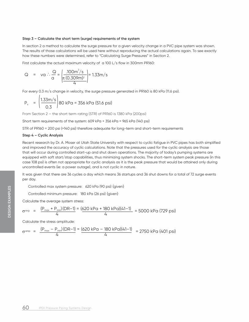
DES
IGN
EXA
MPL
ES
60 IPEX Pressure Piping Systems Design
Step 3 – Calculate the short term (surge) requirements of the system
In section 2 a method to calculate the surge pressure for a given velocity change in a PVC pipe system was shown. The results of those calculations will be used here without reproducing the actual calculations again. To see exactly how these numbers were determined, refer to “Calculating Surge Pressures” in Section 2.
First calculate the actual maximum velocity of a 100 L/s flow in 300mm PR160:
Q = va ··· Q = .100m
3/s
= 1.33m/s a p (0.309m)2
4
For every 0.3 m/s change in velocity, the surge pressure generated in PR160 is 80 kPa (11.6 psi).
Ps = 1.33m/s 80 kPa = 356 kPa (51.6 psi)
0.3From Section 2 – the short term rating (STR) of PR160 is 1380 kPa (200psi)
Short term requirements of the system: 609 kPa + 356 kPa = 965 kPa (140 psi)
STR of PR160 = 200 psi (>140 psi) therefore adequate for long-term and short-term requirements
Step 4 – Cyclic Analysis
Recent research by Dr. A. Moser at Utah State University with respect to cyclic fatigue in PVC pipes has both simplified and improved the accuracy of cyclic calculations. Note that the pressures used for the cyclic analysis are those that will occur during controlled start-up and shut down operations. The majority of today’s pumping systems are equipped with soft start/stop capabilities, thus minimizing system shocks. The short-term system peak pressure (in this case 108 psi) is often not appropriate for cyclic analysis as it is the peak pressure that would be attained only during uncontrolled events (ie: a power outage), and is not cyclic in nature.
It was given that there are 36 cycles a day which means 36 startups and 36 shut downs for a total of 72 surge events per day.
Controlled max system pressure: 620 kPa (90 psi) {given}
Controlled minimum pressure: 180 kPa (26 psi) {given}
Calculate the average system stress:
savg = (Pmax + Pmin) (DR–1) = (620 kPa + 180 kPa)(41–1) = 5000 kPa (729 psi) 4 4
Calculate the stress amplitude:
samp = (Pmax – Pmin) (DR–1) = (620 kPa – 180 kPa)(41–1) = 2750 kPa (401 psi) 4 4
( )
( )

61IPEX Pressure Piping Systems Design
DESIG
N EXA
MPLES
Determine the predicted number of cycles to failure using Moser’s plot.
From the plot, the predicted cycles to failure are roughly 9 x 10⁶ pump starts and stops
Calculate cyclic life:
72 events per day x 365 = 26,280 events per year
0 x 106/26280 = 342 years
Therefore, SDR41 is more than adequate for the application.
9x10⁶
997
PositiveNegativeBoundary
3000
2500
2000
1500
1000
500
0
102 103 104 105 106 107 108 109 1010 1011 1012 1013
Ave
rage
Str
ess
(psi
)
Cycles to Failure
Resulting Cyclic-Failure Curves for PVC
20
30
40
50
70
10
0
15
0
20
0
30
0
50
07
00
10
00
15
00
20
00
30
00
StressAmplitude
(psi)
Figure 3 – Resulting Cyclic-Failure Curves for PVC

DES
IGN
EXA
MPL
ES
62 IPEX Pressure Piping Systems Design
This analysis of a relatively simple pipeline will illustrate the use of the design principles discussed in this guide section. PVC pipe standards offer a variety of pipe strengths and sizes. Ideally, the designer will make selections that minimize capital and operating costs while maintaining an adequate design safety factor.
The project is a 20,000’ long PVC water transmission main designed for an ultimate capacity of 4,000 gpm (5.76 mgd).
The profile of the pipeline is shown below. Water is being pumped to a ground storage tank (point f) with a maximum water level of 35’ from the floor. The centerline of the discharge end of the main, at the tie-in to the storage tank, will be 5’ below the tank floor.
Key stations and their elevations along the pipeline are:
The objective of the design process will be to select proper DRs of PVC for appropriate sections of pipeline while never exceeding the PR nor the WPR of the pipe at any point. An effort will be made to select DRs that meet the design criteria while providing optimum economic value for the utility or owner.
The key determinant of PVC pressure pipe design is the internal pressure. The pipe dimensions can be found in the AWWA pipe standards. For this example, AWWA Standard C900, Polyvinyl Chloride (PVC) Pressure Pipe and Fabricated Fittings, 4 In. through 60 In. (100mm through 1,500mm), for Water Transmission and Distribution, was used. The exact pipe dimensions are required to determine the flow velocity. The total pressure in the pipeline at any point is the sum of the static head, the friction loss, and the pressure rise as a result of sudden velocity changes. For simplicity, the selection of PVC pipe in this example will be limited to four PRs in CIOD only (PR 235, 165, 125 and 100).
Design Example #3: Transmission Pipe (Taken from AWWA M23 - PVC Pipe Design & Installation Manual)
19,998 16,665 13,332 9,999 6,666 3,333 0Ft
1,032
960
888
816
744
672
600
Pump House
a600
Tank
Energy Grade Line
e940
f 165+00
d800
115+00
c720
75+00 b670
45+00
Ele
vati
on (
ft)
Point Station Elevation at Pipe Centerline (ft)
a 0 + 00 600
b 45 + 00 670
c 75 + 00 720
d 115 + 00 800
e 165 + 00 940
f 200 + 00 940
Figure 4 – Pipeline Profile
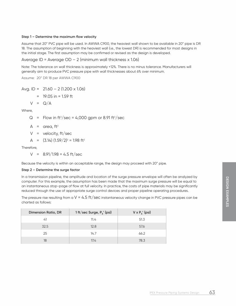
63IPEX Pressure Piping Systems Design
DESIG
N EXA
MPLES
Step 1 – Determine the maximum flow velocity
Assume that 20” PVC pipe will be used. In AWWA C900, the heaviest wall shown to be available in 20” pipe is DR 18. The assumption of beginning with the heaviest wall (i.e., the lowest DR) is recommended for most designs in the initial stage. The first assumption may be confirmed or revised as the design is developed.
Average ID = Average OD – 2 (minimum wall thickness x 1.06)
Note: The tolerance on wall thickness is approximately +12%. There is no minus tolerance. Manufacturers will generally aim to produce PVC pressure pipe with wall thicknesses about 6% over minimum.
Assume: 20” DR 18 per AWWA C900
Avg. ID = 21.60 – 2 (1.200 x 1.06)
= 19.05 in = 1.59 ft
V = Q/A
Where,
Q = Flow in ft3/sec = 4,000 gpm or 8.91 ft3/sec
A = area, ft2
V = velocity, ft/sec
A = (3.14) (1.59/2)2 = 1.98 ft2
Therefore,
V = 8.91/1.98 = 4.5 ft/sec
Because the velocity is within an acceptable range, the design may proceed with 20” pipe.
Step 2 – Determine the surge factor
In a transmission pipeline, the amplitude and location of the surge pressure envelope will often be analyzed by computer. For this example, the assumption has been made that the maximum surge pressure will be equal to an instantaneous stop -page of flow at full velocity. In practice, the costs of pipe materials may be significantly reduced through the use of appropriate surge control devices and proper pipeline operating procedures.
The pressure rise resulting from a V = 4.5 ft/sec instantaneous velocity change in PVC pressure pipes can be charted as follows:
Dimension Ratio, DR 1 ft/sec Surge, Ps’ (psi) V x Ps’ (psi)
41 11.4 51.3
32.5 12.8 57.6
25 14.7 66.2
18 17.4 78.3

DES
IGN
EXA
MPL
ES
64 IPEX Pressure Piping Systems Design
Step 3 – Determine the WPR for each of the DRs of Step 2
The WPR is a job-specific pressure rating of the pipe, taking into account the maximum possible surges versus the short-term strength of the pipe. The WPR may be either higher or lower than the PR of the pipe, depending on the flow conditions. The lower value between the WPR and the PR should be used as the upper limit for system steady-state operating pressure.
WPR = STR – V x Ps’
It can be seen that the governing parameter for the pressure design of this example will be the WPR analysis since it is lower than the PR of each DR.
Step 4 – Determine the friction loss f under full-flow conditions
Continue to assume DR 18 for this calculation because this pipe will produce slightly greater losses than the other DRs under consideration. The result will be conservative for all design operations.
The Hazen-Williams equation is convenient to use:
f = 0.2083 (100/C)1.852 Q1.852
di4.8655
Where,
f = friction head, ft of water per 100 ft of pipe
di = inside diameter of pipe, in.
Q = flow, gpm
C = flow coefficient, 150 for PVC
Substituting for 20” PR 235 pipe, where d = 19.05 in
f = 0.273 ft of water per 100 ft of pipeline
= 0.118 psi per 100 ft (station) of pipeline
DR STR (psi) V x Ps’ (psi) WPR (psi) PR (psi)
41 130 51.3 78.7 100
32.5 165 57.6 107.4 125
25 215 66.2 148.8 165
18 300 78.3 221.7 235

65IPEX Pressure Piping Systems Design
DESIG
N EXA
MPLES
Step 5 – Determine the pressures at key points in the pipeline under steady-state, full-flow conditions
This pressure, P, at any point is the sum of the static head as a result of difference in elevations and the friction loss.
Referring to Figure 4, the pressure at key points can be calculated as follows:
Starting at the storage tank:
The pressure, P, at each of the key points are summarized as follows:
Station 200 + 00
Static Head = 980 – 940 = 40 ft
or 40 ft x (0.43 psi/ft) = 17.3 psi
Station 165 + 00
Static Head = (980 – 940) ft x (0.43 psi/ft) = 17.3 psi
Friction Head = (3,500 ft) x (0.118 psi/100 ft) = 4.1 psi
Total Head = 21.4 psi
Station 115 + 00
Static Head = (980 – 800) ft x (0.43 psi/ft) = 77.4 psi
Friction Head = (8,500 ft) x (0.118 psi/100 ft) = 10.0 psi
Total Head = 87.4 psi
Station 75 + 00
Static Head = (980 – 720) ft x (0.43 psi/ft) = 111.8 psi
Friction Head = (12,500 ft) x (0.118 psi/100 ft) = 14.8 psi
Total Head = 126.6 psi
Station 45 + 00
Static Head = (980 – 670) ft x (0.43 psi/ft) = 133.3 psi
Friction Head = (15,500 ft) x (0.118 psi/100 ft) = 18.3 psi
Total Head = 151.6 psi
Station 0 + 00
Static Head = (980 – 600) ft x (0.43 psi/ft) = 163.4 psi
Friction Head = (20,000 ft) x (0.118 psi/100 ft) = 23.6 psi
Total Head = 187.0 psi
Point Station Static Head (psi) Friction Head (psi) Pressure, P (psi)
f 200 + 00 17.3 0 17.3
e 165 + 00 17.3 4.1 21.4
d 115 + 00 77.4 10.0 87.4
c 75 + 00 111.8 14.8 126.6
b 45 + 00 133.3 18.3 151.6
a 0 + 00 163.4 23.6 187.0

DES
IGN
EXA
MPL
ES
66 IPEX Pressure Piping Systems Design
Step 6 – Determine the appropriate DR of pipe for each section of the pipeline
From previous calculations in Step 3, DR 18 PVC pressure pipe has a working pressure rating 221.7 psi. For the next greater DR, DR 25, the WPR is 148.8 psi. Therefore, DR 18 is selected to start out at the pumphouse until a point in the system where the operating pressure, P, drops to be equal to the WPR of DR 25. At this point, DR 25 may be used. Subsequent steps will determine the starting points for DR 32.5 as well as DR 41.
It can be seen from the above summary of pressures by section that the transition to DR 25 will occur between Stations 45 + 00 and 75 + 00, in section bc. To pinpoint the exact location, the pressure gradient for that section must be calculated.
D P(bc) = (Pc + Pb) Station Length of bc
= 126.6 psi – 151.6 psi (75 – 45) x (100 ft)
= –0.83 psi/100 ft
The length beyond Station 45 + 00 (point b) can be calculated as follows:
Station Length = WPR(DR 25) – Pb D P(bc)
= (148.8 psi) – (151.6 psi) –0.83 psi/100 ft
= 337 ft (i.e., at 337 ft downstream of Station 45 + 00)
Therefore, begin using DR 25 at Station 48 + 37.
Similarly, the transition point for DR 32.5 can be found.
From the summary of pressures and knowing the WPR of DR 32.5 is 107.4 psi, DR 32.5 can be used between Station 75 + 00 and Station 115 + 00, i.e., section cd.
First, calculate the pressure gradient in section cd.
D P(cd) = (Pd – Pc) Station Length of cd
= 87.4 psi – 126.6 psi (115 – 75) x (100 ft)
= –0.98 psi/100 ft
Next, the Station Length beyond Station 75 + 00 can be calculated:
Station Length = WPR(DR 32.5) – Pc D P(cd)
= (107.4 psi) – (126.6 psi) –0.98 psi/100 ft
= 1,959 ft (i.e., at 1,959 ft downstream of Station 7 5 + 00)
Therefore, begin using DR 32.5 at Station 94 + 59.

67IPEX Pressure Piping Systems Design
DESIG
N EXA
MPLES
Similarly, it can be calculated where DR 41 usage may begin.
From review of the summary of pressures and knowing the WPR of DR 41 is 78.7 psi, the range for DR 41 begins between Station 115 + 00 and Station 165 + 00, i.e., section de.
First, calculate the pressure gradient in section de.
D P(de) = (Pe – Pd) Station Length of de
= 21.4 psi – 87.4 psi (165 – 115) x (100 ft)
= –1.32 psi/100 ft
Next, the Station Length beyond point d:
Station Length = WPR(DR 41) – Pd D P(de)
= (78.7 psi) – (87.4 psi) –1.32 psi/100 ft
= 659 ft (i.e., at 659 ft downstream of Station 115 + 00)
Therefore, DR 41 may begin usage at Station 121 + 59 and continue for the duration of the pipeline up to its terminus at the reservoir.
The design for internal pressure may be summarized as follows:
In this example of a 3.8 mile pipeline, the designer has the opportunity to make significant cost savings through the use of several PVC pipe pressure ratings. Computer modeling may disclose even further potential savings by showing exactly where and how surge control is most effective. (Note that the above pipe selection was made assuming that the potential exists for the instantaneous stoppage of flow.)
If the pipeline is operated in a cycle mode (i.e., like some sewage force mains), an analysis of fatigue life should be made. Both present and future modes of operation should be examined.
Distance from Pumphouse (ft) Use 20 in. Pressure Gradient (psi)
0 – 4.837 DR 18 (PR 235) 187.0 – 148.8
4,837 – 9,459 DR 25 (PR 165) 148.8 – 107.4
9,459 – 12,159 DR 32.5 (PR 125) 107.4 – 78.7
12,159 – 20,000 DR 41 (PR 100) 78.7 – 17.3

68 IPEX Pressure Piping Systems Design
NOTES

69IPEX Pressure Piping Systems Design
APPEN
DIC
ES
SECTION FOUR: APPENDICES
APPENDIX A: REFERENCES
1 Duranceau, Schiff, Bell. “Electrical Grounding, Pipe Integrity and Shock Hazard”, Journal of the AWWA, July 1998, pp. 40-51
2 Hulsmann, Nowack,”70 Years of Experience with PVC Pipes” Conference Paper, Plastic Pipes XII, Milan, April 2004
3 Jenkins, Thompson,”Review of Water Industry Plastic Pipe Practices”, AWWA Research Foundation, 1987
4 Berens, A.R., “Prediction of Chemical Permeation through PVC Pipe”, Journal of the AWWA, November 1985
5 Hoogensen Metallurgical Engineering Ltd.,” Examination of Submitted PVC Pipe Section”, Report to IPEX, December 1998
6 Uni-Bell PVC Pipe Association, “Handbook of PVC Pipe – Design and Construction”, fourth edition, (August 2001)

APP
END
ICES
70 IPEX Pressure Piping Systems Design
TABLE B-2 WEIGHTS OF WATER
Units of VolumeWeight
pounds kilograms
1 US Gallon 8.35 3.79
1 Imperial Gallon 10.02 4.55
1 litre 2.21 1.00
1 cubic yard 1,685.610 765.267
1 cubic foot 62.430 28.343
1 cubic inch 0.036 0.016
1 cubic cm 0.002 0.001
1 cubic metre 2,210.000 1,000.000
APPENDIX B: REFERENCE TABLES AND CONVERSION CHARTS
Table B-1 Pipe Capacity
Table B-2 Weights of Water
Table B-3 Decimal & Millimeter Equivalents of Fractions
Table B-4 Volume Conversion
Table B-5 Pressure Conversion
Table B-6 Flow Conversion
Table B-7 Temperature Conversion
Table B-8 Length Conversion
Pipe Size Outside Diameter – IPS OD Pipe Volume for 1 foot length of pipe
inches inch feet cm in3 ft3 cm3 US Gal Imp Gal
1/4 0.250 0.021 0.098 0.589 0.0003 9.648 0.003 0.002
3/8 0.375 0.031 0.148 1.325 0.001 21.708 0.006 0.005
1/2 0.500 0.042 0.197 2.355 0.001 38.591 0.010 0.008
3/4 0.750 0.063 0.295 5.299 0.003 86.831 0.023 0.019
1 1.000 0.083 0.394 9.420 0.005 154.366 0.041 0.034
1-1/4 1.250 0.104 0.492 14.719 0.009 241.196 0.064 0.053
1-1/2 1.500 0.125 0.591 21.195 0.012 347.322 0.092 0.076
2 2.000 0.167 0.787 37.680 0.022 617.462 0.163 0.136
3 3.000 0.250 1.181 84.780 0.049 1,389.290 0.367 0.306
4 4.000 0.333 1.575 150.720 0.087 2,469.849 0.652 0.543
5 5.000 0.417 1.969 235.500 0.136 3,859.139 1.019 0.849
6 6.000 0.500 2.362 339.120 0.196 5,557.159 1.468 1.222
8 8.000 0.667 3.150 602.880 0.349 9,879.395 2.610 2.173
10 10.000 0.833 3.937 942.000 0.545 15,436.554 4.078 3.396
12 12.000 1.000 4.724 1,356.480 0.785 22,228.638 5.872 4.890
14 14.000 1.167 5.512 1,846.320 1.068 30,255.646 7.993 6.655
16 16.000 1.333 6.299 2,411.520 1.396 39,517.578 10.439 8.693
18 18.000 1.500 7.087 3,052.080 1.766 50,014.435 13.212 11.002
20 20.000 1.667 7.874 3,768.000 2.181 61,746.216 16.312 13.582
24 24.000 2.000 9.449 5,425.920 3.140 88,914.551 23.489 19.559
TABLE B-1 PIPE CAPACITY
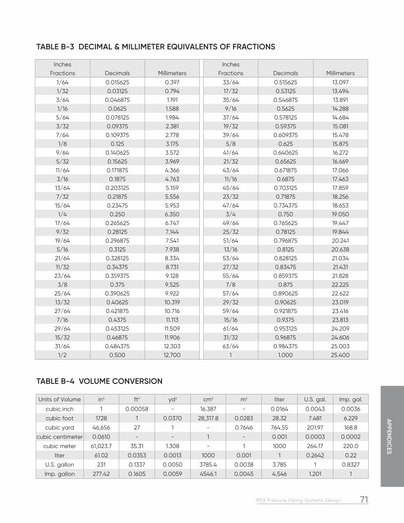
71IPEX Pressure Piping Systems Design
APPEN
DIC
ES
TABLE B-3 DECIMAL & MILLIMETER EQUIVALENTS OF FRACTIONS
TABLE B-4 VOLUME CONVERSION
Units of Volume in3 ft3 yd3 cm3 m3 liter U.S. gal. Imp. gal.
cubic inch 1 0.00058 - 16.387 - 0.0164 0.0043 0.0036
cubic foot 1728 1 0.0370 28,317.8 0.0283 28.32 7.481 6.229
cubic yard 46,656 27 1 - 0.7646 764.55 201.97 168.8
cubic centimeter 0.0610 - - 1 - 0.001 0.0003 0.0002
cubic meter 61,023.7 35.31 1.308 - 1 1000 264.17 220.0
liter 61.02 0.0353 0.0013 1000 0.001 1 0.2642 0.22
U.S. gallon 231 0.1337 0.0050 3785.4 0.0038 3.785 1 0.8327
Imp. gallon 277.42 0.1605 0.0059 4546.1 0.0045 4.546 1.201 1
Inches InchesFractions Decimals Millimeters Fractions Decimals Millimeters
1/64 0.015625 0.397 33/64 0.515625 13.0971/32 0.03125 0.794 17/32 0.53125 13.4943/64 0.046875 1.191 35/64 0.546875 13.8911/16 0.0625 1.588 9/16 0.5625 14.2885/64 0.078125 1.984 37/64 0.578125 14.6843/32 0.09375 2.381 19/32 0.59375 15.0817/64 0.109375 2.778 39/64 0.609375 15.4781/8 0.125 3.175 5/8 0.625 15.875
9/64 0.140625 3.572 41/64 0.640625 16.2725/32 0.15625 3.969 21/32 0.65625 16.66911/64 0.171875 4.366 43/64 0.671875 17.0663/16 0.1875 4.763 11/16 0.6875 17.463
13/64 0.203125 5.159 45/64 0.703125 17.8597/32 0.21875 5.556 23/32 0.71875 18.25615/64 0.23475 5.953 47/64 0.734375 18.653
1/4 0.250 6.350 3/4 0.750 19.05017/64 0.265625 6.747 49/64 0.765625 19.4479/32 0.28125 7.144 25/32 0.78125 19.84419/64 0.296875 7.541 51/64 0.796875 20.2415/16 0.3125 7.938 13/16 0.8125 20.638
21/64 0.328125 8.334 53/64 0.828125 21.03411/32 0.34375 8.731 27/32 0.83475 21.43123/64 0.359375 9.128 55/64 0.859375 21.828
3/8 0.375 9.525 7/8 0.875 22.22525/64 0.390625 9.922 57/64 0.890625 22.62213/32 0.40625 10.319 29/32 0.90625 23.01927/64 0.421875 10.716 59/64 0.921875 23.4167/16 0.4375 11.113 15/16 0.9375 23.813
29/64 0.453125 11.509 61/64 0.953125 24.20915/32 0.46875 11.906 31/32 0.96875 24.60631/64 0.484375 12.303 63/64 0.984375 25.003
1/2 0.500 12.700 1 1.000 25.400

APP
END
ICES
72 IPEX Pressure Piping Systems Design
TABLE B-5 PRESSURE CONVERSION
Units of Pressure atm bar lb/in2 lb/ft2 kg/cm2 kg/m2 inch H20
atmosphere (atm) 1 0.987 0.068 - 0.968 - 0.002
bar 1.013 1 0.069 - 0.981 - 0.002
pound per square inch (psi) 14.7 14.5 1 0.007 14.22 0.001 0.036
pound per square foot (psf) 2,116 2,089 144 1 2,048 0.205 5.2
kilogram per square centimeter 1.033 1.02 0.07 - 1 0.0001 0.003
kilogram per square meter 10,332 10,197 703 4.88 10,000 1 25.4
inch of water (H20) (4ºC) 406.78 401.46 27.68 0.192 393.7 0.039 1
inch of mercury (Hg) (0ºC) 29.921 29.53 2.036 0.014 28.96 0.003 0.074
inch of air (15ºC) 332,005 327,664 22,592 148.7 321,328 32.13 816.2
foot of water (4ºC) 33.9 33.46 2.307 0.016 32.81 0.003 0.083
foot of air (15ºC) 27,677 27,305 1,883 13.07 26,777 2.678 0.006
millimeter of mercury (0ºC) 760 750 51.71 0.36 735.6 0.074 1.868
millimeter of water (4ºC) 10,332 10,197 703 4.88 10,000 1 25.4
kilopascal (kP) 101.3 100 6.89 0.048 98.07 0.01 0.249
Newton per square meter - - - 0.021 - 0.102 0.004
Units of Pressure inch Hg inch air ft H20 ft air mm Hg mm H20 kilopascal N/m2
atmosphere (atm) 0.033 - 0.029 - 0.001 - 0.01 -
bar 0.034 - 0.03 - 0.001 - 0.01 -
pound per square inch (psi) 0.491 - 0.434 0.001 0.019 0.001 0.145 -
pound per square foot (psf) 70.73 0.006 62.43 0.076 2.784 0.205 20.89 0.021kilogram per square centimeter 0.035 - 0.03 - 0.001 - 0.01 -
kilogram per square meter 345.3 0.031 304.8 0.373 13.6 1 101.97 0.102
inch of water (H20) (4ºC) 13.6 0.001 12 0.015 0.535 0.039 4.015 0.004
inch of mercury (Hg) (0ºC) 1 - 0.883 0.001 0.039 0.003 0.295 -
inch of air (15ºC) 11,096 1 9,794 12 436.8 32.13 3,277 3.106
foot of water (4ºC) 1.133 - 1 - 0.045 0.003 0.335 -
foot of air (15ºC) 924.7 0.083 816.2 1 36.4 2.678 273.1 0.273
millimeter of mercury (0ºC) 25.4 0.002 22.42 0.027 1 0.074 7.5 0.008
millimeter of water (4ºC) 345.3 0.031 304.8 0.373 13.6 1 101.97 0.102
kilopascal (kP) 3.386 - 2.99 0.004 0.133 0.01 1 0.001
Newton per square meter - 3.277 - 0.273 0.008 0.102 0.001 1

73IPEX Pressure Piping Systems Design
APPEN
DIC
ES
TABLE B-6 FLOW CONVERSION
Units of Flow Rate US gps US gpm US gph US gpd Imp gps Imp gpm Imp gph Imp gpd liters/sec liters/min liters/hr liters/day
US gal/sec (gps) 1 0.017 - - 1.2 0.02 - - 0.264 0.004 - -
US gal/min (gpm) 60 1 0.017 0.001 72.06 1.2 0.02 0.001 15.85 0.264 0.004 -
US gal/hr (gph) 3,600 60 1 0.042 4,323 72.06 1.2 0.05 951.02 15.85 0.264 0.011
US gal/day (gpd) 86,400 1,440 24 1 103,762 1,729.40 28.82 1.2 22,824 380.41 6.34 0.264
Imperial gal/sec 0.833 0.014 - - 1 0.017 - - 0.22 0.004 - -
Imperial gal/min 49.96 0.833 0.014 0.001 60 1 0.017 0.001 13.2 0.22 0.004 -
Imperial gal/hr 2,997.60 49.96 0.833 0.035 3,600 60 1 0.042 791.89 13.2 0.22 0.009
Imperial gal/day 71,943 1,199 19.98 0.833 86,400 1,440 24 1 19,005 316.76 5.279 0.22
Liters/sec 3.79 0.063 0.002 - 4.55 0.076 0.001 - 1 0.017 - -
Liters/min 227.12 3.785 0.063 0.003 272.77 4.55 0.076 0.003 60 1 0.017 0.001
Liters/hr 13,627 227.12 3.785 0.158 16,366 272.77 4.55 0.189 3,600 60 1 0.042
Liters/day 327,060 5,451 90.85 3.785 392,782 6,546 109.11 4.55 86,400 1,440 24 1
Cubic ft/sec (cfs) 0.134 0.002 - - 0.161 0.003 - - 0.035 0.001 - -
Cubic ft/min (cfm) 8.02 0.134 0.002 - 9.633 0.161 0.003 - 2.119 0.035 0.001 -
Cubic ft/hr (cfh) 481.25 8.02 0.134 0.006 577.96 9.63 0.161 0.007 127.13 2.119 0.035 0.001
Cubic ft/day (cfd) 11,550 192.5 3.21 0.134 13,871 231.18 3.853 0.161 3,051.20 50.85 0.848 0.001
Acre in/min 0.002 - - - 0.003 - - - 0.001 - - -
Acre in/hr 0.133 0.002 - - 0.159 0.003 - - 0.035 - - -
Acre in/day 3.182 0.053 0.001 - 3.821 0.064 0.001 - 0.841 0.001 - -
Cubic m/sec 0.004 - - - 0.005 - - - 0.001 - - -
Cubic m/min 0.227 0.004 - - 0.273 0.005 - - 0.06 0.001 - -
Cubic m/hr 13.628 0.227 0.004 - 16.366 0.273 0.005 - 3.6 0.06 0.001 -
Cubic m/day 327.06 5.451 0.091 0.004 392.78 6.546 0.109 0.005 86.4 1.44 0.024 0.001
Units of Flow Rate ft3/sec ft3/min ft3/hr ft3/day Acre in/min Acre in/hr Acre in/day m3/sec m3/min m3/hr m3/day
US gal/sec (gps) 7.48 0.125 0.002 - 452.6 7.54 0.31 264.2 4.4 0.073 0.003
US gal/min (gpm) 448.8 7.48 0.125 0.005 27,154 452.6 18.86 15,850 264.2 4.403 0.183
US gal/hr (gph) 26,930 448.83 7.481 0.312 1.629E+06 27,154 1,131 951,019 15,850 264.17 11.007
US gal/day (gpd) 646,317 10,772 179.53 7.481 3.910E+07 651,703 27,154 2.282E+07 380,408 6,340 264.17
Imperial gal/sec 6.229 0.104 0.002 - 376.8 6.28 0.26 220 3.67 0.061 0.003
Imperial gal/min 373.73 6.229 0.104 0.004 22,611 376.8 15.7 13,198 220 3.666 0.153
Imperial gal/hr 22,424 373.73 6.229 0.259 1.357E+06 22,611 942.1 791,889 13,198 220 9.165
Imperial gal/day 538,171 8,970 149.49 6.229 3.256E+07 542,656 22,611 1.901E+07 316,756 5,279 220
Liters/sec 28.32 0.472 0.008 - 1,713 28.6 1.19 1,000 16.67 0.278 0.012
Liters/min 1,699 28.32 0.472 0.2 102,790 1,713 71.38 60,000 1,000 16.67 0.694
Liters/hr 101,941 1,669 28.32 1.18 6.167E+06 102,790 4,283 3.600E+06 60,000 1,000 42.67
Liters/day 2,446,575 40,776 679.6 28.32 1.480E+08 2.467E+06 102,790 8.640E+07 1.440E+06 24,000 1,000
Cubic ft/sec (cfs) 1 0.017 - - 60.5 1.008 0.042 35.31 0.589 0.01 -
Cubic ft/min (cfm) 60 1 0.017 - 3,630 60.5 2.52 2,119 35.31 0.59 0.025
Cubic ft/hr (cfh) 3,600 60 1 0.042 217,800 3,630 151.25 127,133 2,119 35.31 1.471
Cubic ft/day (cfd) 86,400 1,440 24 1 5.227E+06 87,120 3,630 3,051,187 50,853 847.55 35.31
Acre in/min 0.017 - - - 1 0.017 0.001 0.584 0.01 - -
Acre in/hr 0.992 0.001 - - 60 1 0.042 35.02 0.584 0.01 -
Acre in/day 23.8 0.033 0.006 - 1,440 24 1 840.55 14.001 0.233 0.001
Cubic m/sec 0.028 - - - 1.71 0.029 0.001 1 0.017 - -
Cubic m/min 1.7 0.028 - - 102.8 1.71 0.071 60 1 0.017 0.001
Cubic m/hr 101.94 1.7 0.028 0.001 6,167 102.8 4.283 3,600 60 1 0.042
Cubic m/day 2446.6 40.78 0.68 0.028 148,018 2,467 102.79 86,400 1,400 24 1

APP
END
ICES
74 IPEX Pressure Piping Systems Design
ºF ºC °F ºC ºF ºC ºF ºC ºF ºC-60 -51 22 -5.6 50 10.0 78 25.6 160 71
-50 -46 23 -5.0 51 10.6 79 26.1 170 77
-40 -40 24 -4.4 52 11.1 80 26.7 180 82
-30 -34 25 -3.9 53 11.7 81 27.2 190 88
-20 -29 26 -3.3 54 12.2 82 27.8 200 92
-10 -23.0 27 -2.8 55 12.8 83 28.3 210 99
0 -17.8 28 -2.2 56 13.3 84 28.9 212 100
1 -17.2 29 -1.7 57 13.9 85 29.4 220 104
2 -16.7 30 -1.1 58 14.4 86 30.0 230 110
3 -16.1 31 -0.6 59 15.0 87 30.6 240 116
4 -15.6 32 0.0 60 15.6 88 31.1 250 121
5 -15.0 33 0.6 61 16.1 89 31.7 260 127
6 -14.4 34 1.1 62 16.7 90 32.2 270 132
7 -13.9 35 1.7 63 17.2 91 32.8 280 138
8 -13.3 36 2.2 64 17.8 92 33.3 290 143
9 -12.8 37 2.8 65 18.3 93 33.9 300 149
10 -12.2 38 3.3 66 18.9 94 34.4 310 154
11 -11.7 39 3.9 67 19.4 95 35.0 320 160
12 -11.1 40 4.4 68 20.0 96 35.6 330 166
13 -10.6 41 5.0 69 20.6 97 36.1 340 171
14 -10.0 42 5.6 70 21.1 98 36.7 350 177
15 -9.4 43 6.1 71 21.7 99 37.2 360 182
16 -8.9 44 6.7 72 22.2 100 37.8 370 188
17 -8.3 45 7.2 73 22.8 110 43 380 193
18 -7.8 46 7.8 74 23.3 120 49 390 199
19 -7.2 47 8.3 75 23.9 130 54 400 204
20 -6.7 48 8.9 76 24.4 140 60
21 -6.1 49 9.4 77 25.0 150 66
TABLE B-7 TEMPERATURE CONVERSION
TABLE B-8 LENGTH CONVERSION
Units of Length in. ft. yd. mile mm cm m km
inch 1 0.0833 0.0278 - 25.4 2.54 0.0254 -foot 12 1 0.3333 - 304.8 30.48 0.3048 -yard 36 3 1 - 914.4 91.44 0.9144 -mile - 5280 1760 1 - - 1609.3 1.609millimeter 0.0394 0.0033 - - 1 0.100 0.001 -centimeter 0.3937 0.0328 0.0109 - 10 1 0.01 -meter 39.37 3.281 1.094 - 1000 100 1 0.001kilometer - 3281 1094 0.6214 - - 1000 1
(1 micron = 0.001 millimeter)
Degrees Celsius °C = (°F - 32) Degrees Fahrenheit °F = °C + 32
Degrees Kelvin °T = °C + 273.2 Degrees Rankine °R = °F + 459.7
59
95

75IPEX Pressure Piping Systems Design
APPEN
DIC
ES
APPENDIX C: USEFUL FORMULAS
• Area of a Circle
• Circumference of a Circle
• Length of Circular Arc
• Area of Circle Sector
• Equation of a Circle (cartesian coordinates)
• Equation of a Line (quadratic formula)
• Basic Trigonometric Functions
• Area of an Ellipse
• Circumference of an Ellipse
• Area of a Triangle
• Area of a Trapezoid
• Area of a Parallelogram
• Surface Area of a Sphere
• Volume of a Sphere
• Surface Area of a Cylinder
• Volume of a Cylinder
• Surface Area of an Elliptical Tank
• Volume of an Elliptical Tank
• Surface Area of a Cone
• Volume of a Cone
• Surface Area of a Rectangular Solid
• Volume of a Rectangular Solid

APP
END
ICES
76 IPEX Pressure Piping Systems Design
APPENDIX C: USEFUL FORMULAS
r
SO
Length of Circular Arc
S = Ø x ( p ) x r Ø in degrees 180
S = Ø x r Ø in radians
Area of Circle Sector
A = x ( Ø ) x p x r2 Ø in degrees 360
A = x ( Ø ) x r2 Ø in radians 2
Equation of a Circle (cartesian co-ordinates) - for a circle with center (j, k) and radius (r)
(x - j)2 + (y - k)2 = r2
Equation of a line (quadratic formula)
ax + by + c = 0 or ax2 + bx + c = 0
x -b + b2 - 4ac2a
Circle
Diameter = r 2
Circumference = pD = 2pr
Area = pr2
Sine Law
9 = 6 = c = 2Rsin A sin B sin C
Cosine Law
C2 = a2 + b2 - 2ab cos C
b2 = a2 + c2 - 2ac cos B
a2 = b2 + c2 - 2bc cos A
Trigonometry
sin Ø = b ccos Ø = a ctan Ø = b a
c
a
b
B C
A
O
ba
Ellipse
Area = p x a x b
Circumference
= p (3 (a + b) – (3a + b) (a + 3b)
h
w
Triangle
Area = w h 2
Trapezoid
Area = 1 (b1 + b2) h 2
b
b
h
Parallelogram
Area = b h
b
h
Sphere
Surface Area = 4 p r2
Volume = 4 p r3 3
r

77IPEX Pressure Piping Systems Design
APPEN
DIC
ES
Cylinder
Surface Area = (2 p r2) + (2 p r h)
Volume = p r2 h
r
h
Elliptical Tank
Surface Area
Volume = p abh
a b
h 2 π a2 +
2b2( (h + (2π ab)
Cone
Surface Area = p r S
Volume = p r2 h 3
S
h
r
Rectangular Solid
Surface Area = 2 (Lw + Lh + wh)
Volume = L w h
L
h
w

APP
END
ICES
78 IPEX Pressure Piping Systems Design
APPENDIX D: ABBREVIATIONS
AGA American Gas Association
ANSI American National Standards Institute
API American Petroleum Institute
ASME American Society of Mechanical Engineers
ASTM American Society for Testing and Materials
AWWA American Water Works Association
BOCA Building Officials and Code Administrators
BS British Standards Institution
CPVC Chlorinated poly (vinyl chloride) plastic or resin
CS Commercial Standard, see Product Standard
CSA Canadian Standards Association
DR Dimension Ratio
DIN German Industrial Norms
FHA Federal Housing Administration or Farmers Home Administration
HDB Hydrostatic design basis
HDS Hydrostatic design stress
IAPD International Association of Plastics Distributors
IAPMO International Association of Plumbing and Mechanical Officials
IPC International Plumbing Code
ISO International Standards Organization
JIS Japanese Industrial Standards
NSF National Sanitation Foundation International
PPI Plastics Pipe Institute
PS Product Standard when in reference to a specification for plastic pipe and fittings. These specifications are promulgated by the U.S. Department of Commerce and were formerly known as Commercial Standards.
PVC Poly-(vinyl chloride) plastic, resin or compound
PVCO Molecularly Oriented Polyvinyl Chloride Plastic
RVCM Residual Vinyl Chloride Monomer
SCS Soil Conservation Service
SDR Standard Dimension Ratio
SI International System of Units
SPI Society of the Plastics Industry, Inc.
UPC Uniform Plumbing Code
USASI United States of America Standards Institute (formerly American Standards Association)
WOG Water, Oil, Gas
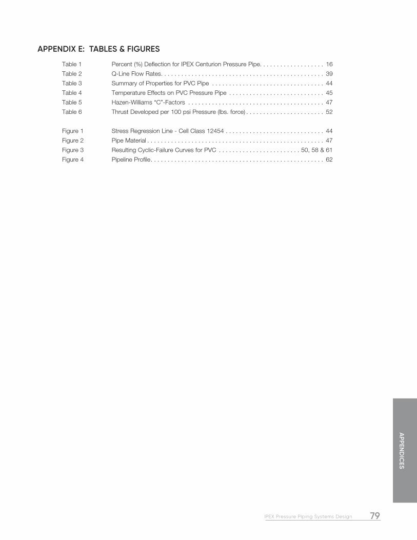
79IPEX Pressure Piping Systems Design
APPEN
DIC
ES
APPENDIX E: TABLES & FIGURES
Table 1 Percent (%) Deflection for IPEX Centurion Pressure Pipe. . . . . . . . . . . . . . . . . . . 16
Table 2 Q-Line Flow Rates . . . . . . . . . . . . . . . . . . . . . . . . . . . . . . . . . . . . . . . . . . . . . . . . 39
Table 3 Summary of Properties for PVC Pipe . . . . . . . . . . . . . . . . . . . . . . . . . . . . . . . . . 44
Table 4 Temperature Effects on PVC Pressure Pipe . . . . . . . . . . . . . . . . . . . . . . . . . . . . 45
Table 5 Hazen-Williams “C”-Factors . . . . . . . . . . . . . . . . . . . . . . . . . . . . . . . . . . . . . . . . 47
Table 6 Thrust Developed per 100 psi Pressure (lbs. force) . . . . . . . . . . . . . . . . . . . . . . . 52
Figure 1 Stress Regression Line - Cell Class 12454 . . . . . . . . . . . . . . . . . . . . . . . . . . . . . 44
Figure 2 Pipe Material . . . . . . . . . . . . . . . . . . . . . . . . . . . . . . . . . . . . . . . . . . . . . . . . . . . . 47
Figure 3 Resulting Cyclic-Failure Curves for PVC . . . . . . . . . . . . . . . . . . . . . . . . 50, 58 & 61
Figure 4 Pipeline Profile . . . . . . . . . . . . . . . . . . . . . . . . . . . . . . . . . . . . . . . . . . . . . . . . . . . 62

80 IPEX Pressure Piping Systems Design
NOTES

SALES AND CUSTOMER SERVICE
IPEX Inc. Toll free: (866) 473-9462 ipexna.com
About the IPEX Group of Companies
As leading suppliers of thermoplastic piping systems, the IPEX Group of Companies provides our customers with some of the largest and most comprehensive product lines. All IPEX products are backed by more than 50 years of experience. With state-of-the-art manufacturing facilities and distribution centers across North America, we have earned a reputation for product innovation, quality, end-user focus and performance.
Markets served by IPEX group products are:
• Electrical systems
• Telecommunications and utility piping systems
• PVC, CPVC, PP, PVDF, PE, ABS, and PEX pipe and fittings
• Industrial process piping systems
• Municipal pressure and gravity piping systems
• Plumbing and mechanical piping systems
• Electrofusion systems for gas and water
• Industrial, plumbing and electrical cements
• Irrigation systems
Products manufactured by IPEX Inc.
Bionax®, Blue904®, IPEX Centurion®, CycleTough®, IPEX FusibleTM, Q-Line® and TerraBrute® CR and are trademarks of IPEX Branding Inc.
MNMNNAIP170904R1C © 2018 IPEX IND0033CMNMNNAIP200502R2C © 2021 IPEX IND0033C
SALES AND CUSTOMER SERVICE
IPEX Inc. Toll Free: (866) 473-9462 ipexna.com
About the IPEX Group of Companies
As leading suppliers of thermoplastic piping systems, the IPEX Group of Companies provides our customers with some of the largest and most comprehensive product lines. All IPEX products are backed by more than 50 years of experience. With state-of-the-art manufacturing facilities and distribution centers across North America, we have earned a reputation for product innovation, quality, end-user focus and performance.
Markets served by IPEX group products are:
• Electrical systems
• Telecommunications and utility piping systems
• PVC, CPVC, PP, PVDF, PE, ABS, and PEX pipe and fittings
• Industrial process piping systems
• Municipal pressure and gravity piping systems
• Plumbing and mechanical piping systems
• Electrofusion systems for gas and water
• Industrial, plumbing and electrical cements
• Irrigation systems
Products manufactured by IPEX Inc.
Bionax®, Blue904TM, IPEX Centurion®, CycleTough®, Gold901TM, IPEX FusibleTM, Q-Line® and TerraBrute® CR and are trademarks of IPEX Branding Inc.
This literature is published in good faith and is believed to be reliable. However it does not represent and/or warrant in any manner the information and suggestions contained in this brochure. Data presented is the result of laboratory tests and field experience.
A policy of ongoing product improvement is maintained. This may result in modifications of features and/or specifications without notice.