Power Piping - Standards Michigan
113
ASME B31.1-2016 (Revision of ASME B31.1-2014) Power Piping ASME Code for Pressure Piping, B31 AN INTERNATIONAL PIPING CODE ® Two Park Avenue • New York, NY • 10016 USA
-
Upload
khangminh22 -
Category
Documents
-
view
0 -
download
0
Transcript of Power Piping - Standards Michigan

ASME B31.1-2016(Revision of ASME B31.1-2014)
Power PipingASME Code for Pressure Piping, B31
A N I N T E R N A T I O N A L P I P I N G C O D E ®
Two Park Avenue • New York, NY • 10016 USA
OBrienC
Text Box
PROPOSED REVISION OF:
DUrsoU
Text Box
DUrsoU
Text Box
DUrsoU
Text Box
DUrsoU
Text Box
DUrsoU
Cross-Out
DUrsoU
Cross-Out
DUrsoU
Text Box
20XX
DUrsoU
Text Box
2016
DUrsoU
Text Box
TENTATIVE SUBJECT TO REVISION OR WITHDRAWAL Specific Authorization Required for Reproduction or Quotation ASME Codes and Standards

(16) INTRODUCTION
The ASME B31 Code for Pressure Piping consists ofa number of individually published Sections, each anAmerican National Standard, under the direction ofASME Committee B31, Code for Pressure Piping.
Rules for each Section have been developed consider-ing the need for application of specific requirements forvarious types of pressure piping. Applications consid-ered for each Code Section include
B31.1 Power Piping: piping typically found in elec-tric power generating stations, in industrialand institutional plants, geothermal heatingsystems, and central and district heating andcooling systems
B31.3 Process Piping: piping typically found inpetroleum refineries; chemical, pharmaceuti-cal, textile, paper, semiconductor, and cryo-genic plants; and related processing plantsand terminals
B31.4 Pipeline Transportation Systems for Liquidsand Slurries: piping transporting productsthat are predominately liquid between plantsand terminals and within terminals, pump-ing, regulating, and metering stations
B31.5 Refrigeration Piping and Heat TransferComponents: piping for refrigerants andsecondary coolants
B31.8 Gas Transmission and Distribution PipingSystems: piping transporting products thatare predominately gas between sources andterminals, including compressor, regulating,and metering stations; and gas gatheringpipelines
B31.9 Building Services Piping: piping typicallyfound in industrial, institutional, commercial,and public buildings, and in multi-unit resi-dences, which does not require the range ofsizes, pressures, and temperatures covered inB31.1
B31.12 Hydrogen Piping and Pipelines: piping ingaseous and liquid hydrogen service, andpipelines in gaseous hydrogen service
This is the B31.1 Power Piping Code Section. Hereafter,in this Introduction and in the text of this CodeSection B31.1, where the word Code is used withoutspecific identification, it means this Code Section.
It is the owner ’s responsibility to select the CodeSection that most nearly applies to a proposed pipinginstallation. Factors to be considered by the ownerinclude limitations of the Code Section, jurisdictional
xii
requirements, and the applicability of other codes andstandards. All applicable requirements of the selectedCode Section shall be met. For some installations, morethan one Code Section may apply to different parts of theinstallation. The owner is also responsible for imposingrequirements supplementary to those of the selectedCode Section, if necessary, to assure safe piping for theproposed installation.
Certain piping within a facility may be subject to othercodes and standards, including but not limited to
– ASME Boiler and Pressure Vessel Code, Section III:nuclear power piping
– ANSI Z223.1/NFPA 54 National Fuel Gas Code:piping for fuel gas from the point of delivery to theconnection of each fuel utilization device
– NFPA Fire Protection Standards: fire protection sys-tems using water, carbon dioxide, halon, foam, drychemical, and wet chemicals
– NFPA 85 Boiler and Combustion Systems HazardsCode
– building and plumbing codes, as applicable, for pota-ble hot and cold water, and for sewer and drain systems
The Code sets forth engineering requirements deemednecessary for safe design and construction of pressurepiping. While safety is the basic consideration, this factoralone will not necessarily govern the final specificationsfor any piping system. The designer is cautioned thatthe Code is not a design handbook; it does not eliminatethe need for the designer or for competent engineeringjudgment.
To the greatest possible extent, Code requirements fordesign are stated in terms of basic design principles andformulas. These are supplemented as necessary withspecific requirements to ensure uniform application ofprinciples and to guide selection and application of pip-ing elements. The Code prohibits designs and practicesknown to be unsafe and contains warnings where cau-tion, but not prohibition, is warranted.
The specific design requirements of the Code usuallyrevolve around a simplified engineering approach to asubject. It is intended that a designer capable of applyingmore complete and rigorous analysis to special orunusual problems shall have latitude in the develop-ment of such designs and the evaluation of complex orcombined stresses. In such cases the designer is responsi-ble for demonstrating the validity of his approach.
This Code Section includes the following:(a) references to acceptable material specifications
and component standards, including dimensionalrequirements and pressure–temperature ratings
DUrsoU
Cross-Out
DUrsoU
Callout
The Code sets specifies engineering requirements deemed necessary for safe design, construction, operation and maintenance of pressure piping. While safety is the overriding consideration, this factor alone will not necessarily govern the final specifications for any piping installation or operation. The Code is not a design handbook. Many decisions that must be made to produce a safe piping installation and to maintain system integrity are not specified in detail within this Code. The Code does not serve as a substitute for sound engineering judgment by the owner and the designer.
DUrsoU
Cross-Out
DUrsoU
Line

(b) requirements for design of components andassemblies, including pipe supports
(c) requirements and data for evaluation and limita-tion of stresses, reactions, and movements associatedwith pressure, temperature changes, and other forces
(d) guidance and limitations on the selection andapplication of materials, components, and joiningmethods
(e) requirements for the fabrication, assembly, anderection of piping
(f) requirements for examination, inspection, andtesting of piping
(g) requirements for operation and maintenance ofpiping systems
It is intended that this edition of Code Section B31.1not be retroactive. Unless agreement is specifically madebetween contracting parties to use another issue, or theregulatory body having jurisdiction imposes the use ofanother issue, the latest edition issued at least 6 monthsprior to the original contract date for the first phase ofactivity covering a piping system or systems shall bethe governing document for all design, materials, fabri-cation, erection, examination, and testing for the pipinguntil the completion of the work and initial operation.
Users of this Code are cautioned against making useof revisions without assurance that they are acceptableto the proper authorities in the jurisdiction where thepiping is to be installed.
Code users will note that clauses in the Code are notnecessarily numbered consecutively. Such discontinu-ities result from following a common outline, insofar aspracticable, for all Code Sections. In this way, corres-ponding material is correspondingly numbered in mostCode Sections, thus facilitating reference by those whohave occasion to use more than one Section.
The Code is under the direction of ASME CommitteeB31, Code for Pressure Piping, which is organized andoperates under procedures of The American Society ofMechanical Engineers which have been accredited bythe American National Standards Institute. TheCommittee is a continuing one, and keeps all CodeSections current with new developments in materials,construction, and industrial practice. New editions arepublished at intervals of two to five years.
When no Section of the ASME Code for PressurePiping, specifically covers a piping system, at the user’sdiscretion, he/she may select any Section determined
xiii
to be generally applicable. However, it is cautioned thatsupplementary requirements to the Section chosen maybe necessary to provide for a safe piping system forthe intended application. Technical limitations of thevarious Sections, legal requirements, and possible appli-cability of other codes or standards are some of thefactors to be considered by the user in determining theapplicability of any Section of this Code.
The Committee has established an orderly procedureto consider requests for interpretation and revision ofCode requirements. To receive consideration, inquiriesmust be in writing and must give full particulars (seeMandatory Appendix H covering preparation of techni-cal inquiries). The Committee will not respond to inquir-ies requesting assignment of a Code Section to a pipinginstallation.
The approved reply to an inquiry will be sent directlyto the inquirer. In addition, the question and reply willbe published as part of an Interpretation Supplementissued to the applicable Code Section.
A Case is the prescribed form of reply to an inquirywhen study indicates that the Code wording needs clari-fication or when the reply modifies existing require-ments of the Code or grants permission to use newmaterials or alternative constructions. The Case will bepublished as part of a Case Supplement issued to theapplicable Code Section.
The ASME B31 Standards Committee took action toeliminate Code Case expiration dates effectiveSeptember 21, 2007. This means that all Code Cases ineffect as of this date will remain available for use untilannulled by the ASME B31 Standards Committee.
Materials are listed in the Stress Tables only whensufficient usage in piping within the scope of the Codehas been shown. Materials may be covered by a Case.Requests for listing shall include evidence of satisfactoryusage and specific data to permit establishment of allow-able stresses, maximum and minimum temperature lim-its, and other restrictions. Additional criteria can befound in the guidelines for addition of new materialsin the ASME Boiler and Pressure Vessel Code, Section II.(To develop usage and gain experience, unlisted materi-als may be used in accordance with para. 123.1.)
Requests for interpretation and suggestions for revi-sion should be addressed to the Secretary, ASME B31Committee, Two Park Avenue, New York, NY10016-5990.
DUrsoU
Callout
The Code generally specifies a simplified approach for many of its requirements. (a) For design and construction, a designer may choose to use a more rigorous analysis to develop design and construction requirements. When the designer decides to take this approach, the designer shall provide to the owner details and calculations demonstrating that design, construction, examination, and testing are consistent with the criteria of this Code. These details shall be adequate for the owner to verify the validity of the approach and shall be approved by the owner. The details shall be documented in the engineering design. (b) For operation and maintenance, an owner may choose to use a more rigorous approach to develop operation and maintenance requirements. When the owner decides to take this approach, the owner shall provide details and calculations demonstrating that such alternative practices are consistent with the general philosophy of this Code. The details shall be documented in the operating records and retained for the lifetime of the facility.

ASME B31.1-2016
POWER PIPING
Chapter IScope and Definitions
100 GENERAL
This Power Piping Code is one of several Sections ofthe American Society of Mechanical Engineers Code forPressure Piping, B31. This Section is published as a sepa-rate document for convenience.
Standards and specifications specifically incorporatedby reference into this Code are shown in Table 126.1. Itis not considered practical to refer to a dated edition ofeach of the standards and specifications in this Code.Instead, the dated edition references are included in anAddenda and will be revised yearly.
100.1 Scope
Rules for this Code Section have been developed con-sidering the needs for applications that include pipingtypically found in electric power generating stations, inindustrial and institutional plants, geothermal heatingsystems, and central and district heating and coolingsystems.
100.1.1 This Code prescribes requirements for thedesign, materials, fabrication, erection, test, inspection,operation, and maintenance of piping systems.
Piping as used in this Code includes pipe, flanges,bolting, gaskets, valves, pressure-relieving valves/devices, fittings, and the pressure-containing portionsof other piping components, whether manufactured inaccordance with Standards listed in Table 126.1 or spe-cially designed. It also includes hangers and supportsand other equipment items necessary to preventoverstressing the pressure-containing components.
Rules governing piping for miscellaneous appurte-nances, such as water columns, remote water level indi-cators, pressure gages, gage glasses, etc., are includedwithin the scope of this Code, but the requirements forboiler appurtenances shall be in accordance withSection I of the ASME Boiler and Pressure Vessel Code,PG-60.
The users of this Code are advised that in some areaslegislation may establish governmental jurisdiction overthe subject matter covered by this Code. However, anysuch legal requirement shall not relieve the owner ofhis inspection responsibilities specified in para. 136.1.
1
100.1.2 Power piping systems as covered by thisCode apply to all piping and their component partsexcept as excluded in para. 100.1.3. They include butare not limited to steam, water, oil, gas, and air services.
(A) This Code covers boiler external piping as definedbelow for power boilers and high-temperature, high-pressure water boilers in which steam or vapor is gener-ated at a pressure of more than 15 psig [100 kPa (gage)];and high temperature water is generated at pressuresexceeding 160 psig [1 103 kPa (gage)] and/or tempera-tures exceeding 250°F (120°C).
Boiler external piping shall be considered as pipingthat begins where the boiler proper terminates at
(1) the first circumferential joint for welding endconnections; or
(2) the face of the first flange in bolted flangedconnections; or
(3) the first threaded joint in that type of connec-tion; and that extends up to and including the valve orvalves required by para. 122.1.
The terminal points themselves are considered part ofthe boiler external piping. The terminal points and pip-ing external to power boilers are illustrated byFigs. 100.1.2(A.1), 100.1.2(A.2), 100.1.2(B.1), 100.1.2(B.2),100.1.2(B.3), and 100.1.2(C).
Piping between the terminal points and the valve orvalves required by para. 122.1 shall be provided withData Reports, inspection, and stamping as required bySection I of the ASME Boiler and Pressure Vessel Code.All welding and brazing of this piping shall be per-formed by manufacturers or contractors authorized touse the ASME Certification Mark and appropriateDesignators shown in Figs. PG-105.1 through PG-109 ofSection I of the ASME Boiler and Pressure Vessel Code.The installation of boiler external piping by mechanicalmeans may be performed by an organization not holdingan ASME Certification Mark. However, the holder of avalid ASME Certification Mark, Certificate ofAuthorization, with an “S,” “A,” or “PP” Designatorshall be responsible for the documentation and hydro-static test, regardless of the method of assembly. Thequality control system requirements of Section I of the
(16)
DUrsoU
Cross-Out
DUrsoU
Typewritten Text
(C.1), and 100.1.2(C.2).
DUrsoU
Cross-Out
DUrsoU
Typewritten Text
ASME CA-1, Conformity Assessment Requirements
DUrsoU
Cross-Out
DUrsoU
Line
DUrsoU
Callout
Where service requirements necessitate measures beyond those required by this Code, such measures shall be specified by the engineering design.
DUrsoU
Text Box

ASME B31.1-2016
Fig. 100.1.2(A.1) Code Jurisdictional Limits for Piping — An Example of Forced Flow Steam Generators WithNo Fixed Steam and Water Line
Condenser
From feed pumps
Alternatives para. 122.1.7(B.9)
Administrative Jurisdiction and Technical Responsibility
Para. 122.1.7(B)
Start-up system may vary to suit boiler manufacturer
Economizer
Convection and radiant section
Reheater
Superheater
Turbine valve or Code stop valve para. 122.1.7(A)
Turbine
To equipment
Boiler Proper — The ASME Boiler and Pressure Vessel Code (ASME BPVC) has total administrative jurisdiction and technical responsibility. Refer to ASME BPVC Section I Preamble.
Boiler External Piping and Joint (BEP) — The ASME BPVC has total administrative jurisdiction (mandatory certification by stamping the Certification Mark with the appropriate Designator, ASME Data Forms, and Authorized Inspection) of BEP. The ASME Section Committee B31.1 has been assigned technical responsibility. Refer to ASME BPVC Section I Preamble, fifth, sixth, and seventh paragraphs and ASME B31.1 Scope, para. 100.1.2(A). Applicable ASME B31.1 Editions and Addenda are referenced in ASME BPVC Section I, PG-58.3.
Nonboiler External Piping and Joint (NBEP) — The ASME Code Committee for Pressure Piping, B31, has total administrative and technical responsibility.
2
hen03868
Callout
or
hen03868
Strikethrough
hen03868
Cloud+
hen03868
Cloud+
Insert New Figure 100.1.2(A.1)
DUrsoU
Text Box

hen03868
Text Box
NEW FIGURE 100.1.2(A.1)

ASME B31.1-2016
Fig. 100.1.2(A.2) Code Jurisdictional Limits for Piping — An Example of Steam Separator Type Forced FlowSteam Generators With No Fixed Steam and Water Line
Boiler feed pump
Alternatives para. 122.1.7(B.9)
Para. 122.1.7(B) (if used) (if used)
(if used)
Water
collector
Recirculation pump
(if used)
Steam
separator
Superheater
Reheater
Turbine
To equipment
Economizer
Convection
and radiant
section
Start-up system
may vary to suit
boiler manufacturer
Turbine valve or Code
stop valve para. 122.1.7(A)
Administrative Jurisdiction and Technical Responsibility
Boiler Proper – The ASME Boiler and Pressure Vessel Code (ASME BPVC) has total
administrative jurisdiction and technical responsibility. Refer to ASME BPVC Section I Preamble.
Boiler External Piping and Joint (BEP) – The ASME BPVC has total administrative jurisdiction
(mandatory certification by stamping the Certification Mark with the appropriate Designator,
ASME Data Forms, and Authorized Inspection) of BEP. The ASME Section Committee B31.1 has
been assigned technical responsibility. Refer to ASME BPVC Section I Preamble, fifth, sixth,
and seventh paragraphs and ASME B31.1 Scope, para. 100.1.2(A). Applicable ASME B31.1 Editions
and Addenda are referenced in ASME BPVC Section I, PG-58.3.
Nonboiler External Piping and Joint (NBEP) – The ASME Code Committee for Pressure Piping,
B31, has total administrative and technical responsibility.
3
hen03868
Callout
or
hen03868
Strikethrough
hen03868
Cloud+
hen03868
Cloud+
Insert New Figure 100.1.2(A.2)
DUrsoU
Text Box

hen03868
Text Box
NEW FIGURE 100.1.2(A.2)
(16)
ASME B31.1-2016
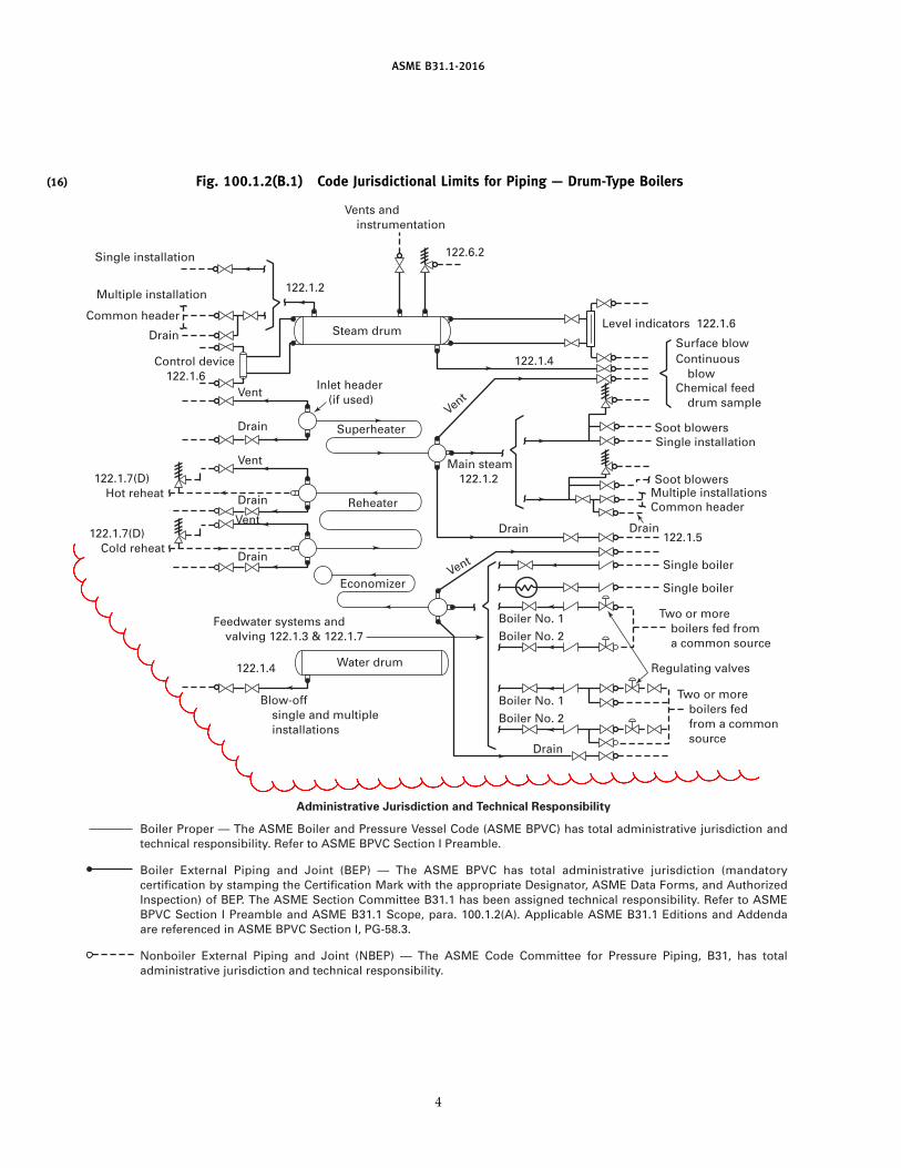
Fig. 100.1.2(B.1) Code Jurisdictional Limits for Piping — Drum-Type Boilers
Blow-off single and multiple installations
Feedwater systems and valving 122.1.3 & 122.1.7
Drain
Drain Drain 122.1.5
Soot blowers
Level indicators 122.1.6
122.1.4
Main steam 122.1.2
122.6.2
Vents and instrumentation
Drain
Single installation
Multiple installation
Common header
Control device 122.1.6
Vent
Drain
Inlet header (if used)
Superheater
Reheater
Economizer
Drain
122.1.7(D) Hot reheat
122.1.7(D) Cold reheat
Vent
Vent
Drain
122.1.2
Steam drum
Soot blowers
Surface blow Continuous blow Chemical feed drum sample
Multiple installations
Single installation
Common header
Single boiler
Single boiler
Two or more boilers fed from a common source
Two or more boilers fed from a common source
Regulating valves
Boiler No. 2
Boiler No. 1
Boiler No. 2
Boiler No. 1
Vent
Vent
122.1.4 Water drum
Administrative Jurisdiction and Technical Responsibility
Boiler Proper — The ASME Boiler and Pressure Vessel Code (ASME BPVC) has total administrative jurisdiction and technical responsibility. Refer to ASME BPVC Section I Preamble.
Boiler External Piping and Joint (BEP) — The ASME BPVC has total administrative jurisdiction (mandatory certification by stamping the Certification Mark with the appropriate Designator, ASME Data Forms, and Authorized Inspection) of BEP. The ASME Section Committee B31.1 has been assigned technical responsibility. Refer to ASME BPVC Section I Preamble and ASME B31.1 Scope, para. 100.1.2(A). Applicable ASME B31.1 Editions and Addenda are referenced in ASME BPVC Section I, PG-58.3.
Nonboiler External Piping and Joint (NBEP) — The ASME Code Committee for Pressure Piping, B31, has total administrative jurisdiction and technical responsibility.
4
hen03868
Cloud+
hen03868
Cloud+
Insert New Figure 100.1.2(B.1)
DUrsoU
Text Box
DUrsoU
Text Box

hen03868
Text Box
NEW FIGURE 100.1.2(B.1)

AS
ME
B31.1-2016
(16) Fig. 100.1.2(B.2) Code Jurisdictional Limits for Piping — Isolable Economizers Located in Feedwater Piping and IsolableSuperheaters in Main Steam Piping (Boiler Pressure Relief Valves, Blowoff, and Miscellaneous Piping for Boiler Proper Not
Shown for Clarity)
Vent
Isolable Main steam [see Fig. 100.1.2(B.1)]
Boiler proper [see Fig. 100.1.2(B.1)]
Drain 122.1.5
Drain 122.1.5
Inlet header (if used)
Intervening valve
Intervening valve
Vent
superheater
Isolable
Drain 122.1.5
122.6.2
Drain 122.1.5
Vent
Vent
Feedwater systems [see Fig. 100.1.2(B.1)]
economizer
Administrative Jurisdiction and Technical Responsibility
Boiler Proper — The ASME Boiler and Pressure Vessel Code (ASME BPVC) has total administrative jurisdiction and technical responsibility. Refer to ASME BPVC Section I Preamble.
Boiler External Piping and Joint (BEP) — The ASME BPVC has total administrative jurisdiction (mandatory certification by stamping the Certification Mark with the appropriate Designator, ASME Data Forms, and Authorized Inspection) of BEP. The ASME Section Committee B31.1 has been assigned technical responsibility. Refer to ASME BPVC Section I Preamble and ASME B31.1 Scope, para. 100.1.2(A). Applicable ASME B31.1 Editions and Addenda are referenced in ASME BPVC Section I, PG-58.3.
Nonboiler External Piping and Joint (NBEP) — The ASME Code Committee for Pressure Piping, B31, has total administrative jurisdiction and technical responsibility.
5
hen03868
Cloud+
hen03868
Cloud+
Insert New Figure 100.1.2(B.2)

ASME BPVC Section I, Part PFE).
hen03868
Text Box
NEW FIGURE 100.1.2(B.2)
hen03868
Line
hen03868
Line
hen03868
Line
hen03868
PolyLine
hen03868
Check Valves
hen03868
Line
hen03868
Cloud
hen03868
Arrow
hen03868
Arrow
hen03868
Text Box
Note 1
hen03868
Text Box
Notes: (1) With feedwater regulator located between the boiler and economizer, the economizer may be constructed utilizing austenitic stainless steel (see Part PFE).
PDFescape
Strikeout

(16)
ASME B31.1-2016
Fig. 100.1.2(B.3) Code Jurisdictional Limits for Piping — Nonintegral Separately Fired Superheaters
superheater
Drain 122.1.5
Drain 122.1.5
Inlet header (if used)
Vent
Steam out
Steam in
Vent
Nonintegral separately fired
Administrative Jurisdiction and Technical Responsibility
Boiler Proper — The ASME Boiler and Pressure Vessel Code (ASME BPVC) has total administrative jurisdiction and technical responsibility. Refer to ASME BPVC Section I Preamble.
Boiler External Piping and Joint (BEP) — The ASME BPVC has total administrative jurisdiction (mandatory certification by stamping the Certification Mark with the appropriate Designator, ASME Data Forms, and Authorized Inspection) of BEP. The ASME Section Committee B31.1 has been assigned technical responsibility. Refer to ASME BPVC Section I Preamble and ASME B31.1 Scope, para. 100.1.2(A). Applicable ASME B31.1 Editions and Addenda are referenced in ASME BPVC Section I, PG-58.3.
Nonboiler External Piping and Joint (NBEP) — The ASME Code Committee for Pressure Piping, B31, has total administrative jurisdiction and technical responsibility.
ASME Boiler and Pressure Vessel Code shall apply.These requirements are shown in Mandatory Appendix Jof this Code.
The valve or valves required by para. 122.1 are partof the boiler external piping, but do not require ASMEBoiler and Pressure Vessel Code, Section I inspectionand stamping except for safety, safety relief, and reliefvalves; see para. 107.8.2. Refer to PG-11.
Pipe connections meeting all other requirements ofthis Code but not exceeding NPS 1⁄2 (DN 15) may bewelded to pipe or boiler headers without inspection andstamping required by Section I of the ASME Boiler andPressure Vessel Code.
(B) Nonboiler external piping includes all the pipingcovered by this Code except for that portion definedabove as boiler external piping.
100.1.3 This Code does not apply to the following:(A) economizers, heaters, pressure vessels, and
components covered by Sections of the ASME Boilerand Pressure Vessel Code.
(B) building heating and distribution steam and con-densate piping designed for 15 psig [100 kPa (gage)] or
6
less, or hot water heating systems designed for 30 psig[200 kPa (gage)] or less.
(C) piping for hydraulic or pneumatic tools and theircomponents downstream of the first block or stop valveoff the system distribution header.
(D) piping for marine or other installations underFederal control.
(E) towers, building frames, tanks, mechanical equip-ment, instruments, and foundations.
(F) piping included as part of a shop-assembled pack-aged equipment assembly within a B31.1 Code pipinginstallation when such equipment piping is constructedto another B31 Code Section (e.g., B31.3 or B31.9) withthe owner’s approval. See para. 100.2 for a definition ofpackaged equipment.
100.1.4 This Code does not provide procedures forflushing, cleaning, start-up, operating, or maintenance.
100.2 Definitions
Some commonly used terms relating to piping aredefined below. Terms related to welding generally agreewith AWS A3.0. Some welding terms are defined with
(16)
(16)
hen03868
Callout
Reheaters and
hen03868
Cloud+
hen03868
Cloud+
Insert New Figure 100.1.2(B.3)
DUrsoU
Typewritten Text
, ASME CA-1, Conformity Assessment Requirements, and ASME QAI-1 Qualifications for Authorized Inspectors
DUrsoU
Line
DUrsoU
Callout
Code users are advised, however, that the cleaning and purging of flammable gas systems may be subject to the requirements of NFPA Standard 56.
DUrsoU
Text Box

hen03868
Text Box
NEW FIGURE 100.1.2(B.3)
hen03868
Callout
Note to Editor: Make dashed line.
hen03868
Arrow
hen03868
Arrow

ASME B31.1-2016
Fig. 100.1.2(C) Code Jurisdictional Limits for Piping — Spray-Type Desuperheater
Regulating valve para. 122.4(A.1)
Regulating valve para. 122.4(A.1)
Stop valve para. 122.4(A.1)
Stop valve para. 122.4(A.1)
Administrative Jurisdiction and Technical Responsibility
Desuperheater located in boiler proper
Block valve para. 122.4(A.1)
Block valve para. 122.4(A.1)
Boiler Proper — The ASME Boiler and Pressure Vessel Code (ASME BPVC) has total administrative jurisdiction and technical responsibility. Refer to ASME BPVC Section 1 Preamble.
Boiler External Piping and Joint (BEP) — The ASME BPVC has total administrative jurisdiction (mandatory certification by stamping the Certification Mark with the appropriate Designator, ASME Data Forms, and Authorized Inspection) of BEP. The ASME Section Committee B31.1 has been assigned technical responsibility. Refer to ASME BPVC Section I Preamble and ASME B31.1 Scope, para. 100.1.2(A). Applicable ASME B31.1 Editions and Addenda are referenced in ASME BPVC Section I, PG-58.3.
Nonboiler External Piping and Joint (NBEP) — The ASME Code Committee for Pressure Piping, B31, has total administrative and technical responsibility.
Desuperheater located in boiler proper
7
NOTE TO EDITOR: The next page contains a new Figure 100.1.2(C.2) which needs tobe inserted after this page.
hen03868
Strikethrough
hen03868
Callout
C.1
hen03868
Text Box
, See Figure 100.1.2(C.2)
DUrsoU
Line
DUrsoU
Text Box
hen03868
Text Box
, See Figure 100.1.2(C.2)
DUrsoU
Text Box

HRSG - Desuperheater Protection Devices
hen03868
Image
hen03868
Callout
Code Jurisdictional Limits for Piping —
PDFescape
Strikeout

ASME B31.1-2016
specified reference to piping. For welding terms used inthis Code, but not shown here, definitions of AWS A3.0apply.
alteration: a change in any item described in the originaldesign that affects the pressure-containing capability ofthe pressure-retaining component.
anchor: a rigid restraint providing substantially full fixa-tion, permitting neither translatory nor rotational dis-placement of the pipe.
annealing: see heat treatments.
arc welding: a group of welding processes wherein coales-cence is produced by heating with an electric arc or arcs,with or without the application of pressure and with orwithout the use of filler metal.
assembly: the joining together of two or more pipingcomponents by bolting, welding, caulking, brazing, sol-dering, cementing, or threading into their installed loca-tion as specified by the engineering design.
automatic welding: welding with equipment that per-forms the entire welding operation without constantobservation and adjustment of the controls by an opera-tor. The equipment may or may not perform the loadingand unloading of the work.
backing ring: backing in the form of a ring that can beused in the welding of piping.
ball joint: a component that permits universal rotationalmovement in a piping system.
base metal: the metal to be welded, brazed, soldered,or cut.
branch connection: the attachment of a branch pipe to therun of a main pipe with or without the use of fittings.
braze welding: a method of welding whereby a groove,fillet, plug, or slot weld is made using a nonferrous fillermetal having a melting point below that of the basemetals, but above 840°F (450°C). The filler metal is notdistributed in the joint by capillary action. (Bronze weld-ing, formerly used, is a misnomer for this term.)
brazing: a metal joining process wherein coalescence isproduced by use of a nonferrous filler metal having amelting point above 840°F (450°C) but lower than thatof the base metals joined. The filler metal is distributedbetween the closely fitted surfaces of the joint by capil-lary action.
butt joint: a joint between two members lying approxi-mately in the same plane.
capacitor discharge welding (CDW): stud arc welding pro-cess in which DC arc power is produced by a rapiddischarge of stored electrical energy with pressureapplied during or immediately following the electricaldischarge. The process uses an electrostatic storage sys-tem as a power source in which the weld energy is storedin capacitors.
8
cold spring: the intentional movement of piping duringassembly to produce a desired initial displacement andreaction.
component: component as used in this Code is definedas consisting of but not limited to items such as pipe,piping subassemblies, parts, valves, strainers, reliefdevices, fittings, pipe supports and hangers, etc.
specially designed component: a component designed inaccordance with para. 104.7.2.
standard component: a component manufactured inaccordance with one or more of the standards listed inTable 126.1.
covered piping systems (CPS): piping systems on whichcondition assessments are to be conducted. As a mini-mum for electric power generating stations, the CPSsystems are to include NPS 4 (DN 100) and larger ofthe main steam, hot reheat steam, cold reheat steam,and boiler feedwater piping systems. In addition to theabove, CPS also includes NPS 4 (DN 100) and largerpiping in other systems that operate above 750°F (400°C)or above 1,025 psi (7 100 kPa). The Operating Companymay add other piping systems to the scope of coveredpiping systems.
creep strength enhanced ferritic steel: steel in which themicrostructure, consisting of lower transformation prod-ucts such as martensite and bainite, is stabilized bycontrolled precipitation of temper-resistant carbides,carbonitrides, and/or nitrides.
defect: a flaw (imperfection or unintentional discontinu-ity) of such size, shape, orientation, location, or proper-ties as to be rejectable.
discontinuity: a lack of continuity or cohesion; an inter-ruption in the normal physical structure of material ora product.
employer: the owner, manufacturer, fabricator, contractor,assembler, or installer responsible for the welding, braz-ing, and NDE performed by his organization includingprocedure and performance qualifications.
engineering design: the detailed design developed fromprocess requirements and conforming to Code require-ments, including all necessary drawings and specifica-tions, governing a piping installation.
equipment connection: an integral part of such equipmentas pressure vessels, heat exchangers, pumps, etc.,designed for attachment of pipe or piping components.
erection: the complete installation of a piping system,including any field assembly, fabrication, testing, andinspection of the system.
examination: denotes the procedures for all nondestruc-tive examination. Refer to para. 136.3 and the definitionfor visual examination.
expansion joint: a flexible piping component that absorbsthermal and/or terminal movement.
DUrsoU
Cross-Out
DUrsoU
Callout
austenitizing: see heat treatments.
DUrsoU
Text Box

ASME B31.1-2016
fabrication: primarily, the joining of piping componentsinto integral pieces ready for assembly. It includes bend-ing, forming, threading, welding, or other operationsupon these components, if not part of assembly. It maybe done in a shop or in the field.
face of weld: the exposed surface of a weld on the sidefrom which the welding was done.
failure: a physical condition that renders a system orcomponent unable to perform its intended function(s)or is a hazard to personnel safety.
failure analysis: the process of collecting and evaluatingdata to determine the damage mechanism(s) and causeof a failure.
filler metal: metal to be added in welding, soldering,brazing, or braze welding.
fillet weld: a weld of approximately triangular cross sec-tion joining two surfaces approximately at right anglesto each other in a lap joint, tee joint, corner joint, orsocket weld.
fire hazard: situation in which a material of more thanaverage combustibility or explosibility exists in the pres-ence of a potential ignition source.
flaw: an imperfection or unintentional discontinuity thatis detectable by a nondestructive examination.
full fillet weld: a fillet weld whose size is equal to thethickness of the thinner member joined.
fusion: the melting together of filler metal and base metal,or of base metal only, that results in coalescence.
gas blow: a process to clean and remove debris fromthe gas supply piping by releasing gas (flammable ornonflammable) at a high pressure and velocity throughthe piping system while venting to atmosphere.
gas purge: a process to purge air from the flammable gassupply piping, typically conducted at a low pressureand velocity.
gas welding: a group of welding processes whereincoalescence is produced by heating with a gas flame orflames, with or without the application of pressure, andwith or without the use of filler metal.
groove weld: a weld made in the groove between twomembers to be joined.
heat affected zone: portion of the base metal that has notbeen melted, but whose mechanical properties or micro-structure have been altered by the heat of welding orcutting.
heat treatmentsannealing, full: heating a metal or alloy to a tempera-
ture above the critical temperature range and holdingabove the range for a proper period of time, followedby cooling to below that range. (A softening treatmentis often carried out just below the critical range, whichis referred to as a subcritical anneal.)
9
normalizing: a process in which a ferrous metal isheated to a suitable temperature above the transforma-tion range and is subsequently cooled in still air at roomtemperature.
postweld heat treatment: any heat treatment subsequentto welding.
preheating: the application of heat to a base metalimmediately prior to a welding or cutting operation.
stress-relieving: uniform heating of a structure or por-tion thereof to a sufficient temperature to relieve themajor portion of the residual stresses, followed by uni-form cooling.
imperfection: a condition of being imperfect; a departureof a quality characteristic from its intended condition.
indication: the response or evidence from the applicationof a nondestructive examination.
inert gas metal arc welding: an arc welding processwherein coalescence is produced by heating with anelectric arc between a metal electrode and the work.Shielding is obtained from an inert gas, such as heliumor argon. Pressure may or may not be used and fillermetal may or may not be used.
inspection: denotes the activities performed by anAuthorized Inspector, or an owner’s Inspector, to verifythat all required examinations and testing have beencompleted, and to ensure that all the documentation formaterial, fabrication, and examination conforms to theapplicable requirements of this Code and the engi-neering design.
integrally reinforced branch outlet fitting: a branch outletfitting that is welded directly to a run pipe, where thebranch fitting and the deposited weld metal used toattach the fitting to the run pipe are designed by thefitting manufacturer to provide all the reinforcementrequired by this Code without the addition of separatesaddles or pads. The attachment of the branch pipe tothe fitting is by butt welding, socket welding, threading,or by a flanged connection. Integrally reinforced branchoutlet fittings include those fittings conforming toMSS SP-97.
joint design: the joint geometry together with the requireddimensions of the welded joint.
joint penetration: the minimum depth of a grooveweld extends from its face into a joint, exclusive ofreinforcement.
low energy capacitor discharge welding: a resistance weld-ing process wherein coalescence is produced by the rapiddischarge of stored electric energy from a low voltageelectrostatic storage system.
manual welding: welding wherein the entire weldingoperation is performed and controlled by hand.
maximum allowable stress: the maximum stress value thatmay be used in the design formulas for a given materialand design temperature.
Insert Text: "forthat material"
Insert Text:(or transformation)
Insert Text: "forthat material"
Insert Text: austenitizing: forming austeniteby heating a steel object steel above thetransformation range.
Insert Text: PWHT often refers to a general heattreatment applied to provide tempering, stressrelieving, or a controlled rate of cooling toprevent formation of a hard or brittlemicrostructure.
Insert Text:"(PWHT)"
Insert Text: subcritical heat treatment: a general heat treating process where ametal or alloy ferritic or martensitic steelis heated to a temperature below thetemperature at which austenite begins toform.
Insert Text: tempering: reheating aquench hardened or normalized steelto a temperature below thetemperature at which austenite beginsto form, and then cooling at anydesired rate.
Note to Editor: The threedefinitions being addedunder the heat treatmentsgroup should be slightlyindented (e.g., see stress-relieving).
Insert Text:below the critical (ortransformation) temperaturerange for that material
Edit to heading has beenremoved.
Delete Text:
Delete Text:
Insert Text:transformation
DUrsoU
Line
DUrsoU
Line
DUrsoU
Callout
failure: a physical condition that renders a system or component unable to perform its intended function(s), meet design and performance requirements or is a hazard to personnel safety.
DUrsoU
Text Box

ASME B31.1-2016
(E) double submerged arc welded pipe: pipe having alongitudinal butt joint produced by the submerged arcprocess, with at least two passes, one of which is on theinside of the pipe.
(F) seamless pipe: pipe produced by one or more ofthe following processes:
(F.1) rolled pipe: pipe produced from a forged billetthat is pierced by a conical mandrel between two diamet-rically opposed rolls. The pierced shell is subsequentlyrolled and expanded over mandrels of increasinglylarger diameter. Where closer dimensional tolerancesare desired, the rolled pipe is cold or hot drawn throughdies, and machined.
One variation of this process produces the hollow shellby extrusion of the forged billet over a mandrel in avertical, hydraulic piercing press.
(F.2) forged and bored pipe: pipe produced by boringor trepanning of a forged billet.
(F.3) extruded pipe: pipe produced from hollow orsolid round forgings, usually in a hydraulic extrusionpress. In this process the forging is contained in a cylin-drical die. Initially a punch at the end of the extrusionplunger pierces the forging. The extrusion plunger thenforces the contained billet between the cylindrical dieand the punch to form the pipe, the latter acting as amandrel.
(F.4) centrifugally cast pipe: pipe formed from thesolidification of molten metal in a rotating mold. Bothmetal and sand molds are used. After casting, the pipeis machined, to sound metal, on the internal and externaldiameters to the surface roughness and dimensionalrequirements of the applicable material specification.
One variation of this process utilizes autofrettage(hydraulic expansion) and heat treatment, above therecrystallization temperature of the material, to producea wrought structure.
(F.5) statically cast pipe: pipe formed by the solidifi-cation of molten metal in a sand mold.
pipe supporting elements: pipe supporting elements con-sist of hangers, supports, and structural attachments.
hangers and supports: hangers and supports includeelements that transfer the load from the pipe or struc-tural attachment to the supporting structure or equip-ment. They include hanging type fixtures, such ashanger rods, spring hangers, sway braces, counter-weights, turnbuckles, struts, chains, guides, andanchors, and bearing type fixtures, such as saddles,bases, rollers, brackets, and sliding supports.
structural attachments: structural attachments includeelements that are welded, bolted, or clamped to the pipe,such as clips, lugs, rings, clamps, clevises, straps, andskirts.
porosity: cavity-type discontinuities formed by gasentrapment during metal solidification.
postweld heat treatment: see heat treatments.
11
preheating: see heat treatments.
pressure: an application of force per unit area; fluidpressure (an application of internal or external fluidforce per unit area on the pressure boundary of pipingcomponents).
Procedure Qualification Record (PQR): a record of the weld-ing data used to weld a test coupon. The PQR is a recordof variables recorded during the welding of the testcoupons. It also contains the test results of the testedspecimens. Recorded variables normally fall within asmall range of the actual variables that will be used inproduction welding.
qualified (personnel): individuals who have demonstratedand documented abilities gained through training and/or experience that enable them to perform a requiredfunction to the satisfaction of the Operating Company.
readily accessible: for visual examination, readily accessi-ble inside surfaces are defined as those inside surfacesthat can be examined without the aid of optical devices.(This definition does not prohibit the use of opticaldevices for a visual examination; however, the selectionof the device should be a matter of mutual agreementbetween the owner and the fabricator or erector.)
Reid vapor pressure: the vapor pressure of a flammableor combustible liquid as determined by ASTM StandardTest Method D323 Vapor Pressure of Petroleum Products(Reid Method).
reinforcement of weld: weld metal on the face of a grooveweld in excess of the metal necessary for the specifiedweld size.
repair: the work necessary to restore pressure-retainingitems to a safe and satisfactory operating condition.
restraint: any device that prevents, resists, or limits move-ment of a piping system.
root opening: the separation between the members to bejoined, at the root of the joint.
root penetration: the depth a groove weld extends intothe root opening of a joint measured on the centerlineof the root cross section.
seal weld: a weld used on a pipe joint primarily to obtainfluid tightness as opposed to mechanical strength.
semiautomatic arc welding: arc welding with equipmentthat controls only the filler metal feed. The advance ofthe welding is manually controlled.
shall: “shall” or “shall not” is used to indicate that aprovision or prohibition is mandatory.
shielded metal arc welding: an arc welding process whereincoalescence is produced by heating with an electric arcbetween a covered metal electrode and the work.Shielding is obtained from decomposition of the elec-trode covering. Pressure is not used and filler metal isobtained from the electrode.
DUrsoU
Callout
the work necessary to restore a system or component to meet the applicable Code requirements and to a safe and satisfactory operating condition.
DUrsoU
Cross-Out
paul.davis22
Callout
(external)
paul.davis22
Callout
reinforcement of weld (internal): weld metal on the interior face of a groove weld which extends past the root opening of the joint.

ASME B31.1-2016
should: “should” or “it is recommended” is used to indi-cate that a provision is not mandatory but recommendedas good practice.
size of weldfillet weld: for equal leg fillet welds, the leg lengths of
the largest isosceles right triangle that can be inscribedwithin the fillet weld cross section. For unequal leg filletwelds, the leg lengths of the largest right triangle thatcan be inscribed within the fillet weld cross section.
groove weld: the joint penetration (depth of chamferingplus the root penetration when specified).
slag inclusion: nonmetallic solid material entrapped inweld metal or between weld metal and base metal.
soldering: a metal joining process wherein coalescence isproduced by heating to suitable temperature and byusing a nonferrous alloy fusible at temperatures below840°F (450°C) and having a melting point below that ofthe base metals being joined. The filler metal is distrib-uted between closely fitted surfaces of the joint by capil-lary action. In general, solders are lead–tin alloys andmay contain antimony, bismuth, silver, and otherelements.
steel: an alloy of iron and carbon with no more than 2%carbon by weight. Other alloying elements may includemanganese, sulfur, phosphorus, silicon, aluminum,chromium, copper, nickel, molybdenum, vanadium, andothers depending upon the type of steel. For acceptablematerial specifications for steel, refer to Chapter III,Materials.
stressessustained stress: a stress developed by an imposed load-
ing that is necessary to satisfy the laws of equilibriumbetween external and internal forces and moments. Thebasic characteristic of a sustained stress is that it is notself-limiting. If a sustained stress exceeds the yieldstrength of the material through the entire thickness, theprevention of failure is entirely dependent on the strain-hardening properties of the material. A thermal stress isnot classified as a sustained stress. Further, the sustainedstresses calculated in this Code are “effective” stressesand are generally lower than those predicted by theoryor measured in strain-gage tests.
displacement stress: a stress developed by the self-constraint of the structure. It must satisfy an imposedstrain pattern rather than being in equilibrium with anexternal load. The basic characteristic of a displacementstress is that it is self-limiting. Local yielding and minordistortions can satisfy the displacement or expansionconditions that cause the stress to occur. Failure from oneapplication of the stress is not to be expected. Further,the displacement stresses calculated in this Code are
12
“effective” stresses and are generally lower than thosepredicted by theory or measured in strain-gage tests.1
peak stress: the highest stress in the region under con-sideration. The basic characteristic of a peak stress isthat it causes no significant distortion and is objection-able only as a possible source of a fatigue crack initiationor a brittle fracture. This Code does not utilize peakstress as a design basis, but rather uses effective stressvalues for sustained stress and for displacement stress;the peak stress effect is combined with the displacementstress effect in the displacement stress range calculation.
stress-relieving: see heat treatments.
submerged arc welding: an arc welding process whereincoalescence is produced by heating with an electric arcor arcs between a bare metal electrode or electrodesand the work. The welding is shielded by a blanket ofgranular, fusible material on the work. Pressure is notused, and filler metal is obtained from the electrode andsometimes from a supplementary welding rod.
supplementary steel: steel members that are installedbetween existing members for the purpose of installingsupports for piping or piping equipment.
swivel joint: a component that permits single-plane rota-tional movement in a piping system.
tack weld: a weld made to hold parts of a weldment inproper alignment until the final welds are made.
throat of a fillet weldactual: the shortest distance from the root of a fillet
weld to its face.theoretical: the distance from the beginning of the root
of the joint perpendicular to the hypotenuse of the larg-est right triangle that can be inscribed within the filletweld cross section.
toe of weld: the junction between the face of the weldand the base metal.
tube: refer to pipe and tube.
tungsten electrode: a nonfiller metal electrode used in arcwelding, consisting of a tungsten wire.
undercut: a groove melted into the base metal adjacentto the toe of a weld and not filled with weld metal.
visual examination: the observation of whatever portionsof components, joints, and other piping elements thatare exposed to such observation either before, during,or after manufacture, fabrication, assembly, erection,
1 Normally, the most significant displacement stress is encoun-tered in the thermal expansion stress range from ambient to thenormal operating condition. This stress range is also the stressrange usually considered in a flexibility analysis. However, if othersignificant stress ranges occur, whether they are displacement stressranges (such as from other thermal expansion or contraction events,or differential support point movements) or sustained stress ranges(such as from cyclic pressure, steam hammer, or earthquake inertiaforces), paras. 102.3.2(B) and 104.8.3 may be used to evaluate theireffect on fatigue life.
DUrsoU
Typewritten Text
a groove melted into the base metal adjacent to the weld toe or weld root and left unfilled by weld metal.
DUrsoU
Cross-Out
DUrsoU
Line
DUrsoU
Callout
subcritical heat treatment: see heat treatments.
DUrsoU
Callout
tempering: see heat treatments.
DUrsoU
Text Box

ASME B31.1-2016
used to define or refine the design wind forces. Wherelocal jurisdictional rules covering the design of buildingstructures are in effect and specify wind loadings forpiping, these values shall be considered the minimumdesign values. Wind need not be considered as actingconcurrently with earthquakes.
101.5.3 Earthquake. The effect of earthquakes shallbe considered in the design of piping, piping supports,and restraints. The analysis considerations and loadsmay be as described in ASCE/SEI 7. Authoritative localseismological data may also be used to define or refinethe design earthquake forces. Where local jurisdictionalrules covering the design of building structures are ineffect and specify seismic loadings for piping, these val-ues shall be considered the minimum design values.ASME B31E, Standard for the Seismic Design andRetrofit of Above-Ground Piping Systems, may be usedas an alternate method of seismic qualification or forguidance in seismic design. Earthquakes need not beconsidered as acting concurrently with wind.
101.5.4 Vibration. Piping shall be arranged andsupported with consideration of vibration [seeparas. 120.1(C) and 121.7.5].
101.6 Weight Effects
The following weight effects combined with loads andforces from other causes shall be taken into account in thedesign of piping. Piping shall be carried on adjustablehangers or properly leveled rigid hangers or supports,and suitable springs, sway bracing, vibration dampen-ers, etc., shall be provided where necessary.
101.6.1 Live Load. The live load consists of theweight of the fluid transported. Snow and ice loads shallbe considered in localities where such conditions exist.
101.6.2 Dead Load. The dead load consists of theweight of the piping components, insulation, protectivelining and coating, and other superimposed permanentloads.
101.6.3 Test or Cleaning Fluid Load. The test orcleaning fluid load consists of the weight of the test orcleaning fluid.
101.7 Thermal Expansion and Contraction Loads
101.7.1 General. The design of piping systems shalltake account of the forces and moments resulting fromthermal expansion and contraction, and from the effectsof expansion joints.
Thermal expansion and contraction shall be providedfor preferably by pipe bends, elbows, offsets, or changesin direction of the pipeline.
Hangers and supports shall permit expansion and con-traction of the piping between anchors.
15
101.7.2 Expansion, Swivel, or Ball Joints, and FlexibleMetal Hose Assemblies. Joints of the corrugated bel-lows, slip, sleeve, ball, or swivel types and flexible metalhose assemblies may be used if their materials conformto this Code, their structural and working parts are ofample proportions, and their design prevents the com-plete disengagement of working parts while in service.In determining expansion joint design criteria, thedesigner shall give due consideration to conditions ofservice, including, but not limited to, temperature, pres-sure, externally imposed displacements, corrosion/erosion, fatigue, and flow velocity.
102 DESIGN CRITERIA
102.1 General
These criteria cover pressure–temperature ratings forstandard and specially designed components, allowablestresses, stress limits, and various allowances to be usedin the design of piping and piping components.
102.2 Pressure–Temperature Ratings for PipingComponents
102.2.1 Components Having Specific Ratings.Pressure–temperature ratings for certain piping compo-nents have been established and are contained in someof the standards listed in Table 126.1.
Where piping components have established pressure–temperature ratings that do not extend to the uppermaterial temperature limits permitted by this Code, thepressure–temperature ratings between those establishedand the upper material temperature limit may be deter-mined in accordance with the rules of this Code, but suchextensions are subject to restrictions, if any, imposed bythe standards.
Standard components may not be used at conditionsof pressure and temperature that exceed the limitsimposed by this Code.
102.2.2 Components Not Having Specific Ratings.Some of the Standards listed in Table 126.1, such as thosefor buttwelding fittings, specify that components shallbe furnished in nominal thicknesses. Unless limited else-where in this Code, such components shall be rated forthe same allowable pressures as seamless pipe of thesame nominal thickness, as determined in paras. 103and 104 for material having the same allowable stress.
Piping components, such as pipe, for which allowablestresses have been developed in accordance withpara. 102.3, but that do not have established pressureratings, shall be rated by rules for pressure design inpara. 104, modified as applicable by other provisions ofthis Code.
Should it be desired to use methods of manufactureor design of components not covered by this Code ornot listed in referenced standards, it is intended thatthe manufacturer shall comply with the requirements
(16)
DUrsoU
Callout
The design of metallic bellows expansion joints shall be in accordance with Appendix P.
DUrsoU
Text Box

ASME B31.1-2016
Table 102.4.5 Bend Thinning Allowance
Minimum ThicknessRecommended Prior to
Radius of Bends Bending
6 pipe diameters or greater 1.06tm
5 pipe diameters 1.08tm
4 pipe diameters 1.14tm
3 pipe diameters 1.25tm
GENERAL NOTES:(a) Interpolation is permissible for bending to intermediate radii.(b) tm is determined by eq. (7) or (8) of para. 104.1.2(A).(c) Pipe diameter is the nominal diameter as tabulated in
ASME B36.10M, Tables 1, and ASME B36.19M, Table 1. Forpiping with a diameter not listed in these Tables, and also fortubing, the nominal diameter corresponds with the outsidediameter.
allowable stress values given in Mandatory Appendix A.The factors in Table 102.4.3 apply to both straight seamand spiral seam welded pipe.
102.4.4 Mechanical Strength. Where necessary formechanical strength to prevent damage, collapse, exces-sive sag, or buckling of pipe due to superimposed loadsfrom supports or other causes, the wall thickness of thepipe should be increased; or, if this is impractical orwould cause excessive local stresses, the superimposedloads or other causes shall be reduced or eliminated byother design methods. The requirements ofpara. 104.1.2(C) shall also apply.
102.4.5 Bending. The minimum wall thickness atany point on the bend shall conform to (A) or (B) below.
(A) The minimum wall thickness at any point in acompleted bend shall not be less than required by eq. (7)or (8) of para. 104.1.2(A).
(A.1) Table 102.4.5 is a guide to the designer whomust specify wall thickness for ordering pipe. In general,it has been the experience that when good shop practicesare employed, the minimum thicknesses of straight pipeshown in Table 102.4.5 should be sufficient for bendingand still meet the minimum thickness requirements ofpara. 104.1.2(A).
(A.2) The bend thinning allowance in Table 102.4.5may be provided in all parts of the cross section ofthe pipe circumference without any detrimental effectsbeing produced.
(B) The minimum required thickness, tm, of a bend,after bending, in its finished form, shall be determinedin accordance with eq. (3) or (4)
tm pPDo
2(SE/I + Py)+ A (3)
or
tm pPd + 2SEA/I + 2yPA
2(SE/I + Py − P)(4)
19
Fig. 102.4.5 Nomenclature for Pipe Bends
Extrados
End of bend (typ.)
R
Intrados
where at the intrados (inside of bend)
I p4(R/Do) − 14(R/Do) − 2
(5)
and at the extrados (outside of bend)
I p4(R/Do) + 14(R/Do) + 2
(6)
and at the sidewall on the bend centerline
I p 1.0
whereR p bend radius of pipe bend
Thickness variations from the intrados to the extradosand at the ends of the bend shall be gradual. The thick-ness requirements apply at the center of the bend arc,at the intrados, extrados, and bend centerline (seeFig. 102.4.5). The minimum thickness at the ends ofthe bends shall not be less than the requirements ofpara. 104.1.2 for straight pipe. For bends to conform tothis paragraph, all thickness requirements must be met.
102.4.6 Casting Quality Factors(A) General. Except for gray iron castings, the use of
a casting quality factor is required for all cast compo-nents that use the allowable stress values of MandatoryAppendix A as the design basis. The factor, 0.80 forcastings and 0.85 for centrifugally cast pipe, is includedin the allowable stress values given in MandatoryAppendix A.
This required factor does not apply to component stan-dards listed in Table 126.1, if such standards defineallowable pressure–temperature ratings or provide theallowable stresses to be used as the design basis for thecomponent.
(16)
DUrsoU
Callout
SEW
DUrsoU
Cross-Out
DUrsoU
Cross-Out
DUrsoU
Cross-Out
DUrsoU
Callout
SEW
DUrsoU
Callout
SEW
DUrsoU
Callout
See para. 104.1.2 for the other nomenclature used above. W = 1 for seamless pipe or for seam welded pipe operating below the creep range and for parts of the bend that do not contain a weld.

ASME B31.1-2016
Table 102.4.6(B.2.2) Maximum Severity Level forCasting Thickness Greater Than 41⁄2 in. (114 mm)
DiscontinuityCategory Designation Severity Level
A, B, and Types 1, 2, and 3 of C 2
D, E, and F Noneacceptable
Vessel Code. Radiographs shall conform to the require-ments of ASTM E280.
The maximum acceptable severity level for a 1.0 qual-ity factor shall be as listed in Table 102.4.6(B.2.2).MSS SP-54 may be used for guidance. Where appro-priate, radiographic examination (RT) of castings may besupplemented or replaced with ultrasonic examination(UT), provided it is performed in accordance withMSS SP-94.
(B.2.3) Any discontinuities in excess of the maxi-mum permitted in (B.2.1) and (B.2.2) above shall beremoved and may be repaired by welding after the basemetal has been magnetic particle or dye penetrantinspected to ensure complete removal of discontinuities.[Refer to para. 127.4.11(A).]
(B.2.4) All weld repairs of depth exceeding 1 in.(25 mm) or 20% of the section thickness, whichever isthe lesser, shall be inspected by volumetric examination(RT or UT) in accordance with (B.2.2) above and bymagnetic particle or dye penetrant inspection of thefinished weld surface. All weld repairs of depth lessthan 20% of the section thickness, or 1 in. (25 mm),whichever is the lesser, and all weld repairs of sectionthat cannot be effectively radiographed shall be exam-ined by magnetic particle or dye penetrant inspectionof the first layer, of each 1⁄4 in. (6 mm) thickness ofdeposited weld metal, and of the finished weld surface.Magnetic particle or dye penetrant testing of the finishedweld surface shall be done after postweld heat treatment.
(C) For cast iron and nonferrous materials, no increaseof the casting quality factor is allowed except whenspecial methods of examination, prescribed by the mate-rial specification, are followed. If such increase is specifi-cally permitted by the material specification, a factornot exceeding 1.0 may be applied.
102.4.7 Weld Strength Reduction Factors. At ele-vated temperatures, seam welds on longitudinal-weldedor spiral-welded pipe can have lower creep strengththan the base material. This reduction is a factor indetermining the minimum wall thickness for longitudi-nal-welded or spiral-welded pipe (i.e., not seamless),whether fabricated in accordance with a material specifi-cation or fabricated in accordance with the rules of thisCode. The weld strength reduction factor, W, is given
21
in Table 102.4.7. The designer is responsible to assessapplication of weld strength reduction factor require-ments for welds other than longitudinal and spiral, asapplicable (e.g., circumferential welds).
PART 2PRESSURE DESIGN OF PIPING COMPONENTS
103 CRITERIA FOR PRESSURE DESIGN OF PIPINGCOMPONENTS
The design of piping components shall consider theeffects of pressure and temperature, in accordance withparas. 104.1 through 104.7, including the considerationof allowances permitted by paras. 102.2.4 and 102.4. Inaddition, the mechanical strength of the piping systemshall be determined adequate in accordance withpara. 104.8 under other applicable loadings, includingbut not limited to those loadings defined in para. 101.
104 PRESSURE DESIGN OF COMPONENTS
104.1 Straight Pipe
104.1.1 Straight Pipe Under Internal Pressure.Straight pipe under internal pressure shall have a mini-mum wall thickness calculated per para. 104.1.2 if thepipe is of seamless construction or is designed for sus-tained operation below the creep range. Straight pipeunder internal pressure shall have a minimum wallthickness calculated per para. 104.1.4 if the pipe is oflongitudinal-welded or spiral-welded constructiondesigned for sustained operation within the creep range.(See para. 123.4 for definition of the creep range.)
104.1.2 Straight Pipe Under Internal Pressure —Seamless, Longitudinal Welded, or Spiral Welded andOperating Below the Creep Range
(A) Minimum Wall Thickness. The minimum thicknessof pipe wall required for design pressures and for tem-peratures not exceeding those for the various materialslisted in the Allowable Stress Tables, including allow-ances for mechanical strength, shall not be less than thatdetermined by eq. (7) or (8), as follows:
tm pPDo
2(SE + Py)+ A (7)3
tm pPd + 2SEA + 2yPA
2(SE + Py − P)(8)3
Design pressure shall not exceed
P p2SE(tm − A)
Do − 2y(tm − A)(9)3
3 SF shall be used in place of SE where casting quality factorsare intended. See definition of SE. Units of P and SE must beidentical. Mandatory Appendix A values must be converted tokPa when the design pressure is in kPa.
(16)
DUrsoU
Cross-Out
DUrsoU
Cross-Out
DUrsoU
Cross-Out
DUrsoU
Typewritten Text
W
DUrsoU
Line
DUrsoU
Line
DUrsoU
Line
DUrsoU
Typewritten Text
W
DUrsoU
Line
DUrsoU
Text Box

ASME B31.1-2016
P p2SE(tm − A)
d − 2y(tm − A) + 2tm(10)3
where the nomenclature used above is(A.1) tm p minimum required wall thickness, in.
(mm)(A.1.1) If pipe is ordered by its nomi-
nal wall thickness, the manufacturing tol-erance on wall thickness must be takeninto account. After the minimum pipewall thickness tm is determined by eq. (7)or (8), this minimum thickness shall beincreased by an amount sufficient to pro-vide the manufacturing toleranceallowed in the applicable pipe specifica-tion or required by the process. The nextheavier commercial wall thickness shallthen be selected from thickness schedulessuch as contained in ASME B36.10M orfrom manufacturers’ schedules for otherthan standard thickness.
(A.1.2) To compensate for thinning inbends, refer to para. 102.4.5.
(A.1.3) For cast piping components,refer to para. 102.4.6.
(A.1.4) Where ends are subject toforming or machining for jointing, thewall thickness of the pipe, tube, or com-ponent after such forming or machiningshall not be less than tm minus the amountprovided for removal by para. 104.1.2(A.6.1).
(A.2) P p internal design pressure, psig [kPa(gage)]
NOTE: When computing the design pressure for a pipe of adefinite minimum wall thickness by eq. (9) or (10), the value of Pobtained by these formulas may be rounded out to the next higherunit of 10. For cast iron pipe, see para. 104.1.2(B).
(A.3) Do p outside diameter of pipe, in. (mm). Fordesign calculations, the outside diameterof pipe as given in tables of standardsand specifications shall be used inobtaining the value of tm. When calculat-ing the allowable working pressure ofpipe on hand or in stock, the actual mea-sured outside diameter and actual mea-sured minimum wall thickness at thethinner end of the pipe may be used tocalculate this pressure.
(A.4) d p inside diameter of pipe, in. (mm). Fordesign calculations, the inside diameterof pipe is the maximum possible valueallowable under the purchase specifica-tion. When calculating the allowableworking pressure of pipe on hand or in
23
stock, the actual measured inside diame-ter and actual measured minimum wallthickness at the thinner end of the pipemay be used to calculate this pressure.
(A.5) SEor SF p maximum allowable stress in material
due to internal pressure and joint effi-ciency (or casting quality factor) at thedesign temperature, psi (MPa). The valueof SE or SF shall not exceed that givenin Mandatory Appendix A, for therespective material and design tempera-ture. These values include the weld jointefficiency, E, or the casting factor, F.
(A.6) A p additional thickness, in. (mm)(A.6.1) To compensate for material
removed in threading, grooving, etc.,required to make a mechanical joint, referto para. 102.4.2.
(A.6.2) To provide for mechanicalstrength of the pipe, refer to para. 102.4.4(not intended to provide for extreme con-ditions of misapplied external loads orfor mechanical abuse).
(A.6.3) To provide for corrosion and/or erosion, refer to para. 102.4.1.
(A.7) y p coefficient having values as given inTable 104.1.2(A)
(B) Thickness of gray and ductile iron fittings con-veying liquids may be determined from ANSI/AWWAC110/A21.10 or ANSI/AWWA C153/A21.53. The thick-ness of ductile iron pipe may be determined by ANSI/AWWA C115/A21.15 or ANSI/AWWA C150/A21.50.These thicknesses include allowances for foundry toler-ances and water hammer.
(C) While the thickness determined from eq. (7) or(8) is theoretically ample for both bursting pressure andmaterial removed in threading, the following minimumrequirements are mandatory to furnish added mechani-cal strength:
(C.1) Where steel pipe is threaded and used forsteam service at pressure above 250 psi (1 750 kPa) orfor water service above 100 psi (700 kPa) with watertemperature above 220°F (105°C), the pipe shall be seam-less having the minimum ultimate tensile strength of48,000 psi (330 MPa) and a weight at least equal toSchedule 80 of ASME B36.10M.
(C.2) Where threaded brass or copper pipe is usedfor the services described in (C.1) above, it shall complywith pressure and temperature classifications permittedfor these materials by other paragraphs of this Codeand shall have a wall thickness at least equal to thatspecified above for steel pipe of corresponding size.
DUrsoU
Typewritten Text
W
DUrsoU
Line
DUrsoU
Callout
(A.8) W = weld strength reduction factor (see para. 102.4.7) W = 1 for seamless pipe or for seam welded pipe operating below the creep range
DUrsoU
Text Box

(16)
ASME B31.1-2016
Table 104.1.2(A) Values of y
Temperature, °F (°C)
900 1,250(482) (677)and 950 1,000 1,050 1,100 1,150 1,200 and
Material Below (510) (538) (566) (593) (621) (649) Above
Ferritic steels 0.4 0.5 0.7 0.7 0.7 0.7 0.7 0.7Austenitic steels 0.4 0.4 0.4 0.4 0.5 0.7 0.7 0.7Nickel alloy UNS No. N06690 0.4 0.4 0.4 0.4 0.5 0.7 0.7 . . .Nickel alloys UNS Nos. N06617, 0.4 0.4 0.4 0.4 0.4 0.4 0.5 0.7
N08800, N08810, N08825Cast iron 0.0 . . . . . . . . . . . . . . . . . . . . .Other metals [Note (1)] 0.4 0.4 0.4 0.4 0.4 0.4 0.4 0.4
GENERAL NOTES:(a) The value of y may be interpolated between the 50°F (27.8°C) incremental values shown in the
Table.(b) For pipe with a Do /tm ratio less than 6, the value of y for ferritic and austenitic steels designed for
temperatures of 900°F (480°C) and below shall be taken as
y pd
d + Do
NOTE:(1) Metals listed in Mandatory Appendix A that are not covered by the categories of materials listed
above.
(C.3) Plain end nonferrous pipe or tube shall haveminimum wall thicknesses as follows:
(C.3.1) For nominal sizes smaller than NPS 3⁄4(DN 20), the thickness shall not be less than that specifiedfor Type K of ASTM B88.
(C.3.2) For nominal sizes NPS 3⁄4 (DN 20) andlarger, the wall thickness shall not be less than 0.049 in.(1.25 mm). The wall thickness shall be further increased,as required, in accordance with para. 102.4.
104.1.3 Straight Pipe Under External Pressure. Fordetermining wall thickness and stiffening requirementsfor straight pipe under external pressure, the proceduresoutlined in UG-28, UG-29, and UG-30 of Section VIII,Division 1 of the ASME Boiler and Pressure Vessel Codeshall be followed.
104.1.4 Longitudinal-Welded or Spiral-Welded PipeOperating in the Creep Range. The minimum thicknessof pipe wall required for design pressures and for tem-perature not exceeding that for the various materialslisted in the Allowable Stress Tables shall not be lessthan that determined by eq. (11) or (12) as follows:
tm pPDo
2(SEW + Py)+ A (11)
tm pPd + 2SEWA + 2yPA
2(SEW + Py − P)(12)
Design pressure shall not exceed
P p2SEW(tm − A)
Do − 2y(tm − A)
24
P p2SEW(tm − A)
d − 2y(tm − A) + 2tm
where the nomenclature used above is given inpara. 104.1.2 and
E p weld joint efficiency factor (as given inTable 102.4.3 and referenced in MandatoryAppendix A tables)
SE p maximum allowable stress in material due tointernal pressure and joint efficiency at thedesign temperature, psi (MPa). The value ofSE shall not exceed that given in MandatoryAppendix A, for the respective material anddesign temperature. These values include theweld joint efficiency factor, E.
W p weld strength reduction factor (seepara. 102.4.7)
Also see requirements in para. 123.4 and Table 102.4.3.
104.2 Curved Segments of Pipe
104.2.1 Pipe Bends. Pipe bends shall be subject tothe following limitations:
(A) The minimum wall thickness shall meet therequirements of para. 102.4.5 and the fabrication require-ments of para. 129.
(B) Limits on flattening and buckling at bends maybe specified by design, depending upon the service, thematerial, and the stress level involved. Where limits onflattening and buckling are not specified by design, therequirements of para. 129.1 shall be met.
DUrsoU
Cross-Out
DUrsoU
Cross-Out
DUrsoU
Text Box

AS
ME
B31.1-2016
Fig. 104.3.1(D) Reinforcement of Branch Connections (Cont’d)
Reinforcement area
(b)(a)
Example B
Tb
d1 d1
Tb
ThTh
Reinforcement area
tr
tr
60 deg60 deg
Branch pipe or nozzle
Reinforcement zone
A3
Excess wall in header
A2
A1
A3
Header or run pipe
tr
Saddle, A5 [Note (3)]
90 deg
Detail
for Example A
GENERAL NOTES:(a) This Figure illustrates the nomenclature of para. 104.3.1(D).(b) Required reinforcement area p A7 p A6 (2 − sin �) p (tmh − A)dt (2 − sin �).(c) Available reinforcement areas p A1 + A2 + A3 + A4 + A5 (as applicable).(d) Available reinforcement areas ≥ required reinforcement area.
NOTES:(1) When a ring or pad is added as reinforcement (Example A), the value of reinforcement area may be taken in the same manner in which excess header metal is
considered, provided the weld completely fuses the branch pipe, header pipe, and ring or pad. Typical acceptable methods of welding that meet the aboverequirement are shown in Fig. 127.4.8(D), sketches (c) and (d).
(2) Width to height of rings and pads shall be reasonably proportioned, preferably on a ratio as close to 4:1 as the available horizontal space within the limits of thereinforcing zone along the run and the outside diameter of the branch will permit, but in no case may the ratio be less than 1:1.
(3) Reinforcement saddles are limited to use on 90 deg branches (Example A Detail).
28
DUrsoU
Callout
(dt should be replaced with d1)
DUrsoU
Cross-Out
DUrsoU
Text Box

(16)
ASME B31.1-2016
(SI Units)
SL pPDo
(1 000)4tn+
0.75iMA
Z≤ 1.0 Sh
wherei p stress intensification factor (see Mandatory
Appendix D). The product 0.75i shall neverbe taken as less than 1.0.
MA p resultant moment loading on cross section dueto weight and other sustained loads, in-lb(mm-N) (see para. 104.8.4)
Sh p basic material allowable stress at maximum(hot) temperature [see para. 102.3.2(B)]
SL p sum of the longitudinal stresses due to pres-sure, weight, and other sustained loads
Z p section modulus, in.3 (mm3) (see para. 104.8.4)
104.8.2 Stress Due to Occasional Loads. The effectsof pressure, weight, other sustained loads, and occa-sional loads including earthquake shall meet the require-ments of eq. (16).
(U.S. Customary Units)
PDo
4tn+
0.75iMA
Z+
0.75iMB
Z≤ kSh (16)
(SI Units)
PDo
(1 000)4tn+
0.75iMA
Z+
0.75iMB
Z≤ kSh
Terms same as para. 104.8.1, exceptk p 1.15 for occasional loads acting for no more
than 8 hr at any one time and no more than800 hr/yr [see para. 102.3.3(A)]
p 1.2 for occasional loads acting for no more than1 hr at any one time and no more than 80 hr/yr[see para. 102.3.3(A)]
MB p resultant moment loading on the cross sectiondue to occasional loads, such as thrusts fromrelief/safety valve loads, from pressure andflow transients, and earthquake, in.-lb (mm-N)[see paras. 102.3.3(A) and 104.8.4]
104.8.3 Stress Due to Displacement Load Ranges.The effects of thermal expansion and other cyclic loadsshall meet the requirements of eq. (17).
SE piMC
Z≤ SA (17)
Terms same as para. 104.8.1, exceptMC p resultant moment loading range on the cross
section due to the reference displacement loadrange. For flexibility analyses, the resultantmoment due to the ambient to normaloperating load range and eq. (1A) are typicallyused, in.-lb (mm-N) [see paras. 102.3.2(B),104.8.4, and 119.7].
35
Fig. 104.8.4 Cross Section ResultantMoment Loading
My1My3
My2
Mz2
Mx2
Mx3
Mx1
Mz3
Mz1
y
x
z
Junction of legs
104.8.4 Moments and Section Modulus(A) For eqs. (15), (16), and (17), the resultant moments
for straight through components, curved pipe, or weld-ing elbows may be calculated as follows:
Mj p (Mxj2 + Myj
2 + Mzj2)1/2
wherej p A, B, or C as defined in paras. 104.8.1, 104.8.2,
and 104.8.3Z p section modulus of piping, in.3 (mm3)
(B) For full outlet branch connections, calculate theresultant moment of each leg separately in accordancewith (A) above. Use Z, section modulus, in eqs. (15),(16), and (17) as applicable to branch or run pipe.Moments are taken at the junction point of the legs. SeeFig. 104.8.4.
(C) For reduced outlets, calculate the resultantmoment of each leg separately in accordance with (A)above. Moments are to be taken at the junction point ofthe legs, unless the designer can demonstrate the validityof a less conservative method. See Fig. 104.8.4. For thereduced outlet branch, except for branch connectionscovered by Mandatory Appendix D, Fig. D-1,
MA, MB,MC p �Mx3
2 + My32 + Mz3
2
andZ p �rb
2te (effective section modulus)rb p branch mean cross-sectional radius, in.
(mm)te p effective branch wall thickness, in. (mm)
p lesser of tnh or itnb in eq. (17), or lesser oftnh or 0.75itnb, where 0.75i ≥ 1.0, in eqs. (15)and (16)
DUrsoU
Typewritten Text
Table D-1 Note 15 or
DUrsoU
Line
DUrsoU
Callout
Po = Pressure coincident with the occasional load being evaluated, psi (kPa)
DUrsoU
Cross-Out
DUrsoU
Cross-Out
DUrsoU
Callout
Po
DUrsoU
Callout
Po
DUrsoU
Cross-Out
DUrsoU
Callout
The loads described in paragraph 101.5 may be considered as occasional loads, if the time limitations of the term k are met.

ASME B31.1-2016
For the reduced outlet branch connections covered byFig. D-1,
MA, MB,MC p �Mx3
2 + My32 + Mz3
2
andZ p �r′m2Tb
If L1 in Fig. D-1, illustrations (a), (b), and (c) equals orexceeds 0.5 �riTb, then r′m can be taken as the radius tothe center of Tb when calculating the section modulusand the stress intensification factor. For such a case,the transition between branch pipe and nozzle must beevaluated separately from the branch connection.
For the main run outlets,MA, MB,
MC p �Mx12 + My1
2 + Mz12
p �Mx22 + My2
2 + Mz22
andZ p section modulus of pipe, in.3 (mm3)
PART 3SELECTION AND LIMITATIONS OF PIPING
COMPONENTS
105 PIPE
105.1 General
Pipe conforming to the standards and specificationslisted in Mandatory Appendix A shall be used withinthe range of temperatures for which allowable stressesare given within the limitations specified herein.
105.2 Metallic Pipe
105.2.1 Ferrous Pipe(A) Furnace butt welded steel pipe shall not be used
for flammable, combustible, or toxic fluids.(B) Ductile iron pipe may be used for design pressures
within the ratings established by the standards and spec-ifications listed in Tables 126.1 and A-5 and Notesthereto, and the limitations herein and in para. 124.6.Ductile iron pipe shall not be used for flammable, com-bustible, or toxic fluids. Temperature limits for the useof ductile iron pipe are often determined by the type ofelastomeric gasket used in the pipe joints, or the liningmaterial used on the internal surface of the pipe. It isthe reponsibility of the Designer to determine whetherthese components are suitable for use in the particularapplication being considered. See para. 106.1(E).
105.2.2 Nonferrous Pipe(A) Copper and brass pipe for water and steam ser-
vice may be used for design pressures up to 250 psi(1 750 kPa) and for design temperatures to 406°F (208°C).
36
(B) Copper and brass pipe for air may be used inaccordance with the allowable stresses given in theAllowable Stress Tables.
(C) Copper tubing may be used for dead-endinstrument service with the limitations stated inpara. 122.3.2(D).
(D) Copper, copper alloy, or aluminum alloy pipe ortube may be used under the conditions stated inpara. 124.7. Copper, copper alloy, or aluminum pipe ortube shall not be used for flammable, combustible, ortoxic fluids except as permitted in paras. 122.7 and 122.8.
105.3 Nonmetallic Pipe
(A) Rules and service limitations for plastic andelastomer-based piping materials, with or without fabricor fibrous material added for pressure reinforcement,are given in Mandatory Appendix N. These materialsinclude thermoplastics and reinforced thermosettingresins.
(B) Metallic piping lined with nonmetals may be usedfor fluids that would corrode or be contaminated byunprotected metal. See para. 122.9 and MandatoryAppendix N.
(C) Reinforced concrete pipe may be used in accor-dance with the specifications listed in Table 126.1 forwater service up to 150°F (65°C).
(D) A flexible nonmetallic pipe or tube assembly maybe used in applications where
(D.1) satisfactory service experience exists(D.2) the pressure and temperature conditions are
within the manufacturer’s recommendations(D.3) the conditions described in paras. 104.7, 124.7,
and 124.9 are met
106 FITTINGS, BENDS, AND INTERSECTIONS
106.1 Fittings
(A) Threaded, flanged, grooved and shoulderedsocket-welding, buttwelding, compression, push-on,mechanical gland, and solder-joint fittings made inaccordance with the applicable standards in Table 126.1may be used in power piping systems within the mate-rial, size, pressure, and temperature limitations of thosestandards, and within any further limitations specifiedin this Code. Material for fittings in flammable, combus-tible, or toxic fluid systems shall in addition conformto the requirements of paras. 122.7 and 122.8.
(B) Fittings not covered by the Standards listed inTable 126.1 may be used if they conform to para. 104.7.
(C) Cast buttwelding steel fittings not covered by thedimensional standards listed in Table 126.1 may be usedup to the manufacturer’s pressure and temperature rat-ings, provided they are radiographed in accordance withMSS SP-54. Fittings with discontinuities in excess ofthose permitted by MSS SP-54 shall be rejected. The
DUrsoU
Cross-Out
DUrsoU
Typewritten Text
shouldered,
DUrsoU
Text Box

ASME B31.1-2016
Chapter IIIMaterials
123 GENERAL REQUIREMENTS
Chapter III contains limitations and required qualifica-tions for materials based on their inherent properties.Use of these materials in piping systems is also subjectto requirements and limitations in other parts of thisCode.
123.1 Materials and Specifications
123.1.1 Listed Materials. Material meeting the fol-lowing requirements shall be considered listed andacceptable material:
(A) Materials for which allowable stress values arelisted in Mandatory Appendix A or that have beenapproved by the procedure established by (C) below.
(B) A material conforming to a specification for whichallowable stresses are not listed in MandatoryAppendix A is acceptable provided its use is not specifi-cally prohibited by this Code Section and it satisfies oneof the following requirements:
(B.1) It is referenced in a standard listed inTable 126.1. Such a material shall be used only withinthe scope of and in the product form covered by thereferencing standard listed in Table 126.1.
(B.2) It is referenced in other parts of this CodeSection and shall be used only within the scope of andin the product form permitted by the referencing text.
(C) Where it is desired to use materials that are notcurrently acceptable under the rules of this Code Section,written application shall be made to the Committee fullydescribing the proposed material and the contemplateduse. Such material shall not be considered listed andnot used as a listed material until it has been approvedby the Committee and allowable stress values have beenassigned. Details of information that should be includedin such applications are given in NonmandatoryAppendix VI. See para. 123.1.2.
(D) Materials conforming to ASME SA or SB specifi-cations may be used interchangeably with material spec-ified to the listed ASTM A or B specifications of the samenumber, except where the requirements of para. 123.2.2apply.
(E) The tabulated stress values in MandatoryAppendix A that are shown in italics are at temperaturesin the range where creep and stress rupture strengthgovern the selection of stresses.
123.1.2 Unlisted Materials. Materials other thanthose meeting the requirements of para. 123.1.1 shall be
68
considered unlisted materials. Such unlisted materialsmay only be used for nonboiler external piping providedthey satisfy all of the following requirements:
(A) Unlisted materials are certified by the materialmanufacturer to satisfy the requirements of a specifica-tion listed in any Code Section of the ASME B31 Codefor Pressure Piping, the ASME Boiler and Pressure VesselCode, Section II, Part D, or to a published specificationcovering chemistry, physical and mechanical properties,method and process of manufacture, heat treatment, andquality control.
(B) The allowable stresses of the unlisted materialsshall be determined in accordance with the rules ofpara. 102.3.1(C).
(C) Unlisted materials shall be qualified for servicewithin a stated range of minimum and maximum tem-peratures based upon data associated with successfulexperience, tests, or analysis; or a combination thereof.See para. 124.1.2 for minimum service temperaturequalifications.
(D) The designer shall document the owner’s accept-ance for use of unlisted material.
(E) All other requirements of this Code are satisfied.
123.1.3 Unknown Materials. Materials of unknownspecification shall not be used for pressure-containingpiping components.
123.1.5 Size or Thickness. Materials outside thelimits of size or thickness given in the title or scopeclause of any specification listed in Table 126.1 may beused if the material is in compliance with the otherrequirements of the specification, and no other similarlimitation is given in the rules for construction.
123.1.6 Marking of Materials or Products. Materialsor products marked as meeting the requirements formore than one grade, type, or alloy of a material specifi-cation or multiple specifications, are acceptableprovided
(A) one of the markings includes the material specifi-cation, grade, class, and type or alloy of the materialpermitted by this Code and the material meets all therequirements of that specification
(B) the appropriate allowable stress for the specifiedgrade, type, or alloy of a material specification fromMandatory Appendix A is used
(C) all other requirements of this Code are satisfiedfor the material permitted
[Insert text from firstsentence of Appendix VI, asindicated above]
Start New Section:(C.1)
Insert text: ", the user need,"Replace Deleted Text with: "ASMEBoiler and Pressure Vessel Code (ASMEBPVC) Section II, Part D, MandatoryAppendix 5.
Add New Section:(C.2) [insert textfrom Appendix VI,as indicated above]
DUrsoU
Text Box

ASME B31.1-2016
123.1.7 Materials Manufactured to OtherSpecification Editions. Materials may meet the require-ments of material specification editions other than theeditions listed in Mandatory Appendix F provided
(A) the materials are the same specification, grade,type, class, or alloy, and heat-treated condition, asapplicable.
(B) the material tensile and yield strengths shall becompared and any differences shall be evaluated. If thematerial has a lower strength than required by the edi-tion of the specification in Mandatory Appendix F, theeffect of the reduction on the allowable stress and thedesign shall be reconciled.
123.2 Piping Components
123.2.1 General. Materials that do not comply withthe rules of para. 123.1 may be used for flared, flareless,and compression type tubing fittings, provided that therequirements of para. 115 are met.
123.2.2 Boiler External Piping(A) Materials for boiler external piping, as defined in
para. 100.1.2(A), shall be specified in accordance withASME SA, SB, or SFA specifications. Material producedunder an ASTM specification may be used, providedthat the requirements of the ASTM specification areidentical or more stringent than the ASME specificationfor the Grade, Class, or Type produced. The materialmanufacturer or component manufacturer shall certify,with evidence acceptable to the Authorized Inspector,that the ASME specification requirements have beenmet. Materials produced to ASME or ASTM materialspecifications are not limited as to country of origin.
(B) Materials that are not fully identified shall complywith PG-10 of Section I of the ASME Boiler and PressureVessel Code.
(C) In addition to materials listed in MandatoryAppendix A without Note (1), materials that are listedin Section I of the ASME Boiler and Pressure VesselCode may be used in boiler external piping. When suchSection I materials are used, the allowable stresses shallbe those listed in Section II, Part D, Subpart 1, Tables 1Aand 1B applicable to Section I. For these Section I materi-als, the applicable requirements in Table 1A, Table 1B,and Section I paras. PG-5 through PG-13, PW-5, PWT-5,PMB-5, and PEB-5 shall be met.
123.3 Pipe-Supporting Elements
Materials used for pipe-supporting elements shall besuitable for the service and shall comply with therequirements of para. 121.2(C), para. 121.7.2(C),para. 121.7.2(D), para. 123.1, or MSS SP-58. When utiliz-ing MSS SP-58, the allowable stresses for unlisted materi-als shall be established in accordance with the rules ofpara. 102.3.1(C) of ASME B31.1 in lieu of para. 4.4 ofMSS SP-58.
69
123.4 Longitudinal-Welded or Spiral-Welded PipeWith Filler Metal Added
(A) For the purposes of para. 104.1.1, the start of thecreep range is the highest temperature where the non-italicized stress values end in Mandatory Appendix A.
(B) All welds in longitudinal-welded or spiral-weldedpipe operating in the creep range shall receive and passa 100% volumetric examination (RT or UT) per the appli-cable material specification or in accordance with para.136.4.5 or 136.4.6 and Table 136.4, or the joint efficiencyfactor (used as a multiplier to the weld strength reduc-tion factor) from Table 102.4.7 shall be used.
124 LIMITATIONS ON MATERIALS
124.1 Temperature Limitations
124.1.1 Upper Temperature Limits. The materialslisted in the Allowable Stress Tables A-1 through A-10,Mandatory Appendix A, shall not be used at designtemperatures above those for which stress values aregiven except as permitted by para. 122.6.2(G).
124.1.2 Lower Temperature Limits(A) The designer shall give consideration to the possi-
bility of brittle fracture at low service temperature.(B) The requirements of ASME B31T, Standard
Toughness Requirements for Piping, shall be met.(B.1) For materials listed in B31T, see
Nonmandatory Appendix VIII for guidelines to deter-mine if low-temperature service requirements apply.
(B.2) For materials not listed in B31T, the designershall establish the T-number group using the guidelinesprovided in B31T Nonmandatory Appendix B, and therequirements of B31T for that T-number group shall bemet. To confirm the T-number group assignment, impacttests shall be run on three heats of the material. The testshall be in accordance with the requirements of section 4of B31T and the test temperature shall be at or belowthe “Material Minimum Temperature Without Impacts”listed for the T-number group in Table 3.1-1 of B31T.
124.2 Steel
(A) Upon prolonged exposure to temperatures above800°F (427°C), the carbide phase of plain carbon steel,plain nickel alloy steel, carbon–manganese alloy steel,manganese–vanadium alloy steel, and carbon–siliconsteel may be converted to graphite.
(B) Upon prolonged exposure to temperatures above875°F (468°C), the carbide phase of alloy steels, such ascarbon–molybdenum, manganese–molybdenum–vanadium, manganese–chromium–vanadium, andchromium–vanadium, may be converted to graphite.
(C) Carbon or alloy steel having carbon content ofmore than 0.35% shall not be used in welded construc-tion or be shaped by oxygen cutting process or otherthermal cutting processes.
DUrsoU
Typewritten Text
carbon-molybdenum steel,
DUrsoU
Line
DUrsoU
Cross-Out
DUrsoU
Text Box

ASME B31.1-2016
(D) Where low alloy 2¼% chromium steels are usedat temperatures above 850°F (454°C), the carbon contentof the base material and weld filler metal shall be 0.05%or higher.
124.4 Cast Gray Iron
The low ductility of cast gray iron may result in suddenfailure if shock loading (pressure, temperature, ormechanical) should occur. Possible shock loadings andconsequences of failure must be considered before speci-fying the use of such material. Cast iron componentsmay be used within the nonshock pressure–temperatureratings established by the standards and specificationsherein and in para. 105.2.1(B). Castings to ASME SA-278and ASTM A278 shall have maximum limits of 250 psig[1 725 kPa (gage)] and 450°F (232°C).
The following referenced paragraphs prohibit orrestrict the use of gray cast iron for certain applicationsor to certain pressure–temperature ratings:
Pipe supports 121.7.2(C)BEP blowoff 122.1.4(A.3)BEP blowdown 122.1.4(B.3)BEP valves and fittings 122.1.7Blowoff valves 122.1.7(C.5) and (C.6)Non-BEP blowoff 122.2(A.1)Non-BEP blowdown 122.2(A.2)Flammable or combustible liquids 122.7.2(A) and (B),
122.7.4Flammable gases 122.8.1(B) and (C)Toxic gases or liquids 122.8.2(B) and (D)
124.5 Malleable Iron
Certain types of malleable iron have low ductility char-acteristics and may be subject to brittle fracture. Mallea-ble iron may be used for design conditions not to exceed350 psig [2 415 kPa (gage)] or 450°F (232°C).
The following referenced paragraphs prohibit orrestrict the use of malleable iron for certain applicationsor to certain pressure–temperature ratings:
Pipe supports 121.7.2(D)BEP blowoff 122.1.4(A.3)BEP blowdown 122.1.4(B.3)Non-BEP blowoff 122.2(A.1)Non-BEP blowdown 122.2(A.2)Flammable or combustible liquids 122.7.2(A) and (B),
122.7.4Flammable gases 122.8.1(B) and (C)Toxic gases or liquids 122.8.2(B) and (D)
124.6 Ductile (Nodular) Iron
Ductile iron components complying with ANSI/AWWA C110/A21.10, C115/A21.15, C151/A21.51, orC153/A21.53 may be used for water and other nontoxic,nonflammable service, with pressure limits as specifiedin those standards and temperature limits as specifiedin para. 106(E). These components may not be used forboiler external piping.
70
Ductile (nodular) iron components conforming toASME B16.42 may be used for services including boilerexternal piping under the following conditions:
(A) Components for boiler external piping shall beused only within the following limitations.
(A.1) Only ASME SA-395 material may be used.(A.2) Design pressure shall not exceed 350 psig
[2 415 kPa (gage)].(A.3) Design temperature shall not exceed 450°F
(232°C).(B) Welding shall not be used, either in fabrication of
the components or in their assembly as a part of a pipingsystem.
(C) The following referenced paragraphs prohibit orrestrict the use of ductile iron for certain applicationsor to certain pressure–temperature ratings:
BEP blowoff 122.1.4(A.3)BEP blowdown 122.1.4(B.3)BEP blowoff valves 122.1.7(C.5) and (C.6)Non-BEP blowoff 122.2(A.1)Non-BEP blowdown 122.2(A.2)Flammable or combustible liquids 122.7.2(A) and (B),
122.7.4Flammable gases 122.8.1(B) and (C)Toxic gases or liquids 122.8.2(B) and (D)Pipe supports 123.3
124.7 Nonferrous Metals
Nonferrous metals may be used in piping systemsunder the following conditions:
(A) The melting points of copper, copper alloys, alu-minum, and aluminum alloys must be considered partic-ularly where there is a fire hazard.
(B) The Designer shall consider the possibility of gal-vanic corrosion when combinations of dissimilar metals,such as copper, aluminum, and their alloys, are used inconjunction with each other or with steel or other metalsin the presence of an electrolyte.
(C) Threaded Connections. A suitable thread com-pound shall be used in making up threaded joints inaluminum pipe to prevent seizing that might cause leak-age and perhaps prevent disassembly. Pipe in theannealed temper should not be threaded.
124.8 Cladding and Lining Materials
Materials with cladding or lining may be used pro-vided that
(A) the base material is an approved Code material.The allowable stress used shall be that of the base metalat the design temperature.
(B) the cladding or lining is a material that in thejudgment of the user is suitable for the intended service,and the cladding/lining and its method of applicationdo not detract from the serviceability of the basematerial.
DUrsoU
Text Box
(E) Carbon and low alloy steels may be susceptible to flow-accelerated corrosion (FAC, also referred to as flow-assisted corrosion) under certain conditions, which might include rapid or turbulent single- or two-phase flow, low pH, low oxygen concentration, and temperatures in the range of approximately 200oF (93oC) to 500oF (260oC). Materials containing at least 0.1% chromium are considered to be less susceptible to FAC, and these steels will exhibit increasing resistance to FAC as chromium content is increased. Additional information regarding FAC is provided in Appendix IV.
DUrsoU
Line
DUrsoU
Text Box

ASME B31.1-2016
(C) bending procedures are such that damaging ordetrimental thinning of the cladding material isprevented.
(D) welding and the inspection of welds is in accor-dance with the provisions of Chapters V and VI of thisCode.
(E) the thickness of the cladding is not credited forstructural strength in the piping design.
124.9 Nonmetallic Pipe
This Code recognizes the existence of a wide varietyof nonmetallic piping materials that may be used incorrosive (either internal or external) or other specializedapplications. Extreme care must be taken in their selec-tion, as their design properties vary greatly and dependupon the material, type, and grade. Particular consider-ation shall be given to
(A) possible destruction where fire hazard is involved(B) possible decrease in tensile strength at slight
increase in temperature(C) effects of toxicity(D) requirements for providing adequate support for
flexible pipeRules and service limitations for plastic and elastomer-
based piping materials, including thermoplastics andreinforced thermosetting resins, are given in MandatoryAppendix N.
124.10 Deterioration of Materials in Service
It is the responsibility of the engineer to select materi-als suitable for the intended application. Some guidelinefor selection of protective coatings for metallic pipingare provided in Nonmandatory Appendix IV.
124.11 Gaskets
Limitations on gasket materials are covered inpara. 108.4.
124.12 Bolting
Limitations on bolting materials are covered inpara. 108.5.
125 CREEP STRENGTH ENHANCED FERRITICMATERIALS
125.1 Requirements for ASTM A217 Grade C12ACastings
125.1.1 Required Examinations. The casting shallbe examined in accordance with the requirements ofpara. 102.4.6(B).
Alternatively, castings for valves may be examined inaccordance with the requirements of ASME B16.34 forspecial class valves.
125.1.2 Heat Treatment Requirements(A) The material shall be austenitized within the tem-
perature range of 1,900°F to 1,975°F (1 040°C to 1 080°C),
71
followed by air or accelerated cooling1 to a temperatureof 200°F (95°C) or below, followed by tempering withina range of 1,350°F to 1,470°F (730°C to 800°C). However,if a major weld repair, as defined in ASTM A217, Section9.4, is made after the austenitizing and tempering heattreatment, then a new austenitizing and tempering heattreatment in accordance with the requirements of thissubparagraph shall be carried out.
(B) When heat treating single castings, compliancewith the specified temperature range shall be verifiedby thermocouples placed directly on the casting. Forcastings that are heat treated in batches, compliancewith the specified temperature range shall be verifiedby thermocouples placed on selected castings in eachheat treatment batch. The number and location of ther-mocouples to be placed on each casting, or on eachheat treatment batch of castings, for verification of heattreatment shall be as agreed between the purchaser andthe producer. A record of the final austenitizing andtempering heat treatment, and any subsequent subcriti-cal heat treatment, to include both the number and loca-tion of thermocouples applied to each casting, or to eachheat treatment batch of castings, shall be prepared andmade available to the purchaser. In addition, all heattreatment temperatures and cycle times for the finalaustenitizing and tempering heat treatment, and anysubsequent subcritical heat treatment, shall be shownon the certification report.
(C) The hardness of the cast material after the finalheat treatment (including PWHT) shall be Brinell hard-ness number 185 to 248 or Rockwell B90 to C25. Hard-ness testing shall be in accordance with SupplementaryRequirement S13 of ASTM A217.
125.1.3 Weld Repair Requirements(A) Weld repairs to castings shall be made with one
of the following welding processes and consumables:(A.1) SMAW, SFA-5.5/SFA-5.5M E90XX-B9(A.2) SAW, SFA-5.23/SFA-5.23M EB9 + neutral flux(A.3) GTAW, SFA-5.28/SFA-5.28M ER90S-B9(A.4) FCAW, SFA-5.29/SFA-5.29M E91T1-B9
In addition, the Ni + Mn content of all welding con-sumables shall not exceed 1.0%.
(B) Weld repairs to castings as part of material manu-facture shall be made with welding procedures andwelders qualified in accordance with ASME BPVCSection IX.
(C) All weld repairs shall be recorded with respect totheir location on the casting. For all major weld repairs,as defined in ASTM A217, Section 9.4, the record shallinclude a description of the length, width, and depth ofthe repair. Supplementary Requirement S12 ofASTM A703 shall apply. For weld repairs performed aspart of material manufacture, the documentation shall
1 To facilitate complete transformation to martensite after theaustenitizing, cooling should be as uniform as possible.
Pete.Deubler
Callout
or in ASTM A1091, Paragraph 10.3.4, as applicable,
Pete.Deubler
Callout
or ASTM A1091, as applicable
Pete.Deubler
Callout
and ASTM A1091, Grade C91
Pete.Deubler
Callout
,
Pete.Deubler
Callout
or in ASTM A1091, Paragraph 10.3.4, as applicable,
Pete.Deubler
Callout
Paragraph
DUrsoU
Cross-Out
DUrsoU
Text Box

ASME B31.1-2016
Table 126.1 Specifications and Standards
Designator Title
AISC Publication
(16)
. . . Manual of Steel Construction Allowable Stress Design
ASCE Standard
ASCE/SEI 7 Minimum Design Loads for Buildings and Other Structures
ASTM Ferrous Material Specifications
Bolts, Nuts, and Studs
A193/A193M Alloy-Steel and Stainless Steel Bolting Materials for High-Temperature ServiceA194/A194M Carbon and Alloy Steel Nuts for Bolts for High-Pressure and High-Temperature ServiceA307 Carbon Steel Bolts and Studs, 60,000 psi Tensile StrengthA320/A320M Alloy-Steel Bolting Materials for Low-Temperature ServiceA354 Quenched and Tempered Alloy Steel Bolts, Studs and Other Externally-Threaded FastenersA437/A437M Stainless and Alloy-Steel Turbine-Type Bolting Material Specially Heat Treated for High Temperature ServiceA449 Hex Cap Screws, Bolts, and Studs, Steel, Heat TreatedA453 / A453M High-Temperature Bolting Materials, With Expansion Coefficients Comparable to Austenitic Steels
Castings
A47/A47M Ferritic Malleable Iron CastingsA48/A48M Gray Iron CastingsA126 Gray Iron Castings for Valves, Flanges, and Pipe FittingsA197/A197M Cupola Malleable IronA216/A216M Steel Castings, Carbon Suitable for Fusion Welding for High Temperature ServiceA217/A217M Steel Castings, Martensitic Stainless and Alloy, for Pressure-Containing Parts Suitable for High-Temperature ServiceA278/A278M Gray Iron Castings for Pressure-Containing Parts for Temperatures Up to 650°F (350°C)A351/A351M Steel Castings, Austenitic, for High-Temperature ServiceA389/A389M Steel Castings, Alloy, Specially Heat-Treated for Pressure-Containing Parts Suitable for High-Temperature ServiceA395/A395M Ferritic Ductile Iron Pressure-Retaining Castings for Use at Elevated TemperaturesA536 Ductile Iron Castings
Forgings
A105/A105M Carbon Steel Forgings for Piping ApplicationsA181/A181M Carbon Steel Forgings for General Purpose PipingA182/A182M Forged or Rolled Alloy and Stainless Steel Pipe Flanges, Forged Fittings, and Valves and Parts for High-Temperature
ServiceA336/A336M Alloy Steel Forgings for Pressure and High-Temperature PartsA350/A350M Carbon and Low-Alloy Steel Forgings Requiring Notch Toughness Testing for PipingA965/A965M Steel Forgings, Austenitic, for Pressure and High Temperature Parts
Cast Pipe
A377 Standard Index of Specifications for Ductile Iron Pressure PipeA426/A426M Centrifugally Cast Ferritic Alloy Steel Pipe for High-Temperature ServiceA451/A451M Centrifugally Cast Austenitic Steel Pipe for High-Temperature Service
Seamless Pipe and Tube
A106/A106M Seamless Carbon Steel Pipe for High-Temperature ServiceA179/A179M Seamless Cold-Drawn Low-Carbon Steel Heat-Exchanger and Condenser TubesA192/A192M Seamless Carbon Steel Boiler Tubes for High-Pressure ServiceA210/A210M Seamless Medium-Carbon Steel Boiler and Superheater TubesA213/A213M Seamless Ferritic and Austenitic Alloy-Steel Boiler, Superheater, and Heat-Exchanger TubesA335/A335M Seamless Ferritic Alloy Steel Pipe for High-Temperature ServiceA369/A369M Carbon and Ferritic Alloy Steel Forged and Bored Pipe for High-Temperature ServiceA376/A376M Seamless Austenitic Steel Pipe for High-Temperature Central-Station Service
74
Pete.Deubler
Callout
A1091/A1091M Steel Castings, Creep-Strength Enhanced Ferritic Alloy, for Pressure-Containing . Parts, Suitable for High Temperature Service
DUrsoU
Line
DUrsoU
Cross-Out
DUrsoU
Typewritten Text
Minimum Design Loads and Associated Criteria for Buildings and Other Structures
DUrsoU
Text Box

ASME B31.1-2016
Table 126.1 Specifications and Standards (Cont’d)
Designator Title
MSS Standard Practices (Cont’d)
SP-93 Quality Standard for Steel Castings and Forgings for Valves, Flanges, and Fittings and Other Piping Components —Liquid Penetrant Examination Method
SP-94 Quality Standard for Ferritic and Martensitic Steel Castings for Valves, Flanges, and Fittings and Other PipingComponents — Ultrasonic Examination Method
SP-95 Swage(d) Nipples and Bull PlugsSP-97 Integrally Reinforced Forged Branch Outlet Fittings — Socket Welding, Threaded and Buttwelding EndsSP-105 Instrument Valves for Code ApplicationsSP-106 Cast Copper Alloy Flanges and Flanged Fittings: Class 125, 150, and 300
ASME Codes & Standards
. . . ASME Boiler and Pressure Vessel CodeB1.1 Unified Inch Screw ThreadsB1.13M Metric Screw Threads — M ProfileB1.20.1 Pipe Threads, General Purpose (Inch)B1.20.3 Dryseal Pipe Threads (Inch)B16.1 Cast Iron Pipe Flanges and Flanged Fittings — 25, 125, 250 & 800 ClassesB16.3 Malleable Iron Threaded FittingsB16.4 Gray Iron Threaded FittingsB16.5 Pipe Flanges and Flanged FittingsB16.9 Factory-Made Wrought Buttwelding FittingsB16.10 Face-to-Face and End-to-End Dimensions of ValvesB16.11 Forged Fittings, Socket-Welding and ThreadedB16.14 Ferrous Pipe Plugs, Bushings, and Locknuts With Pipe ThreadsB16.15 Cast Bronze Threaded Fittings, Classes 125 and 250B16.18 Cast Copper Alloy Solder-Joint Pressure FittingsB16.20 Metallic Gaskets for Pipe Flanges — Ring Joint, Spiral Wound, and JacketedB16.21 Nonmetallic Flat Gaskets for Pipe FlangesB16.22 Wrought Copper and Copper Alloy Solder Joint Pressure FittingsB16.24 Cast Copper Alloy Pipe Flanges and Flanged Fittings — Class 150, 300, 400, 600, 900, 1500, and 2500B16.25 Butt Welding EndsB16.26 Cast Copper Alloy Fittings for Flared Copper TubesB16.34 Valves — Flanged, Threaded, and Welding EndB16.42 Ductile Iron Pipe Flanges and Flanged Fittings — Classes 150 and 300B16.47 Large Diameter Steel FlangesB16.48 Steel Line BlanksB16.50 Wrought Copper and Copper Alloy Braze-Joint Pressure FittingsB18.2.1 Square and Hex Bolts and Screws — Inch SeriesB18.2.2 Square and Hex Nuts (Inch Series)B18.2.3.5M Metric Hex BoltsB18.2.3.6M Metric Heavy Hex BoltsB18.2.4.6M Hex Nuts, Heavy, MetricB18.21.1 Lock Washers (Inch Series)B18.22M Washers, Metric PlainB18.22.1 [Note (2)] Plain WashersB31.3 Process PipingB31.4 Pipeline Transportation Systems for Liquid Hydrocarbons and Other LiquidsB31.8 Gas Transmission and Distribution Piping SystemsB31E Standard for the Seismic Design and Retrofit of Above-Ground Piping SystemsB31J Standard Test Method for Determining Stress Intensification Factors (i-Factors) for Metallic Piping ComponentsB31T Standard Toughness Requirements for PipingB36.10M Welded and Seamless Wrought Steel PipeB36.19M Stainless Steel PipeTDP-1 Recommended Practices for the Prevention of Water Damage to Steam Turbines Used for Electric Power Generation —
Fossil Fueled Plants
79
DUrsoU
Cross-Out
DUrsoU
Typewritten Text
Stress Intensification Factors (i-Factors), Flexibility Factors (k-Factors) and their Determination for Metallic Piping Components
DUrsoU
Line
DUrsoU
Text Box

ASME B31.1-2016
Table 126.1 Specifications and Standards (Cont’d)
Designator Title
AWS Specifications
A3.0 Standard Welding Terms and DefinitionsD10.10 Recommended Practices for Local Heating of Welds in Piping and TubingQC1 Standard for AWS Certification of Welding Inspectors
AWWA and ANSI/AWWA Standards
C110/A21.10 Ductile-Iron and Gray-Iron Fittings, 3 in. Through 48 in. (76 mm Through 1200 mm), for Water and Other LiquidsC111/A21.11 Rubber-Gasket Joints for Ductile-Iron Pressure Pipe and FittingsC115/A21.15 Flanged Ductile-Iron Pipe With Threaded FlangesC150/A21.50 Thickness Design of Ductile-Iron PipeC151/A21.51 Ductile-Iron Pipe, Centrifugally Cast, for WaterC153/A21.53 Ductile-Iron Compact Fittings, 3 in. Through 24 in. (76 mm Through 610 mm) and 54 in. Through 64 in. (1,400 mm
Through 1,600 mm), for Water ServiceC200 Steel Water Pipe—6 in. (150 mm) and LargerC207 Steel Pipe Flanges for Waterworks Service—Sizes 4 in. Through 144 in. (100 mm Through 3,600 mm)C208 Dimensions for Fabricated Steel Water Pipe FittingsC300 Reinforced Concrete Pressure Pipe, Steel-Cylinder Type, for Water and Other Liquids (Includes Addendum C300a-93.)C301 Prestressed Concrete Pressure Pipe, Steel-Cylinder Type, for Water and Other LiquidsC302 Reinforced Concrete Pressure Pipe, Noncylinder Type, for Water and Other LiquidsC304 Design of Prestressed Concrete Cylinder PipeC500 Metal-Seated Gate Valves for Water Supply ServiceC504 [Note (1)] Rubber Seated Butterfly ValvesC509 Resilient-Seated Gate Valves for Water Supply ServiceC600 Installation of Ductile-Iron Water Mains and Their AppurtenancesC606 Grooved and Shouldered Joints
National Fire Codes
NFPA 85 Boiler and Combustion Systems Hazards CodeNFPA 1963 Standard for Fire Hose Connections
PFI Standards
ES-16 Access Holes and Plugs for Radiographic Inspection of Pipe WeldsES-24 Pipe Bending Methods, Tolerances, Process and Material Requirements
FCI Standard
79-1 Proof of Pressure Ratings for Pressure Regulators
GENERAL NOTES:
(a) For boiler external piping application, see para. 123.2.2.
(b) For all other piping, materials conforming to an ASME SA or SB specification may be used interchangeably with material specified to anASTM A or B specification of the same number listed in Table 126.1.
(c) The approved year of issue of the specifications and standards is not given in this Table. This information is given in MandatoryAppendix F of this Code.
(d) The addresses and phone numbers of organizations whose specifications and standards are listed in this Table are given at the end ofMandatory Appendix F.
NOTES:
(1) See para. 107.1(D) for valve stem retention requirements.
(2) ANSI B18.22.1 is nonmetric.
80
DUrsoU
Callout
Expansion Joint Manufacturers Association, Inc. Standards of the Expansion Joint Manufacturers Association, Inc.
DUrsoU
Line
DUrsoU
Line
DUrsoU
Typewritten Text
-09
DUrsoU
Line
DUrsoU
Line
DUrsoU
Line
DUrsoU
Text Box

ASME B31.1-2016
Table 127.4.2 Reinforcement of Girth and Longitudinal Butt Welds
Maximum Thickness of Reinforcementfor Design Temperature
> 750°F 350°F–750°F < 350°F(400°C) (175°C–400°C) (175°C)Thickness of Base Metal,
in. (mm) in. mm in. mm in. mm
Up to 1⁄8 (3.0), incl. 1⁄16 2.0 3⁄32 2.5 3⁄16 5.0Over 1⁄8 to 3⁄16 (3.0 to 5.0), incl. 1⁄16 2.0 1⁄8 3.0 3⁄16 5.0Over 3⁄16 to 1⁄2 (5.0 to 13.0), incl. 1⁄16 2.0 5⁄32 4.0 3⁄16 5.0
Over 1⁄2 to 1 (13.0 to 25.0), incl. 3⁄32 2.5 3⁄16 5.0 3⁄16 5.0Over 1 to 2 (25.0 to 50.0), incl. 1⁄8 3.0 1⁄4 6.0 1⁄4 6.0Over 2 (50.0) 5⁄32 4.0 The greater of 1⁄4 in. (6 mm) or 1⁄8 times
the width of the weld in inches (millimeters).
GENERAL NOTES:(a) For double welded butt joints, this limitation on reinforcement given above shall apply separately to both inside and outside surfaces
of the joint.(b) For single welded butt joints, the reinforcement limits given above shall apply to the outside surface of the joint only.(c) The thickness of weld reinforcement shall be based on the thickness of the thinner of the materials being joined.(d) The weld reinforcement thicknesses shall be determined from the higher of the abutting surfaces involved.(e) Weld reinforcement may be removed if so desired.
85
paul.davis22
Callout
(b): For single sided groove welds with backing strips or bars that remain in place, the limitation on reinforcement given above shall apply to the outside surface. For single sided groove welds without backing strips or bars that remain in place, the limits shall apply to the outside surface; and they also apply to the inside surface when the inside surface is readily available.
DUrsoU
Cross-Out
DUrsoU
Cross-Out
DUrsoU
Cross-Out
DUrsoU
Cross-Out
DUrsoU
Cross-Out
DUrsoU
Cross-Out
DUrsoU
Cross-Out
DUrsoU
Cross-Out
DUrsoU
Cross-Out
DUrsoU
Cross-Out
DUrsoU
Cross-Out
DUrsoU
Cross-Out
paul.davis22
Text Box
<
paul.davis22
Line
paul.davis22
Callout
double sided groove welds
DUrsoU
Cross-Out
DUrsoU
Text Box

ASME B31.1-2016
Table 129.3.1 Approximate Lower CriticalTemperatures
ApproximateLower CriticalTemperature,
°F (°C)Material [Note (1)]
Carbon steel (P-No. 1) 1,340 (725)Carbon–molybdenum steel (P-No. 3) 1,350 (730)1Cr–1⁄2Mo (P-No. 4, Gr. No. 1) 1,375 (745)11⁄4Cr–1⁄2Mo (P-No. 4, Gr. No. 1) 1,430 (775)21⁄4Cr–1Mo, 3Cr–1Mo (P-No. 5A) 1,480 (805)5Cr–1⁄2Mo (P-No. 5B, Gr. No. 1) 1,505 (820)9Cr 1,475 (800)9Cr–1Mo–V, 9Cr–2W (P-No. 15E) 1,470 (800)
NOTE:(1) These values are intended for guidance only. The user may
apply values obtained for the specific material in lieu of thesevalues.
records that identify the braze joints(s) made by thebrazer or brazing operator.
129 BENDING AND FORMING
129.1 Bending
Pipe may be bent by any hot or cold method and toany radius that will result in a bend surface free ofcracks. Such bends shall meet the design requirementsof para. 102.4.5 with regard to minimum wall thickness.Where limits on flattening and buckling are not specifiedby design, as delineated in para. 104.2.1, manufacturinglimits of PFI ES-24 shall be met. When defaulting toPFI ES-24, mutual agreement between purchaser andfabricator beyond the stated manufacturing limits shallnot be allowed without the approval of the designer.
The use of bends designed as creased or corrugatedis not prohibited.
129.2 Forming
Piping components may be formed (swedging, lap-ping, or upsetting of pipe ends, extrusion of necks, etc.)by any suitable hot or cold working method, providedsuch processes result in formed surfaces that are uniformand free of cracks or other defects, as determined bymethod of inspection specified in the design.
129.3 Heat Treatment of Bends and FormedComponents
129.3.1 Except for creep strength enhanced ferriticsteels (P-No. 15E), hot bending or hot forming is per-formed at a temperature equal to or above Tcrit − 100°F(56°C), where Tcrit is the lower critical temperature ofthe material. Cold bending or cold forming is performedat a temperature below Tcrit − 100°F (56°C). (SeeTable 129.3.1 for lower critical temperatures.) For creep
94
strength enhanced ferritic steels (P-No. 15E), hot bend-ing or hot forming is performed at a temperature equalto or above 1,300°F (705°C). Cold bending or cold form-ing is performed at a temperature below 1,300°F (705°C).
129.3.2 A postbending or postforming heat treat-ment at the time and temperature cycles listed for post-weld heat treatment in Table 132 is required on all carbonsteel (P-No. 1) materials with a nominal wall thicknessin excess of 0.75 in. (19.0 mm) unless the bending orforming operations are performed and completed attemperatures of 1,650°F (900°C) or greater.
129.3.3 A postforming or postbending heat treat-ment as defined below is required for all ferritic alloysteel (excluding P-No. 1 and P-No. 15E) materials witha nominal pipe size 4 in. (DN 100) and larger or with anominal thickness of 0.50 in. (12.7 mm) or greater.
(A) If hot bending or hot forming is performed, thematerial shall receive a full anneal, normalization andtemper, or tempering heat treatment as specified by thedesigner.
(B) If cold bending or cold forming is performed, aheat treatment is required at the time and temperaturecycle listed for the material in Table 132.
129.3.3.1 Creep strength enhanced ferritic steel(P-No. 15E) materials subject to forming or bending shallbe heat treated in accordance with the following rules.When the material is cold formed or cold bent, coldforming strains shall be calculated in accordance withpara. 129.3.4.1 or para. 129.3.4.2.
(A) If hot bending or hot forming is performed, andfor all cold swages, flares, or upsets, normalizing andtempering of the material is required in accordance withthe requirements in the base material specification.
(B) If cold bending or cold forming is performed, thematerial shall be heat treated as listed in Table 129.3.3.1.
129.3.3.2 For materials with less than or equalto 5% strain or design temperatures less than 1,000°F(540°C), heat treatment is neither required norprohibited.
129.3.4 Postbending or postforming heat treat-ment of austenitic materials shall be performed asfollows:
129.3.4.1 Cold-formed areas of componentsmanufactured of austenitic alloys shall be heat treatedafter forming if they exceed both the design tempera-tures and forming strains shown in Table 129.3.4.1.Forming strains shall be calculated as follows:
(A) For cylinders formed from plate
% strain p 50tn/Rf(1 − Rf/Rg)
(B) For spherical or dished heads formed from plate
% strain p 75tn/Rf(1 − Rf /Rg)
(16)
(16)
DUrsoU
Cross-Out
DUrsoU
Cross-Out
DUrsoU
Typewritten Text
steels
DUrsoU
Typewritten Text
and nickel alloys
DUrsoU
Line
DUrsoU
Typewritten Text
and nickel alloys
DUrsoU
Line
DUrsoU
Cross-Out
DUrsoU
Text Box

ASME B31.1-2016
Table 129.3.3.1 Post Cold-Forming Strain Limits and Heat-Treatment Requirements
Limitations in HigherLimitations in Lower Temperature Range Temperature RangeFor Design Temperature For Design Required Heat Treatment
But Less Than Temperature When Design TemperatureExceeding or Equal to ExceedingUNS And Forming And Forming and Forming Strain Limits
Grade Number °F °C °F °C Strains °F °C Strains Are Exceeded
91 K90901 1,000 540 1,115 600 >25% 1,115 600 >20% Normalize and temper[Note (1)]
1,000 540 1,115 600 >5% to ≤25% 1,115 600 >5% to ≤20% Postbend heat treatment[Notes (2), (3), and (4)]
GENERAL NOTE: The limits shown are for pipe and tube formed from plates, spherical or dished heads formed from plate, and tube andpipe bends. The forming strain limits tabulated in this Table shall be divided by two if para. 129.3.4.2 is applied.
NOTES:(1) Normalization and tempering shall be performed in accordance with the requirements in the base material specification, and shall not
be performed locally. The material shall either be heat treated in its entirety, or the cold-strained area (including the transition to theunstrained portion) shall be cut away from the balance of the tube or component and heat treated separately or replaced.
(2) Postbend heat treatments shall be performed at 1,350°F to 1,425°F (730°C to 775°C) for 1 hr/in. (1 h/25 mm) or 30 min minimum.Alternatively, a normalization and temper in accordance with the requirements in the base material specification may be performed.
(3) For materials with greater than 5% strain but less than or equal to 25% strain, with design temperatures less than or equal to 1,115°F(600°C), if a portion of the component is heated above the heat-treatment temperature allowed above, one of the following actionsshall be performed:
(a) The component in its entirety must be renormalized and tempered.(b) For BEP piping only, the allowable stress shall be that for Grade 9 material (i.e., SA-213 T9, SA-335 P9, or equivalent product
specification) at the design temperature, provided that the portion of the component that was heated to a temperature exceeding themaximum holding temperature is subjected to a final heat treatment within the temperature range and for the time required in Note (2)above. The use of this provision shall be noted on the Manufacturer’s Data Report.
(4) If a longitudinal weld is made to a portion of the material that is cold strained, that portion shall be normalized and tempered prior toor following welding. This normalizing and tempering shall not be performed locally.
(C) For tube and pipe bends
% strain p 100rod/R
whereR p centerline radius of bendRf p mean radius after formingRg p original mean radius (equal to infinity for a flat
plate)rod p nominal outside radius of pipe or tubetn p nominal thickness of the plate, pipe, or tube
before forming
129.3.4.2 When forming strains cannot be calcu-lated as shown in para. 129.3.4.1, the manufacturer shallhave the responsibility to determine the maximum form-ing strain.
129.3.4.3 For flares, swages, or upsets, heat treat-ment in accordance with Table 129.3.4.1 shall apply,regardless of the amount of strain, unless the finishingforming temperature is equal to or greater than the mini-mum heat treatment temperature for a given grade orUNS number material, provided the requirements ofpara. 129.3.4.5 are met.
129.3.4.4 Heat treatment, in accordance withTable 129.3.4.1, shall not be required if the finishing
95
forming temperature is equal to or greater than the mini-mum heat treatment temperature for a given grade orUNS number material, provided the requirements ofpara. 129.3.4.5 are met.
129.3.4.5 The piping components being heattreated shall be held at the temperatures given inTable 129.3.4.1 for 20 min/in. (20 min/25 mm) of thick-ness, or for 10 min, whichever is greater.
129.3.4.6 Postbending or postforming heat treat-ment of materials not identified in Table 129.3.4.1 isneither required nor prohibited. If a postbending or post-forming heat treatment is to be performed, the designershall fully describe the procedure to be used.
129.3.5 For ASTM A335 P36 and ASTM A182 F36,after either cold bending to strains in excess of 5% orany hot bending of this material, the full length of thecomponent shall be heat treated in accordance with therequirements specified in the material specification.
129.3.6 Postbending or postforming heat treat-ment of other materials is neither required nor prohib-ited. If a postbending or postforming heat treatment isto be performed, the designer shall fully describe theprocedure to be used.
(16)
(16)
DUrsoU
Typewritten Text
or Creep Strength Enhanced Ferritic Steels
DUrsoU
Line
DUrsoU
Text Box

ASME B31.1-2016
(16) Table 129.3.4.1Post Cold-Forming Strain Limits and Heat-Treatment Requirements
Minimum Heat-Treatment
Limitations in Higher Temperature WhenLimitations in Lower Temperature Range Temperature Range Design TemperatureFor Design Temperature For Design and Forming StrainAnd
But Less Than Temperature Limits Are ExceededAnd Forming FormingExceeding or Equal to Exceeding [Notes (1) and (2)]UNS Strains Strains
Grade Number °F °C °F °C Exceeding °F °C Exceeding °F °C
304 S30400 1,075 580 1,250 675 20% 1,250 675 10% 1,900 1 040304H S30409 1,075 580 1,250 675 20% 1,250 675 10% 1,900 1 040304N S30451 1,075 580 1,250 675 15% 1,250 675 10% 1,900 1 040309S S30908 1,075 580 1,250 675 20% 1,250 675 10% 2,000 1 095310H S31009 1,075 580 1,250 675 20% 1,250 675 10% 2,000 1 095310S S31008 1,075 580 1,250 675 20% 1,250 675 10% 2,000 1 095
316 S31600 1,075 580 1,250 675 20% 1,250 675 10% 1,900 1 040316H S31609 1,075 580 1,250 675 20% 1,250 675 10% 1,900 1 040316N S31651 1,075 580 1,250 675 15% 1,250 675 10% 1,900 1 040321 S32100 1,000 540 1,250 675 15% [Note (3)] 1,250 675 10% 1,900 1 040321H S32109 1,000 540 1,250 675 15% [Note (3)] 1,250 675 10% 2,000 1 095
347 S34700 1,000 540 1,250 675 15% 1,250 675 10% 1,900 1 040347H S34709 1,000 540 1,250 675 15% 1,250 675 10% 2,000 1 095348 S34800 1,000 540 1,250 675 15% 1,250 675 10% 1,900 1 040348H S34809 1,000 540 1,250 675 15% 1,250 675 10% 2,000 1 095
600 N06600 1,075 580 1,200 650 20% 1,200 650 10% 1,900 1 040617 N06617 1,200 650 1,400 760 15% 1,400 760 10% 2,100 1 150690 N06690 1,075 580 1,200 650 20% 1,200 650 10% 1,900 1 040
800 N08800 1,100 595 1,250 675 15% 1,250 675 10% 1,800 980800H N08810 1,100 595 1,250 675 15% 1,250 675 10% 2,050 1 120
. . . S30815 1,075 580 1,250 675 15% 1,250 675 10% 1,920 1 050
. . . N06022 1,075 580 1,250 675 15% . . . . . . . . . 2,050 1 120
GENERAL NOTE: The limits shown are for pipe and tube formed from plates, spherical or dished heads formed from plate, and pipe andtube bends. When the forming strains cannot be calculated as shown in para. 129.3.4.1, the forming strain limits shall be half those tabulatedin this Table (see para. 129.3.4.2).
NOTES:(1) Rate of cooling from heat-treatment temperature not subject to specific control limits.(2) While minimum heat-treatment temperatures are specified, it is recommended that the heat-treatment temperature range be limited to
150°F (85°C) above that minimum and 250°F (140°C) for 347, 347H, 348, and 348H.(3) For simple bends of tubes or pipes whose outside diameter is less than 3.5 in. (89 mm), this limit is 20%.
96
DUrsoU
Typewritten Text
for Austenitic Materials and Nickel Alloys
DUrsoU
Line
DUrsoU
Text Box

ASME B31.1-2016
Table 131.4.1 Preheat Temperatures
Greater MaterialThickness Required Minimum TemperatureBase Metal Base Metal
P-No. [Note (1)] Group in. mm Additional Limits °F °C
1 Carbon steel ≤1 ≤25 %C > 0.30 [Note (2)] 50 10>1 >25 %C ≤ 0.30 [Note (2)] 50 10>1 >25 %C > 0.30 [Note (2)] 200 95
3 Alloy steel ≤1⁄2 ≤13 SMTS ≤ 65 ksi (450 MPa) 50 10Cr ≤ 1⁄2% >1⁄2 >13 SMTS ≤ 65 ksi (450 MPa) 200 95
All All SMTS > 65 ksi (450 MPa) 200 95
4 Alloy steel All All None 250 1201⁄2% < Cr ≤ 2%
5A Alloy steel All All SMTS ≤ 60 ksi (414 MPa) 300 150SMTS > 60 ksi (414 MPa) 400 200
5B Alloy steel All All SMTS ≤ 60 ksi (414 MPa) 300 150All All SMTS > 60 ksi (414 MPa) 400 200>1⁄2 >13 %Cr > 6.0 [Note (2)] 400 200
6 Martensitic All All None 400 200stainless steel [Note (3)] [Note (3)]
9A Nickel alloy steel All All None 250 120
9B Nickel alloy steel All All None 300 150
10I 27Cr steel All All None 300 150[Note (4)] [Note (4)]
15E 9Cr–1Mo–V CSEF All All None 400 200steel
All other materials . . . . . . None 50 10
GENERAL NOTE: SMTS p specified minimum tensile strength.
NOTES:(1) P-Nos. and Group nos. from ASME BPV Code, Section IX, QW/QB-422.(2) Composition may be based on ladle or product analysis or per specification limits.(3) Maximum interpass temperature 600°F (315°C).(4) Maintain interpass temperature between 300°F and 450°F (150°C and 230°C).
listed below. Except as otherwise provided inparas. 127.4.9, 132.2, and 132.3, all welds in materialsincluded in the P-Numbers listed in Table 132 shall begiven a postweld heat treatment within the temperaturerange specified in Table 132. (The range specified inTable 132 may be modified by Table 132.1 for the lowerlimit and para. 132.2 for the upper limit.) The materialsin Table 132 are listed in accordance with the materialP-Numbers and Group numbers of ASME BPVC,Section IX, Table QW/QB-422. (Note that the P-Nos.are also listed in Mandatory Appendix A.) Welds ofmaterials not included in Table 132 shall be heat treatedin accordance with the WPS. Austenitizing PWHTs maybe performed but are required to be addressed withinthe qualified WPS.
98
132.1.2 Pressure part welds and attachment weldsusing ferritic filler metals that have a specified chro-mium content of more than 3% shall receive a postweldheat treatment. The postweld heat treatment time andtemperature range used shall be that shown in Table 132for a base metal of similar composition.
132.1.3 For ASTM A335 P36 and ASTM A182F36, postweld heat treatment is mandatory under allconditions. Postweld heat treatment shall be in accor-dance with Table 132.1.3.
132.2 Mandatory PWHT Requirements
Heat treatment may be accomplished by a suitableheating method that will provide the desired heating
DUrsoU
Cross-Out
DUrsoU
Typewritten Text
None
DUrsoU
Text Box

ASME B31.1-2016
Table 132 Postweld Heat Treatment
P-No. and Group No. Minimum Holding Time at Temperature for Control(ASME BPV Code, Thickness [Note (2)]
Section IX, Holding Temperature Range,QW/QB-420) °F (°C) [Note (1)] ≤2 in. (50 mm) >2 in. (50 mm)
P-No. 1, Groups 1–3 1,100 to 1,200 (595 to 650) 1 hr/in. (25 mm), 2 hr plus 15 min for eachP-No. 3, Groups 1 and 2 1,100 to 1,200 (595 to 650) 15 min minimum additional inch (25 mm)P-No. 4, Groups 1 and 2 1,200 to 1,300 (650 to 705) over 2 in. (50 mm)P-No. 5A, Group 1 1,250 to 1,400 (675 to 760)P-No. 5B, Group 1 1,250 to 1,400 (675 to 760)P-No. 6, Groups 1–3 1,400 to 1,475 (760 to 800)P-No. 7, Groups 1 and 2 1,350 to 1,425 (730 to 775)
[Note (3)]P-No. 8, Groups 1–4 PWHT not required unless
required by WPSP-No. 9A, Group 1 1,100 to 1,200 (595 to 650)P-No. 9B, Group 1 1,100 to 1,175 (595 to 630)P-No. 10H, Group 1 PWHT not required unless
required by WPS. If done, seeNote (4).
P-No. 10I, Group 1 1,350 to 1,500 (730 to 815)[Note (3)]
P-No. 15E, Group 1 1,350 to 1,425 (730 to 775) 1 hr/in. (25 mm), 1 hr/in. (25 mm) up to[Note (5)] [Notes (6), (7)] 30 min minimum 5 in. (125 mm) plus
15 min for each addi-tional inch (25 mm)over 5 in. (125 mm)
All other materials PWHT as required by WPS Per WPS Per WPS
GENERAL NOTE: The exemptions for mandatory PWHT are defined in Table 132.2.
NOTES:(1) The holding temperature range is further defined in paras. 132.1.1 and 132.2.(2) The control thickness is defined in para. 132.4.1.(3) Cooling rate shall not be greater than 100°F (55°C) per hour in the range above 1,200°F (650°C), after which the cooling rate shall be
sufficiently rapid to prevent embrittlement.(4) If PWHT is performed after bending, forming, or welding, it shall be within the following temperature ranges for the specific alloy, fol-
lowed by rapid cooling:Alloys S31803 and S32205 — 1,870°F to 2,010°F (1 020°C to 1 100°C)Alloy S32550 — 1,900°F to 2,050°F (1 040°C to 1 120°C)Alloy S32750 — 1,880°F to 2,060°F (1 025°C to 1 125°C)All others — 1,800°F to 1,900°F (980°C to 1 040°C)
(5) See para. 125.1.2(C) for hardness requirements for ASTM A217 Grade C12A castings after PWHT.(6) The minimum PWHT holding temperature may be 1,325°F (720°C) for nominal material thicknesses (see para. 132.4.3) ≤1⁄2 in.
(13 mm).(7) The Ni+Mn content of the filler metal shall not exceed 1.2% unless specified by the designer, in which case the maximum temperature
to be reached during PWHT shall be the A1 (lower transformation or lower critical temperature) of the filler metal, as determined byanalysis and calculation or by test, but not exceeding 1,470°F (800°C). If the 1,470°F (800°C) was not exceeded but the A1 of the fillermetal was exceeded or if the composition of the filler metal is unknown, the weld must be removed and replaced. It shall then berewelded with compliant filler metal and subjected to a compliant PWHT. If the 1,470°F (800°C) limit was exceeded, the weld and theentire area affected by the PWHT will be removed and, if reused, shall be renormalized and tempered prior to reinstallation.
99
Pete.Deubler
Callout
and A1091 Grade C91
DUrsoU
Cross-Out
DUrsoU
Typewritten Text
1300 to 1425 (705 to 775)
DUrsoU
Line
DUrsoU
Cross-Out
DUrsoU
Typewritten Text
1250F (675C)
DUrsoU
Line
DUrsoU
Text Box

ASME B31.1-2016
Table 132.1 Alternate Postweld Heat TreatmentRequirements for Carbon and Low Alloy Steels,
P-Nos. 1 and 3
Decrease in Specified Minimum Holding Time atMinimum Temperature, Decreased Temperature,
°F (°C) hr [Note (1)]
50 (30) 2100 (55) 4150 (85) [Note (2)] 10200 (110) [Note (2)] 20
NOTES:(1) Times shown apply to thicknesses ≤1 in. (25 mm). Add
15 min/in. (25 mm) of thickness for control thicknesses >1 in.(25 mm) (see para. 132.4).
(2) A decrease >100°F (55°C) below the minimum specified tem-perature is allowable only for P-No. 1, Groups 1 and 2materials.
Table 132.1.3 Postweld HeatTreatment of P36/F36
HoldingTemperature,
Class °F (°C) Holding Time
1 1,100–1,200 2 in. (50 mm) and less thickness: 1 hr/in.(595–650) (25 mm), 15 min minimum
Over 2 in. (50 mm): add 15 min for eachadditional 1 in. (25 mm) of thickness
2 1,000–1,150 1 hr/in. (25 mm), 1⁄2 hr minimum(540–620)
and cooling rates, the required metal temperature, tem-perature uniformity, and temperature control.
(A) The upper limit of the PWHT temperature rangein Table 132 is a recommended value that may beexceeded provided the actual temperature does notexceed the lower critical temperature of either material(see Table 129.3.1).
(B) When parts of two different P-Numbers are joinedby welding, the postweld heat treatment shall be thatspecified for the material requiring the higher PWHTtemperature. When a nonpressure part is welded to apressure part and PWHT is required for either part,the maximum PWHT temperature shall not exceed themaximum temperature acceptable for the pressureretaining part.
(C) Caution is necessary to preclude metallurgicaldamage to some materials or welds not intended orqualified to withstand the PWHT temperaturesrequired. The use of material transition joint designsmay be required.
(D) The designer may require PWHT even if not man-datory per Table 132 or Table 132.2.
100
132.3 Exemptions to Mandatory PWHT Requirements
132.3.1 Postweld heat treatment is not required forthe following conditions unless required by the qualifiedWPS or the designer:
(A) welds in nonferrous materials(B) welds exempted in Table 132 or Table 132.2(C) welds subject to temperatures above the lower
critical temperature (see Table 129.3.1) during fabrica-tion provided the WPS has been qualified with PWHT(see para. 132.1) at the temperature range to be reachedduring fabrication
132.3.2 The postweld heat treatment exemptionsof Table 132.2 may be based on the actual chemical com-position as determined by a ladle or product analysisin accordance with the material specification in lieu ofthe specified or maximum specified chemical composi-tion limits.
132.3.3 Thermocouples may be temporarilyattached directly to pressure-containing parts using thecapacitor discharge method of welding in accordancewith the requirements of para. 127.4.9(A).
132.4 Definition of Thicknesses Governing PWHT
132.4.1 The term control thicknesses as used inTable 132, Table 132.2, and Notes is the lesser thicknessof (A) or (B) as follows:
(A) the thickness of the weld(B) the thicker of the materials being joined at the
weld or the thickness of the pressure-containing materialif the weld is attaching a nonpressure-containing mate-rial to a pressure-containing material
132.4.2 Thickness of the weld, which is a factor indetermining the control thickness, is defined as follows:
(A) groove welds (girth and longitudinal) — thethicker of the two abutting ends after weld preparation,including I.D. machining
(16)
DUrsoU
Cross-Out
DUrsoU
Typewritten Text
Controlling
DUrsoU
Text Box

(16)
ASME B31.1-2016
Chapter VIInspection, Examination, and Testing
136 INSPECTION AND EXAMINATION
136.1 Inspection
136.1.1 General. Inspection is the responsibility ofthe owner and may be performed by employees of theowner or a party authorized by the owner, except forthe inspections required by para. 136.2.
136.1.2 Verification of Compliance. Prior to initialoperation, a piping installation shall be inspected toensure that the piping has been constructed in accor-dance with the design, material, fabrication, assembly,examination, and testing requirements of this Code.
(A) For boiler external piping (BEP), the AuthorizedInspector shall verify, in accordance with PG-90 ofSection I of the Boiler and Pressure Vessel Code, compli-ance with the requirements of this Code when a Codestamp for BEP is to be applied. The quality control sys-tem requirements of Nonmandatory Appendix A, A-301and A-302, of Section I of the ASME Boiler and PressureVessel Code and Mandatory Appendix J of this Codeshall apply.
(B) For nonboiler external piping (NBEP), the ownershall ensure that the design and construction documentsand the requirements of this Code have been compliedwith in accordance with the owner’s requirements.
136.1.3 Rights of Inspectors. Inspectors shall haveaccess to any place where work concerned with thepiping is being performed. This includes manufacture,fabrication, heat treatment, assembly, erection, examina-tion, and testing of the piping. They shall have the rightto audit any examination, to inspect the piping usingany appropriate examination method required by theengineering design or this Code, and to review all certifi-cations and records necessary to satisfy the owner’sresponsibility as stated in para. 136.1.1.
136.1.4 Qualifications of the Owner’s Inspector(A) The Owner’s Inspector shall be designated to per-
form inspections on behalf of the owner and shall bean employee of the owner, an engineering or scientificorganization, or a recognized insurance or inspectioncompany acting as the owner ’s agent. The Owner ’sInspector shall not represent nor be an employee of thepiping manufacturer, fabricator, or erector unless theowner is also the manufacturer, fabricator, or erector.
106
(B) The Owner’s Inspector shall meet one of the fol-lowing requirements:
(B.1) have at least 10 yr of experience in the design,manufacture, erection, fabrication, inspection, or exami-nation of piping systems. Each year of satisfactorily com-pleted work toward an accredited engineering orengineering technology degree shall be consideredequivalent to 1 yr of experience, up to 5 yr total.
(B.2) have a professional engineering registrationor nationally recognized equivalent with a minimum of5 yr of experience in the design, manufacturing, erection,fabrication, inspection, or examination of pipingsystems.
(B.3) be a certified Welding Inspector or a SeniorCertified Welding Inspector as defined in AWS QC1, ora nationally recognized equivalent, with a minimum of5 yr of experience in the design, manufacturing, erection,fabrication, inspection, or examination of pipingsystems.
(B.4) be an Authorized Piping Inspector as definedin API 570, Piping Inspection Code: In-Service Inspec-tion, Rating, Repair, and Alteration of Piping Systems,with a minimum of 5 yr of experience in the design,manufacturing, erection, fabrication, inspection, orexamination of piping systems.
(C) In delegating the performance of inspections, theowner is responsible for determining that a person towhom an inspection function is delegated is qualifiedto perform that function.
136.2 Inspection and Qualification of AuthorizedInspector for Boiler External Piping
136.2.1 Piping for which inspection and stampingis required as determined in accordance with para.100.1.2(A) shall be inspected during construction andafter completion and at the option of the AuthorizedInspector at such stages of the work as he/she maydesignate. For specific requirements see the applicableparts of Section I of the ASME Boiler and Pressure VesselCode, PG-104 through PG-113. Each manufacturer, fabri-cator, or assembler is required to arrange for the servicesof Authorized Inspectors.
136.2.1.1 The inspections required by thisSection shall be performed by an Inspector employedby an ASME accredited Authorized Inspection Agency.
136.2.2 Certification by use of the ASMECertification Mark and Designators, and Data Reports,
DUrsoU
Cross-Out
DUrsoU
Cross-Out
DUrsoU
Cross-Out
DUrsoU
Typewritten Text
Authorized Inspection
DUrsoU
Typewritten Text
Authorized Inspection
DUrsoU
Typewritten Text
Authorized Inspection
DUrsoU
Line
DUrsoU
Line
DUrsoU
Line
DUrsoU
Text Box

(16)
ASME B31.1-2016
where required, shall be as per PG-104, PG-105, PG-109,PG-110, PG-111, and PG-112 of Section I of the ASMEBoiler and Pressure Vessel Code.
136.3 Examination
136.3.1 General. Examination denotes the func-tions performed by the manufacturer, fabricator, erector,or a party authorized by the owner that include nonde-structive examinations (NDE), such as visual, radiogra-phy, ultrasonic, eddy current, liquid penetrant, andmagnetic particle methods. The degree of examinationand the acceptance standards beyond the requirementsof this Code shall be a matter of prior agreement betweenthe manufacturer, fabricator, or erector and the owner.
136.3.2 Qualification of NDE Personnel. Personnelwho perform nondestructive examination of welds shallbe qualified and certified for each examination methodin accordance with a program established by theemployer of the personnel being certified, which shallbe based on the following minimum requirements:
(A) instruction in the fundamentals of the nonde-structive examination method.
(B) on-the-job training to familiarize the NDE person-nel with the appearance and interpretation of indica-tions of weld defects. The length of time for such trainingshall be sufficient to ensure adequate assimilation of theknowledge required.
(C) an eye examination performed at least once eachyear to determine optical capability of NDE personnelto perform the required examinations.
(D) upon completion of (A) and (B) above, the NDEpersonnel shall be given an oral or written examinationand performance examination by the employer to deter-mine if the NDE personnel are qualified to perform therequired examinations and interpretation of results.
(E) certified NDE personnel whose work has notincluded performance of a specific examination methodfor a period of 1 yr or more shall be recertified by success-fully completing the examination of (D) above and alsopassing the visual examination of (C) above. Substantialchanges in procedures or equipment shall require recer-tification of the NDE personnel.
As an alternative to the preceding program, therequirements of the ASME Boiler and Pressure VesselCode, Section V, Article 1 may be used for the qualifica-tion of NDE personnel. Personnel qualified to AWS QC1may be used for the visual examination of welds pro-vided they meet the annual eye examination require-ment of (C) above and the J1 visual acuity requirementof Section V, Article 9.
136.4 Examination Methods of Welds
136.4.1 Nondestructive Examination. Nondestruc-tive examinations shall be performed in accordance withthe requirements of this Chapter. The types and extentof mandatory examinations for pressure welds and
107
welds to pressure retaining components are specifiedin Table 136.4. For welds other than those covered byTable 136.4, only visual examination is required. Weldsrequiring nondestructive examination shall comply withthe applicable acceptance standards for indications asspecified in paras. 136.4.2 through 136.4.6. As a guide,the detection capabilities for the examination methodare shown in Table 136.4.1. Welds not requiring examina-tion (i.e., RT, UT, MT, or PT) by this Code or the engi-neering design shall be judged acceptable if they meetthe examination requirements of para. 136.4.2 and thepressure test requirements specified in para. 137. NDEfor P-Nos. 3, 4, 5A, 5B, and 15E material welds shall beperformed after postweld heat treatment unless directedotherwise by engineering design. Required NDE forwelds in all other materials may be performed beforeor after postweld heat treatment.
136.4.2 Visual Examination. Visual examination asdefined in para. 100.2 shall be performed in accordancewith the requirements described in Section V, Article 9,of the ASME Boiler and Pressure Vessel Code. Visualexaminations may be conducted, as necessary, duringthe fabrication and erection of piping components toprovide verification that the design and WPS require-ments are being met. In addition, visual examinationshall be performed to verify that all completed weldsin pipe and piping components comply with the accept-ance standards specified in (A) below or with the limita-tions on imperfections specified in the materialspecification under which the pipe or component wasfurnished.
(A) Acceptance Standards. The following indicationsare unacceptable:
(A.1) cracks — external surface.(A.2) undercut on the surface that is greater than
1⁄32 in. (1.0 mm) deep, or encroaches on the minimumrequired section thickness.
(A.3) undercut on the surface of longitudinal buttwelds.
(A.4) weld reinforcement greater than specified inTable 127.4.2.
(A.5) lack of fusion on surface.(A.6) incomplete penetration (applies only when
inside surface is readily accessible).(A.7) any other linear indications greater than 3⁄16 in.
(5.0 mm) long.(A.8) surface porosity with rounded indications
having dimensions greater than 3⁄16 in. (5.0 mm) or fouror more rounded indications separated by 1⁄16 in.(2.0 mm) or less edge to edge in any direction. Roundedindications are indications that are circular or ellipticalwith their length less than three times their width.
136.4.3 Magnetic Particle Examination. Wheneverrequired by this Chapter (see Table 136.4), magneticparticle examination shall be performed in accordance
(16)
(16)
DUrsoU
Cross-Out
DUrsoU
Cross-Out
DUrsoU
Typewritten Text
, T-120(e) or (f),
DUrsoU
Line
DUrsoU
Typewritten Text
ASME CA-1 Conformity Assessment Requirements
DUrsoU
Cross-Out
DUrsoU
Line
DUrsoU
Text Box

(16)
(16)
ASME B31.1-2016
(B.2) rounded indications with dimensions greaterthan 3⁄16 in. (5.0 mm)
(B.3) four or more rounded indications in a lineseparated by 1⁄16 in. (2.0 mm) or less edge to edge
(B.4) ten or more rounded indications in any 6 in.2
(3 870 mm2) of surface with the major dimension of thisarea not to exceed 6 in. (150 mm) with the area taken inthe most unfavorable location relative to the indicationsbeing evaluated
136.4.5 Radiography. When required by thisChapter (see Table 136.4), radiographic examinationshall be performed in accordance with the requirementsof Section V, Article 2, of the ASME Boiler and PressureVessel Code, except that the requirements of T-274 are tobe used as a guide but not for the rejection of radiographsunless the geometrical unsharpness exceeds 0.07 in.(2.0 mm).
(A) Acceptance Standards. Welds that are shown byradiography to have any of the following types of dis-continuities are unacceptable:
(A.1) any type of crack or zone of incomplete fusionor penetration
(A.2) any other elongated indication that has alength greater than
(A.2.1) 1⁄4 in. (6.0 mm) for t up to 3⁄4 in. (19.0 mm),inclusive
(A.2.2) 1⁄3t for t from 3⁄4 in. (19.0 mm) to 21⁄4 in.(57.0 mm), inclusive
(A.2.3) 3⁄4 in. (19.0 mm) for t over 21⁄4 in. (57.0 mm)where t is the thickness of the thinner portion of the weld
NOTE: t referred to in (A.2.1), (A.2.2), and (A.2.3) above pertainsto the thickness of the weld being examined; if a weld joins twomembers having different thickness at the weld, t is the thinnerof these two thicknesses.
(A.3) any group of indications in line that have anaggregate length greater than t in a length of 12t, exceptwhere the distance between the successive indicationsexceeds 6L where L is the longest indication in the group
(A.4) porosity in excess of that shown as acceptablein Nonmandatory Appendix A, A-250 of Section I ofthe ASME Boiler and Pressure Vessel Code
(A.5) root concavity when there is an abrupt changein density, as indicated on the radiograph
136.4.6 Ultrasonic Examination. When required bythis Chapter (see Table 136.4), ultrasonic examination(UT) shall be performed in accordance with the require-ments of Section V, Article 4, of the ASME Boiler andPressure Vessel Code and the additional requirementsbelow.
(A) The following criteria shall also be met when per-forming ultrasonic examinations:
(A.1) The equipment used to perform the examina-tion shall be capable of recording the UT data to facilitatethe analysis by a third party and for the repeatabilityof subsequent examinations, should they be required.
110
Where physical obstructions prevent the use of systemscapable of recording the UT data, manual UT may beused with the approval of the owner.
(A.2) NDE personnel performing and evaluatingUT examinations shall be qualified and certified inaccordance with their employer’s written practice andthe requirements of para. 136.3.2 of this Code. Personnel,procedures, and equipment used to collect and analyzeUT data shall have demonstrated their ability to performan acceptable examination using test blocks approvedby the owner.
(B) Acceptance Standards. Welds that are shown byultrasonic examination to have discontinuities that pro-duce an indication greater than 20% of the referencelevel shall be investigated to the extent that ultrasonicexamination personnel can determine their shape, iden-tity, and location so that they may evaluate each disconti-nuity for acceptance in accordance with (B.1) and (B.2)below.
(B.1) Discontinuities evaluated as being cracks, lackof fusion, or incomplete penetration are unacceptableregardless of length.
(B.2) Other discontinuities are unacceptable if theindication exceeds the reference level and their lengthexceeds the following:
(B.2.1) 1⁄4 in. (6.0 mm) for t up to 3⁄4 in. (19.0 mm).(B.2.2) 1⁄3t for t from 3⁄4 in. (19.0 mm) to 21⁄4 in.
(57.0 mm).(B.2.3) 3⁄4 in. (19.0 mm) for t over 21⁄4 in. (57.0 mm)
where t is the thickness of the weld being examined. Ifthe weld joins two members having different thicknessesat the weld, t is the thinner of these two thicknesses.
137 PRESSURE TESTS
137.1 General Requirements
137.1.1 Subassemblies. When conducted in accor-dance with the requirements of this Code, the pressuretesting of piping systems to ensure leak tightness shallbe acceptable for the determination of any leaks in pip-ing subassemblies.
137.1.2 Temperature of Test Medium. The tempera-ture of the test medium shall be that of the availablesource unless otherwise specified by the owner. The testpressure shall not be applied until the system and thepressurizing medium are approximately at the sametemperature. When conducting pressure tests at lowmetal temperatures, the possibility of brittle fractureshall be considered.
137.1.3 Personnel Protection. Suitable precautionsin the event of piping system rupture shall be taken toeliminate hazards to personnel in the proximity of linesbeing tested.
137.1.4 Maximum Stress During Test. At no timeduring the pressure test shall any part of the piping
DUrsoU
Callout
(C) As an alternative to (B.1) and (B.2) above, the fracture mechanics ultrasonic acceptance criteria in Mandatory Appendix R may be used providing all of the requirements of Mandatory Appendix R are met.
DUrsoU
Line

ASME B31.1-2016
Table A-1 Carbon Steel (Cont’d)
Maximum Allowable Stress Values in Tension, ksi, for Metal Temperature, °F, Not Exceeding
Spec.100 200 300 400 500 600 650 700 750 800 Grade No.
Wrought Fittings (Seamless and Welded)
17.1 17.1 17.1 17.1 17.1 17.1 17.1 15.6 13.0 10.8 WPB A23420.0 20.0 20.0 20.0 20.0 20.0 19.8 18.3 14.8 12.0 WPC
Castings
13.7 13.7 13.7 13.7 13.0 12.2 11.8 11.4 10.4 8.6 WCA A21616.0 16.0 16.0 16.0 15.7 14.7 14.2 13.8 11.8 9.6 WCB16.0 16.0 16.0 16.0 16.0 16.0 15.8 14.6 11.8 9.6 WCC
Bars and Shapes
16.6 16.6 16.6 16.6 16.6 16.6 16.6 15.6 13.0 10.8 . . . A3618.6 18.6 18.6 18.6 18.6 18.6 18.6 16.9 13.9 11.4 . . . A992
NOTES:(1) THIS MATERIAL IS NOT ACCEPTABLE FOR CONSTRUCTION OF PRESSURE RETAINING PARTS OF BOILER EXTERNAL PIPING — SEE FIG.
100.1.2(A.1), FIG. 100.1.2(A.2), FIG. 100.1.2(B.1), FIG. 100.1.2(B.2), AND FIG. 100.1.2(B.3).(2) Upon prolonged exposure to temperatures above 800°F (427°C), the carbide phase of carbon steel may be converted to graphite.(3) The allowable stress values given are for pipe fabricated from plate not exceeding 21/2 in. in thickness.(4) This material shall not be used for flammable fluids. Refer to para. 105.2.1(A).(5) Tensile value in parentheses is expected minimum.(6) The 0.80 material quality factor for casting may be increased in accordance with para. 102.4.6.(7) The stress values for structural quality plate include a material quality factor of 0.92. The allowable stresses for A283 Grade D and
A36 plate have been limited to 12.7 ksi.(8) These stress values are permitted only if killed or semikilled steels are used.(9) A254 is copper brazed (not welded) steel pipe.(10) For saturated steam at 250 psi (406°F), the values given for 400°F may be used.(11) The allowable stress values listed in MSS SP-58 for this material may be used for pipe supporting elements designed in accordance
with MSS SP-58.(12) These values apply to material less than or equal to 1 in. thick.(13) These values apply to material greater than 1 in. thick.(14) This material is not listed in the ASME Boiler and Pressure Vessel Code, Section IX. However, weld procedures shall be qualified in
accordance with the P-Number shown. See para. 127.5.1.(15) This material shall not be used in nominal wall thicknesses exceeding 3⁄4 in.(16) These allowable stress values are for pipe made using a butt-welded joint process. Pipe made by other processes shall not be used.
129
DUrsoU
Cross-Out
DUrsoU
Cross-Out
DUrsoU
Typewritten Text
,100.1.2(C.1), AND 100.1.2(C.2).
DUrsoU
Cross-Out
DUrsoU
Text Box

ASME B31.1-2016
Table A-2 Low and Intermediate Alloy Steel (Cont’d)
Specified SpecifiedMinimum Minimum E
Spec. Nominal Tensile, Yield, orNo. Grade Type or Class Composition P-No. Notes ksi ksi F
Seamless Pipe and Tube (Cont’d)
A369 FP12 . . . 1Cr–1⁄2 Mo 4 . . . 60 32 1.00FP21 . . . 3Cr–1Mo 5A . . . 60 30 1.00FP22 . . . 21⁄4 Cr–1Mo 5A (5) 60 30 1.00
A714 V . . . 2Ni–1Cu 9A (1) 65 46 1.00
Centrifugally Cast Pipe
A426 CP1 . . . C–1⁄2 Mo 3 (1)(2)(3)(4)(7) 65 35 0.85CP2 . . . 1⁄2 Cr–1⁄2 Mo 3 (1)(3)(4)(7) 60 30 0.85CP5 . . . 5Cr–1⁄2 Mo 5B (1)(3)(4)(7) 90 60 0.85CP5b . . . 5Cr–1⁄2 Mo–Si 5B (1)(3)(4)(7) 60 30 0.85
A426 CP9 . . . 9Cr–1Mo 5B (1)(3)(4)(7) 90 60 0.85CP11 . . . 11⁄4 Cr–1⁄2 Mo 4 (1)(3)(4)(7) 70 40 0.85
A426 CP12 . . . 1Cr–1⁄2 Mo 4 (1)(3)(4)(7) 60 30 0.85CP21 . . . 3Cr–1Mo 5A (1)(3)(4)(7) 60 30 0.85CP22 . . . 21⁄4 Cr–1Mo 5A (1)(3)(4)(5)(7) 70 40 0.85
Electric Resistance Welded Pipe
A333 3 . . . 31⁄2 Ni 9B (1) 65 35 0.857 . . . 21⁄2 Ni 9A (1) 65 35 0.859 . . . 2Ni–1Cu 9A (1) 63 46 0.85
A714 V E 2Ni–Cu 9A (1) 65 46 0.85
Electric Fusion Welded Pipe — Filler Metal Added
A672 L65 20,23,30,33 C–1⁄2 Mo 3 (1) 65 37 0.90L65 21,22,31,32 C–1⁄2 Mo 3 (1) 65 37 1.00
A672 L70 20,23,30,33 C–1⁄2 Mo 3 (1) 70 40 0.90L70 21,22,31,32 C–1⁄2 Mo 3 (1) 70 40 1.00
A672 L75 20,23,30,33 C–1⁄2Mo 3 (1) 75 43 0.90L75 21,22,31,32 C–1⁄2Mo 3 (1) 75 43 1.00
A691 CM-65 20,23,30,33 C–1⁄2 Mo 3 (1) 65 37 0.90CM-65 21,22,31,32 C–1⁄2 Mo 3 (1) 65 37 1.00
A691 CM-70 20,23,30,33 C–1⁄2 Mo 3 (1) 70 40 0.90CM-70 21,22,31,32 C–1⁄2 Mo 3 (1) 70 40 1.00
A691 CM-75 20,23,30,33 C–1⁄2 Mo 3 (1) 75 43 0.90CM-75 21,22,31,32 C–1⁄2 Mo 3 (1) 75 43 1.00
A691 1⁄2 CR 20,23 1⁄2 Cr–1⁄2 Mo 3 (1)(8) 55 33 0.901⁄2 CR 21,22 1⁄2 Cr–1⁄2 Mo 3 (1)(8) 55 33 1.001⁄2 CR 20,23,30,33,40,43 1⁄2 Cr–1⁄2 Mo 3 (1)(9) 70 45 0.901⁄2 CR 21,22,31,32,41,42 1⁄2 Cr–1⁄2 Mo 3 (1)(9) 70 45 1.00
132
DUrsoU
Typewritten Text
(2)
DUrsoU
Typewritten Text
(2)
DUrsoU
Typewritten Text
(2)
DUrsoU
Typewritten Text
(2)
DUrsoU
Typewritten Text
(2)
DUrsoU
Typewritten Text
(2)
DUrsoU
Line
DUrsoU
Line
DUrsoU
Line
DUrsoU
Line
DUrsoU
Line
DUrsoU
Line
DUrsoU
Line
DUrsoU
Line
DUrsoU
Line
DUrsoU
Line
DUrsoU
Line
DUrsoU
Line
DUrsoU
Text Box

ASME B31.1-2016
Table A-2 Low and Intermediate Alloy Steel (Cont’d)
Specified SpecifiedMinimum Minimum E
Spec. Nominal Tensile, Yield, orNo. Grade Type or Class Composition P-No. Notes ksi ksi F
Castings
A217 WC1 . . . C–1⁄2 Mo 3 (2)(3)(4) 65 35 0.80WC4 . . . 1Ni–1⁄2Cr–1⁄2Mo 4 (3)(4) 70 40 0.80WC5 . . . 3⁄4Ni–1Mo–3⁄4Cr 4 (3)(4) 70 40 0.80WC6 . . . 11⁄4 Cr–1⁄2 Mo 4 (3)(4) 70 40 0.80
A217 WC9 . . . 21⁄4 Cr–1Mo 5A (3)(4) 70 40 0.80C5 . . . 5Cr–1⁄2 Mo 5B (3)(4) 90 60 0.80C12 . . . 9Cr–1Mo 5B (3)(4) 90 60 0.80C12A . . . 9Cr–1Mo–V 15E (4)(14) 85 60 0.80
GENERAL NOTES:(a) The tabulated specifications are ANSI/ASTM or ASTM. For ASME Boiler and Pressure Vessel Code applications, see related specifica-
tions in Section II of the ASME Code.(b) The stress values in this Table may be interpolated to determine values for intermediate temperatures.(c) The P-Numbers indicated in this Table are identical to those adopted by the ASME Boiler and Pressure Vessel Code, Section IX, except
as modified by para. 127.5.(d) Tensile strengths and allowable stresses shown in “ksi” are “thousands of pounds per square inch.”(e) The materials listed in this Table shall not be used at design temperatures above those for which allowable stress values are given.(f) The tabulated stress values are S � E (weld joint efficiency factor) or S � F (material quality factor), as applicable. Weld joint effi-
ciency factors are shown in Table 102.4.3.(g) Pressure–temperature ratings of piping components, as published in standards referenced in this Code, may be used for components
meeting the requirements of those standards. The allowable stress values given in this Table are for use in designing piping compo-nents which are not manufactured in accordance with referenced standards.
(h) All the materials listed are classifed as ferritic [see Table 104.1.2(A)].(i) The tabulated stress values that are shown in italics are at temperatures in the range where creep and stress rupture strength govern
the selection of stresses.(j) See para. 124.1.2 for lower temperature limits.
NOTES:(1) THIS MATERIAL IS NOT ACCEPTABLE FOR USE ON BOILER EXTERNAL PIPING — SEE FIG. 100.1.2(A.1), FIG. 100.1.2(A.2), FIG.
100.1.2(B.1), FIG. 100.1.2(B.2), AND FIG. 100.1.2(B.3).(2) Upon prolonged exposure to temperature above 875°F, the carbide phase of carbon-molybdenum steel may be converted to graphite.(3) These allowable stress values apply to normalized and tempered material only.(4) The material quality factors and allowable stress values for these materials may be increased in accordance with para. 102.4.6.(5) For use at temperatures above 850°F, the carbon content of the base material and, where applicable, weld filler metal shall be
0.05% or higher. See para. 124.2(D).(6) If A234 Grade WP-12 fittings are made from A387 Grade 12 Class 1 plate, the allowable stress values shall be reduced by the ratio
of 55 divided by 60 in the temperature range —20°F through 850°F. At 900°F through 1,100°F, the values shown may be used.(7) The mutual quality factor for centrifugally cast pipe (0.85) is based on all surfaces being machined, after heat treatment, to a surface
finish of 250 �in. arithmetic average deviation or better.(8) These allowable stress values are for pipe fabricated from ASTM A387 Class 1 plate in the annealed condition.(9) These allowable stress values are for pipe fabricated from ASTM A387 Class 2 plate.(10) These allowable stress values apply to thickness less than 3 in.(11) These allowable stress values apply to thickness 3 in. or greater.(12) Separate weld procedure and performance qualifications shall apply for both classes of this material. The postweld heat treatment
shall be in accordance with para. 132.1.3.
138
Pete.Deubler
Callout
A1091 C91 1 9Cr-1Mo-V 15E (4)(14) 85 60 0.80
DUrsoU
Line
DUrsoU
Typewritten Text
,100.1.2(C.1), AND 100.1.2(C.2).
DUrsoU
Cross-Out
DUrsoU
Cross-Out
DUrsoU
Cross-Out
DUrsoU
Callout
800°F (427°C)
DUrsoU
Text Box

ASME B31.1-2016
Table A-2 Low and Intermediate Alloy Steel (Cont’d)
Maximum Allowable Stress Values in Tension, ksi, for Metal Temperature, °F, Not Exceeding
Spec.100 200 300 400 500 600 650 700 750 800 850 900 950 1,000 1,050 1,100 1,150 1,200 Grade No.
Castings
14.9 14.9 14.9 14.9 14.9 14.9 14.9 14.7 14.3 13.9 13.5 . . . . . . . . . . . . . . . . . . . . . WC1 A21716.0 16.0 16.0 16.0 16.0 16.0 16.0 16.0 16.0 16.0 15.4 12.0 7.4 4.7 . . . . . . . . . . . . WC416.0 16.0 16.0 16.0 16.0 16.0 16.0 16.0 16.0 16.0 15.4 13.0 8.8 5.5 3.7 2.2 . . . . . . WC516.0 16.0 16.0 16.0 16.0 16.0 16.0 16.0 15.8 15.4 15.0 11.0 7.4 5.0 3.4 2.2 . . . . . . WC6
16.0 16.0 15.8 15.5 15.4 15.4 15.3 15.0 14.8 14.3 13.8 12.6 9.1 6.2 4.1 2.6 . . . . . . WC9 A21720.6 20.6 19.9 19.8 19.7 19.4 19.1 18.7 18.2 15.3 11.4 8.7 6.4 4.6 3.4 2.3 1.4 0.8 C520.6 20.6 19.9 19.8 19.7 19.4 19.1 18.7 18.2 17.4 16.6 13.1 8.8 5.9 4.0 2.6 1.8 1.2 C1219.4 19.4 18.9 18.2 17.6 17.1 16.8 16.5 16.2 15.8 15.3 14.8 14.2 11.4 9.1 7.0 5.2 3.4 C12A
NOTES (Cont’d):(13) CAUTIONARY NOTE: Corrosion fatigue occurs by the combined actions of cyclic loading and a corrosive environment. In piping sys-
tems, corrosion fatigue is more likely to occur in portions of water systems with low strain rates (<1.0%/sec), higher temperatures[above 300°F (150°C)], and higher dissolved oxygen (>0.04 ppm), with a preference toward regions with increased local stresses.While the mechanisms of crack initiation and growth are complex and not fully understood, there is consensus that the two major fac-tors are strain and waterside environment. Strain excursions of sufficient magnitude to fracture the protective oxide layer play a majorrole. In terms of the waterside environment, high levels of dissolved oxygen and pH excursions are known to be detrimental. Histori-cally, the steels applied in these water-touched components have had the minimum specified yield strengths in the range of 27 ksito 45 ksi (185 MPa to 310 MPa) and minimum specified tensile strengths in the range of 47 ksi to 80 ksi (325 MPa to 550 MPa). Asthese materials are supplanted by higher strength steels, some have concern that the higher design stresses and thinner wall thick-nesses will render components more vulnerable to failures by corrosion fatigue. Thus, when employing such higher strength steelsfor water systems, it is desirable to use “best practices” in design by minimizing localized strain concentrations, in control of waterchemistry and during lay-up by limiting dissolved oxygen and pH excursions, and in operation by conservative startup, shutdown,and turndown practices.
(14) For additional requirements for this material, see para. 125.1.
139
Pete.Deubler
Callout
19.4 19.4 18.9 18.2 17.6 17.1 16.8 16.5 16.2 15.8 15.3 14.8 14.2 11.4 9.1 7.0 5.2 3.4 C91 A1091
DUrsoU
Line
DUrsoU
Text Box

ASME B31.1-2016
Table A-3 Stainless Steels (Cont’d)
Specified SpecifiedUNS Minimum Minimum E
Spec. Type or Alloy Nominal P- Tensile, Yield, orNo. Grade Class No. Composition No. Notes ksi ksi F
(16)
Seamless Pipe and Tube (Cont’d)Austenitic (Cont’d)
A312 TP304L . . . S30403 18Cr–8Ni 8 (1) 70 25 1.00TP304L . . . S30403 18Cr–8Ni 8 (1)(9) 70 25 1.00TP304N . . . S30451 18Cr–8Ni–N 8 (10) 80 35 1.00TP304N . . . S30451 18Cr–8Ni–N 8 (9)(10) 80 35 1.00
A312 . . . . . . S30815 21Cr–11Ni–N 8 (1) 87 45 1.00. . . . . . S30815 21Cr–11Ni–N 8 (1)(9) 87 45 1.00
A312 TP309H . . . S30909 23Cr–12Ni 8 (9) 75 30 1.00TP309H . . . S30909 23Cr–12Ni 8 . . . 75 30 1.00TP310H . . . S31009 25Cr–20Ni 8 (9) 75 30 1.00TP310H . . . S31009 25Cr–20Ni 8 . . . 75 30 1.00
A312 TP316 . . . S31600 16Cr–12Ni–2Mo 8 (10) 75 30 1.00TP316 . . . S31600 16Cr–12Ni–2Mo 8 (9)(10) 75 30 1.00TP316H . . . S31609 16Cr–12Ni–2Mo 8 . . . 75 30 1.00TP316H . . . S31609 16Cr–12Ni–2Mo 8 (9) 75 30 1.00
A312 TP316L . . . S31603 16Cr–12Ni–2Mo 8 (1)(29) 70 25 1.00TP316L . . . S31603 16Cr–12Ni–2Mo 8 (1)(9)(29) 70 25 1.00TP316N . . . S31651 16Cr–12Ni–2Mo–N 8 (10) 80 35 1.00TP316N . . . S31651 16Cr–12Ni–2Mo–N 8 (9)(10) 80 35 1.00
A312 TP317LMN . . . S31726 19Cr–15.5Ni–4Mo 8 (1) 80 35 1.00TP317LMN . . . S31726 19Cr–15.5Ni–4Mo 8 (1)(9) 80 35 1.00TP316Ti . . . S31635 16Cr–12Ni–2Mo–Ti 8 (10) 75 30 1.00TP316Ti . . . S31635 16Cr–12Ni–2Mo–Ti 8 (9)(10) 75 30 1.00
A312 TP317 . . . S31700 18Cr–13Ni–3Mo 8 (1)(10) 75 30 1.00TP317 . . . S31700 18Cr–13Ni–3Mo 8 (1)(9)(10) 75 30 1.00TP317L . . . S31703 18Cr–13Ni–3Mo 8 . . . 75 30 1.00TP317L . . . S31703 18Cr–13Ni–3Mo 8 (9) 75 30 1.00
A312 TP321 . . . S32100 18Cr–10Ni–Ti 8 (10) 75 30 1.00TP321 . . . S32100 18Cr–10Ni–Ti 8 (9)(10) 75 30 1.00TP321H . . . S32109 18Cr–10Ni–Ti 8 . . . 75 30 1.00TP321H . . . S32109 18Cr–10Ni–Ti 8 (9) 75 30 1.00
A312 TP347 . . . S34700 18Cr–10Ni–Cb 8 (10) 75 30 1.00TP347 . . . S34700 18Cr–10Ni–Cb 8 (9)(10) 75 30 1.00TP347H . . . S34709 18Cr–10Ni–Cb 8 . . . 75 30 1.00TP347H . . . S34709 18Cr–10Ni–Cb 8 (9) 75 30 1.00
A312 TP348 . . . S34800 18Cr–10Ni–Cb 8 (10) 75 30 1.00TP348 . . . S34800 18Cr–10Ni–Cb 8 (9)(10) 75 30 1.00TP348H . . . S34809 18Cr–10Ni–Cb 8 . . . 75 30 1.00TP348H . . . S34809 18Cr–10Ni–Cb 8 (9) 75 30 1.00
A312 TPXM-15 . . . S38100 18Cr–18Ni–2Si 8 (1) 75 30 1.00TPXM-15 . . . S38100 18Cr–18Ni–2Si 8 (1)(9) 75 30 1.00TPXM-19 . . . S20910 22Cr–13Ni–5Mn 8 (1) 100 55 1.00TPXM-19 . . . S20910 22Cr–13Ni–5Mn 8 (1)(9) 100 55 1.00. . . . . . S31254 20Cr–18Ni–6Mo 8 (1) 95 45 1.00. . . . . . S31254 20Cr–18Ni–6Mo 8 (1)(9) 95 45 1.00
142
DUrsoU
Text Box
DUrsoU
Typewritten Text
(30)
DUrsoU
Typewritten Text
(30)
DUrsoU
Typewritten Text
(30)
DUrsoU
Line
DUrsoU
Line
DUrsoU
Line

ASME B31.1-2016
Table A-3 Stainless Steels (Cont’d)
Maximum Allowable Stress Values in Tension, ksi, for Metal Temperature, °F, Not Exceeding
Typeor Spec.
100 200 300 400 500 600 650 700 750 800 850 900 950 1,000 1,050 1,100 1,150 1,200 Grade No.
(16)
Seamless Pipe and Tube (Cont’d)Austenitic (Cont’d)
16.7 14.3 12.8 11.7 10.9 10.4 10.2 10.0 9.8 9.7 . . . . . . . . . . . . . . . . . . . . . . . . TP304L A31216.7 16.7 16.7 15.8 14.7 14.0 13.7 13.5 13.3 13.0 . . . . . . . . . . . . . . . . . . . . . . . . TP304L22.9 19.1 16.7 15.1 14.0 13.3 13.0 12.8 12.5 12.3 12.1 11.8 11.6 11.3 11.0 9.8 7.7 6.1 TP304N22.9 22.9 21.7 20.3 18.9 17.9 17.5 17.2 16.9 16.6 16.3 16.0 15.6 15.2 12.4 9.8 7.7 6.1 TP304N
24.9 24.7 22.0 19.9 18.5 17.7 17.4 17.2 17.0 16.8 16.6 16.4 16.2 14.9 11.6 9.0 6.9 5.2 . . . A31224.9 24.7 23.3 22.4 21.8 21.4 21.2 21.0 20.8 20.6 20.3 20.0 19.1 14.9 11.6 9.0 6.9 5.2 . . .
20.0 20.0 20.0 20.0 19.4 18.8 18.5 18.2 18.0 17.7 17.5 17.2 16.9 13.8 10.3 7.6 5.5 4.0 TP309H A31220.0 17.5 16.1 15.1 14.4 13.9 13.7 13.5 13.3 13.1 12.9 12.7 12.5 12.3 10.3 7.6 5.5 4.0 TP309H20.0 20.0 20.0 19.9 19.3 18.5 18.2 17.9 17.7 17.4 17.2 16.9 16.7 13.8 10.3 7.6 5.5 4.0 TP310H20.0 17.6 16.1 15.1 14.3 13.7 13.5 13.3 13.1 12.9 12.7 12.5 12.3 12.1 10.3 7.6 5.5 4.0 TP310H
20.0 17.3 15.6 14.3 13.3 12.6 12.3 12.1 11.9 11.8 11.6 11.5 11.4 11.3 11.2 11.1 9.8 7.4 TP316 A31220.0 20.0 20.0 19.3 18.0 17.0 16.6 16.3 16.1 15.9 15.7 15.6 15.4 15.3 15.1 12.4 9.8 7.4 TP31620.0 17.3 15.6 14.3 13.3 12.6 12.3 12.1 11.9 11.8 11.6 11.5 11.4 11.3 11.2 11.1 9.8 7.4 TP316H20.0 20.0 20.0 19.3 18.0 17.0 16.6 16.3 16.1 15.9 15.7 15.6 15.4 15.3 15.1 12.4 9.8 7.4 TP316H
16.7 14.2 12.7 11.7 10.9 10.4 10.2 10.0 9.8 9.6 9.4 9.2 9.0 8.8 8.6 8.4 8.3 6.4 TP316L A31216.7 16.7 16.7 15.7 14.8 14.0 13.7 13.5 13.2 12.9 12.7 12.4 12.1 11.9 11.6 11.4 8.8 6.4 TP316L22.9 20.7 19.0 17.6 16.5 15.6 15.2 14.9 14.5 14.2 13.9 13.7 13.4 13.2 12.9 12.3 9.8 7.4 TP316N22.9 22.9 22.0 21.5 21.2 21.0 20.5 20.0 19.6 19.2 18.8 18.5 18.1 17.8 15.8 12.3 9.8 7.4 TP316N
22.9 20.0 17.9 16.3 15.3 14.6 . . . . . . . . . . . . . . . . . . . . . . . . . . . . . . . . . . . . TP317LMN A31222.9 21.8 20.9 20.5 20.3 19.7 . . . . . . . . . . . . . . . . . . . . . . . . . . . . . . . . . . . . TP317LMN20.0 17.7 15.8 14.3 13.2 12.4 12.2 12.0 11.9 11.8 11.7 11.6 11.5 11.4 11.2 11.0 9.8 7.4 TP316Ti20.0 20.0 20.0 19.4 17.8 16.8 16.5 16.2 16.0 15.9 15.8 15.7 15.5 15.3 15.1 12.3 9.8 7.4 TP316Ti
20.0 17.3 15.6 14.3 13.3 12.6 12.3 12.1 11.9 11.8 11.6 11.5 11.4 11.3 11.2 11.1 9.8 7.4 TP317 A31220.0 20.0 20.0 19.3 18.0 17.0 16.6 16.3 16.1 15.9 15.7 15.6 15.4 15.3 15.1 12.4 9.8 7.4 TP31720.0 17.0 15.2 14.0 13.1 12.5 12.2 12.0 11.7 11.5 11.3 . . . . . . . . . . . . . . . . . . . . . TP317L20.0 20.0 19.6 18.9 17.7 16.9 16.5 16.2 15.8 15.5 15.2 . . . . . . . . . . . . . . . . . . . . . TP317L
20.0 18.0 16.5 15.3 14.3 13.5 13.2 13.0 12.7 12.6 12.4 12.3 12.1 12.0 9.6 6.9 5.0 3.6 TP321 A31220.0 20.0 19.1 18.7 18.7 18.3 17.9 17.5 17.2 16.9 16.7 16.5 16.4 16.2 9.6 6.9 5.0 3.6 TP32120.0 18.0 16.5 15.3 14.3 13.5 13.2 13.0 12.7 12.6 12.4 12.3 12.1 12.0 11.9 9.1 6.9 5.4 TP321H20.0 20.0 19.1 18.7 18.7 18.3 17.9 17.5 17.2 16.9 16.7 16.5 16.4 16.2 12.3 9.1 6.9 5.4 TP321H
20.0 18.4 17.1 16.0 15.0 14.3 14.0 13.8 13.7 13.6 13.5 13.4 13.4 13.4 12.1 9.1 6.1 4.4 TP347 A31220.0 20.0 18.8 17.8 17.2 16.9 16.8 16.8 16.8 16.8 16.8 16.7 16.6 16.0 12.1 9.1 6.1 4.4 TP34720.0 18.4 17.1 16.0 15.0 14.3 14.0 13.8 13.7 13.6 13.5 13.4 13.4 13.4 13.4 13.3 10.5 7.9 TP347H20.0 20.0 18.8 17.8 17.1 16.9 16.8 16.8 16.8 16.8 16.8 16.7 16.6 16.4 16.2 14.1 10.5 7.9 TP347H
20.0 18.4 17.1 16.0 15.0 14.3 14.0 13.8 13.7 13.6 13.5 13.4 13.4 13.4 12.1 9.1 6.1 4.4 TP348 A31220.0 20.0 18.8 17.8 17.2 16.9 16.8 16.8 16.8 16.8 16.8 16.7 16.6 16.0 12.1 9.1 6.1 4.4 TP34820.0 18.4 17.1 16.0 15.0 14.3 14.0 13.8 13.7 13.6 13.5 13.4 13.4 13.4 13.4 13.3 10.5 7.9 TP348H20.0 20.0 18.8 17.8 17.1 16.9 16.8 16.8 16.8 16.8 16.8 16.7 16.6 16.4 16.2 14.1 10.5 7.9 TP348H
20.0 16.7 15.0 13.8 12.9 12.3 12.0 11.7 11.5 11.2 11.0 10.8 10.6 10.4 . . . . . . . . . . . . TPXM-15 A31220.0 20.0 18.9 18.3 17.5 16.6 16.2 15.8 15.5 15.2 14.9 14.6 10.6 10.4 . . . . . . . . . . . . TPXM-1528.6 28.4 26.9 26.0 25.5 25.0 24.6 24.2 23.9 23.5 23.3 23.0 22.7 22.5 22.2 . . . . . . . . . TPXM-1928.6 28.4 26.9 26.0 25.5 25.1 24.9 24.7 24.5 24.2 23.9 23.6 23.2 22.8 22.3 . . . . . . . . . TPXM-1927.1 27.1 25.8 24.6 23.7 23.2 23.1 23.0 22.9 . . . . . . . . . . . . . . . . . . . . . . . . . . . . . .27.1 24.5 21.9 20.2 19.1 18.3 18.0 17.8 17.7 . . . . . . . . . . . . . . . . . . . . . . . . . . . . . .
143
DUrsoU
Line
DUrsoU
Line

ASME B31.1-2016
(16) Table A-3 Stainless Steels (Cont’d)
Specified Specified UNS Minimum Minimum E
Spec. Type or Alloy Nominal P- Tensile, Yield, or No. Grade Class No. Composition No. Notes ksi ksi F
Seamless Pipe and Tube (Cont’d) Austenitic (Cont’d)
A376 TP304 . . . S30400 18Cr–8Ni 8 (10) 75 30 1.00 TP304 . . . S30400 18Cr–8Ni 8 (9)(10) 75 30 1.00 TP304H . . . S30409 18Cr–8Ni 8 . . . 75 30 1.00 TP304H . . . S30409 18Cr–8Ni 8 (9) 75 30 1.00 TP304N . . . S30451 18Cr–8Ni–N 8 (10) 80 35 1.00 TP304N . . . S30451 18Cr–8Ni–N 8 (9)(10) 80 35 1.00
A376 TP316 . . . S31600 16Cr–12Ni–2Mo 8 (10) 75 30 1.00 TP316 . . . S31600 16Cr–12Ni–2Mo 8 (9)(10) 75 30 1.00 TP316H . . . S31609 16Cr–12Ni–2Mo 8 . . . 75 30 1.00 TP316H . . . S31609 16Cr–12Ni–2Mo 8 (9) 75 30 1.00 TP316N . . . S31651 16Cr–12Ni–2Mo–N 8 (10) 80 35 1.00 TP316N . . . S31651 16Cr–12Ni–2Mo–N 8 (9)(10) 80 35 1.00
A376 TP321 . . . S32100 18Cr–10Ni–Ti 8 (10) 75 30 1.00 TP321 . . . S32100 18Cr–10Ni–Ti 8 (9)(10) 75 30 1.00 TP321H . . . S32109 18Cr–10Ni–Ti 8 . . . 75 30 1.00 TP321H . . . S32109 18Cr–10Ni–Ti 8 (9) 75 30 1.00
A376 TP347 . . . S34700 18Cr–10Ni–Cb 8 (10) 75 30 1.00 TP347 . . . S34700 18Cr–10Ni–Cb 8 (9)(10) 75 30 1.00 TP347H . . . S34709 18Cr–10Ni–Cb 8 . . . 75 30 1.00 TP347H . . . S34709 18Cr–10Ni–Cb 8 (9) 75 30 1.00
A376 TP348 . . . S34800 18Cr–10Ni–Cb 8 (10) 75 30 1.00 TP348 . . . S34800 18Cr–10Ni–Cb 8 (9)(10) 75 30 1.00
A789 . . . . . . S32550 25.5Cr–5.5Ni–3.5Mo–2Cu 10H (1)(25)(26) 110 80 1.00 A790 . . . . . . S32550 25.5Cr–5.5Ni–3.5Mo–2Cu 10H (1)(25)(26) 110 80 1.00
Ferritic/Martensitic
A268 TP405 . . . S40500 12Cr–Al 7 (3) 60 30 1.00 TP410 . . . S41000 13Cr 6 . . . 60 30 1.00 TP429 . . . S42900 15Cr 6 (3) 60 35 1.00 TP430 . . . S43000 17Cr 7 (3) 60 35 1.00 TPXM-27 . . . S44627 26Cr–1Mo 10I (1)(2) 65 40 1.00 TP446-1 . . . S44600 27Cr 10I . . . 70 40 1.00 TPXM-33 . . . S44626 27Cr–1Mo–Ti 10I (2) 68 45 1.00
Ferritic/Austenitic
A789 S31803 . . . S31803 22Cr–5.5Ni–3Mo–N 10H (1)(23)(24) 90 65 1.00 S32101 . . . S32101 21Cr–5Mn–1.5Ni–Cu–N 10H (1)(23)(24) 94 65 1.00 2205 . . . S32205 22Cr–5.5Ni–3Mo–N 10H (1)(23)(24) 95 70 1.00 S32003 … S32003 21Cr-3.5Ni-1.75Mo-N 10H (1)(23)(24) 100 70 1.00 S32101 . . . S32101 21Cr–5Mn–1.5Ni–Cu–N 10H (1)(23)(24) 101 77 1.00 S32750 . . . S32750 25Cr–7Ni–4Mo–N 10H (1)(22)(23) 116 80 1.00
A790 S31803 . . . S31803 22Cr–5.5Ni–3Mo–N 10H (1)(23)(24) 90 65 1.00 S32101 . . . S32101 21Cr–5Mn–1.5Ni–Cu–N 10H (1)(23)(24) 94 65 1.00 S32003 … S32003 21Cr-3.5Ni-1.75Mo-N 10H (1)(23)(24) 95 65 1.00 2205 . . . S32205 22Cr–5.5Ni–3Mo–N 10H (1)(23)(24) 95 65 1.00 S32101 . . . S32101 21Cr–5Mn–1.5Ni–Cu–N 10H (1)(23)(24) 101 77 1.00 S32750 . . . S32750 25Cr–7Ni–4Mo–N 10H (1)(22)(23) 116 80 1.00
144
B31.1 - Item 17-116 (V3)
Fay
Text Box
New Lines Added (highlighted) in both A789 and A790 for UNS S32003. Placed in order of strength in Ferritic/Austenitic Category.
DUrsoU
Text Box
DUrsoU
Text Box

ASME B31.1-2016
Table A-3 Stainless Steels (Cont’d) Maximum Allowable Stress Values in Tension, ksi, for Metal Temperature, °F, Not Exceeding
Type or Spec.
(16)
100 200 300 400 500 600 650 700 750 800 850 900 950 1,000 1,050 1,100 1,150 1,200 Grade No.
Seamless Pipe and Tube (Cont’d)
Austenitic (Cont’d)
20.0 16.7 15.0 13.8 12.9 12.3 12.0 11.7 11.5 11.2 11.0 10.8 10.6 10.4 10.1 9.8 7.7 6.1 TP304 A376 20.0 20.0 18.9 18.3 17.5 16.6 16.2 15.8 15.5 15.2 14.9 14.6 14.3 14.0 12.4 9.8 7.7 6.1 TP304 20.0 16.7 15.0 13.8 12.9 12.3 12.0 11.7 11.5 11.2 11.0 10.8 10.6 10.4 10.1 9.8 7.7 6.1 TP304H 20.0 20.0 18.9 18.3 17.5 16.6 16.2 15.8 15.5 15.2 14.9 14.6 14.3 14.0 12.4 9.8 7.7 6.1 TP304H 22.9 19.1 16.7 15.1 14.0 13.3 13.0 12.8 12.5 12.3 12.1 11.8 11.6 11.3 11.0 9.8 7.7 6.1 TP304N 22.9 22.9 21.7 20.3 18.9 17.9 17.5 17.2 16.9 16.6 16.3 16.0 15.6 15.2 12.4 9.8 7.7 6.1 TP304N 20.0 17.3 15.6 14.3 13.3 12.6 12.3 12.1 11.9 11.8 11.6 11.5 11.4 11.3 11.2 11.1 9.8 7.4 TP316 A376 20.0 20.0 20.0 19.3 18.0 17.0 16.6 16.3 16.1 15.9 15.7 15.6 15.4 15.3 15.1 12.4 9.8 7.4 TP316 20.0 17.3 15.6 14.3 13.3 12.6 12.3 12.1 11.9 11.8 11.6 11.5 11.4 11.3 11.2 11.1 9.8 7.4 TP316H 20.0 20.0 20.0 19.3 18.0 17.0 16.6 16.3 16.1 15.9 15.7 15.6 15.4 15.3 15.1 12.4 9.8 7.4 TP316H 22.9 20.7 19.0 17.6 16.5 15.6 15.2 14.9 14.5 14.2 13.9 13.7 13.4 13.2 12.9 12.3 9.8 7.4 TP316N 22.9 22.9 22.0 21.5 21.2 21.0 20.5 20.0 19.6 19.2 18.8 18.5 18.1 17.8 15.8 12.3 9.8 7.4 TP316N 20.0 18.0 16.5 15.3 14.3 13.5 13.2 13.0 12.7 12.6 12.4 12.3 12.1 12.0 9.6 6.9 5.0 3.6 TP321 A376 20.0 20.0 19.1 18.7 18.7 18.3 17.9 17.5 17.2 16.9 16.7 16.5 16.4 16.2 9.6 6.9 5.0 3.6 TP321 20.0 18.0 16.5 15.3 14.3 13.5 13.2 13.0 12.7 12.6 12.4 12.3 12.1 12.0 11.9 9.1 6.9 5.4 TP321H 20.0 20.0 19.1 18.7 18.7 18.3 17.9 17.5 17.2 16.9 16.7 16.5 16.4 16.2 12.3 9.1 6.9 5.4 TP321H 20.0 18.4 17.1 16.0 15.0 14.3 14.0 13.8 13.7 13.6 13.5 13.4 13.4 13.4 12.1 9.1 6.1 4.4 TP347 A376 20.0 20.0 18.8 17.8 17.2 16.9 16.8 16.8 16.8 16.8 16.8 16.7 16.6 16.0 12.1 9.1 6.1 4.4 TP347 20.0 18.4 17.1 16.0 15.0 14.3 14.0 13.8 13.7 13.6 13.5 13.4 13.4 13.4 13.4 13.3 10.5 7.9 TP347H 20.0 20.0 18.8 17.8 17.1 16.9 16.8 16.8 16.8 16.8 16.8 16.7 16.6 16.4 16.2 14.1 10.5 7.9 TP347H 20.0 18.4 17.1 16.0 15.0 14.3 14.0 13.8 13.7 13.6 13.5 13.4 13.4 13.4 12.1 9.1 6.1 4.4 TP348 A376 20.0 20.0 18.8 17.8 17.2 16.9 16.8 16.8 16.8 16.8 16.8 16.7 16.6 16.0 12.1 9.1 6.1 4.4 TP348 31.4 31.3 29.5 28.6 28.2 . . . . . . . . . . . . . . . . . . . . . . . . . . . . . . . . . . . . . . . . . . A789 31.4 31.3 29.5 28.6 28.2 . . . . . . . . . . . . . . . . . . . . . . . . . . . . . . . . . . . . . . . . . . A790
Ferritic/Martensitic
17.1 17.1 16.8 16.5 16.3 15.9 15.6 15.2 . . . . . . . . . . . . . . . . . . . . . . . . . . . . . . TP405 A268 17.1 17.1 16.8 16.5 16.3 15.9 15.6 15.2 . . . . . . . . . . . . . . . . . . . . . . . . . . . . . . TP410 17.1 17.1 16.8 16.5 16.3 15.9 15.6 15.2 . . . . . . . . . . . . . . . . . . . . . . . . . . . . . . TP429 17.1 17.1 16.8 16.5 16.3 15.9 15.6 15.2 . . . . . . . . . . . . . . . . . . . . . . . . . . . . . . TP430 18.6 18.6 18.3 18.1 18.1 18.1 18.1 . . . . . . . . . . . . . . . . . . . . . . . . . . . . . . . . . TPXM-27 20.0 20.0 19.3 18.8 18.4 17.9 17.7 . . . . . . . . . . . . . . . . . . . . . . . . . . . . . . . . . TP446-1 19.4 19.4 19.3 19.0 18.8 18.4 18.1 . . . . . . . . . . . . . . . . . . . . . . . . . . . . . . . . . TPXM-33
Ferritic/Austenitic
25.7 25.7 24.8 23.9 23.3 23.1 . . . . . . . . . . . . . . . . . . . . . . . . . . . . . . . . . . . . S31803 A789 26.9 26.9 25.6 24.7 24.7 24.7 . . . . . . . . . . . . . . . . . . . . . . . . . . . . . . . . . . . . S32101 27.1 27.1 26.2 25.2 24.6 24.3 . . . . . . . . . . . . . . . . . . . . . . . . . . . . . . . . . . . . 2205 28.6 27.7 26.1 25.8 25.8 25.8 . . . . . . . . . . . . . . . . . . . . . . . . . . . . . . . . . . . . S32003 28.9 28.9 27.5 26.5 26.5 26.5 . . . . . . . . . . . . . . . . . . . . . . . . . . . . . . . . . . . . S32101 33.1 33.0 31.2 30.1 29.6 29.4 . . . . . . . . . . . . . . . . . . . . . . . . . . . . . . . . . . . . S32750 25.7 25.7 24.8 23.9 23.3 23.1 . . . . . . . . . . . . . . . . . . . . . . . . . . . . . . . . . . . . S31803 A790 26.9 26.9 25.6 24.7 24.7 24.7 . . . . . . . . . . . . . . . . . . . . . . . . . . . . . . . . . . . . S32101 27.1 26.3 24.8 24.5 24.5 24.5 . . . . . . . . . . . . . . . . . . . . . . . . . . . . . . . . . . . . S32003 27.1 27.1 26.2 25.2 24.6 24.3 . . . . . . . . . . . . . . . . . . . . . . . . . . . . . . . . . . . . 2205 28.9 28.9 27.5 26.5 26.5 26.5 . . . . . . . . . . . . . . . . . . . . . . . . . . . . . . . . . . . . S32101 33.1 33.0 31.2 30.1 29.6 29.4 . . . . . . . . . . . . . . . . . . . . . . . . . . . . . . . . . . . . S32750
145
B31.1 - Item 17-116 (V3)
Fay
Text Box
New Lines Added (highlighted) in both A789 and A790 for UNS S32003. Placed in order of strength in Ferritic/Austenitic Category.
Fay
Text Box
25.8
Fay
Text Box
24.5
Fay
Callout
Added values at 650 F as listed in CC
Fay
Line
DUrsoU
Text Box
DUrsoU
Text Box

ASME B31.1-2016
(16) Table A-3 Stainless Steels (Cont’d)
Specified Specified UNS Minimum Minimum E Spec. Type or Alloy Nominal P- Tensile, Yield, or No. Grade Class No. Composition No. Notes ksi ksi F
Welded Pipe and Tube — Without Filler Metal (Cont’d)
Austenitic (Cont’d)
A312 TP348 . . . S34800 18Cr–10Ni–Cb 8 (1)(10) 75 30 0.85 TP348 . . . S34800 18Cr–10Ni–Cb 8 (1)(9)(10) 75 30 0.85 TP348H . . . S34809 18Cr–10Ni–Cb 8 (1) 75 30 0.85 TP348H . . . S34809 18Cr–10Ni–Cb 8 (1)(9) 75 30 0.85
A312 TPXM-15 . . . S38100 18Cr–18Ni–2Si 8 (1) 75 30 0.85 TPXM-15 . . . S38100 18Cr–18Ni–2Si 8 (1)(9) 75 30 0.85 . . . . . . S31254 20Cr–18Ni–6Mo 8 (1) 95 45 0.85 . . . . . . S31254 20Cr–18Ni–6Mo 8 (1)(9) 95 45 0.85
A409 . . . . . . S30815 21Cr–11Ni–N 8 (1) 87 45 0.85 . . . . . . S30815 21Cr–11Ni–N 8 (1)(9) 87 45 0.85
A789 . . . . . . S32550 25.5Cr–5.5Ni–3.5Mo–2Cu 10H (1)(25)(26) 110 80 0.85 A790 . . . . . . S32550 25.5Cr–5.5Ni–3.5Mo–2Cu 10H (1)(25)(26) 110 80 0.85
Ferritic/Martensitic
A268 TP405 . . . S40500 12Cr–Al 7 . . . 60 30 0.85 TP410 . . . S41000 13Cr 6 . . . 60 30 0.85 TP429 . . . S42900 15Cr 6 . . . 60 35 0.85 TP430 . . . S43000 17Cr 7 . . . 60 35 0.85 TP446-1 . . . S44600 27Cr 10I (1) 70 40 0.85 TPXM-27 . . . S44627 26Cr–1Mo 10I (1)(2) 65 40 0.85 TPXM-33 . . . S44626 27Cr–1Mo–Ti 10I (2) 68 45 0.85
Ferritic/Austenitic
A789 S31803 . . . S31803 22Cr–5.5Ni–3Mo–N 10H (1)(23)(24) 90 65 0.85 S32101 . . . S32101 21Cr–5Mn–1.5Ni–Cu–N 10H (1)(23)(24) 94 65 0.85 2205 . . . S32205 22Cr–5.5Ni–3Mo–N 10H (1)(23)(24) 95 70 0.85 532003 . . . S32003 21Cr-3.5Ni-1.75Mo-N 10H (1)(23)(24) 100 70 0.85 S32101 . . . S32101 21Cr–5Mn–1.5Ni–Cu–N 10H (1)(23)(24) 101 77 0.85 S32750 . . . S32750 25Cr–7Ni–4Mo–N 10H (1)(22)(23) 116 80 0.85
A790 S31803 . . . S31803 22Cr–5.5Ni–3Mo–N 10H (1)(23)(24) 90 65 0.85 S32101 . . . S32101 21Cr–5Mn–1.5Ni–Cu–N 10H (1)(23)(24) 94 65 0.85 532003 . . . S32003 21Cr-3.5Ni-1.75Mo-N 10H (1)(23)(24) 95 65 0.85 2205 . . . S32205 22Cr–5.5Ni–3Mo–N 10H (1)(23)(24) 95 65 0.85 S32101 . . . S32101 21Cr–5Mn–1.5Ni–Cu–N 10H (1)(23)(24) 101 77 0.85 S32750 . . . S32750 25Cr–7Ni–4Mo–N 10H (1)(22)(23) 116 80 0.85
Welded Pipe — Filler Metal Added Austenitic
A358 304 1 & 3 S30400 18Cr–8Ni 8 (1)(10)(11) 75 30 1.00 304 2 S30400 18Cr–8Ni 8 (1)(10)(11) 75 30 0.90 304 1 & 3 S30400 18Cr–8Ni 8 (1)(9)(10)(11) 75 30 1.00 304 2 S30400 18Cr–8Ni 8 (1)(9)(10)(11) 75 30 0.90
A358 304L 1 & 3 S30403 18Cr–8Ni 8 (1) 70 25 1.00 304L 2 S30403 18Cr–8Ni 8 (1) 70 25 0.90 304L 1 & 3 S30403 18Cr–8Ni 8 (1)(9) 70 25 1.00 304L 2 S30403 18Cr–8Ni 8 (1)(9) 70 25 0.90
A358 304N 1 & 3 S30451 18Cr–8Ni–N 8 (1)(10) 80 35 1.00 304N 2 S30451 18Cr–8Ni–N 8 (1)(10) 80 35 0.90 304N 1 & 3 S30451 18Cr–8Ni–N 8 (1)(9)(10) 80 35 1.00 304N 2 S30451 18Cr–8Ni–N 8 (1)(9)(10) 80 35 0.90
150
B31.1 - Item 17-116 (V3)
Fay
Text Box
New Lines Added (highlighted) in both A789 and A790 for UNS S32003. Placed in order of strength in Ferritic/Austenitic Category.
Fay
Cross-Out
Fay
Cross-Out
Fay
Callout
S32003
Fay
Line
DUrsoU
Text Box
DUrsoU
Text Box

ASME B31.1-2016
Table A-3 Stainless Steels (Cont’d) Maximum Allowable Stress Values in Tension, ksi, for Metal Temperature, °F, Not Exceeding
Type or Spec.
(16)
100 200 300 400 500 600 650 700 750 800 850 900 950 1,000 1,050 1,100 1,150 1,200 Grade No.
Welded Pipe and Tube – Without Filler Metal (Cont’d)
Austenitic (Cont’d)
17.0 15.6 14.6 13.6 12.8 12.2 11.9 11.8 11.6 11.5 11.5 11.4 11.4 11.4 10.3 7.8 5.2 3.8 TP348 A312 17.0 17.0 16.0 15.1 14.6 14.3 14.3 14.3 14.3 14.3 14.3 14.2 14.1 13.6 10.3 7.8 5.2 3.8 TP348 17.0 15.6 14.6 13.6 12.8 12.2 11.9 11.8 11.6 11.5 11.5 11.4 11.4 11.4 11.4 11.3 8.9 6.7 TP348H 17.0 17.0 16.0 15.1 14.6 14.3 14.3 14.3 14.3 14.3 14.3 14.2 14.1 14.0 13.7 12.0 8.9 6.7 TP348H 17.0 14.2 12.7 11.7 11.0 10.4 10.2 10.0 9.8 9.6 9.4 9.2 9.0 8.8 . . . . . . . . . . . . TPXM-15 A312 17.0 17.0 16.1 15.5 14.8 14.1 13.8 13.5 13.2 12.9 12.6 12.4 12.1 11.9 . . . . . . . . . . . . TPXM-15 23.0 20.8 18.6 17.2 16.2 15.6 15.3 15.1 15.0 . . . . . . . . . . . . . . . . . . . . . . . . . . . . . . 23.0 23.0 21.9 20.9 20.1 19.7 19.6 19.6 19.5 . . . . . . . . . . . . . . . . . . . . . . . . . . . . . . 21.2 21.0 18.7 16.9 15.7 15.0 14.8 14.6 14.5 14.3 14.1 13.9 13.8 12.7 9.9 7.7 5.9 4.4 . . . A409 21.2 21.0 19.8 19.0 18.5 18.2 18.0 17.9 17.7 17.5 17.3 17.0 16.2 12.7 9.9 7.7 5.9 4.4 . . . 26.7 26.6 25.1 24.3 24.0 . . . . . . . . . . . . . . . . . . . . . . . . . . . . . . . . . . . . . . . . . . A789 26.7 26.6 25.1 24.3 24.0 . . . . . . . . . . . . . . . . . . . . . . . . . . . . . . . . . . . . . . . . . . A790
Ferritic/Martensitic
14.6 14.6 14.3 14.0 13.8 13.5 13.2 12.9 . . . . . . . . . . . . . . . . . . . . . . . . . . . . . . TP405 A268 14.6 14.6 14.3 14.0 13.8 13.5 13.2 12.9 . . . . . . . . . . . . . . . . . . . . . . . . . . . . . . TP410 14.6 14.6 14.3 14.0 13.8 13.5 13.2 12.9 . . . . . . . . . . . . . . . . . . . . . . . . . . . . . . TP429 14.6 14.6 14.3 14.0 13.8 13.5 13.2 12.9 . . . . . . . . . . . . . . . . . . . . . . . . . . . . . . TP430 17.0 17.0 16.4 16.0 15.6 15.2 15.0 14.7 . . . . . . . . . . . . . . . . . . . . . . . . . . . . . . TP446-1 15.8 15.8 15.5 15.4 15.4 15.4 15.4 . . . . . . . . . . . . . . . . . . . . . . . . . . . . . . . . . TPXM-27 16.5 16.5 16.4 16.2 16.0 15.7 15.4 . . . . . . . . . . . . . . . . . . . . . . . . . . . . . . . . . TPXM-33
Ferritic/Austenitic
21.9 21.9 21.1 20.3 19.8 19.6 . . . . . . . . . . . . . . . . . . . . . . . . . . . . . . . . . . . . S31803 A789 22.8 22.8 21.7 21.0 21.0 21.0 . . . . . . . . . . . . . . . . . . . . . . . . . . . . . . . . . . . . S32101 23.1 23.1 22.3 21.4 20.9 20.7 . . . . . . . . . . . . . . . . . . . . . . . . . . . . . . . . . . . . 2205 24.3 23.6 22.1 21.9 21.9 21.9 . . . . . . . . . . . . . . . . . . . . . . . . . . . . . . . . . . . . S32003 24.5 24.5 23.4 22.6 22.6 22.6 . . . . . . . . . . . . . . . . . . . . . . . . . . . . . . . . . . . . S32101 28.2 28.0 26.5 25.6 25.2 25.0 . . . . . . . . . . . . . . . . . . . . . . . . . . . . . . . . . . . . S32750 21.9 21.9 21.1 20.3 19.8 19.6 . . . . . . . . . . . . . . . . . . . . . . . . . . . . . . . . . . . . S31803 A790 22.8 22.8 21.7 21.0 21.0 21.0 . . . . . . . . . . . . . . . . . . . . . . . . . . . . . . . . . . . . S32101 23.1 22.4 21.0 20.8 20.8 20.8 . . . . . . . . . . . . . . . . . . . . . . . . . . . . . . . . . . . . S32003 23.1 23.1 22.3 21.4 20.9 20.7 . . . . . . . . . . . . . . . . . . . . . . . . . . . . . . . . . . . . 2205 24.5 24.5 23.4 22.6 22.6 22.6 . . . . . . . . . . . . . . . . . . . . . . . . . . . . . . . . . . . . S32101 28.2 28.0 26.5 25.6 25.2 25.0 . . . . . . . . . . . . . . . . . . . . . . . . . . . . . . . . . . . . S32750
Welded Pipe – Filler Metal Added Austenitic
20.0 16.7 15.0 13.8 12.9 12.3 12.0 11.7 11.5 11.2 11.0 10.8 10.6 10.4 10.1 9.8 7.7 6.1 304 A358 18.0 15.0 13.5 12.4 11.6 11.1 10.8 10.6 10.3 10.1 9.9 9.7 9.5 9.3 9.1 8.8 7.0 5.5 304 20.0 20.0 18.9 18.3 17.5 16.6 16.2 15.8 15.5 15.2 14.9 14.6 14.3 14.0 12.4 9.8 7.7 6.1 304 16.2 16.2 15.3 14.8 14.1 13.4 13.1 12.8 12.6 12.3 12.0 11.8 11.6 11.3 10.0 7.9 6.3 4.9 304 16.7 14.3 12.8 11.7 10.9 10.4 10.2 10.0 9.8 9.7 . . . . . . . . . . . . . . . . . . . . . . . . 304L A358 15.0 12.8 11.5 10.5 9.8 9.3 9.1 9.0 8.8 8.7 . . . . . . . . . . . . . . . . . . . . . . . . 304L 16.7 16.7 16.7 15.8 14.7 14.0 13.7 13.5 13.3 13.0 . . . . . . . . . . . . . . . . . . . . . . . . 304L 15.0 15.0 15.0 14.2 13.3 12.6 12.3 12.1 11.9 11.7 . . . . . . . . . . . . . . . . . . . . . . . . 304L 22.9 19.1 16.7 15.1 14.0 13.3 13.0 12.8 12.5 12.3 12.1 11.8 11.6 11.3 11.0 9.8 7.7 6.1 304N A358 20.6 17.2 15.0 13.5 12.6 11.9 11.7 11.5 11.3 11.1 10.9 10.6 10.4 10.2 9.9 8.8 7.0 5.5 304N 22.9 22.9 21.7 20.3 18.9 17.9 17.5 17.2 16.9 16.6 16.3 16.0 15.6 15.2 12.4 9.8 7.7 6.1 304N 20.6 20.6 19.6 18.3 17.0 16.1 15.8 15.5 15.2 14.9 14.7 14.4 14.0 13.7 11.2 8.8 7.0 5.5 304N
151
B31.1 - Item 17-116 (V3)
Fay
Text Box
New Lines Added (highlighted) in both A789 and A790 for UNS S32003. Placed in order of strength in Ferritic/Austenitic Category.
Fay
Callout
Added values at 650 F as listed in CC
Fay
Text Box
21.9
Fay
Text Box
20.8
Fay
Line
DUrsoU
Text Box
DUrsoU
Text Box

ASME B31.1-2016
Table A-3 Stainless Steels (Cont’d)
Specified SpecifiedUNS Minimum Minimum E
Spec. Type or Alloy Nominal P- Tensile, Yield, orNo. Grade Class No. Composition No. Notes ksi ksi F
(16)
Welded Pipe — Filler Metal Added (Cont’d)Austenitic (Cont’d)
A409 TP316L . . . S31603 16Cr–12Ni–2Mo 8 (1)(19)(29) 70 25 1.00TP316L . . . S31603 16Cr–12Ni–2Mo 8 (1)(20)(29) 70 25 0.90TP316L . . . S31603 16Cr–12Ni–2Mo 8 (1)(21)(29) 70 25 0.80TP316L . . . S31603 16Cr–12Ni–2Mo 8 (1)(9)(19)(29) 70 25 1.00TP316L . . . S31603 16Cr–12Ni–2Mo 8 (1)(9)(20)(29) 70 25 0.90TP316L . . . S31603 16Cr–12Ni–2Mo 8 (1)(9)(21)(29) 70 25 0.80
Ferritic/Austenitic
A928 S31803 1 & 3 S32205 22Cr–5.5Ni–3Mo–N 10H (1)(23)(24) 95 65 1.00S31803 2 S31803 22Cr–5.5Ni–3Mo–N 10H (1)(23)(24) 90 65 0.902205 1 & 3 S32205 22Cr–5.5Ni–3Mo–N 10H (1)(23)(24) 95 65 1.002205 2 S32205 22Cr–5.5Ni–3Mo–N 10H (1)(23)(24) 95 65 0.90
Plate, Sheet, and StripAustenitic
A240 . . . . . . N08904 44Fe–25Ni–21Cr–Mo 45 (1) 71 31 1.00201LN . . . S20153 16Cr–4Ni–6Mn 8 (1) 95 45 1.00201LN . . . S20153 16Cr–4Ni–6Mn 8 (1)(9) 95 45 1.00
A240 304 . . . S30400 18Cr–8Ni 8 (10)(11) 75 30 1.00304 . . . S30400 18Cr–8Ni 8 (9)(10)(11) 75 30 1.00304L . . . S30403 18Cr–8Ni 8 (1) 70 25 1.00304L . . . S30403 18Cr–8Ni 8 (1)(9) 70 25 1.00304N . . . S30451 18Cr–8Ni–N 8 (1)(10) 80 35 1.00304N . . . S30451 18Cr–8Ni–N 8 (1)(9)(10) 80 35 1.00
A240 . . . . . . S30815 21Cr–11Ni–N 8 (1) 87 45 1.00. . . . . . S30815 21Cr–11Ni–N 8 (1)(9) 87 45 1.00
A240 309H . . . S30909 23Cr–12Ni 8 (9)(11)(18) 75 30 1.00309H . . . S30909 23Cr–12Ni 8 (11)(18) 75 30 1.00309S . . . S30908 23Cr–12Ni 8 (1)(10) 75 30 1.00309S . . . S30908 23Cr–12Ni 8 (1)(9)(10) 75 30 1.00
A240 310H . . . S31009 25Cr–20Ni 8 (9) 75 30 1.00310H . . . S31009 25Cr–20Ni 8 . . . 75 30 1.00310S . . . S31008 25Cr–20Ni 8 (10)(11)(14) 75 30 1.00310S . . . S31008 25Cr–20Ni 8 (9)(10)(11)(14) 75 30 1.00310S . . . S31008 25Cr–20Ni 8 (10)(11)(15) 75 30 1.00310S . . . S31008 25Cr–20Ni 8 (9)(10)(11)(15) 75 30 1.00
A240 316 . . . S31600 16Cr–12Ni–2Mo 8 (10)(11) 75 30 1.00316 . . . S31600 16Cr–12Ni–2Mo 8 (9)(10)(11) 75 30 1.00316L . . . S31603 16Cr–12Ni–2Mo 8 (1)(29) 70 25 1.00316L . . . S31603 16Cr–12Ni–2Mo 8 (1)(9)(29) 70 25 1.00316N . . . S31651 16Cr–12Ni–2Mo–N 8 (10) 80 35 1.00316N . . . S31651 16Cr–12Ni–2Mo–N 8 (9)(10) 80 35 1.00
156
DUrsoU
Cross-Out
DUrsoU
Typewritten Text
S31803
DUrsoU
Cross-Out
DUrsoU
Typewritten Text
90
DUrsoU
Text Box

ASME B31.1-2016
(16) Table A-3 Stainless Steels (Cont’d)
Specified Specified UNS Minimum Minimum E Spec. Type or Alloy Nominal P- Tensile, Yield, or No. Grade Class No. Composition No. Notes ksi ksi F
Plate, Sheet, and Strip (Cont’d)
Austenitic (Cont’d)
A240 317 . . . S31700 18Cr–13Ni–3Mo 8 (1)(10)(11) 75 30 1.00 317 . . . S31700 18Cr–13Ni–3Mo 8 (1)(9)(10)(11) 75 30 1.00 317L . . . S31703 18Cr–13Ni–3Mo 8 (1) 75 30 1.00 317L . . . S31703 18Cr–13Ni–3Mo 8 (1)(9) 75 30 1.00 321 . . . S32100 18Cr–10Ni–Ti 8 (10)(11) 75 30 1.00 321 . . . S32100 18Cr–10Ni–Ti 8 (9)(10)(11) 75 30 1.00
A240 347 . . . S34700 18Cr–10Ni–Cb 8 (10)(11) 75 30 1.00 347 . . . S34700 18Cr–10Ni–Cb 8 (9)(10)(11) 75 30 1.00 348 . . . S34800 18Cr–10Ni–Cb 8 (1)(10)(11) 75 30 1.00 348 . . . S34800 18Cr–10Ni–Cb 8 (1)(9)(10)(11) 75 30 1.00
A240 XM-15 . . . S38100 18Cr–8Ni–2Si 8 (1) 75 30 1.00 XM-15 . . . S38100 18Cr–8Ni–2Si 8 (1)(9) 75 30 1.00 317LMN . . . S31726 19Cr–15.5Ni–4Mo 8 (1) 80 35 1.00 317LMN . . . S31726 19Cr–15.5Ni–4Mo 8 (1)(9) 80 35 1.00
A240 . . . . . . S31254 20Cr–18Ni–6Mo 8 (1) 95 45 1.00 . . . . . . S31254 20Cr–18Ni–6Mo 8 (1)(9) 95 45 1.00 . . . . . . S31254 20Cr–18Ni–6Mo 8 (1) 100 45 1.00 . . . . . . S31254 20Cr–18Ni–6Mo 8 (1)(9) 100 45 1.00 . . . . . . S32550 25.5Cr–5.5Ni–3.5Mo–2Cu 10H (1)(25)(26) 110 80 1.00
Ferritic/Martensitic
A240 405 . . . S40500 12Cr–1Al 7 (3) 60 25 1.00 410 . . . S41000 13Cr 6 (1) 65 30 1.00 410S . . . S41008 13Cr 7 (1) 60 30 1.00 429 . . . S42900 15Cr 6 (1)(3) 65 30 1.00
A240 430 . . . S43000 17Cr 7 (1)(3) 65 30 1.00 XM-27 . . . S44627 26Cr–1Mo 10I (1)(3) 65 40 1.00 XM-33 . . . S44626 27Cr–1Mo–Ti 10I (2) 68 45 1.00
Ferritic/Austenitic
A240 S31803 . . . S31803 22Cr–5.5Ni–3Mo–N 10H (1)(23)(24) 90 65 1.00 S32101 . . . S32101 21Cr–5Mn–1.5Ni–Cu–N 10H (1)(23)(24) 94 65 1.00 S32003 . . . S32003 21Cr-3.5Ni-1.75Mo-N 10H (1)(23)(24) 95 65 1.00 2205 . . . S32205 22Cr–5.5Ni–3Mo–N 10H (1)(23)(24) 95 65 1.00 S32003 . . . S32003 21Cr-3.5Ni-1.75Mo-N 10H (1)(23)(24) 100 70 1.00 S32101 . . . S32101 21Cr–5Mn–1.5Ni–Cu–N 10H (1)(23)(24) 101 77 1.00 S32750 . . . S32750 25Cr–7Ni–4Mo–N 10H (1)(22)(23) 116 80 1.00
Forgings Austenitic
A182 F904L . . . N08904 44Fe–25Ni–21Cr–Mo 45 (1) 71 31 1.00 F44 . . . S31254 20Cr–18Ni–6Mo 8 (1) 94 44 1.00 F44 . . . S31254 20Cr–18Ni–6Mo 8 (1)(9) 94 44 1.00
A182 F304 . . . S30400 18Cr–8Ni 8 (10)(12) 70 30 1.00 F304 . . . S30400 18Cr–8Ni 8 (9)(10)(12) 70 30 1.00 F304 . . . S30400 18Cr–8Ni 8 (10) 75 30 1.00 F304 . . . S30400 18Cr–8Ni 8 (9)(10) 75 30 1.00
A182 F304H . . . S30409 18Cr–8Ni 8 (12) 70 30 1.00 F304H . . . S30409 18Cr–8Ni 8 (9)(12) 70 30 1.00 F304H . . . S30409 18Cr–8Ni 8 . . . 75 30 1.00 F304H . . . S30409 18Cr–8Ni 8 (9) 75 30 1.00
158
B31.1 - Item 17-116 (V3)
Fay
Text Box
New Lines Added (highlighted) in A240 for UNS S32003. Placed in order of strength in Ferritic/Austenitic Category.
DUrsoU
Text Box
DUrsoU
Text Box

ASME B31.1-2016
Table A-3 Stainless Steels (Cont’d) Maximum Allowable Stress Values in Tension, ksi, for Metal Temperature, °F, Not Exceeding
Type or Spec.
(16)
100 200 300 400 500 600 650 700 750 800 850 900 950 1,000 1,050 1,100 1,150 1,200 Grade No.
Plate, Sheet, and Strip (Cont’d)
Austenitic (Cont’d)
20.0 17.3 15.6 14.3 13.3 12.6 12.3 12.1 11.9 11.8 11.6 11.5 11.4 11.3 11.2 11.1 9.8 7.4 317 A240 20.0 20.0 20.0 19.3 18.0 17.0 16.6 16.3 16.1 15.9 15.7 15.6 15.4 15.3 15.1 12.4 9.8 7.4 317 20.0 17.0 15.2 14.0 13.1 12.5 12.2 12.0 11.7 11.5 11.3 . . . . . . . . . . . . . . . . . . . . . 317L 20.0 20.0 19.6 18.9 17.7 16.9 16.5 16.2 15.8 15.5 15.2 . . . . . . . . . . . . . . . . . . . . . 317L 20.0 18.0 16.5 15.3 14.3 13.5 13.2 13.0 12.7 12.6 12.4 12.3 12.1 12.0 9.6 6.9 5.0 3.6 321 20.0 20.0 19.1 18.7 18.7 18.3 17.9 17.5 17.2 16.9 16.7 16.5 16.4 16.2 9.6 6.9 5.0 3.6 321 20.0 18.4 17.1 16.0 15.0 14.3 14.0 13.8 13.7 13.6 13.5 13.4 13.4 13.4 12.1 9.1 6.1 4.4 347 A240 20.0 20.0 18.8 17.8 17.2 16.9 16.8 16.8 16.8 16.8 16.8 16.7 16.6 16.0 12.1 9.1 6.1 4.4 347 20.0 18.4 17.1 16.0 15.0 14.3 14.0 13.8 13.7 13.6 13.5 13.4 13.4 13.4 12.1 9.1 6.1 4.4 348 20.0 20.0 18.8 17.8 17.2 16.9 16.8 16.8 16.8 16.8 16.8 16.7 16.6 16.0 12.1 9.1 6.1 4.4 348 20.0 16.7 15.0 13.8 12.9 12.3 12.0 11.7 11.5 11.2 11.0 10.8 10.6 10.4 . . . . . . . . . . . . XM-15 A240 20.0 20.0 18.9 18.3 17.5 16.6 16.2 15.8 15.5 15.2 14.9 14.6 14.3 14.0 . . . . . . . . . . . . XM-15 22.9 20.0 17.9 16.3 15.3 14.6 . . . . . . . . . . . . . . . . . . . . . . . . . . . . . . . . . . . . 317LMN 22.9 21.8 20.9 20.5 20.3 19.7 . . . . . . . . . . . . . . . . . . . . . . . . . . . . . . . . . . . . 317LMN 27.1 24.5 21.9 20.2 19.1 18.3 18.0 17.8 17.7 . . . . . . . . . . . . . . . . . . . . . . . . . . . . . . A240 27.1 27.1 25.8 24.6 23.7 23.2 23.1 23.0 22.9 . . . . . . . . . . . . . . . . . . . . . . . . . . . . . . 28.6 24.5 21.9 20.2 19.1 18.3 18.0 17.8 17.7 . . . . . . . . . . . . . . . . . . . . . . . . . . . . . . 28.6 28.6 27.2 25.9 25.0 24.4 24.3 24.1 23.9 . . . . . . . . . . . . . . . . . . . . . . . . . . . . . . 31.4 31.3 29.5 28.6 28.2 . . . . . . . . . . . . . . . . . . . . . . . . . . . . . . . . . . . . . . . . . .
Ferritic/Martensitic
16.7 15.3 14.8 14.5 14.3 14.0 13.8 13.5 . . . . . . . . . . . . . . . . . . . . . . . . . . . . . . 405 A240 18.6 18.4 17.8 17.4 17.2 16.8 16.6 16.2 15.7 15.1 14.4 12.3 8.8 6.4 4.4 2.9 1.8 1.0 410 17.1 17.1 16.8 16.5 16.3 15.9 15.6 15.2 14.7 14.1 13.4 12.3 8.8 6.4 4.4 2.9 1.8 1.0 410S 18.6 18.4 17.8 17.4 17.2 16.8 16.6 16.2 15.7 15.1 14.4 12.0 9.2 6.5 4.5 3.2 2.4 1.8 429 18.6 18.4 17.8 17.4 17.2 16.8 16.6 16.2 15.7 15.1 14.4 12.0 9.2 6.5 4.5 3.2 2.4 1.8 430 A240 18.6 18.6 18.3 18.1 18.1 18.1 18.1 . . . . . . . . . . . . . . . . . . . . . . . . . . . . . . . . . XM-27 19.4 19.4 19.3 19.0 18.8 18.4 18.1 . . . . . . . . . . . . . . . . . . . . . . . . . . . . . . . . . XM-33
25.7
25.7
24.8
23.9
23.3
23.1
. . .
. . .
. . .
. . .
. . .
. . .
. . .
. . .
. . .
. . .
. . .
. . .
Ferritic/Austenitic
S31803 A240 26.9 26.9 25.6 24.7 24.7 24.7 . . . . . . . . . . . . . . . . . . . . . . . . . . . . . . . . . . . . S32101 27.1 26.3 24.8 24.5 24.5 24.5 . . . . . . . . . . . . . . . . . . . . . . . . . . . . . . . . . . . . S32003 27.1 27.1 26.2 25.2 24.6 24.3 . . . . . . . . . . . . . . . . . . . . . . . . . . . . . . . . . . . . 2205 28.6 27.7 26.1 25.8 25.8 25.8 . . . . . . . . . . . . . . . . . . . . . . . . . . . . . . . . . . . . S32003 28.9 28.9 27.5 26.5 26.5 26.5 . . . . . . . . . . . . . . . . . . . . . . . . . . . . . . . . . . . . S32101 33.1 33.0 31.2 30.1 29.6 29.4 . . . . . . . . . . . . . . . . . . . . . . . . . . . . . . . . . . . . S32750
Forgings
20.3
16.7
15.1
13.8
12.7
11.9
11.6
11.4
. . .
. . .
. . .
. . .
. . .
. . .
. . .
. . .
. . .
. . .
F904L
Austenitic
A182 26.9 23.9 21.4 19.8 18.6 17.9 17.6 17.4 17.3 . . . . . . . . . . . . . . . . . . . . . . . . . . . F44 26.9 26.9 25.5 24.3 23.5 23.0 22.8 22.7 22.6 . . . . . . . . . . . . . . . . . . . . . . . . . . . F44 20.0 16.7 15.0 13.8 12.9 12.3 12.0 11.7 11.5 11.2 11.0 10.8 10.6 10.4 10.1 9.8 7.7 6.1 F304 A182 20.0 20.0 18.9 18.3 17.5 16.6 16.2 15.8 15.5 15.2 14.9 14.6 14.3 14.0 12.4 9.8 7.7 6.1 F304 20.0 16.7 15.0 13.8 12.9 12.3 12.0 11.7 11.5 11.2 11.0 10.8 10.6 10.4 10.1 9.8 7.7 6.1 F304 20.0 20.0 18.9 18.3 17.5 16.6 16.2 15.8 15.5 15.2 14.9 14.6 14.3 14.0 12.4 9.8 7.7 6.1 F304 20.0 16.7 15.0 13.8 12.9 12.3 12.0 11.7 11.5 11.2 11.0 10.8 10.6 10.4 10.1 9.8 7.7 6.1 F304H A182 20.0 18.9 17.7 17.1 16.9 16.6 16.2 15.8 15.5 15.2 14.9 14.6 14.3 14.0 12.4 9.8 7.7 6.1 F304H 20.0 16.7 15.0 13.8 12.9 12.3 12.0 11.7 11.5 11.2 11.0 10.8 10.6 10.4 10.1 9.8 7.7 6.1 F304H 20.0 20.0 18.9 18.3 17.5 16.6 16.2 15.8 15.5 15.2 14.9 14.6 14.3 14.0 12.4 9.8 7.7 6.1 F304H
159
B31.1 - Item 17-116 (V3)
Fay
Text Box
New Lines Added (highlighted) in A240 for UNS S32003. Placed in order of strength in Ferritic/Austenitic Category.
Fay
Callout
Added values at 650 F as listed in CC
Fay
Text Box
24.5
Fay
Text Box
25.8
Fay
Line
DUrsoU
Text Box

ASME B31.1-2016
Table A-3 Stainless Steels (Cont’d)
Specified SpecifiedUNS Minimum Minimum E
Spec. Type or Alloy Nominal P- Tensile, Yield, orNo. Grade Class No. Composition No. Notes ksi ksi F
(16)
Bar (Cont’d)Austenitic (Cont’d)
A479 348 . . . S34800 18Cr–10Ni–Cb 8 (10) 75 30 1.00348 . . . S34800 18Cr–10Ni–Cb 8 (9)(10) 75 30 1.00348H . . . S34809 18Cr–10Ni–Cb 8 . . . 75 30 1.00348H . . . S34809 18Cr–10Ni–Cb 8 (9) 75 30 1.00
Ferritic/Martensitic
A479 XM-27 . . . S44627 27Cr–1Mo 10I (2) 65 40 1.00
Ferritic/Austenitic
A479 S31803 . . . S31803 22Cr–5.5Ni–3Mo–N 10H (1)(23)(24) 90 65 1.00S32101 . . . S32101 21Cr–5Mn–1.5Ni–Cu–N 10H (1)(23)(24) 94 65 1.002205 . . . S32205 25Cr–7Ni–4Mo–N 10H (1)(22)(23) 95 65 1.00S32750 . . . S32750 25Cr–7Ni–4Mo–N 10H (1)(22)(23) 116 80 1.00
GENERAL NOTES:(a) The tabulated specifications are ANSI/ASTM or ASTM. For ASME Boiler and Pressure Vessel Code applications, see related specifica-
tions in Section II of the ASME Code.(b) The stress values in this Table may be interpolated to determine values for intermediate temperatures.(c) The P-Numbers indicated in this Table are identical to those adopted by the ASME Boiler and Pressure Vessel Code. Qualification of
welding procedures, welders, and welding operators is required and shall comply with the ASME Boiler and Pressure Vessel Code,Section IX, except as modified by para. 127.5.
(d) Tensile strengths and allowable stresses shown in “ksi” are “thousands of pounds per square inch.”(e) The materials listed in this Table shall not be used at design temperatures above those for which allowable stress values are given
herein or in Table A-8.(f) The tabulated stress values are S � E (weld joint efficiency factor) or S � F (material quality factor), as applicable. Weld joint effi-
ciency factors are shown in Table 102.4.3.(g) Pressure–temperature ratings of piping components, as published in standards referenced in this Code, may be used for components
meeting the requirements of those standards. The allowable stress values given in this Table are for use in designing piping compo-nents which are not manufactured in accordance with referenced standards.
(h) The tabulated stress values that are shown in italics are at temperatures in the range where creep and stress rupture strength governthe selection of stresses.
(i) See para. 124.1.2 for lower temperature limits.
NOTES:(1) THIS MATERIAL IS NOT ACCEPTABLE FOR USE ON BOILER EXTERNAL PIPING — SEE FIG. 100.1.2(A.1), FIG. 100.1.2(A.2), FIG.
100.1.2(B.1), FIG. 100.1.2(B.2), AND FIG. 100.1.2(B.3).(2) Use of this material at temperatures above 650°F is not approved because of the possibility of temper embrittlement.(3) This steel may be expected to develop embrittlement at room temperature after service at temperatures above 700°F. Consequently,
its use at higher temperatures is not recommended unless due caution is observed.(4) For fittings made from A182 forgings over 5 in. in thickness, the allowable stress values tabulated shall be reduced by the ratio of 70
divided by 75.(5) The material quality factors and allowable stress values for these materials may be increased in accordance with para. 102.4.6.(6) Tensile strengths in parentheses are expected minimum values.(7) See MSS SP-43 for requirements for lightweight stainless steel fittings. MSS SP-43 Schedule 5S fittings shall not be used for design
temperatures above 400°F. MSS SP-43 Schedule 10S fittings shall not be used for design temperatures above 750°F.(8) The material quality factor for centrifugally cast pipe (0.85) is based on all surfaces being machined after heat treatment. The surface
finish, after machining, shall be 250 �in. arithmetic average deviation or smoother.(9) Due to relatively low yield strength of these materials, these higher allowable stress values were established at temperatures where
the short time tensile properties govern to permit the use of these alloys where slightly greater deformation is acceptable. Thesestress values exceed 67% but do not exceed 90% of the yield strength at temperature. Use of these stress values may result indimensional changes due to permanent strain. These values should not be used for the flanges of gasketed joints or other applica-tions where slight amounts of distortion can cause leakage or malfunction.
(10) The allowable stress values tabulated for temperatures over 1,000°F apply only if the carbon content of the material is 0.04% orhigher.
168
DUrsoU
Cross-Out
DUrsoU
Cross-Out
DUrsoU
Typewritten Text
,100.1.2(C.1), AND 100.1.2(C.2).
DUrsoU
Text Box
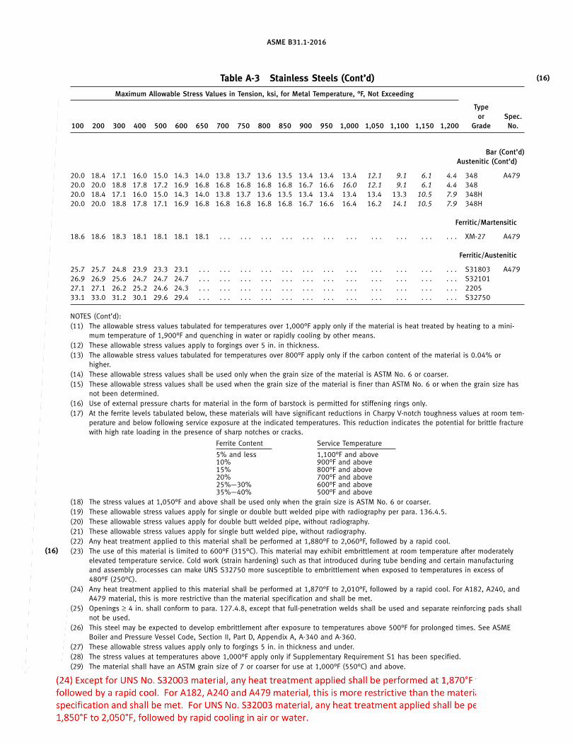
ASME B31.1-2016
Table A-3 Stainless Steels (Cont’d)
Maximum Allowable Stress Values in Tension, ksi, for Metal Temperature, °F, Not Exceeding
Typeor Spec.
100 200 300 400 500 600 650 700 750 800 850 900 950 1,000 1,050 1,100 1,150 1,200 Grade No.
(16)
Bar (Cont’d)Austenitic (Cont’d)
20.0 18.4 17.1 16.0 15.0 14.3 14.0 13.8 13.7 13.6 13.5 13.4 13.4 13.4 12.1 9.1 6.1 4.4 348 A47920.0 20.0 18.8 17.8 17.2 16.9 16.8 16.8 16.8 16.8 16.8 16.7 16.6 16.0 12.1 9.1 6.1 4.4 34820.0 18.4 17.1 16.0 15.0 14.3 14.0 13.8 13.7 13.6 13.5 13.4 13.4 13.4 13.4 13.3 10.5 7.9 348H20.0 20.0 18.8 17.8 17.1 16.9 16.8 16.8 16.8 16.8 16.8 16.7 16.6 16.4 16.2 14.1 10.5 7.9 348H
Ferritic/Martensitic
18.6 18.6 18.3 18.1 18.1 18.1 18.1 . . . . . . . . . . . . . . . . . . . . . . . . . . . . . . . . . XM-27 A479
Ferritic/Austenitic
25.7 25.7 24.8 23.9 23.3 23.1 . . . . . . . . . . . . . . . . . . . . . . . . . . . . . . . . . . . . S31803 A47926.9 26.9 25.6 24.7 24.7 24.7 . . . . . . . . . . . . . . . . . . . . . . . . . . . . . . . . . . . . S3210127.1 27.1 26.2 25.2 24.6 24.3 . . . . . . . . . . . . . . . . . . . . . . . . . . . . . . . . . . . . 220533.1 33.0 31.2 30.1 29.6 29.4 . . . . . . . . . . . . . . . . . . . . . . . . . . . . . . . . . . . . S32750
NOTES (Cont’d):(11) The allowable stress values tabulated for temperatures over 1,000°F apply only if the material is heat treated by heating to a mini-
mum temperature of 1,900°F and quenching in water or rapidly cooling by other means.(12) These allowable stress values apply to forgings over 5 in. in thickness.(13) The allowable stress values tabulated for temperatures over 800°F apply only if the carbon content of the material is 0.04% or
higher.(14) These allowable stress values shall be used only when the grain size of the material is ASTM No. 6 or coarser.(15) These allowable stress values shall be used when the grain size of the material is finer than ASTM No. 6 or when the grain size has
not been determined.(16) Use of external pressure charts for material in the form of barstock is permitted for stiffening rings only.(17) At the ferrite levels tabulated below, these materials will have significant reductions in Charpy V-notch toughness values at room tem-
perature and below following service exposure at the indicated temperatures. This reduction indicates the potential for brittle fracturewith high rate loading in the presence of sharp notches or cracks.
Ferrite Content Service Temperature
5% and less 1,100°F and above10% 900°F and above15% 800°F and above20% 700°F and above25%—30% 600°F and above35%—40% 500°F and above
(18) The stress values at 1,050°F and above shall be used only when the grain size is ASTM No. 6 or coarser.(19) These allowable stress values apply for single or double butt welded pipe with radiography per para. 136.4.5.(20) These allowable stress values apply for double butt welded pipe, without radiography.(21) These allowable stress values apply for single butt welded pipe, without radiography.(22) Any heat treatment applied to this material shall be performed at 1,880°F to 2,060°F, followed by a rapid cool.
(16) (23) The use of this material is limited to 600°F (315°C). This material may exhibit embrittlement at room temperature after moderatelyelevated temperature service. Cold work (strain hardening) such as that introduced during tube bending and certain manufacturingand assembly processes can make UNS S32750 more susceptible to embrittlement when exposed to temperatures in excess of480°F (250°C).
(24) Any heat treatment applied to this material shall be performed at 1,870°F to 2,010°F, followed by a rapid cool. For A182, A240, andA479 material, this is more restrictive than the material specification and shall be met.
(25) Openings ≥ 4 in. shall conform to para. 127.4.8, except that full-penetration welds shall be used and separate reinforcing pads shallnot be used.
(26) This steel may be expected to develop embrittlement after exposure to temperatures above 500°F for prolonged times. See ASMEBoiler and Pressure Vessel Code, Section II, Part D, Appendix A, A-340 and A-360.
(27) These allowable stress values apply only to forgings 5 in. in thickness and under.(28) The stress values at temperatures above 1,000°F apply only if Supplementary Requirement S1 has been specified.(29) The material shall have an ASTM grain size of 7 or coarser for use at 1,000°F (550°C) and above.
169
DUrsoU
Callout
(24) Except for UNS No. S32003 material, any heat treatment applied shall be performed at 1,870°F to 2,010°F, followed by a rapid cool. For A182, A240 and A479 material, this is more restrictive than the material specification and shall be met. For UNS No. S32003 material, any heat treatment applied shall be performed at 1,850°F to 2,050°F, followed by rapid cooling in air or water.
DUrsoU
Cross-Out
DUrsoU
Cross-Out
DUrsoU
Typewritten Text
A-207 and A-208.
DUrsoU
Line
DUrsoU
Text Box
DUrsoU
Callout
(30) These allowable stress values apply to seamless pipe ≤ 3/8" in wall thickness. (31) These allowable stress values apply to seamless pipe > 3/8" in wall thickness.
DUrsoU
Line

ASME B31.1-2016
Table A-4 Nickel and High Nickel Alloys
Specified SpecifiedUNS Minimum Minimum E
Spec. Alloy Temper or Nominal P- Tensile, Yield, orNo. No. Condition Composition No. Notes ksi ksi F
(16)
Seamless Pipe and Tube
B161 N02200 Annealed Ni 41 (1)(5) 55 15 1.00N02200 Annealed Ni 41 (1)(6) 55 12 1.00N02200 Str. rel. Ni 41 (1) 65 40 1.00
B161 N02201 Annealed Ni–Low C 41 (1)(5) 50 12 1.00N02201 Annealed Ni–Low C 41 (1)(6) 50 10 1.00N02201 Str. rel. Ni–Low C 41 (1) 60 30 1.00
B163 N08800 Annealed Ni–Cr–Fe 45 (1)(7) 75 30 1.00N08800 Annealed Ni–Cr–Fe 45 (1)(2)(7) 75 30 1.00N08810 Annealed Ni–Cr–Fe 45 (1) 65 25 1.00N08810 Annealed Ni–Cr–Fe 45 (1)(2) 65 25 1.00
B165 N04400 Annealed Ni–Cu 42 (1)(5) 70 28 1.00N04400 Annealed Ni–Cu 42 (1)(6) 70 25 1.00N04400 Str. rel. Ni–Cu 42 (1)(2)(3) 85 35 1.00
B167 N06600 H.F./ann. Ni–Cr–Fe 43 (1)(5) 80 30 1.00N06600 H.F./ann. Ni–Cr–Fe 43 (1)(2)(5) 75 30 1.00N06600 H.F./ann. Ni–Cr–Fe 43 (1)(6) 75 25 1.00N06600 H.F./ann. Ni–Cr–Fe 43 (1)(2)(6) 80 25 1.00
B167 N06600 C.D./ann. Ni–Cr–Fe 43 (1)(5) 80 35 1.00N06600 C.D./ann. Ni–Cr–Fe 43 (1)(2)(5) 80 35 1.00N06600 C.D./ann. Ni–Cr–Fe 43 (1)(6) 80 30 1.00N06600 C.D./ann. Ni–Cr–Fe 43 (1)(2)(6) 80 30 1.00
B167 N06617 Annealed 52Ni–22Cr–13Co–9Mo 43 (1)(7) 95 35 1.00N06617 Annealed 52Ni–22Cr–13Co–9Mo 43 (1)(2)(7) 95 35 1.00N06690 C.W./ann. 58Ni–29Cr–9Fe 43 (7)(23) 85 35 1.00N06690 C.W./ann. 58Ni–29Cr–9Fe 43 (2)(7)(23) 85 35 1.00
B407 N08800 C.D./ann. Ni–Cr–Fe 45 (7) 75 30 1.00N08800 C.D./ann. Ni–Cr–Fe 45 (2)(7) 75 30 1.00N08810 Annealed Ni–Cr–Fe 45 (7) 65 25 1.00N08810 Annealed Ni–Cr–Fe 45 (2)(7) 65 25 1.00
B423 N08825 C.W./ann. Ni–Fe–Cr–Mo–Cu 45 (1)(7) 85 35 1.00N08825 C.W./ann. Ni–Fe–Cr–Mo–Cu 45 (1)(2)(7) 85 35 1.00
B444 N06625 Sol. ann. Ni–Cr–Mo–Cb 43 (14)(18) 100 40 1.00N06625 Annealed Ni–Cr–Mo–Cb 43 (2)(14) 120 60 1.00
B622 N06022 Sol. ann. Ni–Mo–Cr–Low C 44 (1)(12) 100 45 1.00N06022 Sol. ann. Ni–Mo–Cr–Low C 44 (1)(2)(12) 100 45 1.00N10276 Sol. ann. Low C–Ni–Mo–Cr 43 (1)(12) 100 41 1.00N10276 Sol. ann. Low C–Ni–Mo–Cr 43 (1)(2)(12) 100 41 1.00R30556 Annealed Ni–Fe–Cr–Co–Mo–W 45 (1) 100 45 1.00R30556 Annealed Ni–Fe–Cr–Co–Mo–W 45 (1)(2) 100 45 1.00
B677 N08925 Annealed Ni–Fe–Cr–Mo–Cu–Low C 45 (1) 87 43 1.00N08925 Annealed Ni–Fe–Cr–Mo–Cu–Low C 45 (1)(2) 87 43 1.00N08926 Annealed Ni–Fe–Cr–Mo–Cu–N–Low C 45 (1)(19)(20) 94 43 1.00N08926 Annealed Ni–Fe–Cr–Mo–Cu–N–Low C 45 (1)(2)(19)(20) 94 43 1.00
170
DUrsoU
Cross-Out
DUrsoU
Cross-Out
DUrsoU
Cross-Out
DUrsoU
Cross-Out
DUrsoU
Cross-Out
DUrsoU
Cross-Out
DUrsoU
Cross-Out
DUrsoU
Cross-Out
DUrsoU
Cross-Out
DUrsoU
Cross-Out
DUrsoU
Cross-Out
DUrsoU
Cross-Out
DUrsoU
Cross-Out
DUrsoU
Cross-Out
DUrsoU
Cross-Out
DUrsoU
Cross-Out
DUrsoU
Cross-Out
DUrsoU
Cross-Out
DUrsoU
Cross-Out
DUrsoU
Cross-Out
DUrsoU
Text Box
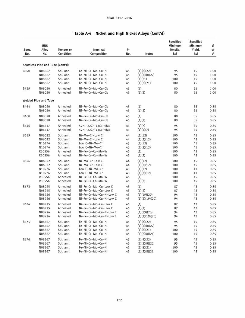
ASME B31.1-2016
Table A-4 Nickel and High Nickel Alloys (Cont’d)
Specified SpecifiedUNS Minimum Minimum E
Spec. Alloy Temper or Nominal P- Tensile, Yield, orNo. No. Condition Composition No. Notes ksi ksi F
Seamless Pipe and Tube (Cont’d)
B690 N08367 Sol. ann. Fe–Ni–Cr–Mo–Cu–N 45 (1)(8)(22) 95 45 1.00N08367 Sol. ann. Fe–Ni–Cr–Mo–Cu–N 45 (1)(2)(8)(22) 95 45 1.00N08367 Sol. ann. Fe–Ni–Cr–Mo–Cu–N 45 (1)(21) 100 45 1.00N08367 Sol. ann. Fe–Ni–Cr–Mo–Cu–N 45 (1)(2)(21) 100 45 1.00
B729 N08020 Annealed Ni–Fe–Cr–Mo–Cu–Cb 45 (1) 80 35 1.00N08020 Annealed Ni–Fe–Cr–Mo–Cu–Cb 45 (1)(2) 80 35 1.00
Welded Pipe and Tube
B464 N08020 Annealed Ni–Fe–Cr–Mo–Cu–Cb 45 (1) 80 35 0.85N08020 Annealed Ni–Fe–Cr–Mo–Cu–Cb 45 (1)(2) 80 35 0.85
B468 N08020 Annealed Ni–Fe–Cr–Mo–Cu–Cb 45 (1) 80 35 0.85N08020 Annealed Ni–Fe–Cr–Mo–Cu–Cb 45 (1)(2) 80 35 0.85
B546 N06617 Annealed 52Ni–22Cr–13Co–9Mo 43 (1)(7) 95 35 0.85N06617 Annealed 52Ni–22Cr–13Co–9Mo 43 (1)(2)(7) 95 35 0.85
B619 N06022 Sol. ann. Ni–Mo–Cr–Low C 44 (1)(12) 100 45 0.85N06022 Sol. ann. Ni–Mo–Cr–Low C 44 (1)(2)(12) 100 45 0.85N10276 Sol. ann. Low C–Ni–Mo–Cr 43 (1)(12) 100 41 0.85N10276 Sol. ann. Low C–Ni–Mo–Cr 43 (1)(2)(12) 100 41 0.85R30556 Annealed Ni–Fe–Cr–Co–Mo–W 45 (1) 100 45 0.85R30556 Annealed Ni–Fe–Cr–Co–Mo–W 45 (1)(2) 100 45 0.85
B626 N06022 Sol. ann. Ni–Mo–Cr–Low C 44 (1)(12) 100 45 0.85N06022 Sol. ann. Ni–Mo–Cr–Low C 44 (1)(2)(12) 100 45 0.85N10276 Sol. ann. Low C–Ni–Mo–Cr 43 (1)(12) 100 41 0.85N10276 Sol. ann. Low C–Ni–Mo–Cr 43 (1)(2)(12) 100 41 0.85R30556 Annealed Ni–Fe–Cr–Co–Mo–W 45 (1) 100 45 0.85R30556 Annealed Ni–Fe–Cr–Co–Mo–W 45 (1)(2) 100 45 0.85
B673 N08925 Annealed Ni–Fe–Cr–Mo–Cu–Low C 45 (1) 87 43 0.85N08925 Annealed Ni–Fe–Cr–Mo–Cu–Low C 45 (1)(2) 87 43 0.85N08926 Annealed Ni–Fe–Cr–Mo–Cu–N–Low C 45 (1)(19)(20) 94 43 0.85N08926 Annealed Ni–Fe–Cr–Mo–Cu–N–Low C 45 (1)(2)(19)(20) 94 43 0.85
B674 N08925 Annealed Ni–Fe–Cr–Mo–Cu–Low C 45 (1) 87 43 0.85N08925 Annealed Ni–Fe–Cr–Mo–Cu–Low C 45 (1)(2) 87 43 0.85N08926 Annealed Ni–Fe–Cr–Mo–Cu–N–Low C 45 (1)(19)(20) 94 43 0.85N08926 Annealed Ni–Fe–Cr–Mo–Cu–N–Low C 45 (1)(2)(19)(20) 94 43 0.85
B675 N08367 Sol. ann. Fe–Ni–Cr–Mo–Cu–N 45 (1)(8)(22) 95 45 0.85N08367 Sol. ann. Fe–Ni–Cr–Mo–Cu–N 45 (1)(2)(8)(22) 95 45 0.85N08367 Sol. ann. Fe–Ni–Cr–Mo–Cu–N 45 (1)(8)(21) 100 45 0.85N08367 Sol. ann. Fe–Ni–Cr–Mo–Cu–N 45 (1)(2)(8)(21) 100 45 0.85
B676 N08367 Sol. ann. Fe–Ni–Cr–Mo–Cu–N 45 (1)(8)(22) 95 45 0.85N08367 Sol. ann. Fe–Ni–Cr–Mo–Cu–N 45 (1)(2)(8)(22) 95 45 0.85N08367 Sol. ann. Fe–Ni–Cr–Mo–Cu–N 45 (1)(8)(21) 100 45 0.85N08367 Sol. ann. Fe–Ni–Cr–Mo–Cu–N 45 (1)(2)(8)(21) 100 45 0.85
172
DUrsoU
Cross-Out
DUrsoU
Cross-Out
DUrsoU
Cross-Out
DUrsoU
Cross-Out
DUrsoU
Cross-Out
DUrsoU
Cross-Out
DUrsoU
Cross-Out
DUrsoU
Cross-Out
DUrsoU
Cross-Out
DUrsoU
Cross-Out
DUrsoU
Cross-Out
DUrsoU
Cross-Out
DUrsoU
Text Box

ASME B31.1-2016
Table A-4 Nickel and High Nickel Alloys (Cont’d)
Specified SpecifiedUNS Minimum Minimum E
Spec. Alloy Temper or Nominal P- Tensile, Yield, orNo. No. Condition Composition No. Notes ksi ksi F
(16)
Welded Pipe and Tube (Cont’d)
B704 N06625 Annealed Ni–Cr–Mo–Cb 43 (14) 120 60 0.85
B705 N06625 Annealed Ni–Cr–Mo–Cb 43 (14) 120 60 0.85
B804 N08367 Sol. ann. Fe–Ni–Cr–Mo–Cu–N 45 (1)(8) 95 45 0.85N08367 Sol. ann. Fe–Ni–Cr–Mo–Cu–N 45 (1)(2)(8) 95 45 0.85N08367 Sol. ann. Fe–Ni–Cr–Mo–Cu–N 45 (1)(8)(21) 100 45 0.85N08367 Sol. ann. Fe–Ni–Cr–Mo–Cu–N 45 (1)(2)(8)(21) 100 45 0.85
Plate, Sheet, and Strip
B168 N06600 Annealed Ni–Cr–Fe 43 (1) 80 35 1.00N06600 Annealed Ni–Cr–Fe 43 (1)(2) 80 35 1.00N06600 Hot rolled Ni–Cr–Fe 43 (1)(4) 85 35 1.00N06600 Hot rolled Ni–Cr–Fe 43 (1)(2)(4) 85 35 1.00
B168 N06617 Annealed 52Ni–22Cr–13Co–9Mo 43 (1)(7) 95 35 1.00N06617 Annealed 52Ni–22Cr–13Co–9Mo 43 (1)(2)(7) 95 35 1.00N06690 Annealed 58Ni–29Cr–9Fe 43 (7) 85 35 1.00N06690 Annealed 58Ni–29Cr–9Fe 43 (2)(7) 85 35 1.00
B409 N08800 Annealed Ni–Cr–Fe 45 (4)(7) 75 30 1.00N08800 Annealed Ni–Cr–Fe 45 (2)(4)(7) 75 30 1.00N08810 Annealed Ni–Cr–Fe 45 (4)(7) 65 25 1.00N08810 Annealed Ni–Cr–Fe 45 (2)(4)(7) 65 25 1.00
B424 N08825 Annealed Ni–Fe–Cr–Mo–Cu 45 (1)(7) 85 35 1.00N08825 Annealed Ni–Fe–Cr–Mo–Cu 45 (1)(2)(7) 85 35 1.00
B435 R30556 Annealed Ni–Fe–Cr–Co–Mo–W 45 (1) 100 45 1.00R30556 Annealed Ni–Fe–Cr–Co–Mo–W 45 (1)(2) 100 45 1.00
B443 N06625 Sol. ann. Ni–Cr–Mo–Cb 43 (14)(18) 100 40 1.00N06625 Annealed Ni–Cr–Mo–Cb 43 (14) 110 55 1.00N06625 Annealed Ni–Cr–Mo–Cb 43 (14)(15) 120 60 1.00
B463 N08020 Annealed Ni–Fe–Cr–Mo–Cu–Cb 45 (1) 80 35 1.00N08020 Annealed Ni–Fe–Cr–Mo–Cu–Cb 45 (1)(12) 80 35 1.00
B575 N06022 Sol. ann. Ni–Mo–Cr–Low C 44 (1)(12) 100 45 1.00N06022 Sol. ann. Ni–Mo–Cr–Low C 44 (1)(2)(12) 100 45 1.00N10276 Sol. ann. Low C–Ni–Mo–Cr 43 (1)(12) 100 41 1.00N10276 Sol. ann. Low C–Ni–Mo–Cr 43 (1)(2)(12) 100 41 1.00
B625 N08925 Annealed Ni–Fe–Cr–Mo–Cu–Low C 45 (1) 87 43 1.00N08925 Annealed Ni–Fe–Cr–Mo–Cu–Low C 45 (1)(2) 87 43 1.00N08926 Annealed Ni–Fe–Cr–Mo–Cu–N–Low C 45 (1)(19)(20) 94 43 1.00N08926 Annealed Ni–Fe–Cr–Mo–Cu–N–Low C 45 (1)(2)(19)(20) 94 43 1.00
B688 N08367 Sol. ann. Fe–Ni–Cr–Mo–Cu–N 45 (1)(7)(11)(22) 95 45 1.00N08367 Sol. ann. Fe–Ni–Cr–Mo–Cu–N 45 (1)(2)(7)(11)(22) 95 45 1.00N08367 Sol. ann. Fe–Ni–Cr–Mo–Cu–N 45 (1)(7)(10)(21) 100 45 1.00N08367 Sol. ann. Fe–Ni–Cr–Mo–Cu–N 45 (1)(2)(7)(10)(21) 100 45 1.00
174
DUrsoU
Cross-Out
DUrsoU
Cross-Out
DUrsoU
Cross-Out
DUrsoU
Cross-Out
DUrsoU
Cross-Out
DUrsoU
Cross-Out
DUrsoU
Cross-Out
DUrsoU
Cross-Out
DUrsoU
Cross-Out
DUrsoU
Cross-Out
DUrsoU
Cross-Out
DUrsoU
Cross-Out
DUrsoU
Text Box
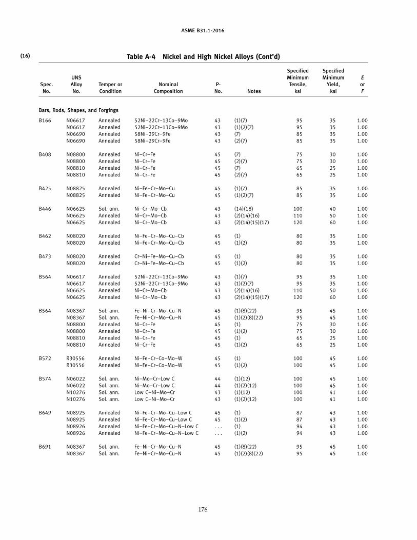
ASME B31.1-2016
Table A-4 Nickel and High Nickel Alloys (Cont’d)
Specified SpecifiedUNS Minimum Minimum E
Spec. Alloy Temper or Nominal P- Tensile, Yield, orNo. No. Condition Composition No. Notes ksi ksi F
(16)
Bars, Rods, Shapes, and Forgings
B166 N06617 Annealed 52Ni–22Cr–13Co–9Mo 43 (1)(7) 95 35 1.00N06617 Annealed 52Ni–22Cr–13Co–9Mo 43 (1)(2)(7) 95 35 1.00N06690 Annealed 58Ni–29Cr–9Fe 43 (7) 85 35 1.00N06690 Annealed 58Ni–29Cr–9Fe 43 (2)(7) 85 35 1.00
B408 N08800 Annealed Ni–Cr–Fe 45 (7) 75 30 1.00N08800 Annealed Ni–Cr–Fe 45 (2)(7) 75 30 1.00N08810 Annealed Ni–Cr–Fe 45 (7) 65 25 1.00N08810 Annealed Ni–Cr–Fe 45 (2)(7) 65 25 1.00
B425 N08825 Annealed Ni–Fe–Cr–Mo–Cu 45 (1)(7) 85 35 1.00N08825 Annealed Ni–Fe–Cr–Mo–Cu 45 (1)(2)(7) 85 35 1.00
B446 N06625 Sol. ann. Ni–Cr–Mo–Cb 43 (14)(18) 100 40 1.00N06625 Annealed Ni–Cr–Mo–Cb 43 (2)(14)(16) 110 50 1.00N06625 Annealed Ni–Cr–Mo–Cb 43 (2)(14)(15)(17) 120 60 1.00
B462 N08020 Annealed Ni–Fe–Cr–Mo–Cu–Cb 45 (1) 80 35 1.00N08020 Annealed Ni–Fe–Cr–Mo–Cu–Cb 45 (1)(2) 80 35 1.00
B473 N08020 Annealed Cr–Ni–Fe–Mo–Cu–Cb 45 (1) 80 35 1.00N08020 Annealed Cr–Ni–Fe–Mo–Cu–Cb 45 (1)(2) 80 35 1.00
B564 N06617 Annealed 52Ni–22Cr–13Co–9Mo 43 (1)(7) 95 35 1.00N06617 Annealed 52Ni–22Cr–13Co–9Mo 43 (1)(2)(7) 95 35 1.00N06625 Annealed Ni–Cr–Mo–Cb 43 (2)(14)(16) 110 50 1.00N06625 Annealed Ni–Cr–Mo–Cb 43 (2)(14)(15)(17) 120 60 1.00
B564 N08367 Sol. ann. Fe–Ni–Cr–Mo–Cu–N 45 (1)(8)(22) 95 45 1.00N08367 Sol. ann. Fe–Ni–Cr–Mo–Cu–N 45 (1)(2)(8)(22) 95 45 1.00N08800 Annealed Ni–Cr–Fe 45 (1) 75 30 1.00N08800 Annealed Ni–Cr–Fe 45 (1)(2) 75 30 1.00N08810 Annealed Ni–Cr–Fe 45 (1) 65 25 1.00N08810 Annealed Ni–Cr–Fe 45 (1)(2) 65 25 1.00
B572 R30556 Annealed Ni–Fe–Cr–Co–Mo–W 45 (1) 100 45 1.00R30556 Annealed Ni–Fe–Cr–Co–Mo–W 45 (1)(2) 100 45 1.00
B574 N06022 Sol. ann. Ni–Mo–Cr–Low C 44 (1)(12) 100 45 1.00N06022 Sol. ann. Ni–Mo–Cr–Low C 44 (1)(2)(12) 100 45 1.00N10276 Sol. ann. Low C–Ni–Mo–Cr 43 (1)(12) 100 41 1.00N10276 Sol. ann. Low C–Ni–Mo–Cr 43 (1)(2)(12) 100 41 1.00
B649 N08925 Annealed Ni–Fe–Cr–Mo–Cu–Low C 45 (1) 87 43 1.00N08925 Annealed Ni–Fe–Cr–Mo–Cu–Low C 45 (1)(2) 87 43 1.00N08926 Annealed Ni–Fe–Cr–Mo–Cu–N–Low C . . . (1) 94 43 1.00N08926 Annealed Ni–Fe–Cr–Mo–Cu–N–Low C . . . (1)(2) 94 43 1.00
B691 N08367 Sol. ann. Fe–Ni–Cr–Mo–Cu–N 45 (1)(8)(22) 95 45 1.00N08367 Sol. ann. Fe–Ni–Cr–Mo–Cu–N 45 (1)(2)(8)(22) 95 45 1.00
176
DUrsoU
Cross-Out
DUrsoU
Cross-Out
DUrsoU
Cross-Out
DUrsoU
Cross-Out
DUrsoU
Cross-Out
DUrsoU
Cross-Out
DUrsoU
Cross-Out
DUrsoU
Cross-Out
DUrsoU
Cross-Out
DUrsoU
Cross-Out
DUrsoU
Cross-Out
DUrsoU
Cross-Out
DUrsoU
Cross-Out
DUrsoU
Cross-Out
DUrsoU
Text Box

ASME B31.1-2016
Table A-4 Nickel and High Nickel Alloys (Cont’d)
Specified SpecifiedUNS Minimum Minimum E
Spec. Alloy Temper or Nominal P- Tensile, Yield, orNo. No. Condition Composition No. Notes ksi ksi F
(16)
Seamless Fittings
B366 N06022 Sol. ann. Low C–Ni–Mo–Cr 44 (1)(12) 100 45 1.00N06022 Sol. ann. Low C–Ni–Mo–Cr 44 (1)(2)(12) 100 45 1.00N06625 Annealed Ni–Cr–Mo–Cb 43 (1)(14) 110 50 1.00
B366 N08020 Annealed Cr–Ni–Fe–Mo–Cu–Cb 45 (1) 80 35 1.00N08020 Annealed Cr–Ni–Fe–Mo–Cu–Cb 45 (1)(2) 80 35 1.00N08367 Annealed Fe–Ni–Cr–Mo–N 45 (1)(8)(22) 95 45 1.00N08367 Annealed Fe–Ni–Cr–Mo–N 45 (1)(2)(8)(22) 95 45 1.00
B366 N08925 Annealed Low C–Ni–Fe–Cr–Mo–Cu 45 (1) 87 43 1.00N08925 Annealed Low C–Ni–Fe–Cr–Mo–Cu 45 (1)(2) 87 43 1.00N08926 Annealed Low C–Ni–Fe–Cr–Mo–Cu–N 45 (1) 94 43 1.00N08926 Annealed Low C–Ni–Fe–Cr–Mo–Cu–N 45 (1)(2) 94 43 1.00
B366 N10276 Sol. ann. Low C–Ni–Mo–Cr 43 (1)(12) 100 41 1.00N10276 Sol. ann. Low C–Ni–Mo–Cr 43 (1)(2)(12) 100 41 1.00R30556 Annealed Ni–Fe–Cr–Co–Mo–W 45 (1) 100 45 1.00R30556 Annealed Ni–Fe–Cr–Co–Mo–W 45 (1)(2) 100 45 1.00
B462 N08367 Sol. ann. Fe–Ni–Cr–Mo–N 45 (1)(8)(22) 95 45 1.00N08367 Sol. ann. Fe–Ni–Cr–Mo–N 45 (1)(2)(8)(22) 95 45 1.00
Welded Fittings
B366 N06022 Sol. ann. Low C–Ni–Mo–Cr 44 (1)(12) 100 45 0.85N06022 Sol. ann. Low C–Ni–Mo–Cr 44 (1)(12)(13) 100 45 1.00N06022 Sol. ann. Low C–Ni–Mo–Cr 44 (1)(2)(12) 100 45 0.85N06022 Sol. ann. Low C–Ni–Mo–Cr 44 (1)(2)(12)(13) 100 45 1.00N06625 Annealed Ni–Cr–Mo–Cb 43 (14) 110 50 0.85N06625 Annealed Ni–Cr–Mo–Cb 43 (13)(14) 110 50 1.00
B366 N08020 Annealed Cr–Ni–Fe–Mo–Cu–Cb 45 (1) 80 35 0.85N08020 Annealed Cr–Ni–Fe–Mo–Cu–Cb 45 (1)(13) 80 35 1.00N08020 Annealed Cr–Ni–Fe–Mo–Cu–Cb 45 (1)(2) 80 35 0.85N08020 Annealed Cr–Ni–Fe–Mo–Cu–Cb 45 (1)(2)(13) 80 35 1.00
B366 N08367 Sol. ann. Fe–Ni–Cr–Mo–N 45 (1)(8)(22) 95 45 0.85N08367 Sol. ann. Fe–Ni–Cr–Mo–N 45 (1)(8)(13)(22) 95 45 1.00N08367 Sol. ann. Fe–Ni–Cr–Mo–N 45 (1)(2)(8)(22) 95 45 0.85N08367 Sol. ann. Fe–Ni–Cr–Mo–N 45 (1)(2)(8)(13)(22) 95 45 1.00
B366 N08925 Annealed Low C–Ni–Fe–Cr–Mo–Cu 45 (1) 87 43 0.85N08925 Annealed Low C–Ni–Fe–Cr–Mo–Cu 45 (1)(13) 87 43 1.00N08925 Annealed Low C–Ni–Fe–Cr–Mo–Cu 45 (1)(2) 87 43 0.85N08925 Annealed Low C–Ni–Fe–Cr–Mo–Cu 45 (1)(2)(13) 87 43 1.00
B366 N08926 Annealed Low C–Ni–Fe–Cr–Mo–Cu–N 45 (1)(19)(20) 94 43 0.85N08926 Annealed Low C–Ni–Fe–Cr–Mo–Cu–N 45 (1)(13) 94 43 1.00N08926 Annealed Low C–Ni–Fe–Cr–Mo–Cu–N 45 (1)(2)(19)(20) 94 43 0.85N08926 Annealed Low C–Ni–Fe–Cr–Mo–Cu–N 45 (1)(2)(13) 94 43 1.00
B366 N10276 Sol. ann. Low C–Ni–Mo–Cr 43 (1)(12) 100 41 0.85N10276 Sol. ann. Low C–Ni–Mo–Cr 43 (1)(12)(13) 100 41 1.00N10276 Sol. ann. Low C–Ni–Mo–Cr 43 (1)(2)(12) 100 41 0.85N10276 Sol. ann. Low C–Ni–Mo–Cr 43 (1)(2)(12)(13) 100 41 1.00
178
DUrsoU
Cross-Out
DUrsoU
Cross-Out
DUrsoU
Cross-Out
DUrsoU
Cross-Out
DUrsoU
Cross-Out
DUrsoU
Cross-Out
DUrsoU
Cross-Out
DUrsoU
Cross-Out
DUrsoU
Cross-Out
DUrsoU
Cross-Out
DUrsoU
Cross-Out
DUrsoU
Cross-Out
DUrsoU
Cross-Out
DUrsoU
Text Box

ASME B31.1-2016
Table A-4 Nickel and High Nickel Alloys (Cont’d)
Specified SpecifiedUNS Minimum Minimum E
Spec. Alloy Temper or Nominal P- Tensile, Yield, orNo. No. Condition Composition No. Notes ksi ksi F
Welded Fittings (Cont‘d)
B366 R30556 Annealed Ni–Fe–Cr–Co–Mo–W 45 (1) 100 45 0.85R30556 Annealed Ni–Fe–Cr–Co–Mo–W 45 (1)(13) 100 45 1.00R30556 Annealed Ni–Fe–Cr–Co–Mo–W 45 (1)(2) 100 45 0.85R30556 Annealed Ni–Fe–Cr–Co–Mo–W 45 (1)(2)(13) 100 45 1.00
GENERAL NOTES:(a) The tabulated specifications are ANSI/ASTM or ASTM. For ASME Boiler and Pressure Vessel Code applications, see related specifica-
tions in Section II of the ASME Code.(b) The stress values in this Table may be interpolated to determine values for intermediate temperatures.(c) The P-Numbers indicated in this Table are identical to those adopted by the ASME Boiler and Pressure Vessel Code. Qualification of
welding procedures, welders, and welding operators is required and shall comply with the ASME Boiler and Pressure Vessel Code,Section IX, except as modified by para. 127.5.
(d) Tensile strengths and allowable stresses shown in “ksi” are “thousands of pounds per square inch.”(e) The materials listed in this table shall not be used at design temperatures above those for which allowable stress values are given
herein or in Table A-8.(f) The tabulated stress values are S � E (weld joint efficiency factor) or S � F (material quality factor), as applicable. Weld joint effi-
ciency factors are shown in Table 102.4.3.(g) Pressure–temperature ratings of piping components, as published in standards referenced in this Code, may be used for components
meeting the requirements of those standards. The allowable stress values given in this Table are for use in designing piping compo-nents that are not manufactured in accordance with referenced standards.
(h) The y coefficient p 0.4 except where Note (7) applies [see Table 104.1.2(A)].(i) The tabulated stress values that are shown in italics are at temperatures in the range where creep and stress rupture strength govern
the selection of stresses.(j) See para. 124.1.2 for lower temperature limits.
NOTES:(1) THIS MATERIAL IS NOT ACCEPTABLE FOR USE ON BOILER EXTERNAL PIPING — SEE FIG. 100.1.2(A.1), FIG. 100.1.2(A.2), FIG. 100.1.2(B.1),
FIG. 100.1.2(B.2), AND FIG. 100.1.2(B.3).(2) Due to the relatively low yield strengths of these materials, these higher allowable stress values were established at temperatures
where the short time tensile properties govern to permit the use of these alloys where slightly greater deformation is acceptable. Thesestress values exceed 67% but do not exceed 90% of the yield strength at temperature. Use of these values may result in dimensionalchanges due to permanent strain. These values should not be used for flanges of gasketed joints or other applications where slightamounts of distortion can cause leakage or malfunction.
(3) The maximum temperature is limited to 500°F because harder temper adversely affects design stress in the creep rupture temperaturerange.
180
DUrsoU
Typewritten Text
,100.1.2(C.1), AND 100.1.2(C.2).
DUrsoU
Cross-Out
DUrsoU
Cross-Out
DUrsoU
Text Box

ASME B31.1-2016
Table A-5 Cast Iron (16)
Maximum Allowable Stress Values in Tension, ksi, for Metal Temperature, °F, NotExceeding
400 450 500 600 650 Class Spec. No.
Gray Cast Iron
2.0 . . . . . . . . . . . . 20 A482.5 . . . . . . . . . . . . 253.0 . . . . . . . . . . . . 303.5 . . . . . . . . . . . . 354.0 . . . . . . . . . . . . 404.5 . . . . . . . . . . . . 455.0 . . . . . . . . . . . . 505.5 . . . . . . . . . . . . 556.0 . . . . . . . . . . . . 60
2.1 . . . . . . . . . . . . A A1263.1 . . . . . . . . . . . . B4.1 . . . . . . . . . . . . C
2.0 2.0 . . . . . . . . . 20 A2782.5 2.5 . . . . . . . . . 253.0 3.0 . . . . . . . . . 303.5 3.5 . . . . . . . . . 354.0 4.0 . . . . . . . . . 404.5 4.5 . . . . . . . . . 455.0 5.0 . . . . . . . . . 505.5 5.5 . . . . . . . . . 556.0 6.0 . . . . . . . . . 60
Ductile Cast Iron
9.6 9.6 9.6 9.6 8.5 60-40-18 A39510.4 10.4 . . . . . . . . . 65-45-15
9.6 9.6 9.6 9.0 8.5 60-42-10 A53611.2 11.2 11.2 10.5 10.0 70-50-05
NOTES:(1) THIS MATERIAL IS NOT ACCEPTABLE FOR BOILER EXTERNAL PIPING — SEE FIG. 100.1.2(A.1), FIG. 100.1.2(A.2), FIG. 100.1.2(B.1),
FIG.100.1.2(B.2), AND FIG. 100.1.2(B.3).(2) Material quality factors are not applicable to these materials.(3) For saturated steam at 250 psi (406°F), the stress values given at 400°F may be used.(4) For limitations on the use of this material, see para. 124.4.(5) This material shall not be used where the design pressure exceeds 250 psig [1 725 kPa (gage)] or where the design temperature
exceeds 450°F (230°C).(6) This material shall not be used for boiler external piping where the design pressure exceeds 350 psig [2 415 kPa (gage)] or where the
design temperature exceeds 450°F (230°C).(7) Piping components conforming to either ASME B16.1 or ASME B16.4 may be used for boiler external piping, subject to all the require-
ments of the particular standard.(8) For limitations on the use of this material, see para. 124.6.
183
DUrsoU
Cross-Out
DUrsoU
Cross-Out
DUrsoU
Typewritten Text
,100.1.2(C.1), AND 100.1.2(C.2).
DUrsoU
Cross-Out
DUrsoU
Typewritten Text
9.0
DUrsoU
Text Box

ASME B31.1-2016
Table A-6 Copper and Copper Alloys (Cont’d)
Maximum Allowable Stress Values in Tension, ksi, for Metal Temperature, °F, Not Exceeding
Spec.100 150 200 250 300 350 400 450 500 550 600 650 700 750 800 UNS Alloy No. No.
Rod
13.3 12.6 12.0 11.5 11.1 10.7 5.3 2.0 . . . . . . . . . . . . . . . . . . . . . C36000 B1612.0 11.3 10.8 10.4 10.0 9.7 5.3 2.0 . . . . . . . . . . . . . . . . . . . . . C3600010.0 9.4 9.0 8.7 8.3 8.1 5.3 2.0 . . . . . . . . . . . . . . . . . . . . . C36000
12.0 11.6 11.3 11.0 10.8 10.5 10.3 10.1 9.9 9.8 9.6 9.5 9.4 . . . . . . C71500 B151
10.7 10.1 9.6 9.2 8.9 8.6 5.3 2.0 . . . . . . . . . . . . . . . . . . . . . C35300 B45310.0 9.4 9.0 8.7 8.3 8.1 5.3 2.0 . . . . . . . . . . . . . . . . . . . . . C3530010.0 9.4 9.0 8.7 8.3 8.1 5.3 2.0 . . . . . . . . . . . . . . . . . . . . . C35300
Bar
12.0 11.3 10.8 10.4 10.0 9.7 5.3 2.0 . . . . . . . . . . . . . . . . . . . . . C36000 B1610.0 9.4 9.0 8.7 8.3 8.1 5.3 2.0 . . . . . . . . . . . . . . . . . . . . . C36000
Die Forgings (Hot Pressed)
12.0 11.3 10.8 . . . . . . . . . . . . . . . . . . . . . . . . . . . . . . . . . . . . C37700 B28310.0 9.4 9.0 . . . . . . . . . . . . . . . . . . . . . . . . . . . . . . . . . . . . C37700
Castings
7.8 7.8 7.8 7.8 7.8 7.8 6.6 6.2 5.8 4.0 . . . . . . . . . . . . . . . C92200 B61
6.9 6.9 6.9 6.9 6.6 6.5 5.5 5.4 . . . . . . . . . . . . . . . . . . . . . C83600 B62
13.4 12.6 12.2 11.8 11.6 11.4 11.4 11.4 11.4 9.4 5.9 . . . . . . . . . . . . C95200 B14816.0 15.2 15.0 14.8 14.8 14.8 14.8 12.8 11.1 8.8 6.8 . . . . . . . . . . . . C95400
7.8 7.8 7.8 7.8 7.8 7.8 6.6 6.2 5.8 4.0 . . . . . . . . . . . . . . . C92200 B5846.4 5.9 5.5 5.3 5.3 5.2 5.1 . . . . . . . . . . . . . . . . . . . . . . . . C937006.0 5.8 5.6 5.5 5.4 . . . . . . . . . . . . . . . . . . . . . . . . . . . . . . C97600
NOTES:(1) THIS MATERIAL IS NOT ACCEPTABLE FOR USE ON BOILER EXTERNAL PIPING — SEE FIG. 100.1.2(A.1), FIG. 100.1.2(A.2), FIG. 100.1.2(B.1),
FIG. 100.1.2(B.2), AND FIG. 100.1.2(B.3).(2) This material may be used for Boiler External Piping provided that the nominal size does not exceed 3 in. and the design temperature
does not exceed 406°F. This material shall not be used for blowoff or blowdown piping except as permitted in para. 122.1.4. Wherethreaded brass or copper pipe is used for feedwater piping, it shall have a wall thickness not less than that required for schedule 80steel pipe of the same nominal size.
(3) Welding or brazing of this material is not permitted.(4) When this material is used for welded or brazed construction, the allowable stress values used shall not exceed those given for the
same material in the annealed condition.(5) Castings that are welded or repair welded shall be heat treated at 1,150°F–1,200°F, followed by moving-air cooling. The required time
at temperature is based on the cross-section thicknesses as follows:(a) 11⁄2 hr for the first inch or fraction thereof(b) 1⁄2 hr for each additional inch or fraction thereof
(6) Welds must be made by an electric fusion welding process involving the addition of filler metal.(7) Material conforming to ASTM B16 alloy C36000 shall not be used in primary pressure relief valve applications.(8) Materials shall be tested to determine the presence of residual stresses that might result in failure of individual parts due to stress cor-
rosion cracking. Tests shall be conducted in accordance with ASTM B154 or ASTM B858. The test frequency shall be as specified inASTM B249.
187
DUrsoU
Cross-Out
DUrsoU
Cross-Out
DUrsoU
Typewritten Text
,100.1.2(C.1), AND 100.1.2(C.2).
DUrsoU
Text Box

ASME B31.1-2016
Table A-7 Aluminum and Aluminum Alloys (Cont’d)
Specified SpecifiedSize or Minimum Minimum E
Spec. Thickness, P- Tensile, Yield, orNo. UNS Alloy No. Temper in. No. Notes ksi ksi F
Rods, Bars, and Shapes (Cont’d)
B221 A96063 T1 Up thru 0.500 23 (1)(2)(21)(22) 17 9 1.00A96063 T1 0.501–1.000 23 (1)(2)(21)(22) 16 8 1.00A96063 T5 Up thru 0.500 23 (1)(2)(21)(22) 22 16 1.00A96063 T5 0.501–1.000 23 (1)(2)(21)(22) 21 15 1.00A96063 T6 Up thru 1.000 23 (1)(2)(21)(22) 30 25 1.00A96063 T5, T6 welded Up thru 1.000 23 (1)(7)(21)(22) 17 10 1.00
Castings
B26 A24430 F . . . . . . (1)(2) 17 6 0.80A03560 T6 . . . . . . (1)(2) 30 20 0.80A03560 T71 . . . . . . (1)(2) 25 18 0.80
GENERAL NOTES:(a) The tabulated specifications are ANSI/ASTM or ASTM. For ASME Boiler and Pressure Vessel Code applications, see related specifica-
tions in Section II of the ASME Code.(b) The stress values in this Table may be interpolated to determine values for intermediate temperatures.(c) The P-Numbers listed in this Table are identical to those adopted by the ASME Boiler and Pressure Vessel Code. Qualification of weld-
ing procedures, welders, and welding operators is required and shall comply with the ASME Boiler and Pressure Vessel Code,Section IX, except as modified by para. 127.5.
(d) Tensile strengths and allowable stresses shown in “ksi” are “thousands of pounds per square inch.”(e) The materials listed in this Table shall not be used at design temperatures above those for which allowable stress values are given.(f) The tabulated stress values are S � E (weld joint efficiency factor) or S � F (material quality factor), as applicable. Weld joint effi-
ciency factors are shown in Table 102.4.3.(g) Pressure–temperature ratings of piping components, as published in standards referenced in this Code, may be used for components
meeting the requirements of those standards. The allowable stress values given in this Table are for use in designing piping compo-nents that are not manufactured in accordance with referenced standards.
(h) Aluminum and aluminum alloys shall not be used for flammable fluids within the boiler plant structure (see para. 122.7).(i) The y coefficient equals 0.4 [see Table 104.1.2(A)].(j) The tabulated stress values that are shown in italics are at temperatures in the range where creep and stress rupture strength govern
the selection of stresses.(k) See para. 124.1.2 for lower temperature limits.
NOTES:(1) THIS MATERIAL IS NOT ACCEPTABLE FOR USE ON BOILER EXTERNAL PIPING — SEE FIG. 100.1.2(A.1), FIG. 100.1.2(A.2), FIG. 100.1.2(B.1),
FIG. 100.1.2(B.2), AND FIG. 100.1.2(B.3).(2) These allowable stress values are not applicable when either welding or thermal cutting is employed.(3) These allowable stress values are not applicable when either welding or thermal cutting is employed. In such cases, the corresponding
stress values for the O temper shall be used.(4) These allowable stress values are 90% of those for the corresponding core material.(5) These allowable stress values apply only to seamless pipe smaller than NPS 1 that is extruded and then drawn.(6) These allowable stress values are not applicable when either welding or thermal cutting is employed. In such cases, the corresponding
stress values for the welded condition shall be used.
194
DUrsoU
Cross-Out
DUrsoU
Cross-Out
DUrsoU
Typewritten Text
,100.1.2(C.1), AND 100.1.2(C.2).
DUrsoU
Text Box

ASME B31.1-2016
Table A-8 Temperatures 1,200°F and Above
Specified SpecifiedUNS Minimum Minimum
Spec. Type or Alloy P- Tensile, Yield,No. Grade No. Temper Nominal Composition No. Notes ksi ksi
Seamless Pipe and Tube
A213 TP304H S30409 . . . 18Cr–8Ni 8 . . . 75 30. . . S30815 . . . 21Cr–11Ni–N 8 (1) 87 45TP310H S31009 . . . 25Cr–20Ni 8 (2)(4) 75 30TP316H S31609 . . . 16Cr–12Ni–2Mo 8 . . . 75 30TP316L S31603 . . . 16Cr–12Ni–2Mo 8 (1) 70 25
A213 TP321H S32109 . . . 18Cr–10Ni–Ti 8 . . . 75 30TP347H S34709 . . . 18Cr–10Ni–Cb 8 . . . 75 30TP348H S34809 . . . 18Cr–10Ni–Cb 8 . . . 75 30
A312 TP304H S30409 . . . 18Cr–8Ni 8 . . . 75 30. . . S30815 . . . 21Cr–11Ni–N 8 (1) 87 45TP310H S31009 . . . 25Cr–20Ni 8 (2)(4) 75 30TP316H S31609 . . . 16Cr–12Ni–2Mo 8 . . . 75 30
A312 TP321H S32109 . . . 18Cr–10Ni–Ti 8 . . . 75 30TP347H S34709 . . . 18Cr–10Ni–Cb 8 . . . 75 30TP348H S34809 . . . 18Cr–10Ni–Cb 8 . . . 75 30
A376 TP304H S30409 . . . 18Cr–8Ni 8 . . . 75 30TP316H S31609 . . . 16Cr–12Ni–2Mo 8 . . . 75 30TP321H S32109 . . . 18Cr–10Ni–Ti 8 . . . 75 30TP347H S34709 . . . 18Cr–10Ni–Cb 8 . . . 75 30
B163 . . . N08800 Annealed Ni–Cr–Fe 45 (1) 75 30. . . N08810 Annealed Ni–Cr–Fe 45 (1) 65 25
B167 . . . N06617 Annealed 52Ni–22Cr–13Co–9Mo 43 . . . 95 35
B407 . . . N08800 C.D./ann. Ni–Cr–Fe 45 . . . 75 30. . . N08810 Annealed Ni–Cr–Fe 45 . . . 65 25
B622 . . . R30556 Annealed Ni–Fe–Cr–Co–Mo–W 45 (1) 100 45
Welded Pipe and Tube — Without Filler Metal
A249 TP304H S30409 . . . 18Cr–8Ni 8 . . . 75 35. . . S30815 . . . 21Cr–11Ni–N 8 (1) 87 45TP310H S31009 . . . 25Cr–20Ni 8 (1)(2)(4) 75 35TP316H S31609 . . . 16Cr–12Ni–2Mo 8 . . . 75 35
A249 TP321H S32109 . . . 18Cr–10Ni–Ti 8 . . . 75 35TP347H S34709 . . . 18Cr–10Ni–Cb 8 . . . 75 35TP348H S34809 . . . 18Cr–10Ni–Cb 8 . . . 75 35
A312 TP304H S30409 . . . 18Cr–8Ni 8 . . . 75 30. . . S30815 . . . 21Cr–11Ni–N 8 (1) 87 45TP310H S31009 . . . 25Cr–20Ni 8 (2)(4) 75 30TP316H S31609 . . . 16Cr–12Ni–2Mo 8 . . . 75 30
196
DUrsoU
Line
DUrsoU
Line
DUrsoU
Cross-Out
DUrsoU
Cross-Out
DUrsoU
Typewritten Text
(8)

ASME B31.1-2016
Table A-8 Temperatures 1,200°F and Above
Maximum Allowable Stress Values in Tension, ksi, for Metal Temperature, °F, Not ExceedingE or Type or Spec.F 1,200 1,250 1,300 1,350 1,400 1,450 1,500 Grade No.
Seamless Pipe and Tube
1.00 6.1 4.7 3.7 2.9 2.3 1.8 1.4 TP304H A2131.00 5.2 4.0 3.1 2.4 1.9 1.6 1.3 . . .1.00 4.0 3.0 2.2 1.7 1.3 0.97 0.75 TP310H1.00 7.4 5.5 4.1 3.1 2.3 1.7 1.3 TP316H1.00 6.4 4.7 3.5 2.5 1.8 1.3 1.0 TP316L
1.00 5.4 4.1 3.2 2.5 1.9 1.5 1.1 TP321H A2131.00 7.9 5.9 4.4 3.2 2.5 1.8 1.3 TP347H1.00 7.9 5.9 4.4 3.2 2.5 1.8 1.3 TP348H
1.00 6.1 4.7 3.7 2.9 2.3 1.8 1.4 TP304H A3121.00 5.2 4.0 3.1 2.4 1.9 1.6 1.3 . . .1.00 4.0 3.0 2.2 1.7 1.3 0.97 0.75 TP310H1.00 7.4 5.5 4.1 3.1 2.3 1.7 1.3 TP316H
1.00 5.4 4.1 3.2 2.5 1.9 1.5 1.1 TP321H A3121.00 7.9 5.9 4.4 3.2 2.5 1.8 1.3 TP347H1.00 7.9 5.9 4.4 3.2 2.5 1.8 1.3 TP348H
1.00 6.1 4.7 3.7 2.9 2.3 1.8 1.4 TP304H A3761.00 7.4 5.5 4.1 3.1 2.3 1.7 1.3 TP316H1.00 5.4 4.1 3.2 2.5 1.9 1.5 1.1 TP321H1.00 7.9 5.9 4.4 3.2 2.5 1.8 1.3 TP347H
1.00 6.6 4.2 2.0 1.6 1.1 1.0 0.80 . . . B1631.00 7.4 5.9 4.7 3.8 3.0 2.4 1.9 . . .
1.00 15.3 14.5 11.2 8.7 6.6 5.1 3.9 . . . B167
1.00 6.6 4.2 2.0 1.6 1.1 1.0 0.80 . . . B4071.00 7.4 5.9 4.7 3.8 3.0 2.4 1.9 . . .
1.00 13.6 10.9 8.8 7.0 5.6 4.5 3.6 . . . B622
Welded Pipe and Tube — Without Filler Metal
0.85 5.2 4.0 3.2 2.5 2.0 1.6 1.2 TP304H A2490.85 4.4 3.4 2.6 2.0 1.6 1.4 1.1 . . .0.85 3.4 2.6 1.9 1.4 1.1 0.82 0.64 TP310H0.85 6.3 4.7 3.5 2.6 1.9 1.5 1.1 TP316H
0.85 4.6 3.5 2.7 2.1 1.6 1.3 1.0 TP321H A2490.85 6.7 5.0 3.7 2.7 2.1 1.6 1.1 TP347H0.85 6.7 5.0 3.7 2.7 2.1 1.6 1.1 TP348H
0.85 5.2 4.0 3.2 2.5 2.0 1.6 1.2 TP304H A3120.85 4.4 3.4 2.6 2.0 1.6 1.4 1.1 . . .0.85 3.4 2.6 1.9 1.4 1.1 0.82 0.64 TP310H0.85 6.3 4.7 3.5 2.6 1.9 1.5 1.1 TP316H
197
DUrsoU
Line
DUrsoU
Line

ASME B31.1-2016
Table A-8 Temperatures 1,200°F and Above (Cont’d)
Maximum Allowable Stress Values in Tension, ksi, for Metal Temperature, °F, Not ExceedingE or Type or Spec.F 1,200 1,250 1,300 1,350 1,400 1,450 1,500 Grade No.
Forgings (Cont’d)
1.00 5.4 4.1 3.2 2.5 1.9 1.5 1.1 F321H A1821.00 7.9 5.9 4.4 3.2 2.5 1.8 1.3 F347H1.00 7.9 5.9 4.4 3.2 2.5 1.8 1.3 F348H
1.00 15.3 14.5 11.2 8.7 6.6 5.1 3.9 . . . B5641.00 6.6 4.2 2.0 1.6 1.1 1.0 0.80 . . .1.00 7.4 5.9 4.7 3.8 3.0 2.4 1.9 . . .
Fittings (Seamless and Welded)
1.00 6.1 4.7 3.7 2.9 2.3 1.8 1.4 WP304H A4031.00 7.4 5.5 4.1 3.1 2.3 1.7 1.3 WP316H1.00 6.4 4.7 3.5 2.5 1.8 1.3 1.0 WP316L1.00 5.4 4.1 3.2 2.5 1.9 1.5 1.1 WP321H1.00 7.9 5.9 4.4 3.2 2.5 1.8 1.3 WP347H1.00 7.9 5.9 4.4 3.2 2.5 1.8 1.3 WP348H
1.00 13.6 10.9 8.8 7.0 5.6 4.5 3.6 . . . B3660.85 11.6 9.3 7.5 6.0 4.8 3.8 3.1 . . .
NOTES:(1) THIS MATERIAL IS NOT ACCEPTABLE FOR USE ON BOILER EXTERNAL PIPING — SEE FIG. 100.1.2(A.1), FIG. 100.1.2(A.2), FIG. 100.1.2(B.1),
FIG. 100.1.2(B.2), AND FIG. 100.1.2(B.3).(2) These allowable stress values shall be used only if the carbon content of the material is 0.04% or higher.(3) These allowable stress values tabulated shall be used only if the material is heat treated by heating to a minimum temperature of
1,900°F and quenching in water or rapidly cooling by other means.(4) These allowable stress values shall be used only when the grain size of the material is ASTM No. 6 or coarser.(5) These allowable stress values shall be used only when Supplementary Requirement S1 per ASTM A479 has been specified.(6) Seamless.(7) Welded—all filler metal, including consumable insert material, shall comply with the requirements of Section IX of the ASME Boiler and
Pressure Vessel Code.
201
DUrsoU
Typewritten Text
,100.1.2(C.1), AND 100.1.2(C.2).
DUrsoU
Cross-Out
DUrsoU
Cross-Out
DUrsoU
Callout
(8) These allowable stress values apply to seamless pipe ≤3/8 in wall thickness (9) These allowable stress values apply to seamless pipe >3/8 in wall thickness
DUrsoU
Text Box

ASME B31.1-2016
Table A-9 Titanium and Titanium Alloys (Cont’d)
Maximum Allowable Stress Values in Tension, ksi, for Metal Temperature, °F, Not Exceeding
Spec.100 150 200 250 300 350 400 450 500 550 600 Grade No.
Bars and Billets
10.0 9.3 8.3 7.4 6.6 6.0 5.5 5.1 4.7 4.2 3.6 1 B34814.3 13.7 12.4 11.3 10.3 9.5 8.8 8.2 7.6 7.0 6.5 218.6 17.5 15.8 14.2 12.8 11.5 10.3 9.3 8.5 7.9 7.4 314.3 13.7 12.4 11.3 10.3 9.5 8.8 8.2 7.6 7.0 6.5 720.0 20.0 18.7 17.4 16.2 15.2 14.3 13.6 13.1 12.7 12.3 12
Castings
11.4 10.5 10.0 9.0 8.3 7.6 . . . . . . . . . . . . . . . C-2 B367
NOTES:(1) THIS MATERIAL IS NOT ACCEPTABLE FOR USE ON BOILER EXTERNAL PIPING — SEE FIG. 100.1.2(A.1), FIG. 100.1.2(A.2), FIG. 100.1.2(B.1),
FIG. 100.1.2(B.2), AND FIG. 100.1.2(B.3).(2) Filler metal shall not be used in the manufacture of welded pipe or tubing.(3) Welding of this material is not permitted.
205
DUrsoU
Cross-Out
DUrsoU
Cross-Out
DUrsoU
Typewritten Text
,100.1.2(C.1), AND 100.1.2(C.2).
DUrsoU
Text Box

ASME B31.1-2016
Table A-10 Bolts, Nuts, and Studs (Cont’d)GENERAL NOTE: See para. 124.1.2 for lower temperature limits.
NOTES:(1) This is a product specification. Allowable stresses are not necessary. Limitations on metal temperature for materials covered by this
specification for use under B31.1 are as follows:(a) Grades 1 and 2, −20°F to 600°F(b) Grade 2H, −20°F to 800°F(c) Grades 3 and 7, −20°F to 1,100°F(d) Grade 4, −20°F to 900°F(e) Grades 6 and 8F, −20°F to 800°F(f) Grades 8, 8C, 8M, and 8T, −20°F to 1,200°F
(2) THIS MATERIAL IS NOT ACCEPTABLE FOR CONSTRUCTION OF PRESSURE-RETAINING PARTS OF BOILER EXTERNAL PIPING — SEEFIG. 100.1.2(A.1), FIG. 100.1.2(A.2), FIG. 100.1.2(B.1), FIG. 100.1.2(B.2), AND FIG. 100.1.2(B.3).
(3) This material shall not be used above 400°F. The allowable stress value is 7,000 psi.(4) The allowable stress values listed in MSS SP-58 for this material may be used for pipe supporting elements designed in accordance
with MSS SP-58.(5) These allowable stress values are established from a consideration of strength only and will be satisfactory for average service. For
bolted joints, where freedom from leakage over a long period of time without retightening is required, lower stress values may benecessary as determined from the relative flexibility of the flange, bolt, and corresponding relaxation properties.
(6) These allowable stress values apply to bolting materials less than or equal to 1 in. in diameter.(7) These allowable stress values apply to bolting materials greater than or equal to 1 in. in diameter and less than or equal to 11⁄2 in.
in diameter.(8) These allowable stress values apply to bolting materials greater than or equal to 11⁄2 in. in diameter and less than or equal to 3 in.
in diameter.(9) Between temperatures of −20°F and 400°F, allowable stress values equal to the lower of the following may be used: 20% of the
specified tensile strength or 25% of the specified yield strength.(10) These allowable stress values apply to bolting materials 4 in. in diameter and smaller.(11) These allowable stress values apply to bolting materials 21⁄2 in. in diameter and smaller.(12) These allowable stress values apply to bolting materials larger than 21⁄2 in. in diameter but not larger than 4 in. in diameter.(13) These allowable stress values apply to bolting materials larger than 4 in. in diameter but not larger than 7 in. in diameter.(14) Upon prolonged exposures to temperatures above 875°F, the carbide phase of carbon–molybdenum steel may be converted to
graphite.(15) Minimum tempering temperature shall be 800°F.(16) The allowable stress values tabulated for temperatures over 1,000°F apply only if the carbon content of the material is 0.04% or
higher.(17) The allowable stress values tabulated for temperatures over 1,000°F apply only if the material is heat treated by heating to a mini-
mum temperature of 1,900°F and quenching in water or rapidly cooling by other means.(18) The hardness of this material, under the thread roots, shall not exceed Rockwell C35. The hardness shall be measured on a flat area,
at least 1⁄8 in. across, prepared by removing thread. No more material than necessary shall be removed to prepare the flat area. Hard-ness measurements shall be made at the same frequency as the tensile test.
(19) These allowable stress values apply to bolting materials 3⁄4 in. in diameter and smaller.(20) These allowable stress values apply to bolting materials larger than 3⁄4 in. but not larger than 1 in. in diameter.(21) These allowable stress values apply to bolting materials larger than 1 in. but not larger than 11⁄4 in. in diameter.(22) These allowable stress values apply to bolting materials larger than 11⁄4 in. but not larger than 11⁄2 in. in diameter.(23) These allowable stress values apply to bolting material that has been carbide solution treated.(24) Due to relatively low yield strength of these materials, these higher allowable stress values were established at temperatures where
the short-time tensile properties govern to permit the use of these alloys where slightly greater deformation is acceptable. Thesestress values exceed 67% but do not exceed 90% of the yield strength at temperature. Use of these stress values may result indimensional changes due to permanent strain. These values should not be used for the flanges of gasketed joints or other applica-tions where slight amounts of distortion can cause leakage or malfunction.
(25) These allowable stress values apply to bolting materials 8 in. in diameter and smaller.(26) Welding or brazing of this material is not permitted.(27) These allowable stress values apply to bolting materials 1⁄2 in. in diameter and smaller.(28) Tempered to HR50.(29) These allowable stress values apply to bolting materials greater than 1⁄2 in. but not larger than 1 in. in diameter.(30) These allowable stress values apply to bolting materials greater than 1 in. but not larger than 2 in. in diameter.(31) These allowable stress values apply to bolting materials greater than 2 in. but not larger than 3 in. in diameter.
210
DUrsoU
Typewritten Text
,100.1.2(C.1), AND 100.1.2(C.2).
DUrsoU
Cross-Out
DUrsoU
Cross-Out
DUrsoU
Cross-Out
DUrsoU
Callout
800°F (427°C)
DUrsoU
Text Box
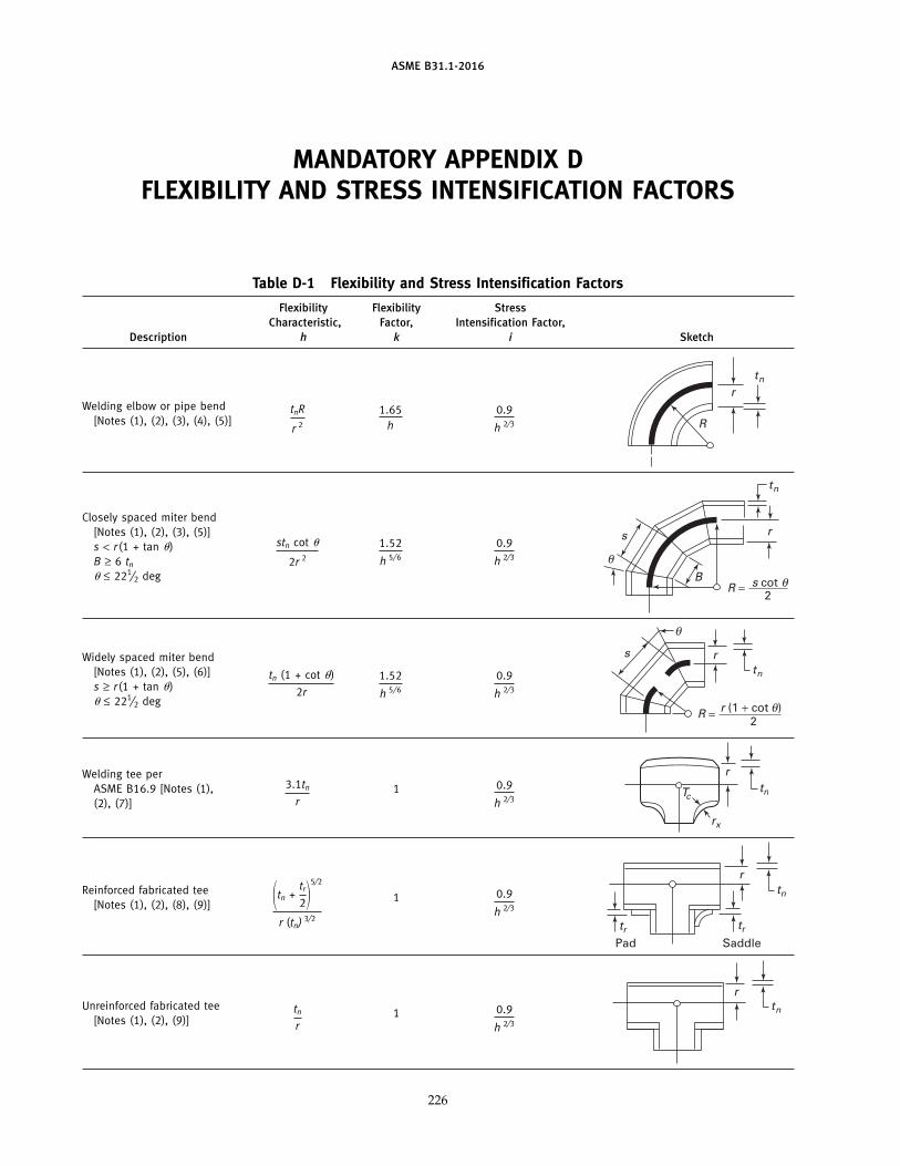
ASME B31.1-2016
MANDATORY APPENDIX DFLEXIBILITY AND STRESS INTENSIFICATION FACTORS
Table D-1 Flexibility and Stress Intensification Factors
Flexibility Flexibility StressCharacteristic, Factor, Intensification Factor,
Description h k i Sketch
Welding elbow or pipe bend 1.65h
0.9
h 2⁄3
tnR
r 2[Notes (1), (2), (3), (4), (5)]
tn
R
r
Closely spaced miter bend[Notes (1), (2), (3), (5)]s < r (1 + tan �) 1.52
h 5⁄6
0.9
h 2⁄3
stn cot �
2r 2B ≥ 6 tn
� ≤ 221⁄2 deg
tn
r
BR = s cot
2
s
θ
θ
Widely spaced miter bend[Notes (1), (2), (5), (6)] 1.52
h 5⁄6
0.9
h 2⁄3
tn (1 + cot �)
2rs ≥ r(1 + tan �)� ≤ 221⁄2 deg
tn
r
θ
θ
s
R = r (1 + cot )2
Welding tee perASME B16.9 [Notes (1), 1 0.9
h 2⁄3
3.1tn
r(2), (7)]tn
r
rx
Tc
Reinforced fabricated tee1 0.9
h 2⁄3[Notes (1), (2), (8), (9)] �tn +tr
2�5⁄2
r (tn) 3⁄2
tn
tr
SaddlePad
r
tr
Unreinforced fabricated tee1 0.9
h 2⁄3
tn
r[Notes (1), (2), (9)]tn
r
226
DUrsoU
Callout
Insert in subscript: "[Note (15)]"
DUrsoU
Text Box

ASME B31.1-2016
Table D-1 Flexibility and Stress Intensification Factors (Cont’d)
Flexibility Flexibility StressCharacteristic, Factor, Intensification Factor,
Description h k i Sketch
Branch welded-on fitting(integrally reinforced) per 1 0.9
h 2⁄3
3.3tn
rMSS SP-97 [Notes (1), (2)]
r
tn
Extruded outlet meeting therequirements of para. 1 0.9
h 2⁄3
tn
r104.3.1(G) [Notes (1), (2)]r
tn
Welded-in contour insert1 0.9
h 2⁄33.1
tn
r[Notes (1), (2), (7)] r
tn
Tc
rx
FlexibilityFactor, Stress Intensification Factor,
Description k i Sketch
For checking branch end
Branch connection1 See Fig. D-11.5 �Rm
tnh�
2⁄3
�r ′mRm
�1⁄2
�tnb
tnh� �r ′m
rp�[Notes (1), (10)]
Butt weld [Note (1)]
t ≥ 0.237 in., 1 1.0 [Note (11)]�max ≤ 1⁄16 in.,and �avg/t ≤ 0.13
Butt weld [Note (1)]
t ≥ 0.237 in., 1�max ≤ 1⁄8 in.,and �avg/t p any value
Butt weld [Note (1)]
1.9 max. or [0.9 + 2.7(�avg/t)],
t < 0.237 in., 1
but not less than 1.0
�max ≤ 1⁄16 in.,
[Note (11)]
and �avg/t ≤ 0.33
t t
δ
See Figs. 127.4.4(A), 127.4.4(B), andFillet welds 1 1.3 [Note (12)]
127.4.4(C)
1.9 max. orTapered transition per para.127.4.2(B) and 1ASME B16.25 [Note (1)] 1.3 + 0.0036
Do
tn+ 3.6
�
tn
tn
Do δ
227
DUrsoU
Callout
Insert in subscript: "[Note (15)]"
DUrsoU
Text Box

ASME B31.1-2016
Table D-1 Flexibility and Stress Intensification Factors (Cont’d)
Flexibility Stress Intensification Factor,Description Factor, k i Sketch
2.0 max. or
Concentric reducer perASME B16.9 1[Notes (1), (13)]
0.5 + 0.01� �D2
t2 �1⁄2
D1D2
t1
t2α
Threaded pipe joint or1 2.3 . . .
threaded flange
Corrugated straight pipe, orcorrugated or creased bend 5 2.5 . . .[Note (14)]
GENERAL NOTE: The validity of the stress intensification and flexibility factor data in Table D-1 has been demonstrated for Do/tn ≤ 100.
NOTES:(1) The following nomenclature applies to Table D-1:
B p length of miter segment at crotch, in. (mm)Do p outside diameter, in. (mm)
Dob p outside diameter of branch, in. (mm)D1 p outside diameter of reducer on large end, in. (mm)D2 p outside diameter of reducer on small end, in. (mm)
R p bend radius of elbow or pipe bend, in. (mm)r p mean radius of pipe, in. (mm) (matching pipe for tees)
rx p external crotch radius of welded-in contour inserts and welding tees, in. (mm)s p miter spacing at centerline, in. (mm)
Tc p crotch thickness of welded-in contour inserts and welding tees, in. (mm)tn p nominal wall thickness of pipe, in. (mm) (matching pipe for tees)tr p reinforcement pad or saddle thickness, in. (mm)� p reducer cone angle, deg� p mismatch, in. (mm)� p one-half angle between adjacent miter axes, deg
(2) The flexibility factors k and stress intensification factors i in Table D-1 apply to bending in any plane for fittings and shall in no casebe taken less than unity. Both factors apply over the effective arc length (shown by heavy centerlines in the sketches) for curved andmiter elbows, and to the intersection point for tees. The values of k and i can be read directly from Chart D-1 by entering with thecharacteristic h computed from the formulas given.
(3) Where flanges are attached to one or both ends, the values of k and i in Table D-1 shall be multiplied by the factor c given below,which can be read directly from Chart D-2, entering with the computed h: one end flanged, c p h1/6; both ends flanged, c p h1/3.
(4) The designer is cautioned that cast butt welding elbows may have considerably heavier walls than those of the pipe with which theyare used. Large errors may be introduced unless the effect of these greater thicknesses is considered.
(5) In large diameter thin-wall elbows and bends, pressure can significantly affect magnitudes of k and i. Values from the Table may becorrected by dividing k by
�1 + 6 �PEc� �r
tn�
7/3
�Rr �1/3�
and dividing i by
�1 + 3.25 �PEc� �r
tn�
5/2
�Rr �2/3�
(6) Also includes single miter joints.(7) If rx ≥ Dob/8 and Tc ≥ 1.5tn, a flexibility characteristic, h, of 4.4tn/r may be used.(8) When tr > 1.5tn, h p 4.05tn /r.(9) The stress intensification factors in the Table were obtained from tests on full size outlet connections. For less than full size outlets,
the full size values should be used until more applicable values are developed.
228
DUrsoU
Callout
Insert in subscript: "[Note (15)]"
DUrsoU
Text Box

ASME B31.1-2016
Table D-1 Flexibility and Stress Intensification Factors (Cont’d)NOTES (Cont’d):(10) The equation applies only if the following conditions are met:
(a) The reinforcement area requirements of para. 104.3 are met.(b) The axis of the branch pipe is normal to the surface of run pipe wall.(c) For branch connections in a pipe, the arc distance measured between the centers of adjacent branches along the surface of the
run pipe is not less than three times the sum of their inside radii in the longitudinal direction or is not less than two times the sumof their radii along the circumference of the run pipe.
(d) The inside corner radius r1 (see Fig. D-1) is between 10% and 50% of tnh.(e) The outer radius r2 (see Fig. D-1) is not less than the larger of Tb /2, (Tb + y)/2 [shown in Fig. D-1 sketch (c)], or tnh /2.(f ) The outer radius r3 (see Fig. D-1) is not less than the larger of:
(1) 0.002�do;(2) 2(sin �)3 times the offset for the configurations shown in Fig. D-1 sketches (a) and (b).
(g) Rm /tnh ≤ 50 and r ′m /Rm ≤ 0.5.
(11) The stress intensification factors apply to girth butt welds between two items for which the wall thicknesses are between 0.875t and1.10t for an axial distance of �Dot. Do and t are nominal outside diameter and nominal wall thickness, respectively. �avg is the aver-age mismatch or offset.
(12) For welds to socket welded fittings, the stress intensification factor is based on the assumption that the pipe and fitting are matchedin accordance with ASME B16.11 and a full weld is made between the pipe and fitting as shown in Fig. 127.4.4(C). For welds tosocket welding flanges, the stress intensification factor is based on the weld geometry shown in Fig. 127.4.4(B) and has been shownto envelop the results of the pipe to socket welded fitting tests. Blending the toe of the fillet weld, with no undercut, smoothly intothe pipe wall, as shown in the concave fillet welds in Fig. 127.4.4(A) sketches (b) and (d), has been shown to improve the fatigueperformance of the weld.
(13) The equation applies only if the following conditions are met:(a) Cone angle � does not exceed 60 deg, and the reducer is concentric.(b) The larger of D1/t1 and D2/t2 does not exceed 100.(c) The wall thickness is not less than t1 throughout the body of the reducer, except in and immediately adjacent to the cylindrical
portion on the small end, where the thickness shall not be less than t2.(14) Factors shown apply to bending; flexibility factor for torsion equals 0.9.
229
DUrsoU
Callout
(15) The designer may use the stress intensification and flexibility factors from ASME B31J instead of the stress intensification and flexibility factors herein. When using the stress intensification factors from ASME B31J, the maximum of in-plane (ii), out-plane (io), and torsional (it) stress intensification factor shall be used in calculating stresses in accordance with para. 104.8. Alternatively, stress intensification factors may be developed using ASME B31J, Appendix A.
DUrsoU
Text Box

ASME B31.1-2016
MANDATORY APPENDIX FREFERENCED STANDARDS
Specific editions of standards incorporated in this Code by reference are shown in this issue of Mandatory Appendix F. It is not practicalto refer to a specific edition of each standard throughout the Code text, but instead, the specific edition reference dates are shown here.Mandatory Appendix F will be revised at intervals as needed and issued. The names and addresses of the sponsoring organizations arealso shown in this issue.
American National Standard ASTM Specifications [Note (1)] ASTM Specifications [Note (1)](Cont’d) (Cont’d)
Z223.1-2012A307-07b A815/A815M-07a
ASCE/SEI Standard A312/A312M-13bA320/A320M-07a A928/A928M-11
7-05, 7-10 A322-07 A965/A965M-12A333/A333M-05 A992/A992M-06a
ASTM Specifications [Note (1)] A335/A335M-06A336/A336M-07 B26/B26M-05
A36/A36M-05 A350/A350M-04a B32-04A47/A47M-99 (R04) A351/A351M-06 B42-02A48/A48M-03 A354-07 B43-98 (R04)A53/A53M-07 A358/A358M-05 B61-02
A369/A369M-06 B62-02A105/A105M-05 A376/A376M-06 B68-02A106/A106M-10 A377-03 B68M-99 (R05)A125-96 (R07) A387/A387M-06a B75-02A126-04 A389/A389M-03 B88-03A134-96 (R05) A395/A395M-99 (R04) B88M-05A135/A135M-06A139/A139M-04 A403/A403M-13a B108-06A178/A178M-02 A409/A409M-01 (R05) B111/B111M-04A179/A179M-90a (R05) A420/A420M-07 B148-97A181/A181M-06 A426/A426M-07 B150/B150M-03A182/A182M-07a A437/A437M-06 B151/B151M-05A192/A192M-02 A449-07b B161-05A193/A193M-07 A450/A450M-04a B163-04A194/A194M-07a A451/A451M-06 B165-05A197/A197M-00 (R06) A453/A453M-04 B166-08
A479/A479M-11 B167-11A210/A210M-02 B168-08A213/A213M-07a A515/A515M-03 B171-04A214/A214M-96 (R05) A516/A516M-06A216/A216M-07 A530/A530M-04a B209/B209M-06A217/A217M-07 A564/A564M-04 B210-04A229/A229M-99 A575-96 (R02) B210M-05A234/A234M-07 A576-90b (R06) B221-06A240/A240M-11b A587-96 (R05) B234-04A242/A242M-04�1 B234M-04A249/A249M-07 A671-06 B241/B241M-02A254-97 (R02) A672-06 B247-02aA268/A268M-05a A691-98 (R02) B247M-02aA276-06 B251-02�1
A278/A278M-01 (R06) A714-99 (R03) B251M-97 (R03)A283/A283M-00 A789/A789M-11 B265-07A285/A285M-03 A790/A790M-11 B280-03A299/A299M-04 B283-06
233
(16)
Pete.Deubler
Callout
A1091/A1091M-16e1
DUrsoU
Cross-Out
DUrsoU
Typewritten Text
16
DUrsoU
Typewritten Text
17
DUrsoU
Typewritten Text
16
DUrsoU
Cross-Out
DUrsoU
Cross-Out
DUrsoU
Typewritten Text
, 7-16
DUrsoU
Text Box

ASME B31.1-2016
Referenced Standards (Cont’d)
ASTM Specifications [Note (1)] ASTM Specifications [Note (1)] ASME Codes & Standards(Cont’d) (Cont’d)
Boiler and Pressure Vessel Code,B302-07 B804-02 2001 Edition, includingB315-06 B828-02 AddendaB338-06a B861-06aB348-06a B862-06b�1 B1.1-1989B361-02 B1.13M-2001B366-04b�1 ASTM Standard Test Methods B1.20.1-1983 (R2001)B367-06 (ANSI/ASME B1.20.1)B381-06a D323-06 B1.20.3-1976 (R1998)
E94-04 (ANSI B1.20.3)B407-04 E125-85 (R04) B16.1-2005B408-06 E186-04 B16.3-1998B409-06�1 E280-04 B16.4-2005B423-05 E446-04 B16.5-2003B424-05 B16.9-2001B425-99 (R05) MSS Standard Practices B16.10-2000B435-06 B16.11-2005B443-00 (R05) SP-6-12 B16.14-1991B444-06 SP-9-13 B16.15-1985 (R1994)B446-03 (R08) SP-25-13 (ANSI/ASME B16.15)B462-06 SP-42-13 B16.18-1984 (R1994)B463-04 SP-43-13 (ANSI B16.18)B464-05 SP-45-03 (R08) B16.20-1998B466/B466M-07 SP-51-12 B16.21-2005B467-88 (R03) SP-53-99 (R07) B16.22-2001 (R2005)B468-04 SP-54-99 (R07) B16.24-2001B473-07 SP-55-06 B16.25-2003
SP-58-09 B16.26-2011B546-04 SP-61-13 B16.34-2004B547/B547M-02 SP-67-11 B16.42-1998B564-06a SP-68-11 B16.47-1996 (1998a)B572-06 SP-75-14 B16.48-2005B574-06�1 SP-79-11 B16.50-2001B575-06 SP-80-13B584-06a SP-83-14 B18.2.1-1996 (1999a)
SP-88-10 B18.2.2-1987 (R1999)B608-07 SP-93-99 (R04) (ASME/ANSI B18.2.2)B619-06 SP-94-92 B18.2.3.5M-1979 (R2001)B622-06 SP-95-14 B18.2.3.6M-1979 (R2001)B625-05 SP-97-12 B18.2.4.6M-1979 (R1998)B626-06 SP-105-10 B18.21.1-1999B649-06 SP-106-12 B18.22M-1981B673-05�1 B18.22.1-1965 (R1998)B674-05 AWS SpecificationsB675-02 B31.3-2002B676-03 A3.0-01 B31.4-2002B677-05 D10.10-99 B31.8-1999B688-96 (R04) QC1-07 B31Ea-2010B690-02 (R07) B31J-2008 (R2013)B691-95 API Specifications B31T-2010
B36.10M-2004B704-03 5L, 38th Edition, 1990 B36.19M-2004B705-05 570, 3rd Edition, 2009B729-05 TDP-1-1998
234
DUrsoU
Cross-Out
DUrsoU
Cross-Out
DUrsoU
Cross-Out
DUrsoU
Typewritten Text
Latest Edition
DUrsoU
Typewritten Text
CA-1, Latest Edition QAI-1, Latest Edition
DUrsoU
Line
DUrsoU
Cross-Out
DUrsoU
Typewritten Text
2017
DUrsoU
Text Box

ASME B31.1-2016
Referenced Standards (Cont’d)
AWWA and ANSI/AWWA AWWA and ANSI/AWWA National Fire CodesStandards Standards (Cont’d)
NFPA 85-11C110/A21.10-98 C300-97 NFPA 1963-09C111/A21.11-95 C301-99C115/A21.15-99 C302-95 PFI StandardsC150/A21.50-96 C304-99C151/A21.51-96 ES-16-08C153/A21.53-94 C500-93(95a) ES-24-08
C504-94C200-97 C509-94 FCI StandardC207-94C208-96 C600-99 79-1-03
C606-97
GENERAL NOTE: The issue date shown immediately following the hyphen after the number of the standard (e.g., B1.1-1989, A36/A36M-05,SP-6-12) is the effective date of issue (edition) of the standard. B18.2.2-1987 (R1999) designates specification reaffirmed without change in 1999.
NOTE:(1) For boiler external piping material application, see para. 123.2.2.
Specifications and standards of the following organizations appear in this Appendix:
AISC ASTMAmerican Institute of Steel Construction American Society for Testing and Materials1 East Wacker Drive, Suite 700 (ASTM International)Chicago, IL 60601-1802 100 Barr Harbor DrivePhone: 312 670-2400 P.O. Box C700Fax: 312 670-5403 West Conshohocken, PA 19428-2959www.aisc.org Phone: 610 832-9585
Fax: 610 832-9555ANSI www.astm.orgAmerican National Standards Institute
25 West 43rd StreetNew York, NY 10036 AWS American Welding SocietyPhone: 212 642-4900 8669 NW 36 Street, No. 130Fax: 212 398-0023 Miami, FL 33166www.ansi.org Phone: 305 443-9353 or 800 443-9353
www.aws.orgAPI American Petroleum Institute
1220 L Street, NW AWWA American Water Works AssociationWashington, DC 20005-4070 6666 West Quincy AvenuePhone: 202 682-8000 Denver, CO 80235www.api.org Phone: 303 794-7711 or 800 926-7337
www.awwa.orgASCE American Society of Civil Engineers
1801 Alexander Bell Drive FCI Fluid Controls Institute, Inc.Reston, VA 20191-4400 1300 Sumner AvenuePhone: 800 548-2723 Cleveland, OH 44115-2851
703 295-6300 (International) Phone: 216 241-7333Fax: 703 295-6222 Fax: 216 241-0105www.asce.org www.fluidcontrolsinstitute.org
ASME MSSThe American Society of Mechanical Engineers Manufacturers Standardization Society ofTwo Park Avenue the Valve and Fittings Industry, Inc.New York, NY 10016-5990 127 Park Street, NEPhone: 800-843-2763 Vienna, VA 22180-4602Fax: 973 882-1717, 5155 Phone: 703 281-6613www.asme.org www.msshq.org
235
DUrsoU
Cross-Out
DUrsoU
Typewritten Text
15
DUrsoU
Cross-Out
DUrsoU
Typewritten Text
14
DUrsoU
Callout
EJMA Expansion Joint Manufacturers Association, Inc. 25 North Broadway Tarrytown, NY 10591 Phone: 914‐332‐0040 www.ejma.org
DUrsoU
Callout
EJMA Standards Standards of the EJMA, Inc. 10th Edition 2015
DUrsoU
Line
DUrsoU
Line
DUrsoU
Callout
and Standards
DUrsoU
Callout
NFPA 56-14
DUrsoU
Cross-Out
DUrsoU
Cross-Out
DUrsoU
Cross-Out
DUrsoU
Cross-Out
DUrsoU
Cross-Out
DUrsoU
Cross-Out
DUrsoU
Cross-Out
DUrsoU
Cross-Out
DUrsoU
Cross-Out
DUrsoU
Cross-Out
DUrsoU
Cross-Out
DUrsoU
Cross-Out
DUrsoU
Cross-Out
DUrsoU
Cross-Out
DUrsoU
Cross-Out
DUrsoU
Cross-Out
DUrsoU
Cross-Out
DUrsoU
Cross-Out
DUrsoU
Typewritten Text
08
DUrsoU
Typewritten Text
07
DUrsoU
Typewritten Text
05
DUrsoU
Typewritten Text
08
DUrsoU
Typewritten Text
02
DUrsoU
Typewritten Text
06
DUrsoU
Typewritten Text
05
DUrsoU
Typewritten Text
07
DUrsoU
Typewritten Text
07
DUrsoU
Typewritten Text
04
DUrsoU
Typewritten Text
07
DUrsoU
Typewritten Text
04
DUrsoU
Typewritten Text
07
DUrsoU
Typewritten Text
02
DUrsoU
Typewritten Text
06
DUrsoU
Typewritten Text
01
DUrsoU
Typewritten Text
05
DUrsoU
Typewritten Text
06
DUrsoU
Cross-Out
DUrsoU
Typewritten Text
09
DUrsoU
Line
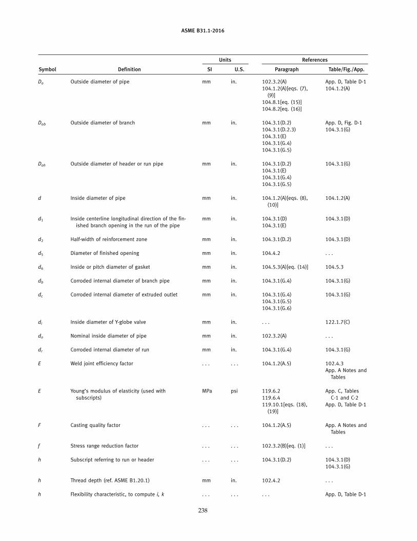
ASME B31.1-2016
Units References
Symbol Definition SI U.S. Paragraph Table/Fig./App.
Do Outside diameter of pipe mm in. 102.3.2(A) App. D, Table D-1104.1.2(A)[eqs. (7), 104.1.2(A)
(9)]104.8.1[eq. (15)]104.8.2[eq. (16)]
Dob Outside diameter of branch mm in. 104.3.1(D.2) App. D, Fig. D-1104.3.1(D.2.3) 104.3.1(G)104.3.1(E)104.3.1(G.4)104.3.1(G.5)
Doh Outside diameter of header or run pipe mm in. 104.3.1(D.2) 104.3.1(G)104.3.1(E)104.3.1(G.4)104.3.1(G.5)
d Inside diameter of pipe mm in. 104.1.2(A)[eqs. (8), 104.1.2(A)(10)]
d1 Inside centerline longitudinal direction of the fin- mm in. 104.3.1(D) 104.3.1(D)ished branch opening in the run of the pipe 104.3.1(E)
d2 Half-width of reinforcement zone mm in. 104.3.1(D.2) 104.3.1(D)
d5 Diameter of finished opening mm in. 104.4.2 . . .
d6 Inside or pitch diameter of gasket mm in. 104.5.3(A)[eq. (14)] 104.5.3
db Corroded internal diameter of branch pipe mm in. 104.3.1(G.4) 104.3.1(G)
dc Corroded internal diameter of extruded outlet mm in. 104.3.1(G.4) 104.3.1(G)104.3.1(G.5)104.3.1(G.6)
di Inside diameter of Y-globe valve mm in. . . . 122.1.7(C)
dn Nominal inside diameter of pipe mm in. 102.3.2(A) . . .
dr Corroded internal diameter of run mm in. 104.3.1(G.4) 104.3.1(G)
E Weld joint efficiency factor . . . . . . 104.1.2(A.5) 102.4.3App. A Notes and
Tables
E Young’s modulus of elasticity (used with MPa psi 119.6.2 App. C, Tablessubscripts) 119.6.4 C-1 and C-2
119.10.1[eqs. (18), App. D, Table D-1(19)]
F Casting quality factor . . . . . . 104.1.2(A.5) App. A Notes andTables
f Stress range reduction factor . . . . . . 102.3.2(B)[eq. (1)] . . .
h Subscript referring to run or header . . . . . . 104.3.1(D.2) 104.3.1(D)104.3.1(G)
h Thread depth (ref. ASME B1.20.1) mm in. 102.4.2 . . .
h Flexibility characteristic, to compute i, k . . . . . . . . . App. D, Table D-1
238
DUrsoU
Text Box
hThru wall dimension (height) of a flawmmin.App. R, R-107(a)(2) App. R, Table R-108.1 drawn normal to the inside pressure App. R, R-107(a)(4) App. R Table R-108.2 surface of the component App. R Table R-108.3 App. R Figure R-108
DUrsoU
Line
DUrsoU
Line

ASME B31.1-2016
Units References
Symbol Definition SI U.S. Paragraph Table/Fig./App.
ho Height of extruded lip mm in. 104.3.1(G.2) 104.3.1(G)104.3.1(G.4)
I Lorenz equation compensation factor . . . . . . 102.4.5[eqs. (3), (4), . . .(5), (6)]
i Stress intensification factor . . . . . . 104.8.1[eq. (15)] App. D, Table D-1104.8.2[eq. (16)]104.8.3[eq. (17)]104.8.4(C)
j Subscript for resultant moment . . . . . . 104.8.4(A) . . .
K Factor for reinforcing area . . . . . . 104.3.1(G.5) 104.3.1(G)
k Factor for occasional loads . . . . . . 104.8.2[eq. (16)] . . .
k Flexibility factor . . . . . . . . . App. D, Table D-1
L Developed length of line axis m ft 119.7.1(A.3) . . .
L1 Height of nozzle mm in. 104.8.4(C) App. D, Fig. D-1
L4 Altitude of reinforcing zone outside run pipe mm in. 104.3.1(D.2) 104.3.1(D)
L8 Altitude of reinforcing zone for extruded outlet mm in. 104.3.1(G.4) 104.3.1(G)104.3.1(G.6)
M Moment of bending or torsional force (used with mm·N in.-lb 104.8.1[eq. (15)] 104.8.4subscripts to define applications as shown in 104.8.2[eq. (16)]referenced paragraphs) 104.8.3[eq. (17)]
104.8.4(A)104.8.4(C)
MAWP Maximum allowable working pressure kPa psi 100.2 . . .
MSOP Maximum sustained operating pressure kPa psi 101.2.2 . . .
N Total number of equivalent reference displace- . . . . . . 102.3.2(B)[eq. (2)] . . .ment stress range cycles
NE Number of cycles of reference displacement . . . . . . 102.3.2(B)[eq. (2)] . . .stress range
Ni Number of cycles associated with displacement . . . . . . 102.3.2(B)[eq. (2)] . . .stress range
NPS Nominal pipe size . . . in. General . . .
239
DUrsoU
Line
DUrsoU
Line
DUrsoU
Text Box
lLength of flaw, drawn parallel mmin.App. R, R-107(a)(1) App. R Table R-108.1 to the inside pressure retainingApp. R Table R-108.2 surface of the component App. R Table R-108.3 App. R Figure R-108

ASME B31.1-2016
Units References
Symbol Definition SI U.S. Paragraph Table/Fig./App.
P Internal design gage pressure of pipe, component kPa psi 102.3.2(A) App. D, Table D-1104.1.2(A)[eqs. (7),
(8), (9), (10)]104.5.1(A)104.5.2(B)104.5.3(A)[eq. (14)]104.5.3(B)104.8.1[eq. (15)]104.8.2[eq. (16)]122.1.2(A)122.1.3(A)122.1.4(A)122.1.4(B)122.1.6(B)122.1.7(C)122.4(B)
qi Ratio of computed stress range other than refer- . . . . . . 102.3.2(B)[eq. (2)] . . .ence range (Si) to computed reference stressrange (SE)
R Reaction moment in flexibility analysis (used with mm-N in.-lb 119.10.1[eqs. (18), . . .subscripts) (19)]
R Centerline radius of elbow or bend, and effective mm in. 102.4.5(B) App. D, Table D-1“radius” of miter bends 104.3.3(C.3.1) 102.4.5
129.3.4.1
Rf Mean radius after forming mm in. 129.3.4.1 . . .
Rg Original mean radius mm in. 129.3.4.1 . . .
Rm Mean radius of run pipe mm in. . . . App. D, Fig. D-1App. D, Table D-1
r Mean radius of pipe using nominal wall tn mm in. 104.3.3 App. D, Table D-1
r1 Half width of reinforcement zone mm in. 104.3.1(G.4) 104.3.1(G)
r1, r2, r3 Transition radii of branch reinforcement mm in. . . . App. D, Fig. D-1
rb Branch mean cross-sectional radius mm in. 104.8.4 . . .
ri Inside radius of branch mm in. 104.8.4(C) App. D, Fig. D-1
r ′m Mean radius of branch mm in. 104.8.4(C) App. D, Fig. D-1App. D, Table D-1
ro Radius of curvature of external curved portion mm in. 104.3.1(G.2) 104.3.1(G)104.3.1(G.4)104.3.1(G.6)
rod Normal outside radius of pipe or tube mm in. 129.3.4.1 . . .
rp Outside radius of branch reinforcement mm in. . . . App. D, Fig. D-1App. D, Table D-1
rx External crotch radius of welded-in contour mm in. . . . App. Dinserts
240
DUrsoU
Cross-Out
DUrsoU
Callout
Po = Pressure coincident with the occasional load being evaluated kPa psi 104.8.2[eq. (16)]
DUrsoU
Text Box

ASME B31.1-2016
Units References
Symbol Definition SI U.S. Paragraph Table/Fig./App.
S Basic material allowable stress MPa psi 122.1.2(A) . . .122.1.3(B)122.4(B.3)
S Basic material allowable stress MPa ksi 102.3.1(A) App. A Tablesand Notes
Sa Bolt design stress at atmospheric temperature kPa psi 104.5.1(A) . . .
Sb Bolt design stress at design temperature kPa psi 104.5.1(A) . . .
Sc Basic material allowable stress at minimum (cold) MPa psi 102.3.2(B)[eq. (1)] . . .temperature
Sf Allowable stress for flange material or pipe kPa psi 104.5.1(A) . . .
Sh Basic material allowable stress at maximum (hot) MPa psi 102.3.2(B)[eq. (1)] . . .temperature 104.8.1[eq. (15)]
104.8.2[eq. (16)]104.8.3[eq. (17)]119.10.1 [eq. (19)]
Slp Longitudinal pressure stress kPa psi 102.3.2(A) . . .104.8
SA Allowable stress range for expansion stress MPa psi 102.3.2(B)[eq. (1)] . . .104.8.3[eq. (17)]
SE Computed thermal expansion stress range MPa psi 104.8.3[eq. (17)] . . .119.6.4119.10.1[eq. (19)]
SL Longitudinal stress due to pressure, weight, and MPa psi 102.3.2(D) . . .other sustained loads 104.8.1[eq. (15)]
SE Allowable stress (including weld joint efficiency MPa psi 102.3.2(B) . . .factor) 104.1.2(A)[eqs. (7),
(8), (9), (10)]104.5.2(B)104.5.3(A)[eq. (14)]104.5.3(B)
SE Allowable stress (including weld joint efficiency MPa ksi 102.3.1(A) App. A Tablesfactor) and Notes
SF Allowable stress (including casting quality factor) MPa psi 104.1.2(A) . . .
SF Allowable stress (including casting quality factor) MPa ksi 102.3.1(A) App. A Tablesand Notes
s Miter spacing pipe centerline mm in. . . . App. D, Table D-1
T Actual pipe wall thickness (by measurement) or mm in. 104.3.1(D.2) 104.3.1(D)the minimum wall thickness permissible under 104.3.1(G.4) 104.3.1(G)the purchase specification, used with or with- 104.3.1(G.6) App. D, Fig. D-1out subscripts, namely 104.8.4(C)
Tbpthickness of branchThpthickness of header, etc.
Tc Crotch thickness of welded-in contour inserts mm in. . . . App. D, Table D-1
241
DUrsoU
Text Box
SSeperation distance between the outermmin.App. R, R-107(a)(4) App. R Figure R-108 extent of a flaw and the nearest surface.
DUrsoU
Line
DUrsoU
Line

ASME B31.1-2016
Units References
Symbol Definition SI U.S. Paragraph Table/Fig./App.
To Corroded finished thickness extruded outlet mm in. 104.3.1(G.4) 104.3.1(G)104.3.1(G.6)
t Pressure design thickness pipe, components mm in. 104.1.2(A)[eqs. (7), 104.3.1(G)(used with subscripts) (8), (9), (10)] 104.5.3
104.3.1(D.2) 127.4.8(D)104.3.1(G.4)104.3.3(C.3.1)104.3.3(C.3.2)104.4.1(B)104.4.2104.5.2(B)[eq. (13)]104.5.3(A)[eq. (14)]104.5.3(B)104.8.1104.8.4(C)127.4.8(B)132.4.2(E)
t1,2 Nominal wall thickness of reducer mm in. . . . App. D, Table D-1
tc Throat thickness of cover fillet weld, branch mm in. 127.4.8(B) 127.4.8(D)connection 132.4.2(E) 127.4.8(E)
te Effective branch wall thickness mm in. 104.8.4(C) . . .
tm Minimum required thickness of component, mm in. 104.1.2(A)[eqs. (7), 102.4.5including allowances (c) for mechanical joining, (8), (9), (10)] 104.1.2(A)corrosion, etc. (used with subscripts), namely 104.3.1(D.2) 104.3.1(D)
tmbpminimum thickness of branch 104.3.1(E) 104.3.1(G)tmhpminimum thickness of header 104.3.1(G) 127.4.2
104.3.3(C.3.1)104.3.3(C.3.2)104.4.1(B)104.5.2(B)[eq. (13)]104.5.3(A)
tn Nominal wall thickness of component (used with mm in. 102.3.2(A.3) 127.4.4(B)subscripts), namely 104.3.3 127.4.4(C)
tnbpnominal wall thickness of branch 104.8.1[eq. (15)] 127.4.8(D)tnhpnominal wall thickness of header 104.8.2[eq. (16)] 127.4.8(E)tnrpnominal thickness of reinforcement 104.8.4(C) App. D, Fig. D-1
127.4.8(B) App. D, Table D-1129.3.4.1132.4.2(E)
tr Thickness of reinforcing pad or saddle mm in. 104.3.1(D.2) 104.3.1(D)104.3.1(E) App. D, Table D-1
ts Wall thickness of segment or miter mm in. 104.3.3(C.3) . . .
tw Weld thickness mm in. 104.3.1(C.2) 127.4.8(G)
U Anchor distance (length of straight line joining m ft 119.7.1(A.3) . . .anchors)
W Weld strength reduction factor . . . . . . 102.4.7 102.4.7104.1.4
xmin Size of fillet weld for slip-on and socket welding mm in. . . . 127.4.4(B)flanges or socket wall for socket welds
Y Resultant of movement to be absorbed by . . . . . . 119.7.1(A.3) . . .pipelines
242
DUrsoU
Typewritten Text
102.4.5(B)
DUrsoU
Typewritten Text
104.1.2
DUrsoU
Line
DUrsoU
Line
DUrsoU
Text Box

ASME B31.1-2016
MANDATORY APPENDIX JQUALITY CONTROL REQUIREMENTS FOR
BOILER EXTERNAL PIPING (BEP)
FOREWORD
This Mandatory Appendix contains the quality con-trol requirements for boiler external piping. The follow-ing is that portion of Nonmandatory Appendix A, A-301and A-302, of the ASME Boiler and Pressure Vessel Code,Section I, which is applicable to BEP.
J-1 QUALITY CONTROL SYSTEM
J-1.1 General
J-1.1.1 Quality Control System. The Manufactureror assembler shall have and maintain a quality controlsystem which will establish that all Code requirements,including material, design, fabrication, examination (bythe Manufacturer), and inspection of boilers and boilerparts (by the Authorized Inspector), will be met. Pro-vided that Code requirements are suitably identified,the system may include provisions for satisfying anyrequirements by the Manufacturer or user that exceedminimum Code requirements and may include provi-sions for quality control of non-Code work. In such sys-tems, the Manufacturer may make changes in parts ofthe system that do not affect the Code requirementswithout securing acceptance by the AuthorizedInspector. Before implementation, revisions to qualitycontrol systems of Manufacturers and assemblers ofsafety and safety relief valves shall have been foundacceptable to an ASME designee if such revisions affectCode requirements.
The system that the Manufacturer or assembler usesto meet the requirements of this Section must be onesuitable for his/her own circumstances. The necessaryscope and detail of the system shall depend on the com-plexity of the work performed and on the size and com-plexity of the Manufacturer ’s (or assembler ’s)organization. A written description of the system theManufacturer or assembler will use to produce a Codeitem shall be available for review. Depending upon thecircumstances, the description may be brief orvoluminous.
The written description may contain information ofproprietary nature relating to the Manufacturer’s (orassembler’s) processes. Therefore, the Code does notrequire any distribution of this information, except forthe Authorized Inspector or ASME designee.
245
It is intended that information learned about the sys-tem in connection with evaluation will be treated asconfidential and that all loaned descriptions will bereturned to the Manufacturer upon completion of theevaluation.
J-1.2 Outline of Features to Be Included in theWritten Description of the Quality ControlSystem
The following is a guide to some of the features thatshould be covered in the written description of the qual-ity control system and that is equally applicable to bothshop and field work.
J-1.2.1 Authority and Responsibility. The authorityand responsibility of those in charge of the quality con-trol system shall be clearly established. Persons per-forming quality control functions shall have sufficientand well-defined responsibility, the authority, and theorganizational freedom to identify quality control prob-lems and to initiate, recommend, and provide solutions.
J-1.2.2 Organization. An organization chart show-ing the relationship between management and engi-neering, purchasing, manufacturing, field assembling,inspection, and quality control is required to reflect theactual organization. The purpose of this chart is to iden-tify and associate the various organizational groups withthe particular function for which they are responsible.The Code does not intend to encroach on theManufacturer’s right to establish, and from time to timeto alter, whatever form of organization the Manufacturerconsiders appropriate for its Code work.
J-1.2.3 Drawings, Design Calculations, andSpecification Control. The Manufacturer’s or assem-bler’s quality control system shall provide proceduresthat will ensure that the latest applicable drawings,design calculations, specifications, and instructions,required by the Code, as well as authorized changes,are used for manufacture, assembly, examination,inspection, and testing.
J-1.2.4 Material Control. The Manufacturer orassembler shall include a system of receiving controlthat will ensure that the material received is properlyidentified and has documentation, including requiredmaterial certifications or material test reports, to satisfy
DUrsoU
Cross-Out
DUrsoU
Text Box

ASME B31.1-2016
Code requirements as ordered. The material control sys-tem shall insure that only the intended material is usedin Code construction.
J-1.2.5 Examination and Inspection Program. TheManufacturer’s quality control system shall describe thefabrication operations, including examinations, suffi-ciently to permit the Authorized Inspector to determineat what stages specific inspections are to be performed.
J-1.2.6 Correction of Nonconformities. There shallbe a system agreed upon with the Authorized Inspectorfor correction of nonconformities. A nonconformity isany condition that does not comply with the applicablerules of this Section. Nonconformities must be correctedor eliminated in some way before the completed compo-nent can be considered to comply with this Section.
J-1.2.7 Welding. The quality control system shallinclude provisions for indicating that welding conformsto requirements of Section IX as supplemented by thisSection.
J-1.2.8 Nondestructive Examination. The qualitycontrol system shall include provisions for identifyingnondestructive examination procedures theManufacturer will apply to conform with requirementsof this Section.
J-1.2.9 Heat Treatment. The quality control systemshall provide controls to ensure that heat treatments asrequired by the rules of this Section are applied. Meansshall be indicated by which the Authorized Inspectorcan satisfy him/herself that these Code heat treatmentrequirements are met. This may be by review of furnacetime – temperature records or by other methods asappropriate.
J-1.2.10 Calibration of Measurement and TestEquipment. The Manufacturer or assembler shall havea system for the calibration of examination, measuring,and test equipment used in fulfillment of requirementsof this Section.
J-1.2.11 Records Retention. The Manufacturer orassembler shall have a system for the maintenance ofradiographs and Manufacturers’ Data Reports asrequired by this Section.
J-1.2.12 Sample Forms. The forms used in the qual-ity control system and any detailed procedures for theiruse shall be available for review. The written descriptionshall make necessary references to these forms.
246
J-1.2.13 Inspection of Boilers and Boiler Parts
J-1.2.13.1 Inspection of boilers and boiler partsshall be by the Authorized Inspector described in PG-91.
J-1.2.13.2 The written description of the qualitycontrol system shall include reference to the AuthorizedInspector.
J-1.2.13.2.1 The Manufacturer (or assembler)shall make available to the Authorized Inspector at theManufacturer’s plant (or construction site) a currentcopy of the written description or the applicable qualitycontrol system.
J-1.2.13.2.2 The Manufacturer’s quality controlsystem shall provide for the Authorized Inspector at theManufacturer’s plant to have access to all drawings,calculations, specifications, procedures, process sheets,repair procedures, records, test results, and any otherdocuments as necessary for the Inspector to performhis/her duties in accordance with this Section. TheManufacturer may provide such access either to his/herown files of such documents or by providing copies tothe Inspector.
J-1.2.14 Inspection of Pressure-Relieving Valves
J-1.2.14.1 Inspection of safety, safety-relief, andpower-actuated pressure-relieving valves shall be bydesignated representative of the ASME, as described inPG-73.3.
J-1.2.14.2 The written description of the qualitycontrol system shall include reference to the ASMEdesignee.
J-1.2.14.2.1 The valve Manufacturer (or assem-bler) shall make available to the ASME designee at theManufacturer ’s plant a current copy of the writtendescription of the applicable quality control system.
J-1.2.14.2.2 The valve Manufacturer ’s (orassembler’s) quality control system shall provide for theASME designee to have access to all drawings, calcula-tions, specifications, procedures, process sheets, repairprocedures, records, test results, and any other docu-ments as necessary for the designee to perform his/herduties in accordance with this Section. The Manufacturermay provide such access either to his/her own files ofsuch documents or by providing copies to the designee.
DUrsoU
Cross-Out
DUrsoU
Cross-Out
DUrsoU
Text Box

ASME B31.1-2016
grout: a heavily filled paste material used to fill crevicesand transitions between piping components.
heat fusion joint: a joint made by heating the surfaces tobe joined and pressing them together so they fuse andbecome essentially one piece.
hot-gas welded joint: a joint made by simultaneously heat-ing a filler material and the surfaces to be joined witha stream of hot air or hot inert gas until the materialssoften, after which the surfaces to be joined are pressedtogether and welded with the molten filler material.
hydraulic design basis (HDB)for reinforced thermosetting resins (filament wound or cen-
trifugally cast): one of a series of established stress valuesspecified in ASTM Test Method D2992 for an RTR com-ponent, obtained by categorizing the long-term hydro-static strength determined in accordance with TestMethod D2992.
for thermoplastics: one of a series of established stressvalues specified in ASTM Test Method D2837 for a plas-tic compound, obtained by categorizing the long-termhydrostatic strength determined in accordance with TestMethod D2837. This method subjects the material totensile stress for an extended period of time, and extrap-olates the creep results to estimate the tensile strengthfor a 50-yr life.
hydrostatic design stress (HDS): the estimated maximumtensile stress in the wall of the pipe in the circumferentialorientation due to internal hydrostatic pressure that canbe applied continuously with a high degree of certaintythat failure of the pipe will not occur. Estimated byapplying a design factor, typically 0.5 for thermoplasticsin water service, to the HDB.
liner: a coating or layer of material, constructed as,applied to, or inserted within the inside surface of apiping component, intended to protect the structurefrom chemical attack, to inhibit erosion, or to preventleakage under strain.
seal weld: the addition of material external to a joint, bywelding or bonding, for the purpose of enhancing leaktightness.
249
solvent cement joint: a joint using a solvent cement tosoften the surfaces to be joined, after which the joiningsurfaces are pressed together and become essentiallyone piece as the solvent evaporates.
stiffness factor: the measurement of a pipe’s ability toresist deflection, as determined in accordance withASTM D2412.
thixotropic agent: a material added to resin to impart highstatic shear strength (viscosity) and low dynamic shearstrength.
ultraviolet absorber: a material that, when combined in aresin mixture, will selectively absorb ultravioletradiation.
woven roving: a heavy glass fiber fabric reinforcing mate-rial made by the weaving of glass fiber roving.
N-100.2.2 Abbreviations. Abbreviations used in thisAppendix denote materials and terms as follows:Abbreviation Term
ABS1 Acrylonitrile-butadiene-styreneAP PolyacetalCP Chlorinated polyetherCPVC1 Chlorinated poly (vinyl chloride)DS Design stressFEP1 Perfluoro (ethylene propylene)HDB Hydrostatic design basisHDPE High density polyethyleneHDS Hydrostatic design stressPA1 Polyamide (nylon)PB PolybutylenePE1 PolyethylenePFA Poly (perfluoroalkoxy)POP Poly (phenylene oxide)PP1 PolypropylenePPS PolyphenylenePR Pressure ratedPTFE1 PolytetrafluoroethylenePVC1 Poly (vinyl chloride)PVDC Poly (vinylidene chloride)PVDF Poly (vinlyidene fluoride)RTR Reinforced thermosetting resinSDR Standard dimension ratioSIDR Standard inside diameter dimension ratio
NOTE:(1) Abbreviation in accordance with ASTM D1600.
DUrsoU
Callout
winding angle: the acute angle (q in Fig N100.2.1) between the pipe longitudinal axis and the helical winding of the reinforcing filament being wound around a mandrel to produce a filament wound fiber-reinforced thermosetting resin pipe.
DUrsoU
Text Box

ASME B31.1-2016
listed in Tables N-102.2.1(A)-1, N-102.2.1(A)-2, andN-102.2.1(A)-3.
(B) Pipe and other piping components that do nothave allowable stresses or pressure–temperature ratingsshall be qualified for pressure design as required in para.N-104.7.
N-102.2.3 Ratings: Normal Operating Condition. Anonmetallic piping system shall be considered safe foroperation if the maximum anticipated coincident tem-perature and pressure that may act on any part or com-ponent of the system does not exceed the maximumpressure and temperature allowed by this Code for thatparticular part or component. The design pressure andtemperature shall not exceed the pressure–temperaturerating for the particular component and material asdefined in the applicable specification or standard listedin Table N-126.1. For metallic piping with nonmetalliclining, the rules of para. 102.2.3 apply, provided thatthe suitability of the lining material for the maximumanticipated coincident temperature and pressure condi-tions has been established through prior successfulextensive experience or tests.
N-102.2.4 Allowances for Pressure and TemperatureVariations
(A) Nonmetallic Piping. Allowances for variations ofpressure, temperature, or both above design conditionsare not permitted. The most severe conditions of coinci-dent pressure and temperature shall be used to deter-mine the design conditions.
(B) Metallic Piping Lined With Nonmetals. Allowancesfor pressure and temperature variations provided inpara. 102.2.4 are permitted only if the suitability of thelining material for the increased conditions is estab-lished through prior successful extensive experience ortests under comparable conditions.
N-102.2.5 Ratings at Transitions. Where two ser-vices that operate at different pressure–temperature con-ditions are connected, the valve segregating the twoservices shall be rated for the most severe service condi-tions. Other requirements of para. 102.2.5 must be con-sidered where applicable.
N-102.3 Allowable Stresses and Other Limits
N-102.3.1 Allowable Stress Values(A) General. Tables N-102.2.1(A)-1, N-102.2.1(A)-2,
and N-102.2.1(A)-3 list recommended maximum allow-able stresses in the form of hydrostatic design stresses(HDS), allowable design stresses (DS), and the hydro-static design basis (HDB) that may be used in designcalculations except where modified by other provisionsof this Appendix. The use of hydrostatic design stressesfor calculations other than pressure design has not beenestablished. The basis for determining allowable stressesand pressures is outlined in (B) below. The allowablestresses are grouped by materials and listed for stated
254
temperatures. Where sufficient data have been provided,straight-line interpolation between temperatures is per-missible. The materials listed are available from one ormore manufacturers, and some manufacturers may pub-lish somewhat different HDS values for the materialsthan the values listed in Tables N-102.2.1(A)-1,N-102.2.1(A)-2, and N-102.2.1(A)-3. The manufacturer’spublished values for these materials are acceptable foruse where they have been established in accordance with(B) below and verified in accordance with para. N-104.7.
(B) Basis for Allowable Stresses for Internal Pressure(B.1) Thermoplastics. A method of determining
hydrostatic design basis (HDB) and pressure rating (PR)is described in ASTM D2837, which also describes appli-cation of a design factor to the HDB to determine hydro-static design stress (HDS) and pressure rating (PR).Hydrostatic design stresses are provided inTable N-102.2.1(A)-1, based on HDB values listed in PPITR-4 and design factors for water from PPI TR-9. Designfactors for other services are also given in PPI TR-9.
(B.2) Reinforced Thermosetting Resin (Laminated).For laminated piping components, the design stresses(DS) are listed in Table N-102.2.1(A)-2. These typicallyare based on one-tenth of the minimum tensile strengthsspecified in Table 1 of ASTM C582.
(B.3) Reinforced Thermosetting Resin (Filament Woundand Centrifugally Cast). For filament wound and centrif-ugally cast piping components, hydrostatic design basis(HDB) values are listed in Table N-102.2.1(A)-3. Thesevalues may be obtained by procedures in ASTM D2992.HDS may be obtained by multiplying the HDB by aservice (design) factor1 selected for the application, inaccordance with procedures described in ASTM D2992,within the following limits:
(B.3.1) When using the cyclic HDB fromTable N-102.2.1(A)-3, the service (design) factor shall notexceed 1.0.
(B.3.2) When using the static HDB fromTable N-102.2.1(A)-3, the service (design) factor shall notexceed 0.5.
N-102.3.2 Limits of Calculated Stresses Due toSustained Loads
(A) Internal Pressure Stresses. The limits for stress dueto internal pressure are provided in para. N-104.1.2.
(B) External Pressure Stresses. Thermoplastic piping,reinforced thermosetting resin piping, and metallic pip-ing lined with nonmetals, subject to external pressure,shall be considered safe when the wall thickness and/or means of stiffening meet the requirements ofpara. N-104.7.2.
1 The service (design) factor, F, should be selected by the designerafter evaluating fully the service conditions and the engineeringproperties of the specific material under consideration. Aside fromthe limits in paras. N-102.3.1(B.3.1) and (B.3.2), it is not the intentof this Code to specify service (design) factors.
DUrsoU
Callout
Add New Para. (see next page)
DUrsoU
Text Box

(B.3.3) The evaluation of stresses in filament wound reinforced thermosetting resin pipe and fitting components must consider the different strengths in the hoop and axial directions of the material. For a 55 degree filament winding angle (which is typical for filament wound pipe), the axial strength is approximately ½ of the hoop strength of the material. For greater winding angles, the axial strength will be even lower. The figure N-102.1.3(B.3.3) shows a typical axial strength versus hoop strength diagram for a filament wound material. The data points for the axial strength at zero hoop stress and the axial strength at the maximum hoop stress will need to be provided by a vendor for his specific product, since no generic allowable stress diagrams currently exist. Note that for most filament wound fiberglass products, the portion of the allowable axial stress available for weight, thermal expansion and occasional loads will approach zero as the hoop stress approaches the maximum allowable limit for the material.
(B.3.4) The stress analysis of the filament wound pipe and fitting components must consider both the simultaneous axial and hoop stresses at each point in the piping system, and take into account any hoop stress, stress intensification factors (SIF’s) as well as axial stress SIF’s that may be applicable to a given component.
Figure N-2.3.1(B.3.3) - Typical Allowable Stress Curve for Filament Wound Reinforced Thermosetting Resin Pipe

(B.3.5) Note that for above ground pipe, due to the different axial and hoop strengths of filament wound reinforced thermosetting resin pipe and fitting components, the minimum wall thickness required for the pipe and fitting components may be governed by the axial strength requirements, rather than just hoop strength considerations.
Hoop Stress
Axial Stress
Curve of Hoop Stress versus Axial Stress due to internal pressure
Typical Allowable stress curve from vendor
Portion of axial stress allowable limit that may be used for bending stresses due to weight, thermal expansion and occasional loads
Axial stress due to internal pressure for given hoop stress value

ASME B31.1-2016
joint and one pipe-to-fitting joint. The size of the pipeused for the test assembly shall be as follows:
(C.1.1) When the largest size to be joined (withinthe BPS) is NPS 4 or smaller, the test assembly shall bethe same NPS as the largest size to be joined.
(C.1.2) When the largest size to be joined withinthe BPS is greater than NPS 4, the test assembly shallbe made of piping components either NPS 4 or a mini-mum of 25% of the NPS of the largest piping componentto be joined, whichever is larger.
(C.2) The test assembly shall be subjected to oneof the following qualification test operations:
(C.2.1) When the test assembly has been cured,it shall be subjected to a hydrostatic pressure test of themaximum of either 150 psig or 1.5 times an equivalentallowable pressure, which shall be calculated using theleast nominal wall thickness and outside diameter ofthe pipe in the test assembly. This pressure shall bedetermined using the equation in para. N-104.1.2(A) forthe test material. The test shall be conducted so that thejoint is loaded in both the circumferential and longitudi-nal directions. Joints shall not leak or separate whentested.
(C.2.2) When a test assembly is joined by heatfusion, the fusion joints may be tested by cutting a mini-mum of three coupons containing the joint and bendingthe strips using a procedure that shall be defined in theBPS. As a minimum requirement, the test strips shallnot break when bent a minimum of 90 deg, at ambienttemperature, over an inside bend radius of 1.5 times thenominal diameter of the tested pipe.
(D) Performance Requalification(D.1) Renewal of a bonding performance qualifica-
tion is required when(D.1.1) a bonder or bonding operator has not
used the specific bonding process for a period of timegreater than 6 months, or a specific maximum periodof time otherwise permitted in the BPS for the work
(D.1.2) there is a specific reason to question abonder or bonding operator’s ability to make bonds thatmeet the BPS
(D.2) Renewal of a bonding performance qualifica-tion for a specific bonding process may be made in onlya single test assembly.
N-127.6 Qualification Records
An erector using bonders or bonding operators shallmaintain a record of the procedures used and of opera-tors employed by him/her who are qualified in theseprocedures.
N-127.7 Thermoplastic Pipe Joints
N-127.7.1 Solvent-Cemented Joints(A) Preparation. PVC and CPVC surfaces to be
cemented shall be cleaned by wiping with a clean clothmoistened with acetone or methylethyl ketone. Cleaning
269
Fig. N-127.7.1(B) Solvent-Cemented Joint
for ABS shall conform to ASTM D2235. Cuts shall befree of burrs and circumferential cuts shall be as squareas those obtained by the use of a saw with a miter boxor a square-end sawing vise. A slight interference fitbetween the pipe and a fitting socket is preferred, andthe diametral clearance between a pipe and the entranceof a mating socket shall not exceed 0.04 in. This fit shallbe checked before solvent cementing.
(B) Procedure. Joints shall be made in accordance witha qualified BPS. ASTM D2855 provides a suitable basisfor such a procedure. Solvent cements for PVC, CPVC,and ABS shall conform to ASTM D2564, D2846, andD2235, respectively. Cement shall be sufficient to pro-duce a small continuous fillet of cement at the outerlimits of the joints. See Fig. N-127.7.1(B).
(C) Branch Connections. For branch connections notusing a tee, a manufactured full reinforcement saddlewith an integral branch socket shall be solvent cementedto the run pipe over its entire contract surface.
(D) Limitations on Imperfections. Imperfectionsexceeding the following limitations are considereddefects and shall be repaired and reexamined in accor-dance with para. N-127.7.3:
(D.1) protrusion of dried cement exceeding 50% ofpipe wall thickness into the bore of the pipe
(D.2) unfilled or unbonded areas in a joint, as indi-cated by the lack of interruption of the continuous filletnoted in (B) above
N-127.7.2 Heat and Fusion Joints(A) Preparation. Surfaces to be heat fused together
shall be cleaned of any foreign material. Cuts shall befree of burrs, and circumferential cuts shall be as squareas those obtained by the use of a saw with a miter boxor a square-end sawing vise.
(B) Procedure. Joints shall be made in accordance witha qualified BPS. The general procedures in ASTM D2657,Technique I — Socket Fusion, Technique II — ButtFusion, and Technique III — Saddle Fusion, provide asuitable basis for such a procedure. Both surfaces to bejoined shall be uniformly heated to produce a continuous
DUrsoU
Cross-Out
DUrsoU
Callout
FPS (Fusion Procedure Specification) that meets the applicable requirements of ASME BPVC Section IX Part QF. For socket fusion and saddle fusion joints not addressed in Part QF, ASTM D2657 provides a basis for FPS development.
DUrsoU
Text Box

ASME B31.1-2016
Fig. N-127.7.2(B) Heat Fusion Joints
(a) Socket Joint (b) Butt Joint
homogeneous bond between them. This will produce asmall continuous fillet of fused material at the outerlimits of the joints. See Fig. N-127.7.2(B).
(C) Branch Connections. Branch connections shall bemade only with the use of molded fittings in sizes thatare commercially available.
(D) Limitations on Imperfections. Imperfectionsexceeding the following limitations are considereddefects and shall be repaired and reexamined in accor-dance with para. N-127.7.3:
(D.1) protrusion of fused material exceeding 25%of the pipe wall thickness into the bore of the pipe
(D.2) unfilled or unbonded areas in a joint as indi-cated by the lack or interruption of the continuous filletnoted in (B) above
N-127.7.3 Electrofusion Joints(A) Preparation. Surfaces to be heat fused together
shall be cleaned of all foreign material.(B) Procedure. Joints shall be made in accordance with
the qualified BPS. The general procedures inASTM F1290, Technique 1 — Coupling Procedure andTechnique 2 — Saddle Procedure, provide a suitablebasis for the development of such a procedure. SeeFig. N-127.7.3(B).
N-127.7.4 Repair of Defects. Defective material,joints, and other workmanship in piping that fail to meetthe requirements of Chapters N-III and N-V, and of theengineering design, shall be repaired or replaced. Limi-tations on imperfections, and the method and extent ofthe required examination of repairs and replacements,shall be the same as for the original work.
N-127.8 FRP Pipe Joints
N-127.8.1 Thermosetting Resin Joints(A) Preparation. Cutting of pipe and preparation of
bonding surfaces shall be done as recommended by themanufacturer, without chipping or cracking of the cutends; particularly, the inner surface of centrifugally cast
270
pipe. Pipe may be preheated, if necessary, to complywith the above requirements. Cuts shall be free of burrs,and circumferential cuts shall be as square as requiredby the purchaser’s specifications or the recommenda-tions of the manufacturer, whichever requires the closersquareness. For branch connections, holes in the runpipe may be made with a hole saw. Mold-release agent,and any other material that may interfere with adhesion,shall be removed from surfaces to be bonded.
(B) Joining Procedures(B.1) Socket and Spigot Joints. Joints shall be made
in accordance with a qualified BPS based on the manu-facturer ’s recommended procedure. Application ofadhesive to the surfaces to be joined and assembly ofthose surfaces shall produce a continuous bond betweenthem. Cut ends of the pipe and edges of the laminatefabric shall be sealed to prevent fluid penetration of thepipe wall or the laminate material. See Fig. N-127.8.1(B).
(B.2) Butt-and-Wrap Joints. Joints shall be made inaccordance with a qualified BPS. The general proceduresin ASTM C582, Contact-Molded ReinforcedThermosetting Plastic (RTP) Laminated for CorrosionResistant Equipment, provide a suitable basis for thedevelopment of such a procedure. Application of pliesof reinforcement, saturated with catalyzed resin, to thesurfaces to be joined shall produce a continuous struc-ture with the surfaces. Cut ends shall be sealed asrequired in (B.1) above. See Fig. N-127.8.1(B).
(C) Branch Connections. Branch connections shall bemade using a manufactured tee fitting or a full reinforce-ment saddle having suitable provisions for joining as in(B) above. The cut edges of any hole in the run pipeshall be sealed with adhesive at the time the saddle isbonded to the run pipe.
(D) Limitations on Imperfections. Imperfectionsexceeding the following limitations are considereddefects and shall be repaired and reexamined in accor-dance with para. N-127.7.3:
(D.1) protrusion of adhesive exceeding 25% of pipewall thickness into the bore at the bottom of a socket,or inside a branch connection
(D.2) unfilled or unbonded areas in the joint
N-127.8.2 Repair of Defects. Defective material,joints, and other workmanship in piping that fail to meetthe requirements of Chapters N-III and N-V, and of theengineering design, shall be repaired or replaced. Limi-tations on imperfections, and the method and extent ofthe required examination of repairs and replacements,shall be the same as for the original work.
N-127.9 Welding of Metallic Piping Lined WithNonmetals
Welding is not permitted on lined components in thefield. Welding performed by the manufacturer to pro-duce pipe, fittings, and flanges to be used in an elasto-meric lined piping system shall conform to the
DUrsoU
Cross-Out
DUrsoU
Callout
a qualified FPS that meets the requirements of ASME BPVC Section IX Part QF. See Fig. N-127.7.3(B).

ASME B31.1-2014
MANDATORY APPENDIX P METALLIC BELLOWS EXPANSION JOINTS
Design requirements of Appendix P are dependent on and compatible with Standards of the Expansion Joint Manufacturers Association, Inc.
(EJMA Standards)
P-1 GENERAL
The intent of this Appendix is to set forth design, manufacturing, and installation requirements and considerations for bellows type expansion joints, supplemented by the EJMA Standards. It is intended that applicable provisions and requirements of Chapters I through VI of this Code shall be met, except as modified herein. This Appendix does not specify design details. The detailed design of all elements of the expansion joint is the responsibility of the manufacturer.
P-2 PIPING DESIGNER RESPONSIBILITIES
The piping designer shall specify the design conditions and requirements necessary for the detailed design and manufacture of the expansion joint in accordance with para. P-2.1 and the piping layout, anchors, restraints, guides, and supports required by para. P-2.2.
P-2.1 Expansion Joint Design Conditions
The piping designer shall specify all necessary design conditions including the following.
P-2.1.1 Static Design Conditions. The design conditions shall include any possible variations of pressure or temperature, or both, above operating levels. Use of a design metal temperature other than the fluid temperature for any component of the expansion joint shall be verified by computation, using accepted heat transfer procedures, or by test or measurement on similarly designed equipment in service under equivalent operating conditions.
P-2.1.2 Cyclic Design Conditions. These conditions shall include coincident pressure, temperature, imposed end displacements and thermal expansion of the expansion joint itself, for cycles during operation. Cycles due to transient conditions (startup, shutdown, and abnormal operation) shall be stated separately. (See EJMA Standards, 4.12.1.5 on fatigue life expectancy, for guidance in defining cycles.)
P-2.1.3 Other Loads. Other loads, including dynamic effects (such as wind, thermal shock, vibration, seismic forces, and hydraulic surge); and static loads, such as weight (insulation, snow, ice, etc.), shall be stated.
P-2.1.4 Fluid Properties. Properties of the flowing medium pertinent to design requirements, flow velocity and direction, for internal liners, etc., shall be specified.
P-2.1.5 Other Design Conditions. Other conditions that may affect the design of the expansion joint, such as use of shrouds, external or internal insulation, limit stops, other constraints, and connections in the body (e.g., drains or bleeds) shall be stated.
P-2.2 Piping Design Requirements
P-2.2.1 General. Piping layout, anchorage, restraints, guiding, and support shall be designed to avoid imposing motions and forces on the expansion joint other than those for which it is intended. For example, a bellows expansion joint is not normally designed to absorb torsion. Pipe guides, restraints, and anchorage shall conform to the EJMA Standards. Anchors and guides shall be provided to withstand expansion joint thrust forces when not self-restrained by tie rods, hinge bars, pins, etc. (See para. P-3.1.) Column buckling of the piping (e.g., due to internal fluid pressure) shall also be considered.
P-2.2.2 Design of Anchors (a) Main Anchors. Main anchors shall be designed to withstand the forces and moments listed in P-2.2.2(b), and pressure thrust, defined as the product of the effective thrust area of the bellows and the maximum pressure to which the joint will be subjected in operation. Consideration shall be given to the increase of pressure thrust loads on anchors due to unrestrained expansion joints during leak testing if supplemental restraints are not used during the test (see para. 137.2.3). For convoluted, omega, or disk type joints, the effective thrust area recommended by the manufacturer shall be used. If this information is unavailable, the area shall be based on the mean diameter of the bellows. (b) Intermediate Anchors. Anchors shall be capable of withstanding the following forces and moments: (1) those required to compress, extend, offset, or rotate the joint by an amount equal to the calculated linear or angular displacement (2) static friction of the pipe in moving on its supports between extreme extended and contracted positions (with calculated movement based on the length
DUrsoU
Text Box

ASME B31.1-2014
of pipe between anchor and expansion joint) (3) operating and transient dynamic forces caused by the flowing medium (4) other piping forces and moments
P-3 EXPANSION JOINT MANUFACTURER RESPONSIBILITIES
The expansion joint manufacturer shall provide the detailed design and fabrication of all elements of the expansion joint in accordance with the requirements of the Code and the engineering design. This includes (a) all piping within the end connections of the assembly supplied by the manufacturer, including pipe, flanges, fittings, connections, bellows, and supports or restraints of piping (b) specifying the need for supports or restraints external to the assembly as required, and of the data for their design (c) determining design conditions for all components supplied with the expansion joint that are not in contact with the flowing medium
P-3.1 Expansion Joint Design
The design of bellows-type expansion joints shall be based on recognized and accepted analysis methods and design conditions stated in para. P-2.1. These joints shall be designed so that permanent deformation of the expansion joint and pressure-restraint hardware will not occur during leak testing. Convoluted-type bellows shall be designed in accordance with the EJMA Standards, except as otherwise required or permitted herein. Design of other types of bellows shall be qualified as required by para. 104.7.2.
P-3.1.1 Factors of Safety. The factor of safety on squirm pressure shall be not less than 2.25. (See EJMA Standards, 4.12.1.6 on bellows stability and squirm.) The factor of safety on ultimate rupture pressure shall be not less than 3.0.
P-3.1.2 Design Stress Limits. For convoluted type bellows, stresses shall be calculated either by the formulas shown in the EJMA Standards or by other methods acceptable to the owner. (a) Stresses shall be calculated in restraints (tie rods, hinge bars, pins, etc.) in self-restrained expansion joints and in the attachments of the restraining devices to the pipe or flanges. Direct tension, compression, bearing, and shear stresses shall not exceed the allowable stress limits stated in para. 102.3.1. The summation of general bending stress plus tension or compression stress shall not exceed the stress values listed in Appendix A, times the shape factor of the cross section. The shape factor is the
ratio of the plastic moment to the yield moment (e.g., 1.5 for a rectangular section). For attachment of restraints to piping, see para. 121.8. Local stresses may be evaluated using the criteria of ASME Section VIII, Division 2, Part 5. Compression members shall be evaluated for buckling in accordance with the AISC Manual of Steel Construction, Allowable Stress Design. For self-restrained expansion joints, the restraints shall be designed to withstand the full design pressure thrust. Additional considerations may be required where time-dependent stresses prevail. (b) Pressure design of pipe sections, fittings, and flanges shall meet the requirements of paras. 103 and 104. (c) When the operating metal temperature of the bellows element is in the creep range,1 the design shall be given special consideration and, in addition to meeting the requirements of this Appendix, shall be qualified as required by para. 104.7.2.
P-3.1.3 Fatigue Analysis (a) A fatigue analysis1 that takes into account all design cyclic conditions shall be performed and the calculated design cycle life shall be reported. The method of analysis for convoluted U-shaped bellows shall be in accordance with EJMA Standards. (b) Material design fatigue curves for bellows with seams welded using an autogenous method are provided in the EJMA Standards. The curves are for use only in conjunction with the EJMA stress equations. (c)Fatigue testing in accordance with Appendix F of the EJMA standards is required to develop fatigue curves for bellows of materials other than those provided for use in conjunction with the EJMA stress equations. (d)When applying the fatigue curves from the EJMA Standards, a fatigue correction factor, fc=0.75, shall be used. (e)An alternate fatigue correction factor, fc, may be used with the permission of the owner.
P-3.1.4 Limitations (a) Expansion joint bellows shall not be constructed from lap welded pipe or lap welded tubing. (b) All pressure containing or pressure thrust restraining materials shall conform to the requirements of Chapter III and Appendix A.
P-3.2 Expansion Joint Manufacture
Expansion joints shall be produced in accordance with the manufacturer’s specification, which shall include at least the following requirements.
P-3.2.1 Fabrication
DUrsoU
Text Box

ASME B31.1-2014
(a) All welds shall be made by qualified welders or welding operators using welding procedures qualified as required by para. 127.5. (b) The longitudinal seam weld in the bellows element shall be a full penetration butt weld. Prior to forming, the thickness of the weld shall be not less than 1.00 nor more than 1.10 times the thickness of the bellows material. (c) A full fillet weld may be used as a primary weld to attach a bellows element to an adjoining piping component. (d) When bellows are attached directly to an adjoining piping component by welding and the piping component is P-Nos. 4, 5A, or 5B base metal, the attachment weld shall be heat treated in accordance with para. 132, except that the exemptions from heat treatment given in para. 132.3 shall not be permitted. The holding time shall be based on the thickness of the piping component at the bellows attachment weld location. Examination of the attachment welds shall be performed after heat treatment. This heat treatment may affect bellows pressure capacity, mechanical properties, and corrosion resistance. If the required heat treatment is determined to be detrimental to the bellows’ performance, the bellows shall not be attached directly to the piping component. In that case, the piping component side of the weld joint shall be buttered in accordance with ASME Section IX, para. QW-283 with appropriate filler metal, heat treated in accordance with Table 132, and then welded to the bellows.
P-3.2.2 Examination. The following are minimum quality control requirements: (a) Required examinations shall be in accordance with para. 136. (b) The bellows tube longitudinal seam weld shall be 100% visually examined (VT) on both the inside and outside surfaces prior to forming. Also, the longitudinal seam weld shall be 100% examined prior to forming either by radiography (RT) or, for material thickness ≤ 3⁄32 in.(2.4 mm) welded in a single pass, by liquid penetrant (PT) of both inside and outside surfaces. For the purposes of this Appendix, either RT or PT is acceptable for design with a weld joint efficiency factor E of 1.00 when used within the stated thickness limits. (c) After forming, a liquid penetrant examination shall be conducted on all accessible surfaces of the longitudinal seam weld, inside and outside. Welds attaching the bellows to the piping, etc., shall be 100% liquid penetrant examined. (d) Acceptance criteria for RT shall be in accordance with para. 136.4.5. Acceptance criteria for PT shall be in accordance with para. 136.4.4. Acceptance criteria for VT shall be that cracks,
undercutting, and incomplete penetration are not permitted.
P-3.2.3 Leak Test (a) Each expansion joint shall receive a hydrostatic or pneumatic shop pressure test by the manufacturer in accordance with para. 137, except that the test pressure shall be the lesser of that calculated by eq. (P1) or eq. (P2), but not less than 1.5 times the design pressure. Rr in eq. (P2) shall be based on the bellows material. When the bellows design temperature is equal to or greater than Tcr,
2 Rr in eq. (P2) shall be replaced by SyT/Syt, where SyT is the yield strength at the test temperature and Syt is the yield strength at the bellows design temperature. The test pressure shall be maintained for not less than 10 min.
PT = 1.5 PS Et/E (P1)
where E = Young’s modulus of elasticity at
design temperature Et = Young’s modulus of elasticity at
test temperature PS = limiting design pressure based on
column instability (for convoluted U-shaped bellows, see 4.13.1 and 4.13.2 of the EJMA Standards)
PT = minimum test gage pressure
PT = 1.5 P Rr (P2)
where
P = internal design gage pressure
Rr = ST/S, but shall not exceed 6.5
ST = allowable stress at test temperature
S = allowable stress at design temperature
(b) Expansion joints designed to resist the pressure thrust shall not be provided with any additional axial restraint during the leak test. Moment restraint simulating piping rigidity may be applied if necessary. (c) In addition to examination for leaks and general structural integrity during the pressure test, the expansion joint shall be examined before, during, and after the test to confirm that no unacceptable squirm has occurred. Squirm shall be considered to have occurred if under the internal test pressure an initially symmetrical bellows deforms, resulting in lack of parallelism or uneven spacing of convolutions. Such deformation shall be considered unacceptable when the maximum ratio of bellows pitch under pressure to the
DUrsoU
Text Box

ASME B31.1-2014
pitch before applying pressure exceeds 1.15 for unreinforced bellows or 1.20 for reinforced bellows. Examination for leakage and deformation shall be performed at a pressure not less than two-thirds of the test pressure, after full test pressure has been applied. (d) Examination for squirm shall be performed at full test pressure. For safety purposes, this may be accomplished by remote viewing (e.g., by optical magnification or video recording) of the changes in convolution spacing with respect to a temporarily mounted dimensional reference. Examination for leakage shall be performed at a pressure not less than two-thirds of test pressure, after application of full test pressure. For a pneumatic test, the precautions of para. 137.5 shall be observed. _________________________________________ 1 Consideration shall be given to the detrimental effects of creep-fatigue interaction when the operating metal temperature of the bellows element will be in the creep range. Creep-fatigue interaction may become significant at temperatures above 800°F (425°C) for austenitic stainless steels. 2 Tcr = temperature 50°F (25°C) below the temperature identifying the start of time-dependent properties listed under “NOTES – TIME-DEPENDENT PROPERTIES” (Txx) in the Notes to Table 1A of ASME Section II, Part D for the base materials joined by welding.
DUrsoU
Text Box

Mandatory Appendix R Use of Alternative Ultrasonic Acceptance criteria
R-100 General
This Appendix provides an alternative ultrasonic fracture mechanics based acceptance criteria that may be used for Code piping welds in lieu of those described in para. 136.4.6 (B).
R-101 Scope
a) The examination shall be conducted using automated or semi-automated techniques utilizing computer based data acquisition.
b) The examination shall be performed in accordance with a written procedure approved by a UT (Ultrasonic Testing) Level III and conforming to the requirements of ASME Section V, Article 4 Mandatory Appendix VIII and: 1) For Phased Array – ASME Section
V, Article 4, Mandatory Appendix V.
2) For Time of Flight Diffraction (TOFD) - ASME Section V, Article 4, Mandatory Appendix III.
c) Procedure qualification shall meet the requirements of ASME Section V, Article 4, Mandatory Appendix IX.
R-102 Equipment
A mechanical guided scanner capable of maintaining a fixed and consistent search unit position relative to the weld centerline shall be used.
R-103 Personnel
a) Personnel performing nondestructive examination to the requirements of this Appendix shall be qualified and certified i n t h e U l t r a s o n i c me t h o d i n a c c o r d a n c e w i t h a procedure or program as described in BPV Code, Section V, Article 1, T-120 (e),or (f), and (g).
b) Set-up and scanning of welds shall be performed by personnel certified as UT
Level II or III (or by Level I personnel under the direct supervision of Level II or Level III personnel).
c) Interpretation and evaluation of data shall be performed by NDE Level II or III personnel.
d) Personnel demonstration requirements shall be as stated in ASME Section V, Article 4 Mandatory Appendix VIII.
R-104 Examination
a) The initial straight beam scan for reflectors that could interfere with the angle beam examination shall be performed (a) manually, (b) as part of a previous manufacturing process, or (c) during the weld examination, provided detection of these reflectors is included in the demonstration as required in R-101(c).
b) The examination area shall include the volume of the weld, plus the lesser of 1 .0 in . (25mm) or t of adjacent base metal. Alternatively, the examination volume may be reduced to include the actual heat affected zone (HAZ) plus 0.25 in. (6mm) of base material beyond the heat affected zone on each side of the weld, provided the extent of the weld HAZ is measured and documented.
R-105 Data Recording
Data shall be recorded in the unprocessed form as specified in Section V, Article 4, V-471.6. The data record shall include the complete examination area as specified in R-104 (b).
R-106 Data Analysis
a) Reflectors exceeding the limits below shall be investigated to determine whether the indication originates from a discontinuity or is a geometric indication in accordance with (b) below.
1) For amplitude based techniques,

the location, amplitude, and extent of all reflectors that produce a response greater than 20% of the reference level shall be evaluated.
2) For non-amplitude based techniques, the location and extent of all images that have an indicated length greater than 0.16 in (4.0mm) shall be investigated.
b) Ultrasonic indications of geometric and/or metallurgical origin shall be classified as specified in ASME Section V, Article 4 Paragraph T-481.
1) Alternatively, other techniques or NDE methods may be used to classify an indication as geometric (e.g., alternative beam angles, radiography). The method employed is for information only to classify the indication as geometric, and ASME B31.1 requirements for examination techniques are only required to the extent they are applicable.
R-107 Discontinuity Evaluation a) The dimension of the discontinuity(s) shall
be determined by the rectangle that fully contains the area of the discontinuity(s). (Refer to Figure R-108)
1) The length, ℓ, of the discontinuity shall be drawn parallel to the inside pressure retaining surface of the component.
2) The height, h, of the discontinuity shall be drawn normal to the inside pressure retaining surface of the component.
3) The discontinuity shall be characterized as a surface or
subsurface discontinuity, as shown in Figure R-108.
4) A subsurface indication shall be considered as a surface discontinuity if the separation (S in Figure R -108) of the indication from the nearest surface of the component is equal to or less than half the through wall dimension (h in Figure R-108, sketch [b]) of the subsurface indication.
b) Multiple Discontinuities
1) Discontinuous indications that are oriented primarily in parallel planes shall be considered to lie in a single plane if the distance between the adjacent planes is equal to or less than 0 .50 in .(13mm) or 0.5t, whichever is less.
2) If the space between two indications aligned along the axis of weld is less than the height of the indication of greater height, the two discontinuities shall be considered a single discontinuity.
3) If the space between two indication aligned in the through-thickness dimension is less than the height of the indication of greater height, the two indications shall be considered a single discontinuity.
R-108 Discontinuity Acceptance Criteria
Discontinuities shall be evaluated using the applicable criteria of Tables R-108.1 through R-108.3. Regardless of discontinuity height or aspect ratio, discontinuity length shall not exceed 4t
TABLE R-108.1 Discontinuity Acceptance Criteria for Weld Thickness
<25mm (1.0 in.)
h/t ℓ Surface discontinuity < 0.100 < 6.4 mm (0.25 in.) Subsurface discontinuity < 0.286 < 6.4 mm (0.25 in.)

GENERAL NOTES: (a) t = thickness of the weld excluding any allowable reinforcement. For a butt joint joining two members
having different thickness at the joint, t is the thinner of the two thicknesses joined. If a full penetration weld includes a fillet weld, the effective throat dimension of the fillet weld shall be included in t.
(b) A discontinuity is considered rejectable if its dimensions exceed the h/t value or the ℓ value in the Table above.
TABLE R-108.2 Surface Discontinuity Acceptance Criteria for Weld Thickness > 25mm (1.0in.)
Aspect Ratio, h/ℓ
Weld Thickness > 25mm to 64mm (1.0 in. to 2.5 in.)
> 64mm to < 100mm (2.5 in. to 3.9 in.)
100mm to 300mm (3.9 in. to 11.8 in.)
h/t
(See Note C)
h/t 0.00 < 0.031 < 0.019 0.05 < 0.033 < 0.020 0.10 < 0.036 < 0.022 0.15 < 0.041 < 0.025 0.20 < 0.047 < 0.028 0.25 < 0.055 < 0.033 0.30 < 0.064 < 0.038 0.35 < 0.074 < 0.044 0.40 < 0.083 < 0.050 0.45 < 0.085 < 0.051 0.50 < 0.087 < 0.052
General Notes: (a) t = thickness of the weld excluding any allowable reinforcement.
For a butt joint joining two members having different thickness at the joint, t is the thinner of the two thicknesses joined. If a full penetration weld includes a fillet weld, the effective throat dimension of the fillet weld shall be included in t.
(b) Aspect Ratio (h/ℓ) used may be determined by rounding the calculated h/ℓ down to the nearest 0.05 increment value within the column, or by linear interpolation.
(c) Regardless of discontinuity height or aspect ratio, discontinuity length shall not exceed 4t.
(d) For intermediate thickness t (weld thicknesses between 64mm and 100mm [2.5 in. and 3.9 in.]) linear interpolation is required to obtain h/t values.

TABLE R-108.3 Subsurface Discontinuity Acceptance Criteria for Weld Thickness > 25mm (1.0in.)
Aspect Ratio, h/ℓ
Weld Thickness > 25mm to 64mm (1.0 in. to 2.5 in.)
> 64mm to < 100mm (2.5 in. to 3.9 in.)
100mm to 300mm (3.9 in. to 11.8 in.)
h/t
(See Note C)
h/t 0.00 < 0.068 < 0.040 0.10 < 0.076 < 0.044 0.20 < 0.086 < 0.050 0.30 < 0.098 < 0.058 0.40 < 0.114 < 0.066 0.50 < 0.132 < 0.076 0.60 < 0.156 < 0.088 0.70 < 0.180 < 0.102 0.80 < 0.210 < 0.116 0.90 < 0.246 < 0.134 1.00 < 0.286 < 0.152
General Notes: (a) t = thickness of the weld excluding any allowable
reinforcement. For a butt joint joining two members having different thickness at the joint, t is the thinner of the two thicknesses joined. If a full penetration weld includes a fillet weld, the effective throat dimension of the fillet weld shall be included in t.
b) Aspect Ratio (h/ℓ) used may be determined by rounding the calculated h/ℓ down to the nearest 0.05 increment value within the column, or by linear interpolation.
c) Regardless of discontinuity height or aspect ratio, discontinuity length shall not exceed 4t.
d) For intermediate thickness t (weld thicknesses between 64mm and 100mm [2.5 in. and 3.9 in.]) linear interpolation is required to obtain h/t values.

Figure R-108: Surface and Subsurface Indications
h h
(a) Surface Discontinuity
S < 0.5h
(b) Surface Discontinuity
h
S > 0.5h (c) Subsurface Discontinuity

ASME B31.1-2016
Fig. II-2-1 Discharge Elbow (Open Discharge Installation)
Point 1
F1 = + (P1 - Pa)A1
WV1gc
Point 1a
(A.2) Determine the velocity, V1, that exists at thedischarge elbow outlet (Fig. II-2-1).
V1 p ! 2gcJ(ho − a)
(2b − 1)
whereA1 p discharge elbow area, in.2
gc p gravitational constantp 32.2 lbm-ft/lbf-sec 2
ho p stagnation enthalpy at the safety valve inlet,Btu/lbm
J p 778.16 ft-lbf/BtuP1 p pressure, psia (lbf/in.2, absolute)V1 p velocity, ft/secW p actual mass flow rate, lbm/sec
Common values of a and b are listed in Table II-2.2.1.(A.3) Determine the safety valve outlet pressure,
P1a, at the inlet to the discharge elbow (Fig. II-2-1).(A.3.1) Determine the length to diameter ratio
(dimensionless) for the pipe sections in the dischargeelbow (L/D).
L/D p
Lmax
D
(A.3.2) Determine a Darcy-Weisbach friction fac-tor, f, to be used. (For steam, a value of 0.013 can beused as a good estimate since fwill vary slightly inturbulent pipe flow.)
279
Table II-2.2.1 Values of a and b
Steam Condition a, Btu/lbm b
Wet steam, 291 11
< 90% quality
Saturated steam, 823 4.33
³ 90% quality,
15 psia £ P1 £ 1,000 psia
Superheated steam, 831 4.33
³ 90% quality,
1,000 psia < P1 £ 2,000 psia1
NOTE:
(1) This method may be used as an approximation for pressures
over 2,000 psi, but an alternate method should be used for
verification.
(A.3.3) Determine a specific heat ratio (for super-heated steam, k p 1.3 can be used as an estimate —forsaturated steam, k p 1.1).
(A.3.4) Calculate f(Lmax/D).(A.3.5) Enter Chart II-1 with value of f(Lmax/D)
and determine P/P*.(A.3.6) P1a p P1 (P/P*).(A.3.7) P1a is the maximum operating pressure of
the discharge elbow.(B) Second, determine the design pressure and veloc-
ity for the vent pipe.
(A.3.1) Determine the total equivalent length to diameter ratio (L/D) by adding the ratio of each component (pipe, elbow, fittings, etc.).
L D
L D
DUrsoU
Text Box

ASME B31.1-2016
Chart II-1 Compressible Flow Analysis
0.50.41 × 100
1 × 10⁻¹
1 × 10⁻²
8
6
4
2
8
6
4
2
1.1 1.2 1.3 1.4 1.5
P/P*
P/P*
V/V*
V/V*
1.6 1.7 1.8
0.6 0.7 0.8 0.9 1.0 1.1
k = 1.4
k = 1.4
k = 1.3
k = 1.2
k = 1.1
k = 1.0
k = 1.3
k = 1.2
k = 1.1k = 1.0
L m
ax.
D
f(
)
Fanno lines: one-dimensionalcompressible-flow functionsfor adiabatic flow at constantarea with friction. From gastables by Keenan and Kaye,1948
(B.1) Determine the pressure, P3, that exists at thevent pipe outlet (Fig. II-2-2).
P3 p P1 1A1A32
(B.2) Determine the velocity, V3, that exists at thevent pipe outlet (Fig. II-2-2).
V3 p V1
(B.3) Repeat Steps (A.3.1) to (A.3.7) in the calcula-tion of the discharge elbow maximum operating pres-sure to determine the maximum operating pressure ofthe vent pipe.
(B.4) Determine the velocity, V2, and pressure, P2,that exist at the inlet to the vent pipe (Fig. II-2-2).
280
(B.4.1) Enter Chart II-12 with value of f(Lmax/D)from Step (3.4) and determine values of V/V* and P/P*.
(B.4.2) Calculate V2.
V2 p V3 (V/V*)
(B.4.3) P2 p P3 (P/P*). This is the highest pressurethe vent stack will see and should be used in calculatingvent pipe blowback (see para. II-2.3.1.2).
II-2.2.2 Pressure forClosed Discharge Installations.The pressures in a closed discharge pipe during steady
2 Chart II-1 may be extended to other values of f(Lmax/D) byuse of the Keenan and Kaye Gas Tables for Fanno lines. The Darcy–Weisbach friction factor is used in Chart II-1, whereas the GasTables use the Fanning factor, which is one-fourth the value of theDarcy–Weisbach factor.
L D
L
D
DUrsoU
Text Box

ASME B31.1-2016
II-3 BENDING MOMENT COMPUTATIONS
II-3.1 General
One of the most important considerations related tothe mechanical design and analysis of safety valve instal-lation is the identification and calculation of themoments at critical points in the installation. If the bend-ing moments are not properly calculated, it will not bepossible to meet the loading and stress criteria containedin ASME B31.1. As a minimum, the following loads,previously discussed in para. II-2 of this Appendix,should be considered in determining these moments:
(A) thermal expansion(B) deadweight(C) earthquake(D) reaction force from valve discharge(E) other mechanical loadsThe analysis of the safety valve installation should
include all critical sections, such as intersection points,elbows, transition sections, etc., and any related piping,vessels, and their supports that may interact with thesafety valve installation. It is often most appropriate tomodel the safety valve installation and its related pipingas a lumped mass system joined by straight or curvedelements.
II-3.2 Thermal Expansion Analysis
There are many standard and acceptable methods fordetermination of moments due to thermal expansion ofthe piping installation. The thermal expansion analysismust comply with the requirements in para. 119. Thesafety valve installation often presents a special problemin that there may be a variety of operational modes toconsider where each mode represents a different combi-nation of temperatures in various sections of the pipingsystem. The design condition shall be selected so thatnone of the operational modes represents a conditionthat gives thermal expansion bending moments greaterthan the design condition.
The design of the safety valve installation should con-sider the differential thermal growth and expansionloads, as well as the local effects of reinforcing and sup-ports. The design should also consider the differentialthermal growth and expansion loads existing after anycombination of safety valves (one valve to all valves)operates, raising the temperature of the dischargepiping.
II-3.3 Deadweight Analysis
The methods used for determination of bendingmoments due to deadweight in a safety valve installationare not different from the methods used in any otherpiping installation. If the support system meets therequirements in para. 121, the bending moments due todeadweight may be assumed to be 1,500Z (in.-lb) whereZ is the section modulus (in.3) of the pipe or fittingbeing considered. However, bending moments due to
283
deadweight are easily determined and should alwaysbe calculated in systems where stresses exceed 90% ofthe allowable stress limits in meeting the requirementsof eqs. (15) and (16) of para. 104.8.
II-3.4 Earthquake Analysis
Seismic loads must be known to calculate bendingmoments at critical points in the safety valve installation.If a design specification exists, it should stipulate if thepiping system must be designed for earthquake. If so,it should specify the magnitude of the earthquake, theplant conditions under which the earthquake is assumedto occur, and the type earthquake analysis to be used(equivalent static or dynamic). If a design specificationdoes not exist, it is the responsibility of the designer todetermine what consideration must be given to earth-quake analysis. It is beyond the scope of this Appendixto provide rules for calculating moments due to earth-quake. The literature contains satisfactory references fordetermining moments by use of static seismic coeffi-cients and how to perform more sophisticated dynamicanalyses of the piping system using inputs in such formas time histories of displacement, velocity, and accelera-tion or response spectra where displacement, velocity,or acceleration is presented as a function of frequency.
Two types of seismic bending moments occur. Onetype is due to inertia effects and the other type is dueto seismic motions of pipe anchors and other attach-ments. As will be shown later, the moments due to inertiaeffects must be considered in eq. (16), para. 104.8, in thekSh category. Moments due to seismic motions of theattachments may be combined with thermal expansionstress and considered in eq. (17), para. 104.8 in the SAcategory. For this reason, it may sometimes be justifiedfor the designer to consider the moments separately;otherwise both sets of moments would have to beincluded in the kSh category.
II-3.5 Analysis for Reaction Forces Due to ValveDischarge
II-3.5.1 Open Discharge Systems
II-3.5.1.1 The moments due to valve reactionforces may be calculated by simply multiplying theforce, calculated as described in para. II-2.3.1.1, timesthe distance from the point in the piping system beinganalyzed, times a suitable dynamic load factor. In nocase shall the reaction moment used in para. II-4.2 atthe branch connection below the valve be taken at lessthan the product of
(DLF) (F1) (D)
whereD p nominal O.D. of inlet pipe
DLF p dynamic load factor (see para. II-3.5.1.3)F1 p force calculated per para. II-2.3.1.1
DUrsoU
Cross-Out
DUrsoU
Text Box

ASME B31.1-2016
such as the reaction force of a blowing valve or thepressure-momentum transient in a closed piping system.Since snubbers generally displace a small distancebeforebecoming rigid, the displacement must be consideredin the analysis. In addition, if the load is applied to thesnubber for a relatively long time, the snubber perform-ance characteristics shall be reviewed to ensure that thesnubber will not permit motion during the time periodof interest, or the additional displacement must be con-sidered in the analysis. The snubber performance shallalso be reviewed for response to repetitive load applica-tions caused by the safety valve cycling open and closedseveral times during a pressure transient.
II-5.8 Silencer Installation
Silencers are occasionally installed on safety valvedischarges to dissipate the noise generated by the sonicvelocity attained by the fluid flowing through the valve.
Silencers must be properly sized to avoid excessivebackpressure on the safety valve causing improper valveaction or reducing relieving capacity.
Safety valve discharge piping, silencers, and ventstacks shall be properly supported to avoid excessiveloading on the valve discharge flange.
II-6 SAMPLE DESIGNS
Examples of various safety valve installations that adesigner may encounter in practice are presented inFig. II-1.2(A) and Fig. II-6-1.
II-7 SAMPLE PROBLEM (SEE FIG. II-7-1 AND FIG.II-7-2)
II-7.1 Procedure
(A) Determine pressure and velocity at dischargeelbow exit.
(B) Calculate maximum operating pressure for dis-charge exit.
(C) Calculate reaction force at discharge elbow exit.(D) Calculate bending moments of Points (1) and (2)
from reaction force and seismic motion.(E) Determine stress intensification factors at Points
(1) and (2).(F) Calculate predicted stresses at Points (1) and (2)
and compare with allowable stress.(G) Calculate maximum operating pressure for vent
pipe.(H) Check for blowback.(I) Calculate forces and moments on vent pipe.
II-7.1.1 Pressure and Velocityat Discharge Elbow Exit(Para. II-2.2.1)
P1 p
W
A1
(b − 1)b !2(ho − a)J
gc(2b − 1)
289
V1 p !2gc J(ho −a)
(2b − 1)
whereA1 p 50.03 in.2
a p 823 Btu/lbm for 15 £ P1 £ 1,000 psia and ho £
1,600 Btu/lbmb p 4.33 for 15 £ P1 £ 1,000 psia and ho £
1,600 Btu/lbmgc p 32.2 lbm-ft/lbf-sec 2
ho p stagnation enthalpy for steam at 925 psia,1,000°F
p 1,507.3 Btu/lbmJ p 778 ft-lbf/Btu
P1 p 118 psiaV1 p 2,116 ft/secW p flow rate
p 116.38 lbm/sec
II-7.1.2 Discharge Elbow Maximum OperatingPressure. For 8 in. Class 150 ASME weld neck flange,
L D
p
4 in.7.981 in.
p 0.5
For 8 in. SCH 40 short radius elbow,
L
Dp 30
For 12 in. of 8 in. SCH 40 pipe,
L D
p
12 in.7.981 in.
p 1.5
å 1LD2 p 1 Lmax
D 2 p 0.5 + 30 + 1.5 p 32.0
fp 0.013
k p 1.3
f1 Lmax
D 2 p 0.416
From Chart II-1, P/P* p 1.647.
P1a p P1 (P/P*) p 194 psia
II-7.1.3 Reaction Force at Discharge Elbow Exit.Reaction force,
F1 p
WV1
gc+ (P1 − Pa) A1
whereW p 116.38 lbm/secV1 p 2,116 ft/secgc p 32.2 lbm-ft/lbf-sec2
P1 p 118 psiaPa p 15 psiaA1 p 50.03 in.2
L D
NPS 8
DUrsoU
Text Box

ASME B31.1-2016
Fig. II-7-1 Sample Problem Figure 1
Point (2)
Short radius elbow
12 in.
Weld neck flange 12 in.
7 in.Point (1)
20 ft 0 in.
24 in.
Not to scale
4 in.
10 ft 0 in.
Anchor (a)Anchor
Vent pipe
Point (3)
60 deg
21/2 in.
331/4 in.
= 910 psigrelief valve set pressure
steam temperature
orifice size actual flow capacity of valve
at 10% accumulation
valve inlet I.D.
valve outlet I.D.
valve discharge elbow
valve vent pipe
seismic coefficient
nozzle material
allowable stress at 1000°F
valve weight
valve rise time
Determine stresses at Points (1) and (2) due to seismic and relief valve discharge loads only.
= 418,950 lbm/hr
= 6 in.
= 8 in.
= 7,800 psi
= 800 lb
= 0.040 sec
= 8 in. SCH 40
= 12 in. SCH 30
= ASTM A335 P22 21/4Cr–1Mo
= 1.5g
= 11.05 in.2 (Q orifice)
= 1,000°F
291
NPS 8
NPS 6
NPS 12
NO CHANGES TO BE MADE TO VALVE INLET AND OUTLET I.D.sR
EC
IRC
DUrsoU
Text Box

ASME B31.1-2016
Do p 8.75 in.
tn p 1.218 in.
Pressure stress (2) p 1,635 psi
Flexure stress (2) p
0.75 i M(2)
Z(2)
Z(2) p
p
32
D o 4− D i
4
Do
Do p 8.75 in.
Di p 6 in.
Z(2) p 51.1 in.3
i(2) p 1.0
M(2) p 355,419 in.-lb
Flexure stress(2) p 6,955 psi
(Note that 0.75i is set equal to 1.0 whenever 0.75i is less than1.0, as in this case.)
Combined stress (2) p pressure stress(2)
+ flexure stress (2)
p 8,590 psi
(C) Comparison ofPredicted Stress With Allowable Stress.Allowable stress of nozzle material at 1,000°F is
Sh p 7,800 psi
k p 1.2
kSh p 9,360 psi
Combined stress(1) p 6,969 psi
Combined stress (2) p 8,590 psi
II-7.1.7 Calculate the Maximum Operating Pressurefor Vent Pipe
P3 p P1 1A1 A32 p 118 psia 1 50.03 in.2
114.80 in.22p 51.4 psia
L/D for 20 ft 0 in. of 12 in. SCH 30 pipe p 19.85.
å(L/D) p1 Lmax
D 2 p 19.85
fp 0.013
k p 1.3
294
f1Lmax
D 2 p 0.258
From Chart II-1, P/P* p 1.506.
P2 p P3 (P/P*) p 77.4 psia
II-7.1.8 Check for Blowback From Vent Pipe. Calcu-late the velocity V2 that exists at the inlet to the ventpipe (para. II-2.2.1.4).
f1Lmax
D 2 p 0.258 from Step (7)
V3 p V1 p 2,116 ft/sec
From Chart II-1, V/V* p 0.7120.
V2 p V3 (V/V*) p 1,507 ft/sec
Check the inequality from para. II-2.3.1.2.
W (V1 − V2)
gc> (P2 − Pa) A2
− (P1 − Pa) A1
116.38 (2,116 − 1,507)32.2
> (77.4− 14.7)(114.8)
− (118 − 14.7)(50.03)
2,201 > 2,030
The inequality has been satisfied but the designer mayrequire a design margin that would make 14 in. SCH 30more acceptable. If a larger vent pipe is chosen, thenthe vent pipe analysis would have to be repeated forthe 14 in. SCH 30 pipe.
II-7.1.9 Calculate Forces and Moments on Vent PipeAnchor
F2 p
WV2
gc+ (P2 − Pa) A2
p
(116.38)(1,507)32.2
+ (77.4− 14.7) (114.8)
p 5,447 + 7,198.0 p 12,645 lbf
F3 p
(116.38)(2,116)32.2
+ (51.4− 14.7)(114.8)
p 7,648 + 4,213 p 11,861 lbf
L D
L D
L D
NPS 12
NPS 14
DUrsoU
Text Box

ASME B31.1-2016
Assume a 30 deg jet deflection angle for vent pipe outlet.Vertical component of F3
F3V p F3 cos 30 deg p 10,272 lbf
Horizontal component of F3
F3H p F3 sin 30 deg p 5,931 lbf
Net imbalance on the vent pipe in the vertical direction is
F2 − F3V p 2,373 lbf
Fig. II-7-3 Sample Problem Figure 3
2,373 lb
Anchor (a)
60,568 lb-ft
295
Moment on vent pipe anchor
åMp (F2 − F3V)Do
2
+ F3H 3 [distance from (a) to Point (3)]
p (2,373) 1 1.062 2 + (5,931)(10.0)
p 60,568 ft-lb
The vent pipe anchor would then be designed for theloads shown in Fig. II-7-3 for safety valve operation.
II-7.1.10 Conclusion. Branch connection stresses atPoints (1) and (2) due to seismic and relief valve dis-charge are within 1.2 Sh. Blowback will not occur withthe 12 in. standard weight vent pipe. The vent pipeanchor loads have been identified.
NPS 12
DUrsoU
Text Box

ASME B31.1-2016
V-6.1.4 Welding procedures and preheat/postheattreatments of the weld joints shall meet the minimumrequirements of Chapter V.
V-6.2 Inspection Program for Materials With AdverseHistory
V-6.2.1 Materials that have been reported to theindustry to exhibit an adverse performance under cer-tain conditions shall be given special attention by theOperating Company through a program of plannedexamination and testing. This program shall include thedevelopment of procedures for repair or replacement ofthe material when the Operating Company determinesthat such action is necessary.
V-6.2.2 Methods of surveillance and analysis shallbe determined by the Operating Company.
V-6.2.3 The frequency of the material inspectionshall also consider the expected service life of thecomponent.
V-6.3 Nondestructive Examination
Nondestructive examinations used to investigate anysuspect materials or problem areas shall be in accordancewith Chapter VI.
Other techniques or acceptance criteria may be usedwhen appropriate for the investigation being performedand when approved by the owner.
V-7 CPS POSITION HISTORY
V-7.1 General
V-7.1.1 The Operating Company shall develop andimplement a program and procedures requiringrecording and documentation of piping support obser-vations and piping displacements. This program shouldinclude, at a minimum, CPS operating in the creep range.Records should be kept and maintained of position indi-cator readings, load adjustments, travel adjustments,repairs, and replacements.
V-7.1.2 Although the Code recognizes that CPSpipe supports seldom return to their exact original posi-tions after each heat cycle, piping system displacementsshould be maintained within the bounds of engineering-evaluated limitations.
V-7.1.3 Documentation of the piping supportobservations and piping displacements should be per-formed on a periodic basis. Each set of hot and coldwalkdowns should not exceed 5-yr intervals (typicallyassociated with a scheduled major outage). Specific unitwalkdown intervals are determined by the OperatingCompany. The intervals may be dependent on previouswalkdown and NDE results, unit operating conditions,environment, and industry experience with specific pip-ing or pipe supports. If a set of hot and cold walkdowns
303
is not performed within 5 yr, the justification should bedocumented.
V-7.2 Visual Survey
The CPS should be observed visually, as frequentlyas deemed necessary. Any unusual conditions shouldbe brought to the attention of plant management person-nel as prescribed in the procedures of para. V-3.1. Obser-vations should include determination of interferenceswith or from other piping or equipment, vibrations, andgeneral condition of the piping system and supports,including but not limited to hangers, guides, restraints,anchors, supplementary steel, and attachments.
V-7.3 Piping Position Markers
V-7.3.1 Piping position and displacements may hemonitored periodically at selected locations to documentfield conditions and to identify any migration beyondthe bounds of engineering-evaluated limitations. For thepurpose of easily making periodic position determina-tions at the selected locations, permanent markings orpointers may be attached to piping components. Thepositions of these markings or pointers should be notedand recorded with respect to stationary datum referencepoints.
V-7.3.2 Placement of pointers should be such thatpersonnel safety hazards are not created.
V-7.4 Pipe Supports on CPS
V-7.4.1 Pipe support readings should be observedand recorded periodically. Piping system anomalies,such as interferences and lagging/insulation damage,should also be noted and recorded. Readings should beobtained while the piping is within the range of normaloperating temperatures. The online pipe temperaturerange during the time of reading supports should berecorded. Walkdowns during unit shutdown should alsobe performed when the pipe is sufficiently cool [approxi-mately 100°F (38°C) or below]. In addition to online andoff-line walkdowns, a post-adjustment walkdown of theadjusted and adjacent supports should be performed.Walkdowns should be scheduled to evaluate the mostcritical operation scenarios; readings associated witheach critical operation mode should be documented.
V-7.4.2 Variable and constant spring supports,dynamic restraints and snubbers, sliding supports, andrigid rod supports should be maintained so that theyfunction as designed and within the limits specified bythe manufacturers and designers. Maintenance of theseitems may include, but not necessarily be limited to,cleaning, lubrication, and corrosion protection. Snub-bers should be examined and tested periodically inaccordance with the manufacturer’s recommendationsto assure that they travel freely without binding andlock up within design parameters.
DUrsoU
Callout
ASME PCC-3 “Inspection Planning Using Risk-Based Methods” offers guidance for the development and implementation of a risk-based inspection program.
DUrsoU
Line

ASME B31.1-2016
NONMANDATORY APPENDIX VIAPPROVAL OF NEW MATERIALS
The ASME B31.1 Committee considers requests foradoption of new materials desired by the owner/useror fabricator, manufacturer, installer, assembler of pipingor piping components constructed to the Code. For thematerial to receive proper consideration, informationand data are required to categorize the material properly.In general this information and data include, but arenot necessarily limited to, the following:
(A) the chemical composition of the material includ-ing those elements that establish the characteristics andbehavior of the material.
(B) the mechanical properties of the material, includ-ing tensile test data, ductility data, and other specialmechanical test data, which will assist the Committeein its review of the material and its application.
(B.1) tensile test data (per ASTM E21), includingboth ultimate tensile strength and yield strength, at roomtemperature and at 100°F or 50°C intervals to a tempera-ture at least 100°F higher than the intended use of thematerial.
(B.2) when creep properties are expected to limitthe allowable stress, creep and creep rupture data attemperature intervals of 100°F or 50°C are also required.Such data should be for four or more time intervals, oneof which should be longer than 2,000 hr but less than6,000 hr, and one of which should be longer than 6,000 hr.
(C) if the material is to be used in welded construc-tion, data from actual welding tests made in accordancewith Section IX of the ASME Boiler and Pressure VesselCode (BPVC) should be submitted. Welding test datashould include
(C.1) the welding processes and weld filler metal(s)intended for the fabrication of the material.
(C.2) all-weld-metal tensile test data for tempera-tures representative of intended service.
(C.3) any special restrictions on the welding of thematerial.
(C.4) the appropriate preheat and postweld heattreatment, if any, which will be given the material. Ifpostweld heat treatment results in embrittlement of thematerial, the significance of such treatments with sub-stantiating data should be forwarded. Toughness dataon weld metal and heat affected zone in the as-weldedand postweld heat treated conditions, when appro-priate, should be submitted.
(D) where the material is intended for special applica-tions, requires special handling or special welding proce-dures, or has known limitations or susceptibility to
313
failure in certain services, precautionary requirementsand information should also be submitted for reviewby the Committee.
(E) applicable product form(s) of the material, suchas sheet, strip, plate, bars, shapes, seamless or weldedpipe or tube forgings, castings, etc., for which applica-tion is to be considered must be identified.
The general data recommended should be submittedon a minimum of three heats, preferably commercialheats, of the material. Where the range of chemical com-position affects the mechanical properties, the heatsselected should cover both the high and low range ofthe effective chemical elements to show the effect onthe mechanical properties. Any special heat treatment,whether applied by the material supplier or the fabrica-tor, should be applied to the test pieces used to obtainthe data.
If the material is covered by an ASTM specification,the specification number(s) and grade(s) involved mustbe identified in the application. If the material is notcovered by an ASTM specification, application must bemade to ASTM for specification coverage of thismaterial.
Should there be a need for Code use prior to theinclusion of the material in ASTM specifications, theCommittee will consider issuing a Code Case.
In addition to the information and data noted above,the Committee should be provided with an indicationof user need, a copy of the letter to ASTM requestingspecification coverage, and sufficient information for theCommittee to modify an appropriate existing ASTMspecification to establish the material specificationrequirements for the material product form.
When the new material is a minor modification of amaterial that is currently accepted by the Code, the datarequired may be reduced with the concurrence of theCommittee.
If it is desired that the material be permitted for usein Boiler External Piping, this should be noted in therequest. The request should indicate whether the mate-rial is currently permitted for use by ASME BPVCSection I or an ASME BPVC Section I Code Case andwhether a request has been made or will be made toSection I to consider permitting the use of the material.The request shall indicate the intended application andrange of service temperatures for the material. Indetermining whether a material should be permitted to
To be Moved to123.1.1 C inChapter III
Delete
Delete
To be Moved to123.1.1 C.2 inChapter III
Record 12-02182nd Proposal to Delete Nonmandatory AppendixVI Based on Updated Sec II New MaterialRequirements (Includes additional edits in bluetext.) - also see "For Information..." on next pg...
For Info - Note that this ballot passedpreviously and this 2nd proposal (with thesame edits but now shown on the 2016code version) is to address 1 negative andcomment at the Standards Committee.
DUrsoU
Text Box
DUrsoU
Text Box

ASME B31.1-2016
be used in Boiler External Piping, the Committee willconsider the following and other pertinent factors:
• whether the material is permitted to be used byASME BPVC Section I
• whether the material is essentially the same as amaterial permitted to be used by ASME BPVC Section I
• the experience base for the use of the material• whether the material is seam welded with filler
metal added (seam-welded pipe with filler metal addedis generally not permitted)
314
• whether the material is intended for use in water-wetted service and is austenitic stainless steel (austeniticstainless steels are generally not permitted in water-wetted service)
When the data supplied are insufficient for an ade-quate evaluation, the Committee will request additionaldata. Such requests will be returned, indicating thoseareas in which additional information is required.
To be Moved to 123.1.1 C.2 in Chapter III
To be Moved to 123.1.1 C.2 in Chapter III
Delete
For Information Only:Key 2013 changes to BPVC Section II included a major rewrite of Mandatory Appendix 5,which covers the approval of new materials. As such, it is being proposed thatNonmandatory Appendix VI of B31.1 be deleted, and reference to the new Section IIrequirements for new materials be added to Chapter III (as indicated below). The textfrom Appendix VI that is being preserved, as indicated above, was recently added toAppendix VI per Record 03-294, and is still applicable for B31.1 material considerations.
DUrsoU
Text Box
DUrsoU
Text Box