PILOT'S OPERATING HANDBOOK - Kjeller sportsflyklubb
79
PILOT’S OPERATING HANDBOOK Type: WT9 Dynamic Model: Speed iS Sport Aircraft Serial Number: DY-XYZ/201X Aircraft Registration Number: __-___ Issue No.: Initial Date of Issue: 20.01.2015 Signature: Authority: Stamp: Original date of approval: This aircraft has to be operated in compliance with information and limitations contained herein.
-
Upload
khangminh22 -
Category
Documents
-
view
3 -
download
0
Transcript of PILOT'S OPERATING HANDBOOK - Kjeller sportsflyklubb
PILOT’S OPERATING HANDBOOK
Type: WT9 Dynamic
Model: Speed iS Sport
Aircraft Serial Number: DY-XYZ/201X
Aircraft Registration Number: __-___
Issue No.: Initial
Date of Issue: 20.01.2015
Signature:
Authority:
Stamp:
Original date of approval:
This aircraft has to be operated in compliance with information and limitations contained herein.
PILOT’S OPERATING HANDBOOK WT9 Dynamic UL / Speed iS
Date of revision: 20.01.2015 Revision: 00 Chapter 0, Page 1
Aerospool spol. s r. o.
Letisková 10
971 03 Prievidza
Slovak Republic
Web: www.aerospool.sk
E-mail: [email protected]
Tel.: +421 46 51 83 200
Fax: +421 46 51 83 250
PILOT’S OPERATING HANDBOOK WT9 Dynamic UL / Speed iS
Date of revision: 20.01.2015 Revision: 00 Chapter 0, Page 2
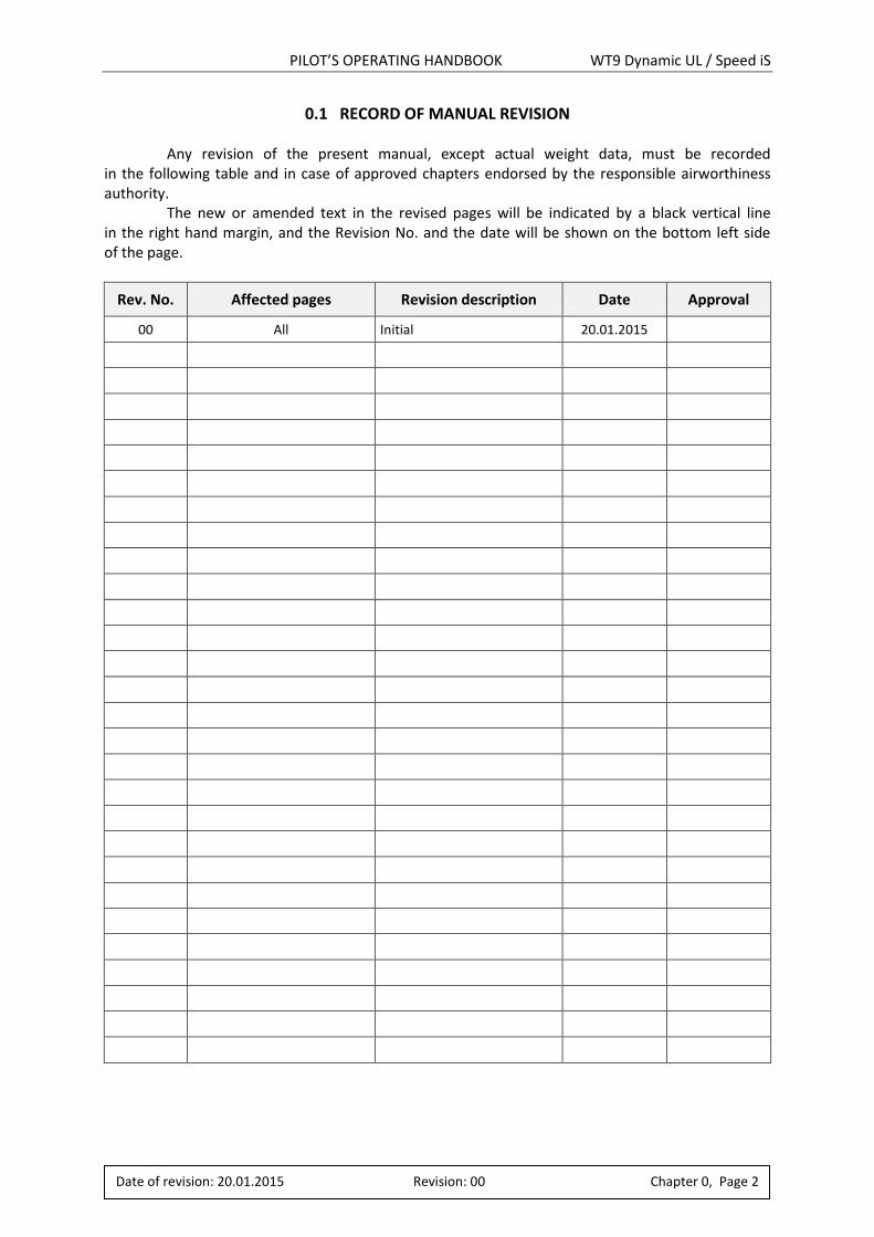
0.1 RECORD OF MANUAL REVISION Any revision of the present manual, except actual weight data, must be recorded in the following table and in case of approved chapters endorsed by the responsible airworthiness authority. The new or amended text in the revised pages will be indicated by a black vertical line in the right hand margin, and the Revision No. and the date will be shown on the bottom left side of the page.
Rev. No. Affected pages Revision description Date Approval
00 All Initial 20.01.2015

PILOT’S OPERATING HANDBOOK WT9 Dynamic UL / Speed iS
Date of revision: 20.01.2015 Revision: 00 Chapter 0, Page 3
Intentionally left blank
PILOT’S OPERATING HANDBOOK WT9 Dynamic UL / Speed iS
Date of revision: 20.01.2015 Revision: 00 Chapter 0, Page 4
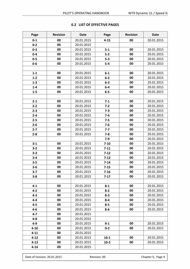
0.2 LIST OF EFFECTIVE PAGES
Page Revision Date Page Revision Date
0-1 00 20.01.2015 4-15 00 20.01.2015
0-2 00 20.01.2015
0-3 00 20.01.2015 5-1 00 20.01.2015
0-4 00 20.01.2015 5-2 00 20.01.2015
0-5 00 20.01.2015 5-3 00 20.01.2015
0-6 00 20.01.2015 5-4 00 20.01.2015
1-1 00 20.01.2015 6-1 00 20.01.2015
1-2 00 20.01.2015 6-2 00 20.01.2015
1-3 00 20.01.2015 6-3 00 20.01.2015
1-4 00 20.01.2015 6-4 00 20.01.2015
1-5 00 20.01.2015 6-5 00 20.01.2015
2-1 00 20.01.2015 7-1 00 20.01.2015
2-2 00 20.01.2015 7-2 00 20.01.2015
2-3 00 20.01.2015 7-3 00 20.01.2015
2-4 00 20.01.2015 7-4 00 20.01.2015
2-5 00 20.01.2015 7-5 00 20.01.2015
2-6 00 20.01.2015 7-6 00 20.01.2015
2-7 00 20.01.2015 7-7 00 20.01.2015
2-8 00 20.01.2015 7-8 00 20.01.2015
7-9 00 20.01.2015
3-1 00 20.01.2015 7-10 00 20.01.2015
3-2 00 20.01.2015 7-11 00 20.01.2015
3-3 00 20.01.2015 7-12 00 20.01.2015
3-4 00 20.01.2015 7-13 00 20.01.2015
3-5 00 20.01.2015 7-14 00 20.01.2015
3-6 00 20.01.2015 7-15 00 20.01.2015
3-7 00 20.01.2015 7-16 00 20.01.2015
3-8 00 20.01.2015 7-17 00 20.01.2015
4-1 00 20.01.2015 8-1 00 20.01.2015
4-2 00 20.01.2015 8-2 00 20.01.2015
4-3 00 20.01.2015 8-3 00 20.01.2015
4-4 00 20.01.2015 8-4 00 20.01.2015
4-5 00 20.01.2015 8-5 00 20.01.2015
4-6 00 20.01.2015 8-6 00 20.01.2015
4-7 00 20.01.2015
4-8 00 20.01.2015
4-9 00 20.01.2015 9-1 00 20.01.2015
4-10 00 20.01.2015 9-2 00 20.01.2015
4-11 00 20.01.2015
4-12 00 20.01.2015 10-1 00 20.01.2015
4-13 00 20.01.2015 10-2 00 20.01.2015
4-14 00 20.01.2015
PILOT’S OPERATING HANDBOOK WT9 Dynamic UL / Speed iS
Date of revision: 20.01.2015 Revision: 00 Chapter 0, Page 5
Page Revision Date Page Revision Date
PILOT’S OPERATING HANDBOOK WT9 Dynamic UL / Speed iS
Date of revision: 20.01.2015 Revision: 00 Chapter 0, Page 6
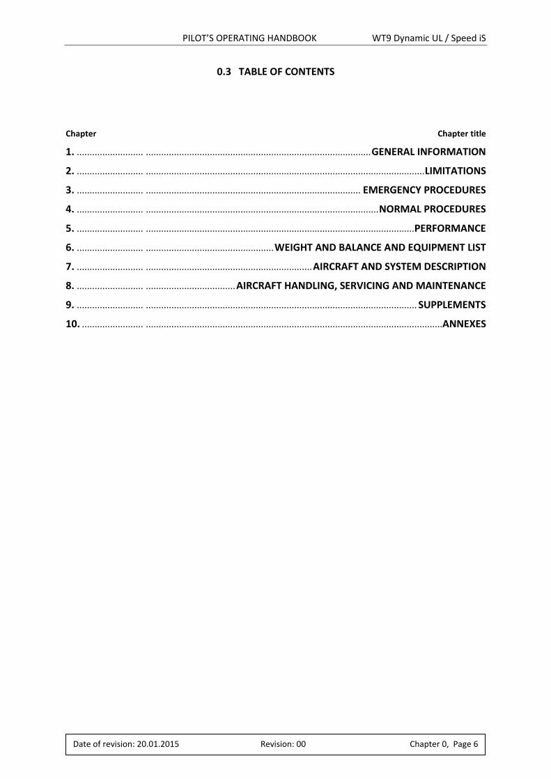
0.3 TABLE OF CONTENTS Chapter Chapter title
1. .......................... ........................................................................................ GENERAL INFORMATION
2. .......................... ............................................................................................................. LIMITATIONS
3. .......................... .................................................................................... EMERGENCY PROCEDURES
4. .......................... ........................................................................................... NORMAL PROCEDURES
5. .......................... ......................................................................................................... PERFORMANCE
6. .......................... .................................................. WEIGHT AND BALANCE AND EQUIPMENT LIST
7. .......................... ................................................................. AIRCRAFT AND SYSTEM DESCRIPTION
8. .......................... ................................... AIRCRAFT HANDLING, SERVICING AND MAINTENANCE
9. .......................... .......................................................................................................... SUPPLEMENTS
10. ........................ ....................................................................................................................ANNEXES
PILOT’S OPERATING HANDBOOK WT9 Dynamic UL / Speed iS
Date of revision: 20.01.2015 Revision: 00 Chapter 1, Page 1
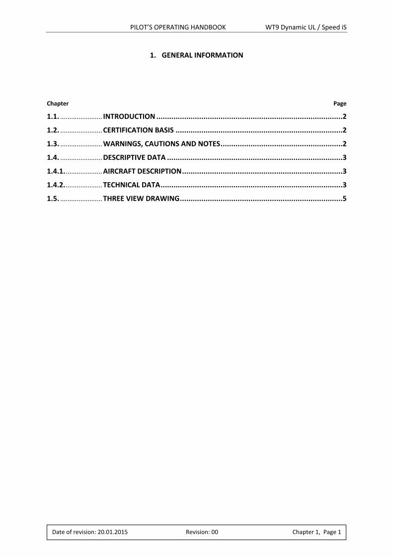
1. GENERAL INFORMATION
Chapter Page
1.1. ....................... INTRODUCTION .......................................................................................2
1.2. ....................... CERTIFICATION BASIS ..............................................................................2
1.3. ....................... WARNINGS, CAUTIONS AND NOTES .........................................................2
1.4. ....................... DESCRIPTIVE DATA ..................................................................................3
1.4.1. .................... AIRCRAFT DESCRIPTION ...........................................................................3
1.4.2. .................... TECHNICAL DATA .....................................................................................3
1.5. ....................... THREE VIEW DRAWING ............................................................................5
PILOT’S OPERATING HANDBOOK WT9 Dynamic UL / Speed iS
Date of revision: 20.01.2015 Revision: 00 Chapter 1, Page 2
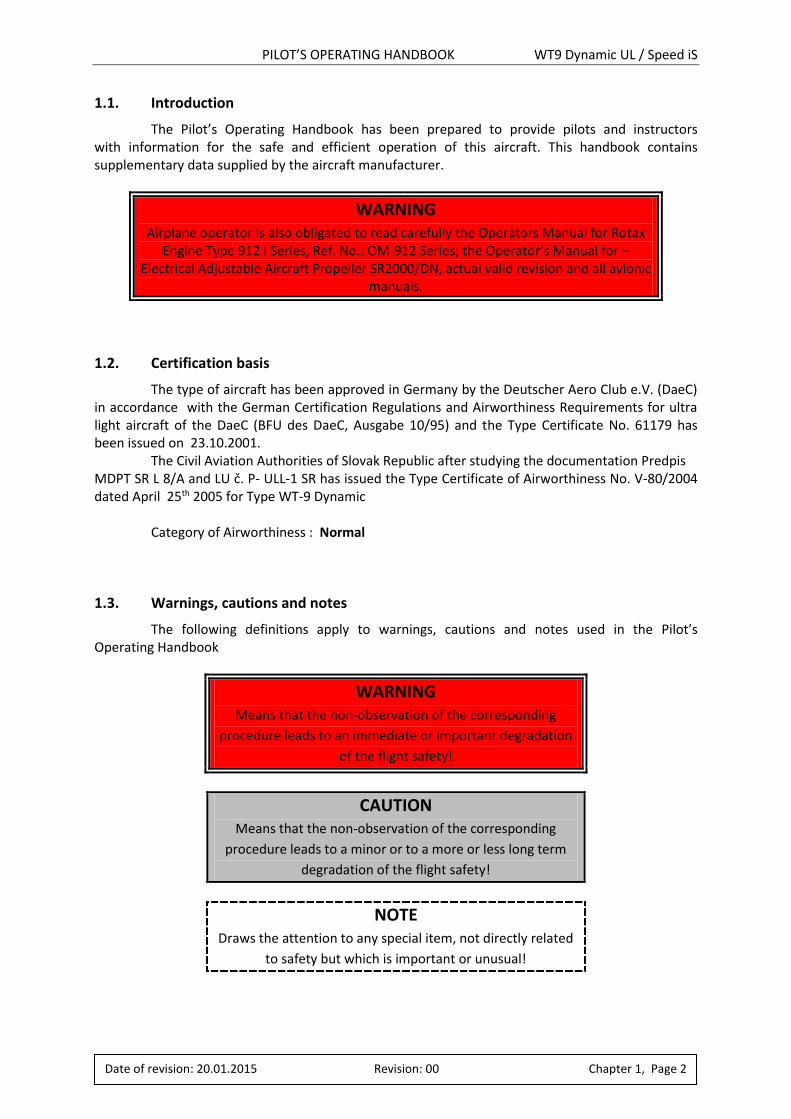
1.1. Introduction
The Pilot’s Operating Handbook has been prepared to provide pilots and instructors with information for the safe and efficient operation of this aircraft. This handbook contains supplementary data supplied by the aircraft manufacturer.
WARNING Airplane operator is also obligated to read carefully the Operators Manual for Rotax
Engine Type 912 i Series, Ref. No.: OM-912 Series; the Operator’s Manual for – Electrical Adjustable Aircraft Propeller SR2000/DN, actual valid revision and all avionic
manuals.
1.2. Certification basis
The type of aircraft has been approved in Germany by the Deutscher Aero Club e.V. (DaeC) in accordance with the German Certification Regulations and Airworthiness Requirements for ultra light aircraft of the DaeC (BFU des DaeC, Ausgabe 10/95) and the Type Certificate No. 61179 has been issued on 23.10.2001. The Civil Aviation Authorities of Slovak Republic after studying the documentation Predpis MDPT SR L 8/A and LU č. P- ULL-1 SR has issued the Type Certificate of Airworthiness No. V-80/2004 dated April 25th 2005 for Type WT-9 Dynamic
Category of Airworthiness : Normal
1.3. Warnings, cautions and notes
The following definitions apply to warnings, cautions and notes used in the Pilot’s Operating Handbook
WARNING Means that the non-observation of the corresponding
procedure leads to an immediate or important degradation
of the flight safety!
CAUTION Means that the non-observation of the corresponding
procedure leads to a minor or to a more or less long term
degradation of the flight safety!
NOTE Draws the attention to any special item, not directly related
to safety but which is important or unusual!
PILOT’S OPERATING HANDBOOK WT9 Dynamic UL / Speed iS
Date of revision: 20.01.2015 Revision: 00 Chapter 1, Page 3
1.4. Descriptive data
1.4.1. Aircraft description
WT9 Dynamic Speed is low-wing monoplane with retractable landing gear. The airframe consists of a sandwich shells from advanced composite material. There are two places in the cockpit, side by side type. This aircraft is intended for sporting, recreation and tourist flying in accordance with VFR day.
Models of WT9 Dynamic (MTOW 472,5 kg) Club are equipped with wide range of combinations of instruments, engines and propellers. This POH describes one of many combinations. Powerplant of the aircraft is the 4 cylinder, 4-stroke engine Rotax 912 iS Sport with a maximum take-off RPM limitation 5800 min-1. The aircraft is fitted with a 3-bladed in-flight electrically adjustable propeller WOODCOMP SR2000/DN with diameter 1700 mm.
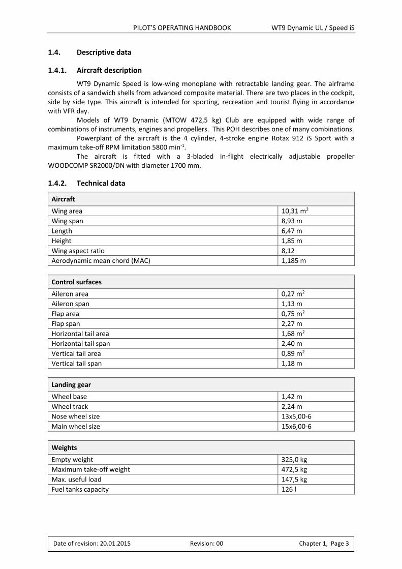
1.4.2. Technical data
Aircraft
Wing area 10,31 m2
Wing span 8,93 m
Length 6,47 m
Height 1,85 m
Wing aspect ratio 8,12
Aerodynamic mean chord (MAC) 1,185 m
Control surfaces
Aileron area 0,27 m2
Aileron span 1,13 m
Flap area 0,75 m2
Flap span 2,27 m
Horizontal tail area 1,68 m2
Horizontal tail span 2,40 m
Vertical tail area 0,89 m2
Vertical tail span 1,18 m
Landing gear
Wheel base 1,42 m
Wheel track 2,24 m
Nose wheel size 13x5,00-6
Main wheel size 15x6,00-6
Weights
Empty weight 325,0 kg
Maximum take-off weight 472,5 kg
Max. useful load 147,5 kg
Fuel tanks capacity 126 l

PILOT’S OPERATING HANDBOOK WT9 Dynamic UL / Speed iS
Date of revision: 20.01.2015 Revision: 00 Chapter 1, Page 4
Intentionally left blank
PILOT’S OPERATING HANDBOOK WT9 Dynamic UL / Speed iS
Date of revision: 20.01.2015 Revision: 00 Chapter 1, Page 5
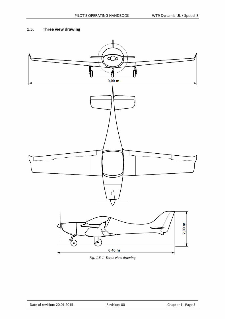
1.5. Three view drawing
Fig. 1.5-1 Three view drawing
PILOT’S OPERATING HANDBOOK WT9 Dynamic UL / Speed iS
Date of revision: 20.01.2015 Revision: 00 Chapter 2, Page 1
2. LIMITATIONS
Chapter Page
2.1. ....................... INTRODUCTION .......................................................................................2
2.2. ....................... AIRSPEEDS ...............................................................................................2
2.3. ....................... AIRSPEED INDICATOR MARKINGS ............................................................3
2.4. ....................... POWERPLANT ..........................................................................................3
2.5. ....................... POWERPLANT INSTRUMENT MARKINGS ..................................................5
2.6. ....................... MISCELLANEOUS INSTRUMENT MARKINGS ..............................................5
2.7. ....................... WEIGHTS .................................................................................................6
2.8. ....................... CENTRE OF GRAVITY ................................................................................6
2.9. ....................... APPROVED MANOEUVRES .......................................................................6
2.10. ..................... MANOEUVRING LOAD FACTORS ..............................................................7
2.11. ..................... FLIGHT CREW ...........................................................................................7
2.12. ..................... KIND OF OPERATION ...............................................................................7
2.13. ..................... FUEL ........................................................................................................7
2.14. ..................... MAXIMUM PASSENGER SEATING .............................................................8
2.15. ..................... OTHER LIMITATIONS ................................................................................8
2.16. ..................... LIMITATIONS PLACARDS ..........................................................................8
PILOT’S OPERATING HANDBOOK WT9 Dynamic UL / Speed iS
Date of revision: 20.01.2015 Revision: 00 Chapter 2, Page 2
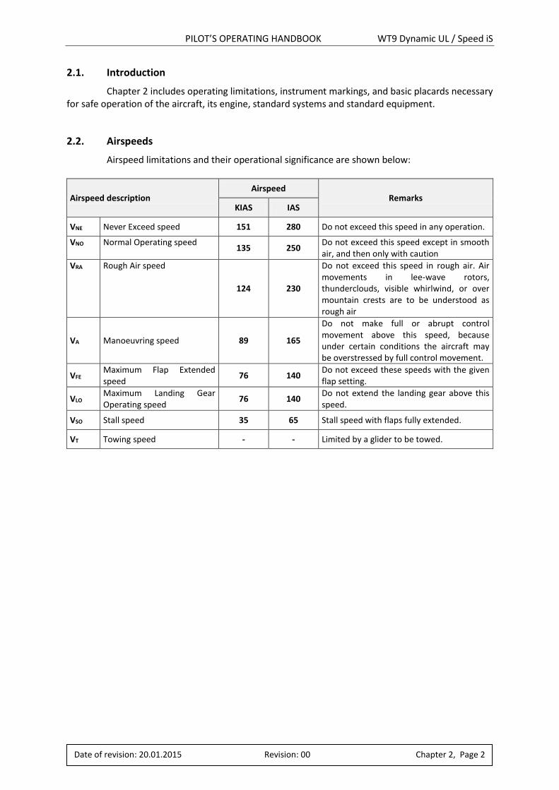
2.1. Introduction
Chapter 2 includes operating limitations, instrument markings, and basic placards necessary for safe operation of the aircraft, its engine, standard systems and standard equipment.
2.2. Airspeeds
Airspeed limitations and their operational significance are shown below:
Airspeed description Airspeed
Remarks KIAS IAS
VNE Never Exceed speed 151 280 Do not exceed this speed in any operation.
VNO Normal Operating speed 135 250
Do not exceed this speed except in smooth air, and then only with caution
VRA Rough Air speed
124 230
Do not exceed this speed in rough air. Air movements in lee-wave rotors, thunderclouds, visible whirlwind, or over mountain crests are to be understood as rough air
VA Manoeuvring speed 89 165
Do not make full or abrupt control movement above this speed, because under certain conditions the aircraft may be overstressed by full control movement.
VFE Maximum Flap Extended speed
76 140 Do not exceed these speeds with the given flap setting.
VLO Maximum Landing Gear Operating speed
76 140 Do not extend the landing gear above this speed.
VSO Stall speed 35 65 Stall speed with flaps fully extended.
VT Towing speed - - Limited by a glider to be towed.
PILOT’S OPERATING HANDBOOK WT9 Dynamic UL / Speed iS
Date of revision: 20.01.2015 Revision: 00 Chapter 2, Page 3
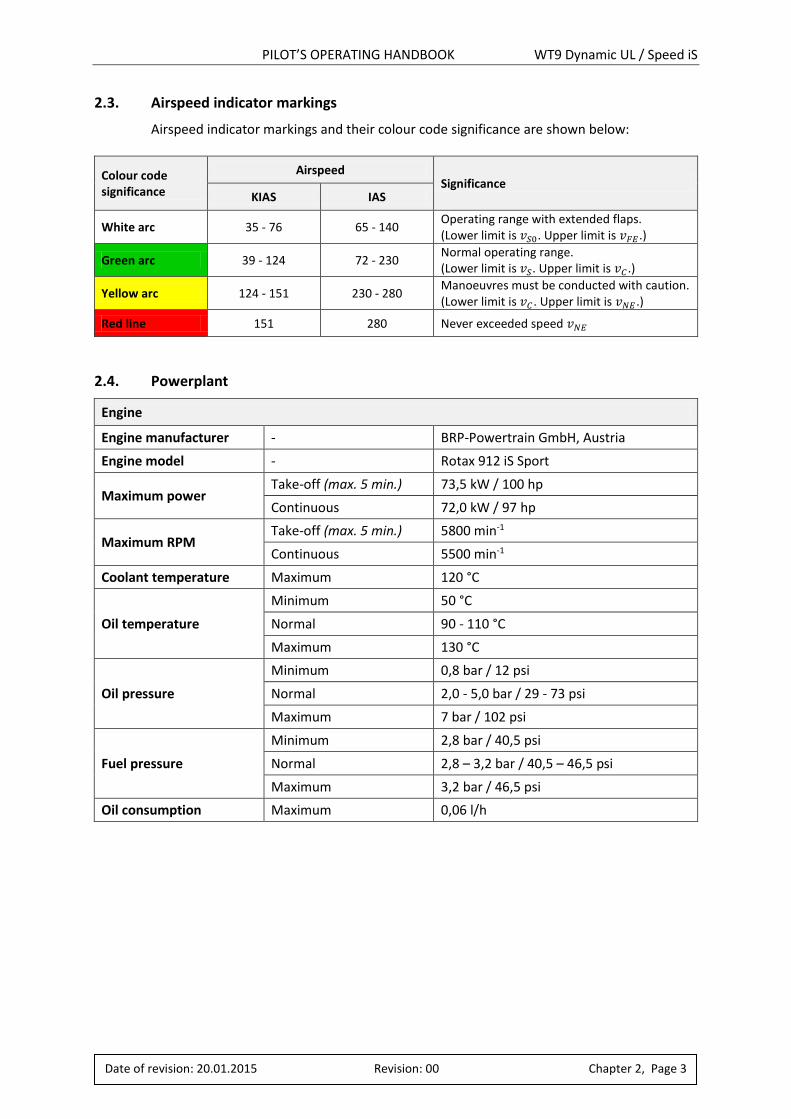
2.3. Airspeed indicator markings
Airspeed indicator markings and their colour code significance are shown below:
Colour code significance
Airspeed Significance
KIAS IAS
White arc 35 - 76 65 - 140 Operating range with extended flaps. (Lower limit is 𝑣𝑆0. Upper limit is 𝑣𝐹𝐸 .)
Green arc 39 - 124 72 - 230 Normal operating range. (Lower limit is 𝑣𝑆. Upper limit is 𝑣𝐶 .)
Yellow arc 124 - 151 230 - 280 Manoeuvres must be conducted with caution. (Lower limit is 𝑣𝐶 . Upper limit is 𝑣𝑁𝐸 .)
Red line 151 280 Never exceeded speed 𝑣𝑁𝐸
2.4. Powerplant
Engine
Engine manufacturer - BRP-Powertrain GmbH, Austria
Engine model - Rotax 912 iS Sport
Maximum power Take-off (max. 5 min.) 73,5 kW / 100 hp
Continuous 72,0 kW / 97 hp
Maximum RPM Take-off (max. 5 min.) 5800 min-1
Continuous 5500 min-1
Coolant temperature Maximum 120 °C
Oil temperature
Minimum 50 °C
Normal 90 - 110 °C
Maximum 130 °C
Oil pressure
Minimum 0,8 bar / 12 psi
Normal 2,0 - 5,0 bar / 29 - 73 psi
Maximum 7 bar / 102 psi
Fuel pressure
Minimum 2,8 bar / 40,5 psi
Normal 2,8 – 3,2 bar / 40,5 – 46,5 psi
Maximum 3,2 bar / 46,5 psi
Oil consumption Maximum 0,06 l/h

PILOT’S OPERATING HANDBOOK WT9 Dynamic UL / Speed iS
Date of revision: 20.01.2015 Revision: 00 Chapter 2, Page 4
Propeller
Propeller manufacturer WOODCOMP spol. s r. o., Odolená Voda, Czech republic
Propeller model SR2000DN, 3-bladed in flight electrically adjustable
Propeller diameter 1700 mm
WARNING Additional data can be found in Chapter 7.9 and in the Operators Manual for Rotax
Engine Type 912 Series, Ref. No.: OM-912 i Series and in the Operator’s Manual for – Electrical Adjustable Aircraft Propeller SR2000DN, actual valid revision.
WARNING Never run the engine without propeller! This inevitably
causes engine damage and is an explosion hazard!
PILOT’S OPERATING HANDBOOK WT9 Dynamic UL / Speed iS
Date of revision: 20.01.2015 Revision: 00 Chapter 2, Page 5
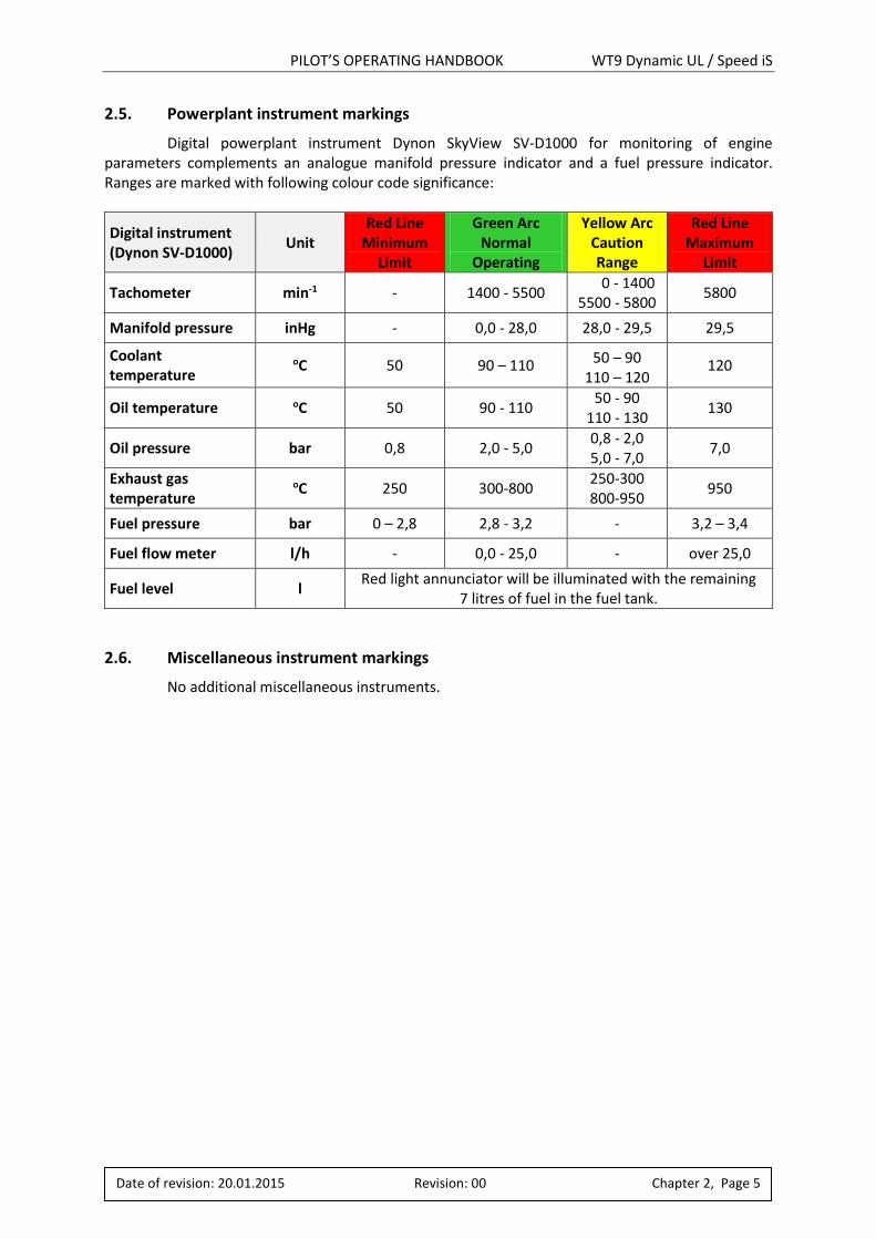
2.5. Powerplant instrument markings
Digital powerplant instrument Dynon SkyView SV-D1000 for monitoring of engine parameters complements an analogue manifold pressure indicator and a fuel pressure indicator. Ranges are marked with following colour code significance:
Digital instrument (Dynon SV-D1000)
Unit Red Line
Minimum Limit
Green Arc Normal
Operating
Yellow Arc Caution Range
Red Line Maximum
Limit
Tachometer min-1 - 1400 - 5500 0 - 1400 5500 - 5800
5800
Manifold pressure inHg - 0,0 - 28,0 28,0 - 29,5 29,5
Coolant temperature
oC 50 90 – 110 50 – 90 110 – 120
120
Oil temperature oC 50 90 - 110 50 - 90
110 - 130 130
Oil pressure bar 0,8 2,0 - 5,0 0,8 - 2,0 5,0 - 7,0
7,0
Exhaust gas temperature
oC 250 300-800 250-300 800-950
950
Fuel pressure bar 0 – 2,8 2,8 - 3,2 - 3,2 – 3,4
Fuel flow meter l/h - 0,0 - 25,0 - over 25,0
Fuel level l Red light annunciator will be illuminated with the remaining
7 litres of fuel in the fuel tank.
2.6. Miscellaneous instrument markings
No additional miscellaneous instruments.
PILOT’S OPERATING HANDBOOK WT9 Dynamic UL / Speed iS
Date of revision: 20.01.2015 Revision: 00 Chapter 2, Page 6
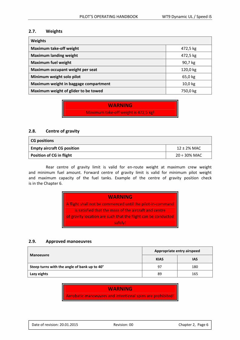
2.7. Weights
Weights
Maximum take-off weight 472,5 kg
Maximum landing weight 472,5 kg
Maximum fuel weight 90,7 kg
Maximum occupant weight per seat 120,0 kg
Minimum weight solo pilot 65,0 kg
Maximum weight in baggage compartment 10,0 kg
Maximum weight of glider to be towed 750,0 kg
WARNING Maximum take-off weight is 472,5 kg!
2.8. Centre of gravity
CG positions
Empty aircraft CG position 12 ± 2% MAC
Position of CG in flight 20 ÷ 30% MAC
Rear centre of gravity limit is valid for en-route weight at maximum crew weight and minimum fuel amount. Forward centre of gravity limit is valid for minimum pilot weight and maximum capacity of the fuel tanks. Example of the centre of gravity position check is in the Chapter 6.
WARNING A flight shall not be commenced until the pilot-in-command
is satisfied that the mass of the aircraft and centre
of gravity location are such that the flight can be conducted
safely!
2.9. Approved manoeuvres
Manoeuvre Appropriate entry airspeed
KIAS IAS
Steep turns with the angle of bank up to 40° 97 180
Lazy eights 89 165
WARNING Aerobatic manoeuvres and intentional spins are prohibited!
PILOT’S OPERATING HANDBOOK WT9 Dynamic UL / Speed iS
Date of revision: 20.01.2015 Revision: 00 Chapter 2, Page 7
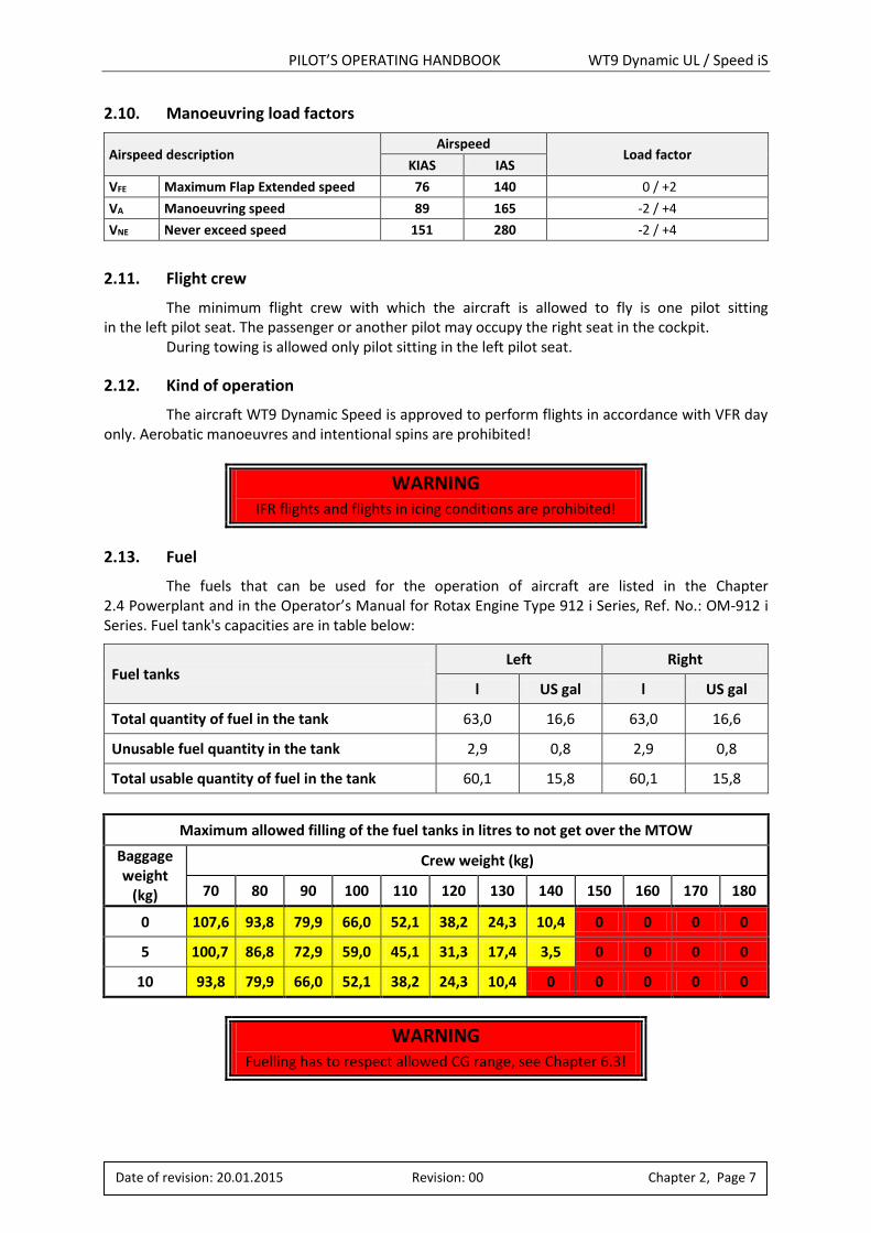
2.10. Manoeuvring load factors
Airspeed description Airspeed
Load factor KIAS IAS
VFE Maximum Flap Extended speed 76 140 -0 / +2
VA Manoeuvring speed 89 165 -2 / +4
VNE Never exceed speed 151 280 -2 / +4
2.11. Flight crew
The minimum flight crew with which the aircraft is allowed to fly is one pilot sitting in the left pilot seat. The passenger or another pilot may occupy the right seat in the cockpit. During towing is allowed only pilot sitting in the left pilot seat.
2.12. Kind of operation
The aircraft WT9 Dynamic Speed is approved to perform flights in accordance with VFR day only. Aerobatic manoeuvres and intentional spins are prohibited!
WARNING IFR flights and flights in icing conditions are prohibited!
2.13. Fuel
The fuels that can be used for the operation of aircraft are listed in the Chapter 2.4 Powerplant and in the Operator’s Manual for Rotax Engine Type 912 i Series, Ref. No.: OM-912 i Series. Fuel tank's capacities are in table below:
Fuel tanks Left Right
l US gal l US gal
Total quantity of fuel in the tank 63,0 16,6 63,0 16,6
Unusable fuel quantity in the tank 2,9 0,8 2,9 0,8
Total usable quantity of fuel in the tank 60,1 15,8 60,1 15,8
Maximum allowed filling of the fuel tanks in litres to not get over the MTOW
Baggage weight
(kg)
Crew weight (kg)
70 80 90 100 110 120 130 140 150 160 170 180
0 107,6 93,8 79,9 66,0 52,1 38,2 24,3 10,4 0 0 0 0
5 100,7 86,8 72,9 59,0 45,1 31,3 17,4 3,5 0 0 0 0
10 93,8 79,9 66,0 52,1 38,2 24,3 10,4 0 0 0 0 0
WARNING Fuelling has to respect allowed CG range, see Chapter 6.3!
PILOT’S OPERATING HANDBOOK WT9 Dynamic UL / Speed iS
Date of revision: 20.01.2015 Revision: 00 Chapter 2, Page 8
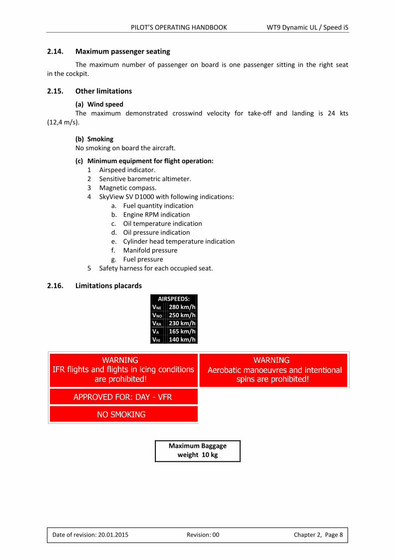
2.14. Maximum passenger seating
The maximum number of passenger on board is one passenger sitting in the right seat in the cockpit.
2.15. Other limitations
(a) Wind speed The maximum demonstrated crosswind velocity for take-off and landing is 24 kts (12,4 m/s).
(b) Smoking No smoking on board the aircraft.
(c) Minimum equipment for flight operation: 1 Airspeed indicator. 2 Sensitive barometric altimeter. 3 Magnetic compass. 4 SkyView SV D1000 with following indications:
a. Fuel quantity indication b. Engine RPM indication c. Oil temperature indication d. Oil pressure indication e. Cylinder head temperature indication f. Manifold pressure g. Fuel pressure
5 Safety harness for each occupied seat.
2.16. Limitations placards
AIRSPEEDS: VNE 280 km/h VNO 250 km/h VRA 230 km/h VA 165 km/h VFE 140 km/h
Maximum Baggage weight 10 kg
PILOT’S OPERATING HANDBOOK WT9 Dynamic UL / Speed iS
Date of revision: 20.01.2015 Revision: 00 Chapter 3, Page 1
3. EMERGENCY PROCEDURES
Chapter Page
3.1. ....................... INTRODUCTION .......................................................................................2
3.2. ....................... ENGINE FAILURE ......................................................................................2
3.3. ....................... AIR START ...............................................................................................3
3.4. ....................... SMOKE AND FIRE .....................................................................................3
3.5. ....................... GLIDE ......................................................................................................4
3.6. ....................... EMERGENCY LANDING .............................................................................4
3.7. ....................... RECOVERY FROM UNINTENTIONAL SPIN ..................................................5
3.8. ....................... OTHER EMERGENCIES ..............................................................................6
PILOT’S OPERATING HANDBOOK WT9 Dynamic UL / Speed iS
Date of revision: 20.01.2015 Revision: 00 Chapter 3, Page 2
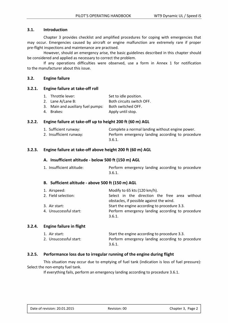
3.1. Introduction
Chapter 3 provides checklist and amplified procedures for coping with emergencies that may occur. Emergencies caused by aircraft or engine malfunction are extremely rare if proper pre-flight inspections and maintenance are practised. However, should an emergency arise, the basic guidelines described in this chapter should be considered and applied as necessary to correct the problem. If any operations difficulties were observed, use a form in Annex 1 for notification to the manufacturer about this issue.
3.2. Engine failure
3.2.1. Engine failure at take-off roll
1. Throttle lever: Set to idle position. 2. Lane A/Lane B: Both circuits switch OFF. 3. Main and auxiliary fuel pumps: Both switched OFF. 4. Brakes: Apply until stop.
3.2.2. Engine failure at take-off up to height 200 ft (60 m) AGL
1. Sufficient runway: Complete a normal landing without engine power. 2. Insufficient runway: Perform emergency landing according to procedure
3.6.1.
3.2.3. Engine failure at take-off above height 200 ft (60 m) AGL
A. Insufficient altitude - below 500 ft (150 m) AGL
1. Insufficient altitude: Perform emergency landing according to procedure 3.6.1.
B. Sufficient altitude - above 500 ft (150 m) AGL
1. Airspeed: Modify to 65 kts (120 km/h). 2. Field selection: Select in the direction the free area without
obstacles, if possible against the wind. 3. Air start: Start the engine according to procedure 3.3. 4. Unsuccessful start: Perform emergency landing according to procedure
3.6.1.
3.2.4. Engine failure in flight
1. Air start: Start the engine according to procedure 3.3. 2. Unsuccessful start: Perform emergency landing according to procedure
3.6.1.
3.2.5. Performance loss due to irregular running of the engine during flight
This situation may occur due to emptying of fuel tank (indication is loss of fuel pressure): Select the non-empty fuel tank.
If everything fails, perform an emergency landing according to procedure 3.6.1.
PILOT’S OPERATING HANDBOOK WT9 Dynamic UL / Speed iS
Date of revision: 20.01.2015 Revision: 00 Chapter 3, Page 3
3.3. Air start
1. Airspeed: Modify to 65 kts (120 km/h). 2. Altitude: Check. 3. Field selection: Select according to height available. 4. Fuel selector: Select non-empty tank. 5. Main and auxiliary fuel pumps: Both switched ON. 6. Throttle lever: Put between 1 to 2 cm of throttle opening. 7. Lane A/Lane B: Both circuits switched ON. 1. Starter key: Press until engine runs, then release to ACC position. 8. Successful start: Adjust throttle to achieve smooth running
at 2500 min-1 for approximately half a minute before reaching required power.
9. Unsuccessful start: Perform emergency landing according to procedure 3.6.1.
WARNING The rate of descent approximately 600 ft/min (3,0 m/s)
causes measurable loss of altitude during the air start.
If the air start is unsuccessful up to height 500 ft (150 m)
above ground level, perform the emergency landing
according to procedure 3.6.1!
3.4. Smoke and fire
3.4.1. Engine fire on the ground
1. Fuel selector: Set OFF. 2. Throttle lever: Set full throttle. 3. Lane A/Lane B: Both circuits switched OFF after the fuel has been
consumed. 4. Main and auxiliary fuel pumps: Both switched OFF. 5. Crew: Leave the cockpit immediately. 6. Extinguish fire: With best available means.
3.4.2. Engine fire in flight
1. Fuel selector: Set OFF. 2. Throttle lever: Set full throttle. 3. Lane A/Lane B: Both circuits switched OFF after the fuel has been
consumed. 4. Main and auxiliary fuel pumps: Both switched OFF. 5. Extinguish fire: Try to extinguish the fire with side slip. 6. Emergency landing: Perform emergency landing according to procedure
3.6.1.
CAUTION After the fire has been extinguished, do not start the engine
again!
PILOT’S OPERATING HANDBOOK WT9 Dynamic UL / Speed iS
Date of revision: 20.01.2015 Revision: 00 Chapter 3, Page 4
3.4.3. Fire in cockpit
1. Fire source: Localize. 2. Lane A/Lane B: Both circuits switched OFF. 3. Main and auxiliary fuel pumps: Both switched OFF. 4. Master switch: Set OFF. 5. Crew: On the ground: Leave the cockpit.
During flight: Perform an emergency landing according to procedure 3.6.1.
6. Extinguish fire: Try to extinguish with best available means.
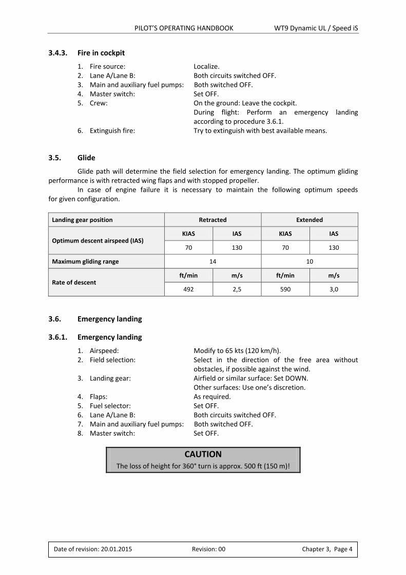
3.5. Glide
Glide path will determine the field selection for emergency landing. The optimum gliding performance is with retracted wing flaps and with stopped propeller. In case of engine failure it is necessary to maintain the following optimum speeds for given configuration.
Landing gear position Retracted Extended
Optimum descent airspeed (IAS) KIAS IAS KIAS IAS
70 130 70 130
Maximum gliding range 14 10
Rate of descent ft/min m/s ft/min m/s
492 2,5 590 3,0
3.6. Emergency landing
3.6.1. Emergency landing
1. Airspeed: Modify to 65 kts (120 km/h). 2. Field selection: Select in the direction of the free area without
obstacles, if possible against the wind. 3. Landing gear: Airfield or similar surface: Set DOWN.
Other surfaces: Use one’s discretion. 4. Flaps: As required. 5. Fuel selector: Set OFF. 6. Lane A/Lane B: Both circuits switched OFF. 7. Main and auxiliary fuel pumps: Both switched OFF. 8. Master switch: Set OFF.
CAUTION The loss of height for 360° turn is approx. 500 ft (150 m)!
PILOT’S OPERATING HANDBOOK WT9 Dynamic UL / Speed iS
Date of revision: 20.01.2015 Revision: 00 Chapter 3, Page 5
3.6.2. Precautionary landing
In the event of the aircraft failure, disorientation, shortage of fuel, dangerous deterioration of the meteorological conditions (visibility, thunderstorm) and coming sunset, a precautionary landing should be conducted.
1. Select a suitable landing field, if possible against the wind.
2. Fly over selected field with wing flaps 15 and 65 kts (120 km/h) airspeed at a height
200 ft (60 m) AGL, check properly the preferred area for landing to inspect the terrain
properties (obstructions, surface conditions).
3. Make landing circuit at a height 500 ft (150 m) AGL or at a safe altitude as allowed by
cloud base with flaps 15 and 65 kts (120 km/h) airspeed. Extend “down wind” position
and make approach with sufficient power.
4. Don’t lose sight on the selected field in the case of low visibility.
5. Landing approach with flaps for landing and sufficient power.
Landing gear: airfield or similar surface – set DOWN, other surfaces – use one’s
discretion.
6. Arrange approach so that the desired touchdown spot will be immediately
after passing the edge of the selected landing field. In the case of object collision,
perform obstacle avoidance manoeuvre to the side.
7. After touchdown apply heavy breaking till stopped.
8. When the aircraft comes to a stop, shut down the engine, master switch off, close
the main fuel selector, secure the aircraft and seek assistance.
3.6.3. Landing with a flat tyre
1. Landing approach: Flaps take-off position (35°), airspeed 65 kts (120 km/h).
2. Touchdown: With the bank angle on the inflated tyre at minimum touchdown speed.
3. Direction after landing: Maintain ground roll direction.
3.7. Recovery from unintentional spin
For recovery from an unintentional spin the following procedure should be used:
1. Throttle lever: Set to idle position.
2. Control stick: Set neutral position, without deflection of the ailerons.
3. Rudder control: Apply full rudder opposite to the direction of rotation.
4. Control stick: Move forward of neutral in a brisk motion until rotation stops.
5. Rudder control: Immediately as rotation stops, neutralize rudder position.
6. Control stick: Make a smooth recovery from the resulting dive.
WARNING Intentional spins are prohibited!
PILOT’S OPERATING HANDBOOK WT9 Dynamic UL / Speed iS
Date of revision: 20.01.2015 Revision: 00 Chapter 3, Page 6
3.8. Other emergencies
3.8.1. Control failures
Aileron control fault: The aircraft is possible to control laterally by the secondary effect of the rudder. Start
and termination of the yawing up to bank angle 15 is possible using the rudder only.
Rudder control fault: The yawing and the termination are conducted with the help of the lateral control of the ailerons.
3.8.2. Vibrations
The powerplant can be the source of the vibrations.
1. Reduce engine speed to minimize the vibrations. 2. Proceed to the nearest airport for landing or select a suitable precautionary landing
field in accordance with procedure 3.6.2.
3.8.3. Emergency extension of the landing gear
In the case of hydraulic pump malfunction switch OFF the switch labelled as "HYDRAULICS" (fig. 3.8.3-1) and the emergency extension of the landing gear is carried out by its own mass with the help of gas struts. The landing gear is extended even in the electric power loss. The emergency extension of the landing gear is terminated, when three green lights are illuminated on the instrument panel.
Fig. 3.8.3-1 Emergency extension of landing gear
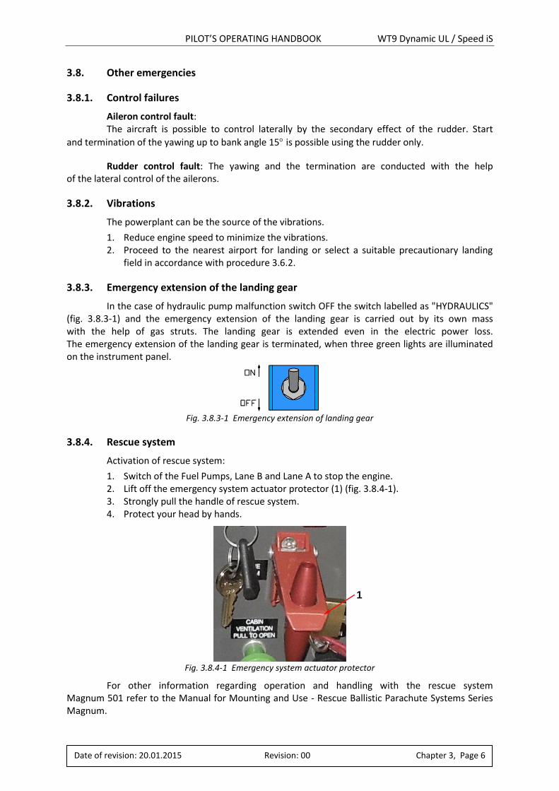
3.8.4. Rescue system
Activation of rescue system:
1. Switch of the Fuel Pumps, Lane B and Lane A to stop the engine. 2. Lift off the emergency system actuator protector (1) (fig. 3.8.4-1). 3. Strongly pull the handle of rescue system. 4. Protect your head by hands.
Fig. 3.8.4-1 Emergency system actuator protector
For other information regarding operation and handling with the rescue system Magnum 501 refer to the Manual for Mounting and Use - Rescue Ballistic Parachute Systems Series Magnum.
1
PILOT’S OPERATING HANDBOOK WT9 Dynamic UL / Speed iS
Date of revision: 20.01.2015 Revision: 00 Chapter 3, Page 7
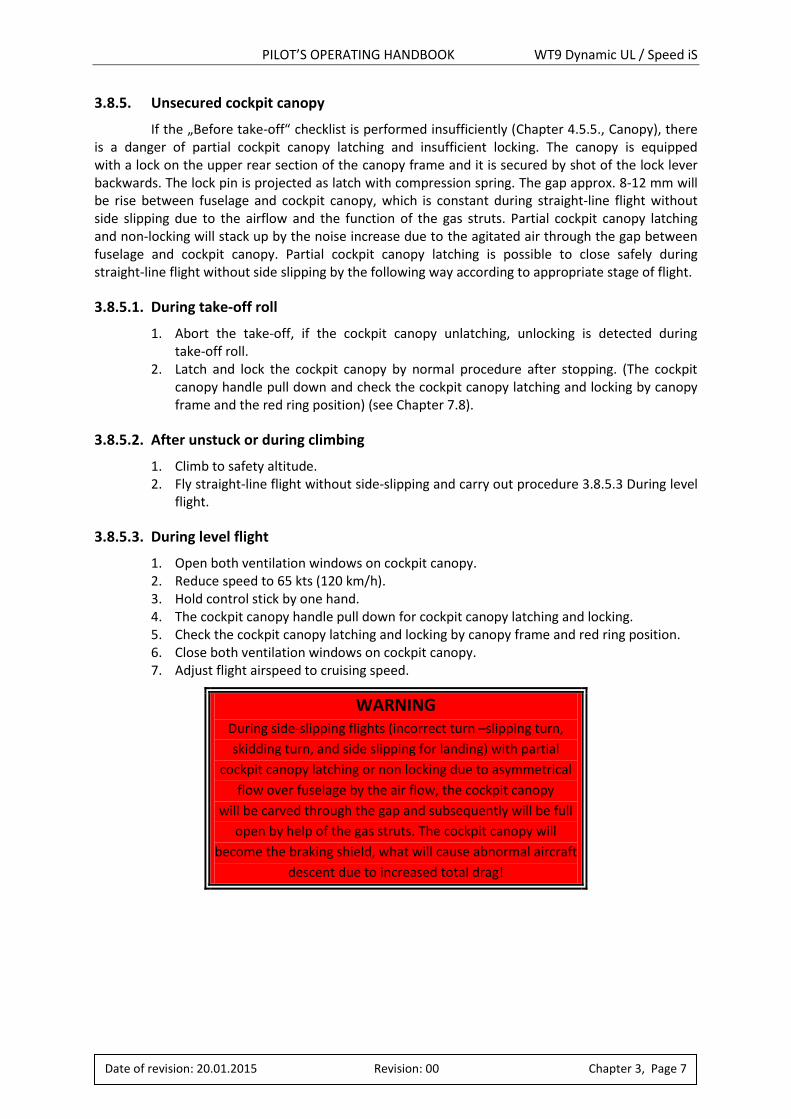
3.8.5. Unsecured cockpit canopy
If the „Before take-off“ checklist is performed insufficiently (Chapter 4.5.5., Canopy), there is a danger of partial cockpit canopy latching and insufficient locking. The canopy is equipped with a lock on the upper rear section of the canopy frame and it is secured by shot of the lock lever backwards. The lock pin is projected as latch with compression spring. The gap approx. 8-12 mm will be rise between fuselage and cockpit canopy, which is constant during straight-line flight without side slipping due to the airflow and the function of the gas struts. Partial cockpit canopy latching and non-locking will stack up by the noise increase due to the agitated air through the gap between fuselage and cockpit canopy. Partial cockpit canopy latching is possible to close safely during straight-line flight without side slipping by the following way according to appropriate stage of flight.
3.8.5.1. During take-off roll
1. Abort the take-off, if the cockpit canopy unlatching, unlocking is detected during take-off roll.
2. Latch and lock the cockpit canopy by normal procedure after stopping. (The cockpit canopy handle pull down and check the cockpit canopy latching and locking by canopy frame and the red ring position) (see Chapter 7.8).
3.8.5.2. After unstuck or during climbing
1. Climb to safety altitude. 2. Fly straight-line flight without side-slipping and carry out procedure 3.8.5.3 During level
flight.
3.8.5.3. During level flight
1. Open both ventilation windows on cockpit canopy. 2. Reduce speed to 65 kts (120 km/h). 3. Hold control stick by one hand. 4. The cockpit canopy handle pull down for cockpit canopy latching and locking. 5. Check the cockpit canopy latching and locking by canopy frame and red ring position. 6. Close both ventilation windows on cockpit canopy. 7. Adjust flight airspeed to cruising speed.
WARNING During side-slipping flights (incorrect turn –slipping turn,
skidding turn, and side slipping for landing) with partial
cockpit canopy latching or non locking due to asymmetrical
flow over fuselage by the air flow, the cockpit canopy
will be carved through the gap and subsequently will be full
open by help of the gas struts. The cockpit canopy will
become the braking shield, what will cause abnormal aircraft
descent due to increased total drag!
PILOT’S OPERATING HANDBOOK WT9 Dynamic UL / Speed iS
Date of revision: 20.01.2015 Revision: 00 Chapter 3, Page 8
3.8.6. Hot engine
1. Increase the airspeed and reduce the engine power. 2. Wait until the temperature will drop down and continue with the flying. 3. If temperature keeps increasing, land immediately.
3.8.7. Towing emergency procedure
During glider towing this must be done before performing of any emergency procedure. 1. Transmit “RELEASE, RELEASE, RELEASE”. 2. If the glider pilot does not act, release the towing rope by pulling of tow release lever. 3. Follow the emergency procedure.
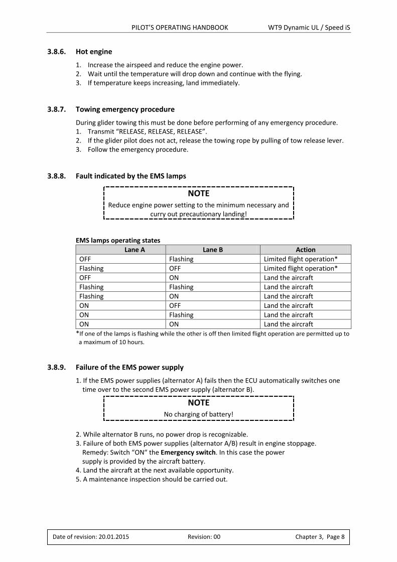
3.8.8. Fault indicated by the EMS lamps
EMS lamps operating states
Lane A Lane B Action
OFF Flashing Limited flight operation*
Flashing OFF Limited flight operation*
OFF ON Land the aircraft
Flashing Flashing Land the aircraft
Flashing ON Land the aircraft
ON OFF Land the aircraft
ON Flashing Land the aircraft
ON ON Land the aircraft
*If one of the lamps is flashing while the other is off then limited flight operation are permitted up to
a maximum of 10 hours.
3.8.9. Failure of the EMS power supply
1. If the EMS power supplies (alternator A) fails then the ECU automatically switches one time over to the second EMS power supply (alternator B).
2. While alternator B runs, no power drop is recognizable. 3. Failure of both EMS power supplies (alternator A/B) result in engine stoppage. Remedy: Switch “ON“ the Emergency switch. In this case the power supply is provided by the aircraft battery. 4. Land the aircraft at the next available opportunity. 5. A maintenance inspection should be carried out.
NOTE Reduce engine power setting to the minimum necessary and
curry out precautionary landing!
NOTE No charging of battery!
PILOT’S OPERATING HANDBOOK WT9 Dynamic UL / Speed iS
Date of revision: 20.01.2015 Revision: 00 Chapter 4, Page 1
4. NORMAL PROCEDURES
Chapter Page
4.1. ....................... INTRODUCTION .......................................................................................2
4.2. ....................... WING DERIGGING AND RIGGING .............................................................2
4.3. ....................... DAILY INSPECTION ...................................................................................5
4.4. ....................... PRE-FLIGHT INSPECTION ..........................................................................5
4.5. ....................... NORMAL PROCEDURES AND CHECK LIST ..................................................8
4.5.1. .................... BEFORE STARTING ENGINE ......................................................................9
4.5.2. .................... ENGINE STARTING ...................................................................................9
4.5.3. .................... ENGINE WARMING UP ........................................................................... 11
4.5.4. .................... TAXIING ................................................................................................ 11
4.5.5. .................... BEFORE TAKE-OFF .................................................................................. 12
4.5.6. .................... NORMAL TAKE-OFF................................................................................ 12
4.5.7. .................... CLIMBING .............................................................................................. 12
4.5.8. .................... CRUISE .................................................................................................. 13
4.5.9. .................... APPROACH ............................................................................................ 13
4.5.10................... LANDING ............................................................................................... 14
4.5.11................... BALKED LANDING .................................................................................. 15
4.5.12................... AFTER LANDING .................................................................................... 15
4.5.13................... SECURING AIRCRAFT .............................................................................. 15
4.5.14................... TAKE-OFF AND LANDING WITHIN CROSSWIND ....................................... 15
PILOT’S OPERATING HANDBOOK WT9 Dynamic UL / Speed iS
Date of revision: 20.01.2015 Revision: 00 Chapter 4, Page 2
4.1. Introduction
Chapter 4 provides checklist and amplified procedures for the conduct of normal operation. Normal procedures associated with optional systems can be found in Chapter 9.
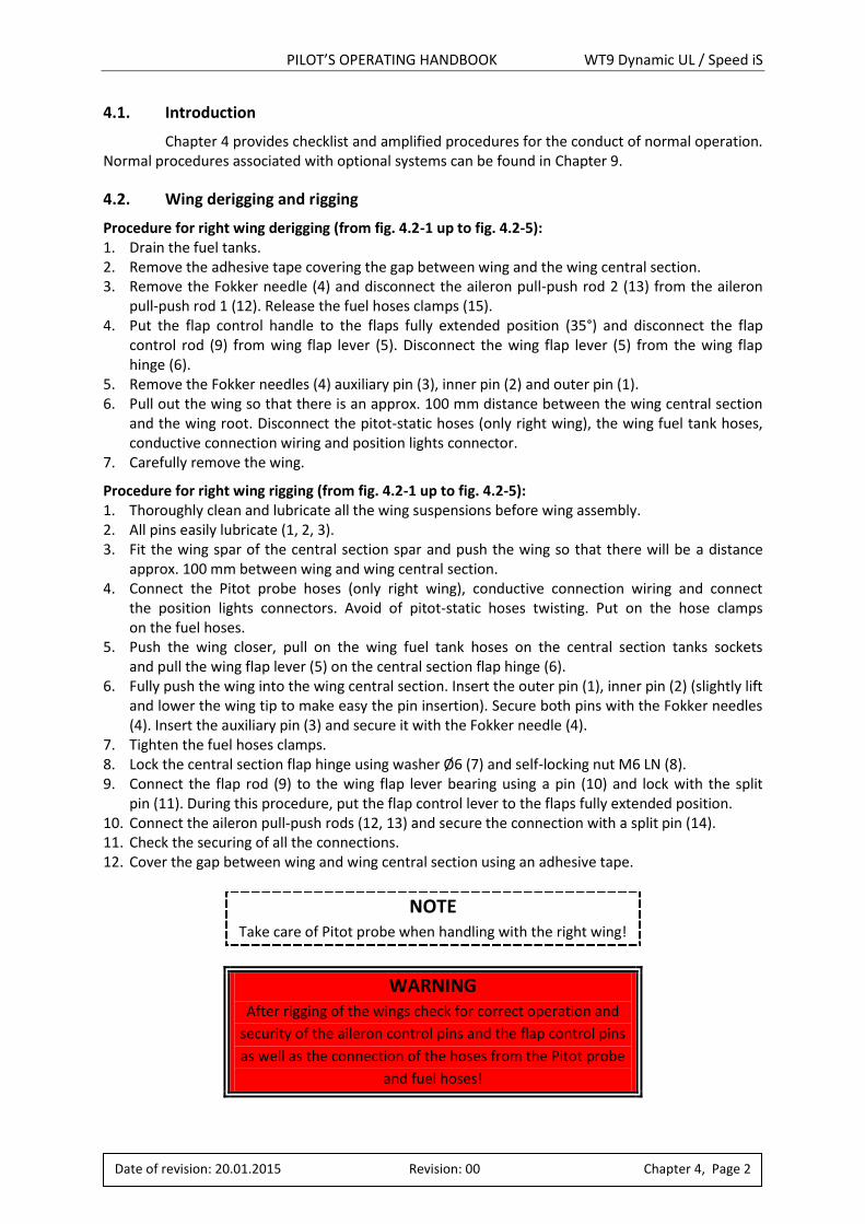
4.2. Wing derigging and rigging
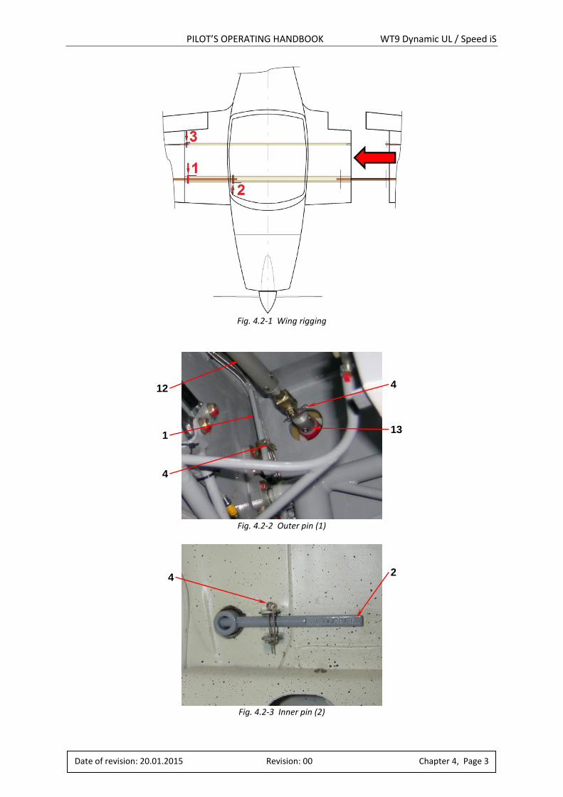
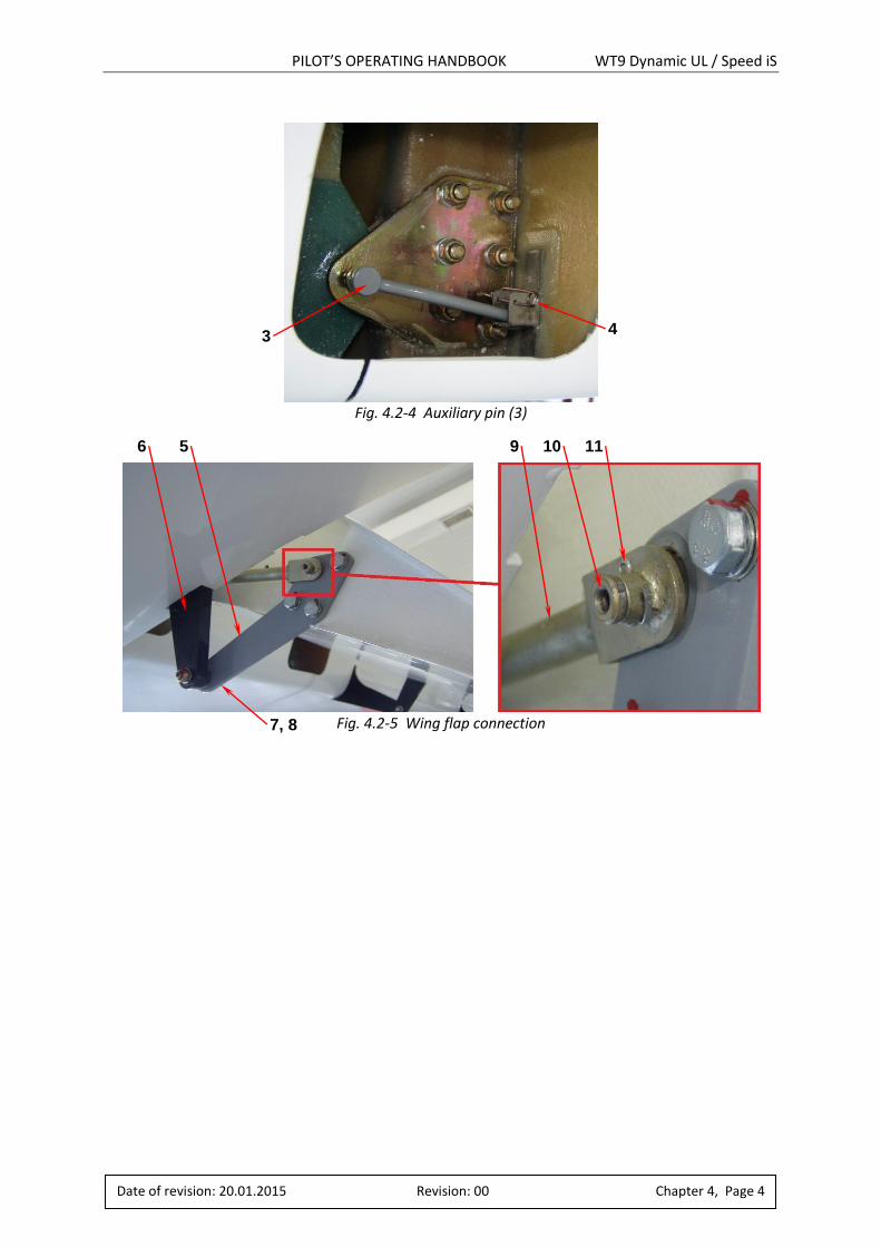
Procedure for right wing derigging (from fig. 4.2-1 up to fig. 4.2-5): 1. Drain the fuel tanks. 2. Remove the adhesive tape covering the gap between wing and the wing central section. 3. Remove the Fokker needle (4) and disconnect the aileron pull-push rod 2 (13) from the aileron
pull-push rod 1 (12). Release the fuel hoses clamps (15). 4. Put the flap control handle to the flaps fully extended position (35°) and disconnect the flap
control rod (9) from wing flap lever (5). Disconnect the wing flap lever (5) from the wing flap hinge (6).
5. Remove the Fokker needles (4) auxiliary pin (3), inner pin (2) and outer pin (1). 6. Pull out the wing so that there is an approx. 100 mm distance between the wing central section
and the wing root. Disconnect the pitot-static hoses (only right wing), the wing fuel tank hoses, conductive connection wiring and position lights connector.
7. Carefully remove the wing.
Procedure for right wing rigging (from fig. 4.2-1 up to fig. 4.2-5): 1. Thoroughly clean and lubricate all the wing suspensions before wing assembly. 2. All pins easily lubricate (1, 2, 3). 3. Fit the wing spar of the central section spar and push the wing so that there will be a distance
approx. 100 mm between wing and wing central section. 4. Connect the Pitot probe hoses (only right wing), conductive connection wiring and connect
the position lights connectors. Avoid of pitot-static hoses twisting. Put on the hose clamps on the fuel hoses.
5. Push the wing closer, pull on the wing fuel tank hoses on the central section tanks sockets and pull the wing flap lever (5) on the central section flap hinge (6).
6. Fully push the wing into the wing central section. Insert the outer pin (1), inner pin (2) (slightly lift and lower the wing tip to make easy the pin insertion). Secure both pins with the Fokker needles (4). Insert the auxiliary pin (3) and secure it with the Fokker needle (4).
7. Tighten the fuel hoses clamps. 8. Lock the central section flap hinge using washer Ø6 (7) and self-locking nut M6 LN (8). 9. Connect the flap rod (9) to the wing flap lever bearing using a pin (10) and lock with the split
pin (11). During this procedure, put the flap control lever to the flaps fully extended position. 10. Connect the aileron pull-push rods (12, 13) and secure the connection with a split pin (14). 11. Check the securing of all the connections. 12. Cover the gap between wing and wing central section using an adhesive tape.
NOTE Take care of Pitot probe when handling with the right wing!
WARNING After rigging of the wings check for correct operation and
security of the aileron control pins and the flap control pins
as well as the connection of the hoses from the Pitot probe
and fuel hoses!
PILOT’S OPERATING HANDBOOK WT9 Dynamic UL / Speed iS
Date of revision: 20.01.2015 Revision: 00 Chapter 4, Page 3
Fig. 4.2-1 Wing rigging
Fig. 4.2-2 Outer pin (1)
Fig. 4.2-3 Inner pin (2)
1
2
13
4
4
12
4
PILOT’S OPERATING HANDBOOK WT9 Dynamic UL / Speed iS
Date of revision: 20.01.2015 Revision: 00 Chapter 4, Page 4
Fig. 4.2-4 Auxiliary pin (3)
Fig. 4.2-5 Wing flap connection
6 5 9 10 11
7, 8
3 4
PILOT’S OPERATING HANDBOOK WT9 Dynamic UL / Speed iS
Date of revision: 20.01.2015 Revision: 00 Chapter 4, Page 5
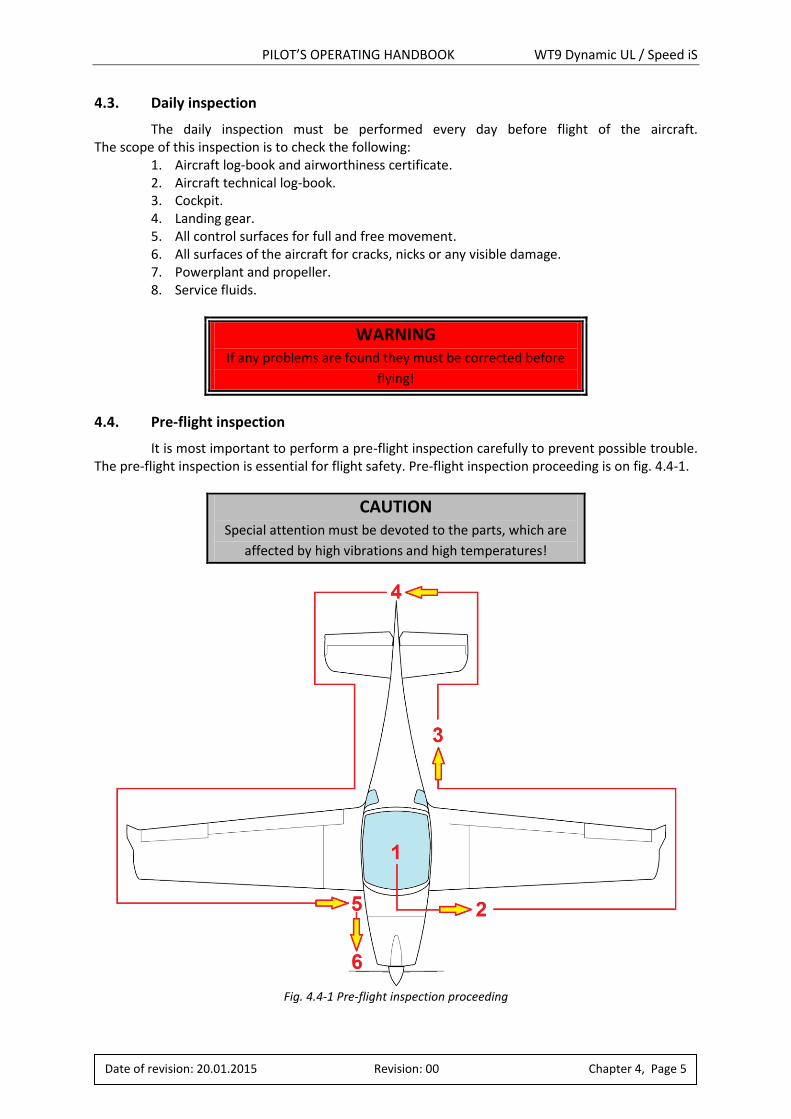
4.3. Daily inspection
The daily inspection must be performed every day before flight of the aircraft. The scope of this inspection is to check the following:
1. Aircraft log-book and airworthiness certificate. 2. Aircraft technical log-book. 3. Cockpit. 4. Landing gear. 5. All control surfaces for full and free movement. 6. All surfaces of the aircraft for cracks, nicks or any visible damage. 7. Powerplant and propeller. 8. Service fluids.
WARNING If any problems are found they must be corrected before
flying!
4.4. Pre-flight inspection
It is most important to perform a pre-flight inspection carefully to prevent possible trouble. The pre-flight inspection is essential for flight safety. Pre-flight inspection proceeding is on fig. 4.4-1.
CAUTION Special attention must be devoted to the parts, which are
affected by high vibrations and high temperatures!
Fig. 4.4-1 Pre-flight inspection proceeding
PILOT’S OPERATING HANDBOOK WT9 Dynamic UL / Speed iS
Date of revision: 20.01.2015 Revision: 00 Chapter 4, Page 6
A. Cockpit:
Flight controls: Check for freedom of movement. Master switch: Switched OFF. Lane A/Lane B: Both circuits switched OFF. Emergency (backup battery) switch: Switched OFF. Hydraulic pump: Switched OFF. Landing gear: Set DOWN. Loose items: Secure or remove. Check instruments: Set “0” (zero). Cockpit canopy glass: Clean, check cockpit canopy lock. Safety harness: Inspect. Fuel: Check fuel quantity, check fuel selector.
B. Wing:
Surface: State of wing surface. Connection: Wing pins fully inserted and secured. Fuel tank caps: State of fuel tank caps. Pitot probe: Pitot probe cover removed, check opening for blockage. Leading edges: Without damage, clean. Ailerons: Check for freedom of movement and security. Wing flaps: Without play, check hinges for security.
C. Fuselage:
Surface: Without damage. Static pressure receivers: Check opening for blockage. Antennas: Fixed, without damage. Cockpit wing walks: Without damage.
D. Tail units:
Surface: Without damage. Control surfaces: Check for freedom of movement, without excess play Tail skid: Check for secure attachment.
E. Landing gear:
Main gear legs: Main wheel tyres state and inflation (250 kPa), attachment, suspension check. Brakes: Visually check condition of brake pads, brake system for leaks. Legs: State without damage, attachment. Nose gear leg: Nose wheel tyre state and inflation (200 kPa) attachment, suspension check, wheel free of rotation.

PILOT’S OPERATING HANDBOOK WT9 Dynamic UL / Speed iS
Date of revision: 20.01.2015 Revision: 00 Chapter 4, Page 7
F. Powerplant
Propeller: Attachment, leading edge blade state, check for nicks and security, check spinner for cracks and attachment. Engine: Check for any operating fluids leaks. State of the engine cowlings. State of the exhaust system attachment. Check coolant level and oil level. Engine attachment in rubber silentblocks. Carburettors attachment. State of hoses holders. Condition and integrity of wires, plugs Fuel filters. Turn the propeller by hand several times for odd noises or excessive resistance and normal compression. Fuel system: Drain the fuel tanks: 1. Place a suitable bottle below the drain valve. 2. Open the fuel tank filling cap. 3. Drain a small quantity of fuel by pushing of drain valve (fig. 4.4-2) to remove accumulated water if any. 4. Close and check the drain valve.
Fig. 4.4-2 Drain valves
WARNING Before cranking the propeller, switch off both ignition
circuits. The propeller must be caught at the blade surface
every time. Do not catch at the edge!
PILOT’S OPERATING HANDBOOK WT9 Dynamic UL / Speed iS
Date of revision: 20.01.2015 Revision: 00 Chapter 4, Page 8
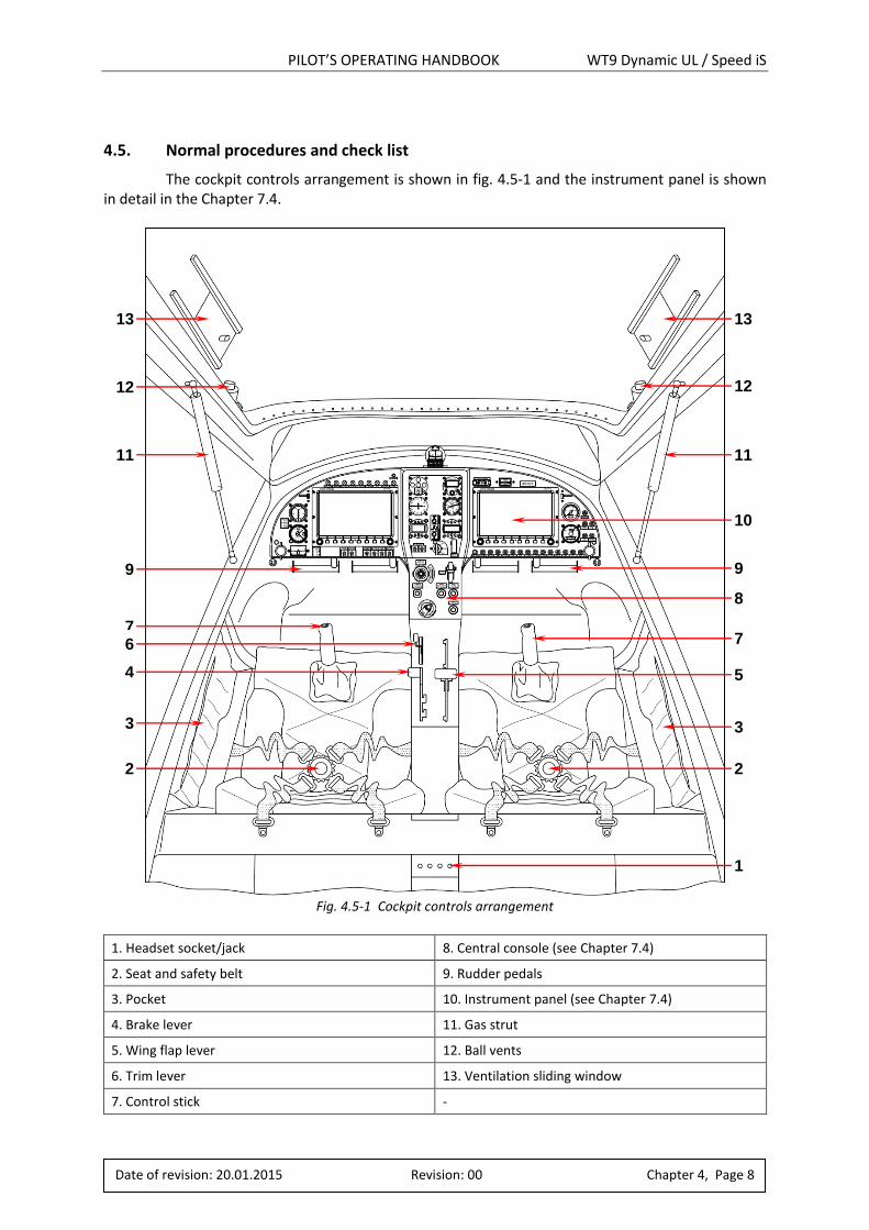
4.5. Normal procedures and check list
The cockpit controls arrangement is shown in fig. 4.5-1 and the instrument panel is shown in detail in the Chapter 7.4.
Fig. 4.5-1 Cockpit controls arrangement
1. Headset socket/jack 8. Central console (see Chapter 7.4)
2. Seat and safety belt 9. Rudder pedals
3. Pocket 10. Instrument panel (see Chapter 7.4)
4. Brake lever 11. Gas strut
5. Wing flap lever 12. Ball vents
6. Trim lever 13. Ventilation sliding window
7. Control stick -
1
2 2
3 3
7 7
5 4
8
6
9 9
11 11
10
12 12
13 13
PILOT’S OPERATING HANDBOOK WT9 Dynamic UL / Speed iS
Date of revision: 20.01.2015 Revision: 00 Chapter 4, Page 9
4.5.1. Before starting engine
1. Master switch: Switched OFF. 2. Lane A/Lane B: Both circuits switched OFF. 3. Emergency switch: Switched OFF. 4. Control stick: Freedom of movement. 5. Throttle lever: Freedom of movement, set to idle position. 6. Elevator trim control: Set to neutral position. 7. Fuel quantity: Check. 8. Instruments: Setting and check up of the value. 9. Circuit breakers: Check. 10. Radio: Function check. 11. Seat and safety harness: Adjust and lock. 12. Brake: Function check. 13. Landing gear: Set DOWN. 14. Propeller pitch range: Check the min. and max. propeller pitch and adjust
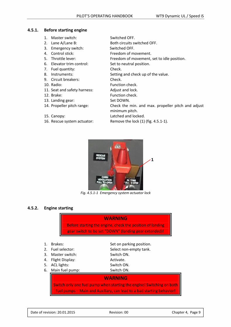
minimum pitch. 15. Canopy: Latched and locked. 16. Rescue system actuator: Remove the lock (1) (fig. 4.5.1-1).
Fig. 4.5.1-1 Emergency system actuator lock
4.5.2. Engine starting
WARNING Before starting the engine, check the position of landing
gear switch to be set “DOWN” (landing gear extended)!
1. Brakes: Set on parking position. 2. Fuel selector: Select non-empty tank. 3. Master switch: Switch ON. 4. Flight Display: Activate. 5. ACL lights: Switch ON. 6. Main fuel pump: Switch ON.
WARNING Switch only one fuel pump when starting the engine! Switching on both
fuel pumps – Main and Auxiliary, can lead to a bad starting behavior!
1
PILOT’S OPERATING HANDBOOK WT9 Dynamic UL / Speed iS
Date of revision: 20.01.2015 Revision: 00 Chapter 4, Page 10
7. Fuel pressure: Check if it has reached 3 bars. 8. Lane A/Lane B: Both circuits switch ON and check if Lane A and
Lane B Warning Lamps extinguish within 6 seconds. 9. Starter key: Switch to Start Power position. 10. Warning lamps: Check if illuminate and extinguish within 3 seconds. 11. Throttle lever: Put between 1 to 2 cm of throttle opening. 12. Starter key: Press until the engine runs and release to ACC
position after engine has reached 1500 min-1 or more (stable engine run).
CAUTION Activate starter for maximum of 10 seconds only (without interruption), followed by a cooling period of 2 minutes!
13. As soon as engine runs: Adjust throttle lever to achieve smooth running
at approx. 2500 min-1and hold speed at least 5 seconds (await generator shift from Gen B to Gen A).
CAUTION Increasing engine speed is only permitted at steady oil
pressure readings above 3 bar!
WARNING If after the engine start a warning lamp flashes or lights up,
perfrom a LANE and IGNITION check. After the check both
warning lamps must be deactivated. Otherwise the error
must be located and repaired before the flight!
CAUTION Cooling of the engine is insufficient when idling on the
ground. If idling is needed never do that for a longer time, monitor temperatures and preferably relocate the plane into
upwind position!
14. Warming up: Start warming up procedure according
to the procedure in 4.5.3. 15. Fuel quantity: Check. 16. Avionics: Switch ON and Set. Function check.
PILOT’S OPERATING HANDBOOK WT9 Dynamic UL / Speed iS
Date of revision: 20.01.2015 Revision: 00 Chapter 4, Page 11
4.5.3. Engine warming up
In accordance with the Operator’s Manual for Rotax Engine Type 912 i Series, Ref. No.: OM-912 i, start the warming up period at 2000 min-1 for approx. 2 minutes, continue at 2500 min-1, duration depending on ambient temperature, until oil temperature reaches 50 °C. Check temperatures and pressures.
Engine ground test: 1. Brakes: Brakes set on full. 2. LANE and ignition check: Check the two ignition circuits (LANE A/B) at 4000
min-1. Speed drop with only one ignition circuit must not exceed 180 min-1. Max. difference 75 min-1 of speed by use of either circuit A or B. Check power supply and minimum voltage of 12V at each LANE.
3. Throttle response: Short (maximum of 10 seconds) full throttle ground test, speed must not exceed 5800 min-1 (at min. propeller pitch).
4. Minimum speed: Minimum speed on the ground at full throttle (100%) must be 5500 ±200 min-1 depending on ambient temperature and pressure (at min. propeller pitch).
5. Idle speed: Check the idle speed 1600 ±100 min-1. 6. Fuel pumps check: Set both fuel pumps ON and engine speed to 2000 min-1.
Turn auxiliary fuel pump OFF for 5 seconds, check fuel pressure, then turn auxiliary fuel pump ON. Turn main fuel pump OFF for 5 seconds, check fuel pressure, then turn main fuel pump ON.
WARNING If fuel pressure is not within the limits, the cause must be
determinated and repaired before the flight!
4.5.4. Taxiing
Use of the throttle control (screw in, screw out) what will help with smooth adjustments of power during taxiing. Taxiing of the aircraft is controlled by the rudder pedals which are connected to the nose wheel steering. The wheel brakes are actuated by sliding the brake lever rearwards in the centre console. During taxiing check the rudder pedals freedom of movement.
In addition before glider towing: 1. Taxi to the front of a glider to can attach the towing rope. 2. Set the aircraft to take-off configuration (use manual propeller control). 3. Start slowly taxiing to tighten the rope. 4. Check in the rear mirror if the glider wings are levelled and an area in front of glider
is clear.
PILOT’S OPERATING HANDBOOK WT9 Dynamic UL / Speed iS
Date of revision: 20.01.2015 Revision: 00 Chapter 4, Page 12
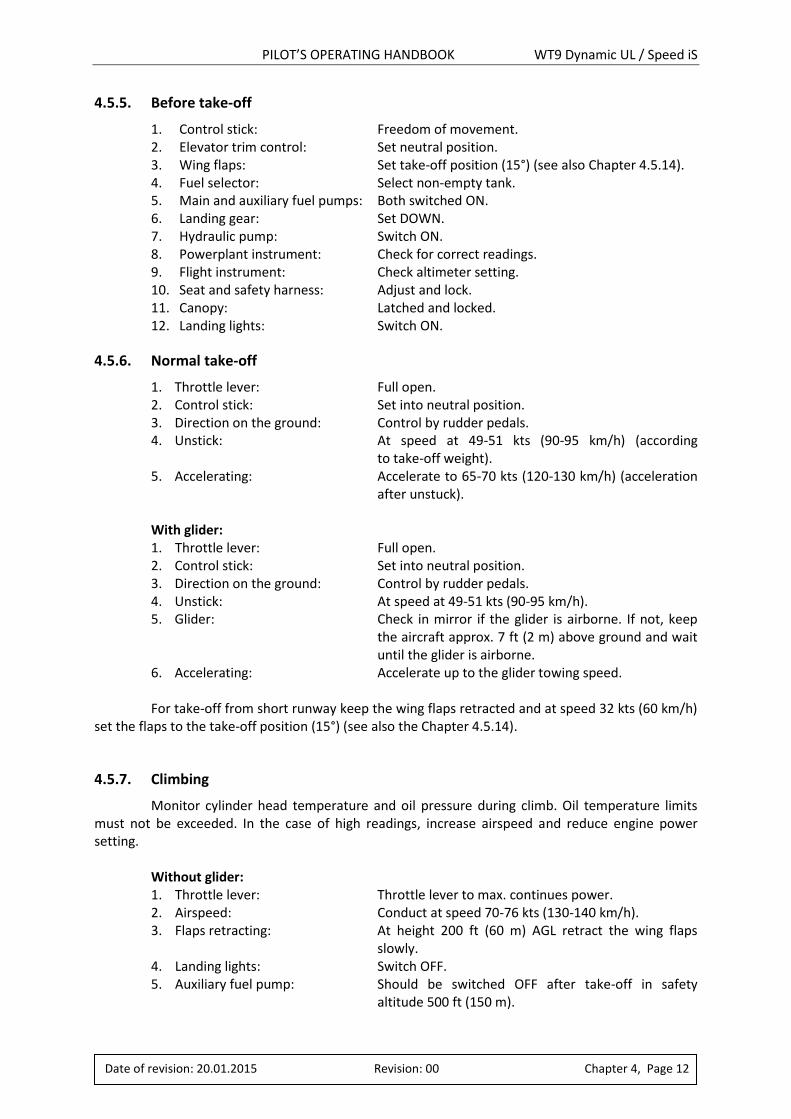
4.5.5. Before take-off
1. Control stick: Freedom of movement. 2. Elevator trim control: Set neutral position. 3. Wing flaps: Set take-off position (15°) (see also Chapter 4.5.14). 4. Fuel selector: Select non-empty tank. 5. Main and auxiliary fuel pumps: Both switched ON. 6. Landing gear: Set DOWN. 7. Hydraulic pump: Switch ON. 8. Powerplant instrument: Check for correct readings. 9. Flight instrument: Check altimeter setting. 10. Seat and safety harness: Adjust and lock. 11. Canopy: Latched and locked. 12. Landing lights: Switch ON.
4.5.6. Normal take-off
1. Throttle lever: Full open. 2. Control stick: Set into neutral position. 3. Direction on the ground: Control by rudder pedals. 4. Unstick: At speed at 49-51 kts (90-95 km/h) (according
to take-off weight). 5. Accelerating: Accelerate to 65-70 kts (120-130 km/h) (acceleration
after unstuck).
With glider: 1. Throttle lever: Full open. 2. Control stick: Set into neutral position. 3. Direction on the ground: Control by rudder pedals. 4. Unstick: At speed at 49-51 kts (90-95 km/h). 5. Glider: Check in mirror if the glider is airborne. If not, keep
the aircraft approx. 7 ft (2 m) above ground and wait until the glider is airborne.
6. Accelerating: Accelerate up to the glider towing speed.
For take-off from short runway keep the wing flaps retracted and at speed 32 kts (60 km/h) set the flaps to the take-off position (15°) (see also the Chapter 4.5.14).
4.5.7. Climbing
Monitor cylinder head temperature and oil pressure during climb. Oil temperature limits must not be exceeded. In the case of high readings, increase airspeed and reduce engine power setting.
Without glider: 1. Throttle lever: Throttle lever to max. continues power. 2. Airspeed: Conduct at speed 70-76 kts (130-140 km/h). 3. Flaps retracting: At height 200 ft (60 m) AGL retract the wing flaps
slowly. 4. Landing lights: Switch OFF. 5. Auxiliary fuel pump: Should be switched OFF after take-off in safety
altitude 500 ft (150 m).
PILOT’S OPERATING HANDBOOK WT9 Dynamic UL / Speed iS
Date of revision: 20.01.2015 Revision: 00 Chapter 4, Page 13
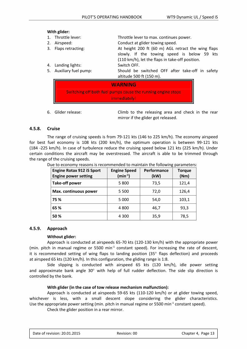
With glider: 1. Throttle lever: Throttle lever to max. continues power. 2. Airspeed: Conduct at glider towing speed. 3. Flaps retracting: At height 200 ft (60 m) AGL retract the wing flaps
slowly. If the towing speed is below 59 kts (110 km/h), let the flaps in take-off position.
4. Landing lights: Switch OFF. 5. Auxiliary fuel pump: Should be switched OFF after take-off in safety
altitude 500 ft (150 m).
WARNING Switching off both fuel pumps cause the running engine stops
immediately!
6. Glider release: Climb to the releasing area and check in the rear
mirror if the glider got released.
4.5.8. Cruise
The range of cruising speeds is from 79-121 kts (146 to 225 km/h). The economy airspeed for best fuel economy is 108 kts (200 km/h), the optimum operation is between 99-121 kts (184 -225 km/h). In case of turbulence reduce the cruising speed below 121 kts (225 km/h). Under certain conditions the aircraft may be overstressed. The aircraft is able to be trimmed through the range of the cruising speeds. Due to economy reasons is recommended to maintain the following parameters:
Engine Rotax 912 iS Sport Engine power setting
Engine Speed (min-1)
Performance (kW)
Torque (Nm)
Take-off power 5 800 73,5 121,4
Max. continuous power 5 500 72,0 126,4
75 % 5 000 54,0 103,1
65 % 4 800 46,7 93,3
50 % 4 300 35,9 78,5
4.5.9. Approach
Without glider: Approach is conducted at airspeeds 65-70 kts (120-130 km/h) with the appropriate power (min. pitch in manual regime or 5500 min-1 constant speed). For increasing the rate of descent,
it is recommended setting of wing flaps to landing position (35 flaps deflection) and proceeds at airspeed 65 kts (120 km/h). In this configuration, the gliding range is 1:8. Side slipping is conducted with airspeed 65 kts (120 km/h), idle power setting
and approximate bank angle 30 with help of full rudder deflection. The side slip direction is controlled by the bank.
With glider (in the case of tow release mechanism malfunction): Approach is conducted at airspeeds 59-65 kts (110-120 km/h) or at glider towing speed, whichever is less, with a small descent slope considering the glider characteristics. Use the appropriate power setting (min. pitch in manual regime or 5500 min-1 constant speed). Check the glider position in a rear mirror.
PILOT’S OPERATING HANDBOOK WT9 Dynamic UL / Speed iS
Date of revision: 20.01.2014 Revision: 00 Chapter 4, Page 14
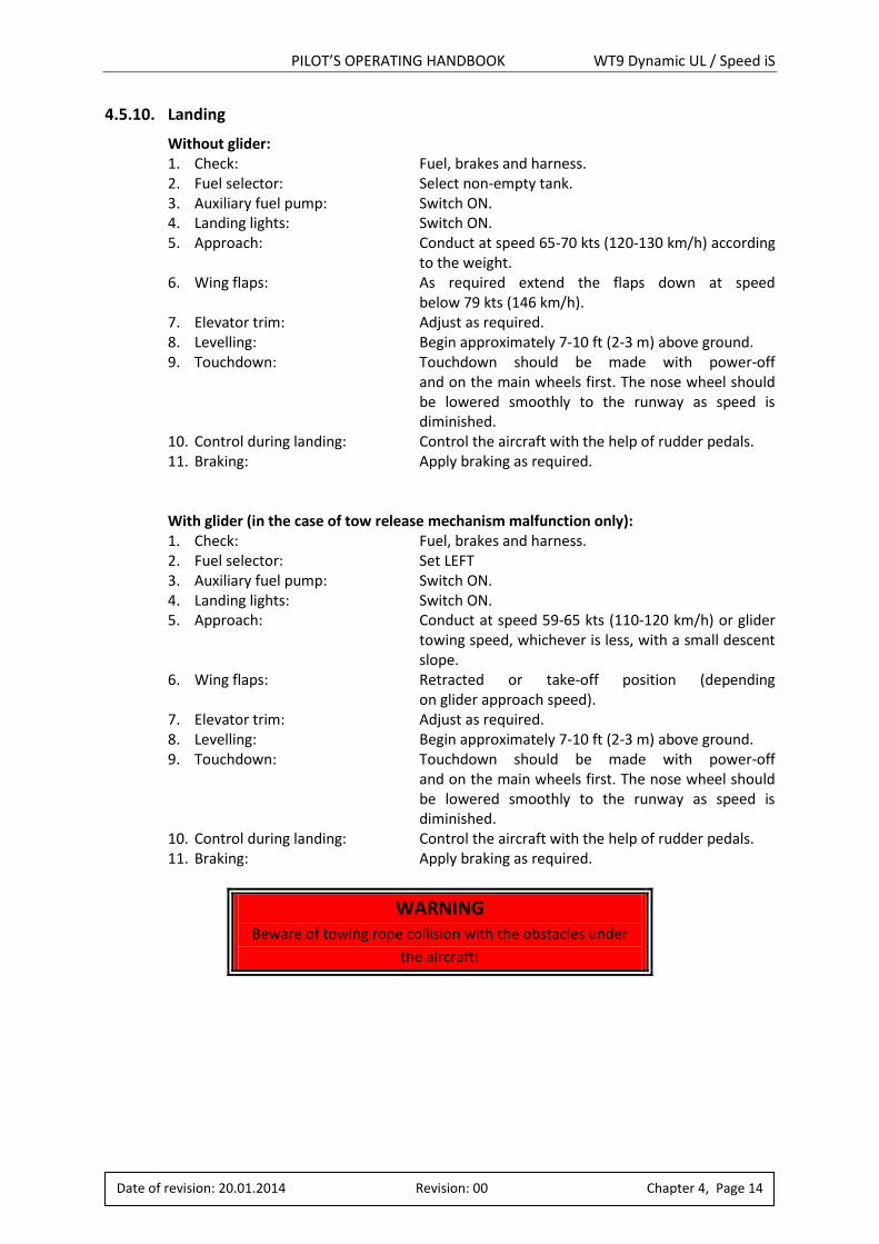
4.5.10. Landing
Without glider: 1. Check: Fuel, brakes and harness. 2. Fuel selector: Select non-empty tank. 3. Auxiliary fuel pump: Switch ON. 4. Landing lights: Switch ON. 5. Approach: Conduct at speed 65-70 kts (120-130 km/h) according
to the weight. 6. Wing flaps: As required extend the flaps down at speed
below 79 kts (146 km/h). 7. Elevator trim: Adjust as required. 8. Levelling: Begin approximately 7-10 ft (2-3 m) above ground. 9. Touchdown: Touchdown should be made with power-off
and on the main wheels first. The nose wheel should be lowered smoothly to the runway as speed is diminished.
10. Control during landing: Control the aircraft with the help of rudder pedals. 11. Braking: Apply braking as required.
With glider (in the case of tow release mechanism malfunction only): 1. Check: Fuel, brakes and harness. 2. Fuel selector: Set LEFT 3. Auxiliary fuel pump: Switch ON. 4. Landing lights: Switch ON. 5. Approach: Conduct at speed 59-65 kts (110-120 km/h) or glider
towing speed, whichever is less, with a small descent slope.
6. Wing flaps: Retracted or take-off position (depending on glider approach speed).
7. Elevator trim: Adjust as required. 8. Levelling: Begin approximately 7-10 ft (2-3 m) above ground. 9. Touchdown: Touchdown should be made with power-off
and on the main wheels first. The nose wheel should be lowered smoothly to the runway as speed is diminished.
10. Control during landing: Control the aircraft with the help of rudder pedals. 11. Braking: Apply braking as required.
WARNING Beware of towing rope collision with the obstacles under
the aircraft!
PILOT’S OPERATING HANDBOOK WT9 Dynamic UL / Speed iS
Date of revision: 20.01.2015 Revision: 00 Chapter 4, Page 15
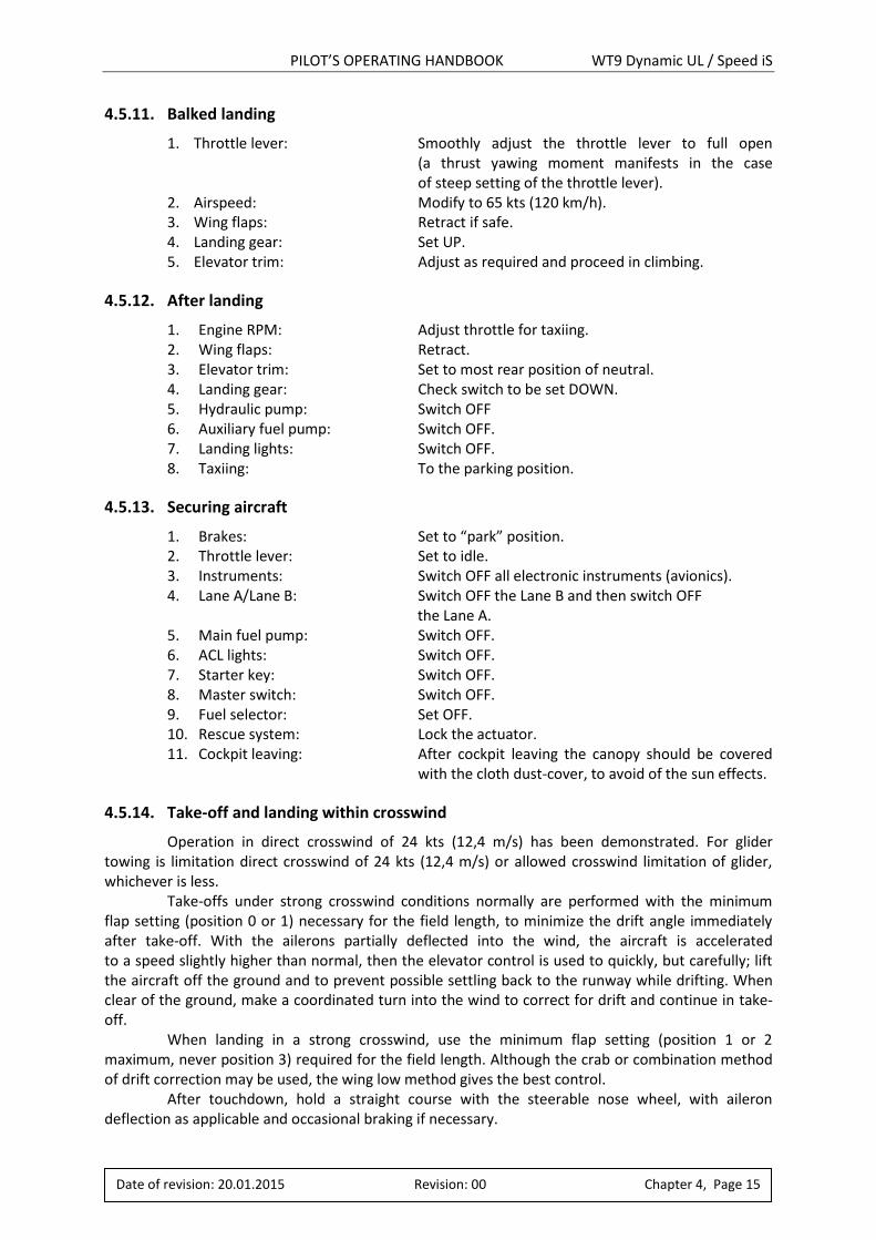
4.5.11. Balked landing
1. Throttle lever: Smoothly adjust the throttle lever to full open (a thrust yawing moment manifests in the case of steep setting of the throttle lever).
2. Airspeed: Modify to 65 kts (120 km/h). 3. Wing flaps: Retract if safe. 4. Landing gear: Set UP. 5. Elevator trim: Adjust as required and proceed in climbing.
4.5.12. After landing
1. Engine RPM: Adjust throttle for taxiing. 2. Wing flaps: Retract. 3. Elevator trim: Set to most rear position of neutral. 4. Landing gear: Check switch to be set DOWN. 5. Hydraulic pump: Switch OFF 6. Auxiliary fuel pump: Switch OFF. 7. Landing lights: Switch OFF. 8. Taxiing: To the parking position.
4.5.13. Securing aircraft
1. Brakes: Set to “park” position. 2. Throttle lever: Set to idle. 3. Instruments: Switch OFF all electronic instruments (avionics). 4. Lane A/Lane B: Switch OFF the Lane B and then switch OFF
the Lane A. 5. Main fuel pump: Switch OFF. 6. ACL lights: Switch OFF. 7. Starter key: Switch OFF. 8. Master switch: Switch OFF. 9. Fuel selector: Set OFF. 10. Rescue system: Lock the actuator. 11. Cockpit leaving: After cockpit leaving the canopy should be covered
with the cloth dust-cover, to avoid of the sun effects.
4.5.14. Take-off and landing within crosswind
Operation in direct crosswind of 24 kts (12,4 m/s) has been demonstrated. For glider towing is limitation direct crosswind of 24 kts (12,4 m/s) or allowed crosswind limitation of glider, whichever is less. Take-offs under strong crosswind conditions normally are performed with the minimum flap setting (position 0 or 1) necessary for the field length, to minimize the drift angle immediately after take-off. With the ailerons partially deflected into the wind, the aircraft is accelerated to a speed slightly higher than normal, then the elevator control is used to quickly, but carefully; lift the aircraft off the ground and to prevent possible settling back to the runway while drifting. When clear of the ground, make a coordinated turn into the wind to correct for drift and continue in take-off. When landing in a strong crosswind, use the minimum flap setting (position 1 or 2 maximum, never position 3) required for the field length. Although the crab or combination method of drift correction may be used, the wing low method gives the best control. After touchdown, hold a straight course with the steerable nose wheel, with aileron deflection as applicable and occasional braking if necessary.
PILOT’S OPERATING HANDBOOK WT9 Dynamic UL / Speed iS
Date of revision: 20.01.2015 Revision: 00 Chapter 5, Page 1
5. PERFORMANCE
Chapter Page
5.1. ....................... INTRODUCTION .......................................................................................2
5.2. ....................... APPROVED DATA .....................................................................................2
5.2.1. .................... AIRSPEED INDICATOR SYSTEM CALIBRATION ...........................................2
5.2.2. .................... STALL SPEED ............................................................................................2
5.2.3. .................... TAKE-OFF PERFORMANCE ........................................................................3
5.2.4. .................... LANDING DISTANCE .................................................................................3
5.2.5. .................... CLIMB PERFORMANCE .............................................................................3
5.3. ....................... ADDITIONAL INFORMATION ....................................................................4
5.3.1. .................... BALKED LANDING CLIMB .........................................................................4
5.3.2. .................... EFFECT ON FLIGHT PERFORMANCE AND CHARACTERISTICS ......................4
5.3.3. .................... DEMONSTRATED CROSSWIND PERFORMANCE ........................................4
PILOT’S OPERATING HANDBOOK WT9 Dynamic UL / Speed iS
Date of revision: 20.01.2015 Revision: 00 Chapter 5, Page 2
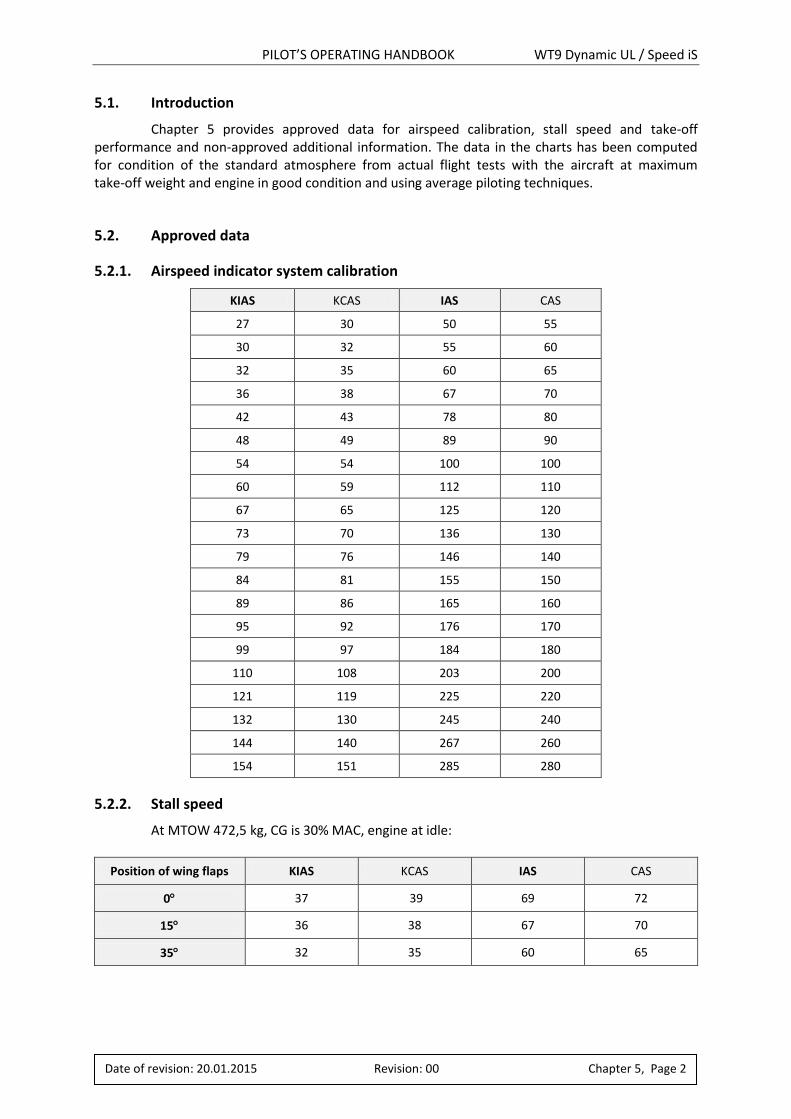
5.1. Introduction
Chapter 5 provides approved data for airspeed calibration, stall speed and take-off performance and non-approved additional information. The data in the charts has been computed for condition of the standard atmosphere from actual flight tests with the aircraft at maximum take-off weight and engine in good condition and using average piloting techniques.
5.2. Approved data
5.2.1. Airspeed indicator system calibration
KIAS KCAS IAS CAS
27 30 50 55
30 32 55 60
32 35 60 65
36 38 67 70
42 43 78 80
48 49 89 90
54 54 100 100
60 59 112 110
67 65 125 120
73 70 136 130
79 76 146 140
84 81 155 150
89 86 165 160
95 92 176 170
99 97 184 180
110 108 203 200
121 119 225 220
132 130 245 240
144 140 267 260
154 151 285 280
5.2.2. Stall speed
At MTOW 472,5 kg, CG is 30% MAC, engine at idle:
Position of wing flaps KIAS KCAS IAS CAS
0 37 39 69 72
15 36 38 67 70
35 32 35 60 65
PILOT’S OPERATING HANDBOOK WT9 Dynamic UL / Speed iS
Date of revision: 20.01.2015 Revision: 00 Chapter 5, Page 3
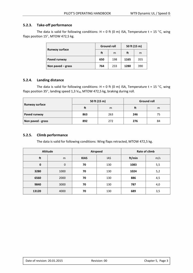
5.2.3. Take-off performance
The data is valid for following conditions: H = 0 ft (0 m) ISA, Temperature t = 15 C, wing
flaps position 15, MTOW 472,5 kg.
Runway surface Ground roll 50 ft (15 m)
ft m ft m
Paved runway 650 198 1165 355
Non paved – grass 764 233 1280 390
5.2.4. Landing distance
The data is valid for following conditions: H = 0 ft (0 m) ISA, Temperature t = 15 C, wing
flaps position 35, landing speed 1,3 VS0, MTOW 472,5 kg, braking during roll.
Runway surface 50 ft (15 m) Ground roll
ft m ft m
Paved runway 863 263 246 75
Non paved - grass 892 272 276 84
5.2.5. Climb performance
The data is valid for following conditions: Wing flaps retracted, MTOW 472,5 kg.
Altitude Airspeed Rate of climb
ft m KIAS IAS ft/min m/s
0 0 70 130 1083 5,5
3280 1000 70 130 1024 5,2
6560 2000 70 130 886 4,5
9840 3000 70 130 787 4,0
13120 4000 70 130 689 3,5
PILOT’S OPERATING HANDBOOK WT9 Dynamic UL / Speed iS
Date of revision: 20.01.2015 Revision: 00 Chapter 5, Page 4
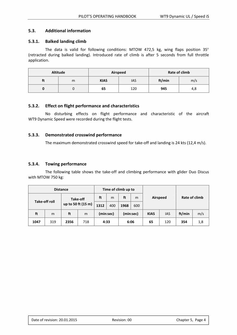
5.3. Additional information
5.3.1. Balked landing climb
The data is valid for following conditions: MTOW 472,5 kg, wing flaps position 35 (retracted during balked landing). Introduced rate of climb is after 5 seconds from full throttle application.
Altitude Airspeed Rate of climb
ft m KIAS IAS ft/min m/s
0 0 65 120 945 4,8
5.3.2. Effect on flight performance and characteristics
No disturbing effects on flight performance and characteristic of the aircraft WT9 Dynamic Speed were recorded during the flight tests.
5.3.3. Demonstrated crosswind performance
The maximum demonstrated crosswind speed for take-off and landing is 24 kts (12,4 m/s).
5.3.4. Towing performance
The following table shows the take-off and climbing performance with glider Duo Discus with MTOW 750 kg:
Distance Time of climb up to
Airspeed Rate of climb Take-off roll
Take-off up to 50 ft (15 m)
ft m ft m
1312 400 1968 600
ft m ft m (min:sec) (min:sec) KIAS IAS ft/min m/s
1047 319 2356 718 4:33 6:06 65 120 354 1,8
PILOT’S OPERATING HANDBOOK WT9 Dynamic UL / Speed iS
Date of revision: 20.01.2015 Revision: 00 Chapter 6, Page 1
6. WEIGHT AND BALANCE AND EQUIPMENT LIST
Chapter Page
6.1. ....................... INTRODUCTION .......................................................................................2
6.2. ....................... WEIGHTING PROCEDURE .........................................................................2
6.3. ....................... WEIGHT AND BALANCE RECORD AND PERMITTED PAYLOAD RANGE ........3
6.4. ....................... EQUIPMENT LIST .....................................................................................5
PILOT’S OPERATING HANDBOOK WT9 Dynamic UL / Speed iS
Date of revision: 20.01.2015 Revision: 00 Chapter 6, Page 2
6.1. Introduction
This chapter contains the payload range with which the aircraft may be safely operated. CG position is very important parameter that affects the safety of flight.
6.2. Weighting procedure
To define the aircraft CG it is necessary to weigh the empty aircraft with standard and optional equipment, with operating fluids of the engine but without the fuel in the fuel tanks (for empty weight and empty moment see Weight and balance record). The aircraft is weighted with the help of three weighting-machines located under the left and right main wheels and under the nose wheel. The aircraft position for weighting has to be adjusted to be levelled the side edge of the cockpit. The datum reference point (RP) is leading edge of wing root section where wing-fuselage radius starts. Measure the distance from datum point (RP) to centre of main landing wheel axle and nose wheel axle. The leading edge of Mean Aerodynamic Chord (MAC) is located in distance 77 mm rearward from RP. CG position is expressed as a distance from MAC leading edge (𝑋𝑇 (mm)) and as a MAC ratio (𝑋𝐶𝑇 (% MAC)). CG position after loading of aircraft (crew, fuel and baggage or additional equipment) can be calculated as follows (see CALCULATION OF FLIGHT CG POSITION in Chapter 6.3):
1. Determine the partial weights of crew(𝐺𝐶), fuel(𝐺𝐹)*, baggage(𝐺𝐵)and add them to empty weight(𝐺𝐸)to get total weight(𝐺𝑇).
2. Calculate the partial moments of crew (𝑀𝐶), fuel (𝑀𝐹)*, baggage (𝑀𝐵)and add them to empty moment(𝑀𝐸) to get total moment(𝑀𝑇).
3. Calculate the position of CG on MAC (𝑋𝑇) (in mm). Calculate the position of CG on MAC(𝑋𝐶𝑇)(in %MAC)
4. Check if the flight CG is inside of allowed range (For safety flight it must be considered that the fuel is consumed during flight what results in moving of CG forward!).
* Be careful to use fuel weight (in kg) not fuel volume (in litres)!
PILOT’S OPERATING HANDBOOK WT9 Dynamic UL / Speed iS
Date of revision: 20.01.2015 Revision: 00 Chapter 6, Page 3
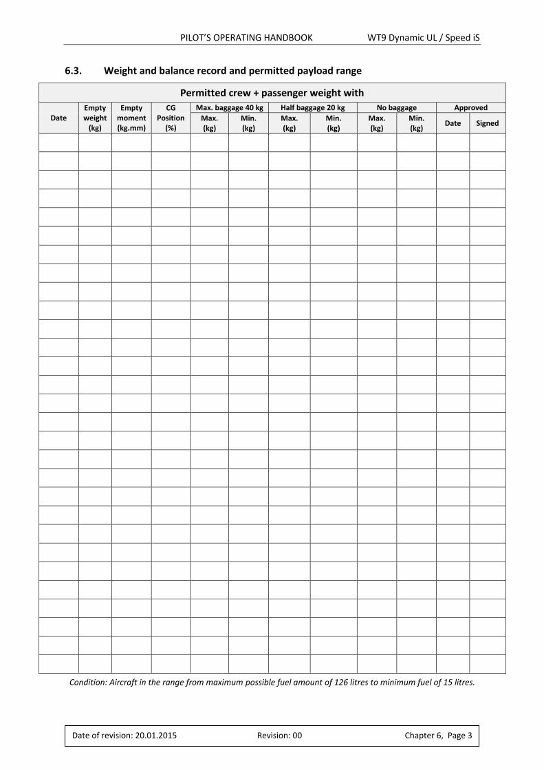
6.3. Weight and balance record and permitted payload range
Permitted crew + passenger weight with
Date Empty weight
(kg)
Empty moment (kg.mm)
CG Position
(%)
Max. baggage 40 kg Half baggage 20 kg No baggage Approved
Max. (kg)
Min. (kg)
Max. (kg)
Min. (kg)
Max. (kg)
Min. (kg)
Date Signed
Condition: Aircraft in the range from maximum possible fuel amount of 126 litres to minimum fuel of 15 litres.
PILOT’S OPERATING HANDBOOK WT9 Dynamic UL / Speed iS
Date of revision: 20.01.2015 Revision: 00 Chapter 6, Page 4
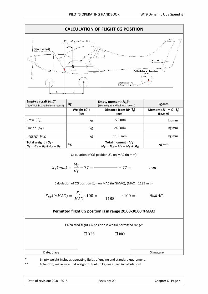
CALCULATION OF FLIGHT CG POSITION
Empty aircraft (𝐺𝐸)* (See Weight and balance record) kg
Empty moment (𝑀𝐸)* (See Weight and balance record) kg.mm
Weight (𝑮𝒊)
(kg)
Distance from RP (𝒍𝒊) (mm)
Moment (𝑴𝒊 = 𝑮𝒊. 𝒍𝒊) (kg.mm)
Crew (𝐺𝐶) kg 720 mm kg.mm
Fuel** (𝐺𝐹) kg 240 mm kg.mm
Baggage (𝐺𝐵) kg 1100 mm kg.mm
Total weight (𝑮𝑻) 𝑮𝑻 = 𝑮𝑬 + 𝑮𝑪 + 𝑮𝑭 + 𝑮𝑩
kg Total moment (𝑴𝑻)
𝑴𝑻 = 𝑴𝑬 + 𝑴𝑪 + 𝑴𝑭 + 𝑴𝑩 kg.mm
Calculation of CG position 𝑋𝑇 on MAC (in mm):
𝑋𝑇(𝑚𝑚) = 𝑀𝑇
𝐺𝑇− 77 =
− 77 = 𝑚𝑚
Calculation of CG position 𝑋𝐶𝑇 on MAC (in %MAC), (MAC = 1185 mm):
𝑋𝐶𝑇(%𝑀𝐴𝐶) = 𝑋𝑇
𝑀𝐴𝐶· 100 =
1185· 100 = %𝑀𝐴𝐶
Permitted flight CG position is in range 20,00-30,00 %MAC!
Calculated flight CG position is whitin permitted range:
YES NO
Date, place Signature
* Empty weight includes operating fluids of engine and standard equipment. ** Attention, make sure that weight of fuel (in kg) was used in calculation!
PILOT’S OPERATING HANDBOOK WT9 Dynamic UL / Speed iS
Date of revision: 20.01.2015 Revision: 00 Chapter 6, Page 5
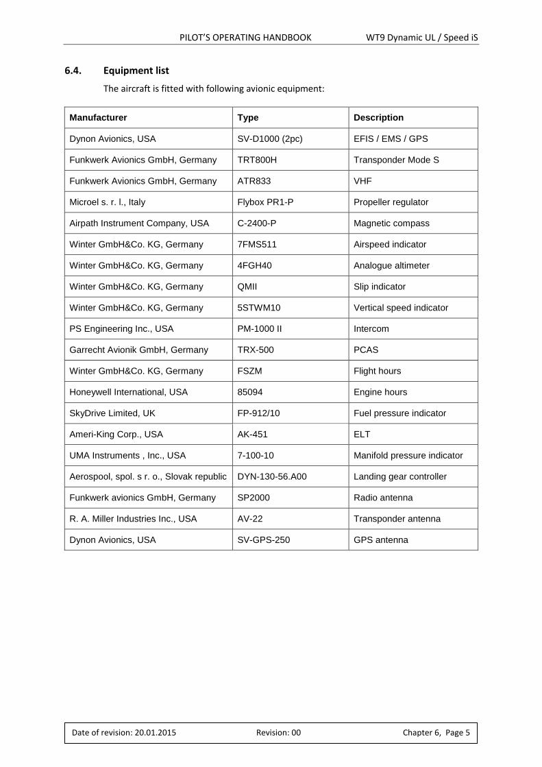
6.4. Equipment list
The aircraft is fitted with following avionic equipment:
Manufacturer Type Description
Dynon Avionics, USA SV-D1000 (2pc) EFIS / EMS / GPS
Funkwerk Avionics GmbH, Germany TRT800H Transponder Mode S
Funkwerk Avionics GmbH, Germany ATR833 VHF
Microel s. r. l., Italy Flybox PR1-P Propeller regulator
Airpath Instrument Company, USA C-2400-P Magnetic compass
Winter GmbH&Co. KG, Germany 7FMS511 Airspeed indicator
Winter GmbH&Co. KG, Germany 4FGH40 Analogue altimeter
Winter GmbH&Co. KG, Germany QMII Slip indicator
Winter GmbH&Co. KG, Germany 5STWM10 Vertical speed indicator
PS Engineering Inc., USA PM-1000 II Intercom
Garrecht Avionik GmbH, Germany TRX-500 PCAS
Winter GmbH&Co. KG, Germany FSZM Flight hours
Honeywell International, USA 85094 Engine hours
SkyDrive Limited, UK FP-912/10 Fuel pressure indicator
Ameri-King Corp., USA AK-451 ELT
UMA Instruments , Inc., USA 7-100-10 Manifold pressure indicator
Aerospool, spol. s r. o., Slovak republic DYN-130-56.A00 Landing gear controller
Funkwerk avionics GmbH, Germany SP2000 Radio antenna
R. A. Miller Industries Inc., USA AV-22 Transponder antenna
Dynon Avionics, USA SV-GPS-250 GPS antenna
PILOT’S OPERATING HANDBOOK WT9 Dynamic UL / Speed iS
Date of revision: 20.01.2015 Revision: 00 Chapter 7, Page 1
7. AIRCRAFT AND SYSTEM DESCRIPTION
Chapter Page
7.1. ....................... INTRODUCTION .......................................................................................2
7.2. ....................... AIRFRAME ...............................................................................................2
7.3. ....................... FLIGHT CONTROLS ...................................................................................3
7.4. ....................... INSTRUMENT PANEL ................................................................................4
7.5. ....................... LANDING GEAR SYSTEM...........................................................................6
7.6. ....................... SEATS AND SAFETY HARNESS ...................................................................8
7.7. ....................... BAGGAGE COMPARTMENT ......................................................................8
7.8. ....................... DOORS, WINDOWS AND EXITS .................................................................8
7.9. ....................... POWERPLANT ..........................................................................................9
7.10. ..................... FUEL SYSTEM ......................................................................................... 13
7.11. ..................... ELECTRICAL SYSTEM .............................................................................. 14
7.12. ..................... PITOT AND STATIC PRESSURE SYSTEM ................................................... 14
7.13. ..................... AVIONICS .............................................................................................. 15
7.14. ..................... MISCELLANEOUS EQUIPMENT ............................................................... 17
PILOT’S OPERATING HANDBOOK WT9 Dynamic UL / Speed iS
Date of revision: 20.01.2015 Revision: 00 Chapter 7, Page 2
7.1. Introduction
This chapter provides a description of the operation of the aircraft and its systems. Refer to the Chapter 9, Supplements, for details of optional systems and equipment.
7.2. Airframe
Fuselage: The fuselage sandwich shell is divided in the symmetry plane. The shell is of three layer construction. The external and internal shell layers are made of glass and carbon fibre fabrics, which are saturated with a resin. Between them there is a filling of hard foam panels. The fin is made together with the fuselage. The wing central panel is fixed at the fuselage. There are two places in the cockpit, side by side type. The interior width is 1,15 m. A lifting cockpit canopy hinges forward. The canopy opening system is assisted by a gas strut. The wing central panel with span 2,45 m is fixed at the fuselage. There are integral tanks in the forward box of the wing central panel. Wing: The tapered wing is a monospar construction with a rear auxiliary spar for the aileron and flap attachments. The main spar caps are made from carbon rovings. The slotted flaps are rectangular sandwich construction. The flap is attached to the wing with four hinges. The aileron is attached to the upper surface of the wing with three hinges. The spars of right and left wings are joined to the wing central panel spar with the help of two pins. The third connecting point is the pin in the rear auxiliary spar. An aileron control system consists of duraluminium rods. The control handle of flaps is attached to the top of central tunnel in the cockpit. The movement by help of the rods and the bellcranks is transmitted to the flap's torsion tube in the wing, next the movement from the flap's torsion tube is transmitted to the flaps. There are wing fuel tanks are integral part of wing structure. They are connected with central section tanks with simple hose connection and tightened with clamps. Horizontal tail: The horizontal tail unit consists of a stabilizer and elevator. The stabilizer consists of sandwich shells from advanced composite material. The stabilizer is fixed at the fin. The width of the horizontal tail unit is 2,4 m (similar width as the wing central panel) and allows the transport of the fuselage with regular truck. The elevator consists of two parts, which are joined together by help of the elevator control. Vertical tail: The vertical tail unit consists of the fin and rudder and has trapezoidal shape. The rudder consists of a sandwich shell from advanced composite material. The rudder is attached by three hinges at the fin.
PILOT’S OPERATING HANDBOOK WT9 Dynamic UL / Speed iS
Date of revision: 20.01.2015 Revision: 00 Chapter 7, Page 3
7.3. Flight controls
The aircraft has dual controls with two control sticks. The ailerons are controlled by means of control sticks, connecting rods and levers. The elevator is controlled by means of control sticks, connecting rods and levers. The rudder is controlled by means of steel cables attached at the rudder pedals and guided alongside the fuselage sides to the rudder. The rudder pedals position is adjustable (see Chapter 1.6.5 in the Maintenance Manual for WT9 Dynamic).
The wing flaps are controlled manually by a flap lever located on the top of central tunnel.
The slotted link allows four positions of the flaps: retracted, take-off (flaps deflection 15), landing
position (flap deflection 24) and landing position (flap deflection 35). Movement with help of rods and bellcranks is transmitted onto the flap's torsion tube and from the flap's torsion tube is transmitted onto the flaps with help of the rod.
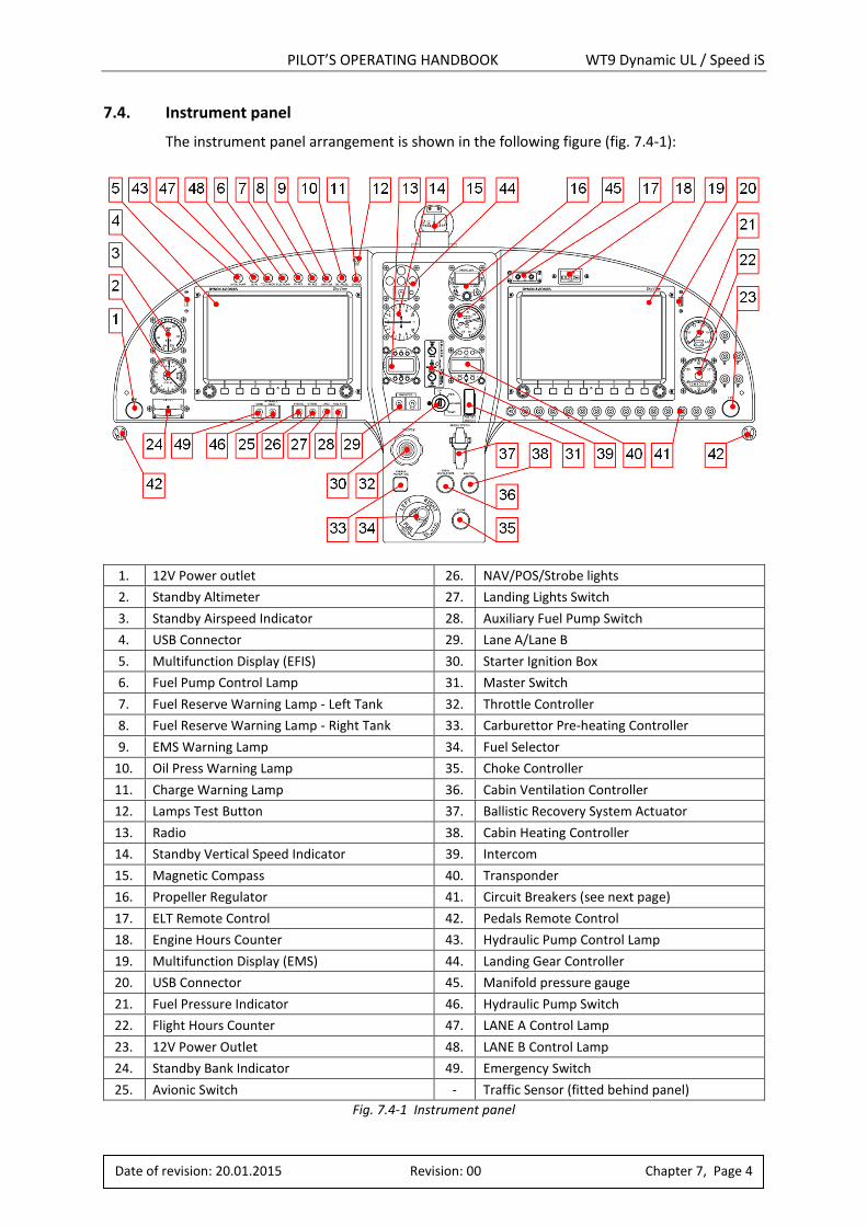
PILOT’S OPERATING HANDBOOK WT9 Dynamic UL / Speed iS
Date of revision: 20.01.2015 Revision: 00 Chapter 7, Page 4
7.4. Instrument panel
The instrument panel arrangement is shown in the following figure (fig. 7.4-1):
1. 12V Power outlet 26. NAV/POS/Strobe lights
2. Standby Altimeter 27. Landing Lights Switch
3. Standby Airspeed Indicator 28. Auxiliary Fuel Pump Switch
4. USB Connector 29. Lane A/Lane B
5. Multifunction Display (EFIS) 30. Starter Ignition Box
6. Fuel Pump Control Lamp 31. Master Switch
7. Fuel Reserve Warning Lamp - Left Tank 32. Throttle Controller
8. Fuel Reserve Warning Lamp - Right Tank 33. Carburettor Pre-heating Controller
9. EMS Warning Lamp 34. Fuel Selector
10. Oil Press Warning Lamp 35. Choke Controller
11. Charge Warning Lamp 36. Cabin Ventilation Controller
12. Lamps Test Button 37. Ballistic Recovery System Actuator
13. Radio 38. Cabin Heating Controller
14. Standby Vertical Speed Indicator 39. Intercom
15. Magnetic Compass 40. Transponder
16. Propeller Regulator 41. Circuit Breakers (see next page)
17. ELT Remote Control 42. Pedals Remote Control
18. Engine Hours Counter 43. Hydraulic Pump Control Lamp
19. Multifunction Display (EMS) 44. Landing Gear Controller
20. USB Connector 45. Manifold pressure gauge
21. Fuel Pressure Indicator 46. Hydraulic Pump Switch
22. Flight Hours Counter 47. LANE A Control Lamp
23. 12V Power Outlet 48. LANE B Control Lamp
24. Standby Bank Indicator 49. Emergency Switch
25. Avionic Switch - Traffic Sensor (fitted behind panel)
Fig. 7.4-1 Instrument panel
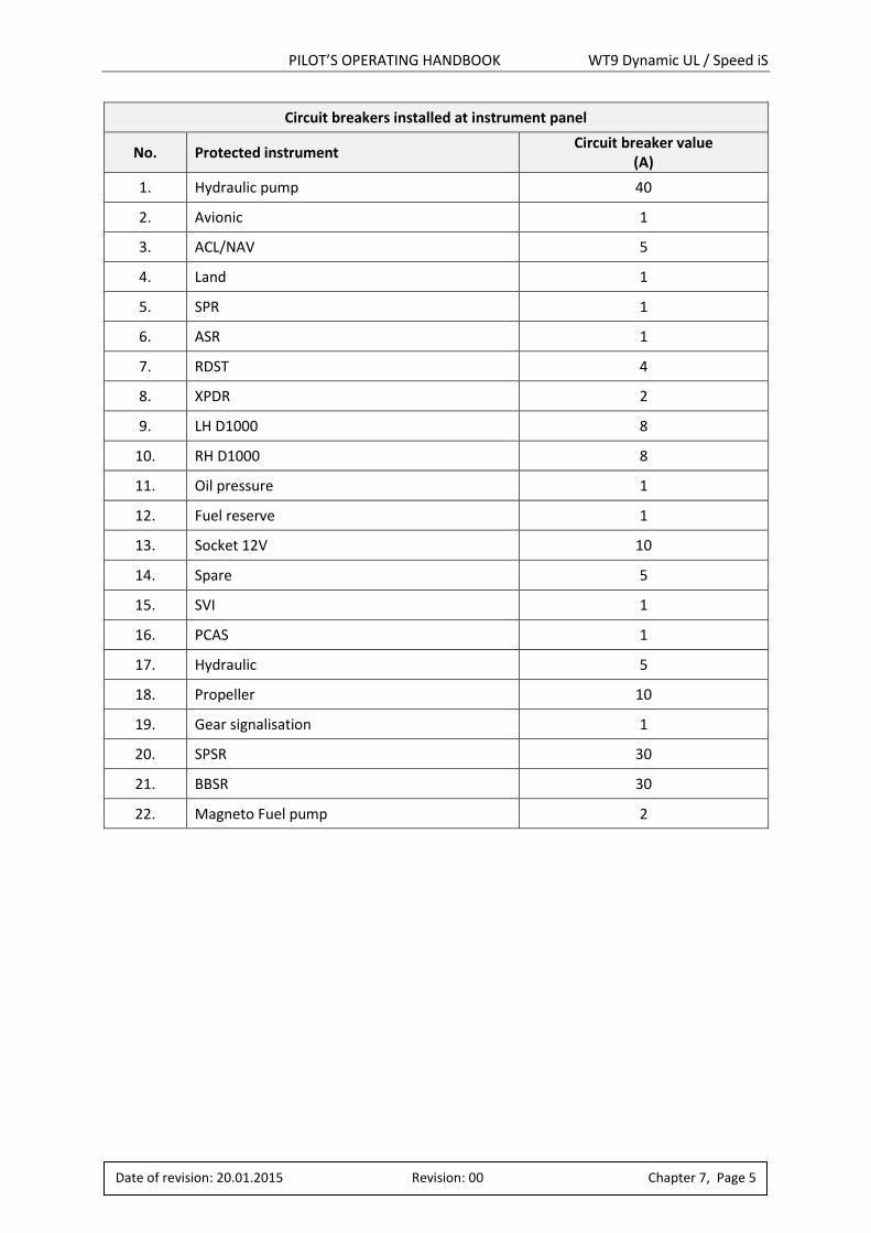
PILOT’S OPERATING HANDBOOK WT9 Dynamic UL / Speed iS
Date of revision: 20.01.2015 Revision: 00 Chapter 7, Page 5
Circuit breakers installed at instrument panel
No. Protected instrument Circuit breaker value
(A)
1. Hydraulic pump 40
2. Avionic 1
3. ACL/NAV 5
4. Land 1
5. SPR 1
6. ASR 1
7. RDST 4
8. XPDR 2
9. LH D1000 8
10. RH D1000 8
11. Oil pressure 1
12. Fuel reserve 1
13. Socket 12V 10
14. Spare 5
15. SVI 1
16. PCAS 1
17. Hydraulic 5
18. Propeller 10
19. Gear signalisation 1
20. SPSR 30
21. BBSR 30
22. Magneto Fuel pump 2
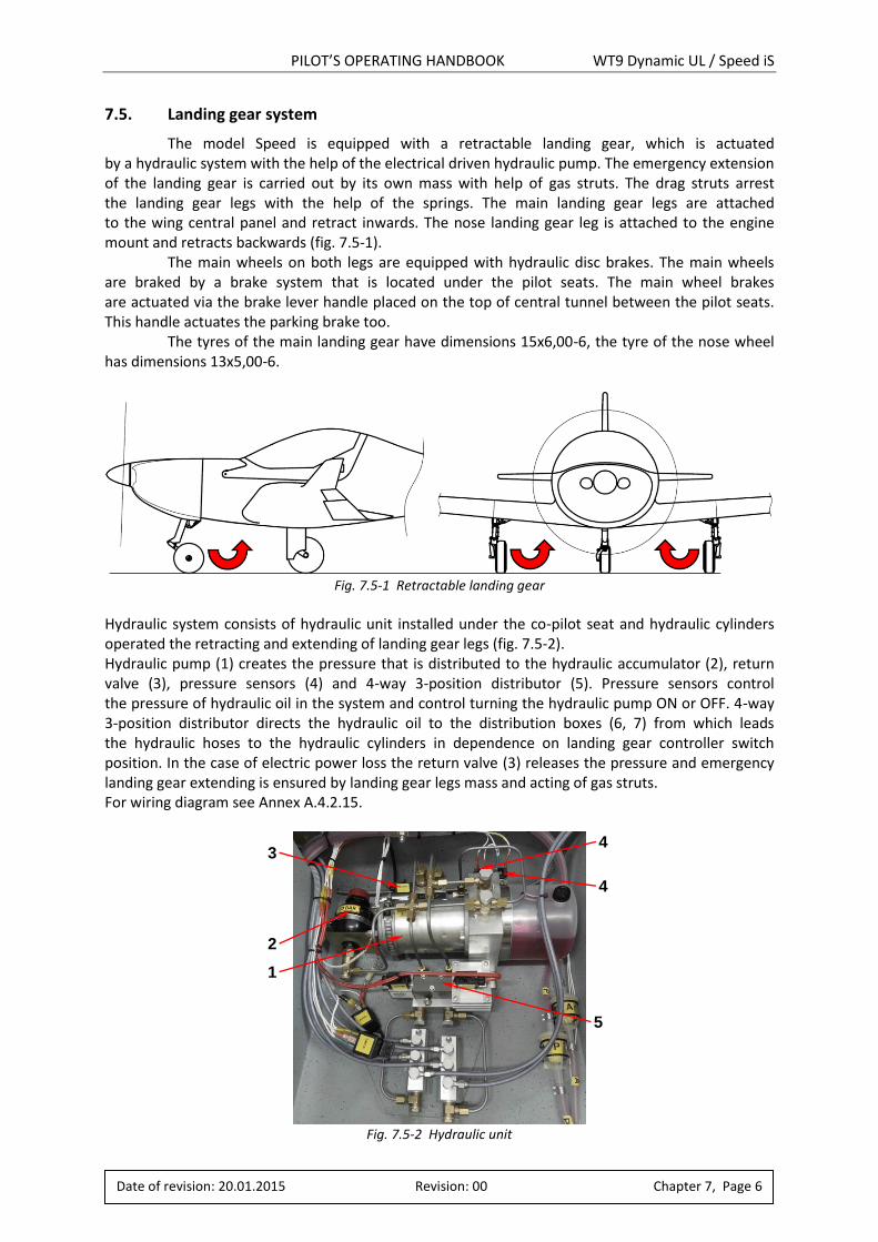
PILOT’S OPERATING HANDBOOK WT9 Dynamic UL / Speed iS
Date of revision: 20.01.2015 Revision: 00 Chapter 7, Page 6
7.5. Landing gear system
The model Speed is equipped with a retractable landing gear, which is actuated by a hydraulic system with the help of the electrical driven hydraulic pump. The emergency extension of the landing gear is carried out by its own mass with help of gas struts. The drag struts arrest the landing gear legs with the help of the springs. The main landing gear legs are attached to the wing central panel and retract inwards. The nose landing gear leg is attached to the engine mount and retracts backwards (fig. 7.5-1). The main wheels on both legs are equipped with hydraulic disc brakes. The main wheels are braked by a brake system that is located under the pilot seats. The main wheel brakes are actuated via the brake lever handle placed on the top of central tunnel between the pilot seats. This handle actuates the parking brake too. The tyres of the main landing gear have dimensions 15x6,00-6, the tyre of the nose wheel has dimensions 13x5,00-6.
Fig. 7.5-1 Retractable landing gear
Hydraulic system consists of hydraulic unit installed under the co-pilot seat and hydraulic cylinders operated the retracting and extending of landing gear legs (fig. 7.5-2). Hydraulic pump (1) creates the pressure that is distributed to the hydraulic accumulator (2), return valve (3), pressure sensors (4) and 4-way 3-position distributor (5). Pressure sensors control the pressure of hydraulic oil in the system and control turning the hydraulic pump ON or OFF. 4-way 3-position distributor directs the hydraulic oil to the distribution boxes (6, 7) from which leads the hydraulic hoses to the hydraulic cylinders in dependence on landing gear controller switch position. In the case of electric power loss the return valve (3) releases the pressure and emergency landing gear extending is ensured by landing gear legs mass and acting of gas struts. For wiring diagram see Annex A.4.2.15.
Fig. 7.5-2 Hydraulic unit
4
3
2
1
4
5
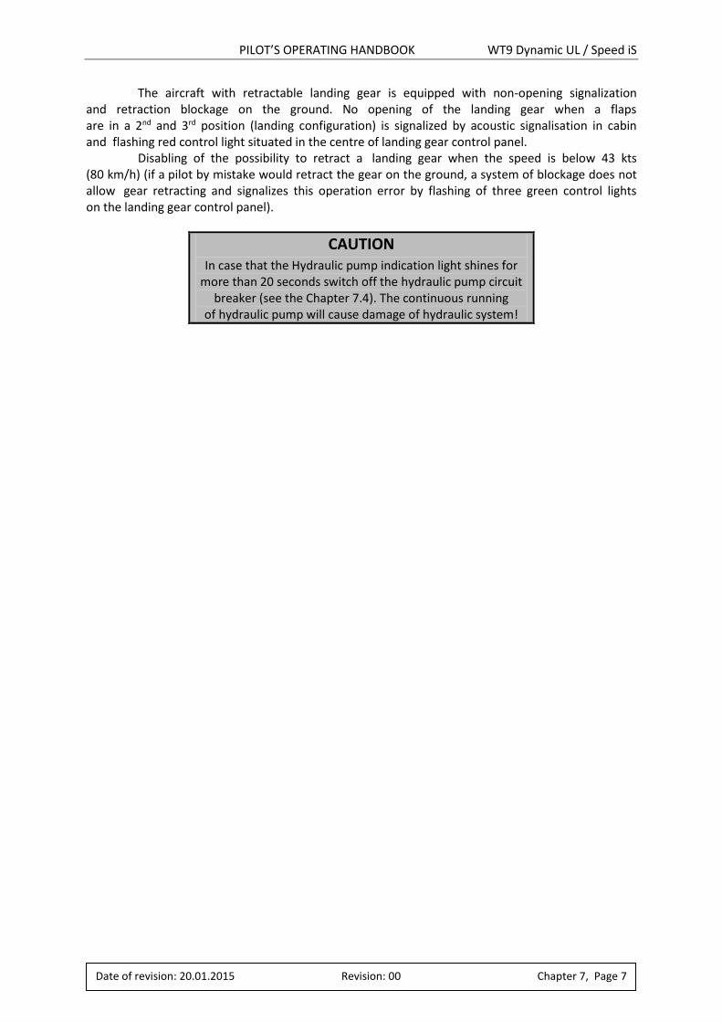
PILOT’S OPERATING HANDBOOK WT9 Dynamic UL / Speed iS
The aircraft with retractable landing gear is equipped with non-opening signalization and retraction blockage on the ground. No opening of the landing gear when a flaps are in a 2nd and 3rd position (landing configuration) is signalized by acoustic signalisation in cabin and flashing red control light situated in the centre of landing gear control panel. Disabling of the possibility to retract a landing gear when the speed is below 43 kts (80 km/h) (if a pilot by mistake would retract the gear on the ground, a system of blockage does not allow gear retracting and signalizes this operation error by flashing of three green control lights on the landing gear control panel).
CAUTION In case that the Hydraulic pump indication light shines for
more than 20 seconds switch off the hydraulic pump circuit breaker (see the Chapter 7.4). The continuous running
of hydraulic pump will cause damage of hydraulic system!
Date of revision: 20.01.2015 Revision: 00 Chapter 7, Page 7
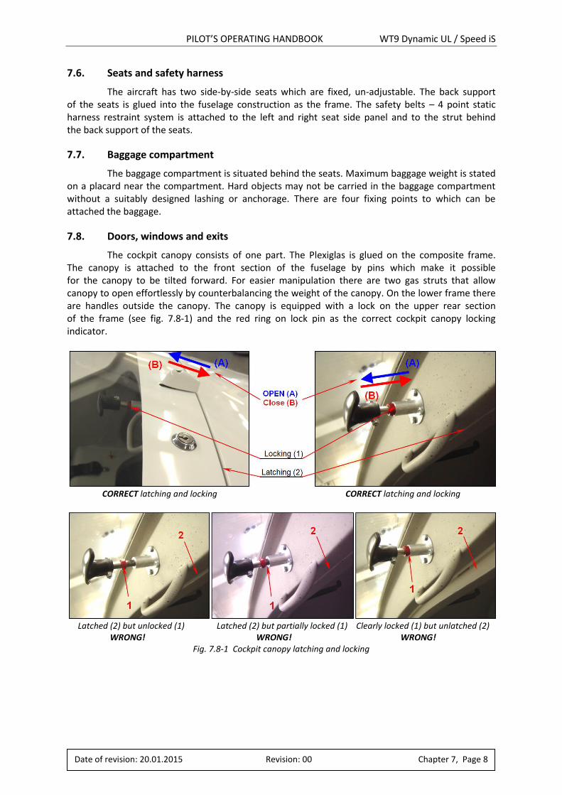
PILOT’S OPERATING HANDBOOK WT9 Dynamic UL / Speed iS
7.6. Seats and safety harness
The aircraft has two side-by-side seats which are fixed, un-adjustable. The back support of the seats is glued into the fuselage construction as the frame. The safety belts – 4 point static harness restraint system is attached to the left and right seat side panel and to the strut behind the back support of the seats.
7.7. Baggage compartment
The baggage compartment is situated behind the seats. Maximum baggage weight is stated on a placard near the compartment. Hard objects may not be carried in the baggage compartment without a suitably designed lashing or anchorage. There are four fixing points to which can be attached the baggage.
7.8. Doors, windows and exits
The cockpit canopy consists of one part. The Plexiglas is glued on the composite frame. The canopy is attached to the front section of the fuselage by pins which make it possible for the canopy to be tilted forward. For easier manipulation there are two gas struts that allow canopy to open effortlessly by counterbalancing the weight of the canopy. On the lower frame there are handles outside the canopy. The canopy is equipped with a lock on the upper rear section of the frame (see fig. 7.8-1) and the red ring on lock pin as the correct cockpit canopy locking indicator.
CORRECT latching and locking CORRECT latching and locking
Latched (2) but unlocked (1) Latched (2) but partially locked (1) Clearly locked (1) but unlatched (2) WRONG! WRONG! WRONG!
Fig. 7.8-1 Cockpit canopy latching and locking
Date of revision: 20.01.2015 Revision: 00 Chapter 7, Page 8

PILOT’S OPERATING HANDBOOK WT9 Dynamic UL / Speed iS
Date of revision: 20.01.2015 Revision: 00 Chapter 7, Page 9
7.9. Powerplant
Powerplant consists of 4 cylinder horizontally opposed 4-stroke engine Rotax 912 iS Sport and a 3-bladed in-flight electrically adjustable propeller WOODCOMP SR2000DN. These engines are suitable for aircraft, but they must never fly at locations, airspeeds, altitudes, or in any other circumstances from which a successful no-power landing cannot be made, after sudden engine stoppage. Engine (fig. 7.9-1): Rotax 912 iS Sport is 4-stroke, 4 cylinders horizontally opposed, spark ignition engine, one central camshaft-push-rods-OHV. Combined liquid cooled cylinder heads and ram air cooled cylinders. Dry sump forced lubrication. The engine is fitted with an electric starter, AC generator, mechanical fuel pump and the reduction gear with integrated shock absorber. For more information see the Maintenance Manual for Rotax Engine Type 912 i Series, Ref. No.: OM-912 i).
WARNING Due to carburettors, flying in icing conditions is prohibited!
The periodic inspections must be performed according to the maintenance schedule (see the Maintenance Manual for Rotax Engine Type 912 i Series, Ref. No.: MML-912 i). There are two laminated cowlings (upper and lower) which cover the engine compartment. The disassembly and assembly of the upper cowling is easy – just release the quick-closing locks. The upper cowling is usually removed during engine pre-flight inspection to check the engine compartment, operating fluids quantity (oil, coolant) and to check engine installation. After removing the upper cowling of the engine, check the following:
1. Oil quantity check: Remove the cover of the oil tank. The oil level in the oil tank should be between two marks (max./min.) on the dip-stick, but must never fall below the min. mark.
2. Coolant quantity check: Remove the cover of the expansion tank and check if it is filled fully. Warning, never check the coolant level when the engine is hot!!! Always let the engine to cool down before!!! Check the coolant level in the overflow bottle should be between min. and max. mark.
The lower cowling is removed after unscrewing of attachment screws connecting the cooler to the cowling face side, and then unscrew the attachment screws connecting the cowling to the firewall border.
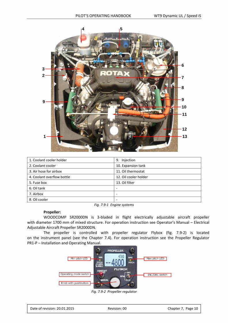
PILOT’S OPERATING HANDBOOK WT9 Dynamic UL / Speed iS
Date of revision: 20.01.2015 Revision: 00 Chapter 7, Page 10
1. Coolant cooler holder 9. Injection
2. Coolant cooler 10. Expansion tank
3. Air hose for airbox 11. Oil thermostat
4. Coolant overflow bottle 12. Oil cooler holder
5. Fuse box 13. Oil filter
6. Oil tank -
7. Airbox -
8. Oil cooler -
Fig. 7.9-1 Engine systems
Propeller: WOODCOMP SR2000DN is 3-bladed in flight electrically adjustable aircraft propeller
with diameter 1700 mm of mixed structure. For operation instruction see Operator’s Manual – Electrical Adjustable Aircraft Propeller SR2000DN.
The propeller is controlled with propeller regulator Flybox (fig. 7.9-2) is located on the instrument panel (see the Chapter 7.4). For operation instruction see the Propeller Regulator PR1-P – Installation and Operating Manual.
Fig. 7.9-2 Propeller regulator
12
11
8
7
6
5 4
3
2
1 13
10
9 9

PILOT’S OPERATING HANDBOOK WT9 Dynamic UL / Speed iS
Date of revision: 20.01.2015 Revision: 00 Chapter 7, Page 11
Intentionally left blank

PILOT’S OPERATING HANDBOOK WT9 Dynamic UL / Speed iS
Date of revision: 20.01.2015 Revision: 00 Chapter 7, Page 12
Intentionally left blank

PILOT’S OPERATING HANDBOOK WT9 Dynamic UL / Speed iS
7.10. Fuel system
The integral fuel tanks are located in the forward box of the wing central section and both halves of wing. The wing and central section tanks are connected by a simple hose connection with clamps. There is one large diameter hose between tanks, which serves the fuel from the wing tanks to central section tanks. There are two small diameter hoses, one of them is venting line of wing tank and second one is connects the both tanks (air connection). The integral fuel tanks are covered by a special paint resistive to fuel with a less electrical resistance. There is a rib in the each tank for preclusion of a rapid fuel flowage during the flight manoeuvres. The fuel tank filler caps are located on a wing upper surface. There is a drain valve in the lowest point of each tank. The fuel flows to the fuel selector through the fuel filters from the left or right fuel tank (in dependence on position of fuel selector). Fuel from the fuel selector flows through the gascolator, main and auxiliary electric fuel pumps (each fuel pump is by-passed and fitted with check valve), fuel flow sensor to the fuel pressure regulator. Unconsumed fuel is returned from the fuel pressure regulator through the fuel selector to the same fuel tank from which is supplied to the engine. In the fuel system are installed also fuel pressure sensor (in the engine compartment) and analogue fuel pressure indicator (at the instrument panel) that are connected to the fuel pressure regulator.
Fuel tank venting is outgoing from the upper part of each wing fuel tank (close to the filling cap), proceeds through central section tank and along the rescue system board, inside of central tunnel and discharge through the lower surface of fuselage in front of main spar (fig. 7.10-1).
Amount of fuel in the left and right fuel tanks indicates Dynon SkyView SV-D1000. Due to design of fuel tanks it indicates the fuel volume in the fuel tank within the range 0 - 45 litres. If there is more fuel in the fuel tank, Dynon indicates “45+”. Red light annunciator illuminates when 15 litres of fuel remain in the corresponding fuel tank.
Fig. 7.10-1 Fuel system
Low fuel pressure indications are possible and allowed. But the pressure must stabilize to the operating limit within 5 seconds. If not, the cause should be determined and rectified.
Due to the technical design and installation conditions (construction of the return line, etc.) pressure fluctuations, at the fuel pump are possible. These pressure fluctuations within the specified operating limits are not considered to a problem.
PILOT’S OPERATING HANDBOOK WT9 Dynamic UL / Speed iS
Date of revision: 20.01.2015 Revision: 00 Chapter 7, Page 14
Date of revision: 20.01.2015 Revision: 00 Chapter 7, Page 14
Fuel management: The left tank must be used for all take offs and landings. When you are flying with full tanks,
use the left tank for 30 – 40 minutes before changing to the right tank. This creates space for the return fuel without venting it overboard. To maximize endurance when the red annunciator lights illuminates, the following procedure is recommended: Select the right tank and use this tank until became empty. Change back to the left tank where should be slightly more than 7 litres (due to return fuel) what allows around 20 minutes of flying depending on power settings.
CAUTION Electric fuel pump running when the left fuel tank is not
selected can cause its damage!
NOTE The tanks in wings are connected with the fuselage tanks
with a hose. The hose diameter is not enough to fill the
fuselage tank from wing tank when refuelling. Please wait
when the fuel from the wing tank comes into the fuselage
tank, and then fill up till the wing tanks are full!
7.11. Electrical system
Refer to the Chapter 1.6.9 in the Maintenance Manual for WT9 Dynamic. Detailed description of the ignition and the AC generator is listed at the Operators Manual
for Rotax Engine Type 912 i Series, Ref. No.: OM-912 i.
7.12. Pitot and static pressure system
The Pitot probe for the airspeed indicator is located bellow the right wing. Pressure distribution to individual instruments in the cockpit is done through flexible plastic hoses. The static pressure receivers are located on the both sides of the fuselage behind the cockpit. Keep the system clear to assure its right function.
Refer to the Chapter 1.6.10 in the Maintenance Manual for WT9 Dynamic.
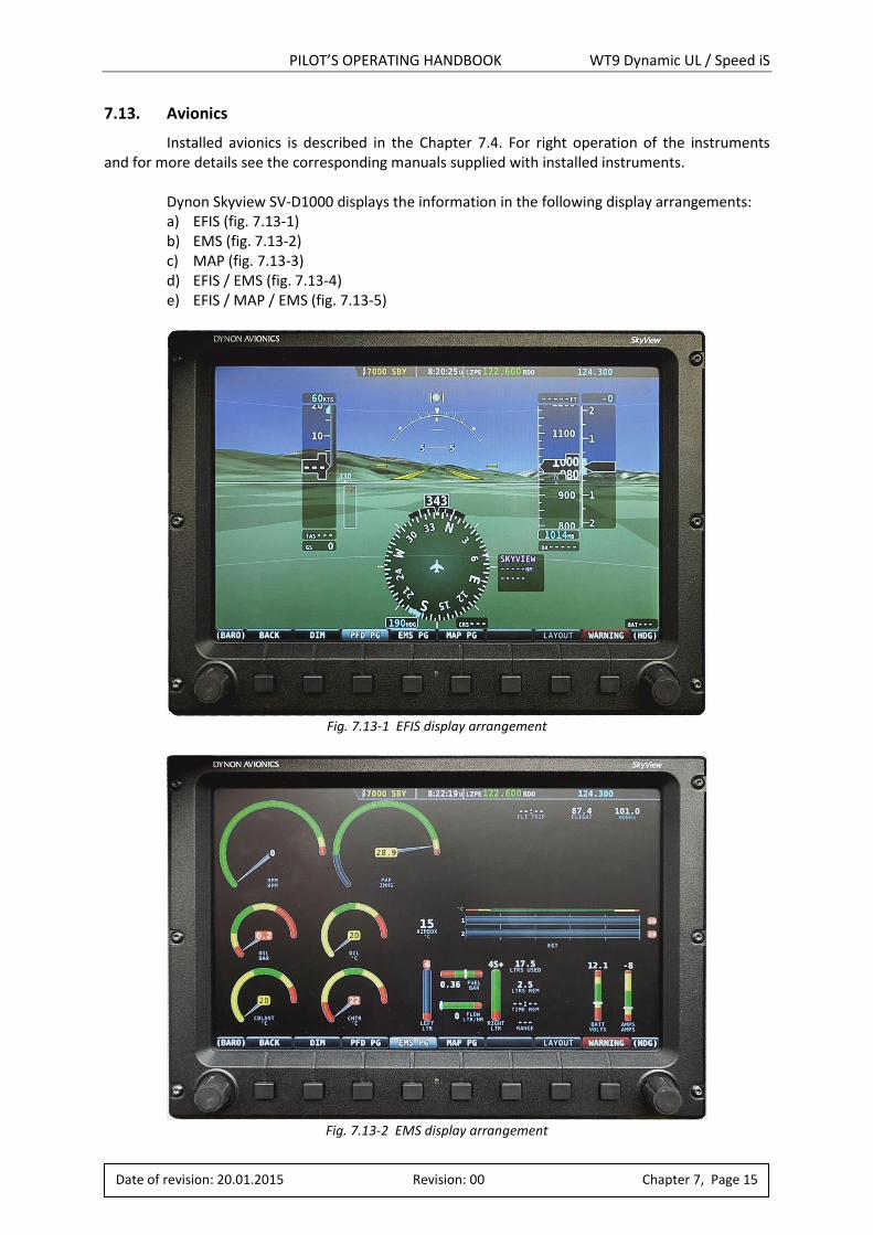
PILOT’S OPERATING HANDBOOK WT9 Dynamic UL / Speed iS
Date of revision: 20.01.2015 Revision: 00 Chapter 7, Page 15
7.13. Avionics
Installed avionics is described in the Chapter 7.4. For right operation of the instruments and for more details see the corresponding manuals supplied with installed instruments. Dynon Skyview SV-D1000 displays the information in the following display arrangements:
a) EFIS (fig. 7.13-1) b) EMS (fig. 7.13-2) c) MAP (fig. 7.13-3) d) EFIS / EMS (fig. 7.13-4) e) EFIS / MAP / EMS (fig. 7.13-5)
Fig. 7.13-1 EFIS display arrangement
Fig. 7.13-2 EMS display arrangement
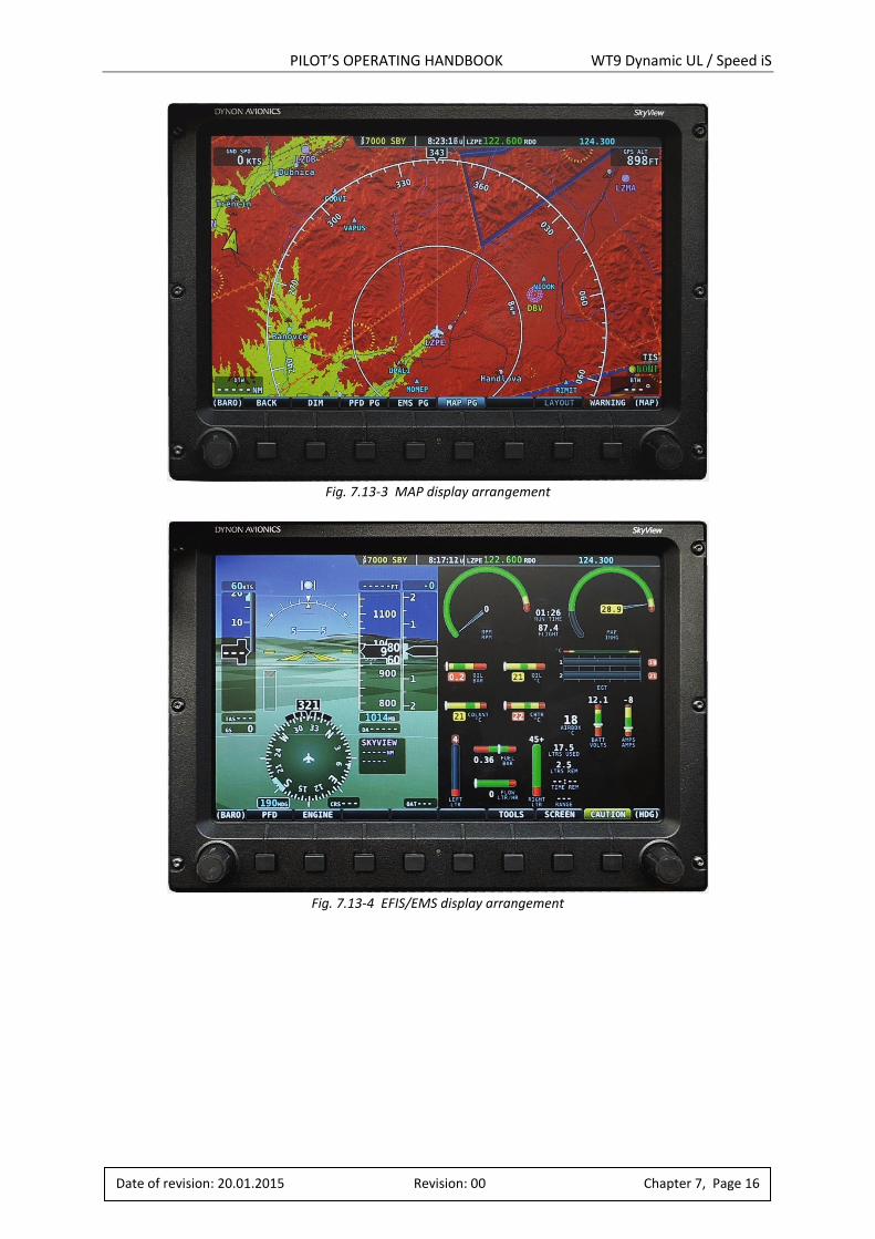
PILOT’S OPERATING HANDBOOK WT9 Dynamic UL / Speed iS
Date of revision: 20.01.2015 Revision: 00 Chapter 7, Page 16
Fig. 7.13-3 MAP display arrangement
Fig. 7.13-4 EFIS/EMS display arrangement

PILOT’S OPERATING HANDBOOK WT9 Dynamic UL / Speed iS
Date of revision: 20.01.2015 Revision: 00 Chapter 7, Page 17
Fig. 7.13-5 EFIS/MAP/EMS display arrangement
WARNING Do not forget perform backup battery check regularly.
For more details see Dynon Skyview manual!
7.14. Miscellaneous equipment
Ballistic recovery system Magnum 501 : Ballistic recovery system is mounted as a miscellaneous equipment of the aircraft. For operation instructions see Manual for Mounting and Use – Ballistic recovery Systems Series Magnum.
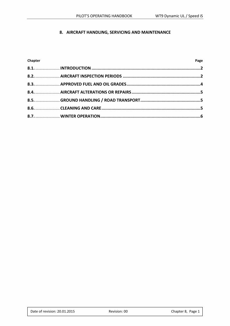
PILOT’S OPERATING HANDBOOK WT9 Dynamic UL / Speed iS
Date of revision: 20.01.2015 Revision: 00 Chapter 8, Page 1
8. AIRCRAFT HANDLING, SERVICING AND MAINTENANCE
Chapter Page
8.1. ....................... INTRODUCTION .......................................................................................2
8.2. ....................... AIRCRAFT INSPECTION PERIODS ..............................................................2
8.3. ....................... APPROVED FUEL AND OIL GRADES ...........................................................4
8.4. ....................... AIRCRAFT ALTERATIONS OR REPAIRS .......................................................5
8.5. ....................... GROUND HANDLING / ROAD TRANSPORT ................................................5
8.6. ....................... CLEANING AND CARE ...............................................................................5
8.7. ....................... WINTER OPERATION ................................................................................6
PILOT’S OPERATING HANDBOOK WT9 Dynamic UL / Speed iS
Date of revision: 20.01.2015 Revision: 00 Chapter 8, Page 2
8.1. Introduction
This chapter contains factory recommended procedures for proper ground handling and servicing of the aircraft. It also identifies certain inspection and maintenance requirements which must be followed if the aircraft is to retain that new-plane performance and dependability. It is wise to follow a planned schedule of lubrication and preventive maintenance based on climatic and flying conditions encountered. The airframe surfaces should be protected with light plastic foil or cloth cover against dust. All engine intakes, vents, the fuel vents and pitot static system should be covered before long term aircraft parking or storing, due to contamination by foreign objects (insects, birds). The external surfaces of the aircraft should be washed with a sufficient quantity of the water and an adequate quantity of detergent. Do not apply petrol or chemical solvents for cleaning the external surfaces of the aircraft. It is advisable to park the aircraft inside a hangar or eventually inside other weather-proof space with stable temperature, good ventilation, low humidity and dust-free environment. The parking place should be protected against possible damage caused by sun radiation, humidity and wind. Sunbeams reflected through the canopy can magnify and may cause spot heating, which can create damage to the cockpit area and the upholstery.
8.2. Aircraft inspection periods
8.2.1. Powerplant
The engine periodic inspections and maintenance are conducted according to the procedures contained in the Maintenance Manual for Rotax Engine Type 912 i Series, Ref. No.: MML-912 i. Daily inspection: Is carried out in accordance with the instructions for execution of the pre-flight inspection, which are contained in Chapter 4, item 4.4. Check after 25 hr. of operation: Must be carried out according to the Maintenance Manual for Rotax Engine Type 912 i Series, Ref. No.: MML-912 i. Check after 50 hr. of operation: Must be carried out according to the Maintenance Manual for Rotax Engine Type 912 i Series, Ref. No.: MML-912 i. 100 hr. check or once a year: Must be performed according to the Maintenance Manual for Rotax Engine Type 912 i Series, Ref. No.: MML-912 i every 100 hours of operation or once a year, whichever comes first. The renewal of the spark plugs, the fuel filter and the coolant are carried out after 200 hours of operation. TBO (Time Between Overhaul): 2000 hr. or 15 years, whichever comes first. Oil change It must be performed according to the Maintenance Manual for Rotax Engine Type 912 i Series, Ref. No.: MML-912 i. There is an oil drain screw at the bottom of the oil tank. There is an oil filter at the left side beside the propeller gearbox. At every oil change, replace the oil filter and open the old one with special tool, to ensure the engine is not producing chips. Remove filter insert, cut top and bottom cover off, unroll and check it for metal chips, foreign matter, contamination and abrasion. This check is important as it allows conclusions regarding the condition of the engine and gives information about a possible cause of any failure.
PILOT’S OPERATING HANDBOOK WT9 Dynamic UL / Speed iS
Date of revision: 20.01.2015 Revision: 00 Chapter 8, Page 3
8.2.2. Propeller
The propeller must be maintained according to Operator’s Manual for – Electrical Adjustable Aircraft Propeller SR2000DN. In operation does not require any special maintenance. In the case of propeller contamination wash its surface with a piece of cloth dipped in warm water with addition of the usual detergent.
The operator is allowed carry out repairs which are noted in Operator’s Manual for – Electrical Adjustable Aircraft Propeller SR2000DN. Any other dismantling is forbidden. The repairs of large damage must be carried out by the manufacturer or by an authorised service centre. TBO (Time Between Overhaul): 1200 hours or 5 years whichever comes first.
8.2.3. Airframe
Daily inspection: Is carried out in accordance with the instructions for the execution of the pre-flight inspection, which are contained in Chapter 4.4.
Check after 25 hr. of operation: It must be performed according to the Maintenance Manual for WT-9 Dynamic
after the first 25 2 hr. operation together with the engine check.
Check after 50 hr. of operation: It must be performed according to the Maintenance Manual for WT-9 Dynamic
after the first 50 3 hr. of operation together with the engine check.
100 hr. check: Must be performed every 100 hr. of operation or once a year, whichever comes first. This inspection must be performed by qualified staff.
Lubrication: The manufacturer recommends using grease and oil without acid for lubrication only. Apply the lubricants sparingly without contaminating of the airframe. For more information refer to the Chapter 3.7.3 in the Maintenance Manual for WT9 Dynamic.
Battery: The aircraft is equipped with 17 Ah lead-acid battery. The powerplant is equipped with an AC generator, which recharges the battery in the flight. Battery is dry and hermetically closed. It doesn’t release any toxic or explosive gas. The battery needs a visual check of the attachment and security. Rubber parts: All rubber parts (hoses, tyres, etc.) have to be changed after 5 years of operation.
PILOT’S OPERATING HANDBOOK WT9 Dynamic UL / Speed iS
Date of revision: 20.01.2015 Revision: 00 Chapter 8, Page 4
8.3. Approved fuel and oil grades
8.3.1. Oil grade
Use only oil with API classification „SG“ or higher! Due to the high stresses in the reduction gears, oils with gear additives such as good quality 4 stroke motorcycle oils are highly recommended. Heavy duty semi- or fully synthetic (depending on fuel type used) brand name oils are recommended.
WARNING Do not use AVGAS 100 LL with fully synthetic engine oils!
8.3.2. Fuel grade
Following types of fuels can be used:
Min. RON 95 EN 228 Super (Unleaded Automotive Gasoline RON 95)
EN 228 Super Plus (Unleaded Automotive Gasoline RON 98)
AVGAS 100 LL (Due to higher lead content in AVGAS, the wear of the valve seats, depositing in combustion chamber and lead sediments in the lubrication system will increase. Therefore use AVGAS only if you encounter problems with vapour lock or if the other fuel types are not available.)
PILOT’S OPERATING HANDBOOK WT9 Dynamic UL / Speed iS
Date of revision: 20.01.2015 Revision: 00 Chapter 8, Page 5
8.4. Aircraft alterations or repairs
It is essential that the responsible airworthiness authority be contacted prior to any alterations on the aircraft to ensure that the airworthiness of the aircraft is not violated. For repairs refer to the applicable Maintenance Manual. The operator is allowed replace parts supplied by the producer only. The repairs to damaged skin must be carried out by qualified staff in accordance with approved procedures.
WARNING After aircraft repairs, repainting or mounting of additional
instruments or equipment it is necessary to check weights
and CG positions!
8.5. Ground handling / Road transport
The aircrafts can suffer higher stress loads on the ground than in the air. In this case it can result a potential menace of the safety, as the aircraft construction is designed for the manoeuvring load. The high aircraft normal accelerations are occurred at the hard landing, during the taxiing at the rough surface and during the driving through a hole at road. Don’t use unnecessary transportation in the road.
CAUTION The aircraft is equipped with mooring eyes which are
screwed into the threaded hubs on the wing lower surface
located approx. half way along the wing. It is also necessary
to moor the nose wheel landing gear!
CAUTION Push or pull the aircraft from the propeller blade root only,
never at the wing tips or the control surfaces!
8.6. Cleaning and care
Regular cleaning and care of the powerplant, propeller, wings and the airframe is the first consideration for safe and efficient operation. Cleaning and care should be based on climatic and flying conditions. The exterior painted surfaces should be cleaned with clear water using a sponge or soft cotton towel and chamois. These surfaces should also be protected with a silicone free hard wax reapplied at least once a year by hand or with a rotating cloth disc. Clean the Plexiglass canopy only as necessary using a soft cotton towel and clear water mixed with a small amount of mild detergent. Protect the canopy with anti-static cleaning agents that are made specifically for Plexiglas.
CAUTION Do not clean the canopy with alcohol, acetone or lacquer
thinner, because the canopy is made from acrylic. Acrylic
becomes fragile after contact with these liquids!
CAUTION Do not use pressure washers!
PILOT’S OPERATING HANDBOOK WT9 Dynamic UL / Speed iS
Date of revision: 20.01.2015 Revision: 00 Chapter 8, Page 6
8.7. Winter operation
Pre-flight inspection: In addition during the pre-flight inspection in winter operation must be done:
Remove the ice from the aircraft surfaces.
Check control surfaces free movement and cleanness of slots of control surfaces and flaps.
Check cleanness of the fuel tank venting. Engine and oil pre-heating:
There is possible to start an engine without need of pre-heating if outside temperature is not below +5 °C. It is recommended to pre-heat the engine and oil if temperature falls below +5 °C. Use suitable air heater or a dryer.
Blow the hot air from the front into the hole around the propeller hub. Temperature of hot air should not exceed 100 °C. Pre-heat until cylinder head temperature and oil temperature exceed +20 °C. Parking and taxiing:
Check wheel brakes for freezing when parking outside and temperature is below 0 °C. Check wheels free rotation prior to taxiing (hold a propeller and tow the aircraft). Heat the brakes with the hot air to remove ice. Do not remove the ice by braking during taxiing!
WARNING Never use open fire to pre-heat an engine!
CAUTION If cylinder heads and oil temperatures fall during parking
among flights than is recommended to start and warm up
engine from time to time. Do not open choke when starting
hot engine!
PILOT’S OPERATING HANDBOOK WT9 Dynamic UL / Speed iS
Date of revision: 20.01.2015 Revision: 00 Chapter 9, Page 1
9. SUPPLEMENTS
Chapter Page
9.1. ....................... INTRODUCTION .......................................................................................2
9.2. ....................... LIST OF INSERTED SUPPLEMENTS .............................................................2
9.3. ....................... SUPPLEMENTS INSERTED .........................................................................2
PILOT’S OPERATING HANDBOOK WT9 Dynamic UL / Speed iS
Date of revision: 20.01.2015 Revision: 00 Chapter 9, Page 2
9.1. Introduction
This chapter contains the appropriate supplements necessary to safely and efficiently operate the aircraft when equipped with various optional systems and equipment not provided with the standard aircraft.
NOTE Additional individual equipment in accordance
with a customer’s request may increase the aircraft empty
weight and reduce the allowed useful load!
9.2. List of inserted supplements
None.
9.3. Supplements inserted
None.
PILOT’S OPERATING HANDBOOK WT9 Dynamic UL / Speed iS
Date of revision: 20.01.2015 Revision: 00 Chapter 10, Page 1
10. ANNEXES
Annex Page
ANNEX 1 ............ ...............................................................................................................2
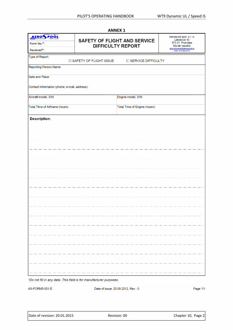
PILOT’S OPERATING HANDBOOK WT9 Dynamic UL / Speed iS
Date of revision: 20.01.2015 Revision: 00 Chapter 10, Page 2
ANNEX 1