
Pilot's Guide - Garmin
594
Pilot’s Guide Cirrus SR2x Diamond DA50 System Software Version 2576.01 or later ®
-
Upload
khangminh22 -
Category
Documents
-
view
3 -
download
0
Transcript of Pilot's Guide - Garmin

Pilot’s Guide
190-02799-00Revision B
Garmin International, Inc.1200 East 151st StreetOlathe, Kansas 66062, U.S.A.
Garmin AT, Inc.2345 Turner Road SESalem, OR 97302, U.S.A.
Garmin (Europe) Ltd.Liberty House, Hounsdown Business ParkSouthampton, Hampshire SO40 9LR U.K.
Garmin CorporationNo. 68, Zhangshu 2nd RoadXizhi District,New Taipei City, Taiwan
Contact Garmin Product Support or view warranty information at flygarmin.com.
Cirrus SR2xG
1000® N
Xi Pilo
t’s Gu
ide
Diam
on
d D
A50
Diamond DA50System Software Version 2576.01 or later
®


190-02799-00 Rev. B Garmin G1000 NXi Pilot’s Guide for the Diamond DA50
Copyright © 2021 Garmin Ltd. or its subsidiaries. All rights reserved.
This manual reflects the operation of System Software version 2576.01 or later for the Diamond DA50. Some differences in operation may be observed when comparing the information in this manual to earlier or later software versions.
Garmin International, Inc.1200 East 151st StreetOlathe, Kansas 66062, U.S.A.
Garmin (Europe) Ltd.Liberty House, Hounsdown Business ParkSouthampton, Hampshire SO40 9LR U.K.
Garmin AT, Inc.2345 Turner Road SESalem, OR 97302, U.S.A.
Garmin CorporationNo. 68, Zhangshu 2nd RoadXizhi District, New Taipei City, Taiwan
Contact Garmin Product Support or view warranty information at flygarmin.com.
Except as expressly provided herein, no part of this manual may be reproduced, copied, transmitted, disseminated, downloaded or stored in any storage medium, for any purpose without the express written permission of Garmin. Garmin hereby grants permission to download a single copy of this manual and of any revision to this manual onto a hard drive or other electronic storage medium to be viewed for personal use, provided that such electronic or printed copy of this manual or revision must contain the complete text of this copyright notice and provided further that any unauthorized commercial distribution of this manual or any revision hereto is strictly prohibited.
Garmin®, G1000® NXi, FliteCharts®, and SafeTaxi® are registered trademarks of Garmin International, Inc. or its subsidiaries. Garmin ESP™, Garmin SVT™, and Connext™ are trademarks of Garmin International, Inc. or its subsidiaries. These trademarks may not be used without the express permission of Garmin.
Stormscope® is a registered trademark of L-3 Communications. Avidyne® is a registered trademark of Avidyne Corporation. AC-U-KWIK® is a registered trademark of Penton Business Media Inc. Bendix/King® and Honeywell® are registered trademarks of Honeywell International, Inc. NavData® is a registered trademark of Jeppesen, Inc.; Wi-Fi® is a registered trademark of the Wi-Fi Alliance. Sirius, XM, and all related marks and logos are trademarks of Sirius XM Radio, Inc. and its subsidiaries. The Bluetooth® word mark and logos are owned by the Bluetooth SIG, Inc. and any use of such marks by Garmin is under license.
AOPA Membership Publications, Inc. and its related organizations (hereinafter collectively “AOPA”) expressly disclaim all warranties, with respect to the AOPA information included in this data, express or implied, including, but not limited to, the implied warranties of merchantability and fitness for a particular purpose. The information is provided “as is” and AOPA does not warrant or make any representations regarding its accuracy, reliability, or otherwise. Under no circumstances including negligence, shall AOPA be liable for any incidental, special or consequential damages that result from the use or inability to use the software or related documentation, even if AOPA or an AOPA authorized representative has been advised of the possibility of such damages. User agrees not to sue AOPA and, to the maximum extent allowed by law, to release and hold harmless AOPA from any causes of action, claims or losses related to any actual or alleged inaccuracies in the information. Some jurisdictions do not allow the limitation or exclusion of implied warranties or liability for incidental or consequential damages so the above limitations or exclusions may not apply to you.
AC-U-KWIK and its related organizations (hereafter collectively “AC-U-KWIK Organizations”) expressly disclaim all warranties with respect to the AC-U-KWIK information included in this data, express or implied, including, but not limited to, the implied warranties of merchantability and fitness for a particular purpose. The information is provided “as is” and AC-U-KWIK Organizations do not warrant or make any representations regarding its accuracy, reliability, or otherwise. Licensee agrees not to sue AC-U-KWIK Organizations and, to the maximum extent allowed by law, to release and hold harmless AC-U-KWIK Organizations from any cause of action, claims or losses related to any actual or alleged inaccuracies in the information arising out of Garmin’s use of the information in the datasets. Some jurisdictions do not allow the limitation or exclusion of implied warranties or liability for incidental or consequential damages so the above limitations or exclusions may not apply to licensee.
Printed in the U.S.A.

Garmin G1000 NXi Pilot’s Guide for the Diamond DA50 190-02799-00 Rev. B
Blank Page

190-02799-00 Rev. B Garmin G1000 NXi Pilot’s Guide for the Diamond DA50 i
WARNINGS, CAUTIONS, AND NOTES
WARNING: Do not operate this equipment without first obtaining qualified instruction.
WARNING: Always refer to current aeronautical charts and NOTAMs for verification of displayed aeronautical information. Displayed aeronautical data may not incorporate the latest NOTAM information.
WARNING: Do not use geometric altitude for compliance with air traffic control altitude requirements. The primary barometric altimeter must be used for compliance with all air traffic control altitude regulations, requirements, instructions, and clearances.
WARNING: Do not use basemap information (land and water data) as the sole means of navigation. Basemap data is intended only to supplement other approved navigation data sources and should be considered only an aid to enhance situational awareness.
WARNING: Do not rely solely upon the display of traffic information to accurately depict all of the traffic within range of the aircraft. Due to lack of equipment, poor signal reception, and/or inaccurate information from aircraft or ground stations, traffic may be present that is not represented on the display.
WARNING: Do not use data link weather information for maneuvering in, near, or around areas of hazardous weather. Information contained within data link weather products may not accurately depict current weather conditions.
WARNING: Do not use the indicated data link weather product age to determine the age of the weather information shown by the data link weather product. Due to time delays inherent in gathering and processing weather data for data link transmission, the weather information shown by the data link weather product may be older than the indicated weather product age.
WARNING: Do not use terrain avoidance displays as the sole source of information for maintaining separation from terrain and obstacles. Garmin obtains terrain and obstacle data from third party sources and cannot independently verify the accuracy of the information.
WARNING: Do not rely on the displayed minimum safe altitude (MSAs) as the sole source of obstacle and terrain avoidance information. Always refer to current aeronautical charts for appropriate minimum clearance altitudes.
WARNING: Do not use GPS to navigate to any active waypoint identified as a ‘NON WGS84 WPT’ by a system message. ‘NON WGS84 WPT’ waypoints are derived from an unknown map reference datum that may be incompatible with the map reference datum used by GPS (known as WGS84) and may be positioned in error as displayed.
Garmin G1000 NXi Pilot’s Guide for the Diamond DA50 190-02799-00 Rev. Bii
WARNINGS, CAUTIONS, AND NOTES
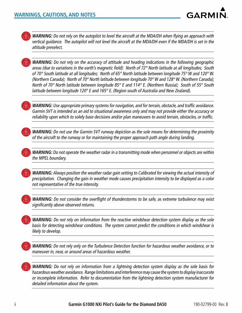
WARNING: Do not rely on the autopilot to level the aircraft at the MDA/DH when flying an approach with vertical guidance. The autopilot will not level the aircraft at the MDA/DH even if the MDA/DH is set in the altitude preselect.
WARNING: Do not rely on the accuracy of attitude and heading indications in the following geographic areas (due to variations in the earth’s magnetic field): North of 72° North latitude at all longitudes; South of 70° South latitude at all longitudes; North of 65° North latitude between longitude 75° W and 120° W. (Northern Canada); North of 70° North latitude between longitude 70° W and 128° W. (Northern Canada); North of 70° North latitude between longitude 85° E and 114° E. (Northern Russia); South of 55° South latitude between longitude 120° E and 165° E. (Region south of Australia and New Zealand).
WARNING: Use appropriate primary systems for navigation, and for terrain, obstacle, and traffic avoidance. Garmin SVT is intended as an aid to situational awareness only and may not provide either the accuracy or reliability upon which to solely base decisions and/or plan maneuvers to avoid terrain, obstacles, or traffic.
WARNING: Do not use the Garmin SVT runway depiction as the sole means for determining the proximity of the aircraft to the runway or for maintaining the proper approach path angle during landing.
WARNING: Do not operate the weather radar in a transmitting mode when personnel or objects are within the MPEL boundary.
WARNING: Always position the weather radar gain setting to Calibrated for viewing the actual intensity of precipitation. Changing the gain in weather mode causes precipitation intensity to be displayed as a color not representative of the true intensity.
WARNING: Do not consider the overflight of thunderstorms to be safe, as extreme turbulence may exist significantly above observed returns.
WARNING: Do not rely on information from the reactive windshear detection system display as the sole basis for detecting windshear conditions. The system cannot predict the conditions in which windshear is likely to develop.
WARNING: Do not rely only on the Turbulence Detection function for hazardous weather avoidance, or to maneuver in, near, or around areas of hazardous weather.
WARNING: Do not rely on information from a lightning detection system display as the sole basis for hazardous weather avoidance. Range limitations and interference may cause the system to display inaccurate or incomplete information. Refer to documentation from the lightning detection system manufacturer for detailed information about the system.

190-02799-00 Rev. B Garmin G1000 NXi Pilot’s Guide for the Diamond DA50 iii
WARNINGS, CAUTIONS, AND NOTES
WARNING: Do not rely solely upon the display of traffic information for collision avoidance maneuvering. The traffic display does not provide collision avoidance resolution advisories and does not under any circumstances or conditions relieve the pilot’s responsibility to see and avoid other aircraft.
WARNING: Do not use QFE altimeter setting outside of the terminal environment for the corresponding issuing airport to ensure adequate obstacle clearance.
WARNING: Do not fly QFE procedures above the Transition Altitude or when navigating to a waypoint that contains a QNE (flight level) altitude constraint.
WARNING: Always fly a procedure that provides terrain and obstacle clearance from the reference airfield when operating in IMC while conducting QFE procedures.
WARNING: Do not use SurfaceWatch™ information as the primary method of flight guidance during airborne or ground operations. SurfaceWatch does not have NOTAM or ATIS information regarding the current active runway, condition, or information about the position of hold lines.
CAUTION: Do not clean display surfaces with abrasive cloths or cleaners containing ammonia. They will harm the anti-reflective coating.
CAUTION: Do not allow repairs to be made by anyone other than an authorized Garmin service center. Unauthorized repairs or modifications could void both the warranty and affect the airworthiness of the aircraft.
CAUTION: Never disconnect power to the system when loading a database. Power interruption during the database loading process could result in maintenance being required to reboot the system.
CAUTION: Avoid areas on the radar display that appear “shadowed” (gray). The accuracy of the intensity of returns in the shaded areas should be treated as suspect. Exercise extreme caution, making maneuvering decisions with this information in mind.
CAUTION: In Standby mode, the antenna is parked at the center line. It is always a good idea to put the radar in Standby mode before taxiing the aircraft to prevent the antenna from bouncing on the bottom stop and possibly causing damage to the radar assembly.
NOTE All visual depictions contained within this document, including screen images of the system panel and displays, are subject to change and may not reflect the most current system and aviation databases. Depictions of equipment may differ slightly from the actual equipment.

Garmin G1000 NXi Pilot’s Guide for the Diamond DA50 190-02799-00 Rev. Biv
WARNINGS, CAUTIONS, AND NOTES
NOTE: Do not rely solely upon data link services to provide Temporary Flight Restriction (TFR) information. Always confirm TFR information through official sources such as Flight Service Stations or Air Traffic Control.
NOTE: The United States government operates the Global Positioning System and is solely responsible for its accuracy and maintenance. The GPS system is subject to changes which could affect the accuracy and performance of all GPS equipment. Portions of the system utilize GPS as a precision electronic NAVigation AID (NAVAID). Therefore, as with all NAVAIDs, information presented by the system can be misused or misinterpreted and, therefore, become unsafe.
NOTE: This device complies with part 15 of the FCC Rules. Operation is subject to the following two conditions: (1) this device may not cause harmful interference, and (2) this device must accept any interference received, including interference that may cause undesired operation.
NOTE: Use of polarized eyewear may cause the flight displays to appear dim or blank.
NOTE: This product, its packaging, and its components contain chemicals known to the State of California to cause cancer, birth defects, or reproductive harm. This notice is being provided in accordance with California’s Proposition 65. If you have any questions or would like additional information, please refer to our web site at www.garmin.com/prop65.
NOTE: Operating the system in the vicinity of metal buildings, metal structures, or electromagnetic fields can cause sensor differences that may result in nuisance miscompare annunciations during start up, shut down, or while taxiing. If one or more of the sensed values are unavailable, the annunciation indicates no comparison is possible.
NOTE: The system responds to a terminal procedure based on data coded within that procedure in the Navigation Database. Differences in system operation may be observed among similar types of procedures due to differences in the Navigation Database coding specific to each procedure.

190-02799-00 Rev. B Garmin G1000 NXi Pilot’s Guide for the Diamond DA50 v
WARNINGS, CAUTIONS, AND NOTES
NOTE: The FAA has asked Garmin to remind pilots who fly with Garmin database-dependent avionics of the following:
� It is the pilot’s responsibility to remain familiar with all FAA regulatory and advisory guidance and information related to the use of databases in the National Airspace System.
� Garmin equipment will only recognize and use databases that are obtained from Garmin or Jeppesen. Databases obtained from Garmin or Jeppesen that have a Type 2 Letter of Authorization (LOA) from the FAA are assured compliance with all data quality requirements (DQRs). A copy of the Type 2 LOA is available for each applicable database and can be viewed at flygarmin.com by selecting ‘Aviation Database Declarations.’
� Use of a current Garmin or Jeppesen database in your Garmin equipment is required for compliance with established FAA regulatory guidance, but does not constitute authorization to fly any and all terminal procedures that may be presented by the system. It is the pilot’s responsibility to operate in accordance with established pertinent aircraft documents and regulatory guidance or limitations as applicable to the pilot, the aircraft, and installed equipment.
NOTE: The pilot/operator must review and be familiar with Garmin’s database exclusion list as discussed in SAIB CE-14-04 to determine what data may be incomplete. The database exclusion list can be viewed at flygarmin.com by selecting ‘Database Exclusions List.’
NOTE: The pilot/operator must have access to Garmin and Jeppesen database alerts and consider their impact on the intended aircraft operation. The database alerts can be viewed at flygarmin.com by selecting ‘Aviation Database Alerts.’
NOTE: If the pilot/operator wants or needs to adjust the database, contact Garmin Product Support.
NOTE: Garmin requests the flight crew report any observed discrepancies related to database information. These discrepancies could come in the form of an incorrect procedure; incorrectly identified terrain, obstacles and fixes; or any other displayed item used for navigation or communication in the air or on the ground. Go to flygarmin.com and select ‘Aviation Data Error Report’.
NOTE: Electronic aeronautical charts displayed on this system have been shown to meet the guidance in AC 120-76D as a Type B Electronic Flight Bag (EFB) for FliteCharts and ChartView. The accuracy of the charts is subject to the chart data provider. Own-ship position on airport surface charts cannot be guaranteed to meet the accuracy specified in AC 120-76D. Possible additional requirements may make a secondary source of aeronautical charts, such as traditional paper charts or an additional electronic display, necessary on the aircraft and available to the pilot. If the secondary source of aeronautical charts is a Portable Electronic Device (PED), its use must be consistent with the guidance in AC 120-76D.
NOTE: The navigation databases used in Garmin navigation systems contain Special Procedures. Prior to flying these procedures, pilots must have specific FAA authorization, training, and possession of the corresponding current, and legitimately-sourced chart (approach plate, etc.). Inclusion of the Special Procedure in the navigation database DOES NOT imply specific FAA authorization to fly the procedure.

Garmin G1000 NXi Pilot’s Guide for the Diamond DA50 190-02799-00 Rev. Bvi
WARNINGS, CAUTIONS, AND NOTES
NOTE: Terrain and obstacle alerting is not available north of 89º North latitude and south of 89º South latitude. This is due to limitations present within the Terrain database and the system’s ability to process the data representing the affected areas.
NOTE: The nose of the ‘own ship’ symbol represents the location of the aircraft. The center of any traffic symbol represents the location of that traffic. The traffic and own ship symbols are an abstract representation and do not reflect the physical extent of the aircraft/traffic, and should not replace other methods for identifying traffic.
NOTE: When using Stormscope, there are several atmospheric phenomena in addition to nearby thunderstorms that can cause isolated discharge points in the strike display mode. However, clusters of two or more discharge points in the strike display mode do indicate thunderstorm activity if these points reappear after the screen has been cleared.
NOTE: Intruder aircraft at or below 500 ft. AGL may not appear on the Garmin SVT display or may appear as a partial symbol.
NOTE: Interference from GPS repeaters operating inside nearby hangars can cause an intermittent loss of attitude and heading displays while the aircraft is on the ground. Moving the aircraft more than 100 yards away from the source of the interference should alleviate the condition.

190-02799-00 Rev. B Garmin G1000 NXi Pilot’s Guide for the Diamond DA50 vii
SOFTWARE LICENSE AGREEMENT
SOFTWARE LICENSE AGREEMENTBY USING THE DEVICE, COMPONENT OR SYSTEM MANUFACTURED OR SOLD BY GARMIN (“THE GARMIN PRODUCT”), YOU AGREE TO BE BOUND BY THE TERMS AND CONDITIONS OF THE FOLLOWING SOFTWARE LICENSE AGREEMENT. PLEASE READ THIS AGREEMENT CAREFULLY. Garmin Ltd. and its subsidiaries (“Garmin”) grants you a limited license to use the software embedded in the Garmin Product (the “Software”) in binary executable form in the normal operation of the Garmin Product. Title, ownership rights, and intellectual property rights in and to the Software remain with Garmin and/or its third-party providers. You acknowledge the Software is the property of Garmin and/or its third-party providers and is protected under the United States of America copyright laws and international copyright treaties. You further acknowledge the structure, organization, and code of the Software are valuable trade secrets of Garmin and/or its third-party providers and the Software in source code form remains a valuable trade secret of Garmin and/or its third-party providers. You agree not to reproduce, decompile, disassemble, modify, reverse assemble, reverse engineer, or reduce to human readable form the Software or any part thereof or create any derivative works based on the Software. You agree not to export or re-export the Software to any country in violation of the export control laws of the United States of America.

Garmin G1000 NXi Pilot’s Guide for the Diamond DA50 190-02799-00 Rev. Bviii
SOFTWARE LICENSE AGREEMENT
Blank Page

190-02799-00 Rev. B Garmin G1000 NXi Pilot’s Guide for the Diamond DA50 ix
RECORD OF REVISIONS
Record of Revisions
Part Number Revision Date Page Range Description190-02799-00 A 05/26/2021 All Initial Release at GDU 21.60
B 8/11/2021 All Changed System Software number from 3945.01 to 2576.01

Garmin G1000 NXi Pilot’s Guide for the Diamond DA50 190-02799-00 Rev. Bx
RECORD OF REVISIONS
Blank Page

190-02799-00 Rev. B Garmin G1000 NXi Pilot’s Guide for the Diamond DA50 xi
TABLE OF CONTENTS
SECTION 1 SYSTEM OVERVIEW
1.1 System Description ..............................................1Line Replaceable Units (LRU) ..............................................1
1.2 System Controls ...................................................4PFD/MFD Controls ...............................................................4MFD/PFD Control Unit .........................................................7SD Cards .............................................................................9
1.3 System Operation ..............................................10Applying System Power .....................................................10Normal Operation .............................................................10Reversionary Mode ...........................................................11System Annunciations .......................................................12System Status....................................................................13AHRS Operation ................................................................14GPS Receiver Operation ....................................................15
1.4 Accessing System Functionality .........................20Softkey Function ...............................................................20Menus ...............................................................................25MFD Page Groups .............................................................26Split Screen Functionality ..................................................28System Settings .................................................................30System Utilities .................................................................38
1.5 Display Backlighting ..........................................42
SECTION 2 FLIGHT INSTRUMENTS
2.1 Flight Instruments ..............................................46Attitude Indicator ..............................................................46Airspeed Indicator .............................................................47Altimeter ...........................................................................49Vertical Speed Indicator (VSI) ............................................52Vertical Deviation ..............................................................52Vertical Navigation (VNV) Indications ...............................55Horizontal Situation Indicator (HSI) ...................................56Course Deviation Indicator (CDI) .......................................61
2.2 Supplemental Flight Data ..................................67Generic Timer ....................................................................67Temperature Display .........................................................68Wind Data .........................................................................68
2.3 Synthetic Vision Technology (SVT) .....................69SVT Operation ...................................................................70SVT Features .....................................................................71Field of View .....................................................................81
2.4 PFD Annunciations and Alerting Functions ........83Altitude Alerting ................................................................83Baro Transition Alerts ........................................................83BARO QFE Indications .......................................................84Low Altitude Annunciation ................................................84
Marker Beacon Annunciations ..........................................85Minimum Altitude Alerting ................................................85
2.5 Abnormal Operations .........................................87Abnormal GPS Conditions .................................................87Garmin SVT Troubleshooting .............................................88SVT in Reversionary Mode ................................................88Unusual Attitudes .............................................................88SVT Unusual Attitudes ......................................................89
SECTION 3 ENGINE INDICATION SYSTEM (EIS)
3.1 EIS Display .........................................................923.2 Engine Page .......................................................953.3 Fuel Calculations ................................................983.4 EIS Display (Reversionary Mode) .......................99
SECTION 4 AUDIO AND CNS
4.1 Overview ..........................................................101PFD/MFD Controls and Frequency Display ......................102Audio Panel Controls ......................................................104
4.2 COM Operation ................................................107COM Tuning Box .............................................................107COM Transceiver Manual Tuning .....................................109Auto-tuning the COM Frequency ....................................109 Frequency Spacing .........................................................112
4.3 NAV Operation .................................................113NAV Tuning Box ..............................................................113NAV Radio Selection and Activation................................114NAV Receiver Manual Tuning ..........................................114Auto-tuning a NAV Frequency from the MFD ..................115Marker Beacon Receiver .................................................118ADF/DME Tuning .............................................................118ADF Tuning ......................................................................119
4.4 Mode S Transponder ........................................122Transponder Controls ......................................................122Transponder Mode Selection ...........................................123Entering a Transponder Code ..........................................125Ident Function .................................................................126Flight ID Reporting ..........................................................127
4.5 Additional Audio Panel Functions ....................128Power Application ...........................................................128Mono/Stereo Headsets ....................................................1283D Audio .........................................................................128Intercom ..........................................................................130Clearance Recorder .........................................................132Bluetooth ................................................................................................................................ 132
Blue-select Mode (TEL/Entertainment Distribution) ........134Telephone and Entertainment Inputs ..............................135

Garmin G1000 NXi Pilot’s Guide for the Diamond DA50 190-02799-00 Rev. Bxii
TABLE OF CONTENTS
4.6 Audio Panel Preflight Procedure ......................1364.7 Abnormal Operation ........................................137
Audio Panel Fail-safe Operation ......................................137Stuck Microphone ...........................................................137COM Tuning Failure .........................................................137Transponder Failure .........................................................137
SECTION 5 FLIGHT MANAGEMENT
5.1 Introduction .....................................................139PFD Navigation Status Box and MFD Data Bar ...............141
5.2 Using Map Displays ..........................................143Map Orientation .............................................................143Map Range .....................................................................145Map Panning ...................................................................147Measuring Bearing and Distance ....................................149Absolute Terrain ..............................................................150Map Display Symbols ......................................................152
5.3 Waypoints ........................................................163Airports ...........................................................................164Non-Airport and User Created Waypoints .......................169
5.4 Airspaces ..........................................................180Nearest Airspace .............................................................181Smart Airspace ................................................................183
5.5 Flight Planning .................................................184Direct-To Navigation .......................................................185Selection and Modification Methods ..............................188Flight Plan Display ..........................................................190Creating a Basic Flight Plan ............................................193Flight Plan Waypoint and Airway Modifications ..............195Flight Plan Waypoint Constraints ....................................204Flight Plan Vertical Navigation ........................................208Vertical Navigation Direct-To ..........................................213Flight Plan Operations ....................................................214Managing Flight Plans ....................................................225
5.6 Procedures .......................................................235Departures ......................................................................237Arrivals ...........................................................................240Approaches ....................................................................243
5.7 Trip Planning ....................................................256Trip Statistics ...................................................................256Fuel Statistics ..................................................................257Other Statistics ................................................................258
5.8 Abnormal Operation ........................................260Dead Reckoning ..............................................................260
SECTION 6 HAZARD AVOIDANCE
6.1 Data Link Weather............................................264Activating Data Link Weather Services ............................265Weather Product Age ......................................................268Displaying Data Link Weather Products ..........................272Connext Data Requests ...................................................282Weather Product Overview .............................................285FIS-B Weather Status .......................................................319Abnormal Operations for Garmin Connext Weather .......321
6.2 Stormscope Lightning Detection System .........323Using the Stormscope Page .............................................323Setting Up Stormscope on the Navigation Map ..............325
6.3 Airborne Color Weather Radar .........................327System Description ..........................................................327Principles of Airborne Weather Radar..............................327NEXRAD and Airborne Weather Radar ...........................328Antenna Beam Illumination ............................................329Safe Operating Distance .................................................333Basic Antenna Tilt and Range Setup ...............................334Weather Mapping and Interpretation .............................336Ground Mapping and Interpretation ...............................349Additional Weather Radar Displays .................................350System Status..................................................................353
6.4 Terrain Displays ................................................355Relative Terrain Symbology .............................................356Wire Obstacle Information and Alerting ..........................361Alerting Displays .............................................................362Forward Looking Terrain Avoidance ................................364System Status..................................................................365
6.5 Traffic Information Service (TIS) ......................366Displaying Traffic Data ....................................................367Traffic Map Page .............................................................368TIS Alerts .........................................................................369System Status..................................................................371
6.6 TAS Traffic .........................................................373TAS Theory of Operation .................................................373TAS Alerts ........................................................................377System Test .....................................................................378Operation ........................................................................379 System Status.................................................................384
6.7 ADS-B Traffic ....................................................385ADS-B System Overview .................................................385Conflict Situational Awareness & Alerting (CSA) .............388Airborne and Surface Applications ..................................390Traffic Description ...........................................................391Operation ........................................................................392ADS-B System Status.......................................................397

190-02799-00 Rev. B Garmin G1000 NXi Pilot’s Guide for the Diamond DA50 xiii
TABLE OF CONTENTS
SECTION 7 AUTOMATIC FLIGHT CONTROL SYSTEM
7.1 Overview ..........................................................401Basic Autopilot Operation ...............................................401
7.2 AFCS Controls ..................................................403AFCS Controller ...............................................................403Additional AFCS Controls ................................................404
7.3 Flight Director Operation .................................405Activating the Flight Director ..........................................405AFCS Status Box..............................................................405Flight Director Modes......................................................406Command Bars ...............................................................407
7.4 AFCS Modes .....................................................408Vertical Modes ................................................................408Lateral Modes .................................................................413Combination modes ........................................................416
7.5 Autopilot and Yaw Damper Operation .............426Flight Control ..................................................................426Engaging the Autopilot and Yaw Damper .......................426Control Wheel Steering (CWS) ........................................427Disengaging the Autopilot and Yaw Damper ...................427
7.6 AFCS Annunciations and Alerts ........................429AFCS Status Annunciations .............................................429AFCS Voice Alerts ............................................................429Autopilot Overspeed Protection ......................................430Autopilot Underspeed Protection ....................................430
7.7 Abnormal Operation ........................................433Suspected Autopilot Malfunction ....................................433Overpowering Autopilot Servos ......................................433
SECTION 8 ADDITIONAL FEATURES
8.1 Overview ..........................................................4358.2 SafeTaxi ............................................................4368.3 SurfaceWatch (Optional) ..................................439
Information Box ..............................................................439Alerts ..............................................................................440SurfaceWatch Setup ........................................................443
8.4 Electronic Charts ..............................................445FliteCharts .......................................................................446ChartView .......................................................................456IFR/VFR Charts ................................................................465
8.5 Satellite Telephone/Datalink Services (Opt) ....469Registering the System with Garmin Connext .................469Disabling/Enabling the Iridium Transceiver ......................470Contacts ..........................................................................471Telephone Communication..............................................473Text Messaging (SMS) .....................................................477
8.6 Connext (Optional) ...........................................4888.7 SiriusXM Satellite Radio (Optional) .................491
Activating SiriusXM Satellite Radio Services ...................491Using SiriusXM Radio ......................................................492
8.8 Flight Data Logging .........................................4968.9 Maintenance Logs ............................................497
Menu Options .................................................................497Registering the System with Garmin Connext .................498
8.10 Electronic Checklists ........................................5038.11 Electronic Stability & Protection (Optional) ....506
Roll Engagement .............................................................506Pitch Engagement ...........................................................508Low Airspeed Protection .................................................509High Airspeed Protection ................................................509
8.12 Database Management ....................................510Cycle Number and Revision ............................................510
8.13 Abnormal Operation ........................................513Datalink Troubleshooting ................................................513
APPENDICES
Annunciations and Alerts .........................................515Crew Alerting System (CAS) ............................................515Alerting System Test ........................................................518System Message Annunciations ......................................519System Messages ............................................................520
Database Management ............................................537Loading Updated Databases ...........................................537Updating Databases with SD card or Wireless Transceiver Card ..............................................................539Updating Databases with Garmin Pilot / Wireless Transceiver .....................................................................542Deleting Databases .........................................................548Magnetic Field Variation Database Update .....................549
Aviation Terms, Abbreviations, and Acronyms ..........551Frequently Asked Questions .....................................565
INDEX
Index ......................................................................... I-1

Garmin G1000 NXi Pilot’s Guide for the Diamond DA50 190-02799-00 Rev. Bxiv
TABLE OF CONTENTS
Blank Page

190-02799-00 Rev. B Garmin G1000 NXi Pilot’s Guide for the Diamond DA50
SYSTEMO
VERVIEWFLIG
HTIN
STRUMEN
TSEIS
AUDIO
& CN
SFLIG
HTM
AN
AGEM
ENT
HAZA
RDAVO
IDA
NCE
AFCS
AD
DITIO
NA
LFEATURES
APPEN
DICES
IND
EX
1
SYSTEM OVERVIEW
SECTION 1 SYSTEM OVERVIEW
1.1 SYSTEM DESCRIPTIONThis section provides an overview of the G1000 NXi Integrated Avionics System as installed in the Diamond
DA50. The system presents flight instrumentation, position, navigation, communication, and identification information to the pilot through large-format displays.
LINE REPLACEABLE UNITS (LRU)The system consists of the following Line Replaceable Units (LRUs):
- GDU 1050 (1) and GDU 1055 (1) – The system features two 10.4-inch backlit LED display units with high resolution. The left (GDU 1050) display is configured as a Primary Flight Display (PFD) and the right (GDU 1055) display is configured as an Multi Function Display (MFD). The displays communicate with each other through a High-Speed Data Bus (HSDB) connection. Each display is also connected to the onside Integrated Avionics Unit (IAU).
- GIA 64W (2) – The GIA Integrated Avionics Units (IAU) function as the main communication hub, linking all LRUs with the PFD and MFD. Each IAU contains a GPS SBAS receiver, VHF COM/NAV/GS receivers, a flight director (FD) and system integration microprocessors. Each IAU is paired with the PFD and MFD via HSDB connection.
- GCU 476 (1) (Optional) – Provides additional controls for the MFD and PFD.
- GRS 79 (1) – The GRS Attitude and Heading Reference System (AHRS) provides aircraft attitude and heading information to the displays and the IAUs. The AHRS contains advanced sensors (including accelerometers and rate sensors) and interfaces with the Magnetometer to obtain magnetic field information, with the Air Data Computer (ADC) to obtain air data, and with both IAUs to obtain GPS information.
- GMU 44 / 44B (1) – The GMU Magnetometer measures local magnetic field. Data is sent to the AHRS for processing to determine aircraft magnetic heading. The unit receives power directly from the AHRS and communicates with the GRS unit using an RS-485 digital interface.
- GDC 72 (1) – The GDC Air Data Computer (ADC) processes data from the pitot/static system and outside air temperature (OAT) probe. The ADC provides pressure altitude, airspeed, vertical speed, and OAT information to the system, and it communicates with the IAUs, displays, and AHRS.
- GEA 71B (1) – The GEA Engine Airframe Unit receives and processes signals from the engine and airframe sensors. This unit communicates with both IAUs using an RS-485 digital interface.
- GMA 1360 (1) – The GMA Audio Panel integrates NAV/COM digital audio, intercom system and marker beacon controls. Pressing the red DISPLAY BACKUP button on this unit, enables the manual control of the display reversionary mode and communicates with the #1 IAU, using an HSDB connection. GMA 1360 offers Bluetooth® capability.
- GTX 335R (1) (Standard) or GTX 345R (1) (Optional) – The GTX 335R Transponder is a solid-state transponder that provides Mode A, C, S capability. The optional GTX 345R also provides ADS-B In/Out. The transponders can be controlled from the PFD. The transponders communicates with the both IAUs through an RS-232 digital interface.

190-02799-00 Rev. BGarmin G1000 NXi Pilot’s Guide for the Diamond DA50
SYST
EMO
VERV
IEW
FLIG
HTIN
STRU
MEN
TSEI
SAU
DIO
& C
NS
FLIG
HTM
AN
AGEM
ENT
HAZA
RDAV
OID
AN
CEA
FCS
AD
DIT
ION
AL
FEAT
URES
APP
END
ICES
IND
EX
2
SYSTEM OVERVIEW
- GSA 81 (3) (Optional) and GSA 80 (1) (Optional) – The GSA 81 servos are used for the automatic control of roll, pitch, and pitch trim. The GSA 80 servo is used for the automatic control of yaw. The These units interface with each IAU.
- GSR 56 (1) (Optional) – The GSR Iridium Transceiver operation for voice communication is by means of pilot and copilot headsets in the cockpit. The transceiver can provide Garmin Connext Weather and SMS functions.
- GWX 75 (1) (Optional) – The Airborne Weather Radar provides airborne real-time weather and ground-mapped radar data to the displays. The unit is connected to the MFD.
- Flight Stream 510 (1) (Optional) – The Flight Stream Wireless Transceiver provides wireless connectivity between a compatible tablet/mobile device and the avionics system. GPS, AHRS, ADS-B, traffic, SiriusXM audio, and weather data can then be shared with the mobile device, and flight plans can be transferred to or from the mobile device. Also, database updates may be performed using the Flight Stream 510 WiFi link.
- GDL 69A SXM (1) (Optional) – The GDL SiriusXM Datalink Receiver provides data link weather information to the MFD and, indirectly, to the PFD map as well as digital audio entertainment. The unit communicates with the MFD via HSDB connection. Subscriptions to SiriusXM Weather or SiriusXM Satellite Radio are required to enable services.
- GTS 800 (1) (Optional) – The GTS Traffic Advisory System (TAS) uses active interrogations of Mode S and Mode C transponders to provide Traffic Advisories to the pilot independent of the air traffic control system.
The following figure shows interactions between the LRUs. Additional/optional equipment are also shown. The system is capable of interfacing with the following third party equipment:
- WX-500 Stormscope Lightning Detection
- KN 63 DME
- TAS 600 Traffic Advisory System
- RA 3502 ADF
NOTE: For information on non-Garmin equipment, consult the applicable optional interface user’s guide. This document assumes the reader is already familiar with the operation of this additional equipment.

190-02799-00 Rev. B Garmin G1000 NXi Pilot’s Guide for the Diamond DA50
SYSTEMO
VERVIEWFLIG
HTIN
STRUMEN
TSEIS
AUDIO
& CN
SFLIG
HTM
AN
AGEM
ENT
HAZA
RDAVO
IDA
NCE
AFCS
AD
DITIO
NA
LFEATURES
APPEN
DICES
IND
EX
3
SYSTEM OVERVIEW
Non-Garmin EquipmentOptional
Garmin EquipmentOptional
Non-Garmin EquipmentGarmin Equipment
#1 GDU 1050(PFD)
GDL 69A SXM (SiriusXM
Datalink Receiver)
GMA 1360(Audio Panel)
#1 GIA 64W(Integrated
Avionics Unit)
VHF COM
GPS/SBAS
VOR/LOC
G/S
FlightDirector
AFCS Mode Logic
Servo Logic
#2 GIA 64W(Integrated
Avionics Unit)
VHF COM
GPS/SBAS
VOR/LOC
G/S
FlightDirector
AFCS Mode Logic
Servo Logic
#2 GDU 1055(MFD)
GEA 71B (Engine &
Airframe I/F)
GTX 335Ror
GTX 345R(Transponder)
GSA 81 (Pitch Servo)
GMU 44 / 44B(Magnetometer)
GRS 79(AHRS)
GDC 72 (Air Data
Computer)
GTS 800(TAS)
WX-500Stormscope
KN-63(DME)
RA 3502(ADF)
FS 510(SD Card Wireless
Transceiver)
GSR 56(Iridium Transceiver)
GSA 80(Yaw Servo)
GSA 81(Roll Servo)
GSA 81(Pitch Trim Servo)
GCU 476(Display
Controller)
GWX 75(Weather
Radar)
TAS 600(Traffic Advisory
System)
Figure 1-1 System Block Diagram

190-02799-00 Rev. BGarmin G1000 NXi Pilot’s Guide for the Diamond DA50
SYST
EMO
VERV
IEW
FLIG
HTIN
STRU
MEN
TSEI
SAU
DIO
& C
NS
FLIG
HTM
AN
AGEM
ENT
HAZA
RDAV
OID
AN
CEA
FCS
AD
DIT
ION
AL
FEAT
URES
APP
END
ICES
IND
EX
4
SYSTEM OVERVIEW
1.2 SYSTEM CONTROLS
NOTE: The Audio Panel (GMA) is described in the Audio & CNS section.
The system controls are located on the PFD and MFD bezels and audio panel. The controls for the PFD and MFD are discussed within the following pages of this section.
PFD/MFD CONTROLS
Figure 1-2 PFD/MFD Controls
20
21
19
18
22
23
25
24
28
27
26
29
421 65 7 983
12
16
11
10
15
14
13
17
MFD Only

190-02799-00 Rev. B Garmin G1000 NXi Pilot’s Guide for the Diamond DA50
SYSTEMO
VERVIEWFLIG
HTIN
STRUMEN
TSEIS
AUDIO
& CN
SFLIG
HTM
AN
AGEM
ENT
HAZA
RDAVO
IDA
NCE
AFCS
AD
DITIO
NA
LFEATURES
APPEN
DICES
IND
EX
5
SYSTEM OVERVIEW
1 NAV VOL/ID Knob Turn to control NAV audio volume (shown in the NAV Frequency Box as a percentage).Push to toggle Morse code identifier audio ON/OFF.
2 NAV FrequencyTransfer Key
Transfers the standby and active NAV frequencies.
3 NAV Knob Turn to tune NAV receiver standby frequencies (large knob for MHz; small for kHz).Push to toggle cyan tuning box between NAV1 and NAV2.
4 Heading Knob Turn to manually select a heading. This knob provides the heading reference to the flight director.Press to synchronize the Selected Heading to the current heading.
5 Joystick Turn to change map range.Push to activate Map Pointer for map panning.
6 BARO Knob Sets the altimeter barometric pressure. Press to enter standard pressure (29.92).
7 COM Knob Turn to tune COM transceiver standby frequencies (large knob for MHz; small for kHz).Push to toggle cyan tuning box between COM1 and COM2.The selected COM (green) is controlled with the COM MIC Key (Audio Panel).
8 COM Frequency Transfer Key (EMERG)
Transfers the standby and active COM frequencies.Press and hold two seconds to tune the emergency frequency (121.5 MHz) automatically into the active frequency field.
9 COM VOL/SQ Knob Turn to control COM audio volume level (shown as a percentage in the COM Frequency Box).Push to turn the COM automatic squelch ON/OFF.
10 Direct-to Key ( ) Activates the direct-to function and allows the user to enter a destination waypoint and establish a direct course to the selected destination (specified by identifier, chosen from the active route).
11 FPL Key Displays flight plan information.
12 CLR Key(DFLT MAP)
Erases information, cancels entries, or removes menus.Press and hold to display the MFD Navigation Map Page (MFD only).
13 MENU Key Displays a context-sensitive list of options for accessing additional features or making setting changes.
14 PROC Key Gives access to IFR departure procedures (DPs), arrival procedures (STARs), and approach procedures (IAPs) for a flight plan or selected airport.
15 ENT Key Validates/confirms menu selection or data entry.

190-02799-00 Rev. BGarmin G1000 NXi Pilot’s Guide for the Diamond DA50
SYST
EMO
VERV
IEW
FLIG
HTIN
STRU
MEN
TSEI
SAU
DIO
& C
NS
FLIG
HTM
AN
AGEM
ENT
HAZA
RDAV
OID
AN
CEA
FCS
AD
DIT
ION
AL
FEAT
URES
APP
END
ICES
IND
EX
6
SYSTEM OVERVIEW
16 FMS Knob(Flight Management System Knob)
Push to turn the selection cursor ON/OFF.Data Entry: With cursor ON, turn to enter data in the highlighted field (large knob moves cursor location; small knob selects character for highlighted cursor location). When the cursor is turned ON while viewing the ‘FPL - Active Flight Plan’ Page, the cursor is placed on the line below the Data Insertion Pointer. The pointer indicates data entered at the cursor will be inserted above the line selected. Scrolling: When a list of information is too long for the window/box, a scroll bar appears, indicating more items to view. With cursor ON, turn large knob to scroll through the list.Page Selection: Turn knob on MFD to select the page to view (large knob selects a page group; small knob selects a specific page from the group).
17 ALT Knob Sets the selected altitude in the Selected Altitude Box (the large knob selects the thousands, the small knob selects the hundreds). In addition to providing the standard system altitude alert function, selected altitude provides an altitude setting for the Altitude Capture/Hold mode of the AFCS.
18 AP Key1 Engages/disengages the Autopilot and Flight Director in the default vertical and lateral modes.
19 FD Key1 Activates/deactivates the Flight Director only. Pressing the FD Key turns on the Flight Director in the default vertical and lateral modes. Pressing the FD Key again deactivates the Flight Director and removes the command bars, unless the Autopilot is engaged. If the Autopilot is engaged, the FD Key is disabled.
20 NAV Key1 Selects/deselects the Navigation mode.
21 ALT Key1 Selects/deselects the Altitude Hold mode.
22 VS Key1 Selects/deselects the Vertical Speed mode.
23 FLC Key1 Selects/deselects the Flight Level Change mode.
24 YD Key1 Engages/disengages the Yaw Damper
25 HDG Key1 Selects/deselects the Heading Select mode.
26 APR Key1 Selects/deselects the Approach mode.
27 VNV Key 1 Selects/deselects Vertical Navigation mode.
28 NOSE UP Key1 Controls the active pitch reference for the Pitch Hold, Vertical Speed, and Flight Level Change modes.
29 NOSE DN Key1 Controls the active pitch reference for the Pitch Hold, Vertical Speed, and Flight Level Change modes.
1 MFD Only

190-02799-00 Rev. B Garmin G1000 NXi Pilot’s Guide for the Diamond DA50
SYSTEMO
VERVIEWFLIG
HTIN
STRUMEN
TSEIS
AUDIO
& CN
SFLIG
HTM
AN
AGEM
ENT
HAZA
RDAVO
IDA
NCE
AFCS
AD
DITIO
NA
LFEATURES
APPEN
DICES
IND
EX
7
SYSTEM OVERVIEW
MFD/PFD CONTROL UNITThe MFD/PFD Control Unit is a pedestal-mounted user interface allowing for ease of data entry, MFD/PFD
operation, and NAV/COM tuning. Many procedures in this Pilot’s Guide can be performed using the MFD/PFD Control Unit rather than the display bezel controls. Indicators above the PFD, MFD, NAV, and COM keys are illuminated when their respective control mode(s) are selected. The unit is in MFD control mode by default when applying power.
NAV/COM radio tuning can be accomplished in either PFD or MFD control mode. The appropriate frequency box on the selected display is outlined by a cyan selection box, which flashes for a few seconds to indicate Control Unit activity (refer to the Audio and CNS Section for more information about NAV/COM tuning). Selection of a different display control or radio tuning mode results in cancelation of the previous radio tuning mode.
Figure 1-3 GCU 476 MFD/PFD Control Unit (Optional)
3 41 2
8
7
6
5
1011 9
12
19
18
17
16
14
15
13
1 FPL Key Displays flight plan information.
2 Direct-to Key ( ) Activates the direct-to function and allows the user to enter a destination waypoint and establish a direct course to the selected destination (specified by identifier, chosen from the active route).
3 MENU Key Displays a context-sensitive list of options for accessing additional features or making setting changes.
4 PROC Key Gives access to IFR departure procedures (DPs), arrival procedures (STARs), and approach procedures (IAPs) for a flight plan or selected airport.

190-02799-00 Rev. BGarmin G1000 NXi Pilot’s Guide for the Diamond DA50
SYST
EMO
VERV
IEW
FLIG
HTIN
STRU
MEN
TSEI
SAU
DIO
& C
NS
FLIG
HTM
AN
AGEM
ENT
HAZA
RDAV
OID
AN
CEA
FCS
AD
DIT
ION
AL
FEAT
URES
APP
END
ICES
IND
EX
8
SYSTEM OVERVIEW
5 Joystick Turn to change map range.Press to activate Map Pointer for map panning.
6 Alphanumeric Keys Allow data entry (rather than using the FMS Knob to select characters/numbers).
7 BKSP Key Moves cursor back one character space and removes last character entered.
8 SPC Key Adds a space character.
9 ENT Key Validates or confirms a menu selection or data entry.
10 CLR Key Erases information, cancels entries, or removes menus.Press and hold to display the MFD Navigation Map Page (MFD only).
11 SEL Key Arrows move cyan Softkey Selection Box (Figure 1-3) on selected display.Press the center to activate the selected softkey.
12 Decimal Key Enters a decimal point character.
13 Plus-Minus (±) Key Toggles entry between the + and - characters.
14 NAV Key Selects/deselects NAV radio tuning mode on the MFD/PFD Control Unit.
15 COM Key Selects/deselects COM radio tuning mode on the MFD/PFD Control Unit.
16 Frequency Transfer Key (EMERG)
Transfers between active and standby selected COM or NAV tuning frequencies.Press and hold 2 seconds to tune the emergency frequency (121.5 MHz) automatically into the active frequency field.
17 PFD Key When selected, the MFD/PFD Control Unit can be used to access PFD functions.
18 MFD Key When selected, the MFD/PFD Control Unit can be used to access MFD functions (default display control mode).
19 FMS/NAV-COM Knob NAV/COM Tuning Modes: Acts as the NAV or COM Knob.PFD/MFD Control Modes: Acts as the FMS Knob.

190-02799-00 Rev. B Garmin G1000 NXi Pilot’s Guide for the Diamond DA50
SYSTEMO
VERVIEWFLIG
HTIN
STRUMEN
TSEIS
AUDIO
& CN
SFLIG
HTM
AN
AGEM
ENT
HAZA
RDAVO
IDA
NCE
AFCS
AD
DITIO
NA
LFEATURES
APPEN
DICES
IND
EX
9
SYSTEM OVERVIEW
SD CARDS
NOTE: Refer to the Appendices for instructions on updating the aviation databases.
NOTE: Ensure the system is powered off before inserting the SD card.
The data card slots on the PFD and MFD use Secure Digital (SD) cards and are located on the top right portion of the display bezels. Each display bezel is equipped with two SD card slots.
Inserting and Removing an SD card
Insert the SD card in the SD card slot, pushing the card in until the spring latch engages. The front of the card should remain flush with the face of the display bezel. To remove, gently press on the SD card to release the spring latch and eject the card.
Figure 1-4 PFD/MFD Display Bezel SD Card Slots
SD Card Slots

190-02799-00 Rev. BGarmin G1000 NXi Pilot’s Guide for the Diamond DA50
SYST
EMO
VERV
IEW
FLIG
HTIN
STRU
MEN
TSEI
SAU
DIO
& C
NS
FLIG
HTM
AN
AGEM
ENT
HAZA
RDAV
OID
AN
CEA
FCS
AD
DIT
ION
AL
FEAT
URES
APP
END
ICES
IND
EX
10
SYSTEM OVERVIEW
1.3 SYSTEM OPERATIONThis section discusses powering up the system, normal and reversionary display operation, system status, AHRS
modes of operation, and GPS receiver operation.
APPLYING SYSTEM POWER
NOTE: See the Appendices for additional information regarding system-specific annunciations and alerts.
NOTE: See the current, pertinent flight manual for specific procedures concerning avionics power application and emergency power supply operation.
The system is integrated with the aircraft electrical system and receives power directly from electrical busses. The PFD, MFD, and supporting sub-systems include application of power and continuous built-in test features that exercise the processor, RAM, ROM, external inputs and outputs to provide safe operation.
When power is applied to the system, test annunciations are displayed and key annunciator lights also become momentarily illuminated on the audio panel and the display bezels. On the PFD, the AHRS begins to initialize and displays ‘AHRS ALIGN: Remain Stationary’. All system annunciations should disappear typically within one minute of application of power.
When MFD powers is applied, the MFD displays the following information: - System version
- Land database name and version
- SafeTaxi database name and effective dates
- Terrain database name and version
- Obstacle database name and effective dates
- Navigation database name and effective dates
- Airport Directory name and effective dates
- FliteCharts/ChartView database information
- IFR/VFR Charts information (optional)
- Copyright
- Electronic Stability and Protection (ESP) Status
Aircraft equipped with Garmin Electronic Stability and Protection (ESP) will display “Electronic Stability and Protection System; Garmin ESP” on the MFD. Aircraft without ESP will not have any ESP indication. Refer to the Additional Features section for more details on Garmin ESP™.
Current database information includes the valid operating dates, cycle number and database type. When this information has been reviewed for currency (to verify that no databases have expired), the pilot is prompted to continue. Pressing the ENT Key acknowledges this information and displays the ‘Map - Navigation Map’ Page.
NORMAL OPERATION
NOTE: In normal operating mode, backlighting can only be adjusted from the PFD (see Section 1.5). In reversionary mode, it can be adjusted from the remaining display.
In normal operating mode, the PFD presents graphical flight instrumentation (attitude, heading, airspeed, altitude, vertical speed), replacing the traditional flight instrument cluster (see the Flight Instruments Section for more information). The MFD normally displays a full-color moving map with navigation information (see the Flight Management Section), while the left portion of the MFD is dedicated to the Engine Indication System (see the EIS Section). Both displays offer control for COM and NAV frequency selection.

190-02799-00 Rev. B Garmin G1000 NXi Pilot’s Guide for the Diamond DA50
SYSTEMO
VERVIEWFLIG
HTIN
STRUMEN
TSEIS
AUDIO
& CN
SFLIG
HTM
AN
AGEM
ENT
HAZA
RDAVO
IDA
NCE
AFCS
AD
DITIO
NA
LFEATURES
APPEN
DICES
IND
EX
11
SYSTEM OVERVIEW
Figure 1-5 System Normal Operation
REVERSIONARY MODE
NOTE: The system alerts the pilot when backup paths are utilized by the LRUs. Refer to the Appendices for further information regarding system-specific alerts.
In the event of a display failure, the system automatically switches to reversionary (backup) mode. In reversionary mode, all important flight information is presented on the remaining display in the same format as in normal operating mode.
If a display fails, the appropriate IAU-display Ethernet interface is cut off. Thus, the IAU can no longer communicate with the remaining display, and the NAV and COM functions provided to the failed display by the IAU are flagged as invalid on the remaining display. The system reverts to backup paths for the AHRS, ADC, Engine/Airframe Unit, and Transponder, as required. The change to backup paths is completely automated for all LRUs and no pilot action is required.
Reversionary mode may be manually activated at any time by pressing the Audio Panel red DISPLAY BACKUP Button. Pressing this button again deactivates reversionary mode.
Figure 1-6 Reversionary Mode (Failed PFD)
NAV1 and COM1 Flagged Invalid (provided by the failed PFD)
DISPLAY BACKUP ButtonManually Activates/Deactivates Reversionary Mode on All Displays

190-02799-00 Rev. BGarmin G1000 NXi Pilot’s Guide for the Diamond DA50
SYST
EMO
VERV
IEW
FLIG
HTIN
STRU
MEN
TSEI
SAU
DIO
& C
NS
FLIG
HTM
AN
AGEM
ENT
HAZA
RDAV
OID
AN
CEA
FCS
AD
DIT
ION
AL
FEAT
URES
APP
END
ICES
IND
EX
12
SYSTEM OVERVIEW
SYSTEM ANNUNCIATIONS
NOTE: After applying power, certain windows remain invalid as system equipment begins to initialize. All windows should be operational within one minute of application of power. If any window continues to remain flagged, the system should be serviced by a Garmin-authorized repair facility.
When an LRU or LRU function fails, a large red or amber ‘X’ is typically displayed on windows associated with the failed data (refer to the following table for possible flags and the responsible LRUs).
NOTE: Refer to the current, pertinent flight manual for additional information regarding pilot responses to these annunciations.
System Annunciation Comment
Air Data, Attitude and Heading Reference System is aligning.
Display system is not receiving attitude information from the AHRS.
Air Data, Attitude, and Heading calibration incomplete or configuration module failure.
GPS information is either not present or is invalid for navigation use. Note that AHRS utilizes GPS inputs during normal operation. AHRS operation may be degraded if GPS signals are not present (see pertinent flight manual).
Display system is not receiving airspeed input from the air data computer.
System Annunciation Comment
Display system is not receiving vertical speed input from the air data computer.
Display system is not receiving valid heading input from the AHRS or magnetometer.
Display system is not receiving altitude input from the air data computer.
Display system is not receiving valid OAT information from the air data computer.
Display system is not receiving valid transponder information.
Other Various Red and Amber X Indications
A red or amber ‘X’ through any other display field (such as engine instrumentation fields) indicates the field is not receiving valid data.
Table 1-1 System Annunciations

190-02799-00 Rev. B Garmin G1000 NXi Pilot’s Guide for the Diamond DA50
SYSTEMO
VERVIEWFLIG
HTIN
STRUMEN
TSEIS
AUDIO
& CN
SFLIG
HTM
AN
AGEM
ENT
HAZA
RDAVO
IDA
NCE
AFCS
AD
DITIO
NA
LFEATURES
APPEN
DICES
IND
EX
13
SYSTEM OVERVIEW
SYSTEM STATUSThe status of detected LRUs can be checked on the ‘Aux - System Status’ Page. Active LRUs are indicated
by green check marks; failed by red “X”s. Note failed LRUs and inform a service center or Garmin-authorized dealer.
Figure 1-7 Example ‘Aux - System Status’ Page
The LRU and ARFRM Softkeys on the ‘Aux - System Status’ Page select the applicable list (‘LRU Information’ or ‘Airframe’ Window) through which the FMS Knob can be used to scroll information within the selected window.
Pressing the MFD1 DB Softkey (label annunciator turns green indicting the softkey is selected) places the cursor in the database window. Use the FMS Knob to scroll through database information for the MFD. Pressing the softkey again will change the softkey label to PFD1 DB. PFD1 database information is now displayed in the database window. Pressing the softkey a third time will change the softkey label back to MFD1 DB. MFD database information is displayed again in the database window.
The ANN Test Softkey, when pressed, causes an annunciation test tone to be played.
Viewing LRU Information:
1) Use the FMS Knob to select the ‘Aux - System Status’ Page.
2) To place the cursor in the ‘LRU Info’ Box,
Press the LRU Softkey
Or:
a) Press the MENU Key
b) With the ‘Select LRU’ Window highlighted, press the ENT Key.
3) Use the FMS Knob to scroll through the box to view LRU status information.

190-02799-00 Rev. BGarmin G1000 NXi Pilot’s Guide for the Diamond DA50
SYST
EMO
VERV
IEW
FLIG
HTIN
STRU
MEN
TSEI
SAU
DIO
& C
NS
FLIG
HTM
AN
AGEM
ENT
HAZA
RDAV
OID
AN
CEA
FCS
AD
DIT
ION
AL
FEAT
URES
APP
END
ICES
IND
EX
14
SYSTEM OVERVIEW
AHRS OPERATION
NOTE: Refer to the Appendices for specific system message information.
In addition to using internal sensors, the AHRS uses GPS information, magnetic field data and air data to assist in attitude/heading calculations. In normal mode, the AHRS relies upon GPS and magnetic field measurements. If either of these external measurements is unavailable or invalid, the AHRS uses air data information for attitude determination. Four AHRS modes of operation are available and depend upon the combination of available sensor inputs. Loss of air data, GPS, or magnetometer sensor inputs is communicated to the pilot by message advisory alerts.
The AHRS corrects for shifts and variations in the magnetic field of the Earth by applying the Magnetic Field Variation Database. The Magnetic Field Variation Database is derived from the International Geomagnetic Reference Field (IGRF). The IGRF is a mathematical model that describes the main magnetic field of the Earth and its annual rate of change. The database is updated approximately every 5 years. See the Appendices for information on updating the Magnetic Field Variation Database. The system will prompt you on startup when an update is available. Failure to update this database could lead to erroneous heading information being displayed to the pilot.
AHRS no-GPSMode
AHRS coast-on-gyrosuntil invalid
AHRS NormalMode
AHRS no-MagMode
AHRS no-Mag/no-Air Mode
Heading Invalid Heading Invalid Attitude/Heading Invalid
YES
YES
YES
NO
NO
NO
Air Data Available and Reliable?
Mag Data Available and Reliable?
YES
NO
Mag Data AND Air DataAvailable and Reliable?
GPS Data Available and Reliable?
Figure 1-8 AHRS Operation

190-02799-00 Rev. B Garmin G1000 NXi Pilot’s Guide for the Diamond DA50
SYSTEMO
VERVIEWFLIG
HTIN
STRUMEN
TSEIS
AUDIO
& CN
SFLIG
HTM
AN
AGEM
ENT
HAZA
RDAVO
IDA
NCE
AFCS
AD
DITIO
NA
LFEATURES
APPEN
DICES
IND
EX
15
SYSTEM OVERVIEW
GPS INPUT FAILURE
NOTE: In-flight initialization of AHRS, when operating without any valid source of GPS data and at true air speed values greater than approximately 200 knots, is not guaranteed. Under these rare conditions, it is possible for in-flight AHRS initialization to take an indefinite amount of time which would result in an extended period of time where valid AHRS outputs are unavailable.
The system provides two sources of GPS information. If a single GPS receiver fails, or if the information provided from one of the GPS receivers is unreliable, the AHRS seamlessly transitions to using the other GPS receiver. An alert message informs the pilot of the use of the backup GPS path. If both GPS inputs fail, the AHRS continues to operate in reversionary No-GPS mode so long as the air data and magnetometer inputs are available and valid.
AIR DATA INPUT FAILURE
A failure of the air data input has no effect on AHRS output while AHRS is operating in normal mode. A failure of the air data input while the AHRS is operating in reversionary No-GPS mode results in invalid attitude and heading information on the PFD (as indicated by red “X” flags).
MAGNETOMETER FAILURE
If the magnetometer input fails, the AHRS transitions to one of the reversionary No-Magnetometer modes and continues to output valid attitude information. However, if the aircraft is airborne, the heading output on the PFD does become invalid (as indicated by a red “X”).
GPS RECEIVER OPERATIONEach IAU Integrated Avionics Unit (IAU) contains a GPS receiver. Information collected by the specified
receiver (GPS1 for the #1 IAU or GPS2 for the #2 IAU) may be viewed on the ‘Aux - GPS Status’ Page.
Internal system checking is performed to ensure both GPS receivers are providing accurate data to the system. In some circumstances, both GPS receivers may be providing accurate data, but one receiver may be providing a better GPS solution than the other. In this case the GPS receiver producing the better solution is automatically coupled to the PFD.
GPS sensor annunciations are most often seen after system power-on when one GPS receiver has acquired satellites before the other, or one of the GPS receivers has not yet acquired a SBAS signal. While the aircraft is on the ground, the SBAS signal may be blocked by obstructions causing one GPS receiver to have difficulty acquiring a good signal. Also, while airborne, turning the aircraft may result in one of the GPS receivers temporarily losing the SBAS signal.
If the sensor annunciation persists, check for a system failure message in the ‘Alerts’ Window on the PFD. If no failure message exists, check the ‘Aux - GPS Status’ Page and compare the information for GPS1 and GPS2. Discrepancies may indicate a problem.

190-02799-00 Rev. BGarmin G1000 NXi Pilot’s Guide for the Diamond DA50
SYST
EMO
VERV
IEW
FLIG
HTIN
STRU
MEN
TSEI
SAU
DIO
& C
NS
FLIG
HTM
AN
AGEM
ENT
HAZA
RDAV
OID
AN
CEA
FCS
AD
DIT
ION
AL
FEAT
URES
APP
END
ICES
IND
EX
16
SYSTEM OVERVIEW
Viewing GPS receiver status information:
1) Use the large FMS Knob to select the Auxiliary Page Group (see Section 1.4 for information on navigating MFD page groups).
2) Use the small FMS Knob to select ‘Aux - GPS Status’ Page.
Selecting the GPS receiver for which data may be reviewed:
1) Use the FMS Knob to select the ‘Aux - GPS Status’ Page.
2) To change the selected GPS receiver:
Press the desired GPS Softkey.
Or:
a) Press the MENU Key.
b) Use the FMS Knob to highlight the receiver which is not selected and press the ENT Key.
Figure 1-9 ‘Aux - GPS Status’ Page (RAIM or SBAS Selected)
Satellite Signal Strength Bars
Satellite Constellation Diagram
Satellite Signal Information Status
RAIM Availability Prediction
GPS Receiver Status
EGNOS and WAAS Selected
RAIM Softkey Selected
SBAS Softkey Selected
GPS Selection Softkeys
SATELLITE CONSTELLATION DIAGRAM
The ‘Aux - GPS Status’ Page displays satellites currently in view at their respective positions on a sky view diagram. The sky view is always in a north-up orientation, with the outer circle representing the horizon, the inner circle representing 45° above the horizon, and the center point showing the position directly overhead.
Each satellite is represented by an oval containing the satellite identification number. Satellites whose signals are currently being used are represented by solid ovals.

190-02799-00 Rev. B Garmin G1000 NXi Pilot’s Guide for the Diamond DA50
SYSTEMO
VERVIEWFLIG
HTIN
STRUMEN
TSEIS
AUDIO
& CN
SFLIG
HTM
AN
AGEM
ENT
HAZA
RDAVO
IDA
NCE
AFCS
AD
DITIO
NA
LFEATURES
APPEN
DICES
IND
EX
17
SYSTEM OVERVIEW
SATELLITE SIGNAL STATUS
This ‘Satellite Status’ Box provides information regarding signal status. The accuracy of the aircraft GPS fix is calculated using Estimated Position Uncertainty (EPU), Dilution of Precision (DOP), and horizontal and vertical figures of merit (HFOM and VFOM). EPU is the radius of a circle centered on an estimated horizontal position in which actual position has 95% probability of laying. EPU is a statistical error indication and not an actual error measurement.
DOP measures satellite geometry quality (i.e., number of satellites received and where they are relative to each other) on a range from 0.0 to 9.9, with lower numbers denoting better accuracy. HFOM and VFOM, measures of horizontal and vertical position uncertainty, are the current 95% confidence horizontal and vertical accuracy values reported by the GPS receiver.
The current calculated GPS position, time, altitude, ground speed, and track for the aircraft are displayed below the satellite signal accuracy measurements.
GPS SOLUTION STATUS
The GPS solution type (ACQUIRING, 2D NAV, 2D DIFF NAV, 3D NAV, 3D DIFF NAV) for the active GPS receiver (GPS1 or GPS2) is shown in the upper right of the ‘Aux - GPS Status’ Page. When the receiver is in the process of acquiring enough satellite signals for navigation, the receiver uses satellite orbital data (collected continuously from the satellites) and last known position to determine the satellites that should be in view. “Acquiring” is indicated as the solution until a sufficient number of satellites have been acquired for computing a solution.
The system will determine if messages are being received from the WAAS engine. If so, the SBAS will read ‘Active’. If no messages have been received for 4 seconds and SBAS providers are enabled, the SBAS status will read ‘Inactive’. If SBAS providers are disabled, SBAS status will read ‘Disabled’. Note, that a fix is not required, but rather the status is determined by communication with the WAAS engine.
RECEIVER AUTONOMOUS INTEGRITY MONITORING (RAIM) PREDICTION
In most cases performing a RAIM prediction is not necessary. However, in some cases, the selected approach may be outside the SBAS coverage area, and it may be necessary to perform a RAIM prediction for the intended approach.
Receiver Autonomous Integrity Monitoring (RAIM) is a GPS receiver function that performs a consistency check on all tracked satellites. RAIM ensures the available satellite geometry allows the receiver to calculate a position within a specified RAIM protection limit (2.0 nautical miles for enroute and 0.3 nm for approaches). During oceanic, enroute, and terminal phases of flight, RAIM is available nearly 100% of the time.
The RAIM prediction function also indicates whether RAIM is available at a specified date and time. RAIM computations predict satellite coverage within ±15 min of the specified arrival date and time.
Because of the tighter protection limit on approaches, there may be times when RAIM is not available. The system automatically monitors RAIM and warns with an alert message when it is not available. If RAIM is not predicted to be available for the final approach course, the approach does not become active, as indicated by the messages “Approach is not active” and “RAIM not available from FAF to Map”. If RAIM is not available when crossing the FAF, the missed approach procedure must be flown.

190-02799-00 Rev. BGarmin G1000 NXi Pilot’s Guide for the Diamond DA50
SYST
EMO
VERV
IEW
FLIG
HTIN
STRU
MEN
TSEI
SAU
DIO
& C
NS
FLIG
HTM
AN
AGEM
ENT
HAZA
RDAV
OID
AN
CEA
FCS
AD
DIT
ION
AL
FEAT
URES
APP
END
ICES
IND
EX
18
SYSTEM OVERVIEW
NOTE: The system RAIM prediction capability does not meet all RAIM prediction requirements. Reference the RAIM/Fault Detection and Exclusion (FDE) Prediction Tool at flygarmin.com as required.
Predicting RAIM availability at a selected waypoint:
1) Select the ‘Aux - GPS Status’ Page.
2) If necessary, press the RAIM Softkey.
3) Push the FMS Knob. The ‘Waypoint’ Field is highlighted.
4) Turn the small FMS Knob to display the ‘Waypoint Information’ Window.
5) Enter the desired waypoint:
Use the FMS Knob to enter the desired waypoint by identifier, facility, or city name and press the ENT Key.
Or:
a) Turn the small FMS Knob counter-clockwise to display a list of flight plan waypoints (the FPL list is populated only when navigating a flight plan).
b) Turn the small FMS Knob clockwise to display the Flight Plan, Nearest, Recent, or User waypoints, if required.
c) Turn the large FMS Knob clockwise to select the desired waypoint. The system automatically fills in the identifier, facility, and city fields with the information for the selected waypoint.
d) Press the ENT Key to accept the waypoint entry.
6) Use the FMS Knob to enter an arrival time and press the ENT Key.
7) Use the FMS Knob to enter an arrival date and press the ENT Key.
8) With the cursor highlighting ‘Compute RAIM?’, press the ENT Key. Once RAIM availability is computed, one of the following is displayed:
• ‘Compute RAIM?’—RAIM has not been computed for the current waypoint, time, and date combination
• ‘Computing Availability’—RAIM calculation in progress
• ‘RAIM Available’—RAIM is predicted to be available for the specified waypoint, time, and date
• ‘RAIM not Available’—RAIM is predicted to be unavailable for the specified waypoint, time, and date
Predicting RAIM availability at present position:
1) Select the ‘Aux - GPS Status’ Page.
2) If necessary, press the RAIM Softkey.
3) Push the FMS Knob. The ‘Waypoint’ Field is highlighted.
4) Press the MENU Key.
5) With ‘Set WPT to Present Position’ highlighted, press the ENT Key.
6) Press the ENT Key to accept the waypoint entry.
7) Use the FMS Knob to enter an arrival time and press the ENT Key.
8) Use the FMS Knob to enter an arrival date and press the ENT Key.

190-02799-00 Rev. B Garmin G1000 NXi Pilot’s Guide for the Diamond DA50
SYSTEMO
VERVIEWFLIG
HTIN
STRUMEN
TSEIS
AUDIO
& CN
SFLIG
HTM
AN
AGEM
ENT
HAZA
RDAVO
IDA
NCE
AFCS
AD
DITIO
NA
LFEATURES
APPEN
DICES
IND
EX
19
SYSTEM OVERVIEW
9) With the cursor highlighting ‘Compute RAIM?’, press the ENT Key. Once RAIM availability is computed, one of the following is displayed:
• ‘Compute RAIM?’—RAIM has not been computed for the current waypoint, time, and date combination
• ‘Computing Availability’—RAIM calculation in progress
• ‘RAIM Available’—RAIM is predicted to be available for the specified waypoint, time, and date
• ‘RAIM not Available’—RAIM is predicted to be unavailable for the specified waypoint, time, and date
SBAS SELECTION (SBAS SOFTKEY SELECTED)In most situations, all SBAS providers should remain enabled. However, in certain situations such as when
the aircraft is outside or on the fringe of the SBAS coverage area, it may be desirable to disable EGNOS or WAAS, (although it is not recommended). When disabled, the ‘SBAS’ Field in the ‘GPS Status’ Box indicates Disabled. There may be a small delay for the ‘GPS Status’ Box to be updated upon SBAS provider enabling/disabling.
Disabling SBAS:
1) Select the ‘Aux - GPS Status’ Page.
2) If necessary, press the SBAS Softkey.
3) Push the FMS Knob, and turn the large FMS Knob to highlight ‘EGNOS’ or ‘WAAS’.
4) Press the ENT Key to uncheck the box.
5) Push the FMS Knob to remove the cursor.
GPS SATELLITE SIGNAL STRENGTHSThe ‘Aux - GPS Status’ Page can be helpful in troubleshooting weak (or missing) signal levels due to poor
satellite coverage or installation problems. As the GPS receiver locks onto satellites, a signal strength bar is displayed for each satellite in view, with the appropriate satellite ID number below each bar. The progress of satellite acquisition is shown in three stages, as indicated by signal bar appearance:
» No bar—Receiver is looking for the indicated satellite » Hollow bar—Receiver has found the satellite and is collecting data » Cyan bar—Receiver has collected the necessary data and the satellite signal can be used » Green bar—Satellite is being used for the GPS solution » Checkered bar—Receiver has excluded the satellite (Fault Detection and Exclusion) » “D” indication—Denotes the satellite is being used as part of the differential computations
Each satellite has a 30-second data transmission that must be collected (signal strength bar is hollow) before the satellite may be used for navigation (signal strength bar becomes solid).

190-02799-00 Rev. BGarmin G1000 NXi Pilot’s Guide for the Diamond DA50
SYST
EMO
VERV
IEW
FLIG
HTIN
STRU
MEN
TSEI
SAU
DIO
& C
NS
FLIG
HTM
AN
AGEM
ENT
HAZA
RDAV
OID
AN
CEA
FCS
AD
DIT
ION
AL
FEAT
URES
APP
END
ICES
IND
EX
20
SYSTEM OVERVIEW
1.4 ACCESSING SYSTEM FUNCTIONALITY
SOFTKEY FUNCTIONSelection softkeys are located along the bottom of the displays. The softkeys shown depend on the softkey
level previously selected. The bezel keys below the softkey labels can be used to press the appropriate softkey. There are three types of softkeys. One selects a simple on/off state, indicated by an annunciator on the softkey label displayed as green (on) or gray (off). The next type of softkey selects among several options, indicated by the softkey label changing (with the exception of the Map Range keys) to reflect the name of the chosen option. The last type of softkey, when pressed displays another set of softkeys available for the selected function. Also, these softkeys revert to the previous level after 45 seconds of inactivity. When a softkey function is disabled, the softkey label is subdued. Another means of selecting softkeys on the MFD is by using the MFD/PFD Control Unit:
Softkey Names (displayed)
Figure 1-10 Softkeys (First-Level PFD Configuration)
Softkey On Softkey Subdued
PFD SOFTKEYS
The PFD softkeys provide control over the PFD display and some flight management functions, including GPS, NAV, terrain, traffic, and weather (optional). Each softkey sublevel has a Back Softkey which can be pressed to return to the previous level. If messages remain after acknowledgement, the Alerts Softkey is black on white. The Alerts Softkey is visible in all softkey levels. For the top level softkeys and the transponder (XPDR) levels, the Ident Softkey remains visible.
The following table describes PFD Softkey functions. Softkeys which display another set of softkeys are indicated in the table by showing the given set as an increased level. For example, the Map/HSI softkey is shown in the Level 1 column. When pressed, the Map/HSI softkey will display another set of softkeys and these softkeys are explained in the Level 2 column. If a softkey on Level 2 provides yet another set of softkey functions, those new available softkeys are then explained in the Level 3 column, etc.
Level 1 Level 2 Level 3 Level 4 DescriptionCAS Displays the scroll key. Only selectable when the number of CAS messages
exceeds the capacity of the display window.CAS Up Scrolls up list of CAS messages.
CAS Down Scrolls down list of CAS messages.
Map/HSI Displays the PFD Map display settings softkeys.
Layout Displays the PFD Map selection softkeys.
Map Off Removes the PFD map from display (Inset, HSI, or Traffic).
Inset Map Displays the Inset Map.
HSI Map Displays the HSI Map.
Inset Trfc Replaces the Inset Map with a dedicated traffic display.

190-02799-00 Rev. B Garmin G1000 NXi Pilot’s Guide for the Diamond DA50
SYSTEMO
VERVIEWFLIG
HTIN
STRUMEN
TSEIS
AUDIO
& CN
SFLIG
HTM
AN
AGEM
ENT
HAZA
RDAVO
IDA
NCE
AFCS
AD
DITIO
NA
LFEATURES
APPEN
DICES
IND
EX
21
SYSTEM OVERVIEW
Level 1 Level 2 Level 3 Level 4 DescriptionHSI Trfc Replaces the HSI Map with a dedicated traffic display.
Detail Selects desired amount of map detail: - All (No Declutter): All map features visible. - Detail 3: Declutters land data. - Detail 2: Declutters land and SUA data. - Detail 1: Removes everything except for the active flight plan
Traffic Displays traffic information on PFD Map.
TER - Topo: Displays topographical data (e.g., coastlines, terrain, rivers, lakes) and elevation scale on PFD Map.
- REL: Displays relative terrain information on the PFD Map. - Off: Removes terrain.
WX LGND Displays/removes the name of the selected weather data provider (SiriusXM) and the weather product icon and age box (for enabled weather products).
NEXRAD Displays XM NEXRAD weather and coverage on PFD Map (subscription optional).
METAR Displays METAR information on Inset Map (subscription optional).
Lightning Adds/removes the display of SiriusXM or Connext lightning information (based on weather data source selection) on the PFD Map.
LTNG Off Disables lightning function on PFD Map. The softkey annunciator is green when the lightning function is off.
Datalink Selects the datalink weather source for the PFD Map.
STRMSCP Adds or removes the display of Stormscope information on the PFD Map. The softkey annunciator is green when the function is on. When the function is off, the annunciator is gray.
WX Radar Displays the airborne weather radar overlay on HSI Map (optional).
RDR Opt Displays softkeys for airborne weather radar options.
Mode Displays softkeys for weather radar mode selection.
Standby Selects standby weather radar mode.
Weather Activates weather radar mode.
Map Activates ground map weather radar mode.
Gain - Decreases weather radar gain setting.
Gain + Increases weather radar gain setting.
GCS Enables ground clutter suppression.
Features Activates
WX ALRT When enabled, displays weather alerts as system messages.only).
WX WATCH Enables Weather Watch when green annunciator is on.
ACT Activates Altitude Compensated Tilt feature.

190-02799-00 Rev. BGarmin G1000 NXi Pilot’s Guide for the Diamond DA50
SYST
EMO
VERV
IEW
FLIG
HTIN
STRU
MEN
TSEI
SAU
DIO
& C
NS
FLIG
HTM
AN
AGEM
ENT
HAZA
RDAV
OID
AN
CEA
FCS
AD
DIT
ION
AL
FEAT
URES
APP
END
ICES
IND
EX
22
SYSTEM OVERVIEW
Level 1 Level 2 Level 3 Level 4 Description
TURB Enables Turbulence Detection when green annunciator is on.
TFC Map Replaces the PFD Map with a dedicated traffic display.
PFD Opt Displays second-level softkeys for additional PFD options.
SVT Displays additional SVT overlay softkeys.
Pathways Displays Pathway Boxes on the Synthetic Vision Display.
Terrain Enables synthetic terrain depiction.
HDG LBL Displays compass heading along the Zero-Pitch line.
APT Sign Displays position markers for airports within approximately 15 nm of the current aircraft position. Airport identifiers are displayed when the airport is within approximately 9 nm.
FPA Ref Displays the FPA reference line on the SVT pitch scale at the selected angle.
Wire Displays power lines on the synthetic vision display.
AOA Selects the display mode of the AOA Indicator (optional) - Off: Disables the display of the AOA Indicator on the PFD. - Auto: Enables automatic display of the AOA Indicator on the PFD when
the angle of attack is ≥ 0.2, or when flaps are extended. - On: Enables the display of the AOA Indicator on the PFD.
Wind Displays the wind option softkeys.
Off Wind information not displayed.
Option 1 Headwind/Tailwind and crosswind arrows with numeric components.
Option 2 Total wind direction arrow and numeric speed.
Option 3 Total wind direction arrow with digital numeric direction and speed.
DME Displays DME information (optional).
Bearing 1 Cycles the Bearing 1 Information Window through NAV1, NAV2, GPS/waypoint identifier and GPS-derived distance information, ADF/frequency, and Off.
Bearing 2 Cycles the Bearing 2 Information Window through NAV1, NAV2, GPS/waypoint identifier and GPS-derived distance information, ADF/frequency, and Off.
ALT Units Displays softkeys to select altitude unit parameters.
Meters When enabled, displays altimeter in meters.
IN Press to display the BARO setting as inches of mercury.
HPA Press to display the BARO setting as hectopascals.
STD Baro Sets barometric pressure to 29.92 in Hg (1013 hPa if metric units are selected).
OBS Selects OBS mode on the CDI when navigating by GPS (only available with active leg). When OBS is on, the softkey annunciator is green.

190-02799-00 Rev. B Garmin G1000 NXi Pilot’s Guide for the Diamond DA50
SYSTEMO
VERVIEWFLIG
HTIN
STRUMEN
TSEIS
AUDIO
& CN
SFLIG
HTM
AN
AGEM
ENT
HAZA
RDAVO
IDA
NCE
AFCS
AD
DITIO
NA
LFEATURES
APPEN
DICES
IND
EX
23
SYSTEM OVERVIEW
Level 1 Level 2 Level 3 Level 4 DescriptionCDI Cycles through FMS, NAV1, and NAV2 navigation modes on the CDI.
ADF/DME Displays the ‘ADF/DME Tuning’ Window, allowing selection and tuning of the ADF and DME (optional).
XPDR Displays the transponder selection softkeys.
Standby Selects transponder Standby Mode (transponder does not reply to any interrogations).
On Activates transponder (transponder replies to identification interrogations).
ALT Altitude Reporting Mode (transponder replies to identification and altitude interrogations).
VFR Automatically enters the VFR code (1200 in the U.S.A. only).
Code Displays transponder code selection softkeys 0-7.
0 - 7 Use numbers to enter code.
Ident Activates the Special Position Identification (SPI) pulse for 18 seconds, identifying the transponder return on the ATC screen.
BKSP Removes numbers entered, one at a time.
Ident Activates the Special Position Identification (SPI) pulse for 18 seconds, identifying the transponder return on the ATC screen.
Ident Activates the Special Position Identification (SPI) pulse for 18 seconds, identifying the transponder return on the ATC screen.
TMR/REF Displays ‘References’ Window.
Nearest Displays ‘Nearest Airports’ Window.
Alertsor
Message
Displays the ‘Alerts’ Window when pressed. System generated messages cause the Alerts Softkey label to change to a flashing ‘Message’ label. Pressing the Message Softkey opens the ‘Alerts Window, acknowledges the message, and the softkey reverts to the ‘Alerts’ label.
Table 1-2 PFD Softkeys
MFD SOFTKEYS
The MFD softkeys provide control over flight management functions, including GPS, NAV, terrain, traffic, and weather (optional). There are many softkey functions available on the MFD depending on the page group and screen selected.
The following table provides an example of the MFD Softkey functions accessed from the ‘Map - Navigation Map’ Page. Further information concerning softkeys providing more navigation and flight planning functions may be found in the Flight Management Section. Terrain, traffic, and weather softkey descriptions may be found in the Hazard Avoidance section. Further description of optional equipment and corresponding softkey functions may be found in the Additional Features Section.

190-02799-00 Rev. BGarmin G1000 NXi Pilot’s Guide for the Diamond DA50
SYST
EMO
VERV
IEW
FLIG
HTIN
STRU
MEN
TSEI
SAU
DIO
& C
NS
FLIG
HTM
AN
AGEM
ENT
HAZA
RDAV
OID
AN
CEA
FCS
AD
DIT
ION
AL
FEAT
URES
APP
END
ICES
IND
EX
24
SYSTEM OVERVIEW
Level 1 Level 2 Level 3 DescriptionEngine Displays ‘EIS - Engine’ Page and second-level engine softkeys; press again to exit
page (see the EIS Section for more information).Engine Returns to previously shown softkeys.
DEC Fuel Decreases calculated fuel remaining by 1 gallon for each softkey press.
INC Fuel Increases calculated fuel remaining by 1 gallon for each softkey press.
RST Fuel Resets calculated fuel remaining to default and resets fuel used to zero.
Map Opt Displays the various map softkey selectable features.
Traffic Displays traffic information on Navigation Map Page.
Inset Displays inset window second level softkeys.
Off Removes VSD inset from Navigation Map Page.
FPL PROG Displays ‘Flight Plan Progress’ Window.
VSD Displays VSD profile information of terrain/obstacles along the current track, vertical track vector, and selected altitude. - Auto: Automatically displays either VSD profile information for active flight plan
information or along current track with no active flight plan. - FPL: Displays VSD profile information for active flight plan. - TRK: Displays VSD profile information along current track.
TER Displays terrain on the map; cycles through the following: - Off: No terrain information shown on MFD Map. - Topo: Displays topographical data (e.g., coastlines, terrain, rivers, lakes) and
elevation scale on MFD Map. - REL: Displays relative terrain information on the MFD Map.
AWY Displays airways on the map; cycles through the following: - Off: No airways are displayed. - On: All airways are displayed. - LO: Only low altitude airways are displayed. - HI: Only high altitude airways are displayed.
STRMSCP Displays Stormscope information on Navigation Map (optional).
NEXRAD Displays XM NEXRAD weather and coverage on Navigation Map Page (optional).
XM LTNG Displays XM lightning information on Navigation Map Page (optional).
METAR Displays METAR information on Inset Map (subscription optional).
Legend Displays legends for the displayed XM Weather products (optional).
WX Radar Displays/removes the name of the selected data link weather providerand the weather product icon and age box.

190-02799-00 Rev. B Garmin G1000 NXi Pilot’s Guide for the Diamond DA50
SYSTEMO
VERVIEWFLIG
HTIN
STRUMEN
TSEIS
AUDIO
& CN
SFLIG
HTM
AN
AGEM
ENT
HAZA
RDAVO
IDA
NCE
AFCS
AD
DITIO
NA
LFEATURES
APPEN
DICES
IND
EX
25
SYSTEM OVERVIEW
Level 1 Level 2 Level 3 Description
Detail Selects desired amount of map detail; cycles through the following levels: - Detail All: All map features visible. - Detail-3: Declutters land data. - Detail-2: Declutters land and SUA data. - Detail-1: Removes everything except for the active flight plan.
Charts When available, displays optional airport and terminal procedure charts.
CHRT Opt Displays chart display settings softkeys (if available).
ROT CCW Rotates chart 90 degrees counter clockwise.
ROT CW Rotates chart 90 degrees clockwise.
All Displays the complete approach chart on the screen.
Header Displays the header view (approach chart briefing strip) on the screen.
Plan Displays the approach chart two dimensional plan view.
Profile Displays the approach chart descent profile strip.
Minimums Displays the minimum descent altitude/visibility strip at the bottom of theapproach chart.
Fit WDTH Chart zoom adjusted to fill width of display.
Full SCN Displays weather information.
SYNC Displays the chart associated with the current phase of flight.
Info Returns to the selected airport information chart (Airport Diagram, Alternate Minimums, Climb/Descent Table, Diverse Vector Area, Hot Spot, INOP Components, LAHSO, and Takeoff Minimums)
DP Displays departure procedure chart.
STAR Displays standard terminal arrival procedure chart.
APR Displays approach procedure chart.
NOTAM Displays NOTAM information for selected airport, when available.
Checklist When available, displays optional checklists.
Table 1-3 MFD ‘Map - Navigation Map’ Page Softkeys
MENUSThe system has a MENU Key that, when pressed, displays a context-sensitive list of options. This options list
allows the user to access additional features or make settings changes which specifically relate to the currently displayed window/page. There is no all-encompassing menu. Some menus provide access to additional submenus that are used to view, edit, select, and review options. Menus display ‘No Options’ when there are no options for the window/page selected. The main controls used in association with all window/page group operations are described in Section 1.2. Softkey selection does not display menus or submenus.
Navigating the ‘Page Menu’ Window:
1) Press the MENU Key to display the ‘Page Menu’ Window.
2) Turn the FMS Knob to scroll through a list of available options (a scroll bar appears to the right of the window when the option list is longer than the window).

190-02799-00 Rev. BGarmin G1000 NXi Pilot’s Guide for the Diamond DA50
SYST
EMO
VERV
IEW
FLIG
HTIN
STRU
MEN
TSEI
SAU
DIO
& C
NS
FLIG
HTM
AN
AGEM
ENT
HAZA
RDAV
OID
AN
CEA
FCS
AD
DIT
ION
AL
FEAT
URES
APP
END
ICES
IND
EX
26
SYSTEM OVERVIEW
3) Press the ENT Key to select the desired option.
4) The CLR Key may be pressed to remove the menu and cancel the operation. Pushing the FMS Knob also removes the displayed menu.
Figure 1-11 Page Menu Examples
No Options with NRST Window Displayed on PFD
Options with FPL Page Displayed on MFD
MFD PAGE GROUPS
NOTE: Refer to other supporting sections in this Pilot’s Guide for details on specific pages.
Information on the MFD is presented on pages grouped according to function. The page group and active page title are displayed in the upper center of the screen, below the Navigation Data Bar. In the bottom right corner of the screen, a page group window is displayed by turning either FMS Knob. The page group tabs are displayed along the bottom of the window. The page titles are displayed in a list above the page group tabs. The current page group and current page within the group are shown in cyan. For some of these pages (Airport/Procedures/Weather Information, XM, Procedure Loading), the active title of the page changes while the page name in the list remains the same.
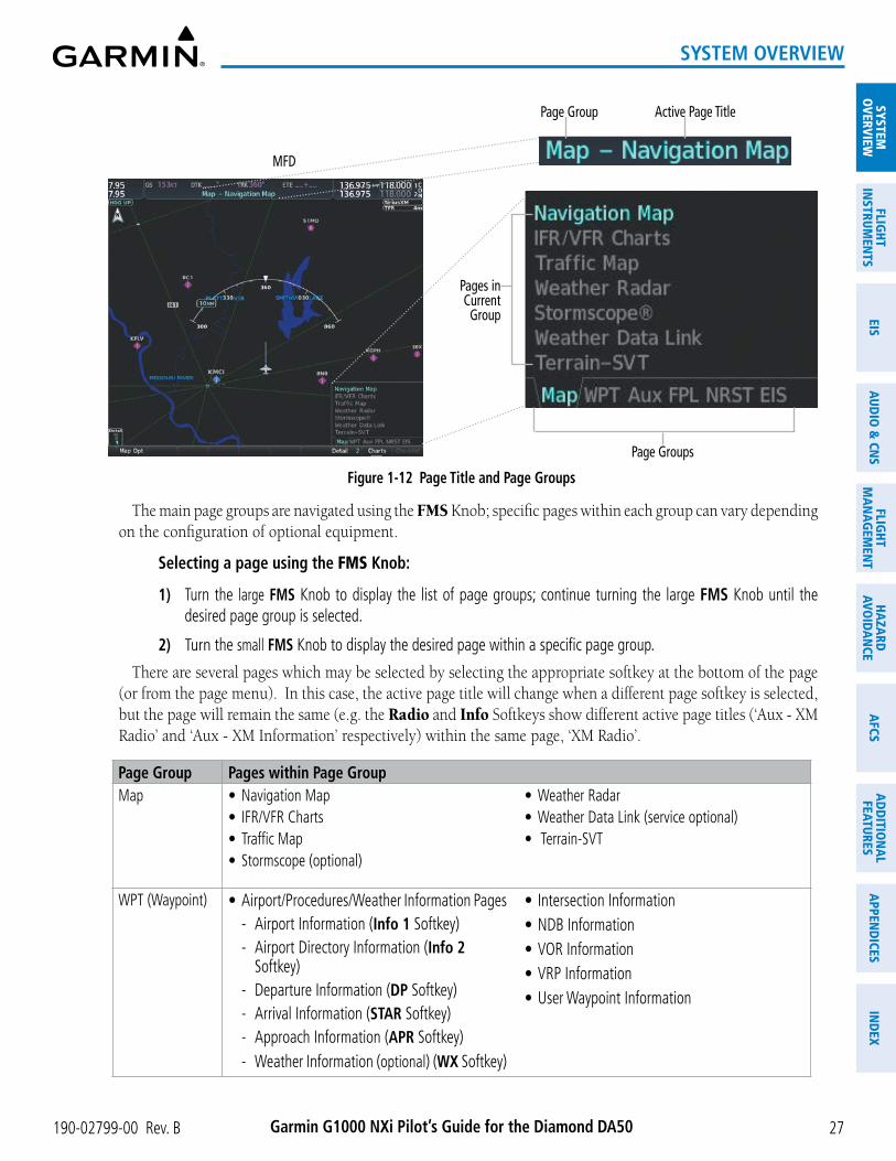
190-02799-00 Rev. B Garmin G1000 NXi Pilot’s Guide for the Diamond DA50
SYSTEMO
VERVIEWFLIG
HTIN
STRUMEN
TSEIS
AUDIO
& CN
SFLIG
HTM
AN
AGEM
ENT
HAZA
RDAVO
IDA
NCE
AFCS
AD
DITIO
NA
LFEATURES
APPEN
DICES
IND
EX
27
SYSTEM OVERVIEW
Figure 1-12 Page Title and Page Groups
Page Group Active Page Title
MFD
Page Groups
Pages inCurrentGroup
The main page groups are navigated using the FMS Knob; specific pages within each group can vary depending on the configuration of optional equipment.
Selecting a page using the FMS Knob:
1) Turn the large FMS Knob to display the list of page groups; continue turning the large FMS Knob until the desired page group is selected.
2) Turn the small FMS Knob to display the desired page within a specific page group.
There are several pages which may be selected by selecting the appropriate softkey at the bottom of the page (or from the page menu). In this case, the active page title will change when a different page softkey is selected, but the page will remain the same (e.g. the Radio and Info Softkeys show different active page titles (‘Aux - XM Radio’ and ‘Aux - XM Information’ respectively) within the same page, ‘XM Radio’.
Page Group Pages within Page GroupMap • Navigation Map
• IFR/VFR Charts• Traffic Map• Stormscope (optional)
• Weather Radar• Weather Data Link (service optional)• Terrain-SVT
WPT (Waypoint) • Airport/Procedures/Weather Information Pages - Airport Information (Info 1 Softkey) - Airport Directory Information (Info 2
Softkey) - Departure Information (DP Softkey) - Arrival Information (STAR Softkey) - Approach Information (APR Softkey) - Weather Information (optional) (WX Softkey)
• Intersection Information• NDB Information• VOR Information• VRP Information• User Waypoint Information

190-02799-00 Rev. BGarmin G1000 NXi Pilot’s Guide for the Diamond DA50
SYST
EMO
VERV
IEW
FLIG
HTIN
STRU
MEN
TSEI
SAU
DIO
& C
NS
FLIG
HTM
AN
AGEM
ENT
HAZA
RDAV
OID
AN
CEA
FCS
AD
DIT
ION
AL
FEAT
URES
APP
END
ICES
IND
EX
28
SYSTEM OVERVIEW
Page Group Pages within Page GroupAux (Auxiliary) • Trip Planning
• Utility• GPS Status• System Setup 1/2• XM Radio Pages (optional)
- XM Information (Info Softkey) - XM Radio (Radio Softkey)
• Satellite Phone (optional) - Telephone (Phone Softkey) - Text Messaging (SMS Softkey)
• Maintenance Logs• System Status• ADS-B Status• Connext Setup• Databases
FPL (Flight Plan) • Active Flight Plan - Wide View, Narrow View (View Softkey)
Active Flight Plan• Standby Flight Plan
- Wide View, Narrow View (View Softkey)
• Flight Plan Catalog - Stored Flight Plan (via New Softkey)
• SurfaceWatch Setup (optional)
NRST (Nearest) • Nearest Airports• Nearest Intersections• Nearest NDB
• Nearest VOR• Nearest VRP• Nearest User WPTS
• Nearest Frequencies• Nearest Airspaces
Table 1-4 Page Group and Pages
PROCEDURE PAGES (PROC)
The Procedure Pages may be accessed at any time on the MFD by pressing the PROC Key. A menu is initialized, and when a departure, approach, or arrival is selected, the appropriate Procedure Loading Page is opened. Turning the FMS Knob does not scroll through the Procedure pages.
» Departure Loading » Arrival Loading » Approach Loading
SPLIT SCREEN FUNCTIONALITYChart pages may be viewed in split screen mode with either the ‘Map - Navigation Map’ or ‘FPL - Active
Flight Plan’ Page open. To activate the split screen functionality, press the Charts Softkey. Two display panes are displayed on the MFD. If split screen is activated from the ‘Map - Navigation Map’ Page, the page title will show ‘Map - Chart + Navigation Map’. If split screen is activated from the ‘FPL - Active Flight Plan’ Page, the page title will change to show ‘FPL - Chart + Active Flight Plan’.

190-02799-00 Rev. B Garmin G1000 NXi Pilot’s Guide for the Diamond DA50
SYSTEMO
VERVIEWFLIG
HTIN
STRUMEN
TSEIS
AUDIO
& CN
SFLIG
HTM
AN
AGEM
ENT
HAZA
RDAVO
IDA
NCE
AFCS
AD
DITIO
NA
LFEATURES
APPEN
DICES
IND
EX
29
SYSTEM OVERVIEW
Figure 1-13 Split Screen Mode
MFD in Split Screen Mode (Narrow View)
Cyan Pane Selector shows Charts is the active display pane
Page Title shows ‘Map - Chart + Navigation Map’
Softkeys for the active display pane
CONTROLLING DISPLAY PANES
In split screen mode, the active display pane is outlined by a cyan box called the pane selector. Softkeys and menu options will automatically change depending on which display pane is active. Display panes may be displayed vertically in Narrow View, or horizontally in Wide View. In Narrow View, move the Joystick left or right to move the pane selector. In Wide View, move the Joystick up and down to move the pane selector. To change between Wide View and Narrow View, push and hold the Joystick.
Figure 1-14 Split Screen in Wide View
MFD in Split Screen Mode (Wide View)
Cyan Pane Selector shows Charts is the active display pane
Pane Selector Box - Move Joystick in direction of cyan arrows to move display pane - Push and hold Joystick to change Narrow/Wide view
Softkeys for the active display pane
For information on viewing Charts and the Active ‘FPL - Active Flight Plan’ Page with the Flight Plan map, see the Flight Management Section.
For more information on Charts and how to enable Charts Full Screen, see the Additional Features Section.

190-02799-00 Rev. BGarmin G1000 NXi Pilot’s Guide for the Diamond DA50
SYST
EMO
VERV
IEW
FLIG
HTIN
STRU
MEN
TSEI
SAU
DIO
& C
NS
FLIG
HTM
AN
AGEM
ENT
HAZA
RDAV
OID
AN
CEA
FCS
AD
DIT
ION
AL
FEAT
URES
APP
END
ICES
IND
EX
30
SYSTEM OVERVIEW
Enabling/disabling split screen mode:
1) From the ‘Map - Navigation Map’ Page or the ‘FPL - Active Flight Plan’ Page press the Charts Softkey, or press the MENU Key and select ‘Chart Mode On’. If necessary, press the CHRT Opt Softkey and press the Full SCN Softkey to disable full screen mode.
2) To disable the split screen mode, press the Charts Softkey again or press the MENU Key and select ‘Chart Mode Off’. The display returns to the base page, either the ‘Map - Navigation Map’ Page or the ‘FPL - Active Flight Plan’ Page.
SYSTEM SETTINGSSystem settings are managed from the ‘Aux - System Setup’ Pages. Fields shown in cyan text may be edited.
Managing the system time format, display units, arrival alerts, and audio voice format settings are discussed in this section. For other system settings, see the reference given to their respective sections.
If desired, the default system settings may be restored at any time.
Restoring system setup defaults:
1) Select the ‘Aux - System Setup’ Page.
2) Press the Defaults Softkey; or press the MENU Key, highlight ‘Restore Page Defaults’, and press the ENT Key. The message ‘Restore Setup X Page Defaults?’ is displayed.
3) With ‘OK’ highlighted, press the ENT Key.

190-02799-00 Rev. B Garmin G1000 NXi Pilot’s Guide for the Diamond DA50
SYSTEMO
VERVIEWFLIG
HTIN
STRUMEN
TSEIS
AUDIO
& CN
SFLIG
HTM
AN
AGEM
ENT
HAZA
RDAVO
IDA
NCE
AFCS
AD
DITIO
NA
LFEATURES
APPEN
DICES
IND
EX
31
SYSTEM OVERVIEW
Figure 1-15 ‘Aux - System Setup (1 or 2)’ Pages
Restore System Defaults
Configure System Time
Change Display Unit Settings Configure arrival alert settings
- Enable / disable alert - Set arrival alert trigger distance
Change audio alert voice setting
Fields shown in Cyan may be edited
Select System Setup Page - Setup 1 - Setup 2
Crew Profile - Choose active profile- Create new profile- Edit, rename, and delete existing profile (other than default profile) - Import / Export profile to SD Card
CREW PROFILES
System settings may be saved under a crew profile. The system can store up to 25 profiles; the currently active profile, the number of memory slots used, and the number of available memory slots are shown at the top of the System Setup Page in the box labeled ‘Crew Profile’. From here, crew profiles may be created, selected, renamed, or deleted. Crew profiles may also be exported from the system to an SD card, or imported from an SD card into the system.
Crew Profile imPort/exPort messages
In some circumstances, some messages may appear in conjunction with others:
Message Explanation‘No crew profile files found.’ Displayed if the SD card does not have one or more valid crew profile filenames. ‘Overwrite existing profile?’ Displayed if the profile name matches the name of existing profile.‘Profile name invalid. Enter a different profile name.’
Displayed if the profile name is invalid.
‘All available crew profiles in use. Delete a profile before importing another.’
Displayed if the maximum number for crew profiles has been reached.

190-02799-00 Rev. BGarmin G1000 NXi Pilot’s Guide for the Diamond DA50
SYST
EMO
VERV
IEW
FLIG
HTIN
STRU
MEN
TSEI
SAU
DIO
& C
NS
FLIG
HTM
AN
AGEM
ENT
HAZA
RDAV
OID
AN
CEA
FCS
AD
DIT
ION
AL
FEAT
URES
APP
END
ICES
IND
EX
32
SYSTEM OVERVIEW
Message Explanation‘Crew profile import failed.’ Displayed if the importing operation fails for any other reason.‘Crew profile import succeeded.’ Displayed if the importing operation succeeds.‘Overwrite existing file?’ Displayed if the filename matches the name of an existing file on the SD card.‘Crew profile export failed.’ Displayed if the export operation fails.‘Crew profile export succeeded.’ Displayed if the export operation succeeds.
Table 1-5 Crew Profile Import/Export Messages
Creating a profile:
1) Select the ‘Aux - System Setup (1 or 2)’ Page.
2) Press the FMS Knob momentarily to activate the flashing cursor.
3) Turn the large FMS Knob to highlight ‘Create’ in the ‘Crew Profile’ Box.
4) Press the ENT Key. A ‘Create Profile’ Window is displayed.
5) Use the FMS Knob to enter a profile name up to 16 characters long and press the ENT Key. Crew profile names cannot begin with a blank as the first letter.
6) In the next field, use the small FMS Knob to select the desired settings upon which to base the new profile. Profiles can be created based on Garmin factory defaults, default profile settings (initially based on Garmin factory defaults unless edited by the pilot), or other previously created profile settings.
7) Press the ENT Key.
8) With ‘Create’ highlighted, press the ENT Key to create the profile
Or:
Use the large FMS Knob to select ‘Create & Activate’ and press the ENT Key to activate the new profile.
9) To cancel the process, select ‘Cancel’ with the large FMS Knob and press the ENT Key.
Selecting an active profile:
1) Select the ‘Aux - System Setup (1 or 2)’ Page.
2) Press the FMS Knob momentarily to activate the flashing cursor.
3) Turn the large FMS Knob to highlight the active profile field in the ‘Crew Profile’ Box.
4) Turn the small FMS Knob to display the crew profile list and highlight the desired profile.
5) Press the ENT Key. The system loads and displays the system settings for the selected profile.
NOTE: “DEFAULT PROFILE” cannot be renamed.
Renaming a profile:
1) Select the ‘Aux - System Setup (1 or 2)’ Page.
2) Press the FMS Knob momentarily to activate the flashing cursor.
3) Turn the large FMS Knob to highlight ‘Rename’ in the ‘Crew Profile’ Box.
4) Press the ENT Key.

190-02799-00 Rev. B Garmin G1000 NXi Pilot’s Guide for the Diamond DA50
SYSTEMO
VERVIEWFLIG
HTIN
STRUMEN
TSEIS
AUDIO
& CN
SFLIG
HTM
AN
AGEM
ENT
HAZA
RDAVO
IDA
NCE
AFCS
AD
DITIO
NA
LFEATURES
APPEN
DICES
IND
EX
33
SYSTEM OVERVIEW
5) In the ‘Rename Profile’ Window, turn the FMS Knob to select the profile to rename.
6) Press the ENT Key.
7) Use the FMS Knob to enter a new profile name up to 16 characters long and press the ENT Key.
8) With ‘Rename’ highlighted, press the ENT Key.
9) To cancel the process, use the large FMS Knob to select ‘Cancel’ and press the ENT Key.
Deleting a profile:
1) Select the ‘Aux - System Setup (1 or 2)’ Page.
2) Press the FMS Knob momentarily to activate the flashing cursor.
3) Turn the large FMS Knob to highlight ‘Delete’ in the ‘Crew Profile’ Box.
4) Press the ENT Key.
5) In the ‘Delete Profile’ Window, turn the FMS Knob to select the profile to delete.
6) Press the ENT Key.
7) With ‘Delete’ highlighted, press the ENT Key.
8) To cancel the process, use the large FMS Knob to select ‘Cancel’ and press the ENT Key.
Importing a profile from an SD card:
1) Insert an SD card containing the crew profile(s) into the top card slot on the MFD.
2) Turn the FMS Knob to select the ‘Aux - System Setup (1 or 2)’ Page.
3) Press the Import Softkey.
Or:
a) Press the MENU Key.
b) Turn the FMS Knob to highlight ‘Import Crew Profile’ and press the ENT Key.
4) The system displays the Crew Profile Importing window with ‘Import’ highlighted. Turn the large FMS Knob to highlight the ‘Profile Name’ field, then scroll to the desired profile name with the large and small FMS Knobs, then press the ENT Key. Then press the ENT Key with ‘Import’ highlighted.
5) If the imported profile name is the same as an existing profile on the system, the system displays an ‘Overwrite existing profile? OK or CANCEL’ prompt. Press the ENT Key to replace profile on the system with the profile imported from the SD card, or turn the FMS Knob to highlight ‘CANCEL’ and press the ENT Key to return to the ‘Crew Profile Importing’ Window.
6) If successful, the system displays ‘Crew profile import succeeded.’ in the window below. With ‘OK’ highlighted, press the ENT or CLR Keys or press the FMS Knob to return to the ‘Aux - System Setup (1 or 2)’ Page. The imported profile becomes the active profile.

190-02799-00 Rev. BGarmin G1000 NXi Pilot’s Guide for the Diamond DA50
SYST
EMO
VERV
IEW
FLIG
HTIN
STRU
MEN
TSEI
SAU
DIO
& C
NS
FLIG
HTM
AN
AGEM
ENT
HAZA
RDAV
OID
AN
CEA
FCS
AD
DIT
ION
AL
FEAT
URES
APP
END
ICES
IND
EX
34
SYSTEM OVERVIEW
Crew Profile Importing and Import Results Window
Crew Profiles Available for Import from SD Card
Import Successful
Figure 1-16 Crew Profile Import (Aux - System Setup Page)
NOTE: “DEFAULT PROFILE” will be exported as “DEFAULT COPY”.
Exporting a profile to an SD card:
1) Insert the SD card to be used for storing the Crew Profile into the top card slot on the MFD.
2) Turn the FMS Knob to select the ‘Aux - System Setup (1 or 2)’ Page.
3) Press the Export Softkey. The system displays the ‘Crew Profile Exporting’ Window.
Or:
a) Press the MENU Key.
b) Turn the FMS Knob to highlight ‘Export Crew Profile’ and press the ENT Key.
4) To export the crew profile using the current selected profile, press the ENT Key with ‘Export’ highlighted. To change the selected profile, turn the large FMS Knob to highlight the ‘Profile Name’ field, then scroll to the desired profile name with the large and small FMS Knobs, then press the ENT Key. Then press the ENT Key with ‘Export’ highlighted.
5) If the selected profile to be exported is the same as an existing profile file name on the SD card, the system displays an ‘Overwrite existing profile? OK or CANCEL’ prompt. Press the ENT Key to replace the profile on the SD card with the profile to be exported, or turn the FMS Knob to highlight ‘CANCEL’ and press the ENT Key to return to the ‘Crew Profile Exporting’ Window without exporting the profile.
6) If successful, the window displays ‘Crew profile export succeeded.’ With ‘OK’ highlighted, press the ENT or CLR Keys, or press the FMS Knob to return to the ‘Aux - System Setup (1 or 2)’ Page.
‘Crew Profile Exporting’ Window, Enter a Name to Use for Exported Profile
Export Successful
Figure 1-17 Crew Profile Export on the Aux - System Setup Page

190-02799-00 Rev. B Garmin G1000 NXi Pilot’s Guide for the Diamond DA50
SYSTEMO
VERVIEWFLIG
HTIN
STRUMEN
TSEIS
AUDIO
& CN
SFLIG
HTM
AN
AGEM
ENT
HAZA
RDAVO
IDA
NCE
AFCS
AD
DITIO
NA
LFEATURES
APPEN
DICES
IND
EX
35
SYSTEM OVERVIEW
DATE/TIMEThe system obtains the current Universal Coordinated Time (UTC) date and time directly from the GPS
satellite signals (shown on the ‘Aux - GPS Status’ Page). System time (displayed in the lower right corner of the PFD) can be displayed in three formats: local 12-hr, local 24-hr, or UTC. Local time is set by adding/subtracting an offset (hours:minutes) to/from UTC.
Figure 1-18 System Time (UTC Format)
Configuring the system time:
1) Select the ‘Aux - System Setup’ Page.
2) Push the FMS Knob to activate the cursor.
3) Turn the large FMS Knob to highlight the ‘Time Format’ field.
4) Turn the small FMS Knob to select the desired format and press the ENT Key to confirm selection. If local time format is selected, the ‘Time Offset’ field is highlighted.
5) If necessary, use the FMS Knob to enter the desired time offset (±HH:MM) and press the ENT Key to confirm selection.
DISPLAY UNITS
Units in which various quantities are displayed on the system screens are listed on the ‘Aux - System Setup’ Pages. The Navigation Angle reference, the Temperature units, and the Position units can be set from here.
Category Settings Affected QuantitiesNavigation Angle Magnetic (North) 1
True (North) HeadingCourseBearingTrackDesired TrackWind direction (‘Trip Planning’ Page)
Distance and Speed 2 Nautical 1
MetricCrosstrack error (HSI)Bearing distances (information windows)DME distance (information window)Flight plan distancesMap rangesDIS, GS, TAS, XTK Fields (Navigation Data Bar)All distances on MFDAltitude buffer distance (System Setup)Arrival Alert trigger distance (System Setup)All speeds on MFD3
Altitude and Vertical Speed 2
Feet 1
MetersAll altitudes on MFDAll elevations on MFD4

190-02799-00 Rev. BGarmin G1000 NXi Pilot’s Guide for the Diamond DA50
SYST
EMO
VERV
IEW
FLIG
HTIN
STRU
MEN
TSEI
SAU
DIO
& C
NS
FLIG
HTM
AN
AGEM
ENT
HAZA
RDAV
OID
AN
CEA
FCS
AD
DIT
ION
AL
FEAT
URES
APP
END
ICES
IND
EX
36
SYSTEM OVERVIEW
Category Settings Affected QuantitiesTemperature Celsius 1
FahrenheitAll temperatures on PFDTotal Air Temperature (‘Trip Planning’ Page)5
Fuel and Fuel Flow 2 Gallons1
IMP GALKilogramsLitersPounds
Fuel parameters (‘Trip Planning’ Page) 5
Weight 2 PoundsKilograms
N/A
Position HDDD°MM.MM’ 1
HDDD°MM’SS.S”MGRS 1mMGRS 10m
All positions
1 Default setting.2 Not configurable.3 Excludes: airspeed indicator, altitude, true airspeed (PFD), wind speed vector, map range (‘Map - Traffic Map’ Page),CDI
scaling (System Setup), and fuel range calculation (EIS) .4 Excludes: altimeter, Vertical Speed Indicator, and VNV altitudes (Active Flight Plan). QFE settings can be in meters.5 Excludes: Engine Indication System (EIS).
Table 1-6 Display Units Settings (‘Aux - System Setup’ Page)
Changing a display unit setting:
1) While on the ‘Aux - System Setup’ Page, push the FMS Knob+ momentarily to activate the flashing cursor.
2) Turn the large FMS Knob to highlight the desired field in the ‘Display Units’ Box.
3) Turn the small FMS Knob to select the desired units.
4) Press the ENT Key. Press the CLR Key to cancel the action without changing the units.
BARO QFE
See the Flight Instruments Section for information on Baro QFE settings.
SURFACEWATCH
See the Additional Features Section for information on SurfaceWatch settings.
BARO TRANSITION ALERT
See the Flight Instruments Section for information on setting the Baro Transition Alert.
AIRSPACE ALERTS
See the Flight Management Section for information on Airspace Alerts settings.
ARRIVAL ALERTS
See the Flight Management Section for information on Arrival Alerts settings.

190-02799-00 Rev. B Garmin G1000 NXi Pilot’s Guide for the Diamond DA50
SYSTEMO
VERVIEWFLIG
HTIN
STRUMEN
TSEIS
AUDIO
& CN
SFLIG
HTM
AN
AGEM
ENT
HAZA
RDAVO
IDA
NCE
AFCS
AD
DITIO
NA
LFEATURES
APPEN
DICES
IND
EX
37
SYSTEM OVERVIEW
FLIGHT DIRECTOR
The Flight Director command bars format is set to Single Cue and may not be changed. See the AFCS Section for more information.
MFD DATA BAR FIELDS
See the Flight Management Section for information on the MFD Data Bar Fields settings.
GPS CDI
See the Flight Instruments Section for information on setting the GPS CDI format.
NEAREST AIRPORT
See the Flight Management Section for information on the Nearest Airport settings.
STABILITY & PROTECTION
See the Additional Features Section for information on the Electronic Stability and Protection (ESP) settings.
COM CONFIGURATION
See the Audio & CNS Section for information on the COM Configuration for channel spacing.
AUDIO ALERTS
The ‘Audio’ Box on the ‘Aux - System Setup 2’ Page allows the audio alert voice setting (male or female).
Changing the audio alert voice:
1) Use the FMS Knob to select the ‘Aux - System Setup 2’ Page.
2) Push the FMS Knob momentarily to activate the flashing cursor.
3) Turn the large FMS Knob to highlight the voice field in the ‘Audio’ Box.
4) Use the FMS Knob to select the desired voice setting and press the ENT Key.

190-02799-00 Rev. BGarmin G1000 NXi Pilot’s Guide for the Diamond DA50
SYST
EMO
VERV
IEW
FLIG
HTIN
STRU
MEN
TSEI
SAU
DIO
& C
NS
FLIG
HTM
AN
AGEM
ENT
HAZA
RDAV
OID
AN
CEA
FCS
AD
DIT
ION
AL
FEAT
URES
APP
END
ICES
IND
EX
38
SYSTEM OVERVIEW
SYSTEM UTILITIESFor flight planning purposes, timers, trip statistics, and a scheduler feature are provided on the ‘Aux - Utility’
Page. The timers available include a stopwatch-like generic timer, a total time in flight timer, and a record of the time of departure. Trip statistics—odometer, trip odometer, and average trip and maximum groundspeeds—are displayed from the time of the last reset.
Figure 1-19 ‘Aux - Utility’ PageTIMERS
The system timers available on the ‘Aux - Utility’ Page include:
» Stopwatch-like generic timers
» Total-time-in-flight timer
» Time since departure
The generic timer can be set to count up or down from a specified time (HH:MM:SS). When the countdown on the timer reaches zero the digits begin to count up from zero. If the timer is reset before reaching zero on a countdown, the digits are reset to the initial value. If the timer is counting up when reset, the digits return to zero.
Setting the generic timer:
1) Use the FMS Knob to select the ‘Aux - Utility’ Page.
2) Push the FMS Knob momentarily to activate the flashing cursor.
3) Turn the small FMS Knob to select the timer counting direction (Up/Dn) and press the ENT Key.
4) If a starting time is desired:
a) Use the large FMS Knob to highlight the HH:MM:SS field.
b) Use the FMS Knob to enter the desired time and press the ENT Key.
5) Turn the large FMS Knob to highlight ‘Start?’ and press the ENT Key to start the timer. The field changes to ‘Stop?’.

190-02799-00 Rev. B Garmin G1000 NXi Pilot’s Guide for the Diamond DA50
SYSTEMO
VERVIEWFLIG
HTIN
STRUMEN
TSEIS
AUDIO
& CN
SFLIG
HTM
AN
AGEM
ENT
HAZA
RDAVO
IDA
NCE
AFCS
AD
DITIO
NA
LFEATURES
APPEN
DICES
IND
EX
39
SYSTEM OVERVIEW
6) To stop the timer, press the ENT Key with ‘Stop?’ highlighted. The field changes to ‘Reset?’.
7) To reset the timer, press the ENT Key with ‘Reset?’ highlighted. The field changes back to ‘Start?’ and the digits are reset.
The flight timer can be set to count up from zero starting at system power-on or from the time the aircraft lifts off; the timer can also be reset to zero at any time.
Setting the flight timer starting criterion:
1) Use the FMS Knob to select the ‘Aux - Utility’ Page.
2) Push the FMS Knob momentarily to activate the flashing cursor.
3) Turn the large FMS Knob to highlight the field next to the flight timer.
4) Turn the small FMS Knob to select the starting criterion (Pwr-On or In-Air) and press the ENT Key.
Resetting the flight timer:
1) Use the FMS Knob to select the ‘Aux - Utility’ Page.
2) Press the MENU Key.
3) With ‘Reset Flight Timer’ highlighted, press the ENT Key.The system records the time at which departure occurs, depending on whether the pilot prefers the time
to be recorded from system power-on or from aircraft lift off. The displayed departure time can also be reset to display the current time at the point of reset. The format in which the time is displayed is controlled from the ‘Aux - System Setup’ Page.
Setting the departure timer starting criterion:
1) Use the FMS Knob to select the ‘Aux - Utility’ Page.
2) Push the FMS Knob momentarily to activate the flashing cursor.
3) Turn the large FMS Knob to highlight the field next to the departure time.
4) Turn the small FMS Knob to select the starting criterion (Pwr-On or In-Air) and press the ENT Key.
Resetting the departure time:
1) Use the FMS Knob to select the ‘Aux - Utility’ Page.
2) Press the MENU Key.
3) Use the FMS Knob to highlight ‘Reset Departure Time’ and press the ENT Key.

190-02799-00 Rev. BGarmin G1000 NXi Pilot’s Guide for the Diamond DA50
SYST
EMO
VERV
IEW
FLIG
HTIN
STRU
MEN
TSEI
SAU
DIO
& C
NS
FLIG
HTM
AN
AGEM
ENT
HAZA
RDAV
OID
AN
CEA
FCS
AD
DIT
ION
AL
FEAT
URES
APP
END
ICES
IND
EX
40
SYSTEM OVERVIEW
TRIP STATISTICSThe odometer and trip odometer record the total mileage traveled from the last reset; these odometers can
be reset independently. Resetting the trip odometer also resets the average trip groundspeed. Maximum groundspeed for the period of time since the last reset is also displayed.
Resetting trip statistics indications:
1) Use the FMS Knob to select the ‘Aux - Utility’ Page.
2) Press the MENU Key. The following reset options for trip statistics are displayed:
• Reset Trip ODOM/AVG GS—Resets trip average ground speed and odometer
• Reset Odometer—Resets odometer only
• Reset Maximum Speed—Resets maximum speed only
• Reset All—Resets flight timer, departure timer, odometers, and groundspeed
3) Use the FMS Knob to highlight the desired reset option and press the ENT Key. The selected parameters are reset to zero and begin to display data from the point of reset.
SCHEDULER
The system Scheduler feature can be used to enter and display reminder messages (e.g., “Switch fuel tanks”, “Overhaul”, etc.) in the ‘Alerts’ Window on the PFD. Messages can be set to display based on a specific date and time (event), once the message timer reaches zero (one-time; default setting), or recurrently whenever the message timer reaches zero (periodic). Message timers set to periodic alerting automatically reset to the original timer value once the message is displayed. When power is cycled, messages are retained until deleted, and message timer countdown is restarted.
Scheduler messages appear in the ‘Alerts’ Window on the PFD and cause the Alerts Softkey label to change to a flashing ‘Message’ label. Pressing the Message Softkey opens the ‘Alerts’ Window and acknowledges the scheduler message. The softkey reverts to the “Alerts” label. Pressing the Alerts Softkey again removes the ‘Alerts’ Window from the display and the scheduler message is deleted from the message queue.
Figure 1-20 PFD ‘Alerts’ WindowEntering a scheduler message:
1) Select the ‘Aux - Utility’ Page.
2) Push the FMS Knob momentarily to activate the flashing cursor.
3) Turn the large FMS Knob to highlight the first empty field within the ‘Scheduler’ Box.

190-02799-00 Rev. B Garmin G1000 NXi Pilot’s Guide for the Diamond DA50
SYSTEMO
VERVIEWFLIG
HTIN
STRUMEN
TSEIS
AUDIO
& CN
SFLIG
HTM
AN
AGEM
ENT
HAZA
RDAVO
IDA
NCE
AFCS
AD
DITIO
NA
LFEATURES
APPEN
DICES
IND
EX
41
SYSTEM OVERVIEW
4) Use the FMS Knob to enter text within the ‘Message’ Field to be displayed in the ‘Messages’ Window and press the ENT Key.
5) Press the ENT Key again or use the large FMS Knob to move the cursor to the ‘Type’ Field.
6) Turn the small FMS Knob to select set the message alert type:
• ‘Event’ — Message issued at the specified date/time
• ‘One-time’ — Message issued when the message timer reaches zero (default setting)
• ‘Periodic’ — Message issued each time the message timer reaches zero
7) Press the ENT Key again or use the large FMS Knob to move the cursor to the next field.
8) For periodic and one-time message, use the FMS Knob to enter the timer value (HHH:MM:SS) from which to countdown and press the ENT Key.
9) For event-based messages:
a) Use the FMS Knob to enter the desired date (DD-MMM-YY) and press the ENT Key.
b) Press the ENT Key again or use the large FMS Knob to move the cursor to the next field.
c) Use the FMS Knob to enter the desired time (HH:MM) and press the ENT Key.
10) Press the ENT Key again or use the large FMS Knob to move the cursor to enter the next message.
Deleting a scheduler message:
1) Select the ‘Aux - Utility’ Page.
2) Push the FMS Knob momentarily to activate the flashing cursor.
3) Turn the large FMS Knob to highlight the ‘Message’ Field of the scheduler message to be deleted.
4) Press the CLR Key to clear the message text. If the CLR Key is pressed again, the message is restored.
5) Press the ENT Key to confirm message deletion.
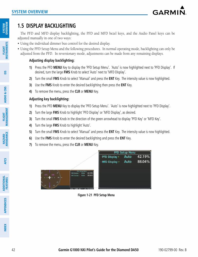
190-02799-00 Rev. BGarmin G1000 NXi Pilot’s Guide for the Diamond DA50
SYST
EMO
VERV
IEW
FLIG
HTIN
STRU
MEN
TSEI
SAU
DIO
& C
NS
FLIG
HTM
AN
AGEM
ENT
HAZA
RDAV
OID
AN
CEA
FCS
AD
DIT
ION
AL
FEAT
URES
APP
END
ICES
IND
EX
42
SYSTEM OVERVIEW
1.5 DISPLAY BACKLIGHTINGThe PFD and MFD display backlighting, the PFD and MFD bezel keys, and the Audio Panel keys can be
adjusted manually in one of two ways:
• Using the individual dimmer bus control for the desired display.
• Using the PFD Setup Menu and the following procedures. In normal operating mode, backlighting can only be adjusted from the PFD. In reversionary mode, adjustments can be made from any remaining displays.
Adjusting display backlighting:
1) Press the PFD MENU Key to display the ‘PFD Setup Menu’. ‘Auto’ is now highlighted next to ‘PFD Display’. If desired, turn the large FMS Knob to select ‘Auto’ next to ‘MFD Display’.
2) Turn the small FMS Knob to select ‘Manual’ and press the ENT Key. The intensity value is now highlighted.
3) Use the FMS Knob to enter the desired backlighting then press the ENT Key.
4) To remove the menu, press the CLR or MENU Key.
Adjusting key backlighting:
1) Press the PFD MENU Key to display the ‘PFD Setup Menu’. ‘Auto’ is now highlighted next to ‘PFD Display’.
2) Turn the large FMS Knob to highlight ‘PFD Display’ or ‘MFD Display’, as desired.
3) Turn the small FMS Knob in the direction of the green arrowhead to display ‘PFD Key’ or ‘MFD Key’.
4) Turn the large FMS Knob to highlight ‘Auto’.
5) Turn the small FMS Knob to select ‘Manual’ and press the ENT Key. The intensity value is now highlighted.
6) Use the FMS Knob to enter the desired backlighting and press the ENT Key.
7) To remove the menu, press the CLR or MENU Key.
Figure 1-21 PFD Setup Menu

190-02799-00 Rev. B Garmin G1000 NXi Pilot’s Guide for the Diamond DA50 43
FLIGHT INSTRUMENTS
SYSTEMO
VERVIEWFLIG
HTIN
STRUMEN
TSEIS
AUDIO
& CN
SFLIG
HTM
AN
AGEM
ENT
HAZA
RDAVO
IDA
NCE
AFCS
AD
DITIO
NA
LFEATURES
APPEN
DICES
IND
EX
SECTION 2 FLIGHT INSTRUMENTS
NOTE: The Automatic Flight Control System (AFCS) provides additional indications and bugs on selected flight instruments. Refer to the AFCS Section for details on these bugs and indications, as they appear on the display during certain AFCS flight director modes.
The system increases pilot situational awareness by providing an easy-to-scan Primary Flight Display (PFD) featuring a large horizon, airspeed, attitude, vertical speed, and course deviation information. In addition to the flight instruments, navigation, communication, terrain, traffic, and weather information are also presented on the PFD and are explained in other sections of this Pilot’s Guide.
The following flight instruments and supplemental flight data are displayed on the PFD:
• Airspeed Indicator, showing
- Indicated Airspeed
- True Airspeed
- Airspeed awareness ranges
- Vspeed reference bugs
• Attitude Indicator with slip/skid indication
• Altimeter, showing
- Trend vector
- Barometric setting
- Selected altitude
• Vertical Deviation, Glideslope, and Glidepath Indicators
• Vertical Speed Indicator (VSI)
• Vertical Navigation (VNV) indications
• Outside Air Temperature (OAT)
• Horizontal Situation Indicator, showing
- Turn Rate Indicator
- Bearing pointers and information windows
- Navigation source
- Course Deviation Indicator (CDI)
- HSI Map
- DME Information Window (optional)
• DME Tuning Window (optional)
• Transponder Mode, Code, and Ident/Reply
• References Window, showing
- Generic timer
- Vspeed values
- Barometric or temperature compensated minimum altitude alert
• Wind data
The PFD also displays various alerts and annunciations discussed throughout this Pilot’s Guide.

Garmin G1000 NXi Pilot’s Guide for the Diamond DA50 190-02799-00 Rev. B44
FLIGHT INSTRUMENTS
SYST
EMO
VERV
IEW
FLIG
HTIN
STRU
MEN
TSEI
SAU
DIO
& C
NS
FLIG
HTM
AN
AGEM
ENT
HAZA
RDAV
OID
AN
CEA
FCS
AD
DIT
ION
AL
FEAT
URES
APP
END
ICES
IND
EX
Figure 2-1 Primary Flight Display (Default)
1 Airspeed Indicator
2 True Airspeed
3 Current Heading
4 Horizontal Situation Indicator (HSI)
5 Outside Air Temperature (OAT), ISA Relative Temperature, and Ground Speed
6 Softkeys
7 System Time
8 Generic Timer
9 Transponder Data Box
10 Selected Heading Bug
11 Barometric Altimeter Setting
12 Turn Rate Indicator
13 Vertical Speed Indicator (VSI)
14 Selected Altitude Bug
15 Altimeter
16 Selected Altitude
17 Navigation Status Box
18 Slip/Skid Indicator
19 Attitude Indicator
4
5
2
1
3
171819
6
13
16
7
14
15
8
10
11
9
12

190-02799-00 Rev. B Garmin G1000 NXi Pilot’s Guide for the Diamond DA50 45
FLIGHT INSTRUMENTS
SYSTEMO
VERVIEWFLIG
HTIN
STRUMEN
TSEIS
AUDIO
& CN
SFLIG
HTM
AN
AGEM
ENT
HAZA
RDAVO
IDA
NCE
AFCS
AD
DITIO
NA
LFEATURES
APPEN
DICES
IND
EX
Figure 2-2 Additional PFD Information
1 Selected Heading
2 Wind Data Box
3 Inset Map
4 Bearing Information Windows
5 Minimum Altitude Alert
6 Desired Track
7 Required Vertical Speed Indicator
8 Vertical Deviation Indication
9 VNV Target Altitude
1
3
2
54
6
7
8
9

Garmin G1000 NXi Pilot’s Guide for the Diamond DA50 190-02799-00 Rev. B46
FLIGHT INSTRUMENTS
SYST
EMO
VERV
IEW
FLIG
HTIN
STRU
MEN
TSEI
SAU
DIO
& C
NS
FLIG
HTM
AN
AGEM
ENT
HAZA
RDAV
OID
AN
CEA
FCS
AD
DIT
ION
AL
FEAT
URES
APP
END
ICES
IND
EX
2.1 FLIGHT INSTRUMENTS
ATTITUDE INDICATORAttitude information is displayed over a virtual blue sky and brown ground with a white horizon line. The
Attitude Indicator displays the pitch, roll, and slip/skid information.
1 Roll Pointer
2 Roll Scale
3 Horizon Line
4 Aircraft Symbol
5 Land Representation
6 Pitch Scale
7 Slip/Skid Indicator
8 Sky Representation
9 Roll Scale Zero
Figure 2-3 Attitude Indicator
7
8
6
5
91
2
3
4
The horizon line is part of the pitch scale. Above and below the horizon line, major pitch marks and numeric labels are shown for every 10˚, up to 90˚. Minor pitch marks are shown for intervening 5˚ increments, up to 25˚ below and 45˚ above the horizon line. Between 20˚ below to 20˚ above the horizon line, minor pitch marks occur every 2.5˚. When the optional Garmin Synthetic Vision System Technology system (Garmin SVT™) is activated, the pitch scale is reduced to 10˚ up and 7.5˚ down; refer to the Additional Features section for more information about Synthetic Vision.
The inverted white triangle indicates zero on the roll scale. Major tick marks at 30˚ and 60˚ and minor tick marks at 10˚, 20˚, and 45˚ are shown to the left and right of the zero. Angle of bank is indicated by the position of the pointer on the roll scale.
When the optional Electronic Stability and Protection System (Garmin ESP™) system is installed and enabled, additional indications also appear on the roll scale; refer to the Additional Features Section for more information about Garmin ESP.
The Slip/Skid Indicator is the bar beneath the roll pointer. The indicator bar moves with the roll pointer and moves laterally away from the pointer to indicate uncoordinated flight. Slip (inside the turn) or skid (outside the turn) is indicated by the location of the bar relative to the pointer.
Figure 2-4 Slip/Skid Indicator

190-02799-00 Rev. B Garmin G1000 NXi Pilot’s Guide for the Diamond DA50 47
FLIGHT INSTRUMENTS
SYSTEMO
VERVIEWFLIG
HTIN
STRUMEN
TSEIS
AUDIO
& CN
SFLIG
HTM
AN
AGEM
ENT
HAZA
RDAVO
IDA
NCE
AFCS
AD
DITIO
NA
LFEATURES
APPEN
DICES
IND
EX
AIRSPEED INDICATOR
NOTE: Refer to the current version of the pertinent flight manual for airspeed criteria and Vspeed values.
The Airspeed Indicator displays airspeed on a moving tape rolling number gauge. The numeric labels and major tick marks on the moving tape are shown at intervals of 10 knots. The minor tick marks on the moving tape are shown at intervals of 5 knots. Speed indication starts at 20 knots, with 60 knots of airspeed viewable at any time. The indicated airspeed is displayed inside the black pointer. The pointer remains black until reaching never exceed speed (V
NE), then it becomes red. The true airspeed is displayed in knots below the
Airspeed Indicator.
Red Pointer Showing Airspeed Above VNE
Vspeed Reference Bugs
TrueAirspeed
IndicatedAirspeed
Color coded speed ranges
Figure 2-5 Airspeed Indicator
A color-coded (solid red, white, green, amber) speed range strip is located on the moving tape. The colors denote solid red low speed awareness range, a flaps operating range, normal operating range, caution range, and never-exceed speed (V
NE). Speeds above the never-exceed speed (VNE), appear in the high speed warning
range, represented on the airspeed tape by red/white “barber pole” coloration.
The Airspeed Trend Vector is a vertical magenta line that appears to the right of the color-coded speed range strip when airspeed is either accelerating or decelerating. One end of the magenta line is anchored to the tip of the airspeed pointer while the other end moves continuously up or down corresponding to the rate of acceleration or deceleration. For any constant rate of acceleration or deceleration, the moving end of the line shows approximately what the indicated airspeed value will be in six seconds. If the trend vector crosses V
NE,
the number in the indicated airspeed pointer changes to amber. The trend vector is absent if the speed remains constant or if any data needed to calculate airspeed is not available due to a system failure.
Black reference bugs with cyan letters appear along the right side of the airspeed scale denote GLIDE, VR,
VX, and VY. The pilot can enable/disable the display of these bugs, as well as change their values. When the indicated airspeed is below 20 knots, enabled Vspeeds Reference Bugs and their numeric values appear in a list at the bottom of the airspeed tape, ordered from highest to lowest.
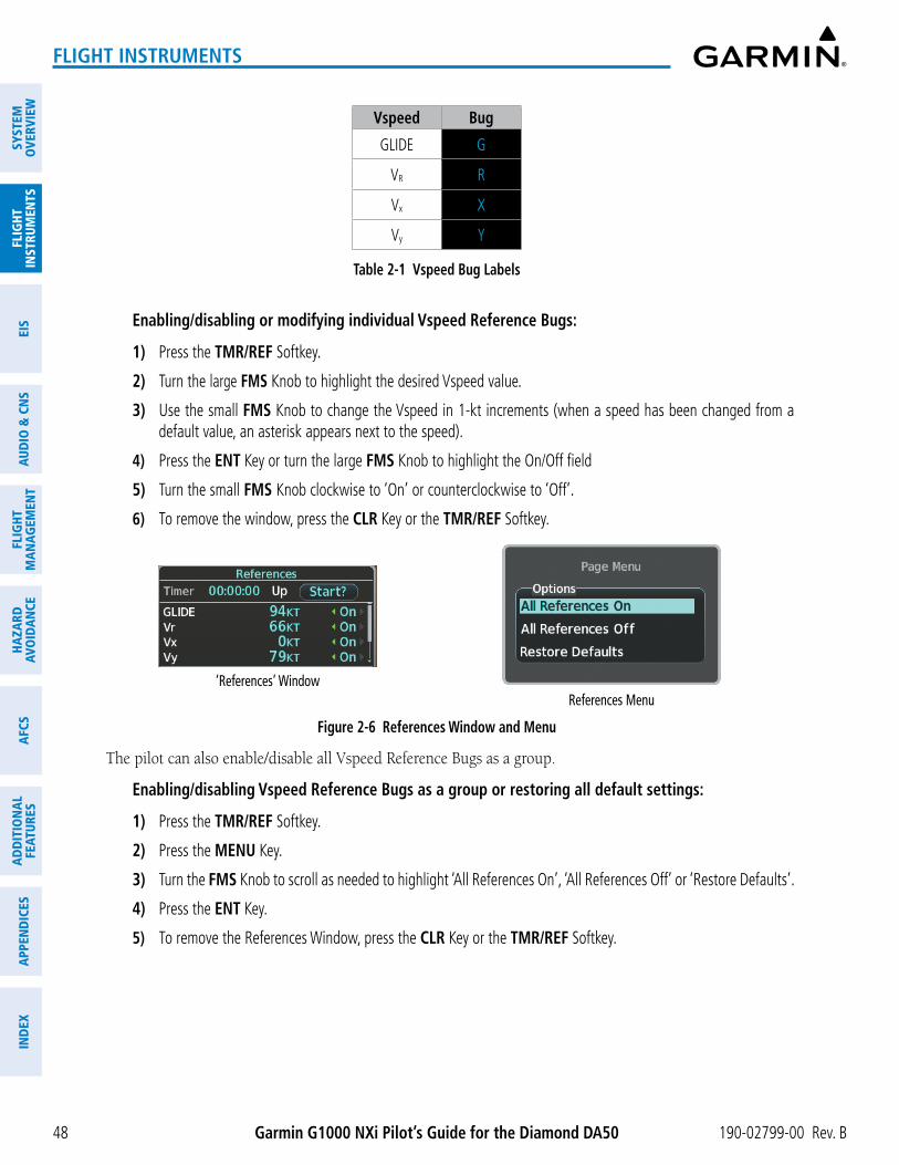
Garmin G1000 NXi Pilot’s Guide for the Diamond DA50 190-02799-00 Rev. B48
FLIGHT INSTRUMENTS
SYST
EMO
VERV
IEW
FLIG
HTIN
STRU
MEN
TSEI
SAU
DIO
& C
NS
FLIG
HTM
AN
AGEM
ENT
HAZA
RDAV
OID
AN
CEA
FCS
AD
DIT
ION
AL
FEAT
URES
APP
END
ICES
IND
EX
Vspeed Bug
GLIDE G
VR R
Vx X
Vy Y
Table 2-1 Vspeed Bug Labels
Enabling/disabling or modifying individual Vspeed Reference Bugs:
1) Press the TMR/REF Softkey.
2) Turn the large FMS Knob to highlight the desired Vspeed value.
3) Use the small FMS Knob to change the Vspeed in 1-kt increments (when a speed has been changed from a default value, an asterisk appears next to the speed).
4) Press the ENT Key or turn the large FMS Knob to highlight the On/Off field
5) Turn the small FMS Knob clockwise to ‘On’ or counterclockwise to ‘Off’.
6) To remove the window, press the CLR Key or the TMR/REF Softkey.
Figure 2-6 References Window and Menu
‘References’ WindowReferences Menu
The pilot can also enable/disable all Vspeed Reference Bugs as a group.
Enabling/disabling Vspeed Reference Bugs as a group or restoring all default settings:
1) Press the TMR/REF Softkey.
2) Press the MENU Key.
3) Turn the FMS Knob to scroll as needed to highlight ‘All References On’, ‘All References Off’ or ‘Restore Defaults’.
4) Press the ENT Key.
5) To remove the References Window, press the CLR Key or the TMR/REF Softkey.

190-02799-00 Rev. B Garmin G1000 NXi Pilot’s Guide for the Diamond DA50 49
FLIGHT INSTRUMENTS
SYSTEMO
VERVIEWFLIG
HTIN
STRUMEN
TSEIS
AUDIO
& CN
SFLIG
HTM
AN
AGEM
ENT
HAZA
RDAVO
IDA
NCE
AFCS
AD
DITIO
NA
LFEATURES
APPEN
DICES
IND
EX
ALTIMETERThe Altimeter indicates barometric altitude on a moving tape rolling number gauge. The pilot can choose
display units format for the Altimeter as feet or meters. Altitude display units are set from the ‘Aux - System Setup 1’ Page. See the System Overview section for details on changing displayed units of measure.
If the altitude is displayed in feet, the Altimeter shows 600 feet of barometric altitude at a time, with numeric labels and major tick marks displayed at intervals of 100 feet. Minor tick marks are at intervals of 20 feet.
If the altitude is displayed in meters, the Altimeter shows 180 meters of barometric altitude at a time, with numeric labels and major tick market displayed at intervals of 50 meters. Minor tick marks are at intervals of 10 meters. The name of the selected units, ‘FEET’ or ‘METERS’, appears near the bottom of the altimeter.
The Selected Altitude is displayed above the Altimeter in the box indicated by a selection bug symbol. A bug corresponding to this altitude is shown on the tape; if the Selected Altitude exceeds the range shown on the tape, the bug appears at the upper or lower edge of the tape. See the AFCS Section for more information about the Selected Altitude.
A magenta Altitude Trend Vector extends up or down the left of the altitude tape, with the end resting at the approximate altitude to be reached in six seconds at the current vertical speed. The trend vector is not shown if altitude remains constant or if data needed for calculation is not available due to a system failure.
Setting the Selected Altitude:
Turn the ALT Knob to set the Selected Altitude. Turn the large knob for 1000-ft increments, small knob for 100-ft increments. If set to Metric mode, the large knob adjusts the Selected Altitude in 500-meter increments; the small knob adjusts the Selected Altitude in 50-meter increments.
If a minimum altitude alert value has been set, this altitude is also available for the Selected Altitude while turning the ALT Knob.
Selected Altitude (Meters)
Indicated Altitude (Meters)
Barometric Setting Box (Hectopascals)
Selected Altitude Bug
VSI in m/s
Altitude Trend Vector
Minimum Altitude Bug
Barometric Setting
“METERS”
Figure 2-7 Altimeter
Default altimeterDefault altimeter (metric overlay) Metric altimeter

Garmin G1000 NXi Pilot’s Guide for the Diamond DA50 190-02799-00 Rev. B50
FLIGHT INSTRUMENTS
SYST
EMO
VERV
IEW
FLIG
HTIN
STRU
MEN
TSEI
SAU
DIO
& C
NS
FLIG
HTM
AN
AGEM
ENT
HAZA
RDAV
OID
AN
CEA
FCS
AD
DIT
ION
AL
FEAT
URES
APP
END
ICES
IND
EX
The crew can choose to display overlays for the indicated altitude and Selected Altitude using complementary display units without changing the scale of the Altimeter. For example, if the Altimeter is displaying feet, the system can show a metric overlay for the indicated and selected altitudes without changing the scale or display units of the Altimeter.
Enabling complementary altitude units overlays:
1) Press the PFD Opt Softkey to display the second-level softkeys.
2) Press the ALT Units Softkey.
3) Press the Meters or Feet Softkey to enable/disable the altitude overlay.
4) Press the Back Softkey twice to return to the top-level softkeys.
The barometric pressure setting is displayed below the Altimeter in inches of mercury (in Hg) or hectopascals (hPa). The pressure setting units can be specified independently of altitude units.
Adjusting the altimeter barometric pressure setting creates discontinuities in VNV vertical deviation, moving the descent path. For large adjustments, it may take several minutes for the aircraft to re-establish on the descent path. If the change is made while nearing a waypoint with a VNV Target Altitude, the aircraft may not re-establish on the descent path in time to meet the vertical constraint.
NOTE: Changing the BARO setting with the autopilot engaged in ALT mode will result in the aircraft slowly climbing or descending to return to the original indicated altitude.
Selecting the altimeter barometric pressure setting:
Turn the BARO Knob to select the desired setting.
Selecting standard barometric pressure (29.92 in Hg):
1) Press the PFD Opt Softkey to display the second-level softkeys.
2) Press the STD Baro Softkey. The PFD softkeys automatically return to the top-level after pressing the softkey.
Figure 2-8 Standard Barometric Setting
Changing altimeter barometric pressure setting units:
1) Press the PFD Opt Softkey to display the second-level softkeys.
2) Press the ALT Units Softkey.
3) Press the IN Softkey to display the barometric pressure setting in inches of mercury (in Hg).
Or:
Press the HPA Softkey to display the barometric pressure setting in hectopascals (hPa).
4) Press the Back Softkey twice to return to the top-level softkeys.

190-02799-00 Rev. B Garmin G1000 NXi Pilot’s Guide for the Diamond DA50 51
FLIGHT INSTRUMENTS
SYSTEMO
VERVIEWFLIG
HTIN
STRUMEN
TSEIS
AUDIO
& CN
SFLIG
HTM
AN
AGEM
ENT
HAZA
RDAVO
IDA
NCE
AFCS
AD
DITIO
NA
LFEATURES
APPEN
DICES
IND
EX
BARO QFE ALTIMETER SETTING
WARNING: Do not use a QFE altimeter setting outside of the terminal environment for the corresponding issuing airport to ensure adequate obstacle clearance.
BARO QFE is the isobaric surface pressure at the airfield reference point. With BARO QFE set, the altimeter will read zero at the airfield reference point or the touch-down zone of the runway in use. At other altitudes the altimeter will read an indication of the height above the reference point. Refer to PFD Annunciations and Alerting Functions in this section for QFE annunciations.
QFE mode should be enabled and the Baro setting should be set to the QFE setting in conjunction with each other. This can be done automatically by arming QFE while the baro setting is still set to STD BARO ahead of time; at the appropriate time set the baro setting on the PFD to the QFE setting when QFE operation is required. When both baro settings are set to something other than STD BARO with QFE armed, BARO QFE mode will automatically become active.
When entering QFE VNAV altitude constraints, it is important to note that only the current QFE reference is used. It is not possible to enter a QFE constraint for the destination while the origin is the current reference. Therefore, while QFE is active and the QFE reference is the origin:
» QFE constraints cannot be entered for the destination airport/runway
» QFE constraints cannot be entered for any arrival/approach waypoints
» Entering an MSL/AGL constraint for any departure/enroute waypoints displays a message clarifying the constraint will be shown as a converted QFE value relative to the origin
NOTE: ‘FMS ORIG’ and ‘FMS DEST’ references do not dynamically update with flight plan changes. Always verify QFE settings when changing the QFE reference (airfield, runway, etc.) or flight plan and re-enter settings on the ‘Aux - System Setup 1’ Page.
NOTE: VPTH changes and VSD and/or VNV discontinuities may occur when switching from QNH to QFE Baro settings.
Setting BARO QFE while on the ground:
1) Set the appropriate QFE BARO setting on the PFD.
2) Use the FMS Knob to select the ‘Aux - System Setup 1’ Page on the MFD.
3) Push the FMS Knob to activate the cursor.
4) Turn the large FMS Knob to select the ‘REF’ field in the ‘BARO QFE’ Box.
5) Use the small FMS Knob to select ‘Manual’ or ‘FMS ORIG’, and press the ENT Key to accept.
6) If ‘Manual’ was selected, use the FMS Knobs to enter the field elevation of the departure airport in the ‘ELEV’ field and press the ENT Key.
7) If ‘FMS ORIG’ was selected, the field elevation of the selected departure airport/runway from the flight plan will be shown in the ‘BARO QFE’ Box. Verify this information is correct.
8) The ‘On/Off’ Field will automatically highlight, turn the small FMS Knob to change ‘Off’ to ‘On’.
9) Push the FMS Knob to deactivate the cursor. QFE mode is now active.
Change the BARO setting to STD BARO to disable BARO QFE.

Garmin G1000 NXi Pilot’s Guide for the Diamond DA50 190-02799-00 Rev. B52
FLIGHT INSTRUMENTS
SYST
EMO
VERV
IEW
FLIG
HTIN
STRU
MEN
TSEI
SAU
DIO
& C
NS
FLIG
HTM
AN
AGEM
ENT
HAZA
RDAV
OID
AN
CEA
FCS
AD
DIT
ION
AL
FEAT
URES
APP
END
ICES
IND
EX
Setting BARO QFE while in flight:
1) Set the BARO setting to STD BARO on the PFD.
2) Use the FMS Knob to select the ‘Aux - System Setup 1’ Page on the MFD.
3) Push the FMS Knob to activate the cursor.
4) Turn the large FMS Knob to select the ‘REF’ field in the BARO QFE Box.
5) Use the small FMS Knob to select ‘Manual’ or ‘FMS DEST’, and press the ENT Key to accept.
6) If ‘Manual’ was selected, use the FMS Knobs to enter the field elevation of the destination airport in the ‘ELEV’ field and press the ENT Key.
7) If ‘FMS DEST’ was selected, the field elevation of the selected destination airport/runway from the flight plan will be shown in the BARO QFE Box. Verify this information is correct.
8) The ‘On/Off’ Field will automatically highlight, turn the small FMS Knob to change the selection from ‘Off’ to ‘On’.
9) Push the FMS Knob to deactivate the cursor. BARO QFE mode is now armed.
10) Enter the reference field QFE BARO setting. As soon as barometric settings change from STD BARO, QFE mode activates.
Change the BARO setting to STD BARO to disable BARO QFE. The desired BARO setting can now be entered.
VERTICAL SPEED INDICATOR (VSI)The Vertical Speed Indicator displays the aircraft vertical speed on a fixed scale with labels at 1000 and 2000
fpm (5 and 10 mps) and minor tick marks every 500 fpm (2.5 mps). Digits appear in the pointer when the climb or descent rate is greater than 100 fpm (0.5 mps). If the rate of ascent/descent exceeds 2000 fpm (10 mps), the pointer appears at the edge of the tape and the rate appears inside the pointer.
A magenta chevron is displayed on the VSI to indicate the Required Vertical Speed for reaching a VNV target altitude once the “TOD [Top of Descent] within 1 minute” alert has generated.
VERTICAL DEVIATION
NOTE: The Glidepath Indicator is only available on GPS approaches supporting vertical guidance when SBAS or Baro VNAV is available.
When Vertical Navigation (VNV) is being used, the Vertical Deviation Indicator (VDI) appears to the left of the altimeter and is displayed with a magenta ‘V’ at the top of the scale and a magenta chevron indicating the VNAV vertical deviation. The VDI appears in conjunction with the “TOD within 1 minute” alert. The VDI is removed from the display if vertical deviation becomes invalid. See the Flight Management Section for details on VNV features, and refer to the Supplemental Flight Data discussion later in this section for more information about VNV indications on the PFD.

190-02799-00 Rev. B Garmin G1000 NXi Pilot’s Guide for the Diamond DA50 53
FLIGHT INSTRUMENTS
SYSTEMO
VERVIEWFLIG
HTIN
STRUMEN
TSEIS
AUDIO
& CN
SFLIG
HTM
AN
AGEM
ENT
HAZA
RDAVO
IDA
NCE
AFCS
AD
DITIO
NA
LFEATURES
APPEN
DICES
IND
EX
The Glideslope Indicator appears to the left of the Altimeter whenever an ILS frequency is tuned in the active NAV field and the selected course and heading are within 107°. A green diamond acts as the Glideslope Indicator, like a glideslope needle on a conventional indicator. If a localizer frequency is tuned and there is no glideslope, “NO GS” is displayed in place of the diamond.
Figure 2-9 Vertical Speed andDeviation Indicator (VSI and VDI)
Vertical Speed Scale
RequiredVertical
Speed
Vertical Speed Indicator
VNV Target Altitude
Vertical Deviation Indicator Glideslope
Indicator
Marker Beacon Annunciation
Figure 2-10 Glideslope Indicator
The Glidepath Indicator is a vertical deviation scale for RNAV GPS approaches supporting SBAS vertical guidance (LNAV+V, L/VNAV, LPV, LP+V). The Glidepath Indicator, a magenta diamond appears on the display as soon as the Final Approach Fix (FAF) becomes the active waypoint, and GPS is the selected navigation source. Full-scale deflection (two dots), is angular with upper and lower limits. The upper limit is ±492 feet (150 meters) and lower limits depend on approach service level:
- LNAV/VNAV, LNAV+V, LP+V is ±148 feet (45 meters)
- LPV is ±49 feet (15 meters)
If the approach downgrades past the final approach fix (FAF), “NO GP” is displayed in place of the diamond.
NOTE: The Glidepath Indicator appears on the display as soon as the Final Approach Fix (FAF) becomes the active waypoint. Depending on procedure design, pilot action, and/or ATC clearance, the aircraft may be centered on or above the glidepath when the Glidepath Indicator appears.
NOTE: When the temperature is warmer than a standard day, the system-generated glidepath guidance for a non-precision approach may cross below the FAF minimum altitude restriction.

Garmin G1000 NXi Pilot’s Guide for the Diamond DA50 190-02799-00 Rev. B54
FLIGHT INSTRUMENTS
SYST
EMO
VERV
IEW
FLIG
HTIN
STRU
MEN
TSEI
SAU
DIO
& C
NS
FLIG
HTM
AN
AGEM
ENT
HAZA
RDAV
OID
AN
CEA
FCS
AD
DIT
ION
AL
FEAT
URES
APP
END
ICES
IND
EX
Figure 2-11 Glidepath Indicator
Glidepath Indicator
PreviewGlidepath Indicator
While executing an LNAV/VNAV approach, and between the FAF and MAP, the Vertical Deviation Limit Indicators appear as vertical white lines (following figure) indicating the area where deviation exceeds allowable limits for the glidepath. The Vertical Deviation Limit Indicator provides a scaled representation of ±75 feet of the calculated glidepath. The “window” between the lines represents the area of acceptable deviation. The length of the lines will change while progressing through the final approach, but the area between the lines will still represent ±75 feet. When the Glidepath Indicator enters an excessive deviation area, the Glidepath and Vertical Deviation Limit Indicators become amber.
While executing an LNAV/VNAV approach and SBAS is unavailable or disabled, Baro-VNAV (barometric vertical navigation) is used for vertical guidance. This occurs due to any of the following conditions:
- SBAS fails or becomes unavailable prior to the FAF
- The aircraft is outside of SBAS coverage
- SBAS is manually disabled on the ‘Aux - GPS Status’ Page
Baro-VNAV is also the source of vertical approach guidance if the LNAV/VNAV procedure does not support SBAS vertical guidance. Garmin’s Baro-VNAV system is automatically temperature-compensated for the final approach segment. In context of GPS LNAV/VNAV approaches, the system generated GlidePath is automatically compensated for temperature variation in both SBAS and Baro-VNAV modes; therefor, the uncompensated Baro-VNAV temperature restriction published on some LNAV/VNAV approach plates does not apply.
However, in regards to approach altitudes and minimums, cold temperature limits (as indicated by a snowflake symbol on the approach plate) may apply in accordance with regulatory agency requirements. Thus, manual entry of temperature compensation for approach loaded altitudes and approach minimums may be done. For more information, refer to the Flight Management Section.

190-02799-00 Rev. B Garmin G1000 NXi Pilot’s Guide for the Diamond DA50 55
FLIGHT INSTRUMENTS
SYSTEMO
VERVIEWFLIG
HTIN
STRUMEN
TSEIS
AUDIO
& CN
SFLIG
HTM
AN
AGEM
ENT
HAZA
RDAVO
IDA
NCE
AFCS
AD
DITIO
NA
LFEATURES
APPEN
DICES
IND
EX
Figure 2-12 Example of Approach with Cold Temperature Limit
Restriction does not apply to Garmin’s Baro-VNAV system
Cold Temperature Limit requires manual entry
of temp. comp. for approach
loaded altitudes and approach
minimums
While Baro-VNAV is being used, the Glidepath Indicator appears as a magenta pentagon. If the approach downgrades past the final approach fix (FAF), “NO GP” is displayed in place of the pentagon.
Figure 2-13 Glidepath Indicator with Baro-VNAV and Vertical Deviation Limit Indicators
Glidepath Indicator
(Baro-VNAV)
“V” instead of “G”
Outside FAF Inside FAF
Vertical Deviation
Limit Indicators
Excessive deviation
VERTICAL NAVIGATION (VNV) INDICATIONSWhen a VNV flight plan has been activated, VNV indications (VNV Target Altitude, RVSI, VDI) appear on the
PFD in conjunction with the “TOD within 1 minute” message and “Vertical track” voice alert. See the Flight Management and AFCS sections for details on VNV features. VNV indications are removed from the PFD according to the criteria listed in the table.

Garmin G1000 NXi Pilot’s Guide for the Diamond DA50 190-02799-00 Rev. B56
FLIGHT INSTRUMENTS
SYST
EMO
VERV
IEW
FLIG
HTIN
STRU
MEN
TSEI
SAU
DIO
& C
NS
FLIG
HTM
AN
AGEM
ENT
HAZA
RDAV
OID
AN
CEA
FCS
AD
DIT
ION
AL
FEAT
URES
APP
END
ICES
IND
EX
Figure 2-14 Vertical Navigation Indications (PFD)
Top of Descent Message
VNV Target Altitude
Vertical Deviation Indicator
Required Vertical Speed Indicator
CriteriaVNV Indication Removed
Required Vertical Speed (RVSI)
Vertical Deviation (VDI)
VNV Target Altitude*
Aircraft > 1 min before the next TOD due to flight plan change X X XVNV cancelled (Cncl VNV Softkey pressed on MFD) X X XDistance to active waypoint cannot be computed due to unsupported flight plan leg type (see Flight Management Section)
X X X
Aircraft > 250 feet below active VNV Target Altitude X X XCurrent crosstrack or track angle error has exceeded limit X X XActive altitude-constrained waypoint can not be reached within maximum allowed flight path angle and vertical speed X X
Table 2-2 VNV Indication Removal Criteria
HORIZONTAL SITUATION INDICATOR (HSI)The Horizontal Situation Indicator (HSI) displays a rotating compass card in a heading-up orientation. Letters
indicate the cardinal points with numeric labels every 30˚. Long dashes are at 10˚ intervals and short dashes are at 5˚ intervals. A digital reading of the current heading appears on top of the HSI. The HSI also presents turn rate, course deviation, bearing, and selected navigation source information. The HSI is available in two formats: a 360˚ compass rose and a 210˚ HSI Map. The HSI Map and Inset Maps cannot be displayed at the same time.

190-02799-00 Rev. B Garmin G1000 NXi Pilot’s Guide for the Diamond DA50 57
FLIGHT INSTRUMENTS
SYSTEMO
VERVIEWFLIG
HTIN
STRUMEN
TSEIS
AUDIO
& CN
SFLIG
HTM
AN
AGEM
ENT
HAZA
RDAVO
IDA
NCE
AFCS
AD
DITIO
NA
LFEATURES
APPEN
DICES
IND
EX
Enabling/disabling the HSI Map on the PFD:
1) Press the Map/HSI Softkey.
2) Press the Layout Softkey.
3) Press the HSI Map Softkey to enable the HSI Map.
Or:
Press the Map Off Softkey to disable the HSI Map.
4) Press the Back Softkey twice to return to the top-level PFD Softkeys.
The HSI with the HSI map disabled presents a Course Deviation Indicator (CDI) with a Course Pointer, To/From Indicator, and a sliding deviation bar and scale. The Course Pointer is a single line arrow (GPS, VOR1, and LOC) or a double line arrow (VOR2 and LOC2) which points in the direction of the set course. The To/From Indicator rotates with the Course Pointer and appears when the system is receiving the active NAVAID.
1 Current Track Indicator
2 Selected Heading Bug
3 Course Deviation Indicator (CDI)
4 Navigation Source
5 Aircraft Symbol
6 To/From Indicator
7 Rotating Compass Card
8 OBS Mode Active
9 Lateral Deviation Scale
10 Flight Phase
11 Course Pointer
12 Selected Course
13 Lubber Line
14 Current Heading
15 Turn Rate and Heading Trend Vector
16 Selected Heading
6
1
3
5
7
16 13
12
2
8
10
11
15 14
4
9
Figure 2-15 Horizontal Situation Indicator

Garmin G1000 NXi Pilot’s Guide for the Diamond DA50 190-02799-00 Rev. B58
FLIGHT INSTRUMENTS
SYST
EMO
VERV
IEW
FLIG
HTIN
STRU
MEN
TSEI
SAU
DIO
& C
NS
FLIG
HTM
AN
AGEM
ENT
HAZA
RDAV
OID
AN
CEA
FCS
AD
DIT
ION
AL
FEAT
URES
APP
END
ICES
IND
EX
The HSI Map is a 210 ̊ expanded compass rose which also includes a navigation map with overlay capabilities such as topographical, weather, and land information. The HSI Map contains a Course Pointer, a combined To/From Indicator with a sliding deviation indicator, and a lateral deviation scale. Upon passing a station, the To/From Indicator points to the tail of the aircraft. Depending on the navigation source, the CDI on the HSI Map can appear either as an arrowhead (GPS, VOR, OBS) as a diamond (LOC). Refer to the Flight Management Section for information about using HSI Map overlays.
Flight Phase Annunciation
Course Pointer
Navigation Source
Lateral Deviation Scale
Course Deviation Indicator and To/From Indicator
Figure 2-16 HSI Map
A digital indication of the current heading appears above the rotating compass card. A magenta diamond on the HSI represents the current track over the ground the aircraft is flying. To the upper left of the HSI, the Selected Heading is shown in cyan, which corresponds to the cyan heading bug on the compass rose. The Desired Track (DTK) is shown in magenta to the upper right of the HSI when the selected navigation source is GPS and OBS Mode is not active. The Selected Course (CRS) is shown to the upper right of the HSI when the selected navigation source is VOR or LOC and in magenta when the selected navigation source is GPS with OBS Mode active.
Adjusting the Selected Heading:
Turn the HDG Knob to set the Selected Heading.
Push the HDG Knob to synchronize the bug to the current heading.
Adjusting the Selected Course:
Turn the CRS Knob to set the Selected Course.
Push the CRS Knob to center the CDI and set the course to the bearing of the active waypoint or navigation station.

190-02799-00 Rev. B Garmin G1000 NXi Pilot’s Guide for the Diamond DA50 59
FLIGHT INSTRUMENTS
SYSTEMO
VERVIEWFLIG
HTIN
STRUMEN
TSEIS
AUDIO
& CN
SFLIG
HTM
AN
AGEM
ENT
HAZA
RDAVO
IDA
NCE
AFCS
AD
DITIO
NA
LFEATURES
APPEN
DICES
IND
EX
Figure 2-17 Heading and Course Indications
Selected Heading Selected Course
Current HeadingCurrent Track Indicator
Selected Heading Bug
Navigation angles (track, heading, course, bearing) are corrected to the computed magnetic deviation or referenced to true north (T), set on the ‘Aux - System Setup 1’ Page. When an approach referenced to true north has been loaded into the flight plan, the system generates an alert to change the navigation angle setting to True at the appropriate time.
Figure 2-18 Heading and Course Indications (True)
Changing the navigation angle true/magnetic setting:
1) Use the FMS Knob to select the ‘Aux - System Setup 1’ Page on the MFD.
2) Push the FMS Knob to activate the cursor.
3) Turn the large FMS Knob to highlight the NAV Angle setting in the ‘Display Units’ Box.
4) Turn the small FMS Knob to highlight the desired setting and press the ENT Key.
• ‘Magnetic(º)’ - Angles corrected to the computed magnetic deviation
• ‘True(ºT)’ - References angles to true north
TURN RATE INDICATOR
The Turn Rate Indicator is located directly above the rotating compass card. Tick marks to the left and right of the lubber line denote half-standard and standard turn rates. A magenta Turn Rate Trend Vector shows the current turn rate. The end of the trend vector gives the heading predicted in six seconds, based on the present turn rate. A standard-rate turn is shown on the indicator by the trend vector stopping at the standard turn rate tick mark, corresponding to a predicted heading of 18˚ from the current heading. At rates greater than 4 deg/sec, an arrowhead appears at the end of the magenta trend vector and the prediction is no longer valid.
Figure 2-19 Turn Rate Indicator and Trend Vector
Arrow Shown for Turn Rate >4 Degrees per Second
Standard Turn Rate
Half Standard Turn Rate

Garmin G1000 NXi Pilot’s Guide for the Diamond DA50 190-02799-00 Rev. B60
FLIGHT INSTRUMENTS
SYST
EMO
VERV
IEW
FLIG
HTIN
STRU
MEN
TSEI
SAU
DIO
& C
NS
FLIG
HTM
AN
AGEM
ENT
HAZA
RDAV
OID
AN
CEA
FCS
AD
DIT
ION
AL
FEAT
URES
APP
END
ICES
IND
EX
BEARING POINTERS AND INFORMATION WINDOWS
Two bearing pointers and associated information can be displayed on the HSI for NAV and GPS sources by pressing the PFD Opt Softkey then either the Bearing 1 or Bearing 2 Softkey. The bearing pointers are cyan and are single-line (BRG1) or double-line (BRG2). A pointer symbol is shown in the information window to indicate the navigation source. The bearing pointers never override the CDI and are visually separated from the CDI by a white ring. The white ring is not shown when the HSI Map is enabled. Bearing pointers may be selected but not necessarily visible due to data unavailability.
Figure 2-20 HSI with Bearing and DME Information
Bearing 2 Pointer
DME Information Window
Frequency
Tuning Mode
Distance
Bearing 1 Information Window
Bearing to Source
Station Identifier
Bearing 2 Information Window
Pointer Icon
Bearing Source
Distance to Bearing Source
Bearing 1 Pointer
When a bearing pointer is displayed, the associated information window is also displayed. The Bearing Information windows are displayed below the HSI and give the following information:
» Bearing source (NAV, GPS, ADF)
» Pointer icon (BRG1 = single line, BRG2 = double line)
» Station/waypoint identifier (NAV, GPS)
» GPS-derived great circle distance to bearing source
» Frequency (NAV)
When the NAV radio is tuned to an ILS frequency the bearing source and the bearing pointer is removed from the HSI. When NAV1 or NAV2 is the selected bearing source, the frequency is replaced by the station identifier when the station is within range. If GPS is the bearing source, the active waypoint identifier is displayed instead of a frequency.
The bearing pointer is removed from the HSI and dashes are displayed in the information window if the NAV radio is not receiving a VOR station or if GPS is the bearing source and an active waypoint is not selected.

190-02799-00 Rev. B Garmin G1000 NXi Pilot’s Guide for the Diamond DA50 61
FLIGHT INSTRUMENTS
SYSTEMO
VERVIEWFLIG
HTIN
STRUMEN
TSEIS
AUDIO
& CN
SFLIG
HTM
AN
AGEM
ENT
HAZA
RDAVO
IDA
NCE
AFCS
AD
DITIO
NA
LFEATURES
APPEN
DICES
IND
EX
Selecting bearing display and changing sources:
1) Press the PFD Opt Softkey.
2) Press either Bearing 1 or Bearing 2 Softkey to display the desired bearing pointer and information window with the NAV1 source.
3) Press the bearing softkey again to display the bearing pointer with the NAV2 source.
4) Press the bearing softkey again to display the bearing pointer with GPS as the source.
5) Press the bearing softkey again to display the bearing pointer with the optional ADF as the source.
6) To remove the bearing pointer and information window, press either Bearing 1 or Bearing 2 Softkey again.
DME INFORMATION WINDOW
NOTE: DME radio installation is optional.
The DME Information Window is displayed above the Bearing 1 Information Window and shows the DME label, tuning mode (NAV1, NAV2, or HOLD), frequency, and distance. When a signal is invalid, the distance is replaced by “– –.– NM”. Refer to the Audio Panel and CNS Section for information on tuning the radios.
Displaying the DME Information Window:
1) Press the PFD Opt Softkey.
2) Press the DME Softkey to display the DME Information Window to the left of the HSI.
3) To remove the DME Information Window, press the DME Softkey again.
COURSE DEVIATION INDICATOR (CDI)The deviation bar (D-bar) within the Course Deviation Indicator (CDI) moves left or right from the course
pointer along a lateral deviation scale to display aircraft position relative to the course. If the course deviation data is not valid, the D-bar is not displayed.
Figure 2-21 Course Deviation Indicator
Deviation bar
Flight Phase
Crosstrack Error
Navigation Source
Lateral Deviation Scale

Garmin G1000 NXi Pilot’s Guide for the Diamond DA50 190-02799-00 Rev. B62
FLIGHT INSTRUMENTS
SYST
EMO
VERV
IEW
FLIG
HTIN
STRU
MEN
TSEI
SAU
DIO
& C
NS
FLIG
HTM
AN
AGEM
ENT
HAZA
RDAV
OID
AN
CEA
FCS
AD
DIT
ION
AL
FEAT
URES
APP
END
ICES
IND
EX
The CDI can display two sources of navigation, GPS or VOR/LOC. The color indicates the current navigation source, magenta for GPS and green for VOR and LOC. The full scale limits for the CDI are defined by a GPS-derived distance when coupled to GPS. If the CDI exceeds the maximum deviation on the scale (two dots) while navigating with GPS, the crosstrack error (XTK) is displayed below the white aircraft symbol. When navigating using a VOR or localizer (LOC), the CDI uses the same angular deviation as a mechanical CDI.
Figure 2-22 Navigation Sources
Changing navigation sources:
1) Press the CDI Softkey to change from GPS to VOR1 or LOC1. This places the cyan tuning box over the NAV1 standby frequency in the upper left corner of the PFD.
2) Press the CDI Softkey again to change from VOR1 or LOC1 to VOR2 or LOC2. This places the cyan tuning box over the NAV2 standby frequency.
3) Press the CDI Softkey a third time to return to GPS.
Figure 2-23 Selecting a Navigation Source
Pressing the CDI Softkey Cycles through
Navigation Sources
GPS Selected
NAV1 Selected for Tuning
LOC1 Selected
NAV2 Selected for Tuning
VOR2 Selected

190-02799-00 Rev. B Garmin G1000 NXi Pilot’s Guide for the Diamond DA50 63
FLIGHT INSTRUMENTS
SYSTEMO
VERVIEWFLIG
HTIN
STRUMEN
TSEIS
AUDIO
& CN
SFLIG
HTM
AN
AGEM
ENT
HAZA
RDAVO
IDA
NCE
AFCS
AD
DITIO
NA
LFEATURES
APPEN
DICES
IND
EX
The system automatically changes from GPS to LOC navigation source and changes the CDI scaling accordingly when all of the following occur:
- A localizer or ILS approach has been loaded into the active flight plan
- The final approach fix (FAF) is the active leg, the FAF is less than 15 nm away, and the aircraft is moving toward the FAF
- A valid localizer frequency has been tuned
- The GPS CDI deviation is less than 1.2 times full-scale deflection
GPS steering guidance is still provided after the CDI automatically changes to LOC until LOC capture, up to the Final Approach Fix (FAF) for an ILS approach, or until GPS information becomes invalid. Activating a Vector-to-Final (VTF) also causes the CDI to switch to LOC navigation source. GPS steering guidance is not provided after the change.
On some ILS approaches where the glideslope intercept point is at or in close proximity to the fix prior to the FAF), it is possible to be above the glideslope when the navigation source automatically changes from GPS to LOC. The probability of this occurring varies based on air temperature.
Figure 2-24 ILS Approach with Glideslope Intercept Point at Fix Prior to the FAF
Fix Prior to the FAF
Glideslope Intercept Point
GPS CDI SCALINGWhen GPS is the selected navigation source, the flight plan legs are sequenced automatically and
annunciations appear on the HSI for the flight phase. Flight phase annunciations are normally shown in magenta, but when cautionary conditions exist the color changes to amber. If the current leg in the flight plan is a heading leg, ‘HDG LEG’ is annunciated in magenta beneath the aircraft symbol.
The current GPS CDI scale setting is displayed as System CDI on the ‘Aux - System Setup 1’ Page and the full-scale deflection setting may also be selected (2.0 nm, 1.0 nm, 0.3 nm, or Auto) from this page. If the selected scaling is smaller than the automatic setting for enroute and terminal phases, the CDI is scaled accordingly and the selected setting is displayed rather than the flight phase annunciation.
Changing the selected GPS CDI setting:
1) Use the FMS Knob to select the ‘Aux - System Setup 1’ Page on the MFD.
2) Push the FMS Knob to activate the cursor.
3) Turn the large FMS Knob to highlight the Format Allowed selection in the ‘GPS CDI’ box.
4) Turn the small FMS Knob to highlight the desired setting and press the ENT Key.
5) To cancel the selection, push the FMS Knob or the CLR Key.

Garmin G1000 NXi Pilot’s Guide for the Diamond DA50 190-02799-00 Rev. B64
FLIGHT INSTRUMENTS
SYST
EMO
VERV
IEW
FLIG
HTIN
STRU
MEN
TSEI
SAU
DIO
& C
NS
FLIG
HTM
AN
AGEM
ENT
HAZA
RDAV
OID
AN
CEA
FCS
AD
DIT
ION
AL
FEAT
URES
APP
END
ICES
IND
EX
When set to Auto (default), the GPS CDI scale automatically adjusts to the desired limits based upon the current phase of flight (following figure and table).
Figure 2-25 Automatic CDI Scaling
2.0
nm
Enroute(Oceanic if >200 nmfrom nearest airport)
0.3
nm
MissedApproach
1.0
nm
Approach
1.0
nm
Terminal
1.0
nm
Terminal
0.3
nm
Departure
CDI F
ull-s
cale
De�
ectio
n
Refer to accompanyingapproach CDI scaling �gures
» Once a departure procedure is activated, the CDI is scaled for departure (0.3 nm).
» The system switches from departure to terminal CDI scaling (1.0 nm) under the following conditions:
� The next leg in the departure procedure is not aligned with the departure runway
� The next leg in the departure procedure is not a CA, CD, CF, CI, CR, DF, FA, FC, FD, FM, IF, or TF (see Glossary for leg type definitions)
� After any leg in the departure procedure that is not a CA or FA
» At 30 nm from the departure airport, the enroute phase of flight is automatically entered and CDI scaling changes to 2.0 nm over a distance of 1.0 nm, except under the following conditions:
� When navigating with an active departure procedure, the flight phase and CDI scale does not change until the aircraft arrives at the last departure waypoint (if more than 30 nm from the departure airport) or the leg after the last departure waypoint has been activated or a direct-to waypoint is activated.
» If after completing the departure procedure the nearest airport is more than 200 nm away from the aircraft and the approach procedure has not yet commenced, the CDI is scaled for oceanic flight (2.0 nm).
» Within 31 nm of the destination airport (terminal area), the CDI scale gradually decreases from 2.0 nm to 1.0 nm over a distance of 1.0 nm, except under the following conditions:
� Upon reaching the first waypoint of an arrival route that is more than 31 nm from the destination airport, the flight phase changes to terminal and the CDI scale begins to decrease from 2.0 nm to 1.0 nm over a distance of 1.0 nm.
» During approach, the CDI scale decreases even further (following figures). This transition normally occurs within 2.0 nm of the final approach fix (FAF). The CDI changes to approach scaling automatically once the approach procedure is activated or if Vectors-To-Final (VTF) are selected.
� If the active waypoint is the FAF, the ground track and the bearing to the FAF must be within 45° of the final approach segment course.
� If the active waypoint is part of the missed approach procedure, the active leg and the preceding missed approach legs must be aligned with the final approach segment course and the aircraft must not have passed the turn initiation point.

190-02799-00 Rev. B Garmin G1000 NXi Pilot’s Guide for the Diamond DA50 65
FLIGHT INSTRUMENTS
SYSTEMO
VERVIEWFLIG
HTIN
STRUMEN
TSEIS
AUDIO
& CN
SFLIG
HTM
AN
AGEM
ENT
HAZA
RDAVO
IDA
NCE
AFCS
AD
DITIO
NA
LFEATURES
APPEN
DICES
IND
EX
Figure 2-26 Typical LNAV, LNAV+V, and Visual Approach CDI Scaling
1.0
nm2 nm
350
ftangle setby system
0.3
nm
FAF
CDI F
ull-s
cale
De�
ectio
n CDI scale is set to the smaller of 0.3 nmor an angle set by the system
CDI scale varies if VTF is activated
Figure 2-27 Typical LNAV/VNAV, LPV, LP+V, and LP Approach CDI Scaling
1.0
nm
2 nm
FAF
0.3
nm
cour
se w
idth
LandingThreshold
CDI F
ull-s
cale
De�
ectio
n
angle basedon databaseinformation
CDI scale varies if VTF is activated
» When a missed approach is activated, the CDI scale changes to 0.3 nm.
» The system automatically switches back to terminal mode under the following conditions:
� The next leg in the missed approach procedure is not aligned with the final approach path
� The next leg in the missed approach procedure is not a CA, CD, CF, CI, CR, DF, FA, FC, FD, FM, IF, or TF
� After any leg in the missed approach procedure that is not a CA or FA
Flight Phase Annunciation* Automatic CDI Full-scale DeflectionDeparture DPRT 0.3 nmTerminal TERM 1.0 nmEnroute ENR 2.0 nmOceanic OCN 4.0 nm
Approach (Non-precision) LNAV
1.0 nm decreasing to 350 feet depending on variables.Approach
(Non-precision with Advisory Vertical Guidance)
LNAV + V
VISUAL
Approach (LNAV/VNAV) L/VNAV
1.0 nm decreasing to a specified course width, then 0.3 nm, depending on variables.
Approach (LPV) LPV
Approach (Non-precision with Advisory Vertical Guidance)
LP+V
Approach (LP) LP
Missed Approach MAPR 0.3 nm* Flight phase annunciations are normally shown in magenta, but when cautionary
conditions exist the color changes to amber.
Table 2-3 Automatic GPS CDI Scaling

Garmin G1000 NXi Pilot’s Guide for the Diamond DA50 190-02799-00 Rev. B66
FLIGHT INSTRUMENTS
SYST
EMO
VERV
IEW
FLIG
HTIN
STRU
MEN
TSEI
SAU
DIO
& C
NS
FLIG
HTM
AN
AGEM
ENT
HAZA
RDAV
OID
AN
CEA
FCS
AD
DIT
ION
AL
FEAT
URES
APP
END
ICES
IND
EX
OBS MODE
NOTE: VNV is inhibited while automatic waypoint sequencing has been suspended.
Enabling Omni-bearing Selector (OBS) Mode suspends the automatic sequencing of waypoints in a GPS flight plan (GPS must be the selected navigation source), but retains the current active waypoint as the navigation reference even after passing the waypoint. OBS is annunciated to the lower right of the aircraft symbol when OBS Mode is selected.
While OBS Mode is enabled, a course line is drawn through the active waypoint on the moving map. If desired, the course to/from the waypoint can now be adjusted. Magnetic variation correction is applied for the active waypoint, not current aircraft position; thus, the deviation indicator may move when enabling/disabling OBS Mode.
When OBS Mode is disabled, the GPS flight plan returns to normal operation, with automatic sequencing of waypoints, following the course set in OBS Mode. The flight plan on the moving map retains the modified course line.
Figure 2-28 Omni-bearing Selector (OBS) Mode
GPSSelected
Pressing the OBS Softkey Enables OBS Mode
OBS Mode Enabled
Extended Course
Line
Pressing the OBS Softkey Again Disables OBS Mode
Enabling/disabling OBS Mode while navigating a GPS flight plan:
1) Press the OBS Softkey to select OBS Mode.
2) Turn the CRS Knob to select the desired course to/from the waypoint. Push the CRS Knob to synchronize the Selected Course with the bearing to the next waypoint.
3) Press the OBS Softkey again to return to automatic waypoint sequencing.
As the aircraft crosses the missed approach point (MAP), automatic approach waypoint sequencing is suspended. SUSP appears on the HSI to the lower right of the aircraft symbol. The OBS Softkey becomes the SUSP Softkey with its annunciator green to indicate the suspension is active as shown in the following figure. Pressing the SUSP Softkey deactivates the suspension and resumes automatic sequencing of approach waypoints, and the SUSP Softkey becomes the OBS Softkey.

190-02799-00 Rev. B Garmin G1000 NXi Pilot’s Guide for the Diamond DA50 67
FLIGHT INSTRUMENTS
SYSTEMO
VERVIEWFLIG
HTIN
STRUMEN
TSEIS
AUDIO
& CN
SFLIG
HTM
AN
AGEM
ENT
HAZA
RDAVO
IDA
NCE
AFCS
AD
DITIO
NA
LFEATURES
APPEN
DICES
IND
EX
Figure 2-29 Suspending Automatic Waypoint Sequencing
SUSP Softkey SUSP
Annunciation
2.2 SUPPLEMENTAL FLIGHT DATAIn addition to the flight instruments, the PFD also displays various supplemental information, including
temperature, wind data, and Vertical Navigation (VNV) indications.
GENERIC TIMERThe generic timer can be accessed via softkeys on the PFD and allows for quick access for timing functions
(either counting up or down) for the pilot.
Using the generic timer:
1) Press the TMR/REF Softkey.
2) Turn the large FMS Knob to select the timer field (HH:MM:SS).
3) Use the FMS Knob to enter the desired time.
4) Press the ENT Key. The Up/Dn field is now highlighted.
5) Turn the small FMS Knob to display the Up/Dn Window.
6) Turn the small FMS Knob to select ‘Up’ or ‘Dn’.
7) Press the ENT Key. ‘Start?’ is now highlighted.
8) Press the ENT Key to start the timer. The field changes to ‘Stop?’. If the timer is counting down, it will start counting up after reaching zero.
9) To stop the timer, press the ENT Key with ‘Stop?’ highlighted. The field changes to ‘Reset?’.
10) To reset the timer, press the ENT Key with ‘Reset?’ highlighted. The field changes back to ‘Start?’ and the digits are reset.
11) To remove the window, press the CLR Key or the TMR/REF Softkey.

Garmin G1000 NXi Pilot’s Guide for the Diamond DA50 190-02799-00 Rev. B68
FLIGHT INSTRUMENTS
SYST
EMO
VERV
IEW
FLIG
HTIN
STRU
MEN
TSEI
SAU
DIO
& C
NS
FLIG
HTM
AN
AGEM
ENT
HAZA
RDAV
OID
AN
CEA
FCS
AD
DIT
ION
AL
FEAT
URES
APP
END
ICES
IND
EX
TEMPERATURE DISPLAYThe Outside Air Temperature (OAT) is displayed in the lower left corner of the PFD. It may be shown in degrees
Celsius (°C) or Fahrenheit (°F), depending on the selected temperature units on the ‘Aux - System Setup 1’ Page.
Figure 2-30 Outside Air Temperature
WIND DATAWind direction and speed in knots can be displayed relative to the aircraft in a window to the upper left of
the HSI. When the window is selected for display, but wind information is invalid or unavailable, the window displays NO WIND DATA. Wind data can be displayed in three different ways.
Figure 2-31 Wind Data
Option 1 Option 2
Option 3 No Data
Displaying wind data:
1) Press the PFD Opt Softkey.
2) Press the Wind Softkey to display wind data to the left of the HSI.
3) Press one of the numbered option softkeys to change how wind data is displayed:
• Option 1: Headwind/tailwind and crosswind arrows with numeric speed components
• Option 2: Wind direction arrow and speed
• Option 3: Wind direction arrow with numeric direction and speed
4) To remove the window, press the Off Softkey.

190-02799-00 Rev. B Garmin G1000 NXi Pilot’s Guide for the Diamond DA50 69
FLIGHT INSTRUMENTS
SYSTEMO
VERVIEWFLIG
HTIN
STRUMEN
TSEIS
AUDIO
& CN
SFLIG
HTM
AN
AGEM
ENT
HAZA
RDAVO
IDA
NCE
AFCS
AD
DITIO
NA
LFEATURES
APPEN
DICES
IND
EX
2.3 SYNTHETIC VISION TECHNOLOGY (SVT)
WARNING: Use appropriate primary systems for navigation, and for terrain, obstacle, and traffic avoidance. SVT is intended as an aid to situational awareness only and may not provide either the accuracy or reliability upon which to solely base decisions and/or plan maneuvers to avoid terrain, obstacles, or traffic.
NOTE: Do not use the flight path marker as a flight director.
NOTE: Terrain alerting is not available north of 89º North latitude and south of 89º South latitude. This is due to limitations present within the Terrain database and the system’s ability to process the data representing the affected areas.
Garmin SVT™ (Synthetic Vision Technology) is a visual enhancement to the system. SVT depicts a forward-looking attitude display of the topography immediately in front of the aircraft. The field of view is 29 degrees to the left and 35.5 degrees to the right. During reversionary mode, field of view is 21.5 degrees to the left and 35.5 degrees to the right. SVT information is shown on the Primary Flight Display (PFD), or on the Multifunction Display (MFD) in Reversionary Mode. The depicted imagery is derived from the aircraft attitude, heading, GPS three-dimensional position, and a 4.9 arc-second database of terrain, obstacles, and other relevant features. The terrain data resolution of 4.9 arc-seconds, meaning the terrain elevation contours are stored in squares measuring 4.9 arc-seconds on each side, is required for the operation of SVT. Loss of any of the required data, including temporary loss of the GPS signal, will cause SVT to be disabled (although the softkeys will still appear functional) until the required data is restored.
The SVT terrain display shows land contours (colors are consistent with those of the topographical map display), large water features, towers, and other obstacles over 200’ AGL that are included in the obstacle database. Wire obstacles, such as power lines, may be also shown in the vicinity of airports; refer to the WireAware™ discussion later in this section for additional information. Cultural features on the ground such as roads, highways, railroad tracks, cities, and state boundaries are not displayed even if those features are found on the navigation maps. The terrain display also includes a north–south east–west grid with lines oriented with true north and spaced at one arc-minute intervals to assist in orientation relative to the terrain.
The optional Terrain Awareness and Warning System (TAWS-B) or standard Terrain-SVT is integrated within Garmin-SVT to provide visual and auditory alerts to indicate the presence of terrain and obstacle threats relevant to the projected flight path. Terrain alerts are displayed in red and yellow shading on the PFD.
Garmin-SVT can be displayed on the Multifunction Display (MFD) in Reversionary Mode. If SVT is enabled when switching to Reversionary Mode, it may take up to 30 seconds to be displayed. The standard, non-SVT PFD display will be shown in the interim.
The terrain display is intended for situational awareness only. It may not provide the accuracy or fidelity on which to base decisions and plan maneuvers to avoid terrain or obstacles. Navigation must not be predicated solely upon the use of the Garmin-SVT or TAWS-B terrain or obstacle data displayed by the SVT.
The following SVT enhancements appear on the PFD:• Flight Path Marker
• Horizon Heading Marks
• Airport Signs
• Runway Display
• Terrain Alerting
• Pathways
• Traffic Display
• Obstacle Alerting including wire obstacles

Garmin G1000 NXi Pilot’s Guide for the Diamond DA50 190-02799-00 Rev. B70
FLIGHT INSTRUMENTS
SYST
EMO
VERV
IEW
FLIG
HTIN
STRU
MEN
TSEI
SAU
DIO
& C
NS
FLIG
HTM
AN
AGEM
ENT
HAZA
RDAV
OID
AN
CEA
FCS
AD
DIT
ION
AL
FEAT
URES
APP
END
ICES
IND
EX
Figure 2-32 Synthetic Vision Imagery
SVT OPERATIONSVT is activated from the PFD using the softkeys located along the bottom edge of the display. Pressing the
softkeys turns the related function on or off. When SVT is enabled, the pitch attitude scale is reduced from 20 degrees up and down to 10 degrees up to 7.5 degrees down.
SVT functions are displayed on three levels of softkeys. The PFD Opt Softkey leads into the PFD function softkeys, including synthetic vision. Pressing the SVT Softkey displays the SVT feature softkeys. The softkeys are labeled Pathways, Terrain, HDG LBL, APT Sign, and Wire. The Back Softkey returns to the previous level of softkeys. Synthetic Terrain must be active before any other SVT feature may be activated.
Pathways, HDG LBL, and APT Sign Softkeys are only available when the Terrain Softkey is activated (gray with black characters). After activating the Terrain Softkey, the Pathways, HDG LBL, and APT Sign softkeys may be activated in any combination to display desired features. When system power is cycled, the last selected state (on or off) of the Pathways, Terrain, HDG LBL, APT Sign and Wire softkeys is remembered by the system.
- Pathways Softkey enables display of rectangular boxes that represent course guidance.
- Terrain Softkey enables synthetic terrain depiction.
- HDG LBL Softkey enables horizon heading marks and digits.
- APT Sign Softkey enables airport signposts.
- Wire Softkey enables the display of wire obstacles.
Toggling SVT depiction:
1) Press the PFD Opt Softkey.
2) Press the SVT Softkey.
3) Press the Terrain Softkey.

190-02799-00 Rev. B Garmin G1000 NXi Pilot’s Guide for the Diamond DA50 71
FLIGHT INSTRUMENTS
SYSTEMO
VERVIEWFLIG
HTIN
STRUMEN
TSEIS
AUDIO
& CN
SFLIG
HTM
AN
AGEM
ENT
HAZA
RDAVO
IDA
NCE
AFCS
AD
DITIO
NA
LFEATURES
APPEN
DICES
IND
EX
SVT FEATURES
Figure 2-33 SVT on the Primary Flight Display
SVT Softkeys
Synthetic Terrain
Flight Path
Marker
Airport Runway
Zero Pitch Line (ZPL) with Compass Heading Marks
Aircraft Symbol
NOTE: Pathways and terrain features are not a substitute for standard course and altitude deviation information provided by the altimeter, CDI, and VDI.
ZERO PITCH LINE
The Zero Pitch Line is drawn completely across the display and represents the horizon when the terrain horizon is difficult to distinguish from other terrain being displayed. It may not align with the terrain horizon, particularly when the terrain is mountainous or when the aircraft is flown at high altitudes.
AIRPORT SIGNS
Airport Signs provide a visual representation of airport location and identification on the synthetic terrain display. When activated, the signs appear on the display when the aircraft is approximately 15 nm from an airport and disappear at approximately 4.5 nm. Airport signs are shown without the identifier until the aircraft is approximately eight nautical miles from the airport. Airport signs are not shown behind the airspeed or altitude display. Airport signs are activated and deactivated by pressing the APT Sign Softkey.
Toggling Airport Signs depiction:
1) Press the PFD Opt Softkey.
2) Press the SVT Softkey.
3) Press the APT Sign Softkey.

Garmin G1000 NXi Pilot’s Guide for the Diamond DA50 190-02799-00 Rev. B72
FLIGHT INSTRUMENTS
SYST
EMO
VERV
IEW
FLIG
HTIN
STRU
MEN
TSEI
SAU
DIO
& C
NS
FLIG
HTM
AN
AGEM
ENT
HAZA
RDAV
OID
AN
CEA
FCS
AD
DIT
ION
AL
FEAT
URES
APP
END
ICES
IND
EX
Figure 2-34 Airport Signs
Airport Sign with Identifier (Between
4.5 nm and 8 nm)
Airport Sign without Identifier (Between 8 nm and 15 nm)
FLIGHT PATH MARKER
The Flight Path Marker (FPM), also known as a Velocity Vector, is displayed on the PFD at groundspeeds above 30 knots. The FPM depicts the approximate projected path of the aircraft accounting for wind speed and direction relative to the three-dimensional terrain display.
The FPM is always available when the Synthetic Terrain feature is in operation. The FPM represents the direction of the flight path as it relates to the terrain and obstacles on the display, while the airplane symbol represents the aircraft heading.
The FPM works in conjunction with the Pathways feature to assist the pilot in maintaining desired altitudes and direction when navigating a flight plan. When on course and altitude the FPM is aligned inside the pathway boxes as shown.
The FPM may also be used to identify a possible conflict with the aircraft flight path and distant terrain or obstacles. Displayed terrain or obstacles in the aircraft’s flight path extending above the FPM could indicate a potential conflict, even before an alert is issued by Terrain-SVT or TAWS. However, decisions regarding terrain and/or obstacle avoidance should not be made using only the FPM.

190-02799-00 Rev. B Garmin G1000 NXi Pilot’s Guide for the Diamond DA50 73
FLIGHT INSTRUMENTS
SYSTEMO
VERVIEWFLIG
HTIN
STRUMEN
TSEIS
AUDIO
& CN
SFLIG
HTM
AN
AGEM
ENT
HAZA
RDAVO
IDA
NCE
AFCS
AD
DITIO
NA
LFEATURES
APPEN
DICES
IND
EX
Figure 2-35 Flight Path Marker and Pathways
Flight Path Marker (FPM)
Wind
HORIZON HEADING
The Horizon Heading is synchronized with the HSI and shows approximately 60 degrees of compass heading in 30-degree increments on the Zero Pitch Line. Horizon Heading tick marks and digits appearing on the zero pitch line are not visible behind either the airspeed or altitude display. Horizon Heading is used for general heading awareness, and is activated and deactivated by pressing the HDG LBL Softkey.
Toggling Horizon Headings depiction:
1) Press the PFD Opt Softkey.
2) Press the SVT Softkey.
3) Press the HDG LBL Softkey.

Garmin G1000 NXi Pilot’s Guide for the Diamond DA50 190-02799-00 Rev. B74
FLIGHT INSTRUMENTS
SYST
EMO
VERV
IEW
FLIG
HTIN
STRU
MEN
TSEI
SAU
DIO
& C
NS
FLIG
HTM
AN
AGEM
ENT
HAZA
RDAV
OID
AN
CEA
FCS
AD
DIT
ION
AL
FEAT
URES
APP
END
ICES
IND
EX
PATHWAYS
Pathways provide a three-dimensional perspective view of the selected route of flight shown as colored rectangular boxes representing the horizontal and vertical flight path of the active flight plan. The box size represents 700 feet wide by 200 feet tall during enroute, oceanic, and terminal flight phases. During an approach, the box width is 700 feet or one half full scale deviation on the HSI, whichever is less. The height is 200 feet or one half full scale deviation on the VDI, whichever is less. The altitude at which the pathway boxes are displayed is determined by the higher of either the selected altitude or the VNAV altitude programmed for the active leg in the flight plan.
The color of the rectangular boxes may be magenta, green, or white depending on the route of flight and navigation source selected. The active GPS or GPS overlay flight plan leg is represented by magenta boxes that correspond to the Magenta CDI. A localizer course is represented by green boxes that correspond to a green CDI. An inactive leg of an active flight plan is represented by white boxes corresponding to a white line drawn on a navigation map indicating an inactive leg.
Toggling Pathways depiction:
1) Press the PFD Opt Softkey.
2) Press the SVT Softkey.
3) Press the Pathways Softkey.
Figure 2-36 Programmed and Selected Altitude
Selected Altitude
Programmed Altitudes

190-02799-00 Rev. B Garmin G1000 NXi Pilot’s Guide for the Diamond DA50 75
FLIGHT INSTRUMENTS
SYSTEMO
VERVIEWFLIG
HTIN
STRUMEN
TSEIS
AUDIO
& CN
SFLIG
HTM
AN
AGEM
ENT
HAZA
RDAVO
IDA
NCE
AFCS
AD
DITIO
NA
LFEATURES
APPEN
DICES
IND
EX
Pathways provide supplemental glidepath/glideslope information on an active ILS, LPV, LNAV/VNAV, some LNAV and visual approaches. Pathways are intended as an aid to situational awareness and should not be used independent of the CDI, VDI, glide path indicator, and glide slope indicator. They are removed from the display when the selected navigation information is not available. Pathways are not displayed beyond the active leg when leg sequencing is suspended and are not displayed on any portion of the flight plan leg that would lead to intercepting a leg in the wrong direction.
DeParture anD enroute
Prior to intercepting an active flight plan leg, pathways are displayed as a series of boxes with pointers at each corner that point in the direction of the active waypoint. Pathways are not displayed for the first leg of the flight plan if that segment is a Heading-to-Altitude leg. The first segment displaying pathways is the first active GPS leg or active leg with a GPS overlay. If this leg of the flight plan route is outside the SVT field of view, pathways will not be visible until the aircraft has turned toward this leg. While approaching the center of the active leg and prescribed altitude, the number of pathway boxes decreases to a minimum of four.
Climb profiles cannot be displayed due to the variables associated with aircraft performance. Flight plan legs requiring a climb are indicated by pathways displayed at a level above the aircraft at the altitude selected or programmed.
DesCent anD aPProaCh
Pathways are shown descending only for a programmed descent. When the flight plan includes programmed descent segments, pathways are displayed along the descent path provided the selected altitude is lower than the programmed altitude.
When an approach providing vertical guidance is activated, Pathways are shown level at the selected altitude up to the point along the final approach course where the altitude intercepts the extended vertical descent path, glidepath, or glideslope. From the vertical path descent, glidepath, or glideslope intercept point, the pathways are shown inbound to the Missed Approach Point (MAP) along the published lateral and vertical descent path, or at the selected altitude, whichever is lower.
During an ILS approach, the initial approach segment is displayed in magenta at the segment altitudes if GPS is selected as the navigation source on the CDI. When switching to localizer inbound with LOC selected as the navigation source on the CDI, pathways are displayed in green along the localizer and glide slope.
VOR, LOC BC, and ADF approach segments that are approved to be flown using GPS are displayed in magenta boxes. Segments that are flown using other than GPS or ILS, such as heading legs or VOR final approach courses are not displayed.

Garmin G1000 NXi Pilot’s Guide for the Diamond DA50 190-02799-00 Rev. B76
FLIGHT INSTRUMENTS
SYST
EMO
VERV
IEW
FLIG
HTIN
STRU
MEN
TSEI
SAU
DIO
& C
NS
FLIG
HTM
AN
AGEM
ENT
HAZA
RDAV
OID
AN
CEA
FCS
AD
DIT
ION
AL
FEAT
URES
APP
END
ICES
IND
EX
Figure 2-37 SVT Pathways, Enroute and Descent
Climbs NOTdisplayed
by pathway
TOD
Programmed descentdisplayed by pathway
Selected Altitudeset for Departure
Selected Altitudeset for Enroute
Selected Altitude or Programmed Altitude(whichever is higher)
Selected Altitudefor Step Down
Non-programmed descents NOT displayed by pathway
misseD aPProaCh
Upon activating the missed approach, pathways lead to the Missed Approach Holding Point (MAHP) and are displayed as a level path at the published altitude for the MAHP, or the selected altitude, whichever is the highest. If the initial missed approach leg is a Course-to-Altitude (CA) leg, the pathways boxes will be displayed level at the altitude published for the MAHP. If the initial missed approach leg is defined by a course using other than GPS, pathways are not displayed for that segment. In this case, the pathways displayed for the next leg may be outside the field of view and will be visible when the aircraft has turned in the direction of that leg.
Pathways are displayed along each segment including the path required to track course reversals that are part of a procedure, such as holding patterns. Pathways boxes will not indicate a turn to a MAHP unless a defined geographical waypoint exists between the MAP and MAHP.

190-02799-00 Rev. B Garmin G1000 NXi Pilot’s Guide for the Diamond DA50 77
FLIGHT INSTRUMENTS
SYSTEMO
VERVIEWFLIG
HTIN
STRUMEN
TSEIS
AUDIO
& CN
SFLIG
HTM
AN
AGEM
ENT
HAZA
RDAVO
IDA
NCE
AFCS
AD
DITIO
NA
LFEATURES
APPEN
DICES
IND
EX
Figure 2-38 SVT Pathways, Approach, Missed Approach, and Holding
Descent displayedby pathway Selected Altitude
or Programmed Altitude(whichever is higher)
FAF
MAP
MAHP
Climbs NOT displayedby pathway
Turn SegmentNOT displayedby pathway

Garmin G1000 NXi Pilot’s Guide for the Diamond DA50 190-02799-00 Rev. B78
FLIGHT INSTRUMENTS
SYST
EMO
VERV
IEW
FLIG
HTIN
STRU
MEN
TSEI
SAU
DIO
& C
NS
FLIG
HTM
AN
AGEM
ENT
HAZA
RDAV
OID
AN
CEA
FCS
AD
DIT
ION
AL
FEAT
URES
APP
END
ICES
IND
EX
RUNWAYS
WARNING: Do not use SVT runway depiction as the sole means for determining the proximity of the aircraft to the runway or for maintaining the proper approach path angle during landing.
NOTE: Not all airports have runways with endpoint data in the database, therefore, these runways are not displayed.
Runway data provides improved awareness of runway location with respect to the surrounding terrain. All runway thresholds are depicted at their respective elevations as defined in the database. In some situations, where threshold elevations differ significantly, crossing runways may appear to be layered. As runways are displayed, those within 45 degrees of the aircraft heading are displayed in white. Other runways will be gray in color. When an approach for a specific runway is active, that runway will appear brighter and be outlined with a white box, regardless of the runway orientation as related to aircraft heading. As the aircraft gets closer to the runway, more detail such as runway numbers and centerlines will be displayed.
Figure 2-39 Airport Runways
Other Runway on Airport
Airport Runway

190-02799-00 Rev. B Garmin G1000 NXi Pilot’s Guide for the Diamond DA50 79
FLIGHT INSTRUMENTS
SYSTEMO
VERVIEWFLIG
HTIN
STRUMEN
TSEIS
AUDIO
& CN
SFLIG
HTM
AN
AGEM
ENT
HAZA
RDAVO
IDA
NCE
AFCS
AD
DITIO
NA
LFEATURES
APPEN
DICES
IND
EX
TRAFFIC
NOTE: Intruder aircraft at or below 500 ft. AGL may not appear on the SVT display or may appear as a partial symbol.
Traffic symbols are displayed in their approximate locations as determined by the related traffic systems. Traffic symbols are displayed in three dimensions, appearing larger as they are getting closer, and smaller when they are further away. Traffic within 250 feet laterally of the aircraft will not be displayed on the SVT display. Traffic symbols and coloring are consistent with that used for traffic displayed in the Inset map or MFD traffic page. If the traffic altitude is unknown, the traffic will not be displayed on the SVT display. For more details refer to the traffic system discussion in the Hazard Avoidance section.
TERRAIN AND OBSTACLE ALERTING
Terrain alerting on the synthetic terrain display is triggered by Forward-looking Terrain Avoidance (FLTA) alerts from the Terrain-SVT or optional TAWS system, and corresponds to the yellow terrain shading for a caution alert and the red shading for a warning alert on the navigation maps. These yellow or red areas represent potential impact areas. For more detailed information about terrain displays and alerting, refer to the Hazard Avoidance section.
In some instances, a terrain or obstacle alert may be issued with no conflict shading displayed on the synthetic terrain. In these cases, the conflict is outside the SVT field of view to the left or right of the aircraft.
Figure 2-40 Terrain Alert
Terrain Annunciation
Potential Impact
Area

Garmin G1000 NXi Pilot’s Guide for the Diamond DA50 190-02799-00 Rev. B80
FLIGHT INSTRUMENTS
SYST
EMO
VERV
IEW
FLIG
HTIN
STRU
MEN
TSEI
SAU
DIO
& C
NS
FLIG
HTM
AN
AGEM
ENT
HAZA
RDAV
OID
AN
CEA
FCS
AD
DIT
ION
AL
FEAT
URES
APP
END
ICES
IND
EX
Obstacles are represented on the synthetic terrain display by standard two-dimensional tower symbols or wind turbine symbols found on the maps. Obstacle symbols appear in the perspective view with relative height above terrain and distance from the aircraft. Unlike the maps, which present obstacles as gray, yellow, or red based on the obstacle height relative to the aircraft altitude, obstacles shown synthetic terrain display are gray until the obstacle is associated with an actual FLTA alert, at which point an obstacle may be yellow or red. Obstacles greater than 1000 feet below the aircraft altitude are not shown. Obstacles may appear behind the flight instruments.
Figure 2-41 Obstacle Caution
Potential Impact Obstacle
Terrain Annunciation
WIREAWARE POWER LINE OBSTACLES
NOTE: The WireAware obstacle database does not contain all known power lines. And as such, obstacle avoidance is the sole responsibility of the flight crew.
To enhance safety, SVT incorporates Garmin’s WireAware wire obstacle technology. WireAware database information mainly includes Hazardous Obstacle Transmission (HOT) power lines which are typically high voltage transmission lines depicted on the VFR Sectional charts, and are considered of special interest to pilots. These include power lines which may span rivers, valleys, canyons, or be in close proximity to airports/heliports. For wire obstacles present in the obstacle database, the system shows these on the maps as well as the Synthetic Vision display; see Hazard Avoidance section for more information about WireAware alerting.

190-02799-00 Rev. B Garmin G1000 NXi Pilot’s Guide for the Diamond DA50 81
FLIGHT INSTRUMENTS
SYSTEMO
VERVIEWFLIG
HTIN
STRUMEN
TSEIS
AUDIO
& CN
SFLIG
HTM
AN
AGEM
ENT
HAZA
RDAVO
IDA
NCE
AFCS
AD
DITIO
NA
LFEATURES
APPEN
DICES
IND
EX
Toggling WireAware depiction:
1) Press the PFD Opt Softkey.
2) Press the SVT Softkey.
3) Press the Wire Softkey.
Figure 2-42 Wire Caution
Potential Impact Area Cautions
FIELD OF VIEWThe PFD field of view can be represented on the MFD ‘Map - Navigation Map’ Page. Two dashed lines forming
a V-shape in front of the aircraft symbol on the map, represent the forward viewing area shown on the PFD.
Configuring SVT field of view depiction on the navigation map:
1) While viewing the ‘Map - Navigation Map’ Page, press the MENU Key to display the ‘Page Menu’.
2) Turn the large FMS Knob to highlight ‘Map Settings’ and press the ENT Key.
3) Turn the FMS Knob to select the ‘Map’ Group and press the ENT Key.
4) Turn the large FMS Knob to scroll through the Map Group options to Field of View.
5) Turn the small FMS Knob to select On or Off.
6) Push the FMS Knob to return to the ‘Map - Navigation Map’ Page.

Garmin G1000 NXi Pilot’s Guide for the Diamond DA50 190-02799-00 Rev. B82
FLIGHT INSTRUMENTS
SYST
EMO
VERV
IEW
FLIG
HTIN
STRU
MEN
TSEI
SAU
DIO
& C
NS
FLIG
HTM
AN
AGEM
ENT
HAZA
RDAV
OID
AN
CEA
FCS
AD
DIT
ION
AL
FEAT
URES
APP
END
ICES
IND
EX
Figure 2-43 Enabling SVT Field of View on the MFD
‘Map - Navigation Map’ Page Menu Map Settings Menu, Map Group, Field of View Option
Field of View
The following figure compares the PFD forward looking depiction with the MFD plan view and Field of View turned on.
Figure 2-44 PFD and MFD Field of View Comparison
Lines Depict PFD Field of View
SVT View on the PFD Field of View on the MFD
Obstacle outside of Field of View not shown on PFD

190-02799-00 Rev. B Garmin G1000 NXi Pilot’s Guide for the Diamond DA50 83
FLIGHT INSTRUMENTS
SYSTEMO
VERVIEWFLIG
HTIN
STRUMEN
TSEIS
AUDIO
& CN
SFLIG
HTM
AN
AGEM
ENT
HAZA
RDAVO
IDA
NCE
AFCS
AD
DITIO
NA
LFEATURES
APPEN
DICES
IND
EX
2.4 PFD ANNUNCIATIONS AND ALERTING FUNCTIONSThe following annunciations and alerting functions pertaining to flight instruments are displayed on the PFD.
Refer to Appendix A for more information on alerts and annunciations.
ALTITUDE ALERTINGAltitude Alerting provides the pilot with a visual alert when approaching the Selected Altitude. Whenever the
Selected Altitude is changed, the Altitude Alerter is reset. The following occur when approaching the Selected Altitude:
- Upon passing through 1000 feet of the Selected Altitude, the system generates an aural tone and the Selected Altitude changes to black text on a cyan background and flashes for five seconds.
- When the aircraft passes within 200 feet of the Selected Altitude, the Selected Altitude changes to cyan text on a black background and flashes for five seconds.
- After reaching the Selected Altitude, if the pilot flies outside the deviation band (±200 feet of the Selected Altitude) an aural tone is generated. The Selected Altitude changes to amber text on a black background and flashes for five seconds.
Figure 2-45 Altitude Alerting Visual Annunciations
Within 1000 ft Within 200 ft Deviation of ±200 ft
BARO TRANSITION ALERTSThe Baro Transition Alerts flash the barometric pressure setting to remind the pilot to change the barometric
pressure setting to or from standard. Two alerts are available. The altitude Baro Transition Alert occurs when climbing through the transition altitude beginning at 200 feet below this altitude. The flight level Baro Transition Alert occurs when descending through the transition flight level beginning at 200 feet above this flight level. The barometric pressure setting stops flashing after the pilot changes the barometric pressure setting. The pilot can enable/disable either Baro Transition Alerts, and choose the altitude or flight level used to trigger the alerts.
Setting the Baro Transition Alerts:
1) Use the FMS Knob to select the ‘Aux - System Setup 1’ Page on the MFD.
2) Push the FMS Knob to activate the cursor.
3) To enable/disable the Baro Transition Alert based on altitude, turn the large FMS Knob to highlight the ‘On’ or ‘Off’ field for the BARO Transition Alert Altitude in the BARO Transition Alert Box.
4) If desired, turn the small FMS Knob to set the BARO Transition Alert Altitude On or Off.
5) Turn the large FMS Knob to highlight the Altitude field.
6) Use the FMS Knobs to change the altitude and press the ENT Key to accept or press the CLR Key to return to the previous altitude selection.

Garmin G1000 NXi Pilot’s Guide for the Diamond DA50 190-02799-00 Rev. B84
FLIGHT INSTRUMENTS
SYST
EMO
VERV
IEW
FLIG
HTIN
STRU
MEN
TSEI
SAU
DIO
& C
NS
FLIG
HTM
AN
AGEM
ENT
HAZA
RDAV
OID
AN
CEA
FCS
AD
DIT
ION
AL
FEAT
URES
APP
END
ICES
IND
EX
7) Turn the large FMS Knob to highlight the ‘On’ or ‘Off’ field for the BARO Transition Alert Level.
8) If desired, turn the small FMS Knob to set the BARO Transition Alert Flight Level On or Off.
9) Turn the large FMS Knob to highlight the Flight Level field.
10) Use the FMS Knobs to change the Flight Level for the alert and press the ENT Key to accept or press the CLR Key to return to the previous altitude selection.
11) Push the FMS Knob to deactivate the cursor.
BARO QFE INDICATIONSBARO QFE will be set to armed mode if the PFD baro altimeter is set to STD BARO and BARO QFE on the
‘Aux - System Setup Page 1’ on the MFD is set to ‘On’. When the altimeter setting is moved from STD BARO, BARO QFE Mode is active. During QFE operations an annunciation will be displayed to the left of the altimeter.
Figure 2-46 BARO QFE Altimeter Annunciations on the PFD
BARO QFE Annunciation
BARO QFE Mode Active
BARO QFE Mode Armed
LOW ALTITUDE ANNUNCIATION
NOTE: The Low Altitude Annunciation requires SBAS. Terrain alerts from Terrain-SVT or TAWS-B systems will appear instead of the Low Altitude Annunciation when these systems are operating and not inhibited.
When the Final Approach Fix (FAF) is the active waypoint in a GPS SBAS approach using vertical guidance, a Low Altitude Annunciation may appear if the current aircraft altitude is at least 164 feet below the prescribed altitude at the FAF. A black-on-amber LOW ALT annunciation appears to the right of the roll scale, flashes for several seconds, then remains displayed until the condition is resolved.
Figure 2-47 Low Altitude Annunciation

190-02799-00 Rev. B Garmin G1000 NXi Pilot’s Guide for the Diamond DA50 85
FLIGHT INSTRUMENTS
SYSTEMO
VERVIEWFLIG
HTIN
STRUMEN
TSEIS
AUDIO
& CN
SFLIG
HTM
AN
AGEM
ENT
HAZA
RDAVO
IDA
NCE
AFCS
AD
DITIO
NA
LFEATURES
APPEN
DICES
IND
EX
MARKER BEACON ANNUNCIATIONSMarker Beacon Annunciations are displayed on the PFD to the left of the Altimeter. The outer marker (O)
reception is indicated in cyan, middle (M) in amber, and inner (I) in white. Refer to the Audio Panel and CNS Section for more information on Marker Beacon Annunciations.
Figure 2-48 Marker Beacon Annunciations
Inner MarkerMiddle MarkerOuter Marker
Altimeter
MINIMUM ALTITUDE ALERTINGFor altitude awareness, a Minimum Altitude Alert based on barometric or temperature compensated altitude
can be set. When active, the altitude setting is displayed to the lower left of the Altimeter and with a bug at the corresponding altitude along the Altimeter (once the altitude is within the visible range of the tape). The following visual annunciations alert the pilot when approaching the alert setting:
- When a minimum altitude alert is set, the ‘BARO MIN’ or ‘TEMP COMP’ box appears with the altitude in cyan text. The bug appears on the altitude tape in cyan once in range.
- When the aircraft enters within 100 feet of the alert, the bug and text turn white.
- Once the aircraft reaches the alert altitude, the bug and text turn amber and a “Minimums Minimums” voice alert is issued.
Figure 2-49 Barometric MDA/DH Alerting Visual Annunciations
Within 100 ft Altitude ReachedBeyond 100 ft
Barometric Minimum
Bug
Barometric Minimum
Box

Garmin G1000 NXi Pilot’s Guide for the Diamond DA50 190-02799-00 Rev. B86
FLIGHT INSTRUMENTS
SYST
EMO
VERV
IEW
FLIG
HTIN
STRU
MEN
TSEI
SAU
DIO
& C
NS
FLIG
HTM
AN
AGEM
ENT
HAZA
RDAV
OID
AN
CEA
FCS
AD
DIT
ION
AL
FEAT
URES
APP
END
ICES
IND
EX
Alerting is inhibited while the aircraft is on the ground and until the aircraft reaches 150 feet above the setting for the alert. The function is reset (set to “Off”) when the power is cycled or another approach is activated.
Setting the Baro/Temp Comp Minimum Altitude Alert and bug:
1) Press the TMR/REF Softkey.
2) Turn the large FMS Knob to highlight the MINS field.
3) Turn the small FMS Knob to select ‘BARO’ or ‘TEMP COMP’. ‘Off’ is selected by default. Press the ENT Key or turn the large FMS Knob to highlight the next field.
4) Use the small FMS Knob to enter the desired altitude (from zero to 16,000 feet).
5) If ‘TEMP COMP’ was selected, press the ENT Key or turn the large FMS Knob to highlight the next field and then enter the temperature (-59˚C to 59˚C).
6) To remove the window, press the CLR Key or the TMR/REF Softkey.
Figure 2-50 BARO and TEMP COMP Minimum Altitude Alert

190-02799-00 Rev. B Garmin G1000 NXi Pilot’s Guide for the Diamond DA50 87
FLIGHT INSTRUMENTS
SYSTEMO
VERVIEWFLIG
HTIN
STRUMEN
TSEIS
AUDIO
& CN
SFLIG
HTM
AN
AGEM
ENT
HAZA
RDAVO
IDA
NCE
AFCS
AD
DITIO
NA
LFEATURES
APPEN
DICES
IND
EX
2.5 ABNORMAL OPERATIONS
ABNORMAL GPS CONDITIONSThe annunciations listed in the following table can appear on the HSI when abnormal GPS conditions occur.
Refer to the Flight Management Section for more information on Dead Reckoning Mode.
Annunciation Location Description
GPS LOI Right of HSI Loss of Integrity Monitoring–GPS integrity is insufficient for the current phase of flight
GPS INTEG OK Right of HSI Integrity OK–GPS integrity has been restored to within normal limits (annunciation displayed for 5 seconds)
DR Lower left of aircraft symbol
Dead Reckoning–System is using projected position rather than GPS position to compute navigation data and sequence active flight plan waypoints
Table 2-4 Abnormal GPS Conditions Annunciated on HSI
Figure 2-51 Example HSI Annunciations
In Dead Reckoning Mode the CDI is removed from the display when GPS is the selected navigation source. Verify the following amber items when operating in Dead Reckoning Mode as they become increasingly inaccurate over time.
• Current Track Indicator
• Wind Data
• Ground Speed
• Distances in the Bearing Information Windows
• GPS bearing pointers
• Desired track (DTK)

Garmin G1000 NXi Pilot’s Guide for the Diamond DA50 190-02799-00 Rev. B88
FLIGHT INSTRUMENTS
SYST
EMO
VERV
IEW
FLIG
HTIN
STRU
MEN
TSEI
SAU
DIO
& C
NS
FLIG
HTM
AN
AGEM
ENT
HAZA
RDAV
OID
AN
CEA
FCS
AD
DIT
ION
AL
FEAT
URES
APP
END
ICES
IND
EX
GARMIN SVT TROUBLESHOOTINGSVT is intended to be used with traditional attitude, heading, obstacle, terrain, and traffic inputs. SVT is
disabled when valid attitude or heading data is not available for the display. In case of invalid SVT data, the PFD display reverts to the standard blue-over-brown attitude display.
SVT becomes disabled without the following data resources:
- Attitude data
- Heading data
- GPS position data
- 4.9 Arc-second Terrain data
- Obstacle data
- TAWS function is not available, in test mode, or failed
- The position of the aircraft exceeds the range of the terrain database.
SVT IN REVERSIONARY MODESVT can be displayed on the Multifunction Display (MFD) in Reversionary Mode. If it is enabled when
switching to Reversionary Mode, SVT may take up to 30 seconds to be displayed. The standard, non-SVT PFD display will be shown in the interim.
UNUSUAL ATTITUDESWhen the aircraft enters an unusual pitch attitude, red chevrons pointing toward the horizon warn of extreme
pitch. The chevrons are displayed on the Attitude Indicator, starting at 50˚ above and 30˚ below the horizon line.
If pitch exceeds +30˚/-20˚ or bank exceeds 65˚, some information displayed on the PFD is removed. The Altimeter and Airspeed, Attitude, Vertical Speed, and Horizontal Situation indicators remain on the display and the Bearing Information, Alerts, and Annunciation windows can be displayed during such situations. The following information is removed from the PFD and their softkeys are disabled when the aircraft experiences unusual attitudes:
- Traffic Annunciations
- AFCS Annunciations
- PFD Inset Map
- Outside Air Temperature (OAT)
- Wind data
- Selected Heading indication
- Selected Course indication
- Transponder Status Box
- System Time
- PFD Setup Menu
- Minimum Altitude Alert indication
- Vertical Deviation, Glideslope, and Glidepath Indicators
- Altimeter Barometric Setting
- Selected Altitude
- VNV Target Altitude
- True Airspeed
- Windows displayed in the lower right corner of the PFD:
- References Window
- Nearest Airports
- Flight Plan
- Alerts
- Procedures

190-02799-00 Rev. B Garmin G1000 NXi Pilot’s Guide for the Diamond DA50 89
FLIGHT INSTRUMENTS
SYSTEMO
VERVIEWFLIG
HTIN
STRUMEN
TSEIS
AUDIO
& CN
SFLIG
HTM
AN
AGEM
ENT
HAZA
RDAVO
IDA
NCE
AFCS
AD
DITIO
NA
LFEATURES
APPEN
DICES
IND
EX
Figure 2-52 Pitch Attitude Warnings
Nose High Nose Low
SVT UNUSUAL ATTITUDESDuring extreme pitch attitudes, the display shows either a brown or blue colored bar at the top or bottom
of the screen to represent earth or sky. The blue colored bar is also displayed when terrain gradient is great enough to completely fill the display. This is intended to prevent losing sight of the horizon during extreme pitch attitudes.
Figure 2-53 Blue Sky Bar with Full Display Terrain
Blue Band
Terrain Completely Fills Display

Garmin G1000 NXi Pilot’s Guide for the Diamond DA50 190-02799-00 Rev. B90
FLIGHT INSTRUMENTS
SYST
EMO
VERV
IEW
FLIG
HTIN
STRU
MEN
TSEI
SAU
DIO
& C
NS
FLIG
HTM
AN
AGEM
ENT
HAZA
RDAV
OID
AN
CEA
FCS
AD
DIT
ION
AL
FEAT
URES
APP
END
ICES
IND
EX
Blank Page

190-02799-00 Rev. B Garmin G1000 NXi Pilot’s Guide for the Diamond DA50 91
ENGINE INDICATION SYSTEM
SYSTEMO
VERVIEWFLIG
HTIN
STRUMEN
TSEIS
AUDIO
& CN
SFLIG
HTM
AN
AGEM
ENT
HAZA
RDAVO
IDA
NCE
AFCS
AD
DITIO
NA
LFEATURES
APPEN
DICES
IND
EX
SECTION 3 ENGINE INDICATION SYSTEM (EIS)
NOTE: The gauge values shown in this section are taken from an example configuration. Refer to the current version of the pertinent flight manual for specific values and operating limitations.
The Engine Indication System (EIS) displays critical engine, electrical, fuel, and other system parameters on the left side of the Multi Function Display (MFD) during normal operations. In reversionary mode, the displays are re-configured to present Primary Flight Display (PFD) symbology together with the EIS. (Refer to the System Overview for information about Reversionary Mode.)
EISDisplay
Figure 3-1 Multi Function Display
Green bands on the instruments indicate normal ranges of operation; amber and red bands indicate caution and warning, respectively. When unsafe operating conditions occur, annunciations, pointers and labels change color corresponding to the level of the condition; warnings also flash. If sensory data to an instrument becomes invalid or unavailable, a red “X” and amber “X” are shown across the instruments.

Garmin G1000 NXi Pilot’s Guide for the Diamond DA50 190-02799-00 Rev. B92
ENGINE INDICATION SYSTEM
SYST
EMO
VERV
IEW
FLIG
HTIN
STRU
MEN
TSEI
SAU
DIO
& C
NS
FLIG
HTM
AN
AGEM
ENT
HAZA
RDAV
OID
AN
CEA
FCS
AD
DIT
ION
AL
FEAT
URES
APP
END
ICES
IND
EX
3.1 EIS DISPLAYEIS information is presented using gauges, horizontal and vertical bar indicators, slide bars, and digital displays.
Green ranges on the instrument scales indicate normal ranges of operation; amber and red bands indicate caution and warning, respectively. When data is out of the range of the indicator or gauge, the pointer moves to the end of the scale; digital displays are shown as “---” (dashes). Invalid data will replace the normal graphic with an amber ‘X’.
When an unsafe operating condition occurs, the pointer and display color may change to amber or flash red, indicating a caution or warning. If the sensor data for a parameter becomes invalid or unavailable, an amber “X” is shown across the indicator and/or display.
Figure 3-2 EIS Display
10
4
6
2
1
3
5
7
8
9

190-02799-00 Rev. B Garmin G1000 NXi Pilot’s Guide for the Diamond DA50 93
ENGINE INDICATION SYSTEM
SYSTEMO
VERVIEWFLIG
HTIN
STRUMEN
TSEIS
AUDIO
& CN
SFLIG
HTM
AN
AGEM
ENT
HAZA
RDAVO
IDA
NCE
AFCS
AD
DITIO
NA
LFEATURES
APPEN
DICES
IND
EX
1 Load Engine Load is displayed as a percentage here.
2 Rotations Per Minute
Rotations Per Minute are displayed here.
Caution Warning
3 Fuel Flow Fuel flow is displayed in Gallons Per Hour (GPH).
4 Oil Pressure Oil Pressure is displayed in Bar.
Caution Warning
5 Oil Temperature Oil Temperature is displayed in degrees Celsius.
Caution Warning
6 Coolant Temperature
Coolant Temperature is displayed in degrees Celsius.
Caution Warning

Garmin G1000 NXi Pilot’s Guide for the Diamond DA50 190-02799-00 Rev. B94
ENGINE INDICATION SYSTEM
SYST
EMO
VERV
IEW
FLIG
HTIN
STRU
MEN
TSEI
SAU
DIO
& C
NS
FLIG
HTM
AN
AGEM
ENT
HAZA
RDAV
OID
AN
CEA
FCS
AD
DIT
ION
AL
FEAT
URES
APP
END
ICES
IND
EX
7 Gearbox Temperature
Gearbox Temperature is displayed in degrees Celsius.
Caution Warning
8 Volts Volts are displayed here.
Caution Warning
9 Fuel Quantity Fuel quantity is displayed for the left (L) and right (R) fuel tanks in gallons.
Warning
10 Rudder Trim Displays rudder trim position.

190-02799-00 Rev. B Garmin G1000 NXi Pilot’s Guide for the Diamond DA50 95
ENGINE INDICATION SYSTEM
SYSTEMO
VERVIEWFLIG
HTIN
STRUMEN
TSEIS
AUDIO
& CN
SFLIG
HTM
AN
AGEM
ENT
HAZA
RDAVO
IDA
NCE
AFCS
AD
DITIO
NA
LFEATURES
APPEN
DICES
IND
EX
3.2 ENGINE PAGEPressing the ENGINE Softkey accesses the ‘EIS - Engine’ page, which displays all engine, fuel calculation, and
electrical information.
NOTE: Refer to the current version of the pertinent flight manual for engine operating limitations.
1
7 8
4
2
9
Figure 3-3 Engine Page
13
5
6
123
11
14
10
151617
1 Rudder Trim Displays rudder trim position.
2 Gearbox Temperature Displays Gearbox Temperature in degrees Celsius.
Caution Warning

Garmin G1000 NXi Pilot’s Guide for the Diamond DA50 190-02799-00 Rev. B96
ENGINE INDICATION SYSTEM
SYST
EMO
VERV
IEW
FLIG
HTIN
STRU
MEN
TSEI
SAU
DIO
& C
NS
FLIG
HTM
AN
AGEM
ENT
HAZA
RDAV
OID
AN
CEA
FCS
AD
DIT
ION
AL
FEAT
URES
APP
END
ICES
IND
EX
3 Coolant Temperature Coolant Temperature is displayed in degrees Celsius.
Caution Warning
4 Oil Temperature Oil Temperature is displayed in degrees Celcius.
Caution Warning
5 Oil Pressure Displays pressure of oil supplied to the engine in bar.
Caution Warning
6 Load Displays engine load as a percentage..
7 Fuel Quantity Displays fuel quantities, in US gallons (GAL), for the left (L) and right (R) fuel tanks.
8 Rotations Per Minute Displays Rotations Per Minute.
9 Amps Amps are displayed here.
Caution Warning
10 Volts Volts are displayed here.
Caution Warning

190-02799-00 Rev. B Garmin G1000 NXi Pilot’s Guide for the Diamond DA50 97
ENGINE INDICATION SYSTEM
SYSTEMO
VERVIEWFLIG
HTIN
STRUMEN
TSEIS
AUDIO
& CN
SFLIG
HTM
AN
AGEM
ENT
HAZA
RDAVO
IDA
NCE
AFCS
AD
DITIO
NA
LFEATURES
APPEN
DICES
IND
EX
11 Oxygen Pressure Oxygen Pressure is displayed in Pounds per Square Inch (PSI).
Caution Warning
12 De-Ice Remaining de-Icing fluid is shown here in U.S. Gallons.
13 Endurance Displays the de-icing endurance for 3 gallons per hour (norm) and 6 gallons per hour (high).
14 Engine Hours Displays the total time in hours the engine has been in service.
15 Fuel Pressure Fuel pressure is displayed in Bar.
Warning
16 Fuel Calculator Fuel Calculator shows Gallons Remaining, Gallons Used, Endurance, and Range. See Section 3.3 for more information.
17 Fuel Temperature Displays Left and Right fuel temperature in degrees Celsius.
Caution Warning

Garmin G1000 NXi Pilot’s Guide for the Diamond DA50 190-02799-00 Rev. B98
ENGINE INDICATION SYSTEM
SYST
EMO
VERV
IEW
FLIG
HTIN
STRU
MEN
TSEI
SAU
DIO
& C
NS
FLIG
HTM
AN
AGEM
ENT
HAZA
RDAV
OID
AN
CEA
FCS
AD
DIT
ION
AL
FEAT
URES
APP
END
ICES
IND
EX
3.3 FUEL CALCULATIONS
NOTE: Fuel calculations do not use the aircraft fuel quantity indicators and are calculated from the last time the fuel was reset.
Fuel used (GAL USED), time remaining (ENDUR), range in nautical miles, (RANGE NM), and economy (ECON NM/GAL) are calculated based on the displayed fuel remaining (GAL REM) and the fuel flow totalizer. The calculated range is based upon ground speed, distance, economy and fuel remaining. See the Flight Management Section for information regarding the map feature related to the EIS Fuel Calculations.
Adjusting the fuel totalizer quantity:
1) Press the Engine Softkey to display the Engine Page.
2) Press INC Fuel to increase the initial usable fuel displayed, or press DEC Fuel to decrease the initial usable fuel displayed. Press RST Fuel to reset displayed fuel remaining to maximum fuel capacity and reset fuel used to zero.
CalculatedTime
Remaining
CalculatedFuel Used
FuelRemaining
CalculatedRange
Figure 3-4 Fuel Calculations Group

190-02799-00 Rev. B Garmin G1000 NXi Pilot’s Guide for the Diamond DA50 99
ENGINE INDICATION SYSTEM
SYSTEMO
VERVIEWFLIG
HTIN
STRUMEN
TSEIS
AUDIO
& CN
SFLIG
HTM
AN
AGEM
ENT
HAZA
RDAVO
IDA
NCE
AFCS
AD
DITIO
NA
LFEATURES
APPEN
DICES
IND
EX
3.4 EIS DISPLAY (REVERSIONARY MODE)In the event of a PFD or MFD display failure, the display(s) operating in Reversionary Mode are configured to
present PFD symbology together with the EIS Display (refer to the System Overview for information about display reversionary mode).
The Engine Display, in reversionary mode, is identical to the normal EIS Display on the MFD.
Figure 3-5 Reversionary Mode
EIS Display

Garmin G1000 NXi Pilot’s Guide for the Diamond DA50 190-02799-00 Rev. B100
ENGINE INDICATION SYSTEM
SYST
EMO
VERV
IEW
FLIG
HTIN
STRU
MEN
TSEI
SAU
DIO
& C
NS
FLIG
HTM
AN
AGEM
ENT
HAZA
RDAV
OID
AN
CEA
FCS
AD
DIT
ION
AL
FEAT
URES
APP
END
ICES
IND
EX
Blank Page

Garmin G1000 NXi Pilot’s Guide for the Diamond DA50190-02799-00 Rev. B
SYSTEMO
VERVIEWFLIG
HTIN
STRUMEN
TSEIS
AUDIO
& CN
SFLIG
HTM
AN
AGEM
ENT
HAZA
RDAVO
IDA
NCE
AFCS
AD
DITIO
NA
LFEATURES
APPEN
DICES
IND
EX
101
AUDIO & CNS
SECTION 4 AUDIO AND CNS
4.1 OVERVIEWThe Communication/Navigation/Surveillance (CNS) system includes the Audio Panels, communication radios,
navigation radios, and Mode S transponders. The System Overview Section provides a block diagram description of the Audio Panels and CNS system interconnection.
CNS operation is performed by the following Line Replaceable Units (LRUs):
• Primary Flight Display (PFD)
• Multi Function Display (MFD)
• Integrated Avionics Unit (2)
• Audio Panel
• Mode S Transponder
The MFD/PFD controls are used to tune the communication transceivers and navigation radios.
The Audio Panel provides the traditional audio selector functions of microphone and receiver audio selection. The Audio Panel includes an intercom system (ICS) between the pilot, copilot, and passengers, a marker beacon receiver, and a COM clearance recorder. Ambient noise from the aircraft radios is reduced by a feature called Master Avionics Squelch (MASQ). When no audio is detected, MASQ processing further reduces the amount of background noise from the radios.
The Mode S transponder is controlled with softkeys and the FMS Knob located on the Primary Flight Display (PFD). The Transponder Data Box is located to the left of the System Time Box. The data box displays the active four-digit code, mode, and reply status.

Garmin G1000 NXi Pilot’s Guide for the Diamond DA50 190-02799-00 Rev. B
SYST
EMO
VERV
IEW
FLIG
HTIN
STRU
MEN
TSEI
SAU
DIO
& C
NS
FLIG
HTM
AN
AGEM
ENT
HAZA
RDAV
OID
AN
CEA
FCS
AD
DIT
ION
AL
FEAT
URES
APP
END
ICES
IND
EX
102
AUDIO & CNS
PFD/MFD CONTROLS AND FREQUENCY DISPLAY
Figure 4-1 PFD Controls, NAV/COM Frequency Tuning Boxes, and ADF/DME Tuning Window
1213
9
10
11
21 6 873 4 5

Garmin G1000 NXi Pilot’s Guide for the Diamond DA50190-02799-00 Rev. B
SYSTEMO
VERVIEWFLIG
HTIN
STRUMEN
TSEIS
AUDIO
& CN
SFLIG
HTM
AN
AGEM
ENT
HAZA
RDAVO
IDA
NCE
AFCS
AD
DITIO
NA
LFEATURES
APPEN
DICES
IND
EX
103
AUDIO & CNS
# Control Name Description
1NAV VOL/ID
KnobControls NAV audio volume level. Push to turn the Morse code identifier audio on and off. Volume level is shown in the NAV frequency field as a percentage.
2NAV Frequency
Transfer KeyTransfers the standby and active NAV frequencies.
3 NAV KnobTunes the standby frequencies for the NAV receiver (large knob for MHz; small knob for kHz). Push to move the frequency selected for tuning (cyan box) and the Frequency Transfer Arrow between NAV1 and NAV2.
4NAV Frequency
BoxDisplays NAV standby and active frequency fields, volume, and station ID. The frequency of the NAV radio selected for navigation is displayed in green.
5COM
Frequency Box
Displays COM standby and active frequency fields and volume. The selected COM transceiver frequency is displayed in green. If available, the COM frequency source is displayed below the COM frequency box. A + sign next to the frequency source indicates there is more than one facility in the area that shares the same frequency. The closest facility will be displayed.
6 COM KnobTunes the standby frequencies for the COM transceiver (large knob for MHz; small knob for kHz). Push to move the frequency selected for tuning (cyan box) and the Frequency Transfer Arrow between COM1 and COM2.
7COM
Frequency Transfer Key
Transfers the standby and active COM frequencies. Press and hold this key for two seconds to tune the emergency frequency (121.500 MHz) automatically into the active frequency field.
8COM VOL/SQ
KnobControls COM audio volume level. Push to turn the COM automatic squelch on and off. Volume level is shown in the COM frequency field as a percentage.
9‘ADF/DME
Tuning’ Window
Displays ADF frequencies, volume setting, and modes, and DME tuning selection. Display by pressing the ADF/DME Softkey.
10 ENT Key Validates or confirms DME pairing mode and Auto-tune selections.
11 FMS Knob
Flight Management System Knob, used to enter transponder codes, select DME modes, and Auto-tune entries when ‘ADF/DME Tuning’ Window or ‘Nearest Airports’ Window is present. Push the FMS Knob to turn the selection cursor on and off. The large knob moves the cursor in the window. The small knob selects individual characters for the highlighted cursor location.
12Transponder
Data BoxDisplays the transponder code, mode, reply, and ident status for the selected transponder.
13ADF/DME Softkey
Displays the ‘ADF/DME Tuning’ Window.
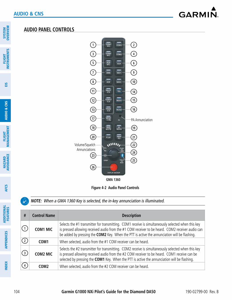
Garmin G1000 NXi Pilot’s Guide for the Diamond DA50 190-02799-00 Rev. B
SYST
EMO
VERV
IEW
FLIG
HTIN
STRU
MEN
TSEI
SAU
DIO
& C
NS
FLIG
HTM
AN
AGEM
ENT
HAZA
RDAV
OID
AN
CEA
FCS
AD
DIT
ION
AL
FEAT
URES
APP
END
ICES
IND
EX
104
AUDIO & CNS
AUDIO PANEL CONTROLS
Figure 4-2 Audio Panel Controls
GMA 1360
24
21
19
25
26
Volume/SquelchAnnunciations
23
22
PA Annunciation
15
2
16
4
9
10
14
6
17
18
13
12
11
8
20
7
3
1
5
NOTE: When a GMA 1360 Key is selected, the in-key annunciation is illuminated.
# Control Name Description
1 COM1 MICSelects the #1 transmitter for transmitting. COM1 receive is simultaneously selected when this key is pressed allowing received audio from the #1 COM receiver to be heard. COM2 receiver audio can be added by pressing the COM2 Key. When the PTT is active the annunciation will be flashing.
2 COM1 When selected, audio from the #1 COM receiver can be heard.
3 COM2 MICSelects the #2 transmitter for transmitting. COM2 receive is simultaneously selected when this key is pressed allowing received audio from the #2 COM receiver to be heard. COM1 receive can be selected by pressing the COM1 Key. When the PTT is active the annunciation will be flashing.
4 COM2 When selected, audio from the #2 COM receiver can be heard.

Garmin G1000 NXi Pilot’s Guide for the Diamond DA50190-02799-00 Rev. B
SYSTEMO
VERVIEWFLIG
HTIN
STRUMEN
TSEIS
AUDIO
& CN
SFLIG
HTM
AN
AGEM
ENT
HAZA
RDAVO
IDA
NCE
AFCS
AD
DITIO
NA
LFEATURES
APPEN
DICES
IND
EX
105
AUDIO & CNS
# Control Name Description
5 AUX MIC Not used in this aircraft.
6 AUX Not used in this aircraft.
7 DME If equipped, turns DME audio on or off.
8 ADF If equipped, turns ADF receiver audio on or off.
9 NAV1 When selected, audio from the #1 NAV receiver can be heard.
10 NAV2 When selected, audio from the #2 NAV receiver can be heard.
11 PILOT ICS Controls the pilot intercom system. Press and hold to enable/disable Bluetooth recording mode.
12 COPLT ICS Controls the copilot intercom system.
13 PASS ICS Controls the passenger intercom system.
14 TEL
If equipped, selects/deselects the TEL audio source and assigns the Bluetooth device to the TEL audio. Press the TEL Key until the annunciation turns blue. The in-key annunciation will cycle from OFF to WHITE to BLUE. WHITE selects the wired audio source and BLUE selects the Bluetooth audio source.
15 MUS1
Selects/Deselects the MUS1 audio source and assigns the Bluetooth device to the MUS1 audio. Press the MUS1 Key until the annunciation turns blue. The in-key annunciation will cycle from OFF to WHITE to BLUE. WHITE selects the wired audio source and BLUE selects the Bluetooth audio source. NOTE: The Bluetooth audio can only be assigned to one source at a time for each audio panel. Once the Bluetooth audio is assigned to an audio source, the remaining entertainment audio sources will only cycle between OFF and WHITE.
16 MUS2
Selects/Deselects the MUS2 audio source and can assign the Bluetooth device to the MUS2 audio. Press the MUS2 Key until the annunciation turns blue. The in-key annunciation will cycle from OFF to WHITE to BLUE. WHITE selects the wired audio source and BLUE selects the Bluetooth audio source. NOTE: The Bluetooth audio can only be assigned to one source at a time for each audio panel. Once the Bluetooth audio is assigned to an audio source, the remaining entertainment audio sources will only cycle between OFF and WHITE.
17 SPKR/PA Not used in this aircraft.
18 MKR/MUTESelects marker beacon receiver audio. Mutes the currently received marker beacon receiver audio. Unmutes automatically when new marker beacon audio is received. Also, stops play of recorded COM audio.
19 HI SENS Press to increase marker beacon receiver sensitivity. Press again to return to low sensitivity.
20 PLAY
Press once to play the last recorded COM audio. Press again while audio is playing and the previous block of recorded audio is played. Each subsequent press plays each previously recorded block. Play stops when receiving an audio transmission or when a push-to-talk (PTT) Key is pressed. Pressing the MKR/MUTE Key during play of a memory block also stops play.
21 MAN SQEnables manual squelch for the intercom. When the intercom is active, push the VOL/SQ Knob to illuminate the squelch annunciation. Turn the VOL/SQ Knob to adjust squelch.

Garmin G1000 NXi Pilot’s Guide for the Diamond DA50 190-02799-00 Rev. B
SYST
EMO
VERV
IEW
FLIG
HTIN
STRU
MEN
TSEI
SAU
DIO
& C
NS
FLIG
HTM
AN
AGEM
ENT
HAZA
RDAV
OID
AN
CEA
FCS
AD
DIT
ION
AL
FEAT
URES
APP
END
ICES
IND
EX
106
AUDIO & CNS
# Control Name Description
22Volume/Squelch
IndicatorIndicates volume/squelch setting relative to full scale.
23
Volume/Squelch (VOL/SQ) Control
Knob
Turn the smaller knob to control volume or squelch of the selected source (indicated by the flashing white or blue annunciation). When the volume control cursor is not active push to switch to Blue-Select mode. If the volume control cursor is active, push twice (once to cancel the cursor, twice to activate Blue-Select mode). Push and hold for two seconds to enable the audio panel as discoverable for pairing. The Bluetooth Annunciation will flash to indicate the unit is discoverable. The unit will remain discoverable for 60 seconds or until a successful pair is established. Once a successful pairing is established, the Bluetooth Annunciation will stop flashing and turn solid blue and the audio “Bluetooth paired” is played.
24 Cursor (CRSR) Control Knob Turn to move the cursor (flashing white or blue annunciation) to the desired source.
25
Bluetooth Connection
Annunciation
A flashing blue annunciation indicates the unit is discoverable. A solid blue annunciation indicates an active Bluetooth connection.
26DISPLAY
BACKUP ButtonManually selects PFD/MFD Reversionary Mode.

Garmin G1000 NXi Pilot’s Guide for the Diamond DA50190-02799-00 Rev. B
SYSTEMO
VERVIEWFLIG
HTIN
STRUMEN
TSEIS
AUDIO
& CN
SFLIG
HTM
AN
AGEM
ENT
HAZA
RDAVO
IDA
NCE
AFCS
AD
DITIO
NA
LFEATURES
APPEN
DICES
IND
EX
107
AUDIO & CNS
4.2 COM OPERATION
COM TUNING BOX
Figure 4-3 COM Tuning Box Indications
2 4
6
5
8
1 3
7
NOTE: When turning on the system for use, the system remembers the last frequencies used and the active COM transceiver state prior to shutdown.
# Display Description
1 Active Field
The COM Frequency Box is composed of four fields; the two active frequencies are on the left. An active COM frequency is displayed in green and indicates the COM transceiver is selected on the Audio Panel (COM1/MIC1 or COM2/MIC2). Both active COM frequencies appearing in white indicate that no COM radio is selected for transmitting.
2Frequency Transfer Arrow
Indicates which COM transceiver is selected for frequency transfer between the Standby and Active fields. Moves between the upper and lower radio frequency fields with the Frequency Tuning Box. Push the COM Knob to move the Frequency Transfer Arrow between the upper and lower radio frequency fields.
3 Standby Field The COM Frequency Box is composed of four fields; the two standby frequencies are on the right. Frequencies in the standby field are displayed in either white or gray. The standby frequency in the tuning box is white. The other standby frequency is gray.
4 Frequency Tuning Box
Indicates which COM transceiver is to be tuned in the Standby Field. Moves between the upper and lower radio frequency fields with the Frequency Transfer Arrow. Moving the Frequency Tuning Box is accomplished by pushing the COM Knob on the PFD.

Garmin G1000 NXi Pilot’s Guide for the Diamond DA50 190-02799-00 Rev. B
SYST
EMO
VERV
IEW
FLIG
HTIN
STRU
MEN
TSEI
SAU
DIO
& C
NS
FLIG
HTM
AN
AGEM
ENT
HAZA
RDAV
OID
AN
CEA
FCS
AD
DIT
ION
AL
FEAT
URES
APP
END
ICES
IND
EX
108
AUDIO & CNS
# Display Description
5Automatic
Squelch Indication
Indicates that Automatic Squelch is disabled. Automatic Squelch quiets unwanted static noise when no audio signal is received, while still providing good sensitivity to weak COM signals. When Automatic Squelch is disabled, COM audio reception is always on. Continuous static noise is heard over the headsets.
6Transmit
and Receive Indications
During COM transmission, a white TX appears by the active COM frequency replacing the Frequency Transfer Arrow. During COM signal reception, a white RX appears by the active COM frequency replacing the Frequency Transfer Arrow.
7 Frequency Spacing
The COM radios can tune either 25-kHz spacing (118.000 to 136.975 MHz) or 8.33-kHz spacing (118.000 to 136.990 MHz) for 760-channel or 3040-channel configuration. When 8.33-kHz channel spacing is selected, all of the 25-kHz channel spacing frequencies are also available in the complete 3040-channel list.
8 COM Volume
COM radio volume level can be adjusted from 0 to 100% using the VOL/SQ Knob. Turning the knob clockwise increases volume, turning the knob counterclockwise decreases volume. When adjusting volume, the level is displayed in place of the standby frequencies. Volume level indication remains for two seconds after the change.

Garmin G1000 NXi Pilot’s Guide for the Diamond DA50190-02799-00 Rev. B
SYSTEMO
VERVIEWFLIG
HTIN
STRUMEN
TSEIS
AUDIO
& CN
SFLIG
HTM
AN
AGEM
ENT
HAZA
RDAVO
IDA
NCE
AFCS
AD
DITIO
NA
LFEATURES
APPEN
DICES
IND
EX
109
AUDIO & CNS
COM TRANSCEIVER MANUAL TUNINGThe COM frequency controls and frequency boxes are on the right side of the MFD and PFD.
Manually tuning a COM frequency:
1) Turn the COM Knob to tune the desired frequency (large knob for MHz; small knob for kHz).
2) Press the Frequency Transfer Key to transfer the frequency to the active field.
3) Adjust the volume level with the COM VOL/SQ Knob.
4) Push the COM VOL/SQ Knob to turn automatic squelch on and off.
AUTO-TUNING THE COM FREQUENCYCOM frequencies can be automatically tuned from the following:
- ‘Nearest Airports’ Window (PFD)
- ‘WPT – Airport Information’ Page
- ‘NRST – Nearest Airports’ Page
- ‘NRST – Nearest Frequencies’ Page (ARTCC, FSS, WX)
- ‘NRST – Nearest Airspaces’ Page
AUTO-TUNING FROM THE PFD
COM frequencies for the nearest airports can be automatically tuned from the ‘Nearest Airports’ Window on the PFD. When the desired frequency is entered, it becomes a standby frequency. Pressing the Frequency Transfer Key places this frequency into the COM Active Frequency Field.
Auto-tuning a COM frequency for a nearby airport from the PFD:
1) Press the Nearest Softkey on the PFD to open the ‘Nearest Airports’ Window. A list of 25 nearest airport identifiers and COM frequencies is displayed.
2) Turn the FMS Knob to scroll through the list and highlight the desired COM frequency.
3) Press the ENT Key to load the COM frequency into the COM Standby Frequency Field.
4) Press the Frequency Transfer Key to transfer the frequency to the COM Active Frequency Field.
Figure 4-4 ‘Nearest Airports’ Window (PFD)
Press the Nearest Softkey to open the ‘Nearest Airports’ Window

Garmin G1000 NXi Pilot’s Guide for the Diamond DA50 190-02799-00 Rev. B
SYST
EMO
VERV
IEW
FLIG
HTIN
STRU
MEN
TSEI
SAU
DIO
& C
NS
FLIG
HTM
AN
AGEM
ENT
HAZA
RDAV
OID
AN
CEA
FCS
AD
DIT
ION
AL
FEAT
URES
APP
END
ICES
IND
EX
110
AUDIO & CNS
AUTO-TUNING FROM THE MFD
Frequencies can be automatically loaded into the COM Frequency Box from pages in the NRST or WPT page group by highlighting the frequency and pressing the ENT Key.
Auto-tuning a COM frequency from the NRST and WPT Pages:
1) From any page the COM frequency can be auto-tuned, activate the cursor by pushing the FMS Knob or pressing the appropriate softkey.
2) Turn the large FMS Knob to place the cursor on the desired COM frequency.
3) Press the ENT Key to display the ‘Load Frequency’ Window.
4) Turn the FMS Knob to select the desired COM1 or COM2 active or standby location.
5) Press the ENT Key to load the frequency.
Figure 4-5 ‘Load Frequency’ Window
Or:
1) Press the MENU Key to display the ‘Page Menu’ Window.
2) Turn the FMS Knob to scroll through the menu options.
3) Press the ENT Key to place the cursor on the desired selection.
4) Turn the FMS Knob to scroll through the frequency selections.
5) Press the ENT Key to display the ‘Load Frequency’ Window.
6) Turn the FMS Knob to select the desired COM1 or COM2 active or standby location.
7) Press the ENT Key to load the frequency.
Figure 4-6 Nearest Page Menus
Nearest Airspaces MenuNearest Airports Menu Nearest Frequencies Menu

Garmin G1000 NXi Pilot’s Guide for the Diamond DA50190-02799-00 Rev. B
SYSTEMO
VERVIEWFLIG
HTIN
STRUMEN
TSEIS
AUDIO
& CN
SFLIG
HTM
AN
AGEM
ENT
HAZA
RDAVO
IDA
NCE
AFCS
AD
DITIO
NA
LFEATURES
APPEN
DICES
IND
EX
111
AUDIO & CNS
On the ‘WPT - Airport Information’ Page, the cursor can be placed on the frequency field by pushing the FMS Knob and scrolling through the list. The frequency can be transferred to the desired COM field by pressing the ENT Key to bring up the ‘Load Frequency’ Window, selecting the desired COM field, and pressing the ENT Key again.
Press ENT Key to display the ‘Load Frequency’ Window
Select the desired location and press the ENT Key
Figure 4-7 ‘WPT – Airport Information’ Page
Select Info 1 Softkey
Selected Airport Identifier and Information
Runway Information
COM frequencies can also be auto-tuned from the ‘NRST – Nearest Airspaces’ Page, ‘NRST – Nearest Frequencies’ Page, and ‘NRST – Nearest Airports’ Page on the MFD in a similar manner using the appropriate softkeys or MENU Key, the FMS Knob, and the ENT Key.

Garmin G1000 NXi Pilot’s Guide for the Diamond DA50 190-02799-00 Rev. B
SYST
EMO
VERV
IEW
FLIG
HTIN
STRU
MEN
TSEI
SAU
DIO
& C
NS
FLIG
HTM
AN
AGEM
ENT
HAZA
RDAV
OID
AN
CEA
FCS
AD
DIT
ION
AL
FEAT
URES
APP
END
ICES
IND
EX
112
AUDIO & CNS
FREQUENCY SPACINGThe COM radios can tune either 25-kHz spacing (118.000 to 136.975 MHz) or 8.33-kHz spacing (118.000
to 136.990 MHz) for 760-channel or 3040-channel configuration. When 8.33-kHz channel spacing is selected, all of the 25-kHz channel spacing frequencies are also available in the complete 3040-channel list. COM channel spacing is set from the Aux Page Group.
Changing COM frequency channel spacing:
1) Select the ‘Aux – System Setup 1’ Page.
2) Press the Setup 2 Softkey
3) Push the FMS Knob to activate the flashing cursor.
4) Turn the large FMS Knob to highlight the Channel Spacing Field in the ‘COM Configuration’ Box.
5) Turn the small FMS Knob to select the desired channel spacing.
6) Press the ENT Key to complete the channel spacing selection.
While the ‘COM Configuration’ Window is selected, the softkeys are blank.
Figure 4-8 ‘Aux – System Setup 2’ Page
Select 8.33-kHz or 25.0-kHz COM Frequency
Channel Spacing
COM Configuration Box

Garmin G1000 NXi Pilot’s Guide for the Diamond DA50190-02799-00 Rev. B
SYSTEMO
VERVIEWFLIG
HTIN
STRUMEN
TSEIS
AUDIO
& CN
SFLIG
HTM
AN
AGEM
ENT
HAZA
RDAVO
IDA
NCE
AFCS
AD
DITIO
NA
LFEATURES
APPEN
DICES
IND
EX
113
AUDIO & CNS
4.3 NAV OPERATION
NAV TUNING BOX
Figure 4-9 NAV Tuning Box Indications
7
1 2 4 653
# Display Description
1 Standby Fields
The NAV Frequency Box is composed of four fields; the two standby frequencies are on the left. Frequencies in the standby field are displayed in either white or gray. The standby frequency in the tuning box is white. The other standby frequency is gray.
2Frequency Transfer Arrow
Indicates which NAV receiver is selected for frequency transfer between the Standby and Active fields. Push the NAV Knob to move the Frequency Transfer Arrow between the upper and lower radio frequency fields.
3 Active Fields
The NAV Frequency Box is composed of four fields; the two active frequencies are on the right. An active NAV frequency is displayed in green. The active NAV radio is selected by pressing the CDI Softkey on the PFD. Both active NAV frequencies appearing in white indicate that no NAV radio is selected.
4 NAV Tuning Box
Indicates which NAV transceiver is to be tuned in the Standby Field. Push the NAV Knob to move the Frequency Tuning Box between the upper and lower radio frequency fields.
5
VOR/LOC Morse
Code Audio Indication
When the Morse code identifier audio is selected for a NAV radio, a white ID replaces the Frequency Transfer Arrow to the left of the active NAV frequency. To listen to a station identifier, press the NAV1 or NAV2 Key on the Audio Panel. Pushing the VOL/ID Knob turns on/off the Morse code audio only in the radio with the NAV Tuning Box. To turn on/off both NAV IDs, transfer the NAV Tuning Box between NAV1 and NAV2 by pushing the NAV Knob and pushing the VOL/ID Knob again to turn the Morse code off in the other radio.
6
Decoded Morse Code
Station Identifier
The NAV Frequency Box displays the decoded Morse Code station identifier that is received from the navigation source. Audio verification of the selected station identifier can be accomplished by selecting the corresponding NAV radio on the audio panel and pushing the NAV VOL/ID Knob.
7 NAV Volume
NAV radio volume level can be adjusted from 0 to 100% using the VOL/SQ Knob. Turning the knob clockwise increases volume, turning the knob counterclockwise decreases volume. When adjusting volume using the PFD or MFD VOL/SQ Knob, the level is displayed in place of the standby frequencies. Volume level indication remains for two seconds after the change.

Garmin G1000 NXi Pilot’s Guide for the Diamond DA50 190-02799-00 Rev. B
SYST
EMO
VERV
IEW
FLIG
HTIN
STRU
MEN
TSEI
SAU
DIO
& C
NS
FLIG
HTM
AN
AGEM
ENT
HAZA
RDAV
OID
AN
CEA
FCS
AD
DIT
ION
AL
FEAT
URES
APP
END
ICES
IND
EX
114
AUDIO & CNS
NAV RADIO SELECTION AND ACTIVATIONThe NAV Frequency Box is composed of four fields; two standby fields and two active fields. The active
frequencies are on the right side and the standby frequencies are on the left.
A NAV radio is selected for navigation by pressing the CDI Softkey located on the PFD. The active NAV frequency selected for navigation is displayed in green. Pressing the CDI Softkey once selects NAV1 as the navigation radio. Pressing the CDI Softkey a second time selects NAV2 as the navigation radio. Pressing the CDI Softkey a third time activates GPS mode. Pressing the CDI Softkey again cycles back to NAV1.
While cycling through the CDI Softkey selections, the selected NAV standby frequency is selected for tuning, the Frequency Transfer Arrow is placed in the selected NAV Frequency Field, and the active NAV frequency color changes to green.
The three navigation modes that can be cycled through are:
- VOR1 (or LOC1) – If NAV1 is selected, a green single line arrow labeled either VOR1 or LOC1 is displayed on the HSI and the active NAV1 frequency is displayed in green.
- VOR2 (or LOC2) – If NAV2 is selected, a green double line arrow labeled either VOR2 or LOC2 is displayed on the HSI and the active NAV2 frequency is displayed in green.
- GPS – If GPS Mode is selected, a magenta single line arrow appears on the HSI and neither NAV radio is selected. Both active NAV frequencies are then displayed in white and the previously selected NAV standby frequency remains selected for tuning.
See the Flight Instruments Section for selecting Bearing Information and navigation source for the bearing pointer.
The NAV Frequency Box displays the decoded Morse Code station identifier that is received from the navigation source. Audio verification of the selected station identifier can be accomplished by selecting the corresponding NAV radio on the audio panel and pushing the NAV VOL/ID Knob.
NAV radios are selected for listening by pressing the corresponding keys on the Audio Panel. Pressing the NAV1, NAV2, ADF, or DME Key selects and deselects the navigation radio source. Selected audio can be heard over the headset and the speakers (if selected). All radios can be selected individually or simultaneously.
NAV RECEIVER MANUAL TUNINGThe NAV frequency controls and frequency boxes are on the upper left side of the PFD and MFD.
Manually tuning a NAV frequency:
1) Turn the NAV Knob to tune the desired frequency in the NAV Tuning Box.
2) Press the Frequency Transfer Key to transfer the frequency to the NAV Active Frequency Field.
3) Adjust the volume level with the NAV VOL/ID Knob.
4) Push the NAV VOL/ID Knob to turn the Morse code identifier audio on and off.

Garmin G1000 NXi Pilot’s Guide for the Diamond DA50190-02799-00 Rev. B
SYSTEMO
VERVIEWFLIG
HTIN
STRUMEN
TSEIS
AUDIO
& CN
SFLIG
HTM
AN
AGEM
ENT
HAZA
RDAVO
IDA
NCE
AFCS
AD
DITIO
NA
LFEATURES
APPEN
DICES
IND
EX
115
AUDIO & CNS
AUTO-TUNING A NAV FREQUENCY FROM THE MFDNAV frequencies can be selected and loaded from the following MFD pages:
- ‘WPT – Airport Information’ Page
- ‘WPT – VOR Information’ Page
- ‘NRST – Nearest Airports‘ Page
- ‘NRST – Nearest VOR’ Page
- ‘NRST – Nearest Frequencies’ (FSS, WX) Page
- ‘NRST – Nearest Airspaces’ Page
The MFD provides auto-tuning of NAV frequencies from waypoint and nearest pages. During enroute navigation, the NAV frequency is entered automatically into the NAV standby frequency field. During approach activation the NAV frequency is entered automatically into the NAV active frequency field.
Frequencies can be automatically loaded into the NAV Frequency Box from pages in the NRST or WPT page group by highlighting the frequency and pressing the ENT Key.
Auto-tuning a NAV frequency from the WPT and NRST Pages:
1) From any page the NAV frequency can be auto-tuned, activate the cursor by pushing the FMS Knob or the appropriate softkey.
2) Turn the large FMS Knob to place the cursor on the desired NAV identifier or NAV frequency.
3) On the Nearest VOR and Nearest Airports pages, press the FREQ Softkey to place the cursor on the NAV frequency.
4) Press the ENT Key to display the ‘Load Frequency’ Window.
5) Turn the FMS Knob to place the cursor on the desired NAV frequency field.
6) Press the ENT Key to load the frequency into the selected NAV frequency field.
Figure 4-10 ‘Load Frequency’ Window
Or:
1) When on the NRST pages, press the MENU Key on the MFD to display the ‘Page Menu’ Window.
2) Turn the large FMS Knob to scroll through the menu options.
3) Press the ENT Key to place the cursor in the desired window.
4) Turn the FMS Knob to scroll through the frequency selections.
5) Press the ENT Key to display the ‘Load Frequency’ Window.
6) Turn the FMS Knob to select the desired NAV1 or NAV2 active or standby location.
7) Press the ENT Key to load the frequency into the selected NAV frequency field.

Garmin G1000 NXi Pilot’s Guide for the Diamond DA50 190-02799-00 Rev. B
SYST
EMO
VERV
IEW
FLIG
HTIN
STRU
MEN
TSEI
SAU
DIO
& C
NS
FLIG
HTM
AN
AGEM
ENT
HAZA
RDAV
OID
AN
CEA
FCS
AD
DIT
ION
AL
FEAT
URES
APP
END
ICES
IND
EX
116
AUDIO & CNS
Figure 4-11 Nearest Pages Menus
Nearest Airspaces MenuNearest Airports Menu Nearest Frequencies MenuNearest VOR Menu
In the example shown, the VOR list is selected with the VOR Softkey or from the page menu. The FMS Knob or ENT Key is used to scroll through the list. The cursor is placed on the frequency by pressing the FREQ Softkey and is loaded into the NAV Tuning Box using the ENT Key and the ‘Load Frequency’ Window.
Figure 4-12 Loading the NAV Frequency from the ‘NRST – Nearest VOR’ Page
Selected - Press the ENT Key to display the ‘Load Frequency’ Window
Press the VOR or FREQ Softkey to place the cursor
Select desired location and press the ENT Key
While enroute, NAV frequencies can also be auto-tuned from the ‘NRST – Nearest Airports’, ‘WPT – Airport Information’, ‘WPT – VOR Information’, and ‘NRST – Nearest Frequencies’ Pages on the MFD in a similar manner using the appropriate softkeys or MENU Key, the FMS Knob, and the ENT Key.

Garmin G1000 NXi Pilot’s Guide for the Diamond DA50190-02799-00 Rev. B
SYSTEMO
VERVIEWFLIG
HTIN
STRUMEN
TSEIS
AUDIO
& CN
SFLIG
HTM
AN
AGEM
ENT
HAZA
RDAVO
IDA
NCE
AFCS
AD
DITIO
NA
LFEATURES
APPEN
DICES
IND
EX
117
AUDIO & CNS
AUTO-TUNING NAV FREQUENCIES ON APPROACH ACTIVATION
NOTE: The primary NAV frequency is auto-tuned upon loading a VOR or ILS/Localizer approach.
NOTE: When an ILS/LOC approach has been activated in GPS Mode, the system switches to NAV Mode as the final approach course is intercepted (within 15 nm of the FAF). See the Flight Instruments Section for details.
NOTE: In some circumstances the G1000 NXi system may auto-tune a course for an unintended localizer facility because that facility shares the same frequency and is nearby the intended localizer facility. Always verify auto-tuned courses and frequencies with FAA published data and manually correct if required.
NAV frequencies are automatically loaded into the NAV Tuning Box upon approach activation. When loading or activating a VOR or ILS/LOC approach, the approach frequency is automatically transferred to a NAV frequency field as follows:
If the current CDI NAV Source is NAV1 or NAV2 If the current NAV Source is GPSApproach Loaded
Approach frequency is transferred to the standby frequency field of the current CDI NAV source and to the active frequency field of the non-selected CDI Nav source.
The approach frequency is transferred to the NAV1 and NAV2 active frequency fields and the previously active frequencies are transferred to standby. If the approach frequency was already in the NAV1 or NAV2 standby frequency field, the standby frequency is transferred to active.
Approach Activated
Approach frequency is transferred to the active frequency field on both NAV1 and NAV2 and the previously active frequencies are transferred to standby.
Table 4-1 Approach Frequency Automatic Transfers

Garmin G1000 NXi Pilot’s Guide for the Diamond DA50 190-02799-00 Rev. B
SYST
EMO
VERV
IEW
FLIG
HTIN
STRU
MEN
TSEI
SAU
DIO
& C
NS
FLIG
HTM
AN
AGEM
ENT
HAZA
RDAV
OID
AN
CEA
FCS
AD
DIT
ION
AL
FEAT
URES
APP
END
ICES
IND
EX
118
AUDIO & CNS
MARKER BEACON RECEIVER
NOTE: The marker beacon indicators operate independently of marker beacon audio and cannot be turned off.
The marker beacon receiver is used as part of the ILS. The marker beacon receiver is always on and detects any marker beacon signals within the reception range of the aircraft.
The receiver detects the three marker tones – outer, middle, and inner – and provides marker beacon annunciations located to the left of the altimeter on the PFD.
The Audio Panel provides three different states of marker beacon audio; On, Muted, and Deselected. Press the MKR/MUTE Key to enable marker beacon audio monitoring (annunciation illuminated).
During marker beacon audio reception, press the MKR/MUTE Key to mute the audio. The in-key annunciation remains illuminated, but the current marker tone is silenced. Marker muting does not affect the marker annunciations on the PFD. Audio muting deactivates automatically and marker beacon audio is heard when the next marker beacon signal is received.
Press the MKR/MUTE Key to disable marker beacon audio monitoring (annunciation extinguished). To deselect marker beacon audio while receiving marker beacon signal, press the MKR/MUTE Key twice, once to mute (annunciation remains illuminated) and once more to deselect audio monitoring (annunciation extinguished).
Pressing the HI SENS Key switches between high and low marker beacon receiver sensitivity. The HI SENS function (annunciation illuminated) is used to provide an earlier indication when nearing a marker during an approach. The LO SENS function (annunciation extinguished) results in a narrower marker dwell while over a station.
Figure 4-13 Marker Beacon Keys
ADF/DME TUNING
NOTE: When another auxiliary window is turned on, the ADF/DME Tuning Window is replaced on the PFD.
See the Flight Instruments Section for displaying the DME and bearing information windows (ADF) and using the ADF as the source for the bearing pointer.
The system tunes the ADF receiver (optional) and DME transceiver (optional). The ADF is tuned by entering the frequency in the ADF standby frequency field of the ‘ADF/DME Tuning’ Window. The softkey may be labeled ADF/DME, ADF, or DME, depending on installed equipment.
The UHF DME frequency is tuned by pairing with a VHF NAV frequency. DME frequency pairing is automatic and only the VHF NAV frequency is shown.
The following ADF/DME information is displayed in the ‘ADF/DME Tuning’ Window:
- Active and standby ADF frequencies
- ADF receiver mode
- ADF receiver volume
- DME tuning mode (DME transceiver pairing)

Garmin G1000 NXi Pilot’s Guide for the Diamond DA50190-02799-00 Rev. B
SYSTEMO
VERVIEWFLIG
HTIN
STRUMEN
TSEIS
AUDIO
& CN
SFLIG
HTM
AN
AGEM
ENT
HAZA
RDAVO
IDA
NCE
AFCS
AD
DITIO
NA
LFEATURES
APPEN
DICES
IND
EX
119
AUDIO & CNS
When the ‘ADF/DME Tuning’ Window is displayed, the selection cursor is placed over the standby ADF frequency field.
Turning the large FMS Knob moves the selection cursor through the various fields (standby ADF frequency, ADF receiver mode, ADF radio volume, and DME tuning mode). Pushing the FMS Knob activates/deactivates the selection cursor in the ‘ADF/DME Tuning’ Window. The ADF frequency is entered using the FMS Knob and the ENT Key.
Figure 4-14 ‘ADF/DME Tuning’ Window
Active ADF Frequency Standby ADF Frequency
ADF Mode
DME Tuning Mode
ADF TUNINGADF frequencies in the 190.0-kHz to 1799.5-kHz range are entered in the standby ADF frequency field of the
‘ADF/DME Tuning’ Window. The system does not tune the ADF emergency frequency, 2182.0-kHz.
Tuning an ADF frequency:
1) Press the ADF/DME Softkey to display the ‘ADF/DME Tuning’ Window.
2) Turn the large FMS Knob to place the selection cursor over the standby ADF frequency field.
3) Turn the small FMS Knob to begin data entry and change each digit.
4) Turn the large FMS Knob to move the cursor to the next digit position.
5) Press the ENT Key to complete data entry for the standby frequency.
Figure 4-15 Entering ADF Standby Frequencies
Press the ENT Key to complete ADF Frequency entryTurn the small
FMS Knob to enter data in
the Standby ADF Frequency Field Turn the large FMS
Knob to move the cursor to the next character
Pressing the CLR Key before completing frequency entry cancels the frequency change and reverts back to the previously entered frequency.
Pressing the CLR Key when the cursor is flashing, clears the frequency and replaces the standby field with 0000.0.

Garmin G1000 NXi Pilot’s Guide for the Diamond DA50 190-02799-00 Rev. B
SYST
EMO
VERV
IEW
FLIG
HTIN
STRU
MEN
TSEI
SAU
DIO
& C
NS
FLIG
HTM
AN
AGEM
ENT
HAZA
RDAV
OID
AN
CEA
FCS
AD
DIT
ION
AL
FEAT
URES
APP
END
ICES
IND
EX
120
AUDIO & CNS
Transferring the active and standby ADF frequencies:
1) Turn the large FMS Knob to place the selection cursor over the standby ADF frequency field.
2) Press the ENT Key to complete the frequency transfer.
Figure 4-16 Transferring ADF Frequencies
Press the ENT Key to Transfer the ADF Frequencies
SELECTING ADF RECEIVER MODE
The following modes can be selected: (In all modes NDB audio can be heard by selecting the ADF Key on the Audio Panel.)
» ANT (Antenna) – The ADF bearing pointer is removed. Best mode for listening to NDB audio.
» ADF (Automatic Direction Finder) – The ADF pointer points to the relative bearing of the NDB station.
» ADF/BFO (ADF/Beat Frequency Oscillator) – The ADF pointer points to the relative bearing of the NDB station and an audible tone confirms signal reception. This mode allows identification of the interrupted carrier beacon stations used in various parts of the world.
» ANT/BFO (Antenna/Beat Frequency Oscillator) – The ADF bearing pointer is removed and an audible tone is provided when a signal is received. This mode also allows identification of the interrupted carrier beacon stations and confirms signal reception.
Selecting an ADF receiver mode:
1) Turn the large FMS Knob to place the selection cursor over the ADF mode field.
2) Turn the small FMS Knob to select the desired ADF receiver mode.
Figure 4-17 Selecting ADF Receiver Mode
Turn the small FMS Knob to select the ADF Mode
ADF receiver volume level can be adjusted in the tuning window from 0 to 100%. The default volume level is set to 50%.
Adjusting ADF receiver volume:
1) Turn the large FMS Knob to place the selection cursor over the ADF volume field.
2) Turn the small FMS Knob to adjust volume as desired.

Garmin G1000 NXi Pilot’s Guide for the Diamond DA50190-02799-00 Rev. B
SYSTEMO
VERVIEWFLIG
HTIN
STRUMEN
TSEIS
AUDIO
& CN
SFLIG
HTM
AN
AGEM
ENT
HAZA
RDAVO
IDA
NCE
AFCS
AD
DITIO
NA
LFEATURES
APPEN
DICES
IND
EX
121
AUDIO & CNS
Turn the small FMS Knob to adjust volume
Figure 4-18 Adjusting ADF Receiver Volume
DME TUNING
NOTE: When turning on the system for use, it will remember the last frequency used for DME tuning and the NAV1, NAV2, or HOLD state prior to shutdown.
The system tunes the DME transceiver. The UHF DME frequency is tuned by pairing with a VHF NAV frequency. DME frequency pairing is automatic and only the VHF NAV frequency is shown. The DME transceiver is tuned by selecting NAV1, NAV2, or HOLD in the ‘ADF/DME Tuning’ Window.
The following DME transceiver pairings can be selected:
» NAV1 – Pairs the DME frequency from the selected NAV1 frequency.
» NAV2 – Pairs the DME frequency from the selected NAV2 frequency.
» HOLD – When in the HOLD position, the DME frequency remains paired with the last selected NAV frequency.
Selecting DME transceiver pairing:
1) Press the ADF/DME Softkey to display the ‘ADF/DME Tuning’ Window.
2) Turn the small FMS Knob to select the DME tuning mode.
3) Press the ENT Key to complete the selection.
Figure 4-19 Selecting DME Modes
DME Modes
Pressing the CLR Key or FMS Knob while in the process of DME pairing cancels the tuning entry and reverts back to the previously selected DME tuning state. Pushing the FMS Knob activates/deactivates the cursor in the ‘ADF/DME Tuning’ Window.
See the Flight Instruments Section for displaying the DME information window.

Garmin G1000 NXi Pilot’s Guide for the Diamond DA50 190-02799-00 Rev. B
SYST
EMO
VERV
IEW
FLIG
HTIN
STRU
MEN
TSEI
SAU
DIO
& C
NS
FLIG
HTM
AN
AGEM
ENT
HAZA
RDAV
OID
AN
CEA
FCS
AD
DIT
ION
AL
FEAT
URES
APP
END
ICES
IND
EX
122
AUDIO & CNS
4.4 MODE S TRANSPONDERThe Mode S Transponder provides Mode A, Mode C, and Mode S interrogation and reply capabilities. Selective
addressing or Mode Select (Mode S) capability includes the following features:
• Level-2 reply data link capability (used to exchange information between aircraft and ATC facilities)
• Surveillance identifier capability
• Flight ID (Flight Identification) reporting – The Mode S Transponder reports aircraft identification as either the aircraft registration or a unique Flight ID.
• Altitude reporting
• Airborne status determination
• Transponder capability reporting
• Mode S Enhanced Surveillance (EHS) requirements
• Acquisition squitter – Acquisition squitter, or short squitter, is the transponder 24-bit identification address. The transmission is sent periodically, regardless of the presence of interrogations. The purpose of acquisition squitter is to enable Mode S ground stations and aircraft equipped with a Traffic Avoidance System (TAS) to recognize the presence of Mode S-equipped aircraft for selective interrogation.
• Extended squitter – The extended squitter is transmitted periodically and contains information such as altitude (barometric and GPS), GPS position, and aircraft identification. The purpose of extended squitter is to provide aircraft position and identification to ADS-B Ground-Based Transceivers (GBTs) and other aircraft.
The Hazard Avoidance Section provides more details on traffic avoidance systems.
TRANSPONDER CONTROLSTransponder function is displayed on three levels of softkeys on the PFD: Top-level, Mode Selection, and
Code Selection. When the top-level XPDR Softkey is pressed, the Mode Selection softkeys appear: Standby, On, ALT, VFR, Code, Ident, Back.
When the Code Softkey is pressed, the number softkeys appear: 0, 1, 2, 3, 4, 5, 6, 7, Ident, BKSP, Back. The digits 8 and 9 are not used for code entry. Pressing the numbered softkeys in sequence enters the transponder code. If an error is made, pressing the BKSP Softkey moves the code selection cursor to the previous digit. Pressing the BKSP Softkey again moves the cursor to the next previous digit.
Pressing the Back Softkey during code selection reverts to the Mode Selection Softkeys. Pressing the Back Softkey during mode selection reverts to the top-level softkeys.
The code can also be entered with the FMS Knob on the PFD. Code entry must be completed with either the softkeys or the FMS Knob, but not a combination of both.
Pressing the Ident Softkey while in Mode or Code Selection initiates the ident function and reverts to the top-level softkeys.
After 45 seconds of transponder control inactivity, the system reverts back to the top-level softkeys.
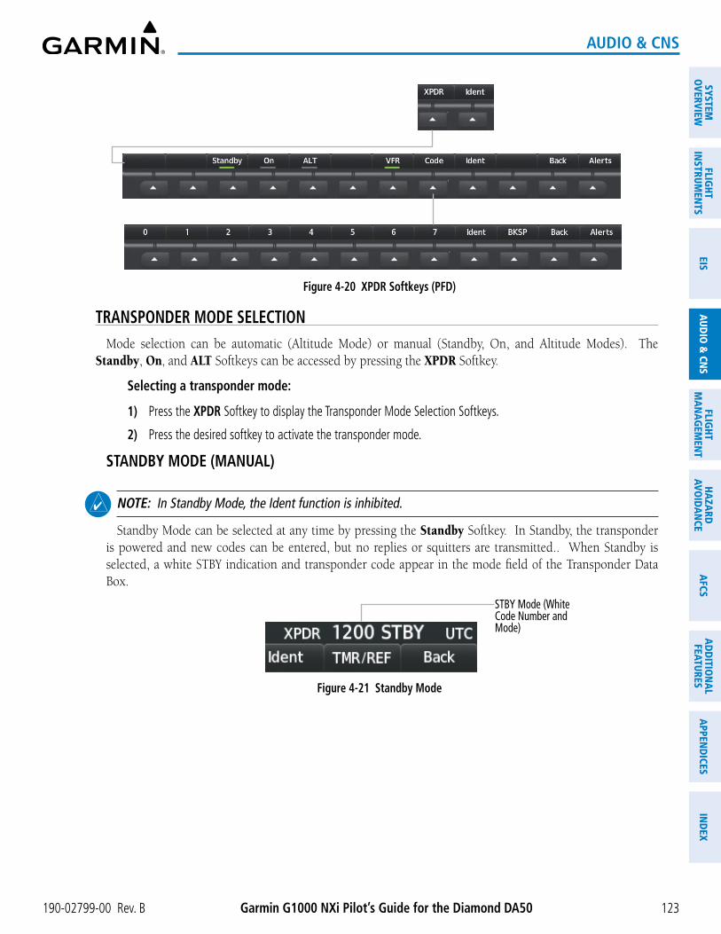
Garmin G1000 NXi Pilot’s Guide for the Diamond DA50190-02799-00 Rev. B
SYSTEMO
VERVIEWFLIG
HTIN
STRUMEN
TSEIS
AUDIO
& CN
SFLIG
HTM
AN
AGEM
ENT
HAZA
RDAVO
IDA
NCE
AFCS
AD
DITIO
NA
LFEATURES
APPEN
DICES
IND
EX
123
AUDIO & CNS
Figure 4-20 XPDR Softkeys (PFD)
TRANSPONDER MODE SELECTIONMode selection can be automatic (Altitude Mode) or manual (Standby, On, and Altitude Modes). The
Standby, On, and ALT Softkeys can be accessed by pressing the XPDR Softkey.
Selecting a transponder mode:
1) Press the XPDR Softkey to display the Transponder Mode Selection Softkeys.
2) Press the desired softkey to activate the transponder mode.
STANDBY MODE (MANUAL)
NOTE: In Standby Mode, the Ident function is inhibited.
Standby Mode can be selected at any time by pressing the Standby Softkey. In Standby, the transponder is powered and new codes can be entered, but no replies or squitters are transmitted.. When Standby is selected, a white STBY indication and transponder code appear in the mode field of the Transponder Data Box.
STBY Mode (White Code Number and Mode)
Figure 4-21 Standby Mode

Garmin G1000 NXi Pilot’s Guide for the Diamond DA50 190-02799-00 Rev. B
SYST
EMO
VERV
IEW
FLIG
HTIN
STRU
MEN
TSEI
SAU
DIO
& C
NS
FLIG
HTM
AN
AGEM
ENT
HAZA
RDAV
OID
AN
CEA
FCS
AD
DIT
ION
AL
FEAT
URES
APP
END
ICES
IND
EX
124
AUDIO & CNS
MANUAL ON MODE
On Mode can be selected at any time by pressing the On Softkey. An On indication will appear in the mode field of the Transponder Data Box. Selecting On mode enables transmission of transponder replies and squitters, but transmissions will not include altitude information. The On indication and transponder code in the Transponder Data Box will appear green while airborne and white while on the ground. When the transponder is operating with an air state of on-ground it will disable replies to Mode A, Mode C, and Mode S all-call interrogations so the aircraft will not show up on the traffic systems of other aircraft.
Figure 4-22 On Mode
On-Ground On Mode (No Altitude Reporting)
Airborne On Mode (No Altitude Reporting)
ALTITUDE MODE (AUTOMATIC OR MANUAL)
ALT Mode can be selected at any time by pressing the ALT Softkey. When ALT mode is selected, an ALT indication will appear in the mode field of the Transponder Data Box. Selecting ALT mode enables transmission of transponder replies and squitters. Transmissions will include pressure altitude information. The ALT indication and transponder code in the Transponder Data Box will appear green while airborne and white while on the ground. When the transponder is operating with an air state of on-ground it will disable replies to Mode A, Mode C, and Mode S all-call interrogations so the aircraft will not show up on the traffic systems of other aircraft.
Figure 4-23 Altitude Mode
On-Ground ALT Mode
Airborne ALT Mode

Garmin G1000 NXi Pilot’s Guide for the Diamond DA50190-02799-00 Rev. B
SYSTEMO
VERVIEWFLIG
HTIN
STRUMEN
TSEIS
AUDIO
& CN
SFLIG
HTM
AN
AGEM
ENT
HAZA
RDAVO
IDA
NCE
AFCS
AD
DITIO
NA
LFEATURES
APPEN
DICES
IND
EX
125
AUDIO & CNS
REPLY STATUS
When the transponder sends replies to interrogations, a white R indication appears momentarily in the reply status field of the Transponder Data Box.
Figure 4-24 Reply Indication
Reply to Interrogation
VFR CODE
The VFR code can be entered either manually or by pressing the XPDR Softkey, then the VFR Softkey. When the VFR Softkey is pressed, the pre-programmed VFR code is automatically displayed in the code field of the Transponder Data Box. Pressing the VFR Softkey again restores the previous identification code.
The pre-programmed VFR Code is set at the factory to 1200. If a VFR code change is required, contact a Garmin authorized service center for configuration.
Figure 4-25 VFR Code
VFR Code
ENTERING A TRANSPONDER CODE
Entering a transponder code with softkeys:
1) Press the XPDR Softkey to display the Transponder Mode Selection Softkeys.
2) Press the Code Softkey to display the Transponder Code Selection Softkeys, for digit entry.
3) Press the digit softkeys to enter the code in the code field. When entering the code, the next softkey in sequence must be pressed within 10 seconds or the entry is cancelled and restored to the previous code. Press the BKSP Softkey to move the code selection cursor to the previous digit. Five seconds after the fourth digit has been entered, the transponder code becomes active.
Figure 4-26 Entering a Code
Entering a Code

Garmin G1000 NXi Pilot’s Guide for the Diamond DA50 190-02799-00 Rev. B
SYST
EMO
VERV
IEW
FLIG
HTIN
STRU
MEN
TSEI
SAU
DIO
& C
NS
FLIG
HTM
AN
AGEM
ENT
HAZA
RDAV
OID
AN
CEA
FCS
AD
DIT
ION
AL
FEAT
URES
APP
END
ICES
IND
EX
126
AUDIO & CNS
Entering a transponder code with the PFD FMS Knob:
1) Press the XPDR Softkey.
2) Press the Code Softkey.
3) Turn the small FMS Knob to enter the first two code digits.
4) Turn the large FMS Knob to move the cursor to the next code field.
5) Enter the last two code digits with the small FMS Knob.
6) Press the ENT Key to complete code digit entry.
Pressing the CLR Key or small FMS Knob before code entry is complete cancels code entry and restores the previous code. Waiting for 10 seconds after code entry is finished activates the code automatically.
Figure 4-27 Entering a Code with the FMS Knob
Press the ENT Key to complete code entry
Turn the large FMS Knob to move the cursor to the next code field
Turn the small FMS Knob to
enter two code digits at a time
IDENT FUNCTION
NOTE: In Standby Mode, the Ident Softkey is inoperative.
Pressing the Ident Softkey sends a distinct identity indication to Air Traffic Control (ATC). The indication distinguishes the identing transponder from all the others on the air traffic controller’s screen. The Ident Softkey appears on all levels of transponder softkeys. When the Ident Softkey is pressed, a green Ident indication is displayed in the mode field of the Transponder Data Box for a duration of 18 seconds.
After the Ident Softkey is pressed while in Mode or Code Selection, the system reverts to the top-level softkeys.
Figure 4-28 Ident Softkey and Indication
Ident Indication
Select the Ident Softkey to Initiate the ID Function

Garmin G1000 NXi Pilot’s Guide for the Diamond DA50190-02799-00 Rev. B
SYSTEMO
VERVIEWFLIG
HTIN
STRUMEN
TSEIS
AUDIO
& CN
SFLIG
HTM
AN
AGEM
ENT
HAZA
RDAVO
IDA
NCE
AFCS
AD
DITIO
NA
LFEATURES
APPEN
DICES
IND
EX
127
AUDIO & CNS
FLIGHT ID REPORTING
NOTE: If the Flight ID is required but the system is not configured for it, contact a Garmin-authorized service center for configuration.
When the Flight ID must be entered before flight operation, the identifier is placed in the ‘References’ Window on the PFD. The Flight ID is not to exceed seven characters. No space is needed when entering Flight ID. When a Flight ID contains a space, the system automatically removes it upon completion of Flight ID entry.
Entering a Flight ID:
1) Press the TMR/REF Softkey to display the ‘References’ Window.
2) Push the FMS Knob to activate the selection cursor, if not already activated.
3) Turn the large FMS Knob to scroll down to the Flight ID.
4) Turn the small FMS Knob to enter the desired Flight ID.
5) Press the ENT Key to complete Flight ID entry.
Figure 4-29 Entering Flight ID - ‘References’ Window (PFD)
Flight ID
If an error is made during Flight ID entry, pressing the CLR Key returns to the original Flight ID entry. While entering a Flight ID, turning the FMS Knob counterclockwise moves the cursor back one space for each detent of rotation. If an incorrect Flight ID is discovered after the unit begins operation, reenter the correct Flight ID using the same procedure.

Garmin G1000 NXi Pilot’s Guide for the Diamond DA50 190-02799-00 Rev. B
SYST
EMO
VERV
IEW
FLIG
HTIN
STRU
MEN
TSEI
SAU
DIO
& C
NS
FLIG
HTM
AN
AGEM
ENT
HAZA
RDAV
OID
AN
CEA
FCS
AD
DIT
ION
AL
FEAT
URES
APP
END
ICES
IND
EX
128
AUDIO & CNS
4.5 ADDITIONAL AUDIO PANEL FUNCTIONS
POWER APPLICATIONThe Audio Panel performs a self-test at power application. During the self-test all Audio Panel annunciation
lights illuminate for approximately two seconds. Once the self-test is completed, most of the settings are restored to those in use before the unit was last turned off. The exceptions are the speaker and intercom, which are always selected at power application.
MONO/STEREO HEADSETSStereo headsets are recommended for use in this aircraft. Using a monaural headset in a stereo jack shorts the
right headset channel output to ground. While this does not damage the Audio Panel, a person listening on a monaural headset hears only the left channel in both ears. If a monaural headset is used at one of the passenger positions, any other passenger using a stereo headset hears audio in the left ear only.
3D AUDIO3D Audio is useful when multiple COM audio sources are present. By using different responses in each ear,
3D audio processing creates spatial separation from each audio source, aiding in the distinction of which audio source the pilot is hearing.
Because this feature uses different signals for left and right channels, it requires wiring for stereo intercom and stereo headsets. If an aircraft is not wired to support stereo headsets, or the crew does not use stereo headsets, then COMs audio will be distributed to both ears regardless of the 3D audio functionality selection.
With a single COM selected and 3D Audio enabled, the listener hears the audio source at the 12 o’clock position. If both COMs are selected, the listener hears COM1 at 11 o’clock and COM2 at the 1 o’clock position. The scope of 3D audio is limited to COM audio for the pilot and copilot stations. All other audio (alerts, side-tones, intercom, etc.) are distributed equally to both ears.
Pilot and copilot 3D audio can be enabled or disabled. When 3D Audio is enabled, the aural message “3D audio left” is heard in the left ear followed by “3D audio right” in the right ear. The 3D audio left and right reference can be changed using the Left-Right Swap function. This allows pilots to use their headset microphone on either side of the head while using 3D audio.

Garmin G1000 NXi Pilot’s Guide for the Diamond DA50190-02799-00 Rev. B
SYSTEMO
VERVIEWFLIG
HTIN
STRUMEN
TSEIS
AUDIO
& CN
SFLIG
HTM
AN
AGEM
ENT
HAZA
RDAVO
IDA
NCE
AFCS
AD
DITIO
NA
LFEATURES
APPEN
DICES
IND
EX
129
AUDIO & CNS
Enabling/Disabling 3D Audio:
1) Use the FMS Knob and the Setup 2 Softkey to display the ‘Aux - System Setup 2’ Page.
2) Push the FMS Knob to activate the flashing cursor.
3) Turn the large FMS Knob to highlight the Pilot or Copilot 3D Audio Field in the Audio Configuration Box.
4) Turn the small FMS Knob to select ‘Off’ or ‘On’.
5) Press the ENT Key to complete the selection.
Swapping Left-Right Audio:
1) Use the FMS Knob and the Setup 2 Softkey to select the ‘Aux - System Setup 2’ Page.
2) Push the FMS Knob to activate the flashing cursor.
3) Turn the large FMS Knob to highlight Pilot or Copilot L-R Swap in the Audio Configuration Box.
4) Turn the small FMS Knob to select ‘Off’ or ‘On’.
5) Press the ENT Key to complete the selection.
Figure 4-30 3D Audio and L-R Swap Selection
Pilot 3D Audio enabled
Pilot L-R Swap enabled

Garmin G1000 NXi Pilot’s Guide for the Diamond DA50 190-02799-00 Rev. B
SYST
EMO
VERV
IEW
FLIG
HTIN
STRU
MEN
TSEI
SAU
DIO
& C
NS
FLIG
HTM
AN
AGEM
ENT
HAZA
RDAV
OID
AN
CEA
FCS
AD
DIT
ION
AL
FEAT
URES
APP
END
ICES
IND
EX
130
AUDIO & CNS
INTERCOMThe GMA 1360 includes an intercom system (ICS), two MUSIC inputs, and one telephone/entertainment
input for the pilot, copilot and passengers. The intercom provides for selected Pilot, Copilot, and Passenger audio isolation. Each ICS position can be either active (annunciation illuminated) or inactive (annunciation extinguished). ICS annunciations are blue if an active Bluetooth connection is made to a recording device. Otherwise, the annunciations are white.
Press the PILOT ICS Key, COPLT ICS Key, or the PASS ICS Key to activate/deactivate ICS positions.
Figure 4-31 Intercom Controls and State
PILOT ICS Key active (illuminated)
COPLT ICS Key inactive (extinguished)
ICS control uses the following logic:
- The pilot and copilot always hear the selected aircraft audio (COM, NAV, etc) regardless of ICS key state.
- All active ICS positions will hear aircraft audio.
- All active ICS positions will hear other active ICS positions.
- Passengers will always hear other passengers, regardless of the PASS ICS state.
- Any aircraft or microphone audio not explicitly stated to be heard by an ICS position will not be heard by that position.
Audio Panel Pilot Hears Copilot Hears Passenger Hears
or or
Selected RadiosAural Alerts
Selected RadiosAural Alerts
Passenger MIC
Selected RadiosAural Alerts
Selected RadiosAural Alerts
Selected RadiosAural AlertsPassenger MIC
Selected RadiosAural AlertsCopilot MIC
Selected RadiosAural AlertsPilot MIC
Passenger MIC

Garmin G1000 NXi Pilot’s Guide for the Diamond DA50190-02799-00 Rev. B
SYSTEMO
VERVIEWFLIG
HTIN
STRUMEN
TSEIS
AUDIO
& CN
SFLIG
HTM
AN
AGEM
ENT
HAZA
RDAVO
IDA
NCE
AFCS
AD
DITIO
NA
LFEATURES
APPEN
DICES
IND
EX
131
AUDIO & CNS
Audio Panel Pilot Hears Copilot Hears Passenger HearsSelected RadiosAural Alerts
Selected RadiosAural AlertsPassenger MIC
Selected RadiosAural AlertsCopilot MICPassenger Mic
Selected RadiosAural AlertsPassenger MIC
Selected RadiosAural Alerts
Selected RadiosAural AlertsPilot MICPassenger MIC
Selected RadiosAural AlertsCopilot MICPassenger MIC
Selected RadiosAural AlertsPilot MICPassenger MIC
Selected RadiosAural AlertsPilot MICCopilot MICPassenger MIC
Table 4-2 GMA 1360 ICS Modes
INTERCOM VOLUME AND SQUELCH
The VOL/SQ and CRSR Knobs control selection, volume, and manual squelch adjustment for audio sources. The small knob controls the volume or squelch. Turning the large knob activates and moves the cursor (flashing white or blue annunciation if in Blue-Select Mode) to the audio source to adjust. The cursor will time-out after a few seconds and the position of the cursor will always default back to the PILOT ICS Key. Pushing the small knob cancels the cursor.
Volume Annunciation
MAN SQ KeyOn for Manual Squelch, Off for Automatic Squelch
VOL/SQ Control KnobTurn to adjust squelch when
SQ is illuminated, volume when VOL is illuminated
CRSR Control KnobTurn to move the cursor (flashing annunciation) to the desired audio source
Figure 4-32 Volume/Squelch Control
Volume/Squelch Level - Displays volume or squelch setting of selected audio source
Manual Squelch Selected
Squelch Annunciation
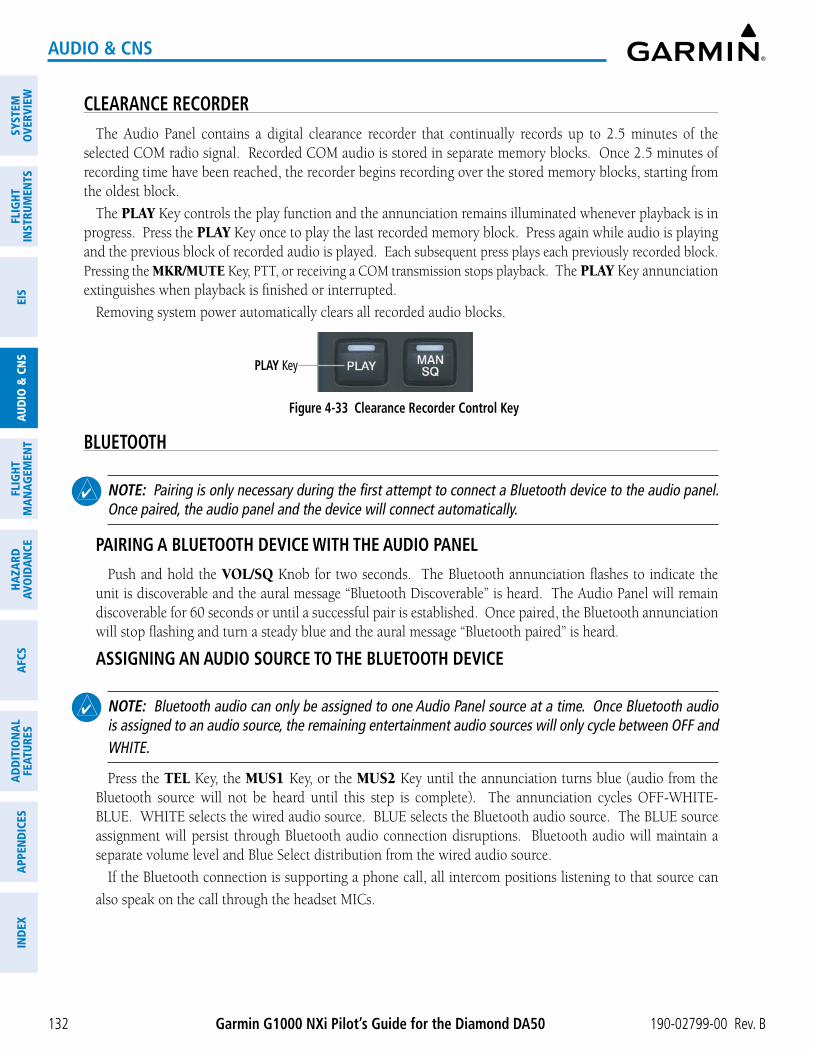
Garmin G1000 NXi Pilot’s Guide for the Diamond DA50 190-02799-00 Rev. B
SYST
EMO
VERV
IEW
FLIG
HTIN
STRU
MEN
TSEI
SAU
DIO
& C
NS
FLIG
HTM
AN
AGEM
ENT
HAZA
RDAV
OID
AN
CEA
FCS
AD
DIT
ION
AL
FEAT
URES
APP
END
ICES
IND
EX
132
AUDIO & CNS
CLEARANCE RECORDERThe Audio Panel contains a digital clearance recorder that continually records up to 2.5 minutes of the
selected COM radio signal. Recorded COM audio is stored in separate memory blocks. Once 2.5 minutes of recording time have been reached, the recorder begins recording over the stored memory blocks, starting from the oldest block.
The PLAY Key controls the play function and the annunciation remains illuminated whenever playback is in progress. Press the PLAY Key once to play the last recorded memory block. Press again while audio is playing and the previous block of recorded audio is played. Each subsequent press plays each previously recorded block. Pressing the MKR/MUTE Key, PTT, or receiving a COM transmission stops playback. The PLAY Key annunciation extinguishes when playback is finished or interrupted.
Removing system power automatically clears all recorded audio blocks.
Figure 4-33 Clearance Recorder Control Key
PLAY Key
BLUETOOTH
NOTE: Pairing is only necessary during the first attempt to connect a Bluetooth device to the audio panel. Once paired, the audio panel and the device will connect automatically.
PAIRING A BLUETOOTH DEVICE WITH THE AUDIO PANEL
Push and hold the VOL/SQ Knob for two seconds. The Bluetooth annunciation flashes to indicate the unit is discoverable and the aural message “Bluetooth Discoverable” is heard. The Audio Panel will remain discoverable for 60 seconds or until a successful pair is established. Once paired, the Bluetooth annunciation will stop flashing and turn a steady blue and the aural message “Bluetooth paired” is heard.
ASSIGNING AN AUDIO SOURCE TO THE BLUETOOTH DEVICE
NOTE: Bluetooth audio can only be assigned to one Audio Panel source at a time. Once Bluetooth audio is assigned to an audio source, the remaining entertainment audio sources will only cycle between OFF and WHITE.
Press the TEL Key, the MUS1 Key, or the MUS2 Key until the annunciation turns blue (audio from the Bluetooth source will not be heard until this step is complete). The annunciation cycles OFF-WHITE-BLUE. WHITE selects the wired audio source. BLUE selects the Bluetooth audio source. The BLUE source assignment will persist through Bluetooth audio connection disruptions. Bluetooth audio will maintain a separate volume level and Blue Select distribution from the wired audio source.
If the Bluetooth connection is supporting a phone call, all intercom positions listening to that source can
also speak on the call through the headset MICs.

Garmin G1000 NXi Pilot’s Guide for the Diamond DA50190-02799-00 Rev. B
SYSTEMO
VERVIEWFLIG
HTIN
STRUMEN
TSEIS
AUDIO
& CN
SFLIG
HTM
AN
AGEM
ENT
HAZA
RDAVO
IDA
NCE
AFCS
AD
DITIO
NA
LFEATURES
APPEN
DICES
IND
EX
133
AUDIO & CNS
BLUETOOTH CONNECTED RECORDING DEVICES
If the Audio Panel detects a recording device as the Bluetooth connected source, the PILOT ICS annunciation will turn blue and all audio heard by the pilot will be recorded. Press and hold the PILOT ICS Key to enable/disable Bluetooth recording mode and the aural messages “Bluetooth Recording Mode Enabled” or “Bluetooth Recording Mode Disabled” is heard.
ADDITIONAL BLUETOOTH CONTROL FUNCTIONS
Enabling/Disabling Automatic Reconnect of a Paired Device:
1) While viewing the ‘Aux - Connext Setup’ Page, push the FMS Knob to activate the cursor.
2) Turn the large FMS Knob to highlight the desired paired device.
3) Turn the small FMS Knob to select ‘Enabled’ or ‘Disabled’. Selecting ‘Enabled’ allows the system to automatically connect to a previously paired device when detected.
4) Push the FMS Knob to remove the cursor.
Figure 4-34 Enable/Disable Automatic Reconnect
Paired Device Name
Auto Reconnect Disabled
Removing a Paired Device:
1) While viewing the ‘Aux - Connext Setup’ Page, push the FMS Knob to activate the cursor.
2) Turn the large FMS Knob to highlight the desired paired device.
3) Press the Remove Softkey. A confirmation screen is displayed.
4) If necessary, turn the large FMS Knob to select ‘Yes’.
5) Press the ENT Key to remove the device from the list of paired devices.
Figure 4-35 Removing a Paired Device

Garmin G1000 NXi Pilot’s Guide for the Diamond DA50 190-02799-00 Rev. B
SYST
EMO
VERV
IEW
FLIG
HTIN
STRU
MEN
TSEI
SAU
DIO
& C
NS
FLIG
HTM
AN
AGEM
ENT
HAZA
RDAV
OID
AN
CEA
FCS
AD
DIT
ION
AL
FEAT
URES
APP
END
ICES
IND
EX
134
AUDIO & CNS
BLUE-SELECT MODE (TEL/ENTERTAINMENT DISTRIBUTION)Non-flight audio (TEL, MUS1, and MUS2) is distributed to crew and passengers using Blue Select Mode.
Push the VOL/SQ Knob (small knob) to activate Blue Select mode. If the volume control cursor is active, push the VOL/SQ Knob twice. The first push cancels the volume control cursor and the second push activates Blue Select Mode.
Press the TEL, MUS1, or MUS2 key to select the audio source for distribution. Turning the CRSR Knob (large knob) will also change the selected audio source. When Blue Select Mode is active, the annunciation of the selected audio source (TEL, MUS1,or MUS2) will be flashing blue and the ICS annunciation of any position currently receiving that source will be solid blue. Press any of the ICS keys to distribute the selected audio to that position.
Selecting any key other than PILOT ICS, COPLT ICS, PASS ICS, TEL, MUS1, or MUS2 will cancel Blue-Select Mode. Pushing the small knob will also cancel Blue-Select Mode. After approximately ten seconds with no input, the Blue-Select Mode will automatically cancel.
The following example indicates the pilot, copilot, and passengers will hear telephone audio.
Figure 4-36 Blue Select Mode

Garmin G1000 NXi Pilot’s Guide for the Diamond DA50190-02799-00 Rev. B
SYSTEMO
VERVIEWFLIG
HTIN
STRUMEN
TSEIS
AUDIO
& CN
SFLIG
HTM
AN
AGEM
ENT
HAZA
RDAVO
IDA
NCE
AFCS
AD
DITIO
NA
LFEATURES
APPEN
DICES
IND
EX
135
AUDIO & CNS
TELEPHONE AND ENTERTAINMENT INPUTS
NOTE: MUSIC INPUT #1 and MUSIC INPUT #2 cannot be completely turned off. Audio level for MUSIC INPUT #1 and MUSIC INPUT #2 can be adjusted by a Garmin-authorized service center.
The Audio Panel provides two stereo auxiliary entertainment inputs: MUSIC INPUT #1 and MUSIC INPUT #2. These inputs are compatible with popular portable entertainment devices such as cell phones, and tablets. Two 3.5-mm stereo phone jacks are installed in convenient locations for audio connection. The headphone outputs of the entertainment devices are plugged into the MUSIC INPUT #1 or MUSIC INPUT #2 jacks.
The current ICS state of isolation affects the distribution of the entertainment input MUSIC INPUT #1.
MUSIC INPUT
Non-flight audio (TEL, MUS1, and MUS2) is distributed to crew and passengers without regard to ICS settings. These distributions are managed via Blue-Select Mode.
MUSIC INPUT MUTING
MUSIC INPUT muting occurs when aircraft radio or marker beacon activity is heard. MUSIC INPUT is always soft muted when an interruption occurs from these sources. Soft muting is the gradual return of MUSIC INPUT to its original volume level. The time required for MUSIC INPUT volume to return to normal is between one-half and four seconds.
MUSIC INPUT MUTING ENABLE/DISABLE
Telephone and entertainment is managed via airframe configuration. Regardless of configuration, telephone and entertainment audio is always muted during alerts.
SIRIUSXM RADIO ENTERTAINMENT
SiriusXM Radio audio from the Data Link Receiver may be heard by the pilot and passengers simultaneously (optional: requires subscription to SiriusXM Radio Service). Refer to the Additional Features Section for more details on the Data Link Receiver.
Connecting a stereo input to either MUSIC INPUT #1 or MUSIC INPUT #2 jacks removes the SiriusXM Radio Audio from that input. For example, if passengers prefer their own music while the pilot listens to the SiriusXM Radio, the entertainment audio should be connected to the MUSIC INPUT #2 jack.

Garmin G1000 NXi Pilot’s Guide for the Diamond DA50 190-02799-00 Rev. B
SYST
EMO
VERV
IEW
FLIG
HTIN
STRU
MEN
TSEI
SAU
DIO
& C
NS
FLIG
HTM
AN
AGEM
ENT
HAZA
RDAV
OID
AN
CEA
FCS
AD
DIT
ION
AL
FEAT
URES
APP
END
ICES
IND
EX
136
AUDIO & CNS
4.6 AUDIO PANEL PREFLIGHT PROCEDURE
NOTE: If the pilot and/or copilot are using headsets that have a high/low switch or volume control knob, verify the switch is in the high position and the volume control on the headsets are at maximum volume setting. On single-pilot flights, verify that all other headsets are not connected to avoid excess noise in the audio system.
NOTE: When the MAN SQ Key is pressed, the ICS squelch can be set manually by the pilot and copilot. If manual squelch is set to full open (SQ annunciated and the knobs turned counterclockwise) background noise is heard in the ICS system as well as during COM transmissions.
After applying power to the system, the following steps aid in maximizing the use of the Audio Panel as well as preventing pilot and copilot induced issues. The system will retain the audio settings from the last power application; however, these preflight procedures can be performed each time a pilot boards the aircraft to ensure awareness of all audio levels for the Audio Panel and radios.
Setting the Audio Panel during preflight:
1) Press the MAN SQ Key so the in-key annunciation is illuminated.
2) Verify manual squelch is set to full open.
3) To enable the intercom selection(s) press the PILOT ICS, COPILOT ICS, and/or PASS ICS Keys so the in-key annunciation(s) are illuminated.
4) Turn CRSR Control Knob to select the intercom audio source to be adjusted. Once selected, turn VOL/SQ Control Knob to set the intercom audio level for that position.
5) Turn CRSR Control Knob to select the COM/NAV radios and each remaining audio source to be adjusted. Once selected, turn VOL/SQ Control Knob to adjust the volume level for that position.
6) Press the MAN SQ Key so the in-key annunciation is no longer illuminated. Auto Squelch will now be active.
Once this procedure has been completed, the pilot and copilot can change settings, keeping in mind the notes above.

Garmin G1000 NXi Pilot’s Guide for the Diamond DA50190-02799-00 Rev. B
SYSTEMO
VERVIEWFLIG
HTIN
STRUMEN
TSEIS
AUDIO
& CN
SFLIG
HTM
AN
AGEM
ENT
HAZA
RDAVO
IDA
NCE
AFCS
AD
DITIO
NA
LFEATURES
APPEN
DICES
IND
EX
137
AUDIO & CNS
4.7 ABNORMAL OPERATIONAbnormal operation of the system includes equipment failures of the system components and failure of
associated equipment, including switches and external devices.
AUDIO PANEL FAIL-SAFE OPERATIONIf there is a failure of the Audio Panel, a fail-safe circuit connects the pilot’s headset and microphone directly
to the COM1 transceiver.
STUCK MICROPHONEIf the push-to-talk (PTT) key becomes stuck, the COM transmitter stops transmitting after 35 seconds of
continuous operation. An alert appears on the PFD to advise the crew of a stuck microphone.
The MIC key annunciation on the Audio Panel flashes as long as the PTT key remains stuck. If in split COM mode (MIC1 and MIC2 selected), the annunciation will flash above the MIC key that has the stuck PTT switch.
Figure 4-37 Stuck Microphone Alert
COM TUNING FAILUREIn case of a COM system tuning failure, the emergency frequency (121.500 MHz) is automatically tuned in
the radio in which the tuning failure occurred. Depending on the failure mode, a yellow X may appear on the frequency display.
Figure 4-38 COM Tuning Failure
Emergency Channel Loaded Automatically
TRANSPONDER FAILUREIf the active transponder fails, a yellow X will appear in the Transponder Data Box on the PFD and a XPDR Fail
system message is displayed.
Figure 4-39 Transponder Fail Indication

Garmin G1000 NXi Pilot’s Guide for the Diamond DA50 190-02799-00 Rev. B
SYST
EMO
VERV
IEW
FLIG
HTIN
STRU
MEN
TSEI
SAU
DIO
& C
NS
FLIG
HTM
AN
AGEM
ENT
HAZA
RDAV
OID
AN
CEA
FCS
AD
DIT
ION
AL
FEAT
URES
APP
END
ICES
IND
EX
138
AUDIO & CNS
Blank Page
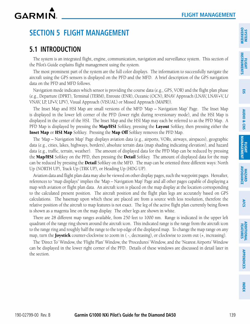
190-02799-00 Rev. B Garmin G1000 NXi Pilot’s Guide for the Diamond DA50
SYSTEMO
VERVIEWFLIG
HTIN
STRUMEN
TSEIS
AUDIO
& CN
SFLIG
HTM
AN
AGEM
ENT
HAZA
RDAVO
IDA
NCE
AFCS
AD
DITIO
NA
LFEATURES
APPEN
DICES
IND
EX
139
FLIGHT MANAGEMENT
SECTION 5 FLIGHT MANAGEMENT
5.1 INTRODUCTIONThe system is an integrated flight, engine, communication, navigation and surveillance system. This section of
the Pilot’s Guide explains flight management using the system.
The most prominent part of the system are the full color displays. The information to successfully navigate the aircraft using the GPS sensors is displayed on the PFD and the MFD. A brief description of the GPS navigation data on the PFD and MFD follows.
Navigation mode indicates which sensor is providing the course data (e.g., GPS, VOR) and the flight plan phase (e.g., Departure (DPRT), Terminal (TERM), Enroute (ENR), Oceanic (OCN), RNAV Approach (LNAV, LNAV+V, L/VNAV, LP, LP+V, LPV), Visual Approach (VISUAL) or Missed Approach (MAPR)).
The Inset Map and HSI Map are small versions of the MFD ‘Map – Navigation Map’ Page. The Inset Map is displayed in the lower left corner of the PFD (lower right during reversionary mode), and the HSI Map is displayed in the center of the HSI. The Inset Map and the HSI Map may each be referred to as the PFD Map. A PFD Map is displayed by pressing the Map/HSI Softkey, pressing the Layout Softkey, then pressing either the Inset Map or HSI Map Softkey. Pressing the Map Off Softkey removes the PFD Map.
The ‘Map – Navigation Map’ Page displays aviation data (e.g., airports, VORs, airways, airspaces), geographic data (e.g., cities, lakes, highways, borders), absolute terrain data (map shading indicating elevation), and hazard data (e.g., traffic, terrain, weather). The amount of displayed data for the PFD Map can be reduced by pressing the Map/HSI Softkey on the PFD, then pressing the Detail Softkey. The amount of displayed data for the map can be reduced by pressing the Detail Softkey on the MFD. The map can be oriented three different ways: North Up (NORTH UP), Track Up (TRK UP), or Heading Up (HDG UP).
Aviation data and flight plan data may also be viewed on other display pages, such the waypoint pages. Hereafter, references to “map displays” implies the ‘Map – Navigation Map’ Page and all other pages capable of displaying a map with aviation or flight plan data. An aircraft icon is placed on the map display at the location corresponding to the calculated present position. The aircraft position and the flight plan legs are accurately based on GPS calculations. The basemap upon which these are placed are from a source with less resolution, therefore the relative position of the aircraft to map features is not exact. The leg of the active flight plan currently being flown is shown as a magenta line on the map display. The other legs are shown in white.
There are 28 different map ranges available, from 250 feet to 1000 nm. Range is indicated in the upper left quadrant of the range ring shown around the aircraft icon. This indicated range is the range from the aircraft icon to the range ring and roughly half the range to the top edge of the displayed map. To change the map range on any map, turn the Joystick counter-clockwise to zoom in ( -, decreasing), or clockwise to zoom out (+, increasing).
The ‘Direct To’ Window, the ‘Flight Plan’ Window, the ‘Procedures’ Window, and the ‘Nearest Airports’ Window can be displayed in the lower right corner of the PFD. Details of these windows are discussed in detail later in the section.

Garmin G1000 NXi Pilot’s Guide for the Diamond DA50 190-02799-00 Rev. B
SYST
EMO
VERV
IEW
FLIG
HTIN
STRU
MEN
TSEI
SAU
DIO
& C
NS
FLIG
HTM
AN
AGEM
ENT
HAZA
RDAV
OID
AN
CEA
FCS
AD
DIT
ION
AL
FEAT
URES
APP
END
ICES
IND
EX
140
FLIGHT MANAGEMENT
Figure 5-1 GPS Navigation Information on the PFD (Inset Map)
Location of:- Direct To Window- Flight Plan Window- Procedures Window- Nearest Airports Window- References Window
Inset Map
Navigation Status Box
Navigation ModeCurrent Track Indicator
Figure 5-2 GPS Navigation Information on the PFD (HSI Map)
HSI Map
Navigation Status Box
Navigation Mode
Current Track Indicator

190-02799-00 Rev. B Garmin G1000 NXi Pilot’s Guide for the Diamond DA50
SYSTEMO
VERVIEWFLIG
HTIN
STRUMEN
TSEIS
AUDIO
& CN
SFLIG
HTM
AN
AGEM
ENT
HAZA
RDAVO
IDA
NCE
AFCS
AD
DITIO
NA
LFEATURES
APPEN
DICES
IND
EX
141
FLIGHT MANAGEMENT
Figure 5-3 GPS Navigation Information on the MFD Navigation Map
Active Flight Plan Leg
Navigation Map- Aviation Data
- Geographic Data- Topographic Data
- Hazard Data
Navigation Data Bar
Aircraft Iconat Present Position
Map Orientation
Map Range
Display Title
Flight Plan Leg
PFD NAVIGATION STATUS BOX AND MFD DATA BARThe Navigation Status Box located at the top of the PFD contains two fields displaying the following
information:
Figure 5-4 PFD Navigation Status Box
- Active flight plan leg (e.g., ‘¯ KICT’ or ‘KIXD ñ KCOS’) or flight plan annunciations (e.g., ‘Turn right to 021˚ in 8 seconds’)
- Distance (DIS) and Bearing (BRG) to the next waypoint or flight plan annunciations (e.g., ‘TOD within 1 minute’)
The symbols used in the PFD status box are:
Symbol Description Symbol Description
Active Leg Left Holding Pattern
Direct-to Vector to Final
Right Procedure Turn Right DME Arc/Radius to Fix Leg
Left Procedure Turn Left DME Arc/Radius to Fix Leg
Right Holding Pattern
Table 5-1 PFD Navigation Status Box Symbols

Garmin G1000 NXi Pilot’s Guide for the Diamond DA50 190-02799-00 Rev. B
SYST
EMO
VERV
IEW
FLIG
HTIN
STRU
MEN
TSEI
SAU
DIO
& C
NS
FLIG
HTM
AN
AGEM
ENT
HAZA
RDAV
OID
AN
CEA
FCS
AD
DIT
ION
AL
FEAT
URES
APP
END
ICES
IND
EX
142
FLIGHT MANAGEMENT
The Navigation Data Bar located at the top of the MFD contains four data fields, each displaying one of the following items:
- BRG (Bearing)
- CCG (Current Climb Gradient)
- DEST (Destination airport identifier)
- DIS (Distance)
- DNALT (Density Altitude)
- DTG (Distance to go to destination)
- DTK (Desired track)
- END (Endurance)
- ENR (ETE to final destination)
- EOD (Endurance Over Destination)
- ESA (Enroute Safe Altitude)
- ETA (Estimated Time of Arrival)
- ETE (Estimated Time Enroute)
- FLT (Flight Timer)
- FOB (Fuel On Board)
- FOD (Fuel Over Destination)
- FODT (Fuel Over Destination Time)
- GAGL (GPS AGL Altitude)
- GS (Groundspeed)
- ISA (Temperature at standard pressure)
- LDG (ETA at final destination)
- MSA (Minimum Safe Altitude)
- TAS (True Airspeed)
- TKE (Track angle error)
- TOD (Time of Top of Descent)
- TRK (Track)
- VSR (Vertical Speed Required)
- XTK (Cross-track error)
Figure 5-5 MFD Navigation Data Bar
The navigation information displayed in the four data fields can be selected on the MFD Data Bar Fields Box on the ‘Aux – System Setup 1’ Page. The default selections (in order left to right) are GS, DTK, TRK, and ETE.
NOTE: The MSA altitude displayed will equal the highest grid MORA (Minimum Off Route Altitude) within a 10 mile square, surrounding the aircraft. The square is aligned to the cardinal directions and provides 1,000 ft separation (2,000 ft in designated mountainous terrain within the U.S.). Grid MORA data (or its equivalent) must be present in the database to provide an MSA value.
NOTE: Fuel over destination time (FODT) is displayed as ‘FOD’ in the MFD Data Bar. FODT is the same calculation as Endurance Over Destination (EOD).
Changing a field in the MFD Navigation Data Bar:
1) Select the ‘Aux – System Setup 1’ Page.
2) Push the FMS Knob momentarily to activate the flashing cursor.
3) Turn the large FMS Knob to highlight the desired field number in the ‘MFD Data Bar Fields’ Box.
4) Turn the small FMS Knob to display and scroll through the data options list to select the desired data.
5) Press the ENT Key. Pressing the Defaults Softkey returns all fields to the default setting.

190-02799-00 Rev. B Garmin G1000 NXi Pilot’s Guide for the Diamond DA50
SYSTEMO
VERVIEWFLIG
HTIN
STRUMEN
TSEIS
AUDIO
& CN
SFLIG
HTM
AN
AGEM
ENT
HAZA
RDAVO
IDA
NCE
AFCS
AD
DITIO
NA
LFEATURES
APPEN
DICES
IND
EX
143
FLIGHT MANAGEMENT
5.2 USING MAP DISPLAYSMap displays are used extensively in the system to provide situational awareness in flight. Most system maps
can display the following information:
• Airports, NAVAIDs, user waypoints, airspaces, airways, land data (highways, cities, lakes, rivers, borders, etc.) with names
• Map Pointer information (distance and bearing to pointer, location of pointer, name, and other pertinent information)
• Map range • Fuel range ring
• Wind direction and speed • Flight plan legs
• Map orientation • Track vector
• Icons for enabled map features • Terrain
• Aircraft icon (representing present position) • Topography scale and data
• Obstacles
The information in this section applies to the following maps unless otherwise noted:
• All Map Group Pages (‘Map’) • All Nearest Group Pages (‘NRST’)
• All Waypoint Group Pages (‘WPT’) • ‘Direct To’ Window
• ‘Aux – Trip Planning’ Page (‘Aux’) • PFD Maps
• Flight Plan Pages (‘FPL’) • Procedure Loading Pages
MAP ORIENTATIONMaps are shown in one of three different orientation options, allowing flexibility in determining aircraft
position relative to other items on the map (north up) or for determining where map items are relative to where the aircraft is going (track up or heading up). The map orientation is shown in the upper left corner of the map.
Figure 5-6 Map Orientation
- North up (North up) aligns the top of the map display to north (default setting).
- Track up (Track up) aligns the top of the map display to the current ground track.
- Heading up (HDG up) aligns the top of the map display to the current aircraft heading.
The North Up Above setting configures the map to switch automatically to a north up orientation when the map range reaches a minimum range.

Garmin G1000 NXi Pilot’s Guide for the Diamond DA50 190-02799-00 Rev. B
SYST
EMO
VERV
IEW
FLIG
HTIN
STRU
MEN
TSEI
SAU
DIO
& C
NS
FLIG
HTM
AN
AGEM
ENT
HAZA
RDAV
OID
AN
CEA
FCS
AD
DIT
ION
AL
FEAT
URES
APP
END
ICES
IND
EX
144
FLIGHT MANAGEMENT
Map orientation of the flight plan map when Split Screen Mode is active is discussed later in the flight Management Section in the Flight Planning portion.
NOTE: When panning or reviewing active flight plan legs in a non-North Up orientation, the map does not show the map orientation nor the wind direction and speed.
Figure 5-7 Navigation Map Page Menu
Map Settings Selection
Figure 5-8 Map Settings Menu - Map Group
Orientation FieldMap Group Selection
North Up Above Field
Changing the orientation for map displays:
1) With the ‘Map – Navigation Map’ Page displayed, press the MENU Key. The cursor flashes on the ‘Map Settings’ option.
2) Press the ENT Key to display the ‘Map Settings’ Window.
3) Select the ‘Map’ Group.
4) Press the ENT Key.
5) Turn the small FMS Knob to select the desired orientation.
6) Press the ENT Key to select the new orientation.
7) Push the FMS Knob to return to the base page.

190-02799-00 Rev. B Garmin G1000 NXi Pilot’s Guide for the Diamond DA50
SYSTEMO
VERVIEWFLIG
HTIN
STRUMEN
TSEIS
AUDIO
& CN
SFLIG
HTM
AN
AGEM
ENT
HAZA
RDAVO
IDA
NCE
AFCS
AD
DITIO
NA
LFEATURES
APPEN
DICES
IND
EX
145
FLIGHT MANAGEMENT
Enabling/disabling North Up Above and selecting the minimum switching range:
1) Press the MENU Key with the ‘Map – Navigation Map’ Page displayed. The cursor flashes on the ‘Map Settings’ option.
2) Press the ENT Key. The ‘Map Settings’ Window is displayed.
3) Select the ‘Map’ Group.
4) Press the ENT Key.
5) Highlight the ‘North Up Above’ Field.
6) Select ‘On’ or ‘Off’ using the small FMS Knob.
7) Press the ENT Key to accept the selected option. The flashing cursor highlights the Range Field.
8) Use the small FMS Knob to select the desired range.
9) Press the ENT Key to accept the selected option.
10) Push the FMS Knob to return to the ‘Map – Navigation Map’ Page.
MAP RANGEThere are 28 different map ranges available, from 250 feet to 1000 nm. The current range is indicated in the
upper left corner of the map and represents the top-to-bottom distance covered by the map. To change the map range turn the Joystick counter-clockwise to decrease the range, or clockwise to increase the range.
Figure 5-9 Map Range
Auto Zoom On
AUTO ZOOM
Auto zoom allows the system to change the map display range to the smallest range clearly showing the active waypoint. Auto zoom can be overridden by adjusting the range with the Joystick, and remains until the active waypoint changes, a terrain or traffic alert occurs, the aircraft takes off, or the manual override times out (timer set on ‘Map Settings’ Window). Auto zoom is suspended while the map pointer is active.
If a terrain caution or warning occurs, all map displays automatically adjust to the smallest map range clearly showing the potential impact areas. If a new traffic advisory alert occurs, any map display showing traffic advisory alerts automatically adjusts to the smallest map range clearly showing the traffic advisory. When terrain or traffic alerts clear, the map returns to the previous auto zoom range based on the active waypoint.

Garmin G1000 NXi Pilot’s Guide for the Diamond DA50 190-02799-00 Rev. B
SYST
EMO
VERV
IEW
FLIG
HTIN
STRU
MEN
TSEI
SAU
DIO
& C
NS
FLIG
HTM
AN
AGEM
ENT
HAZA
RDAV
OID
AN
CEA
FCS
AD
DIT
ION
AL
FEAT
URES
APP
END
ICES
IND
EX
146
FLIGHT MANAGEMENT
The auto zoom function can be turned on or off independently for the PFD and MFD. Control of the ranges at which the auto zoom occurs is done by setting the minimum and maximum ‘look forward’ times (set on the ‘Map Settings’ Window for the ‘Map’ Group). These settings determine the minimum and maximum distance to display based upon the aircraft’s ground speed.
» Waypoints that are long distances apart cause the map range to increase to a point where many details on the map are decluttered. If this is not acceptable, lower the maximum look ahead time to a value that limits the auto zoom to an acceptable range.
» Waypoints that are very short distances apart cause the map range to decrease to a point where situational awareness may not be what is desired. Increase the minimum look ahead time to a value that limits the auto zoom to a minimum range that provides acceptable situational awareness.
» Flight plans that have a combination of long and short legs cause the range to increase and decrease as waypoints sequence. To avoid this, auto zoom can be disabled or the maximum/ minimum times can be adjusted.
» The ‘Time Out’ Field (configurable on the ‘Map Settings’ Window for the ‘Map’ Group) determines how long auto zoom is overridden by a manual adjustment of the range knob. At the expiration of this time, the auto zoom range is restored. Setting the ‘Time Out’ Field to zero causes the manual override to never time out.
» When the ‘Max Look FWD’ Field is set to zero, the upper limit becomes the maximum range available (1000 nm).
» When the ‘Min Look FWD’ Field is set to zero, the lower limit becomes 1.5 nm.
Configuring automatic zoom:
1) Press the MENU Key with the ‘Map – Navigation Map’ Page displayed. The cursor flashes on the ‘Map Settings’ option.
2) Press the ENT Key. The ‘Map Settings’ Window is displayed.
3) Turn the small FMS Knob to select the ‘Map’ Group.
4) Press the ENT Key.
5) Turn the large FMS Knob to highlight the ‘Auto Zoom’ On/Off Field, and select ‘Off’ or ‘On’ using the small FMS Knob.
6) Press the ENT Key to accept the selected option. The flashing cursor highlights the ‘Auto Zoom’ display selection Field.
7) Select ‘MFD’, ‘PFD’, or ‘All’ using the small FMS Knob.
8) Press the ENT Key to accept the selected option. The flashing cursor highlights the ‘Max Look FWD’ Field. Times are from zero to 999 minutes.
9) Use the FMS Knob to set the time. Press the ENT Key.
10) Repeat step 9 for ‘Min Look FWD’ (zero to 99 minutes) and ‘Time Out’ (zero to 99 minutes).
11) Push the FMS Knob to return to the ‘Map – Navigation Map’ Page.

190-02799-00 Rev. B Garmin G1000 NXi Pilot’s Guide for the Diamond DA50
SYSTEMO
VERVIEWFLIG
HTIN
STRUMEN
TSEIS
AUDIO
& CN
SFLIG
HTM
AN
AGEM
ENT
HAZA
RDAVO
IDA
NCE
AFCS
AD
DITIO
NA
LFEATURES
APPEN
DICES
IND
EX
147
FLIGHT MANAGEMENT
MAP PANNINGMap panning allows the pilot to:
- View parts of the map outside the displayed range without adjusting the map range
- Highlight and select locations on the map
- Review information for a selected airport, NAVAID or user waypoint
- Designate locations for use in flight planning
- Graphically create user waypoints
- Measure the bearing distance from the aircraft present position to any location on the map display, or between any two points on the map display
- View obstacle, airspace, and airway information
When the panning function is selected by pushing the Joystick, the Map Pointer flashes on the map display. A window also appears at the top of the map display showing the latitude/longitude position of the pointer, the bearing and distance to the pointer from the aircraft’s present position, and the elevation of the land at the position of the pointer.
NOTE: The map is normally centered on the aircraft’s position. If the map has been panned and there has been no pointer movement for about 60 seconds, the map reverts back to centered on the aircraft position and the flashing pointer is removed.
Figure 5-10 Navigation Map - Map Pointer Activated
Map Pointer
Map Pointer Information
When the Map Pointer is placed on an object, the name of the object is highlighted (even if the name was not originally displayed on the map). When any map feature or object is selected on the map display, pertinent information is displayed.

Garmin G1000 NXi Pilot’s Guide for the Diamond DA50 190-02799-00 Rev. B
SYST
EMO
VERV
IEW
FLIG
HTIN
STRU
MEN
TSEI
SAU
DIO
& C
NS
FLIG
HTM
AN
AGEM
ENT
HAZA
RDAV
OID
AN
CEA
FCS
AD
DIT
ION
AL
FEAT
URES
APP
END
ICES
IND
EX
148
FLIGHT MANAGEMENT
Figure 5-11 Navigation Map - Map Pointer on Point of Interest
Map Pointeron POI
Information aboutPoint of Interest
Panning the map:
1) With the desired map display shown on the MFD, push the Joystick to display the Map Pointer.
2) Move the Joystick to move the Map Pointer around the map.
3) Push the Joystick to remove the Map Pointer and recenter the map on the aircraft’s current position.
Reviewing information for an airport, NAVAID, or user waypoint:
1) With the desired map display shown on the MFD, push the Joystick to display the Map Pointer and place the Map Pointer on a waypoint.
2) Press the ENT Key to display the information page for the selected waypoint.
3) Press the Go Back Softkey, the CLR Key, or the ENT Key to exit the information page and return to the ‘Map – Navigation Map’ Page.
When the Map Pointer crosses an airspace boundary, the boundary is highlighted and airspace information is shown. The information includes the name and class of airspace, the ceiling in feet above Mean Sea Level (MSL), and the floor in feet MSL.
Reviewing information for a special-use or controlled airspace:
1) With the desired map display shown on the MFD, push the Joystick to display the Map Pointer. Place the Map Pointer on the boundary of an airspace. Information about the airspace is displayed on the map next to the map pointer.
2) Push the Joystick to remove the Map Pointer and center the map on the aircraft.
Or:

190-02799-00 Rev. B Garmin G1000 NXi Pilot’s Guide for the Diamond DA50
SYSTEMO
VERVIEWFLIG
HTIN
STRUMEN
TSEIS
AUDIO
& CN
SFLIG
HTM
AN
AGEM
ENT
HAZA
RDAVO
IDA
NCE
AFCS
AD
DITIO
NA
LFEATURES
APPEN
DICES
IND
EX
149
FLIGHT MANAGEMENT
1) With the desired map display shown on the MFD, push the Joystick to display the Map Pointer and place the Map Pointer on an open area within the boundaries of an airspace.
2) Press the ENT Key to display an options menu.
3) ‘Review Airspaces’ should already be highlighted, if not select it. Press the ENT Key to display the ‘Information’ Window for the selected airspace.
4) Push the FMS Knob, or press the CLR or ENT Key to exit the ‘Information’ Window.
MEASURING BEARING AND DISTANCEDistance and bearing from the aircraft’s present position to any point on the viewable map display may be
calculated using the ‘Measure Bearing and Distance’ selection from page menu. This function is only available on the ‘Map – Navigation Map’ Page and the VFR/IFR map pages. The bearing and distance tool displays a dashed Measurement Line and a Measure Pointer to aid in graphically identifying points with which to measure. Lat/Long, distance and elevation data for the Measure Pointer is provided in a window at the top of the map display.
Figure 5-12 Navigation Map - Measuring Bearing and Distance
Pointer Lat/LongMeasurement Information
Measurement Line
Measuring bearing and distance between any two points:
1) Press the MENU Key (with the ‘Map – Navigation Map’ Page or one of the VFR/IFR pages displayed).
2) Use the FMS Knob to highlight the ‘Measure Bearing/Distance’ Field.
3) Press the ENT Key. A Measure Pointer is displayed on the map at the aircraft’s present position.
4) Move the Joystick to place the reference pointer at the desired location. The bearing and distance are displayed at the top of the map. Elevation at the current pointer position is also displayed. Pressing the ENT Key changes the starting point for measuring.
5) To exit the Measure Bearing/Distance option, push the Joystick; or select ‘Stop Measuring’ from the ‘Page Menu’ Window and press the ENT Key.

Garmin G1000 NXi Pilot’s Guide for the Diamond DA50 190-02799-00 Rev. B
SYST
EMO
VERV
IEW
FLIG
HTIN
STRU
MEN
TSEI
SAU
DIO
& C
NS
FLIG
HTM
AN
AGEM
ENT
HAZA
RDAV
OID
AN
CEA
FCS
AD
DIT
ION
AL
FEAT
URES
APP
END
ICES
IND
EX
150
FLIGHT MANAGEMENT
ABSOLUTE TERRAINAll map displays can show various shades of absolute terrain colors representing land elevation, similar to
aviation sectional charts. The absolute terrain data range is the maximum map range on which topographic data is displayed.
Topographic data can be displayed or removed as described in the following procedures. Topographic data can also be displayed on the selectable VSD Inset at the bottom of the ‘Map – Navigation Map’ Page. In addition, the ‘Map – Navigation Map’ Page can display a topographic scale (located in the lower right hand side of the map) showing a scale of the terrain elevation and minimum/maximum displayed elevations.
Relative terrain discussion can be referenced in the Hazard Avoidance Section.
Navigation Map Black Background
TOPO Off
Figure 5-13 Navigation Map - Topographic Data
TER Softkey-Topo Selected
Navigation Map Topographic Data
TOPO On
TER Softkey-Off Selected
Topographic Data on VSD Inset
Figure 5-14 PFD Inset Map - Topographic Data
Topo Data Off
Topo Data On
Figure 5-15 HSI Map - Topographic Data
Topo Data Off
Topo Data On

190-02799-00 Rev. B Garmin G1000 NXi Pilot’s Guide for the Diamond DA50
SYSTEMO
VERVIEWFLIG
HTIN
STRUMEN
TSEIS
AUDIO
& CN
SFLIG
HTM
AN
AGEM
ENT
HAZA
RDAVO
IDA
NCE
AFCS
AD
DITIO
NA
LFEATURES
APPEN
DICES
IND
EX
151
FLIGHT MANAGEMENT
Figure 5-16 Navigation Map - Topo Scale
Maximum Displayed Elevation
Minimum Displayed Elevation
Displaying/removing absolute terrain data on MFD map displays:
1) Press the Map Opt Softkey on the ‘Map – Navigation Map’ Page.
2) Press the TER Softkey until ‘Topo’ is shown on the softkey to display topographic data.
3) Press the TER Softkey until ‘Off’ is shown on the softkey to remove topographic data from the map. When topographic data is removed from the page, all navigation data is presented on a black background.
Or:
1) Press the MENU Key with the ‘Map – Navigation Map’ Page displayed. The cursor flashes on the ‘Map Settings’ option.
2) Press the ENT Key. The ‘Map Settings’ Window is displayed.
3) Turn the small FMS Knob to select the ‘Map’ Group.
4) Press the ENT Key.
5) Turn the large FMS Knob to highlight the ‘Terrain Display’ Field.
6) Turn the small FMS Knob to select ‘Topo’ or ‘Off’. Press the ENT Key.
7) Push the FMS Knob to return to the ‘Map – Navigation Map’ Page.
Displaying/removing absolute terrain data on the PFD Map:
1) Press the Map/HSI Softkey.
2) Press the TER Softkey until ‘Topo’ is displayed.
3) Press the TER Softkey until ‘Off’ is shown on the softkey to remove topographic data from the map display. When topographic data is removed from the page, all navigation data is presented on a black background.
Selecting a absolute terrain data range (Terrain Display):
1) Press the MENU Key with the ‘Map – Navigation Map’ Page displayed. The cursor flashes on the ‘Map Settings’ option.
2) Press the ENT Key. The ‘Map Settings’ Window is displayed.
3) Turn the small FMS Knob to select the ‘Map’ Group.
4) Press the ENT Key.
5) Use the large FMS Knob to highlight the Terrain Display Range Field. Ranges are from 1 nm to 1000 nm.
6) To change the Terrain Display Range setting, turn the small FMS Knob to display the range list.

Garmin G1000 NXi Pilot’s Guide for the Diamond DA50 190-02799-00 Rev. B
SYST
EMO
VERV
IEW
FLIG
HTIN
STRU
MEN
TSEI
SAU
DIO
& C
NS
FLIG
HTM
AN
AGEM
ENT
HAZA
RDAV
OID
AN
CEA
FCS
AD
DIT
ION
AL
FEAT
URES
APP
END
ICES
IND
EX
152
FLIGHT MANAGEMENT
7) Select the desired range using the small FMS Knob.
8) Press the ENT Key.
9) Push the FMS Knob to return to the ‘Map – Navigation Map’ Page.
Displaying/removing the absolute terrain scale (Topo Scale):
1) Press the MENU Key with the ‘Map – Navigation Map’ Page displayed. The cursor flashes on the ‘Map Settings’ option.
2) Press the ENT Key. The ‘Map Settings’ Window is displayed.
3) Turn the small FMS Knob to select the ‘Map’ Group and press the ENT Key.
4) Turn the large FMS Knob to highlight the ‘Topo Scale’ Field.
5) Turn the small FMS Knob to select ‘On’ or ‘Off’. Press the ENT Key.
6) Push the FMS Knob to return to the ‘Map – Navigation Map’ Page.
MAP DISPLAY SYMBOLSThis section discusses the types of land, aviation, airspace, airway, and map symbols that can be displayed.
Each listed type of symbol can be turned on or off, and the maximum range to display each symbol can be set. The maximum range is based upon the range ring setting, not distance from the aircraft. The decluttering of the symbols from the map using the Detail Softkey is also discussed. For information on VSD inset settings, reference the Flight Planning discussion later in this section.
LAND SYMBOLS
The following items are configured on the land menu:
Land Symbol Name Symbol Default Range (nm)
Maximum Range (nm)
User Waypoint (Route)
(Airport)1000 1000
Highways and Roads (see below)
- Interstate Highway (Freeway) 50 400
- International Highway (Freeway) 50 400
- US Highway (National Highway) 15 150
- State Highway (Local Highway) 10 100
- Local Road (Local Road) N/A 4 25

190-02799-00 Rev. B Garmin G1000 NXi Pilot’s Guide for the Diamond DA50
SYSTEMO
VERVIEWFLIG
HTIN
STRUMEN
TSEIS
AUDIO
& CN
SFLIG
HTM
AN
AGEM
ENT
HAZA
RDAVO
IDA
NCE
AFCS
AD
DITIO
NA
LFEATURES
APPEN
DICES
IND
EX
153
FLIGHT MANAGEMENT
Land Symbol Name Symbol Default Range (nm)
Maximum Range (nm)
Railroad 7.5 25
Large City (> 200,000) 100 1000
Medium City (> 50,000) 50 400
Small City (> 5,000) 25 100
State/Province 750 1000
River/Lake 75 100
Latitude/Longitude (LAT/LON) 1 1000
Table 5-2 Land Symbol Information
AVIATION SYMBOLS
The following items are configured on the aviation menu:
Aviation Symbol Name Symbol Default Range (nm)
Maximum Range (nm)
Large Airport (Longest Runway ≥ 8100 ft)
100 1000Medium Airport (8100 ft > Longest Runway ≥ 5000 ft, or Longest Runway < 5000 ft with control tower) 50 400
Small Airport (Longest Runway < 5000 ft without a control tower) 25 150
Taxiways (SafeTaxi) See Additional Features 1.5 5
Runway Extension 7.5 150
Intersection (INT) 10 40
Non-directional Beacon (NDB) 25 50
VOR (VOR, VOR/DME, DME, VORTAC, TACAN) 50 250
- VOR Compass Rose On/Off N/A N/A
Visual Reporting Point (VRP) 25 40
Temporary Flight Restriction (TFR) 250 1000
VNAV Constraints (manually modified)(‘Show All’ also displays auto-designated and published constraints) 1000 1000
Table 5-3 Aviation Symbol Information

Garmin G1000 NXi Pilot’s Guide for the Diamond DA50 190-02799-00 Rev. B
SYST
EMO
VERV
IEW
FLIG
HTIN
STRU
MEN
TSEI
SAU
DIO
& C
NS
FLIG
HTM
AN
AGEM
ENT
HAZA
RDAV
OID
AN
CEA
FCS
AD
DIT
ION
AL
FEAT
URES
APP
END
ICES
IND
EX
154
FLIGHT MANAGEMENT
AIRSPACE SYMBOLSThe following items are configured on the airspace menu:
Airspace Symbol Name Symbol Default Range (nm)
Maximum Range (nm)
Class B Airspace Altitude Label (ceiling/floor)
Variable 1Class C Airspace Altitude Label (ceiling/floor)
Class D Airspace Altitude Label (ceiling)
CL B/TMA/AWY (see below)
- Class B (CL B) and Terminal Manoeuvring Area (TMA) 2
50 150
- Airway (AWY) 2
CL C/CTA (see below)
- Class C Airspace (CL C)
50 100
- Control Area (CTA) 2
CL A/D (see below)
- Terminal Radar Service Area (TRSA), Controlled Traffic Region (CTR) 2, and Class A (CL A) 2
10 100 - Class D
- Aerodrome Traffic Zone (ATZ) 2
- Traffic Information Zone (TIZ) 2
Restricted and Prohibited Areas (Restricted) 50 100
Military Operations Areas (MOA (Military)) 50 250
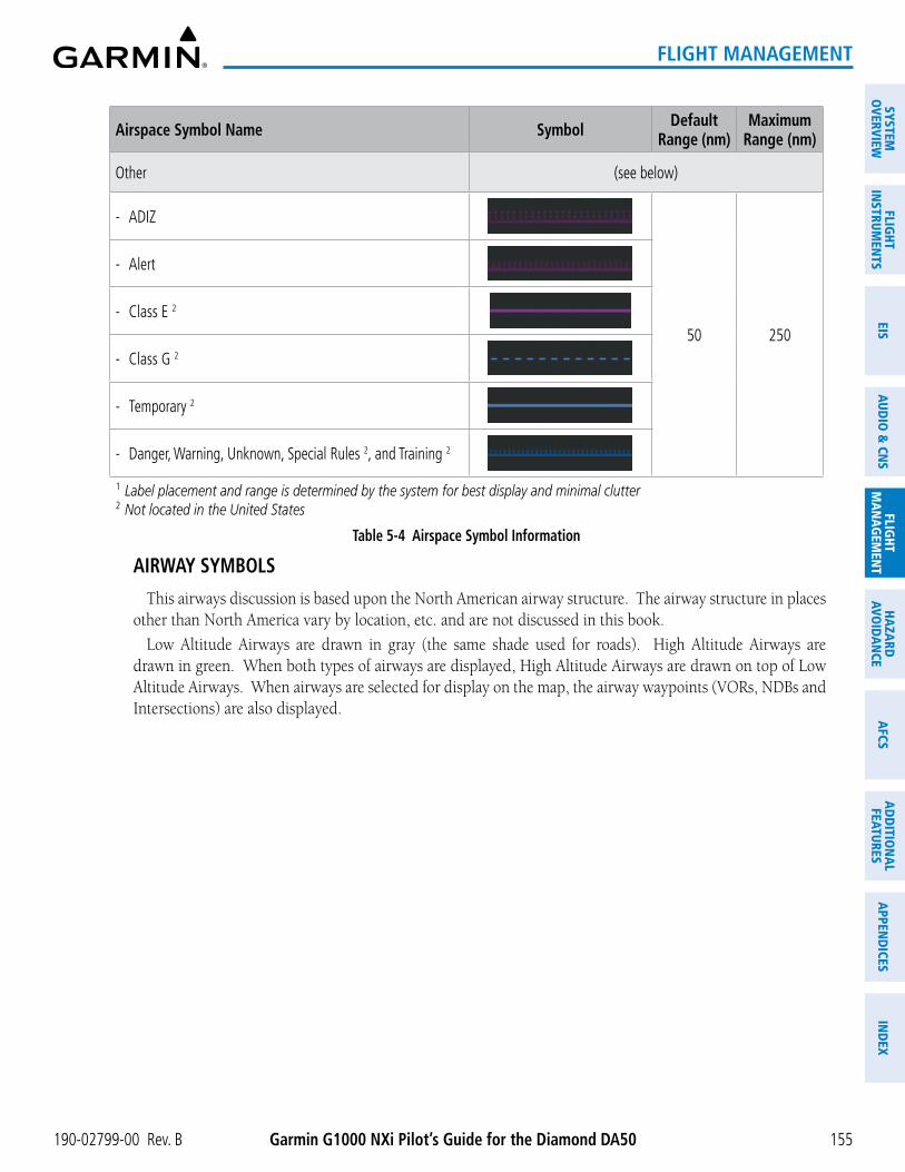
190-02799-00 Rev. B Garmin G1000 NXi Pilot’s Guide for the Diamond DA50
SYSTEMO
VERVIEWFLIG
HTIN
STRUMEN
TSEIS
AUDIO
& CN
SFLIG
HTM
AN
AGEM
ENT
HAZA
RDAVO
IDA
NCE
AFCS
AD
DITIO
NA
LFEATURES
APPEN
DICES
IND
EX
155
FLIGHT MANAGEMENT
Airspace Symbol Name Symbol Default Range (nm)
Maximum Range (nm)
Other (see below)
- ADIZ
50 250
- Alert
- Class E 2
- Class G 2
- Temporary 2
- Danger, Warning, Unknown, Special Rules 2, and Training 2
1 Label placement and range is determined by the system for best display and minimal clutter2 Not located in the United States
Table 5-4 Airspace Symbol Information
AIRWAY SYMBOLS
This airways discussion is based upon the North American airway structure. The airway structure in places other than North America vary by location, etc. and are not discussed in this book.
Low Altitude Airways are drawn in gray (the same shade used for roads). High Altitude Airways are drawn in green. When both types of airways are displayed, High Altitude Airways are drawn on top of Low Altitude Airways. When airways are selected for display on the map, the airway waypoints (VORs, NDBs and Intersections) are also displayed.

Garmin G1000 NXi Pilot’s Guide for the Diamond DA50 190-02799-00 Rev. B
SYST
EMO
VERV
IEW
FLIG
HTIN
STRU
MEN
TSEI
SAU
DIO
& C
NS
FLIG
HTM
AN
AGEM
ENT
HAZA
RDAV
OID
AN
CEA
FCS
AD
DIT
ION
AL
FEAT
URES
APP
END
ICES
IND
EX
156
FLIGHT MANAGEMENT
Figure 5-17 Airways on MFD Navigation Page
Low Altitude Airway
(Victor Airway)
High Altitude Airway(Jet Route)
Low Altitude Airway
(T-Route)
High Altitude Airway(Q-Route)
The following items are configured on the airways menu:
Airway Symbol Name Symbol Default Range (nm)
Maximum Range (nm)
Low Altitude Airway (V Routes and T Routes) 50 100
High Altitude Airway (J Routes and Q Routes) 50 100
Table 5-5 Airways Symbol Information
SYMBOL SETUPAll map displays can show land, aviation, airspace and airway symbols. Symbol types (e.g. runway
extensions, railroads) can be removed individually. The range sets the maximum range at which items appear on the display. For example, enabling “Runway Extension” displays a dashed line on the map extending from each runway of an airport in the flight plan when the range is set at or below the value of the map settings option.
NOTE: The HSI Map does not display Intersections, Cities, Roads, or Lat/Lon lines.
Setting up the ‘Land’, ‘Aviation’, ‘Airspace’, or ‘Airways’ Group items:
1) Press the MENU Key with the ‘Map – Navigation Map’ Page displayed. The cursor flashes on the ‘Map Settings’ option.
2) Press the ENT Key. The ‘Map Settings’ Window is displayed.
3) Turn the small FMS Knob to select the desired group.
190-02799-00 Rev. B Garmin G1000 NXi Pilot’s Guide for the Diamond DA50
SYSTEMO
VERVIEWFLIG
HTIN
STRUMEN
TSEIS
AUDIO
& CN
SFLIG
HTM
AN
AGEM
ENT
HAZA
RDAVO
IDA
NCE
AFCS
AD
DITIO
NA
LFEATURES
APPEN
DICES
IND
EX
157
FLIGHT MANAGEMENT
4) Press the ENT Key. The cursor flashes on the first field.
5) Turn the large FMS Knob to select the desired option.
6) Turn the small FMS Knob to select the desired setting (e.g. On/Off or maximum range).
7) Press the ENT Key to accept the selected option and move the cursor to the next item.
8) Repeat steps 5-7 as necessary.
9) Push the FMS Knob to return to the ‘Map – Navigation Map’ Page.
The preceding procedure can be used for selecting which Airspaces should be shown on the map display. Additionally, airspace altitude labels may also be shown, as explained in the following procedure.
Displaying and removing airspace altitude labels:
1) Press the MENU Key with the ‘Map – Navigation Map’ Page displayed. The cursor flashes on the ‘Map Settings’ option.
2) Press the ENT Key. The ‘Map Settings’ Window is displayed.
3) Turn the small FMS Knob to select the ‘Airspace’ Group, if necessary, and press the ENT Key.
4) Turn the large FMS Knob to select the ‘Airspace ALT LBL’ Field.
5) Turn the small FMS Knob to select ‘On’ to display labels and ‘Off’ to remove labels.
6) Push the FMS Knob to return to the ‘Map – Navigation Map’ Page.
Airways may be displayed on the map at the pilot’s discretion using either a combination of AWY Softkey selections, or menu selections using the MENU Key from the ‘Map – Navigation Map’ Page. The Airway range can also be programmed to only display Airways on the MFD when the map range is at or below a specific number.
Displaying/removing airways:
1) Press the Map Opt Softkey with the ‘Map – Navigation Map’ Page displayed.
2) Press the AWY Softkey. Both High and Low Altitude Airways are displayed (AWY On).
3) Press the softkey again to display Low Altitude Airways only (AWY LO).
4) Press the softkey again to display High Altitude Airways only (AWY HI).
5) Press the softkey again to remove High Altitude Airways. No airways are displayed (AWY Off).
Or:
1) Press the MENU Key with the ‘Map – Navigation Map’ Page displayed. The cursor flashes on the ‘Map Settings’ option.
2) Press the ENT Key. The ‘Map Settings’ Window is displayed.
3) Turn the small FMS Knob to select the ‘Airways’ Group, and press the ENT Key.
4) Turn the large FMS Knob to highlight the ‘Low ALT Airways’ or the ‘High ALT Airways’ On/Off Field.
5) Turn the small FMS Knob to select ‘Off’ or ‘On’. Press the ENT Key.
6) Push the FMS Knob to return to the ‘Map – Navigation Map’ Page.

Garmin G1000 NXi Pilot’s Guide for the Diamond DA50 190-02799-00 Rev. B
SYST
EMO
VERV
IEW
FLIG
HTIN
STRU
MEN
TSEI
SAU
DIO
& C
NS
FLIG
HTM
AN
AGEM
ENT
HAZA
RDAV
OID
AN
CEA
FCS
AD
DIT
ION
AL
FEAT
URES
APP
END
ICES
IND
EX
158
FLIGHT MANAGEMENT
Selecting an airway range (Low ALT Airways or High ALT Airways):
1) Press the MENU Key with the ‘Map – Navigation Map’ Page displayed. The cursor flashes on the ‘Map Settings’ option.
2) Press the ENT Key. The ‘Map Settings’ Window is displayed.
3) Turn the small FMS Knob to select the ‘Airways’ Group, and press the ENT Key.
4) Turn the large FMS Knob to highlight the Low ALT Airways Range Field or High ALT Airways Range Field.
5) To change the range setting, turn the small FMS Knob to display the range list.
6) Select the desired range using the small FMS Knob.
7) Press the ENT Key.
8) Push the FMS Knob to return to the ‘Map – Navigation Map’ Page.
MAP DECLUTTER
The declutter feature allows the pilot to progressively step through four levels of removing map information. The declutter level is displayed in the Detail Softkey and next to the Declutter Menu Option.
The following table lists the items that are decluttered at each map detail level. The ‘X’ represents map items decluttered for each level of detail.
Item Detail 3 Detail 2 Detail 1Data Link Radar Precipitation XData Link Lightning XGraphical METARs XAirports XSafe Taxi XRunway Labels XTFRs XRestricted XMOA (Military) XLatitude/Longitude Grid X XUser Waypoints and VRPs X XNAVAIDs and Intersections (does not declutter if used to define airway) X XClass B Airspaces/TMA/AWY X XClass C Airspaces/CTA X XClass A/D Airspaces X XOther Airspaces/ADIZ X XObstacles X XCities X X XRoads X X XRailroads X X XState/Province Boundaries X X X
Table 5-6 Map Items Decluttered for each Detail Level

190-02799-00 Rev. B Garmin G1000 NXi Pilot’s Guide for the Diamond DA50
SYSTEMO
VERVIEWFLIG
HTIN
STRUMEN
TSEIS
AUDIO
& CN
SFLIG
HTM
AN
AGEM
ENT
HAZA
RDAVO
IDA
NCE
AFCS
AD
DITIO
NA
LFEATURES
APPEN
DICES
IND
EX
159
FLIGHT MANAGEMENT
Decluttering the MFD map display:
Press the Detail Softkey with the ‘Map – Navigation Map’ Page displayed. The current declutter level is shown. With each softkey press, another level of map information is removed.
Or:
1) Press the MENU Key with the ‘Map – Navigation Map’ Page displayed.
2) Turn the FMS Knob to highlight ‘Declutter’. The current declutter level is shown.
3) Press the ENT Key to apply the next declutter level and return to the ‘Map – Navigation Map’ Page.
Decluttering the PFD Map:
1) Press the Map/HSI Softkey.
2) Press the Detail Softkey. The current declutter level is shown. With each selection, another level of map information is removed.
ADDITIONAL MAP DISPLAY ITEMS
Map displays can show some additional items. Some items can be displayed through the use of the nearest frequency, map panning, and map measuring functions. Other items (e.g. optional SVT Field of View, track vector, selected altitude intercept arc, wind vector, and fuel range ring) can be displayed/removed individually through the ‘Map Settings’ Window option. Refer to the Hazard Avoidance Section for information on displaying obstacles (Point Obstacle, Wire Obstacle) on the map.
The icons in the following table will be displayed when specific map functions are conducted or the heading or GPS solution is invalid:
Symbol Name Description SymbolARTCC Frequency or FSS Frequency Displayed when using the Nearest Frequencies function
Map Pointer Displayed when panning (see Using Map Displays in Flight Management)
Measuring Pointer Displayed when measuring bearing and distance (see Using Map Displays in Flight Management)
No heading aircraft icon
Replaces the normal aircraft icon when aircraft GPS location is valid, but the heading is invalid.
Dead reckoning aircraft icon
‘DR’ text displayed over the aircraft icon when the GPS solution is invalid (see Abnormal Operations in Flight Management)
Table 5-7 Miscellaneous Map Display Symbols

Garmin G1000 NXi Pilot’s Guide for the Diamond DA50 190-02799-00 Rev. B
SYST
EMO
VERV
IEW
FLIG
HTIN
STRU
MEN
TSEI
SAU
DIO
& C
NS
FLIG
HTM
AN
AGEM
ENT
HAZA
RDAV
OID
AN
CEA
FCS
AD
DIT
ION
AL
FEAT
URES
APP
END
ICES
IND
EX
160
FLIGHT MANAGEMENT
Setting up additional ‘Map’ Group items:
1) Press the MENU Key with the ‘Map – Navigation Map’ Page displayed. The cursor flashes on the ‘Map Settings’ option.
2) Press the ENT Key. The ‘Map Settings’ Window is displayed.
3) Turn the small FMS Knob to select the ‘Map’ Group.
4) Press the ENT Key. The cursor flashes on the first field.
5) Turn the large FMS Knob to select the desired option.
6) Turn the small FMS Knob to select ‘On’ or ‘Off’.
Or:
If it is a data field, use the FMS Knob to select the range or time value.
7) Press the ENT Key to accept the selected option and move the cursor to the next item.
8) Repeat Steps 5 through 7, as necessary.
9) Push the FMS Knob to return to the ‘Map – Navigation Map’ Page.
traCk VeCtor
Map displays can show a track vector that is useful in minimizing track angle error. The track vector is a solid cyan line segment extended to a predicted location. The track vector look-ahead time is selectable (30 sec, 60 sec (default), 2 min, 5 min, 10 min, 20 min) and determines the length of the track vector. The track vector shows up to 90 degrees of a turn for the 30 and 60 second time settings. It is always a straight line for the 2 min, 5 min, 10 min and 20 min settings.
Figure 5-18 Navigation Map -Track Vector
Track Vector

190-02799-00 Rev. B Garmin G1000 NXi Pilot’s Guide for the Diamond DA50
SYSTEMO
VERVIEWFLIG
HTIN
STRUMEN
TSEIS
AUDIO
& CN
SFLIG
HTM
AN
AGEM
ENT
HAZA
RDAVO
IDA
NCE
AFCS
AD
DITIO
NA
LFEATURES
APPEN
DICES
IND
EX
161
FLIGHT MANAGEMENT
seleCteD altituDe interCePt arC
Map displays can show the location along the current track where the aircraft will intercept the selected altitude. The location will be shown as a cyan arc when the aircraft is actually climbing or descending.
Figure 5-19 Navigation Map - Range to Altitude Arc
Selected Altitude Intercept Arc
winD VeCtor on mfD
The map displays a wind vector arrow in the upper right-hand portion of the display. Wind vector information is displayed as a white arrow pointing in the direction in which the wind is moving for wind speeds greater than or equal to 1 kt.
Figure 5-20 Navigation Map - Wind Vector
Wind Direction Wind Speed
NOTE: The wind vector is not displayed until the aircraft is moving. It is not displayed on the Waypoint Information pages.

Garmin G1000 NXi Pilot’s Guide for the Diamond DA50 190-02799-00 Rev. B
SYST
EMO
VERV
IEW
FLIG
HTIN
STRU
MEN
TSEI
SAU
DIO
& C
NS
FLIG
HTM
AN
AGEM
ENT
HAZA
RDAV
OID
AN
CEA
FCS
AD
DIT
ION
AL
FEAT
URES
APP
END
ICES
IND
EX
162
FLIGHT MANAGEMENT
fuel range ring
The map can display a fuel range ring which shows the remaining flight distance. A dashed green circle indicates the selected range to reserve fuel. A solid green circle indicates the total endurance range. If only reserve fuel remains, the range is indicated by a solid amber circle. Fuel reserve time can be input into the Fuel Range (RSV) time field within the ‘Map Settings’ Window.
Figure 5-21 Navigation Map - Fuel Range Ring
Range to Reserve Fuel
Time to Reserve FuelTotal Endurance Range
fielD of View (sVt)
Map displays can show the boundaries of the optional PFD Synthetic Vision Technology (SVT) lateral Field of View. The Field of View is shown as two dashed lines forming a V shape in front of the aircraft symbol on the map. This is only available if SVT is installed on the aircraft.
Figure 5-22 Navigation Map - Field of View
Lateral Field of View Boundaries

190-02799-00 Rev. B Garmin G1000 NXi Pilot’s Guide for the Diamond DA50
SYSTEMO
VERVIEWFLIG
HTIN
STRUMEN
TSEIS
AUDIO
& CN
SFLIG
HTM
AN
AGEM
ENT
HAZA
RDAVO
IDA
NCE
AFCS
AD
DITIO
NA
LFEATURES
APPEN
DICES
IND
EX
163
FLIGHT MANAGEMENT
5.3 WAYPOINTSWaypoints are predetermined geographical positions (internal database) or pilot-entered positions, and are
used for all phases of flight planning and navigation.
Communication and navigation frequencies can be tuned “automatically” from various Waypoint Information (WPT) pages, Nearest (NRST) pages, and the ‘Nearest Airports’ Window (on PFD). This auto-tuning feature simplifies frequency entry over manual tuning. Refer to the Audio & CNS Section for details on auto-tuning.
Waypoints can be selected by entering the ICAO identifier, entering the name of the facility, or by entering the city name. See the System Overview section for detailed instructions on entering data in the system. As a waypoint identifier, facility name, or location is entered, the system scrolls through the database, displaying those waypoints matching the characters which have been entered to that point. A direct-to navigation leg to the selected waypoint can be initiated by pressing the ¯ Key on any of the waypoint pages.
Figure 5-23 Waypoint Information
Map Area Showing Entered Waypoint
Identifier Entry Field
Entered Waypoint on Map
Facility Entry FieldCity Entry Field
- Waypoint Identifier- Type (symbol)- Facility Name- City
Waypoint Location
If duplicate entries exist for the entered facility name or location, additional entries may be viewed by continuing to turn the small FMS Knob during the selection process. If duplicate entries exist for an identifier, a ‘Duplicate Waypoints’ Window is displayed when the ENT Key is pressed.

Garmin G1000 NXi Pilot’s Guide for the Diamond DA50 190-02799-00 Rev. B
SYST
EMO
VERV
IEW
FLIG
HTIN
STRU
MEN
TSEI
SAU
DIO
& C
NS
FLIG
HTM
AN
AGEM
ENT
HAZA
RDAV
OID
AN
CEA
FCS
AD
DIT
ION
AL
FEAT
URES
APP
END
ICES
IND
EX
164
FLIGHT MANAGEMENT
Figure 5-24 Waypoint Information - Duplicate Identifier
Duplicate Message
Identifier with Duplicates
Duplicate Waypoints
AIRPORTS
AIRPORT INFORMATION
NOTE: ‘North Up’ orientation on the ‘WPT – Airport Information’ Page cannot be changed; the pilot needs to be aware of proper orientation if the other map display orientation is different from the ‘WPT – Airport Information’ Page Map.
The ‘WPT – Airport Information’ Page is the first page in ‘WPT’ Group and allows the pilot to view airport information, load frequencies (COM, NAV, and lighting), review runways, and review instrument procedures that may be involved in the flight plan. See the Audio & CNS Section for more information on loading frequencies (auto-tuning). After engine startup, the ‘WPT – Airport Information’ Page defaults to the airport where the aircraft is located. After a flight plan has been loaded, it defaults to the destination airport. On a flight plan with multiple airports, it defaults to the airport which is the current active waypoint.
In addition to displaying a map of the currently selected airport and surrounding area, the ‘WPT – Airport Information’ Page displays airport information in three boxes labeled ‘Airport’, ‘Runways’, and ‘Frequencies’. For airports with multiple runways, information for each runway is available. This information is viewed on the ‘WPT – Airport Information’ Page by pressing the Info Softkey until 1 is displayed.

190-02799-00 Rev. B Garmin G1000 NXi Pilot’s Guide for the Diamond DA50
SYSTEMO
VERVIEWFLIG
HTIN
STRUMEN
TSEIS
AUDIO
& CN
SFLIG
HTM
AN
AGEM
ENT
HAZA
RDAVO
IDA
NCE
AFCS
AD
DITIO
NA
LFEATURES
APPEN
DICES
IND
EX
165
FLIGHT MANAGEMENT
Figure 5-25 Airport Information
Airport/Runway Diagram
Navigation MapShowing Selected
Airport
Runway Information - Designation - Length/Width/Surface - Lighting Available
Airport Information - ID/Facility/City - Usage Type/Region - Lat/Long/Elev - Fuel Available - Time Zone (UTC Offset)
COM/NAV Freq. Info. - Identification - Frequency - Availability - Additional Information
Softkeys
The following descriptions and abbreviations are used on the ‘WPT – Airport Information’ Page:
» Usage type: Public, Military, Private, or Heliport
» Runway surface type: Hard, Turf, Sealed, Gravel, Dirt, Soft, Unknown, or Water
» Runway lighting type: No Lights, Part Time, Full Time, Unknown, or PCL Freq (pilot-controlled lighting)
» COM Availability: TX (transmit only), RX (receive only), PT (part time), i (additional information available)
The ‘Frequencies’ Box uses the descriptions and abbreviations listed in the following table:
Communication Frequencies Navigation FrequenciesApproach 1
Arrival 1
ASOSATISAWOSCenterClass B 1
Class C 1
Clearance
ControlCTA 1
Departure 1
FSSGateGroundHelicopterMulticomOther
Pre-TaxiRadarRampTerminal 1
TMA 1
TowerTRSA 1
Unicom
ILSLOC
1 May include Additional Information
Table 5-8 Airport Frequency Abbreviations
A departure, arrival, or approach can be loaded using the softkeys on the ‘WPT – Airport Information’ Page. See the Procedures section for details. METARs or TAFs applicable to the selected airport can be selected for display (see the Hazard Avoidance section for details about weather).

Garmin G1000 NXi Pilot’s Guide for the Diamond DA50 190-02799-00 Rev. B
SYST
EMO
VERV
IEW
FLIG
HTIN
STRU
MEN
TSEI
SAU
DIO
& C
NS
FLIG
HTM
AN
AGEM
ENT
HAZA
RDAV
OID
AN
CEA
FCS
AD
DIT
ION
AL
FEAT
URES
APP
END
ICES
IND
EX
166
FLIGHT MANAGEMENT
Figure 5-26 Airport Directory Example
Airport Information - ID/Facility/City
- Usage Type/Region
Airport Directory Information
Softkeys
The airport directory information is viewed on the ‘WPT – Airport Directory’ Page by pressing the Info Softkey until 2 is displayed. The Aircraft Owners and Pilots Association (AOPA) and AC-U-KWIK Airport Directory databases provide detailed information. Both directories are available for downloading at flygarmin.com, however copy only one of the databases to the Supplemental Data Card since the system cannot recognize both databases simultaneously:
Selecting an airport for review by identifier, facility name, or location:
1) From the ‘WPT – Airport Information’ Page (Info 1 Softkey), push the FMS Knob.
2) Use the FMS Knob and enter an identifier, facility name, or location within the ‘Airport’ Box.
3) Press the ENT Key.
4) Push the FMS Knob to remove the flashing cursor.
Selecting a runway:
1) With the ‘WPT – Airport Information’ Page (Info 1 Softkey) displayed, push the FMS Knob to activate the cursor.
2) Turn the large FMS Knob to place the cursor in the ‘Runways’ Box, on the runway designator.
3) Turn the small FMS Knob to display the desired runway (if more than one) for the selected airport.
4) To remove the flashing cursor, push the FMS Knob.
Viewing a destination airport:
From the ‘WPT – Airport Information’ Page (Info 1 Softkey) press the MENU Key. Select ‘View Destination Airport’. The Destination Airport is displayed.

190-02799-00 Rev. B Garmin G1000 NXi Pilot’s Guide for the Diamond DA50
SYSTEMO
VERVIEWFLIG
HTIN
STRUMEN
TSEIS
AUDIO
& CN
SFLIG
HTM
AN
AGEM
ENT
HAZA
RDAVO
IDA
NCE
AFCS
AD
DITIO
NA
LFEATURES
APPEN
DICES
IND
EX
167
FLIGHT MANAGEMENT
NEAREST AIRPORT
The system can display the nearest airports on both the PFD and the MFD. This gives the pilot quick access to nearest airport information (very useful if an immediate landing is required).
The Nearest Softkey on the PFD, displays the ‘Nearest Airports’ Window containing up to 25 of the nearest airports (three entries can be displayed at one time). If there are more than three they are displayed in a scrollable list. If there are no nearest airports available, “None Within 200nm” is displayed.
Figure 5-27 Nearest Airports on PFD
COM Freq. Info. - Identification
- Frequency
Airport Identifier/Type
Length of Longest Runway
Approach Available
Additional Airports (within 200 nm)
Nearest Softkey
Bearing/Distance to Airport
Pressing the ENT Key displays the PFD ‘Airport Information’ Window for the highlighted airport. Pressing the ENT Key again returns to the ‘Nearest Airports’ Window with the cursor on the next airport in the list. Continued presses of the ENT Key sequences through the information pages for all airports in the Nearest Airports list.
Figure 5-28 Airport Information on PFD
Airport Information - Usage/Time/Elev - Region
Airport Information - Lat/Long
Airport Information - ID/Type/City
- Facility
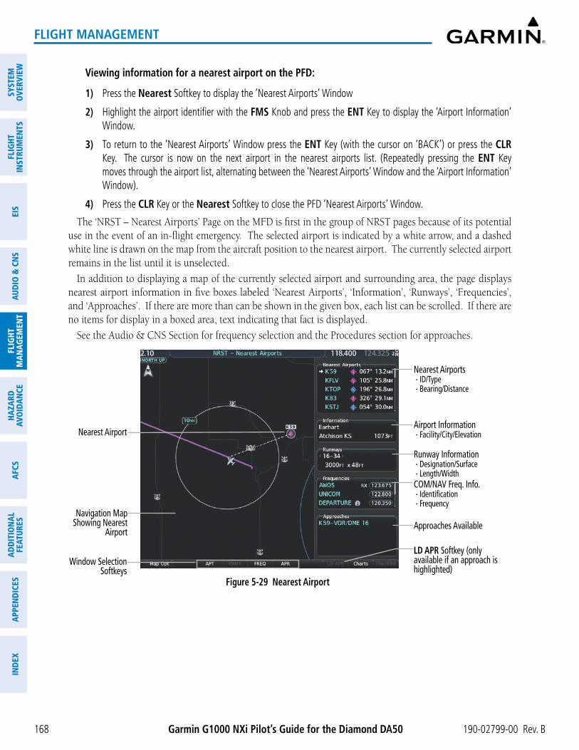
Garmin G1000 NXi Pilot’s Guide for the Diamond DA50 190-02799-00 Rev. B
SYST
EMO
VERV
IEW
FLIG
HTIN
STRU
MEN
TSEI
SAU
DIO
& C
NS
FLIG
HTM
AN
AGEM
ENT
HAZA
RDAV
OID
AN
CEA
FCS
AD
DIT
ION
AL
FEAT
URES
APP
END
ICES
IND
EX
168
FLIGHT MANAGEMENT
Viewing information for a nearest airport on the PFD:
1) Press the Nearest Softkey to display the ‘Nearest Airports’ Window
2) Highlight the airport identifier with the FMS Knob and press the ENT Key to display the ‘Airport Information’ Window.
3) To return to the ‘Nearest Airports’ Window press the ENT Key (with the cursor on ‘BACK’) or press the CLR Key. The cursor is now on the next airport in the nearest airports list. (Repeatedly pressing the ENT Key moves through the airport list, alternating between the ‘Nearest Airports’ Window and the ‘Airport Information’ Window).
4) Press the CLR Key or the Nearest Softkey to close the PFD ‘Nearest Airports’ Window.
The ‘NRST – Nearest Airports’ Page on the MFD is first in the group of NRST pages because of its potential use in the event of an in-flight emergency. The selected airport is indicated by a white arrow, and a dashed white line is drawn on the map from the aircraft position to the nearest airport. The currently selected airport remains in the list until it is unselected.
In addition to displaying a map of the currently selected airport and surrounding area, the page displays nearest airport information in five boxes labeled ‘Nearest Airports’, ‘Information’, ‘Runways’, ‘Frequencies’, and ‘Approaches’. If there are more than can be shown in the given box, each list can be scrolled. If there are no items for display in a boxed area, text indicating that fact is displayed.
See the Audio & CNS Section for frequency selection and the Procedures section for approaches.
Figure 5-29 Nearest Airport
Nearest Airport
Navigation MapShowing Nearest
Airport
Runway Information - Designation/Surface - Length/Width
Nearest Airports - ID/Type - Bearing/Distance
COM/NAV Freq. Info. - Identification - Frequency
Window Selection Softkeys
Airport Information - Facility/City/Elevation
Approaches Available
LD APR Softkey (only available if an approach is highlighted)

190-02799-00 Rev. B Garmin G1000 NXi Pilot’s Guide for the Diamond DA50
SYSTEMO
VERVIEWFLIG
HTIN
STRUMEN
TSEIS
AUDIO
& CN
SFLIG
HTM
AN
AGEM
ENT
HAZA
RDAVO
IDA
NCE
AFCS
AD
DITIO
NA
LFEATURES
APPEN
DICES
IND
EX
169
FLIGHT MANAGEMENT
Viewing information for a nearest airport on the MFD:
1) Turn the FMS Knob to select the ‘NRST – Nearest Airports’ Page (it is the first page of the group, so it may already be selected). If there are no Nearest Airports available, “None Within 200nm” is displayed.
2) Press the APT Softkey; or push the FMS Knob; or press the MENU Key, highlight ‘Select Airport Window’ and press the ENT Key. The cursor is placed in the ‘Nearest Airports’ Box. The first airport in the nearest airports list is highlighted.
3) Turn the FMS Knob to highlight the desired airport. (Pressing the ENT Key also moves to the next airport.)
4) Push the FMS Knob to remove the flashing cursor.
Viewing runway information for a specific airport:
1) With the ‘NRST – Nearest Airports’ Page displayed, press the RNWY Softkey; or press the MENU Key, highlight ‘Select Runway Window’; and press the ENT Key. The cursor is placed in the ‘Runways’ Box.
2) Turn the small FMS Knob to select the desired runway.
3) Push the FMS Knob to remove the flashing cursor.
The ‘Nearest Airports’ Box on the ‘Aux – System Setup 1’ Page defines the minimum runway length and surface type used when determining the 25 nearest airports to display on the MFD ‘NRST – Nearest Airports’ Page. A minimum runway length and/or surface type can be entered to prevent airports with small runways or runways that are not appropriately surfaced from being displayed. Default settings are 3000 feet (or 914 meters) for runway length and “Hard Only” for runway surface type.
Selecting nearest airport surface and minimum runway length matching criteria:
1) Use the FMS Knob to select the ‘Aux – System Setup 1’ Page.
2) Push the FMS Knob momentarily to activate the flashing cursor.
3) Turn the large FMS Knob to highlight the ‘Runway Surface’ Field in the ‘Nearest Airport’ Box.
4) Turn the small FMS Knob to select the desired runway option (Any, Hard Only, Hard/ Soft, Water).
5) Press the ENT Key. The cursor moves to the ‘Minimum Length’ Field in the ‘Nearest Airport’ Box.
6) Use the FMS Knob to enter the minimum runway length (zero to 25,000 feet) and press the ENT Key.
7) Push the FMS Knob to remove the flashing cursor.
NON-AIRPORT AND USER CREATED WAYPOINTS
WAYPOINT INFORMATION
Information pages for Intersections, VORs, NDBs, VRPs, and User Waypoints will show a map of the currently selected waypoint, the waypoint identifier, and location. Additionally, intersections will show the nearest VOR while both the VOR and NDB waypoints will show their frequency and the nearest airport. User Waypoint information also provides the reference Mode (radial/radial, radial/DME, or latitude/longitude), temporary status, comments, and a User Waypoint list.

Garmin G1000 NXi Pilot’s Guide for the Diamond DA50 190-02799-00 Rev. B
SYST
EMO
VERV
IEW
FLIG
HTIN
STRU
MEN
TSEI
SAU
DIO
& C
NS
FLIG
HTM
AN
AGEM
ENT
HAZA
RDAV
OID
AN
CEA
FCS
AD
DIT
ION
AL
FEAT
URES
APP
END
ICES
IND
EX
170
FLIGHT MANAGEMENT
The ‘VOR Information’ Page can be used to view information about VOR and ILS signals (since ILS signals can be received on a NAV receiver), or to quickly tune a VOR or ILS frequency. If a VOR station is combined with a TACAN station it is listed as a VOR-TACAN on the ‘VOR Information’ Page and if it includes only DME, it is displayed as VOR-DME. Also, the VOR class (Low Altitude, High Altitude, and Terminal) will be shown in the VOR ‘Information’ Box.
The system can create and store up to 1,000 user-defined waypoints. User waypoints can be created from any map display (except PFD Inset Map, ‘Aux – Trip Planning’ Page, or Procedure Pages) by selecting a position on the map using the Joystick, or from the ‘WPT – User WPT Information’ Page by referencing a bearing/distance from an existing waypoint, bearings from two existing waypoints, or a latitude and longitude. Once a waypoint has been created, it can be renamed, removed, or moved. Temporary user waypoints are erased upon system power down.
NOTE: The VOR displayed on the ‘WPT – Intersection Information’ Page is the nearest VOR, not necessarily the VOR used to define the intersection.
Selected Waypoint:Intersection
(as seen here)NDBVOR
VRP, orUser Waypoint
Navigation MapShowing Selected
Intersection
Intersection Identifier
Nearest VOR Info - Identifier/Type (symbol) - Radial to VOR - Distance to VOR
Intersection Info - Region - Lat/Long
Figure 5-30 Non-Airport Waypoint Information (Intersection Example)
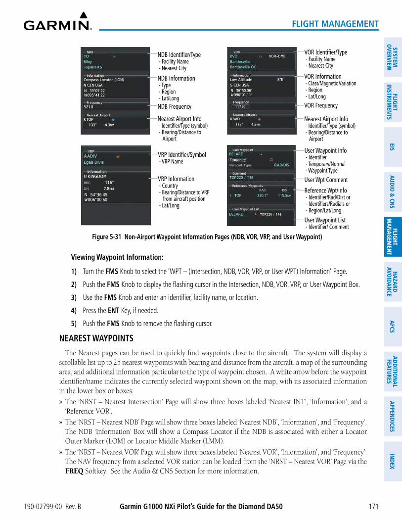
190-02799-00 Rev. B Garmin G1000 NXi Pilot’s Guide for the Diamond DA50
SYSTEMO
VERVIEWFLIG
HTIN
STRUMEN
TSEIS
AUDIO
& CN
SFLIG
HTM
AN
AGEM
ENT
HAZA
RDAVO
IDA
NCE
AFCS
AD
DITIO
NA
LFEATURES
APPEN
DICES
IND
EX
171
FLIGHT MANAGEMENT
VOR Identifier/Type - Facility Name - Nearest City
Nearest Airport Info - Identifier/Type (symbol) - Bearing/Distance to Airport
VOR Information - Class/Magnetic Variation - Region - Lat/LongVOR Frequency
VRP Identifier/Symbol - VRP Name
VRP Information - Country - Bearing/Distance to VRP from aircraft position - Lat/Long
User Waypoint Info - Identifier - Temporary/Normal - Waypoint Type
User Waypoint List - Identifier/ Comment
Reference Wpt/Info - Identifier/Rad/Dist or - Identifiers/Radials or - Region/Lat/Long
User Wpt Comment
NDB Identifier/Type - Facility Name - Nearest City
Nearest Airport Info - Identifier/Type (symbol) - Bearing/Distance to Airport
NDB Information - Type - Region - Lat/LongNDB Frequency
Figure 5-31 Non-Airport Waypoint Information Pages (NDB, VOR, VRP, and User Waypoint)
Viewing Waypoint Information:
1) Turn the FMS Knob to select the ‘WPT – (Intersection, NDB, VOR, VRP, or User WPT) Information’ Page.
2) Push the FMS Knob to display the flashing cursor in the Intersection, NDB, VOR, VRP, or User Waypoint Box.
3) Use the FMS Knob and enter an identifier, facility name, or location.
4) Press the ENT Key, if needed.
5) Push the FMS Knob to remove the flashing cursor.
NEAREST WAYPOINTS
The Nearest pages can be used to quickly find waypoints close to the aircraft. The system will display a scrollable list up to 25 nearest waypoints with bearing and distance from the aircraft, a map of the surrounding area, and additional information particular to the type of waypoint chosen. A white arrow before the waypoint identifier/name indicates the currently selected waypoint shown on the map, with its associated information in the lower box or boxes:
» The ‘NRST – Nearest Intersection’ Page will show three boxes labeled ‘Nearest INT’, ‘Information’, and a ‘Reference VOR’.
» The ‘NRST – Nearest NDB’ Page will show three boxes labeled ‘Nearest NDB’, ‘Information’, and ‘Frequency’. The NDB ‘Information’ Box will show a Compass Locator if the NDB is associated with either a Locator Outer Marker (LOM) or Locator Middle Marker (LMM).
» The ‘NRST – Nearest VOR’ Page will show three boxes labeled ‘Nearest VOR’, ‘Information’, and ‘Frequency’. The NAV frequency from a selected VOR station can be loaded from the ‘NRST – Nearest VOR’ Page via the FREQ Softkey. See the Audio & CNS Section for more information.

Garmin G1000 NXi Pilot’s Guide for the Diamond DA50 190-02799-00 Rev. B
SYST
EMO
VERV
IEW
FLIG
HTIN
STRU
MEN
TSEI
SAU
DIO
& C
NS
FLIG
HTM
AN
AGEM
ENT
HAZA
RDAV
OID
AN
CEA
FCS
AD
DIT
ION
AL
FEAT
URES
APP
END
ICES
IND
EX
172
FLIGHT MANAGEMENT
» The ‘NRST – Nearest VRP’ Page will show two boxes labeled ‘Nearest VRP’ and ‘Information’. Information will contain the VRP Name, Country and latitude/longitude.
» The ‘NRST – Nearest User WPTS’ Page will show three boxes labeled ‘Nearest User’, ‘Information’, and ‘Reference Waypoints’. Information will include any Comments and the latitude/longitude. The ‘Reference Waypoints’ Box will provide a reference NAVAID with a radial/DME that coincides with the User Waypoint.
The nearest waypoint list will only include waypoints within 200nm. If there are no waypoints in the list, text indicating that there are no nearest waypoints will be displayed, and the information and frequency fields (if applicable) will be dashed.
Nearest Non-Airport Waypoint:
- Intersection (this example) - NDB- VOR
- VRP, or- User Waypoint
Navigation MapExample:
Showing Nearest Intersection
Nearest Intersections - White arrow indicates the selected waypoint shown.
Reference VOR Info - Identifier/Type (symbol) - Radial to VOR - Distance to VOR
Intersection Info - Lat/Long
Figure 5-32 Nearest Intersection Example
Note: See next Figure for NDB, VOR, VRP, and User Waypoint examples.

190-02799-00 Rev. B Garmin G1000 NXi Pilot’s Guide for the Diamond DA50
SYSTEMO
VERVIEWFLIG
HTIN
STRUMEN
TSEIS
AUDIO
& CN
SFLIG
HTM
AN
AGEM
ENT
HAZA
RDAVO
IDA
NCE
AFCS
AD
DITIO
NA
LFEATURES
APPEN
DICES
IND
EX
173
FLIGHT MANAGEMENT
NDB Information - Facility Name/City - Type - Lat/Long
Nearest NDB - NDB Identifier/Symbol - Bearing/Distance to NDB from aircraft position
NDB Frequency
VOR Information - Facility Name/City - Class/Magnetic Variation - Lat/Long
Nearest VOR - VOR Identifier/Symbol - Bearing/Distance to VOR from aircraft position
VOR Frequency
VRP Information - VRP Name - Country - Lat/Long
Nearest VRP - VRP Identifier/Symbol - Bearing/Distance to VRP from aircraft position
Nearest User Wpt List - Identifier - Bearing/Distance from aircraft position
User Waypoint Info - Comment - Lat/Long
Reference Wpt Info - Identifier - Radial/Distance
Figure 5-33 Nearest Non-Airport Waypoints (NDB, VOR, VRP, and User WPTS)

Garmin G1000 NXi Pilot’s Guide for the Diamond DA50 190-02799-00 Rev. B
SYST
EMO
VERV
IEW
FLIG
HTIN
STRU
MEN
TSEI
SAU
DIO
& C
NS
FLIG
HTM
AN
AGEM
ENT
HAZA
RDAV
OID
AN
CEA
FCS
AD
DIT
ION
AL
FEAT
URES
APP
END
ICES
IND
EX
174
FLIGHT MANAGEMENT
Viewing Nearest Non-Airport Waypoints:
1) Turn the FMS Knob to select the ‘NRST – Nearest (Intersections, NDB, VOR, VRP, or User WPTS)’ Page.
2) Push the FMS Knob to display the flashing cursor in the ‘Nearest INT, NDB, VOR, VRP, or User’ Box,
Or:
If the ‘NRST – Nearest VOR’ Page is displayed, to display the flashing cursor:
Press the VOR Softkey.
Or:
a) Press the MENU Key
b) Highlight ‘Select VOR Window’, and press the ENT Key.
3) If needed, press the ENT Key or turn either FMS Knob as needed to select an identifier.
4) Push the FMS Knob to remove the flashing cursor.
USER WAYPOINTS
The system can create and store up to 1,000 user-defined waypoints. User waypoints can be created on most MFD map displays by selecting a position on the map using the Joystick, or through the ‘WPT – User WPT Information’ or flight plan pages. Waypoints created from WPT or FPL pages will default to the current aircraft position.
The different Types of user waypoints include Route or Airport. Elevation must be entered for User Airport waypoints. A Route User Waypoint may have up 6 characters in the waypoint name. However, the waypoint name for a User Airport is limited to 4 characters.
Temporary user waypoints, as indicated by a green check mark in the ‘Temporary’ Field, will be automatically deleted upon the next power cycle. The default storage setting for creating a new user waypoint can be changed from the ‘Waypoint Setup’ Window.
Three Modes of reference are available to define the user waypoint position: radial/distance from an existing waypoint (RAD/DIS), radial intersection from two existing waypoints (RAD/RAD), or la titude and longitude (LAT/LON). By default, new waypoints will be created as a Route waypoint type using the RAD/DIS mode of reference.
A system generated comment for a user-defined waypoint incorporates the reference waypoint identifier, bearing, and distance. A new comment may be entered, limited to 25 characters.

190-02799-00 Rev. B Garmin G1000 NXi Pilot’s Guide for the Diamond DA50
SYSTEMO
VERVIEWFLIG
HTIN
STRUMEN
TSEIS
AUDIO
& CN
SFLIG
HTM
AN
AGEM
ENT
HAZA
RDAVO
IDA
NCE
AFCS
AD
DITIO
NA
LFEATURES
APPEN
DICES
IND
EX
175
FLIGHT MANAGEMENT
Figure 5-34 User Waypoint Types and Modes of ReferenceUser Waypoint – RAD/RAD Mode
Waypoint Type Route, Airport, or Heliport
User Airport – LAT/LON Mode
Comment Field
Elevation must be entered for User Airport / Heliport
User Airport / Heliport Symbol
Waypoint Mode
LAT/LON Coordinates
Route User Waypoint Symbol
Temporary Storage Enabled
System Generated Comment
Reference Waypoint Radials
Creating user wayPoints
Creating a user waypoint:
1) Create a new waypoint name:
a) From any page showing a map display, push the Joystick to activate the panning function and pan to the map location of the desired user waypoint (excluding the ‘Aux – Trip Planning’ and Procedure pages).
b) Press the ENT Key. (If the map pointer is within the boundaries of an airspace, a menu pops. Use the FMS Knob to highlight ‘Create User Waypoint’ and press the ENT Key.) The ‘WPT – User WPT Information’ Page is displayed with the captured position.
c) Use the FMS Knob to enter the waypoint name. Press the ENT Key to accept the waypoint name.
Or:

Garmin G1000 NXi Pilot’s Guide for the Diamond DA50 190-02799-00 Rev. B
SYST
EMO
VERV
IEW
FLIG
HTIN
STRU
MEN
TSEI
SAU
DIO
& C
NS
FLIG
HTM
AN
AGEM
ENT
HAZA
RDAV
OID
AN
CEA
FCS
AD
DIT
ION
AL
FEAT
URES
APP
END
ICES
IND
EX
176
FLIGHT MANAGEMENT
a) With the ‘WPT – User WPT Information’ Page displayed, press the New Softkey; or press the MENU Key and select ‘Create New User Waypoint’ and press the ENT Key.
b) Use the FMS Knob to enter a user waypoint name.
c) Press the ENT Key to accept the waypoint name.
Or:
a) With the ‘WPT – User WPT Information’ Page displayed, push the FMS Knob to activate the cursor. Use the large FMS Knob to highlight the waypoint name.
b) Enter a user waypoint name.
c) Press the ENT Key. The message ‘Are you sure you want to create the new user waypoint AAAAAA?’ is displayed.
d) With ‘Yes’ highlighted, press the ENT Key to accept the waypoint name.
Or:
a) With a flight plan page or window displayed, push the FMS Knob to activate the cursor (not required on the PFD).
b) Select the point in the flight plan before which to add the new user waypoint. The new waypoint is placed directly in front of (above) the highlighted waypoint.
c) Turn the small FMS Knob clockwise to display the ‘Waypoint Information’ Window.
d) Enter the name of the new user waypoint (a waypoint that does not match any existing waypoint in the database) and press the ENT Key.
e) The message ‘AAAAA does not exist. Create User Waypoint?’ is displayed. Press the ENT Key with ‘Yes’ highlighted to accept the waypoint name.
2) Select the Waypoint Type:
a) Use the FMS Knob to highlight the desired waypoint type and press ENT Key.
b) If an aerodrome is selected as the Waypoint Type, the message ‘User airports require valid elevation.’ is displayed. Press the ENT Key.
c) Use the FMS Knob to enter the elevation and press the ENT Key.
3) If desired, use the large FMS Knob to highlight the ‘Temporary’ Field and press the ENT Key to check or uncheck the box to change the storage method to temporary or normal, as desired.
4) Use the large FMS Knob to highlight the ‘Waypoint Mode’ Field if necessary. If desired, change the waypoint mode of reference in one of the following ways:
Select ‘RAD/RAD’ using the small FMS Knob, press the ENT Key, and enter the two reference waypoint identifiers and radials into the ‘Reference Waypoints’ Box using the FMS Knob.
Or:
Select ‘RAD/DIS’ using the small FMS Knob, press the ENT Key, and enter the reference waypoint identifier, the radial, and the distance into the ‘Reference Waypoints’ Box using the FMS Knob.
Or:

190-02799-00 Rev. B Garmin G1000 NXi Pilot’s Guide for the Diamond DA50
SYSTEMO
VERVIEWFLIG
HTIN
STRUMEN
TSEIS
AUDIO
& CN
SFLIG
HTM
AN
AGEM
ENT
HAZA
RDAVO
IDA
NCE
AFCS
AD
DITIO
NA
LFEATURES
APPEN
DICES
IND
EX
177
FLIGHT MANAGEMENT
Select ‘LAT/LON’ using the small FMS Knob, press the ENT Key, and enter the latitude and longitude into the ‘Information’ Box using the FMS Knob.
5) Use the large FMS Knob to highlight the field in the ‘Comment’ Box. If desired, use the FMS Knob to change the comment (limited to 25 characters).
6) When finished, push the FMS Knob to remove the flashing cursor.
Or:
With a flight plan page or window displayed, turn the large FMS Knob to highlight ‘Load WPT to FPL’ and press the ENT Key.
eDiting user wayPoints
Editing a user waypoint comment or location:
1) With the ‘WPT – User WPT Information’ Page displayed, push the FMS Knob to activate the cursor. The cursor is placed in the ‘User Waypoint’ Box.
2) Use the FMS Knob to enter the name of the User Waypoint; or turn the large FMS Knob and scroll to the desired waypoint in the ‘User Waypoint List’ Box.
3) Turn the large FMS Knob to move the cursor to the desired field.
4) Use the FMS Knob to make any changes.
5) Press the ENT Key to accept the changes.
6) Push the FMS Knob to remove the flashing cursor.
Resetting the comment field to the system generated comment:
1) With the ‘WPT - User WPT Information’ Page displayed, push the FMS Knob to activate the cursor. The cursor is placed in the ‘User Waypoint’ Box.
2) Use the FMS Knob to enter the name of the User Waypoint; or turn the large FMS Knob and scroll to the desired waypoint in the ‘User Waypoint List’ Box.
3) Press the MENU Key.
4) Use the large FMS Knob to select ‘Auto Comment’.
5) Press the ENT Key. The generated comment is based on the reference point used to define the waypoint.
Changing the location of an existing waypoint to the aircraft present position:
1) With the ‘WPT - User WPT Information’ Page displayed, push the FMS Knob to activate the cursor. The cursor is placed in the ‘User Waypoint’ Box.
2) Use the FMS Knob to enter the name of the User Waypoint; or turn the large FMS Knob and scroll to the desired waypoint in the ‘User Waypoint List’ Box.
3) Press the MENU Key.
4) Use the large FMS Knob to select ‘Use Present Position’.
5) Press the ENT Key. The new waypoint’s location is saved.
6) Push the FMS Knob to remove the flashing cursor.

Garmin G1000 NXi Pilot’s Guide for the Diamond DA50 190-02799-00 Rev. B
SYST
EMO
VERV
IEW
FLIG
HTIN
STRU
MEN
TSEI
SAU
DIO
& C
NS
FLIG
HTM
AN
AGEM
ENT
HAZA
RDAV
OID
AN
CEA
FCS
AD
DIT
ION
AL
FEAT
URES
APP
END
ICES
IND
EX
178
FLIGHT MANAGEMENT
Renaming user waypoints:
1) With the ‘WPT - User WPT Information’ Page displayed, push the FMS Knob to activate the cursor. The cursor is placed in the ‘User Waypoint’ Box.
2) Use the FMS Knob to enter the name of the User Waypoint; or turn the large FMS Knob and scroll to the desired waypoint in the ‘User Waypoint List’ Box.
3) Select the rename function:
Press the Rename Softkey.
Or:
a) Press the MENU Key.
b) Turn the large FMS Knob to select ‘Rename User Waypoint’.
c) Press the ENT Key.
4) Use the FMS Knob to enter a new name.
5) Press the ENT Key. The message ‘Do you want to rename the user waypoint AAAAAA to BBBBBB?’ is displayed.
6) With ‘YES’ highlighted, press the ENT Key.
7) Push the FMS Knob to remove the flashing cursor.
Changing the user waypoint storage duration default setting:
1) With the ‘WPT – User WPT Information’ Page displayed, press the MENU Key.
2) Move the cursor to select ‘Waypoint Setup’, and press the ENT Key.
3) Use the small FMS Knob to select ‘Normal’ or ‘Temporary’ as desired, and press the ENT Key.
4) Push the FMS Knob to remove the flashing cursor and return to the ‘WPT – User WPT Information’ Page.

190-02799-00 Rev. B Garmin G1000 NXi Pilot’s Guide for the Diamond DA50
SYSTEMO
VERVIEWFLIG
HTIN
STRUMEN
TSEIS
AUDIO
& CN
SFLIG
HTM
AN
AGEM
ENT
HAZA
RDAVO
IDA
NCE
AFCS
AD
DITIO
NA
LFEATURES
APPEN
DICES
IND
EX
179
FLIGHT MANAGEMENT
Deleting user wayPoints
Deleting a single user waypoint:
1) With the ‘WPT – User WPT Information’ Page displayed, highlight a User Waypoint in the ‘User Waypoint List’ Box, or enter a waypoint in the ‘User Waypoint’ Box.
2) Press the Delete Softkey or press the CLR Key. ‘Yes’ is highlighted in the confirmation window.
3) Press the ENT Key.
4) Push the FMS Knob to remove the flashing cursor.
Or:
1) With the ‘WPT – User WPT Information’ Page displayed, push the FMS Knob to activate the cursor.
2) Use the large FMS Knob to highlight a User Waypoint in the ‘User Waypoint List’ Box, or use the FMS Knob to enter a waypoint in the ‘User Waypoint’ Box.
3) Press the MENU Key. Use the FMS Knob to highlight ‘Delete User Waypoint’.
4) Press the ENT Key twice to confirm the selection.
5) Push the FMS Knob to remove the flashing cursor.
NOTE: The option to ‘Delete All User Waypoints’ is not available while the aircraft is in flight.
Deleting all user waypoints:
1) With the ‘WPT – User WPT Information’ Page displayed, highlight a User Waypoint in the ‘User Waypoint List’ Box.
2) Press the MENU Key.
3) Use the FMS Knob to highlight ‘Delete All User Waypoints.’
4) Press the ENT Key twice to confirm the selection.

Garmin G1000 NXi Pilot’s Guide for the Diamond DA50 190-02799-00 Rev. B
SYST
EMO
VERV
IEW
FLIG
HTIN
STRU
MEN
TSEI
SAU
DIO
& C
NS
FLIG
HTM
AN
AGEM
ENT
HAZA
RDAV
OID
AN
CEA
FCS
AD
DIT
ION
AL
FEAT
URES
APP
END
ICES
IND
EX
180
FLIGHT MANAGEMENT
5.4 AIRSPACESThe system can display the following types of airspaces: Class B, TMA, and Airways surrounding TMA, Class
C, CTA, Class A, Class D, Restricted (Prohibited), MOA (Military), and other airspace provided by the navigation database. Some examples of typical airspaces are depicted below. See the Map Symbols portion of this section for the maximum ranges for each type of airspace and the symbol used to define the airspace area. Temporary Flight Restrictions (TFRs) are discussed in the Hazard Avoidance Section.
Figure 5-35 Airspaces
MOA (Military)
Class D Airspace
Class B Airspace
Restricted Area
Class C Airspace
Alert Area
ADIZ
Warning Area
Airspace Altitude Label

190-02799-00 Rev. B Garmin G1000 NXi Pilot’s Guide for the Diamond DA50
SYSTEMO
VERVIEWFLIG
HTIN
STRUMEN
TSEIS
AUDIO
& CN
SFLIG
HTM
AN
AGEM
ENT
HAZA
RDAVO
IDA
NCE
AFCS
AD
DITIO
NA
LFEATURES
APPEN
DICES
IND
EX
181
FLIGHT MANAGEMENT
NEAREST AIRSPACE
SETTING AIRSPACE ALERTS
The ‘Airspace Alerts’ Box (‘Aux – System Setup 1’ Page) on the MFD allows the pilot to turn the controlled/special-use airspace message alerts on or off. This does not affect the alerts listed on the ‘NRST – Nearest Airspaces‘ Page or the airspace boundaries depicted on the map display. It simply turns on/off the system messages related to airspace alerts provided when the aircraft is approaching or near an airspace.
The following system messages will be generated on the PFD when airspace alerts are set to on.
Message CommentsINSIDE ARSPC – Inside airspace. The aircraft is inside the airspace.ARSPC AHEAD – Airspace ahead – less than 10 minutes.
Special use airspace is ahead of aircraft track. The aircraft current ground track penetrates the airspace within 10 minutes.
ARSPC NEAR – Airspace near and ahead. Special use airspace is near and ahead of the aircraft position.
ARSPC NEAR – Airspace near – less than 2 nm. Special use airspace is within 2 nm of the aircraft position.
Table 5-9 Airspace Messages
An altitude buffer is also provided which “expands” the vertical range above or below an airspace. For example, if the buffer is set at 500 feet, and the aircraft is more than 500 feet above/ below an airspace, an alert message is not generated, but if the aircraft is less than 500 feet above/below an airspace and projected to enter it, the pilot is notified with an alert message. The default setting for the altitude buffer is 200 feet.
Enabling/disabling airspace alerts:
1) Use the FMS Knob to select the ‘Aux – System Setup 1’ Page (Setup 1 Softkey).
2) Push the FMS Knob momentarily to activate the flashing cursor.
3) Turn the large FMS Knob to highlight the desired field in the ‘Airspace Alerts’ Box.
4) Turn the small FMS Knob clockwise to turn the airspace alert On or counterclockwise to turn the alert Off.
5) Push the FMS Knob to remove the flashing cursor.
Changing the altitude buffer distance setting:
1) Use the FMS Knob to select the ‘Aux – System Setup 1’ Page (Setup 1 Softkey).
2) Push the FMS Knob momentarily to activate the flashing cursor.
3) Turn the large FMS Knob to highlight the ‘Altitude Buffer’ Field in the ‘Airspace Alerts’ Box.
4) Use the FMS Knob to enter an altitude buffer value and press the ENT Key.
5) Push the FMS Knob to remove the flashing cursor.

Garmin G1000 NXi Pilot’s Guide for the Diamond DA50 190-02799-00 Rev. B
SYST
EMO
VERV
IEW
FLIG
HTIN
STRU
MEN
TSEI
SAU
DIO
& C
NS
FLIG
HTM
AN
AGEM
ENT
HAZA
RDAV
OID
AN
CEA
FCS
AD
DIT
ION
AL
FEAT
URES
APP
END
ICES
IND
EX
182
FLIGHT MANAGEMENT
VIEWING NEAREST AIRSPACE INFORMATION
The ‘NRST – Nearest Airspaces’ Page can be used to quickly find airspaces close to the flight path. In addition, a selected frequency associated with the airspace can be loaded from the ‘NRST – Nearest Airspaces’ Page. In addition to displaying a map of airspace boundaries and surrounding area, the ‘NRST – Nearest Airspaces’ Page displays airspace information in four boxes labelled ‘Airspace Alerts’, ‘Airspace Agency’, ‘Vertical Limits’, and ‘Frequencies’.
The map on the ‘NRST – Nearest Airspaces’ Page automatically zooms in on the nearest airspace as listed in the ‘Airspace Alerts’ Box and an information window about that airspace is shown on the map. Use the FMS Knob to select and view other nearest airspaces on the map. If there are no nearest airspaces listed, the map will be centered around the aircraft present position.
Airspace alerts and associated frequencies are shown in scrollable lists on the ‘NRST – Nearest Airspaces’ Page. The Alerts and FREQ Softkeys place the cursor in the respective list. The FREQ Softkey is enabled only if one or more frequencies exist for a selected airspace.
Figure 5-36 Nearest Airspaces Page
Airspace Alerts Info - Name - Proximity (Ahead, Inside, Ahead < 2nm, Within 2nm) - Time till Intercept (only if Ahead or Ahead < 2nm)
Airspace Vertical Limits - Ceiling - Floor
Airspace/Agency Info - Airspace Type - Controlling Agency
Nearest Airspace Information
Associated Frequencies - Type - Availability/Info - Frequency
Airspace within 2nm
Inside of Airspace
Selecting and viewing an airspace alert with its associated information:
1) Use the FMS Knob to select the ‘NRST – Nearest Airspaces’ Page.
2) Press the Alerts Softkey on the MFD; or push the FMS Knob; or press the MENU Key, highlight ‘Select Alerts Window’, and press the ENT Key. The cursor is placed in the ‘Airspace Alerts’ Box.
3) Use the FMS Knob to highlight the desired airspace.
4) Push the FMS Knob to remove the flashing cursor.

190-02799-00 Rev. B Garmin G1000 NXi Pilot’s Guide for the Diamond DA50
SYSTEMO
VERVIEWFLIG
HTIN
STRUMEN
TSEIS
AUDIO
& CN
SFLIG
HTM
AN
AGEM
ENT
HAZA
RDAVO
IDA
NCE
AFCS
AD
DITIO
NA
LFEATURES
APPEN
DICES
IND
EX
183
FLIGHT MANAGEMENT
SMART AIRSPACEThe Smart Airspace function de-emphasizes airspaces above or below the current aircraft altitude. The
function does not require the aircraft’s present position or flight path to enter the lateral boundaries of the airspace. If the current aircraft altitude is within 1100 feet of the vertical boundaries of the airspace, the airspace boundary is shown normally. If the current aircraft altitude is not within 1100 feet of the vertical boundaries of the airspace, the airspace boundary is shown subdued.
NOTE: Smart Airspace function will not de-emphasize airspaces on the HSI Map when the MFD is in reversionary mode.
Figure 5-37 Smart AirspaceSmart Airspace Off Smart Airspace On
Turning smart airspace on or off:
1) Use the FMS Knob to select the ‘Map – Navigation Map’ Page.
2) Press the MENU Key, and press the ENT Key. The ’Map Settings’ Window is displayed.
3) Turn the small FMS Knob to highlight the ‘Airspace’ and press the ENT Key.
4) Turn the large FMS Knob to highlight the ‘Smart Airspace’ Field.
5) Turn the small FMS Knob clockwise to turn smart airspace ‘On’ or counterclockwise to turn smart airspace ‘Off’.
6) Push the FMS Knob to remove the flashing cursor.

Garmin G1000 NXi Pilot’s Guide for the Diamond DA50 190-02799-00 Rev. B
SYST
EMO
VERV
IEW
FLIG
HTIN
STRU
MEN
TSEI
SAU
DIO
& C
NS
FLIG
HTM
AN
AGEM
ENT
HAZA
RDAV
OID
AN
CEA
FCS
AD
DIT
ION
AL
FEAT
URES
APP
END
ICES
IND
EX
184
FLIGHT MANAGEMENT
5.5 FLIGHT PLANNINGFlight planning on the system consists of building a flight plan by entering waypoints one at a time, adding
waypoints along airways, and inserting departures, airways, arrivals, or approaches as needed. The system allows flight planning information to be entered from either the MFD or PFD. Additionally, the system provides direct-to functionality, allowing short-term navigation to a single waypoint. Activated direct-to navigation information is displayed in the ‘Active Flight Plan’ Box above the Active Flight Plan. The flight plan is displayed on maps using different line widths, colors, and types, based on the type of leg and the segment of the flight plan currently being flown (departure, enroute, arrival, approach, or missed approach).
Flight Plan Symbol Name Description Symbol
Course Leg
Course leg currently flown
A future course leg in the current phase of flight
A course leg in either a previously flown course leg, or a future course leg not in the current phase of flight
Heading LegHeading leg currently flown
Future heading leg
Roll Steering Path 1
Turning path currently flown
Turning path for the next flight plan leg
Turning path beyond the next flight plan leg
Turn Anticipation ArcDisplayed when sequencing to the next flight plan leg via a fly-by waypoint, a lead turn is created, adjusting for groundspeed
Fly-Over Waypoint Displayed as a fly-over waypoint
Along Track Waypoint Displayed when an along track waypoint is created
Flight Path Fix A fix that terminates: manually, at a specified altitude, or at a specified distance or radial when flying a heading
Top of Descent (TOD) and Bottom of Descent (BOD)
When vertically navigating, the system will display where the aircraft will begin complete the descent
Parallel Track Waypoint Displayed when a parallel track is created
1 Roll Steering Path transitions between two disconnected legs (i.e. holding), some procedure turn segments, parallel track segments, or after some fly-over waypoints (discussed later in this section).
Table 5-10 Flight Plan Symbols on Map

190-02799-00 Rev. B Garmin G1000 NXi Pilot’s Guide for the Diamond DA50
SYSTEMO
VERVIEWFLIG
HTIN
STRUMEN
TSEIS
AUDIO
& CN
SFLIG
HTM
AN
AGEM
ENT
HAZA
RDAVO
IDA
NCE
AFCS
AD
DITIO
NA
LFEATURES
APPEN
DICES
IND
EX
185
FLIGHT MANAGEMENT
DIRECT-TO NAVIGATIONThe Direct-to method of navigation, initiated by pressing the ¯ Key, allows quick selection of a destination
and provides guidance to the selected point. Once a direct-to is activated, the system establishes a point-to-point course line from the present position to the selected direct-to destination. Course guidance is provided until the direct-to is replaced with a new direct-to or flight plan, or cancelled.
A vertical navigation (VNV) direct-to creates a descent path (and provides guidance to stay on the path) from the current altitude to a selected altitude at the direct-to waypoint. Vertical navigation is based on barometric altitudes, not on GPS altitude, and is used for cruise and descent phases of flight.
The ‘Direct To’ Window allows selection and activation of direct-to navigation. The ‘Direct To’ Window displays selected direct-to waypoint data on the PFD and the MFD.
Figure 5-38 Direct-to Window - MFD
Direct-to Point Info - Identifier/Symbol/Region - Facility Name - City
Location of Destination - Bearing/Distance
Map of Selected Point
Desired Course
VNV Constraints- Altitude at Arrival- Along Track Offset
Figure 5-39 Direct-to - PFD
Direct-to Point Info - Identifier/Symbol/City - Facility Name
Activation Command
Direct-to Point Info - Bearing/Distance - Desired Course
VNV Constraints- Altitude at Arrival- Along Track Offset

Garmin G1000 NXi Pilot’s Guide for the Diamond DA50 190-02799-00 Rev. B
SYST
EMO
VERV
IEW
FLIG
HTIN
STRU
MEN
TSEI
SAU
DIO
& C
NS
FLIG
HTM
AN
AGEM
ENT
HAZA
RDAV
OID
AN
CEA
FCS
AD
DIT
ION
AL
FEAT
URES
APP
END
ICES
IND
EX
186
FLIGHT MANAGEMENT
Any waypoint can be entered as a direct-to destination from a ‘Direct To’ Window. Also, any waypoint contained in the active flight plan can be selected as a direct-to waypoint from a ‘Direct To’ Window, the ‘FPL – Active Flight Plan’ Page, or the active ‘Flight Plan’ Window.
The ‘Direct To’ Window can always be displayed and allows selection and activation of direct-to navigation. If the direct-to is initiated from any page except the WPT pages, the default waypoint is the active flight plan waypoint (if a flight plan is active) or a blank waypoint field. Direct-to requests on any WPT page defaults to the displayed waypoint.
When navigating a direct-to, the system sets a direct great circle course to the selected destination. The course to a destination can also be manually selected using the ‘CRS’ or ‘Course’ Field on the ‘Direct To’ Window.
Entering a waypoint identifier, facility name, or city as a direct-to destination:
1) Press the ¯ Key. The ‘Direct To’ Window is displayed (with the active flight plan waypoint as the default selection or a blank waypoint field if no flight plan is active).
2) Turn the small FMS Knob clockwise to begin entering a waypoint identifier (turning it counter-clockwise brings up the waypoint selection submenu - press the CLR Key to remove it), or use the keypad to begin entering a waypoint identifier, or turn the large FMS Knob to select the facility name, or city field and turn the small FMS Knob or use the keypad to begin entering a facility name or city. If duplicate entries exist for the entered facility or city name, additional entries can be viewed by turning the small FMS Knob during the selection process.
3) Press the ENT Key. The ‘Activate?’ Field is highlighted.
4) Press the ENT Key to activate the direct-to.
Selecting an active flight plan waypoint as a direct-to destination:
1) While navigating an active flight plan, press the ¯ Key. The ‘Direct To’ Window is displayed with the active flight plan waypoint as the default selection.
2) Turn the small FMS Knob counter-clockwise to display the waypoint submenu window with a list of flight plan waypoints.
3) Turn the large FMS Knob to select the desired waypoint.
4) Press the ENT Key. The cursor is now displayed on ‘Activate?’.
5) Press the ENT Key again to activate the direct-to.
Or:
1) Press the FPL Key.
2) Push the FMS Knob to activate the cursor (not required on PFD), and turn the large FMS Knob to highlight the desired waypoint.
3) Press the ¯ Key.
4) Press the ENT Key. The cursor is now displayed on ‘Activate?’.
5) Press the ENT Key again to activate the direct-to.

190-02799-00 Rev. B Garmin G1000 NXi Pilot’s Guide for the Diamond DA50
SYSTEMO
VERVIEWFLIG
HTIN
STRUMEN
TSEIS
AUDIO
& CN
SFLIG
HTM
AN
AGEM
ENT
HAZA
RDAVO
IDA
NCE
AFCS
AD
DITIO
NA
LFEATURES
APPEN
DICES
IND
EX
187
FLIGHT MANAGEMENT
Selecting a Nearest, Recent or User Waypoint as a direct-to destination:
1) Press the ¯ Key. The ‘Direct To’ Window is displayed (with the active flight plan destination as the default selection or a blank destination if no flight plan is active).
2) Turn the small FMS Knob counter-clockwise to display the waypoint submenu window.
3) Turn the small FMS Knob clockwise to display the Nearest, Recent or User waypoints.
4) Turn the large FMS Knob clockwise to select the desired waypoint.
5) Press the ENT Key. The cursor is now displayed on ‘Activate?’.
6) Press the ENT Key again to activate the direct-to.
Selecting any waypoint as a direct-to destination:
1) Select the page or window containing the desired waypoint type and select the desired waypoint.
2) Press the ¯ Key to display the ‘Direct To’ Window with the selected waypoint as the direct-to destination.
3) Press the ENT Key. The cursor is now displayed on ‘Activate?’.
4) Press ENT again to activate the direct-to.
Selecting a nearby airport as a direct-to destination:
1) Press the Nearest Softkey on the PFD; or turn the FMS Knob to display the ‘NRST – Nearest Airports’ Page on the MFD and push the FMS Knob.
2) Use the FMS Knob to select the desired airport (the nearest one is already selected).
3) Press the ¯ Key.
4) Press the ENT Key. The cursor is now displayed on ‘Activate?’.
5) Press the ENT Key again to activate the direct-to.
Selecting a manual direct-to course:
1) Press the ¯ Key. The ‘Direct To’ Window is displayed (with the active flight plan waypoint as the default selection or a blank waypoint field if no flight plan is active).
2) Turn the large FMS Knob to highlight the ‘CRS’ or ‘Course’ Field.
3) Use the small FMS Knob or keypad to enter the desired course.
4) Press the ENT Key. The cursor is now displayed on ‘Activate?’.
5) Press the ENT Key again to activate the direct-to.
Reselecting the direct course from the current position:
1) Press the ¯ Key. The ‘Direct To’ Window is displayed.
2) Press the ENT Key. The cursor is now displayed on ‘Activate?’.
3) Press the ENT Key again to activate the direct-to.

Garmin G1000 NXi Pilot’s Guide for the Diamond DA50 190-02799-00 Rev. B
SYST
EMO
VERV
IEW
FLIG
HTIN
STRU
MEN
TSEI
SAU
DIO
& C
NS
FLIG
HTM
AN
AGEM
ENT
HAZA
RDAV
OID
AN
CEA
FCS
AD
DIT
ION
AL
FEAT
URES
APP
END
ICES
IND
EX
188
FLIGHT MANAGEMENT
Direct-to destinations may also be selected by using the Map Pointer on any map display (Map Pointer functionality is not available for traffic or terrain pages). If no airport, NAVAID, or user waypoint exists at the desired location, a temporary waypoint named ‘MAPWPT’ is automatically created at the location of the map arrow.
Selecting a waypoint as a direct-to destination using the Map Pointer:
1) From any page showing a map display (excluding the traffic and terrain pages), push the Joystick to display the Map Pointer.
2) Move the Joystick to place the pointer at the desired destination location. If the Map Pointer is placed on a waypoint, the waypoint name is highlighted.
3) Press the ̄ Key to display the ‘Direct To’ Window with the selected point entered as the direct-to destination.
4) Press the ENT Key. The cursor is now displayed on ‘Activate?’.
5) Press the ENT Key again to activate the direct-to.
Cancelling a Direct-to:
1) Press the ¯ Key to display the ‘Direct To’ Window.
2) Press the MENU Key.
3) With ‘Cancel Direct-To NAV’ highlighted, press the ENT Key. If a flight plan is still active, the system resumes
navigating the flight plan along the closest leg.
A direct-to with altitude constraints creates a vertical path (and provides guidance to stay on the path) from the aircraft’s current altitude to the altitude constraint of the direct-to waypoint. The altitude is reached at the waypoint, or at the specified distance along the flight path if VNV offset distance has been entered. Direct-to vertical navigation is discussed in the Flight Plan Vertical Navigation portion of Flight Management. Offset distances (Along Track Offsets) are discussed in the Flight Plan Operations portion of Flight Management.
SELECTION AND MODIFICATION METHODSThere are four methods to create or modify a flight plan:
- ‘Flight Plan’ Window on the PFD (create/modify the active flight plan)
- ‘FPL – Active Flight Plan’ Page on the MFD (create/modify the active flight plan)
- ‘FPL – ‘Standby Flight Plan’ Page on the MFD (create/modify the standby flight plan)
- ‘FPL – Flight Plan Catalog’ Page on the MFD (create/modify a stored flight plan)
To create or modify a flight plan, the cursor can be used to edit the required fields within the flight plan and the ‘Active VNV Profile’ Box within the ‘FPL – Active Flight Plan’ Page. The cursor will appear as a field consisting of a solid cyan or magenta rectangle. The cursor can be activated by pushing the FMS Knob. The Insertion Point Indicator is displayed as a small cyan triangle and is associated with the cursor location.
Fields can be highlighted by turning the large FMS Knob, and edits can be accomplished within the field by combining small and large FMS Knob turns or utilizing the alphanumeric keypad on the PFD/MFD Controller.

190-02799-00 Rev. B Garmin G1000 NXi Pilot’s Guide for the Diamond DA50
SYSTEMO
VERVIEWFLIG
HTIN
STRUMEN
TSEIS
AUDIO
& CN
SFLIG
HTM
AN
AGEM
ENT
HAZA
RDAVO
IDA
NCE
AFCS
AD
DITIO
NA
LFEATURES
APPEN
DICES
IND
EX
189
FLIGHT MANAGEMENT
Figure 5-40 ‘FPL - Active Flight Plan’ Page
Active FPL Waypoint List - Comment - Procedure Header - Waypoint Identifier - Airway Identifier - Desired Track to Waypoint - Distance to Waypoint - Waypoint Altitude Constraint
Vertical Navigation Profile - Active Vertical WPT Alt/ID - Time to Top of Descent - Vertical Speed Target - Flight Path Angle - Vertical Speed Target - Vertical Deviation
Active Flight Plan Leg
Turn Anticipation Arc
Non-Active,Flight Plan Leg
Active Flight Plan Comment
Figure 5-41 Active ‘Flight Plan’ Window on PFD
Active Flight Plan Leg
Active Flight Plan Waypoint List - Waypoint ID - Desired Track to Waypoint - Distance to Waypoint - Airway Identifier

Garmin G1000 NXi Pilot’s Guide for the Diamond DA50 190-02799-00 Rev. B
SYST
EMO
VERV
IEW
FLIG
HTIN
STRU
MEN
TSEI
SAU
DIO
& C
NS
FLIG
HTM
AN
AGEM
ENT
HAZA
RDAV
OID
AN
CEA
FCS
AD
DIT
ION
AL
FEAT
URES
APP
END
ICES
IND
EX
190
FLIGHT MANAGEMENT
Figure 5-42 ‘FPL – Standby Flight Plan’ Page
Standby FPL Waypoint List – Comment – Procedure Header – Waypoint Identifier – Airway Identifier – Desired Track to Waypoint – Distance to Waypoint – Waypoint Altitude Constraint
Standby Flight Plan Map
Figure 5-43 ‘FPL - Flight Plan Catalog’ Page
Flight Plan List - Comment
Selected FPL Info - Departure Waypoint - Destination Waypoint - Total Flight Plan Distance - Enroute Safe Altitude
Catalog Contents - # Used - # Empty
Selected Flight Plan
Map
NOTE: The system supports AFCS lateral guidance for all leg types (using navigation or approach mode). The system does not support course deviation for any heading leg types (VA, VD, VI, VM, or VR).
FLIGHT PLAN DISPLAYFlight plan information can be displayed in different locations and formats. Active flight plan information
can be displayed on the ‘Map – Navigation Map’ Page by enabling the Flight Plan Progress inset. Standby flight plan information is only displayed on the ‘FPL – Standby Flight Plan’ Page. Profile information for the active

190-02799-00 Rev. B Garmin G1000 NXi Pilot’s Guide for the Diamond DA50
SYSTEMO
VERVIEWFLIG
HTIN
STRUMEN
TSEIS
AUDIO
& CN
SFLIG
HTM
AN
AGEM
ENT
HAZA
RDAVO
IDA
NCE
AFCS
AD
DITIO
NA
LFEATURES
APPEN
DICES
IND
EX
191
FLIGHT MANAGEMENT
flight plan may also be displayed; see the Vertical Situation Display portion of Flight Management for more information. Active flight plan creation and modifications can be made on the ‘FPL – Active Flight Plan’ Page or on the ‘Flight Plan’ Window. The MFD Split Screen feature allows a side by side display of the active flight plan and corresponding chart.
FLIGHT PLAN PROGRESS INSET
Active flight plan progress can be displayed on the ‘Map – Navigation Map’ Page.
NOTE: ETE can be displayed as either HH+MM (ETE greater than 60 minutes) or MM:SS (ETE less than 60 minutes).
Displaying/removing the active flight plan progress on the ‘Map – Navigation Map’ Page:
1) Select the ‘Map – Navigation Map’ Page.
2) Press the Map Opt Softkey.
3) Press the Inset Softkey.
4) Press the FPL PROG Softkey to display the active flight plan progress.
5) To remove the active flight plan progress, press the Off softkey.
FLIGHT PLAN VIEWS
The ‘FPL – Active Flight Plan’ Page and ‘FPL – Standby Flight Plan’ Page can be configured to show cumulative distance over the length of the flight plan or the distance for each leg of the flight plan; and it can be viewed in a narrow or wide view. In the wide view, additional information is displayed: Fuel Remaining (‘Fuel REM’), Estimated Time Enroute (‘ETE’), Estimated Time of Arrival (‘ETA’), and Bearing to the waypoint (‘BRG’).
Changing the flight plan view:
1) Press the FPL Key for the MFD to display the ‘FPL – Active Flight Plan’ Page.
2) Press the View Softkey to display the Wide, Narrow, Leg-Leg, and CUM Softkeys.
3) Press the CUM Softkey to view cumulative waypoint distance, or press the Leg-Leg Softkey to view leg-to-leg waypoint distance.
4) Press the Wide Softkey to display the wide view, or press the Narrow Softkey to display the narrow view.
5) Press the Back Softkey to return to the top level active flight plan softkeys.
SPLIT SCREEN
Charts may be viewed alongside the active flight plan in Split Screen mode. Pressing the Charts Softkey from the ‘FPL – Active Flight Plan’ Page will remove the active flight plan map to display a Charts Pane alongside the Active Flight Plan Pane. The active flight plan map can be re-displayed. However, displaying the map in split screen limits the flight plan content which can be displayed. For example, displaying the Flight Plan Map while in split screen narrow view removes the ‘Active VNV Profile’ Box. See the following figures depicting the different split screen displays with the active flight plan.
See the System Overview section for more information on Split Screen Mode. For more information on Charts, see the Additional Features Section.

Garmin G1000 NXi Pilot’s Guide for the Diamond DA50 190-02799-00 Rev. B
SYST
EMO
VERV
IEW
FLIG
HTIN
STRU
MEN
TSEI
SAU
DIO
& C
NS
FLIG
HTM
AN
AGEM
ENT
HAZA
RDAV
OID
AN
CEA
FCS
AD
DIT
ION
AL
FEAT
URES
APP
END
ICES
IND
EX
192
FLIGHT MANAGEMENT
Figure 5-44 Split Screen Mode Narrow and Wide View
Split Screen Narrow View Split Screen Wide View
Display Title shows ‘Chart + Active Flight Plan’
Figure 5-45 Split Screen Mode with Flight Plan Map
Split Screen Narrow View with Flight Plan Map Split Screen Wide View with Flight Plan Map
Enabling/Disabling split screen mode from the ‘FPL – Active Flight Plan’ Page:
1) Press the FPL Key for the MFD to display the ‘FPL – Active Flight Plan’ Page.
2) Press the Charts Softkey. If necessary, press the CHRT Opt Softkey and press the Full SCN Softkey to disable full screen mode. Split screen mode is now enabled showing two display panes. The Chart Pane is highlighted by a cyan border indicating it is the active pane.
3) To quickly view the chart corresponding to the active flight plan leg, press the SYNC Softkey.
4) Press the Charts Softkey again to disable split screen mode.

190-02799-00 Rev. B Garmin G1000 NXi Pilot’s Guide for the Diamond DA50
SYSTEMO
VERVIEWFLIG
HTIN
STRUMEN
TSEIS
AUDIO
& CN
SFLIG
HTM
AN
AGEM
ENT
HAZA
RDAVO
IDA
NCE
AFCS
AD
DITIO
NA
LFEATURES
APPEN
DICES
IND
EX
193
FLIGHT MANAGEMENT
Displaying the flight plan map on the ‘FPL – Active Flight Plan’ Page in split screen mode:
1) Press the FPL Key for the MFD to display the ‘FPL – Active Flight Plan’ Page.
2) Press the Charts Softkey. If necessary, press the CHRT Opt Softkey and press the Full SCN Softkey to disable full screen mode. Split screen mode is now enabled showing two display panes. The Chart Pane is highlighted by a cyan border indicating it is the active pane.
3) Use the Joystick to select the ‘Active Flight Plan’ Pane as the active pane.
4) Press the MENU Key. ‘Show Flight Plan Map’ is highlighted. Press the ENT Key.
5) To remove the Flight Plan Map, press the MENU Key and select ‘Hide Flight Plan Map’. Press the ENT Key.
Changing the flight plan map orientation in split screen mode:
1) If necessary, use the Joystick to select the ‘FPL – Active Flight Plan’ Pane as the active display pane.
2) Press the MENU Key. Turn the FMS Knob to highlight ‘FPL Map Orientation to (TRK Up, HDG Up, North Up)’.
3) Press the ENT Key to select the orientation setting and return to the ‘FPL – Active Flight Plan’ Pane.
4) Repeat steps 2 through 3 to cycle through the different orientation settings.
CREATING A BASIC FLIGHT PLANThe active flight plan is listed on the ‘FPL – Active Flight Plan’ Page on the MFD, and in the ‘Flight Plan’
Window on the PFD. It is the flight plan to which the system is currently providing guidance, and is shown on the map displays. One flight plan can be activated at a time and becomes the active flight plan. The active flight plan is overwritten when another flight plan is activated.
A standby flight plan can be created by copying the active flight plan or by manual entry on the ‘FPL – Standby Flight Plan’ Page. The standby flight plan can be activated. A flight plan can also be created and stored in the system memory. If the standby flight plan is not stored, it will be erased upon the next power cycle.
Stored flight plans are listed on the ‘FPL – Flight Plan Catalog’ Page, and are available for activation (becomes the active flight plan).
Auto-designation will determine the most likely airport of origin and auto-populate the Active Flight Plan. Once determined, the airfield identifier automatically appears in the ‘Origin’ Field and the line immediately below ‘Origin’ while keeping the runway (‘RW’) Field empty. The line below the Origin line serves as the first point in the flight plan.
NOTE: If the ‘RW’ Field is filled, then the first point in the flight plan is auto-populated with the runway selected, located in the line immediately below the ‘RW’ Field.
Auto-designation occurs between 15 and 60 seconds after the display receives power under the following conditions:
- Aircraft position is known
- Aircraft is on the ground
- Nearest airport is within 200NM
- Flight plan is empty

Garmin G1000 NXi Pilot’s Guide for the Diamond DA50 190-02799-00 Rev. B
SYST
EMO
VERV
IEW
FLIG
HTIN
STRU
MEN
TSEI
SAU
DIO
& C
NS
FLIG
HTM
AN
AGEM
ENT
HAZA
RDAV
OID
AN
CEA
FCS
AD
DIT
ION
AL
FEAT
URES
APP
END
ICES
IND
EX
194
FLIGHT MANAGEMENT
If the pilot manually enters the origin, or any other leg of the flight plan before auto-designation occurs, nothing gets inserted automatically. The automatic insertion logic only runs once, so the pilot can edit the origin if the nearest airport is not the desired origin.
If the pilot enters a different airport into the first point of the flight plan, the Origin will change to this entry, and the pilot will be prompted to enter the departure runway.
Both the Origin airport/runway and the first point of the flight plan will be the same unless a departure is entered and a manual leg is inserted at the beginning of the loaded departure. Loading a departure locks in the origin information.
The following procedure is intended to provide an overview of basic flight plan creation. It will create a flight plan from the origin runway to the destination runway, and includes enroute waypoint selection. The following procedure does not include airways or terminal procedures. For instructions on how to add airways to a flight plan, see the Flight Plan Waypoint and Airway Modifications discussion later in this Flight Planning Section. For information on departures, arrivals, approaches, and missed approaches see the Procedures Section.
Figure 5-46 Flight Plan Waypoints
Enroute Waypoints
Origin Header
Destination Header
Enroute Header
Creating a flight plan:
1) For an active flight plan, press the FPL Key. Push the FMS Knob to activate the cursor (not required on PFD).
Or:
For a standby flight plan, press the FPL Key for the MFD. Turn the small FMS Knob to select the ‘FPL – Standby Flight Plan’ Page and push the FMS Knob to activate the cursor.
Or:
For a stored flight plan:
a) Press the FPL Key for the MFD. Turn the small FMS Knob to select the ‘FPL – Flight Plan Catalog’ Page.
b) Press the New Softkey; push the FMS Knob and select an empty Flight Plan List Field, and press the ENT Key; or press the ENT Key; or press the MENU Key, highlight ‘Create New Flight Plan’, and press the ENT Key to display a blank flight plan for the first empty storage location.

190-02799-00 Rev. B Garmin G1000 NXi Pilot’s Guide for the Diamond DA50
SYSTEMO
VERVIEWFLIG
HTIN
STRUMEN
TSEIS
AUDIO
& CN
SFLIG
HTM
AN
AGEM
ENT
HAZA
RDAVO
IDA
NCE
AFCS
AD
DITIO
NA
LFEATURES
APPEN
DICES
IND
EX
195
FLIGHT MANAGEMENT
2) If the system auto-designated the Origin, proceed to Step 3.
Or:
Enter or modify the origin airport and runway as follows:
a) Select the field below the Origin header to enter the origin airport identifier.
b) Use the FMS Knob, alphanumeric keypad, or the waypoint submenu to enter the identifier, facility, or city name of the airport.
c) Press the ENT Key. The ‘Set Runway’ Window is displayed with the ‘Runway’ Field highlighted.
d) Turn the small FMS Knob to select the runway, and press the ENT Key.
e) Press the ENT Key again to add the airport/runway to the flight plan.
3) Select the destination airport and runway by highlighting the field below the Destination header and completing steps 2b – 2e.
4) Select the enroute waypoints:
a) Select the location to insert the waypoint.
b) Use the FMS Knob or alphanumeric keypad to enter the identifier, facility, or city name of the waypoint.
c) Press the ENT Key. The flight plan is modified as each waypoint is entered.
5) Repeat step number 4 to enter each additional enroute waypoint.
6) When all waypoints have been entered, push the FMS Knob to remove the flashing cursor.
FLIGHT PLAN WAYPOINT AND AIRWAY MODIFICATIONSAll flight plans can be edited at any time. Waypoints and airways can be added, modified, or removed from
any flight plan. Edits made to an active flight plan affect navigation as soon as they are entered. Modifications to flight planned departures, arrivals, approaches, and missed approaches are discussed later in the Procedures portion of Flight Management.
FLIGHT PLAN WAYPOINTS
Within flight plans, waypoints can be added, removed and designated as fly-over or fly-by. Flight plans are limited to 100 waypoints (including waypoints within airways and procedures). If the number of waypoints in the flight plan exceeds 100, the message “Flight plan is full. Remove unnecessary waypoints.” appears and the new waypoint(s) are not added to the flight plan.
aDDing wayPoints
To add a waypoint, choose the flight plan, select the desired point of insertion, enter the waypoint, and the waypoint will be added prior to the selected waypoint. Either the ‘Waypoint Information’ Window or Waypoint Submenu can be used when entering the waypoint.
NOTE: If the identifier entered in the ‘Waypoint Information’ Window has duplicates, a ‘Duplicate Waypoint’ Window is displayed. Use the FMS Knob to select the correct waypoint.

Garmin G1000 NXi Pilot’s Guide for the Diamond DA50 190-02799-00 Rev. B
SYST
EMO
VERV
IEW
FLIG
HTIN
STRU
MEN
TSEI
SAU
DIO
& C
NS
FLIG
HTM
AN
AGEM
ENT
HAZA
RDAV
OID
AN
CEA
FCS
AD
DIT
ION
AL
FEAT
URES
APP
END
ICES
IND
EX
196
FLIGHT MANAGEMENT
NOTE: If the flight plan is successfully edited in the ‘Flight Plan’ Window from PFD while the MFD ‘FPL – Active Flight Plan’ Page is in the process of being edited, the ‘Flight Plan Modified By Other User’ Window will appear on the MFD. Press the ENT key to return to the ‘FPL – Active Flight Plan’ Page with the accepted changes.
Figure 5-47 Active Flight Plan Waypoints
Enroute Waypoints
Origin Header
Destination Header
Enroute Header
Figure 5-48 Waypoint Submenu
Waypoint Submenu - Airway Waypoints (displayed
when a waypoint within a flight plan airway has been selected, and the waypoint submenu is opened)
- Flight Plan Waypoints - Nearest Airports - Recent Waypoints - User Waypoints
Adding a waypoint to a flight plan:
1) For the active flight plan, press the FPL Key, and push the FMS Knob to activate the cursor (not required on PFD). Or:
For the standby flight plan, press the FPL Key for the MFD. Turn the small FMS Knob to select the ‘FPL – Standby Flight Plan’ Page and push the FMS Knob to activate the cursor.
Or:
For a stored flight plan:
a) Press the FPL Key for the MFD. Turn the small FMS Knob to select the ‘FPL – Flight Plan Catalog’ Page and push the FMS Knob to activate the cursor.
b) Turn the FMS Knob to highlight the desired flight plan.

190-02799-00 Rev. B Garmin G1000 NXi Pilot’s Guide for the Diamond DA50
SYSTEMO
VERVIEWFLIG
HTIN
STRUMEN
TSEIS
AUDIO
& CN
SFLIG
HTM
AN
AGEM
ENT
HAZA
RDAVO
IDA
NCE
AFCS
AD
DITIO
NA
LFEATURES
APPEN
DICES
IND
EX
197
FLIGHT MANAGEMENT
c) Press the EDIT Softkey; or press the ENT Key, turn the large FMS Knob clockwise to select ‘Edit’ and press the ENT Key; or press the MENU Key, select ‘Edit Flight Plan’ and press the ENT Key. The ‘FPL – Stored Flight Plan’ Page is displayed.
2) Select the point in the flight plan before which to add the new waypoint. The new waypoint is placed directly in front of the highlighted waypoint.
3) Turn the small FMS Knob to display the ‘Waypoint Information’ Window. (Turning it clockwise displays a blank ‘Waypoint Information’ Window, turning it counter-clockwise displays the ‘Waypoint Information’ Window with a waypoint selection submenu allowing selection of active flight plan, nearest, recent, user, or airway waypoints).
4) Enter the identifier, facility, or city name of the waypoint or select a waypoint from the submenu of waypoints and press the ENT Key. The flight plan is modified as each waypoint is entered.
Creating and adding user waypoints to a flight plan using the map pointer on the MFD:
1) For the active flight plan, press the FPL Key, and push the FMS Knob to activate the cursor (not required on PFD).
Or:
For a standby flight plan, press the FPL. Turn the small FMS Knob to select the ‘FPL – Standby Flight Plan’ Page and push the FMS Knob to activate the cursor.
Or:
For a stored flight plan:
a) Press the FPL Key. Turn the small FMS Knob to select the ‘FPL – Flight Plan Catalog’ Page and push the FMS Knob to activate the cursor.
b) Turn the FMS Knob to highlight the desired flight plan.
c) Press the EDIT Softkey; or press the ENT Key, turn the large FMS Knob clockwise to select ‘Edit’ and press the ENT Key; or press the MENU Key, select ‘Edit Flight Plan’ and press the ENT Key. The ‘FPL – Stored Flight Plan’ Page is displayed.
2) Select the location to insert the waypoint.
3) Push the Joystick for the MFD to activate the panning function on the flight plan map and pan to the location of the desired user waypoint.
4) Press the LD WPT Softkey; or press the MENU Key, select ‘Load Waypoint’, and press the ENT Key. The user waypoint is created with a name of MAPxxx (using the next available in sequence) and is added to the flight plan.
remoVing wayPoints
Individual waypoints and airways can be removed from a flight plan. Some waypoints in the final approach segment (such as the FAF or MAP) can not be removed individually. Attempting to remove a waypoint that is not allowed results in a window displaying ‘Invalid flight plan modification’. To remove a waypoint, choose the flight plan, select the desired point of insertion or waypoint to remove, enter/remove the waypoint, and it is added in front of the selected waypoint.
NOTE: If removal of a flight plan item (waypoint, procedure, etc.) results in the removal of the end waypoint of the active leg, an off-route direct-to to the removed waypoint is created and activated.

Garmin G1000 NXi Pilot’s Guide for the Diamond DA50 190-02799-00 Rev. B
SYST
EMO
VERV
IEW
FLIG
HTIN
STRU
MEN
TSEI
SAU
DIO
& C
NS
FLIG
HTM
AN
AGEM
ENT
HAZA
RDAV
OID
AN
CEA
FCS
AD
DIT
ION
AL
FEAT
URES
APP
END
ICES
IND
EX
198
FLIGHT MANAGEMENT
Removing an individual waypoint from a flight plan:
1) For the active flight plan, press the FPL Key, and push the FMS Knob to activate the cursor (not required on PFD).
Or:
For a standby flight plan, press the FPL. Turn the small FMS Knob to select the ‘FPL – Standby Flight Plan’ Page and push the FMS Knob to activate the cursor.
Or:
For a stored flight plan:
a) Press the FPL Key for the MFD. Turn the small FMS Knob to select the ‘FPL – Flight Plan Catalog’ Page and push the FMS Knob to activate the cursor.
b) Turn the FMS Knob to highlight the desired flight plan.
c) Press the EDIT Softkey; or press the ENT Key, turn the large FMS Knob clockwise to select ‘Edit’ and press the ENT Key; or press the MENU Key, select ‘Edit Flight Plan’ and press the ENT Key. The ‘FPL – Stored Flight Plan’ Page is displayed.
2) Turn the large FMS Knob to highlight the waypoint to be removed.
3) Press the CLR Key. The ‘Remove XXXXX?’ window is displayed.
4) With ‘OK’ highlighted, press the ENT Key. To cancel the request, press the CLR Key, or highlight ‘Cancel’ and press the ENT Key.
5) Push the FMS Knob to remove the flashing cursor.
fly-oVer wayPoints
Waypoints entered in the enroute segment of the flight plan may be treated as either fly-by or fly-over waypoints.
If the system determines the flight plan leg geometry cannot support fly-by navigation for a waypoint sequence in the current flight plan, it will change a fly-by waypoint to a fly-over waypoint automatically. A roll steering path or future roll steering path may be displayed after the fly-over waypoint until the roll steering path aligns with the course leg connecting the fly-over waypoint and the following waypoint in the flight plan. This system generated fly-over waypoint will not display the fly-over symbol.
Figure 5-49 PNH Fly-Over Waypoint
Fly-Over Waypoint - No fly-over symbol
Active Leg to PNH- Geometry cannot support fly-by to the following leg (PNH to ILOZA)
Roll Steering to next leg- Roll Steering until path aligns with course leg (PNH to ILOZA)

190-02799-00 Rev. B Garmin G1000 NXi Pilot’s Guide for the Diamond DA50
SYSTEMO
VERVIEWFLIG
HTIN
STRUMEN
TSEIS
AUDIO
& CN
SFLIG
HTM
AN
AGEM
ENT
HAZA
RDAVO
IDA
NCE
AFCS
AD
DITIO
NA
LFEATURES
APPEN
DICES
IND
EX
199
FLIGHT MANAGEMENT
A fly-over waypoint may also be manually designated by the pilot, in which case, the fly-over waypoint symbol is displayed.
Enroute Segment – TOP as Fly-By Waypoint
Figure 5-50 TOP Fly-By Waypoint
Figure 5-51 TOP Fly-Over Waypoint
Fly-Over Waypoint Symbol
Enroute Segment – TOP designated as Fly-Over WaypointFly-Over
Waypoint Symbol

Garmin G1000 NXi Pilot’s Guide for the Diamond DA50 190-02799-00 Rev. B
SYST
EMO
VERV
IEW
FLIG
HTIN
STRU
MEN
TSEI
SAU
DIO
& C
NS
FLIG
HTM
AN
AGEM
ENT
HAZA
RDAV
OID
AN
CEA
FCS
AD
DIT
ION
AL
FEAT
URES
APP
END
ICES
IND
EX
200
FLIGHT MANAGEMENT
Designating a fly-over waypoint:
1) For the active flight plan, press the FPL Key, and push the FMS Knob to activate the cursor (not required on PFD).
Or:
For the standby flight plan, press the FPL Key for the MFD. Turn the small FMS Knob to select the ‘FPL – Standby Flight Plan’ Page and push the FMS Knob to activate the cursor.
Or:
For a stored flight plan:
a) Press the FPL Key for the MFD. Turn the small FMS Knob to select the ‘FPL – Flight Plan Catalog’ Page and push the FMS Knob to activate the cursor.
b) Turn the FMS Knob to highlight the desired flight plan.
c) Press the EDIT Softkey; or press the ENT Key, turn the large FMS Knob clockwise to select ‘Edit’ and press the ENT Key; or press the MENU Key, select ‘Edit Flight Plan’ and press the ENT Key. The ‘FPL – Stored Flight Plan’ Page is displayed.
2) Highlight the desired waypoint.
3) Press the MENU Key, highlight ‘Set Fly-Over Waypoint’, and press the ENT Key. The ‘Set <waypoint> to be a fly-over waypoint?’ Window is displayed.
4) With ‘OK’ highlighted, press the ENT Key. To cancel the request, press the CLR Key, or highlight ‘Cancel’ and press the ENT Key.
5) To change the waypoint back to a fly-by waypoint, highlight the desired waypoint. Press the MENU Key, highlight ‘Set Fly-By Waypoint’, and press the ENT Key. The ‘Set <waypoint> to be a fly-by waypoint?’ Window is displayed. With ‘OK’ highlighted, press the ENT Key.
FLIGHT PLAN AIRWAYS
Within flight plans, airways can be added, removed and collapsed/expanded.
When the database is updated, the airways need to be reloaded also. Each airway segment is reloaded from the database given the entry waypoint, the airway identifier and the exit waypoint. This reloads the sequence of waypoints between the entry and exit waypoints (the sequence may change when the database is updated). The update of an airway can fail during this process. If that happens, the airway waypoints are changed to regular (non-airway) flight plan waypoints, and an alert is displayed (see messages in Appendix A).
The following could cause the airway update to fail:
» Airway identifier, entry waypoint or exit waypoint not found in the new database.
» Airway entry/exit waypoint is not an acceptable waypoint for the airway – either the waypoint is no longer on the airway, or there is a new directional restriction that prevents it being used.
» Loading the new airway sequence would exceed the capacity of the flight plan.
aDDing airways
Airways can be added to any flight plan. An airway can only be added if there is an existing entry waypoint in the flight plan that is part of the desired airway and is not part of an arrival or approach procedure. The system anticipates the desired airway based on the selected waypoint and the flight plan.

190-02799-00 Rev. B Garmin G1000 NXi Pilot’s Guide for the Diamond DA50
SYSTEMO
VERVIEWFLIG
HTIN
STRUMEN
TSEIS
AUDIO
& CN
SFLIG
HTM
AN
AGEM
ENT
HAZA
RDAVO
IDA
NCE
AFCS
AD
DITIO
NA
LFEATURES
APPEN
DICES
IND
EX
201
FLIGHT MANAGEMENT
Figure 5-52 ‘FPL - Select Airway’ Page – Selecting Airway
Airway Entry Waypoint
Selected Airway
Airways Available at TOP
Airway Waypoint Sequence
Preview of Selected Airway
Figure 5-53 ‘FPL - Select Airway’ Page – Selecting Exit Point
Airway Entry Waypoint
Selected Airway
Airway Exit Points Available
Selected Exit Point
Selected Airway Exit Point
Preview ofSelected Airway
Adding an airway to a flight plan:
1) For the active flight plan, press the FPL Key, and push the FMS Knob to activate the cursor (not required on PFD).
Or:
For the standby flight plan, press the FPL Key for the MFD. Turn the small FMS Knob to select the ‘FPL – Standby Flight Plan’ Page and push the FMS Knob to activate the cursor.
Or:

Garmin G1000 NXi Pilot’s Guide for the Diamond DA50 190-02799-00 Rev. B
SYST
EMO
VERV
IEW
FLIG
HTIN
STRU
MEN
TSEI
SAU
DIO
& C
NS
FLIG
HTM
AN
AGEM
ENT
HAZA
RDAV
OID
AN
CEA
FCS
AD
DIT
ION
AL
FEAT
URES
APP
END
ICES
IND
EX
202
FLIGHT MANAGEMENT
For a stored flight plan:
a) Press the FPL Key for the MFD. Turn the small FMS Knob to select the ‘FPL – Flight Plan Catalog’ Page and push the FMS Knob to activate the cursor.
b) Turn the FMS Knob to highlight the desired flight plan.
c) Press the EDIT Softkey; or press the ENT Key, turn the large FMS Knob clockwise to select ‘Edit’ and press the ENT Key; or press the MENU Key, select ‘Edit Flight Plan’ and press the ENT Key. The ‘FPL – Stored Flight Plan’ Page is displayed.
2) Turn the large FMS Knob to move the cursor below the airway entry waypoint for the insertion point. If there is no valid airway entry waypoint in the flight plan, one must be entered first.
3) Turn the small FMS Knob for the MFD one click clockwise and press the LD AIRWY Softkey, or press the MENU Key and select “Load Airway”(PFD or MFD). The LD AIRWY Softkey or the “Load Airway” menu item is available only when a valid airway entry waypoint has already been entered in the flight plan.
4) Turn the FMS Knob to highlight the desired airway from the list, and press the ENT Key. Low altitude airways are shown first in the list, followed by “all” altitude airways, and then high altitude airways.
5) Turn the FMS Knob to highlight the desired airway exit point from the list, and press the ENT Key. ‘Load?’ is highlighted.
6) Press the ENT Key. The system returns to editing the flight plan with the new airway inserted.
Some airways have directional restrictions on all or part of the route. Airway “A2” in Europe has a directional restriction requiring the route to be flown in one direction only.
For example, airway “UR975” in North Africa has more complicated directional restrictions within the list of airway waypoints. That is, each waypoint may have its own conditional route in relation to another waypoint.
In the US, airways that are “one-way” for specified hours of operation are not uncommon. These airways are always bidirectional in the system database.
The system only allows correct airway sequences to be inserted. If the pilot subsequently inverts the flight plan, the system inverts the airway waypoint sequence and removes the airway header.
remoVing airways
Removing an entire airway from a flight plan:
1) For the active flight plan, press the FPL Key, and push the FMS Knob to activate the cursor (not required on PFD).
Or:
For the standby flight plan, press the FPL Key for the MFD. Turn the small FMS Knob to select the ‘FPL – Standby Flight Plan’ Page and push the FMS Knob to activate the cursor.
Or:

190-02799-00 Rev. B Garmin G1000 NXi Pilot’s Guide for the Diamond DA50
SYSTEMO
VERVIEWFLIG
HTIN
STRUMEN
TSEIS
AUDIO
& CN
SFLIG
HTM
AN
AGEM
ENT
HAZA
RDAVO
IDA
NCE
AFCS
AD
DITIO
NA
LFEATURES
APPEN
DICES
IND
EX
203
FLIGHT MANAGEMENT
For a stored flight plan:
a) Press the FPL Key for the MFD. Turn the small FMS Knob to select the ‘FPL – Flight Plan Catalog’ Page and push the FMS Knob to activate the cursor.
b) Turn the FMS Knob to highlight the desired flight plan.
c) Press the EDIT Softkey; or press the ENT Key, turn the large FMS Knob clockwise to select ‘Edit’ and press the ENT Key; or press the MENU Key, select ‘Edit Flight Plan’ and press the ENT Key. The ‘FPL – Stored Flight Plan’ Page is displayed.
2) Select the header of the airway to be removed.
3) Press the CLR Key. The ‘Remove <airway name> from flight plan?’ window is displayed.
4) With ‘OK’ highlighted, press the ENT Key. To cancel the request, press the CLR Key, or highlight ‘Cancel’ and press the ENT Key.
5) Push the FMS Knob to remove the flashing cursor.
CollaPsing airways
The system allows airways on the active flight plan to be collapsed or expanded. When airways have been collapsed, it is indicated on the airway heading.
When airways are collapsed, leg-to-leg computed values such as DIS or ETE shown for the exit waypoint reflect the total of all the legs on the airway that have been hidden in the collapsed display. The DTK value is inhibited because it is not usable in this context.
The flight plan will always keep the following three waypoints visible: “From” waypoint, “To” waypoint, and “Next” waypoint. To prevent one or more of these waypoints from being hidden in a collapsed airway segment, the airway segment that contains either the “To” or the “Next” waypoint is automatically expanded. When an airway is loaded, airways are automatically expanded to facilitate flight plan review.
Figure 5-54 Expanded/Collapsed Airways
All AirwaysCollapsed View
V4.SLN AirwayExpanded View

Garmin G1000 NXi Pilot’s Guide for the Diamond DA50 190-02799-00 Rev. B
SYST
EMO
VERV
IEW
FLIG
HTIN
STRU
MEN
TSEI
SAU
DIO
& C
NS
FLIG
HTM
AN
AGEM
ENT
HAZA
RDAV
OID
AN
CEA
FCS
AD
DIT
ION
AL
FEAT
URES
APP
END
ICES
IND
EX
204
FLIGHT MANAGEMENT
Collapsing/expanding the airways in a flight plan:
1) For the active flight plan, press the FPL Key.
Or:
For the standby flight plan, press the FPL Key for the MFD. Turn the small FMS Knob to select the ‘FPL – Standby Flight Plan’ Page and push the FMS Knob to activate the cursor.
Or:
For a stored flight plan:
a) Press the FPL Key for the MFD. Turn the small FMS Knob to select the ‘FPL – Flight Plan Catalog’ Page and push the FMS Knob to activate the cursor.
b) Turn the FMS Knob to highlight the desired flight plan.
c) Press the EDIT Softkey; or press the ENT Key, turn the large FMS Knob clockwise to select ‘Edit’ and press the ENT Key; or press the MENU Key, select ‘Edit Flight Plan’ and press the ENT Key. The ‘FPL – Stored Flight Plan’ Page is displayed.
2) Press the MENU Key, highlight ‘Collapse Airways’ or ‘Expand Airways’, and press the ENT Key. The airways are collapsed/expanded.
FLIGHT PLAN WAYPOINT CONSTRAINTS
NOTE: Manually specifying an FPA to the FAF, or manually creating an altitude constraint at the FAF inhibits the Transition to Approach (TTA) function.
ALTITUDE CONSTRAINTS
The system can use altitude constraints associated with lateral waypoints to give guidance for vertical navigation. These altitudes are, depending on the specific instance, manually entered or retrieved from the published altitudes in the navigation database. See the following figure for an example of how different Altitude Constraint Types are displayed in the active flight plan. Any published BETWEEN altitude restriction derived from the database is displayed in white text as an AT-or-ABOVE constraint type; the lower altitude of the published restriction is used to define the constraint.
The system will auto-designate (automatically enter and enable) altitude constraints to be used for vertical guidance when a procedure is loaded. An altitude constraint which has been auto-designated by the system will be displayed as cyan text.
An altitude constraint may be manually designated for procedure waypoints and enroute waypoints by activating and moving the cursor to the desired altitude in the active flight plan, turning the small FMS Knob and pressing the ENT Key. An altitude constraint may be manually designated only if it is available for vertical guidance. Altitudes that are not available for vertical guidance are shown in white text and cannot be selected by the cursor.
The system is capable of providing vertical navigation for crossing AT the altitude constraint designated for use, regardless of published constraint type. For example, a published departure procedure may contain an AT-or-ABOVE 3,000 feet altitude crossing restriction. Designating this altitude constraint in the flight plan allows vertical navigation for crossing AT 3,000 feet.

190-02799-00 Rev. B Garmin G1000 NXi Pilot’s Guide for the Diamond DA50
SYSTEMO
VERVIEWFLIG
HTIN
STRUMEN
TSEIS
AUDIO
& CN
SFLIG
HTM
AN
AGEM
ENT
HAZA
RDAVO
IDA
NCE
AFCS
AD
DITIO
NA
LFEATURES
APPEN
DICES
IND
EX
205
FLIGHT MANAGEMENT
NOTE: All designated altitudes (cyan text) will be displayed in the active flight plan without restriction bars regardless of what is shown on the published procedure.
NOTE: If the Final Approach Fix (FAF) is available for vertical guidance, the FAF altitude constraint may be modified and set above or below the published FAF altitude.
For all designated altitudes, the system will automatically calculate advisory altitudes prior to the designated altitude constraint. These advisory altitudes are not auto-designated and are displayed as white text.
Altitudes that have been designated for use in vertical guidance can be “un-designated”. Pressing the CLR Key with the altitude constraint highlighted in the active flight plan removes the altitude constraint designation. The altitude will not be used for vertical guidance and the text displayed will be shown in white. The system will recalculate advisory altitudes (white text) once any altitude constraint is designated, modified, or un-designated.
An altitude constraint may be entered as a flight level (FL), height above mean sea level (MSL), or height above ground level (AGL). AGL format is only available for airport waypoints.
VNAV guidance is only provided for valid descent altitude constraints which have been designated for use. An altitude constraint that is crossed out indicates the system has determined this constraint to be invalid based on aircraft limitations or logical sequencing of the altitude constraint within the flight plan.
Altitude constraints can be modified or removed after having been added to the flight plan. If an altitude constraint is removed and the navigation database contains an altitude restriction for the lateral waypoint, the system will display that altitude restriction in white text. The system also provides a way to reinstate a published altitude constraint that has been modified.
Figure 5-55 Waypoint Altitude Constraints
Auto Designated Altitude (Cyan Text)
Published AltitudeNot Designated (White Text with Altitude Restriction Bar)
System Calculated Advisory Altitude (White Text)
Modified Altitude Constraint (Cyan Text with Pencil Icon)
Altitude Constraint Types
Temperature Compensated
Altitude
7898
Cross AT or BELOW 3,000 ft
3OOOFT
Cross AT or ABOVE 5,000 ft
5OOOFT
Cross AT 2,300 ft
23OOFT

Garmin G1000 NXi Pilot’s Guide for the Diamond DA50 190-02799-00 Rev. B
SYST
EMO
VERV
IEW
FLIG
HTIN
STRU
MEN
TSEI
SAU
DIO
& C
NS
FLIG
HTM
AN
AGEM
ENT
HAZA
RDAV
OID
AN
CEA
FCS
AD
DIT
ION
AL
FEAT
URES
APP
END
ICES
IND
EX
206
FLIGHT MANAGEMENT
White Text Cyan Text
5OOOFT
Advisory altitude calculated by the system estimating the altitude of the aircraft as it passes the waypoint.
5OOOFT
Altitude retrieved from the navigation database. White line(s) above and/or below indicate the type of constraint,
as shown in the preceding figure.These altitudes are provided as a reference, and are not designated to be used in determining vertical guidance.
Altitude is designated for vertical guidance. A pencil icon indicates a
manually modified altitude constraint.
The system cannot use this altitude in determining vertical guidance because of
an invalid constraint condition.
Table 5-11 Altitude Constraint Legend
Entering/designating or modifying an altitude constraint:
1) Press the FPL Key for the MFD to display the ‘FPL – Active Flight Plan’ Page.
2) Push the FMS Knob to activate the cursor.
3) Turn the small FMS Knob and enter an altitude constraint value using the FMS Knob or PFD/MFD Controller or MFD Controller. To enter altitudes as a flight level, turn the small FMS Knob counter-clockwise past zero or clockwise past 9 on the first character, and the system automatically changes to show units of Flight Level. Turn the large FMS Knob clockwise to highlight the first zero and enter the three digit flight level. To enter altitudes as a flight level using the keypad, enter ‘F’ as the first character.
4) Press the ENT Key to accept the altitude constraint; if the selected waypoint is an aerodrome without a runway selected, an additional choice is displayed. Turn the small FMS Knob to choose ‘MSL’ or ‘AGL’, and press the ENT Key to accept the altitude.
Removing/undesignating an altitude constraint:
1) Press the FPL Key for the MFD to display the ‘FPL – Active Flight Plan’ Page.
2) Push the FMS Knob to activate the cursor and turn to highlight the desired waypoint altitude constraint.
3) Press the CLR Key. A ‘Remove VNV altitude?’ confirmation window is displayed.
4) Select ‘OK’ and press the ENT Key.
Reverting a manually entered altitude constraint back to the navigation database value:
1) Press the FPL Key for the MFD to display the ‘FPL – Active Flight Plan’ Page.
2) Push the FMS Knob to activate the cursor and turn to highlight the desired waypoint altitude constraint.
3) Press the CLR Key. A ‘Remove or Revert to published VNV altitude of nnnnnFT?’ confirmation window is displayed.
4) Select ‘Revert’ and press the ENT Key. The altitude is changed to the navigation database value.

190-02799-00 Rev. B Garmin G1000 NXi Pilot’s Guide for the Diamond DA50
SYSTEMO
VERVIEWFLIG
HTIN
STRUMEN
TSEIS
AUDIO
& CN
SFLIG
HTM
AN
AGEM
ENT
HAZA
RDAVO
IDA
NCE
AFCS
AD
DITIO
NA
LFEATURES
APPEN
DICES
IND
EX
207
FLIGHT MANAGEMENT
QFE CONSTRAINTS
Baro QFE settings may be enabled within the System Setup Page so the altimeter will read zero at the selected airfield reference point (Origin or Destination airfield) or to a manual setting. Once QFE is enabled, altitude constraints based on Baro QFE may be entered or modified in the flight plan. All former QNH altitude constraints in the flight plan will be displayed as the height above the reference airfield and will be in parenthesis. QNE altitudes in the flight plan will continue to appear as “FLXXX” in white or cyan text without parenthesis. See the Flight Instruments Section for more information on how to enable Baro QFE.
WARNING: Do not fly QFE procedures above the Transition Altitude or when navigating to a waypoint that contains a QNE (flight level) altitude constraint.
WARNING: Always fly a procedure that provides terrain and obstacle clearance from the reference airfield when operating in IMC while conducting QFE procedures.
NOTE: The system will generate a system message and inhibit VNAV guidance when the aircraft is vertically approaching a flight level altitude constraint with QFE active. The system will automatically resume VNAV guidance if QFE is disabled or the flight level altitude constraint is bypassed.
NOTE: ‘FMS ORIG’ and ‘FMS DEST’ references do not dynamically update with flight plan changes. Always verify QFE settings when changing the QFE reference (airfield, runway, etc.) or flight plan and re-enter settings within the Avionics Settings.
Entering or modifying a Baro QFE altitude constraint:
1) With Baro QFE enabled, press the FPL Key for the MFD to display the ‘FPL – Active Flight Plan’ Page.
2) Push the FMS Knob, and turn the large FMS Knob to highlight the desired waypoint altitude constraint (‘ALT’).
3) Turn the small FMS Knob to begin entry of the altitude constraint, and use the FMS Knob to enter the constraint in reference to Baro QFE. If modifying an existing Baro QFE altitude constraint, turning the small FMS Knob displays the existing constraint in MSL in the entry field. If adding a new altitude constraint, turning the small FMS Knob displays ‘00000FT’ in the entry field.
4) Press the ENT Key. Turn the small FMS Knob to highlight ‘QFE’ and press the ENT Key to accept the altitude constraint. The constraint is shown in parenthesis indicating it is based on the Baro QFE setting.

Garmin G1000 NXi Pilot’s Guide for the Diamond DA50 190-02799-00 Rev. B
SYST
EMO
VERV
IEW
FLIG
HTIN
STRU
MEN
TSEI
SAU
DIO
& C
NS
FLIG
HTM
AN
AGEM
ENT
HAZA
RDAV
OID
AN
CEA
FCS
AD
DIT
ION
AL
FEAT
URES
APP
END
ICES
IND
EX
208
FLIGHT MANAGEMENT
Figure 5-56 Baro QFE Altitude Constraints
System Calculated Advisory Altitude Baro QFE Altitude
Designated Altitude ConstraintBaro QFE Altitude
FLIGHT PLAN VERTICAL NAVIGATION
NOTE: The system supports vertical path guidance and altitude constraints for the following leg types: AF, CD, CF, CI, CR, DF, FC, FD, HF, PI, RF, and TF. Altitude constraints are not retained in stored flight plans.
The Vertical Navigation (VNV) feature provides vertical profile guidance during the enroute and terminal phases of flight. Guidance based on specified altitudes at waypoints in the active flight plan or to a direct-to waypoint is provided. It includes vertical path guidance to a descending path, which is provided as a linear deviation from the desired path. The desired path is defined by a line joining two waypoints with specified altitudes or as a vertical angle from a specified waypoint/altitude. The vertical waypoints are integrated into the active flight plan. Both manual and autopilot-coupled guidance are supported.
Vertical navigation is available for flight director guidance when valid VNV data is entered in flight plan and the ENBL VNV Softkey is pressed (softkey label changes to ‘CNCL VNV’ once enabled) on the ‘FPL – Active Flight Plan’ Page. Refer to the AFCS Section for more information on utilizing vertical navigation for aircraft control.
Canceling vertical navigation results in vertical deviation (V DEV), vertical speed required (VS REQ), and time to top of descent/bottom of descent (TOD/BOD) going invalid. The Vertical Deviation Indicator (VDI) and Required Vertical Speed Indicator (RVSI) on the PFD are removed, and the V DEV, VS REQ, and TOD items displayed in the Active VNV Profile box are dashed. VNV remains disabled until manually enabled. Vertical guidance in reversionary mode can only be enabled for a direct-to waypoint.
NOTE: VNV is inhibited while automatic waypoint sequencing has been suspended.
Enabling and Disabling VNV guidance:
1) Press the FPL Key for the MFD to display the ‘FPL – Active Flight Plan’ Page.
2) Press the ENBL VNV Softkey; or press the MENU Key, highlight ‘Enable VNV’, and press the ENT Key. Vertical navigation is enabled, and vertical guidance begins with the waypoint shown in the ‘Active VNV Profile’ Box (defaults first waypoint in the active flight plan with an altitude enabled for vertical navigation (e.g., FALUR)).
3) To disable VNV guidance, press the CNCL VNV Softkey; or press the MENU Key, highlight ‘Cancel VNV’, and press the ENT Key. Vertical navigation is disabled.

190-02799-00 Rev. B Garmin G1000 NXi Pilot’s Guide for the Diamond DA50
SYSTEMO
VERVIEWFLIG
HTIN
STRUMEN
TSEIS
AUDIO
& CN
SFLIG
HTM
AN
AGEM
ENT
HAZA
RDAVO
IDA
NCE
AFCS
AD
DITIO
NA
LFEATURES
APPEN
DICES
IND
EX
209
FLIGHT MANAGEMENT
Figure 5-57 Enabling/Disabling Flight Plan Vertical Navigation CNCL VNV Softkey
Active Vertical Navigation ProfileDisabled (fields dashed)
ENBL VNV Softkey
Active Vertical Navigation ProfileEnabled (valid data)
ACTIVE VNAV PROFILE
The active vertical navigation profile can be modified by directly entering a vertical speed target (‘VS TGT’) and/or flight path angle (‘FPA’) in the ‘Active VNV Profile’ Box. The default FPA is -2.5 degrees.
Modifying the VS TGT and FPA:
1) Press the FPL Key for the MFD to display the ‘FPL – Active Flight Plan’ Page.
2) Press the VNV Prof Softkey; or press the MENU Key, highlight ‘Select VNV Profile Window’, and press the ENT Key. The cursor is now located in the ‘Active VNV Profile’ Box.
3) Turn the FMS Knob as needed to edit the values.4) Push the FMS Knob to remove the flashing cursor.
VERTICAL SITUATION DISPLAY (VSD)
A Vertical Situation Display (VSD) can be shown on the bottom of the ‘Map – Navigation Map’ Page. The terrain, obstacles, vertical track vector, selected altitude, and active flight plan information (active flight plan information consists of waypoints, associated altitude constraints, current VNAV profile, TOD/BOD, and destination runway) can be displayed on the VSD, depending on the selected mode. See the Hazard Avoidance section for information about winds aloft, obstacles, and relative terrain on the VSD.
The VSD horizontal range is equal to the map indicated range when the VSD is in Track mode. When the VSD is in Flight Plan mode, the horizontal range is the lower of twice the map indicated range or the lowest range the displays all of the remaining active flight plan. The VSD altitude range automatically changes when the map range is changed to keep a constant ratio of altitude range to horizontal range, until both minimum and maximum display limits have been met. At ranges above the maximum, the altitude range remains constant at the maximum.
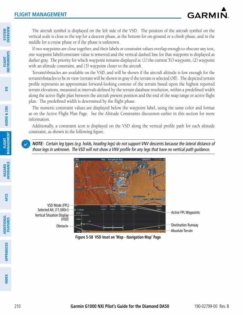
Garmin G1000 NXi Pilot’s Guide for the Diamond DA50 190-02799-00 Rev. B
SYST
EMO
VERV
IEW
FLIG
HTIN
STRU
MEN
TSEI
SAU
DIO
& C
NS
FLIG
HTM
AN
AGEM
ENT
HAZA
RDAV
OID
AN
CEA
FCS
AD
DIT
ION
AL
FEAT
URES
APP
END
ICES
IND
EX
210
FLIGHT MANAGEMENT
The aircraft symbol is displayed on the left side of the VSD. The position of the aircraft symbol on the vertical scale is close to the top for a descent phase, at the bottom for on-ground or a climb phase, and in the middle for a cruise phase or if the phase is unknown.
If two waypoints are close together, and their labels or constraint values overlap enough to obscure any text, one waypoint label/constraint value is removed and the vertical dashed line for that waypoint is displayed as darker gray. The priority for which waypoint remains displayed is: (1) the current TO waypoint, (2) waypoint with an altitude constraint, and (3) waypoint closer to the aircraft.
Terrain/obstacles are available on the VSD, and will be shown if the aircraft altitude is low enough for the terrain/obstacles to be in view (terrain will be shown in gray if the terrain is selected Off). The depicted terrain profile represents an approximate forward-looking contour of the terrain based upon the highest reported terrain elevations, measured at intervals defined by the terrain database resolution, within a predefined width along the active flight plan between the aircraft present position and the end of the map range or active flight plan. The predefined width is determined by the flight phase.
The numeric constraint values are displayed below the waypoint label, using the same color and format as on the Active Flight Plan Page. See the Altitude Constraints discussion earlier in this section for more information.
Additionally, a constraint icon is displayed on the VSD along the vertical profile path for each altitude constraint, as shown in the following figure.
NOTE: Certain leg types (e.g. holds, heading legs) do not support VNV descents because the lateral distance of those legs in unknown. The VSD will not show a VNV profile for any legs that have no vertical path guidance.
Figure 5-58 VSD Inset on ‘Map - Navigation Map’ Page
Obstacle
Vertical Situation Display (VSD)
VSD Mode (FPL)Selected Alt. (11,000ft)
Active FPL Waypoints
Absolute TerrainDestination Runway

190-02799-00 Rev. B Garmin G1000 NXi Pilot’s Guide for the Diamond DA50
SYSTEMO
VERVIEWFLIG
HTIN
STRUMEN
TSEIS
AUDIO
& CN
SFLIG
HTM
AN
AGEM
ENT
HAZA
RDAVO
IDA
NCE
AFCS
AD
DITIO
NA
LFEATURES
APPEN
DICES
IND
EX
211
FLIGHT MANAGEMENT
Altitude Constraint, Published (White Text)
Constraint Icon, Published Altitude (White Icon)-Tip of icon indicates barometric altitude of the constraint
Constraint Icon, Designated Altitude (Cyan Icon)
Altitude Constraint, Designated (Cyan Text)
Top of Descent (TOD) Vertical Profile Path
Figure 5-59 Vertical Situation Display (VSD)
VSD Mode Softkey
Displayed Mode FPL Criteria Items available on VSD
Auto
AUTO FPL Available active FPL & aircraft within FPL swath
Terrain/obstacles along the active flight plan route, vertical track vector, selected altitude, and active flight plan information 1
AUTO TRK(1) Active FPL available &
aircraft not within FPL swath, or (2) Active FPL not available
Terrain/obstacles along the current track, vertical track vector, and selected altitude
Flight Plan FPLActive FPL available Terrain/obstacles along the active flight plan route, vertical track
vector, selected altitude, and active flight plan information 1
Active FPL not available Only shows message ‘Flight Plan Not Available’
Track TRK N/A Terrain/obstacles along the current track, vertical track vector, and selected altitude
1 Active flight plan information consists of waypoints, associated altitude constraints, current VNAV profile, TOD/BOD, and destination runway
Table 5-12 VSD Modes
Flight Phase Width of SwathApproach, Departure 0.6 nm
Terminal 2.0 nmEn Route, Oceanic 4.0 nm
Table 5-13 VSD Width of Swath

Garmin G1000 NXi Pilot’s Guide for the Diamond DA50 190-02799-00 Rev. B
SYST
EMO
VERV
IEW
FLIG
HTIN
STRU
MEN
TSEI
SAU
DIO
& C
NS
FLIG
HTM
AN
AGEM
ENT
HAZA
RDAV
OID
AN
CEA
FCS
AD
DIT
ION
AL
FEAT
URES
APP
END
ICES
IND
EX
212
FLIGHT MANAGEMENT
VsD messages
Under certain conditions, some messages may appear in conjunction with others.
Message Description‘Loading…’ VSD is loading data due to a range change, full/half switch, or first being
selected for display.‘Flight Plan Not Available’ Flight Plan mode is selected and there is not a flight plan loaded with at
least one leg.‘Flight Plan mode unavailable because aircraft off course and active leg over 200 NM’
All of the following are true:- Flight Plan mode is selected- The active leg is greater than 200 nm- The aircraft is outside the swath
‘Aircraft Beyond Active Leg’ Flight Plan mode is selected and the aircraft’s position, as projected on the flight plan, is past the end of the active leg.
‘VSD Not Available’ At least one of the following is true:- Valid terrain database not available- GPS MSL altitude not available- Current barometric altitude not available- Neither current track nor current heading available- GPS position not available- Map range setting is less than 1 nm
‘VSD Data is old, disable and enable VSD’ The system has encountered a delay and VSD data has failed to update for 2 seconds or more. This message may be momentarily displayed and then removed as the delay is overcome. In the event the message persists, it is recommended to disable and enable VSD.
Table 5-14 VSD System Messages
Enabling and changing settings for the Vertical Situation Display:
1) Select the ‘Map – Navigation Map’ Page.
2) Press the Map Opt Softkey.
3) Press the Inset Softkey.
4) Press the VSD or Off Softkey to enable or disable the Vertical Situation Display.
5) If desired, press the VSD Mode Softkey to choose between Auto, FPL, or TRK.
Or:
1) Select the ‘Map – Navigation Map’ Page.
2) Press the MENU Key:
a) Turn the FMS Knob to highlight ‘Show VSD’ or ‘Hide VSD’ and press the ENT Key.
b) Press the Map Opt Softkey.
c) Press the Inset Softkey.
d) Press the VSD Mode softkey to choose between Auto, FPL, or TRK.
Or:

190-02799-00 Rev. B Garmin G1000 NXi Pilot’s Guide for the Diamond DA50
SYSTEMO
VERVIEWFLIG
HTIN
STRUMEN
TSEIS
AUDIO
& CN
SFLIG
HTM
AN
AGEM
ENT
HAZA
RDAVO
IDA
NCE
AFCS
AD
DITIO
NA
LFEATURES
APPEN
DICES
IND
EX
213
FLIGHT MANAGEMENT
a) Press the ENT Key to select Map Settings.
b) Turn the large FMS Knob to select ‘VSD’ and press the ENT Key.
c) Highlight the ‘Mode’ ‘On’ or ‘Off’ Field and turn the small FMS Knob to enable/disable VSD.
d) To change the Mode setting, highlight the ‘Mode’ Field.
e) Use the small FMS Knob to select ‘Auto’, ‘FPL’, or ‘TRK’, and press the ENT Key.
Disabling the Vertical Situation Display:
1) Select the ‘Map – Navigation Map’ Page.
2) Press the Map Opt Softkey.
3) Press the Inset Softkey.
4) Press the Off Softkey.
Or:
1) Select the ‘Map – Navigation Map’ Page.
2) Press the MENU Key:
a) Turn the FMS Knob to highlight ‘Show VSD’
b) Press the ENT Key.
Or:
a) Press the ENT Key to select Map Settings.
b) Turn the large FMS Knob to select ‘VSD’ and press the ENT Key.
c) Highlight the ‘Mode’ On/Off Field and turn the small FMS Knob to select ‘Off’.
d) Press the ENT Key.
VERTICAL NAVIGATION DIRECT-TOThe system allows a vertical navigation direct-to for any waypoint in the active flight plan with an altitude
constraint “designated” for vertical guidance. Pressing the VNV ¯ Softkey on the ‘FPL – Active Flight Plan’ Page allows the flight plan to be flown, while vertical guidance based on the altitude constraint at the VNV direct-to waypoint is provided. The altitude change begins immediately and is spread along the flight plan from current position to the vertical direct-to waypoint, not just along the leg for the direct-to waypoint. A direct-to with altitude constraint activated by pressing the ¯ Key also provides vertical guidance, but would bypass flight plan waypoints between the current position in the flight plan and the direct-to waypoint. A top of descent (TOD) point is computed based on the default flight path angle; descent begins once the TOD is reached. All VNV altitudes prior to the direct-to destination are removed from the active flight plan upon successful activation of a direct-to destination that is part of the active flight plan. All VNV altitudes following the direct-to waypoint are retained.
Activating a vertical navigation direct-to:
1) Press the FPL Key for the MFD to display the ‘FPL – Active Flight Plan’ Page.
2) Push the FMS Knob to activate the cursor and turn to highlight the desired waypoint.

Garmin G1000 NXi Pilot’s Guide for the Diamond DA50 190-02799-00 Rev. B
SYST
EMO
VERV
IEW
FLIG
HTIN
STRU
MEN
TSEI
SAU
DIO
& C
NS
FLIG
HTM
AN
AGEM
ENT
HAZA
RDAV
OID
AN
CEA
FCS
AD
DIT
ION
AL
FEAT
URES
APP
END
ICES
IND
EX
214
FLIGHT MANAGEMENT
NOTE: The selected waypoint must have a designated altitude constraint (cyan number) to be used, not to include ‘BETWEEN’ altitude constraints. If not, the first waypoint in the flight plan with a designated altitude constraint is selected.
3) Press the VNV ̄ Softkey; or press the MENU Key, highlight ‘VNV ̄ ’, and press the ENT Key. An ‘Activate vertical Direct-to to: NNNNNFT at XXXXXX?’ confirmation window is displayed.
4) Press the ENT Key. Vertical guidance begins to the altitude constraint for the selected waypoint.
5) Push the FMS Knob to remove the flashing cursor.
Removing a VNV altitude constraint:
1) Press the ¯ Key to display the ‘Direct To’ Window.
2) Press the MENU Key.
3) With ‘Clear Vertical Constraints’ highlighted, press the ENT Key.
FLIGHT PLAN OPERATIONSThis section will discuss activating a flight plan leg, utilizing the standby flight plan, and conducting enroute
operations such as creating an along track offset, parallel track, closest point from a reference point and user defined holding. For information on departures, arrivals, and approaches refer to the Procedures portion in the Flight Management Section.
In-flight, the system automatically sequences through the active flight plan, with the exception of manually terminated legs (such as FM, HM, or VM) that can occur within procedures (refer to the Procedures Section later in the Flight Management Section).
ACTIVATING A FLIGHT PLAN LEG
The flight plan leg which is currently being used for navigation guidance is referred to as the ‘active leg’. The system automatically sequences from one active leg to the next as defined by the active flight plan. Any leg in the active flight plan successive to the leg currently being flown may be selected to become the new active leg.
Activating a flight plan leg:
1) Press the FPL Key to display the ‘FPL – Active Flight Plan’ Page (MFD) or the ‘Flight Plan’ Window (PFD).
2) Push the FMS Knob to activate the cursor (not required on PFD), and turn the large FMS Knob to highlight the destination waypoint for the desired leg.
3) Press the ACT Leg Softkey (MFD only); or press the MENU Key, highlight ‘Activate Leg’, and press the ENT Key. A confirmation window is displayed with ‘Activate’ highlighted.
4) Press the ENT Key to activate the flight plan leg. To cancel, press the CLR Key, or highlight ‘Cancel’ and press the ENT Key.
5) Push the FMS Knob to remove the flashing cursor.

190-02799-00 Rev. B Garmin G1000 NXi Pilot’s Guide for the Diamond DA50
SYSTEMO
VERVIEWFLIG
HTIN
STRUMEN
TSEIS
AUDIO
& CN
SFLIG
HTM
AN
AGEM
ENT
HAZA
RDAVO
IDA
NCE
AFCS
AD
DITIO
NA
LFEATURES
APPEN
DICES
IND
EX
215
FLIGHT MANAGEMENT
ALONG TRACK OFFSETS
A waypoint having an “along track offset” distance from an existing waypoint can be entered into a flight plan. Along track offset waypoints lie along the path of the existing flight plan, and can be used to make the system reach a specified altitude before or after reaching the specified flight plan waypoint. Offset distances can be entered from 1 to 999 nm in increments of 1 nm.
Offset distance is calculated as a radial distance from the reference waypoint rather than a direct distance. The system will place the offset waypoint in the flight plan leg for which the radial distance intersects, regardless of distance between preceding flight plan legs. If the system is unable to determine a point for which the radial offset distance intersects the flight path, the message ‘Unable to place <offset waypoint and distance> on the existing Flight Plan’ will be displayed.
Entering a negative offset distance results in an along track offset waypoint inserted before the selected waypoint, whereas entering a positive offset distance results in an along track offset waypoint inserted after the selected waypoint. Offset waypoints can span multiple flight plan legs, and multiple offset waypoints are allowed on each leg.
The system limits the along track offset distance so the along-track offset falls between the first and last waypoints in the flight plan. Assigning an along track offset to a leg with indeterminate length is not permitted. An along track offset is not allowed between the final approach fix and missed approach point of an approach.
An along track offset distance cannot be modified once entered. If the along track offset distance must be changed, the existing along track offset waypoint must be removed and a new one created with the new offset distance.
Altitude constraints can also be entered for the along track waypoint, and are modifiable. An along track offset waypoint can also be used for lateral navigation, such as the creation of a user-defined hold or a direct-to destination.
Figure 5-60 Along Track Offset
Along Track Offset Waypoint and
Distance
Along Track Offset Waypoint and Distance from Flight Plan Waypoint
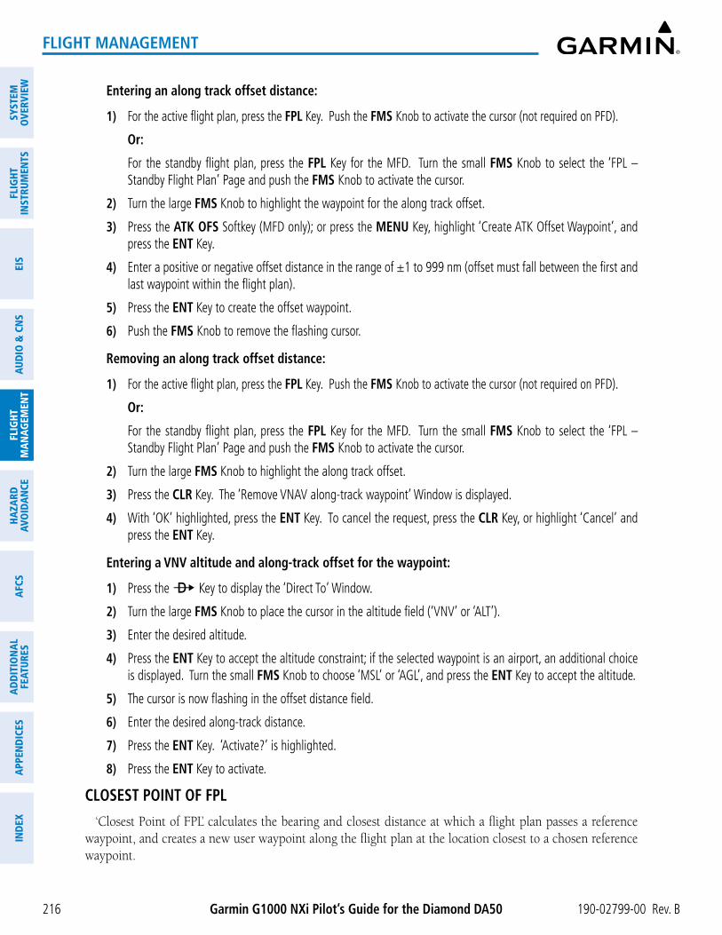
Garmin G1000 NXi Pilot’s Guide for the Diamond DA50 190-02799-00 Rev. B
SYST
EMO
VERV
IEW
FLIG
HTIN
STRU
MEN
TSEI
SAU
DIO
& C
NS
FLIG
HTM
AN
AGEM
ENT
HAZA
RDAV
OID
AN
CEA
FCS
AD
DIT
ION
AL
FEAT
URES
APP
END
ICES
IND
EX
216
FLIGHT MANAGEMENT
Entering an along track offset distance:
1) For the active flight plan, press the FPL Key. Push the FMS Knob to activate the cursor (not required on PFD).
Or:
For the standby flight plan, press the FPL Key for the MFD. Turn the small FMS Knob to select the ‘FPL – Standby Flight Plan’ Page and push the FMS Knob to activate the cursor.
2) Turn the large FMS Knob to highlight the waypoint for the along track offset.
3) Press the ATK OFS Softkey (MFD only); or press the MENU Key, highlight ‘Create ATK Offset Waypoint’, and press the ENT Key.
4) Enter a positive or negative offset distance in the range of ±1 to 999 nm (offset must fall between the first and last waypoint within the flight plan).
5) Press the ENT Key to create the offset waypoint.
6) Push the FMS Knob to remove the flashing cursor.
Removing an along track offset distance:
1) For the active flight plan, press the FPL Key. Push the FMS Knob to activate the cursor (not required on PFD).
Or:
For the standby flight plan, press the FPL Key for the MFD. Turn the small FMS Knob to select the ‘FPL – Standby Flight Plan’ Page and push the FMS Knob to activate the cursor.
2) Turn the large FMS Knob to highlight the along track offset.
3) Press the CLR Key. The ‘Remove VNAV along-track waypoint’ Window is displayed.
4) With ‘OK’ highlighted, press the ENT Key. To cancel the request, press the CLR Key, or highlight ‘Cancel’ and press the ENT Key.
Entering a VNV altitude and along-track offset for the waypoint:
1) Press the ¯ Key to display the ‘Direct To’ Window.
2) Turn the large FMS Knob to place the cursor in the altitude field (‘VNV’ or ‘ALT’).
3) Enter the desired altitude.
4) Press the ENT Key to accept the altitude constraint; if the selected waypoint is an airport, an additional choice is displayed. Turn the small FMS Knob to choose ‘MSL’ or ‘AGL’, and press the ENT Key to accept the altitude.
5) The cursor is now flashing in the offset distance field.
6) Enter the desired along-track distance.
7) Press the ENT Key. ‘Activate?’ is highlighted.
8) Press the ENT Key to activate.
CLOSEST POINT OF FPL
‘Closest Point of FPL’ calculates the bearing and closest distance at which a flight plan passes a reference waypoint, and creates a new user waypoint along the flight plan at the location closest to a chosen reference waypoint.

190-02799-00 Rev. B Garmin G1000 NXi Pilot’s Guide for the Diamond DA50
SYSTEMO
VERVIEWFLIG
HTIN
STRUMEN
TSEIS
AUDIO
& CN
SFLIG
HTM
AN
AGEM
ENT
HAZA
RDAVO
IDA
NCE
AFCS
AD
DITIO
NA
LFEATURES
APPEN
DICES
IND
EX
217
FLIGHT MANAGEMENT
Determining the closest point along the flight plan to a selected waypoint:
1) For the active flight plan, press the FPL Key.
Or:
For the standby flight plan, press the FPL Key for the MFD. Turn the small FMS Knob to select the ‘FPL – Standby Flight Plan’ Page and push the FMS Knob to activate the cursor.
Or:
For a stored flight plan:
a) Press the FPL Key for the MFD. Turn the small FMS Knob to select the ‘FPL – Flight Plan Catalog’ Page and push the FMS Knob to activate the cursor.
b) Turn the FMS Knob to highlight the desired flight plan.
c) Press the EDIT Softkey; or press the ENT Key, turn the large FMS Knob clockwise to select ‘Edit’ and press the ENT Key. The ‘FPL – Stored Flight Plan’ Page is displayed.
2) Press the MENU Key, highlight ‘Closest Point Of FPL’’, and press the ENT Key. A window appears with the reference waypoint field highlighted.
3) Enter the identifier of the reference waypoint and press the ENT Key. The system displays the bearing (BRG) and distance (DIS) to the closest point along the flight plan to the selected reference waypoint and creates a user waypoint at this location. The name for the new user waypoint is derived from the identifier of the reference waypoint.
PARALLEL TRACK
The Parallel Track feature allows creation of a parallel course offset of 1 to 50 nm left or right of the current flight plan. When Parallel Track is activated, the course line drawn on the map pages shows the parallel course, and waypoint names have a lower case “p” placed after the identifier. Activation of parallel track will apply from the current position along the flight plan until a leg that does not meet the criteria for parallel track. Guidance will be computed to return to the original track at the beginning of that leg.
If the parallel track proposed by the offset direction and distance is not allowed by the system, the activation prompt is displayed, but disabled.
The following will inhibit activation of a parallel track:
» Initiating a direct-to, to the selected waypoint.
» If an approach leg is active, the status indicates the system is unable to activate the parallel track with the message ‘Parallel Track Unavailable Approach Leg Active’.
» If the offset direction and distance results in an unreasonable route geometry (e.g., there is a sharp turn of more than 120 degrees), the status indicates the system is unable to activate the parallel track because of invalid geometry (‘Parallel Track Unavailable Invalid Route Geometry’).
» If the active leg is not a track between two fixes (TF) or a course to a fix (DF) leg, the status indicates the system is unable to activate the parallel track because parallel track is not available for the active leg type (‘Parallel Track Unavailable Not Allowed for Active Leg’).
If there are no legs remaining in the flight plan after the given leg, or OBS mode is active. The following will cancel the parallel track:
» Initiating a direct-to, to a waypoint.
» Initiating a hold at the present position.

Garmin G1000 NXi Pilot’s Guide for the Diamond DA50 190-02799-00 Rev. B
SYST
EMO
VERV
IEW
FLIG
HTIN
STRU
MEN
TSEI
SAU
DIO
& C
NS
FLIG
HTM
AN
AGEM
ENT
HAZA
RDAV
OID
AN
CEA
FCS
AD
DIT
ION
AL
FEAT
URES
APP
END
ICES
IND
EX
218
FLIGHT MANAGEMENT
» If a course change occurs greater than 120° or the parallel tracks overlap as a result of the course change.
» No legs are remaining in the flight plan after the given leg, or OBS mode is active. Initiating a hold at a waypoint will result in the aircraft flying the parallel track until a turn is required to fly to the hold waypoint. If the hold is removed prior to reaching the hold waypoint, the parallel track will be resumed. Once the holding pattern is active, the parallel track will not be resumed upon exiting the hold.
NOTE: Vertical navigation is unavailable while the Parallel Track feature is active.
Figure 5-61 Parallel Track Active
Parallel Track Waypoints - TIFTO-p - TOP-p - ... - LAA-p
Parallel TrackOriginal Track
Activating parallel track:
1) Press the FPL Key to display the ‘FPL – Active Flight Plan’ Page (MFD) or the ‘Flight Plan’ Window (PFD).
2) Press the MENU Key, highlight ‘Parallel Track’, and press the ENT Key. The ‘Parallel Track’ Window is displayed with the ‘Direction’ Field highlighted.
3) Turn the small FMS Knob to select ‘LEFT’ or ‘RIGHT’ and press the ENT Key. The ‘Distance’ Field is highlighted.
4) Turn the small FMS Knob to enter a distance from 1-50 nm and press the ENT Key. ‘Activate Parallel Track?’ ‘Activate Parallel Track’ is highlighted.
5) Press the ENT Key to activate parallel track. Push the FMS Knob or the CLR Key to cancel the parallel track activation.
Cancelling parallel track:
1) Press the FPL Key to display the ‘FPL – Active Flight Plan’ Page (MFD) or the Active ‘Flight Plan’ Window (PFD).
2) Press the MENU Key, highlight ‘Parallel Track’, and press the ENT Key. The ‘Parallel Track’ Window is displayed with ‘Cancel Parallel Track?’ highlighted.
3) Press the ENT Key.
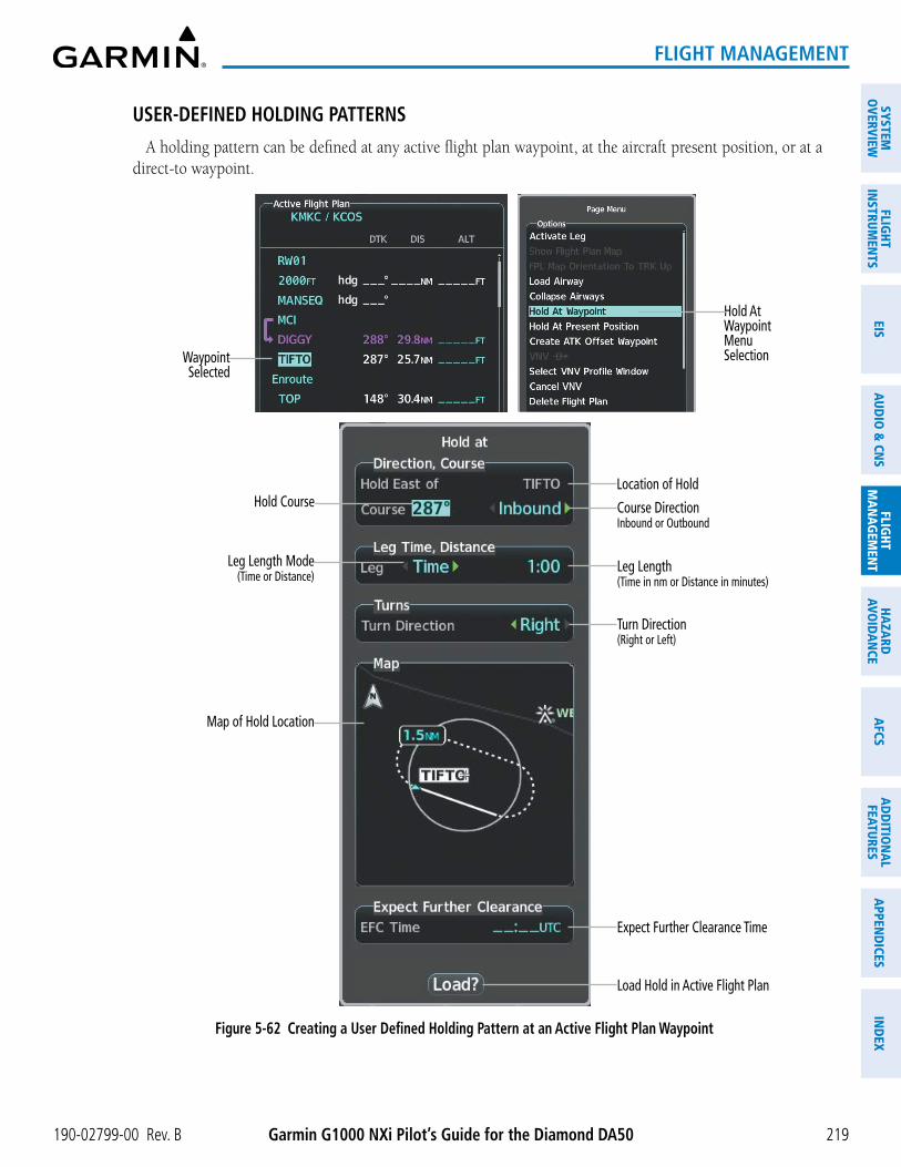
190-02799-00 Rev. B Garmin G1000 NXi Pilot’s Guide for the Diamond DA50
SYSTEMO
VERVIEWFLIG
HTIN
STRUMEN
TSEIS
AUDIO
& CN
SFLIG
HTM
AN
AGEM
ENT
HAZA
RDAVO
IDA
NCE
AFCS
AD
DITIO
NA
LFEATURES
APPEN
DICES
IND
EX
219
FLIGHT MANAGEMENT
USER-DEFINED HOLDING PATTERNS
A holding pattern can be defined at any active flight plan waypoint, at the aircraft present position, or at a direct-to waypoint.
Waypoint Selected
Hold At Waypoint Menu Selection
Figure 5-62 Creating a User Defined Holding Pattern at an Active Flight Plan Waypoint
Location of Hold
Expect Further Clearance Time
Leg Length Mode(Time or Distance)
Map of Hold Location
Course DirectionInbound or Outbound
Leg Length(Time in nm or Distance in minutes)
Hold Course
Turn Direction(Right or Left)
Load Hold in Active Flight Plan

Garmin G1000 NXi Pilot’s Guide for the Diamond DA50 190-02799-00 Rev. B
SYST
EMO
VERV
IEW
FLIG
HTIN
STRU
MEN
TSEI
SAU
DIO
& C
NS
FLIG
HTM
AN
AGEM
ENT
HAZA
RDAV
OID
AN
CEA
FCS
AD
DIT
ION
AL
FEAT
URES
APP
END
ICES
IND
EX
220
FLIGHT MANAGEMENT
Waypoint Selected
Hold At Direct To Waypoint Selection
Figure 5-63 Creating a User Defined Holding Pattern at a Direct To Waypoint
Location of Hold
Expect Further Clearance Time
Course Direction(Inbound or Outbound)
Leg Length(Time in nm or Distance in minutes)
Turn Direction(Right or Left)
Load Hold and Activate Direct To
Map of Hold Location
Hold Course
Leg Length Mode(Time or Distance)

190-02799-00 Rev. B Garmin G1000 NXi Pilot’s Guide for the Diamond DA50
SYSTEMO
VERVIEWFLIG
HTIN
STRUMEN
TSEIS
AUDIO
& CN
SFLIG
HTM
AN
AGEM
ENT
HAZA
RDAVO
IDA
NCE
AFCS
AD
DITIO
NA
LFEATURES
APPEN
DICES
IND
EX
221
FLIGHT MANAGEMENT
Creating a user-defined hold at a flight plan waypoint:
1) For the active flight plan, press the FPL Key. Push the FMS Knob to activate the cursor (not required on PFD).
Or:
For the standby flight plan, press the FPL Key for the MFD. Turn the small FMS Knob to select the ‘FPL – Standby Flight Plan’ Page and push the FMS Knob to activate the cursor.
Or:
For a stored flight plan:
a) Press the FPL Key for the MFD. Turn the small FMS Knob to select the ‘FPL – Flight Plan Catalog’ Page and push the FMS Knob to activate the cursor.
b) Turn the FMS Knob to highlight the desired flight plan.
c) Press the EDIT Softkey; or press the ENT Key, turn the large FMS Knob clockwise to select ‘Edit’ and press the ENT Key. The ‘FPL – Stored Flight Plan’ Page is displayed.
2) Turn the large FMS Knob to highlight the waypoint for the hold.
3) Press the MENU Key, highlight ‘Hold At Waypoint’, and press the ENT Key. The ‘Hold at’ Window appears with the course field highlighted.
4) Use the FMS Knob to edit the course, and press the ENT Key.
5) Use the small FMS Knob to select ‘Inbound’ or ‘Outbound’ course direction, and press the ENT Key.
6) Use the small FMS Knob to select ‘Time’ or ‘Distance’ length mode, and press the ENT Key.
7) Use the FMS Knob to edit the length, and press the ENT Key.
8) Use the small FMS Knob to select ‘Right’ or ‘Left’ turn direction, and press the ENT Key.
9) Use the FMS Knob to edit the Expect Further Clearance Time (EFC Time), and press the ENT Key.
10) Press the ENT Key while ‘Load?’ is highlighted to insert the hold into the flight plan.
Creating a user-defined hold at the aircraft present position:
1) Press the FPL Key to display the ‘FPL – Active Flight Plan’ Page (MFD) or the ‘Flight Plan’ Window (PFD).
2) Press the MENU Key, highlight ‘Hold At Present Position’, and press the ENT Key. The ‘Hold at’ Window appears with the course field highlighted.
3) If desired, use the FMS Knob to edit the course, and press the ENT Key.
4) Use the small FMS Knob to select ‘Inbound’ or ‘Outbound’ course direction, and press the ENT Key.
5) Use the small FMS Knob to select ‘Time’ or ‘Distance’ length mode, and press the ENT Key.
6) Use the FMS Knob to edit the length, and press the ENT Key.
7) Use the small FMS Knob to select ‘Right’ or ‘Left’ turn direction, and press the ENT Key.
8) Use the FMS Knob to edit the Expect Further Clearance Time (EFC Time), and press the ENT Key.
9) Press the ENT Key while ‘Activate?’ is highlighted to create an Offroute Direct-to hold waypoint at the aircraft present position and activate the hold.

Garmin G1000 NXi Pilot’s Guide for the Diamond DA50 190-02799-00 Rev. B
SYST
EMO
VERV
IEW
FLIG
HTIN
STRU
MEN
TSEI
SAU
DIO
& C
NS
FLIG
HTM
AN
AGEM
ENT
HAZA
RDAV
OID
AN
CEA
FCS
AD
DIT
ION
AL
FEAT
URES
APP
END
ICES
IND
EX
222
FLIGHT MANAGEMENT
Creating a user-defined hold at a direct-to waypoint:
1) Press a ¯ Key and set up the direct-to waypoint as desired, then select ‘Hold?’ when finished.
2) Use the FMS Knob to edit the course, and press the ENT Key.
3) Use the small FMS Knob to select ‘Inbound’ or ‘Outbound’ course direction, and press the ENT Key.
4) Use the small FMS Knob to select ‘Time’ or ‘Distance’ length mode, and press the ENT Key.
5) Use the FMS Knob to edit the length, and press the ENT Key.
6) Use the small FMS Knob to select ‘Right’ or ‘Left’ turn direction, and press the ENT Key.
7) Use the FMS Knob to edit the Expect Further Clearance Time (EFC Time), and press the ENT Key.
8) Press the ENT Key while ‘Activate?’ is highlighted to activate the direct-to with the user-defined hold defined at the direct-to waypoint. (If the direct-to waypoint is part of the active flight plan, ‘HOLD’ is inserted into the active flight plan. If the direct-to waypoint is not part of the active flight plan, an off-route direct-to hold is created.)
Exiting a user-defined hold inserted into the active flight plan:
Press the SUSP Softkey. The system will provide guidance to follow the holding pattern to the inbound course and resume automatic waypoint sequencing.
Removing a user-defined hold from a flight plan:
1) For the active flight plan, press the FPL Key. Push the FMS Knob to activate the cursor (not required on PFD).
Or:
For the standby flight plan, press the FPL Key for the MFD. Turn the small FMS Knob to select the ‘FPL – Standby Flight Plan’ Page and push the FMS Knob to activate the cursor.
Or:
For a stored flight plan:
a) Press the FPL Key for the MFD. Turn the small FMS Knob to select the ‘FPL – Flight Plan Catalog’ Page and push the FMS Knob to activate the cursor.
b) Turn the FMS Knob to highlight the desired flight plan.
c) Press the EDIT Softkey; or press the ENT Key, turn the large FMS Knob clockwise to select ‘Edit’ and press the ENT Key. The ‘FPL – Stored Flight Plan’ Page is displayed.
2) Turn the large FMS Knob to highlight the ‘HOLD’ in the flight plan.
3) Press the CLR Key. A ‘Remove Holding Pattern?’ confirmation window is displayed.
4) Select ‘OK’ and press the ENT Key. The holding pattern is removed from the flight plan. Select ‘Cancel’ and press the ENT Key to cancel the removal of the holding pattern.
Removing a user-defined hold at an off-route direct-to:
1) Press a ¯ Key to display the ‘Direct To’ Window.
2) Press the MENU Key to display the ‘Page Menu’ Window with the cursor on the ‘Cancel Direct-To NAV’ selection.
3) Press the ENT Key. The holding pattern is removed.

190-02799-00 Rev. B Garmin G1000 NXi Pilot’s Guide for the Diamond DA50
SYSTEMO
VERVIEWFLIG
HTIN
STRUMEN
TSEIS
AUDIO
& CN
SFLIG
HTM
AN
AGEM
ENT
HAZA
RDAVO
IDA
NCE
AFCS
AD
DITIO
NA
LFEATURES
APPEN
DICES
IND
EX
223
FLIGHT MANAGEMENT
ARRIVAL ALERTS
The ‘Arrival Alert’ Box on the ‘Aux – System Setup 1’ Page allows arrival alert messages to be turned On/Off and the alert trigger distance (up to 99.9 units) set for alerts provided on the PFD. An arrival alert can be set to notify the pilot with a message upon reaching a user-specified distance from the final destination (the direct-to waypoint or the last waypoint in a flight plan). When Arrival Alerts is set to ‘On’, and the set distance is reached, an “Arrival at waypoint” message is displayed in the PFD Navigation Status Box, and a “WPT ARRIVAL – Arriving at waypoint – [xxxx]” is displayed on the PFD. When Arrival Alerts is set to ‘Off’, only the PFD Navigation Status Box message “Arriving at waypoint” is displayed, and it is displayed when the time to the final destination is approximately ten seconds.
Figure 5-64 Arrival Alert Settings (‘Aux - System Setup 1’ Page)
Enabling/disabling the Arrival Alert:
1) Use the FMS Knob to select the ‘Aux – System Setup 1’ Page (Setup 1 Softkey).
2) Push the FMS Knob momentarily to activate the flashing cursor.
3) Turn the large FMS Knob to select the ‘On/Off’ Field in the ‘Arrival Alert’ Box.
4) Turn the small FMS Knob clockwise to turn the arrival alert On or counterclockwise to turn the alert Off.
Changing the arrival alert trigger distance:
1) Use the FMS Knob to select the ‘Aux – System Setup 1’ Page (Setup 1 Softkey).
2) Push the FMS Knob momentarily to activate the flashing cursor.
3) Turn the large FMS Knob to highlight the ‘Distance’ Field in the ‘Arrival Alert’ Box.
4) Use the FMS Knob to enter a trigger distance and press the ENT Key.
UTILIZING THE STANDBY FLIGHT PLAN
A standby flight plan may be created manually on the ‘Standby Flight Plan’ Page or by copying the active flight plan. The standby flight plan is available for activation (becomes the active flight plan).
Viewing the active and standby flight plan:
For the active flight plan, press the FPL Key. The active flight plan may be viewed on either the PFD or the MFD.
Or:
For the standby flight plan, press the FPL Key for the MFD. Turn the small FMS Knob to select the ‘FPL – Standby Flight Plan’ Page.
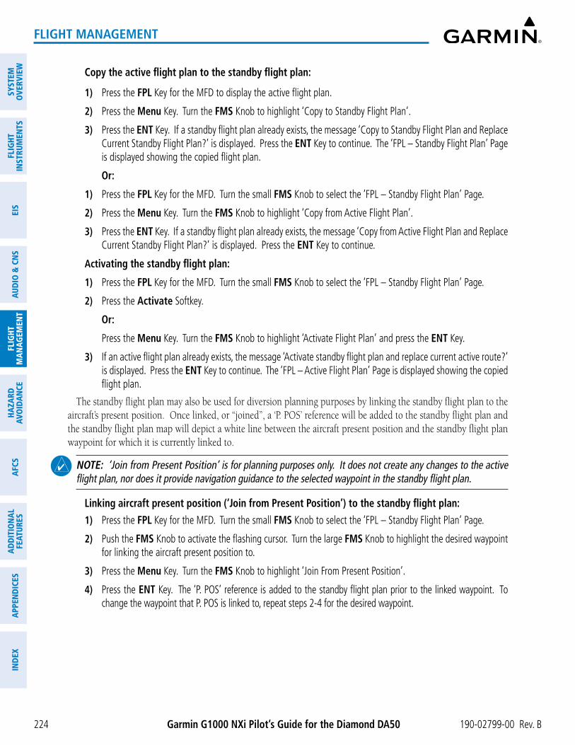
Garmin G1000 NXi Pilot’s Guide for the Diamond DA50 190-02799-00 Rev. B
SYST
EMO
VERV
IEW
FLIG
HTIN
STRU
MEN
TSEI
SAU
DIO
& C
NS
FLIG
HTM
AN
AGEM
ENT
HAZA
RDAV
OID
AN
CEA
FCS
AD
DIT
ION
AL
FEAT
URES
APP
END
ICES
IND
EX
224
FLIGHT MANAGEMENT
Copy the active flight plan to the standby flight plan:
1) Press the FPL Key for the MFD to display the active flight plan.
2) Press the Menu Key. Turn the FMS Knob to highlight ‘Copy to Standby Flight Plan’.
3) Press the ENT Key. If a standby flight plan already exists, the message ‘Copy to Standby Flight Plan and Replace Current Standby Flight Plan?’ is displayed. Press the ENT Key to continue. The ‘FPL – Standby Flight Plan’ Page is displayed showing the copied flight plan.
Or:
1) Press the FPL Key for the MFD. Turn the small FMS Knob to select the ‘FPL – Standby Flight Plan’ Page.
2) Press the Menu Key. Turn the FMS Knob to highlight ‘Copy from Active Flight Plan’.
3) Press the ENT Key. If a standby flight plan already exists, the message ‘Copy from Active Flight Plan and Replace Current Standby Flight Plan?’ is displayed. Press the ENT Key to continue.
Activating the standby flight plan:
1) Press the FPL Key for the MFD. Turn the small FMS Knob to select the ‘FPL – Standby Flight Plan’ Page.
2) Press the Activate Softkey.
Or:
Press the Menu Key. Turn the FMS Knob to highlight ‘Activate Flight Plan’ and press the ENT Key.
3) If an active flight plan already exists, the message ‘Activate standby flight plan and replace current active route?’ is displayed. Press the ENT Key to continue. The ‘FPL – Active Flight Plan’ Page is displayed showing the copied flight plan.
The standby flight plan may also be used for diversion planning purposes by linking the standby flight plan to the aircraft’s present position. Once linked, or “joined”, a ‘P. POS’ reference will be added to the standby flight plan and the standby flight plan map will depict a white line between the aircraft present position and the standby flight plan waypoint for which it is currently linked to.
NOTE: ‘Join from Present Position’ is for planning purposes only. It does not create any changes to the active flight plan, nor does it provide navigation guidance to the selected waypoint in the standby flight plan.
Linking aircraft present position (‘Join from Present Position’) to the standby flight plan:
1) Press the FPL Key for the MFD. Turn the small FMS Knob to select the ‘FPL – Standby Flight Plan’ Page.
2) Push the FMS Knob to activate the flashing cursor. Turn the large FMS Knob to highlight the desired waypoint for linking the aircraft present position to.
3) Press the Menu Key. Turn the FMS Knob to highlight ‘Join From Present Position’.
4) Press the ENT Key. The ‘P. POS’ reference is added to the standby flight plan prior to the linked waypoint. To change the waypoint that P. POS is linked to, repeat steps 2-4 for the desired waypoint.

190-02799-00 Rev. B Garmin G1000 NXi Pilot’s Guide for the Diamond DA50
SYSTEMO
VERVIEWFLIG
HTIN
STRUMEN
TSEIS
AUDIO
& CN
SFLIG
HTM
AN
AGEM
ENT
HAZA
RDAVO
IDA
NCE
AFCS
AD
DITIO
NA
LFEATURES
APPEN
DICES
IND
EX
225
FLIGHT MANAGEMENT
Figure 5-65 Standby Flight Plan – Join From P.POS link active
White line indicates link from P. POS to TYTUS
Standby Flight Plan Map
P. POS reference in standby flight plan
Aircraft present position
Removing P. POS link from the standby flight plan:
1) Press the FPL Key for the MFD. Turn the small FMS Knob to select the ‘FPL – Standby Flight Plan’ Page.
2) Push the FMS Knob to activate the flashing cursor. Turn the large FMS Knob to highlight the ‘P. POS’ reference.
3) Press the CLR Key. The message, ‘Remove Link?’ is displayed. Press the ENT Key to remove the link from the standby flight plan.
MANAGING FLIGHT PLANSThe pilot can manage flight plans by importing/exporting via SD Card or the optional Wireless Transceiver
(Flight Stream 510), and by storing, copying, inverting, and deleting. Also, the comment field (name) of each flight plan can be changed to something that is useful for identification and sorting.
IMPORTING AND EXPORTING FLIGHT PLANS
Flight plans can be transferred to or from a wireless connection via the optional Wireless Transceiver. Wireless transfer of a flight plan to a mobile device is controlled by the wireless device. When a wireless connection is attempting to transfer a flight plan to the system, the pending flight plan may be ignored, previewed, stored, or activated by the pilot.

Garmin G1000 NXi Pilot’s Guide for the Diamond DA50 190-02799-00 Rev. B
SYST
EMO
VERV
IEW
FLIG
HTIN
STRU
MEN
TSEI
SAU
DIO
& C
NS
FLIG
HTM
AN
AGEM
ENT
HAZA
RDAV
OID
AN
CEA
FCS
AD
DIT
ION
AL
FEAT
URES
APP
END
ICES
IND
EX
226
FLIGHT MANAGEMENT
Figure 5-66 Pending Flight Plan Transfer from a Wireless Device
Pending Flight Plan
Ignoring a flight plan transfer from a wireless connection:
1) When a flight plan transfer has been initiated from a wireless connection, a Pending Flight Plan pop-up alert appears in the lower right corner of the MFD, and a Connext annunciation appears to the right of the MFD page name.
2) Press the CLR Key to remove the pop-up alert and ignore the pending flight plan. The pending flight plan will still be available on the ‘FPL – Flight Plan Catalog’ Page.
Or:
Press the Ignore Softkey to remove the pop-up alert and ignore the pending flight plan. The pending flight plan will still be available on the ‘FPL – Flight Plan Catalog’ Page.
Previewing a flight plan transfer from a wireless connection:
1) When a flight plan transfer has been initiated from a wireless connection, a Pending Flight Plan pop-up alert appears in the lower right corner of the MFD, and an Connext annunciation appears to the right of the MFD page name.
2) Press the ENT Key to display the ‘FPL – Preview Flight Plan’ Page on the MFD.
Or:
Press the Preview Softkey to display the ‘FPL – Preview Flight Plan’ Page on the MFD.
Or:
a) Press the MENU Key.
b) Turn the FMS Knob to highlight ‘Preview Flight Plan’.
c) Press the ENT Key to display the ‘FPL – Preview Flight Plan’ Page on the MFD.
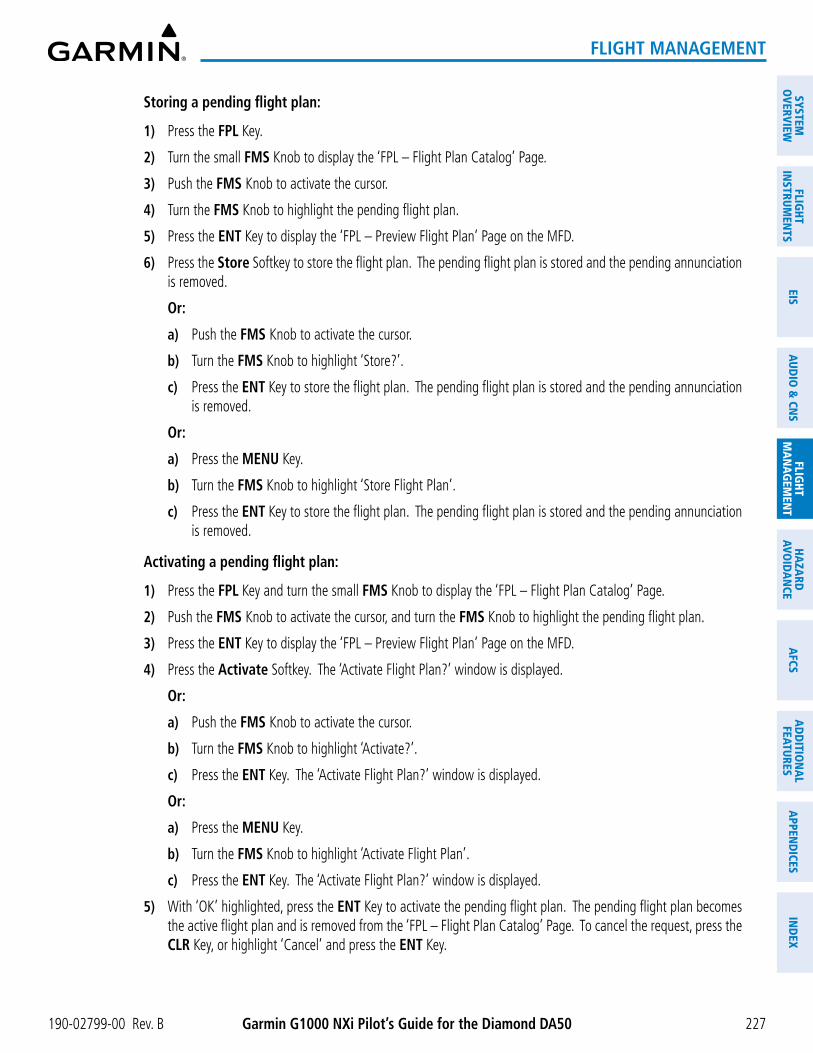
190-02799-00 Rev. B Garmin G1000 NXi Pilot’s Guide for the Diamond DA50
SYSTEMO
VERVIEWFLIG
HTIN
STRUMEN
TSEIS
AUDIO
& CN
SFLIG
HTM
AN
AGEM
ENT
HAZA
RDAVO
IDA
NCE
AFCS
AD
DITIO
NA
LFEATURES
APPEN
DICES
IND
EX
227
FLIGHT MANAGEMENT
Storing a pending flight plan:
1) Press the FPL Key.
2) Turn the small FMS Knob to display the ‘FPL – Flight Plan Catalog’ Page.
3) Push the FMS Knob to activate the cursor.
4) Turn the FMS Knob to highlight the pending flight plan.
5) Press the ENT Key to display the ‘FPL – Preview Flight Plan’ Page on the MFD.
6) Press the Store Softkey to store the flight plan. The pending flight plan is stored and the pending annunciation is removed.
Or:
a) Push the FMS Knob to activate the cursor.
b) Turn the FMS Knob to highlight ‘Store?’.
c) Press the ENT Key to store the flight plan. The pending flight plan is stored and the pending annunciation is removed.
Or:
a) Press the MENU Key.
b) Turn the FMS Knob to highlight ‘Store Flight Plan’.
c) Press the ENT Key to store the flight plan. The pending flight plan is stored and the pending annunciation is removed.
Activating a pending flight plan:
1) Press the FPL Key and turn the small FMS Knob to display the ‘FPL – Flight Plan Catalog’ Page.
2) Push the FMS Knob to activate the cursor, and turn the FMS Knob to highlight the pending flight plan.
3) Press the ENT Key to display the ‘FPL – Preview Flight Plan’ Page on the MFD.
4) Press the Activate Softkey. The ‘Activate Flight Plan?’ window is displayed.
Or:
a) Push the FMS Knob to activate the cursor.
b) Turn the FMS Knob to highlight ‘Activate?’.
c) Press the ENT Key. The ‘Activate Flight Plan?’ window is displayed.
Or:
a) Press the MENU Key.
b) Turn the FMS Knob to highlight ‘Activate Flight Plan’.
c) Press the ENT Key. The ‘Activate Flight Plan?’ window is displayed.
5) With ‘OK’ highlighted, press the ENT Key to activate the pending flight plan. The pending flight plan becomes the active flight plan and is removed from the ‘FPL – Flight Plan Catalog’ Page. To cancel the request, press the CLR Key, or highlight ‘Cancel’ and press the ENT Key.

Garmin G1000 NXi Pilot’s Guide for the Diamond DA50 190-02799-00 Rev. B
SYST
EMO
VERV
IEW
FLIG
HTIN
STRU
MEN
TSEI
SAU
DIO
& C
NS
FLIG
HTM
AN
AGEM
ENT
HAZA
RDAV
OID
AN
CEA
FCS
AD
DIT
ION
AL
FEAT
URES
APP
END
ICES
IND
EX
228
FLIGHT MANAGEMENT
Deleting a pending flight plan:
1) Press the FPL Key.
2) Turn the small FMS Knob to display the ‘FPL – Flight Plan Catalog’ Page.
3) Push the FMS Knob to activate the cursor.
4) Turn the FMS Knob to highlight the desired pending flight plan.
5) Press the Delete Softkey. The ‘Delete Flight Plan XX?’ window is displayed.
Or:
Press the CLR Key. The ‘Delete Flight Plan XX?’ window is displayed.
Or:
a) Press the MENU Key.
b) Turn the FMS Knob to highlight ‘Delete Flight Plan’.
c) Press the ENT Key. The ‘Delete Flight Plan XX?’ window is displayed.
6) With ‘OK’ highlighted, press the ENT Key to delete the pending flight plan. The pending flight plan is removed from the ‘FPL – Flight Plan Catalog’ Page. To cancel the request, press the CLR Key, or highlight ‘Cancel’ and press the ENT Key.
Deleting all pending flight plans:
1) Press the FPL Key.
2) Turn the small FMS Knob to display the ‘FPL – Flight Plan Catalog’ Page.
3) Press the MENU Key.
4) Turn the FMS Knob to highlight ‘Delete All Pending’.
5) Press the ENT Key. A ‘Delete all pending flight plans?’ confirmation window is displayed.
6) With ‘OK’ highlighted, press the ENT Key to delete all pending flight plans. To cancel the request, press the CLR Key, or highlight ‘Cancel’ and press the ENT Key.
Importing a Flight Plan from an SD Card:
1) Insert the SD card containing the flight plan in the top card slot on the MFD.
2) Press the FPL Key to display the ‘FPL – Active Flight Plan’ Page on the MFD.
3) Turn the small FMS Knob to select the ‘FPL – Flight Plan Catalog’ Page.
4) Push the FMS Knob to activate the cursor.
5) Turn either FMS Knob to highlight an empty or existing flight plan.
6) Press the Import Softkey; or press the MENU Key, select “Import Flight Plan”, and press the ENT Key.
If an empty slot is selected, a list of the available flight plans on the SD card will be displayed.
Or:
If an existing flight plan is selected, an “Overwrite existing flight plan? OK or Cancel” prompt is displayed. Press the ENT Key to choose to overwrite the selected flight plan and see the list of available flight plans on the SD card. If overwriting the existing flight plan is not desired, select “Cancel” using the FMS Knob, press the ENT Key, select another flight plan slot, and press the Import Softkey again.

190-02799-00 Rev. B Garmin G1000 NXi Pilot’s Guide for the Diamond DA50
SYSTEMO
VERVIEWFLIG
HTIN
STRUMEN
TSEIS
AUDIO
& CN
SFLIG
HTM
AN
AGEM
ENT
HAZA
RDAVO
IDA
NCE
AFCS
AD
DITIO
NA
LFEATURES
APPEN
DICES
IND
EX
229
FLIGHT MANAGEMENT
7) Turn the small FMS Knob to highlight the desired flight plan for importing.
8) Press the ENT Key to initiate the import.
9) Press the ENT Key again to confirm the import.
NOTE: If the imported flight plan contains a waypoint with a name that duplicates the name of a waypoint already stored on the system, the system compares the coordinates of the imported waypoint with those of the existing waypoint. If the coordinates are different, the imported waypoint is automatically renamed by adding characters to the end of the name.
Exporting a flight plan to an SD Card:
1) Insert the SD card into the top card slot on the MFD.
2) Press the FPL Key to display the ‘FPL – Active Flight Plan’ Page on the MFD.
3) Turn the small FMS Knob to select the ‘FPL – Flight Plan Catalog’ Page.
4) Push the FMS Knob to activate the cursor.
5) Turn the large FMS Knob to highlight the flight plan to be exported.
6) Press the Export Softkey; or press the MENU Key, select “Export Flight Plan”.
7) If desired, change the name for the exported file by turning the large FMS Knob to the left to highlight the name, then use the small and large FMS Knob to enter the new name, and press the ENT Key.
8) Press the ENT Key to initiate the export.
9) Press the ENT Key to confirm the export.
NOTE: The exported flight plan will not contain any procedures or airways.
Under certain conditions, some messages may appear when a flight plan is imported or exported.
Flight Plan Import/Export Results Description‘Flight plan successfully imported.’ A flight plan file stored on the SD card was successfully imported as a stored flight
plan.‘File contained user waypoints only. User waypoints imported successfully. No stored flight plan data was modified.’
The file stored on the SD card did not contain a flight plan, only user waypoints. These waypoints have been saved to the system user waypoints. No flight plans stored in the system have been modified.
‘No flight plan files found to import.’ The SD card contains no flight plan data.‘Flight plan import failed.’ Flight plan data was not successfully imported from the SD card.‘Flight plan partially imported.’ Some flight plan waypoints were successfully imported from the SD card, however
others had errors and were not imported. A partial stored flight plan now exists in the system.
‘File contained user waypoints only.’ The file stored on the SD card did not contain a flight plan, only user waypoints. One or more of these waypoints did not import successfully.
‘Too many points. Flight plan truncated.’ The flight plan on the SD card contains more waypoints than the system can support. The flight plan was imported with as many waypoints as possible.

Garmin G1000 NXi Pilot’s Guide for the Diamond DA50 190-02799-00 Rev. B
SYST
EMO
VERV
IEW
FLIG
HTIN
STRU
MEN
TSEI
SAU
DIO
& C
NS
FLIG
HTM
AN
AGEM
ENT
HAZA
RDAV
OID
AN
CEA
FCS
AD
DIT
ION
AL
FEAT
URES
APP
END
ICES
IND
EX
230
FLIGHT MANAGEMENT
Flight Plan Import/Export Results Description‘Some waypoints not loaded. Waypoints locked.’
The flight plan on the SD card contains one or more waypoints the system cannot find in the navigation database. The flight plan has been imported, but must be edited within the system before it can be activated for use.
‘User waypoint database full. Not all loaded.’
The flight plan file on the SD card contains user waypoints. The quantity of stored user waypoints has exceeded system capacity, therefore not all the user waypoints on the SD card have been imported. Any flight plan user waypoints that were not imported are locked in the flight plan. The flight plan must be edited within the system before it can be activated for use.
‘One or more user waypoints renamed.’ One or more imported user waypoints were renamed when imported due to naming conflicts with waypoints already existing in the system.
‘Flight plan contains invalid waypoint(s)’ One or more imported flight plan waypoints is/are invalid or locked (this may occur if waypoints in the flight plan were removed in a recent database cycle). The imported flight plan can be deleted or it can be viewed and edited to remove invalid waypoints prior to use.
‘Flight plan successfully exported.’ The stored flight plan was successfully exported to the SD card.‘Flight plan export failed.’ The stored flight plan was not successfully exported to the SD card. The SD card
may not have sufficient available memory or the card may have been removed prematurely.
Table 5-15 Flight Plan Import/Export Messages
INVERTING A FLIGHT PLAN
A flight plan may be inverted (reversed) for navigation back to the original departure point.
Inverting the active or standby flight plan:
1) For the active flight plan, press the FPL Key.
Or:
For the standby flight plan, press the FPL Key for the MFD. Turn the small FMS Knob to select the ‘FPL – Standby Flight Plan’ Page and push the FMS Knob to activate the cursor.
2) Press the MENU Key, highlight ‘Invert Flight Plan’, and press the ENT Key.
3) For the active flight plan, an ‘Invert active flight plan?’ confirmation window is displayed. Press the ENT Key to invert and activate the flight plan. To cancel, press the CLR Key, or highlight ‘Cancel’ and press the ENT Key.
Inverting and activating a stored flight plan on the MFD:
1) Press the FPL Key and turn the small FMS Knob to display the ‘FPL – Flight Plan Catalog’ Page.
2) Push the FMS Knob to activate the cursor, and turn the FMS Knob to highlight the desired flight plan.
3) Press the Invert Softkey; or press the MENU Key, highlight ‘Invert & Activate FPL?’, and press the ENT Key. The ‘Invert and activate stored flight plan?’ window is displayed.
4) With ‘OK’ highlighted, press the ENT Key. To cancel the request, press the CLR Key, or highlight ‘Cancel’ and press the ENT Key.

190-02799-00 Rev. B Garmin G1000 NXi Pilot’s Guide for the Diamond DA50
SYSTEMO
VERVIEWFLIG
HTIN
STRUMEN
TSEIS
AUDIO
& CN
SFLIG
HTM
AN
AGEM
ENT
HAZA
RDAVO
IDA
NCE
AFCS
AD
DITIO
NA
LFEATURES
APPEN
DICES
IND
EX
231
FLIGHT MANAGEMENT
DELETING THE ACTIVE OR STANDBY FLIGHT PLAN
The active flight plan is erased when the system is turned off, overwritten when another flight plan is activated. Additionally, the system allows the pilot to delete the active and standby flight plan. Deleting the active flight plan suspends navigation by the system.
Deleting the active or standby flight plan:
1) For the active flight plan, press the FPL Key.
Or:
For the standby flight plan, press the FPL Key for the MFD. Turn the small FMS Knob to select the ‘FPL – Standby Flight Plan’ Page and push the FMS Knob to activate the cursor.
2) Press the MENU Key, highlight ‘Delete Flight Plan’, and press the ENT Key. The ‘Delete all waypoints in flight plan?’ window is displayed.
3) With ‘OK’ highlighted, press the ENT Key to delete the flight plan. To cancel the request, press the CLR Key, or highlight ‘Cancel’ and press the ENT Key.
ACTIVE FLIGHT PLAN RETENTION
Upon power application, the previously active flight plan is retained and automatically repopulated if the aircraft position is at the origin airport and the aircraft is on the ground. If, however, the aircraft is not within 5 nm of the airport origin, on the ground, or if more than 12 hours have passed since the last active flight plan modification, the previously active flight plan is not retained.
STORED FLIGHT PLAN FUNCTIONS
Up to 99 flight plans with up to 100 waypoints each can be created and stored in memory. Details about each stored flight plan can be viewed on the ‘FPL – Flight Plan Catalog’ Page and on the ‘FPL – Stored Flight Plan’ Page. If the flight plan memory is full and a flight plan is imported, it will overwrite the last flight plan in the catalog.
A stored flight plan may be viewed or edited. The system also allows copying a flight plan into a new flight plan memory slot, allowing editing, etc., without affecting the original flight plan. This can be used to duplicate an existing stored flight plan for use in creating a modified version of the original stored flight plan.
Activating a stored flight plan erases the active flight plan and replaces it with the flight plan being activated. Inverting a stored flight plan reverses the waypoint order, erases the active flight plan, and replaces it with the flight plan being activated (the stored flight plan is not changed).
When storing flight plans with an approach, departure, or arrival, the system uses the waypoint information from the current database to define the waypoints. If the database is changed or updated, the system automatically updates the information if the procedure has not been modified. If an approach, departure, or arrival procedure is no longer available, the procedure is removed from the affected stored flight plan(s), and an alert is displayed (see Miscellaneous Messages in Appendix A) advising that one or more stored flight plans need to be edited.
Lastly, individual or all stored flight plans can be deleted from the system memory.

Garmin G1000 NXi Pilot’s Guide for the Diamond DA50 190-02799-00 Rev. B
SYST
EMO
VERV
IEW
FLIG
HTIN
STRU
MEN
TSEI
SAU
DIO
& C
NS
FLIG
HTM
AN
AGEM
ENT
HAZA
RDAV
OID
AN
CEA
FCS
AD
DIT
ION
AL
FEAT
URES
APP
END
ICES
IND
EX
232
FLIGHT MANAGEMENT
Figure 5-67 ‘FPL - Stored Flight Plan’ Page
Stored Flight Plan Selected - Memory Slot - Comment - Procedure Identifier - Waypoint Identifier - Airway Identifier - Desired Track to Waypoint - Distance to Waypoint - Waypoint Altitude Constraint
Viewing information about a stored flight plan:
1) Press the FPL Key for the MFD to display the ‘FPL – Active Flight Plan’ Page.
2) Turn the small FMS Knob clockwise one click to display the ‘FPL – Flight Plan Catalog’ Page.
3) Push the FMS Knob to activate the cursor and turn the FMS Knob to highlight the desired flight plan.
4) The Flight Plan Information is displayed showing departure, destination, total distance, and enroute safe altitude information for the selected Flight Plan.
5) Press the Edit Softkey to open the ‘FPL – Stored Flight Plan’ Page and view the waypoints in the flight plan.
6) Push the FMS Knob to exit the ‘FPL – Stored Flight Plan’ Page.
Storing a flight plan:
1) For the active flight plan, press the FPL Key.
Or:
For the standby flight plan, press the FPL Key for the MFD. Turn the small FMS Knob to select the ‘FPL – Standby Flight Plan’ Page and push the FMS Knob to activate the cursor.
2) Press the Menu Key. Highlight ‘Store Flight Plan’.
3) Press the ENT Key.
4) With ‘OK’ highlighted, press the ENT Key. The flight plan is stored in the next available position in the flight plan list on the ‘FPL – Flight Plan Catalog’ Page.
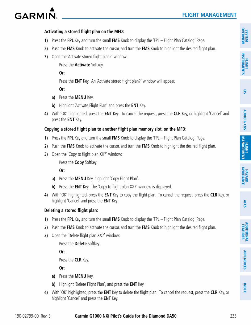
190-02799-00 Rev. B Garmin G1000 NXi Pilot’s Guide for the Diamond DA50
SYSTEMO
VERVIEWFLIG
HTIN
STRUMEN
TSEIS
AUDIO
& CN
SFLIG
HTM
AN
AGEM
ENT
HAZA
RDAVO
IDA
NCE
AFCS
AD
DITIO
NA
LFEATURES
APPEN
DICES
IND
EX
233
FLIGHT MANAGEMENT
Activating a stored flight plan on the MFD:
1) Press the FPL Key and turn the small FMS Knob to display the ‘FPL – Flight Plan Catalog’ Page.
2) Push the FMS Knob to activate the cursor, and turn the FMS Knob to highlight the desired flight plan.
3) Open the ‘Activate stored flight plan?’ window:
Press the Activate Softkey.
Or:
Press the ENT Key. An ‘Activate stored flight plan?’ window will appear.
Or:
a) Press the MENU Key.
b) Highlight ‘Activate Flight Plan’ and press the ENT Key.
4) With ‘OK’ highlighted, press the ENT Key. To cancel the request, press the CLR Key, or highlight ‘Cancel’ and press the ENT Key.
Copying a stored flight plan to another flight plan memory slot, on the MFD:
1) Press the FPL Key and turn the small FMS Knob to display the ‘FPL – Flight Plan Catalog’ Page.
2) Push the FMS Knob to activate the cursor, and turn the FMS Knob to highlight the desired flight plan.
3) Open the ‘Copy to flight plan XX?’ window:
Press the Copy Softkey.
Or:
a) Press the MENU Key, highlight ‘Copy Flight Plan’.
b) Press the ENT Key. The ‘Copy to flight plan XX?’ window is displayed.
4) With ‘OK’ highlighted, press the ENT Key to copy the flight plan. To cancel the request, press the CLR Key, or highlight ‘Cancel’ and press the ENT Key.
Deleting a stored flight plan:
1) Press the FPL Key and turn the small FMS Knob to display the ‘FPL – Flight Plan Catalog’ Page.
2) Push the FMS Knob to activate the cursor, and turn the FMS Knob to highlight the desired flight plan.
3) Open the ‘Delete flight plan XX?’ window:
Press the Delete Softkey.
Or:
Press the CLR Key.
Or:
a) Press the MENU Key.
b) Highlight ‘Delete Flight Plan’, and press the ENT Key.
4) With ‘OK’ highlighted, press the ENT Key to delete the flight plan. To cancel the request, press the CLR Key, or highlight ‘Cancel’ and press the ENT Key.

Garmin G1000 NXi Pilot’s Guide for the Diamond DA50 190-02799-00 Rev. B
SYST
EMO
VERV
IEW
FLIG
HTIN
STRU
MEN
TSEI
SAU
DIO
& C
NS
FLIG
HTM
AN
AGEM
ENT
HAZA
RDAV
OID
AN
CEA
FCS
AD
DIT
ION
AL
FEAT
URES
APP
END
ICES
IND
EX
234
FLIGHT MANAGEMENT
NOTE: The option to delete all stored flight plans is not available while the aircraft is in flight.
Deleting all stored flight plans:
1) Press the FPL Key and turn the small FMS Knob to display the ‘FPL – Flight Plan Catalog’ Page.
2) Press the MENU Key.
3) Highlight ‘Delete All’ and press the ENT Key. A ‘Delete all flight plans?’ confirmation window is displayed.
4) With ‘OK’ highlighted, press the ENT Key to delete all flight plans. To cancel the request, press the CLR Key, or highlight ‘Cancel’ and press the ENT Key.
Changing a Flight Plan Comment (Name):
1) For the active flight plan, press the FPL Key. Push the FMS Knob to activate the cursor (not required on PFD).
Or:
For the standby flight plan, press the FPL Key for the MFD. Turn the small FMS Knob to select the ‘FPL – Standby Flight Plan’ Page and push the FMS Knob to activate the cursor.
Or:
For a stored flight plan:
a) Press the FPL Key for the MFD. Turn the small FMS Knob to select the ‘FPL – Flight Plan Catalog’ Page and push the FMS Knob to activate the cursor.
b) Turn the FMS Knob to highlight the desired flight plan.
c) Press the EDIT Softkey; or press the ENT Key, turn the large FMS Knob clockwise to select ‘Edit’ and press the ENT Key. The ‘FPL – Stored Flight Plan’ Page is displayed.
2) Select the comment field.
3) Use the FMS Knob or alphanumeric keypad to edit the comment.
4) Press the ENT Key to accept the changes.
5) Push the FMS Knob to remove the flashing cursor.

190-02799-00 Rev. B Garmin G1000 NXi Pilot’s Guide for the Diamond DA50
SYSTEMO
VERVIEWFLIG
HTIN
STRUMEN
TSEIS
AUDIO
& CN
SFLIG
HTM
AN
AGEM
ENT
HAZA
RDAVO
IDA
NCE
AFCS
AD
DITIO
NA
LFEATURES
APPEN
DICES
IND
EX
235
FLIGHT MANAGEMENT
5.6 PROCEDURESThe system can access the whole range of instrument procedures available. Departures (DPs), arrivals (STARs),
and non-precision and precision approaches (APPRs) are stored within the database and can be loaded using any Procedures (PROC) Key.
NOTE: The charts database may contain Special Procedures. Prior to flying these procedures, pilots must have specific FAA authorization, training, and possession of the corresponding current, and legitimately-sourced chart (approach plate, etc.). Inclusion of the Special Procedure in the navigation database DOES NOT imply specific FAA authorization to fly the procedure.
NOTE: Some airports may have published instrument approach procedures not contained within the navigation database. These procedures may be available for preview from the charts database, but are not available for navigation guidance. See the Additional Features Section for more information on previewing Charts.
The selected procedure for the departure or arrival airport is added to the active flight plan. No waypoints are required to be in the active flight plan to load procedures; however, if the origin and destination airport are already loaded, the procedure loading window defaults to the appropriate airport, saving some time selecting the correct airport on the Procedure Loading Page. Furthermore, only one procedure for each type of procedure (DP, STAR, APPR) can be loaded at a time in a flight plan.
Whenever an approach, departure, or arrival procedure is loaded into the active flight plan, a set of approach, departure, or arrival waypoints is inserted into the flight plan along with a header line describing the instrument procedure the pilot selected. The original enroute portion of the flight plan remains active (unless an instrument procedure is activated) when the procedure is loaded.
The system adds terminal procedures to the flight plan based on leg types coded within that procedure in the navigation database. If the terminal procedure in the flight plan contains an identifier like ‘6368ft’, that indicates a leg that terminates when the specified altitude (6368 feet) has been exceeded. A heading leg in the flight plan displays ‘hdg’ preceding the DTK (e.g. ‘hdg 008°’). A flight plan leg requiring the pilot to manually initiate sequencing to the next leg displays ‘MANSEQ’ as the identifier.
Figure 5-68 Procedure Leg Identifiers
Heading Leg Terminating at the Specified AltitudeManually Sequenced Heading Leg

Garmin G1000 NXi Pilot’s Guide for the Diamond DA50 190-02799-00 Rev. B
SYST
EMO
VERV
IEW
FLIG
HTIN
STRU
MEN
TSEI
SAU
DIO
& C
NS
FLIG
HTM
AN
AGEM
ENT
HAZA
RDAV
OID
AN
CEA
FCS
AD
DIT
ION
AL
FEAT
URES
APP
END
ICES
IND
EX
236
FLIGHT MANAGEMENT
Viewing available procedures at an airport:
1) From the ‘WPT – Airport Information’ Page (Info 1 Softkey):
Press the DP Softkey. The ‘WPT – Departure Information’ Page is displayed, defaulting to the airport displayed on the ‘WPT – Airport Information’ Page.
Or:
Press the STAR Softkey. The ‘WPT – Arrival Information’ Page is displayed, defaulting to the airport displayed on the ‘WPT – Airport Information’ Page.
Or:
Press the APR Softkey. The ‘WPT – Approach Information’ Page is displayed, defaulting to the airport displayed on the ‘WPT – Airport Information’ Page.
2) To select another airport, push the FMS Knob to activate the cursor, enter an identifier/facility name/city, and press the ENT Key.
3) Turn the large FMS Knob to highlight the procedure. The procedure is previewed on the map.
4) Turn the small FMS Knob to view the available procedures. Press the ENT Key to select the procedure. The cursor moves to the next box (runway or transition). The procedure is previewed on the map.
5) Turn the small FMS Knob to view the available runway or transition. Press the ENT Key to select the runway or transition. The cursor moves to the next box (if available). The procedure is previewed on the map.
6) Repeat Step 5, until desired information has been viewed for the chosen procedure.
7) Press the Info 1 Softkey to return to the ‘WPT - Airport Information’ Page.

190-02799-00 Rev. B Garmin G1000 NXi Pilot’s Guide for the Diamond DA50
SYSTEMO
VERVIEWFLIG
HTIN
STRUMEN
TSEIS
AUDIO
& CN
SFLIG
HTM
AN
AGEM
ENT
HAZA
RDAVO
IDA
NCE
AFCS
AD
DITIO
NA
LFEATURES
APPEN
DICES
IND
EX
237
FLIGHT MANAGEMENT
DEPARTURESA Departure Procedure (DP) is loaded at the departure airport in the flight plan. Only one departure can be
loaded at a time in a flight plan. If a departure is loaded when another departure is already in the active flight plan, the new departure replaces the previous departure. The route is defined by selection of a departure, the transition waypoints, and a runway.
Figure 5-69 Departure Selection
Departure Airport
Departure Preview
Available Procedure Actions
Departure ChoicesLoaded Procedures
Procedure Loading Page Selection Softkeys
Figure 5-70 Departure Loading
Loaded DepartureSelected Departure

Garmin G1000 NXi Pilot’s Guide for the Diamond DA50 190-02799-00 Rev. B
SYST
EMO
VERV
IEW
FLIG
HTIN
STRU
MEN
TSEI
SAU
DIO
& C
NS
FLIG
HTM
AN
AGEM
ENT
HAZA
RDAV
OID
AN
CEA
FCS
AD
DIT
ION
AL
FEAT
URES
APP
END
ICES
IND
EX
238
FLIGHT MANAGEMENT
Loading a departure into the active flight plan using the PROC Key:
1) Press the PROC Key. The ‘Procedures’ Window is displayed.
2) Highlight ‘Select Departure’.
3) Press the ENT Key. The ‘PROC – Departure Loading’ Page is displayed.
4) Use the FMS Knob to select an airport and press the ENT Key.
5) Select a departure from the list and press the ENT Key.
6) Select a runway (if required) and press the ENT Key.
7) Select a transition (if required) and press the ENT Key. ‘Load?’ is highlighted.
8) Press the ENT Key to load the departure procedure.
Loading a departure into the active flight plan from the ‘WPT – Departure Information’ Page:
1) From the ‘WPT – Airport Information’ Page (first page in the WPT group), press the DP Softkey. The ‘WPT – Departure Information’ Page is displayed, defaulting to the airport displayed on the ‘WPT – Airport information’ Page.
2) To select another airport, push the FMS Knob to activate the cursor, enter an identifier/facility name/city, and press the ENT Key.
3) Select a different departure, if desired.
a) Turn the large FMS Knob to place the cursor in the ‘Departure’ Box. The departure is previewed on the map.
b) Turn the small FMS Knob to view the available departures. Press the ENT Key to select the departure. The cursor moves to the ‘Runway’ Box. The departure is previewed on the map.
c) Turn the small FMS Knob to view the available runways. Press the ENT Key to select the runway. The cursor moves to the ‘Transition’ Box (only if there are available transitions). The departure is previewed on the map.
d) Turn the small FMS Knob to view the available transitions. Press the ENT Key to select the transition. The cursor moves to the ‘Sequence’ Box. The departure is previewed on the map.
4) Press the MENU Key to display the ‘Page Menu’ Window.
5) Turn the FMS Knob to highlight ‘Load Departure’.
6) Press the ENT Key to load the departure procedure into the active flight plan.
Loading a departure procedure into a standby flight plan or a stored flight plan:
1) Select the Standby or Stored Flight Plan page:
If loading into the standby flight plan, press the FPL Key for the MFD. Turn the small FMS Knob to select the ‘FPL – Standby Flight Plan’ Page.
Or:

190-02799-00 Rev. B Garmin G1000 NXi Pilot’s Guide for the Diamond DA50
SYSTEMO
VERVIEWFLIG
HTIN
STRUMEN
TSEIS
AUDIO
& CN
SFLIG
HTM
AN
AGEM
ENT
HAZA
RDAVO
IDA
NCE
AFCS
AD
DITIO
NA
LFEATURES
APPEN
DICES
IND
EX
239
FLIGHT MANAGEMENT
If loading into the stored flight plan:
a) Press the FPL Key for the MFD. Turn the small FMS Knob to select the ‘FPL – Flight Plan Catalog’ Page.
b) Push the FMS Knob to activate the cursor.
c) Turn the FMS Knob to highlight the desired flight plan.
d) Press the EDIT Softkey; or press the ENT Key, turn the large FMS Knob clockwise to select ‘Edit’ and press the ENT Key. The ‘FPL – Stored Flight Plan’ Page is displayed.
2) Press the LD DP Softkey; or press the MENU Key, select ‘Load Departure’, and press the ENT Key. The ‘PROC – Departure Loading’ Page is displayed.
3) Select a departure. Press the ENT Key.
4) Select a runway served by the selected departure (if required). Press the ENT Key.
5) Select a transition for the selected departure (if required). Press the ENT Key.
6) Press the ENT Key to load the selected departure procedure.
Removing a departure procedure from a flight plan:
1) If removing from the active flight plan, press the FPL Key for the MFD.
Or:
If removing from the standby flight plan, press the FPL Key for the MFD. Turn the small FMS Knob to select the ‘FPL – Standby Flight Plan’ Page.
Or:
If removing from the stored flight plan:
a) Press the FPL Key for the MFD. Turn the small FMS Knob to select the ‘FPL – Flight Plan Catalog’ Page.
b) Push the FMS Knob to activate the cursor.
c) Turn the FMS Knob to highlight the desired flight plan.
d) Press the EDIT Softkey; or press the ENT Key, turn the large FMS Knob clockwise to select ‘Edit’ and press the ENT Key. The ‘FPL – Stored Flight Plan’ Page is displayed.
2) Select the departure for removal:
a) Press the MENU Key, and highlight ‘Remove Departure’.
b) Press the ENT Key. A confirmation window is displayed listing the departure procedure.
Or:
a) Push the FMS Knob to activate the cursor (not required on PFD).
b) Turn the large FMS Knob to highlight the departure header in the flight plan.
c) Press the CLR Key. A confirmation window is displayed listing the departure procedure.
3) With ‘OK’ highlighted, press the ENT Key. To cancel the removal request, highlight ‘Cancel’ and press the ENT Key.
4) Push the FMS Knob to remove the flashing cursor.

Garmin G1000 NXi Pilot’s Guide for the Diamond DA50 190-02799-00 Rev. B
SYST
EMO
VERV
IEW
FLIG
HTIN
STRU
MEN
TSEI
SAU
DIO
& C
NS
FLIG
HTM
AN
AGEM
ENT
HAZA
RDAV
OID
AN
CEA
FCS
AD
DIT
ION
AL
FEAT
URES
APP
END
ICES
IND
EX
240
FLIGHT MANAGEMENT
ARRIVALS A Standard Terminal Arrival (STAR) can be loaded at any airport that has one available. Only one arrival can
be loaded at a time in a flight plan. If an arrival is loaded when another arrival is already in the active flight plan, the new arrival replaces the previous arrival. The route is defined by selection of an arrival, the transition
waypoints, and a runway.
Figure 5-71 Arrival Selection
Destination Airport
Arrival Preview
Available Procedure Actions
Arrival ChoicesLoaded Procedures
Figure 5-72 Arrival Loading
Loaded ArrivalSelected Arrival
Procedure Loading Page Selection Softkeys

190-02799-00 Rev. B Garmin G1000 NXi Pilot’s Guide for the Diamond DA50
SYSTEMO
VERVIEWFLIG
HTIN
STRUMEN
TSEIS
AUDIO
& CN
SFLIG
HTM
AN
AGEM
ENT
HAZA
RDAVO
IDA
NCE
AFCS
AD
DITIO
NA
LFEATURES
APPEN
DICES
IND
EX
241
FLIGHT MANAGEMENT
Loading an arrival into the active flight plan using the PROC Key:
1) Press the PROC Key. The ‘Procedures’ Window is displayed.
2) Highlight ‘Select Arrival’.
3) Press the ENT Key. The ‘PROC – Arrival Loading’ Page is displayed.
4) Use the FMS Knob to select an airport and press the ENT Key.
5) Select an arrival from the list and press the ENT Key.
6) Select a transition (if required) and press the ENT Key.
7) Select a runway (if required) and press the ENT Key. ‘Load?’ is highlighted.
8) Press the ENT Key to load the arrival procedure
Loading an arrival into the active flight plan from the ‘WPT – Arrival Information’ Page:
1) From the ‘WPT – Airport Information’ Page (first page in the WPT group), press the STAR Softkey. The ‘WPT – Arrival Information’ Page is displayed, defaulting to the airport displayed on the ‘WPT – Airport Information’ Page.
2) To select another airport, push the FMS Knob to activate the cursor, enter an identifier/facility name/city, and press the ENT Key.
3) Select a different arrival, if desired.
a) Turn the large FMS Knob to highlight the arrival. The arrival is previewed on the map.
b) Turn the small FMS Knob to view the available arrivals. Press the ENT Key to select the arrival. The cursor moves to the ‘Transition’ Box (only if there are available transitions). The arrival is previewed on the map.
c) Turn the small FMS Knob to view the available transitions. Press the ENT Key to select the transition. The cursor moves to the ‘Runway’ Box. The arrival is previewed on the map.
d) Turn the small FMS Knob to view the available runways. Press the ENT Key to select the runway. The cursor moves to the ‘Sequence’ Box. The arrival is previewed on the map.
4) Press the MENU Key to display the Arrival Information ‘Page Menu’ Window.
5) Turn the FMS Knob to highlight ‘Load Arrival’.
6) Press the ENT Key to load the arrival procedure into the active flight plan.
Loading an arrival procedure into the standby flight plan or stored flight plan:
1) If loading into the standby flight plan, press the FPL Key for the MFD. Turn the small FMS Knob to select the ‘FPL – Standby Flight Plan’ Page.
Or:
If loading into the stored flight plan:
a) Press the FPL Key for the MFD. Turn the small FMS Knob to select the ‘FPL – Flight Plan Catalog’ Page.
b) Push the FMS Knob to activate the cursor.
c) Turn the FMS Knob to highlight the desired flight plan.
d) Press the EDIT Softkey; or press the ENT Key, turn the large FMS Knob clockwise to select ‘Edit’ and press the ENT Key. The ‘FPL – Stored Flight Plan’ Page is displayed.

Garmin G1000 NXi Pilot’s Guide for the Diamond DA50 190-02799-00 Rev. B
SYST
EMO
VERV
IEW
FLIG
HTIN
STRU
MEN
TSEI
SAU
DIO
& C
NS
FLIG
HTM
AN
AGEM
ENT
HAZA
RDAV
OID
AN
CEA
FCS
AD
DIT
ION
AL
FEAT
URES
APP
END
ICES
IND
EX
242
FLIGHT MANAGEMENT
2) Press the LD STAR Softkey; or press the MENU Key, select ‘Load Arrival’, and press the ENT Key. The ‘PROC – Arrival Loading’ Page is displayed.
3) Select an arrival. Press the ENT Key.
4) Select a transition for the selected arrival (if required). Press the ENT Key.
5) Select a runway served by the selected arrival (if required). Press the ENT Key.
6) Press the ENT Key to load the selected arrival procedure.
Removing an arrival procedure from a flight plan:
1) If removing from the active flight plan, press the FPL Key for the MFD.
Or:
If removing from the standby flight plan, press the FPL Key for the MFD. Turn the small FMS Knob to select the ‘FPL – Standby Flight Plan’ Page.
Or:
If removing from the stored flight plan:
a) Press the FPL Key for the MFD. Turn the small FMS Knob to select the ‘FPL – Flight Plan Catalog’ Page.
b) Push the FMS Knob to activate the cursor.
c) Turn the FMS Knob to highlight the desired flight plan.
d) Press the EDIT Softkey; or press the ENT Key, turn the large FMS Knob clockwise to select ‘Edit’ and press the ENT Key. The ‘FPL – Stored Flight Plan’ Page is displayed.
2) Select the arrival for removal:
a) Press the MENU Key, and highlight ‘Remove Arrival’.
b) Press the ENT Key. A confirmation window is displayed listing the arrival procedure.
Or:
a) Push the FMS Knob to activate the cursor (not required on PFD).
b) Turn the large FMS Knob to highlight the arrival header in the flight plan.
c) Press the CLR Key. A confirmation window is displayed listing the arrival procedure.
3) With ‘OK’ highlighted, press the ENT Key. To cancel the removal request, highlight ‘Cancel’ and press the ENT Key.
4) Push the FMS Knob to remove the flashing cursor.

190-02799-00 Rev. B Garmin G1000 NXi Pilot’s Guide for the Diamond DA50
SYSTEMO
VERVIEWFLIG
HTIN
STRUMEN
TSEIS
AUDIO
& CN
SFLIG
HTM
AN
AGEM
ENT
HAZA
RDAVO
IDA
NCE
AFCS
AD
DITIO
NA
LFEATURES
APPEN
DICES
IND
EX
243
FLIGHT MANAGEMENT
APPROACHES The system can provide navigation guidance for GPS and NAVAID instrument approach procedures. Visual
Approach guidance is also available. This section will discuss loading, activating, and removing approaches designated for navigation. For information on changing the navigation source of the CDI, and for information on the display of vertical guidance on the PFD, see the Flight Instruments Section. See the Audio & CNS Section for information on selecting and tuning a NAV receiver.
INSTRUMENT APPROACHThe system provides guidance for non-precision and precision approaches to airports with published
instrument approach procedures. Only one approach can be loaded at a time in a flight plan. If an approach is loaded when another approach is already in the active flight plan, the new approach replaces the previous approach. The route is defined by selection of an approach and the transition waypoints.
NOTE: When flying Direct-to the Final Approach Fix (FAF), the system will suspend (SUSP) leg sequencing if the approach intercept angle exceeds 45 degrees.
NOTE: When Vectors to Final is selected, the system will display an extended centerline, but guidance is not provided to the Final Approach Course.
PublisheD aPProaChes using gPs
RNAV/GPS approach procedures require GPS and can be selected for use. When the display shows ‘gps’ after a NAVAID prefix (such as `VORgps 17L’), this indicates the procedure is an Overlay Approach. The procedure may be flown either as a conventional, ground-based approach procedure or may be flown using GPS. When the display shows an approach with ‘+V’, this indicates the system will provide advisory vertical guidance when using GPS to fly the approach.
Figure 5-73 Example of Available Approaches with GPS Guidance
Approach Service Level (LNAV, LNAV/VNAV, LP, LPV)
+V indicates advisory vertical navigation
Overlay Approaches ‘VORgps’ indicates approach can be flown using VOR or GPS navigation

Garmin G1000 NXi Pilot’s Guide for the Diamond DA50 190-02799-00 Rev. B
SYST
EMO
VERV
IEW
FLIG
HTIN
STRU
MEN
TSEI
SAU
DIO
& C
NS
FLIG
HTM
AN
AGEM
ENT
HAZA
RDAV
OID
AN
CEA
FCS
AD
DIT
ION
AL
FEAT
URES
APP
END
ICES
IND
EX
244
FLIGHT MANAGEMENT
The system will allow the applicable level of service for the chosen approach using GPS navigation. See the following table for approach service levels allowed by the system:
HSI Annunciation Description Example on HSILNAV
Approach to the published MDA
Approach Service Level- LNAV, LNAV+V, L/VNAV, LP, LP+V, LPV,
LP
LNAV+VApproach with advisory vertical guidance to the published MDALP+V
L/VNAVApproach with approved vertical guidance to the published DALPV
Table 5-16 Approach Service Levels
The system GPS receivers will use Satellite Based Augmentation (SBAS) when available. Some approaches require the use of SBAS for lateral and/or vertical GPS navigation. For information on how lateral and vertical guidance is depicted on the PFD, see the Flight Instruments Section.
Approach Service Level Lateral Navigation Source Vertical Navigation Source
LNAV GPS N/A
LNAV+V GPS GPS
(advisory only)
LNAV/VNAV GPS GPS 1
LP GPS 1 N/A
LP+V GPS 1 GPS 1
(advisory only)
LPV GPS 1 GPS 1
1 SBAS required
Table 5-17 Source of Lateral and Vertical Navigation per Approach Service Level
Loss of SBAS
Due to the high level of precision required by some approach service levels, losing SBAS may require the pilot to acknowledge a downgrade of approach service level, or to abort the approach. See the following table for approach degradation behavior:
NOTE: Refer to the current, pertinent flight manual for additional information regarding crew responses for loss of SBAS and approach downgrade procedures.

190-02799-00 Rev. B Garmin G1000 NXi Pilot’s Guide for the Diamond DA50
SYSTEMO
VERVIEWFLIG
HTIN
STRUMEN
TSEIS
AUDIO
& CN
SFLIG
HTM
AN
AGEM
ENT
HAZA
RDAVO
IDA
NCE
AFCS
AD
DITIO
NA
LFEATURES
APPEN
DICES
IND
EX
245
FLIGHT MANAGEMENT
Approach SBAS Becomes Unavailable Description Action Required Downgrade
LNAV Approach phase not specified
SBAS not required. The approach is continued.
None N/ALNAV+V
LNAV/VNAV
Prior to the FAFHSI displays approach service level in amber;VDI displays ‘NO GP’. 2
None N/A
At/after the FAFHSI displays downgraded approach service level in magenta;VDI displays ‘NO GP’.
None LNAV 1
LP
More than 1 min prior to the FAF
HSI displays approach service level in amber. None N/A
Within 1 min prior to the FAF
HSI displays downgraded approach service level in magenta;CDI is removed. 2
Acknowledge message to redisplay CDI with LNAV 1 LNAV 1
At/after the FAF CDI is removed. 2Acknowledge
ABORT APR message to redisplay CDI
N/A
LP+V
More than 1 min prior to the FAF
HSI displays approach service level in amber;VDI displays ‘NO GP’.
None N/A
Within 1 min prior to the FAF
HSI displays downgraded approach service level in magenta;CDI is removed.VDI displays ‘NO GP’. 2
Acknowledge message to redisplay CDI with LNAV 1 LNAV 1
At/after the FAFCDI is removed;VDI displays ‘NO GP’. 2
AcknowledgeABORT APR message to
redisplay CDIN/A
LPV
More than 1 min prior to the FAF
HSI displays approach service level in amber; None N/A
Within 1 min prior to the FAF
HSI displays downgraded approach service level in magenta;VDI displays ‘NO GP’. 2
None LNAV 1
At/after the FAFHSI displays downgraded approach service level in magenta;VDI displays ‘NO GP’.
None LNAV 1
1 Some approaches may not publish minimums for the downgrade given as an example in this table. The system will determine the appropriate downgrade, if available, for each published approach as it is derived from the database. If an appropriate downgrade is not available, the approach should be aborted.
2 System message is generated.
Table 5-18 Approach Degradation Behavior

Garmin G1000 NXi Pilot’s Guide for the Diamond DA50 190-02799-00 Rev. B
SYST
EMO
VERV
IEW
FLIG
HTIN
STRU
MEN
TSEI
SAU
DIO
& C
NS
FLIG
HTM
AN
AGEM
ENT
HAZA
RDAV
OID
AN
CEA
FCS
AD
DIT
ION
AL
FEAT
URES
APP
END
ICES
IND
EX
246
FLIGHT MANAGEMENT
Loss of GPS on a Published GPS Approach
When the system is no longer receiving sufficient GPS integrity while on the final segment of a GPS approach, the approach service level on the HSI will turn amber, the annunciation ‘GPS LOI’ will be displayed on the PFD, and the ‘LOSS OF GPS NAVIGATION’ system message will be given. If the aircraft is at or beyond the FAF when the condition occurs, the ‘ABORT APR’ system message is given, and the CDI deviation bar is removed from the HSI. The CDI deviation bar will reappear when the ‘ABORT APR’ message is acknowledged.
If a total loss of GPS positioning occurs while on the final segment of a GPS approach, the approach service level on the HSI will turn amber, the annunciation ‘GPS LOI’ will be displayed on the PFD, and the ‘LOSS OF GPS NAVIGATION’ system message will be given. If the aircraft is at or beyond the FAF when the condition occurs, the ‘ABORT APR’ message is displayed. The CDI deviation bar is removed from the HSI and cannot be restored when GPS positioning is unavailable.
VISUAL APPROACH
The system provides a visual approach feature. Unlike instrument approaches, visual approaches are not defined in the navigation database and do not follow a precise prescribed path. Instead, the system calculates the lateral and vertical path for the chosen runway and creates visual approach waypoints based on runway position and course as specified in the navigation database.
NOTE: The charts database may contain Charted Visual Flight Procedures (CVFPs) for certain airports. CVFPs follow a precise prescribed path and are classified as Instrument Approach Procedures (IAPs). See the Additional Features Section for more information on Charts.
Each visual approach will have two transitions, the straight in transition (STRAIGHT) and the Vectors-to-Final transition (VECTORS). The visual approach waypoints (fixes) consist of the initial fix (STRGHT), the final approach fix (FINAL), and the missed approach point (RWxx).
NOTE: When flying direct-to the visual approach ‘FINAL’ waypoint, the system will suspend (SUSP) leg sequencing if the approach intercept angle exceeds 45 degrees. For visual approaches only, if leg sequencing is subsequently unsuspended, turn anticipation from ‘FINAL’ will be provided.
For visual approaches, the pilot is responsible for avoiding terrain, obstacles and traffic. Therefore, when a visual approach is selected, the message “Obstacle clearance is not provided for visual approaches” is displayed on the approach selection page and must be acknowledged before the visual approach is loaded into the flight plan.

190-02799-00 Rev. B Garmin G1000 NXi Pilot’s Guide for the Diamond DA50
SYSTEMO
VERVIEWFLIG
HTIN
STRUMEN
TSEIS
AUDIO
& CN
SFLIG
HTM
AN
AGEM
ENT
HAZA
RDAVO
IDA
NCE
AFCS
AD
DITIO
NA
LFEATURES
APPEN
DICES
IND
EX
247
FLIGHT MANAGEMENT
Figure 5-74 Loading Visual Approach
LOADING AND ACTIVATING AN APPROACH
Whenever an approach is selected, the choice to either ‘Load?’ or ‘Activate?’ is given. ‘Load’ adds the approach to the end of the flight plan without immediately using it for navigation guidance. This allows continued navigation via the intermediate waypoints in the original flight plan, but keeps the procedure available for quick activation when needed. ‘Activate’ also adds the procedure to the end of the flight plan but immediately begins to provide guidance to the first waypoint in the approach.
In many cases, it may be easiest to load the full approach while still some distance away, enroute to the destination airport. Later, if vectored to final, use the steps below to select ‘Activate Vector-To- Final’ — which makes the inbound course to the FAF waypoint active.
NOTE: If there is no arrival procedure in the active flight plan, loading an approach to a flight plan in which the destination airport has already been entered, will result in the previously entered destination airport waypoint becoming a fly-over waypoint followed by the newly loaded approach.
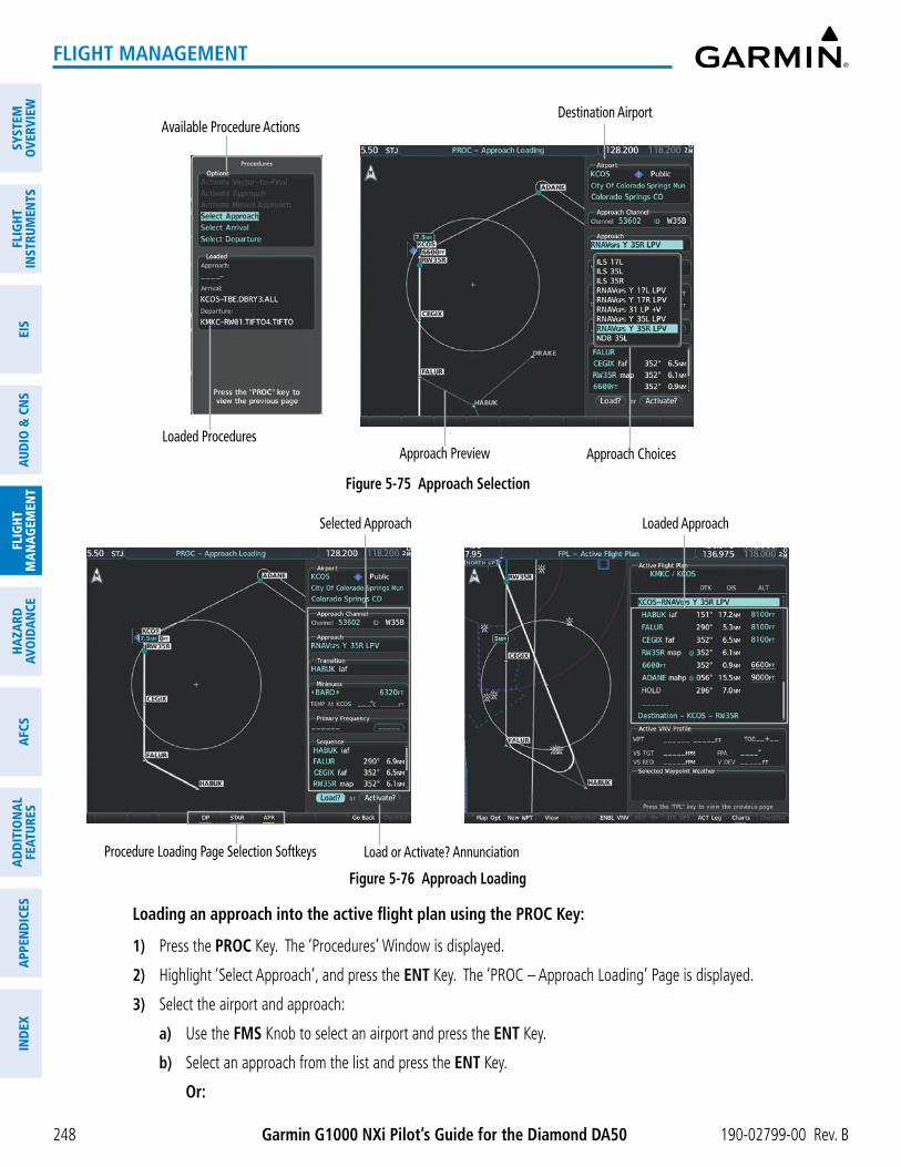
Garmin G1000 NXi Pilot’s Guide for the Diamond DA50 190-02799-00 Rev. B
SYST
EMO
VERV
IEW
FLIG
HTIN
STRU
MEN
TSEI
SAU
DIO
& C
NS
FLIG
HTM
AN
AGEM
ENT
HAZA
RDAV
OID
AN
CEA
FCS
AD
DIT
ION
AL
FEAT
URES
APP
END
ICES
IND
EX
248
FLIGHT MANAGEMENT
Figure 5-75 Approach Selection
Destination Airport
Approach Preview
Available Procedure Actions
Approach ChoicesLoaded Procedures
Figure 5-76 Approach Loading
Loaded ApproachSelected Approach
Load or Activate? AnnunciationProcedure Loading Page Selection Softkeys
Loading an approach into the active flight plan using the PROC Key:
1) Press the PROC Key. The ‘Procedures’ Window is displayed.
2) Highlight ‘Select Approach’, and press the ENT Key. The ‘PROC – Approach Loading’ Page is displayed.
3) Select the airport and approach:
a) Use the FMS Knob to select an airport and press the ENT Key.
b) Select an approach from the list and press the ENT Key.
Or:

190-02799-00 Rev. B Garmin G1000 NXi Pilot’s Guide for the Diamond DA50
SYSTEMO
VERVIEWFLIG
HTIN
STRUMEN
TSEIS
AUDIO
& CN
SFLIG
HTM
AN
AGEM
ENT
HAZA
RDAVO
IDA
NCE
AFCS
AD
DITIO
NA
LFEATURES
APPEN
DICES
IND
EX
249
FLIGHT MANAGEMENT
a) If necessary, push the FMS Knob to exit the approach list, and use the large FMS Knob to move the cursor to the Approach ‘Channel’ Field.
b) Use the FMS Knob to enter the approach channel number, and press the ENT Key to accept the approach channel number. The airport and approach are selected.
4) Select a transition (if required) and press the ENT Key.
5) Enter minimums:
To skip setting minimums, press the ENT Key.
Or:
a) To set ‘Minimums’, turn the small FMS Knob to select ‘BARO’ or ‘TEMP COMP’, and press the ENT Key. Turn the small FMS Knob to select the altitude, and press the ENT Key.
b) If ‘TEMP COMP’ was selected, the cursor moves to the temperature field. Turn the small FMS Knob to select the temperature (as reported at the destination airport), and press the ENT Key.
6) Press the ENT Key with ‘Load?’ highlighted to load the approach procedure; or turn the large FMS Knob to highlight ‘Activate?’ and press the ENT Key to load and activate the approach procedure.
If a visual approach was selected, the message ‘Obstacle clearance is not provided for visual approaches’ is displayed. With ‘OK’ highlighted, press the ENT Key.
Loading an approach into the active flight plan from the ‘NRST – Nearest Airport’ Page:
1) Select the ‘NRST – Nearest Airports’ Page.
2) Push the FMS Knob, then turn the large FMS Knob to highlight the desired nearest airport. The airport is previewed on the map.
3) Press the APR Softkey; or press the MENU Key, highlight ‘Select Approach Window’, and press the ENT Key.
4) Turn the FMS Knob to highlight the desired approach.
5) Press the LD APR Softkey; or press the MENU Key, highlight ‘Load Approach’, and press the ENT Key. The ‘PROC – Approach Loading’ Page is displayed with the ‘Transition’ Field highlighted.
6) Turn the FMS Knob to highlight the desired transition, and press the ENT Key.
7) Enter Minimums:
To skip setting minimums, press the ENT Key. The ‘Load?’ Field is highlighted.
Or:
a) To set ‘Minimums’, turn the small FMS Knob to select ‘BARO’ or ‘TEMP COMP’, and press the ENT Key. Turn the small FMS Knob to select the altitude, and press the ENT Key.
b) If ‘TEMP COMP’ was selected, the cursor moves to the temperature field. Turn the small FMS Knob to select the temperature, and press the ENT Key.
8) Press the ENT Key with ‘Load?’ highlighted to load the approach procedure; or turn the large FMS Knob to highlight ‘Activate?’ and press the ENT Key to load and activate the approach procedure.
If a visual approach was selected, the message ‘Obstacle clearance is not provided for visual approaches’ is displayed. With ‘OK’ highlighted, press the ENT Key.

Garmin G1000 NXi Pilot’s Guide for the Diamond DA50 190-02799-00 Rev. B
SYST
EMO
VERV
IEW
FLIG
HTIN
STRU
MEN
TSEI
SAU
DIO
& C
NS
FLIG
HTM
AN
AGEM
ENT
HAZA
RDAV
OID
AN
CEA
FCS
AD
DIT
ION
AL
FEAT
URES
APP
END
ICES
IND
EX
250
FLIGHT MANAGEMENT
Loading an approach procedure into a standby flight plan or a stored flight plan:
1) For the standby flight plan, press the FPL Key for the MFD. Turn the small FMS Knob to select the ‘FPL – Standby Flight Plan’ Page.
Or:
For a stored flight plan:
a) Press the FPL Key for the MFD. Turn the small FMS Knob to select the ‘FPL – Flight Plan Catalog’ Page and push the FMS Knob to activate the cursor.
b) Turn the FMS Knob to highlight the desired flight plan.
c) Press the EDIT Softkey; or press the ENT Key, turn the large FMS Knob clockwise to select ‘Edit’ and press the ENT Key. The ‘FPL – Stored Flight Plan’ Page is displayed.
2) Press the LD APR Softkey; or press the MENU Key, select “Load Approach”, and press the ENT Key. The ‘PROC – Approach Loading’ Page is displayed.
3) Select the airport and approach:
a) Use the FMS Knob to select an airport and press the ENT Key.
b) Select an approach from the list and press the ENT Key.
Or:
a) If necessary, push the FMS Knob to exit the approach list, and use the large FMS Knob to move the cursor to the Approach ‘Channel’ Field.
b) Use the FMS Knob to enter the approach channel number, and press the ENT Key to accept the approach channel number. The airport and approach are selected.
4) Select a transition for the selected approach. Press the ENT Key.
5) Press the ENT Key to load the selected approach procedure.
If a visual approach was selected, the message ‘Obstacle clearance is not provided for visual approaches’ is displayed. With ‘OK’ highlighted, press the ENT Key.
Activating a previously loaded approach:
1) Press the PROC Key. The ‘Procedures’ Window is displayed with ‘Activate Approach’ highlighted.
2) Press the ENT Key to activate the approach.
Activating a previously loaded approach with vectors to final:
1) Press the PROC Key to display the ‘Procedures’ Window.
2) Highlight ‘Activate Vector-to-Final’ and press the ENT Key.
Loading and activating an approach using the MENU Key:
1) From the ‘PROC – Approach Loading’ Page, press the MENU Key. The ‘Page Menu’ Window is displayed with ‘Load & Activate Approach’ highlighted.
2) Press the ENT Key.
Or:

190-02799-00 Rev. B Garmin G1000 NXi Pilot’s Guide for the Diamond DA50
SYSTEMO
VERVIEWFLIG
HTIN
STRUMEN
TSEIS
AUDIO
& CN
SFLIG
HTM
AN
AGEM
ENT
HAZA
RDAVO
IDA
NCE
AFCS
AD
DITIO
NA
LFEATURES
APPEN
DICES
IND
EX
251
FLIGHT MANAGEMENT
1) Press the PROC Key.
2) Use the large FMS Knob to highlight ‘Select Approach’ and press the ENT Key.
3) From the ‘PROC – Approach Loading’ Page, press the MENU Key for the MFD. The ‘Page Menu’ Window is displayed with ‘Load & Activate Approach’ highlighted.
4) Press the ENT Key.
If a visual approach was selected, the message ‘Obstacle clearance is not provided for visual approaches’ is displayed. With ‘OK’ highlighted, press the ENT Key.
REMOVING AN APPROACH
Removing an approach from the active, standby, or stored flight plan:
1) Open the appropriate flight plan page:
For the active flight plan, press the FPL Key, or turn the FMS Knob to select the ‘FPL – Active Flight Plan’ Page.
Or:
For the standby flight plan, turn the FMS Knob for the MFD to select the ‘FPL – Standby Flight Plan’ Page.
Or:
For a stored flight plan:
a) Turn the FMS Knob to select the ‘FPL – Flight Plan Catalog’ Page and push the FMS Knob to activate the cursor.
b) Turn the FMS Knob to highlight the desired flight plan.
c) Press the EDIT Softkey; or press the ENT Key, turn the large FMS Knob clockwise to select ‘Edit Flight Plan’ and press the ENT Key. The ‘FPL – Stored Flight Plan’ Page is displayed.
2) Remove the approach:
a) Press the MENU Key, and highlight ‘Remove Approach’.
b) Press the ENT Key. A confirmation window is displayed listing the approach procedure.
c) With ‘OK’ highlighted, press the ENT Key.
Or:
a) Push the FMS Knob to activate the cursor if not already activated.
b) Turn the large FMS Knob to highlight the approach header in the active flight plan.
c) Press the CLR Key. A confirmation window is displayed listing the approach procedure.
d) With ‘OK’ highlighted, press the ENT Key.
e) Push the FMS Knob to remove the flashing cursor.

Garmin G1000 NXi Pilot’s Guide for the Diamond DA50 190-02799-00 Rev. B
SYST
EMO
VERV
IEW
FLIG
HTIN
STRU
MEN
TSEI
SAU
DIO
& C
NS
FLIG
HTM
AN
AGEM
ENT
HAZA
RDAV
OID
AN
CEA
FCS
AD
DIT
ION
AL
FEAT
URES
APP
END
ICES
IND
EX
252
FLIGHT MANAGEMENT
MISSED APPROACH
NOTE: When changing the destination while navigating on a missed approach, delete the arrival (if loaded) or the approach prior to changing the destination in order to preserve the missed approach guidance. DF legs on the missed approach will still be preserved even if the arrival and approach are not deleted.
The system is capable of providing guidance for the approach as well as the missed approach. Once the missed approach is activated, MAPR will be displayed on the HSI next to the CDI. If the missed approach is activated prior to the Missed Approach Point (MAP), waypoint sequencing will continue along the approach to the missed approach. If the missed approach is not activated prior to the MAP, the system will enter SUSP Mode once the aircraft crosses the MAP until the missed approach is activated or SUSP Mode is disabled. See the Flight Instruments, Course Deviation Indicator section for more information on SUSP Mode.
See the Using Map Displays, Map Symbols discussion previously given in this section for information on displaying the missed approach preview on map displays.
In the missed approach procedure shown in the following figure, the altitude immediately following the MAP may or may not be part of the published procedure. Regardless, it represents a Course to Altitude (CA) leg along the runway centerline. The altitude shown must be achieved before turning safely toward the MAHP. If the aircraft altitude is below the specified altitude after crossing the MAP, a direct-to is established to provide a course on runway heading until the altitude is reached. After reaching the altitude, a direct-to is established to the next published waypoint. If the aircraft altitude is above the specified altitude after crossing the MAP, a direct-to is established to the published fix to begin the missed approach procedure.
Figure 5-77 Course to Altitude
Course to Altitude Leg

190-02799-00 Rev. B Garmin G1000 NXi Pilot’s Guide for the Diamond DA50
SYSTEMO
VERVIEWFLIG
HTIN
STRUMEN
TSEIS
AUDIO
& CN
SFLIG
HTM
AN
AGEM
ENT
HAZA
RDAVO
IDA
NCE
AFCS
AD
DITIO
NA
LFEATURES
APPEN
DICES
IND
EX
253
FLIGHT MANAGEMENT
Activating a missed approach in the active flight plan:
Press the Go-Around Button.
Or:
Fly past the MAP, and press the SUSP Softkey on the PFD.
Or:
1) Press the PROC Key.
2) Turn the FMS Knob to highlight ‘Activate Missed Approach’. (This option is selectable after the leg to the FAF becomes active and GPS is the active NAV source.)
3) Press the ENT Key.
TRANSITION TO APPROACH FUNCTION
When utilizing Baro-VNAV to descend to the FAF on an approach, the system utilizes the Transition to Approach (TTA) function to calculate and adjust the descent path between the FAF and the waypoint preceding the FAF so that a seamless capture of and transition to approach vertical guidance occurs. The time and location of the Bottom of Descent (BOD) may change once any TTA adjustments are made.
TEMPERATURE COMPENSATED ALTITUDE
temPerature ComPensation for aPProaCh altituDes
If desired, the system can calculate temperature compensation for waypoint crossing altitudes loaded as part of an approach procedure. The pilot must manually enable temperature compensation and then enter the destination airport temperature. The system adjusts the altitudes accordingly, and the snowflake icon ( ) is displayed next to those altitudes.
NOTE: Manually enabling temperature compensation for approach altitudes inhibits the Transition to Approach (TTA) function.
Manually setting temperature compensation for approach waypoint altitudes:
1) From the ‘FPL – Active Flight Plan’ Page, press the MENU Key. The ‘Page Menu’ Window is displayed.
2) Turn the FMS Knob to highlight ‘Temperature Compensation’.
3) Press the ENT Key. The ‘Temperature Compensation’ Window is displayed with the temperature highlighted.
4) Use the small FMS Knob to change the ‘Temperature at <airport>’ Field. The compensated altitude is computed as the temperature is selected.
5) Press the ENT Key. ‘Activate Compensation?’ is highlighted.
6) Press the ENT Key. The compensated altitudes for the approach are shown in the flight plan.

Garmin G1000 NXi Pilot’s Guide for the Diamond DA50 190-02799-00 Rev. B
SYST
EMO
VERV
IEW
FLIG
HTIN
STRU
MEN
TSEI
SAU
DIO
& C
NS
FLIG
HTM
AN
AGEM
ENT
HAZA
RDAV
OID
AN
CEA
FCS
AD
DIT
ION
AL
FEAT
URES
APP
END
ICES
IND
EX
254
FLIGHT MANAGEMENT
Cancelling temperature compensation setting for approach waypoint altitudes:
1) From the ‘FPL – Active Flight Plan’ Page, press the MENU Key. The ‘Page Menu’ Window is displayed.
2) Turn the FMS Knob to highlight ‘Temperature Compensation’.
3) Press the ENT Key. The ‘Temperature Compensation’ Window is displayed.
4) Press the ENT Key. ‘Cancel Compensation?’ is highlighted.
5) Press the ENT Key.
NOTE: Activating/cancelling temperature compensation for the loaded approach altitudes does not select/deselect temperature compensated minimums (MDA/DH), nor does selecting/deselecting temperature compensated minimums activate/cancel temperature compensated approach altitudes.
NOTE: Regardless of when the destination temperature setting is entered (when enabling temperature compensation for approach waypoint altitudes, or when enabling temperature compensation for approach minimums), the system will use the same temperature setting for all temperature compensation calculations.
Temperature Compensation
SelectedFigure 5-78 Manually Setting Temperature Compensation
Selected Temperature
FAF Altitude
Compensated Altitude
Compensated Altitudes
Figure 5-79 Temperature Compensation set for approach loaded altitudes
Uncompensated Altitudes

190-02799-00 Rev. B Garmin G1000 NXi Pilot’s Guide for the Diamond DA50
SYSTEMO
VERVIEWFLIG
HTIN
STRUMEN
TSEIS
AUDIO
& CN
SFLIG
HTM
AN
AGEM
ENT
HAZA
RDAVO
IDA
NCE
AFCS
AD
DITIO
NA
LFEATURES
APPEN
DICES
IND
EX
255
FLIGHT MANAGEMENT
temPerature ComPensation for aPProaCh minimums
A temperature compensated minimum descent altitude can be entered for the approach. Once this is entered, the altitude is also displayed on the PFD.
Entering a temperature compensated minimum into an approach:
1) From the ‘FPL – Active Flight Plan’ Page, press the PROC Key. The ‘Procedures’ Window is displayed.
2) If necessary, turn the large FMS Knob to highlight ‘Select Approach’. Press the ENT Key.
3) If necessary, use the FMS Knob and the ENT Key to select the desired airport, approach, and transition.
4) Use the FMS Knob to place the flashing cursor in the ‘Minimums’ Box. Turn the small FMS Knob to select ‘TEMP COMP’. Press the ENT Key.
5) Turn the small FMS Knob to enter the minimums altitude. Press the ENT Key. The cursor is placed in the ‘TEMP AT <destination airport>’ Field.
6) Turn the small FMS Knob to enter the temperature at the destination. Press the ENT Key.
7) Press the ENT Key with either ‘Load?’ or ‘Activate?’ highlighted. The approach is added to the active flight plan, and the temperature compensated minimums are displayed on the PFD.
Figure 5-80 Entering Temp Comp Minimums for an Approach
Temperature at destination
MFD – ‘PROC – Approach Loading’ Page
TEMP COMP Minimum
PFD – COMP MIN Shown
Approach minimum

Garmin G1000 NXi Pilot’s Guide for the Diamond DA50 190-02799-00 Rev. B
SYST
EMO
VERV
IEW
FLIG
HTIN
STRU
MEN
TSEI
SAU
DIO
& C
NS
FLIG
HTM
AN
AGEM
ENT
HAZA
RDAV
OID
AN
CEA
FCS
AD
DIT
ION
AL
FEAT
URES
APP
END
ICES
IND
EX
256
FLIGHT MANAGEMENT
5.7 TRIP PLANNINGThe system allows the pilot to view trip planning information, fuel information, and other information for a
specified flight plan or flight plan leg based on automatic data, or based on manually entered data. All of the input of data needed for calculation and viewing of the statistics is displayed on the ‘Aux – Trip Planning’ Page.
Figure 5-81 Trip Planning Page
Trip StatisticsDesired Track -
Distance -Est. Time Enroute -
Est. Time of Arrival -Enroute Safe Altitude -
Sunrise Time (local) -Sunset Time (local) -
Trip Input Data (sensor/pilot) - Departure Time (local) - Ground Speed - Fuel Flow - Fuel On Board Aircraft - Calibrated Airspeed - Indicated Altitude - Barometric Pressure - Total Air Temperature
Softkeys - Automatic/Manual Page Mode - Flight Plan/Waypoint Mode
Preview of Selected Flight Plan/
Flight Plan Leg
Trip Planning Page Mode - Automatic/Manual
Selected Flight Plan Segment- FPL Number/Cumulative Legs (CUM or REM) or Leg Number (NN)
- Waypoints Defining Selected Flight Plan/Flight Plan Leg
Fuel StatisticsEfficiency -
Total Endurance -Remaining Fuel -
Remaining Endurance -Fuel Required -
Total Range -
Other Statistics - Density Altitude - True Airspeed (TAS)
The trip planning calculations for the current flight plan are based on fuel weight and sensor inputs (automatic page mode) or pilot inputs (manual page mode). Some additional explanation of the sources for some of the inputs is as follows:
• Departure Time - This defaults to the current time in automatic page mode. The computations are from the aircraft present position, so the aircraft is always just departing.
• Calibrated Airspeed - The primary source is from the air data system, and the secondary source of information is GPS ground speed.
• Indicated Altitude - The primary source is the barometric altitude, and the secondary source of information is GPS altitude.
TRIP STATISTICSThe trip statistics are calculated based on the selected starting and ending waypoints and the trip planning
inputs.
In flight plan mode (FPL) with a stored flight plan selected (01-99), and the entire flight plan (CUM) selected, the waypoints are the starting and ending waypoints of the selected flight plan.
In flight plan mode (FPL) with a stored flight plan selected (01-99) and a specific leg selected, the waypoints are the endpoints of the selected leg.

190-02799-00 Rev. B Garmin G1000 NXi Pilot’s Guide for the Diamond DA50
SYSTEMO
VERVIEWFLIG
HTIN
STRUMEN
TSEIS
AUDIO
& CN
SFLIG
HTM
AN
AGEM
ENT
HAZA
RDAVO
IDA
NCE
AFCS
AD
DITIO
NA
LFEATURES
APPEN
DICES
IND
EX
257
FLIGHT MANAGEMENT
In flight plan mode (FPL) with the active flight plan selected (00), and the remaining flight plan (REM) selected, the ‘from’ waypoint is the present position of the aircraft and the ‘to’ waypoint is the endpoint of the active flight plan.
In flight plan mode (FPL) with the active flight plan selected (00), and a specific leg selected, the ‘from’ waypoint is the current aircraft position and the ‘to’ waypoint is the endpoint of the selected leg.
In waypoint (WPTs) mode these are manually selected waypoints (if there is an active flight plan, these default to the endpoints of the active leg).
Some of the calculated trip statistics are dashed when the selected leg of the active flight plan has already been flown.
- Desired Track - Desired Track is shown as nnn° and is the desired track between the selected waypoints. It is dashed unless only a single leg is selected.
- Distance - The distance is shown in tenths of units up to 99.9, and in whole units up to 9999.
- Estimated time enroute (ETE) - ETE is shown as hours+minutes until less than an hour, then it is shown as minutes:seconds.
- Estimated time of arrival (ETA) - ETA is shown as hours:minutes and is the local time at the destination.
» If in waypoint mode then the ETA is the ETE added to the departure time.
» If a flight plan other than the active flight plan is selected it shows the ETA by adding to the departure time all of the ETEs of the legs up to and including the selected leg. If the entire flight plan is selected, then the ETA is calculated as if the last leg of the flight plan was selected.
» If the active flight plan is selected, the ETA reflects the current position of the aircraft and the current leg being flown. The ETA is calculated by adding to the current time the ETEs of the current leg up to and including the selected leg. If the entire flight plan is selected, then the ETA is calculated as if the last leg of the flight plan was selected.
- Enroute safe altitude (ESA) - The ESA is shown as nnnnnFT.
- Destination sunrise and sunset times (Sunrise, Sunset) - These times are shown as hours:minutes of the time at the destination.
FUEL STATISTICSThe fuel statistics are calculated based on the selected starting and ending waypoints and the trip planning
inputs. Some of the calculated trip statistics are dashed when the selected leg of the active flight plan has already been flown.
- Fuel efficiency (Efficiency) - This value is calculated by dividing the current Ground Speed by the current Fuel Flow.
- Time of fuel endurance (Total Endurance) - This time is shown as hours+minutes. This value is obtained by dividing the amount of Fuel on Board by the current Fuel Flow.
- Fuel on Board upon reaching end of selected leg (Remaining Fuel) - This value is calculated by taking the amount of Fuel on Board and subtracting the Fuel Required to reach the end of the selected leg.
- Fuel endurance remaining at end of selected leg (Remaining Endurance) - This value is calculated by taking the time of Remaining Endurance and subtracting the ETE to the end of the selected leg.
- Fuel required for trip (Fuel Required) - This value is calculated by multiplying the time to go by the Fuel Flow.
- Total range at entered fuel flow (Total Range) - This value is calculated by multiplying the time of Remaining Endurance by the Ground Speed.

Garmin G1000 NXi Pilot’s Guide for the Diamond DA50 190-02799-00 Rev. B
SYST
EMO
VERV
IEW
FLIG
HTIN
STRU
MEN
TSEI
SAU
DIO
& C
NS
FLIG
HTM
AN
AGEM
ENT
HAZA
RDAV
OID
AN
CEA
FCS
AD
DIT
ION
AL
FEAT
URES
APP
END
ICES
IND
EX
258
FLIGHT MANAGEMENT
OTHER STATISTICSThese statistics are calculated based on the system sensor inputs or the manual trip planning inputs.
- Density Altitude
- True Airspeed
The pilot may select Automatic or Manual page mode, and flight plan (FPL) or waypoint (WPTs) mode. In automatic page mode, only the FPL, LEG, or waypoint IDs are editable (based on FPL/ WPTs selection). In manual page mode, the other eight trip input data fields must be entered by the pilot, in addition to flight plan and leg selection.
Figure 5-82 Trip Planning - Flight Plan Mode
Selected Leg(s)Stored Flight Plan - CUM: Beginning to End of FPL - NN: Beginning to End of Selected LegActive Flight Plan - REM: Pres. Pos. to End of FPL - NN: Pres. Pos. to End of Selected Leg
Starting and Ending Waypoint of Selected Flight Plan Segment
Selected Flight Plan NN -00 is Active FPL
01-99 are Stored FPLs
Figure 5-83 Trip Planning - Waypoint Mode
Selected Leg(s)Not Available
Selected Starting and Ending Waypoints
Selected Flight PlanNot Available

190-02799-00 Rev. B Garmin G1000 NXi Pilot’s Guide for the Diamond DA50
SYSTEMO
VERVIEWFLIG
HTIN
STRUMEN
TSEIS
AUDIO
& CN
SFLIG
HTM
AN
AGEM
ENT
HAZA
RDAVO
IDA
NCE
AFCS
AD
DITIO
NA
LFEATURES
APPEN
DICES
IND
EX
259
FLIGHT MANAGEMENT
Selecting automatic or manual page mode:
From the ‘Aux – Trip Planning’ Page, press the Auto Softkey or the Manual Softkey; or press the MENU Key, highlight ‘Auto Mode’ or ‘Manual Mode’, and press the ENT Key.
Selecting flight plan or waypoint mode:
From the ‘Aux – Trip Planning’ Page, press the FPL Softkey or the WPTs Softkey; or press the MENU Key, highlight ‘Flight Plan Mode’ or ‘Waypoints Mode’, and press the ENT Key.
Selecting a flight plan and leg for trip statistics:
1) From the ‘Aux – Trip Planning’ Page, push the FMS Knob to activate the cursor in the ‘FPL’ Field.
2) Turn the small FMS Knob to select the desired flight plan number.
3) Turn the large FMS Knob to highlight ‘CUM’ or ‘REM’. The statistics for each leg can be viewed by turning the small FMS Knob to select the desired leg. The Trip Planning Map also displays the selected data.
Selecting waypoints for waypoint mode:
1) From the ‘Aux – Trip Planning’ Page, press the WPTs Softkey; or press the MENU Key, highlight ‘Waypoints Mode’, and press the ENT Key. The cursor is positioned in the waypoint field directly below the ‘FPL’ Field.
2) Turn the FMS Knob to select the desired waypoint (or select from the ‘Page Menu’ Window ‘Set WPT to Present Position’ if that is what is desired), and press the ENT Key. The cursor moves to the second waypoint field.
3) Turn the FMS Knob to select the desired waypoint, and press the ENT Key. The statistics for the selected leg are displayed.
Entering manual data for trip statistics calculations:
1) From the ‘Aux – Trip Planning’ Page, press the Manual Softkey or select ‘Manual Mode’ from the ‘Page Menu’ Window, and press the ENT Key. The cursor may now be positioned in any field within the input data box.
2) Turn the FMS Knob to move the cursor onto the ‘Departure Time’ Field and enter the desired value. Press the ENT Key. The statistics are calculated using the new value and the cursor moves to the next entry field. Repeat until all desired values have been entered.

Garmin G1000 NXi Pilot’s Guide for the Diamond DA50 190-02799-00 Rev. B
SYST
EMO
VERV
IEW
FLIG
HTIN
STRU
MEN
TSEI
SAU
DIO
& C
NS
FLIG
HTM
AN
AGEM
ENT
HAZA
RDAV
OID
AN
CEA
FCS
AD
DIT
ION
AL
FEAT
URES
APP
END
ICES
IND
EX
260
FLIGHT MANAGEMENT
5.8 ABNORMAL OPERATION
DEAD RECKONINGThis section discusses the Dead Reckoning mode of operation and the subsequent indications.
NOTE: Dead Reckoning Mode only functions in the Enroute or Oceanic phase of flight. In all other phases, an invalid GPS solution produces a “NO GPS POSITION” annunciation on the map and the system stops using GPS.
The system will revert to Dead Reckoning (DR) Mode if the system is no longer using GPS for position fixing. In DR Mode, the system uses its last-known position combined with continuously updated airspeed and heading data (when available) to calculate and display the aircraft’s current estimated position. It is important to note that estimated navigation data supplied by the system in DR Mode may become increasingly unreliable and must not be used as a sole means of navigation.
DR Mode is inherently less accurate than the standard GPS/SBAS Mode due to the lack of satellite measurements needed to determine a position. Changes in wind speed and/or wind direction compound the relative inaccuracy of DR Mode. Because of this degraded accuracy, other navigation equipment must be relied upon for position awareness until GPS-derived position data is restored.
DR mode is indicated on the system by the appearance of the letters “DR” displayed in amber on the HSI below and to the left of the aircraft symbol, and on top of the aircraft symbol on map displays. The CDI deviation bar is removed. The autopilot will not couple in DR Mode. Lastly, but at the same time, a ‘GPS NAV LOST’ alert message appears on the PFD. Normal navigation using GPS/SBAS source data resumes automatically once a valid GPS solution is restored.
NOTE: GPS derived information will remain displayed in magenta (not amber) on the Flight Plan Progress if operating in Dead Reckoning mode. However, this information shall still be considered as degraded navigation source information.
As a result of operating in DR mode, all data that is dependent upon GPS is displayed as amber text to denote degraded navigation source information. The accuracy of all bearing and distance information on nearest pages (airports, airspaces, and waypoints) and waypoint information pages is questionable, and is displayed in amber. If the VSD Inset is enabled, ‘VSD Not Available’ will be displayed. Airspace alerts continue to function, but with degraded accuracy. Also, while the system is in DR mode, optional SVT and terrain alerting functions are disabled.
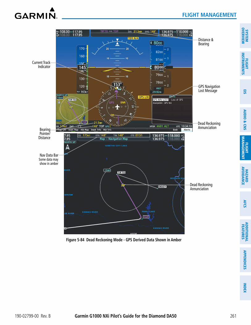
190-02799-00 Rev. B Garmin G1000 NXi Pilot’s Guide for the Diamond DA50
SYSTEMO
VERVIEWFLIG
HTIN
STRUMEN
TSEIS
AUDIO
& CN
SFLIG
HTM
AN
AGEM
ENT
HAZA
RDAVO
IDA
NCE
AFCS
AD
DITIO
NA
LFEATURES
APPEN
DICES
IND
EX
261
FLIGHT MANAGEMENT
Figure 5-84 Dead Reckoning Mode - GPS Derived Data Shown in Amber
Dead Reckoning Annunciation
Nav Data BarSome data may show in amber
Distance &Bearing
GPS Navigation Lost Message
Dead Reckoning AnnunciationBearing
Pointer/Distance
Current Track Indicator

Garmin G1000 NXi Pilot’s Guide for the Diamond DA50 190-02799-00 Rev. B
SYST
EMO
VERV
IEW
FLIG
HTIN
STRU
MEN
TSEI
SAU
DIO
& C
NS
FLIG
HTM
AN
AGEM
ENT
HAZA
RDAV
OID
AN
CEA
FCS
AD
DIT
ION
AL
FEAT
URES
APP
END
ICES
IND
EX
262
FLIGHT MANAGEMENT
Blank Page

190-02799-00 Rev. B Garmin G1000 NXi Pilot’s Guide for the Diamond DA50
SYSTEMO
VERVIEWFLIG
HTIN
STRUMEN
TSEIS
AUDIO
& CN
SFLIG
HTM
AN
AGEM
ENT
HAZA
RDAVO
IDA
NCE
AFCS
AD
DITIO
NA
LFEATURES
APPEN
DICES
IND
EX
263
HAZARD AVOIDANCE
SECTION 6 HAZARD AVOIDANCEHazard avoidance features available for the system are designed to aid situational awareness and provide advisory
information with regard to potential hazards to flight safety associated with weather, terrain, and air traffic.
• Weather
- GDL 69/69A SXM SiriusXM Weather (Subscription Optional)
- GSR 56 Garmin Connext Weather (Optional)
- Flight Information Services-Broadcast (Optional)
- L-3 Stormscope® WX-500 Lightning Detection System (Optional)
- GWX 75 Weather Radar (Optional)
• Terrain Avoidance
- Terrain Proximity
- Terrain-SVT (included with Garmin SVT option)
• Traffic
- Traffic Information Service (TIS)
- Traffic Advisory System (TAS) (Optional)
- Automatic Dependent Surveillance-Broadcast (ADS-B) Traffic (Optional)

Garmin G1000 NXi Pilot’s Guide for the Diamond DA50 190-02799-00 Rev. B
SYST
EMO
VERV
IEW
FLIG
HTIN
STRU
MEN
TSEI
SAU
DIO
& C
NS
FLIG
HTM
AN
AGEM
ENT
HAZA
RDAV
OID
AN
CEA
FCS
AD
DIT
ION
AL
FEAT
URES
APP
END
ICES
IND
EX
264
HAZARD AVOIDANCE
6.1 DATA LINK WEATHER
WARNING: Do not use data link weather information for maneuvering in, near, or around areas of hazardous weather. Information contained within data link weather products may not accurately depict current weather conditions.
WARNING: Do not use the indicated data link weather product age to determine the age of the weather information shown by the data link weather product. Due to time delays inherent in gathering and processing weather data for data link transmission, the weather information shown by the data link weather product may be older than the indicated weather product age.
The Data Link Weather feature enables the system to receive weather information from a variety of weather sources, depending on the equipment installed in the aircraft. These sources may include SiriusXM Weather, Garmin Connext Weather, and Flight Information Services-Broadcast (FIS-B). For each source, a ground-based system processes the weather information collected from a network of sensors and weather data providers.
The SiriusXM Weather service, available with the Garmin 69A SXM data link receiver and an active service subscription, updates its weather data periodically and automatically, and transmits this information to the aircraft’s receiver via satellite on the S-Band frequency. This service provides continuous reception capabilities at any altitude throughout North America.
The FIS-B Weather service, available when equipped with a capable transponder or data link receiver which can receive 978 MHz Universal Access Transceiver (UAT) data, delivers subscription-free weather information periodically and automatically to the aircraft. FIS-B uses a network of FAA-operated Ground-Based Transceivers (GBTs) to transmit the information to the aircraft’s receiver. Reception is limited to line-of-sight, and is available below 24,000 feet MSL in the United States. FIS-B broadcasts provide weather data in a repeating cycle which may take approximately ten minutes to transmit all available weather data. Therefore, not all weather data may be present immediately upon initial FIS-B signal acquisition. FIS-B is a component of the Automatic Dependent Surveillance (ADS-B) system, which offers both weather and traffic data; refer to the ADS-B Traffic discussion later in this section for a more detailed discussion of the ADS-B system and its capabilities.
The Garmin Connext Weather service, available when equipped with the Garmin GSR 56 Iridium Satellite Transceiver and an active service subscription, provides data link weather information to the aircraft after the pilot defines a geographic area and subsequently selects a manual or automatically recurring Connext Data Request. The transceiver then contacts the Garmin Connext Weather service using the Iridium Satellite telephone system and retrieves the weather data for the specified area. The Garmin Connext Weather service offers worldwide weather coverage, but the availability of individual weather products, such as radar precipitation, varies by region.
NOTE: To check the availability of Garmin Connext weather products offered in a particular region, visit flygarmin.com

190-02799-00 Rev. B Garmin G1000 NXi Pilot’s Guide for the Diamond DA50
SYSTEMO
VERVIEWFLIG
HTIN
STRUMEN
TSEIS
AUDIO
& CN
SFLIG
HTM
AN
AGEM
ENT
HAZA
RDAVO
IDA
NCE
AFCS
AD
DITIO
NA
LFEATURES
APPEN
DICES
IND
EX
265
HAZARD AVOIDANCE
ACTIVATING DATA LINK WEATHER SERVICES
NOTE: Service activation is not applicable to the FIS-B Weather service.
ACTIVATING THE SIRIUSXM WEATHER SERVICE
Before SiriusXM Weather can be used, the service must be enabled by providing SiriusXM’s customer service the coded ID(s) unique to the installed data link receiver. The Data Radio ID must be provided to activate the weather service. A separate Audio Radio ID, if present, enables the receiver to provide SiriusXM Radio entertainment. To view this information, refer to the following locations:
» The ‘Aux - XM Information’ Page on the MFD
» The SiriusXM Activation Instructions included with the Data Link Receiver
» The label on the back of the Data Link Receiver
SiriusXM uses the coded IDs to send an activation signal that allows the system to display weather data and/or provide audio entertainment programming through the data link receiver.
Establishing an account for SiriusXM services:
1) Select the XM Radio Page in the Aux Page Group.
2) If necessary, press the Info Softkey to display the ‘Aux - XM Information’ Page.
3) Note the Data Radio ID (for SiriusXM Weather data) and/or the Audio Radio ID (for SiriusXM Satellite Radio).
4) Contact SiriusXM customer service through the phone number listed on its website, www.siriusxm.com.
5) Provide SiriusXM customer service the Data Radio ID and/or Audio Radio ID, in addition to payment information, and the desired weather product subscription package.
After SiriusXM has been contacted, it may take approximately 15 minutes until the activation occurs.
Verifying the SiriusXM Weather service activation:
1) Once a SiriusXM Weather account has been established, select the XM Radio Page in the Auxiliary Page Group.
2) If necessary, press the Info Softkey to display the ‘Aux - XM Information’ Page.
3) View the list of supported Weather Products. An empty box appears next to an unavailable weather product; a green filled box appears next to an available weather product. During activation, it may take several minutes for weather products in the selected subscription package to become available.
NOTE: Not all weather products offered by SiriusXM are supported for display on this system. This pilot’s guide only discusses supported weather products.

Garmin G1000 NXi Pilot’s Guide for the Diamond DA50 190-02799-00 Rev. B
SYST
EMO
VERV
IEW
FLIG
HTIN
STRU
MEN
TSEI
SAU
DIO
& C
NS
FLIG
HTM
AN
AGEM
ENT
HAZA
RDAV
OID
AN
CEA
FCS
AD
DIT
ION
AL
FEAT
URES
APP
END
ICES
IND
EX
266
HAZARD AVOIDANCE
Figure 6-1 XM Information Page
Weather Products (Available Products for Service Class Indicated in Green)
Audio Radio ID (for SiriusXM Satellite Radio)
Data Radio ID (for SiriusXM
Weather
ACTIVATING GARMIN CONNEXT WEATHER
The Garmin Connext weather service requires an active Iridium satellite telephone and weather data subscription. Registration begins by first obtaining the serial number(s) for the installed Iridium Satellite Transceiver (GSR 1), and the System ID. Then go to the website flygarmin.com and follow the instructions for establishing an account for Garmin Connext data services. Note additional information about the airframe may be required. After an account has been established, Garmin provides an access code that must be entered on the system and successfully transmitted to the Garmin Connext service via the Iridium satellite network.
Obtaining the LRU serial numbers and System ID:
1) Select the ‘Aux - System Status’ Page.
2) Press the LRU Softkey.
3) Turn the FMS Knob to scroll the cursor until ‘GSR 1’ is visible in the ‘LRU Information’ window.
4) Note the serial number displayed for ‘GSR 1’.
5) Push the FMS Knob to deactivate the cursor.

190-02799-00 Rev. B Garmin G1000 NXi Pilot’s Guide for the Diamond DA50
SYSTEMO
VERVIEWFLIG
HTIN
STRUMEN
TSEIS
AUDIO
& CN
SFLIG
HTM
AN
AGEM
ENT
HAZA
RDAVO
IDA
NCE
AFCS
AD
DITIO
NA
LFEATURES
APPEN
DICES
IND
EX
267
HAZARD AVOIDANCE
Figure 6-2 Identification Needed for Iridium Registration
System ID Number
Iridium Transceiver Serial Number
When an account is established, Garmin provides an Access Code which must be entered on the system in order to complete the registration process.
Registering the system to receive Garmin Connext Weather:
1) Go to flygarmin.com. Locate the information for subscribing to Garmin Connext Satellite Services on the website.
2) Choose a desired service which includes weather data and enter the requested information about the aircraft.
3) Note the Access Code provided during the registration process and any additional instructions received.
4) With the aircraft outside and having a clear view of the sky, turn the large FMS Knob on the MFD to select the Map page group.
5) Turn the small FMS Knob to select the ‘Map - Weather Data Link (CNXT)’ Page. If another data link weather source such as ‘XM’ or ‘FIS-B’ is displayed in the page title, it will be necessary to change the data link weather source to CNXT before continuing. Refer to ‘Viewing the Weather Data Link (CNXT) Page’ procedure to change the data link source to prior to registration.
6) If the system displays the Connext Registration Window, proceed to step 8. Otherwise, press the MENU Key. The page menu window is now displayed.
7) Turn the large FMS Knob to select ‘Register With Connext’ in the menu list.
8) Press the ENT Key. The Connext Registration Window appears as shown in the following figure.
9) Enter the access code provided by Garmin in the ‘Access Code’ field.

Garmin G1000 NXi Pilot’s Guide for the Diamond DA50 190-02799-00 Rev. B
SYST
EMO
VERV
IEW
FLIG
HTIN
STRU
MEN
TSEI
SAU
DIO
& C
NS
FLIG
HTM
AN
AGEM
ENT
HAZA
RDAV
OID
AN
CEA
FCS
AD
DIT
ION
AL
FEAT
URES
APP
END
ICES
IND
EX
268
HAZARD AVOIDANCE
10) Press the ENT Key. ‘Register’ is highlighted.
11) Press the ENT Key. The system contacts Garmin through the Iridium network. System registration is complete when the Current Registration Window displays the correct information for the Airframe, Tail Number, Airframe Serial Number, and Iridium Serial Number.
12) When finished, push the FMS Knob to remove the Connext Registration Window.
Figure 6-3 Enter Access Code
WEATHER PRODUCT AGEUnlike real-time weather information collected directly from weather sensors on-board an aircraft, such as an
airborne weather radar or a lightning detection system, data link weather in contrast relies on external service providers to collect, process, and transmit weather information to the aircraft. This information can come from a variety of sources such as government agencies.
NOTE: Due to the time it takes to collect, process, and distribute data link weather information, it is imperative for pilots to understand that data link weather information is not real-time information and may not accurately depict current conditions.

190-02799-00 Rev. B Garmin G1000 NXi Pilot’s Guide for the Diamond DA50
SYSTEMO
VERVIEWFLIG
HTIN
STRUMEN
TSEIS
AUDIO
& CN
SFLIG
HTM
AN
AGEM
ENT
HAZA
RDAVO
IDA
NCE
AFCS
AD
DITIO
NA
LFEATURES
APPEN
DICES
IND
EX
269
HAZARD AVOIDANCE
For each data link weather product which can be displayed as a map overlay, such as radar precipitation, the system can also show a weather product age. This age represents the elapsed time, in minutes, since the weather service provider compiled the weather product and the current time. It does not represent the age of the information contained within the weather product itself. For example, a single mosaic of radar precipitation is comprised data from multiple radar sites providing data at differing scan rates or intervals. The weather service provider periodically compiles this data to create a single composite image, and assigns one time to this image which becomes the basis of the product age. The service provider then makes this weather product available for data link transmission at the next scheduled update time. The actual age of the weather data contained within the mosaic is therefore older than its weather product age and should never be considered current.
SiriusXM and FIS-B weather products are broadcast automatically on a repeating cycle without pilot intervention. For the Garmin Connext service, the pilot schedules a one-time or repeating data request at regular intervals.
Each data link weather product age has an expiration time. The weather product age is shown in white if it is less than half of this expiration time, otherwise it is shown in amber until reaching its expiration time. After a weather product has expired, the system removes the expired weather product from the displays, and shows white dashes instead of the age. If the data link receiver has not yet received a weather product ‘N/A’ appears instead of the age to show the product is currently not available for display. This may occur, for example, after powering on the system but before the data link receiver has received a complete weather data transmission. It could also indicate a possible outage of a weather product.
The weather product age is shown automatically for weather products displayed on MFD maps. For PFD maps, the pilot can manually enable/disable the age information.
Enabling/disabling the weather product age for PFD Maps:
1) With the PFD Inset Map or HSI Map displayed, press the Map/HSI Softkey.
2) Press the WX LGND to show/remove the weather product age information for PFD maps.
The following tables show the weather product symbols, and the expiration times for SiriusXM Weather and FIS-B Weather, respectively. The FIS-B broadcast rate represents the interval at which the FIS-B Weather service transmits new signals that may or may not contain updated weather product information. It does not represent the rate at which the weather information is updated or when the Data Link Receiver receives new data. The service provider and its weather data suppliers define and control the data update intervals, which are subject to change.

Garmin G1000 NXi Pilot’s Guide for the Diamond DA50 190-02799-00 Rev. B
SYST
EMO
VERV
IEW
FLIG
HTIN
STRU
MEN
TSEI
SAU
DIO
& C
NS
FLIG
HTM
AN
AGEM
ENT
HAZA
RDAV
OID
AN
CEA
FCS
AD
DIT
ION
AL
FEAT
URES
APP
END
ICES
IND
EX
270
HAZARD AVOIDANCE
SiriusXM Weather Product Product SymbolExpiration Time
(Minutes)
Next-generation Radar (NEXRAD) 30
Cloud Tops 60
Echo Tops 30
SiriusXM Lightning 30
Storm Cell Movement 30
SIGMETs 60
AIRMETs 60
METARs 90
City Forecast 90
Surface Analysis 60
Freezing Levels 120
Winds Aloft 90
County Warnings 60
Cyclone (Hurricane) Warnings 60
Icing Potential (CIP and SLD) 90
Pilot Weather Report (PIREPs) 90
Air Report (AIREPs) 90
Turbulence 180
No Radar Coverage No product symbol 30
Temporary Flight Restrictions (TFRs) 60
Terminal Aerodrome Reports (TAFs) No product symbol 60
Table 6-1 SiriusXM Weather Product Symbols and Data Timing

190-02799-00 Rev. B Garmin G1000 NXi Pilot’s Guide for the Diamond DA50
SYSTEMO
VERVIEWFLIG
HTIN
STRUMEN
TSEIS
AUDIO
& CN
SFLIG
HTM
AN
AGEM
ENT
HAZA
RDAVO
IDA
NCE
AFCS
AD
DITIO
NA
LFEATURES
APPEN
DICES
IND
EX
271
HAZARD AVOIDANCE
FIS-B Weather Product Product SymbolExpiration Time
(Minutes)
NEXRAD Composite (US) 30
NEXRAD Composite (Regional) 30
METARs 90
Pilot Weather Report (PIREP) 90
Winds Aloft 90
SIGMETs/AIRMETs 60
No Radar Coverage No product symbol 30
Terminal Aerodrome Forecast (TAF)
No product symbol 60
Temporary Flight Restriction (TFR) 60
Table 6-2 FIS-B Weather Product Symbols and Data Timing

Garmin G1000 NXi Pilot’s Guide for the Diamond DA50 190-02799-00 Rev. B
SYST
EMO
VERV
IEW
FLIG
HTIN
STRU
MEN
TSEI
SAU
DIO
& C
NS
FLIG
HTM
AN
AGEM
ENT
HAZA
RDAV
OID
AN
CEA
FCS
AD
DIT
ION
AL
FEAT
URES
APP
END
ICES
IND
EX
272
HAZARD AVOIDANCE
The following table shows the Garmin Connext Weather product symbols, the expiration times and the refresh rates. The refresh rate represents the interval at which Garmin Connext weather service makes available the most current known weather data. It does not necessarily represent the rate at which the service receives new data from various weather sources. The pilot chooses how often to contact the Garmin Connext weather service in order to retrieve weather data through the Connext Data Request.
Garmin Connext Weather Product
Product SymbolExpiration Time
(Minutes)
Connext Radar 30
IR Satellite 60
Connext Lightning 30
SIGMETs 60
AIRMETs 60
Meteorological Aerodrome Report (METARs)
90
Winds Aloft 90
Pilot Weather Reports (PIREPs)
90
Temporary Flight Restrictions (TFRs)
60
Terminal Aerodrome Reports (TAFs)
No product symbol 60
1 The composite precipitation image is updated every 3 minutes, but individual radar sites may take between 3 and 10 minutes to provide new data.
2 Canadian radar precipitation data provided by Environment Canada.3 Australian radar precipitation data provided by the Australia Bureau of
Meteorology.Table 6-3 Garmin Connext Weather Product Symbols and Data Timing
DISPLAYING DATA LINK WEATHER PRODUCTS
WEATHER DATA LINK PAGE
The Weather Data Link Page is the principal map page for viewing data link weather information. This page provides the capability for displaying the most data link weather products of any map on the system. The Weather Data Link Page also provides system-wide controls for selecting the data link weather source, if more than one source has been installed. The page title indicates the selected data link weather source (e.g., ‘XM’, ‘FIS-B’ or ‘CNXT’).

190-02799-00 Rev. B Garmin G1000 NXi Pilot’s Guide for the Diamond DA50
SYSTEMO
VERVIEWFLIG
HTIN
STRUMEN
TSEIS
AUDIO
& CN
SFLIG
HTM
AN
AGEM
ENT
HAZA
RDAVO
IDA
NCE
AFCS
AD
DITIO
NA
LFEATURES
APPEN
DICES
IND
EX
273
HAZARD AVOIDANCE
Figure 6-4 Weather Data Link (XM) Page
NEXRAD Weather Product Display Enabled Icon
NEXRAD Weather Product Age (US)
NEXRAD Weather Product Selected
for Display
Viewing the Weather Data Link Page and changing the data link weather source, if applicable:
1) Turn the large FMS Knob to select the Map Page Group.
2) Turn the small FMS Knob to select the Weather Data Link (XM or CNXT or FIS-B) Page. The currently selected data link weather source appears in the page title.
3) If the page title does not contain the desired weather source, press the MENU Key.
a) Turn the FMS Knob to highlight ‘Display XM Weather’, ‘Display Connext Weather’ or ‘Display FIS-B Weather’ (choices may vary depending on the installed equipment).
b) Press the ENT Key.
Figure 6-5 Changing the Data Link Weather Source
The system presents the softkeys for the selected source on the Weather Data Link Page, and for map overlays used throughout the system. The following figures show the softkeys for the Weather Data Link Page based on the selected source.
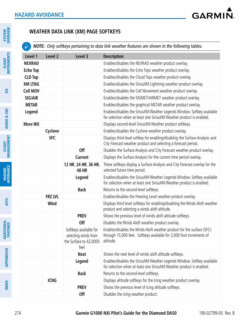
Garmin G1000 NXi Pilot’s Guide for the Diamond DA50 190-02799-00 Rev. B
SYST
EMO
VERV
IEW
FLIG
HTIN
STRU
MEN
TSEI
SAU
DIO
& C
NS
FLIG
HTM
AN
AGEM
ENT
HAZA
RDAV
OID
AN
CEA
FCS
AD
DIT
ION
AL
FEAT
URES
APP
END
ICES
IND
EX
274
HAZARD AVOIDANCE
WEATHER DATA LINK (XM) PAGE SOFTKEYS
NOTE: Only softkeys pertaining to data link weather features are shown in the following tables.
Level 1 Level 2 Level 3 DescriptionNEXRAD Enables/disables the NEXRAD weather product overlay.
Echo Top Enables/disables the Echo Tops weather product overlay.
CLD Top Enables/disables the Cloud Tops weather product overlay.
XM LTNG Enables/disables the SiriusXM Lightning weather product overlay.
Cell MOV Enables/disables the Cell Movement weather product overlay.
SIG/AIR Enables/disables the SIGMET/AIRMET weather product overlay.
METAR Enables/disables the graphical METAR weather product overlay.
Legend Enables/disables the SiriusXM Weather Legends Window. Softkey available for selection when at least one SiriusXM Weather product is enabled.
More WX Displays second-level SiriusXM Weather product softkeys.
Cyclone Enables/disables the Cyclone weather product overlay.
SFC Displays third level softkey for enabling/disabling the Surface Analysis and City Forecast weather product and selecting a forecast period.
Off Disables the Surface Analysis and City Forecast weather product overlay.
Current Displays the Surface Analysis for the current time period overlay.
12 HR, 24 HR, 36 HR, 48 HR
These softkeys display a Surface Analysis and City Forecast overlay for the selected future time period.
Legend Enables/disables the SiriusXM Weather Legends Window. Softkey available for selection when at least one SiriusXM Weather product is enabled.
Back Returns to the second-level softkeys.
FRZ LVL Enables/disables the Freezing Level weather product overlay.
Wind Displays third level softkeys for enabling/disabling the Winds Aloft weather product and selecting a winds aloft altitude.
PREV Shows the previous level of winds aloft altitude softkeys.
Off Disables the Winds Aloft weather product overlay.
Softkeys available for selecting winds from
the Surface to 42,0000 feet
Enables/disables the Winds Aloft weather product for the surface (SFC) through 15,000 feet. Softkeys available for 3,000 foot increments of altitude.
Next Shows the next level of winds aloft altitude softkeys.
Legend Enables/disables the SiriusXM Weather Legends Window. Softkey available for selection when at least one SiriusXM Weather product is enabled.
Back Returns to the second-level softkeys.
ICNG Displays altitude softkeys for the Icing weather product overlay.
PREV Shows the previous level of Icing altitude softkeys.
Off Disables the Icing weather product.

190-02799-00 Rev. B Garmin G1000 NXi Pilot’s Guide for the Diamond DA50
SYSTEMO
VERVIEWFLIG
HTIN
STRUMEN
TSEIS
AUDIO
& CN
SFLIG
HTM
AN
AGEM
ENT
HAZA
RDAVO
IDA
NCE
AFCS
AD
DITIO
NA
LFEATURES
APPEN
DICES
IND
EX
275
HAZARD AVOIDANCE
Level 1 Level 2 Level 3 Description
Softkeys available for selecting winds from
the Icing altitude from to 1,000 to 30,000 feet
Enables/disables the Icing weather product overlay from 1,000 feet to 30,000 feet. Softkeys available for 3,000 foot increments of altitude.
Next Shows the next level of Icing weather product softkeys.
Legend Enables/disables the SiriusXM Weather Legends Window. Softkey available for selection when at least one SiriusXM Weather product is enabled.
TURB Displays softkeys for enabling/disabling the Turbulence weather product overlay.
PREV Shows the previous level of Turbulence altitude softkeys.
Off Disables the Turbulence weather product overlay.
Softkeys available for selecting Turbulence altitude from 21,000 feet to 45,000 feet
Enables/disables the Icing weather product overlay from 21,000 feet to 45,000 feet. Softkeys available for 3,000 foot increments of altitude.
Next Shows the next level of Icing weather product softkeys.
Legend Enables/disables the SiriusXM Weather Legends Window. Softkey available for selection when at least one SiriusXM Weather product is enabled.
Back Returns to the second-level softkeys.
AIREPS Enables/disables the AIREPs weather product overlay.
PIREPS Enables/disables the PIREPs weather product overlay.
County Enables/disables the County Warnings weather product overlay.
Back Returns to the first level softkeys.
WEATHER DATA LINK (CNXT) PAGE SOFTKEYS
Level 1 Level 2 Level 3 DescriptionPRECIP Enables/disables the Precipitation weather product overlay.
IR SAT Enables/disables the Infrared Satellite weather product overlay.
SIG/AIR Enables/disables the SIGMET/AIRMET weather product overlay.
DL LTNG Enables/disables Lightning weather product overlay.
METAR Enables/disables the METAR weather product overlay.
Legend Enables/disables the Connext Weather Legends Window. Softkey available for selection when at least one Connext Weather product is enabled.
More WX Displays second-level Connext Weather product softkeys.
Wind Displays third level softkeys for enabling/disabling the Winds Aloft weather product and selecting a winds aloft altitude.
PREV Shows the previous level of winds aloft altitude softkeys.
Off Disables the Winds Aloft weather product overlay.

Garmin G1000 NXi Pilot’s Guide for the Diamond DA50 190-02799-00 Rev. B
SYST
EMO
VERV
IEW
FLIG
HTIN
STRU
MEN
TSEI
SAU
DIO
& C
NS
FLIG
HTM
AN
AGEM
ENT
HAZA
RDAV
OID
AN
CEA
FCS
AD
DIT
ION
AL
FEAT
URES
APP
END
ICES
IND
EX
276
HAZARD AVOIDANCE
Level 1 Level 2 Level 3 Description
Softkeys available for selecting winds from
the Surface to 42,0000 feet
Enables/disables the Winds Aloft weather product for the surface (SFC) through 15,000 feet. Softkeys available for 3,000 foot increments of altitude.
Next Shows the next level of winds aloft altitude softkeys.
Legend Enables/disables the Connext Weather Legends Window. Softkey available for selection when at least one Connext Weather product is enabled.
Back Returns to the second-level softkeys.
PIREPs Enables/disables the PIREPs weather product overlay.
Back Returns to the first level softkeys.
WEATHER DATA LINK (FIS-B) PAGE SOFTKEYS)
Level 1 Level 2 Level 3 DescriptionNXRD
orUSor
REGor
ALL
Cycles through NEXRAD display modes with each press:
- NEXRAD (with annunciator disabled): No NEXRAD is shown. - US: Displays NEXRAD data for the Continental US (CONUS). - REG: Displays regional NEXRAD data. - ALL: Displays regional NEXRAD data where available, and CONUS
NEXRAD data in other coverage areas.
SIG/AIR Enables/disables the SIGMET/AIRMET weather product overlay.
METAR Enables/disables the METAR weather product overlay.
Legend Enables/disables the Connext Weather Legends Window. Softkey available for selection when at least one Connext Weather product is enabled.
More WX Displays second-level Connext Weather product softkeys.
Wind Displays third level softkeys for enabling/disabling the Winds Aloft weather product and selecting a winds aloft altitude.
PREV Shows the previous level of winds aloft altitude softkeys.
Off Disables the Winds Aloft weather product overlay.
Softkeys available for selecting winds from
the Surface to 42,0000 feet
Enables/disables the Winds Aloft weather product for the surface (SFC) through 15,000 feet. Softkeys available for 3,000 foot increments of altitude.
Next Shows the next level of winds aloft altitude softkeys.
Legend Enables/disables the Connext Weather Legends Window. Softkey available for selection when at least one Connext Weather product is enabled.
Back Returns to the second-level softkeys.
PIREPs Enables/disables the PIREPs weather product overlay.
Back Returns to the first level softkeys.

190-02799-00 Rev. B Garmin G1000 NXi Pilot’s Guide for the Diamond DA50
SYSTEMO
VERVIEWFLIG
HTIN
STRUMEN
TSEIS
AUDIO
& CN
SFLIG
HTM
AN
AGEM
ENT
HAZA
RDAVO
IDA
NCE
AFCS
AD
DITIO
NA
LFEATURES
APPEN
DICES
IND
EX
277
HAZARD AVOIDANCE
The Weather Data Link Page can display a legend for each enabled weather product.
Viewing legends for displayed weather products on the Weather Data Link Page:
1) Select the Weather Data Link Page.
2) Press the Legend Softkey to display the legends for the displayed weather products.
Or:
a) Press the MENU Key.
b) Select ‘Weather Legend’ and press the ENT Key.
3) Turn the FMS Knob to scroll through the legends if more are available than fit in the window.
4) To remove the Weather Legends Window, press the Legend Softkey, the ENT or the CLR Key, or push the FMS Knob.
Additional information about the following weather products can be displayed by panning the Map Pointer over the following products on the Weather Data Link Page:
- Echo Tops
- Cloud Tops
- Cell Movement
- SIGMETs
- AIRMETs
- METARs
- County Warnings
- TFRs
- AIREPs
- PIREPs
The map panning feature is enabled by pushing the Joystick. The map range is adjusted by turning the Joystick. If the map range is adjusted while panning is enabled, the map is re-centered on the Map Pointer.
Figure 6-6 Panning on the Weather Data Link (XM) Page
Additional Information on Weather
Feature Selected with Map Pointer
Storm CellSelected with Map Pointer

Garmin G1000 NXi Pilot’s Guide for the Diamond DA50 190-02799-00 Rev. B
SYST
EMO
VERV
IEW
FLIG
HTIN
STRU
MEN
TSEI
SAU
DIO
& C
NS
FLIG
HTM
AN
AGEM
ENT
HAZA
RDAV
OID
AN
CEA
FCS
AD
DIT
ION
AL
FEAT
URES
APP
END
ICES
IND
EX
278
HAZARD AVOIDANCE
Certain weather products, such as METARs or TFRs have associated full text. When a weather product is selected with the Map Pointer, press the ENT Key. The system displays the full text for the selected weather product in a window. To remove the window, push the FMS Knob or the CLR Key.
The Weather Data Link Page also has a page menu that can be accessed by pressing the MENU Key. It has controls for enabling/disabling the weather products as an alternative to using the softkeys.
Customizing the weather Data link Page
The Weather Data Link Page includes controls for selecting the maximum map range to display each weather product on the page. If the pilot increases the map range beyond this selected maximum range, the system removes the weather product from the map. If more than one data link weather source has been installed, the system uses the same maximum map range for the comparable weather product of another source.
Setting up and customizing the Weather Data Link Page:
1) Select the Weather Data Link Page.
2) Press the MENU Key.
3) Turn the FMS Knob to highlight ‘Weather Setup’, then press the ENT Key.
4) Turn the small FMS Knob to select ‘Product Group 1’ or ‘Product Group 2’, and press the ENT Key.
5) Turn the large FMS Knob or press the ENT Key to scroll through product selections.
6) Turn the small FMS Knob to scroll through options for each product (On/Off, range settings, etc.).
7) Press the ENT Key to select an option.
8) Push the FMS Knob or press the CLR Key to return to the Weather Data Link (XM) Page with the changed settings.

190-02799-00 Rev. B Garmin G1000 NXi Pilot’s Guide for the Diamond DA50
SYSTEMO
VERVIEWFLIG
HTIN
STRUMEN
TSEIS
AUDIO
& CN
SFLIG
HTM
AN
AGEM
ENT
HAZA
RDAVO
IDA
NCE
AFCS
AD
DITIO
NA
LFEATURES
APPEN
DICES
IND
EX
279
HAZARD AVOIDANCE
NOTE: ‘Product Group 2’ is only applicable to SiriusXM and Garmin Connext Weather.
Restoring default Weather Data Link Page settings:
1) Select the Weather Data Link Page.
2) Press the MENU Key.
3) Turn the FMS Knob to highlight ‘Weather Setup’, then press the ENT Key.
4) Press the MENU Key.
5) Highlight the desired default(s) to restore (all or for selection) and press ENT Key.
6) When finished, push the FMS Knob or press the CLR Key.

Garmin G1000 NXi Pilot’s Guide for the Diamond DA50 190-02799-00 Rev. B
SYST
EMO
VERV
IEW
FLIG
HTIN
STRU
MEN
TSEI
SAU
DIO
& C
NS
FLIG
HTM
AN
AGEM
ENT
HAZA
RDAV
OID
AN
CEA
FCS
AD
DIT
ION
AL
FEAT
URES
APP
END
ICES
IND
EX
280
HAZARD AVOIDANCE
WEATHER PRODUCT MAP OVERLAYS
Other PFD and MFD maps and pages can display a smaller set of data link weather products. The following table shows which data link weather products can be displayed on specific maps, indicated with a ‘+’ symbol.
Data Link Weather Product
PFD
Map
Navi
gatio
n M
ap
Wea
ther
Dat
a Li
nk P
age
Wea
ther
Info
rmat
ion
Page
Aux
- Trip
Pla
nnin
g Pa
ge
Aux
- Vid
eo P
age
Near
est P
age
Gro
up
Flig
ht P
lan
Page
s
NEXRAD + + + + + + +
Cloud Top +
Echo Top +
Data Link Lightning + + + + + + +
Cell Movement + + +
SIGMETs/AIRMETs +
METARs + + + + + + + +
Surface Analysis & City Forecast +
Freezing Levels +
Winds Aloft +1 +
County Warnings +
Cyclone Warnings +
Icing Potential +
PIREPs + +
AIREPs + +
Turbulence (TURB) +
No Radar Coverage + + + + + + +
TFRs + + + + + + + +
TAFs +1 Winds Aloft data is available inside the VSD when VSD is enabled on the ‘Map - Navigation Map’ Page.
Table 6-4 Weather Product Display Maps
Displaying Data Link Weather Products on the ‘Map - Navigation Map’ Page:
1) Select the ‘Map - Navigation Map’ Page.
2) Press the Map Opt Softkey.
3) Press the softkey to enable/disable the desired weather product.

190-02799-00 Rev. B Garmin G1000 NXi Pilot’s Guide for the Diamond DA50
SYSTEMO
VERVIEWFLIG
HTIN
STRUMEN
TSEIS
AUDIO
& CN
SFLIG
HTM
AN
AGEM
ENT
HAZA
RDAVO
IDA
NCE
AFCS
AD
DITIO
NA
LFEATURES
APPEN
DICES
IND
EX
281
HAZARD AVOIDANCE
The ‘Map - Navigation Map’ Page also can display legends for weather products enabled on this map with the Legend Softkey. This softkey is subdued if no weather products are enabled.
Showing/removing the weather legend on the ‘Map - Navigation Map’ Page:
1) Select the ‘Map - Navigation Map’ Page.
2) Press the Map Opt Softkey.
3) Press the Legend Softkey to show the weather legends window.
4) When finished, press the Legend Softkey again, or press the FMS Knob or the CLR Key to remove the window.
The ‘Map - Navigation Map’ Page also allows the pilot to select the maximum map range to display weather products. If the pilot increases the map range beyond this selected maximum range, the system removes the weather product from the map. The system uses this setting for all navigation maps, including those displayed on the PFD.
Setting up and customizing weather data for the navigation maps:
1) Select the ‘Map - Navigation Map’ Page.
2) Press the MENU Key.
3) With ‘Map Settings’ highlighted, press the ENT Key.
4) Turn the small FMS Knob to select the ‘WX’ Group and press the ENT Key.
5) Turn the large FMS Knob or press the ENT Key to scroll through product selections.
6) Turn the small FMS Knob to scroll through options for each product (ON/OFF, range settings).
7) Press the ENT Key to select an option.
8) Push the FMS Knob or press the CLR Key to return to the ‘Map - Navigation Map’ Page with the changed settings.
The system can also display data link weather information on the PFD navigation maps.
Displaying Data Link Weather products on the PFD:
1) On the PFD, press the Map/HSI Softkey.
2) To enable/disable a data link lightning weather product on a PFD, press the Lightning Softkey.
a) Press the desired source of lightning or press the LTNG Off Softkey.
b) Press the Back Softkey twice to return to the top-level PFD Softkeys.
NOTE: Data link lightning is not applicable to the FIS-B Weather service.
On the MFD maps, the weather product icon and age appear automatically when a weather is enabled and the range is within the maximum display limits. On PFD maps, this information is available using the PFD softkeys.
Enabling/disabling the weather product icon and age display (PFD maps):
1) On the PFD, press the Map/HSI Softkey.

Garmin G1000 NXi Pilot’s Guide for the Diamond DA50 190-02799-00 Rev. B
SYST
EMO
VERV
IEW
FLIG
HTIN
STRU
MEN
TSEI
SAU
DIO
& C
NS
FLIG
HTM
AN
AGEM
ENT
HAZA
RDAV
OID
AN
CEA
FCS
AD
DIT
ION
AL
FEAT
URES
APP
END
ICES
IND
EX
282
HAZARD AVOIDANCE
2) Press the WX LGND Softkey to enable/disable the weather product age, source, and icon box display on PFD Maps.
The setup menus for the ‘Map - Navigation Map’ Page and the Weather Data Link Page control the map range settings above which weather products data are decluttered from the display. If a map range larger than the weather product map range setting is selected, the weather product data is removed from the map. The page menus also provide an alternative to using the softkeys to enable/disable data link weather product overlays on maps.
CONNEXT DATA REQUESTS
NOTE: Data requests are not applicable to the SiriusXM Weather or FIS-B Weather services.
The Connext Data Request Menu provides the pilot with the options to define the requested weather coverage area(s), choose automatic weather update intervals (if desired), and the ability to send or cancel weather data requests. A Request Status Window inside the menu shows the status of the Connext Data Request.
Before a Connext Data Request can occur, a valid request coverage area must be defined from which all currently available Garmin Connext Weather products will be retrieved. At a minimum, either the aircraft’s present position or a waypoint (as part of a flight plan or entered directly in the ‘Waypoint’ coverage field) must be part of the request coverage area, otherwise the request status window indicates ‘Invalid Coverage Area’ and the system will not allow a request to occur.
It is not necessary for a destination (based on an active flight plan), a flight plan, or waypoint to be specified prior to enabling these coverage areas; however no weather data will be retrieved for these option(s) until a flight plan or waypoint is provided, respectively.
Manually Requesting Garmin Connext Weather information:
1) Select the ‘Weather Data Link (CNXT)’ Page.
2) Press the MENU Key.
3) With ‘Connext Data Request’ highlighted, press the ENT Key.
4) Turn the large FMS Knob to highlight the desired coverage option(s) and press the ENT Key to show or hide a green check mark to select one of more of the following coverage selections:
• Present Position – Requests data based on current location.
• Destination – Requests data based on the active flight plan destination (Direct-To destinations excluded). See the Flight Management section for more information about entering and activating flight plans.
• FPL – Requests data along an active flight plan, if one currently exists. Turn the small FMS Knob to select the desired flight plan look-ahead distance option (or choose ‘Remaining FPL’ to request weather data for the remainder of the flight plan), then press the ENT Key.
• Waypoint – Requests data based on a waypoint (which may be off-route). Turn the large and small FMS Knobs to enter a waypoint, then press the ENT Key.
5) Turn the large FMS Knob highlight to the ‘Diameter / Route Width’ distance field and turn the small FMS Knob to select the desired diameter and route width of the request, then press the ENT Key.

190-02799-00 Rev. B Garmin G1000 NXi Pilot’s Guide for the Diamond DA50
SYSTEMO
VERVIEWFLIG
HTIN
STRUMEN
TSEIS
AUDIO
& CN
SFLIG
HTM
AN
AGEM
ENT
HAZA
RDAVO
IDA
NCE
AFCS
AD
DITIO
NA
LFEATURES
APPEN
DICES
IND
EX
283
HAZARD AVOIDANCE
6) Turn the large FMS Knob until the ‘Send Request’ field is highlighted. Press the ENT Key to initiate the request immediately or push the FMS Knob to return to the ‘Map - Weather Data Link (CNXT)’ Page without requesting weather data.
Figure 6-8 Connext Data Request Window
Figure 6-7 ‘Map - Weather Data Link (CNXT)’ Page Menu
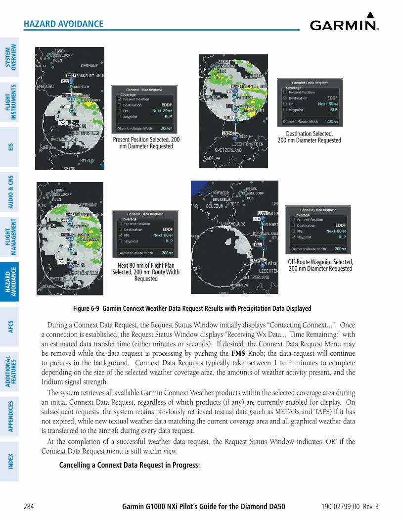
Garmin G1000 NXi Pilot’s Guide for the Diamond DA50 190-02799-00 Rev. B
SYST
EMO
VERV
IEW
FLIG
HTIN
STRU
MEN
TSEI
SAU
DIO
& C
NS
FLIG
HTM
AN
AGEM
ENT
HAZA
RDAV
OID
AN
CEA
FCS
AD
DIT
ION
AL
FEAT
URES
APP
END
ICES
IND
EX
284
HAZARD AVOIDANCE
Present Position Selected, 200 nm Diameter Requested
Destination Selected, 200 nm Diameter Requested
Figure 6-9 Garmin Connext Weather Data Request Results with Precipitation Data Displayed
Next 80 nm of Flight Plan Selected, 200 nm Route Width
Requested
Off-Route Waypoint Selected, 200 nm Diameter Requested
During a Connext Data Request, the Request Status Window initially displays “Contacting Connext...”. Once a connection is established, the Request Status Window displays “Receiving Wx Data... Time Remaining:” with an estimated data transfer time (either minutes or seconds). If desired, the Connext Data Request Menu may be removed while the data request is processing by pushing the FMS Knob; the data request will continue to process in the background. Connext Data Requests typically take between 1 to 4 minutes to complete depending on the size of the selected weather coverage area, the amounts of weather activity present, and the Iridium signal strength.
The system retrieves all available Garmin Connext Weather products within the selected coverage area during an initial Connext Data Request, regardless of which products (if any) are currently enabled for display. On subsequent requests, the system retains previously retrieved textual data (such as METARs and TAFS) if it has not expired, while new textual weather data matching the current coverage area and all graphical weather data is transferred to the aircraft during every data request.
At the completion of a successful weather data request, the Request Status Window indicates ‘OK’ if the Connext Data Request menu is still within view.
Cancelling a Connext Data Request in Progress:

190-02799-00 Rev. B Garmin G1000 NXi Pilot’s Guide for the Diamond DA50
SYSTEMO
VERVIEWFLIG
HTIN
STRUMEN
TSEIS
AUDIO
& CN
SFLIG
HTM
AN
AGEM
ENT
HAZA
RDAVO
IDA
NCE
AFCS
AD
DITIO
NA
LFEATURES
APPEN
DICES
IND
EX
285
HAZARD AVOIDANCE
1) Select the ‘Weather Data Link (CNXT)’ Page.
2) Press the MENU Key.
3) With ‘Connext Data Request’ highlighted, press the ENT Key.
4) Turn the large FMS Knob to select the ‘Cancel Request’ field and press the ENT Key. The request status box indicates ‘Request Cancelled’.
5) Push the FMS Knob to return to the ‘Weather Data Link (CNXT)’ Page.
The flight crew can schedule Connext Data Requests to recur automatically. Automatic requests remain enabled until the flight crew them, or the system power is removed. The Request Status Window indicates the number of minutes or seconds until the next automatic data request occurs.
NOTE: If automatic Connext Data Requests were enabled prior to the system entering Reversionary Mode, the automatic weather data requests will continue in Reversionary Mode, however the Connext Data Request Window and its associated options will not be available in Reversionary Mode.
Enabling/disabling automatic Connext Data Requests:
1) Select the ‘Weather Data Link (CNXT)’ Page.
2) Press the MENU Key.
3) With ‘Connext Data Request’ highlighted, press the ENT Key.
4) Choose the desired weather coverage options.
5) Turn the large FMS Knob to select the ‘Update Rate’ field. Then turn the small FMS Knob to highlight the desired automatic update frequency (Off, 5 Min, 10 Min, 15 Min, 20 Min, 30 Min, 45 Min, or 60 Min), then press the ENT Key.
6) The ‘Send Request’ field is highlighted and a countdown timer is displayed in the ‘Request Status’ Window based on the currently selected update rate. Press the ENT Key to immediately send an immediate Connext Data Request.
7) Push the FMS Knob to return to the ‘Weather Data Link (CNXT)’ Page.
WEATHER PRODUCT OVERVIEWThe following is an overview of data link weather products the system can display.
NEXRAD (SIRIUSXM)
NOTE: Datalink weather radar information cannot be displayed at the same time as relative terrain, echo tops, icing, or turbulence data.
The National Weather Service (NWS) operates the WSR-88D, or NEXRAD (NEXt-generation RADar) system, an extensive network of 156 high-resolution Doppler radar systems. The NEXRAD network provides centralized meteorological information for the continental United States and selected overseas locations. The maximum range of a single NEXRAD site is 250 nm.
Individual NEXRAD sites supply the network with radar images, and the images from each radar site may arrive at the network at different rates and times. Periodically, the weather data provider compiles the available

Garmin G1000 NXi Pilot’s Guide for the Diamond DA50 190-02799-00 Rev. B
SYST
EMO
VERV
IEW
FLIG
HTIN
STRU
MEN
TSEI
SAU
DIO
& C
NS
FLIG
HTM
AN
AGEM
ENT
HAZA
RDAV
OID
AN
CEA
FCS
AD
DIT
ION
AL
FEAT
URES
APP
END
ICES
IND
EX
286
HAZARD AVOIDANCE
individual site images from the network to form a composite image, and assigns a single time to indicate when it created the image. This image becomes the NEXRAD weather product. Individual images--gathered from each NEXRAD site--differ in age, and are always older than the displayed NEXRAD weather product age. The data provider then sends the NEXRAD data to the SiriusXM Weather service, whose satellites transmit this information during the next designated broadcast time for the NEXRAD weather product.
Because of the time required to detect, assemble, and distribute the NEXRAD weather product, the displayed weather information contained within the product may be significantly older than the current radar synopsis and may not depict the current weather conditions. The NEXRAD weather product should never be used as a basis for maneuvering in, near, or around areas of hazardous weather regardless of the information it contains.
Figure 6-10 NEXRAD Weather Product on the Weather Data Link (XM) Page
For radar sites in the United States, the NEXRAD weather product shows a composite reflectivity image. This shows the highest radar energy received from multiple antenna tilt angles at various altitudes. For radar sites based in Canada, the NEXRAD weather product shows radar returns from the lowest antenna tilt angle, known as base reflectivity. The display of the information is color-coded to indicate the intensity of the echoes and the type of precipitation, if known.
Displaying the NEXRAD weather product on the ‘Map - Weather Data Link (XM)’ Page
1) Select the ‘Map - Weather Data Link (XM)’ Page.
2) Press the NEXRAD Softkey.
A mosaic of data from all the available NEXRAD radar sites is shown.

190-02799-00 Rev. B Garmin G1000 NXi Pilot’s Guide for the Diamond DA50
SYSTEMO
VERVIEWFLIG
HTIN
STRUMEN
TSEIS
AUDIO
& CN
SFLIG
HTM
AN
AGEM
ENT
HAZA
RDAVO
IDA
NCE
AFCS
AD
DITIO
NA
LFEATURES
APPEN
DICES
IND
EX
287
HAZARD AVOIDANCE
No Radar Coverage
Figure 6-11 NEXRAD Weather Product Legend
Displaying the NEXRAD weather product on the ‘Map - Navigation Map’ Page
1) Press the Map Opt Softkey.
2) Press the NEXRAD Softkey.
Displaying the NEXRAD weather product on PFD maps
1) Press the Map/HSI Softkey.
2) Press the NEXRAD Softkey to enable/disable the display of NEXRAD information.
The display of No Radar Coverage is always active when either NEXRAD or Echo Tops is selected. Areas where NEXRAD radar coverage and Echo Tops information is not currently available or is not being collected are indicated in gray shade of purple.
The pilot can select either the Base or Composite region for the desired NEXRAD coverage area on the Weather Data Link (XM) Page. NEXRAD information is shown for the selected region, while a gray shade of purple is shown for the region which is not selected.
Selecting the NEXRAD Coverage Region on the ‘Map - Weather Data Link (XM)’ Page:
1) Press the MENU Key.
2) Turn the FMS Knob to select ‘Weather Setup’ and press the ENT Key.
3) With Product Group 1 selected, turn the large FMS Knob to highlight the NEXRAD Region field.
4) Turn the small FMS Knob to select ‘COMP’ or ‘Base’, then press the ENT Key.
5) To remove the menu, push the FMS Knob or the CLR Key.
The NEXRAD weather product age display indicates either ‘COMP’ or ‘Base’ for the selected coverage region.
refleCtiVity
Reflectivity is the amount of transmitted power returned to the radar receiver. Colors on the NEXRAD display are directly correlative to the level of detected reflectivity. Reflectivity as it relates to hazardous weather can be very complex.
The role of radar is essentially to detect moisture in the atmosphere. Simply put, certain types of weather reflect radar better than others. The intensity of a radar reflection is not necessarily an indication of the weather hazard level. For instance, wet hail returns a strong radar reflection, while dry hail does not. Both wet and dry hail can be extremely hazardous.

Garmin G1000 NXi Pilot’s Guide for the Diamond DA50 190-02799-00 Rev. B
SYST
EMO
VERV
IEW
FLIG
HTIN
STRU
MEN
TSEI
SAU
DIO
& C
NS
FLIG
HTM
AN
AGEM
ENT
HAZA
RDAV
OID
AN
CEA
FCS
AD
DIT
ION
AL
FEAT
URES
APP
END
ICES
IND
EX
288
HAZARD AVOIDANCE
The different NEXRAD echo intensities are measured in decibels (dB) relative to reflectivity (Z). NEXRAD measures the radar reflectivity ratio, or the energy reflected back to the radar receiver (designated by the letter Z). The value of Z increases as the returned signal strength increases.
nexraD limitations
NEXRAD radar images may have certain limitations:
� Undetermined precipitation types may be displayed as mixed.
� An individual NEXRAD site cannot depict high altitude storms at close ranges. It has no information about storms directly over the site.
� Precipitation may be occurring below the lowest antenna tilt angle (0.5º), and therefore the radar beam overshoots the precipitation. For example, at a distance of 124 miles from the radar site, the radar beam is approximately 18,000 feet above the radar site. The radar cannot detect any precipitation occurring below the beam at this distance and altitude.
� At smaller map ranges, the smallest square block on the display represents an area of approximately four square kilometers. The intensity level reflected by each square represents the highest level of radar reflectivity sampled within the area.
� Unknown precipitation below 52ºN is displayed as rain regardless of actual precipitation type.
Figure 6-12 NEXRAD Weather Product with 30 NM Map Range
Block represents approximately 4 km2
The following may cause abnormalities in displayed NEXRAD radar images:
� Ground clutter
� Strobes and spurious radar data
� Sun strobes (when the radar antenna points directly at the sun)
� Interference from buildings or mountains, which may cause shadows
� Metallic dust (chaff) from military aircraft, which can cause alterations in radar scans

190-02799-00 Rev. B Garmin G1000 NXi Pilot’s Guide for the Diamond DA50
SYSTEMO
VERVIEWFLIG
HTIN
STRUMEN
TSEIS
AUDIO
& CN
SFLIG
HTM
AN
AGEM
ENT
HAZA
RDAVO
IDA
NCE
AFCS
AD
DITIO
NA
LFEATURES
APPEN
DICES
IND
EX
289
HAZARD AVOIDANCE
nexraD limitations (CanaDa)
� Radar coverage extends to 55ºN.
� Any precipitation displayed between 52ºN and 55ºN is displayed as mixed precipitation regardless of actual precipitation type.
� If the precipitation type is unknown, the system displays the precipitation as rain, regardless of actual precipitation type.
Figure 6-13 NEXRAD Weather Product - Canada
Precipitation Above 52°N
Always Displays as Mixed
No Coverage Above 55°N
NEXRAD (FIS-B)
NOTE: The NEXRAD weather product cannot be displayed at the same time as terrain.
The National Weather Service (NWS) operates the WSR-88D, or NEXRAD (NEXt-generation RADar) system, an extensive network of 156 high-resolution Doppler radar systems. The NEXRAD network provides centralized meteorological information for the continental United States and selected overseas locations. The maximum range of a single NEXRAD site is 250 nm.
Individual NEXRAD sites supply the network with radar images, and the images from each radar site may arrive at the network at different rates and times. Periodically, the weather data provider to FIS-B compiles the available individual site images from the network to form a composite image, and assigns a single time to indicate when it created the image. This image becomes the NEXRAD weather product. Individual images--gathered from each NEXRAD site--differ in age, and are always older than the displayed NEXRAD weather product age. The data provider then sends the NEXRAD data to the FIS-B GBTs, which transmit this information during the next designated broadcast time for the NEXRAD weather product.
Because of the time required to detect, assemble, and distribute the NEXRAD weather product, the displayed weather information contained within the product may be older than the current radar synopsis and may not depict the current weather conditions. NEXRAD information should never be used as a basis for maneuvering in, near, or around areas of hazardous weather regardless of the information it contains.

Garmin G1000 NXi Pilot’s Guide for the Diamond DA50 190-02799-00 Rev. B
SYST
EMO
VERV
IEW
FLIG
HTIN
STRU
MEN
TSEI
SAU
DIO
& C
NS
FLIG
HTM
AN
AGEM
ENT
HAZA
RDAV
OID
AN
CEA
FCS
AD
DIT
ION
AL
FEAT
URES
APP
END
ICES
IND
EX
290
HAZARD AVOIDANCE
Figure 6-14 Regional NEXRAD Weather Product on the ‘Map - Weather Data Link (FIS-B)’ Page
Regional NEXRAD Weather Product Icon and Age
Regional NEXRAD Weather Product
enabled
Boundary of Regional NEXRAD
Data
No radar coverage within coverage
boundary
The FIS-B NEXRAD weather product may be displayed for a region around the GBT (higher resolution, updated more frequently) or for across the continental United States (lower resolution, updated less frequently). A combined version of both weather products is also available for display on the same map. When the combined NEXRAD is selected, regional NEXRAD takes display precedence where data is available, and continental US NEXRAD is displayed outside of the regional NEXRAD coverage area.
Displaying the FIS-B NEXRAD weather product on the ‘Map - Weather Data Link (FIS-B)’ Page
1) Select the ‘Map - Weather Data Link (FIS-B)’ Page.
2) Press the NXRD Softkey. Each press cycles though a coverage option as the softkey name changes (NXRD US, NXRD REG, NXRD OFF, or NXRD ALL).
Or:
1) Press the MENU Key.
2) Turn the FMS Knob to highlight ‘Weather Setup’ and press the ENT Key.
3) To enable/disable the display of NEXRAD information for the continental United States, turn the small FMS Knob to highlight the NEXRAD On/Off field.
a) Turn the small FMS Knob to highlight ‘On’ to enable the display of NEXRAD or ‘Off’ to disable.
b) Press the ENT Key.
4) To select the region, turn the small FMS Knob to highlight the Region field.
a) Turn the small FMS Knob to select the desired region. (CONUS, Regional, or Combined)
b) Press the ENT Key.
5) When finished, push the FMS Knob.

190-02799-00 Rev. B Garmin G1000 NXi Pilot’s Guide for the Diamond DA50
SYSTEMO
VERVIEWFLIG
HTIN
STRUMEN
TSEIS
AUDIO
& CN
SFLIG
HTM
AN
AGEM
ENT
HAZA
RDAVO
IDA
NCE
AFCS
AD
DITIO
NA
LFEATURES
APPEN
DICES
IND
EX
291
HAZARD AVOIDANCE
Figure 6-15 Continental US (CONUS) NEXRAD Weather Product on the ‘Map - Weather Data Link (FIS-B)’ Page
Regional NEXRAD Weather Product
enabled
No radar coverage
Continental USA NEXRAD Weather Product Icon and Age
Figure 6-16 ‘Map - Weather Data Link (FIS-B)’ Page Menu
Figure 6-17 ‘Map - Weather Data Link (FIS-B)’ Page Setup Menu
Enables/disables NEXRAD data display for the continental United States
Selects regions for NEXRAD display

Garmin G1000 NXi Pilot’s Guide for the Diamond DA50 190-02799-00 Rev. B
SYST
EMO
VERV
IEW
FLIG
HTIN
STRU
MEN
TSEI
SAU
DIO
& C
NS
FLIG
HTM
AN
AGEM
ENT
HAZA
RDAV
OID
AN
CEA
FCS
AD
DIT
ION
AL
FEAT
URES
APP
END
ICES
IND
EX
292
HAZARD AVOIDANCE
Displaying the FIS-B NEXRAD weather product on the ‘Map - Navigation Map’ Page
1) Press the Map Opt Softkey.
2) Press the NEXRAD Softkey. Each press cycles though a coverage option as the softkey name changes (US, REG, or ALL).
Or:
3) Press the MENU Key.
4) With ‘Map Settings’ highlighted, press the ENT Key.
5) Turn the small FMS Knob to select the ‘Weather’ Group, then press the ENT Key.
6) Turn the large FMS Knob to highlight the NEXRAD Data Region field.
7) Turn the small FMS Knob to highlight ‘CONUS’ (continental United States), ‘RGNL’ (regional), or ‘Combined’, then press the ENT Key. This selection also affects display of NEXRAD on the PFD Maps.
8) When finished, push the FMS Knob or press the CLR Key.
Displaying the FIS-B NEXRAD weather product on PFD maps:
1) Press the Map/HSI Softkey.
2) Press the NEXRAD Softkey to enable/disable the display of NEXRAD information.
The regional NEXRAD weather product coverage area varies, as it is determined by the data received from ground-based sources. When the regional NEXRAD weather product is enabled, a white spiked boundary encloses this area to indicate the geographic limits of the regional NEXRAD coverage being displayed. The system shows composite radar data from all available NEXRAD sites inside of this boundary area.
If the continental United States version of the NEXRAD weather product is shown (US Softkey enabled), the coverage boundary is not shown on the map.
This data is composed of the maximum reflectivity from the individual radar sweeps. The display of the information is color-coded to indicate the weather severity level. All weather product legends can be viewed on the ‘Map - Weather Data Link (FIS-B)’ Page. For the NEXRAD legend, select the Legend Softkey when the NEXRAD weather product is enabled.
Boundary of radar coverage area
No radar coverage
Figure 6-18 NEXRAD Weather Product Legend

190-02799-00 Rev. B Garmin G1000 NXi Pilot’s Guide for the Diamond DA50
SYSTEMO
VERVIEWFLIG
HTIN
STRUMEN
TSEIS
AUDIO
& CN
SFLIG
HTM
AN
AGEM
ENT
HAZA
RDAVO
IDA
NCE
AFCS
AD
DITIO
NA
LFEATURES
APPEN
DICES
IND
EX
293
HAZARD AVOIDANCE
The display of no radar coverage is enabled when NEXRAD is selected for display. Areas where radar data is not currently available, has not yet been received, or is not being collected are indicated in gray shade of purple.
NOTE: If the system has not received all available NEXRAD weather data (such as during initial FIS-B signal acquisition or in areas of marginal or poor signal reception), the system may display areas of no radar coverage which are subsequently removed as radar data is received. It may take up to approximately ten minutes to receive all FIS-B data, when adequate reception is available.
refleCtiVity
Reflectivity is the amount of transmitted power returned to the radar receiver. Colors on the NEXRAD display are directly correlative to the level of detected reflectivity. Reflectivity as it relates to hazardous weather can be very complex.
The role of radar is essentially to detect moisture in the atmosphere. Simply put, certain types of weather reflect radar better than others. The intensity of a radar reflection is not necessarily an indication of the weather hazard level. For instance, wet hail returns a strong radar reflection, while dry hail does not. Both wet and dry hail can be extremely hazardous. The different NEXRAD echo intensities are measured in decibels (dB) relative to reflectivity (Z). NEXRAD measures the radar reflectivity ratio, or the energy reflected back to the radar receiver (designated by the letter Z). The value of Z increases as the returned signal strength increases.
nexraD limitations
NEXRAD radar images may have certain limitations:
� At smaller map ranges, individual blocks of NEXRAD weather data are viewable. For the regional version of the NEXRAD weather product, the smallest block represents 1.5 nm wide by 1 nm tall. For the continental United States version of the NEXRAD weather product, each block is 7.5 nm wide by 5 nm wide. The color of each block represents the highest radar reflectivity detected within that area.
� The continental US version of the NEXRAD weather product is not available above 60º of latitude.
The following may cause abnormalities in displayed NEXRAD radar images:
� Ground clutter
� Strobes and spurious radar data
� Sun strobes (when the radar antenna points directly at the sun)
� Interference from buildings or mountains, which may cause shadows
� Metallic dust (chaff) from military aircraft, which can cause alterations in radar scans
PRECIPITATION (GARMIN CONNEXT)
NOTE: Precipitation data cannot be displayed at the same time as terrain data.
The Precipitation weather product provides radar precipitation information in selected radar coverage areas. This information comes from individual weather radar sites and weather data sources such as government agencies. Each radar site or source may provide weather data at differing rates and times. Periodically, the Garmin Connext Weather service compiles the available information to form a composite image, and assigns a single time to indicate when it created the image. This image becomes the Precipitation weather product. Individual images--gathered from each radar site--differ in age, and are always older than the displayed Precipitation weather product age.

Garmin G1000 NXi Pilot’s Guide for the Diamond DA50 190-02799-00 Rev. B
SYST
EMO
VERV
IEW
FLIG
HTIN
STRU
MEN
TSEI
SAU
DIO
& C
NS
FLIG
HTM
AN
AGEM
ENT
HAZA
RDAV
OID
AN
CEA
FCS
AD
DIT
ION
AL
FEAT
URES
APP
END
ICES
IND
EX
294
HAZARD AVOIDANCE
Because of the time required to detect, assemble, and distribute the Precipitation weather product, the displayed weather information contained within the product may be significantly older than the current radar synopsis and may not depict the current weather conditions. The Precipitation weather product should never be used as a basis for maneuvering in, near, or around areas of hazardous weather regardless of the information it contains.
Figure 6-19 Precipitation Weather Product on the ‘Map - Weather Data Link (CNXT)’ Page
Boundary of weather data
request
Precipitation Weather Product Icon and Age
Precipitation Weather Product
enabled
Displaying Precipitation weather information:
1) Press the Map Opt Softkey (for PFD maps, press the Map/HSI Softkey). This step is not necessary on the ‘Map - Weather Data Link (CNXT)’ Page.
2) Press the PRECIP Softkey.
The system displays either base or composite radar imagery, depending on the region.
Region Radar Reflectivity Type
United States Composite Reflectivity
Canada, Europe, Australia Base Reflectivity
The base reflectivity precipitation weather product shows the radar returns from the perspective of a single antenna tilt angle. The composite reflectivity precipitation weather product shows the highest radar energy received from multiple antenna tilt angles. The display of the information is color-coded to indicate the intensity of the echoes and the type of precipitation.

190-02799-00 Rev. B Garmin G1000 NXi Pilot’s Guide for the Diamond DA50
SYSTEMO
VERVIEWFLIG
HTIN
STRUMEN
TSEIS
AUDIO
& CN
SFLIG
HTM
AN
AGEM
ENT
HAZA
RDAVO
IDA
NCE
AFCS
AD
DITIO
NA
LFEATURES
APPEN
DICES
IND
EX
295
HAZARD AVOIDANCE
All weather product legends can be viewed on the ‘Map - Weather Data Link (CNXT)’ Page. For the Precipitation legend, press the Legend Softkey when Precipitation is selected for display.
Boundary of weather data request
No radar coverage
Figure 6-20 Precipitation Weather Product Legend
The display of radar coverage is enabled active when Precipitation is selected for display. Areas where precipitation radar coverage is not currently available or is not being collected are indicated in gray shade of purple. A white boundary line depicting the selected coverage area of the Connext Data Request encloses the precipitation data when this weather product is displayed.
refleCtiVity
Reflectivity is the amount of transmitted power returned to the radar receiver. Colors on the Precipitation display directly correlate to the level of detected reflectivity. Reflectivity as it relates to hazardous weather can be very complex.
The role of radar is essentially to detect moisture in the atmosphere. Simply put, certain types of weather reflect radar better than others. The intensity of a radar reflection is not necessarily an indication of the weather hazard level. For instance, wet hail returns a strong radar reflection, while dry hail does not. Both wet and dry hail can be extremely hazardous.
The different radar echo intensities are measured in decibels (dB) relative to reflectivity (Z). Weather radars measure the reflectivity ratio, or the energy reflected back to the radar receiver (designated by the letter Z). The value of Z increases as the returned signal strength increases.
PreCiPitation limitations
Radar images may have certain limitations:
� Radar composite reflectivity does not provide sufficient information to determine precipitation characteristics (wet hail vs. rain). For example, it is not possible to distinguish between wet snow, wet hail, and rain.
� An individual radar site cannot depict high altitude storms at close ranges. It has no information about storms directly over the site.
� At smaller map ranges, individual blocks of radar data are viewable. Each block of radar information represents approximately four square kilometers and depicts the highest level of reflectivity detected within that area.

Garmin G1000 NXi Pilot’s Guide for the Diamond DA50 190-02799-00 Rev. B
SYST
EMO
VERV
IEW
FLIG
HTIN
STRU
MEN
TSEI
SAU
DIO
& C
NS
FLIG
HTM
AN
AGEM
ENT
HAZA
RDAV
OID
AN
CEA
FCS
AD
DIT
ION
AL
FEAT
URES
APP
END
ICES
IND
EX
296
HAZARD AVOIDANCE
Figure 6-21 Precipitation Weather Product at 10 NM Map Range
Block represents approximately 4 km2
The following may cause abnormalities in displayed radar images:
� Ground clutter
� Strobes and spurious radar data
� Sun strobes (when the radar antenna points directly at the sun)
� Interference from buildings or mountains, which may cause shadows
� Metallic dust (chaff) from military aircraft, which can cause alterations in radar scans
ECHO TOPS (SIRISUXM)
NOTE: Echo Tops cannot be displayed at the same time as Cloud Tops or NEXRAD data is displayed.
The Echo Tops weather product shows the location, elevation, and direction of the highest radar echo. The highest radar echo does not indicate the top of a storm or clouds; rather it indicates the highest altitude at which precipitation is detected. Information is derived from NEXRAD data.

190-02799-00 Rev. B Garmin G1000 NXi Pilot’s Guide for the Diamond DA50
SYSTEMO
VERVIEWFLIG
HTIN
STRUMEN
TSEIS
AUDIO
& CN
SFLIG
HTM
AN
AGEM
ENT
HAZA
RDAVO
IDA
NCE
AFCS
AD
DITIO
NA
LFEATURES
APPEN
DICES
IND
EX
297
HAZARD AVOIDANCE
Figure 6-22 Echo Tops Weather Product
Altitude for selected Echo Top
Displaying Echo Tops information:
1) Select the ‘Map - Weather Data Link (XM)’ Page.
2) Press the Echo Top Softkey.
Since Echo Tops and Cloud Tops use the same color scaling to represent altitude, display of these weather products is mutually exclusive. When Echo Tops is activated, NEXRAD and Cloud Tops data are removed.
Figure 6-23 Echo Tops Legend
No Radar Coverage

Garmin G1000 NXi Pilot’s Guide for the Diamond DA50 190-02799-00 Rev. B
SYST
EMO
VERV
IEW
FLIG
HTIN
STRU
MEN
TSEI
SAU
DIO
& C
NS
FLIG
HTM
AN
AGEM
ENT
HAZA
RDAV
OID
AN
CEA
FCS
AD
DIT
ION
AL
FEAT
URES
APP
END
ICES
IND
EX
298
HAZARD AVOIDANCE
CLOUD TOPS (SIRIUSXM)
NOTE: Cloud Tops and Echo Tops cannot be displayed at the same time.
NOTE: If a GDL 69/69A SXM receiver is installed, the broadcast rate for Cloud Tops is 30 minutes. As with all SiriusXM Weather products, the product age becomes amber when it reaches half of the expiration time, which is 60 minutes for Cloud Tops. Therefore, this weather product age may be amber during routine operation.
The Cloud Tops weather product depicts cloud top altitudes as determined from satellite imagery.
Figure 6-24 Cloud Tops Weather Product
Displaying Cloud Tops information:
1) Select the ‘Map - Weather Data Link (XM)’ Page with the FMS Knob.
2) Press the CLD Top Softkey.
Since Cloud Tops and Echo Tops use the same color scaling to represent altitude, display of these weather products is mutually exclusive. When Cloud Tops is activated, Echo Tops data is removed.
Figure 6-25 Cloud Tops Legend

190-02799-00 Rev. B Garmin G1000 NXi Pilot’s Guide for the Diamond DA50
SYSTEMO
VERVIEWFLIG
HTIN
STRUMEN
TSEIS
AUDIO
& CN
SFLIG
HTM
AN
AGEM
ENT
HAZA
RDAVO
IDA
NCE
AFCS
AD
DITIO
NA
LFEATURES
APPEN
DICES
IND
EX
299
HAZARD AVOIDANCE
DATA LINK LIGHTNING (SIRIUSXM, GARMIN CONNEXT)
NOTE: Lightning from a data link source cannot be displayed simultaneously on the same map as information from an optional on-board lightning detection system.
The Data Link Light weather product shows the approximate location of cloud-to-ground lightning strikes. A strike icon represents a strike that has occurred within a two-kilometer region. The exact location of the lightning strike is not displayed.
Figure 6-26 Data Link Weather Product
Lightning Strikes
Displaying Data Link Lightning information on Weather Data Link Page:
1) Turn the FMS Knob to select the Weather Data Link (XM, CNXT) Page.
2) Press the XM LTNG or DL LTNG Softkey (softkey name depends on the selected weather source).
To display the Lightning legend on the Weather Data Link Page, press the Legend Softkey when Data Link Lightning is selected for display.
Figure 6-27 Data Link Lightning Legend
Displaying Data Link Lightning information on the ‘Map - Navigation Map’ Page:
1) Turn the FMS Knob to select the ‘Map - Navigation Map’ Page.
2) Press the Map Opt Softkey.
3) Press the XM LTNG or DL LTNG Softkey.

Garmin G1000 NXi Pilot’s Guide for the Diamond DA50 190-02799-00 Rev. B
SYST
EMO
VERV
IEW
FLIG
HTIN
STRU
MEN
TSEI
SAU
DIO
& C
NS
FLIG
HTM
AN
AGEM
ENT
HAZA
RDAV
OID
AN
CEA
FCS
AD
DIT
ION
AL
FEAT
URES
APP
END
ICES
IND
EX
300
HAZARD AVOIDANCE
Enabling/disabling Data Link Lightning information on PFD maps:
1) On the PFD, press the Map/HSI Softkey.
2) Press the Lightning Softkey.
3) Press the Datalink Softkey to enable data link lightning from the selected data link weather source, or press the LTNG Off Softkey to disable data link lightning.
4) When finished, press the Back Softkey.
CELL MOVEMENT (SIRIUSXM)
The Cell Movement weather product shows the location and movement of storm cells as identified by the ground-based system. Cells are represented by yellow squares, with direction of movement indicated with short, orange arrows.
Figure 6-28 Cell Movement Weather Product
Storm Cells
Additional information for
selected Storm Cell
On the Weather Data Link (XM) Page, the Cell Movement weather product has a dedicated Cell MOV softkey for enabling/disabling this weather product on this page.
NOTE: The Storm Cell base height is not available if a GDL 69 SXM or 69A SXM data link receiver is installed. In this case, the Storm Cell base height is displayed as 0 feet when the map pointer selects a storm cell.
Displaying Cell Movement information on the Weather Data Link (XM) Page:
1) Select the ‘Map -Weather Data Link (XM)’ Page using the FMS Knob.
2) Press the Cell MOV Softkey.
Figure 6-29 Cell Movement Legend

190-02799-00 Rev. B Garmin G1000 NXi Pilot’s Guide for the Diamond DA50
SYSTEMO
VERVIEWFLIG
HTIN
STRUMEN
TSEIS
AUDIO
& CN
SFLIG
HTM
AN
AGEM
ENT
HAZA
RDAVO
IDA
NCE
AFCS
AD
DITIO
NA
LFEATURES
APPEN
DICES
IND
EX
301
HAZARD AVOIDANCE
For navigation maps, the pilot can enable/disable the Cell Movement weather product using the NEXRAD Softkey. For this to occur, the pilot must first enable the ‘Cell Movement’ option in the Map Settings menu of the ‘Map - Navigation Map’ Page.
Setting up the system to display Cell Movement with NEXRAD on navigation maps:
1) Use the FMS Knob to select the ‘Map - Navigation Map’ Page.
2) Press the MENU Key.
3) With ‘Map Settings’ highlighted, press the ENT Key.
4) Turn the small FMS Knob to highlight ‘Weather’ and press the ENT Key.
5) Turn the large FMS Knob to ‘On’ or ‘Off’ for the Cell Movement menu option. When set to ‘On’, Cell Movement is enabled/disabled with the NEXRAD weather product on navigation maps. When set to ‘Off’, Cell Movement is not displayed on navigation maps.
6) When finished, push the FMS Knob or CLR Key to remove the menu.
After the ‘Cell Movement’ option is set to ‘On’, refer to the previous procedures for enabling/disabling the NEXRAD weather product to control both products simultaneously on navigation maps using the NEXRAD Softkey.
INFRARED SATELLITE (GARMIN CONNEXT)
The Infrared Satellite (IR SAT) weather product depicts cloud top temperatures from satellite imagery. Brighter cloud top colors indicate cooler temperatures occurring at higher altitudes.
Figure 6-30 Infrared Satellite Weather Product on the ‘Map - Weather Data Link (CNXT)’ Page

Garmin G1000 NXi Pilot’s Guide for the Diamond DA50 190-02799-00 Rev. B
SYST
EMO
VERV
IEW
FLIG
HTIN
STRU
MEN
TSEI
SAU
DIO
& C
NS
FLIG
HTM
AN
AGEM
ENT
HAZA
RDAV
OID
AN
CEA
FCS
AD
DIT
ION
AL
FEAT
URES
APP
END
ICES
IND
EX
302
HAZARD AVOIDANCE
Displaying Intrared Satellite information:
1) Select the ‘Weather Data Link (CNXT)’ Page.
2) Select the IR SAT Softkey.
Figure 6-31 Infrared Satellite Legend
SIGMETS AND AIRMETS
SIGMET (SIGnificant METeorological Information) and AIRMET (AIRmen’s METeorological Information) are issued for potentially hazardous weather. A Convective SIGMET is issued for hazardous convective weather such as severe or widespread thunderstorms. A localized SIGMET is a significant weather condition occurring at a localized geographical position.
NOTE: If SiriusXM Weather is the active data link weather source and a GDL 69/69A SXM receiver installed, the SIGMET and AIRMET weather products are not available unless at least one SIGMET or AIRMET has been received. The weather product age indicates ‘N/A’ when no SIGMET or AIRMET is available.
Figure 6-32 SIGMET/AIRMET Data
AIRMET for IFR conditionsAIRMET for Icing
conditions
SIGMET
AIRMET for Turbulence

190-02799-00 Rev. B Garmin G1000 NXi Pilot’s Guide for the Diamond DA50
SYSTEMO
VERVIEWFLIG
HTIN
STRUMEN
TSEIS
AUDIO
& CN
SFLIG
HTM
AN
AGEM
ENT
HAZA
RDAVO
IDA
NCE
AFCS
AD
DITIO
NA
LFEATURES
APPEN
DICES
IND
EX
303
HAZARD AVOIDANCE
Displaying SIGMETs and AIRMETs:
1) Select the Weather Data Link Page.
2) Press the SIG/AIR Softkey.
3) To view the text of the SIGMET or AIRMET, push the Joystick and move the Map Pointer over the icon.
4) Press the ENT key. The following figure shows sample SIGMET text.
Sample SIGMET Text SIGMET/AIRMET Legend
Figure 6-33 SIGMET/AIRMET Text and Legend
METARS AND TAFS
NOTE: Atmospheric pressure as reported for METARs is given in hectopascals (hPa), except for in the United States, where it is reported in inches of mercury (in Hg). Temperatures are reported in Celsius.
NOTE: METAR information is only displayed within the installed navigation database service area.
METARs (METeorological Aerodrome Reports) typically contain information about the temperature, dewpoint, wind, precipitation, cloud cover, cloud heights, visibility, and barometric pressure at an airport or observation station. They can also contain information on precipitation amounts, lightning, and other critical data. METARs reflect hourly observations; non-routine updates include the code “SPECI” in the report. METARs are shown as colored flags at airports that provide them.

Garmin G1000 NXi Pilot’s Guide for the Diamond DA50 190-02799-00 Rev. B
SYST
EMO
VERV
IEW
FLIG
HTIN
STRU
MEN
TSEI
SAU
DIO
& C
NS
FLIG
HTM
AN
AGEM
ENT
HAZA
RDAV
OID
AN
CEA
FCS
AD
DIT
ION
AL
FEAT
URES
APP
END
ICES
IND
EX
304
HAZARD AVOIDANCE
Figure 6-34 METAR Flags on the Weather Data Link Page
METAR flag selected with Map Pointer
Additional Information on Weather Feature Selected with Map Pointer
TAFs (Terminal Aerodrome Forecasts) are weather predictions for specific airports within a 24- hour period, and may span up to 36 hours. TAFs typically include forecast wind, visibility, weather phenomena, and sky conditions using METAR codes.
METAR and TAF text are displayed on the Weather Information Page. METAR data is displayed first in a decoded fashion, followed by the original text. Note the original text may contain additional information not found in the decoded version. TAF information is displayed only in its original form when TAFs are available.
Displaying METAR and TAF text on the MFD:
1) On the Weather Data Link Page, press the METAR Softkey.
2) Push the Joystick and pan to the desired airport.
3) Press the ENT Key. The Weather Information Page is shown with METAR and TAF text.
4) Use the FMS Knob or the ENT Key to scroll through the METAR and TAF text. METAR text must be completely scrolled through before scrolling through the TAF text.
5) Push the FMS Knob or the CLR Key to return to the Weather Data Link Page.
Or:
1) Turn the large FMS Knob to select the Waypoint Page Group
a) Select the Airport Information Page.
b) Press the WX Softkey to select the Weather Information Page.
2) Push the FMS Knob to display the cursor.
3) Use the FMS Knob to enter the desired airport and press the ENT Key.
4) Use the FMS Knob or the ENT Key to scroll through the METAR and TAF text. Note the METAR text must be completely scrolled through before scrolling through the TAF text.

190-02799-00 Rev. B Garmin G1000 NXi Pilot’s Guide for the Diamond DA50
SYSTEMO
VERVIEWFLIG
HTIN
STRUMEN
TSEIS
AUDIO
& CN
SFLIG
HTM
AN
AGEM
ENT
HAZA
RDAVO
IDA
NCE
AFCS
AD
DITIO
NA
LFEATURES
APPEN
DICES
IND
EX
305
HAZARD AVOIDANCE
Figure 6-35 METAR and TAF Text on the Weather Information Page
METAR Text for the Selected Airport
TAF Text for the Selected Airport
To display the METAR legend on the Weather Data Link (XM) Page, select the Legend Softkey when METARs are enabled for display.
The METAR flag color is determined by the information in the METAR text. The system displays a gray METAR flag when the system cannot determine the METAR category based on the information available.
Figure 6-36 METAR Legend
The system also shows METAR flags and their associated text on the Active Flight Plan Page on the MF.D. The system shows a METAR flag next to waypoints in the flight plan with an available METAR.
Displaying original METAR text on the Active Flight Plan Page:
1) Select the ‘FPL - Active Flight Plan’ Page on the MFD.
2) Push the FMS Knob to activate the cursor.
3) Turn the large FMS Knob to highlight a waypoint with an available METAR (indicated with a METAR flag next to it). The METAR text will appear in the ‘Selected Waypoint Weather’ Window below.
4) When finished, push the FMS Knob to remove the cursor or press the FPL Key to exit the Active Flight Plan Page.
Original METAR text is also accessible on navigation maps displaying METAR flags. When the map pointer is panned over a METAR flag, the METAR text is shown in a box near the flag.
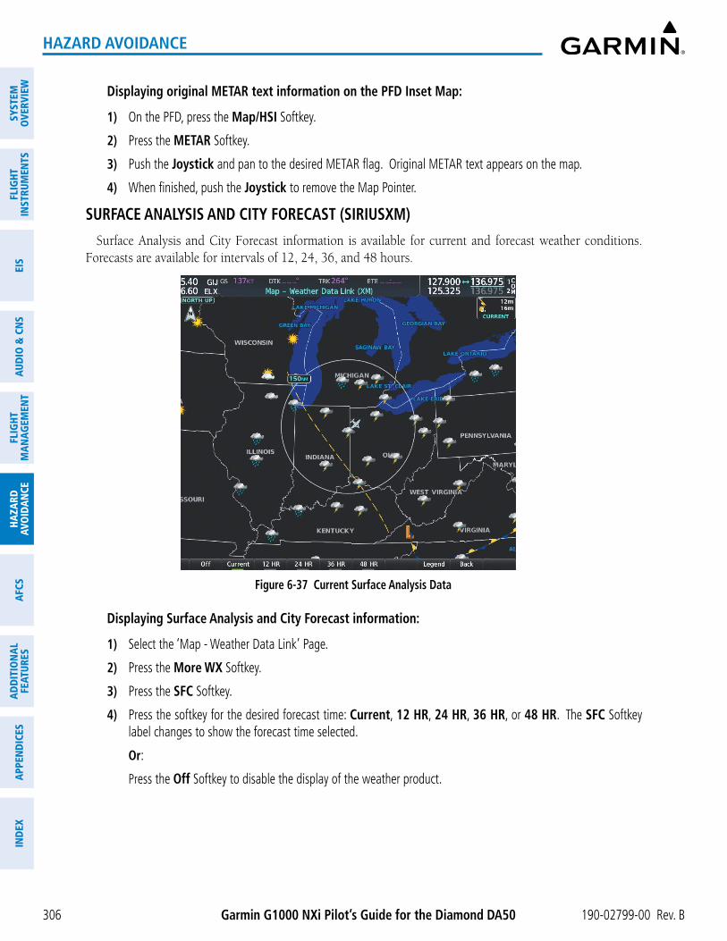
Garmin G1000 NXi Pilot’s Guide for the Diamond DA50 190-02799-00 Rev. B
SYST
EMO
VERV
IEW
FLIG
HTIN
STRU
MEN
TSEI
SAU
DIO
& C
NS
FLIG
HTM
AN
AGEM
ENT
HAZA
RDAV
OID
AN
CEA
FCS
AD
DIT
ION
AL
FEAT
URES
APP
END
ICES
IND
EX
306
HAZARD AVOIDANCE
Displaying original METAR text information on the PFD Inset Map:
1) On the PFD, press the Map/HSI Softkey.
2) Press the METAR Softkey.
3) Push the Joystick and pan to the desired METAR flag. Original METAR text appears on the map.
4) When finished, push the Joystick to remove the Map Pointer.
SURFACE ANALYSIS AND CITY FORECAST (SIRIUSXM)
Surface Analysis and City Forecast information is available for current and forecast weather conditions. Forecasts are available for intervals of 12, 24, 36, and 48 hours.
Figure 6-37 Current Surface Analysis Data
Displaying Surface Analysis and City Forecast information:
1) Select the ‘Map - Weather Data Link’ Page.
2) Press the More WX Softkey.
3) Press the SFC Softkey.
4) Press the softkey for the desired forecast time: Current, 12 HR, 24 HR, 36 HR, or 48 HR. The SFC Softkey label changes to show the forecast time selected.
Or:
Press the Off Softkey to disable the display of the weather product.

190-02799-00 Rev. B Garmin G1000 NXi Pilot’s Guide for the Diamond DA50
SYSTEMO
VERVIEWFLIG
HTIN
STRUMEN
TSEIS
AUDIO
& CN
SFLIG
HTM
AN
AGEM
ENT
HAZA
RDAVO
IDA
NCE
AFCS
AD
DITIO
NA
LFEATURES
APPEN
DICES
IND
EX
307
HAZARD AVOIDANCE
Figure 6-38 Surface Analysis Legend
FREEZING LEVEL (SIRIUSXM)
The Freezing Level weather product shows the color-coded contour lines for the altitude and location at which the first isotherm is found. When no data is displayed for a given altitude, the data for that altitude has not been received, or is out of date and has been removed from the display. New data appears when it becomes available.
Figure 6-39 Freezing Level Data
Displaying Freezing Level information:
1) Select the ‘Map - Weather Data Link’ Page.
2) Press the More WX Softkey.
3) Press the FRZ LVL Softkey.

Garmin G1000 NXi Pilot’s Guide for the Diamond DA50 190-02799-00 Rev. B
SYST
EMO
VERV
IEW
FLIG
HTIN
STRU
MEN
TSEI
SAU
DIO
& C
NS
FLIG
HTM
AN
AGEM
ENT
HAZA
RDAV
OID
AN
CEA
FCS
AD
DIT
ION
AL
FEAT
URES
APP
END
ICES
IND
EX
308
HAZARD AVOIDANCE
Figure 6-40 Freezing Levels Legend
WINDS ALOFT
The Winds Aloft weather product shows the forecast wind speed and direction at the surface and at selected altitudes. Altitude can be displayed in 3000-foot increments beginning at the surface up to 42,000 feet MSL.
If the FIS-B option is installed and FIS-B is the active data link weather source, the Winds Aloft weather product also displays temperatures aloft next to the winds aloft arrows on the ‘Map - Weather Data Link (FIS-B)’ Page.
Displaying the Winds Aloft weather product:
1) Select the ‘Map - Weather Data Link’ Page with the FMS Knob.
2) Press the More WX Softkey.
3) Press the Wind Softkey.
4) Select a softkey for the desired altitude level: SFC (surface) up to 42,000 feet. Press the Next or Prev Softkey to cycle through the altitude softkeys. The Wind Softkey label changes to reflect the altitude selected.
Figure 6-41 Winds Aloft Data at 12,000 Feet

190-02799-00 Rev. B Garmin G1000 NXi Pilot’s Guide for the Diamond DA50
SYSTEMO
VERVIEWFLIG
HTIN
STRUMEN
TSEIS
AUDIO
& CN
SFLIG
HTM
AN
AGEM
ENT
HAZA
RDAVO
IDA
NCE
AFCS
AD
DITIO
NA
LFEATURES
APPEN
DICES
IND
EX
309
HAZARD AVOIDANCE
Figure 6-42 Winds Aloft Data with Legend
Headwind and tailwind components aloft are available inside the Vertical Situation Display (VSD) on the ‘Map - Navigation Map’ Page. The displayed components are relative to current aircraft altitude and track, but not to aircraft speed.
Figure 6-43 Navigation Map Page with Winds Aloft Data on VSD
Wind Component Velocity and Direction Arrows
Winds Aloft Data Age
Altitude Scale
Track Mode Boundary of VSD
Arrows pointing to the left indicate headwind components; tailwind component arrows point to the right, as shown in the following table.
Headwind Symbol Tailwind Symbol Headwind/Tailwind Component
None None Less than 5 knots
5 knots
10 knots
50 knots
Table 6-5 VSD Headwind/Tailwind Component Symbols

Garmin G1000 NXi Pilot’s Guide for the Diamond DA50 190-02799-00 Rev. B
SYST
EMO
VERV
IEW
FLIG
HTIN
STRU
MEN
TSEI
SAU
DIO
& C
NS
FLIG
HTM
AN
AGEM
ENT
HAZA
RDAV
OID
AN
CEA
FCS
AD
DIT
ION
AL
FEAT
URES
APP
END
ICES
IND
EX
310
HAZARD AVOIDANCE
Enabling/disabling the Vertical Situation Display (containing winds aloft data):
1) Select the ‘Map - Navigation Map’ Page.
2) Press the Map Opt Softkey.
3) Press the Inset Softkey.
4) Press the VSD Softkey to enable/disable the Vertical Situation Display.
Or:
1) Select the ‘Map - Navigation Map’ Page.
2) Press the MENU Key.
3) Turn the FMS Knob to highlight ‘Show VSD’ or ‘Hide VSD’ and press the ENT Key.
Winds Aloft data inside the VSD is enabled by default when the VSD is displayed on the ‘Map - Navigation Map’ Page. This behavior can be changed on the ‘Map - Navigation Map’ Page.
Enabling/disabling winds aloft data display for the VSD:
1) Select the ‘Map - Navigation Map’ Page.
2) Press the MENU Key.
3) With ‘Map Settings’ highlighted, press the ENT Key.
4) Turn the small FMS Knob to select ‘VSD’ and press the ENT Key.
5) Turn the large FMS Knob to highlight the Winds on/off field.
6) Turn the small FMS Knob to select ‘On’ or ‘Off’.
7) Push the FMS Knob or CLR Key to return to the ‘Map - Navigation Map’ Page with the changed settings.

190-02799-00 Rev. B Garmin G1000 NXi Pilot’s Guide for the Diamond DA50
SYSTEMO
VERVIEWFLIG
HTIN
STRUMEN
TSEIS
AUDIO
& CN
SFLIG
HTM
AN
AGEM
ENT
HAZA
RDAVO
IDA
NCE
AFCS
AD
DITIO
NA
LFEATURES
APPEN
DICES
IND
EX
311
HAZARD AVOIDANCE
COUNTY WARNINGS (SIRIUSXM)
The County warning weather product provides specific public awareness and protection weather warnings from the National Weather Service (NWS). This can include information on tornadoes, severe thunderstorms, and flood conditions.
Figure 6-44 County Flood Warning
Additional Information on Flood Warning Selected with Map Pointer
Flood Warnings
Thunderstorm Warning
Displaying County Warning information:
1) Select the ‘Map - Weather Data Link’ Page with the FMS Knob.
2) Press the More WX Softkey.
3) Press the County Softkey.
Figure 6-45 County Warnings Legend

Garmin G1000 NXi Pilot’s Guide for the Diamond DA50 190-02799-00 Rev. B
SYST
EMO
VERV
IEW
FLIG
HTIN
STRU
MEN
TSEI
SAU
DIO
& C
NS
FLIG
HTM
AN
AGEM
ENT
HAZA
RDAV
OID
AN
CEA
FCS
AD
DIT
ION
AL
FEAT
URES
APP
END
ICES
IND
EX
312
HAZARD AVOIDANCE
CYCLONE (SIRIUSXM)
The Cyclone weather product shows the current location of cyclones (hurricanes), tropical storms, and their projected tracks. The system displays the projected track information in the form of DD/HH:MM.
Figure 6-46 Cyclone Weather Product on the Weather Data Link (XM) Page
Cyclone
Displaying cyclone (hurricane) track information:
1) Select the ‘Map - Weather Data Link’ Page with the FMS Knob.
2) Press the More WX Softkey.
3) Press the Cyclone Softkey.
Figure 6-47 Cyclone Legend
NOTE: The Cyclone weather product is not available unless at least one cyclone or tropical storm has been received. The weather product age indicates ‘N/A’ when no cyclone or tropical storm has been received.
ICING (CIP & SLD) (SIRIUSXM)
The Current Icing Product (CIP) weather product shows a graphical view of the current icing environment. Icing severity is displayed in four categories: light, moderate, severe, and extreme (not specific to aircraft type). The CIP product is not a forecast, but a presentation of the current conditions at the time of the analysis.

190-02799-00 Rev. B Garmin G1000 NXi Pilot’s Guide for the Diamond DA50
SYSTEMO
VERVIEWFLIG
HTIN
STRUMEN
TSEIS
AUDIO
& CN
SFLIG
HTM
AN
AGEM
ENT
HAZA
RDAVO
IDA
NCE
AFCS
AD
DITIO
NA
LFEATURES
APPEN
DICES
IND
EX
313
HAZARD AVOIDANCE
Supercooled Large Droplet (SLD) icing conditions are characterized by the presence of relatively large, super cooled water droplets indicative of freezing drizzle and freezing rain aloft. SLD threat areas are depicted as magenta dots over the CIP colors.
Displaying Icing data:
1) Select the ‘Map - Weather Data Link’ Page.
2) Press the More WX Softkey.
3) Press the ICNG Softkey.
4) Select a softkey for the desired altitude level: 1,000 feet up to 30,000 feet. Press the Next or PREV Softkey to cycle through the altitude softkeys. The ICNG Softkey label changes to indicate the altitude selected.
Figure 6-48 Icing Data at 18,000 Feet
Light Icing Potential
Figure 6-49 Icing Potential Legend

Garmin G1000 NXi Pilot’s Guide for the Diamond DA50 190-02799-00 Rev. B
SYST
EMO
VERV
IEW
FLIG
HTIN
STRU
MEN
TSEI
SAU
DIO
& C
NS
FLIG
HTM
AN
AGEM
ENT
HAZA
RDAV
OID
AN
CEA
FCS
AD
DIT
ION
AL
FEAT
URES
APP
END
ICES
IND
EX
314
HAZARD AVOIDANCE
TURBULENCE (SIRIUSXM)
The Turbulence weather product identifies the potential for erratic movement of high-altitude air mass associated winds. Turbulence is classified as light, moderate, severe or extreme, at altitudes between 21,000 and 45,000 feet. Turbulence information is intended to supplement AIRMETs, SIGMETs, and PIREPs.
Displaying Turbulence data:
1) Select the ‘Map - Weather Data Link’ Page.
2) Press the More WX Softkey.
3) Press the TURB Softkey.
4) Select a softkey for the desired altitude: 21,000 feet up to 45,000 feet. Press the Next or PREV Softkey to cycle through the altitude softkeys. The TURB Softkey label changes to indicate the altitude selection.
Figure 6-50 Turbulence Weather Product at 21,000 Feet
Figure 6-51 Turbulence Legend

190-02799-00 Rev. B Garmin G1000 NXi Pilot’s Guide for the Diamond DA50
SYSTEMO
VERVIEWFLIG
HTIN
STRUMEN
TSEIS
AUDIO
& CN
SFLIG
HTM
AN
AGEM
ENT
HAZA
RDAVO
IDA
NCE
AFCS
AD
DITIO
NA
LFEATURES
APPEN
DICES
IND
EX
315
HAZARD AVOIDANCE
PIREPS AND AIREPS
NOTE: AIREPs are only available with the SiriusXM Weather service.
Pilot Weather Reports (PIREPs) are in-flight weather observations collected from pilots. When significant weather conditions are reported or forecast, Air Traffic Control (ATC) facilities are required to solicit PIREPs. A PIREP may contain adverse weather conditions, such as low in-flight visibility, icing conditions, windshear, and turbulence. PIREPs are issued as either Routine (UA) or Urgent (UUA).
Another type of PIREP is an Air Report (AIREP). Commercial airlines typically generate AIREPs.
Figure 6-52 PIREPs and AIREPS on the Weather Data Link (XM) Page
Urgent PIREP
PIREP selected with Map Pointer
AIREP
Displaying PIREP and AIREP text:
1) Select the Map - Weather Data Link Page.
2) Press the More WX Softkey.
3) Press the PIREPS or AIREPS Softkey. (Note the AIREPS Softkey is only available with the SiriusXM Weather service.)
4) Push the Joystick and pan to the desired weather report. A gray circle will appear around the weather report when it is selected.
5) Press the ENT Key. The Weather Information Page is shown with PIREP or AIREP text. The data is first displayed in a decoded fashion, followed by the original text. Note the original text may contain additional information not present in the decoded version.
6) Use the FMS Knob or the ENT Key to scroll through the PIREP or AIREP text.
7) Push the FMS Knob or the CLR Key to return to the ‘Map - Weather Data Link’ Page.

Garmin G1000 NXi Pilot’s Guide for the Diamond DA50 190-02799-00 Rev. B
SYST
EMO
VERV
IEW
FLIG
HTIN
STRU
MEN
TSEI
SAU
DIO
& C
NS
FLIG
HTM
AN
AGEM
ENT
HAZA
RDAV
OID
AN
CEA
FCS
AD
DIT
ION
AL
FEAT
URES
APP
END
ICES
IND
EX
316
HAZARD AVOIDANCE
Figure 6-53 PIREP Text on the Weather Data Link (XM) Page
Decoded PIREP Text
Original PIREP Text
The PIREP color is determined by the type (routine or urgent).
Figure 6-54 AIREPs & PIREPs Legend

190-02799-00 Rev. B Garmin G1000 NXi Pilot’s Guide for the Diamond DA50
SYSTEMO
VERVIEWFLIG
HTIN
STRUMEN
TSEIS
AUDIO
& CN
SFLIG
HTM
AN
AGEM
ENT
HAZA
RDAVO
IDA
NCE
AFCS
AD
DITIO
NA
LFEATURES
APPEN
DICES
IND
EX
317
HAZARD AVOIDANCE
TFRS
NOTE: Do not rely solely upon data link services to provide Temporary Flight Restriction (TFR) information. Always confirm TFR information through official sources such as Flight Service Stations or Air Traffic Control.
NOTE: Temporary Flight Restriction (TFR) data from Garmin Connext is only available in the United States (not including any U.S. territories.) Refer to http://sites.garmin.com/connext for product coverage information.
In the United States, the FAA issues Temporary Flight Restrictions (TFRs) to designate areas where flight is restricted. TFRs are issued to restrict flight for a variety of reasons including national security, law enforcement, natural disasters, and large sporting events. TFRs may be issued at any time, and TFR data displayed on the system is only intended to supplement official TFR information obtained from Flight Service Stations (FSS), and air traffic control.
The age of TFR data is not shown; however, if TFR data is not available or has expired, the system displays ‘TFR N/A’ in the upper-left corner of maps on which TFRs can be displayed.
Figure 6-55 TFR Data on the Weather Data Link (XM) Page
Information for selected TFR
Displaying TFR Data:
1) Select the ‘Map - Weather Data Link’ Page or the ‘Map - Navigation Map’ Page.
2) Push the Joystick and pan the map pointer over a TFR to highlight it. The system displays TFR summary information above the map.
3) Press the ENT Key. The system displays a pop-up menu.
4) If necessary, turn the FMS Knob to select ‘Review Airspaces’ and press the ENT Key. The system displays the TFR Information window.
5) Push the FMS Knob or the CLR Key to remove the TFR Information window.

Garmin G1000 NXi Pilot’s Guide for the Diamond DA50 190-02799-00 Rev. B
SYST
EMO
VERV
IEW
FLIG
HTIN
STRU
MEN
TSEI
SAU
DIO
& C
NS
FLIG
HTM
AN
AGEM
ENT
HAZA
RDAV
OID
AN
CEA
FCS
AD
DIT
ION
AL
FEAT
URES
APP
END
ICES
IND
EX
318
HAZARD AVOIDANCE
Figure 6-56 Full Text for Selected TFR
The setup menus for the ‘Map - Navigation Map’ Page control the map range settings above which TFR data is decluttered from the display. If a map range larger than the TFR product map range setting is selected, the TFR product data is removed from the map.
Maps other than the ‘Map - Navigation Map’ Page use settings based on those selected for the ‘Map - Navigation Map’ Page.
Setting up and customizing TFR data for maps on which TFR data can be displayed:
1) Select the ‘Map - Navigation Map’ Page.
2) Press the MENU Key.
3) With ‘Map Settings’ highlighted, press the ENT Key.
4) Turn the small FMS Knob to select the ‘Aviation’ Group and press the ENT Key.
5) Turn the large FMS Knob to scroll to the TFR product range setting.
6) Turn the small FMS Knob to scroll through options (Off, range settings).
7) Press the ENT Key to select an option.
8) Push the FMS Knob or CLR Key to return to the ‘Map - Navigation Map’ Page with the changed settings.

190-02799-00 Rev. B Garmin G1000 NXi Pilot’s Guide for the Diamond DA50
SYSTEMO
VERVIEWFLIG
HTIN
STRUMEN
TSEIS
AUDIO
& CN
SFLIG
HTM
AN
AGEM
ENT
HAZA
RDAVO
IDA
NCE
AFCS
AD
DITIO
NA
LFEATURES
APPEN
DICES
IND
EX
319
HAZARD AVOIDANCE
FIS-B WEATHER STATUSAdditional information about the status of FIS-B weather products is available on the ‘Aux - ADS-B Status’
Page.Viewing FIS-B status:
1) Turn the large FMS Knob to select the Aux Page Group.
2) Turn the small FMS Knob to select the ‘Aux - ADS-B Status’ Page.
On the ‘Map - Weather Data Link (FIS-B)’ Page, the pilot can enable/disable the FIS-B weather feature, which includes all FIS-B weather products and related softkeys on various maps.
Enabling/disabling the FIS-B weather feature:
1) Select the ‘Map - Weather Data Link’ Page.
2) Press the MENU Key.
3) Turn the small FMS Knob to highlight ‘Enable FIS-B Weather’ or ‘Disable FIS-B Weather’, and press the ENT Key.
Figure 6-57 Viewing FIS-B Weather Status on the ADS-B Status Page

Garmin G1000 NXi Pilot’s Guide for the Diamond DA50 190-02799-00 Rev. B
SYST
EMO
VERV
IEW
FLIG
HTIN
STRU
MEN
TSEI
SAU
DIO
& C
NS
FLIG
HTM
AN
AGEM
ENT
HAZA
RDAV
OID
AN
CEA
FCS
AD
DIT
ION
AL
FEAT
URES
APP
END
ICES
IND
EX
320
HAZARD AVOIDANCE
ADS-B Status Page ItemStatus
MessageDescription
FIS-B Weather Status:FIS-B Processing
Enabled The FIS-B weather feature is enabled to process and display FIS-B weather products.
Disabled The FIS-B weather feature is disabled.---------------- No FIS-B weather data received from the transponder.
Weather Products:AIRMETCONUS NEXRADMETARMETAR GraphicalNOTAM/TFRPIREPRegional NEXRADSIGMETTAFWinds/Temp Aloft
Available FIS-B weather data is available for display for the weather product.
Not AvailableFIS-B weather data is not available for the weather product, and/or the system is not receiving the FIS-B weather service.
Awaiting DataThe system is receiving the FIS-B weather service, and is waiting to receive the weather product from the FIS-B data broadcast.
Table 6-6 ‘Aux - ADS-B Status’ Page Messages for FIS-B Weather

190-02799-00 Rev. B Garmin G1000 NXi Pilot’s Guide for the Diamond DA50
SYSTEMO
VERVIEWFLIG
HTIN
STRUMEN
TSEIS
AUDIO
& CN
SFLIG
HTM
AN
AGEM
ENT
HAZA
RDAVO
IDA
NCE
AFCS
AD
DITIO
NA
LFEATURES
APPEN
DICES
IND
EX
321
HAZARD AVOIDANCE
ABNORMAL OPERATIONS FOR GARMIN CONNEXT WEATHERIf the system cannot complete a Connext Data Request, one or more messages will appear in the Request
Status Window.
Weather Request Status Message
Description
Auto requests inhibited Send manual request to reset.
The system has disabled automatic weather data requests due to excessive errors. Automatic weather data requests have stopped. Send a manual weather data request to resume automatic updates.
Auto update retry: ## Seconds
The system will attempt another automatic weather data request after an error occurred during the previous request. Timer counts down until the next automatic request occurs.
Connext Comm Error [1] A general error has occurred. If the error persists, the system should be serviced.Connext Comm Error [2] A communications error has occurred with the GIA. The system should be serviced.Connext Comm Error [3] A general error has occurred. If the error persists, the system should be serviced.
Connext Comm Error [4] This occurs if multiple automatic weather data requests have recently failed, or the GIA is off-line.
Connext Comm Error [5] This can occur if the Iridium or Garmin Connext services are not accessible. Check Iridium signal strength. If this error persists, the system should be serviced.
Connext Comm Error [6] A communications error has occurred. It this error persists, the system should be serviced.Connext Comm Error [7] A weather data transfer has timed out. Check Iridium signal strength and re-send the data request.Connext Comm Error [8] A server error has occurred or invalid data received.Connext Comm Error [9] An error occurred while reading or writing data. If the error persists, the system should be serviced.
Connext Login Invalid There is a problem with the Garmin Connext registration.
Connext Server Temp Inop
The Garmin Connext Weather data server is temporarily out of service, but is expected to return to service in less than 30 minutes.
Connext Server Inop The Garmin Connext Weather data server will be out of service for at least 30 minutes.
Invalid Coverage Area The weather data request coverage area does not contain at least one of the following: a waypoint, a flight plan, or a flight plan destination. Verify at least one of the coverage options is enabled (checked) and contains required criteria, then re-send the data request.
No Connext Subscription
The system is not be currently subscribed to Garmin Connext services or the access code is incorrect. Verify the access code.
Reduce Request Area The size of the received weather data has exceeded system memory limits. Reduce the size of the coverage area and issue another Connext Data Request to ensure all available weather data has been received.
Request Canceled The user has cancelled a Connext Data Request.Request Failed - Try Again
The weather data request timed-out. Re-send data request.
Table 6-7 Abnormal Garmin Connext Data Request Status Messages

Garmin G1000 NXi Pilot’s Guide for the Diamond DA50 190-02799-00 Rev. B
SYST
EMO
VERV
IEW
FLIG
HTIN
STRU
MEN
TSEI
SAU
DIO
& C
NS
FLIG
HTM
AN
AGEM
ENT
HAZA
RDAV
OID
AN
CEA
FCS
AD
DIT
ION
AL
FEAT
URES
APP
END
ICES
IND
EX
322
HAZARD AVOIDANCE
When the system is operating in Reversionary Mode, only those weather products which can be displayed on the PFD maps will be available for display.
If manual Connext Data Requests were enabled prior to entering Reversionary Mode, no new weather data will be retrieved while operating in Reversionary Mode. If automatic Connext Data Requests were enabled prior to Reversionary Mode operation, the system will continue the automatic data requests in Reversionary Mode (provided automatic requests have not been inhibited due to a system error).

190-02799-00 Rev. B Garmin G1000 NXi Pilot’s Guide for the Diamond DA50
SYSTEMO
VERVIEWFLIG
HTIN
STRUMEN
TSEIS
AUDIO
& CN
SFLIG
HTM
AN
AGEM
ENT
HAZA
RDAVO
IDA
NCE
AFCS
AD
DITIO
NA
LFEATURES
APPEN
DICES
IND
EX
323
HAZARD AVOIDANCE
6.2 STORMSCOPE LIGHTNING DETECTION SYSTEM
WARNING: Do not rely on information from the lightning detection system display as the sole basis for hazardous weather avoidance. Range limitations and interference may cause the system to display inaccurate or incomplete information. Refer to documentation from the lightning detection system manufacturer for detailed information about the system.
NOTE: Stormscope lightning information cannot be displayed simultaneously on the same map as lightning information from data link lightning sources.
The system can display L-3 WX-500 Stormscope lightning detection system information on the Stormscope Page, and as an overlay on navigation maps. The system uses the symbols shown in the following table to depict lightning strikes and cells based on the age of the information.
Lightning Age Symbol
Strike is less than 6 seconds old
Strike is between 6 and 60 seconds old
Strike is between 1 and 2 minutes old
Strike is between 2 and 3 minutes old
Table 6-8 Lightning Age and Symbols
USING THE STORMSCOPE PAGEOn the Stormscope Page, lightning information can be displayed at the ranges of 25 nm, 50 nm, 100 nm,
and 200 nm.
Adjusting the Stormscope Map Range:
1) Turn the large FMS Knob to select the Map Page Group.
2) Turn the small FMS Knob to select the Stormscope Page.
3) Turn the Joystick clockwise to increase the map range or counter-clockwise to decrease the map range.

Garmin G1000 NXi Pilot’s Guide for the Diamond DA50 190-02799-00 Rev. B
SYST
EMO
VERV
IEW
FLIG
HTIN
STRU
MEN
TSEI
SAU
DIO
& C
NS
FLIG
HTM
AN
AGEM
ENT
HAZA
RDAV
OID
AN
CEA
FCS
AD
DIT
ION
AL
FEAT
URES
APP
END
ICES
IND
EX
324
HAZARD AVOIDANCE
Figure 6-58 Stormscope Page with Cell Mode Selected
Stormscope Mode
Lightning Strike Rate Per Minute
Selecting ‘cell’ or ‘strike’ mode:
1) Select the ‘Map - Stormscope®’ Page.
2) Press the Mode Softkey. The Cell and Strike softkeys are displayed.
3) Press the Cell Softkey to display ‘CELL’ data or select the Strike Softkey to display ‘STRIKE’ data. ‘CELL’ or ‘STRIKE’ is displayed in the mode box in the upper right corner of the Stormscope Page.
4) Press the Back Softkey to return to the top level softkeys for the Stormscope Page.
Or:
1) Select the ‘Map - Stormscope®’ Page.
2) Press the MENU Key to display the Stormscope Page Menu. Either ‘Cell Mode’ or ‘Strike Mode’ is highlighted in cyan to indicate the mode to be selected.
3) Press the ENT Key to select the highlighted mode and remove the menu. To remove the menu without changing modes, press the MENU Key or the CLR Key, or push the FMS Knob.
If heading input is lost, strikes and/or cells must be cleared manually after the execution of each turn . This is to ensure the strike and/or cell positions are depicted accurately in relation to the nose of the aircraft. Clearing Stormscope lightning on any map clears this information from all displays on the system.
Manually clearing Stormscope cell or strike information:
1) Select the ‘Map - Stormscope®’ Page.
2) Press the Clear Softkey.
Or:
a) Press the MENU Key.
b) Turn the FMS Knob to highlight ‘Clear Lightning Data’, then press the ENT Key.
Or:

190-02799-00 Rev. B Garmin G1000 NXi Pilot’s Guide for the Diamond DA50
SYSTEMO
VERVIEWFLIG
HTIN
STRUMEN
TSEIS
AUDIO
& CN
SFLIG
HTM
AN
AGEM
ENT
HAZA
RDAVO
IDA
NCE
AFCS
AD
DITIO
NA
LFEATURES
APPEN
DICES
IND
EX
325
HAZARD AVOIDANCE
1) Select the ‘Map - Navigation Map’ Page.
2) Press the MENU Key.
3) Turn the FMS Knob to highlight ‘Clear Stormscope® Lightning’, then press the ENT Key.
Displaying Stormscope information on MFD navigation maps:
1) Press the Map Opt Softkey.
2) Press the STRMSCP Softkey.
Displaying Stormscope information on PFD maps:
1) On the PFD, press the Map/HSI Softkey.
2) Press the Lightning Softkey.
3) Press the STRMSCP Softkey.
SETTING UP STORMSCOPE ON THE NAVIGATION MAP
Setting up Stormscope options on the ‘Map - Navigation Map’:
1) On the ‘Map - Navigation Map’ Page, press the MENU Key.
2) With ‘Map Settings’ selected, press the ENT Key.
3) Turn the small FMS Knob to display the group selection window. Turn the small FMS Knob to select ‘WX’, and press the ENT Key.
4) Turn the large FMS Knob to highlight and move between the product selections.
5) When an item is highlighted, turn the small FMS Knob to select the option.
6) Press the ENT Key.
7) Push the FMS Knob to return to the ‘Map - Navigation Map’ Page.
The following options are available:
- Stormscope On/Off field – Enables/disables the display of Stormscope lightning symbols.
- Stormscope maximum display range – Selects the maximum map range to display Stormscope symbols. Stormscope data is removed when a map range greater than the STRMSCP SMBL value is selected.
- Stormscope Mode – Selects the Cell or Strike mode of lightning activity. Cell mode identifies clusters or cells of electrical activity. Strike mode indicates the approximate location of lightning strikes.
CELL AND STRIKE MODE ON THE NAVIGATION MAP
On the Navigation Map, cell mode identifies cells of lightning activity. Stormscope identifies clusters of electrical activity that indicate cells. Strike mode indicates the approximate location of lightning strikes.
Selecting the ‘cell’ or ‘strike’ mode on the ‘Map - Navigation Map’:
1) Press the MENU Key.
2) With ‘Map Settings’ selected, press the ENT Key.
3) Turn the FMS Knob to select the ‘Weather’ group and press the ENT Key.
4) Turn the large FMS Knob to select the Stormscope Mode field.

Garmin G1000 NXi Pilot’s Guide for the Diamond DA50 190-02799-00 Rev. B
SYST
EMO
VERV
IEW
FLIG
HTIN
STRU
MEN
TSEI
SAU
DIO
& C
NS
FLIG
HTM
AN
AGEM
ENT
HAZA
RDAV
OID
AN
CEA
FCS
AD
DIT
ION
AL
FEAT
URES
APP
END
ICES
IND
EX
326
HAZARD AVOIDANCE
5) Turn the small FMS Knob to change between ‘Cell’ and ‘Strike’ options. When the desired item is selected, press the ENT Key.
6) Push the FMS knob to return to the ‘Map - Navigation Map’ Page.
Figure 6-59 Navigation Map Page with Stormscope Lightning Data
Stormscope Navigation Map Overlay Enabled Icon
Stormscope ModeLightning Strike Rate Per Minute
If heading input is lost, strikes and/or cells must be cleared manually after the execution of each turn. This is to ensure the strike and/or cell positions are depicted accurately in relation to the nose of the aircraft.
Manually clearing Stormscope data on the ‘Map - Navigation Map’:
1) Press the MENU Key.
2) Turn the FMS Knob to highlight ‘Clear Stormscope® Lightning’.
3) Press the ENT Key.
Selecting a Stormscope range on the ‘Map - Navigation Map’:
1) Press the MENU Key.
2) With ‘Map Settings’ highlighted, press the ENT Key.
3) Turn the FMS Knob to highlight the select the ‘Weather’ group, and press the ENT Key.
4) Turn the large FMS Knob to highlight the Stormscope maximum map display range distance.
5) Turn the small FMS Knob to select the Stormscope maximum map display range distance.
6) Press the ENT Key.
7) Push the FMS Knob to return to the ‘Map - Navigation Map’ Page.
To change the display range on the ‘Map - Navigation Map’ Page, turn the Joystick clockwise to increase the map range or counter-clockwise to decrease the map range.

190-02799-00 Rev. B Garmin G1000 NXi Pilot’s Guide for the Diamond DA50
SYSTEMO
VERVIEWFLIG
HTIN
STRUMEN
TSEIS
AUDIO
& CN
SFLIG
HTM
AN
AGEM
ENT
HAZA
RDAVO
IDA
NCE
AFCS
AD
DITIO
NA
LFEATURES
APPEN
DICES
IND
EX
327
HAZARD AVOIDANCE
6.3 AIRBORNE COLOR WEATHER RADAR
SYSTEM DESCRIPTIONThe Garmin GWX 75 Airborne Color Weather Radar is a solid-state pulsed radar with forty watts of output
power. The radar combines excellent range and adjustable scanning profiles with a high-definition target display. The GWX 75 has an effective pulse length of 27.31 microseconds (µs), and the system optimizes the pulse length to maximize resolution at each range setting.
The Diamond DA50 uses a 10-inch antenna that is fully stabilized to accommodate 30º of pitch and roll.
To focus radar scanning on specific areas, Sector Scanning offers pilot-adjustable horizontal scan angles. A vertical scanning function helps to analyze storm tops, gradients, and cell buildup activity at various altitudes.
Radar features include:
- Extended Sensitivity Time Constant (STC) logic that automatically correlates distance of the return echo with intensity, so cells do not suddenly appear to get larger as they get closer.
- WATCH™ (Weather ATtenuated Color Highlight) helps identify possible shadowing effects of short-range cell activity, identifying areas where radar return signals are weakened or attenuated by intense precipitation (or large areas of lesser precipitation) and may not fully reflect the weather behind a storm.
- Weather Alert that looks ahead for intense cell activity in the 80-320 nm range, even if these ranges are not being monitored.
If a GWX 75 is installed, the following features may also be available:
- Altitude-Compensated Tilt (ACT) management, which automatically adjusts the antenna tilt angle as the aircraft altitude changes.
- Independent weather radar scans for each PFD HSI Map while the aircraft is in the air.
- Optional Turbulence Detection presents areas of turbulence associated with precipitation using Doppler measurements.
- Optional Ground Clutter Suppression (GCS), to remove ground clutter from the displays.
NOTE: Garmin recommends the user obtain instruction in the proper operation of airborne weather radar.
PRINCIPLES OF AIRBORNE WEATHER RADARThe term RADAR is an acronym for RAdio Detecting And Ranging. Pulsed radar locates targets by transmitting
a microwave pulse beam that, upon encountering a target, is reflected back to the radar receiver as a return echo. The microwave pulses are focused and radiated by the antenna, with the most intense energy in the center of the beam and decreasing intensity near the edge. The same antenna is used for both transmitting and receiving.
Radar detection is a two-way process that requires 12.36 µs for the transmitted microwave pulses to travel out and back for each nautical mile of target range. It takes 123.6 µs for a transmitted pulse to make the round trip if a target is ten nautical miles away.
The airborne weather radar has the capability to detect the velocity of precipitation moving toward or away from the radar antenna. As the radar pulse beam strikes a moving object, the frequency of the returned echo shifts in relation to the speed at which the object is moving. This effect is analogous to the audible pitch change observed when an emergency vehicle’s siren gets closer or moves away. Doppler radar employs this effect to detect areas of precipitation moving at a high rate of speed (indicative of turbulence), and to determine when an object, such as the ground, is stationary. The system can use this information to suppress the display of ground clutter.

Garmin G1000 NXi Pilot’s Guide for the Diamond DA50 190-02799-00 Rev. B
SYST
EMO
VERV
IEW
FLIG
HTIN
STRU
MEN
TSEI
SAU
DIO
& C
NS
FLIG
HTM
AN
AGEM
ENT
HAZA
RDAV
OID
AN
CEA
FCS
AD
DIT
ION
AL
FEAT
URES
APP
END
ICES
IND
EX
328
HAZARD AVOIDANCE
Airborne weather radar should be used to avoid severe weather. The decision to fly into an area of radar targets depends on target intensity, spacing between the targets, aircraft capabilities, and crew experience. Airborne weather radar is efficient at detecting wet precipitation such as rain, wet snow, and water coated hail, however it will not detect clouds or mist. The display may indicate clear areas between intense returns, but this does not necessarily mean it is safe to fly between them, as these areas may contain severe turbulence or other hazards such as hail. In addition, Doppler radar measurement of precipitation velocity only occurs when rain or hail is moving along the radar beam and either toward or away from the antenna. Airborne weather radar systems cannot detect Clear Air Turbulence (CAT) as there are no particulate for the radar to detect.
Airborne weather radar has other capabilities beyond weather detection. It also has the ability to detect and provide distance to cities, mountains, coastlines, rivers, lakes, and oceans.
NEXRAD AND AIRBORNE WEATHER RADAR Both Airborne Weather Radar and NEXRAD measure weather reflectivity in decibels (dB). A decibel is a
logarithmic expression of the ratio of two quantities. Airborne Weather Radar measures the ratio of power against the gain of the antenna, while NEXRAD measures the energy reflected back to the radar, or the radar reflectivity ratio.
Although both radar systems use colors to identify the different echo intensities, the thresholds and colors are not interchangeable. Airborne color radar values from the installed weather radar system must not be confused with NEXRAD radar values. In addition, NEXRAD depicts lower intensity returns than airborne weather radar. Airborne weather radar return images will not appear the same as NEXRAD return images.
Convective weather activity is known to develop rapidly, with cell growth capable of exceeding several thousand feet per minute. Airborne weather radar provides the flight crew with real-time weather avoidance information for precipitation detected within the airborne weather radar’s beam. NEXRAD information is not real-time. It is intended to assist the flight crew with hazardous weather avoidance planning. NEXRAD images are comprised of individual radar scans arriving at a network at different rates and times, which are periodically compiled into a mosaic (the NEXRAD weather product) and transmitted via data link. Due to inherent delays in this process, it is common for the displayed NEXRAD images to be significantly older than the current weather situation, and may also differ from information the airborne weather radar presents.
Because NEXRAD operates from an extensive network of ground-based radar antennas performing 360º scans, it is capable of providing information on large-scale weather patterns such as precipitation associated with significant frontal activity from multiple radar locations. The airborne weather radar can perform up to 90º scan, but is more affected by distance and precipitation attenuation discussed earlier in this section. Other factors including curvature of the earth (particularly at map ranges greater than 150 miles), antenna tilt setting, and aircraft altitude may also cause the airborne weather radar’s antenna beam to miss areas of precipitation which are detected by NEXRAD. In addition, since the airborne weather radar’s beam often produces ground returns, it may be difficult to distinguish precipitation from ground returns, especially stratus rain when the aircraft is above the precipitation.
Both airborne weather radar and the NEXRAD system can detect a radar top of a storm cell. Airborne weather radar can display this information in vertical scan mode, while NEXRAD radar top information appears in the Echo Tops SiriusXM Weather Product (Refer to Section 6.1 for more information about SiriusXM Weather). Because airborne weather radar and NEXRAD use different detection thresholds, a radar top from airborne weather radar may appear 5,000 feet or more below the NEXRAD-derived Echo Top. Furthermore, radar top information provided from either source is not the actual or true top of the storm, which is only observable with the eyes in clear air and may be much higher than the radar top detected by either system.

190-02799-00 Rev. B Garmin G1000 NXi Pilot’s Guide for the Diamond DA50
SYSTEMO
VERVIEWFLIG
HTIN
STRUMEN
TSEIS
AUDIO
& CN
SFLIG
HTM
AN
AGEM
ENT
HAZA
RDAVO
IDA
NCE
AFCS
AD
DITIO
NA
LFEATURES
APPEN
DICES
IND
EX
329
HAZARD AVOIDANCE
Because airborne weather radar and NEXRAD present information using similar (but not interchangeable colors), only one radar source may be shown on a map Display Page at a time. Pilots should carefully consider information from airborne and data link weather sources, in addition to other available resources to avoid flight into hazardous weather conditions.
ANTENNA BEAM ILLUMINATIONRadar beams are much like the beam of a flashlight, in that they will illuminate targets within the beam. Just
as with a flashlight, the further the beam travels, the wider it becomes and the less effective it is at illuminating targets. The certified beam width contains 90% of the energy of the radar signal, with the strongest part of the beam in the center. Pointing the center of the beam at targets to investigate provides the best returns for a particular target.
The remaining 10% of beam energy (outside the certified beam) has sufficient strength and the antenna has the sensitivity to display highly reflective targets, including additional weather and ground returns. Weather returns from this portion of the beam energy will most likely be under representative of the true intensity of the hazards, because they are so far from the center of the beam (and outside of the certified beam width). The strong reflective nature of terrain features will cause the display of ground clutter well short of where the certified beam width intersects the ground. For the 10-inch antenna this additional beam energy represents approximately four additional degrees at the top and bottom of the certified beam width of 10 degrees.
The following figure depicts the radar beam as seen from the side, with both the certified beam width and the additional beam energy illustrated. With the aircraft at 30,000 ft. AGL and a radar tilt angle of zero degrees, ground clutter may be observed starting at approximately 30 NM. The cell located 20 NM from own ship would be over-scanned by the beam, and as a result would not be represented on the radar display. The cell located 80 NM from own ship displays radar tops of 22,000 ft. AGL which is relatively close to the beam center, so this cell would be represented on the display. However, utilizing a lower radar tilt angle would better depict the precipitation intensities of this cell. The cell located at approximately 190 NM displays radar tops of 28,000 ft. AGL, while the center of the beam is at about 65,500 ft. AGL (due to the Earth’s curvature at that distance). While this particular cell may appear on the display due to being within the certified beam width, it would most likely be under-represented due to being so distant from the beam center. The radar tilt angle would need to be adjusted downwards to properly explore this cell’s precipitation intensity.
Figure 6-60 Radar Beam in Relation to the Curvature of the Earth from a 12 inch Antenna

Garmin G1000 NXi Pilot’s Guide for the Diamond DA50 190-02799-00 Rev. B
SYST
EMO
VERV
IEW
FLIG
HTIN
STRU
MEN
TSEI
SAU
DIO
& C
NS
FLIG
HTM
AN
AGEM
ENT
HAZA
RDAV
OID
AN
CEA
FCS
AD
DIT
ION
AL
FEAT
URES
APP
END
ICES
IND
EX
330
HAZARD AVOIDANCE
RADAR SIGNAL ATTENUATION
The phenomenon of radar signal attenuation affects the operation of weather radar. When the radar signal is transmitted, it is progressively absorbed and scattered, making the signal weaker. This weakening, or attenuation, is caused by two primary sources, distance and precipitation.
Distance attenuation occurs due to the fact the radar energy leaving the antenna is inversely proportional to the square of the distance. The reflected radar energy from a target 40 miles away that fills the radar beam is one fourth the energy reflected from an equivalent target 20 miles away. This would appear to the operator the storm is gaining intensity as the aircraft gets closer. Internal signal processing within the equipped weather radar system compensates for much of this distance attenuation.
Attenuation due to precipitation is not as predictable as distance attenuation. It is also more intense. As the radar signal passes through moisture, a portion of the radar energy is reflected back to the antenna. However, much of the energy is absorbed. If precipitation is very heavy, or covers a large area, the signal may not reach completely through the area of precipitation. The weather radar system cannot distinguish between an attenuated signal and an area of no precipitation. If the signal has been fully attenuated, the radar displays a radar shadow. This appears as an end to the precipitation when, in fact, the heavy rain may extend much further. A cell containing heavy precipitation may block another cell located behind the first, preventing it from being displayed on the radar. Never fly into these shadowed areas and never assume that all of the heavy precipitation is being displayed unless another cell or a ground target can be seen beyond the heavy cell. The WATCH® feature of the installed weather radar system can help to identify these shadowed areas. Areas in question appear as shadowed or gray on the radar display. Proper use of the antenna tilt control can also help detect radar shadows.
Attenuation can also be due to poor maintenance or degradation of the radome. Even the smallest amount of wear and scratching, pitting, and pinholes on the radome surface can cause damage and system inefficiency.
RADAR SIGNAL REFLECTIVITY
PreCiPitation
Precipitation or objects more dense than water, such as the surface of the earth or solid structures, are detected by the weather radar. The weather radar does not detect clouds, thunderstorms, or turbulence directly. It detects precipitation associated with clouds, thunderstorms, and turbulence. The best radar signal reflectors are raindrops, wet snow, or wet hail. The larger the raindrop, the better the reflectivity. The size of the precipitation droplet is the most important factor in radar reflectivity. Because large drops in a small concentrated area are characteristic of a severe thunderstorm, the radar displays the storm as a strong return. Ice crystals, dry snow, and dry hail have low levels of reflectivity as shown in the illustration, and often are not displayed by the radar. Additionally, a cloud that contains only small raindrops, such as fog or drizzle, does not reflect enough radar energy to produce a measurable target return.

190-02799-00 Rev. B Garmin G1000 NXi Pilot’s Guide for the Diamond DA50
SYSTEMO
VERVIEWFLIG
HTIN
STRUMEN
TSEIS
AUDIO
& CN
SFLIG
HTM
AN
AGEM
ENT
HAZA
RDAVO
IDA
NCE
AFCS
AD
DITIO
NA
LFEATURES
APPEN
DICES
IND
EX
331
HAZARD AVOIDANCE
Figure 6-61 Precipitation Type and Reflectivity
Figure 6-62 Precipitation Reflectivity by Altitude

Garmin G1000 NXi Pilot’s Guide for the Diamond DA50 190-02799-00 Rev. B
SYST
EMO
VERV
IEW
FLIG
HTIN
STRU
MEN
TSEI
SAU
DIO
& C
NS
FLIG
HTM
AN
AGEM
ENT
HAZA
RDAV
OID
AN
CEA
FCS
AD
DIT
ION
AL
FEAT
URES
APP
END
ICES
IND
EX
332
HAZARD AVOIDANCE
When using the airborne weather radar to explore a more intense thunderstorm cell, it is critical to understand where radar returns can be expected to be intense, and where they can be expected to decrease to a point where no returns will be displayed. Since wet precipitation reflects radar energy far better than dry precipitation, strong radar returns can be expected at lower altitudes, with the strongest radar returns found near the melting level. At higher altitudes, precipitation becomes frozen, and reflectivity is significantly reduced. At a certain altitude within in a thunderstorm cell, returns will begin to diminish. This is the “echo top” of a cell, where radar can no longer detect the frozen precipitation, but this is not the actual top of the cell, which could extend significantly further into the atmosphere. Since it is difficult to detect the actual tops of a thunderstorm cell with radar, and invisible bow waves may extend beyond visible tops, overflight of thunderstorms should never be attempted.
grounD returns
The intensity of ground target returns depends upon the angle at which the radar beam strikes the ground target (Angle of Incidence) and the reflective properties of that target. The gain can be adjusted so shorelines, rivers, lakes, and cities are well defined. Increasing the gain too much causes the display to fill in between targets, thus obscuring some landmarks.
Cities normally provide a strong return signal. While large buildings and structures provide good returns, small buildings can be shadowed from the radar beam by the taller buildings. As the aircraft approaches and shorter ranges are selected, details become more noticeable as the highly reflective regular lines and edges of the city become more defined.
Bodies of water such as lakes, rivers, and oceans are not good reflectors and normally do not provide good returns. The energy is reflected in a forward scatter angle with inadequate energy being returned. They can appear as dark areas on the display. However, rough or choppy water is a better reflector and provides stronger returns from the downwind sides of the waves.
Mountains also provide strong return signals to the antenna, but also block the areas behind. However, over mountainous terrain, the radar beam can be reflected back and forth in the mountain passes or off canyon walls, using up all or most of the radar energy. In this case, no return signal is received from this area, causing the display to show a dark spot which could indicate a pass where no pass exists.
grounD Clutter suPPression (oPtional)
Ground Clutter Suppression (GCS) enhances the flight crews ability to differentiate precipitation returns from ground clutter, by suppressing most, but not all, returns from ground objects. The optional feature is most effectively used by first obtaining the desired tilt and range settings, and then activating GCS. For normal surveillance of an air mass, tilt angle and range should be adjusted to obtain minimal ground clutter prior to activation of the GCS feature. This ensures the radar beam is functioning and tilt is set to observe the air above the ground clutter before that clutter is suppressed. The same holds true for investigating suspected precipitation returns. Tilt angle and range should be set to maximize the precipitation return image prior to activation of GCS to suppress clutter.
angle of inCiDenCe
The angle at which the radar beam strikes the target is called the Angle of Incidence. The figure illustrates the incident angle (‘A’). This directly affects the detectable range, the area of illumination, and the intensity of the displayed target returns. A large incident angle gives the radar system a smaller detectable range and lower display intensity due to minimized reflection of the radar energy.

190-02799-00 Rev. B Garmin G1000 NXi Pilot’s Guide for the Diamond DA50
SYSTEMO
VERVIEWFLIG
HTIN
STRUMEN
TSEIS
AUDIO
& CN
SFLIG
HTM
AN
AGEM
ENT
HAZA
RDAVO
IDA
NCE
AFCS
AD
DITIO
NA
LFEATURES
APPEN
DICES
IND
EX
333
HAZARD AVOIDANCE
Figure 6-63 Angle of Incidence
A smaller incident angle gives the radar a larger detectable range of operation and the target display shows a higher intensity. Since more radar energy is reflected back to the antenna with a low incident angle, the resulting detectable range is increased for mountainous terrain.
SAFE OPERATING DISTANCE
WARNING: Do not operate the weather radar in a transmitting mode when personnel or objects are within the MPEL boundary.
The following information establishes a minimum safe distance from the antenna for personnel near operating weather radar. The minimum safe distance is based on the FCC’s exposure limit at 9.3 to 9.5 GHz for general population/uncontrolled environments, which is 1 mW/cm2. See Advisory Circular 20-68B for more information on safe distance determination.
MAXIMUM PERMISSIBLE EXPOSURE LEVEL (MPEL)
The zone in which the radiation level exceeds the US Government standard of 1 mW/cm2 is the semicircular area of at least 14 feet from the 12-inch antenna. All personnel must remain outside of this zone. This recommendation slightly exceeds the calculation methods defined in Advisory Circular 20-68B. With a scanning or rotating beam, the averaged power density at the MPEL boundary is significantly reduced.
12’ for 10”antenna
Approximate MPELBoundary
Figure 6-64 MPEL Boundary

Garmin G1000 NXi Pilot’s Guide for the Diamond DA50 190-02799-00 Rev. B
SYST
EMO
VERV
IEW
FLIG
HTIN
STRU
MEN
TSEI
SAU
DIO
& C
NS
FLIG
HTM
AN
AGEM
ENT
HAZA
RDAV
OID
AN
CEA
FCS
AD
DIT
ION
AL
FEAT
URES
APP
END
ICES
IND
EX
334
HAZARD AVOIDANCE
NOTE: The previously published MPEL values are still valid and beyond the minimum safe distances as determined by AC 20-68B. For elevated safety margins, Garmin recommends minimum safe distance values that exercise further caution than those determined in AC 20-68B.
BASIC ANTENNA TILT AND RANGE SETUPProper antenna tilt management techniques are a major factor for the successful use of any airborne weather
system. If the antenna tilt angle is set too low, the radar display will show excessive ground returns, making it difficult for the pilot to distinguish adverse weather phenomena from ground clutter. If the antenna tilt angle is set too high, the radar beam will overscan the top of the adverse weather. In either of these examples, the flight crew would be unable to adequately recognize critical weather information.
The following discussion is a simple method for setting up the weather radar antenna tilt for most situations. It is not to be considered an all encompassing setup that works in all situations, but this method does provide good overall parameters for the monitoring of intense weather threats. Correct application of tilt angle is directly dependent on the storms height and intensity and its relative distance from own ship. Adjusting the airborne weather radar tilt angle setting until minimal ground clutter is displayed is the simplest setup method for general surveillance of precipitation returns. For ranges of up to 80 NM this ground clutter should appear on the outer portion of the radar display. At ranges greater than 80 NM, the displayed ground clutter will move lower on the radar display due to the curvature of the earth. By displaying a minimal amount of ground clutter on the installed weather radar system the flight crew can ensure the system is operating and the air mass above the ground clutter is being scanned.
When a strong a weather return is detected within the ground clutter it must be further investigated to determine the source of this return. Further tilt angle adjustment of the airborne radar may be required to explore this return. Adjusting the radar tilt angle upwards can reveal the radar tops of this return, while adjusting the tilt angle downwards may be necessary to investigate the strongest intensity of a particular return.
Effective airborne weather radar range management during all phases of flight should be based on the volume of air to be scanned for returns ahead of own aircraft, to allow sufficient time needed to investigate, analyze, decide, and tactically maneuver around these hazardous weather returns. Longer ranges may be used to tactically identify intense weather returns that may warrant further investigation, and closer ranges may be used during the investigation process.
There is no one tilt or range setting that works for all situations. It is best to remember that active tilt and range management is necessary to identify and then investigate returns.
NOTE: When a strong weather return is displayed on the weather radar, the tilt angle may be adjusted to explore return intensities at various altitudes to aid in determination of radar tops.
NOTE: It is the sole responsibility of the flight crew to avoid areas of hazardous weather by adequate margins.
WARNING: Overflight of thunderstorms should not be considered safe, as extreme turbulence may exist significantly above observed returns.

190-02799-00 Rev. B Garmin G1000 NXi Pilot’s Guide for the Diamond DA50
SYSTEMO
VERVIEWFLIG
HTIN
STRUMEN
TSEIS
AUDIO
& CN
SFLIG
HTM
AN
AGEM
ENT
HAZA
RDAVO
IDA
NCE
AFCS
AD
DITIO
NA
LFEATURES
APPEN
DICES
IND
EX
335
HAZARD AVOIDANCE
MANAGING TILT ANGLE AND RANGE
There are many factors to be considered in order to become proficient at using airborne weather radar in all situations. The following setup provides a good starting point for the practical application of radar tilt management.
Radar tilt management can easily be remembered by use of the 1-10-1000 rule. The summary of this rule is the fact that when the flight crew changes the radar tilt angle by 1 degree the resulting change will displace the center of the beam 1000 feet vertically at a range of 10 nautical miles. Applying the 1-10-1000 rule to various distances provides the flight crew with the ability to determine how much a 1-degree change in tilt will move the beam vertically. The radar tilt angle is capable of being adjusted in one-quarter degree increments, allowing for greater accuracy in the placement of the beam center at desired altitudes.
Figure 6-65 Vertical Change in Radar Beam per Nautical Mile
Verti
cal C
hang
e of R
adar
Bea
m (f
eet)
Change in Antenna Tilt
10 nm
01000200030004000
1000200030004000
-1°0°
-2°-3°
-4°
+1°+2°
+3°+4°
The 10-inch antenna has a certified beam width of 10 degrees, which means the beam is approximately 10,000 feet in height (and width) at 10 NM and approximately 100,000 feet in height (and width) at 100 NM.
» At 20 NM range the beam height changes by 2,000 ft. per degree of tilt change.
» At 40 NM range the beam height changes by 4,000 ft. per degree of tilt change.
» At 100 NM range the beam height changes by 10,000 ft. per degree of tilt change.
Additionally, setting the tilt to UP 4.00 degrees places the bottom of the certified beam at the same altitude as the aircraft, which is a technique used to determine whether radar tops reach your current altitude.
Phase of Flight Tilt Angle Range Setting NotesTaxi Up 7.50° to
10.00°20 NM Activate weather mode when clear
of ramp area.
Takeoff / Initial Climb
Up 7.50° to 10.00° Altitude
Compensated Tilt On
40 - 60 NM If precipitation is observed in the departure path, gain can be reduced to aid in identification of intense returns.
Table 6-9 Typical Tilt Settings by Phase of Flight

Garmin G1000 NXi Pilot’s Guide for the Diamond DA50 190-02799-00 Rev. B
SYST
EMO
VERV
IEW
FLIG
HTIN
STRU
MEN
TSEI
SAU
DIO
& C
NS
FLIG
HTM
AN
AGEM
ENT
HAZA
RDAV
OID
AN
CEA
FCS
AD
DIT
ION
AL
FEAT
URES
APP
END
ICES
IND
EX
336
HAZARD AVOIDANCE
Phase of Flight Tilt Angle Range Setting Notes10,000 Ft. AGL Up 3.00 to 5.00°
Altitude Compensated Tilt
On
60 - 80 NM Range setting is dependent upon ground speed and time available for deviations.
Cruise Tilt to Minimize Clutter
Altitude Compensated Tilt
On
60 - 120 NM Range setting is dependent upon ground speed and time available for deviations. Tilt angle set to show minimal ground clutter.
Descent To 10,000 FT
Tilt to Minimize Clutter
Altitude Compensated Tilt
On
60 - 120 NM Range setting is dependent upon ground speed and time available for deviation.
Descent Below 10,000 FT
Up 7.50° to 10.00° Altitude
Compensated Tilt On
40 - 60 NM Range setting is dependent upon ground speed and time available for deviation. Tilt angle set to show ground clutter in outer 1/3 of radar display.
Approach Up 7.50° to 10.00° Altitude
Compensated Tilt On
20 NM These settings allow for observation of the approach area and the missed approach holding area.
Table 6-9 Typical Tilt Settings by Phase of Flight
NOTE: Garmin recommends the user obtain instruction in the proper operation of airborne weather radar.
ALTITUDE COMPENSATED TILT (ACT)
After the pilot has identified an area of precipitation using manual antenna tilt controls, the Altitude Compensated Tilt (ACT) feature can help maintain the display of the identified precipitation during climbs or descents. ACT automatically adjusts the antenna tilt angle setting as the aircraft altitude changes. It keeps the center of the radar beam at a constant altitude at 75% of the map range.
For example, if the ACT feature is enabled and the aircraft climbs, the system compensates by adjusting the tilt downward. As the aircraft descends with ACT enabled, the system adjusts the antenna tilt upward. The system uses the ground as a reference for adjusting the antenna tilt setting with ACT enabled. The ACT feature is not typically used for an extended period during level flight.
WEATHER MAPPING AND INTERPRETATION
WEATHER DISPLAY INTERPRETATION
When evaluating various target returns on the weather radar display, the colors denote precipitation intensity and rates shown in the table.

190-02799-00 Rev. B Garmin G1000 NXi Pilot’s Guide for the Diamond DA50
SYSTEMO
VERVIEWFLIG
HTIN
STRUMEN
TSEIS
AUDIO
& CN
SFLIG
HTM
AN
AGEM
ENT
HAZA
RDAVO
IDA
NCE
AFCS
AD
DITIO
NA
LFEATURES
APPEN
DICES
IND
EX
337
HAZARD AVOIDANCE
NOTE: The color white only represents turbulence on the GWX 75 when the turbulence detection option is installed.
Weather Mode Color Intensity (in dBz)Black < 23 dBZGreen 23 dBZ or 24 dBZGreen 25 dBZ or 26 dBZGreen 27 dBZ or 28 dBZGreen 29 dBZ or 30 dBZGreen 31 dBZ or 32 dBZYellow 33 dBZ or 34 dBZYellow 35 dBZ or 36 dBZYellow 37 dBZ or 38 dBZYellow 39 dBZ or 40 dBZ
Red 41 dBZ or 42 dBZRed 43 dBZ or 44 dBZRed 45 dBZ or 46 dBZRed 47 dBZ or 48 dBZ
Magenta 49 dBZ to 50 dBZMagenta 51 dBZ to 53 dBZMagenta > 54 dBZ
WhiteTURB- Turbulence Detection uses the color white to show areas of rain or hail that may also contain turbulence
Table 6-10 Precipitation Intensity Levels (GWX-75)
In addition, when the optional Turbulence Detection feature is enabled, the system uses the color white to show areas of rain or hail which likely contain turbulence.
thunDerstorms
Updrafts and downdrafts in thunderstorms carry water through the cloud. The more severe the drafts, the greater the number and size of the precipitation droplets. With this in mind, the following interpretations can be made from what is displayed on the weather radar. Avoid these areas by an extra wide margin.
� Areas that show steep color gradients (intense color changes) over thin bands or short distances suggest irregular rainfall rate, hail, and severe turbulence. Vertical scanning and antenna tilt management may be necessary in order to assist in identifying areas of maximum intensity.
� In areas where the displayed weather return intensity is strong (indicating high precipitation rates), the associated turbulence should be considered severe.
� Areas of radar shadowing which can result from an attenuated (weakened) signal from a nearby storm, hiding a larger and more dangerous storm which may exist in the apparently benign area directly behind the nearby return.
Along squall lines (multiple cells or clusters of cells in a line) individual cells may be in different stages of development. Areas between closely spaced, intense targets may contain developing clouds not having

Garmin G1000 NXi Pilot’s Guide for the Diamond DA50 190-02799-00 Rev. B
SYST
EMO
VERV
IEW
FLIG
HTIN
STRU
MEN
TSEI
SAU
DIO
& C
NS
FLIG
HTM
AN
AGEM
ENT
HAZA
RDAV
OID
AN
CEA
FCS
AD
DIT
ION
AL
FEAT
URES
APP
END
ICES
IND
EX
338
HAZARD AVOIDANCE
enough moisture to produce a return. However, these areas could have strong updrafts or downdrafts. Targets showing wide areas of green are generally precipitation without severe turbulence.
Irregularities in the target return may also indicate turbulence, appearing as hooks, fingers, or scalloped edges. These irregularities may be present in green areas in the absence of a steep color gradient return and should be treated as highly dangerous areas. These areas of irregularity should be avoided.
Figure 6-66 Cell Irregularities
Steep Gradient
Squall Line
Hook or Finger Scalloped Edge
Thunderstorm development is rapid. A course may become blocked within a short time. When displaying shorter ranges, periodically select a longer range to see if problems are developing further out. That can help prevent getting trapped in a blind alley or an area that is closed at one end by convective weather.
Figure 6-67 The Blind Alley - Horizontal Scan
In areas of multiple heavy cells, use the Vertical Scan feature along with antenna tilt management to examine the areas. Remember to avoid shadowed areas behind targets.
Figure 6-68 The Blind AlleyThe Blind Alley at Close Range The Large Storm Behind

190-02799-00 Rev. B Garmin G1000 NXi Pilot’s Guide for the Diamond DA50
SYSTEMO
VERVIEWFLIG
HTIN
STRUMEN
TSEIS
AUDIO
& CN
SFLIG
HTM
AN
AGEM
ENT
HAZA
RDAVO
IDA
NCE
AFCS
AD
DITIO
NA
LFEATURES
APPEN
DICES
IND
EX
339
HAZARD AVOIDANCE
tornaDoes
There are no conclusive radar target return characteristics which identify a tornado. However, tornadoes may be present if the following characteristics are observed:
� A narrow, finger-like portion extends and in a short time curls into a hook and closes on itself.
� A hook, which may be in the general shape of the numeral 6 (9 in the southern hemisphere), especially if bright and projecting from the southwest quadrant (northeast quadrant in the southern hemisphere) of a major thunderstorm.
� V-shaped notches.
� Doughnut shapes.
These shapes do not always indicate tornadoes, and tornado returns are not limited to these characteristics. Confirmed radar observations of tornadoes most often have not shown shapes different from those of a normal thunderstorm display.
hail anD raDar toPs
Hail results from updrafts carrying water high enough to freeze. Therefore, the higher the top of a thunderstorm, the greater the probability it contains hail. Vertically scanning the target return can give the radar top of a thunderstorm that contains hail. Radar top is the top of a storm cell as detected by radar. It is not the actual top, or true top of the storm. The actual top of a storm cell is seen with the eyes in clear air and may be much higher than the radar top. Neither the radar top nor the actual top necessarily indicate the top of the hazardous area, which may be much higher.
Hail can fall below the minimum reflectivity threshold for radar detection. It can have a film of water on its surface, making its reflective characteristics similar to a very large water droplet. Because of this film of water, and because hail stones usually are larger than water droplets, thunderstorms with large amounts of wet hail return stronger signals than those with rain. Some hail shafts are extremely narrow (100 yards or less) and make poor radar targets. In the upper regions of a cell where ice particles are dry (no liquid coating), target returns are less intense.
Hail shafts are associated with the same radar target return characteristics as tornados. U-shaped cloud edges three to seven miles across can also indicate hail. These target returns appear quite suddenly along any edge of the cell outline. They also change in intensity and shape in a matter of seconds, making vigilant monitoring essential.
WARNING: Overflight of thunderstorms should not be considered safe, as extreme turbulence may exist significantly above observed returns.
stratus PreCiPitation
Detecting areas of low altitude, stratus precipitation while the aircraft altitude is significantly above the precipitation is difficult to accomplish with airborne weather radar. This is because as the radar beam detects the low altitude precipitation, it also receives significant ground returns which are displayed with the precipitation. Raising the antenna tilt angle may reduce the ground returns, however the radar beam is likely to overshoot the low-altitude precipitation when the aircraft is at a high altitude above the precipitation.

Garmin G1000 NXi Pilot’s Guide for the Diamond DA50 190-02799-00 Rev. B
SYST
EMO
VERV
IEW
FLIG
HTIN
STRU
MEN
TSEI
SAU
DIO
& C
NS
FLIG
HTM
AN
AGEM
ENT
HAZA
RDAV
OID
AN
CEA
FCS
AD
DIT
ION
AL
FEAT
URES
APP
END
ICES
IND
EX
340
HAZARD AVOIDANCE
Figure 6-69 Stratus Rain Combines with Ground Returns when Aircraft is at Higher Altitudes
80
45 60 75 90
Range (nautical miles)
Antenna at Zero Tilt
18,000 ft.
18,000 ft.8°
Stratus Rain at Low Altitude
Altitude (x1000 ft.)
As the aircraft descends to a lower altitude, increasing the antenna tilt angle may help to reduce unwanted ground returns and make the display of stratus precipitation more apparent.
OPERATION IN WEATHER MODE
WARNING: Do not operate the weather radar in a transmitting mode when personnel or objects are within the MPEL boundary.
WARNING: Do not assume weather radar transmission is disabled unless all display panes displaying weather radar are set to Standby Mode, and are displaying ‘STANDBY’ in the center of each weather radar display.
CAUTION: In Standby mode, the antenna is parked at the center line. It is always a good idea to ensure the radar is in Standby mode before taxiing the aircraft to prevent the antenna from bouncing on the bottom stop and possibly causing damage to the radar assembly.
NOTE: Garmin recommends the user obtain instruction in the proper operation of airborne weather radar.
When the weather radar system is in the Weather or Ground Map mode, the system automatically switches to Standby mode on landing.
In Reversionary mode, the weather radar system automatically switches to Standby mode. The system remains in Standby mode until both displays are restored. In Reversionary mode, the weather radar system cannot be controlled.

190-02799-00 Rev. B Garmin G1000 NXi Pilot’s Guide for the Diamond DA50
SYSTEMO
VERVIEWFLIG
HTIN
STRUMEN
TSEIS
AUDIO
& CN
SFLIG
HTM
AN
AGEM
ENT
HAZA
RDAVO
IDA
NCE
AFCS
AD
DITIO
NA
LFEATURES
APPEN
DICES
IND
EX
341
HAZARD AVOIDANCE
Figure 6-70 Weather Radar Page with a Horizontal Scan Selected (GWX-75)
Weather Radar Mode
Antenna Tilt Angle, Bearing, Sector Scan and Gain Settings
Displaying weather on the ‘Map - Weather Radar’ Page:
1) Select the ‘Map - Weather Radar’ Page in the Map Page Group with the FMS Knob.
2) Select the Mode Softkey.
3) While on the ground, select the Standby Softkey.
a) Select the Weather Softkey. A confirmation window is displayed.
b) Turn the small FMS Knob to highlight ‘Yes’ and press the ENT Key to continue radar activation.
Or:
If the aircraft is airborne, select the Weather Softkey.
4) Turn the Joystick to select the desired map range.
5) The horizontal scan is initially displayed. If desired, select the Vertical Softkey to change to vertical scanning.
Figure 6-71 Confirming Activating Radar
NOTE: Vertical scanning of a storm cell should be done with the aircraft wings level to avoid constant adjustment of the Bearing Line.

Garmin G1000 NXi Pilot’s Guide for the Diamond DA50 190-02799-00 Rev. B
SYST
EMO
VERV
IEW
FLIG
HTIN
STRU
MEN
TSEI
SAU
DIO
& C
NS
FLIG
HTM
AN
AGEM
ENT
HAZA
RDAV
OID
AN
CEA
FCS
AD
DIT
ION
AL
FEAT
URES
APP
END
ICES
IND
EX
342
HAZARD AVOIDANCE
Vertically scanning a storm cell:
1) While in the Horizontal Scan view, press the BRG Softkey. This places the cursor in the ‘Bearing’ field and displays the Bearing Line.
If the Bearing Line is not displayed, press the MENU Key and turn the large FMS Knob to select ‘Show Bearing Line’. Press the ENT Key.
2) Press the ENT Key.
3) Turn the small FMS Knob to place the Bearing Line on the desired storm cell or other area to be vertically scanned.
4) Press the Vertical Softkey. A vertical scan of the selected area is now displayed.
5) The small FMS Knob may be used to move the scanned bearing line a few degrees right or left.
6) Turn the Joystick to adjust the range.
7) Press the FMS Knob to remove the cursor.
8) To select a new area to be vertically scanned, press the Horizontal Softkey to return to the Horizontal Scan view and repeat the previous steps.
Figure 6-72 Bearing Line on Horizontal Scan (GWX-75)
Bearing Line
Scan Line
The Joystick can also be used to adjust bearing from left to right.

190-02799-00 Rev. B Garmin G1000 NXi Pilot’s Guide for the Diamond DA50
SYSTEMO
VERVIEWFLIG
HTIN
STRUMEN
TSEIS
AUDIO
& CN
SFLIG
HTM
AN
AGEM
ENT
HAZA
RDAVO
IDA
NCE
AFCS
AD
DITIO
NA
LFEATURES
APPEN
DICES
IND
EX
343
HAZARD AVOIDANCE
Figure 6-73 Vertical Scan Display (GWX-75)
aDjusting antenna tilt angle
In order to make an accurate interpretation of a storm cell, the radar beam should be pointed at the wet part of the weather cell to record the proper rainfall intensity (color level). The ideal aiming point is just below the freezing level of the storm. The best way to find this point is to use the Vertical Scan feature. The antenna tilt angle can be centered on the strongest return area in the vertical scan to get a more accurate view of the coverage and intensity of the target in the horizontal scan.
Adjusting antenna tilt on the Horizontal Scan display:
1) Press the FMS Knob to activate the cursor in the ‘Tilt’ Field.
2) Turn the small FMS Knob to select the desired antenna tilt angle.
3) Press the ENT Key.
4) Press the FMS Knob to remove the cursor.
The Joystick can also be used to adjust tilt up and down.
Adjusting antenna tilt on the Vertical Scan display:
1) Press the Tilt Softkey to activate the cursor in the ‘Tilt’ Field and display the Tilt Line.
If the Tilt Line is not displayed, press the MENU Key and turn the large FMS Knob to select Show Tilt Line. Press the ENT Key.
2) Turn the small FMS Knob to adjust the antenna tilt angle. The selected tilt angle is implemented when Horizontal Scan is again selected.
The Joystick can also be used to adjust tilt.

Garmin G1000 NXi Pilot’s Guide for the Diamond DA50 190-02799-00 Rev. B
SYST
EMO
VERV
IEW
FLIG
HTIN
STRU
MEN
TSEI
SAU
DIO
& C
NS
FLIG
HTM
AN
AGEM
ENT
HAZA
RDAV
OID
AN
CEA
FCS
AD
DIT
ION
AL
FEAT
URES
APP
END
ICES
IND
EX
344
HAZARD AVOIDANCE
Figure 6-74 Adjusting Antenna Tilt Angle on a Vertical Scan Display (GWX-75)
Tilt Line
Scan Line
Enabling/disabling manual gain adjustment:
1) Press the CAL Gain Softkey to activate the cursor in the ‘Gain’ Field.
2) Turn the small FMS Knob to adjust the gain for the desirable level. The gain setting is visible in the ‘Gain’ Field as a movable horizontal bar in a flashing box. The line pointer is a reference depicting the calibrated position.
3) Press the FMS Knob to remove the cursor.
4) Press the CAL Gain Softkey again to return to the calibrated gain setting. ‘Calibrated’ is displayed in the ‘Gain’ Field.
WARNING: Changing the gain in weather mode causes precipitation intensity to be displayed as a color not representative of the true intensity. Remember to return the gain setting to Calibrated for viewing the actual intensity of precipitation.

190-02799-00 Rev. B Garmin G1000 NXi Pilot’s Guide for the Diamond DA50
SYSTEMO
VERVIEWFLIG
HTIN
STRUMEN
TSEIS
AUDIO
& CN
SFLIG
HTM
AN
AGEM
ENT
HAZA
RDAVO
IDA
NCE
AFCS
AD
DITIO
NA
LFEATURES
APPEN
DICES
IND
EX
345
HAZARD AVOIDANCE
Figure 6-75 Gain Calibration (GWX-75)
Calibrated Gain Setting Manual Gain Set Greater than Calibrated Gain Setting
Enabling/disabling Sector Scanning:
1) While in horizontal scan mode, press the BRG Softkey to display the Bearing Line and place the cursor in the ‘Bearing’ Field. If the Bearing Line is not displayed, press the MENU Key and turn the large FMS Knob to select Show Bearing Line.
2) Press the ENT Key.
3) Turn the small FMS Knob to place the Bearing Line in the desired position. The location of the Bearing Line becomes the center point of the Sector Scan.
4) Turn the large FMS Knob to place the cursor in the ‘Sector Scan’ Field.
5) Turn the small FMS Knob to highlight the desired scan. Selecting ‘Full’ enables a 120º scan.
6) If desired, readjust the Bearing Line as discussed previously to change the center of the Sector Scan.
7) Press the BRG Softkey again to remove the Bearing Line and cursor. The bearing reference is reset to 0º.

Garmin G1000 NXi Pilot’s Guide for the Diamond DA50 190-02799-00 Rev. B
SYST
EMO
VERV
IEW
FLIG
HTIN
STRU
MEN
TSEI
SAU
DIO
& C
NS
FLIG
HTM
AN
AGEM
ENT
HAZA
RDAV
OID
AN
CEA
FCS
AD
DIT
ION
AL
FEAT
URES
APP
END
ICES
IND
EX
346
HAZARD AVOIDANCE
Figure 6-76 40° Sector Scan (GWX-75)
TURBULENCE DETECTION
The optional Turbulence Detection feature, available with the GWX 75, identifies areas of turbulence associated with precipitation using the color white during a horizontal scan. The magenta or white areas represent precipitation moving at a high rate of speed either toward or away from the radar antenna, using Doppler radar measurements. This feature cannot detect areas of Clear Air Turbulence.
The Turbulence Detection feature is only available in Weather Mode while a horizontal scan is selected. The GWX 75 can detect turbulence up to 40 nm in front of the aircraft. Turbulence detection will be shown regardless of the range selected beyond 40 nm. If the system is missing information needed to detect turbulence, a ‘TURB Detection Unavailable’ annunciation appears on the “Map - Weather Radar’ Page.
Enabling/Disabling Turbulence Detection during a Horizontal Scan:
1) Select the ‘Map - Weather Radar’ Page.
2) With the radar in weather mode, press the Features Softkey.
3) To activate or deactivate the turbulence detection feature, press the TURB Softkey. Turbulence detection is enabled when the softkey annunciator is green; turbulence detection is disabled when the softkey annunciator is gray. The system indicates the current turbulence detection feature status in the upper right of the ‘Map - Weather Radar’ Page.
weather attenuateD Color highlight (watCh™)
While in horizontal scan mode, this feature can be used as a tool to determine areas of possible inaccuracies in displayed intensity due to weakening of the radar energy. This weakening is known as attenuation. The radar energy weakens as it passes through areas of intense precipitation, large areas of lesser precipitation, and distance. Issues with the radome also attenuates the radar energy. All these factors have an effect on the return intensity. The more energy that dissipates, the lesser the displayed intensity of the return. Accuracy of the displayed intensity of returns located in the shaded areas are suspect. Make maneuvering decisions with this information in mind. Proper antenna tilt management should still be employed to determine the extent of attenuation in a shaded area.

190-02799-00 Rev. B Garmin G1000 NXi Pilot’s Guide for the Diamond DA50
SYSTEMO
VERVIEWFLIG
HTIN
STRUMEN
TSEIS
AUDIO
& CN
SFLIG
HTM
AN
AGEM
ENT
HAZA
RDAVO
IDA
NCE
AFCS
AD
DITIO
NA
LFEATURES
APPEN
DICES
IND
EX
347
HAZARD AVOIDANCE
Enabling/Disabling Weather Attenuated Color Highlight (WATCH) during a Horizontal Scan:
1) Select the ‘Map - Weather Radar’ Page.
2) With the radar in weather mode, press the Features Softkey.
3) To activate or deactivate the WATCH feature, press the WATCH Softkey. The WATCH feature is enabled when the softkey annunciator is green; WATCH is disabled when the softkey annunciator is gray.
Figure 6-77 Horizontal Scan with WATCH Enabled (GWX-75)
Areas of Attenuated Signal
Precipitation intensity is
questionable. Potentially
stronger than displayed
REMOVING GROUND CLUTTER
The optional Ground Clutter Suppression (GCS) feature can distinguish between reflected ground returns (such as terrain features and buildings) and airborne weather phenomena. Ground clutter may be most pronounced when using a low antenna tilt angle, or when approaching mountainous terrain.
The Ground Clutter Suppression feature is available while the weather radar Sector Scan is set to Full. When Ground Clutter Suppression is enabled, the system removes echoes determined to be ground clutter from the display. While viewing a map with GCS enabled, adjustment of the map range or antenna tilt angle will momentarily cause the display of ground clutter to return.
NOTE: The GCS feature of the airborne weather radar may remove the display of low-intensity precipitation in addition to ground returns when the feature is enabled.
NOTE: The ground clutter suppression feature is optional.
Enabling/disabling Ground Clutter Suppression:
1) Select the ‘Map - Weather Radar’ Page.
2) Press the Mode Softkey.
3) To enable or disable the ground clutter suppression feature, press the GCS Softkey. Ground clutter suppression is enabled when the softkey annunciator is green; ground clutter suppression is disabled when the annunciator is gray.

Garmin G1000 NXi Pilot’s Guide for the Diamond DA50 190-02799-00 Rev. B
SYST
EMO
VERV
IEW
FLIG
HTIN
STRU
MEN
TSEI
SAU
DIO
& C
NS
FLIG
HTM
AN
AGEM
ENT
HAZA
RDAV
OID
AN
CEA
FCS
AD
DIT
ION
AL
FEAT
URES
APP
END
ICES
IND
EX
348
HAZARD AVOIDANCE
weather alert banDs anD PfD alert
The Weather Alert feature indicates the presence of heavy precipitation between the ranges of 80 and 320 nm regardless of the currently displayed range. Weather Alerts are displayed as red bands along the outer range ring at the approximate azimuth of the detected returns.
If a Weather Alert is detected within ±10° of the aircraft heading, and the WX ALRT Softkey is enabled, the system also displays an alert on the PFD in the Alerts Window.
If the antenna tilt is adjusted too low, a weather alert can be generated by ground returns. To avoid unwanted weather alerts from being displayed on the PFD, deselect the WX ALRT Softkey.
Weather Alert Band
Figure 6-78 Weather Alert Bands on the ‘Map - Weather Radar’ Page (GWX-75)
The pilot can enable or disable the Weather Alert Bands and the Weather Alerts which appear in the Alerts Window on the PFD, press the WX ALRT Softkey.
Enabling/disabling the Weather Alerts Bands and Alerts Window Message:
1) Select the ‘Map - Weather Radar’ Page.
2) Select the Features Softkey.
3) Select the WX ALRT Softkey to enable/disable the Weather Alert Bands and ‘Alerts’ Window message for severe weather head.
4) Select the Back Softkey to return to the top-level softkeys.
Enabling/disabling the Weather Alerts Bands and Alerts Window Message on the PFD.
1) If necessary, enable the HSI Map on the PFD.
2) On the PFD, press the Map/HSI Softkey.
3) Press the WX Radar Softkey to enable/disable the airborne weather radar HSI Map overlay.
4) Press the RDR Opt Softkey.

190-02799-00 Rev. B Garmin G1000 NXi Pilot’s Guide for the Diamond DA50
SYSTEMO
VERVIEWFLIG
HTIN
STRUMEN
TSEIS
AUDIO
& CN
SFLIG
HTM
AN
AGEM
ENT
HAZA
RDAVO
IDA
NCE
AFCS
AD
DITIO
NA
LFEATURES
APPEN
DICES
IND
EX
349
HAZARD AVOIDANCE
5) Press the Features Softkey.
6) Press the WX ALRT Softkey to enable/disable the Weather Alert Bands and ‘Alerts’ Window message for severe weather head.
7) Press the Back Softkey three times to return to the top-level softkeys.
Figure 6-79 Weather Alert on PFD
GROUND MAPPING AND INTERPRETATIONA secondary use of the weather radar system is for the presentation of terrain. This can be a useful tool for
verifying aircraft position. A picture of the ground is represented much like a topographical map that can be used as a supplement to the navigation map on the MFD.
Ground Map mode uses a different gain range than Weather mode. Different colors are also used to represent the intensity levels. The displayed intensity of ground target returns are defined in the table below. Use of the Gain and Tilt Softkeys help improve contrast so that specific ground targets can be recognized more easily. As previously discussed, the type and orientation of the target in relation to the aircraft affects the intensity displayed.
When the weather radar system is in either the Weather or Ground Map mode, the system automatically switches to Standby mode upon landing.
Ground Map Mode Color
Intensity
Black 0 to 2 dBCyan 3 dB to < 13 dB
Yellow 13 dB to less than 21 dBMagenta 21 dB to less than 29 dB
Blue 29 dB and greater
Table 6-11 Ground Target Return Intensity Levels
Operation in Ground Map Mode:
1) Press the Mode Softkey.
2) Press the Ground Softkey to place the radar in Ground Map mode.
3) Press the Back Softkey.
4) Press the FMS Knob to activate the cursor.
5) Turn the large FMS Knob to place the cursor in the ‘Tilt’ Field.
6) Adjust the antenna tilt angle by turning the small FMS Knob to display ground returns at the desired distance.
7) Press the FMS Knob to remove the cursor.

Garmin G1000 NXi Pilot’s Guide for the Diamond DA50 190-02799-00 Rev. B
SYST
EMO
VERV
IEW
FLIG
HTIN
STRU
MEN
TSEI
SAU
DIO
& C
NS
FLIG
HTM
AN
AGEM
ENT
HAZA
RDAV
OID
AN
CEA
FCS
AD
DIT
ION
AL
FEAT
URES
APP
END
ICES
IND
EX
350
HAZARD AVOIDANCE
ADDITIONAL WEATHER RADAR DISPLAYS
NOTE: The NEXRAD weather product cannot be displayed simultaneously on the ‘Map - Navigation Map’ Page with weather radar information.
The ‘Map - Weather Radar’ Page is the principal map page for viewing airborne weather radar information. Airborne weather radar information may also be shown as an overlay on the ‘Map - Navigation Map’ Page. The airborne weather radar is also available on the HSI Map, with independent weather radar controls for each PFD, allowing for different settings and modes for each display. The radar range increases or decreases automatically as the map range increases or decreases.
When the airborne weather radar overlay is enabled on a navigation map, a weather radar information box appears on the map. It indicates the selected radar mode, radar range, antenna tilt angle, and gain setting. The navigation map overlay uses a horizontal scan. The GWX 75 allows for either horizontal or vertical scan to be selected on the ‘Map - Weather Radar’ Page, and shows a horizontal scan on the navigation maps with the weather radar overlay.
The pilot may enable airborne weather radar information with other map overlays on navigation maps, such as traffic, absolute terrain information, and aviation data. However, relative terrain and data link weather radar (such as NEXRAD) cannot be enabled simultaneously with airborne weather radar information on the same navigation map. If relative terrain or data link radar is enabled, the system automatically disables the airborne weather radar overlay for the selected map.
NOTE: When viewing airborne weather radar information overlay on the ‘Map - Navigation Map’ Page, selecting a Heading Up navigation map orientation may be desired, since it is identical to the orientation on the ‘Map - Weather Radar’ Page.
Scan Line
Weather Radar RangeAntenna Tilt AngleGain Setting
Weather Radar Mode
Figure 6-80 Airborne Weather Radar Overlay on the ‘Map - Navigation Map’ Page

190-02799-00 Rev. B Garmin G1000 NXi Pilot’s Guide for the Diamond DA50
SYSTEMO
VERVIEWFLIG
HTIN
STRUMEN
TSEIS
AUDIO
& CN
SFLIG
HTM
AN
AGEM
ENT
HAZA
RDAVO
IDA
NCE
AFCS
AD
DITIO
NA
LFEATURES
APPEN
DICES
IND
EX
351
HAZARD AVOIDANCE
Enabling/disabling Airborne Weather Radar Overlay on the ‘Map - Navigation Map’ Page:
1) Select the ‘Map- Navigation Map’ Page.
2) Select the Map Opt Softkey.
3) Select the WX Radar Softkey.
Or:
1) On the ‘Map - Navigation Map’ Page, press the MENU Key.
2) With ‘Map Settings’ highlighted, press the ENT Key.
3) Turn the small FMS Knob to select the ‘Weather’ group, then press the ENT Key.
4) Turn the large FMS Knob to scroll through the product selections and highlight the ‘Weather Radar’ overlay selection (‘On’ or ‘Off’). Turn the small FMS knob to highlight the desired selection.
5) To remove the menu, press the FMS Knob or CLR Key.
Weather radar controls on the ‘Map - Navigation Map’ Page are limited to adjustment of the radar range, bearing, and antenna tilt angle. The airborne weather radar overlay is viewable at Navigation Map Ranges between 1.5 and 500 nautical miles. At map ranges beyond these limits, the system removes the weather radar information from the map. Adjusting the range on the ‘Map - Navigation Map’ Page simultaneously adjusts the range of the weather radar proportionally. This radar range is annunciated in the weather radar information box that appears when the overlay is enabled. When the radar range is adjusted on the ‘Map - Navigation Map’ Page, system synchronizes the same range to the ‘Map - Weather Radar’ Page.
The radar bearing is adjustable in one degree increments on the ‘Map - Navigation Map’ Page using the Joystick when the overlay is enabled. The bearing line appears on the ‘Map - Navigation Map’ Page as a white dashed line, and is displayed during and momentarily after adjustment.
Radar antenna tilt angle is adjustable in 0.25 degree increments on the ‘Map - Navigation Map’ Page using the Joystick. An up or down arrow next to the antenna tilt angle setting indicates the direction of the antenna tilt angle.
Adjusting the bearing and antenna tilt angle on the ‘Map - Navigation Map’ Page:
1) With the weather radar overlay enabled, push the Joystick twice. The bearing and tilt legend is displayed.
2) Move the Joystick up to adjust the antenna tilt angle downward, or move the Joystick up to adjust the antenna tilt angle upward.
3) Move the Joystick left or right to adjust the bearing line in the desired direction. The bearing line is displayed during and momentarily after adjustment.
If a GWX 75 is installed and the aircraft is in the air, PFD softkeys control the airborne weather radar overlay when the HSI Map is displayed. These softkeys are subdued if the aircraft is on the ground. The pilot and copilot can select a weather radar mode for each PFD (Standby, Weather, Ground), make adjustments to antenna gain, antenna tilt angle, or enable/disable antenna stabilization or Altitude Compensated Tilt features. Weather radar settings on the HSI Map are independent for each PFD. For example, the pilot’s PFD may have Weather Mode selected while the copilot’s PFD may have Standby Mode selected. The GWX 75 weather radar perform multiple scans as necessary to accommodate displays of weather radar data among the PFDs and MFD.

Garmin G1000 NXi Pilot’s Guide for the Diamond DA50 190-02799-00 Rev. B
SYST
EMO
VERV
IEW
FLIG
HTIN
STRU
MEN
TSEI
SAU
DIO
& C
NS
FLIG
HTM
AN
AGEM
ENT
HAZA
RDAV
OID
AN
CEA
FCS
AD
DIT
ION
AL
FEAT
URES
APP
END
ICES
IND
EX
352
HAZARD AVOIDANCE
When the airborne weather radar overlay is enabled on the HSI Map, a weather radar information box appears on the right side of this map. It indicates the selected radar mode, radar range, antenna tilt angle, and gain setting. When increasing or decreasing the HSI Map range the corresponding airborne weather radar range overlay will be the same as the HSI Map range, in most cases. However, a few instances do exist where the selected airborne weather radar overlay range does not match the current displayed HSI Map range. For example, if 25 nm is selected for the HSI Map range, the airborne weather radar range will be automatically selected to 40 nm, but only 25 nm of radar data will be displayed.
NOTE: The aircraft must be in the air in order for HSI Map airborne weather radar softkeys to become available.
Controlling of weather radar information on the HSI Map (GWX-70/75):
1) If necessary, enable the HSI Map on the PFD.
2) On the PFD, press the Map/HSI Softkey.
3) Press the Wx Radar Softkey to enable/disable the airborne weather radar HSI Map overlay.
4) Press the RDR Opt Softkey.
5) To select a weather radar mode, press the Mode SEL Softkey
a) Press a softkey for the desired mode: Standby, Weather, or Ground.
b) When finished, press the Back Softkey.
6) Press the Gain- Softkey to decrease the gain setting or press the Gain+ Softkey to increase the gain setting in increments of 0.5 with each press, or press and hold the softkey for continuous adjustment. A gain setting of 0.0 is equivalent to the calibrated gain setting.
7) Move the PFD Joystick up to adjust the antenna tilt angle downward, or move the Joystick down to adjust the antenna tilt angle upward.
8) Press the WX Alert Softkey to enable/disable the display of Weather Alerts.
9) Press the ACT Softkey to enable/disable the Altitude Compensated Tilt feature.
10) Press the GCS Softkey to enable/disable the optional Ground Clutter Suppression feature.
11) Press the TURB Softkey to enable/disable the optional Turbulence Detection feature.
12) When finished adjusting the HSI Map display of the airborne weather radar, press the Back Softkey.
The airborne weather radar overlay uses the same colors as those shown on the ‘Map - Weather Radar’ Page to indicate the intensity of radar returns. However, the display of gray WATCH radar attenuation and red weather alert bands is exclusive to the ‘Map - Weather Radar’ Page. Because data link radar precipitation and relative terrain present information using similar colors, enabling the airborne weather radar overlay on the navigation amps disables the display of the data link radar and relative terrain information for this page.

190-02799-00 Rev. B Garmin G1000 NXi Pilot’s Guide for the Diamond DA50
SYSTEMO
VERVIEWFLIG
HTIN
STRUMEN
TSEIS
AUDIO
& CN
SFLIG
HTM
AN
AGEM
ENT
HAZA
RDAVO
IDA
NCE
AFCS
AD
DITIO
NA
LFEATURES
APPEN
DICES
IND
EX
353
HAZARD AVOIDANCE
Figure 6-81 HSI Map with Airborne Weather Radar Overlay and Softkeys
SYSTEM STATUSThe system displays the radar mode annunciation in the upper left corner of the ‘Map - Weather Radar’ Page.
Additional information may be displayed in the center of the ‘Map - Weather Radar’ Page as a center banner annunciation. Refer to the following tables for a list of annunciations and their locations for airborne weather radar.
Figure 6-82 Radar System Status Indications on ‘Map - Weather Radar’ Page
Center Banner Annunciation
Radar Mode Annunciation
Radar Mode Radar Mode Annunciation Box Center Banner Annunciation
Standby Standby STANDBYSTANDBY
Weather Weather None
Ground Mapping Ground Mapping None
Radar Failed1 FAIL RADAR FAIL
1 See Table 6-14 for additional failure annunciations
Table 6-12 Radar Modes on the ‘Map - Weather Radar’ Page

Garmin G1000 NXi Pilot’s Guide for the Diamond DA50 190-02799-00 Rev. B
SYST
EMO
VERV
IEW
FLIG
HTIN
STRU
MEN
TSEI
SAU
DIO
& C
NS
FLIG
HTM
AN
AGEM
ENT
HAZA
RDAV
OID
AN
CEA
FCS
AD
DIT
ION
AL
FEAT
URES
APP
END
ICES
IND
EX
354
HAZARD AVOIDANCE
The system displays the status of the weather radar features in the upper-right corner of the ‘Map - Weather Radar’ Page.
Radar Feature Status Description
STAB INOP The radar is not receiving pitch and roll information. The antenna stabilization feature is inoperative.
ALTITUDE COMP TILT ON The altitude-compensated tilt feature is selected on.
ALTITUDE COMP TILT OFF The altitude-compensated tilt feature is selected off.
GND CLTR SUPPRESS ON The ground clutter suppression feature is selected on.
GND CLTR SUPPRESS INACTIVEThe ground clutter suppression feature is enabled, but the radar is in a mode which cannot support ground clutter suppression (e.g. vertical scan or sector scan).
GND CLTR SUPPRESS UNAVAILABLE The radar is missing data needed to suppress ground clutter.
TURB DETECTION ON The turbulence detection feature is selected on.
TURB DETECTION INACTIV Turbulence detection is inactive when a radar is in a mode which cannot support turbulence detection.
TURB DETECTION UNAVAILABLE The radar is missing data needed to detect turbulence.
Table 6-13 Radar Feature Status Annunciations on the ‘Map - Weather Radar’ Page
If the weather radar unit fails, an annunciation as to the cause of the failure is shown as a banner in the center of the ‘Map - Weather Radar’ Page.
Weather Radar Page Center Banner
AnnunciationDescription
BAD CONFIG The radar configuration is invalid. The radar should be serviced.
RDR FAULT The radar unit is reporting a fault. The radar should be serviced.
RADAR FAIL The system is not receiving valid data from the radar unit. The system should be serviced.
Table 6-14 Abnormal Radar Status Annunciations on the ‘Map - Weather Radar’ Page

190-02799-00 Rev. B Garmin G1000 NXi Pilot’s Guide for the Diamond DA50
SYSTEMO
VERVIEWFLIG
HTIN
STRUMEN
TSEIS
AUDIO
& CN
SFLIG
HTM
AN
AGEM
ENT
HAZA
RDAVO
IDA
NCE
AFCS
AD
DITIO
NA
LFEATURES
APPEN
DICES
IND
EX
355
HAZARD AVOIDANCE
6.4 TERRAIN DISPLAYS
WARNING: Do not use terrain avoidance displays as the sole source of information for maintaining separation from terrain and obstacles. Garmin obtains terrain and obstacle data from third party sources and cannot independently verify the accuracy of the information.
NOTE: Terrain data is not displayed when the aircraft is outside of the installed terrain database coverage area.
NOTE: Terrain and obstacle alerting is not available north of 89º North latitude and south of 89º South latitude. This is due to limitations present within the Terrain database and the system’s ability to process the data representing the affected areas.
NOTE: Terrain and obstacle alerting requires the Terrain-SVT option included with Garmin SVT. No terrain or obstacle alerting occurs for the Terrain Proximity feature.
The terrain system increases situational awareness and aids in reducing controlled flight into terrain (CFIT) and obstacles.
One of the following terrain systems is installed on this aircraft:
• Terrain Proximity
• Terrain-SVT (included with the Garmin SVT option) is not installed; refer to the Flight Instruments section for more information about Garmin SVT.)taws
The installed terrain system provides color indications on map displays when terrain or obstacles are within a certain altitude threshold from the aircraft. Terrain-SVT furthermore provides advisory visual annunciations and voice alerts to indicate the presence of threatening terrain or obstacles relevant to the projected flight path. This alerting capability is not present in the Terrain Proximity feature. The terrain system requires the following for proper operation:
• Valid 3-D GPS position
• Valid terrain and obstacle databases
The terrain system uses terrain and obstacle information supplied by government sources. Terrain information is based on terrain elevation information in a database that may contain inaccuracies. Individual obstructions may be shown if available in the database. Garmin verifies the data to confirm accuracy of the content. However, the displayed information should never be understood as being all-inclusive and data may still contain inaccuracies.
The terrain system uses information provided from the GPS receiver to provide a horizontal position and altitude. GPS altitude is derived from satellite measurements. GPS altitude is then converted to the height above geodetic sea level (GSL), which is the height above mean sea level (MSL) calculated geometrically. The system uses GSL altitude to determine alerts for the Terrain-SVT system. GSL altitude accuracy is affected by satellite geometry, but is not subject to variations in pressure and temperature that normally affect pressure altitude sensors. GSL altitude does not require local altimeter settings to determine MSL altitude. It is a widely-used MSL altitude source. Therefore, GSL altitude provides a highly accurate and reliable MSL altitude source to calculate terrain and obstacle alerts.

Garmin G1000 NXi Pilot’s Guide for the Diamond DA50 190-02799-00 Rev. B
SYST
EMO
VERV
IEW
FLIG
HTIN
STRU
MEN
TSEI
SAU
DIO
& C
NS
FLIG
HTM
AN
AGEM
ENT
HAZA
RDAV
OID
AN
CEA
FCS
AD
DIT
ION
AL
FEAT
URES
APP
END
ICES
IND
EX
356
HAZARD AVOIDANCE
The terrain and obstacle databases used by the terrain system are referenced to MSL. Using the GPS position and GSL altitude, terrain system displays a 2-D picture of the surrounding terrain and obstacles relative to the position and altitude of the aircraft. Furthermore, for the Terrain-SVT, the system uses the GPS position and GSL altitude to calculate and “predict” the aircraft’s flight path in relation to the surrounding terrain and obstacles. In this manner, the Terrain-SVT can provide advanced alerts of predicted dangerous terrain conditions.
Baro-corrected altitude (or indicated altitude) is derived by adjusting the altimeter setting for local atmospheric conditions. The most accurate baro-corrected altitude can be achieved by frequently updating the altimeter setting to the nearest reporting station along the flight path. However, because actual atmospheric conditions seldom match the standard conditions defined by the International Standard Atmosphere (ISA) model (where pressure, temperature, and lapse rates have fixed values), it is common for the baro-corrected altitude (as read from the altimeter) to differ from the GSL altitude. This variation results in the aircraft’s GSL altitude differing from the baro-corrected altitude.
RELATIVE TERRAIN SYMBOLOGYThe terrain system uses colors and symbols to represent terrain and obstacles (with heights greater than 200
feet above ground level, AGL) present in the databases relative to aircraft altitude. The system dynamically adjusts these colors as the aircraft altitude changes, and after takeoff and landing.
While the aircraft is on the ground, the system displays relative terrain 400 feet or more above the aircraft altitude using red, and terrain at less than 400 feet above aircraft altitude using black, as shown on the On-Ground Legend. When the aircraft is in the air, the system displays relative terrain information using red, yellow, green, and black, as shown on the In-Air Legend. As the aircraft transitions from on-ground to in-air, or from in-air to on-ground, the display of relative terrain momentarily fades into the corresponding colors. For Terrain-SVT system, if an alert occurs, the relative terrain colors transition to the In-Air Legend if in the On-Ground Legend was shown in order to provide the flight crew with the most information possible.
Figure 6-83 Relative Terrain Legend
In-Air Legend
On-Ground Legend
The following figure shows the relative terrain coloring for the Terrain Proximity system.

190-02799-00 Rev. B Garmin G1000 NXi Pilot’s Guide for the Diamond DA50
SYSTEMO
VERVIEWFLIG
HTIN
STRUMEN
TSEIS
AUDIO
& CN
SFLIG
HTM
AN
AGEM
ENT
HAZA
RDAVO
IDA
NCE
AFCS
AD
DITIO
NA
LFEATURES
APPEN
DICES
IND
EX
357
HAZARD AVOIDANCE
Figure 6-84 Terrain Altitude/Color Correlation for Terrain Proximity
Terrain above or within 100 feetbelow the aircraft altitude
Terrain is between 100 feet and1000 feet below aircraft altitude
Terrain is between 1000 feet and 2000 feet below aircraft altitude
Terrain is at least 2000 feetbelow aircraft altitude
Red
Yellow
Green
Black
Lighted Obstacle
100 ft Threshold
2000 ft
The following figure shows relative terrain coloring for the Terrain-SVT.
Terrain above or within 100 feetbelow the aircraft altitude
Terrain is between 100 feet and1000 feet below aircraft altitude
Terrain is between 1000 feet and 2000 feet below aircraft altitude
Terrain is at least 2000 feetbelow aircraft altitude
Red
Yellow
Green
Black
Projected Flight Path
Lighted Obstacle
100 ft Threshold
2000 ft
Figure 6-85 Terrain Altitude/Color Correlation for the Terrain-SVT System
The following tables show the relative obstacle coloring used by the terrain systems.
Unlighted Obstacle Lighted ObstacleObstacle Location
< 1000’ AGL > 1000’ AGL < 1000’ AGL > 1000’ AGL
Red obstacle is above or within 100 ft below the aircraft altitude
Yellow obstacle is between 100 ft and 1000 ft below the aircraft altitude
White obstacle is more than 1000 ft below aircraft altitude
Table 6-15 Relative Obstacle Symbols and Colors

Garmin G1000 NXi Pilot’s Guide for the Diamond DA50 190-02799-00 Rev. B
SYST
EMO
VERV
IEW
FLIG
HTIN
STRU
MEN
TSEI
SAU
DIO
& C
NS
FLIG
HTM
AN
AGEM
ENT
HAZA
RDAV
OID
AN
CEA
FCS
AD
DIT
ION
AL
FEAT
URES
APP
END
ICES
IND
EX
358
HAZARD AVOIDANCE
Wire Obstacle Wire Obstacle Location
Red wire obstacle is at or above the aircraft altitude
Yellow wire obstacle is between the aircraft altitude to within 250 feet below the aircraft altitude
White wire obstacle is more than 250 ft below the aircraft altitude
Table 6-16 Relative Wire Obstacles and Colors
Unlighted Wind Turbine Obstacle
Lighted Wind Turbine Obstacle
Wind Turbine Obstacle Location
Red obstacle is above or within 100 ft below the aircraft altitude
Yellow obstacle is between 100 ft and 1000 ft below the aircraft altitude
White obstacle is more than 1000 ft below aircraft altitude
Table 6-17 Wind Turbine Obstacles and Colors
The Terrain-SVT system shows potential impacts areas for terrain and obstacles using yellow and red as shown in the following table.
Potential Impact Area Examples
Alert Type Example Annunciation
or
Warning TERRAIN
or
Caution TERRAIN
Table 6-18 Terrain-SVT Potential Impact Area with Annunciations
The Map - Terrain Proximity or Terrain-SVT Page is the principal map page for viewing terrain information. Terrain and obstacle information can be displayed on the following maps and pages:
- PFD Maps
- Navigation Map Page
- Terrain Proximity/Terrain-SVT Page
- Trip Planning Page
- Flight Plan Page
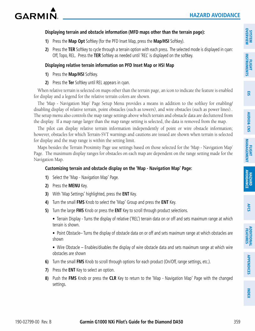
190-02799-00 Rev. B Garmin G1000 NXi Pilot’s Guide for the Diamond DA50
SYSTEMO
VERVIEWFLIG
HTIN
STRUMEN
TSEIS
AUDIO
& CN
SFLIG
HTM
AN
AGEM
ENT
HAZA
RDAVO
IDA
NCE
AFCS
AD
DITIO
NA
LFEATURES
APPEN
DICES
IND
EX
359
HAZARD AVOIDANCE
Displaying terrain and obstacle information (MFD maps other than the terrain page):
1) Press the Map Opt Softkey (for the PFD Inset Map, press the Map/HSI Softkey).
2) Press the TER Softkey to cycle through a terrain option with each press. The selected mode is displayed in cyan: Off, Topo, REL. Press the TER Softkey as needed until ‘REL’ is displayed on the softkey.
Displaying relative terrain information on PFD Inset Map or HSI Map
1) Press the Map/HSI Softkey.
2) Press the Ter Softkey until REL appears in cyan.
When relative terrain is selected on maps other than the terrain page, an icon to indicate the feature is enabled for display and a legend for the relative terrain colors are shown.
The ‘Map - Navigation Map’ Page Setup Menu provides a means in addition to the softkey for enabling/disabling display of relative terrain, point obstacles (such as towers), and wire obstacles (such as power lines).. The setup menu also controls the map range settings above which terrain and obstacle data are decluttered from the display. If a map range larger than the map range setting is selected, the data is removed from the map.
The pilot can display relative terrain information independently of point or wire obstacle information; however, obstacles for which Terrain-SVT warnings and cautions are issued are shown when terrain is selected for display and the map range is within the setting limit.
Maps besides the Terrain Proximity Page use settings based on those selected for the ‘Map - Navigation Map’ Page. The maximum display ranges for obstacles on each map are dependent on the range setting made for the Navigation Map.
Customizing terrain and obstacle display on the ‘Map - Navigation Map’ Page:
1) Select the ‘Map - Navigation Map’ Page.
2) Press the MENU Key.
3) With ‘Map Settings’ highlighted, press the ENT Key.
4) Turn the small FMS Knob to select the ‘Map’ Group and press the ENT Key.
5) Turn the large FMS Knob or press the ENT Key to scroll through product selections.
• Terrain Display - Turns the display of relative (‘REL’) terrain data on or off and sets maximum range at which terrain is shown.
• Point Obstacle– Turns the display of obstacle data on or off and sets maximum range at which obstacles are shown
• Wire Obstacle – Enables/disables the display of wire obstacle data and sets maximum range at which wire obstacles are shown
6) Turn the small FMS Knob to scroll through options for each product (On/Off, range settings, etc.).
7) Press the ENT Key to select an option.
8) Push the FMS Knob or press the CLR Key to return to the ‘Map - Navigation Map’ Page with the changed settings.

Garmin G1000 NXi Pilot’s Guide for the Diamond DA50 190-02799-00 Rev. B
SYST
EMO
VERV
IEW
FLIG
HTIN
STRU
MEN
TSEI
SAU
DIO
& C
NS
FLIG
HTM
AN
AGEM
ENT
HAZA
RDAV
OID
AN
CEA
FCS
AD
DIT
ION
AL
FEAT
URES
APP
END
ICES
IND
EX
360
HAZARD AVOIDANCE
Additional information about obstacles can be displayed by panning over the display on the map. The map panning feature is enabled by pressing the Joystick. The map range is adjusted by turning the Joystick. If the map range is adjusted while panning is enabled, the map is re-centered on the Map Pointer.
Figure 6-86 Terrain Information on the Navigation Map Page
Lighted Obstacle Selected with Map
Pointer
Additional Information on Obstacle Selected
with Map Pointer
Red Terrain Area (Above or Within
100’ Below Aircraft Altitude)
Red Lighted Obstacles (Above or Within
100’ Below Aircraft Altitude)
Yellow Terrain Area (Between 100’ and 1000’ Below Aircraft Altitude)
Terrain Legend
Terrain Display Enabled Icon
TERRAIN PAGE
The ‘Map - Terrain Proximity’, ‘Map - Terrain-SVT’, is specialized to show terrain, and obstacle in relation to the aircraft’s current altitude, without clutter from the basemap. This page is the principal page for viewing terrain information. Aviation data (airports, VORs, and other NAVAIDs) can be enabled for reference.
For Terrain-SVT systems only, this page also shows potential impact areas. If terrain or obstacles (including wire obstacles) and the projected flight path of the aircraft intersect, the display automatically adjusts to a map range if necessary to emphasize the display of the potential impact area.
Aircraft orientation on this map is always heading up unless there is no valid heading, in which case the orientation is track up. Map range is adjustable with the Joystick from 1 to 200 nm, as indicated by the map range rings (or arcs).
Displaying the terrain page:
1) Turn the large FMS Knob to select the Map Page Group.
2) Turn the small FMS Knob to select the ‘Map - Terrain Proximity Page/Terrain-SVT’ Page.
Showing/hiding aviation information on the terrain page:
1) Press the MENU Key.
2) Select ‘Show Aviation Data’ or ‘Hide Aviation Data’ (choice dependent on current state) and press the ENT Key.

190-02799-00 Rev. B Garmin G1000 NXi Pilot’s Guide for the Diamond DA50
SYSTEMO
VERVIEWFLIG
HTIN
STRUMEN
TSEIS
AUDIO
& CN
SFLIG
HTM
AN
AGEM
ENT
HAZA
RDAVO
IDA
NCE
AFCS
AD
DITIO
NA
LFEATURES
APPEN
DICES
IND
EX
361
HAZARD AVOIDANCE
Figure 6-87 Terrain Proximity Page
Map Orientation Current Aircraft GPS-derived GSL Altitude
Red Terrain (Above or Within 100’ Below the
Aircraft Altitude)
Red Lighted Obstacle (Above or Within 100’ Below Aircraft Altitude)
Yellow Lighted Obstacles (Between 100’ and 1000’
Below Aircraft Altitude)
Yellow Terrain (Between 100’ and 1000’ Below the Aircraft Altitude)
Terrain Legend
Black Terrain (More than 1000’ Below the Aircraft Altitude)
WIRE OBSTACLE INFORMATION AND ALERTINGFor additional safety, the terrain system incorporates Garmin’s WireAware™ wire obstacle information. For
wire obstacles such as power lines present in the obstacle database, the system shows these on the maps as well as the Synthetic Vision display; see the Flight Instruments section for more information about Synthetic Vision displays of power lines. For the Terrain-SVT only, this system can also issue cautions or warnings for potential impact with wire obstacles.
WireAware database information mainly includes Hazardous Obstacle Transmission (HOT) power lines which are typically high voltage transmission lines depicted on VFR Sectional charts, and are considered of special interest to fixed-wing pilots. These include power lines which may span rivers, valleys, canyons, or be in close proximity to airports/heliports.
It is important to note the obstacle database does not contain all power lines. In fact, WireAware database coverage is mostly limited to HOT power lines, such as the especially tall transmission lines and their associated support structures. It does not typically have information for the more prevalent smaller utility poles or lines, such as those found in residential areas. Furthermore, WireAware obstacle database coverage exists mainly in the United States; with limited coverage in portions of Canada and Mexico. In addition, the height of the wire obstacles is commonly estimated and should not be relied upon for maneuvering decisions.
NOTE: Wire obstacle symbols are not depicted in the Vertical Situation Display (VSD).

Garmin G1000 NXi Pilot’s Guide for the Diamond DA50 190-02799-00 Rev. B
SYST
EMO
VERV
IEW
FLIG
HTIN
STRU
MEN
TSEI
SAU
DIO
& C
NS
FLIG
HTM
AN
AGEM
ENT
HAZA
RDAV
OID
AN
CEA
FCS
AD
DIT
ION
AL
FEAT
URES
APP
END
ICES
IND
EX
362
HAZARD AVOIDANCE
ALERTING DISPLAYSAlerts are issued when flight conditions meet parameters that are set within Terrain-SVT software algorithms.
Terrain alerts typically employ a CAUTION or a WARNING alert severity level, or both. When an alert is issued, visual annunciations are displayed and voice alerts are simultaneously issued.
When an alert is issued, annunciations appear on the PFD and MFD. The terrain alert annunciation appears to the left of the Selected Altitude box on the PFD, and bottom left on the MFD on the Terrain-SVT Page. If the terrain page is not displayed at the time, a pop-up alert appears on the MFD. To acknowledge the pop-up alert:
- Press the CLR Key (returns to the currently viewed page), or
- Press the ENT Key (accesses the Terrain-SVT Page)
Figure 6-88 Terrain-SVT Alert Annunciations
Alert AnnunciationPop-up Alert
Figure 6-89 TAWS-B Page With Impact Point
Alert Annunciation
Terrain Legend
Potential Impact Area

190-02799-00 Rev. B Garmin G1000 NXi Pilot’s Guide for the Diamond DA50
SYSTEMO
VERVIEWFLIG
HTIN
STRUMEN
TSEIS
AUDIO
& CN
SFLIG
HTM
AN
AGEM
ENT
HAZA
RDAVO
IDA
NCE
AFCS
AD
DITIO
NA
LFEATURES
APPEN
DICES
IND
EX
363
HAZARD AVOIDANCE
The following table lists the possible Terrain-SVT alerts.
Alert TypePFD/Terrain-
SVTAnnunciation
MFDPop-Up Alert (except
Terrain-SVT Page)Voice Alert
Reduced Required Terrain Clearance Warning (RTC)
TERRAIN WARNING - TERRAIN“Warning; Terrain, Terrain”
Reduced Required Line Clearance (RLC) TERRAIN WARNING - WIRE “Warning; Wire, Wire”
Imminent Terrain Impact Warning (ITI) TERRAIN WARNING - TERRAIN“Warning; Terrain, Terrain”
Reduced Required Obstacle Clearance Warning (ROC)
TERRAIN WARNING - OBSTACLE “Warning; Obstacle, Obstacle”
Imminent Obstacle Impact Warning (IOI) TERRAIN WARNING - OBSTACLE “Warning; Obstacle, Obstacle”
Reduced Required Terrain Clearance Caution (RTC)
TERRAIN CAUTION - TERRAIN“Caution; Terrain, Terrain”
Imminent Line Impact Caution (ILI) TERRAIN CAUTION - WIRE “Caution, Wire, Wire”
Imminent Terrain Impact Caution (ITI) TERRAIN CAUTION - TERRAIN“Caution; Terrain, Terrain”
Reduced Required Line Clearance Caution (RLC)
TERRAIN CAUTION - WIRE “Caution, Wire, Wire”
Reduced Required Obstacle Clearance Caution (ROC)
TERRAIN CAUTION - OBSTACLE“Caution; Obstacle, Obstacle”
Imminent Obstacle Impact Caution (IOI) TERRAIN CAUTION - OBSTACLE“Caution; Obstacle, Obstacle”
Table 6-19 Terrain-SVT Alerts Summary

Garmin G1000 NXi Pilot’s Guide for the Diamond DA50 190-02799-00 Rev. B
SYST
EMO
VERV
IEW
FLIG
HTIN
STRU
MEN
TSEI
SAU
DIO
& C
NS
FLIG
HTM
AN
AGEM
ENT
HAZA
RDAV
OID
AN
CEA
FCS
AD
DIT
ION
AL
FEAT
URES
APP
END
ICES
IND
EX
364
HAZARD AVOIDANCE
FORWARD LOOKING TERRAIN AVOIDANCEThe Forward Looking Terrain Avoidance (FLTA) feature of Terrain-SVT compares the projected flight path as
derived from GPS data with terrain features and obstacles from the terrain and obstacle databases. The system issues FLTA alerts when the projected flight path conflicts with terrain or obstacles.
The projected flight path is a calculated area ahead of, to the sides, and below the aircraft. The size of the projected flight path varies based on factors including ground speed (the path ahead is larger when the ground speed is higher), whether the aircraft is level, turning, or descending, and the proximity to the nearest runway along the current track. As the aircraft approaches the runway, the projected flight path becomes narrower until the system automatically disables FLTA alerts or the pilot manually inhibits them.
There are two types of FLTA alerts, Reduced Required Terrain/Obstacle Clearance (RTC or ROC respectively) and Imminent Terrain/Obstacle Impact (ITI or IOI respectively).
0
100
200
300
400
500
600
700
800
0 5 10 15 20 25 30
Req
uire
d Te
rrai
n C
lear
ance
(FT)
Level (FT) Descending (FT)
Figure 6-90 FLTA Alert Minimum Terrain and Obstacle Clearance Values
Distance From Runway (NM)
Requ
ired
Clea
ranc
e (F
T)
The system automatically disables FLTA alerts when the aircraft is less than 200 feet above the destination runway elevation while within 0.5 nm of the approach runway or the aircraft is between runway ends.
When Terrain-SVT or FLTA alerts are manually inhibited, the annunciation is shown on the PFD and in the MFD for maps displaying relative terrain
Figure 6-91 Alerting is Inhibited when Annunciation is displayed
TAWS System
TAWS INH
Terrain-SVT System
TER INH

190-02799-00 Rev. B Garmin G1000 NXi Pilot’s Guide for the Diamond DA50
SYSTEMO
VERVIEWFLIG
HTIN
STRUMEN
TSEIS
AUDIO
& CN
SFLIG
HTM
AN
AGEM
ENT
HAZA
RDAVO
IDA
NCE
AFCS
AD
DITIO
NA
LFEATURES
APPEN
DICES
IND
EX
365
HAZARD AVOIDANCE
SYSTEM STATUS
TERRAIN-SVT
During power-up, Terrain-SVT conducts a self-test of its visual annunciations and voice alerts. An voice alert is issued at test completion.
Terrain-SVT continually monitors several system-critical items such as database validity, hardware status, and GPS status. If the terrain/obstacle database is not available, the system issues the voice alert “Terrain System Failure” along with the ‘TER FAIL’ alert annunciation.
Terrain-SVT requires a 3-D GPS navigation solution along with specific vertical accuracy minimums. Should the navigation solution become degraded or if the aircraft is out of the database coverage area, the annunciation ‘TER N/A’ is generated in the annunciation window and on the Terrain-SVT Page. The voice alert “Terrain System Not Available” is generated. When sufficient GPS signal is returns and the aircraft is within the database coverage area, the voice alert “Terrain System Available” is generated.
Alert TypePFD/Terrain-
SVTAnnunciation
Terrain-SVT Page Center Banner Annunciation
Voice Alert
System Test in Progress TER TEST TERRAIN TEST None
System Test Pass None None “Terrain System Test OK”
Terrain Alerting Inhibited TER INH None None
No GPS position TER N/A NO GPS POSITION “Terrain System Not Available”1
Excessively degraded GPS signal; or Out of database coverage area
TER N/A None “Terrain System Not Available”1
Terrain System Test Fail; Terrain or Obstacle database unavailable or invalid; Invalid software configuration; or System audio fault
TER FAIL TERRAIN FAIL “Terrain System Failure”
MFD Terrain or Obstacle database unavailable or invalid, and Terrain-SVT operating with PFD Terrain or Obstacle databases
None TERRAIN DATABASE FAILURE None
1 “Terrain System Available” will be heard when sufficient GPS signal is received, or Terrain database coverage area re-entered.
Table 6-20 Terrain-SVT System Status Annunciations

Garmin G1000 NXi Pilot’s Guide for the Diamond DA50 190-02799-00 Rev. B
SYST
EMO
VERV
IEW
FLIG
HTIN
STRU
MEN
TSEI
SAU
DIO
& C
NS
FLIG
HTM
AN
AGEM
ENT
HAZA
RDAV
OID
AN
CEA
FCS
AD
DIT
ION
AL
FEAT
URES
APP
END
ICES
IND
EX
366
HAZARD AVOIDANCE
6.5 TRAFFIC INFORMATION SERVICE (TIS)
WARNING: Do not rely solely upon the display of traffic information for collision avoidance maneuvering. The traffic display does not provide collision avoidance resolution advisories and does not under any circumstances or conditions relieve the pilot’s responsibility to see and avoid other aircraft.
NOTE: TIS is available only when the aircraft is within the service volume of a TIS-capable terminal radar site. Aircraft without an operating transponder are invisible to both Traffic Advisory Systems (TAS), Traffic Alert and Collision Avoidance Systems (TCAS) and TIS. Aircraft without altitude reporting capability are shown without altitude separation data or climb descent indication.
NOTE: Mode S TIS is disabled if another traffic system such as TAS or Automatic Dependent Surveillance-Broadcast (ADS-B) is installed.
Traffic Information Service (TIS) is designed to help in detection and avoidance of other aircraft. TIS uses the Mode S transponder for the traffic data link. TIS receives traffic information from ground stations, and is updated every five seconds. The system displays up to eight traffic symbols within a 7.5-nm radius, from 3000 feet below to 3500 feet above the requesting aircraft. The system displays TIS traffic with the symbology shown in the following table.
TIS Symbol Description
Non-Threat Traffic
Traffic Advisory (TA)
Traffic Advisory Off Scale
Table 6-21 TIS Traffic Symbols
Traffic Advisories (TA) alert the crew to intruding aircraft. When traffic meets the advisory criteria for the TA, a solid amber circle symbol appears. A TA which is detected but is outside the range of the map on which traffic is displayed are indicated with a message in the lower left corner of the map.
TIS also provides a vector line showing the direction in which the traffic is moving, to the nearest 45°. Traffic information for which TIS is unable to determine the bearing (non-bearing traffic) is displayed in the center of the Traffic Map Page or in a banner at the lower left corner of maps other than the Traffic Map Page on which traffic can be displayed.
The altitude difference between the requesting aircraft and other intruder aircraft is displayed above/below the traffic symbol in hundreds of feet. If the other aircraft is above the requesting aircraft, the altitude separation appears above the traffic symbol; if below, the altitude separation appears below. Altitude trend is displayed as an up/down arrow (for speeds greater than 500 fpm in either direction) to the right of the target symbol. Traffic symbols for aircraft without altitude reporting capability appear without altitude separation or climb/descent information.

190-02799-00 Rev. B Garmin G1000 NXi Pilot’s Guide for the Diamond DA50
SYSTEMO
VERVIEWFLIG
HTIN
STRUMEN
TSEIS
AUDIO
& CN
SFLIG
HTM
AN
AGEM
ENT
HAZA
RDAVO
IDA
NCE
AFCS
AD
DITIO
NA
LFEATURES
APPEN
DICES
IND
EX
367
HAZARD AVOIDANCE
DISPLAYING TRAFFIC DATAThe ‘Map - Traffic Map’ Page is the principal map page for viewing traffic information. Traffic information
can also be displayed on the following other maps for additional reference on the MFD when the traffic TIS is operating:
- PFD Maps
- Navigation Map Page
- Traffic Map Page
- Trip Planning Page
- Nearest Pages
- Active Flight Plan Page
Traffic information can also be displayed on the PFD when the Terrain-SVT option is installed and enabled. See the Flight Instruments Section for details.
Enabling/disabling traffic overlays (MFD navigation maps):
1) Press the Map Opt Softkey.
2) Press the Traffic Softkey. Traffic is now displayed on the navigation map.
When traffic is selected on maps other than the ‘Map - Traffic Map’ Page, an icon is shown to indicate the feature is enabled for display.
Figure 6-92 TIS Traffic on Navigation Map Page
Traffic Advisory, 500’ Below,
Climbing
Non-Threat Traffic, Not Reporting
Altitude
Traffic System Status Banner Annunciations
TA Off Scale Banner
Annunciation
The ‘Map - Navigation Map’ Page Setup Menu provides a means in addition to the softkey for enabling/disabling display of traffic. The setup menu also controls the map range settings above which traffic data (symbols and labels) are decluttered from the display. If a map range larger than the map range setting is selected, the data is removed from the map. Maps besides the Traffic Map Page use settings based on those selected for the ‘Map - Navigation Map’ Page.
Enabling/disabling traffic information on the PFD Inset Map or HSI Map:
1) On the PFD, press the Map/HSI Softkey.
2) Press the Traffic Softkey to enable/disable the display traffic information on the Inset Map or HSI Map.

Garmin G1000 NXi Pilot’s Guide for the Diamond DA50 190-02799-00 Rev. B
SYST
EMO
VERV
IEW
FLIG
HTIN
STRU
MEN
TSEI
SAU
DIO
& C
NS
FLIG
HTM
AN
AGEM
ENT
HAZA
RDAV
OID
AN
CEA
FCS
AD
DIT
ION
AL
FEAT
URES
APP
END
ICES
IND
EX
368
HAZARD AVOIDANCE
Customizing traffic display on the ‘Map - Navigation Map’ Page:
1) Select the ‘Map - Navigation Map’ Page.
2) Press the MENU Key.
3) With ‘Map Settings’ highlighted, press the ENT Key.
4) Turn the small FMS Knob to select the ‘Traffic’ Group and press the ENT Key.
5) Turn the large FMS Knob or press the ENT Key to scroll through product selections.
• Traffic – Turns the display of traffic data on or off
• Traffic Mode – Selects the traffic mode for display; select from:
- All Traffic - Displays all traffic
- TA/PA - Traffic Alerts and Proximity Alerts.
- TA Only - Displays Traffic Alerts only
• Traffic Symbols – Selects the maximum range at which traffic symbols are shown
• Traffic Labels – Selects the maximum range at which traffic labels are shown (with the option to turn off)
6) Turn the small FMS Knob to scroll through options for each product (On/Off, range settings, etc.).
7) Press the ENT Key to select an option.
8) Push the FMS Knob or CLR Key to return to the ‘Map - Navigation Map’ Page with the changed settings.
TRAFFIC MAP PAGEThe ‘Map - Traffic Map’ Page is specialized to show surrounding TIS traffic data in relation to the aircraft’s
current position and altitude, without clutter from the basemap. Aircraft orientation on this map is always heading up unless there is no valid heading. Map range is adjustable with the Joystick from 2 to 12 nm, as indicated by the map range rings.
The traffic mode is annunciated in the upper left corner of the ‘Map - Traffic Map’ Page. When the aircraft is on the ground, TIS automatically enters Standby Mode. Once the aircraft is airborne, TIS switches from Standby to Operating Mode and the system begins to display traffic information. Refer to the System Status discussion for more information.
Displaying traffic on the Traffic Map Page:
1) Turn the large FMS Knob to select the Map Page Group.
2) Turn the small FMS Knob to select the ‘Map - Traffic Map’ Page.
3) Confirm TIS is in Operating Mode:
a) Press the TIS OPER Softkey to begin displaying traffic.
Or:
a) Press the MENU Key.
b) Select ‘Operate Mode’ (shown if TIS is in Standby Mode) and press the ENT Key.

190-02799-00 Rev. B Garmin G1000 NXi Pilot’s Guide for the Diamond DA50
SYSTEMO
VERVIEWFLIG
HTIN
STRUMEN
TSEIS
AUDIO
& CN
SFLIG
HTM
AN
AGEM
ENT
HAZA
RDAVO
IDA
NCE
AFCS
AD
DITIO
NA
LFEATURES
APPEN
DICES
IND
EX
369
HAZARD AVOIDANCE
Figure 6-93 Traffic Map Page
“Non-Bearing” Traffic (System Unable to
Determine Bearing) Distance is 4.0 nm,
1100’ Above, Descending
Off-Scale Traffic Advisory
400’ Below, Level
Traffic Status Banner Annunciations
Traffic Mode Annunciation
“TIS Not Available” Voice Alert Status
Select to Mute “TIS Not Available” Voice Alert
Traffic Advisory, 500’ Below, Climbing
Non-Threat Traffic, 1200’ Above, Descending
Range Marking Rings
TIS ALERTSWhen the number of TAs on the ‘Map - Traffic Map’ Page increases from one scan to the next, the following
occur:
- A single “Traffic” voice alert is generated.
- A ‘TRAFFIC’ Annunciation appears to the right of the airspeed tape, flashes for five seconds, and remains displayed until no TAs are detected in the area.
- The PFD Inset Map or HSI Map is automatically displayed with traffic.
To reduce the number of nuisance alerts due to proximate aircraft, the “Traffic” voice alert is generated only when the number of TAs increases. For example, when the first TA is displayed, a voice and visual annunciation are generated. As long as a single TA remains on the display, no additional voice alerts are generated. If a second TA appears on the display or if the number of TAs initially decreases and then subsequently increases, another voice alert is generated.

Garmin G1000 NXi Pilot’s Guide for the Diamond DA50 190-02799-00 Rev. B
SYST
EMO
VERV
IEW
FLIG
HTIN
STRU
MEN
TSEI
SAU
DIO
& C
NS
FLIG
HTM
AN
AGEM
ENT
HAZA
RDAV
OID
AN
CEA
FCS
AD
DIT
ION
AL
FEAT
URES
APP
END
ICES
IND
EX
370
HAZARD AVOIDANCE
Figure 6-94 Traffic Annunciation (PFD)
Inset Map Displays When TA is Detected
A “TIS Not Available” (TNA) voice alert is generated when the TIS service becomes unavailable or is out of range. TIS may be unavailable in the radar coverage area due to the following:
- Radar site TIS Mode S sensor is not operational or is out of service
- Traffic or requesting aircraft is beyond the maximum range of the TIS-capable Mode S radar site.
- Traffic or requesting aircraft is above the radar site in the cone of silence and out of range of an adjacent site.
- Traffic or requesting aircraft is below radar coverage. In flat terrain, the coverage extends from about 3000 feet upward at 55 miles. Terrain and obstacles around the radar site can further decrease radar coverage in all directions.
- Traffic does not have an operating transponder.
The “TIS Not Available” (TNA) voice alert can be manually muted to reduce nuisance alerting. TNA muting status is shown in the upper right corner of the Traffic Map Page.
Muting the “TIS Not Available” voice alert:
1) Select the ‘Map - Traffic Map’ Page.
2) Press the TNA Mute Softkey. The status is displayed in the upper left corner of the Traffic Map Page.
Or:
a) Press the MENU Key.
b) Select ‘‘’Not Available” Mute On’ (shown if TNA muting is currently off) and press the ENT Key.

190-02799-00 Rev. B Garmin G1000 NXi Pilot’s Guide for the Diamond DA50
SYSTEMO
VERVIEWFLIG
HTIN
STRUMEN
TSEIS
AUDIO
& CN
SFLIG
HTM
AN
AGEM
ENT
HAZA
RDAVO
IDA
NCE
AFCS
AD
DITIO
NA
LFEATURES
APPEN
DICES
IND
EX
371
HAZARD AVOIDANCE
SYSTEM STATUSThe system performs an automatic test of TIS during power-up. If TIS passes the test, TIS enters Standby
Mode (on the ground) or Operating Mode (in the air). If TIS fails the power up test, an annunciation is shown in the center of the ‘Map - Traffic Map’ Page.
Traffic Map Page Center Banner Annunciation
Description
NO DATA Data is not being received from the transponder1
DATA FAILEDData is being received from the transponder, but a failure is detected in the data stream1
FAILED The transponder has failed1
UNAVAILABLE TIS is unavailable or out of range1 Contact a service center or Garmin dealer for corrective action
Table 6-22 TIS Failure Annunciations
The traffic mode is annunciated in the upper right corner of the Traffic Map Page. When the aircraft is on the ground, TIS automatically enters Standby Mode. If traffic is selected for display on another map while Standby Mode is selected, the traffic display enabled icon is crossed out (also the case whenever TIS has failed). Once the aircraft is airborne, TIS switches to Operating Mode and traffic information is displayed. The mode can be changed manually using softkeys or the page menu.
Traffic Map Mode Annunciation
Traffic Map Center Banner Annunciation
Traffic Overlay Status Icon (Navigation Maps)
Description
DATA FAILED TRFC FAILData is being received from the transponder, but a failure is detected in the data stream1
NO DATA TRFC FAILData is not being received from the transponder1
OPERATING NoneTIS is operating and is receiving traffic data from a data link.
OPERATING UNAVAILABLETIS is operating, but the traffic service is currently unavailable or is out of reception range.
STANDBY STANDBY TIS is in Standby Mode.
UNIT FAILED TRFC FAIL The transponder has failed1
1 Contact a service center or Garmin dealer for corrective action
Table 6-23 TIS Modes and Status Annunciations

Garmin G1000 NXi Pilot’s Guide for the Diamond DA50 190-02799-00 Rev. B
SYST
EMO
VERV
IEW
FLIG
HTIN
STRU
MEN
TSEI
SAU
DIO
& C
NS
FLIG
HTM
AN
AGEM
ENT
HAZA
RDAV
OID
AN
CEA
FCS
AD
DIT
ION
AL
FEAT
URES
APP
END
ICES
IND
EX
372
HAZARD AVOIDANCE
Switching between TIS modes:
1) Select the ‘Map - Traffic Map’ Page.
2) Press the Standby or Operate Softkey to switch between modes. The mode is displayed in the upper right corner of the Traffic Map Page.
Or:
a) Press the MENU Key.
b) Select ‘Operate Mode’ or ‘Standby Mode’ (choice dependent on current state) and press the ENT Key.
The annunciations to indicate the status of traffic information appear in a banner at the lower left corner of maps on which traffic can be displayed, as shown in the following table.
Traffic Status Banner Annunciation
Description
TA OFF SCALEA Traffic Advisory is outside the selected display range1 Annunciation is removed when traffic comes within the selected display range
TA X.X ± XX ↕System cannot determine bearing of Traffic Advisory2 Annunciation indicates distance in nm, altitude separation in hundreds of feet, and altitude trend arrow (climbing/descending)
AGE MM:SSAppears if traffic data is not refreshed within 6 seconds If after another 6 seconds data is not received, traffic is removed from the display The quality of displayed traffic information is reduced as the age increases
TRFC COASTThe displayed data is not current (6 to 12 seconds since last message) The quality of displayed traffic information is reduced when this message is displayed
TRFC RMVDTraffic is removed because it is too old for coasting (12 to 60 seconds since last message) Traffic may exist within the selected display range, but it is not displayed
TRFC FAIL Traffic data has failedNO TRFC DATA Traffic has not been detectedTRFC UNAVAIL The traffic service is unavailable or out of range
1 Shown as symbol on ’Map -Traffic Map’ Page2 Shown in center of ‘Map - Traffic Map’ Page
Table 6-24 TIS Traffic Status Annunciations

190-02799-00 Rev. B Garmin G1000 NXi Pilot’s Guide for the Diamond DA50
SYSTEMO
VERVIEWFLIG
HTIN
STRUMEN
TSEIS
AUDIO
& CN
SFLIG
HTM
AN
AGEM
ENT
HAZA
RDAVO
IDA
NCE
AFCS
AD
DITIO
NA
LFEATURES
APPEN
DICES
IND
EX
373
HAZARD AVOIDANCE
6.6 TAS TRAFFIC
WARNING: Do not rely solely upon the display of traffic information for collision avoidance maneuvering. The traffic display does not provide collision avoidance resolution advisories and does not under any circumstances or conditions relieve the pilot’s responsibility to see and avoid other aircraft.
WARNING: Do not rely solely upon the display of traffic information to accurately depict all of the traffic information within range of the aircraft. Due to lack of equipment, poor signal reception, and/or inaccurate information from other aircraft, traffic may be present but not represented on the display.
NOTE: Pilots should be aware of traffic system limitations. Traffic systems require transponders of other aircraft to respond to system interrogations. If the transponders do not respond to interrogations due to phenomena such as antenna shading or marginal transponder performance, traffic may be displayed intermittently, or not at all. Aircraft without altitude reporting capability are shown without altitude separation data or climb descent indication. Pilots should remain vigilant for traffic at all times.
NOTE: Mode-S TIS is disabled when another traffic system is installed.
NOTE: Refer to the Avidyne TAS600 Series Pilot’s Guide for a detailed discussion of the Avidyne TAS600 System.
The optional Garmin GTS 800 or Avidyne TAS600 is a Traffic Advisory System (TAS). It enhances flight crew situational awareness by displaying traffic information for transponder-equipped aircraft. The system also provides visual annunciations and voice alerts to help the pilot visually acquire traffic.
The Garmin GTS 800 is capable of tracking up to 45 intruding aircraft equipped with Mode A or C transponders, and up to 30 intruding aircraft equipped with Mode S transponders. A maximum of 30 aircraft with the highest threat potential can be displayed simultaneously.
No TAS surveillance is provided for aircraft without operating transponders.
TAS THEORY OF OPERATIONWhen the traffic system is in Operating Mode, the system directly interrogates the transponders of other
aircraft in the vicinity. The traffic system uses this information to derive the distance, relative bearing, and if reported, the altitude and vertical trend for each aircraft within its surveillance range. The traffic system then calculates a closure rate to each intruder based on the projected Closest Point of Approach (CPA). If the closure rate meets the threat criteria for a Traffic Advisory (TA), the traffic system provides visual annunciations and voice alerts.

Garmin G1000 NXi Pilot’s Guide for the Diamond DA50 190-02799-00 Rev. B
SYST
EMO
VERV
IEW
FLIG
HTIN
STRU
MEN
TSEI
SAU
DIO
& C
NS
FLIG
HTM
AN
AGEM
ENT
HAZA
RDAV
OID
AN
CEA
FCS
AD
DIT
ION
AL
FEAT
URES
APP
END
ICES
IND
EX
374
HAZARD AVOIDANCE
TAS SURVEILLANCE VOLUME AND SYMBOLOGY
The GTS 800 TAS surveillance system actively scans the airspace within ±10,000 feet of its altitude. Under ideal conditions, the GTS 800 scans transponder traffic up to 22 nm in the forward direction. The range is somewhat reduced to the sides and aft of the aircraft due to the directional interrogation signal patterns. In areas of greater transponder traffic density or when TCAS II (Traffic Alert and Collision Avoidance System II) systems are detected, the on-board traffic system automatically reduces its interrogation transmitter power (and therefore range) in order to limit potential interference from other signals.
If a Garmin GTX 335 or GTX 345R transponder is installed with the TAS, the symbols in the following tables depict traffic, and include Automatic Dependent Surveillance-Broadcast (ADS-B) information. Refer to the ADS-B Traffic discussion later in this section for more information.
Traffic Symbol DescriptionOther Non-Threat Traffic
Proximity Advisory (PA)
Traffic Advisory (TA)
Traffic Advisory Off Scale
Table 6-25 TAS Symbol Description
Traffic Symbol DescriptionTraffic Advisory with ADS-B directional information. Points in the direction of the intruder aircraft track.
Proximity Advisory with ADS-B directional information. Points in the direction of the aircraft track.
Other Non-threat traffic with ADS-B directional information. Points in the direction of the intruder aircraft track.
Table 6-26 Traffic with ADS-B Symbology (GTX 335 Transponder)

190-02799-00 Rev. B Garmin G1000 NXi Pilot’s Guide for the Diamond DA50
SYSTEMO
VERVIEWFLIG
HTIN
STRUMEN
TSEIS
AUDIO
& CN
SFLIG
HTM
AN
AGEM
ENT
HAZA
RDAVO
IDA
NCE
AFCS
AD
DITIO
NA
LFEATURES
APPEN
DICES
IND
EX
375
HAZARD AVOIDANCE
Symbol DescriptionTraffic Advisory with ADS-B directional information. Arrow points in the direction of the intruder aircraft track.
Traffic Advisory without directional information.
Traffic Advisory with ADS-B directional information is beyond the selected display range. Displayed at outer range ring at proper bearing. Arrow points in the direction of the intruder aircraft track.
Traffic Advisory out of the selected display range without directional information. Displayed at outer range ring at proper bearing.
Proximity Advisory with ADS-B directional information. Arrow points in the direction of the aircraft track.
Proximity Advisory without directional information.
Other Non-Threat traffic with ADS-B directional information. Arrow points in the direction of the intruder aircraft track.
Other Non-Threat traffic without directional information.
Traffic located on the ground with ADS-B directional information. Arrow points in the direction of the aircraft track. Ground traffic is only displayed when ADS-B is in Surface (SURF) Mode or own aircraft is on the ground.
Ground traffic without ADS-B directional information. Ground traffic is only displayed when ADS-B is in Surface (SURF) Mode or own aircraft is on the ground.
Non-aircraft ground traffic with ADS-B directional information. Pointed end indicates direction of travel. Ground traffic is only displayed when ADS-B is in Surface (SURF) Mode or own aircraft is on the ground.
Non-aircraft ground traffic without ADS-B directional information. Ground traffic is only displayed when ADS-B is in Surface (SURF) Mode or own aircraft is on the ground.
Table 6-27 ADS-B Traffic Symbology with GTX 345R Transponder
A Traffic Advisory (TA), displayed as a solid amber circle or circle enclosing an arrow, alerts the crew to a potentially hazardous intruding aircraft, if the closing rate, distance, and vertical separation meet TA criteria. A TA that is beyond the selected display range (off scale) is indicated by a half TA symbol at the edge of the screen at the relative bearing of the intruder.
A Proximity Advisory (PA), displayed as a solid white diamond or arrow, indicates the intruding aircraft is within ±1200 feet and is within a 6 nm range, but is still not considered a TA threat.
Other, non-threat traffic, shown as an open white diamond or arrow, is displayed for traffic beyond six nautical miles that is neither a TA or PA.

Garmin G1000 NXi Pilot’s Guide for the Diamond DA50 190-02799-00 Rev. B
SYST
EMO
VERV
IEW
FLIG
HTIN
STRU
MEN
TSEI
SAU
DIO
& C
NS
FLIG
HTM
AN
AGEM
ENT
HAZA
RDAV
OID
AN
CEA
FCS
AD
DIT
ION
AL
FEAT
URES
APP
END
ICES
IND
EX
376
HAZARD AVOIDANCE
Relative altitude, when available, is displayed above or below the corresponding intruder symbol in hundreds of feet. When this altitude is above own aircraft, it is preceded by a ‘+’ symbol; a minus sign ‘-’ indicates traffic is below own aircraft.
The system displays the altitude vertical trend as an up/down arrow (for speeds greater than 500 fpm in either direction) to the right of the intruder symbol.
Relative Altitude
Vertical trend arrow
Figure 6-95 Intruder Altitude and Vertical Trend Arrow
TA ALERTING CONDITIONS (GTS 800)
The GTS 800 traffic system automatically adjusts its TA sensitivity level to reduce the likelihood of nuisance TA alerting when the aircraft is more likely to be near an airport. The system uses Level A (less) sensitivity when the height above terrain is at or below 2,000’ AGL. If the height above terrain is unavailable, Level A sensitivity applies when the ground speed is less than 120 knots. In all other conditions, Level B (higher) sensitivity applies.
Sensitivity Level
Intruder Altitude Available
TA Alerting Conditions
A Yes
Intruder closing rate provides less than 20 seconds of vertical and horizontal separation.Or:Intruder closing rate provides less than 20 seconds of horizontal separation and vertical separation is within 600 feet.Or:Intruder range is within 0.2 nm and vertical separation is within 600 feet.
A NoIntruder closing rate provides less than 15 seconds of separation or intruder range is within 0.2 NM.
B Yes
Intruder closing rate provides less than 30 seconds of vertical and horizontal separation.Or:Intruder closing rate provides less than 30 seconds of horizontal separation and vertical separation is within 800 feet.Or:Intruder range is within 0.55 nm and vertical separation is within 800 feet.
B NoIntruder closing rate provides less than 20 seconds of separation or intruder range is within 0.55 NM.
Table 6-28 TA Sensitivity Level and TA Alerting Criteria

190-02799-00 Rev. B Garmin G1000 NXi Pilot’s Guide for the Diamond DA50
SYSTEMO
VERVIEWFLIG
HTIN
STRUMEN
TSEIS
AUDIO
& CN
SFLIG
HTM
AN
AGEM
ENT
HAZA
RDAVO
IDA
NCE
AFCS
AD
DITIO
NA
LFEATURES
APPEN
DICES
IND
EX
377
HAZARD AVOIDANCE
TAS ALERTS
NOTE: If an optional Avidyne TAS600 is installed, refer to the applicable Pilot’s Guide from the manufacturer for information about applicable voice alerts for the system test.
When the GTS 800 or Avidyne TAS600 detects a new TA, the following occur:
- The system issues a single “Traffic!” voice alert, followed by additional voice information about the bearing, relative altitude, and approximate distance from the intruder that triggered the TA. For example, the announcement “Traffic! 12 o’clock, high, four miles,” would indicate the traffic is in front of own aircraft, above own altitude, and approximately four nautical miles away.
Bearing Relative Altitude Approximate Distance (nm)
“One o’clock” through “Twelve o’clock”or “No Bearing”
“High”, “Low”, “Same Altitude” (if within 200 feet of own altitude), or
“Altitude not available”
“Less than one mile”, “One Mile” through “Ten Miles”, or
“More than ten miles”
Table 6-29 TA Descriptive Voice Announcements
- A TRAFFIC Annunciation appears at the right of the airspeed on the PFD, flashes for five seconds, and remains displayed until no TAs are detected in the area.
- The system displays the TA traffic on a PFD map. If a navigation map, such as the Inset Map or HSI Map was already shown on the PFD prior to a TA occurrence, the system automatically enables the traffic overlay on the map if necessary in order to show the TA. If no map was shown on the PFD prior to the TA, then the Traffic Inset Map is displayed on the PFD.
- If the bearing of TA traffic cannot be determined, a yellow text banner will be displayed in the center of the ‘Map - Traffic Map’ Page and in the lower-left of the PFD inset map instead of a TA symbol. The text will indicate “TA” followed by the distance, relative altitude, and vertical trend arrow for the TA traffic, if known.
A TA will be displayed for at least eight seconds, even if the condition(s) that initially triggered the TA are no longer present.
Figure 6-96 Traffic Annunciation (PFD)

Garmin G1000 NXi Pilot’s Guide for the Diamond DA50 190-02799-00 Rev. B
SYST
EMO
VERV
IEW
FLIG
HTIN
STRU
MEN
TSEI
SAU
DIO
& C
NS
FLIG
HTM
AN
AGEM
ENT
HAZA
RDAV
OID
AN
CEA
FCS
AD
DIT
ION
AL
FEAT
URES
APP
END
ICES
IND
EX
378
HAZARD AVOIDANCE
SYSTEM TEST
NOTE: If an optional Avidyne TAS600 is installed, refer to the applicable Pilot’s Guide from the manufacturer for information about applicable voice alerts for the system test.
The traffic system provides a system test mode to verify the TAS is operating normally. The test takes about ten seconds to complete. When the system test is initiated, a test pattern of traffic symbols appears on the ‘Map - Traffic Map’ Page. For the GTS 800, if system test passes, the system announces, “TAS System Test Passed” or “TAS System Test Failed.” When the system test is complete, the traffic system enters Standby Mode.
Testing the traffic system:
1) Turn the large FMS Knob to select the Map Page Group.
2) Turn the small FMS Knob to select the ‘Map - Traffic Map’ Page.
3) Turn the Joystick to set the range to 2/6 nm to allow for full test pattern to be displayed during test.
4) Press the Standby or TAS STBY Softkey.
5) Press the Test Softkey.
Or:
1) With the Traffic system in Standby mode, press the MENU Key.
2) Turn the small FMS Knob to select ‘Test Mode’.
3) Press the ENT Key.
Figure 6-97 System Test in Progress with Test Pattern
ADS-B Test Mode

190-02799-00 Rev. B Garmin G1000 NXi Pilot’s Guide for the Diamond DA50
SYSTEMO
VERVIEWFLIG
HTIN
STRUMEN
TSEIS
AUDIO
& CN
SFLIG
HTM
AN
AGEM
ENT
HAZA
RDAVO
IDA
NCE
AFCS
AD
DITIO
NA
LFEATURES
APPEN
DICES
IND
EX
379
HAZARD AVOIDANCE
OPERATION
NOTE: The Garmin GTS 800 TAS automatically changes from Standby to Operating mode eight seconds after takeoff. The system also automatically changes from Operating to Standby mode 24 seconds after landing.
NOTE: Refer to the Avidyne TAS600 Series Pilot’s Guide for a detailed discussion of the Avidyne TAS600 system operation.
When the avionics system initially receives power on the ground, the traffic system is in Standby Mode. The system must be in Operating Mode for traffic to be displayed and for TAs to be issued.
Changing traffic system modes on the ‘Map - Traffic Map’ Page:
1) Turn the large FMS Knob to select the Map Page Group.
2) Turn the small FMS Knob to select the ‘Map - Traffic Map’ Page.
3) Press the Operate or TAS OPER Softkey to begin displaying traffic. ‘TAS: OPERATING’ is displayed in the Traffic mode field.
4) Press the Standby or TAS STBY Softkey to place the system in the Standby mode. ‘TAS: STANDBY’ is displayed in the Traffic mode field.
Or:
1) With the ‘Map - Traffic Map’ Page displayed, press the MENU Key.
2) Turn the small FMS knob to highlight the desired mode.
3) Press the ENT Key.
TRAFFIC MAP PAGE
The ‘Map - Traffic Map’ Page shows surrounding traffic data in relation to the aircraft’s current position and altitude, without basemap clutter. It is the principal map page for viewing traffic information. Aircraft orientation is always heading up unless there is no valid heading. The pilot can adjust the map range with the Joystick. A range indication appears on each range ring.
The system annunciates the traffic mode and altitude display mode in the upper right corner of the ‘Map -
Traffic Map’ Page.

Garmin G1000 NXi Pilot’s Guide for the Diamond DA50 190-02799-00 Rev. B
SYST
EMO
VERV
IEW
FLIG
HTIN
STRU
MEN
TSEI
SAU
DIO
& C
NS
FLIG
HTM
AN
AGEM
ENT
HAZA
RDAV
OID
AN
CEA
FCS
AD
DIT
ION
AL
FEAT
URES
APP
END
ICES
IND
EX
380
HAZARD AVOIDANCE
Figure 6-98 ‘Map - Traffic Map’ Page
TAS Operating Mode Annunciation
Other Non-Threat Traffic, 1000 below, climbing
Traffic Advisory, 200’ above, climbing
No-bearing Traffic Advisory, 4.0 nm away, 1100’ above, descending
Proximity Advisory, 1200’ feet below, descending
Traffic Display Range Rings
altituDe DisPlay moDe
The pilot can select the volume of airspace in which Other Non-Threat and Proximity Advisory traffic is displayed. If traffic meets the criteria for a TA, it is also displayed even if it is outside of the selected volume of airspace.
Changing the altitude range:
1) On the ‘Map - Traffic Map’ Page, select the ALT Mode Softkey.
2) Select one of the following Softkeys:
• Above: Displays Other Non-Threat and Proximity Advisory traffic from 9900 feet above the aircraft to 2700 feet below the aircraft. Typically used during climb phase of flight.
• Normal: Displays Other Non-Threat and Proximity Advisory traffic from 2700 feet above the aircraft to 2700 feet below the aircraft. Typically used during enroute phase of flight.
• Below: Displays Other Non-Threat and Proximity Advisory traffic from 2700 feet above the aircraft to 9900 feet below the aircraft. Typically used during descent phase of flight.
• UNREST (unrestricted): All traffic is displayed from 9900 feet above and 9900 feet below the aircraft.
3) To return to the Traffic Page, select the Back Softkey.
Or:

190-02799-00 Rev. B Garmin G1000 NXi Pilot’s Guide for the Diamond DA50
SYSTEMO
VERVIEWFLIG
HTIN
STRUMEN
TSEIS
AUDIO
& CN
SFLIG
HTM
AN
AGEM
ENT
HAZA
RDAVO
IDA
NCE
AFCS
AD
DITIO
NA
LFEATURES
APPEN
DICES
IND
EX
381
HAZARD AVOIDANCE
1) Press the MENU Key.
2) Turn the small FMS Knob to select one of the following (see softkey description in the previous step 2):
• Above
• Normal
• Below
• Unrestricted
3) Select the ENT Softkey.
traffiC maP Page DisPlay range
The display range on the ‘Map - Traffic Map’ Page can be changed at any time. Map range is adjustable with the Joystick, and rings on the map denote the ranges.
Changing the display range on the ‘Map - Traffic Map’ Page:
1) Turn the Joystick.
2) The following range options are available:
• 750 ft (with optional ADS-B)
• 750 ft and 1500 ft (with optional ADS-B)
• 1500 ft and 0.5 nm (with optional ADS-B)
• 0.5 nm and 1 nm (with optional ADS-B)
• 1 nm and 2 nm (with optional ADS-B)
• 2 nm
• 2 and 6 nm
• 6 and 12 nm
• 12 and 24 nm
• 24 and 40 nm (available with ADS-B)

Garmin G1000 NXi Pilot’s Guide for the Diamond DA50 190-02799-00 Rev. B
SYST
EMO
VERV
IEW
FLIG
HTIN
STRU
MEN
TSEI
SAU
DIO
& C
NS
FLIG
HTM
AN
AGEM
ENT
HAZA
RDAV
OID
AN
CEA
FCS
AD
DIT
ION
AL
FEAT
URES
APP
END
ICES
IND
EX
382
HAZARD AVOIDANCE
ADDITIONAL TRAFFIC DISPLAYS
The ‘Map - Traffic Map’ Page is the principal map page for viewing traffic information. Traffic information can also be displayed on the following other maps for additional reference on the MFD when the traffic unit is operating:
» ‘Map - Navigation Map’ Page
» ‘Map - Traffic Map’ Page
» Trip Planning Page
» Nearest Pages
» ‘FPL - Active Flight Plan’ Page
» ‘Aux - Aux Video’ Page
Enabling/disabling traffic information (MFD maps other than the ‘Map - Traffic Map’ Page):
1) Press the Map Opt Softkey.
2) Press the Traffic Softkey. Traffic is now displayed on the map.
When traffic is selected on maps other than the ‘Map - Traffic Map’ Page, the system shows a traffic status icon to indicate traffic is enabled for display as well as the altitude display mode (Above, Below, Normal, Unres).
Figure 6-99 TAS Traffic on Navigation Map
Traffic Advisory
Proximity Advisory with ADS-B Directional Information
Traffic overlay enabled icon and Altitude Display Mode
Traffic Advisory Off-Scale Banner Annunciation
Non-Threat Traffic

190-02799-00 Rev. B Garmin G1000 NXi Pilot’s Guide for the Diamond DA50
SYSTEMO
VERVIEWFLIG
HTIN
STRUMEN
TSEIS
AUDIO
& CN
SFLIG
HTM
AN
AGEM
ENT
HAZA
RDAVO
IDA
NCE
AFCS
AD
DITIO
NA
LFEATURES
APPEN
DICES
IND
EX
383
HAZARD AVOIDANCE
Customizing the traffic display on the ‘Map - Navigation Map’ Page:
1) Select the ‘Map - Navigation Map’ Page.
2) Press the MENU Key.
3) With ‘Map Settings’ highlighted, press the ENT Key.
4) Turn the small FMS Knob to select the Traffic Group and press the ENT Key.
5) Turn the large FMS Knob or press the ENT Key to scroll through the selections.
• Traffic – Turns the display of traffic data on or off
• Traffic Mode – Selects the traffic mode for display; select from:
- All Traffic - Displays all traffic
- TA/PA - Displays only Traffic Advisories and Proximity Advisories
- TA Only - Displays Traffic Advisories only
• Traffic Symbols – Selects the maximum range at which traffic symbols are shown
• Traffic Labels – Selects the maximum range at which traffic labels (relative altitude, vertical trend) are shown with the option to turn off
6) Turn the small FMS Knob to scroll through options (On/Off, range settings, etc.).
7) Press the ENT Key to select an option.
8) Push the FMS Knob or CLR Key to return to the ‘Map - Navigation Map’ Page.
The ‘Map - Navigation Map’ Page Setup Menu also controls the display of traffic. The setup menu controls the map range settings. Traffic data symbols and labels can be decluttered from the display. If a map range larger than the map range setting is selected, the data is removed from the map. Maps, besides the ‘Map - Traffic Map’ Page, use settings based on those selected for the ‘Map - Navigation Map’ Page.
A traffic-only inset map is available on the PFD by pressing the TFC Map Softkey. A traffic map appears on the PFD. This map resembles the ‘Map - Traffic Map’ Page, and presents a heading up format. Traffic information can also be overlaid on PFD navigation maps.
Enabling/disabling traffic overlay on PFD navigation maps:
1) With the Inset Map or HSI Map displayed, press the Map/HSI Softkey on the PFD.
2) Press the Traffic Softkey to enable/disable the display traffic information.
Or:
Press the TFC Map Softkey on the PFD.

Garmin G1000 NXi Pilot’s Guide for the Diamond DA50 190-02799-00 Rev. B
SYST
EMO
VERV
IEW
FLIG
HTIN
STRU
MEN
TSEI
SAU
DIO
& C
NS
FLIG
HTM
AN
AGEM
ENT
HAZA
RDAV
OID
AN
CEA
FCS
AD
DIT
ION
AL
FEAT
URES
APP
END
ICES
IND
EX
384
HAZARD AVOIDANCE
SYSTEM STATUSThe traffic mode is annunciated in the upper right corner of the ‘Map - Traffic Map’ Page.
ModeTraffic Mode Annunciation
(Traffic Map Page)Traffic Display Status Icon
(Other Maps)
Traffic System Test Initiated
TEST (‘TEST MODE’ shown in center of page)
Operating OPERATING
StandbySTANDBY
(also shown in white in center of page)
Traffic System Failed1 FAIL
1 See Table 6-32 for additional failure annunciationsTable 6-30 Traffic Modes
If the traffic unit fails, an annunciation as to the cause of the failure is shown in the center of the ‘Map - Traffic Map’ Page. During a failure condition, the Operating Mode cannot be selected.
Traffic Map Page Center Annunciation
Description
NO DATA Data is not being received from the TAS unitDATA FAILED Data is being received from the TAS unit, but the unit is self-reporting a failure
FAILED Incorrect data format received from the TAS unit
Table 6-31 TAS Failure Annunciations
The annunciations to indicate the status of traffic information appear in a banner at the lower left corner of maps on which traffic can be displayed.
Traffic Status Banner Annunciation
Description
TA OFF SCALEA Traffic Advisory is outside the selected display range.1 Annunciation is removed when traffic comes within the selected display range.
TA X.X ± XX ↕System cannot determine bearing of Traffic Advisory.2 Annunciation indicates distance in nm, altitude separation in hundreds of feet, and altitude trend arrow (climbing/descending).
TRFC FAIL TAS unit has failed (unit is self-reporting a failure or sending incorrectly formatted data)NO TRFC DATA Data is not being received from the TAS unit
1 Shown as symbol on ‘Map - Traffic Map’ Page2 Shown in center of ‘Map - Traffic Map’ Page
Table 6-32 TAS Traffic Status Annunciations

190-02799-00 Rev. B Garmin G1000 NXi Pilot’s Guide for the Diamond DA50
SYSTEMO
VERVIEWFLIG
HTIN
STRUMEN
TSEIS
AUDIO
& CN
SFLIG
HTM
AN
AGEM
ENT
HAZA
RDAVO
IDA
NCE
AFCS
AD
DITIO
NA
LFEATURES
APPEN
DICES
IND
EX
385
HAZARD AVOIDANCE
6.7 ADS-B TRAFFIC
WARNING: Do not rely solely upon the display of traffic information for collision avoidance maneuvering. The traffic display does not provide collision avoidance resolution advisories and does not under any circumstances or conditions relieve the pilot’s responsibility to see and avoid other aircraft.
WARNING: Do not rely solely upon the display of traffic information to accurately depict all of the traffic information within range of the aircraft. Due to lack of equipment, poor signal reception, and/or inaccurate information from other aircraft, traffic may be present but not represented on the display.
ADS-B SYSTEM OVERVIEWAutomatic Dependent Surveillance-Broadcast (ADS-B) is a core technology in the FAA NextGen air traffic
control system. It offers improved surveillance services, both air-to-air and air-to-ground, especially in areas where radar coverage is ineffective due to terrain, or where it is impractical or cost prohibitive. ADS-B is comprised of three segments for the purposes of providing traffic information: ADS-B (Broadcast), ADS-R (Rebroadcast), and Traffic Information Service-Broadcast (TIS-B).
ADS-B includes the automatic broadcast of position reports by aircraft, surface vehicles, and transmitters on fixed objects. These broadcasts contain information such as GPS position, identity (Flight ID, Call Sign, Tail Number, ICAO registration number, etc.), ground track, ground speed, pressure altitude, and emergency status.
18,000 FT
10,000 FT
GPS
RADAR ATC
1090 ESUAT
RADARComposite
ADS-B Ground Station (ADS-R, TIS-B, FIS-B)
Mode A/C
1090 ES
1090 ES
UATUAT
UAT
Figure 6-100 ADS-B System

Garmin G1000 NXi Pilot’s Guide for the Diamond DA50 190-02799-00 Rev. B
SYST
EMO
VERV
IEW
FLIG
HTIN
STRU
MEN
TSEI
SAU
DIO
& C
NS
FLIG
HTM
AN
AGEM
ENT
HAZA
RDAV
OID
AN
CEA
FCS
AD
DIT
ION
AL
FEAT
URES
APP
END
ICES
IND
EX
386
HAZARD AVOIDANCE
For the purpose of distinguishing between levels of ADS-B service, there are three classifications of aircraft or system capability: ADS-B In, ADS-B Out, and ADS-B participating. ADS-B In refers to the capability to receive ADS-B information. ADS-B Out refers to the capability to transmit ADS-B information. ADS-B participating refers to the capability to both send and receive ADS-B information. Aircraft lacking either ADS-In, ADS-B Out, or both ADS-B capabilities may also be referred to as ADS-B nonparticipating aircraft.
The ADS-B system operates on two frequencies: 1090 MHz and 978 MHz. Both frequencies provide the same traffic information. An aircraft may be ADS-B In, Out, or participating on one or both frequencies, depending on the installed equipment. The 1090 MHz frequency portion of ADS-B is known as 1090 Extended Squitter (1090 ES). The 978 MHz portion of ADS-B is known as Universal Access Transceiver (UAT).
The optional Garmin GTX 345R transponder provides ADS-B Out functions using the 1090 ES data link. It also performs ADS-B In functions using the UAT data link. This includes the reception of Flight Information Services-Broadcast (FIS-B) data link weather service, provided when the aircraft is receiving data from a participating ground station; refer to the Data Link Weather section for more information about FIS-B Weather.
AUTOMATIC DEPENDENT SURVEILLANCE-REBROADCAST (ADS-R)
Because it is not required that ADS-B In capable aircraft be able to receive ADS-B data on both the 1090 MHz and 978 MHz data links, a method exists to get data from one data link to the other. ADS-R is the rebroadcast of ADS-B data by FAA ground stations, which provide this service by taking traffic data from one link and rebroadcasting it on the other. For example, if two aircraft are in the service volume for a ground station, and one is transmitting on 1090 MHz and the other is transmitting on 978 MHz, the ground station retransmits the data from each aircraft on the other link to ensure the two aircraft can “see” each other as traffic.
If another aircraft can only receive 978 MHz UAT information, it cannot directly ‘see’ another aircraft sending only 1090 ES information aircraft unless an ADS-R ground station in the vicinity rebroadcasts the 1090 ES data over the 978 MHz UAT frequency. This is also true for an aircraft when can only receive 1090 ES data; it would need an ADS-R ground station to ‘see’ another aircraft operating on the UAT frequency.
TRAFFIC INFORMATION SERVICE-BROADCAST (TIS-B)
TIS-B provides a link between the secondary surveillance radar (SSR)-based system ATC uses and the ADS-B-based system. When an ADS-B In or Out capable aircraft is within the service volume of an FAA ADS-B ground station, the ground station broadcasts a portion of the ATC radar data to the aircraft. This aircraft is then included in the list of aircraft being provided TIS-B service and is then considered a “TIS-B participant.”
TIS-B coverage is available when the aircraft is within ground station coverage, in SSR coverage, and the other aircraft is also in SSR coverage, and is transmitting its altitude.
The ground station provides ATC radar information for other aircraft within ±3,500 feet and 15 NM of the participant, to include altitude, position, ground speed, and ground track. TIS-B broadcasts occur once every three to thirteen seconds, depending on the characteristics of the ground station providing the TIS-B service.
The following table describes the aircraft that are observed by a GTX 345R-equipped aircraft according to the level of equipment installed in the other aircraft.

190-02799-00 Rev. B Garmin G1000 NXi Pilot’s Guide for the Diamond DA50
SYSTEMO
VERVIEWFLIG
HTIN
STRUMEN
TSEIS
AUDIO
& CN
SFLIG
HTM
AN
AGEM
ENT
HAZA
RDAVO
IDA
NCE
AFCS
AD
DITIO
NA
LFEATURES
APPEN
DICES
IND
EX
387
HAZARD AVOIDANCE
Other Aircraft Equipment Viewable by GTX 345R Equipped Aircraft1090ES Out Equipped Yes
UAT Receive Only Capable No
UAT Transmit Equipped YesNo Transponder, No ADS-B No
Non ADS-B Equipped, but with Mode C or S Transponder Yes1
1 Only when in ADS-B ground station coverage and when the other aircraft is in ATC radar coverage. Table 6-33 Aircraft Available for Viewing by an ADS-B Equipped Own Aircraft
ADS-B WITH TAS
When an optional Traffic Advisory System (TAS) is also installed and operating with the UAT, the UAT receives traffic from the active traffic system and attempts to match (or “correlate”) this traffic with ADS-B traffic the UAT is tracking. When a correlation is made, only the traffic with the most accurate information is displayed to the flight crew. Any traffic that is not correlated (i.e., only detected by one system but not the other) is also displayed for the flight crew. This correlation of traffic by the UAT improves the accuracy of the traffic displayed, while reducing the occurrence of the same aircraft being displayed twice.
NOTE: In certain situations, a single aircraft may be depicted as two aircraft on the display if the system is unable to correlate the traffic. This may occur, for example, when operating on the edges of ATC radar coverage, or when using an optional active traffic system providing intermittent data. This may also occur if TIS-B traffic data does not closely match the traffic data from other sources, especially while the traffic tracked by ATC radar is turning.
NOTE: The TAS system issues alerts for traffic it is tracking using TAS alerting criteria. The ADS-B system issues alerts for traffic it is tracking using the Conflict Situational Awareness & Alerting (CSA) criteria.
Either the TAS or the UAT unit can issue a traffic alert. If both systems determine an alert is necessary, and the traffic is correlated, only the TAS-generated alert is issued. If traffic is not correlated, and both systems determine an alert is necessary, the TAS-generated alert occurs first, followed by the UAT-generated alert.

Garmin G1000 NXi Pilot’s Guide for the Diamond DA50 190-02799-00 Rev. B
SYST
EMO
VERV
IEW
FLIG
HTIN
STRU
MEN
TSEI
SAU
DIO
& C
NS
FLIG
HTM
AN
AGEM
ENT
HAZA
RDAV
OID
AN
CEA
FCS
AD
DIT
ION
AL
FEAT
URES
APP
END
ICES
IND
EX
388
HAZARD AVOIDANCE
CONFLICT SITUATIONAL AWARENESS & ALERTING (CSA)Conflict Situational Awareness (CSA) is an alerting algorithm which provides ADS-B traffic alerting similar to
the TAS system discussed previously.
When a TA occurs with this equipment, the system displays a ‘TRAFFIC’ annunciation and provides a voice alert for example “Traffic! Two O’clock, Low, Two Miles.”.
The own aircraft altitude above terrain determines the sensitivity of the CSA algorithm to minimize nuisance alerts. Height Above Terrain, and Geodetic Sea Level (GSL) altitude are used to adjust the sensitivity of the CSA algorithm in accordance with the following table:
Sensitivity Level
Height Above Terrain (HAT)
GPS Phase of FlightOwn Altitude
(Feet)Look-ahead time (sec)
Vertical Threshold for Alert (feet)
Protected Volume
(NM)4 Any Any Any 20 850 0.204 Any Any Any 20 850 0.204 Unavailable Approach Any 20 850 0.205 Any Any Any 25 850 0.205 >1000
<=2350Any Any 25 850 0.20
5 Unavailable Terminal Any 25 850 0.206 Unavailable or
>2350Not approach and not
Terminal (including unavailable)
<=5000 30 850 0.35
7 Unavailable or >2350
Not approach and not Terminal (including
unavailable)
>5000 <=10,000
40 850 0.55
8 Unavailable or >2350
Not approach and not Terminal (including
unavailable)
>10,000 <=20,000
45 850 0.80
9 Unavailable or >2350
Not approach and not Terminal (including
unavailable)
>20,000 <=42,000
48 850 1.10
10 Unavailable or >2350
Not approach and not Terminal (including
unavailable)
> 42,000 48 1200 1.10
Table 6-34 CSA Alerting Thresholds for ADS-B Traffic

190-02799-00 Rev. B Garmin G1000 NXi Pilot’s Guide for the Diamond DA50
SYSTEMO
VERVIEWFLIG
HTIN
STRUMEN
TSEIS
AUDIO
& CN
SFLIG
HTM
AN
AGEM
ENT
HAZA
RDAVO
IDA
NCE
AFCS
AD
DITIO
NA
LFEATURES
APPEN
DICES
IND
EX
389
HAZARD AVOIDANCE
When the system detects a new Traffic Advisory (TA), the following occur:
- The system issues a single “Traffic!” voice alert, followed by additional voice information about the bearing, relative altitude, and approximate distance from the intruder that triggered the TA. For example, the announcement “Traffic! 12 o’clock, high, four miles,” would indicate the traffic is in front of own aircraft, above own altitude, and approximately four nautical miles away.
Bearing Relative Altitude Approximate Distance (nm)
“One o’clock” through “Twelve o’clock”or “No Bearing”
“High”, “Low”, “Same Altitude” (if within 200 feet of own altitude), or
“Altitude not available”
“Zero miles”, “Less than one mile”, “One Mile” through “Ten Miles”, or
“More than ten miles”
Table 6-35 TA Descriptive Voice Announcements
- A ‘TRAFFIC’ annunciation appears to the right of the Airspeed Indicator on the PFD, flashes for five seconds, and remains displayed until no TAs are detected in the area..
- If the PFD Inset Map or HSI Map was already displayed, the traffic is shown on the displayed map. Otherwise the Traffic Map is shown on the PFD.
- If the bearing of TA traffic cannot be determined, a yellow text banner will be displayed in the center of the Traffic Map and in the lower-left of the PFD inset map instead of a TA symbol. The text will indicate ‘TA’ followed by the distance, relative altitude, and vertical trend arrow for the TA traffic, if known.
A TA will be displayed for at least eight seconds, even if the condition(s) that initially triggered the TA are no longer a factor.
Figure 6-101 Traffic Annunciation (PFD)
Inset Map Displays When TA is Detected
NOTE: ADS-B traffic voice alerts are suppressed when below 500 feet.

Garmin G1000 NXi Pilot’s Guide for the Diamond DA50 190-02799-00 Rev. B
SYST
EMO
VERV
IEW
FLIG
HTIN
STRU
MEN
TSEI
SAU
DIO
& C
NS
FLIG
HTM
AN
AGEM
ENT
HAZA
RDAV
OID
AN
CEA
FCS
AD
DIT
ION
AL
FEAT
URES
APP
END
ICES
IND
EX
390
HAZARD AVOIDANCE
AIRBORNE AND SURFACE APPLICATIONSADS-B traffic can help the pilot visually acquire traffic both in the air and on-the-ground. There are two ADS-B
applications or modes: Airborne Situational Awareness (AIRB) and Surface Situational Awareness (SURF). The system automatically selects the appropriate application based on conditions.
The AIRB application is on when the aircraft is more than five NM and 1,500 feet above the nearest airport. When the AIRB application is active, the system only displays traffic which is airborne.
The SURF application is on when the aircraft is within five NM and less than 1,500 feet above field elevation. When the SURF applications is on, the system displays airborne and on the ground traffic. At a Traffic Map Page range of one nm or less, the airport environment (including taxiways and runways) appears in addition to traffic. The airport displays are derived from the SafeTaxi database. Refer to the Additional Features section for more information about SafeTaxi displays.
NOTE: Do not rely on the solely on the traffic display to determine the runway alignment of traffic, especially when runways are in close proximity to each other.
Due to the varying precision of the data received via ADS-B, ADS-R, and TIS-B services, not all traffic symbols may be depicted on the traffic display. Because higher data precision is required for traffic to be displayed in the SURF environment, some traffic eligible for AIRB will not be displayed while SURF is on. Availability for AIRB and SURF is depicted on the Aux - ADS-B Status Page, discussed later in this section.
Figure 6-102 Traffic Map Page with SURF Mode On
SURF Application On
Ground-based vehicle
Aircraft on the ground

190-02799-00 Rev. B Garmin G1000 NXi Pilot’s Guide for the Diamond DA50
SYSTEMO
VERVIEWFLIG
HTIN
STRUMEN
TSEIS
AUDIO
& CN
SFLIG
HTM
AN
AGEM
ENT
HAZA
RDAVO
IDA
NCE
AFCS
AD
DITIO
NA
LFEATURES
APPEN
DICES
IND
EX
391
HAZARD AVOIDANCE
TRAFFIC DESCRIPTIONThe symbols used to display ADS-B traffic are shown in the following table.
Symbol DescriptionTraffic Advisory with ADS-B directional information. Arrow points in the direction of the intruder aircraft track.
Traffic Advisory without directional information.
Traffic Advisory with ADS-B directional information is beyond the selected display range. Displayed at outer range ring at proper bearing. Arrow points in the direction of the intruder aircraft track.
Traffic Advisory out of the selected display range without directional information. Displayed at outer range ring at proper bearing.
Proximity Advisory with ADS-B directional information. Arrow points in the direction of the aircraft track.
Proximity Advisory without directional information.
Other Non-Threat traffic with ADS-B directional information. Arrow points in the direction of the intruder aircraft track.
Other Non-Threat traffic without directional information.
Traffic located on the ground with ADS-B directional information. Arrow points in the direction of the aircraft track. Ground traffic is only displayed when ADS-B is in Surface (SURF) Mode or own aircraft is on the ground.
Ground traffic without ADS-B directional information. Ground traffic is only displayed when ADS-B is in Surface (SURF) Mode or own aircraft is on the ground.
Non-aircraft ground traffic with ADS-B directional information. Pointed end indicates direction of travel. Ground traffic is only displayed when ADS-B is in Surface (SURF) Mode or own aircraft is on the ground.
Non-aircraft ground traffic without ADS-B directional information. Ground traffic is only displayed when ADS-B is in Surface (SURF) Mode or own aircraft is on the ground.
Table 6-36 ADS-B Traffic Symbology

Garmin G1000 NXi Pilot’s Guide for the Diamond DA50 190-02799-00 Rev. B
SYST
EMO
VERV
IEW
FLIG
HTIN
STRU
MEN
TSEI
SAU
DIO
& C
NS
FLIG
HTM
AN
AGEM
ENT
HAZA
RDAV
OID
AN
CEA
FCS
AD
DIT
ION
AL
FEAT
URES
APP
END
ICES
IND
EX
392
HAZARD AVOIDANCE
OPERATION
TRAFFIC MAP PAGE
The ‘Map - Traffic Map’ Page shows surrounding traffic data in relation to the aircraft’s current position and altitude, without basemap clutter. Aircraft orientation is always heading up unless there is no valid heading. Map range is adjustable with the Joystick, as indicated by the map range rings.
The traffic mode and altitude display mode are annunciated in the upper right corner of the page.
Figure 6-103 ‘Map - Traffic Map’ Page (GTS 800)
Traffic Display Range Rings
AIRB Application On
Other Non-Threat Traffic, 1000 below, climbing
Traffic Advisory, 200’ above, climbing
No-bearing Traffic Advisory, 4.0 nm away, 1100’ above, descending
Enabling/disabling the display of ADS-B traffic:
1) Select the ‘Map - Traffic Map’ Page.
2) Press the ADS-B Softkey.
Or:
a) Press the MENU Key and turn the small FMS Knob to highlight ‘ADS-B On’ or ‘ADS-B Off’.
b) Press the ENT Key.
Testing the display of ADS-B traffic:
1) Select the ‘Map - Traffic Map’ Page.
2) If necessary, turn the Joystick to select a map range of 2 and 6 nm to ensure full test pattern display.
3) Ensure the ADS-B Softkey is disabled.
4) If the optional TAS is installed, ensure the TAS STBY Softkey is enabled.

190-02799-00 Rev. B Garmin G1000 NXi Pilot’s Guide for the Diamond DA50
SYSTEMO
VERVIEWFLIG
HTIN
STRUMEN
TSEIS
AUDIO
& CN
SFLIG
HTM
AN
AGEM
ENT
HAZA
RDAVO
IDA
NCE
AFCS
AD
DITIO
NA
LFEATURES
APPEN
DICES
IND
EX
393
HAZARD AVOIDANCE
5) Press the Test Softkey.
Or:
a) Press the MENU Key.
b) Turn the small FMS Knob to highlight ‘Test Mode’.
c) Press the ENT Key.
A test pattern of traffic symbols appears during the test, and a ‘TRAFFIC’ annunciation appears on the PFD. At the conclusion of the test, the system issues the voice alert “Traffic System Test”. If the test pattern is displayed and the voice alert is heard, the system has passed the test.
Figure 6-104 System Test in Progress on the ‘Map - Traffic Map’ Page (GTS 800)
ADS-B Test Mode
The pilot can select the volume of airspace in which Other Non-Threat and Proximity traffic is displayed. TAs occurring outside of these limits will always be shown.
Changing the altitude range:
1) On the ‘Map - Traffic Map’ Page, press the ALT Mode Softkey.
2) Press one of the following softkeys:
• Above: Displays Other Non-Threat and proximity traffic from 9000 feet above the aircraft to 2700 feet below the aircraft. Typically used during climb phase of flight.
• Normal: Displays Other Non-Threat and proximity traffic from 2700 feet above the aircraft to 2700 feet below the aircraft. Typically used during enroute phase of flight.
• Below: Displays Other Non-Threat and proximity traffic from 2700 feet above the aircraft to 9000 feet below the aircraft. Typically used during descent phase of flight.
• UNREST (unrestricted): All traffic is displayed from 9900 feet above and 9900 feet below the aircraft.
3) To return to the ‘Map - Traffic Map’ Page, press the Back Softkey. Or:

Garmin G1000 NXi Pilot’s Guide for the Diamond DA50 190-02799-00 Rev. B
SYST
EMO
VERV
IEW
FLIG
HTIN
STRU
MEN
TSEI
SAU
DIO
& C
NS
FLIG
HTM
AN
AGEM
ENT
HAZA
RDAV
OID
AN
CEA
FCS
AD
DIT
ION
AL
FEAT
URES
APP
END
ICES
IND
EX
394
HAZARD AVOIDANCE
1) Press the MENU Key.
2) Turn the small FMS Knob to highlight one of the following options (see softkey description in the previous step 2):
• Above
• Normal
• Below
• Unrestricted
3) Press the ENT Key.
DISPLAYING MOTION VECTORS
When Absolute Motion Vectors are selected, the vectors extending from the traffic symbols depict the traffic’s reported track and speed over the ground. When Relative Motion Vectors are selected, the vectors extending from the traffic symbols display how the traffic is moving relative to own aircraft. These vectors are calculated using the traffic’s track and ground speed and own aircraft’s track and ground speed. These two values are combined to depict where the traffic is moving purely with respect to own aircraft, and provide a forecast of where the traffic will be, relative to own aircraft, in the near future.
Figure 6-105 Absolute Motion Vectors Enabled on the ‘Map - Traffic Map’ Page (GTS 800)
Absolute Motion Vectors selected
Absolute Motion Vectors

190-02799-00 Rev. B Garmin G1000 NXi Pilot’s Guide for the Diamond DA50
SYSTEMO
VERVIEWFLIG
HTIN
STRUMEN
TSEIS
AUDIO
& CN
SFLIG
HTM
AN
AGEM
ENT
HAZA
RDAVO
IDA
NCE
AFCS
AD
DITIO
NA
LFEATURES
APPEN
DICES
IND
EX
395
HAZARD AVOIDANCE
Figure 6-106 Relative Motion Vectors Enabled on the ‘Map - Traffic Map’ Page (GTS 800)
Relative Motion Vectors selected
Relative Motion Vectors
Enabling/disabling the Motion Vector display:
1) Press the ‘Map -Traffic Map’ Page.
2) Press the Motion Softkey.
3) Select one of the following softkeys:
• Absolute: Displays the motion vector pointing in the absolute direction.
• Relative: Displays the motion vector relative to own aircraft
• Off: Disables the display of the motion vector.
Or:
1) Select the ‘Map -Traffic Map’ Page.
2) Press the MENU Key.
3) Turn the small FMS Knob to highlight ‘Relative Motion’, ‘Absolute Motion’ or ‘Motion Vector Off’.
4) Press the ENT Key.
Adjusting the duration for the Motion Vector projected time:
1) Select the ‘Map - Traffic Map’ Page.
2) Press the Motion Softkey.
3) Press the Duration Softkey.
4) Press a softkey for the desired duration (30 SEC, 1 MIN, 2 MIN, 5 MIN).
5) When finished, press the Back Softkey to return to the ‘Map - Traffic Map’ Page.

Garmin G1000 NXi Pilot’s Guide for the Diamond DA50 190-02799-00 Rev. B
SYST
EMO
VERV
IEW
FLIG
HTIN
STRU
MEN
TSEI
SAU
DIO
& C
NS
FLIG
HTM
AN
AGEM
ENT
HAZA
RDAV
OID
AN
CEA
FCS
AD
DIT
ION
AL
FEAT
URES
APP
END
ICES
IND
EX
396
HAZARD AVOIDANCE
DisPlaying aDDitional traffiC information
The ‘Map - Traffic Map’ Page can display additional information for a selected aircraft symbol. This may include the aircraft tail number/Flight ID, type of aircraft (e.g., glider, small/medium/large aircraft, service vehicle, unmanned airborne vehicle (UAV), course, track, groundspeed), and other information.
Showing additional traffic information:
1) Select the ‘Map - Traffic Map’ Page.
2) Push the FMS Knob. A cyan border appears on the first selected traffic symbol. Additional information appears in a window in the lower-left corner of the ‘Map - Traffic Map’ Page.
3) To select a different aircraft symbol, turn the FMS Knob to move the cyan border until another symbol is selected.
4) When finished, push the FMS Knob again to disable the traffic selection.
traffiC maP Page DisPlay range
The display range on the ‘Map - Traffic Map’ Page can be changed at any time. Map range is adjustable with the Joystick, as indicated by the map range rings.
Changing the display range on the Traffic Map Page:
1) Turn the Joystick.
2) The following range options are available:
• 750 feet
• 750 feet and 1500 feet
• 1500 feet and 0.5 nm
• 0.5 and 1 nm
• 1 and 2 nm
• 2 and 6 nm
• 6 and 12 nm
• 12 and 24 nm
• 24 and 40 nm
NOTE: ADS-B traffic can be displayed as an overlay to navigation maps and IFR/VFR Charts. Refer to the previous TAS discussions for information about these additional traffic displays.

190-02799-00 Rev. B Garmin G1000 NXi Pilot’s Guide for the Diamond DA50
SYSTEMO
VERVIEWFLIG
HTIN
STRUMEN
TSEIS
AUDIO
& CN
SFLIG
HTM
AN
AGEM
ENT
HAZA
RDAVO
IDA
NCE
AFCS
AD
DITIO
NA
LFEATURES
APPEN
DICES
IND
EX
397
HAZARD AVOIDANCE
ADS-B SYSTEM STATUSThe traffic mode is annunciated in the upper right corner of the ‘Map - Traffic Map’ Page.
ADS-B ModeTraffic Mode Annunciation
(Traffic Map Page)Traffic Map Page Center
Banner AnnunciationTraffic Display Status Icon
(Other Maps)ADS-B System Test Initiated
ADS-B: TEST TEST MODE
ADS-B Operating in Airborne Mode
ADS-B: AIRB None
ADS-B Operating in Surface Mode
ADS-B: SURF None
ABS-B Traffic Off ADS-B: OFF ADS-B TRFC OFF
ADS-B Traffic Not Available
ADS-B: N/A ADS-B TRFC N/A
ADS-B Failed1 ADS-B: FAIL ADS-B TRFC FAIL
1 See Table 6-38 for additional failure annunciations
Table 6-37 ADS-B Modes
NOTE: If the optional TAS fails, the display of ADS-B traffic (ADS-B In) also fails, unless a GTX 345R transponder is installed. In this case, if the TAS fails, the display of ADS-B traffic continues even if the TAS has failed.
If the traffic unit fails, an annunciation as to the cause of the failure is shown in the center of the ‘ Map - Traffic Map’ Page. During a failure condition, the Operating Mode cannot be selected.
Traffic Map Page Center Annunciation
Description
NO DATA Data is not being received from the traffic unitDATA FAILED Data is being received from the traffic unit, but the unit is self-reporting a failure
FAILED Incorrect data format received from the traffic unit
Table 6-38 Traffic Failure Annunciations

Garmin G1000 NXi Pilot’s Guide for the Diamond DA50 190-02799-00 Rev. B
SYST
EMO
VERV
IEW
FLIG
HTIN
STRU
MEN
TSEI
SAU
DIO
& C
NS
FLIG
HTM
AN
AGEM
ENT
HAZA
RDAV
OID
AN
CEA
FCS
AD
DIT
ION
AL
FEAT
URES
APP
END
ICES
IND
EX
398
HAZARD AVOIDANCE
The annunciations to indicate the status of traffic information appear in a banner at the lower left corner of maps on which traffic can be displayed.
Traffic Status Banner Annunciation
Description
TA OFF SCALEA Traffic Advisory is outside the selected display range1. Annunciation is removed when traffic comes within the selected display range.
TA X.X ± XX ↕System cannot determine bearing of Traffic Advisory2. Annunciation indicates distance in nm, altitude separation in hundreds of feet, and altitude trend arrow (climbing/descending).
TRFC FAIL Traffic unit has failed (unit is self-reporting a failure or sending incorrectly formatted data)NO TRFC DATA Data is not being received from the traffic unit
1 Shown as symbol on ‘Map - Traffic Map’ Page2 Shown in center of ‘Map - Traffic Map’ Page
Table 6-39 Traffic Status Annunciations
Additional information about the status of ADS-B traffic products is available on the ‘Aux - ADS-B Status’ Page.
Viewing ADS-B Traffic Status:
1) Turn the large FMS Knob to select the Aux Page Group.
2) Turn the small FMS Knob to select the ‘Aux - ADS-B Status’ Page.
Figure 6-107 Viewing ADS-B Traffic Status on ADS-B Status Page

190-02799-00 Rev. B Garmin G1000 NXi Pilot’s Guide for the Diamond DA50
SYSTEMO
VERVIEWFLIG
HTIN
STRUMEN
TSEIS
AUDIO
& CN
SFLIG
HTM
AN
AGEM
ENT
HAZA
RDAVO
IDA
NCE
AFCS
AD
DITIO
NA
LFEATURES
APPEN
DICES
IND
EX
399
HAZARD AVOIDANCE
ADS-B Status Page Item
Status Message Description
Traffic Application Status: Airborne (AIRB), Surface (SURF), Airborne Alerts (CSA)
On Traffic application is currently on. Required input data is available, and it meets performance requirements.
Available to Run Traffic application is not currently active, but application is ready to run when condition(s) determine the application should be active. Required input data is available, and it meets performance requirements.
Not Available Traffic application is not available. Required input data is available, but it does not meet performance requirements.
Fault Traffic application is not available. Required input data is not available or the application has failed.
Not Configured Traffic application is not available, because it has not been configured. If this annunciation persists, the system should be serviced.
---------------- Traffic application status is invalid or unknown.TIS-B/ADS-R Coverage Available The system is receiving the ADS-R coverage from an FAA ground station.
Not Available The system is not receiving the ADS-R coverage from an FAA ground station.--------------- ADS-R coverage is invalid or unknown.
GPS Status: GPS Source
External #1 The system is using the #1 GPS receiver for the GPS position source.External #2 The system is using the #2 GPS receiver for the GPS position source.
--------- The GPS source is invalid or unknown.Ground Uplink Status: Last Uplink
Number of minutes, or ‘------’
Displays the number of minutes since the last uplink from a ground station occurred. If no uplink has been received, or the status is invalid, dashes appear instead of the number of minutes.
Table 6-40 Aux-ADS-B Status Page Messages for ADS-B Traffic
The ‘Traffic Map’ Page displays a white antenna icon to indicate the successful reception of ADS-B traffic services from a ground station. A white-X over this icon indicates reception of ADS-B services is unavailable.
ADS-B Ground Station Reception Status ‘Traffic Map’ Pane IconReceiving ADS-B traffic services from a ground station
Not receiving ADS-B traffic services from a ground station
Table 6-41 ADS-B Modes

Garmin G1000 NXi Pilot’s Guide for the Diamond DA50 190-02799-00 Rev. B
SYST
EMO
VERV
IEW
FLIG
HTIN
STRU
MEN
TSEI
SAU
DIO
& C
NS
FLIG
HTM
AN
AGEM
ENT
HAZA
RDAV
OID
AN
CEA
FCS
AD
DIT
ION
AL
FEAT
URES
APP
END
ICES
IND
EX
400
HAZARD AVOIDANCE
Blank Page

Garmin G1000 NXi Pilot’s Guide for the Diamond DA50190-02799-00 Rev. B 401
AUTOMATIC FLIGHT CONTROL SYSTEM
SYSTEMO
VERVIEWFLIG
HTIN
STRUMEN
TSEIS
AUDIO
& CN
SFLIG
HTM
AN
AGEM
ENT
HAZA
RDAVO
IDA
NCE
AFCS
AD
DITIO
NA
LFEATURES
APPEN
DICES
IND
EX
SECTION 7 AUTOMATIC FLIGHT CONTROL SYSTEM
7.1 OVERVIEW
NOTE: The current version of the pertinent flight manual always supersedes the information in this Pilot’s Guide.
The Garmin Automatic Flight Control System (AFCS) is fully integrated within the system avionics architecture. The System Overview Section provides a block diagram to support this system description. Garmin AFCS functionality is distributed across the following Line Replaceable Units (LRUs):
• GDU 1050 Flight Display (1)
• GDU 1055 Flight Display (1)
• GIA 64W Integrated Avionics Unit (2)
• GSA 8X Servo Actuator (4) (Pitch, Roll, Pitch-Trim, Yaw Damper)
The AFCS can be divided into these main operating functions:
• Flight Director (FD) — The aircraft has two flight directors, each operating within an IAU. Flight director commands are displayed on the PFD. The flight director provides:
- Vertical/lateral mode selection and processing.
- Command bars showing pitch/roll guidance.
- Pitch and roll commands to the autopilot.
• Autopilot (AP) — Autopilot operation occurs within the pitch and roll servos. It provides automatic flight control in response to flight director steering commands, Attitude and Heading Reference System (AHRS) attitude and rate information, and airspeed.
• Yaw Damper (YD) — The yaw servo provides Dutch roll damping and turn coordination in response to yaw rate, roll angle, lateral acceleration, and airspeed.
• Manual Electric Trim (MET) — Manual electric trim pitch trim and rudder trim is available when the autopilot is not engaged.
BASIC AUTOPILOT OPERATIONThis section provides an overview for autopilot engagement and disengagement. A more detailed description
follows in the Autopilot and Yaw Damper Operation Section.
- Autopilot Engagement — The autopilot may be engaged by pushing the AP Key on the AFCS Controller. Annunciations regarding the engagement are indicated on the PFD. Engaging the autopilot also engages the yaw damper.
- Autopilot Engagement with Flight Director Off — Upon engagement, the autopilot will be set to hold the current attitude of the airplane, if the flight director was not previously on. In this case, ‘PIT’ and ‘ROL’ will be annunciated.
- Autopilot Engagement with Flight Director On — If the flight director is on, the autopilot will smoothly pitch and roll the airplane to capture the FD command bars. The prior flight director modes remain unchanged.

Garmin G1000 NXi Pilot’s Guide for the Diamond DA50 190-02799-00 Rev. B402
AUTOMATIC FLIGHT CONTROL SYSTEM
SYST
EMO
VERV
IEW
FLIG
HTIN
STRU
MEN
TSEI
SAU
DIO
& C
NS
FLIG
HTM
AN
AGEM
ENT
HAZA
RDAV
OID
AN
CEA
FCS
AD
DIT
ION
AL
FEAT
URES
APP
END
ICES
IND
EX
- Autopilot Disengagement — The most common way to disconnect the autopilot is to press and release the AP DISC Switch, which is located on each control stick. An autopilot disconnect tone will be heard and annunciated on the PFD. Other ways to disconnect the autopilot include:
» Pressing the AP Key on the MFD.
» Operating the AP TRIM Switch.
» Pulling the autopilot circuit breaker.
In the event of unexpected autopilot behavior, pressing and holding the AP DISC Switch will disconnect the autopilot and remove all power to the servos.

Garmin G1000 NXi Pilot’s Guide for the Diamond DA50190-02799-00 Rev. B 403
AUTOMATIC FLIGHT CONTROL SYSTEM
SYSTEMO
VERVIEWFLIG
HTIN
STRUMEN
TSEIS
AUDIO
& CN
SFLIG
HTM
AN
AGEM
ENT
HAZA
RDAVO
IDA
NCE
AFCS
AD
DITIO
NA
LFEATURES
APPEN
DICES
IND
EX
7.2 AFCS CONTROLS
AFCS CONTROLLERThe AFCS controls are positioned on the MFD and has the following keys:
1 AP Key Engages/disengages the autopilot2 FD Key Activates/deactivates the flight director only
- Pressing once turns on the flight director in the default pitch and roll modes. - Pressing again deactivates the flight director and removes the command bars. If the autopilot is
engaged, the key is disabled.3 NAV Key Selects/deselects Navigation Mode4 ALT Key Selects/deselects Altitude Hold Mode5 VS Key Selects/deselects Vertical Speed Mode6 FLC Key Selects/deselects Flight Level Change Mode7 YD Key Engages/disengages the yaw damper8 HDG Key Selects/deselects Heading Select Mode9 APR Key Selects/deselects Approach Mode10 VNV Key Selects/deselects Vertical Path Tracking Mode for Vertical Navigation flight control11 NOSE UP Key
NOSE DN KeyControl the mode reference in Pitch Hold, Vertical Speed, and Flight Level Change modes
Figure 7-1 Dedicated MFD AFCS Controls
7
8
10
9
11
1
2
3
4
5
6

Garmin G1000 NXi Pilot’s Guide for the Diamond DA50 190-02799-00 Rev. B404
AUTOMATIC FLIGHT CONTROL SYSTEM
SYST
EMO
VERV
IEW
FLIG
HTIN
STRU
MEN
TSEI
SAU
DIO
& C
NS
FLIG
HTM
AN
AGEM
ENT
HAZA
RDAV
OID
AN
CEA
FCS
AD
DIT
ION
AL
FEAT
URES
APP
END
ICES
IND
EX
ADDITIONAL AFCS CONTROLSThe following AFCS controls are located in the cockpit separately from the MFD:
AP DISC Switch (Autopilot Disconnect)
Disengages the autopilot and interrupts pitch trim operation - This switch may be used to mute the aural autopilot disconnect alert. - The AP DISC Switch is located on each control stick.
CWS Button (Control Wheel Steering)
While pressed, allows manual control of the aircraft while the autopilot is engaged and synchronizes the flight director’s command bars with the current aircraft pitch (if not in Glideslope Mode) and roll (if in Roll Hold Mode) - Upon release of the CWS Button, the flight director may establish new reference points,
depending on the current pitch and roll modes. CWS operation details are discussed in the Autopilot and Yaw Damper Operation Section as well as throughout the AFCS Modes Section.
- The CWS Button is located on the top of the left control stick.GO AROUND Button Disengages the autopilot and selects Takeoff Mode (on ground) or Go Around Mode (airborne)
- If an approach procedure is loaded, this switch also activates the missed approach when the selected navigation source is GPS or when the navigation source is VOR/LOC and a valid frequency has been tuned.
- The GO AROUND Button is located on the left side of the throttle.AP TRIM Switch (Autopilot Trim)
Used to command Manual Electric Pitch Trim - This composite switch is split into left and right sides. The left switch is the ARM contact and the
right switch controls the DN (forward) and UP (rearward) contacts. The AP TRIM ARM switch can be used to disengage the autopilot and to acknowledge an autopilot disconnect alert and mute the associated aural tone.
- Manual trim commands are generated only when both sides of the switch are operated simultaneously. If either side of the switch is active separately for more than three seconds, MET function is disabled and ‘PTRM’ is displayed as the AFCS Status Annunciation on the PFD. The function remains disabled until both sides of the switch are inactivated.
- The AP TRIM Switch is located on the left control stick.MET Switch Manual Electric Trim
Used to command Manual Electric Rudder Trim - The MET Switch is located on the throttle.
LVL Button (Level)
Engages the autopilot (if the autopilot is disengaged and the aircraft is within the autopilot engagement limitations) in level vertical and lateral modes. - The LVL Button is located on the instrument panel.

Garmin G1000 NXi Pilot’s Guide for the Diamond DA50190-02799-00 Rev. B 405
AUTOMATIC FLIGHT CONTROL SYSTEM
SYSTEMO
VERVIEWFLIG
HTIN
STRUMEN
TSEIS
AUDIO
& CN
SFLIG
HTM
AN
AGEM
ENT
HAZA
RDAVO
IDA
NCE
AFCS
AD
DITIO
NA
LFEATURES
APPEN
DICES
IND
EX
7.3 FLIGHT DIRECTOR OPERATIONThe flight director function provides pitch and roll commands to the AFCS and displays them on the PFD.
With the flight director activated, the aircraft can be hand-flown to follow the path shown by the command bars. Maximum commanded pitch (-15°/+20°) and roll angles (25°), vertical acceleration, and roll rate are limited to established values. The flight director also provides commands to the autopilot.
ACTIVATING THE FLIGHT DIRECTORAn initial press of a key listed in the following table (when the flight director is not active) activates the flight
director in the listed modes. The flight director may be turned off and the command bars removed from the display by pressing the FD Key again. The FD Key is disabled when the autopilot is engaged.
Control PressedModes Selected
Lateral VerticalFD Key Roll Hold (default) ROL Pitch Hold (default) PITAP Key Roll Hold (default) ROL Pitch Hold (default) PIT
CWS Button Roll Hold (default) ROL Pitch Hold (default) PITGO-AROUND
ButtonTakeoff (on ground)Go Around (in air)
TOGA
Takeoff (on ground)Go Around (in air)
TOGA
ALT Key Roll Hold (default) ROL Altitude Hold ALTVS Key Roll Hold (default) ROL Vertical Speed VS
VNV Key Roll Hold (default) ROL Vertical Path Tracking1 VPTH
NAV Key Navigation2
GPS VOR LOCBC
Pitch Hold (default) PIT
APR Key Approach2GPS VOR LOC
Pitch Hold (default)PITGPGS
HDG Key Heading Select HDG Pitch Hold (default) PITLVL Button Level Hold LVL Level Hold LVL
1 A valid VNV Flight Plan must be entered before VNV Key press activates the flight director.
2 The selected navigation receiver must have a valid VOR or LOC signal or active GPS course before NAV or APR Key press activates the flight director.
Table 7-1 Flight Director Activation
AFCS STATUS BOXFlight director mode annunciations are displayed on the PFD when the flight director is active. Autopilot
status is displayed in the center of the AFCS Status Box. Lateral flight director modes are displayed on the left and vertical modes on the right. Armed modes are annunciated in white and active in green.

Garmin G1000 NXi Pilot’s Guide for the Diamond DA50 190-02799-00 Rev. B406
AUTOMATIC FLIGHT CONTROL SYSTEM
SYST
EMO
VERV
IEW
FLIG
HTIN
STRU
MEN
TSEI
SAU
DIO
& C
NS
FLIG
HTM
AN
AGEM
ENT
HAZA
RDAV
OID
AN
CEA
FCS
AD
DIT
ION
AL
FEAT
URES
APP
END
ICES
IND
EX
Figure 7-2 PFD AFCS Display
AFCS Status Box
ArmedMode Reference
Active
Vertical ModesAutopilot
Status
Active
Yaw Damper StatusLateral Modes
SelectedAltitude
GPS isSelected
NavigationSource
CommandBars
Armed
FLIGHT DIRECTOR MODESFlight director modes are normally selected independently for the pitch and roll axes. Unless otherwise
specified, all mode keys are alternate action (i.e., press on, press off). In the absence of specific mode selection, the flight director reverts to the default pitch and/or roll mode(s).
Armed modes are annunciated in white and active in green in the AFCS Status Box. Under normal operation when the flight director is activated by pressing the FD Button, the flight director activates the default mode(s) for the axis(es). Automatic transition from armed to active mode is indicated by the white armed mode annunciation moving to the green active mode field and flashing for 10 seconds.
If the information required to compute a flight director mode becomes invalid or unavailable, the flight director automatically reverts to the default mode for that axis. A flashing amber mode annunciation indicates loss of sensor (ADC) or navigation data (VOR, LOC, GPS) required to compute commands. When such a loss occurs, the command bars give guidance to roll the wings level, and then depending on the affected axis, either enters Roll Hold Mode or maintains the pitch angle (enters Pitch Hold Mode). The flashing annunciation stops when the affected mode key is pressed or another mode for the axis is selected. If after 10 seconds no action is taken, the flashing annunciation stops.
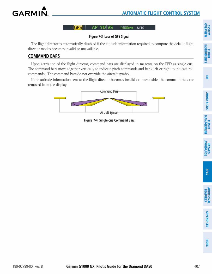
Garmin G1000 NXi Pilot’s Guide for the Diamond DA50190-02799-00 Rev. B 407
AUTOMATIC FLIGHT CONTROL SYSTEM
SYSTEMO
VERVIEWFLIG
HTIN
STRUMEN
TSEIS
AUDIO
& CN
SFLIG
HTM
AN
AGEM
ENT
HAZA
RDAVO
IDA
NCE
AFCS
AD
DITIO
NA
LFEATURES
APPEN
DICES
IND
EX
Figure 7-3 Loss of GPS Signal
The flight director is automatically disabled if the attitude information required to compute the default flight director modes becomes invalid or unavailable.
COMMAND BARSUpon activation of the flight director, command bars are displayed in magenta on the PFD as single cue.
The command bars move together vertically to indicate pitch commands and bank left or right to indicate roll commands. The command bars do not override the aircraft symbol.
If the attitude information sent to the flight director becomes invalid or unavailable, the command bars are removed from the display.
Figure 7-4 Single-cue Command Bars
Aircraft Symbol
Command Bars

Garmin G1000 NXi Pilot’s Guide for the Diamond DA50 190-02799-00 Rev. B408
AUTOMATIC FLIGHT CONTROL SYSTEM
SYST
EMO
VERV
IEW
FLIG
HTIN
STRU
MEN
TSEI
SAU
DIO
& C
NS
FLIG
HTM
AN
AGEM
ENT
HAZA
RDAV
OID
AN
CEA
FCS
AD
DIT
ION
AL
FEAT
URES
APP
END
ICES
IND
EX
7.4 AFCS MODESThe AFCS is capable of operating in a variety of independent Vertical Modes, Lateral Modes, and a Combination
of both the Lateral and Vertical Modes.
VERTICAL MODESThe following table lists the vertical modes with their corresponding controls and annunciations. The mode
reference is displayed next to the active mode annunciation for Altitude Hold, Vertical Speed, and Flight Level Change modes. The NOSE UP/NOSE DN Keys can be used to change the vertical mode reference while operating under Pitch Hold, Vertical Speed, or Flight Level Change Mode.
Vertical Mode Description Control Annunciation Reference Range
Reference Change
Increment
Pitch HoldHolds the current aircraft pitch attitude; may be used to climb/descend to the Selected Altitude
(Default) PIT -15° to +20° 0.5°
Selected Altitude Capture Captures the Selected Altitude 1 ALTSAltitude Hold Holds the current Altitude Reference ALT Key ALT xx,xxx fT
Vertical SpeedMaintains the current aircraft vertical speed; may be used to climb/descend to the Selected Altitude
VS Key VS x,xxx fpm-3,000 to
+1,500 fpm100 fpm
Flight Level ChangeMaintains the current aircraft airspeed while the aircraft is climbing/descending to the Selected Altitude
FLC Key FLC xxx kT85 to
185 kTS1 kT
1 ALTS is armed automatically when the Selected Altitude is to be captured instead of the VNAV Target Altitude.
Table 7-2 Flight Director Vertical Modes
PITCH HOLD MODE (PIT)
When the flight director is activated (e.g., the FD Key is pressed), Pitch Hold Mode is selected by default. Pitch Hold Mode is indicated as the active vertical mode by the ‘PIT’ annunciation. This mode may be used for climb or descent to the Selected Altitude (shown above the Altimeter), since Selected Altitude Capture Mode is automatically armed when Pitch Hold Mode is activated.
In Pitch Hold Mode, the flight director maintains a constant pitch attitude, the pitch reference. The pitch reference is set to the aircraft pitch attitude at the moment of mode selection. If the aircraft pitch attitude exceeds the flight director pitch command limitations, the flight director commands a pitch angle equal to the nose-up/down limit.
Changing the PitCh referenCe
When operating in Pitch Hold Mode, the pitch reference can be adjusted by: � Using the NOSE UP/NOSE DN Keys.
� Pressing the CWS Button, hand-flying the aircraft to establish a new pitch reference, then releasing the CWS Button.

Garmin G1000 NXi Pilot’s Guide for the Diamond DA50190-02799-00 Rev. B 409
AUTOMATIC FLIGHT CONTROL SYSTEM
SYSTEMO
VERVIEWFLIG
HTIN
STRUMEN
TSEIS
AUDIO
& CN
SFLIG
HTM
AN
AGEM
ENT
HAZA
RDAVO
IDA
NCE
AFCS
AD
DITIO
NA
LFEATURES
APPEN
DICES
IND
EX
Figure 7-5 Pitch Hold Mode
Pitch Hold Mode Active
Selected Altitude Capture Mode Armed
SelectedAltitude
Command Bars MaintainDesired Pitch Reference
SELECTED ALTITUDE CAPTURE MODE (ALTS)
Selected Altitude Capture Mode is automatically armed with activation of the following modes:
» Pitch Hold
» Vertical Speed
» Flight Level Change
» Takeoff/ Go Around
» Vertical Path Tracking (if the Selected Altitude is to be captured instead of the VNAV Target Altitude)
The white ‘ALTS’ annunciation indicates Selected Altitude Capture Mode is armed (see previous figure for example). The ALT Knob is used to set the Selected Altitude (shown above the Altimeter) until Selected Altitude Capture Mode becomes active.
As the aircraft nears the Selected Altitude, the flight director automatically transitions to Selected Altitude Capture Mode with Altitude Hold Mode armed (see following figure). This automatic transition is indicated by the green ‘ALTS’ annunciation flashing for up to 10 seconds and the appearance of the white ‘ALT’ annunciation. The Selected Altitude is shown as the Altitude Reference beside the ‘ALTS’ annunciation.
At 50 feet from the Selected Altitude, the flight director automatically transitions from Selected Altitude Capture Mode to Altitude Hold Mode and holds the Selected Altitude (shown as the Altitude Reference). As Altitude Hold Mode becomes active, the white ‘ALT’ annunciation moves to the active vertical mode field and flashes green for 10 seconds to indicate the automatic transition.
Flash up to 10 sec, Indicating Automatic Transition
Figure 7-6 Automatic Mode Transitions During Altitude Capture
Altitude Reference (in this case, equal to Selected Altitude)

Garmin G1000 NXi Pilot’s Guide for the Diamond DA50 190-02799-00 Rev. B410
AUTOMATIC FLIGHT CONTROL SYSTEM
SYST
EMO
VERV
IEW
FLIG
HTIN
STRU
MEN
TSEI
SAU
DIO
& C
NS
FLIG
HTM
AN
AGEM
ENT
HAZA
RDAV
OID
AN
CEA
FCS
AD
DIT
ION
AL
FEAT
URES
APP
END
ICES
IND
EX
Changing the seleCteD altituDe
NOTE: Pressing the CWS Button while in Selected Altitude Capture Mode does not cancel the mode.
Use of the ALT Knob to change the Selected Altitude while Selected Altitude Capture Mode is active causes the flight director to revert to Pitch Hold Mode with Selected Altitude Capture Mode armed for the new Selected Altitude.
ALTITUDE HOLD MODE (ALT)
Altitude Hold Mode can be activated by pressing the ALT Key; the flight director maintains the current aircraft altitude (to the nearest 10 feet) as the Altitude Reference. The flight director’s Altitude Reference, shown in the AFCS Status Box, is independent of the Selected Altitude, displayed above the Altimeter. Altitude Hold Mode active is indicated by a green ‘ALT’ annunciation in the AFCS Status Box.
Altitude Hold Mode is automatically armed when the flight director is in Selected Altitude Capture Mode. Selected Altitude Capture Mode automatically transitions to Altitude Hold Mode when the altitude error is less than 50 feet. In this case, the Selected Altitude becomes the flight director’s Altitude Reference.
Changing the altituDe referenCe
NOTE: Turning the ALT Knob while in Altitude Hold Mode changes the Selected Altitude, but not the flight director’s Altitude Reference, and does not cancel the mode.
With the CWS Button depressed, the aircraft can be hand-flown to a new Altitude Reference. When the CWS Button is released at the desired altitude, the new altitude is established as the Altitude Reference.
Figure 7-7 Altitude Hold Mode
Altitude Hold Mode Active
AltitudeReference
Selected Altitude
Bug
SelectedAltitude
Command Bars Hold Pitch Attitude to Maintain Altitude Reference

Garmin G1000 NXi Pilot’s Guide for the Diamond DA50190-02799-00 Rev. B 411
AUTOMATIC FLIGHT CONTROL SYSTEM
SYSTEMO
VERVIEWFLIG
HTIN
STRUMEN
TSEIS
AUDIO
& CN
SFLIG
HTM
AN
AGEM
ENT
HAZA
RDAVO
IDA
NCE
AFCS
AD
DITIO
NA
LFEATURES
APPEN
DICES
IND
EX
VERTICAL SPEED MODE (VS)
In Vertical Speed Mode, the flight director acquires and maintains a Vertical Speed Reference. Current aircraft vertical speed (to the nearest 100 fpm) becomes the Vertical Speed Reference at the moment of Vertical Speed Mode activation. This mode may be used for climb or descent to the Selected Altitude (shown above the Altimeter) since Selected Altitude Capture Mode is automatically armed when Vertical Speed Mode is selected.
When Vertical Speed Mode is activated by pressing the VS Key, ‘VS’ is annunciated in green in the AFCS Status Box along with the Vertical Speed Reference. The Vertical Speed Reference is also displayed above the Vertical Speed Indicator. A Vertical Speed Reference Bug corresponding to the Vertical Speed Reference is shown on the indicator.
Changing the VertiCal sPeeD referenCe
The Vertical Speed Reference (shown both in the AFCS Status Box and above the Vertical Speed Indicator) may be changed by:
� Using the NOSE UP/NOSE DN Keys.
� Pressing the CWS Button, hand-flying the aircraft to attain a new Vertical Speed Reference, then releasing the CWS Button.
NOTE: If the Selected Altitude is reached during CWS maneuvering, the Altitude Reference is not changed. To adjust the Altitude Reference in this case, the CWS Button must be pressed again after the Selected Altitude is reached.
Figure 7-8 Vertical Speed Mode
VerticalSpeed
ReferenceBug
VerticalSpeed Reference
SelectedAltitude
Command Bars Indicate Climb to Maintain Vertical Speed Reference
Vertical Speed
Reference
SelectedAltitude Capture
Mode Armed
Vertical Speed Mode
Active

Garmin G1000 NXi Pilot’s Guide for the Diamond DA50 190-02799-00 Rev. B412
AUTOMATIC FLIGHT CONTROL SYSTEM
SYST
EMO
VERV
IEW
FLIG
HTIN
STRU
MEN
TSEI
SAU
DIO
& C
NS
FLIG
HTM
AN
AGEM
ENT
HAZA
RDAV
OID
AN
CEA
FCS
AD
DIT
ION
AL
FEAT
URES
APP
END
ICES
IND
EX
FLIGHT LEVEL CHANGE MODE (FLC)
NOTE: The Selected Altitude should be set before selecting Flight Level Change Mode.
Flight Level Change Mode is selected by pressing the FLC Key. This mode acquires and maintains the Airspeed Reference while climbing or descending to the Selected Altitude (shown above the Altimeter). When Flight Level Change Mode is active, the flight director continuously monitors Selected Altitude, airspeed, and altitude. When Flight Level Change Mode is used in conjunction with VNAV (V FLC), VNAV Target Altitude Capture is also enabled.
The Airspeed Reference is set to the current airspeed upon mode activation. Flight Level Change Mode is indicated by a green ‘FLC’ annunciation beside the Airspeed Reference in the AFCS Status Box. The Airspeed Reference is also displayed directly above the Airspeed Indicator, along with a bug corresponding to the Airspeed Reference along the tape.
Engine power must be adjusted to allow the autopilot to fly the aircraft at a pitch attitude corresponding to the desired flight profile (climb or descent) while maintaining the Airspeed Reference. The flight director maintains the current altitude until either engine power or the Airspeed Reference are adjusted and does not allow the aircraft to climb or descend away from the Selected Altitude.
Changing the airsPeeD referenCe
The Airspeed Reference (shown in both the AFCS Status Box and above the Airspeed Indicator) may be adjusted by:
� Using the NOSE UP/NOSE DN Keys.
� Pressing the CWS Button, hand-flying the aircraft to attain a new Airspeed Reference, then releasing the CWS Button.
NOTE: If the Selected Altitude is reached during CWS maneuvering, the Airspeed Reference is not changed. To adjust the Airspeed Reference in this case, the CWS Button must be pressed again after the Selected Altitude is reached.
Figure 7-9 Flight Level Change Mode
Airspeed Reference
Bug
AirspeedReference
Command Bars Indicate Climbto Attain Selected Altitude
Airspeed Reference
SelectedAltitude Capture
Mode Armed
Flight LevelChange
Mode Active

Garmin G1000 NXi Pilot’s Guide for the Diamond DA50190-02799-00 Rev. B 413
AUTOMATIC FLIGHT CONTROL SYSTEM
SYSTEMO
VERVIEWFLIG
HTIN
STRUMEN
TSEIS
AUDIO
& CN
SFLIG
HTM
AN
AGEM
ENT
HAZA
RDAVO
IDA
NCE
AFCS
AD
DITIO
NA
LFEATURES
APPEN
DICES
IND
EX
LATERAL MODESThe following table relates each Garmin AFCS lateral mode to its respective control and annunciation. Refer
to the combination modes section for information regarding Takeoff and Go Around modes.
Lateral Mode Description Control Annunciation
Maximum Roll
Command Limit
Roll HoldHolds the current aircraft roll attitude or rolls the wings level, depending on the commanded bank angle
(Default) ROL 25°
Heading Select Captures and tracks the Selected Heading HDG Key HDG 25°Navigation Mode
GPS
Captures and tracks the selected navigation source (GPS, VOR, LOC) NAV Key
GPS 25°
VOR Enroute Arm/Capture/Track VOR 25° Capture 10° Track
LOC Capture/Track (No Glideslope) LOC 25° Capture 10° Track
Table 7-3 Flight Director Lateral Modes
The CWS Button does not change lateral references for Heading Select, Navigation, Backcourse, or Approach Mode. The autopilot guides the aircraft back to the Selected Heading/Course upon release of the CWS Button.
ROLL HOLD MODE (ROL)
NOTE: If Roll Hold Mode is activated as a result of a mode reversion, the flight director rolls the wings level.
When the flight director is activated or switched, Roll Hold Mode is selected by default. This mode is annunciated as ‘ROL’ in the AFCS Status Box. The current aircraft bank angle is held, subject to the bank angle condition.
Figure 7-10 Roll Hold Mode Annunciation
Bank Angle Flight Director Response< 6° Rolls wings level
6 to 25° Maintains current aircraft roll attitude> 25° Limits bank to 25°
Table 7-4 Roll Hold Mode Responses
Changing the roll referenCe
The roll reference can be changed by pressing the CWS Button, establishing the desired bank angle, then releasing the CWS Button.

Garmin G1000 NXi Pilot’s Guide for the Diamond DA50 190-02799-00 Rev. B414
AUTOMATIC FLIGHT CONTROL SYSTEM
SYST
EMO
VERV
IEW
FLIG
HTIN
STRU
MEN
TSEI
SAU
DIO
& C
NS
FLIG
HTM
AN
AGEM
ENT
HAZA
RDAV
OID
AN
CEA
FCS
AD
DIT
ION
AL
FEAT
URES
APP
END
ICES
IND
EX
HEADING SELECT MODE (HDG)
Heading Select Mode is activated by pressing the HDG Key. Heading Select Mode acquires and maintains the Selected Heading. The Selected Heading is shown by a cyan bug on the HSI and in the box to the upper left of the HSI.
Changing the seleCteD heaDing
NOTE: Pressing the HDG Knob synchronizes the Selected Heading to the current heading.
The Selected Heading is adjusted using the HDG Knob. Pressing the CWS Button and hand-flying the aircraft does not change the Selected Heading. The autopilot guides the aircraft back to the Selected Heading upon release of the CWS Button.
Turns are commanded in the same direction as Selected Heading Bug movement, even if the bug is turned more than 180° from the present heading (e.g., a 270° turn to the right). However, Selected Heading changes of more than 330° at a time result in turn reversals.
Figure 7-11 Heading Select Mode
Heading Select Mode Active
Command Bars TrackSelected HeadingCurrent
Heading SelectedHeading
Bug
NAVIGATION MODE
NOTE: The selected navigation receiver must have a valid VOR or LOC signal or active GPS course for the flight director to enter Navigation Mode.
Pressing the NAV Key selects Navigation Mode. Navigation Mode acquires and tracks the selected navigation source (GPS, VOR, LOC). The flight director follows GPS roll steering commands when GPS is the selected navigation source. When the navigation source is VOR or LOC, the flight director creates roll steering commands from the Selected Course and deviation. Navigation Mode can also be used to fly non-precision GPS and LOC approaches where vertical guidance is not required.

Garmin G1000 NXi Pilot’s Guide for the Diamond DA50190-02799-00 Rev. B 415
AUTOMATIC FLIGHT CONTROL SYSTEM
SYSTEMO
VERVIEWFLIG
HTIN
STRUMEN
TSEIS
AUDIO
& CN
SFLIG
HTM
AN
AGEM
ENT
HAZA
RDAVO
IDA
NCE
AFCS
AD
DITIO
NA
LFEATURES
APPEN
DICES
IND
EX
If the Course Deviation Indicator (CDI) shows greater than one dot when the NAV Key is pressed, the selected mode is armed. If the CDI shows less than one dot, Navigation Mode is automatically captured when the NAV Key is pressed. The armed annunciation appears in white to the left of the active lateral mode.
Figure 7-12 GPS Navigation Mode Active
When the CDI has automatically switched from GPS to LOC during a LOC/ILS approach, GPS Navigation Mode remains active, providing GPS steering guidance until the localizer signal is captured. LOC Navigation Mode is armed automatically when the navigation source switch takes place if the APR Key is not pressed prior to the automatic source switch.
If Navigation Mode is active and any of the following occur, the flight director reverts to Roll Hold Mode (wings rolled level):
» Different VOR tuned while in VOR Navigation Mode (VOR Navigation Mode reverts to armed)
» Navigation source manually switched (with the CDI Softkey)
» During a LOC/ILS approach, the FAF is crossed while in GPS Navigation Mode after the automatic navigation source switch from GPS to LOC
Changing the seleCteD Course
If the navigation source is VOR or localizer or OBS Mode has been enabled when using GPS, the Selected Course is controlled using the CRS Knob. Pressing the CWS Button and hand-flying the aircraft does not change the Selected Course while in Navigation Mode. The autopilot guides the aircraft back to the Selected Course (or GPS flight plan) when the CWS Button is released.
Figure 7-13 Navigation Mode
GPS Navigation Mode Active
GPS is Selected Navigation Source

Garmin G1000 NXi Pilot’s Guide for the Diamond DA50 190-02799-00 Rev. B416
AUTOMATIC FLIGHT CONTROL SYSTEM
SYST
EMO
VERV
IEW
FLIG
HTIN
STRU
MEN
TSEI
SAU
DIO
& C
NS
FLIG
HTM
AN
AGEM
ENT
HAZA
RDAV
OID
AN
CEA
FCS
AD
DIT
ION
AL
FEAT
URES
APP
END
ICES
IND
EX
COMBINATION MODESThe following table lists the modes that operating by using both Vertical and Lateral Modes with their
corresponding controls and annunciations.
Mode Description Control Annunciation
Maximum Roll
Command Limit
Reference Range
Vertical Navigation Modes
Vertical Path Tracking Captures and tracks descent legs of an active vertical profile VNV Key VPTH
VNV Target Altitude Capture Captures the Vertical Navigation (VNV) Target Altitude
1 ALTV
VOR Approach Mode
VOR Arm/Capture/Track Captures and tracks the VOR navigation source APR Key VAPP 25°
GPS Approach Mode
GPS Arm/Capture/Track Captures and tracks the GPS navigation source
APR KeyGPS 25°
Glidepath Captures and tracks the SBAS glidepath on approach GP
LOC Approach Mode
ILS Arm/Capture/Track Captures and tracks the LOC navigation source APR Key LOC 25°
Glideslope Captures and tracks the ILS glideslope on approach GS
Backcourse Arm/Capture/Track Captures and tracks a localizer signal for backcourse approaches N/A N/A 25°
Additional Modes
Takeoff Commands a constant pitch angle on the ground in preparation for takeoff GO-
AROUND Button
TO 6°
Go Around Commands a constant pitch angle and wings level in the air GA 6°
LevelAutopilot engages and commands pitch angle necessary to establish zero vertical fpm
2 LVL N/A
1 ALTV is armed automatically under VPTH when VNV Target Altitude is to be captured instead of Selected Altitude.2 Level mode can only become activated as a function of Electronic Stability and Protection (ESP). Refer to the Additional
Features Section for a detailed discussion of the optional ESP feature.
Table 7-5 Flight Director Combination Modes

Garmin G1000 NXi Pilot’s Guide for the Diamond DA50190-02799-00 Rev. B 417
AUTOMATIC FLIGHT CONTROL SYSTEM
SYSTEMO
VERVIEWFLIG
HTIN
STRUMEN
TSEIS
AUDIO
& CN
SFLIG
HTM
AN
AGEM
ENT
HAZA
RDAVO
IDA
NCE
AFCS
AD
DITIO
NA
LFEATURES
APPEN
DICES
IND
EX
VERTICAL NAVIGATION
NOTE: VNV is disabled when parallel track or Dead Reckoning Mode is active.
NOTE: The Selected Altitude takes precedence over any other vertical constraints.
Vertical Navigation (VNV) flight control is available for enroute/terminal cruise and descent operations any time that VNV flight planning is available. Refer to the Flight Management Section for more information on VNAV flight plans. Conditions for availability include, but are not limited to:
» The selected navigation source is GPS
» A VNV flight plan (with at least one altitude-constrained waypoint) or vertical direct-to is active
» VNV is enabled
» Crosstrack error is valid and within certain limits
» Desired/actual track are valid or track angle error is within certain limits
» The VNV Target Altitude of the active waypoint is no more than 250 ft above the current aircraft altitude
The command bars provide vertical profile guidance based on specified altitudes (entered manually or loaded from the database) at waypoints in the active flight plan or vertical direct-to. The appropriate VNV flight control modes are sequenced by the flight director to follow the path defined by the vertical profile. Upon reaching the last waypoint in the VNV flight plan, the flight director transitions to Altitude Hold Mode and cancels any armed VNV modes.
VertiCal Path traCking moDe (VPth)
NOTE: If another vertical mode key is pressed while Vertical Path Tracking Mode is selected, Vertical Path Tracking Mode reverts to armed.
NOTE: Pressing the CWS Button while Vertical Path Tracking Mode is active does not cancel the mode. The autopilot guides the aircraft back to the descent path upon release of the CWS Button.
When a vertical profile (VNV flight plan) is active and the VNV Key is pressed, Vertical Path Tracking Mode is armed in preparation for descent path capture. ‘VPTH’ (or ‘/V’ when Glidepath or Glideslope Mode is concurrently armed) is annunciated in white in addition to previously armed modes. If applicable, the appropriate altitude capture mode is armed for capture of the next VNV Target Altitude (ALTV) or the Selected Altitude (ALTS), whichever is greater.
Figure 7-14 Vertical Path Tracking Armed Annunciations
Prior to descent path interception, the Selected Altitude must be set below the current aircraft altitude by at least 75 feet. For the flight director to transition to Vertical Path Tracking Mode, the pilot must:
� Press the VNV Key, and
� Adjust the Selected Altitude to below the current altitude.

Garmin G1000 NXi Pilot’s Guide for the Diamond DA50 190-02799-00 Rev. B418
AUTOMATIC FLIGHT CONTROL SYSTEM
SYST
EMO
VERV
IEW
FLIG
HTIN
STRU
MEN
TSEI
SAU
DIO
& C
NS
FLIG
HTM
AN
AGEM
ENT
HAZA
RDAV
OID
AN
CEA
FCS
AD
DIT
ION
AL
FEAT
URES
APP
END
ICES
IND
EX
In conjunction with the “TOD [top of descent] within 1 minute” annunciation in the Navigation Status Box and the “Vertical track” voice message, VNV indications (VNV Target Altitude, vertical deviation, and vertical speed required) appear on the PFD in magenta.
Figure 7-15 Vertical Path Capture Mode
RequiredVerticalSpeed Bug
VerticalDeviation Indicator
VNV Target Altitude
SelectedAltitude
Enroute Phase
of Flight
GPS is Selected Navigation
Source
Altitude HoldMode Active
Vertical Path Tracking Mode Armed
When a descent leg is captured, Vertical Path Tracking becomes active and tracks the descent profile (see following figure). An altitude capture mode (‘ALTS’ or ‘ALTV’) is armed as appropriate.
Figure 7-16 Vertical Path Tracking Mode
VNV Target Altitude Capture Armed
Vertical Path Tracking Active
GPS is Selected Navigation
Source
EnroutePhase of
Flight
Command Bars Indicate Descent toMaintain Required Vertical Speed
VNV Target Altitude
RequiredVerticalSpeed Bug
Vertical Deviation Indicator

Garmin G1000 NXi Pilot’s Guide for the Diamond DA50190-02799-00 Rev. B 419
AUTOMATIC FLIGHT CONTROL SYSTEM
SYSTEMO
VERVIEWFLIG
HTIN
STRUMEN
TSEIS
AUDIO
& CN
SFLIG
HTM
AN
AGEM
ENT
HAZA
RDAVO
IDA
NCE
AFCS
AD
DITIO
NA
LFEATURES
APPEN
DICES
IND
EX
If the altimeter barometric setting is adjusted while Vertical Path Tracking is active, the flight director increases/decreases the descent rate by up to 500 fpm to re-establish the aircraft on the descent path (without commanding a climb). Adjusting the altimeter barometric setting creates discontinuities in VNV vertical deviation, moving the descent path. For large adjustments, it may take several minutes for the aircraft to re-establish on the descent path. If the change is made while nearing a waypoint with a VNV Target Altitude, the aircraft may not re-establish on the descent path in time to meet the vertical constraint.
Automatic Reversion to Pitch Hold Mode
Several situations can occur while Vertical Path Tracking Mode is active which cause the flight director to revert to Pitch Hold Mode including when:
4 Vertical deviation exceeds 200 feet during an overspeed condition.
4 Vertical deviation experiences a discontinuity that both exceeds 200 feet in magnitude and results in the vertical deviation exceeding 200 feet in magnitude. Such discontinuities are usually caused by flight plan changes that affect the vertical profile.
4 Vertical deviation becomes invalid (the Vertical Deviation Indicator is removed from the PFD).
4 A display enters Reversionary Mode (this does not apply to an active vertical direct-to).
Unless VNV is disabled, Vertical Path Tracking Mode and the appropriate altitude capture mode become armed following the reversion to Pitch Hold Mode to allow for possible profile recapture.
Non-Path Descents
Pitch Hold, Vertical Speed, and Flight Level Change modes can also be used to fly non-path descents while VNV flight control is selected. If the VS or FLC Key is pressed while Vertical Path Tracking Mode is selected, Vertical Path Tracking Mode reverts to armed along with the appropriate altitude capture mode to allow profile re-capture.
Figure 7-17 Flight Level Change VNV Non-Path Descent
To prevent immediate profile re-capture, the following must be satisfied:
4 At least 10 seconds have passed since the non-path transition was initiated
4 Vertical deviation from the profile has exceeded 250 feet, but is now less than 200 feet
Pressing the VNV Key twice re-arms Vertical Path Tracking for immediate profile re-capture.
VnV target altituDe CaPture moDe (altV)
NOTE: Armed VNV Target Altitude and Selected Altitude capture modes are mutually exclusive. However, Selected Altitude Capture Mode is armed implicitly (not annunciated) whenever VNV Target Altitude Capture Mode is armed.
VNV Target Altitude Capture is analogous to Selected Altitude Capture Mode and is armed automatically after the VNV Key is pressed and the next VNV Target Altitude is to be intercepted before the Selected Altitude. The annunciation ‘ALTV’ indicates that VNV Target Altitude is to be captured. VNV Target Altitudes are shown in the active flight plan or vertical direct-to, and can be entered manually or loaded from a database (see the GPS Navigation Section for details). At the same time as “TOD within 1 minute” is annunciated in the Navigation Status Box, the active VNV Target Altitude is displayed above the Vertical Speed Indicator.

Garmin G1000 NXi Pilot’s Guide for the Diamond DA50 190-02799-00 Rev. B420
AUTOMATIC FLIGHT CONTROL SYSTEM
SYST
EMO
VERV
IEW
FLIG
HTIN
STRU
MEN
TSEI
SAU
DIO
& C
NS
FLIG
HTM
AN
AGEM
ENT
HAZA
RDAV
OID
AN
CEA
FCS
AD
DIT
ION
AL
FEAT
URES
APP
END
ICES
IND
EX
As the aircraft nears the VNV Target Altitude, the flight director automatically transitions to VNV Target Altitude Capture Mode with Altitude Hold Mode armed. This automatic transition is indicated by the green ‘ALTV’ annunciation flashing for up to 10 seconds and the appearance of the white ‘ALT’ annunciation. The VNV Target Altitude is shown as the Altitude Reference beside the ‘ALTV’ annunciation and remains displayed above the Vertical Speed Indicator. The Required Vertical Speed Indication (RVSI) is removed once VNV Target Altitude Capture Mode becomes active.
At 50 feet from the VNV Target Altitude, the flight director automatically transitions from VNV Target Altitude Capture to Altitude Hold Mode and tracks the level leg. As Altitude Hold Mode becomes active, the white ‘ALT’ annunciation moves to the active vertical mode field and flashes green for 10 seconds to indicate the automatic transition. The flight director automatically arms Vertical Path Tracking, allowing upcoming descent legs to be captured and subsequently tracked.
Figure 7-18 Automatic Mode Transitions During Altitude Capture
Flash up to 10 sec, Indicating Automatic Transition
Altitude Reference (In This Case, Equal To VNV Altitude Target)
Changing the VNV Target Altitude
NOTE: Pressing the CWS Button while in VNV Target Altitude Capture Mode does not cancel the mode.
Changing the current VNV Target Altitude while VNV Target Altitude Capture Mode is active causes the flight director to revert to Pitch Hold Mode. Vertical Path Tracking and the appropriate altitude capture mode are armed in preparation to capture the new VNV Target Altitude or the Selected Altitude, depending on which altitude is to be intercepted first.
VNV target altitudes can be changed while editing the active flight plan (see the Flight Management Section for details).
APPROACH MODES
NOTE: The selected navigation receiver must have a valid VOR or LOC signal or active GPS course for the flight director to enter Approach Mode.
Approach Mode is activated when the APR Key is pressed. Approach Mode acquires and tracks the selected navigation source (GPS, VOR, or LOC), depending on loaded approach. This mode uses the selected navigation receiver deviation and desired course inputs to fly the approach. Pressing the APR Key when the CDI is greater than one dot arms the selected approach mode (annunciated in white to the left of the active lateral mode). If the CDI is less the 1 dot, the LOC is automatically captured when the APR Key is pressed.
Vor aPProaCh moDe
VOR Approach Mode (VAPP) provides greater sensitivity for signal tracking than VOR Navigation Mode.

Garmin G1000 NXi Pilot’s Guide for the Diamond DA50190-02799-00 Rev. B 421
AUTOMATIC FLIGHT CONTROL SYSTEM
SYSTEMO
VERVIEWFLIG
HTIN
STRUMEN
TSEIS
AUDIO
& CN
SFLIG
HTM
AN
AGEM
ENT
HAZA
RDAVO
IDA
NCE
AFCS
AD
DITIO
NA
LFEATURES
APPEN
DICES
IND
EX
Selecting VOR Approach Mode:
1) Ensure a valid VOR frequency is tuned.
2) Ensure that VOR is the selected navigation source (use the CDI Softkey to cycle through navigation sources if necessary).
3) Press the APR Key.
Figure 7-19 VOR Approach Mode
gPs aPProaCh moDe
When GPS Approach Mode is armed, Glidepath Mode is also armed. GPS Approach Mode can be utilized to fly non-precision and precision approaches.
Selecting GPS Approach without a glidepath:
1) Ensure a GPS approach is loaded into the active flight plan. The active waypoint must be part of the flight plan (cannot be a direct-to a waypoint not in the flight plan).
2) Ensure that GPS is the selected navigation source (use the CDI Softkey to cycle through navigation sources if necessary).
3) Press the NAV Softkey.
Figure 7-20 GPS Approach Mode (No Glideslope)
Glidepath Mode (GP)
Glidepath Mode is used to track the SBAS-based glidepath. When Glidepath Mode is armed, ‘GP’ is annunciated in white in the AFCS Status Box.
Selecting Glidepath Mode:
1) Ensure a GPS approach is loaded into the active flight plan. The active waypoint must be part of the flight plan (cannot be a direct-to a waypoint not in the flight plan).
2) Ensure that GPS is the selected navigation source (use the CDI Softkey to cycle through navigation sources if necessary).
3) Press the APR Key.
NOTE: Some RNAV (GPS) approaches provide a vertical descent angle as an aid in flying a stabilized approach. These approaches are NOT considered Approaches with Vertical Guidance (APV). Approaches that are annunciated on the HSI as LNAV or LNAV+V should be flown to an MDA, until visual with the landing surface, even though vertical glidepath (GP) information may be provided.
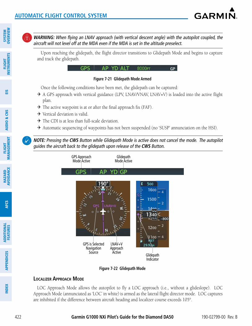
Garmin G1000 NXi Pilot’s Guide for the Diamond DA50 190-02799-00 Rev. B422
AUTOMATIC FLIGHT CONTROL SYSTEM
SYST
EMO
VERV
IEW
FLIG
HTIN
STRU
MEN
TSEI
SAU
DIO
& C
NS
FLIG
HTM
AN
AGEM
ENT
HAZA
RDAV
OID
AN
CEA
FCS
AD
DIT
ION
AL
FEAT
URES
APP
END
ICES
IND
EX
WARNING: When flying an LNAV approach (with vertical descent angle) with the autopilot coupled, the aircraft will not level off at the MDA even if the MDA is set in the altitude preselect.
Upon reaching the glidepath, the flight director transitions to Glidepath Mode and begins to capture and track the glidepath.
Figure 7-21 Glidepath Mode Armed
Once the following conditions have been met, the glidepath can be captured:
4 A GPS approach with vertical guidance (LPV, LNAV/VNAV, LNAV+V) is loaded into the active flight plan.
4 The active waypoint is at or after the final approach fix (FAF).
4 Vertical deviation is valid.
4 The CDI is at less than full-scale deviation.
4 Automatic sequencing of waypoints has not been suspended (no ‘SUSP’ annunciation on the HSI).
NOTE: Pressing the CWS Button while Glidepath Mode is active does not cancel the mode. The autopilot guides the aircraft back to the glidepath upon release of the CWS Button.
Figure 7-22 Glidepath Mode
Glidepath Mode Active
GPS Approach Mode Active
GPS is Selected Navigation
Source
LNAV+V Approach
ActiveGlidepathIndicator
loCalizer aPProaCh moDe
LOC Approach Mode allows the autopilot to fly a LOC approach (i.e., without a glideslope). LOC Approach Mode (annunciated as ‘LOC’ in white) is armed as the lateral flight director mode. LOC captures are inhibited if the difference between aircraft heading and localizer course exceeds 105°.

Garmin G1000 NXi Pilot’s Guide for the Diamond DA50190-02799-00 Rev. B 423
AUTOMATIC FLIGHT CONTROL SYSTEM
SYSTEMO
VERVIEWFLIG
HTIN
STRUMEN
TSEIS
AUDIO
& CN
SFLIG
HTM
AN
AGEM
ENT
HAZA
RDAVO
IDA
NCE
AFCS
AD
DITIO
NA
LFEATURES
APPEN
DICES
IND
EX
Selecting LOC Approach Mode without a glidepath:
1) Ensure a valid localizer frequency is tuned.
2) Ensure that LOC is the selected navigation source (use the CDI Softkey to cycle through navigation sources if necessary).
3) Press the NAV Key.
Glideslope Mode (GS)
Glideslope Mode is available for LOC/ILS approaches to capture and track the glideslope. When Glideslope Mode is armed (annunciated as ‘GS’ in white), LOC Approach Mode is armed as the lateral flight director mode.
Selecting Glideslope Mode:
1) Ensure a valid localizer frequency is tuned.
2) Ensure that LOC is the selected navigation source (use the CDI Softkey to cycle through navigation sources if necessary).
3) Press the APR Key.
Figure 7-23 Glideslope Mode Armed
Once LOC is the navigation source, the localizer and glideslope can be captured. Upon reaching the glideslope, the flight director transitions to Glideslope Mode and begins to capture and track the glideslope.
NOTE: Pressing the CWS Button while Glideslope Mode is active does not cancel the mode. The autopilot guides the aircraft back to the glideslope upon release of the CWS Button.
Figure 7-24 Glideslope Mode
Glideslope Mode Active
Localizer Approach
Mode Active
Active ILS Frequency Tuned
GlideslopeIndicator
LOC1 (Localizer) is Selected Navigation Source

Garmin G1000 NXi Pilot’s Guide for the Diamond DA50 190-02799-00 Rev. B424
AUTOMATIC FLIGHT CONTROL SYSTEM
SYST
EMO
VERV
IEW
FLIG
HTIN
STRU
MEN
TSEI
SAU
DIO
& C
NS
FLIG
HTM
AN
AGEM
ENT
HAZA
RDAV
OID
AN
CEA
FCS
AD
DIT
ION
AL
FEAT
URES
APP
END
ICES
IND
EX
If the following occurs, the flight director reverts to Roll Hold Mode (wings rolled level):
4 Approach Mode is active and a Vectors-To-Final is activated
4 Approach Mode is active and Navigation source is manually switched
4 During a LOC/ILS approach, GPS Navigation Mode is active and the FAF is crossed after the automatic navigation source switch from GPS to LOC
Changing the Selected Course
If the navigation source localizer or OBS Mode has been enabled when using GPS, the Selected Course is controlled using the CRS Knob.
Pressing the CWS Button and hand-flying the aircraft does not change the Selected Course while in Approach Mode. The autopilot guides the aircraft back to the Selected Course (or GPS flight plan) when the CWS Button is released.
Backcourse Mode (BC)
NOTE: When making a backcourse approach, set the Selected Course to the localizer front course.
Backcourse Mode captures and tracks a localizer signal in the backcourse direction. Backcourse Mode is armed if the CDI is greater than one dot when the mode is selected. The flight director creates roll steering commands from the Selected Course and deviation when in Backcourse Mode.
Changing the Selected Course
If the navigation source is localizer or OBS Mode has been enabled when using GPS, the Selected Course is controlled using the CRS Knob.
Pressing the CWS Button and hand-flying the aircraft does not reset any reference data while in Backcourse Mode. The autopilot guides the aircraft back to the Selected Course when the CWS Button is released.
interCePting anD flying a Dme arC
The AFCS will intercept and track a DME arc that is part of the active flight plan provided that GPS Navigation Mode is engaged, GPS is the active navigation source on the CDI, and the DME arc segment is the active flight plan leg. It is important to note that automatic navigation of DME arcs is based on GPS. Thus, even if the APR Key is pressed and LOC or VOR Approach Mode is armed prior to reaching the Initial Approach Fix (IAF), Approach Mode will not activate until the arc segment is completed.
If the pilot decides to intercept the arc at a location other than the published IAF (i.e., ATC provides vectors to intercept the arc) and subsequently selects Heading Mode or Roll Mode, the AFCS will not automatically intercept or track the arc unless the pilot activates the arc leg of the flight plan and arms GPS Navigation Mode. The AFCS will not intercept and fly a DME arc before reaching an IAF that defines the beginning of the arc segment. Likewise, if at any point while established on the DME arc the pilot deselects GPS Navigation Mode, the AFCS will no longer track the arc.
TAKEOFF AND GO AROUND MODES
Takeoff and Go Around Modes are coupled pitch and roll modes and are annunciated as both the vertical and lateral modes when active. In these modes, the flight director commands a constant set pitch attitude and wings level. The GO AROUND Button is used to select both modes. The mode entered by the flight director depends on whether the aircraft is on the ground.

Garmin G1000 NXi Pilot’s Guide for the Diamond DA50190-02799-00 Rev. B 425
AUTOMATIC FLIGHT CONTROL SYSTEM
SYSTEMO
VERVIEWFLIG
HTIN
STRUMEN
TSEIS
AUDIO
& CN
SFLIG
HTM
AN
AGEM
ENT
HAZA
RDAVO
IDA
NCE
AFCS
AD
DITIO
NA
LFEATURES
APPEN
DICES
IND
EX
takeoff moDe (to)
Takeoff Mode provides an attitude reference during rotation and takeoff. This mode can be selected only while on the ground by pushing the GO AROUND Button. The flight director command bars assume a wings-level, pitch-up attitude.
Command Bars Indicate Climb
Takeoff Mode Active
Figure 7-25 Takeoff Mode
go arounD moDe (ga)
Pressing the GO AROUND Button while in the air activates the flight director in wings level, pitch-up attitudes, allowing the execution of a missed approach or a go around.
Figure 7-26 Go Around Mode
Go Around Mode Active
LEVEL MODE (LVL)
Level Mode is a coupled pitch and roll mode and is annunciated as both the vertical and lateral modes when active. Pressing the LVL Button engages the autopilot and yaw damper in level vertical and lateral modes.
While Level Mode does not track altitude or heading, it will adjust the pitch angle to maintain zero vertical speed. When the LVL Button is pressed, all armed and active modes are cancelled and the autopilot and flight director revert to LVL Mode for pitch and roll. While in Level Mode, all other AFCS modes are available by pressing the corresponding AFCS key.
Figure 7-27 Level Mode

Garmin G1000 NXi Pilot’s Guide for the Diamond DA50 190-02799-00 Rev. B426
AUTOMATIC FLIGHT CONTROL SYSTEM
SYST
EMO
VERV
IEW
FLIG
HTIN
STRU
MEN
TSEI
SAU
DIO
& C
NS
FLIG
HTM
AN
AGEM
ENT
HAZA
RDAV
OID
AN
CEA
FCS
AD
DIT
ION
AL
FEAT
URES
APP
END
ICES
IND
EX
7.5 AUTOPILOT AND YAW DAMPER OPERATION
NOTE: Refer to the current version of the pertinent flight manual for specific instructions regarding emergency procedures.
The autopilot and yaw damper operate flight control surface servos to provide automatic flight control. The autopilot controls the aircraft pitch and roll attitudes following commands received from the flight director. Manual Electric pitch trim and rudder trim provide commands to the applicable trim servo to relieve any sustained effort required by the pitch or rudder servo. The yaw damper reduces Dutch roll tendencies and coordinates turns.
FLIGHT CONTROLPitch and roll commands are provided to the servos, based on the active flight director modes. Servo motor
control limits the maximum servo speed and torque. The servo mounts are equipped with slip-clutches set to certain values. This allows the servos to be overridden in case of an emergency.
PITCH AXIS AND PITCH TRIM
The autopilot pitch axis uses pitch rate to stabilize the aircraft pitch attitude during upsets and flight director maneuvers. Flight director pitch commands are rate and attitude-limited, combined with pitch damper control, and sent to the pitch servo motor. The pitch servo measures the output effort (torque) and provides this signal to the pitch trim servo. The pitch trim servo commands the motor to reduce the average pitch servo effort.
When the autopilot is not engaged, the pitch trim servo may be used to provide manual electric trim. This allows the aircraft to be trimmed using a control stick switch rather than the trim wheel. Manual trim commands are generated only when both halves of the AP TRIM Switch are operated simultaneously. Trim speeds are scheduled with airspeed to provide more consistent response.
ROLL AXIS
The autopilot roll axis uses roll rate to stabilize aircraft roll attitude during upsets and flight director maneuvers. The flight director roll commands are rate- and attitude-limited, combined with roll damper control, and sent to the roll servo motor.
YAW AXIS AND RUDDER TRIM
The yaw damper uses yaw rate and roll attitude to dampen the aircraft’s natural Dutch roll response. It also uses lateral acceleration to coordinate turns. Yaw damper operation is independent of autopilot engagement.
When the autopilot is not engaged, the yaw trim servo may be used to provide manual electric rudder trim. This allows the aircraft to be trimmed using the MET Switch which is located on the throttle.
ENGAGING THE AUTOPILOT AND YAW DAMPER
NOTE: Autopilot engagement/disengagement is not equivalent to servo engagement/disengagement. Use the CWS Button to disengage the pitch and roll servos while the autopilot remains active.
When the AP Key is pressed, the autopilot, yaw damper, and flight director (if not already active) are activated. The flight director engages in Pitch and Roll Hold Modes when initially activated.

Garmin G1000 NXi Pilot’s Guide for the Diamond DA50190-02799-00 Rev. B 427
AUTOMATIC FLIGHT CONTROL SYSTEM
SYSTEMO
VERVIEWFLIG
HTIN
STRUMEN
TSEIS
AUDIO
& CN
SFLIG
HTM
AN
AGEM
ENT
HAZA
RDAVO
IDA
NCE
AFCS
AD
DITIO
NA
LFEATURES
APPEN
DICES
IND
EX
Figure 7-28 Autopilot and Yaw Damper Engaged
Autopilot Engaged
Yaw Damper Engaged
When the YD Key is pressed, the system engages the yaw damper independently of the autopilot and the yaw damper annunciator light is illuminated.
Autopilot and yaw damper status are displayed in the center of the AFCS Status Box. Engagement is indicated by green ‘AP’ and ‘YD’ annunciations, respectively.
CONTROL WHEEL STEERING (CWS)During autopilot operation, the aircraft may be hand-flown without disengaging the autopilot. Pressing and
holding the CWS Button disengages the pitch and roll servos from the flight control surfaces and allows the aircraft to be hand-flown. At the same time, the flight director is synchronized to the aircraft attitude during the maneuver. CWS activity has no effect on yaw damper engagement.
The ‘AP’ annunciation is temporarily replaced by ‘CWS’ in white for the duration of CWS maneuvers.
Figure 7-29 CWS Annunciation
Control Wheel Steering
In most scenarios, releasing the CWS Button reengages the autopilot with a new reference. Refer to flight director mode descriptions for specific CWS behavior in each mode.
DISENGAGING THE AUTOPILOT AND YAW DAMPER
MANUAL DISENGAGEMENT
The autopilot is manually disengaged by pushing the AP DISC Switch, AP TRIM Switch, or the AP Key on the MFD. Manual disengagement is indicated by a five-second flashing amber ‘AP’ annunciation and a two-second autopilot disconnect aural alert. After manual disengagement, the autopilot disconnect aural alert may be cancelled by pushing the AP TRIM Switch or the AP DISC Switch (the AP DISC Switch also cancels the flashing ‘AP’ annunciation).
Figure 7-30 Manual Autopilot Disengagement
The YD Key or AP DISC Switch can be used to disengage the yaw damper. The ‘YD’ annunciation turns amber and flashes for five seconds upon disengagement.
Figure 7-31 Manual Yaw Damper Disengagement

Garmin G1000 NXi Pilot’s Guide for the Diamond DA50 190-02799-00 Rev. B428
AUTOMATIC FLIGHT CONTROL SYSTEM
SYST
EMO
VERV
IEW
FLIG
HTIN
STRU
MEN
TSEI
SAU
DIO
& C
NS
FLIG
HTM
AN
AGEM
ENT
HAZA
RDAV
OID
AN
CEA
FCS
AD
DIT
ION
AL
FEAT
URES
APP
END
ICES
IND
EX
AUTOMATIC DISENGAGEMENT
Automatic autopilot disengagement is indicated by a flashing red and white ‘AP’ annunciation and by the autopilot disconnect aural alert, which continue until acknowledged by pushing the AP DISC Switch or AP TRIM Switch. Automatic autopilot disengagement occurs due to:
» System failure.
» Invalid sensor data.
» Stall warning.
» Inability to compute default flight director modes (FD also disengages automatically).
Yaw damper disengagement is indicated by a five-second flashing amber ‘YD’ annunciation. Automatic yaw damper disengagement occurs when autopilot disengagement is caused by failure in a parameter also affecting the yaw damper. This means the yaw damper can remain operational in some cases where the autopilot automatically disengages. A localized failure in the yaw damper system or invalid sensor data also cause yaw damper disengagement.
Figure 7-32 Automatic Autopilot and Yaw Damper Disengagement

Garmin G1000 NXi Pilot’s Guide for the Diamond DA50190-02799-00 Rev. B 429
AUTOMATIC FLIGHT CONTROL SYSTEM
SYSTEMO
VERVIEWFLIG
HTIN
STRUMEN
TSEIS
AUDIO
& CN
SFLIG
HTM
AN
AGEM
ENT
HAZA
RDAVO
IDA
NCE
AFCS
AD
DITIO
NA
LFEATURES
APPEN
DICES
IND
EX
7.6 AFCS ANNUNCIATIONS AND ALERTS
AFCS STATUS ANNUNCIATIONSThe annunciations in the following table (listed in order of increasing priority) can appear on the PFD above
the Airspeed and Attitude indicators. Only one annunciation may occur at a time.
Alert Condition Annunciation Description
Rudder Mistrim Right RUDñYaw servo providing sustained force in the indicated direction
Rudder Mistrim Left œRUD
Aileron Mistrim Right AILñRoll servo providing sustained force in the indicated direction
Aileron Mistrim Left œAIL
Elevator Mistrim Down ¤ELE Pitch servo providing sustained force in the indicated direction - May indicate a failure of the pitch trim servo or trim systemElevator Mistrim Up £ELE
Pitch Trim Failure
(or stuck AP TRIM Switch)PTRM
If AP engaged, take control of the aircraft and disengage AP or if the AP is disengaged, move the AP TRIM switches separately to unstick
Yaw Damper Failure YAW YD control failure
Roll Failure ROLL Roll axis control failure; AP inoperative
Pitch Failure PTCH Pitch axis control failure; AP inoperative
System Failure AFCS AP and MET are unavailable; FD may still be available
Preflight TestPFT
Performing preflight system test; aural alert sounds at completion - Do not press the AP DISC Switch during servo power initialization and
preflight system tests as this may cause the preflight system test to fail or never to start (if servos fail their power initialization tests). Power must be cycled to the servos to remedy the situation.
PFT Preflight system test failed; aural alert sounds at failure
Table 7-6 AFCS Status Alerts
AFCS VOICE ALERTSThe voice alerts listed in the following table relate to AFCS; for a complete list of voice alerts, see Appendix A.
Voice Alert Description
“Autopilot”Warning – Autopilot is disengaged - Single alert for manual AP disengagement - Continuous alert for automatic AP disengagement; cancelled with AP DISC Switch
“Flight Director” Single warning – Flight director has reverted to a default mode“Trim, Trim, Trim” Continuous advisory (stops after 6 seconds) – AP TRIM Switch malfunction
Table 7-7 AFCS Voice Alerts

Garmin G1000 NXi Pilot’s Guide for the Diamond DA50 190-02799-00 Rev. B430
AUTOMATIC FLIGHT CONTROL SYSTEM
SYST
EMO
VERV
IEW
FLIG
HTIN
STRU
MEN
TSEI
SAU
DIO
& C
NS
FLIG
HTM
AN
AGEM
ENT
HAZA
RDAV
OID
AN
CEA
FCS
AD
DIT
ION
AL
FEAT
URES
APP
END
ICES
IND
EX
AUTOPILOT OVERSPEED PROTECTION
NOTE: Overspeed protection is not active in ALT, GS, or GP modes.
While Pitch Hold, Vertical Speed, Flight Level Change, Vertical Path Tracking, or an altitude capture mode is active, airspeed is monitored by the flight director. Overspeed protection is provided to limit the flight director’s pitch command in situations where the flight director cannot acquire and maintain the mode reference for the selected vertical mode without exceeding Vne.
When Overspeed Protection is active, the Airspeed Reference appears in a box above the Airspeed Indicator, flashing a amber ‘MAXSPD’ annunciation. Engine power should be reduced and/or the pitch reference adjusted to slow the aircraft. The annunciation disappears when the overspeed condition is resolved.
Figure 7-33 Maximum Speed Annunciation
AUTOPILOT UNDERSPEED PROTECTIONUnderspeed Protection is available when the Electronic Stability and Protection (ESP) system is installed and
the autopilot is on. It is designed to discourage aircraft operation below minimum established airspeeds.
When the aircraft reaches a predetermined airspeed (specific to each flap setting), a amber MINSPD annunciation will appear above the airspeed indicator.

Garmin G1000 NXi Pilot’s Guide for the Diamond DA50190-02799-00 Rev. B 431
AUTOMATIC FLIGHT CONTROL SYSTEM
SYSTEMO
VERVIEWFLIG
HTIN
STRUMEN
TSEIS
AUDIO
& CN
SFLIG
HTM
AN
AGEM
ENT
HAZA
RDAVO
IDA
NCE
AFCS
AD
DITIO
NA
LFEATURES
APPEN
DICES
IND
EX
Figure 7-34 Minimum Speed Annunciation
If the aircraft continues to decelerate, Underspeed Protection functionality depends on which vertical flight director mode is selected. For the purpose of this discussion, the vertical flight director modes can be divided into two categories: Those in which it is important to maintain altitude for as long as possible (altitude-critical modes), and those in which maintaining altitude is less crucial (non-altitude critical modes).
ALTITUDE-CRITICAL MODES (ALT, GS, GP, TO, GA, FLC)
If the aircraft decelerates to stall warning, the lateral and vertical flight director modes will change from active to armed, and the autopilot will provide input causing the aircraft to pitch down and the wings to level.
Lateral and Vertical FD
Modes Armed
Figure 7-35 Lateral and Vertical Flight Director Modes Armed
An aural “AIRSPEED” alert will sound every five seconds and a red “UNDERSPEED PROTECT ACTIVE” annunciation (see following figure) will appear to the right of the vertical speed indicator. The pitch down force will continue until the aircraft reaches a pitch attitude at which IAS equals the IAS at which stall warning turns off, plus two knots.

Garmin G1000 NXi Pilot’s Guide for the Diamond DA50 190-02799-00 Rev. B432
AUTOMATIC FLIGHT CONTROL SYSTEM
SYST
EMO
VERV
IEW
FLIG
HTIN
STRU
MEN
TSEI
SAU
DIO
& C
NS
FLIG
HTM
AN
AGEM
ENT
HAZA
RDAV
OID
AN
CEA
FCS
AD
DIT
ION
AL
FEAT
URES
APP
END
ICES
IND
EX
Figure 7-36 ‘Underspeed Protect Active’ Annunciation
When airspeed increases (as a result of adding power/thrust) to above the IAS at which stall warning turns off, plus two knots, the autopilot will cause the aircraft to pitch up until recapturing the vertical reference. The vertical and lateral flight director modes will change from armed to active, and when aircraft angle of attack reaches approximately five degrees below stall warning angle of attack, the Pitch Limit Indicator will be removed.
NON-ALTITUDE CRITICAL MODES (VS, VNAV, IAS)
When the airspeed trend vector (specific to each flap setting) reaches a predetermined airspeed, a single aural “AIRSPEED” will sound, alerting the pilot to the impending underspeed condition. If the aircraft decelerates to an IAS below the minimum commandable autopilot airspeed, a red “UNDERSPEED PROTECT ACTIVE” annunciation (see previous figure) will appear to the right of the vertical speed indicator. The vertical flight director mode will change from active to armed (see following figure), and the autopilot will cause the aircraft to pitch down until reaching a pitch attitude at which IAS equals the minimum commandable autopilot airspeed.
Vertical FD Mode Armed
Figure 7-37 Vertical Flight Director Mode Armed
When airspeed increases (as a result of adding power/thrust) to an IAS above the minimum commandable autopilot airspeed, the autopilot will cause the aircraft to pitch up until recapturing the vertical reference. The vertical flight director mode will change from armed to active, and when aircraft angle of attack reaches approximately five degrees below stall warning angle of attack, the Pitch Limit Indicator will be removed.

Garmin G1000 NXi Pilot’s Guide for the Diamond DA50190-02799-00 Rev. B 433
AUTOMATIC FLIGHT CONTROL SYSTEM
SYSTEMO
VERVIEWFLIG
HTIN
STRUMEN
TSEIS
AUDIO
& CN
SFLIG
HTM
AN
AGEM
ENT
HAZA
RDAVO
IDA
NCE
AFCS
AD
DITIO
NA
LFEATURES
APPEN
DICES
IND
EX
7.7 ABNORMAL OPERATION
SUSPECTED AUTOPILOT MALFUNCTION
NOTE: Consult the aircraft documentation for the location of circuit breakers as well as specifics that may supplement or amplify this procedure.
Mitigating suspected autopilot failure or trim failure:
1) Firmly grasp the control stick.
2) Press and hold the AP DISC Switch. The autopilot will disconnect and power is removed from the trim motor. Power is also removed from all primary servo motors and engaged solenoids. Note the visual and aural alerting indicating autopilot disconnect.
3) Retrim the aircraft as needed. Substantial trim adjustment may be needed.
4) Pull the appropriate circuit breaker(s) to electrically isolate the servo and solenoid components.
5) Release the AP DISC Switch.
OVERPOWERING AUTOPILOT SERVOSIn the context of this discussion, “overpowering” refers to any pressure or force applied to the pitch controls
when the autopilot is engaged. A small amount of pressure or force on the pitch controls can cause the autopilot automatic trim to run to an out-of-trim condition. Therefore, any application of pressure or force to the controls should be avoided when the autopilot is engaged.
Overpowering the autopilot during flight will cause the autopilot’s automatic trim to run, resulting in an out-of-trim condition or cause the trim to hit the stop if the action is prolonged. In this case, larger than anticipated control forces are required after the autopilot is disengaged. The following procedure should be added to the preflight checks.
Checking autopilot servos during the preflight check:
1) Check for proper autopilot operation and ensure the autopilot can be overpowered.
2) Note the forces required to overpower the autopilot servo clutches.

Garmin G1000 NXi Pilot’s Guide for the Diamond DA50 190-02799-00 Rev. B434
AUTOMATIC FLIGHT CONTROL SYSTEM
SYST
EMO
VERV
IEW
FLIG
HTIN
STRU
MEN
TSEI
SAU
DIO
& C
NS
FLIG
HTM
AN
AGEM
ENT
HAZA
RDAV
OID
AN
CEA
FCS
AD
DIT
ION
AL
FEAT
URES
APP
END
ICES
IND
EX
Blank Page

Garmin G1000 NXi Pilot’s Guide for the Diamond DA50190-02799-00 Rev. B
SYSTEMO
VERVIEWFLIG
HTIN
STRUMEN
TSEIS
AUDIO
& CN
SFLIG
HTM
AN
AGEM
ENT
HAZA
RDAVO
IDA
NCE
AFCS
AD
DITIO
NA
LFEATURES
APPEN
DICES
IND
EX
435
ADDITIONAL FEATURES
SECTION 8 ADDITIONAL FEATURES
8.1 OVERVIEW
NOTE: With the availability of SafeTaxi®, ChartView, or FliteCharts®, it may be necessary to carry another source of charts on-board the aircraft.
Additional features of the Integrated Avionics System include the following:
• SafeTaxi®
• SurfaceWatch™ (Optional)
• Electronic Charts:
- FliteCharts®
- ChartView
- IFR/VFR Charts
• Satellite Telephone and Datalink Services (Optional)
• Connext® (Optional)
• SiriusXM Satellite Radio (Optional)
• Flight Data Logging
• Maintenance Logs
• Electronic Checklists
• Electronic Stability & Protection (Optional)
• Database Management
The SafeTaxi diagrams provide detailed taxiway, runway, and ramp information at more than 700 airports in the United States. By decreasing range on an airport that has a SafeTaxi diagram available, a close up view of the airport layout can be seen.
The optional SurfaceWatch feature provides voice and visual annunciations to aid in maintaining situational awareness and avoid potential runway incursions during ground and air operations in the airport environment.
Electronic charts offer the convenience of rapid access to essential flight chart information. FliteCharts provide AeroNav Services on-board electronic terminal procedures charts. ChartView provides Jeppesen on-board electronic terminal procedures charts.
The optional Iridium Transceiver provides an airborne low speed datalink, Iridium Satellite Telephone service, and Short Message Service (SMS).
The optional Connext feature allows for setting up the installed optional Flight Stream device for a Bluetooth connection between the system and a mobile device running the Garmin Pilot™ application.
The optional SiriusXM Satellite Radio entertainment audio feature of the SiriusXM Datalink Receiver handles more than 170 channels of music, news, and sports. SiriusXM Satellite Radio offers more entertainment choices and longer range coverage than commercial broadcast stations.
The Flight Data Logging feature automatically stores critical flight and engine data on an SD data card. Approximately 1,000 flight hours can be recorded for each 1GB of available space on the card.
The Maintenance Logs feature allows the pilot and maintenance crews to view event fault monitoring and logged data on the aircraft.
The Electronic Checklists feature allows the pilot to view and interact with aircraft checklists. This feature supports font and color control, hyperlink-based navigation, branched questioning, and checklist images.
The optional Electronic Stability and Protection (ESP™) feature discourages aircraft operation outside the normal flight envelope.
The database management feature provides a comprehensive means to view and manage all databases installed on the system.

Garmin G1000 NXi Pilot’s Guide for the Diamond DA50 190-02799-00 Rev. B
SYST
EMO
VERV
IEW
FLIG
HTIN
STRU
MEN
TSEI
SAU
DIO
& C
NS
FLIG
HTM
AN
AGEM
ENT
HAZA
RDAV
OID
AN
CEA
FCS
AD
DIT
ION
AL
FEAT
URES
APP
END
ICES
IND
EX
436
ADDITIONAL FEATURES
8.2 SAFETAXISafeTaxi is an enhanced feature that gives greater map detail when viewing airports at close range. The
maximum map ranges for enhanced detail are pilot configurable. When viewing at ranges close enough to show the airport detail, the map reveals taxiways with identifying letters/numbers, airport Hot Spots, and airport landmarks including ramps, buildings, control towers, and other prominent features. Resolution is greater at lower map ranges. When the MFD display is within the SafeTaxi ranges, the airplane symbol on the airport provides enhanced position awareness.
Designated Hot Spots are recognized at airports with many intersecting taxiways and runways, and/or complex ramp areas. Airport Hot Spots are outlined to caution pilots of areas on an airport surface where positional awareness confusion or runway incursions happen most often. Hot Spots are defined with a magenta circle or outline around the region of possible confusion.
Any map page that displays the navigation view can also show the SafeTaxi airport layout within the maximum configured range. The following is a list of pages where the SafeTaxi feature can be seen:
• ‘Map - Navigation Map’ Page
• Inset Map (PFD)
• All ‘WPT’ pages
• ‘Aux - Trip Planning’ Page
• All ‘NRST’ pages
• All ‘FPL’ pages
During ground operations the aircraft’s position is displayed in reference to taxiways, runways, and airport features. In the example shown, the aircraft is on the active runway approaching the High Alert Intersection boundary on KSFO airport. Airport Hot Spots are outlined in magenta. When panning over the airport, features such as runway holding lines and taxiways are shown at the cursor.
Airport Features
Figure 8-1 SafeTaxi on the ‘Map - Navigation Map’ Page
Taxiway Identification
Aircraft Position

Garmin G1000 NXi Pilot’s Guide for the Diamond DA50190-02799-00 Rev. B
SYSTEMO
VERVIEWFLIG
HTIN
STRUMEN
TSEIS
AUDIO
& CN
SFLIG
HTM
AN
AGEM
ENT
HAZA
RDAVO
IDA
NCE
AFCS
AD
DITIO
NA
LFEATURES
APPEN
DICES
IND
EX
437
ADDITIONAL FEATURES
The Detail Softkey (declutter) label advances to Detail All, Detail 3, Detail 2, and Detail 1 each time the softkey is pressed for easy recognition of decluttering level. Pressing the Detail All Softkey removes the taxiway markings and airport feature labels. Pressing the Detail 3 Softkey removes VOR station ID, the VOR symbol, and intersection names if within the airport plan view. Pressing the Detail 2 Softkey removes the airport runway layout, unless the airport in view is part of an active route structure. Pressing the Detail 1 Softkey cycles back to the original map detail. For additional information, refer to Map Declutter Levels in the Flight Management Section.
Configuring SafeTaxi range:
1) While viewing the ‘Map - Navigation Map’ Page, press the MENU Key to display the ‘Page Menu.’
2) Turn the FMS Knob to highlight the ‘Map Settings’ menu option and press the ENT Key.
Figure 8-2 ‘Page Menu,’ Map Settings Option
3) Turn the small FMS Knob to select the ‘Aviation’ Group and press the ENT Key.
4) Turn the large FMS Knob to scroll through the ‘Aviation’ Group options to SafeTaxi.
5) Turn the small FMS Knob to display the range of distances.
6) Turn either FMS Knob to select the desired distance for maximum SafeTaxi display range.
7) Press the ENT Key to complete the selection.
8) Push the FMS Knob to return to the ‘Map - Navigation Map’ Page.

Garmin G1000 NXi Pilot’s Guide for the Diamond DA50 190-02799-00 Rev. B
SYST
EMO
VERV
IEW
FLIG
HTIN
STRU
MEN
TSEI
SAU
DIO
& C
NS
FLIG
HTM
AN
AGEM
ENT
HAZA
RDAV
OID
AN
CEA
FCS
AD
DIT
ION
AL
FEAT
URES
APP
END
ICES
IND
EX
438
ADDITIONAL FEATURES
Figure 8-3 SafeTaxi Map Settings
SafeTaxi Option
SafeTaxi Range Options

Garmin G1000 NXi Pilot’s Guide for the Diamond DA50190-02799-00 Rev. B
SYSTEMO
VERVIEWFLIG
HTIN
STRUMEN
TSEIS
AUDIO
& CN
SFLIG
HTM
AN
AGEM
ENT
HAZA
RDAVO
IDA
NCE
AFCS
AD
DITIO
NA
LFEATURES
APPEN
DICES
IND
EX
439
ADDITIONAL FEATURES
8.3 SURFACEWATCH (OPTIONAL)
WARNING: Do not use SurfaceWatch information as the primary method of flight guidance during airborne or ground operations. SurfaceWatch does not have NOTAM or ATIS information regarding the current active runway, condition, or information about the position of hold lines.
NOTE: The SafeTaxi database must be available to provide information regarding taxiways, aprons, and other objects in the airport environment.
NOTE: When the flight plan is modified, data manually entered on the ‘FPL - SurfaceWatch Setup’ Page will be cleared.
The SurfaceWatch™ feature provides visual annunciations to help the flight crew maintain situational awareness and avoid potential runway incursions and excursions during ground and air operations in the airport environment. The full SurfaceWatch feature is not available in Reversionary Mode. The SurfaceWatch feature is comprised of the following key components:
• Alert Annunciations
- Taxiway Takeoff
- Runway Too Short (during takeoff or landing)
- Check Runway (during takeoff or landing)
- Taxiway Landing
• Provides information on the Primary Flight Display (PFD) that contains runway and taxiway information that changes as the aircraft moves through the airport environment
Inhibiting/uninhibiting SurfaceWatch:
1) Select the ‘Aux - System Setup 1’ Page.
2) Push the FMS Knob momentarily to activate the flashing cursor.
3) Turn the large FMS Knob to highlight the ‘SurfaceWatch’ Field.
4) Turn the small FMS Knob to toggle Inhibit ‘on’ or ‘off.’
INFORMATION BOXThe SurfaceWatch Information Box is displayed on the PFD. It contains runway and taxiway information that
dynamically changes as the aircraft moves through the airport environment. The information that is displayed in the Information Box is the aircraft’s relative position to nearby aprons, taxiways, and runways.
There are three components to the SurfaceWatch Information Box. These components are ‘Currently Occupied,’ ‘Approaching,’ and ‘Crossing’ Runways.

Garmin G1000 NXi Pilot’s Guide for the Diamond DA50 190-02799-00 Rev. B
SYST
EMO
VERV
IEW
FLIG
HTIN
STRU
MEN
TSEI
SAU
DIO
& C
NS
FLIG
HTM
AN
AGEM
ENT
HAZA
RDAV
OID
AN
CEA
FCS
AD
DIT
ION
AL
FEAT
URES
APP
END
ICES
IND
EX
440
ADDITIONAL FEATURES
Figure 8-4 Information Types Displayed in the Information Box
CURRENTLY OCCUPIED
This component indicates the aircraft is ‘ON’ the indicated apron, taxiway, or runway. The aircraft is currently ‘ON’ RWY 01L. The remaining runway distance is also shown when the aircraft is situated on and aligned with a runway.
If the aircraft is airborne and approaching an airport, ‘AIRBORNE TO’ and the destination airport identifier will be displayed.
Information regarding non-manuevering areas not labeled on the SafeTaxi diagram will not be displayed.
APPROACHING COMPONENT
This component indicates the aircraft is ‘APPROACHING’ the indicated apron, taxiway, or runway. The distance to the runway is also shown.
When the aircraft is taxiing and approaching an intersection of multiple taxiways, the taxiway identifiers will be listed in order of proximity and the distance to the nearest is displayed.
CROSSING RUNWAYS
When the aircraft is taxiing and crossing an intersection of multiple taxiways, ‘CROSSING’ will be displayed and no distance will be shown.
This component lists the taxiways and runways, from closest to furthest, the aircraft will intersect. The distance to each taxiway or runway is also shown in order of closest distance. Runways behind the aircraft are not depicted.
ALERTSThe SurfaceWatch alert annunciations are displayed in the central portion of the PFD. The alert annunciations
are accompanied by a corresponding voice alert.

Garmin G1000 NXi Pilot’s Guide for the Diamond DA50190-02799-00 Rev. B
SYSTEMO
VERVIEWFLIG
HTIN
STRUMEN
TSEIS
AUDIO
& CN
SFLIG
HTM
AN
AGEM
ENT
HAZA
RDAVO
IDA
NCE
AFCS
AD
DITIO
NA
LFEATURES
APPEN
DICES
IND
EX
441
ADDITIONAL FEATURES
SurfaceWatch Alert Annunciation
Associated Voice Alert
Description
TWY TAKEOFF “Taxiway” Issued when the aircraft is taking off from a non-runway (e.g., a taxiway).
RWY TOO SHORT “Runway Too Short” Issued when the aircraft is taking off from, or landing on a runway with a distance less than what was entered by the crew.
CHECK RUNWAY “Check Runway” Issued when the aircraft is taking off from, or landing on a runway different than that entered by the crew.
TWY LANDING “Taxiway” Issued when the aircraft is landing on a non-runway (e.g., a taxiway).
Table 8-1 SurfaceWatch Alert Annunciations
TAKEOFF ALERTS
The Takeoff phase-of-flight, as determined by the system, must be valid in order for the system to issue Takeoff Alerts.
taxiway takeoff
The ‘Taxiway Takeoff’ Alert is issued when the aircraft attempts to takeoff from a non-runway (e.g., a taxiway) or the aircraft is not aligned with a runway.
In addition to the visual and voice alerts, the Information Box contains a textual description of the currently occupied taxiway (or other maneuvering area) and potentially the next area (e.g., an apron or maneuvering area) to be occupied (based on aircraft heading and the airport geometry) and the distance to that area.
Figure 8-5 Taxiway Information Displayed in the Information Box
runway too short
The ‘Runway Too Short’ (during takeoff) alert is issued when the aircraft attempts to takeoff from a runway and the remaining runway length is less than the required length. The insufficient runway length condition is determined based on aircraft current position during the takeoff roll and the required takeoff distance information entered on the ‘FPL - SurfaceWatch Setup’ Screen.
Note that while the ‘Runway Too Short’ Alert may be issued for any runway from which the aircraft is taking off, the system will always calculate the runway length for the specific runway entered in the ‘FPL - SurfaceWatch Setup’ Screen.
In addition to the visual and voice alert, the Information Box will contain a textual description of the currently occupied runway and the remaining runway length.

Garmin G1000 NXi Pilot’s Guide for the Diamond DA50 190-02799-00 Rev. B
SYST
EMO
VERV
IEW
FLIG
HTIN
STRU
MEN
TSEI
SAU
DIO
& C
NS
FLIG
HTM
AN
AGEM
ENT
HAZA
RDAV
OID
AN
CEA
FCS
AD
DIT
ION
AL
FEAT
URES
APP
END
ICES
IND
EX
442
ADDITIONAL FEATURES
CheCk runway
The ‘Check Runway’ Alert is issued when the aircraft attempts to takeoff from a runway that does not match the departure runway entered in ‘FPL - SurfaceWatch Setup’ Screen.
In addition to the visual and voice alert, the Information Box contains a textual description of the currently occupied runway.
LANDING ALERTS
NOTE: Landing alerts are removed when the pilot initiates a climb during go-around.
The On-Final Phase-of-Flight, as determined by the system, must be valid in order for the system to issue Landing Alerts.
taxiway lanDing
The ‘Taxiway Landing’ Alert is issued when the aircraft attempts to land on a non-runway (e.g., a taxiway) or the aircraft is not aligned with a runway.
In addition to the visual and voice alert, the Information Box will display the destination airport identifier and the text “APPROACHING TWY” to indicate a non-runway landing is being attempted.
Figure 8-6 Information Displayed During a ‘Taxiway Landing’ Alert
runway too short
The ‘Runway Too Short’ Alert is issued when the aircraft attempts to land on a runway where the remaining runway length is less than the required landing runway length entered into the system.
Note that while the ‘Runway Too Short’ Alert may be issued for any runway with which aircraft is aligned, the system will always calculate the runway length for the specific runway entered in entered in ‘FPL - SurfaceWatch Setup’ Screen.
In addition to the visual and voice alert, the Information Box will display the destination airport identifier and the remaining runway length.
Figure 8-7 Information Displayed During a ‘Runway Too Short’ Alert

Garmin G1000 NXi Pilot’s Guide for the Diamond DA50190-02799-00 Rev. B
SYSTEMO
VERVIEWFLIG
HTIN
STRUMEN
TSEIS
AUDIO
& CN
SFLIG
HTM
AN
AGEM
ENT
HAZA
RDAVO
IDA
NCE
AFCS
AD
DITIO
NA
LFEATURES
APPEN
DICES
IND
EX
443
ADDITIONAL FEATURES
CheCk runway
The ‘Check Runway’ Alert is issued when the aircraft attempts to land on a runway that does not match the arrival runway specified in the system.
Additionally, the Information Box will display the destination airport identifier, the runway with which the aircraft is aligned, and the distance to the runway.
SURFACEWATCH SETUPOrigin/destination airport, runway, and distance data entered integrates with SurfaceWatch technology to
alert the flight crew to a runway too short for takeoff/landing, or to advise of a potential taxiway takeoff/landing. The runway selected on the ‘FPL - SurfaceWatch Setup’ Page appears on the airport diagram in cyan, and appears outlined in cyan on the synthetic vision representation of the runway on the PFD.
Entering origin/destination airport:
1) Select the ‘FPL - SurfaceWatch Setup’ Page.
2) Push the FMS Knob momentarily to activate the flashing cursor.
3) Turn the large FMS Knob (if necessary) to highlight the ‘Origin’ or ‘Destination’ Airport Field.
4) Use the FMS Knobs to input the desired origin and/or destination airport.
Selecting origin/destination runway:
1) Select the ‘FPL - SurfaceWatch Setup’ Page.
2) Push the FMS Knob momentarily to activate the flashing cursor.
3) Turn the large FMS Knob if necessary to highlight the ‘Runway’ or ‘Landing Runway’ Field.
4) Turn the small FMS Knob to select the desired available runway or landing runway. As the small FMS Knob is turned, the preview of the selected runway or landing runway is also displayed.
Selecting required takeoff/landing distance:
1) Select the ‘FPL - SurfaceWatch Setup’ Page.
2) Push the FMS Knob momentarily to activate the flashing cursor.
3) Turn the large FMS Knob if necessary to highlight the ‘REQD Takeoff DIS’ or ‘REQD Landing DIS’ Field.
4) Use the FMS Knobs to enter the required takeoff or landing distance. Upon pushing the FMS Knob and selecting the required takeoff or landing distance, the ‘Runway Length’ Field will turn amber (as seen in the following figure) if an insufficient runway length exists.

Garmin G1000 NXi Pilot’s Guide for the Diamond DA50 190-02799-00 Rev. B
SYST
EMO
VERV
IEW
FLIG
HTIN
STRU
MEN
TSEI
SAU
DIO
& C
NS
FLIG
HTM
AN
AGEM
ENT
HAZA
RDAV
OID
AN
CEA
FCS
AD
DIT
ION
AL
FEAT
URES
APP
END
ICES
IND
EX
444
ADDITIONAL FEATURES
Figure 8-8 ‘SurfaceWatch Setup’ Page (MFD)
Amber Text Indicates REQD Takeoff DIS is Greater Than Runway Length

Garmin G1000 NXi Pilot’s Guide for the Diamond DA50190-02799-00 Rev. B
SYSTEMO
VERVIEWFLIG
HTIN
STRUMEN
TSEIS
AUDIO
& CN
SFLIG
HTM
AN
AGEM
ENT
HAZA
RDAVO
IDA
NCE
AFCS
AD
DITIO
NA
LFEATURES
APPEN
DICES
IND
EX
445
ADDITIONAL FEATURES
8.4 ELECTRONIC CHARTS
WARNING: Always refer to current aeronautical charts and NOTAMs for verification of displayed aeronautical information. Displayed aeronautical data may not incorporate the latest NOTAM information.
WARNING: Do not rely on the displayed minimum safe altitude (MSAs) as the sole source of obstacle and terrain avoidance information. Always refer to current aeronautical charts for appropriate minimum clearance altitudes.
WARNING: Do not rely on the autopilot to level the aircraft at the MDA/DH when flying an approach with vertical guidance. The autopilot will not level the aircraft at the MDA/DH even if the MDA/DH is set in the altitude preselect.
NOTE: Do not rely solely upon datalink services to provide Temporary Flight Restriction (TFR) information. Always confirm TFR information through official sources such as Flight Service Stations or Air Traffic Control.
NOTE: Electronic aeronautical charts displayed on this system have been shown to meet the guidance in AC 120-76D as a Type ‘B’ Electronic Flight Bag (EFB) for FliteCharts and ChartView. The accuracy of the charts is subject to the chart data provider. Own-ship position on airport surface charts cannot be guaranteed to meet the accuracy specified in AC 120-76D. Possible additional requirements may make a secondary source of aeronautical charts, such as traditional paper charts or an additional electronic display, necessary on the aircraft and available to the pilot. If the secondary source of aeronautical charts is a Portable Electronic Device (PED), its use must be consistent with the guidance in AC 120-76D.
NOTE: The pilot/operator must have access to Garmin and Jeppesen database alerts and consider their impact on the intended aircraft operation. The database alerts can be viewed at flygarmin.com by selecting ‘Aviation Database Alerts.’
Electronic charts that resemble the paper versions of AeroNav Services terminal procedures charts (FliteCharts) and Jeppesen Terminal Procedures Charts (ChartView) can be displayed on the MFD or PFD.
When the databases for both chart types are purchased and loaded in the system, the desired charts brand, or source, can be selected for viewing. The active chart source for a particular procedure is shown on the ‘Charts Setup’ Screen under ‘Preferred Charts Source.’
Selecting preferred charts source:
1) While viewing a chart press the MENU Softkey to display the ‘Page Menu.’
2) Turn the large FMS Knob to highlight the ‘Charts Setup’ menu option and press the ENT Key.
3) Turn the large FMS Knob to move to the ‘Preferred Charts Source’ option.
4) Turn the small FMS Knob to choose between the available options (ChartView or FliteCharts).

Garmin G1000 NXi Pilot’s Guide for the Diamond DA50 190-02799-00 Rev. B
SYST
EMO
VERV
IEW
FLIG
HTIN
STRU
MEN
TSEI
SAU
DIO
& C
NS
FLIG
HTM
AN
AGEM
ENT
HAZA
RDAV
OID
AN
CEA
FCS
AD
DIT
ION
AL
FEAT
URES
APP
END
ICES
IND
EX
446
ADDITIONAL FEATURES
Figure 8-9 Preferred Charts Source
Page Menu, Charts Setup Option Select Preferred Charts Source
FLITECHARTSFliteCharts resemble the paper version of AeroNav Services terminal procedures charts. The charts are
displayed with high-resolution and in color for applicable charts.
The geo-referenced aircraft position is indicated by an aircraft symbol displayed on the chart when the current position is within the boundaries of the chart. Not all charts are geo-referenced. These charts will display an ‘Aircraft Not Shown’ Icon in the lower right corner of the MFD.
Figure 8-10 ‘Aircraft Not Shown’ Icon
An aircraft symbol may be displayed within an off-scale area depicted on some charts. Off-scale areas are indicated by the grey shading. Note, these areas are not shaded on the published chart. These off-scale areas appear on the chart to convey supplemental information. However, the depicted geographical position of this information, as it relates to the chart plan view, is not the actual geographic position. Therefore, when the aircraft symbol appears within one of these areas, the aircraft position indicated is relative to the chart plan view, not to the off-scale area.
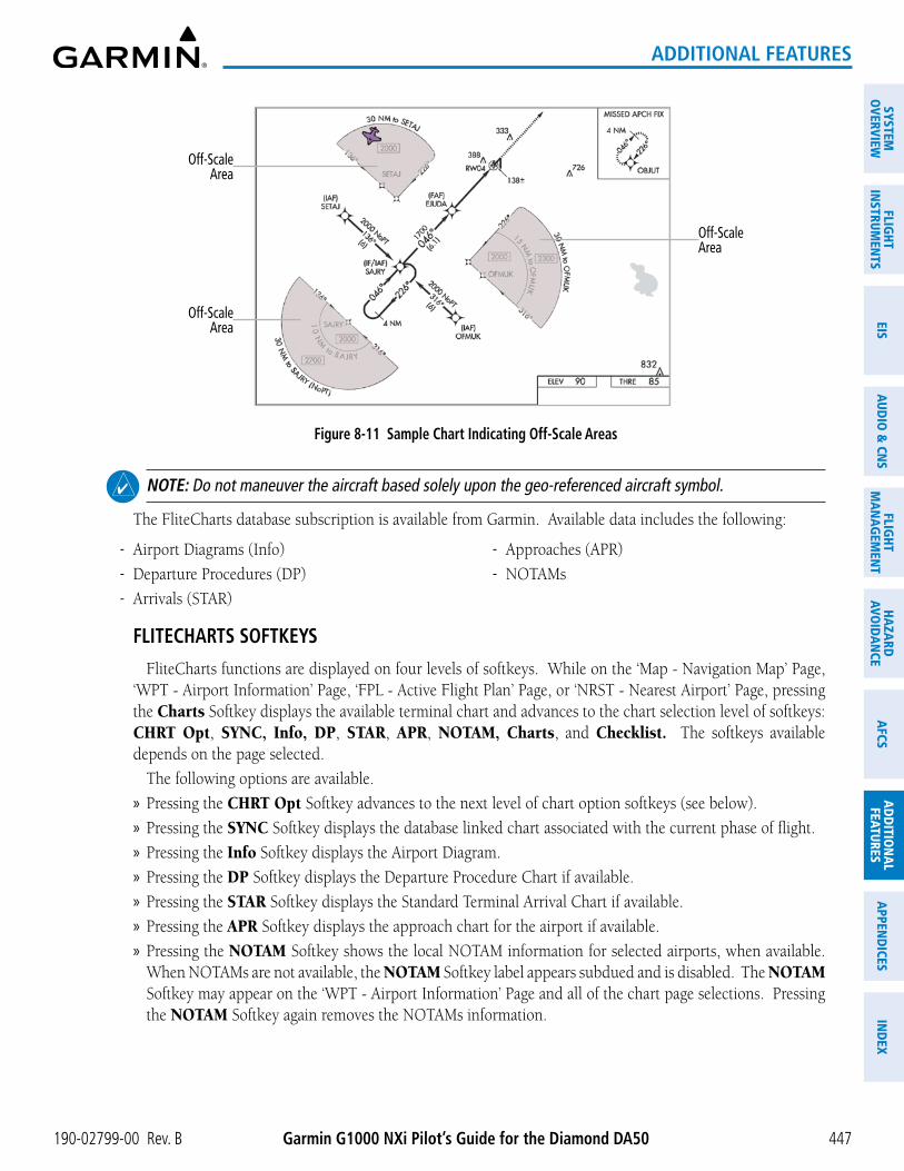
Garmin G1000 NXi Pilot’s Guide for the Diamond DA50190-02799-00 Rev. B
SYSTEMO
VERVIEWFLIG
HTIN
STRUMEN
TSEIS
AUDIO
& CN
SFLIG
HTM
AN
AGEM
ENT
HAZA
RDAVO
IDA
NCE
AFCS
AD
DITIO
NA
LFEATURES
APPEN
DICES
IND
EX
447
ADDITIONAL FEATURES
Off-Scale Area
Off-Scale Area
Off-Scale Area
Figure 8-11 Sample Chart Indicating Off-Scale Areas
NOTE: Do not maneuver the aircraft based solely upon the geo-referenced aircraft symbol.
The FliteCharts database subscription is available from Garmin. Available data includes the following:
- Airport Diagrams (Info)
- Departure Procedures (DP)
- Arrivals (STAR)
- Approaches (APR)
- NOTAMs
FLITECHARTS SOFTKEYS
FliteCharts functions are displayed on four levels of softkeys. While on the ‘Map - Navigation Map’ Page, ‘WPT - Airport Information’ Page, ‘FPL - Active Flight Plan’ Page, or ‘NRST - Nearest Airport’ Page, pressing the Charts Softkey displays the available terminal chart and advances to the chart selection level of softkeys: CHRT Opt, SYNC, Info, DP, STAR, APR, NOTAM, Charts, and Checklist. The softkeys available depends on the page selected.
The following options are available.
» Pressing the CHRT Opt Softkey advances to the next level of chart option softkeys (see below).
» Pressing the SYNC Softkey displays the database linked chart associated with the current phase of flight.
» Pressing the Info Softkey displays the Airport Diagram.
» Pressing the DP Softkey displays the Departure Procedure Chart if available.
» Pressing the STAR Softkey displays the Standard Terminal Arrival Chart if available.
» Pressing the APR Softkey displays the approach chart for the airport if available.
» Pressing the NOTAM Softkey shows the local NOTAM information for selected airports, when available. When NOTAMs are not available, the NOTAM Softkey label appears subdued and is disabled. The NOTAM Softkey may appear on the ‘WPT - Airport Information’ Page and all of the chart page selections. Pressing the NOTAM Softkey again removes the NOTAMs information.

Garmin G1000 NXi Pilot’s Guide for the Diamond DA50 190-02799-00 Rev. B
SYST
EMO
VERV
IEW
FLIG
HTIN
STRU
MEN
TSEI
SAU
DIO
& C
NS
FLIG
HTM
AN
AGEM
ENT
HAZA
RDAV
OID
AN
CEA
FCS
AD
DIT
ION
AL
FEAT
URES
APP
END
ICES
IND
EX
448
ADDITIONAL FEATURES
» Pressing the Charts Softkey switches between the chart diagram and the associated map in the ‘WPT’ Page Group.
» Pressing the Checklist Softkey advances to the electronic checklist feature (see the Electronic Checklist Section for further details).
Chart oPtions
While viewing the CHRT Opt softkeys, after 45 seconds of softkey inactivity, the system reverts to the chart selection softkeys. The following describes the sublevel softkeys:
� Pressing the ROT CCW Softkey rotates the chart counterclockwise.
� Pressing the ROT CW Softkey rotates the chart clockwise.
� Pressing the Fit WIDTH Softkey fits the width of the chart in the display viewing area.
� Pressing the Full SCN Softkey alternates between removing and replacing the data window to the right.
� Pressing the Back Softkey reverts to the top level softkeys and previous page.
TERMINAL PROCEDURES CHARTS
Selecting terminal procedures charts:
While viewing the ‘Map - Navigation Map’ Page, ‘WPT - Airport Information’ Page, ‘FPL - Active Flight Plan’ Page, or ‘NRST - Nearest Airport’ Page, press the Charts Softkey.
Or:
1) From the ‘Map - Navigation Map’ Page, press the MENU Key to display the ‘Page Menu.’
2) Turn the large FMS Knob to scroll through the ‘Options’ Menu to ‘Show Charts.’
3) Press the ENT Key to display the chart.
4) After the chart is displayed, press the Menu Key and select the desired type of chart (e.g., ‘Show Information Chart,’ ‘Show Departure Chart,’ ‘Show Arrival Chart,’ ‘Show Approach Chart,’ etc.) and press the ENT Key to display the chart.
When no terminal procedure chart is available, the banner ‘No Available Charts’ appears on the screen. The ‘No Available Charts’ Banner does not refer to the FliteCharts subscription, but rather the availability of a particular airport chart selection or procedure for a selected airport.
Figure 8-12 ‘No Available Charts’ Banner
If there is a problem in rendering the data (i.e., a data error or a failure of an individual chart), the banner ‘Unable to Display Chart’ is then displayed.
Figure 8-13 ‘Unable To Display Chart’ Banner
When a chart is not available by pressing the Charts Softkey or selecting a ‘Page Menu’ Option, charts may be obtained for other airports from the ‘WPT’ pages or ‘Flight Plan’ pages.

Garmin G1000 NXi Pilot’s Guide for the Diamond DA50190-02799-00 Rev. B
SYSTEMO
VERVIEWFLIG
HTIN
STRUMEN
TSEIS
AUDIO
& CN
SFLIG
HTM
AN
AGEM
ENT
HAZA
RDAVO
IDA
NCE
AFCS
AD
DITIO
NA
LFEATURES
APPEN
DICES
IND
EX
449
ADDITIONAL FEATURES
If a chart is available for the destination airport or the airport selected in the active flight plan, the chart appears on the screen. When no flight plan is active, or when not flying to a direct-to destination, pressing the Charts Softkey displays the chart for the nearest airport, if available.
The airport runway diagram is usually displayed on the ‘WPT - Airport Information’ Page after the Info Softkey is pressed. Where no runway diagram exists, but ‘Take Off Minimums’ or ‘Alternate Minimums’ are available, that page appears. If ‘WPT - Airport Information’ pages are unavailable, the approach chart for the airport is shown.
Selecting a chart:
1) While viewing the ‘Map - Navigation Map’ Page, ‘WPT - Airport Information’ Page, ‘FPL - Active Flight Plan’ Page, or ‘NRST - Nearest Airport’ Page, press the Charts Softkey.
2) Push the FMS Knob to activate the cursor.
3) Turn the large FMS Knob to select either the ‘Airport’ Identifier Box or the ‘Charts’ Box. (Press the APR Softkey if not already selected).
4) Turn the small and large FMS Knob to enter the desired airport identifier.
5) Press the ENT Key to complete the airport selection.
6) Turn the large FMS Knob to select the ‘Charts’ Box.
7) Turn the small FMS Knob to show the approach chart selection choices.
8) Turn either FMS Knob to scroll through the available charts.
9) Press the ENT Key to complete the chart selection.
Figure 8-14 FliteChart, Chart Selection

Garmin G1000 NXi Pilot’s Guide for the Diamond DA50 190-02799-00 Rev. B
SYST
EMO
VERV
IEW
FLIG
HTIN
STRU
MEN
TSEI
SAU
DIO
& C
NS
FLIG
HTM
AN
AGEM
ENT
HAZA
RDAV
OID
AN
CEA
FCS
AD
DIT
ION
AL
FEAT
URES
APP
END
ICES
IND
EX
450
ADDITIONAL FEATURES
While the Charts Box is selected using the FMS Knob, the softkeys are blank. Once the desired chart is selected, the chart scale can be changed and the chart can be panned using the Joystick. Pushing the Joystick centers the chart on the screen.
The Chart Scale Box displays a banner ‘NOT TO SCALE,’ and the ‘Aircraft Not Shown’ Icon is displayed in the lower right corner of the screen.
Pressing the Charts Softkey switches between the FliteCharts diagram and the associated map in the ‘Aux - Map’ Page Group.
Pressing the Info Softkey while viewing a chart returns to the airport diagram when viewing the departure procedure, STAR, or approach chart. If the displayed chart is the airport diagram, the Info Softkey has no effect.
Selecting full screen On or Off:
1) While viewing a terminal chart press the MENU Key to display the ‘Page Menu’ Options.
Figure 8-15 Full Screen On or Off
2) Turn the large FMS Knob to highlight the ‘Full Screen Off’ Option and press the ENT Key.

Garmin G1000 NXi Pilot’s Guide for the Diamond DA50190-02799-00 Rev. B
SYSTEMO
VERVIEWFLIG
HTIN
STRUMEN
TSEIS
AUDIO
& CN
SFLIG
HTM
AN
AGEM
ENT
HAZA
RDAVO
IDA
NCE
AFCS
AD
DITIO
NA
LFEATURES
APPEN
DICES
IND
EX
451
ADDITIONAL FEATURES
Figure 8-16 Split Screen View
The full screen view can be turned back on by following the previous steps and selecting ‘Full Screen On’ Option.
Selecting additional information:
1) From the ‘WPT - Airport Information’ Page, push the FMS Knob to activate the cursor.
2) Turn the large FMS Knob to highlight the Airport, Runways, or Frequencies Box.
3) Turn the small FMS Knob to select the Info Box choices. If multiple choices are available, scroll to the desired choice with the large FMS Knob and press the ENT Key to complete the selection.
4) Push the FMS Knob again to deactivate the cursor.

Garmin G1000 NXi Pilot’s Guide for the Diamond DA50 190-02799-00 Rev. B
SYST
EMO
VERV
IEW
FLIG
HTIN
STRU
MEN
TSEI
SAU
DIO
& C
NS
FLIG
HTM
AN
AGEM
ENT
HAZA
RDAV
OID
AN
CEA
FCS
AD
DIT
ION
AL
FEAT
URES
APP
END
ICES
IND
EX
452
ADDITIONAL FEATURES
Figure 8-17 Selecting Additional Information
automatiC Chart seleCtion on lanDing
When a chart is displayed while airborne and a landing is executed, the pane is automatically switched to the Airport Diagram of the nearest airport, when available. If an Airport Diagram chart is not available for the nearest airport, no change is made and the pane continues to display the previously selected chart.
Selecting Automatic Chart Selection:
1) While viewing a chart, press the MENU Softkey to display the ‘Page Menu.’
2) Turn the large FMS Knob to highlight the ‘Charts Setup’ menu option and press the ENT Key.
3) Turn the large FMS Knob to move to the ‘Taxi’ option in the ‘AUTO Chart Update’ Box.
4) With the ‘Taxi’ option highlighted, turn the small FMS Knob to choose either ‘On’ or ‘Off.’

Garmin G1000 NXi Pilot’s Guide for the Diamond DA50190-02799-00 Rev. B
SYSTEMO
VERVIEWFLIG
HTIN
STRUMEN
TSEIS
AUDIO
& CN
SFLIG
HTM
AN
AGEM
ENT
HAZA
RDAVO
IDA
NCE
AFCS
AD
DITIO
NA
LFEATURES
APPEN
DICES
IND
EX
453
ADDITIONAL FEATURES
Figure 8-18 ‘AUTO Chart Update’ Options
Phase of flight matChing
The Phase of Flight Matching Feature provides quick access to charts matching the current phase-of-flight (e.g., the departure, arrival, and approach phases of flight).
When a chart is accessed via the navigation map and/or flight plan pages, the chart may be updated automatically as the phase of flight changes. This feature may be enabled/disabled by following the procedure below. The chart for the current phase of flight may be recalled at any time on the navigation map and/or flight plan pages when a chart pane is displayed by pressing the SYNC Softkey.
Syncing charts to the current phase of flight:
1) While viewing a chart, press the MENU Softkey to display the ‘Page Menu.’
2) Turn the large FMS Knob to highlight the ‘Charts Setup’ menu option and press the ENT Key.
3) Turn the large FMS Knob to move to the ‘Phase of Flight’ option in the ‘AUTO Chart Update’ Box.
4) With the ‘Phase of Flight’ option highlighted, turn the small FMS Knob to choose either ‘On’ or ‘Off.’
DAY/NIGHT VIEW
FliteCharts can be displayed on a white or black background for day or night viewing. The Day View offers a better presentation in a bright environment. The Night View gives a better presentation for viewing in a dark environment. When the ‘Charts Setup’ Box is selected the MFD softkeys are blank.
Selecting day, night, or automatic view:
1) While viewing a terminal chart press the MENU Key to display the ‘Page Menu’ Options.
2) Turn the large FMS Knob to highlight the ‘Charts Setup’ Menu Option and press the ENT Key.

Garmin G1000 NXi Pilot’s Guide for the Diamond DA50 190-02799-00 Rev. B
SYST
EMO
VERV
IEW
FLIG
HTIN
STRU
MEN
TSEI
SAU
DIO
& C
NS
FLIG
HTM
AN
AGEM
ENT
HAZA
RDAV
OID
AN
CEA
FCS
AD
DIT
ION
AL
FEAT
URES
APP
END
ICES
IND
EX
454
ADDITIONAL FEATURES
Color Scheme OptionsCharts Setup Option
Figure 8-19 Page Menu, Charts Setup
3) The ‘Color Scheme’ Field is selected by default. If not already selected, turn the large FMS Knob to move to the ‘Color Scheme’ Field.
4) Turn the small FMS Knob to choose between ‘Day,’ ‘Auto,’ and ‘Night’ Options.
5) If Auto Mode is selected, turn the large FMS Knob to select the percentage field. Use the small FMS Knob to change the percentage value. The percentage value is the day/night crossover point based on the percentage of backlighting intensity. For example, if the value is set to 15%, the day/night display changes when the display backlight reaches 15% of full brightness.
The display must be changed in order for the new setting to become active. This may be accomplished by selecting another page or changing the display range.
6) Push the FMS Knob when finished to remove the ‘Charts Setup’ Menu.

Garmin G1000 NXi Pilot’s Guide for the Diamond DA50190-02799-00 Rev. B
SYSTEMO
VERVIEWFLIG
HTIN
STRUMEN
TSEIS
AUDIO
& CN
SFLIG
HTM
AN
AGEM
ENT
HAZA
RDAVO
IDA
NCE
AFCS
AD
DITIO
NA
LFEATURES
APPEN
DICES
IND
EX
455
ADDITIONAL FEATURES
Figure 8-20 Approach Chart, Day View
Figure 8-21 Approach Chart, Night View

Garmin G1000 NXi Pilot’s Guide for the Diamond DA50 190-02799-00 Rev. B
SYST
EMO
VERV
IEW
FLIG
HTIN
STRU
MEN
TSEI
SAU
DIO
& C
NS
FLIG
HTM
AN
AGEM
ENT
HAZA
RDAV
OID
AN
CEA
FCS
AD
DIT
ION
AL
FEAT
URES
APP
END
ICES
IND
EX
456
ADDITIONAL FEATURES
CHARTVIEWChartView resembles the paper version of Jeppesen terminal procedures charts. The charts are displayed in
full color with high-resolution. The MFD depiction shows the aircraft position on the moving map in the plan view of approach charts and on airport diagrams.
The georeferenced aircraft position is indicated by an aircraft symbol displayed on the chart when the current position is within the boundaries of the chart. Inset boxes are not considered within the chart boundaries. Therefore, when the aircraft symbol reaches a chart boundary line, or inset box, the aircraft symbol is removed from the display.
The following figure shows examples of an inset box and off-scale areas, indicated by the grey shading. Note, the grey shading is for illustrative purposes only and will not appear on the published chart or MFD display. These off-scale areas appear on the chart to convey supplemental information. However, the depicted geographical position of this information, as it relates to the chart plan view, is not the actual geographic position. Therefore, when the aircraft symbol appears within one of these areas, the aircraft position indicated is relative to the chart plan view, not to the off-scale area.
Figure 8-22 Sample Chart Indicating Off-Scale Areas
Off-Scale Area
Off-Scale Area
Inset Box
Off-Scale Area
NOTE: Do not maneuver the aircraft based solely upon the georeferenced aircraft symbol.
The ChartView database subscription is available from Jeppesen, Inc. Available data includes the following:
- Airport Diagrams (Info)
- Departure Procedures (DP)
- Arrivals (STAR)
- Approaches (APR)
- NOTAMs

Garmin G1000 NXi Pilot’s Guide for the Diamond DA50190-02799-00 Rev. B
SYSTEMO
VERVIEWFLIG
HTIN
STRUMEN
TSEIS
AUDIO
& CN
SFLIG
HTM
AN
AGEM
ENT
HAZA
RDAVO
IDA
NCE
AFCS
AD
DITIO
NA
LFEATURES
APPEN
DICES
IND
EX
457
ADDITIONAL FEATURES
CHARTVIEW SOFTKEYS
ChartView functions are displayed on four levels of softkeys. While on the ‘Map - Navigation Map’ Page, ‘WPT - Airport Information’ Page, ‘FPL - Active Flight Plan’ Page, or ‘NRST - Nearest Airport’ Page, pressing the Charts Softkey displays the available terminal chart and advances to the chart selection level of softkeys: CHRT Opt, SYNC, Info, DP, STAR, APR, NOTAM, Charts, and Checklist. The softkeys available depends on the page selected.
The following options are available:
» Pressing the CHRT Opt Softkey advances to the next level of chart option softkeys (see below).
» Pressing the SYNC Softkey displays the database linked chart associated with the current phase of flight.
» Pressing the Info Softkey displays the Airport Diagram.
» Pressing the DP Softkey displays the Departure Procedure Chart if available.
» Pressing the STAR Softkey displays the Standard Terminal Arrival Chart if available.
» Pressing the APR Softkey displays the approach chart for the airport if available.
» Recent NOTAMs applicable to the current ChartView cycle are included in the ChartView database. Pressing the NOTAM Softkey shows the local NOTAM information for selected airports, when available. When NOTAMs are not available, the NOTAM Softkey label appears subdued and is disabled. The NOTAM Softkey may appear on the ‘WPT - Airport Information’ Page and all of the chart page selections. Pressing the NOTAM Softkey again removes the NOTAMs information.
» Pressing the Charts Softkey switches between the chart diagram and the associated map in the ‘WPT’ Page Group.
» Pressing the Checklist Softkey advances to the electronic checklist feature (see the Electronic Checklist Section for further details).
NOTE: Only NOTAMs applicable to specific information conveyed on the displayed Jeppesen chart are available when the NOTAM Softkey is pressed. There may be other NOTAMs available pertaining to the flight that may not be displayed. Contact Jeppesen for more information regarding Jeppesen database published NOTAMs.
Chart oPtions
While viewing the CHRT Opt softkeys, after 45 seconds of softkey inactivity, the system reverts to the chart selection softkeys. The following describes the sublevel softkeys:
� Pressing the ROT CCW Softkey rotates the displayed chart counter clockwise in 90 degree increments.
� Pressing the ROT CW Softkey rotates the displayed chart clockwise in 90 degree increments.
� Pressing the All Softkey shows the complete approach chart on the screen.
� Pressing the Header Softkey shows the header view (approach chart briefing strip) on the screen.
� Pressing the Plan Softkey shows the approach chart two dimensional plan view.
� Pressing the Profile Softkey displays the approach chart descent profile strip.
� Pressing the Minimums Softkey displays the minimum descent altitude/visibility strip at the bottom of the approach chart.

Garmin G1000 NXi Pilot’s Guide for the Diamond DA50 190-02799-00 Rev. B
SYST
EMO
VERV
IEW
FLIG
HTIN
STRU
MEN
TSEI
SAU
DIO
& C
NS
FLIG
HTM
AN
AGEM
ENT
HAZA
RDAV
OID
AN
CEA
FCS
AD
DIT
ION
AL
FEAT
URES
APP
END
ICES
IND
EX
458
ADDITIONAL FEATURES
� If the chart scale has been adjusted to view a small area of the chart, pressing the Fit WDTH Softkey changes the chart size to fit the available screen width.
4 Pressing the Full SCN Softkey alternates between removing and replacing the data window to the right.
� Pressing the Back Softkey returns you to the previously selected level.
TERMINAL PROCEDURES CHARTS
Selecting terminal procedures charts:
While viewing the ‘Map - Navigation Map’ Page, ‘WPT - Airport Information’ Page, ‘FPL - Active Flight Plan’ Page, or ‘NRST - Nearest Airport’ Page, press the Charts Softkey.
Or:
1) Press the MENU Key to display the ‘Page Menu.’
2) Turn the large FMS Knob to scroll through the ‘Options’ Menu to ‘Show Charts.’
3) Press the ENT Key to display the chart.
4) After the chart is displayed, press the Menu Key and select the desired type of chart (e.g., ‘Show Information Chart,’ ‘Show Departure Chart,’ ‘Show Arrival Chart,’ ‘Show Approach Chart,’ etc.) and press the ENT Key to display the chart.
When no terminal procedure chart is available, the banner ‘No Available Charts’ appears on the screen. The banner does not refer to the ChartView subscription, but rather the availability of a particular airport chart selection or procedure for a selected airport.
Figure 8-23 ‘No Available Charts’ Banner
If there is a problem in rendering the data (e.g., a data error or a failure of an individual chart), the banner ‘Unable to Display Chart’ is then displayed.
Figure 8-24 ‘Unable To Display Chart’ Banner
When a chart is not available by pressing the Charts Softkey or selecting a ‘Page Menu’ Option, charts may be obtained for other airports from the ‘WPT’ Pages or ‘Flight Plan’ Pages.
If a chart is available for the destination airport, or the airport selected in the active flight plan, the chart appears on the screen. When no flight plan is active, or when not flying to a direct-to destination, pressing the Charts Softkey displays the chart for the nearest airport, if available.
The airport runway diagram is usually displayed on the ‘WPT - Airport Information’ page after the Info Softkey is pressed. Where no runway diagram exists, but Take Off Minimums or Alternate Minimums are available, that page appears. If ‘WPT - Airport Information’ Pages are unavailable, the Approach Chart for the airport is shown.

Garmin G1000 NXi Pilot’s Guide for the Diamond DA50190-02799-00 Rev. B
SYSTEMO
VERVIEWFLIG
HTIN
STRUMEN
TSEIS
AUDIO
& CN
SFLIG
HTM
AN
AGEM
ENT
HAZA
RDAVO
IDA
NCE
AFCS
AD
DITIO
NA
LFEATURES
APPEN
DICES
IND
EX
459
ADDITIONAL FEATURES
Selecting a chart:
1) While viewing the ‘Map - Navigation Map’ Page, ‘WPT - Airport Information’ Page, ‘FPL - Active Flight Plan’ Page, or ‘NRST - Nearest Airport’ Page, press the Charts Softkey.
2) Push the FMS Knob to activate the cursor.
3) Turn the large FMS Knob to select either the ‘Airport’ Identifier Box or the ‘Charts’ Box.
4) Turn the small and large FMS Knob to enter the desired airport identifier.
5) Press the ENT Key to complete the airport selection.
6) Turn the large FMS Knob to select the ‘Charts’ Box.
7) Turn the small FMS Knob to show the approach chart selection choices.
8) Turn either FMS Knob to scroll through the available charts.
9) Press the ENT Key to complete the chart selection.
Figure 8-25 ChartView, Chart Selection
Chart Scale
Select Desired Approach Chart from Menu
While the Charts Box is selected using the FMS Knob, the system softkeys are blank. Once the desired chart is selected, the chart scale can be changed and the chart page can be scrolled using the Joystick. Pushing the Joystick centers the chart on the screen.
The aircraft symbol is shown on the chart only if the chart is to scale and the aircraft position is within the boundaries of the chart. The aircraft symbol is not displayed when the ‘Aircraft Not Shown’ Icon appears. If the Chart Scale Box displays a banner ‘NOT TO SCALE,’ the aircraft symbol is not shown. The ‘Aircraft Not Shown’ Icon may appear at certain times, even if the chart is displayed to scale.
Pressing the Chart Softkey switches between the ChartView diagram and the previously selected page.
The aircraft position is shown in magenta on the ChartView diagrams when the location of the aircraft is within the chart boundaries.

Garmin G1000 NXi Pilot’s Guide for the Diamond DA50 190-02799-00 Rev. B
SYST
EMO
VERV
IEW
FLIG
HTIN
STRU
MEN
TSEI
SAU
DIO
& C
NS
FLIG
HTM
AN
AGEM
ENT
HAZA
RDAV
OID
AN
CEA
FCS
AD
DIT
ION
AL
FEAT
URES
APP
END
ICES
IND
EX
460
ADDITIONAL FEATURES
Selecting full screen On or Off:
1) While viewing a terminal chart press the MENU Key to display the ‘Page Menu’ Options.
Figure 8-26 Full Screen On/Off Selection
2) Turn the large FMS Knob to highlight the ‘Full Screen On’ or ‘Full Screen Off’ option and press the ENT Key.
Figure 8-27 Split Screen View
The full screen view can be turned back on by following the previous steps and selecting ‘Full Screen On’ Option.

Garmin G1000 NXi Pilot’s Guide for the Diamond DA50190-02799-00 Rev. B
SYSTEMO
VERVIEWFLIG
HTIN
STRUMEN
TSEIS
AUDIO
& CN
SFLIG
HTM
AN
AGEM
ENT
HAZA
RDAVO
IDA
NCE
AFCS
AD
DITIO
NA
LFEATURES
APPEN
DICES
IND
EX
461
ADDITIONAL FEATURES
Selecting Additional Information:
1) From the ‘WPT - Airport Information’ Page, push the FMS Knob to activate the cursor.
2) Turn the large FMS Knob to highlight the ‘Airport,’ ‘Runways,’ or ‘Frequencies’ Box.
3) Turn the small FMS Knob to select the Info Box choices. If multiple choices are available, scroll to the desired choice with the large FMS Knob and press the ENT Key to complete the selection.
4) Push the FMS Knob again to deactivate the cursor.
Figure 8-28 Selecting Additional Information
automatiC Chart seleCtion on lanDing
When a chart is displayed while airborne and a landing is executed, the pane is automatically switched to the Airport Diagram of the nearest airport, when available. If an Airport Diagram chart is not available for the nearest airport, no change is made and the pane continues to display the previously selected chart.
Selecting Automatic Chart Selection:
1) While viewing a chart, press the MENU Softkey to display the ‘Page Menu.’
2) Turn the large FMS Knob to highlight the ‘Charts Setup’ menu option and press the ENT Key.
3) Turn the large FMS Knob to move to the ‘Taxi’ option in the ‘AUTO Chart Update’ Box.
4) With the ‘Taxi’ option highlighted, turn the small FMS Knob to choose either ‘On’ or ‘Off.’

Garmin G1000 NXi Pilot’s Guide for the Diamond DA50 190-02799-00 Rev. B
SYST
EMO
VERV
IEW
FLIG
HTIN
STRU
MEN
TSEI
SAU
DIO
& C
NS
FLIG
HTM
AN
AGEM
ENT
HAZA
RDAV
OID
AN
CEA
FCS
AD
DIT
ION
AL
FEAT
URES
APP
END
ICES
IND
EX
462
ADDITIONAL FEATURES
Figure 8-29 ‘AUTO Chart Update’ Options
Phase of flight matChing
The Phase of Flight Matching Feature provides quick access to charts matching the current phase-of-flight (e.g., the departure, arrival, and approach phases of flight).
When a chart is accessed via the navigation map and/or flight plan pages, the chart may be updated automatically as the phase of flight changes. This feature may be enabled/disabled by following the procedure below. The chart for the current phase of flight may be recalled at any time on the navigation map and/or flight plan pages when a chart pane is displayed by pressing the SYNC Softkey.
Syncing charts to the current phase of flight:
1) While viewing a chart, press the MENU Softkey to display the ‘Page Menu.’
2) Turn the large FMS Knob to highlight the ‘Charts Setup’ menu option and press the ENT Key.
3) Turn the large FMS Knob to move to the ‘Phase of Flight’ option in the ‘AUTO Chart Update’ Box.
4) With the ‘Phase of Flight’ option highlighted, turn the small FMS Knob to choose either ‘On’ or ‘Off.’
DAY/NIGHT VIEW
ChartView can be displayed on a white or black background for day or night viewing. The day view offers a better presentation in a bright environment. The night view gives a better presentation for viewing in a dark environment. When the Charts Setup Box is selected the MFD softkeys are blank.
Selecting day, night, or automatic view:
1) While viewing a terminal chart press the MENU Key to display the ‘Page Menu’ Options.
2) Turn the large FMS Knob to highlight the ‘Charts Setup’ menu option and press the ENT Key.

Garmin G1000 NXi Pilot’s Guide for the Diamond DA50190-02799-00 Rev. B
SYSTEMO
VERVIEWFLIG
HTIN
STRUMEN
TSEIS
AUDIO
& CN
SFLIG
HTM
AN
AGEM
ENT
HAZA
RDAVO
IDA
NCE
AFCS
AD
DITIO
NA
LFEATURES
APPEN
DICES
IND
EX
463
ADDITIONAL FEATURES
Figure 8-30 Page Menu, Charts Setup
Color Scheme OptionsCharts Setup Option
3) Turn the large FMS Knob to move to the ‘Color Scheme’ Option.
4) Turn the small FMS Knob to choose between ‘Day,’ ‘Auto,’ and ‘Night’ Options.
5) If Auto Mode is selected, turn the large FMS Knob to select the percentage field. Use the small FMS Knob to change the percentage value. The percentage value is the day/night crossover point based on the percentage of backlighting intensity. For example, if the value is set to 15%, the day/night display changes when the display backlight reaches 15% of full brightness.
The display must be changed in order for the new setting to become active. This may be accomplished by selecting another page or changing the display range.
6) Push the FMS Knob when finished to remove the ‘Charts Setup’ Menu.
Figure 8-31 Approach Chart, Day View

Garmin G1000 NXi Pilot’s Guide for the Diamond DA50 190-02799-00 Rev. B
SYST
EMO
VERV
IEW
FLIG
HTIN
STRU
MEN
TSEI
SAU
DIO
& C
NS
FLIG
HTM
AN
AGEM
ENT
HAZA
RDAV
OID
AN
CEA
FCS
AD
DIT
ION
AL
FEAT
URES
APP
END
ICES
IND
EX
464
ADDITIONAL FEATURES
Figure 8-32 Approach Chart, Night View

Garmin G1000 NXi Pilot’s Guide for the Diamond DA50190-02799-00 Rev. B
SYSTEMO
VERVIEWFLIG
HTIN
STRUMEN
TSEIS
AUDIO
& CN
SFLIG
HTM
AN
AGEM
ENT
HAZA
RDAVO
IDA
NCE
AFCS
AD
DITIO
NA
LFEATURES
APPEN
DICES
IND
EX
465
ADDITIONAL FEATURES
IFR/VFR CHARTSThe system can display GPS navigation information on a VFR Sectional Aeronautical Chart, an Enroute Low
Altitude IFR Chart, or an Enroute High Altitude IFR Chart, if installed. The information overlaid on IFR/VFR Charts is selected and setup on the Navigation Map, but the IFR/VFR charts will not display some of the selected items. Only the following items will be overlaid on the chart:
- Map Pointer (distance and bearing to pointer, location of pointer, name, and other pertinent information)
- Map Range (17 range choices from 1 nm to 150 nm)
- Map Orientation (always North Up for IFR/VFR Charts)
- Aircraft Icon (representing present position)
- Wind Direction and Speed
- Icons for enabled map features (Traffic only)
- Flight Plan Legs
- Track Vector
- Runway Extension
- Missed Approach Preview
- Intersections (only as part of active flight plan)
- Visual Reporting Points
- VNAV Constraints
- Selected Altitude Intercept Arc
Map panning on the IFR/VFR Charts works the same as on the Navigation Map. Map range selected on either the Navigation Map or the IFR/VFR Charts applies to both.
Due to the potential error involved with the electronic depiction of maps, charts will display a ‘gray circle of uncertainty’ centered upon the aircraft icon. The aircraft’s actual position can be anywhere within the range of the gray circle. The range of the circle will change based on the chart displayed and current zoom range.
The georeferenced aircraft position is indicated by an aircraft symbol displayed on the chart when the current position is within the boundaries of the chart. Not all charts are geo-referenced. IFR/VFR charts may be viewed by selecting the ‘Map - IFR/VFR Charts’ Page.

Garmin G1000 NXi Pilot’s Guide for the Diamond DA50 190-02799-00 Rev. B
SYST
EMO
VERV
IEW
FLIG
HTIN
STRU
MEN
TSEI
SAU
DIO
& C
NS
FLIG
HTM
AN
AGEM
ENT
HAZA
RDAV
OID
AN
CEA
FCS
AD
DIT
ION
AL
FEAT
URES
APP
END
ICES
IND
EX
466
ADDITIONAL FEATURES
Figure 8-33 VFR Chart
Circle of Uncertainty
Active Flight Plan LegAircraft Icon
at Present Position
Map Range
Map Orientation
Selecting IFR Low, IFR High, or VFR Charts:
1) Select the ‘Map - IFR/VFR Charts’ Page.
2) Press the VFR, IFR Low, or IFR High Softkey to display the desired chart.
Or:
1) From the ‘Map - IFR/VFR Charts’ Page, press the MENU Key to display the ‘Page Menu.’
2) Select ‘Display VFR’, ‘Display IFR Low’ or ‘Display IFR High’ to display the desired chart.
3) Press the ENT Key.
Enabling/disabling the traffic overlay:
1) Select the ‘Map - IFR/VFR Charts’ Page.
2) With any IFR/VFR chart displayed, press the Map Opt Softkey to display the map options.
3) Press the Traffic Softkey to enable/disable traffic overlaid onto the charts displayed.

Garmin G1000 NXi Pilot’s Guide for the Diamond DA50190-02799-00 Rev. B
SYSTEMO
VERVIEWFLIG
HTIN
STRUMEN
TSEIS
AUDIO
& CN
SFLIG
HTM
AN
AGEM
ENT
HAZA
RDAVO
IDA
NCE
AFCS
AD
DITIO
NA
LFEATURES
APPEN
DICES
IND
EX
467
ADDITIONAL FEATURES
Figure 8-34 IFR Low Altitude Chart
Active Flight Plan LegAircraft Icon
at Present Position
Map Range
Map Orientation
Circle of Uncertainty
DAY/NIGHT VIEW
IFR/VFR Charts can be displayed on a white or black background for day or night viewing. The day view offers a better presentation in a bright environment. The night view gives a better presentation for viewing in a dark environment. When the ‘Page Menu’ Box is selected, the MFD softkeys are blank.
Selecting day, night, or automatic view:
1) While viewing an IFR/VFR Chart, press the MENU Key to display the ‘Page Menu’ Options.
2) With the ‘Settings’ menu option highlighted, press the ENT Key.
Figure 8-35 VFR/IFR Settings
Color Scheme OptionsSettings Option
3) Turn the small FMS Knob to choose between ‘Day,’ ‘Auto,’ and ‘Night’ Options.

Garmin G1000 NXi Pilot’s Guide for the Diamond DA50 190-02799-00 Rev. B
SYST
EMO
VERV
IEW
FLIG
HTIN
STRU
MEN
TSEI
SAU
DIO
& C
NS
FLIG
HTM
AN
AGEM
ENT
HAZA
RDAV
OID
AN
CEA
FCS
AD
DIT
ION
AL
FEAT
URES
APP
END
ICES
IND
EX
468
ADDITIONAL FEATURES
4) If Auto Mode is selected, turn the large FMS Knob to select the percentage field. Use the small FMS Knob to change the percentage value. The percentage value is the day/night crossover point based on the percentage of backlighting intensity. For example, if the value is set to 15%, the day/night display changes when the display backlight reaches 15% of full brightness.
The display must be changed in order for the new setting to become active. This may be accomplished by selecting another page or changing the display range.
5) Push the FMS Knob when finished to remove the ‘VFR/IFR Settings’ Menu.
Figure 8-36 Night IFR High Altitude Chart
Active Flight Plan LegAircraft Icon
at Present Position
Map Range
Map Orientation
Circle of Uncertainty

Garmin G1000 NXi Pilot’s Guide for the Diamond DA50190-02799-00 Rev. B
SYSTEMO
VERVIEWFLIG
HTIN
STRUMEN
TSEIS
AUDIO
& CN
SFLIG
HTM
AN
AGEM
ENT
HAZA
RDAVO
IDA
NCE
AFCS
AD
DITIO
NA
LFEATURES
APPEN
DICES
IND
EX
469
ADDITIONAL FEATURES
8.5 SATELLITE TELEPHONE AND DATALINK SERVICES (OPTIONAL)
NOTE: An account must be established to access the Iridium Satellite Network for voice and SMS Services.
The Iridium Transceiver (GSR 56) provides an airborne low speed datalink, Iridium Satellite Telephone service, and Short Message Service (SMS).
The telephone is available to the flight crew through the audio panel and headsets.
Operation of these features in the cockpit is accomplished through the ‘Aux - Telephone’ Page or the ‘Aux - Text Messaging’ Page.
For aircraft equipped with an Iridium Transceiver (GSR 56) and the optional Wireless Transceiver (FS 510), calls and SMS text can be made using a Portable Electronic Device through the Garmin Pilot™ App. Please refer to the Garmin Pilot™ user guide for Iridium Datalink.
REGISTERING THE SYSTEM WITH GARMIN CONNEXTA subscriber account must be established prior to using the Iridium Satellite System. Before setting up an
Iridium account, obtain the serial number of the Iridium Transceiver (GSR 1) and the System ID by selecting the ‘Aux - System Status’ Page. Contact Garmin at flygarmin.com.
Registering the system for datalink services:
1) Using the FMS Knob, select the ‘Aux - System Status’ Page.
2) Touch the LRU Softkey, if not already selected.
3) Push the FMS Knob to activate the cursor.
4) Use the large FMS Knob to view ‘GSR 1.’
5) Note the GSR 1 Serial Number. This number will be needed when contacting Garmin Connext to establish the account.
6) Also note the System ID. It is found in the Airframe Box on the ‘Aux - System Status’ Page. The System ID will also be needed when contacting Garmin Connext.
7) Contact Garmin Connext to establish an account and receive an access code.

Garmin G1000 NXi Pilot’s Guide for the Diamond DA50 190-02799-00 Rev. B
SYST
EMO
VERV
IEW
FLIG
HTIN
STRU
MEN
TSEI
SAU
DIO
& C
NS
FLIG
HTM
AN
AGEM
ENT
HAZA
RDAV
OID
AN
CEA
FCS
AD
DIT
ION
AL
FEAT
URES
APP
END
ICES
IND
EX
470
ADDITIONAL FEATURES
Figure 8-37 ‘Aux - System Status’ Page
System ID
GSR 1 Serial Number
DISABLING/ENABLING THE IRIDIUM TRANSCEIVERIridium telephone and data communications may be turned on or off by performing these simple steps.
Disabling/enabling telephone and low speed data services:
1) Turn the large FMS Knob on the MFD to select the ‘Aux’ Page Group.
2) Turn the small FMS Knob to select the ‘Aux - Satellite Phone’ Page.
3) If necessary, press the Phone Softkey to display the ‘Aux - Telephone’ Page.
Figure 8-38 ‘Aux - Telephone’ Page

Garmin G1000 NXi Pilot’s Guide for the Diamond DA50190-02799-00 Rev. B
SYSTEMO
VERVIEWFLIG
HTIN
STRUMEN
TSEIS
AUDIO
& CN
SFLIG
HTM
AN
AGEM
ENT
HAZA
RDAVO
IDA
NCE
AFCS
AD
DITIO
NA
LFEATURES
APPEN
DICES
IND
EX
471
ADDITIONAL FEATURES
4) Press the MENU Key. The ‘Page Menu’ Window is now displayed.
5) Turn the FMS Knob to select ‘Disable Iridium Transmission’ in the menu list.
Figure 8-39 Select ‘Disable Iridium Transmission’
6) Press the ENT Key. The Iridium transceiver is now disabled.
7) To enable the Iridium transceiver, repeat steps 1 through 4, then select ‘Enable Iridium Transceiver.’
CONTACTSThe names, telephone number, and email addresses can be saved in a list of contacts for easy use when
making telephone calls.
Creating a new contact:
1) With the ‘Aux - Telephone Phone’ Page displayed, push the FMS Knob to display the cursor.
2) If necessary, turn either FMS Knob to place the cursor on ‘New Entry.’
3) Press the ENT Key. The cursor moves the ‘Name’ Field of the ‘Contact Details’ Window.
4) Enter the desired name of the new contact. Entry is accomplished through the alphanumeric keys on the PFD/MFD Controller, the FMS Knob on the PFD/MFD Controller, or via the FMS Knob on the MFD.

Garmin G1000 NXi Pilot’s Guide for the Diamond DA50 190-02799-00 Rev. B
SYST
EMO
VERV
IEW
FLIG
HTIN
STRU
MEN
TSEI
SAU
DIO
& C
NS
FLIG
HTM
AN
AGEM
ENT
HAZA
RDAV
OID
AN
CEA
FCS
AD
DIT
ION
AL
FEAT
URES
APP
END
ICES
IND
EX
472
ADDITIONAL FEATURES
Figure 8-40 PFD/MFD Controller (GCU 476) (Optional)
5) Press the ENT Key. The cursor moves to the ‘Phone Number’ Field.
6) Enter the desired telephone number. Entry is accomplished through the alphanumeric keys on the PFD/MFD Controller, the FMS Knob on the PFD/MFD Controller, or via the FMS Knob on the MFD.
7) Press the ENT Key. The cursor moves to the ‘Email’ Field.
8) Enter the desired email address. Entry is accomplished through the alphanumeric keys on the PFD/MFD Controller, the FMS Knob on the PFD/MFD Controller, or via the FMS Knob on the MFD.
9) Press the Symbols Softkey to display the “@” symbol, the period, and other special characters. Pressing the More Softkey will cycle through additional special characters.
Figure 8-41 Special Characters
10) Press the ENT Key. The Save Softkey is highlighted.
11) Press the ENT Key. The new contact entry is added to the list of saved contacts.
Editing a contact:
1) With the ‘Aux - Telephone’ Page displayed, push the FMS Knob to display the cursor.
2) Turn either FMS Knob to place the cursor on the desired contact name.
3) Press the Edit Softkey. The cursor is placed in the ‘Name’ Field. Enter the desired changes. Entry is accomplished through the alphanumeric keys on the PFD/MFD Controller, the FMS Knob on the PFD/MFD Controller, or via the FMS Knob on the MFD.
4) Press the ENT Key when each field is complete. The Save Button is now highlighted.
5) Press the ENT Key to save the changes.

Garmin G1000 NXi Pilot’s Guide for the Diamond DA50190-02799-00 Rev. B
SYSTEMO
VERVIEWFLIG
HTIN
STRUMEN
TSEIS
AUDIO
& CN
SFLIG
HTM
AN
AGEM
ENT
HAZA
RDAVO
IDA
NCE
AFCS
AD
DITIO
NA
LFEATURES
APPEN
DICES
IND
EX
473
ADDITIONAL FEATURES
Figure 8-42 Editing a Contact
Deleting a contact:
1) With the ‘Aux - Telephone’ Page displayed, push the FMS Knob to display the cursor.
2) Turn either FMS Knob to place the cursor on the desired contact name.
3) Press the Delete Softkey. A confirmation window is displayed.
4) With ‘OK’ highlighted, press the ENT Key to delete the selected contact.
TELEPHONE COMMUNICATIONThe pilot or copilot can place and answer calls on the Iridium Satellite Network. Control and monitoring of
telephone functions are accomplished through the ‘Aux - Telephone’ Page.
Viewing the ‘Aux - Telephone‘ Page:
1) Turn the large FMS Knob on the MFD to select the ‘Aux’ Page Group.
2) Turn the small FMS Knob to select the ‘Aux - Satellite Phone’ Page.
3) If necessary, press the Phone Softkey to display the ‘Aux - Telephone’ Page.
The phone status display gives a graphical representation of the current disposition of voice and/or data transmissions.

Garmin G1000 NXi Pilot’s Guide for the Diamond DA50 190-02799-00 Rev. B
SYST
EMO
VERV
IEW
FLIG
HTIN
STRU
MEN
TSEI
SAU
DIO
& C
NS
FLIG
HTM
AN
AGEM
ENT
HAZA
RDAV
OID
AN
CEA
FCS
AD
DIT
ION
AL
FEAT
URES
APP
END
ICES
IND
EX
474
ADDITIONAL FEATURES
Internal Phone
External Phone Description
Phone is Idle
Phone is ringing
Phone has a dial tone (off hook) or connected to another phone
Phone dialed is busy
Phone is dialing another phone
Phone has failed
Phone status not known
Phone is disabled
Phone is reserved for data transmission
Calling other phone or incoming call from other phone
Other phone is on hold
Phones are connected
Table 8-2 Telephone Symbols
INCOMING CALLS
When viewing MFD pages other than the ‘Aux - Telephone’ Page, a pop-up alert will be displayed and an aural alert “Incoming Call” will be heard. If the incoming call is an Iridium Network call, ‘Iridium’ will be displayed. The pop-up alert may be inhibited at times, such as during takeoff. In addition to the pop-up alert, a ringing phone symbol will be displayed to the right of the MFD page title. Also, the voice alert “Incoming Call” will be heard on the selected cockpit audio.

Garmin G1000 NXi Pilot’s Guide for the Diamond DA50190-02799-00 Rev. B
SYSTEMO
VERVIEWFLIG
HTIN
STRUMEN
TSEIS
AUDIO
& CN
SFLIG
HTM
AN
AGEM
ENT
HAZA
RDAVO
IDA
NCE
AFCS
AD
DITIO
NA
LFEATURES
APPEN
DICES
IND
EX
475
ADDITIONAL FEATURES
NOTE: The Push-to-Talk Switch is not utilized for telephone communication. The microphone is active after pressing the Answer Softkey, and stays active until the call is terminated.
Answering a call from the cockpit:
While viewing the ‘Aux - Telephone’ Page, press the Answer Softkey on the MFD.
Or:
1) While viewing the ‘Aux - Telephone’ Page, press the MENU Key to display the ‘Page Menu.’
2) Turn either FMS Knob to place the cursor on ‘Answer Incoming Call.’
3) Press the ENT Key.
Pressing the Ignore Softkey will extinguish the pop-up window and leave the call unanswered. Pressing the Phone Softkey will display the ‘Aux - Telephone’ Page allowing additional call information to be viewed before answering.
Muting incoming call alerts:
1) With the ‘Aux - Telephone’ Page displayed, press the MENU Key on the MFD to display the ‘Page Menu.’
2) Turn either FMS Knob to place the cursor on ‘Disable Incoming Call Alerts.’
3) Press the ENT Key. The voice and pop-up alert will not be displayed now when an incoming call is received and in the ‘Phone Status’ Box, “Incoming Call Alerts Disabled” is displayed.
OUTGOING CALLS
Voice calls can be made from the cockpit to an external phone through the Iridium Satellite Network.
The International dialing sequence is necessary to place a call from the cockpit to an external phone: Country Code + City/Area Code (if any) + Telephone Number. The following country codes may be used when calling other satellite telephone systems.
Satellite System Country CodeInmarsat 870
ICO 8810 or 8811
Ellipso 8812 or 8813Iridium 8816 or 8817
Globalstar 8818 or 8819
Table 8-3 Country Codes
Making an external call from the cockpit using the Iridium satellite network:
1) With the ‘Aux - Telephone’ Page displayed, press the Phone Softkey (if not already selected).
2) Press the Dial Softkey on the MFD.

Garmin G1000 NXi Pilot’s Guide for the Diamond DA50 190-02799-00 Rev. B
SYST
EMO
VERV
IEW
FLIG
HTIN
STRU
MEN
TSEI
SAU
DIO
& C
NS
FLIG
HTM
AN
AGEM
ENT
HAZA
RDAV
OID
AN
CEA
FCS
AD
DIT
ION
AL
FEAT
URES
APP
END
ICES
IND
EX
476
ADDITIONAL FEATURES
Figure 8-43 Telephone Number Entry
3) Enter the desired telephone number (country code first) by using the FMS Knob on the MFD, by pressing the number softkeys on the MFD, or by pressing the numeric keys on the MFD/PFD Controller.
4) Press the ENT Key. ‘OK’ is highlighted.
Figure 8-44 Make the Call
5) Press the ENT Key. The system will begin calling the number.
Figure 8-45 Establishing a Connection

Garmin G1000 NXi Pilot’s Guide for the Diamond DA50190-02799-00 Rev. B
SYSTEMO
VERVIEWFLIG
HTIN
STRUMEN
TSEIS
AUDIO
& CN
SFLIG
HTM
AN
AGEM
ENT
HAZA
RDAVO
IDA
NCE
AFCS
AD
DITIO
NA
LFEATURES
APPEN
DICES
IND
EX
477
ADDITIONAL FEATURES
When the phone is answered, the connection is established. To exit the call, press the Hangup Softkey.
Figure 8-46 Telephone Connected
Making an external call from the cockpit by using the Contact List:
1) With the ‘Aux - Telephone’ Page displayed, press the Phone Softkey (if not already selected).
2) Press the FMS Knob to activate the cursor.
3) Turn the FMS Knob to select the desired contact name in the list of contacts.
4) Press the Call Softkey. The external call is initiated and the number associated with the contact name is dialed.
PLACING THE COCKPIT PHONE ON HOLD
Placing a call on hold:
Press the Hold Softkey on the MFD.
Or:
1) Press the MENU Key to display the ‘Page Menu.’
2) Turn either FMS Knob to place the cursor on ‘Put Current Call On Hold.’
3) Press the ENT Key.
The cockpit phone is now isolated from the call. The following figure shows a call between the cockpit and an external phone in which the cockpit phone has been put on hold. Press the Hold Softkey again to resume the call.
TEXT MESSAGING (SMS)The pilot or copilot can send and receive text messages on the Iridium Satellite Network. Messages may be
sent to an email address or text message capable cellular telephone. Message length is limited to 160 characters, including the email address. Senders should address text messages to aircraft by entering [aircraft Iridium phone number]@msg.iridium.com.
The text messaging user interface is accessed through the ‘Aux - Text Messaging’ Page.

Garmin G1000 NXi Pilot’s Guide for the Diamond DA50 190-02799-00 Rev. B
SYST
EMO
VERV
IEW
FLIG
HTIN
STRU
MEN
TSEI
SAU
DIO
& C
NS
FLIG
HTM
AN
AGEM
ENT
HAZA
RDAV
OID
AN
CEA
FCS
AD
DIT
ION
AL
FEAT
URES
APP
END
ICES
IND
EX
478
ADDITIONAL FEATURES
Viewing the ‘Aux - Text Messaging’ Page:
1) Turn the large FMS Knob on the MFD to select the ‘Aux’ Page Group.
2) Turn the small FMS Knob to select the ‘Aux - Satellite Phone’ Page.
3) If necessary, press the SMS Softkey to display the ‘Aux - Text Messaging’ Page.
Figure 8-47 ‘Aux - Text Messaging’ Page
Message Symbol Description
Received text message that has not been opened
Received text message that has been opened
A reply has been sent for this text message
Saved text message, draft not sent
System is sending text message
Text message has been sent
System failed to send text message
Table 8-4 Text Message Symbols
VIEWING A TEXT MESSAGE WHEN RECEIVED
When viewing MFD pages other than the ‘Aux - Text Messaging’ Page, a pop-up alert will be displayed when a new text message is received.

Garmin G1000 NXi Pilot’s Guide for the Diamond DA50190-02799-00 Rev. B
SYSTEMO
VERVIEWFLIG
HTIN
STRUMEN
TSEIS
AUDIO
& CN
SFLIG
HTM
AN
AGEM
ENT
HAZA
RDAVO
IDA
NCE
AFCS
AD
DITIO
NA
LFEATURES
APPEN
DICES
IND
EX
479
ADDITIONAL FEATURES
Figure 8-48 New Text Message Pop-up
Press the View Softkey (see previous figure) to view the message. Pressing the Ignore Softkey will extinguish the pop-up window and leave the text message unopened. Pressing the Ignore All Softkey will extinguish the pop-window and ignore all future incoming text messages. Pressing the SMS Softkey will display the ‘Aux - Text Messaging’ Page.
Figure 8-49 Text Message Displayed from Pop-Up Alert
Pop-up alerts may be enabled or disabled through the ‘Page Menu.’
Enabling/disabling incoming text message pop-up alerts:
1) With the ‘Aux - Text Messaging’ Page displayed, press the MENU Key on the MFD to display the ‘Page Menu.’
2) Turn either FMS Knob to place the cursor on ‘Disable New Message Popups’ or ‘Enable New Message Popups.’
3) Press the ENT Key. The pop-up alert will not be displayed when an incoming text message is received. The notification, “New Message Popups Disabled” displays in the ‘Notices’ Window.
Figure 8-50 Disabling New Text Message Pop-Ups

Garmin G1000 NXi Pilot’s Guide for the Diamond DA50 190-02799-00 Rev. B
SYST
EMO
VERV
IEW
FLIG
HTIN
STRU
MEN
TSEI
SAU
DIO
& C
NS
FLIG
HTM
AN
AGEM
ENT
HAZA
RDAV
OID
AN
CEA
FCS
AD
DIT
ION
AL
FEAT
URES
APP
END
ICES
IND
EX
480
ADDITIONAL FEATURES
REPLY TO A TEXT MESSAGE
After reading a text message, a reply may be sent.
Replying to a text message:
While viewing the text message, press the Reply Softkey.
Or:
1) Press the MENU Key to display the ‘Page Menu.’
2) Turn either FMS Knob to place the cursor on ‘Reply To Message.’
3) Press the ENT Key.
SENDING A TEXT MESSAGE
Text messages may be sent from the ‘Aux - Text Messaging’ Page.
Sending a text message:
1) While viewing the ‘Aux - Text Messaging’ Page, press the New Softkey.
Or:
a) While viewing the ‘Aux - Text Messaging’ Page, press the MENU Key to display the ‘Page Menu.’
b) Turn either FMS Knob to place the cursor on ‘Draft New Message.’
c) Press the ENT Key.
Figure 8-51 Composing a New Text Message
2) The ‘SMS Text Message Draft’ Window is now displayed with the cursor in the ‘To’ Field. Enter the desired telephone number or email address.
Entry is accomplished through use of the FMS Knob on the MFD and by use of the softkeys on the MFD. The FMS Knob is used to enter letters, numbers, and the “at” symbol, or numbers can be entered from the MFD by pressing the Numbers Softkey. Press the CapsLock Softkey to create upper and lower case alpha characters. Special characters can be accessed by pressing the Symbols Softkey.

Garmin G1000 NXi Pilot’s Guide for the Diamond DA50190-02799-00 Rev. B
SYSTEMO
VERVIEWFLIG
HTIN
STRUMEN
TSEIS
AUDIO
& CN
SFLIG
HTM
AN
AGEM
ENT
HAZA
RDAVO
IDA
NCE
AFCS
AD
DITIO
NA
LFEATURES
APPEN
DICES
IND
EX
481
ADDITIONAL FEATURES
Entry can also be accomplished through use of the alphanumeric keys on the PFD/MFD Controller, or by using the FMS Knob on the PFD/MFD Controller.
3) Press the ENT Key. The cursor is now displayed in the ‘Message’ Field.
4) Enter the desired message using any combination of entry methods as described in step 2.
5) Press the ENT Key.
6) Press the Send Softkey to send the message immediately. Confirm you wish to send the message by pressing the ENT Key with ‘Yes’ highlighted.
Or:
Press the Save Softkey to save the message in Outbox for sending at a later time.
Or:
Press the Cancel Softkey to delete the message.
Text messages and emails may also be sent to contacts from the ‘Aux - Telephone’ Page.
Sending a new text message/email to a saved contact:
1) With the ‘Aux - Telephone’ Page displayed, push the FMS Knob to display the cursor.
2) Turn either FMS Knob to place the cursor on the desired contact name.
3) Press either the Text EML Softkey to send to the email address saved for the contact or the Text PHN Softkey to send to the phone number saved for the contact. The cursor is placed in the ‘To’ Field. Confirm the contact you wish to send a message to by pressing the ENT Key.
4) Enter the desired message, then press the ENT Key.
5) Confirm you wish to send the message by pressing the ENT Key with ‘Yes’ highlighted. Select ‘No’ to return to the message entry field.
Or:
Press the Save Softkey to save the message as a draft.
Or:
Press the Cancel Softkey to delete the message.
PREDEFINED TEXT MESSAGES
Time and effort can be saved in typing text messages that are used repeatedly by saving these messages as a predefined message.
Creating a predefined text message:
1) While viewing the ‘Aux - Text Messaging’ Page, press the MENU Key to display the ‘Page Menu.’
2) Turn either FMS Knob to select ‘Edit Predefined Messages.’

Garmin G1000 NXi Pilot’s Guide for the Diamond DA50 190-02799-00 Rev. B
SYST
EMO
VERV
IEW
FLIG
HTIN
STRU
MEN
TSEI
SAU
DIO
& C
NS
FLIG
HTM
AN
AGEM
ENT
HAZA
RDAV
OID
AN
CEA
FCS
AD
DIT
ION
AL
FEAT
URES
APP
END
ICES
IND
EX
482
ADDITIONAL FEATURES
Figure 8-52 Creating/Editing Predefined Messages
3) Press the ENT Key. The Predefined Messages view is now displayed.
4) Press the NEW Softkey. The ‘Predefined SMS Text Message’ Window is now displayed.
Or:
a) Press the MENU Key to display the ‘Page Menu.’
b) Turn either FMS Knob to place the cursor on ‘Draft New Predefined Message.’
c) Press the ENT Key. The ‘Predefined SMS Text Message’ Window is now displayed.
Figure 8-53 Composing a Predefined Message
5) The cursor is displayed in the ‘Title’ Field. Enter the desired message title.
Entry is accomplished through use of the FMS Knob on the MFD and by use of the softkeys on the MFD. The FMS Knob is used to enter letters, numbers, and the “at” symbol, or numbers can be entered from the MFD by pressing the Numbers Softkey. Press the CapsLock Softkey to create upper and lower case alpha characters. Special characters can be accessed by pressing the Symbols Softkey.
Entry can also be accomplished through use of the alphanumeric keys on the PFD/MFD Controller, or by using the FMS Knob on the PFD/MFD Controller.
6) Press the ENT Key. The cursor is now displayed in the ‘Message’ Field.
7) Enter the desired message using any combination of entry methods as described in step 5.

Garmin G1000 NXi Pilot’s Guide for the Diamond DA50190-02799-00 Rev. B
SYSTEMO
VERVIEWFLIG
HTIN
STRUMEN
TSEIS
AUDIO
& CN
SFLIG
HTM
AN
AGEM
ENT
HAZA
RDAVO
IDA
NCE
AFCS
AD
DITIO
NA
LFEATURES
APPEN
DICES
IND
EX
483
ADDITIONAL FEATURES
8) Press the ENT Key.
9) Press the Save Softkey. The new predefined message is now shown in the displayed list. Pressing the Cancel Softkey will delete the message without saving.
NOTE: In order to send a predefined text message, as in the following procedure, a predefined text message must first be created using the previous procedure: ‘Creating a predefined text message.’
Sending a predefined text message:
1) While viewing the ‘Aux - Text Messaging’ Page, press the New Softkey after a predefined text message has already been drafted as in the previous procedure.
2) The ‘SMS Text Message Draft’ Window is now displayed with the cursor in the ‘To’ Field. Enter the desired telephone number or email address.
Entry is accomplished through use of the FMS Knob on the MFD and by use of the softkeys on the MFD. The FMS Knob is used to enter letters, numbers, and the “at” symbol, or numbers can be entered from the MFD by pressing the Numbers Softkey. Press the CapsLock Softkey to create upper and lower case alpha characters. Special characters can be accessed by pressing the Symbols Softkey.
Entry can also be accomplished through use of the alphanumeric keys on the PFD/MFD Controller, or by using the FMS Knob on the PFD/MFD Controller.
3) Press the ENT Key. The cursor is now displayed in the ‘Message’ Field.
Figure 8-54 Predefined Message Key Shown When Composing a Message
PREDEFD Key
4) Press the PREDEFD Softkey. The ‘Predefined Message Menu’ Window is displayed.

Garmin G1000 NXi Pilot’s Guide for the Diamond DA50 190-02799-00 Rev. B
SYST
EMO
VERV
IEW
FLIG
HTIN
STRU
MEN
TSEI
SAU
DIO
& C
NS
FLIG
HTM
AN
AGEM
ENT
HAZA
RDAV
OID
AN
CEA
FCS
AD
DIT
ION
AL
FEAT
URES
APP
END
ICES
IND
EX
484
ADDITIONAL FEATURES
Figure 8-55 Predefined Message Key Visible
5) Turn either FMS Knob to select the desired predefined message.
6) Press the ENT Key. The predefined message text is inserted into the message field. If desired, the message can be edited.
7) Press the ENT Key.
8) Confirm you wish to send the message by pressing the ENT Key with ‘Yes’ highlighted. Select ‘No’ to return to the message entry field.
TEXT MESSAGE BOXES
Received text messages reside in the Inbox as read or unread messages. The Outbox contains sent and unsent text messages. Saved messages that are meant to be sent later are stored as drafts. Each text message box may be viewed separately, or together in any combination.
Showing Inbox messages:
While viewing the ‘Aux - Text Messaging’ Page, press the Arrange Softkey, then press the Outbox Softkey and the Drafts Softkey to only display the Inbox messages. After pressing each softkey, the green annunciation below the applicable softkey will extinguish.
Figure 8-56 Viewing Inbox Messages
Viewing the Inbox Only
Showing Outbox messages:
While viewing the ‘Aux - Text Messaging’ Page, press the Arrange Softkey, then press the Inbox Softkey and the Drafts Softkey to only display the Outbox. After pressing each softkey, the green annunciation below the applicable softkey will extinguish.

Garmin G1000 NXi Pilot’s Guide for the Diamond DA50190-02799-00 Rev. B
SYSTEMO
VERVIEWFLIG
HTIN
STRUMEN
TSEIS
AUDIO
& CN
SFLIG
HTM
AN
AGEM
ENT
HAZA
RDAVO
IDA
NCE
AFCS
AD
DITIO
NA
LFEATURES
APPEN
DICES
IND
EX
485
ADDITIONAL FEATURES
Showing Draft messages:
While viewing the ‘Aux - Text Messaging’ Page, press the Arrange Softkey, then press the Inbox Softkey and the Outbox Softkey to only display the Draft messages. After pressing each softkey, the green annunciation below the applicable softkey will extinguish.
MANAGING TEXT MESSAGES
The viewed messages may be sorted according to the date/time the message was sent or received, the type of message (e.g., read, unread, sent, unsent, etc.), or by message address.
Viewing messages sorted by type:
While viewing the ‘Aux - Text Messaging’ Page, press the Arrange Softkey, then press the Type Softkey (if not already selected).
Viewing messages sorted by date/time:
While viewing the ‘Aux - Text Messaging’ Page, press the Arrange Softkey, then press the Time Softkey (if not already selected).
Viewing messages sorted by address:
While viewing the ‘Aux - Text Messaging’ Page, press the Arrange Softkey, then press the Address Softkey (if not already selected).
Viewing the content of a text message:
1) While viewing the ‘Aux - Text Messaging’ Page, push the FMS Knob to activate the cursor.
2) Turn either FMS Knob to select the desired message.
3) Press the View Softkey.
Or:
Press the ENT Key.
Or:
a) Press the MENU Key to display the ‘Page Menu.’
b) Turn either FMS Knob to place the cursor on ‘View Selected Message.’
c) Press the ENT Key. The message content is displayed.

Garmin G1000 NXi Pilot’s Guide for the Diamond DA50 190-02799-00 Rev. B
SYST
EMO
VERV
IEW
FLIG
HTIN
STRU
MEN
TSEI
SAU
DIO
& C
NS
FLIG
HTM
AN
AGEM
ENT
HAZA
RDAV
OID
AN
CEA
FCS
AD
DIT
ION
AL
FEAT
URES
APP
END
ICES
IND
EX
486
ADDITIONAL FEATURES
Figure 8-57 Viewing Message Content
4) To close the text message, press the Cancel Softkey.
Or:
a) Press the MENU Key to display the ‘Page Menu.’
b) Turn either FMS Knob to place the cursor on ‘Cancel Drafting Message.’
c) Press the ENT Key.
Marking selected message as read:
1) While viewing the Inbox on the ‘Aux - Text Messaging’ Page, push the FMS Knob to activate the cursor.
2) Turn either FMS Knob to select the desired message.
3) Press the MRK Read Softkey.
Or:
a) Press the MENU Key to display the ‘Page Menu.’
b) Turn either FMS Knob to place the cursor on ‘Mark Selected Message As Read.’
c) Press the ENT Key. The message symbol now indicates the message has been opened.
Marking all messages as read:
1) While viewing the Inbox on the ‘Aux - Text Messaging’ Page, press the MENU Key to display the ‘Page Menu.’
2) Turn either FMS Knob to place the cursor on ‘Mark All New Messages As Read.’
3) Press the ENT Key. A confirmation window is displayed.
4) With cursor highlighting ‘Yes,’ press the ENT Key. The message symbols now indicate all the message have been opened.

Garmin G1000 NXi Pilot’s Guide for the Diamond DA50190-02799-00 Rev. B
SYSTEMO
VERVIEWFLIG
HTIN
STRUMEN
TSEIS
AUDIO
& CN
SFLIG
HTM
AN
AGEM
ENT
HAZA
RDAVO
IDA
NCE
AFCS
AD
DITIO
NA
LFEATURES
APPEN
DICES
IND
EX
487
ADDITIONAL FEATURES
Deleting a message:
1) While viewing the Inbox on the ‘Aux - Text Messaging’ Page, push the FMS Knob to activate the cursor.
2) Turn either FMS Knob to select the desired message.
3) Press the Delete Softkey. A confirmation window is displayed.
4) With cursor highlighting ‘YES’, press the ENT Key. The message is now deleted.
Or:
a) Press the MENU Key to display the ‘Page Menu.’
b) Turn either FMS Knob to place the cursor on ‘Delete Selected Message.’
c) Press the ENT Key. A confirmation window is displayed.
5) With cursor highlighting ‘Yes,’ press the ENT Key. The message is now deleted.
Deleting all messages:
1) While viewing the Inbox on the ‘Aux - Text Messaging’ Page, press the MENU Key to display the ‘Page Menu.’
2) Turn either FMS Knob to select ‘Delete All Messages in List.’
3) Press the ENT Softkey. A confirmation window is displayed.
4) With cursor highlighting ‘YES’, press the ENT Key. All messages are now deleted.

Garmin G1000 NXi Pilot’s Guide for the Diamond DA50 190-02799-00 Rev. B
SYST
EMO
VERV
IEW
FLIG
HTIN
STRU
MEN
TSEI
SAU
DIO
& C
NS
FLIG
HTM
AN
AGEM
ENT
HAZA
RDAV
OID
AN
CEA
FCS
AD
DIT
ION
AL
FEAT
URES
APP
END
ICES
IND
EX
488
ADDITIONAL FEATURES
8.6 CONNEXT (OPTIONAL)Connext seamlessly brings together people, flight information, and hardware to create a connected environment.
This section will discuss how to setup the Wireless Transceiver (FS 510) with a mobile device running the Garmin Pilot™ application. Data shared is dependent upon the hardware installed on your aircraft and whether you are operating Garmin Pilot on an iOS System or an Android System.
The following section will be presented from the flight deck point of view. See the Garmin Pilot for iOS Manual or the Garmin Pilot for Android Manual for discussion in detail on how to use the below features from the Garmin Pilot Application point of view.
Upon successful connection, the Garmin Pilot application and the wireless transceiver enable an array of features:
• Database Concierge: enables wireless transfer of databases to select avionics
• Flight Plan Transfer: supports two-way flight plan transmission
• Garmin Pilot Interface:
- SiriusXM Music: delivers audio remote control of SiriusXM audio entertainment
» Requires SiriusXM Datalink Receiver (GDL 69A) and a SiriusXM subscription
• Flight Deck Data Streaming to Mobile Device:
- Attitude & Heading Reference System (AHRS): displays attitude information including roll, pitch, and yaw
- Traffic: displays traffic targets
- GPS Information: shares position, velocity, and time with Garmin Pilot
- SiriusXM Weather: displays SiriusXM aviation weather for the U.S. and Canada
» Requires SiriusXM Datalink Receiver (GDL 69A) and a SiriusXM subscription
- Flight Data Logging: streamed in real time to Garmin Pilot and saved as a log for each flight in Garmin Pilot on your portable electronic device
The mobile device must be ‘paired’ with the system in order to use the various functions. Pairing is accomplished by first placing the system in pairing mode by displaying the ‘Aux - Connext Setup’ Page. The system is ‘discoverable’ whenever this page is displayed. The pairing operation is completed from the mobile device and the Garmin Pilot application. See the device Bluetooth pairing instructions and the connection instructions in the Garmin Pilot application.
Viewing the ‘Aux - Connext Setup’ Page:
1) Turn the large FMS Knob on the MFD to select the ‘Aux’ Page Group.
2) Turn the small FMS Knob to select the ‘Aux - Connext Setup’ Page.
Changing the Bluetooth Name:
1) While viewing the ‘Aux - Connext Setup’ Page, push the FMS Knob to activate the cursor.
2) Turn the large FMS Knob to place the cursor in the ‘Bluetooth Name’ Field.
3) Enter the desired name by using the large FMS Knob to select the character field, and the small FMS Knob select the desired alphanumeric character for that field.
4) Press the ENT Key. The cursor is removed and the new name is displayed.

Garmin G1000 NXi Pilot’s Guide for the Diamond DA50190-02799-00 Rev. B
SYSTEMO
VERVIEWFLIG
HTIN
STRUMEN
TSEIS
AUDIO
& CN
SFLIG
HTM
AN
AGEM
ENT
HAZA
RDAVO
IDA
NCE
AFCS
AD
DITIO
NA
LFEATURES
APPEN
DICES
IND
EX
489
ADDITIONAL FEATURES
Figure 8-58 Changing the Bluetooth Name
Enabling/disabling Flight Plan Importing from Garmin Pilot:
1) While viewing the ‘Aux - Connext Setup’ Page, push the FMS Knob to activate the cursor.
2) Turn the large FMS Knob to place the cursor in the ‘Flight Plan Import’ Field.
3) Turn the small FMS Knob to select ‘Enabled’ or ‘Disabled.’
4) Push the FMS Knob to remove the cursor.
Figure 8-59 Flight Plan Import Enabled
Enabling/disabling WiFi Database Importing from Garmin Pilot:
1) While viewing the ‘Aux - Connext Setup’ Page, push the FMS Knob to activate the cursor.
2) Turn the large FMS Knob to place the cursor in the ‘WiFi Database Import’ Field.
3) Turn the small FMS Knob to select ‘Enabled’ or ‘Disabled.’
4) Push the FMS Knob to remove the cursor.
Figure 8-60 WiFi Database Disabled
Enabling/disabling automatic reconnection of a paired device:
1) While viewing the ‘Aux - Connext Setup’ Page, push the FMS Knob to activate the cursor.
2) Turn the large FMS Knob to highlight the desired paired device.
3) Turn the small FMS Knob to select ‘Enabled’ or ‘Disabled.’ Selecting ‘Enabled’ allows the system to automatically connect to a previously paired device when detected.
4) Push the FMS Knob to remove the cursor.
Figure 8-61 Disabled Auto Connect
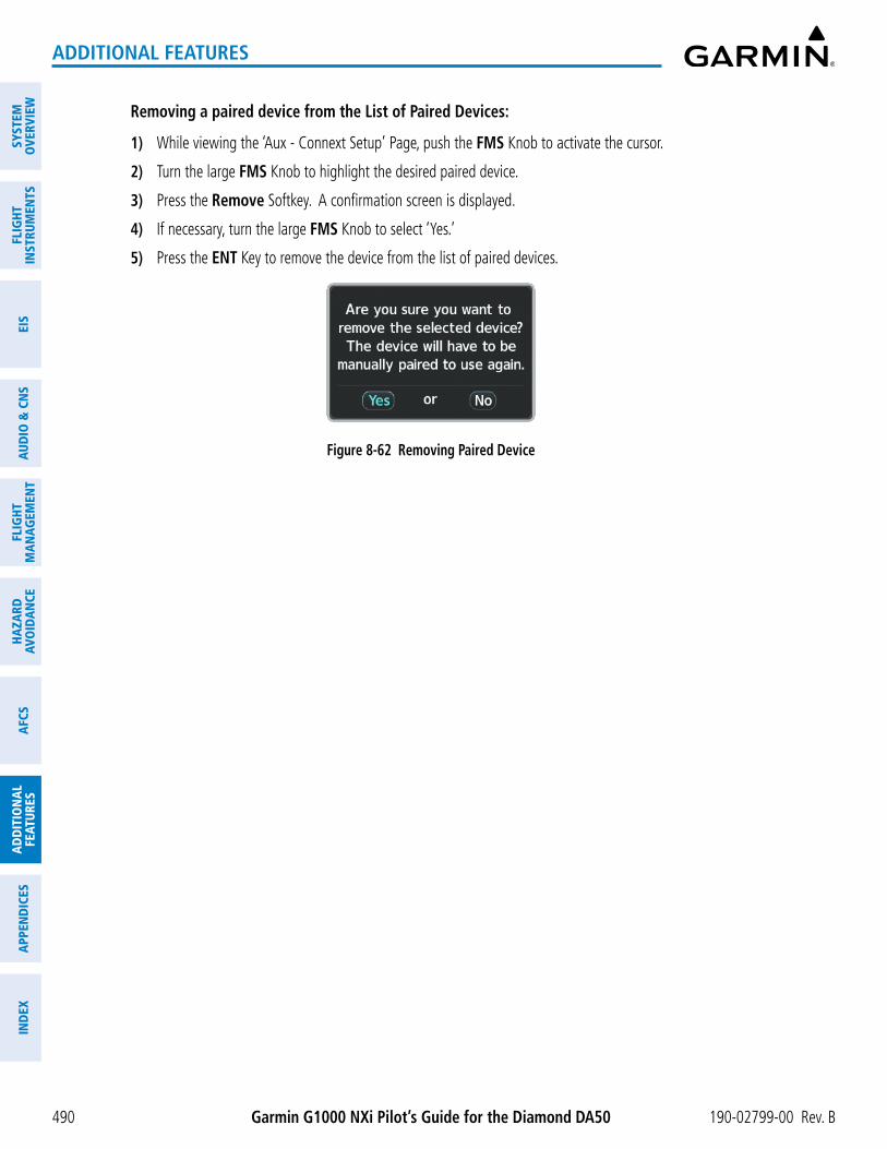
Garmin G1000 NXi Pilot’s Guide for the Diamond DA50 190-02799-00 Rev. B
SYST
EMO
VERV
IEW
FLIG
HTIN
STRU
MEN
TSEI
SAU
DIO
& C
NS
FLIG
HTM
AN
AGEM
ENT
HAZA
RDAV
OID
AN
CEA
FCS
AD
DIT
ION
AL
FEAT
URES
APP
END
ICES
IND
EX
490
ADDITIONAL FEATURES
Removing a paired device from the List of Paired Devices:
1) While viewing the ‘Aux - Connext Setup’ Page, push the FMS Knob to activate the cursor.
2) Turn the large FMS Knob to highlight the desired paired device.
3) Press the Remove Softkey. A confirmation screen is displayed.
4) If necessary, turn the large FMS Knob to select ‘Yes.’
5) Press the ENT Key to remove the device from the list of paired devices.
Figure 8-62 Removing Paired Device

Garmin G1000 NXi Pilot’s Guide for the Diamond DA50190-02799-00 Rev. B
SYSTEMO
VERVIEWFLIG
HTIN
STRUMEN
TSEIS
AUDIO
& CN
SFLIG
HTM
AN
AGEM
ENT
HAZA
RDAVO
IDA
NCE
AFCS
AD
DITIO
NA
LFEATURES
APPEN
DICES
IND
EX
491
ADDITIONAL FEATURES
8.7 SIRIUSXM SATELLITE RADIO (OPTIONAL)
NOTE: Refer to the Hazard Avoidance Section for information about SiriusXM Weather products.
The SiriusXM Satellite Radio entertainment feature provided by the SiriusXM Datalink Receiver (GDL 69A) is available for the pilot’s and passengers’ enjoyment. The SiriusXM Datalink Receiver receives XM Satellite Radio entertainment services at any altitude throughout the Continental U.S. Audio entertainment is available only with the GDL 69A SiriusXM Datalink Receiver, not the GDL 69.
SiriusXM Satellite Radio offers a variety of radio programming reliably over long distances. Based on signals from satellites, coverage far exceeds land-based transmissions. SiriusXM Satellite Radio services are subscription-based. For more information on specific service packages, visit www.siriusxm.com.
ACTIVATING SIRIUSXM SATELLITE RADIO SERVICESThe service is activated by providing SiriusXM Satellite Radio with either one or two coded IDs, depending on
the equipment. The Audio Radio ID (XM Weather), the Data Radio ID (XM Radio), or both, must be provided to SiriusXM Satellite Radio to activate the entertainment subscription.
It is not required to activate both the entertainment and weather service subscriptions separately with the SiriusXM Datalink Receiver. Either service can be activated. SiriusXM Satellite Radio uses the coded IDs to send an activation signal that, when received by the SiriusXM Datalink Receiver, allows it to play entertainment programming.
These IDs are located:
- On the label on the back of the SiriusXM Datalink Receiver.
- On the ‘Aux - XM Information’ Page on the MFD.
- On the XM Satellite Radio Activation Instructions included with the unit.
Contact the installer if the Data Radio ID and the Audio Radio ID cannot be located.
Activating the SiriusXM Satellite Radio services:
1) After gathering the Audio Radio ID and the Data Radio ID, contact SiriusXM and complete subscription activation.
2) Turn the large FMS Knob to select the ‘Aux’ Page Group.
3) Turn the small FMS Knob to select the ‘Aux - XM Radio’ Page.
4) Select the Info Softkey to display the ‘Aux - XM Information’ Page.
5) Verify the desired services are activated.
6) Select the Lock Softkey. A confirmation window is displayed.
7) Turn the large FMS Knob to highlight ‘Yes.’
8) To complete activation, press the ENT Key.

Garmin G1000 NXi Pilot’s Guide for the Diamond DA50 190-02799-00 Rev. B
SYST
EMO
VERV
IEW
FLIG
HTIN
STRU
MEN
TSEI
SAU
DIO
& C
NS
FLIG
HTM
AN
AGEM
ENT
HAZA
RDAV
OID
AN
CEA
FCS
AD
DIT
ION
AL
FEAT
URES
APP
END
ICES
IND
EX
492
ADDITIONAL FEATURES
Figure 8-63 ‘Aux - XM Information’ Page
Audio Radio ID
Weather Products Window
Data Radio ID
If SiriusXM Weather services have not been activated, all the weather product boxes are blank on the ‘Aux - XM Information’ Page. The ‘Service Class’ refers to the groupings of weather products available for subscription.
USING SIRIUSXM RADIOThe ‘Aux - XM Radio’ Page provides information and control of the audio entertainment features of the
SiriusXM Satellite Radio.
Selecting the ‘Aux - XM Radio’ Page:
1) Turn the large FMS Knob to select the ‘Aux’ Page Group.
2) Turn the small FMS Knob to select the ‘Aux - XM Radio’ Page.
3) If not already selected, press the Radio Softkey to show the ‘Aux - XM Radio’ Page where audio entertainment is controlled.

Garmin G1000 NXi Pilot’s Guide for the Diamond DA50190-02799-00 Rev. B
SYSTEMO
VERVIEWFLIG
HTIN
STRUMEN
TSEIS
AUDIO
& CN
SFLIG
HTM
AN
AGEM
ENT
HAZA
RDAVO
IDA
NCE
AFCS
AD
DITIO
NA
LFEATURES
APPEN
DICES
IND
EX
493
ADDITIONAL FEATURES
Figure 8-64 ‘Aux - XM Radio’ Page
Categories Field
Active Channel
Channels List
VolumeField
‘ACTIVE CHANNEL’ BOX AND ‘CHANNELS’ LIST
The ‘Active Channel’ Box on the ‘Aux - XM Radio’ Page displays the currently selected channel. The ‘Channels’ Box on the ‘Aux - XM Radio’ Page shows a list of the available channels for the selected category. Channels can be stepped through one at a time or may be selected directly by channel number.
Selecting a channel from the ‘Channels’ List:
1) While on the ‘Aux - XM Radio’ Page, press the Channel Softkey.
2) Press the CH + Softkey to go up through the list of channels, or move down the list with the CH – Softkey.
Or:
1) From the ‘Aux - XM Radio’ Page, push the FMS Knob to highlight the ‘Channels’ List and turn the large FMS Knob to scroll through the channels.
2) Press the ENT Key to activate the selected channel.
Selecting a channel directly:
1) While on the ‘Aux - XM Radio’ Page, press the Channel Softkey.
2) Press the Direct CH Softkey. The channel number in the ‘Active Channel’ Box is highlighted.
3) Press the numbered softkeys located on the bottom of the display to directly select the desired channel number.
4) Press the ENT Key to activate the selected channel.

Garmin G1000 NXi Pilot’s Guide for the Diamond DA50 190-02799-00 Rev. B
SYST
EMO
VERV
IEW
FLIG
HTIN
STRU
MEN
TSEI
SAU
DIO
& C
NS
FLIG
HTM
AN
AGEM
ENT
HAZA
RDAV
OID
AN
CEA
FCS
AD
DIT
ION
AL
FEAT
URES
APP
END
ICES
IND
EX
494
ADDITIONAL FEATURES
CATEGORY
The Category Box of the ‘Aux - XM Radio’ Page, displays the currently selected category of audio. Categories of channels such as jazz, rock, or news can be selected to list the available channels for a type of music or other contents. One of the optional categories is Presets which is used to view channels that have been programmed by the crew.
Selecting a category:
1) While on the ‘Aux - XM Radio’ Page, press the Category Softkey.
2) Press the CAT + and CAT - softkeys to cycle through the categories.
Or:
1) Push the FMS Knob to activate the cursor.
2) Turn the large FMS Knob to select the ‘Categories’ Field.
3) Using the small FMS Knob, highlight the desired category and press the ENT Key. Selecting ‘All Categories’ places all channels in the list.
Figure 8-65 Categories List
PRESETS
Up to 15 channels from any category can be assigned a preset number. The preset channels are selected by pressing the Presets and More softkeys. Then the preset channel can be selected directly and added to the channel list for the Presets category.
Setting a preset channel number:
1) On the ‘Aux - XM Radio’ Page, while listening to an active channel, press the Presets Softkey to access the first five preset channels (Preset 1 - Preset 5).
2) Press the More Softkey to access the next five channels (Preset 6 – Preset 10), and again to access the last five channels (Preset 11 – Preset 15). Pressing the More Softkey repeatedly cycles through the preset channels.
3) Press any one of the (Preset 1 - Preset 15) softkeys to assign a number to the active channel.
4) Press the Set Softkey on the desired channel number to save the channel as a preset.

Garmin G1000 NXi Pilot’s Guide for the Diamond DA50190-02799-00 Rev. B
SYSTEMO
VERVIEWFLIG
HTIN
STRUMEN
TSEIS
AUDIO
& CN
SFLIG
HTM
AN
AGEM
ENT
HAZA
RDAVO
IDA
NCE
AFCS
AD
DITIO
NA
LFEATURES
APPEN
DICES
IND
EX
495
ADDITIONAL FEATURES
Figure 8-66 Accessing and Selecting SiriusXM Preset Channels
Select Presets to Access the Preset Channels Softkeys
Select More to Cycle Through the Preset
Channels
Select Set to Save Each Preset
Channel
Pressing the Back Softkey, or 45 seconds of softkey inactivity, returns the system to the top level softkeys.
VOLUME
Radio volume is shown as a percentage. Volume level is controlled by pressing the Volume Softkey, which brings up the VOL – and VOL + softkeys.
Adjusting the volume:
1) With the ‘Aux - XM Radio’ Page displayed, press the Volume Softkey.
2) Press the VOL – Softkey to reduce volume or press the VOL + Softkey to increase volume. Once the VOL Softkey is pressed, the volume can also be adjusted using the small FMS Knob. Volume can also be adjusted with the audio panel using the VOL/SQ Control Knob. See the Audio and CNS Section for further details on adjusting volume using the audio panel.
Figure 8-67 Volume Control

Garmin G1000 NXi Pilot’s Guide for the Diamond DA50 190-02799-00 Rev. B
SYST
EMO
VERV
IEW
FLIG
HTIN
STRU
MEN
TSEI
SAU
DIO
& C
NS
FLIG
HTM
AN
AGEM
ENT
HAZA
RDAV
OID
AN
CEA
FCS
AD
DIT
ION
AL
FEAT
URES
APP
END
ICES
IND
EX
496
ADDITIONAL FEATURES
8.8 FLIGHT DATA LOGGING
NOTE: Some aircraft installations may not provide all aircraft/engine data capable of being logged by the system.
NOTE: If a Wireless Transceiver (FS 510) is installed, Flight Data Logging will be available through Connext and the Garmin Pilot™ application. See Garmin Pilot User’s Guide for further information.
The Flight Data Logging feature will automatically store critical flight and engine data on an SD data card (up to 16GB) inserted into the top card slot of the MFD. Approximately 1,000 flight hours can be recorded for each 1GB of available space on the card.
Data is written to the SD card once each second while the MFD is powered on. All flight data logged on a specific date is stored in a file named in a format which includes the date, time, and nearest airport identifier. The file is created automatically each time the system is powered on, provided an SD card has been inserted.
The status of the Flight Data Logging feature can be viewed on the ‘Aux - Utility’ Page. If no SD card has been inserted, “NO CARD” is displayed. When data is being written to the SD card, “LOGGING DATA” is displayed. The .csv file may be viewed with Microsoft Excel® or other spreadsheet applications. The following is a list of data parameters the system is capable of logging.
• Local Date
• Local Time
• UTC Offset
• Active Waypoint
• GPS Fix
• Distance to Next Waypoint
• Bearing to Next Waypoint
• Magnetic Variation
• Latitude/Longitude Position
• Indicated Barometric Altitude
• Selected Barometric Pressure Setting
• GPS Altitude relative to MSL
• WGS84 GPS Altitude (ft)
• OAT (degrees C)
• Indicated airspeed (kts)
• True Airspeed (kts)
• Ground Speed (kts)
• Vertical Speed (fpm)
• GPS Vertical Speed (fpm)
• Attitude Pitch Angle (degrees)
• Attitude Roll Angle (degrees)
• Lateral and Vertical G Force (g)
• Heading (degrees)
• Ground Track (degrees)
• HSI Source (NAV1, NAV2, GPS)
• Selected Course
• Navigation Radio 1&2 Frequency
• COM Radio 1&2 Frequency
• Horizontal/Vertical CDI (fsd)
• GPS Horizontal/Vertical Alert Limit
• WAAS GPS Horizontal Protection Level
• WAAS GPS Vertical Protection Level
• GPS Horizontal Protection Level
• Autopilot Engagement (on/off)
• Autopilot Pitch/Roll Mode
• Autopilot Pitch/ Roll Command
• Wind Speed (kts)
• Wind Direction (degrees)
• Battery (1&2) Volts
• Fuel Quantity L&R (gals)
• Fuel Flow (gph)
• Engine Fuel Pressure (psi)
• Oil Temperature (degrees F)
• Oil Pressure (psi)
• Manifold Pressure (inHg)
• Engine RPM
• Engine Power (%)
The file containing the recorded data will appear in the format shown in the following figure. This file can be imported into most computer spreadsheet applications.
log_YYMMDD_HHMMSS_KIXD.csv
Local Date Local 24hr TimeNearest Airport
(A blank will be inserted if no airport is found)
Figure 8-68 Flight Data Log File Format
Data logging status can be monitored on the ‘Aux - Utility’ Page.

Garmin G1000 NXi Pilot’s Guide for the Diamond DA50190-02799-00 Rev. B
SYSTEMO
VERVIEWFLIG
HTIN
STRUMEN
TSEIS
AUDIO
& CN
SFLIG
HTM
AN
AGEM
ENT
HAZA
RDAVO
IDA
NCE
AFCS
AD
DITIO
NA
LFEATURES
APPEN
DICES
IND
EX
497
ADDITIONAL FEATURES
8.9 MAINTENANCE LOGSThe Maintenance Logs feature allows the pilot and maintenance crews to view event fault monitoring and logged
data on the aircraft. Any log displayed can be selected for viewing. The selected log and its contents are displayed on the MFD. This includes information from the header along with fault events and associated parameters.
The system records CAS, CMC, exceedances, and other critical aircraft data that occur while the aircraft is on the ground or in flight. Central Maintenance Computer (CMC) functionality for acquisition, event/fault monitoring, logging, storage, viewing, and exporting data is resident on the MFD and the PFD. Data is retained in the system when the MFD is not powered on. Each GDU in the system will generate a separate, independent data log.
Exporting CMC logs over multiple means (e.g., SD card, optional Iridium, etc.) is available for any GDU log. In practice, PFD logging will be a backup repository and will only be utilized in the event the MFD is not powered. There is no synchronization process for the logs across GDUs and all log file synchronization will be performed as a post processing step once the data is off the aircraft.
Aircraft data can be viewed from the MFD through the ‘Aux - Maintenance Logs’ Page. Folders, logs, event entries, and trigger values are all accessible.
MENU OPTIONSThe following ‘Page Menu’ Options are available on the ‘Aux - Maintenance Logs’ Page by pressing the MENU
Key on the MFD.
Figure 8-69 Maintenance Log Folder
- Register With Connext: Select this option to open the ‘Connext® Registration’ Window (see the discussion in the following paragraph).
- Folder Settings: Select this option to view the ‘Folder Controls’ Window (see following image). Here you can set ‘Manual’ export options, ‘Auto’ export options, and set ‘Advanced’ Options.
- Delete All Logs in Folder: Select this option to delete all logs in the selected folder.
- Delete All Logs: Select this log to delete all logs from the system.
- Export All Logs in Folder: Select this option to export all logs from the selected folder.
- Cancel Folder Exports: Select this option to cancel all active or queued exports.

Garmin G1000 NXi Pilot’s Guide for the Diamond DA50 190-02799-00 Rev. B
SYST
EMO
VERV
IEW
FLIG
HTIN
STRU
MEN
TSEI
SAU
DIO
& C
NS
FLIG
HTM
AN
AGEM
ENT
HAZA
RDAV
OID
AN
CEA
FCS
AD
DIT
ION
AL
FEAT
URES
APP
END
ICES
IND
EX
498
ADDITIONAL FEATURES
REGISTERING THE SYSTEM WITH GARMIN CONNEXTA subscriber account must be established prior to using the optional Iridium Satellite System as a data transfer
method. Before setting up an Iridium account, obtain the serial number of the Iridium Transceiver (GSR 1) and the System ID by selecting the ‘Aux - System Status’ Page. Then go to flygarmin.com and follow the instructions for establishing an account for Garmin Connext Data Services. After an account has been established, Garmin provides an access code that must be entered and successfully transmitted to the Garmin Connext Service via the Iridium Satellite Network.
Figure 8-70 ‘Aux - System Status’ Page
GSR 1 Serial Number
System ID Number
Registering the system with Connext:
1) With the aircraft outside and having a clear view of the sky, turn the large FMS Knob on the MFD to select the ‘Aux - Maintenance Logs’ Page.
2) Touch the MENU Key, to access the ‘Page Menu.’
Figure 8-71 Select ‘Register With Connext’

Garmin G1000 NXi Pilot’s Guide for the Diamond DA50190-02799-00 Rev. B
SYSTEMO
VERVIEWFLIG
HTIN
STRUMEN
TSEIS
AUDIO
& CN
SFLIG
HTM
AN
AGEM
ENT
HAZA
RDAVO
IDA
NCE
AFCS
AD
DITIO
NA
LFEATURES
APPEN
DICES
IND
EX
499
ADDITIONAL FEATURES
3) Turn the large FMS Knob to select ‘Register With Connext’ and press the ENT Key.
4) Enter the access code provided by Garmin in the ‘Access Code’ Field.
Figure 8-72 Enter Access Code
‘Access Code’ Field
5) Press the ENT Key. ‘Register’ is highlighted.
6) Press the ENT Key. The system contacts Garmin through the Iridium Network. System registration is complete when the ‘Current Registration & Subscriptions’ Window displays the correct information for the Airframe, Tail Number, Airframe Serial Number, and Iridium Serial Number.
7) When finished, push the FMS Knob to remove the ‘Connext Registration’ Window.
Accessing and navigating the ‘Aux - Maintenance Logs’ Page:
1) Use the large FMS Knob to select the ‘Aux - Maintenance Logs’ Page.
2) Push the FMS Knob momentarily to activate the flashing cursor.
3) Turn the large FMS Knob to highlight the desired folder.
Figure 8-73 ‘Aux - Maintenance Logs’ Top Level Page

Garmin G1000 NXi Pilot’s Guide for the Diamond DA50 190-02799-00 Rev. B
SYST
EMO
VERV
IEW
FLIG
HTIN
STRU
MEN
TSEI
SAU
DIO
& C
NS
FLIG
HTM
AN
AGEM
ENT
HAZA
RDAV
OID
AN
CEA
FCS
AD
DIT
ION
AL
FEAT
URES
APP
END
ICES
IND
EX
500
ADDITIONAL FEATURES
4) Press the ENT Key to access the folder.
Figure 8-74 Maintenance Log Folder
5) Turn the large FMS Knob to highlight the desired event.
6) Press the View Softkey.
7) Once you have accessed the ‘Aux - CMC Log Viewer’ Page, push the FMS Knob momentarily to activate the flashing cursor.
8) Turn either FMS Knob to highlight the desired event entry.
9) Press the Details Softkey to view the trigger values.

Garmin G1000 NXi Pilot’s Guide for the Diamond DA50190-02799-00 Rev. B
SYSTEMO
VERVIEWFLIG
HTIN
STRUMEN
TSEIS
AUDIO
& CN
SFLIG
HTM
AN
AGEM
ENT
HAZA
RDAVO
IDA
NCE
AFCS
AD
DITIO
NA
LFEATURES
APPEN
DICES
IND
EX
501
ADDITIONAL FEATURES
Figure 8-75 Trigger Values View
10) Press the Data Softkey to read further details about the event data. Press the Entries Softkey to return the cursor to the ‘Event Entries’ Field.
Exporting an event log:
1) Use the large FMS Knob to select the ‘Aux - Maintenance Logs’ Page.
2) Push the FMS Knob momentarily to activate the flashing cursor.
3) Turn the large FMS Knob to highlight the desired folder.
4) Press the ENT Key to access the folder.
5) Turn the large FMS Knob to highlight the desired event log.
6) With the ‘Export’ Option highlighted on the selected log, press the ENT Key. The ‘Export Log’ Window is now displayed.

Garmin G1000 NXi Pilot’s Guide for the Diamond DA50 190-02799-00 Rev. B
SYST
EMO
VERV
IEW
FLIG
HTIN
STRU
MEN
TSEI
SAU
DIO
& C
NS
FLIG
HTM
AN
AGEM
ENT
HAZA
RDAV
OID
AN
CEA
FCS
AD
DIT
ION
AL
FEAT
URES
APP
END
ICES
IND
EX
502
ADDITIONAL FEATURES
Figure 8-76 ‘Export Log’ Window Figure 8-77 Log Transfer Options
7) Use the large FMS Knob to highlight the ‘Select Manual Export Mode’ Field if not already selected.
8) Turn the small FMS Knob to choose an available transfer method (see previous image).
9) Press the ENT Key.
10) Use the large FMS Knob to select the ‘Select Data To Export’ Field.
Figure 8-78 ‘Export Log’ Window
11) Use the small FMS Knob, select ‘Complete Log’ or ‘New Data Only’ as applicable and push the ENT Key.
12) Use the large FMS Knob to select ‘OK’ and press the ENT Key to begin the data transfer.
13) Transfer status, export status, and the ‘Cancel’ option are now available.

Garmin G1000 NXi Pilot’s Guide for the Diamond DA50190-02799-00 Rev. B
SYSTEMO
VERVIEWFLIG
HTIN
STRUMEN
TSEIS
AUDIO
& CN
SFLIG
HTM
AN
AGEM
ENT
HAZA
RDAVO
IDA
NCE
AFCS
AD
DITIO
NA
LFEATURES
APPEN
DICES
IND
EX
503
ADDITIONAL FEATURES
8.10 ELECTRONIC CHECKLISTS
NOTE: The checklists presented here are for example only and may differ from checklists available for the airframe. The information described in this section is not intended to replace the checklist information described in the approved current pertinent flight manual or the Pilot Safety and Warning Supplements document.
NOTE: Garmin is not responsible for the content of checklists. Checklists are created by the aircraft manufacturer. Modifications or updates to the checklists are coordinated through the aircraft manufacturer. The user cannot edit these checklists.
The MFD is able to display electronic checklists which allow a pilot to quickly find the proper procedure on the ground and during each phase of flight. Checklists are stored in internal memory once loaded into the system. New checklist files, if made available by the manufacturer, may be installed by placing them on an SD card and inserting the SD card into the top slot or bottom slot of either GDU. After system startup and the new checklists are installed, the SD card may be removed (or left in place if data logging is desired).
If the SD card contains an invalid checklist file or no checklist, the message displayed on the power initialization page is ‘Checklist File: Invalid’ or ‘Checklist File: N/A’ (not available) and the Checklist Softkey is not available.
Accessing and navigating checklists:
1) From any page on the MFD (except the ‘EIS’ Page), press the Checklist Softkey or turn the large FMS Knob to select the ‘CHKLST’ Page Group. (Note the ‘CHKLST’ Page Group only displays when the checklist database has been successfully loaded to the system.)
2) Touch the Group Softkey to select the ‘Group’ Field.
3) Turn the FMS Knob to select the desired Group and press the ENT Key.
4) Turn the FMS Knob to select the desired checklist and press the ENT Key. The first checklist item is selected with white text surrounded by a cyan box.

Garmin G1000 NXi Pilot’s Guide for the Diamond DA50 190-02799-00 Rev. B
SYST
EMO
VERV
IEW
FLIG
HTIN
STRU
MEN
TSEI
SAU
DIO
& C
NS
FLIG
HTM
AN
AGEM
ENT
HAZA
RDAV
OID
AN
CEA
FCS
AD
DIT
ION
AL
FEAT
URES
APP
END
ICES
IND
EX
504
ADDITIONAL FEATURES
Figure 8-79 ‘Before Starting Engine’ Checklist
5) Press the ENT Key or the Check Softkey to check the selected checklist item. The line item turns green and a checkmark is placed in the associated box. The next line item is automatically selected for checking. Either FMS Knob can be used to scroll through the checklist and select the desired checklist item. Press the CLR Key or Uncheck Softkey to remove a check mark from an item.
Figure 8-80 First Checklist Item Completed
6) When all checklist items have been checked, ‘*Checklist Finished*’ is displayed in green text at the bottom left of the checklist window. If all items in the checklist have not be checked, ‘*Checklist Not Finished*’ will be displayed in amber text.

Garmin G1000 NXi Pilot’s Guide for the Diamond DA50190-02799-00 Rev. B
SYSTEMO
VERVIEWFLIG
HTIN
STRUMEN
TSEIS
AUDIO
& CN
SFLIG
HTM
AN
AGEM
ENT
HAZA
RDAVO
IDA
NCE
AFCS
AD
DITIO
NA
LFEATURES
APPEN
DICES
IND
EX
505
ADDITIONAL FEATURES
Figure 8-81 Checklist Completed
7) ‘Go To Next Checklist?’ will be highlighted by the cursor. Press the ENT Key to advance to the next checklist.
Accessing emergency procedures:
1) From any page on the MFD (except the ‘EIS’ Page), press the Checklist Softkey or turn the large FMS Knob to select the ‘CHKLST’ Page Group. (Note the ‘CHKLST’ Page Group only displays when the checklist database has been successfully loaded to the system.)
2) Press the EMER Softkey.
3) Turn the FMS Knob to select the desired emergency checklist and press the ENT Key.
4) Press the ENT Key or the Check Softkey to check the selected checklist item. The line item turns green and a checkmark is placed in the associated box. The next line item is automatically selected for checking. Either FMS Knob can be used to scroll through the checklist and select the desired checklist item. Press the CLR Key or Uncheck Softkey to remove a check mark from an item.
5) When all checklist items have been checked, ‘*Checklist Finished*’ is displayed in green text at the bottom left of the checklist window. If all items in the checklist have not be checked, ‘*Checklist Not Finished*’ will be displayed in amber text.
6) ‘Go To Next Checklist?’ will be highlighted by the cursor. Press the ENT Key to advance to the next checklist.
7) Press the Return Softkey to return to the previous checklist.

Garmin G1000 NXi Pilot’s Guide for the Diamond DA50 190-02799-00 Rev. B
SYST
EMO
VERV
IEW
FLIG
HTIN
STRU
MEN
TSEI
SAU
DIO
& C
NS
FLIG
HTM
AN
AGEM
ENT
HAZA
RDAV
OID
AN
CEA
FCS
AD
DIT
ION
AL
FEAT
URES
APP
END
ICES
IND
EX
506
ADDITIONAL FEATURES
8.11 ELECTRONIC STABILITY & PROTECTION (OPTIONAL)
NOTE: ESP is designed to discourage exceeding the normal flight envelope. It is not designed or capable of performing the necessary recovery procedures due to encounters with adverse flight conditions and environments.
NOTE: Refer to the current version of the pertinent flight manual to determine approval of ESP functionality.
The Electronic Stability and Protection (ESP™) feature is intended to discourage the exceedance of attitude and established airspeed parameters. This feature will only function when the aircraft is above 200 feet AGL and the autopilot is not engaged.
ESP engages when the aircraft exceeds one or more conditions beyond the normal flight parameters (e.g., pitch, roll, Vne). Enhanced stability for each condition is provided by applying a force to the appropriate control surface to return the aircraft to the normal flight envelope. This is perceived by the pilot as resistance to control movement in the undesired direction when the aircraft approaches a steep attitude or high airspeed.
As the aircraft deviates further from the normal attitude and/or airspeed, the force increases (up to an established maximum) to encourage control movement in the direction necessary to return to the normal attitude and/or airspeed range. Except in the case of high airspeed, when maximum force is reached, force remains constant up to the maximum engagement limit. Above the maximum engagement limit, forces are no longer applied. There is no maximum engagement related to a high airspeed condition.
The pilot can interrupt ESP by pressing and holding either the Control Wheel Steering (CWS) Switch or the Autopilot Disconnect (AP DISC) Switch. Upon releasing the CWS Switch or the AP DISC Switch, ESP force will again be applied, provided aircraft attitude and/or airspeed are within their respective engagement limits. ESP can also be overridden by overpowering the servo’s mechanical torque limit.
ESP can be enabled or disabled on the ‘Aux - System Setup 2’ Page on the MFD.
Enabling/disabling ESP:
1) Turn the large FMS Knob to select the ‘Aux’ Page Group.
2) Turn the small FMS Knob to select the ‘Aux - System Setup’ Page.
3) If necessary, press the Setup 2 Softkey to display the ‘Aux - System Setup 2’ Page.
4) Push the FMS Knob to activate the cursor.
5) Turn the large FMS Knob to place the cursor in the ‘Stability & Protection’ Field.
6) Turn the small FMS Knob to select ‘Enabled’ or ‘Disabled.’
7) Push the FMS Knob to remove the cursor.
ESP is automatically enabled at system initialization.
ROLL ENGAGEMENTRoll Limit Indicators are displayed on the roll scale at 45° right and left, indicating where ESP will engage
(see the following figure). As roll attitude exceeds 45°, ESP will engage and the on-side Roll Limit Indicator will move to 30°. The Roll Limit Indicator is now showing where ESP will disengage as roll attitude decreases.

Garmin G1000 NXi Pilot’s Guide for the Diamond DA50190-02799-00 Rev. B
SYSTEMO
VERVIEWFLIG
HTIN
STRUMEN
TSEIS
AUDIO
& CN
SFLIG
HTM
AN
AGEM
ENT
HAZA
RDAVO
IDA
NCE
AFCS
AD
DITIO
NA
LFEATURES
APPEN
DICES
IND
EX
507
ADDITIONAL FEATURES
Figure 8-82 ESP Roll Engagement Indication (ESP NOT Engaged)
Roll Limit IndicatorESP Engage (45°)
Roll Limit IndicatorESP Engage (45°)
Figure 8-83 Roll Increasing to ESP Engagement
Before ESP Engage
ESP Engage (45°)Aircraft Roll Attitude = 44°
After ESP Engage
ESP Disengage (30°)Aircraft Roll Attitude = 46°
Once engaged, ESP force will be applied between 30° and 75°, as illustrated in the following figure. The force increases as roll attitude increases and decreases as roll attitude decreases. The applied force is intended to encourage pilot input that returns the airplane to a more normal roll attitude. As roll attitude decreases, ESP will disengage at 30°.

Garmin G1000 NXi Pilot’s Guide for the Diamond DA50 190-02799-00 Rev. B
SYST
EMO
VERV
IEW
FLIG
HTIN
STRU
MEN
TSEI
SAU
DIO
& C
NS
FLIG
HTM
AN
AGEM
ENT
HAZA
RDAV
OID
AN
CEA
FCS
AD
DIT
ION
AL
FEAT
URES
APP
END
ICES
IND
EX
508
ADDITIONAL FEATURES
Figure 8-84 ESP Roll Operating Range When Engaged (Force Increases as Roll Increases & Decreases as Roll Decreases)
0º 10º10º 20º20º30º30º
45º45º
60º60º
75º75º
90º90º
ESP is automatically disengaged if the aircraft reaches the autopilot roll engagement attitude limit of 75° (see following figure).
Figure 8-85 Roll Attitude Autopilot Engagement Limit (ESP Engaged)
ESP Upper Disengage Limit (75°)Aircraft Roll Attitude = 74°
PITCH ENGAGEMENTESP engages at 17° nose-up and 15° nose-down. Once ESP is engaged, it will apply increasing opposing
force between 17° and 20° nose-up and between 15° and 18° nose-down, as indicated in the following figure. Maximum opposing force is applied between 20° and 50° nose-up and between 18° and 50° nose-down. ESP disengages when 50° is exceeded in a nose-up or nose-down attitude.
With ESP engaged, and the aircraft in a nose-up condition, opposing force steadily decreases from 20° nose-up to 15° nose-up as aircraft pitch moves toward zero degrees. ESP disengages at 15° nose-up. With ESP engaged, and the aircraft in a nose-down condition, opposing force steadily decreases from 18° nose-down to 13° nose-down as aircraft pitch moves toward zero degrees. ESP disengages at 13° nose-down.
The opposing force increases or decreases depending on the pitch angle and the direction of pitch travel. This force is intended to encourage movement in the pitch axis in the direction of the normal pitch attitude range for the aircraft.

Garmin G1000 NXi Pilot’s Guide for the Diamond DA50190-02799-00 Rev. B
SYSTEMO
VERVIEWFLIG
HTIN
STRUMEN
TSEIS
AUDIO
& CN
SFLIG
HTM
AN
AGEM
ENT
HAZA
RDAVO
IDA
NCE
AFCS
AD
DITIO
NA
LFEATURES
APPEN
DICES
IND
EX
509
ADDITIONAL FEATURES
There are no indications marking the pitch ESP engage and disengage limits in these nose-up/nose-down conditions.
Figure 8-86 - ESP Pitch Operating Range When Engaged (Force Increases as Pitch Increases & Decreases as Pitch Decreases)
30˚25˚20˚15˚10˚5˚0˚5˚10˚15˚20˚25˚30˚
30˚25˚20˚15˚10˚5˚0˚5˚10˚15˚20˚25˚30˚
35˚40˚45˚50˚
35˚40˚45˚50˚
50˚45˚40˚35˚
50˚45˚40˚35˚
ESP
ESP
LOW AIRSPEED PROTECTIONLow airspeed protection utilizes configurable airspeed limits to protect against an underspeed condition.
Low speed protection is provided as part of the ESP feature. When the stall warning system determines a stall condition is imminent, ESP will engage, applying force in the direction necessary to lower the nose of the aircraft.
HIGH AIRSPEED PROTECTIONHigh airspeed protection utilizes configurable airspeed limits to protect against an overspeed condition.
Exceeding Vne will result in ESP applying force to raise the nose of the aircraft. When the high airspeed condition is remedied, ESP force is no longer applied.

Garmin G1000 NXi Pilot’s Guide for the Diamond DA50 190-02799-00 Rev. B
SYST
EMO
VERV
IEW
FLIG
HTIN
STRU
MEN
TSEI
SAU
DIO
& C
NS
FLIG
HTM
AN
AGEM
ENT
HAZA
RDAV
OID
AN
CEA
FCS
AD
DIT
ION
AL
FEAT
URES
APP
END
ICES
IND
EX
510
ADDITIONAL FEATURES
8.12 DATABASE MANAGEMENT
CAUTION: Never disconnect power to the system when loading a database. Power interruption during the database loading process could result in maintenance being required to reboot the system.
NOTE: The system responds to a terminal procedure based on data coded within that procedure in the Navigation Database. Differences in system operation may be observed among similar types of procedures due to differences in the Navigation Database coding specific to each procedure.
NOTE: The pilot/operator must review and be familiar with Garmin’s database exclusion list as discussed in SAIB CE-14-04 to determine what data may be incomplete. The database exclusion list can be viewed at flygarmin.com by selecting ‘Database Exclusions List.’
NOTE: If the pilot/operator wants or needs to adjust the database, contact Garmin Product Support.
NOTE: Garmin requests the flight crew report any observed discrepancies related to database information. These discrepancies could come in the form of an incorrect procedure; incorrectly identified terrain, obstacles and fixes; or any other displayed item used for navigation or communication in the air or on the ground. Go to flygarmin.com and select ‘Aviation Data Error Report.’
CYCLE NUMBER AND REVISIONDatabases that may be available include FliteCharts, ChartView, IFR/VFR Charts, Checklist, Navigation,
Basemap Land, Terrain, Obstacle, SafeTaxi, and Airport Directory Databases. Data is revised and expiration dates vary. Data is still viewable during a period that extends from the cycle expiration date to the disables date. After applying power to the system, the ‘Aux - Databases’ Page displays the current status of the databases. As an example, see the table below for the various initialization page displays and the definition of each. The expiration date and disables date varies for each database.
Example Page Initialization Display Text
Table 8-5 Database Initialization Annunciations

Garmin G1000 NXi Pilot’s Guide for the Diamond DA50190-02799-00 Rev. B
SYSTEMO
VERVIEWFLIG
HTIN
STRUMEN
TSEIS
AUDIO
& CN
SFLIG
HTM
AN
AGEM
ENT
HAZA
RDAVO
IDA
NCE
AFCS
AD
DITIO
NA
LFEATURES
APPEN
DICES
IND
EX
511
ADDITIONAL FEATURES
White text, such as ‘FliteCharts Data Expires’ plus a date, indicates the chart database is current. Amber text, such as ‘Chart data is out of date!’ or ‘FliteCharts Data: Disabled”, indicates charts are no longer viewable and have expired.
Database time critical information can also be found on the ‘Aux - System Status’ Page. The database Region, Cycle Number, Effective, Expires, and Disables dates of the subscription appear in either white or amber text. Dates shown in white are current data. Dates shown in amber indicate the data is not within the current subscription period. Refer to Updating Garmin Databases in Appendix for instructions on revising databases.
Viewing database information:
1) Turn the large FMS Knob to select the ‘Aux’ Page Group.
2) Turn the small FMS Knob to select the ‘Aux - System Status’ Page.
3) Touch the softkey corresponding to the display (MFD1 or PFD1) for which the database information will be viewed. The flashing cursor activates in the ‘MFD1 Database’ or the ‘PFD1 Database’ Window.
4) Scroll to display the appropriate database information by turning the FMS Knob or pressing the ENT Key until the applicable database information is shown.
Or:
1) Turn the large FMS Knob to select the ‘Aux’ Page Group.
2) Turn the small FMS Knob to select the ‘Aux - Databases’ Page.
3) Push the FMS Knob to activate the flashing cursor.
4) Scroll to display the appropriate database information by turning the FMS Knob until the applicable database information is shown. Applicable database status is shown in the ‘Status’ Field.
Database cycle numbers are in a format such as YYTI or YYII, which are deciphered as follows:
YYTI
» YY – Indicates the last two digits of the year (e.g., 21 represents 2021)
» T – Indicates the database type (e.g., S is for SafeTaxi, D is for Airport Directory).
» I – Indicates the numerical issue of the database for the year (e.g., 5 is the fifth issue of the year).
YYII
» YY – Indicates the last two digits of the year (e.g., 21 represents 2021).
» II – Indicates the numerical issue of the database for the year (e.g., 05 is the fifth issue of the year).

Garmin G1000 NXi Pilot’s Guide for the Diamond DA50 190-02799-00 Rev. B
SYST
EMO
VERV
IEW
FLIG
HTIN
STRU
MEN
TSEI
SAU
DIO
& C
NS
FLIG
HTM
AN
AGEM
ENT
HAZA
RDAV
OID
AN
CEA
FCS
AD
DIT
ION
AL
FEAT
URES
APP
END
ICES
IND
EX
512
ADDITIONAL FEATURES
Example Text on MFD at Initialization Database Cycle Number Format Revision Cycle
YYII 28 days
YYMI Not Applicable
YYTI Not Applicable
YYBI 56 days
YYSI 56 days
YYDI 56 days
YYII 28 days
YYII 14 days
YYII 56 days
Table 8-6 Database Cycle Number and Revision

Garmin G1000 NXi Pilot’s Guide for the Diamond DA50190-02799-00 Rev. B
SYSTEMO
VERVIEWFLIG
HTIN
STRUMEN
TSEIS
AUDIO
& CN
SFLIG
HTM
AN
AGEM
ENT
HAZA
RDAVO
IDA
NCE
AFCS
AD
DITIO
NA
LFEATURES
APPEN
DICES
IND
EX
513
ADDITIONAL FEATURES
8.13 ABNORMAL OPERATION
DATALINK TROUBLESHOOTINGFor troubleshooting purposes,check the ‘LRU Information’ Box on the ‘Aux - System Status’ Page for the
Iridium Receiver (GSR 56), Wireless Transceiver (FS 510), or SiriusXM Datalink Receiver (GDL 69) status, serial number, and software version number. If a failure has been detected in the LRU, the status is marked with a red ‘X.’
Viewing the ‘Aux - System Status’ Page:
1) Turn the large FMS Knob to select the ‘Aux’ Page Group.
2) Turn the small FMS Knob to select the ‘Aux - System Status’ Page.
3) Push the FMS Knob to activate the flashing cursor in the ‘LRU Information’ Window.
4) Scroll to display the appropriate LRU information by turning the FMS Knob or pressing the ENT Key until the applicable database information is shown.
Figure 8-87 ‘LRU Information’ Window on ‘System Status’ Page

Garmin G1000 NXi Pilot’s Guide for the Diamond DA50 190-02799-00 Rev. B
SYST
EMO
VERV
IEW
FLIG
HTIN
STRU
MEN
TSEI
SAU
DIO
& C
NS
FLIG
HTM
AN
AGEM
ENT
HAZA
RDAV
OID
AN
CEA
FCS
AD
DIT
ION
AL
FEAT
URES
APP
END
ICES
IND
EX
514
ADDITIONAL FEATURES
QUICK TROUBLESHOOTING
Some quick troubleshooting steps listed below can be performed to find the possible cause of a failure.
» Ensure the installed hardware has an active subscription or account (e.g., SiriusXM subscription).
» Perform a quick check of the circuit breakers to ensure that power is applied to the applicable hardware.
» If a failure still exists, the following messages may provide insight as to the possible problem:
Message Message Location DescriptionCHECK ANTENNA ‘Aux - XM Information’ Page (MFD) Datalink Receiver antenna error; service required
UPDATING ‘Aux - XM Information’ Page (MFD) Datalink Receiver updating encryption code
NO SIGNAL ‘Aux - XM Information’ Page (MFD) Loss of signal; signal strength too low for receiver
LOADING ‘Aux - XM Radio’ Page (MFD) Acquiring channel audio or information
OFF AIR ‘Aux - XM Radio’ Page (MFD) Channel not in service
-------- ‘Aux - XM Radio’ Page (MFD) Missing channel information
ACTIVATION REQUIRED ‘Aux - XM Information’ Page (MFD) SiriusXM subscription is not activated
DETECTING ACTIVATION ‘Aux - XM Information’ Page (MFD) SiriusXM subscription is activating.
WAITING FOR DATA... ‘Aux - XM Information’ Page (MFD) SiriusXM subscription confirmed downloading data.
Table 8-7 SiriusXM Datalink Receiver (GDL 69A) Messages

190-02799-00 Rev. B Garmin G1000 NXi Pilot’s Guide for the Diamond DA50
SYSTEMO
VERVIEWFLIG
HTIN
STRUMEN
TSEIS
AUDIO
& CN
SFLIG
HTM
AN
AGEM
ENT
HAZA
RDAVO
IDA
NCE
AFCS
AD
DITIO
NA
LFEATURES
APPEN
DICES
IND
EX
515
APPENDIX A
ANNUNCIATIONS AND ALERTS
NOTE: The current version of the pertinent flight manual supersedes information found in this document.
CREW ALERTING SYSTEM (CAS)The Crew Alerting System (CAS) displays Warning, Caution and Advisory messages in the CAS window on
the PFD. Text color is based on priority level. A gray horizontal line separates messages that are acknowledged from messages that are unacknowledged. Higher priority messages are displayed at the top of the window. Lower priority messages are displayed towards the bottom of the window. When the maximum number of messages that can be displayed in the CAS window is reached, pressing the CAS softkey enables CAS Up and CAS Dn softkeys for scrolling through the messages. A CAS scroll-bar is displayed on the right side of the CAS window. CAS messages are also displayed in the ‘Alerts’ Window.
Figure A-1 CAS Scrolling
CASWindow
CASScroll-bar
CASScrolling Softkeys
CAS MESSAGE PRIORITIZATION
NOTE: Information on CAS messages in this pilot’s guide is always superseded by the current version of the pertinent flight manual.
CAS messages are grouped by criticality (warning, caution, advisory, safe operating) and sorted by order of appearance (most recent messages on top). The color of the message is based on its urgency and on required action.
» Warning (red) – Immediate crew awareness and action required. When a new warning CAS message appears in the ‘CAS’ Window, it flashes (inversely red on white) in conjunction with the Alerts Softkey (see Figure A-2) and is accompanied by a continuous aural tone. Pressing the Alerts Softkey acknowledges the presence of the warning alert, stops the aural chime, and extinguishes the Alerts Softkey annunciation. Warning messages are also displayed in the ‘Alerts’ Window.

Garmin G1000 NXi Pilot’s Guide for the Diamond DA50 190-02799-00 Rev. B
SYST
EMO
VERV
IEW
FLIG
HTIN
STRU
MEN
TSEI
SAU
DIO
& C
NS
FLIG
HTM
AN
AGEM
ENT
HAZA
RDAV
OID
AN
CEA
FCS
AD
DIT
ION
AL
FEAT
URES
APP
END
ICES
IND
EX
516
APPENDIX A
» Caution (amber) – Immediate crew awareness and possible future corrective action required. When a new caution message appears in the CAS Window, it is shown in black on amber inverse video in conjunction with the Alerts Softkey (see Figure A-2) and is accompanied by a single chime. The ‘Check Gear’ CAS message has an associated voice alert. Pressing the Alerts Softkey acknowledges the presence of the caution alert and extinguishes the Alerts Softkey annunciation. Caution messages are also displayed in the ‘Alerts’ Window.
» Advisory (white) – Crew awareness required and subsequent action may be required. When a new advisory message appears in the CAS Window, it is shown in black on white inverse video in conjunction with the white Alerts Softkey (see Figure A-2). Pressing the white Alerts Softkey acknowledges the presence of the advisory alert and extinguishes the Alerts Softkey annunciation. Advisory messages are also displayed in the ‘Alerts’ Window.
Alerting System after softkey acknowledgement
CAS Window
‘Alerts’ Window
Alerts Softkey
Alerting System before softkey acknowledgement
CAS Window
Flashing Message Softkey
Figure A-2 CAS Display and Acknowledgement
Unacknowledged CAS Messages
CAS Messages in ‘Alerts’ Window
CAS MESSAGESRed CAS window text signifies warnings, amber signifies cautions and white signifies advisories. See the
current version of the pertinent flight manual for recommended pilot actions.
WARNING MESSAGES Warning messages are accompanied by a continuous aural tone. See the current version of the pertinent
flight manual for recommended pilot actions.
CAS Message Title ‘Alerts’ Window Message TextALTN 1 AMPS Engine alternator 1 output is >70 amps.
ALTN 2 AMPS Engine alternator 2 output is >70 amps.
BAG DOOR OPEN Baggage door is not closed.
COOLANT TEMP Coolant temp is high.
ENG OIL TEMP Engine oil temperature is > 125 deg C.

190-02799-00 Rev. B Garmin G1000 NXi Pilot’s Guide for the Diamond DA50
SYSTEMO
VERVIEWFLIG
HTIN
STRUMEN
TSEIS
AUDIO
& CN
SFLIG
HTM
AN
AGEM
ENT
HAZA
RDAVO
IDA
NCE
AFCS
AD
DITIO
NA
LFEATURES
APPEN
DICES
IND
EX
517
APPENDIX A
CAS Message Title ‘Alerts’ Window Message TextFUEL PRESS Eng fuel pressure is in low or high red range.
GB OIL TEMP Gearbox oil temperature high.
L DOOR OPEN Front left door is not closed.
L FUEL TEMP Left fuel temperature is high.
OIL PRES Engine oil pressure is <2 bar or >7.5 bar.
R DOOR OPEN Front right door is not closed.
R FUEL TEMP Right fuel temperature is high.
REAR DOOR OPEN Rear door is not closed.
STARTER Engine starter is engaged.
CAUTION MESSAGESCaution messages are accompanied by a single chime. The ‘Check Gear’ CAS message has an associated
voice alert. See the current version of the pertinent flight manual for recommended pilot actions.
CAS Message Title ‘Alerts’ Window Message TextALTN 1 FAIL Engine alternator 1 has failed.
ALTN 2 FAIL Engine alternator 2 has failed.
CHECK GEAR Landing gear retracted.
COOLANT LVL Coolant level low.
DEIC LVL LO De-icing level is low.
DEIC PRES LO De-icing pressure is low.
DEIC PRES HI De-icing pressure is high.
ECU A FAIL Engine ECU A has failed.
ECU B FAIL Engine ECU B has failed.
FUEL LOW Main tank fuel quantity is low.
OXY PRESS LO Oxygen system pressure is below 500 PSI.
PITOT FAIL Pitot heat has failed.
PITOT HT OFF Pitot heat is off.
PROP DE-ICE FAIL Propeller de-ice has failed.
STALL HT FAIL Stall warning heat has failed.
STALL HT OFF Stall warning heat is off.
STALL WARN FAIL Stall warning system failure.
VOLTS LOW Essential bus voltage is < 25 volts.
ADVISORY MESSAGES
CAS Message Title ‘Alerts’ Window Message TextFUEL XFER Fuel transfer in progress.
GLOW ON Engine glow plugs active.
OXY PRESS LO Oxygen system pressure is below 850 PSI.
PROP DE-ICE ON Propeller de-ice is on.

Garmin G1000 NXi Pilot’s Guide for the Diamond DA50 190-02799-00 Rev. B
SYST
EMO
VERV
IEW
FLIG
HTIN
STRU
MEN
TSEI
SAU
DIO
& C
NS
FLIG
HTM
AN
AGEM
ENT
HAZA
RDAV
OID
AN
CEA
FCS
AD
DIT
ION
AL
FEAT
URES
APP
END
ICES
IND
EX
518
APPENDIX A
VOICE ALERTSThe following audio alerts are announced by the system using a voice of male or female gender. If the
optional Terrain Awareness and Warning System is installed, voice alerts are also generated (refer to the Hazard Avoidance Section for more information on TAWS alerts).
Voice Alert Alert Trigger“Airspeed” The aircraft is in an underspeed condition.
“Check Gear” Landing gear retracted.“Minimums, Minimums” Issued when the aircraft transitions through the minimum descent altitude/decision height (MDA/
DH).“Traffic” TIS voice alert - issued when a Traffic Advisory (TA) is issued.
“Traffic Not Available” TIS voice alert - issued when the TIS traffic system fails or cannot communicate.“Traffic, Traffic” TAS voice alert - issued when a Traffic Advisory (TA) is issued.
“Traffic Advisory System Test Passed”
TAS voice alert - issued when the TAS passes a pilot-initiated self test.
“Traffic Advisory System Test Failed”
TAS voice alert - issued when the TAS fails a pilot-initiated self test.
“Vertical Track” Aircraft is one minute from Top of Descent - issued only when vertical navigation is enabled.
ALERTING SYSTEM TEST The system issues audio alert tones when specific system conditions are met. Should the #1 GIA fail, audio
and voice alerts are not generated. The annunciation tone an annunciation lights may be tested from the ‘Aux - System Status’ Page.
Testing the annunciation tones and annunciation lights:
1) Use the FMS Knob to select the ‘Aux - System Status’ Page.
2) Select the ANN Test Softkey.
Or:
1) Press the MENU Key.
2) Highlight ‘Enable Annunciator Test Mode’ and press the ENT Key.

190-02799-00 Rev. B Garmin G1000 NXi Pilot’s Guide for the Diamond DA50
SYSTEMO
VERVIEWFLIG
HTIN
STRUMEN
TSEIS
AUDIO
& CN
SFLIG
HTM
AN
AGEM
ENT
HAZA
RDAVO
IDA
NCE
AFCS
AD
DITIO
NA
LFEATURES
APPEN
DICES
IND
EX
519
APPENDIX A
SYSTEM MESSAGE ANNUNCIATIONS
NOTE: Upon applying power, certain windows remain invalid as system equipment begins to initialize. All windows should be operational within one minute of applying power. If any window continues to remain flagged, the system should be serviced by a Garmin-authorized repair facility.
System Messages convey messages to the flight crew regarding problems with the system. Typically, a large red or amber ‘X’ appears in a window when a related LRU fails or detects invalid data. When a new message is issued, the Message Softkey flashes to alert the flight crew. It continues to flash until acknowledged by pressing the softkey. Active messages are displayed in the ‘Alerts’ Window in white text. Messages that have become inactive change to gray text. The Message Softkey flashes again if the state of a displayed message changes or a new message is displayed. Inactive messages can be removed from the ‘Alerts’ Window by pressing the Alerts Softkey, which also removes the ‘Alerts’ Window’ from the PFD.
Figure A-4 System Messages in ‘Alerts’ Window
‘Alerts’Window
Alerts Annunciation (After softkey is pressed)
System Annunciation Amber 'X'
Figure A-3 System Message Softkey
Message Annunciation (Prior to softkey being pressed)
System Annunciation Amber 'X'
System Annunciation
Red ‘X’System
Annunciation Red ‘X’

Garmin G1000 NXi Pilot’s Guide for the Diamond DA50 190-02799-00 Rev. B
SYST
EMO
VERV
IEW
FLIG
HTIN
STRU
MEN
TSEI
SAU
DIO
& C
NS
FLIG
HTM
AN
AGEM
ENT
HAZA
RDAV
OID
AN
CEA
FCS
AD
DIT
ION
AL
FEAT
URES
APP
END
ICES
IND
EX
520
APPENDIX A
SYSTEM MESSAGES
NOTE: This section provides information regarding messages that may be displayed by the system. Knowledge of the aircraft, systems, flight conditions, and other existing operational priorities must be considered when responding to a message.
This section describes various system messages. Certain messages are issued due to an LRU or LRU function failure. Such messages are normally accompanied by a corresponding red or amber ‘X’ annunciation as shown previously in the System Message Annunciations section.
System Message CommentsABORT APR – Loss of GPS navigation. Abort approach.
Abort approach due to loss of GPS navigation.
ADC1 SERVICE – GDC1 needs service. Return unit for repair.
A failure has been detected in the ADC1 / GDC1. The system should be serviced.
AFCS 1 INOP: PFT FAIL – Pre-Flight Test Failure
AFCS Pre-Flight Test failure.
AFCS INOP: ADC 1 COMM – Check ADC 1 and GIA1 wiring
The ADC unit is inoperative due to a loss of communication path to a GIA.
AFCS INOP: ADC 1 COMM – Check ADC 1 and GIA2 wiring
The ADC unit is inoperative due to a loss of communication path to a GIA.
AFCS INOP: ADC 1 FAULT – ADC Failure
The AFCS is unavailable due to invalid data from the ADC unit.
AFCS INOP: ADC 1 POWER – ADC 1 power loss. Check power.
The ADC unit is inoperative due to a loss of communication path to a GIA.
AFCS INOP: AHRS 1 COMM – Check AHRS 1 and GIA1 wiring
Check AHRS 1 and GIA1 wiring.
AFCS INOP: AHRS 1 COMM – Check AHRS 1 and GIA2 wiring
Check AHRS 2 and GIA2 wiring.
AFCS INOP: AHRS 1 FAULT – AHRS Failure
The AFCS is unavailable due to invalid data from the AHRS unit.
AFCS INOP: AHRS 1 POWER – AHRS 1 power loss. Check power.
The AHRS unit is inoperative due to a loss of power.
AFCS INOP: GIA1 SERVOS COMM – Check GIA1 485 bus wiring to servos
The GSA servos are inoperative due to a loss of communication path to a GIA.
AFCS INOP: GIA2 SERVOS COMM – Check GIA2 485 bus wiring to servos
The GSA servos are inoperative due to a loss of communication path to a GIA.
AFCS INOP: PIT SERVO COMM – Check PIT servo wiring to GIA1
The GSA servo is inoperative due to a loss of communication path to a GIA. The system should be serviced.
AFCS INOP: PIT SERVO COMM – Check PIT servo wiring to GIA2
The GSA servo is inoperative due to a loss of communication path to a GIA. The system should be serviced.
AFCS INOP: PIT SERVO FAULT – PIT Servo failure
The GSA servo is inoperative due to an internal servo fault. The system should be serviced.
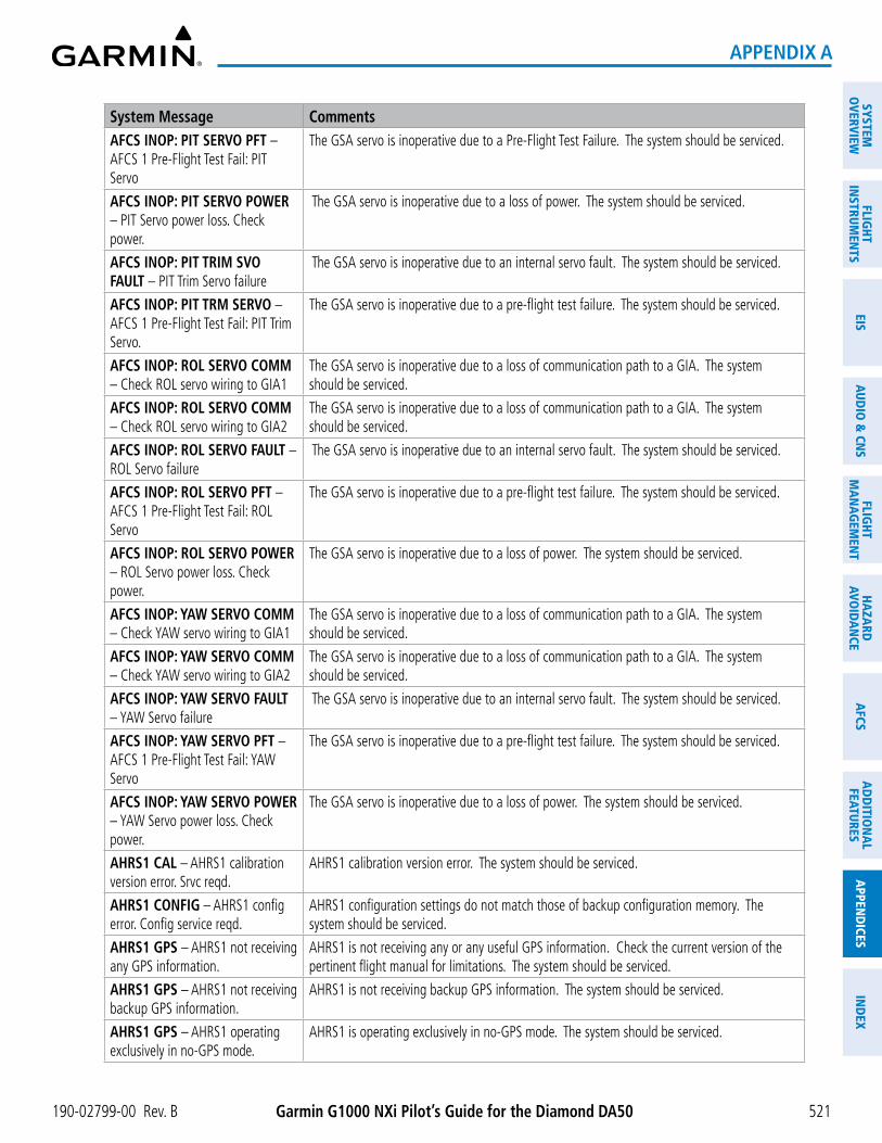
190-02799-00 Rev. B Garmin G1000 NXi Pilot’s Guide for the Diamond DA50
SYSTEMO
VERVIEWFLIG
HTIN
STRUMEN
TSEIS
AUDIO
& CN
SFLIG
HTM
AN
AGEM
ENT
HAZA
RDAVO
IDA
NCE
AFCS
AD
DITIO
NA
LFEATURES
APPEN
DICES
IND
EX
521
APPENDIX A
System Message CommentsAFCS INOP: PIT SERVO PFT – AFCS 1 Pre-Flight Test Fail: PIT Servo
The GSA servo is inoperative due to a Pre-Flight Test Failure. The system should be serviced.
AFCS INOP: PIT SERVO POWER – PIT Servo power loss. Check power.
The GSA servo is inoperative due to a loss of power. The system should be serviced.
AFCS INOP: PIT TRIM SVO FAULT – PIT Trim Servo failure
The GSA servo is inoperative due to an internal servo fault. The system should be serviced.
AFCS INOP: PIT TRM SERVO – AFCS 1 Pre-Flight Test Fail: PIT Trim Servo.
The GSA servo is inoperative due to a pre-flight test failure. The system should be serviced.
AFCS INOP: ROL SERVO COMM – Check ROL servo wiring to GIA1
The GSA servo is inoperative due to a loss of communication path to a GIA. The system should be serviced.
AFCS INOP: ROL SERVO COMM – Check ROL servo wiring to GIA2
The GSA servo is inoperative due to a loss of communication path to a GIA. The system should be serviced.
AFCS INOP: ROL SERVO FAULT – ROL Servo failure
The GSA servo is inoperative due to an internal servo fault. The system should be serviced.
AFCS INOP: ROL SERVO PFT – AFCS 1 Pre-Flight Test Fail: ROL Servo
The GSA servo is inoperative due to a pre-flight test failure. The system should be serviced.
AFCS INOP: ROL SERVO POWER – ROL Servo power loss. Check power.
The GSA servo is inoperative due to a loss of power. The system should be serviced.
AFCS INOP: YAW SERVO COMM – Check YAW servo wiring to GIA1
The GSA servo is inoperative due to a loss of communication path to a GIA. The system should be serviced.
AFCS INOP: YAW SERVO COMM – Check YAW servo wiring to GIA2
The GSA servo is inoperative due to a loss of communication path to a GIA. The system should be serviced.
AFCS INOP: YAW SERVO FAULT – YAW Servo failure
The GSA servo is inoperative due to an internal servo fault. The system should be serviced.
AFCS INOP: YAW SERVO PFT – AFCS 1 Pre-Flight Test Fail: YAW Servo
The GSA servo is inoperative due to a pre-flight test failure. The system should be serviced.
AFCS INOP: YAW SERVO POWER – YAW Servo power loss. Check power.
The GSA servo is inoperative due to a loss of power. The system should be serviced.
AHRS1 CAL – AHRS1 calibration version error. Srvc reqd.
AHRS1 calibration version error. The system should be serviced.
AHRS1 CONFIG – AHRS1 config error. Config service reqd.
AHRS1 configuration settings do not match those of backup configuration memory. The system should be serviced.
AHRS1 GPS – AHRS1 not receiving any GPS information.
AHRS1 is not receiving any or any useful GPS information. Check the current version of the pertinent flight manual for limitations. The system should be serviced.
AHRS1 GPS – AHRS1 not receiving backup GPS information.
AHRS1 is not receiving backup GPS information. The system should be serviced.
AHRS1 GPS – AHRS1 operating exclusively in no-GPS mode.
AHRS1 is operating exclusively in no-GPS mode. The system should be serviced.

Garmin G1000 NXi Pilot’s Guide for the Diamond DA50 190-02799-00 Rev. B
SYST
EMO
VERV
IEW
FLIG
HTIN
STRU
MEN
TSEI
SAU
DIO
& C
NS
FLIG
HTM
AN
AGEM
ENT
HAZA
RDAV
OID
AN
CEA
FCS
AD
DIT
ION
AL
FEAT
URES
APP
END
ICES
IND
EX
522
APPENDIX A
System Message CommentsAHRS1 GPS – AHRS1 using backup GPS source.
AHRS1 is using the backup GPS path. Primary GPS path has failed. The system should be serviced when practical.
AHRS1 SERVICE – AHRS1 needs service. Return unit for repair.
A failure has been detected in AHRS1. The system should be serviced.
AHRS1 SRVC – AHRS1 Magnetic-field model needs update.
AHRS1 earth magnetic field model is out of date. Update magnetic field model when practical.
AHRS1 TAS – AHRS1 not receiving valid airspeed.
AHRS1 is not receiving true airspeed from the air data computer. The AHRS relies on GPS information to augment the lack of airspeed. The system should be serviced.
AP DISC: AP ENGAGE TIMEOUT –
Failed to engage AP due to activation time-out of required resources.
AP DISC: GFC POWER LOSS – Abnormal AP disconnect due to loss of GFC power.
AP DISC: GIA REVERSION – Abnormal AP disconnect while switching to alternate GIA.
AP DISC: HSDB CONNECTIVITY –
Abnormal AP disconnect due to loss of data bus connectivity.
AP DISC: INVALID DATA – PIT servo
Abnormal AP disconnect due to invalid data in pitch servo.
AP DISC: INVALID DATA – ROL servo
Abnormal AP disconnect due to invalid data in roll servo.
AP DISC: INVALID DATA – Servo PFT
Abnormal AP disconnect due to failed servo pre-flight test..
AP DISC: INVALID DATA – PFD Abnormal AP disconnect due to loss of primary flight display.
AP DISC: INVALID DATA – ADC Abnormal AP disconnect due to servo receiving invalid ADC data.
AP DISC: INVALID DATA – SWPS Abnormal AP disconnect due to stall warning activated.
AP DISC: INVALID DATA – AHRS Abnormal AP disconnect due to invalid AHRS data.
AP DISC: INVALID DATA – Cross-side GIA
Abnormal AP disconnect due to cross-side GIA commanding an AP disconnect.
AP DISC: INVALID DATA – Flight Director parameters
Abnormal AP disconnect due to flight director receiving invalid required parameter.
AP DISC: INVALID DATA – Servo comm failure
Abnormal AP disconnect due to loss of servo communication.
AP DISC: MET ACTIVE Abnormal AP disconnect due to use of manual electric trim.
AP DISC: PRIMARY TRIM – Primary Trim not Selected.
Abnormal AP disconnect due to incorrect trim card selection
AP DISC: SENSOR MISCOMPARE – ADC
Abnormal AP disconnect due to use of manual electric trim.
AP DISC: SENSOR MISCOMPARE – AHRS
Abnormal AP disconnect due to miscompared AHRS sensor readings.
AP DISC: SOFTWARE Abnormal AP disconnect due to software fault.
AP DISC: X-SIDE DISCONNECT – Cross-side disconnect
Abnormal AP disconnect due to cross-side GIA commanding an AP disconnect.
AP DISC: YD NOT AVAILABLE Abnormal AP disconnect due to loss of yaw damper.
APR INACTV – Approach is not active.
The system notifies the pilot the loaded approach is not active. Activate approach when required.

190-02799-00 Rev. B Garmin G1000 NXi Pilot’s Guide for the Diamond DA50
SYSTEMO
VERVIEWFLIG
HTIN
STRUMEN
TSEIS
AUDIO
& CN
SFLIG
HTM
AN
AGEM
ENT
HAZA
RDAVO
IDA
NCE
AFCS
AD
DITIO
NA
LFEATURES
APPEN
DICES
IND
EX
523
APPENDIX A
System Message CommentsARSPC AHEAD – Airspace ahead - less than 10 minutes.
Special use airspace is ahead of aircraft. The aircraft will penetrate the airspace within 10 minutes.
ARSPC NEAR – Airspace near – less than 2 nm.
Special use airspace is within 2 nm of the aircraft position.
ARSPC NEAR – Airspace near and ahead.
Special use airspace is near and ahead of the aircraft position.
ARM VNAV CLIMB – Reset altitude preselect to arm climb.
Adjust altitude preselect value to enable VNAV climb.
ARM VNAV DESCENT – Reset altitude preselect to arm descent.
Adjust altitude preselect value to enable VNAV descent.
AUDIO MANIFEST – Audio software mismatch, communication halted.
The GIA has incorrect software installed. The system should be serviced.
AUTOGLIDE/GLIDE RING – Unavailable above [#}.
Autoglide / glide ring unavailable above specified altitude.
BARO QFE – Confirm reference ELEV matches DEST before landing
Confirm reference ELEV matches DEST before landing
CHECK CRS – Database course for LOC1 / [LOC ID] is [CRS]°.
Selected course for LOC1 differs from published localizer course by more than 10 degrees.
CHECK CRS – Database course for LOC2 / [LOC ID] is [CRS]°.
Selected course for LOC2 differs from published localizer course by more than 10 degrees.
CHECK NAV – Approach ID mismatch / <LOC>
Selected course for LOC2 differs from published localizer course by more than 10 degrees.
CNFG MODULE – PFD1 configuration module is inoperative.
The specified GDU configuration module backup memory has failed. The system should be serviced.
COM #1 INOP: CAL – Factory COM Calibration Lost or Corrupted.
COM 1 and/or COM 2 calibration version error. Check COM calibration.
COM #1 INOP: CRNT – Check COM Current.
COM 1 current is low. Check COM current.
COM #1 INOP: INTRL – COM Internal Fault.
COM 1 has an internal fault.
COM #1 INOP - SYNTH – COM Synthesizer Lock Fault.
COM 1 has a synthesizer lock fault.
COM #1 INOP - VOLT – Check COM Voltage.
COM 1 has low voltage.
COM #2 INOP: CAL – Factory COM Calibration Lost or Corrupted.
COM 2 calibration version error. Check COM calibration.
COM #1 REDUCED TX POWER – Reduced COM transmit power.
COM 1 has a reduced transmission power.
COM #2 INOP: CRNT – Check COM Current.
COM 2 current is low. Check COM current.
COM #2 INOP: INTRL – COM Internal Fault.
COM 2 has an internal fault.
COM #2 INOP: SYNTH – COM Synthesizer Lock Fault.
COM 2 has a synthesizer lock fault.

Garmin G1000 NXi Pilot’s Guide for the Diamond DA50 190-02799-00 Rev. B
SYST
EMO
VERV
IEW
FLIG
HTIN
STRU
MEN
TSEI
SAU
DIO
& C
NS
FLIG
HTM
AN
AGEM
ENT
HAZA
RDAV
OID
AN
CEA
FCS
AD
DIT
ION
AL
FEAT
URES
APP
END
ICES
IND
EX
524
APPENDIX A
System Message CommentsCOM #2 INOP: VOLT – Check COM Voltage.
COM 2 has low voltage.
COM #2 REDUCED TX POWER – Reduced COM transmit power.
COM 2 has a reduced transmission power.
COM1 MANIFEST – COM1 software mismatch, communication halted.
The COM 1 has incorrect software installed. The system should be serviced.
COM1 PTT – COM1 push-to-talk key is stuck.
The COM1 external push-to-talk switch is stuck in the enable (or “pressed”) position. Press the PTT switch again to cycle its operation. If the problem persists, the system should be serviced.
COM2 MANIFEST – COM2 software mismatch, communication halted.
The COM 2 has incorrect software installed. The system should be serviced.
COM2 PTT – COM2 push-to-talk key is stuck.
The COM2 external push-to-talk switch is stuck in the enable (or “pressed”) position. Press the PTT switch again to cycle its operation. If the problem persists, the system should be serviced.
DATA LOST – Pilot stored data was lost. Recheck settings.
The pilot profile data was lost. System reverts to default pilot profile and settings. The pilot may reconfigure the MFD & PFDs with preferred settings, if desired.
DATABASE CHANGE – Verify stored airways.
This occurs when a stored flight plan contains an airway that is no longer consistent with the navigation database. This alert is issued only after a navigation database update. Verify use of airways in stored flight plans and reload airways as needed.
DATABASE CHANGE – Verify user modified procedures.
This occurs when a stored flight plan contains procedures that have been manually edited. This alert is issued only after a navigation database update. Verify the user-modified procedures in stored flight plans are correct and current.
DATABASES EXPIRED – Restart avionics to activate standby databases.
The databases in the system have expired. Restart the system to move the standby databases to active status.
DATABASES MISMATCHED – Restart displays to correct mismatch.
The GDUs have different database versions or regions. Restart the system to move the standby databases to active status.
DB ERR – Database error exists. Database verification error. Reload databases with new data card. If problem persists, delete databases and reload with a new card.
DB MISMATCH – Navigation database mismatch. Xtalk is off.
The GDUs have different navigation database versions or regions installed. Crossfill is off. Check the ‘Avionics Status’ Screen to determine versions or regions. Also, check the ‘Avionics Status’ Screen for a database synchronization function not completed. After synchronization is complete, power must be turned off, then on.
DB MISMATCH – Obstacle database mismatch.
The GDUs have different obstacle database versions or regions installed. Check the ‘Avionics Status’ Screen to determine versions or regions. Also, check the ‘Avionics Status’ Screen for a database synchronization function not completed. After synchronization is complete, power must be turned off, then on.
DB MISMATCH – Terrain database mismatch.
The GDUs have different terrain database versions or regions installed. Check the ‘Avionics Status’ Screen to determine versions or regions. Also, check the ‘Avionics Status’ Screen for a database synchronization function not completed. After synchronization is complete, power must be turned off, then on.

190-02799-00 Rev. B Garmin G1000 NXi Pilot’s Guide for the Diamond DA50
SYSTEMO
VERVIEWFLIG
HTIN
STRUMEN
TSEIS
AUDIO
& CN
SFLIG
HTM
AN
AGEM
ENT
HAZA
RDAVO
IDA
NCE
AFCS
AD
DITIO
NA
LFEATURES
APPEN
DICES
IND
EX
525
APPENDIX A
System Message CommentsDB UPDATE IN PROGRESS – See Database Page for more information.
Databases are updating. See the ‘Aux - Databases’ Page on the MFD.
DIG GMA1 MANIFEST – DIG GMA 1 software mismatch, communication halted.
The digital audio controller has incorrect software installed. The system should be serviced.
DISABLE GP TO ARM CLIMB – Press NAV to enable VNAV track change.
Disable AFCS APPR mode to enable VNAV.
DISABLE GS TO ARM CLIMB – Press NAV to enable VNAV track change.
Disable AFCS APPR mode to enable VNAV.
ESP CONFIG – ESP config error. Config service REQ’D.
ESP is not configured properly. The system should be serviced.
ESP DEGRADE – ESP IAS mode is inoperative.
IAS mode of ESP is inoperative. The system should be serviced.
ESP FAIL – ESP is inoperative. The ESP function has failed and is inoperative. The system should be serviced.
ESP OFF – ESP selected off. Electronic Stability and Protection has been disabled on the ‘Avionics Settings’ Screen.
FAILED PATH – A data path has failed.
A data path between two or more LRUs has failed. The system should be serviced when practical.
FLAPS FAIL – FLAP FAIL
FLIGHT PLAN CATALOG – Last plan in catalog was overwritten by an import.
Flight plan storage full. Last plan in the flight plan storage was overwritten by an imported flight plan.
FPL TRUNC – Flight plan has been truncated.
This occurs when a newly installed navigation database eliminates an obsolete approach or arrival used by a stored flight plan. The obsolete procedure is removed from the flight plan. Update flight plan with current arrival or approach.
FPL WPT LOCK – Flight plan waypoint is locked.
Upon power-on, the system detects that a stored flight plan waypoint is locked. This occurs when an aviation database update eliminates an obsolete waypoint. The flight plan cannot find the specified waypoint and flags this message. This can also occur with user waypoints in flight plans that are deleted. Remove the waypoint from the flight plan if it no longer exists in any database, or update the waypoint name/identifier to reflect the new information.
FPL WPT MOVE – Flight plan waypoint moved.
The system has detected that a waypoint coordinate has changed due to a new navigation database update. Verify that stored flight plans contain correct waypoint locations.
FS 510 MANIFEST – FS 510 software mismatch.
Incorrect software version. The system should be serviced.
FS510 CARD ERROR – FS510 not detected in MFD Bottom Slot.
The SD card was removed from the bottom card slot of the MFD. The SD card needs to be reinserted.
GCU1 CONFIG – GCU Config error. Config service REQ’D.
GCU configuration settings do not match those of backup configuration memory. The system should be serviced.
GCU1 FAIL – GCU is inoperative. A failure has been detected in the GCU. The GCU is unavailable.
GCU1 KEYSTK – GCU1 [key name] key is stuck.
Multiple keys stuck on the GCU1 bezel. Attempt to free the stuck key by pressing it several times. The system should be serviced if the problem persists.
GCU1 MANIFEST – GCU software mismatch, Communication halted.
The GCU has incorrect software installed. The system should be serviced.
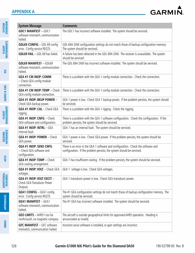
Garmin G1000 NXi Pilot’s Guide for the Diamond DA50 190-02799-00 Rev. B
SYST
EMO
VERV
IEW
FLIG
HTIN
STRU
MEN
TSEI
SAU
DIO
& C
NS
FLIG
HTM
AN
AGEM
ENT
HAZA
RDAV
OID
AN
CEA
FCS
AD
DIT
ION
AL
FEAT
URES
APP
END
ICES
IND
EX
526
APPENDIX A
System Message CommentsGDC1 MANIFEST – GDC1 software mismatch, communication halted.
The GDC1 has incorrect software installed. The system should be serviced.
GDL69 CONFIG – GDL 69 config error. Config service REQ’D.
GDL 69A SXM configuration settings do not match those of backup configuration memory. The system should be serviced.
GDL69 FAIL – GDL 69 has failed. A failure has been detected in the GDL 69A SXM. The receiver is unavailable. The system should be serviced.
GDL69 MANIFEST – GDL69 software mismatch, communication halted.
The GDL 69A SXM has incorrect software installed. The system should be serviced.
GEA #1 CM INOP: COMM – Check GEA config module connection.
There is a problem with the GEA 1 config module connection. Check the connection.
GEA #1 CM INOP: TEMP – Check GEA config module connection.
There is a problem with the GEA 1 config module connection. Check the connection.
GEA #1 INOP: BKUP POWER – Check GEA backup power.
GEA 1 power is low. Check GEA 1 backup power. If the problem persists, the system should be serviced.
GEA #1 INOP: CAL – Check GEA rigging.
There is a problem with the GEA 1 rigging. Check the rigging.
GEA #1 INOP: CNFG – Check GEA software and configuration.
There is a problem with the GEA 1 software configuration. Check the configuration. If the problem persists, the system should be serviced.
GEA #1 INOP: INTRL – GEA internal fault.
GEA 1 has an internal fault. The system should be serviced.
GEA #1 INOP: POWER – Check GEA power.
GEA 1 power is low. Check GEA power. If the problem persists, the system should be serviced.
GEA #1 INOP: SENS CNFG – Check GEA software and configuration.
There is an error in the GEA 1 software and configuration. Check the software and configuration. If the problem persists, the system should be serviced.
GEA #1 INOP: TEMP – Check GEA cooling arrangement.
GEA 1 has insufficient cooling. If the problem persists, the system should be serviced.
GEA #1 INOP: VOLT – Check GEA voltages.
GEA 1 voltage is low. Check GEA voltages.
GEA #1 INOP: VOLT EXCIT – Check GEA Transducer Power Outputs.
GEA 1 transducer power is low. Check GEA transducer power.
GEA1 CONFIG – GEA1 config error. Config service REQ’D.
The #1 GEA configuration settings do not match those of backup configuration memory. The system should be serviced.
GEA1 MANIFEST – GEA1 software mismatch, communication halted.
The #1 GEA has incorrect software installed. The system should be serviced.
GEO LIMITS – AHRS1 too far north/south, no magnetic compass.
The aircraft is outside geographical limits for approved AHRS operation. Heading is annunciated as invalid.
GFC MANIFEST – GFC software mismatch, communication halted.
Incorrect servo software is installed, or gain settings are incorrect.

190-02799-00 Rev. B Garmin G1000 NXi Pilot’s Guide for the Diamond DA50
SYSTEMO
VERVIEWFLIG
HTIN
STRUMEN
TSEIS
AUDIO
& CN
SFLIG
HTM
AN
AGEM
ENT
HAZA
RDAVO
IDA
NCE
AFCS
AD
DITIO
NA
LFEATURES
APPEN
DICES
IND
EX
527
APPENDIX A
System Message CommentsGIA #1 INOP - CRNT – Check GIA Current.
GIA 1 current is low. The current should be checked.
GIA #1 INOP: SERL – Internal GIA Serial Communication Fault.
GIA 1 serial communication fault. Check GIA serial communication.
GIA #1 INOP: VOLT – Check GIA Voltage.
GIA 1 low voltage. Check voltage.
GIA #1 OVER TEMP – Check GIA Temperature.
GIA 1 is reporting an over-temperature condition.
GIA #2 INOP - CRNT – Check GIA Current.
GIA 2 current is low. The current should be checked.
GIA #2 INOP: SERL – Internal GIA Serial Communication Fault.
GIA 2 serial communication fault. Check GIA serial communication.
GIA #2 INOP: VOLT – Check GIA Voltage.
GIA 2 low voltage. Check voltage.
GIA #2 OVER TEMP – Check GIA Temperature.
GIA 2 is reporting an over-temperature condition.
GIA1 MANIFEST – GIA1 software mismatch, communication halted.
The GIA1 1 has incorrect software installed. The system should be serviced.
GIA2 MANIFEST – GIA2 software mismatch, communication halted.
The GIA 2 has incorrect software installed. The system should be serviced.
GMA XTALK – GMA crosstalk error has occurred.
The GMA Audio Controllers are not communicating with each other. The system should be serviced.
GMA1 AUX MANIFEST – Software mismatch, communication halted.
The digital audio controller has incorrect software installed. The system should be serviced.
GMA1 CONFIG – GMA1 config error. Config service REQ’D.
The audio panel configuration settings do not match backup configuration memory. The system should be serviced.
GMA1 FAIL – GMA1 is inoperative. The audio controller has detected a failure. The audio controller is unavailable. The system should be serviced.
GMA1 INSPECTION REQUIRED – Redundant power supply is not present.
GMA1 backup power source is not connected. The system should be serviced.
GMA1 MANIFEST – DIG GMA 1 software mismatch, communication halted.
The audio controller has incorrect software installed. The system should be serviced.
GMA1 SERVICE – GMA1 needs service. Return unit for repair.
The audio controller self-test has detected a problem in the unit. Certain audio functions may still be available, and the audio controller may still be usable. The system should be serviced when practical.
GPS #1 CHK RQRD - BATT – GPS Battery Needs Replacement.
The GPS battery needs to be replaced.
GPS #1 INOP - CAL – Factory GPS Calibration Lost Or Corrupted.
GPS 1 factory calibration lost or corrupted. Check GPS calibration. Check GPS calibration.
GPS #2 CHK RQRD - BATT – GPS Battery Needs Replacement.
The GPS battery needs to be replaced.

Garmin G1000 NXi Pilot’s Guide for the Diamond DA50 190-02799-00 Rev. B
SYST
EMO
VERV
IEW
FLIG
HTIN
STRU
MEN
TSEI
SAU
DIO
& C
NS
FLIG
HTM
AN
AGEM
ENT
HAZA
RDAV
OID
AN
CEA
FCS
AD
DIT
ION
AL
FEAT
URES
APP
END
ICES
IND
EX
528
APPENDIX A
System Message CommentsGPS #2 INOP - CAL – Factory GPS Calibration Lost Or Corrupted.
GPS 2 factory calibration lost or corrupted. Check GPS calibration. Check GPS calibration.
GPS NAV LOST – Loss of GPS navigation. Enable GPS sensors.
Loss of GPS navigation due to GPS being disabled
GPS NAV LOST – Loss of GPS navigation. GPS fail.
Loss of GPS navigation due to GPS failure.
GPS NAV LOST – Loss of GPS navigation. Position error.
Loss of GPS navigation due to position error.
GRS1 MANIFEST – GRS1 software mismatch, communication halted.
The AHRS1 has incorrect software installed. The system should be serviced.
GSR1 FAIL – GSR1 has failed. A failure has been detected in GSR1. The system should be serviced.
GTS CONFIG – GTS Config error. Config service REQ’D.
The GTS and GDU have different copies of the GTS configuration, or the Mode S address is invalid. The system should be serviced.
GTS MANIFEST – GTS software mismatch, communication halted.
The GTS has incorrect software installed. The system should be serviced.
GTX1 MANIFEST – GTX1 software mismatch, communication halted.
The transponder has incorrect software installed. The system should be serviced.
GWX CONFIG – GWX config error. Config service REQ’D.
GWX configuration settings do not match those of the GDU configuration. The system should be serviced.
GWX MANIFEST – GWX software mismatch, communication halted.
The GWX has incorrect software installed. The system should be serviced.
GWX SERVICE – GWX needs service.
A failure has been detected in the GWX. The GWX may still be usable.
HDG FAULT – AHRS1 magnetometer fault has occurred.
A fault has occurred in the #1 GMU. Heading is flagged as invalid. The AHRS uses GPS for backup mode operation. The system should be serviced.
HOLD EXPIRED – Holding EFC time expired.
Expect Further Clearance (EFC) time has expired for the User Defined Hold.
INSIDE ARSPC – Inside airspace. The aircraft is inside the airspace.
LOI – GPS integrity lost. Crosscheck with other NAVS.
GPS integrity is insufficient for the current phase of flight.
LOSS OF GPS NAVIGATION – Insufficient Satellite Reception.
Loss of GPS navigation due to insufficient satellite reception.
LOW BANK ACTIVE – Disengage for approach.
Low Bank mode is active. Disengage to continue approach.
LRG MAG VAR – Verify all course angles.
The GDU internal model cannot determine the exact magnetic variance for geographic locations near the magnetic poles. Displayed magnetic course angles may differ from the actual magnetic heading by more than 2°.
LRU CARD1 ERR – LRU card 1 is invalid.
The SD card in the top card slot of the LRU is invalid.
LRU CARD1 REM – LRU card 1 was removed. Reinsert card.
The SD card was removed from the top card slot of the LRU. The SD card needs to be reinserted.

190-02799-00 Rev. B Garmin G1000 NXi Pilot’s Guide for the Diamond DA50
SYSTEMO
VERVIEWFLIG
HTIN
STRUMEN
TSEIS
AUDIO
& CN
SFLIG
HTM
AN
AGEM
ENT
HAZA
RDAVO
IDA
NCE
AFCS
AD
DITIO
NA
LFEATURES
APPEN
DICES
IND
EX
529
APPENDIX A
System Message CommentsLRU CARD2 ERR – LRU card 2 is invalid.
The SD card in the bottom card slot of the LRU is invalid.
LRU CARD2 REM – LRU card 2 was removed. Reinsert card.
The SD card was removed from the bottom card slot of the LRU. The SD card needs to be reinserted.
LRU CARD3 ERR – LRU card 3 is invalid.
The internal SD micro card of the LRU is invalid.
LRU CARD3 REM – LRU card 3 was removed. Reinsert card.
The internal SD micro card was removed. The SD card needs to be reinserted.
LRU CONFIG – LRU config error. Config service REQ’D.
The LRU configuration settings do not match backup configuration memory. The system should be serviced.
LRU COOLING – LRU has poor cooling. Reducing power usage.
The LRU is overheating and is reducing power consumption by dimming the display. If problem persists, the system should be serviced.
LRU DB ERR – LRU obstacle database error exists.
The LRU detected a failure in the obstacle database. Reload the database with new data card. If problem persists, delete database and reload with a new card.
LRU DB ERR – LRU terrain database error exists.
The LRU detected a failure in the terrain database. Reload the database with new data card. If problem persists, delete database and reload with a new card.
LRU DB ERR – LRU terrain database missing.
The terrain database is present on another LRU, but is missing on the specified LRU.
LRU FAN FAIL – LRU internal fan failure. Unit needs service.
The LRU cooling fan has failed. The system should be serviced.
LRU REPLACEMENT – [LRU name].
The system has detected an LRU replacement. Perform LRU replacement software or full configuration loading procedure.
LRU SERVICE – LRU needs service. Return unit for repair.
The LRU self-test has detected a problem. The system should be serviced.
LRU SOFTWARE – LRU mismatch, communication halted.
LRU has different software versions installed. The system should be serviced.
LRU TERRAIN DSP – LRU Terrain awareness display unavailable.
One of the terrain or obstacle databases required for TAWS in the LRU is missing or invalid.
LRU VOLTAGE – LRU has low voltage. Reducing power usage.
LRU voltage is low. The system should be serviced.
MANIFEST – Software mismatch, communication halted.
The GSR1 has incorrect software installed. The system should be serviced.
MFD1 CARD 1 ERR – MFD1 card 1 is invalid.
The SD card in the top card slot of the MFD contains invalid data.
MFD1 CARD 1 REM – MFD1 card 1 was removed. Reinsert card.
The SD card was removed from the top card slot of the MFD. The SD card needs to be reinserted.
MFD1 CARD 2 ERR – MFD1 card 2 is invalid.
The SD card in the bottom card slot of the MFD contains invalid data.
MFD1 CARD 2 REM – MFD1 card 2 was removed. Reinsert card.
The SD card was removed from the bottom card slot of the MFD. The SD card needs to be reinserted.
MFD1 CHK REQD: BTM SD – Bottom SD card error.
The GDU bottom SD card is inoperative.

Garmin G1000 NXi Pilot’s Guide for the Diamond DA50 190-02799-00 Rev. B
SYST
EMO
VERV
IEW
FLIG
HTIN
STRU
MEN
TSEI
SAU
DIO
& C
NS
FLIG
HTM
AN
AGEM
ENT
HAZA
RDAV
OID
AN
CEA
FCS
AD
DIT
ION
AL
FEAT
URES
APP
END
ICES
IND
EX
530
APPENDIX A
System Message CommentsMFD1 CHK REQD: INT SD – Internal SD card error.
The GDU internal SD card is inoperative.
MFD1 CHK REQD: TOP SD – Top SD card error.
The GDU top SD card is inoperative.
MFD1 CMC INOP: Config – CMC system inop due to invalid config.
The CMC system logging capability is inoperative due to file system corruption.
MFD1 CMC INOP: Corrupt – CMC INOP due to file system corruption.
The CMC system logging capability is inoperative due to file system corruption.
MFD1 CMC INOP: MEM Full – Internal SD card full.
The CMC system logging capability is inoperative due to insufficient memory.
MFD1 CONFIG – MFD1 config error. Config service REQ’D.
The MFD configuration settings do not match backup configuration memory. The system should be serviced.
MFD1 COOLING – MFD1 has poor cooling. Reducing power usage.
The MFD is overheating and is reducing power consumption by dimming the display. If problem persists, the system should be serviced.
MFD1 DB ERR – MFD1 database error. database errors exists.
The MFD detected a failure in more than one database. Reload databases with new data card. If problem persists, delete databases and reload with a new card.
MFD1 DB ERR – MFD1 obstacle database error exists.
The MFD detected a failure in the obstacle database. Reload databases with new data card. If problem persists, delete databases and reload with a new card.
MFD1 DB ERR – MFD1 obstacle database missing.
The obstacle database is present on another LRU, but is missing on the specified LRU.
MFD1 FAN FAIL – MFD1 internal fan failure. Return for repair.
The specified GDU internal cooling fan has failed. The system should be serviced.
MFD1 HEAT TIME EXTD – Heater taking extended time to warm up.
The specified GDU heater is taking an extended time to warm up. The system should be serviced.
MFD1 INOP: DISABLE DSPL – Check Disable Display Input Wiring
The specified GDU has insufficient voltage. The system should be serviced.
MFD1 INOP: ECC ERROR – Internal memory unstable: needs repair.
The internal memory of the specified GDU is unstable. The system should be serviced.
MFD1 INOP: LED FAULT – Reduced backlight level: needs repair.
The specified GDU has reduced backlight levels. The system should be serviced.
MFD1 KEYSTK – MFD1 [key name] is stuck.
A key is stuck on the MFD bezel. Attempt to free the stuck key by pressing it several times. The system should be serviced if the problem persists.
MFD1 MANIFEST – MFD1 software mismatch, communication halted.
The MFD has incorrect software installed. The system should be serviced.
MFD1 OVER TEMP – Check MFD1 temperature.
The specified GDU is over-temperature. The system should be serviced.
MFD1 SERVICE – MFD1 needs service. Return unit for repair.
The MFD self-test has detected a problem. The system should be serviced.

190-02799-00 Rev. B Garmin G1000 NXi Pilot’s Guide for the Diamond DA50
SYSTEMO
VERVIEWFLIG
HTIN
STRUMEN
TSEIS
AUDIO
& CN
SFLIG
HTM
AN
AGEM
ENT
HAZA
RDAVO
IDA
NCE
AFCS
AD
DITIO
NA
LFEATURES
APPEN
DICES
IND
EX
531
APPENDIX A
System Message CommentsMFD1 SOFTWARE – MFD1 mismatch, communication halted.
The MFD has different software versions installed. The system should be serviced.
MFD1 TERRAIN DSP – MFD1 Terrain awareness display unavailable.
One of the terrain or obstacle databases required for TAWS in the MFD is missing or invalid.
MFD1 VOLTAGE – MFD1 has low voltage. Reducing power usage
The MFD voltage is low. The system should be serviced.
NAV #1 INOP: CAL – Factory NAV Calibration Lost or Corrupted.
NAV 1 calibration version error. Check COM calibration.
NAV #1 INOP: CONFIG – Check NAV software and config.
There is a problem with the NAV 1 software configuration. Check the configuration. If the problem persists, the system should be serviced.
NAV #1 INOP: INTRL – NAV Internal Fault.
NAV 1 has an internal fault.
NAV #1 INOP: SERL – Internal NAV Serial Communication Fault..
NAV 1 serial communication fault. Check NAV serial communication.
NAV #1 INOP: SYNTH – NAV Synthesiser Lock Fault.
NAV 1 has a synthesizer lock fault.
NAV #2 INOP: CAL – Factory NAV Calibration Lost or Corrupted.
NAV 2 calibration version error. Check COM calibration.
NAV #2 INOP: CONFIG – Check NAV software and config.
There is a problem with the NAV 2 software configuration. Check the configuration. If the problem persists, the system should be serviced.
NAV #2 INOP: INTRL – NAV Internal Fault.
NAV 2 has an internal fault.
NAV #2 INOP: SERL – Internal NAV Serial Communication Fault.
NAV 2 serial communication fault. Check NAV serial communication.
NAV #2 INOP: SYNTH – NAV Synthesiser Lock Fault.
NAV 2 has a synthesizer lock fault.
NAV2 MANIFEST – NAV2 software mismatch, communication halted.
The NAV 2 has incorrect software installed. The system should be serviced.
NON-MAGNETIC UNITS – Non-MAG NAV angle display units are active.
Navigation angle is not set to Non-MAG NAV at power-on.
NO RUNWAY POSITION DATA – Inhibit SurfaceWatch. No runway position data.
Inhibit SurfaceWatch.
NON WGS84 WPT – Do not use GPS for navigation to [xxxx]
The position of the selected waypoint [xxxxx] is not calculated based on the WGS84 map reference datum and may be positioned in error as displayed. Do not use GPS to navigate to the selected non-WGS84 waypoint.
PFD1 CARD 1 ERR – PFD1 card 1 is invalid.
The SD card in the top card slot of the PFD contains invalid data.
PFD1 CARD 1 REM – PFD1 card 1 was removed. Reinsert card.
The SD card was removed from the top card slot of the PFD. The SD card needs to be reinserted.

Garmin G1000 NXi Pilot’s Guide for the Diamond DA50 190-02799-00 Rev. B
SYST
EMO
VERV
IEW
FLIG
HTIN
STRU
MEN
TSEI
SAU
DIO
& C
NS
FLIG
HTM
AN
AGEM
ENT
HAZA
RDAV
OID
AN
CEA
FCS
AD
DIT
ION
AL
FEAT
URES
APP
END
ICES
IND
EX
532
APPENDIX A
System Message CommentsPFD1 CARD 2 ERR – PFD1 card 2 is invalid.
The SD card in the bottom card slot of the PFD contains invalid data.
PFD1 CARD 2 REM – PFD1 card 2 was removed. Reinsert card.
The SD card was removed from the bottom card slot of the PFD. The SD card needs to be reinserted.
PFD1 CHK REQD: BTM SD – Bottom SD card error.
The GDU bottom SD card is inoperative.
PFD1 CHK REQD: INT SD – Internal SD card error.
The GDU internal SD card is inoperative.
PFD1 CHK REQD: TOP SD – Top SD card error.
The GDU top SD card is inoperative.
PFD1 CMC INOP: Config – CMC system inop due to invalid config.
The CMC system logging capability is inoperative due to file system corruption.
PFD1 CMC INOP: Corrupt – CMC INOP due to file system corruption.
The CMC system logging capability is inoperative due to file system corruption.
PFD1 CMC INOP: MEM Full – Internal SD card full.
The CMC system logging capability is inoperative due to insufficient memory.
PFD1 CONFIG – PFD1 config error. Config service REQ’D.
The PFD configuration settings do not match backup configuration memory. The system should be serviced.
PFD1 COOLING – PFD1 has poor cooling. Reducing power usage.
The PFD is overheating and is reducing power consumption by dimming the display. If problem persists, the system should be serviced.
PFD1 DB ERR – PFD1 database error. database errors exists.
The PFD detected a failure in more than one database. Reload databases with new data card. If problem persists, delete databases and reload with a new card.
PFD1 DB ERR – PFD1 obstacle database error exists.
The PFD detected a failure in the obstacle database. Reload databases with new data card. If problem persists, delete databases and reload with a new card.
PFD1 DB ERR – PFD1 obstacle database missing.
The obstacle database is present on another LRU, but is missing on the specified LRU.
PFD1 FAN FAIL – PFD1 internal fan failure. Return for repair.
The specified GDU internal cooling fan has failed. The system should be serviced.
PFD1 HEAT TIME EXTD – Heater taking extended time to warm up.
The specified GDU heater is taking an extended time to warm up. The system should be serviced.
PFD1 INOP: DISABLE DSPL – Check Disable Display Input Wiring
The specified GDU has insufficient voltage. The system should be serviced.
PFD1 INOP: ECC ERROR – Internal memory unstable: needs repair.
The internal memory of the specified GDU is unstable. The system should be serviced.
PFD1 INOP: LED FAULT – Reduced backlight level: needs repair.
The specified GDU has reduced backlight levels. The system should be serviced.
PFD1 KEYSTK – PFD1 [key name] is stuck.
A key is stuck on the PFD bezel. Attempt to free the stuck key by pressing it several times. The system should be serviced if the problem persists.
PFD1 MANIFEST – PFD 1 software mismatch, communication halted.
The PFD has incorrect software installed. The system should be serviced.

190-02799-00 Rev. B Garmin G1000 NXi Pilot’s Guide for the Diamond DA50
SYSTEMO
VERVIEWFLIG
HTIN
STRUMEN
TSEIS
AUDIO
& CN
SFLIG
HTM
AN
AGEM
ENT
HAZA
RDAVO
IDA
NCE
AFCS
AD
DITIO
NA
LFEATURES
APPEN
DICES
IND
EX
533
APPENDIX A
System Message CommentsPFD1 OVER TEMP – Check PFD1 temperature.
The specified GDU is over-temperature. The system should be serviced.
PFD1 SERVICE – PFD1 needs service. Return unit for repair.
The PFD self-test has detected a problem. The system should be serviced.
PFD1 SOFTWARE – PFD1 mismatch, communication halted.
The PFD has different software versions installed. The system should be serviced.
PFD1 TERRAIN DSP – PFD1 Terrain awareness display unavailable.
One of the terrain or obstacle databases required for TAWS in the PFD is missing or invalid.
PFD1 VOLTAGE – PFD1 has low voltage. Reducing power usage
The PFD voltage is low. The system should be serviced.
PIT TRIM INOP – Data Miscompare
The system has detected conflicting sensor readings from the trim monitors.
PIT TRIM INOP – Uncommanded Movement
The system has detected uncommanded trim surface movement and stopped operation.
PIT TRIM INOP – Runaway Trim The system has detected a runaway trim situation and stopped operation.
PIT TRIM INOP – Wrong direction detected
The system has determined the trim is moving in the wrong direction compared to what was commanded.
PIT TRIM INOP – Servo Fault The system has detected a trim servo fault.
PIT TRIM INOP – Sensor Fault The system has detected a fault with a monitor sensor.
PIT TRIM INOP – Flap configuration trim inoperative
The system has detected the flag configuration trim is inoperative.
PIT TRIM INOP – Spoiler configuration trim inoperative
The system has detected the gear configuration trim is inoperative.
PIT TRIM INOP – Gear configuration trim inoperative
The system has detected the gear configuration trim is inoperative.
PIT TRIM INOP – Thrust configuration trim inoperative
The system has detected the thrust configuration trim is inoperative.
PIT TRIM INOP – Primary trim failure
The system has detected a failure of the primary trim system.
PIT TRIM INOP – Manual electric trim fault
The system has detected a fault in the manual electric trim system
PIT TRIM INOP – Trim response fault
The system has detected an improper response to trim commands.
PTK FAIL – Parallel track unavailable: bad geometry.
Bad parallel track geometry.
PTK FAIL – Parallel track unavailable: invalid leg type.
Invalid leg type for parallel offset.
PTK FAIL – Parallel track unavailable: past IAF.
IAF waypoint for parallel offset has been passed.
RAIM UNAVAIL – RAIM not available from FAF to MAP waypoints.
GPS satellite coverage is insufficient to perform Receiver Autonomous Integrity Monitoring (RAIM) from the FAF to the MAP waypoints.

Garmin G1000 NXi Pilot’s Guide for the Diamond DA50 190-02799-00 Rev. B
SYST
EMO
VERV
IEW
FLIG
HTIN
STRU
MEN
TSEI
SAU
DIO
& C
NS
FLIG
HTM
AN
AGEM
ENT
HAZA
RDAV
OID
AN
CEA
FCS
AD
DIT
ION
AL
FEAT
URES
APP
END
ICES
IND
EX
534
APPENDIX A
System Message CommentsSCHEDULER [#] – <message>. Message criteria entered by the user.
SLCT FREQ – Select appropriate frequency for approach.
The system notifies the pilot to load the approach frequency for the appropriate NAV receiver. Select the correct frequency for the approach.
SLCT MAG – Select MAGNETIC NAV ANGLE display units.
The system notifies the pilot to set the Nav Angle units on the ‘Avionics Settings’ Screen to Magnetic.
SLCT NAV – Select NAV on CDI for approach.
The system notifies the pilot to set the CDI to the correct NAV receiver. Set the CDI to the correct NAV receiver.
SLCT NON-MAG – Select alternate NAV ANGLE display units.
The system notifies the pilot to set the Nav Angle units on the ‘Avionics Settings’ Screen to True.
SMS TEXT MSG MEM LIMIT – Oldest MSG will be deleted when MSG received.
The memory limit for SMS text messaging has been reached. The oldest text message will automatically be deleted when a new SMS text message is received.
STEEP TURN – Steep turn ahead. The computed bank angle needed to execute the turn ahead may exceed the current bank angle limit.
STRMSCP FAIL – Stormscope has failed.
Stormscope has failed. The system should be serviced.
SURFACEWATCH DISABLED – Too far north/south.
The SurfaceWatch system has been disabled.
SURFACEWATCH FAIL – Invalid audio configuration.
The SurfaceWatch system has failed due to an invalid audio configuration.
SURFACEWATCH FAIL – Invalid configurable alerts.
The SurfaceWatch system has failed due to invalid configurable alerts.
SURFACEWATCH FAIL – One or more inputs invalid.
The SurfaceWatch system has failed due to one or more invalid inputs.
SURFACEWATCH INHIBITED – Surfacewatch inhibited.
The SurfaceWatch system has been inhibited.
SVT DISABLED – Out of available terrain region.
Synthetic Vision is disabled because the aircraft is not within the boundaries of the installed terrain database.
SVT DISABLED – Terrain DB resolution too low.
Synthetic Vision is disabled because a terrain database of sufficient resolution (9 arc-second or better) is not currently installed.
SYSTEM CONFIG – SYSTEM config error. Config service REQ’D.
The system configuration has changed unexpectedly. The system should be serviced.
TCAS FAIL – TCAS system is inoperative.
The TCAS system has failed. The system should be serviced.
TCAS FAIL – Traffic: TAS/TCAS inop or connection lost..
Traffic: TAS/TCAS inop or connection lost. The system should be serviced.
TERRAIN AUD CFG – Trn Awareness audio config error. Service REQ’D.
TAWS is disabled because the audio configuration is invalid. The system should be serviced.
TIMER EXPIRD – Timer has expired.
The system notifies the pilot the timer has expired.
TRAFFIC FAIL – Traffic device has failed.
The system is no longer receiving data from the traffic system. The traffic device should be serviced.
TRN AUD FAIL – Trn Awareness audio source unavailable.
TAWS is disabled because an aural alert audio source is unavailable.

190-02799-00 Rev. B Garmin G1000 NXi Pilot’s Guide for the Diamond DA50
SYSTEMO
VERVIEWFLIG
HTIN
STRUMEN
TSEIS
AUDIO
& CN
SFLIG
HTM
AN
AGEM
ENT
HAZA
RDAVO
IDA
NCE
AFCS
AD
DITIO
NA
LFEATURES
APPEN
DICES
IND
EX
535
APPENDIX A
System Message CommentsUSP ACTIVE – Underspeed protection active due to slow speed.
VNV UNAVAILABLE – Excessive crosstrack error.
The current crosstrack exceeds the limit, causing vertical deviation to go invalid.
VNV UNAVAILABLE – Excessive track angle error.
The current track angle error exceeds the limit, causing the vertical deviation to go invalid.
VNV UNAVAILABLE – Parallel course selected.
A parallel course has been selected, causing the vertical deviation to go invalid.
VNV UNAVAILABLE – Unsupported leg type in flight plan.
The lateral flight plan contains a procedure turn, vector, or other unsupported leg type prior to the active vertical waypoint. This prevents vertical guidance to the active vertical waypoint.
UNABLE VNAV – QFE mode conflicts with VNAV altitude.
The aircraft is vertically approaching a flight level altitude constraint with QFE mode active.
UNABLE VNAV ALTITUDE – Cannot meet VNAV altitude constraint.
The current vertical speed is insufficient to make the active flight plan altitude constraint prior to crossing the waypoint.
VNAV CONFIG – VNAV config error Config service REQ’D.
VNAV configuration error. The system should be serviced.
VOR1 APR DEV NOT AVAIL – Approach NAVAID deviation not available.
VOR-based deviation is not available.
VOR2 APR DEV NOT AVAIL – Approach NAVAID deviation not available.
VOR-based deviation is not available.
WPT ARRIVAL – Arriving at waypoint - [xxxx]
Arriving at waypoint [xxxx], where [xxxx] is the waypoint name.
WX ALERT – Possible severe weather ahead.
The GWX indicates severe weather within ±10 degrees of the aircraft heading at a range of 80 to 320 nm.
XPDR1 ADS-B 1090 – Datalink: ADS-B 1090 receiver has failed.
A failure has been detected in the 1090 receiver.
XPDR1 ADS-B NO POS – ADS-B is not transmitting position.
The transponder is not able to receive position information.
XPDR1 ADS-B TRFC – Transponder: ADS-B traffic has failed
The Transponder is incapable of processing traffic information.
XPDR1 ADS-B NO TX – Transponder: ADS-B out has failed.
ADS-B is inoperative. The transponder may not be receiving a valid GPS position. Other transponder functions may be available. Service when possible.
XPDR1 ADS-B UAT – Datalink: ADS-B in UAT receiver has failed.
A failure has been detected in the UAT receiver.
XPDR1 CONFIG – XPDR1 config error. Config service REQ’D.
The transponder configuration settings do not match those of backup configuration memory. The system should be serviced.
XPDR1 CSA FAIL – Traffic: ADS-B In traffic alerting has failed.
ADS-B Conflict Situational Awareness (CSA) is unavailable.
XPDR1 FAULT – Datalink: ADS-B in has failed.
The transponder is unable to receive ADS-B information.

Garmin G1000 NXi Pilot’s Guide for the Diamond DA50 190-02799-00 Rev. B
SYST
EMO
VERV
IEW
FLIG
HTIN
STRU
MEN
TSEI
SAU
DIO
& C
NS
FLIG
HTM
AN
AGEM
ENT
HAZA
RDAV
OID
AN
CEA
FCS
AD
DIT
ION
AL
FEAT
URES
APP
END
ICES
IND
EX
536
APPENDIX A
System Message CommentsXPDR1 FIS-B WX – Datalink: FIS-B Weather has failed.
The transponder is unable to receive FIS-B weather information.
XPDR1 GND TEST – Transponder: Ground test mode active.
Transponder ground test active.
XPDR1 OVER TEMP – Transponder: Transponder over temp.
The system has detected an over temperature condition in XPDR1. The transmitter operates at reduced power. If the problem persists, the system should be serviced.
XPDR1 PRES ALT – Transponder: ADS-B no pressure altitude.
Unable to provide pressure altitude information.
XPDR1 SERVICE – XPDR1 needs service. Return unit for repair.
The #1 transponder should be serviced when possible.
XPDR1 TEST MODE – Transponder: Test mode active.
Transponder test mode active.
XPDR1 UNDER TEMP – Transponder: Transponder under temp.
The system has detected an under temperature condition in XPDR1. The transmitter operates at reduced power. If the problem persists, the system should be serviced.
XTALK ERROR – Flight display crosstalk error has occurred.
The GDUs are not communicating with each other. The system should be serviced.

190-02799-00 Rev. B Garmin G1000 NXi Pilot’s Guide for the Diamond DA50
SYSTEMO
VERVIEWFLIG
HTIN
STRUMEN
TSEIS
AUDIO
& CN
SFLIG
HTM
AN
AGEM
ENT
HAZA
RDAVO
IDA
NCE
AFCS
AD
DITIO
NA
LFEATURES
APPEN
DICES
IND
EX
537
APPENDIX B
DATABASE MANAGEMENTDatabase information is obtained from third party sources. Inaccuracies in the data may be discovered from
time to time. Garmin communicates this information by issuing a Database Alert. These notifications are available on flygarmin.com.
Garmin requests the flight crew report any observed discrepancies related to database information. These discrepancies could come in the form of an incorrect procedure; incorrectly identified terrain, obstacles and fixes; or any other displayed item used for navigation or communication in the air or on the ground. Go to flygarmin.com and select Aviation Data Error Report.
A 32 GB Supplemental Data (SD) card (including FS 510 Wireless Transceiver card when used as a storage device) is required to perform database updates. Only cards provided by Garmin or the OEM should be used. In the event there is a file corruption problem with the SD card or Wireless Transceiver card, it may be necessary to reformat the card. This can cause an issue when formatting using Mac OS, where the newly formatted device will not be recognized by the avionics system. When using a Macintosh computer to format the SD card or Wireless Transceiver card, Garmin recommends using the SD Memory Card Formatter application made available by the SD Association as a download from sdcard.org. When running the application, use the Quick Format option.
NOTE: Use of SD cards that are not Garmin or OEM provided may cause system malfunctions when left in the MFD after the databases are loaded.
Databases may be loaded through Garmin Pilot™ and Wireless Transceiver. When loading databases through Garmin Pilot™ and the Wireless Transceiver, the Wireless Transceiver must be enabled on the system and the Wireless Transceiver card inserted in the bottom SD slot of the MFD.
NOTE: Loading a database in the system prior to its effective date will result in the expiration date on the power-on screen and the effective date on the ‘Aux – Databases’ Page being displayed in amber.
LOADING UPDATED DATABASES
CAUTION: Never disconnect power to the system when loading a database. Power interruption during the database loading process could result in maintenance being required to reboot the system.
NOTE: When loading database updates, the ‘DB Mismatch’ system message will be displayed until database synchronization is complete, followed by turning system power off, then on. Synchronization can be monitored on the ‘Database Status’ Screen.
NOTE: Loading a database in the system prior to its effective date will result in the expiration date on the Power-on Display and the effective date on the ‘Database Status’ Screen being displayed in amber.

Garmin G1000 NXi Pilot’s Guide for the Diamond DA50 190-02799-00 Rev. B
SYST
EMO
VERV
IEW
FLIG
HTIN
STRU
MEN
TSEI
SAU
DIO
& C
NS
FLIG
HTM
AN
AGEM
ENT
HAZA
RDAV
OID
AN
CEA
FCS
AD
DIT
ION
AL
FEAT
URES
APP
END
ICES
IND
EX
538
APPENDIX B
NOTE: The FAA has asked Garmin to remind pilots who fly with Garmin database-dependent avionics of the following: � It is the pilot’s responsibility to remain familiar with all FAA regulatory and advisory guidance and information related to the use of databases in the National Airspace System.
� Garmin equipment will only recognize and use databases that are obtained from Garmin or Jeppesen. Databases obtained from Garmin or Jeppesen are assured compliance with all data quality requirements (DQRs) by virtue of a Type 2 Letter of Authorization (LOA) from the FAA. A copy of the Type 2 LOA is available for each database and can be viewed at flygarmin.com by selecting ‘Type 2 LOA Status.’
� Use of a current Garmin or Jeppesen database in your Garmin equipment is required for compliance with established FAA regulatory guidance, but does not constitute authorization to fly any and all terminal procedures that may be presented by the system. It is the pilot’s responsibility to operate in accordance with established AFM(S) and regulatory guidance or limitations as applicable to the pilot, the aircraft, and installed equipment.
NOTE: The pilot/operator must review and be familiar with Garmin’s database exclusion list as discussed in SAIB CE-14-04 to determine what data may be incomplete. The database exclusion list can be viewed at flygarmin.com by selecting ‘Database Exclusions List.’
NOTE: The pilot/operator must have access to Garmin and Jeppesen database alerts and consider their impact on the intended aircraft operation. The database alerts can be viewed at flygarmin.com by selecting ‘Aviation Database Alerts.’
NOTE: If the pilot/operator wants or needs to adjust the database, contact Garmin Product Support to coordinate the revised DQRs.
NOTE: Garmin requests the flight crew report any observed discrepancies related to database information. These discrepancies could come in the form of an incorrect procedure; incorrectly identified terrain, obstacles and fixes; or any other displayed item used for navigation or communication in the air or on the ground. Go to flygarmin.com and select ‘Report An Aviation Data Error Report.’
The cycles and dates for both standby and active databases are displayed on the ‘Aux – Databases’ Page on the MFD. Any active databases with expiration dates in the past will be highlighted with amber text. When an expired active database has a standby database that is ready to become effective, a cyan double-sided arrow will be displayed between the database cycles. When this arrow is visible, it indicates the standby and active databases in that row will be switched on the next power cycle, activating the current standby database. Databases can also be manually selected (or deselected) by highlighting a list item and pressing the ENT Key, provided a valid, verified standby database is present.
In some cases it may be necessary to obtain an unlock code from Garmin in order to make the database product functional. It may also be necessary to have the system configured by a Garmin authorized service facility in order to use some database features.
The navigation database contains the aeronautical data used by the system for the flight management and flight planning functions. Included is detailed data for waypoints, procedures (arrivals, departures, approaches), and airways. The navigation database is updated every 28 days.

190-02799-00 Rev. B Garmin G1000 NXi Pilot’s Guide for the Diamond DA50
SYSTEMO
VERVIEWFLIG
HTIN
STRUMEN
TSEIS
AUDIO
& CN
SFLIG
HTM
AN
AGEM
ENT
HAZA
RDAVO
IDA
NCE
AFCS
AD
DITIO
NA
LFEATURES
APPEN
DICES
IND
EX
539
APPENDIX B
The basemap database contains data for the topography and land features, such as rivers, lakes, and towns. It is updated only periodically, with no set schedule. There is no expiration date.
The terrain database contains the terrain mapping data. These databases are updated periodically and have no expiration date.
The obstacle database contains data for obstacles, such as towers, that pose a potential hazard to aircraft. Obstacles 200 feet and higher are included in the obstacle database. It is very important to note that not all obstacles are necessarily charted and therefore may not be contained in the obstacle database. This database is updated on a 56-day cycle.
NOTE: The data contained in the terrain and obstacle databases comes from government agencies. Garmin accurately processes and cross-validates the data, but cannot guarantee the accuracy and completeness of the data.
The AOPA or AC-U-KWIK Airport Directory provides data on airports and heliports throughout the U.S. or worldwide, respectively. The AOPA Directory offers detailed information for over 5,300 U. S. airports, along with the names and phone numbers of thousands of FBOs. These databases are updated every 56 days. The AC-U-KWIK Directory offers detailed information for more than 8,000 airports with runways longer than 3,000 feet worldwide.
The SafeTaxi database contains detailed airport diagrams for selected airports. These diagrams aid in following ground control instructions by accurately displaying the aircraft position on the map in relation to taxiways, ramps, runways, terminals, and services. This database is updated on a 56-day cycle.
The FliteCharts database contains procedure charts. This database is updated on a 28-day cycle. If not updated within 180 days of the expiration date, FliteCharts will no longer function.
The ChartView database is updated on a 14-day cycle. If the ChartView database is not updated within 70 days of the expiration date, ChartView will no longer function. The ChartView database must be purchased directly from Jeppesen, but can be updated at jeppesen.com or flygarmin.com.
The IFR/VFR charts database contains VFR and IFR raster charts. The VFR Charts are digital representations of the Sectional Aeronautical Charts and Terminal Area Charts. The IFR Charts include both IFR High (designed for navigation at or above 18,000 ft) and IFR Low (designed for navigation below 18,000 ft). IFR/VFR Charts are updated every 28 days except for Canadian IFR/VFR Charts which are updated every 56 days.
The Checklist database is a custom configured database. Refer to the Additional Features Section for details.
UPDATING DATABASES WITH SD CARD OR WIRELESS TRANSCEIVER CARDAll databases are updated through a single SD card or Wireless Transceiver card in the bottom slot of the
MFD. When the card is inserted, the databases on the card will be copied to standby and synchronized across all powered, configured units. After update, the card is removed and the databases are stored on the system. When in standby, databases are not immediately available for use, but stored to be activated at a later time.
Database updates can be obtained by following the instructions detailed in the ‘Aviation Databases’ section of the Garmin website (flygarmin.com). Once the updated files have been downloaded from the website, a personal computer equipped with an appropriate SD card reader is used to unpack and program the new databases onto an existing SD card. When database files are loaded to the SD card, any previously loaded database files of the same type residing on the SD card will be overwritten. This includes loading a database of a different coverage area or data cycle than that currently residing on the SD card. Equipment required to perform the update is as follows:

Garmin G1000 NXi Pilot’s Guide for the Diamond DA50 190-02799-00 Rev. B
SYST
EMO
VERV
IEW
FLIG
HTIN
STRU
MEN
TSEI
SAU
DIO
& C
NS
FLIG
HTM
AN
AGEM
ENT
HAZA
RDAV
OID
AN
CEA
FCS
AD
DIT
ION
AL
FEAT
URES
APP
END
ICES
IND
EX
540
APPENDIX B
» PC with Window Vista or later/Mac with OS X 10.9 or later
» SD card Reader: SanDisk SDDR-93, SanDisk SDDR-99, Verbatim #96504, or equivalent.
» Garmin SD card Reader for Wireless Transceiver cards.
» Updated databases obtained from the Garmin website.
» Garmin or OEM provided 32 GB SD card or Wireless Transceiver card.
Update Databases:
1) Download and install the databases on an SD card or the Wireless Transceiver card.
2) Put the card in the bottom SD card slot of the MFD.
3) Turn the system ON.
4) Press the ENT Key or the right-most softkey on MFD display to acknowledge the startup screen.
5) Turn the large FMS Knob and select ‘Aux’.
6) Turn the small FMS Knob and select ‘Databases’.
7) Database synchronization will begin. Monitor the Sync Status on the ‘Aux-Databases’ Page. Wait for all databases to complete syncing, indicated by ‘Sync Complete’ being displayed. A cyan double-arrow will appear between the ‘Standby’ and ‘Active’ columns to show which Standby databases will be transferred to ‘Active’ at the next power cycle.
Figure B-1 ‘Aux - Databases’ Page before Activation of Standby Databases
8) Verify the correct database cycle information is shown in the ‘Standby’ Column.
9) Remove and reapply power to the system.
10) Press the ENT Key or the right-most softkey on MFD display to acknowledge the start-up screen.
11) Turn the large FMS Knob and select ‘Aux’.
12) Turn the small FMS Knob and select ‘Databases’.
13) Verify the standby databases transferred and are now in the ‘Active’ Column.

190-02799-00 Rev. B Garmin G1000 NXi Pilot’s Guide for the Diamond DA50
SYSTEMO
VERVIEWFLIG
HTIN
STRUMEN
TSEIS
AUDIO
& CN
SFLIG
HTM
AN
AGEM
ENT
HAZA
RDAVO
IDA
NCE
AFCS
AD
DITIO
NA
LFEATURES
APPEN
DICES
IND
EX
541
APPENDIX B
Figure B-2 ‘Aux - Databases’ Page - Updated Databases
14) To manually activate any databases that did not transfer to the ‘Active’ Column:
a) Press the FMS Knob. The first database title on the screen will be selected.
b) To select the database for transfer, press the ENT Key. A cyan double-sided arrow will appear indicating the standby database will become active.
Or:
Press the Menu Key and select ‘Swap Standby and Active’ using the small FMS Knob and press the ENT Key. A cyan double-sided arrow will appear indicating the standby database will become active. Press the ENT Key or the FMS Knob to exit.
c) Turn the small FMS Knob as necessary to select the additional titles.
d) Repeat steps a through c for additional databases to be transferred.
e) Remove and reapply power to the system.
g) Press the ENT Key or the right-most softkey on MFD display to acknowledge the start-up screen.
h) Turn the large FMS Knob and select Aux.
i) Turn the small FMS Knob and select Databases.
j) Verify the standby databases transferred and are now in the ‘Active’ Column.
15) For additional information on each database, press and then turn the FMS Knob to select the database, and then press the Details Softkey. Press the ENT Key or the FMS Knob to exit.
Or:
Press the Menu Key and select ‘View Details’ using the small FMS Knob and press the ENT Key. Press the ENT Key or the FMS Knob to exit.

Garmin G1000 NXi Pilot’s Guide for the Diamond DA50 190-02799-00 Rev. B
SYST
EMO
VERV
IEW
FLIG
HTIN
STRU
MEN
TSEI
SAU
DIO
& C
NS
FLIG
HTM
AN
AGEM
ENT
HAZA
RDAV
OID
AN
CEA
FCS
AD
DIT
ION
AL
FEAT
URES
APP
END
ICES
IND
EX
542
APPENDIX B
16) To view database information for an individual display:
a) Turn the large FMS Knob and select Aux.
b) Turn the small FMS Knob and select System Status.
c) Press the Display Database Selection Softkey (MFD1 DB, PFD1 DB) to show database information for each display. Use the small FMS Knob to scroll through the database information. Press the ENT Key or the FMS Knob to exit.
UPDATING DATABASES WITH GARMIN PILOT / WIRELESS TRANSCEIVER In order to load databases through Garmin Pilot™ and the Wireless Transceiver, the Wireless Transceiver
must be enabled on the system and inserted in the bottom SD slot of the MFD. A mobile device with Garmin Pilot™ must be paired with the wireless transceiver over Bluetooth (Refer to the Additional Features section). When the system is enabled it will automatically connect to the preferred device. If the preferred device has not been selected or is not available, the system will automatically connect to the first of any available, paired devices. The preferred device can be selected on the ‘Aux - Databases’ Page from a menu list of paired devices.
Once a connection to the paired mobile device is made, Garmin Pilot™ makes available databases that can be transferred to the Wireless Transceiver. If any of these databases is more recent than the respective standby database on the system, (or if there is no standby database on the system) those databases will be automatically selected to load. The database updates may be initiated from the ‘Aux - Databases’ Page, or from other pages on the MFD.
NOTE: The system will only provide a WIFI connection if new databases have been detected for download on Garmin Pilot™ WIFI a valid Bluetooth connection. If there are no database updates required the system will not provide a WiFi signal.
NOTE: If the mobile device has previously connected to the Wireless Transceiver, and is not connected to another bluetooth device, the mobile device should connect automatically to the Wireless Transceiver. If the mobile device is connected to another bluetooth device, then the Wireless Transceiver will not connect automatically.
Update Databases from any MFD page (except the ‘Aux - Databases’ Page):
1) Insert the Wireless Transceiver card in the bottom slot of the MFD if not already inserted.
2) Turn the system ON.
3) Press the ENT Key or the right-most softkey on MFD display to acknowledge the startup screen.
4) On the mobile device, start Garmin Pilot and touch Home > Connext > Database Concierge.
5) Turn the large FMS Knob and select ‘Aux’.
6) Turn the small FMS Knob and select the ‘Connext Setup’.
7) Ensure that WIFI Database Import is enabled in the ‘Device’ Window (Refer to Additional Features section for instructions to enable WIFI Database Import).

190-02799-00 Rev. B Garmin G1000 NXi Pilot’s Guide for the Diamond DA50
SYSTEMO
VERVIEWFLIG
HTIN
STRUMEN
TSEIS
AUDIO
& CN
SFLIG
HTM
AN
AGEM
ENT
HAZA
RDAVO
IDA
NCE
AFCS
AD
DITIO
NA
LFEATURES
APPEN
DICES
IND
EX
543
APPENDIX B
Bluetooth Status
Figure B-3 ‘Connext Setup’ Page
WiFi Status
WiFi Enabled
WiFi Password
8) Verify the mobile device is enabled via Bluetooth in the Bluetooth settings on the mobile device.
9) In the ‘Paired Devices’ Window on the ‘Connext Setup’ Page, ensure the system is paired with the mobile device in use. (Refer to Additional Features for instructions on connection to a preferred device).
NOTE: The database updates may now be continued from any MFD page, however, the update windows shown in these instructions will not be shown on the ‘Aux - Databases’ Page. Use the instructions for updating databases from the ‘Aux - Databases’ Page if desired.
10) Press the Update Softkey when the following window appears. (Pressing the View Softkey will allow database updates to be viewed from the ‘Aux Databases’ Page, however, the windows shown below will not appear on the ‘Aux Databases’ Page. Pressing the Ignore Softkey will postpone the updates until further action is taken.)
Figure B-4 Database Update Available
11) If using a device that has not been previously paired with the system, a password prompt will appear on the mobile device. Enter the password shown in the ‘Password’ Field of the ‘Aux - Connext Setup’ Page.
12) The following window will appear. Database update progress may be monitored on the mobile device.
Figure B-5 Starting Database Transfer
13) When the transfer is complete, the following screen will appear.

Garmin G1000 NXi Pilot’s Guide for the Diamond DA50 190-02799-00 Rev. B
SYST
EMO
VERV
IEW
FLIG
HTIN
STRU
MEN
TSEI
SAU
DIO
& C
NS
FLIG
HTM
AN
AGEM
ENT
HAZA
RDAV
OID
AN
CEA
FCS
AD
DIT
ION
AL
FEAT
URES
APP
END
ICES
IND
EX
544
APPENDIX B
Figure B-6 Database Transfer Complete
14) Press the Close Softkey.
15) Remove and reapply power to the system.
16) Press the ENT Key or the right-most softkey on MFD display to acknowledge the startup screen.
17) Turn the large FMS Knob and select ‘Aux’.
18) Turn the small FMS Knob and select ‘Databases’.
19) Verify the standby databases transferred and are now in the ‘Active’ Column.
Figure B-7 ‘Aux Databases’ Page with Updated Databases
20) To manually activate any databases that did not transfer to the ‘Active’ Column:
a) Press the FMS Knob. The first database title on the screen will be selected.
b) To select the database for transfer, press the ENT Key. A cyan double-sided arrow will appear indicating the standby database will become active.
Or:
Press the Menu Key and select ‘Swap Standby and Active’ using the small FMS Knob and press the ENT Key. A cyan double-sided arrow will appear indicating the standby database will become active. Press the ENT Key or the FMS Knob to exit.

190-02799-00 Rev. B Garmin G1000 NXi Pilot’s Guide for the Diamond DA50
SYSTEMO
VERVIEWFLIG
HTIN
STRUMEN
TSEIS
AUDIO
& CN
SFLIG
HTM
AN
AGEM
ENT
HAZA
RDAVO
IDA
NCE
AFCS
AD
DITIO
NA
LFEATURES
APPEN
DICES
IND
EX
545
APPENDIX B
c) Turn the small FMS Knob as necessary to select the additional titles.
d) Repeat steps a through c for additional databases to be transferred.
e) Remove and reapply power to the system.
f) Press the ENT Key or the right-most softkey on MFD display to acknowledge the start-up screen.
g) Turn the large FMS Knob and select Aux.
h) Turn the small FMS Knob and select Databases.
i) Verify the standby databases transferred and are now in the ‘Active’ Column.
21) For additional information on each database, press and then turn the FMS Knob to select the database, and then press the Details Softkey. Press the ENT Key or the FMS Knob to exit.
Or:
Press the Menu Key and select ‘View Details’ using the small FMS Knob and press the ENT Key. Press the ENT Key or the FMS Knob to exit.
22) To view database information for an individual display:
a) Turn the large FMS Knob and select Aux.
b) Turn the small FMS Knob and select System Status.
c) Press the Display Database Selection Softkey (MFD1 DB, PFD1 DB) to show database information for each display. Use the small FMS Knob to scroll through the database information. Press the ENT Key or the FMS Knob to exit.
Update Databases from the ‘Aux - Databases’ Page:
NOTE: The system will only provide a WIFI connection if new databases have been detected for download on Garmin Pilot via a valid Bluetooth connection. If there are no database updates required the system will not provide a WIFI signal.
NOTE: If the mobile device has previously connected to the Wireless Transceiver, and is not connected to another bluetooth device, the mobile device should connect automatically to the Wireless Transceiver. If the mobile device is connected to another bluetooth device, the Wireless Transceiver will not connect automatically.
1) Insert the Wireless Transceiver card in the bottom slot of the MFD if not already inserted.
2) Turn the system ON.
3) Press the ENT Key or the right-most softkey on MFD display to acknowledge the start-up screen.
4) On the mobile device, start Garmin Pilot and touch Home > Connext > Database Concierge.
5) Turn the large FMS Knob and select ‘Aux’.
6) Turn the small FMS Knob and select the ‘Connext Setup’.
7) Ensure that WIFI Database Import is enabled in the ‘Device’ Window (Refer to Additional Features section for instructions to enable WIFI Database Import).

Garmin G1000 NXi Pilot’s Guide for the Diamond DA50 190-02799-00 Rev. B
SYST
EMO
VERV
IEW
FLIG
HTIN
STRU
MEN
TSEI
SAU
DIO
& C
NS
FLIG
HTM
AN
AGEM
ENT
HAZA
RDAV
OID
AN
CEA
FCS
AD
DIT
ION
AL
FEAT
URES
APP
END
ICES
IND
EX
546
APPENDIX B
Bluetooth Status
Figure B-8 ‘Connext Setup’ Page
WiFi Status
WiFi Enabled
WiFi Password
8) Verify the mobile device is enabled via Bluetooth in the Bluetooth settings on the mobile device.
9) In the ‘Paired Devices’ Window on the ‘Connext Setup’ Page, ensure the system is paired with the mobile device in use. (Refer to Additional Features for instructions on connection to a preferred device).
10) Press the Device Softkey to view databases that are ready to be loaded from the mobile device (pressing the Stby/Actv Softkey will again display the current Standby and Active databases).
11) The ‘Aux - Databases’ Page will show the databases connected to the mobile device in place of the active databases on the system. Databases selected to load to the system will be indicated by a single cyan arrow.
12) Press the Update Softkey.
13) If using a device that has not been previously paired with the system, a password prompt will appear on the mobile device. Enter the password shown in the ‘Password’ Field of the ‘Aux - Connext Setup’ Page.
14) Database Update status will appear in the ‘Status’ Window at the top of the page. Monitor update progress in the ‘Status’ Window, or on the mobile device.
Figure B-9 Device Database Transfer
15) When all databases have been successfully transferred from the mobile device, they will appear in the Standby Column.

190-02799-00 Rev. B Garmin G1000 NXi Pilot’s Guide for the Diamond DA50
SYSTEMO
VERVIEWFLIG
HTIN
STRUMEN
TSEIS
AUDIO
& CN
SFLIG
HTM
AN
AGEM
ENT
HAZA
RDAVO
IDA
NCE
AFCS
AD
DITIO
NA
LFEATURES
APPEN
DICES
IND
EX
547
APPENDIX B
16) Database synchronization will begin. Monitor the ‘Sync Status’ on the ‘Aux-Databases’ Page. Wait for all databases to complete synchronizing, indicated by ‘Sync Complete’ being displayed. A cyan double-arrow will appear between the ‘Standby’ and ‘Active’ Columns to show which Standby databases will be transferred to ‘Active’ at the next power cycle.
17) Remove and reapply power to the system.
18) Press the ENT Key or the right-most softkey on MFD display to acknowledge the startup screen.
19) Turn the large FMS Knob and select ‘Aux’.
20) Turn the small FMS Knob and select ‘Databases’.
21) Verify the standby databases transferred and are now in the ‘Active’ Column.
Figure B-10 ‘Aux - Databases’ Page with Updated Databases
22) To manually activate any databases that did not transfer to the ‘Active’ Column:
a) Press the FMS Knob. The first database title on the screen will be selected.
b) To select the database for transfer, press the ENT Key. A cyan double-sided arrow will appear indicating the standby database will become active.
Or:
Press the Menu Key and select ‘Swap Standby and Active’ using the small FMS Knob and press the ENT Key. A cyan double-sided arrow will appear indicating the standby database will become active. Press the ENT Key or the FMS Knob to exit.

Garmin G1000 NXi Pilot’s Guide for the Diamond DA50 190-02799-00 Rev. B
SYST
EMO
VERV
IEW
FLIG
HTIN
STRU
MEN
TSEI
SAU
DIO
& C
NS
FLIG
HTM
AN
AGEM
ENT
HAZA
RDAV
OID
AN
CEA
FCS
AD
DIT
ION
AL
FEAT
URES
APP
END
ICES
IND
EX
548
APPENDIX B
c) Turn the small FMS Knob as necessary to select the additional titles.
d) Repeat steps a through c for additional databases to be transferred.
e) Remove and reapply power to the system.
f) Press the ENT Key or the right-most softkey on MFD display to acknowledge the start-up screen.
g) Turn the large FMS Knob and select Aux.
h) Turn the small FMS Knob and select Databases.
i) Verify the standby databases transferred and are now in the ‘Active’ Column.
23) For additional information on each database, press and then turn the FMS Knob to select the database, and then press the Details Softkey. Press the ENT Key or the FMS Knob to exit.
Or:
Press the Menu Key and select ‘View Details’ using the small FMS Knob and press the ENT Key. Press the ENT Key or the FMS Knob to exit.
24) To view database information for an individual display:
a) Turn the large FMS Knob and select Aux.
b) Turn the small FMS Knob and select System Status.
c) Press the Display Database Selection Softkey (MFD1 DB, PFD1 DB) to show database information for each display. Use the small FMS Knob to scroll through the database information. Press the ENT Key or the FMS Knob to exit.
DELETING DATABASESIf databases are not properly loading or functioning, and an attempt has been made to load the databases
using a new SD card or Wireless Transceiver card, it may be necessary to delete the databases from the system.
Deleting databases:
1) Turn the large FMS Knob and select ‘Aux’.
2) Turn the small FMS Knob and select ‘Databases’.
3) Press the Menu Key.
4) Turn the small FMS Knob to select ‘Delete Databases.’
5) Press the ENT Key.
6) A prompt will appear to confirm deletion of all internal databases. Push the ENT Key.
Figure B-11 Delete Databases Confirmation Window
7) Another prompt will appear to confirm deletion of all internal databases. Push the ENT Key.

190-02799-00 Rev. B Garmin G1000 NXi Pilot’s Guide for the Diamond DA50
SYSTEMO
VERVIEWFLIG
HTIN
STRUMEN
TSEIS
AUDIO
& CN
SFLIG
HTM
AN
AGEM
ENT
HAZA
RDAVO
IDA
NCE
AFCS
AD
DITIO
NA
LFEATURES
APPEN
DICES
IND
EX
549
APPENDIX B
Figure B-12 Delete Databases Confirmation Window
8) Remove and reapply power to the system.
9) Press the ENT Key or the right-most softkey on MFD display to acknowledge the startup screen.
10) Turn the large FMS Knob and select Aux.
11) Turn the small FMS Knob and select Databases.
12) Confirm that all databases have been deleted from the system.
MAGNETIC FIELD VARIATION DATABASE UPDATEA copy of the current magnetic field variation database (MV DB) is included with the navigation database.
At startup, the system compares this version of the MV DB with that presently being used by the AHRS. If the system determines the MV DB needs to be updated, a prompt is displayed on the Navigation Map Page.
Figure B-13 Magnetic Field Variation Database Update Prompt
Loading the magnetic field variation database update:
With ‘OK’ highlighted, as seen in Figure B-13, press the ENT Key on the MFD. A progress monitor is displayed as shown in Figure B-14. When the upload is complete, the system is ready for use.
Figure B-14 Uploading Database

Garmin G1000 NXi Pilot’s Guide for the Diamond DA50 190-02799-00 Rev. B
SYST
EMO
VERV
IEW
FLIG
HTIN
STRU
MEN
TSEI
SAU
DIO
& C
NS
FLIG
HTM
AN
AGEM
ENT
HAZA
RDAV
OID
AN
CEA
FCS
AD
DIT
ION
AL
FEAT
URES
APP
END
ICES
IND
EX
550
APPENDIX B
Blank Page

190-02799-00 Rev. B Garmin G1000 NXi Pilot’s Guide for the Diamond DA50
SYSTEMO
VERVIEWFLIG
HTIN
STRUMEN
TSEIS
AUDIO
& CN
SFLIG
HTM
AN
AGEM
ENT
HAZA
RDAVO
IDA
NCE
AFCS
AD
DITIO
NA
LFEATURES
APPEN
DICES
IND
EX
551
APPENDIX C
A Amps, AmperesABN AbnormalAC Advisory Circular, Alternating CurrentACARS Aircraft Communications Addressing and
Reporting SystemACC AccuracyACFT AircraftACK AcknowledgeACT, ACTV Active, Activate, Altitude Compensated TiltADAHRS Air Data, Attitude and Heading Reference
SystemADC Air Data ComputerADF Automatic Direction FinderADI Attitude Direction IndicatorADIZ Air Defense Identification ZoneADM Administrative DomainADS-B Automatic Dependent Surveillance-
BroadcastADS-C Automatic Dependent Surveillance-
ContractADS-R Automatic Dependent Surveillance-
RebroadcastAEA Aircraft Electronic AssociationAF Arc to Fix LegAFCS Automatic Flight Control SystemAFM Airplane Flight ManualAFMS Airplane Flight Manual SupplementAFN ATS Facilities NotificationAFRM AirframeAFTN Aeronautical Fixed Telecommunication
NetworkA/G Air-to-GroundAGL Above Ground LevelAHRS Attitude and Heading Reference SystemAIM Aeronautical Information ManualAIRB AirborneAIRMET, AIRM Airman’s Meteorological InformationAIRREP Air ReportsALRT Alert, Alerting
ALT AltitudeALT, ALTN Alternator, AlternateALTM AltimeterALTS Altitude Select, Selected Altitude Capture
ModeALTV VNAV Altitude Capture ModeAM Amplitude ModulationAMP Amplifier, AmpereAMPS AmperesANN/ANNUNC Annunciation/AnnunciatorANSP Air Navigation Service ProviderANT AntennaAOA Angle of Attack, ACARS Over AVLCAOC Aeronautical Operational ControlAOG Aircraft On GroundAOPA Aircraft Owners and Pilots AssociationAP AutopilotAP DISC Autopilot DisconnectAPPR, APR Approach, Approach ControlAPT Airport, Aerodrome, Automatic Pitch TrimAPTSIGNS Airport SignsAPU Auxiliary Power UnitAPV Approaches with Vertical GuidanceARINC Aeronautical Radio IncorporatedARM Arm, ArmedARSPC AirspaceARTCC Air Route Traffic Control CenterARV ArrivalAS AirspeedASB Aviation Support BranchASDA Accelerate-Stop Distance AvaialbleASI Airspeed IndicatorASOS Automated Surface Observing SystemAT Auto ThrottleATAS ADS-B Traffic Advisory SystemATC Air Traffic ControlATCRBS ATC Radar Beacon System
AVIATION TERMS, ABBREVIATIONS, AND ACRONYMS

Garmin G1000 NXi Pilot’s Guide for the Diamond DA50 190-02799-00 Rev. B
SYST
EMO
VERV
IEW
FLIG
HTIN
STRU
MEN
TSEI
SAU
DIO
& C
NS
FLIG
HTM
AN
AGEM
ENT
HAZA
RDAV
OID
AN
CEA
FCS
AD
DIT
ION
AL
FEAT
URES
APP
END
ICES
IND
EX
552
APPENDIX C
ATD Along-Track DistanceATE Along-Track Error, Automatic Test
EquipmentATIS Automatic Terminal Information ServiceATK Along TrackATN Aeronautical Telecommunications
NetworkATS Air Traffic ServicesATT AttitudeATZ Aerodrome Traffic ZoneAUD AudioAUTO AutomaticAUTOSEQ Automatic SequenceAUX AuxiliaryAVAIL AvailableAVG AverageAVLC Aviation VHF Link ControlAWOS Automated Weather Observing SystemAWY AirwayAZ AzimuthB Both RunwaysB ALT Barometric AltitudeBC, B/C Back CourseBARO Barometer, Barometric SettingBATT BatteryBearing The compass direction from the present
position to a destination waypoint.BFO Beat Frequency OscillatorBKLT BacklightBKSP BackspaceBKUP BackupBLKHD BulkheadBluetooth Wireless standard for data exchange over
short distancesBOC Bottom of ClimbBOD Bottom of DescentBRG see also BearingBRK BrakeBTM Bottom°C Degrees Celsius
C Center RunwayCA Course to Altitude LegCAL CalibratedCALC CalculatorCalibrated Airspeed
Indicated airspeed corrected for installation and instrument errors.
CAS Crew Alerting SystemCAT Clear Air TurbulenceCLB ClimbCB Circuit BreakerCCG Current Climb GradientCD Course to DME Distance LegCDA Current Data AuthorityCDI Course Deviation IndicatorCDU Control Display UnitCF Course to Fix LegCFG ConfigurationCFIT Controlled Flight into TerrainCG Center of GravityCH, CHNL ChannelCHK CheckCHKLIST ChecklistCHRG ChargeCHT Cylinder Head TemperatureCI Course to Intercept LegCIP Current Icing PotentialCL Class, CenterlineCLB ClimbCLD CloudCLG CeilingCLR ClearCLS CloseCLTR ClutterCM Centimeter, Context ManagementCMC Central Maintenance ComputerCMPRTR ComparatorCN CanadaCNCL CancelCNFM Confirm

190-02799-00 Rev. B Garmin G1000 NXi Pilot’s Guide for the Diamond DA50
SYSTEMO
VERVIEWFLIG
HTIN
STRUMEN
TSEIS
AUDIO
& CN
SFLIG
HTM
AN
AGEM
ENT
HAZA
RDAVO
IDA
NCE
AFCS
AD
DITIO
NA
LFEATURES
APPEN
DICES
IND
EX
553
APPENDIX C
CNI Communication, Navigation, & Identification
CNS Communication, Navigation, & Surveillance
CNXT ConnextCO Carbon MonoxideCOM Communication RadioCOMP Compensated, CompensationCONFIG ConfigurationCONUS Continental United StatesCOOL CoolantCOPLT CopilotCORR Correct, Corrected, CorrectionCourse The line between two points to be
followed by the aircraft.Course to Steer
The recommended direction to steer in order to reduce course error or stay on course. Provides the most efficient heading to get back to the desired course and proceed along the flight plan.
CP Copilot, Control PanelCPDLC Controller Pilot Datalink CommunicationsCPL CoupleCR Course to Radial LegCRC Cyclic Redundancy CheckCRG Cockpit Reference GuideCRNT CurrentCrosstrack Error
The distance the aircraft is off a desired course in either direction, left or right.
CRS see also Course, Course to SteerCRSR CursorCRU, CRZ CruiseCSA Conflict Situational AwarenessCSC Current Speed ControlCSTR ConstraintCTA Control AreaCTAF Common Traffic Advisory FrequencyCTR Center, Controlled Traffic RegionCTRL ControlCumulative, CUM
The total of all legs in a flight plan.
CVDR Cockpit Voice Data RecorderCVFP Charted Visual Flight ProcedureCVR Cockpit Voice RecorderCVRG CoverageCWS Control Wheel SteeringCYC CTR Cyclic CenteringCYL CylinderCZ Control Zone
D->, ¯ Direct-To
D/A Digital to Analog ConverterD ALT Density AltitudeD-ATIS Digital Automatic Terminal Info ServiceDA Decision Altitude, Drift AngleDB, DBASE DatabaseDBZ Decibels ‘Z’ (Radar Return)DCL Departure ClearanceDCLTR, DECLTR DeclutterDEC DeclinationDEC FUEL Decrease FuelDEG DegreeDEIC, DEICE De-icingDEL DeleteDEP Departure, Departure ControlDESC DescentDesired Track The desired course between the active
“from” and “to” waypoints.DEST, DES Destination, Destination Airport IdentifierDET Detect, Detected, Detection, DetectorDEV DeviationDF Direction Finder, Direct to Fix LegDFLT DefaultDG Directional GyroDGPS Differential GPSDGRD DegradeDH Decision HeightDIFF DifferentialDilution of Precision
A measure of GPS satellite geometry quality on a scale of one to ten (lower numbers equal better geometry, where higher numbers equal poorer geometry).

Garmin G1000 NXi Pilot’s Guide for the Diamond DA50 190-02799-00 Rev. B
SYST
EMO
VERV
IEW
FLIG
HTIN
STRU
MEN
TSEI
SAU
DIO
& C
NS
FLIG
HTM
AN
AGEM
ENT
HAZA
RDAV
OID
AN
CEA
FCS
AD
DIT
ION
AL
FEAT
URES
APP
END
ICES
IND
EX
554
APPENDIX C
DIR DirectionDIS DistanceDISENG DisengageDISP DisplayDistance The ‘great circle’ distance from the
present position to a destination waypoint.
DIV Divert, DiversionDL LTNG Datalink LightningDLS Data Link SystemDME Distance Measuring EquipmentDN DownDNALT Density AltitudeDNGR DangerDNLK DownlinkDOD Department of DefenseDOP see also Dilution of PrecisionDOPP DopplerDP Departure Procedure, Differential PressureDPRT DepartureDQR Data Quality RequirementsDR Dead ReckoningDSBL DisabledDSP Display, Datalink Service Provider, Digital
Signal ProcessorDTG Distance To Go, Remaining distance to
last active FPL waypointDTK see also Desired TrackDWNGRADE DowngradeE Empty, EastEAS Engine and Airframe Systems
EC Error CorrectionECC Error Correcting CodeECL Eledtronic ChecklistECR Excessive Closure RateECS Environmental Control SystemECU Engine Control UnitEDM Emergency Descent ModeEDR Excessive Descent RateEEP Expanded Envelope Protection
EFB Electronic Flight BagEFC Expected Further ClearanceEfficiency A measure of fuel consumption,
expressed in distance per unit of fuel.EGNOS European Geostationary Navigation
Overlay ServiceEGT Exhaust Gas TemperatureEHS Enhanced SurveillanceEICAS Engine Indication and Crew Alerting
SystemEIS Engine Indication SystemELEC ElectricalELEV Elevation, ElevatorELT Emergency Locator TransmitterEMER, EMERG, EMERGCY
Emergency
EMI Electromagnetic InterferenceEND, ENDUR EnduranceEndurance Flight endurance, or total possible flight
time based on available fuel on board.ENG EngineENGA EngageENGD EngagedENR Enroute; ETE to Final DestinationEnroute Safe Altitude (ESA)
Uses Grid MORAs to determine a safe altitude within ten miles left or right of the desired course on an active flight plan or direct-to.
ENT EnterEP Envelope ProtectionEPE see also Estimated Position ErrorEPU Estimated Position UncertaintyERR ErrorES Extended SquitterESA Emergency Safe Altitude, see also Enroute
Safe AltitudeESOSP Electronic Stability Overspeed ProtectionESP Electronic Stability and ProtectionEstimated Position Error (EPE)
A measure of horizontal GPS position error derived by satellite geometry conditions and other factors.

190-02799-00 Rev. B Garmin G1000 NXi Pilot’s Guide for the Diamond DA50
SYSTEMO
VERVIEWFLIG
HTIN
STRUMEN
TSEIS
AUDIO
& CN
SFLIG
HTM
AN
AGEM
ENT
HAZA
RDAVO
IDA
NCE
AFCS
AD
DITIO
NA
LFEATURES
APPEN
DICES
IND
EX
555
APPENDIX C
Estimated Time Enroute (ETE)
The estimated time it takes to reach the destination waypoint from the present position, based upon current groundspeed.
Estimated Time of Arrival (ETA)
The estimated time at which the aircraft should reach the destination waypoint, based upon current speed and track.
ET Elapsed TimeETA see also Estimated Time of ArrivalETD Estimated Time of DepartureETE see also Estimated Time EnrouteEVS Enhanced Vision SystemEXP ExpandEXPIRD ExpiredEXT ExternalEXTD ExtendEXTING Extinguish, ExtinguisherEXTR Extract, Extraction°F Degrees FahrenheitFA Course From Fix to Altitude LegFAA Federal Aviation AdministrationFADEC Full Authority Digital Engine ControlFAF Final Approach FixFAIL FailureFANS Future Air Navigation SystemFAP Final Approach PointFAPP Final ApproachFAR Federal Aviation RegulationsFBO Fixed Base OperatorF/C Flight CrewFC Course From Fix to Distance LegFCC Federal Communication CommissionFCST ForecastFCTN FunctionFD Flight Director, Course From Fix to DME
Distance LegFDE Fault Detection and ExclusionFDR Flight Data RecorderFF, FFLOW see also Fuel FlowFIS-B Flight Information Services-Broadcast
FISDL Flight Information Service Data LinkFIT Flight Into TerrainFL Flight LevelFLC, FLCH Flight Level ChangeFLT Flight, Flight TimerFLTA Forward Looking Terrain AvoidanceFLW Follow, FollowingFM Course From Fix to Manual Termination
LegFMS Flight Management SystemFOB see also Fuel On BoardFOD see also Fuel Over DestinationFPA Flight Path AngleFPL Flight PlanFPM Feet Per Minute, Flight Path MarkerFR FromFREQ FrequencyFRMT FormatFRT FrontFRZ FreezingFS Flight StreamFSD Full-Scale DeflectionFSM Flight System MessagesFSS Flight Service StationFT Foot/FeetFuel Flow The fuel flow rate, expressed in units of
fuel per hour.Fuel On Board The total amount of usable fuel on board
the aircraft.Fuel Over Destination
The estimated fuel remaining when the aircraft reaches the destination waypoint, based upon current fuel flow.
FWD ForwardG/A Ground to AirG/S GlideslopeGA Go-AroundGAGAN GPS Aided GEO Augmented NavigationGAGL GPS AGL AltitudeGAL, GL Gallon(s)GBAS Ground Based Augmentation System

Garmin G1000 NXi Pilot’s Guide for the Diamond DA50 190-02799-00 Rev. B
SYST
EMO
VERV
IEW
FLIG
HTIN
STRU
MEN
TSEI
SAU
DIO
& C
NS
FLIG
HTM
AN
AGEM
ENT
HAZA
RDAV
OID
AN
CEA
FCS
AD
DIT
ION
AL
FEAT
URES
APP
END
ICES
IND
EX
556
APPENDIX C
GBOX GearboxGBT Ground Based TransceiverGCS Ground Clutter SuppressionGCSS Garmin Connext Satellite ServicesGCU Garmin Control UnitGDC Garmin Air Data ComputerGDL Garmin Satellite Data LinkGDR Garmin Data RadioGDU Garmin Display UnitGEA Garmin Engine/Airframe UnitGEAR Landing GearGEN GeneratorGEO GeographicGFC Garmin Flight ControlGHZ GigahertzGIA Garmin Integrated Avionics UnitGLONASS Global Orbiting Navigation Satellite
Landing SystemGLS Global Navigation Satellite Landing
SystemGMA Garmin Audio Panel SystemGMC Garmin Mode ControllerGMT Greenwich Mean TimeGMU Garmin Magnetometer UnitGND GroundGNSS Global Navigation Satellite SystemGOLD Global Operational Data LinkGP GlidepathGPH Gallons per HourGPN Garmin Part NumberGPS Global Positioning SystemGPWS Ground Proximity Warning SystemGRA Garmin Radar AltimeterGRC Garmin Remote ControlGrid MORA (Minimum Off-Route Altitude)
One degree latitude by one degree longitude in size and clears the highest elevation reference point in the grid by: a) 1,000 feet where the highest elevation is <5001MSL or b) 2,000 feet where the highest elevation is >5000MSL
Ground Track See TrackGroundspeed The velocity the aircraft is travelling
relative to a ground position.
GRP Geographic/Ground Reference PointGRS Garmin Reference SystemGRT Garmin Radio TransceiverGS Ground Speed, GlideslopeGSA Garmin Servo AdapterGSD Glideslope/Glidepath Deviation, Garmin
Data ConcentratorGSL Geometric/Geodetic Sea LevelGSR Garmin Satellite RadioGSU Garmin Sensor UnitGTC Garmin Touchscreen ControllerGTS Garmin Traffic SystemGTX Garmin TransponderGW Gross WeightGWX Garmin Weather RadarH HoursH+MM Hours and MinutesHA Hold Terminating at Altitude LegHAL Horizontal Alert LimitHAT Height Above ThresholdHDG see also HeadingHDOP Horizontal Dilution of PrecisionHeading The direction an aircraft is pointed,
based upon indications from a magnetic compass or a properly set directional gyro.
HF High Frequency, Hold Terminating at Fix Leg
HFOM see also Horizontal Figure of MeritHG MercuryHI HighHI SENS High SensitivityHLD Hold, Holding, Holding PatternHM Hold with Manual Termination LegHNS Hybrid Navigation SensorHorizontal Figure of Merit
A measure of the uncertainty in the aircraft horizontal position.
HOV HoverHOV-P Hover PredictionHP High Pressure, HorsepowerHPA HectopascalHPI Hover Power Indicator

190-02799-00 Rev. B Garmin G1000 NXi Pilot’s Guide for the Diamond DA50
SYSTEMO
VERVIEWFLIG
HTIN
STRUMEN
TSEIS
AUDIO
& CN
SFLIG
HTM
AN
AGEM
ENT
HAZA
RDAVO
IDA
NCE
AFCS
AD
DITIO
NA
LFEATURES
APPEN
DICES
IND
EX
557
APPENDIX C
HPL Horizontal Protection LevelHR HourHRZN HDG Horizon HeadingHSDB High-Speed Data BusHSI Horizontal Situation IndicatorHT Heat, HeightHTR HeaterHUL Horizontal Uncertainty LevelHWND HeadwindHYD HydraulicHZ Hertz (cycles per second)HZN HorizonI Inner MarkerIAF Initial Approach FixIAP Instrument Approach ProcedureIAS Indicated Air SpeedIAT Indicated Air TemperatureIATA International Air Transport AssociationIAU Integrated Avionics UnitIBD, INBD InboardICAO International Civil Aviation OrganizationICE IcingICS Intercom SystemID Identification/Morse Code IdentifierIDENT, IDNT IdentificationIEEE Institute of Electrical & Electronics
EngineersIF Initial FixIFR Instrument Flight RulesIG Imperial GallonIGE In Ground EffectILI Imminent Line ImpactILS Instrument Landing SystemIM Inner MarkerIMC Instrument Meteorological ConditionsIN InchIN HG, “HG Inches of MercuryINACTV InactiveINBD Inboard
INBND InboundINC FUEL Increase FuelIND Indicator, IndicatedIndicated Information provided by properly
calibrated and set instrumentation on the aircraft panel.
INDX IndexINFO InformationINH, INHIB InhibitINIT InitializationINOP InoperativeINS Inertial Navigation SystemINSTR InstrumentINT Intersection(s)INTEG Integrity (RAIM unavailable)INTERN, INTRL InternalINV InvalidIOI Imminent Obstacle ImpactIR InfraredIrDA, IRDA Infrared Data AssociationIRST Infrared Surveillance and TrackingISA International Standard Atmosphere; ISA
Relative TemperatureISO International Standards OrganizationISOL IsolationITI Imminent Terrain ImpactITT Inter-Turbine Temperature, Interstage
Turbine TemperatureKEYSTK Key StuckKG KilogramKHZ KilohertzKIAS Knots Indicated AirspeedKM KilometerKT KnotL Left, Left RunwayLAT Latitude, LateralLB PoundLBL LabelLCD Liquid Crystal DisplayLCL Local
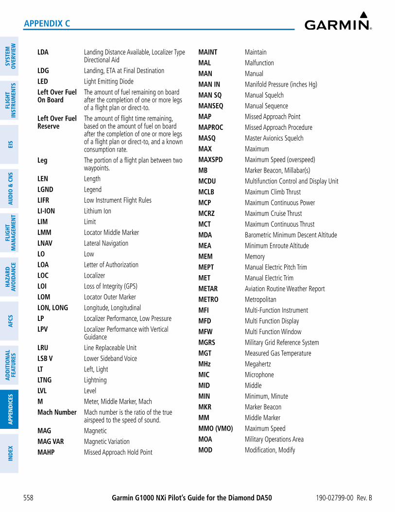
Garmin G1000 NXi Pilot’s Guide for the Diamond DA50 190-02799-00 Rev. B
SYST
EMO
VERV
IEW
FLIG
HTIN
STRU
MEN
TSEI
SAU
DIO
& C
NS
FLIG
HTM
AN
AGEM
ENT
HAZA
RDAV
OID
AN
CEA
FCS
AD
DIT
ION
AL
FEAT
URES
APP
END
ICES
IND
EX
558
APPENDIX C
LDA Landing Distance Available, Localizer Type Directional Aid
LDG Landing, ETA at Final DestinationLED Light Emitting DiodeLeft Over Fuel On Board
The amount of fuel remaining on board after the completion of one or more legs of a flight plan or direct-to.
Left Over Fuel Reserve
The amount of flight time remaining, based on the amount of fuel on board after the completion of one or more legs of a flight plan or direct-to, and a known consumption rate.
Leg The portion of a flight plan between two waypoints.
LEN LengthLGND LegendLIFR Low Instrument Flight RulesLI-ION Lithium IonLIM LimitLMM Locator Middle MarkerLNAV Lateral NavigationLO LowLOA Letter of AuthorizationLOC LocalizerLOI Loss of Integrity (GPS)LOM Locator Outer MarkerLON, LONG Longitude, LongitudinalLP Localizer Performance, Low PressureLPV Localizer Performance with Vertical
GuidanceLRU Line Replaceable UnitLSB V Lower Sideband VoiceLT Left, LightLTNG LightningLVL LevelM Meter, Middle Marker, MachMach Number Mach number is the ratio of the true
airspeed to the speed of sound.MAG MagneticMAG VAR Magnetic VariationMAHP Missed Approach Hold Point
MAINT MaintainMAL MalfunctionMAN ManualMAN IN Manifold Pressure (inches Hg)MAN SQ Manual SquelchMANSEQ Manual SequenceMAP Missed Approach PointMAPROC Missed Approach ProcedureMASQ Master Avionics SquelchMAX MaximumMAXSPD Maximum Speed (overspeed)MB Marker Beacon, Millabar(s)MCDU Multifunction Control and Display Unit
MCLB Maximum Climb ThrustMCP Maximum Continuous PowerMCRZ Maximum Cruise ThrustMCT Maximum Continuous ThrustMDA Barometric Minimum Descent AltitudeMEA Minimum Enroute AltitudeMEM MemoryMEPT Manual Electric Pitch TrimMET Manual Electric TrimMETAR Aviation Routine Weather ReportMETRO MetropolitanMFI Multi-Function InstrumentMFD Multi Function DisplayMFW Multi Function WindowMGRS Military Grid Reference SystemMGT Measured Gas TemperatureMHz MegahertzMIC MicrophoneMID MiddleMIN Minimum, MinuteMKR Marker BeaconMM Middle MarkerMMO (VMO) Maximum SpeedMOA Military Operations AreaMOD Modification, Modify

190-02799-00 Rev. B Garmin G1000 NXi Pilot’s Guide for the Diamond DA50
SYSTEMO
VERVIEWFLIG
HTIN
STRUMEN
TSEIS
AUDIO
& CN
SFLIG
HTM
AN
AGEM
ENT
HAZA
RDAVO
IDA
NCE
AFCS
AD
DITIO
NA
LFEATURES
APPEN
DICES
IND
EX
559
APPENDIX C
MON Monitor, Monitored, MonitoringMORA Minimum Off-Route AltitudeMOV MovementMPEL Maximum Permissible Exposure LevelMPM Meters per MinuteMSA Minimum Safe AltitudeMSAS Multi-functional Satellite Augmentation
SystemMSG MessageMSL Mean Sea LevelMT, M MeterMTG MountingMTN MountainMTOGW Maximum Takeoff Gross WeightMTOW Maximum Takeoff WeightMV Millivolt(s)MVFR Marginal Visual Flight RulesN NorthNATS North Atlantic Tracks SystemNAV NavigationNAVAID Navigation AidNCR Negative Climb RateNDA Next Data AuthorityNDB Non-Directional BeaconNEG NegativeNEXRAD Next Generation RadarNG Gas Producer Rotation SpeedNM Nautical Mile(s)NMPG Nautical Miles per GallonNoPT No Procedure Turn Required (procedure
shall not be executed without ATC clearance)
NORM NormalNOTAM Notice To AirmanNP Power Turbine SpeedNPA Non-Precision ApproachNR Rotor SpeedNRST NearestNWHL Nosewheel
NWS National Weather Service, Nosewheel Steering
O Outer MarkerOAT Outside Air TemperatureOBD, OUTBD OutboardOBS Omni Bearing Selector, Observation,
Observe, ObservedOBSCR ObscurationOCL Oceanic ClearanceOEM Original Equipment ManufacturerOFST OffsetOGE Out of Ground EffectOM Outer MarkerOOOI Out of the gate, Off the ground, On the
ground, and In the gateOROCA Off Route Obstacle Clearance AltitudeOSP Overspeed ProtectionOUTBD OutboardOUTBND OutboundOVBD OverboardOVFL OverflowOVFLY Overfly, OverflyingOVHD OverheadOVHT OverheatOVLIM OverlimitOVLD OverloadOVPR OverpressureOVR, OVRD OverrideOVRN OverrunOVSPD OverspeedOVTMP OvertemperatureOXY OxygenP ALT Pressure AltitudeP-ATT Pitch AttitudePA Precision Approach, Passenger Address,
Proximity AdvisoryPB Push ButtonPASS, PAX Passenger(s)PC Personal ComputerPCL Pilot Controlled Lighting

Garmin G1000 NXi Pilot’s Guide for the Diamond DA50 190-02799-00 Rev. B
SYST
EMO
VERV
IEW
FLIG
HTIN
STRU
MEN
TSEI
SAU
DIO
& C
NS
FLIG
HTM
AN
AGEM
ENT
HAZA
RDAV
OID
AN
CEA
FCS
AD
DIT
ION
AL
FEAT
URES
APP
END
ICES
IND
EX
560
APPENDIX C
PDA Premature Descent AlertingPDC Pre-Departure ClearancePED Portable Electronic DevicePERF PerformancePFD Primary Flight DisplayPFT Preflight TestPG Pilot’s GuidePI Procedure Turn to Course Intercept LegPIREP Pilot ReportPIT, PTCH PitchPLT PilotPNR Prior Notice RequiredPOA Plain Old ACARSPOB Persons (Souls) on BoardPOF Phase of FlightPOH Pilot’s Operating HandbookPOHS Pilot’s Operating Handbook SupplementPOS, POSN PositionPOSS PossiblePPH Pounds per HourPPM Parts per MillionPPOS, P. POS Present PositionPREFLT PreflightPRES, PRESS, P PressurePREV PreviousPRI PrimaryPRL ParallelPRN Pseudo Random NoisePROC Procedure(s), Procedure TurnPROP PropellerPROX ProximityPSI Pounds per Square Inch, Power Situation
IndicatorPT Procedure Turn, Part TimePTK Parallel TrackPTT Push-to-TalkPWR PowerQ Engine TorqueQFE Field Elevation Pressure
QNE Pressure AltitudeQNH Sea Level PressureQTY QuantityR Right, Right RunwayRA Resolution Advisory, Radio Altimeter,
Radar AltimeterRAD RadialRAD ALT Radio Altimeter, Radar AltimeterRAIM Receiver Autonomous Integrity MonitoringRAM Random Access MemoryRAT Ram Air TemperatureRCVR ReceiverR/D Radial/DistanceRDR RadarREC Record, RecorderRECIRC Recirculate/RecirculatingREF ReferenceREGL RegulatorREM Remaining (fuel remaining), Reminder,
Removed, RemoteREQ RequestREQD RequiredRES Reserve (fuel reserve entered by pilot)REST Restricted, RestrictionRET ReturnREV Reverse, Revision, ReviseRF Radio Frequency, Constant Radius Turn to
Fix LegRFM Rotorcraft Flight ManualRLC Required Line ClearanceRMI Radio Magnetic IndicatorRMT RemoteRNAV Area NavigationRNG RangeRNP Required Navigation PerformanceRNWY, RWY RunwayROASS Runway Overrun Awareness and Alerting
SystemROC Required Obstacle Clearance, Rate of
Cllmb

190-02799-00 Rev. B Garmin G1000 NXi Pilot’s Guide for the Diamond DA50
SYSTEMO
VERVIEWFLIG
HTIN
STRUMEN
TSEIS
AUDIO
& CN
SFLIG
HTM
AN
AGEM
ENT
HAZA
RDAVO
IDA
NCE
AFCS
AD
DITIO
NA
LFEATURES
APPEN
DICES
IND
EX
561
APPENDIX C
ROD Rate of DescentROL RollROM Read Only MemoryROT RotaryRPM Revolutions Per MinuteRQRD RequiredRST FUEL Reset FuelRSV Reserve (fuel reserve entered by pilot)RT RightRTC Required Terrain ClearanceRTE RouteRTR RouterRUDICS Router-Based Unrestricted Digital
Interworking Connectivity SolutionRVRSNRY ReversionaryRVSI Required Vertical Speed IndicatorRVSM Reduced Vertical Separation MinimumsRX ReceiveS SouthSA Selective AvailabilitySAIB Special Airworthiness Information BulletinSAR Search and RescueSAT Static Air TemperatureSATCOM Satellite CommunicationSBAS Satellite-Based Augmentation SystemS-CLB Step ClimbSC Short CircuitSCIT Storm Cell Identification and TrackingS-DES Step DescentSD Secure DigitalSDF Simplified Directional FacilitySEC Second(s)SECT SectionSEG SegmentSEL, SLCT SelectSELCAL Selective CallingSENS Sense, SensitivitySEQ Sequence, SequencingSERL Serial
SERV Service, Servicing, ServedSET SetupSFC SurfaceSHT ShortSIAP Standard Instrument Approach ProceduresSID Standard Instrument DepartureSIG SignalSIG/AIR SIGMET/AIRMETSIGM SIGMETSIGMET Significant Meteorological InformationSIM SimulatorSITA Societe Internationale de
TelecommunicationsSLD Supercooled Large DropletSLP/SKD Slip/SkidSLW SlowSM Statute MileSMBL SymbolSMK SmokeSMS Short Message SystemSNGL SingleSOB Souls on BoardSPBK Speed BrakeSPC SpaceSPD SpeedSPI Special Position IdentificationSPKR SpeakerSQ, SQL SquelchSRVC, SVC ServiceSSEC Static Source Error CorrectionSSID Wireless Service Set IdentifierSSR Secondary Surveillance RadarSTAB StabilizationSTAL StallSTAR Standard Terminal Arrival RouteSTAT StatusSTATS StatisticsSTBY Standby

Garmin G1000 NXi Pilot’s Guide for the Diamond DA50 190-02799-00 Rev. B
SYST
EMO
VERV
IEW
FLIG
HTIN
STRU
MEN
TSEI
SAU
DIO
& C
NS
FLIG
HTM
AN
AGEM
ENT
HAZA
RDAV
OID
AN
CEA
FCS
AD
DIT
ION
AL
FEAT
URES
APP
END
ICES
IND
EX
562
APPENDIX C
STC Sensitivity Time Constant, Supplemental Type Certificate
STD StandardSTN StationSTR StripSTRMSCP StormscopeSUA Special Use AirspaceSUB SubstituteSUPPRESS SuppressionSURF SurfaceSUSP SuspendSVBL ServiceableSVT Synthetic Vision TechnologySW SoftwareSYN TERR Synthetic TerrainSYN VIS Synthetic VisionSYNC SynchronizeSYNTH SynthesizerSYS SystemT TrueT HDG True HeadingT/R Thrust ReverserTA Traffic Advisory, Transition AltitudeTAC Tactical, Terminal Area ChartTACAN, TCN Tactical Air Navigation SystemTAF Terminal Aerodrome ForecastTAS True Airspeed, Traffic Advisory SystemTAT Total Air TemperatureTAWS Terrain Awareness and Warning SystemTC Table of ContentsTCA Terminal Control AreaTCAS Traffic Alert Collision Avoidance SystemTCH Threshold Crossing HeightTD TouchdownTEL TelephoneTEMP, TMP TemperatureTERM TerminalTERR TerrainT/F To/From
TF Track Between Two Fixes LegTFR Temporary Flight RestrictionTGT TargetTH True HeadingTHLD ThresholdTHR ThrustTIS Traffic Information ServiceTIS-B Traffic Information Service-BroadcastTIT Turbine Inlet TemperatureTIZ Traffic Information ZoneTKE see also Track Angle ErrorTL Transition LevelTLA Throttle Lever Angle, Thrust Lever AngleTMA Terminal Maneuvering AreaTMR/REF Timer/ReferenceTNK TankTO To, TakeoffTOC Top of Climb, Table of ContentsTOD Top of Descent, Time to TODTOGA, TO/GA Take-Off, Go-AroundTOLD Takeoff and Landing DataTOPO TopographicTORA Takeoff Run AvailableTOT TotalTPA Traffic Pattern AltitudeTrack Direction of aircraft movement relative to
a ground position; also ‘Ground Track’.Track Angle Error
The angle difference between the desired track and the current track.
TRFC TrafficTRK see also TrackTRM TrimTRN TerrainTRSA Terminal Radar Service AreaTRUNC TruncatedTSO Technical Standard OrderTST TestTTA Time-to-AlertTTK True Track

190-02799-00 Rev. B Garmin G1000 NXi Pilot’s Guide for the Diamond DA50
SYSTEMO
VERVIEWFLIG
HTIN
STRUMEN
TSEIS
AUDIO
& CN
SFLIG
HTM
AN
AGEM
ENT
HAZA
RDAVO
IDA
NCE
AFCS
AD
DITIO
NA
LFEATURES
APPEN
DICES
IND
EX
563
APPENDIX C
TTL TotalTTS Text to SpeechTUR TurbineTURB TurbulenceTURN Procedure TurnTWND TailwindTWIP Terminal Weather Information for PilotsTWR TowerTWY TaxiwayTX TransmitUA Routine PIREPUAT Universal Access TransceiverUAV Unmanned Airborne VehicleUHF Ultra-High FrequencyUNABL UnableUNAVAIL UnavailableUNLIM UnlimitedUPLK UplinkUS United StatesUSB V Upper Sideband VoiceUSP Underspeed ProtectionUSR UserUTC Coordinated Universal TimeUTM/UPS Universal Transverse Mercator/ Universal
Polar Stereographic GridUUA Urgent PIREPV Volts, VerticalV DEV Vertical DeviationV, Vspeed Velocity (airspeed)V1 Takeoff Decision SpeedV2 Takeoff Safety SpeedVA Maneuvering SpeedVA Heading Vector to Altitude LegVAC Volts Alternating CurrentVAL Vertical Alert LimitVAPP VOR Approach ModeVAPP , VAC Approach Climb SpeedVAR Variable, VariationVCO Voice Call Out
VD Heading Vector to DME Distance LegVDC Volts Direct CurrentVDI Vertical Deviation IndicatorVDL VHF DatalinkVE, VENR Enroute Climb SpeedVECT VectorVERT VerticalVertical Figure of Merit
A measure of the uncertainty in the aircraft vertical position.
Vertical Speed Required
The vertical speed necessary to descend/climb from a current position and altitude to a defined target position and altitude, based upon current groundspeed.
VFE Maximum Flap Extended SpeedVFOM see also Vertical Figure of MeritVFR Visual Flight RulesVHF Very High FrequencyVI Heading Vector to Intercept LegVIB VibrationVLE Maximum Landing Gear Extended SpeedVLNDx Approach Speed (Flaps at x°)VLO Maximum Landing Gear Operating SpeedVLD ValidVLOC, VOR/L VOR/Localizer ReceiverVM Heading Vector to Manual Termination
LegVMC Minimum Control SpeedVMC Visual Meteorological ConditionsVMO (MMO) Maximum Operating SpeedVNAV, VNV Vertical NavigationVNE Never-Exceed SpeedVOL VolumeVOR VHF Omnidirectional RangeVOR/D VOR/DMEVOR/I VOR/ILSVORTAC VHF Omnidirectional Range Station and
Tactical Air NavigationVPATH, VPTH Vertical PathVPL Vertical Protection LevelVPROF VNAV Profile, Vertical Profile
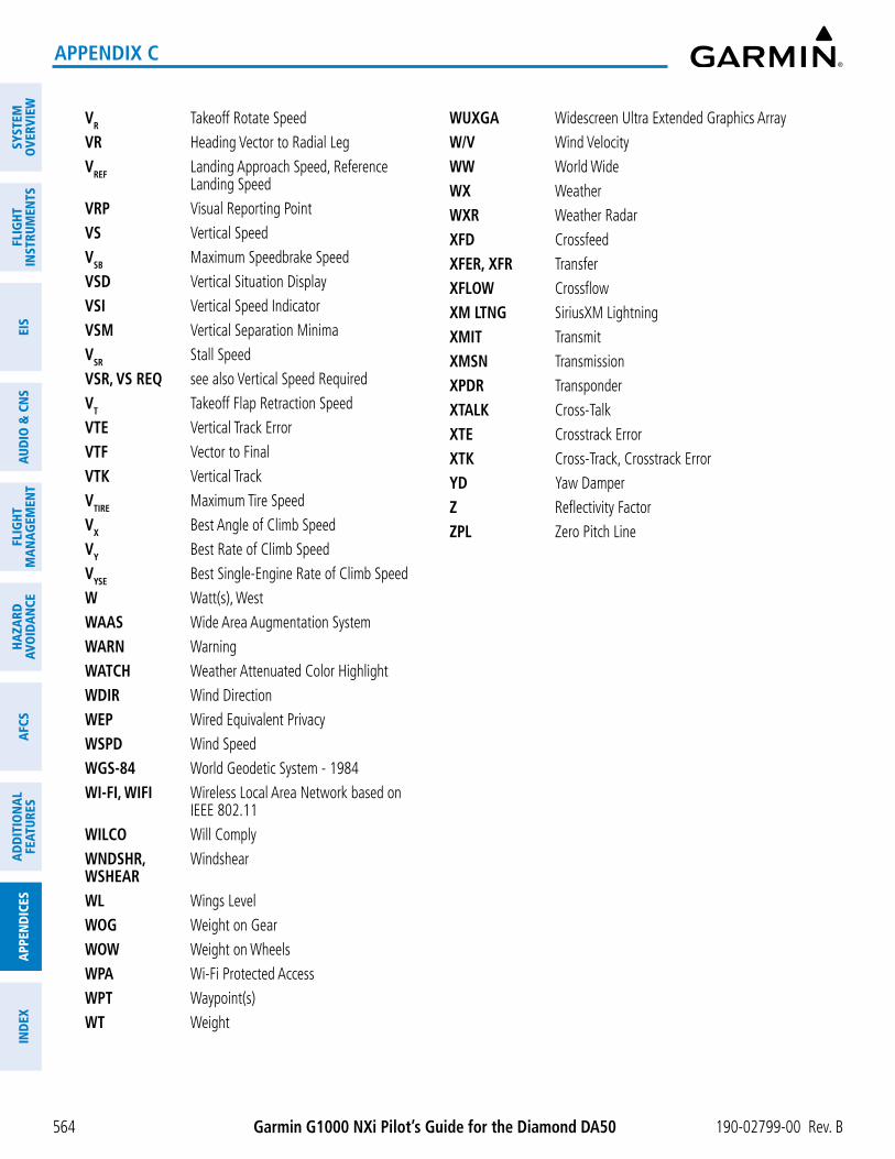
Garmin G1000 NXi Pilot’s Guide for the Diamond DA50 190-02799-00 Rev. B
SYST
EMO
VERV
IEW
FLIG
HTIN
STRU
MEN
TSEI
SAU
DIO
& C
NS
FLIG
HTM
AN
AGEM
ENT
HAZA
RDAV
OID
AN
CEA
FCS
AD
DIT
ION
AL
FEAT
URES
APP
END
ICES
IND
EX
564
APPENDIX C
VR Takeoff Rotate SpeedVR Heading Vector to Radial LegVREF Landing Approach Speed, Reference
Landing SpeedVRP Visual Reporting PointVS Vertical SpeedVSB Maximum Speedbrake SpeedVSD Vertical Situation DisplayVSI Vertical Speed IndicatorVSM Vertical Separation MinimaVSR Stall SpeedVSR, VS REQ see also Vertical Speed RequiredVT Takeoff Flap Retraction SpeedVTE Vertical Track ErrorVTF Vector to FinalVTK Vertical TrackVTIRE Maximum Tire SpeedVX Best Angle of Climb SpeedVY Best Rate of Climb SpeedVYSE Best Single-Engine Rate of Climb SpeedW Watt(s), WestWAAS Wide Area Augmentation SystemWARN WarningWATCH Weather Attenuated Color HighlightWDIR Wind DirectionWEP Wired Equivalent PrivacyWSPD Wind SpeedWGS-84 World Geodetic System - 1984WI-FI, WIFI Wireless Local Area Network based on
IEEE 802.11WILCO Will ComplyWNDSHR, WSHEAR
Windshear
WL Wings LevelWOG Weight on GearWOW Weight on WheelsWPA Wi-Fi Protected AccessWPT Waypoint(s)WT Weight
WUXGA Widescreen Ultra Extended Graphics ArrayW/V Wind VelocityWW World WideWX WeatherWXR Weather RadarXFD CrossfeedXFER, XFR TransferXFLOW CrossflowXM LTNG SiriusXM LightningXMIT TransmitXMSN TransmissionXPDR TransponderXTALK Cross-TalkXTE Crosstrack ErrorXTK Cross-Track, Crosstrack ErrorYD Yaw DamperZ Reflectivity FactorZPL Zero Pitch Line

190-02799-00 Rev. B Garmin G1000 NXi Pilot’s Guide for the Diamond DA50
SYSTEMO
VERVIEWFLIG
HTIN
STRUMEN
TSEIS
AUDIO
& CN
SFLIG
HTM
AN
AGEM
ENT
HAZA
RDAVO
IDA
NCE
AFCS
AD
DITIO
NA
LFEATURES
APPEN
DICES
IND
EX
565
APPENDIX D
FREQUENTLY ASKED QUESTIONSIf a particular aspect of system NXi operational capability is not addressed by these commonly asked questions
or in the index, contact Garmin (see the copyright page or back cover for contact information) or a Garmin-authorized dealer. Garmin is dedicated to supporting its products and customers.
what is sbas?
The Satellite Based Augmentation System (SBAS) uses a system of ground stations to correct any GPS signal errors. These ground stations correct for errors caused by ionospheric disturbances, timing, and satellite orbit errors. It also provides vital integrity information regarding the health of each GPS satellite. The signal correction is then broadcast through geostationary satellites. This correction information can then be received by any SBAS-enabled GPS receiver.
SBAS is designed to provide the additional accuracy, availability, and integrity necessary to enable users to rely on GPS for all phases of flight.
There are several SBAS systems serving different parts of the world. The Wide Area Augmentation System (WAAS) is currently available in the United States, including Alaska and Hawaii. The European Geostationary Navigation Overlay Service (EGNOS) offers coverage of Europe, parts of the middle east and northern Africa. The Multi-functional Satellite Augmentation System (MSAS) covers mainly Japan and parts of northern Australia.
how Does sbas affeCt aPProaCh oPerations?
Both LNAV/VNAV and LPV approaches use the accuracy of SBAS to include vertical (glide path) guidance capability. The additional accuracy and vertical guidance capability allows improved instrument approaches to an expanded number of airports throughout the U.S.
The implementation of LPV approaches further improves precision approach capabilities. LPV approaches are designed to make full use of the improved GPS signal from the SBAS. This approach combines the LNAV/VNAV vertical accuracy with lateral guidance similar to the typical Instrument Landing System (ILS). LPV approaches allow lower approach minimums.
what is raim anD how Does it affeCt aPProaCh oPerations?
When SBAS is unavailable, the GPS receivers use Receiver Autonomous Integrity Monitoring (RAIM) to perform the following functions:
- Monitor and verify integrity and geometry of tracked GPS satellites
- Notify pilot when satellite conditions do not provide necessary coverage to support a certain phase of flight
- Predict satellite coverage of a destination area to determine whether the number of available satellites is sufficient to satisfy requirements (refer to the System Overview Section for instructions on RAIM prediction)
- Detect and exclude bad satellites from the navigation solution (Fault Detection and Exclusion, FDE)
RAIM ensures that satellite geometry allows for a navigation solution calculation within a specified protection limit (4.0 nm for oceanic, 2.0 nm for enroute, 1.0 nm for terminal, and 0.3 nm for non-precision approaches). Without SBAS or RAIM, GPS position accuracy integrity cannot be monitored.
why might there be no aPProaChes aVailable for a flight Plan?
Approaches are available for the final destination airport in a flight plan or as a direct-to (keep in mind that some VOR/VORTAC identifiers are similar to airport identifiers). If a destination airport does not have a published approach, the system indicates “NONE” for the available procedures.

Garmin G1000 NXi Pilot’s Guide for the Diamond DA50 190-02799-00 Rev. B
SYST
EMO
VERV
IEW
FLIG
HTIN
STRU
MEN
TSEI
SAU
DIO
& C
NS
FLIG
HTM
AN
AGEM
ENT
HAZA
RDAV
OID
AN
CEA
FCS
AD
DIT
ION
AL
FEAT
URES
APP
END
ICES
IND
EX
566
APPENDIX D
what haPPens when an aPProaCh is seleCteD? Can a flight Plan with an aPProaCh, a DeParture, or an arriVal be storeD?
When an approach, departure, or arrival is loaded into the active flight plan, a set of approach, departure, or arrival waypoints is inserted into the flight plan, along with a header line showing the title of the selected instrument procedure. The original enroute portion of the flight plan remains active, unless the instrument procedure is activated. This may be done either when the procedure is loaded or at a later time.
Flight plans can also be stored with an approach, a departure, or an arrival. Note the active flight plan is erased when the system is turned off. Also, the active flight plan is overwritten when another flight plan is activated. When storing flight plans with an approach, a departure, or an arrival, the system uses the waypoint information from the current database to define the waypoints. If the database is changed or updated, the system automatically updates the information, provided the procedure has not been modified. Should an approach, departure, or arrival procedure no longer be available, the flight plan becomes locked until the procedure is deleted from the flight plan.
what Does the obs softkey Do?
The OBS Softkey is used to select manual sequencing of waypoints. Activating OBS mode sets the current active-to waypoint as the primary navigation reference and prevents the system from sequencing to the next waypoint in a flight plan. When OBS mode is cancelled, automatic waypoint sequencing is continued, and the system automatically activates the next waypoint in the flight plan once the aircraft has crossed the present active waypoint.
Normal (OBS not activated) OBS• Automatic sequencing of waypoints • Manual sequencing - ‘holds’ on selected waypoint• Manual course change on HSI not possible • Manually select course to waypoint from HSI• Always navigates ‘TO’ the active waypoint • Indicates ‘TO’ or ‘FROM’ waypoint• Must be in this mode for final approach course • Cannot be set for final approach course or published holding patterns
When OBS mode is active, the system allows the pilot to set a desired course to/from a waypoint using the CRS/BARO Knob and HSI (much like a VOR).
The most common application for using the OBS Softkey is the missed approach. The system suspends automatic waypoint sequencing (indicated by a ‘SUSP’ annunciation placed on the HSI) when the missed approach point (MAP) is crossed. This prevents the system from automatically sequencing to the missed approach holding point (MAHP). During this time, the OBS Softkey designation changes to SUSP. Selecting the SUSP Softkey reactivates automatic waypoint sequencing. The OBS Softkey then resumes its normal functionality.
why might the system not automatiCally sequenCe to the next wayPoint?
The system only sequences flight plan waypoints when automatic sequencing is enabled (i.e., no ‘OBS’ or ‘SUSP’ annunciation on the HSI). For automatic sequencing to occur, the aircraft must also cross the bisector of the turn being navigated. The bisector is a line passing through the waypoint common to two flight plan legs at an equal angle from each leg.
how Can a wayPoint be skiPPeD in an aPProaCh, a DeParture, or an arriVal?
The system allows the pilot to manually select any approach, departure, or arrival leg as the active leg of the flight plan. This procedure is performed on the MFD from the ‘Active Flight Plan’ Page by highlighting the desired waypoint and selecting the ACT Leg Softkey then the ENT Key to approve the selection. The GPS then provides navigation along the selected flight plan leg.
190-02799-00 Rev. B Garmin G1000 NXi Pilot’s Guide for the Diamond DA50
SYSTEMO
VERVIEWFLIG
HTIN
STRUMEN
TSEIS
AUDIO
& CN
SFLIG
HTM
AN
AGEM
ENT
HAZA
RDAVO
IDA
NCE
AFCS
AD
DITIO
NA
LFEATURES
APPEN
DICES
IND
EX
567
APPENDIX D
when Does turn antiCiPation begin?
The system smooths adjacent leg transitions based on a normal 15° bank angle (with the ability to roll up to 30°) and provides three pilot cues for turn anticipation:
- A waypoint alert (‘Next DTK ###° in # seconds’ or ‘Next HDG ###° in # seconds’) appears on the PFD 10 seconds before the turn point and flashes as it counts down to zero.
- A flashing turn advisory (‘Turn [right/left] to ###° in # seconds’) appears on the PFD 10 seconds before the turn and flashes as it counts down to zero. ‘Turn [right/left] to ###° now’ or ‘Next [DTK/HDG] to ###° now’ is displayed when the pilot is to begin the turn and the HSI (GPS mode) automatically sequences to the next DTK or HDG value.
- The To/From indicator on the HSI flips momentarily to indicate the midpoint of the turn has been crossed.
when Does the CDi sCale Change?
Once a departure is activated, the system Course Deviation Indicator (CDI) full scale deflection is set to 0.3 nm. The CDI scale changes to 1.0 nm (terminal mode) then ramps up to 2.0 nm (enroute mode) at 30 nm from the departure airport. When 31 nm from the destination, the CDI scale smoothly transition from 2.0 nm back to 1.0 nm (terminal mode). At 2.0 nm before the FAF during an active approach, the CDI scale transitions down further based on the type of approach activated (LNAV, LNAV/VNAV, LPV). When a missed approach is activated, the CDI is set to 0.3 nm. See the Flight Instruments Section for more details on CDI scaling.
why Does the hsi not resPonD like a Vor when obs moDe is aCtiVe?
Unlike a VOR, the CDI scale used on GPS equipment is based on the crosstrack distance to the desired course, not on the angular relationship to the destination. Therefore, the CDI deflection on the GPS is constant regardless of the distance to the destination and does not become less sensitive when further away from the destination.
what is the CorreCt misseD aPProaCh ProCeDure? how is the misseD aPProaCh holDing Point seleCteD?
To comply with TSO specifications, the system does not automatically sequence past the MAP. The first waypoint in the missed approach procedure becomes the active waypoint when the SUSP Softkey is selected after crossing the MAP. All published missed approach procedures must be followed, as indicated on the approach plate.
To execute the missed approach procedure prior to the MAP (not recommended), select the ‘Active Flight Plan’ Page and use the ACT Leg Softkey to activate the missed approach portion of the procedure.
after a misseD aPProaCh, how Can the same aPProaCh be re-seleCteD? how Can a new aPProaCh be aCtiVateD?
NOTE: Do not attempt to reactivate the current approach prior to crossing the missed approach point (MAP). If an attempt to do so is made, an alert message “Are you sure you want to discontinue the current approach?” appears. The system directs the pilot back to the transition waypoint and does not take into consideration any missed approach procedures, if the current approach is reactivated.
After flying the missed approach procedure, the pilot may reactivate the same approach for another attempt by pressing the PROC Key. Once the clearance is given for another attempt, activate the approach by highlighting ‘Activate Approach’ using the large FMS Knob and pressing the ENT Key. The system provides navigation along the desired course to the waypoint and rejoins the approach in sequence from that point.

Garmin G1000 NXi Pilot’s Guide for the Diamond DA50 190-02799-00 Rev. B
SYST
EMO
VERV
IEW
FLIG
HTIN
STRU
MEN
TSEI
SAU
DIO
& C
NS
FLIG
HTM
AN
AGEM
ENT
HAZA
RDAV
OID
AN
CEA
FCS
AD
DIT
ION
AL
FEAT
URES
APP
END
ICES
IND
EX
568
APPENDIX D
To activate a new approach for the same airport, select the new procedure by pressing the PROC Key. Choose ‘Select Approach’, select the desired approach from the list shown, and press the ENT Key. Select the desired transition, then activate the approach using the ENT Key.
To activate a new approach to a different airport, press the Direct-to Key and select the desired airport using the FMS Knobs. Press the ENT Key to accept the selected airport, then follow the steps in the preceding paragraph to select an approach for the new airport.

190-02799-00 Rev. B Garmin G1000 NXi Pilot’s Guide for the Diamond DA50
SYSTEMO
VERVIEWFLIG
HTIN
STRUMEN
TSEIS
AUDIO
& CN
SFLIG
HTM
AN
AGEM
ENT
HAZA
RDAVO
IDA
NCE
AFCS
AD
DITIO
NA
LFEATURES
APPEN
DICES
IND
EX
I-1
INDEX
SYMBOLS3D Audio...... ...........................................................128
AAbbreviations...... ....................................................551Acronyms
Aviation................................................................551AC-U-KWIK...... .......................................................539Additional Features...... ............................................435ADF Frequency Tuning...... .......................................119ADF Modes...... .......................................................120ADS-R...... ...............................................................386AFCS Annunciations and Alerts...... ..........................429AFCS Controller...... .................................................403AFCS Controls...... ...................................................403AFCS Modes...... ......................................................408AIRB...... .................................................................390Airport
Auto-Designation...... ...........................................193Directory...... .................................................166, 539Information...... .................................... 164, 165, 169Nearest...... .......................................... 167, 168, 169User Airport...... ....................................................174
Airspace...... ............................................................180Nearest...... ..................................................181, 182Smart...... .............................................................183Symbols...... ..........................................................154
Airspeed Indicator...... ................................................47Airways
Collapsing / Expanding...... ...........................203, 204In a Flight Plan...... .......................................200, 202On the Map...... ....................................................156
Alerting system test...... ...........................................518Alerts
Aircraft...... ...........................................................516Audio...... ...............................................................37Audio voice...........................................................518
Along Track Offset...... .....................................215, 216Altimeter...... .......................................................49–52
Altitude Selection (Bug)...... ....................................49Barometric Setting...... ............................................50STD Baro...... ..........................................................50Trend Vector...... ......................................................49
Altitude Constraints...... ...................................204, 206Enabling VNV Guidance...... ..................................208
Altitude Hold Mode (ALT)...... ..................................410
Annunciations...... ...................................................519Abnormal GPS...... ..................................................87BARO QFE...... ........................................................84Baro Transition Alert...... ..........................................83Low Altitude...... .....................................................84Marker Beacon...... .................................................85Minimum Altitude...... .............................................85System...... .....................................................12, 519Test tone...... ..................................................13, 518
AOPA...... ................................................................539AP DISC Switch...... .................................................404Approach...... ..........................................................566Approaches...... .......................................................243
Activating...... ...............................................247, 250Degradation Behavior...... ......................................245Loading...... .......................................... 248, 249, 250Removing...... .......................................................251Visual...... .............................................................246
Approach Modes (VAPP, GPS, LOC)...... ....................420Approach Service Levels...... .....................................244AP TRIM Switch...... .................................................404Arrival Alerts...... ......................................................223Arrivals...... .............................................. 240, 241, 242Attitude and Heading Reference System (AHRS)...... ..14,
525Attitude Indicator.......................................................46Audio Alerting System...... .......................................518Automatic Direction Finder (ADF)...... .........................61Automatic Flight Control System (AFCS)...... .............401Autopilot and Yaw Damper Operation...... ................426Autopilot (AP)...... ...................................................401Autopilot Overspeed Protection...... .........................430Autopilot Underspeed Protection...... .......................430Auto-tuning NAV Frequencies...... ............................117Auto Zoom...... ........................................................145Aviation Symbols...... ...............................................153
BBackcourse Mode (BC)...... ......................................424Baro QFE...... .....................................................51, 207Basic Autopilot Operation...... ..................................401Bearing/Distance, Measuring...... .............................149Bearing Information Window...... .........................45, 60Bearing Line...... ..............................................342, 345Bearing Pointer...... ....................................................60Blue-select Mode...... ...............................................134Bluetooth Pairing...... ...............................................132

Garmin G1000 NXi Pilot’s Guide for the Diamond DA50 190-02799-00 Rev. B
SYST
EMO
VERV
IEW
FLIG
HTIN
STRU
MEN
TSEI
SAU
DIO
& C
NS
FLIG
HTM
AN
AGEM
ENT
HAZA
RDAV
OID
AN
CEA
FCS
AD
DIT
ION
AL
FEAT
URES
APP
END
ICES
IND
EX
I-2
INDEX
CCharted Visual Flight Procedure (CVFP)...... ..............246ChartView...... .................................................435, 456Clearance Recorder...... ............................................132Closest Point...... .....................................................217Cloud Tops...... ........................................................301Combination modes...... ..........................................416COM Frequency Spacing...... ....................................112COM Frequency Tuning Box...... ...............................107Command Bars...... ..................................................407Conflict Situational Awareness (CSA)...... .................388Connext...... ....................................................435, 488Contacts...... ............................................................471Control Wheel Steering (CWS)...... ...........................427Correlation...... ........................................................387Course
Pointer...... ..............................................................57Selection...... ..........................................................58
Course Deviation Indicator (CDI)...... ..............57, 61–65Crosstrack Error (XTK)...... .......................................61Flight Phase...... ......................................................61Lateral Deviation Scale...... ......................................61Navigation Source...... .............................................61Scaling...... .............................................................63
Crew Alerting System...............................................515Messages...... .......................................................516
Crew Profiles...... .......................................................31Current Heading...... ..................................................57CWS Button...... ......................................................404
DDatabase Management...... .............................435, 510Databases...... .........................................................537
Deleting...... .........................................................548Magnetic field variation database update...... ........549Updating with SD card...... ....................................539Updating with wireless transceiver...... ...................542
Datalink Troubleshooting...... ...................................513Dead Reckoning Mode...... .......................................260Departures...... ........................................................237
Loading...... ..........................................................238Removing...... .......................................................239
Direct-To...... ........................................... 185, 186, 187VNV Direct-To...... .................................................213
Display and Key Backlighting (Brightness)...... ............42Display Backup...... ....................................................11Display Backup Button...... .......................................106Display Pane...... ........................................................29Display Units (Units of Measure)...... ..........................35
Distance Measuring Equipment (DME)DME Tuning...... ....................................................118Information Window...... .........................................61
DME Tuning...... .......................................................121
EElectronic Charts...... .......................................435, 445Electronic Checklists...... ..................................435, 503Electronic Stability and Protection (ESP)...... 46, 435, 506Engine Indication System (EIS)...... .....................91–100Entertainment Inputs...... .........................................135
FFault Detection and Exclusion (FDE)...... .....................18Field of View (SVT)...................................................162Flight Data Logging...... ...................................435, 496Flight Director (FD)...... ............................................401Flight Director Operation...... ...................................405Flight Level Change Mode (FLC)...... .........................412Flight Path Angle (FPA)...... ......................................209Flight plan
Storing...... ...........................................................566Flight Plan Map...... .................................................193Flight Planning
Activating a Flight Plan Leg...... .............................214Activating the Standby Flight Plan...... ...................224Adding Airways...... .......................................200, 201Adding Waypoints...... ........................... 195, 196, 197Along Track Offsets...... .................................215, 216Closest Point to Reference...... ...............................217Comment Changes...... .........................................234Copy to the Standby Flight Plan...... ......................224Creating...... .........................................................194Deleting...... .................................................231, 233Importing/Exporting...... ........................ 225, 228, 229Inverting...... .........................................................230Origin...... .....................................................193, 195Origin Auto-Designation........................................193Parallel Track...... ...........................................217, 218Split Screen...................................................191, 192Standby Flight Plan...... ................. 188, 223, 224, 225Stored Flight Plan...... ...........................................232Symbols on Map...... .............................................184Transferring...... ....................................................225Views...... .............................................................191
Flight Plan Progress Inset...... ...................................191Flight Plan Retention...... .........................................231FliteCharts...... .................................................435, 446Fly-By/Fly-Over Waypoint...... ...........................198, 200

190-02799-00 Rev. B Garmin G1000 NXi Pilot’s Guide for the Diamond DA50
SYSTEMO
VERVIEWFLIG
HTIN
STRUMEN
TSEIS
AUDIO
& CN
SFLIG
HTM
AN
AGEM
ENT
HAZA
RDAVO
IDA
NCE
AFCS
AD
DITIO
NA
LFEATURES
APPEN
DICES
IND
EX
I-3
INDEX
Frequently asked questions...... ................................565Fuel Range Ring...... ................................................162Fuel Statistics...... ....................................................257
GGeodetic Sea Level (GSL)...... ...................................355Glidepath Indicator...... ..............................................54Glidepath Mode (GP)...... .........................................421Glideslope Indicator...... .............................................53Glideslope Mode (GS)...... ........................................423Global Positioning System (GPS)
Receiver...... ............................................................15Receiver Autonomous Integrity Monitoring (RAIM)Prediction...... .........................................................17Satellite-Based Augmentation System (SBAS)...... .....19Satellite Constellation Diagram...... .........................16Satellite Signal Status...... ........................................17Satellite Signal Strength...... ....................................19
GO AROUND Button...... ..........................................404Go Around Mode (GA)...... .......................................425GPS Approach Mode...... ..........................................421Ground Mapping, Weather Radar...... .......................349
HHail...... ...................................................................339Heading
Indicator...... ...........................................................59Selection (Bug)...... .................................................58
Heading Select Mode (HDG)...... ..............................414High Airspeed Protection...... ...................................509Holding
User Defined...... ...................................................219Horizontal Scan...... ......................... 341, 342, 343, 349Horizontal Situation Indicator (HSI)...... ..........56, 56–58HSI Map...... ............................................ 139, 151, 159
IIFR/VFR Charts...... ..........................................435, 465Imminent Obstacle Impact (IOI)...... ..........................363Importing and Exporting Flight Plans...... ..................225Inset Map...... ..................................................139, 151Intercom...... ...........................................................130Intercom Logic.........................................................130Intercom Squelch...... ...............................................131Intercom Volume...... ...............................................131Intersection
Information...... .................................... 169, 170, 171Nearest...... ..................................................171, 174
Inverting a Flight Plan...... ........................................230
KKey...... ....................................................................557
LLand Symbols...... ....................................................152Lateral Modes...... ...................................................413Level Mode (LVL)...... ...............................................425Line Replaceable Units (LRU)...... .................................1Link P. POS to Standby Flight Plan...... ......................224Localizer Approach Mode...... ...................................422Low Airspeed Protection...... ....................................509LVL Button...... ........................................................404
MMaintenance Logs...... .....................................435, 497Manual Electric Trim (MET).......................................401Map
Airways...... ..........................................................155Declutter...... .................................................158, 159Fuel Range Ring...... .............................................162Orientation...... ..................................... 143, 144, 193Panning...... ..................................................147, 148Pointer...... ....................................................147, 148Range...... .....................................................139, 145Settings...... ...144, 146, 151, 152, 156, 158, 159, 160Symbols...... .......................................... 152, 156, 159Topography...... .....................................................150
Marker Beacon...... ..................................................118Master Avionics Squelch...... ....................................101Measure Bearing and Distance...... ...........................149Menus...... .................................................................25Metric Units...... ........................................................49MET Switch...... .......................................................404MFD/PFD Control Unit...... .......................................7–8Missed Approach...... .......................................252, 253Morse Code Identifier...... ........................................113Motion Vectors...... ..................................................394MSA (Minimum Safe Altitude)...... ............................142Multifunction Display (MFD)
Controls....................................................................4Page Groups...... .....................................................26
NNational Weather Service (NWS)...... ........................311NAV Frequency Tuning Box...... ................................113Navigation Data Bar...... ..................................141, 142Navigation Mode...... ...............................................414Navigation Status Box...... .......................................141

Garmin G1000 NXi Pilot’s Guide for the Diamond DA50 190-02799-00 Rev. B
SYST
EMO
VERV
IEW
FLIG
HTIN
STRU
MEN
TSEI
SAU
DIO
& C
NS
FLIG
HTM
AN
AGEM
ENT
HAZA
RDAV
OID
AN
CEA
FCS
AD
DIT
ION
AL
FEAT
URES
APP
END
ICES
IND
EX
I-4
INDEX
NDBInformation...... ............................................169, 171Nearest...... .......................................... 171, 173, 174
NearestAirport.................................................. 167, 168, 169Airspace...... .........................................................181Intersection...... ............................................171, 174NDB...... .......................................................171, 174User Waypoint...... ........................................171, 174VOR...... .......................................................171, 174VRP...... ........................................................171, 174
Normal Operation...... ................................................10
OOBS Mode...... ...........................................................66Oil pressure...... .........................................................96Omni Bearing Selector (OBS)...... ......................566–567Other Statistics...... ..................................................256Overpowering Autopilot Servos...... ..........................433
PParallel Track...... .............................................217, 218Pending Flight Plan...... ............................ 226, 227, 228PFD Map
HSI Map...... ......................................... 139, 151, 159Inset Map...... .......................................................139
Pitch Hold Mode (PIT)...... ........................................408P. POS Link...... ................................................224, 225Primary Flight Display (PFD)
Controls....................................................................4Procedures...... ........................................................235
QQFE Constraints...... .................................................207
RRadar Top...... ..........................................................339Receiver Autonomous Integrity Monitoring (RAIM)...... 17,
565Recording Devices...... .............................................133Required Obstacle Clearance (ROC)...... ...................363Reversionary Mode...... ..............................................11Roll Hold Mode (ROL)...... ........................................413Rotating Compass Card...... .......................................57
SSafeTaxi...... ....................................................435, 436Satellite Telephone and Datalink Services...... ...435, 469
SBAS...... ...........................................................19, 565Loss While on an Approach...... .............................244
Scheduler/Scheduled Messages...... ......................40–41SD Cards...... ...............................................................9Sector Scan...... .......................................................345Selected Altitude Capture Mode (ALTS)...... ..............409Selected Altitude Intercept Arc...... ...........................161Sequencing, automatic...... ......................................566SIGMET...... .............................................................302SiriusXM Satellite Radio...... .............................435, 491SiriusXM Weather
AIREPs...... ............................................................315AIRMETs...... .........................................................302Cell Movement...... ...............................................300Cloud Tops...... ......................................................298County Warnings...... ............................................311Cyclones & Hurricanes...... .....................................312Echo Tops...... .......................................................296Freezing Level...... .................................................307Icing...... ...............................................................312Lightning...... ........................................................299PIREPs...... ............................................................315SIGMETs...... .........................................................302Surface Analysis...... ..............................................306Winds Aloft...........................................................308
Slip/Skid Indicator...... ................................................46Smart Airspace...... ..................................................183Softkeys
EIS...... ....................................................................24MFD...... .................................................................23PFD...... ..................................................................20
Split ScreenFlight Plan Views...... .............................................191
Split Screen Functionality...... .....................................28Standby
database...... ........................................................540Standby Flight Plan...... .................... 188, 223, 224, 225Stratus Precipitation...... ..........................................339SURF...... .................................................................390Surface Analysis...... .................................................306SurfaceWatch...... ............................................435, 439Suspected Autopilot Malfunction...... .......................433Symbols...... ............................................................152Synthetic Vision Technology (SVT)...... .........................69
Airport Signs...... .....................................................71Field of View...... .....................................................81Flight Path Marker...... .............................................72Horizon Heading...... ...............................................73

190-02799-00 Rev. B Garmin G1000 NXi Pilot’s Guide for the Diamond DA50
SYSTEMO
VERVIEWFLIG
HTIN
STRUMEN
TSEIS
AUDIO
& CN
SFLIG
HTM
AN
AGEM
ENT
HAZA
RDAVO
IDA
NCE
AFCS
AD
DITIO
NA
LFEATURES
APPEN
DICES
IND
EX
I-5
INDEX
Pathways...... ..........................................................74Runways...... ...........................................................78Terrain and Obstacle Alerting...... ............................79Traffic...... ...............................................................79Troubleshooting...... ................................................88WireAware...... .......................................................80Zero Pitch Line...... ..................................................71
SystemBlock Diagram...... ....................................................3Settings...... ............................................................30Status...... ...............................................................13Time...... .................................................................35
System Alerting...... ...................................................83System Messages...... ..............................................520
Annunciations...... .................................................519Messages...... .......................................................520
TTakeoff Mode (TO)...... .............................................425TAS Traffic
Non-Threat Traffic...... ...........................................374Proximity Advisory PA)...... ....................................374
Telephone Communication...... ................................473Temperature Compensated Approach Altitudes...... ...253Temperature Compensated Minimums...... ...............255Temperatures
Outside Air Temperature (OAT)...... ..........................68Terminal Aerodrome Forecast (TAF)...... ....................304Terms
Aviation................................................................551Text Messaging (SMS)..............................................477Tilt, Antenna...... ......................................................343Tilt Line...... .............................................................343Timer
Generic...... .............................................................67Topography (TOPO)...... ...........................................151Track Indicator...... ...............................................57, 58Tracking...... ....................................................557, 561Track Vector...... .......................................................160Traffic Advisory System (TAS)...... ...... 341, 343, 344, 346Traffic Information Service-Broadcast (TIS-B)...... ......387Transition to Approach Function...... .........................253Transponder Mode Selection...... ..............................123Trend Vector
Altitude...... ............................................................49Turn Rate...... ..........................................................59
Trip Planning...... ..................................... 256, 257, 258Fuel Statistics...... ..................................................257Other Statistics...... ...............................................258Trip Statistics.........................................................256
Trip Statistics...... .......................................................40True Airspeed (TAS)...... ..............................................47Turn Rate Indicator...... ..............................................59
UUnusual Attitudes...... ................................................88User-Defined Holding Pattern...... ............. 219, 221, 222User Waypoints
Airport User Waypoint...... .....................................174Creating...... .................................................174, 175Heliport User Waypoint...... ...................................175Information...... ....................................................169Route User Waypoint...... ..............................174, 175
VVector-To-Final...... ..........................................246, 250Vertical Modes...... ..................................................408Vertical Navigation...... ............................................417Vertical Navigation Direct-to...... ..............................213Vertical Navigation (VNV) Indications...... ...................55
Baro-VNAV...... .......................................................54Required Vertical Speed Indicator (RVSI)...... ............56Target Altitude...... ..................................................56Vertical Deviation Indicator (VDI)...... .......................56
Vertical Navigation (VNV) in Flight Plan...... 204, 208, 209Vertical Path Tracking Mode (VPTH)..........................417Vertical Scan, Weather Radar...... ............. 343, 344, 346Vertical Situation Display (VSD)...... ..................209, 210Vertical Speed Indicator (VSI)...... ...............................52Vertical Speed Mode (VS)...... ..................................411Vertical Speed Target (VS TGT)...... ...........................209Visual Approach...... ................................................246VNV Target Altitude Capture Mode (ALTV)...... ..........419Voice Alerts...... .......................................................518Voice Alerts, TIS Traffic...... .......................................369VOR
Information...... .................................... 169, 170, 171Nearest...... .......................................... 171, 173, 174
VOR Approach Mode...... .........................................420VRP
Information...... ............................................169, 171Nearest...... ..................................................173, 174

Garmin G1000 NXi Pilot’s Guide for the Diamond DA50 190-02799-00 Rev. B
SYST
EMO
VERV
IEW
FLIG
HTIN
STRU
MEN
TSEI
SAU
DIO
& C
NS
FLIG
HTM
AN
AGEM
ENT
HAZA
RDAV
OID
AN
CEA
FCS
AD
DIT
ION
AL
FEAT
URES
APP
END
ICES
IND
EX
I-6
INDEX
WWaypoints
Airports...... ..........................................................164Automatic sequencing...... ....................................566Fly-Over...... ..........................................................198Information...... ....................................................169Nearest Airports...... ..............................................167Nearest (Non-Airport)...... .....................................171Selection Submenu...... .................................186, 196Skipping...... .........................................................566User Waypoints...... ...............................................175
Weather Attenuated Color Highlight (WATCH)...... 346, 347, 348
Wind Data...... ...........................................................68Wind Vector on MFD...... ..........................................161Wire Obstacle...... ....................................................361
YYaw Damper (YD)...... ..............................................401


Pilot’s Guide
190-02799-00Revision A
Garmin International, Inc.1200 East 151st StreetOlathe, Kansas 66062, U.S.A.
Garmin AT, Inc.2345 Turner Road SESalem, OR 97302, U.S.A.
Garmin (Europe) Ltd.Liberty House, Hounsdown Business ParkSouthampton, Hampshire SO40 9LR U.K.
Garmin CorporationNo. 68, Zhangshu 2nd RoadXizhi District,New Taipei City, Taiwan
Contact Garmin Product Support or view warranty information at flygarmin.com.
Cirrus SR2x
G1000
® NX
i Pilot’s G
uid
eD
iamo
nd
DA
50
Diamond DA50System Software Version 3945.01 or later
®