pa-44-180t pilot's operating - Salt Aviation
398
TURBO SEMINOLE PA-44-180T PILOT'S OPERATING \)\s?\ 0 1/4 - \„ HANDBOOK FAA APPROVED AIRPLANE FLIGHT MANUAL • AIRPLANE AIRPLANE 44-8207019 SERIAL NO. REGIST. NO iV go ?,4 PA-44-180T REPORT: VB-1100 FAA APPROVED BY: DATE OF APPROVAL: MARCH 14, 1980 (.4) EZ•1 3-4 -• WARD EVANS D.O.A. NO. SO-1 PIPER AIRCRAFT CORPORATION VERO BEACH, FLORIDA THIS HANDBOOK INCLUDES THE MATERIAL REQUIRED TO BE FURNISHED TO THE PILOT BY THE FEDERAL AVIATION REGULATIONS AND ADDITIONAL INFORMATION PROVIDED BY THE MANUFACTURER AND CONSTITUTES THE FAA APPROVED AIRPLANE FLIGHT MANUAL. THIS HANDBOOK MUST BE CARRIED IN THE AIRPLANE AT ALL TIMES. • PIPER
-
Upload
khangminh22 -
Category
Documents
-
view
0 -
download
0
Transcript of pa-44-180t pilot's operating - Salt Aviation

TURBO SEMINOLE
PA-44-180T PILOT'S
OPERATING \)\s?\01/4-\„ HANDBOOK
FAA APPROVED AIRPLANE FLIGHT MANUAL • AIRPLANE AIRPLANE 44-8207019 SERIAL NO. REGIST. NO
iV go ?,4
PA-44-180T REPORT: VB-1100 FAA APPROVED BY:
DATE OF APPROVAL: MARCH 14, 1980
(.4) EZ•13-4 -• WARD EVANS D.O.A. NO. SO-1 PIPER AIRCRAFT CORPORATION VERO BEACH, FLORIDA
THIS HANDBOOK INCLUDES THE MATERIAL REQUIRED TO BE FURNISHED TO THE PILOT BY THE FEDERAL AVIATION REGULATIONS AND ADDITIONAL INFORMATION PROVIDED BY THE MANUFACTURER AND CONSTITUTES THE FAA APPROVED AIRPLANE FLIGHT MANUAL. THIS HANDBOOK MUST BE CARRIED IN THE AIRPLANE AT ALL TIMES. •
PIPER

Published by PUBLICATIONS DEPARTMENT
Piper Aircraft Corporation Issued: March 14, 1980
1q
V11-1100

• APPLICABILITY
Application of this handbook is limited to the specific Piper PA-44-180T model airplane designated by serial number and registration number on the face of the title page of this handbook.
This handbook cannot be used for operational purposes unless kept in a current status.
REVISIONS
The information compiled in the Pilot's Operating Handbook will be kept current by revisions distributed to the airplane owners.
• Revision material will consist of information necessary to update the text of the present handbook and/or to add information to cover added airplane equipment.
I. Revisions
Revisions will be distributed whenever necessary as complete page replacements or additions and shall be inserted into the handbook in accordance with the instructions given below:
I. Revision pages will replace only pages with the same page number. 2. Insert all additional pages in proper aum;:rical order within each
section. 3. Page numbers followed by a small letter shall be inserted in direct
sequence with the same common numbered page.
II. Identification of Revised Material
Revised text and illustrations shall be indicated by a black vertical line along the outside margin of the page, opposite revised, added or • deleted material. A line along the outside margin of the page opposite the page number will indicate that an entire page was added.
REPORT: Viillob ill

Black lines will indicate only current revisions with changes and additions to or deletions of existing text and illustrations. Changes in capitalization, spelling, punctuation or the physical location of material on a page will not be identified.
ORIGINAL PAGES ISSUED
The original pages issued for this handbook prior to revision are given below:
Title, ii through vii, 1-1 through 1-21, 2-I through 2-10, 3-I through 3-21, 4-1 through 4-29, 5-I through 5-32, 6-I through 6-50, 7-1 through 7-38, 8-I through 8-19, 9-I through 9-34, and 10-I through 10-3.
REPORT: VB-1100 Iv

PILOTS OPERATING HANDBOOK LOG OF REVISIONS •Current Revisions to the PA-44-180T Turbo Seminole Pilot's Operating Handbook, REPORT: VB-I100 issued March 14, 1980.
Revision Number and
Code Revised Pages
Description of Revision FAA Approval Signature and
Date
Rev. I 2-3 Revised item 2.7 (f). (PR800709) 2-4 Revised item 2.9 (e). UN& gbar-
Ward Evans July 9, 1980
Rev. 2 Title Revised title pg. (PR800929) Publ. Revised Warning.
2-9 Revised Takeoff checklist. 2-10 Revised Landing checklist:
relocated placards to pg. 2-11. 2-11 Added pg. (added placards
from pg. 2-10). 4-i Revised pg. no. 4-9 Revised Before Takeoff
checklist. 4-11 Revised Approach and
Landing. 4-18 Added para. 4.25 from pg. 4-19. 4-19 Relocated para. to pg. 4-18;
revised para. 4.27. 4-20 Revised para. 4.27. 4-25 Revised para. 4.37. 6-i Revised pg. nos. 6-6 Revised Fig. 6-5. 6-11 Revised Fig. 6-11. 6-22 Added items 59 and 61. 6-26 Added item 104: relocated
item 113 to pg. 6-26a. 6-26a Added pg. (added item 113
from pg. 6-26 and 115 and 117 from pg. 6-27).
6-26b Added pg.
REPORT: VB-1100

PILOTS OPERATING HANDBOOK LOG OF REVISIONS (cont)
Revision Number and
Code Revised Pages
Description of Revision FAA Approval Signature and
Date
Rev. 2(cont) 6-27 Relocated items 115 and 117 to pg. 6-26a; added item 127 from pg. 6-28.
6-28 Relocated item 127 to pg. 6-27; added items from pg. 6-29; revised item nos.; added new item 142; revised item 137.
6-29 Relocated items to pg. 6-28; added items 143 and 144.
6-35 Added items 194 and 195. 6-35a Added items 199 thru 211. thru 6-35d 6-36, Revised item nos. . 6-37 6-39 Revised item 237. 6-40 Added new items 246 and
247; revised item no.; re-located item 253 to pg. 6-40a.
6-40a Added pg. (added items from pgs. 6-40 and 6-41).
6-40b Added pg. 6-41 Renumbered items; added
new items 257 and 259. 6-44 Added item 297 from pg.
6-45. 6-45 Relocated item 297 to pg. 6-44;
added item 302. 6-47 Added item 353. 6-49 Renumbered items; added
items 373, 374 and 375; re-located item to pg. 6-50.
6-50 Added item from pg. 6-49; renumbered items.
REPORT: VB-1100 Vi

PILOT'S OPERATING HANDBOOK LOG OF REVISIONS (contj
Revision Vumber and
Code Revised Pages
Description of Revision FAA Approval Signature and
Date
Rev. 2 (cont) 7-18 Revised Fig. 7-17. 7-20 Revised Fig. 7-19. 7-26 Revised Fig. 7-25. 7-31, Added info. to para. 7.27. 7-32 8-4 Revised para. 8.7. 8-9 Revised Fig. 8-I. 9-i Added Supplements 8 thru 15. 9-35 Added Supplement 8 (Air thru Cond. Instl.). 9-40 9-41 Added Supplement 9 (Century thru 21 Autopilot Instl.). 9-44 9-45 Added Supplement 10 thru (Century 41 Autopilot Instl.). 9-56 9-57, Added Supplement 11 9-58 (Control Wheel Clock). 9-59 Added Supplement 12 (RCA thru WeatherScout II Radar). 9-64 9-65 Added Supplement 13 (RCA thru Color WeatherScout 11 Radar). 9-70 9-71 Added Supplement 14 thru (RDR-160 Radar). 9-76 9-77 Added Supplement 15 Om/ ff.o."4 thru (RDR-160/ IN-2026A Radar). Ward Evans 9-82 Sept. 29, 1980
/
REPORT: VB-1100 vi-a

PILOTS OPERATING HANDBOOK LOG OF REVISIONS
Revision Number and
Code Revised Pages
Description of Revision FAA Approval Signature and
Date
Rev. 3 3-5 Revised Air Start (PR810105) (Unfeathering Procedures).
3-8 Revised Electrical Failures. 3-8a, New pages; continue revision 3-8b, Electrical Failures. 3-8c, 3-8d 3-15 Revised para. 3.7 (Air
Start - Unfeathering Procedure).
3-19 Revised para. 3.25. 3-19a, New pages continue para. 3.25 3-19b revision. 6-34 Added item 182. 6-50 Move info. to pg. 6-52. 6-51 New page; added items 401,
403 and 405. 6-52 New page; relocated info. from
pg. 6-50. 7-16 Revised para. 7.17. 7-17 Revised fig. 7-15. 7-19 Cont. para. 7.17 revision. 7-21 Cont. para. 7.17 revision. 9-i Added Supplement 16. 9-69 9-83
Added info. Added Supplement 16 (Prop ( ) iA A.0/~ -c
thru Heat and Ice Light) Ward Evans 9-86 Jan. 5, 1981
Rev. 4 1-6; Revised para. 1.9 info. (PR810331) 1-11
3-ii Revised Table of Contents. 3-3 Added Warning. 3-4 Removed Warning. 3-13 Relocated revised Warning. 3-20 Revised para. 3.27.
REPORT: VB-1100 vi-b
•
•

PILOT'S OPERATING HANDBOOK LOG OF REVISIONS (cont)
Revision Number and
Code Revised Pages
Description of Revision FAA Approval Signature and
Date
Rev. 4 (cont) 4-11 Revised procedures. (PR810331) 4-14 Revised para. 4.11.
4-19 Revised para. 4.27. 4-24 Revised para. 4.33. 5-4 Corrected syntax. 5-14 Revised fig. 5-9. 5-18 Revised fig. 5-17. 5-23 Revised fig. 5-27. 6-9 Revised para. 6.7. 6-19 Revised item 11. 6-25 Revised items 99 and 101;
moved item 101 to pg. 6-26. 6-26 Relocated item 101 from pg.
6-25; revised items 103 and 104.
6-33a New page. 6-33b New page; added item 178. 6-39 Added item 236; moved
item 241 to pg. 6-40. 6-40 Relocated item 241 from pg.
6-39; moved item 251 to pg. 6-40a.
6-40a Relocated item 251 from pg. 6-40.
6-41 Revised item 257. 6-49 Revised items 373, 374 and
375; moved item 375 to pg. 6-50.
6-50 Relocated item 375 from pg. 6-49.
7-17 Revised fig. 7-15. 8-11 Revised para. 8.19. 9-29 Revised Sec. 4 (b) (8) a and b. 9-32 Revised Sec. 4 Preflight. ' 9-34 Revised Sec. 4 Preflight (b). talAg- 8=i4... 9-45 Revised Sec. 2 (c). Ward Evans 9-47 Revised Note. March 31, 1981
REPORT: VB-1100 vi-c

PILOT'S OPERATING HANDBOOK LOG OF REVISIONS (cont)
Revision Number and
Code Revised Pages
Description of Revision FAA Approval Signature and
Date
Rev. 5 1-5 • Revised para. 1.13. (PR810702) 5-3 Revised para. 5.5 (a).
5-7 Revised para. 5.5 (d), (f) and W.
5-26 Revised Figure 5-33. 6-28 Added item 136; moved item
142 to pg. 6-29. 6-29 Relocated item 142 from pg.
6-28. 6-31 Revised item 163; added item
164; moved item 165 to pg. 6-32.
6-32 Relocated item 165 from pg. 6-31; moved item 173 to pg. 6-33.
6-33 Relocated item 173 from pg. 6-32; moved item 177 to pg. 6-336.
6-33b Relocated item 177 from pg. 6-33.
6-35 Revised item 195. 6-35b Revised item 207. 6-35d Relocated items 212 thru 215
from pg. 6-36. 6-36 Moved items 212 thru 215 to
pg. 6-35d; relocated items 216 thru 220 from pg. 6-37.
6-37 Moved items 216 thru 220 to pg. 6-36; relocated items 221 and 223 from pg. 6-38; added item 227.
6-38 Moved items 221 and 223 to pg. 6-37; added item 229.
6-39 Added item 238; moved item 239 to pg. 6-40.
6-40 Relocated item 239 from pg. 6-39; moved item 249 to pg. 6-40a.
REPORT: VB-1100 vi-d

Revision Number and
Code Revised Pages
Description of Revision FAA Approval Signature and
Date
Rev. 5 (cont) 6-40a Relocated item 249 from pg. 6-40; moved item 256 to pg. 6-40b.
6-40b Relocated item 256 from pg. 6-40a; relocated item 257 from pg. 6-41.
6-41 Revised and moved item 257 to pg. 6-40b.
6-52 Added item 407; removed info.
7-19 Revised para. 7.17; moved info. to pg. 7-21.
7-21 Relocated info. from pg. 7-19; added info. from pg. 7-23.
7-23 Moved info. to pg. 7-21. LJDAS Eft 7-36 Revised para. 7.41. Ward Evans 9-31 Revised Sec. 2 (b) and (c). July 2, 1981
Rev. 6 2-i Revised Table of Contents. (PR820219) 2-4 Revised para. 2.9; moved
info. to pg. 2-5. 2-5 Relocated info. from pg. 2-4;
moved para. 2.15 to pg. 2-6. 2-6 Relocated para. 2.15 from
pg. 2-5. 3-i, 3-ii Revised Table of Contents.
3-iii New page, cont. revised Table of Contents.
3-2 Revised procedure. 3-5 Added procedure; moved
info. to pg. 3-6. 3-6 Relocated info. from pg. 3-5;
moved info. to pg. 3-7. 3-7 Relocated info. from pg. 3-6;
moved info. to pg. 3-8. 3-8 Relocated info. from pg. 3-7;
moved info. to pg. 3-8a.
•
PILOT'S OPERATING HANDBOOK LOG OF REVISIONS (cont)
REPORT: VB-1100 vi-e

PILOT'S OPERATING HANDBOOK LOG OF REVISIONS (cont)
Revision Number and
Code Revised Pages
Description of Revision FAA Approval Signature and
Date
Rev. 6 (cont) 3-8a Relocated, revised, retitled procedure from pg. 3-8.
3-8b, Revised procedure. 3-8c, 3-8d 3-8e, New pages; continued revised 3-8f, procedures. 3-8g 3-8h New page. 3-12 Revised para. 3.7 Engine
Securing Procedure. 3-15 Added procedure to para. 3.7. 3-19, Retitled, revised para. 3.25. 3-19a, 3-19b 3-19c, New pages; cont. revised para. 3-19d 3.25. 3-20 Cont. revised para. 3.25; moved
info. to pg. 3-21. 3-21 Relocated info. from pg. 3-20;
moved para. 3.41 to pg. 3-22. 3-22 New page; relocated para. 3.41
from pg. 3-21. 4-i Revised Table of Contents. 4-ii New page; cont. revised Table
of Contents. 4-3 Relocated info. from pg. 4-4. 4-4 Moved info. to pg. 4-3; re-
located info. from pg. 4-5. 4-5 Moved info. to pg. 4-4;
revised procedure; added to note.
4-9 Revised procedure. 4-11 Revised procedure. 4-14 Revised caution. 4-15 Added note; moved para.
4.15 to pg. 4-15b. 4-I5a New page.
REPORT: VB-1100 vi-f

PILOT'S OPERATING HANDBOOK LOG OF REVISIONS (cont)
Revision Number and
Code Revised Pages
Description of Revision FAA Approval Signature and
Date
Rev. 6(cont) 4-I5b New page; relocated para. 4.15 from pg. 4-15; relocated info. from pg. 4-16.
4-16 Moved info. to pg. 4-15b; re-located para. 4.19 and 4.21 from pg. 4-17.
4-17 Moved para. 4.19 and 4.21 to pg. 4-16; relocated info. from pg. 4-18.
4-18 Moved info. to pg. 4-17; re-located info. from pg. 4-19.
4-19 Moved info. to pg. 4-18; re-located info. from pg. 4-20.
4-20 Moved info. to pg. 4-19; added note; moved info. to pg. 4-21.
4-21 Relocated info. from pg. 4-20.
4-25 Added note; moved info. to pg. 4-26.
4-26 Relocated info. from pg. 4-25; moved info. and para. 4.39 to pg. 4-27.
4-27 Relocated info. and para. 4.39 from pg. 4-26; moved para. 4.45 and 4.47 to pg. 4-28.
4-28 Relocated para. 4.45 and 4.47 from pg. 4-27; moved para. 4.51 to pg. 4-29.
4-29 Relocated para. 4.51 from pg. 4-28; moved info. and para. 4.53 to pg. 4-30.
4-30 New page; relocated info. and para. 4.53 from pg. 4.29.
5-3 Revised para. 5.5. thru 5-7
REPORT: VB-1100 vi-g

PILOT'S OPERATING HANDBOOK LOG OF REVISIONS (cont)
Revision Number and
Code Revised Pages
Description of Revision FAA Approval Signature and
Date
Rev. 8 (cont) 8-11 Relocated para. 8.19 from pg. 8-10.
8-15 Revised paras. 8.23 and 8.25. 8-17 Revised para. 8.31. 9-13 Revised Sec. 3 (f) (2) and (3). 9-23 Revised Sec. 3. 9-27 Revised Sec. 3. 9-31 Revised Sec. 1. 9-46 Revised Sec. 3 (a) (3) b. 9-59 Revised Sec. 3. 9-65 Revised Sec. 3. 9-68 Revised Table 4-3. 9-69 Added Sec. 4 (c); moved info.
• and Sec. 5 to pg. 9-70. 9-70 Relocated info. and Sec. 5
from pg. 9-69. 9-71 Revised Sec. 3. 9-73 Revised Table 4-3. 9-77 Revised Sec. 3. 9-79, Revised Table 4-3. 9-80 9-81 Revised Table 4-3; continued
Table 4-3 to pg. 9-82. 9-82 Continued revised Table 4-3
from pg. 9-81. wa.a 6,...4 9-86 Revised fig. 9-3. Ward Evans 9-87 Revised description. April 2, 1982
Rev. 9 Title Revised title. (PR820812) 1-i Revised Table of Contents.
1-5 Revised para. 1.17. 1-12 Deleted pages and para. 1.21. thru 1-21 4-15 Revised para. 4.11. 6-i Revised Table of Contents.
REPORT: VB-1100 vi-j

PILOT'S OPERATING HANDBOOK LOG OF REVISIONS (cont)
Revision Number and 1 Code
Revised Pages
Description of Revision FAA Approval Signature and
Date
Rev. 9 (cont) 6-5 Revised para. 6.5. 6-10 Revised fig. 6-9. 6-14 Revised para. 6.9. 7-25 Revised para. 7.23. 7-26 Revised fig. 7-25. 7-27 Revised para. 7.25; moved
info. to pg. 7-30. 7-30 Relocated info. from pg. 7-27. 7-31 Revised para. 7.27; moved
info. to pg. 7-32. 7-32 Relocated info. from pg. 7-31;
revised para. 7.26. t . Qomsi {) Er..., %Ai
7-33 Revised para. 7.33. Ward Evans 8-2 Revised para. 8.3. Aug. 12, 1982
1 Rev. 10 Title Bottom para. (PR830311) 1-1 Revised para. 1.1.
1-8 Revised meteorological terminology.
1-10 Deleted MEA. 3-iii Revised No. 3.27. 3-19b Revised Note. 3-19c Revised Note. 3-19d Revised top Note. 4-15 Revised para. 4.13 Note. 4-20 Revised top Note. 4-22 Revised para. 4.31 Caution. 4-25 Revised para. 4.37 Note. 5-13 Revised Fig. 5-7 thru 5-21. thru 5-20 7-6 Revised para. 7.7 and 7.9. 7-21 Added Caution, para. 7.17. 7-33 Revised para. 7.33. 8-3 Revised para. 8.5. 8-4 Moved text para. 8.7.
REPORT: VB-1100 vi-k

PILOT'S OPERATING HANDBOOK LOG OF REVISIONS (cont)
Revision Number and
Code Revised Pages
Description of Revisions FAA Approved
Signature and Date
Rev. 10 9-79 Revised Note. (cont) 9-80 Revised Note.
9-84 9-97
Revised 3rd para. Added Supplement No. 18. an i ./.0.
thru Ward Evans 9-100 March 11, 1983
Rev. 11 3-1 Revised para. 3.1. (PR900507) 3-8d Added serial no. info.
3-17 Revised para. 3.11. 3-19b Added serial no. info. 4-5 Added Warning. Revised
procedure. 4-8 Revised procedure. 4-11 Revised procedure. 4-15 Revised para. 4.13. Added
Warning. 4-19 Revised para. 4.27. 4-26 Revised para. 4.37. 5-9 Corrected spelling. 7-i Revised Table of Contents. 7-12 Revised para. 7.11. Added
Warning. Moved para. 7.13 to pg. 7-13.
7-13 Relocated para. 7.13 from pg. 7-12.
8-1 Revised para. 8.1. 8-2 Revised paras. 8.1 and 8.3. 8-3 Revised para. 8.3. 8-11 Revised para. 8.19. Moved
para. 8.21 (b) to pg. 8-12. 8-12 Relocated para. 8.21 (b) from
pg. 8-11. Revised Fuel Grade 1 Comparison Chart. D. H. Trom ler
8-18 Added Caution. May 7, 1990
REPORT: VB-1100 vi-1

PILOT'S OPERATING HANDBOOK LOG OF REVISIONS (cont)
Revision Number and
Code Revised Pages
Description of Revisions FAA Approval
Signature and Date
Rev. 12 (PRO51010)
vi-m
vi-n
Added page & Rev. 12 to L of R. Added page.
4-10 4-22
Revised para. 4.5. Revised para. 4.31.
, /,—
4-23 Revised para. 4.33. Linda J. Dicken 7-9 Revised para. 7.9. October 10, 2005
REPORT: VB-11001 vi-m REVISED: OCTOBER 10, 2005

PILOT'S OPERATING HANDBOOK LOG OF REVISIONS (cont)
Revision Number and
Code Revised Pages
Description of Revisions FAA Approval
Signature and Date
REPORT: VB-1100 vi-n REVISED: OCTOBER 10, 2005
•
TABLE OF CONTENTS
SECTION 1 GENERAL
SECTION 2 LIMITATIONS
SECTION 3 EMERGENCY PROCEDURES
SECTION 4 NORMAL PROCEDURES
SECTION 5 PERFORMANCE
SECTION 6 WEIGHT AND BALANCE
SECTION 7 DESCRIPTION AND OPERATION OF THE AIRPLANE AND ITS SYSTEMS
SECTION 8 AIRPLANE HANDLING, SERVICING AND MAINTENANCE
SECTION 9 SUPPLEMENTS
SECTION 10 SAFETY TIPS
REPORT: VB-1100 vii

•
•

• TABLE OF CONTENTS
SECTION 1
GENERAL
Paragraph Page No. No.
Introduction 1-1 Engine 1-3 Propeller 1-3 Fuel 1-4 Oil 1-4 Maximum Weights 1-4 Standard Airplane Weights 1-5 Baggage Space 1-5 Specific Loadings 1-5 Symbols, Abbreviations and Terminology 1-6
REPORT: VB-1100 1-i


PIPER AIRCRAVI CORPORATION SECTION 1 PA-44-180T, TURBO SEMINOLE
GENERAL
SECTION 1
GENERAL
1.1 INTRODUCTION
This Pilot's Operating Handbook is designed for maximum utilization as an operating guide for the pilot. It includes the material required to be furnished to the pilot by the Federal Aviation Regulations and additional information provided by the manufacturer and constitutes the FAA Approved Airplane Flight Manual.
Assurance that the airplane is in an airworthy condition is the responsi-bility of the owner. The pilot in command is responsible for determining that the airplane is safe for flight. The pilot is also responsible for remaining within the operating limitations as outlined by instrument markings, placards, and this handbook.
Although the arrangement of this handbook is intended to increase its in-flight capabilities, it should not be used solely as an occasional operating reference. The pilot should study the entire handbook to become familiar with the limitations, performance, procedures and operational handling characteristics of the airplane before flight.
The handbook has been divided into numbered (arabic) sections, each provided with a "finger-tip" tab divider for quick reference. The limitations and emergency procedures have been placed ahead of the normal procedures, performance and other sections to provide easier access to information that may be required in flight. The "Emergency Procedures" 0 Section has been furnished with a red tab divider to present an instant reference to the section. Provisions for expansion of the handbook have been made by the deliberate omission of certain paragraph numbers. figure numbers, item numbers and pages noted as being intentionally left blank.
This handbook is not designed as a substitute for adequate and competent flight instruction, knowledge of current airworthiness directives, applicable federal air regulations or advisory circulars. It is not intended to be a guide for basic flight instruction or a training manual and should not be used for operational purposes unless kept in a current status. •
ISSUED: MARCH 14, 1980 REPORT: VB-1!00 REVISED: MARCH 11, 1983 1-1

SECTION 1 GENERAL
PIPER AIRCRAFT CORPORATION PA-44-180T, TURBO SEMINOLE
Wing Area (12 sq. ft.) 183.8 Min. Turning Radius (ft.) 33.0 (from pivot point to wingtip)
THREE VIEW Figure 1-1
REPORT: VB-1100 ISSUED: MARCH 14, 1980 1-2

1.5 PROPELLER • STANDARD (a) Number of Propellers (b) Propeller Manufacturer (c) Model
Left
Right
(d) Number of Blades (e) Propeller Diameter (in.)
(1) Maximum (2) Minimum
(1) Propeller Type
• OPTIONAL (a) Number of Propellers (b) Propeller Manufacturer (c) Model
Left
Right
ISSUED: MARCH 14, 1980
PIPER AIRCRAFT CORPORATION
SECTION 1 PA-44-180T, TURBO SEMINOLE
GENERAL
1.3 ENGINE
(a)
• (b) (c)
(d) (e) (f) (8) (h) (1) 0)
Number of Engines Engine Manufacturer Engine Model Number Left Right Rated Horsepower Rated Speed (rpm) Bore (in.) Stroke (in.) Displacement (cu. in.) Compression Ratio Engine Type
2 Lycoming
10-360-E1A6D LT0-360-E1A6D
180 2575 5.1/5 4.375
361 8.00:1
Turbosupercharged, Four Cylinder, Direct
Drive, Horizontally Opposed, Air Cooled
2 Hartzell
HC-C2YR-2C( )UF/ FC7666A-2R
HC-C2YR-2CL( )UF/ FJC7666A-2R
2
74 72
Constant Speed, Hydraulically Actuated,
Full Feathering
2 Hartzell
HC-C3YR-2( )UF/ FC-7663-SR
HC-C3YR-2L( )UF/ FJC-7663-5R
REPORT: VB-1100 1-3

SECTION 1
PIPER AIRCRAFT CORPORATION GENERAL PA-44-180T, TURBO SEMINOLE
(d) Number of Blades (e) Propeller Diameter (in.)
(I) Maximum (2) Minimum
(f) Propeller Type
3
73 72 ill
Constant Speed, Hydraulically Actuated,
Full Feathering
1.7 FUEL
(a) Fuel Capacity (U.S. gal.) (total) (b) Usable Fuel (U.S. gal.) (total) (c) Fuel
(1) Minimum Grade
(2) Alternate Fuel
110 108
100 Green or lOOLL Blue Aviation Grade
Refer to latest revision of Lycoming,
Service Instruction 1070.
1.9 OIL
(a) Oil Capacity (U.S. qts.) (per engine) (b) Oil Specifications
(c) Oil Viscosity
6 • Refer to latest issue
of Lycoming Service Instructions 1014.
Refer to Section 8 - paragraph 8.19.
1.11 MAXIMUM WEIGHTS
(a) Maximum Ramp Weight (lbs) (b) Maximum Takeoff Weight (lbs) (c) Maximum Landing Weight (lbs.) (d) Maximum Weight Baggage
Compartment (lbs.)
3943 3925 3800
200
• REPORT: VB-1100 ISSUED: MARCH 14, 1980 1-4

PIPER AIRCRAFT CORPORATION
SECTION 1 PA-44-180T, TURBO SEMINOLE
GENERAL
1.13 STANDARD AIRPLANE WEIGHTS
Refer to Figure 6-5 for the Standard Empty Weight and the Useful ii•Load.
1.15 BAGGAGE SPACE
(a) Compartment Volume (cu. ft.) 24 (b) Entry Width (in.) 22 (c) Entry Height (in.) 20
1.17 SPECIFIC LOADINGS
(a) Wing Loading (lbs. per sq. ft.) 21.4 (b) Power Loading (lbs. per hp) 10.9
•
• ISSUED: MARCH 14, 1980 REPORT: VB-1100 REVISED: AUGUST 12, 1982 1-5

SECTION 1
PIPER AIRCRAFT CORPORATION GENERAL
PA-44-180T, TURBO SEMINOLE
1.9 SYMBOLS, ABBREVIATIONS AND TERMINOLOGY
The following definitions are of symbols, abbreviations and termi-nology used throughout the handbook and those which may be of added operational significance to the pilot.
(a) General Airspeed Terminology and Symbols
CAS
Calibrated Airspeed means the indicated speed of an aircraft, corrected for position and instrument error. Calibration airspeed is equal to true airspeed in standard atmosphere at sea level.
KCAS Calibrated Airspeed expressed in "Knots."
GS Ground Speed is the speed of an airplane relative to the ground.
CAS Indicated Airspeed is the speed of an air- craft as shown on the airspeed indicator when corrected for instrument error. IAS values published in this handbook assume zero instrument error.
KIAS Indicated Airspeed expressed in "Knots."
M Mach Number is the ratio of true airspeed to the speed of sound.
TAS True Airspeed is the airspeed of an airplane relative to undisturbed air which is the CAS corrected for altitude, temperature and compressibility.
Maneuvering Speed is the maximum speed at which application of full available aerodynamic control will not overstress the airplane.
VFE Maximum Flap Extended Speed is the
highest speed permissible with wing flaps in a prescribed extended position.
REPORT; VB-1100 ISSUED: MARCH 14, 1980 1-6 REVISED: MARCH 31, 1981
VLE
V LO
VMCA
PIPER AIRCRAFT CORPORATION SECTION 1
PA-44-180T, TURBO SEMINOLE
GENERAL
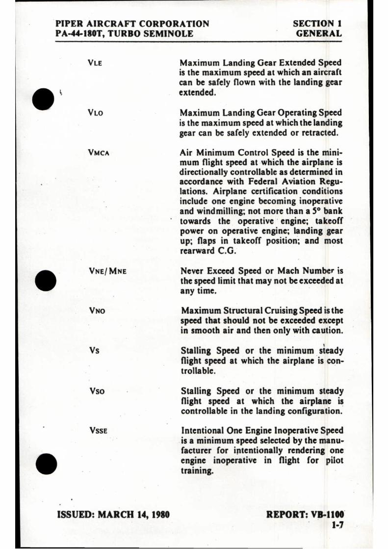
Maximum Landing Gear Extended Speed is the maximum speed at which an aircraft can be safely flown with the landing gear extended.
Maximum Landing Gear Operating Speed is the maximum speed at which the landing gear can be safely extended or retracted.
Air Minimum Control Speed is the mini-mum flight speed at which the airplane is directionally controllable as determined in accordance with Federal Aviation Regu-lations. Airplane certification conditions include one engine becoming inoperative and windmilling; not more than a 5° bank towards the operative engine; takeoff power on operative engine; landing gear up; flaps in takeoff position; and most rearward C.G.
VNE/ MNE
VNO
Vs
Vso
Never Exceed Speed or Mach Number is the speed limit that may not be exceeded at any time.
Maximum Structural Cruising Speed is the speed that should not be exceeded except in smooth air and then only with caution.
Stalling Speed or the minimum steady flight speed at which the airplane is con-trollable.
Stalling Speed or the minimum steady flight speed at which the airplane is controllable in the landing configuration.
VSSE Intentional One Engine Inoperative Speed is a minimum speed selected by the manu-facturer for intentionally rendering one engine inoperative in flight for pilot training.
ISSUED: MARCH 14, 1980 REPORT: VB-1100 1-7

SECTION 1
PIPER AIRCRAFT CORPORATION GENERAL PA-44-180T, TURBO SEMINOLE
Vx
Best Angle-of-Climb Speed is the airspeed which delivers the greatest gain of altitude in the shortest possible horizontal distance.
V v
Best Rate-of-Climb Speed is the airspeed • which delivers the greatest gain in altitude in the shortest possible time.
(b) Meteorological Terminology
ISA
OAT
Indicated Pressure Altitude
Pressure Altitude
International Standard Atmosphere in which: The air is a dry perfect gas; The temperature at sea level is 15° Celsius (59° Fahrenheit); The pressure at sea level is 29.92 inches Hg (1013.2 mb); The tempera-ture gradient from seal level to the altitude at which the temperature is -56.6° C (-69.7°F) is -0.00198°C (-0.003564° F) per foot and zero above that altitude.
Outside Air Temperature is the free air static temperature obtained either from inflight temperature indications or ground meteorological sources, adjusted for in-strument error and compressibility effects.
The number actually read from an altimeter when the barometric subscale has been set to 29.92 inches of mercury (1013.2 millibars).
Altitude measured from standard sea-level pressure (29.92 in. Hg) by a pressure or barometric altimeter. It is the indicated pressure altitude corrected for position and instrument error. In this handbook, altimeter instrument errors are assumed to be zero.
Station Pressure Actual atmospheric pressure at field elevation.
REPORT: VB-1100 ISSUED: MARCH 14, 1980 1-8 REVISED: MARCH 11, 1983

PIPER AIRCRAFT CORPORATION SECTION 1 PA-44-180T, TURBO SEMINOLE GENERAL
Wind
(c) Power Terminology
Takeoff Power
Maximum Con-tinuous Power
Maximum Climb Power
Maximum Cruise Power
(d) Engine Instruments
EGT Gauge
CHT Gauge
The wind velocities recorded as variables on the charts of this handbook are to be understood as the headwind or tailwind components of the reported winds.
Maximum power permissible for takeoff.
Maximum power permissible continuously during flight.
Maximum power permissible during climb.
Maximum power permissible during cruise.
Exhaust Gas Temperature Gauge
Cylinder Head Temperature Gauge
(e) Airplane Performance and Flight Planning Terminology
Climb Gradient
Demonstrated Crosswind Velocity
Accelerate-Stop Distance
The demonstrated ratio of the change in height during a portion of a climb, to the horizontal distance traversed in the same time interval.
The demonstrated crosswind velocity is the velocity of the crosswind component for which adequate control of the airplane during takeoff and landing was actually demonstrated during certification tests.
The distance required to accelerate an air plane to a specified speed and, assuming failure of an engine at the instant that speed is attained, to bring the airplane to a stop.
ISSUED: MARCH 14, 1980 REPORT: VB-1100 1-9

SECTION 1 PIPER AIRCRAFT CORPORATION
GENERAL
PA-44-180T, TURBO SEMINOLE
Route Segment A part of a route. Each end of that part is identified by: ( I ) a geographical location; or (2) a point at which a definite radio fix • can be established.
(1) Weight and Balance Terminology
Reference Datum An imaginary vertical plane from which all horizontal distances are measured for balance purposes.
Station A location along the airplane fuselage usually given in terms of distance in inches from the reference datum.
Arm The horizontal distance from the reference datum to the center of gravity (C.G.) of an item.
Moment The product of the weight of an item multi- plied by its arm. (Moment divided by a constant is used to simplify balance calcu- lations by reducing the number of digits.)
Center of Gravity (C.G.)
C.G. Arm
C.G. Limits
The point at which an airplane would balance if suspended. Its distance from the reference datum is found by dividing the total moment by the total weight of the airplane.
The arm obtained by adding the airplane's individual moments and dividing the sum by the total weight.
The extreme center of gravity locations within which the airplane must be operated at a given weight.
REPORT: VB-1100 ISSUED: MARCH 14, 1980 1-10 REVISED: MARCH 11, 1983

PIPER AIRCRAFT CORPORATION SECTION 1 PA-44-180T, TURBO SEMINOLE GENERAL
Usable Fuel Fuel available for flight planning.
Unusable Fuel Fuel remaining after a runout test has been completed in accordance with govern-mental regulations.
Standard Empty Weight of a standard airplane including Weight unusable fuel, full operating fluids and full
oil.
Basic Empty Standard empty weight plus optional I Weight equipment.
Payload Weight of occupants, cargo and baggage.
Useful Load Difference between takeoff weight, or ramp weight if applicable, and basic empty weight.
Maximum Ramp Maximum weight approved for ground Weight maneuver, (It includes weight of start, taxi
and run up fuel.)
Maximum Maximum weight approved for the start of Takeoff Weight the takeoff run.
Maximum Maximum weight approved for the landing Landing Weight touchdown.
Maximum Zero Fuel Weight
Maximum weight exclusive of usable fuel.
ISSUED: MARCH 14, 1980 REPORT: VB-1100 REVISED: MARCH 31, 1981 1-11

~ i

• I
TABLE OF CONTENTS
SECTION 2
LIMITATIONS
Paragraph No.
Page No.
2.1 General 2-1 2.3 Airspeed Limitations 2-1 2.5 Airspeed Indicator Markings 2-2 2.7 Power Plant Limitations 2-3 2.9 Power Plant Instrument Markings 2-4 2.11 Weight Limits 2-5 2.13 Center of Gravity Limits 2-5 2.15 Maneuver Limits 2-6 2.17 Flight Maneuvering Load Factors 2-6 2.19 Types of Operation 2-6 2.21 Fuel Limitations 2-6 2.23 Noise Level 2-7 2.25 Gyro Suction Limits 2-7 2.27 Operating Altitude Limitations 2-7 2.29 Maximum Seating Configuration 2-7 2.31 Placards 2-8
REPORT: VB-I100 2-i
•

•
•

PIPER AIRCRAFT CORPORATION SECTION 2 PA-44-180T, TURBO SEMINOLE LIMITATIONS
SECTION 2
LIMITATIONS
2.1 GENERAL
This section provides the "FAA Approved" operating limitations, instrument markings, color coding and basic placards necessary for operation of the airplane and its systems.
The airplane must be operated as a normal category airplane in compliance with the operating limitations stated in the form of placards and markings and those given in this section and handbook.
Limitations associated with those optional systems and equipment which require handbook supplements can be found in Section 9
*Supplements).
2.3 AIRSPEED LIMITATIONS
SPEED KIAS KCAS
Design Maneuvering Speed (VA) - Do not make full or abrupt control movements above this speed.
3925 lbs. 137 135 2700 lbs. 112 112
CAUTION
• Maneuvering speed decreases at lighter weight as the effects of aerodynamic forces become more pronounced. Linear interpolation may be used for intermediate gross weights. Maneuvering speed should not be exceeded while operating in rough air.
ISSUED: MARCH 14, 1980 REPORT: VB-1100 2-1

SECTION 2 PIPER AIRCRAFT CORPORATION LIMITATIONS PA-44-180T, TURBO SEMINOLE
SPEED
Never Exceed Speed (VNE) - Do not exceed
K1AS KCAS
this speed in any operation. 202 194 • Maximum Structural Cruising Speed (VNo) - Do not exceed this speed except in smooth air and then only with caution. 170 165
Maximum Flaps Extended Speed (VFE) - Do not exceed this speed with the flaps extended. I 1 1 109
Maximum Gear Extended Speed (VLE) - Do not exceed this speed with landing gear extended. 140 138
Maximum Landing Gear Extending Speed - Do not extend landing gear above this speed. 140 138
Maximum Landing Gear Retracting • Speed - Do not retract landing gear above this speed. 109 109
Air Minimum Control Speed (VMCA) - Lowest airspeed at which airplane is con-trollable with one engine operating and no flaps. Note: This is a stalled condition. 57 62
One Engine Inoperative Best Rate of Climb Speed. 88 90
2.5 AIRSPEED INDICATOR MARKINGS
MARKING IAS
Red Radial Line (Never Exceed) 202 KTS.
Red Radial Line (One Engine Inoperative Air Minimum Control Speed) 57 KTS 411
REPORT: VB-1100 ISSUED: MARCH 14, 1980 2-2

PIPER AIRCRAFT CORPORATION SECTION 2 PA-44-180T, TURBO SEMINOLE LIMITATIONS
MARKING
Blue Radial Line (One Engine Inoperative Best Rate of Climb Speed)
Yellow Arc (Caution Range - Smooth Air Only)
Green Arc (Normal Operating Range)
White Arc (Flap Down)
IAS
88 KTS
170 KTS to 202 KTS
60 KTS to 170 KTS
56 KTS to 1 I 1 KTS
2.7 POWER PLANT LIMITATIONS
(a) Number of Engines 2 (b) Engine Manufacturer Lycoming (c) Engine Model No.
Left TO-360-E1A6D • Right LTO-360-E I A6D
(d) Engine Operating Limits (1) Maximum Horsepower 180 (2) Maximum Rotation Speed (RPM) 2575 (3) Maximum Manifold Pressure 36.5" Hg (4) Maximum Cylinder Head Temperature 500° F (5) Maximum Oil Temperature 245° F
(e) Oil Pressure Minimum (red line) 15 PSI Maximum (red line) 115 PSI
(f) Fuel Pressure Minimum (red line) 13 PSI Maximum (red line) 35 PSI
(g) Fuel (minimum grade) 100 or IOOLL Aviation Grade
(h) Number of Propellers 2 (i) Propeller Manufacturer Hartzell (j) Propeller Hub and Blade Models
(1) Standard (Two Blade) • Left HC-C2YR-2C ( )UF/
FC7666A-2R Right H C-C2YR-2CL( )UF/
FJC7666A-2R
ISSUED: MARCH 14, 1980 REPORT: VB-1100 REVISED: JULY 9, 1980 2-3

SECTION 2 PIPER AIRCRAFT CORPORATION LIMITATIONS PA-.44-180T, TURBO SEMINOLE
(2) Optional (Three Blade) Left
Right
(k) Propeller Diameter (1) Standard (Two Blade)
Maximum Minimum
(2) Optional (Three Blade) Maximum Minimum
HC-C3YR-2( )UF/ FC-7663-5 R
HC-C3YR-2L( )UF/ 411) FJC-7663-5R
74 IN. 72 IN.
73 IN. 72 IN.
2.9 POWER PLANT INSTRUMENT MARKINGS
(a) Tachometer Green Arc (Normal Operating Range) 500 to 2575 RPM Red Line (Maximum) 2575 RPM
(b) Manifold Pressure Green Arc (Normal Operating Range) 10 to 36.5 in. Hg. Red Line (Maximum) 36.5 in. Hg.
(c) Oil Temperature Green Arc (Normal Operating Range) 75° to 245°F Red Line (Maximum) 245° F
(d) Oil Pressure Green Arc (Normal Operating Range) 60 PSI to 90 PSI Yellow Arc (Caution Range) (Idle) 15 PSI to 60 PSI Yellow Arc (Ground Warm-Up) 90 PSI to 115 PSI Red Line (Minimum) 15 PSI Red Line (Maximum) 115 PSI
or Green Arc (Normal Operating Range) 55 PSI to 90 PSI Yellow Arc (Caution Range) (Idle) 15 PSI to 55 PSI Yellow Arc (Ground Warm-Up) 90 PSI to 115 PSI Red Line (Minimum) 15 PSI Red Line (Maximum) 115 PSI
(e) Fuel Pressure Green Arc (Normal Operating Range) 13 PSI to 35 PSI Red Line (Minimum) 13 PSI Red Line (Maximum) 35 PSI
REPORT: VB-1100 ISSUED: MARCH 14, 1980 2-4 REVISED: FEBRUARY 19, 1982
•

PIPER AIRCRAFT CORPORATION SECTION 2 PA-44-180T, TURBO SEMINOLE LIMITATIONS
(1) Cylinder Head Temperature Green Arc (Normal Range) 200° to 435°F Red Line (Maximum) 500°F
(g) Exhaust Gas Temperature (EGT) Green Arc (Normal Operating Range) 1200°F to 1650° F Red Line (Maximum) 1650° F
2.11 WEIGHT LIMITS
(a) Maximum Ramp Weight (b) Maximum Takeoff Weight (c) Maximum Landing Weight (d) Maximum Weight-Baggage
Compartment
3943 lbs. 3925 lbs. 3800 lbs.
200 lbs.
2.13 CENTER OF GRAVITY LIMITS
Weight Forward Limit Rearward Limit
Pounds Inches Aft of Datum Inches Aft of Datum
2700
83.0
93.0
3400
85.0
93.0
3800
87.3
93.0 3925
89.7
93.0
NOTES
Straight line variation between points given.
The datum used is 78.4 inches ahead of the wing leading edge at wing station 106.
It is the responsibility of the airplane owner and the pilot to insure that the airplane is properly loaded. Maximum allowable gross weight is 3925 pounds. See Section 6 (Weight and Balance) for proper loading instructions.
ISSUED: MARCH 14, 1980 REPORT: VB-1100 REVISED: FEBRUARY 19, 1982 2-5

■I■
SECTION 2 PIPER AIRCRAFT CORPORATION LIMITATIONS PA-44-180T, TURBO SEMINOLE
2.15 MANEUVER LIMITS
MI intentional acrobatic maneuvers (including spins) are prohibited. • Avoid abrupt maneuvers.
2.17 FLIGHT MANEUVERING LOAD FACTORS
FLAPS UP (a) Positive Load Factor (Maximum) (b) Negative Load Factor (Maximum)
FLAPS DOWN (a) Positive Load Factor (Maximum) (b) Negative Load Factor (Maximum)
3.8 G No inverted maneuvers
approved
2.0 G No inverted maneuvers
approved
2.19 TYPES OF OPERATION
The airplane is approved for the following operations when equipped in accordance with FAR 91 or FAR 135. •
(a) Day V.F.R. (b) Night V.F.R. (c) Day I.F.R. (d) Night I.F.R. (e) Non Icing
2.21 FUEL LIMITATIONS
(a) Total Capacity (b) Unusable Fuel
The unusable fuel for this airplane has been determined as 1.0 gallon in each nacelle in critical flight attitudes.
(c) Usable Fuel The usable fuel in this airplane has been determined as 54 gallons in each nacelle or a total of 108 gallons.
110 U.S. GAL. 2 U.S. GAL.
108 U.S. GAL. • REPORT: VB-1100 ISSUED: MARCH 14, 1980 2-6 REVISED: FEBRUARY 19, 1982

PIPER AIRCRAFT CORPORATION SECTION 2 PA-44-180T, TURBO SEMINOLE LIMITATIONS
2.23 NOISE LEVEL
The corrected noise level of this aircraft is 71.5d B(A) with the two trade • propeller and 72.4d B(A) with the three blade propeller.
No determination has been made by the Federal Aviation Administra-tion that the noise levels of this airplane are or should be acceptable or unacceptable for operation at, into, or out of, any airport.
The above statement notwithstanding, the noise level stated above has been verified by and approved by the Federal Aviation Administration in noise level test flights conducted in accordance with FAR 36, Noise Standards - Aircraft Type and Airworthiness Certification. This aircraft model is in compliance with all FAR 36 noise standards applicable to this type.
2.25 GYRO SUCTION LIMITS
The operating limits for the suction system are 4.8 to 5.1 inches of mercury for all operations as indicated by the gyro suction gauge.
2.27 OPERATING ALTITUDE LIMITATIONS
Flight above 20,000 feet is not approved. Flight up to and including 20,000 feet is approved if equipped with oxygen in accordance with FAR 23.1441 and avionics in accordance with FAR 91 or FAR 135.
2.29 MAXIMUM SEATING CONFIGURATION
The maximum seating capacity of this aircraft is 4 (four) persons.
• ISSUED: MARCH 14, 1980 REPORT: VB-1100
2-7

SECTION 2 PIPER AIRCRAFT CORPORATION LIMITATIONS PA-44-180T, TURBO SEMINOLE
2.31 PLACARDS .
In full view of the pilot:
The markings and placards installed in this airplane contain operating limitations which must be complied with when operating this airplane in the normal category. Other operating limitations which must be complied with when operating this airplane in this category are contained in the airplane flight manual. No acrobatic maneuvers, including spins, approved.
This aircraft approved for V.F.R., I.F.R., day and night non-icing flight when equipped in accordance with FAR 91 or FAR 135.
In full view of the pilot:
ONE ENGINE INOPERATIVE AIR MINIMUM CONTROL SPEED 57 KIAS
In full view of the pilot:
WARNING -TURN OFF STROBE LIGHTS WHEN IN CLOSE PROXIMITY TO GROUND, OR DURING FLIGHT THROUGH CLOUD, FOG OR HAZE.
On instrument panel in full view of the pilot:
VA 137 AT 3925 LBS (SEE AFM)
Vi.o 140 DN, 109 UP VIE 140 MAX.
DEMO X-WIND 17 KTS
REPORT: VB-1100 ISSUED: MARCH 14, 1980 2-8

PIPER AIRCRAFT CORPORATION SECTION 2 PA-44-180T, TURBO SEMINOLE LIMITATIONS
Near emergency gear release:
EMERGENCY GEAR EXTENSION PULL TO RELEASE. SEE AFM
BEFORE RE-ENGAGEMENT
Near gear selector switch:
GEAR UP
109 KIAS MAX. DOWN
140 KIAS MAX.
Adjacent to upper door latch:
ENGAGE LATCH BEFORE FLIGHT
On inside of baggage compartment door: • BAGGAGE MAXIMUM 200 LBS.
On storm window:
DO NOT OPEN ABOVE 129 KIAS
On pilot's sunvisor:
TAKEOFF CHECK LIST
• Fuel Selectors On Electric Fuel Pumps On Alternators On Engine Gauges Checked Mixtures Set Propellers Set Carb Heat Off
Cowl Flaps Set Seat Backs Erect Flaps Set Trim Set (Stab. & Rudder) Fasten Belts/ Harness Controls Free - Full Travel Doors Latched Air Conditioner Off
ISSUED: MARCH 14, 1980 REPORT: VB-I100 REVISED: SEPTEMBER 29, 1980 2-9

SECTION 2 PIPER AIRCRAFT CORPORATION LIMITATIONS PA-44-180T, TURBO SEMINOLE
LANDING CHECK LIST
Seat Backs Erect Fasten Belts/ Harness Fuel Selectors On Cowl Flaps Set
Electric Fuel Pumps On Mixtures Rich Propellers Set Gear Down Flaps Set - (White Arc) Air Conditioner Off
• The "AIR CONDITIONER OFF" item in the preceding takeoff and
landing check list is mandatory for air conditioned aircraft only.
In full view of the pilot:
ONE ENGINE INOPERATIVE STALLS NOT RECOMMENDED. CAN CAUSE 400 FT. LOSS OF ALTITUDE AND 30° PITCH ANGLE.
In full view of the pilot when the oil cooler winterization kit is installed: III OIL COOLER WINTERIZATION PLATE TO BE REMOVED WHEN AMBIENT TEMPERATURE EXCEEDS 50°F.
On the vertical window post between the first and second left side windows and close to the Emergency Exit release handle:
EMERGENCY EXIT PULL HANDLE FORWARD
PUSH WINDOW OUT
REPORT: VB-I100 ISSUED: MARCH 14, 1980 2-10 REVISED: SEPTEMBER 29, 1980

PIPER AIRCRAFT CORPORATION SECTION 2 PA-44-180T, TURBO SEMINOLE LIMITATIONS
Adjacent to fuel tank filler caps:
FUEL 100 OR 10011
AVIATION GRADE
On the manifold pressure gauge face (three blade props only):
CONTINUOUS OPERATION LESS THAN 15" MP ABOVE 12,000 FT PROHIBITED.
ISSUED: SEPTEMBER 29, 1980 REPORT: VB-1100 2-11

•

• TABLE OF CONTENTS
SECTION 3
EMERGENCY PROCEDURES
Paragraph Page
No. No.
3.1 General 3-I
3.3 Emergency Procedures Checklist 3-2 Airspeeds. For Safe Operations 3-2 Engine Inoperative Procedures 3-2 Fire 3-6 Fuel Management During One Engine Inoperative Operation 3-6
• Carburetor Ice Engine Driven Fuel Pump Failure 3-7 Landing Gear Unsafe Warnings
3-7
3-7 Manual Extension Of Landing Gear 3-8 Gear Up Landing 3-8 Gyro Suction Failures 3-8 Electrical Power Loss - (For Airplanes With Inter locked Master And Alt Switch Operation) 3-8a
Electrical Power Loss - (For Airplanes With Separate Bat And Alt Switch Operation With Single Electrical Bus System) 3-8b
Electrical Power Loss - (For Airplanes With Split Electrical Bus System) 3-8d
Electrical Overload (Alternators over 30 amps above known electrical load) - (For Airplanes With Inter- locked Master And Alt Switch Operation) 3-8f
Electrical Overload (Alternators over 30 amps above known electrical load) - (For Airplanes With A Separate Bat And Alt Switch Operation) 3-8f
• Spins Open Door
3-9 3-9
Propeller Overspeed 3-10
REPORT: VB-1100 3-i

TABLE OF CONTENTS (cont)
SECTION 3 (cont)
Paragraph Page No. No.
Combustion Heater Overheat 3-10 Oxygen System Malfunction 3-10 Emergency Descent 3-10 Emergency Exit 3-10
3.5 Amplified Emergency Procedures (General) 3-11 3.7 Engine Inoperative Procedures 3-11 3.9 Fire 3-16 3.11 Fuel Management During One Engine Inoperative
Operation 3-16 3.13 Carburetor Ice 3-17 3.15 Engine Driven Fuel Pump Failure 3-17 3.17 Landing Gear Unsafe Warnings . . . 3-18 3.19 Manual Extension Of The Landing Gear 3-18 3.21 Gear-Up Emergency landing 3-18 3.23 Gyro Suction Failures 3-19 3.25 Electrical Power Loss 3-19
Electrical Power Loss - (For Airplanes With Inter locked Master And Alt Switch Operation) 3-19
Electrical Power Loss - (For Airplanes With Separate Bat And Alt Switch Operation) 3-I9a
Electrical Power Loss - (For Airplanes With Split Electrical Bus System) 3-19b
3.27 Electrical Overload 3-I9c Electrical Overload (Alternators over 30 amps above known electrical load) - (For Airplanes With Inter- locked Master And Alt Switch Operation) 3-I9c
Electrical Overload (Alternators over 30 amps above known electrical load) - (For Airplanes With Separate Bat And Alt Switch Operation) 3-19d•
REPORT: VB-1100 3-ii

TABLE OF CONTENTS (cont)
SECTION 3 (cont)
Paragraph No.
Page .
No.
'3.29 Spins 3-20 3.31 Open Door 3-20 3.33 Propeller Overspeed 3-21 3.35 Combustion Heater Overheat 3-21 3.37 Oxygen System Malfunction 3-21 3.39 Emergency Descent 3-21 3.41 Emergency Exit 3-22
REPORT: VB-1100 I 3-iii


PIPER AIRCRAFT CORPORATION SECTION 3 PA-44-180T, TURBO SEMINOLE EMERGENCY PROCEDURES
SECTION 3
EMERGENCY PROCEDURES
3.1 GENERAL The recommended procedures for coping with various types of
emergencies and critical situations are provided by this section. All of required (FAA regulations) emergency procedures and those necessary for operation of the airplane as determined by the operating and design features of the airplane are presented.
Emergency procedures associated with those optional systems and equipment which require handbook supplements are provided in Section 9 (Supplements).
The first portion of this section consists of an abbreviated emergency checklist which supplies an action sequence for critical situations with little emphasis on the operation of systems.
The remainder of the section is devoted to amplified emergency procedures containing additional information to provide the pilot with a more complete understanding of the procedures.
These procedures are suggested as a course of action for coping with the particular condition described, but are not a substitute for sound judgement and common sense. Pilots should familiarize themselves with the procedures given in this section and be prepared to take appropriate action should an emergency arise.
Most basic emergency procedures, such as power off landings, are a normal part of pilot training. Although these emergencies are discussed here, this information is not intended to replace such training, but only to provide a source of reference and review, and to provide information on procedures which are not the same for all aircraft. It is suggested that the pilot review standard emergency procedures periodically to remain proficient in them.
ISSUED: MARCH 14, 1980 REPORT: VB-1100 REVISED: MAY 7, 1990 3-1

SECTION 3 PIPER AIRCRAFT CORPORATION EMERGENCY PROCEDURES PA-44-180T, TURBO SEMINOLE
3.3 EMERGENCY PROCEDURES CHECK LIST
AIRSPEEDS FOR SAFE OPERATIONS
One engine inoperative air minimum control 57 KIAS One engine inoperative best rate of climb 88 KIAS One engine inoperative best angle of climb 82 KIAS Maneuverings 137 KIAS Never exceed 202 KIAS
ENGINE INOPERATIVE PROCEDURES
DETECTING DEAD ENGINE
Loss of thrust. Nose Of aircraft will yaw in direction of dead engine (with coordinated controls).
ENGINE SECURING PROCEDURE (FEATHERING PROCEDURE)
Minimum control speed 57 KIAS One engine inoperative best rate of climb 88 KIAS Maintain direction and airspeed above 82 KIAS. Mixture controls forward Propeller controls forward Throttle controls 36.5 in. Hg. Max. Flaps retract Gear retract Identify inoperative engine. Throttle of inop. engine retard to verify
To attempt to restore power prior to the feathering: Mixtures as required Fuel selector ON Magnetos left or right only Electric fuel pump check ON Carburetor heat ON
Prop control of inop. engine feather before RPM drops below 950
Mixture of inop. engine idle cut-off
REPORT: VB-1100 ISSUED: MARCH 14, 1980 3-2 REVISED: FEBRUARY 19, 1982

PIPER AIRCRAFT CORPORATION SECTION 3 PA-44-180T, TURBO SEMINOLE EMERGENCY PROCEDURES
Trim as required (3° to 5° of bank toward operative engine - ball 1/2 to 3/4 out)
Electric fuel pump of inop. engine OFF • Magnetos of inop. engine OFF Cowl flaps close on inop. engine,
as required on operative engine Alternator of inop. engine OFF Electrical load reduce Fuel selector OFF inop. engine,
consider crossfeed Electric fuel pump operative engine OFF
ENGINE FAILURE DURING TAKEOFF (Below 75 KIAS)
If engine failure occurs during takeoff and 75 KIAS has not been attained: Throttles CLOSE both immediately Stop straight ahead.
If inadequate runway remains to stop: Throttles CLOSED Brakes apply max. braking • Master switch OFF Fuel selectors OFF Continue straight ahead, turning to avoid obstacles.
ENGINE FAILURE DURING TAKEOFF (75 K1AS or above)
If engine failure occurs during takeoff ground roll or after lift-off with gear still down and 75 KIAS has been attained: If adequate runway remains CLOSE both throttles immediately, land if airborne and stop straight ahead. If runway remaining is inadequate for stopping, decide whether to abort or continue. if decision is made to continue, maintain heading and when climb is established retract landing gear, accelerate to 88 KIAS, and feather inoperative engine prop (see Engine Securing Procedure).
WARNING
• In certain combinations of aircraft weight, configuration, ambient conditions and speed, negative climb performance may result. Refer to One Engine Inoperative Climb Performance chart, Figure 5-27.
ISSUED: MARCH 14, 1980 REPORT: VB-1100 REVISED: MARCH 31, 1981 3-3

SECTION 3 PIPER AIRCRAFT CORPORATION EMERGENCY PROCEDURES PA-44-180T, TURBO SEMINOLE
ENGINE FAILURE DURING CLIMB
Airspeed maintain 88 KIAS Directional control maintain Inop. engine identify and verify Inop. engine complete Engine Securing Procedure Land as soon as practical at nearest suitable airport.
ENGINE FAILURE DURING FLIGHT
(Maintain Airspeed above 88 KIAS) Inop. engine identify Operative engine adjust as required
Before securing Inop. engine: Fuel pressure check (if deficient-Electric
fuel pump ON) Fuel quantity check Fuel selector (inop. eng.) ON Oil pressure and temp • check Magneto switches check
If engine does not start, complete Engine Securing Procedure. Land as soon as practical at nearest suitable airport.
ONE ENGINE INOPERATIVE LANDING
Mop. engine prop feather When certain of making field: Landing gear extend Wing flaps lower Maintain additional altitude and speed during approach. Final approach speed 90 KIAS Wing flaps 25°
ONE ENGINE INOPERATIVE GO-AROUND (SHOULD BE AVOIDED IF AT ALL POSSIBLE)
Mixture forward Propeller forward Throttle open slowly (36.5 in Hg. Max.) Flaps retract Landing gear retract .
REPORT: VB-1100 ISSUED: MARCH 14, 1980 3-4 REVISED: APRIL 2, 1982

PIPER AIRCRAFT CORPORATION SECTION 3 PA-44-180T, TURBO SEMINOLE EMERGENCY PROCEDURES
Airspeed 88 KIAS Trim set Cowl flap operating engine as required • AIR START (UNFEATHERING PROCEDURE)
engine ON inop. engine ON
RICH open 1/4 inch
ON ON, 2 seconds maximum
full forward engage until prop
windmills freely Throttle reduce power until
engine is warm
If engine does not start, prime as required - 2 seconds maximum. Alternator ON
AIR START (UNFEATHERING PROCEDURE) • (Optional propeller unfeathering system installed)
Fuel selector inop. engine ON Electric fuel pump inop. engine ON Mixture RICH Throttle open 1/4 inch Magneto switches ON Prop control and latch push full forward Starter engage after 5 - 7 seconds
if prop is not windmilling freely
Throttle reduce power until engine is warm
Alternator after restart ON
STARTER ON LIGHT
If light remains illuminated after the starter switch is released:
• BUS ISO (60A) circuit breakers Pl_TLL Battery switch OFF Electrical loads REDUCE Land as soon as practical.
Fuel selector inop. Electric fuel pump Mixture Throttle Magneto switches Primer Prop control Starter
ISSUED: MARCH 14, 1980 REPORT: VB-1!00 REVISED: APRIL 2, 1982 3-5

SECTION 3 PIPER AIRCRAFT CORPORATION EMERGENCY PROCEDURES PA-44-180T, TURBO SEMINOLE
FIRE
ENGINE FIRE ON GROUND
If engine has not started: Mixture idle cut-off Throttle open Starter crank engine
If engine has already started and is running, continue operating to try pulling the fire into the engine. If fire continues, extinguish with best available means. If external fire extinguishing is to be applied: Fuel selector valves OFF Mixture idle cut-off
ENGINE FIRE IN FLIGHT
Affected engine: Fuel selector OFF Throttle close Propeller feather Mixture idle cut-off Cowl flap OPEN If terrain permits land immediately.
FUEL MANAGEMENT DURING ONE ENGINE INOPERATIVE OPERATION
CRUISING
When using fuel from tank on the same side as the operating engine: Fuel selector operating engine ON Fuel selector inop. engine OFF Electric fuel pumps OFF
(except in case of engine driven pump failure, electric fuel pump on operating
engine side must be used)
REPORT: VB-1100 ISSUED: MARCH 14, 1980 3-6 REVISED: FEBRUARY 19, 1982

PIPER AIRCRAFT CORPORATION SECTION 3 PA-44-180T, TURBO SEMINOLE EMERGENCY PROCEDURES
When using fuel from tank on the side opposite the operating engine: Fuel selector operating engine CROSSFEED Fuel selector inop. engine OFF
illectric fuel pumps OFF (except in case of engine driven pump
failure, electric fuel pump on operating engine side must be used)
If engine failure occurs due to loss of fuel pressure during crossfeed operation, return fuel selector to ON position.
NOTE
Use crossfeed in level cruise flight only.
LANDING
Fuel selector operating engine ON Fuel selector inop. engine OFF
CARBURETOR ICE
litarburetor heat full ON fixture adjust as required
ENGINE DRIVEN FUEL PUMP FAILURE
Throttle retard Electric fuel pump ON Throttle reset
LANDING GEAR UNSAFE WARNINGS
Red light indicates gear in transit. Recycle gear if indication continues. Light will illuminate and gear horn sounds when the gear is not down and locked if throttles , are at low settings or wing flaps are in second or third notch position. • ISSUED: MARCH 14, 1980 REPORT: VB-1100 REVISED: FEBRUARY 19, 1982 3-7

SECTION 3 PIPER AIRCRAFT CORPORATION EMERGENCY PROCEDURES PA-44-180T, TURBO SEMINOLE
MANUAL EXTENSION OF LANDING GEAR
Check following before extending gear manually:
Master switch check
ON Circuit breakers
Alternators check Navigation lights OFF (daytime)
To extend, proceed as follows: Airspeed reduce (100 KIAS max.) Gear selector GEAR DOWN LOCKED position Emerg. gear extend knob pull Indicator lights 3 green Leave emergency gear extension knob out.
GEAR UP LANDING
Seat backs erect Seat belts and harness fastened Fuel selectors ON Cowl flaps as required Electric fuel pumps ON Mixture controls . ••• . ••• ••••• •••• ■ ••••
. •
Prop controls full FORWARD Flaps as desired Approach speed 75 KIAS or above Throttles close prior to touchdown Fuel selector OFF prior to touchdown Master switch OFF prior to touchdown Ignition switches OFF prior to touchdown Touch Down minimum possible speed
GYRO SUCTION FAILURES
Suction below 4.5 in. Hg. RPM increase to 2575 Altitude descend to maintain
4.5 in. Hg. Use electric turn indicator to monitor Directional Indicator and Attitude Indicator performance.
•
REPORT: VB-1100 ISSUED: MARCH 14, 1980 3-8 REVISED: FEBRUARY 19, 1982

PIPER AIRCRAFT CORPORATION SECTION 3 PA-44-180T, TURBO SEMINOLE EMERGENCY PROCEDURES
ELECTRICAL POWER LOSS - (FOR AIRPLANES WITH INTER-LOCKED MASTER AND ALT SWITCH OPERATION)
OLT annunciator light illuminated: mmeters check to determine
inop. alt.
If one ammeter shows zero: Inop. ALT switch OFF
Reduce electrical loads to minimum: ALT circuit breaker check and reset
as required Inop. ALT switch ON
If power is not restored: Inop. ALT switch OFF Electrical loads re-establish to
60 amps max.
If both ammeters show zero: eiLT switches both OFF
Determine ALT showing LEAST (but not zero) amps: ALT switches least load ON
other OFF Electrical loads re-establish to
60 amps max.
If alternator outputs are NOT restored: ALT switches OFF Electrical loads reduce to minimum
Land as soon as practical. The battery is the only remaining source of electrical power. Anticipate complete electrical failure. •
educe electrical loads to minimum: ALT. circuit breakers check both and
reset as required ALT switches ON one at a time
ISSUED: JANUARY 5, 1981 REPORT: VB-1100 REVISED: FEBRUARY 19, 1982 3-8a

SECTION 3 PIPER AIRCRAFT CORPORATION EMERGENCY PROCEDURES PA-44-180T, TURBO SEMINOLE
WARNING
Compass error may exceed 10 degrees with both alternators inoperative.
NOTE
If battery is depleted, the landing gear must be lowered using the emergency gear extension procedure. The gear position lights will be inoperative.
ELECTRICAL POWER LOSS -(FOR AIRPLANES WITH SEPARATE BAT AND ALT SWITCH OPERATION WITH SINGLE ELECTRICAL BUS SYSTEM)
ALT annunciator light illuminated: Ammeters check to determine
inop alt.
If one ammeter shows zero: lnop. ALT switch OFF.
Reduce electrical loads to minimum ALT circuit breaker check and reset
as required lnop. ALT switch ON
If power is not restored: lnop. ALT switch OFF Electrical loads re-establish to
60 amps max.
If both ammeters show zero: ALT switches both OFF
Reduce electrical loads to minimum: ALT circuit breakers check both and
reset as required ALT switches ON one at a time •
REPORT: VB-1100 ISSUED: JANUARY 5, 1981 3-8b REVISED: FEBRUARY 19, 1982

PIPER AIRCRAFT CORPORATION SECTION 3 PA-44-180T, TURBO SEMINOLE EMERGENCY PROCEDURES
Determine ALT showing LEAST (but not zero) amps: ALT switches least load ON
other OFF 41, Electrical loads re-establish to
60 amps max.
If alternator outputs are NOT restored: BAT switch OFF ALT switches ON one at a time
If one or both alternator outputs are restored: Electrical loads reduce to minimum
Land as soon as practical. The alternator(s) is the only remaining source of electrical power.
NOTE
• Due to increased system voltage and radio frequency noise, operation with ALT switch ON and BAT switch OFF should be made only when required by an electrical system failure.
If alternator outputs are NOT restored: ALT switched OFF Electrical loads reduce to minimum
Land as soon as practical. The battery is the only remaining source of electrical power. Anticipate complete electrical system failure.
WARNING
Compass error may exceed 10 degrees with both alternators inoperative.
NOTE
If the battery is depleted, the landing gear must be lowered using the emergency gear extension procedure. The gear position lights will be inoperative.
ISSUED: JANUARY 5, 1981 REPORT: VB-1100 REVISED: FEBRUARY 19, 1982 3-8c

SECTION 3 PIPER AIRCRAFT CORPORATION EMERGENCY PROCEDURES PA-44-180T, TURBO SEMINOLE
ELECTRICAL POWER LOSS - (FOR AIRPLANES WITH SPLIT I ELECTRICAL BUS SYSTEM) (Aircraft serial numbers 44-8207001 and • up)
ALT annunciator light illuminated: Ammeters check to determine
Inop. alt.
If one ammeter shows zero: Inop. ALT switch OFF
Reduce electrical loads to minimum: ALT circuit breaker check and reset
as required Inop. ALT switch ON
If power is not restored: Inop. ALT switch OFF Electrical loads re-establish to
60 amps. max.
If both ammeters show zero: ALT switches both OFF
Reduce electrical loads to minimum: ALT circuit breakers check both and
reset as required ALT switches ON one at a time
Determine ALT showing LEAST (but not zero) amps: ALT switches least load ON
other OFF Electrical loads re-establish to
60 amps. max.
Land as soon as practical. The battery is the only remaining source of electrical III power. Anticipate complete electrical failure.
REPORT: VB-1100 ISSUED: JANUARY 5, 1981 3-8d REVISED:MAY 7, 1990
If ammeters show zero: Inop. ALT switches OFF

PIPER AIRCRAFT CORPORATION SECTION 3 PA-44-180T, TURBO SEMINOLE EMERGENCY PROCEDURES
If systems powered from zero reading ammeter bus are inop: Reduce electrical loads on that bus by pulling circuit breakers of more than 5 amp, and turn avionics Master Switch OFF, then: • Bus ISO circuit breaker Pull lnop. ALT switch ON
If power is restored: Electrical loads may be restored.
If power is not restored: lnop. ALT switch OFF Land as soon as practical.
WARNING
Compass error may exceed 10 degrees with both alternators inoperative.
NOTE
• If the battery is depleted, the landing gear must be lowered using the emergency gear extension procedure. The gear position lights will be inoperative.
• ISSUED: FEBRUARY 19, 1982
REPORT: VB-1100
3-8e

SECTION 3 PIPER AIRCRAFT CORPORATION EMERGENCY PROCEDURES PA-44-180T, TURBO SEMINOLE
Electrical load reduce • If alternator loads are NOT reduced: ALT switches OFF
Land as soon as possible. The battery is the only remaining source of electrical power. Anticipate complete electrical failure.
WARNING
Compass error may exceed 10 degrees with both alternators inoperative.
NOTE
If the battery is depleted, the landing gear must be lowered using the emergency gear extension procedure. The gear position lights will be inoperative.
ELECTRICAL OVERLOAD (Alternators over 30 amps above known electrical load) - (FOR AIRPLANES WITH A SEPARATE BAT AND ALT SWITCH OPERATION)
ALT switches ON BAT switch OFF
If alternator loads are reduced, this indicates a malfunction of the battery and/or battery wiring.
Electrical loads reduce to min.
Land as soon as practical. The alternator(s) is the only remaining source of electrical power.
ELECTRICAL OVERLOAD (Alternators over 30 amps above known electrical load) - (FOR AIRPLANES WITH INTERLOCKED MASTER AND ALT SWITCH OPERATION)
•
• REPORT: VB-1100
ISSUED: FEBRUARY 19, 1982 3-8f

PIPER AIRCRAFT CORPORATION SECTION 3 PA-44-180T, TURBO SEMINOLE EMERGENCY PROCEDURES
NOTE
Due to increased system voltage and radio frequency noise, operation with ALT switches ON and BAT switch OFF should be made only when required by an electrical failure.
If alternator loads are NOT reduced: ALT switches OFF BAT switch as required Electrical loads reduce to minimum
Land as soon as practical. The battery is the only remaining source of electrical power. Anticipate complete electrical failure.
WARNING
Compass error may exceed 10 degrees with both alternators inoperative.
NOTE
If the battery is depleted, the landing gear must be lowered using the emergency gear extension procedure. The gear position lights'• will be inoperative.
ISSUED: FEBRUARY 19, 1982 REPORT: VB-1100 I 3-8g
•
•

SECTION 3 PIPER AIRCRAFT CORPORATION EMERGENCY PROCEDURES PA:44-180T, TURBO SEMINOLE
THIS PAGE INTENTIONALLY LEFT BLANK
REPORT: VB-1100 ISSUED: FEBRUARY 19, 1982 34h

PIPER AIRCRAFT CORPORATION SECTION 3 PA-44-180T, TURBO SEMINOLE EMERGENCY PROCEDURES
SPINS (INTENTIONAL SPINS PROHIBITED)
Throttles retard to idle • Rudder full opposite to
direction of spin Control wheel release back pressure Control wheel full forward if
nose does not drop Ailerons neutral Rudder neutralize when
rotation stops Control Wheel smooth back pressure
to recover from dive
NOTE
Federal Aviation Administration Regulations do not require spin demonstration of multi-engine airplanes; therefore, spin tests have not been conducted. The recovery technique presented is based on the best available information. •
OPEN DOOR (ENTRY DOOR ONLY)
If both upper and side latches are open, the door will trail slightly open and airspeeds will be reduced slightly.
To close the door in flight: Slow airplane to 82 KIAS. Cabin vents close Storm window open
If upper latch is open latch If side latch is open pull on armrest while
moving latch handle to latched position
If both latches are open latch side latch • then top latch
ISSUED: MARCH 14, 1980 REPORT: VB-1100 3-9

SECTION 3 PIPER AIRCRAFT CORPORATION EMERGENCY PROCEDURES PA-44-180T, TURBO SEMINOLE
PROPELLER OVERSPEED
Throttle retard Oil pressure check Prop control full DECREASE rpm,
then set if any control available
Airspeed reduce ' Throttle as required to remain
below 2575 rpm
COMBUSTION HEATER OVERHEAT
Fuel, air and ignition is automatically cut off. Do not attempt to restart.
OXYGEN SYSTEM MALFUNCTION
Proceed with emergency descent.
EMERGENCY DESCENT
Carburetor heat ON Throttles CLOSED Prop Control FORWARD Mixture as REQD. Landing gear extend 140 KIAS Max Airspeed 140 K1AS
EMERGENCY EXIT
Remove thermoplastic cover Pull handle forward Push window out.
REPORT: VB-I100 ISSUED: MARCH 14, 1980 3-10
•
•
•

PIPER AIRCRAFT CORPORATION SECTION 3 PA-44-180T, TURBO SEMINOLE EMERGENCY PROCEDURES
3.5 AMPLIFIED EMERGENCY PROCEDURES (GENERAL)
The following paragraphs are presented to supply additional • information for the purpose of providing the pilot with a more complete understanding of the recommended course of action and probable cause of an emergency situation.
3.7 ENGINE INOPERATIVE PROCEDURES
DETECTING A DEAD ENGINE
A loss of thrust will be noted with coordinated controls, the nose of the aircraft will yaw in the direction of the dead engine.
ENGINE SECURING PROCEDURE (FEATHERING PROCEDURE)
Keep in mind that the one engine inoperative air minimum control speed is 57 KIAS and the one engine inoperative best rate of climb speed is 88 KIAS when beginning the feathering procedure.
To feather a propeller, maintain direction and an airspeed above 82 • KIAS. Move the mixture and propeller controls forward. The throttle controls should be moved forward (36.5 in. Hg. max.) to maintain a safe air-speed. Retract the flaps and landing gear and identify the inoperative engine. The airplane will yaw in the direction of the dead engine. Retard the throttle of the inoperative engine to verify loss of power.
NOTE
If circumstances permit, in the event of an actual engine failure, the pilot may elect to attempt to restore power prior to feathering.
If circumstances permit an attempt to restore power prior to feathering, adjust the mixture control as required, move the fuel selector control to ON and select either L (left) or R (right) magneto. Move the carburetor heat control to ON and the electric fuel pump to the ON position. If power is not immediately restored turn off the electric fuel pump.
ISSUED: MARCH 14, 1980 REPORT: VB-1100 3-11

SECTION 3 PIPER AIRCRAFT CORPORATION EMERGENCY PROCEDURES PA-44-180T, TURBO SEMINOLE
The propellers can be feathered only while the engine is rotating above 1 950 RPM. Loss of centrifugal force due to slowing RPM will actuate a stop
pin that keeps the propeller from feathering each time the engine is stopped on the ground. One engine inoperative performance will decrease if the propeller of the inoperative engine is not feathered.
The propeller control of the inoperative engine should be moved to the feather position and the mixture control of the inoperative engine to idle cut-off.
Trim the aircraft as required and maintain a 3 ° to 5° bank toward the operating engine. The ball will be % to 3/4 out for minimum drag. The electric fuel pumps should be off except in the case of an engine driven fuel pump failure. Turn OFF the magnetos and close the cowl flaps on the inoperative engine. Cowl flaps should be used as necessary on the operative engine. The alternator of the inoperative engine should be turned OFF and the electrical load reduced to prevent depletion of the battery. Move the fuel selector control for the inoperative engine to the OFF position. If necessary, consider the use of crossfeed (refer to Fuel Management During One Engine Inop-erative Operation, paragraph 3.11). Turn OFF the operative engine's electric fuel pump.
NOTE
When an engine is feathered the alternator, gyro air, and oil annunciator warning lights will remain illuminated.
ENGINE FAILURE DURING TAKEOFF (Below 75 KIAS)
The one engine inoperative air minimum control speed for this airplane is 57 KIAS under standard conditions.
NOTE
This is a stalled condition.
REPORT: VB-1100 ISSUED: MARCH 14, 1980 3-12 REVISED: FEBRUARY 19, 1982

PIPER AIRCRAFT CORPORATION SECTION 3 PA-44-180T, TURBO SEMINOLE EMERGENCY PROCEDURES
If engine failure occurs during takeoff ground roll and 75 KIAS has not been attained, CLOSE both throttles immediately and stop straight ahead. If inadequate runway remains to stop, close the throttles and apply •maximum braking. The master switch and fuel selectors should be turned OFF. Continue path straight ahead turning to avoid obstacles as necessary.
ENGINE FAILURE DURING TAKEOFF (75 KIAS or above)
If engine failure occurs during takeoff ground roll or after lift-off with the gear still down and 75 KIAS has been attained the course of action to be taken will depend on the runway remaining. If adequate runway remains, CLOSE both throttles immediately, land if airborne and stop straight ahead. If the runway remaining is inadequate for stopping, the pilot must decide wheather to abort the takeoff or to continue. The decision must be based on the pilot's judgment considering loading, density altitude, obstruc-tions, the weather, and the pilot's competence. If the decision is made to continue the takeoff, maintain heading and airspeed. When climb is established RETRACT the landing gear, accelerate to 88 KIAS, and FEATHER the inoperative engine (refer to Engine Securing Procedure).
WARNING • In certain combinations of aircraft weight, configuration, ambient conditions and speed, negative climb performance may result. Refer to One Engine Inoperative Climb Performance chart, Figure 5-27.
ENGINE FAILURE DURING CLIMB
If engine failure occurs during climb, a minimum airspeed of 88 KIAS should be maintained. Since one engine will be inoperative and the other will be at maximum power, the airplane will want to turn in the direction of the inoperative engine. Rudder pedal force on the side of the operating engine will be necessary to maintain directional control. After the faulty engine has been identified and power loss verified, complete the "Engine Securing Procedures." Continue a straight ahead climb until sufficient altitude is reached to execute the "One Engine Inoperative Landing" procedure at the nearest suitable airport.
ISSUED: MARCH 14, 1980 REPORT: VB-1100 REVISED: MARCH 31, 1981 3-13

SECTION 3 PIPER AIRCRAFT CORPORATION EMERGENCY PROCEDURES PA-44-180T, TURBO SEMINOLE
ENGINE FAILURE DURING FLIGHT
Should an engine fail during flight at an airspeed below 88 K I AS, begin corrective response by identifying the inoperative engine. Apply rudder towards the operative engine to maintain directional control. The throttles should be retarded to stop the yaw force produced by the inoperative engine. Lower the nose of the aircraft to accelerate above 88 KIAS and increase the power on the operative engine as the airspeed exceeds 88 KIAS.
Maintain an airspeed above 88 KIAS and, prior to securing the inopera-tive engine, check to make sure the fuel flow to the engine is sufficient. if the fuel flow is deficient, turn ON the emergency fuel pump. Check the fuel quantity on the inoperative engine side and switch the fuel selector to the other tank if a sufficient supply is indicated. Check the oil pressure and oil temperature and insure that the magneto switches are ON.
If the engine fails to start it should be secured using the "Engine Securing Procedure".
ONE ENGINE INOPERATIVE LANDING
Complete the Engine Securing Procedure. The landing gear should not be extended and the wing flaps should not be lowered until certain of making the field.
Maintain additional altitude and speed during approach, keeping in mind that landing should be made right the first time and that a go-around should be avoided if at all possible.
A final approach speed of 90 KIAS and the use of 25° rather than full wing flaps will place the airplane in the best configuration for a go-around should this be necessary.
WARNING
Under some conditions of loading and density altitude a go-around may be impossible, and in any event the sudden application of power during one engine inoperative operation makes control of the airplane more difficult.
REPORT: VB-1100 ISSUED: MARCH 14, 1980 3-14

PIPER AIRCRAFT CORPORATION SECTION 3 PA-44-180T, TURBO SEMINOLE EMERGENCY PROCEDURES
ONE ENGINE INOPERATIVE GO-AROUND
NOTE
A one engine inoperative go-around should be avoided if at all possible.
To execute a one engine inoperative go-around, advance the mixture and propeller levers forward. The throttle should be advanced slowly to 36.5 in. H g. Retract the flaps and landing gear. Maintain airspeed at the one engine inoperative best rate of climb speed of 88 KI AS. Set the trim and cowl flaps as required.
AIR START (UNFEATHERING PROCEDURE)
Move the fuel selector for the inoperative engine to the ON position and check to make sure the electric fuel pump is ON. The mixture should be set RICH. Open the throttle I /4 inch and turn ON the magneto switches. Prime the engine for a maximum of 2 seconds. Push the prop control to the full forward position. Engage the starter until the propeller windmills. The throttle should be set at reduced power until the engine is warm. If the engine does not start, prime as necessary (2 seconds maximum). The alternator •witch should be turned ON.
AIR START (UNFEATHERING PROCEDURE)
(Optional propeller unfeathering system installed)
Move the fuel selector for the inoperative engine to the ON position and check to make sure the electric fuel pump is ON. The mixture should be set RICH. Open the throttle I /4 inch and turn ON the magneto switches. Push the prop control and latch to the full forward position. If the propeller does not windmill freely within 5 - 7 seconds after the prop control has been moved full forward, engage the starter for 1 - 2 seconds. The throttle should be set at reduced power until the engine is warm. The alternator switch should be turned ON after restart.
STARTER ON LIGHT
When the STARTER ON light illuminates during flight, pull both
Oolation (60A) circuit breakers and turn off the battery switch. This will How self-excited alternator operation to supply electrical power. Reduce
electrical loads and land as soon as practical.
ISSUED: MARCH 14, 1980 REPORT: VB-1100 REVISED: APRIL 2, 1982 3-15

SECTION 3 PIPER AIRCRAFT CORPORATION EMERGENCY PROCEDURES PA-44-180T, TURBO SEMINOLE
3.9 FIRE
ENGINE FIRE ON THE GROUND
The first attempt to extinguish the fire is to try to draw the fire back into the engine. If the engine has not started move the mixture control to idle cut-off and open the throttle. Begin to crank the engine with the starter in an attempt to pull the fire into the engine.
If the engine has already started and is running, continue operating to try to pull the fire into the engine
In either case (above), if the fire continues longer than a few seconds the fire should be extinguished by the best available external means.
If an external fire extinguisher method is to be applied move the fuel selector valves to OFF and the mixture to idle cut-off.
ENGINE FIRE 1N-FLIGHT
The possibility of an engine fire in flight is extremely remote. The procedure given below is general. The pilot judgment should be the deciding factor for action in such an emergency.
If an engine fire occurs in flight, place the fuel selector of the affected engine in the OFF position and close its throttle. Feather the propeller on the faulty engine. Move the mixture control to idle cut-off. The cowl flap should be open. A landing should be made if terrain permits.
3.11 FUEL MANAGEMENT DURING ONE ENGINE INOPERATIVE OPERATION
A crossfeed is provided to increase range during one engine inoperative operation. Use crossfeed in level flight only.
When using fuel from the fuel tank on the same side as the operating engine the fuel selector of the operating engine should be ON and the fuel selector for the inoperative engine should be OFF. The electric fuel pumps
•
•
• REPORT: VB-1100 ISSUED: MARCH 14, 1980 3-16

PIPER AIRCRAFT CORPORATION SECTION 3 PA-44-180T, TURBO SEMINOLE EMERGENCY PROCEDURES
• should be OFF except in the case of an engine driven fuel pump failure. If an engine driven fuel pump has failed, the electric fuel pump in the operating engine side must be ON.
Increased range is available by using fuel from the tank on the opposite side of the operating engine. For this configuration, the fuel selector of the operating engine must be on X-FEED (crossfeed) and the fuel selector of the inoperative engine must be OFF. The electric fuel pumps should be OFF. Crossfeed is approved for level cruise flight only.
During the landing sequence, the fuel selector of the operating engine must be ON and the fuel selector of the inoperative engine OFF. The electric fuel pump of the operating engine should be ON.
3.13 CARBURETOR ICE Under certain moist atmospheric conditions at temperatures of -5° to
30°C, it is possible for ice to form in the induction system, even in summer • weather. This is due to the high air velocity through the carburetor venturi and the absorption of heat from this air by vaporization of the fuel.
To avoid this, a carburetor preheater is provided to replace the heat lost by vaporization. Carburetor heat should be full on when carburetor ice is encountered. Adjust mixture for maximum smoothness.
3.15 ENGINE DRIVEN FUEL PUMP FAILURE Loss of fuel pressure and engine power can be an indication of failure of
the engine driven fuel pump. Should these occur and engine driven fuel pump failure is suspected, turn ON the electric fuel pump.
• CAUTION
If normal engine operation and fuel flow is not immediately re-established, the electric fuel pump should be turned off. The lack of a fuel flow indication while on the electric fuel pump could indicate a leak in the fuel system, or fuel exhaustion.
ISSUED: MARCH 14, 1980 REPORT: VB-1100 REVISED: MAY 7, 1990 3-17

SECTION 3 PIPER AIRCRAFT CORPORATION EMERGENCY PROCEDURES PA-44-180T, TURBO SEMINOLE
3.17 LANDING GEAR UNSAFE WARNINGS
The red landing gear light will illuminate when the landing gear is in transition between the full up position and the down and locked position. The pilot should recycle the landing gear if continued illumination of the light occurs. Additionally, the light will illuminate when the gear warning horn sounds. The gear warning horn will sound at low throttle settings if the gear is not down and locked, and when landing flaps are selected and the gear is not down and locked.
3.19 MANUAL EXTENSION OF THE LANDING GEAR
Several items should be checked prior to extending the landing gear manually. Check for popped circuit breakers and ensure the master switch is ON. Now check the alternators. If it is daytime, turn OFF the navigation lights.
To execute a manual extension of the landing gear, power should be reduced to maintain airspeed below 100 KIAS. Place the landing gear selector switch in the GEAR DOWN LOCKED position and pull the emergency gear extension knob. Check for 3 green indicator lights.
WARNING
If the emergency gear extension knob has been pulled out to lower the gear due to a gear system malfunction, leave the control in its extended position until the airplane has been put on jacks to check the proper function of the landing gears hydraulic and electrical systems.
3.21 GEAR-UP EMERGENCY LANDING
An approach should be made with power as required for 75 KIAS with 40° flaps. Close the throttles just before touchdown. Turn OFF the master and ignition switches and move the fuel selector valve controls to OFF. Contact with the surface should be made at a minimum airspeed.
REPORT: VB-1100 ISSUED: MARCH 14, 1980 3-18

PIPER AIRCRAFT CORPORATION SECTION 3 PA-44-180T, TURBO SEMINOLE EMERGENCY PROCEDURES
3.23 GYRO SUCTION FAILURES
A malfunction of the instrument suction system will be indicated by a eduction of the suction reading on the gauge. A red button annunciator will ow in case of a feathered engine or vacuum pump failure.
In the event of a suction system malfunction, (suction lower than 4.5 inches of mercury) increase engine RPM to 2575. Descend to an altitude at which 4.5 inches of mercury suction can be maintained, if possible. The electric turn indicator should be used to monitor the performance of the directional and attitude indicators.
3.25 ELECTRICAL POWER LOSS
ELECTRICAL POWER LOSS - (FOR AIRPLANES WITH INTER-LOCKED MASTER AND ALT SWITCH OPERATION)
If one ammeter shows zero output, turn its switch OFF, reduce electrical loads to a minimum and check its circuit breaker. Reset if required. Turn ALT switch ON. If alternator remains inoperative, repeat the above
0 rocedure one more time. If the alternator still remains inoperative, turn LT switch OFF, maintain an electrical load of 60 amps maximum on the
perating alternator and exercise judgment regarding continued flight.
If both ammeters show zero output, turn both ALT switches OFF and reduce electrical loads to a minimum. Check both alternator circuit breakers and reset if required. Turn ALT switches ON one at a time while observing the ammeters. The alternator showing the LEAST (but not zero) output, should be turned ON and the other alternator should be left OFF. Electrical loads may be re-established as required to a maximum of 60 amps.
If neither alternator output can be restored, both alternator switches should be left OFF. Reduce electrical load to essential systems and land as soon as practical. The battery is the only remaining source of electrical power.
WARNING
Compass error may exceed 10 degrees with • both alternators inoperative.
ISSUED: MARCH 14, 1980 REPORT: VB-1100 REVISED: FEBRUARY 19, 1982 3- 19

SECTION 3 PIPER AIRCRAFT CORPORATION EMERGENCY PROCEDURES PA-44-180T, TURBO SEMINOLE
NOTE
If the battery is depleted, the landing gear must be lowered using the emergency gear extension procedure. The gear position lights will be inoperative.
ELECTRICAL POWER LOSS - (FOR AIRPLANES WITH SEPARATE BAT AND ALT SWITCH OPERATION)
If one ammeter shows zero output, turn its switch OFF, reduce electrical loads to a minimum and check its circuit breaker. Reset if required. Turn ALT switch ON. If the alternator remains inoperative, repeat the above procedure one more time. If the alternator still remains inoperative, turn ALT switch OFF, maintain an electrical load of 60 amps maximum on the operating alternator and exercise judgment regarding continued flight.
If both ammeters show zero output, turn both ALT switches OFF and reduce electrical loads to a minimum. Check both alternator circuit breakers and reset if required. Turn ALT switches ON one at a time while observing the ammeters. The alternator showing the LEAST (but not zero) output, should be turned ON and the other alternator should be left OFF. Electrical loads may be re-established as required to a maximum of 60 amps.
If alternator outputs are not restored, turn BAT switch OFF, ALT switches OFF, then ON one at a time, If one or both alternator outputs are restored, leave the BAT switch OFF and land as soon as practical. This condition is an indication of a battery and/ or battery wiring malfunction.
NOTE
Operation with the ALT switches ON and the BAT switch OFF should be made only when required by an electrical failure, due to increased system voltage and radio frequency noise.
If neither alternator output can be restored, turn both ALT switches OFF and turn the BAT switch ON as required. Maintain a minimum electrical load and land as soon as practical. The battery, is the only remaining source of electrical power.
REPORT: VB-1100 ISSUED: JANUARY 5, 1981 3-19a REVISED: FEBRUARY 19, 1982

PIPER AIRCRAFT CORPORATION SECTION 3 PA-44-180T, TURBO SEMINOLE EMERGENCY PROCEDURES
WARNING Compass error may exceed 10 degrees with both alternators inoperative.
NOTE If the battery is depleted, the landing gear must be lowered using the emergency extension procedure. The gear position lights will be inoperative.
ELECTRICAL POWER LOSS - (FOR AIRPLANES WITH SPLIT ELECTRICAL BUS SYSTEM) (Aircraft serial numbers 44-8207001 and I up)
If one ammeter shows zero output, turn its switch OFF, reduce electrical loads to a minimum and check its circuit breaker. Reset if required. Turn ALT switch ON. If the alternator remains inoperative, repeat the above procedure one more time. If the alternator still remains inoperative, turn ALT switch OFF, maintain an electrical load of 60 amps maximum on the operating alternator and exercise judgement regarding continued flight.
If both ammeters show zero output, turn both ALT switches OFF and reduce electrical loads to a minimum. Check both alternator circuit breakers and reset if required. Turn ALT switches ON one at a time while observing the ammeters. The alternator showing the LEAST (but not zero) output, should be turned ON and the other alternator should be left OFF. Electrical loads may be re-established as required to a maximum of 60 amps. If the ammeters show zero readings, turn the inoperative ALT switches OFF, and land as soon as practical. The battery is the only remaining source of electrical power. Anticipate complete electrical failure.
If systems powered from a zero reading ammeter bus are inoperative, reduce electrical loads on that bus by pulling circuit breakers of more than 5 amp value and turning the avionics master switch OFF. Pull the BUS ISO circuit breaker and turn the inoperative ALT switch ON. If power is restored, electrical loads may be re-established as required. If power is not restored, turn the inoperative ALT switch OFF, and land as soon as practical.
ISSUED: JANUARY 5, 1981 REPORT: VB-11()0 REVISED: MAY 7, 1990 3-19b

SECTION 3 PIPER AIRCRAFT CORPORATION EMERGENCY PROCEDURES PA-44-180T, TURBO SEMINOLE
WARNING
Compass error may exceed 10 degrees with both alternators inoperative.
NOTE
If the battery is depleted, the landing gear must be lowered using the emergency extension procedure. The gear position lights will be inoperative.
3.27 ELECTRICAL OVERLOAD
ELECTRICAL OVERLOAD (Alternators over 30 amps above known electrical load) - (FOR AIRPLANES WITH INTERLOCKED MASTER AND ALT SWITCH OPERATION)
If abnormally high alternator outputs are observed and persist (more than 30 amps above known electrical load for the operating conditions), they may be caused by a low battery, a battery fault or other abnormal electrical load. If the cause is a low battery, the indication should begin to decrease toward normal within 5 minutes. If the overload condition persists proceed as follows:
• Reduce electrical loads by turning off non-essential electrical equip-
ment. If the loads cannot be reduced, turn the ALT switches OFF, maintain minimum electrical load and land as soon as practical. The battery is the only remaining source of electrical power. Also anticipate complete electrical failure.
WARNING
Compass error may exceed 10 degrees with both alternators inoperative.
REPORT: VB-1100 ISSUED: FEBRUARY 19, 1982 3-19c REVISED: MARCH 11, 1983

PIPER AIRCRAFT CORPORATION SECTION 3 PA-44-180T, TURBO SEMINOLE EMERGENCY PROCEDURES
NOTE
If the battery is depleted, the landing gear must be lowered using the emergency extension procedure. The gear position lights will be inoperative.
ELECTRICAL OVERLOAD (Alternators over 30 amps above known electrical load)- (FOR AIRPLANES WITH SEPARATE BAT AND ALT SWITCH OPERATION)
If abnormally high alternator outputs are observed and persist (more than 30 amps above known electrical load for the operating conditions), they may be caused by a low battery, a battery fault or other abnormal electrical load. If the cause is a low battery, the indication should begin to decrease toward normal within 5 minutes. lithe overload condition persists proceed as follows:
Turn the BAT switch OFF. If the alternator loads are reduced, this indicates a malfunction of the battery and/ or battery wiring. Reduce the • electrical load by turning off non-essential electrical equipment. Land as soon as practical. All electrical loads are being supplied by the alternators.
NOTE
Operation with the ALT switches ON and the BAT switch OFF should be made only when required by an electrical failure, due to increased system voltage and radio frequency noise.
If the above procedure did not reduce the high alternator outputs, turn the ALT switches OFF and set the BAT switch as required. Reduce the electrical load by turning off non-essential electrical equipment. Land as soon as practical. The battery is the only remaining source of electrical power. Anticipate complete electrical failure.
WARNING
Compass error may exceed 10 degrees with both alternators inoperative. •
ISSUED: FEBRUARY 19, 1982 REPORT: VB-1100 REVISED: MARCH 11, 1983 3-19d

SECTION 3 PIPER AIRCRAFT CORPORATION EMERGENCY PROCEDURES PA-44-180T, TURBO SEMINOLE
NOTE
If the battery is depleted, the landing gear must be lowered using the emergency gear extension procedure. The gear position lights will be inoperative.
3.29 SPINS
Intentional spins are prohibited in this airplane. In the event a spin is encountered unintentionally, immediate recovery actions must be taken.
To recover from an unintentional spin, immediately retard the throttles to the idle position. Apply full rudder opposite the direction of the spin rotation. Let up all back pressure on the control wheel. If the nose does not drop, immediately push the control wheel forward. Keep the ailerons neutral. Maintain the controls in these positions until spin rotation stops, then neutralize the rudder. Recovery from the resultant dive should be with smooth back pressure on the control wheel. No abrupt control movement should be used during recovery from the dive, as the positive limit maneu-vering load factor may be exceeded.
NOTE
Federal Aviation Administration Regulations do not require spin demonstration of multi-engine airplanes therefore, spin tests have not been conducted. The recovery technique presented is based on the best available information.
1 3.31 OPEN DOOR (ENTRY DOOR ONLY)
The cabin door is double latched, so the chances of its springing open in flight at both the top and side are remote. However, should you forget the upper latch, or not fully engage the side latch, the door may spring partially open. This will usually happen at takeoff or soon afterward. A partially open door will not affect normal flight characteristics, and a normal landing can be made with the door open.
If both upper and side latches are open, the door will trail slightly open, and airspeed will be reduced slightly.
•
• REPORT: VB-1100 ISSUED: MARCH 14, 1980 3-20 REVISED: FEBRUARY 19, 1982

PIPER AIRCRAFT CORPORATION SECTION 3 PA-44-180T, TURBO SEMINOLE EMERGENCY PROCEDURES
To close the door in flight, slow the airplane to 82 KIAS, close the cabin vents and open the storm window. If the top latch is open, latch it. If the side latch is open, pull on the armrest while moving the latch handle to the latched position. If both latches are open, close the side latch then the top latch.
3.33 PROPELLER OVERSPEED
Propeller overspeed is usually caused by a malfunction in the propeller goyernor which allows the propeller blades to rotate to full low pitch.
If propeller overspeed should occur, retard the throttle. The propeller control should be moved to full "DECREASE rpm" and then set if any con-trol is available. Airspeed should be reduced and throttle used to maintain 2575 RPM.
3.35 COMBUSTION HEATER OVERHEAT
In the event of an overheat condition, the fuel, air and ignition to the heater is automatically cut off. Do not attempt to restart the heater until it has been inspected and the cause of the malfunction has been determined and corrected.
3.37 OXYGEN SYSTEM MALFUNCTION
A malfunction of the oxygen system requires an immediate descent to or below 12,500 ft. Proceed with emergency descent. The time of useful cons-ciousness at 20,000 feet is approximately 10 minutes.
3.39 EMERGENCY DESCENT
In the event an emergency descent becomes necessary, move the carburetor heat control to ON, CLOSE the throttles and move the propeller controls full FORWARD. Adjust the mixture control as necessary to attain smooth operation. Extend the landing gear at 140 K1AS and maintain this airspeed.
ISSUED: MARCH 14, 1980 REPORT: VB-1100 REVISED: FEBRUARY 19, 1982 3-21
SECTION 3 PIPER AIRCRAFT CORPORATION EMERGENCY PROCEDURES PA-44-180T, TURBO SEMINOLE
3.41 EMERGENCY EXIT
The emergency exit is the pilot's left side window. This is to be used when emergency egress becomes necessary on the ground only. The emergency exit release handle is located beneath the thermoplastic cover on the vertical post between the I st and 2nd left side windows. To exit the aircraft, remove the thermoplastic cover, push the release handle forward and then push the window out. The window then will fall free from the fuselage.
REPORT: VB-1100 3-22
ISSUED: FEBRUARY 19, 1982

• TABLE OF CONTENTS
SECTION 4
NORMAL PROCEDURES
Paragraph Page No. No.
4.1 4.3 4.5 •
4.7 4.9
ak4.11 W4.13
4.15
General 4-I Airspeeds For Safe Operations 4-2 Normal Procedures Checklist 4-3
Preparation 4-3 Preflight Check 4-3 Before Starting Engines 4-5 Starting Engines 4-5 Starting Engines In Cold Weather (Below 10°F) 4-6 Starting Engines When Hot Starting Engines When Flooded
4-6 4-7
Starting Engines With External Power 4-7 Warm-Up 4-7 Taxiing 4-8 Before Takeoff - Ground Check 4-8 Takeoff 4-9 Takeoff Climb 4-10 Cruise Climb 4-10 Cruising 4-10 Descent 4-11 Approach and Landing 4-11 Go-Around 4-12 After Landing 4-12 Shutdown 4-12 Parking 4-12
Amplified Normal Procedures (General) 4-13 Preparation 4-13 Preflight Check 4-13 Before Starting Engines 4-15 Starting Engines 4-I5b
REPORT: VB-1100 4-i

TABLE OF CONTENTS (cont)
SECTION 4 (cont)
Paragraph No.
4.16. Starting Engines In Cold Weather (Below 10°F) 4-16 4.17 Starting Engines When Hot 4-16 4.19 Starting Engines When Flooded 4-16 4.21 Starting Engines With External Power 4-16 4.23 Warm-Up 4-18 4.25 Taxiing 4-18 4.27 Before Takeoff -Ground Check 4-19 4.29 Takeoff 4-20 4.31 Climb 4-22 4.33 Cruising 4-23 4.35 Descent 4-24 4.37 Approach and Landing 4-25 4.39 Go-Around 4-27 4.41 After Landing 4-27 4.43 Shutdown 4-27 4.45 Parking 4-28 4.47 Turbulent Air Operation 4-28 4.49 Vssi: - Intentional One Engine Inoperative Speed 4-28 4.51 V Mt'A - Air Minimum Control Speed 4-29 4.53 Stalls 4-30
REPORT: VB-I100 4-ii
Page No.
411

PIPER AIRCRAFT CORPORATION SECTION 4 PA-44-180T, TURBO SEMINOLE NORMAL PROCEDURES
SECTION 4
NORMAL PROCEDURES
4.1 GENERAL
This section describes the recommended procedures for the conduct of normal operations. All of the required (FAA regulations) procedures and those necessary for operation of the airplane as determined by the operating and design features of the airplane are presented.
Normal procedures associated with those optional systems and equip-ment which require handbook supplements are provided by Section 9 (Supplements).
These procedures are provided to present a source of reference and review and to supply information on procedures which are not the same for
0 all aircraft. Pilots should familiarize themselves with the procedures given in this section in order to become proficient in the normal operations of the airplane.
The first portion of this section consists of a short form check list which supplies an action sequence for normal operations with little emphasis on the operation of the systems.
The remainder of the section is devoted to amplified normal procedures which provide detailed information and explanation of the procedures and how to perform them. This portion of the section is not intended for use as an in-flight reference due to the lengthy explanations. The short form check list should be used for this purpose.
All data given is for both two and three blade propellers unless otherwise noted.
• ISSUED: MARCH 14, 1980 REPORT: VB-1100
4-1

SECTION 4 PIPER AIRCRAFT CORPORATION NORMAL PROCEDURES PA-44-180T, TURBO SEMINOLE
4.3 AIRSPEEDS FOR SAFE OPERATIONS
The following airspeeds are those which are significant to the safe operation of the airplane. These figures are for standard airplanes flown at gross weight under standard conditions at sea level.
Performance for a specific airplane may vary from published figures depending upon the equipment installed, the condition of the engines, airplane and equipment, atmospheric conditions and piloting technique.
• (a) Best Rate of Climb Speed (b) Best Angle of Climb Speed (c) Turbulent Air Operating Speed (See
Subsection 2.3) (d) Maximum Flap Speed (e) Landing Final Approach Speed (Flaps 40°)
Short Field Effort (f) Intentional One Engine Inoperative Speed (g) Maximum Demonstrated Crosswind Velocity
88 KIAS 82 KIAS
137 KIAS 111 KIAS
75 KIAS 82 KIAS
17 KTS
•
REPORT: VB-1100 ISSUED: MARCH 14, 1980 4-2

t: . ... .. . .. . ...... . .
PIPER AIRCRAFT CORPORATION SECTION 4 PA-44-180T, TURBO SEMINOLE NORMAL PROCEDURES
Lk A .♦ lal rtrikeria■I +
* .. . ... . ... . ... . ... . .. . .. .
WALK-AROUND Figure 4-I
•4.5 NORMAL PROCEDURES CHECK LIST
PREPARATION
Airplane status airworthy, papers on board Weather suitable Baggage weighed, stowed, tied Weight and C.G within limits Navigation planned Charts and navigation equipment on board Performance and range computed and safe
PREFLIGHT CHECK
INSIDE CABIN
. I anding gear control DOWN positica vionics OFF
Master switch ON Landing gear lights 3 GREEN
ISSUED: MARCH 14, 1980 REPORT: VB-1100 REVISED: FEBRUARY 19, 1982
4-3

SECTION 4 PIPER AIRCRAFT CORPORATION NORMAL PROCEDURES PA-44-180T, TURBO SEMINOLE
Fuel quantity adequate plus reserve Cowl flaps OPEN Master switch OFF Magneto switches OFF • Mixture controls idle cut-off Trim indicators neutral Flaps check operation Controls free Pitot and static systems drain Empty seats fasten belts Emergency exit closed and locked
OUTSIDE CABIN
drain check, no ice
no leaks proper inflation check
check check, no ice open, check quantity and •
color, secure check oil
check OPEN and secure
drain check
no leaks proper inflation
check removed and stowed
check clean
nacelle and landing gear check as on right side
check clear, checked clear check, no ice
free • check check
secure and locked
REPORT: VB-1100 ISSUED: MARCH 14, 1980 4-4 REVISED: APRIL 2, 1982
Fuel sump drains Right wing, aileron and flap Right main gear Strut Tire Right wing tip Right leading edge Fuel cap
Right engine nacelle Right propeller Cowl flaps Fuel drains Nose section Nose gear Strut Tire Tow bar Landing light Windshield Left wing, engine
Stall warning vanes Pitot/ static mast Dorsal fin air scoop Empennage Stabilator Antennas Navigation and landing lights Baggage door

•
•
PIPER AIRCRAFT CORPORATION SECTION 4 PA-44-180T, TURBO SEMINOLE NORMAL PROCEDURES
BEFORE STARTING ENGINES Seats adjusted Seat belts and harness fasten/adjust
check inertia reel Parking brake set
WARNING No braking will occur if aircraft brakes are applied while parking brake knob is pulled and held.
Circuit breakers in Radios OFF Cowl flaps OPEN Carburetor heat OFF Alternators ON Prop sync. MANUAL
STARTING ENGINES Fuel selector ON Mixture RICH Throttle 1/4 inch open Propeller Master switch
FORWARD ON ON Electric fuel pump ON Magneto switches
clear Propeller Starter engage Primer as req. - 2 seconds Max. Throttle adjust when engine starts Oil pressure check Repeat for opposite engine. Alternators check Gyro suction check
NOTES When starting at ambient temperatures +20°F and below, operate first engine started with al-ternator ON (at max. charging rate not to ex-ceed 1500 RPM) for 15 minutes minimum before initializing start on second engine. If the STARTER ON light remains illuminated after the starter switch is released, turn off the battery switch and shut down the engines.
ISSUED: MARCH 14, 1980 REPORT: VB-1100 REVISED: MAY 7, 1990 4-5

SECTION 4 PIPER AIRCRAFT CORPORATION NORMAL PROCEDURES PA-44-180T, TURBO SEMINOLE
STARTING ENGINES IN COLD WEATHER (BELOW OFF)
If available, preheat should be considered. Rotate each propeller through 10 blades manually during preflight inspection.
CAUTION
Insure magneto and master switches are OFF and mixture controls are in idle cut-off before turning propeller manually.
Master switch OFF External power connected (See
Starting Engines With External Power)
OFF ON
full RICH full forward
1/4 inch open ON engage
ON - 2 seconds Max. check
STARTING ENGINES WHEN HOT
1/2 inch open ON
ON full RICH
engage adjust
check •
REPORT: VB-1100 ISSUED: MARCH 14, 1980 4-6
Magnetos Electric fuel pump Mixture Propellers Throttle Magnetos Starter Primer Oil pressure If engine does not start, add prime and repeat above. When engine fires, prime as required until engine is running smoothly. External power disconnected Master switch ON
•
Throttle Master switch Electric fuel pump Mixture Starter Throttle Oil pressure

PIPER AIRCRAFT CORPORATION SECTION 4 PA-44-180T, TURBO SEMINOLE NORMAL PROCEDURES
STARTING ENGINES WHEN FLOODED
Mixture Throttle Propeller Master switch Magneto switches Electric fuel pump Starter Throttle Mixture Oil pressure
STARTING ENGINES WITH EXTERNAL POWER
Master switch OFF All electric equipment OFF Terminals connect External power plug insert in fuselage • Proceed with normal start. Throttles lowest possible RPM
WARNING
Shutdown the right engine when it is warmed prior to disconnecting the external power plug.
External power plug disconnect from fuselage Master switch ON - check ammeter Oil pressure check Right engine restart
WARM-UP
Throttles 1000 to 1200 RPM
ISSUED: MARCH 14, 1980 REPORT: VB-1100 REVISED: APRIL 2, 1982 4-7
idle cut-off open full
full forward ON ON
OFF engage
retard advance
check

SECTION 4 PIPER AIRCRAFT CORPORATION NORMAL PROCEDURES PA-44-180T, TURBO SEMINOLE
TAXIING Chocks removed Taxi area clear Throttle apply slowly Brakes check Steering check Instruments check Heater and defroster check Fuel selector ON, check crossfeed
BEFORE TAKEOFF - GROUND CHECK Parking brake ON Mixture controls .FORWARD Prop controls .FORWARD
I Prop sync. MANUAL Throttle controls 1500 RPM Prop controls check feathering,
500 RPM max. drop Throttle controls 2000 RPM • Prop controls check governor Prop controls .full FORWARD Carburetor heat check Magnetos check, max. drop
175 RPM, max. cliff. drop 50 RPM
Alternator output check Gyro suction gauge 4.8 to 5.2 in. Hg. Throttles 800-1000 RPM Fuel selectors ON Electric fuel pumps ON Alternators ON Engine gauges In the green Annunciator panel press-to-test Altimeter set Attitude indicator set D.G. set Clock wound and set Mixtures set Primers check - OFF Propellers set in forward position
REPORT: VB-1100 ISSUED: MARCH 14, 1980 4-8 REVISED: MAY 7, 1990

PIPER AIRCRAFT CORPORATION SECTION 4 PA-44-180T, TURBO SEMINOLE NORMAL PROCEDURES
Quadrant friction adjusted • Carburetor heat OFF Cowl flaps set Wing flaps set Trim set Seat backs erect Seat belts and harness fastened/adjusted Empty seats seat belts fastened Controls free, full travel Doors latched Air Conditioners OFF Pitot heat as required
TAKEOFF
CAUTION
III Adjust mixture prior to takeoff from high elevations. Do not over heat. Adjust mixture only enough to obtain smooth engine operation.
NORMAL TAKEOFF (Flaps up)
Flaps UP Accelerate to 75 KIAS. Control wheel ease back to rotate
to climb attitude After breaking ground, accelerate to best rate of climb speed of 88 KIAS Gear UP
SHORT FIELD TAKEOFF (Flaps up)
Flaps UP Stabilator trim takeoff range Brakes set
0 Takeoff power before brake release. Accelerate to 70 KIAS. Control wheel rotate firmly to attain
75 KIAS through 50 ft.
Fast taxi turns immediately prior to takeoff run should be avoided.
ISSUED: MARCH 14, 1980 REPORT: VB-1100 REVISED: FEBRUARY 19,1982 4-9

SECTION 4 PIPER AIRCRAFT CORPORATION NORMAL PROCEDURES PA-44-180T, TURBO SEMINOLE
Accelerate to best angle of climb speed of 82 KIAS for obstacle clearance or best rate of climb speed of 88 KIAS, no obstacle. Gear UP • SHORT FIELD TAKEOFF (25° Flaps)
Flaps 25° (second notch) Stabilator trim set Brakes set Takeoff power before brake release. Accelerate to 63 KIAS. Control wheel rotate firmly to attain
67 KIAS through 50 ft. Gear UP
TAKEOFF CLIMB
Best rate (flaps up) 88 KIAS Best angle (flaps up) 82 KIAS En route 105 KIAS Cowl flaps as required
' Electric fuel pumps ON
CRUISE CLIMB
Mixture full RICH Power 75% Climb speed 105 KIAS Cowl flaps as required
I Electric fuel pumps ON
CRUISING
Reference performance charts and Avco-Lycoming Operator's Manual. Power set per power table, Electric fuel pumps OFF (ON if required
above 10,000 ft.) Mixture controls adjust Cowl flaps as required
REPORT: VB-1100 ISSUED: MARCH 14, 1980 4-10 REVISED: OCTOBER 10, 2005

•
•
PIPER AIRCRAFT CORPORATION SECTION 4 PA-44-180T, TURBO SEMINOLE NORMAL PROCEDURES
DESCENT Propellers 2400 RPM Throttles as required for 165 KIAS &
500 FPM descent Airspeed 165 KIAS Mixture .as required Carburetor heat ON if required Cowl flaps closed Landing gear & wing flaps UP
DESCENT (Power off) Prop. controls FORWARD Throttles closed Airspeed as required Mixture as required Carburetor heat ON Power Verify - throttle open &
closed every 30 seconds Cowl flaps CLOSED Landing gear & wing flaps UP
APPROACH AND LANDING Gear warning horn check Seat backs erect Seat belts and harness fasten/adjust Fuel selectors ON Cowl flaps as required Electric fuel pumps ON Mixture controls rich Prop sync. MANUAL I Prop controls full FORWARD Landing gear DOWN, 140 KIAS max. Flaps set, white arc Approach speed 75 KIAS or above Air Conditioner OFF
ISSUED: MARCH 14, 1980 REPORT: VB-1100 REVISED: MAY 7, 1990 4-11

SECTION 4 PIPER AIRCRAFT CORPORATION NORMAL PROCEDURES PA-44-180T, TURBO SEMINOLE
GO-AROUND
Full takeoff power, both engines. Establish positive climb. Flaps retract Gear UP Cowl flaps adjust
AFTER LANDING
Clear of runway. Flaps retract Cowl flaps fully OPEN Carburetor heat OFF Electric fuel pumps OFF
SHUTDOWN
Electric fuel pumps OFF 410 Radios OFF Throttle full aft Mixture idle cut-off Magnetos OFF Master switch OFF
PARKING
Parking brake as required Control wheel secured with belts Flaps full up Wheel chocks in place Tie downs secure
• REPORT: VB-1100 ISSUED: MARCH 14, 1980 4-12
)

PIPER AIRCRAFT CORPORATION SECTION 4 PA-44-180T, TURBO SEMINOLE NORMAL PROCEDURES
4.7 AMPLIFIED NORMAL PROCEDURES (GENERAL)
The following paragraphs are provided to supply detailed information •
•
nd• 'explanations of the normal procedures necessary for the operation of he airplane.
4.9 PREPARATION
The airplane should be given thorough preflight and walk-around check. The preflight should include a determination of the airplane's oper-ational status, a check that necessary papers and charts are on board and in order, and a computation of weight and C.G. limits, takeoff distance and in-flight performance. Baggage should be weighed, stowed and tied down. Passengers should be briefed on the use of seat belts and shoulder harnesses, oxygen, and ventilation controls, advised when smoking is prohibited, and cautioned against handling or interfering with controls, equipment, door handles, etc. A weather briefing for the intended flight path should be obtained, and any other factors relating to the flight should be checked before takeoff.
0.11 PREFLIGHT CHECK
CAUTION
The flap position should be noted before boarding the airplane. The flaps must be placed in the "UP" position before they will lock and support weight on the step.
Upon entering the cockpit, check that the landing gear selector is in the DOWN position, turn OFF all avionics equipment (to save power and prevent wear on the units), and turn the master switch ON. Check the landing gear indicator lights to insure that the three green lights have illuminated and the red light has not illuminated. Check the fuel supply. Adequate fuel should be indicated for the flight plus reserve. The cowl flaps should be OPEN to facilitate inspection and ensure cooling after engine start. Return the master switch to OFF to save the battery. • ISSUED: MARCH 14, 1980 REPORT: VB-I100
4-13

SECTION 4 PIPER AIRCRAFT CORPORATION NORMAL PROCEDURES PA-44-180T, TURBO SEMINOLE
Check that the magneto switches are OFF and move the mixture controls to idle cut-off to prevent an inadvertent start while checking propel-lers. Move the trim controls to neutral so that the tabs can be checked for alignment. Extend and retract the flaps to check for proper operation. This check is performed prior to engine start so that you can hear any noise which might indicate binding. The controls should be free and move properly. Drain the picot and static system lines through the drains located on the side panel next to the pilot's seat. Fasten the seat belts on the empty seats. Before leaving the cockpit, check the emergency exit for security, verify that the emergency exit latch is locked and all components are in place.
CAUTION
If the emergency exit is unlatched in flight it may separate and damage the exterior of the airplane.
The first item to check during the walk-around is the fuel sumps. Drain and check for foreign matter. Check the right wing, aileron and flap hinges and surfaces for damage and ice. Make a close check of the right landing gear for leaks, proper piston exposure under a static load (2.6 inches) and that the tires are properly inflated and not excessively worn. The right wing tip and leading edge should be free from ice and damage.
Open the fuel cap to check the quantity and color of the fuel. Check fuel quantity with the calibrated dipstick provided for the purpose. For an accurate reading, the airplane should be on level ground. The cap vent should be free of obstructions. Secure the fuel cap properly. Check the oil quantity (four to six quarts). Six quarts are required for maximum range. Secure the inspection door. Check the right propeller for nicks or leaks. The spinner should be secure and undamaged (check closely for cracks). The cowl flap should be open and secure.
Check the nose section for damage and the nose landing gear for leaks and proper strut inflation. Under a normal static load, 2.7 inches of strut should be exposed. Check the tire for wear and proper inflation. If the tow bar was used, remove and stow. Check the condition of the landing light.
At the front of the airplane, the windshield should be clean, secure and free from cracks or distortion. Moving around to the left wing, check the wing, engine nacelle and landing gear as described for the right side. Don't • forget to check the fuel and oil.
REPORT: VB-1100 ISSUED: MARCH 14, 1980 4-14 REVISED: APRIL 2, 1982

PIPER AIRCRAFT CORPORATION SECTION 4 PA-44-180T, TURBO SEMINOLE NORMAL PROCEDURES
If a pitot cover was installed, it should be removed before flight and the holes checked for obstructions. With the heated pitot switch on, check the heated pitot head for proper heating. Check the stall warning vanes for freedom of movement and for damage. A squat switch in the stall warning system does not allow the units to be activated on the ground.
CAUTION Care should not be taken when an operational check of the heated pitot head is being per-formed. The unit becomes very hot. Ground operation should be limited to 3 minutes maxi-mum to avoid damaging the heating elements.
Check the dorsal fin air scoop for obstructions. The empennage should be free of ice and damage and all hinges should be secure. Check the stabi-lator for freedom of movement. Antennas should be secure and undamaged. After turning on the master switch and light switches in the cockpit, check the navigation and landing lights. Check to make sure the baggage door is secured and locked.
4.13 BEFORE STARTING ENGINES Before starting engines, adjust the seats and fasten the seat belts and
shoulder harnesses. Set the parking brake.
WARNING No braking will occur if aircraft brakes are applied while parking brake knob is pulled and held.
Check to make sure all the circuit breakers are in and the radios are OFF. Cowl flaps should be OPEN and carburetor heat OFF. The alternators should now be switched ON. Ensure prop sync. is in the MANUAL position.
NOTES If the fixed shoulder harness (non-inertia reel type) is installed, it must be connected to the seat belt and adjusted to allow proper accessi-bility to all controls, including fuel selectors, flaps, trim, etc., while maintaining adequate restraint for the occupant. If the inertia reel type shoulder harness is installed, a pull test of its locking restraint feature should be performed.
ISSUED: MARCH 14, 1980 REPORT: VB-1100 REVISED: MAY 7, 1990 4-15

SECTION 4 PIPER AIRCRAFT CORPORATION NORMAL PROCEDURES PA-44-180T, TURBO SEMINOLE
•
THIS PAGE INTENTIONALLY LEFT BLANK
REPORT: VB-1100 ISSUED: FEBRUARY 19,1982 4-15a
•

PIPER AIRCRAFT CORPORATION SECTION 4 PA-44-180T, TURBO SEMINOLE NORMAL PROCEDURES
4.15 STARTING ENGINES
The first step in starting is to move the fuel selector to the ON position. • Advance the mixture control to full RICH, open the throttle 1/ 4 inch and move the propeller control full FORWARD. Turn the master switch, electric fuel pump and magneto switches ON. After ensuring that the pro-pellers are clear, engage the starter and prime for twp seconds maximum. The applicable electric fuel pump must be on for engine primer operation. Prime only while engine is cranking with magneto switches ON. Do not prime for more than two seconds continuously. When the engine starts, adjust the throttle and monitor the oil pressure gauge. If no oil pressure is indicated within 30 seconds, shut down the engine and have it checked. In cold weather it may take somewhat longer for an oil pressure indication. Repeat the above procedure for the opposite engine. After the engines have started, check the alternators for sufficient output and the gyro suction for a reading between 4.8 and 5.1 in. Hg.
NOTES
To prevent starter damage, limit starter crank-ing to 30-second periods. If the engine does not start within that time, allow a cooling period of several minutes before engaging starter again. Do not engage the starter immediately after releasing it. This practice may damage the starter mechanism.
When starting at ambient temperature +20°F and below, operate first engine started with alternator ON (at max charging rate not to exceed 1500 RPM) for 5 minutes minimum be-fore initiating start on second engine.
If the STARTER ON light remains illuminated after the starter switch is released, turn off the battery switch and shut down the engines.
• ISSUED: FEBRUARY 19, 1982 REPORT: VB-1100 REVISED: APRIL 2, 1982 4-i3b

SECTION 4 PIPER AIRCRAFT CORPORATION NORMAL PROCEDURES PA-44-180T, TURBO SEMINOLE
4.16 STARTING ENGINES IN COLD WEATHER (BELOW 10°F)
If available, preheat should be considered. After checking that the master and magneto switches arc OFF, rotate each engine through 10 propeller blades manually during the preflight inspection. Read Section 4.21 before starting with external power.
Turn the master switch OFF and connect the external power. Turn the magneto switches OFF, electric fuel pump ON, move the propeller control full forward and open the throttle 1/4 inch. Next turn the magnetos ON and engage the starter and prime for two seconds maximum, reprime at two second intervals until engine fires. It may be necessary to disengage the starter and prime again if the engine does not start. When the engine fires, prime as required until the engine is running smoothly. Follow the instructions in Section 4.21 for removing the external power.
4.17 STARTING ENGINES WHEN HOT
If the engines are hot, open the throttle 1/2 inch. Turn ON the master switch and electric fuel pump. Advance the mixture control to full RICH and engage the starter. When the engine starts, adjust the throttle and monitor the oil pressure gauge.
4.19 STARTING ENGINES WHEN FLOODED
If an engine is flooded, move the mixture control to idle cut-off and advance the throttle and propeller controls full forwaid. Turn ON the master switch and magneto switches. The electric fuel pump should be OFF. After ensuring that the propeller is clear, engage the starter. When the engine fires, retard the throttle, advance the mixture slowly and check the oil pressure.
4.21 STARTING ENGINES WITH EXTERNAL POWER
An optional feature called the Piper External Power (PEP) allows the . operator to use an external battery to crank the engines without having to gain access to the airplane's battery.
REPORT: VB-1100 ISSUED: MARCH 14, 1980 4-16 REVISED: APRIL 2, 1982
•
•
•

PIPER AIRCRAFT CORPORATION SECTION 4 PA-44-180T, TURBO SEMINOLE NORMAC PROCEDURES
Turn the master switch OFF and turn all electrical equipment OFF. Connect the RED lead of the PEP kit jumper cable to the POSITIVE (+) terminal of an external 12-volt battery and the BLACK lead to the NEGA-
40TIVE (-) terminal. Insert the plug of the jumper cable into the socket located on the fuselage. Note that when the plug is inserted, the electrical system is ON. Proceed with the normal starting technique.
After the engines have started, reduce power on the left engine to the lowest possible RPM to reduce sparking, and shut down the right engine. Disconnect the jumper cable from the aircraft. Turn the master switch ON and check the alternator ammeter for an indication of output. DO NOT ATTEMPT FLIGHT IF THERE IS NO INDICATION OF ALTERNA-TOR OUTPUT. Check the oil pressure. Restart the right engine after the external power plug has been removed.
NOTE
For all normal operations using the PEP jumper cables, the master switch should be OFF, but it is possible to use the ship's battery in parallel by turning the master switch ON. This will give longer cranking capabilities, but will not increase the amperage.
CAUTION
•
Care should be exercised because if the ship's battery has been depleted, the external power supply can be reduced to the level of the ship's battery. This can be tested by turning the master switch ON momentarily while the starter is engaged. If cranking speed increases, the ship's battery is at a higher level than the external power supply. If the battery has been depleted by excessive cranking, it must be re-charged before the second engine is started. All the alternator current will go to the low battery until it receives sufficient charge, and it may not start the other engine immediately.
ISSUED: MARCH 14, 1980 REPORT: VB-1100 REVISED: FEBRUARY 19, 1982 4-17

SECTION 4 PIPER AIRCRAFT CORPORATION NORMAL PROCEDURES PA-44-180T, TURBO SEMINOLE
4.23 WARM-UP
Warm-up the engines at 1000 to 1200 RPM. Avoid prolonged idling at low RPM, as this practice may result in fouled spark plugs.
Takeoff may be made as soon as the ground check is completed, and the engines are warmed up.
Do not operate the engines at high RPM when running up or taxiing over ground containing loose stones, gravel or any loose materials that may cause damage to the propeller blades.
4.25 TAXIING
Remove chocks from the wheels and check to make sure the taxi area is clear. Always apply the throttles slowly.
Before taxiing, the brakes should be checked by moving forward a few feet, throttling back and applying pressure on the toe pedals. As much as possible, turns during taxiing should be made using rudder pedal motion and differential power (more power on the engine on the outside of the turn, less on the inside engine) rather than brakes.
During the taxi, check the instruments (turn indicator, directional gyro, coordination ball, compass) and the heater and defroster. Check the opera-tion of the fuel management controls by moving each fuel selector to CROSSFEED for a short time, while the other selector is in the ON position. Return the selectors to the ON position.
REPORT: VB-1100 ISSUED: MARCH 14, 1980 4-18 REVISED: FEBRUARY 19, 1982

PIPER AIRCRAFT CORPORATION SECTION 4 PA-44-180T, TURBO SEMINOLE NORMAL PROCEDURES
4.27 BEFORE TAKEOFF - GROUND CHECK A thorough check should be made before takeoff, using a checklist.
Before advancing the throttle to check the magnetos and the propeller action, be sure that the engine oil temperature is 75°F or above.
During engine run-up, head the airplane into the wind if possible and set the parking brake. Ensure prop sync. is in the MANUAL position. Advance I the mixture and propeller controls forward and the throttle controls to 1500 RPM. Check the feather position of the pro-pellers by bringing the controls fully aft and then full forward. Do not allow more than a 500 RPM drop during the feathering check. Move the throttles to 2000 RPM and exercise the propeller controls to check the function of the governor. Retard control until a 200 to 300 drop in RPM is indicated. This should be done three times on the first flight of the day. The governor can be checked by retarding the propeller control until a drop of 100 RPM to 200 RPM appears, then advancing the throttle to get a slight increase in manifold pressure. The propeller speed should stay the same when the throttle is advanced, thus indicating proper function of the governor.
Return the propeller controls to full forward and move the carburetor heat controls to ON then OFF. Check the magnetos at 2000 RPM. The normal drop on each magneto is 100 RPM and the maximum drop should not exceed 175 RPM. The maximum differential drop should not exceed 50 RPM. If the RPM drop or engine roughness is excessive, the engines may be leaned to peak RPM for a short period. After approximately 10 seconds, the mixtures should be returned to the full rich position and another mag check performed. The alternator output should be approximately equal for both alternators. A 4.8 to 5.2 in. Hg. indication on the gyro suction gauge signifies proper operation of the gyro suction system.
Set the throttles between 800 and 1000 RPM, check that the fuel se-lectors and alternator switches are ON and that all the engine gauges are within their normal operating ranges (green arc). Press-to-test the annun-ciator light to make sure they all illuminate. Set the altimeter, attitude indi-cator and directional gyro. Wind and set the clock. Set the mixtures, check primers OFF and advance the propeller controls in the forward position. The friction lock should be adjusted. Check to make sure the carburetor heat is OFF. Adjust the cowl flaps and set the wing flaps and trim (stabilator and rudder) tabs as required. The seat backs should be erect and seat belts and harness fastened. Fasten the seat belts on the empty seats.
ISSUED: MARCH 14, 1980 REPORT: VB-1100 REVISED: MAY 7, 1990 4-19

SECTION 4 PIPER AIRCRAFT CORPORATION NORMAL PROCEDURES PA-44-180T, TURBO SEMINOLE
NOTES
If the fixed shoulder harness (non-inertia reel type) is installed, it must be connected to the seat belt and adjusted to allow proper accessi-bility to all controls, including fuel selectors, flaps, trim, etc., while maintaining adequate restraint for the occupant.
If the inertia reel type shoulder harness is installed, a pull test of its locking restraint feature should be performed.
All controls should be free with full travel, and all doors should be se-curely latched. Ensure that the electric fuel pumps are ON. Pitot heat should be used as required. Turn OFF the air conditioner to insure maximum power.
4.29 TAKEOFF
The normally recommended procedure for sea level takeoff is to ad-vance the throttles until a manifold pressure of 36.5 in. Hg. is indicated at 2575 RPM . During pretakeoff check at a high elevation, lean the mixture to obtain smooth operation. weave the mixture in this position for takeoff. Do not overheat the engine when operating with mixture leaned.
If overheating occurs. enrich the mixture enough that temperature returns to normal.
NOTE
The overboost lights will illuminate at approximately 36.1 in. Hg. manifold pressure. Do not exceed 36.5 in. Hg. manifold pressure.
Takeoff should not be attempted with ice or frost on the wings. Takeoff distances and 50-foot obstacle clearance distances are shown on charts in the Performance Section of this Handbook. The performance shown on charts will be reduced by uphill gradient, tailwind component, or soft wet, rough, • or grassy surface or poor pilot technique.
REPORT: VB-1100 ISSUED: MARCH 14, 1980 4-20 REVISED: MARCH 11, 1983

PIPER AIRCRAFT CORPORATION SECTION 4 PA-44-180T, TURBO SEMINOLE NORMAL PROCEDURES
Avoid fast turns onto the runway, followed by immediate takeoff, • especially with a low fuel supply. As power is applied at the start of the take-off roll, look at the engine instruments to see that the engines are operating properly and putting out normal power, and at the airspeed indicator to see that it is functioning. Apply throttle smoothly.
The flap setting for normal takeoff is 0°. In certain short field takeoff efforts when the shortest possible ground roll and the greatest clearance distance over a 50 ft. obstacle is desired, a flap setting of 25° is rec-ommended.
When obstacle clearance is no problem, a normal flaps up (0°) takeoff may be used. Accelerate to 75 KIAS and ease back on the wheel enough to let the airplane lift off. After lift-off, accelerate to the best rate of climb speed, 88 KIAS, or higher if desired, retracting the landing gear when a gear-down landing is no longer possible on the runway.
When a short field effort is required but the situation presents a wide margin on obstacle clearance, the short field technique to use is with the flaps up (0°). In the event of an engine failure, the airplane is in the best flight • configuration to sustain altitude immediately after the gear is raised. Set the stabilator trim indicator in the takeoff range. Set the brakes and bring the engines to full power before release. Accelerate to 70 KIAS and rotate the airplane firmly so that the airspeed is approximately 75 KIAS when passing through the 50-foot height. The airplane should then be allowed to accelerate to the best angle of climb speed (82 KIAS at sea level) if obstacle clearance is necessary, or best rate of climb speed (88 KIAS) if obstacles are not a problem. The landing gear should be retracted when a gear-down landing is no longer possible on the runway.
When the shortest possible ground roll and the greatest clearance distance over a 50-foot obstacle is desired, use a 25-degree flap setting (sec-ond notch). Set the stabilator trim indicator slightly nose up from the take-off range. Set the brakes and bring the engines to takeoff power before release. Accelerate to 63 KIAS and rotate firmly so that when passing through the 50-foot height the airspeed is approximately 67 KIAS. Retract the gear when a gear down landing is no longer possible on the runway. It should also be noted that when a 25-degree flap setting is used on the takeoff • roll, an effort to hold the airplane on the runway too long may result in a "wheelbarrowing" tendency. This should be avoided.
The distances required using these takeoff procedures are given on charts in the Performance Section of this Handbook.
ISSUED: MARCH 14, 1980 REPORT: VB-1100 REVISED: FEBRUARY 19,1982 4-21

SECTION 4 PIPER AIRCRAFT CORPORATION NORMAL PROCEDURES PA-44-180T, TURBO SEMINOLE
4.31 CLIMB
On climb-out after takeoff, it is recommended that the best rate of climb speed (88 KIAS) be maintained with full power on the engines until adequate terrain clearance is obtained. If obstacle clearance is a consideration, maintain best angle of climb speed (82 KIAS) until clear of all obstacles, then accelerate to best rate of climb speed (88 KIAS). The cowl flaps should be adjusted as required. The electric fuel pumps should be ON until level off is accomplished at desired cruise altitude. At this point, engine power should be reduced to approximately 75% power for cruise climb. A cruise climb speed of 105 KIAS or higher is also recommended. This combination of reduced power and increased climb speed provides better engine cooling, less engine wear, reduced fuel consumption, lower cabin noise level, and better forward visibility.
When reducing engine power the throttles should be retarded first, followed by the propeller controls. The mixture controls should remain at full rich during the climb.
CAUTION When climbing above 12,000 feet, manual mixture leaning is permitted to reduce engine roughness. Cylinder head temperatures must be closely monitored. Do not exceed 1400°F EGT when engine power is above 75 percent.
Cowl flaps should be adjusted to maintain cylinder head and oil temperatures within the normal ranges specified for the engine. The electric fuel pumps should be ON until level off is accomplished at desired cruise altitude.
During climbs above 10,000 feet it may be necessary to use the electric fuel pumps for vapor suppression. Presence of fuel vapor may be indicated by a fluctuating fuel pressure indicator.
Consistent operational use of cruise climb power settings is strongly recommended since this practice will make a substantial contribution to fuel economy and increased engine life, and will reduce the incidence of premature engine overhauls.
REPORT: VB-1100 ISSUED: MARCH 14,1980 4-22 REVISED: OCTOBER 10, 2005

PIPER AIRCRAFT CORPORATION SECTION 4 PA-44-180T, TURBO SEMINOLE NORMAL PROCEDURES
4.33 CRUISING
When leveling off at cruise altitude, the pilot may reduce to a cruise power setting in accordance with the Power Setting Table in this Handbook.
For maximum service life, cylinder head temperature should be maintained below 435°F during high performance cruise operation and below 400° F during economy cruise operation. If cylinder head temperatures become too high during flight, reduce them by enriching the mixture, by opening cowl flaps, by reducing power, or by use of any combination of these methods.
During cruise above 1 0,000 feet under hot weather and/ or high altitude conditions, it may be necessary to use the electric fuel pumps for vapor suppression. Presence of fuel vapor may be indicated by a fluctuating fuel pressure indicator.
Following level-off for cruise, the electric fuel pumps may be turned OFF, unless required above 10,000 feet for vapor suppression. The cowl flaps should be closed or adjusted as necessary to maintain proper cylinder head temperatures and the airplane should be trimmed to fly hands off.
The pilot should monitor weather conditions while flying and should be alert to conditions which might lead to icing. If induction system icing is expected, place the carburetor heat control in the "ON" position.
WARNING Flight in icing conditions is prohibited. If icing is encountered, immediate action should be taken to fly out of icing conditions. Icing is hazardous due to greatly reduced performance, loss of forward visibility, possible longitudinal control difficulties due to increased control sensitivity, and impaired power plant and fuel system operation.
The ammeters for the electrical system should be monitored during flight, especially during night or instrument flight, so that corrective measures can be taken in case of malfunction. The procedures for dealing
0 with electrical failures are contained in the Emergency Procedure Section of this Handbook. The sooner a problem is recognized and corrective action taken, the greater is the chance of avoiding total electrical failure. Both alternator switches should be ON for normal operation. The two ammeters continuously indicate the alternator outputs. Certain regulator failures can
ISSUED: MARCH 14, 1980 REPORT: VB-1100 REVISED: OCTOBER 10, 2005 4-23

SECTION 4 PIPER AIRCRAFT CORPORATION NORMAL PROCEDURES PA-44-180T, TURBO SEMINOLE
cause the alternator output voltage to increase uncontrollably. To prevent damage, overvoltage relays are installed to automatically shut off the al-ternator(s). The alternator light on the annunciator panel will illuminate t warn of the tripped condition. Alternator outputs will vary with the electric equipment in use and the state of charge of the battery. Alternator outputs should not exceed 60 amperes.
It is not recommended to takeoff into IFR operation with a single al-ternator. During flight, electrical loads should be limited to 50 amperes for each alternator. Although the alternators are capable of 60 amperes output, limiting loads to 50 amperes will assure battery charging current.
Since the fuel system has one tank per engine, it is advisable to feed the engines symmetrically during cruise so that approximately the same amount of fuel will be left in each side for the landing. A crossfeed is provided and can be used to even up the fuel, if necessary.
During flight, keep account of time and fuel used in connection with power settings to determine how the fuel flow and fuel quantity gauging systems are operating.
40 There are no mechanical uplocks in the landing gear system. In the even
4.35 DESCENT
To achieve the performance indicated in Section 5, the power on descent must be used. Set the propeller controls for 2400 RPM, throttles as required for 165 KIAS and 500 FPM descent and the mixture adjusted as required. The landing gear and wing flaps should be up and cowl flaps closed. In case carburetor ice is encountered apply full carburetor heat.
If a prolonged power off descent is to be made, move propeller controls Full Forward, close throttles, mixture Full Rich and apply full carburetor heat. Verify power by opening and closing the throttle every 30 seconds When leveling off set power as required and select carb. heat OFF unles carb. ice is encountered.
of a hydraulic system malfunction, the landing gear will free-fall to the gear down position. The true airspeed with gear down is approximately 75% of the gear retracted airspeed for any given power setting. Allowances for the reduction in airspeed and range should be made when planning extended flight between remote airfields or flight over water.
REPORT: VB- 1100 ISSUED: MARCH 14,1980 4-24 REVISED: MARCH 31,1981

PIPER AIRCRAFT CORPORATION SECTION 4 PA-44-180T, TURBO SEMINOLE NORMAL PROCEDURES
4.37 APPROACH AND LANDING
Sometime during the approach for a landing, the throttle controls • should be retarded to check the gear warning horn. Flying the airplane with the horn inoperative is not advisable. Doing so can lead to a gear up landing as it is easy to forget the landing gear, especially when approaching for a one engine inoperative landing, or when other equipment is inoperative, or when attention is drawn to events outside the cabin. The red landing gear unsafe light will illuminate when the landing gear is in transition between the full up position and the down and locked position. Additionally, the light will illuminate when the gear warning horn sounds. The gear warning horn will sound at low throttle settings if the gear is not down and locked and when landing flaps are selected and the gear is not down and locked.
The light is off when the landing gear is in either the full down and locked or full up positions.
Prior to entering the traffic pattern, the aircraft should be slowed to approximately 100 KIAS and this speed should be maintained on the down wind leg. The landing check should be made on the downwind leg. The seat • backs should be erect and the seat belts and shoulder harness fastened. Both fuel selectors should normally be ON and the cowl flaps set as required. The electric fuel pumps must be ON. Set the mixture controls. Select landing gear DOWN and check for three green lights on the panel and look for the nose wheel in the nose wheel mirror. The landing gear should be lowered at speeds below 140 KIAS and the flaps at speeds below 111 KIAS.
NOTES
If the fixed shoulder harness (non-inertia reel type) is installed, it must be connected to the seat belt and adjusted to allow proper accessi-bility to all controls, including fuel selectors, flaps trim, etc., while maintaining adequate restraint for the occupant. • If the inertia reel type shoulder harness is installed. a pull test of its locking restraint feature should be performed.
ISSUED: MARCH 14, 1980 REPORT: VB-1100 REVISED: MARCH 11, 1983 4-25

SECTION 4 PIPER AIRCRAFT CORPORATION NORMAL PROCEDURES PA-44-180T, TURBO SEMINOLE
Maintain a traffic pattern speed of 100 KIAS and a final approach speed of 90 KIAS. If the aircraft is lightly loaded, the final approach speed may be reduced to 80 KIAS.
I When the power is reduced on close final approach, the prop sync. should be in MANUAL and the propeller controls should be advanced to the full forward position to provide maximum power in the event of a go-around. The air conditioner should also be turned OFF to ensure maximum power.
The landing gear position should be checked on the downwind leg and again on final approach by checking the three green indicator lights on the instrument panel and looking at the external mirror to check that the nose gear is extended. Remember that when the navigation lights are on, the gear position lights are dimmed and are difficult to see in the daytime.
Flap position for landing will depend on runway length and surface wind. Full flaps will reduce stall speed during final approach and will permit contact with the runway at a slower speed. Good pattern management includes a smooth, gradual reduction of power on final approach, with the power fully off before the wheels touch the runway. This gives the gear warning horn a chance to blow if the gear is not locked down. If electric trim is available, it can be used to assist a smooth back pressure during flare-out.
Maximum braking after touch-down is achieved by retracting the flaps, applying back pressure to the wheel and applying pressure on the brakes. However, unless extra braking is needed or unless a strong crosswind or gusty air condition exists, it is best to wait until turning off the runway to re-tract the flaps. This will permit full attention to be given to the landing and landing roll, and will also prevent the pilot's accidentally reaching for the gear handle instead of the flap handle.
For a normal landing, approach with full flaps (40°) and partial power until shortly before touch-down. Hold the nose up as long as possible before and after contacting the ground with the main wheels.
Approach with full flaps at 75 KIAS for a short field landing. Immedi-ately after touch-down, raise the flaps, apply back pressure to the wheel and apply brakes.
REPORT: VB-1100 ISSUED: MARCH 14, 1980 4-26 REVISED:MAY 7, 1990

PIPER AIRCRAFT CORPORATION SECTION 4 PA-44-180T, TURBO SEMINOLE NORMAL PROCEDURES
If a crosswind or high-wind landing is necessary, approach with higher than normal speed and with zero to 25 degrees of flaps. Immediately after touch-down, raise the flaps. During a crosswind approach hold a crab angle • into the wind until ready to flare out for the landing. Then lower the wing that is into the wind, to eliminate the crab angle without drifting, and use the rudder to keep the wheels aligned with the runway. Avoid prolonged side slips with a low fuel indication.
The maximum demonstrated crosswind component for landing is 17 KTS.
4.39 GO-AROUND
If a go-around from a normal approach with the airplane in the landing configuration becomes necessary, apply takeoff power to both engines. Establish a positive climb attitude, retract the flaps and landing gear and adjust the cowl flaps for adequate engine cooling.
4.41 AFTER LANDING
111 After leaving the runway, retract the flaps and open the cowl flaps. Test the toe brakes, a spongy pedal is often an indication that the brake fluid needs to be replenished. The carburetor heat control and electric fuel pumps should be OFF.
4.43 SHUTDOWN
Turn the electric fuel pumps and all radio and electrical equipment OFF. Move the throttle controls full aft and the mixture controls to idle cut-off. Turn OFF the magneto and master switches.
NOTE
The flaps must be placed in the "UP" position for the flap step to support weight. Passengers should be cautioned accordingly. •
ISSUED: MARCH 14, 1980 REPORT: VB-1100 REVISED: FEBRUARY 19, 1982 4-27

SECTION 4 PIPER AIRCRAFT CORPORATION NORMAL PROCEDURES PA-44-180T, TURBO SEMINOLE
4.45 PARKING
The airplane can be moved on the ground with the aid of the optional nose wheel tow bar. Set the parking brake. The ailerons and stabilator should be secured by looping the seat belt through the control wheel and pulling it snug. The rudder need not be secure under normal conditions, as its connection to the nose wheel holds it in position. The flaps are locked when in the fully retracted position. Tie-down ropes may be attached to mooring rings under each wing and to the tail skid.
4.47 TURBULENT AIR OPERATION
In keeping with good operating practice used in all aircraft, it is rec-ommended that when turbulent air is encountered or expected, the airspeed should be reduced to maneuvering speed to reduce the structural loads caused by gusts and to allow for inadvertent speed build-ups which may occur as a result of the turbulence or of distractions caused by the conditions. (See Subsection 2.3).
4.49 Vsse - INTENTIONAL ONE ENGINE INOPERATIVE SPEED
Vsse is a speed selected by the aircraft manufacturer as a training aid for pilots in the handling of multi-engine aircraft. It is the minimum speed for intentionally rendering one engine inoperative in flight. This minimum speed provides the margin the manufacturer recommends for use when intentionally performing engine inoperative maneuvers during training in the particular airplane.
The intentional one engine inoperative speed, VSSF for the PA-44-180T is 82 KIAS.
REPORT: VB-1100 ISSUED: MARCH 14, 1980 4-28 REVISED: FEBRUARY 19, 1982

PIPER AIRCRAFT CORPORATION SECTION 4 PA-44-180T, TURBO SEMINOLE NORMAL PROCEDURES
4.51 VMCA - AIR MINIMUM CONTROL SPEED
VMCA is the minimum flight speed at which a twin -engine airplane is
0 directionally controllable as determined in accordance with Federal Avia-tion Regulations. Airplane certification conditions include one engine be-coming inoperative and windmilling; not more than a 5° bank towar6 the operative engine; landing gear up; flaps in takeoff position; and most rear- ward center of gravity.
VMCA for the PA-44-180T has been determined to be 57 KIAS and is a stalled condition.
The VMCA demonstration which may be required for the FAA flight test for the multi-engine rating approaches an uncontrolled flight condition with power reduced on one engine. The demonstration and all intentional one engine operations should not be performed at an altitude of less than '4000 feet above the ground. The recommended procedure for VMCA demonstration is to reduce the power to idle on the simulated inoperative engine at or above the intentional one engine inoperative speed, VSSE, and slow down approximately one knot per second until the FAA Required Demonstration Speed, VMCA, or stall warning is obtained.
0
VSSE is a minimum speed selected by the manufacturer for inten- tionally rendering one engine inoperative in flight for pilot training.
VSSE for the PA-44-180T is 82 KIAS.
VMCA DEMONSTRATION
(a) Landing Gear UP (b) Flaps UP (c) Airspeed at or above 82 KIAS (VssE) (d) Propeller Controls HIGH RPM (e) Throttle (Simulated Inoperative Engine) IDLE (f) Throttle (Other Engine) 36.5 In. Hg. (g) Airspeed
Reduce approximately 1 knot per second until either VMCA or STALL WARNING is obtained •
ISSUED: MARCH 14, 1980 REPORT: VB-1100 REVISED: FEBRUARY 19, 1982 4-29

SECTION 4 PIPER AIRCRAFT CORPORATION NORMAL PROCEDURES PA-44-180T, TURBO SEMINOLE
CAUTIONS
Use rudder to maintain directional control (heading) and ailerons to maintain 5°bank towards the operative engine (lateral attitude). At the first sign.of either VMCA or stall warn-ing (which may be evidenced by: Inability to maintain heading or lateral attitude, aero-dynamic stall buffet, or stall warning horn) immediately initiate recovery; reduce power to idle on the operative engine, and immediately lower the nose to regain VSSE.
One engine inoperative stalls are not recom-mended.
Under no circumstances should an attempt be made to fly at a speed below VMCA with only one engine operating.
4.53 STALLS
The loss of altitude during a power off stall with the gear and flaps re-tracted may be as much as 400 feet.
The stall warning system is inoperative with the master switch OFF.
I REPORT: VB-1100 4-30
ISSUED: FEBRUARY 19, 1982
•
•

• TABLE OF CONTENTS
SECTION 5
PERFORMANCE
Paragraph No.
Page No.
5.1 General 5-I 5.3 Introduction - Performance and Flight Planning 5-I 5.5 Flight Planning Example 5-3 5.7 Performance Graphs 5-9
List of Figures 5-9
REPORT: VB-1100 5-i


PIPER AIRCRAFT CORPORATION SECTION 5 PA-44-180T, TURBO SEMINOLE PERFORMANCE
SECTION 5
PERFORMANCE
5.1 GENERAL
All of the required (FAA regulations) and complementary performance information applicable to this aircraft is provided by this section.
Performance information associated with those optional systems and equipment which require handbook supplements is provided by Section 9 (Supplements).
All data given is for both two and three blade propellers unless other-wise noted.
05.3 INTRODUCTION - PERFORMANCE AND FLIGHT PLANNING
The performance information presented in this section is based on measured Flight Test Data corrected to 1.C.A.O. standard day conditions and analytically expanded for the various parameters of weight, altitude, temperature, etc.
The performance charts are unfactored and do not make any allowance for varying degrees of pilot proficiency or mechanical deterioration of the aircraft. This performance, however, can be duplicated by following the stated procedures in a properly maintained airplane.
Effects of conditions not considered on the charts must be evaluated by the pilot, such as the effect of soft or grass runway surface on takeoff and landing performance, or the effect of winds aloft on cruise and range performance. Endurance can be grossly affected by improper leaning procedures, and inflight fuel flow and quantity checks are recommended. • REMEMBER! To get chart performance, follow the chart procedures.
ISSUED: MARCH 14, 1980 REPORT: VB-1100 5-1

SECTION 5 PIPER AIRCRAFT CORPORATION PERFORMANCE PA-44-180T, TURBO SEMINOLE
The information provided by paragraph 5.5 (Flight Planning Example) outlines a detailed flight plan using the performance charts in this section. Each chart includes its own example to show how it is used.
WARNING • Performance information derived by extrapo- lation beyond the limits shown on the charts should not be used for flight planning purposes.
REPORT: VB-1100 ISSUED: MARCH 14, 1980 5-2

PIPER AIRCRAFT CORPORATION SECTION 5 PA-44-180T, TURBO SEMINOLE PERFORMANCE
5.5 FLIGHT PLANNING EXAMPLE
(a) Aircraft Loading
The first step in planning a flight is to calculate the airplane weight and center of gravity by utilizing the information provided by Section 6 (Weight and Balance) of this handbook.
The basic empty weight for the airplane as delivered from the factory has been entered in Figure 6-5. If any alterations to the airplane have been made affecting weight and balance, reference to the aircraft logbook and Weight and Balance Record (Figure 6-7) should be made to determine the current basic empty weight of the airplane.
Make use of the Weight and Balance Loading Form (Figure 6-I I) and the C.G. Range and Weight graph (Figure 6-15) to deter-mine the total weight of the airplane and the center of gravity position.
After proper utilization of the information provided, the following weights have been found for consideration in the flight planning example.
The landing weight cannot be determined until the weight of the fuel to be used has been established [ refer to item (g)( I) J.
(I) Basic Empty Weight 2603 lbs. (2) Occupants (2 x 170 lbs.) 340 lbs. (3) Baggage and Cargo 27 lbs. (4) Fuel (6 lb./gal. x 80) 480 lbs. (5) Takeoff Weight (3925 lb. max. allowable) 3450 lbs. (6) Landing Weight
(a)(5) minus (g)(1), (3450 lbs. minus 277 lbs.) 3173 lbs.
Takeoff and landing weights'are below the maximum and the weight and balance calculations have determined the C.G. position within the approved limits.
(b) Takeoff and Landing
Now that aircraft loading has been determined, consider all aspects of the takeoff and landing.
ISSUED: MARCH 14, 1980 REPORT: VB-1100 REVISED: FEBRUARY 19, 1982 5-3

SECTION 5 PIPER AIRCRAFT CORPORATION PERFORMANCE PA-44-180T, TURBO SEMINOLE
All of the existing conditions at the departure and destination airport must be acquired, evaluated and maintained throughout the flight.
Apply the departure airport conditions and takeoff weight to the appropriate Takeoff Performance and Accelerate and Stop Distance graphs (Figures 5-7 thru 5-21) to determine the length of runway necessary for the takeoff and/or the barrier distance.
The landing distance calculations are performed in the same manner using the existing conditions at the destination airport and, when established, the landing weight.
The conditions and calculations for the example flight are listed below. The takeoff and landing distances required for the example flight have fallen well below the available runway lengths.
Departure Airport
Destination Airport
(1) Pressure Altitude 5680 ft. 2680 ft. (2) Temperature 8°C 8°C (3) Wind Component 5 KTS 6 KTS
(Headwind) (Headwind) (4) Runway Length Available 7400 ft. 9000 ft. (5) Runway Required (Normal
Procedure, Std. Brakes) Takeoff 2200 ft. * Accelerate and Stop 2800 ft.** Landing 1240***
NOTE
The remainder of the performance charts used in this flight plan example assume a no wind condition. The effect of winds aloft must be considered by the pilot when computing climb, cruise and descent performance.
*reference Figure 5-13 **reference Figure 5-7
***reference Figure 5-45
REPORT: VB-I100 ISSUED: MARCH 14, 1980 5-4 REVISED: FEBRUARY 19, 1982

PIPER AIRCRAFT CORPORATION SECTION 5 PA-44-180T, TURBO SEMINOLE PERFORMANCE
(c) Climb
The next step in the flight plan is to determine the necessary I climb segment components.
The desired cruise pressure altitude and corresponding cruise outside air temperature values are the first variables to be considered in determining the climb components from the Time, Distance and Fuel to Climb graph (Figure 5-29). After the time, .distance and fuel for the cruise pressure altitude and outside air temperature values have been established, apply the existing conditions at the departure field to graph (Figure 5-29). Now, substract the values obtained from the graph for the field of departure conditions from those for the cruise pressure altitude.
The remaining values are the true time, distance and fuel components for the climb segment of the flight plan corrected for field pressure altitude and temperature.
The following values were determined from tions in the flight planning example.
(I) Airport pressure altitude (2) Airport OAT (3) Cruise Pressure Altitude (4) Cruise OAT (5) Time of Climb (13 min. minus 4 min.) (6) Distance to Climb (22 naut. miles
minus 6.5 naut. miles) (7) Fuel to Climb (8.5 gal. minus 3 gal.)
(d) Descent
the above instruc-
• 5680 ft. 8°C
14000 ft. -2°C
9.0 min.*
15.5 naut. miles 5.5 gal.*
The descent data will be determined prior to the cruise data to provide the descent distance for establishing the total cruise distance.
Utilizing the cruise pressure altitude and OAT, determine the I basic time, distance and fuel for descent (Figure 5-41). These figures must be adjusted for the field pressure altitude and temperature at the destination airport. To find the necessary adjustment values, use the existing pressure altitude and temperature conditions at the destination airport as variables to find the time, distance and fuel
*reference Figure 5-29 •
ISSUED: MARCH 14, 1980 REPORT: VB-1100 REVISED: FEBRUARY 19, 1982 5-5

SECTION 5 PIPER AIRCRAFT CORPORATION PERFORMANCE PA-44-180T, TURBO SEMINOLE
values from the graph (Figure 5-41). Now, subtract the values obtained from the field conditions from the values obtained from the cruise conditions to find the true time distance and fuel values needed for the flight plan.
The values obtained by proper utilization of the graphs for the descent segment of the example are shown below.
(I) Time to Descend (28 min. minus 5 min.) 23 min.*
(2) Distance to Descend (84 naut. miles minus 14 naut. miles) 70 naut. miles*
(3) Fuel to Descend (5 gal. minus 1 gal.) 4 gal.*
(e) Cruise
Using the total distance to be traveled during the flight, subtract the previously calculated distance to climb and distance to descend to establish the total cruise distance. Refer to the appropriate Lycoming Operator's Manual and the Power Setting Tables when selecting the cruise power setting. The established pressure altitude and temperature values and the selected cruise power should now be utilized to determine the true airspeed from the Speed Power graph (Figure 5-33).
Calculate the cruise fuel for the cruise power setting from the information provided on Figure 5-33.
The cruise time is found by dividing the cruise distance by the cruise speed and the cruise fuel is found by multiplying the cruise fuel flow by the cruise time.
The cruise calculations established for the cruise segment of the flight planning example are as follows:
(1) Total Distance 394 miles (2) Cruise Distance
(e)(I) minus (c)(6) minus (d)(2). (394 naut. miles minus 15.5 naut. miles minus 70 naut. miles) 308.5 naut. miles
*reference Figure 5-41
REPORT: VB-1100
ISSUED: MARCH 14, 1980 5-6
REVISED: FEBRUARY 19, 1982

PIPER AIRCRAFT CORPORATION SECTION 5 PA-44-180T, TURBO SEMINOLE PERFORMANCE
(3) Cruise Power (Best Economy Mixture) 75% rated power
(4) Cruise Speed 175 KTS TAS* (5) Cruise Fuel Consumption 20.8 GPH* (6) Cruise Time
(e)(2) divided by (e)(4), (308.5 naut. miles divided by 175 KTS) 1.76 hrs.
(7) Cruise Fuel (e)(5)multiplied by (e)(6), (20.8 GPH multiplied by 1.76 hrs.) 36.7 gal.
(f) Total Flight Time
The total flight time is determined by adding the time to climb, the time to descend and the cruise time. Remember! The time values taken from the climb and descent graphs are in minutes and must be converted to hours before adding them to the cruise time.
The following flight time is required for the flight planning example.
(I) Total Flight Time • (c)(5) plus (d)(I) plus (e)(6), (.15 hrs. plus .38 hrs. plus 1.76 hrs.) 2.29 hrs.
(g) Total Fuel Required
Determine the total fuel required by adding the fuel to climb, the fuel to descend and the cruise fuel. When the total fuel (in gallons) is determined, multiply this value by 6 lb./ gal. to determine the total fuel weight used for the flight.
The total fuel calculations for the example flight plan are shown below.
(1) Total Fuel Required (c)(7) plus (d)(3) plus (e)(7), (5.5 gal. plus 4.0 gal. plus 36.7 gal.) 46.2 gal. (46.2 gal. multiplied by 6 lb./ gal.) 277 lbs.
*reference Figure 5-33 •
ISSUED: MARCH 14, 1980 REPORT: VB-1100 REVISED: FEBRUARY 19, 1982 5-7

SECTION 5 PIPER AIRCRAFT CORPORATION PERFORMANCE PA-44-180T, TURBO SEMINOLE
THIS PAGE INTENTIONALLY LEFT BLANK
REPORT: VB-1100 ISSUED: MARCH 14, 1980 5-8

I
PIPER AIRCRAFT CORPORATION SECTION 5 PA-44-180T, TURBO SEMINOLE PERFORMANCE
5.7 PERFORMANCE GRAPHS
LIST OF FIGURES
Figure No.
Page No.
5-1 Temperature Conversion Chart 5-10 5-3 Airspeed Calibration 5-11 5-5 Stall Speed Vs. Angle of Bank 5-12 5-7 Normal Procedure - Accelerate and Stop Distance 5- 13 5-9 Short Field Accelerate and Stop Distance 5-14 5-11 Normal Procedure Takeoff Ground Roll (0° Flaps) 5-15 5-13 Normal Procedure Takeoff Distance Over 50 Ft.
Barrier (0° Flaps) 5-16 5-15 Short Field Effort Takeoff Ground Roll (0° Flaps) 5-17 5-17 Short Field Effort Takeoff Distance Over 50 Ft.
Barrier (0° Flaps) 5-18 5-19 Short Field Effort Takeoff Ground Roll (25° Flaps) 5-19 5-21 Short Field Effort Takeoff Distance Over 50 Ft.
Barrier (25° Flaps) 5-20 5-23 Gear Down - Climb Performance - Both Engines
Operating 5-22 5-25 Gear Up - Climb Performance - Both Engines
Operating 5-23 5-27 One Engine Inoperative - Climb Performance -
Gear Up 5-22 5-29 'lime, Distance and Fuel to Climb 5-24 5-31 Power Setting Table 5-25 5-33 Speed Power 5-26 5-35 Performance Cruise Range 5-27 5-37 Economy Cruise Range 5-28 5-39 Cruise Endurance 5-29 5-41 Time, Distance and Fuel to Descend 5-30 5-43 Landing Ground Roll 5-31 5-45 Landing Distance over 50 Ft. Barrier 5-32
ISSUED: MARCH 14, 1980 REPORT: VB-1100 REVISED: MAY 7, 1990 5-9

SECTION 5 PERFORMANCE
PIPER AIRCRAFT CORPORATION PA-44-180T, TURBO SEMINOLE
100 40
9() 30
80
70 20
60
50 10
40 FAHRENHEIT CELSIUS 1 0 30 --s_
DEGREES DEGREES
20 10
10
0 20
-10
-20 30
-30
-40 40
TEMPERATURE CONVERSION CHART Figure 5-1
•
REPORT: VS-1100 ISSUED: MARCH 14, 1980 5-10

(81/1)1) —
033d8WV
031YO
KIN
I
0Ot
00l O
Zt O
tt O
tt 00Z
09 09
B
IWA
• • • •
09
001
Ott.
Ott
091 B
OA
I
O
lt
OOL
SVON 8E1 8! S
VIN
Ott
do scteij S
tf3)I 6L s! WIN
BL
.0
sdeu :ttglum
g 9
I .
I
I. n
soN
tioa
N01.1.11111311V3 1333dS81V 108 L
- VV- V
d
• •
•
MIII*111 ■1 MINI • 1981
81/33 813 — 033delinf 031VVIII1V

VEMOM S••••••111•••••••••1 OME IMOMMUOMMO
OM 1 .u..'.
:S:: "M::::22 11O
• • ■ 417" V.• SO I. 'Amp P irn Pui M
MMMMM
: a !m ull"! A. As:
•••• ANIMA I :7'47:71;.;
V•••
:•••:
FAO AM MAOSIFITA:11%::1 KM=Ela !!!n!!!! 4" :
'mail mom mom! ..... .. d81 -OMOh 6:::::::::::1:::1111i P•
SO.: MOO I! Illiiii li ....6 .0 n• illie ul mill!...... III!' I' 11111111 .......op
..... map 1:111/111A1441111111111111 1 MMMMM I
glimass, aliielli
eim • amm. :1 1 0 : 111:111
... .L1 :UM:1%W H I
:::::::::::::
11:11:::::::::::::1111111::11 :111:111.11:11 11111 111$1 MOO II MB MMU:::::: .."
:1:1111111 101"1.11"111 I • - • OSOVIZI. aISS:1111:110::•••• ■ .......... Sams.:
Iiiiiiiiiilliekliiiiiiiiiiiiiiir il 11 111!!!!!!!!Iliiiiiii111111111111 :
4 "-- 911111rdral um unnum -&---go mun :me! ■ wp 11111111
mum: :••••••••
LEO
am ones Tins 2
0 2 2
to
P.
2 w a. 2
0
.■
SECTION 5 PIPER AIRCRAFT CORPORATION PERFORMANCE PA-44-180T, TURBO SEMINOLE
STALL SPEED VS. ANGLE OF BANK Figure 5-5
REPORT: VB-1100
ISSUED: MARCH 14, 1980 5-12

• co O
1861 '11 21321VIN :03S1/1.311 0011-8A :1210(13H 0861 'PI 11321VIN :(1311SSI
L-S 33NVISIO dOIS (INV 31V2131333V - 3211103302:1d
0
5
m
]0 7oCmrn Z
9,00xximr-„,-J 0 m 0 -
m I "
4, 0, moozo,,,- r- ..433 F.* z
Eti-Jrm:>033 m cn 0
c,Iza -I CI .1:-.F>X0 0 M 1"Zr7,53130 ;a Os 0 0 •• ••• XI r ma, rn
iiiiiiiii11111111111111111111"1".1 I a,53 --4
c Hp:maim c .<53^`T4 oz 0° ""rn g..eriggeil gage REF. UNE 3926 LOS 111
ran
2 , •••Irn
■
::::::EstibMilio"'":,:lpilliF:spnalifg 9111111414u irami" 6 2 8 "4144" 11 - - 11 7.00'• ":111:•••••••I'M
A A e .. d.," .. .011.11....1:: gorogriume...r.r4 ilitimplimillew :::. lipalleee...1:::::: ..... I no :::::: PekrdnilerPsii1u: elsasini 1 :firliierliPdf air ......... pH:
ripprillrliplinalMil pump : J. 111,AL vagrilp .01 .11:1Vg.
Ism 1.11P411.4 Arigiuglnil Niniriallaigiallildin :pip:MUM „E. idlideMIMPlklindini REF. LINE NO WIND 41474firlirlirm-rdiguiminil J.:6.J
T ,....7...„........,.... ,
kn.. 'I 70:1:rarraily.:-.%.- .. A .. 117r:4474,0 mormormayaliVinA WARIV gm: 14g_ ,,leiums, ...... 43+ mrglicargi:ras ,
yureArefiaragl•rdVai•ltdit .31...11 MO/ 01111,1 ' .1■•.' ' MN „x1 supESI;60A •dale AIM U
8 8 8
ACCELERATE AND STOP DISTANCE — FEET
:MONSILIMOO
g I 2r, mw
::::::11111::
:III; MOMmin
OWE MOOS MOSS SUMO. OEM::
11:11
rn* 0
33NVIA1210.1H3d c NO1133S
TIONI1N3S 0811111`1081-1/7-Vd NOI1V110c1210a 1.11121a2I111213tI1d

kIe1
1I:I.'
!
PIPER AIRCRAFT CORPORATION PA-44-180T, TURBO SEMINOLE
SECTION 5 PERFORMANCE
.1.33d — 3ONVISICI d0.1.8 ONV 31,10131333V 8 1 I §
111111111 11111 gOO 'Sg ONO MIMS.•
BOPP Mass MMMMMM wOOMMOIN
:II i SO Onlinn• MI 1:11:1
1,,■linn411 nr,
EPP' • O O -14•• w I a SOMME 4 AA 1111..nOVOMIVA■ OOO O O Oui,C1.1b, mi".6
„tareprioomp: NUP:MINP. I' 4 A O AMOZ.480:-AMO:.41.8..4m s. Awn: • no
IP" 1""11111:1111111:
111A104 .0 110/11:21W41 0.1g1:11:41140:1,:itin inl'a 2: suiminiatianhanigia a
1..r......a..mard.-14, IMP Mew. OOSOWSEM , WASTAwriownf 41.,470,41
M PIPIN05741:1111111111
4. mm"
■ ONIM ON 3N11 d3t1 a
2
iiiiiiililiiiiiiiiiiiiiiiiiiiiiii III 11/11111111:: OOOOO immouppre 111:111" ri
I ! 11/1/:111141: Mien mu mm." ::: Onahlia! FThialliNIMM
aimilmilammaaaam
' AM nO■ral 111111MIiiiiiiii i iiiilliiiiikaillatimin. ! MOOTIO RONK SO
Olin. IiiiroifilLodriiiiiNfpit
. 1. k ..11 , A WM • • 1 1
r1 ,.511 k .. 1 1 • "4, 1 MI :41:B.L 0 MOUMBOMWINE MOO:
Illwil l'?.111"!!!1;;;;:iiiiiiiiiiii1111111
I imp1200 t. O 11 I..
filillini:11111P-'11,6% "1"-..: aniii ii '
. p. . ... to) umnia..... re .11 a .. 111:11:1M111
WOE RO ■ :I
; 11111m. IS
1111111AM • • MI
• •
SHORT FIELD ACCELERATE AND STOP DISTANCE Figure 5-9
REPORT: VB-1100 ISSUED: MARCH 14, 1980
'eel liZet 3N11 'd311
....... v...
In •
:CHI MI6 MOM MEM
REVISED: MARCH 11, 1983 5-14

MI II.)HVIAI 411SIAM1 0011 -HA :.I.H0(11H 0061 '111 41311SSI
11..c airr3! ..1 TIOH (INAOW) ..1:10:01V.I. 3H11(13.)0H41 'IVINHON •
O
O
3
Z o
8 TAKEOFF GROUND ROLL — FT.
5
0 2 0 oa
8 § 0 0
§
S g 3.2 _ . 0 7s 2. PI fp 0 - gli 3:1 ",
9 I v..3 7 IO " A.' < Ul 0 a/ r" m ..1
5 i -um - m 0 23 - I- IP c ,.....• 0 t) ...ip ■ 0 31 •••• ow. m - -C in 0 0 x E c . z i XI C
0 3; 20 • c ..0 r- ITI - f2• r-- ..1 - , 0 D - 0 , x
f.g in Ty 0 'T1
(ATs -n 0 0 III RI m 2 2
1-4
-..DNIVINH0:1H3d
TION I IN3S 0101111 . .1.0111 -1-1--Vt1 N01.1.33S
NOIJ 11 O.) .1...1VH.Th 1 V Wit11.1

C861 '11 :(1:1SIA:.111 91 - 5 0861 11.)HVIN :MASS! 0011 -11i1 :.1.Z1011:1H
ti 1 -S aing! ..4 (Si1V1.4 00) mamma
Os n:ino muicra.)ozm "IVINZION P
—1 Ca r- * * 0 v °' o&EIS
mw50-c3 mA =go 0-c 11. S (4 0;!
0 . 1
11411; ,.A.--8 .3g52-;oi, 8 cn -4 ° ' 8 1111111101 1111111 ////1 1 ;
§ 1. t • . u" u) in o ii10011111HM111 2/2all
0 IP
ijV :.
ri 0 ~~ 1 i ` , ••,, Milli ztl
1 ..11:•• 4.9m"mem =HO i 4
:1:::::51 101Ifik " , x ?1,1:0 0 g
cl; 'lc': I' 2 ! "Ilimn .J1 ppu -:::it V iiiiiitilligoolo hi iiiiiiiiiiill il11011111iiiiii o 0 i 0 % F4 S3 0 in
sti 11111P 11191/111111111141001,1 - .g Z> >1 it m co o m 0 Z
0 r.: !Pew. REF. LINE 3925 LBS. Mir= ■PH rnx MO 11 .11 '' M .n. fil 10111110111111110111111111
w, 7 i, V 13' XI > 01 0 < rn
0< .o m 0 xi m C° (71 0 0
irdrildiNIN1111111111111111 v, rn a; la in II
c21.1)" zi < co r- D o c -I m 111.111111111111111111111111111111 t mirri2 33>C°
"to xi m o
I illirli .iiiili011111011;;;;; 11;4 1 III i m mr7133
. Cil 0 e 111111111/10111 j"r I I IIIIIIIIII • 1 i IN"' I
TAKEOFF DISTANCE OVER 50 F.T BARRIER - FT.
TIONINIAS OANIIJ. `10111-PP-Vd 1.)SIV INI10.1213(1 NO1111 110‘1110:) LiVIDNIV ?Mild N101.1.:MS
•

'1331 - 110ti aNnoup 8 ro
PIPER AIRCRAFT CORPORATION SECTION 5 PA-44-180T, TURBO SEMINOLE PERFORMANCE
4 11.1 (0 > 4 IL D ..1 0 W CC> W CC
Ju ° M i" "j cc .t. cn CC 0 CO ,s1 c
CU Z Of 1-■, 0 cc gcc:4 H. 0 u. ft. W it 0 CO us 2 m a•
,
._ in I w
_IV.° 1"1 V ,,JZ 9
..I a. a. z vs NJ CC i 0 co iCli LT. 0 u. 1 in 5
•l''' u.
°in cr to 0 gu i el., 0 0 si. ;- I .., x • .7 I
Now I - ago
0 04 li . VI b I"" 4 .
2 4 a a• s 5 IO U- 0 CU10 2
8
111:11iii11:11 11 ' 111 EN ISO 110 M a OO
■
• O ON,A O N,.., Ala Of NON . OE SO • • ES , , r , S 1 11 OOSE
A 'AM ANNASENNum mu 4 mummer :::::: -. ::: upwriirimimiimilEsi
_ I 1 11 • • 'AMEN 46"*”.,11111 1111,:..,111;14i.dblliaAmmiss 1111 1111111:114.1.ww. ..e...I.Iiiii
lin iii ipimiszar4:15:1154Plii ..... _ _„.A...s............,11! e !IPA I 6.11011-21!!!!!:1 -N;;;7411111111 111:11111:11
....., MMMMM .iii
:mom M SIPS .1 el
!!!!!IIIIIIIiiiiiii IIIII 6:"." 2 8110/1341
:4444 '110/19;1
1 111.2111:1111:11iiiiffliii ,
11111 1111:11 314 voson.....12.. • onmes sm. firSONOMMUMON SMONOSOMNASN'l
MINA i : ii. 1 Ii11:1111111 MMMMM ..... WOW SOISOAEHM ,
:ISOONSO Immo Wiwi's' soopoloompoolioloosil 1 mogul Osuoame mom omoomi 1:::: i
vioesoo Mon on Moo
1.1""":: 1n 11.91311111Memium MMMMMM me ..... .... :. 1......1.1" mom Mgr 11.A....
imegammo• MMMMM 22 11111
11111"111:11 ... IMULINS=1""1 "'"'"'"11 11:1 MIMMOOrniff. MOO . • OOSAWAOONSOSNOOO111W1111111
111:1■111V0'.10 VIEW 89111111
4 EOM' AMMO'A, gmA AO' MONNOMM,
$ INNEISO40 VONV
MMMM1
MM1MM MONOSSON.
111111 11 INSIONA
a 11111111WEEIP • EN ISMENO:: ;M: MMMMM Mid nuilkirutionouginung: ,..„....,,
11141841 • •• J•••LONO' ASSO1SON1ONEN .0 poNSOISOMIAMOOESSISSONSOO
18 III: 1
4111 'a:11T
SISS
AM IMMINOWEONIEJ 0.4101.0.SON ANI 0 •
MOONS 41111%11%81114iiiailD11111111111i IrAOME./OSOA NOV
04,
11" Iri • ON IM 3N11 '1311
1.111 imuuum • 4 .
OOSENSE SOMME S....a:SAS:1MM :, trImPolla
II
oliminimitay " romul ."....
I ileigli ',1" 1 ill 1111
iiSISSUSFigl 4151 5 A ""AraINO :1A1111 I 1111
NOS1.1111:1 11111g
I:1: SON 1:4111111 :mu". umnumune:::
Sig Wi
§11! rN
0
a
IND
Cs M
PON
EN
TS
— K
T
tIJ
5 : 11
TIDEE
ITW
N1r
0
0
SHORT FIELD EFFORT TAKEOFF GROUND ROLL (0° FLAPS) Figure 5-15
ISSUED: MARCH 14, 1980 REPORT: VB-1100 REVISED: MARCH 11, 1983 5-17

SECTION 5
PIPER AIRCRAFT CORPORATION PERFORMANCE
PA..44•180T, TURBO SEMINOLE
1334 — 1131991/9 'Id 09 1:13A0 33NVISIO Al0391/1 § § § -n ID Z IP, w
11111011111111111171.110111111 .e•-,u2 MI
gg, In/ li r 111111111D.:L..1,0:00:202igaini! 2 cc ° E IL La; ■ iiiiirdiMIIIIIIIIikimmr7 31111,;31 8 2 1 Z :.a
4 tc. 41 l' CO ag 0 - 11111111111111110111 CC cl 'PPR - : 2
O o gad. 1 111111111151111111Pili tc. cc., gi W > cc- gR:22 4 -8 ill 11 /II Um La 11. ill 14.1 ■ • Um CC lij > t O > It z 1:1". 14 1 t7Ria 1 111011 1/111111111111111111 Ili uj 6111 124111
.-JI 0 If t5 1111 ilZ6C 3NI1 'AMA
T w 2o.cc poiliiimiliiiiiiiiiiiii . -, tHilti I_ z •5 IllillthirihilidiM1111111111 III II if: 11 LL .. 0-
. u 1 0 ww
cc < I ''' .,....1•1111• 1 1 1
U) a (VI' 1 I Mit Bill .1 I 1 HI . 0 1- ircs mu) 2 P
ujOm r!! la '4. el ill". 111111111N;11111111111111
:I i LL. 4 b IL 2" 0
4 N I 1 2 1 ,1 w
iiiiviiii. mill .1 7. I ir,I 2i : 1 11, . :IIII ILI iii ea°
11111111 ittpar: anill 11""I 11111 2r0
Jill 11111111AL, ..I a... § .. . t litiPn po§xS,11,2
SHORT FIELD EFFORT TAKEOFF DISTANCE OVER 50 FT. BARRIER (0" FLAPS)
Figure 5-17
O co 4
Icup
rmrr
n
•
• REPORT: VB-1100 ISSUED: MARCH 14, 1980 5-18 REVISED: MARCH II, 1983

= O z
-
7-; 2: <
[• .:
Qx
— a4
44
0.
. cy
•S/)
I —
SIN
3NO
dY
900
ON
IM
soN
noa—
IHO
I3N
1 91
O
L 9
0 0
092
0001
00
11
• N
OS
Y I
N M
OM
S.
••••
•■••
••I M
M
•
NM
I M
I M
O •
OE
MS
•11111••
••••
•■•
• •1
11
1••
•••
•• M
OM
•II
Mil
•MII
ISS
I IS
M
IMI
ON
NIS
IMIII
__
-_••
11
•1•M
IMO
S•
OE
M N
OM
ME
N M
OE
=
••••
••••
•• •
•••1
1111 =
I 111••••
11•1
•11•
• O
M 3
, . =
•1
••••
•••
• •
MS
••■
••••
•
ON
IO••
•• O
NS
IS
sam
mai
mm
a lo
.m.m■•=
edia
l rn
.
7 "
---r.
-
....
....g
.e...u
. m
a....... rm
..
.............
• ..
.L..
....
....
....
....
....
.e.
....w
m....... .. •
••••
••••
•••
111M
111••
•••1
III
MIN
• • 111111••• • •11111••••••
■ • O
M N
IB M
OS
ISIL
••..
.-: -
..•
NN
E
7...
• M
OO
N 6
•1
111O
111•
••••
AN
!-
--."
'' M
OM
M
OM
MO
MS
•• E
S
IMO
•••
•••••
MM
. •
KW
••
•11
1,-
-d1
ION
• N
s..
...
..-
-••
"..
. S
01=
In t
o
as
ima
• arm
ilim
mi s
o N
om m
alin
Nis
■al
ls■
mall II
MO
NIM
MIM
IND
MO
MM
A
NO
01
•••
MI
MO
••
• S
EM
....
._ ,N
I•M
• =
IN
IMII
ON
-7m
2.4
111-'
." "
'll'Il
lW
2 IS
.
•N
'
1111
11•1
•NO
• •
OIN
INIO
NIS
SM
IMIII
IIMM
I M
O N
IIIIIIIS
OM
11•1
1••
• ••
•••■
•••-
..
...1
NI
NO
E .
' .0
•1•1
1
Ma
a.1
11
11
11
•11
.1.;
- -.
I MIN
INO
MM
•11
....-_,
7
1",-...
_ O
. -
....-_
-........-
-_-
...•.--.
........
111!"
.7-..1
111•1
11
MN
SIS
SO
MIN
S•
1111M
... -
.•••
••
...-a
mes
mam
m■
...
7.
-..
.1.
,,,,
-= -
......!=
i ••••■
".4•
11
• S
"
. • . ."
.11.
..--
■■
.- .
" " "
• . 4 I
' " .
a'z
IMN
, .........
mal l
b: .0
." 4
0111
1n 1
1•1•
1•."
'" .
. _:
.a•M
el•
. •
•• .'
ne M
EE
•••
"7: .
4•1•
01•W
.... -
r
r
,1,
ft =m
•OBI
1111
•11
.: /M
S
• O
••
• M In
SO
•• ••
•■••
••■
IL• M
ONS
ON
• SO
N M
MM
MM
INIO
NN
IMSM
•••••■
••••
• M
EM ••
• • •
• =I
O•1
1•••1
111
••••=
1111
1111
•• C
•=
.•
11O
H O
Nfl
OH
O 3
303)
11/1
11
:10d
A3
crui
A 11
:10H
S MMMM
108
1.-1
717-V
d
••••
•..Z
.M•O
ME
M
••••
••••
•••.
-, m
••••
1
MIM
S S
IMO
N-
Ih 'I
lk*
0111
4.7•
01•1
1111
WV=
■
•111/1
11■
7•1
71 a
6.7.
1••■
IS =
MN
O
SIII
IINZm
Il M
IMI.
IMM
O S
OZM
IIMIII
IIII,_
-M
I OEM
. '..I
IS M
IMES
IS
-• ••
••••■
= ...-
.....4
115 L
.... -
in i'
-
...7
.m..............
-.:,..z.
...1---.
..c...
-_-..
...zc
w_.
.---..
......
.--- MI
11
1•••
•I N
.' -.
.•
ow-
,. I
.9=
1 Za
n l=
1:
61....'Z
'lll lle
-Mill
• ••
1••
••••
••••■
•• -
••-
••
•=11%
II
II•Z
ON
S•
IMM
IM •
MO
O 1
:1=
1•ii
Z••
•=a
ON
1111
41...■••
NO
M IM
MO
••
••••
•••
• :A
SS
OR
M IN
•11=
111
111•
1111
O...
- 011
••11
1."I
n•I I
• NM
MI
Z.
N.:
-,•I
NO
1•••
••••
••••
1
lb. l
• W
M •
•••■
•• -
_
• •10,
:. a
• •
BO
••11
1PP•
-.
ON
O a
III . 1
3 •%
.4611
11 O
IL •
• •11
•111
•11•
111•
11NO
N•11
...-
00°S
• •
••••
•
zwer
ism
e....
.-...n
. mo
m ..
.....“
.. iii
iiiM
ia•le
...11
1111
11••
•■• I
II u
nia
4.
OZ
./ON
O •
111■
m 1
1••1
011
MEM
NO
N M
IR O
NN
IM11
11...
.•••••
11.:
NO
111•
1•UM
""
-.8•
WIIM
ON
I •••
• M
ON
O
••••
....1
111•
11• N
OP
■ ••
••S
MIN
OIN
INE
N IM
MO
MO
M S
INIM
-,••
••1
NM
011
••••
••01
3
- :
MO
SO
= M
N m
en
wo
m•:
=
OS
SIN
I.Zm
IS S
ON
•••
•••
••••
••••
•• N
OM
MIN
II IM
1111
•111
• ill
0•1
•111
ON
SII
•111
•110
•111
/M: N
OVO
•110
1•11
MEM
NON
• ••••
••••1
111•
• MO
INS•
1■
7, 0
1111
•011
01•S
11
1=1=
::=•1
1111
311•
111•
::•••
1110
111S
IIM
MIN
INIP
O ...
:••••
MOS
IOUN
INIM
IN• 1
1111
•111
1•11
1181
•111
•111
••■
•• IN
ISO
MP
OS
SIO
..•
SS
IIIM
IOS
•••
•••
OW
1••
••••
•••■
111111
1■11
110
WO
WS
OM
., B
OO
WO
O •
■••
• =N
O M
EM
111
11•D
INIII
II 11
1•O
ON
II•41
SO
ISIII
IMM
INIO
NII
OW
N O
N M
OM
= •
• ••
• M
O O
M
• O
N S
ON
O •
MO
ON
•••
1111
1011
S•1•
i• W
OM
EN
ON
O •
••••
MO
S=
ipl
i em
u Is
airi
Blia
WS
W m
a. O
M M
OM
• M
N O
MN
I O
MIO
NIM
I In
• •••
1•11
1•••
•• •
In =
SO
BS
MI N
INO
N N
I • •
MO
SS
O M
MM
MM
M •
MO
•JI
NIIM
ION
• •
••••
••••
111
ME
MO
S=
l• M
OM
S IS
•
• •
SO
NO
ON
• •
MA
O M
I 11
1811
1••■••
• •
ON
O
SS
ON
ISI •
MO
ON
= =
I IS
••
• •
• •
• 11
1•11
1111
•11•
111O
002
0 • I
II•••
••g
IIMI
• •
Oa
• M
OO
NO
••••
• •
••••
••••
.0
O
OS
000S
. M
MM
MM
IMO
IUM
IIMM
ININ
WO
INN
IIIIII
II•••
••••
••••
111
1111
1111
11• O
SMO
SIS
Mil•
••■••
••••
• • •
•• N
ON
MO
N •
• M
N •
••••
ION
• 11
01•M
INIS
•111
••••
••••
••11
MO
NS
ON
•••
• M
INN
OW
IIS
SIO
NO
S II
MIN
IMIN
IN 1
1•11
1011
• 1••
•■• =
=
nil H
i. •
=11 r-
...M
EM
NO
N! M
OO
• N
all O
NS
ININ
IS N
OO
N M
OW
IN
OMIS
INS
SOO
• •01
11• 1
1111
1111
1111
11•••
•• •■
IMO
111•1
11•01
111■
NIM
MO
S•
• •
II 1-
01:
29
99
09
E9
0004 01,
IMO
M
N
SF
1•11
MM
MM
M O
a O
MNI
• • N
S SI
M •1
1111
11O
f Ol••
=11•
•••
• '3. —
3k1
111V
1134
1‘31
VI V
acu
nno
OP
Oe
a
01 0
01 O
r O
t- O
P-
.001
In •
0
0 00
01
0
C
2
0 m 00
91
0
min~~ 000
1
OM
ON
O •
• •1
1 •
HO
MO
Oil
RO
M M
in •
1011
•111
•111
•1•1
111M
OIO
• •
MS
MO
OS
SO
::::::2
:=
U:n
t9
92
9E
au. 1
.....1
111M
MIIM
MIM
ION
IIM
MIII
MIN
ISO
N
O O
ME
N ••
••••
MO
SS
IMIII
IIIIM
PIO
N •■
••1111
11 ••
•■••
•Ia
llia
• • •
IN
=
••••
••••
•••
• N
IMI a:
MO
M%
..
.• s
r w
as
am
mo
a w
e m
us
we
sso
mm
au
m E
lm
1190
1 0
33d9
so
tano
a IIS
IBO
O11•1
NO
INO
SS
I ••
••••
•• N
I =
MN
O
EM
WO
OE
N O
SIII
I IM
INN
IIIIII
•1••
• N
O M
EE
a= m
1.22
22.4
.02...
akoo
lin
...........................=
....
OS
IIIIM
Erl
i SO
SO
ISM
MO
IIIO
N•
IMO
NO
MO
W M
ON
O N
E •
•••■
••••
••S
• M
OO
S M
N •
OlIN
S•N
N O
S
OE
MN
MIM
S M
O •
• M
N •
• M
a •
•
OW
IN
0 0
"M
S
3113
113d
0Vd
30V1
1 33
1:11
41 H
O O
WL
AY
MN
Ila A
HO
13A
31 0
3/W
d —
N3d
0 S
dIr
ld 1
M00
— 0
9Z S
dIr
ll O
NIM
39
1131
3H 3
)1V
119
31:1
0339
'SS
38d
'NV
IN 'O
H 'N
I 9'9
E 9
Wd
l1 S
L9Z
-
096
p~no
,13 g
oer
SVIN
L9
:pee
ds L
LOLP
1
spun
od 0
917E
1LIB
!em
s.
pu
yAp
eeti
9.D
i 9 :
Lu
euod
woo
pu
m
r■
.308
:ei
nn
iiie
dw
ei n
e ep
!sln
o -L
I 08
99 :
lie
•ssa
id u
odn
v

•
2000
1500
1000
2575 RP
M &
36.5 IN. H
G. M
AN
. PR
ES
S. B
EFO
RE
BR
AK
E R
ELE
AS
E
WIN
G FLA
PS 25° — C
OW
L FLAPS O
PEN —
PAVED
LEVEL DR
Y RU
NW
AY
TWO
OR
THR
EE BLA
DE PR
OPELLER
S If
PI
r t
Example:
Airport press. alt.: 5880 ft.
Outside air tem
perature: 8°C. W
ind component 5 K
TS headwind
Weight: 3450 pounds
Lift off speed: 61 KIAS Barrier speed: 64 KTS Takeoff distance over 50 ft. barrier: 1450 ft.
.4_
WEIG
HT
LIFT OFF
BA
RR
IER
PO
UN
DS
SP
EE
D K
IAS
SP
EE
D K
IAS
31125
S4 SS
3100 63
17 3400
60 63
lem
otw
as
. =
3000
56 60
so
a N
ow
ein
rom
2100
52 56
■ANI
me
._, . ..... •11...Bar .
W
INO •
MI NM NM 1111.711 III
III . 1
6 C Clb..M
1101111
11=
=::=
.
..=:.......---r.i.===.. —
= .
500 0
5 1
0 1
5
WIN
D C
OM
PO
NE
NT
— K
TS.
PA
-44-180T SH
OR
T FIELD EFFO
RT
TAK
EOFF D
ISTAN
CE O
VER
50 FT. BA
RR
IER
pM
EM
ilig
la 2
= C
Clu
.'"=1:=
M
INN
• N II,MI b..
. MIN
NIPIEN
OW
• : t■IMIlb.■
1416,11•Aal. M
OIN
NIM
MIN
INI ....
M11••• ..,..4.
7...,••
■
ParAb~
.11PI•INI■
. ■ W
AM
IM 0.:M
INO
NIIIII..
I= 'A
MEN
N•11,,
OPIIMINN ■:•••11• =W
aft ...EIMIS
IIIII ■0111•_,
•. MN
IIIIIIIIM:7•
•IffIrift .7.11.,
.. ■e■
,,..7 •=
', _ ME
41•• al,-^11111•MM
II M
•
1111■■
•■ ■
■•■■
• ••■■
•■,•• N
UM
MI ..:11.1111•11••■
■••“M
a kli
n.
NINO iMINEM
I a ..-*I 42__M
IM7b
--..0
•:rx: kot.-
-..Mo
nfta
ANNIM •••••1
6._,
NE .11i IN
NIM
IMIIM
Oft...
- mm
ag
am
m•
. 11...--RU
NIM
M•
MIIJ
IIINIIIIIM
a.:.■
."..d
~, M
inillia
Mr.:.•
W
- CL
4..1M
,4
.i.l
igg111::
MV
.
MIIIIM
M.--..M
MO
N N
M
NE
W 22•1•4.Z
"..•• N
W an M
NIM
NO
11..:: ,
J.U.11•111•141•111•1• =
IM
II
■ -. II
WIZ
: t=
C =
=
MIM
I'
-40 -3
0 -2
0 -1
0
0 1
0 2
0 3
0
OU
TSID
E A
IR TE
MP
ER
ATU
RE
— °C
40 3500
3000 2500
WEIG
HT —
LBS.

"1 liiiillilliIl 11 I• i
MOOMIIPIIIMA"M:
Il i "iiiiiHiiIMi MP i 11 " 1 MI .11 MM. : 11114 11:1011:11111111111
OOPS
iii:::::: :::::. .:: 1111 .. .1 .: :: .11.• 11 1:111611 1:11:11111:::: :11:111::::::: killimillalkl.:1 4:1 imp 1::: 1
.,. ...di:: III i 1.. .. ,.. lisull Valli liailiiinaM1121 1
IMPAIIIIILli immumv....1 . es I OOOOOOOOO LOWOMMMMEMI
IIIIIMMT:11 ■ IMO wmm MI.MM i ISM 1 1111 11.1 1 EMMIN_ k. mos • vismo t:....1
.... g ory O 1 OOO 41:::1,1A III: I: II 11111 ■ 11111..... :::: II am '
e I 1 •
IMen011:181 W 1 11M Inn4 InnWing1 . /N4 IMO li Milii■- - i iii
MIMEO.. • i• in 1.01111 I 116:11110:1111:. IMP ME , 1 • I
I OP KO I .11 WO 1M :ring i ArIXIMMIMS 16 ill ill ie mi: II I
• limn
11.2111 llo il I k 1:11INIIIIA....11
.... . .I 1.01.10111iiii111111 01..1.1. ommosommuivemal 1....0.... l Vii $$a ;•a' H60
4:011111111 Iiiniiii Inlair gililliiill::::::::: PA SMO::::-- . 2::! 41111;i21:::Viiiiii::::::::: ::1:::::111111111111::: 2:28111.111111111111111 8111
:II 11::::t. : Iii::::::iiiihhillill UMW%
0_11. mis seleglimpases smolge.11111111111 11: irm EI mil....1........• ma.: : mu • . II . Pi' • le
HMSO ISOM • am:a I 11111111/111iiiiiigle" 1111111iiiiiii1111:11
MU
E [
M f
fi E
rMiU
tMA
AQ
Ci G
M i
PIPER AIRCRAFT CORPORATION SECTION 5 PA-44-180T, TURBO SEMINOLE PERFORMANCE
GEAR DOWN - CLIMB PERFORMANCE- BOTH ENGINES OPERATING
Figure 5 -23
ISSUED: MARCH 14, 1980 REPORT: VB-1100 5-21

niall 014121LICICIiL
1:111MC I II (Oh 11/BIDO
MM
IE•1111111•11101111111•11 M
EO
NS
OM
MIS
MO
ON
N
SU
SY
MM
U M
S N
O
SON
S
ON
E
EM
ME
N. M
MM
MM
MM
EM
MO
NS
MO
M
E
SIONOMMINME
NYS MM
MMMM WOOSESSNO
OU
SS
OS
SEM
EME
=2:::
toz
Nro 0
vz -
i°
c) rm S
EE
NY
MO
NS
IMM
EM
INE
NS
ES
O
SN
OW
NIS
SO
ON
NE
YS
IES
SM
S
EM
INU
EN
NO
MM
MO
NE
EM
OO
M
•O
NN
MO
NS
•ON
IMIN
EM
EW
EN
N
IMO
NO
N M
EN
WE
UO
ME
NM
ES
OM
EO
W
OO
INE
NIE
SS
OW
EN
S
......"11111111•
11111 •••••••••
=JO
M
M
•11•11111111111111111••1111111M
INIO•NIIM
MINIIM
EN.
IMIW
IIIIINIIIEEM
•OOO•
N••111111111111111•11••1111111111111110SEN
O••Y
S....
MIM
OM
EN
111.11111111M•O
NIN
•NE
BE
MO
I•EM
•SIM
M
N
OS
NS
IMP
E••M
EN
ES
S•M
MIS
IIN
11
1•1
11
10
•••••01
11
11
11
••••••••••HE
EM
WE
INIM
INIIIIM
EN
INIE
N•Y
MIS
E••Y
N
Y
YU
MM
Y...M
OM
SY
••••••••••••••••••••••••••■
•••
IIIIIIIIIIININ
OW
IMM
IYM
EM
ES
SE
MS
..4111 S
MIY
".•••11•6111111111": ■1111M
MIN
•A
INE
NE
sam
mesm
aassim
ma.
...sai ma essommdM111111111•11
W•1111.!: O
• EM
NIM
IIMO
NIM
YM
ION
NIE
NE
=1
11
1••••••••1
11
11
11
11
11
1Y
1M
ININ
IIMI
11•1111111111111ONYE
••••
Sk
•
•
31e51
E
MS
MM
O
INIM
OS
O•
OS
S!■
0111• 1111"."1111111111
•IN
INIIIN
Y•E111••111111s
E
NU
MM
IS••• •
•EM
EM
EN
NIM
AN
SE
N
••■•1111111111Y111 OOOOOO M
OS
ON
OS
ION
MIM
MIS
ISIM
S•IO•
NE
M
S
■11101111•11111111,-A/SW•
AO
MM
ES
SO
M.N
.:10.8.111. OOOOO MOUSY E
ll ■OOOOOOO••• S
Y•••
EEN •
AW
N IIM
AIM
IM
-INS
WO
NE
MIN
V!A
MIS
MO
YE
ES
OM
ME
UM
ES
EE
SN
O
OS OVA
"O
E
■N
OO
OM•• N
FW
AIM
MS
EN••
MO•••••
MO•
lem
1 m
es.
•mu•
mm
u••
om••m
mo•
! MVO
■E
SS
OS
SO
NO
!AY
S
NIM
OS
EN
S M
MM
MM
M NESE 11011
OE
M" M
INN
S. •U
NE
M
OS
•• M
EW
A■
SE
I ■
OU
NIM
INN
IES
PY
INIO
N
UM
EN
UM
EM
SE
ME
NE
MM
EM
INE
Y M
MM
MM
MM
MM
NE
OO A OOOO NE
MO
UN
EE
MO
SIS
SO
N
MA
NIO
N ■
O•M
I A
SE
NN
OM
MM
AIE
MIN
iff0.0
"!■
=0111
•SE
,' S
NIM
EA
SIN
IMM
EIM
ISE
YE
NY
I•SO S
IME
!YE
D
NIM
OIN
PA
SO
MM
EY
EN
A:Y
I•U
NN
••S
AO
ON
S•Y
US
UU
SE
INE
NN
EN
SE
ION••
NA
M•• 111!•1111111111
EN
NE
S!A
NO
RM
SO
ME
!AS
EE
NU
NIM
MIY
MO
MM
ON
IMIO
M M
MM
MM
MM
NO
MM
MM
M A
NIM
MIN
IIILY
IMIS
ILY
11111111
YO
NN
• S
EN
O!Y
ON
SIN
IMIS
EN
OM
EN
UE
SS
OU
UM
EN
IES
SO
OS
UO
NM
OS
OM
EM
S•M
MM
MM
MM
VO
YS
EA
SE
SE
ES
AS
SY
MI•E
MI•••S
INE
• O
WE
S.. A
ISE
!A
MM
MO
MM
INE
•■E
W•M
ME
MO
SS
OM
EM
OS
IMM
E■
IN
N•S
eL
YE
INN
EA
SO
NS
MIA
•ES
IM•E
MM
ON
SM
O.
NE
NE
MO
!■10.
SE
MA
INIM
AIM
YN
NO
WN
I":•OS
IMM
OM
SE
MIO
NIN
EIM
NY
OM
MIN
NO
MO
VIIIY
AV
E111. M
MM
MM
NE
ME
SIS
.
NW
EO
!AM
OS
N
EM
INV
7■AS
ON
MM
INN
EW
■A
MM
EM
INM
SE
SS
YN
NO
M
OO
IN
IME
NE
LY
NIS
MIS
IO•••
E
WA
. .411111
■S
W■O
SO
M•S
M.1
1.!A
SS
EN
NIS
SE
ME
EM
OIN
IN•IM
OW
M
OO
S
MO
MM
IEN
MO
OM
ME
NO
•
!AN
SIM
ES
INI
■MM
I -.A
IMIN
IMIM
MO
ME
EIA
MIM
MIN
OY
ME
SIM
MO
MM
ES
SO
NS
YM
YS
ES
S
OS
ES
ON
IMM
ION
Y M
MM
MM
M O
NS
ES
OU
U•
SIM
EN
NO
MN
IMA
INI
IMIN
IMM
INE
Y:S
NIM
MIN
ME
MN
!MO
SE
NIM
ME
ME
NM
EM
ES
SO
ME
MO
WN
SM
OS
OU
SIIO
NE
EM
EA
SS
EM
ON
ISM
OM
ES
. MM
MM
MM
IM
EN
NO
W:A
MII
...a FZ=M--11==.=.11=7.1
-======;
-73
1=
1S
ZM
L:=
11
1=
=.=
EZ
•IC ;IN
EM
EN
ON
SM
OM
EY
OO
NS
UE
N.1 MIN.
■
NO
NA
MA
MO
NO
NE
SS
A-■O
ES
SO
NO
MM
INN
IMM
IIMM
INS
UM
UN
ME
YW
OO
NN
OS
SE
IMS
YM
EM
ISM
ON
EM
EM
OS
E .
M•••• IM
EM
NIS
IIME
MIE
AW
NS
• .401111•011111
111••••••••••••••••••••••=11111.. S
MU
MM
INS
IMI•N
NIS
MO
S•M
MO
!aO
.O•N
ON
NA
MW
O
.1.4■111111111111111101M,a111•1•1111111M
•■
SY
NN
EW
ES
IME
SS
IME
ME
O• E
SIIIM
INW
IEO
US
YN
OW
OM
IYO
UN
SO
U
NO
MM
EW
IAIS
O•
.61M
IIMO
WY
!AN
AM
INN
EM
OO
NO
!........10 S
INIO
NIN
INS
II OW
ON
S•.0
. MO
SIO
NM
EW
OO
SS
OM
MIN
SE
MO
SS
O•MM
MM
M
-aly
INIIIM
MIP
,MIN
INM
INE
EE
NN
IVIIIM
ME
NS
WE
IS S
SO
MM
YO
U S
Y•M
EN
NO
SA
IMM
EN
INE
NN
UE
M••N
•NN
O
WO
OV
IAM
EM
OS
O.P
•EM
IE IN
WA
IME
NM
EM
EN
/i0M
ON
EM
EN
NO
MO
NS
•
ME
MM
ON
S. M
EN
OM
ON
EE
01
10
11
11
01
1.1
1.0
1M
ON
OS
YS
OM
ON
ION
EY
O
Pid•
EM
ON
SW
IAIN
S
....imm
umesm
or.summ
umeassam
masa m
o••amm
111111111111M
INO
WN
ME
CM
INIE
MM
EIN
NW
IMIN
IM•N
NO
NE
•IME
N
EM
O••••O
VId
.A
SS
OM
MO
MP
!AN
OM
MO
OM
OW
NS
E SYS ONSE•E •
EM E
ME
ME•
IO•• IM
MIN
NIS
MO
MM
EE
MO
NO
IM•
OM•N
EW
MA
OM
...M
O N
OM
ON
W.•A
NO
MM
UM
OW
E'IN
EN
IS N
ES
S W
EIM
ES
INS
OW
•IMM
IYM
ES
US
EIIE
ME
MO
MM
OS
IMM
ES
EM
ES
•MM
MM
M E
SE
•
SO
ME
MO
NE
SO
MM
•P■S
EI• M
EW
INO
WS
US
YM
Y■A
NN
IN
NO
S•A
ISIM
MI S
YN
ON
YM
EM
EIS
SIN
IMS
EN
UO
MM
OS
YN
O M
MM
MM
M UM
imm
usm
asu
mm
orin
iner
.LA
IMM
OS
•MIN
EN
iON
S•S
ON
O M
UM
NO
NO
WO
MW
ME
SIIM
M•M
EN
S IN
SM
EO
MM
ON
ME
MS
ON
ME
SIE
NO
SN
OO
NS
.0
.A.M
OO
IMM
OW
! M
M O
US
ES
IEU
M• .1
10
11
.0.0
.11
.11
10
01
1N
UM
OS
SO
ION
EM
M
MO
O
AM
IOA
MM
ON
V!
WE
N M
OIM
ES
NO
WE
NIM
INE
••MIN
N IIM
OS
I'MO
SS
EE
IME
ME
NI
EMMA
SE
WS
ME
SA
.. N
OW
NIE
SS••
OS
NO
ININ
EIN
EW
SIM
B•M
OO
M•
N!A
IMM
m
usamm
ess•mm
as mum
s W
INE
INS
SE
EM
IUM
OR
MY
SO
.NO
WO
MIS
...■
■
WIN
NIS
IMIN
O N
OM
INO
MO
SS
ON
S_O
OS
MIN
NIO
NII O
NO
WIS
EN
SO
UN
IMM
EIN
ISIIM
ME
SE
NIN
UO
N
MIM
PA
INN
UM
INE
....OM
MIS
INS
I ■A
MIN
rO
NN
MO
MM
EN
NE
SS
YS
EM
EN
ym
EN
EW
EIO
NO
NS
INA
MP
IEN
NE
SO
ME
MIW
ON
SW
AM
ES
ON
ON
IM.
AM
ON
WM
ION
4S
IME
NO
ME
SP
,ME
MO
k A
MM
ON
S.•M
MM
MM
MM
MO
OM
ME
ME
NO
SM
OM
EM
ON
S.O
. NO
SN
EIN
IES
EV
EM
EN
ON
OM
MIE
SS
ON
NY
U
SY
NE
WA
SIN
IMM
EN
OW
-■E
NE
INIE
NO,
LA
YIN
OM
MO
OM
EM
S0E
NE
WE
SS
EN
SIN
EM
OM
MO
OM
EO
MM
ON
NI W
EE
NU
MO
M
OM
EM
IAM
ME
ME
SE
EM
-40
-30 -20 .10
0 10 20 30 40
500 1000
1500
OU
TSID
E A
IR TE
MP
ER
ATU
RE
— °C
R
ATE
OF C
UM
B —
FPM
PA-44-1 8 OT
Example:
EM
I
Pressure alt.: 9000 ft. O
AT
. 5°C.
Weight: 3800 lbs.
Rate of clim
b: 1120 FPM
MOSSY
IN
VO
SO
S M
MM
MM
MM
=111111111111111ON
INIM
111.1•11•11•11111
_11. Of
MIO
NN
IEN
YIE
INIO
NM
EN
OMS .
SO
■O
OS
E=
/MM•
ME
MO
. M
EN
EM
Y...
ME
MN
ON
... N
YR
E
GEA
R U
P CLIM
B PER
FOR
MA
NC
E B
OTH
ENG
INES O
PERA
TING
2575 R
PM
& 36.5 IN
. HG
. MA
N. P
RE
SS
. C
OW
L FLAP
S O
PE
N —
MIX
TUR
E R
ICH
88 KIA
S
TWO
OR
THR
EE
BLA
DE
PR
OP
ELLE
RS
INS
TALLE
D
• ISO
•MM
MM
MM
MM
NO
YO M
NS
0 S
YS
WM
OS
S
MIN
•MM
•■
SO
MO
N•N
SO
■ONNO
■
NN
E
SS
O
OIS
SIM
ON
YM
NIS
SE
NE
MO
SS
IINN
O M
MM
MM
INW
EIN
SM
ON
ON
S M
MM
MM
MM
MM
MM
MM
M IM
OD
OO
NN
INS
MM
MM
M N
O
MM
M M
ON
NE
MM
MM
MM
M E
MM
ISO
MM
O M
••OM
M•S
NE
UM
SO
SO
ME
NO
MM
ES
ES
MIN
O
ME
SN
EE
NN
EO
NE
EM
EN
EM
EU
ME
EN
US
AU
SW
OU
NIM
EM
ME
MM
MM
MM
MM
SU
EM
EN
SIM
SE
SE
RM
INO
Nyo
m
=16
.•110=1
NM
ES
SM
EN
WE
SE
SO
MM
EN
EM
OS
ON
IMU
NE
UM
US
EM
ES
EM
EE
SE
EN
UM
ME
MM
MM
M U
EM
OS
EN
IMIN
IMO
YN
ON
SO
MIE
SS
EE
MIN
NY
E
IN•IN
••NE
NI•••O
S
•••IIME
MOSYSIM
MEMINS• O
MR
N
YM
EM
SE
•MO
SS
E
SS
ON
ME
NE
MO
MM
MM
M
M
OO
S
2000
• •
•

2
W
4
• a
40 a 4 ot V
0
PIPER AIRCRAFT CORPORATION
SECTION 5 PA-44-180T, TURBO SEMINOLE
PERFORMANCE
1111111111PW"""- Pligiillimill
•
1 - 0 co
:11:311101111111011 ii i ii:: iihnipini;.11,mumill:11:: F,
ler: ill ..111110 . 1.11 IL/
w Z Z I MOON INN aiill
.117: rj Cg 21 2i HIFI MI,
coutio. 0 ...,1 cc .1 ,D.,`>'E.!>:1-.!-ta IIM Ilil a! II
-:.,..7.124 8
. — u. ff,60=05 11111111111 11111 ,, 2 54>`",..."
:4°Occ L'illcca3;
Oca c.i5orl,ixzw D"giLUP■let1 11101111111110111111 §Z"ECCO LU CC us tEiocu,3e, Z "I a. _ w 0
—a. tozka cc cc■–cc
ij 2 u,..04i40 0 ...1 03 11.1 03
- UJ-1 cDc) a. Igif a II Ilk Ilik 1
Z C) c) Nii Li : URIHEI MEL UV .0 NIA :Ifi 110 7. Hargoimh 111111B.Millik ilk I: ir"wmilgli -11kittPLorltliw- , 0" dilLC. L 11611 t!,-sici,.— e,€)-43 E <,2.-43,
;°-°3cc
ONE ENGINE INOPERATIVE - CLIMB PERFORMANCE - GEAR UP Figure 5-27
X 3 VL 0
ISSUED: MARCH 14, 1980 REPORT: VB-1100 REVISED: MARCH 31, 1981 5-23

Ire.
I
:
s1
Imo MI,O1p1,1111111 9 I 9 I 999 MI NOE MMMMM 111111111111:::::=V Ms ISO
11 MMMMM LIU Nana VI NEI •••• en
SIIIIIM IOU M I ••11
1:1 IIILII 1111110•11••• OOOOOOO r:" Vag •111 OW OOOOO all NON O
WEE • Mg ENS Mall O Ogg MOM MENU MI III I.
MS IBM I II milluell mul.......Imirlumum Elm • • HIM SW 111111111,1111111111 ISSN ISOM In
:um; II:: O ill I IS• III VIM SNOW IDENI 111•111 NMI MSS Iron
111,11111111 NM ISOM INS, .111•111 IOW NOSS 1...• III'ma *M..
••O•OO slIggfiglan 1111111111'4111 INNS 111111111 anal Cu., 1•111.0.. ,S Ing• !IMPS ••••11111•••■•• 'MINS WS s' la 1•1111 •IIIIIIS •OO•O • la Inge
• ISMS 111•111111
SO ••••II NO•g1NONSIIII ...Vas NOMINESSI CuOran,
se ow ego. •:•• In SE If I••• MOVIES g• r oi• In 1111 IMMO i.e.
111./ IN In INNIII INNS ISMS 11:1011:11:11.
III. Oa 1• IN HIM..., 1111111
.•• IS IN IONE ISOM IMMO, 1••• •• . on • IN IMMO 1§•§1 NOS 1•••
OM INE I a• IN l• II INNS MIMI NNW 1••• ... "" ad gal al 1:11 WM :1:t I::: •• IMMO • 11 NM anlli Magi •••■ MOP NNIII,.••1111 OM ■ DM •••1 'NEI Ig••l DOW Inge NNE s 1g NOM • OOOOOOO 1 ISM 1111••1 NOW IOU • i
I.NI OM•I IMO INE• I NOM SOU 1••■
Ig ISDN MOM op OOOOO I amp mg Now Irmo s uptown mu ow OOOOOO ml ell sm•, um
• I Imoopse, oil! OPEN MOO SIMI NO 1 NOE I••• • I NI SIM gall 'miens swop pson us a EN•1 lees NN OOOOOO a sem maw moo me. me wpm NMI IN•■
co
0
0
0
0.4
rilUA
EIL
MIkL
UIA
MII.M
=1-
- •
P'
SECTION 5
PIPER AIRCRAFT CORPORATION PERFORMANCE
PA-44-180T, TURBO SEMINOLE
TIME, DISTANCE AND FUEL TO CLIMB Figure 5-29
REPORT: VB-1100 ISSUED: MARCH 14, 1980 5-24

• PO
WER
SETTING
TABLE - LY
CO
MIN
G (L)T0-360-E1A
6D
55% Pow
er 65%
Power
75% Pow
er
Press. A
lt. Feet
Std. Tem
p. °C
'Approx. Fuel Flow
G.P.H
. 9.5
9.7
9.8
10.0
R
PM A
ND
MA
N. PR
ESS.
'Approx. Fuel Flow
G.P.H
. 10.6
10.9 11.0
11.1 R
PM A
ND
MA
N. PR
ESS.
•Approx. Fuel Flow
G.P.H
. 11.8
12.0 12.1
12.3 R
PM A
ND
MA
N. PR
ESS.
Press. A
lt. Feet
2200 2300
2400 2575
2200 2300
2400 2575
2200 2300
2400 2575
SL 15
28.2 27.5
26.9 26.3
31.6 30.7
30.0 28.5
34.5 33.5
32.6 31.0
SL 2000
11 27.0
26.2 25.4
24.7 30.3
29.4 28.6
27.1 33.5
32.5 31.6
30.0 2000
4000 7.1
26.0 25.2
24.3 23.5
29.2 28.3
27.5 26.1
32.8 31.7
30.8 29.2
4000 6000
3.1 25.4
24.4 23.4
22.6 28.4
27.5 26.7
25.3 32.2
31.1 30.2
28.7 6000
8000 -0.8
24.8 23.8
22.7 22.0
27.8 27.0
26.0 24.8
31.7 30.5
29.7 28.2
8000 10,000
-4.8 24.4
23.3 22.2
21.5 27.3
26.5 25.5
24.3 -
30.0 29.3
27.8 10,000
12,000 -8.8
24.0 23.0
21.8 21.1
-
26.0 25.1
23.9 -
-
29.0 27.4
12,000 14,000
-12.7 23.7
22.7 21.5
20.8 -
25.7 24.7
23.5 -
-
28.4 27.1
14,000 16,000
-16.7 -
22.4 21.2
20.6 -
-
24.4 23.2
-
-
-
26.8 16,000
18,000 -20.7
-
22.2 21.0
20.4 -
-
24.0 22.9
-
-
26.5 18,000
20,000 -24.6
-
-
20.7 20.3
-
-
-
22.6 -
-
-
26.3 20,000
'Mixture leaned to 100°F R
ich of Peak E.G
.T.
01161 1.1 Ha2IVIA1 413 fISSI
ro 0 cA
ttl
Z 0
A
Z

OO
ono
sg« 0... ....., t ••••■,... •• : X Imo LIPOOMO
II
VMUMWOOMISOAM .e.ISOOO IIIIILIWILTMO MO1 oloOmMO V/ WOOO 1,11••• g
gana:P:::: 1 •
moolso•so ovuom van Imam moog o• a • 1:11:::::1::::::::::eigin '....".." A o 01_111 • g. ■••••■••••• Was. I III
■10 "
U. •••Ir
... ••• HUE illanimml. ,..... ........11:11:11.11....ple..........1::: mi.. 011111111........ ,..,.. .....61111111811811811TA MOM ISOM • •• Imo IIIII
■::1111; IMO,
MR MMUMWINN001td11 100 WESIVOnA31: II " Is MO 6 MO.10• SE gm •• 2
I
1I
1I
1I
1I
1I
1I
1I
1I
1I
1 I•
13
go .MMMMO........,,.•...•..
O10 ........,,.•...• ........,,.•...•...
OMm ONEDA
: W lo•dmss oso ism
I .••• •• mo ._ ,
O -MMSMI■ OM ISOOOMMS 121 IN
Mge OOMS IBS SO MOMOMOONNCOM .• •
O°- • ••:••■■••:• WWII •...3...... 0 ..d• MU • ••• •
! 141121111i111121111‘1
11111111111 p . 1 11::
iii: •• OM
Il 1 II
0 c14 t mans 888 M 8
MMMM 1 MMMM NM •a••nlisinhomonmallnii g 1.1...111,41; 011131111■1111111
MM
1. mk OOOOMOMOOMOOMI
III 0111110LOI .
0 2 • 0 E 0
1 i q bt 1 : it 0 g 45
11111!!!!:16: m mil V It
3 111111111/111111111 04, heit p
W
!
a ,- ,1 i I. k:.„, '” tit 5. ri i
< 0
3 ■■■ •
• 11:11012MAIIIIIIIIIIIIIIIMEMIgni Iliniiiiii"14/11:11 III rill%
1 oftromm. ol hit • It lesto,11
11,116:Plii:".. 1 lit!i/- I M/1011 aw " 12,16:1:::11::42.811:11ini
Imear":"IgUi :"Tlie...oirini:
I itinliiraWallimm".̀"ni • il in.., z.m.:11.221.1powfmossiomApi Inglillrorogyom
1111/1111111kiiiiiiiiiillailari:SO I 11111111111r 1:11111iiii::i:::" ° "2!
I I 1111111111P11111111111:1".1114 1 :111:ffilill:g::::::::::::::: : IlliiiiiiiiiIII : to 11
1 E E
O
O
N ir•
E AIR
SP
E D
— K
NO
T A
TS
IDE
AIR
TEM
PE
RA
U' —
° s;
SECTION 5 PIPER AIRCRAFT CORPORATION
PERFORMANCE
PA-44-180T, TURBO SEMINOLE
10 •
SPEED POWER Figure 5-33
et
REPORT: VB-1100
ISSUED: MARCH 14, 1980 5-26
REVISED: APRIL 2, 1982

11111111ifyilli
1 il ma: :. 1 IIIIAMISM:111 ...,- • m■Mmilim00•0011000010000001 .9.. .........uum Ism.' :zoom.. 3
00011.ZIP4OVaill,
:04 1:20::::!:1111: rielit[lOO ;SO, ... •
a
:ii:IF:9 :di ill ON 0000w011 a? .00. .. •
0.7..
SOW"
:::::: 1:1111011: : : MOMS 3 111000
:MB omit . ip. . 000momf mO
1:::OWE MMMMMM !Mg 9''.11...
OM 0 MMMMMMM 00110004., moms ma
ow. Imempoomm Imo.. mem mom mi...
:":1/ IIII emm; s. • = anginal
. .... .... z 0 ,z ul
gem. MMMMMMM • mumpungsm
4 iii •• 0— _ kg 0 .:- Hailliiiii
EC 1 Z g Liiiiihiiiii 11J0.. 1 ...-- !PM ...umlummul u. ..1 a: :0 0 10
5 x (..)
I,.to a.
CC Ti Q 'wig Wm Z 6° C3 - C.3 0 gr-.- moo Q °o17 ---eirglirollin W I u-',.. rumummounnuor litiellse LC Ul to I:. t ; ' .1::::::::::::::MW1801 IihijirilLi:
1 C4 :41.8."F"../enhOO Imie %.0 Cg el liponsiiiiiiii. ip, g MI:1: min....,......... .1:
CL o .... u 111111:1111.0se. ,... .
umms I:. .. Tom 100 *0 111 Id 10 00 0 OS I 9 if •.11.1
ss v. ,4 0 1400
MN 01 20100:010
w. 11. 9v. I :::tililwrai! 10 IS M;t1° 11 11 N11: • IV Ifni
dell"'":10111:111:LII IIIIILI MM 'Ilmil41-10114111M1 iii joultolli 51. v..1,.....i.
1101111110 iiiiiiiii I* . . L. . 1,,,. kumn..:1:::.;
8
8
PIPER AIRCRAFT CORPORATION
SECTION 5 PA-44-180T, TURBO SEMINOLE
PERFORMANCE
PERFORMANCE CRUISE RANGE Figure 5-35
ISSUED: MARCH 14, 1980 REPORT: VB-1100 5-27

i■iiM
M7X
Xtf
_.
/3_11
7&.
WI ti
le]
0861 1, 1 HO IVW :(1311SS1 0011-8A :11104311
LE-S ainfltd 39NVII 3si11s3 ANIONOD3
iiii:11161:::::111illyiiii.. ' "8 a .. ma:Mr mol ,:i Vim " 11 Newasolu aa 1 aaa ih a S..L.On",11 I
IMEESASEESOESSOOSSOne :MOVIIIIS,
114, • ... L .r. ,11,./1111110 :1101101g::";;::::::::::!: So n, nil
, IIIIEW .11. 111 II klurilq,,,..t.,. 'um ■• — ■ ..,............. , .. -3.11. Oft 2 • OM mom Onallimie SOlovismUSO a. 4/1111L • Olinnennn IIMOSAESSOLUS E ma .1.11".%. onS L onnEoLmoson:o la, •SES, nowsemonioonsiso Onlinnamoonnon :SSE ISUIS■
•
PlinIVI'in SO malsswelmilman minimmomems rim oftweemOomismos. ____
sm. moo ip:::::110:168 II!1. .11 •
EEO
EL Vain& 11:::: la" SE OS nO
VS um Impessis
"117:11:0111:: ,E111 i• ■ ..,....., . ..0 .... .. aaa 1:11111:1"""1::1111::
119464: !I'
La.1.. • dit..11k i!!!!!!!!!!!!!!!!!!!!
OOOO Enean SenSEsoMEEE11
ifilik!hillhahliMPL!!!!!!!!!numih.
usammuniappudgm anummum opmess.m.mensm.pg.* umaimmesuormsams mem :um EnnillinEVESEESS
• 1i 1111111 En N■1,.11111 IROPM1111111111
TriffirelhilLE,2 Ifivesespoin Eti22"!!!i=1:: ifl111111111111 11110111111:1:: morn UM gem I" !Ippil 1::
1 Illsm OOOOO 11:1....1
"2:::i",:: 1: . "11!!!!! ii1:::::: Illi 111.■ OOOO :LOS
6121qiiiillil :Min.:. fib •.411. .111.Z•S1200.- O "tliiiian SIOSSI-.Sann.- !MS En... ._ a Ego.. : no.z
■milarniia: MOSIII: 2====GZZE-. =7C- t-- on MEE gpil m.....0 11101.114i mita MMMMMMMMMMM I:: emseisimmumm iminme mommommil 2 ........222 ...... ....2
310N11413S 0021111 `1081-11-Vd
33NIVINNOAH3d NOLINI10411110".) .I.AVH:)111V S NI01133S
•
•
•
... 11::1111

13A31 V3S
0009
00001
00091
0000Z
11 - aaniulv ninss3u.
(31N11 IN33930 O
NV
BW
IIO ssanioNO swum
— 33N
1/9110N3
9 _
...........67 ..• Ill ISO
M el •111111I .
I ■
■5
MIM
I MI..
I • 111•111111 MU
M M
MM
MM
M M
IN. M
IMI
1 UM
W
• IOU
S M
IMI
MIN
55511 I S
US
I SIM
• 1 1111111•11
MIM
EO
S M
UM
!
11■11111.
I M■M
I MO
SS
11••••11
11•••
■
MI 1
I SIM
I IS
II NM
I IMO
M
. I
11 OEM
01511181
1.■
••11 1 IM
MO
MIM
I 11•111• 1
V M
IMI S
IMI ~~
1•••• 1
1
11
WO
••• 1
SUMS 1
V M
OM
1•••11
1
Mau
I 1 ••••11118•11
1 i•••• 1
1
11
•••• SU
I
• 1 ••••1111111511
I MO
OS
I ••• M
MUUS M
OM
•
1 • W• I M
M i
11•• ••• 1
11
•••• 1
I MO
SE
1•
ISM
M
EM
MU
MS
.
1 5
55
5 V
•
111•••1
••• 11
1 11•11111 MO
• I
SO
SO
MS
I 3411311..
11
•••• MIM
I 0
171E
iet
1
1 M
ir 1
1 ••
• I
1 ••
MS M
MMMM
•• I
IW
O I
15 51 OW
1 M
IMI O
.U.
NM
i
1
1••••1111•11111 1 •••• IS
M • M
MM
MM
Was.
•
1111■1•0111
• •
• 1111511111 I
• •
IN•11 M. 1
1 1••• 1
MO
OS
, M
EO
W IM
MO
1
OWINGS, 1
••5 1
.. 5--M
1.11 _1 :LIM
: !::: 4. ...m
om
~ •••••••■••••• •
1111
1 1•411•1 IM
O M
MO
OS
1555 1 S
.S.
■
1MO
OS
' 5551 M
SS
MI5 11
15/M
I DIM
II U
UU
UU
IOU
I 1551
1
MO
O 1
1 MIM
S MM
MM
M
1 ■••111 M
OO
M N
MI •••• M
MM
M
••••• ••• • IS
M ■•••• M
MM
M
II IM
MO
I 1
5 111••• ■1•1111
Mau
IS•1
1
1 15•• 1111•1111•••••••
111•111.1
1•• SO
MIM
I 11555 M
IBM 11•11111
1
55511 11•••• M
OH 1
■ i••■
IOUS IM
O ■ 1
•MA& 1551 1
I MS& ISO
I
V
' ••••1
1•81
M
IMI O
RO
S
•
5•1 1•• 1
1 M
OM
S
EE
M U
S
I MO
M ••• M
1 DEMI 1111O V
318v3sn -rvo aoi — •stri sue
3O
NVHflON3 3S1111:13
108 L
-VV- V
d
• •
17=3
:••••1 'rt•-
11A1131119 O
N '11.01.1014 A
NO
N033 1139
V3M
0011 999 IV 1A
S/3939
NIN
95
NA
M 3
9N
VIM
ON
3
30NVIM
ON
3 3S nao AIN
ON
033 NVIG
I 01 03N1/31 S
NIW
ON
NaM
Od
S99
I0NV
IMO
N3 3stm
o 33NV
VIIV
OJS
3d X
V3d JO
NO
W I .0
0~~ 0
1 tow
n 111111X1V1
X1 4 t~
4 1111493) laud may gE
.g :souse., ou eouoinpug 9E
1- 060 '09919,104991r AM
MO
! uom octuoinpug
%gg :Aom
od os!rup 1 p
oo
p ein
ssom
i &lum
p :oskurga
1 Ll..111 A Ulla tift0 ffE 19:

C7;
"TI Crl
nv c t-*
O
tr,
12 CA
ZA q
l .4
0 0
a: „ P
A-44-180T
TIME
,DIS
TAN
CE
AN
D FU
EL TO
DE
SC
EN
D
isi:
RO
TH EN
GIN
ES 2400 RPM
II THR
OTTLE A
S REQ
UIR
ED
• W
HIM
TO
MA
INTA
IN 165 K
IAS
• 500 FPM
DE
SC
EN
T,
!!!!1111111111:
;:::::5
6.1
iii.4.1
....... 1:1411.111
WIN
G FLA
PS RETR
AC
TED —
CO
WL FLA
PS CLO
SED
LAN
DIN
G G
EAR
RETR
AC
TED —
NO
WIN
D■
ME
MM
.OB
OO
OM
OO
MM
AS
MO
................ VE
M.M
Offili
■M
OS
IO V
OIIIIM
OO
MM
OD
ON
O O
OO
OO
OO
OO
OO
:::::::::: On:r.
IS
:
: 11,10 :
V
OO
.r. :: IS
M000110...
OD
OE
MS
-40 -30 -20 -10 0 10 20 30 40
0 20
40
00
SO
100 120
OU
TSID
E A
IR TE
MP
ER
ATU
RE
— °C
. TIM
E D
ISTA
NC
E i FU
EL TO
DE
SC
EN
D
:" :II
Example:
Destination airport press. alt.: 2680 ft
Destination airport O
AT.: 8°C
C
ruise press. alt.: 14000 ft. C
ruise OA
T.: - 2°C
Fuel to descend: 5 -1 = 4 gal. Tim
e to descend: 28 -5 = 23 min.
Distance to descend:.84 -14 = 70 N
M
• •
•

1331 — 1108 aNnotio ONIONY
MILT
111.... X o .41
",74114;1111 101
........ 1:211I'AJOIAbrallatarg :".462 Sa ( l:1111 (atom okl3Z/ 3N11 . A3N :::::::::
ass lenedelr. ,,Ormir4
OS. ria."1:::•010MiniirgratiN
ern, *
;741:1. e" 1:1"8"NiPo rdite... •
.:00OU p•dirMOW. ISSOKOMSEIWANOW. MOOMO: Wier. .... %Asa. ...
OI1MOOOO. ... 4080,001.141
1•2131 0011E) 3N11 '13h1
OMOOMINSOIIMMISOAMEMITOSSOOMMOSOOMM
ODOM ONO 01•11 SOS
MSS U
Orn
SISSOMM:4114:11:: iM8 1 1:31:::O0i
• MESESIK Oak sow mesa ern,
.10011110•004•01
VESM• EMISMOWASIMAS mat; BONI melehvassumen.1 OOOOOOOOOOOO OMMESSMO
Maw • liov.. sae
looms' ref • • O Mac OOOOO 'WM.. .Ordelle
O L,•• • vatil# ••• Oftile • isk Vol. u• limit 4115
itim, 10. 1112 '. 4111 Olt Vilb
IMO, lee .:16.11054•1144 Erns& ma, u!,e OOOOO .••••• ■• : MOSESE les 0•••• ■••••• iwommilelouncoi
AO1O110 '..ssosommiedis•Asom , :: 0010ASIOWA O
1 IOW lime
VISOARIVIOAMV
SOMMOMOOMMLORAMMAIDOMV Ows..010411rnes:
IOISSIMI IMMO • AM • MOOMOMMI :::006•002:LIng MOOAOMMOSMISOMP000 ii:JO :1".4.111 :::: IMIll
001rOWS NU MBE MEOW MMMMMMMM MIA DU
00010.081.04
•
• III
PIPER AIRCRAFT CORPORATION SECTION 5 PA-44-180T, TURBO SEMINOLE PERFORMANCE
LANDING GROUND ROLL Figure 5-43
ISSUED: MARCH 14, 1980 REPORT: VB-1100 5-31

ONION. 18.11.11111.111. l MINN. INANOIWOWIMNMI.,...11. MOW. INNO ANOMMOPME ONO
.......4110".•114:: I M
ima.• a■mo sas im eves.
." Ina
eves owu
sm.1, .0 .1 IWI OW ~~ 11.0. ISO OW. 11, WNW WM IOW
11.\ .IO. .WO. %
IN % DOWEL NOM
PAO INIONNIMMOWAN■114!
ran MMINOMO
. ONO OIMINO
-NWION 1....4
VIIIIM ONIONAIMONLIMAON MOWN 11.11~OMANNI
REF. UNE (31100 UM. Amp, MM
Lasminimpiewstmammes 'dOWANOCMINIMINPAION.1.11% SMCO:P4NO..WON., MM MM FAISON
WIEN.
• 8 5 0 m, Da A
A
O
8
..0P• so mal•am• ,.......alm... mg ,41111411.1.
0 5
3 2
•
• MONO • .... • UMEN
WOOS
is 'AIWA ON4O A.W. OMNIOW.
m 2
LANDING DISTANCE OVER 50 FT. BARRIER — FEET • O ;o
z0 m pN
4
2 0 4/
Z£-S 01161 `PI HatIVIN :CI3fISSI OOIJIIA :1110d3H
gircainS!A 1'311111W" 1.1 OS 1I3A0 3DNIVISI4
31ONIIN3S 01121(12 1.011I-PP-Vd IsIOLLVII0dH03 2I3dId
ENO ONO
MOON MOON OMEN
MONO
U.N. ONNO
MIRO NMON ■NON SIMS
OWNS
3DNIVINHO,i113d S NOI133S

4
z 7). 6.11 E
QU
IPME
NT
LIST
-C tii (,)
5 tri The follow
ing is a list of equipment w
hich may be installed in the PA
-44-180T. It consists of those items used
;
trl 0 for defining the configuration of alii airplane w
hen the basic empty w
eight is established at the time of licensing.
I -
4 O
nly those standard items w
hich are alternate standard items and those required to be listed by the certificating
..i.i ›. authority (FA
A) are presented. Item
s marked w
ith an "X" are those item
s which w
ere installed on the airplane tri XI
00:1 r".3 described below
as licensed by the manufacturer.
›- •- the letter "A
," "B," or "C
" precedes an item; "A
" denotes an item w
hich is required equipment that
must be installed in the aircraft; "B" denotes an item
which is required equipm
ent that must be installed in the
I.< ■-,
cc vz aircraft unless replaced by an optional equivalent item
; "C" denotes an optional item
which replaces a required
•-,
,.`.0 ,=.• item
of standard equipment. W
here no letter precedes an item, that item
is not required equipment.
•-. ~Ci 0 IN 0
Unless otherw
ise indicated, the installation certification basis for the equipment included in this list is the
aircraft's approved type design.
PIPER
AIR
CR
AFT
CO
RPO
RA
TIO
N
PA-44-180T TU
RB
O SEM
INO
LE
44-8207019 N9OPA
3/2/84 O
SER
IAL N
O
REG
ISTRA
TION
NO
. D
ATE
.
■4I

5" 7Z (a
ropeller and Propeller Accessories
00 po
trj
• 0
Item
M
ark if W
eight A
rm (In.)
Mom
ent
1.73 N
o. Item
lnstl.
(Pounds) A
ft Datum
(Lb-In.)
0861 'PI 1-1 311VIN :U3f1SSI
1 B
Tw
o Propellers C
ert. Basis - T
C P920
Left Engine H
artzell Model H
C-C
2YR
-2C( )U
F/ FC
7666A-2R
R
ight Engine H
artzell Model H
C-C
2YR
-2CL
( )UF/
FJ C7666A-2 R
3 A T
wo H
ydraulic Governors
Cert. B
asis - TC
P920 H
artzell Governor
Model E-3-2 (Left Engine)
Hartzell G
overnor M
odel E-3-2L
(Right E
ngine)
5 T
wo Spinners &
Attachm
ent Plates H
artzell Model C
2285-3 (Left Prop)
Hartzell M
odel C2285-3L
(Rt. Prop)
65.0 31.4
65.0 31.4
3.9 41.2
3.9 41.2
3.8 29.6
3.8 29.6
2041
2041
112 112
•

ip
0
~4
bo
c,
Item
No. (b)
Engine and Engine Accessories
• M
ark if Item
Instl.
Weight
(Pounds) A
rm (In.)
Aft D
atum
Mom
ent (1.b-In.)
11 A
Two Engines
Cert. B
asis - TC E26EA
Lycom
ing Model:
TO-360-EIA
6D (Left W
ing) 347.0
51.7 17940
LTO-360-EIA
6D (R
ight Wing)
347.0 51.7
17940
13 A
Engine Driven Fuel Pum
ps (2) C
ert. Basis - TC
E286 P/N
LW-15399
(Included in engine weight)
15 A
Electric Fuel Pumps (2)
Piper Dw
g. 86867-2 3.9
104.6 408
17 A
Fuel Valves (2)
Scott Aviation C
orp. 23640-5 R
ev. K
1.0 110.0
110
19 A
Oil C
oolers (2) Stew
art Warner 10641
5.6 61.6
345
21 A
Air Filters (2)
Donaldson PI3-8580
1.5 60.3
90
23 A
Alternator (2)
Prestolite AIy-6421
25.4 23.4
594

• L
anding Gear and B
rakes ft.> tri
0
Item
yo.
N
Item
tfs 31 B
T
wo M
ain Wheel A
ssemblies
a. C
leveland Aircraft P
roducts W
heel Assy. #40-90
Brake A
ssy. #30-65 C
ert. Basis - T
SO
C26a
b. 6.00-6 T
ype III 8 Ply R
ating T
ires with R
eg. Tubes
Cert. B
asis - TS
O C
62
33
B N
ose W
heel A
ssemb
ly
a. C
leveland Aircraft P
roducts W
heel Assy. #40-77
Cert. B
asis - TS
O C
26a b.
McC
auley Industrial Corp.
Wheel A
ssy. #D-30500
Cert. B
asis - TS
O C
26b c.
5.00-5 Type III 6 P
ly Rating
Tire w
ith Reg. T
ube C
ert. Basis - T
SO
C62
35 A
T
oe Brake C
ylinder (4) a.
Cleveland A
ircraft Products
No. 10-27
b. G
ar-Kenyon Instrum
ents 17000
Mark if
Weight
Instl. (Pounds)
Arm
(In.) A
ft Datum
M
oment
(Lb-In.)
34.4 109.8
3777
2.6 8.6
22
3.6 8.6
31
6.1 8.6
52
0.7 53.0
37 0.4
53.0 21
0861 ̀171 HDLI VNI :(1311SSI • •
•

• (c)
Item
No.
Landing G
ear and Brakes (cont)
Mark if
Item
Instl. W
eight (Pounds)
Arm
(In.) A
ft Datum
M
oment
(Lb-In.)
37 A
L
anding Gear H
ydraulic Pump
Piper Dw
g. 96671-2 (Prestolite H
VC
-5005) 9.0
160.4 1444
39 A
M
ain Gear H
ydraulic Cylinders (2)
Piper Dw
g. 96860-0 (Synco D
evices SFA 232-3)
2.2 108.0
238
41 A
N
ose Gear H
ydraulic Cylinder
Piper Dw
g. 35797-2 (G
ar-Kenyon 94951)
2.0 31.4
63
43 A
Parking Brake V
alve 060-0031 C
leveland Aircraft Products
0.6 45.6
27
086 1 ̀17I H 311V1■1 :(1311SSI
cl)
ate
rn
ay
20

Item
No. (a,
Electrical E
quipment
Mark if
Item
Instl. W
eight (Pounds)
Arm
(In.) A
ft Datum
M
oment
(Lb-In.) -1 2
51 A
Voltage R
egulator (2) Piper D
wg. 86368-2
1.0 27.3
27
53 B
attery 12V 35 A
.H.
Rebat R
35 28.4
9.1 258
55 A
Starter R
elay (2) Piper D
wg. 99130-2
1.0 9.7
10 (R
BM
Controls P/N
111-111) 1.0
12.3 12
57 A
Overvoltage R
elay (2) Piper PS50034-1 (Prestolite, W
ico Div.,
(P/N X
16799) 1.0
32.3 32
• F)
59 A
Stall Warning D
evices C` 11
Piper Dw
g. 86831-2-3
61 A
(Safe Flight P/N 148-7)
Stall Warning H
orn
0.4 85.9
34 cc 0 o cn trl
Piper Dw
g. 86831-2-2 4 7::1
(Safe Flight P/N 35214)
0.2 55.0
11 O
—
2
7,o 70' oo 00 0
0
4 tri N ri 7:3

0861 ̀171 HDIIVIN :(13C1SSI
Item
No. (e)
Instruments
Mark if
Item
Instl. W
eight (Pounds)
Arm
(In.) A
ft Datum
M
oment
(Lb-In.)
69 B
Altim
eter, Piper PS50008-2-2 (U
nited Instruments U
15934-P or U
15934P-1) C
ert. Basis - TSO
C 10b
1.1 60.9
67
71 B
Airspeed Indicator,
Piper PS50049-54S C
ert. Basis - TSO
C2b
0.6 61.7
37
73 A
Manifold Pressure G
auge Piper D
wg. 86848-2
Cert. B
asis - TSO C
45 1.0
60.6 61
75 A
Com
pass, Piper Dw
g. 67462-6 (A
irpath P/N C
-2200-L4-B)
Cert. B
asis - TSO C
7c 0.9
64.4 58
77 A
Tachometer (D
ual) Piper D
wg. 86849-3
Aerosonic 23355
Cert. B
asis - ISO C
49a 1.4
60.7 85

(e) •struments (cont)
• •
Item
No.
79 A
Mark if
Item
Instl.
Left Engine Cluster
Weight
(Pounds) A
rm (In.)
Aft D
atum
Mom
ent (Lb-In.)
Piper Dw
g. 86552-3 6r -12 0.8
62.4 50
81 A
R
ight Engine C
luster Piper D
wg. 86552-3 or -12
0.8 62.4
50
83 A
E
xhaust Gas T
emp G
auge (Dual)
Instl. Piper Dw
g. 86856-2 Indicator Piper D
wg. 86858-2
.4 61.4
25
85 A
E
ngine Hour M
eter Piper D
wg. 86812-2
.3 61.2
18
87 B
Cylinder H
ead Tem
p Gauge (D
ual) Instl. Piper D
wg. 86855-2
Indicator Piper Dw
g. 86857-2 .4
61.4 25
• •

• rit
< 7 tT1 ••
n
`.0
90 00
00 rTi ~11 0
IN) e0 O
Item
No.
91
93
95
97
99 (f) B A
Miscellaneous
Mark if
Item
Instl.
Left Front Seat Piper D
wg. 79337-19
Weight
(Pounds)
15.5
15.5
14.5
14.5
1.8
Arm
(In.) A
ft Datum
88.2
88.2
124.2
124.2
86.9
Mom
ent (Lb-1n.)
1367
1367
1801
1801
156
io t11
> "d
0
tnn
rxi
0
4 o
r) Z o
7:1 tri -3 0
z
00 MI
t- •-i
z0
n z
Right Front Seat
Piper Dw
g. 79337-20
Left Rear Seat Piper D
wg. 79479-2
Right Rear Seat Piper D
wg. 79479-3
Front Seat Belts (2) Piper PS50039-4-2A
(A
merican Safety Eqpt. Corp. 500576)
(Davis A
cft. Prod. Inc. FDC-5900-120-5) (Black) Cert. Basis - TSO
C22f

os O
2:1 171
"c7. CP
7
cf)
tv F., 4 4 as n st)
oo ao •..4
(f)
Item
No.
101 A
103 A
104 B
105 A
Miscellaneous (cont)
Mark if
Item
Instl.
Aft Seat B
elts (2) Piper PS50039-4-3 (A
merican Safety Eqpt. C
orp. 449968) (D
avis Acft. Prod. Inc.
FDC
-5900-120-2) (Black)
Cert. B
asis - TSO C
22f
Shoulder Harness (2)
(Front Seats Only)
Piper PS50039-4-20 (Pacific Scientific 1107447-13) (B
lack)
Shoulder Harness - Fixed
(Front) (2) Piper PS50039-4-23
Weight
(Pounds)
1.6
1.4
1.1
1.3
Arm
(In.) A
ft Datum
122.0
119.5
119.5
142.4
Mom
ent (Lb-1n.)
195
167
131
185
Vl
C) Ro .7)
1.4 "11
2:$ (-) az 0 0 Al
cr) rrl O Z
0 Z
(Am
erican Safety Eqpt. Corp.
501385-407) (D
avis Acft. Prod. Inc.
FDC
-7275-16-4) (Black)
Baggage Straps, Piper
Dw
g. 66804-0 and 66805-0
• •

(g)
Item
No.
113 C
Propeller and Propeller Accessories
(Optional E
quipment)'
Item
Tw
o Propellers C
ert. Basis - T
C P25E
A
Left Engine H
artzell Model H
C-C
3YR
-2( )U
F/
Mark if
Instl. W
eight (Pounds)
Arm
(In.) A
ft Datum
M
oment
(Lb-In.)
FC7663-5R
*19.0
31.4 597
Right E
ngine H
artzell Model H
C-C
3YR
-2L(
)UF/
FJC7663-5 R
*19.0
31.4 597
115 T
wo Spinners &
Attachm
ent Plates H
artzell Model C
-4558 *
1.8 29.6
53
117 Synchrophaser (E
-8-5L G
ov.) Piper D
wg. 86818-2
X I 5.1
63.3 323
*Weight and m
oment difference betw
een standard and optional equipment.

SECTION 6 PIPER AIRCRAFT CORPORATION WEIGHT & BALANCE PA-44-180T, TURBO SEMINOLE
• THIS PAGE INTENTIONALLY LEFT BLANK
•
• REPORT: VB-1100 ISSUED: SEPTEMBER 29, 1980
1 6-26b

7:1 7
Cc p (h)
Engine and E
ngine Accessories
(Optional E
quipment)
rii rr0 l tTi i
Item
Mark if
Weight
Arm
(In.) M
oment
'..21 > N
o. Item
Instl.
(Pounds)
Aft D
atum
(Lb-1n.)
t.21
04 2:) 121
Vacuum
Pum
p,
z=
a. P
iper Dw
g. 79399-0 and -2
..,- (A
irborne P/N
211cc & 212cw)
AL
L.
7.2 64.0
461
,:— b. P
iper Dw
g. 36535-2 1-C
Item
Mark if
Weight
Arm
(In.) M
oment
No.
Item
lnstl. (P
ounds) A
ft Datum
(L
b-1n.)
12
7 C
Heav
y D
uty
Gro
up N
o. 1
a. C
leveland Aircraft P
roducts 40-120C
Wheel A
ssy. (2), 30-83 Brake A
ssy. (2), C
ert. Basis - T
SO
C26a
* t.2111 G
oodrich 6.00 x 6 Ribbed T
ype III 0
8 Ply R
ating Tire w
ith Tube (2)
X
Cert. B
asis - TS
O C
62 *2.9
109.8 318
:73 b. G
oodrich 5.00 x 5 Ribbed
Type III 6 P
ly Rating T
ire with T
ube C
ert. Basis - T
SO
C62
(Sam
e as Standard E
quipment)
C::$
7:') (E
do-Aire P
/N 1U
128A)
4.4 64.0
282 0- 00
.. w0e0
.. 0
+
,C1
(i) L
anding Gear and B
rakes co "
(Optional E
quipment)
*Weight and m
oment difference betw
een standard and optional equipment.

NrrJ
oe CD
(7) 7:) O
•• tri >
•< Ina A o
• s0
00
00
00
(j)
Item
No.
135
136
137
139
140
141
Electrical Equipment
(Optional Equipm
ent)
Mark if
dtem
Instl.
Instrument Panel Lights Instl.
Piper Dw
g. 86355-3
Weight
(Pounds)
0.3
0.1
0.5
3.7
0.4
0.2
0.2
Arm
(In.) A
ft Datum
62.8
99.0
-16.4
0.4
106.6
302.5
273.1
Mom
ent (Lb-In.)
19
10
-8 1
43
61
55
Crl ctfi) n
G*)
.••3
r) tri t•Ti > Aa
c3,; r) )2:2 ~11
0 p
Cl) trl 0
4 > 0
0 r-'
Instrument Light
Grim
es 15-0083-7 or W
helen A300-W
-14
a. Landing Light Piper PSI0008-4509 (G
.E. Model 4509)
b. Landing Light Instl. Piper D
wg. 86925-2
Navigation Lights (W
ing) (2) (R
ed & G
reen) (Whelen P/N
A
429-PG-D
-14 and A429-PR
-D-14)
Navigation Light (R
ear) G
rimes M
odel A2064 (W
hite)
Navigation Light (R
ear) G
rimes M
odel A2064 (W
hite)

z 5 (j)
Electrical Equipment
(Optional Equipm
ent) (cont)
" Item
4 N
o. Item
t-4Z
142 N
avigation Lights (Wing) (2)
o< S
R
ed/White and G
reen/ White
Whelen M
odel A675
00 143
Navigation Lights (W
ing) (2) o
• 00 R
ed/White and G
reen/ White
with W
hite Strobe W
helen Model A
600
Mark if
Weight
Arm
(In.) M
oment
Instl. (Pounds)
Aft D
atum
(Lb-In.)
0.5 106.6
53
6.4 186.5
1194
144 N
avigation Lights (Wing) (2)
Red/ W
hite and Green/ W
hite w
ith Red Strobe
Whelen M
odel A600
6.4 186.5
1194
145 A
nti Collision Lights
(Wing Tip) (W
helen) Piper D
wg. 86355-3
0
Cert. B
asis - STC SA
6I5EA
6.3 186.5
1175
.ct

Item
No.
149
• • Electrical Equipm
ent (O
ptional Equipment) (cont)
Mark if
Item
Instl.
Piper Pitch Trim
Weight
(Pounds) A
rm (In.)
Aft D
atum
Mom
ent (Lb-In.)
Piper Dw
g. 67496-4 4.3
159.7 687
Auxiliary Pow
er Receptacle
Piper Dw
g. 86680 2.7
14.6 39
External Pow
er Cable
Piper Dw
g. 62355-2 4.6
142.8 657
Lighter C
asco P/N 200462
0.2 62.4
12
VD VD
00
00
IN
CD
151
153

z 7 t..i ci) C
C
5 eil ril NO -
d4 >
r z
■-e n =
,c. cc oe
(=>
re,c O
:73
do
L.4
©
A -
(k)
Item
No.
159
161
163
164
Instruments
(Optional Equipm
ent)
Item
Attitude G
yro, Piper Dw
g. 99002-3 (Edo-A
ire P/N 5000B
-9) (A
eritalia S.P.A. P/N
36101P) C
ert. Basis - TSO
C4c
Directional G
yro a. Piper D
wg. 99003-3
(Edo-Aire P/N
4000B-9)
b. Piper Dw
g. 99003-4 (Aviation
Inst. Mfg. C
orp. P/N 200-5)
Cert. B
asis - TSO C
5c c. Piper D
wg. 99003-7
(Aeritalia S.P.A
. P/N 3110I-P)
Horizontal Situation Indicator
Mitchell P/N
NSD
360A
Cert. B
asis - TSO C
6c, C9c, C
52a
Horizontal Situation Indicator
Mitchell P/N
NSD
360A - Slaved
Cert. B
asis - TSO C
6c, C9c, C
52a
Mark if
Instl. W
eight (Pounds)
1.9
2.6
2.8
1.8
4.9 /
/I/i 8.2
Arm
(In.) A
ft Datum
/
59.4
59.7
59.7
59.7
58.9
136.0
Mom
ent (Lb-In.)
113
155
167
107
289
1116
"0 'V > tr
z
OH
u) 24 0
O ;$*
0
ri
Re cn ni
> (-) r•-•
2: 0
z tai
1 4

tr z
A
oon '271.
H
CH
to 0
O
cip rtl 42:1
.1■1 ro tr, 2
167 C
Altim
eter, Piper PS50008-3-2 (U
nited Instruments P/N
U15934-PM
or P/N
U15934PM
-1) C
ert. Basis - T
SO C
lOb
ct (I
Instruments
rri (O
ptional Equipm
ent) (cont)
Item
~~N
o.
ti/ 165 C
T
ru-Speed Indicator Piper PS50049-54T C
ert. Basis - T
SO C
2b
Mark if
Weight
Arm
(In.) M
oment
Instl. (Pounds)
Aft D
atum
(Lb-In.)
(Same as Standard E
quipment)
(Same as Standard E
quipment)
Item
X,
169 C
Encoding A
ltimeter, Piper PS50008-6-2
(United Instrum
ents P/N U
15035P-P23) or Piper PS50008-7-2 (U
nited Instrum
ents P/N U
15035PM-P24
Cert. B
asis - TSO
ClO
b and C88
*0.7 60.3
42 tri O
171
Attitude D
igitizer (U
nited Instruments P/N
5125-P3) tri
Cert. B
asis - TSO
C88
1.0 51.5
52
Cn
t•-■
,•CP CD 00 0
0 *W
eight and mom
ent difference between standard and optional equipm
ent.
• •
•

'::.' vi
(k) Instrum
ents
tri cA
(Optional E
quipment) (cont)
5 tri
.,e2i '5? Item
1
h'
a..4 N
o. Item
›.
t-I 2:J 173
Rate of C
limb
.< =
n a. Piper D
wg. 99010-3
it..4
ce .
•-, 4D b. Piper D
wg. 99010-5
00
c> (U
nited Instruments P/N
UI-7000)
Cert. B
asis - TSO
C8b
175 T
urn and Slip Indicator a.
Piper PS50030-2-2 b.
Piper PS50030-2-3 E
lectric Gyro C
orp. P/N
1234T100-5(p)
c. Piper PS50030-2-4 E
lectric Gyro C
orp. P/N
1234T100-(T
Y)
Cert. B
asis - TSO
C3b
0
e::\ 0— w
o
(.4 eD
Mark if
Weight
Instl. (Pounds)
Arm
(In.) A
ft Datum
0.5 61.9
0.7 60.9
1.1 61.0
Standard Precision Co.
■AD .... .:1'
P/N Sp-1403 (1)-PIP)
Mom
ent (Lb-In.)
31
43
67

SECTION 6 PIPER AIRCRAFT CORPORATION WEIGHT & BALANCE PA-44-180T, TURBO SEMINOLE •
THIS PAGE INTENTIONALLY LEFT BLANK
• REPORT: VB-1100 ISSUED: MARCH 31, 1981 6-33a

(k) Instrum
ents (O
ptional Equipment) (cont)
Item
No.
Mark if
Weight
Arm
(In.) M
oment
Item
Instl. (Pounds)
Aft D
atum
(Lb-In.)
67
128
18 0 to ar
r,
4 z ch
177 Turn C
oordinator a. Piper PS50030-3-2 b. Piper PS50030-3-3
Electric Gyro C
orp. 1394T100-3 (5Y
) c. Piper PS50030-3-5
Electric Gyro C
orp. 1394T100-3 (5PE)
d. Piper PS50030-3-4 B
rittain (AIM
) P/N
600-009-900 C
ert. Basis - TSO
C3b
178 Engine H
our Meter
Piper Dw
g. 86651-2
1.1 61.0
2.1 61.0
0.3 61.2

00 1 1 -8A :1 110d 321 (k)
Item
No.
179
181
182
183
185
187
189
ruments
tional Equipm
ent) (cont)
Item
MK
IOX
Radar A
ltimeter
Piper Dw
g. 37693-10
Clock, Piper D
wg. 86367-3
Borg. Instrum
ent CA
7613
Control W
heel Digital C
lock Piper D
wg. 87347-3
Outside A
ir Tem
perature Gauge
Piper Dw
g. 99479-2 (D
resser Industries P/N N
HM
-70)
Gyro Suction G
auge Piper D
wg. 99480-0
(Airborne P/N
IG10-1) or
(AN
Std. P/N A
N577-11)
Vacuum
Regulators (2)
Airborne P/N
2H3-27
Vacuum
Filter Piper D
wg. 66673-0
(Airborne P/N
1J7-1)
Mark if
Instl. W
eight (Pounds)
5.4
0.3
0.3
0.2
0.5
1.2
0.3
Arm
(In.) A
ft Datum
156.3
62.0
71.9
71.4
61.9
73.0
73.3
Mom
ent (Lb-In.)
844
19
22
14
31
88
22
n
>- 2
"0
rri z
00 (-1
'11
OH
MI pz on r11 CD 4 zy r 0
2
°
• •
•

(1) A
utopilots (O
ptional Equipment) ,
Item
No.
Item
191 A
utoControl 111B
a. Directional G
yro 52D54
b. Om
ni Coupler IC
-388 C
ert. Basis - STC
SA-3276 SW
-D
193 A
ltiMatic IIIC
a. D
irectional Gyro 52D
54 b. O
mni C
oupler IC-388
c. G/S C
oupler IC-493
Cert. B
asis - STC SA
-3277 SW-D
194 C
entury 21 Autopilot
Cert. B
asis - STC SA
-3376 SW-D
195 C
entury 41 Autopilot
tri 'V
a. Horizon Ind. 52D
267 0
b. Steering H
orizon 52D177
Z
c. Steering Horizon 52C
77
C
'.73 d. D
irectional Gyro 52D
254 ticl
Cert. B
asis - STC SA
-3375 SW-D
un ©
Mark if
Weight
Instl. (Pounds)
Arm
(In.) A
ft Datum
M
oment
(Lb-In.)
7.4 88.5
655 2.9
59.0 171
1.0 59.3
59
22.8 127.5
2907 2.9
59.0 171
1.0 59.3
59 1.5
46.6 70
12.0 69.0
828
23.0 122.0
2806 2
.8
___
59.3 166
3.3 59.1
195 3.7
58.8 218
3.3 59.4
196

Item Item
ai No.
199 Bendix - AS-20I5A-7 or -9 Audio Panel
Ts Z t..-1 rii
iP 't:1 (m) Ilidio Equipment 0
= (Optional Equipment)
200 Bendix - CN 2013-I COM/NAV Cert. Basis - TSO C34c, C35d, C36c, C37b, C38b, C40a
201 Bendix - CN 2013-2 COM/NAV with GS Receiver Cert. Basis - TSO C34c, C35d, C36c, C37b, C38b, C40a
202 Bendix - CN 2013-4 COM/NAV with GS Receiver Cert. Basis - TSO C34c, C35d, C36c, C37b, C38b, C40a
203 Bendix - ADF 2070 Cert. Basis - TSO C41c, C2a
*Weight includes marker antenna and cable.
Mark if Weight Instl. (Pounds)
Arm (In.) Aft Datum
1.0 66.4
7.5 61.4
8.2 61.4
8.5 61.4
*6.0 105
0861
'6Z
Haaw
aici
as :
aaA
ssi
• • •
• Moment (Lb-In.)
66
461
504
522
629
n
o. to I> t-s
tTI

Z 5
tri rA
•C
C
(m) R
adio Equipm
ent r,3 mi
ri 5? (O
ptional Equipm
ent) (cont) 5 I , , ,
c., 1 m
Item
Mark if
Weight
Arm
(In.) M
oment
No.
Item
Instl. (Pounds)
Aft D
atum
(Lb-In.)
K
■< t'l ...k.,
204 B
endix - TR
2060 Transponder
Di
Cert. B
asis - TSO
C74c
*2.8 63.6
178 •-. rii a Z
..f::, "
205 B
endix - CN
2011 Dual C
OM
/NA
V
- ' C
ert. Basis - T
SO C
34c, C35d, C
36c, 7.
00 C
37b, C40a
16.8 66.8
1122 ©
206
Bendix - IN
20I4B Indicator
a. Single
b. D
ual C
ert. Basis - T
SO C
36c, C40a, C
66c
1.9 3.8
63.4 63.4
121 241
207 B
endix - DM
E 2030
Cert. B
asis - TSO
C66a
*10.3 185
1906
*Weight includes m
arker antenna and cable.

g'b
(m)eadio E
quipment
O
(Optional E
quipment) (cont)
Item
od N
o.
208 B
endix Radar - R
DR
-160 (Monochrom
e) Piper D
wg. 39697-4
Cert. B
asis - TSO
C63b
209 B
endix Radar - R
DR
-160 (Color)
or RD
R-160X
D (C
olor) Piper D
wg. 39697-5 or 39697-6
Cert. B
asis - TSO
C63b
210 R
CA
- WeatherScout II
Monochrom
e Radar
Piper Dw
g. 39697-2 C
ert. Basis - T
SO C
63b
211 R
CA
- WeatherScout II
Color R
adar Piper D
wg. 39697-3
Cert. B
asis - TSO
C63b
Item
.0111111111111111.
• Mark if
Weight
Instl. (Pounds)
Arm
(In.) A
ft Datum
M
oment
(Lb-1n.)
19.5 16.6
324
23.5 26.1
613
15.2 16.6
253
24.4 26.1
637
• •

• -7
r.,1 (,) e
(m) R
adio Equipm
ent stri 0
rrl (O
ptional Equipm
ent) (cont) tyi tri t7—
1
c. Item
C
ill N
o. Item
ri '- 0C t'l 1,1
212 Collins V
HF
-250 or VH
F-251
00
214 C
ollins AN
S 351 R-N
AV
C
ert. Basis - T
SO C
36c
(.1.1 215
Collins IN
D-350 ( )V
OR
/LO
C
O
Indicator a.
Single b.
Dual
txl C
ert. Basis - T
SO C
40a, C36c
(!:
Mark if
Weight
Instl. (Pounds)
Arm
(In.) A
ft Datum
M
oment
(Lb-In.)
4.0 56.9
228 -8.1
56.9 461
3.9 57.4
224 7.9
57.4 453
3.8 58.2
221
1.0 60.2
60 2.0
60.2 120
•-. trj C
omm
Transceiver
a z a. Single b. D
ual
„r C
ert. Basis - T
SO C
37b, C38b
s4:1 00
ez 213
Collins V
IR-350 or V
IR-351
Nav R
eceiver a.
Single b.
Dual
Cert. B
asis - TSO
C40a, C
36c

O
(Optional E
quipment) (cont)
Item
No.
7:1 C
ol MI
Pv (m
)Sadio E
quipment
Item
217
218
in
ril tv 7 -•
219
da 220
Collins G
LS-350 G
lide Slope R
eceiver C
ert. Basis - T
SO C
34c
Collins D
CE
400 Distance
Com
puting Equipment
Cert. B
asis - TSO
C40a
Collins D
M E-451
w/1N
D 451/450
Cert. B
asis - TSO
C66a
Collins R
CR
-650A A
DF R
eceiver and A
ntenna and IND
-650A
Indicator C
ert. Basis - T
SO C
41c
2I6 C
ollins 1ND
-351( )VO
R /L
OC
/ G
S Indicator C
ert. Basis - T
SO C
40a. C36c
Mark if
Weight
Instl. (Pounds)
Arm
(In.) A
ft Datum
M
oment
(Lb-In.)
r.cf.5) rn 7.
rrl 1.3
60.2 78
"1:
2.0 181.8
364
Ay
2.1 58.9
124 00 ;
i "r1
r-) 8.0
174.9 I399
O 0 z
8.4 100.9
848 o r1

R45
rn
70
n 2
t
7ri c,, -c 7 ril
tri 0 Item
0
Mark if
Weight
Arm
(In.) M
oment
514- N
o. Item
Instl.
(Pounds) A
ft Datum
(Lb-In.)
ce." >
t;mt PO 221
Collins A
MR
-350 Audio/
oe
1,-) n
Marker Panel
Cert. B
asis - TSO C
35d, C50b
*3.3 -
.... •-• .i.„ ,40 ‘• 00
om,
,.., .t0 223
Collins TD
R-950 Transponder
00
00 C
ert. Basis - TSO
C74c
*2.8
110.0 363
63.2 177
(m) R
adio Equipm
ent (O
ptional Equipment) (cont)
5.0 58.1
291
5.3 58.1
308
4.8 58.1
279
5.7 58.0
331
5.1 58.1
296
L
227 K
ing KX
155 VH
F Com
m N
av a. W
ith Audio A
mplifier
b. With G
lide Slope Receiver
c. Without G
lide Slope Receiver
Cert. B
asis - ?SO C
37b, C38b,
C40a, C
36a
229 K
ing KX
165 VH
F Com
m N
av a. W
ith Glide Slope R
eceiver b. W
ithout Glide Slope R
eceiver C
ert. Basis - TSO
C37b, C
38b, C
40a, C36a
:71 *W
eight includes marker antenna and cable.
td
0

it` t1 oo
adio Equipm
ent O
ptional Equipm
ent) (cont) O
Item
•
No.
tic 231
King K
X 170 ( ) V
1HF C
omm
N
ay a. T
ransceiver, Single b. T
ransceiver, Dual
233 K
ing KX
175 ( ) VH
F
Transceiver, K
ing KN
75 Glide Slope
Receiver
King K
N 72 V
OR
/LO
C
Converter
King K
1 204 VO
R/lL
S 5
Indicator 7:J (4
Cert. B
asis - TSO
C3bc, C
37b, t2i ~~ C
C
38b, C40a
5
tri nz
t•-■
Mark if
Weight
Instl. (Pounds)
Arm
(In.) A
ft Datum
7.3 56.6
14.6 56.6
11.4 56.6
1.6 184.3
1.3 183.6
1.7 60.5 • M
oment
(Lb-In.)
413 826
645
295
239
103
Item
••■
0G 0O
00 0
0
• S
•

OZ 5
cp
5
t11
OItem
4
t" 4
14
00 00
0
tr wo kC
C:)
No.
235
236
237
238
(m)
Kadio E
quipment
(Optional E
quipment) (cont)
Item
King K
X 175 (
) VH
F T
ransceiver (2nd) K
ing KN
72 VO
R/L
OC
C
onverter K
ing KI 203 V
OR
/ILS
Indicator C
ert Basis - T
SO C
36c, C37b,
C38b, C
40a
King K
Y 196E
Transceiver w
ith R
B 125 Pow
er Booster
a. Single
b. D
ual
King K
Y-197 Transceiver
a. Single
b. D
ual C
ert. Basis - T
SO C
37b, C38b
King K
I 202 VO
R/L
OC
Indicator C
ert. Basis - T
SO C
40a, C36c
Mark if
Instl. W
eight (Pounds)
10.0
1.3
1.6
5.7 11.4
4.2 8.4
1.3
Arm
(In.) A
ft Datum
56.6
183.6
60.5
77.0 77.0
58.7 58.7
60.9
Mom
ent (Lb-In.)
566
239
97
439 878
247 493
79
.0 PO 44. .9 *-1 o ce) 0 4 ?'5 z0
t•-■ O
T1 EC 1-3 ft° CA
ay
Z cn 2 cs,
X X A

• A
adio Equipm
ent .1, mi © p.0
(Optional E
quipment) (cont)
0
Vz P—i
tr
©
Item
No.
239
Item
King K
I 208 VO
R/L
OC
Indicator
Mark if
Instl. W
eight (Pounds)
Arm
(In.) A
ft Datum
M
oment
(Lb-In.)
a. Single
1.0 59.6
60 b.
Dual
2.0 59.6
119 C
ert. Basis - T
SO C
34c, C36c, C
40a
241 K
ing KI 209 V
OR
/LO
C/
GS Indicator
Cert. B
asis - TSO
C34c, C
36c, C40a
1.2 59.9
72
243 K
ing KI 206 R
-Nav Indicator
Cert. B
asis - TSO
C34c, C
36c, C40a
1.3 56.6
74
245 K
ing KN
S-80 R-N
AV
X
.■ 7.0
56.6 •
396 X
a. K
ing-KA
20 14 VD
C B
lower
0.9 53.9
49
246 K
ing KN
-53 NA
V R
eceiver with
GS R
eceiver a.
Single 3.1
63.8 198
b. D
ual 6.2
63.8 396
Cert. B
asis - TSO
C40a, C
34c, C36c
247 K
ing KN
-53 NA
V R
eceiver C
ert. Basis - T
SO C
40a, C34c, C
36c 2.8
63.8 179
• •

• Item
N
o.
248
249
251
253
255 (m)
Radio Equipm
ent (O
ptional Equipment) (cont)
Mark if
Item
Instl.
King K
N 62A
DM
E
Weight
(Pounds)
3.3
9.5 0.8
8.6 0.8
6.7 9.7 0.8
7.6 10.6 0.8
Arm
(In.) A
ft Datum
58.3
85.2 51.0
85.2 51.0
91.6 107.8 51.0
91.6 107.8 51.0
Mom
ent (Lb-1n.)
193
809 41
733 41
614 1046
41
696 1143
41
"V ';1
Hn
XI ›.
OH
mi 4' 0 Oa
O
r71 F ci)
mi
aH 0
tri crN
KR
85 AD
F Single with
KA
42B Loop and Sense A
ntenna a. A
udio Am
plifier C
ert. Basis - TSO
C4
1b
King K
R 85 D
igital AD
F a. A
udio Am
plifier C
ert. Basis - TSO
C41b
King K
R 86 A
DF
a. First b. Second c. A
udio Am
plifier
KR
86 Single AD
F with
KA
42B Loop and Sense antenna
a. First
b. Second c. A
udio Am
plifier

II , Radio E
quipment
cr0
(O
ptional Equipment) (cont)
•
• -‹* ao —
c=
5 C rri
Z P
tll cf)
Cr/ 5 *0 til *-3 0 r" 4 g
t-4 pc, I.)
Item
No.
256
257
Item
KR
86 Dual A
DF w
ith K
A 42B
Loop and Sense A
ntenna
King K
R 87 A
DF
a. R
eceiver and Indicator Single D
ual b.
KA
44 Antenna
Single D
ual c.
KA
44B A
ntenna Single D
ual d.
Audio A
mplifier
Cert. B
asis - TSO
C41c
1
Mark if
Instl. W
eight (Pounds)
11.5
4.0 7.4
2.8 5.8
3.6 7.4 0.8
Arm
(In.) A
ft Datum
107.8
59.0 58.6
147.4 161.4
150.6 188.9 51.0
Mom
ent (Lb-In.)
1240
236 434
413 936
542 680
41
AL,L __
__
•

259 K
ing KM
A-24 A
udio Control Panel
Cert. B
asis - TSO C
35d, C50b
ril cl,
<
5 r11 (m
) Radio E
quipment
t=1 CI (O
ptional Equipment) (cont)
C —
—
C >
Item
t-1
n XJ N
o. Item
,..
I., x 258
King K
MA
20 ( ) Audio
. Z:
Panel
00,, C
ert. Basis - TSO
C35c, C
50b - 00 0::.
260 K
ing KR
A 10 R
adio A
ltimeter
Mark if
Weight
Arm
(In.) M
oment
Instl. (Pounds)
Aft D
atum
(Lb-In.)
*3.7 70.8
262
1.7 65.3
11l
4.3 162.6
699
261 K
ing KT
76 ( ) Tralsponder C
ert. Basis - TSO
C74b
*3.1 58.1
180
*Weight includes m
arker antenna and cable.

o rrl
(m)
dio Equipm
ent tional E
quipment) (cont)
o
Item
No.
Item
271 N
arco Com
m 120 V
HF
o Transceiver a.
Single b.
Dual
273 N
arco Nav 121 V
HF R
eceiver a.
Single b.
Dual
Cert. B
asis - TSO
C36c, C
40c C
66a
275 N
arco Nav 122 V
HF R
eceiver a.
Single b. D
ual C
ert. Basis - T
SO C
35d, C36c,
C40c, C
66a
277 N
arco Nav 122A
VH
F Receiver
a. Single b. D
ual C
ert. Basis - T
SO C
34c, C35d,
C36c, C
40c, C66a
*Weight includes m
arker antenna and cable.
• M
ark if W
eight Instl.
(Pounds) A
rm (In.)
Aft D
atum
Mom
ent (L
b-In.)
4.8 56.9
273 8.6
57.4 494
3.1 58.4
181 6.2
58.4 362
*5.1 99.4
507 *8.6
82.9 713
*5.2 98.5
512 *8.8
82.2 723
086 1 171 HDHVIN :(1311SSI
• •
•

086 1 ̀t1 H DHVIA1 :CRISSI
(m) R
adio Equipm
ent (O
ptional Equipm
ent) (cont)
Item
No.
Item
279 N
arco Nav I24A
VH
F Receiver
a. Single
b. D
ual C
ert. Basis - T
SO C
35d, C36c,
C40a, C
66a
281 N
arco Nav 124R
VH
F Receiver
Cert. B
asis - TSO
C36c, C
40a, C
66a
Mark if
Weight
Arm
(In.) M
oment
Instl. (Pounds)
Aft D
atum
(Lb-In.)
*6.2 92.3
572
* 10.9 77.2
841
4.4 57.5
253
283 N
arco ID 124 V
OR
/LO
C/G
S
Indicator a.
Single 1.2
60.5 73
b. D
ual 2.4
60.5 145
Cert. B
asis - TSO
C34c, C
35d,
XI C
36c, C40c
rri '-o
0
285 N
arco UG
R-2A
Glide Slope
.--i a. S
ingle 4.2
154.0 647
b. Dual
8.4 220.0
1848
cF C
ert. Basis - T
SO C
34b cr, .—
•—•
.a. C:7 o
*W
eight includes marker antenna and cable.
(44

girl° E
quipment
ptional Equipm
ent) (cont) 7:3
Item
No.
Item
287 N
arco CP-I35 A
udit:4 Selector Panel a
C
ert. Basis - T
SO C
50b
289 N
arco CP-I35M
Audio Selector Panel
Cert. B
asis - TSO
C50b, C
35d
291 N
arco CL
C-60A
R
-Nav
a. N
arco SA-I I
Adapter
ZI 293
Narco D
ME
-190 trl <
C
ert. Basis - T
SO C66a
511 O i 7, 0
cn 295
Narco D
M E
-195 Receiver and
**Indicator
cn rri b ,i . 0 . .
Cert. B
asis - TS
O C
66a .-i trf 4
297 N
arco AD
F-141 >
to x
a. Single
b. D
ual =
=
—
N
Cert. B
asis - TSO
C41c
o 4....
• .
*Weight includes m
arker antenna and cable. 7; 7:;
**Weight includes antenna and cable.
oc x
=, =
***W
eight includes dual antenna and cable.
Mark if
Weight
Instl. (Pounds)
Arm
(In.) A
ft Datum
2.2 55.0
*3.7 114.3
9.6 140.1
0.7 174.0
**5.9 65.9
**13.2 154.5
**8.9 91.2
*** 17.9 80.4
Mom
ent (L
b-In.)
121
423
1345 122
389
2039
812 1439
-o
.1"
yx ?-1)
to 0
0
t-zt 0
3 71 > z
• •
•

rp" CC 5
tri ,
2:1 n
>
22 -7-- I< 7, 1■
■
00
VD 0
.. et) trl 0
X,
54/ .11. c
Lit
(m)
Radio Equipm
ent (O
ptional Equipment) (cont)
Item
No.
Item
299 N
arco AT150 Transponder
Cert. B
asis - TSO C
74c a. N
arco AR
-500 Altitude
Encoder C
ert. Basis - TSO
C88
300 A
ntenna and Cable
a. Nay R
eceiving VR
P-37 or AV
-12PPR
b. #1 VH
F Com
m PS-50040-18
c. #2 VH
F Com
m PS-50040-18
d. Single AD
F Sense e. Single A
DF Sense (all w
eather)
301 M
arker Beacon A
ntenna Piper PS50040-15 K
ing KA
-23 or Narco V
MA
-15 or C
omant C
I-102
302 M
arker Beacon A
ntenna C
omant C
I 102 with C
able Piper D
wg. 39737-2
*Weight includes m
arker antenna and cable.
Mark if
Weight
Arm
(In.) M
oment
Instl. (Pounds)
Aft D
atum
(Lb-In.)
*3.0 57.3
172
oti • 0 tri
›.
0
(/)en
4 :01 zo 0
od
e rT1
r° o
(-) crs
X.2 1.0
51.5 52
1.4 195.7
274 1.4
144.3 202
1.5 170.7
256 0.4
147.5 59
0.5 147.5
74
Included as part of the marker beacon installation.
1.2 192.0
230

0
7:1 :-..3 -< .
c7, cz 0861 11 HDII VIN :133 11 SSI
2:1 (m
adio E
quipment
III III
...t..,
a...0 ,O
ptional Equipm
ent) (cont)
Item
No.
303
Item
Emergency Locator Ttansm
itter
Mark if
lnstl. W
eight (Pounds)
Arm
(In.) A
ft Datum
M
oment
(Lb-In.)
(Narco M
odel ELT-10) _L
i_
3.5 254.0
889 0.3
240.0 72
a. Antenna and C
oax._
b. Shelf 0.5
253.5 127
305 H
eadphone W
m. J. M
urdock PN P-23
300 Ohm
s with M
C162A
C
ushions or Telex Com
m.
PN 61650-03
0.5 60.0
30
307 M
icrophone a. Telex A
coustics PN
60837-17 (Model 66C
) 0.3
64.9 19
b. Narco PN
M700B
c. Telex A
coustics PN
0.6 69.9
42
62800-04 (Model 100T N
H)
0.3 64.9
19
309 B
oom M
icrophone - Headset
a. Single, Piper Dw
g. 37921-7 0.3
80.5 24
b. Dual, Piper D
wg. 86402-10
0.6 80.5
48 (Telex 5 x 5 M
ark Il PN
62629-00)
• •
•

• •
7
• C(m
) Radio E
quipment
(Optional E
quipment) (cont)
F;) rri •
•• Item
(
No.
Item
/). 4
rri z
311
Cabin Speaker, Installation
to Piper D
wg. 99746-0
(n) M
iscellaneous (O
ptional Equipm
ent)
Item
co ci>
No.
Item
351 Z
inc Chrom
ate
353 A
ir Conditioner
Piper Dw
g. 39702
355 G
round Ventilating B
lower
Piper Dw
g. 36938-8
357 A
ssist Step, Piper D
wg. 65384-0
359 Super C
abin Soundproofing 4' -71
Piper Dw
g. 79601-9 TA. c=,
Mark if
Weight
Arm
(In.) M
oment
(Pounds) A
ft Datum
(Lb-In.)
1.1 99.0
109
Mark if
Weight
Arm
(In.) M
oment
Instl. (Pounds)
Aft D
atum
(Lb-In.)
5.0 158.0
790
54.7 105.4
5765
8.5 181.8
1545
1.8 156.0
281
18.1 86.8
1571

:71
bd 086 1 'VI 1-1 311V1N 41311 SSI (0 M
iscellaneous (O
ptional Equipm
ent) (cont)
Item
No.
361
Item
C A
djustable Front Seal (Left),
Mark if
Instl. W
eight (Pounds)
Arm
(In.) A
ft Datum
M
oment
(Lb-In.)
Piper Dw
g. 79592-2 *6.6
80.3 530
363 A
djustable Front Seat (Right),
Piper Dw
g. 79592-3 *6.6
79.6 525
365 O
xygen System - Scott A
viation M
K Ill (Portable System
) Scott 802180-04 Piper D
wg. 35822-2
19.2 118.1
2268
367 O
xygen System - Scott A
viation M
K 111 (B
uilt-In System)
Scott 802889-04 Piper Dw
g. 36960-4 X
l 38.5
173.9 6695
369 H
eadrests (2) Front, Piper D
wg. 79337-18
XJ
2.2 94.5
208
371 H
eadrests (2) Rear,
Piper Dw
g. 79337-18 2.2
132.1 291
*Weight and m
oment difference betw
een standard and optional equipment.
•

(n) M
iscellaneous (O
ptional Equipment) (cont)
Item
Mark it
Weight
Arm
(In.) M
oment
No.
Item
Instl. (Pounds)
Aft D
atum
(Lb-In.)
00 11 -HA
372 Inertia Safety B
elts (Rear) (2)
Piper PS50039-4-I4 (Pacific Scientific P/N
1107319-01 Black) or
(Am
erican Safety Equipment C
o., P/N
500853-401)
373 C
Shoulder Harness - Inertia
(Front) (2) Piper PS50039-4-20 (Pacific Scientific
1107447-13) (Black)
374 Shoulder H
arness - Fixed (R
ear) (2) Piper PS50039-4-22 (A
merican Safety Eqpt. C
orp. 501385-403)
(Davis A
cft. Prod. Inc. FO
C-7275-16-2) (B
lack)
1.6 122.0
195
1.3 119.5
155
140.3 154

001 1 -8A :1 110( 086 1 ̀P I HillVIN 4:1311SSI 1861 ̀ i :U3SIA311
• •
Item
Mark if
Weight
Arm
(in.) M
oment
No.
Item
Instl. (Pounds)
Aft D
atum
(Lb-In.)
1.3 140.3
182
0.3 109.5
33
1.2 129.2
155
*17.0 101. 9
1732
5.6 57.9
324
*Weight and m
oment difference betw
een standard and optional equipm
ent.
Miscellaneous
(Optional E
quipment) (cont)
375 Shoulder H
arness - Inertia (R
ear) (2) Piper PS50039-4-I9 (Pacific Scientific
1107447-01) (Black)
377 A
ssist Straps Piper D
wg. 79455-0
379 C
urtain & R
od Installation Piper D
wg. 79721-3
381 Luxurious Interior Piper D
wg. 86690
383 Fire Extinguisher Piper D
wg. 37872-9
(Graviner P/N
HA
I014-01)
• •

z 7 tri cf)
t1.1 tri l71 •• •• txi
Item
No.
401
(n) M
iscellaneous (O
ptional Equipment) (cont)
Mark if
Item
Instl.
Ice Protection Equipment
Weight
(Pounds) A
rm (In.)
Aft D
atum
Mom
ent (Lb-In.)
Installations a. W
indshield Heating U
nit
ro CO 0.• oo
Piper Dw
g. 86911-2 2.5
0.4
69.0
100.4
173
40 b.
Heated Pitot H
ead Piper D
wg. 96392-4
c. Ice Light Kit
Piper Dw
g. 86912-2 0.4
69.3 28
d. Electrothermal H
artzell Propeller D
eicing System
Piper Dw
g. 86909-2 *7.8
41.1 321
e. Electrothermal H
artzell Propeller D
eicing System
Piper Dw
g. 86909-3 *8.3
40.5 336
f. Pneum
atic Surface Boots
Including Vacuum
Pumps,
and Heated Lift D
etectors Piper D
wg. 86908-2
32.0 98.0
3144 g. Ice Shields
Piper Dw
g. 86942-2 and -3 2.1
31.2 66
©
1■■■ o
*Weight and m
oment difference betw
een standard and optional equipment.

7:1 (nW
Miscellaneous
011 (O
ptional Equipm
ent) (cont)
Item
Mark if
Weight
Arm
(In.) M
oment
No.
Item
Instl. (Pounds)
Aft D
atum
(Lb-In.)
407 L
ocking Gas C
ap Piper D
wg. 39830-2
*0.1 86.6
9
*Weight and m
oment difference betw
een standard and optional equipment.
TO
TA
L O
PTIO
NA
L E
QU
IPME
NT
293.5
102.2 30005

• TABLE OF CONTENTS
SECTION 6
WEIGHT AND BALANCE
Paragraph Page No. No.
6.1 General 6-1 6.3 Airplane Weighing Procedure 6-2 6.5 Weight and Balance Data and Record 6-5 6.7 Weight and Balance Determination for Flight 6-9 6.9 Instructions for Usitig the Weight and Balance Plotter 6-14 6.11 *Equipment List 6-17
(a) Propeller and Propeller Accessories 6-18 (b) Engine and Engine Accessories 6-19
III (c)
(e)
Landing Gear and Brakes Electrical Equipment 6-22 Instruments
6-20 (d)
6-23 (f) Miscellaneous 6-25 (g) Propeller and Propeller Accessories
(Optional Equipment) 6-26a (h) Engine and Engine Accessories (Optional
Equipment) 6-27 (i) Landing Gear and Brakes (Optional
Equipment) 6-27 (j) Electrical Equipment (Optional Equipment) 6-28 (k) Instruments (Optional Equipment) 6-31 (1) Autopilots (Optional Equipment) 6-35 (m) Radio Equipment (Optional Equipment) 6-35a (n) Miscellaneous (Optional Equipment) 6-47
**Equipment List (Form 240-0016) ENCLOSED WITH THIS HANDBOOK
•For 1982 and preceding models only. **For 1983 and subsequent models only.
REPORT: VB-1100 6-i

•
•
•

PIPER AIRCRAFT CORPORATION SECTION 6 PA-44-180T, TURBO SEMINOLE WEIGHT & BALANCE
SECTION 6
WEIGHT AND BALANCE
6.1 GENERAL
In order to achieve the performance and flying characteristics which are designed into the airplane, it must be flown with the weight and center of gravity (C.G.) position within the approved operating range (envelope). Although the airplane offers flexibility of loading, it cannot be flown with the maximum number of adult passengers, full fuel tanks and maximum baggage. With the flexibility comes responsibility. The pilot must ensure that the airplane is loaded within the loading envelope before he makes a takeoff.
Misloading carries consequences for any aircraft. An overloaded airplane will not take off, climb or cruise as well as a properly loaded one. he heavier the airplane is loaded, the less climb performance it will have.
Center of gravity is a determining factor in the flight characteristics. If the C.G. is too far forward in any airplane, it may be difficult to rotate for takeoff or landing, If the C.G. is too far aft, the airplane may rotate prematurely on takeoff or tend to pitch up during climb. Longitudinal stability will be reduced. This can lead to inadvertent stalls and even spins; and spin recovery becomes more difficult as the center of gravity moves aft of the approved limit.
A properly loaded airplane, however, will perform as intended. This airplane is designed to provide performance within the flight envelope. Before the airplane is licensed, it is weighed, and a basic empty weight and C.G. location is computed (basic empty weight consists of the standard empty weight of the airplane plus the optional equipment). Using the basic empty weight and C.G. location, the pilot can determine the weight and C.G. position for the loaded airplane by computing the total weight and moment • and then determining whether they are within the approved envelope.
ISSUED: MARCH 14, 1980 REPORT: VB-1100 REVISED: AUGUST 12, 1982 6-1

SECTION 6
PIPER AIRCRAFT CORPORATION WEIGHT & BALANCE PA-44-180T, TURBO SEMINOLE
The basic empty weight and C.C. location are recorded in the Weight and Balance Data Form (Figure 6-5) and the Weight and Balance Record (Figure 6-7). The current values should always be used. Whenever new equipment is added or any modification work is done, the mechanic responsible for the work is required to compute a new basic empty weight and C.G. position and to write these in the Aircraft Log Book and the Weight and Balance Record. The owner should make sure that it is done.
A weight and balance calculation is necessary in determining how much fuel or baggage can be boarded so as to keep within allowable limits. Check calculations prior to adding fuel to insure against overloading.
The following pages are forms used in weighing an airplane in production and in computing basic empty weight, C.G. position, and useful load. Note that the useful load includes usable fuel, baggage, cargo and passengers. Following this is the method of computing takeoff weight and C.G.
6.3 AIRPLANE WEIGHING PROCEDURE
At the time of licensing, Piper Aircraft Corporation provides each airplane with the basic empty weight and center of gravity location. This data is supplied by Figure 6-5.
The removal or addition of equipment or airplane modifications can affect the basic empty weight and center of gravity. The following is a weighing procedure to determine this basic empty weight and center of gravity location:
(a) Preparation
(I) Be certain that all items checked in the airplane equipment list are installed in the proper location in the airplane.
(2) Remove excessive dirt, grease, moisture, foreign items such as rags and tools from the airplane before weighing.
(3) Defuel airplane. Then open all fuel drains until all remaining fuel is drained. Operate each engine until all undrainable fuel is used and engine stops. Then add the unusable fuel (2.0 gallons total, 1.0 gallon each wing).
REPORT: VB-1100 ISSUED: MARCH 14, 1980 6-2 REVISED: APRIL 2, 1982

PIPER AIRCRAFT CORPORATION SECTION 6 PA-44-180T, TURBO SEMINOLE WEIGHT & BALANCE
(4) Fill with oil to full capacity.
(5) Place pilot and copilot seats in fourth (4th) notch, aft of forward position. Put flaps in the fully retracted position and all control surfaces in the neutral position. Tow bar should be in the proper location and entrance and baggage door closed.
(6) Weigh the airplane inside a closed building to prevent errors in scale readings due to wind.
(b) Leveling
(I) With airplane on scales, block main gear oleo pistons in the fully extended position.
(2) Level airplane (refer to Figure 6-3) deflating nose wheel tire, to center bubble on level.
(c) Weighing - Airplane Basic Empty Weight
(I) With the airplane level and brakes released, record the weight shown on each scale. Deduct the tare, if any, from each reading.
Scale Position and Symbol Scale
Reading Tare Net
Weight
Nose Wheel (N)
Right Main Wheel (R)
Left Main Wheel (L)
Basic Empty Weight, as Weighed (T)
WEIGHING FORM Figure 6-I
ISSUED: MARCH 14, 1980 REPORT: VB-1100 6-3

Nacelle W.S. 106
78.4 C.G. Arm
78.4
Fairing (Outboard of Nacelle) Level Points (Fuselage Left Side)
Wing Leading Edge
R + L
A = 8.7 B = 109.7
The datum is 78.4 inches • ahead of the wing leading edge at Wing Station 106.
SECTION 6 PIPER AIRCRAFT CORPORATION WEIGHT & BALANCE PA-44-180T, TURBO SEMINOLE
(d) Basic Empty Weight Center of Gravity
(I) The following geometry applies to the PA-44-180T air-plane when it is level. Refer to Leveling paragraph 6.3 (b).
Top View
LEVELING DIAGRAM Figure 6-3 •
(2) The basic empty weight center of gravity (as weighed including optional equipment, full oil and unusable fuel) can be determined by the following formula:
C.G. Arm = N (A) + (R + L) (B) inches T
Where: T=N + R +L
REPORT: VB-1100 ISSUED: MARCH 14, 1980 6-4

PIPER AIRCRAFT CORPORATION SECTION 6 PA-44-180T, TURBO SEMINOLE WEIGHT & BALANCE
6.5 WEIGHT AND BALANCE DATA AND RECORD
The Basic Empty Weight, Center of Gravity Location and Useful Load • listed in Figure 6-5 are for the airplane as licensed at the factory. These figures apply only to the specific airplane serial number and registration number shown.
The basic empty weight of the airplane as licensed at the factory has been entered in the Weight and Balance Record (Figure 6-7). This form is provided to present the current status of the airplane basic empty weight and a complete history of previous modifications. Any change to the permanently installed equipment of modification which affects weight or moment must be entered in the Weight and Balance Record.
•
• ISSUED: MARCH 14, 1980 REPORT: VB-1100 REVISED: AUGUST 12, 1982 6-5

SECTION 6 PIPER AIRCRAFT CORPORATION WEIGHT & BALANCE PA-44-180T, TURBO SEMINOLE
MODEL PA-44-180T, TURBO SEMINOLE
Airplane Serial Number
Registration Number
Date
AIRPLANE BASIC EMPTY WEIGHT
C.G. Arm Weight x (Inches Aft = Moment
Item (Lbs) of Datum) (1n-Lbs)
Actual Standard Empty Weight* Computed
Optional Equipment
Basic Empty Weight
*The standard empty weight includes full oil capacity and 2.0 gallons of unusable fuel.
AIRPLANE USEFUL LOAD - NORMAL CATEGORY OPERATION
(Ramp Weight)** - (Basic Empty Weight) = Useful Load
(3943 lbs.) - ( lbs.) = lbs.
THIS BASIC EMPTY WEIGHT, C.G. AND USEFUL LOAD ARE FOR THE AIRPLANE AS LICENSED AT THE FACTORY. REFER TO APPROPRIATE AIRCRAFT RECORD WHEN ALTERATIONS HAVE BEEN MADE.
**Includes Fuel Allowances for Start-up, Taxi & Run-up (18 lbs.)
WEIGHT AND BALANCE DATA FORM Figure 6-5
•
•
• REPORT: VB-1100 ISSUED: MARCH 14, 1980 6-6 REVISED: APRIL 2, 1982

PIPER AIRCRAFT CORPORATION SECTION 6 PA-44-180T, TURBO SEMINOLE WEIGHT & BALANCE
6.5 WEIGHT AND BALANCE DATA AND RECORD
The Basic Empty Weight, Center of Gravity Location and Useful Load listed in Figure 6-5 are for the airplane as licensed at the factory. These figures apply only to the specific airplane serial number and registration number shown.
The basic empty weight of the airplane as licensed at the factory has been entered in the Weight and Balance Record (Figure 6-7). This form is provided to present the current status of the airplane basic empty weight and a complete history of previous modifications. Any change to the permanently installed equipment of modification which affects weight or moment must be entered in the Weight and Balance Record.
ISSUED: MARCH 14, 1980 REPORT: VB-1100 REVISED: AUGUST 12, 1982 6-5

SECTION 6 PIPER AIRCRAFT CORPORATION WEIGHT & BALANCE PA-44-180T, TURBO SEMINOLE
MODEL PA-44-180T, TURBO SEMINOLE
Airplane Serial Number 44-8207019
Registration Number N9OPA
Date 4/4/84
AIRPLANE BASIC EMPTY WEIGHT
C.G. Arm Weight x (Inches Aft = Moment
Item (Lbs) of Datum) (In-Lbs)
Actual Standard EmpteyeiKggg E5t1t5 84.6 210051
30005 Optional EquipQeY 293.5 102.2
Basic EmptySFAVVISED WEIGHT & BALANCE 2775,2 86.5 240056
6 *The standard • • • I .city and 2.0 gallons of unusable fueLPER AIRCRAFT CORPORATION
VERO BEACH, FLORIDA AIRPLANE USEFUL LOAD - NORMAL CATEGORY OPERATION
(Ramp Weight)** - (Basic Empty Weight) = Useful Load
(3943 lbs.) - ( 2775.2 Ms.) =1167.8 lbs.
THIS BASIC EMPTY WEIGHT, C.G. AND USEFUL LOAD ARE FOR THE AIRPLANE AS LICENSED AT THE FACTORY. REFER TO APPROPRIATE AIRCRAFT RECORD WHEN ALTERATIONS HAVE BEEN MADE.
**Includes Fuel Allowances for Start-up, Taxi & Run-up (18 lbs.)
WEIGHT AND BALANCE DATA FORM Figure 6-5
4, 4*
REPORT: - VB-1100 6-6
ISSUED: MARCH 14, 1980 REVISED: APRIL 2, 1982

PA-44-180T
Serial Num
ber 44-8207019 R
egistration Num
ber N90PA
Page N
umber
Date
Description of A
rticle or M
odification
Weight C
hange Running Basic Em
pty Weight
Wt.
(Lb.) A
rm
(In.) M
oment
, 100 W
t. (Lb.)
Mom
ent , 100
4/4/84 4/6/d4
As Licensed
King K
T76A Transponder
+ 3.1
58.1 180
2775.2 2778.3
240056 240236
O
0 7
< 7 lSJ ta
d
C4
as
''SJ ?-1:1 rx
oe IN
00 op
O
4

1=A 0861 'P t HalIVIN :11311S SI
ny
ZO
yz
Re a,
t.1 z
A cc n
Cy
© o cn
3 4
o ro z
PA-44-180T
Serial Num
ber R
egistration Num
ber Page N
umber
Date
Description of A
rticle or M
odification
Weight C
hange R
unning Basic
Empty W
eight
Wt.
(Lb.) A
rm
(In.) M
oment
/ 100 W
t. (Lb.)
Mom
ent 100
•

PIPER AIRCRAFT CORPORATION PA-44-180T, TURBO SEMINOLE
SECTION 6 WEIGHT & BALANCE
Pag e
Nu
mbe
r
Run
nin
g B
asic
Em
pty
Wei
ght
Mom
ent
100
,...... ,..; 3... :I
Regist
ratio
n N
um
ber
Wei
ght
Cha
nge M
omen
t /1
00
,..— fi
(-) panowall (+) PaPPV
Seri
al N
umbe
r
Des
crip
tion
of A
rtic
le or
Mod
ifica
tion
mi N . U_ .._,
:c)
[ PA
-44-
180T
]
•O N Luau
C 0
WEIGHT AND BALANCE RECORD Figure 6-7
ISSUED: MARCH 14, 1980 REVISED: APRIL 2, 1982
REPORT: VB-11,10 6-7

Page
Num
ber
Run
n ing
Bas
ic Em
pty
Wei
g ht
Mom
ent
/100
...12;
Reg
istra
tion
Nu
mbe
r
Wei
ght
Cha
nge M
omen
t / I
00
.-.'-
..; js —1 3
(-) paA01.11211 (+) P2PPV
Seri
al N
umbe
r
Des
crip
tion
of A
rtic
le or
Mod
ifica
tion
PA-4
4-18
0T
•oN Luau
I,
• SECTION 6 PIPER AIRCRAFT CORPORATION WEIGHT & BALANCE
PA-44-180T, TURBO SEMINOLE
WEIGHT AND BALANCE RECORD (cont) Figure 6-7 (cont)
REPORT: VB-1100
ISSUED: MARCH 14, 1980 6-8

PIPER AIRCRAFT CORPORATION SECTION 6 PA-44-180T, TURBO SEMINOLE WEIGHT & BALANCE
6.7 WEIGHT AND BALANCE DETERMINATION FOR FLIGHT
(a) Add the weight of all items to be loaded to the basic empty weight. (b) Use the loading graph (Figure 6-13) to determine the moment of all
items to be carried in the airplane. (c) Add the moment of all items to be loaded to the basic empty weight
moment. (d) Divide the total moment by the total weight to determine the C.G.
location. (e) By using the figures in item (a) and item (d) (above), locate a point
on the C.G. range and weight graph (Figure 6-15). If the point falls within the C.G. envelope, the loading meets the weight and balance requirements.
NOTES
Actual fuel allowance for start-up, taxi and runup (18 Lbs. Max.) should be determined based on local operating conditions.
Moment due to gear retraction is +819 in. lbs. This does not significantly affect C.G. location.
ISSUED: MARCH 14, 1980 REPORT: VB-1100 REVISED: MARCH 31, 1981 6-9

SECTION 6 WEIGHT & BALANCE
PIPER AIRCRAFT CORPORATION PA-44-180T, TURBO SEMINOLE
Weight (Lbs)
Arm Aft Datum
(Inches) Moment (In-Lbs)
Basic Empty Weigbt 2730 86.1 235053 Pilot and Front Passenger 340 80.5 27370 Passengers (rear seats) 340 118.1 40154 Fuel (108 Gal. Max.) 533 95.0 50635 Baggage (200 Lbs. Max.) 142.8 Ramp Weight (3943 Lbs. Max.) 3943 89.6 353212 Fuel Allowance for Start, Taxi, Runup -18 95.0 -1710 Take-Off Weight (3925 Lbs. Max.) 3925 89.6 351502
The center of gravity (C.G.) for the take-off weight of this sample loading problem is at (89.6) inches aft of the datum line. Locate this point on the C.G. range and weight graph. Since this point falls within the weight - C.G. Envelope, this loading meets the weight and balance requirements.
Takeoff Weight (3925 Lbs. Max.) 3925 89.6 351502 Minus Estimated Fuel Burnoff @ 6.0 Lbs. per Gal.
420 95.0 39900
Landing Weight (3800 Lbs. Max.) 3505 88.9 311602
Locate the center of gravity for the landing weight on the C.G. range and weight graph. Since this point falls within the weight - C.G. Envelope, the loading may be assumed acceptable for landing.
IT IS THE RESPONSIBILITY OF THE PILOT AND AIRCRAFT OWNER TO INSURE THAT THE AIRPLANE IS LOADED PROPERLY AT ALL TIMES.
SAMPLE LOADING PROBLEM (NORMAL CATEGORY) •
Figure 6-9
•
•
REPORT: VB-1100 ISSUED: MARCH 14, 1980 6-10 REVISED: AUGUST 12, 1982

PIPER AIRCRAFT CORPORATION PA-44-180T, TURBO SEMINOLE
SECTION 6 WEIGHT & BALANCE
Weight (Lbs)
Arm Aft Datum
(Inches) Moment (In-Lbs)
Basic Empty Weight Pilot and Front Passenger 80.5 Passenger (rear seats) . 118.1 Fuel (108 Gal. Max.) 95.0 Baggage (200 Lbs. Max.) 142.8 Ramp Weight (3943 Lbs. Max.) Fuel Allowance for Start, Taxi, Runup -18 95.0 -1710 Take-Off Weight (3925 Lbs. Max.)
The center of gravity (C.G.) for the take-off weight of the actual loading problem is at ( ) inches aft of the datum line. Locate this point on the C.G. range and weight graph. If this point falls within the weight C.G. envelope, this loading meets the weight and balance requirement.
Take-Off Weight (3925 Lbs. Max.)
Minus Estimated Fuel Burnoff @ 6.0 Lbs. per Gal. 95.0
Landing Weight (3800 Lbs. Max.)
Locate the center of gravity for the landing weight on the C.G. range and weight graph. If this point falls within the weight C.G. envelope, the loading may be assumed acceptable for landing.
IT IS THE RESPONSIBILITY OF THE PILOT AND AIRCRAFT OWNER TO INSURE THAT THE AIRPLANE IS LOADED PROPERLY AT ALL TIMES.
WEIGHT AND BALANCE LOADING FORM (NORMAL CATEGORY)
Figure 6- 11
ISSUED: MARCH 14, 1980 REPORT: VB-1100 REVISED: SEPTEMBER 29, 1980 6-11

SECTION 6
PIPER AIRCRAFT CORPORATION WEIGHT & BALANCE PA-44-180T, TURBO SEMINOLE
700
660
500
550
SOO
4, 41:11.
av AS■ Ato Cr •10k .
igli AL lb-
::. 4,,,,, 1..41"
.::. 43 ..
of s• • •. 4. ,941
• G .
ANODE OM AMMAOMOWAIO VOW
•Artall•We •. rvAPASP%
MOUSIn/.
OP
450
Oil 400
3110
2 300
250
200
150
100
50
0 o 6 10 II 20 25 30 36 40 46
50 66 SO 66
MOMENT/1000 (POUNDS.INCHES)
LOADING GRAPH Figure 6-13
REPORT: VB-1100 ISSUED: MARCH 14, 1980 6-12
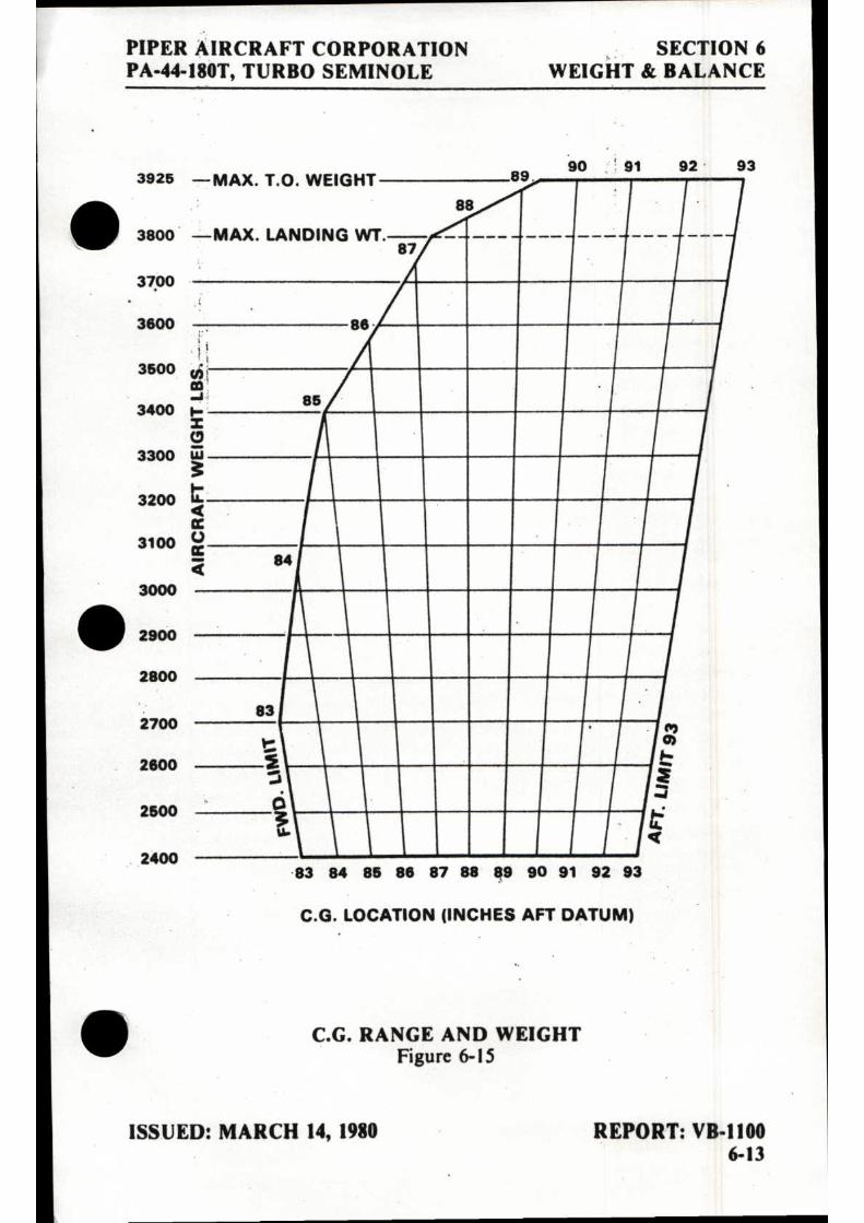
PIPER AIRCRAFT CORPORATION SECTION 6
PA-44-180T, TURBO SEMINOLE WEIGHT & BALANCE
3925 —MAX. T.O. WEIGHT 90 91 92 93
89
•
88 —MAX. LANDING WT. 87
se
61 co -a 85 I- I
iii 3 t < cc U cc 7C ea
MIN
83 (1 of
0 3 u.
S: 14 qi
83 84 85 86 87 88 89 90 91 92 93
C.G. LOCATION (INCHES AFT DATUM)
C.G. RANGE AND WEIGHT Figure 6-15
• 3800
3700
3600
3500
3400
3300
3200
3100
3000
• 2900
2800
2700
2600
2500
2400
ISSUED: MARCH 14, 1980 REPORT: VB-1100 6-13

SECTION 6 PIPER AIRCRAFT CORPORATION WEIGHT & BALANCE. PA-44-180T, TURBO SEMINOLE
6.9 INSTRUCTIONS FOR USING THE WEIGHT AND BALANCE PLOTTER
This plotter is provided to enable the pilot quickly and conveniently to: (a) Determine the total weight and C.G. position. (b) Decide how to change his load if his first loading is not within the
allowable envelope.
Heat can warp or ruin the plotter if it is left in the sunlight. Replace-ment plotters may be purchased from Piper dealers and distributors.
The Basic Empty Weight Center of Gravity location is taken from the weight and balance form (Figure 6-5): the weight and balance record (Figure 6-7), or the latest FAA major repair or alteration form.
The plotter enables the user to add weights and corresponding moments graphically. The effect of adding or disposing of useful load can easily be seen. The plotter does not cover the situation where cargo is loaded in locations other than on the seats or in the baggage compartments.
Brief instructions are given on the plotter itself. To use it, first plot a point on the grid to locate the basic weight and C.G. location. This can be put on more or less permanently because it will not change until the airplane is modified. Next, position the zero weight end of any one of the loading slots over this point. Using a pencil, draw a line along the slot to the weight which will be carried in that location. Then position the zero weight end of the next slot over the end of this line and draw another line representing the weight which will be located in this second position. When all the loads have been drawn in this manner, the final end of the segmented line locates the total load and the C.G. position of the airplane for takeoff. If this point is not within the allowable envelope it will be necessary to remove fuel, baggage, or passengers and/ or to rearrange baggage and passengers to get the final point to fall within the envelope.
Fuel burn-off and gear movement do not significantly affect the center of gravity.
REPORT: VB-1100 ISSUED: MARCH 14, 1980 6-14 REVISED: AUGUST 12, 1982

PIPER AIRCRAFT CORPORATION SECTION 6 PA-44-180T, TURBO SEMINOLE WEIGHT & BALANCE
SAMPLE PROBLEM
A sample problem will demonstrate the use of the weight and balance otter.
Assume a basic weight and C.G. location of 2535 pounds at 86.0 inches respectively. We wish to carry a pilot and 3 passengers. Two men weighing 180 and 200 pounds will occupy the front seats, and two children weighing 80 and 100 pounds will ride in the rear. Two suitcases weighing 25 pounds and 20 pounds respectively, will be carried in the rear compartment. We wish to carry 60 gallons of fuel. Will we be within the safe envelope?
(a) Place a dot on the plotter grid at 2535 pounds and 86.0 inches to represent the basic airplane. (See illustration.)
(b) Slide the slotted plastic into position so that the dot is under the slot for the forward seats, at zero weight.
(c) Draw a line up the slot to the 380 pound position (180 + 200) and put a dot.
(d) Continue moving the plastic and plotting points to account for weight in the rear seats (80 + 100), baggage compartments (45), and fuel tanks (360).
(e) As can be seen from the illustration, the final dot shows the total • weight to be 3500 pounds with the C.G. at 88.5. This is well within the envelope.
(1) There will be room for more fuel.
As fuel is burned off, the weight and C.G. will follow down the fuel line and stay within the envelope for landing.
• ISSUED: MARCH 14, 1980 REPORT: VB-1100
6-15

3800
3600
3400
3300
3200
3100
3000
2900
2800
2700
2800
2500
2400
3926 -MAX. T.O. WEIGHT
3800 -MAX. LANDING WT.
3700 8 4 8 119 11111 A 11111111 All aavi_, AMID . 111111M11111111 iti 111111111111/M111110 ucl 1111111, MIN
111111/ BAGGAGE MIN Q
ME REAR SEATS III -11111111111111111111 MR FRONT SEATS INN
III 111111111111 1 1-2 BASIC WEIGHT IIIIII — AND C.G. 111E1 III
83
85
88
TAKEOFF WEIGHT AND C.G.
90 91 92 93
SECTION 6 PIPER AIRCRAFT CORPORATION WEIGHT & BALANCE PA-44-180T, TURBO SEMINOLE
SAMPLE PROBLEM
83 84 85 88 87 88 89 90 91 92 93
C.G. LOCATION (INCHES AFT DATUM) • REPORT: VB-1100 ISSUED: MARCH 14, 1980 6-16

11/ AIRCRAFT WEIGHING FORM
AIRCRAFT MODEL: Piper PA44-180T SERIAL: 44R- 8207019 REGISTRATION: N9OPA
REGISTERED OWNER: Premier Aircraft Sales DATE WEIGHED: 12-11-2012
ADDRESS: 5544 VAI 23rd Ave PLACE: FXE
Ft Lauderdale, Fl 33309 TACH: HM: 0126.8
WEIGHING POINT SCALE READING TARE NET WEIGHT ARM MOMENT
LEFT MAIN WHEEL 1,356.0 0 1,356.0 109.7 148,753.2
RIGHT MAIN WHEEL 1,320.0 0 1,320.0 109.7 144,804.0
NOSETLAPLMHEEL 738.0 0 738.0 8.7 6,420.6
TOTAL AS WEIGHED 3,414.0 0 3,414.0 87.8 299,977.8
LESS USABLE FUEL 108.0 GAL -648.0 95.0 -61,560.0
LESS USABLE FUEL GAL
NEW AIRCRAFT BASIC TOTALS 2,766.0 86.19 238,417.8
NOTES Aircraft weighed inside hanger in level flight attitude. Weighed with full fuel ani oil, with 4 seats installed.
SCALES MODEL EW-3-0101-299C, SERIAL 1239 CALIBRATED ON: 5-14-2012 LB. NEW AIRCRAFT BASIC WEIGHT 2,766.0 NEW BASIC C.G 86.19 IN.
AIRCRAFT GROSS WEIGHT Ramp 3,943.0 LB. NEW USEFUL LOAD 1,177.0 LB.
AIRFRAME LICENSE NO. 3485687 WEIGHED BY ----2/ 73_(/
AIRCRAFT WEIGHING CORPORATION 1020 NW 62nd Street, Hangar #6
FT. LAUDERDALE, FL 33309 TEL: 954-772-0772 FAX: 954-938-5173

pl 1/46041i4' , cornel'
WEIGHT/BALANCE & EQUIPMENT LIST REVISION 27-JUL-01 FLIGHT TRAILS HELICOPTERS, INC. - FAA CRS# IL3R583L
4805 E. FALCON DR - MESA„ AZ 85215
JIM YARD N9OPA 11840 E. CANNON DR. PIPER PA44-180T Scottsdale, AZ 85259 S# 44R-8207019
OLD > USEFUL LOAD EMPTY WEIGHT ARM MOMENT 101,5.50
2907.50 87.64 254813.30
* REMOVED *
CENTURY 21 AUTOPI OT COMP
* INSTALLED *
* NO ITEMS INSTALLED
-7.00 192.40 -1346.80
NEW > USEFUL LOAD EMPTY WEIGHT ARM MOMENT 1042.50
2900.50 87.39
253466.50
It is the pilot's responsibilty to load the A/C properly at all times. The "OLD" figures were taken from a document dated 31-MAY-00.
(1.06,i2W*Q")

I
• TABLE OF CONTENTS
SECTION 7
DESCRIPTION AND OPERATION OF THE AIRPLANE AND ITS SYSTEMS
Paragraph No.
Page No.
7.1 The Airplane 7-1 7.3 Airframe 7-1 7.5 Engines 7-2 7.7 Propellers 7-5 7.9 Landing Gear 7-6 7.11 Brake System 7-12 7.13 Flight Control System 7-13 7.15 Fuel System 7-14 7.17 Electrical System 7-16 7.19 Vacuum System 7-21 7.21 Pitot Static System 7-23 7.23 Instrument Panel 7-25 7.25 Heating, Ventilating, and Defrosting System 7-27 7.27 Cabin Features 7-31 7.29 Stall Warning 7-32 7.31 Baggage Area 7-33 7.33 Finish 7-33 7.35 Emergency Locator Transmitter 7-33 7.37 Piper External Power 7-35 7.39 Propeller Synchrophaser 7-35 7.41 Oxygen 7-36
REPORT: VB-1100 7-i
•


PIPER AIRCRAFT CORPORATION SECTION 7 PA-44-180T, TURBO SEMINOLE DESCR/OPERATION
SECTION 7
DESCRIPTION AND OPERATION OF THE AIRPLANE AND ITS SYSTEMS
7.1 THE AIRPLANE
The Turbo Seminole is a turbosupercharged twin-engine, all metal, retractable landing gear, airplane. It has seating for up to four occupants and has a two hundred pound luggage compartment.
7.3 AIRFRAME
With the exception of the steel engine mounts and landing gear, the fiberglass nose cone, cowling nose bowls and tips of wings, and the ABS • thermoplastic extremities (tail fin, rudder and stabilator), the basic airframe is of aluminum alloy. Aerobatics are prohibited in this airplane since the structure is not designed for acrobatic loads.
The fuselage is a semi-monocoque structure with a passenger door on the forward right side, a cargo door on the aft right side with an emergency egress door on the forward left side.
The wing is of a semi-tapered design and employs a laminar flow NACA 652-415 airfoil section. The main spar is located at approximately 40% of the chord. The wings are attached to the fuselage by the insertion of the butt ends of the spar into a spar box carry-through, which is an integral part of the fuselage structure. Thebolting of the spar ends into the spar box carry-through structure, which is located under the rear seats, provides in effect a continuous main spar. The wings are also attached fore and aft of the main spar by an auxiliary front spar and a rear spar. The rear spar, in addi-tion to taking torque and drag loads, provides a mount for flaps and aile-rons. The four-position wing flaps are mechanically controlled by a handle • located between the front seats. When fully retracted, the right flap locks into place to provide a step for cabin entry. Each nacelle contains one fuel tank.
ISSUED: MARCH 14, 1980 REPORT: VB-1100 7-1

SECTION 7 PIPER AIRCRAFT CORPORATION DESCR/OPERATION PA-44-180T, TURBO SEMINOLE
A vertical stabilizer, an all-movable horizontal stabilator, and a rudder make up the empennage. The stabilator, which is mounted on top of the fin, incorporates an anti-servo tab which provides longitudinal stability and trim. This tab moves in the same direction as the stabilator, but with in-creased travel. Rudder effectiveness is increased by an anti-servo tab on the rudder.
73 ENGINES
The aircraft is powered by two turbosupercharged Lycoming four-cylinder engines, each rated at 180 horsepower at 2575 RPM from sea level to 12000 ft. The engines are air cooled and are equipped with oil coolers with low temperature bypass systems and engine-mounted oil filters. A winteriza-tion plate is provided to restrict air during winter operation. (See Winteriza-tion in Section 8.) Asymmetric thrust during takeoff and climb is eliminated by the counter-rotation of the engines, the left engine rotating in a clockwise direction when viewed from the cockpit, and the right engine rotating counterclockwise.
The engines are accessible through removable cowls. The upper cowl half is attached with quarter-turn fasteners and is removable. Engine mounts are constructed of steel tubing, and dynafocal engine mounts are provided to reduce vibration.
The induction air box incorporates a manually operated two-way valve which allows the carburetor to receive either induction air which passes through the air filter or heated air which bypasses the filter. Carburetor heat selection provides heated air to the carburetor in the event of carburetor icing, and also allows selection of an alternate source of air in the event the induction air source or the air filter becomes blocked with ice, snow, freezing rain, etc. Carburetor heat selection provides air which is unfiltered; there-fore, it should not be used during ground operation when dust or other con-taminants might enter the system. The primary (through the filter) induction source should always be used for takeoffs.
Engine controls consists of a throttle, a propeller control and a mixture control lever for each engine. These controls are located on the control quadrant on the lower center of the instrument panel where they are accessible to both the pilot and the copilot (Figure 7-I). The controls utilize teflon-lined control cables to reduce friction and binding.
REPORT: VB-1100 ISSUED: MARCH 14, 1980 7-2

PIPER AIRCRAFT CORPORATION SECTION 7 PA-44-180T, TURBO SEMINOLE
DESCR/OPERATION
CONTROL PEDESTAL Figure 7-I
ISSUED: MARCH 14, 1980 REPORT: VB-1100 7-3

SECTION 7 DESCR/OPERATION
PIPER AIRCRAFT CORPORATION PA-44-180T, TURBO SEMINOLE
• PULL —CLOSE
L COWL FLAP
PUSH — OPEN
COWL FLAP CONTROL Figure 7-3
The throttle levers are used to adjust the manifold pressure to 36.5 in. HG Max. They incorporate a gear up warning horn switch which is activated during the last portion of travel of the throttle levers to the low power position. If the landing gear is not locked down, the horn will sound until the gear is down and locked or until the power setting is increased. This is a feature to warn the pilot of an inadvertent gear up landing.
The propeller control levers are used to adjust the propeller speed from high RPM to feather.
This aircraft is equipped with a dual electric tachometer which is inoperative with the master switch turned OFF.
The mixture control levers are used to adjust the air to fuel ratio. An engine is shut down by the placing of the mixture control lever in the full lean (idle cut-off) position.
The friction adjustment lever on the right side of the control quadrant may be adjusted to increase or decrease the friction holding the throttle, propeller, and mixture controls or to lock the controls in a selected position.
REPORT: VB-1100 • ISSUED: MARCH 14, 1980 7-4
•
•

PIPER AIRCRAFT CORPORATION SECTION 7 PA-44-180T, TURBO SEMINOLE DESCR/OPERATION
The carburetor heat controls are located on the control quadrant just below the engine control levers. When a carburetor heat lever is in the up, or off, position the engine is operating on filtered air. When the lever is in the ii• down, or on, position the engine is operating on unfiltered, heated air.
The cowl flap control levers (Figure 7-3), located below the control quadrant, are used to regulate cooling air for the engines. The levers have three positions; full open, full closed, and intermediate. A lock incorporated in each control lever locks the cowl flap in the selected position. To operate the cowl flaps, depress the lock and move the lever toward the desired setting. Release the lock after initial movement and continue movement of the lever. The control will stop and lock into place at the next setting. The lock must be depressed for each selection of a new cowl flap setting.
All throttle operation should be made with a smooth, not too rapid movement to prevent unnecessary engine wear or damage to the engines.
7.7 PROPELLERS
Counter-rotation of the propellers provides balanced thrust during • takeoff and climb and eliminates the "critical engine" factor in single-engine flight.
Constant speed, controllable pitch and feathering Hartzell propellers are installed as standard equipment. The propellers mount directly to the engine crankshafts. Pitch is controlled by oil and nitrogen pressure. Oil pressure sends a propeller toward the high RPM or unfeather position; nitrogen pressure and a large spring send a propeller toward the low RPM or feather position and also prevent propeller overspeeding. Governors, one on each engine, supply engine oil at various pressures through the propeller shafts to maintain constant RPM settings. A governor controls engine speed by varying the pitch of the propeller to match load torque to engine torque in response to changing flight conditions. The recommended nitro-gen pressure to be used when charging the unit is listed on placards on the propeller domes and inside the spinners. This pressure varies with ambient temperature at the time of charging. Although dry nitrogen gas is recom-mended, compressed air may be used provided it contains no moisture. For more detailed instructions, see "Propeller Service" in Section 8 of this Handbook. • ISSUED: MARCH 14, 1980 REPORT: VB-1100
7-5

SECTION 7
PIPER AIRCRAFT CORPORATION DESCR/OPERATION
PA-44-180T, TURBO SEMINOLE
Each propeller is controlled by the propeller control levers located in the center of the power control quadrant. Feathering of a propeller is accom-plished by moving the control fully aft thrpugh the low RPM detent, into the FEATHER position. Feathering takes place in approximately six seconds. Unfeathering is accomplished by moving the propeller control forward and engaging the starter until the propeller is windmilling.
The optional propeller unfeathering system stores air and oil pressure in an accumulator to move the propeller out of the feathered position.
Unfeathering is accomplished by unlatching the mechanical latch on the prop control lever by pressing it forward while pushing the prop control full forward which releases the stored pressure from the accumulator to the propeller dome. Starter assist is required if the propeller is not windmilling freely within 5 - 7 seconds after the prop control has been moved forward.
A feathering lock, operated by centrifugal force, prevents feathering during engine shut down by making it impossible to feather any time the engine speed falls below 950 RPM. For this reason, when airborne, and the pilot wishes to feather a propeller to save an engine, he must be sure to move the propeller control into the FEATHER position before the engine speed drops below 950 RPM.
7.9 LANDING GEAR
The aircraft is equipped with hydraulically operated, fully retractable, tricycle landing gear.
Hydraulic pressure for gear operation is furnished by an electrically powered, reversible hydraulic pump (refer to Figures 7-7 and 7-9). The pump is activated by a two-position gear selector switch located to the left of the control quadrant on the instrument panel (Figure 7-5). The gear selector switch, which has a wheel-shaped knob, must be pulled out before it is moved to the UP or DOWN position. When hydraulic pressure is exerted in one direction, the gear is retracted; when it is exerted in the other direction, the gear is extended. Gear extension or retraction normally takes six to seven seconds.
REPORT: VB-1100 ISSUED: MARCH 14, 1980 7-6 REVISED: MARCH 11, 1983
•
•

PIPER AIRCRAFT CORPORATION SECTION 7 PA-44-180T, TURBO SEMINOLE DESCR/OPERATION
CAUTION
If the landing gear is in transit, and the hydraulic pump is running, it is NOT advisable to move the gear selector switch to the opposite position before the gear has reached its full travel limit, because a sudden reversal may damage the electric pump.
The landing gear is designed to extend even in the event of hydraulic failure. Since the gear is held in the retracted position by hydraulic pressure, should the hydraulic system fail for any reason, gravity will allow the gear to extend. When the landing gear is retracted, the main wheels retract inboard into the wings and the nose wheel retracts aft into the nose section. Springs assist in gear extension and in locking the gear in the down position. After the gears are down and the downlock hooks engage, springs maintain force on each hook to keep it locked until it is released by hydraulic pressure.
To extend and lock the gears in the event of hydraulic failure, it is necessary only to relieve the hydraulic pressure. An emergency gear extension knob, located directly beneath the gear selector switch is provided • for this purpose. Pulling this knob releases the hydraulic pressure holding the gear in the up position and allows the gear to fall free. Before pulling the emergency gear extension knob, place the landing gear selector switch in the DOWN position to prevent the pump from trying to raise the gear. If the emergency gear knob has been pulled out to lower the gear by gravity, due to a gear system malfunction, leave the control in its extended position until the airplane has been put on jacks to check the proper function of the landing gear hydraulic and electrical systems. See the Service Manual for proper landing gear system check out procedures. If the airplane is being used for training purposes or a pilot check out mission, and the emergency gear extension knob has been pulled out, it may be pushed in again when desired if there has not been any apparent malfunction of the landing gear system.
• ISSUED: MARCH 14, 1980 REPORT: VB-1100 REVISED: APRIL 2, 1982 7-7

SECTION 7 PIPER AIRCRAFT CORPORATION DESCR /OPERATION PA-44-180T, TURBO SEMINOLE
LANDING GEAR SELECTOR Figure 7-5
When the gear is fully extended or fully retracted and the gear selector is in the corresponding position, electrical limit switches• stop the flow of current to the motor of the hydraulic pump. The three green lights directly above the landing gear selector switch illuminate to indicate that each of the three landing gears is down and locked. A convex mirror on the left engine nacelle both serves as a taxiing aid and allows the pilot to visually confirm the condition of the nose gear. If the gear is in neither the full up nor the full down position, a red warning light on the instrument panel illuminates. Should the throttle be placed in a low setting - as for a landing approach-while the gear is retracted, a warning horn sounds to alert the pilot that the gear is retracted. The gear warning horn emits a 90 cycles per minute beeping sound.
REPORT: VB-1100 ISSUED: MARCH 14, 1980 7-8 REVISED: APRIL 2, 1982

PIPER AIRCRAFT CORPORATION SECTION 7 PA-44-180T, TURBO SEMINOLE DESCR/OPERATION
The green gear lights are dimmed automatically when the navigation • lights are turned on. For this reason, if the navigation lights are turned on in the daytime, it is difficult to see the landing gear lights. If the green lights are not observed after the landing gear selector switch is placed in the DOWN position, the first thing to check is the position of the navigation lights switch.
•
If one or two of the three green lights do not illuminate when the gear DOWN position has been selected, any of the following conditions could exist for each light that is out:
(a) The gear is not locked down. (b) A bulb is burned out. (c) There is a malfunction in the indicating system.
In order to check the bulbs, the square indicator lights can be pulled out and interchanged.
A micro switch incorporated in the switching network activates the gear I warning horn under the following conditions:
(a) The gear is not locked down and the manifold pressure has fallen below 14 inches on either one or both engines.
(b) The gear selector switch is in the UP position when the airplane is on the ground.
(c) The gear selector switch is in the UP position and landing flaps are extended.
To prevent inadvertent gear retraction should the gear selector be placed in the UP position when the airplane is on the ground, a squat switch located on the left main gear will prevent the hydraulic pump from actuating if the master switch is turned on. On takeoff, when the landing gear oleo strut drops to its full extension, the safety switch closes to complete the circuit which allows the hydraulic pump to be activated to raise the landing gear when the gear selector is moved to the UP position. During the preflight check, be sure the landing gear selector is in the DOWN position and that the three green gear indicator lights are illuminated. On takeoff, the gear should be retracted before an airspeed of 109 KIAS is exceeded. The landing gear may be lowered at any speed up to 140 KIAS.
The hydraulic reservoir for landing gear operation is an integral part of • the gear hydraulic pump. Access to the combination pump and reservoir is through a panel in the baggage compartment. For filling instructions, see the Service Manual.
ISSUED: MARCH 14,1980 REPORT: VB-1100 REVISED: OCTOBER 10, 2005 7-9

TERMINAL EMEMP3 TERMINAL
SECTION 7 PIPER AIRCRAFT CORPORATION DESCR/OPERATION PA-44-180T, TURBO SEMINOLE
LANWNS WAR NEDRAULM CONTROL • MAP NARROW
0$ •
TERMINAL 2 TERMINAL I
SQUAT SW
NC NT
NO
Sc
LIP
C
) DOWN LOCK
_9
Sw. NC
SODS SEAR
NO NC
DOWN LOCK Sw.
NO up Sw
NC
RIGHT SEAR
NO NO
LETT GEAR DOWN
LOCK
uP
„3.... HTDRAULIC PUMP MOTOR
M
-.7
SOLENOIDS
DOWN
TERMINAL 3
NC
0
SEAR SELECT SNITCH
_L GEAR HORN „„j.,„
LANDING GEAR ELECTRICAL SYSTEM SCHEMATIC Figure 7-7
REPORT: VB-1100 ISSUED: MARCH 14, 1980 7-10

LEFT MAIN GEAR HYDRAULIC CYLINDER
RIGHT MAIN GEAR HYDRAULIC CYLINDER
UP
DOWN
UP
DOWN (Q)
PRESSURE SWITCH
RESTRICTOR
FREE FALL CONTROL
RESERVOR
LOW PRESSURE CONTROL
650±150 PSI
DELIVERED PRESS. 400-1100
1600-2000 PSI HIGH
PRESSURE CONTROL
THERMAL RELIEF
4000 PSI
GEAR UP CHECK VALVE
SHUTTLE VALVE GEAR DOWN UP
NOSE GEAR HYDRAULIC CYLINDER
PIPER AIRCRAFT CORPORATION SECTION 7 PA-44-180T, TURBO SEMINOLE DESCR/OPERATION
LANDING GEAR HYDRAULIC SYSTEM SCHEMATIC Figure 7-9
ISSUED: MARCH 14, 1980 REPORT: VB-1100 7-11

SECTION 7 PIPER AIRCRAFT CORPORATION DESCR/OPERATION PA-44-180T, TURBO SEMINOLE
The nose gear is steerable through a 30 degree arc either side of center by use of a combination of full rudder pedal travel and brakes. A gear centering spring, incorporated in the nose gear steering system, prevents shimmy tendencies. A bungee assembly reduces ground steering effort and dampens shocks and bumps during taxiing. When the gear is retracted, the nose wheel centers as it enters the wheel well, and the steering linkage disengages to reduce pedal loads in flight.
The main landing gear carry 6.00 x 6, 8-ply tires. The nose wheel has a 5.00 x 5, 6-ply tire. For information on servicing the tires, see "Tire Inflation" in Section 8 of this Handbook.
Struts for the landing gear are air-oil asssemblies. Strut exposure should be checked during each preflight inspection. If a need for service or adjust-ment is indicated, refer to the instructions printed on the units. Should more detailed landing gear service information be required, refer to the Service Manual.
7.11 BRAKE SYSTEM The brake system is designed to meet all normal braking needs. Two
single-disc, double puck brake assemblies, one on each main gear, are actuated by toe brake pedals mounted on both the pilot's and copilot's rudder pedals. A brake system hyddraulic reservoir, independent of the landing gear hydraulic reservoir, is located in the rear top of the nose compartment. Brake fluid should be maintained at the level marked on the reservoir. For further information, see "Brake Service" in Section 8 of this Handbook.
The parking brake knob is located on the lower instrument panel adjacent to the throttle quadrant. To set the parking brake, first depress and hold the toe brake pedals and then pull out the parking brake knob. To release the parking brake, first depress and hold the toe brake pedals and then push in on the parking brake knob.
WARNING
No braking will occur if aircraft brakes are applied while parking brake knob is pulled and held.
REPORT: VB-1100 ISSUED: MARCH 14, 1980 7-12 REVISED: MAY 7, 1990
•
•
•

• PIPER AIRCRAFT CORPORATION SECTION 7 PA-44-180T, TURBO SEMINOLE DESCR/OPERATION
7.13 FLIGHT CONTROL SYSTEM Dual flight controls are installed as standard equipment. The controls
actuate the control surfaces through a cable system. The horizontal tail surface (stabilator) is of the all movable slab type with an anti-servo tab mounted on the trailing edge. This tab, actuated by a control mounted on the console between the front seats, also acts as a longitudinal trim tab (refer to Figure 7-11).
•
• CONSOLE Figure 7-11
ISSUED: MARCH 14, 1980 REPORT: VB-1100 REVISED: MAY 7, 1990 7-13

SECTION 7 PIPER AIRCRAFT CORPORATION DESCR/OPERATION PA-44-180T, TURBO SEMINOLE
The vertical tail is fitted with a rudder which incorporates a combination rudder trim and anti-servo tab. The rudder trim control is located on the control console between the front seats.
The flaps are manually operated and spring loaded to return to the retracted position. A four-position flap control lever (Figure 7-11) between the front seats adjusts the flaps for reduced landing speeds and glide path control. The flaps have three extended positions - 10, 25 and 40 degrees - as well as the fully retracted position. A button on the end of the lever must be depressed before the control can be moved. A past center lock incorporated in the actuating linkage holds the flap when it is in the retracted position so that it may be used as a step on the right side. Since the flap will not support a step load except in the fully retracted position, the flaps should be retracted when people are entering or leaving the airplane.
7.15 FUEL SYSTEM
Fuel is stored in two 55 gallon fuel tanks, one in each nacelle (Figure 7-13). One gallon of fuel in each nacelle is unusable, giving a total of 108 usable gallons. The minimum fuel grade is 100 or 100LL Aviation Grade. The fuel tank vents, one installed under each wing, feature an anti-icing design to prevent ice formation from blocking the fuel tank vent lines.
Normally, fuel is supplied to the engines through engine-driven fuel pumps. Auxiliary electric fuel pumps serve as a back-up feature. The electric fuel pumps are controlled by rocker switches on the switch panel to the left of the pilot. The electric fuel pumps should be ON during takeoffs and landings. The electric fuel pumps must be on to operate the electric primers. The electric fuel pumps may be used for vapor suppression above 10,000 feet should it be necessary as evidenced by unstable engine operation or fluctuating fuel pressure indications at high altitude.
Fuel quantities and pressures are indicated on gauges on the instrument panel. There is a separate fuel quantity gauge for each tank. A calibrated fuel dipstick is provided with the airplane. To visually check the quantity of fuel in a tank, insert the dipstick to the bottom of the tank, close off the pro-truding end with a finger, withdraw the dipstick, and read the fuel level. The most accurate reading will be obtained with the airplane on level ground. An optional locking fuel cap is available for each fuel filler. A common key will fit the cabin door and baggage door locks, these fuel caps and the ignition switch.
REPORT: VB - 1100 ISSUED: MARCH 14, 1980 7- 14 REVISED: FEBRUARY 19, 1982

PRIMER SOLENOID VALVE
TO CYL'S
COMBUSTION HEATER FUEL PUMP
PRIMER SOLENOID VALVE
L. FUEL R. FUEL PRESS. PRESS. GAUGE GAUGE TO CYL'S
FILLER CA FILLER CAP
L. FUEL CELL R. FUEL CELL F LTER & SUMP
FILTER & SUMP
SELECTOR VALVE -SCUPPER DRAIN FUEL VENT
SCUPPER DRAIN FUEL VENT
I QUICK DRAIN
FUEL SYSTEM SCHEMATIC Figure 7-13
TO HEATER
1, 2 & 4 CARBURET R
ENGINE DRIVEN FUEL PUMP
ELECTRIC FUEL PUMP
FUEL SELECTOR CONTROLS L. ENGINE R. ENGINE
ON ON OFF OFF
X•FEED X•FEED
1, 2 & 4
ENGINE DRIVEN FUEL PUMP
• ELECTRIC FUEL PUMP
PIPER AIRCRAFT CORPORATION
SECTION 7 PA-44-180T, TURBO SEMINOLE DESCR/OPERATION
ISSUED: MARCH 14, 1980 REPORT: VB-1100 7-15
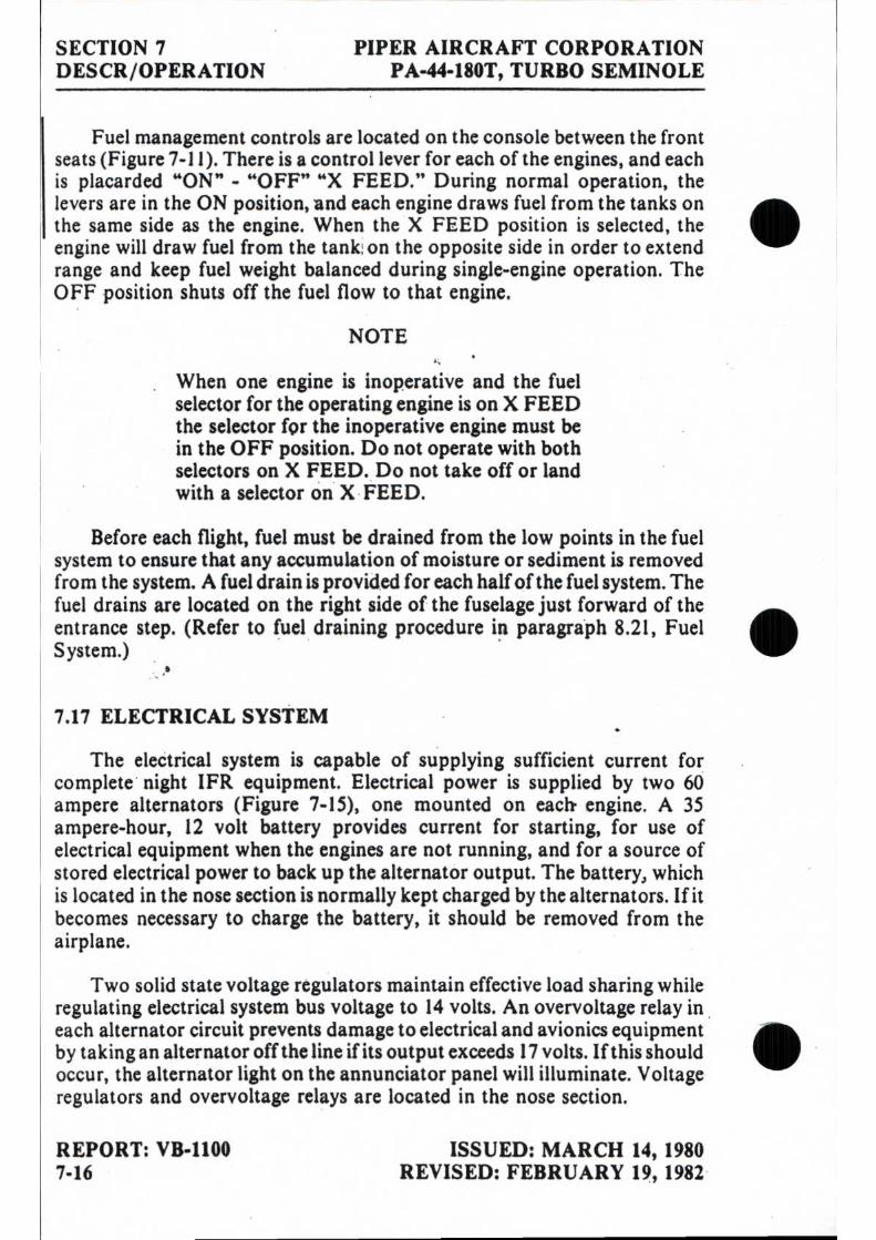
SECTION 7 PIPER AIRCRAFT CORPORATION DESCR/OPERATION PA-44-180T, TURBO SEMINOLE
Fuel management controls are located on the console between the front seats (Figure 7-11). There is a control lever for each of the engines, and each is placarded "ON" - "OFF" "X FEED." During normal operation, the levers are in the ON position, and each engine draws fuel from the tanks on the same side as the engine. When the X FEED position is selected, the engine will draw fuel from the tank on the opposite side in order to extend range and keep fuel weight balanced during single-engine operation. The OFF position shuts off the fuel flow to that engine.
NOTE
When one engine is inoperative and the fuel selector for the operating engine is on X FEED the selector for the inoperative engine must be in the OFF position. Do not operate with both selectors on X FEED. Do not take off or land with a selector on X FEED.
Before each flight, fuel must be drained from the low points in the fuel system to ensure that any accumulation of moisture or sediment is removed from the system. A fuel drain is provided for each half of the fuel system. The fuel drains are located on the right side of the fuselage just forward of the entrance step. (Refer to fuel draining procedure in paragraph 8.21, Fuel System.)
7.17 ELECTRICAL SYSTEM
The electrical system is capable of supplying sufficient current for complete night IFR equipment. Electrical power is supplied by two 60 ampere alternators (Figure 7-15), one mounted on each engine. A 35 ampere-hour, 12 volt battery provides current for starting, for use of electrical equipment when the engines are not running, and for a source of stored electrical power to back up the alternator output. The battery, which is located in the nose section is normally kept charged by the alternators. If it becomes necessary to charge the battery, it should be removed from the airplane.
Two solid state voltage regulators maintain effective load sharing while regulating electrical system bus voltage to 14 volts. An overvoltage relay in each alternator circuit prevents damage to electrical and avionics equipment by taking an alternator off the line if its output exceeds 17 volts. If this should occur, the alternator light on the annunciator panel will illuminate. Voltage regulators and overvoltage relays are located in the nose section.
REPORT: VB-1100 ISSUED: MARCH 14, 1980 7-16 REVISED: FEBRUARY 19, 1982

PIPER AIRCRAFT CORPORATION SECTION 7 PA-44-180T, TURBO SEMINOLE DESCR/OPERATION
• ALTERNATOR AND STARTER SCHEMATIC (EARLY MODELS) I
Figure 7-15
ISSUED: MARCH 14, 1980
REPORT: VB-1100 REVISED: FEBRUARY 19, 1982
7-17

SECTION 7 PIPER AIRCRAFT CORPORATION DESCR/OPERATION PA-44-180T, TURBO SEMINOLE
2 --qjb
1•111110W•. ■ •., ea.*
•
ALTERNATOR AND STARTER SCHEMATIC (LATER MODELS) • Figure 7-16
REPORT: VB-1100 7-17*
ISSUED: FEBRUARY 19, 1982

PIPER AIRCRAFT CORPORATION SECTION 7 PA-44-180T, TURBO SEMINOLE DESCR /OPERATION
CIRCUIT BREAKER PANEL (EARLY MODELS) Figure 7-17
ISSUED: FEBRUARY 19, 1982 REPORT: VB-1100 I 7-17b

SECTION 7 DESCR/OPERATION
PIPER AIRCRAFT CORPORATION PA-44-180T, TURBO SEMINOLE
CIRCUIT BREAKER PANEL (LATER MODELS) Figure 7-18
REPORT: VB-1100 ISSUED: MARCH 14, 1980 7-18 REVISED: FEBRUARY 19, 1982

PIPER AIRCRAFT CORPORATION SECTION 7 PA-44-180T, TURBO SEMINOLE DESCR / OP ER ATION
The electrical system and equipment are protected by circuit breakers located on a circuit breaker panel on the lower right side of the instrument • panel (Figure 7-17). The circuit breaker panel is provided with enough blank spaces to accommodate additional circuit breakers if extra electrical equip-ment is installed. In the event of equipment malfunctions or a sudden surge of current, a circuit breaker can trip automatically. The pilot can reset the breaker by pressing it in (preferably after a few minutes cooling period). The circuit breakers can be pulled out manually.
Later airplanes incorporate a split bus electrical system consisting of three electrical buses (left bus, right bus and essential bus), and two avionics buses (left and right avionics). Power to the left and right bus is supplied by a 60 amp alternator, one on each engine. Battery power is provided through two 50 amp current limiters and two 60 amp BUS ISO circuit breakers to each bus. The essential bus is supplied with electrical power from both left and right bus through blocking diodes. A 30 amp fuse connecting the left and right buses provides load equalizing between the two alternators up to 30 amps. The left bus supplies electrical power to the left avionics bus through a relay controlled by the left avionics master switch. The right bus supplies electrical power to the right avionics bus in a similar fashion ( Figure
• 7-16).
Circuit breakers located on the left bus are those in the top row of breakers to the left of the diamond ( • ), the three breakers to the left of the left diamond in the center row of breakers, and two breakers to the left of the left diamond in the bottom row of breakers. Those on the right bus are located in the same way, to the right of the diamonds ( • ). The essential bus circuit breakers are located between the left and right diamonds ( • ) in the center row. The left avionics bus breakers are located between the left and center diamond in the bottom row and the right avionics bus breakers are located between the center and right diamonds ( • ) Figure 7-18).
Most of the electrical switches, including the master switch and switches for magnetos, fuel pumps, starters, alternators, lights and pitot heat, are 411) conveniently located on the switch panel (Figure 7-19) to the left of the pilot.
In the event a bus has a ground fault, the circuits powered by that bus will be inoperative and the ammeter will indicate zero. For abnormal and or emergency °petitions and procedures, refer to Section 3, Emergency Procedures.
ISSUED: MARCH 14, 1980 REPORT: VB-1100 REVISED: FEBRUARY 19, 1982 7-19

SECTION 7 PIPER AIRCRAFT CORPORATION DESCR/OPERATION PA-44-180T, TURBO SEMINOLE
Later airplanes incorporate a STARTER ON annunciator light, which illuminates when either starter switch is selected (Figure 7-20). For abnormal and or emergency operation and procedures, refer to Section 3, Emergency Procedures.
Optional electrical accessories includes navigation, anti-collision, land-ing, instrument and cabin dome lighting. •
An optional light, mounted in the overhead panel, provides instrument and cockpit lighting for night flying. The light is controlled by a rheostat switch located adjacent to the light. A map light window in the lens is actuated by an adjacent switch.
WARNING
Anti-collision lights should not be operating when flying through cloud, fog or haze, since the reflected light can produce spatial disori-entation. Strobe lights should not be. used in close proximity to the ground, such as during taxiing, takeoff or landing.
Approximately 2000 RPM or more is required to obtain full alternator output of 60 amperes. It is normal to have zero output at idle RPM. This is due to the reduced drive ratio from the engine. Dual ammeters and the ALT annunciator light provide a means of monitoring the electrical system operation. The two ammeters (load meters) indicate the output of the alter-nators. Should an ammeter indicate a load much higher than the known consumption of the electrical equipment in use, it should be suspected of a malfunction and turned off. In this event, the remaining alternator's ammeter should show a normal indication after approximately one minute. If both ammeters indicate a load much higher than the known consumption for more than approximately five minutes, an electrical defect other than the alternator system should be suspected because a discharged battery will reduce the alternator load as it approaches the charged conditions. A zero ammeter reading indicates an alternator is not producing current and should be accompanied by illumination of the ALT annunciator light. A single alternator is capable of supporting a continued flight in case of alternator or engine failure in most conditions; however, with deicing equipment and other high loads, care must be exercised to prevent the loads from exceeding the 60 ampere rating and subsequent depleting of the battery. For abnormal and or emergency operations and procedures, refer to Section 3, Emergency Procedures.
REPORT: VB-1100 ISSUED: MARCH 14, 1980 7-20 REVISED: FEBRUARY 19, 1982

PIPER AIRCRAFT CORPORATION
SECTION 7 PA-44-180T, TURBO SEMINOLE
DESCR/OPERATION
SWITCH PANEL (EARLY MODELS) Figure 7 - 19
REPORT: VB-1100 I 7-20a
ISSUED: FEBRUARY 19, 1982

SECTION 7
PIPER AIRCRAFT CORPORATION DESCR/OPERATION PA-44-180T, TURBO SEMINOLE
SWITCH PANEL (LATER MODELS) Figure 7-20
I REPORT: VB-1100
ISSUED: FEBRUARY 19, 1982 7-20b
•
•
•

PIPER AIRCRAFT CORPORATION SECTION 7 PA-44-180T, TURBO SEMINOLE DESCR/OPERATION
An optional starting installation known as Piper External Power (PEP) is accessible through a receptacle located on the lower left side of the nose section. An external battery can he connected to the socket, thus allowing othe operator to crank the engine without having to gain access to the airplane's battery.
CAUTION
Do not use cigar lighter receptacles as power sources for any devices other than the cigar lighters supplied with the airplane. Any other device plugged into these receptacles may be damaged.
7.19 VACUUM SYSTEM
The vacuum system operates the air-driven gyro instruments. The vacuum system (Figure 7-21) consists of a vacuum pump on each engine, plus plumbing and regulating equipment.
ea The vacuum pumps arc dry-type pumps, which eliminates the need for n air/ oil separator and its plumbing. A shear drive protects the engine from
damage. If the drive shears, the gyros will become inoperative.
The vacuum gauge, mounted on the right instrument panel to the right of the radios (refer to Figure 7-25), provides valuable information to the pilot about the operation of the vacuum system. A decrease in pressure in a system that has remained constant over an extended period, may indicate a dirty filter, dirty screens, possibly a sticking vacuum regulator or leak in the system (a low vacuum indicator light is provided in the annunciator panel). Zero pressure would indicate a sheared pump drive, defective pump, possibly a defective gauge or collapsed line. In the event of any gauge variation from the norm, the pilot should have a mechanic check the system to prevent possible damage to the system components or eventual failure of the system.
• ISSUED: MARCH 14, 1980 REPORT: VB-1100 REVISED: MARCH 11, 1983 7-21

•
/\ \
A '1 1
VACUUM SYSTEM Figure 7-21
SECTION 7 PIPER AIRCRAFT CORPORATION DESCR/OPERATION PA-44180T, TURBO SEMINOLE
REPORT: VB-1100 ISSUED: MARCH 14, 1980 7-22

PIPER AIRCRAFT CORPORATION SECTION 7 PA-44-180T, TURBO SEMINOLE DESCR/OPERATION
A vacuum regulator is provided in the system to protect the gyros. The valve is set so the normal vacuum reads 4.8 to 5.1 inches of mercury, a setting whichprovides sufficient vacuum to operate all the gyros at their rated
("
RPM. Higher settings will damage the gyros and with a low setting the gyros will be unreliable. The regulator is located behind the instrument panel.
7.21 PITOT STATIC SYSTEM
The pitot static system (Figure 7-23) supplies both pitot and static pressure for the airspeed indicator and static pressure for the altimeter and vertical speed indicator (when installed). Pitot and static pressure are picked up by the pitot head on the bottom of the left wing.
The control valve for an alternate static source is located below the left side of the instrument panel. When the valve is set in the alternate position, the altimeter, vertical speed indicator and airspeed indicator will be using cabin air for static pressure. The storm window and cabin vents must be closed and the cabin heater and defroster must be on during alternate static source operation. The altimeter error is less than 50 feet unless otherwise placarded.
• To prevent bugs and water from entering the pitot and static pressure holes when the airplane is parked, a cover should be placed over the pitot head. A partially or completely blocked pitot head will give erratic or zero readings on the instruments.
NOTE
During preflight, check to make sure the pitot cover is removed.
• ISSUED: MARCH 14, 1980 REPORT: VB-1100 REVISED: JULY 2, 1981 7-23

SECTION 7 PIPER AIRCRAFT CORPORATION DESCR/OPERATION PA-44-180T, TURBO SEMINOLE
PITOT STATIC SYSTEM Figure 7-23
REPORT: VB-1100
ISSUED: MARCH 14, 1980 7-24

PIPER AIRCRAFT CORPORATION SECTION 7 PA-44-180T, TURBO SEMINOLE DESCR/OPERATION
An optional heated pitot head installation, which alleviates problems with icing or heavy rains, is available. The switch for pitot heat is located on the switch panel to the pilot's left. The pitot heat system has a separate circuit
reaker located in the circuit breaker panel and labeled "Pitot Heat." The operational status of the pitot heat system should be included in the preflight check.
CAUTION
Care should be exercised when checking the operation of the heated pitot head. The unit becomes very hot. Ground operation of pitot heat should be limited to 3 minutes maximum to avoid damaging the heating units.
7.23 INSTRUMENT PANEL
Flight instruments are grouped in the upper instrument panel (Figure 7-25); engine and electrical system monitoring instruments, the autopilot, and the circuit breaker panel are in the lower instrument panel. Left and
• ight engine instruments are separated by the left control wheel shaft.
Radios are mounted in the center of the upper instrument panel. An optional radio master switch is located near the top of the instrument panel between the radio stacks. It controls the power to all radios through the aircraft master switch. An emergency bus switch is also provided to provide auxiliary power to the avionics bus in event of a radio master switch circuit failure. The emergency bus switch is located behind the lower right shin guard left of the circuit breaker panel. The control quadrant - throttles and propeller and mixture controls - is in the center of the lower instrument panel. To the left of the control quadrant is the landing gear selector.
A ground clearance energy saver system is available to provide direct power to Comm #1 without turning on the master switch. An internally lit pushbutton switch, located on the instrument panel, provides annunciation for engagement of the system. When the button is engaged direct aircraft battery power is applied to Comm #1, audio amplifier (speaker) and radio accessories. The switch must be turned OFF or depletion of the battery could
•
esult.
Various warning lights are located with the pilot's flight instruments on the left upper instrument panel. The gear unsafe warning light is to the left of the annunciator panel.
ISSUED: MARCH 14, 1980 REPORT: VB-1100 REVISED: AUGUST 12, 1982 7-25

2 3
4
6 7 1 9 10
11 12
13 14
15 16
17 18 19 20
21
0.1 00.111111111111111111111111111 111111111111111111111111111111
0.I.II I IIIIIIIIIIIIIIIII IIIIIIIIII
WI
1:-::0000,1 iii
.........• ill11111111111 10111%
1 AL\
111 1111111110 Elii
--...,
:44m o 9-
---.--
tr8.013 4.119
,„....-------S
co 10 E1 35
%-r"---"\---
❑
....--..,
C
In {0
00o. ...m
.
031:Q12.;31liaIM
O
N16,11M
QQa
main 0
00
00
00
00
00
00
00
1
. 7. :71- z....7.12 = - -,1
ooct000000cidio Oar)
o o,o ..ro
l■
es-Arati
oitalcio o o
22 23 24 25 26
27 21 21 31
32 33
34 35 36 37 38 39
40
1. AD
F 2. CLO
CK 3. TU
RN
IND
ICA
TOR
4.
AIR
SPEED IN
DIC
ATO
R
5. DIR
ECTIO
NA
L GYR
O
6. GEA
R U
NSA
FE WA
RN
ING
LIGH
T 7. A
TTITUD
E GYR
O
8. VERTIC
AL SPEED
IND
ICA
TOR
9. A
LTIMETER
10. A
NN
UN
CIA
TOR
TEST SWITC
H
11. AN
NU
NC
IATO
R D
ISPLAY
12. D
ME
13. N
AV
14.
AVIO
NIC
S 15.
RA
DIO
MA
STER SW
ITCH
16.
RN
AV
17. R
AD
AR
18. V
AC
UU
M G
AU
GE
19 H
OU
R M
ETE
R
20. GR
OU
ND
CLEA
RA
NC
E SWITC
H
21. C
IGA
R LIG
HTER
22.
LEFT AM
METER
23.
AU
TOPILO
T CO
NTR
OLS
24. M
IKE
/PH
ON
E JA
CK
S
25. A
DF
26. LEFT EN
GIN
E GA
UG
ES 27.
DU
AL M
AN
IFOLD
PRESSU
RE
GA
UG
E 28.
RIG
HT A
MM
ETER
29. D
UA
L TAC
HO
METER
30.
RIG
HT
EN
GIN
E G
AU
GE
S
31. LA
NQ
ING
GEA
R SELEC
TOR
32.
CA
RB
UR
ETOR
HEA
T CO
NTR
OLS
33. C
ON
TRO
L LEVERS
34. D
UA
L CYLIN
DER
HEA
D TEM
PERA
TUR
E G
AU
GE
35 CO
NTR
OL FR
ICTIO
N LO
CK
36 LIG
HT D
IMM
ER
SW
ITCH
ES
37 D
UA
L EX
HA
US
T TEM
PE
RA
TUR
E G
AU
GE
38
. AVIO
NIC
S EMER
GEN
CY B
US SW
ITCH
39 C
IRC
UIT B
REA
KER
PAN
EL 40. C
LIMA
TE CO
NTR
OL PA
NEL
A ov M
I rt.,
ca 4
n cA ci) 41> 0 '40 C
O
It4
'0 -• '0' 11100
101135
• •
•

PIPER AIRCRAFT CORPORATION SECTION 7 PA-44-180T, TURBO SEMINOLE DESCR/OPERATION
The annunciator panel, with oil pressure, gyro vacuum alternator, and turbocharger overboost lights, and incorporating a press-to-test feature, is • located to the upper left of the radios. The illumination of these lights in flight is an indication of a possible system malfunction. The pilot should closely monitor instrument panel gauges to check the condition of a system whose corresponding light on the annunciator panel illuminates. During preflight, the operational status of the annunciator panel should be tested by use of the press-to-test button. When the button is depressed, all annunciator panel lights should illuminate.
NOTE
When an engine is feathered, the alternator, gyro air and engine oil pressure annunciator lights will remain illuminated.
Instrument panel lighting can be dimmed or brightened by rheostat switches to the right of the control quadrant. Back-lights and a red flood light are optional equipment. When instrument panel lights are turned on, annunciator lights are dimmed. However, they will not show dim when the • press-to-test switch is depressed.
7.25 HEATING, VENTILATING AND DEFROSTING SYSTEM
Heated air for cabin heat and windshield defrosting is provided by a Janitrol combustion heater located in the forward fuselage (refer to Figure 7-27). Air from the heater is distributed by a manifold to the ducts along the cabin floor to outlets at each seat and to the defroster outlets.
Operation of the combustion heater is controlled by a three-position switch located on the instrument panel (Figure 7-29) and labeled FAN, OFF and HEATER. Airflow and temperature are regulated by the three levers on the instrument panel. The upper lever regulates air intake and the center lever regulates cabin temperature. Cabin comfort can be maintained as desired through various combinations of lever positions. Passengers have secondary control over heat output by individual adjustable outlets at each seat location. The third lever on the instrument panel controls the windshield defrosters. ii• For cabin heat, the air intake lever on the instrument panel must be partially or fully open and the three-position switch set to the HEATER position. This simultaneously starts fuel flow and ignites the heater; and, during ground opeiation, it also activates the ventilation blower which is an
ISSUED: MARCH 14, 1980 REPORT: VB-1100 REVISED: AUGUST 12, 1982 7-27

•
•
SECTION 7 PIPER AIRCRAFT CORPORATION DESCR/OPERATION PA-44-180T, TURBO SEMINOLE
CABIN HEATING, VENTILATING AND DEFROSTING SYSTEM • Figure 7-27
REPORT: VB-1100 ISSUED: MARCH 14, 1980 7-28

PIPER AIRCRAFT CORPORATION SECTION 7 PA-44-180T, TURBO SEMINOLE DESCR/OPERATION
•
• HEATING, VENTILATING & DEFROSTING CONTROL CONSOLE Figure 7-29
ISSUED: MARCH 14, 1980 REPORT: VB-I100 7-29

SECTION 7 PIPER AIRCRAFT CORPORATION DESCR/OPERATION PA-44-180T, TURBO SEMINOLE
integral part of the combustion heater. With instant starting and no need for priming, heat should be felt within a few seconds. When cabin air reaches the temperature selected on the cabin temperature lever, ignition of the heater cycles automatically to maintain the selected temperature. Two safety switches activated by the intake valve and located aft of the heater unit prevent both fan and heater operation when the air intake lever is in the closed position. A micro switch, which actuates when the landing gear is retracted, turns off the ventilation blower so that in flight the cabin air is circulated by ram air pressure only.
When the three-position switch is in the FAN position during ground operation, the ventilation fan blows fresh air through the heater duct work for cabin ventilation and windshield defogging when heat is not desired.
To introduce fresh, unheated air into the cabin during flight, the air intake should be open and the heater off. Ram air enters the system and can be individually regulated at each floor outlet. Overhead outlets also supply fresh air for cabin ventilation. The occupant of each seat can manually adjust an outlet in the ceiling to regulate the flow of fresh air to that seat area. An optional fresh air blower may be installed in the overhead ventilation system to provide additional fresh air flow during ground operation.
An overheat switch located in the heater unit acts as a safety device to render the heater inoperative if a malfunction should occur. Should the switch deactivate the heater, the OVERHEAT light on the instrument panel will illuminate. The overheat switch is located on the aft inboard end of the heater vent jacket. The red reset button is located on the heater shroud in the nose cone compartment.
To prevent activation of the overheat switch upon normal heater shutdown during ground operation, turn the three-position switch to FAN for two minutes with the air intake lever in the . open position before turning the switch to OFF. During flight, leave the air intake lever open for a minimum of fifteen seconds after turning the switch to OFF.
The combustion heater uses fuel from the airplane fuel system. An electric fuel pump draws fuel from the left tank at a rate of approximately one-half gallon per hour. Fuel used for heater operation should be considered when planning for a flight.
REPORT: VB-1100 ISSUED: MARCH 14, 1980 7-30 REVISED: AUGUST 12, 1982

PIPER AIRCRAFT CORPORATION
SECTION 7 PA-44-180T, TURBO SEMINOLE
DESCR/OPERATION
EMERGENCY EXIT • Figure 7-31
7.27 CABIN FEATURES
The front seats are adjustable fore and aft. Each seat reclines and is provided with an armrest. The rear seats are easily removed to provide additional cargo space.
NOTE
To remove the rear seats, depress the plunger behind each front leg and slide seat to rear.
4 Currently, shoulder harnesses with inertia reels are provided for each
front seat occupant and are available for all rear seats. A check of the inertia reel mechanism can be made by pulling sharply on the strap and checking that thereel will lock in place under sudden stress. This locking feature prevents the strap from extending and holds the occupant in place. Under normal movement the strap will extend and retract as required. On earlier aircraft provided with a single strap adjustable shoulder harness located above the side window for each front seat the shoulder strap is routed over
ISSUED: MARCH 14, 1980 REPORT: VB-1100 REVISED: AUGUST 12, 1982 7-31

SECTION 7 PIPER AIRCRAFT CORPORATION DESCR/OPERATION PA-44-180T, TURBO SEMINOLE
the shoulder adjacent to the window and attached to the lap belt in the general area of the occupant's hip. Adjust this fixed strap so that all controls are accessible while maintaining adequate restraint for the occupant. Optional shoulder straps are available for the rear occupants. Shoulder harnesses should be routinely worn during takeoff, landing and whenever an inflight emergency situation occurs. Other seat options include headrests and push-button vertically adjustable pilot and copilot seats. The seat belt should be snugly fastened over each unoccupied seat.
Standard cabin features include a pilot's storm window, ashtrays, map pockets, sun visors, and pockets on the front seat backs. Among the options which may be added to suit individual needs are headrests, a fire extin-guisher, and a special cabin sound-proofing package.
The pilot's left side window is an emergency exit. The emergency exit release handle is located beneath the thermoplastic cover on the vertical post between the first and second left side windows (Figure 7-31).
CAUTION
The emergency exit is for ground use only. When released, the window will fall free from the fuselage.
7.29 STALL WARNING
An approaching stall is indicated by a stall warning horn whiCh is activated between five and ten knots above stall speed. Mild airframe buffeting and gentle pitching may also precede the stall. Stall-speeds are shown on a graph in the Performance Charts Section. The stall warning indication consists of a continuous sounding horn located behind the instru-ment panel. The stall warning horn has a different sound from that of the gear warning horn which has a 90 cycles per minute beeping sound. The stall warning horn is activated by two lift detectors on the leading edge of the left wing, outboard of the engine nacelle. The inboard detector activates the horn when the flaps are in the 25 and 40 degree positions, the outboard when the flaps are in the other positions.
A squat switch in the stall warning system does not allow the units to be activated on the ground.
REPORT: VB-1100 ISSUED: MARCH 14, 1980 7-32 REVISED: MARCH 11, 1983

PIPER AIRCRAFT CORPORATION SECTION 7 PA-44-180T, TURBO SEMINOLE DESCR/OPERATION
7.31 BAGGAGE AREA
The 24 cubic foot baggage compartment, located aft of the seats, has a weight capacity of 200 pounds. This compartment is loaded and unloaded hrough a separate 22 x 20 inch baggage door, and it is accessible during
flight. Tie-down straps are provided and they should be used at all times. The baggage compartment and passenger doors use the same key.
NOTE
It is the pilot's responsibility to be sure when baggage is loaded that the airplane C.G. falls within the allowable C.G. range. (See Weight and Balance Section.)
7.33 FINISH
The standard exterior finish is painted with acrylic lacquer. An optional polyurethane finish is also available. To keep the finish attractive, economy size spray cans of touch-up paint are available from Piper Dealers.
•.35 EMERGENCY LOCATOR TRANSMITTER*
The Emergency Locator Transmitter (ELT), when installed, is located in the aft portion of the fuselage and is accessible through a plate on the right side of the fuselage or through the tail cone by entering through the baggage compartment access panel. The ELT is an emergency locator transmitter which meets the requirements of FAR 91.52. The unit operates on a self-contained battery.
A battery replacement date is marked on the transmitter label. To comply with FAA regulations, the battery must be replaced on or before this date. The battery must also be replaced if the transmitter has been used in an emergency situation or if accumulated test time exceeds one hour or if the unit has been inadvertently activated for an undetermined time period.
On the unit itself is a three-position selector switch placarded "OFF," "ARM" and "ON." The ARM position is provided to set the unit to the
Ooltomatic position so that it will transmit only after impact and will continue transmit until the battery is drained to depletion or until the switch is
*Optional equipment
ISSUED: MARCH 14, 1980 REPORT: VB-1100 REVISED: MARCH 11, 1983 7-33

SECTION 7 PIPER AIRCRAFT CORPORATION DESCR /OPERATION PA-44-180T, TURBO SEMINOLE
manually moved to the OFF position. The ARM position is selected when the transmitter is installed at the factory and the switch should remain in that position whenever the unit is installed in the airplane. The ON position is provided so the unit can be used as a portable transmitter or in the event the automatic feature was not triggered by impact or to periodically test the function of the transmitter.
Select the OFF position when changing the battery, when rearming the unit if it has been activated for any reason, or to discontinue transmission.
NOTE
If the switch has been placed in the ON position for any reason, the OFF position has to be selected before selecting ARM. If ARM is selected directly from the ON position, the unit will continue to transmit in the ARM position.
A pilot's remote switch, located on the left side panel, is provided to allow the transmitter to be controlled from inside the cabin. The pilot's remote switch is placarded "ON, AUTO/ ARM and OFF/ RESET." The switch is normally left in the AUTO/ ARM position. To turn the transmitter off, move the switch momentarily to the OFF/ RESET position. The aircraft master switch must be ON to turn the transmitter OFF. To actuate the transmitter for tests or other reasons, move the switch upward to the ON position and leave it in that position as long as transmission is desired.
The unit is equipped with a portable antenna to allow the locator to be removed from the airplane in case of an emergency and used as a portable signal transmitter.
The locator should be checked during the ground check to make certain the unit has not been accidentally activated. Check by turning a radio receiver to 121.5 MHz. If there is an oscillating sound, the locator may have been activated and should be turned off immediately. Reset to the ARM position and check again to insure against outside interference.
REPORT: VB-1100 ISSUED: MARCH 14, 1980 7-34

PIPER AIRCRAFT CORPORATION SECTION 7 PA-44-180T, TURBO SEMINOLE DESCR/OPERATION
NOTE • If for any reason a test transmission is necessary, the test transmission should be conducted only in the first five minutes of any hour and limited to three audio sweeps. If tests must be made at any other time, the test should be coordinated with the nearest FAA tower or flight service station.
7.37 PIPER EXTERNAL POWER*
An optional starting installation known as Piper External Power (PEP) allows the airplane engine to be started from an external battery without the necessity of gaining access to the airplane battery. The cable from the external battery can be attached to a receptacle under the right side of the nose section of the fuselage. Instructions on a placard located on the cover of the receptacle should be followed when starting with external power. For instructions on the use of the PEP, refer to Starting Engines - Section 4.
0.39 PROPELLER SYNCHROPHASER*
A propeller synchrophaser installation is available as optional equip-ment. Its function is to maintain both propellers at the same RPM and at a preselected phase angle. This eliminates the propeller "beat" effect and minimizes vibration. When the synchrophaser is installed, the left engine is established as the master engine, and the right engine is equipped with a slave governor which automatically maintains its RPM with the left engine RPM. When the propeller synchrophaser is installed, a two-position switch is located on the throttle quadrant below the propeller controls. It is labeled "MANUAL" for manual control or standby and "AUTO SYNC" for propeller synchrophaser.
During taxi, takeoff, landing or single engine operations the propeller synchrophaser switch should be in the MANUAL position. During cruise, propellers should be synchronized manually to within approximately 10 RPM and the switch placed in the AUTO SYNC position. Normally,
ii ropeller synchrophasing will take place within a few seconds, but occa-ionally it may take up to a full minute. When the power setting is to be hanged, the synchrophaser switch should be set to MANUAL for 30
*Optional equipment ISSUED: MARCH 14, 1980 REPORT: VB-1100
7-35

SECTION 7 PIPER AIRCRAFT CORPORATION DESCR/OPERATION PA-44-180T, TURBO SEMINOLE
seconds before the power setting is adjusted; then the synchrophaser switch may be returned to the AUTO SYNC position. If the propeller RPM differential exceeds 50 RPM, the switch should be placed on MANUAL for 30 to 40 seconds; then the propellers can be synchronized again and the synchrophaser switch returned to AUTO SYNC. Pulling the circuit breakers completely deactivates the propeller synchrophaser system. If the master switch is turned OFF or if there is an electrical system failure, the slave engine will return to the controlled selected RPM plus approximately 25 RPM "out of synchronization" regardless of the position of the synchro-phaser switch.
7.41 OXYGEN•
PORTABLE OXYGEN SYSTEM
A portable oxygen system to provide supplementary oxygen for the crew and passengers during high altitude flights (above 10,000 feet) is available as optional equipment. (Refer to Section 9, Supplement 6, for FAA Approved supplemental information.)
The major components of the system consist of a console cylinder kit and four oxygen masks. The console is equipped with a 22 cubic foot oxygen cylinder, an oxygen supply gauge, an ON-OFF flow control knob and two plug-in receptacles.
The cylinder is enclosed in a console carrying case with a separate supply gauge and ON-OFF flow control knob mounted on the sloped face of the unit. Two plug-in outlets are located below the gauge and control knob on the console. The masks are stowed in the consoles.
When fully charged, the cylinder contains oxygen at a pressure of 1850 PSI at 70° F. The filler port is enclosed by a cover at the rear of the unit. If high altitude flight is anticipated, it should be determined that the oxygen supply is adequate for the proposed flight and that the passengers are briefed. When oxygen is required, insert the mask plug-in connector into an outlet and lock by rotating the connector approximately 1/4 turn. Don mask(s) and rotate the ON-OFF control knob fully counterclockwise (approximately two full turns).
•Optional equipment
REPORT: VB-1100 7-36
ISSUED: MARCH 14, 1980 REVISED: JULY 2, 1981

PIPER AIRCRAFT CORPORATION SECTION 7 PA-44-180T, TURBO SEMINOLE DESCR/OPERATION
Each mask assembly oxygen line incorporates a flow indicator. When the red pellet in the indicator disappears, oxygen is flowing through the line normally. If the red indicator appears in any of the lines during a period
hen oxygen is essential, the airplane should be lowered to an altitude below 12,500 feet immediately.
Always remove fittings from the oxygen receptacles and stow the masks when they are not in use. Connect only those mask assemblies being used to prevent oxygen loss through an unused mask assembly. If the control knob is ON and the fitting is in the receptacle, oxygen will flow through the mask continuously. Masks may be damaged if they are not properly stowed.
WARNING
Positively NO SMOKING while oxygen is being used by anyone in the airplane.
To stop the flow of oxygen through the system, the control knob should be turned OFF by rotating fully clockwise, finger tight.
ereaTo preclude the possibility of fire by spontaneous combustion, oil, se, paint, hydraulic fluid and other flammable materials should be kept
way from oxygen equipment.
FIXED OXYGEN SYSTEM
A fixed oxygen system to provide supplementary oxygen for the crew and passengers during high altitude flights (above 10,000 feet) is available as optional equipment. (Refer to Section 9, Supplement 7, for FAA Approved supplemental information.)
The major components of the system are a 48.3 cubic foot oxygen cylinder, an oxygen supply gauge, an ON-OFF flow control knob, a pressure regulator, plug in receptacles and oxygen masks.
The oxygen cylinder is mounted aft in the tailcone. When fully charged, the cylinder contains oxygen at a pressure of 1850 psi at 70° F. The oxygen supply gauge is mounted in the aft overhead vent duct. The gauge is complimented with a post light for night viewing. To light, the bottom switch, located near the oxygen control knob must be pushed in. The
xygen flow control knob, labeled "PULL-ON" is mounted in the pilot's
ISSUED: MARCH 14, 1980 REPORT: VB-1100 7-37

SECTION 7 PIPER AIRCRAFT CORPORATION DESCR/OPERATION PA-44-180T, TURBO SEMINOLE
overhead panel. The pressure regulator is mounted directly on the oxygen cylinder. Once the oxygen flow control knob is on, each of the oxygen plug- in receptacles operates as an automatic ON-OFF valve. The oxygen cylinder 41 can be recharged through the access door aft of the rear window on the left side of the fuselage.
If high altitude flight is anticipated, it should be determined that the oxygen supply is adequate for the proposed flight and that the passengers are briefed. When oxygen is required, the control knob should be pulled forward to the on position, allowing oxygen to flow from the cylinder through the system. Connecting the constant flow mask fitting to a receptacle and turning it 90 degrees clockwise automatically releases oxygen flow to the mask through the ON-OFF valve feature of the receptacle. The occupant then dons the mask and breathes normally for a sufficient supply of oxygen.
Each mask assembly oxygen line incorporates a flow indicator. When the red pellet in the indicator disappears, oxygen is flowing through the line normally. If the red indicator appears in any of the lines during a period when oxygen use is essential, the airplane should be lowered to an altitude below 12,500 feet immediately.
When not in use, masks may be stowed in the storage pockets behind the front seats. Always remove fittings from the oxygen receptacles and stow the masks when they are not in use. If the control knob is pulled on and the fitting is in the receptacle, oxygen will flow through the mask continuously. Masks may be damaged if they are not properly stowed.
CAUTION
Positively NO SMOKING while oxygen is being used by anyone in the airplane.
To stop the flow of oxygen through the system, the control knob should be pushed aft to the off position. To bleed down to pressure lines, it is recommended that the mask assembly be left connected to the outlet for at least three minutes after the control knob is turned off.
To preclude the possibility of fire by spontaneous combustion, oil, grease, paint, hydraulic fluid, and other flammable material should be kept away from oxygen equipment.
REPORT: VB-I100 ISSUED: MARCH 14, 1980 7-38

TABLE OF CONTENTS
SECTION 8
AIRPLANE HANDLING, SERVICING AND MAINTENANCE
Paragraph Page
No. No.
8.1 8.3 8.5 8.7 8.9 8.11 8.13
0.15 .17
8.19 8.21 8.23 8.25 8.27 8.29 8.31 8.33
General 8-1 Airplane Inspection Periods 8-2 Preventive Maintenance 8-3 Airplane Alterations 8-4 Ground Handling 8-5 Engine Induction Air Filters 8-7 Brake Service 8-8 Landing Gear Service 8-8 Propeller Service 8-10 Oil Requirements 8-11 Fuel System 8-11 Tire Inflation 8-15 Battery Service 8-15 Serial Number Plates 8-16 Lubrication 8-16 Cleaning 8-16 Winterization 8-19
• REPORT: VB-1100
8-1


•
•
PIPER AIRCRAFT CORPORATION SECTION 8 PA-44-180T, TURBO SEMINOLE HANDLING, SERV & MAINT
SECTION 8
AIRPLANE HANDLING, SERVICING, AND MAINTENANCE
8.1 GENERAL
This section provides general guidelines relating to the handling, servicing, and maintenance of the Turbo Seminole. For complete maintenance instructions, refer to the PA-44-180/180T Maintenance Manual.
Every owner should stay in close contact with an authorized Piper Service Center or Piper's Customer Service Department to obtain the latest information pertaining to their airplane, and to avail themselves of Piper Aircraft's support systems.
Piper Aircraft Corporation takes a continuing interest in having owners get the most efficient use from their airplane and keeping it in the best mechanical condition. Consequently, Piper Aircraft, from time to time, issues service releases including Service Bulletins, Service Letters, Service Spares Letters, and others relating to the airplane.
Piper Service Bulletins are of special importance and Piper considers compliance mandatory. These are sent directly to the latest FAA-registered owners in the United States (U.S.) and Piper Service Centers worldwide. Depending on the nature of the release, material and labor allowances may apply. This information is provided to all authorized Piper Service Centers.
Service Letters deal with product improvements and servicing techniques pertaining to the airplane. They are sent to Piper Service Centers and, if necessary, to the latest FAA-registered owners in the U.S. Owners should give careful attention to Service Letter information.
Service Spares Letters offer improved parts, kits and optional equipment which were not available originally, and which may be of interest to the owner.
ISSUED: MARCH 14, 1980 REPORT: VB-1100 REVISED: MAY 7, 1990 8-1

SECTION 8 PIPER AIRCRAFT CORPORATION HANDLING, SERV & MAINT PA-44-180T, TURBO SEMINOLE
Piper Aircraft Corporation offers a subscription service for Service Bulletins, Service Letters, and Service Spares Letters. This service is available to interested persons, such as owners, pilots, and mechanics at a nominal fee, and may be obtained through an authorized Piper Service Center or Piper's Customer Services Department.
Maintenance manuals, parts catalogs, and revisions to both are available from Piper Service Centers or Piper's Customer Services Department.
Any correspondence regarding the airplane should include the airplane model and serial number to ensure proper response.
8.3 AIRPLANE INSPECTION PERIODS Piper Aircraft Corporation has developed inspection items and required
inspection intervals (i.e.: 50, 100, 500, and 1000 hours) for the PA-44-180T Turbo Seminole. Appropriate forms are contained in the PA-44-180/180T Maintenance Manual, and should be complied with by a properly trained, knowledgeable, and qualified mechanic at an authorized Piper Service Center or a reputable repair shop. Piper Aircraft Corporation cannot accept responsibility for the continued airworthiness of any aircraft not maintained to these standards, and/or not brought into compliance with applicable Service Bulletins issued by Piper Aircarft Corporation, instructions issued by the engine, propeller, or accessory manufacturers, or Airworthiness Directives issued by the FAA.
A programmed inspection, approved by the Federal Aviation Administration (FAA), is also available to the owner. This involves routine and detailed inspections to allow maximum utilization of the airplane. Maintenance inspection costs are reduced, and the maximum standard of continued airworthiness is maintained. Complete details are available from Piper Aircraft Corporation.
In addition, but in conjunction with the above, the FAA requires periodic inspections on all aircraft to keep the Airworthiness Certificate in effect. The owner is responsible for assuring compliance with these inspection requirements and for maintaining proper documentation in logbooks and/or maintenance records.
REPORT: VB-1100 ISSUED: MARCH 14, 1980 8-2 REVISED: MAY 7, 1990

•
•
PIPER AIRCRAFT CORPORATION SECTION 8 PA-44-180T, TURBO SEMINOLE HANDLING, SERV & MAINT
A spectographic analysis of the engine oil is available from several sources. This inspection, if performed properly, provides a good check of the internal condition of the engine. To be accurate, induction air filters must be cleaned or changed regularly, and oil samples must be taken and sent in at regular intervals.
8.5 PREVENTIVE MAINTENANCE The holder of a Pilot Certificate issued under FAR Part 61 may perform
certain preventive maintenance described in FAR Part 43. This maintenance may be performed only on an aircraft which the pilot owns or operates and which is not used to carry persons or property for hire. Although such maintenance is allowed by law, each individual should make a self-analysis as to whether he has the ability to perform the work.
All other maintenance required on the airplane should be accomplished by appropriately licensed personnel.
If maintenance is accomplished, an entry must be made in the appropriate logbook. The entry should contain:
(a) The date the work was accomplished. (b) Description of the work. (c) Number of hours on the aircraft. (d) The certificate number of pilot performing the work. (e) Signature of the individual doing the work.
• ISSUED: MARCH 14, 1980 REPORT: VB-1100 REVISED: MAY 7, 1990 8-3

SECTION 8 PIPER AIRCRAFT CORPORATION HANDLING, SERV & MAINT PA-44-180T, TURBO SEMINOLE
8.7 AIRPLANE ALTERATIONS
If the owner desires to have his aircraft modified, he must obtain FAA approval for the alteration. Major alterations accomplished in accordance with Advisory Circular 43.13-2, when performed by an A & P mechanic, may be approved by the local FAA office. Major alterations to the basic airframe or systems not covered by AC 43. 13-2 require a Supplemental Type Certificate.
The owner or pilot is required to ascertain that the following Aircraft Papers are in order and in the aircraft.
(a) To be displayed in the aircraft at all times: (1) Aircraft Airworthiness Certificate Form FAA-8100-2. (2) Aircraft Registration Certificate Form FAA-8050-3. (3) Aircraft Radio Station License if transmitters are installed.
(b) To be carried in the aircraft at all times: (1) Pilot's Operating Handbook. (2) Weight and Balance data plus a copy of the latest Repair
and Alteration Form FAA-337, if applicable. (3) Aircraft equipment list.
Although the aircraft and engine logbooks are not required to be in the aircraft, they should be made available upon request. Logbooks should be complete and up to date. Good records will reduce maintenance cost by giving the mechanic information about what has or has not been accomplished.
REPORT: VB-1100 ISSUED: MARCH 14, 1980 8-4 REVISED: MARCH 11, 1983

PIPER AIRCRAFT CORPORATION SECTION 8 PA-44-180T, TURBO SEMINOLE HANDLING, SERV & MAINT
8.9 GROUND HANDLING
(a) Towing
The airplane may be moved on the ground by the use of the nose wheel steering bar that is stowed in the baggage compartment or by power equipment that will not damage or excessively strain the nose gear steering assembly.
CAUTIONS
When towing with power equipment, do not turn the nose gear beyond its steering radius in either direction, as this will result in damage to the nose gear and steering mechanism.
Do not tow the airplane when the controls are secured.
In the event towing lines are necessary, ropes should be attached to both main gear struts as high up on the tubes as possible. Lines should be long enough to clear the nose and tail by not less than fifteen feet, and a qualified person should ride in the pilot's seat to maintain control by use of the brakes.
(b) Taxiing
Before attempting to taxi the airplane, ground personnel should be instructed and approved by a qualified person authorized by the owner. Engine starting and shut-down procedures as well as taxi techniques should be covered. When it is ascertained that the propeller back blast and taxi areas are clear, power should be applied to start the taxi roll, and the following checks should be performed:
( I ) Taxi a few feet forward and apply the brakes to determine their effectiveness.
(2) Taxi with the propeller set in low pitch, high RPM setting. (3) While taxiing, make slight turns to ascertain the effective-
ness of the steering. (4) Observe wing clearance when taxiing near buildings or
other stationary objects. If possible, station an observer outside the airplane.
(5) When taxiing over uneven ground, avoid holes and ruts.
ISSUED: MARCH 14, 1980 REPORT: VB-1100 8-5
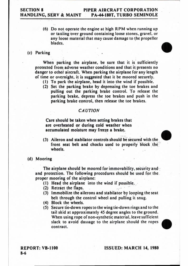
SECTION 8 PIPER AIRCRAFT CORPORATION HANDLING, SERV & MAINT PA-44-180T, TURBO SEMINOLE
(6) Do not operate the engine at high RPM when running up or taxiing'over ground containing loose stones, gravel, or any loose material that may cause damage to the propeller blades.
(c) Parking
When parking the airplane, be sure that it is sufficiently protected from adverse weather conditions and that it presents no danger to other aircraft. When parking the airplane for any length of time or overnight, it is suggested that it be moored securely.
( I) To park the airplane, head it into the wind if possible. (2) Set the parking brake by depressing the toe brakes and
pulling out the parking brake control. To release the parking brake, depress the toe brakes and push in the parking brake control, then release the toe brakes.
CAUTION
Care should be taken when setting brakes that are overheated or during cold weather when accumulated moisture may freeze a brake.
(3) Aileron and stabilator controls should be secured with the front seat belt and chocks used to properly block the wheels.
(d) Mooring
The airplane should be moored for immovability, security and and protection. The following procedures should be used for the proper mooring of the airplane:
( I) Head the airplane into the wind if possible. (2) Retract the flaps. (3) Immobilize the ailerons and stabilator by looping the seat
belt through the control wheel and pulling it snug. (4) Block the wheels. (5) Secure tie-down ropes to the wing tie-down rings and to the
tail skid at approximately 45 degree angles to the ground. When using rope of non-synthetic material, leave sufficient slack to avoid damage to the airplane should the ropes contract.
REPORT: VB - 1100 ISSUED: MARCH 14, 1980 8-6

PIPER AIRCRAFT CORPORATION SECTION 8 PA-44-180T, TURBO SEMINOLE HANDLING, SERV & MAINT
CAUTION
Use bowline knots, square knots or locked slip knots. Do not use plain slip knots.
NOTE
Additional preparations for high winds include using tie-down ropes from the landing gear forks and securing the rudder.
(6) Install a pitot head cover if available. Be sure to remove the pitot head cover before flight.
(7) Cabin and baggage doors should be locked when the airplane is unattended.
8.11 ENGINE INDUCTION AIR FILTERS
(a) Removing Induction Air Filter
(1) Remove the upper cowling to gain access to the air filter box.
(2) Unlatch top and bottom filter clamps. (3) Lift the air filter from the filter box.
(b) Cleaning Induction Air Filters
The induction air filters must be cleaned at least once every 50 hours, and more often, even daily, when operating in dusty conditions. Extra filters are inexpensive, and a spare should be kept on hand for use as a rapid replacement.
To clean the filter: (1) Blow out with compressed air from gasket side or wash
in warm water and mild detergent, and dry. (2) Inspect filter. If paper element is torn or ruptured or gasket
. is damaged, the filter should be replitced. The usable life of the filter should be restricted to one year or 500 hours, whichever comes first.
ISSUED: MARCH 14, 1980 REPORT: VB-1100 8-7

SECTION 8 PIPER AIRCRAFT CORPORATION HANDLING, SERV & MAINT PA-44.180T, TURBO SEMINOLE
(c) Installation of Induction Air Filters
After cleaning, place filter in air box and latch bottom and top filter clamps. Replace cowl.
8.13 BRAKE SERVICE
The brake system is filled with MIL-H-5606 (petroleum base) hydraulic brake fluid. This should be checked periodically or at every 50-hour inspection and replenish when necessary. The brake reservoir is located in the forward maintenance area. Remove the four screws and rotate the fiberglass nose cone forward and down. The reservoir is located at the top rear of the compartment. Keep the fluid level at the level marked on the reservoir.
No adjustment of brake clearance is necessary. Refer to the Service Manual for brake lining replacement instructions.
8.15 LANDING GEAR SERVICE
Two jack points are provided for jacking the aircraft for servicing. One is located outboard of each main landing gear. Before jacking, attach a tail support to the tail skid. Approximately 500 pounds of ballast should be placed on the tail support.
CAUTION
Be sure to apply sufficient support ballast; otherwise the airplane may tip forward, and the nose section could be damaged.
Landing gear oleos should be serviced according to instruction on the units. Under normal static load (empty weight or airplane plus full fuel and oil), main oleo struts should be exposed 2.60 inches and the nose oleo strut should be exposed 2.70 inches. Refer to the Service Manual for complete information on servicing oleo struts.
REPORT: VB-1100 ISSUED: MARCH 14, 1980 8-8

PIPER AIRCRAFT CORPORATION SECTION 8 PA-44-180T, TURBO SEMINOLE HANDLING, SERV & MAINT
BRAKE SYSTEM Figure 8-1
ISSUED: MARCH 14, 1980 REPORT: VB-1100 REVISED: SEPTEMBER 29, 1980 8-9

SECTION 8 PIPER AIRCRAFT CORPORATION HANDLING, SERV & MAINT PA-44-180T, TURBO SEMINOLE
8.17 PROPELLER SERVICE
The gas charge in the propeller cylinder should be kept at the pressure specified on the placard located in the spinner cap. The pressure in the cylinder will increase about one-third psi for every degree Fahrenheit increase in temperature. This effect should be considered when checking pressure. The charge maintained must be accurate and free of excessive moisture since moisture may freeze the piston during cold weather. Dry nitrogen gas is recommended.
CHAMBER PRESSURE REQUIREMENTS WITH TEMPERATURE FOR COUNTERWEIGHT TYPE PROPELLERS
Temp. °F
Pressure (PSI)
FOR PROPELLER HUBS: HC-C2Y(K,R)-2CEU F, HC-C2Y(K,R)-2CLEU F,
HC-C3YK-2EUF AND HC-C3YK-2LEUF
70 to 100
41 t 1
40 to 70
38 t 1
0 to 40
36 1: 1
-30 to 0
33t 1
NOTE: Do not check pressure or charge with propeller in feather position.
The spinner and backing plate should be cleaned and inspected for cracks frequently. Before each flight the propeller should be inspected for nicks, scratches, or corrosion. If found, they should be repaired as soon as possible by a rated mechanic, since a nick or scratch causes an area of increased stress which can lead to serious cracks or the loss of a propeller tip. The back face of the blades should be painted when necessary with flat black paint to retard glare. To prevent corrosion, all surfaces should be cleaned and waxed periodically.
The gas charge in the Optional unfeathering accumulators should be maintained at 90 - 100 PSI. It is important to use a dry gas for this charge since any moisture in the system may freeze and render it inoperative. Nitrogen is recommended. Do not check this pressure while the engine is running.
REPORT: VB-1100 ISSUED: MARCH 14, 1980 8-10 REVISED: APRIL 2, 1982
•
•
•

•
•
•
PIPER AIRCRAFT CORPORATION SECTION 8 PA-44-180T, TURBO SEMINOLE HANDLING, SERV & MAINT
8.19 OIL REQUIREMENTS The oil capacity of the Lycoming engines is 6 quarts per engine with a
minimum safe quantity of 2 quarts per engine. It is necessary that oil be maintained at full for maximum endurance flights. It is recommended that engine oil be drained and replenished every 50 hours. Full flow cartridge type oil filters should be changed every 50 hours of operation. The interval between oil and oil filter changes should not exceed a total of four (4) months. Under unfavorable dusty conditions, the oil and oil filter should be changed more frequently.
The following seasonal aviation oil grades and seasonal ambient temperature ranges are recommended:
MIL-L-22851 Average Ambient MIL-L-6082B Ashless Dispersant
Temperature SAE Grade SAE Grades All Temperatures 15W-50 or 20W-50
Above 80T 60 60 Above 60T 50 40 or 50 30T to 90'F 40 40 O'F to 70'F 30 30, 40 or 20W-40 Below 10T 20 30 or 20W-30
When operating temperatures overlap indicated ranges, use the lighter grade oil.
NOTE Refer to the latest issue of Textron Lycoming Service Instruction 1014 (Lubricating Oil Recommendations) for further information.
8.21 FUEL SYSTEM (a) Servicing Fuel System
The fuel screens in the strainers require cleaning at 50 hour or 90 day intervals, whichever occurs first. The fuel gascolator strainers are located in the fuselage under the rear seats. The fuel selector valves and the auxiliary pumps are in the wings adjacent to the nacelles.
ISSUED: MARCH 14, 1980 REPORT: VB-1100 REVISED: MAY 7, 1990 8-11

SECTION 8 PIPER AIRCRAFT CORPORATION HANDLING, SERV & MAINT PA-44-180T, TURBO SEMINOLE
(b) Fuel Requirements The minimum Aviation Grade fuel for the PA-44-100T is 100.
Since the use of lower grades can cause serious engine damage in a short period of time, the engine warranty is invalidated by the use of lower octanes.
Whenever 100 or 100LL grade fuel is not available, commercial grade 100/130 should be used. (See Fuel Grade Comparison Chart.) Refer to the latest issue of Lycoming Service Instruction No. 1070 for additional information.
A summary of the current grades as well as the previous fuel designations is shown in the following chart:
FUEL GRADE COMPARISON CHART
Previous Commercial Fuel Grades (ASTM-D910)
Current Commercial Fuel Grades (ASTM-D910-75)
Current Military Fuel Grades (MIL-G-5572F)
Grade Color Max. TEL
rnI/U.S. gal Grade Color Max. TEL ml/U.S. gal Grade
Max. TEL Color ml/U.S. gal
80/87 red 91/96 blue 100/130 green 115/145 purple
0.5 2.0 3.0 4.6
80 • 10011 100 none
red blue green none
0.5 2.0
**3.0 none
80/87 100/130 none 115/145
red 0.5 blue 2.0 none none purple 4.6
• - Grade 100LL fuel in some overseas countries is currently colored green and designated as "100L". ** - Commercial fuel grade 100 and grade 100/130 (both of which are colored green) having TEL
content of up to 4 ml/U.S. gallon are approved for use in all engines certificated for use with grade 100/130 fuel.
CAUTION Fuel containing TCP additive is not approved for use in this airplane. Refer to the latest issue of Lycoming Service Letter 190.
The operation of the aircraft is approved with an anti-icing additive in the fuel. When an anti-icing additive is used, it must meet the specification MIL-I-27686, must be uniformly blended with the fuel while refueling, must not exceed .15% by volume of the refueled quantity, and to ensure its effectiveness should be blended at not less than .10% by volume. One and one half liquid ozs. per ten gallons of fuel would fall within this range. A blender supplied by the additive manufacturer should be used. Except for the information contained in this section, the manufacturer's mixing or blending instructions should be carefully followed.
REPORT: VB-1100 ISSUED: MARCH 14, 1980 8-12 REVISED: MAY 7, 1990

PIPER AIRCRAFT CORPORATION SECTION 8 PA-44-180T, TURBO SEMINOLE HANDLING, SERV & MAINT
•••
FUEL DRAINS Figure 8-2
CA UTIONS
Assure that the additive is directed into the flowing fuel stream. The additive flow should start after and stop before the fuel flow. Do not permit the concentrated additive to come in contact with the aircraft painted surfaces or the interior surfaces of the fuel tanks.
Some fuels have anti-icing additives pre-blended in the fuel at the refinery, so no further blending should be performed.
Fuel additive can not be used as a substitute for preflight draining of the fuel system.
ISSUED: MARCH 14, 1980 REPORT: VB-1100 8-13

SECTION 8 PIPER AIRCRAFT CORPORATION HANDLING, SERV & MAINT PA-44-180T, TURBO SEMINOLE
(c) Filling Fuel Tanks
Observe all safety precautions required when handling gaso-line. Fill the fuel tanks through the fillers located inside the acces s, cover aft of the engine cowling on the outboard side of the nacelles. Each nacelle tank holds a maximum of 55 U.S. gallons. When using less than the standard 110 gallon capacity, fuel should be distributed equally between each side.
(d) Draining Fuel Strainers, Sumps and Lines
The aircraft is equipped with single point drains which should be drained before the first flight of the day and after refueling, to check for fuel contamination. If contamination is found, fuel should be drained until the contamination stops. If contamination persists after draining fuel fora minute, contact a mechanic to check the fuel system.
Each half of the fuel system can be drained from a single point which is located just forward of the entrance step. Fuel selectors should be in the ON position during draining. The fuel drained should be collected in a transparent container and examined for• contamination.
CAUTION
When draining fuel, be sure that no fire hazard exists before starting the engines.
(e) Draining Fuel System
The fuel may be drained by opening the valves at the right hand side of the fuselage just forward of the entrance step or by siphoning. The remaining fuel in the lines may be drained through the gascolators.
REPORT: VB-1100 ISSUED: MARCH 14, 1980 8-14
PIPER AIRCRAFT CORPORATION SECTION 8 PA-44-180T, TURBO SEMINOLE HANDLING, SERV & MAINT
8.23 TIRE INFLATION
For maximum service from the tires, keep them inflated to the proper OPressures. The main gear tires should be inflated to 55 psi and the nose gear tire should be inflated to 50 psi.
Interchange the tires on the main wheels, if necessary, to produce even wear. All wheels and tires are balanced before original installation, and the relationship of the tire, tube, and wheel should be maintained if at all possible. Unbalanced wheels can cause extreme vibration on takeoff. In the installation of new components, it may be necessary to rebalance the wheel with the tire mounted.
When checking the pressure, examine the tires for wear, cuts, bruises and slippage.
8.25 BATTERY SERVICE
Access to the 12-volt 35 ampere hour battery is gained through the fiberglass nose cone. The battery container has a plastic drain tube which is eormally closed off. This tube should be opened ocassionally to drain off ny accumulation of liquid.
The battery fluid level must not be brought above the baffle plates. It should be checked every 30 days to determine that the fluid level is proper and the connections are tight and free of corrosion. DO NOT fill the battery above the baffle plates. DO NOT fill the battery with acid. Use distilled water only. A hydrometer check will determine the percent of charge in the battery.
If the battery is not properly charged, recharge it starting with a rate of 4 amperes and finishing with a rate of 2 amperes. Quick charges are not recommended. .
The external power receptacle, if installed, is located on the right side of the nose section. Be sure that master switch is off and the right engine is shut-down prior to inserting or removing a plug at this receptacle.
Refer to the Service Manual for detailed procedures for cleaning and •servicing the battery.
ISSUED: MARCH 14, 1980 REPORT: VB-1100 REVISED: APRIL 2, 1982 8-15

SECTION 8 PIPER AIRCRAFT CORPORATION HANDLING, SERV & MAINT PA-44-180T, TURBO SEMINOLE
8.27 SERIAL NUMBER PLATES
The serial number plate is located on the bottom of the fuselage near the aft end of the tail cone. The serial number should always be used when 411
referring to the airplane on service or warranty matters.
8.29 LUBRICATION
Lubrication at regular intervals is an essential part of the maintenance of an airplane. For lubrication instructions and a chart showing lubrication points, types of lubricants to be used, lubrication methods and recom-mended frequencies, refer to the Service Manual.
8.31 CLEANING
(a) Cleaning Engine Compartment
Before cleaning the engine compartment, place a strip of tape on the magneto vents to prevent any solvent from entering these units.
(1) Place a large pan under the engine to catch waste. (2) With the engine cowling removed, spray or brush the
engine with solvent or a mixture of solvent and degreaser. In order to remove especially heavy dirt and grease deposits, it may be necessary to brush areas that were sprayed.
CAUTION
Do not spray solvent into the alternator, vac-cuum pump, starter, air intakes, or alternate air inlets.
(3) Allow the solvent to remain on the engine from five to ten minutes. Then rinse the engine clean with additional solvent and allow it to dry.
CAUTION
Do not operate the engine until excess solvent has evaporated or otherwise been removed.
REPORT: VB-1100 ISSUED: MARCH 14, 1980 8-16

•
•
•
PIPER AIRCRAFT CORPORATION SECTION 8 PA-44-180T, TURBO SEMINOLE HANDLING, SERV & MAINT
(4) Remove the protective tape from the magnetos. (5) Lubricate the controls, bearing surfaces, etc., in
accordance with the Lubrication Chart in the Service Manual.
(b) Cleaning Landing Gear
Before cleaning the landing gear, place a plastic cover or similar material over the wheel and brake assembly.
(1) Place a pan under the gear to catch waste. (2) Spray or brush the gear area with solvent or a mixture of
solvent and degreaser, as desired. Where heavy grease and dirt deposits have collected, it may be necessary to brush areas that were sprayed, in order to clean them.
(3) Allow the solvent to remain on the gear from five to ten minutes. Then rinse the gear with additional solvent and allow to dry.
(4) Remove the cover from the wheel and remove the catch pan.
(5) Lubricate the gear in accordance with the Lubrication Chart in the Service Manual.
CAUTION
Do not brush the micro switches.
(c) Cleaning Exterior Surfaces
The airplane should be washed with a mild soap and water. Harsh abrasives or alkaline soaps or detergents could make scratches on painted or plastic surfaces or could cause corrosion of metal. Cover areas where cleaning solution could cause damage. To wash the airplane, use the following procedure:
(1) Flush away loose dirt with water. (2) Apply cleaning solution with a soft cloth, a sponge or a
soft bristle brush. (3) To remove exhaust stains, allow the solution to remain on
the surface longer. (4) To remove stubborn oil and grease, use a cloth dampened
with naphtha. (5) Rinse all surfaces thoroughly.
ISSUED: MARCH 14, 1980 REPORT: VB-1100 REVISED: APRIL 2, 1982 8-17

SECTION 8 PIPER AIRCRAFT CORPORATION HANDLING, SERV & MAINT PA-44-180T, TURBO SEMINOLE
(6) Any good automotive wax may be used to preserve painted surfaces. Soft cleaning cloths or a chamois should be used to prevent scratches when cleaning or polishing. A heavier coating of wax on the leading surfaces will reduce the abrasion problems in these areas.
(d) Cleaning Windshield and Windows CAUTION
Use only water and mild soap when cleaning the heated windshield. Use of ANY other cleaning agent or material may cause distortion or damage to windshield coatings.
(1) Remove dirt, mud, and other loose particles from exterior surfaces with clean water.
(2) Wash with mild soap and warm water or with aircraft plastic cleaner. Use a soft cloth or sponge in a straight back and forth motion. Do not rub harshly.
(3) Remove oil and grease with a cloth moistened with kerosene.
CAUTION Do not use gasoline, alcohol, benzene„ carbon tetrachloride, thinner, acetone, or window cleaning sprays.
(4) After cleaning plastic surfaces, apply a thin coat of hard polishing wax. Rub lightly with a soft cloth. Do not use a circular motion.
(5) A severe scratch or mar in plastic can be removed by rubbing out the scratch with jeweler's rouge. Smooth both sides and apply wax.
(e) Cleaning Headliner, Side Panels, and Seats
(1) Clean headliner, side panels, and seats with a stiff brush, and vacuum where necessary.
(2) Soiled upholstery, except leather, may be cleaned with a good upholstery cleaner suitable for the material. Carefully follow the manufacturer's instructions. Avoid soaking or harsh rubbing.
CAUTION Solvent cleaners require adequate ventilation.
REPORT: VB-1100 ISSUED: MARCH 14, 1980 8-18 REVISED: MAY 7, 1990

PIPER AIRCRAFT CORPORATION SECTION 8 PA-44-180T, TURBO SEMINOLE HANDLING, SERV & MAINT
(3) Leather should be cleaned with saddle soap or a mild hand soap with water.
(f) Cleaning Carpets
To clean carpets, first remove loose dirt with a whisk broom or vacuum. For soiled spots and stubborn stains use a nonflammable dry cleaning fluid. Floor carpets may be removed and cleaned like any household carpet.
8.33 WINTERIZATION
For winter operation a winterization kit is installed on the inlet opening of the oil cooler outboard chamber of the plenum chamber. This kit should be installed whenever the ambient temperature is 50° F or less. When the kit is not being used it can be stowed in the nose cone compartment.
ISSUED: MARCH 14, 1980 REPORT: VB-1100 8-19

;~
J Ij
s

• TABLE OF CONTENTS
SECTION 9
SUPPLEMENTS
Paragraph/ Supplement No.
Page No.
9.1 General 9-1
I AutoControl 111B Autopilot Installation 9-3 2 AltiMatic 111C Autopilot Installation 9-9 3 Piper Electric Pitch Trim 9-21 4 ANS 351 Area Navigation Computer 9-23 5 KNS 80 Navigation System 9-27 6 Oxygen Installation (Portable) 9-31 7 Oxygen System Installation (Fixed) 9-33 8 Air Conditioning Installation 9-35 9 Century 21 Autopilot Installation 9-41
10 Century 41 Autopilot Installation 9-45 11 Piper Control Wheel Clock Installation 9-57 12 RCA WeatherScout 11 Weather Radar System 9-59 13 RCA Color WeatherScout II Weather Radar System 9-65 14 RDR-I60 Weather Radar System 9-71 15 RDR-I60/ IN-2026A Weather Radar System 9-77 16 Surface Boots, Prop Heat and Related Equipment 9-83 17 RDR-160XD/ IN-232A Weather Radar System 9-91 18 Electrical Distribution Bus Modification 9-97
• I
• REPORT: VB-1100
9-I

•
•

PIPER AIRCRAFT CORPORATION SECTION 9 PA-44-180T, TURBO SEMINOLE SUPPLEMENTS
SECTION 9
SUPPLEMENTS
9.1 GENERAL
This section provides information in the form of supplements which are necessary for efficient operation of the airplane when it is equipped with one or more of the various optional systems and equipment not approved with the standard airplane.
All of the supplements provided in this section are "FAA Approved" and consecutively numbered as a permanent part of this handbook. The in-formation contained in each supplement applies only when the related equipment is installed in the airplane.
ISSUED: MARCH 14, 1980 REPORT: VB-1100 9-1

SECTION 9 PIPER AIRCRAFT CORPORATION SUPPLEMENTS PA-44-180T, TURBO SEMINOLE
• THIS PAGE INTENTIONALLY LEFT BLANK
• REPORT: VB-1100 ISSUED: MARCH 14, 1980 9-2
PIPER AIRCRAFT CORPORATION SECTION 9 PA-44-180T, TURBO SEMINOLE SUPPLEMENTS
• SUPPLEMENT 1
AUTOCONTROL IIIB AUTOPILOT INSTALLATION
SECTION 1 - GENERAL
This supplement supplies information necessary for the operation of the airplane when the optional Piper AutoControl IIIB Autopilot is installed. The information contained within this supplement is to be used in con-junction with the complete handbook.
This supplement has been "FAA Approved" as a permanent part of this handbook based on EDO-AIRE Mitchell STC SA3276SW-D and must remain in this handbook at all times when the optional Piper AutoControl IIIB Autopilot is installed. .
• SECTION 2 - LIMITATIONS
(a) Autopilot operation prohibited above 185 KIAS. (Autopilot Vmo) (b) Autopilot must be "OFF" for takeoff and landing.
SECTION 3 - EMERGENCY PROCEDURES
•
(a) In an emergency the AutoControl IIIB can be disconnected by pushing the AP ON-OFF switch "OFF."
(b) The autopilot can be overpowered at either control wheel. (c) An autopilot runaway, With a 3 second delay in the initiation of re-
covery while operating in climb, cruise or descending flight, could result in a 58° bank and 400 foot altitude loss. Maximum altitude loss measured at 185 KIAS in descent.
(d) An autopilot runaway, with a 1 second delay in the initiation of re-covery during an approach operation, single or multi-engine, coupled or uncoupled, could result in a 12° bank and 20 foot alti-tude loss.
ISSUED: MARCH 14, 1980 REPORT: VB-1100 9-3

SECTION 9 PIPER AIRCRAFT CORPORATION SUPPLEMENTS PA-44-180T, TURBO SEMINOLE
(e) Emergency operation with optional NSD 360A (HSI) - Slaved and/or Non-Slaved:
NSD 360A (I) Appearance of HDG Flag:
a. Check air supply gauge (vac or pressure) for adequate air supply (4 in. Hg. min.).
b. Check compass circuit breaker. c. Observe display for proper operation.
(2) To disable heading card - pull circuit breaker and use magnetic compass for directional data.
NOTE
If heading card is not operational, autopilot should not be used.
(3) With card disabled, VOR/Localizer and Glide Slope displays are still functional; use card set to rotate card to aircraft head-ing for correct picture.
(4) Slaving Failure - (i.e. failure to self-correct for gyro drift): a. Check gyro slaving switch is set to No. I position. b. Check for HDG Flag. c. Check compass circuit breaker. d. Reset heading card while observing slaving meter.
NOTE
Dead slaving meter needle or needle displaced fully one direction indicates a slaving system failure.
e. Select slaving amplifier No. 2 (gyro slaving switch is set to No. 2 position).
f. Reset heading card while checking slaving meter. g. Switch to free gyro mode and periodically set card as
unslaved gyro.
NOTE
In the localizer mode the "TO-FROM" arrows may remain out of view, depending upon the design of the NAV converter used in the installation.
REPORT: VB-1100 ISSUED: MARCH 14, 1980 9-4
•
•
•

PIPER AIRCRAFT CORPORATION SECTION 9 PA-44-180T, TURBO SEMINOLE SUPPLEMENTS
SECTION 4 - NORMAL PROCEDURES
PREFLIGHT
(a) AUTOPILOT (1) Place radio coupler in HDG mode (if installed) and place the
AP "ON-OFF" switch to the "ON" position to engage roll section. Rotate roll command knob left and right and observe that control wheel describes a corresponding left and right turn, then center knob.
(2) Set proper D.G. heading on D.G. and turn HDG bug to aircraft heading. Engage HDG mode rocker switch and rotate HDG bug right and left. Aircraft control wheel should turn same direction as bug. Grasp control wheel and manually override servo, both directions.
(b) RADIO COUPLER - (OPTIONAL) (1) Tune and identify VOR or VOT station. Position radio coupler
to OMNI mode. Place autopilot and HDG switches to the ON position. Set HDG bug to aircraft heading and rotate OBS to cause OMNI indicator needle to swing left and right slowly. Observe that control wheel rotates in direction of needle movement.
(2) Disengage AP "ON-OFF" switch. Reset radio coupler control to HDG.
IN-FLIGHT
(a) Trim airplane (ball centered).
(b) Check air pressure or vacuum to ascertain that the directional gyro and attituk:e gyro are receiving sufficient air.
ISSUED: MARCH 14, 1980 REPORT: VB-1100 9-5

SECTION 9 PIPER AIRCRAFT CORPORATION SUPPLEMENTS, PA-44-180T, TURBO SEMINOLE
(c) Roll Section (1) To engage, center ROLL COMMAND knob, push AP "ON-
OFF" switch to "ON" position. To turn, rotate ROLL COM-MAND knob in desired direction. (Maximum angle of bank should not exceed 30°.)
(2) For heading mode, set directional gyro with magnetic compass. Push directional gyro HDG knob in, rotate bug to aircraft heading. Push console heading rocker (HDG) switch to "ON" position. To select a new aircraft heading, push D.G. heading knob "IN" and rotate, in desired direction • of turn, to the desired heading.
(d) Radio Coupling VOR-ILS with H.S.1. (Horizontal Situation Indi-cator) Type Instrument Display. (Optional) (1) VOR Navigation
a. Tune and identify VOR station. Select desired course by rotating CRS knob of H.S.I.
b. Select OMNI mode on radio coupler. c. Select HDG mode on autopilot console to engage coupler.
Aircraft will turn to a 45° intercept angle to intercept the selected VOR course. Intercept angle magnitude depends on radio needle off course magnitude, 100% needle deflec-tion will result in 45° intercept with the intercept angle diminishing as the needle offset diminishes.
d. NAV mode - NAV mode provides reduced VOR sensitivity for tracking weak, or noisy VOR signals. NAV mode should be selected after the aircraft is established on course.
(2) ILS-LOC Front Course a. Set inbound, front, localizer course with H.S.I. course
knob. b. Select LOC-Normal on radio coupler to intercept and
track inbound on the localizer. Select LOC-REV to inter-cept and track the localizer course outbound to the pro-cedure turn area.
c. Select HDG mode on autopilot console to engage coupler.
REPORT: VB-1100 ISSUED: MARCH 14, 1980 9-6
•
•
•

PIPER AIRCRAFT CORPORATION SECTION 9 PA-44-180T, TURBO SEMINOLE SUPPLEMENTS
(3) ILS - Back Course a. Set inbound, front localizer course with H.S.1. course
knob. b.. Select LOC-REV on radio coupler to intercept and track
inbound on the back localizer course. Select LOC-NORM to intercept and track outbound on the back course to the procedure turn area.
c. Select HDG mode on autopilot console to engage coupler.
(e) Radio Coupling - VOR/ ILS with standard directional gyro. (Optional) Radio coupler operation in conjunction with a standard directional gyro and VOR/ LOC display differs from operation with an inte-grated display (H.S.I.) only in one respect. The HDG bug is used as the radio course datum and therefore must be set to match the de-sired VOR course as selected on the OBS. (1) For VOR intercepts and tracking:
Select the desired VOR course and set the HDG bug to the same heading. Select OMNI mode on the coupler and HDG mode on the autopilot console.
(2) For ILS Front Course intercepts and tracking: Tune the localizer frequency and place the HDG bug on the in-bound, front course heading. Select LOC-NORM mode on the coupler and HDG mode on the autopilot console.
(3) For LOC Back Course intercepts and tracking: Tune the localizer frequency and place the HDG bug on the in-bound course heading to the airport. Select LOC-REV mode with coupler and HDG mode on the autopilot console.
SECTION 5 - PERFORMANCE
No changes to the basic performance provided by Section 5 of the Pilot's Operating Handbook are necessary for this supplement.
ISSUED: MARCH 14, 1980 REPORT: VB-1100 9-7

SECTION 9 PIPER AIRCRAFT CORPORATION SUPPLEMENTS PA-44-180T, TURBO SEMINOLE
THIS PAGE INTENTIONALLY LEFT BLANK
REPORT: VB-1100 ISSUED: MARCH 14, 1980 9-8

PIPER AIRCRAFT CORPORATION SECTION 9 PA-44-180T, TURBO SEMINOLE SUPPLEMENTS
SUPPLEMENT 2
ALTIMATIC IIIC AUTOPILOT INSTALLATION
SECTION 1 GENERAL
This supplement supplies information necessary for the operation of the airplane when the optional AltiMatic IIIC Autopilot is installed. The in-formation contained within this supplement is to be used in conjunction with the complete handbook.
This supplement has been "FAA Approved" as a permanent part of this handbook based on EDO-AIRE Mitchell STC SA3277SW-D and must re-main in this handbook at all times when the optional AltiMatic IIIC Auto-pilot is installed.
•SECTION 2 LIMITATIONS
(a) Autopilot operation prohibited above 185 KIAS. (Autopilot Vmo) (b) Autopilot must be "OFF" during takeoff and landing. (c) Required placard P/N I3A660 "Conduct Trim Check prior to
flight (see AFM)" to be installed in clear view of pilot. (d) During autopilot operation, the pilot must be in his seat with the
safety belt fastened.
• ISSUED: MARCH 14, 1980 REPORT: VB-1100
9-9

SECTION 9 PIPER AIRCRAFT CORPORATION SUPPLEMENTS PA-44-180T, TURBO SEMINOLE
SECTION 3 - EMERGENCY PROCEDURES
This aircraft is equipped with a Master Disconnect/ Interrupt Switch on the pilot's control wheel. When the switch button is depressed it will dis-connect the autopilot. When depressed and held it will interrupt all Electric Elevator Trim Operations. Trim operations will be restored when the switch is released. If an autopilot or trim emergency is encountered, do not attempt to determine which system is at fault. Immediately depress and hold the Master Disconnect/Interrupt button. Turn off autopilot and trim master switch and retrim aircraft, then release the interrupt switch.
NOTE
During examination of this supplement, the pilot is advised to locate and identify the auto-pilot controls, the trim master switch and cir-cuit breaker for both systems.
(a) In the event of an autopilot malfunction the autopilot can be: (I) Overpowered at either control wheel.
CAUTION
Do not overpower autopilot pitch axis for periods longer than 3 seconds because the autotrim system will operate in a direction to oppose the pilot and will, thereby, cause an in-crease in the pitch overpower forces.
(2) Disconnected by depressing the Master Disconnect/ Interrupt Switch.
(3) Disconnected by depressing the Trim Switch "AP OFF" bar. (4) Disconnected by pushing the roll rocker switch "OFF."
REPORT: VB-1100 ISSUED: MARCH 14, 1980 9-10

PIPER AIRCRAFT CORPORATION SECTION 9 PA-44-180T, TURBO SEMINOLE SUPPLEMENTS
(b) In the event of a trim malfunction: (1) Depress and hold the Master Trim Interrupt Switch. (2) Trim Master Switch - "OFF." Retrim aircraft as necessary
using manual trim system. (3) Release Master Interrupt Switch - be alert for possible trim
action. (4) Trim Circuit Breaker - Pull. Do not operate trim until problem
is corrected. (5) If the trim system operates only in one direction, pull the circuit
breaker and do not operate the trim system until corrective action is taken. Monitor autopilot operation closely when operating without trim follow-up.
(c) If a trim runaway occurs with the autopilot operating, the above procedure will disconnect the autopilot which will immediately re-sult in higher control wheel forces. Be prepared to manually retrim, as necessary to eliminate undesirable forces.
(d) Altitude Loss During Malfunction: (1) An autopilot malfunction during climb, cruise or descent with
a 3 second delay in recovery initiation could result in as much as 60° of bank and 600' of altitude loss. Maximum altitude loss measured in a descent at Vmo.
(2) An autopilot malfunction during an approach with a 1 second delay in recovery initiation could result in as much as 12° of bank and 60' altitude loss. Maximum altitude loss measured in approach configuration gear down and operating either cou-pled or uncoupled, single or multi-engine.
(e) Emergency Operation With Optional NSD 360A (HSI) - Slaved and/ or Non-Slaved:
'NSD 360A . (1) Appearance of HDG ,Flag:
a. Check air supply gauge (vac or pressure) for adequate air supply (4 in. Hg. min.).
b. Check compass circuit breaker. c. Observe display for proper operation.
ISSUED: MARCH 14, 1980 REPORT: VB-1100 9-11

SECTION 9 PIPER AIRCRAFT CORPORATION SUPPLEMENTS PA-44-180T, TURBO SEMINOLE
(2) To disable heading card - pull circuit breaker and use magnetic compass for directional data.
NOTE
If heading card is not operational, autopilot should not be used.
(3) With card disabled, VOR/ Localizer and Glide Slope displays are still functional; use card set to rotate card to aircraft head-ing for correct picture.
(4) Slaving Failure - (i.e. failure to self-correct for gyro drift): a. Check gyro slaving switch is set to No. I position. b. Check for HDG Flag. c. Check compass circuit breaker. d. Reset heading card while observing slaving meter.
NOTE
Dead slaving meter needle or a needle displaced fully one direction indicates a slaving system failure.
e. Select slaving amplifier No. 2 (gyro slaving switch is set to No. 2 position).
f. Reset heading card while checking slaving meter. g. Switch to free gyro and periodically set card as unslaved
gyro.
NOTE
In the localizer mode the "TO-FROM" arrows may remain out of view, depending upon the design of the NAV converter used in the in-stallation.
REPORT: VB-1100 ISSUED: MARCH 14, 1980 9-12

•
•
PIPER AIRCRAFT CORPORATION SECTION 9 PA-44-180T, TURBO SEMINOLE SUPPLEMENTS
(f) Single Engine Operations: (1) Engine failure during an autopilot approach operation: Dis-
engage autopilot; conduct remainder of approach manually. (2) Engine failure during go-around: Disengage autopilot, retrim
aircraft, perform basic airplane flight manual engine out procedures; then re-engage autopilot.
(3) Engine failure during normal climb, cruise, descent: Retrim aircraft, perform basic airplane flight manual engine out procedures.
(4) Maintain aircraft yaw trim throughout all single engine opera-tions.
SECTION 4 - NORMAL PROCEDURES
PREFLIGHT INSPECTION - AUTOPILOT
(a) Roll Section (1) Place Radio Coupler in "Heading" mode and place roll rocker
switch "ON" to engage roll section. Rotate roll command knob left and right and observe that control wheel describes a corre-sponding left and right turn, then center knob.
(2) Set proper D.G. Heading on D.G. and turn Heading Bug to air-craft heading. Engage "Heading" mode rocker switch and ro-tate heading bug right and left. Aircraft control wheel should turn same direction as bug. Grasp control wheel and manually override servo, both directions.
(3) Disengage autopilot by depressing trim switch. Check aileron operation is free and autopilot is disconnected from controls.
(b) Pitch Section (I) Engage "Roll" rocker switch. (2) Center pitch command disc and engage "Pitch" rocker switch. (3) Rotate pitch command disc full UP and full DOWN and check
that control wheel moves same direction. Check to see that servo can be overriden by hand at control wheel.
NOTE
Autopilot might not be able to raise elevators, on ground, without assistance from pilot.
ISSUED: MARCH 14, 1980 REPORT: VB-1100 REVISED: APRIL 2, 1982 9-13

SECTION 9 PIPER AIRCRAFT CORPORATION SUPPLEMENTS PA-44-180T, TURBO SEMINOLE
(4) Hold control wheel and disengage autopilot by pressing Master Autopilot Disconnect/ Trim Interrupt Switch button. Check Roll and Pitch controls to assure autopilot has disconnected.
TRIM SYSTEM
General This aircraft is equipped with a Command Trim System designed to withstand any type of single malfunction, either mechanical or electrical, without uncontrolled operation resulting. The preflight check procedure is designed to uncover hidden failures that might otherwise go undetected. Proper operation of the electric trim system is predicated on conducting the following preflight check before each flight. If the trim system fails any portion of the pro-cedure, pull the trim circuit breaker out until trim system is re-paired. Substitution of any trim system comporient for another model is not authorized. For emergency interrupt information, refer to Section 3 of this Supplement.
Command Electric Trim Switch The Command Electric Trim Switch on the left hand portion of the pilot's control wheel has two functions: (1) When the top bar (AP OFF) is pressed, it disconnects the
Autopilot. (2) When the top bar is pressed AND the rocker is moved forward,
nose down trim will occur, when moved aft, nose up trim will Occur.
(a) Preflight: Command Trim - Before Each Flight (1) Check trim circuit breaker - IN. (2) Trim Master Switch - ON. (3) AP OFF - Check normal trim operation - UP. Grasp trim wheel
and check override capability. Check nose down operation. Re-check override.
(4) With trim operating - depress interrupt switch - trim should stop - release interrupt switch - trim should operate.
(5) Activate center bar only. Push rocker fore and aft only. Trim should not operate with either separate action.
REPORT: VB-1100 ISSUED: MARCH 14, 1980 9-14

•
PIPER AIRCRAFT CORPORATION SECTION 9 PA-44-180T, TURBO SEMINOLE SUPPLEMENTS
(b) Autotrim - Before Each Flight (I) AP ON - (Roll and Pitch Sections) Check automatic operation
by activating autopilot pitch command UP then DN. Observe trim operation follows pitch command direction.
NOTE
In autopilot mode, there will be approximately a 3 second delay between operation of pitch command and operation of trim.
(2) Press center bar (AP OFF) - release - check autopilot dis-engagement.
(3) Rotate trim wheel to check manual trim operation. Reset to takeoff position prior to takeoff.
AUTOPILOT IN-FLIGHT PROCEDURE
(a) Trim airplane (ball centered).
(b) Check air pressure or vacuum to ascertain that the directional gyro and attitude gyro are receiving sufficient air.
(c) Roll Section (1) To engage - Center ROLL COMMAND knob, push ROLL
rocker to "ON" position. To turn, rotate console ROLL knob in desired direction.
(2) For heading mode, set directional gyro with magnetic compass. Push directional gyro HDG knob in, rotate to select desired heading. Push console heading rocker (HDG) to "ON" posi-tion. (Maximum angle to bank will be 20° with heading lock engaged.)
(d) Pitch Section (Roll section must be engaged prior to pitch section engagement). (I) Center pitch trim indicator with the pitch command disc. (2) Engage pitch rocker switch. To change attitude, rotate pitch
command disc in the desired direction, • ISSUED: MARCH 14, 1980 REPORT: VB-1100
9-15

SECTION 9 PIPER AIRCRAFT CORPORATION SUPPLEMENTS PA-44-180T, TURBO SEMINOLE
(e) Altitude Hold Upon reaching desired or cruising altitude, engage altitude hold mode rocker switch. As long as Altitude Hold mode rocker is en-gaged, aircraft will maintain selected altitude. For maximum pas-senger comfort, rate of climb or descent should be reduced to ap-proximately 500 FPM prior to altitude hold engagement. For accurate Altitude Holding below 90 KIAS lower flaps one or two notches.
NOTE
Prior to disengaging Altitude Hold mode, ro-tate Pitch Command Disc to center.
(f) Radio Coupling VOR-ILS with H.S.I. type instrument display. (Optional) (I) VOR Navigation
a. Tune and identify VOR Station. Select desired course by rotating CRS knob of H.S.I.
b. Select OMNI mode on Radio Coupler. c. Select HDG mode on autopilot console to engage coupler.
Aircraft will turn to a 45° intercept angle to intercept the selected VOR course. Intercept angle magnitude depends on radio needle off - course magnitude, 100% needle de-flection will result in 45° intercept angle, diminishing as the needle off-set diminishes.
d. NAV mode - NAV mode *vides reduced VOR sensitivity for tracking weak, or noisy, VOR signals. NAV mode should be selected after the aircraft is established on Course.
(2) 1LS-LOC Front Course a. Set inbound, front, localizer course with H.S.I. course
knob. b. Select LOC-Normal on Radio Coupler to intercept and
track inbound on the localizer. Select LOC-REV to inter-cept and track the localizer course outbound to procedure turn area.
c. Select HDG mode on autopilot console to engage coupler.
REPORT: VB-1100 ISSUED:. MARCH 14, 1980 9-16

PIPER AIRCRAFT CORPORATION SECTION 9 PA-44-180T, TURBO SEMINOLE SUPPLEMENTS
(3) ILS - Back Course a. Set inbound, front, localizer course with H.S.I. course
knob. b. Select LOC-REV, on radio coupler to intercept and track
inbound on the back localizer course. Select LOC-NORM to intercept and track outbound on the back course to the procedure turn area.
c. Engage HDG mode on autopilot console to engage cou-pler.
(g) Radio Coupling - VOR/ ILS with standard directional gyro. (Optional) Radio Coupler operation in conjunction with a standard directional gyro and VOR/LOC display differs from operation with an in-tegrated display (H.S.I.) only in one respect. The HDG bug is used as the radio course datum and therefore must be set to match the de-sired VOR/ ILS course as selected on the O.B.S. (I) For VOR Intercepts and Tracking:
Select the desired VOR Course and set the HDG bug to the same heading. Select OMN1 mode on the coupler and engage • (2) For ILS Front Course Intercepts and Tracking: Tune the localizer frequency and place the HDG bug on the
HDG mode on the autopilot console.
inbound, front course heading. Select LOC-NORM mode on the coupler and engage HDG mode on the autopilot console.
(3) For LOC Back Course Intercepts and Tracking: Tune the localizer frequency and place the HDG bug on the inbound course heading to the airport. Select LOC-REV mode on the coupler and engage HDG mode on the autopilot console.
(h) Coupled Approach Operations (1) VOR or LOC
a. After arrival at the VOR Station, track outbound to the procedure turn area as described in Section 4 (f) or (g) as appropriate. Slow to 110 KIAS and lower one notch of flaps.
b. Use HDG mode and Pitch or Altitude Hold modes as • appropriate during procedure turn.
ISSUED: MARCH 14, 1980 REPORT: VB-1100 9-17

SECTION 9 PIPER AIRCRAFT CORPORATION SUPPLEMENTS PA-44-180T, TURBO SEMINOLE
c. At the F.A.F. inbound, return to pitch mode for control of descent and lower landing gear.
d. At the M.D.A. select altitude hold mode and add power for level flight. Monitor altimeter to assure accurate altitude control is being provided by the autopilot.
e. Go Around - For missed approach select desired pitch at-titude. with pitch command disc and disengage altitude hold mode. This will initiate the pitch up attitude change. Immediately add takeoff power and monitor Altimeter and rate of climb for positive climb indication. After climb is established. retract flaps and gear. Adjust attitude as necessary for desired airspeed and select HDG mode for turn from the VOR final approach course.
(2) ILS - Front Course Approach With Glide Slope Capture. (Optional) a. Track inbound to LOM as described in Section 4 (f) or (g)
above and in Altitude Hold mode. b. Inbound to LOM slow to 100 to 110 KIAS and lower flaps
one notch. c. Automatic Glide Slope capture will occur at Glide Slope
intercept if the following conditions are met: I. Coupler in LOC-Normal mode. 2. Altitude Hold mode engaged (Altitude Rocker on
Console). 3. Under Glide Slope for more than 20 seconds. 4. Localizer radio frequency selected on NAV Receiver.
d. At Glide Slope Intercept immediately lower landing gear and reduce power to maintain approximately 90-100 KIAS on final approach. Glide Slope capture is indicated by lighting of the green Glide Slope engage Annunciator Lamp and by a slight pitch down of the aircraft.
e. Monitor localizer and Glide Slope raw data throughout approach. Adjust power as necessary to maintain correct final approach airspeed. All power changes should be of small magnitude and smoothly applied for best tracking performance. Do not change aircraft configuration during approach while autopilot is engaged.
REPORT: VB-1100 ISSUED: MARCH 14, 1980 9-18

PIPER AIRCRAFT CORPORATION SECTION 9 PA-44-180T, TURBO SEMINOLE SUPPLEMENTS
f. Conduct missed approach maneuver as described in (III( I) e. above.
NOTE
Glide Slope Coupler will not automatically de-couple from Glide Slope. Decoupling may be accomplished by any of the following means:
I. Disengage Altitude Mode. 2. Switch Radio Coupler to HDG Mode. 3. Disengage Autopilot.
SECTION 5 - PERFORMANCE
No changes to the basic performance provided by Section 5 of the Pilot's Operating Handbook are necessary for this supplement.
ISSUED: MARCH 14, 1980 REPORT: VB-1100 9-19

SECTION 9 PIPER AIRCRAFT CORPORATION SUPPLEMENTS PA-44-180T, TURBO SEMINOLE
THIS PAGE INTENTIONALLY LEFT BLANK •
REPORT: VB-1100 ISSUED: MARCH 14, 1980 9-20

•SECTION 2 - LIMITATIONS
No changes to the basic limitations provided by Section 2 of this Pilot's Operating Handbook are necessary for this supplement.
PIPER AIRCRAFT CORPORATION SECTION 9 PA-44-180T, TURBO SEMINOLE SUPPLEMENTS
SUPPLEMENT 3
PIPER ELECTRIC PITCH TRIM
SECTION 1 - GENERAL
This supplement supplies information necessary for the operation of the airplane when the optional Piper Electric Pitch Trim is installed. The in-formation contained within this supplement is to be used "as described" in conjunction with the complete handbook.
This supplement has been "FAA Approved" as a permanent part of this handbook and must remain in this handbook at all times when the optional Piper Electric Pitch Trim is installed.
SECTION 3 - EMERGENCY PROCEDURES
(a) In case of malfunction, ACTIVATE disconnect switch located on the instrument panel below the left control wheel to the OFF position.
(b) In case of malfunction, overpower the electric trim at either control wheel.
(c) Maximum altitude change with a 4 second delay in recovery ini-tiation is 600 feet and occurs in the cruise configuration. Maximum altitude change in the approach configuration with a 2 second re-covery delay is 250 feet.
ISSUED. MARCH 14, 1980 REPORT: VB-1100 REVISED: FEBRUARY 19, 1982 9-21

SECTION 9 PIPER AIRCRAFT CORPORATION SUPPLEMENTS PA-44-180T, TURBO SEMINOLE
SECTION 4 - NORMAL PROCEDURES
The electric trim system may be turned ON or OFF by a switch located on the instrument panel below the left control wheel. The pitch trim may be changed when the electric trim system is turned on either by moving the manual pitch trim control wheel or by operating the trim control switch on the pilot's control yoke. To prevent excessive speed increase in the event of an electric trim run-away malfunction, the system incorporates an automatic disconnect feature which renders the system inoperative above approxi-mately 169 KIAS. The disconnected condition does not affect the manual trim system.
SECTION 5 - PERFORMANCE
No changes to the basic performance provided by Section 5 of this Pilot's Operating Handbook are necessary for this supplement.
REPORT: VB-1100 ISSUED: MARCH 14, 1980 9-22

PIPER AIRCRAFT CORPORATION SECTION 9 PA-44.180T, TURBO SEMINOLE SUPPLEMENTS
SUPPLEMENT 4
ANS 351 AREA NAVIGATION COMPUTER
SECTION 1 - GENERAL
This supplement supplies information necessary for the operation of the airplane when the optional ANS 351 Area Navigation Computer is installed. The information contained within this supplement is to be used in con-junction with the complete handbook.
This supplement has been "FAA Approved" as a permanent part of this handbook and must remain in this handbook at all times when the optional ANS 351 Area Navigation Computer is installed. • SECTION 2 - LIMITATIONS
No changes to the basic limitations provided by Section 2 of this Pilot's Operating Handbook are necessary for this supplement.
SECTION 3 - EMERGENCY PROCEDURES
No changes to the basic Emergency Procedures provided by Section 3 of I this Pilot's Operating Handbook are necessary for this supplement.
• ISSUED: MARCH 14, 1980 REPORT: VB-1100 REVISED: APRIL 2, 1982 9-23

MODE CONTROL
WAYPOINT SELECTOR
USE BUTTON
CHECK BUTTON
AMBIENT LIGHT SENSOR
WAYPOINT NUMBER ENR/APPR
DISTANCE
RADIAL
RETURN BUTTON
DISTANCE SELECTOR
RADIAL SELECTOR
SECTION 9 PIPER AIRCRAFT CORPORATION SUPPLEMENTS PA-44-180T, TURBO SEMINOLE
SECTION 4 - NORMAL PROCEDURES
ANS 351 AREA NAVIGATION COMPUTER, CONTROLS AND INDICATORS
(a) CONTROLS
CONTROL OR
FUNCTION INDICATOR
Mode Control
Waypoint Selector
Return Button
Selects ENR (enroute) or APPR (approach) modes of operation. In the enroute mode, CDI deviation is I mile/dot, 5 miles full scale. In approach, CDI deflection is I / 4 mile/dot, 1-1 / 4 miles full scale.
Sequences display waypoints from I through 8. Winking waypoint number indicates inactive waypoints; steadily-on-waypoint number indi-cates active waypoint.
Depressing RTN (return) button returns the display to . the active waypoint when an inactive waypoint is currently being displayed.
REPORT: VB-1100 ISSUED: MARCH 14, 1980 9-24

PIPER AIRCRAFT CORPORATION SECTION 9 PA-44-180T, TURBO SEMINOLE SUPPLEMENTS
CONTROL OR INDICATOR
Use Button
Radial Selector
Distance Selector
Check Button
Ambient Light Sensor
FUNCTION
Depressing the USE button converts the way- point being displayed into the active waypoint.
Two concentric knobs set radial information into the display. Knobs control information as follows:
Large knob: Changes display in 10-degree increments.
Small knob pushed in: Changes display (-degree increments.
Small knob pulled out: Changes display in 0.1-degree increments.
Two concentric knobs set distance information in nautical miles into the display. Knobs control information as follows:
Large knob: Changes display in 10-mile increments. e.
Small knob pushed in: Changes display I-mile increments.
Small knob pulled out: Changes display in 0.1-mile divisions from 00.0 through 100 miles. Beyond 100 nmi, changes display in 1-mile increments.
Depregsing CHK (check) button causes DME and bearing indicators to display raw distance and bearing information. RNAV computation, CDI deviation, to/from display, and autopilot tracking of RNAV path remain unaffected. The check button is spring-loaded to prevent permanent actuation.
Automatically adjusts display lighting intensity as a function of cockpit ambient light.
ISSUED: MARCH 14, 1980 REPORT: VB-I100 9-25

SECTION 9 PIPER AIRCRAFT CORPORATION SUPPLEMENTS PA-44-180T, TURBO SEMINOLE
(b) AREA NAVIGATION WAYPOINT PROGRAMMING ( I) Presentation Of Waypoint On Ground
Waypoints are entered after engine start, since the waypoint information will probably be lost during the low-voltage condition occurring during engine cranking. Waypoint data should always be written in flight planning form to facilitate checking later in flight. When power is first applied to the ANS 351 and the system is in the RNAV mode, waypoint number I will be active, (waypoint number not blinking) and waypoint bearing and distance preset to zero will appear. a. Waypoint number I coordinates are set into the ANS 351
using concentric knobs under bearing and distance display fields.
b. The waypoint selection knob is then rotated to select way-point number 2. Note that the waypoint number is blink-ing, indicating that the waypoint is at this point inactive. Waypoint number 2 bearing and distance definitions are then set into the ANS 351.
c. Set up the rest of the desired waypoints as described above. d. Press the RTN (return) pushbutton to display the active
waypoint.
(2) Changing Waypoints In Flight To change a waypoint in flight, rotate the waypoint selector until the desired waypoint number and coordinates are dis-played on the ANS 351. a. Verify that the waypoint definition is correct by comparing
the display with the flight plan. b. Uncouple the autopilot if tracking RNAV deviation. c. Select the desired reference facility frequency on the
associated NAV receiver. d. Depress the USE pushbutton and note that the waypoint
identification number stops winking. e. Select the desired course on OBS. f. Recouple the autopilot after deviation and distance-to-
waypoint indications have stabilized.
SECTION 5 - PERFORMANCE
No changes to the basic performance provided by Section 5 of this Pilot's Operating Handbook are necessary for this supplement.
REPORT: VB-1100 ISSUED: MARCH 14, 1980 9-26

PIPER AIRCRAFT CORPORATION SECTION 9 PA-44-180T, TURBO SEMINOLE SUPPLEMENTS
• SUPPLEMENT 5
KNS 80 NAVIGATION SYSTEM
SECTION 1 - GENERAL
This supplement supplies information necessary for the operation of the airplane when the optional KNS 80 Navigation System is installed. The information contained within this supplement is to be used in conjunction with the complete handbook.
This supplement has been "FAA Approved" as a permanent part of this handbook and must remain in this handbook at all times when the optional KNS 80 Navigation System is installed.
"'SECTION 2 - LIMITATIONS
No changes to the basic limitations provided by Section 2 of this Pilot's Operating Handbook are necessary for this supplement.
SECTION 3 - EMERGENCY PROCEDURES
No changes to the basic Emergency Procedures provided by Section 3 of I this Pilot's Operating Handbook are necessary for this supplement.
ISSUED: MARCH 14, 1980 REPORT: VB-1100 REVISED: APRIL 2, 1982 9-27
•

SECTION 9 PIPER AIRCRAFT CORPORATION SUPPLEMENTS PA-44-180T, TURBO SEMINOLE
SECTION 4 - NORMAL PROCEDURES
(a) KNS 80 OPERATION The KNS 80 can be operated in any one of 3 basic modes: (a) VOR, (b) RNAV, or (c) ILS. To change from one mode to another, the appropriate pushbutton switch is pressed, except that the 1LS mode is entered automatically whenever an ILS frequency is channeled in the USE waypoint. The display will annunciate the mode by lighting a message above the pushbutton. In addition to the standard VOR and RNAV enroute (RNV ENR) modes, the KNS 80 has a constant course width or parallel VOR•mode (VOR PAR) and an RNAV approach mode (RNV APR). To place the unit in either of these secondary modes the VOR pushbutton or the RNAV pushbutton, as the case may be, is pushed a second time. Repetitive pushing of the VOR button will cause the system to alternate between the VOR and VOR PAR modes, while repetitive pushing of the RNAV button causes the system to alternate between RNV ENR and RNV APR modes.
(b) CONTROLS (1) VOR BUTTON
Momentary pushbutton. When pushed while system is in either RNV mode causes system to go to VOR mode. Otherwise the button causes system to toggle between VOR and VOR PAR modes.
(2) RNAV BUTTON Momentary pushbutton. When pushed while system is in either VOR mode causes system to go to RNV ENR mode. Otherwise the button causes system to toggle between RNV ENR and RNV APR modes.
(3) HOLD BUTTON Two position pushbutton. When in depressed position, inhibits DME from channeling to a new station when the VOR frequency is changed. Pushing the button again releases the button and channels the DME to the station paired with the VOR station.
(4) USE BUTTON Momentary pushbutton. Causes active waypoint to take on same value as displayed waypoint and data display to go to FRQ mode.
REPORT: VB-1100 ISSUED: MARCH 14, 1980
9-28

PIPER AIRCRAFT CORPORATION SECTION 9 PA-44-180T, TURBO SEMINOLE SUPPLEMENTS
(5) DSP BUTTON Momentary pushbutton. Causes displayed waypoint to increment by I and data display to go to frequency mode.
(6) DATA BUTTON Momentary pushbutton. Causes waypoint data display to change from FRQ to RAD to DST and back to FRQ.
(7) OFF/ PULL ID CONTROL a. Rotate counterclockwise to switch off power to the
KNS 80. b. Rotate clockwise to increase audio level. c. Pull switch out to hear VOR !dent.
(8) DATA INPUT CONTROL Dual concentric knobs. Center knob has "in" and "out" positions. a. Frequency Data
Outer knob varies 1 MHz digit. A carryover occurs from the units to tens position. Rollover occurs from 117 to 108, 'or vice versa. Center knob varies frequency in .05 MHz steps regardless of whether the switch is in its "in" or "out" position.
b. Radial Data Outer knob varies 10 degree digit. A carryover occurs from tens to hundreds position. A rollover to zero occurs at 360 degrees. Center knob "in" position varies I degree digit. Center knob "out" position varies 0.1 degree digit.
c. Distance Data Outer knob varies 10 NM digit. A carryover occurs from the tens to hundreds place. A rollover to zero occurs at 200 NM. Center knob "in" position varies I N M digit. Center knob "out" position varies 0.1 N M digit.
(9) COURSE SELECT KNOB Located in CD! unit. Selects desired course through the VOR .ground station or way point.
ISSUED: MARCH 14, 1980 REPORT: VB-1100 REVISED: MARCH 31, 1981 9-29

SECTION 9 PIPER AIRCRAFT CORPORATION SUPPLEMENTS PA-44-180T, TURBO SEMINOLE
SECTION 5 - PERFORMANCE
No changes to the basic performance provided by Section 5 of this Pilot's Operating Handbook are necessary for this supplement.
REPORT: VB-1100 ISSUED: MARCH 14, 1980 9-30

PIPER AIRCRAFT CORPORATION SECTION 9 PA-44-180T, TURBO SEMINOLE SUPPLEMENTS
• SUPPLEMENT 6
OXYGEN INSTALLATION - SCOTT AVIATION PRODUCTS
EXECUTIVE MARK III PART NUMBER 802180-04
SECTION 1 - GENERAL
This supplement supplies information necessary for the operation of the airplane when the optional portable oxygen system is installed. The infor-mation contained within this supplement is to be used in conjunction with the complete handbook.
• This supplement has been "FAA Approved" as a permanent part of this handbook and must remain in this handbook at all times when the optional portable oxygen system is installed.
SECTION 2 - LIMITATIONS
(a) No smoking allowed. (b) Oxygen duration:
DURATION IN HOURS AT ALTITUDE
Persons Using Each Unit 10,000 15,000 20,000
1 6,3 4.7 3.8 2 3.2 2.4 1.9 3 2.1 1.6 1.3 4 1.6 1.2 .95
ISSUED: MARCH 14, 1980 REPORT: VB-1100 REVISED: APRIL 2, 1982 9-31

SECTION 9 Ping AIRCRAFT CORPORATION SUPPLEMENTS PA-44-180T, TURBO SEMINOLE
SECTION 3 - EMERGENCY PROCEDURES
(a) Time of useful consciousness at 20,000 feet is approximately 10 minutes.
(b) If oxygen flow is interrupted as evidenced by the flow indicators or hypoxic indications; (I) Install another mask unit. (2) Install mask connection in an unused outlet if available. (3) If flow is not restored, immediately descend to below 12,500
feet.
SECTION 4 - NORMAL PROCEDURES
PREFLIGHT
(a) Check oxygen quantity. (b) Installation
(I) Install mounting base between center seats utilizing slotted receptacles for front and rear attachment points.
(2) Slide oxygen bottle into position on top of mounting base ensuring that all mounting lugs engage in the slotted receptacle and that the locking pin is in the raised position.
(c) Turn on oxygen system and check flow indicators on all masks. All masks are stowed in the oxygen system containers.
• IN-FLIGHT
(a) Adjust oxygen mask. (b) Turn on system. (c) Monitor flow indicators and quantity.
CAUTION
Use of oxygen unit is prohibited when gauge approaches red area.
SECTION 5 - PERFORMANCE
No changes to the basic performance provided by Section 5 of this • Pilot's Operating Handbook are necessary for this supplement.
REPORT: VB-1100 ISSUED: MARCH 14, 1980 9-32 REVISED: MARCH 31, 1981

PIPER AIRCRAFT CORPORATION SECTION 9 PA-44-180T, TURBO SEMINOLE SUPPLEMENTS
SUPPLEMENT 7
FIXED OXYGEN SYSTEM INSTALLATION - SCOTT AVIATION PRODUCTS
.
AMBASSADOR MARK III PART NUMBER 802889-04
SECTION 1 - GENERAL
This supplement supplies information necessary for the operation of the airplane when the optional fixed oxygen system is installed. The information contained within this supplement is to be used in conjunction with the complete handbook.
This supplement has been "FAA Approved" as a permanent part of this handbook and must remain in this handbook at all times when the optional exed oxygen system is installed.
SECTION 2 - LIMITATIONS
(a) No smoking allowed when oxygen system is in use. (b) Oxygen duration: (bottle pressure 1850 psi)
DURATION IN HOURS AT ALTITUDE (Based on 90% Consumption)
Persons Using System 10,000 15,000 20,000
1 7.8 8.2 8.5 2 3.9 4.1 4.2 3 2.6 2.7 2.8 4 1.9 2.0 2.1 •
ISSUED; MARCH 14, 1980 REPORT: VB-1100 9-33

SECTION 9 PIPER AIRCRAFT CORPORATION SUPPLEMENTS PA-44-180T, TURBO SEMINOLE
SECTION 3 - EMERGENCY PROCEDURES
(a) Time of useful consciousness at 20,000 feet is approximately 10 minutes.
(b) If oxygen flow is interrupted as evidenced by the flow indicators or hypoxic indications; (1) Install another mask unit. (2) Install mask connection in an unused outlet if available. (3) If flow is not restored, immediately descend to below 12,500
feet.
SECTION 4 - NORMAL PROCEDURES
PREFLIGHT
(a) Check oxygen quantity. (b) Turn on oxygen system and check flow indicators on all masks. All
masks are stored in the seat pockets of the front seats.
IN-FLIGHT
(a) Adjust oxygen mask (b) Turn on system (c) Monitor flow indicators and quantity.
CAUTION
Do not use oxygen system below 200 psi to prevent contamination and/or moisture from entering depleted cylinder-regulator assembly. If cylinder has been depleted it must be removed and refurbished in accordance with the manufacturer's recommended procedures.
SECTION 5 - PERFORMANCE
No changes to the basic performance provided by Section 5 of this Pilot's Operating Handbook are necessary for this supplement.
REPORT: VB-1100 ISSUED: MARCH 14, 1980 9-34 REVISED: MARCH 31, 1981

PIPER AIRCRAFT CORPORATION SECTION 9
PA-44-180T, TURBO-SEMINOLE SUPPLEMENTS
SUPPLEMENT 8
AIR CONDITIONING INSTALLATION
SECTION 1 - GENERAL
This supplement supplies information necessary for the efficient opera-tion of the airplane when the optional air conditioning system is installed. The information contained within this supplement is to be used "as described" in conjunction with the complete handbook.
This supplement has been "FAA Approved" as a permanent part of this handbook and must remain in this handbook at all times when the optional air conditioning system is installed.
The air conditioning system is a recirculating air system. The major components include an evaporator, a condenser, a compressor, a blower, witches and temperature controls.
The evaporator is located behind the rear baggage compartment. Air from the baggage area is drawn through the evaporator by the blower and is distributed through an overhead duct to individual outlets located adjacent to each occupant.
The condenser is mounted aft of the evaporator on the bottom tailcone skin. A continuously operating cooling fan ducts outside air through the condenser and dumps it overboard, on the ground or in flight, when the air conditioning is turned on.
The compressor is mounted on the front side of the left engine. It has an electric clutch which automatically engages or disengages the compressor to its belt drive system.
• ISSUED: SEPTEMBER 29, 1980 REPORT: VB-1100 I
9-35

SECTION 9 PIPER AIRCRAFT CORPORATION SUPPLEMENTS PA-44-180T, TURBO SEMINOLE
CLIMATE CONTROL CENTER Figure I-1 •
The switches and temperature control are located on the lower right side of the instrument panel. The temperature control regulates the temperature of the cabin. Turning the control clockwise increases cooling; counter-clockwise decreases cooling.
The fan-speed switch and the air conditioner ON - OFF switch are inboard of the temperature control. The fan can be operated independently of the air conditioning. However, the fan must be on for air conditioner operation. Turning either switch off will disengage the compressor clutch and switch off the condenser cooling fan. Cooling air should be felt within two minutes after the air conditioner is turned on.
NOTE
If the system is not operating within 2 minutes, turn the system OFF until the fault is corrected.
REPORT: VB-1100
ISSUED: SEPTEMBER 29, 1980 9-36

PIPER AIRCRAFT CORPORATION SECTION 9 PA-44-180T, TURBO-SEMINOLE SUPPLEMENTS
The fan switch allows operation of the fan with the air conditioner turned OFF to aid in cabin air circulation. "LOW" or "HIGH" can be
0 elected to direct a flow of air through the air conditioner outlets in the verhead duct. These outlets can be adjusted or turned off individually.
Two circuit breakers on the circuit breaker panel protect the air conditioning electrical system.
SECTION 2 - LIMITATIONS
(a) To insure maximum climb performance•the air conditioner must be turned "OFF" manually prior to takeoff to disengage the compressor and turn off the condenser cooling fan. Also the air conditioner must be turned "OFF" manually before the landing approach in preparation for a possible go-around.
(b) Placards
In full view of the pilot, in the area of the air conditioner controls when the air conditioner is installed: • "WARNING: AIR CONDITIONER MUST BE OFF TO INSURE NORMAL TAKEOFF CLIMB PERFORMANCE."
SECTION 3 - EMERGENCY PROCEDURES
The air conditioner must be off during all one-engine inoperative operations.
No other changes to the basic Emergency Procedures provided by Section 3 of this Pilot's Operating Handbook are necessary for this supplement.
• ISSUED: SEPTEMBER 29, 1980 REPORT: VB-1100 I
9-37

SECTION 9 PIPER AIRCRAFT CORPORATION SUPPLEMENTS PA-44-180T, TURBO SEMINOLE
SECTION 4 - NORMAL PROCEDURES
Prior to takeoff, the air conditioner should be checked for proper opera-tion as follows:
(a) Check aircraft master switch "ON." (b) Turn the air conditioner control switch to "ON" and the fan switch
to one of the operating positions. A slight decrease in left-engine RPM, and an ammeter increase of about 15 amps each, indicates proper equipment operation. Cool air should be felt from the over-head outlets within 2 minutes. ,
(c) Turn the air conditioner control switch to "OFF." Left-engine RPM should increase and the ammeter indication should drop.
(d) If the system does not respond as specified above, a malfunction is indicated and further investigation should be conducted prior to flight.
The above operational check may be performed during flight if an in-flight failure is suspected.
Installation of the air conditioner does not effect the basic cruise per- •formance information presented in Section 5 of this handbook. The climb performance in Section 5 is not effected when the air conditioner is in the off position.
NOTE
To insure maximum climb performance the air conditioner must be turned off manually before takeoff to disengage the compressor. Also the air conditioner must be turned off manually before the landing approach in preparation for a possible go-around. The air conditioner must be off for all one-engine-inoperative operations.
•
SECTION 5 - PERFORMANCE
I REPORT: VB-1100
ISSUED: SEPTEMBER 29, 1980 9-38

PIPER AIRCRAFT CORPORATION SECTION 9 PA-44-180T, TURBO-SEMINOLE SUPPLEMENTS
Additionally, the air conditioning system is designed so that the compressor will declutch when the throttle is advanced beyond 36 inches of mercury manifold pressure to provide maximum performance should the • ir conditioner be in the on position inadvertently.
•
ISSUED: SEPTEMBER 29, 1980
REPORT: VB-1100 9-39

SECTION 9 PIPER AIRCRAFT CORPORATION SUPPLEMENTS PA-44-180T, TURBO SEMINOLE
THIS PAGE INTENTIONALLY LEFT BLANK
REPORT: VB-1100
ISSUED: SEPTEMBER 29, 1980 9-40

PIPER AIRCRAFT CORPORATION SECTION 9 PA-44-180T, TURBO SEMINOLE SUPPLEMENTS
SUPPLEMENT 9
CENTURY 21 AUTOPILOT INSTALLATION
SECTION 1 - GENERAL
This supplement supplies information necessary for the operation of the airplane when the optional Century 21 Autopilot is installed in accordance with STC SA3376SW-D. The information contained within this supplement is to be used in conjunction with the complete handbook.
This supplement has been "FAA Approved" as a permanent part of this handbook and must remain in this handbook at all times when the optional Century 21 Autopilot is installed.
"'SECTION 2 - LIMITATIONS
(a) Maximum airspeed for autopilot operation is 185 KIAS. (b) Autopilot OFF during takeoff and landing.
SECTION 3 - EMERGENCY PROCEDURES
(a) AUTOPILOT In the event of an autopilot malfunction, or anytime the autopilot is not performing as commanded, do not attempt to identify the problem. Regain control of the aircraft by overpowering and immediately disconnecting the autopilot by depressing the AP ON-OFF switch on the programmer OFF.
Do not operate until the system failure has been identified and corrected. •
ISSUED: SEPTEMBER 29, 1980
REPORT: VB-11001 9-41

SECTION 9 PIPER AIRCRAFT CORPORATION SUPPLEMENTS PA-44-180T, TURBO SEMINOLE
(1) Altitude Loss During Malfunction: a. An autopilot malfunction during climb, cruise or descent
with a 3 second delay in recovery initiation could result in as much as 59° of bank and 350' altitude loss. Maximum altitude loss was recorded at 185 KIAS during descent.
b. An autopilot malfunction during an approach with a 1 second delay in recovery initiation could result in as much as 18° bank and 40' altitude loss. Maximum altitude loss measured in approach configuration, and operating either coupled or uncoupled, single or multi-engine.
(b) COMPASS SYSTEM (1) Emergency Operation With Optional NSD 360A (HSI) Slaved
and/or Non-Slaved:
NSD 360A a. Appearance of HDG Flag:
I . Check air supply gauge (vac or pressure) for adequate air supply (4 in. Hg. min.).
2. Check compass circuit' breaker. 3. Observe display for proper operation.
b. To disable heading card - pull circuit breaker and use magnetic compass for directional data.
NOTE
If heading card is not operational, autopilot should not be used.
c. With card disabled VOR /Localizer and Glide Slope dis-plays are still functional; use card set to rotate card to aircraft heading for correct picture.
d. Slaving Failure - (i.e. failure to self correct for gyro drift): I. Check gyro slaving switch is set to No. 1 position (if
equipped with Slave No. 1- No. 2 switch) or "Slaved" position when equipped with Slaved and Free Gyro Mode Switch.
2. Check for HDG Flag. 3. Check compass circuit breaker. 4. Reset heading card while observing slaving meter.
•
•
• REPORT: VB-1100 ISSUED: SEPTEMBER 29, 1980
9-42
■

PIPER AIRCRAFT CORPORATION SECTION 9 PA-44-180T, TURBO SEMINOLE SUPPLEMENTS
NOTE
Dead slaving meter needle or a needle displaced fully one direction indicates a slaving system failure.
5. Select slaving amplifier No. 2, if equipped. 6. Reset heading card while checking slaving meter. If
proper slaving indication is not obtained, switch to free gyro mode and periodically set card as an unslaved gyro.
NOTE
In the localizer mode, the "TO-FROM" arrows may remain out of view, depending upon the design of the NAV converter used in the instal-lation.
SECTION 4 - NORMAL PROCEDURES • Refer to Edo-Aire Mitchell Century 21 Autopilot Operator's Manual, P/N 68S805, dated 1-79 for Autopilot Description and Normal Operating Procedures.
(a) PREFLIGHT PROCEDURES
NOTE
During system functional check the system must be provided adequate D.C. voltage (12.0 VDC min.) and instrument air (4.2 in. Hg. min.). It is recommended that one engine (min-imum) be operated to provide the necessary power and that the aircraft be positioned in a level attitude, during the functional check.
ISSUED: SEPTEMBER 29, 1980 REPORT: VB-1100
9-43 I

SECTION 9 PIPER AIRCRAFT CORPORATION SUPPLEMENTS PA-44-180T, TURBO SEMINOLE
(b) AUTOPILOT WITH STANDARD D.G. (I) Engage autopilot. (2) Control wheel movement should correspond to HDG
command input. (3) Grasp control wheel and override roll servo actuator to assure
override capability. (4) With HDG bug centered select NAV or APPR mode and note
control wheel movement toward VOR needle offset. (5) Select REV mode and note control wheel movement opposite
VOR needle offset. (6) Disengage autopilot. (7) Check aileron controls through full travel to assure complete
autopilot disengagement.
(c) AUTOPILOT WITH COMPASS SYSTEM (NSD 360A) (For other compass systems, refer to appropriate manufacturer's instructions) (1) Check slaving switch in slave or slave 1 or 2 position, as appro-
priate. (Slaving systems with R.M.I. output provide only slave and free gyro positions.)
(2) Rotate card to center slaving meter - check HDG displayed with magnetic compass HDG.
(3) Perform standard VOR receiver check. (4) Perform Steps (1) - (7) in Section 4 item (b) except in Steps (4)
and (5) substitute course arrow for HDG bug when checking control wheel movement in relation to L/ R needle. HDG bug is inoperative with NAV, APPR, or REV mode selected.
(d) IN-FLIGHT PROCEDURE ( I) Trim aircraft for existing flight condition (all axes). (2) Rotate heading bug to desired heading. Engage autopilot. (3) During maneuvering flight - control aircraft through use of the
HDG bug. (HDG mode) (4) For navigation operations select modes as required by the
operation being conducted and in accordance with the mode description provided in the Century 21 Operator's Manual.
SECTION 5 - PERFORMANCE
No changes to the basic performance provided by Section 5 of this Pilot's Operating Handbook are necessary for this supplement.
I REPORT: VB-1100 9-44
ISSUED: SEPTEMBER 29, 1980

PIPER AIRCRAFT CORPORATION SECTION 9 PA-44-180T, TURBO SEMINOLE SUPPLEMENTS
SUPPLEMENT 10
CENTURY 41 AUTOPILOT INSTALLATION
SECTION 1 - GENERAL
This supplement supplies information necessary for the operation of the airplane when the optional Century 41 Autopilot Model AK873 or Century 41 Flight Director Autopilot Mode AK873FD is installed in accordance with STC SA3375SW-D. The information contained within this supplement is to be used in conjunction with the complete handbook.
This supplement has been "FAA Approved" as a permanent part of this handbook and must remain in this handbook at all times when the optional Century 41 Autopilot or the Century 41 Flight Director Autopilot is installed. • SECTION 2 - LIMITATIONS
(a) Autopilot use prohibited above 185 KIAS. (b) Autopilot OFF during takeoff and landing. (c) Required Placard, P/N 13A990 stating "Conduct trim check prior
to first flight of day - (See A.F.M.)" to be installed in clear view of pilot.
(d) Autopilot coupled Go-Around maneuvers prohibited [See Section 4 item (iX3)].
(e) Category I operations only.
• ISSUED: SEPTEMBER 29, 1980 REPORT: VB-1100 REVISED: MARCH 31, 1981 9-45

SECTION 9 PIPER AIRCRAFT CORPORATION SUPPLEMENTS PA-44-180T, TURBO SEMINOLE
SECTION 3 - EMERGENCY PROCEDURES
(a) AUTOPILOT In the event of an autopilot malfunction, or anytime the autopilot is not performing as commanded, do not attempt to identify the problem system. Regain control by overpowering and immediately disconnecting the autopilot. This will disable both the autotrim system and the autopilot system. If the malfunction was in the auto-trim system there may be residual control wheel force after the system is OFF. Be prepared for any residual trim force and retrim, as necessary, using the aircraft's primary trim control system.
NOTE
Do not overpower autopilot in pitch for more than approximately 3 seconds as the autotrim system will cause an increase in pitch over-power forces.
(I) Autopilot may be disconnected by: a. Depressing "AP OFF" bar on pilot's trim switch. b. Depressing the AP ON-OFF switch on the programmer. c. Depressing master disconnect switch on pilot's control
wheel. (2) Autotrim may be disconnected by:
a. Depressing the autopilot ON-OFF switch - OFF. b. Placing the autotrim master switch - OFF. c. Depressing master disconnect switch on pilot's control
wheel. After failed system has been identified, pull system circuit breaker and do not operate until the system has been corrected.
(3) Single Engine Operations: a. Engine failure during an autopilot approach operation:
Disengage autopilot, conduct remainder of approach manually.
b. Engine failure during climb, cruise, descent: Retrim aircraft, perform basic airplane flight manual engine out procedures.
REPORT: VB-1100 ISSUED: SEPTEMBER 29, 1980 9-46 REVISED: APRIL 2, 1982

PIPER AIRCRAFT CORPORATION SECTION 9 PA-44-180T, TURBO SEMINOLE SUPPLEMENTS
c. Maintain aircraft yaw trim throughout all single engine operations.
NOTE
Single engine operations below Single Engine Best Rate of Climb airspeed may require manual rudder application to maintain directional trim depending upon aircraft configuration and power applied.
(4) Altitude Loss During Malfunction: a. An autopilot malfunction during climb or cruise with a 3
second delay in recovery initiation could result in as much as 59° bank and 700' altitude loss. Maximum altitude loss measured at 185 KIAS during descent.
b. An autopilot malfunction during an approach with a 1 second delay in recovery initiation could result in as much as 20° bank and 80' altitude loss. Maximum altitude loss measured in approach configuration, gear down, and operating either coupled or uncoupled, single or multi-engine.
(b) COMPASS SYSTEM (1) Emergency Operation With Optional NSD 360A (HSI) Slaved
and/or Non-Slaved:
NSD 360A a. Appearance of HDG Flag:
1. Check air supply gauge (vac or pressure) for adequate air supply (4 in. Hg. min.).
2. Check compass circuit breaker. 3. Observe display for proper operation.
b. To disable heading card - pull circuit breaker and use magnetic compass for directional data.
• NOTE
If heading card is not operational, autopilot should not be used.
ISSUED: SEPTEMBER 29, 1980 REPORT: VB-1100 REVISED: MARCH 31, 1981 9-47

SECTION 9 PIPER AIRCRAFT CORPORATION SUPPLEMENTS PA-44-180T, TURBO SEMINOLE
c. With card disabled VOR/ Localizer and Glide Slope dis-plays are still functional; use card set to rotate card to aircraft heading for correct picture.
d. Slaving Failure - (i.e. failure to self correct for gyro drift): I. Check gyro slaving switch is set to No. I position (if
equipped with Slave No. I - No. 2 switch) or "Slaved" position when equipped with Slaved and Free Gyro Mode Switch.
2. Check for HDG Flag. 3. Check compass circuit breaker. 4. Reset heading card while observing slaving meter.
NOTE
Dead slaving meter needle or a needle displaced fully one direction indicates a slaving system failure.
5. Select slaving amplifier No. 2, if equipped. If not equipped, proceed with No. 7.
6. Reset heading card while checking slaving meter. If proper slaving indication is not. obtained,
7. Switch to free gyro mode and periodically set card as an unslaved gyro.
NOTE
In the localizer mode, the "TO-FROM" arrows may remain out of view, depending upon the design of the NAV converter used in the instal-lation.
REPORT: VB-1100 ISSUED: SEPTEMBER 29, 1980 9-48

PIPER AIRCRAFT CORPORATION SECTION 9 PA-44-180T, TURBO SEMINOLE SUPPLEMENTS
SECTION 4 - NORMAL PROCEDURES
(a) NORMAL OPERATING PROCEDURES
NOTE
This autopilot is equipped with an A/ P "OFF" warning horn that will sound for approxi-mately 4 seconds anytime the autopilot is disengaged. This will be accompanied by an "A/ P" message flash on the autopilot remote annunciator for approximately 5 seconds.
The horn may be silenced before the 4 second time limit is up by: (I) Pressing "T" bar atop command trim switch. (2) Or by re-engaging the autopilot.
NOTE
If this autopilot is equipped with a Flight Director steering horizon the F/ D must be switched on before the autopilot may be engaged. Any autopilot mode may be pre-selected and will be retained upon autopilot engagement.
CAUTION
Flight Director Autopilot versions only are equipped with a remote go-around switch. When G/ A mode is selected the AUTOPILOT WILL DISCONNECT and warning horn will sound. Pilot may use Flight Director steering for missed approach guidance and after aircraft is stabilized in a proper climb with gear and flaps up autopilot may be re-engaged and will retain G/ A mode. Autopilot only versions (no Flight Director) do not have a G/ A switch.
ISSUED: SEPTEMBER 29, 1980
REPORT: VB-1100 I 9-49
•
•
•

SECTION 9 PIPER AIRCRAFT CORPORATION SUPPLEMENTS PA-44-180T, TURBO SEMINOLE
CAUTIONS
To avoid inadvertent or false glideslope cap-tures while operating on the localizer use NAV mode instead of APR mode. • Refer to Edo-Aire Mitchell Century 41 Operator's Manual, P/N 68S803, dated 1-79 for additional System Description and Normal Operating Procedures.
(b) PREFLIGHT PROCEDURES
NOTE
During system functional check the system must be provided adequate D.C. voltage (12.0 VDC min.) and instrument air (4.2 in. Hg. min.). It is recommended that one engine be operated (minimum) to provide the necessary power and that the aircraft be positioned in a level attitude, during the functional check.
(1) AUTOPILOT (F/ D Switch ON if F/ D Equipped) • a. Engage autopilot by pushing programmer OFF - ON
switch ON. b. Rotate D.G. HDG bug left then right and verify that
control wheel movement corresponds to HDG command input.
c. Press' pitch modifier button first up then down and note that pitch control follows pitch command input. Autotrim should follow pitch command input after approximately three second delay.
d. Grasp control wheel and override roll and pitch servo actuators to assure override capability.
e. Hold control yoke and disengage autopilot by activating the control wheel trim switch.
f. Check controls through full travel in roll and pitch to assure complete autopilot disengagement.
g. Retrim aircraft for takeoff. • REPORT: VB-I100
ISSUED: SEPTEMBER 29, 1980 9-50

PIPER AIRCRAFT CORPORATION SECTION 9 PA-44-180T, TURBO SEMINOLE SUPPLEMENTS
(c) TRIM SYSTEM The autopilot is provided with an electric elevator trim system having two modes of operation. When the autopilot is engaged and the trim master switch is ON, automatic electric trim (autotrim) is provided. When the autopilot is disengaged, command electric elevator trim is available by use of the control wheel switch provided or by use of the primary trim control wheel. The electric elevator trim system has been designed to withstand any type of single failure, either mechanical or electrical, without uncontrolled operation resulting. The automated system self test circuit pro-vided, in conjunction with a functional check, described below, will uncover internal failures that otherwise could remain undetected and thus compromise the fail-safe properties of the system. Proper operation of the system is, therefore, predicated on conducting the following preflight check before first flight of each day. If the trim system fails any portion of this test, turn the autotrim master switch OFF and pull the autotrim circuit breaker, until the system is corrected.
The command electric trim switch on the left portion of the pilot's control wheel has two functions: (1) When the top bar (AP OFF) is pressed, it disconnects the auto-
pilot. (2) When the top bar is pressed and the rocker is moved forward,
nose down trim will occur; when moved aft, nose up trim will occur.
Command Trim - Before the First Flight of Each Day (I) Trim master switch - ON. (2) Verify normal trim UP and DOWN operation with control
wheel switch. (3) Press - center bar only - then release center bar. (4) Push rocker fore and aft - only. Trim should not operate with
either separate action.
• ISSUED: SEPTEMBER 29, 1980 REPORT: VB-1100 I
9-51
•
•

SECTION 9 PIPER AIRCRAFT CORPORATION SUPPLEMENTS PA-44-180T, TURBO SEMINOLE
Any failure of the preceding operations indicates that a failure exists in the system and the Command Trim shall not be operated until the failure has been identified and corrected.
Autotrim - Before the First Flight of Each Day ( I) Check trim master switch ON, autopilot OFF. (2) Press and hold TEST pushbutton on Mode Annunciator.
Verify the following sequence. (Each sequence will last approx-imately two seconds.): a. All annunciations light with FAIL and AP flashing. b. Autotrim flashes, goes steady, then flashes. c. All lights go steady. d. After three to five seconds, AUTOTRIM and FAIL flash
continually. (3) With TEST button on the Mode Annunciator still depressed,
verify Trim will not operate in either direction with the Control Wheel Switch.
(4) Release TEST pushbutton. All lights except HDG and ATT shall extinguish.
Any deviation from the above sequence indicates that a failure exists in either the primary system or in the monitor circuits. The autopilot and trim system shall not be operated until the failure has been identified and corrected.
CAUTION
Recheck trim position prior to initiating lake-off.
(d) FLIGHT DIRECTOR (I) Check circuit breaker - IN. (2) Flight director switch on steering horizon - ON. (Adjacent to
instrument on single cue horizon.) (3) Pitch modifier DN - UP - check pitch steering indicator moves
appropriately. (4) HDG bug RT - LT - check roll steering indicator moves
appropriately.
REPORT: VB-1100 ISSUED: SEPTEMBER 29, 1980 9-52

PIPER AIRCRAFT CORPORATION SECTION 9 PA-44-180T, TURBO SEMINOLE SUPPLEMENTS
(e) COMPASS SYSTEM (NSD 360A) For other compass systems, refer to appropriate manufacturer's instructions. ( I) Check slaving switch in slave or slave I or 2 position, as appro-
priate. (Slaving systems with R.M.I. output provide only slave and free gyro positions.)
(2) Rotate card to center slaving meter - 'check HDG displayed with magnetic compass HDG.
(3) Perform standard VOR receiver check. (4) NAV - APPR - Engage NAV or APPR mode switch and
observe steering bar indicates turn toward the VOR needle.
NOTE
If the Omni Bearing Selector is more than 45° from the aircraft heading, the flight director steering bar will only indicate a turn toward the omni bearing.
(f) IN-FLIGHT PROCEDURE - FLIGHT DIRECTOR (1) Century 41 circuit breaker - IN. Flight director switch - ON. (2) Adjust HDG bug to aircraft heading and select desired pitch
attitude by activation of the CWS (Pitch Synch) switch or the modifier switch.
(3) Maneuver aircraft manually to satisfy the commands pre-sented. Select other modes as desired; refer to Century 41 Operator's Manual for mode description.
(g) IN-FLIGHT PROCEDURE - AUTOPILOT/ FLIGHT DIREC-TOR AUTOPILOT (1) Flight director switch - ON, if F/ D equipped. Rotate heading
bug to desired heading. (2) Trim aircraft for existing flight condition (all axes). Engage
autopilot. (3) During maneuvering flight - control aircraft through use of the
HDG bug and the pitch modifier. (HDG-ATT modes)(For use of pitch synch switch see Operator's Manual.)
(4) For navigation operations select modei as required by the operation being conducted and in accordance with the mode description provided in Operator's Manual. For specific in-structions relating to coupled instrument approach operations, refer to Special Operations and Information Section 4, item (i).
REPORT: VB-1100 I 9-53
ISSUED: SEPTEMBER 29, 1980

SECTION 9 PIPER AIRCRAFT CORPORATION SUPPLEMENTS PA-44-180T, TURBO SEMINOLE
(h) 1N-FLIGHT PROCEDURE - COM MAN D/ AUTOTR I M SYSTEM (I) Trim master switch - ON. (2) When the autopilot is engaged, pitch trim is accomplished and
maintained automatically. (3) With the autopilot OFF, command trim is obtained by pressing
and rocking the combination TRIM-AP disconnect bar on the pilot's control wheel trim switch.
(i) SPECIAL OPERATIONS AND INFORMATION ( I) Altitude Hold Operation:,
For best results, reduce rate of climb or descent to 1000 FPM before engaging altitude hold mode.
(2) Instrument Approach Operations: Initial and/or intermediate approach segments should be conducted between 95-110 KIAS with the flaps extended as desired. Upon intercepting the glide path or when passing the final approach fix (FAF) immediately lower the landing gear and reduce the power for approximately 80-95 K1AS on the final approach segment. Adjust power as necessary during remainder of approach to maintain correct airspeed. Monitor course guidance information (raw data) throughout the approach. All power changes should be of small magnitude and smoothly applied for best tracking performance. Do not change aircraft configuration during approach while autopilot is engaged. For approaches without glide path coupling, adjust pitch attitude in conjunction with power to maintain desired airspeed and descent rate.
NOTE
Flight director or autopilot will not decouple from the GS or localizer in the event of radio failure, however, warnings will flash in the mode appropriate to the failure. Monitor course guidance raw data during the approach to assure signal quality.
REPORT: VB-1100 ISSUED: SEPTEMBER 29, 1980
9-54

PIPER AIRCRAFT CORPORATION SECTION 9 PA-44-180T, TURBO SEMINOLE SUPPLEMENTS
(3) Instrument Approach Go-Around Maneuver (Flight Director Version Only): a. Select GA mode at the remote GA switch. Autopilot will
disconnect and warning horn will sound. b. Add takeoff power, or power as desired. c. Check the correct attitude and that a positive rate of climb
is indicated, then raise gear and flaps. d. Pilot may hand fly aircraft with reference to flight director
steering information. e. After aircraft is established in climb, gear and flaps up,
autopilot may be re-engaged by pushing "ON" button on console if flight director steering is switched on
f. Set desired HDG and select HDG mode: or. lateral maneuvering.
SECTION 5
No changes to the basic performance provided by Section 5 of this Pilot's Operating Handbook are necessary for this supplement.
REPORT: VB-1100 I 9-55
ISSUED: SEPTEMBER 29, 1980

SECTION 9 PIPER AIRCRAFT CORPORATION SUPPLEMENTS PA-44-180T, TURBO-SEMINOLE
THIS PAGE INTENTIONALLY LEFT BLANK
REPORT: VB-1100 ISSUED: SEPTEMBER 29, 1980 9-56

• SECTION 2 - LIMITATIONS
No changes to the basic limitations provided by Section 2 of this Pilot's Operating Handbook are necessary for this supplement.
• PIPER AIRCRAFT CORPORATION SECTION 9 PA-44-180T, TURBO SEMINOLE SUPPLEMENTS
SUPPLEMENT 11
PIPER CONTROL WHEEL CLOCK INSTALLATION
SECTION 1 - GENERAL
This supplement supplies information necessary for the operation of the airplane when the optional Piper Control Wheel Clock is installed. The information contained within this supplement is to be used in conjunction with the complete handbook.
This supplement has been "FAA Approved"as a permanent part of this handbook and must remain in this handbook at all times when the optional Piper Control Wheel Clock is installed.
SECTION 3 - EMERGENCY PROCEDURES
No changes to the basic Emergency Procedures provided by Section 3 of this Pilot's Operating Handbook are necessary for this supplement.
SECTION 4 - NORMAL PROCEDURES
(a) SETTING While in the CLOCK mode, the time and the date can be set by the operation of the RST button.
ISSUED: SEPTEMBER 29, 1980 ' REPORT: VB-1100 I 9-57
•

SECTION 9 PIPER AIRCRAFT CORPORATION SUPPLEMENTS PA-44-180T, TURBO SEMINOLE
(b) DATE SETTING Pressing the RST button once will cause the date tgappear with the month flashing. Pressing the ST-SP button will advance the month at one per second, or at one per push, until the right month appears.
Pressing the RST button once again will cause the date to flash, and it can be set in a similar manner.
(c) TIME SETTING The RST button must now be pressed two times to cause the hours digits to flash. The correct hout`can be set in as described above.
Pressing the RST button once again will now cause the minutes digits to flash. The minutes should be set to the next minute to come up at the zero seconds time mark. The RST button is pressed once more to hold the time displayed. At the time mark, the ST-SP button is pressed momentarily to begin the time counting at the exact second.
If the minutes are not advanced when they are flashing in the set mode, pressing the RST button will return the clock to the normal timekeeping mode without altering the minutes timing. This feature is useful when changing time zones, when only the hours are to be changed.
(d) AUTOMATIC DATE ADVANCE The calendar function will automatically advance the date correctly according to the four year perpetual calendar. One day must be added manually on Feb. 29 on leap year. The date advances correctly at midnight each day.
(e) DISPLAY TEST Pressing both the RST and ST-SP buttons at the same time will result in a display test function.
SECTION 5 - PERFORMANCE
No changes to the basic performance provided by Section 5 of this Pilot's Operating Handbook are necessary for this supplement.
REPORT: VB-1100
ISSUED: SEPTEMBER 29, 1980 9-58

PIPER AIRCRAFT CORPORATION SECTION 9 PA-44-180T, TURBO SEMINOLE SUPPLEMENTS
SUPPLEMENT 12
RCA WEATHERSCOUT II WEATHER RADAR SYSTEM
SECTION 1 - GENERAL
This supplement supplies information necessary for the operation of the airplane when the optional RCA WeatherScout 11 Weather Radar System is installed. The information contained within this supplement is to be used in conjunction with the complete handbook.
This supplement has been "FAA Approved" as a permanent part of this handbook and must remain in this handbook at all times when the optional RCA WeatherScout 11 Weather Radar System is installed.
"'SECTION 2 - LIMITATIONS
No changes to the basic limitations provided by Section 2 of this Pilot's Operating Handbook are necessary for this supplement.
SECTION 3 - EMERGENCY PROCEDURES
No changes to the basic Emergency Procedures provided by Section 3 of this Pilot's Operating Handbook are necessary for this supplement.
• ISSUED: SEPTEMBER 29, 1980 REPORT: VB-1100 REVISED: APRIL 2, 1982 9-59

SECTION 9 PIPER AIRCRAFT CORPORATION SUPPLEMENTS PA-44-180T, TURBO SEMINOLE
SECTION 4 - NORMAL PROCEDURES
(a) SYSTEM CONTROLS All controls used to operate the radar system are located on the front panel. These controls and the display features are indexed and identified in Figure 4-I and described in Table 4-3.
c ° ° I I L X CIC
imIUNGE
■a- TILTo
16 MO
OF i
MAGI
41' ,r...,,.„..„..„...- s
VII
BO VT OHM mo 0,
ROA
INDICATOR CONTROLS AND DISPLAY FEATURES Figure 4-I
REPORT: VB-1100
ISSUED: SEPTEMBER 29, 1980 9-60

PIPER AIRCRAFT CORPORATION SECTION 9 PA-44-180T, TURBO SEMINOLE SUPPLEMENTS
On/Off function: full CCW rotation of INTensity control places system in OFF condition.
Rotary control used to regulate brightness •(INTensity) of display.
Rotary control used to adjust antenna elevation position. Control indexes incre-ments of tilt from 0 to 12 degrees up or down.
Rotary switch used to select one of four ranges.
Pushbutton switch used to select cyclical contour mode. Data is presented alternately as normal for 0.5 seconds, then contoured for 0.5 seconds. Pressing switch a second time restores normal or WX mode.
Maximum selected range is displayed. Maximum range is always displayed when indicator is in on-condition.
Test block displays three illumination levels.
Individual label displayed for each range mark.
Operating mode is displayed as WX or CYC.
(I) OFF
• (2) INT
(3) TILT
(4) RANGE 12/30/60/90
Or 12/30/60/120
(5) CYC
• (6) Range Field
(7) Test Field
(8) Range Mark Identifier
(9) Mode Field
When system is first turned on, WAIT is displayed until system times out (30-40 seconds). •
INDICATOR CONTROLS AND DISPLAY FEATURES Table 4-3
REPORT: VB-1100 I 9-61
ISSUED: SEPTEMBER 29, 1980

SECTION 9 PIPER AIRCRAFT CORPORATION SUPPLEMENTS PA-44-180T, TURBO SEMINOLE
(b) PRELIMINARY CONTROL SETTINGS Place the Indicator controls in the following positions before applying power from the aircraft electrical system:
INTensity control Fully counterclockwise, in OFF TILT control Fully upward RANGE switch 12 nautical miles
(c) OPERATIONAL CONTROL SETTINGS ' (1) Rotate INTensity control clockwise to bring system into ON
condition. (2) Note that WAIT is displayed during warm-up period of
30-40 seconds. (3) When WX is displayed, rotate INTensity control clockwise
until display brightness is at desired level. (4) Set RANGE switch to desired range. (5) Adjust TILT control for desired forward scan area.
(d) PRECAUTIONS If the radar is to be operated while the aircraft is on the ground: (I) Direct nose of aircraft such that antenna scan sector is free of
large metallic objects (hangars, other aircraft) for a distance of 100 yards (90 meters), and tilt antenna fully upward.
WARNING
Do not operate the radar during refueling operations or in the vicinity of trucks or containers accommodating flammables or explosives; do not allow personnel within 15 feet of area being scanned by antenna when system is transmitting.
(2) Flash bulbs can be exploded by radar energy. (3) Since storm patterns are never stationary, the display is
constantly changing, and continued observation is always advisable where areas of turbulence prevail.
I REPORT: VB-1100 9-62
ISSUED: SEPTEMBER 29, 1980

PIPER AIRCRAFT CORPORATION SECTION 9 PA-44-180T, TURBO-SEMINOLE SUPPLEMENTS
SECTION 5 - PERFORMANCE
00 No changes to the basic performance provided by Section 5 of the Pilot's perating Handbook are necessary for this supplement.
•
• ISSUED: SEPTEMBER 29, 1980
REPORT: VB-1100
9-63

SECTION 9 PIPER AIRCRAFT CORPORATION SUPPLEMENTS PA-44-180T, TURBO-SEMINOLE
THIS PAGE INTENTIONALLY LEFT BLANK
I REPORT: VB-1100
ISSUED: SEPTEMBER 29, 1980 9-64

IFCTION 2 - LIMITATIONS
No changes to the basic limitations provided by Section 2 of this Pilot's Operating Handbook are necessary for this supplement.
PIPER AIRCRAFT CORPORATION SECTION 9 PA-44-180T, TURBO SEMINOLE SUPPLEMENTS
• SUPPLEMENT 13
RCA COLOR WEATHERSCOUT II WEATHER RADAR SYSTEM
SECTION 1 - GENERAL
This supplement supplies information necessary for the operation of the airplane when the optional RCA Color WeatherScout II Weather Radar System is installed. The information contained within this supplement is to be used in conjunction with the complete handbook.
This supplement has been "FAA Approved" as a permanent part of this handbook and must remain in this handbook at all times when the optional RCA Color WeatherScout II Weather Radar System is installed.
SECTION 3 - EMERGENCY PROCEDURES
No changes to the basic Emergency Procedures provided by Section 3 of I this Pilot's Operating Handbook are necessary for this supplement.
• ISSUED: SEPTEMBER 29, 1980 REPORT: VB-1100 REVISED: APRIL 2, 1982 9-65

SECTION 9 PIPER AIRCRAFT CORPORATION SUPPLEMENTS PA-44-180T, TURBO SEMINOLE
SECTION 4 - NORMAL PROCEDURES
(a) SYSTEM CONTROLS All controls used to operate the radar system are located on the indi-cator front panel. These controls and the display features are in-dexed and identified in Figure 4-I and described in Table 4-3.
INDICATOR CONTROLS AND DISPLAY FEATURES Figure 4-I
(b) OPERATION Preliminary Control Settings Place the Indicator controls in the following , positions before ap-plying power from the aircraft electrical system:
INTensity control Fully counterclockwise, in OFF TILT control Fully upward RANGE switch 10 nautical miles
I REPORT: VB-1100
ISSUED: SEPTEMBER 29, 1980 9-66

PIPER AIRCRAFT CORPORATION SECTION 9 PA-44-180T, TURBO SEMINOLE SUPPLEMENTS
(1) Display Area See item A, B, and C for explanation of alphanumeric display.
(A) Mode Field Selected mode is displayed as WX, CYC, MAP, or TEST. STBY is displayed if R-T is warming up and no mode is selected after turn-on. WAIT is displayed if a mode is selected prior to end of warm up or when Indicator and Antenna are syn-chronizing.
(B) Auxiliary FRZ is displayed as a blinking word if Field radar is in freeze mode (to remind pilot
that radar display is not being updated for incoming target returns).
I 2 3 and color bar legend is displayed in WX/C, TEST and MAP modes. In weather mode color bar is green, yellow, and red. In map mode, color bar is cyan, yellow, and magenta.
(C) Range Mark Five labeled range marks are displayed Identifiers on each range. Label of furthest mark is
same as range selected. Range and azi-muth marks are displayed in cyan for WX/C and TEST, green for MAP.
(2) 1NT/OFF Rotary control used to regulate bright- ness (intensity) of display.
On/Off function: Full CCW rotation of intensity control places system in OFF condition. CW rotation from OFF setting turns system on. STBY is displayed until WX/C, MAP, or TEST is selected.
• INDICATOR CONTROLS AND DISPLAY FEATURES
Table 4-3
ISSUED: SEPTEMBER 29, 1980
REPORT: VB-1100 I 9-67

SECTION 9 PIPER AIRCRAFT CORPORATION SUPPLEMENTS PA-44-180T, TURBO SEMINOLE
If WX/C or MAP is selected initially or prior to the end of the warm-up period, WAIT will be displayed until RT warms up (approximately 30 seconds).
If TEST is selected immediately, WAIT will be displayed until Antenna is syn-chronized (less than 4 seconds) and then test pattern will appear.
(3) WX/C Alternate-action pushbutton switch used to select weather mode or cyclic contour mode.
If selected at turn-on, system will come up in weather mode; second depression of switch will select cyclic contour mode.
If selected when system is already oper-ating in another mode, system will return to weather mode; second switch depres-sion will select cyclic contour mode.
In cyclic contour mode, 3-level (red) dis-play will flash on and off at I / 2-second intervals.
(4) MAP
Pushbutton switch used to select ground mapping mode.
INDICATOR CONTROLS AND DISPLAY FEATURES (cont) Table 4-3 (cont)
REPORT: VB-1100 ISSUED: SEPTEMBER 29, 1980 9-68 REVISED: APRIL 2, 1982

PIPER AIRCRAFT CORPORATION SECTION 9 PA-44-180T, TURBO SEMINOLE SUPPLEMENTS
(5) TEST
(6) FRZ
(7) AZ MK
(8) TILT s
Pushbutton switch used to select test mode. Special test pattern is displayed. In test, transmitter does not transmit and range is automatically 100 nm.
Pushbutton switch used to select freeze mode. Radar display is not updated with incoming target return data. As a warning to the pilot, FRZ level will flash on and off at 1/ 2-second intervals.
Slide switch used to display three-azimuth markers at 30-degree intervals.
Rotary control that enables pilot to select angles of antenna beam tilt with relation to airframe. Rotating control CW tilts beam upward; CCW rotation tilts beam downward.
(9) 10/ 25/50/ 100/ Push button switches used to select
200 (DI-1005) desired range. Five range marks are dis- played for each range.
INDICATOR CONTROLS AND DISPLAY FEATURES (cont) Table 4-3 (cont)
(c) PRECAUTIONS If the radar is to be operated while the aircraft is on the ground: (I) Direct nose of aircraft such that antenna scan sector is free of
large metallic objects (hangars, other aircraft) for a distance of 100 yards (90 meters), and tilt antenna fully upward.
WARNING
Do not operate the radar during refueling operations or in the vicinity of trucks or containers accommodating flammables or explosives; do not allow personnel within 15 feet of area being scanned by antenna when system is transmitting.
ISSUED: SEPTEMBER 29, 1980 REPORT: VB-1100 REVISED: APRIL 2, 1982 9-69

SECTION 9 PIPER AIRCRAFT CORPORATION SUPPLEMENTS PA-44-180T, TURBO SEMINOLE
(2) Flash bulbs can be exploded by radar energy. (3) Since storm patterns are never stationary, the display is
constantly changing, and continued observation is always advisable where areas of turbulence prevail.
SECTION 5 - PERFORMANCE
No changes to the basic performance provided by Section 5 of the Pilot's Operating Handbook are necessary for this supplement.
REPORT: VB-I100 ISSUED: SEPTEMBER 29, 1980 9-70 REVISED: APRIL 2, 1982

PIPER AIRCRAFT CORPORATION SECTION 9 PA-44-180T, TURBO SEMINOLE SUPPLEMENTS
SUPPLEMENT 14
RDR-160 WEATHER RADAR SYSTEM
SECTION 1 - GENERAL
This supplement supplies information necessary for the operation of the airplane when the optional RDR-160 Weather Radar System is installed. The information contained within this supplement is to be used in conjunc-tion with the complete handbook.
This supplement has been "FAA Approved" as a permanent part of this handbook and must remain in this handbook at all times when the optional RDR-160 Weather Radar System is installed. • SECTION 2 - LIMITATIONS
No changes to the basic limitations provided by Section 2 of this Pilot's Operating Handbook are necessary for this supplement.
SECTION 3 - EMERGENCY PROCEDURES
No changes to basic Emergency Procedures provided by Section 3 of I this Pilot's Operating Handbook are necessary for this supplement.
SECTION 4 - NORMAL PROCEDURES
(a) SYSTEM CONTROLS Table 4-3 lists and describes the system controls, all of which are mounted on the panel of the radar indicator. Figure 4 - I illustrates the location of these controls. Table 4-5 lists the alphanumeric read-outs of range - range marks and mode selection as a function of switch position.
ISSUED: SEPTEMBER 29, 1980 REPORT: VB-1100 REVISED: APRIL 2, 1982 9-71

SELECTED RANGE N.M. HOW
PUSHBUTTON
RANGE MARK SPACING N.M. SELECTED MOOS RANGE SELECTOR
MODE SELECTOR ANO GAIN CONTROL.
TILT CONTROL
BRIGHTNESS CONTROL
SECTION 9 PIPER AIRCRAFT CORPORATION SUPPLEMENTS PA-44-180T, TURBO SEMINOLE
ALPHANUMERIC ON-SCREEN READOUT ""-"---
LOCATION OF CONTROLS Figure 4-I
CONTROL/ FUNCTION . OPERATIONAL USE
OFF/STBY/TEST I. Controls primary power to radar system.
Range Selector 2. Places system in "standby" condition during warmup period and when system is not in use.
3. Places system in "test" mode to determine operability of system. No transmission in "test" mode.
4. Selects operating range. Enables trans-mitter.
CONTROL FUNCTIONS AND OPERATION Table 4-3
REPORT: VB-1100
ISSUED: SEPTEMBER 29, 1980 9-72

PIPER AIRCRAFT CORPORATION SECTION 9 PA-44-180T, TURBO SEMINOLE SUPPLEMENTS
CONTROL/ FUNCTION
OPERATIONAL USE
Wx/GAIN/Wx A
Gain Control and Mode Selector
I . In Wx position, weather image gain is at pre-adjusted level. Contour operation is auto-matic and constant.
2. In GAIN position, 6 levels from MAP (maximum gain) to MIN may be selected for ground mapping operations. Contour operation is disabled.
3. In Wx A position, the radar indicator dis-play alternately cycles between the Wx posi-tion and the GAIN MAP position. This will verify if a contour storm cell area is a storm cell and not a lake or some other terrain feature.
HOLD When the HOLD pushbution is initially de- Pushbutton pressed, weather or ground mapping image
last presented is retained (frozen) on indicator Video Hold/ display in order to evaluate the significance Scan of storm cell movement. Depressing for a
second time reveals direction and distance of target movement during hold period. During HOLD mode, the antenna continues to scan and a non-updated display will continue to be presented as long as power is supplied to the system. The word HOLD will be flashing.
TILT Electrically adjusts the antenna to move the radar beam to 15 degrees up or down from
Antenna Tilt horizontal ("0" position). Control
BRT Control CRT picture intensity. • Brightness Control
CONTROL FUNCTIONS AND OPERATION (cont) Table 4-3 (cont)
ISSUED: SEPTEMBER 29, 1980 REPORT: VB-1100 REVISED: APRIL 2, 1982 9..73

SECTION 9 PIPER AIRCRAFT CORPORATION SUPPLEMENTS PA-44-180T, TURBO SEMINOLE
RADAR-160 WEATHER RADAR SYSTEM
Range Switch Position Range-Range Mark Readout
**TEST 40-10 5 5-1
10 10-2 20 20-4 40 40-10 80 80-20
160 160-40
Wx-MAP-Wx A Switch Position Mode Readout*
Wx Wx MAP MAP WxA WxA
*When the HOLD pushbutton is initially depressed. the MODE READOUT displays flashing HOLD.
**The MODE READOUT displays TEST.
ALPHANUMERIC READOUT Table 4-5
(b) GENERAL OPERATING PRECAUTIONS
WARNING
Do not operate the radar during refueling operations or in the vicinity of trucks or con-tainers accommodating flammables or ex-plosives; do not allow personnel within 15 feet of area being scanned by antenna when system is transmitting.
I REPORT: VB-1100
ISSUED: SEPTEMBER 29, 1980 9-74

• PIPER AIRCRAFT CORPORATION SECTION 9 PA-44-180T, TURBO SEMINOLE SUPPLEMENTS
(I) Flash bulbs can be exploded by radar energy. (2) Since storm patterns are never stationary, the display is con-
stantly changing, and continued observation is always ad-visable where areas of turbulence prevail.
NOTE
See RDR-I60 pilot manual for detailed oper-ating information and analysis of targets.
SECTION 5 - PERFORMANCE
No changes to the basic performance provided by Section 5 of the Pilot's Operating Handbook are necessary for this supplement.
ISSUED: SEPTEMBER 29, 1980 REPORT: VB-1100I 9-75

SECTION 9 PIPER AIRCRAFT CORPORATION SUPPLEMENTS PA-44-180T, TURBO SEMINOLE
THIS PAGE INTENTIONALLY LEFT BLANK
I REPORT: VB-1100
ISSUED: SEPTEMBER 29, 1980 9-76

PIPER AIRCRAFT CORPORATION SECTION 9 PA-44-180T, TURBO SEMINOLE SUPPLEMENTS
SUPPLEMENT 15
RDR-160/IN-2026A WEATHER RADAR SYSTEM
SECTION 1 - GENERAL
This supplement supplies information necessary for the operation of the airplane when the optional R DR-160, IN-2026A Weather Radar System is installed. The information contained within this supplement is to be used in conjunction with the complete handbook.
This supplement has been "FAA Approved" as a permanent part of this handbook and must remain in this handbook at all times when the optional R DR-160/ IN-2026A Weather Radar System is installed.
"'SECTION 2 - LIMITATIONS
No changes to the basic limitations provided by Section 2 of this Pilot's Operating Handbook are necessary for this supplement:
SECTION 3 - EMERGENCY PROCEDURES
No changes to the basic Emergency Procedures provided by Section 3 of I this Pilot's Operating Handbook are necessary for this supplement.
ISSUED: SEPTEMBER 29, 1980 REPORT: VB-1100 REVISED: APRIL 2, 1982 9-77

TRACK CURSOR MUTTON POSITIONED)
USFO ONLY WITH OPTIONAL EOUIPMENT INAV PLUS WEATHER)
INMATES NAV SUTTON PRESSED OUT NAV OPTION NOT CONNECTED
HOLD CONDITION
INDICATES INDICATES WHEN FUNCTION
RASHES RI SELECTED • SWITCH MOOS RANGE SELECTED SET TO TEST
LEM RIGHT
PRESS TO MOVE TRACK CURSOR
LOCKING P.
PRESS TO RETAIN DISPLAY
TRACK CURSOR POSITION IN DEGREE'S
RADAR RECENER GAR CONTROL
ANTENNA TILT
CONTROL
RANGE MARX 130 MILE)
PRESS TO INCREASE RANGE
PRESS TO DECREASE RANGE
SECTION 9
PIPER AIRCRAFT CORPORATION SUPPLEMENTS
PA-44-180T, TURBO SEMINOLE
IN-2026A CONTROLS AND DISPLAYS Figure 4-I
(a) EQUIPMENT OPERATION AND CONTROLS (1) RDR-160/IN-2026A CONTROLS AND DISPLAYS
Controls and displays for the RDR-160/1N-2026A Weather Radar System are listed in table 4-3, with a functional descrip-tion. Location of the controls and displays is shown in figure 4-I. All operating controls and displays are located on the indicator.
REPORT: VB-1100
ISSUED: SEPTEMBER 29, 1980 9.78

PIPER AIRCRAFT CORPORATION SECTION 9 PA-44-180T, TURBO SEMINOLE SUPPLEMENTS
CONTROL/ DISPLAY
FUNCTION
Function selector I. OFF position removes primary power from the system.
2. STBY position places system in the standby condition during warm-up period and when the system is not in use. No display.
3. TEST position selects test function to de-termine operability of the system. A test pattern is displayed. NO transmission exists in the TEST condition.
4, ON position selects the condition for normal operation. Radar transmission exists in the ON position.
] MODE • button
Moves the indicator display to the next lower mode each time the button is pressed while the list is present. The sequence is as listed above.
NOTE
When the bottom mode (WX) is reached, I this button will not change the mode.
[ ] MODE button
Pressing momentarily produces an "informa-tion list" on the display. Pressing again, while information display is still present, advances the indicator display to the next higher mode shown on the list. The list disappears after a few seconds and the mode does not change if the button is not pressed again. The following stan-dard modes are available in the order shown.
• CONTROL/DISPLAY FUNCTIONS
Table 4-3
ISSUED: SEPTEMBER 29, 1980 REPORT: VB-1100 REVISED: MARCH II, 1983 9-79

SECTION 9 PIPER AIRCRAFT CORPORATION SUPPLEMENTS PA-44-180T, TURBO SEMINOLE
CONTROL/ DISPLAY FUNCTION
• NAV FLAT LOG - Functions available with optional I U-2023A. MAP - Ground mapping WXA - Weather mapping with alert. The red area flashes. WX - Weather mapping
NOTE
When the top mode is reached, the button will not change the mode.
NAV button Operational only when optional 1U-2023A Re- (push-on/ push-off) mote Computer Unit is connected. When ac-
tuated, provides NAV information super- imposed over the MODE selected (WX, WXA, or MAP). If interface is not connected, the words NO NAV will be displayed in the lower • left corner.
BRT control Adjusts brightness of the display for varying cockpit light conditions.
GAIN control
Varies the radar receiver gain when in the MAP mode. Gain and the STC are preset in TEST function and in the WX and WXA modes.
] RANGE Clears the display and advances the indicator button to the next higher range each time the button
is pressed (eg: 20 to 40, 40 to 80, etc.), until 160 mile range is reached. The range selected is dis-played in the upper right corner (on the last range mark), and the distance to each of the other range marks circles is displayed along the right edge of the circles (arcs).
CONTROL/DISPLAY FUNCTIONS (cont) Table 4-3 (cont)
REPORT: VB-I100 ISSUED: SEPTEMBER 29, 1980 9-80 REVISED: MARCH II, 1983

PIPER AIRCRAFT CORPORATION SECTION 9 PA-44-180T, TURBO SEMINOLE SUPPLEMENTS
CONTROL/ DISPLAY
• [ RANGE button
FUNCTION
Clears the display and places the indicator in the next lower range each time the button is pressed (eg: 40 to 20), until minimum range is reached.
TILT control Electrically adjusts the antenna to move the radar beam up to +15 degrees above the hori-zontal, or to a maximum of -15 degrees below the horizontal position. The horizontal posi-tion is indicated as zero degrees on the control.
TRACK [-P-] When pressed, a yellow track cursor line ap- button pears and moves to the right (in one degree
steps) while the button is held depressed. The track cursor stops when the button is released, and remains for about 10 to IS seconds, then disappears unless the button is pressed again. The differential heading will be indicated in yellow numerals in the upper left corner of the display, and disappears simultaneously with the track cursor.
TRACK [ When pressed, the yellow track cursor appears button and moves to the left while held depressed.
Operation is as explained above.
• CONTROL/DISPLAY FUNCTIONS (cont)
Table 4-3 (cont)
ISSUED: SEPTEMBER 29, 1980 REPORT: VB-1100 REVISED: APRIL 2, 1982 9-81

SECTION 9 PIPER AIRCRAFT CORPORATION SUPPLEMENTS PA-44-180T, TURBO SEMINOLE
FUNCTION
Retains the display (NAV and weather) when • button is actuated (push-on). The word HOLD flashes in the upper left corner of the display. The weather or ground mapping image last pre-sented is retained (frozen) on indicator display in order to evaluate the significance of storm cell movement. Switching back to normal op-eration (pressing HOLD pushbutton a second time) reveals direction and distance of target movement during HOLD period. In HOLD, the antenna continues to scan and a non-updated display will continue to be presented as long as power is supplied to the system. A change in range selection, with indicator in HOLD results in a blank screen.
CONTROL/ DISPLAY
HOLD pushbutton (push-on/ push-off)
CONTROL/DISPLAY FUNCTIONS (cont) Table 4-3 (cont)
(b) OPERATING PRECAUTIONS
WARNING
Do not operate the radar during refueling operations or in the vicinity of trucks or con-tainers accommodating flammables or ex-plosives. Do not allow personnel within 15 feet of area being scanned by antenna when system is transmitting.
(1) Flash bulbs can be exploded by radar energy. (2) Since storm patterns are never stationary, the display is con-
stantly changing. Continued observation is always advisable in stormy areas.
SECTION 5 - PERFORMANCE
No changes to the basic performance provided by Section 5 of the Pilot's Operating Handbook are necessary for this supplement.
REPORT: VB-1100 ISSUED: SEPTEMBER 29, 1980 9-82 ' REVISED: APRIL 2, 1982

PIPER AIRCRAFT CORPORATION SECTION 9 PA-44-180T, TURBO SEMINOLE SUPPLEMENTS
PILOT'S OPERATING HANDBOOK AND
FAA APPROVED AIRPLANE FLIGHT MANUAL
SUPPLEMENT 16 SURFACE BOOTS, PROP HEAT AND RELATED EQUIPMENT
PIPER DWGS. 86908-2, 86909-2, -3 & 86911-2
SECTION 1 - GENERAL
This supplement supplies information necessary for the operation of the airplane when optional surface boots, prop heat, windshield heat and related equipment are installed in accordance with "FAA Approved" Piper data.
The information contained within this supplement is to be used in conjunction with the complete handbook.
• This supplement has been "FAA Approved" and must remain in this handbook at all times when the optional systems are installed.
FAA APPROVED 14) (1A1 WARD EVANS D.O.A. NO. SO-1 PIPER AIRCRAFT CORPORATION VERO BEACH, FLORIDA
ISSUED: JANUARY 5, 1981 REPORT: VB-1100 REVISED: FEBRUARY 19,1982 9-83

SECTION 9 PIPER AIRCRAFT CORPORATION SUPPLEMENTS PA-44-180T, TURBO SEMINOLE
The installation of the optional equipment in this supplement does not imply the capability to fly into forecast or known icing. The equipment is provided to enlarge the options available to the pilot as he takes appropriate action to exit inadvertent icing encounters. The optional equipment is shown on Figure I.
The equipment consists of the following components: surface boots with heated lift detectors, wing ice detection light, heated propellers, heated windshield panel, and heated picot head. A single system or any combination of systems may be installed. However, the warning placard specified in Section 2 of this supplement is required.
The pneumatic surface boots are installed on the leading edges of the wings, the vertical stabilizer, and the stabilator. During normal operation, when the surface boot system is off, the engine-driven pneumatic pumps apply a constant suction to the surface boots to provide smooth, streamlined leading edges.
Surface boots are inflated by a momentary ON type SURFACE BOOTS switch (Figure 9-3) located on the instrument panel to the right of the control quadrant. Actuation of the surface boots switch activates a system cycle timer that energizes the pneumatic pressure control valves and allows the system pressure to reach 17 psi maximum within 6 seconds. The boot solenoid valves are activated and air pressure is released to the boots, inflating all surface boots on the airplane. A green indicator light illuminates when the boots are inflated above 8 psi. The.light also incorporates a press-to-test and turn to dim feature. When the cycle is complete, solenoid valves permit automatic overboard exhaustion of pressurized air. Suction is then reapplied to the surface boots. The surface boots do not inflate during press-to-test light operation.
Circuit protection for the surface boot system is provided by a Surface Boots circuit breaker located on the circuit breaker panel.
Wing icing conditions may be detected during night flight by use of an ice detection light installed in the outboard side of the left engine nacelle. The light is controlled by a ICE LIGHT switch (Figure 9-3) located on the instrument panel below the surface boot switch. A wing ice light circuit breaker located in the circuit breaker panel provides circuit protection.
REPORT: VB-1100 ISSUED: JANUARY 5, 1981 9-84 REVISED: MARCH 11, 1983

•
•
•
PIPER AIRCRAFT CORPORATION SECTION 9 PA-44-180T, TURBO SEMINOLE SUPPLEMENTS
SURFACE BOOTS, PROP HEAT AND RELATED EQUIPMENT Figure 9-I
ISSUED: JANUARY 5, 1981 REPORT: VB-1100 REVISED: FEBRUARY 19, 1982 9-85

SECTION 9 PIPER AIRCRAFT CORPORATION SUPPLEMENTS PA-44-180T, TURBO SEMINOLE
Two heated lift detectors and a heated pitot head installed on the left wing are controlled by a single ON-OFF type PITOT HEAT switch located on the switch panel to the left of the pilot. The heated pitot head also has a separate circuit breaker located in the circuit breaker panel labeled Pitot Heat. The lift detectors have a pull type 25 amp circuit breaker marked Lift Det Heat. This may be pulled to deactivate the lift detectors in case load shedding is required due to an alternator failure. The lift detectors have an in-line resistor activated by the main gear squat switch which limits the ground electrical load to approximately 25 percent of the inflight load. This allows the pitot heat and lift detectors to be activated prior to takeoff.
A heated glass panel is installed on the exterior of the pilot's windshield to provide visibility in icing conditions. The panel is heated by current from the airplane's electrical power supply and controlled by an ON-OFF control switch/ circuit breaker. The control switch/circuit breaker is located in the center of the deice panel and is placarded WINDSHIELD PANEL HEAT - SEE AIRPLANE FLIGHT MANUAL.
ICE DETECTION LIGHT, SURFACE BOOTS, PROPELLER HEAT • AND HEATED WINDSHIELD CONTROL SWITCHES Figure 9-3
REPORT: VB-1100 ISSUED: JANUARY 5, 1981 9-86 REVISED: APRIL 2, 1982

PIPER AIRCRAFT CORPORATION SECTION 9 PA-44-180T, TURBO SEMINOLE SUPPLEMENTS
CAUTION
If the airplane is to be flown with the heated glass panel removed, rotate the receptacle plate 180° and replace it to cover the holes in the fuselage skin. Also replace the windshield collar screws.
An operational ground check may be performed by turning the heated windshield panel switch on for a period not exceeding 30 seconds. Proper operation is indicated by the glass section being warm to the touch.
Heated propeller pads are bonded to the leading edges of the propeller blades. The system is controlled by an ON-OFF type PROP HEAT switch located on the deice panel to the right of the control quadrant. Power for the propeller pads is supplied by the airplane's electrical system through a PROP HEAT circuit breaker in the circuit breaker panel. When the prop heat switch is actuated, power is applied to a timer through the PROP HEAT ammeter which monitors the current through the heated propeller system. With the heated propeller system on, the prop heat ammeter needle should indicate within the green shaded portion of the ammeter for a normal eading. Power from the timer is cycled to brush assemblies which distribute ower to slip rings. The current is then supplied from the slip rings directly
to the heated propeller pads. The prop heat system operates by heating the left propeller pads and then the right propeller pads in a time controlled sequence. Once begun, cycling will proceed in the above sequence and will continue until the system is turned off.
WARNING
Flight into known or forecast icing is not approved. If icing is encountered, take avoid-ance action immediately.
ISSUED: FEBRUARY 19, 1982 REPORT: VB-1100 REVISED: APRIL 2, 1982 9-87

SECTION 9 PIPER AIRCRAFT CORPORATION SUPPLEMENTS PA-44-180T, TURBO SEMINOLE
SECTION 2 - LIMITATIONS
(a) Flight into known or forecast icing conditions is not approved regardless of equipment installed.
(b) Under no circumstances should the heated windshield panel, and heated pitot head be turned on for a period exceeding one minute unless the aircraft is in flight.
(c) Maximum speed for surface boot inflation is 180 KIAS. (d) Placards - in full view of pilot:
WARNING - THIS AIRCRAFT IS NOT APPROVED FOR FLIGHT IN ICING CONDITIONS.
CAUTION - COMPASS MAY BE IN ERROR WITH ELEC-TRICAL EQUIPMENT OTHER THAN AVIONICS ON.
SECTION 3 - EMERGENCY PROCEDURES
SURFACE BOOTS PANEL LIGHT
If light is illuminated more than 20 seconds pull surface boots circuit breaker.
SECTION 4 - NORMAL PROCEDURES
(a) An operational check of the heated windshield is accomplished by turning the heated panel switch on for a period not exceeding one minute. Proper operation is indicated by the glass section being warm to the touch.
(b) A preflight check of the heated propeller can be performed by turning the prop heat switch on and feeling the propeller pads for proper heating sequence. The pads should become warm to the touch.
(c) With the heated pitot switch on, check the heated pitot head and the heated lift detectors.
REPORT: VB-1100
ISSUED: FEBRUARY 19, 1982 9-88

PIPER AIRCRAFT CORPORATION SECTION 9 PA-44-180T, TURBO SEMINOLE SUPPLEMENTS
CAUTION
Care should be taken when an operational check of the heated pitot head and heated lift detectors is being performed. Ground operations should be limited to one minute maximum to avoid damaging the heating elements.
(d) The surface boots should be checked prior to flight for damage and cleanliness, if necessary, damage should be repaired and boots cleaned prior to flight. An operational check of the boot system should be performed during engine run up at 2000 RPM as follows: (1) Actuate the momentary SURFACE BOOTS switch - All boots
will inflate simultaneously with a duration of approximately six seconds. The SURFACE BOOTS light will remain on while the pressure is above 8 psi.
(2) Check visually to insure that the boots have deflated fully to indicate proper operation of the suction system.
WARNING
Do not hold momentary surface boot switch ON.
(e) Flight into known or forecast icing conditions is not approved regardless of equipment installed.
SECTION 5 - PERFORMANCE
Cruise speeds are reduced approximately 9 knots when the optional equipment in this supplement is installed. Range is also reduced accordingly. All other performances are unchanged.
REPORT: VB-1100 I 9-89
ISSUED: FEBRUARY 19, 1982

SECTION 9 PIPER AIRCRAFT CORPORATION SUPPLEMENTS 1'A-44-I80T, TURBO SEMINOLE
•
THIS PAGE INTENTIONALLY LEFT BLANK
REPORT: VB-1100 ISSUED: FEBRUARY 19, 1982 9-90

PIPER AIRCRAFT CORPORATION SECTION 9 PA-44-180T, TURBO SEMINOLE SUPPLEMENTS
PILOT'S OPERATING HANDBOOK AND
FAA APPROVED AIRPLANE FLIGHT MANUAL
SUPPLEMENT NO. 17 FOR
RDR-160XD/IN-232A WEATHER RADAR SYSTEM
SECTION 1 - GENERAL
This supplement must be attached to the Pilot's Operating Handbook and FAA Approved Airplane Flight Manual when the RDR-160XD/ 1N-232A Weather Radar System is installed.
The information contained herein supplements or supersedes the basic Pilot's Operating Handbook and FAA Approved Airplane Flight Manual only in those areas listed herein. For limitations, procedures and per-ormance information not contained in this supplement, consult the basic
Pilot's Operating Handbook and FAA Approved Airplane Flight Manual.
Ma 6~4.0 FAA APPROVED WARD EVANS D.O.A. NO. SO-I PIPER AIRCRAFT CORPORATION VERO BEACH, FLORIDA
• ISSUED: MARCH 1, 1982 REPORT: VB-I100
9-91

INDICATES NAV BUTTON PRESSED BUT NAV OPTION NOT CONNECTED
FUNCTION SWITCH
RASHES IN INDICATES HOLD SELECTED CONDITION MODE
INDICATES WHEN FUNCTION SWITCH IS SET TO TEST
RADAR RECEIVER GAIN CONTROL
SCREEN BRIGHTNESS CONTROL
TRACK CURSOR POSITION IN DEGREES
RANGE SELECTED
LOCKING PAWL
USED ONLY WITH OPTIONAL EQUIPMENT INAV PLUS WEATHER,
LEFT RIGHT • PRESS TO MOVE TRACK CURSOR
USED ONLY WITH OPTIONAL EQUIPMENT (DISPLAYS UP TO TEN PILOT PROGRAMMED WAYPOINTSI
PRESS TO SELECT WEATHER MODE
PRESS TO SELECT WEATHER ALERT MODE
PRESS TO SELECT GROUND MAPPING MODE
TRACK CURSOR (BUTTON POSITIONEDI
PRESS TO RETAIN DISPLAY RANGE MARK 130 MILEI
PRESS TO INCREASE RANGE
PRESS TO DECREASE RANGE
ANTENNA TILT CONTROL
SECTION 9 PIPER AIRCRAFT CORPORATION SUPPLEMENTS PA-44-180T, TURBO SEMINOLE
SECTION 2 - LIMITATIONS
No changes to the basic limitations provided by Section 2 of this Pilot's Operating Handbook are necessary for this supplement.
SECTION 3 - EMERGENCY PROCEDURES
No changes to the basic Emergency Procedures provided by Section 3 of this Pilot's Operating Handbook are necessary for this supplement.
SECTION 4 - NORMAL PROCEDURES
(a) EQUIPMENT OPERATION AND CONTROLS (I) RDR-160XD/ IN-232A CONTROLS AND DISPLAYS
Controls and displays for the RDR-160XD/ IN-232A Weather Radar System are listed in Table 4-3, with a functional description. Location of the controls and displays is shown in Figure 4-1. All operating controls and displays are located on the indicator.
IN-232A CONTROLS AND DISPLAYS Figure 4-I
REPORT: VB-1100
ISSUED: MARCH 1, 1982 9-92

PIPER AIRCRAFT CORPORATION SECTION 9 PA-44-180T, TURBO SEMINOLE SUPPLEMENTS
CONTROL/ . DISPLAY III Function selector
FUNCTION
I. OFF position removes primary power from the system.
2. STBY position places system in the standby condition during warm-up period and when the system is not in use. No display.
3. TEST position selects test function to de-termine operability of the system. A test pattern is displayed. NO transmission exists in the TEST condition.
4. ON position selects the condition for normal operation. Radar transmission exists in the ON position.
[ t ] RANGE Clears the display and places the indicator in • button the next lower range each time the button is
pressed (eg: 40 to 20), until minimum range is reached.
TILT control Electrically adjusts the antenna to move the radar beam up to +15 degrees above the hori-zontal, or to a maximum of -15 degrees below the horizontal position. The horizontal posi-tion is indicated as zero degrees on the control.
TRACK [ ] When pressed, a yellow track cursor line ap- button pears and moves to the right (in one degree
steps) while the button is held depressed. The track cursor stops when the button is released, and remains for about 10 to 15 seconds, then disappears unless the button is pressed again. The differential heading will be indicated in yellow numerals in the upper left corner of the display, and disappears simultaneously with
• the track cursor.
CONTROL/DISPLAY FUNCTIONS Table 4-3
REPORT: VB-1100 I 9-93
ISSUED: MARCH 1, 1982

SECTION 9 PIPER AIRCRAFT CORPORATION SUPPLEMENTS PA-44-180T, TURBO SENINOLE
CONTROL/ DISPLAY
FUNCTION
TRACK [ f ] When pressed, the yellow track cursor appears button and moves to the left while held depressed.
Operation is as explained above.
GAIN control
Varies the radar' receiver gain when in the MAP mode. Gain and the STC are preset in TEST function and in the WX and WXA modes.
BRT control Adjusts brightness of the display for varying cockpit light conditions.
NAV button Operational only when optional IU-2023A (push-on/push-off) Remote Computer Unit is connected. When
actuated, provides NAV information super-imposed over the MODE selected (WX, WXA, or MAP). If interface is not connected, the words NO NAV will be displayed in the lower left corner.
[ 4 ] RANGE Clears the display and advances the indicator button to the next higher range each time the button
is pressed (eg: 20 to 40, 40 to 80, etc.), until 240 mile range is reached. The range selected is dis-played in the upper right corner (on the last range mark), and the distance to each of the other range marks circles is displayed along the right edge of the circles (arcs).
CONTROL/DISPLAY FUNCTIONS (cont) Table 4-3 (cont)
•
I REPORT: VB-1100 9-94
ISSUED: MARCH 1, 1982

PIPER AIRCRAFT CORPORATION SECTION 9 PA-44-180T, TURBO SEMINOLE SUPPLEMENTS
CONTROL/ DISPLAY III HOLD pushbutton
(push-on/ push-off)
FUNCTION
Retains the display (NAV and weather) when button is actuated (push-on). The word HOLD flashes in the upper left corner of the display. The weather or ground mapping image last pre-sented is retained (frozen) on indicator display in order to evaluate the significance of storm cell movement. Switching back to normal op-eration (pressing HOLD pushbutton a second time) reveals direction and distance of target movement during HOLD period. In HOLD, the antenna continues to scan and a non-updated display will continue to be presented as long as power is supplied to the system. A change in range selection, with indicator in HOLD results in a blank screen. • Wx pushbutton Selects the weather mode (Wx) when pressed. Pushbutton switch returns to normal position when released. "WX" appears in display.
WxA pushbutton Selects weather alert mode (WxA) when (push-on/ push-off) pressed. Red area flashes. Returns to previous
mode (Wx or MAP) upon push-off.
MAP pushbutton Selects ground mapping mode (MAP) when pressed. Mechanical operation same as Wx.
FLT LOG Operational only when optional NAV equip- pushbutton ment is connected. When actuated, will display
the flight log information stored in the optional NAV programmer. Ten waypoints and course information may be displayed (e.g., from NP-204I A). If a Remote Computer Unit is not connected, the words "NO LOG" appear in the lower left corner. •
CONTROL/DISPLAY FUNCTIONS (cont) Table 4-3 (cont)
ISSUED: MARCH 1, 1982 REPORT: VB-1100 I
9-95

SECTION 9 PIPER AIRCRAFT CORPORATION SUPPLEMENTS PA-44-180T, TURBO SEMINOLE
(b) OPERATING PRECAUTIONS
WARNING
Do not operate the radar during refueling operations or in the vicinity of trucks or con-tainers accommoding flammables or ex-plosives. Do not allow personnel within 15 feet of area being scanned by antenna when system is transmitting.
(I) Flash bulbs can be exploded by radar energy. (2) Since storm patterns are never stationary, the display is con-
stantly changing. Continued observation is always advisable in stormy areas.
SECTION 5 - PERFORMANCE
No changes to the basic performance provided by Section 5 of the Pilot's Operating Handbook are necessary for this supplement.
I REPORT: VB-1100
ISSUED: MARCH 1, 1982 9-96

PIPER AIRCRAFT CORPORATION SECTION 9 PA-44-180T, TURBO SEMINOLE SUPPLEMENTS
PILOT'S OPERATING HANDBOOK AND
FAA APPROVED AIRPLANE FLIGHT MANUAL
SUPPLEMENT NO. 18 FOR
ELECTRICAL DISTRIBUTION BUS MODIFICATION
This supplement must be attached to the Pilot's Operating Handbook and FAA Approved Airplane Flight Manual when the Electrical Distribution Bus Modification is installed in accordance with Piper Kit No. 764 937V.
The information contained herein supplements or supersedes the information in the basic Pilot's Operating Handbook and FAA Approved Airplane Flight Manual only in those areas listed herein. For limitations, procedures and performance information not contained in this supplement,
0 consult basic Pilot's Operating Handbook and FAA Approved Airplane Flight Manual.
Ettti'"4-1 FAA APPROVED 6) 04 WARD EVANS D.O.A. NO. SO-I PIPER AIRCRAFT CORPORATION VERO BEACH, FLORIDA •
ISSUED: MARCH 11, 1983 REPORT: VB-I100 I 9-97

SECTION 9 PIPER AIRCRAFT CORPORATION SUPPLEMENTS PA-44-180T, TURBO SEMINOLE
SECTION 1 - GENERAL
This supplement supplies information necessary for the operation of the airplane when the Electrical Distribution Bus Modification is installed in accordance with "FAA Approved" Piper data.
SECTION 2 - LIMITATIONS
No change.
SECTION 3 - EMERGENCY PROCEDURES
ELECTRICAL POWER LOSS
ALT annunciator light illuminated: Ammeters check to determine inop. ALT
If one ammeter shows zero: Inop. ALT switch OFF
Reduce electrical loads to minimum: ALT circuit breaker (5A) & (60A) ,check and reset
as required
Inop. ALT switch ON
If power is not restored: Inop. ALT switch Electrical loads
If both ammeters show zero: ALT switches
as required
ALT switches
ON one at a time
If either or both ALTS are restored leave its associated switch ON. Turn inop. ALT switch OFF.
Reduce electrical loads to minimum: ALT circuit breakers (5A) & (60A)
OFF re-establish to 60 amps max.
both OFF
check both and reset
I REPORT: VB-1100 9-98
ISSUED: MARCH 11, 1983

PIPER AIRCRAFT CORPORATION SECTION 9 PA-44-180T, TURBO SEMINOLE SUPPLEMENTS
Electrical loads re-establish to 60 amps max.
f f alternator outputs NOT restored: LT switches OFF
Electrical loads reduce to minimum
Land as soon as possible. The battery is the only remaining source of electrical power.
If both alternators cannot be restored and the battery circuit breaker is tripped, a main bus failure is indicated. Turn the emergency avionics switch to ON. Reduce avionics loads to minimum. Land as soon as practical.
WARNING
Compass error may exceed 10 degrees with both alternators inoperative.
NOTE
If the battery is depleted, the landing gear must be lowered using the emergency gear extension procedure. The gear position light will be inoperative.
SECTION 4 - NORMAL PROCEDURES
No change.
SECTION 5 - PERFORMANCE
No change.
SECTION 6 - WEIGHT AND BALANCE
No change.
ISSUED: MARCH 11, 1983 REPORT: VB-1100 I 9-99

SECTION 9 PIPER AIRCRAFT CORPORATION SUPPLEMENTS PA-44-180T, TURBO SEMINOLE
SECTION 7 - DESCRIPTION
Modification of the electrical distribution system per Piper Kit 764 937V provides for additional isolation of main power distribution wires and electrical busses.
Three 60 amp circuit breakers were added for the output lines of the battery, right alternator and left alternator, respectively. A 30 amp breaker was added to power the separate avionics bus. These four new breakers are located just below the existing circuit breaker panel on the right instrument panel and are placarded for their function. The existing emergency avionics master switch is also relocated to this panel for better pilot access. An 80 amp current limiter has also been added at the junction of the battery feed line and the starter contactor.
No change in normal operation of the aircraft electrical system is required by the addition of this supplement. Emergency procedures are covered in Section 3.
I REPORT: VB-1100 ISSUED: MARCH 11, 1983 9-100

• TABLE OF CONTENTS
SECTION 10
SAFETY TIPS
Paragraph Page No. No.
10.1 General 10-I 10.3 Safety Tips 10-1
REPORT: VB-1100 10-i

•
•

PIPER AIRCRAFT CORPORATION SECTION 10 PA-44-180T, TURBO SEMINOLE SAFETY TIPS
• SECTION 10
SAFETY TIPS
10.1 GENERAL
This section provides . safety tips of particular value in the operation of the Turbo Seminole.
10.3 SAFETY TIPS
(a) Learn to trim for takeoff so that only a very light back pressure on the wheel is required to lift the airplane off the ground. • , (b) On takeoff, do not retract the gear prematurely. The airplane may settle and make contact with the ground because of lack of flying speed, atmospheric conditions, or rolling terrain.
(c) Flaps may be lowered at airspeeds up toll l KIAS. To reduce flap operating loads, it is desirable to have the airplane at a slower speed before extending the flaps. The flap step will not support weight if the flaps are in any extended position. The flaps must be placed in the "UP" position before they will lock and support weight on the step.
(d) Before attempting to reset any circuit breaker, allow a two to five minute cooling off period.
(e) Always determine position of landing gear by checking the gear position lights.
(f) The shape of the nacelle fuel to nks is such that in certain maneuvers
•
and with low fuel levels, the fuel may move away from the tank outlet. If the outlet is uncovered, the fuel flow will be interrupted and a temporary loss of power may result. Pilots can prevent in-advertent uncovering of the outlet by avoiding maneuvers which could result in uncovering the outlet.
ISSUED: MARCH 14, 1980 REPORT: VB-1100 10-1

SECTION 10 PIPER AIRCRAFT CORPORATION SAFETY TIPS PA-44-180T, TURBO SEMINOLE
Extreme running turning takeoffs should be avoided.
Prolonged slips and skids which result in excess of 2000 feet of altitude loss, or other radical or extreme maneuvers which could cause uncovering of the fuel outlet must be avoided as fuel flow interruption may occur when the tank being used is not full.
(g) The rudder pedals are suspended from a torque tube which extends across the fuselage. The pilot should become familiar with the proper positioning of his feet on the rudder pedals so as to avoid interference with the torque tube when moving the rudder pedals or operating the toe brakes.
(h) Anti-collision lights should not be operating when flying through overcast and clouds, since reflected light can produce spacial disorientation. Strobe lights should not be used in close proximity to the ground such as during taxiing, takeoff or landing.
t
(i) In an effort to avoid accidents, pilots should obtain and study the safety related information made available in FAA publications such as regulations, advisory circulars, Aviation News, AIM and safety aids.
U) Pilots who fly above 10,000 feet should be aware of the need for special physiological training. Appropriate training is available at approximately twenty-three Air Force Bases throughout the United States for a small fee. The training is free at the NASA Center in Houston and at the FAA Aeronautical Center in Oklahoma.
Forms to be completed (Physiological Training Application and Agreement) for application for the training course may be obtained by writing to the following address:
Chief of Physiological Training, AAC-I43 FAA Aeronautical Center P. 0. Box 25082 Oklahoma City, Oklahoma 73125
It is recommended that all pilots who plan to fly above 10,000 feet take this training before flying this high and then take refresher training every two or three years.
REPORT: VB-I100 ISSUED: MARCH 14, 1980 10-2

• PIPER AIRCRAFT CORPORATION SECTION 10 PA-44-180T, TURBO SEMINOLE SAFETY TIPS
(k) Sluggish. RPM control and propeller overspeed with poor RPM recovery after rapid throttle application are indications that nitrogen pressure in the propeller dome is low.
(I) Experience has shown that the training advantage gained by pulling a mixture control or turning off the fuel to simulate engine failure at low altitude is not worth the risk assumed, therefore it is recom-mended that instead of using either of these procedures to simulate loss of power at low altitude, the throttle be retarded slowly to idle position. Fast reduction of power may be harmful to the engine. A power setting of 2000 RPM and 11.5 in, Hg. MAP is recommended for simulated one engine operation.
(m) Before starting either engine, check that all radio switches, light switches and the pitot heat switch are in the OFF position so as not to create an overloaded condition when the starter is engaged.
(n) The airplane should not be flown in severe turbulence as damage to the airframe structure could result.
(o) The best speed for. takeoff is about 75 KIAS under normal conditions; Trying to pull the airplane off the ground at too lovi an airspeed decreases the controllability of the airplane in the e _ vent uf.. an engine failure.
•
• ISSUED: MARCH 14, 1980 REPORT: V11-1100
10-3