G1000® - Garmin
202
Cockpit Reference Guide Diamond DA42 System Software Version 0370.23 or later G1000 ® Integrated Flight Deck
-
Upload
khangminh22 -
Category
Documents
-
view
0 -
download
0
Transcript of G1000® - Garmin

Cockpit Reference Guide
Diamond DA42System Software Version 0370.23 or later
G1000®
Integrated Flight Deck

FLIGHT INSTRUMENTS
ENGINE INDICaTIoN SySTEM (EIS)
aUDIo aND CNS
FLIGHT MaNaGEMENT SySTEM
HaZaRD aVoIDaNCE
aUToMaTIC FLIGHT CoNTRoL SySTEM
aDDITIoNaL FEaTURES
aBNoRMaL oPERaTIoNS
aNNUNCIaTIoNS & aLERTS
aPPENDIX
INDEX

Garmin G1000 Cockpit Reference Guide for the Diamond Da42190-00406-08 Rev. A
Copyright © 2004-2009, 2014, 2022 Garmin® Ltd. or its subsidiaries. All rights reserved.
This manual reflects the operation of System Software version 0370.23 or later for the Diamond DA42. Some differences in operation may be observed when comparing the information in this manual to earlier or later software versions.
Garmin International, Inc.1200 East 151st StreetOlathe, Kansas 66062, U.S.A.
Garmin (Europe) Ltd.Liberty House, Hounsdown Business ParkSouthampton, Hampshire SO40 9LR U.K.
Garmin aT, Inc.2345 Turner Road SESalem, OR 97302, U.S.A.
Garmin CorporationNo. 68, Zhangshu 2nd RoadXizhi District, New Taipei City, Taiwan
Contact Garmin Product Support or view warranty information at flygarmin.com®.
Except as expressly provided herein, no part of this manual may be reproduced, copied, transmitted, disseminated, downloaded or stored in any storage medium, for any purpose without the express written permission of Garmin. Garmin hereby grants permission to download a single copy of this manual and of any revision to this manual onto a hard drive or other electronic storage medium to be viewed for personal use, provided that such electronic or printed copy of this manual or revision must contain the complete text of this copyright notice and provided further that any unauthorized commercial distribution of this manual or any revision hereto is strictly prohibited.
Garmin, G1000, WATCH, GDL, GNC, FliteCharts, Connext, SafeTaxi, flyGarmin, and flyGarmin.com are registered trademarks of Garmin International, Inc. or its subsidiaries. ChartView, GDU, GEA, GFC 700, GMA, GTX, GWX, Garmin SVT, Garmin Pilot, Flight Stream, and Smart Airspace, are trademarks of Garmin International, Inc. or its subsidiaries. These trademarks may not be used without the express permission of Garmin.
Stormscope is a registered trademark of L-3 Communications. Ryan, TCAD and Avidyne are registered trademarks of Avidyne Corporation. CO Guardian is a trademark of CO Guardian, Inc. AC-U-KWIK is a registered trademark of Penton Business Media Inc. Bendix/King and Honeywell are registered trademarks of Honeywell International, Inc. Becker is a registered trademark of Becker Flugfunkwerk GmbH. NavData is a registered trademark of Jeppesen, Inc.; Wi-Fi is a registered trademark of the Wi-Fi Alliance. Sirius, XM, and all related marks and logos are trademarks of Sirius XM Radio, Inc. and its subsidiaries. The Bluetooth® word mark and logos are owned by the Bluetooth SIG, Inc. and any use of such marks by Garmin is under license. iOS is a registered trademark of Cisco in the US and is used by Apple under license. Android is a trademark of Google LLC.
Garmin G1000 Cockpit Reference Guide for the Diamond Da42 190-00406-08 Rev. A
AOPA Membership Publications, Inc. and its related organizations (hereinafter collectively “AOPA”) expressly disclaim all warranties, with respect to the AOPA information included in this data, express or implied, including, but not limited to, the implied warranties of merchantability and fitness for a particular purpose. The information is provided “as is” and AOPA does not warrant or make any representations regarding its accuracy, reliability, or otherwise. Under no circumstances including negligence, shall AOPA be liable for any incidental, special or consequential damages that result from the use or inability to use the software or related documentation, even if AOPA or an AOPA authorized representative has been advised of the possibility of such damages. User agrees not to sue AOPA and, to the maximum extent allowed by law, to release and hold harmless AOPA from any causes of action, claims or losses related to any actual or alleged inaccuracies in the information. Some jurisdictions do not allow the limitation or exclusion of implied warranties or liability for incidental or consequential damages so the above limitations or exclusions may not apply to you.
AC-U-KWIK and its related organizations (hereafter collectively “AC-U-KWIK Organizations”) expressly disclaim all warranties with respect to the AC-U-KWIK information included in this data, express or implied, including, but not limited to, the implied warranties of merchantability and fitness for a particular purpose. The information is provided “as is” and AC-U-KWIK Organizations do not warrant or make any representations regarding its accuracy, reliability, or otherwise. Licensee agrees not to sue AC-U-KWIK Organizations and, to the maximum extent allowed by law, to release and hold harmless AC-U-KWIK Organizations from any cause of action, claims or losses related to any actual or alleged inaccuracies in the information arising out of Garmin’s use of the information in the datasets. Some jurisdictions do not allow the limitation or exclusion of implied warranties or liability for incidental or consequential damages so the above limitations or exclusions may not apply to licensee.
Printed in the U.S.A.
Garmin G1000 Cockpit Reference Guide for the Diamond Da42190-00406-08 Rev. A
Warnings, Cautions & Notes
WaRNING: Do not operate this equipment without first obtaining qualified instruction.
WaRNING: Always refer to current aeronautical charts and NOTAMs for verification of displayed aeronautical information. Displayed aeronautical data may not incorporate the latest NOTAM information.
WaRNING: Do not use geometric altitude for compliance with air traffic control altitude requirements. The primary barometric altimeter must be used for compliance with all air traffic control altitude regulations, requirements, instructions, and clearances.
WaRNING: Do not use basemap information (land and water data) as the sole means of navigation. Basemap data is intended only to supplement other approved navigation data sources and should be considered only an aid to enhance situational awareness.
WaRNING: Do not rely solely upon the display of traffic information to accurately depict all of the traffic within range of the aircraft. Due to lack of equipment, poor signal reception, and/or inaccurate information from aircraft or ground stations, traffic may be present that is not represented on the display.
WaRNING: Do not use data link weather information for maneuvering in, near, or around areas of hazardous weather. Information contained within data link weather products may not accurately depict current weather conditions.
WaRNING: Do not use the indicated data link weather product age to find the age of the weather information shown by the data link weather product. Due to time delays inherent in gathering and processing weather data for data link transmission, the weather information shown by the data link weather product may be older than the indicated weather product age.
WaRNING: Do not use terrain avoidance displays as the sole source of information for maintaining separation from terrain and obstacles. Garmin obtains terrain and obstacle data from third party sources and cannot independently verify the accuracy of the information.
Garmin G1000 Cockpit Reference Guide for the Diamond Da42 190-00406-08 Rev. A
Warnings, Cautions & Notes
WaRNING: Do not rely on the displayed minimum safe altitude (MSAs) as the sole source of obstacle and terrain avoidance information. Always refer to current aeronautical charts for appropriate minimum clearance altitudes.
WaRNING: Do not use GPS to navigate to any active waypoint identified as a ‘NON WGS84 WPT’ by a system message. ‘NON WGS84 WPT’ waypoints are derived from an unknown map reference datum that may be incompatible with the map reference datum used by GPS (known as WGS84) and may be positioned in error as displayed.
WaRNING: Do not rely on the autopilot to level the aircraft at the MDA/DH when flying an approach with vertical guidance. The autopilot will not level the aircraft at the MDA/DH even if the MDA/DH is set in the altitude preselect.
WaRNING: Do not rely on the accuracy of attitude and heading indications in the following geographic areas (due to variations in the earth’s magnetic field): North of 72° North latitude at all longitudes; South of 70° South latitude at all longitudes; North of 65° North latitude between longitude 75° W and 120° W. (Northern Canada); North of 70° North latitude between longitude 70° W and 128° W. (Northern Canada); North of 70° North latitude between longitude 85° E and 114° E. (Northern Russia); South of 55° South latitude between longitude 120° E and 165° E. (Region south of Australia and New Zealand).
WaRNING: Use appropriate primary systems for navigation, and for terrain, obstacle, and traffic avoidance. Garmin SVT™ is intended as an aid to situational awareness only and may not provide either the accuracy or reliability upon which to solely base decisions and/or plan maneuvers to avoid terrain, obstacles, or traffic.
WaRNING: Do not use the Garmin SVT runway depiction as the sole means for determining the proximity of the aircraft to the runway or for maintaining the proper approach path angle during landing.
WaRNING: Do not operate the weather radar in a transmitting mode when personnel or objects are within the MPEL boundary.
WaRNING: Always position the weather radar gain setting to Calibrated for viewing the actual intensity of precipitation. Changing the gain in weather mode causes precipitation intensity to be displayed as a color not representative of the true intensity.
Garmin G1000 Cockpit Reference Guide for the Diamond Da42190-00406-08 Rev. A
Warnings, Cautions & Notes
WaRNING: Do not consider the overflight of thunderstorms to be safe, as extreme turbulence may exist significantly above observed returns.
WaRNING: Do not rely on information from a lightning detection system display as the sole basis for hazardous weather avoidance. Range limitations and interference may cause the system to display inaccurate or incomplete information. Refer to documentation from the lightning detection system manufacturer for detailed information about the system.
WaRNING: Do not use a QFE altimeter setting with this system. System functions will not operate properly with a QFE altimeter setting. Use only a QNH altimeter setting for height above mean sea level, or the standard pressure setting, as applicable.
WaRNING: Do not use SurfaceWatch™ information as the primary method of flight guidance during airborne or ground operations. SurfaceWatch does not have NOTAM or ATIS information regarding the current active runway, condition, or information about the position of hold lines.
CaUTIoN: Do not clean display surfaces with abrasive cloths or cleaners containing ammonia. They will harm the anti-reflective coating.
CaUTIoN: Do not allow repairs to be made by anyone other than an authorized Garmin service center. Unauthorized repairs or modifications could void both the warranty and affect the airworthiness of the aircraft.
CaUTIoN: Never disconnect power to the system when loading a database. Power interruption during the database loading process could result in maintenance being required to reboot the system.
CaUTIoN: When downloading updates to the Jeppesen Navigation Database, copy the data to an SD card other than a Garmin Supplemental Data Card. Otherwise, data corruption can occur.
Garmin G1000 Cockpit Reference Guide for the Diamond Da42 190-00406-08 Rev. A
Warnings, Cautions & Notes
CaUTIoN: Avoid areas on the radar display that appear “shadowed” (gray). The accuracy of the intensity of returns in the shaded areas should be treated as suspect. Exercise extreme caution, making maneuvering decisions with this information in mind.
NoTE: All visual depictions contained within this document, including screen images of the system panel and displays, are subject to change and may not reflect the most current system and aviation databases. Depictions of equipment may differ slightly from the actual equipment.
NoTE: Do not rely solely upon data link services to provide Temporary Flight Restric-tion (TFR) information. Always confirm TFR information through official sources such as Flight Service Stations or Air Traffic Control.
NoTE: The United States government operates the Global Positioning System and is solely responsible for its accuracy and maintenance. The GPS system is subject to changes which could affect the accuracy and performance of all GPS equipment. Portions of the system utilize GPS as a precision electronic NAVigation AID (NAVAID). Therefore, as with all NAVAIDs, information presented by the system can be misused or misinterpreted and, therefore, become unsafe.
NoTE: This device complies with part 15 of the FCC Rules. Operation is subject to the following two conditions: (1) this device may not cause harmful interference, and (2) this device must accept any interference received, including interference that may cause undesired operation.
NoTE: Use of polarized eyewear may cause the flight displays to appear dim or blank.
NoTE: This product, its packaging, and its components contain chemicals known to the State of California to cause cancer, birth defects, or reproductive harm. This notice is being provided in accordance with California’s Proposition 65. If you have any questions or would like additional information, please refer to our web site at www.garmin.com/prop65.
Garmin G1000 Cockpit Reference Guide for the Diamond Da42190-00406-08 Rev. A
Warnings, Cautions & Notes
NoTE: Operating the system in the vicinity of metal buildings, metal structures, or electromagnetic fields can cause sensor differences that may result in nuisance mis-compare annunciations during start up, shut down, or while taxiing. If one or more of the sensed values are unavailable, the annunciation indicates no comparison is possible.
NoTE: The system responds to a terminal procedure based on data coded within that procedure in the Navigation Database. Differences in system operation may be observed among similar types of procedures due to differences in the Navigation Database coding specific to each procedure.
NoTE: The FAA has asked Garmin to remind pilots who fly with Garmin database-dependent avionics of the following:
• It is the pilot’s responsibility to remain familiar with all FAA regulatory and advisory guidance and information related to the use of databases in the National Airspace System.
• Garmin equipment will only recognize and use databases that are obtained from Garmin or Jeppesen. Databases obtained from Garmin or Jeppesen that have a Type 2 Letter of Authorization (LOA) from the FAA are assured compli-ance with all data quality requirements (DQRs). A copy of the Type 2 LOA is available for each applicable database and can be viewed at flygarmin.com by selecting ‘Aviation Database Declarations.’
• Use of a current Garmin or Jeppesen database in your Garmin equipment is required for compliance with established FAA regulatory guidance, but does not constitute authorization to fly any and all terminal procedures that may be presented by the system. It is the pilot’s responsibility to operate in accor-dance with established pertinent aircraft documents and regulatory guidance or limitations as applicable to the pilot, the aircraft, and installed equipment.
NoTE: The pilot/operator must review and be familiar with Garmin’s database exclusion list as discussed in SAIB CE-14-04 to find what data may be incomplete. The database exclusion list can be viewed at flygarmin.com by selecting ‘Database Exclusions List.’
Garmin G1000 Cockpit Reference Guide for the Diamond Da42 190-00406-08 Rev. A
Warnings, Cautions & Notes
NoTE: The pilot/operator must have access to Garmin and Jeppesen database alerts and consider their impact on the intended aircraft operation. The database alerts can be viewed at flygarmin.com by selecting ‘Aviation Database Alerts.’
NoTE: If the pilot/operator wants or needs to adjust the database, contact Garmin Product Support.
NoTE: Garmin requests the flight crew report any observed discrepancies related to database information. These discrepancies could come in the form of an incorrect procedure; incorrectly identified terrain, obstacles and fixes; or any other displayed item used for navigation or communication in the air or on the ground. Go to flygarmin.com and select ‘Aviation Data Error Report’.
NoTE: Electronic aeronautical charts displayed on this system have been shown to meet the guidance in AC 120-76D as a Type B Electronic Flight Bag (EFB) for FliteCharts® and ChartView™. The accuracy of the charts is subject to the chart data provider. Own-ship position on airport surface charts cannot be guaranteed to meet the accuracy specified in AC 120-76D. Possible additional requirements may make a secondary source of aeronautical charts, such as traditional paper charts or an additional electronic display, necessary on the aircraft and available to the pilot. If the secondary source of aeronautical charts is a Portable Electronic Device (PED), its use must be consistent with the guidance in AC 120-76D.
NoTE: The navigation databases used in Garmin navigation systems contain Special Procedures. Before flying these procedures, pilots must have specific FAA authorization, training, and possession of the corresponding current, and legitimately-sourced chart (approach plate, etc.). Inclusion of the Special Procedure in the navigation database DOES NOT imply specific FAA authorization to fly the procedure.
NoTE: Terrain and obstacle alerting is not available north of 89º North latitude and south of 89º South latitude. This is due to limitations present within the Terrain database and the system’s ability to process the data representing the affected areas.
NoTE: The nose of the ‘own ship’ symbol represents the location of the aircraft. The center of any traffic symbol represents the location of that traffic. The traffic and own ship symbols are an abstract representation and do not reflect the physical extent of the aircraft/traffic, and should not replace other methods for identifying traffic.
Garmin G1000 Cockpit Reference Guide for the Diamond Da42190-00406-08 Rev. A
Warnings, Cautions & Notes
NoTE: The pilot/operator must review all portions of the flight plan following a flight plan import from any source.
NoTE: When using Stormscope®, there are several atmospheric phenomena in addi-tion to nearby thunderstorms that can cause isolated discharge points in the strike display mode. However, clusters of two or more discharge points in the strike display mode do indicate thunderstorm activity if these points reappear after the screen has been cleared.
NoTE: Intruder aircraft at or below 500 ft. AGL may not appear on the Garmin SVT display or may appear as a partial symbol.
NoTE: Lamp(s) inside this product contain mercury (HG) and must be recycled or disposed of according to local, state, or federal laws. For more information, refer to our website at www.garmin.com/en-US/company/environment/recycling
NoTE: Interference from GPS repeaters operating inside nearby hangars can cause an intermittent loss of attitude and heading displays while the aircraft is on the ground. Moving the aircraft more than 100 yards away from the source of the interference should alleviate the condition.
NoTE: Operate the G1000® system power through at least one cycle in a period of four days of continuous operation to avoid an autonomous system reboot.
NoTE: The purpose of this Cockpit Reference Guide is to provide the pilot a resource with which to find operating instructions on the major features of the system more easily. It is not intended to be a comprehensive operating guide. Complete operating procedures for the system are found in the Pilot’s Guide for this aircraft.

Garmin G1000 Cockpit Reference Guide for the Diamond Da42 190-00406-08 Rev. A
Warnings, Cautions & Notes
Blank Page

Garmin G1000 Cockpit Reference Guide for the Diamond Da42190-00406-08 Rev. A
Software License agreement
SoFTWaRE LICENSE aGREEMENTBY USING THE DEVICE, COMPONENT OR SYSTEM MANUFACTURED OR SOLD BY GARMIN (“THE GARMIN PRODUCT”), YOU AGREE TO BE BOUND BY THE TERMS AND CONDITIONS OF THE FOLLOWING SOFTWARE LICENSE AGREEMENT. PLEASE READ THIS AGREEMENT CAREFULLY. Garmin Ltd. and its subsidiaries (“Garmin”) grants you a limited license to use the software embedded in the Garmin Product (the “Software”) in binary executable form in the normal operation of the Garmin Product. Title, ownership rights, and intellectual property rights in and to the Software remain with Garmin and/or its third-party providers. You acknowledge the Software is the property of Garmin and/or its third-party providers and is protected under the United States of America copyright laws and international copyright treaties. You further acknowledge the structure, organization, and code of the Software are valuable trade secrets of Garmin and/or its third-party providers and the Software in source code form remains a valuable trade secret of Garmin and/or its third-party providers. You agree not to reproduce, decompile, disassemble, modify, reverse assemble, reverse engineer, or reduce to human readable form the Software or any part thereof or create any derivative works based on the Software. You agree not to export or re-export the Software to any country in violation of the export control laws of the United States of America.

Garmin G1000 Cockpit Reference Guide for the Diamond Da42 190-00406-08 Rev. A
Software License agreement
Blank Page
Garmin G1000 Cockpit Reference Guide for the Diamond Da42190-00406-08 Rev. A
Record of Revisions
Record of Revisions
Part Number Revision DatePage
RangeDescription
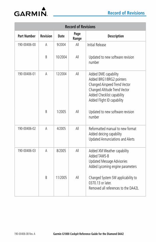
190-00406-00 A 9/2004 All Initial Release
B 10/2004 All Updated to new software revision number
190-00406-01 A 12/2004 All Added DME capabilityAdded BRG1/BRG2 pointersChanged Airspeed Trend VectorChanged Altitude Trend VectorAdded Checklist capabilityAdded Flight ID capability
B 1/2005 All Updated to new software revision number
190-00406-02 A 4/2005 All Reformatted manual to new formatAdded deicing capabilityUpdated Annunciations and Alerts
190-00406-03 A 8/2005 All Added XM Weather capabilityAdded TAWS-BUpdated Message AdvisoriesAdded Lycoming engine parameters
B 11/2005 All Changed System SW applicability to0370.13 or later.Removed all references to the DA42L
Garmin G1000 Cockpit Reference Guide for the Diamond Da42 190-00406-08 Rev. A
Record of Revisions
Record of Revisions
Part Number Revision DatePage
RangeDescription
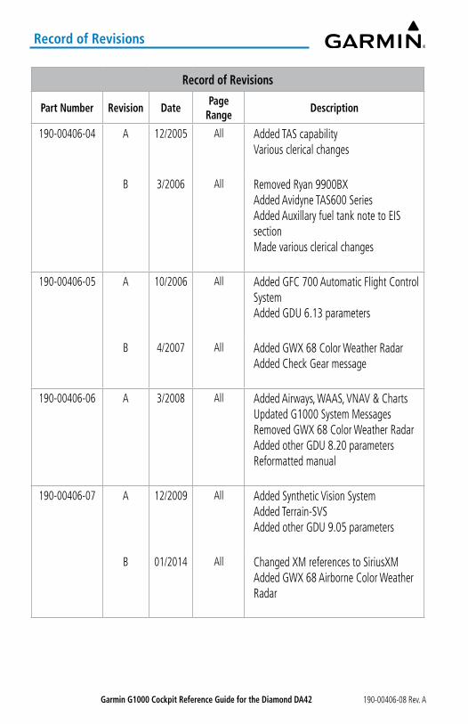
190-00406-04 A 12/2005 All Added TAS capabilityVarious clerical changes
B 3/2006 All Removed Ryan 9900BXAdded Avidyne TAS600 SeriesAdded Auxillary fuel tank note to EIS sectionMade various clerical changes
190-00406-05 A 10/2006 All Added GFC 700 Automatic Flight Control SystemAdded GDU 6.13 parameters
B 4/2007 All Added GWX 68 Color Weather RadarAdded Check Gear message
190-00406-06 A 3/2008 All Added Airways, WAAS, VNAV & ChartsUpdated G1000 System MessagesRemoved GWX 68 Color Weather RadarAdded other GDU 8.20 parametersReformatted manual
190-00406-07 A 12/2009 All Added Synthetic Vision SystemAdded Terrain-SVSAdded other GDU 9.05 parameters
B 01/2014 All Changed XM references to SiriusXMAdded GWX 68 Airborne Color Weather Radar

Garmin G1000 Cockpit Reference Guide for the Diamond Da42190-00406-08 Rev. A
Record of Revisions
Record of Revisions
Part Number Revision DatePage
RangeDescription
190-00406-08 A 03/2022 All Production Release for GDU 15.11Updated WAAS InformationUpdated Database InformationAdded Smart Airspace®
Updated Transponder InformationUpdated Traffic InformationUpdated Terrain Awareness InformationUpdated Approach InformationUpdated AFCS InformationAdded Bluetooth® Management InformationAdded Database Management Information

Garmin G1000 Cockpit Reference Guide for the Diamond Da42 190-00406-08 Rev. A
Record of Revisions
Blank Page
Garmin G1000 Cockpit Reference Guide for the Diamond Da42190-00406-08 Rev. A i
Table of Contents
FLIGHT INSTRUMENTS ............................................................................................. 1
FLIGHT INSTRUMENTS ................................................................................................................ 1airspeed Indicator ...................................................................................................................... 1altimeter ...................................................................................................................................... 1Horizontal Situation Indicator (HSI) ......................................................................................... 2DME Information Window ......................................................................................................... 3Course Deviation Indicator (CDI) .............................................................................................. 3
SUPPLEMENTaL FLIGHT DaTa ................................................................................................... 4Generic Timer .............................................................................................................................. 4outside air Temperature ............................................................................................................ 4Wind Data .................................................................................................................................... 4Synthetic Vision Technology (SVT) ............................................................................................ 5PFD annunciations and alerting Functions .............................................................................. 6
ENGINE INDICaTIoN SySTEM (EIS) ................................................................... 7
EIS DISPLay .................................................................................................................................... 7Engine Indicating System .......................................................................................................... 7
aUDIo aND CNS ....................................................................................................... 19
CoM oPERaTIoN ........................................................................................................................ 19
NaV oPERaTIoN ......................................................................................................................... 19
MoDE S TRaNSPoNDER ........................................................................................................... 21
aUDIo PaNEL PREFLIGHT PRoCEDURE ................................................................................ 21
FLIGHT MaNaGEMENT ......................................................................................... 23
USING MaP DISPLayS ............................................................................................................... 23Map orientation........................................................................................................................ 23Map Range ................................................................................................................................. 24Map Panning .............................................................................................................................. 24Measuring Bearing and Distance ............................................................................................ 25Topography ................................................................................................................................ 25Map Display Symbols ............................................................................................................... 26
WayPoINTS .................................................................................................................................. 28airports ...................................................................................................................................... 28Non-airport and User Created Waypoints ............................................................................. 29
Garmin G1000 Cockpit Reference Guide for the Diamond Da42 190-00406-08 Rev. Aii
Table of Contents
aIRSPaCES .................................................................................................................................... 33Smart airspace .......................................................................................................................... 34
FLIGHT PLaNNING ...................................................................................................................... 34Direct-To Navigation ................................................................................................................ 34Flight Plan Display .................................................................................................................... 37Creating a Basic Flight Plan ..................................................................................................... 37Flight Plan Waypoint and airway Modifications ................................................................... 38Flight Plan Waypoint Constraints ............................................................................................ 41Flight Plan Vertical Navigation ............................................................................................... 43Vertical Navigation Direct-To .................................................................................................. 44Flight Plan operations.............................................................................................................. 44Managing Flight Plans .............................................................................................................. 49
PRoCEDURES ............................................................................................................................... 56Departures ................................................................................................................................. 57arrivals ...................................................................................................................................... 59approaches ............................................................................................................................... 61
TRIP PLaNNING ........................................................................................................................... 69
RECEIVER aUToNoMoUS INTEGRITy MoNIToRING (RaIM) PREDICTIoN .................. 70
HaZaRD aVoIDaNCE ............................................................................................. 73
SIRIUSXM WEaTHER .................................................................................................................. 73activating Services ................................................................................................................... 73Using SiriusXM Weather Products .......................................................................................... 74
SToRMSCoPE LIGHTNING ........................................................................................................ 79Setting Up Stormscope on the ‘MaP - NaVIGaTIoN MaP’ Page......................................... 79
aIRBoRNE CoLoR WEaTHER RaDaR .................................................................................... 80Ground Mapping and Interpretation ...................................................................................... 83
TERRaIN PRoXIMITy ................................................................................................................. 84Displaying Terrain Proximity Data .......................................................................................... 84‘MaP-TERRaIN PRoXIMITy’ Page ............................................................................................ 85
PRoFILE VIEW TERRaIN ............................................................................................................ 85
TERRaIN-SVT ............................................................................................................................... 86Displaying Terrain-SVT Data .................................................................................................... 86MaP-TERRaIN-SVS’ Page ......................................................................................................... 87
Garmin G1000 Cockpit Reference Guide for the Diamond Da42190-00406-08 Rev. A iii
Table of Contents
TRaFFIC INFoRMaTIoN SERVICE (TIS).................................................................................. 88Displaying TRaFFIC Data .......................................................................................................... 88‘MaP-TRaFFIC MaP’ Page ........................................................................................................ 89TIS alerts .................................................................................................................................... 89
aVIDyNE TaS600 (TaS) (oPTIoNaL) ...................................................................................... 90Displaying Traffic Data ............................................................................................................. 90altitude Display ........................................................................................................................ 91‘MaP-TRaFFIC MaP’ Page Display Range .............................................................................. 91TaS alerts ................................................................................................................................... 92
aUToMaTIC FLIGHT CoNTRoL SySTEM........................................................ 93
aFCS oVERVIEW ......................................................................................................................... 93Basic autopilot operation ....................................................................................................... 93
FLIGHT DIRECToR oPERaTIoN................................................................................................ 94activating the Flight Director ................................................................................................. 94
aFCS MoDES ............................................................................................................................... 95Vertical Modes .......................................................................................................................... 95Lateral Modes............................................................................................................................ 96Combination Modes ................................................................................................................. 96
aDDITIoNaL FEaTURES ...................................................................................... 101
SaFETaXI .................................................................................................................................... 101
ELECTRoNIC CHaRTS (oPTIoNaL) ....................................................................................... 101ChartView ................................................................................................................................ 102FliteCharts ............................................................................................................................... 104
SIRIUSXM SaTELLITE RaDIo (oPTIoNaL) .......................................................................... 106activating SiriusXM Satellite Radio Services ...................................................................... 106Using SiriusXM Radio ............................................................................................................. 107
SCHEDULER ................................................................................................................................ 108
ELECTRoNIC CHECKLISTS (oPTIoNaL) ............................................................................... 109
BLUETooTH MaNaGEMENT .................................................................................................. 110
DaTaBaSE MaNaGEMENT ..................................................................................................... 111
PILoT PRoFILES ......................................................................................................................... 112
SCHEDULER ................................................................................................................................ 115
Garmin G1000 Cockpit Reference Guide for the Diamond Da42 190-00406-08 Rev. Aiv
Table of Contents
aBNoRMaL oPERaTIoN .................................................................................... 117Reversionary Mode ................................................................................................................. 117abnormal GPS Conditions ..................................................................................................... 117Garmin SVT Troubleshooting ................................................................................................. 118SVT in Reversionary Mode ..................................................................................................... 118Unusual attitudes ................................................................................................................... 118SVT Unusual attitudes ............................................................................................................ 120audio Panel Fail-Safe operation ........................................................................................... 120Stuck Microphone ................................................................................................................... 120CoM Tuning Failure ................................................................................................................. 120Reversionary Mode ................................................................................................................. 121Dead Reckoning ...................................................................................................................... 121abnormal Radar Status annunciations ................................................................................ 121Suspected autopilot Malfunction ......................................................................................... 122overpowering autopilot Servos ........................................................................................... 122Datalink Troubleshooting ....................................................................................................... 122
aNNUNCIaTIoNS & aLERTS .............................................................................. 125System annunciations ............................................................................................................ 125Crew Profile Import/Export Messages ................................................................................. 126
FLIGHT PLaNNING .................................................................................................................... 127Nearest airspace ..................................................................................................................... 127Managing Flight Plans ............................................................................................................ 127
RaDaR aNNUNCIaTIoNS ........................................................................................................ 129Radar Modes ........................................................................................................................... 129antenna Stabilization annunciations ................................................................................... 129
TERRaIN/oBSTaCLE aNNUNCIaTIoNS ................................................................................ 129Terrain-SVT alerts Summary .................................................................................................. 129 Terrain-SVT System Test Status annunciations ................................................................... 130‘MaP-TERRaIN-SVS’ Page Status annunciations ................................................................. 130
TRaFFIC aNNUNCIaTIoNS ..................................................................................................... 131TIS Failure annunciations ....................................................................................................... 131TIS Modes ................................................................................................................................ 131TIS Traffic Status annunciations ............................................................................................ 131TaS Modes ............................................................................................................................... 132
Garmin G1000 Cockpit Reference Guide for the Diamond Da42190-00406-08 Rev. A v
Table of Contents
TaS Failure annunciations ...................................................................................................... 132TaS Traffic Status annunciations ........................................................................................... 133
aFCS aLERTS .............................................................................................................................. 133aFCS Status alerts .................................................................................................................. 133
CaS MESSaGES ......................................................................................................................... 134Warning CaS Messages .......................................................................................................... 134Caution CaS Messages ........................................................................................................... 135advisory CaS Messages ......................................................................................................... 135
SySTEM aNNUNCIaTIoNS ...................................................................................................... 136Message annunciations ......................................................................................................... 136Voice alerts .............................................................................................................................. 136
SySTEM MESSaGE aDVISoRIES ........................................................................................... 136
aPPENDIX .................................................................................................................. 153
DaTaBaSE MaNaGEMENT ..................................................................................................... 153Navigation Databases ............................................................................................................ 153Dual Navigation Database Feature ..................................................................................... 154Garmin Databases .................................................................................................................. 155
SoFTKEy MaPS ......................................................................................................................... 158PFD Softkeys ............................................................................................................................ 158MFD Softkeys .......................................................................................................................... 161
FLIGHT MaNaGEMENT SyMBoLS ........................................................................................ 162PFD Navigation Status Box .................................................................................................... 162Map Display Symbols ............................................................................................................. 163Flight Planning ........................................................................................................................ 167
TERRaIN/oBSTaCLE SyMBoLS .............................................................................................. 169Terrain Proximity ..................................................................................................................... 169Profile View Terrain/obstacle Colors and Symbology ........................................................ 169Terrain-SVT obstacle Colors and Symbology ...................................................................... 169Terrain-SVT Potential Impact Point Symbols ...................................................................... 170
INDEX ...................................................................................................................... Index-1
INDEX ...................................................................................................................................... Index-1

Garmin G1000 Cockpit Reference Guide for the Diamond Da42 190-00406-08 Rev. Avi
Table of Contents
Blank Page
Garmin G1000 Cockpit Reference Guide for the Diamond Da42190-00406-08 Rev. A 1
FlightInstrum
entsEIS
Nav/Com
/XPD
R/Audio
Flight M
anagement
Hazard
AvoidanceA
FCSA
dditionalFeatures
Annun/A
lertsA
ppendixIndex
Flight Instruments
FlightInstrum
entsEIS
Nav/Com
/XPD
R/Audio
Flight M
anagement
Hazard
AvoidanceA
FCSA
dditionalFeatures
Abnorm
alO
perationA
nnun/Alerts
Appendix
IndexFlight
Instruments
EISN
av/Com/
XPDR/A
udioFlight
Managem
entH
azardAvoidance
AFCS
AdditionalFeatures
Abnorm
alO
perationA
nnun/Alerts
Appendix
IndexFlight
Instruments
EISN
av/Com/
XPDR/A
udioFlight
Managem
entH
azardAvoidance
AFCS
AdditionalFeatures
Abnorm
alO
perationA
nnun/Alerts
Appendix
IndexFlight
Instruments
EISa
udio andCN
SFlight
Managem
entH
azardavoidance
aFCS
additionalFeatures
abnorm
alo
perationa
nnun/alerts
appendix
Index
FLIGHT INSTRUMENTSFLIGHT INSTRUMENTSaIRSPEED INDICaToR
Changing Vspeeds and turning Vspeed bugs on/off:1) Press the TMR/REF Softkey.2) Turn the large FMS Knob to highlight the field of the desired Vspeed to be changed.3) Turn the small FMS Knob to enter the desired value. When a speed has been changed
from a default value, an asterisk appears next to the speed.4) Press the ENT Key or turn the large FMS Knob to highlight the ON/OFF field.5) Turn the small FMS Knob clockwise to ON or counterclockwise to OFF.6) To remove the window, press the CLR Key or the TMR/REF Softkey.
Turning all Vspeed bugs on/off:1) Press the TMR/REF Softkey.2) Press the MENU Key.3) To activate all Vspeed bugs, press the ENT Key with All References On highlighted.4) To remove all Vspeed bugs, turn the FMS Knob to highlight All References Off and press
the ENT Key.
Restoring all Vspeed defaults:1) Press the TMR/REF Softkey.2) Press the MENU Key.3) Turn the FMS Knob to highlight Restore Defaults and press the ENT Key.
aLTIMETERSetting the Selected altitude: Turn the aLT Knob to set the Selected Altitude (large knob for 1000-ft increments, small
knob for 100-ft increments. If set, the Minimum Descent Altitude/Decision Height (MDA/DH) value is also available for
the Selected Altitude.
Displaying altitude in meters:1) Press the PFD Softkey to display the second-level softkeys.2) Press the aLT UNIT Softkey.3) Press the METERS Softkey to turn on metric altitude displays.4) Press the BaCK Softkey to return to the top-level softkeys.
Garmin G1000 Cockpit Reference Guide for the Diamond Da42 190-00406-08 Rev. A2
Flig
htIn
stru
men
tsEI
SN
av/C
om/
XPD
R/A
udio
Flig
ht
Man
agem
ent
Haz
ard
Avoi
danc
eA
FCS
Add
ition
alFe
atur
esA
nnun
/Ale
rts
App
endi
xIn
dex
Flight Instruments
Flig
htIn
stru
men
tsEI
SN
av/C
om/
XPD
R/A
udio
Flig
ht
Man
agem
ent
Haz
ard
Avoi
danc
eA
FCS
Add
ition
alFe
atur
esA
bnor
mal
Ope
ratio
nA
nnun
/Ale
rts
App
endi
xIn
dex
Flig
htIn
stru
men
tsEI
SN
av/C
om/
XPD
R/A
udio
Flig
ht
Man
agem
ent
Haz
ard
Avoi
danc
eA
FCS
Add
ition
alFe
atur
esA
bnor
mal
Ope
ratio
nA
nnun
/Ale
rts
App
endi
xIn
dex
Flig
htIn
stru
men
tsEI
SN
av/C
om/
XPD
R/A
udio
Flig
ht
Man
agem
ent
Haz
ard
Avoi
danc
eA
FCS
Add
ition
alFe
atur
esA
bnor
mal
Ope
ratio
nA
nnun
/Ale
rts
App
endi
xIn
dex
Flig
htIn
stru
men
tsEI
Sa
udio
and
CN
SFl
ight
M
anag
emen
tH
azar
dav
oida
nce
aFC
Sa
dditi
onal
Feat
ures
abn
orm
alo
pera
tion
ann
un/a
lert
sa
ppen
dix
Inde
x
Selecting the altimeter barometric pressure setting: Turn the BaRo Knob to select the desired setting.
Selecting standard barometric pressure (29.92 in Hg):1) Press the PFD Softkey to display the second-level softkeys..2) Press the STD BaRo Softkey; STD BARO is displayed in barometric setting box.
Changing altimeter barometric pressure setting units:1) Press the PFD Softkey to display the second-level softkeys.2) Press the aLT UNIT Softkey.3) Press the IN Softkey to display the barometric pressure setting in inches of mercury (in
Hg). Or, press the HPa Softkey to display the barometric pressure setting in hectopascals (hPa).4) Press the BaCK Softkey to return to the top-level softkeys.
HoRIZoNTaL SITUaTIoN INDICaToR (HSI)Changing the HSI display format:1) Press the PFD Softkey2) Press the HSI FRMT Softkey.3) Press the 360 HSI or aRC HSI Softkey.
adjusting the selected heading: Turn the HDG Knob to set the selected heading. Push the HDG Knob to synchronize the bug to the current heading.
adjusting the Selected Course: Turn the CRS Knob to set the Selected Course. Push the CRS Knob to re-center the CDI and return the course pointer to the bearing of
the active waypoint or navigation station.
Changing the navigation angle true/magnetic setting:1) Use the FMS Knob to select the ‘AUX - SYSTEM SETUP’ Page on the MFD.2) Push the FMS Knob to activate the cursor.3) Turn the large FMS Knob to highlight Nav Angle in the Display Units box.4) Turn the small FMS Knob to highlight the desired setting and press the ENT Key. • TRUE - References angles to true north (T) • MAGNETIC - Angles corrected to the computed magnetic variation (Mag Var)
Garmin G1000 Cockpit Reference Guide for the Diamond Da42190-00406-08 Rev. A 3
FlightInstrum
entsEIS
Nav/Com
/XPD
R/Audio
Flight M
anagement
Hazard
AvoidanceA
FCSA
dditionalFeatures
Annun/A
lertsA
ppendixIndex
Flight Instruments
FlightInstrum
entsEIS
Nav/Com
/XPD
R/Audio
Flight M
anagement
Hazard
AvoidanceA
FCSA
dditionalFeatures
Abnorm
alO
perationA
nnun/Alerts
Appendix
IndexFlight
Instruments
EISN
av/Com/
XPDR/A
udioFlight
Managem
entH
azardAvoidance
AFCS
AdditionalFeatures
Abnorm
alO
perationA
nnun/Alerts
Appendix
IndexFlight
Instruments
EISN
av/Com/
XPDR/A
udioFlight
Managem
entH
azardAvoidance
AFCS
AdditionalFeatures
Abnorm
alO
perationA
nnun/Alerts
Appendix
IndexFlight
Instruments
EISa
udio andCN
SFlight
Managem
entH
azardavoidance
aFCS
additionalFeatures
abnorm
alo
perationa
nnun/alerts
appendix
Index
Bearing Pointers and Information Windows
Selecting bearing display and changing sources:1) Press the PFD Softkey.2) Press a BRG Softkey to display the desired bearing pointer and information window with
a NAV source.3) Press the BRG Softkey again to change the bearing source to GPS.4) Press the BRG Softkey again to change the bearing source to ADF.5) To remove the bearing pointer and information window, press the BRG Softkey again.
DME INFoRMaTIoN WINDoWDisplaying the DME Information Window:1) Press the PFD Softkey.2) Press the DME Softkey to display the DME Information Window.3) To remove the DME Information Window, press the DME Softkey again.
CoURSE DEVIaTIoN INDICaToR (CDI)Changing navigation sources:1) Press the CDI Softkey to change from GPS to VOR1 or LOC1. This places the cyan tuning
box over the NAV1 standby frequency in the upper left corner of the PFD.2) Press the CDI Softkey again to change from VOR1 or LOC1 to VOR2 or LOC2. This places
the cyan tuning box over the NAV2 standby frequency.3) Press the CDI Softkey a third time to return to GPS.
Changing the selected GPS CDI setting:1) Use the FMS Knob to select the ‘AUX - SYSTEM SETUP’ Page on the MFD.2) Push the FMS Knob to activate the cursor.3) Turn the large FMS Knob to highlight Selected in the GPS CDI box.4) Turn the small FMS Knob to highlight the desired setting and press the ENT Key.5) To cancel the selection, push the FMS Knob or press the CLR Key.
Enabling/disabling oBS Mode while navigating a GPS flight plan:1) Press the oBS Softkey to select OBS Mode.2) Turn the CRS Knob to select the desired course to/from the waypoint. Push the CRS
Knob to synchronize the Selected Course with the bearing to the next waypoint.3) Press the oBS Softkey again to return to automatic waypoint sequencing.
Garmin G1000 Cockpit Reference Guide for the Diamond Da42 190-00406-08 Rev. A4
Flig
htIn
stru
men
tsEI
SN
av/C
om/
XPD
R/A
udio
Flig
ht
Man
agem
ent
Haz
ard
Avoi
danc
eA
FCS
Add
ition
alFe
atur
esA
nnun
/Ale
rts
App
endi
xIn
dex
Flight Instruments
Flig
htIn
stru
men
tsEI
SN
av/C
om/
XPD
R/A
udio
Flig
ht
Man
agem
ent
Haz
ard
Avoi
danc
eA
FCS
Add
ition
alFe
atur
esA
bnor
mal
Ope
ratio
nA
nnun
/Ale
rts
App
endi
xIn
dex
Flig
htIn
stru
men
tsEI
SN
av/C
om/
XPD
R/A
udio
Flig
ht
Man
agem
ent
Haz
ard
Avoi
danc
eA
FCS
Add
ition
alFe
atur
esA
bnor
mal
Ope
ratio
nA
nnun
/Ale
rts
App
endi
xIn
dex
Flig
htIn
stru
men
tsEI
SN
av/C
om/
XPD
R/A
udio
Flig
ht
Man
agem
ent
Haz
ard
Avoi
danc
eA
FCS
Add
ition
alFe
atur
esA
bnor
mal
Ope
ratio
nA
nnun
/Ale
rts
App
endi
xIn
dex
Flig
htIn
stru
men
tsEI
Sa
udio
and
CN
SFl
ight
M
anag
emen
tH
azar
dav
oida
nce
aFC
Sa
dditi
onal
Feat
ures
abn
orm
alo
pera
tion
ann
un/a
lert
sa
ppen
dix
Inde
x
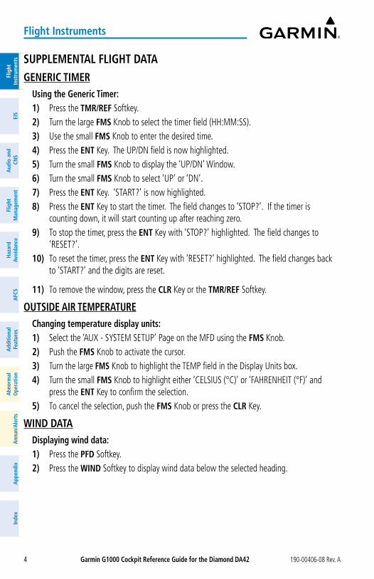
SUPPLEMENTaL FLIGHT DaTaGENERIC TIMER
Using the Generic Timer:1) Press the TMR/REF Softkey.2) Turn the large FMS Knob to select the timer field (HH:MM:SS).3) Use the small FMS Knob to enter the desired time.4) Press the ENT Key. The UP/DN field is now highlighted.5) Turn the small FMS Knob to display the ‘UP/DN’ Window.6) Turn the small FMS Knob to select ‘UP’ or ‘DN’.7) Press the ENT Key. ‘START?’ is now highlighted.8) Press the ENT Key to start the timer. The field changes to ‘STOP?’. If the timer is
counting down, it will start counting up after reaching zero.9) To stop the timer, press the ENT Key with ‘STOP?’ highlighted. The field changes to
‘RESET?’.10) To reset the timer, press the ENT Key with ‘RESET?’ highlighted. The field changes back
to ‘START?’ and the digits are reset.
11) To remove the window, press the CLR Key or the TMR/REF Softkey.
oUTSIDE aIR TEMPERaTUREChanging temperature display units:1) Select the ‘AUX - SYSTEM SETUP’ Page on the MFD using the FMS Knob.2) Push the FMS Knob to activate the cursor.3) Turn the large FMS Knob to highlight the TEMP field in the Display Units box.4) Turn the small FMS Knob to highlight either ‘CELSIUS (°C)’ or ‘FAHRENHEIT (°F)’ and
press the ENT Key to confirm the selection.5) To cancel the selection, push the FMS Knob or press the CLR Key.
WIND DaTaDisplaying wind data:1) Press the PFD Softkey.2) Press the WIND Softkey to display wind data below the selected heading.
Garmin G1000 Cockpit Reference Guide for the Diamond Da42190-00406-08 Rev. A 5
FlightInstrum
entsEIS
Nav/Com
/XPD
R/Audio
Flight M
anagement
Hazard
AvoidanceA
FCSA
dditionalFeatures
Annun/A
lertsA
ppendixIndex
Flight Instruments
FlightInstrum
entsEIS
Nav/Com
/XPD
R/Audio
Flight M
anagement
Hazard
AvoidanceA
FCSA
dditionalFeatures
Abnorm
alO
perationA
nnun/Alerts
Appendix
IndexFlight
Instruments
EISN
av/Com/
XPDR/A
udioFlight
Managem
entH
azardAvoidance
AFCS
AdditionalFeatures
Abnorm
alO
perationA
nnun/Alerts
Appendix
IndexFlight
Instruments
EISN
av/Com/
XPDR/A
udioFlight
Managem
entH
azardAvoidance
AFCS
AdditionalFeatures
Abnorm
alO
perationA
nnun/Alerts
Appendix
IndexFlight
Instruments
EISa
udio andCN
SFlight
Managem
entH
azardavoidance
aFCS
additionalFeatures
abnorm
alo
perationa
nnun/alerts
appendix
Index
3) Press one of the oPTN Softkeys to change how wind data is displayed: • oPTN 1: Wind direction arrows with numeric headwind or tailwind and crosswind
components • oPTN 2: Wind direction arrow and numeric speed • oPTN 3: Total wind direction arrow with numeric headwind or tailwind and crosswind
speed components4) To remove the window, press the oFF Softkey.
SyNTHETIC VISIoN TECHNoLoGy (SVT)
WaRNING: Use appropriate primary systems for navigation, and for terrain, obstacle, and traffic avoidance. SVT is intended as an aid to situational awareness only and may not provide either the accuracy or reliability upon which to solely base decisions and/or plan maneuvers to avoid terrain, obstacles, or traffic.
activating and deactivating SVT:1) Press the PFD Softkey.2) Press the SyN VIS Softkey.3) Press the SyN TERR Softkey. The SVT display will cycle on or off with the SyN TERR
Softkey.
activating and deactivating Pathways:1) Press the PFD Softkey.2) Press the SyN VIS Softkey.3) Press the PaTHWay Softkey. The Pathway feature will cycle on or off with the PaTHWay
Softkey.
activating and deactivating Horizon Headings:1) Press the PFD Softkey.2) Press the SyN VIS Softkey.3) Press the HRZN HDG Softkey. The horizon heading display will cycle on or off with the
HRZN HDG Softkey.
activating and deactivating airport Signs:1) Press the PFD Softkey.2) Press the SyN VIS Softkey.3) Press the aPTSIGNS Softkey. Display of airport signs will cycle on or off with the
aPTSIGNS Softkey.

Garmin G1000 Cockpit Reference Guide for the Diamond Da42 190-00406-08 Rev. A6
Flig
htIn
stru
men
tsEI
SN
av/C
om/
XPD
R/A
udio
Flig
ht
Man
agem
ent
Haz
ard
Avoi
danc
eA
FCS
Add
ition
alFe
atur
esA
nnun
/Ale
rts
App
endi
xIn
dex
Flight Instruments
Flig
htIn
stru
men
tsEI
SN
av/C
om/
XPD
R/A
udio
Flig
ht
Man
agem
ent
Haz
ard
Avoi
danc
eA
FCS
Add
ition
alFe
atur
esA
bnor
mal
Ope
ratio
nA
nnun
/Ale
rts
App
endi
xIn
dex
Flig
htIn
stru
men
tsEI
SN
av/C
om/
XPD
R/A
udio
Flig
ht
Man
agem
ent
Haz
ard
Avoi
danc
eA
FCS
Add
ition
alFe
atur
esA
bnor
mal
Ope
ratio
nA
nnun
/Ale
rts
App
endi
xIn
dex
Flig
htIn
stru
men
tsEI
SN
av/C
om/
XPD
R/A
udio
Flig
ht
Man
agem
ent
Haz
ard
Avoi
danc
eA
FCS
Add
ition
alFe
atur
esA
bnor
mal
Ope
ratio
nA
nnun
/Ale
rts
App
endi
xIn
dex
Flig
htIn
stru
men
tsEI
Sa
udio
and
CN
SFl
ight
M
anag
emen
tH
azar
dav
oida
nce
aFC
Sa
dditi
onal
Feat
ures
abn
orm
alo
pera
tion
ann
un/a
lert
sa
ppen
dix
Inde
x
Configuring field of view:1) While viewing the ‘MAP - NAVIGATION MAP’ Page, press the MENU Key to display the
‘PAGE MENU’.
2) Turn the large FMS Knob to highlight Map Setup and press the ENT Key.3) Turn the FMS Knob to select the Map Group and press the ENT Key.4) Turn the large FMS Knob to scroll through the Map Group options to FIELD OF VIEW.5) Turn the small FMS Knob to select On or Off.6) Push the FMS Knob to return to the ‘MAP - NAVIGATION MAP’ Page.
PFD aNNUNCIaTIoNS aND aLERTING FUNCTIoNSSetting the Minimum Descent altitude/Decision Height and bug:1) Press the TMR/REF Softkey.2) Turn the large FMS Knob to highlight the Minimums field.3) Turn the small FMS Knob to select the desired altitude source: barometric (BARO) or
temperature compensated (TEMP COMP). OFF is selected by default. Press the ENT Key or turn the large FMS Knob to highlight the next field.
4) Use the small FMS Knob to enter the desired altitude for minimums.5) If using temperature compensated (TEMP COMP), use the small FMS Knob to enter
destination air temperature.5) To remove the window, press the CLR Key or the TMR/REF Softkey.
Garmin G1000 Cockpit Reference Guide for the Diamond Da42190-00406-08 Rev. A 7
Engine Indication System
FlightInstrum
entsEIS
Nav/Com
/XPD
R/Audio
Flight M
anagement
Hazard
AvoidanceA
FCSA
dditionalFeatures
Annun/A
lertsA
ppendixIndex
FlightInstrum
entsEIS
audio and
CNS
Flight M
anagement
Hazard
avoidancea
FCSa
dditionalFeatures
abnorm
alo
perationa
nnun/alerts
appendix
Index
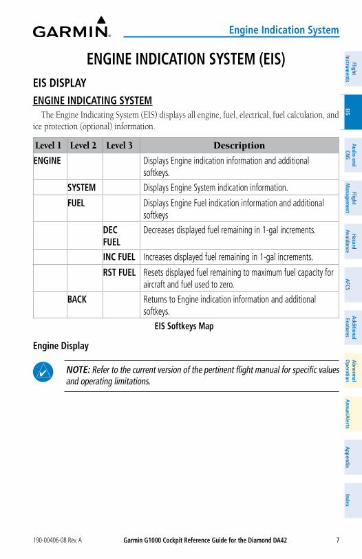
ENGINE INDICaTIoN SySTEM (EIS)EIS DISPLayENGINE INDICaTING SySTEM
The Engine Indicating System (EIS) displays all engine, fuel, electrical, fuel calculation, and ice protection (optional) information.
Level 1 Level 2 Level 3 Description
ENGINE Displays Engine indication information and additional softkeys.
SySTEM Displays Engine System indication information.
FUEL Displays Engine Fuel indication information and additional softkeys
DEC FUEL
Decreases displayed fuel remaining in 1-gal increments.
INC FUEL Increases displayed fuel remaining in 1-gal increments.
RST FUEL Resets displayed fuel remaining to maximum fuel capacity for aircraft and fuel used to zero.
BaCK Returns to Engine indication information and additional softkeys.
EIS Softkeys Map
Engine Display
NoTE: Refer to the current version of the pertinent flight manual for specific values and operating limitations.
Garmin G1000 Cockpit Reference Guide for the Diamond Da42 190-00406-08 Rev. A8
Engine Indication System
Flig
htIn
stru
men
tsEI
SN
av/C
om/
XPD
R/A
udio
Flig
ht
Man
agem
ent
Haz
ard
Avoi
danc
eA
FCS
Add
ition
alFe
atur
esA
nnun
/Ale
rts
App
endi
xIn
dex
Flig
htIn
stru
men
tsEI
Sa
udio
and
CNS
Flig
ht
Man
agem
ent
Haz
ard
avoi
danc
ea
FCS
add
ition
alFe
atur
esa
bnor
mal
ope
ratio
na
nnun
/ale
rts
app
endi
xIn
dex
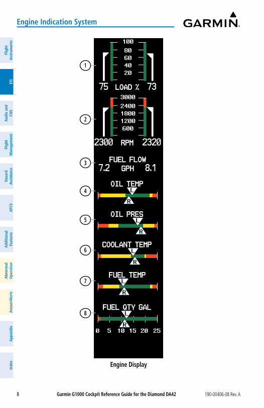
Engine Display
1
2
3
4
5
6
7
8
Garmin G1000 Cockpit Reference Guide for the Diamond Da42190-00406-08 Rev. A 9
Engine Indication System
FlightInstrum
entsEIS
Nav/Com
/XPD
R/Audio
Flight M
anagement
Hazard
AvoidanceA
FCSA
dditionalFeatures
Annun/A
lertsA
ppendixIndex
FlightInstrum
entsEIS
audio and
CNS
Flight M
anagement
Hazard
avoidancea
FCSa
dditionalFeatures
abnorm
alo
perationa
nnun/alerts
appendix
Index
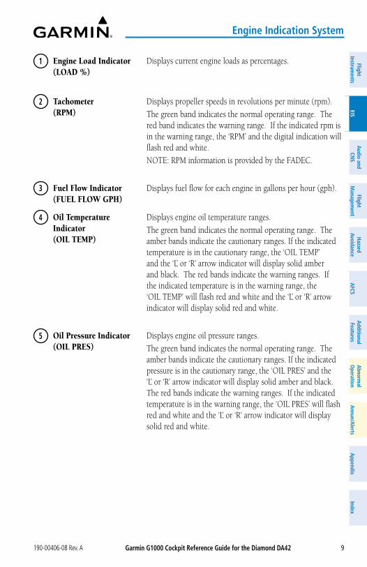
1 Engine Load Indicator (LOAD %)
Displays current engine loads as percentages.
2 Tachometer (RPM)
Displays propeller speeds in revolutions per minute (rpm).
The green band indicates the normal operating range. The red band indicates the warning range. If the indicated rpm is in the warning range, the ‘RPM’ and the digital indication will flash red and white.
NOTE: RPM information is provided by the FADEC.
3 Fuel Flow Indicator (FUEL FLOW GPH)
Displays fuel flow for each engine in gallons per hour (gph).
4 Oil Temperature Indicator (OIL TEMP)
Displays engine oil temperature ranges.
The green band indicates the normal operating range. The amber bands indicate the cautionary ranges. If the indicated temperature is in the cautionary range, the ‘OIL TEMP’ and the ‘L’ or ‘R’ arrow indicator will display solid amber and black. The red bands indicate the warning ranges. If the indicated temperature is in the warning range, the ‘OIL TEMP’ will flash red and white and the ‘L’ or ‘R’ arrow indicator will display solid red and white.
5 Oil Pressure Indicator (OIL PRES)
Displays engine oil pressure ranges.
The green band indicates the normal operating range. The amber bands indicate the cautionary ranges. If the indicated pressure is in the cautionary range, the ‘OIL PRES’ and the ‘L’ or ‘R’ arrow indicator will display solid amber and black. The red bands indicate the warning ranges. If the indicated temperature is in the warning range, the ‘OIL PRES’ will flash red and white and the ‘L’ or ‘R’ arrow indicator will display solid red and white.
Garmin G1000 Cockpit Reference Guide for the Diamond Da42 190-00406-08 Rev. A10
Engine Indication System
Flig
htIn
stru
men
tsEI
SN
av/C
om/
XPD
R/A
udio
Flig
ht
Man
agem
ent
Haz
ard
Avoi
danc
eA
FCS
Add
ition
alFe
atur
esA
nnun
/Ale
rts
App
endi
xIn
dex
Flig
htIn
stru
men
tsEI
Sa
udio
and
CNS
Flig
ht
Man
agem
ent
Haz
ard
avoi
danc
ea
FCS
add
ition
alFe
atur
esa
bnor
mal
ope
ratio
na
nnun
/ale
rts
app
endi
xIn
dex
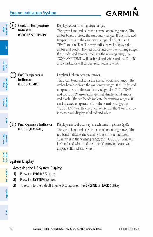
6 Coolant Temperature Indicator (COOLANT TEMP)
Displays coolant temperature ranges.
The green band indicates the normal operating range. The amber bands indicate the cautionary ranges. If the indicated temperature is in the cautionary range, the ‘COOLANT TEMP’ and the ‘L’ or ‘R’ arrow indicator will display solid amber and black. The red bands indicate the warning ranges. If the indicated temperature is in the warning range, the ‘COOLANT TEMP’ will flash red and white and the ‘L’ or ‘R’ arrow indicator will display solid red and white.
7 Fuel Temperature Indicator (FUEL TEMP)
Displays fuel temperature ranges.
The green band indicates the normal operating range. The amber bands indicate the cautionary ranges. If the indicated temperature is in the cautionary range, the ‘FUEL TEMP’ and the ‘L’ or ‘R’ arrow indicator will display solid amber and black. The red bands indicate the warning ranges. If the indicated temperature is in the warning range, the ‘FUEL TEMP’ will flash red and white and the ‘L’ or ‘R’ arrow indicator will display solid red and white.
8 Fuel Quantity Indicator (FUEL QTY GAL)
Displays the fuel quantity in each tank in gallons (gal).
The green band indicates the normal operating range. The red band indicates the warning range. If the indicated quantity is in the warning range, the ‘FUEL QTY GAL’ will flash red and white and the ‘L’ or ‘R’ arrow indicator will display solid red and white.
System Display
accessing the EIS System Display:1) Press the ENGINE Softkey.2) Press the SySTEM Softkey.3) To return to the default Engine Display, press the ENGINE or BaCK Softkey.
Garmin G1000 Cockpit Reference Guide for the Diamond Da42190-00406-08 Rev. A 11
Engine Indication System
FlightInstrum
entsEIS
Nav/Com
/XPD
R/Audio
Flight M
anagement
Hazard
AvoidanceA
FCSA
dditionalFeatures
Annun/A
lertsA
ppendixIndex
FlightInstrum
entsEIS
audio and
CNS
Flight M
anagement
Hazard
avoidancea
FCSa
dditionalFeatures
abnorm
alo
perationa
nnun/alerts
appendix
IndexSystem Display
1
2
3
4
5
6
7
8
9
Garmin G1000 Cockpit Reference Guide for the Diamond Da42 190-00406-08 Rev. A12
Engine Indication System
Flig
htIn
stru
men
tsEI
SN
av/C
om/
XPD
R/A
udio
Flig
ht
Man
agem
ent
Haz
ard
Avoi
danc
eA
FCS
Add
ition
alFe
atur
esA
nnun
/Ale
rts
App
endi
xIn
dex
Flig
htIn
stru
men
tsEI
Sa
udio
and
CNS
Flig
ht
Man
agem
ent
Haz
ard
avoi
danc
ea
FCS
add
ition
alFe
atur
esa
bnor
mal
ope
ratio
na
nnun
/ale
rts
app
endi
xIn
dex
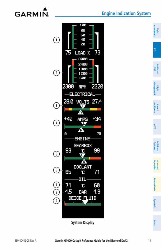
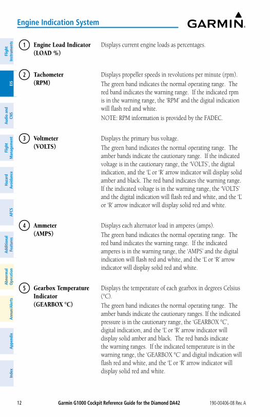
1 Engine Load Indicator (LOAD %)
Displays current engine loads as percentages.
2 Tachometer (RPM)
Displays propeller speeds in revolutions per minute (rpm).
The green band indicates the normal operating range. The red band indicates the warning range. If the indicated rpm is in the warning range, the ‘RPM’ and the digital indication will flash red and white.
NOTE: RPM information is provided by the FADEC.
3 Voltmeter (VOLTS)
Displays the primary bus voltage.
The green band indicates the normal operating range. The amber bands indicate the cautionary range. If the indicated voltage is in the cautionary range, the ‘VOLTS’, the digital indication, and the ‘L’ or ‘R’ arrow indicator will display solid amber and black. The red band indicates the warning range. If the indicated voltage is in the warning range, the ‘VOLTS’ and the digital indication will flash red and white, and the ‘L’ or ‘R’ arrow indicator will display solid red and white.
4 Ammeter (AMPS)
Displays each alternator load in amperes (amps).
The green band indicates the normal operating range. The red band indicates the warning range. If the indicated amperes is in the warning range, the ‘AMPS’ and the digital indication will flash red and white, and the ‘L’ or ‘R’ arrow indicator will display solid red and white.
5 Gearbox Temperature Indicator (GEARBOX °C)
Displays the temperature of each gearbox in degrees Celsius (°C).
The green band indicates the normal operating range. The amber bands indicate the cautionary ranges. If the indicated pressure is in the cautionary range, the ‘GEARBOX °C’, digital indication, and the ‘L’ or ‘R’ arrow indicator will display solid amber and black. The red bands indicate the warning ranges. If the indicated temperature is in the warning range, the ‘GEARBOX °C’ and digital indication will flash red and white, and the ‘L’ or ‘R’ arrow indicator will display solid red and white.
Garmin G1000 Cockpit Reference Guide for the Diamond Da42190-00406-08 Rev. A 13
Engine Indication System
FlightInstrum
entsEIS
Nav/Com
/XPD
R/Audio
Flight M
anagement
Hazard
AvoidanceA
FCSA
dditionalFeatures
Annun/A
lertsA
ppendixIndex
FlightInstrum
entsEIS
audio and
CNS
Flight M
anagement
Hazard
avoidancea
FCSa
dditionalFeatures
abnorm
alo
perationa
nnun/alerts
appendix
Index
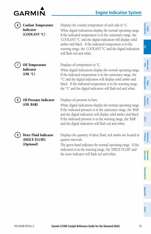
6 Coolant Temperature Indicator (COOLANT °C)
Displays the coolant temperature of each side in °C.
White digital indications display the normal operating range. If the indicated temperature is in the cautionary range, the ‘COOLANT °C’ and the digital indication will display solid amber and black. If the indicated temperature is in the warning range, the ‘COOLANT °C’ and the digital indication will flash red and white.
7 Oil Temperature Indicator (OIL °C)
Displays oil temperature in °C.
White digital indications display the normal operating range. If the indicated temperature is in the cautionary range, the ‘°C’ and the digital indication will display solid amber and black. If the indicated temperature is in the warning range, the ‘°C’ and the digital indication will flash red and white.
8 Oil Pressure Indicator (OIL BAR)
Displays oil pressure in bars.
White digital indications display the normal operating range. If the indicated pressure is in the cautionary range, the ‘BAR’ and the digital indication will display solid amber and black. If the indicated pressure is in the warning range, the ‘BAR’ and the digital indication will flash red and white.
9 Deice Fluid Indicator (DEICE FLUID) (Optional)
Displays the quantity of deice fluid; tick marks are located at quarter intervals.
The green band indicates the normal operating range. If the indication is in the warning range, the ‘DEICE FLUID’ and the arow indicator will flash red and white.
Garmin G1000 Cockpit Reference Guide for the Diamond Da42 190-00406-08 Rev. A14
Engine Indication System
Flig
htIn
stru
men
tsEI
SN
av/C
om/
XPD
R/A
udio
Flig
ht
Man
agem
ent
Haz
ard
Avoi
danc
eA
FCS
Add
ition
alFe
atur
esA
nnun
/Ale
rts
App
endi
xIn
dex
Flig
htIn
stru
men
tsEI
Sa
udio
and
CNS
Flig
ht
Man
agem
ent
Haz
ard
avoi
danc
ea
FCS
add
ition
alFe
atur
esa
bnor
mal
ope
ratio
na
nnun
/ale
rts
app
endi
xIn
dex
Fuel Display
NoTE: Fuel calculations do not use the aircraft fuel quantity indicators and are calculated from the last time the fuel was reset.
NoTE: If optional auxiliary fuel tanks are installed, the fuel remaining can be adjusted up to a maximum of 76.4 gal; the Fuel Quantity Indicator does not account for fuel in the auxiliary tanks.
accessing the EIS Fuel Display:1) Press the ENGINE Softkey.2) Press the FUEL Softkey.3) To return to the default Engine Display, press the ENGINE or BaCK Softkey.
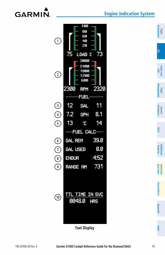
Garmin G1000 Cockpit Reference Guide for the Diamond Da42190-00406-08 Rev. A 15
Engine Indication System
FlightInstrum
entsEIS
Nav/Com
/XPD
R/Audio
Flight M
anagement
Hazard
AvoidanceA
FCSA
dditionalFeatures
Annun/A
lertsA
ppendixIndex
FlightInstrum
entsEIS
audio and
CNS
Flight M
anagement
Hazard
avoidancea
FCSa
dditionalFeatures
abnorm
alo
perationa
nnun/alerts
appendix
IndexFuel Display
1
2
3
4
5
6
7
8
9
10
Garmin G1000 Cockpit Reference Guide for the Diamond Da42 190-00406-08 Rev. A16
Engine Indication System
Flig
htIn
stru
men
tsEI
SN
av/C
om/
XPD
R/A
udio
Flig
ht
Man
agem
ent
Haz
ard
Avoi
danc
eA
FCS
Add
ition
alFe
atur
esA
nnun
/Ale
rts
App
endi
xIn
dex
Flig
htIn
stru
men
tsEI
Sa
udio
and
CNS
Flig
ht
Man
agem
ent
Haz
ard
avoi
danc
ea
FCS
add
ition
alFe
atur
esa
bnor
mal
ope
ratio
na
nnun
/ale
rts
app
endi
xIn
dex
1 Engine Load Indicator (LOAD %)
Displays current engine loads as percentages.
2 Tachometer (RPM)
Displays propeller speeds in revolutions per minute (RPM).
The green band indicates the normal operating range. The red band indicates the warning range. If the indicated rpm is in the warning range, the ‘RPM’ and the digital indication will flash red and white.
NOTE: RPM information is provided by the FADEC.
3 Fuel Quantity Indicator (FUEL GAL)
Displays fuel in each tank in gallons (GAL).
White digital indications display the normal operating range. If the indicated quantity is in the warning range, the digital indication and ‘GAL’ will flash red and white.
4 Fuel Flow Indicator (FUEL GPH)
Displays fuel flow for each engine in gallons per hour (GPH).
5 Fuel Temperature Indicator (FUEL °C)
Displays fuel temperature for each tank in degrees Celsius (°C).
White digital indications display the normal operating range. If the indicated temperature is in the cautionary range, the ‘°C’ and the digital indication will display solid amber and black. If the indicated temperature is in the warning range, the ‘°C’ and the digital indication will flash red and white.
6 Set Fuel Remaining (GAL REM)
Displays current fuel remaining (GAL) as set by the pilot and adjusted for fuel burn since last set.
7 Calculated Fuel Used (GAL USED)
Displays quantity of fuel used (GAL) based on fuel flow since last reset.
8 Calculated Endurance (ENDUR)
Displays flight time remaining (HH:MM) based on the calculated fuel remaining.
9 Calculated Range (RANGE NM)
Displays aircraft range in nautical miles (NM) based on the calculated fuel remaining.

Garmin G1000 Cockpit Reference Guide for the Diamond Da42190-00406-08 Rev. A 17
Engine Indication System
FlightInstrum
entsEIS
Nav/Com
/XPD
R/Audio
Flight M
anagement
Hazard
AvoidanceA
FCSA
dditionalFeatures
Annun/A
lertsA
ppendixIndex
FlightInstrum
entsEIS
audio and
CNS
Flight M
anagement
Hazard
avoidancea
FCSa
dditionalFeatures
abnorm
alo
perationa
nnun/alerts
appendix
Index
10 Total Time in Service (TTL TIME IN SVC)
Displays the aircraft’s total flight hours (HRS); activated when the aircraft becomes airborne.
Fuel CalCulations
NoTE: Fuel calculations do not use the aircraft fuel quantity indicators and are calculated from the last time the fuel was reset.
NoTE: The Fuel Quantity Indicator shows 25 gallons per side when full.
Fuel calculations are based on the fuel flow totalizer and the displayed fuel remaining (GAL REM), adjusted by the pilot using the following softkeys:
adjusting the fuel totalizer quantity: From the Fuel Display, press the DEC FUEL or INC FUEL Softkey to obtain the desired
number of gallons remaining (GAL REM).
Resetting the fuel totalizer: From the Fuel Display, press the RST FUEL Softkey. This also resets the displayed fuel
remaining (GAL REM) to zero.
Enabling/disabling the Fuel Range Ring and selecting a reserve fuel time:1) Display the ‘MAP - NAVIGATION MAP’ Page (press and hold the CLR Key for 2
seconds to quickly select this map).2) Press the MENU Key.3) Highlight ‘Map Setup’ and press the ENT Key. The ‘MAP SETUP’ Menu is displayed.4) Use the small FMS Knob to select the ‘Map’ group and press the ENT Key.5) Highlight the ‘FUEL RNG (RSV)’ Field.6) Turn the small FMS Knob to select ‘On’ or ‘Off’.7) Turn the large FMS Knob to highlight the reserve fuel time, how long the aircraft can fly
after reaching the reserve fuel.8) Enter the desired reserve fuel time (00+00 to 23+59; hours+minutes) and press the ENT
Key.9) Press the FMS Knob to return to the ‘MAP - NAVIGATION MAP’ Page.
Garmin G1000 Cockpit Reference Guide for the Diamond Da42 190-00406-08 Rev. A18
Engine Indication System
Flig
htIn
stru
men
tsEI
SN
av/C
om/
XPD
R/A
udio
Flig
ht
Man
agem
ent
Haz
ard
Avoi
danc
eA
FCS
Add
ition
alFe
atur
esA
nnun
/Ale
rts
App
endi
xIn
dex
Flig
htIn
stru
men
tsEI
Sa
udio
and
CNS
Flig
ht
Man
agem
ent
Haz
ard
avoi
danc
ea
FCS
add
ition
alFe
atur
esa
bnor
mal
ope
ratio
na
nnun
/ale
rts
app
endi
xIn
dex
Blank Page
Garmin G1000 Cockpit Reference Guide for the Diamond Da42190-00406-08 Rev. A 19
audio and CNS
FlightInstrum
entsEIS
Nav/Com
/XPD
R/Audio
Flight M
anagement
Hazard
AvoidanceA
FCSA
dditionalFeatures
Annun/A
lertsA
ppendixIndex
FlightInstrum
entsEIS
audio and
CNS
Flight M
anagement
Hazard
avoidancea
FCSa
dditionalFeatures
abnorm
alo
perationa
nnun/alerts
appendix
Index
aUDIo aND CNSCoM oPERaTIoN
Manually tuning a CoM frequency:1) Turn the CoM Knob to tune the desired frequency in the ‘COM TUNING’ Box (large knob
for MHz; small knob for kHz).2) Press the Frequency Transfer Key to transfer the frequency to the active field.3) Adjust the volume level with the COM VoL/SQ Knob.4) Push the COM VoL/SQ Knob to turn automatic squelch on and off.
auto-tuning a CoM frequency for a nearby airport from the PFD:1) Press the NRST Softkey on the PFD to open the ‘NEAREST AIRPORTS’ Window. A list of
25 nearest airport identifiers and COM frequencies is displayed.2) Turn the FMS Knob to scroll through the list and highlight the desired COM frequency.3) Press the ENT Key to load the COM frequency into the COM Standby Tuning Box.4) Press the Frequency Transfer Key to transfer the frequency to the COM Active Frequency
Field.
auto-tuning a CoM frequency from the WPT and NRST Pages:1) From any page the COM frequency can be auto-tuned, activate the cursor by pushing the
FMS Knob or pressing the appropriate softkey.2) Turn the FMS Knob to place the cursor on the desired COM frequency.3) Press the ENT Key to load the COM frequency into the standby field of the selected COM
radio.4) Press the Frequency Transfer Key to transfer the frequency to the COM Active Frequency
Field.
Changing CoM frequency channel spacing:1) Select the ‘AUX – SYSTEM SETUP’ Page.2) Push the FMS Knob to activate the flashing cursor.3) Turn the large FMS Knob to highlight the Channel Spacing Field in the ‘COM CONFIG’
Box.4) Turn the small FMS Knob to select the desired channel spacing.5) Press the ENT Key to complete the channel spacing selection.
NaV oPERaTIoNManually tuning a NaV frequency:1) Turn the NaV Knob to tune the desired frequency in the NAV Tuning Box.
Garmin G1000 Cockpit Reference Guide for the Diamond Da42 190-00406-08 Rev. A20
audio and CNS
Flig
htIn
stru
men
tsEI
SN
av/C
om/
XPD
R/A
udio
Flig
ht
Man
agem
ent
Haz
ard
Avoi
danc
eA
FCS
Add
ition
alFe
atur
esA
nnun
/Ale
rts
App
endi
xIn
dex
Flig
htIn
stru
men
tsEI
Sa
udio
and
CNS
Flig
ht
Man
agem
ent
Haz
ard
avoi
danc
ea
FCS
add
ition
alFe
atur
esa
bnor
mal
ope
ratio
na
nnun
/ale
rts
app
endi
xIn
dex
2) Press the Frequency Transfer Key to transfer the frequency to the NAV Active Frequency Field.
3) Adjust the volume level with the NAV VoL/ID Knob.4) Push the NAV VoL/ID Knob to turn the Morse code identifier audio on and off.
auto-tuning a NaV frequency from the WPT and NRST Pages:1) From any page the NAV frequency can be auto-tuned, activate the cursor by pushing the
FMS Knob or the appropriate softkey.2) Turn the large FMS Knob to place the cursor on the desired NAV identifier or NAV
frequency.3) On the ‘WPT - VOR INFORMATION’ and ‘NRST - NEAREST AIRPORTS’ pages, press the
FREQ Softkey to place the cursor on the NAV frequency.4) Press the ENT Key to load the NAV frequency into the standby field of the selected NAV
radio.5) Press the Frequency Transfer Key to transfer the frequency to the NAV Active Frequency
Field.Tuning an aDF frequency:1) Press the aDF/DME Softkey to display the ‘ADF/DME TUNING’ Window.2) Turn the large FMS Knob to place the selection cursor over the standby ADF frequency
field.3) Turn the small FMS Knob to begin data entry and change each digit.4) Turn the large FMS Knob to move the cursor to the next digit position.5) Press the ENT Key to complete data entry for the standby frequency.
Transferring the active and standby aDF frequencies:1) Turn the large FMS Knob to place the selection cursor over the standby ADF frequency
field.2) Press the ENT Key to complete the frequency transfer.
Selecting an aDF receiver mode:
1) Turn the large FMS Knob to place the selection cursor over the ADF mode field.2) Turn the small FMS Knob to select the desired ADF receiver mode.
adjusting aDF receiver volume:1) Turn the large FMS Knob to place the selection cursor over the ADF volume field.2) Turn the small FMS Knob to adjust volume as desired.
Selecting DME transceiver pairing:1) Press the aDF/DME Softkey to display the ‘ADF/DME TUNING’ Window.2) Turn the small FMS Knob to select the DME tuning mode.3) Press the ENT Key to complete the selection.
Garmin G1000 Cockpit Reference Guide for the Diamond Da42190-00406-08 Rev. A 21
audio and CNS
FlightInstrum
entsEIS
Nav/Com
/XPD
R/Audio
Flight M
anagement
Hazard
AvoidanceA
FCSA
dditionalFeatures
Annun/A
lertsA
ppendixIndex
FlightInstrum
entsEIS
audio and
CNS
Flight M
anagement
Hazard
avoidancea
FCSa
dditionalFeatures
abnorm
alo
perationa
nnun/alerts
appendix
Index
MoDE S TRaNSPoNDERSelecting a transponder mode:1) Press the XPDR Softkey to display the Transponder Mode Selection Softkeys.2) Press the desired softkey to activate the transponder mode.
Entering a transponder code with softkeys:1) Press the XPDR Softkey to display the Transponder Mode Selection Softkeys.2) Press the CoDE Softkey to display the Transponder Code Selection Softkeys, for digit entry.3) Press the digit softkeys to enter the code in the code field. When entering the code, the
next softkey in sequence must be pressed within 10 seconds, or the entry is cancelled and restored to the previous code. Pressing the BKSP Softkey moves the code selection cursor to the previous digit. Five seconds after the fourth digit has been entered, the transponder code becomes active.
Entering a transponder code with the PFD FMS Knob:1) Press the XPDR and the CoDE Softkeys as in the previous procedure to enable code entry.2) Turn the small FMS Knob on the PFD to enter the first two code digits.3) Turn the large FMS Knob to move the cursor to the next code field.4) Enter the last two code digits with the small FMS Knob.5) Press the ENT Key to complete code digit entry.
Entering a Flight ID:1) Press the TMR/REF Softkey to display the ‘REFERENCES’ Window.2) Push the FMS Knob to activate the selection cursor, if not already activated.3) Turn the large FMS Knob to scroll down to the Flight ID.4) Turn the small FMS Knob to enter the desired Flight ID.5) Press the ENT Key to complete Flight ID entry.
aUDIo PaNEL PREFLIGHT PRoCEDURESetting the audio Panel during preflight:1) Verify the PILOT and COPLT Annunciations are extinguished.2) Verify manual squelch is set to full open.3) Turn the PILoT/PaSS Knobs clockwise two full turns. This sets the intercom level to max
volume (least amount of attenuation).4) Adjust radio volume levels (COM, NAV) to a suitable level.5) Adjust the PILoT/PaSS Knob volume to the desired intercom level.6) Reset squelch to automatic, or adjust to the appropriate level manually.
Garmin G1000 Cockpit Reference Guide for the Diamond Da42 190-00406-08 Rev. A22
audio and CNS
Flig
htIn
stru
men
tsEI
SN
av/C
om/
XPD
R/A
udio
Flig
ht
Man
agem
ent
Haz
ard
Avoi
danc
eA
FCS
Add
ition
alFe
atur
esA
nnun
/Ale
rts
App
endi
xIn
dex
Flig
htIn
stru
men
tsEI
Sa
udio
and
CNS
Flig
ht
Man
agem
ent
Haz
ard
avoi
danc
ea
FCS
add
ition
alFe
atur
esa
bnor
mal
ope
ratio
na
nnun
/ale
rts
app
endi
xIn
dex
Blank Page
Garmin G1000 Cockpit Reference Guide for the Diamond Da42190-00406-08 Rev. A 23
Flight Management
FlightInstrum
entsEIS
Nav/Com
/XPD
R/Audio
Flight M
anagement
Hazard
AvoidanceA
FCSA
dditionalFeatures
Annun/A
lertsA
ppendixIndex
FlightInstrum
entsEIS
audio and
CNS
Flight M
anagement
Hazard
avoidancea
FCSa
dditionalFeatures
abnorm
alo
perationa
nnun/alerts
appendix
Index
FLIGHT MaNaGEMENTChanging a field in the MFD Navigation Data Bar:1) Select the ‘AUX – SYSTEM SETUP ’ Page.2) Push the FMS Knob momentarily to activate the flashing cursor. 3) Turn the large FMS Knob to highlight the desired field number in the ‘MFD DATA BAR
FIELDS’ Box.4) Turn the small FMS Knob to display and scroll through the data options list to select the
desired data.5) Press the ENT Key. Pressing the DFLTS Softkey returns all fields to the default setting.
USING MaP DISPLayS
MaP oRIENTaTIoNChanging the orientation for map displays:1) With the ‘MAP – NAVIGATION MAP’ Page displayed, press the MENU Key. The cursor
flashes on the ‘Map Setup’ option.2) Press the ENT Key to display the ‘MAP SETUP’ Window.3) Select the ‘Map’ Group.4) Press the ENT Key.5) Turn the small FMS Knob to select the desired orientation.6) Press the ENT Key to select the new orientation.7) Push the FMS Knob to return to the base page.
Enabling/disabling auto North Up and selecting the minimum switching range:1) With the ‘MAP – NAVIGATION MAP’ Page displayed, press the MENU Key. The cursor
flashes on the ‘Map Setup’ option.2) Press the ENT Key to display the ‘MAP SETUP’ Window.3) Select the ‘Map’ Group.4) Press the ENT Key.5) Highlight the ‘AUTO NORTH UP’ Field.6) Select ‘On’ or ‘Off’ using the small FMS Knob. 7) Press the ENT Key to accept the selected option. The flashing cursor highlights the Range
Field. 8) Use the small FMS Knob to select the desired range. 9) Press the ENT Key to accept the selected option. 10) Push the FMS Knob to return to the ‘MAP – NAVIGATION MAP’ Page.
Garmin G1000 Cockpit Reference Guide for the Diamond Da42 190-00406-08 Rev. A24
Flight Management
Flig
htIn
stru
men
tsEI
SN
av/C
om/
XPD
R/A
udio
Flig
ht
Man
agem
ent
Haz
ard
Avoi
danc
eA
FCS
Add
ition
alFe
atur
esA
nnun
/Ale
rts
App
endi
xIn
dex
Flig
htIn
stru
men
tsEI
Sa
udio
and
CNS
Flig
ht
Man
agem
ent
Haz
ard
avoi
danc
ea
FCS
add
ition
alFe
atur
esa
bnor
mal
ope
ratio
na
nnun
/ale
rts
app
endi
xIn
dex
MaP RaNGEConfiguring automatic zoom:1) Press the MENU Key with the ‘MAP – NAVIGATION MAP’ Page displayed. The cursor
flashes on the ‘Map Setup’ option.2) Press the ENT Key. The ‘MAP SETUP’ Window is displayed. 3) Turn the small FMS Knob to select the ‘Map’ Group.4) Press the ENT Key.5) Turn the large FMS Knob to highlight the ‘AUTO ZOOM’ On/Off Field, and select ‘Off’ or
‘On’ using the small FMS Knob.6) Press the ENT Key to accept the selected option. The flashing cursor highlights the ‘AUTO
ZOOM’ display selection Field.7) Select ‘MFD’, ‘PFD’, or ‘ALL’ using the small FMS Knob.8) Press the ENT Key to accept the selected option. The flashing cursor highlights the ‘MAX
LOOK FWD’ Field. Times are from zero to 999 minutes.9) Use the FMS Knob to set the time. Press the ENT Key.10) Repeat Step 9 for ‘MIN LOOK FWD’ (zero to 99 minutes) and ‘TIME OUT’ (zero to 99
minutes).
11) Push the FMS Knob to return to the ‘MAP – NAVIGATION MAP’ Page.
MaP PaNNINGPanning the map:1) With the desired map display shown on the MFD, push the Joystick to display the Map
Pointer.2) Move the Joystick to move the Map Pointer around the map.3) Push the Joystick to remove the Map Pointer and recenter the map on the aircraft’s
current position.
Reviewing information for an airport, NaVaID, or user waypoint:1) With the desired map display shown on the MFD, push the Joystick to display the Map
Pointer and place the Map Pointer on a waypoint.2) Press the ENT Key to display the information page for the selected waypoint.3) Press the Go BaCK Softkey, the CLR Key, or the ENT Key to exit the information page
and return to the ‘MAP – NAVIGATION MAP’ Page.
Reviewing information for a special-use or controlled airspace:1) With the desired map display shown on the MFD, push the Joystick to display the Map
Pointer. Place the Map Pointer on the boundary of an airspace. Information about the airspace is displayed on the map next to the map pointer.
Garmin G1000 Cockpit Reference Guide for the Diamond Da42190-00406-08 Rev. A 25
Flight Management
FlightInstrum
entsEIS
Nav/Com
/XPD
R/Audio
Flight M
anagement
Hazard
AvoidanceA
FCSA
dditionalFeatures
Annun/A
lertsA
ppendixIndex
FlightInstrum
entsEIS
audio and
CNS
Flight M
anagement
Hazard
avoidancea
FCSa
dditionalFeatures
abnorm
alo
perationa
nnun/alerts
appendix
Index
2) Push the Joystick to remove the Map Pointer and center the map on the aircraft. or:1) With the desired map display shown on the MFD, push the Joystick to display the Map
Pointer and place the Map Pointer on an open area within the boundaries of an airspace.2) Press the ENT Key to display an options menu.3) ‘Review Airspaces’ should already be highlighted, if not select it. Press the ENT Key to
view information for the airspace.4) Push the FMS Knob, or press the CLR or ENT Key to return to the map display.
MEaSURING BEaRING aND DISTaNCEMeasuring bearing and distance between any two points:1) Press the MENU Key (with the ‘MAP – NAVIGATION MAP’ Page displayed).2) Use the FMS Knob to highlight the ‘Measure Bearing/Distance’ Field.3) Press the ENT Key. A Measure Pointer is displayed on the map at the aircraft’s present
position.4) Move the Joystick to place the reference pointer at the desired location. The bearing and
distance are displayed at the top of the map. Elevation at the current pointer position is also displayed. Pressing the ENT Key changes the starting point for measuring.
5) To exit the Measure Bearing/Distance option, push the Joystick; or select ‘Stop Measuring’ from the ‘PAGE MENU’ Window and press the ENT Key.
ToPoGRaPHyDisplaying/removing topographic data on MFD map displays:1) Press the MaP Softkey on the ‘MAP – NAVIGATION MAP’ Page. 2) Press the ToPo Softkey.3) Press the ToPo Softkey again to remove topographic data from the Navigation Map.
When topographic data is removed from the page, all navigation data is presented on a black background.
Displaying/removing topographic data on the Inset Map:1) Press the INSET Softkey.2) Press the ToPo Softkey.3) Press the ToPo Softkey again to remove topographic data from the Inset Map. When
topographic data is removed from the page, all navigation data is presented on a black background.
Selecting a topographical data range:1) Press the MENU Key with the ‘MAP – NAVIGATION MAP’ Page displayed. The cursor
flashes on the ‘Map Setup’ option.2) Press the ENT Key. The ‘MAP SETUP’ Window is displayed.
Garmin G1000 Cockpit Reference Guide for the Diamond Da42 190-00406-08 Rev. A26
Flight Management
Flig
htIn
stru
men
tsEI
SN
av/C
om/
XPD
R/A
udio
Flig
ht
Man
agem
ent
Haz
ard
Avoi
danc
eA
FCS
Add
ition
alFe
atur
esA
nnun
/Ale
rts
App
endi
xIn
dex
Flig
htIn
stru
men
tsEI
Sa
udio
and
CNS
Flig
ht
Man
agem
ent
Haz
ard
avoi
danc
ea
FCS
add
ition
alFe
atur
esa
bnor
mal
ope
ratio
na
nnun
/ale
rts
app
endi
xIn
dex
3) Turn the small FMS Knob to select the ‘Map’ Group.4) Press the ENT Key. 5) Use the large FMS Knob to highlight the TERRAIN DATA Range Field. Ranges are from
500 FT to 2000 nm.6) To change the TERRAIN DATA Range setting, turn the small FMS Knob to display the
range list.7) Select the desired range using the small FMS Knob. 8) Press the ENT Key.9) Push the FMS Knob to return to the ‘MAP – NAVIGATION MAP’ Page.
Displaying/removing the topographic data scale:1) Press the MENU Key with the ‘MAP – NAVIGATION MAP’ Page displayed. The cursor
flashes on the ‘Map Setup’ option.2) Press the ENT Key. The ‘MAP SETUP’ Window is displayed.3) Turn the small FMS Knob to select the ‘Map’ Group and press the ENT Key.4) Turn the large FMS Knob to highlight the ‘TOPO SCALE’ Field.5) Turn the small FMS Knob to select ‘On’ or ‘Off’. Press the ENT Key.6) Push the FMS Knob to return to the ‘MAP – NAVIGATION MAP’ Page.
Displaying/removing Profile View:1) Press the MaP Softkey on the ‘MAP – NAVIGATION MAP’ Page. 2) Press the PRoFILE Softkey to enable or disable Profile View. or:1) Press the MENU Key.2) Select ‘Show Profile View’ or ‘Hide Profile View’ and press the ENT Key.
MaP DISPLay SyMBoLSSymbol Setup
Setting up the ‘Land’, ‘aviation’, or ‘airways’ Group items:1) Press the MENU Key with the ‘MAP – NAVIGATION MAP’ Page displayed. The cursor
flashes on the ‘Map Setup’ option.2) Press the ENT Key. The ‘MAP SETUP’ Window is displayed.3) Turn the small FMS Knob to select the desired group.4) Press the ENT Key. The cursor flashes on the first field.5) Turn the large FMS Knob to select the desired option.6) Turn the small FMS Knob to select the desired setting (e.g. On/Off or maximum range).7) Press the ENT Key to accept the selected option and move the cursor to the next item.
Garmin G1000 Cockpit Reference Guide for the Diamond Da42190-00406-08 Rev. A 27
Flight Management
FlightInstrum
entsEIS
Nav/Com
/XPD
R/Audio
Flight M
anagement
Hazard
AvoidanceA
FCSA
dditionalFeatures
Annun/A
lertsA
ppendixIndex
FlightInstrum
entsEIS
audio and
CNS
Flight M
anagement
Hazard
avoidancea
FCSa
dditionalFeatures
abnorm
alo
perationa
nnun/alerts
appendix
Index
8) Repeat Steps 5 through 7 as necessary.9) Push the FMS Knob to return to the ‘MAP – NAVIGATION MAP’ Page.
Displaying/removing airways:1) Press the MaP Softkey with the ‘MAP – NAVIGATION MAP’ Page displayed. 2) Press the aIRWayS Softkey. Both High and Low Altitude Airways are displayed (AIRWY
On).3) Press the softkey again to display Low Altitude Airways only (AIRWY LO).4) Press the softkey again to display High Altitude Airways only (AIRWY HI). 5) Press the softkey again to remove High Altitude Airways. No airways are displayed.
Selecting an airway range:1) Press the MENU Key with the ‘MAP – NAVIGATION MAP’ Page displayed. The cursor
flashes on the ‘Map Setup’ option.2) Press the ENT Key. The ‘MAP SETUP’ Window is displayed. 3) Turn the small FMS Knob to select the ‘Airways’ Group, and press the ENT Key.4) Turn the large FMS Knob to highlight the LOW ALT AIRWAY Range Field or HI ALT
AIRWAY Range Field. 5) To change the range setting, turn the small FMS Knob to display the range list.6) Select the desired range using the small FMS Knob. 7) Press the ENT Key.8) Push the FMS Knob to return to the ‘MAP – NAVIGATION MAP’ Page.
Map Declutter
Decluttering the MFD map display: Press the DCLTR Softkey with the ‘MAP – NAVIGATION MAP’ Page displayed. The current
declutter level is shown. With each softkey press, another level of map information is removed.
Decluttering the PFD Inset Map:1) Press the INSET Softkey.2) Press the DCLTR Softkey. The current declutter level is shown. With each selection,
another level of map information is removed.
additional Map display Items
Setting up additional ‘Map’ Group items:1) Press the MENU Key with the ‘MAP – NAVIGATION MAP’ Page displayed. The cursor
flashes on the ‘Map Setup’ option.2) Press the ENT Key. The ‘MAP SETUP’ Window is displayed.
Garmin G1000 Cockpit Reference Guide for the Diamond Da42 190-00406-08 Rev. A28
Flight Management
Flig
htIn
stru
men
tsEI
SN
av/C
om/
XPD
R/A
udio
Flig
ht
Man
agem
ent
Haz
ard
Avoi
danc
eA
FCS
Add
ition
alFe
atur
esA
nnun
/Ale
rts
App
endi
xIn
dex
Flig
htIn
stru
men
tsEI
Sa
udio
and
CNS
Flig
ht
Man
agem
ent
Haz
ard
avoi
danc
ea
FCS
add
ition
alFe
atur
esa
bnor
mal
ope
ratio
na
nnun
/ale
rts
app
endi
xIn
dex
3) Turn the small FMS Knob to select the ‘Map’ Group.4) Press the ENT Key. The cursor flashes on the first field.5) Turn the large FMS Knob to select the desired option.6) Turn the small FMS Knob to select ‘On’ or ‘Off’. or: If it is a data field, use the FMS Knob to select the range or time value.7) Press the ENT Key to accept the selected option and move the cursor to the next item.8) Repeat Steps 5 through 7, as necessary.9) Push the FMS Knob to return to the ‘MAP – NAVIGATION MAP’ Page.
WayPoINTSaIRPoRTS
Selecting an airport for review by identifier, facility name, or location:1) From the ‘WPT – AIRPORT INFORMATION’ Page (INFo-1 Softkey), push the FMS Knob.2) Use the FMS Knob and enter an identifier, facility name, or location within the ‘AIRPORT’
Box.3) Press the ENT Key.4) Push the FMS Knob to remove the flashing cursor.
Selecting a runway:1) With the ‘WPT – AIRPORT INFORMATION’ Page (INFo-1 Softkey) displayed, push the
FMS Knob to activate the cursor.2) Turn the large FMS Knob to place the cursor in the ‘RUNWAYS’ Box, on the runway
designator.3) Turn the small FMS Knob to display the desired runway (if more than one) for the
selected airport. 4) To remove the flashing cursor, push the FMS Knob.
Viewing a destination airport:
From the ‘WPT – AIRPORT INFORMATION’ Page (INFo-1 Softkey) press the MENU Key. Select ‘View Destination Airport’. The Destination Airport is displayed.
Viewing information for a nearest airport on the PFD:1) Press the NRST Softkey to display the ‘NEAREST AIRPORTS’ Window2) Highlight the airport identifier with the FMS Knob and press the ENT Key to display the
‘AIRPORT INFORMATION’ Window.
Garmin G1000 Cockpit Reference Guide for the Diamond Da42190-00406-08 Rev. A 29
Flight Management
FlightInstrum
entsEIS
Nav/Com
/XPD
R/Audio
Flight M
anagement
Hazard
AvoidanceA
FCSA
dditionalFeatures
Annun/A
lertsA
ppendixIndex
FlightInstrum
entsEIS
audio and
CNS
Flight M
anagement
Hazard
avoidancea
FCSa
dditionalFeatures
abnorm
alo
perationa
nnun/alerts
appendix
Index
3) To return to the ‘NEAREST AIRPORTS’ Window press the ENT Key (with the cursor on ‘BACK’) or press the CLR Key. The cursor is now on the next airport in the nearest airports list. (Repeatedly pressing the ENT Key moves through the airport list, alternating between the ‘NEAREST AIRPORTS’ Window and the ‘AIRPORT INFORMATION’ Window).
4) Press the CLR Key or the NRST Softkey to close the PFD ‘NEAREST AIRPORTS’ Window.
Viewing information for a nearest airport on the MFD:1) Turn the FMS Knob to select the ‘NRST – NEAREST AIRPORTS’ Page (it is the first page
of the group, so it may already be selected). If there are no Nearest Airports available, “NONE WITHIN 200NM” is displayed.
2) Press the aPT Softkey; or push the FMS Knob; or press the MENU Key, highlight ‘Select Airport Window’ and press the ENT Key. The cursor is placed in the ‘NEAREST AIRPORTS’ Box. The first airport in the nearest airports list is highlighted.
3) Turn the FMS Knob to highlight the desired airport. (Pressing the ENT Key also moves to the next airport.)
4) Push the FMS Knob to remove the flashing cursor.
Viewing runway information for a specific airport:1) With the ‘NRST – NEAREST AIRPORTS’ Page displayed, press the RNWy Softkey; or press
the MENU Key, highlight ‘Select Runway Window’; and press the ENT Key. The cursor is placed in the ‘RUNWAYS’ Box.
2) Turn the small FMS Knob to select the desired runway.3) Push the FMS Knob to remove the flashing cursor.
Selecting nearest airport surface and minimum runway length matching criteria:1) Use the FMS Knob to select the ‘AUX – SYSTEM SETUP’ Page.2) Push the FMS Knob momentarily to activate the flashing cursor.3) Turn the large FMS Knob to highlight the ‘RNWY SURFACE’ Field in the ‘NEAREST APT’
Box.4) Turn the small FMS Knob to select the desired runway option (ANY, HARD ONLY, HARD/
SOFT, WATER).5) Press the ENT Key. The cursor moves to the ‘MIN LENGTH’ Field in the ‘NEAREST APT’
Box.6) Use the FMS Knob to enter the minimum runway length (zero to 25,000 feet) and press
the ENT Key.7) Push the FMS Knob to remove the flashing cursor.
NoN-aIRPoRT aND USER CREaTED WayPoINTSViewing Waypoint Information:1) Turn the FMS Knob to select the desired ‘WPT’ Page.2) Push the FMS Knob to display the flashing cursor.
Garmin G1000 Cockpit Reference Guide for the Diamond Da42 190-00406-08 Rev. A30
Flight Management
Flig
htIn
stru
men
tsEI
SN
av/C
om/
XPD
R/A
udio
Flig
ht
Man
agem
ent
Haz
ard
Avoi
danc
eA
FCS
Add
ition
alFe
atur
esA
nnun
/Ale
rts
App
endi
xIn
dex
Flig
htIn
stru
men
tsEI
Sa
udio
and
CNS
Flig
ht
Man
agem
ent
Haz
ard
avoi
danc
ea
FCS
add
ition
alFe
atur
esa
bnor
mal
ope
ratio
na
nnun
/ale
rts
app
endi
xIn
dex
3) Use the FMS Knob and enter an identifier, facility name, or location.4) Press the ENT Key, if needed.5) Push the FMS Knob to remove the flashing cursor.
Viewing Nearest Non-airport Waypoints:1) Turn the FMS Knob to select the desired ‘NRST’ Page.2) Push the FMS Knob to display the flashing cursor.
or:
If the ‘NRST – Nearest VOR’ Page is displayed, to display the flashing cursor:
Press the VoR Softkey. or:a) Press the MENU Key. b) Highlight ‘Select VOR Window’, and press the ENT Key.
3) If needed, press the ENT Key or turn either FMS Knob as needed to select an identifier.4) Push the FMS Knob to remove the flashing cursor.
User Waypoints
Creating a user waypoint:1) Create a new waypoint name:
a) From any page showing a map display, push the Joystick to activate the panning function and pan to the map location of the desired user waypoint (excluding the ‘AUX – TRIP PLANNING’ and Procedure pages).
b) Press the ENT Key. The system provides an automated User Waypoint name. (If the map pointer is within the boundaries of an airspace, a menu pops. Use the FMS Knob to highlight ‘Create User Waypoint’ and press the ENT Key.) The ‘WPT – USER WPT INFORMATION’ Page is displayed with the captured position.
c) If desired, use the large FMS Knob to highlight the User Waypoint name, and use the FMS Knob to change the name.
or:a) With the ‘WPT – USER WPT INFORMATION’ Page displayed, press the NEW Softkey,
or press the MENU Key and select ‘Create New User Waypoint’ and press the ENT Key.
b) Use the FMS Knob to enter a user waypoint name.c) Press the ENT Key to accept the waypoint name. or:a) With the ‘WPT – USER WPT INFORMATION’ Page displayed, push the FMS Knob to
activate the cursor. Use the large FMS Knob to highlight the waypoint name.
Garmin G1000 Cockpit Reference Guide for the Diamond Da42190-00406-08 Rev. A 31
Flight Management
FlightInstrum
entsEIS
Nav/Com
/XPD
R/Audio
Flight M
anagement
Hazard
AvoidanceA
FCSA
dditionalFeatures
Annun/A
lertsA
ppendixIndex
FlightInstrum
entsEIS
audio and
CNS
Flight M
anagement
Hazard
avoidancea
FCSa
dditionalFeatures
abnorm
alo
perationa
nnun/alerts
appendix
Index
b) Enter a user waypoint name.c) Press the ENT Key. The message ‘Are you sure you want to create the new user
waypoint AAAAAA?’ is displayed.d) With ‘YES’ highlighted, press the ENT Key to accept the waypoint name. or:a) With a flight plan page or window displayed, push the FMS Knob to activate the
cursor (not required on the PFD). b) Select the point in the flight plan before which to add the new user waypoint. The
new waypoint is placed directly in front of (above) the highlighted waypoint.c) Turn the small FMS Knob clockwise to display the ‘WAYPOINT INFORMATION’
Window. d) Enter the name of the new user waypoint (a waypoint that does not match any
existing waypoint in the database) and press the ENT Key.e) The message ‘AAAAA does not exist. Create User Waypoint?’ is displayed. Press the
ENT Key with ‘YES’ highlighted to accept the waypoint name.2) If desired, use the large FMS Knob to highlight the ‘TEMPORARY’ Field and press the
ENT Key to check or uncheck the box to change the storage method to temporary or normal, as desired.
3) Use the large FMS Knob to highlight the ‘WAYPOINT TYPE’ Field if necessary. If desired, change the waypoint type of reference in one of the following ways: Select ‘RAD/RAD’ using the small FMS Knob, press the ENT Key, and enter the two
reference waypoint identifiers and radials into the ‘REFERENCE WAYPOINTS’ Box using the FMS Knob.
or: Select ‘RAD/DIS’ using the small FMS Knob, press the ENT Key, and enter the
reference waypoint identifier, the radial, and the distance into the ‘REFERENCE WAYPOINTS’ Box using the FMS Knob.
or: Select ‘LAT/LON’ using the small FMS Knob, press the ENT Key, and enter the latitude
and longitude into the ‘INFORMATION’ Box using the FMS Knob.4) If desired, use the large FMS Knob to highlight the field in the ‘COMMENT’ Box, then use
the FMS Knob to change the comment (limited to 25 characters).5) When finished, push the FMS Knob to remove the flashing cursor. or: With a flight plan page or window displayed, turn the large FMS Knob to highlight ‘Load
WPT to FPL’ and press the ENT Key.
Garmin G1000 Cockpit Reference Guide for the Diamond Da42 190-00406-08 Rev. A32
Flight Management
Flig
htIn
stru
men
tsEI
SN
av/C
om/
XPD
R/A
udio
Flig
ht
Man
agem
ent
Haz
ard
Avoi
danc
eA
FCS
Add
ition
alFe
atur
esA
nnun
/Ale
rts
App
endi
xIn
dex
Flig
htIn
stru
men
tsEI
Sa
udio
and
CNS
Flig
ht
Man
agem
ent
Haz
ard
avoi
danc
ea
FCS
add
ition
alFe
atur
esa
bnor
mal
ope
ratio
na
nnun
/ale
rts
app
endi
xIn
dex
editing user waypoints
Editing a user waypoint comment or location:1) With the ‘WPT – USER WPT INFORMATION’ Page displayed, push the FMS Knob to
activate the cursor. The cursor is placed in the ‘USER WAYPOINT’ Box.2) Use the FMS Knob to enter the name of the User Waypoint; or turn the large FMS Knob
and scroll to the desired waypoint in the ‘USER WAYPOINT LIST’ Box.3) Turn the large FMS Knob to move the cursor to the desired field.4) Use the FMS Knob to make any changes.5) Press the ENT Key to accept the changes.6) Push the FMS Knob to remove the flashing cursor.
Resetting the comment field to the system generated comment:1) With the ‘WPT – USER WPT INFORMATION’ Page displayed, push the FMS Knob to
activate the cursor. The cursor is placed in the ‘USER WAYPOINT’ Box.2) Use the FMS Knob to enter the name of the User Waypoint; or turn the large FMS Knob
and scroll to the desired waypoint in the ‘USER WAYPOINT LIST’ Box.3) Press the MENU Key.4) Use the large FMS Knob to select ‘Auto Comment’.5) Press the ENT Key. The generated comment is based on the reference point used to
define the waypoint.
Changing the location of an existing waypoint to the aircraft present position:1) With the ‘WPT – USER WPT INFORMATION’ Page displayed, push the FMS Knob to
activate the cursor. The cursor is placed in the ‘USER WAYPOINT’ Box.2) Use the FMS Knob to enter the name of the User Waypoint; or turn the large FMS Knob
and scroll to the desired waypoint in the ‘USER WAYPOINT LIST’ Box.3) Press the MENU Key.4) Use the large FMS Knob to select ‘Use Present Position’.5) Press the ENT Key. The new waypoint’s location is saved.6) Push the FMS Knob to remove the flashing cursor.
Renaming user waypoints:1) With the ‘WPT – USER WPT INFORMATION’ Page displayed, push the FMS Knob to
activate the cursor. The cursor is placed in the ‘USER WAYPOINT’ Box.2) Use the FMS Knob to enter the name of the User Waypoint; or turn the large FMS Knob
and scroll to the desired waypoint in the ‘USER WAYPOINT LIST’ Box.3) Select the rename function:
Press the RENaME Softkey.
or:
Garmin G1000 Cockpit Reference Guide for the Diamond Da42190-00406-08 Rev. A 33
Flight Management
FlightInstrum
entsEIS
Nav/Com
/XPD
R/Audio
Flight M
anagement
Hazard
AvoidanceA
FCSA
dditionalFeatures
Annun/A
lertsA
ppendixIndex
FlightInstrum
entsEIS
audio and
CNS
Flight M
anagement
Hazard
avoidancea
FCSa
dditionalFeatures
abnorm
alo
perationa
nnun/alerts
appendix
Index
a) Press the MENU Key.b) Turn the large FMS Knob to select ‘Rename User Waypoint’.c) Press the ENT Key.
4) Use the FMS Knob to enter a new name.5) Press the ENT Key. The message ‘Do you want to rename the user waypoint AAAAAA to
BBBBBB?’ is displayed. 6) With ‘YES’ highlighted, press the ENT Key.7) Push the FMS Knob to remove the flashing cursor.
Changing the user waypoint storage duration default setting:1) With the ‘WPT – USER WPT INFORMATION’ Page displayed, press the MENU Key.2) Move the cursor to select ‘Waypoint Setup’, and press the ENT Key.3) Use the small FMS Knob to select ‘NORMAL’ or ‘TEMPORARY’ as desired, and press the
ENT Key.4) Push the FMS Knob to remove the flashing cursor and return to the ‘WPT – USER WPT
INFORMATION’ Page.
deleting user waypoints
Deleting a single user waypoint:1) With the ‘WPT – USER WPT INFORMATION’ Page displayed, highlight a User Waypoint in
the ‘USER WAYPOINT LIST’ Box, or enter a waypoint in the ‘USER WAYPOINT’ Box.2) Press the DELETE Softkey or press the CLR Key. ‘YES’ is highlighted in the confirmation
window.3) Press the ENT Key.4) Push the FMS Knob to remove the flashing cursor.
Deleting all user waypoints:1) With the ‘WPT – USER WPT INFORMATION’ Page displayed, highlight a User Waypoint in
the ‘USER WAYPOINT LIST’ Box.2) Press the MENU Key.3) Use the FMS Knob to highlight ‘Delete All User Waypoints.’4) Press the ENT Key twice to confirm the selection.
aIRSPaCESSetting airspace alerts
Enabling/disabling airspace alerts:1) Use the FMS Knob to select the ‘AUX – SYSTEM SETUP’ Page.2) Push the FMS Knob momentarily to activate the flashing cursor.
Garmin G1000 Cockpit Reference Guide for the Diamond Da42 190-00406-08 Rev. A34
Flight Management
Flig
htIn
stru
men
tsEI
SN
av/C
om/
XPD
R/A
udio
Flig
ht
Man
agem
ent
Haz
ard
Avoi
danc
eA
FCS
Add
ition
alFe
atur
esA
nnun
/Ale
rts
App
endi
xIn
dex
Flig
htIn
stru
men
tsEI
Sa
udio
and
CNS
Flig
ht
Man
agem
ent
Haz
ard
avoi
danc
ea
FCS
add
ition
alFe
atur
esa
bnor
mal
ope
ratio
na
nnun
/ale
rts
app
endi
xIn
dex
3) Turn the large FMS Knob to highlight the desired field in the ‘AIRSPACE ALERTS’ Box.4) Turn the small FMS Knob clockwise to turn the airspace alert ON or counterclockwise to
turn the alert OFF.5) Push the FMS Knob to remove the flashing cursor.
Changing the altitude buffer distance setting:1) Use the FMS Knob to select the ‘AUX – SYSTEM SETUP’ Page.2) Push the FMS Knob momentarily to activate the flashing cursor.3) Turn the large FMS Knob to highlight the ‘ALTITUDE BUFFER’ Field in the ‘AIRSPACE
ALERTS’ Box.4) Use the FMS Knob to enter an altitude buffer value and press the ENT Key.5) Push the FMS Knob to remove the flashing cursor.
Viewing Nearest airspace Information
Selecting and viewing an airspace alert with its associated information:1) Use the FMS Knob to select the ‘NRST – NEAREST AIRSPACES’ Page.2) Press the aLERTS Softkey on the MFD; or push the FMS Knob; or press the MENU Key,
highlight ‘Select Alerts Window’, and press the ENT Key. The cursor is placed in the ‘AIRSPACE ALERTS’ Box.
3) Use the FMS Knob to highlight the desired airspace.4) Push the FMS Knob to remove the flashing cursor.
SMaRT aIRSPaCETurning smart airspace on or off:1) Use the FMS Knob to select the ‘MAP – NAVIGATION MAP’ Page.2) Press the MENU Key, and press the ENT Key. The ‘MAP SETUP’ Window is displayed.3) Turn the small FMS Knob to highlight the ‘Aviation’ Group and press the ENT Key.4) Turn the large FMS Knob to highlight the ‘SMART AIRSPACE’ Field.5) Turn the small FMS Knob clockwise to turn smart airspace ‘On’ or counterclockwise to
turn smart airspace ‘Off’.6) Push the FMS Knob to remove the flashing cursor.
FLIGHT PLaNNINGDIRECT-To NaVIGaTIoN
Entering a waypoint identifier, facility name, or city as a direct-to destination:1) Press the ¯ Key. The ‘DIRECT TO’ Window is displayed (with the active flight plan
waypoint as the default selection or a blank waypoint field if no flight plan is active).
Garmin G1000 Cockpit Reference Guide for the Diamond Da42190-00406-08 Rev. A 35
Flight Management
FlightInstrum
entsEIS
Nav/Com
/XPD
R/Audio
Flight M
anagement
Hazard
AvoidanceA
FCSA
dditionalFeatures
Annun/A
lertsA
ppendixIndex
FlightInstrum
entsEIS
audio and
CNS
Flight M
anagement
Hazard
avoidancea
FCSa
dditionalFeatures
abnorm
alo
perationa
nnun/alerts
appendix
Index
2) Turn the small FMS Knob clockwise to begin entering a waypoint identifier (turning it counter-clockwise brings up the waypoint selection submenu - press the CLR Key to remove it), or turn the large FMS Knob to select the facility name, or city field and turn the small FMS Knob to begin entering a facility name or city. If duplicate entries exist for the entered facility or city name, additional entries can be viewed by turning the small FMS Knob during the selection process.
3) Press the ENT Key. The ‘ACTIVATE?’ Field is highlighted.4) Press the ENT Key to activate the direct-to.
Selecting an active flight plan waypoint as a direct-to destination:1) While navigating an active flight plan, press the ¯ Key. The ‘DIRECT TO’ Window is
displayed with the active flight plan waypoint as the default selection.2) Turn the small FMS Knob counter-clockwise to display the waypoint submenu window
with a list of flight plan waypoints.3) Turn the large FMS Knob to select the desired waypoint.4) Press the ENT Key. The cursor is now displayed on ‘ACTIVATE?’.5) Press the ENT Key again to activate the direct-to. or:1) Press the FPL Key.2) Push the FMS Knob to activate the cursor (not required on PFD), and turn the large FMS
Knob to highlight the desired waypoint.3) Press the ¯ Key. 4) Press the ENT Key. The cursor is now displayed on ‘ACTIVATE?’.5) Press the ENT Key again to activate the direct-to.
Selecting a Nearest, Recent or User Waypoint as a direct-to destination:1) Press the ¯ Key. The ‘DIRECT TO’ Window is displayed (with the active flight plan
destination as the default selection or a blank destination if no flight plan is active).2) Turn the small FMS Knob counter-clockwise to display the waypoint submenu window.3) Turn the small FMS Knob clockwise to display the Nearest, Recent or User waypoints.4) Turn the large FMS Knob clockwise to select the desired waypoint.5) Press the ENT Key. The cursor is now displayed on ‘ACTIVATE?’.6) Press the ENT Key again to activate the direct-to.
Selecting any waypoint as a direct-to destination:1) Select the page or window containing the desired waypoint type and select the desired
waypoint.2) Press the ¯ Key to display the ‘DIRECT TO’ Window with the selected waypoint as the
direct-to destination.
Garmin G1000 Cockpit Reference Guide for the Diamond Da42 190-00406-08 Rev. A36
Flight Management
Flig
htIn
stru
men
tsEI
SN
av/C
om/
XPD
R/A
udio
Flig
ht
Man
agem
ent
Haz
ard
Avoi
danc
eA
FCS
Add
ition
alFe
atur
esA
nnun
/Ale
rts
App
endi
xIn
dex
Flig
htIn
stru
men
tsEI
Sa
udio
and
CNS
Flig
ht
Man
agem
ent
Haz
ard
avoi
danc
ea
FCS
add
ition
alFe
atur
esa
bnor
mal
ope
ratio
na
nnun
/ale
rts
app
endi
xIn
dex
3) Press the ENT Key. The cursor is now displayed on ‘ACTIVATE?’.4) Press ENT again to activate the direct-to.
Selecting a nearby airport as a direct-to destination:1) Press the NRST Softkey on the PFD; or turn the FMS Knob to display the ‘NRST –
NEAREST AIRPORTS’ Page on the MFD and push the FMS Knob.2) Use the FMS Knob to select the desired airport (the nearest one is already selected).3) Press the ¯ Key.4) Press the ENT Key. The cursor is now displayed on ‘ACTIVATE?’.5) Press the ENT Key again to activate the direct-to.
Selecting a manual direct-to course:1) Press the ¯ Key. The ‘DIRECT TO’ Window is displayed (with the active flight plan
waypoint as the default selection or a blank waypoint field if no flight plan is active).2) Turn the large FMS Knob to highlight the ‘CRS’ or ‘COURSE’ Field.3) Use the small FMS Knob to enter the desired course.4) Press the ENT Key. The cursor is now displayed on ‘ACTIVATE?’.5) Press the ENT Key again to activate the direct-to.
Reselecting the direct course from the current position:1) Press the ¯ Key. The ‘DIRECT TO’ Window is displayed.2) Press the ENT Key. The cursor is now displayed on ‘ACTIVATE?’.3) Press the ENT Key again to activate the direct-to.
Selecting a waypoint as a direct-to destination using the Map Pointer:1) From any page showing a map display (excluding the traffic and terrain pages), push the
Joystick to display the Map Pointer.2) Move the Joystick to place the pointer at the desired destination location. If the Map
Pointer is placed on a waypoint, the waypoint name is highlighted.3) Press the ¯ Key to display the ‘DIRECT TO’ Window with the selected point entered as
the direct-to destination.4) Press the ENT Key. The cursor is now displayed on ‘ACTIVATE?’.5) Press the ENT Key again to activate the direct-to.
Cancelling a Direct-to:1) Press the ¯ Key to display the ‘DIRECT TO’ Window.2) Press the MENU Key.3) With ‘Cancel Direct-To NAV’ highlighted, press the ENT Key. If a flight plan is still active,
the system resumes navigating the flight plan along the closest leg.
Garmin G1000 Cockpit Reference Guide for the Diamond Da42190-00406-08 Rev. A 37
Flight Management
FlightInstrum
entsEIS
Nav/Com
/XPD
R/Audio
Flight M
anagement
Hazard
AvoidanceA
FCSA
dditionalFeatures
Annun/A
lertsA
ppendixIndex
FlightInstrum
entsEIS
audio and
CNS
Flight M
anagement
Hazard
avoidancea
FCSa
dditionalFeatures
abnorm
alo
perationa
nnun/alerts
appendix
Index
FLIGHT PLaN DISPLayFlight Plan Views
Changing the flight plan view:1) Press the FPL Key for the MFD to display the ‘FPL – ACTIVE FLIGHT PLAN’ Page.2) Press the VIEW Softkey to display the WIDE, NaRRoW, LEG-LEG, and CUM Softkeys.3) Press the CUM Softkey to view cumulative waypoint distance, or press the LEG-LEG
Softkey to view leg-to-leg waypoint distance.4) Press the WIDE Softkey to display the wide view, or press the NaRRoW Softkey to
display the narrow view.5) Press the BaCK Softkey to return to the top level active flight plan softkeys.
CREaTING a BaSIC FLIGHT PLaNCreating a flight plan:1) For an active flight plan, press the FPL Key. Push the FMS Knob to activate the cursor (not
required on PFD). or:
For a stored flight plan:a) Press the FPL Key for the MFD. Turn the small FMS Knob to select the ‘FPL – FLIGHT
PLAN CATALOG’ Page.b) Press the NEW Softkey; push the FMS Knob and select an empty Flight Plan List
Field, and press the ENT Key; or press the ENT Key; or press the MENU Key, highlight ‘Create New Flight Plan’, and press the ENT Key to display a blank flight plan for the first empty storage location.
2) Turn the small FMS Knob to display the ‘WAYPOINT INFORMATION’ Window. (Turning it clockwise displays a blank window, turning it counter-clockwise displays the window with a waypoint selection submenu allowing selection of active flight plan, nearest, recent, or airway waypoints).
3) Enter the identifier, facility, or city name of the waypoint or select a waypoint from the submenu of waypoints and press the ENT Key. The active flight plan is modified as each waypoint is entered.
4) Repeat step numbers 2 and 3 to enter each additional flight plan waypoint.5) When all waypoints have been entered, push the FMS Knob to remove the cursor.
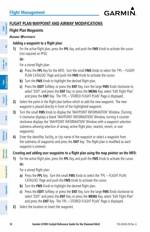
Garmin G1000 Cockpit Reference Guide for the Diamond Da42 190-00406-08 Rev. A38
Flight Management
Flig
htIn
stru
men
tsEI
SN
av/C
om/
XPD
R/A
udio
Flig
ht
Man
agem
ent
Haz
ard
Avoi
danc
eA
FCS
Add
ition
alFe
atur
esA
nnun
/Ale
rts
App
endi
xIn
dex
Flig
htIn
stru
men
tsEI
Sa
udio
and
CNS
Flig
ht
Man
agem
ent
Haz
ard
avoi
danc
ea
FCS
add
ition
alFe
atur
esa
bnor
mal
ope
ratio
na
nnun
/ale
rts
app
endi
xIn
dex
FLIGHT PLaN WayPoINT aND aIRWay MoDIFICaTIoNSFlight Plan Waypoints
adding waypoints
adding a waypoint to a flight plan:1) For the active flight plan, press the FPL Key, and push the FMS Knob to activate the cursor
(not required on PFD). or: For a stored flight plan:
a) Press the FPL Key for the MFD. Turn the small FMS Knob to select the ‘FPL – FLIGHT PLAN CATALOG’ Page and push the FMS Knob to activate the cursor.
b) Turn the FMS Knob to highlight the desired flight plan.c) Press the EDIT Softkey; or press the ENT Key, turn the large FMS Knob clockwise to
select ‘EDIT’ and press the ENT Key; or press the MENU Key, select ‘Edit Flight Plan’ and press the ENT Key. The ‘FPL – STORED FLIGHT PLAN’ Page is displayed.
2) Select the point in the flight plan before which to add the new waypoint. The new waypoint is placed directly in front of the highlighted waypoint.
3) Turn the small FMS Knob to display the ‘WAYPOINT INFORMATION’ Window. (Turning it clockwise displays a blank ‘WAYPOINT INFORMATION’ Window, turning it counter-clockwise displays the ‘WAYPOINT INFORMATION’ Window with a waypoint selection submenu allowing selection of airway, active flight plan, nearest, recent, or user waypoints).
4) Enter the identifier, facility, or city name of the waypoint or select a waypoint from the submenu of waypoints and press the ENT Key. The flight plan is modified as each waypoint is entered.
Creating and adding user waypoints to a flight plan using the map pointer on the MFD:1) For the active flight plan, press the FPL Key, and push the FMS Knob to activate the cursor. or: For a stored flight plan:
a) Press the FPL Key. Turn the small FMS Knob to select the ‘FPL – FLIGHT PLAN CATALOG’ Page and push the FMS Knob to activate the cursor.
b) Turn the FMS Knob to highlight the desired flight plan.c) Press the EDIT Softkey; or press the ENT Key, turn the large FMS Knob clockwise to
select ‘EDIT’ and press the ENT Key; or press the MENU Key, select ‘Edit Flight Plan’ and press the ENT Key. The ‘FPL – STORED FLIGHT PLAN’ Page is displayed.
2) Select the location to insert the waypoint.
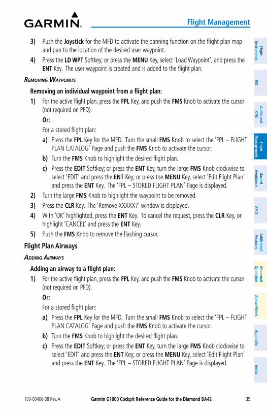
Garmin G1000 Cockpit Reference Guide for the Diamond Da42190-00406-08 Rev. A 39
Flight Management
FlightInstrum
entsEIS
Nav/Com
/XPD
R/Audio
Flight M
anagement
Hazard
AvoidanceA
FCSA
dditionalFeatures
Annun/A
lertsA
ppendixIndex
FlightInstrum
entsEIS
audio and
CNS
Flight M
anagement
Hazard
avoidancea
FCSa
dditionalFeatures
abnorm
alo
perationa
nnun/alerts
appendix
Index
3) Push the Joystick for the MFD to activate the panning function on the flight plan map and pan to the location of the desired user waypoint.
4) Press the LD WPT Softkey; or press the MENU Key, select ‘Load Waypoint’, and press the ENT Key. The user waypoint is created and is added to the flight plan.
removing waypoints
Removing an individual waypoint from a flight plan:1) For the active flight plan, press the FPL Key, and push the FMS Knob to activate the cursor
(not required on PFD). or: For a stored flight plan:
a) Press the FPL Key for the MFD. Turn the small FMS Knob to select the ‘FPL – FLIGHT PLAN CATALOG’ Page and push the FMS Knob to activate the cursor.
b) Turn the FMS Knob to highlight the desired flight plan.c) Press the EDIT Softkey; or press the ENT Key, turn the large FMS Knob clockwise to
select ‘EDIT’ and press the ENT Key; or press the MENU Key, select ‘Edit Flight Plan’ and press the ENT Key. The ‘FPL – STORED FLIGHT PLAN’ Page is displayed.
2) Turn the large FMS Knob to highlight the waypoint to be removed.3) Press the CLR Key. The ‘Remove XXXXX?’ window is displayed.4) With ‘OK’ highlighted, press the ENT Key. To cancel the request, press the CLR Key, or
highlight ‘CANCEL’ and press the ENT Key.5) Push the FMS Knob to remove the flashing cursor.
Flight Plan airways
adding airways
adding an airway to a flight plan:1) For the active flight plan, press the FPL Key, and push the FMS Knob to activate the cursor
(not required on PFD). or: For a stored flight plan:
a) Press the FPL Key for the MFD. Turn the small FMS Knob to select the ‘FPL – FLIGHT PLAN CATALOG’ Page and push the FMS Knob to activate the cursor.
b) Turn the FMS Knob to highlight the desired flight plan.c) Press the EDIT Softkey; or press the ENT Key, turn the large FMS Knob clockwise to
select ‘EDIT’ and press the ENT Key; or press the MENU Key, select ‘Edit Flight Plan’ and press the ENT Key. The ‘FPL – STORED FLIGHT PLAN’ Page is displayed.
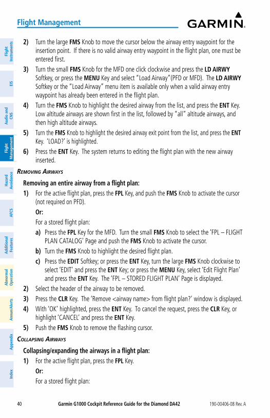
Garmin G1000 Cockpit Reference Guide for the Diamond Da42 190-00406-08 Rev. A40
Flight Management
Flig
htIn
stru
men
tsEI
SN
av/C
om/
XPD
R/A
udio
Flig
ht
Man
agem
ent
Haz
ard
Avoi
danc
eA
FCS
Add
ition
alFe
atur
esA
nnun
/Ale
rts
App
endi
xIn
dex
Flig
htIn
stru
men
tsEI
Sa
udio
and
CNS
Flig
ht
Man
agem
ent
Haz
ard
avoi
danc
ea
FCS
add
ition
alFe
atur
esa
bnor
mal
ope
ratio
na
nnun
/ale
rts
app
endi
xIn
dex
a) Press the FPL Key for the MFD. Turn the small FMS Knob to select the ‘FPL – FLIGHT PLAN CATALOG’ Page and push the FMS Knob to activate the cursor.
b) Turn the FMS Knob to highlight the desired flight plan.c) Press the EDIT Softkey; or press the ENT Key, turn the large FMS Knob clockwise to
select ‘EDIT’ and press the ENT Key; or press the MENU Key, select ‘Edit Flight Plan’ and press the ENT Key. The ‘FPL – STORED FLIGHT PLAN’ Page is displayed.
2) Press the MENU Key, highlight ‘Collapse Airways’ or ‘Expand Airways’, and press the ENT Key. The airways are collapsed/expanded.
FLIGHT PLaN WayPoINT CoNSTRaINTSaltitude Constraints
Waypoint altitude Constraints
Cross AT or ABOVE 5,000 ft
Cross AT or BELOW 3,000 ft
Cross AT 2,300 ft
altitude Constraint Examples
Large Cyan Text
Small White Text with Altitude Restriction Bar
Large White Text
Small Cyan Subdued Text
Small Cyan Text
2) Turn the large FMS Knob to move the cursor below the airway entry waypoint for the insertion point. If there is no valid airway entry waypoint in the flight plan, one must be entered first.
3) Turn the small FMS Knob for the MFD one click clockwise and press the LD aIRWy Softkey, or press the MENU Key and select “Load Airway”(PFD or MFD). The LD aIRWy Softkey or the “Load Airway” menu item is available only when a valid airway entry waypoint has already been entered in the flight plan.
4) Turn the FMS Knob to highlight the desired airway from the list, and press the ENT Key. Low altitude airways are shown first in the list, followed by “all” altitude airways, and then high altitude airways.
5) Turn the FMS Knob to highlight the desired airway exit point from the list, and press the ENT Key. ‘LOAD?’ is highlighted.
6) Press the ENT Key. The system returns to editing the flight plan with the new airway inserted.
removing airways
Removing an entire airway from a flight plan:1) For the active flight plan, press the FPL Key, and push the FMS Knob to activate the cursor
(not required on PFD). or: For a stored flight plan:
a) Press the FPL Key for the MFD. Turn the small FMS Knob to select the ‘FPL – FLIGHT PLAN CATALOG’ Page and push the FMS Knob to activate the cursor.
b) Turn the FMS Knob to highlight the desired flight plan.c) Press the EDIT Softkey; or press the ENT Key, turn the large FMS Knob clockwise to
select ‘EDIT’ and press the ENT Key; or press the MENU Key, select ‘Edit Flight Plan’ and press the ENT Key. The ‘FPL – STORED FLIGHT PLAN’ Page is displayed.
2) Select the header of the airway to be removed.3) Press the CLR Key. The ‘Remove <airway name> from flight plan?’ window is displayed.4) With ‘OK’ highlighted, press the ENT Key. To cancel the request, press the CLR Key, or
highlight ‘CANCEL’ and press the ENT Key.5) Push the FMS Knob to remove the flashing cursor.
Collapsing airways
Collapsing/expanding the airways in a flight plan:1) For the active flight plan, press the FPL Key. or: For a stored flight plan:
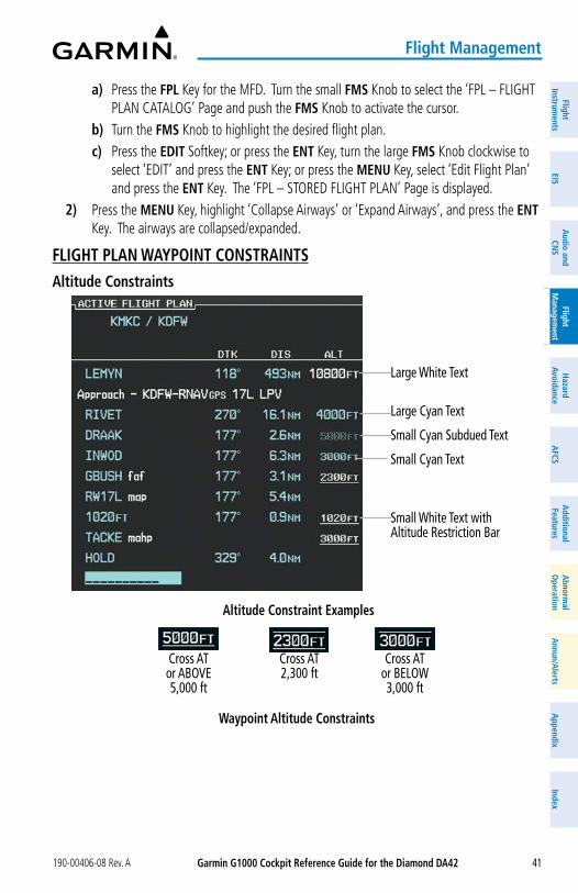
Garmin G1000 Cockpit Reference Guide for the Diamond Da42190-00406-08 Rev. A 41
Flight Management
FlightInstrum
entsEIS
Nav/Com
/XPD
R/Audio
Flight M
anagement
Hazard
AvoidanceA
FCSA
dditionalFeatures
Annun/A
lertsA
ppendixIndex
FlightInstrum
entsEIS
audio and
CNS
Flight M
anagement
Hazard
avoidancea
FCSa
dditionalFeatures
abnorm
alo
perationa
nnun/alerts
appendix
Index
a) Press the FPL Key for the MFD. Turn the small FMS Knob to select the ‘FPL – FLIGHT PLAN CATALOG’ Page and push the FMS Knob to activate the cursor.
b) Turn the FMS Knob to highlight the desired flight plan.c) Press the EDIT Softkey; or press the ENT Key, turn the large FMS Knob clockwise to
select ‘EDIT’ and press the ENT Key; or press the MENU Key, select ‘Edit Flight Plan’ and press the ENT Key. The ‘FPL – STORED FLIGHT PLAN’ Page is displayed.
2) Press the MENU Key, highlight ‘Collapse Airways’ or ‘Expand Airways’, and press the ENT Key. The airways are collapsed/expanded.
FLIGHT PLaN WayPoINT CoNSTRaINTSaltitude Constraints
Waypoint altitude Constraints
Cross AT or ABOVE 5,000 ft
Cross AT or BELOW 3,000 ft
Cross AT 2,300 ft
altitude Constraint Examples
Large Cyan Text
Small White Text with Altitude Restriction Bar
Large White Text
Small Cyan Subdued Text
Small Cyan Text
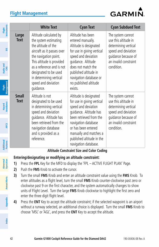
Garmin G1000 Cockpit Reference Guide for the Diamond Da42 190-00406-08 Rev. A42
Flight Management
Flig
htIn
stru
men
tsEI
SN
av/C
om/
XPD
R/A
udio
Flig
ht
Man
agem
ent
Haz
ard
Avoi
danc
eA
FCS
Add
ition
alFe
atur
esA
nnun
/Ale
rts
App
endi
xIn
dex
Flig
htIn
stru
men
tsEI
Sa
udio
and
CNS
Flig
ht
Man
agem
ent
Haz
ard
avoi
danc
ea
FCS
add
ition
alFe
atur
esa
bnor
mal
ope
ratio
na
nnun
/ale
rts
app
endi
xIn
dex
White Text Cyan Text Cyan Subdued Text
Large Text
Altitude calculated by the system estimating the altitude of the aircraft as it passes over the navigation point. This altitude is provided as a reference and is not designated to be used in determining vertical speed and deviation guidance.
Altitude has been entered manually. Altitude is designated for use in giving vertical speed and deviation guidance. Altitude does not match the published altitude in navigation database or no published altitude exists.
The system cannot use this altitude in determining vertical speed and deviation guidance because of an invalid constraint condition.
Small Text
Altitude is not designated to be used in determining vertical speed and deviation guidance. Altitude has been retrieved from the navigation database and is provided as a reference.
Altitude is designated for use in giving vertical speed and deviation guidance. Altitude has been retrieved from the navigation database or has been entered manually and matches a published altitude in the navigation database.
The system cannot use this altitude in determining vertical speed and deviation guidance because of an invalid constraint condition.
altitude Constraint Size and Color Coding
Entering/designating or modifying an altitude constraint:1) Press the FPL Key for the MFD to display the ‘FPL – ACTIVE FLIGHT PLAN’ Page.2) Push the FMS Knob to activate the cursor.3) Turn the small FMS Knob and enter an altitude constraint value using the FMS Knob. To
enter altitudes as a flight level, turn the small FMS Knob counter-clockwise past zero or clockwise past 9 on the first character, and the system automatically changes to show units of Flight Level. Turn the large FMS Knob clockwise to highlight the first zero and enter the three digit flight level.
4) Press the ENT Key to accept the altitude constraint; if the selected waypoint is an airport without a runway selected, an additional choice is displayed. Turn the small FMS Knob to choose ‘MSL’ or ‘AGL’, and press the ENT Key to accept the altitude.
Garmin G1000 Cockpit Reference Guide for the Diamond Da42190-00406-08 Rev. A 43
Flight Management
FlightInstrum
entsEIS
Nav/Com
/XPD
R/Audio
Flight M
anagement
Hazard
AvoidanceA
FCSA
dditionalFeatures
Annun/A
lertsA
ppendixIndex
FlightInstrum
entsEIS
audio and
CNS
Flight M
anagement
Hazard
avoidancea
FCSa
dditionalFeatures
abnorm
alo
perationa
nnun/alerts
appendix
Index
Removing/undesignating an altitude constraint:1) Press the FPL Key for the MFD to display the ‘FPL – ACTIVE FLIGHT PLAN’ Page.2) Push the FMS Knob to activate the cursor and turn to highlight the desired waypoint
altitude constraint.3) Press the CLR Key. A ‘Remove VNV altitude?’ confirmation window is displayed.4) Select ‘OK’ and press the ENT Key.
Reverting a manually entered altitude constraint back to the navigation database value:1) Press the FPL Key for the MFD to display the ‘FPL – ACTIVE FLIGHT PLAN’ Page.2) Push the FMS Knob to activate the cursor and turn to highlight the desired waypoint
altitude constraint.3) Press the CLR Key. A ‘Remove or Revert to published VNV altitude of nnnnnFT?’
confirmation window is displayed.4) Select ‘REVERT’ and press the ENT Key. The altitude is changed to the navigation
database value.
FLIGHT PLaN VERTICaL NaVIGaTIoNEnabling and Disabling VNV guidance:1) Press the FPL Key for the MFD to display the ‘FPL – ACTIVE FLIGHT PLAN’ Page.2) Press the ENBL VNV Softkey; or press the MENU Key, highlight ‘Enable VNV’, and press
the ENT Key. Vertical navigation is enabled, and vertical guidance begins with the waypoint shown in the ‘CURRENT VNV PROFILE’ Box (defaults first waypoint in the active flight plan with an altitude enabled for vertical navigation.
3) To disable VNV guidance, press the CNCL VNV Softkey; or press the MENU Key, highlight ‘Cancel VNV’, and press the ENT Key. Vertical navigation is disabled.
Current VNaV Profile
Modifying the VS TGT and FPa:1) Press the FPL Key for the MFD to display the ‘FPL – ACTIVE FLIGHT PLAN’ Page.2) Press the VNV PRoF Softkey; or press the MENU Key, highlight ‘Select VNV Profile
Window’, and press the ENT Key. The cursor is now located in the ‘CURRENT VNV PROFILE’ Box.
3) Turn the FMS Knob as needed to edit the values.4) Push the FMS Knob to remove the flashing cursor.
Garmin G1000 Cockpit Reference Guide for the Diamond Da42 190-00406-08 Rev. A44
Flight Management
Flig
htIn
stru
men
tsEI
SN
av/C
om/
XPD
R/A
udio
Flig
ht
Man
agem
ent
Haz
ard
Avoi
danc
eA
FCS
Add
ition
alFe
atur
esA
nnun
/Ale
rts
App
endi
xIn
dex
Flig
htIn
stru
men
tsEI
Sa
udio
and
CNS
Flig
ht
Man
agem
ent
Haz
ard
avoi
danc
ea
FCS
add
ition
alFe
atur
esa
bnor
mal
ope
ratio
na
nnun
/ale
rts
app
endi
xIn
dex
VERTICaL NaVIGaTIoN DIRECT-Toactivating a vertical navigation direct-to:1) Press the FPL Key for the MFD to display the ‘FPL – ACTIVE FLIGHT PLAN’ Page.2) Push the FMS Knob to activate the cursor and turn to highlight the desired waypoint.
3) Press the VNV ¯ Softkey; or press the MENU Key, highlight ‘VNV Direct-To’, and press the ENT Key. An ‘Activate vertical ¯ to: NNNNNFT at XXXXXX?’ confirmation window is displayed.
4) Press the ENT Key. Vertical guidance begins to the altitude constraint for the selected waypoint.
5) Push the FMS Knob to remove the flashing cursor.
Removing a VNV altitude constraint:1) Press the ¯ Key to display the ‘DIRECT TO’ Window.2) Press the MENU Key.3) With ‘Clear Vertical Constraints’ highlighted, press the ENT Key.
FLIGHT PLaN oPERaTIoNSactivating a Flight Plan Leg
activating a flight plan leg:1) Press the FPL Key to display the ‘FPL – ACTIVE FLIGHT PLAN’ Page (MFD) or the ‘FLIGHT
PLAN’ Window (PFD).
2) Push the FMS Knob to activate the cursor (not required on PFD), and turn the large FMS Knob to highlight the destination waypoint for the desired leg.
3) Press the aCT LEG Softkey (MFD only); or press the MENU Key, highlight ‘Activate Leg’, and press the ENT Key. A confirmation window is displayed with ‘ACTIVATE’ highlighted.
4) Press the ENT Key to activate the flight plan leg. To cancel, press the CLR Key, or highlight ‘CANCEL’ and press the ENT Key.
5) Push the FMS Knob to remove the flashing cursor.
along Track offsets
Entering an along track offset distance:1) Press the FPL Key. Push the FMS Knob to activate the cursor (not required on PFD).2) Turn the large FMS Knob to highlight the waypoint for the along track offset.3) Press the aTK oFST Softkey (MFD only); or press the MENU Key, highlight ‘Create ATK
Offset Waypoint’, and press the ENT Key.4) Enter a positive or negative offset distance in the range of +/- 1 to 999 nm (limited by leg
distances).
Garmin G1000 Cockpit Reference Guide for the Diamond Da42190-00406-08 Rev. A 45
Flight Management
FlightInstrum
entsEIS
Nav/Com
/XPD
R/Audio
Flight M
anagement
Hazard
AvoidanceA
FCSA
dditionalFeatures
Annun/A
lertsA
ppendixIndex
FlightInstrum
entsEIS
audio and
CNS
Flight M
anagement
Hazard
avoidancea
FCSa
dditionalFeatures
abnorm
alo
perationa
nnun/alerts
appendix
Index
5) Press the ENT Key to create the offset waypoint.6) Push the FMS Knob to remove the flashing cursor.
Removing an along track offset distance:1) Press the FPL Key. Push the FMS Knob to activate the cursor (not required on PFD).2) Turn the large FMS Knob to highlight the along track offset.3) Press the CLR Key. The ‘Remove VNAV along-track waypoint’ Window is displayed.4) With ‘OK’ highlighted, press the ENT Key. To cancel the request, press the CLR Key, or
highlight ‘CANCEL’ and press the ENT Key.
Entering a VNV altitude and along-track offset for the waypoint:1) Press the ¯ Key to display the ‘DIRECT TO’ Window.2) Turn the large FMS Knob to place the cursor in the altitude field (‘VNV’ or ‘ALT’).3) Enter the desired altitude.4) Press the ENT Key to accept the altitude constraint; if the selected waypoint is an airport,
an additional choice is displayed. Turn the small FMS Knob to choose ‘MSL’ or ‘AGL’, and press the ENT Key to accept the altitude.
5) The cursor is now flashing in the offset distance field.6) Enter the desired along-track distance.7) Press the ENT Key. ‘ACTIVATE?’ is highlighted.8) Press the ENT Key to activate.
Closest Point of FPL
Determining the closest point along the flight plan to a selected waypoint:1) For the active flight plan, press the FPL Key.
or: For a stored flight plan:
a) Press the FPL Key for the MFD. Turn the small FMS Knob to select the ‘FPL – FLIGHT PLAN CATALOG’ Page and push the FMS Knob to activate the cursor.
b) Turn the FMS Knob to highlight the desired flight plan.c) Press the EDIT Softkey; or press the ENT Key, turn the large FMS Knob clockwise
to select ‘EDIT’ and press the ENT Key. The ‘FPL – STORED FLIGHT PLAN’ Page is displayed.
2) Press the MENU Key, highlight ‘Closest Point Of FPL’’, and press the ENT Key. A window appears with the reference waypoint field highlighted.
3) Enter the identifier of the reference waypoint and press the ENT Key. The system displays the bearing (BRG) and distance (DIS) to the closest point along the flight plan to the selected reference waypoint and creates a user waypoint at this location. The name for the new user waypoint is derived from the identifier of the reference waypoint.
Garmin G1000 Cockpit Reference Guide for the Diamond Da42 190-00406-08 Rev. A46
Flight Management
Flig
htIn
stru
men
tsEI
SN
av/C
om/
XPD
R/A
udio
Flig
ht
Man
agem
ent
Haz
ard
Avoi
danc
eA
FCS
Add
ition
alFe
atur
esA
nnun
/Ale
rts
App
endi
xIn
dex
Flig
htIn
stru
men
tsEI
Sa
udio
and
CNS
Flig
ht
Man
agem
ent
Haz
ard
avoi
danc
ea
FCS
add
ition
alFe
atur
esa
bnor
mal
ope
ratio
na
nnun
/ale
rts
app
endi
xIn
dex
Parallel Track
activating parallel track:1) Press the FPL Key to display the ‘FPL – ACTIVE FLIGHT PLAN’ Page (MFD) or the ‘FLIGHT
PLAN’ Window (PFD).2) Press the MENU Key, highlight ‘Parallel Track’, and press the ENT Key. The ‘PARALLEL
TRACK’ Window is displayed with the ‘DIRECTION’ Field highlighted.3) Turn the small FMS Knob to select ‘LEFT’ or ‘RIGHT’ and press the ENT Key. The
‘DISTANCE’ Field is highlighted.4) Turn the small FMS Knob to enter a distance from 1-50 nm and press the ENT Key.
‘ACTIVATE PARALLEL TRACK?’ is highlighted.5) Press the ENT Key to activate parallel track. Push the FMS Knob or the CLR Key to cancel
the parallel track activation.
Cancelling parallel track: 1) Press the FPL Key to display the ‘FPL – ACTIVE FLIGHT PLAN’ Page (MFD) or the ‘FLIGHT
PLAN’ Window (PFD).2) Press the MENU Key, highlight ‘Parallel Track’, and press the ENT Key. The ‘PARALLEL
TRACK’ Window is displayed with ‘CANCEL PARALLEL TRACK?’ highlighted.3) Press the ENT Key.
User-Defined Holding Patterns
Creating and editing a user-defined hold at a flight plan waypoint:1) For the active flight plan, press the FPL Key. Push the FMS Knob to activate the cursor
(not required on PFD). or: For a stored flight plan:
a) Press the FPL Key for the MFD. Turn the small FMS Knob to select the ‘FPL – FLIGHT PLAN CATALOG’ Page and push the FMS Knob to activate the cursor.
b) Turn the FMS Knob to highlight the desired flight plan.c) Press the EDIT Softkey; or press the ENT Key, turn the large FMS Knob clockwise
to select ‘EDIT’ and press the ENT Key. The ‘FPL – STORED FLIGHT PLAN’ Page is displayed.
2) Turn the large FMS Knob to highlight the waypoint for the hold.3) Press the MENU Key, highlight ‘Hold At Waypoint’, and press the ENT Key. The ‘HOLD AT’
Window appears with the course field highlighted.4) Use the FMS Knob to edit the course, and press the ENT Key.5) Use the small FMS Knob to select ‘INBOUND’ or ‘OUTBOUND’ course direction, and press
the ENT Key.
Garmin G1000 Cockpit Reference Guide for the Diamond Da42190-00406-08 Rev. A 47
Flight Management
FlightInstrum
entsEIS
Nav/Com
/XPD
R/Audio
Flight M
anagement
Hazard
AvoidanceA
FCSA
dditionalFeatures
Annun/A
lertsA
ppendixIndex
FlightInstrum
entsEIS
audio and
CNS
Flight M
anagement
Hazard
avoidancea
FCSa
dditionalFeatures
abnorm
alo
perationa
nnun/alerts
appendix
Index
6) Use the small FMS Knob to select ‘TIME’ or ‘DIST’ length mode, and press the ENT Key.7) Use the FMS Knob to edit the length, and press the ENT Key.8) Use the small FMS Knob to select ‘RIGHT’ or ‘LEFT’ turn direction, and press the ENT Key.9) Use the FMS Knob to edit the EXPECT FURTHER CLEARANCE Time (EFC Time), and press
the ENT Key.10) Press the ENT Key while ‘LOAD?’ is highlighted to insert the hold into the flight plan.11) If necessary, edit the hold:
a) Highlight the HOLD waypoint using the large FMS Knob.b) Press the Menu Key, highlight ‘Edit Hold’, and press the ENT Key. The ‘HOLD AT’
Window appears.c) Repeat Steps 4 through 9 as desired to edit the hold. d) Press the ENT Key while ‘UPDATE?’ is highlighted to save the changes.
Creating and editing a user-defined hold at the aircraft present position:1) Press the FPL Key to display the ‘FPL – ACTIVE FLIGHT PLAN’ Page (MFD) or the ‘FLIGHT
PLAN’ Window (PFD). or: Press the ¯ Key to display the ‘DIRECT TO’ Window.2) Press the MENU Key, highlight ‘Hold At Present Position’, and press the ENT Key. The
‘HOLD AT’ Window appears with the course field highlighted.3) If desired, use the FMS Knob to edit the course, and press the ENT Key.4) Use the small FMS Knob to select ‘INBOUND’ or ‘OUTBOUND’ course direction, and press
the ENT Key.5) Use the small FMS Knob to select ‘TIME’ or ‘DIS’ length mode, and press the ENT Key.6) Use the FMS Knob to edit the length, and press the ENT Key.7) Use the small FMS Knob to select ‘RIGHT’ or ‘LEFT’ turn direction, and press the ENT Key.8) Use the FMS Knob to edit the EXPECT FURTHER CLEARANCE Time (EFC Time), and press
the ENT Key.9) Press the ENT Key while ‘ACTIVATE?’ is highlighted to create an Offroute Direct-to hold
waypoint at the aircraft present position and activate the hold.10) If necessary, edit the hold:
a) Press the FPL Key to display the ‘FPL – ACTIVE FLIGHT PLAN’ Page (MFD) or the ‘FLIGHT PLAN’ Window (PFD).
or: Press the ¯ Key to display the ‘DIRECT TO’ Window.b) Press the Menu Key, highlight ‘Edit Hold’, and press the ENT Key. The ‘HOLD AT’
Window appears.
Garmin G1000 Cockpit Reference Guide for the Diamond Da42 190-00406-08 Rev. A48
Flight Management
Flig
htIn
stru
men
tsEI
SN
av/C
om/
XPD
R/A
udio
Flig
ht
Man
agem
ent
Haz
ard
Avoi
danc
eA
FCS
Add
ition
alFe
atur
esA
nnun
/Ale
rts
App
endi
xIn
dex
Flig
htIn
stru
men
tsEI
Sa
udio
and
CNS
Flig
ht
Man
agem
ent
Haz
ard
avoi
danc
ea
FCS
add
ition
alFe
atur
esa
bnor
mal
ope
ratio
na
nnun
/ale
rts
app
endi
xIn
dex
c) Repeat Steps 3 through 8 as desired to edit the hold. d) Press the ENT Key while ‘UPDATE?’ is highlighted to save the changes.
Creating and editing a user-defined hold at a direct-to waypoint:1) Press a ¯ Key and set up the direct-to waypoint as desired, then select ‘HOLD?’ when
finished.2) Use the FMS Knob to edit the course, and press the ENT Key.3) Use the small FMS Knob to select ‘INBOUND’ or ‘OUTBOUND’ course direction, and press
the ENT Key.4) Use the small FMS Knob to select ‘TIME’ or ‘DIS’ length mode, and press the ENT Key.5) Use the FMS Knob to edit the length, and press the ENT Key.6) Use the small FMS Knob to select ‘RIGHT’ or ‘LEFT’ turn direction, and press the ENT Key.7) Use the FMS Knob to edit the EXPECT FURTHER CLEARANCE Time (EFC Time), and press
the ENT Key.8) Press the ENT Key while ‘ACTIVATE?’ is highlighted to activate the direct-to with the user-
defined hold defined at the direct-to waypoint. (If the direct-to waypoint is part of the active flight plan, ‘HOLD’ is inserted into the active flight plan. If the direct-to waypoint is not part of the active flight plan, an off-route direct-to hold is created.)
9) If necessary, edit the hold:a) Press the ¯ Key to display the ‘DIRECT TO’ Window.b) Press the Menu Key, highlight ‘Edit Hold’, and press the ENT Key. The ‘HOLD AT’
Window appears.c) Repeat Steps 2 through 7 as desired to edit the hold. d) Press the ENT Key while ‘UPDATE?’ is highlighted to save the changes.
Exiting a user-defined hold inserted into the active flight plan: Press the SUSP Softkey. The system will provide guidance to follow the holding pattern
to the inbound course and resume automatic waypoint sequencing.
Removing a user-defined hold from a flight plan:1) For the active flight plan, press the FPL Key. Push the FMS Knob to activate the cursor
(not required on PFD). or: For a stored flight plan:
a) Press the FPL Key for the MFD. Turn the small FMS Knob to select the ‘FPL – FLIGHT PLAN CATALOG’ Page and push the FMS Knob to activate the cursor.
b) Turn the FMS Knob to highlight the desired flight plan.c) Press the EDIT Softkey; or press the ENT Key, turn the large FMS Knob clockwise
to select ‘EDIT’ and press the ENT Key. The ‘FPL – STORED FLIGHT PLAN’ Page is displayed.
Garmin G1000 Cockpit Reference Guide for the Diamond Da42190-00406-08 Rev. A 49
Flight Management
FlightInstrum
entsEIS
Nav/Com
/XPD
R/Audio
Flight M
anagement
Hazard
AvoidanceA
FCSA
dditionalFeatures
Annun/A
lertsA
ppendixIndex
FlightInstrum
entsEIS
audio and
CNS
Flight M
anagement
Hazard
avoidancea
FCSa
dditionalFeatures
abnorm
alo
perationa
nnun/alerts
appendix
Index
2) Turn the large FMS Knob to highlight the ‘HOLD’ in the flight plan. 3) Press the CLR Key. A ‘Remove Holding Pattern?’ confirmation window is displayed.4) Select ‘OK’ and press the ENT Key. The holding pattern is removed from the flight plan.
Select ‘CANCEL’ and press the ENT Key to cancel the removal of the holding pattern.
Removing a user-defined hold at an off-route direct-to:1) Press a ¯ Key to display the ‘DIRECT TO’ Window.2) Press the MENU Key to display the ‘PAGE MENU’ Window with the cursor on the ‘Cancel
Direct-To NAV’ selection.3) Press the ENT Key. The holding pattern is removed.
arrival alerts
Enabling/disabling the arrival alert:1) Use the FMS Knob to select the ‘AUX – SYSTEM SETUP’ Page.2) Push the FMS Knob momentarily to activate the flashing cursor.3) Turn the large FMS Knob to select the ON/OFF Field in the ‘ARRIVAL ALERT’ Box.4) Turn the small FMS Knob clockwise to turn the arrival alert ON or counterclockwise to
turn the alert OFF.
Changing the arrival alert trigger distance:1) Use the FMS Knob to select the ‘AUX – SYSTEM SETUP’ Page.2) Push the FMS Knob momentarily to activate the flashing cursor.3) Turn the large FMS Knob to highlight the Distance Field in the ‘ARRIVAL ALERT’ Box.4) Use the FMS Knob to enter a trigger distance and press the ENT Key.
MaNaGING FLIGHT PLaNSImporting and Exporting Flight Plans
Ignoring a flight plan transfer from a wireless connection:1) When a flight plan transfer has been initiated from a wireless connection, a Pending
Flight Plan pop-up alert appears in the lower right corner of the MFD, and a Connext® annunciation appears to the right of the MFD page name.
2) Press the CLR Key to remove the pop-up alert and ignore the pending flight plan. The pending flight plan will still be available on the ‘FPL – FLIGHT PLAN CATALOG’ Page.
or: Press the IGNoRE Softkey to remove the pop-up alert and ignore the pending flight plan.
The pending flight plan will still be available on the ‘FPL – FLIGHT PLAN CATALOG’ Page.
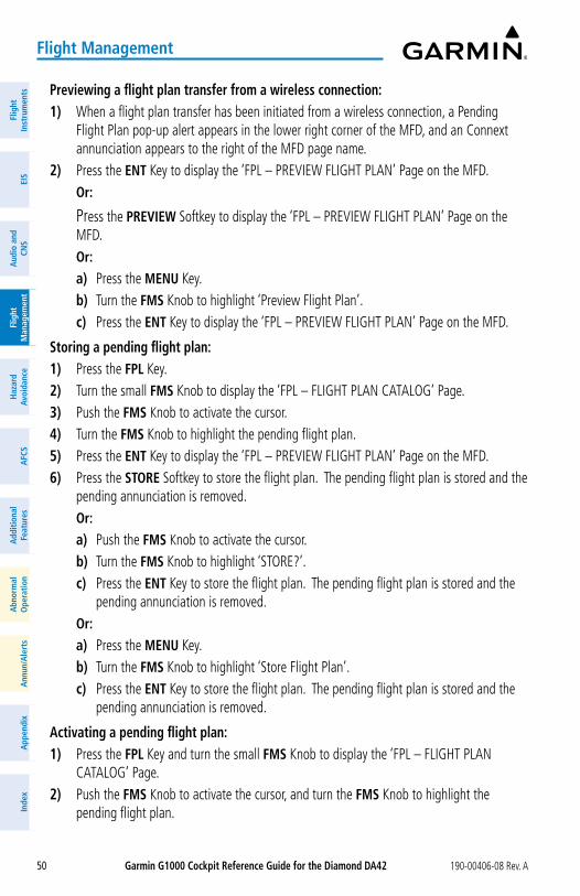
Garmin G1000 Cockpit Reference Guide for the Diamond Da42 190-00406-08 Rev. A50
Flight Management
Flig
htIn
stru
men
tsEI
SN
av/C
om/
XPD
R/A
udio
Flig
ht
Man
agem
ent
Haz
ard
Avoi
danc
eA
FCS
Add
ition
alFe
atur
esA
nnun
/Ale
rts
App
endi
xIn
dex
Flig
htIn
stru
men
tsEI
Sa
udio
and
CNS
Flig
ht
Man
agem
ent
Haz
ard
avoi
danc
ea
FCS
add
ition
alFe
atur
esa
bnor
mal
ope
ratio
na
nnun
/ale
rts
app
endi
xIn
dex
Previewing a flight plan transfer from a wireless connection:1) When a flight plan transfer has been initiated from a wireless connection, a Pending
Flight Plan pop-up alert appears in the lower right corner of the MFD, and an Connext annunciation appears to the right of the MFD page name.
2) Press the ENT Key to display the ‘FPL – PREVIEW FLIGHT PLAN’ Page on the MFD. or:
Press the PREVIEW Softkey to display the ‘FPL – PREVIEW FLIGHT PLAN’ Page on the MFD.
or:a) Press the MENU Key.b) Turn the FMS Knob to highlight ‘Preview Flight Plan’. c) Press the ENT Key to display the ‘FPL – PREVIEW FLIGHT PLAN’ Page on the MFD.
Storing a pending flight plan:1) Press the FPL Key.2) Turn the small FMS Knob to display the ‘FPL – FLIGHT PLAN CATALOG’ Page.3) Push the FMS Knob to activate the cursor. 4) Turn the FMS Knob to highlight the pending flight plan.5) Press the ENT Key to display the ‘FPL – PREVIEW FLIGHT PLAN’ Page on the MFD.6) Press the SToRE Softkey to store the flight plan. The pending flight plan is stored and the
pending annunciation is removed. or:
a) Push the FMS Knob to activate the cursor.b) Turn the FMS Knob to highlight ‘STORE?’. c) Press the ENT Key to store the flight plan. The pending flight plan is stored and the
pending annunciation is removed. or:
a) Press the MENU Key. b) Turn the FMS Knob to highlight ‘Store Flight Plan’. c) Press the ENT Key to store the flight plan. The pending flight plan is stored and the
pending annunciation is removed.
activating a pending flight plan:1) Press the FPL Key and turn the small FMS Knob to display the ‘FPL – FLIGHT PLAN
CATALOG’ Page.2) Push the FMS Knob to activate the cursor, and turn the FMS Knob to highlight the
pending flight plan.
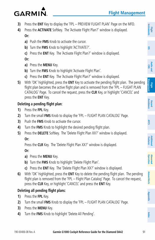
Garmin G1000 Cockpit Reference Guide for the Diamond Da42190-00406-08 Rev. A 51
Flight Management
FlightInstrum
entsEIS
Nav/Com
/XPD
R/Audio
Flight M
anagement
Hazard
AvoidanceA
FCSA
dditionalFeatures
Annun/A
lertsA
ppendixIndex
FlightInstrum
entsEIS
audio and
CNS
Flight M
anagement
Hazard
avoidancea
FCSa
dditionalFeatures
abnorm
alo
perationa
nnun/alerts
appendix
Index
3) Press the ENT Key to display the ‘FPL – PREVIEW FLIGHT PLAN’ Page on the MFD.4) Press the aCTIVaTE Softkey. The ‘Activate Flight Plan?’ window is displayed. or:
a) Push the FMS Knob to activate the cursor.b) Turn the FMS Knob to highlight ‘ACTIVATE?’.c) Press the ENT Key. The ‘Activate Flight Plan?’ window is displayed.or:a) Press the MENU Key.b) Turn the FMS Knob to highlight ‘Activate Flight Plan’.c) Press the ENT Key. The ‘Activate Flight Plan?’ window is displayed.
5) With ‘OK’ highlighted, press the ENT Key to activate the pending flight plan. The pending flight plan becomes the active flight plan and is removed from the ‘FPL – FLIGHT PLAN CATALOG’ Page. To cancel the request, press the CLR Key, or highlight ‘CANCEL’ and press the ENT Key.
Deleting a pending flight plan:1) Press the FPL Key.2) Turn the small FMS Knob to display the ‘FPL – FLIGHT PLAN CATALOG’ Page.3) Push the FMS Knob to activate the cursor.4) Turn the FMS Knob to highlight the desired pending flight plan.5) Press the DELETE Softkey. The ‘Delete Flight Plan XX?’ window is displayed. or: Press the CLR Key. The ‘Delete Flight Plan XX?’ window is displayed. or:
a) Press the MENU Key.b) Turn the FMS Knob to highlight ‘Delete Flight Plan’.c) Press the ENT Key. The ‘Delete Flight Plan XX?’ window is displayed.
6) With ‘OK’ highlighted, press the ENT Key to delete the pending flight plan. The pending flight plan is removed from the ‘FPL – Flight Plan Catalog’ Page. To cancel the request, press the CLR Key, or highlight ‘CANCEL’ and press the ENT Key.
Deleting all pending flight plans:1) Press the FPL Key.2) Turn the small FMS Knob to display the ‘FPL – FLIGHT PLAN CATALOG’ Page.3) Press the MENU Key.4) Turn the FMS Knob to highlight ‘Delete All Pending’.
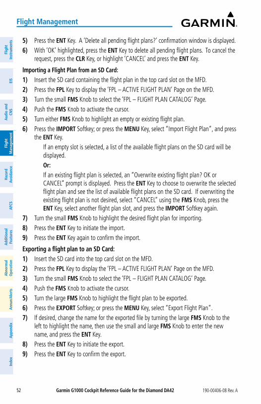
Garmin G1000 Cockpit Reference Guide for the Diamond Da42 190-00406-08 Rev. A52
Flight Management
Flig
htIn
stru
men
tsEI
SN
av/C
om/
XPD
R/A
udio
Flig
ht
Man
agem
ent
Haz
ard
Avoi
danc
eA
FCS
Add
ition
alFe
atur
esA
nnun
/Ale
rts
App
endi
xIn
dex
Flig
htIn
stru
men
tsEI
Sa
udio
and
CNS
Flig
ht
Man
agem
ent
Haz
ard
avoi
danc
ea
FCS
add
ition
alFe
atur
esa
bnor
mal
ope
ratio
na
nnun
/ale
rts
app
endi
xIn
dex
5) Press the ENT Key. A ‘Delete all pending flight plans?’ confirmation window is displayed. 6) With ‘OK’ highlighted, press the ENT Key to delete all pending flight plans. To cancel the
request, press the CLR Key, or highlight ‘CANCEL’ and press the ENT Key.
Importing a Flight Plan from an SD Card:1) Insert the SD card containing the flight plan in the top card slot on the MFD.2) Press the FPL Key to display the ‘FPL – ACTIVE FLIGHT PLAN’ Page on the MFD.3) Turn the small FMS Knob to select the ‘FPL – FLIGHT PLAN CATALOG’ Page.4) Push the FMS Knob to activate the cursor.5) Turn either FMS Knob to highlight an empty or existing flight plan.6) Press the IMPoRT Softkey; or press the MENU Key, select “Import Flight Plan”, and press
the ENT Key. If an empty slot is selected, a list of the available flight plans on the SD card will be
displayed. or: If an existing flight plan is selected, an “Overwrite existing flight plan? OK or
CANCEL” prompt is displayed. Press the ENT Key to choose to overwrite the selected flight plan and see the list of available flight plans on the SD card. If overwriting the existing flight plan is not desired, select “CANCEL” using the FMS Knob, press the ENT Key, select another flight plan slot, and press the IMPoRT Softkey again.
7) Turn the small FMS Knob to highlight the desired flight plan for importing.8) Press the ENT Key to initiate the import.9) Press the ENT Key again to confirm the import.
Exporting a flight plan to an SD Card:1) Insert the SD card into the top card slot on the MFD.2) Press the FPL Key to display the ‘FPL – ACTIVE FLIGHT PLAN’ Page on the MFD.3) Turn the small FMS Knob to select the ‘FPL – FLIGHT PLAN CATALOG’ Page.4) Push the FMS Knob to activate the cursor.5) Turn the large FMS Knob to highlight the flight plan to be exported.6) Press the EXPoRT Softkey; or press the MENU Key, select “Export Flight Plan”.7) If desired, change the name for the exported file by turning the large FMS Knob to the
left to highlight the name, then use the small and large FMS Knob to enter the new name, and press the ENT Key.
8) Press the ENT Key to initiate the export.9) Press the ENT Key to confirm the export.
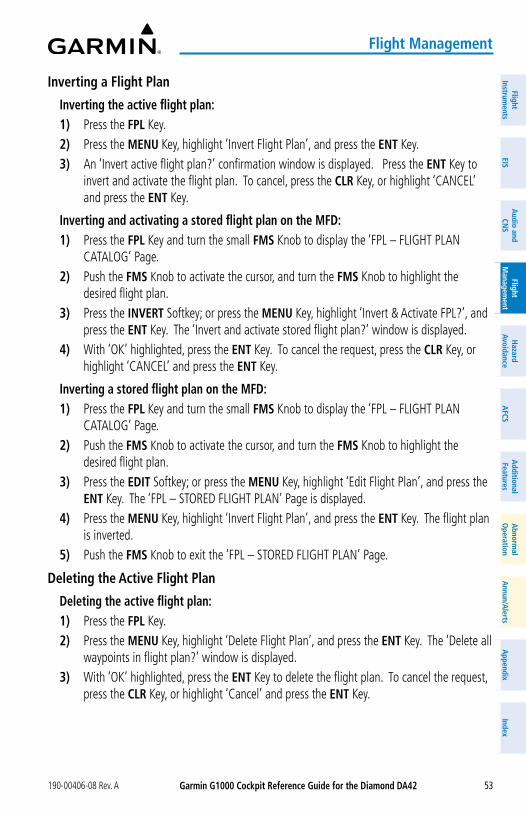
Garmin G1000 Cockpit Reference Guide for the Diamond Da42190-00406-08 Rev. A 53
Flight Management
FlightInstrum
entsEIS
Nav/Com
/XPD
R/Audio
Flight M
anagement
Hazard
AvoidanceA
FCSA
dditionalFeatures
Annun/A
lertsA
ppendixIndex
FlightInstrum
entsEIS
audio and
CNS
Flight M
anagement
Hazard
avoidancea
FCSa
dditionalFeatures
abnorm
alo
perationa
nnun/alerts
appendix
Index
Inverting a Flight Plan
Inverting the active flight plan:1) Press the FPL Key.2) Press the MENU Key, highlight ‘Invert Flight Plan’, and press the ENT Key.3) An ‘Invert active flight plan?’ confirmation window is displayed. Press the ENT Key to
invert and activate the flight plan. To cancel, press the CLR Key, or highlight ‘CANCEL’ and press the ENT Key.
Inverting and activating a stored flight plan on the MFD:1) Press the FPL Key and turn the small FMS Knob to display the ‘FPL – FLIGHT PLAN
CATALOG’ Page.2) Push the FMS Knob to activate the cursor, and turn the FMS Knob to highlight the
desired flight plan.3) Press the INVERT Softkey; or press the MENU Key, highlight ‘Invert & Activate FPL?’, and
press the ENT Key. The ‘Invert and activate stored flight plan?’ window is displayed. 4) With ‘OK’ highlighted, press the ENT Key. To cancel the request, press the CLR Key, or
highlight ‘CANCEL’ and press the ENT Key.
Inverting a stored flight plan on the MFD:1) Press the FPL Key and turn the small FMS Knob to display the ‘FPL – FLIGHT PLAN
CATALOG’ Page.2) Push the FMS Knob to activate the cursor, and turn the FMS Knob to highlight the
desired flight plan.3) Press the EDIT Softkey; or press the MENU Key, highlight ‘Edit Flight Plan’, and press the
ENT Key. The ‘FPL – STORED FLIGHT PLAN’ Page is displayed. 4) Press the MENU Key, highlight ‘Invert Flight Plan’, and press the ENT Key. The flight plan
is inverted. 5) Push the FMS Knob to exit the ‘FPL – STORED FLIGHT PLAN’ Page.
Deleting the active Flight Plan
Deleting the active flight plan:1) Press the FPL Key.2) Press the MENU Key, highlight ‘Delete Flight Plan’, and press the ENT Key. The ‘Delete all
waypoints in flight plan?’ window is displayed.3) With ‘OK’ highlighted, press the ENT Key to delete the flight plan. To cancel the request,
press the CLR Key, or highlight ‘Cancel’ and press the ENT Key.
Garmin G1000 Cockpit Reference Guide for the Diamond Da42 190-00406-08 Rev. A54
Flight Management
Flig
htIn
stru
men
tsEI
SN
av/C
om/
XPD
R/A
udio
Flig
ht
Man
agem
ent
Haz
ard
Avoi
danc
eA
FCS
Add
ition
alFe
atur
esA
nnun
/Ale
rts
App
endi
xIn
dex
Flig
htIn
stru
men
tsEI
Sa
udio
and
CNS
Flig
ht
Man
agem
ent
Haz
ard
avoi
danc
ea
FCS
add
ition
alFe
atur
esa
bnor
mal
ope
ratio
na
nnun
/ale
rts
app
endi
xIn
dex
Stored Flight Plan Functions
Viewing information about a stored flight plan:1) Press the FPL Key for the MFD to display the ‘FPL – ACTIVE FLIGHT PLAN’ Page.2) Turn the small FMS Knob clockwise one click to display the ‘FPL – FLIGHT PLAN
CATALOG’ Page.3) Push the FMS Knob to activate the cursor and turn the FMS Knob to highlight the desired
flight plan.4) The Flight Plan Information is displayed showing departure, destination, total distance,
and enroute safe altitude information for the selected Flight Plan.5) Press the EDIT Softkey to open the ‘FPL – STORED FLIGHT PLAN’ Page and view the
waypoints in the flight plan.6) Push the FMS Knob to exit the ‘FPL – STORED FLIGHT PLAN’ Page.
Storing a flight plan:1) Press the FPL Key.2) Press the Menu Key. Highlight ‘Store Flight Plan’.3) Press the ENT Key.4) With ‘OK’ highlighted, press the ENT Key. The flight plan is stored in the next available
position in the flight plan list on the ‘FPL – FLIGHT PLAN CATALOG’ Page.
activating a stored flight plan on the MFD:1) Press the FPL Key and turn the small FMS Knob to display the ‘FPL – FLIGHT PLAN
CATALOG’ Page.2) Push the FMS Knob to activate the cursor, and turn the FMS Knob to highlight the
desired flight plan.3) Open the ‘Activate stored flight plan?’ window:
Press the aCTIVE Softkey. or: Press the ENT Key. An ‘Activate stored flight plan?’ window will appear. or:a) Press the MENU Key.b) Highlight ‘Activate Flight Plan’ and press the ENT Key.
4) With ‘OK’ highlighted, press the ENT Key. To cancel the request, press the CLR Key, or highlight ‘CANCEL’ and press the ENT Key.
Copying a stored flight plan to another flight plan memory slot, on the MFD:1) Press the FPL Key and turn the small FMS Knob to display the ‘FPL – FLIGHT PLAN
CATALOG’ Page.2) Push the FMS Knob to activate the cursor, and turn the FMS Knob to highlight the
desired flight plan.
Garmin G1000 Cockpit Reference Guide for the Diamond Da42190-00406-08 Rev. A 55
Flight Management
FlightInstrum
entsEIS
Nav/Com
/XPD
R/Audio
Flight M
anagement
Hazard
AvoidanceA
FCSA
dditionalFeatures
Annun/A
lertsA
ppendixIndex
FlightInstrum
entsEIS
audio and
CNS
Flight M
anagement
Hazard
avoidancea
FCSa
dditionalFeatures
abnorm
alo
perationa
nnun/alerts
appendix
Index
3) Open the ‘Copy to flight plan XX?’ window:
Press the CoPy Softkey. or:a) Press the MENU Key, highlight ‘Copy Flight Plan’.b) Press the ENT Key. The ‘Copy to flight plan XX?’ window is displayed.
4) With ‘OK’ highlighted, press the ENT Key to copy the flight plan. To cancel the request, press the CLR Key, or highlight ‘CANCEL’ and press the ENT Key.
Deleting a stored flight plan:1) Press the FPL Key and turn the small FMS Knob to display the ‘FPL – FLIGHT PLAN
CATALOG’ Page.2) Push the FMS Knob to activate the cursor, and turn the FMS Knob to highlight the
desired flight plan.3) Open the ‘Delete flight plan XX?’ window:
Press the DELETE Softkey. or:
Press the CLR Key. or:a) Press the MENU Key.b) Highlight ‘Delete Flight Plan’, and press the ENT Key.
4) With ‘OK’ highlighted, press the ENT Key to delete the flight plan. To cancel the request, press the CLR Key, or highlight ‘CANCEL’ and press the ENT Key.
Deleting all stored flight plans:1) Press the FPL Key and turn the small FMS Knob to display the ‘FPL – FLIGHT PLAN
CATALOG’ Page.2) Press the MENU Key.3) Highlight ‘Delete All’ and press the ENT Key. A ‘Delete all flight plans?’ confirmation
window is displayed. 4) With ‘OK’ highlighted, press the ENT Key to delete all flight plans. To cancel the request,
press the CLR Key, or highlight ‘CANCEL’ and press the ENT Key.
Garmin G1000 Cockpit Reference Guide for the Diamond Da42 190-00406-08 Rev. A56
Flight Management
Flig
htIn
stru
men
tsEI
SN
av/C
om/
XPD
R/A
udio
Flig
ht
Man
agem
ent
Haz
ard
Avoi
danc
eA
FCS
Add
ition
alFe
atur
esA
nnun
/Ale
rts
App
endi
xIn
dex
Flig
htIn
stru
men
tsEI
Sa
udio
and
CNS
Flig
ht
Man
agem
ent
Haz
ard
avoi
danc
ea
FCS
add
ition
alFe
atur
esa
bnor
mal
ope
ratio
na
nnun
/ale
rts
app
endi
xIn
dex
Changing a Flight Plan Comment (Name):1) For the active flight plan, press the FPL Key. Push the FMS Knob to activate the cursor
(not required on PFD). For a stored flight plan:
a) Press the FPL Key for the MFD. Turn the small FMS Knob to select the ‘FPL – FLIGHT PLAN CATALOG’ Page and push the FMS Knob to activate the cursor.
b) Turn the FMS Knob to highlight the desired flight plan.c) Press the EDIT Softkey; or press the ENT Key, turn the large FMS Knob clockwise
to select ‘EDIT’ and press the ENT Key. The ‘FPL – STORED FLIGHT PLAN’ Page is displayed.
2) Select the comment field.3) Use the FMS Knob to edit the comment.4) Press the ENT Key to accept the changes.5) Push the FMS Knob to remove the flashing cursor.
PRoCEDURESViewing available procedures at an airport:1) From the ‘WPT – AIRPORT INFORMATION’ Page: Press the DP Softkey. The ‘WPT – DEPARTURE INFORMATION’ Page is displayed,
defaulting to the airport displayed on the ‘WPT – AIRPORT INFORMATION’ Page. or: Press the STaR Softkey. The ‘WPT – ARRIVAL INFORMATION’ Page is displayed,
defaulting to the airport displayed on the ‘WPT – AIRPORT INFORMATION’ Page. or: Press the aPR Softkey. The ‘WPT – APPROACH INFORMATION’ Page is displayed,
defaulting to the airport displayed on the ‘WPT – AIRPORT INFORMATION’ Page.2) To select another airport, push the FMS Knob to activate the cursor, enter an identifier/
facility name/city, and press the ENT Key.3) Turn the large FMS Knob to highlight the procedure. The procedure is previewed on the
map.4) Turn the small FMS Knob to view the available procedures. Press the ENT Key to select
the procedure. The cursor moves to the next box (runway or transition). The procedure is previewed on the map.
5) Turn the small FMS Knob to view the available runway or transition. Press the ENT Key to select the runway or transition. The cursor moves to the next box (if available). The procedure is previewed on the map.
Garmin G1000 Cockpit Reference Guide for the Diamond Da42190-00406-08 Rev. A 57
Flight Management
FlightInstrum
entsEIS
Nav/Com
/XPD
R/Audio
Flight M
anagement
Hazard
AvoidanceA
FCSA
dditionalFeatures
Annun/A
lertsA
ppendixIndex
FlightInstrum
entsEIS
audio and
CNS
Flight M
anagement
Hazard
avoidancea
FCSa
dditionalFeatures
abnorm
alo
perationa
nnun/alerts
appendix
Index
6) Repeat Step 5, until desired information has been viewed for the chosen procedure.7) Press the INFo-1 Softkey to return to the ‘WPT – AIRPORT INFORMATION’ Page.
DEPaRTURESLoading a departure into the active flight plan using the PRoC Key:1) Press the PRoC Key. The ‘PROCEDURES’ Window is displayed.2) Highlight ‘SELECT DEPARTURE’.3) Press the ENT Key. The ‘PROC – DEPARTURE LOADING’ Page is displayed.4) Use the FMS Knob to select an airport and press the ENT Key.5) Select a departure from the list and press the ENT Key.6) Select a runway (if required) and press the ENT Key.7) Select a transition (if required) and press the ENT Key. ‘LOAD?’ is highlighted.8) Press the ENT Key to load the departure procedure.
Loading a departure into the active flight plan from the ‘WPT – DEPaRTURE INFoRMaTIoN’ Page:1) From the ‘WPT – AIRPORT INFORMATION’ Page (first page in the WPT group), press the
DP Softkey. The ‘WPT – DEPARTURE INFORMATION’ Page is displayed, defaulting to the airport displayed on the ‘WPT – AIRPORT INFORMATION’ Page.
2) To select another airport, push the FMS Knob to activate the cursor, enter an identifier/facility name/city, and press the ENT Key.
3) Select a different departure, if desired.a) Turn the large FMS Knob to place the cursor in the ‘DEPARTURE’ Box. The departure
is previewed on the map.b) Turn the small FMS Knob to view the available departures. Press the ENT Key to
select the departure. The cursor moves to the ‘RUNWAY’ Box. The departure is previewed on the map.
c) Turn the small FMS Knob to view the available runways. Press the ENT Key to select the runway. The cursor moves to the ‘TRANSITION’ Box (only if there are available transitions). The departure is previewed on the map.
d) Turn the small FMS Knob to view the available transitions. Press the ENT Key to select the transition. The cursor moves to the ‘SEQUENCE’ Box. The departure is previewed on the map.
4) Press the MENU Key to display the ‘PAGE MENU’ Window.5) Turn the FMS Knob to highlight ‘Load Departure’.6) Press the ENT Key to load the departure procedure into the active flight plan.
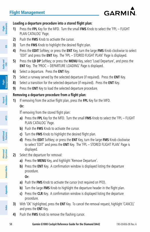
Garmin G1000 Cockpit Reference Guide for the Diamond Da42 190-00406-08 Rev. A58
Flight Management
Flig
htIn
stru
men
tsEI
SN
av/C
om/
XPD
R/A
udio
Flig
ht
Man
agem
ent
Haz
ard
Avoi
danc
eA
FCS
Add
ition
alFe
atur
esA
nnun
/Ale
rts
App
endi
xIn
dex
Flig
htIn
stru
men
tsEI
Sa
udio
and
CNS
Flig
ht
Man
agem
ent
Haz
ard
avoi
danc
ea
FCS
add
ition
alFe
atur
esa
bnor
mal
ope
ratio
na
nnun
/ale
rts
app
endi
xIn
dex
Loading a departure procedure into a stored flight plan:1) Press the FPL Key for the MFD. Turn the small FMS Knob to select the ‘FPL – FLIGHT
PLAN CATALOG’ Page.2) Push the FMS Knob to activate the cursor.3) Turn the FMS Knob to highlight the desired flight plan.4) Press the EDIT Softkey; or press the ENT Key, turn the large FMS Knob clockwise to select
‘EDIT’ and press the ENT Key. The ‘FPL – STORED FLIGHT PLAN’ Page is displayed.5) Press the LD DP Softkey; or press the MENU Key, select ‘Load Departure’, and press the
ENT Key. The ‘PROC – DEPARTURE LOADING’ Page is displayed.6) Select a departure. Press the ENT Key.7) Select a runway served by the selected departure (if required). Press the ENT Key.8) Select a transition for the selected departure (if required). Press the ENT Key.9) Press the ENT Key to load the selected departure procedure.
Removing a departure procedure from a flight plan:1) If removing from the active flight plan, press the FPL Key for the MFD. or:
If removing from the stored flight plan:a) Press the FPL Key for the MFD. Turn the small FMS Knob to select the ‘FPL – FLIGHT
PLAN CATALOG’ Page.b) Push the FMS Knob to activate the cursor.c) Turn the FMS Knob to highlight the desired flight plan.d) Press the EDIT Softkey; or press the ENT Key, turn the large FMS Knob clockwise
to select ‘EDIT’ and press the ENT Key. The ‘FPL – STORED FLIGHT PLAN’ Page is displayed.
2) Select the departure for removal:a) Press the MENU Key, and highlight ‘Remove Departure’.b) Press the ENT Key. A confirmation window is displayed listing the departure
procedure. or:a) Push the FMS Knob to activate the cursor (not required on PFD).b) Turn the large FMS Knob to highlight the departure header in the flight plan.c) Press the CLR Key. A confirmation window is displayed listing the departure
procedure.3) With ‘OK’ highlighted, press the ENT Key. To cancel the removal request, highlight ‘CANCEL’
and press the ENT Key.4) Push the FMS Knob to remove the flashing cursor.
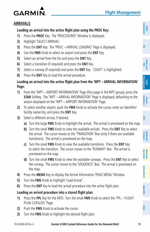
Garmin G1000 Cockpit Reference Guide for the Diamond Da42190-00406-08 Rev. A 59
Flight Management
FlightInstrum
entsEIS
Nav/Com
/XPD
R/Audio
Flight M
anagement
Hazard
AvoidanceA
FCSA
dditionalFeatures
Annun/A
lertsA
ppendixIndex
FlightInstrum
entsEIS
audio and
CNS
Flight M
anagement
Hazard
avoidancea
FCSa
dditionalFeatures
abnorm
alo
perationa
nnun/alerts
appendix
Index
aRRIVaLS Loading an arrival into the active flight plan using the PRoC Key:1) Press the PRoC Key. The ‘PROCEDURES’ Window is displayed.2) Highlight ‘SELECT ARRIVAL’.3) Press the ENT Key. The ‘PROC – ARRIVAL LOADING’ Page is displayed.4) Use the FMS Knob to select an airport and press the ENT Key.5) Select an arrival from the list and press the ENT Key.6) Select a transition (if required) and press the ENT Key.7) Select a runway (if required) and press the ENT Key. ‘LOAD?’ is highlighted.8) Press the ENT Key to load the arrival procedure.
Loading an arrival into the active flight plan from the ‘WPT – aRRIVaL INFoRMaTIoN’ Page:1) From the ‘WPT – AIRPORT INFORMATION’ Page (first page in the WPT group), press the
STaR Softkey. The ‘WPT – ARRIVAL INFORMATION’ Page is displayed, defaulting to the airport displayed on the ‘WPT – AIRPORT INFORMATION’ Page.
2) To select another airport, push the FMS Knob to activate the cursor, enter an identifier/facility name/city, and press the ENT Key.
3) Select a different arrival, if desired.a) Turn the large FMS Knob to highlight the arrival. The arrival is previewed on the map.b) Turn the small FMS Knob to view the available arrivals. Press the ENT Key to select
the arrival. The cursor moves to the ‘TRANSITION’ Box (only if there are available transitions). The arrival is previewed on the map.
c) Turn the small FMS Knob to view the available transitions. Press the ENT Key to select the transition. The cursor moves to the ‘RUNWAY’ Box. The arrival is previewed on the map.
d) Turn the small FMS Knob to view the available runways. Press the ENT Key to select the runway. The cursor moves to the ‘SEQUENCE’ Box. The arrival is previewed on the map.
4) Press the MENU Key to display the Arrival Information ‘PAGE MENU’ Window.5) Turn the FMS Knob to highlight ‘Load Arrival’.6) Press the ENT Key to load the arrival procedure into the active flight plan.
Loading an arrival procedure into a stored flight plan:1) Press the FPL Key for the MFD. Turn the small FMS Knob to select the ‘FPL – FLIGHT
PLAN CATALOG’ Page.2) Push the FMS Knob to activate the cursor.3) Turn the FMS Knob to highlight the desired flight plan.
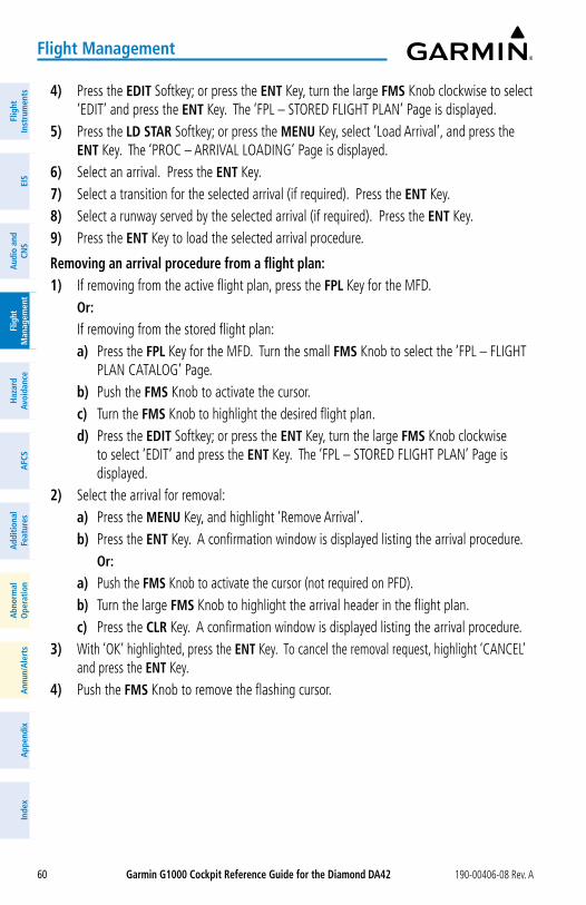
Garmin G1000 Cockpit Reference Guide for the Diamond Da42 190-00406-08 Rev. A60
Flight Management
Flig
htIn
stru
men
tsEI
SN
av/C
om/
XPD
R/A
udio
Flig
ht
Man
agem
ent
Haz
ard
Avoi
danc
eA
FCS
Add
ition
alFe
atur
esA
nnun
/Ale
rts
App
endi
xIn
dex
Flig
htIn
stru
men
tsEI
Sa
udio
and
CNS
Flig
ht
Man
agem
ent
Haz
ard
avoi
danc
ea
FCS
add
ition
alFe
atur
esa
bnor
mal
ope
ratio
na
nnun
/ale
rts
app
endi
xIn
dex
4) Press the EDIT Softkey; or press the ENT Key, turn the large FMS Knob clockwise to select ‘EDIT’ and press the ENT Key. The ‘FPL – STORED FLIGHT PLAN’ Page is displayed.
5) Press the LD STaR Softkey; or press the MENU Key, select ‘Load Arrival’, and press the ENT Key. The ‘PROC – ARRIVAL LOADING’ Page is displayed.
6) Select an arrival. Press the ENT Key.7) Select a transition for the selected arrival (if required). Press the ENT Key.8) Select a runway served by the selected arrival (if required). Press the ENT Key.9) Press the ENT Key to load the selected arrival procedure.
Removing an arrival procedure from a flight plan:1) If removing from the active flight plan, press the FPL Key for the MFD. or: If removing from the stored flight plan:
a) Press the FPL Key for the MFD. Turn the small FMS Knob to select the ‘FPL – FLIGHT PLAN CATALOG’ Page.
b) Push the FMS Knob to activate the cursor.c) Turn the FMS Knob to highlight the desired flight plan.d) Press the EDIT Softkey; or press the ENT Key, turn the large FMS Knob clockwise
to select ‘EDIT’ and press the ENT Key. The ‘FPL – STORED FLIGHT PLAN’ Page is displayed.
2) Select the arrival for removal:a) Press the MENU Key, and highlight ‘Remove Arrival’.b) Press the ENT Key. A confirmation window is displayed listing the arrival procedure. or:a) Push the FMS Knob to activate the cursor (not required on PFD).b) Turn the large FMS Knob to highlight the arrival header in the flight plan.c) Press the CLR Key. A confirmation window is displayed listing the arrival procedure.
3) With ‘OK’ highlighted, press the ENT Key. To cancel the removal request, highlight ‘CANCEL’ and press the ENT Key.
4) Push the FMS Knob to remove the flashing cursor.
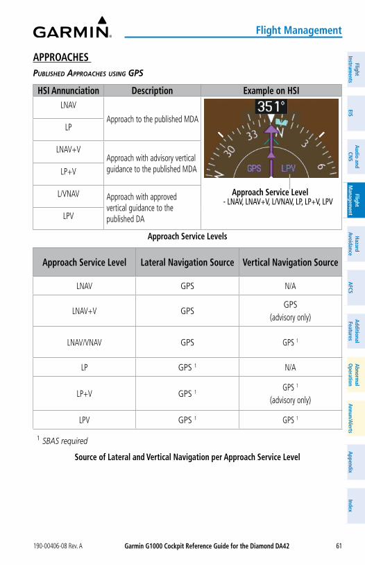
Garmin G1000 Cockpit Reference Guide for the Diamond Da42190-00406-08 Rev. A 61
Flight Management
FlightInstrum
entsEIS
Nav/Com
/XPD
R/Audio
Flight M
anagement
Hazard
AvoidanceA
FCSA
dditionalFeatures
Annun/A
lertsA
ppendixIndex
FlightInstrum
entsEIS
audio and
CNS
Flight M
anagement
Hazard
avoidancea
FCSa
dditionalFeatures
abnorm
alo
perationa
nnun/alerts
appendix
Index
aPPRoaCHES published approaChes using gps
HSI annunciation Description Example on HSILNAV
Approach to the published MDA
approach Service Level- LNAV, LNAV+V, L/VNAV, LP, LP+V, LPV
LP
LNAV+VApproach with advisory vertical guidance to the published MDALP+V
L/VNAV Approach with approved vertical guidance to the published DALPV
approach Service Levels
approach Service Level Lateral Navigation Source Vertical Navigation Source
LNAV GPS N/A
LNAV+V GPS GPS
(advisory only)
LNAV/VNAV GPS GPS 1
LP GPS 1 N/A
LP+V GPS 1GPS 1
(advisory only)
LPV GPS 1 GPS 1
1 SBAS required
Source of Lateral and Vertical Navigation per approach Service Level
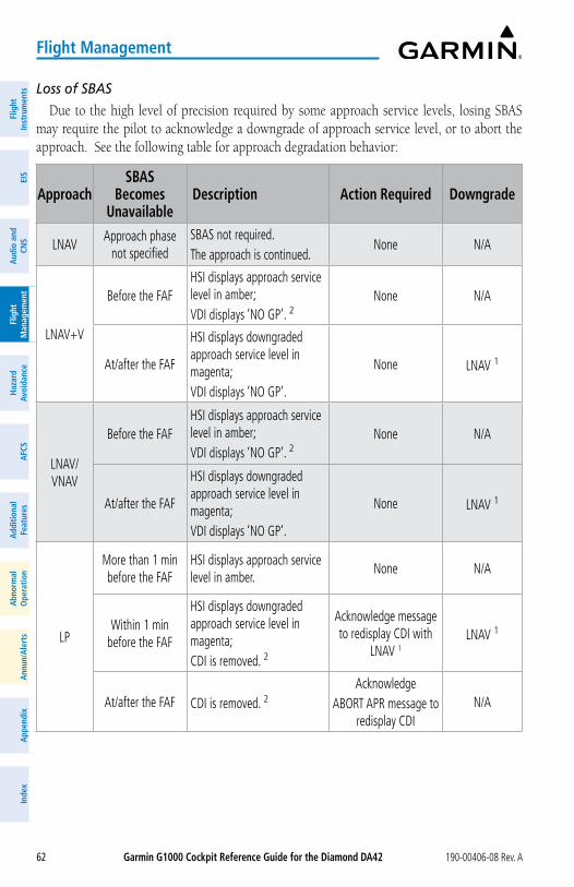
Garmin G1000 Cockpit Reference Guide for the Diamond Da42 190-00406-08 Rev. A62
Flight Management
Flig
htIn
stru
men
tsEI
SN
av/C
om/
XPD
R/A
udio
Flig
ht
Man
agem
ent
Haz
ard
Avoi
danc
eA
FCS
Add
ition
alFe
atur
esA
nnun
/Ale
rts
App
endi
xIn
dex
Flig
htIn
stru
men
tsEI
Sa
udio
and
CNS
Flig
ht
Man
agem
ent
Haz
ard
avoi
danc
ea
FCS
add
ition
alFe
atur
esa
bnor
mal
ope
ratio
na
nnun
/ale
rts
app
endi
xIn
dex
Loss of SBAS
Due to the high level of precision required by some approach service levels, losing SBAS may require the pilot to acknowledge a downgrade of approach service level, or to abort the approach. See the following table for approach degradation behavior:
approachSBaS
Becomes Unavailable
Description action Required Downgrade
LNAVApproach phase
not specifiedSBAS not required. The approach is continued.
None N/A
LNAV+V
Before the FAFHSI displays approach service level in amber;VDI displays ‘NO GP’. 2
None N/A
At/after the FAF
HSI displays downgraded approach service level in magenta;VDI displays ‘NO GP’.
None LNAV 1
LNAV/VNAV
Before the FAFHSI displays approach service level in amber;VDI displays ‘NO GP’. 2
None N/A
At/after the FAF
HSI displays downgraded approach service level in magenta;VDI displays ‘NO GP’.
None LNAV 1
LP
More than 1 min before the FAF
HSI displays approach service level in amber.
None N/A
Within 1 min before the FAF
HSI displays downgraded approach service level in magenta;CDI is removed. 2
Acknowledge message to redisplay CDI with
LNAV 1LNAV 1
At/after the FAF CDI is removed. 2Acknowledge
ABORT APR message to redisplay CDI
N/A
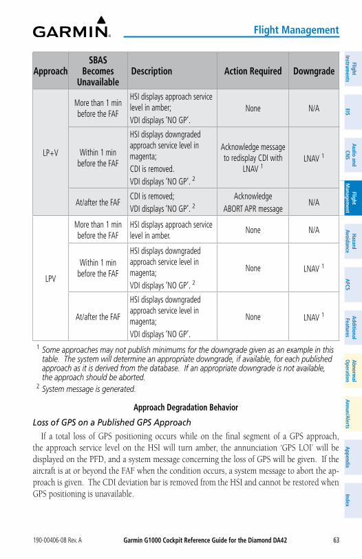
Garmin G1000 Cockpit Reference Guide for the Diamond Da42190-00406-08 Rev. A 63
Flight Management
FlightInstrum
entsEIS
Nav/Com
/XPD
R/Audio
Flight M
anagement
Hazard
AvoidanceA
FCSA
dditionalFeatures
Annun/A
lertsA
ppendixIndex
FlightInstrum
entsEIS
audio and
CNS
Flight M
anagement
Hazard
avoidancea
FCSa
dditionalFeatures
abnorm
alo
perationa
nnun/alerts
appendix
Index
approachSBaS
Becomes Unavailable
Description action Required Downgrade
LP+V
More than 1 min before the FAF
HSI displays approach service level in amber;VDI displays ‘NO GP’.
None N/A
Within 1 min before the FAF
HSI displays downgraded approach service level in magenta;CDI is removed.VDI displays ‘NO GP’. 2
Acknowledge message to redisplay CDI with
LNAV 1LNAV 1
At/after the FAFCDI is removed;VDI displays ‘NO GP’. 2
AcknowledgeABORT APR message
N/A
LPV
More than 1 min before the FAF
HSI displays approach service level in amber.
None N/A
Within 1 min before the FAF
HSI displays downgraded approach service level in magenta;VDI displays ‘NO GP’. 2
None LNAV 1
At/after the FAF
HSI displays downgraded approach service level in magenta;VDI displays ‘NO GP’.
None LNAV 1
1 Some approaches may not publish minimums for the downgrade given as an example in this table. The system will determine an appropriate downgrade, if available, for each published approach as it is derived from the database. If an appropriate downgrade is not available, the approach should be aborted.
2 System message is generated.
approach Degradation Behavior
Loss of GPS on a Published GPS Approach
If a total loss of GPS positioning occurs while on the final segment of a GPS approach, the approach service level on the HSI will turn amber, the annunciation ‘GPS LOI’ will be displayed on the PFD, and a system message concerning the loss of GPS will be given. If the aircraft is at or beyond the FAF when the condition occurs, a system message to abort the ap-proach is given. The CDI deviation bar is removed from the HSI and cannot be restored when GPS positioning is unavailable.
Garmin G1000 Cockpit Reference Guide for the Diamond Da42 190-00406-08 Rev. A64
Flight Management
Flig
htIn
stru
men
tsEI
SN
av/C
om/
XPD
R/A
udio
Flig
ht
Man
agem
ent
Haz
ard
Avoi
danc
eA
FCS
Add
ition
alFe
atur
esA
nnun
/Ale
rts
App
endi
xIn
dex
Flig
htIn
stru
men
tsEI
Sa
udio
and
CNS
Flig
ht
Man
agem
ent
Haz
ard
avoi
danc
ea
FCS
add
ition
alFe
atur
esa
bnor
mal
ope
ratio
na
nnun
/ale
rts
app
endi
xIn
dex
Loss of Integrity
When the system is no longer receiving sufficient GPS integrity while on the final segment of a GPS approach, the approach service level on the HSI will turn amber, the annunciation ‘GPS LOI’ will be displayed on the PFD, and a system message concerning the loss of GPS will be given. If the aircraft is at or beyond the FAF when the condition occurs, a system message to abort the approach is given, and the CDI deviation bar is removed from the HSI. The CDI deviation bar will reappear after acknowledging the system message to abort the approach.
Loading and activating an approach
Loading an approach into the active flight plan using the PRoC Key:1) Press the PRoC Key. The ‘PROCEDURES’ Window is displayed.2) Highlight ‘SELECT APPROACH’, and press the ENT Key. The ‘PROC – APPROACH
LOADING’ Page is displayed.3) Select the airport and approach:
a) Use the FMS Knob to select an airport and press the ENT Key.b) Select an approach from the list and press the ENT Key. or:a) If necessary, push the FMS Knob to exit the approach list, and use the large FMS
Knob to move the cursor to the ‘CHANNEL’ Field.b) Use the FMS Knob to enter the approach channel number, and press the ENT Key to
accept the approach channel number. The airport and approach are selected.4) Select a transition (if required) and press the ENT Key.5) Enter minimums:
To skip setting minimums, press the ENT Key. or:a) To set ‘MINIMUMS’, turn the small FMS Knob to select ‘BARO’ or ‘TEMP COMP’, and
press the ENT Key. Turn the small FMS Knob to select the altitude, and press the ENT Key.
b) If ‘TEMP COMP’ was selected, the cursor moves to the temperature field. Turn the small FMS Knob to select the temperature (as reported at the destination airport), and press the ENT Key.
6) Press the ENT Key with ‘LOAD?’ highlighted to load the approach procedure; or turn the large FMS Knob to highlight ‘ACTIVATE?’ and press the ENT Key to load and activate the approach procedure.
When selecting a NAVAID exclusive approach, the popup message is displayed: ‘NOT APPROVED FOR GPS - GPS guidance is for monitoring only. Load approach?’ With ‘YES’ highlighted, press the ENT Key.
Garmin G1000 Cockpit Reference Guide for the Diamond Da42190-00406-08 Rev. A 65
Flight Management
FlightInstrum
entsEIS
Nav/Com
/XPD
R/Audio
Flight M
anagement
Hazard
AvoidanceA
FCSA
dditionalFeatures
Annun/A
lertsA
ppendixIndex
FlightInstrum
entsEIS
audio and
CNS
Flight M
anagement
Hazard
avoidancea
FCSa
dditionalFeatures
abnorm
alo
perationa
nnun/alerts
appendix
Index
Loading an approach into the active flight plan from the ‘NRST – NEaREST aIRPoRT’ Page:1) Select the ‘NRST – NEAREST AIRPORTS’ Page.2) Push the FMS Knob, then turn the large FMS Knob to highlight the desired nearest
airport. The airport is previewed on the map.3) Press the aPR Softkey; or press the MENU Key, highlight ‘Select Approach Window’, and
press the ENT Key.4) Turn the FMS Knob to highlight the desired approach. 5) Press the LD aPR Softkey; or press the MENU Key, highlight ‘Load Approach’, and
press the ENT Key. The ‘PROC – APPROACH LOADING’ Page is displayed with the ‘TRANSITION’ Field highlighted.
6) Turn the FMS Knob to highlight the desired transition, and press the ENT Key. 7) Enter Minimums:
To skip setting minimums, press the ENT Key. The ‘LOAD?’ Field is highlighted. or:a) To set ‘MINIMUMS’, turn the small FMS Knob to select ‘BARO’ or ‘TEMP COMP’, and
press the ENT Key. Turn the small FMS Knob to select the altitude, and press the ENT Key.
b) If ‘TEMP COMP’ was selected, the cursor moves to the temperature field. Turn the small FMS Knob to select the temperature, and press the ENT Key.
8) Press the ENT Key with ‘LOAD?’ highlighted to load the approach procedure; or turn the large FMS Knob to highlight ‘ACTIVATE?’ and press the ENT Key to load and activate the approach procedure.
When selecting a NAVAID exclusive approach, the popup message is displayed: ‘NOT APPROVED FOR GPS - GPS guidance is for monitoring only. Load approach?’ With ‘YES’ highlighted, press the ENT Key.
Loading an approach procedure into a stored flight plan:1) Press the FPL Key for the MFD. Turn the small FMS Knob to select the ‘FPL – FLIGHT
PLAN CATALOG’ Page and push the FMS Knob to activate the cursor.2) Turn the FMS Knob to highlight the desired flight plan.3) Press the EDIT Softkey; or press the ENT Key, turn the large FMS Knob clockwise to select
‘EDIT’ and press the ENT Key. The ‘FPL – STORED FLIGHT PLAN’ Page is displayed.4) Press the LD aPR Softkey; or press the MENU Key, select “Load Approach”, and press the
ENT Key. The ‘PROC – APPROACH LOADING’ Page is displayed.5) Select the airport and approach:
a) Use the FMS Knob to select an airport and press the ENT Key.b) Select an approach from the list and press the ENT Key. or:
Garmin G1000 Cockpit Reference Guide for the Diamond Da42 190-00406-08 Rev. A66
Flight Management
Flig
htIn
stru
men
tsEI
SN
av/C
om/
XPD
R/A
udio
Flig
ht
Man
agem
ent
Haz
ard
Avoi
danc
eA
FCS
Add
ition
alFe
atur
esA
nnun
/Ale
rts
App
endi
xIn
dex
Flig
htIn
stru
men
tsEI
Sa
udio
and
CNS
Flig
ht
Man
agem
ent
Haz
ard
avoi
danc
ea
FCS
add
ition
alFe
atur
esa
bnor
mal
ope
ratio
na
nnun
/ale
rts
app
endi
xIn
dex
a) If necessary, push the FMS Knob to exit the approach list, and use the large FMS Knob to move the cursor to the ‘APPROACH CHANNEL’ Field.
b) Use the FMS Knob to enter the approach channel number, and press the ENT Key to accept the approach channel number. The airport and approach are selected.
6) Select a transition for the selected approach. Press the ENT Key.7) Press the ENT Key to load the selected approach procedure.activating a previously loaded approach:1) Press the PRoC Key. The ‘PROCEDURES’ Window is displayed with ‘ACTIVATE Approach’
highlighted.2) Press the ENT Key to activate the approach.
activating a previously loaded approach with vectors to final:1) Press the PRoC Key to display the ‘PROCEDURES’ Window.2) Highlight ‘ACTIVATE VECTOR-TO-FINAL’ and press the ENT Key.
Loading and activating an approach using the MENU Key:1) From the ‘PROC – APPROACH LOADING’ Page, press the MENU Key. The ‘PAGE MENU’
Window is displayed with ‘Load & Activate Approach’ highlighted.2) Press the ENT Key. When selecting a NAVAID exclusive approach, the popup message is displayed: ‘NOT
APPROVED FOR GPS - GPS guidance is for monitoring only. Load approach?’ With ‘YES’ highlighted, press the ENT Key.
or:1) Press the PRoC Key.2) Use the large FMS Knob to highlight ‘SELECT APPROACH’ and press the ENT Key.3) From the ‘PROC – APPROACH LOADING’ Page, press the MENU Key for the MFD. The
‘PAGE MENU’ Window is displayed with ‘Load & Activate Approach’ highlighted.4) Press the ENT Key.
When selecting a NAVAID exclusive approach, the popup message is displayed: ‘NOT APPROVED FOR GPS - GPS guidance is for monitoring only. Load approach?’ With ‘YES’ highlighted, press the ENT Key.
Removing an approach
Removing an approach from the active or stored flight plan:1) Open the appropriate flight plan page: For the active flight plan, press the FPL Key, or turn the FMS Knob to select the ‘FPL –
ACTIVE FLIGHT PLAN’ Page. or:
Garmin G1000 Cockpit Reference Guide for the Diamond Da42190-00406-08 Rev. A 67
Flight Management
FlightInstrum
entsEIS
Nav/Com
/XPD
R/Audio
Flight M
anagement
Hazard
AvoidanceA
FCSA
dditionalFeatures
Annun/A
lertsA
ppendixIndex
FlightInstrum
entsEIS
audio and
CNS
Flight M
anagement
Hazard
avoidancea
FCSa
dditionalFeatures
abnorm
alo
perationa
nnun/alerts
appendix
Index
For a stored flight plan:a) Turn the FMS Knob to select the ‘FPL – FLIGHT PLAN CATALOG’ Page and push the
FMS Knob to activate the cursor.b) Turn the FMS Knob to highlight the desired flight plan.c) Press the EDIT Softkey; or press the ENT Key, turn the large FMS Knob clockwise
to select ‘EDIT’ and press the ENT Key. The ‘FPL – STORED FLIGHT PLAN’ Page is displayed.
2) Remove the approach:a) Press the MENU Key, and highlight ‘Remove Approach’.b) Press the ENT Key. A confirmation window is displayed listing the approach
procedure.c) With ‘OK’ highlighted, press the ENT Key. or:a) Push the FMS Knob to activate the cursor if not already activated.b) Turn the large FMS Knob to highlight the approach header in the flight plan.c) Press the CLR Key. A confirmation window is displayed listing the approach
procedure.d) With ‘OK’ highlighted, press the ENT Key.e) Push the FMS Knob to remove the flashing cursor.
Missed approach
activating a missed approach in the active flight plan: Press the Go-Around Button. or:
Fly past the MAP, and press the SUSP Softkey on the PFD. or:1) Press the PRoC Key.2) Turn the FMS Knob to highlight ‘ACTIVATE MISSED APPROACH’. (This option is selectable
after the leg to the FAF becomes active and GPS is the active NAV source.)3) Press the ENT Key.
Temperature Compensated altitude
temperature Compensation For approaCh altitudes
NoTE: The use of temperature compensated altitudes outside the final approach segment shall be coordinated with ATC.
Garmin G1000 Cockpit Reference Guide for the Diamond Da42 190-00406-08 Rev. A68
Flight Management
Flig
htIn
stru
men
tsEI
SN
av/C
om/
XPD
R/A
udio
Flig
ht
Man
agem
ent
Haz
ard
Avoi
danc
eA
FCS
Add
ition
alFe
atur
esA
nnun
/Ale
rts
App
endi
xIn
dex
Flig
htIn
stru
men
tsEI
Sa
udio
and
CNS
Flig
ht
Man
agem
ent
Haz
ard
avoi
danc
ea
FCS
add
ition
alFe
atur
esa
bnor
mal
ope
ratio
na
nnun
/ale
rts
app
endi
xIn
dex
Manually setting temperature compensation for approach waypoint altitudes:1) From the ‘FPL – ACTIVE FLIGHT PLAN’ Page, press the MENU Key. The ‘PAGE MENU’
Window is displayed.2) Turn the FMS Knob to highlight ‘Temperature Compensation’.3) Press the ENT Key. The ‘TEMPERATURE COMPENSATION’ Window is displayed with the
temperature highlighted.
4) Use the small FMS Knob to change the ‘TEMP AT <airport>’ Field. The compensated altitude is computed as the temperature is selected.
5) Press the ENT Key. ‘ACTIVATE COMPENSATION?’ is highlighted.
6) Press the ENT Key. The compensated altitudes for the approach are shown in the flight plan.
Cancelling temperature compensation setting for approach waypoint altitudes:1) From the ‘FPL – ACTIVE FLIGHT PLAN’ Page, press the MENU Key. The ‘PAGE MENU’
Window is displayed.2) Turn the FMS Knob to highlight ‘Temperature Compensation’.
3) Press the ENT Key. The ‘TEMPERATURE COMPENSATION’ Window is displayed.4) Press the ENT Key. ‘CANCEL COMPENSATION?’ is highlighted.
5) Press the ENT Key.
temperature Compensation For approaCh minimums
Entering a temperature compensated minimum into an approach:1) From the ‘FPL – ACTIVE FLIGHT PLAN’ Page, press the PRoC Key. The ‘PROCEDURES’
Window is displayed.2) If necessary, turn the large FMS Knob to highlight ‘SELECT APPROACH’. Press the ENT
Key. 3) If necessary, use the FMS Knob and the ENT Key to select the desired airport, approach,
and transition. 4) Use the FMS Knob to place the flashing cursor in the ‘MINIMUMS’ Box. Turn the small
FMS Knob to select ‘TEMP COMP’. Press the ENT Key. 5) Turn the small FMS Knob to enter the minimums altitude. Press the ENT Key. The cursor
is placed in the ‘TEMP AT <destination airport>’ Field. 6) Turn the small FMS Knob to enter the temperature at the destination. Press the ENT Key. 7) Press the ENT Key with either ‘LOAD?’ or ‘ACTIVATE?’ highlighted. The approach
is added to the active flight plan, and the temperature compensated minimums are displayed on the PFD.
Garmin G1000 Cockpit Reference Guide for the Diamond Da42190-00406-08 Rev. A 69
Flight Management
FlightInstrum
entsEIS
Nav/Com
/XPD
R/Audio
Flight M
anagement
Hazard
AvoidanceA
FCSA
dditionalFeatures
Annun/A
lertsA
ppendixIndex
FlightInstrum
entsEIS
audio and
CNS
Flight M
anagement
Hazard
avoidancea
FCSa
dditionalFeatures
abnorm
alo
perationa
nnun/alerts
appendix
Index
TRIP PLaNNINGSelecting automatic or manual page mode: From the ‘AUX – TRIP PLANNING’ Page, press the aUTo Softkey or the MaNUaL Softkey;
or press the MENU Key, highlight ‘Auto Mode’ or ‘Manual Mode’, and press the ENT Key.
Selecting flight plan or waypoint mode: From the ‘AUX – TRIP PLANNING’ Page, press the FPL Softkey or the WPTS Softkey; or
press the MENU Key, highlight ‘Flight Plan Mode’ or ‘Waypoints Mode’, and press the ENT Key.
Selecting a flight plan and leg for trip statistics:1) From the ‘AUX – TRIP PLANNING’ Page, push the FMS Knob to activate the cursor in the
‘FPL’ Field.2) Turn the small FMS Knob to select the desired flight plan number. 3) Turn the large FMS Knob to highlight ‘CUM’ or ‘REM’. The statistics for each leg can be
viewed by turning the small FMS Knob to select the desired leg. The Trip Planning Map also displays the selected data.
Selecting waypoints for waypoint mode:1) From the ‘AUX – TRIP PLANNING’ Page, press the WPTS Softkey; or press the MENU
Key, highlight ‘Waypoints Mode’, and press the ENT Key. The cursor is positioned in the waypoint field directly below the ‘FPL’ Field.
2) Turn the FMS Knob to select the desired waypoint (or select from the ‘PAGE MENU’ Window ‘Set WPT to Present Position’ if that is what is desired), and press the ENT Key. The cursor moves to the second waypoint field.
3) Turn the FMS Knob to select the desired waypoint, and press the ENT Key. The statistics for the selected leg are displayed.
Entering manual data for trip statistics calculations:1) From the ‘AUX – TRIP PLANNING’ Page, press the MaNUaL Softkey or select ‘Manual
Mode’ from the ‘PAGE MENU’ Window, and press the ENT Key. The cursor may now be positioned in any field within the input data box.
2) Turn the FMS Knob to move the cursor onto the ‘DEP TIME’ Field and enter the desired value. Press the ENT Key. The statistics are calculated using the new value and the cursor moves to the next entry field. Repeat until all desired values have been entered.
Garmin G1000 Cockpit Reference Guide for the Diamond Da42 190-00406-08 Rev. A70
Flight Management
Flig
htIn
stru
men
tsEI
SN
av/C
om/
XPD
R/A
udio
Flig
ht
Man
agem
ent
Haz
ard
Avoi
danc
eA
FCS
Add
ition
alFe
atur
esA
nnun
/Ale
rts
App
endi
xIn
dex
Flig
htIn
stru
men
tsEI
Sa
udio
and
CNS
Flig
ht
Man
agem
ent
Haz
ard
avoi
danc
ea
FCS
add
ition
alFe
atur
esa
bnor
mal
ope
ratio
na
nnun
/ale
rts
app
endi
xIn
dex
RECEIVER aUToNoMoUS INTEGRITy MoNIToRING (RaIM) PREDICTIoN
In most cases, performing a RAIM prediction is not necessary. However, in some cases, the selected approach may be outside the SBAS coverage area and it may be necessary to perform a RAIM prediction for the intended approach.
Receiver Autonomous Integrity Monitoring (RAIM) is a GPS receiver function that performs a consistency check on all tracked satellites. RAIM ensures the available satellite geometry al-lows the receiver to calculate a position within a specified RAIM protection limit (2.0 nm for oceanic and enroute, 1.0 nm for terminal, and 0.3 nm for non-precision approaches). During oceanic, enroute, and terminal phases of flight, RAIM is available nearly 100% of the time.
The RAIM prediction function also indicates whether RAIM is available at a specified date and time. RAIM computations predict satellite coverage within ±15 min of the specified arrival date and time.
Because of the tighter protection limit on approaches, there may be times when RAIM is not available. The system automatically monitors RAIM and warns with an alert message when it is not available. If RAIM is not predicted to be available for the final approach course, the approach does not become active, as indicated by the messages ‘Approach is not active’ and ‘RAIM not available from FAF to MAP’. If RAIM is not available when crossing the FAF, the missed approach procedure must be flown.
NoTE: The system RAIM prediction capability does not meet all RAIM prediction requirements. Reference the RAIM/Fault Detection and Exclusion (FDE) Prediction Tool at flygarmin.com, as required.
Predicting RaIM availability at a selected waypoint:1) Use the FMS Knob to select the AUX – GPS STATUS Page.2) If necessary, press the RaIM Softkey.3) Push the FMS Knob. The ‘WAYPOINT’ Field is highlighted.4) Turn the small FMS Knob to display the WAYPOINT INFORMATION Window.5) Use the FMS Knob to enter the desired waypoint by identifier, facility, or city name and
press the ENT Key.or:a) Turn the small FMS Knob counter-clockwise to display a list of flight plan waypoints
(the flight plan list is populated only when navigating a flight plan).b) Turn the small FMS Knob clockwise to display the Nearest, Recent, or User waypoints,
if required.
Garmin G1000 Cockpit Reference Guide for the Diamond Da42190-00406-08 Rev. A 71
Flight Management
FlightInstrum
entsEIS
Nav/Com
/XPD
R/Audio
Flight M
anagement
Hazard
AvoidanceA
FCSA
dditionalFeatures
Annun/A
lertsA
ppendixIndex
FlightInstrum
entsEIS
audio and
CNS
Flight M
anagement
Hazard
avoidancea
FCSa
dditionalFeatures
abnorm
alo
perationa
nnun/alerts
appendix
Index
c) Turn the large FMS Knob clockwise to select the desired waypoint. Press the ENT Key. The system automatically fills in the identifier, facility, and city fields with the information for the selected waypoint.
d) Press the ENT Key again to accept the waypoint entry.6) Use the FMS Knob to enter an arrival time and press the ENT Key.7) Use the FMS Knob to enter an arrival date and press the ENT Key.8) With the cursor highlighting ‘COMPUTE RAIM?’, press the ENT Key. Once RAIM
availability is computed, one of the following is displayed: • ‘COMPUTE RAIM?’— RAIM has not been computed for the current waypoint, time, and
date combination • ‘COMPUTING AVAILABILITY’— RAIM calculation in progress • ‘RAIM AVAILABLE’— RAIM is predicted to be available for the specified waypoint, time,
and date • ‘RAIM NOT AVAILABLE’— RAIM is predicted to be unavailable for the specified
waypoint, time, and date
Predicting RaIM availability at present position:1) Use the FMS Knob to select the AUX – GPS STATUS Page.2) If necessary, press the RaIM Softkey.3) Push the FMS Knob. ‘P.POS’ in the ‘WAYPOINT’ Field is highlighted.4) Press the ENT Key to accept the present position waypoint entry.5) Use the FMS Knob to enter an arrival time and press the ENT Key.6) Use the FMS Knob to enter an arrival date and press the ENT Key.7) With the cursor highlighting ‘COMPUTE RAIM?’, press the ENT Key. Once RAIM
availability is computed, one of the following is displayed: • ‘COMPUTE RAIM?’— RAIM has not been computed for the current waypoint, time, and
date combination • ‘COMPUTING AVAILABILITY’— RAIM calculation in progress • ‘RAIM AVAILABLE’— RAIM is predicted to be available for the specified waypoint, time,
and date • ‘RAIM NOT AVAILABLE’— RAIM is predicted to be unavailable for the specified
waypoint, time, and date
Garmin G1000 Cockpit Reference Guide for the Diamond Da42 190-00406-08 Rev. A72
Flight Management
Flig
htIn
stru
men
tsEI
SN
av/C
om/
XPD
R/A
udio
Flig
ht
Man
agem
ent
Haz
ard
Avoi
danc
eA
FCS
Add
ition
alFe
atur
esA
nnun
/Ale
rts
App
endi
xIn
dex
Flig
htIn
stru
men
tsEI
Sa
udio
and
CNS
Flig
ht
Man
agem
ent
Haz
ard
avoi
danc
ea
FCS
add
ition
alFe
atur
esa
bnor
mal
ope
ratio
na
nnun
/ale
rts
app
endi
xIn
dex
Blank Page
Garmin G1000 Cockpit Reference Guide for the Diamond Da42190-00406-08 Rev. A 73
Hazard avoidance
FlightInstrum
entsEIS
Nav/Com
/XPD
R/Audio
Flight M
anagement
Hazard
AvoidanceA
FCSA
dditionalFeatures
Annun/A
lertsA
ppendixIndex
FlightInstrum
entsEIS
audio and
CNS
Flight M
anagement
Hazard
avoidancea
FCSa
dditionalFeatures
abnorm
alo
perationa
nnun/alerts
appendix
Index
HaZaRD aVoIDaNCESIRIUSXM WEaTHER
WaRNING: Do not use data link weather information for maneuvering in, near, or around areas of hazardous weather. Information contained within data link weather products may not accurately depict current weather conditions.
WaRNING: Do not use the indicated data link weather product age to verify the age of the weather information shown by the data link weather product. Due to time delays inherent in gathering and processing weather data for data link transmission, the weather information shown by the data link weather product may be significantly older than the indicated weather product age.
aCTIVaTING SERVICESBefore SiriusXM Weather and SiriusXM Satellite Radio can be used, the service must be
activated. Service is activated by providing coded IDs unique to the installed GDL 69/69A. SiriusXM Satellite Radio (audio) and SiriusXM Weather (data) services each have coded IDs. The Data and Audio Radio IDs must be provided to activate the weather service and entertain-ment subscriptions, respectively. These IDs are located on:
– The ‘AUX - XM INFORMATION’ Page on the MFD.
– The XM Satellite Radio Activation Instructions included with the unit
– The label on the back of the Data Link Receiver
Contact the installer if the Audio and Data Radio IDs cannot be located.
SiriusXM uses the coded IDs to send an activation signal that allows the system to provide weather data and/or audio entertainment programming through the GDL 69/69A.
activating the SiriusXM Weather service:1) Once a SiriusXM Weather account has been established, select the ‘AUX-XM
INFORMATION’ Page in the AUX Page Group.2) Press the INFo Softkey to display the ‘AUX-XM INFORMATION’ Page.3) An empty box appears next to an unavailable weather product; a green filled box appears
next to an available weather product. During activation, it may take several minutes for the weather products in the selected subscription package to become available.
4) When the available weather products displayed match the weather products offered in the selected SiriusXM Weather product subscription package, press the LoCK Softkey.
5) Turn the large FMS Knob to highlight ‘YES’.6) To complete activation, press the ENT Key.
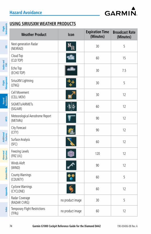
Garmin G1000 Cockpit Reference Guide for the Diamond Da42 190-00406-08 Rev. A74
Hazard avoidance
Flig
htIn
stru
men
tsEI
SN
av/C
om/
XPD
R/A
udio
Flig
ht
Man
agem
ent
Haz
ard
Avoi
danc
eA
FCS
Add
ition
alFe
atur
esA
nnun
/Ale
rts
App
endi
xIn
dex
Flig
htIn
stru
men
tsEI
Sa
udio
and
CNS
Flig
ht
Man
agem
ent
Haz
ard
avoi
danc
ea
FCS
add
ition
alFe
atur
esa
bnor
mal
ope
ratio
na
nnun
/ale
rts
app
endi
xIn
dex
USING SIRIUSXM WEaTHER PRoDUCTS
Weather Product IconExpiration Time
(Minutes)Broadcast Rate
(Minutes)
Next-generation Radar (NEXRAD)
30 5
Cloud Top (CLD TOP)
60 15
Echo Top (ECHO TOP)
30 7.5
SiriusXM Lightning (LTNG)
30 5
Cell Movement (CELL MOV)
30 12
SIGMETs/AIRMETs (SIG/AIR)
60 12
Meteorological Aerodrome Report (METARs)
90 12
City Forecast (CITY)
90 12
Surface Analysis (SFC)
60 12
Freezing Levels (FRZ LVL)
120 12
Winds Aloft (WIND)
90 12
County Warnings (COUNTY)
60 5
Cyclone Warnings (CYCLONE)
60 12
Radar Coverage (RADAR CVRG)
no product image 30 5
Temporary Flight Restrictions (TFRs)
no product image 60 12
Garmin G1000 Cockpit Reference Guide for the Diamond Da42190-00406-08 Rev. A 75
Hazard avoidance
FlightInstrum
entsEIS
Nav/Com
/XPD
R/Audio
Flight M
anagement
Hazard
AvoidanceA
FCSA
dditionalFeatures
Annun/A
lertsA
ppendixIndex
FlightInstrum
entsEIS
audio and
CNS
Flight M
anagement
Hazard
avoidancea
FCSa
dditionalFeatures
abnorm
alo
perationa
nnun/alerts
appendix
Index
Weather Product IconExpiration Time
(Minutes)Broadcast Rate
(Minutes)
Terminal Aerodrome Reports (TAFs)
no product image 60 12
Weather Product Symbols and Data Timing
Setting up and customizing the ‘MaP - WEaTHER DaTa LINK’ Page:1) Select the ‘MAP - WEATHER DATA LINK’ Page.2) Press the MENU Key.3) With ‘Weather Setup’ highlighted, press the ENT Key.4) Turn the large FMS Knob or press the ENT Key to scroll through product selections.5) Turn the small FMS Knob to scroll through options for each product (ON/OFF, maximum
map range settings, etc.).6) Press the ENT Key to select an option.7) Push the FMS Knob or CLR Key to return to the ‘MAP - WEATHER DATA LINK’ Page with
the changed settings.
Restoring default ‘MaP - WEaTHER DaTa LINK’ Page settings:1) Select the ‘MAP - WEATHER DATA LINK’ Page.2) Press the MENU Key.3) With ‘Weather Setup’ highlighted, press the ENT Key.4) Press the MENU Key.5) Highlight the desired default(s) to restore (all or for selection) and press ENT Key.
Setting up and customizing weather data for the ‘MaP - NaVIGaTIoN MaP’ Page:1) Select the ‘MAP - NAVIGATION MAP’ Page.2) Press the MENU Key.3) With ‘Map Setup’ highlighted, press the ENT Key.4) Turn the small FMS Knob to select the ‘Weather’ Group and press the ENT Key.5) Turn the large FMS Knob or press the ENT Key to scroll through product selections.6) Turn the small FMS Knob to scroll through options for each product (ON/OFF, range
settings).7) Press the ENT Key to select an option.8) Push the FMS Knob or CLR Key to return to the ‘MAP - NAVIGATION MAP’ Page with the
changed settings.
Garmin G1000 Cockpit Reference Guide for the Diamond Da42 190-00406-08 Rev. A76
Hazard avoidance
Flig
htIn
stru
men
tsEI
SN
av/C
om/
XPD
R/A
udio
Flig
ht
Man
agem
ent
Haz
ard
Avoi
danc
eA
FCS
Add
ition
alFe
atur
esA
nnun
/Ale
rts
App
endi
xIn
dex
Flig
htIn
stru
men
tsEI
Sa
udio
and
CNS
Flig
ht
Man
agem
ent
Haz
ard
avoi
danc
ea
FCS
add
ition
alFe
atur
esa
bnor
mal
ope
ratio
na
nnun
/ale
rts
app
endi
xIn
dex
Viewing legends for displayed weather products1) Select the ‘MAP - WEATHER DATA LINK’ Page.2) Press the LEGEND Softkey to display the legends for the displayed weather products.
or:a) Press the MENU Key.b) Select ‘Weather Legend’ and press the ENT Key.
3) Turn the FMS Knob to scroll through the legends.4) To remove the Legend Window, press the LEGEND Softkey, the ENT or the CLR Key, or
push the FMS Knob.
NEXRaD RaDaR
NoTE: The NEXRAD weather product cannot be displayed simultaneously with ter-rain, echo tops, or Stormscope lightning features on the same map.
Displaying NEXRaD weather information:1) Press the MaP Softkey (for the PFD Inset Map, press the INSET Softkey). This step is not
necessary on the ‘MAP - WEATHER DATA LINK’ Page.2) Press the NEXRaD Softkey.
Echo Tops
Displaying Echo Tops information:1) Select the ‘MAP - WEATHER DATA LINK’ Page.2) Press the ECHo ToPS Softkey.
Cloud Tops
NoTE: Cloud Tops and Echo Tops cannot be displayed at the same time.
Displaying Cloud Tops information:1) Select the ‘MAP - WEATHER DATA LINK’ Page.2) Press the CLoUD ToPS Softkey.
SiriusXM Lightning
Displaying SiriusXM Lightning information:1) Press the MaP Softkey (for the PFD Inset Map, press the INSET Softkey). This step is not
necessary on the ‘MAP - WEATHER DATA LINK’ Page.2) Press the XM LTNG Softkey (LTNG Softkey on the ‘MAP - WEATHER DATA LINK’ Page.
Garmin G1000 Cockpit Reference Guide for the Diamond Da42190-00406-08 Rev. A 77
Hazard avoidance
FlightInstrum
entsEIS
Nav/Com
/XPD
R/Audio
Flight M
anagement
Hazard
AvoidanceA
FCSA
dditionalFeatures
Annun/A
lertsA
ppendixIndex
FlightInstrum
entsEIS
audio and
CNS
Flight M
anagement
Hazard
avoidancea
FCSa
dditionalFeatures
abnorm
alo
perationa
nnun/alerts
appendix
Index
Cell Movement
Displaying Cell Movement information:1) Press the MaP Softkey (for the PFD Inset Map, press the INSET Softkey). This step is not
necessary on the ‘MAP - WEATHER DATA LINK’ Page.2) Press the NEXRaD Softkey (CEL MoV Softkey on the ‘MAP - WEATHER DATA LINK’
Page). For Cell Movement to be displayed on maps other than the ‘MAP - WEATHER DATA LINK’ Page, Cell Movement must be turned on in the ‘MAP - NAVIGATION MAP’ Page Setup Menu (see “Setting up and customizing weather data for the ‘MAP - NAVIGATION MAP’ Page”).
SIGMETs and aIRMETs
Displaying SIGMETs and aIRMETs:1) Select the ‘MAP - WEATHER DATA LINK’ Page.2) Press the SIG/aIR Softkey.3) To view the text of a SIGMET or AIRMET, press the RaNGE Knob and move the Map
Pointer to highlight the desired SIGMET or AIRMET.4) Press the ENT key.
METaRs and TaFs
Displaying METaR and TaF text:1) On the ‘MAP - WEATHER DATA LINK’ Page, press the METaR Softkey.2) Press the RaNGE Knob and pan to the desired airport.3) Press the ENT Key. The ‘WPT-WEATHER INFORMATION’ Page is shown with METAR and
TAF text.4) Use the FMS Knob or the ENT Key to scroll through the METAR and TAF text. METAR
text must be completely scrolled through before scrolling through the TAF text.5) Push the FMS Knob or the CLR Key to return to the ‘MAP - WEATHER DATA LINK’ Page.
or:1) Select the ‘WPT-WEATHER INFORMATION’ Page.
a) Turn the large FMS Knob to select the Waypoint Page Group.b) Press the WX Softkey to select the ‘WPT-WEATHER INFORMATION’ Page.
2) Push the FMS Knob to display the cursor.
3) Use the FMS Knob to enter the desired airport and press the ENT Key.4) Use the FMS Knob or the ENT Key to scroll through the METAR and TAF text. Note the
METAR text must be completely scrolled through before scrolling through the TAF text.
Garmin G1000 Cockpit Reference Guide for the Diamond Da42 190-00406-08 Rev. A78
Hazard avoidance
Flig
htIn
stru
men
tsEI
SN
av/C
om/
XPD
R/A
udio
Flig
ht
Man
agem
ent
Haz
ard
Avoi
danc
eA
FCS
Add
ition
alFe
atur
esA
nnun
/Ale
rts
App
endi
xIn
dex
Flig
htIn
stru
men
tsEI
Sa
udio
and
CNS
Flig
ht
Man
agem
ent
Haz
ard
avoi
danc
ea
FCS
add
ition
alFe
atur
esa
bnor
mal
ope
ratio
na
nnun
/ale
rts
app
endi
xIn
dex
Surface analysis and City Forecast
Displaying Surface analysis and City Forecast information:1) Select the ‘MAP - WEATHER DATA LINK’ Page.2) Press the MoRE WX Softkey.3) Press the SFC Softkey.4) Select the desired forecast time: CURRENT, 12 HR, 24 HR, 36 HR, or 48 HR. The SFC
Softkey label changes to reflect the forecast time selected.
Freezing Levels
Displaying Freezing Level information:1) Select the ‘MAP - WEATHER DATA LINK’ Page.2) Press the MoRE WX Softkey.3) Press the FRZ LVL Softkey.
Winds aloft
Displaying Winds aloft data:1) Select the ‘MAP - WEATHER DATA LINK’ Page.2) Press the MoRE WX Softkey.3) Press the WIND Softkey.4) Select the desired altitude level: SFC (surface) up to 42,000 feet. Press the NEXT or PREV
Softkey to cycle through the altitude softkeys. The WIND Softkey label changes to reflect the altitude selected.
County Warnings
Displaying County Warning information:1) Select the ‘MAP - WEATHER DATA LINK’ Page.2) Press the MoRE WX Softkey.3) Press the CoUNTy Softkey.
Cyclone
Displaying cyclone (hurricane) track information:1) Select the ‘MAP - WEATHER DATA LINK’ Page.2) Press the MoRE WX Softkey.3) Press the CyCLoNE Softkey.
Garmin G1000 Cockpit Reference Guide for the Diamond Da42190-00406-08 Rev. A 79
Hazard avoidance
FlightInstrum
entsEIS
Nav/Com
/XPD
R/Audio
Flight M
anagement
Hazard
AvoidanceA
FCSA
dditionalFeatures
Annun/A
lertsA
ppendixIndex
FlightInstrum
entsEIS
audio and
CNS
Flight M
anagement
Hazard
avoidancea
FCSa
dditionalFeatures
abnorm
alo
perationa
nnun/alerts
appendix
Index
SToRMSCoPE LIGHTNING
WaRNING: Do not rely on information from a lightning detection system display as the sole basis for hazardous weather avoidance. Range limitations and interfer-ence may cause the system to display inaccurate or incomplete information. Refer to documentation from the lightning detection system manufacturer for detailed information about the system.
NoTE: Lightning information from data link sources such as SiriusXM Weather cannot be displayed simultaneously on the same map as lightning information from an airborne lightning detection system.
SETTING UP SToRMSCoPE oN THE ‘MaP - NaVIGaTIoN MaP’ PaGESetting up Stormscope options on the ‘MaP - NaVIGaTIoN MaP’:1) On the ‘MAP - NAVIGATION MAP’ Page, press the MENU Key.2) With ‘Map Setup’ selected, press the ENT Key. 3) Turn the small FMS Knob to display the group selection window. Turn the small FMS
Knob to select ‘Weather’, and press the ENT Key. 4) Turn the large FMS Knob to highlight and move between the product selections. 5) When an item is highlighted, turn the small FMS Knob to select the option.6) Press the ENT Key.
7) Push the FMS Knob to return to the ‘MAP - NAVIGATION MAP’ Page.
Cell and Strike Mode on the ‘MaP - NaVIGaTIoN MaP’ Page
Selecting the ‘cell’ or ‘strike’ mode on the ‘MaP - NaVIGaTIoN MaP’:1) Press the MENU Key.2) With ‘Map Setup’ selected, press the ENT Key. 3) Select the ‘Weather’ group. 4) Press the ENT Key. The cursor flashes on ‘STRMSCP LTNG’.
5) Turn the large FMS Knob to select ‘STRMSCP MODE’.6) Turn the small FMS Knob to change between ‘CELL’ and ‘STRIKE’ options. When an item
is selected, press the ENT Key.
7) Push the FMS knob to return to the ‘MAP - NAVIGATION MAP’ Page.
Manually clearing Stormscope data on the ‘MaP - NaVIGaTIoN MaP’:
1) Press the MENU Key.2) Select ‘Clear Stormscope® Lightning’.
3) Press the ENT Key.
Garmin G1000 Cockpit Reference Guide for the Diamond Da42 190-00406-08 Rev. A80
Hazard avoidance
Flig
htIn
stru
men
tsEI
SN
av/C
om/
XPD
R/A
udio
Flig
ht
Man
agem
ent
Haz
ard
Avoi
danc
eA
FCS
Add
ition
alFe
atur
esA
nnun
/Ale
rts
App
endi
xIn
dex
Flig
htIn
stru
men
tsEI
Sa
udio
and
CNS
Flig
ht
Man
agem
ent
Haz
ard
avoi
danc
ea
FCS
add
ition
alFe
atur
esa
bnor
mal
ope
ratio
na
nnun
/ale
rts
app
endi
xIn
dex
Zoom Range on the ‘MaP - NaVIGaTIoN MaP’ Page
Selecting a Stormscope range on the ‘MaP - NaVIGaTIoN MaP’ Page:1) Press the MENU Key.2) Select ‘MAP SETUP’.3) Select the ‘Weather’ group. 4) Press the ENT Key.
5) Turn the large FMS Knob to select ‘STRMSCP SMBL’.
6) Turn the small FMS Knob to select the maximum display range.
7) Press the ENT Key.
8) Push the FMS Knob to return to the ‘MAP - NAVIGATION MAP’ Page.
adjusting the Stormscope Map Range:1) Turn the large FMS Knob to select the Map Page Group.2) Turn the small FMS Knob to select the ‘MAP-STORMSCOPE’ Page.3) To change the map range, turn the RaNGE Knob clockwise to increase the map range
or counter-clockwise to decrease the map range.
Changing between ‘cell’ and ‘strike’ mode on the ‘MaP-SToRMSCoPE’ Page:1) Select the ‘MAP-STORMSCOPE’ Page.
2) Press the MoDE Softkey. The CELL and STRIKE softkeys are displayed.
3) Press the CELL Softkey to display ‘CELL’ data or press the STRIKE Softkey to display ‘STRIKE’ data. ‘CELL’ or ‘STRIKE’ is displayed in the mode box in the upper left corner of the ‘MAP-STORMSCOPE’ Page.
4) Press the BaCK Softkey to return to the main ‘MAP-STORMSCOPE’ Page.
Changing the viewing mode between 360˚ and 120˚ on the ‘MaP-SToRMSCoPE’ Page:1) Select the ‘MAP-STORMSCOPE’ Page.
2) Press the VIEW Softkey. The 360 and aRC softkeys are displayed. Press the 360 Softkey to display a 360˚ viewing area or press the aRC Softkey to display a 120˚ viewing area.
3) Press the BaCK Softkey to return to the main ‘MAP-STORMSCOPE’ Page.
aIRBoRNE CoLoR WEaTHER RaDaR
WaRNING: Do not operate the weather radar in a transmitting mode when personnel or objects are within the MPEL boundary.
Garmin G1000 Cockpit Reference Guide for the Diamond Da42190-00406-08 Rev. A 81
Hazard avoidance
FlightInstrum
entsEIS
Nav/Com
/XPD
R/Audio
Flight M
anagement
Hazard
AvoidanceA
FCSA
dditionalFeatures
Annun/A
lertsA
ppendixIndex
FlightInstrum
entsEIS
audio and
CNS
Flight M
anagement
Hazard
avoidancea
FCSa
dditionalFeatures
abnorm
alo
perationa
nnun/alerts
appendix
Index
NoTE: When a strong weather return is displayed on the weather radar, the tilt angle may be adjusted to explore return intensities at various altitudes to aid in determination of radar tops.
NoTE: It is the sole responsibility of the flight crew to avoid areas of hazardous weather by adequate margins.
WaRNING: Overflight of thunderstorms should not be considered safe, as extreme turbulence may exist significantly above observed returns.
operation in Weather Mode
WaRNING: Begin transmitting only when it is safe to do so. When transmitting while the aircraft is on the ground, no personnel or objects should be within 9.16 feet of the antenna.
CaUTIoN: In Standby mode, the antenna is parked at the center line. It is always a good idea to put the radar in Standby mode before taxiing the aircraft to prevent the antenna from bouncing on the bottom stop and possibly causing damage to the radar assembly.
Displaying weather on the ‘MaP - WEaTHER RaDaR’ Page:1) Select the ‘MAP - WEATHER RADAR’ Page in the Map Page Group with the FMS Knob.2) Press the MoDE Softkey.3) While on the ground, press the STaNDBy Softkey. A one-minute warm-up period is
initiated (countdown is displayed on the screen). After the warm-up is complete, the radar enters the Standby Mode.a) Press the WEaTHER Softkey. A confirmation window is displayed.b) Turn the small FMS Knob to highlight YES and press the ENT Key to continue radar
activation.or:
If the aircraft is airborne, press the WEaTHER Softkey. A one-minute warm-up period is initiated (countdown is displayed on the screen). After the warm-up is complete, the radar begins transmitting.
4) Turn the RaNGE Knob to select the desired map range.5) The horizontal scan is initially displayed. If desired, press the VERTICaL Softkey to
change to vertical scanning.
Garmin G1000 Cockpit Reference Guide for the Diamond Da42 190-00406-08 Rev. A82
Hazard avoidance
Flig
htIn
stru
men
tsEI
SN
av/C
om/
XPD
R/A
udio
Flig
ht
Man
agem
ent
Haz
ard
Avoi
danc
eA
FCS
Add
ition
alFe
atur
esA
nnun
/Ale
rts
App
endi
xIn
dex
Flig
htIn
stru
men
tsEI
Sa
udio
and
CNS
Flig
ht
Man
agem
ent
Haz
ard
avoi
danc
ea
FCS
add
ition
alFe
atur
esa
bnor
mal
ope
ratio
na
nnun
/ale
rts
app
endi
xIn
dex
Vertically scanning a storm cell:
NoTE: Vertical scanning of a storm cell should be done with the aircraft wings level to avoid constant adjustment of the Bearing Line.
1) While in the Horizontal Scan view, press the BRG Softkey. This places the cursor in the BEARING field and displays the Bearing Line.
If the Bearing Line is not displayed, press the MENU Key and turn the large FMS Knob to select Show Bearing Line. Press the ENT Key.
2) Press the ENT Key.3) Turn the small FMS Knob to place the Bearing Line on the desired storm cell or other area
to be vertically scanned.4) Press the VERTICaL Softkey. A vertical scan of the selected area is displayed.5) The small FMS Knob may be used to move the scanned bearing line a few degrees right
or left.6) Turn the RaNGE Knob to adjust the range.7) Push the FMS Knob to remove the cursor.8) To select a new area to be vertically scanned, press the HoRIZoN Softkey to return to the
Horizontal Scan view and repeat the previous steps.
adjusting antenna tilt angle
adjusting antenna tilt on the Horizontal Scan display:1) Push the FMS Knob to activate the cursor in the TILT field.2) Turn the small FMS Knob to select the desired antenna tilt angle.3) Press the ENT Key.4) Push the FMS Knob to remove the cursor.
adjusting antenna tilt on the Vertical Scan display:1) Press the TILT Softkey to activate the cursor in the TILT field and display the Tilt Line.
If the Tilt Line is not displayed, press the MENU Key and turn the large FMS Knob to select Show Tilt Line. Press the ENT Key.
2) Turn the small FMS Knob to adjust the antenna tilt angle. The selected tilt angle is implemented when Horizontal Scan is selected again.
The RANGE Knob can also be used to adjust tilt.
Garmin G1000 Cockpit Reference Guide for the Diamond Da42190-00406-08 Rev. A 83
Hazard avoidance
FlightInstrum
entsEIS
Nav/Com
/XPD
R/Audio
Flight M
anagement
Hazard
AvoidanceA
FCSA
dditionalFeatures
Annun/A
lertsA
ppendixIndex
FlightInstrum
entsEIS
audio and
CNS
Flight M
anagement
Hazard
avoidancea
FCSa
dditionalFeatures
abnorm
alo
perationa
nnun/alerts
appendix
Index
adjusting gain
WaRNING: Changing the gain in weather mode causes precipitation intensity to be displayed as a color not representative of the true intensity. Remember to return the gain setting to Calibrated for viewing the actual intensity of precipitation.
1) Press the GaIN Softkey to activate the cursor in the GAIN field.2) Turn the small FMS Knob to adjust the gain for the desirable level. The gain setting is
visible in the GAIN field as a movable horizontal bar in a flashing box. The line pointer is a reference depicting the calibrated position.
3) Push the FMS Knob to remove the cursor.4) Press the GaIN Softkey again to recalibrate the gain. CALIBRATED is displayed in the
GAIN field.
seCtor sCan
1) While in horizontal scan mode, press the BRG Softkey to display the Bearing Line and place the cursor in the BEARING field. If the Bearing Line is not displayed, press the MENU Key and turn the large FMS Knob to select Show Bearing Line.
2) Press the ENT Key.3) Turn the small FMS Knob to place the Bearing Line in the desired position. The location
of the Bearing Line becomes the center point of the Sector Scan.4) Turn the large FMS Knob to place the cursor in the SECTOR SCAN field.5) Turn the small FMS Knob to select FULL, 60˚, 40˚, or 20˚ scan.6) If desired, readjust the Bearing Line as discussed previously to change the center of the
Sector Scan.7) Press the BRG Softkey again to remove the Bearing Line and cursor. The bearing
reference is reset to 0º.
antenna stabilization
1) To activate or deactivate the antenna stabilization, press the MoDE Softkey.2) Press the STaB oN Softkey to activate antenna stabilization or press the STaB oFF
Softkey to deactivate. The current stabilization condition is shown in the upper right of the weather radar display.
GRoUND MaPPING aND INTERPRETaTIoNoperation in Ground Map Mode1) Press the MoDE Softkey.2) Press the GRoUND Softkey to place the radar in Ground Map mode.3) Press the BaCK Softkey.
Garmin G1000 Cockpit Reference Guide for the Diamond Da42 190-00406-08 Rev. A84
Hazard avoidance
Flig
htIn
stru
men
tsEI
SN
av/C
om/
XPD
R/A
udio
Flig
ht
Man
agem
ent
Haz
ard
Avoi
danc
eA
FCS
Add
ition
alFe
atur
esA
nnun
/Ale
rts
App
endi
xIn
dex
Flig
htIn
stru
men
tsEI
Sa
udio
and
CNS
Flig
ht
Man
agem
ent
Haz
ard
avoi
danc
ea
FCS
add
ition
alFe
atur
esa
bnor
mal
ope
ratio
na
nnun
/ale
rts
app
endi
xIn
dex
4) Push the FMS Knob to activate the cursor.5) Turn the large FMS Knob to place the cursor in the TILT field.6) Adjust the antenna tilt angle by turning the small FMS Knob to display ground returns at
the desired distance.7) Push the FMS Knob to remove the cursor.
TERRaIN PRoXIMITy
WaRNING: Do not use Terrain Proximity information for primary terrain avoidance. Terrain Proximity is intended only to enhance situational awareness.
NoTE: Terrain data is not displayed when the aircraft is outside of the installed terrain database coverage area.
DISPLayING TERRaIN PRoXIMITy DaTaDisplaying terrain and obstacle information (maps other than the ‘MaP-TERRaIN PRoX-IMITy’ Page):1) Press the MaP Softkey (for the PFD Inset Map, press the INSET Softkey).2) Press the TERRaIN Softkey to display terrain and obstacle data.
Customizing terrain and obstacle display on the ‘MaP - NaVIGaTIoN MaP’ Page:1) Select the ‘MAP - NAVIGATION MAP’ Page.2) Press the MENU Key.3) With ‘Map Setup’ highlighted, press the ENT Key.4) Turn the small FMS Knob to select the ‘Map’ Group and press the ENT Key.5) Turn the large FMS Knob or press the ENT Key to scroll through product selections.
• TERRAIN DATA – Turns the display of terrain data on or off and sets maximum range at which terrain is shown
• OBSTACLE DATA – Turns the display of obstacle data on or off and sets maximum range at which obstacles are shown
6) Turn the small FMS Knob to scroll through options for each product (ON/OFF, range settings).
7) Press the ENT Key to select an option.8) Push the FMS Knob or CLR Key to return to the ‘MAP - NAVIGATION MAP’ Page with the
changed settings.
Garmin G1000 Cockpit Reference Guide for the Diamond Da42190-00406-08 Rev. A 85
Hazard avoidance
FlightInstrum
entsEIS
Nav/Com
/XPD
R/Audio
Flight M
anagement
Hazard
AvoidanceA
FCSA
dditionalFeatures
Annun/A
lertsA
ppendixIndex
FlightInstrum
entsEIS
audio and
CNS
Flight M
anagement
Hazard
avoidancea
FCSa
dditionalFeatures
abnorm
alo
perationa
nnun/alerts
appendix
Index
‘MaP-TERRaIN PRoXIMITy’ PaGEDisplaying the ‘MaP-TERRaIN PRoXIMITy’ Page:
1) Turn the large FMS Knob to select the Map Page Group.
2) Turn the small FMS Knob to select the ‘MAP-TERRAIN PROXIMITY’ Page.3) To change the view,
a) Press the VIEW Softkey.b) Press the 360 or aRC Softkey to select the desired view. or: a) Press the MENU Key.b) Select ‘View Arc’ or ‘View 360º’ (choice dependent on current state) and press the ENT
Key to change the view.
Showing/hiding aviation information on the ‘MaP-TERRaIN PRoXIMITy’ Page:1) Press the MENU Key.2) Select ‘Show Aviation Data’ or ‘Hide Aviation Data’ (choice dependent on current state)
and press the ENT Key.
PRoFILE VIEW TERRaIN
WaRNING: Do not use Profile View Terrain data for primary terrain avoidance. Profile View Terrain is intended only to enhance situational awareness.
NoTE: Terrain data is not displayed when the aircraft is outside of the installed terrain database coverage area.
accessing Profile View:1) Select the ‘MAP-NAVIGATION MAP’ Page.2) Press the MaP Softkey.3) Press the PRoFILE Softkey to enable or disable Profile View.or:1) Press the MENU Key.2) Select ‘Show Profile View’ or ‘Hide Profile View’ (choice dependent on current state) and
press the ENT Key.
Garmin G1000 Cockpit Reference Guide for the Diamond Da42 190-00406-08 Rev. A86
Hazard avoidance
Flig
htIn
stru
men
tsEI
SN
av/C
om/
XPD
R/A
udio
Flig
ht
Man
agem
ent
Haz
ard
Avoi
danc
eA
FCS
Add
ition
alFe
atur
esA
nnun
/Ale
rts
App
endi
xIn
dex
Flig
htIn
stru
men
tsEI
Sa
udio
and
CNS
Flig
ht
Man
agem
ent
Haz
ard
avoi
danc
ea
FCS
add
ition
alFe
atur
esa
bnor
mal
ope
ratio
na
nnun
/ale
rts
app
endi
xIn
dex
Enabling/Disabling Profile View Terrain on the Navigation Map (when Profile View is enabled):1) Select the ‘MAP-NAVIGATION MAP’ Page.2) Press the MaP Softkey.3) Press the TERRaIN Softkey.
Profile Path
Customizing the Profile Path display on the ‘MaP-NaVIGaTIoN MaP’ Page:1) Select the ‘MAP-NAVIGATION MAP’ Page.2) Press the MENU Key.3) With ‘Map Setup’ highlighted, press the ENT Key.4) Turn the small FMS Knob to select the ‘Profile’ Group and press the ENT Key.5) Turn the large FMS Knob or press the ENT Key to scroll through product selections.
• PROFILE PATH – Turns the display of the Profile Path on or off and sets maximum map range at which the Profile Path is shown
6) Turn the small FMS Knob to scroll through options (ON/OFF, range settings).7) Press the ENT Key to select an option.8) Push the FMS Knob or CLR Key to return to the ‘MAP-NAVIGATION MAP’ Page with the
changed settings.
TERRaIN-SVT
WaRNING: Do not use Terrain-SVT information for primary terrain avoidance. Terrain-SVT is intended only to enhance situational awareness.
NoTE: Terrain data is not displayed when the aircraft is outside of the terrain database coverage area.
NoTE: Terrain-SVT is included with the Synthetic Vision System (SVT) option, and takes precedences over the Terrain Proximity feature.
DISPLayING TERRaIN-SVT DaTaDisplaying terrain and obstacle information (maps other than the ‘MaP-TERRaIN-SVS’ Page):1) Press the MaP Softkey (for the PFD Inset Map, select the INSET Softkey).2) Press the TERRaIN Softkey to display terrain and obstacle data.
Garmin G1000 Cockpit Reference Guide for the Diamond Da42190-00406-08 Rev. A 87
Hazard avoidance
FlightInstrum
entsEIS
Nav/Com
/XPD
R/Audio
Flight M
anagement
Hazard
AvoidanceA
FCSA
dditionalFeatures
Annun/A
lertsA
ppendixIndex
FlightInstrum
entsEIS
audio and
CNS
Flight M
anagement
Hazard
avoidancea
FCSa
dditionalFeatures
abnorm
alo
perationa
nnun/alerts
appendix
Index
Customizing terrain and obstacle display on the ‘MaP - NaVIGaTIoN MaP’ Page:1) Select the ‘MAP - NAVIGATION MAP’ Page.2) Press the MENU Key.3) With ‘Map Setup’ highlighted, press the ENT Key.4) Turn the small FMS Knob to select the ‘Map’ Group and press the ENT Key.5) Turn the large FMS Knob or press the ENT Key to scroll through product selections.
• TERRAIN DATA – Turns the display of terrain data on or off and sets maximum range at which terrain is shown
• OBSTACLE DATA – Turns the display of obstacle data on or off and sets maximum range at which obstacles are shown
6) Turn the small FMS Knob to scroll through options for each product (ON/OFF, range settings).
7) Press the ENT Key to select an option.8) Push the FMS Knob or CLR Key to return to the ‘MAP - NAVIGATION MAP’ Page with the
changed settings.
MaP-TERRaIN-SVS’ PaGEDisplaying the ‘MaP-TERRaIN-SVS’ Page:1) Turn the large FMS Knob to select the Map Page Group.2) Turn the small FMS Knob to select the ‘MAP-TERRAIN-SVS’ Page.
Changing the ‘MaP-TERRaIN-SVS’ Page view:1) Press the VIEW Softkey.2) Press the 360 or aRC Softkey to select the desired view.
or: 1) Press the MENU Key.2) Select ‘View Arc’ or ‘View 360º’ (choice dependent on current state) and press the ENT Key
to change the view
Showing/hiding aviation information on the ‘MaP-TERRaIN-SVS’ Page:1) Press the MENU Key.2) Select ‘Show Aviation Data’ or ‘Hide Aviation Data’ (choice dependent on current state)
and press the ENT Key.
Garmin G1000 Cockpit Reference Guide for the Diamond Da42 190-00406-08 Rev. A88
Hazard avoidance
Flig
htIn
stru
men
tsEI
SN
av/C
om/
XPD
R/A
udio
Flig
ht
Man
agem
ent
Haz
ard
Avoi
danc
eA
FCS
Add
ition
alFe
atur
esA
nnun
/Ale
rts
App
endi
xIn
dex
Flig
htIn
stru
men
tsEI
Sa
udio
and
CNS
Flig
ht
Man
agem
ent
Haz
ard
avoi
danc
ea
FCS
add
ition
alFe
atur
esa
bnor
mal
ope
ratio
na
nnun
/ale
rts
app
endi
xIn
dex
Inhibiting/enabling Terrain-SVT alerting:1) Select the ‘MAP-TERRAIN-SVS’ Page.2) Select the INHIBIT Softkey to inhibit or enable Terrain-SVT (choice dependent on current
state).or:a) Press the MENU Key.b) Select ‘Inhibit Terrain’ or ‘Enable Terrain’ (choice dependent on current state) and
press the ENT Key.
TRaFFIC INFoRMaTIoN SERVICE (TIS)
WaRNING: Do not rely solely upon the display of traffic information for collision avoidance maneuvering. The traffic display does not provide collision avoidance resolution advisories and does not under any circumstances or conditions relieve the pilot’s responsibility to see and avoid other aircraft.
WaRNING: Do not rely solely upon the display of traffic information to accurately depict all of the traffic within range of the aircraft. Due to lack of equipment, poor signal reception, and/or inaccurate information from aircraft or ground stations, traffic may be present that is not represented on the display.
NoTE: TIS is disabled if a Traffic Advisory System (TAS) is installed.
DISPLayING TRaFFIC DaTaDisplaying traffic information (maps other than the ‘MaP-TRaFFIC MaP’ Page):1) Press the MaP Softkey.2) Press the TRaFFIC Softkey.
Displaying traffic information (PFD Inset Map):1) Press the INSET Softkey.2) Press the TRaFFIC Softkey to display traffic data on the inset map (TRFC-1). 3) Press the softkey again to display the traffic-only inset (TRFC-2).4) Press the softkey again to remove traffic data.
Customizing traffic display on the ‘MaP - NaVIGaTIoN MaP’ Page:1) Select the ‘MAP - NAVIGATION MAP’ Page.2) Press the MENU Key.3) With ‘Map Setup’ highlighted, press the ENT Key.
Garmin G1000 Cockpit Reference Guide for the Diamond Da42190-00406-08 Rev. A 89
Hazard avoidance
FlightInstrum
entsEIS
Nav/Com
/XPD
R/Audio
Flight M
anagement
Hazard
AvoidanceA
FCSA
dditionalFeatures
Annun/A
lertsA
ppendixIndex
FlightInstrum
entsEIS
audio and
CNS
Flight M
anagement
Hazard
avoidancea
FCSa
dditionalFeatures
abnorm
alo
perationa
nnun/alerts
appendix
Index
4) Turn the small FMS Knob to select the ‘Traffic’ Group and press the ENT Key.5) Turn the large FMS Knob or press the ENT Key to scroll through product selections.
• TRAFFIC – Turns the display of traffic data on or off
• TRAFFIC MODE – Selects the traffic mode for display; select from: - All Traffic - Displays all traffic - TA/PA - Displays only Traffic Advisories and Proximity Advisories - TA ONLY - Displays only Traffic Advisories
• TRAFFIC SMBL – Selects the maximum range at which traffic symbols are shown
• TRAFFIC LBL – Selects the maximum range at which traffic labels are shown (with the option to turn off)
6) Turn the small FMS Knob to scroll through options for each product (ON/OFF, range settings, etc.).
7) Press the ENT Key to select an option.8) Push the FMS Knob or CLR Key to return to the ‘MAP - NAVIGATION MAP’ Page with the
changed settings.
‘MaP-TRaFFIC MaP’ PaGEDisplaying traffic on the ‘MaP-TRaFFIC MaP’ Page:1) Turn the large FMS Knob to select the Map Page Group.2) Turn the small FMS Knob to select the ‘MAP-TRAFFIC MAP’ Page.3) Confirm TIS is in Operating Mode:
Press the oPERaTE Softkey to begin displaying traffic.or:a) Press the MENU Key.b) Select ‘Operate Mode’ (shown if TIS is in Standby Mode) and press the ENT Key.
TIS aLERTSMuting the “TIS Not available” voice alert:1) Select the ‘MAP-TRAFFIC MAP’ Page.2) Press the TNa MUTE Softkey. The status is displayed in the upper left corner of the ‘MAP-
TRAFFIC MAP’ Page.or:a) Press the MENU Key.b) Select ‘‘’Not Available” Mute On’ (shown if TNA muting is currently off) and press the
ENT Key.

Garmin G1000 Cockpit Reference Guide for the Diamond Da42 190-00406-08 Rev. A90
Hazard avoidance
Flig
htIn
stru
men
tsEI
SN
av/C
om/
XPD
R/A
udio
Flig
ht
Man
agem
ent
Haz
ard
Avoi
danc
eA
FCS
Add
ition
alFe
atur
esA
nnun
/Ale
rts
App
endi
xIn
dex
Flig
htIn
stru
men
tsEI
Sa
udio
and
CNS
Flig
ht
Man
agem
ent
Haz
ard
avoi
danc
ea
FCS
add
ition
alFe
atur
esa
bnor
mal
ope
ratio
na
nnun
/ale
rts
app
endi
xIn
dex
Switching between TIS modes:1) Select the ‘MAP-TRAFFIC MAP’ Page.2) Press the STaNDBy or oPERaTE Softkey to switch between modes. The mode is displayed
in the upper left corner of the ‘MAP-TRAFFIC MAP’ Page.or:a) Press the MENU Key.b) Select ‘Operate Mode’ or ‘Standby Mode’ (choice dependent on current state) and
press the ENT Key.
aVIDyNE TaS600 (TaS) (oPTIoNaL)
WaRNING: Do not rely solely upon the display of traffic information for collision avoidance maneuvering. The traffic display does not provide collision avoidance resolution advisories and does not under any circumstances or conditions relieve the pilot’s responsibility to see and avoid other aircraft.
WaRNING: Do not rely solely upon the display of traffic information to accurately depict all of the traffic within range of the aircraft. Due to lack of equipment, poor signal reception, and/or inaccurate information from aircraft or ground stations, traffic may be present that is not represented on the display.
NoTE: Refer to the Avidyne TAS600 Series Pilot’s Guide for a detailed discussion of the Avidyne TAS600.
DISPLayING TRaFFIC DaTaDisplaying traffic on the ‘MaP-TRaFFIC MaP’ Page:1) Turn the large FMS Knob to select the MAP Page Group.2) Turn the small FMS Knob to select the ‘MAP-TRAFFIC MAP’ Page.3) Turn the RaNGE Knob clockwise to display a larger area or counter-clockwise to display a
smaller area.
Displaying traffic information (maps other than the ‘MaP-TRaFFIC MaP’ Page):1) Select the MaP Softkey.2) Select the TRaFFIC Softkey to display traffic data.
Displaying traffic information (PFD Inset Map):1) Select the INSET Softkey.2) Select the TRaFFIC Softkey to display traffic data on the inset map (TRFC-1).
Garmin G1000 Cockpit Reference Guide for the Diamond Da42190-00406-08 Rev. A 91
Hazard avoidance
FlightInstrum
entsEIS
Nav/Com
/XPD
R/Audio
Flight M
anagement
Hazard
AvoidanceA
FCSA
dditionalFeatures
Annun/A
lertsA
ppendixIndex
FlightInstrum
entsEIS
audio and
CNS
Flight M
anagement
Hazard
avoidancea
FCSa
dditionalFeatures
abnorm
alo
perationa
nnun/alerts
appendix
Index
3) Select the softkey again to display the traffic-only inset (TRFC-2).4) Select the softkey again to remove traffic data.
aLTITUDE DISPLayChanging the altitude display mode:1) On the Traffic Page, select the aLT MoDE Softkey.2) Select one of the following Softkeys:
• BELoW• NoRMaL• aBoVE• UNREST (unrestricted)
3) To return to the Traffic Page, select the BaCK Softkey.or:
1) Press the MENU Key.
2) Turn the small FMS Knob to select one of the following:• BELoW• NoRMaL• aBoVE• UNREST (unrestricted)
3) Select the ENT Softkey.
‘MaP-TRaFFIC MaP’ PaGE DISPLay RaNGEChanging the display range on the Traffic Page: 1) Turn the RaNGE Knob.2) The following range options are available:
• 2 nm• 2 and 6 nm• 6 and 12 nm• 12 and 24 nm
Customizing the traffic display on the ‘MaP - NaVIGaTIoN MaP’ Page:1) Select the ‘MAP - NAVIGATION MAP’ Page.2) Press the MENU Key.3) With Map Setup highlighted, press the ENT Key.4) Turn the small FMS Knob to select the Traffic Group and press the ENT Key.
Garmin G1000 Cockpit Reference Guide for the Diamond Da42 190-00406-08 Rev. A92
Hazard avoidance
Flig
htIn
stru
men
tsEI
SN
av/C
om/
XPD
R/A
udio
Flig
ht
Man
agem
ent
Haz
ard
Avoi
danc
eA
FCS
Add
ition
alFe
atur
esA
nnun
/Ale
rts
App
endi
xIn
dex
Flig
htIn
stru
men
tsEI
Sa
udio
and
CNS
Flig
ht
Man
agem
ent
Haz
ard
avoi
danc
ea
FCS
add
ition
alFe
atur
esa
bnor
mal
ope
ratio
na
nnun
/ale
rts
app
endi
xIn
dex
5) Turn the large FMS Knob or press the ENT Key to scroll through the selections.
• TRAFFIC – Turns the display of traffic data on or off
• TRAFFIC MODE – Selects the traffic mode for display; select from: - All Traffic - Displays all traffic - TA/PA - Displays Traffic Alerts and Proximity Advisories - TA ONLY - Displays Traffic Alerts only
• TRAFFIC SMBL – Selects the maximum range at which traffic symbols are shown
• TRAFFIC LBL – Selects the maximum range at which traffic labels are shown with the option to turn off
6) Turn the small FMS Knob to scroll through options (ON/OFF, range settings, etc.).7) Press the ENT Key to select an option.8) Push the FMS Knob or CLR Key to return to the ‘MAP - NAVIGATION MAP’ Page.
TaS aLERTS
NoTE: Refer to the TAS600 documentation for information on alerts generated by the TAS equipment.
When the number of TAs on the ‘MAP-TRAFFIC MAP’ Page increases from one scan to the next, the following occur:
– A “Traffic” voice alert is generated followed by the clock position, relative altitude and range of the TA.
– A TRAFFIC Annunciation appears at the top right of the airspeed on the PFD, flashing for 5 seconds and remaining displayed until no TAs are detected in the area.
– The PFD Inset Map is automatically displayed with TA traffic.
TaS Voice alerts
Muting the TaS voice alert in progress:1) Select the ‘MAP-TRAFFIC MAP’ Page.2) Select the MUTE Softkey while the voice alert is playing. Subsequent voice alerts will be
heard.
Garmin G1000 Cockpit Reference Guide for the Diamond Da42190-00406-08 Rev. A 93
aFCS
FlightInstrum
entsEIS
Nav/Com
/XPD
R/Audio
Flight M
anagement
Hazard
AvoidanceA
FCSA
dditionalFeatures
Annun/A
lertsA
ppendixIndex
FlightInstrum
entsEIS
audio and
CNS
Flight M
anagement
Hazard
avoidancea
FCSa
dditionalFeatures
abnorm
alo
perationa
nnun/alerts
appendix
Index
aUToMaTIC FLIGHT CoNTRoL SySTEMaFCS oVERVIEW
NoTE: The current, approved version of the pertinent flight manual always supersedes the information in this Pilot’s Guide.
NoTE: If the airplane is equipped with the optional KAP 140 autopilot, refer to the pertinent flight manual supplement(s) and the KAP 140 Pilot’s Guide for information on its controls, operation, and annunciations.
BaSIC aUToPILoT oPERaTIoN – Autopilot Engagement — The autopilot may be engaged by pressing the AP Key on the MFD.
– Autopilot Engagement with Flight Director Off — Upon engagement, the autopilot will be set to hold the current attitude of the airplane, if the flight director was not previously on.
– Autopilot Disengagement — Autopilot disengagement is indicated aurally by a disconnect tone and visually by PFD annunciation. The most common way to disengage the autopilot is to press and release the AP DISC Switch. Other ways to disengage the autopilot include:
» Pressing the AP Key.
» Pressing the GA Button.
» Operating the AP TRIM ARM Switch.
» Pulling the autopilot circuit breaker.
In the event of unexpected autopilot behavior, pressing and holding the AP DISC Switch will disengage the autopilot and remove all power to the servos.
The AFCS Preflight Test is initiated upon system startup. Evidence of this test is indicated by a white ‘PFT’ annunciation on the PFD.
NoTE: If the white ‘PFT’ annunciator on the PFD remains and does not self clear, the test is considered failed.
NoTE: Do not press the aP DISC Switch during servo initialization and preflight system tests. This may cause the preflight system test to fail or never to start (if servos fail their power-on tests). Power must be cycled to the servos to remedy the situation.
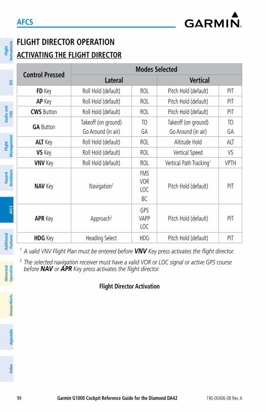
Garmin G1000 Cockpit Reference Guide for the Diamond Da42 190-00406-08 Rev. A94
aFCS
Flig
htIn
stru
men
tsEI
SN
av/C
om/
XPD
R/A
udio
Flig
ht
Man
agem
ent
Haz
ard
Avoi
danc
eA
FCS
Add
ition
alFe
atur
esA
nnun
/Ale
rts
App
endi
xIn
dex
Flig
htIn
stru
men
tsEI
Sa
udio
and
CNS
Flig
ht
Man
agem
ent
Haz
ard
avoi
danc
ea
FCS
add
ition
alFe
atur
esa
bnor
mal
ope
ratio
na
nnun
/ale
rts
app
endi
xIn
dex
FLIGHT DIRECToR oPERaTIoNaCTIVaTING THE FLIGHT DIRECToR
Control PressedModes Selected
Lateral VerticalFD Key Roll Hold (default) ROL Pitch Hold (default) PIT
aP Key Roll Hold (default) ROL Pitch Hold (default) PIT
CWS Button Roll Hold (default) ROL Pitch Hold (default) PIT
Ga ButtonTakeoff (on ground)Go Around (in air)
TOGA
Takeoff (on ground)Go Around (in air)
TOGA
aLT Key Roll Hold (default) ROL Altitude Hold ALT
VS Key Roll Hold (default) ROL Vertical Speed VS
VNV Key Roll Hold (default) ROL Vertical Path Tracking1 VPTH
NaV Key Navigation2
FMS VOR LOCBC
Pitch Hold (default) PIT
aPR Key Approach2
GPS VAPP LOC
Pitch Hold (default) PIT
HDG Key Heading Select HDG Pitch Hold (default) PIT
1 A valid VNV Flight Plan must be entered before VNV Key press activates the flight director.2 The selected navigation receiver must have a valid VOR or LOC signal or active GPS course
before NAV or APR Key press activates the flight director.
Flight Director activation
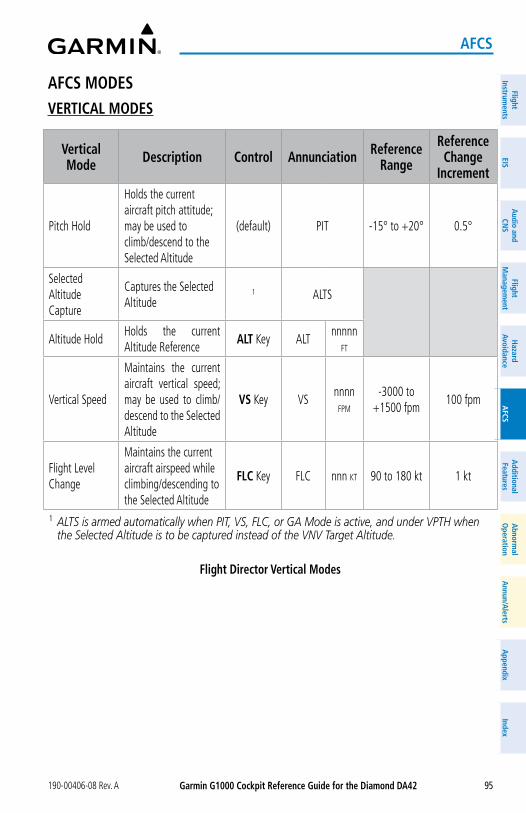
Garmin G1000 Cockpit Reference Guide for the Diamond Da42190-00406-08 Rev. A 95
aFCS
FlightInstrum
entsEIS
Nav/Com
/XPD
R/Audio
Flight M
anagement
Hazard
AvoidanceA
FCSA
dditionalFeatures
Annun/A
lertsA
ppendixIndex
FlightInstrum
entsEIS
audio and
CNS
Flight M
anagement
Hazard
avoidancea
FCSa
dditionalFeatures
abnorm
alo
perationa
nnun/alerts
appendix
Index
aFCS MoDESVERTICaL MoDES
Vertical Mode Description Control annunciation Reference
Range
Reference Change
Increment
Pitch Hold
Holds the current aircraft pitch attitude; may be used to climb/descend to the Selected Altitude
(default) PIT -15° to +20° 0.5°
Selected Altitude Capture
Captures the Selected Altitude
1 ALTS
Altitude HoldHolds the current Altitude Reference
aLT Key ALTnnnnn
fT
Vertical Speed
Maintains the current aircraft vertical speed; may be used to climb/descend to the Selected Altitude
VS Key VSnnnn
fpm
-3000 to +1500 fpm
100 fpm
Flight Level Change
Maintains the current aircraft airspeed while climbing/descending to the Selected Altitude
FLC Key FLC nnn kT 90 to 180 kt 1 kt
1 ALTS is armed automatically when PIT, VS, FLC, or GA Mode is active, and under VPTH when the Selected Altitude is to be captured instead of the VNV Target Altitude.
Flight Director Vertical Modes
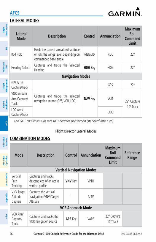
Garmin G1000 Cockpit Reference Guide for the Diamond Da42 190-00406-08 Rev. A96
aFCS
Flig
htIn
stru
men
tsEI
SN
av/C
om/
XPD
R/A
udio
Flig
ht
Man
agem
ent
Haz
ard
Avoi
danc
eA
FCS
Add
ition
alFe
atur
esA
nnun
/Ale
rts
App
endi
xIn
dex
Flig
htIn
stru
men
tsEI
Sa
udio
and
CNS
Flig
ht
Man
agem
ent
Haz
ard
avoi
danc
ea
FCS
add
ition
alFe
atur
esa
bnor
mal
ope
ratio
na
nnun
/ale
rts
app
endi
xIn
dex
LaTERaL MoDES
Lateral Mode Description Control annunciation
Maximum Roll
Command Limit
Roll HoldHolds the current aircraft roll attitude or rolls the wings level, depending on commanded bank angle
(default) ROL 22º
Heading SelectCaptures and tracks the Selected Heading
HDG Key HDG 22º
Navigation ModesGPS Arm/Capture/Track
Captures and tracks the selected navigation source (GPS, VOR, LOC)
NaV Key
GPS 22º
VOR EnrouteArm/Capture/Track
VOR22º Capture
10º TrackLOC Arm/Capture/Track
LOC
The GFC 700 limits turn rate to 3 degrees per second (standard rate turn).
Flight Director Lateral Modes
CoMBINaTIoN MoDES
Mode Description Control annunciation
Maximum Roll
Command Limit
Reference Range
Vertical Navigation ModesVertical Path Tracking
Captures and tracks descent legs of an active vertical profile
VNV Key VPTH
VNV Target Altitude Capture
Captures the Vertical Navigation (VNV) Target Altitude
1 ALTV
VoR approach ModeVOR Arm/Capture/Track
Captures and tracks the VOR navigation source
aPR Key VAPP22º Capture
10º Track
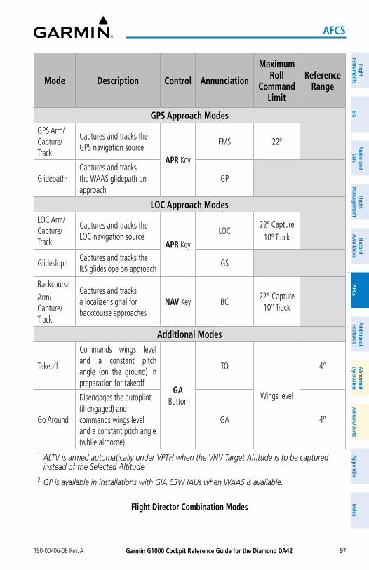
Garmin G1000 Cockpit Reference Guide for the Diamond Da42190-00406-08 Rev. A 97
aFCS
FlightInstrum
entsEIS
Nav/Com
/XPD
R/Audio
Flight M
anagement
Hazard
AvoidanceA
FCSA
dditionalFeatures
Annun/A
lertsA
ppendixIndex
FlightInstrum
entsEIS
audio and
CNS
Flight M
anagement
Hazard
avoidancea
FCSa
dditionalFeatures
abnorm
alo
perationa
nnun/alerts
appendix
Index
Mode Description Control annunciation
Maximum Roll
Command Limit
Reference Range
GPS approach ModesGPS Arm/Capture/Track
Captures and tracks the GPS navigation source
aPR Key
FMS 22º
Glidepath2
Captures and tracks the WAAS glidepath on approach
GP
LoC approach ModesLOC Arm/Capture/Track
Captures and tracks the LOC navigation source
aPR Key
LOC22º Capture
10º Track
GlideslopeCaptures and tracks the ILS glideslope on approach
GS
BackcourseArm/Capture/Track
Captures and tracks a localizer signal for backcourse approaches
NaV Key BC22° Capture
10° Track
additional Modes
Takeoff
Commands wings level and a constant pitch angle (on the ground) in preparation for takeoff
Ga Button
TO
Wings level
4°
Go Around
Disengages the autopilot (if engaged) and commands wings level and a constant pitch angle (while airborne)
GA 4°
1 ALTV is armed automatically under VPTH when the VNV Target Altitude is to be captured instead of the Selected Altitude.
2 GP is available in installations with GIA 63W IAUs when WAAS is available.
Flight Director Combination Modes
Garmin G1000 Cockpit Reference Guide for the Diamond Da42 190-00406-08 Rev. A98
aFCS
Flig
htIn
stru
men
tsEI
SN
av/C
om/
XPD
R/A
udio
Flig
ht
Man
agem
ent
Haz
ard
Avoi
danc
eA
FCS
Add
ition
alFe
atur
esA
nnun
/Ale
rts
App
endi
xIn
dex
Flig
htIn
stru
men
tsEI
Sa
udio
and
CNS
Flig
ht
Man
agem
ent
Haz
ard
avoi
danc
ea
FCS
add
ition
alFe
atur
esa
bnor
mal
ope
ratio
na
nnun
/ale
rts
app
endi
xIn
dex
approach Modes
NoTE: The selected navigation receiver must have a valid VOR or LOC signal or active GPS course for the flight director to enter Approach Mode.
WaRNING: Do not rely on the autopilot to level the aircraft at the MDA/DH when flying a coupled approach with GP or GS Mode active. The autopilot will not level the aircraft at the MDA/DH even if the MDA/DH is set in the altitude preselect.
Selecting VoR approach Mode:1) Ensure a valid VOR frequency is tuned.2) Ensure that VOR is the selected navigation source (use the CDI Softkey to cycle through
navigation sources if necessary).3) Press the aPR Key.
Selecting GPS approach Mode:1) Ensure an RNAV (GPS) approach is loaded into the active flight plan. The active waypoint
must be part of the flight plan (cannot be a direct-to a waypoint not in the flight plan).2) Ensure that GPS is the selected navigation source (use the CDI Softkey to cycle through
navigation sources if necessary).3) Press the aPR Key.
NoTE: Some RNAV (GPS) approaches provide a vertical descent angle as an aid in flying a stabilized approach. These approaches are NOT considered Approaches with Vertical Guidance (APV). Approaches that are annunciated on the HSI as ‘LNAV+V’ or ‘LP+V’ should be flown in compliance with any stepdown altitude constraints and to an MDA, until visual reference with the landing environment is established, even though vertical glidepath (GP) information may be provided.
NoTE: When flying an autopilot-coupled ‘LNAV+V’ or ‘LP+V’ approach with GP Mode active, the aircraft will not level off at the MDA even if the MDA is set in the altitude preselect. A different vertical mode (VS, FLC, PIT) must be selected prior to MDA (as altitude preselect) to arm ALTS Mode.
Selecting GPS approach with Glidepath Mode:1) Ensure an RNAV (GPS) approach providing vertical guidance (LPV, LNAV/VNAV, LNAV+V,
LP+V) is loaded into the active flight plan. The active waypoint must be part of the flight plan (cannot be a direct-to a waypoint not in the flight plan).
Garmin G1000 Cockpit Reference Guide for the Diamond Da42190-00406-08 Rev. A 99
aFCS
FlightInstrum
entsEIS
Nav/Com
/XPD
R/Audio
Flight M
anagement
Hazard
AvoidanceA
FCSA
dditionalFeatures
Annun/A
lertsA
ppendixIndex
FlightInstrum
entsEIS
audio and
CNS
Flight M
anagement
Hazard
avoidancea
FCSa
dditionalFeatures
abnorm
alo
perationa
nnun/alerts
appendix
Index
2) Ensure that GPS is the selected navigation source (use the CDI Softkey to cycle through navigation sources if necessary).
3) Press the aPR Key.
NoTE: Pressing the CWS Button while Glidepath Mode is active does not cancel the mode. The autopilot guides the aircraft back to the glidepath upon release of the CWS Button.
Selecting LoC approach Mode:1) Ensure a valid localizer frequency is tuned.2) Ensure that LOC is the selected navigation source (use the CDI Softkey to cycle through
navigation sources if necessary).3) Press the aPR Key. or:1) Ensure that GPS is the selected navigation source (use the CDI Softkey to cycle through
navigation sources if necessary).2) Ensure a LOC/ILS approach is loaded into the active flight plan.3) Ensure the corresponding LOC frequency is tuned.4) Press the aPR Key.
Selecting Glideslope Mode:1) Ensure a valid localizer frequency is tuned.2) Ensure that LOC is the selected navigation source (use the CDI Softkey to cycle through
navigation sources if necessary).3) Press the aPR Key. or:1) Ensure that GPS is the selected navigation source (use the CDI Softkey to cycle through
navigation sources if necessary).2) Ensure a LOC/ILS approach is loaded into the active flight plan.3) Ensure the corresponding LOC frequency is tuned.4) Press the aPR Key.
NoTE: Pressing the CWS Button while Glideslope Mode is active does not cancel the mode. The autopilot guides the aircraft back to the glideslope upon release of the CWS Button.

Garmin G1000 Cockpit Reference Guide for the Diamond Da42 190-00406-08 Rev. A100
aFCS
Flig
htIn
stru
men
tsEI
SN
av/C
om/
XPD
R/A
udio
Flig
ht
Man
agem
ent
Haz
ard
Avoi
danc
eA
FCS
Add
ition
alFe
atur
esA
nnun
/Ale
rts
App
endi
xIn
dex
Flig
htIn
stru
men
tsEI
Sa
udio
and
CNS
Flig
ht
Man
agem
ent
Haz
ard
avoi
danc
ea
FCS
add
ition
alFe
atur
esa
bnor
mal
ope
ratio
na
nnun
/ale
rts
app
endi
xIn
dex
baCkCourse mode (bC)
NoTE: When making a localizer backcourse approach, set the Selected Course to the localizer front course.
Backcourse Mode may be selected by pressing the NAV Key.
Garmin G1000 Cockpit Reference Guide for the Diamond Da42190-00406-08 Rev. A 101
additional Features
FlightInstrum
entsEIS
Nav/Com
/XPD
R/Audio
Flight M
anagement
Hazard
AvoidanceA
FCSA
dditionalFeatures
Annun/A
lertsA
ppendixIndex
FlightInstrum
entsEIS
audio and
CNS
Flight M
anagement
Hazard
avoidancea
FCSa
dditionalFeatures
abnorm
alo
perationa
nnun/alerts
appendix
Index
aDDITIoNaL FEaTURESSaFETaXI
WaRNING: Always refer to current aeronautical charts and NOTAMs for verifica-tion of displayed aeronautical information. Displayed aeronautical data may not incorporate the latest NOTAM information.
Configuring SafeTaxi range:1) While viewing the ‘MAP - NAVIGATION MAP’ Page, press the MENU Key to display the
PAGE MENU.2) Turn the FMS Knob to highlight the ‘Map Setup’ Menu Option and press the ENT Key.3) Turn the small FMS Knob to select the ‘Aviation’ Group and press the ENT Key.4) Turn the large FMS Knob to scroll through the ‘Aviation’ Group options to SAFETAXI.5) Turn the small FMS Knob to display the range of distances.6) Turn the FMS Knob to select the desired distance for maximum SafeTaxi display range.7) Press the ENT Key to complete the selection.8) Push the FMS Knob to return to the ‘MAP - NAVIGATION MAP’ Page.
ELECTRoNIC CHaRTS (oPTIoNaL)
WaRNING: Always refer to current aeronautical charts and NOTAMs for verifica-tion of displayed aeronautical information. Displayed aeronautical data may not incorporate the latest NOTAM information.
WaRNING: Do not rely on the displayed minimum safe altitude (MSAs) as the sole source of obstacle and terrain avoidance information. Always refer to current aeronautical charts for appropriate minimum clearance altitudes.
NoTE: Do not rely solely upon datalink services to provide Temporary Flight Restric-tion (TFR) information. Always confirm TFR information through official sources such as Flight Service Stations or Air Traffic Control.
NoTE: The pilot/operator must have access to Garmin and Jeppesen database alerts and consider their impact on the intended aircraft operation. The database alerts can be viewed at flyGarmin.com® by selecting ‘Aviation Database Alerts.’
Garmin G1000 Cockpit Reference Guide for the Diamond Da42 190-00406-08 Rev. A102
additional Features
Flig
htIn
stru
men
tsEI
SN
av/C
om/
XPD
R/A
udio
Flig
ht
Man
agem
ent
Haz
ard
Avoi
danc
eA
FCS
Add
ition
alFe
atur
esA
nnun
/Ale
rts
App
endi
xIn
dex
Flig
htIn
stru
men
tsEI
Sa
udio
and
CNS
Flig
ht
Man
agem
ent
Haz
ard
avoi
danc
ea
FCS
add
ition
alFe
atur
esa
bnor
mal
ope
ratio
na
nnun
/ale
rts
app
endi
xIn
dex
NoTE: Electronic aeronautical charts displayed on this system have been shown to meet the guidance in AC 120-76D as a Type ‘B’ Electronic Flight Bag (EFB) for FliteCharts and ChartView. The accuracy of the charts is subject to the chart data provider. Own-ship position on airport surface charts cannot be guaranteed to meet the accuracy specified in AC 120-76D. Possible additional requirements may make a secondary source of aeronautical charts, such as traditional paper charts or an additional electronic display, necessary on the aircraft and available to the pilot. If the secondary source of aeronautical charts is a Portable Electronic Device (PED), its use must be consistent with the guidance in AC 120-76D.
CHaRTVIEWViewing terminal procedures charts:1) Use the FMS Knob to select either the ‘MAP - NAVIGATION MAP’ Page, ‘NRST -
NEAREST AIRPORTS’ Page, or ‘FPL - ACTIVE FLIGHT PLAN’ Page.2) Press the SHW CHRT Softkey. or:
a) Press the MENU Key to display the PAGE MENU.b) Turn the FMS Knob to scroll through the ‘OPTIONS’ Menu to ‘Show Chart.’ c) Press the ENT Key to display the chart.
Selecting a terminal procedures chart:1) Use the FMS Knob to select either the ‘MAP - NAVIGATION MAP’ Page, ‘NRST -
NEAREST AIRPORTS’ Page, or ‘FPL - ACTIVE FLIGHT PLAN’ Page.2) Press the SHW CHRT Softkey. or:
a) Press the MENU Key to display the PAGE MENU.b) Turn the FMS Knob to scroll through the ‘OPTIONS’ Menu to ‘Show Chart.’ c) Press the ENT Key to display the chart.
3) To select a different airport for which charts will be displayed:a) Push the FMS Knob to activate the cursor.b) Turn the large FMS Knob to select the ‘AIRPORT’ Identifier Box, if needed.c) Turn the small and large FMS knobs to enter the desired airport identifier and press
the ENT Key to complete the airport selection.4) To select a different chart type, press the appropriate softkey at the bottom of the screen. or:
Garmin G1000 Cockpit Reference Guide for the Diamond Da42190-00406-08 Rev. A 103
additional Features
FlightInstrum
entsEIS
Nav/Com
/XPD
R/Audio
Flight M
anagement
Hazard
AvoidanceA
FCSA
dditionalFeatures
Annun/A
lertsA
ppendixIndex
FlightInstrum
entsEIS
audio and
CNS
Flight M
anagement
Hazard
avoidancea
FCSa
dditionalFeatures
abnorm
alo
perationa
nnun/alerts
appendix
Index
a) Press the MENU Key to display the PAGE MENU.b) Turn the FMS Knob to scroll and select the desired chart type (‘Show Information
Page’, ‘Show Departure Page’, ‘Show Arrival Page’, or ‘Show Approach Page’), then press the ENT Key to display the chart.
5) To select a different chart:a) Push the FMS Knob to activate the cursor, if needed.b) Turn the large FMS Knob to select the chart selection box, if needed.
c) Turn the small FMS Knob to access and scroll through the available charts and press the ENT Key to complete the chart selection.
6) Push the FMS Knob to deactivate the cursor.
Selecting additional airport information charts:1) From the ‘WPT - AIRPORT INFORMATION’ Page, press the CHRT Softkey to view the ‘WPT
- Airport Chart’ Page.2) Push the FMS Knob to activate the cursor.3) To change the airport for which additional airport information charts are sought:
a) Turn the large FMS Knob to select the ‘AIRPORT’ Identifier Box.b) Turn the small and large FMS knobs to enter the desired airport identifier and press
the ENT Key to complete the airport selection.
4) Turn the large FMS Knob to select the ‘INFO’ Box, if needed.5) Turn the small FMS Knob to access and scroll through the available airport information
charts (e.g., CLASS B AIRSPACE, TAKE-OFF MNMS, etc.) and press the ENT Key to complete the chart selection.
6) Push the FMS Knob to deactivate the cursor.
Selecting full screen chart view on or off:1) While viewing a terminal procedures chart, press the CHRT oPT Softkey.2) Press the FULL SCN Softkey to switch between a full screen chart view and a chart/info
window split screen view. or:1) While viewing a terminal procedures chart, press the MENU Key to display the PAGE
MENU.2) Turn the FMS Knob to highlight the ‘Chart Setup’ Menu Option and press the ENT Key.
3) Turn the large FMS Knob to highlight the ‘FULL SCREEN’ Field.4) Turn the small FMS Knob to select either ‘On’ or ‘Off.’5) Push the FMS Knob to deactivate the cursor and return.
Garmin G1000 Cockpit Reference Guide for the Diamond Da42 190-00406-08 Rev. A104
additional Features
Flig
htIn
stru
men
tsEI
SN
av/C
om/
XPD
R/A
udio
Flig
ht
Man
agem
ent
Haz
ard
Avoi
danc
eA
FCS
Add
ition
alFe
atur
esA
nnun
/Ale
rts
App
endi
xIn
dex
Flig
htIn
stru
men
tsEI
Sa
udio
and
CNS
Flig
ht
Man
agem
ent
Haz
ard
avoi
danc
ea
FCS
add
ition
alFe
atur
esa
bnor
mal
ope
ratio
na
nnun
/ale
rts
app
endi
xIn
dex
Selecting day, night, or automatic chart view:
1) While viewing a terminal procedures chart, press the MENU Key to display the PAGE MENU.
2) Turn the FMS Knob to highlight the ‘Chart Setup’ Menu Option and press the ENT Key.
3) Turn the large FMS Knob to move to the ‘COLOR SCHEME’ Field.4) In the ‘Color Scheme’ Field, turn the small FMS Knob to choose between ‘Day’, ‘Auto’,
and ‘Night’ Options.5) If ‘Auto’ is selected, turn the large FMS Knob to select the percentage field. Use the
small FMS Knob to change the percentage value. The percentage value is the day/night crossover point based on the percentage of backlighting intensity. For example, if the value is set to 15%, the day/night display changes when the display backlight reaches 15% of full brightness.
The display must be changed in order for the new setting to become active. This may be accomplished by selecting another page or changing the display range.
6) Push the FMS Knob when finished to remove the ‘Chart Setup’ Menu.
FLITECHaRTSViewing terminal procedures charts:1) Use the FMS Knob to select either the ‘MAP - NAVIGATION MAP’ Page, ‘NRST -
NEAREST AIRPORTS’ Page, or ‘FPL - ACTIVE FLIGHT PLAN’ Page.2) Press the SHW CHRT Softkey. or:
a) Press the MENU Key to display the PAGE MENU.b) Turn the FMS Knob to scroll through the ‘OPTIONS’ Menu to ‘Show Chart.’ c) Press the ENT Key to display the chart.
Selecting a terminal procedures chart:1) Use the FMS Knob to select either the ‘MAP - NAVIGATION MAP’ Page, ‘NRST -
NEAREST AIRPORTS’ Page, or ‘FPL - ACTIVE FLIGHT PLAN’ Page.2) Press the SHW CHRT Softkey. or:
a) Press the MENU Key to display the PAGE MENU.b) Turn the FMS Knob to scroll through the ‘OPTIONS’ Menu to ‘Show Chart.’ c) Press the ENT Key to display the chart.
Garmin G1000 Cockpit Reference Guide for the Diamond Da42190-00406-08 Rev. A 105
additional Features
FlightInstrum
entsEIS
Nav/Com
/XPD
R/Audio
Flight M
anagement
Hazard
AvoidanceA
FCSA
dditionalFeatures
Annun/A
lertsA
ppendixIndex
FlightInstrum
entsEIS
audio and
CNS
Flight M
anagement
Hazard
avoidancea
FCSa
dditionalFeatures
abnorm
alo
perationa
nnun/alerts
appendix
Index
3) To select a different airport for which charts will be displayed:a) Push the FMS Knob to activate the cursor.b) Turn the large FMS Knob to select the ‘AIRPORT’ Identifier Box, if needed.c) Turn the small and large FMS knobs to enter the desired airport identifier and press
the ENT Key to complete the airport selection.4) To select a different chart type, press the appropriate softkey at the bottom of the screen. or:
a) Press the MENU Key to display the PAGE MENU.b) Turn the FMS Knob to scroll and select the desired chart type (‘Show Information
Page’, ‘Show Departure Page’, ‘Show Arrival Page’, or ‘Show Approach Page’), then press the ENT Key to display the chart.
5) To select a different chart:a) Push the FMS Knob to activate the cursor, if needed.b) Turn the large FMS Knob to select the chart selection box, if needed.
c) Turn the small FMS Knob to access and scroll through the available charts and press the ENT Key to complete the chart selection.
6) Push the FMS Knob to deactivate the cursor.
Selecting additional airport information charts:1) From the ‘WPT - AIRPORT INFORMATION’ Page, press the CHRT Softkey to view the ‘WPT
- Airport Chart’ Page.2) Push the FMS Knob to activate the cursor.3) To change the airport for which additional airport information charts are sought:
a) Turn the large FMS Knob to select the ‘AIRPORT’ Identifier Box.b) Turn the small and large FMS knobs to enter the desired airport identifier and press
the ENT Key to complete the airport selection.
4) Turn the large FMS Knob to select the ‘INFO’ Box, if needed.5) Turn the small FMS Knob to access and scroll through the available airport information
charts (e.g., ALTERNATE MINIMUMS, TAKEOFF MINIMUMS, etc.) and press the ENT Key to complete the chart selection.
6) Push the FMS Knob to deactivate the cursor.
Selecting full screen chart view on or off:1) While viewing a terminal procedures chart, press the CHRT oPT Softkey.2) Press the FULL SCN Softkey to switch between a full screen chart view and a chart/info
window split screen view. or:
Garmin G1000 Cockpit Reference Guide for the Diamond Da42 190-00406-08 Rev. A106
additional Features
Flig
htIn
stru
men
tsEI
SN
av/C
om/
XPD
R/A
udio
Flig
ht
Man
agem
ent
Haz
ard
Avoi
danc
eA
FCS
Add
ition
alFe
atur
esA
nnun
/Ale
rts
App
endi
xIn
dex
Flig
htIn
stru
men
tsEI
Sa
udio
and
CNS
Flig
ht
Man
agem
ent
Haz
ard
avoi
danc
ea
FCS
add
ition
alFe
atur
esa
bnor
mal
ope
ratio
na
nnun
/ale
rts
app
endi
xIn
dex
1) While viewing a terminal procedures chart, press the MENU Key to display the PAGE MENU.
2) Turn the FMS Knob to highlight the ‘Chart Setup’ Menu Option and press the ENT Key.
3) Turn the large FMS Knob to highlight the ‘FULL SCREEN’ Field.4) Turn the small FMS Knob to select either ‘On’ or ‘Off.’5) Push the FMS Knob to deactivate the cursor and return.
Selecting day, night, or automatic chart view:
1) While viewing a terminal procedures chart, press the MENU Key to display the PAGE MENU.
2) Turn the FMS Knob to highlight the ‘Chart Setup’ Menu Option and press the ENT Key.
3) Turn the large FMS Knob to move to the ‘COLOR SCHEME’ Field.4) In the ‘Color Scheme’ Field, turn the small FMS Knob to choose between ‘Day’, ‘Auto’,
and ‘Night’ Options.5) If ‘Auto’ is selected, turn the large FMS Knob to select the percentage field. Use the
small FMS Knob to change the percentage value. The percentage value is the day/night crossover point based on the percentage of backlighting intensity. For example, if the value is set to 15%, the day/night display changes when the display backlight reaches 15% of full brightness.
The display must be changed in order for the new setting to become active. This may be accomplished by selecting another page or changing the display range.
6) Push the FMS Knob when finished to remove the ‘Chart Setup’ Menu.
SIRIUSXM SaTELLITE RaDIo (oPTIoNaL)aCTIVaTING SIRIUSXM SaTELLITE RaDIo SERVICES
The service is activated by providing SiriusXM Satellite Radio with either one or two coded IDs, depending on the equipment. The Audio Radio ID, Data Radio ID, or both, must be pro-vided to SiriusXM Satellite Radio to activate the entertainment subscription.
It is not required to activate both the entertainment and weather service subscriptions with the SiriusXM Datalink Receiver. Either or both services can be activated. SiriusXM Satellite Radio uses one or both of the coded IDs to send an activation signal that, when received by the SiriusXM Datalink Receiver, allows it to play entertainment programming.
These IDs are located:
– On the label on the back of the SiriusXM Datalink Receiver.
– On the ‘AUX - XM INFORMATION’ Page on the MFD.
– On the XM Satellite Radio Activation Instructions included with the unit (available at www.garmin.com, P/N 190-00355-04).
Contact the installer if the Data Radio ID and the Audio Radio ID cannot be located.
Garmin G1000 Cockpit Reference Guide for the Diamond Da42190-00406-08 Rev. A 107
additional Features
FlightInstrum
entsEIS
Nav/Com
/XPD
R/Audio
Flight M
anagement
Hazard
AvoidanceA
FCSA
dditionalFeatures
Annun/A
lertsA
ppendixIndex
FlightInstrum
entsEIS
audio and
CNS
Flight M
anagement
Hazard
avoidancea
FCSa
dditionalFeatures
abnorm
alo
perationa
nnun/alerts
appendix
Index
activating SiriusXM Satellite Radio services:1) After gathering the Audio Radio ID and the Data Radio ID, contact SiriusXM and
complete subscription activation.2) Turn the large FMS Knob on the MFD Controller to select the ‘AUX’ Page Group.3) Turn the small FMS Knob to select the ‘AUX - XM RADIO’ Page.4) Press the INFo Softkey to display the ‘AUX - XM INFORMATION’ Page.5) Verify the desired services are activated.6) Press the LoCK Softkey. A confirmation window is displayed.7) Turn the large FMS Knob to highlight ‘YES.’8) To complete activation, press the ENT Key.
USING SIRIUSXM RaDIoSelecting the ‘aUX - XM RaDIo’ Page:1) Turn the large FMS Knob to select the ‘AUX’ Page Group.2) Turn the small FMS Knob to select the ‘AUX - XM RADIO’ or ‘AUX - XM INFORMATION’
Page.3) If not already selected, press the RaDIo Softkey to show the ‘AUX - XM RADIO’ Page.
Selecting a channel from the channel list:1) While on the ‘AUX - XM RADIO’ Page, press the CHNL Softkey.2) Press the CH + Softkey to go up through the list in the ‘CHANNELS’ Box, or move down
the list by pressing the CH – Softkey. or:1) While on the ‘AUX - XM RADIO’ Page, push the FMS Knob to highlight the ‘CHANNELS’
Box and turn the large FMS Knob to scroll through the channels.2) Press the ENT Key to activate the selected channel.
Selecting a channel directly:1) While on the ‘AUX - XM RADIO’ Page, press the CHNL Softkey.2) Press the DIR CH Softkey. The channel number in the ‘ACTIVE CHANNEL’ Box is
highlighted.3) Press the numbered softkeys located on the bottom of the display to directly select the
desired channel number.4) Press the ENT Key to activate the selected channel.
Selecting a category:1) While on the ‘AUX - XM RADIO’ Page, press the CaTGRy Softkey.2) Press the CaT + and CaT - Softkeys to cycle through the categories. or:
Garmin G1000 Cockpit Reference Guide for the Diamond Da42 190-00406-08 Rev. A108
additional Features
Flig
htIn
stru
men
tsEI
SN
av/C
om/
XPD
R/A
udio
Flig
ht
Man
agem
ent
Haz
ard
Avoi
danc
eA
FCS
Add
ition
alFe
atur
esA
nnun
/Ale
rts
App
endi
xIn
dex
Flig
htIn
stru
men
tsEI
Sa
udio
and
CNS
Flig
ht
Man
agem
ent
Haz
ard
avoi
danc
ea
FCS
add
ition
alFe
atur
esa
bnor
mal
ope
ratio
na
nnun
/ale
rts
app
endi
xIn
dex
Turn the small FMS Knob to display the Categories list. Highlight the desired category with the small FMS Knob and press the ENT Key. Selecting ‘ALL CATEGORIES’ places all channels in the list.
or:1) While on the ‘AUX - XM RADIO’ Page, push the FMS Knob to activate the cursor.2) Turn the large FMS Knob to select the ‘CATEGORY’ Box. 3) Using the small FMS Knob, highlight the desired category and press the ENT Key.
Selecting ‘ALL CATEGORIES’ places all channels in the list.
Setting a preset channel number:1) On the ‘AUX - XM RADIO’ Page, while listening to an Active Channel desired to be a
preset, press the PRESETS Softkey to access the first five preset channels (PS1 - PS5).2) Press the MoRE Softkey to access the next five channels (PS6 – PS10), and again to
access the last five channels (PS11 – PS15). Pressing the MoRE Softkey repeatedly cycles through the preset channels.
3) Press any one of the (PS1 - PS15) softkeys to assign a preset number to the active channel.
4) Press the SET Softkey on the desired channel number to save the channel as a preset.
adjusting the volume:1) With the ‘AUX - XM RADIO’ Page displayed, press the VoL Softkey.2) Press the VoL – Softkey to reduce volume or press the VoL + Softkey to increase volume.
(Once the VoL Softkey is pressed, the volume can also be adjusted using the small FMS Knob).
Muting SiriusXM audio:1) While on the ‘AUX - XM RADIO’ Page or ‘AUX - XM INFORMATION’ Page, press the
MUTE Softkey to mute SiriusXM audio.2) To unmute the audio, press the MUTE Softkey again.
SCHEDULEREntering a scheduler message:1) Use the FMS Knob to select the ‘AUX - UTILITY’ Page.2) Push the FMS Knob momentarily to activate the flashing cursor.
3) Turn the large FMS Knob to highlight the first empty ‘MESSAGE’ Field in the ‘SCHEDULER’ Window.
4) Turn the small and large FMS knobs to enter the message text to be displayed as the scheduled reminder in the ‘ALERTS’ Window and press the ENT Key.
Garmin G1000 Cockpit Reference Guide for the Diamond Da42190-00406-08 Rev. A 109
additional Features
FlightInstrum
entsEIS
Nav/Com
/XPD
R/Audio
Flight M
anagement
Hazard
AvoidanceA
FCSA
dditionalFeatures
Annun/A
lertsA
ppendixIndex
FlightInstrum
entsEIS
audio and
CNS
Flight M
anagement
Hazard
avoidancea
FCSa
dditionalFeatures
abnorm
alo
perationa
nnun/alerts
appendix
Index
5) Press the ENT Key again or use the large FMS Knob to move the cursor to the ‘TYPE’ Field.
6) Turn the small FMS Knob to select the message type:a) ‘Event’ – Message issued at the specified date/timeb) ‘One Time’ (default setting) – Message issued when the message timer reaches zeroc) ‘Periodic’ – Message issued each time the message timer reaches zero
7) Press the ENT Key to move the cursor to the next field.8) For Periodic and One Time messages, use the small and large FMS knobs to enter the
timer value (HH:MM:SS) from which to countdown and press the ENT Key.9) For Event messages:
a) Use the small and large FMS knobs to enter the desired date (DD-MM-YY) and press the ENT Key.
b) Press the ENT Key again or use the large FMS Knob to move the cursor to the next field.
c) Use the small and large FMS knobs to enter the desired time (HH:MM) and press the ENT Key.
10) Press the ENT Key again or use the large FMS Knob to move the cursor to enter the next message, if desired.
11) When finished, push the FMS Knob to deactivate the flashing cursor.
Deleting a scheduler message:1) Use the FMS Knob to select the ‘AUX - UTILITY’ Page.2) Push the FMS Knob momentarily to activate the flashing cursor.
3) Turn the large FMS Knob to highlight the ‘MESSAGE’ Field of the scheduler message to be deleted.
4) Press the CLR Key to clear the message text. If the CLR Key is pressed again, the message is restored.
5) Press the ENT Key while the message line is cleared to delete the scheduler message.6) When finished, push the FMS Knob to deactivate the flashing cursor.
ELECTRoNIC CHECKLISTS (oPTIoNaL)
NoTE: Garmin is not responsible for the content of checklists. Diamond DA42 checklists are created, modified, and updated by the aircraft manufacturer. The user cannot edit these checklists.
NoTE: The CHKLIST Softkey will only display when the checklist database is acces-sible by the system.
Garmin G1000 Cockpit Reference Guide for the Diamond Da42 190-00406-08 Rev. A110
additional Features
Flig
htIn
stru
men
tsEI
SN
av/C
om/
XPD
R/A
udio
Flig
ht
Man
agem
ent
Haz
ard
Avoi
danc
eA
FCS
Add
ition
alFe
atur
esA
nnun
/Ale
rts
App
endi
xIn
dex
Flig
htIn
stru
men
tsEI
Sa
udio
and
CNS
Flig
ht
Man
agem
ent
Haz
ard
avoi
danc
ea
FCS
add
ition
alFe
atur
esa
bnor
mal
ope
ratio
na
nnun
/ale
rts
app
endi
xIn
dex
Immediately accessing emergency procedures checklists:1) From any page on the MFD, press the CHKLIST Softkey.2) Press the EMERGCy Softkey.3) When finished navigating the emergency procedures checklist(s), press the RETURN
Softkey to return to the last accessed normal checklist.
accessing and navigating checklists:1) From any page on the MFD, press the CHKLIST Softkey.2) Push the FMS Knob momentarily to activate the cursor and then turn the large FMS Knob
to select the ‘GROUP’ Field.3) Turn the small FMS Knob to select the desired checklist group and press the ENT Key.4) Turn the large FMS Knob to select the ‘CHECKLIST’ Field.5) Turn the small FMS Knob to select the desired checklist and press the ENT Key. The first checklist item is selected with white text surrounded by a white box.6) Press the ENT Key or the CHECK Softkey to check the selected checklist item. The line
item turns green and a checkmark is placed in the associated box. The next line item is automatically selected for checking.
Either FMS Knob can be used to scroll through the checklist and select a specific checklist item.
If desired, press the CLR Key or the UNCHECK Softkey to remove a checkmark from an item.
7) When all checklist items have been checked, ‘*CHECKLIST FINISHED*’ is displayed in green text at the bottom left of the checklist window and ‘GO TO NEXT CHECKLIST?’ is highlighted at the bottom right.
If ‘GO TO NEXT CHECKLIST?’ is selected before checking all the checklist items, ‘*CHECKLIST NOT FINISHED*’ will be displayed in amber text.
8) Press the ENT Key, if desired. If ‘GO TO NEXT CHECKLIST?’ is highlighted when pressing the ENT Key, the next checklist in the group will be displayed. If ‘EXIT CHECKLISTS?’ is highlighted when pressing the ENT Key, the system will exit the ‘CHKLST’ Page Group.
9) Press the EXIT Softkey at any time to exit checklists and return to the MFD page last viewed. When returning to the Checklist Page after pressing the EXIT Softkey, the system will return to the last selected checklist item.
BLUETooTH MaNaGEMENTViewing the ‘aUX - BLUETooTH MaNaGEMENT’ Page:1) Turn the large FMS Knob to select the ‘AUX’ Page Group.2) Turn the small FMS Knob to select the ‘AUX - BLUETOOTH MANAGEMENT’ Page.
Garmin G1000 Cockpit Reference Guide for the Diamond Da42190-00406-08 Rev. A 111
additional Features
FlightInstrum
entsEIS
Nav/Com
/XPD
R/Audio
Flight M
anagement
Hazard
AvoidanceA
FCSA
dditionalFeatures
Annun/A
lertsA
ppendixIndex
FlightInstrum
entsEIS
audio and
CNS
Flight M
anagement
Hazard
avoidancea
FCSa
dditionalFeatures
abnorm
alo
perationa
nnun/alerts
appendix
Index
Changing the Bluetooth name:1) While viewing the ‘AUX - BLUETOOTH MANAGEMENT’ Page, push the FMS Knob to
activate the cursor.2) Turn the large FMS Knob to place the cursor in the ‘BLUETOOTH NAME’ Field.3) Use the small and large FMS knobs to enter the desired name.4) Press the ENT Key. The cursor is removed and the new name is displayed.
Enabling/disabling flight plan importing from Garmin Pilot:1) While viewing the ‘AUX - BLUETOOTH MANAGEMENT’ Page, push the FMS Knob to
activate the cursor.2) Turn the large FMS Knob to place the cursor in the ‘FLIGHT PLAN IMPORT’ Field.3) Turn the small FMS Knob to select ‘ENABLED’ or ‘DISABLED’.4) Push the FMS Knob to remove the cursor.
Enabling/disabling automatic reconnection of a specific paired device:1) While viewing the ‘AUX - BLUETOOTH MANAGEMENT’ Page, push the FMS Knob to
activate the cursor.2) Turn the large FMS Knob to highlight the desired paired device.3) Turn the small FMS Knob to select ‘ENABLED’ or ‘DISABLED’. Selecting ‘ENABLED’
allows the G1000 to automatically connect to a previously paired device when detected.4) Push the FMS Knob to remove the cursor.
Removing a specific paired device from the list of paired devices:1) While viewing the ‘AUX - BLUETOOTH MANAGEMENT’ Page, push the FMS Knob to
activate the cursor.2) Turn the large FMS Knob to highlight the desired paired device.3) Press the REMoVE Softkey. A confirmation screen is displayed.4) If necessary, turn the large FMS Knob to select ‘YES’.5) Press the ENT Key to remove the device from the list of paired devices.
DaTaBaSE MaNaGEMENT
CaUTIoN: Never disconnect power to the system when loading a database. Power interruption during the database loading process could result in maintenance being required to reboot the system.
NoTE: The system responds to a terminal procedure based on data coded within that procedure in the Navigation Database. Differences in system operation may be observed among similar types of procedures due to differences in the Navigation Database coding specific to each procedure.
Garmin G1000 Cockpit Reference Guide for the Diamond Da42 190-00406-08 Rev. A112
additional Features
Flig
htIn
stru
men
tsEI
SN
av/C
om/
XPD
R/A
udio
Flig
ht
Man
agem
ent
Haz
ard
Avoi
danc
eA
FCS
Add
ition
alFe
atur
esA
nnun
/Ale
rts
App
endi
xIn
dex
Flig
htIn
stru
men
tsEI
Sa
udio
and
CNS
Flig
ht
Man
agem
ent
Haz
ard
avoi
danc
ea
FCS
add
ition
alFe
atur
esa
bnor
mal
ope
ratio
na
nnun
/ale
rts
app
endi
xIn
dex
NoTE: The pilot/operator must review and be familiar with Garmin’s database exclu-sion list as discussed in SAIB CE-14-04 to determine what data may be incomplete. The database exclusion list can be viewed at flyGarmin.com by selecting ‘Database Exclusions List.’
NoTE: If the pilot/operator wants or needs to adjust the database, contact Garmin Product Support.
NoTE: Garmin requests the flight crew report any observed discrepancies related to database information. These discrepancies could come in the form of an incorrect procedure; incorrectly identified terrain, obstacles and fixes; or any other displayed item used for navigation or communication in the air or on the ground. Go to flyGarmin.com and select ‘Aviation Data Error Report.’
Viewing database information:
1) Turn the large FMS Knob to select the ‘AUX’ Page Group.
2) Turn the small FMS Knob to select the ‘AUX - SYSTEM STATUS’ Page.3) Press the MFD1 DB Softkey to place the cursor in the ‘MFD1 DATABASE’ Box and scroll
through the fields by turning the FMS Knob or pressing the ENT Key until the desired database(s) information is displayed.
4) Pressing the MFD1 DB Softkey again will change the softkey label to ‘PFD1 DB’ and place the cursor in the ‘PFD1 DATABASE’ Box. Scroll through the fields by turning the FMS Knob or pressing the ENT Key until the desired database(s) information is displayed.
5) Push the FMS Knob to deactivate the cursor.
PILoT PRoFILESCreating a profile:1) Use the FMS Knob to select the AUX – SYSTEM SETUP Page.2) Push the FMS Knob to activate the flashing cursor.3) Turn the large FMS Knob to highlight CREATE in the PILOT PROFILE Box.4) Press the ENT Key. A CREATE PROFILE Window is displayed.5) Use the FMS Knob to enter a profile name up to 16 characters long and press the ENT
Key. Pilot profile names cannot begin with a blank as the first letter.6) In the next field, turn the small FMS Knob to select the desired settings upon which to
base the new profile. Profiles can be created based on Garmin factory defaults, default profile settings (initially based on Garmin factory defaults unless edited by the pilot), or current system settings.
Garmin G1000 Cockpit Reference Guide for the Diamond Da42190-00406-08 Rev. A 113
additional Features
FlightInstrum
entsEIS
Nav/Com
/XPD
R/Audio
Flight M
anagement
Hazard
AvoidanceA
FCSA
dditionalFeatures
Annun/A
lertsA
ppendixIndex
FlightInstrum
entsEIS
audio and
CNS
Flight M
anagement
Hazard
avoidancea
FCSa
dditionalFeatures
abnorm
alo
perationa
nnun/alerts
appendix
Index
7) Press the ENT Key.8) With CREATE highlighted, press the ENT Key to create the profile. or: Turn the large FMS Knob to select CREATE & ACTIVATE and press the ENT Key to activate
the new profile.9) To cancel the process, select CANCEL with the large FMS Knob and press the ENT Key.
Selecting an active profile:1) Use the FMS Knob to select the AUX – SYSTEM SETUP Page.2) Push the FMS Knob to activate the flashing cursor.3) Turn the large FMS Knob to highlight the ACTIVE Field in the PILOT PROFILE Box.4) Turn the small FMS Knob to display the pilot profile list and highlight the desired profile.5) Press the ENT Key. The system loads and displays the system settings for the selected
profile.
Renaming a profile:1) Use the FMS Knob to select the AUX – SYSTEM SETUP Page.2) Push the FMS Knob to activate the flashing cursor.3) Turn the large FMS Knob to highlight RENAME in the PILOT PROFILE Box.4) Press the ENT Key.5) In the RENAME PROFILE Window, turn the FMS Knob to select the profile to rename.6) Press the ENT Key.7) Use the FMS Knob to enter a new profile name up to 16 characters long and press the
ENT Key.
8) With RENAME highlighted, press the ENT Key.9) To cancel the process, turn the large FMS Knob to select CANCEL and press the ENT Key.
Deleting a profile:1) Use the FMS Knob to select the AUX – SYSTEM SETUP Page.2) Push the FMS Knob to activate the flashing cursor.3) Turn the large FMS Knob to highlight DELETE in the PILOT PROFILE Box.4) Press the ENT Key.5) In the DELETE PROFILE Window, turn the FMS Knob to select the profile to delete.6) Press the ENT Key.7) With DELETE highlighted, press the ENT Key.
8) To cancel the process, turn the large FMS Knob to select CANCEL and press the ENT Key.
Garmin G1000 Cockpit Reference Guide for the Diamond Da42 190-00406-08 Rev. A114
additional Features
Flig
htIn
stru
men
tsEI
SN
av/C
om/
XPD
R/A
udio
Flig
ht
Man
agem
ent
Haz
ard
Avoi
danc
eA
FCS
Add
ition
alFe
atur
esA
nnun
/Ale
rts
App
endi
xIn
dex
Flig
htIn
stru
men
tsEI
Sa
udio
and
CNS
Flig
ht
Man
agem
ent
Haz
ard
avoi
danc
ea
FCS
add
ition
alFe
atur
esa
bnor
mal
ope
ratio
na
nnun
/ale
rts
app
endi
xIn
dex
If an SD card is inserted in the top slot of the MFD, pilot profiles may imported from the SD card to the system, or exported from the system to the SD card.
Because system settings may vary from one airframe to another, always verify system settings from an imported profile are consistent with the desired settings.
Importing a profile from an SD card:1) Insert an SD card containing the pilot profile(s) into the top card slot on the MFD.2) Use the FMS Knob to select the AUX – SYSTEM SETUP Page.3) Press the IMPoRT Softkey. or:
a) Press the MENU Key.b) Turn the FMS Knob to highlight ‘Import Pilot Profile’ and press the ENT Key.
4) The system displays the PILOT PROFILE IMPORTING Window with IMPORT highlighted. To change the selected profile to be imported from the SD card (shown as SELECT FILE), turn the large FMS Knob to highlight the PROFILE NAME Field, then turn the small FMS Knob to highlight a profile from the list, and press the ENT Key.
5) If desired, the profile name to be used after a profile has been imported can be changed by turning the FMS Knob to highlight the profile file name, then use the FMS Knob to enter the new desired name and press the ENT Key. Imported profile names cannot begin with a blank space or be named ‘DEFAULT’, ‘GARMIN DEFAULTS’ or ‘DEFAULT SETTINGS’.
6) With IMPORT highlighted, press the ENT Key.7) If the imported profile name is the same as an existing profile on the system, the system
displays an ‘Overwrite existing file? OK or CANCEL’ prompt. Press the ENT Key to replace profile on the system with the profile imported from the SD card, or turn the FMS Knob to highlight CANCEL and press the ENT Key to return to the PILOT PROFILE IMPORTING Window.
8) If successful, the system displays ‘Pilot profile import succeeded.’ in the IMPORT RESULTS Window. With OK highlighted, press the ENT or CLR Keys or push the FMS Knob to return to the AUX – SYSTEM SETUP Page. The imported profile becomes the active profile.
Exporting a profile to an SD card:1) Insert the SD card for storing the pilot profile into the top card slot on the MFD.2) Use the FMS Knob to select the AUX – System Setup Page.3) If necessary, activate the desired pilot profile to export. Only the currently active pilot
profile can be exported.4) Press the EXPoRT Softkey. The system displays the PILOT PROFILE EXPORTING Window. or:

Garmin G1000 Cockpit Reference Guide for the Diamond Da42190-00406-08 Rev. A 115
additional Features
FlightInstrum
entsEIS
Nav/Com
/XPD
R/Audio
Flight M
anagement
Hazard
AvoidanceA
FCSA
dditionalFeatures
Annun/A
lertsA
ppendixIndex
FlightInstrum
entsEIS
audio and
CNS
Flight M
anagement
Hazard
avoidancea
FCSa
dditionalFeatures
abnorm
alo
perationa
nnun/alerts
appendix
Index
a) Press the MENU Key.b) Turn the FMS Knob to highlight ‘Export Pilot Profile’ and press the ENT Key.
5) To export the pilot profile using the existing name, press the ENT Key with EXPORT highlighted. To change the profile file name, turn the large FMS Knob to highlight the SELECT FILE Field, enter the new name with the large and small FMS Knobs, then press the ENT Key with EXPORT highlighted.
6) If the profile name to be exported is the same as an existing profile file name on the SD card, the system displays an ‘Overwrite existing file? OK or CANCEL’ prompt. Press the ENT Key to replace the profile on the SD card with the profile to be exported, or turn the FMS Knob to highlight CANCEL and press the ENT Key to return to the PILOT PROFILE EXPORTING Window without exporting the profile.
7) If successful, the EXPORT RESULTS Window displays ‘Pilot profile export succeeded.’ With OK highlighted, press the ENT or CLR Keys, or push the FMS Knob to return to the AUX – SYSTEM SETUP Page.
SCHEDULERThe scheduler feature can be used to enter and display reminder messages (e.g., ‘Change oil’,
‘Switch fuel tanks’, ‘Overhaul’).
Entering a scheduler message:1) Use the FMS Knob to select the AUX – UTILITY Page.2) Push the FMS Knob to activate the flashing cursor.
3) Turn the large FMS Knob to highlight the first empty MESSAGE Field in the SCHEDULER Box.
4) Use the FMS Knob to enter the message text to be displayed in the ALERTS Window and press the ENT Key.
5) Press the ENT Key again or turn the large FMS Knob to move the cursor to the TYPE Field.
6) Turn the small FMS Knob to select the message alert type: • Event—Message issued at the specified date/time • One Time—Message issued when the message timer reaches zero (default setting) • Periodic—Message issued each time the message timer reaches zero7) Press the ENT Key again or turn the large FMS Knob to move the cursor to the TIME
Field.8) For periodic and one-time message, use the FMS Knob to enter the timer value
(HHH:MM:SS) from which to countdown and press the ENT Key.
Garmin G1000 Cockpit Reference Guide for the Diamond Da42 190-00406-08 Rev. A116
additional Features
Flig
htIn
stru
men
tsEI
SN
av/C
om/
XPD
R/A
udio
Flig
ht
Man
agem
ent
Haz
ard
Avoi
danc
eA
FCS
Add
ition
alFe
atur
esA
nnun
/Ale
rts
App
endi
xIn
dex
Flig
htIn
stru
men
tsEI
Sa
udio
and
CNS
Flig
ht
Man
agem
ent
Haz
ard
avoi
danc
ea
FCS
add
ition
alFe
atur
esa
bnor
mal
ope
ratio
na
nnun
/ale
rts
app
endi
xIn
dex
9) For event-based messages:a) Use the FMS Knob to enter the desired date (DD-MMM-YY) in the DATE Field and
press the ENT Key.b) Press the ENT Key again or turn the large FMS Knob to move the cursor to the TIME
Field.c) Use the FMS Knob to enter the desired time (HH:MM) and press the ENT Key.
10) Press the ENT Key again or turn the large FMS Knob to move the cursor to enter the next message.
Deleting a scheduler message:1) Use the FMS Knob to select the AUX – UTILITY Page.2) Push the FMS Knob to activate the flashing cursor.
3) Turn the large FMS Knob to highlight the MESSAGE Field of the scheduler message to be deleted.
4) Press the CLR Key to clear the message text. If the CLR Key is pressed again, the message is restored.
5) Press the ENT Key to confirm message deletion.Scheduler messages appear in the ALERTS Window on the PFD and cause the ALERTS
Softkey label to change to ADVISORY. Pressing the ADVISORY Softkey opens the ALERTS Window and acknowledges the scheduler message. The softkey reverts to the ALERTS label, and when pressed, the ALERTS Window is removed from the display and the scheduler mes-sage is deleted from the message list.
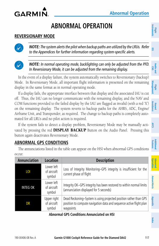
Garmin G1000 Cockpit Reference Guide for the Diamond Da42190-00406-08 Rev. A 117
FlightInstrum
entsEIS
audio and
CNS
Flight M
anagement
Hazard
avoidancea
FCSa
dditionalFeatures
abnorm
alo
perationa
nnun/alerts
appendix
Index
abnormal operation
aBNoRMaL oPERaTIoNREVERSIoNaRy MoDE
NoTE: The system alerts the pilot when backup paths are utilized by the LRUs. Refer to the Appendices for further information regarding system-specific alerts.
NoTE: In normal operating mode, backlighting can only be adjusted from the PFD. In Reversionary Mode, it can be adjusted from the remaining display.
In the event of a display failure, the system automatically switches to Reversionary (backup) Mode. In Reversionary Mode, all important flight information is presented on the remaining display in the same format as in normal operating mode.
If a display fails, the appropriate interface between that display and the associated IAU is cut off. Thus, the IAU can no longer communicate with the remaining display, and the NAV and COM functions provided to the failed display by the IAU are flagged as invalid (with a red ‘X’) on the remaining display. The system reverts to backup paths for the AHRS, ADC, Engine/Airframe Unit, and Transponder, as required. The change to backup paths is completely auto-mated for all LRUs and no pilot action is required.
If the system fails to detect a display problem, Reversionary Mode may be manually acti-vated by pressing the red DISPLAY BACKUP Button on the Audio Panel. Pressing this button again deactivates Reversionary Mode.
aBNoRMaL GPS CoNDITIoNSThe annunciations listed in the table can appear on the HSI when abnormal GPS conditions
occur.
annunciation Location Description
LOILower left of aircraft
symbol
Loss of Integrity Monitoring–GPS integrity is insufficient for the current phase of flight
INTEG OKLower left of aircraft
symbol
Integrity OK–GPS integrity has been restored to within normal limits (annunciation displayed for 5 seconds)
DRUpper right of aircraft
symbol
Dead Reckoning–System is using projected position rather than GPS position to compute navigation data and sequence active flight plan waypoints
abnormal GPS Conditions annunciated on HSI
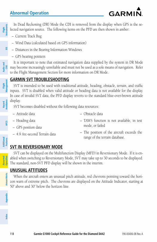
Garmin G1000 Cockpit Reference Guide for the Diamond Da42 190-00406-08 Rev. A118
Flig
htIn
stru
men
tsEI
Sa
udio
and
CNS
Flig
ht
Man
agem
ent
Haz
ard
avoi
danc
ea
FCS
add
ition
alFe
atur
esa
bnor
mal
ope
ratio
na
nnun
/ale
rts
app
endi
xIn
dex
abnormal operation
Pitch attitude Warnings
Nose High Nose Low
If pitch exceeds +30˚/-20˚ or bank exceeds 65˚, some information displayed on the PFD is removed. The Altimeter and Airspeed, Attitude, Vertical Speed, and Horizontal Situation indi-cators remain on the display and the Bearing Information, Alerts, and Annunciation windows can be displayed during such situations. The following information is removed from the PFD and their softkeys are disabled when the aircraft experiences unusual attitudes:
– Traffic Annunciations
– AFCS Annunciations
– Flight Director Com-mand Bars
– Inset Map
– Outside Air Temperature (OAT)
– Wind Data
– Selected Heading Display
– Selected Course Display
– Transponder Status Box
– System Time
– PFD Setup Menu
– Windows displayed in the lower right corner of the PFD:
– Timer/References
– Nearest Airports
– Flight Plan
– Messages
– Procedures
– Minimum Descent Al-titude/Decision Height Display
– Vertical Deviation, Glideslope, and Glide-path Indicators
– Altimeter Barometric Set-ting
– Selected Altitude
– VNV Target Altitude
– DME Window
– True Airspeed
– Marker Beacon Indicator
– Metric Altitude Display
In Dead Reckoning (DR) Mode the CDI is removed from the display when GPS is the se-lected navigation source. The following items on the PFD are then shown in amber:
– Current Track Bug
– Wind Data (calculated based on GPS information)
– Distances in the Bearing Information Windows
– GPS bearing pointers
It is important to note that estimated navigation data supplied by the system in DR Mode may become increasingly unreliable and must not be used as a sole means of navigation. Refer to the Flight Management Section for more information on DR Mode.
GaRMIN SVT TRoUBLESHooTINGSVT is intended to be used with traditional attitude, heading, obstacle, terrain, and traffic
inputs. SVT is disabled when valid attitude or heading data is not available for the display. In case of invalid SVT data, the PFD display reverts to the standard blue-over-brown attitude display.
SVT becomes disabled without the following data resources:
– Attitude data
– Heading data
– GPS position data
– 4.9 Arc-second Terrain data
– Obstacle data
– TAWS function is not available, in test mode, or failed
– The position of the aircraft exceeds the range of the terrain database.
SVT IN REVERSIoNaRy MoDESVT can be displayed on the Multifunction Display (MFD) in Reversionary Mode. If it is en-
abled when switching to Reversionary Mode, SVT may take up to 30 seconds to be displayed. The standard, non-SVT PFD display will be shown in the interim.
UNUSUaL aTTITUDESWhen the aircraft enters an unusual pitch attitude, red chevrons pointing toward the hori-
zon warn of extreme pitch. The chevrons are displayed on the Attitude Indicator, starting at 50˚ above and 30˚ below the horizon line.
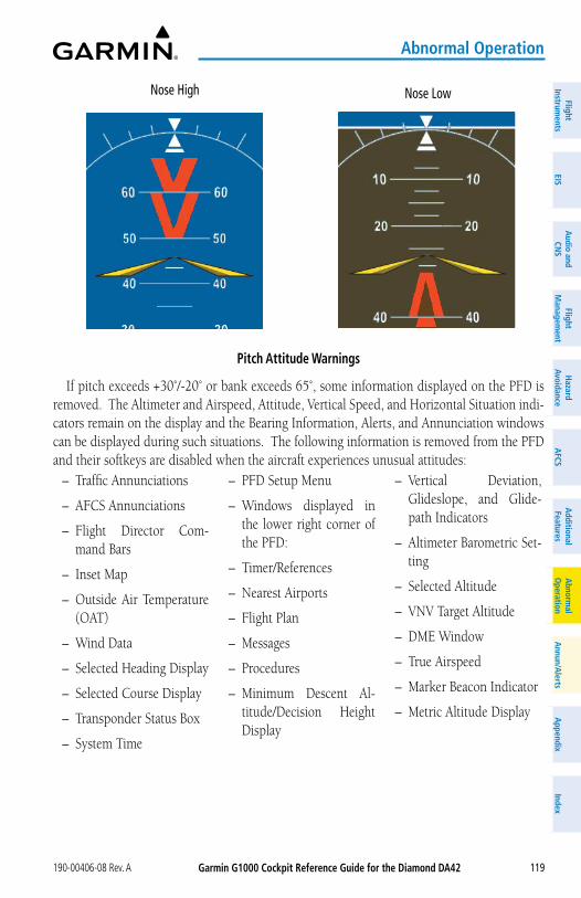
Garmin G1000 Cockpit Reference Guide for the Diamond Da42190-00406-08 Rev. A 119
FlightInstrum
entsEIS
audio and
CNS
Flight M
anagement
Hazard
avoidancea
FCSa
dditionalFeatures
abnorm
alo
perationa
nnun/alerts
appendix
Index
abnormal operation
Pitch attitude Warnings
Nose High Nose Low
If pitch exceeds +30˚/-20˚ or bank exceeds 65˚, some information displayed on the PFD is removed. The Altimeter and Airspeed, Attitude, Vertical Speed, and Horizontal Situation indi-cators remain on the display and the Bearing Information, Alerts, and Annunciation windows can be displayed during such situations. The following information is removed from the PFD and their softkeys are disabled when the aircraft experiences unusual attitudes:
– Traffic Annunciations
– AFCS Annunciations
– Flight Director Com-mand Bars
– Inset Map
– Outside Air Temperature (OAT)
– Wind Data
– Selected Heading Display
– Selected Course Display
– Transponder Status Box
– System Time
– PFD Setup Menu
– Windows displayed in the lower right corner of the PFD:
– Timer/References
– Nearest Airports
– Flight Plan
– Messages
– Procedures
– Minimum Descent Al-titude/Decision Height Display
– Vertical Deviation, Glideslope, and Glide-path Indicators
– Altimeter Barometric Set-ting
– Selected Altitude
– VNV Target Altitude
– DME Window
– True Airspeed
– Marker Beacon Indicator
– Metric Altitude Display
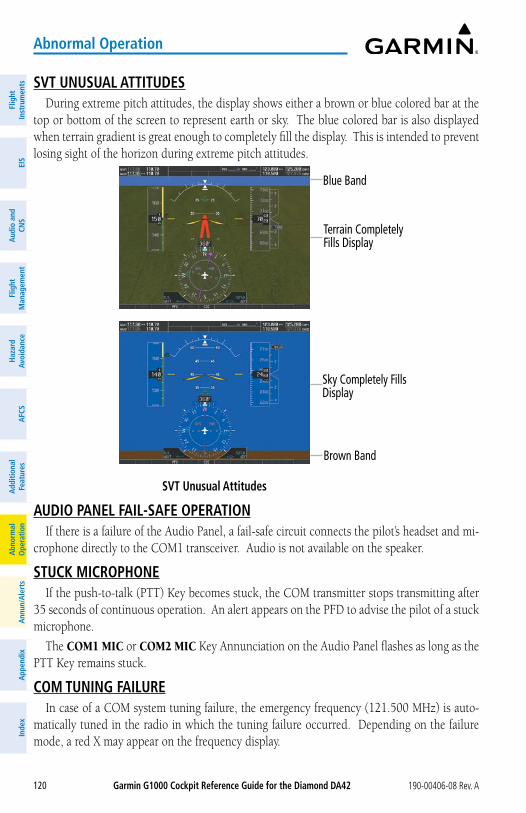
Garmin G1000 Cockpit Reference Guide for the Diamond Da42 190-00406-08 Rev. A120
Flig
htIn
stru
men
tsEI
Sa
udio
and
CNS
Flig
ht
Man
agem
ent
Haz
ard
avoi
danc
ea
FCS
add
ition
alFe
atur
esa
bnor
mal
ope
ratio
na
nnun
/ale
rts
app
endi
xIn
dex
abnormal operation
SVT UNUSUaL aTTITUDESDuring extreme pitch attitudes, the display shows either a brown or blue colored bar at the
top or bottom of the screen to represent earth or sky. The blue colored bar is also displayed when terrain gradient is great enough to completely fill the display. This is intended to prevent losing sight of the horizon during extreme pitch attitudes.
SVT Unusual attitudes
Blue Band
Terrain Completely Fills Display
Brown Band
Sky Completely Fills Display
aUDIo PaNEL FaIL-SaFE oPERaTIoNIf there is a failure of the Audio Panel, a fail-safe circuit connects the pilot’s headset and mi-
crophone directly to the COM1 transceiver. Audio is not available on the speaker.
STUCK MICRoPHoNEIf the push-to-talk (PTT) Key becomes stuck, the COM transmitter stops transmitting after
35 seconds of continuous operation. An alert appears on the PFD to advise the pilot of a stuck microphone.
The COM1 MIC or COM2 MIC Key Annunciation on the Audio Panel flashes as long as the PTT Key remains stuck.
CoM TUNING FaILUREIn case of a COM system tuning failure, the emergency frequency (121.500 MHz) is auto-
matically tuned in the radio in which the tuning failure occurred. Depending on the failure mode, a red X may appear on the frequency display.
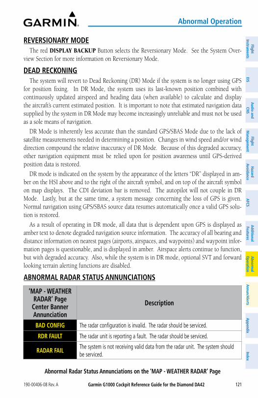
Garmin G1000 Cockpit Reference Guide for the Diamond Da42190-00406-08 Rev. A 121
FlightInstrum
entsEIS
audio and
CNS
Flight M
anagement
Hazard
avoidancea
FCSa
dditionalFeatures
abnorm
alo
perationa
nnun/alerts
appendix
Index
abnormal operation
REVERSIoNaRy MoDEThe red DISPLAY BACKUP Button selects the Reversionary Mode. See the System Over-
view Section for more information on Reversionary Mode.
DEaD RECKoNINGThe system will revert to Dead Reckoning (DR) Mode if the system is no longer using GPS
for position fixing. In DR Mode, the system uses its last-known position combined with continuously updated airspeed and heading data (when available) to calculate and display the aircraft’s current estimated position. It is important to note that estimated navigation data supplied by the system in DR Mode may become increasingly unreliable and must not be used as a sole means of navigation.
DR Mode is inherently less accurate than the standard GPS/SBAS Mode due to the lack of satellite measurements needed in determining a position. Changes in wind speed and/or wind direction compound the relative inaccuracy of DR Mode. Because of this degraded accuracy, other navigation equipment must be relied upon for position awareness until GPS-derived position data is restored.
DR mode is indicated on the system by the appearance of the letters “DR” displayed in am-ber on the HSI above and to the right of the aircraft symbol, and on top of the aircraft symbol on map displays. The CDI deviation bar is removed. The autopilot will not couple in DR Mode. Lastly, but at the same time, a system message concerning the loss of GPS is given. Normal navigation using GPS/SBAS source data resumes automatically once a valid GPS solu-tion is restored.
As a result of operating in DR mode, all data that is dependent upon GPS is displayed as amber text to denote degraded navigation source information. The accuracy of all bearing and distance information on nearest pages (airports, airspaces, and waypoints) and waypoint infor-mation pages is questionable, and is displayed in amber. Airspace alerts continue to function, but with degraded accuracy. Also, while the system is in DR mode, optional SVT and forward looking terrain alerting functions are disabled.
aBNoRMaL RaDaR STaTUS aNNUNCIaTIoNS
‘MaP - WEaTHER RaDaR’ Page
Center Banner annunciation
Description
BaD CoNFIG The radar configuration is invalid. The radar should be serviced.
RDR FaULT The radar unit is reporting a fault. The radar should be serviced.
RaDaR FaILThe system is not receiving valid data from the radar unit. The system should be serviced.
abnormal Radar Status annunciations on the ‘MaP - WEaTHER RaDaR’ Page
Garmin G1000 Cockpit Reference Guide for the Diamond Da42 190-00406-08 Rev. A122
Flig
htIn
stru
men
tsEI
Sa
udio
and
CNS
Flig
ht
Man
agem
ent
Haz
ard
avoi
danc
ea
FCS
add
ition
alFe
atur
esa
bnor
mal
ope
ratio
na
nnun
/ale
rts
app
endi
xIn
dex
abnormal operation
SUSPECTED aUToPILoT MaLFUNCTIoN
NoTE: Consult the aircraft documentation for the location of circuit breakers as well as specifics that may supplement or amplify this procedure.
Mitigating suspected autopilot failure or trim failure:1) Firmly grasp the control stick.2) Press and hold the aP DISC Switch. The autopilot will disconnect and power is removed
from the trim motor. Power is also removed from all primary servo motors and engaged solenoids. Note the visual and aural alerting indicating autopilot disconnect.
3) Retrim the aircraft as needed. Substantial trim adjustment may be needed.4) Pull the appropriate circuit breaker(s) to electrically isolate the servo and solenoid
components.5) Release the aP DISC Switch.
oVERPoWERING aUToPILoT SERVoSIn the context of this discussion, “overpowering” refers to any pressure or force applied
to the pitch controls when the autopilot is engaged. A small amount of pressure or force on the pitch controls can cause the autopilot automatic trim to run to an out-of-trim condition. Therefore, any application of pressure or force to the controls should be avoided when the autopilot is engaged.
Overpowering the autopilot during flight will cause the autopilot’s automatic trim to run, resulting in an out-of-trim condition or cause the trim to hit the stop if the action is prolonged. In this case, larger than anticipated control forces are required after the autopilot is disengaged.
The following procedure should be added to the preflight checks.
Checking autopilot servos during the preflight check:1) Check for proper autopilot operation and ensure the autopilot can be overpowered.2) Note the forces required to overpower the autopilot servo clutches.
DaTaLINK TRoUBLESHooTINGFor troubleshooting purposes, check the ‘LRU INFO’ Box on the ‘AUX - SYSTEM STATUS’
Page for the SiriusXM Datalink Receiver (‘GDL69’) or Bluetooth Transceiver (‘FS210’) LRU status, serial number, and software version number. If a failure has been detected in an LRU, the status is marked with a red ‘X.’
Checking LRU status on the ‘aux - System Status’ Page:1) Turn the large FMS Knob to select the ‘AUX’ Page Group.2) Turn the small FMS Knob to select the ‘AUX - SYSTEM STATUS’ Page.
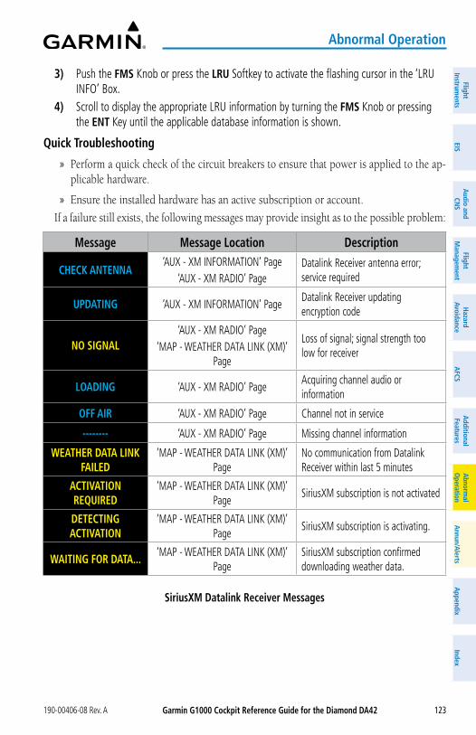
Garmin G1000 Cockpit Reference Guide for the Diamond Da42190-00406-08 Rev. A 123
FlightInstrum
entsEIS
audio and
CNS
Flight M
anagement
Hazard
avoidancea
FCSa
dditionalFeatures
abnorm
alo
perationa
nnun/alerts
appendix
Index
abnormal operation
3) Push the FMS Knob or press the LRU Softkey to activate the flashing cursor in the ‘LRU INFO’ Box.
4) Scroll to display the appropriate LRU information by turning the FMS Knob or pressing the ENT Key until the applicable database information is shown.
Quick Troubleshooting
» Perform a quick check of the circuit breakers to ensure that power is applied to the ap-plicable hardware.
» Ensure the installed hardware has an active subscription or account.
If a failure still exists, the following messages may provide insight as to the possible problem:
Message Message Location Description
CHECK aNTENNa‘AUX - XM INFORMATION’ Page
‘AUX - XM RADIO’ PageDatalink Receiver antenna error; service required
UPDaTING ‘AUX - XM INFORMATION’ PageDatalink Receiver updating encryption code
No SIGNaL‘AUX - XM RADIO’ Page
‘MAP - WEATHER DATA LINK (XM)’ Page
Loss of signal; signal strength too low for receiver
LoaDING ‘AUX - XM RADIO’ PageAcquiring channel audio or information
oFF aIR ‘AUX - XM RADIO’ Page Channel not in service
-------- ‘AUX - XM RADIO’ Page Missing channel information
WEaTHER DaTa LINK FaILED
‘MAP - WEATHER DATA LINK (XM)’ Page
No communication from Datalink Receiver within last 5 minutes
aCTIVaTIoN REQUIRED
‘MAP - WEATHER DATA LINK (XM)’ Page
SiriusXM subscription is not activated
DETECTING aCTIVaTIoN
‘MAP - WEATHER DATA LINK (XM)’ Page
SiriusXM subscription is activating.
WaITING FoR DaTa...‘MAP - WEATHER DATA LINK (XM)’
PageSiriusXM subscription confirmed downloading weather data.
SiriusXM Datalink Receiver Messages
Garmin G1000 Cockpit Reference Guide for the Diamond Da42 190-00406-08 Rev. A124
Flig
htIn
stru
men
tsEI
Sa
udio
and
CNS
Flig
ht
Man
agem
ent
Haz
ard
avoi
danc
ea
FCS
add
ition
alFe
atur
esa
bnor
mal
ope
ratio
na
nnun
/ale
rts
app
endi
xIn
dex
abnormal operation
Blank Page
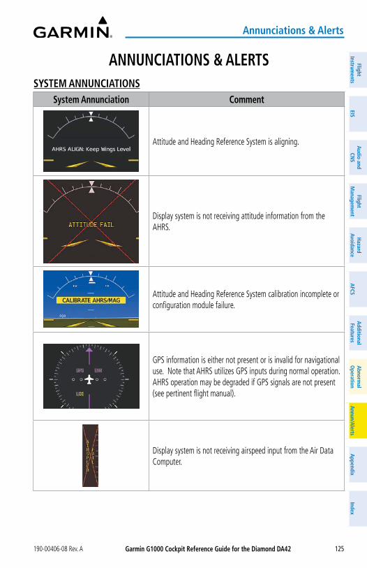
Garmin G1000 Cockpit Reference Guide for the Diamond Da42190-00406-08 Rev. A 125
annunciations & alerts
FlightInstrum
entsEIS
Nav/Com
/XPD
R/Audio
Flight M
anagement
Hazard
AvoidanceA
FCSA
dditionalFeatures
Annun/A
lertsA
ppendixIndex
FlightInstrum
entsEIS
audio and
CNS
Flight M
anagement
Hazard
avoidancea
FCSa
dditionalFeatures
abnorm
alo
perationa
nnun/alerts
appendix
Index
aNNUNCIaTIoNS & aLERTSSySTEM aNNUNCIaTIoNS
System annunciation Comment
Attitude and Heading Reference System is aligning.
Display system is not receiving attitude information from the AHRS.
Attitude and Heading Reference System calibration incomplete or configuration module failure.
GPS information is either not present or is invalid for navigational use. Note that AHRS utilizes GPS inputs during normal operation. AHRS operation may be degraded if GPS signals are not present (see pertinent flight manual).
Display system is not receiving airspeed input from the Air Data Computer.
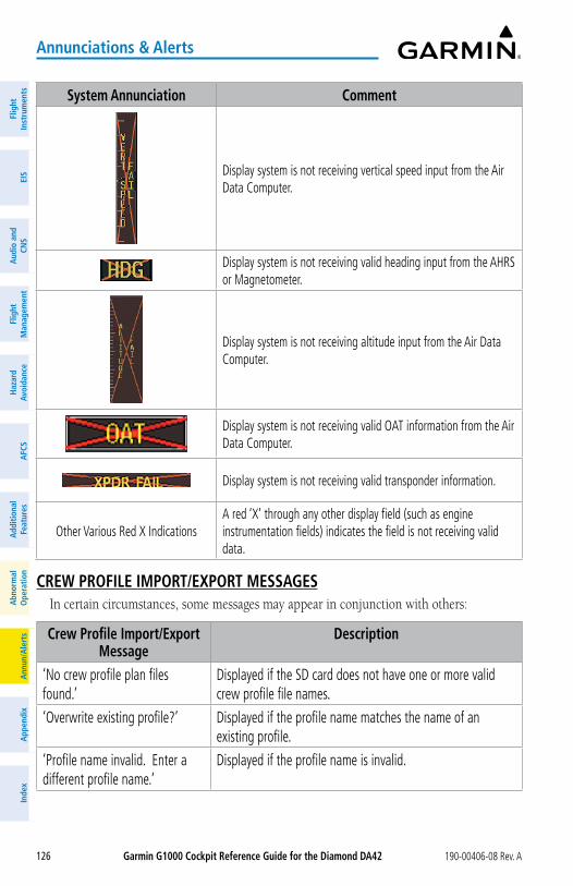
Garmin G1000 Cockpit Reference Guide for the Diamond Da42 190-00406-08 Rev. A126
annunciations & alerts
Flig
htIn
stru
men
tsEI
SN
av/C
om/
XPD
R/A
udio
Flig
ht
Man
agem
ent
Haz
ard
Avoi
danc
eA
FCS
Add
ition
alFe
atur
esA
nnun
/Ale
rts
App
endi
xIn
dex
Flig
htIn
stru
men
tsEI
Sa
udio
and
CNS
Flig
ht
Man
agem
ent
Haz
ard
avoi
danc
ea
FCS
add
ition
alFe
atur
esa
bnor
mal
ope
ratio
na
nnun
/ale
rts
app
endi
xIn
dex
System annunciation Comment
Display system is not receiving vertical speed input from the Air Data Computer.
Display system is not receiving valid heading input from the AHRS or Magnetometer.
Display system is not receiving altitude input from the Air Data Computer.
Display system is not receiving valid OAT information from the Air Data Computer.
Display system is not receiving valid transponder information.
Other Various Red X IndicationsA red ‘X’ through any other display field (such as engine instrumentation fields) indicates the field is not receiving valid data.
CREW PRoFILE IMPoRT/EXPoRT MESSaGESIn certain circumstances, some messages may appear in conjunction with others:
Crew Profile Import/Export Message
Description
‘No crew profile plan files found.’
Displayed if the SD card does not have one or more valid crew profile file names.
‘Overwrite existing profile?’ Displayed if the profile name matches the name of an existing profile.
‘Profile name invalid. Enter a different profile name.’
Displayed if the profile name is invalid.
Garmin G1000 Cockpit Reference Guide for the Diamond Da42190-00406-08 Rev. A 127
annunciations & alerts
FlightInstrum
entsEIS
Nav/Com
/XPD
R/Audio
Flight M
anagement
Hazard
AvoidanceA
FCSA
dditionalFeatures
Annun/A
lertsA
ppendixIndex
FlightInstrum
entsEIS
audio and
CNS
Flight M
anagement
Hazard
avoidancea
FCSa
dditionalFeatures
abnorm
alo
perationa
nnun/alerts
appendix
Index
Crew Profile Import/Export Message
Description
‘All available crew profiles in use. Delete a profile before importing another.’
Displayed if the maximum number of crew profiles has been reached.
‘Crew profile import failed.’ Displayed if the importing operation fails for any other reason.
‘Crew profile import succeeded.’ Displayed if the importing operation succeeds.
‘Overwrite existing file?’ Displayed if the file name matches the name of an existing file on the SD card.
‘Crew profile export failed.’ Displayed if the export operation fails.
‘Crew profile export succeeded.’ Displayed if the export operation succeeds.
FLIGHT PLaNNINGNEaREST aIRSPaCE
Message CommentsINSIDE aRSPC – Inside airspace. The aircraft is inside the airspace.
aRSPC aHEaD – Airspace ahead – less than 10 minutes.
Special use airspace is ahead of aircraft track. The aircraft current ground track penetrates the airspace within 10 minutes.
aRSPC NEaR – Airspace near and ahead. Special use airspace is near and ahead of the aircraft position.
aRSPC NEaR – Airspace near – less than 2 nm.
Special use airspace is within 2 nm of the aircraft position.
MaNaGING FLIGHT PLaNSUnder certain conditions, some messages may appear when a flight plan is imported or
exported.
Flight Plan Import/Export Results
Description
‘Flight plan successfully imported.’
A flight plan file stored on the SD card was successfully imported as a stored flight plan.
‘File contained user waypoints only. User waypoints imported successfully. No stored flight plan data was modified.’
The file stored on the SD card did not contain a flight plan, only user waypoints. These waypoints have been saved to the system user waypoints. No flight plans stored in the system have been modified.
Garmin G1000 Cockpit Reference Guide for the Diamond Da42 190-00406-08 Rev. A128
annunciations & alerts
Flig
htIn
stru
men
tsEI
SN
av/C
om/
XPD
R/A
udio
Flig
ht
Man
agem
ent
Haz
ard
Avoi
danc
eA
FCS
Add
ition
alFe
atur
esA
nnun
/Ale
rts
App
endi
xIn
dex
Flig
htIn
stru
men
tsEI
Sa
udio
and
CNS
Flig
ht
Man
agem
ent
Haz
ard
avoi
danc
ea
FCS
add
ition
alFe
atur
esa
bnor
mal
ope
ratio
na
nnun
/ale
rts
app
endi
xIn
dex
Flight Plan Import/Export Results
Description
‘No flight plan files found to import.’
The SD card contains no flight plan data.
‘Flight plan import failed.’ Flight plan data was not successfully imported from the SD card.
‘Flight plan partially imported.’ Some flight plan waypoints were successfully imported from the SD card, however others had errors and were not imported. A partial stored flight plan now exists in the system.
‘File contained user waypoints only.’
The file stored on the SD card did not contain a flight plan, only user waypoints. One or more of these waypoints did not import successfully.
‘Too many points. Flight plan truncated.’
The flight plan on the SD card contains more waypoints than the system can support. The flight plan was imported with as many waypoints as possible.
‘Some waypoints not loaded. Waypoints locked.’
The flight plan on the SD card contains one or more waypoints the system cannot find in the navigation database. The flight plan has been imported, but must be edited within the system before it can be activated for use.
‘User waypoint database full. Not all loaded.’
The flight plan file on the SD card contains user waypoints. The quantity of stored user waypoints has exceeded system capacity, therefore not all the user waypoints on the SD card have been imported. Any flight plan user waypoints that were not imported are locked in the flight plan. The flight plan must be edited within the system before it can be activated for use.
‘One or more user waypoints renamed.’
One or more imported user waypoints were renamed when imported due to naming conflicts with waypoints already existing in the system.
‘Flight plan contains invalid waypoint(s)’
One or more imported flight plan waypoints is/are invalid or locked (this may occur if waypoints in the flight plan were removed in a recent database cycle). Before their use, the imported flight plan can be deleted or it can be viewed and edited to remove invalid waypoints.
‘Flight plan successfully exported.’ The stored flight plan was successfully exported to the SD card.
‘Flight plan export failed.’ The stored flight plan was not successfully exported to the SD card. The SD card may not have sufficient available memory or the card may have been removed prematurely.
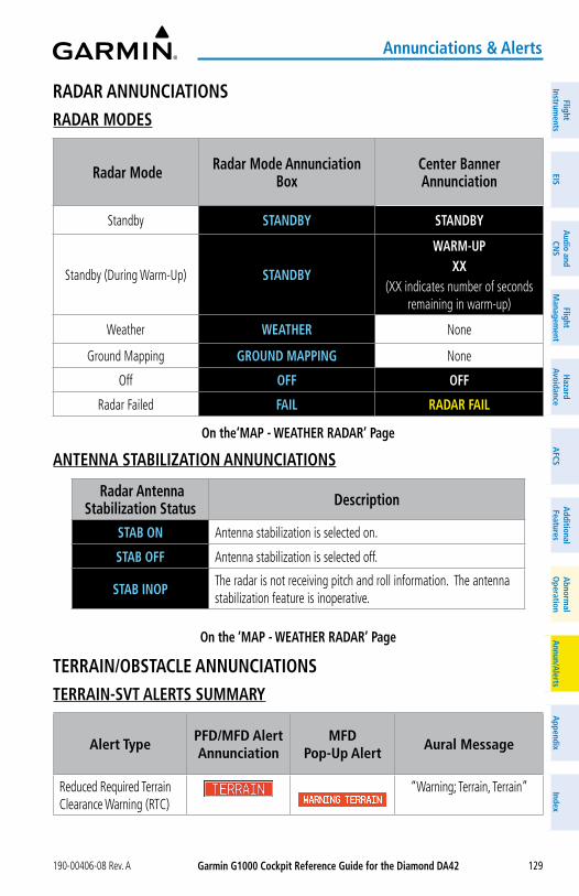
Garmin G1000 Cockpit Reference Guide for the Diamond Da42190-00406-08 Rev. A 129
annunciations & alerts
FlightInstrum
entsEIS
Nav/Com
/XPD
R/Audio
Flight M
anagement
Hazard
AvoidanceA
FCSA
dditionalFeatures
Annun/A
lertsA
ppendixIndex
FlightInstrum
entsEIS
audio and
CNS
Flight M
anagement
Hazard
avoidancea
FCSa
dditionalFeatures
abnorm
alo
perationa
nnun/alerts
appendix
Index
RaDaR aNNUNCIaTIoNSRaDaR MoDES
Radar Mode Radar Mode annunciation Box
Center Banner annunciation
Standby STaNDBy STaNDBy
Standby (During Warm-Up) STaNDBy
WaRM-UPXX
(XX indicates number of seconds remaining in warm-up)
Weather WEaTHER None
Ground Mapping GRoUND MaPPING None
Off oFF oFF
Radar Failed FaIL RaDaR FaIL
on the‘MaP - WEaTHER RaDaR’ Page
aNTENNa STaBILIZaTIoN aNNUNCIaTIoNS
Radar antenna Stabilization Status Description
STaB oN Antenna stabilization is selected on.
STaB oFF Antenna stabilization is selected off.
STaB INoPThe radar is not receiving pitch and roll information. The antenna stabilization feature is inoperative.
on the ‘MaP - WEaTHER RaDaR’ Page
TERRaIN/oBSTaCLE aNNUNCIaTIoNSTERRaIN-SVT aLERTS SUMMaRy
alert TypePFD/MFD alertannunciation
MFDPop-Up alert
aural Message
Reduced Required Terrain Clearance Warning (RTC)
“Warning; Terrain, Terrain”
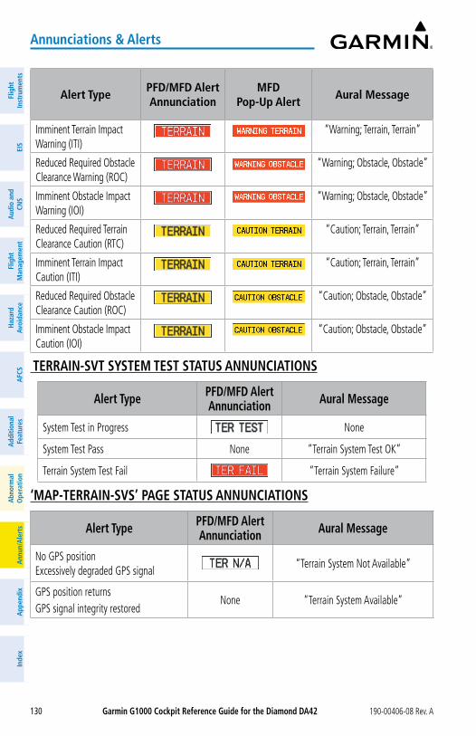
Garmin G1000 Cockpit Reference Guide for the Diamond Da42 190-00406-08 Rev. A130
annunciations & alerts
Flig
htIn
stru
men
tsEI
SN
av/C
om/
XPD
R/A
udio
Flig
ht
Man
agem
ent
Haz
ard
Avoi
danc
eA
FCS
Add
ition
alFe
atur
esA
nnun
/Ale
rts
App
endi
xIn
dex
Flig
htIn
stru
men
tsEI
Sa
udio
and
CNS
Flig
ht
Man
agem
ent
Haz
ard
avoi
danc
ea
FCS
add
ition
alFe
atur
esa
bnor
mal
ope
ratio
na
nnun
/ale
rts
app
endi
xIn
dex
alert TypePFD/MFD alertannunciation
MFDPop-Up alert
aural Message
Imminent Terrain Impact Warning (ITI)
“Warning; Terrain, Terrain”
Reduced Required Obstacle Clearance Warning (ROC)
“Warning; Obstacle, Obstacle”
Imminent Obstacle Impact Warning (IOI)
“Warning; Obstacle, Obstacle”
Reduced Required Terrain Clearance Caution (RTC)
“Caution; Terrain, Terrain”
Imminent Terrain Impact Caution (ITI)
“Caution; Terrain, Terrain”
Reduced Required Obstacle Clearance Caution (ROC)
“Caution; Obstacle, Obstacle”
Imminent Obstacle Impact Caution (IOI)
“Caution; Obstacle, Obstacle”
TERRaIN-SVT SySTEM TEST STaTUS aNNUNCIaTIoNS
alert Type PFD/MFD alert annunciation aural Message
System Test in Progress None
System Test Pass None “Terrain System Test OK”
Terrain System Test Fail “Terrain System Failure”
‘MaP-TERRaIN-SVS’ PaGE STaTUS aNNUNCIaTIoNS
alert Type PFD/MFD alert annunciation aural Message
No GPS position Excessively degraded GPS signal
“Terrain System Not Available”
GPS position returnsGPS signal integrity restored
None “Terrain System Available”
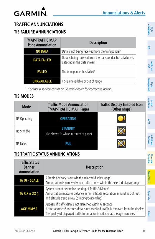
Garmin G1000 Cockpit Reference Guide for the Diamond Da42190-00406-08 Rev. A 131
annunciations & alerts
FlightInstrum
entsEIS
Nav/Com
/XPD
R/Audio
Flight M
anagement
Hazard
AvoidanceA
FCSA
dditionalFeatures
Annun/A
lertsA
ppendixIndex
FlightInstrum
entsEIS
audio and
CNS
Flight M
anagement
Hazard
avoidancea
FCSa
dditionalFeatures
abnorm
alo
perationa
nnun/alerts
appendix
Index
TRaFFIC aNNUNCIaTIoNSTIS FaILURE aNNUNCIaTIoNS
‘MaP-TRaFFIC MaP’ Page annunciation Description
No DaTa Data is not being received from the transponder1
DaTa FaILEDData is being received from the transponder, but a failure is detected in the data stream1
FaILED The transponder has failed1
UNaVaILaBLE TIS is unavailable or out of range
1 Contact a service center or Garmin dealer for corrective action
TIS MoDES
Mode Traffic Mode annunciation (‘MaP-TRaFFIC MaP’ Page)
Traffic Display Enabled Icon (other Maps)
TIS Operating oPERaTING
TIS StandbySTaNDBy
(also shown in white in center of page)
TIS Failed FaIL
TIS TRaFFIC STaTUS aNNUNCIaTIoNS
Traffic Status Banner
annunciationDescription
Ta oFF SCaLEA Traffic Advisory is outside the selected display range1 Annunciation is removed when traffic comes within the selected display range
Ta X.X ± XX ↕System cannot determine bearing of Traffic Advisory2 Annunciation indicates distance in nm, altitude separation in hundreds of feet, and altitude trend arrow (climbing/descending)
aGE MM:SSAppears if traffic data is not refreshed within 6 seconds If after another 6 seconds data is not received, traffic is removed from the display The quality of displayed traffic information is reduced as the age increases

Garmin G1000 Cockpit Reference Guide for the Diamond Da42 190-00406-08 Rev. A132
annunciations & alerts
Flig
htIn
stru
men
tsEI
SN
av/C
om/
XPD
R/A
udio
Flig
ht
Man
agem
ent
Haz
ard
Avoi
danc
eA
FCS
Add
ition
alFe
atur
esA
nnun
/Ale
rts
App
endi
xIn
dex
Flig
htIn
stru
men
tsEI
Sa
udio
and
CNS
Flig
ht
Man
agem
ent
Haz
ard
avoi
danc
ea
FCS
add
ition
alFe
atur
esa
bnor
mal
ope
ratio
na
nnun
/ale
rts
app
endi
xIn
dex
Traffic Status Banner
annunciationDescription
TRFC CoaSTThe displayed data is not current (6 to 12 seconds since last message) The quality of displayed traffic information is reduced when this message is displayed
TRFC RMVDTraffic is removed because it is too old for coasting (12 to 60 seconds since last message) Traffic may exist within the selected display range, but it is not displayed
TRFC FaIL Traffic data has failed
No TRFC DaTa Traffic data has not been detected
TRFC UNaVaIL The traffic service is unavailable or out of range
1 Shown as symbol on ‘MAP-TRAFFIC MAP’ Page2 Shown in center of ‘MAP-TRAFFIC MAP’ Page
TaS MoDES
Mode Traffic Mode annunciation (‘MaP-TRaFFIC MaP’ Page)
Traffic Display Enabled Icon
(other Maps)
TAS Operating oPERaTING
TAS Failed1 FaIL
TaS FaILURE aNNUNCIaTIoNS
‘MaP-TRaFFIC MaP’ Page annunciation Description
No DaTa Data is not being received from the TAS unit
DaTa FaILEDData is being received from the TAS unit, but the unit is self-reporting a failure
FaILED Incorrect data format received from the TAS unit
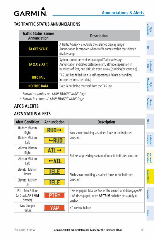
Garmin G1000 Cockpit Reference Guide for the Diamond Da42190-00406-08 Rev. A 133
annunciations & alerts
FlightInstrum
entsEIS
Nav/Com
/XPD
R/Audio
Flight M
anagement
Hazard
AvoidanceA
FCSA
dditionalFeatures
Annun/A
lertsA
ppendixIndex
FlightInstrum
entsEIS
audio and
CNS
Flight M
anagement
Hazard
avoidancea
FCSa
dditionalFeatures
abnorm
alo
perationa
nnun/alerts
appendix
Index
TaS TRaFFIC STaTUS aNNUNCIaTIoNS
Traffic Status Banner annunciation Description
Ta oFF SCaLEA Traffic Advisory is outside the selected display range1 Annunciation is removed when traffic comes within the selected display range
Ta X.X ± XX ↕System cannot determine bearing of Traffic Advisory2 Annunciation indicates distance in nm, altitude separation in hundreds of feet, and altitude trend arrow (climbing/descending)
TRFC FaILTAS unit has failed (unit is self-reporting a failure or sending incorrectly formatted data)
No TRFC DaTa Data is not being received from the TAS unit
1 Shown as symbol on ‘MAP-TRAFFIC MAP’ Page2 Shown in center of ‘MAP-TRAFFIC MAP’ Page
aFCS aLERTSaFCS STaTUS aLERTS
alert Condition annunciation DescriptionRudder Mistrim
Right Yaw servo providing sustained force in the indicated directionRudder Mistrim
LeftAileron Mistrim
RightRoll servo providing sustained force in indicated direction
Aileron Mistrim Left
Elevator Mistrim Down Pitch servo providing sustained force in the indicated
directionElevator Mistrim Up
Pitch Trim Failure (or Stuck aP TRIM
Switch)
If AP engaged, take control of the aircraft and disengage APIf AP disengaged, move aP TRIM switches separately to unstick
Yaw Damper Failure
YD control failure
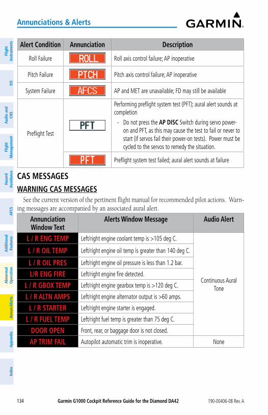
Garmin G1000 Cockpit Reference Guide for the Diamond Da42 190-00406-08 Rev. A134
annunciations & alerts
Flig
htIn
stru
men
tsEI
SN
av/C
om/
XPD
R/A
udio
Flig
ht
Man
agem
ent
Haz
ard
Avoi
danc
eA
FCS
Add
ition
alFe
atur
esA
nnun
/Ale
rts
App
endi
xIn
dex
Flig
htIn
stru
men
tsEI
Sa
udio
and
CNS
Flig
ht
Man
agem
ent
Haz
ard
avoi
danc
ea
FCS
add
ition
alFe
atur
esa
bnor
mal
ope
ratio
na
nnun
/ale
rts
app
endi
xIn
dex
alert Condition annunciation Description
Roll Failure Roll axis control failure; AP inoperative
Pitch Failure Pitch axis control failure; AP inoperative
System Failure AP and MET are unavailable; FD may still be available
Preflight Test
Performing preflight system test (PFT); aural alert sounds at completion
- Do not press the aP DISC Switch during servo power-on and PFT, as this may cause the test to fail or never to start (if servos fail their power-on tests). Power must be cycled to the servos to remedy the situation.
Preflight system test failed; aural alert sounds at failure
CaS MESSaGESWaRNING CaS MESSaGES
See the current version of the pertinent flight manual for recommended pilot actions. Warn-ing messages are accompanied by an associated aural alert.
annunciation Window Text
alerts Window Message audio alert
L / R ENG TEMP Left/right engine coolant temp is >105 deg C.
Continuous Aural Tone
L / R oIL TEMP Left/right engine oil temp is greater than 140 deg C.
L / R oIL PRES Left/right engine oil pressure is less than 1.2 bar.
L/R ENG FIRE Left/right engine fire detected.
L / R GBoX TEMP Left/right engine gearbox temp is >120 deg C.
L / R aLTN aMPS Left/right engine alternator output is >60 amps.
L / R STaRTER Left/right engine starter is engaged.
L / R FUEL TEMP Left/right fuel temp is greater than 75 deg C.
DooR oPEN Front, rear, or baggage door is not closed.
aP TRIM FaIL Autopilot automatic trim is inoperative. None

Garmin G1000 Cockpit Reference Guide for the Diamond Da42190-00406-08 Rev. A 135
annunciations & alerts
FlightInstrum
entsEIS
Nav/Com
/XPD
R/Audio
Flight M
anagement
Hazard
AvoidanceA
FCSA
dditionalFeatures
Annun/A
lertsA
ppendixIndex
FlightInstrum
entsEIS
audio and
CNS
Flight M
anagement
Hazard
avoidancea
FCSa
dditionalFeatures
abnorm
alo
perationa
nnun/alerts
appendix
Index
CaUTIoN CaS MESSaGESSee the current version of the pertinent flight manual for recommended pilot actions. Cau-
tion messages are accompanied by associated aural alert.
annunciation Window Text
alerts Window Message audio alert
CHECK GEaR Landing gear is not down and locked
Single Aural Tone
L / R ECU a FaIL Left/right engine ECU A has failed.
L / R ECU B FaIL Left/right engine ECU B has failed.
L / R FUEL LoW Left/right engine main tank fuel quantity is low.
L / R aLTN FaIL Left/right engine alternator has failed.
L / R VoLTS LoW Left/right bus voltage is less than 25 volts.
L / R CooL LVL Left/right engine coolant level is low.
L/R aUX FUEL E Left/right auxiliary fuel tank is empty.
PIToT FaIL Pitot heat has failed.
PIToT HT oFF Pitot heat is off.
STaL HT FaIL Stall warning heat has failed.
STaL HT oFF Stall warning heat is off.
DEICE LVL Lo De-icing fluid level is low.
DEIC PRES HI De-icing pressure is high.
DEIC PRES Lo De-icing pressure is low.
STICK LIMIT Stick limiting system has failed.
aDVISoRy CaS MESSaGESSee the current version of the pertinent flight manual for recommended pilot actions.
annunciation Window Text
alerts Window Message audio alert
L / R GLoW oN Left/right engine glow plug active.None
L / R FUEL XFER Left/right fuel transfer from aux to main in progress.
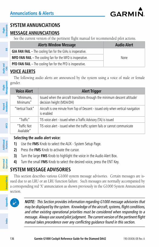
Garmin G1000 Cockpit Reference Guide for the Diamond Da42 190-00406-08 Rev. A136
annunciations & alerts
Flig
htIn
stru
men
tsEI
SN
av/C
om/
XPD
R/A
udio
Flig
ht
Man
agem
ent
Haz
ard
Avoi
danc
eA
FCS
Add
ition
alFe
atur
esA
nnun
/Ale
rts
App
endi
xIn
dex
Flig
htIn
stru
men
tsEI
Sa
udio
and
CNS
Flig
ht
Man
agem
ent
Haz
ard
avoi
danc
ea
FCS
add
ition
alFe
atur
esa
bnor
mal
ope
ratio
na
nnun
/ale
rts
app
endi
xIn
dex
SySTEM aNNUNCIaTIoNSMESSaGE aNNUNCIaTIoNS
See the current version of the pertinent flight manual for recommended pilot actions.
alerts Window Message audio alertGIa FaN FaIL – The cooling fan for the GIAs is inoperative.
NoneMFD FaN FaIL – The cooling fan for the MFD is inoperative.
PFD FaN FaIL – The cooling fan for the PFD is inoperative.
VoICE aLERTSThe following audio alerts are announced by the system using a voice of male or female
gender.
Voice alert alert Trigger“Minimums, Minimums”
Issued when the aircraft transitions through the minimum descent altitude/decision height (MDA/DH)
“Vertical Track” Aircraft is one minute from Top of Descent - issued only when vertical navigation is enabled
“Traffic” TIS voice alert - issued when a Traffic Advisory (TA) is issued
“Traffic Not Available”
TIS voice alert - issued when the traffic system fails or cannot communicate
Selecting the audio alert voice:1) Use the FMS Knob to select the AUX - System Setup Page.2) Press the FMS Knob to activate the cursor.3) Turn the large FMS Knob to highlight the voice in the Audio Alert Box.4) Turn the small FMS Knob to select the desired voice, press the ENT Key.
SySTEM MESSaGE aDVISoRIESThis section describes various G1000 system message advisories. Certain messages are is-
sued due to an LRU or an LRU function failure. Such messages are normally accompanied by a corresponding red ‘X’ annunciation as shown previously in the G1000 System Annunciation section.
NoTE: This Section provides information regarding G1000 message advisories that may be displayed by the system. Knowledge of the aircraft, systems, flight conditions, and other existing operational priorities must be considered when responding to a message. Always use sound pilot judgment. The current version of the pertinent flight manual takes precedence over any conflicting guidance found in this section.
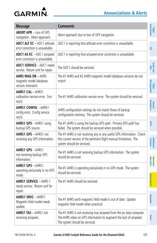
Garmin G1000 Cockpit Reference Guide for the Diamond Da42190-00406-08 Rev. A 137
annunciations & alerts
FlightInstrum
entsEIS
Nav/Com
/XPD
R/Audio
Flight M
anagement
Hazard
AvoidanceA
FCSA
dditionalFeatures
Annun/A
lertsA
ppendixIndex
FlightInstrum
entsEIS
audio and
CNS
Flight M
anagement
Hazard
avoidancea
FCSa
dditionalFeatures
abnorm
alo
perationa
nnun/alerts
appendix
Index
Message CommentsaBoRT aPR – Loss of GPS navigation. Abort approach.
Abort approach due to loss of GPS navigation.
aDC1 aLT EC – ADC1 altitude error correction is unavailable.
GDC1 is reporting that altitude error correction is unavailable.
aDC1 aS EC – ADC1 airspeed error correction is unavailable.
GDC1 is reporting that airspeed error correction is unavailable.
aDC1 SERVICE – ADC1 needs service. Return unit for repair.
The GDC1 should be serviced.
aHRS MaG DB – AHRS magnetic model database version mismatch.
The #1 AHRS and #2 AHRS magnetic model database versions do not match.
aHRS1 CaL – AHRS1 calibration version error. Srvc req’d.
The #1 AHRS calibration version error. The system should be serviced.
aHRS1 CoNFIG – AHRS1 config error. Config service req’d.
AHRS configuration settings do not match those of backup configuration memory. The system should be serviced.
aHRS1 GPS – AHRS1 using backup GPS source.
The #1 AHRS is using the backup GPS path. Primary GPS path has failed. The system should be serviced when possible.
aHRS1 GPS – AHRS1 not receiving any GPS information.
The #1 AHRS is not receiving any or any useful GPS information. Check the current version of the pertinent flight manual limitations. The system should be serviced.
aHRS1 GPS – AHRS1 not receiving backup GPS information.
The #1 AHRS is not receiving backup GPS information. The system should be serviced.
aHRS1 GPS – AHRS1 operating exclusively in no-GPS mode.
The #1 AHRS is operating exclusively in no-GPS mode. The system should be serviced.
aHRS1 SERVICE – AHRS 1 needs service. Return unit for repair.
The #1 AHRS should be serviced.
aHRS1 SRVC – AHRS1 Magnetic-field model needs update.
The #1 AHRS earth magnetic field model is out of date. Update magnetic field model when practical.
aHRS1 TaS – AHRS1 not receiving airspeed.
The #1 AHRS is not receiving true airspeed from the air data computer. The AHRS relies on GPS information to augment the lack of airspeed. The system should be serviced.
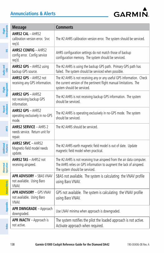
Garmin G1000 Cockpit Reference Guide for the Diamond Da42 190-00406-08 Rev. A138
annunciations & alerts
Flig
htIn
stru
men
tsEI
SN
av/C
om/
XPD
R/A
udio
Flig
ht
Man
agem
ent
Haz
ard
Avoi
danc
eA
FCS
Add
ition
alFe
atur
esA
nnun
/Ale
rts
App
endi
xIn
dex
Flig
htIn
stru
men
tsEI
Sa
udio
and
CNS
Flig
ht
Man
agem
ent
Haz
ard
avoi
danc
ea
FCS
add
ition
alFe
atur
esa
bnor
mal
ope
ratio
na
nnun
/ale
rts
app
endi
xIn
dex
Message CommentsaHRS2 CaL – AHRS2 calibration version error. Srvc req’d.
The #2 AHRS calibration version error. The system should be serviced.
aHRS2 CoNFIG – AHRS2 config error. Config service req’d.
AHRS configuration settings do not match those of backup configuration memory. The system should be serviced.
aHRS2 GPS – AHRS2 using backup GPS source.
The #2 AHRS is using the backup GPS path. Primary GPS path has failed. The system should be serviced when possible.
aHRS2 GPS – AHRS2 not receiving any GPS information.
The #2 AHRS is not receiving any or any useful GPS information. Check the current version of the pertinent flight manual limitations. The system should be serviced.
aHRS2 GPS – AHRS2 not receiving backup GPS information.
The #2 AHRS is not receiving backup GPS information. The system should be serviced.
aHRS2 GPS – AHRS2 operating exclusively in no-GPS mode.
The #2 AHRS is operating exclusively in no-GPS mode. The system should be serviced.
aHRS2 SERVICE – AHRS 2 needs service. Return unit for repair.
The #2 AHRS should be serviced.
aHRS2 SRVC – AHRS2 Magnetic-field model needs update.
The #2 AHRS earth magnetic field model is out of date. Update magnetic field model when practical.
aHRS2 TaS – AHRS2 not receiving airspeed.
The #2 AHRS is not receiving true airspeed from the air data computer. The AHRS relies on GPS information to augment the lack of airspeed. The system should be serviced.
aPR aDVISoRy – SBAS VNAV not available. Using Baro VNAV.
SBAS not available. The system is calculating the VNAV profile using Baro VNAV.
aPR aDVISoRy – GPS VNAV not available. Using Baro VNAV.
GPS not available. The system is calculating the VNAV profile using Baro VNAV.
aPR DWNGRaDE – Approach downgraded.
Use LNAV minima when approach is downgraded.
aPR INaCTV – Approach is not active.
The system notifies the pilot the loaded approach is not active. Activate approach when required.

Garmin G1000 Cockpit Reference Guide for the Diamond Da42190-00406-08 Rev. A 139
annunciations & alerts
FlightInstrum
entsEIS
Nav/Com
/XPD
R/Audio
Flight M
anagement
Hazard
AvoidanceA
FCSA
dditionalFeatures
Annun/A
lertsA
ppendixIndex
FlightInstrum
entsEIS
audio and
CNS
Flight M
anagement
Hazard
avoidancea
FCSa
dditionalFeatures
abnorm
alo
perationa
nnun/alerts
appendix
Index
Message CommentsaRSPC aHEaD – Airspace ahead less than 10 minutes.
Special use airspace is ahead of aircraft. The aircraft will penetrate the airspace within 10 minutes.
aRSPC NEaR – Airspace near – less than 2 nm.
Special use airspace is within 2 nm of the aircraft position.
aRSPC NEaR – Airspace near and ahead.
Special use airspace is near and ahead of the aircraft position.
aUDIo MaNIFEST – Audio software mismatch, communication halted.
The GMA™ has incorrect software installed. The system should be serviced.
CHaRTVIEW ERRoR – Some individual charts may not be viewable
The Chartview database failed library verification for an unspecified number of charts. The Chart database will continue to be usable, however, some charts may not be viewable. To make sure that all charts are available, re-download the chart database to the SD card in the system.
CHECK CRS – Database course for LOC1 / [LOC ID] is [CRS]°.
Selected course for LOC1 differs from published localizer course by more than 10 degrees.
CHECK CRS – Database course for LOC2 / [LOC ID] is [CRS]°.
Selected course for LOC2 differs from published localizer course by more than 10 degrees.
CNFG MoDULE – PFD1 configuration module is inoperative.
The PFD1 configuration module backup memory has failed. The system should be serviced.
CoM1 CoNFIG – COM1 config error. Config service req’d.
The COM1 configuration settings do not match backup configuration memory. The system should be serviced
CoM1 MaNIFEST – COM1 software mismatch, communication halted.
COM 1 has incorrect software installed. The system should be serviced.
CoM1 PTT – COM1 push-to-talk key is stuck.
The COM1 external push-to-talk switch is stuck in the enable (or “pressed”) position. Press the PTT switch again to cycle its operation. If the problem persists, the system should be serviced.
CoM1 RMT XFR – COM1 remote transfer key is stuck.
The COM1 transfer switch is stuck in the enabled (or “pressed”) position. Press the transfer switch again to cycle its operation. If the problem persists, the system should be serviced.
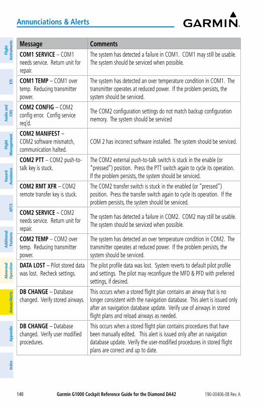
Garmin G1000 Cockpit Reference Guide for the Diamond Da42 190-00406-08 Rev. A140
annunciations & alerts
Flig
htIn
stru
men
tsEI
SN
av/C
om/
XPD
R/A
udio
Flig
ht
Man
agem
ent
Haz
ard
Avoi
danc
eA
FCS
Add
ition
alFe
atur
esA
nnun
/Ale
rts
App
endi
xIn
dex
Flig
htIn
stru
men
tsEI
Sa
udio
and
CNS
Flig
ht
Man
agem
ent
Haz
ard
avoi
danc
ea
FCS
add
ition
alFe
atur
esa
bnor
mal
ope
ratio
na
nnun
/ale
rts
app
endi
xIn
dex
Message CommentsCoM1 SERVICE – COM1 needs service. Return unit for repair.
The system has detected a failure in COM1. COM1 may still be usable. The system should be serviced when possible.
CoM1 TEMP – COM1 over temp. Reducing transmitter power.
The system has detected an over temperature condition in COM1. The transmitter operates at reduced power. If the problem persists, the system should be serviced.
CoM2 CoNFIG – COM2 config error. Config service req’d.
The COM2 configuration settings do not match backup configuration memory. The system should be serviced
CoM2 MaNIFEST – COM2 software mismatch, communication halted.
COM 2 has incorrect software installed. The system should be serviced.
CoM2 PTT – COM2 push-to-talk key is stuck.
The COM2 external push-to-talk switch is stuck in the enable (or “pressed”) position. Press the PTT switch again to cycle its operation. If the problem persists, the system should be serviced.
CoM2 RMT XFR – COM2 remote transfer key is stuck.
The COM2 transfer switch is stuck in the enabled (or “pressed”) position. Press the transfer switch again to cycle its operation. If the problem persists, the system should be serviced.
CoM2 SERVICE – COM2 needs service. Return unit for repair.
The system has detected a failure in COM2. COM2 may still be usable. The system should be serviced when possible.
CoM2 TEMP – COM2 over temp. Reducing transmitter power.
The system has detected an over temperature condition in COM2. The transmitter operates at reduced power. If the problem persists, the system should be serviced.
DaTa LoST – Pilot stored data was lost. Recheck settings.
The pilot profile data was lost. System reverts to default pilot profile and settings. The pilot may reconfigure the MFD & PFD with preferred settings, if desired.
DB CHaNGE – Database changed. Verify stored airways.
This occurs when a stored flight plan contains an airway that is no longer consistent with the navigation database. This alert is issued only after an navigation database update. Verify use of airways in stored flight plans and reload airways as needed.
DB CHaNGE – Database changed. Verify user modified procedures.
This occurs when a stored flight plan contains procedures that have been manually edited. This alert is issued only after an navigation database update. Verify the user-modified procedures in stored flight plans are correct and up to date.
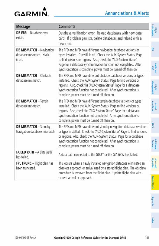
Garmin G1000 Cockpit Reference Guide for the Diamond Da42190-00406-08 Rev. A 141
annunciations & alerts
FlightInstrum
entsEIS
Nav/Com
/XPD
R/Audio
Flight M
anagement
Hazard
AvoidanceA
FCSA
dditionalFeatures
Annun/A
lertsA
ppendixIndex
FlightInstrum
entsEIS
audio and
CNS
Flight M
anagement
Hazard
avoidancea
FCSa
dditionalFeatures
abnorm
alo
perationa
nnun/alerts
appendix
Index
Message CommentsDB ERR – Database error exists.
Database verification error. Reload databases with new data card. If problem persists, delete databases and reload with a new card.
DB MISMaTCH – Navigation database mismatch. Xtalk is off.
The PFD and MFD have different navigation database versions or types installed. Crossfill is off. Check the ‘AUX-System Status’ Page to find versions or regions. Also, check the ‘AUX-System Status’ Page for a database synchronization function not completed. After synchronization is complete, power must be turned off, then on.
DB MISMaTCH – Obstacle database mismatch.
The PFD and MFD have different obstacle database versions or types installed. Check the ‘AUX-System Status’ Page to find versions or regions. Also, check the ‘AUX-System Status’ Page for a database synchronization function not completed. After synchronization is complete, power must be turned off, then on.
DB MISMaTCH – Terrain database mismatch.
The PFD and MFD have different terrain database versions or types installed. Check the ‘AUX-System Status’ Page to find versions or regions. Also, check the ‘AUX-System Status’ Page for a database synchronization function not completed. After synchronization is complete, power must be turned off, then on.
DB MISMaTCH – Standby Navigation database mismatch.
The PFD and MFD have different standby navigation database versions or types installed. Check the ‘AUX-System Status’ Page to find versions or regions. Also, check the ‘AUX-System Status’ Page for a database synchronization function not completed. After synchronization is complete, power must be turned off, then on.
FaILED PaTH – A data path has failed.
A data path connected to the GDU™ or the GIA 64W has failed.
FPL TRUNC – Flight plan has been truncated.
This occurs when a newly installed navigation database eliminates an obsolete approach or arrival used by a stored flight plan. The obsolete procedure is removed from the flight plan. Update flight plan with current arrival or approach.

Garmin G1000 Cockpit Reference Guide for the Diamond Da42 190-00406-08 Rev. A142
annunciations & alerts
Flig
htIn
stru
men
tsEI
SN
av/C
om/
XPD
R/A
udio
Flig
ht
Man
agem
ent
Haz
ard
Avoi
danc
eA
FCS
Add
ition
alFe
atur
esA
nnun
/Ale
rts
App
endi
xIn
dex
Flig
htIn
stru
men
tsEI
Sa
udio
and
CNS
Flig
ht
Man
agem
ent
Haz
ard
avoi
danc
ea
FCS
add
ition
alFe
atur
esa
bnor
mal
ope
ratio
na
nnun
/ale
rts
app
endi
xIn
dex
Message CommentsFPL WPT LoCK – Flight plan waypoint is locked.
Upon applying power, the system detects that a stored flight plan waypoint is locked. This occurs when an navigation database update eliminates an obsolete waypoint. The flight plan cannot find the specified waypoint and flags this message. This can also occur with user waypoints in a flight plan that is deleted.
Remove the waypoint from the flight plan if it no longer exists in any database, OR update the waypoint name/identifier to reflect the new information.
FPL WPT MoVE – Flight plan waypoint moved.
The system has detected that a waypoint coordinate has changed due to a new navigation database update. Verify that stored flight plans contain correct waypoint locations.
G/S1 FaIL – G/S1 is inoperative.
A failure has been detected in glideslope receiver 1. The system should be serviced.
G/S1 SERVICE – G/S1 needs service. Return unit for repair.
A failure has been detected in glideslope receiver 1. The receiver may still be available. The system should be serviced when possible.
G/S2 FaIL – G/S2 is inoperative.
A failure has been detected in glideslope receiver 2. The system should be serviced.
G/S2 SERVICE – G/S2 needs service. Return unit for repair.
A failure has been detected in glideslope receiver 2. The receiver may still be available. The system should be serviced when possible.
GDC1 MaNIFEST – GDC1 software mismatch, communication halted.
The GDC 1 has incorrect software installed. The system should be serviced.
GEa1 CoNFIG – GEA1 config error. Config service REQ’D.
The GEA1 configuration settings do not match those of backup configuration memory. The system should be serviced.
GEa1 MaNIFEST – GEA1 software mismatch, communication halted.
The #1 GEA™ has incorrect software installed. The system should be serviced.
GEo LIMITS – AHRS1 too far North/South, no magnetic compass.
The aircraft is outside geographical limits for approved AHRS operation. Heading is flagged as invalid.
GEo LIMITS – AHRS2 too far North/South, no magnetic compass.
The aircraft is outside geographical limits for approved AHRS operation. Heading is flagged as invalid.
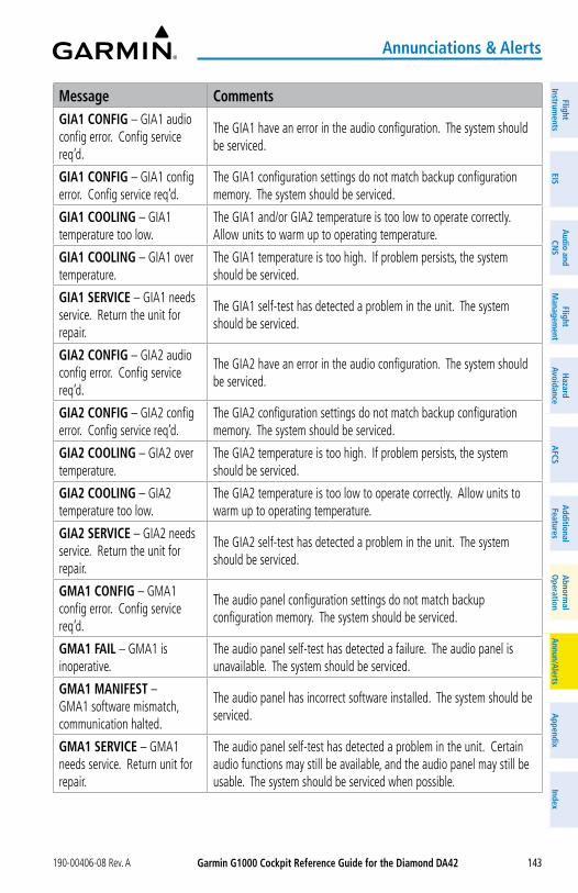
Garmin G1000 Cockpit Reference Guide for the Diamond Da42190-00406-08 Rev. A 143
annunciations & alerts
FlightInstrum
entsEIS
Nav/Com
/XPD
R/Audio
Flight M
anagement
Hazard
AvoidanceA
FCSA
dditionalFeatures
Annun/A
lertsA
ppendixIndex
FlightInstrum
entsEIS
audio and
CNS
Flight M
anagement
Hazard
avoidancea
FCSa
dditionalFeatures
abnorm
alo
perationa
nnun/alerts
appendix
Index
Message CommentsGIa1 CoNFIG – GIA1 audio config error. Config service req’d.
The GIA1 have an error in the audio configuration. The system should be serviced.
GIa1 CoNFIG – GIA1 config error. Config service req’d.
The GIA1 configuration settings do not match backup configuration memory. The system should be serviced.
GIa1 CooLING – GIA1 temperature too low.
The GIA1 and/or GIA2 temperature is too low to operate correctly. Allow units to warm up to operating temperature.
GIa1 CooLING – GIA1 over temperature.
The GIA1 temperature is too high. If problem persists, the system should be serviced.
GIa1 SERVICE – GIA1 needs service. Return the unit for repair.
The GIA1 self-test has detected a problem in the unit. The system should be serviced.
GIa2 CoNFIG – GIA2 audio config error. Config service req’d.
The GIA2 have an error in the audio configuration. The system should be serviced.
GIa2 CoNFIG – GIA2 config error. Config service req’d.
The GIA2 configuration settings do not match backup configuration memory. The system should be serviced.
GIa2 CooLING – GIA2 over temperature.
The GIA2 temperature is too high. If problem persists, the system should be serviced.
GIa2 CooLING – GIA2 temperature too low.
The GIA2 temperature is too low to operate correctly. Allow units to warm up to operating temperature.
GIa2 SERVICE – GIA2 needs service. Return the unit for repair.
The GIA2 self-test has detected a problem in the unit. The system should be serviced.
GMa1 CoNFIG – GMA1 config error. Config service req’d.
The audio panel configuration settings do not match backup configuration memory. The system should be serviced.
GMa1 FaIL – GMA1 is inoperative.
The audio panel self-test has detected a failure. The audio panel is unavailable. The system should be serviced.
GMa1 MaNIFEST – GMA1 software mismatch, communication halted.
The audio panel has incorrect software installed. The system should be serviced.
GMa1 SERVICE – GMA1 needs service. Return unit for repair.
The audio panel self-test has detected a problem in the unit. Certain audio functions may still be available, and the audio panel may still be usable. The system should be serviced when possible.
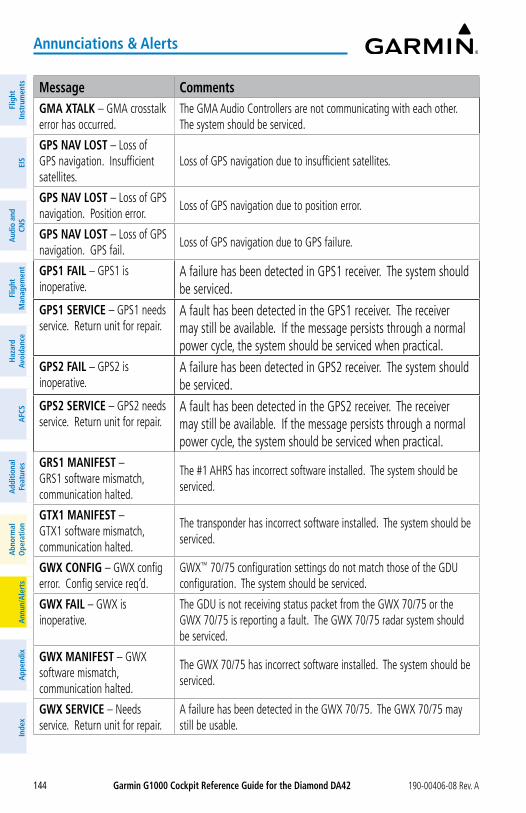
Garmin G1000 Cockpit Reference Guide for the Diamond Da42 190-00406-08 Rev. A144
annunciations & alerts
Flig
htIn
stru
men
tsEI
SN
av/C
om/
XPD
R/A
udio
Flig
ht
Man
agem
ent
Haz
ard
Avoi
danc
eA
FCS
Add
ition
alFe
atur
esA
nnun
/Ale
rts
App
endi
xIn
dex
Flig
htIn
stru
men
tsEI
Sa
udio
and
CNS
Flig
ht
Man
agem
ent
Haz
ard
avoi
danc
ea
FCS
add
ition
alFe
atur
esa
bnor
mal
ope
ratio
na
nnun
/ale
rts
app
endi
xIn
dex
Message CommentsGMa XTaLK – GMA crosstalk error has occurred.
The GMA Audio Controllers are not communicating with each other. The system should be serviced.
GPS NaV LoST – Loss of GPS navigation. Insufficient satellites.
Loss of GPS navigation due to insufficient satellites.
GPS NaV LoST – Loss of GPS navigation. Position error.
Loss of GPS navigation due to position error.
GPS NaV LoST – Loss of GPS navigation. GPS fail.
Loss of GPS navigation due to GPS failure.
GPS1 FaIL – GPS1 is inoperative.
A failure has been detected in GPS1 receiver. The system should be serviced.
GPS1 SERVICE – GPS1 needs service. Return unit for repair.
A fault has been detected in the GPS1 receiver. The receiver may still be available. If the message persists through a normal power cycle, the system should be serviced when practical.
GPS2 FaIL – GPS2 is inoperative.
A failure has been detected in GPS2 receiver. The system should be serviced.
GPS2 SERVICE – GPS2 needs service. Return unit for repair.
A fault has been detected in the GPS2 receiver. The receiver may still be available. If the message persists through a normal power cycle, the system should be serviced when practical.
GRS1 MaNIFEST – GRS1 software mismatch, communication halted.
The #1 AHRS has incorrect software installed. The system should be serviced.
GTX1 MaNIFEST – GTX1 software mismatch, communication halted.
The transponder has incorrect software installed. The system should be serviced.
GWX CoNFIG – GWX config error. Config service req’d.
GWX™ 70/75 configuration settings do not match those of the GDU configuration. The system should be serviced.
GWX FaIL – GWX is inoperative.
The GDU is not receiving status packet from the GWX 70/75 or the GWX 70/75 is reporting a fault. The GWX 70/75 radar system should be serviced.
GWX MaNIFEST – GWX software mismatch, communication halted.
The GWX 70/75 has incorrect software installed. The system should be serviced.
GWX SERVICE – Needs service. Return unit for repair.
A failure has been detected in the GWX 70/75. The GWX 70/75 may still be usable.
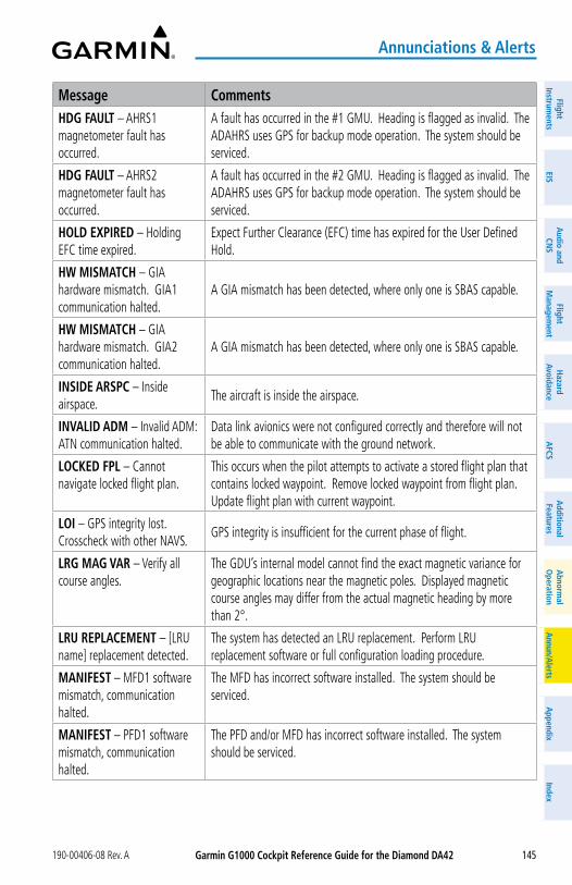
Garmin G1000 Cockpit Reference Guide for the Diamond Da42190-00406-08 Rev. A 145
annunciations & alerts
FlightInstrum
entsEIS
Nav/Com
/XPD
R/Audio
Flight M
anagement
Hazard
AvoidanceA
FCSA
dditionalFeatures
Annun/A
lertsA
ppendixIndex
FlightInstrum
entsEIS
audio and
CNS
Flight M
anagement
Hazard
avoidancea
FCSa
dditionalFeatures
abnorm
alo
perationa
nnun/alerts
appendix
Index
Message CommentsHDG FaULT – AHRS1 magnetometer fault has occurred.
A fault has occurred in the #1 GMU. Heading is flagged as invalid. The ADAHRS uses GPS for backup mode operation. The system should be serviced.
HDG FaULT – AHRS2 magnetometer fault has occurred.
A fault has occurred in the #2 GMU. Heading is flagged as invalid. The ADAHRS uses GPS for backup mode operation. The system should be serviced.
HoLD EXPIRED – Holding EFC time expired.
Expect Further Clearance (EFC) time has expired for the User Defined Hold.
HW MISMaTCH – GIA hardware mismatch. GIA1 communication halted.
A GIA mismatch has been detected, where only one is SBAS capable.
HW MISMaTCH – GIA hardware mismatch. GIA2 communication halted.
A GIA mismatch has been detected, where only one is SBAS capable.
INSIDE aRSPC – Inside airspace.
The aircraft is inside the airspace.
INVaLID aDM – Invalid ADM: ATN communication halted.
Data link avionics were not configured correctly and therefore will not be able to communicate with the ground network.
LoCKED FPL – Cannot navigate locked flight plan.
This occurs when the pilot attempts to activate a stored flight plan that contains locked waypoint. Remove locked waypoint from flight plan. Update flight plan with current waypoint.
LoI – GPS integrity lost. Crosscheck with other NAVS.
GPS integrity is insufficient for the current phase of flight.
LRG MaG VaR – Verify all course angles.
The GDU’s internal model cannot find the exact magnetic variance for geographic locations near the magnetic poles. Displayed magnetic course angles may differ from the actual magnetic heading by more than 2°.
LRU REPLaCEMENT – [LRU name] replacement detected.
The system has detected an LRU replacement. Perform LRU replacement software or full configuration loading procedure.
MaNIFEST – MFD1 software mismatch, communication halted.
The MFD has incorrect software installed. The system should be serviced.
MaNIFEST – PFD1 software mismatch, communication halted.
The PFD and/or MFD has incorrect software installed. The system should be serviced.
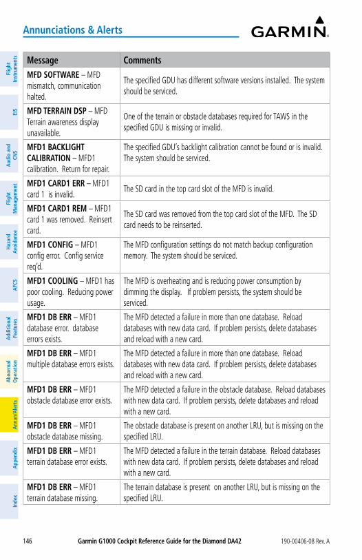
Garmin G1000 Cockpit Reference Guide for the Diamond Da42 190-00406-08 Rev. A146
annunciations & alerts
Flig
htIn
stru
men
tsEI
SN
av/C
om/
XPD
R/A
udio
Flig
ht
Man
agem
ent
Haz
ard
Avoi
danc
eA
FCS
Add
ition
alFe
atur
esA
nnun
/Ale
rts
App
endi
xIn
dex
Flig
htIn
stru
men
tsEI
Sa
udio
and
CNS
Flig
ht
Man
agem
ent
Haz
ard
avoi
danc
ea
FCS
add
ition
alFe
atur
esa
bnor
mal
ope
ratio
na
nnun
/ale
rts
app
endi
xIn
dex
Message CommentsMFD SoFTWaRE – MFD mismatch, communication halted.
The specified GDU has different software versions installed. The system should be serviced.
MFD TERRaIN DSP – MFD Terrain awareness display unavailable.
One of the terrain or obstacle databases required for TAWS in the specified GDU is missing or invalid.
MFD1 BaCKLIGHT CaLIBRaTIoN – MFD1 calibration. Return for repair.
The specified GDU’s backlight calibration cannot be found or is invalid. The system should be serviced.
MFD1 CaRD1 ERR – MFD1 card 1 is invalid.
The SD card in the top card slot of the MFD is invalid.
MFD1 CaRD1 REM – MFD1 card 1 was removed. Reinsert card.
The SD card was removed from the top card slot of the MFD. The SD card needs to be reinserted.
MFD1 CoNFIG – MFD1 config error. Config service req’d.
The MFD configuration settings do not match backup configuration memory. The system should be serviced.
MFD1 CooLING – MFD1 has poor cooling. Reducing power usage.
The MFD is overheating and is reducing power consumption by dimming the display. If problem persists, the system should be serviced.
MFD1 DB ERR – MFD1 database error. database errors exists.
The MFD detected a failure in more than one database. Reload databases with new data card. If problem persists, delete databases and reload with a new card.
MFD1 DB ERR – MFD1 multiple database errors exists.
The MFD detected a failure in more than one database. Reload databases with new data card. If problem persists, delete databases and reload with a new card.
MFD1 DB ERR – MFD1 obstacle database error exists.
The MFD detected a failure in the obstacle database. Reload databases with new data card. If problem persists, delete databases and reload with a new card.
MFD1 DB ERR – MFD1 obstacle database missing.
The obstacle database is present on another LRU, but is missing on the specified LRU.
MFD1 DB ERR – MFD1 terrain database error exists.
The MFD detected a failure in the terrain database. Reload databases with new data card. If problem persists, delete databases and reload with a new card.
MFD1 DB ERR – MFD1 terrain database missing.
The terrain database is present on another LRU, but is missing on the specified LRU.
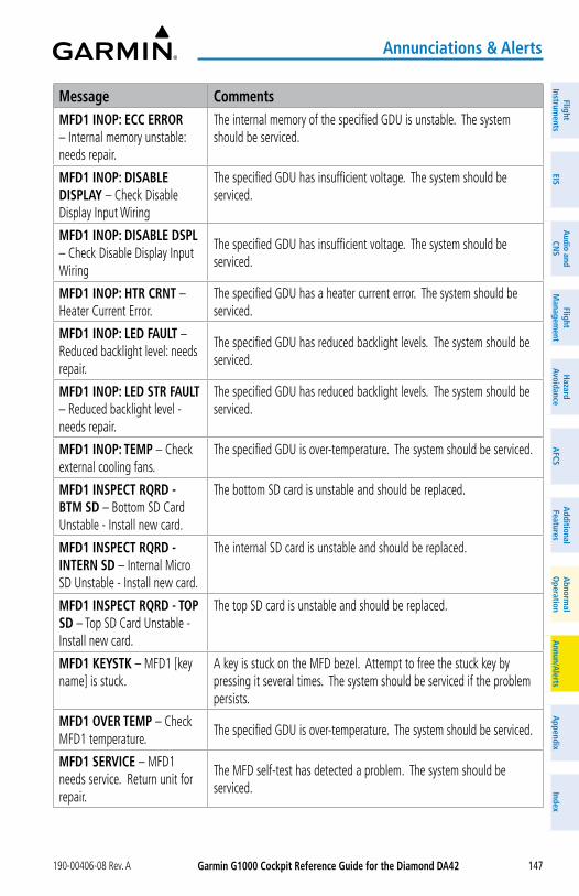
Garmin G1000 Cockpit Reference Guide for the Diamond Da42190-00406-08 Rev. A 147
annunciations & alerts
FlightInstrum
entsEIS
Nav/Com
/XPD
R/Audio
Flight M
anagement
Hazard
AvoidanceA
FCSA
dditionalFeatures
Annun/A
lertsA
ppendixIndex
FlightInstrum
entsEIS
audio and
CNS
Flight M
anagement
Hazard
avoidancea
FCSa
dditionalFeatures
abnorm
alo
perationa
nnun/alerts
appendix
Index
Message CommentsMFD1 INoP: ECC ERRoR – Internal memory unstable: needs repair.
The internal memory of the specified GDU is unstable. The system should be serviced.
MFD1 INoP: DISaBLE DISPLay – Check Disable Display Input Wiring
The specified GDU has insufficient voltage. The system should be serviced.
MFD1 INoP: DISaBLE DSPL – Check Disable Display Input Wiring
The specified GDU has insufficient voltage. The system should be serviced.
MFD1 INoP: HTR CRNT – Heater Current Error.
The specified GDU has a heater current error. The system should be serviced.
MFD1 INoP: LED FaULT – Reduced backlight level: needs repair.
The specified GDU has reduced backlight levels. The system should be serviced.
MFD1 INoP: LED STR FaULT – Reduced backlight level - needs repair.
The specified GDU has reduced backlight levels. The system should be serviced.
MFD1 INoP: TEMP – Check external cooling fans.
The specified GDU is over-temperature. The system should be serviced.
MFD1 INSPECT RQRD - BTM SD – Bottom SD Card Unstable - Install new card.
The bottom SD card is unstable and should be replaced.
MFD1 INSPECT RQRD - INTERN SD – Internal Micro SD Unstable - Install new card.
The internal SD card is unstable and should be replaced.
MFD1 INSPECT RQRD - ToP SD – Top SD Card Unstable - Install new card.
The top SD card is unstable and should be replaced.
MFD1 KEySTK – MFD1 [key name] is stuck.
A key is stuck on the MFD bezel. Attempt to free the stuck key by pressing it several times. The system should be serviced if the problem persists.
MFD1 oVER TEMP – Check MFD1 temperature.
The specified GDU is over-temperature. The system should be serviced.
MFD1 SERVICE – MFD1 needs service. Return unit for repair.
The MFD self-test has detected a problem. The system should be serviced.
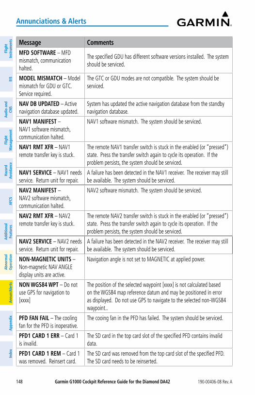
Garmin G1000 Cockpit Reference Guide for the Diamond Da42 190-00406-08 Rev. A148
annunciations & alerts
Flig
htIn
stru
men
tsEI
SN
av/C
om/
XPD
R/A
udio
Flig
ht
Man
agem
ent
Haz
ard
Avoi
danc
eA
FCS
Add
ition
alFe
atur
esA
nnun
/Ale
rts
App
endi
xIn
dex
Flig
htIn
stru
men
tsEI
Sa
udio
and
CNS
Flig
ht
Man
agem
ent
Haz
ard
avoi
danc
ea
FCS
add
ition
alFe
atur
esa
bnor
mal
ope
ratio
na
nnun
/ale
rts
app
endi
xIn
dex
Message CommentsMFD SoFTWaRE – MFD mismatch, communication halted.
The specified GDU has different software versions installed. The system should be serviced.
MoDEL MISMaTCH – Model mismatch for GDU or GTC. Service required.
The GTC or GDU modes are not compatible. The system should be serviced.
NaV DB UPDaTED – Active navigation database updated.
System has updated the active navigation database from the standby navigation database.
NaV1 MaNIFEST – NAV1 software mismatch, communication halted.
NAV1 software mismatch. The system should be serviced.
NaV1 RMT XFR – NAV1 remote transfer key is stuck.
The remote NAV1 transfer switch is stuck in the enabled (or “pressed”) state. Press the transfer switch again to cycle its operation. If the problem persists, the system should be serviced.
NaV1 SERVICE – NAV1 needs service. Return unit for repair.
A failure has been detected in the NAV1 receiver. The receiver may still be available. The system should be serviced.
NaV2 MaNIFEST – NAV2 software mismatch, communication halted.
NAV2 software mismatch. The system should be serviced.
NaV2 RMT XFR – NAV2 remote transfer key is stuck.
The remote NAV2 transfer switch is stuck in the enabled (or “pressed”) state. Press the transfer switch again to cycle its operation. If the problem persists, the system should be serviced.
NaV2 SERVICE – NAV2 needs service. Return unit for repair.
A failure has been detected in the NAV2 receiver. The receiver may still be available. The system should be serviced.
NoN-MaGNETIC UNITS – Non-magnetic NAV ANGLE display units are active.
Navigation angle is not set to MAGNETIC at applied power.
NoN WGS84 WPT – Do not use GPS for navigation to [xxxx]
The position of the selected waypoint [xxxx] is not calculated based on the WGS84 map reference datum and may be positioned in error as displayed. Do not use GPS to navigate to the selected non-WGS84 waypoint..
PFD FaN FaIL – The cooling fan for the PFD is inoperative.
The cooing fan in the PFD has failed. The system should be serviced.
PFD1 CaRD 1 ERR – Card 1 is invalid.
The SD card in the top card slot of the specified PFD contains invalid data.
PFD1 CaRD 1 REM – Card 1 was removed. Reinsert card.
The SD card was removed from the top card slot of the specified PFD. The SD card needs to be reinserted.
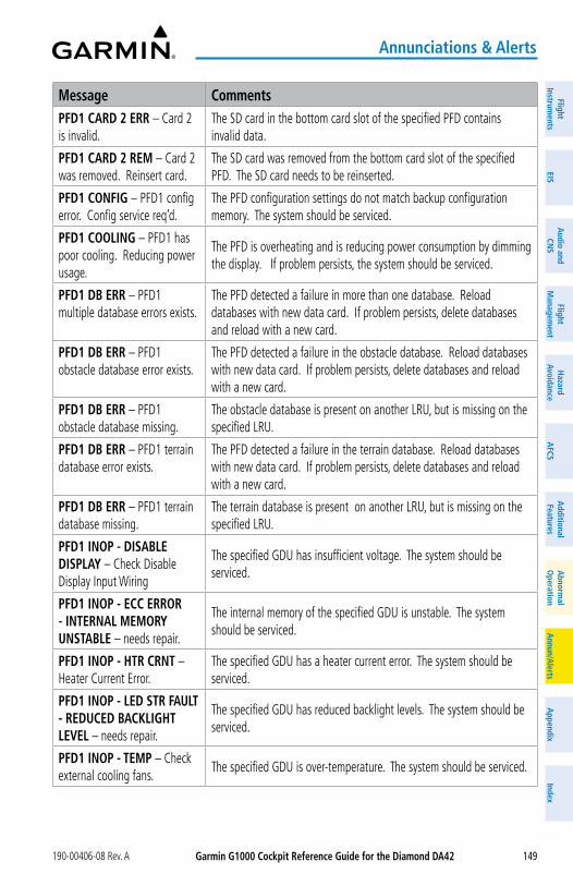
Garmin G1000 Cockpit Reference Guide for the Diamond Da42190-00406-08 Rev. A 149
annunciations & alerts
FlightInstrum
entsEIS
Nav/Com
/XPD
R/Audio
Flight M
anagement
Hazard
AvoidanceA
FCSA
dditionalFeatures
Annun/A
lertsA
ppendixIndex
FlightInstrum
entsEIS
audio and
CNS
Flight M
anagement
Hazard
avoidancea
FCSa
dditionalFeatures
abnorm
alo
perationa
nnun/alerts
appendix
Index
Message CommentsPFD1 CaRD 2 ERR – Card 2 is invalid.
The SD card in the bottom card slot of the specified PFD contains invalid data.
PFD1 CaRD 2 REM – Card 2 was removed. Reinsert card.
The SD card was removed from the bottom card slot of the specified PFD. The SD card needs to be reinserted.
PFD1 CoNFIG – PFD1 config error. Config service req’d.
The PFD configuration settings do not match backup configuration memory. The system should be serviced.
PFD1 CooLING – PFD1 has poor cooling. Reducing power usage.
The PFD is overheating and is reducing power consumption by dimming the display. If problem persists, the system should be serviced.
PFD1 DB ERR – PFD1 multiple database errors exists.
The PFD detected a failure in more than one database. Reload databases with new data card. If problem persists, delete databases and reload with a new card.
PFD1 DB ERR – PFD1 obstacle database error exists.
The PFD detected a failure in the obstacle database. Reload databases with new data card. If problem persists, delete databases and reload with a new card.
PFD1 DB ERR – PFD1 obstacle database missing.
The obstacle database is present on another LRU, but is missing on the specified LRU.
PFD1 DB ERR – PFD1 terrain database error exists.
The PFD detected a failure in the terrain database. Reload databases with new data card. If problem persists, delete databases and reload with a new card.
PFD1 DB ERR – PFD1 terrain database missing.
The terrain database is present on another LRU, but is missing on the specified LRU.
PFD1 INoP - DISaBLE DISPLay – Check Disable Display Input Wiring
The specified GDU has insufficient voltage. The system should be serviced.
PFD1 INoP - ECC ERRoR - INTERNaL MEMoRy UNSTaBLE – needs repair.
The internal memory of the specified GDU is unstable. The system should be serviced.
PFD1 INoP - HTR CRNT – Heater Current Error.
The specified GDU has a heater current error. The system should be serviced.
PFD1 INoP - LED STR FaULT - REDUCED BaCKLIGHT LEVEL – needs repair.
The specified GDU has reduced backlight levels. The system should be serviced.
PFD1 INoP - TEMP – Check external cooling fans.
The specified GDU is over-temperature. The system should be serviced.
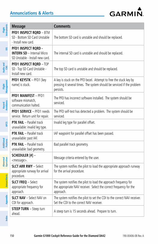
Garmin G1000 Cockpit Reference Guide for the Diamond Da42 190-00406-08 Rev. A150
annunciations & alerts
Flig
htIn
stru
men
tsEI
SN
av/C
om/
XPD
R/A
udio
Flig
ht
Man
agem
ent
Haz
ard
Avoi
danc
eA
FCS
Add
ition
alFe
atur
esA
nnun
/Ale
rts
App
endi
xIn
dex
Flig
htIn
stru
men
tsEI
Sa
udio
and
CNS
Flig
ht
Man
agem
ent
Haz
ard
avoi
danc
ea
FCS
add
ition
alFe
atur
esa
bnor
mal
ope
ratio
na
nnun
/ale
rts
app
endi
xIn
dex
Message CommentsPFD1 INSPECT RQRD – BTM SD - Bottom SD Card Unstable - Install new card.
The bottom SD card is unstable and should be replaced.
PFD1 INSPECT RQRD - INTERN SD – Internal Micro SD Unstable - Install new card.
The internal SD card is unstable and should be replaced.
PFD1 INSPECT RQRD – TOP SD - Top SD Card Unstable - Install new card.
The top SD card is unstable and should be replaced.
PFD1 KEySTK – PFD1 [key name] is stuck.
A key is stuck on the PFD bezel. Attempt to free the stuck key by pressing it several times. The system should be serviced if the problem persists.
PFD1 MaNIFEST – PFD1 software mismatch, communication halted.
The PFD has incorrect software installed. The system should be serviced.
PFD1 SERVICE – PFD1 needs service. Return unit for repair.
The PFD self-test has detected a problem. The system should be serviced.
PTK FaIL – Parallel track unavailable: invalid leg type.
Invalid leg type for parallel offset.
PTK FaIL – Parallel track unavailable: past IAF.
IAF waypoint for parallel offset has been passed.
PTK FaIL – Parallel track unavailable: bad geometry.
Bad parallel track geometry.
SCHEDULER [#] – <message>.
Message criteria entered by the user.
SLCT aRR RWy – Select appropriate runway for arrival procedure.
The system notifies the pilot to load the appropriate approach runway for the arrival procedure.
SLCT FREQ – Select appropriate frequency for approach.
The system notifies the pilot to load the approach frequency for the appropriate NAV receiver. Select the correct frequency for the approach.
SLCT NaV – Select NAV on CDI for approach.
The system notifies the pilot to set the CDI to the correct NAV receiver. Set the CDI to the correct NAV receiver.
STEEP TURN – Steep turn ahead.
A steep turn is 15 seconds ahead. Prepare to turn.
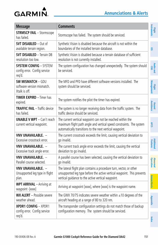
Garmin G1000 Cockpit Reference Guide for the Diamond Da42190-00406-08 Rev. A 151
annunciations & alerts
FlightInstrum
entsEIS
Nav/Com
/XPD
R/Audio
Flight M
anagement
Hazard
AvoidanceA
FCSA
dditionalFeatures
Annun/A
lertsA
ppendixIndex
FlightInstrum
entsEIS
audio and
CNS
Flight M
anagement
Hazard
avoidancea
FCSa
dditionalFeatures
abnorm
alo
perationa
nnun/alerts
appendix
Index
Message CommentsSTRMSCP FaIL – Stormscope has failed.
Stormscope has failed. The system should be serviced.
SVT DISaBLED – Out of available terrain region.
Synthetic Vision is disabled because the aircraft is not within the boundaries of the installed terrain database.
SVT DISaBLED – Terrain DB resolution too low.
Synthetic Vision is disabled because a terrain database of sufficient resolution is not currently installed.
SySTEM CoNFIG – SYSTEM config error. Config service req’d.
The system configuration has changed unexpectedly. The system should be serviced.
SW MISMaTCH – GDU software version mismatch. Xtalk is off.
The MFD and PFD have different software versions installed. The system should be serviced.
TIMER EXPIRD – Timer has expired.
The system notifies the pilot the timer has expired.
TRaFFIC FaIL – Traffic device has failed.
The system is no longer receiving data from the traffic system. The traffic device should be serviced.
UNaBLE V WPT – Can’t reach current vertical waypoint.
The current vertical waypoint can not be reached within the maximum flight path angle and vertical speed constraints. The system automatically transitions to the next vertical waypoint.
VNV UNaVaILaBLE. – Excessive crosstrack error.
The current crosstrack exceeds the limit, causing vertical deviation to go invalid.
VNV UNaVaILaBLE. – Excessive track angle error.
The current track angle error exceeds the limit, causing the vertical deviation to go invalid.
VNV UNaVaILaBLE. – Parallel course selected.
A parallel course has been selected, causing the vertical deviation to go invalid.
VNV UNaVaILaBLE. – Unsupported leg type in flight plan.
The lateral flight plan contains a procedure turn, vector, or other unsupported leg type before the active vertical waypoint. This prevents vertical guidance to the active vertical waypoint.
WPT aRRIVaL – Arriving at waypoint -[xxxx]
Arriving at waypoint [xxxx], where [xxxx] is the waypoint name.
WX aLERT – Possible severe weather ahead.
The GWX 70/75 indicates severe weather within ±10 degrees of the aircraft heading at a range of 80 to 320 nm.
XPDR1 CoNFIG – XPDR1 config error. Config service req’d.
The transponder configuration settings do not match those of backup configuration memory. The system should be serviced.
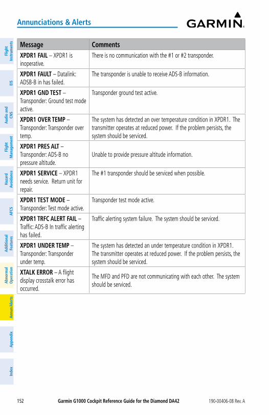
Garmin G1000 Cockpit Reference Guide for the Diamond Da42 190-00406-08 Rev. A152
annunciations & alerts
Flig
htIn
stru
men
tsEI
SN
av/C
om/
XPD
R/A
udio
Flig
ht
Man
agem
ent
Haz
ard
Avoi
danc
eA
FCS
Add
ition
alFe
atur
esA
nnun
/Ale
rts
App
endi
xIn
dex
Flig
htIn
stru
men
tsEI
Sa
udio
and
CNS
Flig
ht
Man
agem
ent
Haz
ard
avoi
danc
ea
FCS
add
ition
alFe
atur
esa
bnor
mal
ope
ratio
na
nnun
/ale
rts
app
endi
xIn
dex
Message CommentsXPDR1 FaIL – XPDR1 is inoperative.
There is no communication with the #1 or #2 transponder.
XPDR1 FaULT – Datalink: ADSB-B in has failed.
The transponder is unable to receive ADS-B information.
XPDR1 GND TEST – Transponder: Ground test mode active.
Transponder ground test active.
XPDR1 oVER TEMP – Transponder: Transponder over temp.
The system has detected an over temperature condition in XPDR1. The transmitter operates at reduced power. If the problem persists, the system should be serviced.
XPDR1 PRES aLT – Transponder: ADS-B no pressure altitude.
Unable to provide pressure altitude information.
XPDR1 SERVICE – XPDR1 needs service. Return unit for repair.
The #1 transponder should be serviced when possible.
XPDR1 TEST MoDE – Transponder: Test mode active.
Transponder test mode active.
XPDR1 TRFC aLERT FaIL – Traffic: ADS-B In traffic alerting has failed.
Traffic alerting system failure. The system should be serviced.
XPDR1 UNDER TEMP – Transponder: Transponder under temp.
The system has detected an under temperature condition in XPDR1. The transmitter operates at reduced power. If the problem persists, the system should be serviced.
XTaLK ERRoR – A flight display crosstalk error has occurred.
The MFD and PFD are not communicating with each other. The system should be serviced.
Garmin G1000 Cockpit Reference Guide for the Diamond Da42190-00406-08 Rev. A
appendix
153
FlightInstrum
entsEIS
Nav/Com
/XPD
R/Audio
Flight M
anagement
Hazard
AvoidanceA
FCSA
dditionalFeatures
Annun/A
lertsA
ppendixIndex
FlightInstrum
entsEIS
audio and
CNS
Flight M
anagement
Hazard
avoidancea
FCSa
dditionalFeatures
abnorm
alo
perationa
nnun/alerts
appendix
Index
aPPENDIXDaTaBaSE MaNaGEMENT
Database information is obtained from third party sources. Inaccuracies in the data may be discovered from time to time. Garmin communicates this information by issuing a Database Alert. These notifications are available on flygarmin.com™.
Garmin requests the flight crew report any observed discrepancies related to da-tabase information. These discrepancies could come in the form of an incor-rect procedure; incorrectly identified terrain, obstacles and fixes; or any other dis-played item used for navigation or communication in the air or on the ground. Go to flygarmin.com™ and select Aviation Data Error Report.
The system uses 8 GB Secure Digital (SD) cards to load and store various types of data. For basic flight operations, SD cards are required for database storage as well as navigation database updates. After update, the databases are stored on the SD cards in the bottom slot, so the card must remain in the bottom slot of the GDUs; however, the Navigation database is stored on the system. Not all SD cards are compatible with the system. Only SD cards sup-plied by Garmin or the aircraft manufacturer can be left in the system. In the event there is a file corruption problem with the SD card, it may be necessary to reformat the card. This can cause an issue when formatting using Mac OS, where the newly formatted device will not be recognized by the avionics system. When using a Macintosh computer to format the SD card, Garmin recommends using the SD Memory Card Formatter application made available by the SD Association as a download from sdcard.org. When running the application, use the Quick Format option.
NaVIGaTIoN DaTaBaSESThe navigation database is updated on a 28-day cycle. There are two possible methods for
updating the navigation database. If the 28-day cycle of your navigation database has already ended, you must update the active navigation database. However, if the expiration date of the navigation database hasn’t already been reached, you may load a standby navigation database. The system will then automatically update the active database at the first aircraft power-on when the new navigation becomes effective.
The navigation database must be installed from the Jeppesen or user supplied SD data card. Go to flygarmin.com or www.jeppesen.com for subscription and update information.
Updating the active navigation database (not using the Dual Navigation Database or automatic Database Synchronization Features):1) Go to flygarmin.com or www.jeppesen.com. Install the navigation database on a blank
SD card.2) With the system OFF, insert the SD card containing the new navigation database version
into the top card slot of the display (label of SD card facing left).
Garmin G1000 Cockpit Reference Guide for the Diamond Da42 190-00406-08 Rev. A
appendix
154
Flig
htIn
stru
men
tsEI
SN
av/C
om/
XPD
R/A
udio
Flig
ht
Man
agem
ent
Haz
ard
Avoi
danc
eA
FCS
Add
ition
alFe
atur
esA
nnun
/Ale
rts
App
endi
xIn
dex
Flig
htIn
stru
men
tsEI
Sa
udio
and
CNS
Flig
ht
Man
agem
ent
Haz
ard
avoi
danc
ea
FCS
add
ition
alFe
atur
esa
bnor
mal
ope
ratio
na
nnun
/ale
rts
app
endi
xIn
dex
3) Turn the system ON. The prompt ‘DO YOU WANT TO UPDATE THE STANDBY NAVIGATION DATABASE ON THE BOTTOM CARD?’ is displayed in the upper left corner of the display:
4) Press the No Softkey to proceed to loading only the active database.5) The prompt ‘DO YOU WANT TO UPDATE THE ACTIVE NAVIGATION DATABASE?’ is
displayed, press the yES Softkey to update the active navigation database.6) After the update completes, the display starts in normal mode. Do not remove power
while the display is starting.7) Turn the system OFF and remove the SD card from the top card slot.8) Repeat steps 2 through 7 for the other display. Remove the SD card when finished.9) Apply power to the system and press the ENT Key or the right-most softkey on the MFD
to acknowledge the startup screen.10) Turn the large FMS Knob to select the AUX Page group on the MFD.11) Turn the small FMS Knob to select the ‘AUX-SYSTEM STATUS’ Page.12) Press the Display Database Selection Softkey, to show active navigation database
information for each display. 13) Verify the correct navigation database cycle information is shown for each display.
DUaL NaVIGaTIoN DaTaBaSE FEaTURE The dual navigation database feature allows each display to store an upcoming navigation
database on the bottom SD card so the system can automatically load it to replace the active database when the new database becomes effective (the next cycle becomes available seven days before its effective date).
If a navigation database loader card is inserted into the top SD card slot of a display, and an SD card is in the bottom slot, the system will prompt the user (when power is applied on-ground) as to whether the database should be stored on the bottom SD card as the standby database. If the user responds affirmatively, the system will copy the navigation database from the top SD card to the bottom SD card. As long as the bottom SD card remains in the card slot, this standby navigation database will be available for the system to use as the active database as soon as it becomes effective.
Loading a standby navigation database:1) Go to flygarmin.com or www.jeppesen.com. Install the navigation database on a blank
SD card.2) With the system OFF, insert the SD card containing the new navigation database version
into the top card slot of the display.3) Verify that an SD card is inserted in the bottom slot of the display.4) Turn the system ON. The prompt ‘DO YOU WANT TO UPDATE THE STANDBY NAVIGATION
DATABASE ON THE BOTTOM CARD?’ is displayed.
Garmin G1000 Cockpit Reference Guide for the Diamond Da42190-00406-08 Rev. A
appendix
155
FlightInstrum
entsEIS
Nav/Com
/XPD
R/Audio
Flight M
anagement
Hazard
AvoidanceA
FCSA
dditionalFeatures
Annun/A
lertsA
ppendixIndex
FlightInstrum
entsEIS
audio and
CNS
Flight M
anagement
Hazard
avoidancea
FCSa
dditionalFeatures
abnorm
alo
perationa
nnun/alerts
appendix
Index
5) Press the yES softkey. The navigation database is copied to the SD card in the bottom of the display.
6) After the navigation database files are copied to the bottom SD card, the ‘UPDATED STANDBY NAVIGATION DATABASE SUCCESSFULLY’ will appear.
7) As instructed on the display, press any key to continue. The display will now appear.8) Press any key to continue. The ‘DO YOU WANT TO UPDATE THE ACTIVE NAVIGATION
DATABASE?’ will now appear.9) Press the No Softkey. The display now starts in normal mode. Since the database
effective date is not yet valid, it should not be loaded as the active database. Do not remove power while the display is starting.
10) Turn the system OFF and remove the SD card from the top card slot.11) Repeat steps 2 through 10 for the other display(s).12) Apply power to the system and press the ENT Key on the MFD display to acknowledge
the startup screen.13) Turn the large FMS Knob to select the AUX Page group on the MFD.14) Turn the small FMS Knob to select the ‘AUX-SYSTEM STATUS’ Page.15) Press the Display Database Selection Softkey to show standby navigation database
information for each display. 16) Verify the correct standby navigation database cycle information is shown for each
display.
GaRMIN DaTaBaSESThe following databases are stored on Supplemental Data Cards provided by Garmin:
– Expanded basemap
– Terrain
– Obstacle
– FliteCharts or ChartView™
– Airport Directory (AOPA or AC-U-KWIK)
After subscribing to the desired database product, these database products will be down-loaded and ultimately stored on three Supplemental Data Cards (with the exception of Fli-teCharts® and ChartView™, which are loaded on only one card). Each Supplemental Data Card resides in the bottom card of each display. These cards must not be removed except to update the databases stored on each card.
Since these databases are not stored internally in the displays, a Supplemental Data Card containing identical database versions must be kept in each display unit.
The basemap database contains data for the topography and land features, such as rivers, lakes, and towns. It is updated only periodically, with no set schedule. There is no expiration date.
Garmin G1000 Cockpit Reference Guide for the Diamond Da42 190-00406-08 Rev. A
appendix
156
Flig
htIn
stru
men
tsEI
SN
av/C
om/
XPD
R/A
udio
Flig
ht
Man
agem
ent
Haz
ard
Avoi
danc
eA
FCS
Add
ition
alFe
atur
esA
nnun
/Ale
rts
App
endi
xIn
dex
Flig
htIn
stru
men
tsEI
Sa
udio
and
CNS
Flig
ht
Man
agem
ent
Haz
ard
avoi
danc
ea
FCS
add
ition
alFe
atur
esa
bnor
mal
ope
ratio
na
nnun
/ale
rts
app
endi
xIn
dex
The terrain database contains the terrain mapping data. These databases are updated peri-odically and have no expiration date.
The obstacle database contains data for obstacles, such as towers, that pose a potential haz-ard to aircraft. Obstacles 200 feet and higher are included in the obstacle database. It is very important to note that not all obstacles are necessarily charted and therefore may not be con-tained in the obstacle database. This database is updated on a 56-day cycle.
automatic Database Synchronization FeatureThe automatic database synchronization feature automatically transfers the database from a
single SD database card to the SD cards on the PFD and the MFD to ensure that all databases are synchronized throughout the system. After power-on, the system compares all copies of each applicable database. If similar databases do not match, the most recent valid database is automatically copied to each card in the system that does not already contain that database.
If an error occurs during the synchronization, an error message will be displayed, followed by the affected display in the Sync Status section of the Database Window. If a synchronization completes on one display, but an error occurs on another, the error message will be displayed with the affected display listed after it. When an error message is displayed, the problem must be corrected before the synchronization can be completed. A power cycle is required to restart synchronization when ‘Card Full’ or ‘Err’ is shown.
Updating Garmin Databases/Jeppesen Chartview DatabaseThe Garmin database updates can be obtained by following the instructions detailed in
the ‘Aviation Databases’ section of the Garmin website (flygarmin.com). Jeppesen Chartview can be download from the Garmin website but operators must contact Jeppesen to subscribe. Once the updated files have been downloaded from the website, a PC equipped with an ap-propriate SD card reader is used to unpack and program the new databases onto an existing Supplemental Data Card. When database files are loaded to the SD card, any previously loaded database files of the same type residing on the SD card will be overwritten. This includes load-ing a database of a different coverage area or data cycle than that currently residing on the SD card. Equipment required to perform the update is as follows:
» Windows-compatible PC computer
» SD Card Reader: SanDisk SDDR-93, SanDisk SDDR-99, Verbatim #96504, or equivalent
» Updated database obtained from the Garmin website
» Supplemental SD Cards In some cases it may be necessary to obtain an unlock code from Garmin in order to make
the database product functional. It may also be necessary to have the system configured by a Garmin authorized service facility in order to use some database features.
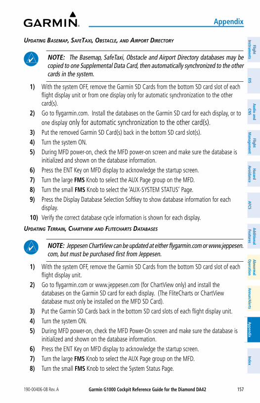
Garmin G1000 Cockpit Reference Guide for the Diamond Da42190-00406-08 Rev. A
appendix
157
FlightInstrum
entsEIS
Nav/Com
/XPD
R/Audio
Flight M
anagement
Hazard
AvoidanceA
FCSA
dditionalFeatures
Annun/A
lertsA
ppendixIndex
FlightInstrum
entsEIS
audio and
CNS
Flight M
anagement
Hazard
avoidancea
FCSa
dditionalFeatures
abnorm
alo
perationa
nnun/alerts
appendix
Index
updating basemap, saFetaxi, obstaCle, and airport direCtory
NoTE: The Basemap, SafeTaxi, Obstacle and Airport Directory databases may be copied to one Supplemental Data Card, then automatically synchronized to the other cards in the system.
1) With the system OFF, remove the Garmin SD Cards from the bottom SD card slot of each flight display unit or from one display only for automatic synchronization to the other card(s).
2) Go to flygarmin.com. Install the databases on the Garmin SD card for each display, or to one display only for automatic synchronization to the other card(s).
3) Put the removed Garmin SD Card(s) back in the bottom SD card slot(s).4) Turn the system ON.5) During MFD power-on, check the MFD power-on screen and make sure the database is
initialized and shown on the database information.6) Press the ENT Key on MFD display to acknowledge the startup screen.7) Turn the large FMS Knob to select the AUX Page group on the MFD.8) Turn the small FMS Knob to select the ‘AUX-SYSTEM STATUS’ Page.9) Press the Display Database Selection Softkey to show database information for each
display. 10) Verify the correct database cycle information is shown for each display.
updating terrain, Chartview and FliteCharts databases
NoTE: Jeppesen ChartView can be updated at either flygarmin.com or www.jeppesen.com, but must be purchased first from Jeppesen.
1) With the system OFF, remove the Garmin SD Cards from the bottom SD card slot of each flight display unit.
2) Go to flygarmin.com or www.jeppesen.com (for ChartView only) and install the databases on the Garmin SD card for each display. (The FliteCharts or ChartView database must only be installed on the MFD SD Card).
3) Put the Garmin SD Cards back in the bottom SD card slots of each flight display unit.4) Turn the system ON.5) During MFD power-on, check the MFD Power-On screen and make sure the database is
initialized and shown on the database information.6) Press the ENT Key on MFD display to acknowledge the startup screen.7) Turn the large FMS Knob to select the AUX Page group on the MFD.8) Turn the small FMS Knob to select the System Status Page.
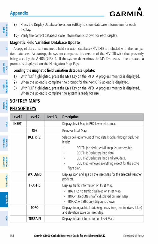
Garmin G1000 Cockpit Reference Guide for the Diamond Da42 190-00406-08 Rev. A
appendix
158
Flig
htIn
stru
men
tsEI
SN
av/C
om/
XPD
R/A
udio
Flig
ht
Man
agem
ent
Haz
ard
Avoi
danc
eA
FCS
Add
ition
alFe
atur
esA
nnun
/Ale
rts
App
endi
xIn
dex
Flig
htIn
stru
men
tsEI
Sa
udio
and
CNS
Flig
ht
Man
agem
ent
Haz
ard
avoi
danc
ea
FCS
add
ition
alFe
atur
esa
bnor
mal
ope
ratio
na
nnun
/ale
rts
app
endi
xIn
dex
9) Press the Display Database Selection Softkey to show database information for each display.
10) Verify the correct database cycle information is shown for each display.
Magnetic Field Variation Database UpdateA copy of the current magnetic field variation database (MV DB) is included with the naviga-
tion database. At startup, the system compares this version of the MV DB with that presently being used by the AHRS (GRS1). If the system determines the MV DB needs to be updated, a prompt is displayed on the Navigation Map Page.
Loading the magnetic field variation database update:1) With ‘OK’ highlighted, press the ENT Key on the MFD. A progress monitor is displayed.2) When the upload is complete, the prompt for the next GRS upload is displayed.3) With ‘OK’ highlighted, press the ENT Key on the MFD. A progress monitor is displayed.
When the upload is complete, the system is ready for use.
SoFTKEy MaPSPFD SoFTKEyS
Level 1 Level 2 Level 3 Description
INSET Displays Inset Map in PFD lower left corner.
oFF Removes Inset Map.
DCLTR (3) Selects desired amount of map detail; cycles through declutter levels:
- DCLTR: (no declutter) All map features visible. - DCLTR-1: Declutters land data. - DCLTR-2: Declutters land and SUA data. - DCLTR-3: Removes everything except for the active
flight plan.
WX LGND Displays icon and age on the Inset Map for the selected weather products.
TRaFFIC Displays traffic information on Inset Map.
- TRAFFIC: No traffic displayed on Inset Map. - TRFC-1: Declutters traffic displayed on Inset Map. - TRFC-2: A traffic only display is shown.
ToPo Displays topographical data (e.g., coastlines, terrain, rivers, lakes) and elevation scale on Inset Map.
TERRaIN Displays terrain information on Inset Map.
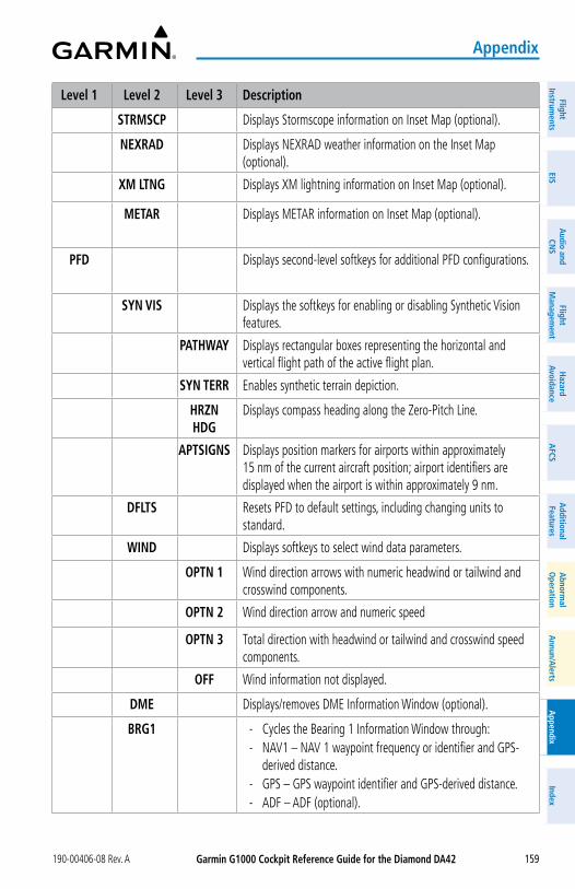
Garmin G1000 Cockpit Reference Guide for the Diamond Da42190-00406-08 Rev. A
appendix
159
FlightInstrum
entsEIS
Nav/Com
/XPD
R/Audio
Flight M
anagement
Hazard
AvoidanceA
FCSA
dditionalFeatures
Annun/A
lertsA
ppendixIndex
FlightInstrum
entsEIS
audio and
CNS
Flight M
anagement
Hazard
avoidancea
FCSa
dditionalFeatures
abnorm
alo
perationa
nnun/alerts
appendix
Index
Level 1 Level 2 Level 3 Description
STRMSCP Displays Stormscope information on Inset Map (optional).
NEXRaD Displays NEXRAD weather information on the Inset Map (optional).
XM LTNG Displays XM lightning information on Inset Map (optional).
METaR Displays METAR information on Inset Map (optional).
PFD Displays second-level softkeys for additional PFD configurations.
SyN VIS Displays the softkeys for enabling or disabling Synthetic Vision features.
PaTHWay Displays rectangular boxes representing the horizontal and vertical flight path of the active flight plan.
SyN TERR Enables synthetic terrain depiction.
HRZN HDG
Displays compass heading along the Zero-Pitch Line.
aPTSIGNS Displays position markers for airports within approximately 15 nm of the current aircraft position; airport identifiers are displayed when the airport is within approximately 9 nm.
DFLTS Resets PFD to default settings, including changing units to standard.
WIND Displays softkeys to select wind data parameters.
oPTN 1 Wind direction arrows with numeric headwind or tailwind and crosswind components.
oPTN 2 Wind direction arrow and numeric speed
oPTN 3 Total direction with headwind or tailwind and crosswind speed components.
oFF Wind information not displayed.
DME Displays/removes DME Information Window (optional).
BRG1 - Cycles the Bearing 1 Information Window through: - NAV1 – NAV 1 waypoint frequency or identifier and GPS-
derived distance. - GPS – GPS waypoint identifier and GPS-derived distance. - ADF – ADF (optional).
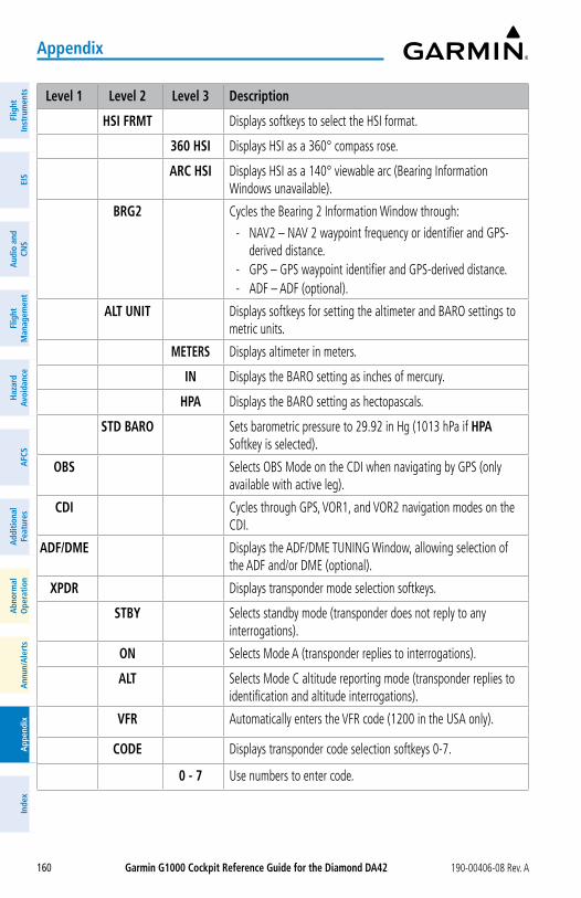
Garmin G1000 Cockpit Reference Guide for the Diamond Da42 190-00406-08 Rev. A
appendix
160
Flig
htIn
stru
men
tsEI
SN
av/C
om/
XPD
R/A
udio
Flig
ht
Man
agem
ent
Haz
ard
Avoi
danc
eA
FCS
Add
ition
alFe
atur
esA
nnun
/Ale
rts
App
endi
xIn
dex
Flig
htIn
stru
men
tsEI
Sa
udio
and
CNS
Flig
ht
Man
agem
ent
Haz
ard
avoi
danc
ea
FCS
add
ition
alFe
atur
esa
bnor
mal
ope
ratio
na
nnun
/ale
rts
app
endi
xIn
dex
Level 1 Level 2 Level 3 Description
HSI FRMT Displays softkeys to select the HSI format.
360 HSI Displays HSI as a 360° compass rose.
aRC HSI Displays HSI as a 140° viewable arc (Bearing Information Windows unavailable).
BRG2 Cycles the Bearing 2 Information Window through:
- NAV2 – NAV 2 waypoint frequency or identifier and GPS-derived distance.
- GPS – GPS waypoint identifier and GPS-derived distance. - ADF – ADF (optional).
aLT UNIT Displays softkeys for setting the altimeter and BARO settings to metric units.
METERS Displays altimeter in meters.
IN Displays the BARO setting as inches of mercury.
HPa Displays the BARO setting as hectopascals.
STD BaRo Sets barometric pressure to 29.92 in Hg (1013 hPa if HPa Softkey is selected).
oBS Selects OBS Mode on the CDI when navigating by GPS (only available with active leg).
CDI Cycles through GPS, VOR1, and VOR2 navigation modes on the CDI.
aDF/DME Displays the ADF/DME TUNING Window, allowing selection of the ADF and/or DME (optional).
XPDR Displays transponder mode selection softkeys.
STBy Selects standby mode (transponder does not reply to any interrogations).
oN Selects Mode A (transponder replies to interrogations).
aLT Selects Mode C altitude reporting mode (transponder replies to identification and altitude interrogations).
VFR Automatically enters the VFR code (1200 in the USA only).
CoDE Displays transponder code selection softkeys 0-7.
0 - 7 Use numbers to enter code.
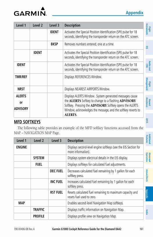
Garmin G1000 Cockpit Reference Guide for the Diamond Da42190-00406-08 Rev. A
appendix
161
FlightInstrum
entsEIS
Nav/Com
/XPD
R/Audio
Flight M
anagement
Hazard
AvoidanceA
FCSA
dditionalFeatures
Annun/A
lertsA
ppendixIndex
FlightInstrum
entsEIS
audio and
CNS
Flight M
anagement
Hazard
avoidancea
FCSa
dditionalFeatures
abnorm
alo
perationa
nnun/alerts
appendix
Index
Level 1 Level 2 Level 3 Description
IDENT Activates the Special Position Identification (SPI) pulse for 18 seconds, identifying the transponder return on the ATC screen.
BKSP Removes numbers entered, one at a time.
IDENT Activates the Special Position Identification (SPI) pulse for 18 seconds, identifying the transponder return on the ATC screen.
IDENT Activates the Special Position Identification (SPI) pulse for 18 seconds, identifying the transponder return on the ATC screen.
TMR/REF Displays REFERENCES Window.
NRST Displays NEAREST AIRPORTS Window.
aLERTS
or
aDVISoRy
Displays ALERTS Window. System generated messages cause the ALERTS Softkey to change to a flashing ADVISORY Softkey. Pressing the ADVISORY Softkey opens the ALERTS Window, acknowledges the message, and the softkey reverts to ALERTS.
MFD SoFTKEySThe following table provides an example of the MFD softkey functions accessed from the
MAP – NAVIGATION MAP Page.
Level 1 Level 2 Level 3 Description
ENGINE Displays second-level engine softkeys (see the EIS Section for more information).
SySTEM Displays system electrical details in the EIS display.
FUEL Displays softkeys for calculated fuel adjustments.
DEC FUEL Decreases calculated fuel remaining by 1 gallon for each softkey press.
INC FUEL Increases calculated fuel remaining by 1 gallon for each softkey press.
RST FUEL Resets calculated fuel remaining to maximum capacity and resets fuel used to zero.
MaP Enables second-level Navigation Map softkeys.
TRaFFIC Displays traffic information on Navigation Map.
PRoFILE Displays profile view on Navigation Map.
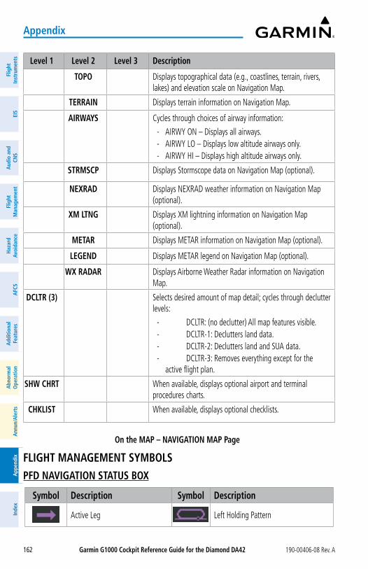
Garmin G1000 Cockpit Reference Guide for the Diamond Da42 190-00406-08 Rev. A
appendix
162
Flig
htIn
stru
men
tsEI
SN
av/C
om/
XPD
R/A
udio
Flig
ht
Man
agem
ent
Haz
ard
Avoi
danc
eA
FCS
Add
ition
alFe
atur
esA
nnun
/Ale
rts
App
endi
xIn
dex
Flig
htIn
stru
men
tsEI
Sa
udio
and
CNS
Flig
ht
Man
agem
ent
Haz
ard
avoi
danc
ea
FCS
add
ition
alFe
atur
esa
bnor
mal
ope
ratio
na
nnun
/ale
rts
app
endi
xIn
dex
Level 1 Level 2 Level 3 Description
ToPo Displays topographical data (e.g., coastlines, terrain, rivers, lakes) and elevation scale on Navigation Map.
TERRaIN Displays terrain information on Navigation Map.
aIRWayS Cycles through choices of airway information:
- AIRWY ON – Displays all airways. - AIRWY LO – Displays low altitude airways only. - AIRWY HI – Displays high altitude airways only.
STRMSCP Displays Stormscope data on Navigation Map (optional).
NEXRaD Displays NEXRAD weather information on Navigation Map (optional).
XM LTNG Displays XM lightning information on Navigation Map (optional).
METaR Displays METAR information on Navigation Map (optional).
LEGEND Displays METAR legend on Navigation Map (optional).
WX RaDaR Displays Airborne Weather Radar information on Navigation Map.
DCLTR (3) Selects desired amount of map detail; cycles through declutter levels:
- DCLTR: (no declutter) All map features visible. - DCLTR-1: Declutters land data. - DCLTR-2: Declutters land and SUA data. - DCLTR-3: Removes everything except for the
active flight plan.
SHW CHRT When available, displays optional airport and terminal procedures charts.
CHKLIST When available, displays optional checklists.
on the MaP – NaVIGaTIoN MaP Page
FLIGHT MaNaGEMENT SyMBoLSPFD NaVIGaTIoN STaTUS BoX
Symbol Description Symbol Description
Active Leg Left Holding Pattern
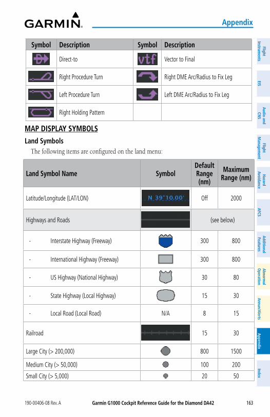
Garmin G1000 Cockpit Reference Guide for the Diamond Da42190-00406-08 Rev. A
appendix
163
FlightInstrum
entsEIS
Nav/Com
/XPD
R/Audio
Flight M
anagement
Hazard
AvoidanceA
FCSA
dditionalFeatures
Annun/A
lertsA
ppendixIndex
FlightInstrum
entsEIS
audio and
CNS
Flight M
anagement
Hazard
avoidancea
FCSa
dditionalFeatures
abnorm
alo
perationa
nnun/alerts
appendix
Index
Symbol Description Symbol Description
Direct-to Vector to Final
Right Procedure Turn Right DME Arc/Radius to Fix Leg
Left Procedure Turn Left DME Arc/Radius to Fix Leg
Right Holding Pattern
MaP DISPLay SyMBoLSLand Symbols
The following items are configured on the land menu:
Land Symbol Name SymbolDefault Range (nm)
Maximum Range (nm)
Latitude/Longitude (LAT/LON) Off 2000
Highways and Roads (see below)
- Interstate Highway (Freeway) 300 800
- International Highway (Freeway) 300 800
- US Highway (National Highway) 30 80
- State Highway (Local Highway) 15 30
- Local Road (Local Road) N/A 8 15
Railroad 15 30
Large City (> 200,000) 800 1500
Medium City (> 50,000) 100 200
Small City (> 5,000) 20 50
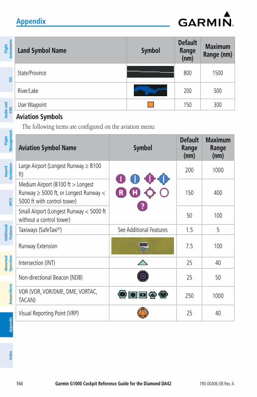
Garmin G1000 Cockpit Reference Guide for the Diamond Da42 190-00406-08 Rev. A
appendix
164
Flig
htIn
stru
men
tsEI
SN
av/C
om/
XPD
R/A
udio
Flig
ht
Man
agem
ent
Haz
ard
Avoi
danc
eA
FCS
Add
ition
alFe
atur
esA
nnun
/Ale
rts
App
endi
xIn
dex
Flig
htIn
stru
men
tsEI
Sa
udio
and
CNS
Flig
ht
Man
agem
ent
Haz
ard
avoi
danc
ea
FCS
add
ition
alFe
atur
esa
bnor
mal
ope
ratio
na
nnun
/ale
rts
app
endi
xIn
dex
Land Symbol Name SymbolDefault Range (nm)
Maximum Range (nm)
State/Province 800 1500
River/Lake 200 500
User Waypoint 150 300
aviation Symbols The following items are configured on the aviation menu:
aviation Symbol Name SymbolDefault Range (nm)
Maximum Range (nm)
Large Airport (Longest Runway ≥ 8100 ft)
200 1000
Medium Airport (8100 ft > Longest Runway ≥ 5000 ft, or Longest Runway < 5000 ft with control tower)
150 400
Small Airport (Longest Runway < 5000 ft without a control tower)
50 100
Taxiways (SafeTaxi®) See Additional Features 1.5 5
Runway Extension 7.5 100
Intersection (INT) 25 40
Non-directional Beacon (NDB) 25 50
VOR (VOR, VOR/DME, DME, VORTAC, TACAN) 250 1000
Visual Reporting Point (VRP) 25 40
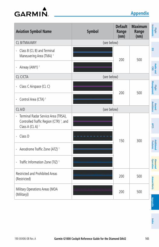
Garmin G1000 Cockpit Reference Guide for the Diamond Da42190-00406-08 Rev. A
appendix
165
FlightInstrum
entsEIS
Nav/Com
/XPD
R/Audio
Flight M
anagement
Hazard
AvoidanceA
FCSA
dditionalFeatures
Annun/A
lertsA
ppendixIndex
FlightInstrum
entsEIS
audio and
CNS
Flight M
anagement
Hazard
avoidancea
FCSa
dditionalFeatures
abnorm
alo
perationa
nnun/alerts
appendix
Index
aviation Symbol Name SymbolDefault Range (nm)
Maximum Range (nm)
CL B/TMA/AWY (see below)
- Class B (CL B) and Terminal Maneuvering Area (TMA) 1
200 500
- Airway (AWY) 1
CL C/CTA (see below)
- Class C Airspace (CL C)
200 500
- Control Area (CTA) 1
CL A/D (see below)
- Terminal Radar Service Area (TRSA), Controlled Traffic Region (CTR) 1, and Class A (CL A) 1
150 300 - Class D
- Aerodrome Traffic Zone (ATZ) 1
- Traffic Information Zone (TIZ) 1
Restricted and Prohibited Areas (Restricted)
200 500
Military Operations Areas (MOA (Military))
200 500
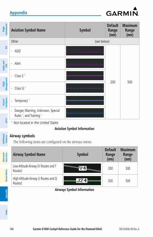
Garmin G1000 Cockpit Reference Guide for the Diamond Da42 190-00406-08 Rev. A
appendix
166
Flig
htIn
stru
men
tsEI
SN
av/C
om/
XPD
R/A
udio
Flig
ht
Man
agem
ent
Haz
ard
Avoi
danc
eA
FCS
Add
ition
alFe
atur
esA
nnun
/Ale
rts
App
endi
xIn
dex
Flig
htIn
stru
men
tsEI
Sa
udio
and
CNS
Flig
ht
Man
agem
ent
Haz
ard
avoi
danc
ea
FCS
add
ition
alFe
atur
esa
bnor
mal
ope
ratio
na
nnun
/ale
rts
app
endi
xIn
dex
aviation Symbol Name SymbolDefault Range (nm)
Maximum Range (nm)
Other (see below)
- ADIZ
200 500
- Alert
- Class E 1
- Class G 1
- Temporary 1
- Danger, Warning, Unknown, Special Rules 1, and Training 1
1 Not located in the United States
aviation Symbol Information
airway symbolsThe following items are configured on the airways menu:
airway Symbol Name SymbolDefault Range (nm)
Maximum Range (nm)
Low Altitude Airway (V Routes and T Routes)
200 500
High Altitude Airway (J Routes and Q Routes)
300 500
airways Symbol Information
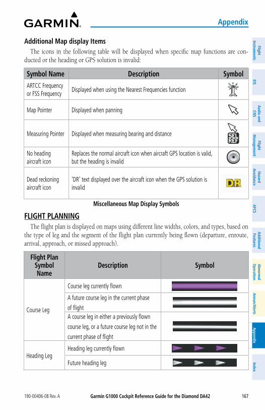
Garmin G1000 Cockpit Reference Guide for the Diamond Da42190-00406-08 Rev. A
appendix
167
FlightInstrum
entsEIS
Nav/Com
/XPD
R/Audio
Flight M
anagement
Hazard
AvoidanceA
FCSA
dditionalFeatures
Annun/A
lertsA
ppendixIndex
FlightInstrum
entsEIS
audio and
CNS
Flight M
anagement
Hazard
avoidancea
FCSa
dditionalFeatures
abnorm
alo
perationa
nnun/alerts
appendix
Index
additional Map display ItemsThe icons in the following table will be displayed when specific map functions are con-
ducted or the heading or GPS solution is invalid:
Symbol Name Description SymbolARTCC Frequency or FSS Frequency
Displayed when using the Nearest Frequencies function
Map Pointer Displayed when panning
Measuring Pointer Displayed when measuring bearing and distance
No heading aircraft icon
Replaces the normal aircraft icon when aircraft GPS location is valid, but the heading is invalid
Dead reckoning aircraft icon
‘DR’ text displayed over the aircraft icon when the GPS solution is invalid
Miscellaneous Map Display Symbols
FLIGHT PLaNNINGThe flight plan is displayed on maps using different line widths, colors, and types, based on
the type of leg and the segment of the flight plan currently being flown (departure, enroute, arrival, approach, or missed approach).
Flight Plan Symbol Name
Description Symbol
Course Leg
Course leg currently flown
A future course leg in the current phase
of flightA course leg in either a previously flown
course leg, or a future course leg not in the
current phase of flight
Heading LegHeading leg currently flown
Future heading leg
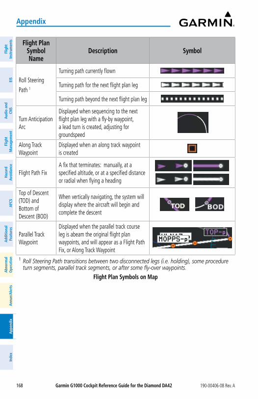
Garmin G1000 Cockpit Reference Guide for the Diamond Da42 190-00406-08 Rev. A
appendix
168
Flig
htIn
stru
men
tsEI
SN
av/C
om/
XPD
R/A
udio
Flig
ht
Man
agem
ent
Haz
ard
Avoi
danc
eA
FCS
Add
ition
alFe
atur
esA
nnun
/Ale
rts
App
endi
xIn
dex
Flig
htIn
stru
men
tsEI
Sa
udio
and
CNS
Flig
ht
Man
agem
ent
Haz
ard
avoi
danc
ea
FCS
add
ition
alFe
atur
esa
bnor
mal
ope
ratio
na
nnun
/ale
rts
app
endi
xIn
dex
Flight Plan Symbol Name
Description Symbol
Roll Steering
Path 1
Turning path currently flown
Turning path for the next flight plan leg
Turning path beyond the next flight plan leg
Turn Anticipation Arc
Displayed when sequencing to the next flight plan leg with a fly-by waypoint, a lead turn is created, adjusting for groundspeed
Along Track Waypoint
Displayed when an along track waypoint is created
Flight Path FixA fix that terminates: manually, at a specified altitude, or at a specified distance or radial when flying a heading
Top of Descent (TOD) and Bottom of Descent (BOD)
When vertically navigating, the system will display where the aircraft will begin and complete the descent
Parallel Track Waypoint
Displayed when the parallel track course leg is abeam the original flight plan waypoints, and will appear as a Flight Path Fix, or Along Track Waypoint
1 Roll Steering Path transitions between two disconnected legs (i.e. holding), some procedure turn segments, parallel track segments, or after some fly-over waypoints.
Flight Plan Symbols on Map
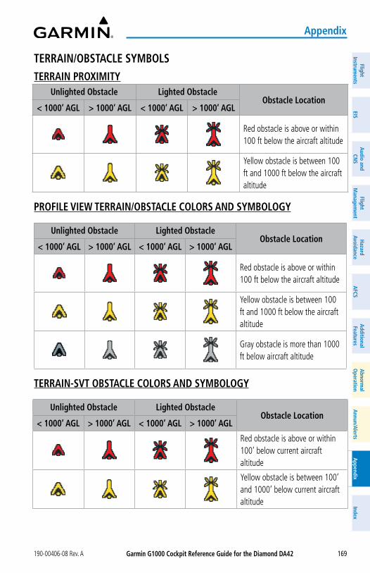
Garmin G1000 Cockpit Reference Guide for the Diamond Da42190-00406-08 Rev. A
appendix
169
FlightInstrum
entsEIS
Nav/Com
/XPD
R/Audio
Flight M
anagement
Hazard
AvoidanceA
FCSA
dditionalFeatures
Annun/A
lertsA
ppendixIndex
FlightInstrum
entsEIS
audio and
CNS
Flight M
anagement
Hazard
avoidancea
FCSa
dditionalFeatures
abnorm
alo
perationa
nnun/alerts
appendix
Index
TERRaIN/oBSTaCLE SyMBoLSTERRaIN PRoXIMITy
Unlighted obstacle Lighted obstacleobstacle Location
< 1000’ aGL > 1000’ aGL < 1000’ aGL > 1000’ aGL
Red obstacle is above or within 100 ft below the aircraft altitude
Yellow obstacle is between 100 ft and 1000 ft below the aircraft altitude
PRoFILE VIEW TERRaIN/oBSTaCLE CoLoRS aND SyMBoLoGy
Unlighted obstacle Lighted obstacleobstacle Location
< 1000’ aGL > 1000’ aGL < 1000’ aGL > 1000’ aGL
Red obstacle is above or within 100 ft below the aircraft altitude
Yellow obstacle is between 100 ft and 1000 ft below the aircraft altitude
Gray obstacle is more than 1000 ft below aircraft altitude
TERRaIN-SVT oBSTaCLE CoLoRS aND SyMBoLoGy
Unlighted obstacle Lighted obstacleobstacle Location
< 1000’ aGL > 1000’ aGL < 1000’ aGL > 1000’ aGL
Red obstacle is above or within 100’ below current aircraft altitude
Yellow obstacle is between 100’ and 1000’ below current aircraft altitude
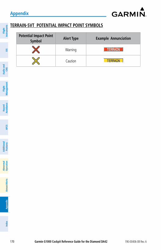
Garmin G1000 Cockpit Reference Guide for the Diamond Da42 190-00406-08 Rev. A
appendix
170
Flig
htIn
stru
men
tsEI
SN
av/C
om/
XPD
R/A
udio
Flig
ht
Man
agem
ent
Haz
ard
Avoi
danc
eA
FCS
Add
ition
alFe
atur
esA
nnun
/Ale
rts
App
endi
xIn
dex
Flig
htIn
stru
men
tsEI
Sa
udio
and
CNS
Flig
ht
Man
agem
ent
Haz
ard
avoi
danc
ea
FCS
add
ition
alFe
atur
esa
bnor
mal
ope
ratio
na
nnun
/ale
rts
app
endi
xIn
dex
TERRaIN-SVT PoTENTIaL IMPaCT PoINT SyMBoLS
Potential Impact Point Symbol
alert Type Example annunciation
Warning
Caution
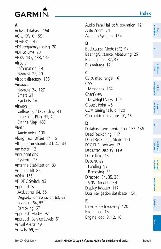
Garmin G1000 Cockpit Reference Guide for the Diamond Da42190-00406-08 Rev. A
Index
Index-1
FlightInstrum
entsEIS
Nav/Com
/XPD
R/Audio
Flight M
anagement
Hazard
AvoidanceA
FCSA
dditionalFeatures
Annun/A
lertsA
ppendixIndex
FlightInstrum
entsEIS
audio and
CNS
Flight M
anagement
Hazard
avoidancea
FCSa
dditionalFeatures
abnorm
alo
perationa
nnun/alerts
appendix
Index
aActive database 154AC-U-KWIK 155ADAHRS 145ADF frequency tuning 20ADF volume 20AHRS 137, 138, 142Airport
Information 29Nearest 28, 29
Airport directory 155Airspace
Nearest 34, 127Smart 34Symbols 165
AirwaysCollapsing / Expanding 41In a Flight Plan 39, 40On the Map 166
AlertsAudio voice 136
Along Track Offset 44, 45Altitude Constraints 41, 42, 43Ammeter 12Annunciations
System 125Antenna Stabilization 83Antenna Tilt 82AOPA 155AP DISC Switch 93Approaches
Activating 64, 66Degradation Behavior 62, 63Loading 64, 65Removing 67
Approach Modes 97Approach Service Levels 61Arrival Alerts 49Arrivals 59, 60
Audio Panel fail-safe operation 121Auto Zoom 24Aviation Symbols 164
BBackcourse Mode (BC) 97Bearing/Distance, Measuring 25Bearing Line 82, 83Bus voltage 12
CCalculated range 16CAS
Messages 134ChartView
Day/Night View 104Closest Point 45COM tuning failure 120Coolant temperature 10, 13
DDatabase synchronization 153, 156Dead Reckoning 117Dead Reckoning Mode 121DEC FUEL softkey 17Declutter, Display 119Deice fluid 13Departures
Loading 57Removing 58
Direct-to 34, 35, 36VNV Direct-to 44
Display Backup 117Dual navigation database 154
EEmergency frequency 120Endurance 16Engine load 9, 12, 16
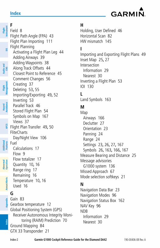
Garmin G1000 Cockpit Reference Guide for the Diamond Da42 190-00406-08 Rev. A
Index
Index-2
Flig
htIn
stru
men
tsEI
SN
av/C
om/
XPD
R/A
udio
Flig
ht
Man
agem
ent
Haz
ard
Avoi
danc
eA
FCS
Add
ition
alFe
atur
esA
nnun
/Ale
rts
App
endi
xIn
dex
Flig
htIn
stru
men
tsEI
Sa
udio
and
CNS
Flig
ht
Man
agem
ent
Haz
ard
avoi
danc
ea
FCS
add
ition
alFe
atur
esa
bnor
mal
ope
ratio
na
nnun
/ale
rts
app
endi
xIn
dex
FField 8Flight Path Angle (FPA) 43Flight Plan Importing 111Flight Planning
Activating a Flight Plan Leg 44Adding Airways 39Adding Waypoints 38Along Track Offsets 44Closest Point to Reference 45Comment Changes 56Creating 37Deleting 53, 55Importing/Exporting 49, 52Inverting 53Parallel Track 46Stored Flight Plan 54Symbols on Map 167Views 37
Flight Plan Transfer 49, 50FliteCharts
Day/Night View 106Fuel
Calculations 17Flow 9Flow totalizer 17Quantity 10, 16Range ring 17Remaining 16Temperature 10, 16Used 16
GGain 83Gearbox temperature 12Global Positioning System (GPS)
Receiver Autonomous Integrity Moni-toring (RAIM) Prediction 70
Ground Mapping 84GTX 33 Transponder 21
HHolding, User Defined 46Horizontal Scan 82HW mismatch 145
IImporting and Exporting Flight Plans 49Inset Map 25, 27Intersection
Information 29Nearest 30
Inverting a Flight Plan 53IOI 130
LLand Symbols 163
MMap
Airways 166Declutter 27Orientation 23Panning 24Range 24Settings 23, 26, 27, 167Symbols 26, 163, 166, 167
Measure Bearing and Distance 25Message advisories
G1000 system 136Missed Approach 67Mode selection softkeys 21
NNavigation Data Bar 23Navigation Modes 96Navigation Status Box 162NAV Key 96NDB
Information 29Nearest 30
Garmin G1000 Cockpit Reference Guide for the Diamond Da42190-00406-08 Rev. A
Index
Index-3
FlightInstrum
entsEIS
Nav/Com
/XPD
R/Audio
Flight M
anagement
Hazard
AvoidanceA
FCSA
dditionalFeatures
Annun/A
lertsA
ppendixIndex
FlightInstrum
entsEIS
audio and
CNS
Flight M
anagement
Hazard
avoidancea
FCSa
dditionalFeatures
abnorm
alo
perationa
nnun/alerts
appendix
Index
NearestAirport 28, 29Airspace 34, 127Intersection 30NDB 30User Waypoint 30VOR 30
Nearest airports, frequency tuning 19
oObstacles 141Oil
Pressure 9, 13Temperature 9, 13
PParallel Track 46Pending Flight Plan 49, 50, 51Pilot Profiles 112
RRange, aircraft 16Range ring 17Receiver Autonomous Integrity
Monitoring (RAIM) 70–71Reserve fuel 17Reversionary mode 121Reversionary Mode 117ROC 130
SSBAS 145
Loss While on an Approach 62Scheduler 115Sector Scan 83Selected Heading 2Smart Airspace 34Softkeys
LTNG 76MFD 161
Software License Agreement 15
STAB 83Standby navigation database 154, 155,
157, 158Stuck microphone 120Synthetic Vision Technology (SVT) 151
Troubleshooting 118
TTachometer 9, 12, 16Temperature Compensated Approach
Altitudes 68Temperature Compensated Minimums
68Terminal Procedures Charts
ChartView 102FliteCharts 104
Terrain 141Tilt 82Tilt Line 82Total flight hours 17Trip Planning 69True Airspeed (TAS) 137, 138
UUser-Defined Holding Pattern 46, 47,
48User Waypoints
Creating 30Information 29
VVectors-to-final 66Vertical Navigation Direct-to 44Vertical Navigation (VNV) in Flight Plan
43Vertical Speed Target (VS TGT) 43Voice alerts, TIS traffic 136Voltmeter 12Volume level
ADF 20
Garmin G1000 Cockpit Reference Guide for the Diamond Da42 190-00406-08 Rev. A
Index
Index-4
Flig
htIn
stru
men
tsEI
SN
av/C
om/
XPD
R/A
udio
Flig
ht
Man
agem
ent
Haz
ard
Avoi
danc
eA
FCS
Add
ition
alFe
atur
esA
nnun
/Ale
rts
App
endi
xIn
dex
Flig
htIn
stru
men
tsEI
Sa
udio
and
CNS
Flig
ht
Man
agem
ent
Haz
ard
avoi
danc
ea
FCS
add
ition
alFe
atur
esa
bnor
mal
ope
ratio
na
nnun
/ale
rts
app
endi
xIn
dex
VORInformation 29Nearest 30
WWAAS 18Waypoints
Airports 28Information 29Nearest Airports 28Nearest (Non-Airport) 30User Waypoints 30
Waypoint Selection Submenu 37Winds Aloft 78


Garmin International, Inc. 1200 East 151st Street Olathe, KS 66062, U.S.A.
Garmin aT, Inc.2345 Turner Road SESalem, OR 97302, U.S.A.
Garmin (Europe) Ltd.Liberty House, Hounsdown Business ParkSouthampton, Hampshire SO40 9LR U.K.
Garmin CorporationNo. 68, Zhangshu 2nd RoadXizhi District, New Taipei City, Taiwan
Contact Garmin Product Support or view warranty information at flygarmin.com®.
190-00406-08 Rev. A© 2004-2009, 2014, 2022 Garmin® Ltd. or its subsidiaries