DESIGN GUIDE
1389
DESIGN GUIDE MARRIOTT INTERNATIONAL Design & Construction Services PROJECT MANUAL MASTER NEW BUILD Revised: April 28, 2017
-
Upload
khangminh22 -
Category
Documents
-
view
0 -
download
0
Transcript of DESIGN GUIDE
DESIGN GUIDE
MARRIOTT INTERNATIONAL Design & Construction Services
PROJECT MANUAL MASTER
NEW BUILD
Revised: April 28, 2017

Marriott TownePlace Suites
Owensboro, Kentucky
Table of Contents
Division 1 General Requirements 1-93
Division 3 Concrete 1-41
Division 4 Masonry 1-21
Division 5 Metals 1-39
Division 6 Woods and Plastics 1-48
Division 7 Thermal and Moisture Protection 1-98
Division 8 Openings 1-103
Division 9 Finishes 1-111
Division 10 Specialties 1-45
Division 11 Equipment 1-28
Division 12 Furnishings 1-73
Division 13 Special Construction 1-20
Division 14 Conveying Equipment 1-18
Division 21 Fire Suppression 1-17
Division 22 Plumbing 1-131
Division 23 HVAC 1-166
Division 26 Electrical 1-105
Division 27 Communications 1-33
Division 28 Electronic Safety and Security 1-20
Division 31 Earthwork 1-25
Division 32 Exterior Improvements 1-30
Division 33 Utilities 1-14
▪ SECTION 01 11 00 (01110) - SUMMARY OF WORK ▪ ▪ PAGE 1 ▪
FILE: Division 01 General Conditions REVISED: 01/01/13
2013, Marriott International, Inc. CFRST SPECMSTR-NEW BUILD
SECTION 01 11 00 (01110) - SUMMARY OF WORK
PART 1 GENERAL 1.01 SUMMARY
A. Section Includes:
1. Project Description
2. Definitions
3. Quality Assurance
4. Contractor Use of Premises
5. Bidding Classification
6. Contracts
7. Owner Furnished Products
8. Owner Provided Work
9. Sample Room
10. Allowances
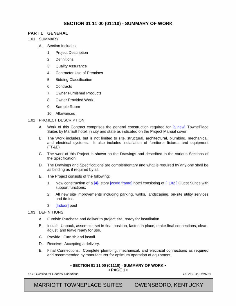
1.02 PROJECT DESCRIPTION
A. Work of this Contract comprises the general construction required for [a new] TownePlace Suites by Marriott hotel, in city and state as indicated on the Project Manual cover.
B. The Work includes, but is not limited to site, structural, architectural, plumbing, mechanical, and electrical systems. It also includes installation of furniture, fixtures and equipment (FF&E).
C. The work of this Project is shown on the Drawings and described in the various Sections of the Specification.
D. The Drawings and Specifications are complementary and what is required by any one shall be as binding as if required by all.
E. The Project consists of the following:
1. New construction of a [4]- story [wood frame] hotel consisting of [ 102 ] Guest Suites with support functions.
2. All new site improvements including parking, walks, landscaping, on-site utility services and tie-ins.
3. [Indoor] pool
1.03 DEFINITIONS
A. Furnish: Purchase and deliver to project site, ready for installation.
B. Install: Unpack, assemble, set in final position, fasten in place, make final connections, clean, adjust, and leave ready for use.
C. Provide: Furnish and install.
D. Receive: Accepting a delivery.
E. Final Connections: Complete plumbing, mechanical, and electrical connections as required and recommended by manufacturer for optimum operation of equipment.
2013, Marriott International, Inc. CFRST SPECMSTR-NEW BUILD MARRIOTT TOWNEPLACE SUITES OWENSBORO, KENTUCKY
▪ SECTION 01 11 00 (01110) - SUMMARY OF WORK ▪ ▪ PAGE 2 ▪
REVISED: 01/01/13 FILE: Division 01 General Conditions
CFRST SPECMSTR-NEW BUILD 2013, Marriott International, Inc.
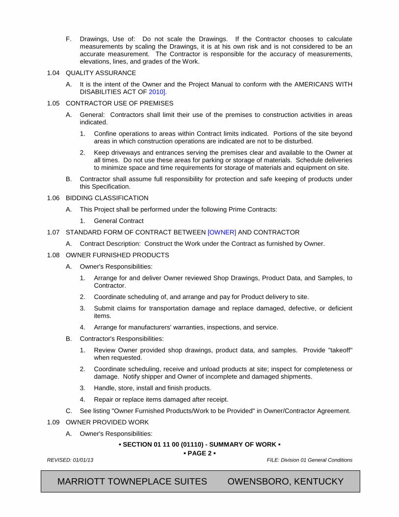
F. Drawings, Use of: Do not scale the Drawings. If the Contractor chooses to calculate measurements by scaling the Drawings, it is at his own risk and is not considered to be an accurate measurement. The Contractor is responsible for the accuracy of measurements, elevations, lines, and grades of the Work.
1.04 QUALITY ASSURANCE
A. It is the intent of the Owner and the Project Manual to conform with the AMERICANS WITH DISABILITIES ACT OF 2010].
1.05 CONTRACTOR USE OF PREMISES
A. General: Contractors shall limit their use of the premises to construction activities in areas indicated.
1. Confine operations to areas within Contract limits indicated. Portions of the site beyond areas in which construction operations are indicated are not to be disturbed.
2. Keep driveways and entrances serving the premises clear and available to the Owner at all times. Do not use these areas for parking or storage of materials. Schedule deliveries to minimize space and time requirements for storage of materials and equipment on site.
B. Contractor shall assume full responsibility for protection and safe keeping of products under this Specification.
1.06 BIDDING CLASSIFICATION
A. This Project shall be performed under the following Prime Contracts:
1. General Contract
1.07 STANDARD FORM OF CONTRACT BETWEEN [OWNER] AND CONTRACTOR
A. Contract Description: Construct the Work under the Contract as furnished by Owner.
1.08 OWNER FURNISHED PRODUCTS
A. Owner's Responsibilities:
1. Arrange for and deliver Owner reviewed Shop Drawings, Product Data, and Samples, to Contractor.
2. Coordinate scheduling of, and arrange and pay for Product delivery to site.
3. Submit claims for transportation damage and replace damaged, defective, or deficient items.
4. Arrange for manufacturers' warranties, inspections, and service.
B. Contractor's Responsibilities:
1. Review Owner provided shop drawings, product data, and samples. Provide "takeoff" when requested.
2. Coordinate scheduling, receive and unload products at site; inspect for completeness or damage. Notify shipper and Owner of incomplete and damaged shipments.
3. Handle, store, install and finish products.
4. Repair or replace items damaged after receipt.
C. See listing "Owner Furnished Products/Work to be Provided" in Owner/Contractor Agreement.
1.09 OWNER PROVIDED WORK
A. Owner's Responsibilities:
MARRIOTT TOWNEPLACE SUITES OWENSBORO, KENTUCKY

▪ SECTION 01 11 00 (01110) - SUMMARY OF WORK ▪ ▪ PAGE 3 ▪
FILE: Division 01 General Conditions REVISED: 01/01/13
2013, Marriott International, Inc. CFRST SPECMSTR-NEW BUILD
1. Arrange for shop drawings, product data and samples, if requested by Contractor.
2. Coordinate scheduling of the Work.
B. Contractor's Responsibilities:
1. Review Owner reviewed shop drawings, product data, and samples if necessary.
2. Coordinate schedule and provide supervision of the Work as Owner's on-site representative.
3. Provide access, use of utilities, vertical transportation, and trash dumpster.
C. See listing "Owner Furnished Products/Work to be Provided" in Owner-Contractor Agreement.
1.10 ALLOWANCES
A. Allowances include direct costs only. All costs for overhead, [home office and site], and profit are included in the Base Bid.
B. See listing "Owner Furnished Products/Work to be Provided" in Owner/Contractor Agreement.
PART 2 PRODUCTS Not Used
PART 3 EXECUTION Not Used
END OF SECTION
Revision Log
MARRIOTT TOWNEPLACE SUITES OWENSBORO, KENTUCKY

▪ SECTION 01 11 00 (01110) - SUMMARY OF WORK ▪ ▪ PAGE 4 ▪
REVISED: 01/01/13 FILE: Division 01 General Conditions
CFRST SPECMSTR-NEW BUILD 2013, Marriott International, Inc.
SECTION 01 26 00 (01250) - CONTRACT MODIFICATION PROCEDURES
PART 4 GENERAL 4.01 SUMMARY
A. Section Includes:
1. Contract Modification Procedures:
a. Submittals
b. Documentation of Change in Contract Sum and Contract Time
2. Contract Modification Pricing Guidelines
3. Requests for Information and Supplemental Instructions
4. Change of Contract Procedures
5. Allowances
6. Construction Change Directive
7. Change of Contract:
a. Stipulated price change order
b. Unit price change order
c. Time and material change order
d. Execution of Change of Contract written orders
8. Correlation of Contractor Submittals
B. Related Sections:
1. Agreement: Monetary values of established unit prices and percentage allowances for Contractor's overhead and profit.
2. Section 01 33 00 (01330) - Submittals and Substitutions: Construction Progress Schedules and miscellaneous submittals.
3. Section 01 60 00 (01600) - Material and Equipment: Product options and substitutions.
4. Section 01 77 00 (01770) - Contract Closeout: Project Record Documents.
4.02 SUBMITTALS
A. Submit name of the individual authorized to receive change documents, and be responsible for informing others in Contractor's employ and Subcontractors of changes to the Work.
B. Change of Contract Forms: Furnished by Owner
4.03 DOCUMENTATION OF CHANGE IN CONTRACT SUM AND CONTRACT TIME
A. Maintain detailed records of work performed on a time and material basis. Provide full information required for evaluation of proposed changes, and to substantiate costs of changes in the Work.
B. Document each quotation for a change in cost or time with sufficient data to allow evaluation of the quotation.
C. On request, provide additional data to support computations:
1. Quantities of products, labor, and equipment.
MARRIOTT TOWNEPLACE SUITES OWENSBORO, KENTUCKY
▪ SECTION 01 11 00 (01110) - SUMMARY OF WORK ▪ ▪ PAGE 5 ▪
FILE: Division 01 General Conditions REVISED: 01/01/13
2013, Marriott International, Inc. CFRST SPECMSTR-NEW BUILD
2. Taxes, insurance, and bonds.
3. Overhead and profit.
4. Justification for change in Contract Time.
5. Credit for deletions from Contract, similarly documented.
D. Support each claim for additional costs, and for work done, with additional information:
1. Origin and date of claim.
2. Dates and times work was performed, and by whom.
3. Time records and wage rates paid.
4. Invoices and receipts for products, equipment, and subcontracts, similarly documented.
4.04 REQUESTS FOR INFORMATION AND SUPPLEMENTAL INSTRUCTIONS
A. Definition: Requests for Information (RFI), is a formal process used during bidding and during construction to facilitate communication between the Contractor and the [Architect] with regard to requests for information and clarification of the intent of the Contract Documents.
1. Request for Information form may be used during bidding phase. Refer to Invitation to Bid and Instructions to Bidders.
B. Procedure:
1. Conditions Requiring Clarification of the Contract Documents: Submit a Request for Information to the [Architect].
a. Submit Requests for Information from Contractor's office or field office only. Requests for Information submitted directly from subcontractors or suppliers will not be accepted.
b. Generate Requests for Information by one source per project and number accordingly.
c. Submit one request for information per form.
2. The [Architect] will review formal requests from the Contractor with reasonable promptness and the Contractor will be notified in writing of decisions made, via the RFI form.
a. The [Architect’s] response shall not be considered as a Change Order or Change Directive, nor does it authorize changes in the Contract Sum or Contract Time.
3. Maintain log of Requests for Information sent to, and responses from the [Architect]
4. Scheduling, Costing, and Owner Furnished Products/Work Coordination: Direct to the [Owner's Representative].
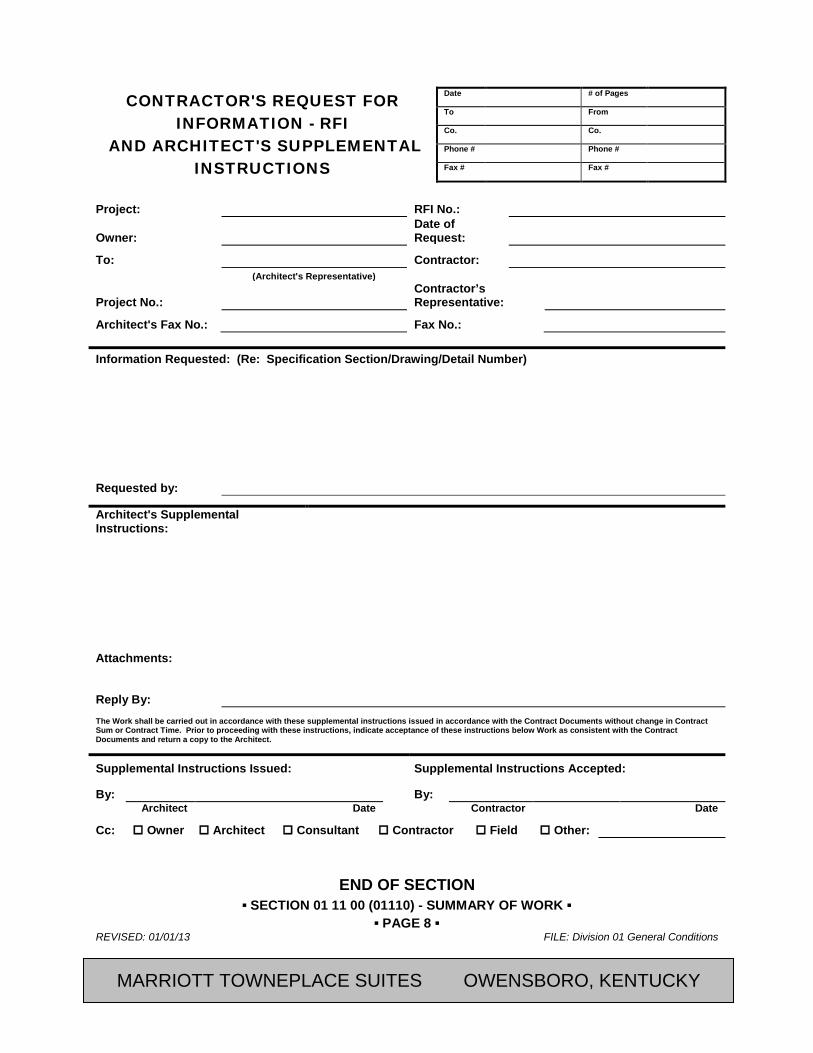
C. RFI Form: Submit requests for information on attached Request for Information form, attached at end of this Section. The [Owner’s Representative] will not respond to requests for information unless this format is utilized.
1. Where submittal form does not provide space needed for complete information, additional sheets may be attached.
4.05 CHANGE PROCEDURES
A. The [Architect] will advise of minor changes in the Work not involving an adjustment to Contract Sum or Contract Time as authorized by the Owner/Architect Agreement, and by issuing supplemental instructions on RFI form attached.
MARRIOTT TOWNEPLACE SUITES OWENSBORO, KENTUCKY

▪ SECTION 01 11 00 (01110) - SUMMARY OF WORK ▪ ▪ PAGE 6 ▪
REVISED: 01/01/13 FILE: Division 01 General Conditions
CFRST SPECMSTR-NEW BUILD 2013, Marriott International, Inc.
B. The [Architect] may issue a Proposal Request, Notice of Change which includes a detailed description of a proposed change with supplementary or revised Drawings and specifications. Contractor will prepare and submit an estimate within 10 days.
C. The Contractor may propose a change by submitting a request for change to the Owner’s Representative, describing the proposed change and its full effect on the Work, with a statement describing the reason for the change, and the effect on the Contract Sum and Contract Time with full documentation and a statement describing the effect on Work by separate or other contractors. Document requested substitutions in accordance with Section 01 33 00.
4.06 ALLOWANCES
A. Allowance Adjustment: For allowance-cost adjustment, base each Change of Contract Proposal on the difference between the actual purchase amount and the allowance, multiplied by the final measurement of work-in-place. Where applicable, include reasonable allowances for cutting losses, tolerances, mixing wastes, normal product imperfections, and similar margins.
1. Include installation costs in the purchase amount only where indicated as part of the allowance.
2. When requested, prepare explanations and documentation to substantiate the margins claimed.
3. The Owner reserves the right to establish the actual quantity of work-in-place by independent quantity survey, measure, or count.
B. Submit claims for increased costs because of a change in scope or nature of the allowance described in the Contract Documents, whether for the purchase order amount or the Contractor's handling, labor, installation, overhead, and profit. Submit claims within 21 days of receipt of the Change of Contract authorizing work to proceed. The Owner will reject claims submitted later than 21 days.
1. Do not include the Contractor's or Subcontractor's indirect expense in the Change of Contract cost amount unless it is clearly shown that the nature or extent of work has changed from what could have been foreseen from information in Contract Documents.
2. No change to the Contractor's indirect expense is permitted for selection of higher or lower-priced materials or systems of the same scope and nature as originally indicated.
4.07 CORRELATION OF CONTRACTOR SUBMITTALS
A. Promptly revise Schedule of Values and Application for Payment forms to record each authorized Change of Contract as a separate line item and adjust the Contract Sum.
B. Promptly revise progress schedules to reflect any change in Contract Time, revise sub-schedules to adjust times for other items of work affected by the change, and resubmit.
C. Promptly enter changes in Project Record Documents.
PART 5 PRODUCTS Not Used
PART 6 EXECUTION Not Used
MARRIOTT TOWNEPLACE SUITES OWENSBORO, KENTUCKY

▪ SECTION 01 11 00 (01110) - SUMMARY OF WORK ▪ ▪ PAGE 7 ▪
FILE: Division 01 General Conditions REVISED: 01/01/13
2013, Marriott International, Inc. CFRST SPECMSTR-NEW BUILD
MARRIOTT TOWNEPLACE SUITES OWENSBORO, KENTUCKY
▪ SECTION 01 11 00 (01110) - SUMMARY OF WORK ▪ ▪ PAGE 8 ▪
REVISED: 01/01/13 FILE: Division 01 General Conditions
CFRST SPECMSTR-NEW BUILD 2013, Marriott International, Inc.
CONTRACTOR'S REQUEST FOR
INFORMATION - RFI AND ARCHITECT'S SUPPLEMENTAL
INSTRUCTIONS
Date # of Pages To From Co. Co. Phone # Phone # Fax # Fax #
Project: RFI No.:
Owner: Date of Request:
To: Contractor: (Architect's Representative)
Project No.: Contractor’s Representative:
Architect's Fax No.: Fax No.: Information Requested: (Re: Specification Section/Drawing/Detail Number)
Requested by:
Architect's Supplemental Instructions:
Attachments:
Reply By: The Work shall be carried out in accordance with these supplemental instructions issued in accordance with the Contract Documents without change in Contract Sum or Contract Time. Prior to proceeding with these instructions, indicate acceptance of these instructions below Work as consistent with the Contract Documents and return a copy to the Architect.
Supplemental Instructions Issued: Supplemental Instructions Accepted:
By: By: Architect Date Contractor Date
Cc: Owner Architect Consultant Contractor Field Other:
END OF SECTION
MARRIOTT TOWNEPLACE SUITES OWENSBORO, KENTUCKY
▪ SECTION 01 11 00 (01110) - SUMMARY OF WORK ▪ ▪ PAGE 9 ▪
FILE: Division 01 General Conditions REVISED: 01/01/13
2013, Marriott International, Inc. CFRST SPECMSTR-NEW BUILD
SECTION 01 31 00 (01310) - PROJECT MANAGEMENT AND COORDINATION
PART 7 GENERAL 7.01 SUMMARY
A. Section Includes:
1. Coordination
2. Administrative Procedures
3. Meetings:
a. Pre-construction Meetings
b. Progress Meetings
c. Preinstallation Meetings
4. Coordination Drawings
5. General Installation Provisions
6. Cleaning and Protection
B. Related Sections:
1. Section 01 71 23 (01720) - Field Engineering
2. Section 01 73 29 (01730) - Cutting and Patching
7.02 COORDINATION:
A. Coordinate construction activities included in various Sections of these Specifications to assure efficient and orderly installation of each component. Coordinate construction operations included under different Sections that depend on each other for proper installation, connection, and operation.
B. Where installation of one component depends on installation of other components before or after its own installation, schedule activities in the sequence required to obtain the best results.
C. Coordinate installation of different components to assure maximum accessibility for maintenance, service and repair.
D. Verify utility requirements and characteristics of operating equipment are compatible with building utilities. Coordinate work of various sections having interdependent responsibilities for installing, connecting to, and placing in service, such equipment.
E. Coordinate space requirements and installation of mechanical and electrical work which are indicated diagrammatically on Drawings. Follow routing shown for pipes, ducts, and conduit, as closely as practicable; place runs parallel with line of building. Utilize spaces efficiently to maximize accessibility for other installations, for maintenance, and for repairs.
F. In finished areas except as otherwise indicated, conceal pipes, ducts, and wiring within the construction. Coordinate locations of fixtures and outlets with finish elements.
G. Coordinate completion and clean up of Work of separate sections in preparation for Substantial Completion and for portions of Work designated for Owner's partial occupancy.
H. After Owner occupancy of premises, coordinate access to site for correction of defective Work and Work not in accordance with Contract Documents, to minimize disruption of Owner's activities.
MARRIOTT TOWNEPLACE SUITES OWENSBORO, KENTUCKY
▪ SECTION 01 11 00 (01110) - SUMMARY OF WORK ▪ ▪ PAGE 10 ▪
REVISED: 01/01/13 FILE: Division 01 General Conditions
CFRST SPECMSTR-NEW BUILD 2013, Marriott International, Inc.
I. Make provisions to accommodate items scheduled for later installation.
7.03 ADMINISTRATIVE PROCEDURES
A. Prepare memoranda for distribution to each party involved outlining required coordination procedures. Include required notices, reports, and attendance at meetings.
1. Prepare similar memoranda for the Owner and separate Contractors where coordination of their Work is required.
B. Coordinate scheduling and timing of administrative procedures with other activities to avoid conflicts and ensure orderly progress. Such activities include:
1. Preparation of Schedules
2. Installation and Removal of Temporary Facilities
3. Delivery and Processing of Submittals
4. Progress Meetings
5. Project Closeout Activities
C. Staff Names: Within 15 days of Notice to Proceed, submit a list of Contractor's staff assignments, including Superintendent and personnel at the site; identify individuals, their duties and responsibilities, addresses and telephone numbers.
7.04 PRE-CONSTRUCTION MEETING
A. Agenda:
1. Execution of Owner-Contractor Agreement.
2. Submission of executed bonds and insurance certificates.
3. Distribution of Contract Documents.
4. Submission of lists of Subcontractors, Products, Schedule of Values, and Progress Schedule.
5. Designation of personnel representing the parties in Contract.
6. Procedures and processing of field decisions, submittals, substitutions, applications for payments, proposal request, Change Orders, and Contract closeout procedures.
7. Scheduling.
B. Record minutes and distribute copies within one day after meeting faxed to participants, with one copy to Architect, Owner, participants, and those affected by decisions made.
7.05 PROGRESS MEETINGS
A. Agenda:
1. Review minutes of previous meetings.
2. Review of Work progress.
3. Field observations, problems, and decisions.
4. Identification of problems which impede planned progress.
5. Review of submittals schedule and status of submittals.
6. Review of off-site fabrication and delivery schedules.
7. Maintenance of progress schedule.
MARRIOTT TOWNEPLACE SUITES OWENSBORO, KENTUCKY
▪ SECTION 01 11 00 (01110) - SUMMARY OF WORK ▪ ▪ PAGE 11 ▪
FILE: Division 01 General Conditions REVISED: 01/01/13
2013, Marriott International, Inc. CFRST SPECMSTR-NEW BUILD
8. Corrective measures to regain projected schedules.
9. Planned progress during succeeding work period.
10. Coordination of projected progress.
11. Maintenance of quality and work standards.
12. Effect of proposed changes on progress schedule and coordination.
13. Other business relating to Work.
7.06 PRE-INSTALLATION MEETINGS
A. When required in individual specification sections, convene a pre-installation meeting at work site prior to commencing work of the section.
B. Require attendance of parties directly affecting, or affected by, work of the specific section.
C. Notify Architect four days in advance of meeting date.
D. Prepare agenda and preside at meeting:
1. Review conditions of installation, preparation and installation procedures.
2. Review coordination with related work.
E. Record minutes and distribute copies within one day after meeting faxed to participants, with one copy to Architect, Owner, participants, and those affected by decisions made.
7.07 COORDINATION DRAWINGS:
A. Prepare Coordination Drawings where close coordination is required for installation of products and materials fabricated off-site by separate entities, and where limited space necessitates maximum utilization of space for efficient installation of different components.
1. Show relationship of components shown on separate Shop Drawings.
2. Indicate required installation sequences.
3. Refer to Division 22 Section "Common Work Results for Plumbing", Division 23 Section "Common Work Results for HVAC", and Division 26 Section "Common Work Results for Electrical", for requirements for plumbing, mechanical and electrical installations.
PART 8 PRODUCTS Not Used
PART 9 EXECUTION 9.01 INSPECTION OF CONDITIONS:
A. The installer of each component shall inspect the substrate and conditions under which work is performed. Do not proceed until unsatisfactory conditions have been corrected.
B. Verification of Conditions:
1. Verify that existing conditions, surfaces, and substrates are acceptable for subsequent Work.
2. Verify that field measurements, are as required to receive subsequent Work.
3. Verify that existing substrate is capable of structural attachment of new Work being applied or attached.
4. Examine and verify specific conditions described in individual specification sections.
MARRIOTT TOWNEPLACE SUITES OWENSBORO, KENTUCKY

▪ SECTION 01 11 00 (01110) - SUMMARY OF WORK ▪ ▪ PAGE 12 ▪
REVISED: 01/01/13 FILE: Division 01 General Conditions
CFRST SPECMSTR-NEW BUILD 2013, Marriott International, Inc.
5. Verify that utility services are available, of the correct characteristics, and in the correct location.
C. Report in writing to the [Architect] prevailing conditions that will adversely affect satisfactory execution of the Work of this Section. Do not proceed with Work until unsatisfactory conditions have been corrected.
D. By beginning Work, Contractor accepts conditions and assumes responsibility for correcting unsuitable conditions encountered at no additional cost to Owner.
9.02 PREPARATION
A. Clean substrate surfaces prior to applying next material or substance.
B. Seal cracks or openings of substrate prior to applying next material or substance.
C. Apply any manufacturer required or recommended substrate primer, sealer, or conditioner prior to applying any new material or substance in contact or bond.
9.03 GENERAL
A. Recheck measurements and dimensions before starting each installation.
B. Install each component during weather conditions and project status that will ensure the best possible results. Isolate each part of the completed construction from incompatible material as necessary to prevent deterioration.
9.04 MANUFACTURER'S INSTRUCTIONS:
A. Comply with the manufacturer's installation instructions and recommendations, to the extent that those instructions and recommendations are more explicit or stringent than requirements contained in Contract Documents.
B. Inspect materials or equipment immediately upon delivery and again prior to installation. Reject damaged and defective items.
C. Provide attachment and connection devices and methods necessary for securing work. Secure work true to line and level. Allow for expansion and building movement.
9.05 VISUAL EFFECTS:
A. Provide uniform joint widths in exposed work. Arrange joints in exposed work to obtain the best visual effect. Refer questionable choices to the Architect for final decision.
9.06 ENCLOSURE OF THE WORK:
A. Coordinate temporary enclosures with required inspections and tests, to minimize the necessity of uncovering completed construction for that purpose.
9.07 MOUNTING HEIGHTS:
A. Where mounting heights are not indicated, install individual components at standard mounting heights recognized within the industry for the particular application indicated. Refer questionable mounting height decisions to the Architect for final decision.
9.08 CLEANING AND PROTECTION:
A. During handling and installation, clean and protect construction in progress and adjoining materials in place. Apply protective covering where required to ensure protection from damage or deterioration at Substantial Completion.
B. Clean and maintain completed construction as often as necessary through the construction period. Adjust and lubricate operable components to ensure operability without damaging effects.
MARRIOTT TOWNEPLACE SUITES OWENSBORO, KENTUCKY
▪ SECTION 01 11 00 (01110) - SUMMARY OF WORK ▪ ▪ PAGE 13 ▪
FILE: Division 01 General Conditions REVISED: 01/01/13
2013, Marriott International, Inc. CFRST SPECMSTR-NEW BUILD
C. Limiting Exposures: Supervise operations to ensure that no part of construction, completed or in progress, is subject to harmful or deleterious exposure. Such exposures include, but are not necessarily limited to, the following:
1. Excessive Weathering
2. Excessively High or Low Temperatures or Humidity
3. Water or Ice
4. Chemicals or Solvents
5. Heavy Traffic, Soiling, Staining and Corrosion
6. Contact Between Incompatible Materials
7. Theft or Vandalism
8. Excessive Static or Dynamic Loading
9. Thermal Shock
10. Combustion
END OF SECTION Revision Log
MARRIOTT TOWNEPLACE SUITES OWENSBORO, KENTUCKY
▪ SECTION 01 11 00 (01110) - SUMMARY OF WORK ▪ ▪ PAGE 14 ▪
REVISED: 01/01/13 FILE: Division 01 General Conditions
CFRST SPECMSTR-NEW BUILD 2013, Marriott International, Inc.
SECTION 01 33 00 (01330) - SUBMITTAL AND SUBSTITUTION PROCEDURES
PART 10 GENERAL 10.01 SUMMARY
A. Section Includes:
1. Wherever possible throughout the Contract Documents, the minimum acceptable quality of workmanship and materials has been defined either by manufacturer's name and catalog number or reference to recognized industry standards.
2. To ensure that the specified products are furnished and installed in accordance with the design intent, procedures have been established for advance submittal of design data for its review and approval or rejection by the [Architect]
3. This Section specifies administrative and procedural requirements for submittals required for performance of the work, including:
a. Contractor's Progress Schedule
b. Shop Drawings, Product Data, and Samples
c. Letters of Conformance
d. Certificates
e. Manufacturer Installation Instructions
4. Substitution Procedures
5. Manuals
6. Miscellaneous Submittals
B. Related Documents:
1. Letter of Conformance Form
2. Contractor’s Substitution Request Form
C. Related Sections:
1. Contractual Requirements for Submittals: General Conditions
a. Two (2) copies of all Submittals, plus number of copies to be returned to Contractor, shall be submitted unless otherwise specified.
b. Provide additional copies as required for use in Project Record Documents.
2. Section 01 77 00 (01770) - Contract Closeout
3. Individual Submittals Required: Pertinent Sections of these Specifications.
10.02 SUBMITTALS
A. Coordination: Coordinate preparation and processing of Submittals with performance of construction activities. Transmit each Submittal sufficiently in advance of performance of related construction activities to avoid delay.
1. Coordinate each Submittal with fabrication, purchasing, testing, delivery, other Submittals and related activities that require sequential activity.
MARRIOTT TOWNEPLACE SUITES OWENSBORO, KENTUCKY
▪ SECTION 01 11 00 (01110) - SUMMARY OF WORK ▪ ▪ PAGE 15 ▪
FILE: Division 01 General Conditions REVISED: 01/01/13
2013, Marriott International, Inc. CFRST SPECMSTR-NEW BUILD
2. Coordinate transmittal of different types of Submittals for related elements of the work so processing will not be delayed by the need to review Submittals concurrently for coordination.
a. The [Architect] reserves the right to withhold action on a Submittal requiring coordination with other Submittals until related Submittals are received.
b. No extension of Contract Time will be authorized because of failure to transmit Submittals to the Owner’s Representative sufficiently in advance of the work to permit processing.
B. Deliver Submittals to the [Architect.
C. Submittal Preparation: Place a permanent label or title block on each Submittal for identification. Indicate the name of the entity that prepared each Submittal on the label or title block.
1. Provide a space approximately 10" x 10" on the label or beside the title block on Shop Drawings to record the Contractor's and [Architect review and approval markings and the action taken.
2. Include the following information on the label for processing and recording action taken:
a. Project Name
b. Name of the Owner
c. Date
d. Name and Address of Architect
e. Name and Address of Contractor
f. Name and Address of Subcontractor or Vendor
g. Location Where Item is to be Used
h. Name of Manufacturer
i. Drawing Number and Detail References, as Appropriate
j. Certification by the Contractor
D. Submittal Transmittal: Package each Submittal appropriately for transmittal and handling. Transmit each Submittal from Contractor to [Architect]. Submittals received from sources other than the Contractor will be returned without action.
1. Transmit each submittal to the Architect with “AIA Document G810 - Transmittal Letter” and "Letter of Conformance".
2. Sequentially number the transmittal form. Revise submittals with original number and a sequential alphabetic suffix.
3. Identify Project, Contractor, Subcontractor or supplier; pertinent drawing and detail number, and specification section number, as appropriate.
4. On the transmittal, record relevant information and requests for data. On the form, or separate sheet, record deviations from Contract Document requirements, including minor variations and limitations. Include Contractor's certification that information complies with Contract Document requirements.
5. After [Architect] review of Submittal, revise and resubmit as required, identifying changes made since previous Submittal.
MARRIOTT TOWNEPLACE SUITES OWENSBORO, KENTUCKY
▪ SECTION 01 11 00 (01110) - SUMMARY OF WORK ▪ ▪ PAGE 16 ▪
REVISED: 01/01/13 FILE: Division 01 General Conditions
CFRST SPECMSTR-NEW BUILD 2013, Marriott International, Inc.
6. When re-submittal is required for any reason, transmit under new letter of transmittal, indicating by reference to a previous Submittal that this is a re-submittal.
a. Identify on submittal all changes made since previous submission.
7. Distribute copies of reviewed Submittals to concerned persons. Instruct recipients to promptly report any inability to comply with provisions.
8. All Submittals shall bear the stamp of approval of the Contractor submitting same as evidence that they have been checked by him, or they will be rejected.
a. Must be signed or initialed certifying that review, verification of Products required, field dimensions, adjacent construction Work, and coordination of information, is in accordance with the requirements of the Work and Contract Documents.
9. Schedule submittals to expedite the Project, and deliver to [Architect]. Coordinate submission of related items. Instruct parties to promptly report any inability to comply with provisions.
10.03 PROGRESS SCHEDULES
A. Submit initial Construction Progress Schedule in duplicate within 14 days after date of Owner-Contractor Contract. Submit in the form required by the General Conditions of the Contract.
B. Revise and resubmit as required.
C. Submit revised schedules with each Application for Payment, identifying changes since previous version.
10.04 LETTERS OF CONFORMANCE
A. Letter of Conformance: Short-form informational submittals which are to be used instead of shop drawings, product data and samples. They are also to be used to supplement shop drawings, product data and samples. A sample "Letter of Conformance" is located at the end of this Section. Use copies of this form for each submittal unless a more specific Letter of Conformance is located at the end of a particular Specification Section.
B. Within 30 days after date of Owner-Contractor Agreement, submit all Letters of Conformance indicating Contractor's selections for products proposed for use, with name of manufacturer, trade name, and model number of each product. For products specified only by reference standards, give manufacturer, trade name, model or catalog designation, and reference standards.
C. Procedure:
1. Submit the number of copies which the Contractor requires, plus [two] copies which will be retained by the [Architect]
2. Submit completed Letter of Conformance for products selected as indicated within each Section.
3. Fill-in required information on form and sign in ink by person authorized to sign on behalf of the Contractor.
4. Clearly identify applicable products, characteristics, models, and options. Attach supplemental information including product data to each Letter of Conformance as necessary to communicate all information specific to the product.
5. No modifications to form permitted.
6. Letters of Conformance are not to be used for substitution requests.
MARRIOTT TOWNEPLACE SUITES OWENSBORO, KENTUCKY
▪ SECTION 01 11 00 (01110) - SUMMARY OF WORK ▪ ▪ PAGE 17 ▪
FILE: Division 01 General Conditions REVISED: 01/01/13
2013, Marriott International, Inc. CFRST SPECMSTR-NEW BUILD
D. By submitting a Letter of Conformance, Contractor declares that the product identified by manufacturer's name and model number:
1. Is one of the product(s) specified
2. Is suitable for the intended use as defined within the Contract Documents, and
3. Will be provided and placed in operational condition in accordance with the Contract Documents and manufacturer's published instructions.
10.05 SHOP DRAWINGS
A. Where Shop Drawings are required, submit newly prepared information drawn to accurate scale. Highlight, encircle, or otherwise indicate deviations from the Contract Documents. Do not reproduce Contract Documents or copy standard information as the basis of Shop Drawings. Standard information prepared without specific reference to the Project is not considered Shop Drawings.
B. Shop Drawings shall be drawn at a scale to clearly indicate all of the above conditions and allow for corrections or modifications which the Architect may wish to make. The Architect shall be the sole judge as to the acceptability of manufacturer's literature and catalog sheets as Shop Drawings.
C. Shop Drawings shall clearly indicate all dimensional data for all parts of the item; types and materials for all connections; finishes; the exact relation of the item to adjacent materials and equipment in the completed structure including clearance, any necessary isolation, and fastening methods and devices; and mechanical and electrical connections.
D. Shop Drawings include fabrication and installation Drawings, setting diagrams, schedules, patterns, templates, and similar Drawings. Include the following information:
1. Dimensions
2. Identification of Products and Materials Included
3. Compliance with Specified Standards
4. Notation of Coordination Requirements
5. Notation of Dimensions Established by Field Measurement
E. Sheet Size: Except for templates, patterns, and similar full-size Drawings, submit Shop Drawings on sheets at least 8-1/2" x 11", but no larger than 36" x 48".
F. Submit in the form of one reproducible transparency and one opaque reproduction, or three opaque reproductions plus required amount to be returned to Contractor. After review, reproduce and distribute to appropriate parties.
G. Do not permit Shop Drawing copies, without an appropriate final "Action" marking by the Architect, to be used in connection with the work.
H. The Contractors shall be responsible for distribution of additional prints to vendors, etc.
10.06 PRODUCT DATA
A. Where Product Data is required, collect Product Data into a single submittal for each element of construction or system. Product Data includes printed information such as manufacturer's installation instructions, catalog cuts, standard color charts, roughing-in diagrams and templates, standard wiring diagrams and performance curves. Where Product Data must be specially prepared because standard printed data is not suitable for use, submit as "Shop Drawings."
MARRIOTT TOWNEPLACE SUITES OWENSBORO, KENTUCKY

▪ SECTION 01 11 00 (01110) - SUMMARY OF WORK ▪ ▪ PAGE 18 ▪
REVISED: 01/01/13 FILE: Division 01 General Conditions
CFRST SPECMSTR-NEW BUILD 2013, Marriott International, Inc.
1. Mark each copy to show applicable choices and options. Where printed Product Data includes information on several products, some of which are not required, mark copies to indicate the applicable information. Include the following information:
a. Manufacturer's Printed Recommendations
b. Compliance with Recognized Trade Association Standards
c. Compliance with Recognized Testing Agency Standards
d. Application of Testing Agency Labels and Seals
e. Notation of Dimensions Verified by Field Measurement
f. Notation of Coordination Requirements
g. Type and Model Numbers
2. Do not submit Product Data until compliance with requirements of the Contract Documents has been confirmed.
B. Distribution: Furnish copies of final Submittal to installers, subcontractors, suppliers, manufacturers, fabricators, and others required for performance of construction activities. Show distribution on transmittal forms.
1. Do not proceed with installation until a copy of Product Data applicable is in the installer's possession.
2. Do not permit use of unmarked copies of Product Data in connection with construction.
10.07 SAMPLES
A. Where Samples are required, submit full-size, fully fabricated Samples cured and finished as specified and physically identical with the material or product proposed. Samples include partial sections of manufactured or fabricated components, cuts or containers of materials, full color-range sets, and swatches showing color, texture, and pattern.
1. Mount, display, or package Samples in the manner specified to facilitate review of qualities indicated. Include the following:
a. Generic Description of the Sample
b. Sample Source
c. Product Name or Name of Manufacturer
d. Compliance with Recognized Standards
e. Availability and Delivery Time
2. Colors:
a. General: Unless the precise color and pattern is specifically described in the Contract Documents, whenever a choice of color or pattern is available in a specified product, submit accurate color charts and pattern charts to the Architect for his review and selection.
3. Submit Samples for review of kind, color, pattern, and texture for a final check of these characteristics with other elements and for a comparison of these characteristics between the final Submittal and the actual component as delivered and installed.
a. Where variation in color, pattern, texture, or other characteristics are inherent in the material or product represented, submit multiple units (not less than 3) that show approximate limits of the variations.
MARRIOTT TOWNEPLACE SUITES OWENSBORO, KENTUCKY
▪ SECTION 01 11 00 (01110) - SUMMARY OF WORK ▪ ▪ PAGE 19 ▪
FILE: Division 01 General Conditions REVISED: 01/01/13
2013, Marriott International, Inc. CFRST SPECMSTR-NEW BUILD
b. Refer to other Specification Sections for requirements for Samples that illustrate workmanship, fabrication techniques, details of assembly, connections, operation, and similar construction characteristics.
c. Refer to other Sections for Samples to be returned to the Contractor for incorporation in the work. Such Samples must be undamaged at time of use. On the transmittal, indicate special requests regarding disposition of Sample Submittals.
4. Preliminary Submittals: Where Samples are for selection of color, pattern, texture, or similar characteristics from a range of standard choices, submit a full set of choices for the material or product.
a. Preliminary Submittals will be reviewed and returned with the Architect's mark indicating selection and other action.
5. Maintain sets of Samples, as returned, at the Project site for quality comparisons throughout the course of construction.
a. Unless noncompliance with Contract Document provisions is observed, the Submittal may serve as the final Submittal.
b. Sample sets may be used to obtain final acceptance of the construction associated with each set.
B. Distribution of Samples: Prepare and distribute additional sets to Subcontractors, manufacturers, fabricators, suppliers, installers, and others as required for performance of the work.
1. Field Samples specified in individual Sections are special types of Samples. Field Samples are full-size examples erected on site to illustrate finishes, coatings, or finish materials and to establish the standard by which the work will be judged.
a. Comply with submittal requirements to the fullest extent possible. Process transmittal forms to provide a record of activity.
10.08 CERTIFICATES
A. When specified in individual specification sections, submit certification by manufacturer to Architect, in quantities specified for Product Data.
B. Indicate material or Product conforms to or exceeds specified requirements. Submit supporting reference data, affidavits, and certifications as appropriate.
C. Certificates may be recent or previous test results on material or Product, but must be acceptable to Architect.
10.09 MANUFACTURER INSTALLATION INSTRUCTIONS
A. When specified in individual specification sections, submit printed instructions for delivery, storage, assembly, installation, start-up, adjusting, and finishing to Architect.
B. Indicate special procedures, perimeter conditions requiring special attention, and special environmental criteria required for application or installation.
PART 11 PRODUCTS 11.01 SUBSTITUTIONS
A. Source Limitations: To the greatest extent possible for each unit of work, provide products, materials, or equipment of a singular generic kind from a single source.
MARRIOTT TOWNEPLACE SUITES OWENSBORO, KENTUCKY
▪ SECTION 01 11 00 (01110) - SUMMARY OF WORK ▪ ▪ PAGE 20 ▪
REVISED: 01/01/13 FILE: Division 01 General Conditions
CFRST SPECMSTR-NEW BUILD 2013, Marriott International, Inc.
B. Compatibility of Options: Where more than one choice is available as options for Contractor's selection of a product or materials, select an option which is compatible with other products and materials already selected (which may have been from among options for those other products and materials). Total compatibility among options, if not assured by limitations within contract documents, must be provided by Contractor. Compatibility is a basic general requirement of product/material selections.
C. Owner's Approval Required:
1. In addition to the following, refer to the General Conditions, Article 4, for additional requirements.
2. The Contract is based on the materials, equipment, and methods described in the Contract Documents.
3. The Contract Drawings and Specifications establish the "minimum standard of quality" each product and/or system must meet to be considered acceptable. Products of other manufacturers will be considered if the product and/or system meets or exceeds the "minimum standard of quality" established by the Contract Documents.
4. The Owner will consider proposals for substitutions under the "or approved substitution" and the "or approved equal" provision of materials, equipment, and methods, only when such proposals are accompanied by full and complete technical data and all other information required by the Owner and Architect to evaluate the proposed substitutions.
a. It will be the responsibility of the submitting Contractor to prove equality.
b. Request must include “Contractor’s Substitution Request” Form, a copy of which is attached to this Section.
c. The Submittal shall include a line-by-line, item-by-item description of the specified and proposed product.
5. Requests for substitutions must be submitted to the [Architect] NO later than 60 days after date of Owner-Contractor Agreement.
6. DO NOT SUBSTITUTE MATERIALS, EQUIPMENT, OR METHODS UNLESS SUCH SUBSTITUTIONS HAVE BEEN SPECIFICALLY APPROVED FOR THIS WORK IN WRITING.
D. "Or Approved Equal" or "Or Approved Substitution"
1. Where the phrase "or approved equal" or "approved substitution" occurs in the Contract Documents, do not assume that material, equipment, or methods will be approved as equal by the Owner and Architect unless the item has been specifically approved for this work by the Owner.
a. Color choices will be one of the determining factors for approval.
2. The decision of the Owner will be final.
E. Availability of Specified Items:
1. Verify prior to bidding that all specified items will be available in time for installation during orderly and timely progress of the work.
2. In the event specified item or items will not be so available, so notify the [Architect] prior to the receipt of Bids.
3. Costs of delay caused on non-availability of specified items, when such delays could have been avoided by the Contractor, will be back-charged as necessary and shall not be borne by the Owner.
MARRIOTT TOWNEPLACE SUITES OWENSBORO, KENTUCKY

▪ SECTION 01 11 00 (01110) - SUMMARY OF WORK ▪ ▪ PAGE 21 ▪
FILE: Division 01 General Conditions REVISED: 01/01/13
2013, Marriott International, Inc. CFRST SPECMSTR-NEW BUILD
F. Whenever the Contractor secures approval for changing any items and such change involves a corresponding change or adjustment in any adjacent or related item, the responsibility for making the required change, or seeing that it is made, rests with the Contractor. The cost of these changes and/or adjustments shall be paid for by the Contractor unless it is otherwise agreed, in writing, at the time the change is approved. The acceptance of any change will not, in any way, relieve the Contractor from full compliance with the Contract Documents.
11.02 MANUALS
A. General: Where Manuals are required to be submitted covering items included in this work, prepare all such Manuals in durable plastic binders approximately 8-1/2 x 11 inches in size with at least the following:
1. Identification on or readable through the front cover stating the general nature of the Manual.
2. Neatly typewritten index near the front of the Manual furnishing immediate information as to location of all emergency data regarding the installation.
3. Complete instructions regarding operating and maintenance of all equipment involved.
4. Complete nomenclature of all replaceable parts, their part numbers, current cost, and name and address of nearest vendor of parts.
5. Copy of all guarantees and warranties issued.
6. Copy of approved Shop Drawing(s) with all data concerning all changes made during construction
11.03 MISCELLANEOUS SUBMITTALS
A. Inspection and Test Reports Not Performed by Owner: Classify each inspection and test report as being either "Shop Drawings" or "Product Data" depending on whether the report is specially prepared for the project or a standard publication of workmanship control testing at the point of production. Process inspection and test reports accordingly.
PART 12 EXECUTION 12.01 COORDINATION OF SUBMITTALS
A. General: Prior to submittal for Architect's review, use all means necessary to fully coordinate all material, including the following:
1. Secure all necessary approvals from public agencies and others. Signify by stamp or other means that all required approvals have been obtained.
2. Clearly indicate all deviations from the Contract Documents.
B. The General Contractor shall submit a prioritized tabulation by date of Submittals required during the first 90 days of construction. List those Submittals required to maintain orderly progress of the work, and those required early because of long lead time for manufacture or fabrication.
1. These dates may be shown on Construction Project Schedule at Contractor's option.
12.02 TIMING OF SUBMITTALS
A. General
1. Make all Submittals enough in advance of scheduled dates for installation to provide all required time for reviews for securing necessary approvals, for possible revision and Resubmittals, and for placing orders and securing delivery.
MARRIOTT TOWNEPLACE SUITES OWENSBORO, KENTUCKY

▪ SECTION 01 11 00 (01110) - SUMMARY OF WORK ▪ ▪ PAGE 22 ▪
REVISED: 01/01/13 FILE: Division 01 General Conditions
CFRST SPECMSTR-NEW BUILD 2013, Marriott International, Inc.
2. In scheduling, allow a minimum of fourteen (14) full calendar days for the Architect’s initial review following receipt of the Submittals. Allow additional time if the Architect requires coordination with subsequent Submittals.
a. The Architect reserves the right to withhold action on a submittal requiring coordination with other submittals until all related Submittals are received.
b. If an Intermediate Submittal is necessary, process the same as the initial Submittal. Allow fourteen (14) calendar days for reprocessing each Submittal.
MARRIOTT TOWNEPLACE SUITES OWENSBORO, KENTUCKY

▪ SECTION 01 11 00 (01110) - SUMMARY OF WORK ▪ ▪ PAGE 23 ▪
FILE: Division 01 General Conditions REVISED: 01/01/13
2013, Marriott International, Inc. CFRST SPECMSTR-NEW BUILD
LETTER OF CONFORMANCE
PROJECT:
PROJECT NO.:
CITY: STATE:
CONTRACTOR:
The following product(s) has been selected for use in the above referenced project from the list of specified items.
Section Number:
Section Name:
Drawing Number(s): Detail Number(s): SPECIFIED ITEM TO BE USED:
Statement of Conformance: This Letter of Conformance is provided as a Submittal for Information in accordance with Section 01 33 00 - Submittals and Substitutions. The undersigned hereby declares that the Product identified above by manufacturer's name and model number is (one of) the product(s) specified and is suitable for the intended use as defined within the Contract Documents and will be provided and placed in operational condition in accordance with the manufacturer's published instructions and the Contract Documents.
SUBCONTRACTOR/SUPPLIER:
Phone Number: ( ) (Contact name of subcontractor/supplier offering above product)
(Subcontractor / Supplier name and address) CONTRACTOR:
(Contact name of Contractor) (Contractor signature and Title of Signatory)
MARRIOTT TOWNEPLACE SUITES OWENSBORO, KENTUCKY

▪ SECTION 01 11 00 (01110) - SUMMARY OF WORK ▪ ▪ PAGE 24 ▪
REVISED: 01/01/13 FILE: Division 01 General Conditions
CFRST SPECMSTR-NEW BUILD 2013, Marriott International, Inc.
CONTRACTOR'S SUBSTITUTION REQUEST
(Use separate form for each request) Date: Request No.: TO: [Architect] Phone: Fax: PROJECT: Project No.: CONTRACTOR SPECIFIED ITEM: Section: Page: Paragraph: Description: Drawing Number(s): Detail Number(s): The undersigned request consideration of the following: PROPOSED SUBSTITUTION: REASON FOR NOT GIVING PRIORITY TO SPECIFIED ITEMS: SAVINGS or CREDIT to OWNER for ACCEPTING SUBSTITUTE: $ Attached data includes description, Specifications, Drawings, photographs, performance and test data adequate for evaluation of the request; applicable portions of the data are clearly identified. Attached data also includes a description of changes to the Contract Documents that the proposed substitution will require for its proper installation. The undersigned certifies that the following paragraphs, unless modified by attachments, are correct:
1. Proposed substitution has been fully checked and coordinated with the Contract Documents. 2. The proposed substitution does not affect dimensions shown on Drawings. 3. The proposed substitution does not require revisions to mechanical or electrical work. 4. The undersigned will pay for changes to the building design, including architectural and engineering design, detailing,
and construction costs caused by the requested substitution. 5. The proposed substitution will have no adverse affect on other trades, the construction schedule, or specified warranty
requirements. 6. Maintenance and service parts will be locally available for the proposed substitution. 7. The proposed substitution will have no adverse effect on LEED credits established through the CFRST LEED Volume
Program. (Applies to CFRST LEED Volume Program Projects ONLY) The undersigned further states that the function, appearance, and quality of the proposed substitution are equivalent or superior to the specified item. Attachments: The attached data is furnished herewith for evaluation of the proposed substitution. Catalog Drawings Samples Reports Tests Other: Submitted by:
(Firm) (Authorized Legal Signature)
( ) (Address) (Telephone)
For use by the Architect: Accepted Accepted as Noted Rejected: Submit Specified Item
BY: (Authorized Signature)
Date: Remarks:
MARRIOTT TOWNEPLACE SUITES OWENSBORO, KENTUCKY
▪ SECTION 01 11 00 (01110) - SUMMARY OF WORK ▪ ▪ PAGE 25 ▪
FILE: Division 01 General Conditions REVISED: 01/01/13
2013, Marriott International, Inc. CFRST SPECMSTR-NEW BUILD
MARRIOTT TOWNEPLACE SUITES OWENSBORO, KENTUCKY
▪ SECTION 01 11 00 (01110) - SUMMARY OF WORK ▪ ▪ PAGE 26 ▪
REVISED: 01/01/13 FILE: Division 01 General Conditions
CFRST SPECMSTR-NEW BUILD 2013, Marriott International, Inc. MARRIOTT TOWNEPLACE SUITES OWENSBORO, KENTUCKY

▪ SECTION 01 11 00 (01110) - SUMMARY OF WORK ▪ ▪ PAGE 27 ▪
FILE: Division 01 General Conditions REVISED: 01/01/13
2013, Marriott International, Inc. CFRST SPECMSTR-NEW BUILD
MARRIOTT TOWNEPLACE SUITES OWENSBORO, KENTUCKY
▪ SECTION 01 11 00 (01110) - SUMMARY OF WORK ▪ ▪ PAGE 28 ▪
REVISED: 01/01/13 FILE: Division 01 General Conditions
CFRST SPECMSTR-NEW BUILD 2013, Marriott International, Inc. MARRIOTT TOWNEPLACE SUITES OWENSBORO, KENTUCKY
▪ SECTION 01 11 00 (01110) - SUMMARY OF WORK ▪ ▪ PAGE 29 ▪
FILE: Division 01 General Conditions REVISED: 01/01/13
2013, Marriott International, Inc. CFRST SPECMSTR-NEW BUILD MARRIOTT TOWNEPLACE SUITES OWENSBORO, KENTUCKY
▪ SECTION 01 11 00 (01110) - SUMMARY OF WORK ▪ ▪ PAGE 30 ▪
REVISED: 01/01/13 FILE: Division 01 General Conditions
CFRST SPECMSTR-NEW BUILD 2013, Marriott International, Inc. MARRIOTT TOWNEPLACE SUITES OWENSBORO, KENTUCKY
▪ SECTION 01 11 00 (01110) - SUMMARY OF WORK ▪ ▪ PAGE 31 ▪
FILE: Division 01 General Conditions REVISED: 01/01/13
2013, Marriott International, Inc. CFRST SPECMSTR-NEW BUILD MARRIOTT TOWNEPLACE SUITES OWENSBORO, KENTUCKY
▪ SECTION 01 11 00 (01110) - SUMMARY OF WORK ▪ ▪ PAGE 32 ▪
REVISED: 01/01/13 FILE: Division 01 General Conditions
CFRST SPECMSTR-NEW BUILD 2013, Marriott International, Inc.
MARRIOTT TOWNEPLACE SUITES OWENSBORO, KENTUCKY

▪ SECTION 01 11 00 (01110) - SUMMARY OF WORK ▪ ▪ PAGE 33 ▪
FILE: Division 01 General Conditions REVISED: 01/01/13
2013, Marriott International, Inc. CFRST SPECMSTR-NEW BUILD
MARRIOTT TOWNEPLACE SUITES OWENSBORO, KENTUCKY

▪ SECTION 01 11 00 (01110) - SUMMARY OF WORK ▪ ▪ PAGE 34 ▪
REVISED: 01/01/13 FILE: Division 01 General Conditions
CFRST SPECMSTR-NEW BUILD 2013, Marriott International, Inc. MARRIOTT TOWNEPLACE SUITES OWENSBORO, KENTUCKY

▪ SECTION 01 11 00 (01110) - SUMMARY OF WORK ▪ ▪ PAGE 35 ▪
FILE: Division 01 General Conditions REVISED: 01/01/13
2013, Marriott International, Inc. CFRST SPECMSTR-NEW BUILD MARRIOTT TOWNEPLACE SUITES OWENSBORO, KENTUCKY
▪ SECTION 01 11 00 (01110) - SUMMARY OF WORK ▪ ▪ PAGE 36 ▪
REVISED: 01/01/13 FILE: Division 01 General Conditions
CFRST SPECMSTR-NEW BUILD 2013, Marriott International, Inc. MARRIOTT TOWNEPLACE SUITES OWENSBORO, KENTUCKY

▪ SECTION 01 11 00 (01110) - SUMMARY OF WORK ▪ ▪ PAGE 37 ▪
FILE: Division 01 General Conditions REVISED: 01/01/13
2013, Marriott International, Inc. CFRST SPECMSTR-NEW BUILD MARRIOTT TOWNEPLACE SUITES OWENSBORO, KENTUCKY
▪ SECTION 01 11 00 (01110) - SUMMARY OF WORK ▪ ▪ PAGE 38 ▪
REVISED: 01/01/13 FILE: Division 01 General Conditions
CFRST SPECMSTR-NEW BUILD 2013, Marriott International, Inc. MARRIOTT TOWNEPLACE SUITES OWENSBORO, KENTUCKY
▪ SECTION 01 11 00 (01110) - SUMMARY OF WORK ▪ ▪ PAGE 39 ▪
FILE: Division 01 General Conditions REVISED: 01/01/13
2013, Marriott International, Inc. CFRST SPECMSTR-NEW BUILD MARRIOTT TOWNEPLACE SUITES OWENSBORO, KENTUCKY
▪ SECTION 01 11 00 (01110) - SUMMARY OF WORK ▪ ▪ PAGE 40 ▪
REVISED: 01/01/13 FILE: Division 01 General Conditions
CFRST SPECMSTR-NEW BUILD 2013, Marriott International, Inc. MARRIOTT TOWNEPLACE SUITES OWENSBORO, KENTUCKY
▪ SECTION 01 11 00 (01110) - SUMMARY OF WORK ▪ ▪ PAGE 41 ▪
FILE: Division 01 General Conditions REVISED: 01/01/13
2013, Marriott International, Inc. CFRST SPECMSTR-NEW BUILD MARRIOTT TOWNEPLACE SUITES OWENSBORO, KENTUCKY

▪ SECTION 01 11 00 (01110) - SUMMARY OF WORK ▪ ▪ PAGE 42 ▪
REVISED: 01/01/13 FILE: Division 01 General Conditions
CFRST SPECMSTR-NEW BUILD 2013, Marriott International, Inc. MARRIOTT TOWNEPLACE SUITES OWENSBORO, KENTUCKY
▪ SECTION 01 11 00 (01110) - SUMMARY OF WORK ▪ ▪ PAGE 43 ▪
FILE: Division 01 General Conditions REVISED: 01/01/13
2013, Marriott International, Inc. CFRST SPECMSTR-NEW BUILD MARRIOTT TOWNEPLACE SUITES OWENSBORO, KENTUCKY
▪ SECTION 01 11 00 (01110) - SUMMARY OF WORK ▪ ▪ PAGE 44 ▪
REVISED: 01/01/13 FILE: Division 01 General Conditions
CFRST SPECMSTR-NEW BUILD 2013, Marriott International, Inc. MARRIOTT TOWNEPLACE SUITES OWENSBORO, KENTUCKY

▪ SECTION 01 11 00 (01110) - SUMMARY OF WORK ▪ ▪ PAGE 45 ▪
FILE: Division 01 General Conditions REVISED: 01/01/13
2013, Marriott International, Inc. CFRST SPECMSTR-NEW BUILD MARRIOTT TOWNEPLACE SUITES OWENSBORO, KENTUCKY

▪ SECTION 01 11 00 (01110) - SUMMARY OF WORK ▪ ▪ PAGE 46 ▪
REVISED: 01/01/13 FILE: Division 01 General Conditions
CFRST SPECMSTR-NEW BUILD 2013, Marriott International, Inc. MARRIOTT TOWNEPLACE SUITES OWENSBORO, KENTUCKY
▪ SECTION 01 11 00 (01110) - SUMMARY OF WORK ▪ ▪ PAGE 47 ▪
FILE: Division 01 General Conditions REVISED: 01/01/13
2013, Marriott International, Inc. CFRST SPECMSTR-NEW BUILD
END OF SECTION Revision Log
MARRIOTT TOWNEPLACE SUITES OWENSBORO, KENTUCKY
▪ SECTION 01 11 00 (01110) - SUMMARY OF WORK ▪ ▪ PAGE 48 ▪
REVISED: 01/01/13 FILE: Division 01 General Conditions
CFRST SPECMSTR-NEW BUILD 2013, Marriott International, Inc.
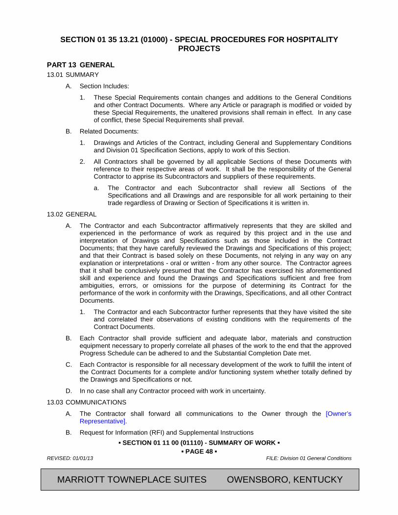
SECTION 01 35 13.21 (01000) - SPECIAL PROCEDURES FOR HOSPITALITY PROJECTS
PART 13 GENERAL 13.01 SUMMARY
A. Section Includes:
1. These Special Requirements contain changes and additions to the General Conditions and other Contract Documents. Where any Article or paragraph is modified or voided by these Special Requirements, the unaltered provisions shall remain in effect. In any case of conflict, these Special Requirements shall prevail.
B. Related Documents:
1. Drawings and Articles of the Contract, including General and Supplementary Conditions and Division 01 Specification Sections, apply to work of this Section.
2. All Contractors shall be governed by all applicable Sections of these Documents with reference to their respective areas of work. It shall be the responsibility of the General Contractor to apprise its Subcontractors and suppliers of these requirements.
a. The Contractor and each Subcontractor shall review all Sections of the Specifications and all Drawings and are responsible for all work pertaining to their trade regardless of Drawing or Section of Specifications it is written in.
13.02 GENERAL
A. The Contractor and each Subcontractor affirmatively represents that they are skilled and experienced in the performance of work as required by this project and in the use and interpretation of Drawings and Specifications such as those included in the Contract Documents; that they have carefully reviewed the Drawings and Specifications of this project; and that their Contract is based solely on these Documents, not relying in any way on any explanation or interpretations - oral or written - from any other source. The Contractor agrees that it shall be conclusively presumed that the Contractor has exercised his aforementioned skill and experience and found the Drawings and Specifications sufficient and free from ambiguities, errors, or omissions for the purpose of determining its Contract for the performance of the work in conformity with the Drawings, Specifications, and all other Contract Documents.
1. The Contractor and each Subcontractor further represents that they have visited the site and correlated their observations of existing conditions with the requirements of the Contract Documents.
B. Each Contractor shall provide sufficient and adequate labor, materials and construction equipment necessary to properly correlate all phases of the work to the end that the approved Progress Schedule can be adhered to and the Substantial Completion Date met.
C. Each Contractor is responsible for all necessary development of the work to fulfill the intent of the Contract Documents for a complete and/or functioning system whether totally defined by the Drawings and Specifications or not.
D. In no case shall any Contractor proceed with work in uncertainty.
13.03 COMMUNICATIONS
A. The Contractor shall forward all communications to the Owner through the [Owner’s Representative].
B. Request for Information (RFI) and Supplemental Instructions
MARRIOTT TOWNEPLACE SUITES OWENSBORO, KENTUCKY

▪ SECTION 01 11 00 (01110) - SUMMARY OF WORK ▪ ▪ PAGE 49 ▪
FILE: Division 01 General Conditions REVISED: 01/01/13
2013, Marriott International, Inc. CFRST SPECMSTR-NEW BUILD
1. It shall be the Contractor's obligation to check the Contract Documents and to request of the [Architect any clarification necessary and in time so as not to delay the progress of the work.
13.04 RELATIONS WITH ADJOINING PROPERTY OWNERS
A. To facilitate his work, the Contractor may choose to make necessary arrangements for use and subsequent rehabilitation of the adjoining Owner's property. Such arrangements are solely the Contractor's responsibility.
B. If work is required off-site, outside the Contract limit lines, or on property of others, such areas shall be restored by said Contractor to their original condition, or as required by local authorities, immediately following completion of the work.
13.05 ACCESS TO SITE AND BUILDING
A. Access and security of the project site are the responsibility of the Contractor and not that of the Owner, the Architect, or the Owner’s Representative. 1. All construction personnel shall protect work, existing facilities, and Owner's operations
from unauthorized entry, vandalism, and theft. 13.06 EXAMINATION OF THE SITE
A. All Contractors submitting proposals for this work shall first examine the site and all conditions thereon. All proposals shall take into consideration all such conditions as may affect the work under this Contract.
13.07 GRADES, LINES, LEVELS, AND SURVEYS
A. Verify all grades, lines, levels, and dimensions as shown on the Drawings, and report any errors or inconsistencies discovered in the above to the [Architect] before commencing work. Provide and maintain established bench marks in not less than two widely separated places.
13.08 FIELD MEASUREMENTS
A. The Contractor shall take measurements in the field to verify or supplement dimensions indicated on Drawings and shall be responsible for accurate fit of specified work. Any discrepancy between the Drawings and the actual conditions shall be reported immediately to the [Architect.
B. Tolerances: The Contractor shall be responsible to maintain dimensions for spaces requiring close tolerances for such items as equipment or fixtures by "grounding" such locations. Uneven surfaces and joints will not be accepted which prevent the installation of units whose dimensions are shown in the documents.
13.09 USE OF SITE
A. Material Delivery and Storage
1. It shall be the responsibility of the Contractor to direct all deliveries to the construction site and not the Architect, the Owner’s Representative, or the Owner.
B. The Contractor shall exercise control over all trucks and equipment using public roads and the Owner's property to preclude spillage, tracking of dirt or debris thereon. Should spillage occur, that Contractor is held to promptly clean and remove same.
13.10 PROTECTION
A. The Contractor shall provide and maintain guard lights for all work at all barricades, railings, obstructions in the streets, roads, or sidewalks, and at all trenches or pits as necessary to direct automobile and truck traffic as well as pedestrians. Remove such work when directed after necessity for same ceases.
MARRIOTT TOWNEPLACE SUITES OWENSBORO, KENTUCKY
▪ SECTION 01 11 00 (01110) - SUMMARY OF WORK ▪ ▪ PAGE 50 ▪
REVISED: 01/01/13 FILE: Division 01 General Conditions
CFRST SPECMSTR-NEW BUILD 2013, Marriott International, Inc.
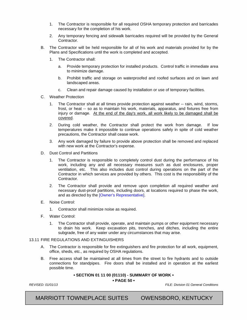
1. The Contractor is responsible for all required OSHA temporary protection and barricades necessary for the completion of his work.
2. Any temporary fencing and sidewalk barricades required will be provided by the General Contractor.
B. The Contractor will be held responsible for all of his work and materials provided for by the Plans and Specifications until the work is completed and accepted.
1. The Contractor shall:
a. Provide temporary protection for installed products. Control traffic in immediate area to minimize damage.
b. Prohibit traffic and storage on waterproofed and roofed surfaces and on lawn and landscaped areas.
c. Clean and repair damage caused by installation or use of temporary facilities.
C. Weather Protection
1. The Contractor shall at all times provide protection against weather -- rain, wind, storms, frost, or heat -- so as to maintain his work, materials, apparatus, and fixtures free from injury or damage. At the end of the day's work, all work likely to be damaged shall be covered.
2. During cold weather, the Contractor shall protect the work from damage. If low temperatures make it impossible to continue operations safely in spite of cold weather precautions, the Contractor shall cease work.
3. Any work damaged by failure to provide above protection shall be removed and replaced with new work at the Contractor's expense.
D. Dust Control and Partitions
1. The Contractor is responsible to completely control dust during the performance of his work, including any and all necessary measures such as dust enclosures, proper ventilation, etc. This also includes dust control during operations on the part of the Contractor in which services are provided by others. This cost is the responsibility of the Contractor.
2. The Contractor shall provide and remove upon completion all required weather and necessary dust-proof partitions, including doors, at locations required to phase the work, and as directed by the [Owner’s Representative].
E. Noise Control:
1. Contractor shall minimize noise as required.
F. Water Control:
1. The Contractor shall provide, operate, and maintain pumps or other equipment necessary to drain his work. Keep excavation pits, trenches, and ditches, including the entire subgrade, free of any water under any circumstances that may arise.
13.11 FIRE REGULATIONS AND EXTINGUISHERS
A. The Contractor is responsible for fire extinguishers and fire protection for all work, equipment, office, sheds, etc., as required by OSHA regulations.
B. Free access shall be maintained at all times from the street to fire hydrants and to outside connections for standpipes. Fire doors shall be installed and in operation at the earliest possible time.
MARRIOTT TOWNEPLACE SUITES OWENSBORO, KENTUCKY

▪ SECTION 01 11 00 (01110) - SUMMARY OF WORK ▪ ▪ PAGE 51 ▪
FILE: Division 01 General Conditions REVISED: 01/01/13
2013, Marriott International, Inc. CFRST SPECMSTR-NEW BUILD
C. Where existing exits occur, they shall be fully maintained at all times and shall be kept free from materials, equipment, or other obstructions.
D. Combustible materials shall not be stored in the building.
E. The use of wood scaffolding shall be kept to a minimum and entirely eliminated when possible in order to eliminate fire hazards from this source. No part of the building where forms are in place shall be used for the storage of flammable materials of any kind. Temporary structures of combustible material shall be located not less than 30 feet from the building.
F. No smoking or use of tobacco in any form shall be permitted within the building or on the roof surfaces.
13.12 HAZARDOUS MATERIALS
A. The Contractor shall comply with all laws concerning hazardous materials. Hazardous material shall be disposed in a legal manner. MSDS sheets for hazardous materials shall be filed at the Contractor's job site office and as otherwise required by law.
PART 14 PRODUCTS Not Used
PART 15 EXECUTION Not Used
END OF SECTION
Revision Log
MARRIOTT TOWNEPLACE SUITES OWENSBORO, KENTUCKY

▪ SECTION 01 11 00 (01110) - SUMMARY OF WORK ▪ ▪ PAGE 52 ▪
REVISED: 01/01/13 FILE: Division 01 General Conditions
CFRST SPECMSTR-NEW BUILD 2013, Marriott International, Inc.
SECTION 01 42 19 (01420) - REFERENCE STANDARDS
PART 16 GENERAL 16.01 SUMMARY
A. Section Includes:
1. Reference Standards
16.02 QUALITY ASSURANCE
A. Conflicting Requirements: Where compliance with two or more standards is specified and the standards establish different or conflicting requirements for minimum quantities or quality levels, comply with the most stringent requirement. Refer uncertainties and requirements that are different, but apparently equal, to the Architect for a decision before proceeding.
1. Minimum Quantity or Quality Levels: The quantity or quality level shown or specified shall be the minimum provided or performed. The actual installation may comply exactly with the minimum quantity or quality specified, or it may exceed the minimum with reasonable limits. To comply with these requirements, indicated numeric values are minimum or maximum, as appropriate, for the context of the requirements. Refer uncertainties to the [Architect] for a decision before proceeding.
16.03 INDUSTRY STANDARDS
A. Reference Standards
1. Conform with the provisions or standards referenced in the sections of the Specifications with the same force and effect as if the Standards referenced were bound or copied directly into the section, except that:
a. Conform with more stringent provisions when contained elsewhere in the Contract Documents; and
b. Conform with the more stringent provision when two or more Standards are referenced; and
c. Conform with the more stringent provision when the Standard referenced and the governing regulations differ unless the governing regulation require conformance to the less stringent provision without exception.
2. Submit for clarification and conform to the decision of the Architect when the Standard referenced:
a. Presents options which have not specifically been selected in the Contract Documents; or
b. Contain provisions which conflict with other provisions in the Contract Documents; or
c. It is uncertain or not clear which of differing provisions is the more stringent.
3. Conform to the provisions of the most recent issue of the Standard referenced as of the date of the Contract Documents.
B. Abbreviations and Acronyms of Organizations
1. Abbreviations and Names: Trade association names and titles of general standards are frequently abbreviated. Where abbreviations and acronyms are used in the Specifications or other Contract Documents, they mean the recognized name of the trade association, standards-producing organization, authorities having jurisdiction, or other
MARRIOTT TOWNEPLACE SUITES OWENSBORO, KENTUCKY
▪ SECTION 01 11 00 (01110) - SUMMARY OF WORK ▪ ▪ PAGE 53 ▪
FILE: Division 01 General Conditions REVISED: 01/01/13
2013, Marriott International, Inc. CFRST SPECMSTR-NEW BUILD
entity applicable to the context of the text provision. Refer to Gale Research’s “Encyclopedia of Associations” or Columbia Books’ “National Trade and Professional Associations of the U.S.,” which are available in most libraries.
2. The names, addresses, and telephone numbers given in the List of Organizations are subject to change and are believed to be, but are not assured to be, accurate and up to date as of the issue date of this Section.
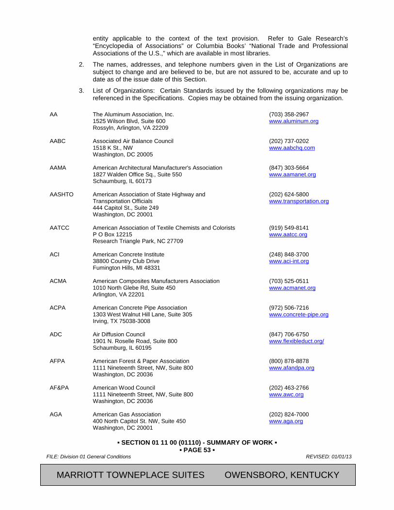
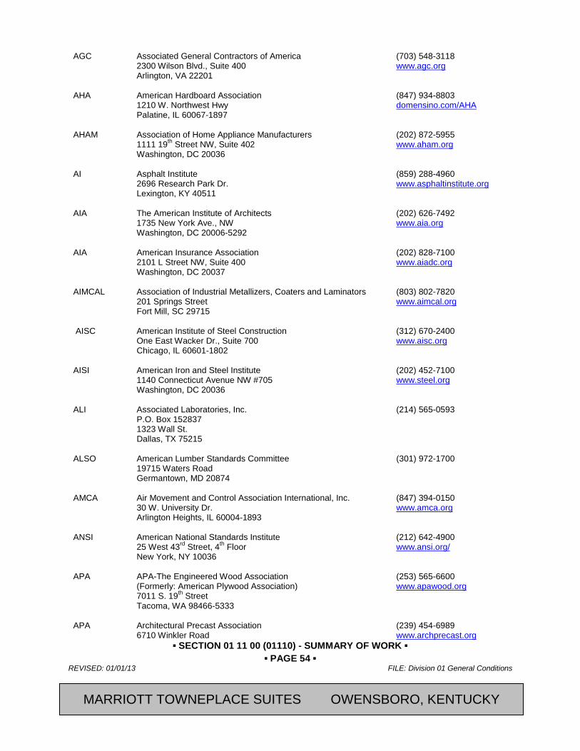
3. List of Organizations: Certain Standards issued by the following organizations may be referenced in the Specifications. Copies may be obtained from the issuing organization.
AA The Aluminum Association, Inc. (703) 358-2967 1525 Wilson Blvd, Suite 600 www.aluminum.org Rossyln, Arlington, VA 22209 AABC Associated Air Balance Council (202) 737-0202 1518 K St., NW www.aabchq.com Washington, DC 20005 AAMA American Architectural Manufacturer's Association (847) 303-5664 1827 Walden Office Sq., Suite 550 www.aamanet.org Schaumburg, IL 60173 AASHTO American Association of State Highway and (202) 624-5800 Transportation Officials www.transportation.org 444 Capitol St., Suite 249 Washington, DC 20001 AATCC American Association of Textile Chemists and Colorists (919) 549-8141 P O Box 12215 www.aatcc.org Research Triangle Park, NC 27709 ACI American Concrete Institute (248) 848-3700 38800 Country Club Drive www.aci-int.org Fumington Hills, MI 48331 ACMA American Composites Manufacturers Association (703) 525-0511 1010 North Glebe Rd, Suite 450 www.acmanet.org Arlington, VA 22201 ACPA American Concrete Pipe Association (972) 506-7216 1303 West Walnut Hill Lane, Suite 305 www.concrete-pipe.org Irving, TX 75038-3008 ADC Air Diffusion Council (847) 706-6750 1901 N. Roselle Road, Suite 800 www.flexibleduct.org/ Schaumburg, IL 60195 AFPA American Forest & Paper Association (800) 878-8878 1111 Nineteenth Street, NW, Suite 800 www.afandpa.org Washington, DC 20036 AF&PA American Wood Council (202) 463-2766 1111 Nineteenth Street, NW, Suite 800 www.awc.org Washington, DC 20036 AGA American Gas Association (202) 824-7000 400 North Capitol St. NW, Suite 450 www.aga.org Washington, DC 20001
MARRIOTT TOWNEPLACE SUITES OWENSBORO, KENTUCKY
▪ SECTION 01 11 00 (01110) - SUMMARY OF WORK ▪ ▪ PAGE 54 ▪
REVISED: 01/01/13 FILE: Division 01 General Conditions
CFRST SPECMSTR-NEW BUILD 2013, Marriott International, Inc.
AGC Associated General Contractors of America (703) 548-3118 2300 Wilson Blvd., Suite 400 www.agc.org Arlington, VA 22201 AHA American Hardboard Association (847) 934-8803 1210 W. Northwest Hwy domensino.com/AHA Palatine, IL 60067-1897 AHAM Association of Home Appliance Manufacturers (202) 872-5955 1111 19th Street NW, Suite 402 www.aham.org Washington, DC 20036 AI Asphalt Institute (859) 288-4960 2696 Research Park Dr. www.asphaltinstitute.org Lexington, KY 40511 AIA The American Institute of Architects (202) 626-7492 1735 New York Ave., NW www.aia.org Washington, DC 20006-5292 AIA American Insurance Association (202) 828-7100 2101 L Street NW, Suite 400 www.aiadc.org Washington, DC 20037 AIMCAL Association of Industrial Metallizers, Coaters and Laminators (803) 802-7820 201 Springs Street www.aimcal.org Fort Mill, SC 29715 AISC American Institute of Steel Construction (312) 670-2400 One East Wacker Dr., Suite 700 www.aisc.org Chicago, IL 60601-1802 AISI American Iron and Steel Institute (202) 452-7100 1140 Connecticut Avenue NW #705 www.steel.org Washington, DC 20036 ALI Associated Laboratories, Inc. (214) 565-0593 P.O. Box 152837 1323 Wall St. Dallas, TX 75215 ALSO American Lumber Standards Committee (301) 972-1700 19715 Waters Road Germantown, MD 20874 AMCA Air Movement and Control Association International, Inc. (847) 394-0150 30 W. University Dr. www.amca.org Arlington Heights, IL 60004-1893 ANSI American National Standards Institute (212) 642-4900 25 West 43rd Street, 4th Floor www.ansi.org/ New York, NY 10036 APA APA-The Engineered Wood Association (253) 565-6600 (Formerly: American Plywood Association) www.apawood.org 7011 S. 19th Street Tacoma, WA 98466-5333 APA Architectural Precast Association (239) 454-6989 6710 Winkler Road www.archprecast.org
MARRIOTT TOWNEPLACE SUITES OWENSBORO, KENTUCKY
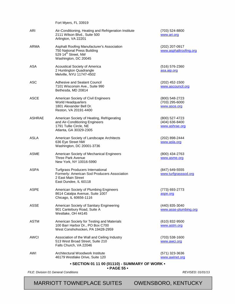
▪ SECTION 01 11 00 (01110) - SUMMARY OF WORK ▪ ▪ PAGE 55 ▪
FILE: Division 01 General Conditions REVISED: 01/01/13
2013, Marriott International, Inc. CFRST SPECMSTR-NEW BUILD
Fort Myers, FL 33919 ARI Air-Conditioning, Heating and Refrigeration Institute (703) 524-8800 2111 Wilson Blvd., Suite 500 www.ari.org Arlington, VA 22201 ARMA Asphalt Roofing Manufacturer’s Association (202) 207-0917 750 National Press Building www.asphaltroofing.org 529 14th Street, NW Washington, DC 20045 ASA Acoustical Society of America (516) 576-2360 2 Huntington Quadrangle asa.aip.org Melville, NYU 11747-4502 ASC Adhesive and Sealant Council (202) 452-1500 7101 Wisconsin Ave., Suite 990 www.ascouncil.org Bethesda, MD 20814 ASCE American Society of Civil Engineers (800) 548-2723 World Headquarters (703) 295-6000 1801 Alexander Bell Dr. www.asce.org Reston, VA 20191-4400 ASHRAE American Society of Heating, Refrigerating (800) 527-4723 and Air-Conditioning Engineers (404) 636-8400 1791 Tullie Circle, NE www.ashrae.org Atlanta, GA 30329-2305 ASLA American Society of Landscape Architects (202) 898-2444 636 Eye Street NW www.asla.org Washington, DC 20001-3736 ASME American Society of Mechanical Engineers (800) 434-2763 Three Park Avenue www.asme.org New York, NY 10016-5990 ASPA Turfgrass Producers International (847) 649-5555 Formerly: American Sod Producers Association www.turfgrasssod.org 2 East Main Street East Dundee, IL 60118 ASPE American Society of Plumbing Engineers (773) 693-2773 8614 Catalpa Avenue, Suite 1007 aspe.org Chicago, IL 60656-1116 ASSE American Society of Sanitary Engineering (440) 835-3040 901 Cantebury Road, Suite A www.asse-plumbing.org Westlake, OH 44145 ASTM American Society for Testing and Materials (610) 832-9500 100 Barr Harbor Dr., PO Box C700 www.astm.org West Conshohocken, PA 19428-2959 AWCI Association of the Wall and Ceiling Industry (703) 538-1600 513 West Broad Street, Suite 210 www.awci.org Falls Church, VA 22046 AWI Architectural Woodwork Institute (571) 323-3636 46179 Westlake Drive, Suite 120 www.awinet.org
MARRIOTT TOWNEPLACE SUITES OWENSBORO, KENTUCKY

▪ SECTION 01 11 00 (01110) - SUMMARY OF WORK ▪ ▪ PAGE 56 ▪
REVISED: 01/01/13 FILE: Division 01 General Conditions
CFRST SPECMSTR-NEW BUILD 2013, Marriott International, Inc.
Potomac Falls, VA 20165 AWPA American Wood Protection Association (205) 733-4077 100 Chase Park South, Suite 116 www.awpa.com Birmingham, AL 35244-1851 AWS American Welding Society (800) 443-9353 550 NW Leleune Rd. (305) 443-9353 Miami, FL 33126 www.aws.org/ AWWA American Water Works Association (800) 926-7337 6666 W. Quincy Ave. (303) 794-7711 Denver, CO 80235 www.awwa.org BHMA Builders Hardware Manufacturers Association (212) 297-2122 355 Lexington Ave., 15th Floor www.buildershardware.com New York, NY 10017 BIA Brick Institute of America (703) 620-0010 1850 Centennial Park Dr., #301 www.bia.org Reston, VA 20191 CAGI Compressed Air and Gas Institute (216) 241-7333 1300 Sumner Ave. www.cagi.org Cleveland, OH 44115-2851 CDA Copper Development Association (212) 251-7200 260 Madison Avenue, 16th Floor www.copper.org New York, NY 10016 CFFA Chemical Fabrics and Film Association (216) 241-7333 1300 Sumner Avenue www.chemicalfabricsandfilm.com Cleveland, Ohio 44115-2851 CGA Compressed Gas Association (703) 788-2700 4221 Walney Road, 5th Floor www.cganet.com Chantilly, VA 20151 CISCA Ceilings & Interior Systems Construction Association (630) 584-1919 405 Illinois Avenue, Unit 2B http://cisca.org St. Charles, IL 60174 CISPI Cast Iron Soil Pipe Institute (423) 892-0137 5959 Shallowford Rd., Suite 419 www.cispi.org Chattanooga, TN 37421 CFLMI Chain Link Fence Manufacturers Institute (301) 596-2583 10015 Old Columbia Road, Suite B-215 CLFMI Columbia, MD 21046 CPA/CWC Composite Panel Association/Composite Wood Council (703) 724-1128 10465 Deerfield Avenue, Suite 306 www.pbmdf.com Leesburg, VA 20176 CPPA Corrugated Polyethylene Pipe Association (800) 510-2772 432 N. Superior St. (419) 241-2221 Toledo, OH 43604 CPSC U.S. Consumer Product Safety Commission (301) 504-7923 4330 East West Highway www.cpsc.gov
MARRIOTT TOWNEPLACE SUITES OWENSBORO, KENTUCKY
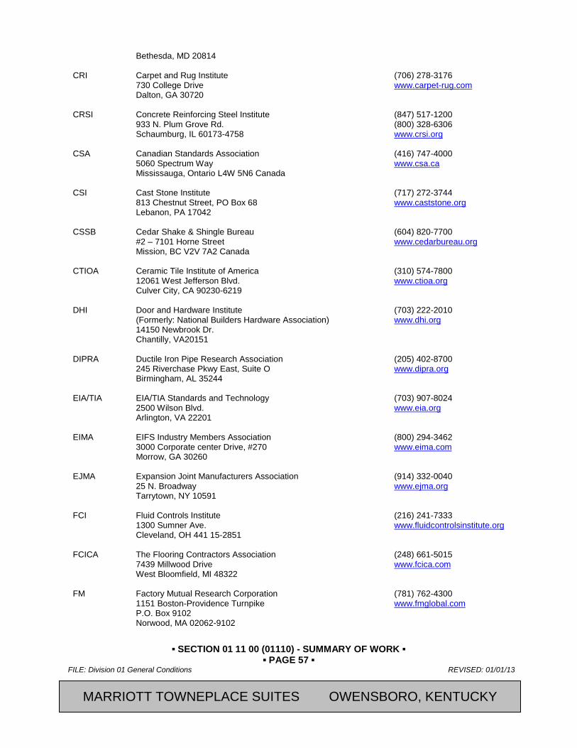
▪ SECTION 01 11 00 (01110) - SUMMARY OF WORK ▪ ▪ PAGE 57 ▪
FILE: Division 01 General Conditions REVISED: 01/01/13
2013, Marriott International, Inc. CFRST SPECMSTR-NEW BUILD
Bethesda, MD 20814 CRI Carpet and Rug Institute (706) 278-3176 730 College Drive www.carpet-rug.com Dalton, GA 30720 CRSI Concrete Reinforcing Steel Institute (847) 517-1200 933 N. Plum Grove Rd. (800) 328-6306 Schaumburg, IL 60173-4758 www.crsi.org CSA Canadian Standards Association (416) 747-4000 5060 Spectrum Way www.csa.ca Mississauga, Ontario L4W 5N6 Canada CSI Cast Stone Institute (717) 272-3744 813 Chestnut Street, PO Box 68 www.caststone.org Lebanon, PA 17042 CSSB Cedar Shake & Shingle Bureau (604) 820-7700 #2 – 7101 Horne Street www.cedarbureau.org Mission, BC V2V 7A2 Canada CTIOA Ceramic Tile Institute of America (310) 574-7800 12061 West Jefferson Blvd. www.ctioa.org Culver City, CA 90230-6219 DHI Door and Hardware Institute (703) 222-2010 (Formerly: National Builders Hardware Association) www.dhi.org 14150 Newbrook Dr. Chantilly, VA20151 DIPRA Ductile Iron Pipe Research Association (205) 402-8700 245 Riverchase Pkwy East, Suite O www.dipra.org Birmingham, AL 35244 EIA/TIA EIA/TIA Standards and Technology (703) 907-8024 2500 Wilson Blvd. www.eia.org Arlington, VA 22201 EIMA EIFS Industry Members Association (800) 294-3462 3000 Corporate center Drive, #270 www.eima.com Morrow, GA 30260 EJMA Expansion Joint Manufacturers Association (914) 332-0040 25 N. Broadway www.ejma.org Tarrytown, NY 10591 FCI Fluid Controls Institute (216) 241-7333 1300 Sumner Ave. www.fluidcontrolsinstitute.org Cleveland, OH 441 15-2851 FCICA The Flooring Contractors Association (248) 661-5015 7439 Millwood Drive www.fcica.com West Bloomfield, MI 48322
FM Factory Mutual Research Corporation (781) 762-4300 1151 Boston-Providence Turnpike www.fmglobal.com P.O. Box 9102 Norwood, MA 02062-9102
MARRIOTT TOWNEPLACE SUITES OWENSBORO, KENTUCKY

▪ SECTION 01 11 00 (01110) - SUMMARY OF WORK ▪ ▪ PAGE 58 ▪
REVISED: 01/01/13 FILE: Division 01 General Conditions
CFRST SPECMSTR-NEW BUILD 2013, Marriott International, Inc.
FMG FM Global (401) 275-3000 Factory Mutual Insurance Company www.fmglobal.com 1301 Atwood Avenue P O Box 7500 Johnston, RI 02919 GA Gypsum Association (301) 277-8686 6525 Belcrest Road #480 www.gypsum.org Hyattsville, MD 20782 GANA Glass Association of North America (785) 271-0208 2945 SW Wanamaker Drive, Suite A www.glasswebsite.com Topeka, KS 66614 HI Hydraulic Institute (973) 267-9700 6 Campus Drive, First Floor North www.pumps.org Pusippuny, NJ 07054 AHRI Hydronics Institute (merged with AHRI 2008) (908) 464-8200 (Division of Gas Appliance Manufacturers Association) Hydronics Institute 2111 Wilson Blvd., Suite 500 Arlington, VA 22201 HMA Hardwood Manufacturers Association (800) 373-WOOD (9663) (Formerly: Southern Hardwood Lumber) www.hardwood.org Manufacturers Association) 400 Penn Center Blvd., Suite 530 Pittsburgh, PA 15235-5605 HPVA Hardwood Plywood and Veneer Association (703) 435-2900 1825 Michael Farraday Dr. www.hpva.org Reston, VA 20190 ICC International Code Council (888) 422-7233 500 New Jersey Avenue, NW, 6th Floor www.iccsafe.org Washington, DC 20001-2070 ICC-ES International Council Evaluation Service Inc. (562) 699-0543 5360 Workman Mill Road www.icc-es.org Whittier, CA 90601 IECA International Erosion Control Association (800) 455-4322 3401 Quebec St, Suite 3500 www.ieca.org Denver, CO 80207 ICEA Insulated Cable Engineers Association, Inc. (770) 830-0369 P.O. Box 1569 www.icea.net Carrollton, GA 30117 ICRI International Concrete Repair Institute (847) 827-0830 3166 S. River Road, Suite 132 www.icri.org Des Plaines, IL 60018 IEEE Institute of Electrical and Electronics Engineers (800) 678-4333 3 Park Avenue, 17th Floor (212) 419-7900 New York, NY 10016 www.ieee.org IESNA Illuminating Engineering Society of North America (212) 248-5000 120 Wall St., 17th Floor www.iesna.org New York, NY 10005-4001
MARRIOTT TOWNEPLACE SUITES OWENSBORO, KENTUCKY

▪ SECTION 01 11 00 (01110) - SUMMARY OF WORK ▪ ▪ PAGE 59 ▪
FILE: Division 01 General Conditions REVISED: 01/01/13
2013, Marriott International, Inc. CFRST SPECMSTR-NEW BUILD
IGCC Insulating Glass Certification Council, Inc. (315) 646-2234 P O Box 730 www.igcc.org Sackets Harbor, NY 13685 IGMA Insulating Glass Manufacturers Alliance (613) 233-1510 27 N. Wacker Drive, Suite 365 www.igmaonline.org Chicago, IL 60606-2800 IIDA International Interior Design Association (888) 799-4432 222 Merchandise Mart, Suite 567 www.iida.com Chicago, IL 60654 ILI Indiana Limestone Institute of America www.iliai.com INCE Institute of Noise Control Engineering of the USA (317) 735-4063 9100 Purdue Road, Suite 200 www.inceusa.org Indianapolis, IN 46268 ISA ISA - International Society for Measurement (919) 549-8411 and Control www.isa.org 67 Alexander Dr. Research Triangle Park, NC 27709 ISO International Organization for Standardization +41 22 749 01 11 1 ch. De la Voie-Creuse www.iso.org Case Postale 56 CH-1211 Geneva 20, Switzerland ISSFA International Solid Surface Fabricators Association (877) 464-7732 910 W. State Street, Unit 1 www.issfa.com Lehi, UT 84043 ITS Intelligent Transportation Systems (800) 853-1351 Research and Innovative Technology Administration (RITA) www.its.dot.gov 1200 New Jersey Avenue, S.E Washington, DC 20590 IWFA International Window Film Association (276) 666-4932 www.iwfa.com
AIST Association for Iron & Steel Technology (724) 814-3000 (Formerly: Iron and Steel Society) www.iss.org 186 Thorn Hill Road Warrendale, PA 15086-7512 KCMA Kitchen Cabinet Manufacturers Association (703) 264-1690 (Formerly: National Kitchen Cabinet Association) www.kcma.org 1899 Preston White Dr. Reston, VA 22091-4326 LGSI Light Gage Structural Institute (972) 625-4560 c/o Loseke Technologies, Inc. www.loseke.com/lgsi.html P.O. Box 560746 The Colony, TX 75056 LMA Laminating Materials Association (Formerly: American Laminators Association) 116 Lawrence St. Hillsdale, NJ 07642-2730
MARRIOTT TOWNEPLACE SUITES OWENSBORO, KENTUCKY
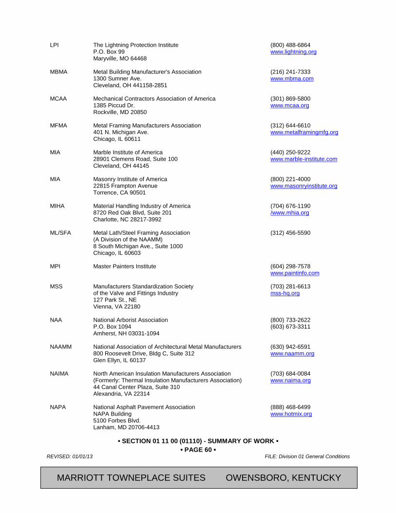
▪ SECTION 01 11 00 (01110) - SUMMARY OF WORK ▪ ▪ PAGE 60 ▪
REVISED: 01/01/13 FILE: Division 01 General Conditions
CFRST SPECMSTR-NEW BUILD 2013, Marriott International, Inc.
LPI The Lightning Protection Institute (800) 488-6864 P.O. Box 99 www.lightning.org Maryville, MO 64468 MBMA Metal Building Manufacturer's Association (216) 241-7333 1300 Sumner Ave. www.mbma.com Cleveland, OH 441158-2851 MCAA Mechanical Contractors Association of America (301) 869-5800 1385 Piccud Dr. www.mcaa.org Rockville, MD 20850 MFMA Metal Framing Manufacturers Association (312) 644-6610 401 N. Michigan Ave. www.metalframingmfg.org Chicago, IL 60611 MIA Marble Institute of America (440) 250-9222 28901 Clemens Road, Suite 100 www.marble-institute.com Cleveland, OH 44145 MIA Masonry Institute of America (800) 221-4000 22815 Frampton Avenue www.masonryinstitute.org Torrence, CA 90501 MIHA Material Handling Industry of America (704) 676-1190 8720 Red Oak Blvd, Suite 201 /www.mhia.org Charlotte, NC 28217-3992 ML/SFA Metal Lath/Steel Framing Association (312) 456-5590 (A Division of the NAAMM) 8 South Michigan Ave., Suite 1000 Chicago, IL 60603 MPI Master Painters Institute (604) 298-7578 www.paintinfo.com MSS Manufacturers Standardization Society (703) 281-6613 of the Valve and Fittings Industry mss-hq.org 127 Park St., NE Vienna, VA 22180 NAA National Arborist Association (800) 733-2622 P.O. Box 1094 (603) 673-3311 Amherst, NH 03031-1094 NAAMM National Association of Architectural Metal Manufacturers (630) 942-6591 800 Roosevelt Drive, Bldg C, Suite 312 www.naamm.org Glen Ellyn, IL 60137 NAIMA North American Insulation Manufacturers Association (703) 684-0084 (Formerly: Thermal Insulation Manufacturers Association) www.naima.org 44 Canal Center Plaza, Suite 310 Alexandria, VA 22314 NAPA National Asphalt Pavement Association (888) 468-6499 NAPA Building www.hotmix.org 5100 Forbes Blvd. Lanham, MD 20706-4413
MARRIOTT TOWNEPLACE SUITES OWENSBORO, KENTUCKY

▪ SECTION 01 11 00 (01110) - SUMMARY OF WORK ▪ ▪ PAGE 61 ▪
FILE: Division 01 General Conditions REVISED: 01/01/13
2013, Marriott International, Inc. CFRST SPECMSTR-NEW BUILD
NBFAA Electronic Life Safety, Security & Systems Professionals (888) 447-1689 (Formerly: National Burglar & Fire Alarm Association) www.alarm.org 2300 Valley View Lane Suite 230 Irving, TX 75062 NBGQA National Building Granite Quarries Association Inc. (800) 557-2848 1220 L. Street, N.W., Suite 100-167 www.nbgqa.com Washington, DC 20005 NCAA National Collegiate Athletic Association (317) 917-6222 700 W. Washington Street www.ncaa.org Indianapolis, IN 46206 NCMA National Concrete Masonry Association (703) 713-1900 13750 Sunrise Valley Drive www.ncma.org Herndon, VA 20171 NCRMA National Ready Mixed Concrete Association (888) 846-7622 900 Spring Street www.nrmca.org Silver Spring, MD 20910 NCSPA National Corrugated Steel Pipe Association (972) 850-1907 14070 Proton Road, Suite 100 LB9 www.ncspa.org Dallas, TX 75244 NEBB National Environmental Balancing Bureau (301) 977-3698 8575 Grovemont Circle www.nebb.org Gaithersburg, MD 20877-4121 NECA National Electrical Contractors Association (301) 657-3110 3 Bethesda Metro Center, Suite 1100 www.necanet.org Bethesda, MD 20814-5372 NEII National Elevator Industry, Inc. (518) 854-3100 P.O. Box 838 www.neii.org Salem, NY 12865-0838 NELMA Northeastern Lumber Manufacturers Association (207) 829-6901 272 Tuttle Rd. www.nelma.org P.O. Box 87A Cumberland Center, ME 04021 NEMA The Association of and Medical Imaging Equipment Manufacturers (703) 841-3200 1300 N 17th St., Suite 1752 www.nema.org Rosslyn, VA 22209 NFPA National Fire Protection Association (800) 344-3555 One Batterymarch Park (617) 770 3000 P.O. Box 9101 http://www.nfpa.org Quincy, MA 02269-9101 NFRC National Fenestration Rating Council (301) 589-1776 6305 Ivy Lane, Suite 140 www.nfrc.org Greenbelt, MD 20770 NFSHSA National Federation of State High School Association (317) 972-6900 PO Box 690 http://nfshsa.org/ Indianapolis, IN 46206
MARRIOTT TOWNEPLACE SUITES OWENSBORO, KENTUCKY
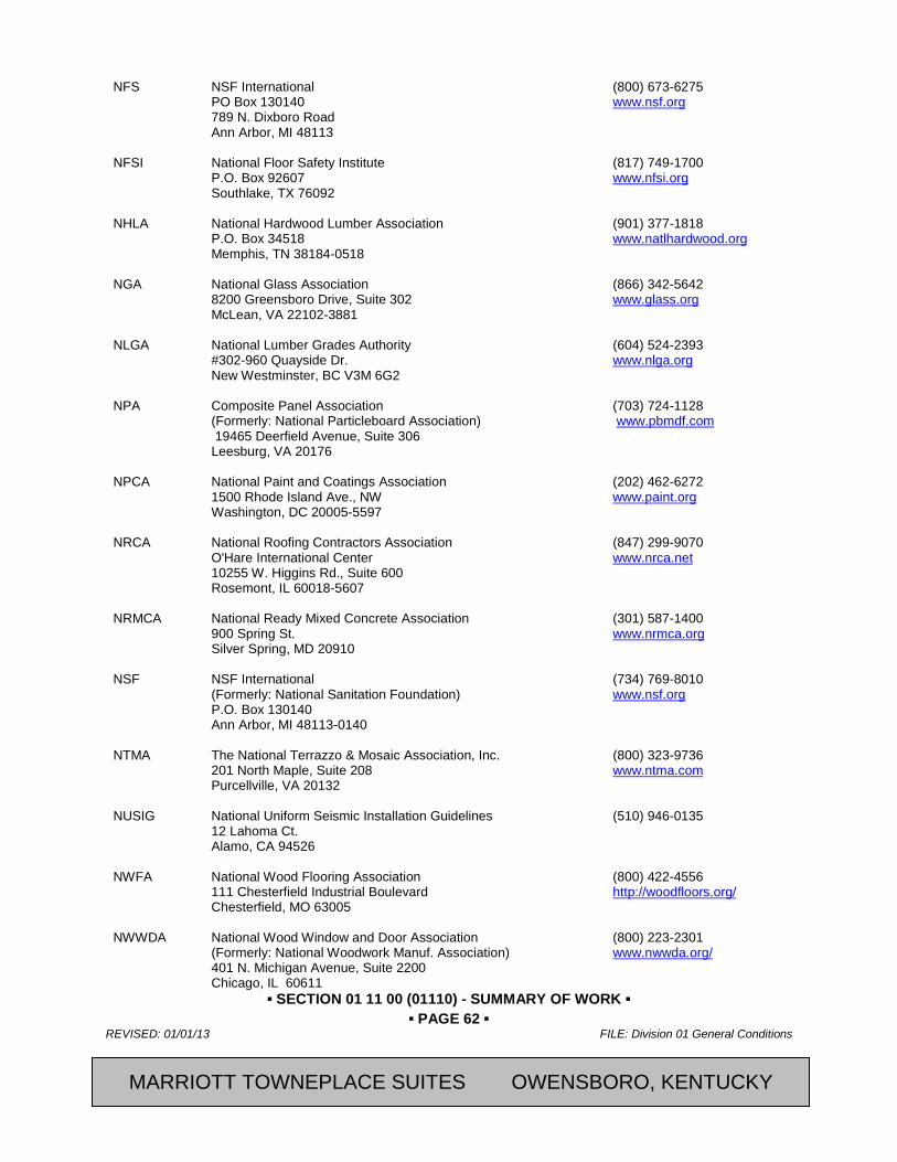
▪ SECTION 01 11 00 (01110) - SUMMARY OF WORK ▪ ▪ PAGE 62 ▪
REVISED: 01/01/13 FILE: Division 01 General Conditions
CFRST SPECMSTR-NEW BUILD 2013, Marriott International, Inc.
NFS NSF International (800) 673-6275 PO Box 130140 www.nsf.org 789 N. Dixboro Road Ann Arbor, MI 48113 NFSI National Floor Safety Institute (817) 749-1700 P.O. Box 92607 www.nfsi.org Southlake, TX 76092 NHLA National Hardwood Lumber Association (901) 377-1818 P.O. Box 34518 www.natlhardwood.org Memphis, TN 38184-0518 NGA National Glass Association (866) 342-5642 8200 Greensboro Drive, Suite 302 www.glass.org McLean, VA 22102-3881 NLGA National Lumber Grades Authority (604) 524-2393 #302-960 Quayside Dr. www.nlga.org New Westminster, BC V3M 6G2 NPA Composite Panel Association (703) 724-1128 (Formerly: National Particleboard Association) www.pbmdf.com 19465 Deerfield Avenue, Suite 306 Leesburg, VA 20176 NPCA National Paint and Coatings Association (202) 462-6272 1500 Rhode Island Ave., NW www.paint.org Washington, DC 20005-5597 NRCA National Roofing Contractors Association (847) 299-9070 O'Hare International Center www.nrca.net 10255 W. Higgins Rd., Suite 600 Rosemont, IL 60018-5607 NRMCA National Ready Mixed Concrete Association (301) 587-1400 900 Spring St. www.nrmca.org Silver Spring, MD 20910 NSF NSF International (734) 769-8010 (Formerly: National Sanitation Foundation) www.nsf.org P.O. Box 130140 Ann Arbor, MI 48113-0140 NTMA The National Terrazzo & Mosaic Association, Inc. (800) 323-9736 201 North Maple, Suite 208 www.ntma.com Purcellville, VA 20132 NUSIG National Uniform Seismic Installation Guidelines (510) 946-0135 12 Lahoma Ct. Alamo, CA 94526 NWFA National Wood Flooring Association (800) 422-4556 111 Chesterfield Industrial Boulevard http://woodfloors.org/ Chesterfield, MO 63005 NWWDA National Wood Window and Door Association (800) 223-2301 (Formerly: National Woodwork Manuf. Association) www.nwwda.org/ 401 N. Michigan Avenue, Suite 2200 Chicago, IL 60611
MARRIOTT TOWNEPLACE SUITES OWENSBORO, KENTUCKY

▪ SECTION 01 11 00 (01110) - SUMMARY OF WORK ▪ ▪ PAGE 63 ▪
FILE: Division 01 General Conditions REVISED: 01/01/13
2013, Marriott International, Inc. CFRST SPECMSTR-NEW BUILD
ODNR Ohio Department of Natural Resources (614) 265-6300
2045 Morse Road, Building G www.dnr.state.oh.us Columbus, OH 43229-6693
PCA Portland Cement Association (847) 966-6200 5420 Old Orchard Rd. www.cement.org Skokie, IL 60077-1083 PCI Precast/Prestressed Concrete Institute (312) 786-0300 209 W. Jackson Blvd. #500 www.pci.org Chicago, IL 60606 PDCA Painting and Decorating Contractors of America (800) 332-7322 1801 Park 270 Drive, Suite 220 www.pdca.com St. Louis, MO 63146 PDI Plumbing and Drainage Institute (800) 589-8956 800 Turnpike St., Suite 300 www.pdionline.org North Andove, MA 01845 PEI Porcelain Enamel Institute (770) 676-9366 P.O. Box 90220 www.porcelainenamel.com Norcross, GA 30010 PPFA Plastic Pipe and Fittings Association (630) 858-6540 800 Roosevelt Rd., Building C, Suite 312 www.ppfahome.org Glen Ellyn, IL 60137-5833 PPI Plastic Pipe Institute (469) 499-1044 (The Society of the Plastics Industry, Inc.) www.plasticpipe.org 105 Decker Court, Suite 825 Irving, TX 75062 RCSC Research Council on Structural Connections www.boltcouncil.org RFCI Resilient Floor Covering Institute (706) 882-3833 115 Broad Street, Suite 201 www.rfci.com LaGrange, GA 30240 RMA Rubber Manufacturers Association (800) 220-7620 1400 K St., NW, Suite 900 (202) 682-4800 Washington, DC 20005 www.rma.org SAE SAE International (877) 606-7323 400 Commonwealth Dr. www.sae.org Warrendale, PA 15096-0001 For publications: Call (412) 776-4970 SDI Steel Door Institute (440) 889-0010 30200 Detroit Rd. www.steeldoor.org Cleveland, OH 44145-1967 SHLMA Southern Hardwood Lumber Manufacturers Association (See HMA) SIGMA Sealed Insulating Glass Manufacturers Association (312) 644-6610 401 N. Michigan Ave. Suite 2400 Chicago, IL 60611-4267
MARRIOTT TOWNEPLACE SUITES OWENSBORO, KENTUCKY
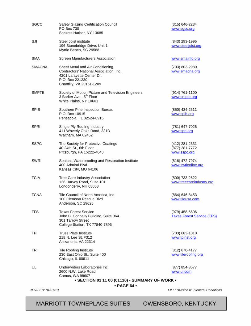
▪ SECTION 01 11 00 (01110) - SUMMARY OF WORK ▪ ▪ PAGE 64 ▪
REVISED: 01/01/13 FILE: Division 01 General Conditions
CFRST SPECMSTR-NEW BUILD 2013, Marriott International, Inc.
SGCC Safety Glazing Certification Council (315) 646-2234 PO Box 730 www.sgcc.org Sackets Harbor, NY 13685 SJI Steel Joist institute (843) 293-1995 196 Stonebridge Drive, Unit 1 www.steeljoist.org Myrtle Beach, SC 29588 SMA Screen Manufacturers Association www.smainfo.org SMACNA Sheet Metal and Air Conditioning (703) 803-2980 Contractors' National Association, Inc. www.smacna.org 4201 Lafayette Center Dr. P.O. Box 221230 Chantilly, VA 20151-1209 SMPTE Society of Motion Picture and Television Engineers (914) 761-1100 3 Barker Ave., 5th Floor www.smpte.org White Plains, NY 10601 SPIB Southern Pine Inspection Bureau (850) 434-2611 P.O. Box 10915 www.spib.org Pensacola, FL 32524-0915 SPRI Single Ply Roofing Industry (781) 647-7026 411 Waverly Oaks Road, 331B www.spri.org Waltham, MA 02452 SSPC The Society for Protective Coatings (412) 281-2331 40 24th St., 6th Floor (877) 281-7772 Pittsburgh, PA 15222-4643 www.sspc.org SWRI Sealant, Waterproofing and Restoration Institute (816) 472-7974 400 Admiral Blvd. www.swrionline.org Kansas City, MO 64106 TCIA Tree Care Industry Association (800) 733-2622 136 Harvey Road, Suite 101 www.treecareindustry.org Londonderry, NH 03053 TCNA Tile Council of North America, Inc. (864) 646-8453 100 Clemson Rescue Blvd. www.tileusa.com Anderson, SC 29625 TFS Texas Forest Service (979) 458-6606 John B. Connally Building, Suite 364 Texas Forest Service (TFS) 301 Tarrow Street College Station, TX 77840-7896 TPI Truss Plate Institute (703) 683-1010 218 N. Lee St, #312 www.tpinst.org Alexandria, VA 22314 TRI Tile Roofing Institute (312) 670-4177 230 East Ohio St., Suite 400 www.tileroofing.org Chicago, IL 60611 UL Underwriters Laboratories Inc. (877) 854-3577 2600 N.W. Lake Road www.ul.com Camas, WA 98607
MARRIOTT TOWNEPLACE SUITES OWENSBORO, KENTUCKY
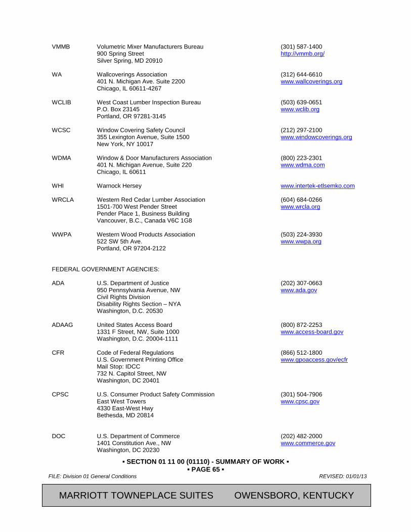
▪ SECTION 01 11 00 (01110) - SUMMARY OF WORK ▪ ▪ PAGE 65 ▪
FILE: Division 01 General Conditions REVISED: 01/01/13
2013, Marriott International, Inc. CFRST SPECMSTR-NEW BUILD
VMMB Volumetric Mixer Manufacturers Bureau (301) 587-1400 900 Spring Street http://vmmb.org/ Silver Spring, MD 20910 WA Wallcoverings Association (312) 644-6610 401 N. Michigan Ave. Suite 2200 www.wallcoverings.org Chicago, IL 60611-4267 WCLIB West Coast Lumber Inspection Bureau (503) 639-0651 P.O. Box 23145 www.wclib.org Portland, OR 97281-3145 WCSC Window Covering Safety Council (212) 297-2100 355 Lexington Avenue, Suite 1500 www.windowcoverings.org New York, NY 10017 WDMA Window & Door Manufacturers Association (800) 223-2301 401 N. Michigan Avenue, Suite 220 www.wdma.com Chicago, IL 60611 WHI Warnock Hersey www.intertek-etlsemko.com WRCLA Western Red Cedar Lumber Association (604) 684-0266 1501-700 West Pender Street www.wrcla.org Pender Place 1, Business Building Vancouver, B.C., Canada V6C 1G8 WWPA Western Wood Products Association (503) 224-3930 522 SW 5th Ave. www.wwpa.org Portland, OR 97204-2122 FEDERAL GOVERNMENT AGENCIES: ADA U.S. Department of Justice (202) 307-0663 950 Pennsylvania Avenue, NW www.ada.gov Civil Rights Division Disability Rights Section – NYA Washington, D.C. 20530 ADAAG United States Access Board (800) 872-2253 1331 F Street, NW, Suite 1000 www.access-board.gov Washington, D.C. 20004-1111 CFR Code of Federal Regulations (866) 512-1800 U.S. Government Printing Office www.gpoaccess.gov/ecfr Mail Stop: IDCC 732 N. Capitol Street, NW Washington, DC 20401 CPSC U.S. Consumer Product Safety Commission (301) 504-7906 East West Towers www.cpsc.gov 4330 East-West Hwy Bethesda, MD 20814 DOC U.S. Department of Commerce (202) 482-2000 1401 Constitution Ave., NW www.commerce.gov Washington, DC 20230
MARRIOTT TOWNEPLACE SUITES OWENSBORO, KENTUCKY
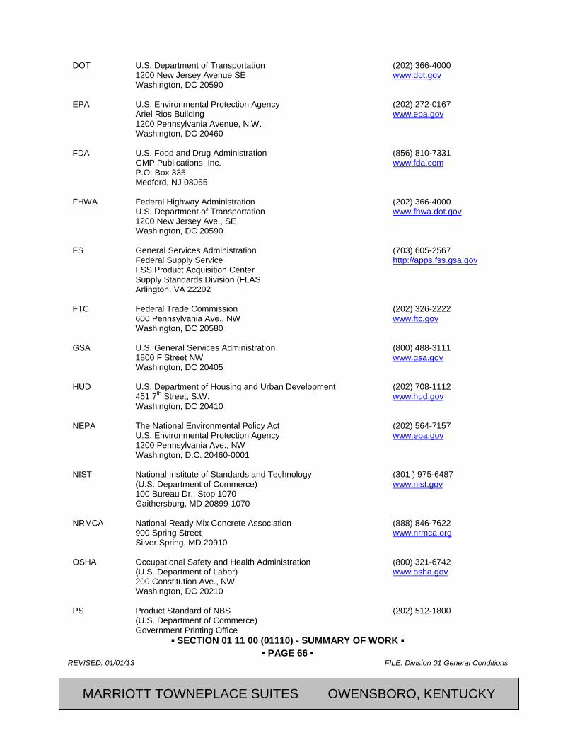
▪ SECTION 01 11 00 (01110) - SUMMARY OF WORK ▪ ▪ PAGE 66 ▪
REVISED: 01/01/13 FILE: Division 01 General Conditions
CFRST SPECMSTR-NEW BUILD 2013, Marriott International, Inc.
DOT U.S. Department of Transportation (202) 366-4000 1200 New Jersey Avenue SE www.dot.gov Washington, DC 20590 EPA U.S. Environmental Protection Agency (202) 272-0167 Ariel Rios Building www.epa.gov 1200 Pennsylvania Avenue, N.W. Washington, DC 20460 FDA U.S. Food and Drug Administration (856) 810-7331 GMP Publications, Inc. www.fda.com P.O. Box 335 Medford, NJ 08055 FHWA Federal Highway Administration (202) 366-4000 U.S. Department of Transportation www.fhwa.dot.gov 1200 New Jersey Ave., SE Washington, DC 20590 FS General Services Administration (703) 605-2567 Federal Supply Service http://apps.fss.gsa.gov FSS Product Acquisition Center Supply Standards Division (FLAS Arlington, VA 22202 FTC Federal Trade Commission (202) 326-2222 600 Pennsylvania Ave., NW www.ftc.gov Washington, DC 20580 GSA U.S. General Services Administration (800) 488-3111 1800 F Street NW www.gsa.gov Washington, DC 20405 HUD U.S. Department of Housing and Urban Development (202) 708-1112 451 7th Street, S.W. www.hud.gov Washington, DC 20410 NEPA The National Environmental Policy Act (202) 564-7157 U.S. Environmental Protection Agency www.epa.gov 1200 Pennsylvania Ave., NW Washington, D.C. 20460-0001
NIST National Institute of Standards and Technology (301 ) 975-6487 (U.S. Department of Commerce) www.nist.gov 100 Bureau Dr., Stop 1070 Gaithersburg, MD 20899-1070 NRMCA National Ready Mix Concrete Association (888) 846-7622 900 Spring Street www.nrmca.org Silver Spring, MD 20910 OSHA Occupational Safety and Health Administration (800) 321-6742 (U.S. Department of Labor) www.osha.gov 200 Constitution Ave., NW Washington, DC 20210 PS Product Standard of NBS (202) 512-1800 (U.S. Department of Commerce) Government Printing Office
MARRIOTT TOWNEPLACE SUITES OWENSBORO, KENTUCKY
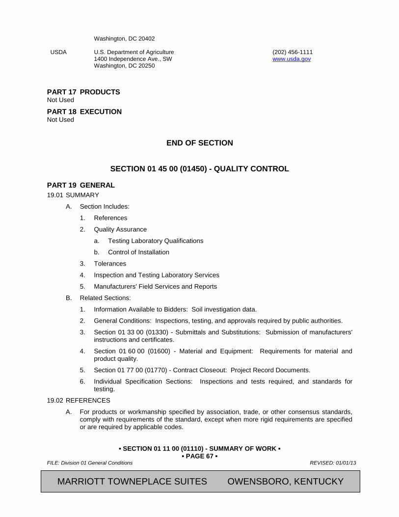
▪ SECTION 01 11 00 (01110) - SUMMARY OF WORK ▪ ▪ PAGE 67 ▪
FILE: Division 01 General Conditions REVISED: 01/01/13
2013, Marriott International, Inc. CFRST SPECMSTR-NEW BUILD
Washington, DC 20402 USDA U.S. Department of Agriculture (202) 456-1111 1400 Independence Ave., SW www.usda.gov Washington, DC 20250
PART 17 PRODUCTS Not Used
PART 18 EXECUTION Not Used
END OF SECTION
SECTION 01 45 00 (01450) - QUALITY CONTROL
PART 19 GENERAL 19.01 SUMMARY
A. Section Includes:
1. References
2. Quality Assurance
a. Testing Laboratory Qualifications
b. Control of Installation
3. Tolerances
4. Inspection and Testing Laboratory Services
5. Manufacturers' Field Services and Reports
B. Related Sections:
1. Information Available to Bidders: Soil investigation data.
2. General Conditions: Inspections, testing, and approvals required by public authorities.
3. Section 01 33 00 (01330) - Submittals and Substitutions: Submission of manufacturers' instructions and certificates.
4. Section 01 60 00 (01600) - Material and Equipment: Requirements for material and product quality.
5. Section 01 77 00 (01770) - Contract Closeout: Project Record Documents.
6. Individual Specification Sections: Inspections and tests required, and standards for testing.
19.02 REFERENCES
A. For products or workmanship specified by association, trade, or other consensus standards, comply with requirements of the standard, except when more rigid requirements are specified or are required by applicable codes.
MARRIOTT TOWNEPLACE SUITES OWENSBORO, KENTUCKY
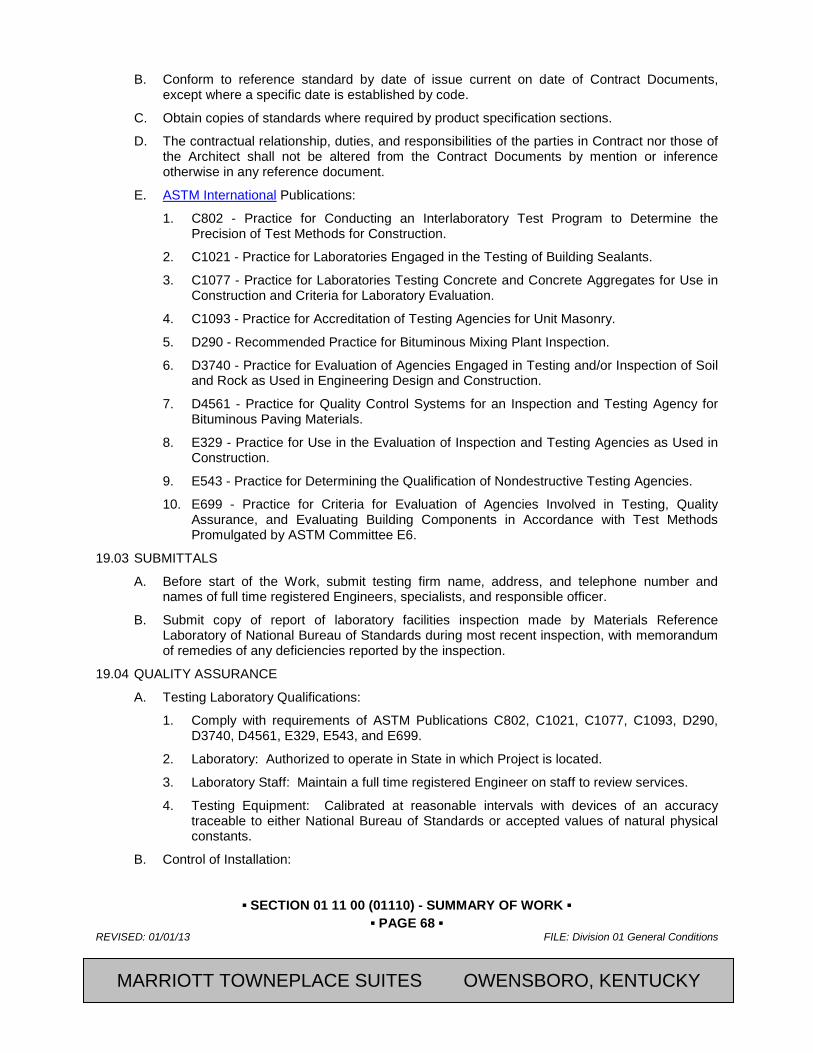
▪ SECTION 01 11 00 (01110) - SUMMARY OF WORK ▪ ▪ PAGE 68 ▪
REVISED: 01/01/13 FILE: Division 01 General Conditions
CFRST SPECMSTR-NEW BUILD 2013, Marriott International, Inc.
B. Conform to reference standard by date of issue current on date of Contract Documents, except where a specific date is established by code.
C. Obtain copies of standards where required by product specification sections.
D. The contractual relationship, duties, and responsibilities of the parties in Contract nor those of the Architect shall not be altered from the Contract Documents by mention or inference otherwise in any reference document.
E. ASTM International Publications:
1. C802 - Practice for Conducting an Interlaboratory Test Program to Determine the Precision of Test Methods for Construction.
2. C1021 - Practice for Laboratories Engaged in the Testing of Building Sealants.
3. C1077 - Practice for Laboratories Testing Concrete and Concrete Aggregates for Use in Construction and Criteria for Laboratory Evaluation.
4. C1093 - Practice for Accreditation of Testing Agencies for Unit Masonry.
5. D290 - Recommended Practice for Bituminous Mixing Plant Inspection.
6. D3740 - Practice for Evaluation of Agencies Engaged in Testing and/or Inspection of Soil and Rock as Used in Engineering Design and Construction.
7. D4561 - Practice for Quality Control Systems for an Inspection and Testing Agency for Bituminous Paving Materials.
8. E329 - Practice for Use in the Evaluation of Inspection and Testing Agencies as Used in Construction.
9. E543 - Practice for Determining the Qualification of Nondestructive Testing Agencies.
10. E699 - Practice for Criteria for Evaluation of Agencies Involved in Testing, Quality Assurance, and Evaluating Building Components in Accordance with Test Methods Promulgated by ASTM Committee E6.
19.03 SUBMITTALS
A. Before start of the Work, submit testing firm name, address, and telephone number and names of full time registered Engineers, specialists, and responsible officer.
B. Submit copy of report of laboratory facilities inspection made by Materials Reference Laboratory of National Bureau of Standards during most recent inspection, with memorandum of remedies of any deficiencies reported by the inspection.
19.04 QUALITY ASSURANCE
A. Testing Laboratory Qualifications:
1. Comply with requirements of ASTM Publications C802, C1021, C1077, C1093, D290, D3740, D4561, E329, E543, and E699.
2. Laboratory: Authorized to operate in State in which Project is located.
3. Laboratory Staff: Maintain a full time registered Engineer on staff to review services.
4. Testing Equipment: Calibrated at reasonable intervals with devices of an accuracy traceable to either National Bureau of Standards or accepted values of natural physical constants.
B. Control of Installation:
MARRIOTT TOWNEPLACE SUITES OWENSBORO, KENTUCKY

▪ SECTION 01 11 00 (01110) - SUMMARY OF WORK ▪ ▪ PAGE 69 ▪
FILE: Division 01 General Conditions REVISED: 01/01/13
2013, Marriott International, Inc. CFRST SPECMSTR-NEW BUILD
1. Monitor quality control over suppliers, manufacturers, Products, services, site conditions, and workmanship, to produce Work of specified quality.
2. Comply with manufacturers' instructions, including each step in sequence.
3. Should manufacturers' instructions conflict with Contract Documents, request clarification from [Architect] before proceeding.
4. Comply with specified standards as minimum quality for the Work except where more stringent tolerances, codes, or specified requirements indicate higher standards or more precise workmanship.
5. Perform work by persons qualified to produce workmanship of specified quality.
6. Secure products in place with positive anchorage devices designed and sized to withstand stresses, vibration, physical distortion, or disfigurement.
19.05 TOLERANCES
A. Monitor tolerance control of installed Products to produce acceptable Work. Do not permit tolerances to accumulate.
B. Comply with manufacturers' tolerances. Should manufacturers' tolerances conflict with Contract Documents, request clarification from the [Architect] before proceeding.
C. Adjust products to appropriate dimensions; position before securing Products in place.
19.06 INSPECTING AND TESTING LABORATORY SERVICES
A. Except as otherwise required in the Owner-Contractor Agreement, the Contractor shall appoint, employ, and pay for specified services of an independent firm to perform inspecting and testing, subject to approval of the Owner
B. Employment of testing laboratory in no way relieves Contractor of obligation to perform Work in accordance with requirements of Contract Documents.
C. The testing firm will perform inspections, tests, and other services specified in individual specification sections and as required by the [Architect]
D. Inspecting, testing, and source quality control may occur on or off the project site.
E. Retesting required because of non-conformance to specified requirements shall be performed by the same testing firm on instructions by the [Architect]
F. Laboratory Responsibilities:
1. Test samples of mixes submitted by Contractor.
2. Provide qualified personnel at site. Cooperate with [Architect] and Contractor in performance of services.
3. Perform specified inspecting, sampling, and testing of Products in accordance with specified standards.
4. Ascertain compliance of materials and mixes with requirements of Contract Documents.
5. Promptly notify [Architect] and Contractor of observed irregularities or non-conformance of Work or Products.
6. Perform additional inspection and tests required by the [Architect]. Attend preconstruction meetings and progress meetings.
G. Laboratory Reports: After each inspection and test, promptly submit copies of laboratory report to the [Architect] and Contractor. Include the following:
1. Date issued
MARRIOTT TOWNEPLACE SUITES OWENSBORO, KENTUCKY
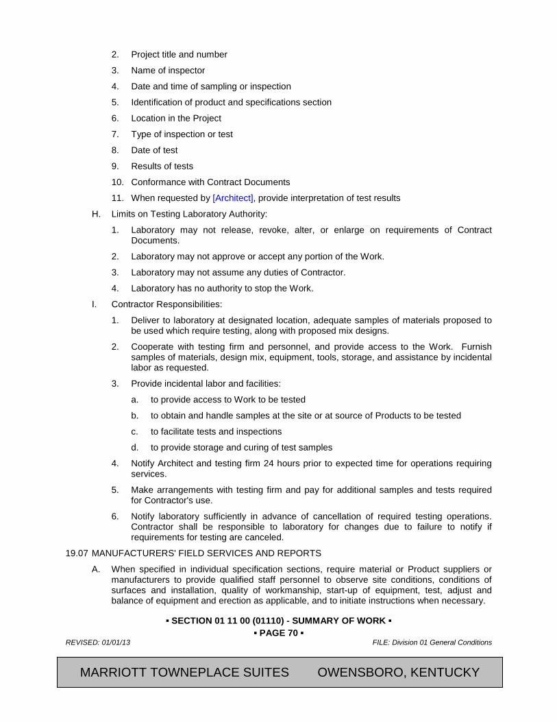
▪ SECTION 01 11 00 (01110) - SUMMARY OF WORK ▪ ▪ PAGE 70 ▪
REVISED: 01/01/13 FILE: Division 01 General Conditions
CFRST SPECMSTR-NEW BUILD 2013, Marriott International, Inc.
2. Project title and number
3. Name of inspector
4. Date and time of sampling or inspection
5. Identification of product and specifications section
6. Location in the Project
7. Type of inspection or test
8. Date of test
9. Results of tests
10. Conformance with Contract Documents
11. When requested by [Architect], provide interpretation of test results
H. Limits on Testing Laboratory Authority:
1. Laboratory may not release, revoke, alter, or enlarge on requirements of Contract Documents.
2. Laboratory may not approve or accept any portion of the Work.
3. Laboratory may not assume any duties of Contractor.
4. Laboratory has no authority to stop the Work.
I. Contractor Responsibilities:
1. Deliver to laboratory at designated location, adequate samples of materials proposed to be used which require testing, along with proposed mix designs.
2. Cooperate with testing firm and personnel, and provide access to the Work. Furnish samples of materials, design mix, equipment, tools, storage, and assistance by incidental labor as requested.
3. Provide incidental labor and facilities:
a. to provide access to Work to be tested
b. to obtain and handle samples at the site or at source of Products to be tested
c. to facilitate tests and inspections
d. to provide storage and curing of test samples
4. Notify Architect and testing firm 24 hours prior to expected time for operations requiring services.
5. Make arrangements with testing firm and pay for additional samples and tests required for Contractor's use.
6. Notify laboratory sufficiently in advance of cancellation of required testing operations. Contractor shall be responsible to laboratory for changes due to failure to notify if requirements for testing are canceled.
19.07 MANUFACTURERS' FIELD SERVICES AND REPORTS
A. When specified in individual specification sections, require material or Product suppliers or manufacturers to provide qualified staff personnel to observe site conditions, conditions of surfaces and installation, quality of workmanship, start-up of equipment, test, adjust and balance of equipment and erection as applicable, and to initiate instructions when necessary.
MARRIOTT TOWNEPLACE SUITES OWENSBORO, KENTUCKY
▪ SECTION 01 11 00 (01110) - SUMMARY OF WORK ▪ ▪ PAGE 71 ▪
FILE: Division 01 General Conditions REVISED: 01/01/13
2013, Marriott International, Inc. CFRST SPECMSTR-NEW BUILD
B. Report observations and site decisions or instructions given to applicators or installers that are supplemental or contrary to manufacturers' written instructions.
C. Submit report in duplicate within 15 days of observation to [Architect] for information.
PART 20 PRODUCTS Not Used
PART 21 EXECUTION Not Used
END OF SECTION
Revision Log
MARRIOTT TOWNEPLACE SUITES OWENSBORO, KENTUCKY
▪ SECTION 01 11 00 (01110) - SUMMARY OF WORK ▪ ▪ PAGE 72 ▪
REVISED: 01/01/13 FILE: Division 01 General Conditions
CFRST SPECMSTR-NEW BUILD 2013, Marriott International, Inc.
SECTION 01 50 00 (01500) - TEMPORARY FACILITIES AND CONTROLS
PART 22 GENERAL 22.01 SUMMARY
A. Section Includes:
1. This Section specifies temporary services and facilities, including utilities, construction and support facilities, security and protection. Provide facilities ready for use. Maintain, expand and modify as needed. Remove when no longer needed, or when replaced by permanent facilities.
2. Work of this Section shall include, but not necessarily be limited to, the following:
a. Project/Site Conditions
b. Use Charges
c. Field Office and Storage Sheds
d. Temporary Sanitary Facilities
e. Temporary Fire Extinguishers
f. Temporary Water
g. Temporary Electric Power Service and Interior Lighting
h. Temporary Telephone Service and Facsimile Service
i. Temporary Storm and Sanitary Sewer
j. Temporary Heating, Cooling, and Ventilation
k. Temporary Paving
l. Temporary Enclosures
m. Project Identification
n. Temporary Exterior Lighting
o. Progress Cleaning and Waste Removal
p. Surface and Underground Water Control
q. Protection of Installed Work
1) Environmental Protection
2) Dust Control
3) Barriers, Barricades, Warning Signs, and Lights
r. Removal of Construction Facilities and Temporary Controls
B. Related Sections:
1. Section 01 35 00.01 (01000) - Special Requirements
2. Section 01 11 00 (01110) - Summary of Work
3. Section 01 56 16 – Temporary Dust Protection
4. Section 01 74 00 (01740) - Cleaning and Waste Management
MARRIOTT TOWNEPLACE SUITES OWENSBORO, KENTUCKY

▪ SECTION 01 11 00 (01110) - SUMMARY OF WORK ▪ ▪ PAGE 73 ▪
FILE: Division 01 General Conditions REVISED: 01/01/13
2013, Marriott International, Inc. CFRST SPECMSTR-NEW BUILD
5. Section 01 77 00 (01770) – Closeout Procedures
6. Section 02 41 19 – Selective Structure Demolition
22.02 REFERENCES
A. American National Standards Institute (ANSI) Publications:
1. A10 “Series standards for "Safety Requirements for Construction and Demolition"
B. Institute of Electrical and Electronics Engineers (IEEE) Publications:
1. “National Electrical Safety Code (NESC)”
C. National Electrical Contractors Association (NECA) Publications:
1. Electrical Design Library "Temporary Electrical Facilities."
D. National Fire Protection Association (NFPA) Publications:
1. 10 "Portable Fire Extinguishers"
2. 70 "National Electric Code"
3. 241 "Standard for Safeguarding Construction, Alterations and Demolition Operations"
22.03 DEFINITIONS
A. Permanent Enclosure: Permanent or temporary roofing is complete, insulated, and weathertight; exterior walls are insulated and weathertight; and all openings are closed with permanent construction or substantial temporary closures, all as determined by the [Owner’s Representative].
22.04 SUBMITTALS
A. Fire-Prevention Plan: Prepare a written plan for preventing fires during the Work, including placement of fire extinguishers, fire blankets, rag buckets, and other fire-control devices during each phase or process. The Contractor shall perform the duties under NFPA 241 titled "Owner's Responsibility for Fire Protection."
22.05 QUALITY ASSURANCE
A. Regulations: Each Contractor shall comply with industry standards and with applicable laws and regulations of authorities having jurisdiction, including but not limited to:
1. Owner's Requirements
2. Building Code Requirements
3. Health and Safety Regulations
4. Utility Company Regulations
5. Police, Fire Department, and Rescue Squad Rules
6. Environmental Protection Regulations
B. Standards: Comply with NFPA 241, "Standard for Safeguarding Construction, Alterations and Demolition Operations", ANSI-A10 Series standards for "Safety Requirements for Construction and Demolition", and NECA Electrical Design Library "Temporary Electrical Facilities."
1. Refer to "Guidelines for Bid Conditions for Temporary Job Utilities and Services", prepared jointly by AGC and ASC for industry recommendations.
MARRIOTT TOWNEPLACE SUITES OWENSBORO, KENTUCKY
▪ SECTION 01 11 00 (01110) - SUMMARY OF WORK ▪ ▪ PAGE 74 ▪
REVISED: 01/01/13 FILE: Division 01 General Conditions
CFRST SPECMSTR-NEW BUILD 2013, Marriott International, Inc.
2. Trade Jurisdictions: Assigned responsibilities for installation and operation of temporary utilities are not intended to interfere with the normal application of trade regulations and union jurisdictions.
3. Safety and Health Standard: Comply with ANSI/ASSE A10.6.
4. Electrical Service: Comply with NEMA, NECA, and UL standards and regulations for temporary electric service. Install service in compliance with NFPA 70 “National Electric Code.
C. Inspections: Arrange for authorities having jurisdiction to inspect and test each temporary utility before use. Obtain required certifications and permits.
22.06 PROJECT/SITE CONDITIONS
A. Temporary Utilities: Prepare a schedule indicating dates of the implementation and termination of each temporary utility. At the earliest feasible time, when acceptable to the Owner, change over from use of the temporary service to use of the permanent service.
1. Temporary Use of Permanent Facilities: The installer of each permanent service or facility shall assume responsibility for its operation, maintenance and protection during its use as a construction service or facility prior to the Owner's acceptance, regardless of previously assigned responsibilities.
B. Conditions of Use: Keep temporary services and facilities clean and neat in appearance. Operate in a safe and efficient manner. Take necessary fire prevention measures. Do not overload facilities, or permit them to interfere with progress. Do not allow hazardous, dangerous, or unsanitary conditions, or public nuisances to develop or persist on the site.
22.07 USE CHARGES
A. General: Cost or use charges for temporary facilities are not chargeable to the Owner or the Architect. Contractor's cost or use charges for temporary services or facilities will not be accepted as a basis of claim for an adjustment in the Contract Sum or Contract Time.
1. Meters: Meters shall be on the Owner's utility systems and shall be furnished and installed by the Subcontractor responsible for respective use charges.
B. Other entities using temporary services and facilities include, but are not limited to:
1. Other Nonprime Contractors
2. The Owner's Work Forces and Separate Contractors
3. Occupants of the Project
4. The Architect
5. The Owner’s Representative
6. Testing Agencies
7. Personnel of Government Agencies
PART 23 PRODUCTS 23.01 MATERIALS
A. General: Provide new materials; if acceptable to the [Owner’s Representative], undamaged previously used materials in serviceable condition may be used. Provide materials suitable for the use intended.
B. Lumber and Plywood: Comply with requirements in Section 06 10 00 - Rough Carpentry.
MARRIOTT TOWNEPLACE SUITES OWENSBORO, KENTUCKY
▪ SECTION 01 11 00 (01110) - SUMMARY OF WORK ▪ ▪ PAGE 75 ▪
FILE: Division 01 General Conditions REVISED: 01/01/13
2013, Marriott International, Inc. CFRST SPECMSTR-NEW BUILD
C. Tarpaulins: Provide waterproof, fire-resistant, UL labeled tarpaulins with flame-spread rating of 15 or less. For temporary enclosures, provide translucent nylon reinforced laminated polyethylene or polyvinyl chloride fire-retardant tarpaulins.
D. Water: Provide potable water approved by local health authorities.
23.02 EQUIPMENT
A. Water Hoses: Provide 3/4" heavy-duty, abrasion-resistant, flexible rubber hoses 100 ft. long, with pressure rating greater than the maximum pressure of the water distribution system; provide adjustable shut-off nozzles at hose discharge.
B. Electrical Outlets: Provide properly configured NEMA polarized outlets to prevent insertion of 110-120 volt plugs into higher voltage outlets. Provide receptacle outlets equipped with ground-fault circuit interrupters, reset button and pilot light, for connection of power tools and equipment.
C. Electrical Power Cords: Provide grounded extension cords; use "hard-service" cords where exposed to abrasion and traffic. Provide waterproof connectors to connect separate lengths of electric cords, if single lengths will not reach areas where construction activities are in progress.
D. Lamps and Light Fixtures: Provide general service incandescent lamps of wattage required for adequate illumination. Provide guard cages or tempered glass enclosures, where exposed to breakage. Provide exterior fixtures where exposed to moisture.
E. Temporary Field Office
1. The General Contractor shall provide and maintain clean, temporary weather-tight offices at the site, in location as approved by the Owner, for the use of the Contractor, his Subcontractors' agents, [Owner's Representative], and at which location he or his authorized agent shall be present, or to which either may be readily called at all times. While the work is in progress, copies of permits, approved Shop Drawings, and a complete set of Contract Drawings and Specifications marked up to date with any revisions, shall be kept at said office ready for use at all times.
a. Provide sturdy furniture, drawing rack, and drawing display table.
2. All expenses in connection with the field office, including the installation cost, and use of heat, light, water, and janitor service shall be borne by the Contractor.
3. Field office shall be maintained until final acceptance and then be removed by the Contractor, no later than 15 days after acceptance of building unless the Owner orders earlier removal by them.
F. Temporary Storage Sheds: Each Subcontractor shall provide and maintain such additional offices, storage sheds, and other temporary buildings or trailers on the project as required for his own use. Location of sheds and trailers shall be located where directed by the Owner’s Representative.
G. Temporary Telephones:
1. The Contractor shall obtain telephone service to the field office with no cost to the Owner or disruption to Owner’s phone service. Cellular Phones will be considered acceptable means of telephone communication to the Owner’s Representatives.
2. The Contractor’s superintendent shall maintain and carry on their person a cellular phone at all times during the working day for the duration of the Project. The telephone number shall be supplied to the Owner’s Representative and Architect prior to commencement of the Work.
MARRIOTT TOWNEPLACE SUITES OWENSBORO, KENTUCKY

▪ SECTION 01 11 00 (01110) - SUMMARY OF WORK ▪ ▪ PAGE 76 ▪
REVISED: 01/01/13 FILE: Division 01 General Conditions
CFRST SPECMSTR-NEW BUILD 2013, Marriott International, Inc.
H. Sanitary Facilities: Toilet rooms within the [new] building shall not be used by construction personnel. Provide sanitary facilities that include temporary toilets, wash facilities and drinking water fixtures. Comply with regulations and health codes for the type, number, location, operation, and maintenance of fixtures. Install where facilities will best serve the Project. Provide toilet tissue, paper towels, paper cups, and similar disposable materials for each facility. Provide covered waste containers for used materials.
1. Toilets: Install self-contained single-occupant toilet units of the chemical, aerated recirculation, or combustion type, properly vented and fully enclosed with a glass fiber reinforced polyester shell or similar nonabsorbent material. Use of pit-type privies will not be permitted.
2. Wash Facilities: Install wash facilities supplied with potable water at convenient locations for personnel involved in handling materials that require wash-up. Dispose of drainage properly. Supply cleaning compounds.
3. Drinking Water Facilities: Provide containerized tap-dispenser bottled-water type drinking water units.
I. First Aid Supplies: Comply with governing regulations.
J. Fire Extinguishers: Provide hand-carried, portable UL-rated, class `A' fire extinguishers for temporary offices and similar spaces. In other locations, provide hand-carried, portable, UL-rated, class `ABC' dry chemical extinguishers, or a combination of extinguishers of NFPA recommended classes for the exposures.
1. Comply with NFPA 10 and 241 for classification, extinguishing agent, and size required by location and class of fire exposure.
PART 24 EXECUTION 24.01 INSTALLATION
A. Use qualified personnel for installation of temporary facilities. Locate facilities where they serve the project adequately and result in minimum interference with performance of the work. Relocate and modify facilities as required.
B. Provide each facility ready for use when needed to avoid delay. Maintain and modify as required. Do not remove until facilities are not longer needed, or are replaced by authorized
24.02 TEMPORARY UTILITY INSTALLATION
A. General: Engage the appropriate local utility company to install temporary service. Where the company provides only part of the service, provide the remainder with matching, compatible materials and equipment; comply with the company's recommendations.
1. Obtain easements to bring temporary utilities to the site, where the Owner's easements cannot be used for that purpose.
B. Water Service:
1. Install water service connected to nearest system, and distribution piping of sizes and pressures adequate for construction until permanent water service is in use.
2. Sterilization: Sterilize temporary water piping prior to use.
3. The Contractor shall remove temporary water service at the completion of the Project.
C. Temporary Electric Power Service: Provide weatherproof, grounded electric power service and distribution system of sufficient size, capacity, and power characteristics during construction period. Include meters, transformers, overload protected disconnects, automatic ground-fault interrupters and main distribution switch gear.
MARRIOTT TOWNEPLACE SUITES OWENSBORO, KENTUCKY
▪ SECTION 01 11 00 (01110) - SUMMARY OF WORK ▪ ▪ PAGE 77 ▪
FILE: Division 01 General Conditions REVISED: 01/01/13
2013, Marriott International, Inc. CFRST SPECMSTR-NEW BUILD
1. Temporary work shall be installed in such a manner as not to interfere with the permanent construction. If such interference does occur, it shall be the responsibility of the Contractor to make such changes as may be required to overcome the interference. The cost of these changes will be included as part of the Contract Sum.
a. Protect installation against weather damage, the normal operations of other trades, Owner’s personnel, and visitors to the site.
2. The electrical work for construction purposes shall conform to all Federal and State Specific Safety requirements as well as the requirements of the NFPA 10 “National Electric Code” and IEEE “National Electrical Safety Code (NESC)”. The Contractor shall obtain required applications, permits, and inspection pertaining to this work in accordance with the General Conditions.
D. Temporary Lighting:
1. Whenever overhead floor or roof deck has been installed, provide temporary lighting with local switching.
2. Install and operate temporary lighting that will fulfill security and protection requirements, without operating the entire system, and will provide adequate illumination for construction operations and traffic conditions.
E. Sewers and Drainage:
1. If sewers are available, provide temporary connections to remove effluent that can be discharged lawfully. If sewers are not available or cannot be sued, provide drainage ditches, dry wells, stabilization ponds and similar facilities. If neither sewers nor drainage facilities can be lawfully used for discharge of effluent, provide containers to remove and dispose of effluent off the site in a lawful manner.
2. Provide earthen embankments and similar barriers in and around excavations and subgrade construction, sufficient to prevent flooding by runoff of storm water from heavy rains.
3. The Contractor shall remove temporary sewer and drainage work at the completion of the Project.
24.03 TEMPORARY CONSTRUCTION AND SUPPORT FACILITIES INSTALLATION
A. Locate field offices, storage sheds, sanitary facilities and other temporary construction and support facilities for easy access.
1. Maintain temporary construction and support facilities until near Substantial Completion. Remove prior to Substantial Completion. Personnel remaining after Substantial Completion will be permitted to use permanent facilities, under conditions acceptable to the Owner.
B. Temporary Heat and Ventilation: Provide temporary heat and ventilation required by construction activities, for curing or drying of completed installations or protection of installed construction from adverse effects of low temperatures or high humidity. Select safe equipment that will not have a harmful effect on completed installations or elements being installed. Coordinate ventilation requirements to produce the ambient condition required and minimize consumption of energy.
1. The Contractor shall provide heat, supplied with air, as follows:
a. Heating Units: Provide temporary heating units that have been tested and labeled by UL, FMG, or another recognized trade association related to the type of fuel being consumed.
MARRIOTT TOWNEPLACE SUITES OWENSBORO, KENTUCKY
▪ SECTION 01 11 00 (01110) - SUMMARY OF WORK ▪ ▪ PAGE 78 ▪
REVISED: 01/01/13 FILE: Division 01 General Conditions
CFRST SPECMSTR-NEW BUILD 2013, Marriott International, Inc.
b. At all times during normal working hours, provide sufficient heat to maintain a temperature of not less than 50 degrees F., and from 40 degrees to 50 degrees F. during periods other than specified herein below.
c. At all times during the placing, setting, and curing of concrete, provide sufficient heat to ensure heating of the spaces involved to not less than 50 degrees F.
d. Well before gypsum board work begins and continuous throughout the setting and drying periods, a temperature range between 55 and 70 degrees F. shall be maintained day and night. During this period, no finish woodwork, wood finish flooring, resilient flooring or flexible wall coverings shall be installed or stored in the buildings, and no finish painting or applying of finish wall coatings shall be undertaken.
e. For a period of ten (10) days previous to the placing of interior wood finish and throughout the placing of this and other interior finishing, varnishing, painting, etc., and until final acceptance of the work or until full occupancy by the Owner, provide sufficient heat to produce a temperature of not less than 70 degrees F.
f. Heat and air shall be supplied in a manner which shall avoid the rapid drying of material but thoroughly dry to such an extent that no remaining moisture will affect finish material.
g. The Contractor shall operate the heating and ventilating systems each day, including Saturdays, Sundays, and holidays; operating shall include necessary labor and approved operating personnel in attendance as required by agencies having jurisdiction.
h. It shall be the Contractor's responsibility to coordinate for the range of temperatures required for temporary heating, during this period, that temperature as recommended by the manufacturer of the materials as mentioned are stored in the building or being installed, and for the length of time recommended, following installation.
2. Temporary heating and ventilating equipment, piping, etc., shall be installed in such a manner as not to interfere with work of other trades or the permanent construction. If such interference does occur, it shall be the responsibility of the Contractor to make any changes required to overcome the interference.
3. Except as hereinafter specified, the permanent heating and ventilating systems shall not be used for temporary heat. The Contractor shall provide, operate, and maintain heating and ventilating units for the purposes specified. The units shall be arranged to bring in sufficient outdoor air (min. 1-1/2 air changes per hour) to ventilate the building and to prevent build-up of harmful dusts and fumes and remove excess moisture, especially to prevent damage to built-up roofing. During warm weather, the Contractor shall provide an adequate supply of fresh air (min. 1-1/2 air changes per hour) when necessary to properly ventilate for moisture, dust, and fumes from paints, cements, or adhesives in tightly enclosed areas where natural ventilation will not be sufficient.
C. Temporary Paving: Construct and maintain temporary roads and paving to adequately support the indicated loading and to withstand exposure to traffic during the construction period. Locate temporary paving for roads, storage areas, and parking, where the same permanent facilities will be located. Review proposed modifications to permanent paving with the [Owner's Representative].
1. Paving:
MARRIOTT TOWNEPLACE SUITES OWENSBORO, KENTUCKY
▪ SECTION 01 11 00 (01110) - SUMMARY OF WORK ▪ ▪ PAGE 79 ▪
FILE: Division 01 General Conditions REVISED: 01/01/13
2013, Marriott International, Inc. CFRST SPECMSTR-NEW BUILD
a. Coordinate development of temporary paving with subgrade grading, compaction, installation, and stabilization of sub-base, and installation of base and finish courses of permanent paving.
D. Temporary Enclosures: Provide temporary enclosure for protection of construction from exposure, foul weather, other construction operations, and similar activities. Where heat is needed and the building enclosure is incomplete, provide enclosures where there is no other provision for containment of heat. Coordinate enclosure with ventilating and material drying or curing requirements to avoid dangerous conditions.
1. Temporary building enclosures shall be defined as infills of door, window and skylight openings or other openings in the building exterior with either final glazing, doors and frames, or infilled in a weather tight manner with plywood or other permanent, solid enclosure materials. Plastic film shall not be accepted as permanent enclosure materials in openings. All temporary doors shall be hinged with closures and latches to keep doors shut at all times, so as to maintain temperature control. Determination of building enclosure is by the [Owner’s Representative] and the Owner, and not subject to Contractor’s interpretation. The Contractor will be required to provide temporary enclosures either by walls or partitions at places where there are no permanent wall, entries, curtain walls, etc. to enclose an area.
2. Installation of finish materials such as insulation, gypsum board, and floor toppings shall not begin until enclosures are made weather-tight and environmental requirements are met for those specific materials.
3. Maintain required exit ways for protection of life and property,
E. Project Identification and Temporary Signs:
1. Prepare project identification and other signs; install signs to inform the public and persons seeking entrance to the project. Support on posts or framing of preservative treated wood or steel. Do not permit installation of unauthorized signs.
2. Temporary Signs: Prepare signs to provide directional information to construction personnel and visitors.
F. Temporary Exterior Lighting: Install exterior yard and sign lights so that signs are visible when work is being performed.
G. Collection and Disposal of Waste: Collect waste from construction areas and elsewhere daily. Comply with requirements of NFPA 241 for removal of combustible waste material and debris. Enforce requirements strictly. Do not hold materials more than seven (7) days during normal weather or 3 days when the temperature is expected to rise above 80 degrees F. Handle hazardous, dangerous, or unsanitary waste materials separately from other waste by containerizing properly. Dispose of material in a lawful manner.
H. Stairs: Until permanent stairs are available, provide temporary stairs where ladders are not adequate. Cover finished permanent stairs with a protective covering of plywood or similar material so finishes will be undamaged at the time of acceptance.
I. Surface and Underground Water Control: Grade site to drain. Maintain excavations free of water. Provide, operate, and maintain pumping equipment. Protect site from puddling or running water. Provide water barriers as required to protect site from soil erosion. Provide dewatering of site as required.
J. Temporary Erosion and Sedimentation Control:
1. Contractor shall provide Site erosion control including maintenance of erosion and sedimentation control measures, along with addition of new facilities required by construction for the duration of the project from the Notice to Proceed according to
MARRIOTT TOWNEPLACE SUITES OWENSBORO, KENTUCKY
▪ SECTION 01 11 00 (01110) - SUMMARY OF WORK ▪ ▪ PAGE 80 ▪
REVISED: 01/01/13 FILE: Division 01 General Conditions
CFRST SPECMSTR-NEW BUILD 2013, Marriott International, Inc.
[requirements of the EPA Construction General Permit, or authorities having jurisdiction, whichever is more stringent]. Do not remove erosion control systems until approved by local jurisdictions. Contractor shall keep a daily log of erosion control maintenance. Perform and document weekly inspections and following rain events of sediment control material and maintain if so required
a. Verify that flows of water redirected from construction areas or generated by construction activity do not enter or cross tree- or plant- protection zones.
24.04 SECURITY AND PROTECTION FACILITIES INSTALLATION
A. Except for use of permanent fire protection as soon as available, do not change from use of temporary security and protection facilities to permanent facilities until Substantial Completion.
B. Fire Protection:
1. General: Follow the fire-prevention plan.
a. The Contractor shall appoint one of his personnel who is continually employed on the job site (such as the Superintendent) to additional duty to act as fire warden for this Project. The fire warden shall institute and vigorously enforce a program of fire safety for the Project.
2. Until fire protection is supplied by permanent facilities, install and maintain temporary fire protection of types needed to protect against predictable and controllable fire losses. Comply with NFPA 10 "Portable Fire Extinguishers" and NFPA 241 "Standard for Safeguarding Construction, Alterations and Demolition Operations."
a. Locate fire extinguishers strategically throughout each area where work is in progress.
b. Prohibit smoking in ALL areas of Project, including adjacent exterior areas.
c. Maintain unobstructed access to fire extinguishers, fire hydrants, temporary fire protection facilities, stairways and other access routes for fighting fires. Prohibit smoking in hazardous fire exposure areas.
d. Store combustible materials in containers in fire-safe locations.
C. Permanent Fire Protection: At the earliest date, complete installation of the permanent fire protection facility, including connected services, and place into operation. Instruct key personnel on use of facilities.
1. The permanent Fire Protection System shall be operational before any furniture is installed in facility.
D. Enclosure Fence: Contractor’s option, unless otherwise required by the Owner/Contractor Agreement.
E. Environmental Protection: Operate temporary facilities and conduct construction by methods that comply with environmental regulations, and minimize the possibility that air, waterways, and subsoil might be contaminated or polluted. Avoid use of tools and equipment which produce harmful noise. Restrict use of noise making tools and equipment to hours that will minimize complaints.
24.05 OPERATION
A. Enforce strict discipline in use of temporary facilities. Limit availability to intended use to minimize abuse. Maintain facilities in good operating condition until removal.
B. Protect from damage by freezing temperatures and the elements.
MARRIOTT TOWNEPLACE SUITES OWENSBORO, KENTUCKY
▪ SECTION 01 11 00 (01110) - SUMMARY OF WORK ▪ ▪ PAGE 81 ▪
FILE: Division 01 General Conditions REVISED: 01/01/13
2013, Marriott International, Inc. CFRST SPECMSTR-NEW BUILD
1. Maintain operation of enclosures, heating, cooling, humidity control, ventilation, and similar facilities on a 24-hour day basis to achieve indicated results and to avoid damage.
2. Prevent piping from freezing. Maintain markers for underground lines. Protect from damage during excavation operations.
24.06 TERMINATION AND REMOVAL
A. Remove each facility when the need has ended, or replaced by a permanent facility, or no later than Substantial Completion. Complete or restore construction delayed because of interference with the facility. Repair damaged Work, clean exposed surfaces, and replace construction that cannot be satisfactorily repaired.
B. Temporary facilities are property of the Contractor.
C. Remove paving that is not acceptable for integration into permanent paving. Where the area is intended for landscape development, remove soil and fill that does not comply with requirements. Remove materials contaminated wit road oil, asphalt and other petrochemical compounds, and other substances that might impair growth of plant materials. Repair or replace street paving, curbs, and sidewalks at the temporary entrances.
D. At Substantial Completion, renovate permanent facilities used during the construction period, including but not limited to:
1. Replace air filters and clean inside of ductwork and housings.
2. Replace worn parts and parts subject to unusual operating conditions.
3. Replace lamps burned out or noticeably dimmed by substantial hours of use.
END OF SECTION
Revision Log
MARRIOTT TOWNEPLACE SUITES OWENSBORO, KENTUCKY
▪ SECTION 01 11 00 (01110) - SUMMARY OF WORK ▪ ▪ PAGE 82 ▪
REVISED: 01/01/13 FILE: Division 01 General Conditions
CFRST SPECMSTR-NEW BUILD 2013, Marriott International, Inc.
SECTION 01 58 00 (01580) - PROJECT IDENTIFICATION
PART 25 GENERAL 25.01 SUMMARY
A. Section Includes:
1. The Contractor shall provide and maintain at the site one project sign.
2. No other signs or advertisements will be allowed to be displayed on the premises.
25.02 QUALITY ASSURANCE
A. Design sign and structure to withstand 50 mph wind velocity.
B. Sign Painter: Engaged as professional sign painter for not less than three years.
C. Finishes, Painting: Adequate to withstand weathering, fading, and chipping for duration of construction.
PART 26 PRODUCTS 26.01 MATERIALS
A. Structure and Framing: New wood, 4' x 4' x 8' treated posts, structurally adequate.
B. Sign Mounting Board: 4' x 8', exterior grade, GPX yellow or green plywood with medium density overlay, minimum 3/4 inch thick.
C. Rough Hardware: Galvanized, aluminum or brass.
D. Paint and Primers: Exterior quality, two coats. Color to be White.
E. Vinyl sign to be provided by Owner and installed by Contractor.
PART 27 EXECUTION 27.01 CONSTRUCTION
A. Install project identification sign within 30 days after date fixed by Owner-Contractor Contract.
B. Erect at designated location as directed by [Architect] [Owner’s Representative].
C. Erect supports and framing with uprights 36 inches below surface, braced and framed to resist wind loadings.
D. Install sign surface plumb and level, with butt joints. Anchor securely.
E. Paint sight-exposed surfaces of sign, supports, and framing.
27.02 MAINTENANCE
A. Maintain signs and supports clean. Repair deterioration and damages.
MARRIOTT TOWNEPLACE SUITES OWENSBORO, KENTUCKY

▪ SECTION 01 11 00 (01110) - SUMMARY OF WORK ▪ ▪ PAGE 83 ▪
FILE: Division 01 General Conditions REVISED: 01/01/13
2013, Marriott International, Inc. CFRST SPECMSTR-NEW BUILD
27.03 REMOVAL
A. Remove signs, framing, supports, and foundations at completion of the Project, when directed by [Owner’s Representative] and restore the area.
END OF SECTION
Revision Log
MARRIOTT TOWNEPLACE SUITES OWENSBORO, KENTUCKY

▪ SECTION 01 11 00 (01110) - SUMMARY OF WORK ▪ ▪ PAGE 84 ▪
REVISED: 01/01/13 FILE: Division 01 General Conditions
CFRST SPECMSTR-NEW BUILD 2013, Marriott International, Inc.
SECTION 01 60 00 (01600) - PRODUCT REQUIREMENTS
PART 28 GENERAL 28.01 SUMMARY
A. Section Includes:
1. Products
2. Transportation and Handling
3. Storage and Protection
4. General Product Requirements
B. Related Sections:
1. Section 01 33 00 (01330) - Submittals and Substitutions
2. Section 01 45 00 (01450) - Quality Control: Product quality monitoring.
28.02 QUALITY ASSURANCE
A. Do not use materials and equipment removed from existing premises, except as specifically permitted by the Contract Documents.
B. Provide interchangeable components of the same manufacturer, for components being replaced.
28.03 PRODUCT DELIVERY AND HANDLING
A. Transport and handle products in accordance with manufacturer's instructions.
B. Promptly inspect shipments to ensure that Products comply with requirements, quantities are correct, and Products are undamaged.
C. Provide equipment and personnel to handle Products by methods to prevent soiling, disfigurement, or damage.
28.04 STORAGE AND PROTECTION
A. Store and protect Products in accordance with manufacturers' instructions, with seals and labels intact and legible.
B. Store sensitive Products in weather tight, climate controlled enclosures.
C. For exterior storage of fabricated Products, place on sloped supports, above ground.
D. Provide bonded off-site storage and protection when site does not permit on-site storage or protection.
E. Cover Products subject to deterioration with impervious sheet covering. Provide ventilation to avoid condensation or potential degradation of Product.
F. Store loose granular materials on solid flat surfaces in a well-drained area. Prevent mixing with foreign matter.
G. Provide equipment and personnel to store Products by methods to prevent soiling, disfigurement, or damage.
H. Arrange storage of Products to permit access for inspection. Periodically inspect to verify Products are undamaged and are maintained in acceptable condition.
MARRIOTT TOWNEPLACE SUITES OWENSBORO, KENTUCKY

▪ SECTION 01 11 00 (01110) - SUMMARY OF WORK ▪ ▪ PAGE 85 ▪
FILE: Division 01 General Conditions REVISED: 01/01/13
2013, Marriott International, Inc. CFRST SPECMSTR-NEW BUILD
PART 29 PRODUCTS 29.01 General Product Requirements:
A. Semi-Open Proprietary Specification Requirements: Where Specifications name one or more products or manufacturers, provide one of the products indicated.
1. Where Specifications specify products or manufacturers by name, accompanied by the term "Approved Substitution”, the [Architect] will allow products as substitutions only after complying with the requirements of the General Conditions and Section 01 33 00.
B. The Contract Documents and governing regulations govern product selection. Procedures governing product selection include the following:
1. Avendra, LLC Preferred Manufacturers: Marriott International has negotiated a strategic national pricing/expedited delivery agreement with the listed manufacturers.
2. Approved Manufacturers: Products by the listed manufacturers are acceptable for use on this Project, but these manufacturers do not have any strategic agreements with Marriott International.
PART 30 EXECUTION Not Used
END OF SECTION
Revision Log
MARRIOTT TOWNEPLACE SUITES OWENSBORO, KENTUCKY
▪ SECTION 01 11 00 (01110) - SUMMARY OF WORK ▪ ▪ PAGE 86 ▪
REVISED: 01/01/13 FILE: Division 01 General Conditions
CFRST SPECMSTR-NEW BUILD 2013, Marriott International, Inc.
SECTION 01 71 23 (01720) - FIELD ENGINEERING
PART 31 GENERAL 31.01 SUMMARY
A. Section Includes:
1. Quality Assurance
2. Submittals
3. Project Record Documents
4. Survey Requirements
5. Examination
6. Survey Reference Points
B. Related Sections:
1. General Conditions: Basic site engineering requirements.
2. Section 01 31 32 (00320) - Geotechnical Data: Owner's topographic survey.
3. Section 01 77 00 (01770) - Contract Closeout: Project Record Documents.
31.02 QUALITY ASSURANCE
A. Employ a Land Surveyor or Engineer registered in the State where project is located and acceptable to the Owner [and Architect], to perform survey work of this section.
B. Submit evidence of Surveyor's or Engineer’s Errors and Omissions insurance coverage in the form of an Insurance Certificate.
31.03 SUBMITTALS
A. Submit a copy of registered site drawing and a certificate signed by the Land Surveyor or Engineer, that the elevations and locations of the Work are in conformance with Contract Documents.
B. On request, submit documentation verifying accuracy of survey work.
31.04 PROJECT RECORD DOCUMENTS
A. Maintain a complete and accurate log of control and survey work as it progresses.
B. On completion of foundation walls and major site improvements, prepare a certified survey illustrating dimensions, locations, angles, and elevations of construction and site work.
31.05 SURVEY REQUIREMENTS
A. Provide field engineering services. Utilize recognized engineering survey practices.
B. Establish a minimum of two permanent bench marks on site, referenced to established control points. Record locations, with horizontal and vertical data, on project record documents.
C. Submit Project Record Documents under provisions of Section 01 78 39.
D. Establish elevations, lines and levels. Locate and lay out by instrumentation and similar appropriate means.
E. Periodically verify layouts by same means
MARRIOTT TOWNEPLACE SUITES OWENSBORO, KENTUCKY
▪ SECTION 01 11 00 (01110) - SUMMARY OF WORK ▪ ▪ PAGE 87 ▪
FILE: Division 01 General Conditions REVISED: 01/01/13
2013, Marriott International, Inc. CFRST SPECMSTR-NEW BUILD
PART 32 PRODUCTS Not Used
PART 33 EXECUTION 33.01 EXAMINATION
A. Verify locations of survey control points prior to starting work. Verify set-backs and easements, confirm drawing dimensions and elevations.
B. Promptly notify [Architect] of any discrepancies discovered.
33.02 SURVEY REFERENCE POINTS
A. Contractor to locate and protect survey control and reference points.
B. Protect survey control points prior to starting site work; preserve permanent reference points during construction.
C. Promptly report to [Architect] the loss or destruction of any reference point or relocation required because of changes in grades or other reasons.
D. Replace dislocated survey control points based on original survey control. Make no changes without prior written notice to [Architect]
END OF SECTION
Revision Log
MARRIOTT TOWNEPLACE SUITES OWENSBORO, KENTUCKY
▪ SECTION 01 11 00 (01110) - SUMMARY OF WORK ▪ ▪ PAGE 88 ▪
REVISED: 01/01/13 FILE: Division 01 General Conditions
CFRST SPECMSTR-NEW BUILD 2013, Marriott International, Inc.
SECTION 01 73 29 (01730) - CUTTING AND PATCHING
PART 34 GENERAL 34.01 SUMMARY
A. Section Includes:
1. Administrative and Procedural Requirements for Cutting and Patching
B. Related Documents:
1. Refer to other Sections of these Specifications, including Divisions 22 (15) through 28 (16), for specific requirements and limitations applicable to cutting and patching individual parts of the work.
34.02 DEFINITIONS
A. Cutting: Removal of in-place construction necessary to permit installation or performance of other Work.
B. Patching: Fitting and repair work required to restore surfaces to original conditions after installation of other Work.
34.03 SUBMITTALS
A. CUTTING AND PATCHING PROPOSAL:
1. Where approval of procedures is required before proceeding, submit a proposal describing procedures in advance of the time cutting and patching will be performed. Include the following information, as applicable:
a. Describe the extent of cutting and patching required and how it is to be performed. Indicate why it cannot be avoided.
b. Describe anticipated results, include changes to structural elements and operating components and changes in the building's appearance and other visual elements.
c. List products to be used and entities that will perform work.
d. Indicate dates when cutting and patching is to be performed.
e. List utilities that will be disturbed, including those that will be relocated and those that will be temporarily out-of service. Indicate how long service will be disrupted.
f. Approval by the [Architect] to proceed does not waive the [Architect] right to later require complete removal and replacement of work found to be unsatisfactory.
34.04 STRUCTURAL WORK:
A. Do not cut and patch structural elements in a manner that would reduce the load-carrying capacity or load deflection ratio. Obtain approval of the cutting and patching proposal before cutting and patching structural elements.
34.05 OPERATIONAL AND SAFETY LIMITATIONS:
A. Do not cut and patch operating elements or safety components in a manner that would reduce their capacity to perform as intended, or would increase maintenance, or decrease operational life or safety. Obtain approval of the cutting and patching proposal before cutting and patching operating elements or safety related systems.
MARRIOTT TOWNEPLACE SUITES OWENSBORO, KENTUCKY
▪ SECTION 01 11 00 (01110) - SUMMARY OF WORK ▪ ▪ PAGE 89 ▪
FILE: Division 01 General Conditions REVISED: 01/01/13
2013, Marriott International, Inc. CFRST SPECMSTR-NEW BUILD
34.06 VISUAL REQUIREMENTS:
A. Do not cut and patch construction exposed on the exterior or in occupied spaces in a manner that would reduce the building's aesthetic qualities or result in visual evidence of cutting and patching. Remove and replace Work cut and patched in a visually unsatisfactory manner.
PRODUCTS 34.07 MATERIALS:
A. Use materials identical to existing materials. If identical materials are not available or cannot be used where exposed surfaces are involved, use materials that match existing adjacent surfaces to the fullest extent possible. Use materials whose performance will equal or surpass that of existing materials.
PART 35 EXECUTION 35.01 EXAMINATION:
A. Before cutting, examine surfaces to be cut and patched and conditions under which cutting and patching is to be performed. Take corrective action before proceeding if unsafe or unsatisfactory conditions are encountered.
35.02 PREPARATION:
A. Provide temporary support of work to be cut.
35.03 CLEANING:
A. Thoroughly clean areas and spaces where cutting and patching is performed or used as access. Remove paint, mortar, oils, putty and similar items. Thoroughly clean piping, conduit, and similar features before painting or finishing is applied. Restore damaged pipe covering to its original condition.
35.04 PROTECTION:
A. Protect existing construction during cutting and patching to prevent damage. Provide protection from adverse weather conditions for portions that might be exposed during cutting and patching operations.
B. Avoid interference with use of adjoining areas or interruption of free passage to adjoining areas.
C. Take all precautions to avoid cutting existing pipe, conduit, or ductwork serving the building, but scheduled to be removed, or relocated until provisions have been made to bypass them.
D. Existing Utility Services and Mechanical/Electrical Systems: Where existing services/systems are required to be removed, relocated, or abandoned, bypass such services/systems, when possible, before cutting to minimize interruption to occupied areas.
35.05 PERFORMANCE:
A. Employ skilled workmen to perform cutting and patching. Proceed with cutting and patching at the earliest feasible time and complete without delay.
B. Cut existing construction to provide for the installation of other components or the performance of other construction activities and the subsequent fitting and patching required to restore surfaces to their original condition.
35.06 CUTTING:
A. All cutting of areas shall be by Contractor requiring cutting, except where noted otherwise in the Specifications and/or Drawings.
MARRIOTT TOWNEPLACE SUITES OWENSBORO, KENTUCKY
▪ SECTION 01 11 00 (01110) - SUMMARY OF WORK ▪ ▪ PAGE 90 ▪
REVISED: 01/01/13 FILE: Division 01 General Conditions
CFRST SPECMSTR-NEW BUILD 2013, Marriott International, Inc.
B. Cut existing construction using methods least likely to damage elements to be retained or adjoining construction. Where possible, review procedures with the original installer. Comply with the original installer's recommendations.
C. Where cutting is required, use hand or small power tools designed for sawing or grinding, not hammering and chopping. Cut holes and slots to size required with minimum disturbance of adjacent surfaces. Temporarily cover openings when not in use. To avoid marring existing finished surfaces, cut or drill from the exposed or finished side into concealed surfaces.
D. Cut through concrete and masonry using a cutting machine such as a carborundum saw or diamond core drill. Overcuts are NOT allowed
1. At concrete slabs on grade cut existing vapor barrier leaving 6-inches of existing vapor barrier material on each side of cut for splicing in new vapor barrier material.
E. Comply with requirements of applicable sections of Division 02 where cutting and patching requires excavating and backfilling.
35.07 PATCHING:
A. All patching shall be provided by Contractor doing cutting work and shall be performed by trade who would customarily be performing that type of work.
B. Patch with durable seams that are as invisible as possible. Comply with specified tolerances.
C. Restore exposed finishes of patched areas and extend finish restoration into retained adjoining construction in a manner that will eliminate evidence of patching and refinishing.
1. Where patching occurs in a smooth painted surface, extend final paint coat over entire unbroken surface containing the patch, after the patched area has received primer and second coat.
2. Patch, point or grout flush all voids, holes, chips, cracks, spalls, broken or otherwise damaged surfaces. Patch with materials which match adjacent surfaces in appearance and quality
D. Repair surfaces exposed by removed finishes, fixtures, or equipment.
END OF SECTION
Revision Log
SECTION 01 74 00 (01740) - CLEANING AND WASTE MANAGEMENT
PART 36 GENERAL 36.01 SUMMARY
A. Section Includes:
1. Throughout all phases and items of the construction period, maintain the building and site in a standard of cleanliness as described in this Section including:
a. Cleaning Materials and Equipment
b. Progress Cleaning
MARRIOTT TOWNEPLACE SUITES OWENSBORO, KENTUCKY
▪ SECTION 01 11 00 (01110) - SUMMARY OF WORK ▪ ▪ PAGE 91 ▪
FILE: Division 01 General Conditions REVISED: 01/01/13
2013, Marriott International, Inc. CFRST SPECMSTR-NEW BUILD
c. Final Cleaning
B. Related Sections:
1. General Conditions.
2. In addition to standards described in this Section, comply with all requirements for cleaning-up as described in various other Sections of these Specifications.
36.02 QUALITY ASSURANCE
A. Inspection: Conduct daily inspection, and more often if necessary, to verify that requirements of cleanliness are being met
B. Codes and Standards: In addition to the standards described in this Section, comply with all pertinent requirements of Governmental agencies having jurisdiction.
C. Disposal of volatile fluid wastes (such as mineral spirits, oil, or paint thinner) in storm or sanitary sewer systems or into streams or waterways is not permitted.
PART 37 PRODUCTS 37.01 CLEANING MATERIALS AND EQUIPMENT:
A. Provide all required personnel, equipment, and materials needed to maintain the specified standard of cleanliness.
37.02 COMPATIBILITY:
A. Use only the cleaning materials and equipment which are compatible with the surface being cleaned, as recommended by the manufacturer of the material or as approved by the Owner’s Representative.
PART 38 EXECUTION 38.01 PROGRESS CLEANING
A. General:
1. Retain all stored items in an orderly arrangement allowing maximum access, not impeding traffic, and providing the required protection of materials.
2. Do not allow the accumulation of scrap, debris, waste material, and other items not required for the construction of this work.
3. Twice weekly, and more often if necessary, the Contractor shall completely remove all scrap, debris, and waste material from the job site, and shall place into container furnished by the Contractor.
4. Provide adequate storage for all items awaiting removal from the job site, observing all requirements for fire protection.
B. Project Site; The Contractor shall:
1. Daily, and more often if necessary, inspect the project site and pick up all scrap, debris, and waste material. Remove all such items to the place designated for their storage.
2. Weekly, and more often if necessary, sweep all interior places clean. "Clean", for the purpose of this subparagraph, shall be interpreted as meaning free from dust and other material capable of being removed by reasonable diligence using a hand-held broom.
3. As required preparatory to installation of succeeding materials, clean the structures or pertinent portions thereof to the degree of cleanliness recommended by the manufacturer of the succeeding material, using all equipment and materials required to achieve the required cleanliness.
MARRIOTT TOWNEPLACE SUITES OWENSBORO, KENTUCKY

▪ SECTION 01 11 00 (01110) - SUMMARY OF WORK ▪ ▪ PAGE 92 ▪
REVISED: 01/01/13 FILE: Division 01 General Conditions
CFRST SPECMSTR-NEW BUILD 2013, Marriott International, Inc.
4. Following the installation of finish floor materials, protect by covering with temporary coverings and/or clean the finish floor daily (and more often if necessary) at all times while work is being performed in the space in which finish materials have been installed. "Clean", for the purpose of this subparagraph, shall be interpreted as meaning free from all foreign material, which may be injurious to the finish floor material.
38.02 FINAL CLEANING
A. Definition: Except as otherwise specifically provided, "Clean" (for the purpose of this Article) shall be interpreted as meaning the level of cleanliness generally provided by commercial building maintenance Subcontractors using commercial quality building maintenance equipment and materials.
B. General: Prior to completion of the work, remove from the job site all tools, temporary structures, surplus materials, equipment, scrap, debris, and waste. Conduct final progress cleaning as described in Article 3.01 above.
C. Interior: Visually inspect all interior surfaces and remove all traces of soil, waste material, smudges, and other foreign matter. Remove all traces of splashed materials from adjacent surfaces. Remove all paint droppings, spots, stains, and dirt from finished surfaces. Use only the specified cleaning materials and equipment.
D. Repair, patch, and touch-up marred or damaged surfaces to match adjacent finishes.
E. Clean the following if located within the project area:
1. Plumbing Fixtures, Strainers and Floor Drains
2. Light Fixtures and Lamps
3. Replace filters of ventilating equipment when units have been operating during construction. In addition, clean grilles and louvers.
4. Excess lubrication is to be removed from mechanical and electrical equipment.
5. All Electrical Panels
F. Clean all transparent materials, including glass and mirrors. Remove glazing compound and other substances that are noticeable from vision-obscuring materials. Replace chipped or broken glass and other damaged transparent materials.
G. Remove labels that are not permanent labels.
H. Polished and Resilient Surfaces: To all surfaces requiring the routine application of protective waxes and/or buffed polish, apply the specified coating and/or polish as recommended by the manufacturer of the material being treated, as specified in individual Specification Sections.
I. Leave concrete floors broom clean. Vacuum carpeted surfaces.
J. Clean areas traversed by construction personnel.
K. Clean the site, including landscape development areas, of rubbish, litter, and other foreign substances. Sweep paved areas broom clean. Remove stains, spills, and other foreign deposits.
L. Maintain cleaning until the building, or portion thereof, is accepted by the Owner.
M. Timing: Schedule final cleaning as approved by the [Owner’s Representative] to enable the Owner to accept a completely clean project.
MARRIOTT TOWNEPLACE SUITES OWENSBORO, KENTUCKY
▪ SECTION 01 11 00 (01110) - SUMMARY OF WORK ▪ ▪ PAGE 93 ▪
FILE: Division 01 General Conditions REVISED: 01/01/13
2013, Marriott International, Inc. CFRST SPECMSTR-NEW BUILD
END OF SECTION
Revision Log SECTION 01 74 19 (01524) - CONSTRUCTION WASTE MANAGEMENT AND
DISPOSAL
PART 39 GENERAL 39.01 SUMMARY
A. Section Includes:
1. Administrative and Procedural Requirements for the Following:
a. Salvaging Nonhazardous Construction Waste.
b. Recycling Nonhazardous Construction Waste.
c. Disposing of Nonhazardous Construction Waste.
d. Development and Implementation of a Construction Waste Management (CWM) Plan.
B. Related Sections:
1. Section 01 33 00 – Submittals and Substitution Procedures
2. Section 01 50 00 – Temporary Facilities and Controls
3. Section 01 74 00 (01740) – Cleaning and Waste Management: For additional cleaning requirements.
4. Section 01 81 13 (01352) - Sustainable Design Requirements: For additional LEED requirements.
5. Section 01 81 19 – Indoor Air Quality Requirements
6. Section 31 10 00 - Site Clearing: For disposition of waste resulting from site clearing and removal of above- and below-grade improvements.
7. Divisions 02 - 23: Individual Sections that involve finish materials that are located inside the vapor retarder as well as auxiliary finishing materials installed within the vapor retarder. This includes, but is not limited to, adhesives, sealants, paints, primers, carpets and composite wood products.
39.02 DEFINITIONS
A. Construction Waste: Building and site improvement materials and other solid waste resulting from construction, remodeling, renovation, or repair operations. Construction waste includes packaging.
B. Demolition Waste: Building and site improvement materials resulting from demolition or selective demolition operations.
C. Disposal: Removal off-site of demolition and construction waste and subsequent sale, recycling, reuse, or deposit in landfill or incinerator acceptable to authorities having jurisdiction.
D. Recycle: Recovery of demolition or construction waste for subsequent processing in preparation for reuse.
MARRIOTT TOWNEPLACE SUITES OWENSBORO, KENTUCKY
▪ SECTION 01 11 00 (01110) - SUMMARY OF WORK ▪ ▪ PAGE 94 ▪
REVISED: 01/01/13 FILE: Division 01 General Conditions
CFRST SPECMSTR-NEW BUILD 2013, Marriott International, Inc.
E. Salvage: Recovery of demolition or construction waste and subsequent sale or reuse in another facility.
F. Salvage and Reuse: Recovery of demolition or construction waste and subsequent incorporation into the Work.
39.03 PERFORMANCE REQUIREMENTS
A. The Owner’s goal is to salvage and recycle as much nonhazardous demolition and construction waste as possible:
39.04 SUBMITTALS
A. Qualification Data: For Waste Management Coordinator.
B. Waste Management Plan: Submit three (3) copies of draft management plan within [7] days of date established for the Notice to Proceed.
1. The Draft Construction Waste Management Plan shall include the Best Management Practices described in Part 3 of this Section.
2. In the Plan designate an on-site party (or parties) responsible for instructing workers and overseeing and documenting results of the Construction Waste Management Plan for the Project.
3. Once the [Owner’s Representative] has determined which of the BMPs contained in the draft Plan are acceptable, the Contractor shall submit, within 5 working days, a Final Construction Waste Management Plan.
a. The Contractor shall distribute copies of the Construction Waste Management Plan to the Job Site Foreman, each Subcontractor, and the [Owner’s Representative] before work commences on the site.
b. Confirm to the [Owner’s Representative] in writing that each Subcontractor has received a copy of the approved Construction Waste Management Plan.
c. Approval by the [Owner’s Representative] of the Contractor's Construction Waste Management Plan will not relieve the Contractor of responsibility for adequate and continuing control of pollutants and other environmental protection measures specified.
4. The Contractor will not be allowed to proceed until an approved Waste Management Plan is in place.
C. Waste Reduction Progress Reports: Concurrent with each Application for Payment, submit three (3) copies of progress report. Include separate reports for demolition and construction waste. Include the following information. Failure to submit this information shall render the Application for Payment incomplete and shall delay Progress Payment.
1. Material category.
2. Total quantity of waste.
a. The amount (in tons or cubic yard of material) of material landfilled from the Project, the location of the Receiving Facility, how the waste will be reused or recycled, the total amount of tip fees paid at the landfill, and the total disposal cost including transportation costs, container rental costs, taxes, etc. Include manifests, weight tickets, receipt, and invoices
3. Quantity of waste salvaged.
a. Provide the date removed from the jobsite, the location of the Receiving Facility, the amount of any money paid or received for the salvaged material, and the total
MARRIOTT TOWNEPLACE SUITES OWENSBORO, KENTUCKY
▪ SECTION 01 11 00 (01110) - SUMMARY OF WORK ▪ ▪ PAGE 95 ▪
FILE: Division 01 General Conditions REVISED: 01/01/13
2013, Marriott International, Inc. CFRST SPECMSTR-NEW BUILD
disposal cost including transportation costs, container rental costs, taxes, etc. Include manifests, weight tickets receipts, and invoices. Obtain average recycling rates for each co-mingled material from each receiving facility where co-mingled waste materials are delivered
4. Quantity of waste recycled.
a. Provide the date removed from the jobsite, the location of the Receiving Facility, the amount of any money paid or received for the recycled material, and the total disposal cost including transportation costs, container rental costs, taxes, etc. Include manifests, weight tickets receipts, and invoices. Obtain average recycling rates for each co-mingled material from each receiving facility where co-mingled waste materials are delivered
5. Total quantity of waste recovered (salvaged plus recycled).
a. Totals for date including: trash generated by weight and percentage of total; waste materials generated by weight and percentage of total identified by salvaged for resale, salvaged for reuse, or recycled; cost savings; and percentage of disposal fees saved.
b. Total quantity of waste recovered (salvaged plus recycled) as a percentage of total waste.
6. Cost savings by waste material due to salvaging, reusing, and recycling materials. Calculate the savings based upon the cost per ton for disposal at landfill compared to the cost per ton for salvaging, reusing, and recycling materials.
D. Waste Reduction Calculations: Before request for Contract Completion, submit three (3) copies of calculated end-of-Project rates for salvage, recycling, and disposal as a percentage of total waste generated by the Work.
1. Use the LEED calculation methodology as defined in the LEED Reference Guide to determine the overall waste diversion rate for the Project.
2. Measurement of diversion rate is based upon either weight or volume, but must be consistent throughout.
a. If co-mingled recycling services are used, the recycling service must be required to provide hauling receipts outlining what percentage of weight was diverted from landfill and where each materials was diverted to.
b. Material sent to a landfill for use as ADC may only be included as “recycled” material in the construction waste management calculations if the landfill provides a letter stating the material was received from the project and was specifically used for ADC, including date of use.
E. Records of Donations: Indicate receipt and acceptance of salvageable waste donated to individuals and organizations. Indicate whether organization is tax exempt.
F. Records of Sales: Indicate receipt and acceptance of salvageable waste sold to individuals and organizations. Indicate whether organization is tax exempt.
G. Recycling and Processing Facility Records: Indicate receipt and acceptance of recyclable waste by recycling and processing facilities licensed to accept them. Include manifests, weight tickets, receipts, and invoices. Computer generated records of waste disposition will be acceptable if they show all pertinent data.
MARRIOTT TOWNEPLACE SUITES OWENSBORO, KENTUCKY
▪ SECTION 01 11 00 (01110) - SUMMARY OF WORK ▪ ▪ PAGE 96 ▪
REVISED: 01/01/13 FILE: Division 01 General Conditions
CFRST SPECMSTR-NEW BUILD 2013, Marriott International, Inc.
H. Landfill and Incinerator Disposal Records: Indicate receipt and acceptance of waste by landfills and incinerator facilities licensed to accept them. Include manifests, weight tickets, receipts, and invoices. Computer generated records of waste disposition will be acceptable if they show all pertinent data.
39.05 QUALITY ASSURANCE
A. Waste Management Coordinator Qualifications: LEED Accredited Professional by U.S. Green Building Council.
1. Designate an on-site party (or parties) responsible for instructing workers and overseeing and documenting results of the Construction Waste Management Plan for the Project.
a. Provide on-site instruction of appropriate separation, handling, and recycling, salvage, reuse, and return methods to be used by all parties at the appropriate stages of the Project. Conduct meetings, post signage, draft subcontractor agreements to communicate the goals of the waste reduction plan.
b. Maintain current waste management records and perform calculations for the Project.
B. Refrigerant Recovery Technician Qualifications: Certified by EPA-approved certification program.
C. Regulatory Requirements: Comply with hauling and disposal regulations of authorities having jurisdiction.
D. Waste Management Conference: Conduct conference at Project site to review methods and procedures related to waste management including, but not limited to, the following:
1. Review and discuss waste management plan including responsibilities of Waste Management Coordinator.
2. Review requirements for documenting quantities of each type of waste and its disposition.
3. Review and finalize procedures for materials separation and verify availability of containers and bins needed to avoid delays.
4. Review procedures for periodic waste collection and transportation to recycling and disposal facilities.
5. Review waste management requirements for each trade.
E. The Contractor, or sub-contractor, that contaminates a recycle bin with unauthorized materials making the container unusable for recycling will be assessed a compensating fine for the cost of removing unauthorized debris from container. Fines will be levied on the respective Contractor responsible for any of their sub-contractors contamination.
39.06 WASTE MANAGEMENT PLAN
A. General: Develop plan consisting of waste identification, waste reduction work plan, and cost/revenue analysis. Include separate sections in plan for demolition and construction waste. Indicate quantities by weight or volume, but use same units of measure throughout waste management plan.
B. Waste Identification: Indicate anticipated types and quantities of demolition, site-clearing, and construction waste generated by the Work. Include estimated quantities and assumptions for estimates.
MARRIOTT TOWNEPLACE SUITES OWENSBORO, KENTUCKY
▪ SECTION 01 11 00 (01110) - SUMMARY OF WORK ▪ ▪ PAGE 97 ▪
FILE: Division 01 General Conditions REVISED: 01/01/13
2013, Marriott International, Inc. CFRST SPECMSTR-NEW BUILD
C. Waste Reduction Work Plan: List each type of waste and whether it will be salvaged, recycled, or disposed of in landfill or incinerator. Include points of waste generation, total quantity of each type of waste, quantity for each means of recovery, and handling and transportation procedures.
1. Primary Recycling Target Materials: The following categories shall be diverted from landfill to a recycling facility:
a. Plant materials from site clearing (rocks and soil must be excluded)
b. Clean dimensional wood, pallet wood, plywood, OSB, and particleboard
c. Asphalt, concrete, brick and masonry
d. Ferrous and non-ferrous metals
e. Gypsum products, acoustical ceiling tile
f. Cardboard, paper (including blueprints), paper-based packaging
2. Secondary Recycling Target Materials: The following categories shall be considered for diversion from landfill to a recycling facility:
a. Paint
b. Glass (bottles and plate) porcelain
c. Plastics, plastic film, fiberglass (solid)
d. Carpet and pad: 100% Reclamation
e. Non-asbestos roofing
f. Mechanical and electrical equipment
g. Batteries
h. Doors, windows frames, relites, hardware, millwork
3. Salvaged Materials for Reuse: For materials that will be salvaged and reused in this Project, describe methods for preparing salvaged materials before incorporation into the Work.
4. Salvaged Materials for Sale: For materials that will be sold to individuals and organizations, include list of their names, addresses, and telephone numbers.
5. Salvaged Materials for Donation: For materials that will be donated to individuals and organizations, include list of their names, addresses, and telephone numbers.
6. Recycled Materials: Include list of local receivers and processors and type of recycled materials each will accept. Include names, addresses, and telephone numbers.
7. Disposed Materials: Indicate how and where materials will be disposed of. Include name, address, and telephone number of each landfill and incinerator facility.
8. Handling and Transportation Procedures: Include method that will be used for separating recyclable waste including sizes of containers, container labeling, and designated location on Project site where materials separation will be located.
a. Protect materials to be recycled from contamination. Handle, store, and transport materials in a manner that meets the requirements of the designated facilities for acceptance.
1) Remove and relocate reusable materials to be reinstalled or retained in a manner to prevent damage or contamination.
MARRIOTT TOWNEPLACE SUITES OWENSBORO, KENTUCKY
▪ SECTION 01 11 00 (01110) - SUMMARY OF WORK ▪ ▪ PAGE 98 ▪
REVISED: 01/01/13 FILE: Division 01 General Conditions
CFRST SPECMSTR-NEW BUILD 2013, Marriott International, Inc.
2) Conduct construction and demolition in such a manner to minimize damage to trees, plants and natural landscape environment.
D. Cost/Revenue Analysis: Indicate total cost of waste disposal as if there was no waste management plan and net additional cost or net savings resulting from implementing waste management plan. Include the following:
1. Total quantity of waste.
2. Estimated cost of disposal (cost per unit). Include hauling and tipping fees and cost of collection containers for each type of waste.
3. Total cost of disposal (with no waste management).
4. Revenue from salvaged materials.
5. Revenue from recycled materials.
6. Savings in hauling and tipping fees by donating materials.
7. Savings in hauling and tipping fees that are avoided.
8. Handling and transportation costs. Include cost of collection containers for each type of waste.
9. Net additional cost or net savings from waste management plan.
PART 40 PRODUCTS 40.01 WASTE CONTAINERS
A. Durable, covered, secured, reusable container for each category or waste.
B. Signs for each container: At least 6 feet by 3 feet, exterior grade panel, painted, message in large letters identifying waste category and waste hauling/disbursement subcontractor.
PART 41 EXECUTION 41.01 PLAN IMPLEMENTATION
A. General: Implement waste management plan as approved by the [Owner’s Representative] [and] [Architect]. Provide handling, containers, storage, signage, transportation, and other items as required to implement waste management plan during the entire duration of the Contract.
1. Minimize the creation of construction and demolition waste on the job site. When designing the Construction Waste Management Plan, the Contractor may use more than one of these practices (simultaneously or phased in) as work progresses. In general, the steps include:
a. Prevent waste in the first place:
1) Order materials precut to required size.
2) Order exact quantity required.
3) Use detailed take-offs to identify location and uses in structure to reduce risk of unplanned and potentially wasteful cuts.
4) Verify that field measurements are as indicated on construction and/or shop drawings before confirming product orders or proceeding with work.
5) Protect products from damage during storage, installation and in-place.
MARRIOTT TOWNEPLACE SUITES OWENSBORO, KENTUCKY

▪ SECTION 01 11 00 (01110) - SUMMARY OF WORK ▪ ▪ PAGE 99 ▪
FILE: Division 01 General Conditions REVISED: 01/01/13
2013, Marriott International, Inc. CFRST SPECMSTR-NEW BUILD
6) Materials that become wet, damp or unusable for any reason due to improper storage shall be replaced at the Contractor’s expense.
7) Request products delivered to the Site with packing materials that can be returned to sender, reused by others, or easily recycled.
8) Coordinate the schedule of product delivery to designated prepared areas in order to minimize site storage time and potential damage to stored materials.
b. Reuse materials that would otherwise become waste:
1) Use temporary materials and facilities that will be reused at other projects.
2) Reuse on-site waste for patching existing work.
3) Arrange for the return of packing materials, such as wood pallets, where economically feasible.
B. Waste Management Coordinator: Engage a waste management coordinator to be responsible for implementing, monitoring, and reporting status of waste management work plan. Coordinator shall be present at Project site full time for duration of Project.
1. It is required by the Contractor and all subcontractors that ALL Construction Materials or demolition materials that leave the Project site shall be under the supervision of the Waste Management Coordinator.
C. Training: Train workers, subcontractors, and suppliers on proper waste management procedures, as appropriate for the Work occurring at Project site.
1. Distribute waste management plan to everyone concerned within three (3) days of submittal return.
2. Distribute waste management plan to entities when they first begin work on-site. Review plan procedures and locations established for salvage, recycling, and disposal.
D. Site Access and Temporary Controls: Conduct waste management operations to ensure minimum interference with roads, streets, walks, walkways, and other adjacent occupied and used facilities.
1. Designate and label specific areas on Project site necessary for separating materials that are to be salvaged, recycled, reused, donated, and sold.
41.02 SALVAGING DEMOLITION WASTE
A. Salvaged Items for Reuse in the Work:
1. Clean salvaged items.
2. Pack or crate items after cleaning. Identify contents of containers.
3. Store items in a secure area until installation.
4. Protect items from damage during transport and storage.
5. Install salvaged items to comply with installation requirements for new materials and equipment. Provide connections, supports, and miscellaneous materials necessary to make items functional for use indicated.
41.03 RECYCLING CONSTRUCTION WASTE, GENERAL
A. General: Recycle paper and beverage containers used by on-site workers.
B. Procedures: Separate recyclable waste from other waste materials, trash, and debris. Separate recyclable waste by type at Project site to the maximum extent practical.
1. Separate construction waste at the project site by one of the following methods:
MARRIOTT TOWNEPLACE SUITES OWENSBORO, KENTUCKY
▪ SECTION 01 11 00 (01110) - SUMMARY OF WORK ▪ ▪ PAGE 100 ▪
REVISED: 01/01/13 FILE: Division 01 General Conditions
CFRST SPECMSTR-NEW BUILD 2013, Marriott International, Inc.
a. Source Separated Method: Waste products and materials, that are recyclable, are separated from trash and sorted into appropriately marked separate containers and then transported to the respective recycling facility for further processing. Trash is transported to a landfill.
b. Co-Mingled Method: Selected waste materials are placed into a single container and then transported to a recycling facility where the recyclable materials are sorted and processed and the remaining trash and waste materials are handled separately.
c. Hazardous Wastes: Separate, store, and dispose of hazardous waste according to local regulations.
d. Other methods proposed by the Contractor and approved by the [Owner’s Representative]
2. Provide appropriately marked containers or bins for controlling recyclable waste until they are removed from Project site. Include list of acceptable and unacceptable materials at each container and bin.
a. Inspect containers and bins for contamination and remove contaminated materials if found.
b. Keep recycling and waste bin areas neat and clean and clearly marked in order to avoid contamination of materials.
3. Stockpile processed materials on-site without intermixing with other materials. Place, grade, and shape stockpiles to drain surface water. Cover to prevent windblown dust.
4. Stockpile materials away from construction area. Do not store within drip line of remaining trees.
5. Store components off the ground and protect from the weather.
6. Remove recyclable waste off Owner's property and transport to recycling receiver or processor.
41.04 RECYCLING DEMOLITION WASTE
A. Asphaltic Concrete Paving: Break up and transport paving to asphalt-recycling facility.
B. Concrete: When required, remove reinforcement and other metals from concrete and sort with other metals.
C. Masonry: Remove metal reinforcement, anchors, and ties from masonry and sort with other metals.
1. Pulverize masonry as required.
2. Clean and stack undamaged, whole masonry units on wood pallets for reuse or recycling.
D. Wood Materials: Sort and stack members according to size, type, and length. Separate lumber, engineered wood products, panel products, and treated wood materials.
E. Metals: Separate metals by type.
1. Structural Steel: Stack members according to size, type of member, and length.
2. Remove and dispose of bolts, nuts, washers, and other rough hardware.
F. Piping: Reduce piping to straight lengths and store by type and size. Separate supports, hangers, valves, sprinklers, and other components by type and size.
G. Lighting Fixtures: Separate lamps by type and protect from breakage.
H. Wiring: Copper.
MARRIOTT TOWNEPLACE SUITES OWENSBORO, KENTUCKY
▪ SECTION 01 11 00 (01110) - SUMMARY OF WORK ▪ ▪ PAGE 101 ▪
FILE: Division 01 General Conditions REVISED: 01/01/13
2013, Marriott International, Inc. CFRST SPECMSTR-NEW BUILD
I. Conduit: Reduce conduit to straight lengths and store by type and size.
41.05 RECYCLING CONSTRUCTION WASTE
A. Packaging:
1. Cardboard and Boxes: Break down packaging into flat sheets. Bundle and store in a dry location.
2. Polystyrene Packaging: Separate and bag materials.
3. Pallets: As much as possible, require deliveries using pallets to remove pallets from Project site. For pallets that remain on-site, break down pallets into component wood pieces and comply with requirements for recycling wood.
4. Crates: Break down crates into component wood pieces and comply with requirements for recycling wood.
B. Site-Clearing Wastes: Chip brush, branches, and trees on-site or at landfill facility.
C. Wood Materials:
1. Clean Cut-Offs of Lumber: Grind or chip into small pieces.
2. Clean Sawdust: Bag sawdust that does not contain painted or treated wood.
41.06 DISPOSAL OF WASTE
A. General: Except for items or materials to be salvaged, recycled, or otherwise reused, remove waste materials from Project site and legally dispose of them in a landfill or incinerator acceptable to authorities having jurisdiction.
1. Except as otherwise specified, do not allow waste materials that are to be disposed of accumulate on-site.
2. Remove and transport debris in a manner that will prevent spillage on adjacent surfaces and areas.
B. Burning: Do not burn waste materials.
C. Disposal: Transport waste materials off Owner's property and legally dispose of them.
SAMPLE WASTE MANAGEMENT PLAN MATERIAL QUANTITY
(IN WEIGHT) DISPOSAL METHOD HANDLING PROCEDURE
Concrete 2 Tons Recycle - XYZ Concrete Company
Break up and put in concrete bin.
Scrap Metal 5 Tons Recycle - ACME Metals Deposit all metals in metal dumpster
Wood Framing 6 Tons Recycled - Wood Recycling Company
Separate "clean wood" in clean wood bin.
All other wastes 14 Tons Landfill - ABC Disposal Dispose of in trash dumpster.
MARRIOTT TOWNEPLACE SUITES OWENSBORO, KENTUCKY

▪ SECTION 01 11 00 (01110) - SUMMARY OF WORK ▪ ▪ PAGE 102 ▪
REVISED: 01/01/13 FILE: Division 01 General Conditions
CFRST SPECMSTR-NEW BUILD 2013, Marriott International, Inc.
WASTE MANAGEMENT PROGRESS REPORT MATERIAL CATEGORY DISPOSED IN
MUNICIPAL SOLID WASTE LANDFILL
DIVERTED FROM LANDFILL BY RECYCLING, SALVAGE OR REUSE
Recycled (Tons) Salvaged ($) Reused ($)
Asphalt Paving Concrete Brick Concrete Masonry Lumber Plywood and OSB Ferrous Metals Non-Ferrous Metals Insulation Roofing Doors and Frames Door Hardware Windows Glazing Plastic Acoustical Tile Carpet Gypsum Equipment Cabinets Plumbing Fixtures Piping Piping Supports / Hangers Valves Sprinklers Mechanical Equipment Electrical Conduit Copper Wiring Light Fixtures Lamps Lighting Ballasts Electrical Devices Switchgear and Panelboards Transformers TOTAL IN WEIGHT OR $ PERCENTAGE OF WASTE DIVERTED
(TOTAL WASTE DIVIDED BY TOTAL DIVERTED
END OF SECTION 01 74 19 (01524) Revision Log
MARRIOTT TOWNEPLACE SUITES OWENSBORO, KENTUCKY
▪ SECTION 01 11 00 (01110) - SUMMARY OF WORK ▪ ▪ PAGE 103 ▪
FILE: Division 01 General Conditions REVISED: 01/01/13
2013, Marriott International, Inc. CFRST SPECMSTR-NEW BUILD
SECTION 01 77 00 (01770) - CLOSEOUT PROCEDURES
PART 42 GENERAL 42.01 SUMMARY
A. Section Includes:
1. Closeout Procedures
2. Inspection Procedures
B. Related Sections:
1. Section 01 33 00 (01330) – Submittal and Substitution Procedures
2. Section 01 74 00 (01740) - Cleaning and Waste Management
3. Section 01 78 13 (01780) – Bonds and Warranties
4. Section 01 78 39 (01785) - Project Record Documents
5. Section 01 78 43 (01790) - Spare Parts and Materials
6. Section 01 79 00 (01820) - Training
7. Section 01 78 23 (01830) - Operating and Maintenance Data
42.02 DEFINITIONS
A. Closeout is hereby defined to include general requirements near end of Contract Time, in preparation for final acceptance, final payment, normal termination of contract, occupancy by Owner, and similar actions evidencing completion of the work. Specific requirements for individual units of work are specified in sections of Divisions 2 (02) through 16 (33). Time of closeout is directly related to "Substantial Completion", and shall be a single time period for the entire work.
42.03 PREREQUISITES TO SUBSTANTIAL COMPLETION
A. General: Prior to requesting inspection for Substantial Completion (for either entire work or portions thereof), complete the following and list known exceptions in request:
1. Include supporting documentation for completion as indicated in these Contract Documents.
2. Submit statement showing accounting of changes to Contract Sum.
3. The Contractor shall prepare, submit and complete a punch list in accordance with General Conditions.
4. Submit specific warranties, workmanship/maintenance bonds, maintenance agreements, final certifications, and similar documents.
5. Obtain and submit releases enabling Owner's full and unrestricted use of the work and access to services and utilities, including (where required) occupancy permits, operating certificates, waivers of lien, and similar releases.
6. Submit record drawings, maintenance manuals, and similar final record information.
7. Deliver tools, spare parts, extra stocks of materials, and similar physical items to Owner.
8. Complete start-up testing of systems, and instructions of Owner's operating/maintenance personnel. Discontinue (or change over) and remove from project site temporary facilities and services, along with construction tools and facilities, mock-ups, and similar elements.
MARRIOTT TOWNEPLACE SUITES OWENSBORO, KENTUCKY
▪ SECTION 01 11 00 (01110) - SUMMARY OF WORK ▪ ▪ PAGE 104 ▪
REVISED: 01/01/13 FILE: Division 01 General Conditions
CFRST SPECMSTR-NEW BUILD 2013, Marriott International, Inc.
9. Complete final cleaning up requirements, including touch-up painting of marred surfaces.
10. Touch-up and otherwise repair and restore marred, exposed finishes.
42.04 INSPECTION PROCEDURES:
A. Upon receipt of Contractor's request, the Architect will either proceed with inspection or advise Contractor of prerequisites not fulfilled. Following initial inspection, the [Architect] will establish the date of Substantial Completion, or advise Contractor of work which must be performed prior to establishing date; and repeat inspection when requested and assured that work has been substantially completed. Results of completed inspection will form initial "punch-list" for final acceptance.
42.05 RECORD DOCUMENTS
A. General: Specific requirements for record documents are indicated in individual sections of these Specifications. Other requirements are indicated in General Conditions. General submittal requirements are indicated in "Submittals" sections. Do not use record documents for construction purposes; protect from deterioration and loss in a secure, fire-resistive location; provide access to record documents for [Owner’s Representative] [or] [Architect's] reference during normal working hours.
PART 43 PRODUCTS Not Used
PART 44 EXECUTION 44.01 CLEANING
A. General: Special cleaning for specific units of work is specified in sections of Divisions 02 through 33. General cleaning during progress of work is specified in General Conditions and as temporary services in Section 01 74 00. Provide final cleaning of the work, at time indicated, consisting of cleaning each surface or unit of work to normal "clean" condition expected for a first-class building cleaning and maintenance program. Comply with manufacturer's instructions for cleaning operations.
1. Where extra materials of value remain after completion of associated work have become Owner's property, dispose of these to Owner's best advantage as directed.
END OF SECTION
Revision Log
MARRIOTT TOWNEPLACE SUITES OWENSBORO, KENTUCKY
▪ SECTION 01 11 00 (01110) - SUMMARY OF WORK ▪ ▪ PAGE 105 ▪
FILE: Division 01 General Conditions REVISED: 01/01/13
2013, Marriott International, Inc. CFRST SPECMSTR-NEW BUILD
SECTION 01 78 13 (01780) - BONDS AND WARRANTIES
PART 45 GENERAL 45.01 SUMMARY
A. Section Includes:
1. This Section specifies general administrative and procedural requirements for warranties, guarantees, and bonds required by the Contract Documents, including manufacturers standard warranties on products and special warranties. Warranties required by the Specifications, Divisions 02 through 33, shall not deprive the Owner of other rights the Owner may have under other provisions of the Contract Documents and shall be in addition to other warranties made by the Contractor under the Contract Documents.
2. Disclaimers and Limitations: Manufacturer's disclaimers and limitations on product warranties do not relieve the Contractor of the warranty on the Work that incorporates the products, nor does it relieve suppliers, manufacturers, and Subcontractors required to countersign special warranties with the Contractor.
B. Related Sections: Note: Reference below is to the Marriott General Conditions for Corporate Projects. Modify
subparagraph if a different document is utilized.
1. Additional requirements as specified in General Conditions.
2. General closeout requirements are included in Section 01 77 00 (01770) Contract Closeout.
3. Warranties, including requirements for certifications for the work and products and installation that are specified to be warranted, are stated in the individual Specification Sections of Divisions 02 through 33.
4. Specific certification requirements and other commitments and agreements for continuing services to the Owner are specified elsewhere in the Contract Documents.
45.02 DEFINITIONS
A. Categories of Specific Warranties: Warranties on the work are in several categories, including those of General Conditions, and including (but not necessarily limited to) the following specific categories related to individual units of work specified in sections of Divisions 02 through 33 of these Specifications.
1. Special Project Warranty (Guarantee): A warranty specifically written and signed by Contractor for a defined portion of the Work and, where required, countersigned by Subcontractor, installer, manufacturer, or other entity engaged by Contractor.
2. Specified Product Warranty: A warranty which is required by Contract Documents, to be provided for a manufactured product incorporated into the Work, regardless of whether manufacturer has published a similar warranty without regard for specific incorporation of product into the Work, or has written and executed a special project warranty as a direct result of Contract Documents requirements.
3. Coincidental Product Warranty: A warranty which is not specifically required by Contract Documents (other than as specified in this Section), but which is available on a product incorporated into the work by virtue of the fact that manufacturer of product has published warranty in connection with purchases and uses of product without regard for specific applications, except as otherwise limited by terms of warranty.
MARRIOTT TOWNEPLACE SUITES OWENSBORO, KENTUCKY
▪ SECTION 01 11 00 (01110) - SUMMARY OF WORK ▪ ▪ PAGE 106 ▪
REVISED: 01/01/13 FILE: Division 01 General Conditions
CFRST SPECMSTR-NEW BUILD 2013, Marriott International, Inc.
45.03 SUBMITTALS
A. If the date of Substantial Completion designates a commencement date for warranties other than the proposed date of Substantial Completion for the Work, or a designated portion of the Work, the Contractor shall submit written warranties upon request of the Owner, in accordance with this Section.
B. When a designated portion of the Work is completed and occupied or used by the Owner, by separate agreement with the Contractor during the construction period, properly executed warranties should be submitted to the Owner within 15 days of completion of that designated portion of the Work.
C. When a special warranty is required to be executed by the Contractor, or the Contractor and a Subcontractor, supplier or manufacturer, a written document should be prepared which contains appropriate terms and identification, ready for execution by the required parties. Draft copies should be submitted for approval prior to final execution.
D. Refer to individual Sections of Divisions 02 through 33 for specific content requirements, and particular requirements for submittal of special warranties.
E. Final Form of Submittal: Prior to certification for Substantial Completion, compile two original copies of each approved warranty and bond properly executed by the Contractor, or by the Contractor, Subcontractor, supplier, or manufacturer. Organize the warranty documents into an orderly sequence based on the table of contents of the Specifications.
1. Bind warranties and bonds in heavy-duty, commercial quality, durable 3-ring vinyl covered loose-leaf binders.
F. Provide additional photocopies of each warranty for inclusion in the appropriate volume of the Operating and Maintenance Manuals.
45.04 QUALITY ASSURANCE
A. Disclaimers and Limitations: Manufacturer's disclaimers and limitations on product warranties do not relieve the Contractor of the warranty on the Work that incorporates the products. Manufacturer's disclaimers and limitations on product warranties do not relieve suppliers, manufacturers, and Subcontractors required to countersign special warranties with the Contractor.
45.05 WARRANTY REQUIREMENTS
1. Related Damages and Losses: When correcting warranted Work that has failed, remove and replace other Work that has been damaged as a result of such failure or that must be removed and replaced to provide access for correction of warranted Work.
2. Reinstatement of Warranty: When Work covered by a warranty has failed and been corrected by replacement or rebuilding, reinstate the warranty by written endorsement. The reinstated warranty shall be equal to the original warranty with date of revised warranty beginning from date of repair.
3. Replacement Cost: Upon determination that Work covered by a warranty has failed, replace or rebuild the Work to an acceptable condition complying with requirements of Contract Documents. The Contractor is responsible for the cost of replacing or rebuilding defective Work regardless of whether the Owner has benefited from use of the Work through a portion of its anticipated useful service life.
B. Owner's Recourse: Written warranties made to the Owner are in addition to implied warranties, and shall not limit the duties, obligations, right and remedies otherwise available under the law, nor shall warranty periods be interpreted as limitations on time in which the Owner can enforce such other duties, obligations, rights, or remedies.
MARRIOTT TOWNEPLACE SUITES OWENSBORO, KENTUCKY
▪ SECTION 01 11 00 (01110) - SUMMARY OF WORK ▪ ▪ PAGE 107 ▪
FILE: Division 01 General Conditions REVISED: 01/01/13
2013, Marriott International, Inc. CFRST SPECMSTR-NEW BUILD
C. Rejection of Warranties: The Owner reserves the right to reject warranties and to limit selections to products with warranties not in conflict with requirements of the Contract Documents.
D. The Owner reserves the right to refuse to accept Work for the Project where a special warranty, certification, or similar commitment is required on such Work or part of the Work, until evidence is presented that entities required to countersign such commitments are willing to do so.
E. In the event that the Owner or any of its agents takes possession of the Work or any portion thereof, pursuant to the Contract Provisions, warranties shall not start until such work, or portions thereof, are separately and finally accepted. Warranty coverage for system components shall not become effective until the Owner makes final acceptance of the system or a separate portion of the system containing the component. All affected warranties shall continue in force for a period of at least one (1) year from the date of final acceptance of the work or any portion thereof.
PART 46 PRODUCTS Not Used
PART 47 EXECUTION Not Used
END OF SECTION
Revision Log
SECTION 01 78 23 (01830) - OPERATION AND MAINTENANCE DATA
PART 48 GENERAL 48.01 SUMMARY
A. Section Includes:
1. This Section specifies the administrative requirements, procedural obligations, terms and conditions and general requirements related to the preparation and submittal of instruction manuals covering the materials installed, care, preservation and maintenance of products, finishes, equipment and systems.
B. Related Sections:
1. Special operating and maintenance data requirements for specific equipment or building operating systems are included in the appropriate Specifications Sections of Divisions 02 through 33.
2. Preparation of Shop Drawings and Product Data are included in Specification Section 01 33 00, "Submittals and Substitutions".
3. General closeout requirements are included in Specification Section 01 77 00, "Contract Closeout".
4. General requirements for submittal of Project Record Documents are included in Section 01 78 39, "Project Record Documents".
48.02 SUBMITTALS
A. Submittal Schedule: Comply with the following schedule for submittal of operating and maintenance manuals:
MARRIOTT TOWNEPLACE SUITES OWENSBORO, KENTUCKY
▪ SECTION 01 11 00 (01110) - SUMMARY OF WORK ▪ ▪ PAGE 108 ▪
REVISED: 01/01/13 FILE: Division 01 General Conditions
CFRST SPECMSTR-NEW BUILD 2013, Marriott International, Inc.
Note: Revise quantity of copies to suit project requirements.
1. Submit [two (2)] copies of the first and subsequent drafts of each manual for review. Include a complete index and table of contents for each volume. One (1) copy will be returned within 45 days of receipt with comments. The first draft shall be at least 95% complete. Provide FINAL manuals prior to commencement of training; these manuals shall be utilized as instructional text during the building orientation and training processes. Refer to Section 01 78 39.
B. Form of Submittal: Manuals should be prepared in the form of an instructional manual for use by the Owner's operating personnel and/or property management company. The information should be bound as follows:
1. Binders: For each manual, provide heavy-gauge, commercial quality, vinyl hanging VUE presentation binders in 3" capacity sized to receive 8-1/2" by 11" paper. Binder color shall be white.
a. Identify each binder on the spine with the typed or printed title "OPERATION AND MAINTENANCE MANUAL", project name and subject matter covered.
b. Indicate the volume number for multiple volume sets of manuals.
2. Dividers: Manual contents shall be organized and divided by specification divisions using index maker dividers.
3. Protective Plastic Jackets: Provide protective transparent plastic jackets designed to enclose diagnostic software for computerized electronic equipment.
4. Text Material: Where written material is required as part of the manual, use the manufacturer's standard printed material.
5. Drawings: Where drawings or diagrams are required as part of the manual, provide protective plastic jackets for the drawings and bind in with the text.
48.03 GENERAL MANUAL CONTENT
A. In each manual, include information specified in the individual Specification Section and the following information for each major component of building equipment and its controls:
1. General system or equipment description.
2. Design factors and assumptions.
3. Copies of approved shop drawings, product data, installation instructions and setup/calibration procedures.
4. Load and performance testing reports including equipment and system startup/performance documentation.
5. Fire/flame spread test certificates.
6. System or equipment identification, including:
a. Name of manufacturer
b. Model number
c. Serial number
7. Standard operating instructions.
8. Emergency operating instructions.
9. Wiring diagrams including color coding, labeling and terminal designations.
MARRIOTT TOWNEPLACE SUITES OWENSBORO, KENTUCKY

▪ SECTION 01 11 00 (01110) - SUMMARY OF WORK ▪ ▪ PAGE 109 ▪
FILE: Division 01 General Conditions REVISED: 01/01/13
2013, Marriott International, Inc. CFRST SPECMSTR-NEW BUILD
10. Inspection and test procedures.
11. Detailed preventative maintenance procedures, frequencies and special tool requirements.
12. Operator trouble-shooting guide.
13. Precautions against improper use and maintenance.
14. Copies of warranties, including extended warranty options.
15. General owners operating/service manual.
16. Factory service manuals, including repair instructions and illustrated parts listing.
17. Electronic copies of operating system software (3.5 in. diskettes or CD-ROM).
18. Material safety data sheets.
19. Sources of required maintenance materials repair/replacement parts and related services.
20. Copies of inspections and certifications by governing authorities.
B. Manual Index: Organize each manual into separate Sections for each piece of related equipment. As a minimum each manual shall contain a title page, a table of contents, copies of Product Data, supplemented by drawings and written text, and copies of each warranty, bond and service contract proposal.
C. Title Page: Provide a title page as the first sheet of each manual. Provide the following information.
1. Subject matter covered by the manual.
2. Name and number of the Contract.
3. Date of submittal.
4. Name, address, and telephone number of the Contractor and Subcontractor.
5. Name and address of the Architect/Engineer.
6. Cross reference to related systems in other operating and maintenance manuals.
D. General Table of Contents: After the Title Page, include a typewritten table of contents for each volume (Divisions 02 through 33 inclusive), arranged according to the specification format.
E. General Information: Provide a general information Section immediately following the Table of Contents, listing by Specification Section each major product included in the manual, identified by product name. Under each product, list the name, address, telephone number, and point of contact of the Subcontractor or installer, and the maintenance contractor. Clearly delineate the extent of responsibility of each of these entities. In addition, list a local source for replacement parts and equipment.
F. Product Data: Where manufacturer's standard printed data is included in the manuals, include only sheets that are pertinent to the part or product installed. Mark each sheet to identify each part or product included in the installation. Where more than one item in a tabular format is included, identify each item, using appropriate references from the Contract Documents. Identify data that is applicable to the installation and delete references to information that is not applicable.
1. Manufacturer's Data: Provide complete information on architectural products, including the following, as applicable:
MARRIOTT TOWNEPLACE SUITES OWENSBORO, KENTUCKY

▪ SECTION 01 11 00 (01110) - SUMMARY OF WORK ▪ ▪ PAGE 110 ▪
REVISED: 01/01/13 FILE: Division 01 General Conditions
CFRST SPECMSTR-NEW BUILD 2013, Marriott International, Inc.
a. Manufacturer's Catalog Number
b. Size
c. Material Composition
d. Color
e. Texture
f. Re-ordering Information for Specially Manufactured Products
2. Care and Maintenance Instructions: Provide information on care and maintenance, including manufacturer's recommendations for types of cleaning agents to be used and methods of cleaning. Provide information regarding cleaning agents and methods that could prove detrimental to the product. Include manufacturer's recommended schedule for cleaning and maintenance.
3. Color Schedules: Provide information showing manufacturer's color name and catalog number for all exposed finishes, including paint, carpet, wallcoverings, and other finish materials.
4. Moisture-Protection and Weather-Exposed Products: Provide complete manufacturer's data with instructions on inspection, maintenance and repair of products exposed to the weather or designed for moisture-protection purposes.
a. Manufacturer's Data: Provide manufacturer's data giving detailed information, including the following, as applicable:
1) Applicable standards
2) Chemical composition
3) Installation details
4) Inspection procedures
5) Maintenance information
6) Repair procedures
G. Equipment and Systems: Provide the following information for each piece of equipment, each building operating system, and each electric or electronic system.
1. Description: Provide a complete description of each unit and related component parts, including the following:
a. Equipment or system function
b. Operating characteristics
c. Limiting conditions
d. Performance curves
e. Engineering data and tests
f. Complete nomenclatures and number of replacement parts
2. Manufacturer's Information: For each manufacturer of a component part or piece of equipment, provide the following:
a. Printed operating and maintenance instructions.
b. Assembly drawings and diagrams required for maintenance.
MARRIOTT TOWNEPLACE SUITES OWENSBORO, KENTUCKY

▪ SECTION 01 11 00 (01110) - SUMMARY OF WORK ▪ ▪ PAGE 111 ▪
FILE: Division 01 General Conditions REVISED: 01/01/13
2013, Marriott International, Inc. CFRST SPECMSTR-NEW BUILD
c. Recommended parts inventory listing.
3. Provide information detailing essential maintenance procedures, including the following:
a. Routine operations
b. Trouble-shooting guide
c. Disassembly, repair and reassembly
d. Alignment, adjusting and checking
4. Operating Procedures: Provide information on equipment and system operating procedures, including the following:
a. Start-up procedures
b. Equipment or system break-in
c. Routine and normal operating instructions
d. Regulation and control procedures
e. Instructions on stopping
f. Shut-down and emergency instructions
g. Day and night operating instructions
h. Summer and winter operating instructions
i. Required sequences for pneumatic, electric, electronic or direct digital control systems
j. Special operating instructions
5. Servicing Schedule: Provide a schedule of routine servicing and lubrication requirements, including a list of required lubricants for equipment with moving parts.
6. Controls: Provide a comprehensive description of the sequence of operation and as-installed control diagrams by the control manufacturer for systems requiring controls.
7. Drawings: Provide copies of each Contractor/Subcontractor set of coordination drawings.
8. Valve Tags: Provide charts of valve tag numbers with the room number location and function of each valve. Valve tag locations shall be clearly indicated on the set of record "As-Built" drawings.
9. Circuit Directories: For electric and electronic systems, provide complete circuit directories of panelboards, including the following:
a. Electric power
b. Lighting
c. Communications
d. Fire Alarm
H. Written Test: Where manufacturer's standard printed data is not available, and information is necessary for proper operation and maintenance of equipment or systems, or it is necessary to provide additional information to supplement data included in the manual, prepare written text to provide necessary information. Organize the text in a consistent format under separate headings for different procedures. Where necessary, provide a logical sequence of instruction for each operating or maintenance procedure.
MARRIOTT TOWNEPLACE SUITES OWENSBORO, KENTUCKY
▪ SECTION 01 11 00 (01110) - SUMMARY OF WORK ▪ ▪ PAGE 112 ▪
REVISED: 01/01/13 FILE: Division 01 General Conditions
CFRST SPECMSTR-NEW BUILD 2013, Marriott International, Inc.
I. Drawings: Provide specially prepared drawings where necessary to supplement manufacturer's printed data to illustrate the relationship of component parts of equipment or systems, or to provide control or flow diagrams. Coordinate these drawings with information contained in Project Record Drawings to assure correct illustration of the completed installation. Do not use original Project Record Documents as part of the Operating and Maintenance Manuals.
J. Warranties, Bonds, and Service Contracts: Provide a photocopy of each warranty, bond, or service contract in the appropriate manual for the information of the Owner's operating personnel. Provide written data outlining procedures to be followed in the event of product failure including the return policies/procedures. List circumstances and conditions that would affect validly of the warranty or bond. Commencement and expiration dates shall be clearly indicated.
K. Provide complete information in the manual on products specified in Divisions 02 through 33.
48.04 TRAINING OF OPERATING AND MAINTENANCE PERSONNEL
A. Prior to final inspection, instruct the hotel personnel in operation, adjustment, and maintenance of products, equipment and systems.
1. Use operation and maintenance manuals for each piece of equipment or system as the basis of instruction. Review contents in detail to explain all aspects of operation and maintenance.
2. Refer to Specification Section 01 79 00, "Training", for detailed training requirements
48.05 OPERATING MAINTENANCE MANUALS
A. Submit copies of each manual, in the form specified, to the [Architect] for distribution.
1. Refer to individual Specification Sections and other paragraphs within this Section for additional requirements.
B. Manuals should be organized into separate and distinct volumes (binders) as described hereafter:
1. "SITE WORK"
a. Asphalt Concrete Pavement
b. Tack and Prime Coat
c. Concrete Curbs and Sidewalks
d. Pavement Markings
e. Guide Rail
f. Termite Control
g. Traffic Signage
2. "SITE WORK UTILITIES"
a. Water and Sanitary Sewer Facilities
b. Drainage Structures
c. Underdrains
d. Electrical Power Service
e. Gas Utility
MARRIOTT TOWNEPLACE SUITES OWENSBORO, KENTUCKY

▪ SECTION 01 11 00 (01110) - SUMMARY OF WORK ▪ ▪ PAGE 113 ▪
FILE: Division 01 General Conditions REVISED: 01/01/13
2013, Marriott International, Inc. CFRST SPECMSTR-NEW BUILD
3. "Landscape and Site Improvements"
a. Soil Preparation and Seeding
b. Trees, Plants, and Ground Cover
c. Fences and Gates
d. Playfields and Equipment
e. Site and Street Furnishings
4. "BUILDINGS AND STRUCTURES"
a. Concrete
b. Unit Masonry
c. Metals
d. Woods and Plastics
e. Thermal and Moisture Protection
f. Doors and Windows
g. Finishes
h. Specialties
i. Fixtures, Furnishings, and Equipment
5. "WAYFINDING"
a. Exterior Signage
b. Exterior Post/Panel and Overhead Panel Signs
6. "SWIMMING POOLS AND SPAS"
a. Basic Piping and Pumps
b. Filtering and Deck Equipment
c. Pool Heater and Controls
d. Chemical Treatment
7. "HYDRAULIC ELEVATORS"
8. "MECHANICAL, HVAC"
a. Basic Materials and Methods
b. Piping and Specialties
c. Insulation
d. Pumping
e. Refrigeration
f. Air Handling and Distribution
g. Automatic Temperature Control
h. Testing/Adjusting/Balancing
9. "MECHANICAL, PLUMBING"
a. Basic Materials and Methods
MARRIOTT TOWNEPLACE SUITES OWENSBORO, KENTUCKY

▪ SECTION 01 11 00 (01110) - SUMMARY OF WORK ▪ ▪ PAGE 114 ▪
REVISED: 01/01/13 FILE: Division 01 General Conditions
CFRST SPECMSTR-NEW BUILD 2013, Marriott International, Inc.
b. Piping and Specialties
c. Insulation
d. Fixtures/Trim/Accessories
e. Water Heaters
f. In-Line Circulating Pumps
g. Water Softening Equipment
10. "FIRE SPRINKLERS"
a. Basic Materials and Methods
b. Standpipe and Hose Systems
c. Fire Pumps
d. Dry Pipe Sprinkler Systems
e. Wet Pipe Sprinkler Systems
11. "ELECTRICAL"
a. Basic Materials and Methods
b. Service and Distribution
1) Service Entrance
2) Switchboards
3) Disconnects
4) Grounding
5) Transformers
6) Panelboards
7) Overcurrent Protective Devices
8) Contactors
9) Voltage Surge Suppression
10) Heat Tracing
c. Lighting
1) Interior and Exterior Luminaries, Lamps and Accessories
2) Emergency Lighting
3) Lighting Control Equipment
12. "SOUND SYSTEMS"
13. "COMMUNICATIONS"
a. Voice and Data
b. Television Distribution System
c. Security Intercom System
14. "FIRE ALARM SYSTEM"
MARRIOTT TOWNEPLACE SUITES OWENSBORO, KENTUCKY
▪ SECTION 01 11 00 (01110) - SUMMARY OF WORK ▪ ▪ PAGE 115 ▪
FILE: Division 01 General Conditions REVISED: 01/01/13
2013, Marriott International, Inc. CFRST SPECMSTR-NEW BUILD
48.06 MAINTENANCE OF DOCUMENTS AND SAMPLES: Store Record Documents and Samples in the field office apart from Contract Documents used for construction. Do not permit Project Record Documents to be used for construction purposes. Maintain Record Documents in good order and in a clean, dry, legible condition. Make Documents and Samples available at all times for inspection by the Owner’s Representative or Architect.
PART 49 PRODUCTS Not Used
PART 50 EXECUTION Not Used
END OF SECTION
Revision Log
MARRIOTT TOWNEPLACE SUITES OWENSBORO, KENTUCKY
▪ SECTION 01 11 00 (01110) - SUMMARY OF WORK ▪ ▪ PAGE 116 ▪
REVISED: 01/01/13 FILE: Division 01 General Conditions
CFRST SPECMSTR-NEW BUILD 2013, Marriott International, Inc.
SECTION 01 78 39 (01785) - PROJECT RECORD DOCUMENTS
PART 51 GENERAL 51.01 SUMMARY
A. Section Includes:
1. This Section specifies administrative and procedural requirements for Project Record Documents to be prepared and submitted by the General Contractor.
2. Project Record Documents required include:
a. Marked-Up Copies of Record Drawings, Specifications, and Product Data
b. Record Samples
c. Miscellaneous Record Submittals
B. Related Sections:
1. General project closeout requirements are included in “Contract Closeout”, Section 01 77 00.
2. General requirements for submittal of Shop Drawings and Product Data are included in General Conditions and the Section “Submittals and Substitutions,” Section 01 33 00.
3. Specific record copy requirements that expand requirements of this Section are included in the individual Sections of Divisions 02 through 33.
4. Operating and maintenance data is specified in Section 01 78 23.
51.02 MAINTENANCE OF DOCUMENTS AND SAMPLES
51.03 RECORD DRAWINGS
A. The Contractor shall maintain a white-print set (blue-line or black-line) of Contract Drawings and Shop Drawings in clean, undamaged condition, with mark-up of actual installations which vary substantially from the work as originally shown. Mark whichever drawing is most capable of showing "field" condition fully and accurately; however, where Shop Drawings are used for mark-up, record a cross reference at corresponding location on working drawings. Mark with red erasable pencil and, where feasible, use other colors to distinguish between variations in separate categories of work. Mark-up new information which is recognized to be of importance to Owner, but was for some reason not shown on either Contract Drawings or Shop Drawings. Give particular attention to concealed work, which would be difficult to measure and record at a later date. Note related change order numbers where applicable. Organize record drawing sheets into manageable sets, bind with durable paper cover sheets, and print suitable titles, dates, and other identification on cover of each set.
B. Responsibility for Markup: Where feasible, the individual or entity who obtained record data, whether the individual or entity is the installer, Subcontractor, or similar entity, is required to prepare the mark-up on Record Drawings.
MARRIOTT TOWNEPLACE SUITES OWENSBORO, KENTUCKY
▪ SECTION 01 11 00 (01110) - SUMMARY OF WORK ▪ ▪ PAGE 117 ▪
FILE: Division 01 General Conditions REVISED: 01/01/13
2013, Marriott International, Inc. CFRST SPECMSTR-NEW BUILD
Refer to Section 01 78 23 for items to be included in manuals.
1. Three (3) copies will be required.
51.04 RECORD SPECIFICATIONS
A. The Contractor shall maintain one copy of specifications, including addenda, change orders, and similar modifications issued in printed form during construction, and mark-up variations (of substance) in actual work in comparison with text of specifications and modifications as issued. Give particular attention to substitutions, selection of option, and similar information on work where it is concealed or cannot otherwise be readily discerned at a alter date by direct observation. Note related record drawing information and product data, where applicable. Upon completion of mark-up, submit to [Architect]
1. The Contractor is responsible for collecting marked-up record Sections from each of the other Subcontractors, and for collating these Sections in proper numeric order with its own Sections to form a complete set of record Specifications. Submit to the Owner.
a. Three (3) copies will be required.
51.05 PRODUCT DATA
A. During the construction period, maintain one copy of each Product Data submittal for Project Record Document purposes.
1. Mark Product Data to indicate the actual product installation where installation varies substantially from that indicated in Product Data submitted. Include significant changes in the product delivered to the site and changes in manufacturer's instructions and recommendations for installation.
2. Give particular attention to information on concealed products and installations that cannot be readily identified and recorded later.
3. Note related Change Orders and mark-up of Record Drawings, where applicable.
4. Where record Product Data is required as part of maintenance manuals, submit marked-up Product Data as an insert in the manual instead of submittal as record Product Data. Refer to Section 01 78 23 (01830) for requirements. Submit to the Owner.
5. The Contractor is responsible for mark-up and submittal of record Product Data.
51.06 SAMPLES
A. Immediately prior to date of Substantial Completion, the Contractor shall meet with the Owner at the site to determine which of the Samples maintained during the construction period shall be transmitted to the Owner for record purposes. Comply with the Owner’s instructions for packaging, identification marking, and delivery to Owner's storage space. Dispose of other Samples in manner specified for disposal of surplus and waste materials.
51.07 MISCELLANEOUS RECORD SUBMITTALS
A. Refer to other Specification Sections for miscellaneous record-keeping requirements and submittals in connection with various construction activities. Immediately prior to Substantial Completion, complete miscellaneous records and place in good order, properly identified and bound or filed, ready for use and reference. Submit to the Owner.
1. Categories of requirements resulting in miscellaneous records include, but are not limited to, the following:
a. Field Records on Excavations and Foundations
b. Field Records on Underground Construction and Similar Work
MARRIOTT TOWNEPLACE SUITES OWENSBORO, KENTUCKY

▪ SECTION 01 11 00 (01110) - SUMMARY OF WORK ▪ ▪ PAGE 118 ▪
REVISED: 01/01/13 FILE: Division 01 General Conditions
CFRST SPECMSTR-NEW BUILD 2013, Marriott International, Inc.
c. Survey Showing Locations and Elevations of Underground Lines
d. Invert Elevations of Drainage Piping
e. Surveys Establishing Building Lines and Levels
f. Authorized Measurements Utilizing Unit Prices or Allowances
g. Batch Mixing and Bulk Delivery Records
h. Load and Performance Testing
i. Inspections and Certifications by Governing Authorities
j. Leakage and Water-Penetration Tests
k. Fire Resistance and Flame Spread Test Results
l. Final Inspection and Correction Procedures
PART 52 PRODUCTS Not Used
PART 53 EXECUTION 53.01 RECORDING
A. Post changes and modifications to the Documents as they occur. Do not wait until the end of the Project.
END OF SECTION
Revision Log
MARRIOTT TOWNEPLACE SUITES OWENSBORO, KENTUCKY
▪ SECTION 01 11 00 (01110) - SUMMARY OF WORK ▪ ▪ PAGE 119 ▪
FILE: Division 01 General Conditions REVISED: 01/01/13
2013, Marriott International, Inc. CFRST SPECMSTR-NEW BUILD
SECTION 01 78 43 (01790) - SPARE PARTS
PART 54 GENERAL 54.01 SUMMARY
A. Section Includes:
1. Spare Parts and Materials
B. Related Sections:
1. Refer to individual sections for items listed herein, as well as other requirements.
PART 55 PRODUCTS Note: Delete Paragraphs below not used on Project.
55.01 EXTRA MATERIALS - GENERAL
A. At the time of building acceptance, deliver to the Owner the following extra materials. Deliver in original unopened cartons or containers (except paint) with each item properly identified.
55.02 ASPHALT SHINGLES (07 31 13)
A. Furnish minimum of one full square of each type/color/texture shingle used in the work. Provide in unopened, clearly labeled bundles or containers.
55.03 JOINT SEALANTS (07 92 00)
A. Furnish extra sealant materials from same production run as the materials applied in the quantities described below. Package materials in unopened, factory-sealed containers with labels describing contents.
1. Quantity: Furnish one unused tube of each type and color of exterior sealant applied.
55.04 TILING (09 30 00)
A. Furnish extra materials described below that match products installed, are packaged with protective covering for storage, and are identified with labels describing contents.
1. Tile and Trim Units: Furnish quantity of full-size units equal to one case for each type, composition, color, pattern, and size indicated.
55.05 ACOUSTIC TILE CEILINGS (09 51 23)
A. Replacement stock amounting to one full box (minimum 12 tiles) of each type.
55.06 PLASTIC-LAMINATE FLOORING (09 62 19)
A. Furnish extra materials matching products installed as described below, packaged with protective covering for storage and identified with labels clearly describing contents.
1. Flooring: Equal to one full box of amount installed for each pattern and color indicated.
2. Trim: 10 lineal feet of each profile used.
55.07 WOOD PARQUET FLOORING (09 64 23)
A. Furnish extra materials matching products installed, packaged with protective covering for storage and identified with labels clearly describing contents.
1. Flooring: Equal to one full carton of product installed from same production run as original material supplied to the project.
2. Include manufacturer’s instruction sheet, including sources and contact information to obtain recommended adhesives and technical assistance.
MARRIOTT TOWNEPLACE SUITES OWENSBORO, KENTUCKY

▪ SECTION 01 11 00 (01110) - SUMMARY OF WORK ▪ ▪ PAGE 120 ▪
REVISED: 01/01/13 FILE: Division 01 General Conditions
CFRST SPECMSTR-NEW BUILD 2013, Marriott International, Inc.
55.08 RESILIENT FLOORING (09 65 00)
A. Furnish extra materials matching products installed as described below, packaged with protective covering for storage and identified with labels clearly describing contents.
1. Furnish not less than one box of each class, wearing surface, color, pattern, and size of resilient floor tile installed.
55.09 CARPETING (09 68 00)
A. Furnish extra materials described below before installation begins that match products installed and that are packaged with protective covering for storage and identified with labels describing contents.
1. The Owner shall be permitted to view all carpet scraps and retain any that is chosen for future repairs before they are removed from the job site.
55.10 PAINTING AND SPECIAL COATINGS (09 90 00 / 09 96 00)
A. Furnish extra paint materials from the same production run as the materials applied in the quantities described below. Package paint materials in unopened, factory-sealed containers for storage.
1. Quantity: Furnish the Owner with two gallons of each material and color applied in addition to any leftover amounts.
2. All cans shall be labeled with Finish Index number.
55.11 WALLCOVERING (09 72 00)
A. Package materials with protective covering and identify with labels describing contents.
1. Furnish full-size units equal to two full rolls of each type installed and return all unused material to Owner.
55.12 FIRE SUPPRESSION (21 10 00)
A. Operating key handles: Furnish one extra for each key-operated hose bibb and hydrant installed.
B. Sprinkler Cabinets:
1. Finished, wall-mounting steel cabinet and hinged cover, with space for a minimum of six spare sprinklers plus sprinkler wrench.
2. Include the number of sprinklers required by NFPA 13 and wrench for sprinklers.
3. Include separate cabinet with sprinklers and wrench for each type of sprinkler on Project.
55.13 PLUMBING FIXTURES (22 40 00)
A. Shower Heads: Two units of each type.
B. Faucet Sets: Five complete sets for Guest Room units.
C. Toilet Seats: Furnish quantity of identical units not less than 2 of each type installed.
55.14 PLUMBING SPECIALTIES (22 40 00.01)
A. Operating key handles: Furnish one extra for each key-operated hose bibb and hydrant installed.
55.15 DUCT ACCESSORIES (23 33 00)
A. Fusible Links: Furnish quantity equal to 5 of each type installed.
MARRIOTT TOWNEPLACE SUITES OWENSBORO, KENTUCKY
▪ SECTION 01 11 00 (01110) - SUMMARY OF WORK ▪ ▪ PAGE 121 ▪
FILE: Division 01 General Conditions REVISED: 01/01/13
2013, Marriott International, Inc. CFRST SPECMSTR-NEW BUILD
55.16 POWER VENTILATORS (23 34 23)
A. Furnish one set of belts for each belt-driven fan that match products installed, are packaged with protective covering for storage, and are identified with labels clearly describing contents.
MARRIOTT TOWNEPLACE SUITES OWENSBORO, KENTUCKY
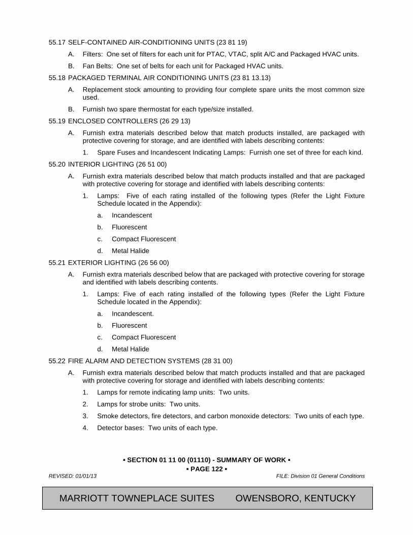
▪ SECTION 01 11 00 (01110) - SUMMARY OF WORK ▪ ▪ PAGE 122 ▪
REVISED: 01/01/13 FILE: Division 01 General Conditions
CFRST SPECMSTR-NEW BUILD 2013, Marriott International, Inc.
55.17 SELF-CONTAINED AIR-CONDITIONING UNITS (23 81 19)
A. Filters: One set of filters for each unit for PTAC, VTAC, split A/C and Packaged HVAC units.
B. Fan Belts: One set of belts for each unit for Packaged HVAC units.
55.18 PACKAGED TERMINAL AIR CONDITIONING UNITS (23 81 13.13)
A. Replacement stock amounting to providing four complete spare units the most common size used.
B. Furnish two spare thermostat for each type/size installed.
55.19 ENCLOSED CONTROLLERS (26 29 13)
A. Furnish extra materials described below that match products installed, are packaged with protective covering for storage, and are identified with labels describing contents:
1. Spare Fuses and Incandescent Indicating Lamps: Furnish one set of three for each kind.
55.20 INTERIOR LIGHTING (26 51 00)
A. Furnish extra materials described below that match products installed and that are packaged with protective covering for storage and identified with labels describing contents:
1. Lamps: Five of each rating installed of the following types (Refer the Light Fixture Schedule located in the Appendix):
a. Incandescent
b. Fluorescent
c. Compact Fluorescent
d. Metal Halide
55.21 EXTERIOR LIGHTING (26 56 00)
A. Furnish extra materials described below that are packaged with protective covering for storage and identified with labels describing contents.
1. Lamps: Five of each rating installed of the following types (Refer the Light Fixture Schedule located in the Appendix):
a. Incandescent.
b. Fluorescent
c. Compact Fluorescent
d. Metal Halide
55.22 FIRE ALARM AND DETECTION SYSTEMS (28 31 00)
A. Furnish extra materials described below that match products installed and that are packaged with protective covering for storage and identified with labels describing contents:
1. Lamps for remote indicating lamp units: Two units.
2. Lamps for strobe units: Two units.
3. Smoke detectors, fire detectors, and carbon monoxide detectors: Two units of each type.
4. Detector bases: Two units of each type.
MARRIOTT TOWNEPLACE SUITES OWENSBORO, KENTUCKY
▪ SECTION 01 11 00 (01110) - SUMMARY OF WORK ▪ ▪ PAGE 123 ▪
FILE: Division 01 General Conditions REVISED: 01/01/13
2013, Marriott International, Inc. CFRST SPECMSTR-NEW BUILD
55.23 [CONCRETE] [BRICK] PAVER UNITS ([32 14 13)] [32 14 16)])
A. Furnish stock of pavers that match blend of products installed in the amount of 10 sf.
PART 56 EXECUTION Not Used
END OF SECTION
Revision Log
MARRIOTT TOWNEPLACE SUITES OWENSBORO, KENTUCKY

▪ SECTION 01 11 00 (01110) - SUMMARY OF WORK ▪ ▪ PAGE 124 ▪
REVISED: 01/01/13 FILE: Division 01 General Conditions
CFRST SPECMSTR-NEW BUILD 2013, Marriott International, Inc.
SECTION 01 79 00 (01820) - DEMONSTRATION AND TRAINING
PART 57 GENERAL 57.01 SUMMARY
A. Section Includes:
1. This Section specifies the administrative requirements, procedural obligations, terms and conditions and training requirements related to instructing the facility engineering personnel in the proper care, preservation, operations and maintenance of materials, finishes, equipment and systems.
a. Preparation and submittal of instructor qualifications, training schedules, and agendas for various building materials, components, systems and equipment.
b. Instruction of the Owner's personnel and adjunct organizations in the proper operation and maintenance of all building materials, components, systems and equipment.
B. Related Sections:
1. Special operating and maintenance data requirements for specific equipment or building operating systems are included in the appropriate Specification Sections of Divisions 02 through 33.
2. Preparation of Shop Drawings and Product Data are included in Specification Section 01 33 00 (01330), Submittals and Substitutions.
3. General closeout requirements are included in Specification Section 01 77 00 (01770). Contract Closeout.
4. General requirements for submittal of Project Record Documents are included in Section 01 78 39 (01785), Project Record Documents.
5. Additional training requirements for building systems and/or equipment are delineated in the appropriate Specification Sections, Divisions 02 through 33.
6. Where training manuals include information on work installed by the Contractor and their Subcontractors, the Contractor shall be responsible for the preparation of the manuals, including collection, collation and binding of the material and submittal of data as specified.
57.02 QUALITY ASSURANCE
A. The status of training deliverables shall be an integral part of the Contractor's coordination process. The Contractor shall meet with the Owner as required, to discuss progress-to-date, deficiencies and non-compliance issues.
57.03 TRAINING MANUALS
A. The completed FINAL VERSION of the approved Operation & Maintenance Manuals and the redlined set of the record "as-built" drawings shall be used as the basis of instruction. The Contractor is not responsible for providing additional copies of these documents for training purposes.
57.04 TRAINING HOURS
A. Training shall be conducted during normal working hours. All training shall be completed prior to the public opening of the hotel property.
MARRIOTT TOWNEPLACE SUITES OWENSBORO, KENTUCKY
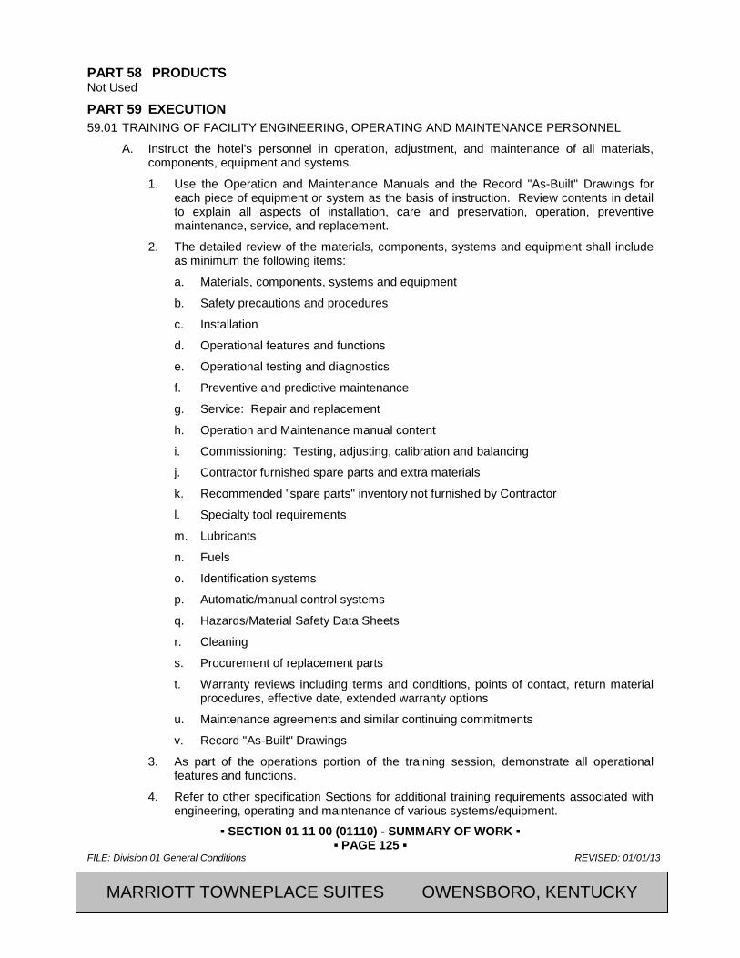
▪ SECTION 01 11 00 (01110) - SUMMARY OF WORK ▪ ▪ PAGE 125 ▪
FILE: Division 01 General Conditions REVISED: 01/01/13
2013, Marriott International, Inc. CFRST SPECMSTR-NEW BUILD
PART 58 PRODUCTS Not Used
PART 59 EXECUTION 59.01 TRAINING OF FACILITY ENGINEERING, OPERATING AND MAINTENANCE PERSONNEL
A. Instruct the hotel's personnel in operation, adjustment, and maintenance of all materials, components, equipment and systems.
1. Use the Operation and Maintenance Manuals and the Record "As-Built" Drawings for each piece of equipment or system as the basis of instruction. Review contents in detail to explain all aspects of installation, care and preservation, operation, preventive maintenance, service, and replacement.
2. The detailed review of the materials, components, systems and equipment shall include as minimum the following items:
a. Materials, components, systems and equipment
b. Safety precautions and procedures
c. Installation
d. Operational features and functions
e. Operational testing and diagnostics
f. Preventive and predictive maintenance
g. Service: Repair and replacement
h. Operation and Maintenance manual content
i. Commissioning: Testing, adjusting, calibration and balancing
j. Contractor furnished spare parts and extra materials
k. Recommended "spare parts" inventory not furnished by Contractor
l. Specialty tool requirements
m. Lubricants
n. Fuels
o. Identification systems
p. Automatic/manual control systems
q. Hazards/Material Safety Data Sheets
r. Cleaning
s. Procurement of replacement parts
t. Warranty reviews including terms and conditions, points of contact, return material procedures, effective date, extended warranty options
u. Maintenance agreements and similar continuing commitments
v. Record "As-Built" Drawings
3. As part of the operations portion of the training session, demonstrate all operational features and functions.
4. Refer to other specification Sections for additional training requirements associated with engineering, operating and maintenance of various systems/equipment.
MARRIOTT TOWNEPLACE SUITES OWENSBORO, KENTUCKY
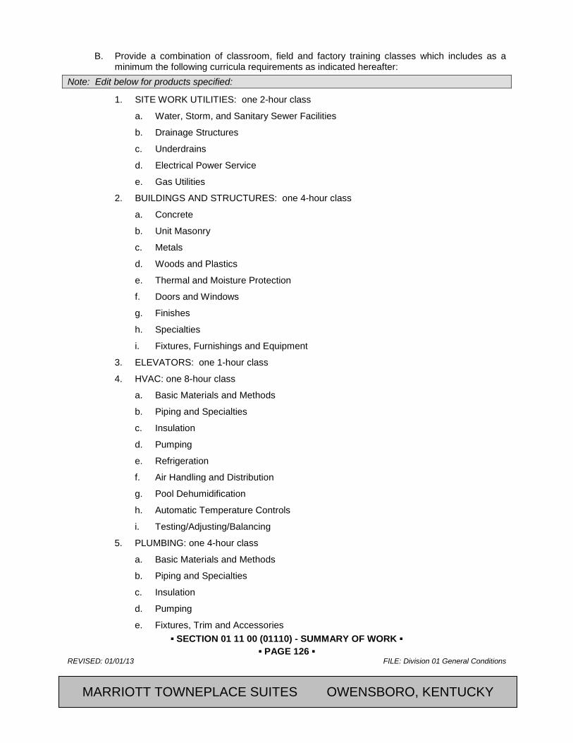
▪ SECTION 01 11 00 (01110) - SUMMARY OF WORK ▪ ▪ PAGE 126 ▪
REVISED: 01/01/13 FILE: Division 01 General Conditions
CFRST SPECMSTR-NEW BUILD 2013, Marriott International, Inc.
B. Provide a combination of classroom, field and factory training classes which includes as a minimum the following curricula requirements as indicated hereafter:
Note: Edit below for products specified:
1. SITE WORK UTILITIES: one 2-hour class
a. Water, Storm, and Sanitary Sewer Facilities
b. Drainage Structures
c. Underdrains
d. Electrical Power Service
e. Gas Utilities
2. BUILDINGS AND STRUCTURES: one 4-hour class
a. Concrete
b. Unit Masonry
c. Metals
d. Woods and Plastics
e. Thermal and Moisture Protection
f. Doors and Windows
g. Finishes
h. Specialties
i. Fixtures, Furnishings and Equipment
3. ELEVATORS: one 1-hour class
4. HVAC: one 8-hour class
a. Basic Materials and Methods
b. Piping and Specialties
c. Insulation
d. Pumping
e. Refrigeration
f. Air Handling and Distribution
g. Pool Dehumidification
h. Automatic Temperature Controls
i. Testing/Adjusting/Balancing
5. PLUMBING: one 4-hour class
a. Basic Materials and Methods
b. Piping and Specialties
c. Insulation
d. Pumping
e. Fixtures, Trim and Accessories
MARRIOTT TOWNEPLACE SUITES OWENSBORO, KENTUCKY
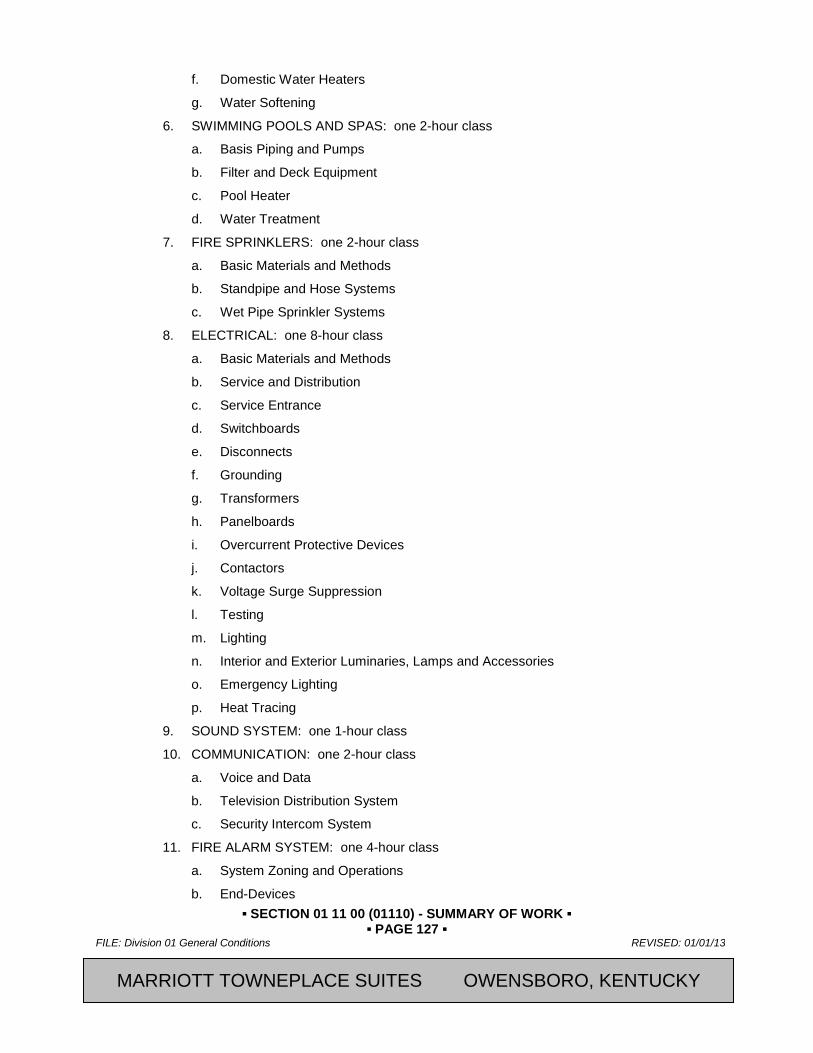
▪ SECTION 01 11 00 (01110) - SUMMARY OF WORK ▪ ▪ PAGE 127 ▪
FILE: Division 01 General Conditions REVISED: 01/01/13
2013, Marriott International, Inc. CFRST SPECMSTR-NEW BUILD
f. Domestic Water Heaters
g. Water Softening
6. SWIMMING POOLS AND SPAS: one 2-hour class
a. Basis Piping and Pumps
b. Filter and Deck Equipment
c. Pool Heater
d. Water Treatment
7. FIRE SPRINKLERS: one 2-hour class
a. Basic Materials and Methods
b. Standpipe and Hose Systems
c. Wet Pipe Sprinkler Systems
8. ELECTRICAL: one 8-hour class
a. Basic Materials and Methods
b. Service and Distribution
c. Service Entrance
d. Switchboards
e. Disconnects
f. Grounding
g. Transformers
h. Panelboards
i. Overcurrent Protective Devices
j. Contactors
k. Voltage Surge Suppression
l. Testing
m. Lighting
n. Interior and Exterior Luminaries, Lamps and Accessories
o. Emergency Lighting
p. Heat Tracing
9. SOUND SYSTEM: one 1-hour class
10. COMMUNICATION: one 2-hour class
a. Voice and Data
b. Television Distribution System
c. Security Intercom System
11. FIRE ALARM SYSTEM: one 4-hour class
a. System Zoning and Operations
b. End-Devices
MARRIOTT TOWNEPLACE SUITES OWENSBORO, KENTUCKY
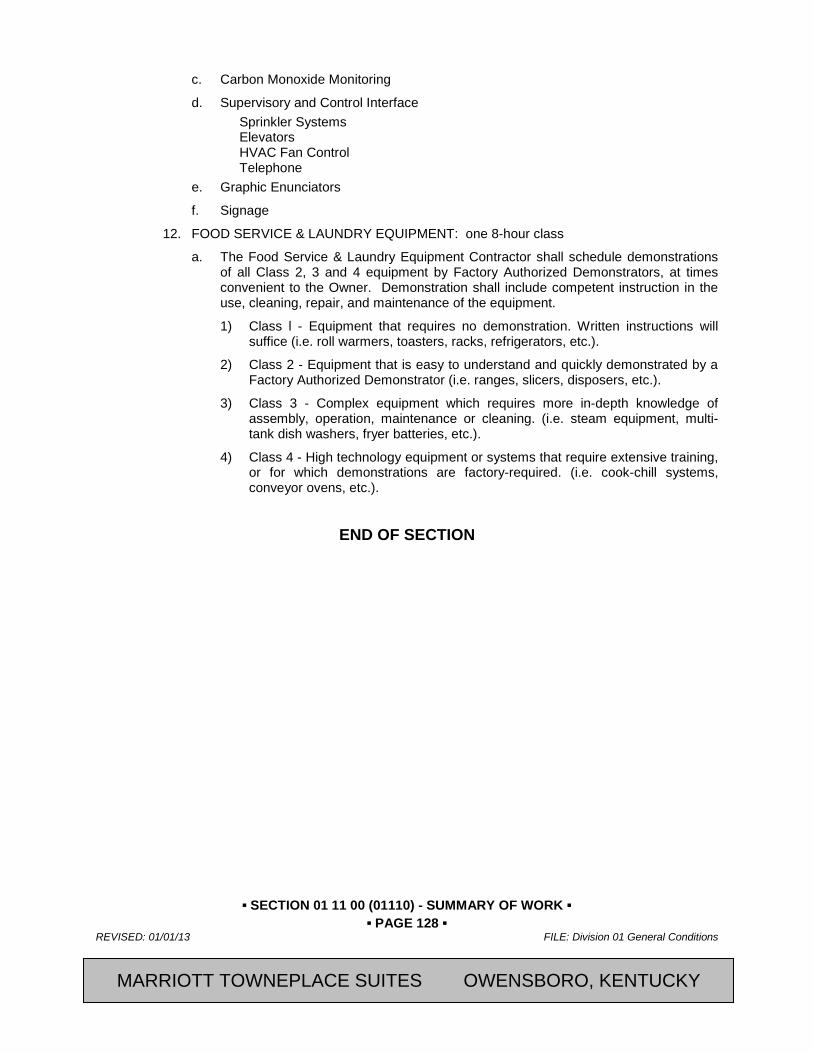
▪ SECTION 01 11 00 (01110) - SUMMARY OF WORK ▪ ▪ PAGE 128 ▪
REVISED: 01/01/13 FILE: Division 01 General Conditions
CFRST SPECMSTR-NEW BUILD 2013, Marriott International, Inc.
c. Carbon Monoxide Monitoring
d. Supervisory and Control Interface Sprinkler Systems Elevators HVAC Fan Control Telephone
e. Graphic Enunciators
f. Signage
12. FOOD SERVICE & LAUNDRY EQUIPMENT: one 8-hour class
a. The Food Service & Laundry Equipment Contractor shall schedule demonstrations of all Class 2, 3 and 4 equipment by Factory Authorized Demonstrators, at times convenient to the Owner. Demonstration shall include competent instruction in the use, cleaning, repair, and maintenance of the equipment.
1) Class l - Equipment that requires no demonstration. Written instructions will suffice (i.e. roll warmers, toasters, racks, refrigerators, etc.).
2) Class 2 - Equipment that is easy to understand and quickly demonstrated by a Factory Authorized Demonstrator (i.e. ranges, slicers, disposers, etc.).
3) Class 3 - Complex equipment which requires more in-depth knowledge of assembly, operation, maintenance or cleaning. (i.e. steam equipment, multi-tank dish washers, fryer batteries, etc.).
4) Class 4 - High technology equipment or systems that require extensive training, or for which demonstrations are factory-required. (i.e. cook-chill systems, conveyor ovens, etc.).
END OF SECTION
MARRIOTT TOWNEPLACE SUITES OWENSBORO, KENTUCKY

▪ SECTION 01 11 00 (01110) - SUMMARY OF WORK ▪ ▪ PAGE 129 ▪
FILE: Division 01 General Conditions REVISED: 01/01/13
2013, Marriott International, Inc. CFRST SPECMSTR-NEW BUILD
SECTION 01 81 19 - INDOOR AIR QUALITY REQUIREMENTS
PART 60 GENERAL 60.01 SUMMARY
A. Special requirements for Indoor Air Quality (IAQ) management during construction operations.
1. Control of emissions during construction.
2. Moisture control during construction.
B. Related Sections:
1. Section 01 11 00 – Summary of Work
2. Section 01 33 00 – Submittal and Substitution Procedures
3. Section 01 74 19 - Construction Waste Management and Disposal
4. Section 01 81 13 – Sustainable Design Requirements.
5. Divisions 01 through 50 Sections for LEED requirements specific to the Work of each of those Sections. These requirements may or may not include reference to LEED.
60.02 REFERENCES
A. American Society of Heating, Refrigerating and Air-Conditioning Engineers, Inc. (ASHRAE) Publications:
1. 52.2, "Method of Testing General Ventilation Air-Cleaning Devices for Removal Efficiency by Particle Size"
B. ASTM International (ASTM) Publications: (Former American Society for Testing and Materials)
1. D7186 “Standard Practice for Quality Assurance Observation of Roof Construction and Repair”
2. E2114 “Standard Terminology for Sustainability Relative to the Performance of Buildings”
C. Carpet & Rug Institute (CRI) Publications:
1. Carpet: “Green Label Plus Program”
2. Carpet Cushion: “Green Label Program”
D. Code of Federal Regulations (CFR) Publications:
1. 40 CFR, Part 59, Subpart D-2001, "National Volatile Organic Compound Emission Standards for Architectural Coatings"
E. U.S. Environmental Protection Agency (EPA) Publications:
1. EPA Protocol for Environmental Requirements, “Testing for Indoor Air Quality, Baseline IAQ, and Materials”, for Research Triangle Park Campus, Section 01445.
2. “EPA Compendium of Methods for the Determination of Inorganic Compounds in Ambient Air”
3. “EPA Compendium of Methods for the Determination of Air Pollutants in Indoor Air”
F. Forest Stewardship Council (FSC) Publications:
1. FSC-STD-01-001, "FSC Principles and Criteria for Forest Stewardship"
2. FSC-STD-01-002, "FSC Glossary of Terms"
G. Green Seal, Inc. Publications:
MARRIOTT TOWNEPLACE SUITES OWENSBORO, KENTUCKY
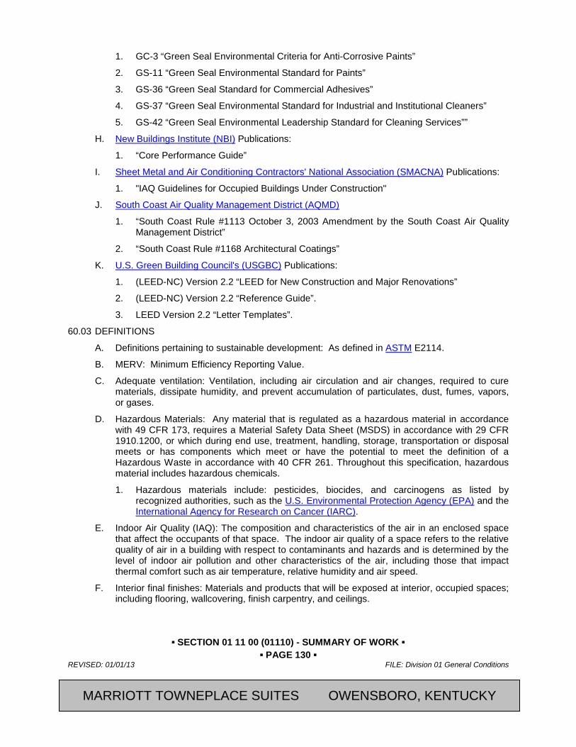
▪ SECTION 01 11 00 (01110) - SUMMARY OF WORK ▪ ▪ PAGE 130 ▪
REVISED: 01/01/13 FILE: Division 01 General Conditions
CFRST SPECMSTR-NEW BUILD 2013, Marriott International, Inc.
1. GC-3 “Green Seal Environmental Criteria for Anti-Corrosive Paints”
2. GS-11 “Green Seal Environmental Standard for Paints”
3. GS-36 “Green Seal Standard for Commercial Adhesives”
4. GS-37 “Green Seal Environmental Standard for Industrial and Institutional Cleaners”
5. GS-42 “Green Seal Environmental Leadership Standard for Cleaning Services””
H. New Buildings Institute (NBI) Publications:
1. “Core Performance Guide”
I. Sheet Metal and Air Conditioning Contractors' National Association (SMACNA) Publications:
1. "IAQ Guidelines for Occupied Buildings Under Construction"
J. South Coast Air Quality Management District (AQMD)
1. “South Coast Rule #1113 October 3, 2003 Amendment by the South Coast Air Quality Management District”
2. “South Coast Rule #1168 Architectural Coatings”
K. U.S. Green Building Council's (USGBC) Publications:
1. (LEED-NC) Version 2.2 “LEED for New Construction and Major Renovations”
2. (LEED-NC) Version 2.2 “Reference Guide”.
3. LEED Version 2.2 “Letter Templates”.
60.03 DEFINITIONS
A. Definitions pertaining to sustainable development: As defined in ASTM E2114.
B. MERV: Minimum Efficiency Reporting Value.
C. Adequate ventilation: Ventilation, including air circulation and air changes, required to cure materials, dissipate humidity, and prevent accumulation of particulates, dust, fumes, vapors, or gases.
D. Hazardous Materials: Any material that is regulated as a hazardous material in accordance with 49 CFR 173, requires a Material Safety Data Sheet (MSDS) in accordance with 29 CFR 1910.1200, or which during end use, treatment, handling, storage, transportation or disposal meets or has components which meet or have the potential to meet the definition of a Hazardous Waste in accordance with 40 CFR 261. Throughout this specification, hazardous material includes hazardous chemicals.
1. Hazardous materials include: pesticides, biocides, and carcinogens as listed by recognized authorities, such as the U.S. Environmental Protection Agency (EPA) and the International Agency for Research on Cancer (IARC).
E. Indoor Air Quality (IAQ): The composition and characteristics of the air in an enclosed space that affect the occupants of that space. The indoor air quality of a space refers to the relative quality of air in a building with respect to contaminants and hazards and is determined by the level of indoor air pollution and other characteristics of the air, including those that impact thermal comfort such as air temperature, relative humidity and air speed.
F. Interior final finishes: Materials and products that will be exposed at interior, occupied spaces; including flooring, wallcovering, finish carpentry, and ceilings.
MARRIOTT TOWNEPLACE SUITES OWENSBORO, KENTUCKY

▪ SECTION 01 11 00 (01110) - SUMMARY OF WORK ▪ ▪ PAGE 131 ▪
FILE: Division 01 General Conditions REVISED: 01/01/13
2013, Marriott International, Inc. CFRST SPECMSTR-NEW BUILD
G. Packaged dry products: Materials and products that are installed in dry form and are delivered to the site in manufacturer's packaging; including carpets, resilient flooring, ceiling tiles, and insulation.
H. Wet products: Materials and products installed in wet form, including paints, sealants, adhesives, special coatings, and other materials which require curing.
60.04 REQUIREMENTS
A. Develop and implement an Indoor Air Quality Management Plan during construction that meets or exceeds the minimum requirements of the SMACNA “IAQ Guideline for Occupied Buildings Under Construction”, 1995, Chapter 3. The required Best Management Practices are summarized in Part 3 of this Section.
B. Protect stored on-site or installed absorptive materials from moisture damage.
C. Use specific filtration media at each return air grill during construction, after construction, and prior to occupancy.
D. Use low- or no-emitting adhesives, sealants, paints, primers, carpets and composite wood products within the vapor barrier.
1. Product requirements are specified in Divisions 02 through 50.
2. Where specific products are not called out, refer to the Requirements within this Section.
60.05 SUBMITTALS
A. IAQ Management Plan: Within [14][20] working days after receipt of Notice of Award of Bid, or prior to HVAC work, whichever occurs sooner, the Contractor should submit 3 copies of the Draft IAQ Management Plan to the [Owner’s Representative] [Architect]for approval.
1. The Draft Plan must meet or exceed the SMACNA Best Management Practices described in Part 3 of this Section.
2. In the Plan designate an on-site party (or parties) responsible for instructing workers and overseeing and documenting results of the IAQ Management Plan for the Project.
3. Once the [Owner’s Representative] [Architect] has determined which of the BMPs contained in the above draft Plan are acceptable, the Contractor shall submit, within 14 working days, a Final IAQ Management Plan. The Contractor shall distribute copies of the IAQ Management Plan to the Job Site Foreman, each Subcontractor, the [Owner’s Representative] [and the] [Architect].
B. IAQ Management Reports: The Contractor shall submit with each Progress Report a summary of IAQ Management issues. The Summary shall be submitted on a form approved by the Owner.
C. Provide a minimum of 18 photographs (3 each on 6 separate occasions) of construction IAQ management measures such as protection of ducts and on-site stored or installed absorptive materials.
D. Provide product data for filtration media used during construction and installed immediately prior to occupancy with MERV values highlighted.
PART 61 PRODUCTS 61.01 PRODUCT REQUIREMENTS
A. If air handlers must be used during construction, filtration media with a Minimum Efficiency Reporting Value (MERV) of 8 must be used at each return air grill.
B. Use low-emitting adhesives, sealants, paints, primers, carpets and composite wood products within the vapor barrier. This includes, but is not limited to:
MARRIOTT TOWNEPLACE SUITES OWENSBORO, KENTUCKY
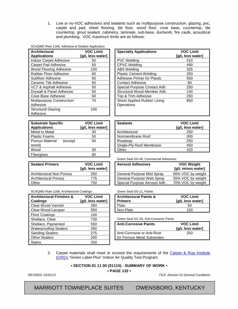
▪ SECTION 01 11 00 (01110) - SUMMARY OF WORK ▪ ▪ PAGE 132 ▪
REVISED: 01/01/13 FILE: Division 01 General Conditions
CFRST SPECMSTR-NEW BUILD 2013, Marriott International, Inc.
1. Low or no-VOC adhesives and sealants such as multipurpose construction, glazing, pvc, carpet and pad, sheet flooring, tile floor, wood floor, cove base, countertop, tile countertop, grout sealant, cabinetry, laminate, sub-base, ductwork, fire caulk, acoustical and plumbing. VOC maximum limits are as follows:
SCAQMD Rule 1168, Adhesive & Sealant Application Architectural Applications
VOC Limit [g/L less water]
Specialty Applications VOC Limit [g/L less water]
Indoor Carpet Adhesive 50 PVC Welding 510 Carpet Pad Adhesive 50 CPVC Welding 490 Wood Flooring Adhesive 100 ABS Welding 325 Rubber Floor Adhesive 60 Plastic Cement Welding 250 Subfloor Adhesive 50 Adhesive Primer for Plastic 550 Ceramic Tile Adhesive 65 Contact Adhesive 80 VCT & Asphalt Adhesive 50 Special Purpose Contact Adh. 250 Drywall & Panel Adhesive 50 Structural Wood Member Adh. 140 Cove Base Adhesive 50 Top & Trim Adhesive 250 Multipurpose Construction Adhesive
70 Sheet Applied Rubber Lining Operations
850
Structural Glazing Adhesive
100
Substrate Specific Applications
VOC Limit [g/L less water]
Sealants VOC Limit [g/L less water]
Metal to Metal 30 Architectural 250 Plastic Foams 50 Nonmembrane Roof 300 Porous Material (except wood)
50 Roadway 250 Single-Ply Roof Membrane 450
Wood 30 Other 420 Fiberglass 80 Green Seal GS-36, Commercial Adhesives Sealant Primers VOC Limit
[g/L less water] Aerosol Adhesives VOC Weight
[g/L minus water] Architectural Non Porous 250 General Purpose Mist Spray 65% VOC by weight Architectural Porous 775 General Purpose Web Spray 55% VOC by weight Other 750 Special Purpose Aerosol Adh. 70% VOC by weight SCAQMD Rule 1168, Architectural Coatings Green Seal GS-11, Paints
Architectural Finishes & Coatings
VOC Limit [g/L less water]
Architectural Paints & Primers
VOC Limit [g/L less water]
Clear Wood Varnish 350 Flats 50 Clear Wood Lacquer 550 Non-Flats 150 Floor Coatings 100 Shellacs, Clear 730 Green Seal GC-03, Anti-Corrosive Paints Shellacs, Pigmented 550 Anti-Corrosive Paints VOC Limit Waterproofing Sealers 250 [g/L less water] Sanding Sealers 275 Anti-Corrosive or Anti-Rust 250 Other Sealers 200 for Ferrous Metal Substrates Stains 250
2. Carpet materials shall meet or exceed the requirements of the Carpet & Rug Institute
(CRI)'s “Green Label Plus” Indoor Air Quality Test Program.
MARRIOTT TOWNEPLACE SUITES OWENSBORO, KENTUCKY
▪ SECTION 01 11 00 (01110) - SUMMARY OF WORK ▪ ▪ PAGE 133 ▪
FILE: Division 01 General Conditions REVISED: 01/01/13
2013, Marriott International, Inc. CFRST SPECMSTR-NEW BUILD
PART 62 EXECUTION 62.01 GENERAL
A. During construction operations, follow the recommendations in SMACNA “IAQ Guidelines for Occupied Buildings under Construction”.
B. Many Best Management Practices are available to maintain IAQ during construction or demolition. The pros, cons, and limitations of each available option should be considered to identify the most effective and most efficient approaches for a particular job. When designing the Plan, the Contractor may use more than one of these practices (simultaneously or phased in) as work progresses. In general, the steps include:
1. Containing the work area
2. Modifying HVAC operation
3. Reducing emissions
4. Intensifying housekeeping
5. Scheduling material delivery to avoid contamination
6. Protecting stored and installed absorptive materials from contamination.
62.02 REQUIRED IAQ MANAGEMENT BEST MANAGEMENT PRACTICES
A. Pathway Interruption:
1. Isolate areas of work as necessary to prevent contamination of clean or occupied spaces. Provide pressure differentials and/or physical barriers to protect clean or occupied spaces.
B. Housekeeping:
1. During construction, maintain project and building products and systems to prevent contamination of building spaces.
2. Use low-toxic cleaning supplies for surfaces, equipment and worker’s personal use. Options include Green Seal, citrus-based or soy-based solvent cleaners. Refer to Green Seal, Inc. website for a list of approved products at www.greenseal.org/certproducts.htm
3. Use wet sanding for gypsum assemblies. Exception: Dry sanding allowed subject to [Owner’s Representative] [Architect’s] approval of the following measures.
a. Full isolation of space under finishing.
b. Plastic protection sheeting is installed to provide air sealing during the sanding
c. Closure of all air system devices and ductwork
d. Sequencing of construction precludes the possibility of contamination of other spaces with gypsum dust
e. Worker protection provided
C. Materials Handling: Protect construction materials from contamination and pollution from contact with construction dust, debris, fumes, solvents, and other pollutants.
1. The design of each system must be evaluated in detail to determine how it may be affected by odor and dust from the project (including site egress, staging areas, etc.).
2. Designate receiving/storage areas for incoming material to be delivered according to installation schedule and to be placed convenient to work area in order to minimize waste due to excessive materials handling and misapplication.
MARRIOTT TOWNEPLACE SUITES OWENSBORO, KENTUCKY

▪ SECTION 01 11 00 (01110) - SUMMARY OF WORK ▪ ▪ PAGE 134 ▪
REVISED: 01/01/13 FILE: Division 01 General Conditions
CFRST SPECMSTR-NEW BUILD 2013, Marriott International, Inc.
3. Protect stored on-site or installed absorptive materials from moisture damage.
4. Hazardous wastes shall be separated, stored, and disposed of according to local regulations.
5. Schedule delivery of materials to minimize the duration of on-site storage.
D. Changing Work Practices:
1. For some demolition tasks (e.g., paint stripping) there may be techniques available that produce less airborne dust. Some painting techniques release fewer odors. Some cleaning practices raise less dust.
E. Modifying Equipment Operation: Use of equipment may need to be restricted in order to meet IAQ objectives. This could involve substituting cleaner equipment or simply changing operating Procedures. Examples of such controls include:
1. Restricting traffic volume or prohibiting idling of motor vehicles where emissions could be drawn into occupied areas.
2. Switching from diesel to biodiesel or bottled gas for equipment such as generators or forklifts (emissions are cleaner but still potentially harmful under some circumstances). Use of electric forklifts and other equipment should be considered when feasible, since they do not burn fossil fuels, thus eliminating exposure to combustion gas emissions.
F. VOC Control: Schedule installation of materials to minimize contamination of absorptive materials with VOCs, solvents, dust, etc. (For example, install carpet after painting has been completed, since carpet can absorb VOCs released while the paint dries).
1. All dry furnishings and materials (such as carpet, floor tile, acoustical tile, textiles, office furniture, wood shelving, etc.) shall be allowed to "air-out" or pre-condition prior to installation.
2. "Bake-outs" of furnishings and construction materials is not recommended due to questionable effectiveness and potential for damage.
3. Reduce exposure to VOCs as follows:
a. An enclosed tanker is preferable to an open kettle for roofing.
b. Containers of wet products should be kept closed as much as possible.
c. Waste materials that can release odor or dust should e covered or sealed.
d. Applying a sealer may control a surface that is persistent odor source.
4. Ductwork and appurtenances should be inspected upon completion of the work for the amount of deposited particulate present and cleaned where needed.
5. Both highly specialized equipment and professional expertise may be required to ensure that dust is effectively removed and contained.
6. The sequence in which duct cleaning occurs in the overall construction process needs to be carefully considered to avoid recontamination.
G. Moisture Control:
1. Keep materials dry. Protect stored on-site and installed absorptive materials from moisture damage.
2. Verify that installed materials and products are dry prior to sealing and weatherproofing the building envelope.
MARRIOTT TOWNEPLACE SUITES OWENSBORO, KENTUCKY
▪ SECTION 01 11 00 (01110) - SUMMARY OF WORK ▪ ▪ PAGE 135 ▪
FILE: Division 01 General Conditions REVISED: 01/01/13
2013, Marriott International, Inc. CFRST SPECMSTR-NEW BUILD
3. Install interior absorptive materials only after building envelope is sealed and weatherproofed.
4. Inspections: Document and report results of inspections; state whether or not inspections indicate satisfactory conditions.
a. Examine materials for dampness as they arrive. If acceptable to [Owner’s Representative] dry damp materials completely prior to installation; otherwise, reject materials that arrive damp.
b. Examine materials for mold as they arrive and reject materials that arrive contaminated with mold.
c. Inspect stored and installed absorptive materials regularly for dampness and mold growth. Inspect weekly, and after each rain event].
1) Where stored on-site or installed absorptive materials become wet, notify [Owner’s Representative] Inspect for damage. If acceptable to [Owner’s Representative]], dry completely prior to closing in assemblies; otherwise, remove and replace with new materials.
d. Site drainage: Verify that final grades of site work and landscaping drain surface water and ground water away from the building.
e. Weather-proofing: Inspect moisture control materials as they are being installed. Include the following: 1) Air barrier: Verify air barrier is installed without punctures and/or other damage.
Verify air barrier is sealed completely.
2) Flashing: Verify correct shingling of the flashing for roof, walls, windows, doors, and other penetrations.
3) Insulation layer: Verify insulation is installed without voids.
4) Roofing: In accordance with ASTM D7186 “Standard Practice for Quality Assurance Observation of Roof Construction and Repair”
f. Plumbing: Verify satisfactory pressure test of pipes and drains is performed before closing in and insulating lines.
H. Mechanical Systems:
1. Protection: All HVAC equipment must be protected from collecting dust and contaminants that can be collected in the system and later be released. Specific HVAC protection requirements generally apply to the return side, central filtration, or supply side of the system.
2. Return Side: The return side of an HVAC system is, by definition, under negative pressure and thus capable of drawing in nearby construction dust and odor. Special attention must be paid to the location of any return vents, return ducts, ceiling plenums, return shafts, VAV plenum intakes, window units, and transfer vents as well as that portion of the air handler which is upstream of the central fan. When possible, the entire system should be shut down during heavy construction or demolition that generates dust and airborne particles.
a. All return system openings in, or immediately adjacent to, the construction area should be sealed with plastic.
b. When the system must remain operational during construction, temporary filters should be added where necessary (e.g., on grills to return air shaft). Filters used
MARRIOTT TOWNEPLACE SUITES OWENSBORO, KENTUCKY
▪ SECTION 01 11 00 (01110) - SUMMARY OF WORK ▪ ▪ PAGE 136 ▪
REVISED: 01/01/13 FILE: Division 01 General Conditions
CFRST SPECMSTR-NEW BUILD 2013, Marriott International, Inc.
during construction must have a minimum rating of MERV 8 and must receive frequent periodic maintenance.
c. Replace the filters at the end of the project with MERV 13 filters. Provide MERV 13 filters to process both return and outside air that is to be delivered as supply air. Verify that equipment is capable of accepting MERV 13 filters, or notify the [Owner’s RepresentativeWhen the general system must remain operational, the heaviest work areas should be dampered off or otherwise blocked if temporary imbalance of the return air system does not create a greater problem.
d. The mechanical room should not be used to store construction or waste materials.
3. Supply Side:
a. Diffusers, terminal units, and ducts may be adequately protected in most cases where the above measures are implemented. When the system is off for the duration of construction, diffusers and window units should also be sealed with plastic for further protection.
b. Ducts, diffusers, and window units should be inspected upon completion of the work for the amount of deposited particulate present and cleaned where needed. If significant dust deposits are observed in the system during construction, some particulate discharge can be expected during start-up. When such a discharge is only minor, delaying re-occupancy long enough to clean up the dust may be sufficient. In more severe cases, installing temporary coarse filters on diffusers or cleaning the ducts may be necessary. The condition of the main duct should be checked whenever visible particles are discharged from the system.
I. Local Exhaust:
1. Pollution sources can be directly exhausted to the outside. This may be done through an exhaust system already available in the building or more often by a portable fan vented to the outside and attached to the work site by flex duct. Depending on the nature of the material and the location of the exhaust, special filtration of the exhaust may or may not be necessary. Any emissions to the outside must be in compliance with applicable regulations and should be directed well away from intakes.
J. Air Cleaning:
1. Where exhaust is not feasible, local re-circulation of air through a portable air cleaner may be effective. The type of filter should be suitable for the material being controlled (e.g., charcoal or potassium permanganate for many odors, a moderate to high efficiency filter for dust).
K. Inspection:
1. Conduct regular inspection and maintenance of indoor air quality measures including ventilation system protection.
END OF SECTION
MARRIOTT TOWNEPLACE SUITES OWENSBORO, KENTUCKY
▪ SECTION 01 11 00 (01110) - SUMMARY OF WORK ▪ ▪ PAGE 137 ▪
FILE: Division 01 General Conditions REVISED: 01/01/13
2013, Marriott International, Inc. CFRST SPECMSTR-NEW BUILD
SECTION 01 91 13 - GENERAL COMMISSIONING REQUIREMENTS
PART 63 GENERAL 63.01 SUMMARY
A. Section includes general requirements that apply to implementation of commissioning without regard to specific systems, assemblies, or components.
1. Commissioning is a systematic process to verify that all building systems perform interactively according to the design intent and the owner’s operational needs. This is achieved by beginning in the design phase and documenting design intent and continuing through construction, acceptance and the warranty period with actual verification of performance. The commissioning process shall encompass and coordinate the traditionally separate functions of system documentation, equipment startup, control system calibration, testing and balancing, performance testing and training.
2. Commissioning during the construction phase is intended to achieve the following specific objectives according to the Contract Documents:
a. Verify that applicable equipment and systems are installed according to the manufacturer’s recommendations and to industry accepted minimum standards and that they receive adequate operational checkout by installing contractors.
b. Verify and document proper performance of equipment and systems.
3. The commissioning process does not take away from or reduce the responsibility of the system designers or installing contractors to provide a finished and fully functioning product.
4. OPR documentation is included for information only.
B. Related Sections:
1. Section 01 31 00 - Project Management and Coordination: To introduce commissioning and refers to this Section.
2. Section 01 77 00 - Closeout Procedures: Which defines substantial completion and functional completion, relative to commissioning.
3. Section 22 08 00 – Commissioning of Plumbing: For commissioning process activities for plumbing systems, assemblies, equipment, and components.
4. Section 23 08 00 –Commissioning of HVAC: For commissioning process activities for HVAC&R systems, assemblies, equipment, and components.
5. Section 26 08 00 – Commissioning of Electrical Systems: For commissioning process activities for integrated automation systems, assemblies, equipment, and components.
63.02 REFERENCES
A. U.S. Green Building Council's (USGBC) Publications:
1. (LEED-NC) Version 2.2 “LEED for New Construction and Major Renovations”
2. (LEED-NC) Version 2.2 “Reference Guide”
63.03 DEFINITIONS
A. Abbreviations. The following are common abbreviations used in the Specifications and in the Commissioning Plan. A/E- Architect and design engineers GC- General contractor (prime) CxA- Commissioning authority MC- Mechanical contractor
MARRIOTT TOWNEPLACE SUITES OWENSBORO, KENTUCKY
▪ SECTION 01 11 00 (01110) - SUMMARY OF WORK ▪ ▪ PAGE 138 ▪
REVISED: 01/01/13 FILE: Division 01 General Conditions
CFRST SPECMSTR-NEW BUILD 2013, Marriott International, Inc.
CC Controls contractor OR- Owner's Representative Cx- Commissioning PC- Prefunctional checklist Cx Plan- Commissioning Plan document PM- Project manager (of the Owner) EC- Electrical contractor Subs- Subcontractors to General FT- Functional performance test TAB- Test and balance contractor
B. Acceptance Phase. Phase of construction after startup and initial checkout when functional performance tests, O&M documentation review and training occurs.
C. Approval. Acceptance that a piece of equipment or system has been properly installed and is functioning in the tested modes according to the Contract Documents.
D. Architect/Engineer (A/E): The prime consultant (architect) and sub-consultants who comprise the design team, generally the HVAC mechanical designer/engineer and the electrical designer/engineer.
E. BoD: Basis of Design. A document that records concepts, calculations, decisions, and product selections used to meet the OPR and to satisfy applicable regulatory requirements, standards, and guidelines. The document includes both narrative descriptions and lists of individual items that support the design process.
F. CxA: Commissioning Authority. An independent agent, not otherwise associated with the A/E team members or the Contractor, hired by the Owner. The CxA directs and coordinates the day-to-day commissioning activities. The CxA does not take an oversight role like the CM. The CxA is part of the Construction Manager (CM) team or shall report directly to the CM.
G. Cx Plan: Commissioning Plan: A document that outlines the organization, schedule, allocation of resources, and documentation requirements of the commissioning process
H. Datalogging: Monitoring flows, currents, status, pressures, etc. of equipment using stand-alone dataloggers separate from the control system.
I. Deferred Functional Tests : FTs that are performed later, after substantial completion, due to partial occupancy, equipment, seasonal requirements, design or other site conditions that disallow the test from being performed.
J. Deficiency : A condition in the installation or function of a component, piece of equipment or system that is not in compliance with the Contract Documents (that is, does not perform properly or is not complying with the design intent)
K. Design Intent: A dynamic document that provides the explanation of the ideas, concepts and criteria that are considered to be very important to the owner. It is initially the outcome of the programming and conceptual design phases.
L. Design Narrative or Design Documentation: Sections of either the Design Intent or Basis of Design.
M. Factory Testing: Testing of equipment on-site or at the factory by factory personnel with an Owner’s representative present.
MARRIOTT TOWNEPLACE SUITES OWENSBORO, KENTUCKY

▪ SECTION 01 11 00 (01110) - SUMMARY OF WORK ▪ ▪ PAGE 139 ▪
FILE: Division 01 General Conditions REVISED: 01/01/13
2013, Marriott International, Inc. CFRST SPECMSTR-NEW BUILD
N. Functional Performance Test (FT): Test of the dynamic function and operation of equipment and systems using manual (direct observation) or monitoring methods. Functional testing is the dynamic testing of systems (rather than just components) under full operation (e.g., the chiller pump is tested interactively with the chiller functions to see if the pump ramps up and down to maintain the differential pressure setpoint). Systems are tested under various modes, such as during low cooling or heating loads, high loads, component failures, unoccupied, varying outside air temperatures, fire alarm, power failure, etc. The systems are run through all the control system’s sequences of operation and components are verified to be responding as the sequences state. Traditional air or water test and balancing (TAB) is not functional testing, in the commissioning sense of the word. TAB’s primary work is setting up the system flows and pressures as specified, while functional testing is verifying that which has already been set up. The commissioning authority develops the functional test procedures in a sequential written form, coordinates, oversees and documents the actual testing, which is usually performed by the installing contractor or vendor. FTs are performed after prefunctional checklists and startup are complete.
O. General Contractor (GC): The prime contractor for this project. Generally refers to all the GC’s subcontractors as well. Also referred to as the Contractor, in some contexts.
P. Indirect Indicators: Indicators of a response or condition, such as a reading from a control system screen reporting a damper to be 100% closed
Q. Manual Test: Using hand-held instruments, immediate control system readouts or direct observation to verify performance (contrasted to analyzing monitored data taken over time to make the “observation”).
R. Monitoring: The recording of parameters (flow, current, status, pressure, etc.) of equipment operation using dataloggers or the trending capabilities of control systems.
S. Non-Compliance: See Deficiency.
T. Non-Conformance: See Deficiency.
U. Over-written Value: Writing over a sensor value in the control system to see the response of a system (e.g., changing the outside air temperature value from 50F to 75F to verify economizer operation). See also “Simulated Signal.”
V. OPR: Owner's Project Requirements. A document that details the functional requirements of a project and the expectations of how it will be used and operated. These include Project goals, measurable performance criteria, cost considerations, benchmarks, success criteria, and supporting information.
W. Prefunctional Checklist (PC): A list of items to inspect and elementary component tests to conduct to verify proper installation of equipment, provided by the CxA to the Sub. Prefunctional checklists are primarily static inspections and procedures to prepare the equipment or system for initial operation (e.g., belt tension, oil levels OK, labels affixed, gages in place, sensors calibrated, etc.). However, some prefunctional checklist items entail simple testing of the function of a component, a piece of equipment or system (such as measuring the voltage imbalance on a three phase pump motor of a chiller system). The word prefunctional refers to before functional testing. Prefunctional checklists augment and are combined with the manufacturer’s start-up checklist. Even without a commissioning process, contractors typically perform some, if not many, of the prefunctional checklist items a commissioning authority will recommend. However, few contractors document in writing the execution of these checklist items. Therefore, for most equipment, the contractors execute the checklists on their own. The commissioning authority only requires that the procedures be documented in writing, and does not witness much of the prefunctional checklisting, except for larger or more critical pieces of equipment.
MARRIOTT TOWNEPLACE SUITES OWENSBORO, KENTUCKY
▪ SECTION 01 11 00 (01110) - SUMMARY OF WORK ▪ ▪ PAGE 140 ▪
REVISED: 01/01/13 FILE: Division 01 General Conditions
CFRST SPECMSTR-NEW BUILD 2013, Marriott International, Inc.
X. Sampling: Functionally testing only a fraction of the total number of identical or near identical pieces of equipment.
Y. Seasonal Performance Tests: FT that are deferred until the system(s) will experience conditions closer to their design conditions.
Z. Simulated Condition: Condition that is created for the purpose of testing the response of a system (e.g., applying a hair blower to a space sensor to see the response in a VAV box).
AA. Simulated Signal: Disconnecting a sensor and using a signal generator to send an amperage, resistance or pressure to the transducer and DDC system to simulate a sensor value.
BB. Systems, Subsystems, Equipment, and Components: Where these terms are used together or separately, they shall mean "as-built" systems, subsystems, equipment, and components.
CC. Startup: The initial starting or activating of dynamic equipment, including executing prefunctional checklists.
DD. Subs: The subcontractors to the GC who provide and install building components and systems.
EE. Test Procedures: The step-by-step process which must be executed to fulfill the test requirements. The test procedures are developed by the CxA.
FF. Test Requirements: Requirements specifying what modes and functions, etc. shall be tested. The test requirements are not the detailed test procedures. The test requirements are specified in the Contract Documents
GG. Trending: Monitoring using the building control system.
HH. Vendor: Supplier of equipment.
II. Warranty Period: Warranty period for entire project, including equipment components. Warranty begins at Substantial Completion and extends for at least one year, unless specifically noted otherwise in the Contract Documents and accepted submittals.
63.04 COORDINATION
A. Commissioning Team. The members of the commissioning team consist of the Commissioning authority (CxA), the Owner's Representative (OR), the General Contractor (GC or Contractor), the architect and design engineers (particularly the mechanical engineer), the Mechanical Contractor (MC), the Electrical Contractor (EC), the TAB representative, the Controls Contractor (CC), any other installing subcontractors or suppliers of equipment. If known, the Owner’s building or plant operator/engineer is also a member of the commissioning team.
B. Management. The CxA directs and coordinates the commissioning activities and the reports to the OR. All members work together to fulfill their contracted responsibilities and meet the objectives of the Contract Documents.
C. Scheduling. The CxA will work with the GC according to established protocols to schedule the commissioning activities. The CxA will provide sufficient notice to the GC for scheduling commissioning activities. The GC will integrate all commissioning activities into the master schedule. All parties will address scheduling problems and make necessary notifications in a timely manner in order to expedite the commissioning process.
D. The CxA will provide the initial schedule of primary commissioning events at the commissioning scoping meeting. The Commissioning Plan—Construction Phase provides a format for this schedule. As construction progresses more detailed schedules are developed by the CxA. The Commissioning Plan also provides a format for detailed schedules.
MARRIOTT TOWNEPLACE SUITES OWENSBORO, KENTUCKY

▪ SECTION 01 11 00 (01110) - SUMMARY OF WORK ▪ ▪ PAGE 141 ▪
FILE: Division 01 General Conditions REVISED: 01/01/13
2013, Marriott International, Inc. CFRST SPECMSTR-NEW BUILD
63.05 COMMISSIONING PROCESS
A. Commissioning Plan. The commissioning plan provides guidance in the execution of the commissioning process. Just after the initial commissioning scoping meeting the CxA will update the plan which is then considered the “final” plan, though it will continue to evolve and expand as the project progresses. The Specifications will take precedence over the Commissioning Plan.
B. Commissioning Process. The following narrative provides a brief overview of the typical commissioning tasks during construction and the general order in which they occur.
1. Commissioning during construction begins with a scoping meeting conducted by the CxA where the commissioning process is reviewed with the commissioning team members.
2. Additional meetings will be required throughout construction, scheduled by the CxA with necessary parties attending, to plan, scope, coordinate, schedule future activities and resolve problems.
3. Equipment documentation is submitted to the CxA during normal submittals, including detailed start-up procedures.
4. The CxA works with the Subs in developing startup plans and startup documentation formats, including providing the Subs with prefunctional checklists to be completed, during the startup process.
5. In general, the checkout and performance verification proceeds from simple to complex; from component level to equipment to systems and intersystem levels with prefunctional checklists being completed before functional testing.
6. The Subs, under their own direction, execute and document the prefunctional checklists and perform startup and initial checkout. The CxA documents that the checklists and startup were completed according to the approved plans. This may include the CxA witnessing start-up of selected equipment.
7. The CxA develops specific equipment and system functional performance test procedures. The Subs review the procedures.
8. The procedures are executed by the Subs, under the direction of, and documented by the CxA.
9. Items of non-compliance in material, installation or setup are corrected at the Sub’s expense and the system retested.
10. Commissioning is completed before Substantial Completion.
11. Deferred testing is conducted, as required based on seasonal impact.
63.06 COMMISSIONING TEAM
A. Members Appointed by Contractor(s): Individuals, each having the authority to act on behalf of the entity he or she represents, explicitly organized to implement the commissioning process through coordinated action. The commissioning team shall consist of, but not be limited to, the General Contractor (GC) and representatives of the Contractor, including Project superintendent and subcontractors, installers, suppliers, and specialists deemed appropriate by the CxA.
B. Members Appointed by Owner:
1. CxA: The designated person, company, or entity that plans, schedules, and coordinates the commissioning team to implement the commissioning process. Owner will engage the CxA under a separate contract.
2. Representatives of the facility user and operation and maintenance personnel.
MARRIOTT TOWNEPLACE SUITES OWENSBORO, KENTUCKY
▪ SECTION 01 11 00 (01110) - SUMMARY OF WORK ▪ ▪ PAGE 142 ▪
REVISED: 01/01/13 FILE: Division 01 General Conditions
CFRST SPECMSTR-NEW BUILD 2013, Marriott International, Inc.
3. The Owners Representative.
4. Architect and engineering design professionals.
63.07 OWNER'S RESPONSIBILITIES
A. Provide the OPR documentation to the CxA and Contractor for information and use.
B. Assign operation and maintenance personnel and schedule them to participate in commissioning team activities.
C. Provide the BoD documentation, prepared by Architect and approved by Owner, to the CxA and Contractor for use in developing the commissioning plan, systems manual, and operation and maintenance training plan.
D. Follow the Commissioning Plan.
E. Attend commissioning scoping meetings and additional meetings as necessary.
63.08 OWNERS REPRESENTATIVE'S RESPONSIBILITIES
A. The Owner's Representative (OR) shall represent the Owner during the commissioning process as follows:
1. Arrange for facility operating and maintenance personnel to attend various field commissioning activities and field training sessions according to the “Commissioning Plan – Construction Phase”.
2. Provide final approval for the completion of the commissioning work.
3. Addresses any seasonal or deferred testing and any deficiency issues.
4. Follows the Commissioning Plan.
5. Attend commissioning scoping meetings and additional meetings as necessary.
63.09 CONTRACTOR'S RESPONSIBILITIES
A. Contractor shall assign representatives with expertise and authority to act on its behalf and shall schedule them to participate in and perform commissioning process activities.
B. Contractor and contractor’s representatives shall engage in commissioning activities including, but not limited to, the following:
1. Evaluate performance deficiencies identified in test reports and, in collaboration with entity responsible for system and equipment installation, recommend corrective action.
2. Cooperate with the CxA for resolution of issues recorded in the Issues Log.
3. Attend commissioning team meetings, commissioning scoping meetings and additional meetings as necessary.
4. Integrate and coordinate commissioning process activities with construction schedule.
5. Provide detailed startup procedures
6. Review and accept construction checklists provided by the CxA.
7. Complete paper or electronic construction checklists as Work is completed and provide to the Commissioning Authority on a weekly basis.
8. Review and accept commissioning process test procedures provided by the Commissioning Authority.
9. Complete commissioning process test procedures.
MARRIOTT TOWNEPLACE SUITES OWENSBORO, KENTUCKY

▪ SECTION 01 11 00 (01110) - SUMMARY OF WORK ▪ ▪ PAGE 143 ▪
FILE: Division 01 General Conditions REVISED: 01/01/13
2013, Marriott International, Inc. CFRST SPECMSTR-NEW BUILD
10. Include the cost of commissioning in the total contract price.
11. Execute seasonal or deferred functional performance testing witnessed by the CxA to facilitate the Cx process.
12. Provide a list of final settings, setpoints, ranges, schedules, and / or trend logs required by the CxA.
13. Follow the Commissioning Plan.
14. Provide copies of all submittals as required in this section and in Section 013300.
15. Prepare O&M manuals, according to the contract documents, including clarifying and updating the original sequences of operation to as-built/as-tested conditions
16. Provide the training of owner personnel.
63.10 EQUIPMENT SUPPLIERS RESPONSIBILITIES
A. The equipment suppliers shall assign representatives with expertise and authority to act on its behalf and shall schedule them to participate in and perform commissioning process activities including, but not limited to, the following:
1. Provide all requested submittal data, including detailed start-up procedures and specific responsibilities of the Owner to keep warranties in force.
2. Assist in equipment testing per agreements with Subs.
3. Include all special tools and instruments (only available from vendor, specific to a piece of equipment) required for testing equipment according to these Contract Documents in the base bid price to the Contractor, except for stand-alone datalogging equipment that may be used by the CxA.
4. Through the contractors they supply products to, analyze specified products and verify that the designer has specified the newest most updated equipment reasonable for this project’s scope and budget.
5. Provide information requested by CxA regarding equipment sequence of operation and testing procedures.
6. Review test procedures for equipment installed by factory representatives.
7. Follow the Commissioning Plan.
8. Attend commissioning scoping meetings and additional meetings as necessary.
63.11 CxA'S RESPONSIBILITIES
A. The CxA is not responsible for design concept, design criteria, compliance with codes, design or general construction scheduling, cost estimating, or construction management. The CxA may assist with problem-solving non-conformance or deficiencies, but ultimately that responsibility resides with the general contractor and the A/E. The primary role of the CxA is to develop and coordinate the execution of a testing plan, observe and document performance—that systems are functioning in accordance with the documented design intent and in accordance with the Contract Documents. The Contractors will provide all tools or the use of tools to start, check-out and functionally test equipment and systems, except for specified testing with portable data-loggers, which shall be supplied and installed by the CxA.
1. Coordinates and directs the commissioning activities using consistent protocols and forms, centralized documentation, clear and regular communications and consultations with all necessary parties, frequently updated timelines and schedules and technical expertise.
MARRIOTT TOWNEPLACE SUITES OWENSBORO, KENTUCKY
▪ SECTION 01 11 00 (01110) - SUMMARY OF WORK ▪ ▪ PAGE 144 ▪
REVISED: 01/01/13 FILE: Division 01 General Conditions
CFRST SPECMSTR-NEW BUILD 2013, Marriott International, Inc.
2. Coordinate the commissioning work and, with the GC, incorporating commissioning activities into the master schedule.
3. Revise, as necessary, the Commissioning Plan—Construction Phase. Collaborate with [each ] Contractor and with subcontractors to develop test and inspection procedures. Include design changes and scheduled commissioning activities coordinated with overall Project schedule. Identify commissioning team member responsibilities, by name, firm, and trade specialty, for performance of each commissioning task.
4. Review and comment on submittals from [each] Contractor for compliance with the OPR, BoD, Contract Documents, and construction-phase commissioning plan. Review and comment on performance expectations of systems and equipment and interfaces between systems relating to the OPR and BoD.
5. Plan and conduct a commissioning scoping meeting and other commissioning meetings.
6. Request and review additional information required to perform commissioning tasks, including O&M materials, contractor start-up and checkout procedures.
7. Before startup, gather and review the current control sequences and interlocks and work with contractors and design engineers until sufficient clarity has been obtained, in writing, to be able to write detailed testing procedures.
8. Write and distribute prefunctional tests and checklists.
9. Perform site visits, as necessary, to observe component and system installations. Attends selected planning and job-site meetings to obtain information on construction progress. Review construction meeting minutes for revisions/substitutions relating to the commissioning process. Assist in resolving any discrepancies.
10. Approve prefunctional tests and checklist completion by reviewing prefunctional checklist reports and by selected site observation and spot checking.
11. Approve systems startup by reviewing start-up reports and by selected site observation.
12. Review TAB execution plan.
13. Oversee sufficient functional testing of the control system and approve it to be used for TAB, before TAB is executed.
14. With necessary assistance and review from installing contractors, write the functional performance test procedures for equipment and systems. This may include energy management control system trending, stand-alone datalogger monitoring or manual functional testing. Submit to GC for review.
15. Analyze any functional performance trend logs and monitoring data to verify performance.
16. Coordinate, witness and approve manual functional performance tests performed by installing contractors. Coordinate retesting as necessary until satisfactory performance is achieved.
17. Maintain a master deficiency and resolution log and a separate testing record. Provide the GC with written progress reports and test results with recommended actions.
18. Compile and maintain a commissioning book.
19. Compile and maintain a building systems manual to ensure optimal operation by facility staff.
20. Oversee and approve the training of the owner’s operating personnel.
21. Review and approve the O&M manuals.
MARRIOTT TOWNEPLACE SUITES OWENSBORO, KENTUCKY
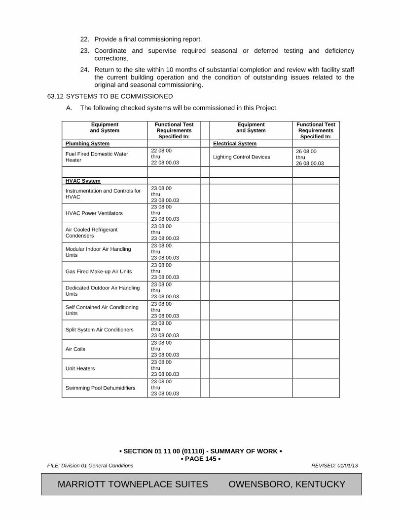
▪ SECTION 01 11 00 (01110) - SUMMARY OF WORK ▪ ▪ PAGE 145 ▪
FILE: Division 01 General Conditions REVISED: 01/01/13
2013, Marriott International, Inc. CFRST SPECMSTR-NEW BUILD
22. Provide a final commissioning report.
23. Coordinate and supervise required seasonal or deferred testing and deficiency corrections.
24. Return to the site within 10 months of substantial completion and review with facility staff the current building operation and the condition of outstanding issues related to the original and seasonal commissioning.
63.12 SYSTEMS TO BE COMMISSIONED A. The following checked systems will be commissioned in this Project.
Equipment and System
Functional Test Requirements Specified In:
Equipment and System
Functional Test Requirements Specified In:
Plumbing System Electrical System
Fuel Fired Domestic Water Heater
22 08 00 thru 22 08 00.03
Lighting Control Devices 26 08 00 thru 26 08 00.03
HVAC System
Instrumentation and Controls for HVAC
23 08 00 thru 23 08 00.03
HVAC Power Ventilators 23 08 00 thru 23 08 00.03
Air Cooled Refrigerant Condensers
23 08 00 thru 23 08 00.03
Modular Indoor Air Handling Units
23 08 00 thru 23 08 00.03
Gas Fired Make-up Air Units 23 08 00 thru 23 08 00.03
Dedicated Outdoor Air Handling Units
23 08 00 thru 23 08 00.03
Self Contained Air Conditioning Units
23 08 00 thru 23 08 00.03
Split System Air Conditioners 23 08 00 thru 23 08 00.03
Air Coils 23 08 00 thru 23 08 00.03
Unit Heaters 23 08 00 thru 23 08 00.03
Swimming Pool Dehumidifiers 23 08 00 thru 23 08 00.03
MARRIOTT TOWNEPLACE SUITES OWENSBORO, KENTUCKY

▪ SECTION 01 11 00 (01110) - SUMMARY OF WORK ▪ ▪ PAGE 146 ▪
REVISED: 01/01/13 FILE: Division 01 General Conditions
CFRST SPECMSTR-NEW BUILD 2013, Marriott International, Inc.
PART 64 PRODUCTS 64.01 TEST EQUIPMENT
A. All standard testing equipment required to perform startup and initial checkout and required functional performance testing shall be provided by the Division contractor for the equipment being tested. For example, the mechanical contractor of Division 23 shall ultimately be responsible for all standard testing equipment for the HVAC system and controls system in Division 23, except for equipment specific to and used by TAB in their commissioning responsibilities. Two-way radios shall be provided by the Division Contractor.
B. Special equipment, tools and instruments (only available from vendor, specific to a piece of equipment) required for testing equipment, according to these Contract Documents shall be included in the base bid price to the Contractor and left on site, except for stand-alone datalogging equipment that may be used by the CxA.
C. Datalogging equipment and software required to test equipment will be provided by the CxA, but shall not become the property of the Owner.
D. All testing equipment shall be of sufficient quality and accuracy to test and/or measure system performance with the tolerances specified in the Specifications. If not otherwise noted, the following minimum requirements apply: Temperature sensors and digital thermometers shall have a certified calibration within the past year to an accuracy of 0.5°F and a resolution of + or - 0.1°F. Pressure sensors shall have an accuracy of + or - 2.0% of the value range being measured (not full range of meter) and have been calibrated within the last year. All equipment shall be calibrated according to the manufacturer’s recommended intervals and when dropped or damaged. Calibration tags shall be affixed or certificates readily available.
E. Refer to Section 01 91 13, Article 3.06 E “Test Methods” for details regarding equipment that may be required to simulate required test conditions.
PART 65 EXECUTION 65.01 MEETINGS
A. Scoping Meeting. Within 90 days of commencement of construction, the CxA will schedule, plan and conduct a commissioning scoping meeting with the entire commissioning team in attendance. Meeting minutes will be distributed to all parties by the CxA. Information gathered from this meeting will allow the CxA to revise the Commissioning Plan to its “final” version, which will also be distributed to all parties.
B. Miscellaneous Meetings. Other meetings will be planned and conducted by the CxA as construction progresses. These meetings will cover coordination, deficiency resolution and planning issues with particular Subs. The CxA will plan these meetings and will minimize unnecessary time being spent by Subs. These meetings may be held monthly, until the final 3 months of construction when they may be held as frequently as one per week.
65.02 REPORTING
A. The CxA will provide regular reports to the OR, with increasing frequency as construction and commissioning progresses.
B. The CxA will regularly communicate with all members of the commissioning team, keeping them apprised of commissioning progress and scheduling changes through memos, progress reports, etc.
C. Testing or review approvals and non-conformance and deficiency reports are made regularly with the review and testing as described in later sections.
MARRIOTT TOWNEPLACE SUITES OWENSBORO, KENTUCKY

▪ SECTION 01 11 00 (01110) - SUMMARY OF WORK ▪ ▪ PAGE 147 ▪
FILE: Division 01 General Conditions REVISED: 01/01/13
2013, Marriott International, Inc. CFRST SPECMSTR-NEW BUILD
D. A final summary report (about four to six pages, not including backup documentation) by the CxA will be provided to the OR, focusing on evaluating commissioning process issues and identifying areas where the process could be improved. All acquired documentation, logs, minutes, reports, deficiency lists, communications, findings, unresolved issues, etc., will be compiled in appendices and provided with the summary report. Prefunctional checklists, functional tests and monitoring reports will not be part of the final report, but will be stored in the Commissioning Record in the O&M manuals.
65.03 SUBMITTALS
A. The CxA will provide appropriate contractors with a specific request for the type of submittal documentation the CxA requires to facilitate the commissioning work. These requests will be integrated into the normal submittal process and protocol of the construction team. At minimum, the request will include the manufacturer and model number, the manufacturer’s printed installation and detailed start-up procedures, full sequences of operation, O&M data, performance data, any performance test procedures, control drawings and details of owner contracted tests. In addition, the installation and checkout materials that are actually shipped inside the equipment and the actual field checkout sheet forms to be used by the factory or field technicians shall be submitted to the Commissioning authority. All documentation requested by the CxA will be included by the Subs in their O&M manual contributions.
1. Requested Submittals:
a. Air Handling Units
b. Building Automation (if applicable)
c. Air Conditioning Units
d. Unit Heaters
e. Plumbing Fixtures
f. Domestic Water Heaters
g. Domestic Hot Water Piping Insulation
h. Ductwork Insulation
i. Exhaust Fans and Power Ventilators
j. Light Fixtures
k. Lighting Controls
l. Pipe Insulation
m. Testing, Adjusting, and Balancing
2. Requested Shop Drawings:
a. Ductwork
b. Lighting Control System
B. The CxA will review and approve submittals related to the commissioned equipment for conformance to the contract documents as it relates to the commissioning process, and to the performance of the equipment and adequacy for developing test procedures. The commissioning authority will notify the Owner/CM, PM or A/E as requested, of items missing or areas that are not in conformance with contract documents and which require resubmission.
MARRIOTT TOWNEPLACE SUITES OWENSBORO, KENTUCKY

▪ SECTION 01 11 00 (01110) - SUMMARY OF WORK ▪ ▪ PAGE 148 ▪
REVISED: 01/01/13 FILE: Division 01 General Conditions
CFRST SPECMSTR-NEW BUILD 2013, Marriott International, Inc.
C. The CxA may request additional design narrative from the A/E and Controls Contractor, depending on the completeness of the design intent documentation and sequences provided with the Specifications.
D. These submittals to the CxA do not constitute compliance for O&M manual documentation. The O&M manuals are the responsibility of the Contractor.
65.04 START-UP, PREFUNCTIONAL CHECKLISTS AND INITIAL CHECKOUT
A. The following procedures apply to all equipment to be commissioned, according to Paragraph 1.12, “Systems to be Commissioned”. Some systems that are not comprised so much of actual dynamic machinery, e.g., electrical system power quality, may have very simplified PCs and startup.
B. General. Prefunctional checklists are important to ensure that the equipment and systems are hooked up and operational. It ensures that functional performance testing (in-depth system checkout) may proceed without unnecessary delays. Each piece of equipment receives full prefunctional checkout. No sampling strategies are used. The prefunctional testing for a given system must be successfully completed prior to formal functional performance testing of equipment or subsystems of the given system.
C. Start-up and Initial Checkout Plan. The CxA shall assist the commissioning team members responsible for startup of any equipment in developing detailed start-up plans for all equipment. The primary role of the CxA in this process is to ensure that there is written documentation that each of the manufacturer-recommended procedures have been completed. Parties responsible for prefunctional checklists and startup are identified in the commissioning scoping meeting and in the checklist forms. Parties responsible for executing functional performance tests are identified in the testing requirements in Sections 22 08 00, 22 08 00.01, 22 08 00.02, 22 08 00.03, 23 08 00, 23 08 00.01, 23 08 00.02, 23 08 00.03, 26 08 00, 26 08 00.01, 26 08 00.02, and 26 08 00.03.
1. The CxA adapts, if necessary, the representative prefunctional checklists and procedures from Section 23 08 00.02 and 26 08 00.02. These checklists indicate required procedures to be executed as part of startup and initial checkout of the systems and the party responsible for their execution.
2. These checklists and tests are provided by the CxA to the Contractor. The Contractor determines which trade is responsible for executing and documenting each of the line item tasks and notes that trade on the form. Each form will have more than one trade responsible for its execution.
3. The subcontractor responsible for the purchase of the equipment develops the full start-up plan by combining (or adding to) the CxA’s checklists with the manufacturer’s detailed start-up and checkout procedures from the O&M manual and the normally used field checkout sheets. The plan will include checklists and procedures with specific boxes or lines for recording and documenting the checking and inspections of each procedure and a summary statement with a signature block at the end of the plan. The full start-up plan could consist of something as simple as:
a. The CxA’s prefunctional checklists.
b. The manufacturer’s standard written start-up procedures copied from the installation manuals with check boxes by each procedure and a signature block added by hand at the end.
c. The manufacturer’s normally used field checkout sheets.
4. The subcontractor submits the full startup plan to the CxA for review and approval.
MARRIOTT TOWNEPLACE SUITES OWENSBORO, KENTUCKY
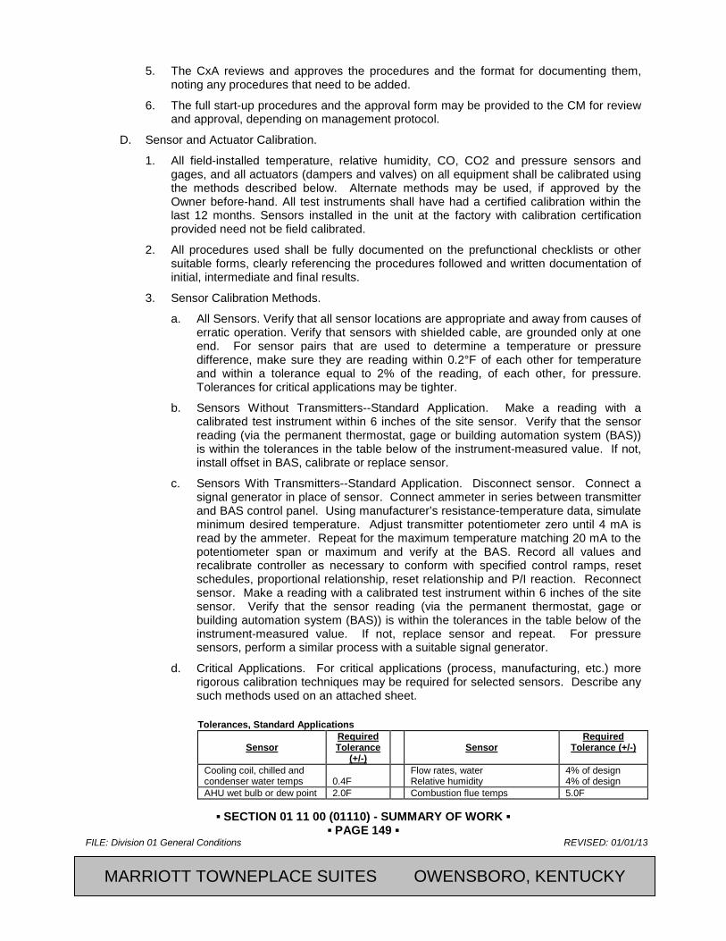
▪ SECTION 01 11 00 (01110) - SUMMARY OF WORK ▪ ▪ PAGE 149 ▪
FILE: Division 01 General Conditions REVISED: 01/01/13
2013, Marriott International, Inc. CFRST SPECMSTR-NEW BUILD
5. The CxA reviews and approves the procedures and the format for documenting them, noting any procedures that need to be added.
6. The full start-up procedures and the approval form may be provided to the CM for review and approval, depending on management protocol.
D. Sensor and Actuator Calibration.
1. All field-installed temperature, relative humidity, CO, CO2 and pressure sensors and gages, and all actuators (dampers and valves) on all equipment shall be calibrated using the methods described below. Alternate methods may be used, if approved by the Owner before-hand. All test instruments shall have had a certified calibration within the last 12 months. Sensors installed in the unit at the factory with calibration certification provided need not be field calibrated.
2. All procedures used shall be fully documented on the prefunctional checklists or other suitable forms, clearly referencing the procedures followed and written documentation of initial, intermediate and final results.
3. Sensor Calibration Methods.
a. All Sensors. Verify that all sensor locations are appropriate and away from causes of erratic operation. Verify that sensors with shielded cable, are grounded only at one end. For sensor pairs that are used to determine a temperature or pressure difference, make sure they are reading within 0.2°F of each other for temperature and within a tolerance equal to 2% of the reading, of each other, for pressure. Tolerances for critical applications may be tighter.
b. Sensors Without Transmitters--Standard Application. Make a reading with a calibrated test instrument within 6 inches of the site sensor. Verify that the sensor reading (via the permanent thermostat, gage or building automation system (BAS)) is within the tolerances in the table below of the instrument-measured value. If not, install offset in BAS, calibrate or replace sensor.
c. Sensors With Transmitters--Standard Application. Disconnect sensor. Connect a signal generator in place of sensor. Connect ammeter in series between transmitter and BAS control panel. Using manufacturer’s resistance-temperature data, simulate minimum desired temperature. Adjust transmitter potentiometer zero until 4 mA is read by the ammeter. Repeat for the maximum temperature matching 20 mA to the potentiometer span or maximum and verify at the BAS. Record all values and recalibrate controller as necessary to conform with specified control ramps, reset schedules, proportional relationship, reset relationship and P/I reaction. Reconnect sensor. Make a reading with a calibrated test instrument within 6 inches of the site sensor. Verify that the sensor reading (via the permanent thermostat, gage or building automation system (BAS)) is within the tolerances in the table below of the instrument-measured value. If not, replace sensor and repeat. For pressure sensors, perform a similar process with a suitable signal generator.
d. Critical Applications. For critical applications (process, manufacturing, etc.) more rigorous calibration techniques may be required for selected sensors. Describe any such methods used on an attached sheet.
Tolerances, Standard Applications
Sensor
Required Tolerance
(+/-)
Sensor
Required Tolerance (+/-)
Cooling coil, chilled and condenser water temps
0.4F
Flow rates, water Relative humidity
4% of design 4% of design
AHU wet bulb or dew point 2.0F Combustion flue temps 5.0F
MARRIOTT TOWNEPLACE SUITES OWENSBORO, KENTUCKY

▪ SECTION 01 11 00 (01110) - SUMMARY OF WORK ▪ ▪ PAGE 150 ▪
REVISED: 01/01/13 FILE: Division 01 General Conditions
CFRST SPECMSTR-NEW BUILD 2013, Marriott International, Inc.
Hot water coil and boiler water temp
1.5F Oxygen or CO2 monitor 0.1 % pts
Outside air, space air, duct air temps
0.4F CO monitor 0.01 % pts
Watthour, voltage & amperage
1% of design
Natural gas and oil flow rate 1% of design
Pressures, air, water and gas
3% of design
Steam flow rate 3% of design
Flow rates, air 10% of design
Barometric pressure 0.1 in. of Hg
4. Valve and Damper Stroke Setup and Check.
5. EMS Readout. For all valve and damper actuator positions checked, verify the actual position against the BAS readout.
a. Set pumps or fans to normal operating mode. Command valve or damper closed, visually verify that valve or damper is closed and adjust output zero signal as required. Command valve or damper open, verify position is full open and adjust output signal as required. Command valve or damper to a few intermediate positions. If actual valve or damper position doesn’t reasonably correspond, replace actuator or add pilot positioner (for pneumatics).
b. Closure for heating coil valves (NO): Set heating setpoint 20°F above room temperature. Observe valve open. Remove control air or power from the valve and verify that the valve stem and actuator position do not change. Restore to normal. Set heating setpoint to 20°F below room temperature. Observe the valve close. For pneumatics, by override in the EMS, increase pressure to valve by 3 psi (do not exceed actuator pressure rating) and verify valve stem and actuator position does not change. Restore to normal.
6. Closure for cooling coil valves (NC): Set cooling setpoint 20°F above room temperature. Observe the valve close. Remove control air or power from the valve and verify that the valve stem and actuator position do not change. Restore to normal. Set cooling setpoint to 20°F below room temperature. Observe valve open. For pneumatics, by override in the EMS, increase pressure to valve by 3 psi (do not exceed actuator pressure rating) and verify valve stem and actuator position does not change. Restore to normal.
E. Execution of Prefunctional Checklists and Startup.
1. Four weeks prior to startup, the Subs and vendors schedule startup and checkout with the GC and CxA. The performance of the prefunctional checklists, startup and checkout are directed and executed by the Sub or vendor. When checking off prefunctional checklists, signatures may be required of other Subs for verification of completion of their work.
2. The CxA shall observe, at minimum, the procedures for each piece of primary equipment, unless there are multiple units, (in which case a sampling strategy may be used as approved by the CM). In no case will the number of units witnessed be less than four on any one building, nor less than 20% of the total number of identical or very similar units.
3. For lower-level components of equipment, (e.g., VAV boxes, sensors, controllers), the CxA shall observe a sampling of the prefunctional and start-up procedures. The sampling procedures are identified in the commissioning plan.
4. The Subs and vendors shall execute startup and provide the CxA with a signed and dated copy of the completed start-up and prefunctional tests and checklists.
MARRIOTT TOWNEPLACE SUITES OWENSBORO, KENTUCKY

▪ SECTION 01 11 00 (01110) - SUMMARY OF WORK ▪ ▪ PAGE 151 ▪
FILE: Division 01 General Conditions REVISED: 01/01/13
2013, Marriott International, Inc. CFRST SPECMSTR-NEW BUILD
5. Only individuals that have direct knowledge and witnessed that a line item task on the prefunctional checklist was actually performed shall initial or check that item off. It is not acceptable for witnessing supervisors to fill out these forms.
F. Deficiencies, Non-Conformance and Approval in Checklists and Startup.
1. The Subs shall clearly list any outstanding items of the initial start-up and prefunctional procedures that were not completed successfully, at the bottom of the procedures form or on an attached sheet. The procedures form and any outstanding deficiencies are provided to the CxA within two days of test completion.
2. The CxA reviews the report and submits either a non-compliance report or an approval form to the Sub or CM. The CxA shall work with the Subs and vendors to correct and retest deficiencies or uncompleted items. The CxA will involve the CM and others as necessary. The installing Subs or vendors shall correct all areas that are deficient or incomplete in the checklists and tests in a timely manner, and shall notify the CxA as soon as outstanding items have been corrected and resubmit an updated start-up report and a Statement of Correction on the original non-compliance report. When satisfactorily completed, the CxA recommends approval of the execution of the checklists and startup of each system to the CM using a standard form.
3. Items left incomplete, which later cause deficiencies or delays during functional testing may result in back charges to the responsible party. Refer to Part 3.07 herein for details.
65.05 FUNCTIONAL PERFORMANCE TESTING
A. This sub-section applies to all commissioning functional testing for all divisions.
B. The general list of equipment to be commissioned is found in Section 01 91 13, Part 1.12 ”Systems to be Commissioned”. The specific equipment and modes to be tested are found in Sections 22 08 00.01, 23 08 00.01, and 26 08 00.01.
C. The parties responsible to execute each test are listed with each test in Sections 22 08 00, 22 08 00.01, 22 08 00.02, 22 08 00.03, 23 08 00, 23 08 00.01, 23 08 00.02, 23 08 00.03, 26 08 00, 26 08 00.01, 26 08 00.02, and 26 08 00.03.
D. Objectives and Scope. The objective of functional performance testing is to demonstrate that each system is operating according to the documented design intent and Contract Documents. Functional testing facilitates bringing the systems from a state of substantial completion to full dynamic operation. Additionally, during the testing process, areas of deficient performance are identified and corrected, improving the operation and functioning of the systems.
1. In general, each system should be operated through all modes of operation (seasonal, occupied, unoccupied, warm-up, cool-down, part- and full-load) where there is a specified system response. Verifying each sequence in the sequences of operation is required. Proper responses to such modes and conditions as power failure, freeze condition, low oil pressure, no flow, equipment failure, etc. shall also be tested. Specific modes required in this project are given in Sections 22 08 00, 22 08 00.01, 22 08 00.02, 22 08 00.03, 23 08 00, 23 08 00.01, 23 08 00.02, 23 08 00.03, 26 08 00, 26 08 00.01, 26 08 00.02, and 26 08 00.03.
2. Development of Test Procedures. Before test procedures are written, the CxA shall obtain all requested documentation and a current list of change orders affecting equipment or systems, including an updated points list, program code, control sequences and parameters. Using the testing parameters and requirements in Sections 22 08 00, 22 08 00.01, 22 08 00.02, 22 08 00.03, 23 08 00, 23 08 00.01, 23 08 00.02, 23 08 00.03, 26 08 00, 26 08 00.01, 26 08 00.02, and 26 08 00.03 the CxA shall develop specific test procedures and forms to verify and document proper operation of each piece of
MARRIOTT TOWNEPLACE SUITES OWENSBORO, KENTUCKY

▪ SECTION 01 11 00 (01110) - SUMMARY OF WORK ▪ ▪ PAGE 152 ▪
REVISED: 01/01/13 FILE: Division 01 General Conditions
CFRST SPECMSTR-NEW BUILD 2013, Marriott International, Inc.
equipment and system. Each Sub or vendor responsible to execute a test, shall provide limited assistance to the CxA in developing the procedures review (answering questions about equipment, operation, sequences, etc.). Prior to execution, the CxA shall provide a copy of the test procedures to the Sub(s) who shall review the tests for feasibility, safety, equipment and warranty protection. The CxA may submit the tests to the A/E for review, if requested.
3. The CxA shall review owner-contracted, factory testing or required owner acceptance tests which the CxA is not responsible to oversee, including documentation format, and shall determine what further testing or format changes may be required to comply with the Specifications. Redundancy of testing shall be minimized.
4. The purpose of any given specific test is to verify and document compliance with the stated criteria of acceptance given on the test form.
5. Representative test formats and examples (not designed for this facility) are found in the appendices to Divisions 22, 23, and 26. The test procedure forms developed by the CxA shall include (but not be limited to) the following information:
a. System and equipment or component name(s)
b. Equipment location and ID number
c. Unique test ID number, and reference to unique prefunctional checklist and start-up documentation ID numbers for the piece of equipment
d. Date
e. Project name
f. Participating parties
g. A copy of the specification section describing the test requirements
h. A copy of the specific sequence of operations or other specified parameters being verified
i. Formulas used in any calculations
j. Required pre-test field measurements
k. Instructions for setting up the test.
l. Special cautions, alarm limits, etc.
m. Specific step-by-step procedures to execute the test, in a clear, sequential and repeatable format
n. Acceptance criteria of proper performance with a Yes / No check box to allow for clearly marking whether or not proper performance of each part of the test was achieved.
o. A section for comments
p. Signatures and date block for the CxA
E. Test Methods.
1. Functional performance testing and verification may be achieved by manual testing (persons manipulate the equipment and observe performance) or by monitoring the performance and analyzing the results using the control system’s trend log capabilities or by stand-alone dataloggers. Sections 22 08 00, 22 08 00.01, 22 08 00.02, 22 08 00.03, 23 08 00, 23 08 00.01, 23 08 00.02, 23 08 00.03, 26 08 00, 26 08 00.01, 26 08 00.02, and 26 08 00.03 specify which methods shall be used for each test. The CxA may
MARRIOTT TOWNEPLACE SUITES OWENSBORO, KENTUCKY

▪ SECTION 01 11 00 (01110) - SUMMARY OF WORK ▪ ▪ PAGE 153 ▪
FILE: Division 01 General Conditions REVISED: 01/01/13
2013, Marriott International, Inc. CFRST SPECMSTR-NEW BUILD
substitute specified methods or require an additional method to be executed, other than what was specified, with the approval of the CM. This may require a change order and adjustment in charge to the Owner. The CxA will determine which method is most appropriate for tests that do not have a method specified.
F. Simulated Conditions. Simulating conditions (not by an overwritten value) shall be allowed, though timing the testing to experience actual conditions is encouraged wherever practical.
G. Overwritten Values. Overwriting sensor values to simulate a condition, such as overwriting the outside air temperature reading in a control system to be something other than it really is, shall be allowed, but shall be used with caution and avoided when possible. Such testing methods often can only test a part of a system, as the interactions and responses of other systems will be erroneous or not applicable. Simulating a condition is preferable. e.g., for the above case, by heating the outside air sensor with a hair blower rather than overwriting the value or by altering the appropriate setpoint to see the desired response. Before simulating conditions or overwriting values, sensors, transducers and devices shall have been calibrated.
H. Simulated Signals. Using a signal generator which creates a simulated signal to test and calibrate transducers and DDC constants is generally recommended over using the sensor to act as the signal generator via simulated conditions or overwritten values.
I. Altering Setpoints. Rather than overwriting sensor values, and when simulating conditions is difficult, altering setpoints to test a sequence is acceptable. For example, to see the AC compressor lockout work at an outside air temperature below 55F, when the outside air temperature is above 55F, temporarily change the lockout setpoint to be 2F above the current outside air temperature.
J. Indirect Indicators. Relying on indirect indicators for responses or performance shall be allowed only after visually and directly verifying and documenting, over the range of the tested parameters, that the indirect readings through the control system represent actual conditions and responses. Much of this verification is completed during prefunctional testing.
K. Setup. Each function and test shall be performed under conditions that simulate actual conditions as close as is practically possible. The Sub executing the test shall provide all necessary materials, system modifications, etc. to produce the necessary flows, pressures, temperatures, etc. necessary to execute the test according to the specified conditions. At completion of the test, the Sub shall return all affected building equipment and systems, due to these temporary modifications, to their pre-test condition.
L. Sampling. Multiple identical pieces of non-life-safety or otherwise non-critical equipment may be functionally tested using a sampling strategy. Significant application differences and significant sequence of operation differences in otherwise identical equipment invalidates their common identity. A small size or capacity difference, alone, does not constitute a difference. The specific recommended sampling rates are specified with each type of equipment in Sections 22 08 00, 22 08 00.01, 22 08 00.02, 22 99 53, 23 08 00, 23 08 00.01, 23 08 00.02, 23 08 00.03, 26 08 00, 26 08 00.01, 26 08 00.02, and 26 08 00.03. It is noted that no sampling by Subs is allowed in prefunctional checklist execution.
1. A common sampling strategy referenced in the Specifications as the “xx% Sampling—yy% Failure Rule” is defined by the following example:
xx = the percent of the group of identical equipment to be included in each sample.
yy = the percent of the sample that if failing, will require another sample to be tested.
2. The example below describes a 20% Sampling—10% Failure Rule.
a. Randomly test at least 20% (xx) of each group of identical equipment. In no case test less than three units in each group. This 20%, or three, constitute the “first sample.”
MARRIOTT TOWNEPLACE SUITES OWENSBORO, KENTUCKY
▪ SECTION 01 11 00 (01110) - SUMMARY OF WORK ▪ ▪ PAGE 154 ▪
REVISED: 01/01/13 FILE: Division 01 General Conditions
CFRST SPECMSTR-NEW BUILD 2013, Marriott International, Inc.
b. If 10% (yy) of the units in the first sample fail the functional performance tests, test another 20% of the group (the second sample).
c. If 10% of the units in the second sample fail, test all remaining units in the whole group.
d. If at any point, frequent failures are occurring and testing is becoming more troubleshooting than verification, the CxA may stop the testing and require the responsible Sub to perform and document a checkout of the remaining units, prior to continuing with functionally testing the remaining units.
M. Coordination and Scheduling. The Subs shall provide sufficient notice to the CxA regarding their completion schedule for the prefunctional checklists and startup of all equipment and systems. The CxA will schedule functional tests through the, GC and affected Subs. The CxA shall direct, witness and document the functional testing of all equipment and systems. The Subs shall execute the tests.
1. In general, functional testing is conducted after prefunctional testing and startup has been satisfactorily completed. The control system is sufficiently tested and approved by the CxA before it is used for TAB or to verify performance of other components or systems. The air balancing and water balancing is completed and debugged before functional testing of air-related or water-related equipment or systems. Testing proceeds from components to subsystems to systems. When the proper performance of all interacting individual systems has been achieved, the interface or coordinated responses between systems is checked.
N. Test Equipment. Refer to Section 01 91 13, Part 2 for test equipment requirements.
O. Problem Solving. The CxA will recommend solutions to problems found, however the burden of responsibility to solve, correct and retest problems is with the GC, Subs and A/E.
65.06 DOCUMENTATION, NON-CONFORMANCE AND APPROVAL OF TESTS
A. Documentation. The CxA shall witness and document the results of all functional performance tests using the specific procedural forms developed for that purpose. Prior to testing, these forms are provided to the GC for review and approval and to the Subs for review. The CxA will include the filled out forms in the O&M manuals.
B. Non-Conformance.
1. The CxA will record the results of the functional test on the procedure or test form. All deficiencies or non-conformance issues shall be noted and reported to the GC on a standard non-compliance form.
2. Corrections of minor deficiencies identified may be made during the tests at the discretion of the CxA. In such cases the deficiency and resolution will be documented on the procedure form.
3. Every effort will be made to expedite the testing process and minimize unnecessary delays, while not compromising the integrity of the procedures. However, the CxA will not be pressured into overlooking deficient work or loosening acceptance criteria to satisfy scheduling or cost issues, unless there is an overriding reason to do so at the request of the GC.
4. As tests progress and a deficiency is identified, the CxA discusses the issue with the executing contractor.
5. When there is no dispute on the deficiency and the Sub accepts responsibility to correct it:
MARRIOTT TOWNEPLACE SUITES OWENSBORO, KENTUCKY

▪ SECTION 01 11 00 (01110) - SUMMARY OF WORK ▪ ▪ PAGE 155 ▪
FILE: Division 01 General Conditions REVISED: 01/01/13
2013, Marriott International, Inc. CFRST SPECMSTR-NEW BUILD
a. The CxA documents the deficiency and the Sub’s response and intentions and they go on to another test or sequence. After the day’s work, the CxA submits the non-compliance reports to the GC for signature, if required. A copy is provided to the Sub and CxA. The Sub corrects the deficiency, signs the statement of correction at the bottom of the non-compliance form certifying that the equipment is ready to be retested and sends it back to the CxA.
b. The CxA reschedules the test and the test is repeated.
6. If there is a dispute about a deficiency, regarding whether it is a deficiency or who is responsible:
a. The deficiency shall be documented on the non-compliance form with the Sub’s response and a copy given to the GC and to the Sub representative assumed to be responsible.
b. Resolutions are made at the lowest management level possible. Other parties are brought into the discussions as needed. Final interpretive authority is with the A/E. Final acceptance authority is with the Project Manager.
c. The CxA documents the resolution process.
d. Once the interpretation and resolution have been decided, the appropriate party corrects the deficiency, signs the statement of correction on the non-compliance form and provides it to the CxA. The CxA reschedules the test and the test is repeated until satisfactory performance is achieved.
7. Cost of Retesting.
a. The cost for the Sub to retest a prefunctional or functional test, if they are responsible for the deficiency, shall be theirs. If they are not responsible, any cost recovery for retesting costs shall be negotiated with the GC.
b. For a deficiency identified, not related to any prefunctional checklist or start-up fault, the following shall apply: The CxA will direct the retesting of the equipment once at no “charge” to the GC for their time. However, the CxA’s time for a second retest will be charged to the GC, who may choose to recover costs from the responsible Sub.
c. The time for the CxA to direct any retesting required because a specific prefunctional checklist or start-up test item, reported to have been successfully completed, but determined during functional testing to be faulty, will be backcharged to the GC, who may choose to recover costs from the party responsible for executing the faulty prefunctional test.
d. Refer to the sampling section of Section 01 91 13, Part 3.06 “Documentation, Non-Conformance And Approval Of Tests” for requirements for testing and retesting identical equipment.
8. The Contractor shall respond in writing to the CxA and OR at least as often as commissioning meetings are being scheduled concerning the status of each apparent outstanding discrepancy identified during commissioning. Discussion shall cover explanations of any disagreements and proposals for their resolution.
9. The CxA retains the original non-conformance forms until the end of the project.
10. Any required retesting by any contractor shall not be considered a justified reason for a claim of delay or for a time extension by the prime contractor.
MARRIOTT TOWNEPLACE SUITES OWENSBORO, KENTUCKY
▪ SECTION 01 11 00 (01110) - SUMMARY OF WORK ▪ ▪ PAGE 156 ▪
REVISED: 01/01/13 FILE: Division 01 General Conditions
CFRST SPECMSTR-NEW BUILD 2013, Marriott International, Inc.
C. Failure Due to Manufacturer Defect. If 10%, or three, whichever is greater, of identical pieces (size alone does not constitute a difference) of equipment fail to perform to the Contract Documents (mechanically or substantively) due to manufacturing defect, not allowing it to meet its submitted performance spec, all identical units may be considered unacceptable by the OR. In such case, the Contractor shall provide the Owner with the following:
1. Within one week of notification from the OR, the Contractor or manufacturer’s representative shall examine all other identical units making a record of the findings. The findings shall be provided to the OR within two weeks of the original notice.
2. Within two weeks of the original notification, the Contractor or manufacturer shall provide a signed and dated, written explanation of the problem, cause of failures, etc. and all proposed solutions which shall include full equipment submittals. The proposed solutions shall not significantly exceed the specification requirements of the original installation.
3. The OR will determine whether a replacement of all identical units or a repair is acceptable.
4. Two examples of the proposed solution will be installed by the Contractor will be allowed to test the installations for up to one week, upon which the OR will decide whether to accept the solution.
5. Upon acceptance, the Contractor and/or manufacturer shall replace or repair all identical items, at their expense and extend the warranty accordingly, if the original equipment warranty had begun. The replacement/repair work shall proceed with reasonable speed beginning within one week from when parts can be obtained.
D. Approval. The CxA notes each satisfactorily demonstrated function on the test form. Formal approval of the functional test is made later after review by the CxA and by the OR, if necessary. The CxA recommends acceptance of each test to the OR using a standard form. The OR gives final approval on each test using the same form, providing a signed copy to the CxA and the Contractor.
65.07 DEFERRED TESTING
A. Unforeseen Deferred Tests. If any check or test cannot be completed due to the building structure, required occupancy condition or other deficiency, execution of checklists and functional testing may be delayed upon approval of the OR. These tests will be conducted in the same manner as the seasonal tests as soon as possible. Services of necessary parties will be negotiated.
B. Seasonal Testing. During the warranty period, seasonal testing (tests delayed until weather conditions are closer to the system’s design) shall be completed as part of this contract. The CxA shall coordinate this activity. Tests will be executed, documented and deficiencies corrected by the appropriate Subs, with facilities staff and the CxA witnessing. Any final adjustments to the O&M manuals and as-builds due to the testing will be made.
65.08 WRITTEN WORK PRODUCTS
A. The commissioning process generates a number of written work products described in various parts of the Specifications. The Commissioning Plan—Construction Phase, lists all the formal written work products, describes briefly their contents, who is responsible to create them, their due dates, who receives and approves them and the location of the specification to create them. In summary, the written products are: Product Developed By 1. Final commissioning plan CxA 2. Cx meeting minutes CxA 3. Commissioning schedules CxA with GC 4. Equipment documentation submittals Subs
MARRIOTT TOWNEPLACE SUITES OWENSBORO, KENTUCKY
▪ SECTION 01 11 00 (01110) - SUMMARY OF WORK ▪ ▪ PAGE 157 ▪
FILE: Division 01 General Conditions REVISED: 01/01/13
2013, Marriott International, Inc. CFRST SPECMSTR-NEW BUILD
5. Sequence clarifications Subs and A/E as needed 5. Prefunctional checklists CxA 6. Startup and initial checkout plan Subs and CxA (compilation of
existing documents) 7. Startup and initial checkout forms filled out Subs 8. Final TAB report TAB 9. Issues log (deficiencies) CxA 10. Commissioning Progress Record CxA 11. Deficiency reports CxA 12. Functional test forms CxA 13. Filled out functional tests CxA 14. Commissioning record book 15. Final commissioning report CxA
END OF SECTION
Revision Log
MARRIOTT TOWNEPLACE SUITES OWENSBORO, KENTUCKY
▪ DIV 03 CONCRETE ▪ ▪ PAGE 1 ▪
RESIDENCE INN BY MARRIOTT - LITTLETON, COLORADO
SECTION 03 30 00 (03300) - CAST-IN-PLACE CONCRETE
PART 1 GENERAL 1.01 SUMMARY
A. Section includes:
1. Cast-in place concrete, including formwork, reinforcement, concrete materials, accessories mix design, placement procedures, and finishes.
B. Related Sections:
1. Section 03 45 00 (03410) - Plant-Precast Structural Concrete
2. Section 03 54 13 (03500) - Cementitious Decks and Underlayment
3. Section 05 50 00 (05500) - Metal Fabrications
4. Section 07 10 00 (07100) – Dampproofing and Waterproofing
5. Section 07 92 00 (07920) - Joint Sealants
6. Section 13 11 00.01 (13151) - Swimming Pools - Exterior
7. Section 13 11 00.02 (13152) - Swimming Pools - Indoor
8. Section 32 13 13 (02751) - Cement Concrete Paving
9. Section 33 00 00 (02500) - Utility Services
1.02 DEFINITIONS
A. Cementitious Materials: Portland cement alone or in combination with one or more of blended hydraulic cement, fly ash and other pozzolans, ground granulated blast-furnace slag, and silica fume.
1.03 REFERENCES 1.04 SUBMITTALS
A. General: Submit the following in accordance with Conditions of Contract and Division 01 Specification Sections.
B. Product Data: Submit “Letter of Conformance” in accordance with Section 01 33 00 (01330) indicating specified items selected for use in project with the following supporting data.
1. Submit “Letter of Conformance” in accordance with Section 01 33 00 (01330) indicating specified items selected for use in project.
C. Design Mixes: For each concrete mix. Include alternate mix designs when characteristics of materials, project conditions, weather, test results, or other circumstances warrant adjustments.
1. Indicate amounts of mix water to be withheld for later addition at Project site.
D. Steel Reinforcement Shop Drawings: Details of fabrication, bending, and placement, prepared according to ACI 315, "Details and Detailing of Concrete Reinforcement." Include material, grade, bar schedules, stirrup spacing, bent bar diagrams, arrangement, and supports of concrete reinforcement. Include special reinforcement required for openings through concrete structures. Coordinate built-in items including anchor bolts, plates and clips.
E. Formwork Shop Drawings: Prepared by or under the supervision of a qualified professional engineer detailing fabrication, assembly, and support of formwork. Design and engineering of formwork are Contractor's responsibility.
MARRIOTT TOWNEPLACE SUITES OWENSBORO, KENTUCKY
▪ DIV 03 CONCRETE ▪ ▪ PAGE 2 ▪
RESIDENCE INN BY MARRIOTT - LITTLETON, COLORADO
1. Shoring and Reshoring: Indicate proposed schedule and sequence of stripping formwork, shoring removal, and installing and removing reshoring.
F. Welding Certificates: Copies of certificates for welding procedures and personnel.
G. Material Test Reports: From a qualified testing agency indicating and interpreting test results for compliance of the following with requirements indicated, based on comprehensive testing of current materials:
H. Material Certificates: Submit “Letter of Conformance” in accordance with Section 01 33 00 (01300) indicating specified items selected for use in project.
1. Cementitious materials and aggregates.
2. Form materials and form-release agents.
3. Steel reinforcement and reinforcement accessories.
4. Fiber reinforcement.
5. Admixtures.
6. Waterstops.
7. Curing materials.
8. Floor and slab treatments.
9. Bonding agents.
10. Adhesives.
11. Vapor retarders.
12. Epoxy joint filler.
13. Joint-filler strips.
14. Repair materials.
I. Minutes of preinstallation conference.
1.05 QUALITY ASSURANCE
A. Installer Qualifications: An experienced installer with a minimum of five years experience, who has completed concrete Work similar in material, design, and extent to that indicated for this Project and whose work has resulted in construction with a record of successful in-service performance.
B. Professional Engineer Qualifications: A professional engineer who is legally qualified to practice in jurisdiction where Project is located and who is experienced in providing engineering services of the kind indicated. Engineering services are defined as those performed for formwork and shoring and reshoring installations that are similar to those indicated for this Project in material, design, and extent.
C. Manufacturer Qualifications: A firm experienced in manufacturing ready-mixed concrete products complying with ASTM C94 requirements for production facilities and equipment.
1. Manufacturer must be certified according to the National Ready Mixed Concrete Association's (NRMCA) "Certification of Ready Mixed Concrete Production Facilities."
D. Testing Agency Qualifications: An independent testing agency, acceptable to authorities having jurisdiction, qualified according to ASTM C1077 and ASTM E329 to conduct the testing indicated, as documented according to ASTM E548.
MARRIOTT TOWNEPLACE SUITES OWENSBORO, KENTUCKY
▪ DIV 03 CONCRETE ▪ ▪ PAGE 3 ▪
RESIDENCE INN BY MARRIOTT - LITTLETON, COLORADO
1. Personnel conducting field tests shall be qualified as ACI Concrete Field Testing Technician, Grade 1, according to ACI CP-1 or an equivalent certification program.
E. Source Limitations: Obtain each type or class of cementitious material of the same brand from the same manufacturer's plant, each aggregate from one source, and each admixture from the same manufacturer.
F. Welding: Qualify procedures and personnel according to AWS D1.4, "Structural Welding Code--Reinforcing Steel."
G. ACI Publications: Comply with the following, unless more stringent provisions are indicated:
1. ACI 301, "Specification for Structural Concrete."
2. ACI 117, "Standard Specifications for Tolerances for Concrete Construction and Materials."
3. ACI 211.1 "Standard Practice for Selecting Proportions for Normal, Heavyweight, and Mass Concrete".
4. ACI 211.2 "Standard Practice for Selecting Proportions for Structural Lightweight Concrete".
5. ACI 212 "Chemical Admixtures for Concrete"
6. ACI 214R "Evaluation of Strength Test Results of Concrete"
7. ACI 301 "Standard Specification for Structural Concrete"
8. ACI 302 "Guide for Concrete Floor and Slab Construction"
9. ACI 304R "Guide for Measuring, Mixing, Transporting and Placing Concrete".
10. ACI 305R "Hot Weather Concreting".
11. ACI 306R "Cold Weather Concreting".
12. ACI 308 "Standard Practice for Curing Concrete"
13. ACI 309R "Guide for Consolidation of Concrete".
14. ACI 311.4R "Guide for Concrete Inspection".
15. ACI 318 "Building Code Requirements for Structural Concrete".
16. ACI 347R "Guide to Formwork for Concrete".
17. ACI 544 "Fibers Reinforced Concrete"
18. ACI SP-66 "ACI Detailing Manual".
H. Other Publications. Comply with the following, unless more stringent provisions are indicated:
1. CRSI-WCRSI "Placing Reinforcing Bars"
2. AWS D1.4 "Structural Welding Code - Reinforcing Steel".
I. Preinstallation Conference: Conduct conference at Project site to comply with requirements in Division 01 Sections.
1. Before submitting design mixes, review concrete mix design and examine procedures for ensuring quality of concrete materials. Require representatives of each entity directly concerned with cast-in-place concrete to attend, including the following:
a. Contractor's superintendent.
b. Independent testing agency responsible for concrete design mixes.
MARRIOTT TOWNEPLACE SUITES OWENSBORO, KENTUCKY
▪ DIV 03 CONCRETE ▪ ▪ PAGE 4 ▪
RESIDENCE INN BY MARRIOTT - LITTLETON, COLORADO
c. Ready-mix concrete producer.
d. Concrete subcontractor.
1.06 DELIVERY, STORAGE, AND HANDLING
A. Deliver, store, and handle steel reinforcement to prevent bending and damage.
1. Avoid damaging coatings on steel reinforcement.
2. Repair damaged epoxy coatings on steel reinforcement according to ASTM D3963.
PART 2 PRODUCTS 2.01 FORM-FACING MATERIALS
A. Smooth-Formed Finished Concrete: Form-facing panels that will provide continuous, true, and smooth concrete surfaces. Furnish in largest practicable sizes to minimize number of joints.
1. Plywood, metal, or other approved panel materials.
2. Exterior-grade plywood panels, suitable for concrete forms, complying with DOC PS 1, and as follows:
a. High-density overlay, Class 1, or better.
b. Medium-density overlay, Class 1, or better, mill-release agent treated and edge sealed.
c. Structural 1, B-B, or better, mill oiled and edge sealed.
d. B-B (Concrete Form), Class 1, or better, mill oiled and edge sealed.
B. Rough-Formed Finished Concrete: Plywood, lumber, metal, or another approved material. Provide lumber dressed on at least two edges and one side for tight fit.
C. Forms for Cylindrical Columns, Pedestals, and Supports: Metal, glass-fiber-reinforced plastic, paper, or fiber tubes that will produce surfaces with gradual or abrupt irregularities not exceeding specified formwork surface class. Provide units with sufficient wall thickness to resist plastic concrete loads without detrimental deformation.
D. Pan-Type Forms: Glass-fiber-reinforced plastic or formed steel, stiffened to resist plastic concrete loads without detrimental deformation.
E. Void Forms: Biodegradable paper surface, treated for moisture resistance, structurally sufficient to support weight of plastic concrete and other superimposed loads.
F. Chamfer Strips: Wood, metal, PVC, or rubber strips, 3/4 by 3/4 inch (19 by 19 mm), minimum.
G. Form-Release Agent: Commercially formulated form-release agent that will not bond with, stain, or adversely affect concrete surfaces and will not impair subsequent treatments of concrete surfaces.
1. Formulate form-release agent with rust inhibitor for steel form-facing materials.
H. Form Ties: Factory-fabricated, removable or snap-off metal or glass-fiber-reinforced plastic form ties designed to resist lateral pressure of fresh concrete on forms and to prevent spalling of concrete on removal.
1. Furnish units that will leave no corrodible metal closer than 1 inch (25 mm) to the plane of the exposed concrete surface.
2. Furnish ties that, when removed, will leave holes not larger than 1 inch (25 mm) in diameter in concrete surface.
MARRIOTT TOWNEPLACE SUITES OWENSBORO, KENTUCKY
▪ DIV 03 CONCRETE ▪ ▪ PAGE 5 ▪
RESIDENCE INN BY MARRIOTT - LITTLETON, COLORADO
3. Furnish ties with integral water-barrier plates to walls indicated to receive dampproofing or waterproofing.
2.02 STEEL REINFORCEMENT
A. Reinforcing Bars: ASTM A615, Grade 60, deformed.
B. Low-Alloy-Steel Reinforcing Bars: ASTM A706, deformed.
C. Epoxy-Coated Reinforcing Bars: ASTM A775, and as follows:
D. Epoxy-Coated Fabricated Reinforcing Bars: ASTM A934, and as follows:
1. Steel Reinforcement: ASTM A615, Grade 60, deformed.
2. Steel Reinforcement: ASTM A706, deformed.
E. Steel Bar Mats: ASTM A184, assembled with clips.
1. Steel Reinforcement: ASTM A615, Grade 60, deformed bars.
2. Steel Reinforcement: ASTM A706, deformed bars.
F. Plain-Steel Wire: ASTM A82, as drawn.
G. Plain-Steel Wire: ASTM A82, galvanized.
H. Deformed-Steel Wire: ASTM A496.
I. Epoxy-Coated Wire: ASTM A884, Class A coated, plain-steel wire.
J. Epoxy-Coated Wire: ASTM A884, Class A coated, deformed-steel wire.
K. Plain-Steel Welded Wire Fabric: ASTM A185, fabricated from as-drawn steel wire into flat sheets.
L. Deformed-Steel Welded Wire Fabric: ASTM A497, flat sheet.
M. Epoxy-Coated Welded Wire Fabric: ASTM A884, Class A, plain steel.
N. Epoxy-Coated Welded Wire Fabric: ASTM A884, Class A, deformed steel.
2.03 REINFORCEMENT ACCESSORIES
A. Bar Supports: Bolsters, chairs, spacers, and other devices for spacing, supporting, and fastening reinforcing bars and welded wire fabric in place. Manufacture bar supports according to CRSI's "Manual of Standard Practice" from steel wire, plastic, or precast concrete or fiber-reinforced concrete of greater compressive strength than concrete, and as follows:
1. For concrete surfaces exposed to view or weather where legs of wire bar supports contact forms, use CRSI Class 1 plastic-protected or CRSI Class 2 stainless-steel bar supports.
2. For epoxy-coated reinforcement, use epoxy-coated or other dielectric-polymer-coated wire bar supports.
B. Joint Dowel Bars: Plain-steel bars, ASTM A615, Grade 60. Cut bars true to length with ends square and free of burrs.
C. Epoxy-Coated Joint Dowel Bars: ASTM A775; with ASTM A615, Grade 60, plain-steel bars.
D. Epoxy Repair Coating: Liquid, two-part, epoxy repair coating; compatible with epoxy coating on reinforcement and complying with ASTM A775.
E. Tie Wire: Minimum 16 gage annealed type.
MARRIOTT TOWNEPLACE SUITES OWENSBORO, KENTUCKY

▪ DIV 03 CONCRETE ▪ ▪ PAGE 6 ▪
RESIDENCE INN BY MARRIOTT - LITTLETON, COLORADO
2.04 CONCRETE MATERIALS
A. Portland Cement: ASTM C150, Type I.
1. Fly Ash: ASTM C618, Class C or F.
2. Ground Granulated Blast-Furnace Slag: ASTM C989, Grade 100 or 120.
B. Normal-Weight Aggregate: ASTM C33, uniformly graded, and as follows:
1. Class: Moderate weathering region, but not less than 3M.
2. Nominal Maximum Aggregate Size: 3/4 inch.
C. Water: Potable and complying with ASTM C94.
2.05 ADMIXTURES
A. General: Admixtures certified by manufacturer to contain not more than 0.1 percent water-soluble chloride ions by mass of cementitious material and to be compatible with other admixtures and cementitious materials. Do not use admixtures containing calcium chloride.
B. Air-Entraining Admixture: ASTM C260.
C. Water-Reducing Admixture: ASTM C494, Type A.
D. High-Range, Water-Reducing Admixture: ASTM C494, Type F.
E. Water-Reducing and Accelerating Admixture: ASTM C494, Type E.
F. Water-Reducing and Retarding Admixture: ASTM C494, Type D.
G. Corrosion-Inhibiting Admixture: Commercially formulated, anodic inhibitor or mixed cathodic and anodic inhibitor; capable of forming a protective barrier and minimizing chloride reactions with steel reinforcement in concrete.
1. Avendra, LLC Preferred Manufacturers:
a. None.
2. Approved Manufacturers:
a. “Catexol 1000CL”; Axim Italcementi Group, Inc. (800-899-8795)
b. “MCI 2000 or MCI 2005”; Cortec Corporation (800-426-7832)
c. “DCI or DCI-S”; W. R. Grace & Co., Construction Products Div. (800-778-2880)
d. “Rheocrete 222+”; BASF Building Systems (216-839-7000)
e. “FerroGard-901”; Sika Construction Products Division, Sika Corporation (800-933-7452)
f. “Eucon CIA”; Euclid Chemical Co, An RPM Company; (800-321-7628)
2.06 FIBER REINFORCEMENT
A. Synthetic Fiber: Fibrillated or monofilament polypropylene fibers engineered and designed for use in concrete, complying with ASTM C1116, Type III, 1/2 to 1-1/2 inches (13 to 38 mm) long.
1. Avendra, LLC Preferred Manufacturers:
a. None
2. Approved Manufacturers:
a. Fibrillated Fibers:
MARRIOTT TOWNEPLACE SUITES OWENSBORO, KENTUCKY

▪ DIV 03 CONCRETE ▪ ▪ PAGE 7 ▪
RESIDENCE INN BY MARRIOTT - LITTLETON, COLORADO
1) “Fibermesh”; Fibermesh, Div. of Synthetic Industries; (423-892-7243)
2) “Super-Net”; Forta Corporation; (800-245-0306)
3) “Grace Fibers”; W. R. Grace & Co., Construction Products Div. (800-778-2880)
4) “Fiberstrand F”; Euclid Chemical Co, An RPM Company; (800-321-7628)
b. Monofilament Fibers:
1) “Fiberstrand 100”; Euclid Chemical Co, An RPM Company; (800-321-7628)
2) “Fibermix Stealth”; Fibermesh, Div. of Synthetic Industries; (423-892-7243)
3) “Mighty-Mono”; Forta Corporation; (800-245-0306)
4) “Grace MicroFiber”; W. R. Grace & Co., Construction Products Div. (800-778-2880)
2.07 WATERSTOPS
A. Flexible PVC Waterstops: CE CRD-C 572, for embedding in concrete to prevent passage of fluids through joints. Factory fabricate corners, intersections, and directional changes.
1. Profile: Ribbed with center bulb.
B. Avendra, LLC Preferred Manufacturers:
1. None
C. Approved Manufacturers:
1. PVC Waterstops:
a. "PVC Waterstop"; Greenstreak, Inc.; (800-325-9504)
b. "Sealtight PVC Waterstops"; W. R. Meadows, Inc.; (800-342-5976)
c. Westec Barrier Technologies; Div. of Western Textile Products, Inc, (800-793-7832)
D. Self-Expanding Strip Waterstops: Manufactured rectangular or trapezoidal strip, sodium bentonite or other hydrophylic material for adhesive bonding to concrete.
1. Avendra, LLC Preferred Manufacturers:
a. None
2. Approved Manufacturers:
a. “Volclay Waterstop-RX”; CETCO, Subsidiary of AMCOL International Corp; (800-527-9948)
b. “Hydrotite”; Greenstreak, Inc.; (800-325-9504)
c. “Adeka Ultra Seal”; OCM, Inc. (800-999-3959)
2.08 VAPOR RETARDERS
A. Refer to Section 07 10 00 for [vapor barrier] [vapor retarder] materials.
B. Granular Fill: Clean mixture of crushed stone or crushed or uncrushed gravel; ASTM D448, Size 57, with 100 percent passing a 1-1/2-inch (38-mm) sieve and 0 to 5 percent passing a No. 4 (4.75-mm) sieve.
2.09 CURING MATERIALS
A. Absorptive Cover: AASHTO M 182, Class 2, burlap cloth made from jute or kenaf, weighing approximately 9 oz./sq. yd. (305 g/sq. m) dry.
MARRIOTT TOWNEPLACE SUITES OWENSBORO, KENTUCKY
▪ DIV 03 CONCRETE ▪ ▪ PAGE 8 ▪
RESIDENCE INN BY MARRIOTT - LITTLETON, COLORADO
B. Moisture-Retaining Cover: ASTM C171, .006 inch (6 mil) thick, polyethylene film or white burlap-polyethylene sheet.
C. Evaporation Retarder: Waterborne, monomolecular film forming, manufactured for application to fresh concrete.
1. Material shall become an integral part of concrete surface and leave floor free of residue or film.
2. Avendra, LLC Preferred Manufacturers:
a. None
3. Approved Manufacturers:
a. “Eucobar”; Euclid Chemical Co, An RPM Company; (800-321-7628)
1) VOC: 88 g/L
b. “Confilm”; BASF Building Systems (800-433-9517)
1) VOC: 10 g/L
c. “SikaFilm”; Sika Construction Products Division, Sika Corporation (800-933-7452)
1) VOC: g/L
D. Water: Potable.
E. Clear, Waterborne, Membrane-Forming Curing Compound: ASTM C309, Type 1, Class B.
1. Avendra, LLC Preferred Manufacturers:
a. None
2. Approved Manufacturers:
a. “Cure & Seal 309 EF”; Dayton Superior; (800-745-3700
1) VOC: <100 g/L
b. “Aqua Cure VOX”; Euclid Chemical Co, An RPM Company; (800-321-7628)
1) VOC: 184 g/L
c. “Glazecote 20”; Lambert Corp (800-432-4746)
1) VOC: 79.3 g/L
d. “Kure-N-Seal WB”; BASF Building Systems (800-433-9517)
1) VOC: 330 g/L
F. Clear, Waterborne, Curing and Sealing Compound: ASTM C1315, 25% solids minimum.
1. Approved Manufacturers:
a. “Cure & Seal 1315 EF”; Dayton Superior; (800-745-3700
1) VOC: <100 g/L
b. “Super Aqua Cure VOX”; Euclid Chemical Co, An RPM Company; (800-321-7628)
1) VOC: <200 g/L
c. “Glazecoat 30”; Lambert Corp (800-432-4746)
1) VOC: 145.4 g/L
d. “Clearseal WB 300”; Euclid Chemical Co, An RPM Company; (800-321-7628)
MARRIOTT TOWNEPLACE SUITES OWENSBORO, KENTUCKY

▪ DIV 03 CONCRETE ▪ ▪ PAGE 9 ▪
RESIDENCE INN BY MARRIOTT - LITTLETON, COLORADO
1) VOC: 134 g/L
e. “Kure 1315”; BASF Building Systems (800-433-9517)
1) VOC: 139 g/L
2.10 RELATED MATERIALS
A. Joint-Filler Strips: ASTM D1751, asphalt-saturated cellulosic fiber, or ASTM D1752, cork or self-expanding cork.
B. Epoxy Joint Filler: Two-component, semirigid, 100 percent solids, epoxy resin with a Shore A hardness of 80 per ASTM D2240.
C. Polyurea Joint Filler: Two-component, 100 percent solids, with a Shore A hardness of 80 per ASTM D2240.
D. Bonding Agent: ASTM C1059, Type II, non-redispersible, acrylic emulsion or styrene butadiene.
E. Epoxy-Bonding Adhesive: ASTM C881, two-component epoxy resin, capable of humid curing and bonding to damp surfaces, of class and grade to suit requirements, and as follows:
1. Type II, non-load bearing, for bonding freshly mixed concrete to hardened concrete.
2. Types I and II, non-load bearing, for bonding hardened or freshly mixed concrete to hardened concrete.
3. Types IV and V, load bearing, for bonding hardened or freshly mixed concrete to hardened concrete.
F. Reglets: Fabricate reglets of not less than 0.0217-inch- (0.55-mm-) thick galvanized steel sheet. Temporarily fill or cover face opening of reglet to prevent intrusion of concrete or debris.
G. Dovetail Anchor Slots: Hot-dip galvanized steel sheet, not less than 0.0336 inch (0.85 mm) thick, with bent tab anchors. Temporarily fill or cover face opening of slots to prevent intrusion of concrete or debris.
2.11 REPAIR MATERIALS
A. Repair Underlayment: Cement-based, polymer-modified, self-leveling product that can be applied in thicknesses from 1/8 inch (3.2 mm) and that can be feathered at edges to match adjacent floor elevations.
1. Cement Binder: ASTM C150, portland cement or hydraulic or blended hydraulic cement as defined in ASTM C219.
2. Primer: Product of underlayment manufacturer recommended for substrate, conditions, and application.
3. Aggregate: Well-graded, washed gravel, 1/8 to 1/4 inch (3 to 6 mm) or coarse sand as recommended by underlayment manufacturer.
4. Compressive Strength: Not less than 4100 psi (29 MPa) at 28 days when tested according to ASTM C109.
B. Repair Topping: Traffic-bearing, cement-based, polymer-modified, self-leveling product that can be applied in thicknesses from 1/4 inch (6 mm).
1. Cement Binder: ASTM C150, portland cement or hydraulic or blended hydraulic cement as defined in ASTM C219.
2. Primer: Product of topping manufacturer recommended for substrate, conditions, and application.
MARRIOTT TOWNEPLACE SUITES OWENSBORO, KENTUCKY
▪ DIV 03 CONCRETE ▪ ▪ PAGE 10 ▪
RESIDENCE INN BY MARRIOTT - LITTLETON, COLORADO
3. Aggregate: Well-graded, washed gravel, 1/8 to 1/4 inch (3 to 6 mm) or coarse sand as recommended by topping manufacturer.
4. Compressive Strength: Not less than 5700 psi (39 MPa) at 28 days when tested according to ASTM C109.
2.12 CONCRETE MIXES
A. Prepare design mixes for each type and strength of concrete determined by either laboratory trial mix or field test data bases, as follows:
1. Proportion normal-weight concrete according to ACI 211.1 and ACI 301.
2. Proportion lightweight structural concrete according to ACI 211.2 and ACI 301.
B. Use a qualified independent testing agency for preparing and reporting proposed mix designs for the laboratory trial mix basis.
C. Proportion concrete mix for each class of concrete to achieve the strengths (28 days) and slumps noted on the drawings.
D. Cementitious Materials: For concrete exposed to deicers, limit percentage, by weight, of cementitious materials other than portland cement according to ACI 301 requirements.
E. Cementitious Materials: Limit percentage, by weight, of cementitious materials other than portland cement in concrete as follows:
1. Fly Ash: 25 percent.
2. Combined Fly Ash and Pozzolan: 25 percent.
3. Ground Granulated Blast-Furnace Slag: 50 percent.
4. Combined Fly Ash or Pozzolan and Ground Granulated Blast-Furnace Slag: 50 percent portland cement minimum, with fly ash or pozzolan not exceeding 25 percent.
F. Maximum Water-Cementitious Materials Ratio: 0.50 for concrete required to have low water permeability.
G. Maximum Water-Cementitious Materials Ratio: 0.45 for concrete exposed to deicers or subject to freezing and thawing while moist.
H. Maximum Water-Cementitious Materials Ratio: 0.40 for corrosion protection of steel reinforcement in concrete exposed to chlorides from deicing chemicals, salt, saltwater, brackish water, seawater, or spray from these sources.
I. Maximum Water-Cementitious Materials Ratio: 0.50 for concrete subject to moderate sulfate exposure.
J. Maximum Water-Cementitious Materials Ratio: 0.45 for concrete subject to severe or very severe sulfate exposure.
K. Air Content: Add air-entraining admixture at manufacturer's prescribed rate to result in concrete at point of placement having an air content as follows within a tolerance of plus 1 or minus 1.5 percent, unless otherwise indicated:
1. Air Content: 5.5 percent for 1-1/2-inch- (38-mm-) nominal maximum aggregate size.
2. Air Content: 6 percent for 1-inch- (25-mm-) nominal maximum aggregate size.
3. Air Content: 6 percent for 3/4-inch- (19-mm-) nominal maximum aggregate size.
L. Do not air entrain concrete to trowel-finished interior floors and suspended slabs. Do not allow entrapped air content to exceed 3 percent.
MARRIOTT TOWNEPLACE SUITES OWENSBORO, KENTUCKY
▪ DIV 03 CONCRETE ▪ ▪ PAGE 11 ▪
RESIDENCE INN BY MARRIOTT - LITTLETON, COLORADO
M. Limit water-soluble, chloride-ion content in hardened concrete to 0.15 percent by weight of cement.
N. Micro-Synthetic Fiber: Uniformly disperse in concrete mix at manufacturer's recommended rate, but not less than 1 lb/cu. yd.
O. Admixtures: Use admixtures according to manufacturer's written instructions.
1. Use water-reducing admixture or high-range water-reducing admixture (superplasticizer) in concrete, as required, for placement and workability.
2. Use water-reducing and retarding admixture when required by high temperatures, low humidity, or other adverse placement conditions.
3. Use water-reducing admixture in pumped concrete, concrete for heavy-use industrial slabs and parking structure slabs, concrete required to be watertight, and concrete with a water-cementitious materials ratio below 0.50.
4. Use corrosion-inhibiting admixture in concrete mixes where indicated.
2.13 FABRICATING REINFORCEMENT
A. Fabricate steel reinforcement according to CRSI's "Manual of Standard Practice."
2.14 CONCRETE MIXING
A. Ready-Mixed Concrete: Measure, batch, mix, and deliver concrete according to ASTM C94 and ASTM C1116, and furnish batch ticket information.
1. When air temperature is between 85 and 90 deg F (30 and 32 deg C), reduce mixing and delivery time from 1-1/2 hours to 75 minutes; when air temperature is above 90 deg F (32 deg C), reduce mixing and delivery time to 60 minutes.
B. Project-Site Mixing: Measure, batch, and mix concrete materials and concrete according to ASTM C94. Mix concrete materials in appropriate drum-type batch machine mixer.
1. For mixer capacity of 1 cu. yd. (0.76 cu. m) or smaller, continue mixing at least one and one-half minutes, but not more than five minutes after ingredients are in mixer, before any part of batch is released.
2. For mixer capacity larger than 1 cu. yd. (0.76 cu. m), increase mixing time by 15 seconds for each additional 1 cu. yd. (0.76 cu. m).
3. Provide batch ticket for each batch discharged and used in the Work, indicating Project identification name and number, date, mix type, mix time, quantity, and amount of water added. Record approximate location of final deposit in structure.
PART 3 EXECUTION 3.01 FORMWORK
A. Design, erect, shore, brace, and maintain formwork, according to ACI 301, to support vertical, lateral, static, and dynamic loads, and construction loads that might be applied, until concrete structure can support such loads.
B. Construct formwork so concrete members and structures are of size, shape, alignment, elevation, and position indicated, within tolerance limits of ACI 117.
C. Limit concrete surface irregularities, designated by ACI 347R as abrupt or gradual, as follows:
1. Class A, 1/8 inch (3 mm).
2. Class B, 1/4 inch (6 mm).
D. Construct forms tight enough to prevent loss of concrete mortar.
MARRIOTT TOWNEPLACE SUITES OWENSBORO, KENTUCKY
▪ DIV 03 CONCRETE ▪ ▪ PAGE 12 ▪
RESIDENCE INN BY MARRIOTT - LITTLETON, COLORADO
E. Fabricate forms for easy removal without hammering or prying against concrete surfaces. Provide crush or wrecking plates where stripping may damage cast concrete surfaces. Provide top forms for inclined surfaces steeper than 1.5 horizontal to 1 vertical. Kerf wood inserts for forming keyways, reglets, recesses, and the like, for easy removal.
1. Do not use rust-stained steel form-facing material.
F. Set edge forms, bulkheads, and intermediate screed strips for slabs to achieve required elevations and slopes in finished concrete surfaces. Provide and secure units to support screed strips; use strike-off templates or compacting-type screeds.
G. Provide temporary openings for cleanouts and inspection ports where interior area of formwork is inaccessible. Close openings with panels tightly fitted to forms and securely braced to prevent loss of concrete mortar. Locate temporary openings in forms at inconspicuous locations.
H. Chamfer exterior corners and edges of permanently exposed concrete unless otherwise noted or detailed on drawings.
I. Form openings, chases, offsets, sinkages, keyways, reglets, blocking, screeds, and bulkheads required in the Work. Determine sizes and locations from trades providing such items.
J. Clean forms and adjacent surfaces to receive concrete. Remove chips, wood, sawdust, dirt, and other debris just before placing concrete.
K. Retighten forms and bracing before placing concrete, as required, to prevent mortar leaks and maintain proper alignment.
L. Coat contact surfaces of forms with form-release agent, according to manufacturer's written instructions, before placing reinforcement.
3.02 EMBEDDED ITEMS
A. Place and secure anchorage devices and other embedded items required for adjoining work that is attached to or supported by cast-in-place concrete. Use Setting Drawings, templates, diagrams, instructions, and directions furnished with items to be embedded.
1. Install anchor bolts, accurately located, to elevations required.
2. Install reglets to receive top edge of foundation sheet waterproofing and to receive through-wall flashings in outer face of concrete frame at exterior walls, where flashing is shown at lintels, shelf angles, and other conditions.
3. Install dovetail anchor slots in concrete structures as indicated.
B. Embedded items shall be located so as not to reduce the strength of the construction. They shall be thoroughly clean and free from coating, rust, scale, oil and other foreign material. No wood shall be permanently embedded in concrete.
C. Embedments shall be maintained in position and protected until the concreting is complete.
3.03 REMOVING AND REUSING FORMS
A. General: Formwork, for sides of beams, walls, columns, and similar parts of the Work, that does not support weight of concrete may be removed after cumulatively curing at not less than 50 deg F (10 deg C) for 24 hours after placing concrete provided concrete is hard enough to not be damaged by form-removal operations and provided curing and protection operations are maintained.
B. Leave formwork, for beam soffits, joists, slabs, and other structural elements, that supports weight of concrete in place until concrete has achieved the following:
1. At least 70 percent of 28-day design compressive strength.
MARRIOTT TOWNEPLACE SUITES OWENSBORO, KENTUCKY
▪ DIV 03 CONCRETE ▪ ▪ PAGE 13 ▪
RESIDENCE INN BY MARRIOTT - LITTLETON, COLORADO
2. Determine compressive strength of in-place concrete by testing representative field- or laboratory-cured test specimens according to ACI 301.
3. Remove forms only if shores have been arranged to permit removal of forms without loosening or disturbing shores.
C. Clean and repair surfaces of forms to be reused in the Work. Split, frayed, delaminated, or otherwise damaged form-facing material will not be acceptable for exposed surfaces. Apply new form-release agent.
D. When forms are reused, clean surfaces, remove fins and laitance, and tighten to close joints. Align and secure joints to avoid offsets. Do not use patched forms for exposed concrete surfaces unless approved by [Owner’s Representative].
3.04 SHORES AND RESHORES
A. Comply with ACI 318, ACI 301, and recommendations in ACI 347R for design, installation, and removal of shoring and reshoring.
B. In multistory construction, extend shoring or reshoring over a sufficient number of stories to distribute loads in such a manner that no floor or member will be excessively loaded or will induce tensile stress in concrete members without sufficient steel reinforcement.
C. Plan sequence of removal of shores and reshore to avoid damage to concrete. Locate and provide adequate reshoring to support construction without excessive stress or deflection.
3.05 VAPOR RETARDERS
A. General: Extend vapor retarder to extremities of areas to be protected from vapor transmission. Place, protect, and repair vapor-retarder sheets according to ASTM E1643 and manufacturer's written instructions.
1. At existing slab cuts repair existing vapor retarder. Splice in new material as required to provide continuous vapor retarder prior to patching concrete slab.
B. Refer to Section 07 10 00 for additional specifications.
3.06 STEEL REINFORCEMENT
A. General: Comply with CRSI's "Manual of Standard Practice" for placing reinforcement.
1. Do not cut or puncture vapor retarder. Repair damage and reseal vapor retarder before placing concrete.
B. Clean reinforcement of loose rust and mill scale, earth, ice, and other foreign materials.
C. Accurately position, support, and secure reinforcement against displacement. Locate and support reinforcement with bar supports to maintain minimum concrete cover. Do not tack weld crossing reinforcing bars.
1. Shop- or field-weld reinforcement according to AWS D1.4, where indicated.
D. Set wire ties with ends directed into concrete, not toward exposed concrete surfaces.
E. Install welded wire fabric in longest practicable lengths on bar supports spaced to minimize sagging. Lap edges and ends of adjoining sheets at least one mesh spacing. Offset laps of adjoining sheet widths to prevent continuous laps in either direction. Lace overlaps with wire.
F. Epoxy-Coated Reinforcement: Use epoxy-coated steel wire ties to fasten epoxy-coated reinforcement. Repair cut and damaged epoxy coatings with epoxy repair coating according to ASTM D3963.
G. Zinc-Coated Reinforcement: Use galvanized steel wire ties to fasten zinc-coated reinforcement. Repair cut and damaged zinc coatings with zinc repair material.
MARRIOTT TOWNEPLACE SUITES OWENSBORO, KENTUCKY
▪ DIV 03 CONCRETE ▪ ▪ PAGE 14 ▪
RESIDENCE INN BY MARRIOTT - LITTLETON, COLORADO
3.07 JOINTS
A. General: Construct joints true to line with faces perpendicular to surface plane of concrete.
B. Construction Joints: Install so strength and appearance of concrete are not impaired, at locations indicated or as approved by [Owner's Representative].
1. Place joints perpendicular to main reinforcement. Continue reinforcement across construction joints, unless otherwise indicated. Do not continue reinforcement through sides of strip placements of floors and slabs.
2. Form from preformed galvanized steel, plastic keyway-section forms, or bulkhead forms with keys, unless otherwise indicated. Embed keys at least 1-1/2 inches (38 mm) into concrete.
3. Locate joints for beams, slabs, joists, and girders in the middle third of spans. Offset joints in girders a minimum distance of twice the beam width from a beam-girder intersection.
4. Locate horizontal joints in walls and columns at underside of floors, slabs, beams, and girders and at the top of footings or floor slabs.
5. Space vertical joints in walls as indicated. Locate joints beside piers integral with walls, near corners, and in concealed locations where possible.
6. Use a bonding agent at locations where fresh concrete is placed against hardened or partially hardened concrete surfaces.
7. Use epoxy-bonding adhesive at locations where fresh concrete is placed against hardened or partially hardened concrete surfaces.
C. Contraction Joints in Slabs-on-Grade: Form weakened-plane contraction joints, sectioning concrete into areas as indicated. Construct contraction joints for a depth equal to at least one-fourth of concrete thickness, as follows:
1. Grooved Joints: Form contraction joints after initial floating by grooving and finishing each edge of joint to a radius of 1/8 inch (3 mm). Repeat grooving of contraction joints after applying surface finishes. Eliminate groover tool marks on concrete surfaces.
2. Sawed Joints: Form contraction joints with power saws equipped with shatterproof abrasive or diamond-rimmed blades. Cut 1/8-inch- (3-mm-) wide joints into concrete when cutting action will not tear, abrade, or otherwise damage surface and before concrete develops random contraction cracks.
D. Isolation Joints in Slabs-on-Grade: After removing formwork, install joint-filler strips at slab junctions with vertical surfaces, such as column pedestals, foundation walls, grade beams, and other locations, as indicated.
1. Extend joint-filler strips full width and depth of joint, terminating flush with finished concrete surface, unless otherwise indicated.
2. Terminate full-width joint-filler strips not less than 1/2 inch (12 mm) or more than 1 inch (25 mm) below finished concrete surface where joint sealants, specified in Division 07 Section "Joint Sealants," are indicated.
3. Install joint-filler strips in lengths as long as practicable. Where more than one length is required, lace or clip sections together.
E. Dowel Joints: Install dowel sleeves and dowels or dowel bar and support assemblies at joints where indicated.
1. Use dowel sleeves or lubricate or asphalt-coat one-half of dowel length to prevent concrete bonding to one side of joint.
MARRIOTT TOWNEPLACE SUITES OWENSBORO, KENTUCKY
▪ DIV 03 CONCRETE ▪ ▪ PAGE 15 ▪
RESIDENCE INN BY MARRIOTT - LITTLETON, COLORADO
3.08 WATERSTOPS
A. Flexible Waterstops: Install in construction joints as indicated to form a continuous diaphragm. Install in longest lengths practicable. Support and protect exposed waterstops during progress of Work. Field-fabricate joints in waterstops according to manufacturer's written instructions.
B. Self-Expanding Strip Waterstops: Install in construction joints and at other locations indicated, according to manufacturer's written instructions, bonding or mechanically fastening and firmly pressing into place. Install in longest lengths practicable.
3.09 CONCRETE PLACEMENT
A. Before placing concrete, verify that installation of formwork, reinforcement, and embedded items is complete and that required inspections have been performed.
B. Do not add water to concrete during delivery, at Project site, or during placement, unless approved by [Owner’s Representative].
C. Before placing concrete, water may be added at Project site, subject to limitations of ACI 301.
1. Do not add water to concrete after adding high-range water-reducing admixtures to mix.
D. Deposit concrete continuously or in layers of such thickness that no new concrete will be placed on concrete that has hardened enough to cause seams or planes of weakness. If a section cannot be placed continuously, provide construction joints as specified. Deposit concrete to avoid segregation.
E. Deposit concrete in forms in horizontal layers no deeper than 24 inches (600 mm) and in a manner to avoid inclined construction joints. Place each layer while preceding layer is still plastic, to avoid cold joints.
1. Consolidate placed concrete with mechanical vibrating equipment. Use equipment and procedures for consolidating concrete recommended by ACI 309R.
2. Do not use vibrators to transport concrete inside forms. Insert and withdraw vibrators vertically at uniformly spaced locations no farther than the visible effectiveness of the vibrator. Place vibrators to rapidly penetrate placed layer and at least 6 inches (150 mm) into preceding layer. Do not insert vibrators into lower layers of concrete that have begun to lose plasticity. At each insertion, limit duration of vibration to time necessary to consolidate concrete and complete embedment of reinforcement and other embedded items without causing mix constituents to segregate.
F. Deposit and consolidate concrete for floors and slabs in a continuous operation, within limits of construction joints, until placement of a panel or section is complete.
1. Consolidate concrete during placement operations so concrete is thoroughly worked around reinforcement and other embedded items and into corners.
2. Maintain reinforcement in position on chairs during concrete placement.
3. Screed slab surfaces with a straightedge and strike off to correct elevations.
4. Slope surfaces uniformly to drains where required.
5. Begin initial floating using bull floats or darbies to form a uniform and open-textured surface plane, free of humps or hollows, before excess moisture or bleedwater appears on the surface. Do not further disturb slab surfaces before starting finishing operations.
G. Cold-Weather Placement: Comply with ACI 306.1 and as follows. Protect concrete work from physical damage or reduced strength that could be caused by frost, freezing actions, or low temperatures.
MARRIOTT TOWNEPLACE SUITES OWENSBORO, KENTUCKY

▪ DIV 03 CONCRETE ▪ ▪ PAGE 16 ▪
RESIDENCE INN BY MARRIOTT - LITTLETON, COLORADO
1. When air temperature has fallen to or is expected to fall below 40 deg F (4.4 deg C), uniformly heat water and aggregates before mixing to obtain a concrete mixture temperature of not less than 50 deg F (10 deg C) and not more than 80 deg F (27 deg C) at point of placement.
2. Do not use frozen materials or materials containing ice or snow. Do not place concrete on frozen subgrade or on subgrade containing frozen materials.
3. Do not use calcium chloride, salt, or other materials containing antifreeze agents or chemical accelerators, unless otherwise specified and approved in mix designs.
H. Hot-Weather Placement: Place concrete according to recommendations in ACI 305R and as follows, when hot-weather conditions exist:
1. Cool ingredients before mixing to maintain concrete temperature below 90 deg F (32 deg C) at time of placement. Chilled mixing water or chopped ice may be used to control temperature, provided water equivalent of ice is calculated to total amount of mixing water. Using liquid nitrogen to cool concrete is Contractor's option.
2. Cover steel reinforcement with water-soaked burlap so steel temperature will not exceed ambient air temperature immediately before embedding in concrete.
3. Fog-spray forms, steel reinforcement, and subgrade just before placing concrete. Keep subgrade moisture uniform without standing water, soft spots, or dry areas.
3.10 FINISHING FORMED SURFACES
A. Rough-Formed Finish: As-cast concrete texture imparted by form-facing material with tie holes and defective areas repaired and patched. Remove fins and other projections exceeding ACI 347R limits for class of surface specified.
B. Smooth-Formed Finish: As-cast concrete texture imparted by form-facing material, arranged in an orderly and symmetrical manner with a minimum of seams. Repair and patch tie holes and defective areas. Remove fins and other projections exceeding 1/8 inch (3 mm) in height.
1. Apply to concrete surfaces exposed to public view or to be covered with a coating or covering material applied directly to concrete, such as waterproofing, dampproofing, veneer plaster, or painting.
2. Do not apply rubbed finish to smooth-formed finish.
C. Rubbed Finish: Apply the following to smooth-formed finished concrete:
1. Grout-Cleaned Finish: Wet concrete surfaces and apply grout of a consistency of thick paint to coat surfaces and fill small holes. Mix one part portland cement to one and one-half parts fine sand with a 1:1 mixture of bonding admixture and water. Add white portland cement in amounts determined by trial patches so color of dry grout will match adjacent surfaces. Scrub grout into voids and remove excess grout. When grout whitens, rub surface with clean burlap and keep surface damp by fog spray for at least 36 hours.
D. Related Unformed Surfaces: At tops of walls, horizontal offsets, and similar unformed surfaces adjacent to formed surfaces, strike off smooth and finish with a texture matching adjacent formed surfaces. Continue final surface treatment of formed surfaces uniformly across adjacent unformed surfaces, unless otherwise indicated.
3.11 FINISHING FLOORS AND SLABS
A. General: Comply with recommendations in ACI 302.1R for screeding, restraightening, and finishing operations for concrete surfaces. Do not wet concrete surfaces.
MARRIOTT TOWNEPLACE SUITES OWENSBORO, KENTUCKY

▪ DIV 03 CONCRETE ▪ ▪ PAGE 17 ▪
RESIDENCE INN BY MARRIOTT - LITTLETON, COLORADO
B. Scratch Finish: While still plastic, texture concrete surface that has been screeded and bull-floated or darbied. Use stiff brushes, brooms, or rakes.
1. Apply scratch finish to surfaces indicated and to surfaces to receive concrete floor topping or mortar setting beds for ceramic or quarry tile, portland cement terrazzo, and other bonded cementitious floor finishes.
C. Float Finish: Consolidate surface with power-driven floats or by hand floating if area is small or inaccessible to power driven floats. Restraighten, cut down high spots, and fill low spots. Repeat float passes and restraightening until surface is left with a uniform, smooth, granular texture.
1. Apply float finish to surfaces indicated, to surfaces to receive trowel finish, and to floor and slab surfaces to be covered with fluid-applied or sheet waterproofing, built-up or membrane roofing, or sand-bed terrazzo.
D. Trowel Finish: After applying float finish, apply first trowel finish and consolidate concrete by hand or power-driven trowel. Continue troweling passes and restraighten until surface is free of trowel marks and uniform in texture and appearance. Grind smooth any surface defects that would telegraph through applied coatings or floor coverings.
1. Apply a trowel finish to surfaces indicated and to floor and slab surfaces exposed to view or to be covered with resilient flooring, carpet, ceramic or quarry tile set over a cleavage membrane, paint, or another thin film-finish coating system.
2. Finish and measure surface so gap at any point between concrete surface and an unleveled freestanding 10-foot- (3.05-m-) long straightedge, resting on two high spots and placed anywhere on the surface, does not exceed 3/16 inch (4.8 mm).
E. Trowel and Fine-Broom Finish: Apply a partial trowel finish, stopping after second troweling, to surfaces indicated and to surfaces where ceramic or quarry tile is to be installed by either thickset or thin-set method. Immediately after second troweling, and when concrete is still plastic, slightly scarify surface with a fine broom.
F. Broom Finish: Apply a broom finish to exterior concrete platforms, steps, and ramps, and elsewhere as indicated.
1. Immediately after float finishing, slightly roughen trafficked surface by brooming with fiber-bristle broom perpendicular to main traffic route. Coordinate required final finish with Owner's Representative before application.
G. Slip-Resistive Aggregate Finish (where required by local codes): Before final floating, apply slip-resistive aggregate finish where indicated and to concrete stair treads, platforms, and ramps. Apply according to manufacturer's written instructions and as follows:
1. Uniformly spread 25 lb/100 sq. ft. (12 kg/10 sq. m) of dampened slip-resistive aggregate over surface in one or two applications. Tamp aggregate flush with surface, but do not force below surface.
2. After broadcasting and tamping, apply float finish.
3. After curing, lightly work surface with a steel wire brush or an abrasive stone, and water to expose slip-resistive aggregate.
3.12 MISCELLANEOUS CONCRETE ITEMS
A. Filling In: Fill in holes and openings left in concrete structures, unless otherwise indicated, after work of other trades is in place. Mix, place, and cure concrete, as specified, to blend with in-place construction. Provide other miscellaneous concrete filling indicated or required to complete Work.
MARRIOTT TOWNEPLACE SUITES OWENSBORO, KENTUCKY
▪ DIV 03 CONCRETE ▪ ▪ PAGE 18 ▪
RESIDENCE INN BY MARRIOTT - LITTLETON, COLORADO
B. Curbs: Other than specified in Section 32 13 13 (02751) Cement Concrete Pavement, provide monolithic finish to interior curbs by stripping forms while concrete is still green and by steel-troweling surfaces to a hard, dense finish with corners, intersections, and terminations slightly rounded.
C. Equipment Bases and Foundations: Provide machine and equipment bases and foundations as shown on Drawings. Set anchor bolts for machines and equipment at correct elevations, complying with diagrams or templates of manufacturer furnishing machines and equipment.
D. Steel Pan Stairs: Provide concrete fill for steel pan stair treads, landings, and associated items. Cast-in inserts and accessories as shown on Drawings. Screed, tamp, and trowel-finish concrete surfaces.
3.13 CONCRETE PROTECTION AND CURING
A. General: Protect freshly placed concrete from premature drying and excessive cold or hot temperatures. Comply with ACI 306.1 for cold-weather protection and with recommendations in ACI 305R for hot-weather protection during curing.
B. Evaporation Retarder: Apply evaporation retarder to unformed concrete surfaces if hot, dry, or windy conditions cause moisture loss approaching 0.2 lb/sq. ft. x h (1 kg/sq. m x h) before and during finishing operations. Apply according to manufacturer's written instructions after placing, screeding, and bull floating or darbying concrete, but before float finishing.
C. Formed Surfaces: Cure formed concrete surfaces, including underside of beams, supported slabs, and other similar surfaces. If forms remain during curing period, moist cure after loosening forms. If removing forms before end of curing period, continue curing by one or a combination of the following methods:
D. Unformed Surfaces: Begin curing immediately after finishing concrete. Cure unformed surfaces, including floors and slabs, concrete floor toppings, and other surfaces, by one or a combination of the following methods:
1. Moisture Curing: Keep surfaces continuously moist for not less than seven days with the following materials:
a. Water.
b. Continuous water-fog spray.
c. Absorptive cover, water saturated, and kept continuously wet. Cover concrete surfaces and edges with 12-inch (300-mm) lap over adjacent absorptive covers.
2. Moisture-Retaining-Cover Curing: Cover concrete surfaces with moisture-retaining cover for curing concrete, placed in widest practicable width, with sides and ends lapped at least 12 inches (300 mm), and sealed by waterproof tape or adhesive. Cure for not less than seven days. Immediately repair any holes or tears during curing period using cover material and waterproof tape.
a. Moisture cure or use moisture-retaining covers to cure concrete surfaces to receive floor coverings.
b. Moisture cure or use moisture-retaining covers to cure concrete surfaces to receive penetrating liquid floor treatments.
c. Cure concrete surfaces to receive floor coverings with either a moisture-retaining cover or a curing compound that the manufacturer recommends for use with floor coverings.
3. Curing Compound: Apply uniformly in continuous operation by power spray or roller according to manufacturer's written instructions. Recoat areas subjected to heavy rainfall
MARRIOTT TOWNEPLACE SUITES OWENSBORO, KENTUCKY
▪ DIV 03 CONCRETE ▪ ▪ PAGE 19 ▪
RESIDENCE INN BY MARRIOTT - LITTLETON, COLORADO
within three hours after initial application. Maintain continuity of coating and repair damage during curing period.
a. Restrictions on use: Do not use curing compound on surfaces over which homogeneous sheet material will be applied. For surfaces to receive other finishes, submit well in advance of time for curing application, written acceptance of curing compound by both the manufacturer and the installer of the finish material, relative to compatibility therewith of finish material, including primers, adhesives, and similar materials. If manufacturer of finish material has not been determined, Contractor shall be responsible for coordinating such acceptance.
4. Curing and Sealing Compound: Apply uniformly to floors and slabs indicated in a continuous operation by power spray or roller according to manufacturer's written instructions. Recoat areas subjected to heavy rainfall within three hours after initial application. Repeat process 24 hours later and apply a second coat. Maintain continuity of coating and repair damage during curing period.
3.14 JOINT FILLING
A. Prepare, clean, and install joint filler according to manufacturer's written instructions.
1. Defer joint filling until concrete has aged at least six months. Do not fill joints until construction traffic has permanently ceased.
B. Remove dirt, debris, saw cuttings, curing compounds, and sealers from joints; leave contact faces of joint clean and dry.
C. Install semirigid epoxy joint filler full depth in saw-cut joints and at least 2 inches (50 mm) deep in formed joints. Overfill joint and trim joint filler flush with top of joint after hardening.
3.15 CONCRETE SURFACE REPAIRS
A. Defective Concrete: Repair and patch defective areas when approved by Owner's Representative. Remove and replace concrete that cannot be repaired and patched to Owner's Representative approval.
B. Patching Mortar: Mix dry-pack patching mortar, consisting of one part portland cement to two and one-half parts fine aggregate passing a No. 16 (1.2-mm) sieve, using only enough water for handling and placing.
C. Repairing Formed Surfaces: Surface defects include color and texture irregularities, cracks, spalls, air bubbles, honeycombs, rock pockets, fins and other projections on the surface, and stains and other discolorations that cannot be removed by cleaning.
1. Immediately after form removal, cut out honeycombs, rock pockets, and voids more than 1/2 inch (13 mm) in any dimension in solid concrete but not less than 1 inch (25 mm) in depth. Make edges of cuts perpendicular to concrete surface. Clean, dampen with water, and brush-coat holes and voids with bonding agent. Fill and compact with patching mortar before bonding agent has dried. Fill form-tie voids with patching mortar or cone plugs secured in place with bonding agent.
2. Repair defects on surfaces exposed to view by blending white portland cement and standard portland cement so that, when dry, patching mortar will match surrounding color. Patch a test area at inconspicuous locations to verify mixture and color match before proceeding with patching. Compact mortar in place and strike off slightly higher than surrounding surface.
3. Repair defects on concealed formed surfaces that affect concrete's durability and structural performance as determined by Owner's Representative.
MARRIOTT TOWNEPLACE SUITES OWENSBORO, KENTUCKY

▪ DIV 03 CONCRETE ▪ ▪ PAGE 20 ▪
RESIDENCE INN BY MARRIOTT - LITTLETON, COLORADO
D. Repairing Unformed Surfaces: Test unformed surfaces, such as floors and slabs, for finish and verify surface tolerances specified for each surface. Correct low and high areas. Test surfaces sloped to drain for trueness of slope and smoothness; use a sloped template.
1. Repair finished surfaces containing defects. Surface defects include spalls, popouts, honeycombs, rock pockets, crazing and cracks in excess of 0.01 inch (0.25 mm) wide or that penetrate to reinforcement or completely through unreinforced sections regardless of width, and other objectionable conditions.
2. After concrete has cured at least 14 days, correct high areas by grinding.
3. Correct localized low areas during or immediately after completing surface finishing operations by cutting out low areas and replacing with patching mortar. Finish repaired areas to blend into adjacent concrete.
4. Correct other low areas scheduled to receive floor coverings with a repair underlayment. Prepare, mix, and apply repair underlayment and primer according to manufacturer's written instructions to produce a smooth, uniform, plane, and level surface. Feather edges to match adjacent floor elevations.
5. Correct other low areas scheduled to remain exposed with a repair topping. Cut out low areas to ensure a minimum repair topping depth of 1/4 inch (6 mm) to match adjacent floor elevations. Prepare, mix, and apply repair topping and primer according to manufacturer's written instructions to produce a smooth, uniform, plane, and level surface.
6. Repair defective areas, except random cracks and single holes 1 inch (25 mm) or less in diameter, by cutting out and replacing with fresh concrete. Remove defective areas with clean, square cuts and expose steel reinforcement with at least 3/4 inch (19 mm) clearance all around. Dampen concrete surfaces in contact with patching concrete and apply bonding agent. Mix patching concrete of same materials and mix as original concrete except without coarse aggregate. Place, compact, and finish to blend with adjacent finished concrete. Cure in same manner as adjacent concrete.
7. Repair random cracks and single holes 1 inch (25 mm) or less in diameter with patching mortar. Groove top of cracks and cut out holes to sound concrete and clean off dust, dirt, and loose particles. Dampen cleaned concrete surfaces and apply bonding agent. Place patching mortar before bonding agent has dried. Compact patching mortar and finish to match adjacent concrete. Keep patched area continuously moist for at least 72 hours.
E. Perform structural repairs of concrete, subject to Owner's Representative's approval, using epoxy adhesive and patching mortar.
F. Repair materials and installation not specified above may be used, subject to Owner's Representative's approval.
3.16 FIELD QUALITY CONTROL
A. Testing Agency: Owner will engage a qualified independent testing and inspecting agency to sample materials, perform tests, and submit test reports during concrete placement. Sampling and testing for quality control may include those specified in this Article.
B. Testing Services: Testing of composite samples of fresh concrete obtained according to ASTM C172 shall be performed according to the following requirements:
1. Testing Frequency: Obtain one composite sample for each day's pour of each concrete mix exceeding 5 cu. yd. (4 cu. m), but less than 25 cu. yd. (19 cu. m), plus one set for each additional 50 cu. yd. (38 cu. m) or fraction thereof.
MARRIOTT TOWNEPLACE SUITES OWENSBORO, KENTUCKY
▪ DIV 03 CONCRETE ▪ ▪ PAGE 21 ▪
RESIDENCE INN BY MARRIOTT - LITTLETON, COLORADO
2. Slump: ASTM C143; one test at point of placement for each composite sample, but not less than one test for each day's pour of each concrete mix. Perform additional tests when concrete consistency appears to change.
3. Air Content: ASTM C231, pressure method, for normal-weight concrete; ASTM C173, volumetric method, for structural lightweight concrete; one test for each composite sample, but not less than one test for each day's pour of each concrete mix.
4. Concrete Temperature: ASTM C1064; one test hourly when air temperature is 40 deg F (4.4 deg C) and below and when 80 deg F (27 deg C) and above, and one test for each composite sample.
5. Unit Weight: ASTM C567, fresh unit weight of structural lightweight concrete; one test for each composite sample, but not less than one test for each day's pour of each concrete mix.
6. When frequency of testing will provide fewer than five compressive-strength tests Compression Test Specimens: ASTM C31; cast and laboratory cure one set of four standard cylinder specimens for each composite sample.
a. Cast and field cure one set of four standard cylinder specimens for each composite sample.
7. Compressive-Strength Tests: ASTM C39; test two laboratory-cured specimens at 7 days and two at 28 days.
a. Test two field-cured specimens at 7 days and two at 28 days.
b. A compressive-strength test shall be the average compressive strength from two specimens obtained from same composite sample and tested at age indicated.
C. When strength of field-cured cylinders is less than 85 percent of companion laboratory-cured cylinders, Contractor shall evaluate operations and provide corrective procedures for protecting and curing in-place concrete.
D. Strength of each concrete mix will be satisfactory if every average of any three consecutive compressive-strength tests equals or exceeds specified compressive strength and no compressive-strength test value falls below specified compressive strength by more than 500 psi (3.4 MPa).
E. Test results shall be reported in writing to [Owner’s Representative,] concrete manufacturer, and Contractor within 48 hours of testing. Reports of compressive-strength tests shall contain Project identification name and number, date of concrete placement, name of concrete testing and inspecting agency, location of concrete batch in Work, design compressive strength at 28 days, concrete mix proportions and materials, compressive breaking strength, and type of break for both 7-and 28-day tests.
F. Nondestructive Testing: Impact hammer, sonoscope, or other nondestructive device may be permitted by [Owner’s Representative] but will not be used as sole basis for approval or rejection of concrete.
G. Additional Tests: Testing and inspecting agency shall make additional tests of concrete when test results indicate that slump, air entrainment, compressive strengths, or other requirements have not been met, as directed by [Owner’s Representative] Testing and inspecting agency may conduct tests to determine adequacy of concrete by cored cylinders complying with ASTM C42 or by other methods as directed by [Owner’s Representative]
END OF SECTION Revision Log
MARRIOTT TOWNEPLACE SUITES OWENSBORO, KENTUCKY
▪ DIV 03 CONCRETE ▪ ▪ PAGE 22 ▪
RESIDENCE INN BY MARRIOTT - LITTLETON, COLORADO
SECTION 03 35 36 (02790) - EXTERIOR CONCRETE POOL DECK FINISHING
PART 4 GENERAL 4.01 SUMMARY
A. Section Includes:
1. Textured cementitious finish with integral color applied over concrete at pool areas.
B. Related Sections:
1. Section 01 33 00 (01300) - Submittals: Procedures for submittals
2. Section 32 13 13 (02751) - Cement Concrete Pavement
3. Section 03 30 00 (03300) - Cast-ln-Place Concrete
4. Section 07 92 00 (07920) – Joint Sealants
5. Section 13 11 00.01 (13151) – Swimming Pools - Exterior
4.02 REFERENCES
A. ASTM International (ASTM) Publications: (Former American Society for Testing and Materials)
1. ASTM
2. C150 “Standard Specification for Portland Cement“
3. C171 “Standard Specification for Sheet Materials for Curing Concrete”
4.03 SUBMITTALS
A. Submit "Letter of Conformance" in accordance with Section 01 33 00 (01330) and with the following supporting data:
1. Product Data:
a. Certificates: Certification from manufacturer indicating that installer is an "Approved Applicator."
b. Manufacturer's Instructions: Submit for mixing, rate, and technique of application.
2. Samples: 12 inch x 12 inch panel showing pattern, texture and color. Owner approved sample will be the standard for acceptance of all surfaces finished with synthetic surfacing.
4.04 QUALITY ASSURANCE
A. Applicator Qualifications: Minimum of five years experience specifically in the field of providing specified finishes. Installer approved by surfacing manufacturer.
4.05 PROJECT CONDITIONS
A. Environmental Conditions:
1. Temperature: 50 degrees F minimum, and rising.
2. Do not start if rain is predicted within 8 hours.
PART 5 PRODUCTS 5.01 MANUFACTURERS
A. Avendra, LLC Preferred Manufactures:
1. None
MARRIOTT TOWNEPLACE SUITES OWENSBORO, KENTUCKY
▪ DIV 03 CONCRETE ▪ ▪ PAGE 23 ▪
RESIDENCE INN BY MARRIOTT - LITTLETON, COLORADO
B. Approved Manufacturers:
1. ["Keystone Kool Deck"]Mortex Manufacturing Company, Inc. (800-338-3225)
2. “Classic Texture”; Sundek Products Inc. (877-478-6335)
3. “Koolcote”; KoolCote Commercial (888-392-5740)
4. Approved Substitution
5.02 MATERIALS
A. Topping Material: Manufacturer's proprietary mix.
B. White Portland Cement: ASTM C150, Type I.
C. Sand: White 20 mesh marble.
D. Water: Clean and potable.
E. Color: Refer to Exterior Finish Index.
F. Joint Sealants: Specified in Section 07 92 00 (07920)
G. Expansion Joint Material: Specified in Section 03 30 00 (03300)
H. Curing Membrane: 6 mil polyethylene sheet meeting the requirements of ASTM C171.
5.03 MIXES AND EQUIPMENT
A. Mix in accordance with manufacturer's published instructions. Take measures to assure uniform color throughout finished application.
B. Use manufacturer recommended tools and equipment.
PART 6 EXECUTION 6.01 PREPARATION
A. Supervise finishing of concrete substrate.
1. After concrete is tamped and floated, one pass shall be made to remove derby wrinkles and water depressions.
2. Provide one pass of a nylon bristled push broom immediately after slab has been trowelled
B. Surfacing may be applied when concrete substrate can be walked on without leaving deep depressions, but still shows water rise when pressed.
C. Protect walls and adjacent surfaces not to be coated. Protect aluminum members.
6.02 APPLICATION
A. Apply surfacing in accordance with manufacturer's instructions. Use consistency of mix and application technique to match approved sample panel.
B. Apply in even, straight rows, overlapping to achieve full uniform coverage.
C. Apply a second coat before the first application has lost its water glaze.
D. Troweling:
1. Begin to trowel as water glaze leaves the deck. Establish pattern with the first pass. Hold trowel level, apply light uniform pressure.
2. Second troweling to follow immediately behind the first; level uneven surface with the trowel held flat.
MARRIOTT TOWNEPLACE SUITES OWENSBORO, KENTUCKY
▪ DIV 03 CONCRETE ▪ ▪ PAGE 24 ▪
RESIDENCE INN BY MARRIOTT - LITTLETON, COLORADO
3. Make a final pass as necessary to bring the deck to a uniformly dense and color-fast surface.
E. Locate expansion joints over joints in concrete substrate.
F. Round edges and control joints with proper tool.
G. Install curing membrane per manufacturer's published instructions.
6.03 CLEANING AND PROTECTION
A. Prevent traffic on newly completed work until material is thoroughly cured for a minimum of 72 hours.
B. Repair damaged surface at no additional cost to [Owner] [Marriott]. Work to be replaced shall be removed and reconstructed within the entire area between regularly scheduled joints.
END OF SECTION
Revision Log
MARRIOTT TOWNEPLACE SUITES OWENSBORO, KENTUCKY
▪ DIV 03 CONCRETE ▪ ▪ PAGE 25 ▪
RESIDENCE INN BY MARRIOTT - LITTLETON, COLORADO
SECTION 03 45 00 (03410) - PRECAST STRUCTURAL CONCRETE
PART 7 GENERAL 7.01 SUMMARY
A. Section Includes:
1. Plant-Precast Structural Concrete Units, Including the Following:
a. Hollow-Core Slab Units
b. Long-Span Units
c. Structural Framing Units
B. Related Sections:
1. Section 03 30 00 (03300) - Cast-In-Place Concrete
2. Section 07 84 00 (07840) - Firestopping
3. Section 07 92 00 (07920) - Joint Sealants
7.02 REFERENCES
A. American Association of State Highway and Transportation Officials (AASHTO) Publications:
1. M 251 “Standard specifications for laminated elastomeric bridge bearings”
B. American Concrete Institute (ACI) Publications:
1. ACI 318 Building Code Requirements for Structural Concrete
C. American Concrete Institute (ACI) Publications:
1. ACI 216.1/TMS 0216.1, "Standard Method for Determining Fire Resistance of Concrete and Masonry Construction Assemblies,"
2. 211.1 "Standard Practice for Selecting Proportions for Normal, Heavyweight, and Mass Concrete"
3. 211.2 "Standard Practice for Selecting Proportions for Structural Lightweight Concrete"
4. 305R "Hot Weather Concreting"
5. 306.1: “Standard Specification for Cold Weather Concreting (Reapproved 2002)”
D. ASTM International (ASTM) Publications:
1. A36 “Standard Specification for Carbon Structural Steel”
2. A47 "Standard Specification for Ferritic Malleable Iron Castings"
3. A82 “Standard Specification for Steel Wire, Plain, for Concrete Reinforcement”
4. A108 "Standard Specification for Steel Bar, Carbon and Alloy, Cold-Finished"
5. A123 “Standard Specification for Zinc (Hot-Dip Galvanized) Coatings on Iron and Steel Products’
6. A153 "Standard Specification for Zinc Coating (Hot-Dip) on Iron and Steel Hardware"
7. A184 “Standard Specification for Fabricated Deformed Steel Bar Mats for Concrete Reinforcement”
8. A185 “Standard Specification for Steel Welded Wire Reinforcement, Plain, for Concrete”
9. A276 “Standard Specification for Stainless Steel Bars and Shapes”
MARRIOTT TOWNEPLACE SUITES OWENSBORO, KENTUCKY

▪ DIV 03 CONCRETE ▪ ▪ PAGE 26 ▪
RESIDENCE INN BY MARRIOTT - LITTLETON, COLORADO
10. A307 "Standard Specification for Carbon Steel Bolts and Studs, 60 000 PSI Tensile Strength"
11. A325 "Standard Specification for Structural Bolts, Steel, Heat Treated, 120/105 ksi Minimum Tensile Strength"
12. A416 “Standard Specification for Steel Strand, Uncoated Seven-Wire for Prestressed Concrete”
13. A497 “Standard Specification for Steel Welded Wire Reinforcement, Deformed, for Concrete”
14. A563 "Standard Specification for Carbon and Alloy Steel Nuts"
15. A615 "Standard Specification for Deformed and Plain Billet-Steel Bars for Concrete Reinforcement"
16. A666 “Standard Specification for Annealed or Cold-Worked Austenitic Stainless Steel Sheet, Strip, Plate, and Flat Bar”
17. A706 “Standard Specification for Low-Alloy Steel Deformed and Plain Bars for Concrete Reinforcement”
18. A767 “Standard Specification for Zinc-Coated (Galvanized) Steel Bars for Concrete Reinforcement”
19. A775 “Standard Specification for Epoxy-Coated Steel Reinforcing Bars”
20. A884 “Standard Specification for Epoxy-Coated Steel Wire and Welded Wire Reinforcement”
21. A934 “Standard Specification for Epoxy-Coated Prefabricated Steel Reinforcing Bars”
22. C33 “Standard Specification for Concrete Aggregates”
23. C42 “Standard Test Method for Obtaining and Testing Drilled Cores and Sawed Beams of Concrete”
24. C144 “Standard Specification for Aggregate for Masonry Mortar”
25. C150 “Standard Specification for Portland Cement“
26. C260 “Standard Specification for Air-Entraining Admixtures for Concrete”
27. C330 “Standard Specification for Lightweight Aggregates for Structural Concrete”
28. C494 “Standard Specification for Chemical Admixtures for Concrete”
29. C567 “Standard Test Method for Determining Density of Structural Lightweight Concrete”
30. C618 “Standard Specification for Coal Fly Ash and Raw or Calcined Natural Pozzolan for Use in Concrete”
31. C881 “Standard Specification for Epoxy-Resin-Base Bonding Systems for Concrete”
32. C1007 "Standard Specification for Installation of Load Bearing (Transverse and Axial) Steel Studs and Related Accessories"
33. C1107 "Standard Specification for Packaged Dry, Hydraulic-Cement Grout (Nonshrink)"
34. C1240 “Standard Specification for Silica Fume Used in Cementitious Mixtures”
35. D412 “Standard Test Methods for Vulcanized Rubber and Thermoplastic Elastomers—Tension’
36. D2240 “Standard Test Method for Rubber Property—Durometer Hardness”
MARRIOTT TOWNEPLACE SUITES OWENSBORO, KENTUCKY
▪ DIV 03 CONCRETE ▪ ▪ PAGE 27 ▪
RESIDENCE INN BY MARRIOTT - LITTLETON, COLORADO
37. E119 “Standard Test Methods for Fire Tests of Building Construction and Materials”
38. E329 "Standard Specification for Agencies Engaged in the Testing and/or Inspection of Materials Used in Construction"
39. E548 "Guide for General Criteria Used for Evaluating Laboratory Competence"
40. F594 "Standard Specification for Stainless Steel Nuts"
41. F844 “Standard Specification for Washers, Steel, Plain (Flat), Unhardened for General Use”
42. F593 “Standard Specification for Stainless Steel Bolts, Hex Cap Screws, and Studs”
E. American Welding Society (AWS) Publications:
1. D1.1 "Structural Welding Code - Steel"
2. D1.4 "Structural Welding Code - Reinforcing Steel"
F. Composite Panel Association/Composite Wood Council (CPA/CWC) (former AHA) Publications:
1. ANSI A135.4-2004 - Basic Hardboard
G. Concrete Reinforcing Steel Institute (CRSI) Publications:
1. "Manual of Standard Practice"
H. Precast/Prestressed Concrete Institute (PCI) Publications:
1. MNL 116, "Manual for Quality Control for Plants and Production of Precast and Prestressed Concrete Products."
2. MNL 120, "PCI Design Handbook - Precast and Prestressed Concrete.
3. MNL 124, "Design for Fire Resistance of Precast Prestressed Concrete,"
4. MNL 127, "Recommended Practice for Erection of Precast Concrete
I. The Society for Protective Coatings (SSPC) Publications:
1. PA - Paint Application Standards, Guides, and Specifications
a. PA 1 “Shop, Field, and Maintenance Painting of Steel”
7.03 PERFORMANCE REQUIREMENTS
A. Structural Performance: Provide precast structural concrete units and connections capable of withstanding design loads within limits and under conditions indicated.
B. Structural Performance: Provide precast structural concrete units and connections capable of withstanding the design loads shown on the structural drawings.
7.04 SUBMITTALS
A. Product Data:
1. Submit “Letter of Conformance” in accordance with Section 01 33 00 (01330) indicating specified items selected for use in project.
B. Design Mixes: For each concrete mix.
C. Shop Drawings: Detail fabrication and installation of precast structural concrete units. Indicate member locations, plans, elevations, dimensions, shapes, cross sections, openings, and types of reinforcement, including special reinforcement and lifting devices necessary for handling and erection.
MARRIOTT TOWNEPLACE SUITES OWENSBORO, KENTUCKY

▪ DIV 03 CONCRETE ▪ ▪ PAGE 28 ▪
RESIDENCE INN BY MARRIOTT - LITTLETON, COLORADO
1. Indicate welded connections by AWS standard symbols. Detail loose and cast-in hardware, inserts, connections, and joints, including accessories.
2. Indicate locations and details of anchorage devices to be embedded in other construction.
3. Include erection procedure for precast units and sequence of erection.
4. Comprehensive engineering analysis by the qualified professional engineer responsible for its preparation licensed in state where project is erected.
a. Include calculated fire-resistance analysis.
D. Samples of bearing pads.
E. Welding Certificates: Copies of certificates for welding procedures and personnel.
F. Qualification Data: For firms and persons specified in "Quality Assurance" Article to demonstrate their capabilities and experience. Include lists of completed projects with project names and addresses, names and addresses of architects and owners, and other information specified.
G. Material Test Reports: From a qualified testing agency indicating and interpreting test results of the following for compliance with requirements indicated:
H. Material Certificates: Signed by manufacturers certifying that each of the following items complies with requirements:
1. Concrete materials
2. Reinforcing materials and prestressing tendons
3. Admixtures
4. Bearing pads
7.05 QUALITY ASSURANCE
A. Installer Qualifications: An experienced installer with a minimum of five years of experience, who has completed precast structural concrete work similar in material, design, and extent to that indicated for this Project and whose work has resulted in construction with a record of successful in-service performance.
B. Fabricator Qualifications: A firm that complies with the following requirements and is experienced in manufacturing precast structural concrete units similar to those indicated for this Project and with a record of successful in-service performance.
1. Assumes responsibility for engineering precast structural concrete units to comply with performance requirements. This responsibility includes preparation of Shop Drawings and comprehensive engineering analysis by a qualified professional engineer.
2. Professional Engineer Qualifications: A professional engineer who is legally qualified to practice in jurisdiction where Project is located and who is experienced in providing engineering services of the kind indicated. Engineering services are defined as those performed for installations of precast structural concrete that are similar to those indicated for this Project in material, design, and extent.
3. Participates in PCI's Plant Certification program and is designated a PCI-certified plant for Group C, Category C2 “Prestressed Hollowcore and Repetitively Produced Products”.
4. Has sufficient production capacity to produce required units without delaying the Work.
MARRIOTT TOWNEPLACE SUITES OWENSBORO, KENTUCKY
▪ DIV 03 CONCRETE ▪ ▪ PAGE 29 ▪
RESIDENCE INN BY MARRIOTT - LITTLETON, COLORADO
C. Testing Agency Qualifications: An independent testing agency qualified according to ASTM C1077 and ASTM E329 to conduct the testing indicated, as documented according to ASTM E548.
D. Design Standards: Comply with ACI 318 and the design recommendations of PCI MNL 120, "PCI Design Handbook - Precast and Prestressed Concrete."
E. Quality-Control Standard: For manufacturing procedures and testing requirements, quality-control recommendations, and camber and dimensional tolerances for types of units required, comply with PCI MNL 116, "Manual for Quality Control for Plants and Production of Precast and Prestressed Concrete Products."
F. Product Options: Drawings indicate size, profiles, and dimensional requirements of precast concrete units and are based on the specific types of units indicated. Other fabricators' precast concrete units complying with requirements may be considered. Refer to Section 01 33 00 "Submittals and Substitutions."
G. Welding: Qualify procedures and personnel according to AWS D1.1, "Structural Welding Code-Steel"; and AWS D1.4, "Structural Welding Code--Reinforcing Steel."
H. Calculated Fire Resistance: Where indicated, provide precast structural concrete units whose fire resistance has been calculated according to PCI MNL 124, "Design for Fire Resistance of Precast Prestressed Concrete," and/or ACI 216.1/TMS 0216.1, "Standard Method for Determining Fire Resistance of Concrete and Masonry Construction Assemblies," and is acceptable to authorities having jurisdiction.
I. Fire-Test-Response Characteristics: Provide precast structural concrete units that comply with the following requirements:
1. Fire-response testing was performed by UL, ITS, or another testing and inspecting agency that is acceptable to authorities having jurisdiction and that performs testing and follow-up services.
2. Fire-resistance-rated assemblies, which are indicated by design designations from UL's "Fire Resistance Directory," from ITS's "Directory of Listed Products," or from the listings of another testing and inspecting agency, are identical in materials and construction to those tested per ASTM E119.
3. Products are identified with appropriate markings of applicable testing and inspecting agency.
J. Preinstallation Conference: Conduct conference at Project site to comply with requirements in Section 01 31 00 - "Project Administration and Coordination."
7.06 DELIVERY, STORAGE, AND HANDLING
A. Deliver precast structural concrete units to Project site in such quantities and at such times to ensure continuity of installation. Store units at Project site to prevent cracking, distorting, warping, staining, or other physical damage, and so markings are visible.
B. Lift and support units only at designated lifting and supporting points as shown on Shop Drawings.
7.07 SEQUENCING
A. Furnish anchorage items to be embedded in other construction without delaying the Work. Provide setting diagrams, templates, instructions, and directions, as required, for installation.
MARRIOTT TOWNEPLACE SUITES OWENSBORO, KENTUCKY
▪ DIV 03 CONCRETE ▪ ▪ PAGE 30 ▪
RESIDENCE INN BY MARRIOTT - LITTLETON, COLORADO
PART 8 PRODUCTS 8.01 MOLD MATERIALS
A. Molds: Provide molds and, where required, form-facing materials of metal, plastic, wood, or another material that is nonreactive with concrete and dimensionally stable to produce continuous and true precast concrete surfaces within fabrication tolerances and suitable for required finishes.
8.02 REINFORCING MATERIALS
A. Reinforcing Bars: ASTM A615, Grade 60, deformed.
B. Low-Alloy-Steel Reinforcing Bars: ASTM A706, deformed.
C. Galvanized Reinforcing Bars: ASTM A767, Class II zinc coated, hot-dip galvanized after fabrication and bending, as follows:
1. Steel Reinforcement, deformed:
2. Typical - ASTM A615, Grade 60
3. Weldable - ASTM A706/A706M
D. Epoxy-Coated Reinforcing Bars: ASTM A775 or ASTM A934, as follows:
1. Steel Reinforcement, deformed:
a. Typical - ASTM A615, Grade 60
b. Weldable - ASTM A706
E. Steel Bar Mats: ASTM A184, assembled with clips, as follows:
1. Steel Reinforcement, deformed bars:
a. Typical - ASTM A615, Grade 60
b. Weldable - ASTM A706
F. Plain-Steel Wire: ASTM A82.
G. Deformed-Steel Wire: ASTM A497.
H. Epoxy-Coated-Steel Wire: ASTM A884, Class A coated, plain.
I. Plain-Steel Welded Wire Fabric: ASTM A185, fabricated from steel wire into flat sheets.
J. Deformed-Steel Welded Wire Fabric: ASTM A497, flat sheet.
K. Epoxy-Coated-Steel Welded Wire Fabric: ASTM A884, Class A coated, plain.
L. Supports: Manufacturer's bolsters, chairs, spacers, and other devices for spacing, supporting, and fastening reinforcing bars and welded wire fabric in place according to CRSI's "Manual of Standard Practice," PCI MNL 116, and as follows:
1. For uncoated reinforcement, use CRSI Class 1 plastic-protected bar supports.
2. For epoxy-coated reinforcement, use CRSI Class 1A epoxy-coated or other dielectric-polymer-coated wire bar supports.
3. For zinc-coated reinforcement, use galvanized wire or dielectric-polymer-coated wire bar supports.
8.03 PRE-STRESSING TENDONS
A. Prestressing Strand: ASTM A416, Grade 250 or 270, uncoated, 7-wire, low-relaxation strand.
MARRIOTT TOWNEPLACE SUITES OWENSBORO, KENTUCKY
▪ DIV 03 CONCRETE ▪ ▪ PAGE 31 ▪
RESIDENCE INN BY MARRIOTT - LITTLETON, COLORADO
8.04 CONCRETE MATERIALS
A. Portland Cement: ASTM C150, Type I or Type III, of same type, brand, and source.
B. Normal-Weight Aggregates: Except as modified by PCI MNL 116, ASTM C33.
C. Lightweight Aggregates: Except as modified by PCI MNL 116, ASTM C330.
D. Water: Potable; free from deleterious material that may affect color stability, setting, or strength of concrete and complying with chemical limits of PCI MNL 116.
E. Air-Entraining Admixture: ASTM C260, certified by manufacturer to be compatible with other required admixtures.
F. Water-Reducing Admixture: ASTM C494, Type A.
G. Retarding Admixture: ASTM C494, Type B.
H. Water-Reducing and Retarding Admixture: ASTM C494, Type D.
I. High-Range, Water-Reducing Admixture: ASTM C494, Type F.
J. High-Range, Water-Reducing and Retarding Admixture: ASTM C494, Type G.
K. Plasticizing Admixture: ASTM C1017.
L. Fly Ash Admixture: ASTM C618, Class C or F.
1. Report the chemical analysis of the fly ash in accordance with ASTM C311. Evaluate and classify fly ash in accordance with ASTM D5759.
M. Metakaolin Admixture: ASTM C618, Class N.
N. Silica Fume Admixture: ASTM C1240.
8.05 STEEL CONNECTION MATERIALS
A. Carbon-Steel Shapes and Plates: ASTM A36.
B. Carbon-Steel Headed Studs: ASTM A108, grade 1010 through 1020, cold finished; AWS D1.1, Type A or B, with arc shields.
C. Malleable Steel Castings: ASTM A47.
D. Deformed-Steel Wire or Bar Anchors: ASTM A496 or ASTM A706.
E. Carbon-Steel Bolts and Studs: ASTM A307, Grade A; carbon-steel, hex-head bolts and studs; carbon-steel nuts; and flat, unhardened steel washers.
F. High-Strength Bolts and Nuts: ASTM A325, Type 1, heavy hex steel structural bolts, heavy hex carbon-steel nuts, ASTM A563, and hardened carbon-steel washers ASTM F844.
G. Finish: For exterior steel items, steel in exterior walls, and items indicated for galvanizing, apply zinc coating by hot-dip process according to ASTM A123, after fabrication, and ASTM A153, as applicable.
1. Galvanizing Repair Paint: High-zinc-dust-content paint with dry film containing not less than 94 percent zinc dust by weight, and complying with SSPC-Paint 20.
H. Shop-Primed Finish: Prepare surfaces of nongalvanized steel items, except those surfaces to be embedded in concrete, according to requirements in SSPC-SP 3 and shop-apply lead- and chromate-free, rust-inhibitive primer, complying with performance requirements in SSPC-Paint 25 according to SSPC-PA 1.
I. Welding Electrodes: Comply with AWS standards.
MARRIOTT TOWNEPLACE SUITES OWENSBORO, KENTUCKY
▪ DIV 03 CONCRETE ▪ ▪ PAGE 32 ▪
RESIDENCE INN BY MARRIOTT - LITTLETON, COLORADO
J. Accessories: Provide clips, hangers, plastic shims, and other accessories required to install precast structural concrete units.
8.06 STAINLESS-STEEL CONNECTION MATERIALS
A. Stainless-Steel Plate: ASTM A666, Type 304, of grade suitable for application.
B. Stainless-Steel Bolts and Studs: ASTM F593, alloy Group 1 or 2, hex-head bolts and studs, ASTM F594, Alloy Group 1 or 2; stainless-steel nuts; and flat, stainless-steel washers.
C. Stainless-Steel Headed Studs: ASTM A276, Alloy 304 or 316, with minimum mechanical properties of PCI MNL 116.
8.07 BEARING PADS
A. Provide bearing pads for precast structural concrete units as follows:
1. Elastomeric Pads: AASHTO M 251, plain, vulcanized, 100 percent polychloroprene (neoprene) elastomer, molded to size or cut from a molded sheet, 50 to 70 Shore A durometer, minimum tensile strength 2250 psi per ASTM D412.
2. Random-Oriented, Fiber-Reinforced Elastomeric Pads: Preformed, randomly oriented synthetic fibers set in elastomer. Surface hardness of 70 to 90 Shore A durometer.
3. Cotton-Duck-Fabric-Reinforced Elastomeric Pads: Preformed, horizontally layered cotton-duck fabric bonded to an elastomer. Surface hardness of 80 to 100 Shore A durometer, ASTM D2240.
4. Frictionless Pads: Tetrafluoroethylene, glass-fiber reinforced, bonded to mild-steel plate, of type required for in-service stress.
5. High-Density Plastic: Multimonomer, nonleaching, plastic strip.
8.08 GROUT MATERIALS
A. Sand-Cement Grout: Portland cement, ASTM C150, Type I, and clean, natural sand, ASTM C144. Mix at ratio of 1 part cement to 2-1/2 parts sand, by volume, with minimum water required for placement and hydration.
B. Nonmetallic, Nonshrink Grout: Premixed, nonmetallic, noncorrosive, nonstaining grout containing selected silica sands, portland cement, shrinkage-compensating agents, plasticizing and water-reducing agents, complying with ASTM C1107, of consistency suitable for application.
C. Epoxy Grout: ASTM C881, 2-component epoxy resin, of type, grade, and class to suit requirements.
8.09 CONCRETE MIXES
A. Prepare design mixes for each type of concrete required.
B. Design mixes may be prepared by a qualified independent testing agency or by qualified precast plant personnel at precast structural concrete fabricator's option.
C. Limit water-soluble chloride ions to the maximum percentage by weight of cement permitted by ACI 318.
D. Normal-Weight Concrete: Proportion mixes by either laboratory trial batch or field test data methods according to ACI 211.1, with materials to be used on Project, to provide normal-weight concrete with the following properties:
1. Compressive Strength (28 Days): 5000 psi.
2. Maximum Water-Cementitious Materials Ratio: 0.40.
MARRIOTT TOWNEPLACE SUITES OWENSBORO, KENTUCKY
▪ DIV 03 CONCRETE ▪ ▪ PAGE 33 ▪
RESIDENCE INN BY MARRIOTT - LITTLETON, COLORADO
3. Add air-entraining admixture at manufacturer's prescribed rate to result in normal-weight concrete at point of placement having an air content as follows, with a tolerance of plus or minus 1-1/2 percent:
a. Air Content: 6 percent for 1-inch-nominal maximum aggregate size.
b. Air Content: 6 percent for 3/4-inch-nominal maximum aggregate size.
c. Air Content: 7 percent for 1/2-inch-nominal maximum aggregate size.
d. Air Content: 2.5 to 4.5 percent.
E. Lightweight Concrete: Proportion mixes by either laboratory trial batch or field test data methods according to ACI 211.2, with materials to be used on Project, to provide lightweight concrete with the following properties:
1. Compressive Strength (28 Days): 5000 psi.
2. Unit Weight: Calculated equilibrium unit weight of 115 lb/cu. ft., plus or minus 3 lb/cu. ft., according to ASTM C567.
3. Add air-entraining admixture at manufacturer's prescribed rate to result in lightweight concrete at point of placement having an air content as follows:
a. Air Content: 4 to 6 percent for 3/4-inch-nominal maximum aggregate size.
b. Air Content: 4.5 to 7.5 percent for 3/8-inch-nominal maximum aggregate size.
c. Air Content: 4 percent, minimum.
F. Other Admixtures: Use water-reducing, high-range water-reducing, water-reducing and accelerating, or water-reducing and retarding admixtures according to manufacturer's written instructions.
G. Concrete Mix Adjustments: Concrete mix design adjustments may be proposed if characteristics of materials, Project conditions, weather, test results, or other circumstances warrant.
8.10 FABRICATION
A. Formwork: Accurately construct forms, mortar tight, of sufficient strength to withstand pressures due to concrete-placement operations and temperature changes and for pretensioning and detensioning operations. Maintain formwork to provide completed precast concrete units of shapes, lines, and dimensions indicated, within fabrication tolerances.
1. Coat surfaces of forms with bond-breaking compound before reinforcement is placed. Provide commercial-formula, form-coating compounds that will not bond with, stain, or adversely affect concrete surfaces and that will not impair subsequent treatments of concrete surfaces requiring bond or adhesion. Apply in compliance with manufacturer's written instructions.
2. Unless forms for precast, prestressed concrete units are stripped before detensioning, design forms so stresses are not induced in precast concrete units because of deformation or movement of concrete during detensioning.
B. Built-in Anchorages: Accurately position built-in anchorage devices and secure to formwork. Locate anchorages where they do not affect position of main reinforcement or concrete placement. Do not relocate bearing plates in units unless approved by Architect.
C. Cast-in openings larger than 10 inches in diameter or 10 inches square according to Shop Drawings. Smaller holes may be field cut by trades requiring them, as approved by Architect.
D. Reinforcement: Comply with recommendations in CRSI's "Manual of Standard Practice" and PCI MNL 116, for fabricating, placing, and supporting reinforcement.
MARRIOTT TOWNEPLACE SUITES OWENSBORO, KENTUCKY

▪ DIV 03 CONCRETE ▪ ▪ PAGE 34 ▪
RESIDENCE INN BY MARRIOTT - LITTLETON, COLORADO
1. Clean reinforcement of loose rust and mill scale, earth, and other materials that reduce or destroy the bond with concrete.
2. Accurately position, support, and secure reinforcement against displacement by formwork, construction, or concrete-placement operations. Locate and support reinforcement by metal chairs, runners, bolsters, spacers, and hangers, as required.
3. Place reinforcement to obtain at least the minimum coverage for concrete protection. Arrange, space, and securely tie bars and bar supports to hold reinforcement in position while placing concrete. Set wire ties so ends are directed into concrete, not toward exposed concrete surfaces.
4. Install welded wire fabric in lengths as long as practicable. Lap adjoining pieces at least one full mesh and lace splices with wire. Offset laps of adjoining widths to prevent continuous laps in either direction.
E. Prestress tendons for precast structural concrete units by either pretensioning or posttensioning methods. Comply with PCI MNL 116.
1. Delay detensioning until concrete has reached at least 70 percent of its compressive strength as established by test cylinders cured under the same conditions as concrete.
2. If concrete has been heat cured, detension while concrete is still warm and moist to avoid dimensional changes that may cause cracking or undesirable stresses.
3. Detension pretensioned tendons either by gradually releasing tensioning jacks or by heat-cutting tendons, using a sequence and pattern to prevent shock or unbalanced loading.
F. Mix concrete according to PCI MNL 116 and requirements in this Section. After concrete batching, no additional water may be added.
G. Place concrete in a continuous operation to prevent seams or planes of weakness from forming in precast concrete units. Comply with requirements in PCI MNL 116 for measuring, mixing, transporting, and placing concrete.
H. Thoroughly consolidate placed concrete by internal and external vibration without dislocating or damaging reinforcement and built-in items. Use equipment and procedures complying with PCI MNL 116.
I. Comply with PCI MNL 116 procedures for hot and cold-weather concrete placement.
J. Identify pickup points of precast concrete units and orientation in structure with permanent markings, complying with markings indicated on Shop Drawings. Imprint casting date on each precast concrete unit on a surface that will not show in finished structure.
K. Cure concrete, according to requirements in PCI MNL 116, by moisture retention without heat or by accelerated heat curing using low-pressure live steam or radiant heat and moisture.
L. Product Tolerances: Fabricate precast structural concrete units straight and true to size and shape with exposed edges and corners precise and true so each finished unit complies with PCI MNL 116 product tolerances.
M. Finish formed surfaces of precast structural concrete as indicated for each type of unit, and as follows:
1. Standard Finish: Normal plant-run finish produced in forms that impart a smooth finish to concrete. Small surface holes caused by air bubbles, normal color variations, form joint marks, and minor chips and spalls will be tolerated. Major or unsightly imperfections, honeycombs, or structural defects are not permitted.
MARRIOTT TOWNEPLACE SUITES OWENSBORO, KENTUCKY
▪ DIV 03 CONCRETE ▪ ▪ PAGE 35 ▪
RESIDENCE INN BY MARRIOTT - LITTLETON, COLORADO
N. Screed finish unformed surfaces. Strike off and consolidate concrete with vibrating screeds to a uniform finish. Hand screed at projections.
O. Smooth steel trowel finish unformed surfaces. Consolidate concrete, bring to proper level with straightedge, float, and trowel to a smooth, uniform finish.
1. Apply scratch finish to precast concrete units that will receive concrete topping after installation. After initial strikeoff, transversely scarify surface to provide ridges approximately 1/4 inch deep.
P. Recess prestressing tendons a minimum of 1/2 inch, fill recesses with grout, and apply a sack finish to vertical ends of precast concrete units.
8.11 HOLLOW-CORE SLAB UNITS
A. Type: Precast, prestressed concrete units with open, hollow cores running the full length of the slab units.
B. Furnish units free of voids and honeycombs.
C. Provide standard finish to precast concrete units with the following additional requirements:
1. Precast units shall have a smooth surface finsih free of depressions. Units shall be manufactured so as to not have a wavy, rippled or washboard surface. A variation of more than a 1/16” of an inch across the units surface will require leveling with an approved product at the manufacturers expense.
D. Reinforce units to resist transportation and erection stresses.
E. Include cast-in weld plates where required.
F. Coordinate with other trades for installation of cast-in items.
G. Provide solid, monolithic, precast concrete slab units forming an integral part of hollow-core slab unit system. Design and fabricate solid units to dimensions and details indicated for hollow-core slab units.
H. Provide headers of cast-in-place concrete or structural-steel shapes for openings larger than one slab width according to hollow-core slab unit fabricator's written recommendations.
8.12 STRUCTURAL FRAMING UNITS
A. Type: Precast, prestressed structural concrete framing units.
B. Furnish units free of voids and honeycombs.
C. Provide standard finish to precast concrete units.
D. Reinforce units to resist transportation and erection stresses.
E. Include cast-in weld plates where required.
F. Coordinate with other trades for installation of cast-in items.
8.13 SOURCE QUALITY CONTROL
A. Owner will employ an independent testing agency to evaluate precast structural concrete fabricator's quality-control and testing methods.
1. Allow Owner's testing agency access to material storage areas, concrete production equipment, concrete placement, and curing facilities. Cooperate with Owner's testing agency and provide samples of materials and concrete mixes as may be requested for additional testing and evaluation.
B. Quality-Control Testing: Test and inspect precast concrete according to PCI MNL 116 requirements.
MARRIOTT TOWNEPLACE SUITES OWENSBORO, KENTUCKY

▪ DIV 03 CONCRETE ▪ ▪ PAGE 36 ▪
RESIDENCE INN BY MARRIOTT - LITTLETON, COLORADO
C. Strength of precast concrete units will be considered deficient if units fail to comply with PCI MNL 116 requirements, including the following:
1. Units fail to comply with compressive-strength test requirements.
2. Reinforcement and prestressed tendons of units do not comply with fabrication requirements.
3. Concrete curing and protection of units against extremes in temperature fail to comply with requirements.
4. Units are damaged during handling and erecting.
D. Testing: If there is evidence that the strength of precast concrete units may be deficient or may not comply with PCI MNL 116 requirements, Owner will employ an independent testing agency to obtain, prepare, and test cores drilled from hardened concrete to determine compressive strength according to ASTM C42.
1. A minimum of three representative cores will be taken from units of suspect strength, from locations directed by Architect.
2. Cores will be tested, after immersion in water, in a wet condition per ACI 301 if units will be wet under service conditions.
3. Cores will be tested in an air-dry condition per ACI 301 if units will be dry under service conditions.
4. Strength of concrete for each series of 3 cores will be considered satisfactory if the average compressive strength is equal to at least 85 percent of the 28-day design compressive strength and no single core is less than 75 percent of the 28-day design compressive strength.
5. Test results will be made in writing on the same day that tests are performed, with copies to Architect, Owner’s Representative, Contractor, and precast concrete fabricator. Test reports will include the following:
a. Project identification name and number.
b. Date when tests were performed.
c. Name of precast concrete fabricator.
d. Name of concrete testing agency.
e. Identification letter, name, and type of precast concrete unit or units represented by core tests; design compressive strength; type of break; compressive strength at break, corrected for length-diameter ratio; and direction of applied load to core in relation to horizontal plane of concrete as placed.
E. Patching: If core test results are satisfactory and precast concrete units comply with requirements, clean and dampen core holes and solidly fill with precast concrete mix that has no coarse aggregate, and finish to match adjacent precast concrete surfaces.
F. Dimensional Tolerances: Units with dimensions smaller or larger than required and not complying with tolerance limits may be subject to additional testing.
1. Precast concrete units with dimensions larger than required will be rejected if the appearance or function of the structure is adversely affected or if larger dimensions interfere with other construction. Repair or remove and replace rejected units, as required, to comply with construction conditions.
MARRIOTT TOWNEPLACE SUITES OWENSBORO, KENTUCKY
▪ DIV 03 CONCRETE ▪ ▪ PAGE 37 ▪
RESIDENCE INN BY MARRIOTT - LITTLETON, COLORADO
G. Defective Work: Precast concrete units that do not comply with requirements, including strength, manufacturing tolerances, and finishes, are unacceptable. Replace with precast concrete units that comply with requirements.
PART 9 EXECUTION 9.01 EXAMINATION
A. Examine substrates and conditions for compliance with requirements for installation tolerances, true and level bearing surfaces, and other conditions affecting performance. Proceed with installation only after unsatisfactory conditions have been corrected.
9.02 INSTALLATION
A. Bearing Pads: Install bearing pads as precast concrete units are being erected. Set pads on true, level, and uniform bearing surfaces and maintain in correct position until precast concrete units are placed.
B. Install precast structural concrete. Shore and brace precast concrete units to maintain location, stability, and alignment until permanent connections are installed.
C. Welding: Perform welding in compliance with AWS D1.1 and AWS D1.4, with qualified welders.
1. Protect precast concrete units and bearing pads from damage by field welding or cutting operations and provide noncombustible shields as required.
2. Repair damaged metal surfaces by cleaning and applying a coat of galvanized repair paint to galvanized surfaces.
3. Repair damaged metal surfaces by cleaning and repriming damaged painted surfaces.
D. Fasteners: Do not use drilled or powder-actuated fasteners for attaching accessory items to precast, prestressed concrete units unless approved by Architect.
E. Erection Tolerances: Install precast concrete units level, plumb, square, and true, without exceeding the recommended erection tolerances in PCI MNL 127, "Recommended Practice for Erection of Precast Concrete" and as follows:
1. Variations from level or elevation: 1/4” in any 20’ run; 1/2” in any 40’ run; total plus or minus 1/2” at any location.
2. Variation from position in plan: plus or minus 1/2” maximum at any location.
3. Offsets in alignment of adjacent members at any joint: 1/16” in any 10’ run; 1/4” maximum.
4. Vertical difference between two adjacents units shall not exceed 3/16”.
F. Grouting Connections and Joints: After precast concrete units have been placed and secured, grout open spaces at keyways, connections, and joints as follows:
1. Provide forms or other approved method to retain grout in place until hard enough to support itself. Pack spaces with stiff grout material, tamping until voids are completely filled. Place grout to finish smooth, level, and plumb with adjacent concrete surfaces. Keep grouted joints damp for not less than 24 hours after initial set. Promptly remove grout material from exposed surfaces before it hardens.
9.03 FIELD QUALITY CONTROL
A. Testing: Owner will engage a qualified independent testing and inspecting agency to perform field tests and special inspections.
B. Field welds and connections using high-strength bolts will be subject to tests and inspections.
MARRIOTT TOWNEPLACE SUITES OWENSBORO, KENTUCKY
▪ DIV 03 CONCRETE ▪ ▪ PAGE 38 ▪
RESIDENCE INN BY MARRIOTT - LITTLETON, COLORADO
C. Testing agency will report test results promptly and in writing to Contractor, Owner’s Representative and Architect.
D. Remove and replace work that does not comply with specified requirements.
E. Additional testing and inspecting, at Contractor's expense, will be performed to determine compliance of corrected work with specified requirements.
9.04 CLEANING
A. Clean exposed surfaces of precast concrete units after erection to remove weld marks, other markings, dirt, and stains.
1. Wash and rinse according to precast concrete fabricator's written recommendations. Protect other work from staining or damage due to cleaning operations.
2. Do not use cleaning materials or processes that could change the appearance of exposed concrete finishes.
END OF SECTION
Revision Log
MARRIOTT TOWNEPLACE SUITES OWENSBORO, KENTUCKY
▪ DIV 03 CONCRETE ▪ ▪ PAGE 39 ▪
RESIDENCE INN BY MARRIOTT - LITTLETON, COLORADO
SECTION 03 54 13 (03500) - GYPSUM CEMENT UNDERLAYMENT
PART 10 GENERAL 10.01 SUMMARY
A. Section Includes:
1. Gypsum Cement Floor Underlayment.
B. Related Sections:
10.02 REFERENCES
A. ASTM International (ASTM) Publications: (Former American Society for Testing and Materials)
1. C472 “Standard Test Methods for Physical Testing of Gypsum, Gypsum Plasters and Gypsum Concrete”.
10.03 SUBMITTALS
A. Product Data: For each type of product indicated.
10.04 QUALITY ASSURANCE
A. Installer's Qualifications: An experienced installer who is acceptable to manufacturer, who has completed cement-based underlayment applications similar in material and extent to that required for this Project, and whose work has resulted in construction with a record of successful in-service performance.
10.05 DELIVERY, STORAGE, AND HANDLING
A. Deliver materials in original packages and containers, with seals unbroken, bearing manufacturer’s labels indicating brand name and directions for storage, mixing with other components, and application.
B. Store materials to comply with manufacturer’s written instructions to prevent deterioration from moisture or other detrimental effects.
10.06 PROJECT CONDITIONS
A. Environmental Limitations: Comply with manufacturer’s written recommendations for substrate temperature and moisture content, ambient temperature and humidity, ventilation, and other conditions affecting underlayment performance.
B. Close areas to traffic during underlayment application and for time period after application recommended in writing by manufacturer.
10.07 COORDINATION
A. Coordinate cement-based underlayment with requirements of finish flooring products, including adhesives, specified in Division 09 Sections.
1. Before installing surface sealers recommended by underlayment manufacturer, if any, verify compatibility with finish flooring installation adhesives.
PART 11 PRODUCTS 11.01 MANUFACTURERS
A. Avendra, LLC Preferred Manufacturers:
1. None
MARRIOTT TOWNEPLACE SUITES OWENSBORO, KENTUCKY
▪ DIV 03 CONCRETE ▪ ▪ PAGE 40 ▪
RESIDENCE INN BY MARRIOTT - LITTLETON, COLORADO
B. Approved Manufacturers:
1. “Gyp-Crete 2000 with Maxxon Overspray Primer/Sealer”; Maxxon Corporation (800-356-7887)
2. “Firm-Fill 3310 with Hacker TopCoat SP”; Hacker Industries, Inc. (800-642-3455)
3. “LevelRock 2500 Floor Underlayment with SE-100 Surface Enhancer”; USG (United States Gypsum Company) (800-847-4431)
C. Acceptable Manufacturers:
1. “LevelRock 4500 NXG Floor Underlaymet”; USG (United States Gypsum Company) (800-847-4431)
2. “Dura-Cap with Maxxon Overspray Primer/Sealer”; Maxxon Corporation (800-356-7887)
3. “Firm-Fill 4010 with Hacker TopCoat SP”; Hacker Industries, Inc. (800-642-3455)
11.02 PRODUCTS AND MATERIALS
A. Gypsum Cement: Gypsum cement product as manufactured by listed manufacturers.
B. Aggregate: Well-graded, washed gravel, 1/8 to ¼”, or coarse sand as recommended by underlayment manufacturer.
1. Provide aggregate when recommended in writing by underlayment manufacturer for underlayment thickness required.
C. Water: Potable and at a temperature of not more than 70 degrees F.
D. Floor Primer and Sealer: Products of underlayment manufacturer recommended in writing for substrate, conditions, and application indicated.
11.03 MIXES: Mix proportions and methods shall be in strict accordance with product manufacturer’s recommendations.
PART 12 PRODUCTS 12.01 EXAMINATION
A. Examine substrates, with Installer present, for conditions affecting performance of underlayment including substrate moisture content. Begin underlayment application only after unsatisfactory conditions have been corrected.
12.02 PREPARATION
A. General: Prepare and clean substrate according to manufacturer’s written instructions for substrate indicated. Provide clean, dry, neutral-pH substrate for underlayment application.
1. Subfloor shall be structurally sound, clean, and free of mud, oil, grease, or other contaminants.
B. Prior to installation of Gypsum Cement Underlayment, General Contractor shall inspect the area to be poured for proper attachment of the subfloor and replace any areas of subfloor that have weakened or delaminated during construction. All stud wall base plates in doors and other openings shall be removed.
1. Wood Substrates: Mechanically fasten loose boards and panels to eliminate substrate movement and squeaks. Sand to remove coatings that might impair underlayment bond and remove sanding dust.
2. Treat nonmoving substrate cracks to prevent cracks from telegraphing through underlayment according to manufacturer’s written recommendations.
3. Fill substrate voids to prevent underlayment from leaking.
MARRIOTT TOWNEPLACE SUITES OWENSBORO, KENTUCKY
▪ DIV 03 CONCRETE ▪ ▪ PAGE 41 ▪
RESIDENCE INN BY MARRIOTT - LITTLETON, COLORADO
4. Verify that the subfloor deflection meets project specification.
C. Priming Subfloor:
1. Spray one coat of Floor Primer with a concrete or garden sprayer over entire plywood deck using mix as recommended by underlayment. When applying underlayment over APA span-rated oriented strand or waferboard, apply conditioner and primer as required by underlayment manufacturer.
D. Expansion Joints: Allow joints to continue through the underlayment at same width.
12.03 APPLICATION OF GYPSUM CEMENT UNDERLAYMENT
A. Scheduling: Application shall not begin until the building is enclosed, including roof, windows, doors, and other fenestration. Install after drywall installation.
A. Application: Place underlayment at [3/4”] minimum over subfloor. Spread and screed to a smooth surface. Except at authorized joints, place underlayment as continuously as possible until application is complete so that no gypsum cement slurry is placed against underlayment product that has obtained its initial set.
B. Curing: General Contractor shall provide continuous ventilation and adequate heat to rapidly remove moisture from the area until the underlayment is dry. Contractor shall provide mechanical ventilation if necessary. This Contractor shall test for dryness in the presence of the Owner’s Representative utilizing the procedure as recommended by the underlayment manufacturer.
12.04 PREPARATION FOR INSTALLATION OF GLUE DOWN FLOOR GOODS
A. Sealing: Seal all areas that receive glue according to the underlayment manufacturer’s specifications. Any floor areas where the surface has been damaged shall be cleaned and sealed regardless of floor covering to be used.
1. Where floor goods manufacturers require special adhesive or installation systems, their requirements supersede these recommendations.
12.05 FIELD QUALITY CONTROL
A. Slump Test: Gypsum cement mix shall be tested for slump as it's being pumped using a 2" x 4" cylinder for compliance with manufacturer’s written recommendations.
B. Field Samples: At least one set of three (3) molded cube samples shall be taken from each day's pour during the application. Cubes shall be tested as recommended by the underlayment manufacturer in accordance with ASTM C472 using split brass molds. Test results shall be available to the Architect, Owner’s Representative and Contractor from applicator upon request.
12.06 PROTECTION
A. During construction, contractor shall place temporary wood planking over underlayment wherever it will be subjected to heavy wheeled or concentrated loads.
END OF SECTION
Revision Log
MARRIOTT TOWNEPLACE SUITES OWENSBORO, KENTUCKY
▪ DIVISION 04 MASONRY ▪
▪ PAGE 1 ▪
RESIDENCE INN BY MARRIOTT - LITTLETON, COLORADO
PART 1 GENERAL 1.01 SUMMARY
A. Section Includes:
1. Simulated Stone
a. Interior Use
b. Exterior Use
B. Related Sections:
1. Section 04 20 00 (04200) - Masonry Units
2. Section 07 19 00 (07190) - Water Repellents
3. Section 07 62 00 (07620) - Sheet Metal Flashing and Trim
4. Section 07 92 00 (07920) - Joint Sealants
5. Section 09 21 16 (09255) - Gypsum Board Assemblies
C. Products installed, but not furnished, under this Section include the following:
1. [Steel Lintels] [and] [Shelf Angles] for simulated stone masonry, furnished under Section 05 50 00 (05500), Metal Fabrications.
2. Hollow-metal frames in simulated stone masonry openings, furnished under Section 08 11 13 (08110), Steel Doors and Frames.
1.02 REFERENCES
A. ASTM International (ASTM) Publications: (Former American Society for Testing and Materials)
1. C144 “Standard Specification for Aggregate for Masonry Mortar”
2. C144 “Standard Specification for Aggregate for Masonry Mortar”
3. C207 “Standard Specification for Hydrated Lime for Masonry Purposes; 1991 (Re-approved 1997)”
1.03 DEFINITIONS
A. Simulated Stone: Architectural precast stone units intended to simulate natural stone.
1.04 SYSTEM DESCRIPTION
A. General: Fabricate and install simulated stone to withstand loads from wind, gravity, movement of building structure, and thermally induced movement, as well as to resist deterioration under conditions of normal use including exposure to weather, without failure.
B. Provide hand-set (field-installed) anchoring system, including connections to building structure, that is capable of sustaining forces generated by gravity loads, wind loads, and stresses induced by thermal movement, acting separately or in combination, within the following parameters:
1.05 SUBMITTALS
A. Product Data: Submit manufacturer's product data for each type of simulated stone, accessory, and other manufactured products, including certifications that each type complies with specified requirements.
MARRIOTT TOWNEPLACE SUITES OWENSBORO, KENTUCKY
▪ DIVISION 04 MASONRY ▪
▪ PAGE 2 ▪
RESIDENCE INN BY MARRIOTT - LITTLETON, COLORADO
B. Samples for verification purposes of simulated stone in form of sets for each color, grade, finish, type, and variety of simulated stone required.
1. Colored pointing mortar and grout samples for each color required showing full range of exposed color and texture to be expected in completed work.
C. Shop Drawings detailing fabrication and installation of simulated stone cladding. Include setting Drawings indicating sizes, dimensions, sections, and profiles of stones, arrangement and provisions for jointing, supporting, anchoring, and bonding stonework, and details showing relationship with, attachment to, and reception of related work.
1. Include building elevations showing layout of units and locations of joints and anchors.
D. Cold-Weather Procedures: Detailed description of methods, materials, and equipment to be used to comply with cold-weather requirements.
1.06 QUALITY ASSURANCE
A. Manufacturer Qualifications: A firm experienced in manufacturing simulated stone similar to those indicated for this Project and with a record of successful in-service performance, as well as sufficient production capacity to manufacture required units.
B. Single-Source Responsibility for Simulated stone: Obtain each color, grade, finish, type, and variety of stone from a single manufacturer with resources to provide materials of consistent quality in appearance and physical properties, including the capacity to mold and finish material without delaying the progress of the work.
C. Single-Source Responsibility for Mortar and Grout Materials: Obtain mortar ingredients of uniform quality and from one manufacturer for each cementitious and admixture component and from one source or producer for each aggregate.
D. Single-Source Responsibility for Other Materials: Obtain each type of simulated stone accessory, sealant, and other materials from one manufacturer for each product.
E. Installer Qualifications; Engage an experienced installer who has completed stone cladding similar in material, design, and extent to that indicated for project that has resulted in construction with a record of 5 years of successful in-service performance.
F. Sample Panels: Before installing simulated stone, build sample panels, using materials indicated for the completed Work, to verify selection and to demonstrate aesthetic effects. Build sample panels for each type of exposed simulated stone assembly in sizes approximately 48 inches long by 48 inches high by full thickness.
1. Locate panels in the locations indicated or, if not indicated, as directed by Owner’s Representative.
2. Build mock-ups for the following types of dimension stonework:
a. Typical exterior simulated stone of each type, full size in conjunction with mock-up for EIFS or face brick. Illustrate field pattern of stone and color and tooling of joints.
b. Mockups may be incorporated into the work. If not, retain mock-ups during construction as standard for judging completed dimensions stonework. When directed, demolish mock-ups and remove from site.
3. Clean exposed faces of panels with masonry cleaner indicated.
4. Maintain sample panels during construction in an undisturbed condition as a standard for judging the completed Work.
5. Approval of sample panels is for color, texture, and blending of masonry units; relationship of mortar and sealant colors to masonry unit colors; tooling of joints;
MARRIOTT TOWNEPLACE SUITES OWENSBORO, KENTUCKY
▪ DIVISION 04 MASONRY ▪
▪ PAGE 3 ▪
RESIDENCE INN BY MARRIOTT - LITTLETON, COLORADO
aesthetic qualities of workmanship; and other material and construction qualities specifically approved by the Owner’s Representative in writing.
a. Approval of sample panels does not constitute approval of deviations from the Contract Documents contained in sample panels, unless such deviations are specifically approved by the Owner’s Representative in writing.
6. Demolish and remove sample panels when directed.
1.07 DELIVERY, STORAGE, AND HANDLING
A. Deliver simulated stone materials to project in undamaged condition in manufacturer's original, unopened, undamaged containers with identification labels intact.
B. Store simulated stone on elevated platforms in a dry location. If units are not stored in an enclosed location, cover tops and sides of stacks with waterproof sheeting, securely tied. If units become wet, do not install until they are dry.
1. Do not use pinch or wrecking bars.
2. Lift with wide-belt-type slings where possible. Do not use wire rope or ropes containing tar or other substances that might cause staining. If required to move stone, use wood rollers with cushions at end of wood slides.
3. Store simulated stone on wood skids or pallets covered with nonstaining, waterproof membrane. Place and stack skids and stones to distribute weight evenly and to prevent breakage or cracking of stones.
4. Protect cast stored stone from weather with waterproof, nonstaining covers or enclosures, but allow air to circulate around stones.
5. Store cementitious materials off the ground, under cover, and in dry location.
6. Do not use salt or calcium-chloride to remove ice from simulated stone surfaces.
C. Store aggregates where grading and other required characteristics can be maintained, and contamination avoided.
D. Store simulated stone accessories, including metal items, to prevent deterioration by corrosion and accumulation of dirt.
1.08 PROJECT/SITE CONDITIONS
A. Protection of Work: During construction, cover tops of walls, projections, and sills with waterproof sheeting at end of each day's work. Cover partially completed simulated stone when construction is not in progress.
B. Staining: Prevent grout, mortar, and soil from staining the face of simulated stone to be left exposed or painted. Immediately remove grout, mortar, and soil that come in contact with such simulated stone.
a. Protect base of walls from rain-splashed mud and from mortar splatter by means of coverings spread on ground and over wall surface.
C. Environmental Requirements:
1. Ambient air temperature shall be in accordance with manufacturer's requirements.
2. Maintain materials and surrounding air temperature to minimum 40 degrees prior to, during, and for 48 hours after completion of work.
3. Protect materials from rain, moisture, and freezing temperatures prior to, during, and after 48 hours after completion of work.
MARRIOTT TOWNEPLACE SUITES OWENSBORO, KENTUCKY
▪ DIVISION 04 MASONRY ▪
▪ PAGE 4 ▪
RESIDENCE INN BY MARRIOTT - LITTLETON, COLORADO
4. Allow no construction activity on opposite side of wall during installation, and for 48 hours after completion of work.
PART 2 PRODUCTS 2.01 MATERIALS, GENERAL
A. Comply with referenced standards and other requirements indicated applicable to each type of material required.
2.02 MANUFACTURERS
A. Avendra, LLC Preferred Manufactures:
1. None
B. Approved Manufacturers:
1. “Cultured Stone”; Cultured Stone, Division of Owens Corning (800-255-1727)
2. “Eldorado Stone “; Eldorado Stone, A Headwaters Company (800-925-1491)
2.03 ACCESSORIES
A. Flexible Flashing: As specified in Section 04 20 00.
B. Metal Lath: 18 gauge galvanized woven wire mesh, or galvanized [2.5 lb. Flat diamond mesh]
C. Weather Resistant Barrier: Kraft waterproof building paper, UBC Standard 14-1.
D. Water Repellant Coating:
1. As specified in Section 07 19 00.
2. Alternate “Craftshield”; Eldorado Stone, A Headwaters Company (800-925-1491)
2.04 MORTAR AND GROUT MATERIALS
A. Portland Cement: ASTM C150, Type I, of natural color or white, as needed to produce color indicated.
B. Hydrated Lime: ASTM C207, Type S
C. Aggregate: ASTM C144, and as indicated below:
1. For joints narrower than 1/4 inch, use aggregate graded with 100percent passing the No. 8 sieve and 95 percent the No. 16 sieve.
2. For pointing mortar, use aggregate graded with 100 percent passing the No. 16 sieve.
3. White Mortar Aggregates: Natural white sand or ground white stone.
2.05 SIMULATED STONE FABRICATION
A. General: Fabricate simulated stone in sizes and shapes required to comply with requirements indicated, including details on Drawings and final Shop Drawings.
B. Carefully inspect finished stones at fabrication plant for compliance with requirements relative to qualities of appearance, material, and fabrication. Replace defective stones with ones that do comply.
2.06 MORTAR AND GROUT MIXES
A. General: Comply with referenced standards and with manufacturers' instructions relative to mix proportions, mixing equipment, mixer speeds, mixing containers, mixing time, and other procedures needed to produce mortars and grouts of uniform quality and with optimum performance characteristics.
MARRIOTT TOWNEPLACE SUITES OWENSBORO, KENTUCKY
▪ DIVISION 04 MASONRY ▪
▪ PAGE 5 ▪
RESIDENCE INN BY MARRIOTT - LITTLETON, COLORADO
1. Do not add admixtures including coloring pigments, air-entraining agents, accelerators, retarders, water repellent agents, antifreeze compounds, or calcium chloride, unless otherwise indicated.
2. Mixing: Combine and thoroughly mix cementitious materials, water, and aggregates in a mechanical batch mixer, unless otherwise indicated. Discard mortars and grout when they have reached their initial set.
B. Portland Cement/Lime Setting Mortar for Nonpaving Installations: Comply with ASTM C 270, Proportion Specification, for types of mortars and stone indicated below:
1. Set stone with Type N mortar. Color as selected by Architect.
PART 3 EXECUTION 3.01 EXAMINATION
A. Examine surfaces to receive simulated stone work, and conditions under which materials will be installed, with installer present, for compliance with requirements for installation tolerances and other conditions affecting performance of dimension stonework. Do not proceed with installation until unsatisfactory conditions have been corrected.
1. For the record, prepare written report, endorsed by installer, listing conditions detrimental to performance of simulated stone work.
3.02 PREPARATION
A. Advise installers of other work about specific requirements relating to placement of inserts, flashing reglets, metal anchors, and similar items to be used by stonework installer for anchoring, supporting, and flashing of dimension stonework. Furnish installers of other work with Drawings or templates showing locations of these items.
B. Verify items provided by other sections of work are properly sized and located.
C. Sheathed Surfaces: Install one layer of weather-resistant barrier with lap joints of 4-inches shingle fashion. Apply code approved metal lath, attach using galvanized nails a minimum of 6-inches on center vertically and 16 inches on center horizontally, which penetrate a minimum of 1-inch into studs. Wrap weather resistant barrier and metal lath a minimum of 16 inches around all outside and inside corners.
3.03 ERECTION
A. Comply with manufacturer's product data, including product technical bulletins and installation instructions.
B. General: Install/set all units and accessories accurately, using skilled, experienced personnel, according to approved shop and setting drawings.
1. Use stone-fitters to perform field-cutting with power saws, when required.
a. Cut masonry units with wet-saw.
C. Clean stone surfaces before setting, using only water or mild cleaning compounds containing no caustic or abrasives. Clean cut units using a stiff fiber brush and clean water. Allow units to surface dry prior to placement.
D. Provide chases, reveals, openings, and other spaces required to accommodate other work. Close up after other work is complete with simulated stone which matches stone already set.
E. Mortar: Apply 3/4 inch of mortar to lath, covering a maximum of 10 square feet at one time. Press the units firmly into position in soft mortar bed, wiggle and apply slight pressure to unit to ensure firm bonding causing mortar to extrude slightly around edges of units.
MARRIOTT TOWNEPLACE SUITES OWENSBORO, KENTUCKY
▪ DIVISION 04 MASONRY ▪
▪ PAGE 6 ▪
RESIDENCE INN BY MARRIOTT - LITTLETON, COLORADO
1. For stones applied in hot or dry weather, the back of each piece shall be moistened with a fine spray of water or a wet brush to adequately prevent excessive absorption of moisture from the mortar. If being installed over concrete, masonry or scratch coat substrate, the substrate surface area should also be dampened before applying mortar.
2. Applications should be protected from freezing, as mortar will not set up properly under such conditions. Do NOT use antifreeze compounds to lower the freezing point of mortar.
F. Masonry Flashing: Extend flashing through veneer, turn up and bed into mortar joint of masonry, seal to concrete or seal into sheathing over steel stud framed back-up.
a. Lap end joints and seal watertight.
G. Lintels: Install lintels as scheduled.
H. Joints:
1. Mortar joints should not be over 1/2-inch to 3/4-inch in width. Set simulated stone accurately, in patterns and locations indicated, with uniform joints of dimensions indicated, and with edges and faces aligned according to established relationships and indicated tolerances.
2. When installing "pre-fitted" stone textures, units should be fitted tight against each other with no allowance for mortar joints.
3. Remove excess mortar; do not allow mortar to set up on face of units. Point, [rake] and tool joints before mortar have set.
I. Movement Control Joints
1. Construct movement joints in locations noted on Drawings.
2. Do not continue horizontal joint reinforcing across movement control joints.
3. Form movement control joints by leaving head joints between stacked units void of mortar, ready for application of bond breaker and joint sealant.
4. Size joint in accordance with Section 07 92 00 for sealant performance.
J. Setting Units: Press each stone into the mortar setting bed firmly enough to squeeze some mortar out around the stone's edges. Apply pressure to the stone to ensure a good bond. Ensure complete coverage between the mortar bed and the surface of the stone. Mortar may also be applied to the entire back of the stone.
K. Shim and adjust anchors, supports, and accessories.
L. Mortar Color: As indicated in [Exterior] Finish Index.
3.04 PROTECTION
A. Protect work during erection as follows:
1. Cover top of walls with nonstaining waterproof sheeting at end of each day's work. Cover partially completed structures when work is not in progress. Extend cover a minimum of 24 inches down both sides and hold securely in place.
2. Prevent staining of stone from mortar, grout, sealants, and other sources. Immediately remove such materials from stone without damage to latter.
3. Protect base of walls from rain-splashed mud and mortar splatter by means of coverings spread on ground and over wall surface.
4. Protect sills, ledges, and projections from droppings of mortar and sealants.
MARRIOTT TOWNEPLACE SUITES OWENSBORO, KENTUCKY

▪ DIVISION 04 MASONRY ▪
▪ PAGE 7 ▪
RESIDENCE INN BY MARRIOTT - LITTLETON, COLORADO
B. Provide final protection and maintain conditions in a manner acceptable to fabricator and installer ensuring dimension stonework being without damage or deterioration at time of Substantial Completion.
3.05 ADJUSTING AND CLEANING
A. General: Perform final cleaning as soon as possible after mortar has set and been tooled. Clean faces of stone at pointed joints immediately. Remove soiled areas, streaks and stains from prefinished panels using clean water and soft bristle brush, followed by clear water rinse.
B. Use no wire brushes, acid-type cleaning agents, cleaning compounds with caustic or harsh fillers, or other materials or methods which could damage, discoloration, etching of surfaces or joints, without written approval from simulated stone manufacturer.
C. Clean stone surfaces that have become dirty or stained prior to setting to remove soil, stains, and foreign materials. Clean stones by thoroughly scrubbing stones with fiber brushes followed by a thorough drenching with clear water. Use only mild cleaning compounds that contain no caustic or harsh filler or abrasives.
D. Remove and replace or repair simulated stone work of the following description:
1. Broken, chipped, stained, or otherwise damaged stones. Broken, chipped, stained, or otherwise damaged stone may be repaired, providing the methods and results are acceptable to Architect.
2. Defective joints.
3. Stones and joints not matching approved samples and field-constructed mock-up.
4. Simulated stone work not complying with other requirements indicated.
E. Acceptable Appearance: Simulated stone shall show no obvious repairs or imperfections, other than minimal color variations, when viewed with the unaided eye at a 20 foot distance in normal daylight conditions.
F. Replace in manner that results in dimension stonework matching approved samples and field-constructed mock-ups, complying with other requirements, and showing no evidence of replacement.
G. Remove protection materials upon substantial performance of the work or when risk of damage is no longer present.
END OF SECTION
Revision Log
MARRIOTT TOWNEPLACE SUITES OWENSBORO, KENTUCKY

▪ DIVISION 04 MASONRY ▪
▪ PAGE 8 ▪
RESIDENCE INN BY MARRIOTT - LITTLETON, COLORADO
SECTION 04 20 00 (04200) - UNIT MASONRY
PART 4 GENERAL 4.01 SUMMARY
A. Section Includes:
1. Types of masonry work required include:
a. Standard Concrete Masonry Units
b. Face Brick
c. Stone Trim Units
d. Special Masonry Shapes
e. Mortar and Grout
f. Reinforcing Steel
g. Masonry Joint Reinforcement
h. Required Masonry Ties and Anchors
B. Related Sections:
1. Section 04 72 00 - Cast Stone Masonry
2. Section 04 73 00 - Manufactured Stone Masonry
3. Section 07 19 00 (07190) - Water Repellents
4. Section 07 20 00 (07200) - Thermal Protection
5. Section 07 62 00 (07620) - Sheet Metal Flashing and Trim
6. Section 07 92 00 (07920) - Joint Sealants
C. Products installed, but not furnished, under this Section include the following:
1. [Steel Lintels] [and] [Shelf Angles] for unit masonry, furnished under Section 05 50 00, (05500) - Metal Fabrications.
2. Hollow-metal frames in unit masonry openings, furnished under Section 08 11 13 (08110) - Hollow Metal Doors and Frames.
4.02 REFERENCES
A. ASTM International Publications:
1. A82 “Standard Specification for Steel Wire, Plain, for Concrete Reinforcement”
2. A185 “Standard Specification for Steel Welded Wire Reinforcement, Plain, for Concrete”
3. A307 "Standard Specification for Carbon Steel Bolts and Studs, 60 000 PSI Tensile Strength"
4. A496 “Standard Specification for Steel Wire, Deformed, for Concrete Reinforcement”
5. A497 “Standard Specification for Steel Welded Wire Reinforcement, Deformed, for Concrete”
6. A615 "Standard Specification for Deformed and Plain Billet-Steel Bars for Concrete Reinforcement"
7. A951 “Standard Specification for Masonry Joint Reinforcement”
MARRIOTT TOWNEPLACE SUITES OWENSBORO, KENTUCKY
▪ DIVISION 04 MASONRY ▪
▪ PAGE 9 ▪
RESIDENCE INN BY MARRIOTT - LITTLETON, COLORADO
8. C67 "Test Methods of Sampling and Testing Brick and Structural Clay Tile"
9. C90 “Standard Specification for Loadbearing Concrete Masonry Units”
10. C140 "Test Methods of Sampling and Testing Concrete Masonry Units and Related Units"
11. C144 “Standard Specification for Aggregate for Masonry Mortar”
12. C216 “Standard Specification for Facing Brick (Solid Masonry Units Made from Clay or Shale)”
13. C270 “Standard Specification for Mortar for Unit Masonry”
14. C404 “Standard Specification for Aggregates for Masonry Grout”
15. C476 “Standard Specification for Grout for Masonry”
16. C641 “Standard Test Methods for Mastics and Coatings Used With Thermal Insulation”
17. C1314 “Standard Test Method for Compressive Strength of Masonry Prisms”
18. D226 “Standard Specification for Asphalt-Saturated Organic Felt Used in Roofing and Waterproofing”
19. D2287 “Standard Specification for Nonrigid Vinyl Chloride Polymer and Copolymer Molding and Extrusion Compounds”
20. E119 "Standard Test Methods for Fire Tests of Building Construction and Materials"
21. E514 "Test Method for Water Penetration and Leakage through Masonry"
B. Joint American Concrete Institute (ACI) / American Society of Civil Engineers (ASCE) / The Masonry Society (TMS) Publications:
1. ACI 530-1/ASCE 6/TMS 602 “Specification for Masonry Structures”
2. ACI 530/ASCE 5/TMS 402 “Building Code Requirements for Masonry Structures”
C. National Concrete Masonry Association (NCMA) Publications:
1. "Tek" Bulletins
4.03 PERFORMANCE REQUIREMENTS
A. Provide unit masonry that develops the net-area compressive strengths at 28 days. Determine compressive strength of masonry from net-area compressive strengths of masonry units and mortar types according to Tables 1 and 2 in ACI 530.1/ASCE 6/TMS 602.
B. Determine net-area compressive strength of masonry by testing masonry prisms according to ASTM C1314.
C. Fire Resistance Ratings: Where indicated, provide materials and construction which are identical to those of assemblies with fire-resistance ratings determined by testing in compliance with ASTM E119 by a recognized testing and inspecting organization, by equivalent concrete masonry thickness, or by another means, as acceptable to authorities having jurisdiction.
4.04 SUBMITTALS
A. General: Submit the following in accordance with Conditions of Contract and Division 01 Specification Sections.
B. Product Data: Submit manufacturer's product data for each type of masonry unit, accessory, and other manufactured products, including certifications that each type complies with specified requirements.
MARRIOTT TOWNEPLACE SUITES OWENSBORO, KENTUCKY
▪ DIVISION 04 MASONRY ▪
▪ PAGE 10 ▪
RESIDENCE INN BY MARRIOTT - LITTLETON, COLORADO
C. Samples for Initial Selection: For the following:
1. Unit masonry samples in small-scale form showing the full range of colors and textures available for each different exposed masonry unit required.
2. Colored mortar Samples showing the full range of colors available.
D. Cold-Weather Procedures: Detailed description of methods, materials, and equipment to be used to comply with cold-weather requirements.
4.05 QUALITY ASSURANCE
A. Unit Masonry Standard: Comply with ACI 530.1/ASCE 6/TMS 602, "Specifications for Masonry Structures", except as otherwise indicated.
1. Revise ACI 530.1/ASCE 6 to exclude Sections 1.5; Parts 1.6-A.1.b and 1.6-A.1.c; an d Part 3.3-E.
B. Fire Resistance Ratings: Where indicated, provide materials and construction which are identical to those of assemblies with fire-resistance ratings determined by testing in compliance with ASTM E119 by a recognized testing and inspecting organization, by equivalent concrete masonry thickness, or by another means, as acceptable to authority having jurisdiction.
C. Single Source Responsibility for Masonry Units: Obtain exposed masonry units of uniform texture and color, or a uniform blend within the ranges accepted for these characteristics, through one source from a single manufacturer for each different product required for each continuous surface or visually related surfaces.
D. Single Source Responsibility for Mortar Materials: Obtain mortar ingredients of uniform quality, including color for exposed masonry, from one manufacturer for each cementitious component and from one source and producer for each aggregate.
E. Sample Panels: Before installing unit masonry, build sample panels, using materials indicated for the completed Work, to verify selection and to demonstrate aesthetic effects. Build sample panels for each type of exposed unit masonry assembly in sizes approximately 48 inches long by 48 inches high by full thickness.
1. Locate panels in the locations indicated or, if not indicated, as directed by [Owner’s Representative].
2. Clean exposed faces of panels with masonry cleaner indicated.
3. Maintain sample panels during construction in an undisturbed condition as a standard for judging the completed Work.
4. Approval of sample panels is for color, texture, and blending of masonry units; relationship of mortar and sealant colors to masonry unit colors; tooling of joints; aesthetic qualities of workmanship; and other material and construction qualities specifically approved by the [Owner’s Representative] in writing.
a. Approval of sample panels does not constitute approval of deviations from the Contract Documents contained in sample panels, unless such deviations are specifically approved by the [Owner’s Representative] in writing.
5. Demolish and remove sample panels when directed.
F. Clay Masonry Unit Test: For each clay masonry unit indicated, per ASTM C67.
G. Concrete Masonry Unit Test: For each concrete masonry unit indicated, per ASTM C140.
H. Prism Test: For each type of wall construction indicated, per [ASTM C1314].
MARRIOTT TOWNEPLACE SUITES OWENSBORO, KENTUCKY
▪ DIVISION 04 MASONRY ▪
▪ PAGE 11 ▪
RESIDENCE INN BY MARRIOTT - LITTLETON, COLORADO
4.06 DELIVERY, STORAGE, AND HANDLING
A. Deliver masonry materials to project in undamaged condition.
B. Store masonry units on elevated platforms in a dry location. If units are not stored in an enclosed location, cover tops and sides of stacks with waterproof sheeting, securely tied. If units become wet, do not install until they are dry.
C. Store cementitious materials on elevated platforms, under cover, and in a dry location. Do not use cementitious materials that have become damp.
D. Store aggregates where grading and other required characteristics can be maintained, and contamination avoided.
E. Store masonry accessories, including metal items, to prevent deterioration by corrosion and accumulation of dirt.
F. Deliver preblended, dry mortar mix in moisture-resistant containers designed for lifting and emptying into dispensing silo. Store preblended, dry mortar mix in delivery containers on elevated platforms, under cover, and in a dry location or in a metal dispensing silo with weatherproof cover.
4.07 PROJECT/SITE CONDITIONS
A. Protection of Work: During construction, cover tops of walls, projections, and sills with waterproof sheeting at end of each day's work. Cover partially completed masonry when construction is not in progress.
1. Extend cover a minimum of 24 inches down both sides and hold cover securely in place.
2. Where one wythe of multi-wythe masonry walls is completed in advance of other wythes, secure cover a minimum of 24 inches down face next to unconstructed wythe and hold cover in place.
B. Do not apply uniform roof loading for at least 12 hours after building masonry walls or columns.
C. Do not apply uniform roof or floor loading until the masonry has cured to the extent that it will safely support the intended load, a minimum of 12 hours after building masonry walls or columns.
D. Do not apply concentrated loads until the masonry has cured to the extent that it will safely support the intended load, a minimum of 3 days after building masonry walls or columns.
E. Staining: Prevent grout, mortar, and soil from staining the face of masonry to be left exposed or painted. Immediately remove grout, mortar, and soil that come in contact with such masonry.
1. Protect base of walls from rain-splashed mud and from mortar splatter by means of coverings spread on ground and over wall surface.
2. Protect surfaces of window and door frames, as well as similar products with painted and integral finishes, from mortar droppings.
4.08 COLD AND HOT WEATHER PROTECTION
A. Cold-Weather Requirements: Do not use frozen materials or materials mixed or coated with ice or frost. Do not build on frozen subgrade or setting beds. Remove and replace unit masonry damaged by frost or by freezing conditions. Comply with cold weather construction requirements contained in ACI 530.1/ASCE 6/TMS 602.
B. Remove masonry damaged by freezing conditions.
MARRIOTT TOWNEPLACE SUITES OWENSBORO, KENTUCKY

▪ DIVISION 04 MASONRY ▪
▪ PAGE 12 ▪
RESIDENCE INN BY MARRIOTT - LITTLETON, COLORADO
C. Cold Weather Construction: When the ambient temperature is within the limits indicated, use the following procedures:
1. 40 to 32 deg F: Heat mixing water or sand to produce mortar temperatures between 40 and 120 deg F.
2. 32 to 25 deg F: Heat mixing water and sand to produce mortar temperatures between 40 and 120 deg F. Heat grout materials to produce grout temperatures between 40 and 120 deg F. Maintain mortar and grout above freezing until used in masonry.
3. 25 to 20 deg F: Heat mixing water and sand to produce mortar temperatures between 40 and 120 deg F. Heat grout materials to produce grout temperatures between 40 and 120 deg F. Maintain mortar and grout above freezing until used in masonry. Heat masonry units to 40 deg F if grouting. Use heat on both sides of walls under construction.
4. 20 deg F and Below: Heat mixing water and sand to produce mortar temperatures between 40 and 120 deg F. Heat grout materials to produce grout temperatures between 40 and 120 deg F. Maintain mortar and grout above freezing until used in masonry. Heat masonry units to 40 deg F. Provide enclosures and use heat on both sides of walls under construction to maintain temperatures above 32 deg F within the enclosures.
D. Cold-Weather Protection: When the mean daily temperature is within the limits indicated, provide the following protection:
1. 40 to 25 deg F: Cover masonry with a weather-resistant membrane for 48 hours after construction.
2. 25 to 20 deg F: Cover masonry with insulating blankets or provide enclosure and heat for 48 hours after construction to prevent freezing. Install wind breaks when wind velocity exceeds 15 mi./h.
3. 20 deg F and Below: Provide enclosure and heat to maintain temperatures above 32 deg F within the enclosure for 48 hours after construction.
E. Cold-Weather Cleaning: Use liquid cleaning methods only when air temperature is 40 deg F and above and will remain so until masonry has dried out, but not less than 7 days after completion of cleaning.
F. Hot-Weather Requirements: Protect unit masonry work when temperature and humidity conditions produce excessive evaporation of water from mortar and grout. Provide artificial shade and wind breaks and use cooled materials as required.
1. Comply with hot weather construction requirements contained in ACI 530.1/ASCE 6/TMS 602.
2. When ambient temperature exceeds 100 deg F, or 90 deg F with a wind velocity greater than 8 mph, do not spread mortar beds more than 48 inches ahead of masonry. Set masonry units within one minute of spreading mortar.
PART 5 PRODUCTS 5.01 FIRE RATINGS: Where fire ratings on masonry walls are shown on the Drawings, the Contractor
shall make certain that the fire-resistant units to be used qualify for the ratings.
5.02 MORTAR AND GROUT MATERIALS
A. Colored Cement Product: Packaged blend made from masonry cement and mortar pigments, all complying with specified requirements, and containing no other ingredients.
1. Avendra, LLC Preferred Manufacturers:
a. None
MARRIOTT TOWNEPLACE SUITES OWENSBORO, KENTUCKY

▪ DIVISION 04 MASONRY ▪
▪ PAGE 13 ▪
RESIDENCE INN BY MARRIOTT - LITTLETON, COLORADO
2. Approved Manufacturers:
a. LeHigh Cement Co. (800-523-5488)
b. Cemex (800-245-1705)
c. Custom Building Products (800-272-8786)
d. LaFarge Corporation (800-336-2490)
e. Essroc, Italcementi Group (800-245-1717)
3. Formulate blend as required to produce color indicated or, if not indicated, as selected from manufacturer’s standard colors. Use cement with synthetic iron oxide pigment only.
4. Aggregate for Mortar: ASTM C144; except for joints less than 1/4 inch thick, use aggregate graded with 100 percent passing the No. 16 sieve.
a. White-Mortar Aggregates: Natural white sand or ground white stone.
b. Colored-Mortar Aggregates: Natural-colored sand or ground marble, granite, or other sound stone; of color necessary to produce required mortar color.
B. Aggregate for Grout: ASTM C404.
C. Grout for Unit Masonry: Comply with ASTM C476 for grout for use in construction of reinforced and nonreinforced unit masonry. Use grout of consistency indicated or, if not otherwise indicated, of consistency (fine or coarse) at time of placement which will completely fill all spaces intended to receive grout. Minimum compressive strength shall be 2,500 psi in 28 days.
1. Use fine grout in grout spaces less than 2" in horizontal direction, unless otherwise indicated.
2. Use coarse grout (maximum 3/8" aggregate) in grout spaces 2" or more in least horizontal dimension, unless otherwise indicated.
D. Water Repellent Admix:
1. Avendra, LLC Preferred Manufacturers:
a. None
2. Approved Manufacturers:
a. "Dry-Block System Mortar Additive"; W. R. Grace & Co., Construction Products Div (800-558-7066)
b. "Blocktite Mortar Admixture"; Euclid Chemical Co, An RPM Company; (800-321-7628)
3. Mortar additive shall be used in Type M or S Mortar Only.
4. For use with above grade colored Concrete Masonry Units with integral water repellent only. Not for use with Standard Gray Concrete Masonry Units or Face Brick.
E. Mortar Color: See Exterior Finish Index.
F. Water: Potable
G. Cold Weather additives shall NOT be used.
5.03 JOINT REINFORCEMENT, TIES AND ANCHORING DEVICES
A. General: Comply with [ASTM A 951].
MARRIOTT TOWNEPLACE SUITES OWENSBORO, KENTUCKY

▪ DIVISION 04 MASONRY ▪
▪ PAGE 14 ▪
RESIDENCE INN BY MARRIOTT - LITTLETON, COLORADO
B. Materials: Comply with requirements indicated below for basic materials and with requirements indicated under each form of joint reinforcement, tie and anchor for size and other characteristics:
1. Mill Galvanized Steel Wire: ASTM A82 for uncoated wire and with ASTM C641 for zinc coating of class indicated below:
a. Class 1 (0.40 oz. per sq. ft. of wire surface).
2. Hot-Dip Galvanized, Carbon Steel Wire: ASTM A82 with ASTM A153 for zinc coating of class indicated below:
a. Class B-2.
C. Joint Reinforcement: Provide welded-wire units prefabricated with deformed continuous side rods and plain cross rods into straight lengths of not less than 10', with prefabricated corner and tee units, and complying with requirements indicated below:
1. Width: Fabricate joint reinforcement in units with widths of approximately 2" less than nominal width of walls and partitions as required to provide mortar coverage of not less than 5/8" on joint faces exposed to exterior.
2. Wire Size for Side and Cross Rods: #9 Gauge
3. For single-wythe masonry, provide type as follows with single pair of side rods:
a. Truss design with continuous diagonal cross rods spaced not more than 16" o.c.
D. Flexible Anchors: Where flexible anchors are indicated for connecting masonry to structural framework, provide 2-piece anchors, as described below, which permit vertical or horizontal differential movement between wall and framework parallel to, but resist tension and compression forces perpendicular to, plane of wall.
1. Masonry Veneer Anchors: Two-piece assemblies which permit vertical or horizontal differential movement between wall and framework parallel to, but resist tension and compression forces perpendicular to, plane of wall, consisting of wire tie section and metal anchor section for attachment over sheathing to metal studs and complying with the following requirements:
a. Wire Size: 0.1875" Diameter
b. Wire Tie Shape: Rectangular with Cavity Drip
c. Wire Tie Length: As Required to Extend Within 1-1/2" of Masonry Wythe of Veneer Face
2. Control Joint Anchors: Corrugated galvanized steel, 6-1/4" long x 1" wide x 24 gauge, with 1/4" wide x 1-3/4" deep V-groove.
E. Anchor Section: Sheet metal plate, with screw holes tope and bottom and with raised, rib-stiffened strap stamped into center to provide slot between strap and plate for connection of wire tie, of overall size and thickness indicated below:
1. Size: Plate and strap size: 1-1/4" wide for plate, 5/8" for strap x lengths indicated below. Slot clearance formed between face of plate and back of strap at maximum rib projection: 1/32" + diameter of wire tie.
2. Plate and Strap Lengths: 5" and 3-5/8", with both sides of plate stiffened by ribs.
3. Thickness: 0.0747" (14 Gauge)
MARRIOTT TOWNEPLACE SUITES OWENSBORO, KENTUCKY
▪ DIVISION 04 MASONRY ▪
▪ PAGE 15 ▪
RESIDENCE INN BY MARRIOTT - LITTLETON, COLORADO
5.04 ACCESSORIES
A. Premolded Control Joint Strips: Material as indicated below, designed to fit standard sash block and to maintain lateral stability in masonry wall. Size and configuration as indicated.
1. Polyvinyl Chloride Complying with ASTM D2287, General Purpose Grade, Designation PVC-63506.
a. Avendra, LLC Preferred Manufacturers:
1) None
b. Approved Manufacturers:
1) "AA2000-2001 Blocktite"; Hohmann & Barnard, Inc. (800-645-0616)
2) "Rapid Poly-Joint"; Dur-O-Wal, A Dayton Superior Company (800-323-0090)
B. Bond Breaker Strips: Asphalt-Saturated Organic Roofing Felt Complying with ASTM D226, Type I (No. 15 Asphalt Felt)
C. Weepholes: Provide the following for weepholes:
1. Round Plastic Weep/Vent Tubing: Medium Density Polyethylene with Rope Insert, Outside Diameter and Length as Indicated Below:
a. 3/8" o.d. x 4" long
D. Flashings:
1. Refer to Section 07 62 00 (07620) – Sheet Metal Flashing & Trim for flashing materials.
E. Flashing Termination Drip Plates
1. Approved Manufacturers:
a. “Foam-Tite Seal Model No.FTSA”; Hohmann & Barnard, Inc. (800-645-0616)
F. Anchor Bolts: Provide steel bolts wit hex nuts and flat washers complying with ASTM A307, Grade A, hot-dip galvanized to comply with ASTM C153, Class C, in sizes and configuration indicated.
5.05 MASONRY CLEANERS
A. Proprietary Acidic Cleaner: Manufacturer's standard strength general purpose cleaner designed for removing mortar/grout stains, efflorescence, and other new construction stains from new masonry surfaces of type indicated; composed of blended organic and inorganic acids combined with special wetting systems and inhibitors; expressly approved for intended use by manufacturer of masonry units being cleaned without damaging or discoloring masonry surfaces.
B. Avendra, LLC Preferred Manufacturers:
1. None
C. Approved Manufacturers:
1. "Sure Klean No. 600 Detergent”; ProSoCo, Inc. (800-255-4255)
2. “202 New Masonry Detergent”; Diedrich Technologies, Inc. (800-323-3565)
5.06 MORTAR AND GROUT MIXES
A. General: Do not use admixtures, including coloring pigments, air-entraining agents, accelerators, retarders, water repellent agents, anti-freeze compounds or other admixtures, unless otherwise indicated.
MARRIOTT TOWNEPLACE SUITES OWENSBORO, KENTUCKY
▪ DIVISION 04 MASONRY ▪
▪ PAGE 16 ▪
RESIDENCE INN BY MARRIOTT - LITTLETON, COLORADO
1. Do not use calcium chloride in mortar or grout.
2. Add cold-weather admixture (if used) at the same rate for all mortar, regardless of weather conditions, to ensure that mortar color is consistent.
B. Mixing: Combine and thoroughly mix cementitious, water and aggregates in a mechanical batch mixer; comply with referenced ASTM standards for mixing time and water content.
C. Mortar for Unit Masonry: Comply with ASTM C270, Proportion Specification, for types of mortar required, unless otherwise indicated.
1. For mortar parge coats use Type N.
D. Colored Pigmented Mortar: Select and Proportion pigments with other ingredients to produce color required. Do not exceed pigment-to-cement ratio of 1-to-10, by weight. Color as selected by Owner’s Representative.
E. Grout for Unit Masonry: Comply with ASTM C476.
1. Use grout of type indicated or, if not otherwise indicated, of type (fine or coarse) that will comply with Table 1.15.1 in ACI 530.1/ASCE 6/TMS 602 for dimensions of grout spaces and pour height.
2. Proportion grout in accordance with ASTM C476, Table 1 or paragraph 4.2.2 for specified 28-day compressive strength indicated, but not less than 2000 psi.
5.07 SOURCE QUALITY CONTROL
A. Contractor will engage a qualified independent testing agency to perform source quality-control testing indicated below:
1. Payment for these services will be made [by Owner]
2. Retesting of materials failing to meet specified requirements shall be done at Contractor's expense.
B. Brick Tests: For each type and grade of brick indicated, units will be tested according to ASTM C67.
C. Concrete Masonry Unit Tests: For each type of concrete masonry unit indicated, units will be tested according to ASTM C140.
PART 6 EXECUTION 6.01 EXAMINATION
A. Examine conditions, with Installer present, for compliance with requirements for installation tolerances and other conditions affecting performance.
1. Verify that foundations are within tolerances specified.
2. Verify that reinforcing dowels are properly placed.
3. Proceed with installation only after unsatisfactory conditions have been corrected.
B. Before installation, examine rough-in and built-in construction to verify actual locations of piping connections.
6.02 INSTALLATION - GENERAL
A. Do not wet concrete masonry units.
B. Cleaning Reinforcing: Before placing, remove loose rust, ice and other coatings from reinforcing.
MARRIOTT TOWNEPLACE SUITES OWENSBORO, KENTUCKY
▪ DIVISION 04 MASONRY ▪
▪ PAGE 17 ▪
RESIDENCE INN BY MARRIOTT - LITTLETON, COLORADO
C. Thickness: Build cavity and composite walls, floors and other masonry construction to the full thickness shown. Build single-wythe walls (if any) to the actual thickness of the masonry units, using units of nominal thickness indicated.
D. Build chases and recesses to accommodate items specified in this Section or in other sections of the Specifications as shown or required. Provide not less than 8" of masonry between chase or recess and jamb of openings, and between adjacent chases and recesses.
E. Leave openings for equipment to be installed before completion of masonry work. After installation of equipment, complete masonry work to match work immediately adjacent to the opening.
F. Cut masonry units using motor-driven saws to provide clean, sharp, unchipped edges. Cut units as required to provide continuous pattern and to fit adjoining work. Use full-size units without cutting where possible.
1. Use dry cutting saws to cut concrete masonry units.
G. Select and arrange units for exposed unit masonry to provide a uniform blend of colors and textures.
6.03 CONSTRUCTION TOLERANCES
A. Comply with tolerances in ACI 530-1/ASCE 6/TMS 602 and the following:
1. Variation from Plumb: For vertical lines and surfaces of columns, walls and arises do not exceed 1/4" in 10', or 3/8" in a story height not to exceed 20'. For external corners, expansion joints, control joints and other conspicuous lines, do not exceed 1/4" in any story or 20' maximum, nor 1/2" in 40' or more. For vertical alignment of head joints, do not exceed plus or minus 1/4" in 10'.
2. Variation from Level: For bed joints and lines of exposed lintels, sills, parapets, horizontal grooves and other conspicuous lines, do not exceed 1/4" in any bay or 20' maximum, nor 1/2" in 40' or more. For top surface of bearing walls, do not exceed 1/8" between adjacent floor elements in 10' or 1/16" within width of a single unit.
3. Variation of Linear Building Line: For position shown in plan and related portion of columns, walls and partitions, do not exceed 1/2" in any bay or 20' maximum, nor 3/4" in 40' or more.
4. Variation in Mortar Joint Thickness: Do not exceed bed joint thickness indicated by more than plus or minus 1/8", with a maximum thickness limited to 1/2". Do not exceed head joint thickness indicated by more than plus or minus 1/8".
6.04 LAYING MASONRY WALLS
A. Lay out walls in advance for accurate spacing of surface bond patterns with uniform joint thicknesses and to accurately locate openings, movement-type joints, returns and offsets. Avoid the use of less-than-half-size units at corners, jambs and wherever possible at other locations.
B. Lay-up walls to comply with specified construction tolerances, with courses accurately spaced and coordinated with other work.
C. Stopping and Resuming Work: In each course, rack back 1/2-unit length for 1/2-running bond or 1/3-unit length for 1/3 running bond; do not tooth. Clean exposed surfaces of set masonry, wet clay units lightly (if required) and remove loose masonry units and mortar prior to laying fresh masonry.
D. Built-in Work: As construction progresses, build-in items specified under this and other Sections of these Specifications. Fill in solidly with masonry around built-in items.
MARRIOTT TOWNEPLACE SUITES OWENSBORO, KENTUCKY
▪ DIVISION 04 MASONRY ▪
▪ PAGE 18 ▪
RESIDENCE INN BY MARRIOTT - LITTLETON, COLORADO
1. Fill space between hollow metal frames and masonry solidly with mortar, unless otherwise indicated.
2. Where built-in items are to be embedded in cores of hollow masonry units, place a layer of metal lath in the joint below and rod mortar or grout into core.
3. Fill cores in hollow concrete masonry units with grout 24” under bearing plates, beams, lintels, posts and similar items, unless otherwise indicated.
E. Build non-load-bearing interior partitions full height of story to underside of solid floor or roof structure above, unless otherwise indicated.
1. Install compressible filler in joint between top of partition and underside of structure above.
2. At fire-rated partitions, install firestopping in joint between top of partition and underside of structure above to comply with Division 07 Section "Firestopping."
6.05 MORTAR BEDDING AND JOINTING
A. Lay solid masonry units and brick units with completely filled bed and head joint; butter ends with sufficient mortar to fill head joints and shove into place. Do not slush head joints.
B. Maintain joint widths shown, except for minor variations required to maintain bond alignment. If not shown, lay walls with 3/8" joints.
C. Cut joints flush for masonry walls which are to be concealed or to be covered by other materials, unless otherwise indicated.
D. All exposed joints shall be well-tooled to a concave or rodded profile, unless otherwise indicated.
1. Provide raked joints at all vertical scores in scored brick units. Strike to match concave or rodded profile of horizontal joints.
2. Rake-out expansion joints and joints indicated on Drawings to receive sealant.
E. Mortar joints shall be struck at a consistent time interval when mortar is at the same medium stiff consistency in order to minimize color variations.
F. Remove masonry units disturbed after laying; clean and reset in fresh mortar. Do not pound corners or jambs to shift adjacent stretcher units which have been set in position. If adjustments are required, remove units, clean off mortar and reset in fresh mortar.
G. Collar Joints: After each course is laid, fill the vertical longitudinal joint between wythes solidly and with mortar for the following masonry work:
1. All exterior walls, except cavity walls, and interior walls and partitions.
H. Use continuous horizontal joint reinforcement installed in horizontal mortar joints for bond tie between wythes. Install at not more than 16" o.c. vertically.
I. Corners: Provide interlocking masonry unit bond in each course at corners, unless otherwise shown.
J. Intersecting and Abutting Walls: Unless vertical expansion or control joints are shown at juncture, provide same type of bonding specified for structural bonding between wythes and space as follows:
1. Provide individual metal ties at not more than 24" o.c. vertically.
MARRIOTT TOWNEPLACE SUITES OWENSBORO, KENTUCKY
▪ DIVISION 04 MASONRY ▪
▪ PAGE 19 ▪
RESIDENCE INN BY MARRIOTT - LITTLETON, COLORADO
6.06 MASONRY JOINT REINFORCEMENT
A. General: Provide continuous masonry joint reinforcement as indicated. Install longitudinal side rods in mortar for their entire length with a minimum cover of 5/8" on exterior side of walls. Lap reinforcing a minimum of 6".
B. Cut or interrupt joint reinforcement at control and expansion joints, unless otherwise indicated.
C. Reinforce walls with continuous horizontal joint reinforcing, unless specifically noted to be omitted.
D. Provide continuity at corners and wall intersections by use of prefabricated "L" and "T" sections. Cut and bend reinforcement units as directed by manufacturer for continuity at returns, offsets, column fireproofing, pipe enclosures and other special conditions.
E. Space continuous horizontal reinforcement as follows:
1. For multi-wythe walls (solid or cavity) which are structurally bonded by masonry headers or individual wire ties, space horizontal reinforcement 24" o.c. vertically.
2. For single-wythe walls, space reinforcement at 16" o.c. vertically, unless otherwise indicated.
3. For parapets, space reinforcement at 8" o.c. vertically, unless otherwise indicated.
F. Reinforce masonry openings greater than 1'-0" wide, with horizontal joint reinforcement placed in 2 horizontal joints approximately 8" apart, immediately above the lintel and immediately below the sill. Extend reinforcement a minimum of 2'-0" beyond jambs of the opening, except at control joints.
1. In addition to wall reinforcement, provide additional reinforcement at openings as required to comply with the above.
6.07 ANCHORING MASONRY WORK
A. General: Provide anchor devices of type indicated. Note: Delete paragraph below if Masonry is not anchored to Structural Members.
B. Anchor masonry to structural members where masonry abuts or faces structural members to comply with the following:
1. Provide an open space not less than 1 inch in width between masonry and structural member, unless otherwise indicated. Keep open space free of mortar or other rigid materials.
2. Anchor masonry to structural members with flexible anchors embedded in masonry joints and attached to structure.
3. Space anchors as indicated, but not more than 24 inches o.c. vertically and 36 inches o.c. horizontally.
4. Space anchors as indicated, but not more than 16 inches o.c. vertically and [32 inches] o.c. horizontally with not less than 1 anchor for each [2.67 sq. ft.] of wall area. Install additional anchors within 12 inches of openings and at intervals, not exceeding 36 inches, around perimeter.
6.08 CONTROL AND EXPANSION JOINTS
A. General: Provide vertical and horizontal expansion, control and isolation joints in masonry where shown. Build-in related items as the masonry work progresses.
MARRIOTT TOWNEPLACE SUITES OWENSBORO, KENTUCKY

▪ DIVISION 04 MASONRY ▪
▪ PAGE 20 ▪
RESIDENCE INN BY MARRIOTT - LITTLETON, COLORADO
B. Control Joint Spacing: If location of control joints is not shown, place vertical joints spaced not to exceed 30’-0” o.c. for concrete masonry wythes if reinforced, or 20’-0” o.c. if not reinforced. Locate control joints at points of natural weakness in the masonry work.
C. Build-in non-metallic joint fillers where indicated.
6.09 LINTELS
A. Provide masonry lintels where shown and wherever openings of more than 2'-0" for block size units or more than 1'-0" for brick size units are shown without structural steel or other supporting lintels.
B. Provide minimum bearing of 8" at each jamb, unless otherwise indicated.
6.10 FLASHING OF MASONRY WORK
A. General: Provide concealed flashing in masonry work at, or above, shelf angles, lintels, ledges and other obstructions to the downward flow of water in the wall so as to divert such water to the exterior. Prepare masonry surfaces smooth and free from projections which could puncture flashing. Place through-wall flashing on sloping bed of mortar and cover with mortar. Seal penetrations in flashing with mastic before covering with mortar. Extend flashings through exterior face of masonry and turn down to form drip.
1. Refer to Division 07 Specification Sections for flashing materials.
B. Extend flashing the full length of lintels and shelf angles and minimum of 4" into masonry each end. Extend flashing from exterior face of outer wythe of masonry, through the outer wythe, turned up a minimum of 4", and through the inner wythe to within 1/2" of the interior face of the wall in exposed work. Where interior surface of inner wythe is concealed by furring, carry flashing completely through the inner wythe and turn up approximately 2". At heads and sills, turn up ends not less than 2" to form a pan. Extend flashing on exterior to 1/4 inch past wall surface. Do NOT cut flush with wall.
C. Install flashing to comply with manufacturer's instructions.
D. Install weep holes in the exterior widths of the head joints of the first course of masonry immediately above embedded flashings. Space 24" o.c. unless otherwise indicated.
6.11 PARGING
A. Parge inside face of firepit wall.
6.12 REPAIRING, POINTING AND CLEANING
A. Remove and replace masonry units which are loose, chipped, broken, stained or otherwise damaged, or if units do not match adjoining units as intended. Install new units to match adjoining units and install in fresh mortar or grout, pointed to eliminate evidence of replacement.
B. Pointing: During the tooling of joints, enlarge any voids or holes, except weep holes, and completely fill with mortar. Point-up all joints including corners, openings and adjacent work to provide a neat, uniform appearance, prepared for application of sealants.
C. Final Cleaning: After mortar is thoroughly set and cured, clean masonry as follows:
1. Remove large mortar particles by hand with wooden paddles and non-metallic scrape hoes or chisels.
2. Test cleaning methods on sample wall panel. Leave 1/2 panel uncleaned for comparison purposes. Obtain Owner’s Representative approval of sample cleaning before proceeding with cleaning of masonry.
MARRIOTT TOWNEPLACE SUITES OWENSBORO, KENTUCKY

▪ DIVISION 04 MASONRY ▪
▪ PAGE 21 ▪
RESIDENCE INN BY MARRIOTT - LITTLETON, COLORADO
3. Protect adjacent stone and non-masonry surfaces from contact with cleaner by covering them with liquid strippable masking agent, polyethylene film or waterproof masking tape.
4. Clean concrete unit masonry to comply with masonry manufacturer's directions and applicable NCMA "Tek" bulletins.
6.13 PROTECTION
A. Provide final protection and maintain conditions in a manner acceptable to Installer, which ensures unit masonry work being without damage and deterioration at time of substantial completion.
END OF SECTION
Revision Log
MARRIOTT TOWNEPLACE SUITES OWENSBORO, KENTUCKY
▪ DIVISION 05 METALS ▪
▪ PAGE 1 ▪
RESIDENCE INN BY MARRIOTT - LITTLETON, COLORADO
SECTION 05 12 00 (05120) - STRUCTURAL STEEL FRAMING
PART 1 GENERAL 1.01 SUMMARY
A. Section Includes:
1. Structural Steel
B. Related Sections:
1. Section 01 45 00 - Quality Control
2. Section 03 30 00 - Cast-in-Place Concrete
3. Section 05 21 00 - Steel Joist Framing
4. Section 05 31 00 - Steel Decking
5. Section 05 40 00 - Cold-Formed Metal Framing
6. Section 05 50 00 - Metal Fabrications
7. Section 09 90 00 - Painting
8. Section 09 96 00 - High Performance Coatings
1.02 DEFINITIONS
A. Structural Steel: Elements of structural-steel frame, as classified by AISC's "Code of Standard Practice for Steel Buildings and Bridges," that support design loads.
1.03 PERFORMANCE REQUIREMENTS
A. Structural Performance: Engineer structural steel connections required by the Contract Documents to be selected or completed by the fabricator to withstand design loadings indicated.
B. Engineering Responsibility: Engage a fabricator who utilizes a qualified professional engineer to prepare calculations, Shop Drawings, and other structural data for structural steel connections.
1.04 SUBMITTALS
A. General: Submit the following in accordance with Conditions of Contract and Division 01 Specification Sections.
B. Product Data: Submit “Letter of Conformance” in accordance with Section 01 33 00 (01330) indicating specified items selected for use in project with the following supporting data.
1. Shop Drawings detailing fabrication of structural steel components.
a. Include details of cuts, connections, splices, camber, holes, and other pertinent data.
b. Indicate welds by standard AWS symbols, distinguishing between shop and field welds, and show size, length, and type of each weld.
c. Indicate type, size, and length of bolts, distinguishing between shop and field bolts. Identify high-strength bolted slip-critical, direct-tension, or tensioned shear/bearing connections.
d. Include Shop Drawings signed and sealed by a qualified professional engineer responsible for their preparation.
MARRIOTT TOWNEPLACE SUITES OWENSBORO, KENTUCKY

▪ DIVISION 05 METALS ▪
▪ PAGE 2 ▪
RESIDENCE INN BY MARRIOTT - LITTLETON, COLORADO
2. Qualification data for firms and persons specified in the "Quality Assurance" Article to demonstrate their capabilities and experience. Include lists of completed projects with project names and addresses, names and addresses of architects and owners, and other information specified.
3. Mill test reports signed by manufacturers certifying that their products, including the following, comply with requirements.
a. Structural steel, including chemical and physical properties
b. Bolts, nuts, and washers, including mechanical properties and chemical analysis
c. Direct-tension indicators
d. Shear stud connectors
e. Shop primers
f. Nonshrink grout
1.05 QUALITY ASSURANCE
A. Installer Qualifications: Engage an experienced Installer with a minimum of five years experience, who has completed structural steel work similar in material, design, and extent to that indicated for this Project and with a record of successful in-service performance.
B. Fabricator Qualifications: Engage a firm experienced in fabricating structural steel similar to that indicated for this Project and with a record of successful in-service performance, as well as sufficient production capacity to fabricate structural steel without delaying the Work.
1. Fabricator must participate in the AISC Quality Certification Program and be designated an AISC-Certified Plant as follows:
a. Category: Category "Sbd", Conventional Steel Building Structures.
b. Fabricator shall be registered with and approved by authorities having jurisdiction.
C. Comply with applicable provisions of the following specifications and documents:
1. American Institute of Steel Construction Inc. (AISC) Publications:
a. "AISC Code of Standard Practice for Steel Buildings and Bridges."
b. "Specification for Structural Steel Buildings-Allowable Stress Design and Plastic Design."
c. "Load and Resistance Factor Design (LFRD) Specification for Structural Steel Buildings."
d. "Specification for Allowable Stress Design of Single-Angle Members."
e. "Load and Resistance Factor Design Specification for Single-Angle Members."
f. "Seismic Provisions for Structural Steel Buildings."
2. ASTM International Publications:
a. A6 "Standard Specification for General Requirements for Rolled Steel Bars, Plates, Shapes, and Sheet Piling."
b. A27 "Standard Specification for Steel Castings, Carbon, for General Application"
c. A36 "Standard Specification for Carbon Structural Steel".
d. A53 "Standard Specification for Pipe, Steel, Black and Hot-Dipped, Zinc-Coated, Welded and Seamless"
MARRIOTT TOWNEPLACE SUITES OWENSBORO, KENTUCKY

▪ DIVISION 05 METALS ▪
▪ PAGE 3 ▪
RESIDENCE INN BY MARRIOTT - LITTLETON, COLORADO
e. A108 "Standard Specification for Steel Bar, Carbon and Alloy, Cold-Finished"
f. A123 "Standard Specification for Zinc (Hot-Dip Galvanized) Coatings on Iron and Steel Products"
g. A148 "Standard Specification for Steel Castings, High Strength, for Structural Purposes"
h. A153 "Standard Specification for Zinc Coating (Hot-Dip) on Iron and Steel Hardware"
i. A325 "Standard Specification for Structural Bolts, Steel, Heat Treated, 120/105 ksi Minimum Tensile Strength"
j. A490 "Standard Specification for Structural Bolts, Alloy Steel, Heat Treated, 150 ksi Minimum Tensile Strength"
k. A500 "Standard Specification for Cold-Formed Welded and Seamless Carbon Steel Structural Tubing in Rounds and Shapes"
l. A501 "Standard Specification for Hot-Formed Welded and Seamless Carbon Steel Structural Tubing"
m. A572 "Standard Specification for High-Strength Low-Alloy Columbium-Vanadium Structural Steel"
n. A588 "Standard Specification for High-Strength Low-Alloy Structural Steel with 50 ksi [345 MPa] Minimum Yield Point to 4-in. [100-mm] Thick"
o. A780 "Standard Practice for Repair of Damaged and Uncoated Areas of Hot-Dip Galvanized Coatings"
p. B695 "Standard Specification for Coatings of Zinc Mechanically Deposited on Iron and Steel"
q. C1107 "Standard Specification for Packaged Dry, Hydraulic-Cement Grout (Nonshrink)"
r. E119 "Standard Test Methods for Fire Tests of Building Construction and Materials"
s. E164 "Standard Practice for Ultrasonic Contact Examination of Weldments"
t. E709 "Standard Guide for Magnetic Particle Examination
u. F959 "Standard Specification for Compressible-Washer-Type Direct Tension Indicators for Use with Structural Fasteners"
3. Research Council on Structural Connections (RCSC) Publications:
a. "Specification for Structural Joints Using ASTM A325 or A490 Bolts."
b. "Load and Resistance Factor Design Specification for Structural Joints Using ASTM A325 or A490 Bolts."
D. Professional Engineer Qualifications: A professional engineer who is legally authorized to practice in the jurisdiction where Project is located and who is experienced in providing engineering services of the kind indicated. Engineering services are defined as those performed for projects with structural steel framing that are similar to that indicated for this Project in material, design, and extent.
E. Welding Standards: Comply with applicable provisions of AWS D1.1 "Structural Welding Code--Steel."
1. Present evidence that each welder has satisfactorily passed AWS qualification tests for welding processes involved and, if pertinent, has undergone recertification.
MARRIOTT TOWNEPLACE SUITES OWENSBORO, KENTUCKY

▪ DIVISION 05 METALS ▪
▪ PAGE 4 ▪
RESIDENCE INN BY MARRIOTT - LITTLETON, COLORADO
F. Pre-installation Conference: Conduct conference at Project site to comply with requirements of Section 01 31 00 "Project Management and Coordination."
1.06 DELIVERY, STORAGE, AND HANDLING
A. Deliver structural steel to Project site in such quantities and at such times to ensure continuity of installation.
B. Store materials to permit easy access for inspection and identification. Keep steel members off ground by using pallets, platforms, or other supports. Protect steel members and packaged materials from erosion and deterioration.
1. Store fasteners in a protected place. Clean and relubricate bolts and nuts that become dry or rusty before use.
2. Do not store materials on structure in a manner that might cause distortion or damage to members or supporting structures. Repair or replace damaged materials or structures as directed.
1.07 SEQUENCING
A. Supply anchorage items to be embedded in or attached to other construction without delaying the Work. Provide setting diagrams, templates, instructions, and directions, as required, for installation.
PART 2 PRODUCTS 2.01 MATERIALS
A. Structural Steel Shapes, Plates, and Bars: As follows:
1. Carbon Steel: ASTM A36.
2. High-Strength, Low-Alloy Columbium-Vanadium Steel: ASTM A572, Grade 50.
3. High-Strength, Low-Alloy Structural Steel: ASTM A588, Grade 50, corrosion resistant.
B. Cold-Formed Structural Steel Tubing: ASTM A500, Grade B.
C. Hot-Formed Structural Steel Tubing: ASTM A501.
D. Steel Pipe: ASTM A53, Type E or S, Grade B.
1. Finish: Black, except where indicated to be galvanized.
2. Carbon-Steel Castings: ASTM A27, Grade 65-35, medium-strength carbon steel.
E. High-Strength Steel Castings: ASTM A148, Grade 80-50.
F. Shear Connectors: ASTM A108, Grade 1015 through 1020, headed-stud type, cold-finished carbon steel, AWS D1.1, Type B.
G. Anchor Rods, Bolts, Nuts, and Washers: As follows:
1. Unheaded Rods: ASTM A36.
2. Headed Bolts: ASTM A325, Type 1, heavy hex steel structural bolts and heavy hex carbon-steel nuts.
3. Headed Bolts: ASTM A490, Type 1, heavy hex steel structural bolts and heavy hex carbon-steel nuts.
4. Washers: ASTM A36.
MARRIOTT TOWNEPLACE SUITES OWENSBORO, KENTUCKY

▪ DIVISION 05 METALS ▪
▪ PAGE 5 ▪
RESIDENCE INN BY MARRIOTT - LITTLETON, COLORADO
H. High-Strength Bolts, Nuts, and Washers: ASTM A325, Type 1, heavy hex steel structural bolts, heavy hex carbon-steel nuts, and hardened carbon-steel washers. Finish shall match material connected unless noted otherwise on plans.
1. Finish: Plain, uncoated.
2. Direct-Tension Indicators: ASTM F959, Type 325.
a. Finish: Plain, uncoated.
I. High-Strength Bolts, Nuts, and Washers: ASTM A490, Type 1, heavy hex steel structural bolts, heavy hex carbon-steel nuts, and hardened carbon-steel washers, uncoated.
1. Direct-Tension Indicators: ASTM F959, Type 490, uncoated.
J. Welding Electrodes: Comply with AWS requirements.
2.02 PRIMER
A. Fabricator’s standard, fast-curing, lead-free, universal primer; selected for good resistance to normal atmospheric corrosion, for compatibility with finish paint systems indicated and for capability to provide a sound foundation for field-applied topcoats despite prolonged exposure, complying with performance requirements of FS TT-P-664.
1. Primer paint shall be compatible with finish coats on architecturally exposed steel.
a. SSPC Paint 25 BCS, Type II, iron oxide, zinc oxide, raw linseed oil and Alkyd or one coat of SSPC Paint 23, latex primer, as verified with top coat manufacturer.
B. Where prime painted steel is to receive sprayed-on fireproofing, the substrate shall provide adequate adhesion. Coordinate with fireproofing installer in selecting primer paint to be used to assure this requirement is met.
2.03 GROUT
A. Nonmetallic, Shrinkage-Resistant Grout: Premixed, nonmetallic, noncorrosive, nonstaining grout containing selected silica sands, portland cement, shrinkage compensating agents, plasticizing and water-reducing agents, complying with ASTM C1107, of consistency suitable for application, and a 30-minute working time.
2.04 FABRICATION
A. Fabricate and assemble structural steel in shop to greatest extent possible. Fabricate structural steel according to AISC specifications referenced in this Section and in Shop Drawings.
1. Camber structural steel members where indicated.
2. Identify high-strength structural steel according to ASTM A6 and maintain markings until steel has been erected.
3. Mark and match-mark materials for field assembly.
4. Fabricate for delivery a sequence that will expedite erection and minimize field handling of structural steel.
5. Complete structural steel assemblies, including welding of units, before starting shop-priming operations.
6. Comply with fabrication tolerance limits of AISC's "Code of Standard Practice for Steel Buildings and Bridges" for structural steel.
B. Fabricate architecturally exposed structural steel with exposed surfaces smooth, square, and free of surface blemishes, including pitting, rust and scale seam marks, roller marks, rolled trade names, and roughness.
MARRIOTT TOWNEPLACE SUITES OWENSBORO, KENTUCKY
▪ DIVISION 05 METALS ▪
▪ PAGE 6 ▪
RESIDENCE INN BY MARRIOTT - LITTLETON, COLORADO
1. Remove blemishes by filling, grinding, or by welding and grinding, prior to cleaning, treating, and shop priming.
2. Comply with fabrication requirements, including tolerance limits, of AISC's "Code of Standard Practice for Steel Buildings and Bridges" for architecturally exposed structural steel.
C. Thermal Cutting: Perform thermal cutting by machine to greatest extent possible.
1. Plane thermally cut edges to be welded.
D. Finishing: Accurately mill ends of columns and other members transmitting loads in bearing.
E. Shear Connectors: Prepare steel surfaces as recommended by manufacturer of shear connectors. Use automatic end welding of headed-stud shear connectors according to AWS D1.1 and manufacturer's printed instructions.
F. Steel Wall Framing: Select true and straight members for fabricating steel wall framing to be attached to structural steel framing. Straighten as required to provide uniform, square, and true members in completed wall framing.
G. Welded Door Frames: Build up welded door frames attached to structural steel framing. Weld exposed joints continuously and grind smooth. Plug-weld fixed steel bar stops to frames. Secure removable stops to frames with countersunk, cross-recessed head machine screws, uniformly spaced not more than 10 inches (250 mm) o.c., unless otherwise indicated.
H. Holes: Provide holes required for securing other work to structural steel framing and for passage of other work through steel framing members, as shown on Shop Drawings.
1. Cut, drill, or punch holes perpendicular to metal surfaces. Do not flame-cut holes or enlarge holes by burning. Drill holes in bearing plates.
2. Weld threaded nuts to framing and other specialty items as indicated to receive other work.
2.05 SHOP CONNECTIONS
A. Shop install and tighten high-strength bolts according to RCSC's "Specification for Structural Joints Using ASTM A325 or A490 Bolts."
1. Bolts: ASTM A325 high-strength bolts, unless otherwise indicated.
2. Connection Type: Snug tightened, unless indicated as slip-critical, direct-tension, or tensioned shear/bearing connections.
B. Weld Connections: Comply with AWS D1.1 for procedures, appearance and quality of welds, and methods used in correcting welding work.
1. Assemble and weld built-up sections by methods that will maintain true alignment of axes without warp.
2. Verify that weld sizes, fabrication sequence, and equipment used for architecturally exposed structural steel will limit distortions to allowable tolerances. Prevent surface bleeding of back-side welding on exposed steel surfaces. Grind smooth exposed fillet welds 1/2 inch and larger. Grind flush butt welds. Dress exposed welds.
2.06 PREFABRICATED BUILDING COLUMNS
A. Avendra, LLC Preferred Manufacturers:
1. None
B. Approved Manufacturers:
1. Black Rock Column, Inc. (800-270-5882)
MARRIOTT TOWNEPLACE SUITES OWENSBORO, KENTUCKY
▪ DIVISION 05 METALS ▪
▪ PAGE 7 ▪
RESIDENCE INN BY MARRIOTT - LITTLETON, COLORADO
2. Dean Lally L.P./Fire-Trol Columns (800-323-5514)
3. Approved substitution
C. Definition: Prefabricated building columns consist of assemblies composed of load-bearing structural steel members encased in manufacturer's standard insulating material for fire protection and wrapped in outer nonload-bearing steel sheet enclosures.
D. Fire-Test-Response Characteristics: Provide prefabricated building column assemblies identical to those of assemblies tested for the following fire-resistance ratings per ASTM E119 by UL or another testing and inspecting agency acceptable to authorities having jurisdiction. Identify columns with appropriate markings of applicable testing and inspecting agency.
1. Fire-Resistance Rating: As indicated.
E. Column Configuration: Provide columns of sizes and shapes indicated. Fabricate connections to comply with details shown or required to suit type of structure indicated.
1. Concrete Fill: Structural concrete, manufacturer's standard mix, with a minimum 28-day compressive strength of 5,000 psi, machine mixed and mechanically vibrated during placement to produce a concrete core free of voids.
F. Available Manufacturers: Subject to compliance with requirements, manufacturers offering prefabricated building columns that may be incorporated in the Work include, but are not limited to, the following:
2.07 SHOP PRIMING
A. Shop prime steel surfaces, except the following:
1. Surfaces embedded in concrete or mortar. Extend priming of partially embedded members to a depth of 2 inches.
2. Surfaces to be field welded.
3. Surfaces to be high-strength bolted with slip-critical connections.
4. Surfaces to receive sprayed-on fireproofing.
5. Exterior Railings and surfaces within interior pool area to receive “high performance coatings” require special primers. See Section 09 06 00.
6. Galvanized surfaces.
B. Surface Preparation: After inspection and before shipping, clean steelwork to be painted. Remove loose rust, loose mill scale, and spatter, slag or flux deposits. Clean steel in accordance with Society for Protective Coatings (SSPC) Surface Preparation Guidelines as follows:
1. All interior steel exposed to view: SSPC-SP 6/NACE No. 3, Commercial Blast Cleaning.
2. All exterior steel exposed to weather: SSPC-SP 10/NACE No. 2, Near White Blast Cleaning.
3. All other steel: SSPC-SP 3, Power Tool Cleaning.
C. Priming: Immediately after surface preparation, apply primer according to manufacturer's instructions and at rate recommended by SSPC to provide a dry film thickness of not less than 2.0 mils. Use priming methods that result in full coverage of joints, corners, edges, and exposed surfaces.
1. Stripe paint corners, crevices, bolts, welds, and sharp edges.
2. Apply 2 coats of shop paint to inaccessible surfaces after assembly or erection. Change color of second coat to distinguish it from first.
MARRIOTT TOWNEPLACE SUITES OWENSBORO, KENTUCKY

▪ DIVISION 05 METALS ▪
▪ PAGE 8 ▪
RESIDENCE INN BY MARRIOTT - LITTLETON, COLORADO
D. Paint Systems: Review painting specifications for finish paint systems. Coordinate surface preparations of steel and type of primer used with specifications and the manufacturer’s recommendations to insure compatibility.
2.08 GALVANIZING
A. Hot-Dip Galvanized Finish: Apply zinc coating by the hot-dip process to structural steel indicated for galvanizing according to ASTM A123.
2.09 SOURCE QUALITY CONTROL
A. Owner will engage an independent testing and inspecting agency to perform shop inspections and tests and to prepare test reports.
1. Testing agency will conduct and interpret tests and state in each report whether test specimens comply with or deviate from requirements.
2. Provide testing agency with access to places where structural steel Work is being fabricated or produced so required inspection and testing can be accomplished.
B. Correct deficiencies in or remove and replace structural steel that inspections and test reports indicate do not comply with specified requirements.
C. Additional testing, at Contractor's expense, will be performed to determine compliance of corrected Work with specified requirements.
D. Joints Using ASTM A325 or A490 Bolts."
E. Shop-bolted connections will be tested and inspected according to RCSC's "Load and Resistance Factor Design Specification for Structural Joints Using ASTM A325 or A490 Bolts."
1. Direct-tension indicator gaps will be verified to comply with ASTM F959, Table 2.
F. In addition to visual inspection of all welds, shop-welded full penetration welds will be inspected and tested according to AWS D1.1
G. In addition to visual inspection, shop-welded shear connectors will be inspected and tested according to requirements of AWS D1.1 for stud welding and as follows:
1. Bend tests will be performed when visual inspections reveal either less than a continuous 360-degree flash or welding repairs to any shear connector.
2. Tests will be conducted on additional shear connectors when weld fracture occurs on shear connectors already tested, according to requirements of AWS D1.1.
PART 3 EXECUTION 3.01 EXAMINATION
A. Before erection proceeds, and with the steel erector present, verify elevations of concrete and masonry bearing surfaces and locations of anchorages for compliance with requirements.
B. Do not proceed with erection until unsatisfactory conditions have been corrected.
3.02 PREPARATION
A. Provide temporary shores, guys, braces, and other supports during erection to keep structural steel secure, plumb, and in alignment against temporary construction loads and loads equal in intensity to design loads. Remove temporary supports when permanent structural steel, connections, and bracing are in place, unless otherwise indicated.
3.03 ERECTION
A. Set structural steel accurately in locations and to elevations indicated and according to AISC specifications referenced in this Section.
MARRIOTT TOWNEPLACE SUITES OWENSBORO, KENTUCKY
▪ DIVISION 05 METALS ▪
▪ PAGE 9 ▪
RESIDENCE INN BY MARRIOTT - LITTLETON, COLORADO
B. Base and Bearing Plates: Clean concrete and masonry bearing surfaces of bond-reducing materials and roughen surfaces prior to setting base and bearing plates. Clean bottom surface of base and bearing plates.
1. Set base and bearing plates for structural members on wedges, shims, or setting nuts as required.
2. Tighten anchor bolts after supported members have been positioned and plumbed. Do not remove wedges or shims but, if protruding, cut off flush with edge of base or bearing plate prior to packing with grout.
3. Pack grout solidly between bearing surfaces and plates so no voids remain. Finish exposed surfaces, protect installed materials, and allow to cure.
a. Comply with manufacturer's instructions for proprietary grout materials.
C. Maintain erection tolerances of structural steel within AISC’s "Code of Standard Practice for Steel Buildings and Bridges."
1. Maintain erection tolerances of architecturally exposed structural steel within AISC's "Code of Standard Practice for Steel Buildings and Bridges."
D. Align and adjust various members forming part of complete frame or structure before permanently fastening. Before assembly, clean bearing surfaces and other surfaces that will be in permanent contact. Perform necessary adjustments to compensate for discrepancies in elevations and alignment.
1. Level and plumb individual members of structure.
2. Establish required leveling and plumbing measurements on mean operating temperature of structure. Make allowances for difference between temperature at time of erection and mean temperature at which structure will be when completed and in service.
E. Splice members only where indicated.
F. Remove erection bolts on welded, architecturally exposed structural steel; fill holes with plug welds; and grind smooth at exposed surfaces.
G. Do not use thermal cutting during erection unless approved by Engineer of Record.
H. Finish sections thermally cut during erection equal to a sheared appearance.
I. Do not enlarge unfair holes in members by burning or by using drift pins. Ream holes that must be enlarged to admit bolts.
3.04 FIELD CONNECTIONS
A. Install and tighten high-strength bolts according to RCSC's "Specification for Structural Joints Using ASTM A325 or A490 Bolts."
1. Bolts: ASTM A325 high-strength bolts, unless otherwise indicated.
2. Connection Type: Snug tightened, unless indicated as slip-critical, direct-tension, or tensioned shear/bearing connections.
B. Weld Connections: Comply with AWS D1.1 for procedures, appearance and quality of welds, and methods used in correcting welding work.
1. Comply with AISC specifications referenced in this Section for bearing, adequacy of temporary connections, alignment, and removal of paint on surfaces adjacent to field welds.
2. Assemble and weld built-up sections by methods that will maintain true alignment of axes without warp.
MARRIOTT TOWNEPLACE SUITES OWENSBORO, KENTUCKY

▪ DIVISION 05 METALS ▪
▪ PAGE 10 ▪
RESIDENCE INN BY MARRIOTT - LITTLETON, COLORADO
3. Verify that weld sizes, fabrication sequence, and equipment used for architecturally exposed structural steel will limit distortions to allowable tolerances. Prevent surface bleeding of back-side welding on exposed steel surfaces. Grind smooth exposed fillet welds 1/2 inch and larger. Grind flush butt welds. Dress exposed welds.
3.05 PREFABRICATED BUILDING COLUMNS
A. Install prefabricated building columns to comply with AISC specifications referenced in this Section, manufacturer's recommendations, and requirements of the testing and inspecting agency that apply to the fire-resistance rating indicated.
3.06 FIELD QUALITY CONTROL Note: Edit paragraph below to suit Project Requirements.
A. Contractor shall engage an independent testing and inspecting agency acceptable to Owner to perform field inspections and tests and to prepare test reports.
1. Testing agency will conduct and interpret tests and state in each report whether tested Work complies with or deviates from requirements.
B. Correct deficiencies in or remove and replace structural steel that inspections and test reports indicate do not comply with specified requirements.
C. Additional testing, at Contractor's expense, will be performed to determine compliance of corrected Work with specified requirements.
D. Field-bolted connections will be tested and inspected according to RCSC's "Specification for Structural Joints Using ASTM A325 or A490 Bolts."
1. Direct-tension indicator gaps will be verified to comply with ASTM F959, Table 2.
E. In addition to visual inspection of all welds, field-welded full penetration welds will be inspected and tested according to AWS D1.1 In addition to visual inspection, field-welded shear connectors will be inspected and tested according to requirements of AWS D1.1 for stud welding and as follows:
1. Bend tests will be performed when visual inspections reveal either less than a continuous 360-degree flash or welding repairs to any shear connector.
2. Tests will be conducted on additional shear connectors when weld fracture occurs on shear connectors already tested, according to requirements of AWS D1.1.
3.07 CLEANING
A. Touchup Painting: Immediately after erection, clean field welds, bolted connections, and abraded areas of shop paint. Apply paint to exposed areas using same material as used for shop painting.
1. Apply by brush or spray to provide a minimum dry film thickness of 1.5 mils.
B. Touchup Painting: Cleaning and touchup painting of field welds, bolted connections, and abraded areas of shop paint on structural steel are included in Section 09 90 00 "Painting."
C. Galvanized Surfaces: Clean field welds, bolted connections, and abraded areas and apply galvanizing repair paint according to ASTM A780.
END OF SECTION
Revision Log
MARRIOTT TOWNEPLACE SUITES OWENSBORO, KENTUCKY
▪ DIVISION 05 METALS ▪
▪ PAGE 11 ▪
RESIDENCE INN BY MARRIOTT - LITTLETON, COLORADO
MARRIOTT TOWNEPLACE SUITES OWENSBORO, KENTUCKY
▪ DIVISION 05 METALS ▪
▪ PAGE 12 ▪
RESIDENCE INN BY MARRIOTT - LITTLETON, COLORADO
SECTION 05 50 00 (05500) - METAL FABRICATIONS
PART 4 GENERAL 4.01 SUMMARY
A. Section Includes:
1. Rough Hardware
2. Loose Bearing and Leveling Plates
3. Loose Steel Lintels
4. Metal Stairs
5. Ladders:
a. Elevator Pit Ladder
b. Roof Ladder
6. Support Angles for Elevator Door Sills
7. Elevator Sump Pit Cover
8. Pipe Bollards
9. Laundry Trench Grate
10. Miscellaneous Metal Trim
11. Steel Framing and Supports for Applications where framing and supports are not specified in other Sections
12. Stair Nosings for Exterior Concrete Stairs
13. Aluminum Roof Shade Canopy:
B. Related Sections:
1. Section 09 90 00 (09900) - Painting
2. Section 09 96 00 (09960) - High Performance Coatings
3. Section 10 82 13 – Exterior Grilles and Screens
4. Section 14 24 13 (14240) - Hydraulic Elevators
5. Section 32 31 13 (02821) - Fences and Gates
4.02 REFERENCES
A. ASTM International Publications:
1. A27 "Standard Specification for Steel Castings, Carbon, for General Application"
2. A36 "Standard Specification for Carbon Structural Steel".
3. A47 "Standard Specification for Ferritic Malleable Iron Castings"
4. A48 "Standard Specification for Gray Iron Castings"
5. A53 "Standard Specification for Pipe, Steel, Black and Hot-Dipped, Zinc-Coated, Welded and Seamless"
MARRIOTT TOWNEPLACE SUITES OWENSBORO, KENTUCKY
▪ DIVISION 05 METALS ▪
▪ PAGE 13 ▪
RESIDENCE INN BY MARRIOTT - LITTLETON, COLORADO
6. A123 "Standard Specification for Zinc (Hot-Dip Galvanized) Coatings on Iron and Steel Products"
7. A153 "Standard Specification for Zinc Coating (Hot-Dip) on Iron and Steel Hardware"
8. A307 "Standard Specification for Carbon Steel Bolts and Studs, 60 000 PSI Tensile Strength"
9. A563 "Standard Specification for Carbon and Alloy Steel Nuts"
10. A615 "Standard Specification for Deformed and Plain Billet-Steel Bars for Concrete Reinforcement"
11. A780 "Standard Practice for Repair of Damaged and Uncoated Areas of Hot-Dip Galvanized Coatings"
12. B429 "Standard Specification for Aluminum-Alloy Extruded Structural Pipe and Tube"
13. B633 "Standard Specification for Electrodeposited Coatings of Zinc on Iron and Steel"
14. C1107 "Standard Specification for Packaged Dry, Hydraulic-Cement Grout (Nonshrink)"
15. E488 "Standard Test Methods for Strength of Anchors in Concrete and Masonry Elements"
16. F593 "Standard Specification for Stainless Steel Bolts, Hex Cap Screws, and Studs"
17. F594 "Standard Specification for Stainless Steel Nuts"
18. F1554 "Standard Specification for Anchor Bolts, Steel, 36, 55, and 105-ksi Yield Strength"
B. Federal Specifications (FS) Publications:
1. FS B 588 “Bolt, Toggle: And Expansion Sleeve, Screw” (Cancelled)
2. FS FF S 325
3. FS FF BS75
4. FS TT P664 - Paint 25 (superceeds FS TT-P-664), Zinc Oxide, Alkyd, Linseed Oil Primer for Use Over Hand Cleaned Steel”
5. DOD-P-21035A (formerly MIL-P-21035), Galvanizing Repair Specification
C. The American Society of Mechanical Engineers (ASME) Publications:
1. A17.1 “Handbook on Safety Code for Elevators and Escalators”
2. B18.2.1 "Square and Hex Bolts and Screws, Inch Series"
3. B18.6.1 "Wood Screws (Inch Series)"
4. B18.6.3 "Machine Screws and Machine Screw Nuts"
5. B18.21.1 "Lock Washers (Inch Series)"
6. B18.22.1 "Plain Washers"
D. American Welding Society (AWS) Publications:
1. D1.1 "Structural Welding Code - Steel"
2. D1.2 "Structural Welding Code--Aluminum"
3. D1.3 "Structural Welding Code - Sheet Steel"
E. National Association of Architectural Metal Manufacturers (NAAMM) Publications:
MARRIOTT TOWNEPLACE SUITES OWENSBORO, KENTUCKY
▪ DIVISION 05 METALS ▪
▪ PAGE 14 ▪
RESIDENCE INN BY MARRIOTT - LITTLETON, COLORADO
1. "Metal Finishes Manual"
2. “Metal Stairs Manual”
F. The Society for Protective Coatings (SSPC) Publications:
1. SP - Surface Preparation Standards and Specifications
a. SP 3 "Power Tool Cleaning"
b. SP 6/NACE No. 3, “Commercial Blast Cleaning”
2. PA - Paint Application Standards, Guides, and Specifications
a. PA 1 “Shop, Field, and Maintenance Painting of Steel”
3. Paint - Paint and Coating Standards and Specifications
a. Paint 12, Cold-Applied Asphalt Mastic (Extra Thick Film)
b. Paint 20 “Zinc-Rich Coating, Type I - Inorganic and Type II - Organic”
c. Paint 25 (superceeds FS TT-P-664), Zinc Oxide, Alkyd, Linseed Oil Primer for Use Over Hand Cleaned Steel”
4.03 SYSTEM DESCRIPTION
A. System Performance Requirements:
1. Ladders: Comply with ANSI A14.3.
4.04 SUBMITTALS
A. General: Submit the following in accordance with Conditions of Contract and Division 01 Specification Sections.
1. Submit “Letter of Conformance” in accordance with Section 01 33 00 (01330) indicating specified items selected for use in project.
a. Include supporting product data for products used in miscellaneous metal fabrications, including paint products and grout.
B. Submit Shop Drawings detailing fabrication and erection of each metal fabrication indicated. Include plans, elevations, sections, and details of metal fabrications and their connections. Show anchorage and accessory items. Provide templates for anchors and bolts specified for installation under other sections.
C. Submit samples representative of materials and finished products as may be requested by Owner’s Representative.
4.05 QUALITY ASSURANCE
A. Fabricator Qualifications: Firm experienced in successfully producing metal fabrications similar to that indicated for this Project, with sufficient production capacity to produce required units without causing delay in the Work.
B. Installer Qualifications: Arrange for installation of metal fabrications specified in this Section by same firm that fabricated them.
C. Quality welding processes and welding operators in accordance with the following:
1. AWS D1.1 "Structural Welding Code - Steel"
2. AWS D1.3 "Structural Welding Code - Sheet Steel"
3. AWS D1.2 "Structural Welding Code - Aluminum"
MARRIOTT TOWNEPLACE SUITES OWENSBORO, KENTUCKY
▪ DIVISION 05 METALS ▪
▪ PAGE 15 ▪
RESIDENCE INN BY MARRIOTT - LITTLETON, COLORADO
D. Certify that each welder has satisfactorily passed AWS qualification tests for welding processes involved and, if pertinent, has undergone recertification.
4.06 PROJECT/SITE CONDITIONS
A. Field Measurements: Check actual locations of walls and other construction to which metal fabrications must fit, by accurate field measurements before fabrication; show recorded measurements on final shop drawings. Coordinate fabrication schedule with construction progress to avoid delay of Work.
4.07 COORDINATION
A. Coordinate installation of anchorages for metal fabrications. Furnish setting drawings, templates, and directions for installing anchorages, including sleeves, concrete inserts, anchor bolts, and items with integral anchors, that are to be embedded in concrete or masonry. Deliver such items to Project site in time for installation.
PART 5 PRODUCTS 5.01 FERROUS METALS
A. Metal Surfaces, General: For metal fabrications exposed to view upon completion of the Work, provide materials selected for their surface flatness, smoothness, and freedom from surface blemishes. Do not use materials whose exposed surfaces exhibit pitting, seam marks, roller marks, rolled trade names, roughness, and, for steel sheet, variations in flatness exceeding those permitted by reference standards for stretcher-leveled sheet.
B. Steel Plates, Shapes, and Bars: ASTM A36
C. Steel Tubing: Cold-formed steel tubing complying with ASTM A500.
D. Steel Pipe: ASTM A53
1. Black finish, unless otherwise indicated.
2. Galvanized finish for exterior installations, unless shown to receive special coatings.
3. Type E, OR S, Grade B, Fy = 35 KSI, unless otherwise indicated, or another weight, type, and grade required by structural loads.
E. Gray Iron Castings: ASTM A48, Class 30
F. Malleable Iron Castings: ASTM A47, Grade 32510
G. Brackets, Flanges and Anchors: Cast or formed metal of the same type material and finish as supported rails, unless otherwise indicated.
H. Concrete Inserts: Threaded or wedge type; galvanized ferrous castings, either malleable iron, ASTM A47, or cast steel, ASTM A27. Provide bolts, washers, and shims as required, hot-dip galvanized per ASTM A153.
I. Welding Rods: Select in accordance with AWS Specifications for the metal alloy to be welded.
5.02 NONFERROUS METALS
A. Aluminum Plate and Sheet: ASTM B209/B209M, Alloy 6061-T6.
B. Aluminum Extrusions: ASTM B221/B221M, Alloy 6063-T6.
C. Aluminum Castings: ASTM B26/B26M, Alloy 443.0-F.
D. Aluminum Extruded Structural Pipe and Tubes: ASTM B429/B429M, alloy and temper recommended in writing by manufacturer for type of use and finish indicated.
MARRIOTT TOWNEPLACE SUITES OWENSBORO, KENTUCKY
▪ DIVISION 05 METALS ▪
▪ PAGE 16 ▪
RESIDENCE INN BY MARRIOTT - LITTLETON, COLORADO
5.03 FASTENERS
A. General: Provide zinc-coated fasteners for exterior use or where built into exterior walls. Select fasteners for the type, grade, and class required for each application and complying with applicable standards.
1. Bolts and Nuts: Regular hexagon head bolts, ASTM A307, Grade A with hex nuts ASTM A563; and, where indicated, flat washers.
2. Anchor Bolts: ASTM F1554, Grade 30
3. Lag Bolts: Square head type, ASME B18.2.1
4. Machine Screws: Cadmium plated steel, ASME B18.6.3
5. Wood Screws: Flat head carbon steel, ASME B18.6.1
6. Plain Washers: Round, carbon steel, ASME B18.22.1
7. Lock Washers: Helical, spring type, carbon steel, ASME B18.21.1
8. Drilled-in Expansion Anchors: Expansion Anchors Complying with FS FF S 325, Group VIII (anchors, expansion), Type I (internally threaded tubular expansion anchor); and machine bolts complying with FS FF BS75, Grade 5.
9. Expansion Anchors: Anchor bolt and sleeve assembly of material indicated below with capability to sustain, without failure, a load equal to six times the load imposed when installed in unit masonry and equal to four times the load imposed when installed in concrete, as determined by testing per ASTM E488, conducted by a qualified independent testing agency.
a. Interior Use - Material: Carbon-steel components zinc-plated to comply with ASTM B633, Class Fe/Zn 5.
b. Exterior and Swimming Pool Use - Material: Alloy Group 1 or 2 stainless-steel bolts complying with ASTM F593 and nuts complying with ASTM F594.
10. Toggle Bolts: FS FF-B-588, tumble-wing type, class and style as needed.
5.04 GROUT AND ANCHORING CEMENT
A. Nonshrink Nonmetallic Grout: Premixed, factory-packaged, nonstaining, noncorrosive, nongaseous grout complying with ASTM C1107. Provide grout specifically recommended by manufacturer for interior and exterior heavy-duty loading applications of type specified in this Section.
B. Avendra, LLC Preferred Manufacturers:
1. None
C. Approved Manufacturers:
1. "Euco N-S Grout", Euclid Chemical Co, An RPM Company (800-321-7628)
2. "Masterflow 713 Plus ", Degussa Building Systems, Inc (800-243-6739)
3. "Sonogrout 10K ", Degussa Building Systems, Inc (800-243-6739)
D. Interior Anchoring Cement: Factory-prepackaged, nonshrink, nonstaining, hydraulic controlled expansion cement formulation for mixing with water at Project site to create pourable anchoring, patching, and grouting compound. Use for interior applications only.
MARRIOTT TOWNEPLACE SUITES OWENSBORO, KENTUCKY

▪ DIVISION 05 METALS ▪
▪ PAGE 17 ▪
RESIDENCE INN BY MARRIOTT - LITTLETON, COLORADO
E. Erosion-Resistant Anchoring Cement: Factory-prepackaged, nonshrink, nonstaining, hydraulic controlled expansion cement formulation for mixing with water at Project site to create pourable anchoring, patching, and grouting compound. Provide formulation that is resistant to erosion from water exposure without need for protection by a sealer or waterproof coating and is recommended for exterior use by manufacturer.
5.05 CONCRETE FILL AND REINFORCING MATERIALS
A. Concrete Materials and Properties: Comply with requirements of Section 03 30 00, and as shown on Drawings, with minimum 28-day compressive strength of 3,000 PSI, unless otherwise indicated.
B. Non-slip Aggregate Finish: Factory-graded, packaged material containing fused aluminum oxide grits or crushed emery as abrasive aggregate; rustproof and non-glazing; unaffected by freezing, moisture, or cleaning materials.
C. Reinforcing Bars: ASTM A615, Grade 60, unless noted otherwise.
5.06 PAINT
A. Shop Primer for Ferrous Metal: Manufacturer's or fabricator's standard, fast-curing, lead and chromate-free, universal modified alkyd primer selected for good resistance to normal atmospheric corrosion, for compatibility with finish paint systems indicated, and for capability to provide a sound foundation for field-applied topcoats despite prolonged exposure complying with performance requirements of SSPC-Paint 25.
1. Avendra, LLC Preferred Manufacturers:
a. None
2. Approved Manufacturers:
a. “Carbozinc 621"; Carboline Co. (800-848-4645)
b. “Tneme-Zinc 90-97”; Tnemec Co. (800-863-6321)
B. Galvanizing Repair Paint: High zinc dust content paint for regalvanizing welds in galvanized steel, with dry film containing not less than 94 percent zinc dust by weight, and complying with SSPC Paint 20.
C. Bituminous Paint: Cold-applied asphalt mastic complying with SSPC Paint 12 except containing no asbestos fibers.
D. All steel to be fireproofed shall not be primed.
5.07 FABRICATION - GENERAL
A. Form metal fabrications from materials of size, thickness, and shapes indicated but not less than that needed to comply with performance requirements indicated. Work to dimensions indicated or accepted on shop drawings, using proven details of fabrication and support. Use type of materials indicated or specified for various components of each metal fabrication.
B. Allow for thermal movement resulting from the following maximum change (range) of exterior metalwork in ambient temperature in the design, fabrication, and installation of installed metal assemblies to prevent buckling, opening up of joints, and overstressing of welds and fasteners. Base design calculations on actual surface temperatures of metals due to both solar heat gain and nighttime sky heat loss. Temperature Change (Range): [120] Degrees F., ambient; [130] degrees F., material surfaces.
MARRIOTT TOWNEPLACE SUITES OWENSBORO, KENTUCKY
▪ DIVISION 05 METALS ▪
▪ PAGE 18 ▪
RESIDENCE INN BY MARRIOTT - LITTLETON, COLORADO
C. Form exposed work true to line and level with accurate angles and surfaces and straight sharp edges. Ease exposed edges to a radius of approximately 1/32 inch, unless otherwise indicated. Form bent-metal corners to smallest radius possible without causing grain separation or otherwise impairing work. Form exposed connections with hairline joints, flush and smooth, using concealed fasteners wherever possible. Use exposed fasteners of type indicated or, if not indicated, Phillips flathead (countersunk) screws or bolts. Locate joints where least conspicuous.
D. Weld corners and seams continuously to comply with AWS recommendations and the following:
1. Use materials and methods that minimize distortion and develop strength and corrosion resistance of base metals.
2. Obtain fusion without undercut or overlap.
3. Remove welding flux immediately.
4. At exposed connections, finish exposed welds and surfaces smooth and blended so that no roughness shows after finishing and contour
E. Provide for anchorage of type indicated; coordinate with supporting structure. Fabricate and space anchoring devices to provide adequate support for intended use.
F. Shop Assembly: Preassemble items in shop to greatest extent possible to minimize field splicing and assembly. Disassemble units only as necessary for shipping and handling limitations. Use connections that maintain structural value of joined pieces. Clearly mark units for reassembly and coordinated installation. Cut, reinforce, drill and tap miscellaneous metal work as indicated to receive finish hardware, screws, and similar items.
G. Fabricate joints that will be exposed to weather in a manner to exclude water, or provide weep holes where water may accumulate.
5.08 ROUGH HARDWARE
A. Furnish bent or otherwise custom fabricated bolts, plates, anchors, hangers, dowels, and other miscellaneous steel and iron shapes as required for framing and supporting woodwork, and for anchoring or securing woodwork to concrete or other structures. Fabricate items to sizes, shapes, and dimensions required. Furnish malleable-iron washers for heads and nuts which bear on wood structural connections; elsewhere, furnish steel washers.
5.09 STEEL LADDERS
A. General: Fabricate ladders for the locations shown, with dimensions, spacings, and anchorages as indicated. Comply with requirements of ANSI A14.3.
1. For elevator pit ladders, comply with ASME A17.1.
B. Siderails: Continuous, steel, 1/2" x 2-1/2" flat bars, with eased edges, space 18" apart.
C. Bar Rungs: 3/4" diameter steel bars, spaced 12" o.c.
D. Fit rungs in centerline of side rails, plug weld and grind smooth on outer rail faces.
E. Support each ladder at top and bottom and at intermediate points space not more than 5' o.c. with welded or bolted steel brackets.
F. Provide nonslip surfaces on top of each rung, either by coating the rung with aluminum-oxide granules set in epoxy-resin adhesive, or by using a type of manufacture rung that is filled with aluminum-oxide grout.
G. Provide ladder safety cages where required by local codes, to comply with ANSI A14.3.
MARRIOTT TOWNEPLACE SUITES OWENSBORO, KENTUCKY

▪ DIVISION 05 METALS ▪
▪ PAGE 19 ▪
RESIDENCE INN BY MARRIOTT - LITTLETON, COLORADO
5.10 LOOSE BEARING AND LEVELING PLATES
A. Provide loose bearing and leveling plates for steel items bearing on masonry or concrete construction, made flat, free from warps or twists, and of required thickness and bearing area. Drill plates to receive anchor bolts and for grouting as required. Galvanize after fabrication.
5.11 LOOSE STEEL LINTELS
A. Fabricate loose structural steel lintels from steel angles and shapes of size indicated for openings and recesses in masonry walls and partitions at locations indicated. Weld adjoining members together to form a single unit where indicated.
B. Hot-dipped galvanize loose steel lintels located in exterior walls.
C. Size loose lintels for equal bearing of one inch per foot of clear span but not less than 8 inches bearing at each side of openings, if not indicated on Drawings.
5.12 MISCELLANEOUS FRAMING AND SUPPORTS
A. General: Provide steel framing and supports for applications indicated or which are not a part of structural steel framework, as required to complete work.
B. Fabricate units to sizes, shapes, and profiles indicated and required to receive adjacent other construction retained by framing and supports. Fabricate from structural steel shapes, plates, and steel bars of welded construction using mitered joints for field connection. Cut, drill, and tap units to receive hardware, hangers, and similar items.
1. Equip units with integrally welded anchors for casting into concrete or building into masonry. Furnish inserts if units must be installed after concrete is placed. Spacing of anchors shall not be more than 24" o.c.
5.13 PIPE BOLLARDS
A. ASTM A153 galvanized schedule 40 steel pipe with concrete fill, as detailed on Drawings. Provide smooth radius for concrete top to prevent accumulation of rainwater. Provide field painted finish.
5.14 LAUNDRY TRENCH GRATE
A. Manufactures:
1. Avendra, LLC Preferred Manufacturers:
a. None:
2. Approved Manufacturers:
a. “Kordek PFR Isopthalic Polyester Resin”, Seasafe, Inc. (800-326-8842)
b. “Fibergrate Molded Gratings”, 1” x 1” x 4”; Fibergrate Composite Structures, Inc., An RPM Company (800-527-4043)
c. “Molded Square Fiberglass Gratings”; McNichols Co. (800-237-3828)
B. Provide square-mesh fiberglass grating, solid compression molded structure, 1” thick x size required, with bearing bars spaced at maximum 1” on center.
C. Accessories:
1. ½” round steel bars for lint screen.
D. Frame: Construct perimeter frame using 1” x 3” x 3/16” seat angle welded to 3” x 3” x 3/16” support steel angle to form seat for trench grate. Weld corners and grind smooth. Grate to be removable.
E. Forming and Finishing:
MARRIOTT TOWNEPLACE SUITES OWENSBORO, KENTUCKY
▪ DIVISION 05 METALS ▪
▪ PAGE 20 ▪
RESIDENCE INN BY MARRIOTT - LITTLETON, COLORADO
1. Form laundry trench using fabricated perimeter frame and concrete forms as required to depth and shape indicated.
2. Set top of perimeter seat angle flush with finish floor, allowing for thickness of finish material.
5.15 SHELF ANGLES
A. Fabricate shelf angles from steel angles of sizes indicated and for attachment to concrete framing. Provide horizontally slotted holes to receive 3/4-inch bolts, spaced not more than 6 inches from ends and 24 inches o.c., unless otherwise indicated.
B. For cavity walls, provide vertical channel brackets to support angles from backup masonry and concrete. Align expansion joints in angles with indicated control and expansion joints in cavity-wall exterior wythe.
C. Galvanize shelf angles to be installed in exterior walls.
5.16 MISCELLANEOUS STEEL TRIM
A. Provide shapes and sizes indicated for profiles shown. Unless otherwise indicated, fabricate units from structural steel shapes, plates, and steel bars, with continuously welded joints and smooth exposed edges. Use concealed field splices wherever possible. Provide cutouts, fittings, and anchorages as required for coordination of assembly and installation with other work.
1. Galvanize miscellaneous framing and supports in exterior locations and where shown to be painted.
5.17 FINISHES, GENERAL
A. Comply with NAAMM "Metal Finishes Manual" for “Architectural and Metal Products” for recommendations relative to application and designations of finishes..
1. Finish metal fabrications after assembly.
5.18 STEEL AND IRON FINISHES
A. Galvanizing: For those items indicated for galvanizing, apply zinc-coating by the hot-dip process in compliance with the following requirements:
1. ASTM A153 for galvanizing iron and steel hardware.
2. ASTM A123 for galvanizing both fabricated and unfabricated iron and steel products made of uncoated rolled, pressed, and forged shapes, plates, bars, and strip 0.0299 inch thick and heavier.
B. Paint Systems: Review painting specifications for finish paint systems. Coordinate surface preparations of steel and type of primer used with specifications and the manufacturer’s recommendations to insure compatibility.
C. Preparation for Shop Priming: Prepare uncoated ferrous metal surfaces to comply with minimum requirements indicated below for SSPC surface preparation specifications and environmental exposure conditions of installed metal fabrications: Interiors (SSPC Zone 1A): SSPC SP 6/NACE No. 3, “Commercial Blast Cleaning”.
D. Apply shop primer to uncoated surfaces of metal fabrications, except those with galvanized finish or to be embedded in concrete, sprayed-on fireproofing, or masonry, unless otherwise indicated. Comply with requirements of SSPC-PA1 "Paint Application Specification No. 1" for shop painting, and at rate recommended by SSPC to provide a minimum dry film thickness of 1.5 mils. Stripe paint all edges, corners, crevices, bolts, welds, and sharp edges.
MARRIOTT TOWNEPLACE SUITES OWENSBORO, KENTUCKY
▪ DIVISION 05 METALS ▪
▪ PAGE 21 ▪
RESIDENCE INN BY MARRIOTT - LITTLETON, COLORADO
PART 6 EXECUTION 6.01 PREPARATION
A. Coordinate and furnish anchorages, setting drawings, diagrams, templates, instructions, and directions for installation of anchorages, including concrete inserts, sleeves, anchor bolts, and miscellaneous items having integral anchors that are to be embedded in concrete or masonry construction. Coordinate delivery of such items to project site.
B. Set sleeves in concrete with tops flush with finish surface elevations; protect sleeves from water and concrete entry.
6.02 INSTALLATION
A. Fastening to In-Place Construction: Provide anchorage devices and fasteners where necessary for securing miscellaneous metal fabrications to in-place construction; include threaded fasteners for concrete and masonry inserts, toggle bolts, through-bolts, lag bolts, wood screws, and other connectors as required.
B. Cutting, Fitting, and Placement: Perform cutting, drilling, and fitting required for installation of miscellaneous metal fabrications. Set metal fabrication accurately in location, alignment, and elevation; with edges and surfaces level, plumb, true, and free of rack; and measured from established lines and levels.
C. Provide temporary bracing or anchors in formwork for items that are to be built into concrete masonry or similar construction.
D. Field Welding: Comply with AWS Code for procedures of manual shielded metal-arc welding, appearance and quality of welds made, methods used in correctly welding work, and the following:
1. Use materials and methods that minimize distortion and develop strength and corrosion resistance of base metals.
2. Obtain fusion without undercut or overlap.
3. Remove welding flux immediately.
4. At exposed connections, finish exposed welds and surfaces smooth and blended so that no roughness shows after finishing and contour of welded surface matches those adjacent.
6.03 INSTALLING MISCELLANEOUS FRAMING AND SUPPORTS
A. General: Install framing and supports to comply with requirements of items being supported, including manufacturers' written instructions and requirements indicated on shop drawings, if any.
B. Anchor supports securely to and rigidly brace from building structure.
C. Support steel girders on solid grouted masonry, concrete, or steel pipe columns. Secure girders with anchor bolts embedded in grouted masonry or concrete or with bolts through top plates of pipe columns.
1. Where grout space under bearing plates is indicated at girders supported on concrete or masonry, install as specified above for setting and grouting bearing and leveling plates.
6.04 SETTING BEARING AND LEVELING PLATES
A. Clean concrete and masonry bearing surfaces of any bond-reducing materials, and roughen to improve bond to surfaces. Clean bottom surface of plates.
MARRIOTT TOWNEPLACE SUITES OWENSBORO, KENTUCKY
▪ DIVISION 05 METALS ▪
▪ PAGE 22 ▪
RESIDENCE INN BY MARRIOTT - LITTLETON, COLORADO
B. Set leveling and bearing plates on wedges, shims, or leveling nuts. After the bearing members have been positioned and plumbed, tighten the anchor bolts. Do not remove wedges or shims, but if protruding, cut off flush with the edge of the bearing plate before packing with grout.
1. Use nonmetallic nonshrink grout, unless otherwise indicated.
2. Pack grout solidly between bearing surfaces and plates to ensure that no voids remain.
6.05 INSTALLING PIPE BOLLARDS
A. Anchor bollards in concrete with pipe sleeves preset and anchored into concrete. After bollards have been inserted into sleeves, fill annular space between bollard and sleeve solidly with nonshrink, nonmetallic grout, mixed and placed to comply with grout manufacturer’s written instructions. Slope group up approximately 1/8” toward bollard.
B. Paint bollards yellow in front of dumpsters.
6.06 TOUCH-UP PAINTING
A. Immediately after erection, clean field welds, bolted connections, and abraded areas of shop paint, and paint exposed areas with same material as used for shop painting to comply with SSPC PA 1 requirements for touch-up of field painted surfaces.
B. Apply by brush or spray to provide a minimum dry film thickness of 2.0 mils.
C. For galvanized surfaces clean welds, bolted connections and abraded areas and apply galvanizing repair paint to comply with ASTM A780.
END OF SECTION
Revision Log
MARRIOTT TOWNEPLACE SUITES OWENSBORO, KENTUCKY

▪ DIVISION 05 METALS ▪
▪ PAGE 23 ▪
RESIDENCE INN BY MARRIOTT - LITTLETON, COLORADO
SECTION 05 52 00 (05520) - METAL RAILINGS
PART 7 GENERAL 7.01 SUMMARY
A. Section Includes:
1. Exterior Railings
B. Related Sections:
1. Section 03 30 00 (03300) - Cast-In-Place Concrete
2. Section 05 50 00 (05500) - Metal Fabrications
3. Section 05 73 00 (05720) - Ornamental Handrails and Railings
4. Section 09 90 00 (09900) - Painting
5. Section 09 96 00 (09960) - High Performance Coatings: For Exterior Railings
7.02 REFERENCES
A. ASTM International Publications:
1. A36 "Standard Specification for Carbon Structural Steel".
2. A47 "Standard Specification for Ferritic Malleable Iron Castings"
3. A48 "Standard Specification for Gray Iron Castings"
4. A53 "Standard Specification for Pipe, Steel, Black and Hot-Dipped, Zinc-Coated, Welded and Seamless"
5. A780 "Standard Practice for Repair of Damaged and Uncoated Areas of Hot-Dip Galvanized Coatings"
6. B633 "Standard Specification for Electrodeposited Coatings of Zinc on Iron and Steel"
7. C1107 "Standard Specification for Packaged Dry, Hydraulic-Cement Grout (Nonshrink)"
8. E488 "Standard Test Methods for Strength of Anchors in Concrete and Masonry Elements"
9. E985 "Standard Specification for Permanent Metal Railing Systems and Rails for Buildings"
B. American Iron and Steel Institute (AISI) Publications:
1. SG02 "North American Specification for the Design of Cold-Formed Steel Structural Members"
C. American Welding Society (AWS) Publications:
1. D1.1 "Structural Welding Code - Steel"
2. D1.3 "Structural Welding Code - Sheet Steel"
D. Federal Specifications (FS) Publications:
1. DOD-P-21035A (formerly MIL-P-21035), Galvanizing Repair Specification
E. National Association of Architectural Metal Manufacturers (NAAMM) Publications:
1. "Metal Finishes Manual"
MARRIOTT TOWNEPLACE SUITES OWENSBORO, KENTUCKY
▪ DIVISION 05 METALS ▪
▪ PAGE 24 ▪
RESIDENCE INN BY MARRIOTT - LITTLETON, COLORADO
2. “Metal Stairs Manual”
F. The Society for Protective Coatings (SSPC) Publications:
1. PA - Paint Application Standards, Guides, and Specifications
a. PA 1 “Shop, Field, and Maintenance Painting of Steel”
2. SP - Surface Preparation Standards and Specifications
a. SP 7 "Brush-Off Blast Cleaning"
3. Paint - Paint and Coating Standards and Specifications
a. Paint 12, Cold-Applied Asphalt Mastic (Extra Thick Film)
b. Paint 20 “Zinc-Rich Coating, Type I - Inorganic and Type II - Organic”
c. Paint 25 (superceeds FS TT-P-664), Zinc Oxide, Alkyd, Linseed Oil Primer for Use Over Hand Cleaned Steel
7.03 DEFINITIONS
A. Definitions in ASTM E985 for railing-related terms apply to this Section.
7.04 PERFORMANCE REQUIREMENTS
A. General: In engineering handrail and railing systems to withstand structural loads indicated, determine allowable design working stresses of railing materials based on the following:
1. For Cold-Formed Structural Steel: AISI SG02 "North American Specification for Design of Cold-Formed Steel Structural Members".
B. Structural Performance of Handrails and Railing Systems: Engineer, fabricate, and install handrails and railing systems to withstand the following structural loads without exceeding the allowable design working stress of the materials for handrails, railing systems, anchors, and connections. Apply each load to produce the maximum stress in each of the respective components comprising handrails and railing systems.
1. Top Rail of Guardrail Systems: Capable of withstanding the following loads applied as indicated:
a. Designed to resist a load of [50] pounds per linear foot (pound per foot) applied in any direction at the top and to transfer this load through the supports to the structure.
b. Concentrated Load: Handrail assemblies and guards shall be able to resist a single concentrated load of [200] pounds applied in any direction at any point along the top, and have attachment devices and supporting structure to transfer this loading to appropriate structural elements of the building . This load need not be assumed to act concurrently with the loads specified in the paragraph above.
2. Intermediate Rails (all those except the handrail), balusters and panel fillers: Capable of withstanding the following loads applied as indicated.
a. Designed to withstand a horizontally applied normal load of 50 pounds on an area not to exceed 1 square foot including openings and space between rails.
C. Control of Corrosion: Prevent galvanic action and other forms of corrosion by insulating metals and other materials from direct contact with incompatible materials.
MARRIOTT TOWNEPLACE SUITES OWENSBORO, KENTUCKY
▪ DIVISION 05 METALS ▪
▪ PAGE 25 ▪
RESIDENCE INN BY MARRIOTT - LITTLETON, COLORADO
D. Thermal Movements: Allow for thermal movement resulting from the following maximum change (range) in ambient temperature in the design, fabrication, and installation of handrails and railings to prevent buckling, opening up of joints, overstressing of components, connections, and other detrimental effects. Base design calculation on actual surface temperatures of materials due to both solar heat gain and nighttime sky heat loss.
1. Temperature Change (Range): [120] deg. F. ambient; [180] deg. F. materials surfaces.
7.05 SUBMITTALS
A. General: Submit the following in accordance with Conditions of Contract and Division 01 Specification Sections.
1. Submit “Letter of Conformance” in accordance with Section 01 33 00 (01330) indicating specified items selected for use in project.
a. Product test reports from and based on tests performed by qualified independent testing laboratory evidencing compliance of railing components and systems with requirements based on comprehensive testing of current products.
2. Shop Drawings showing fabrication and installation of handrails and railings including plans, elevations, sections, details of components, and attachments to other units of Work.
a. Where installed products are indicated to comply with certain design loadings, include structural computations, materials properties, and other information needed for structural analysis that has been signed and sealed by a qualified professional engineer responsible for their preparation.
3. Certify that each welder has satisfactorily passed AWS qualification tests for welding processes involved and, if pertinent, has undergone recertification.
a. Quality welding processes and welding operators in accordance with the following:
1) AWS D1.1 "Structural Welding Code - Steel"
2) AWS D1.3 "Structural Welding Code - Sheet Steel"
7.06 QUALITY ASSURANCE
A. Single-Source Responsibility: Obtain handrails and railing systems of each type and material from a single manufacturer.
B. Engineering Responsibility: Engineer handrails and railing systems by qualified professional engineer legally authorized to practice in jurisdiction where Project is located.
7.07 DELIVERY, STORAGE, AND HANDLING
A. Store handrails and railing systems in clean, dry location, away from uncured concrete and masonry, protected against damage of any kind. Cover with waterproof paper, tarpaulin, or polyethylene sheeting; allow for air circulation inside the covering.
7.08 PROJECT CONDITIONS
A. Field Measurements: Where handrails and railings are indicated to fit to other construction, check actual dimensions of other construction by accurate field measurements before fabrication; show recorded measurements on final shop drawings. Coordinate fabrication schedule with construction progress to avoid delay of Work.
1. Where field measurements cannot be made without delaying the Work, guarantee dimensions and proceed with fabrication of products without field measurements. Coordinate other construction to ensure that actual dimensions correspond to guaranteed dimensions.
MARRIOTT TOWNEPLACE SUITES OWENSBORO, KENTUCKY
▪ DIVISION 05 METALS ▪
▪ PAGE 26 ▪
RESIDENCE INN BY MARRIOTT - LITTLETON, COLORADO
7.09 SEQUENCING
A. Sequence and coordinate installation of handrails and railings as follows:
1. Mount handrails only on completed walls. Do not support handrails temporarily by any means not satisfying structural performance requirements.
2. Mount handrails only on gypsum board assemblies reinforced to receive anchors and where the location of concealed anchor plates has been clearly marked for benefit of installer. Do not support temporarily by any means that does not satisfy structural performance requirements.
PART 8 PRODUCTS 8.01 METALS
A. General: Provide metal forms and types that comply with requirements of referenced standards and that are free from surface blemishes where exposed to view in the finished unit. Exposed-to-view surfaces exhibiting pitting, seam marks, roller marks, stains, discolorations, or other imperfections on finished units are not acceptable.
A. Steel Pipe: ASTM A53; finish, type, and weight class as follows:
1. Black finish, unless otherwise indicated.
2. Galvanized finish where indicated.
3. Type S, Grade A, standard weight (Schedule 40), unless otherwise indicated, or another weight required by structural loads.
B. Steel Plates, Shapes, and Bars: ASTM A36
C. Gray Iron Castings: ASTM A48, Class 30
D. Malleable Iron Castings: ASTM A47, Grade 32510
1. Bracket:
a. Avendra, LLC Preferred Manufacturers:
1) None
b. Approved Manufacturers:
1) “Model 382”; Julius Blum & Co., Inc. (800-526-6293)
2) Approved Substitution
E. Fittings: Steel Elbows, Tee-Shapes, Wall Brackets, Escutcheons
F. Mounting: Brackets and Flanges: Steel inserts for casting or setting in new and existing concrete and with steel brackets for embedding into masonry.
G. Cast-In-Place and Post-Installed Anchors in Concrete: Anchors of type indicated below, fabricated from corrosion-resistant materials with capability to sustain, without failure, load imposed within a safety factor of 4, as determined by testing per ASTM E488, conducted by a qualified independent testing laboratory.
1. Sleeves: For steel posts set in concrete, fabricate sleeves from steel pipe not less than 6 inches long with an inside diameter not less than 1/2 inch greater than the outside diameter of post, with steel plate closure welded to bottom of sleeve.
MARRIOTT TOWNEPLACE SUITES OWENSBORO, KENTUCKY
▪ DIVISION 05 METALS ▪
▪ PAGE 27 ▪
RESIDENCE INN BY MARRIOTT - LITTLETON, COLORADO
8.02 GROUT AND ANCHORING CEMENT
A. Nonshrink, Nonmetallic Grout: Premixed, factory-packaged, nonstaining, noncorrosive, nongaseous grout complying with ASTM C1107. Provide grout specifically recommended by manufacturer for interior and exterior applications of type specified in this Section.
B. Avendra, LLC Preferred Manufacturers:
1. None
C. Approved Manufacturers:
1. "Euco N-S Grout", Euclid Chemical Co, An RPM Company; (800-321-7628)
2. "Masterflow 713", Degussa Building Systems, Inc (800-243-6739)
3. "Sonogrout 10K", Degussa Building Systems, Inc (800-243-6739)
D. Erosion-Resistant Anchoring Cement: Factory-prepackaged, nonshrink, nonstaining, hydraulic controlled expansion cement formulation for mixing with water at Project site to create pourable anchoring, patching, and grouting compound. Provide formulation that is resistant to erosion from water exposure without need for protection by a sealer or waterproof coating and is recommended for exterior use by manufacturer.
8.03 PAINT
A. Refer to Section 09 96 00 (09960) for Special Coatings used for exterior railings.
B. Shop Primer for Ferrous Metal: Manufacturers or Fabricators standard, fast-curing, lead and chromate-free, primer with performance requirements in FS TT-P-664; selected for resistance to normal atmosperic corrosion, for compatibility with substrate and field-applied finish paint system indicated, and for capability to provide a sound foundation for field-applied topcoats despite prolonged exposure.
1. Avendra, LLC Preferred Manufacturers:
a. None
2. Approved Manufacturers:
a. "Carbozinc 621"; Carboline Co. (800-848-4645)
b. "Epoxy Zinc-Rich Primer CM18/CM19"; Benjamin Moore & Co. (888-236-6667)
c. "Tneme-Zinc 90-97"; Tnemec Co. (800-863-6321)
C. Galvanizing Repair Paint: High-zinc-dust-content paint for regalvanizing welds in galvanized steel, with dry film containing not less than 94 percent zinc dust by weight, and complying with DOD-P-21035 or SSPC Paint 20.
D. Bituminous Paint: Cold-applied asphalt mastic complying with SSPC Paint 12 except containing no asbestos fibers and complying with ASTM D1187.
8.04 WELDING MATERIALS, FASTENERS, AND ANCHORS
A. Welding Electrodes and Filler Metal: Provide type and alloy of filler metal and electrodes as recommended by producer of metal to be welded and as required for color match, strength, and compatibility in fabricated items.
B. Fasteners for Anchoring Railings to Other Construction: Select fasteners of the type, grade, and class required to produce connections that are suitable for anchoring railing to other types of construction indicated and capable of withstanding design loadings.
1. For steel railings and fittings use plated fasteners complying with ASTM B633, Class Fe/Zen 25 for electro-deposited zinc coating.
MARRIOTT TOWNEPLACE SUITES OWENSBORO, KENTUCKY
▪ DIVISION 05 METALS ▪
▪ PAGE 28 ▪
RESIDENCE INN BY MARRIOTT - LITTLETON, COLORADO
2. Cast-In-Place and Post-Installed Anchors in Concrete: Anchors fabricated from corrosion-resistant materials with capability to sustain, without failure, load imposed within a safety factor of 4, as determined by testing per ASTM E488, conducted by a qualified independent testing laboratory.
3. Sleeves: For steel posts set in concrete, fabricate sleeves from steel pipe not less than 6 inches long with an inside diameter not less than 1/2 inch greater than the outside diameter of post, with steel plate closure welded to bottom of sleeve.
C. Fasteners for Interconnecting Railing Components: Use fasteners of same basic metal as the fastened metal, unless otherwise indicated. Do not use metals that are corrosive or incompatible with materials jointed.
1. Provide concealed fasteners for interconnection of handrail and railing components and for their attachment to other work except where exposed fasteners are unavoidable or are the standard fastening method for handrail and railing system indicated.
2. Provide Phillips flat-head machine screws for exposed fasteners, unless otherwise indicated.
8.05 FABRICATION
A. General: Fabricate handrails and railing systems to comply with requirements indicated for design, dimensions, details, finish, and member sizes, including wall thickness of hollow members, post spacings, and anchorage, but not less than those required to support structural loads.
B. Preassemble railing systems in the shop to greatest extent possible to minimize field splicing and assembly. Disassemble units only as necessary for shipping and handling limitations. Clearly mark units for reassembly and coordinated installation. Use connections that maintain structural value of jointed pieces. Clearly mark units for reassembly and coordinated installation.
C. Form changes in direction of railing members as shown on Drawings.
D. Form simple and compound curves by bending pipe in jigs to produce uniform curvature for each repetitive configuration required; maintain cylindrical cross-section of pipe throughout entire bend without buckling, twisting, cracking, or otherwise deforming exposed surfaces of pipe.
E. Welded Connections: Fabricate railing systems and handrails for connection of members by welding. For connections made during fabrication, weld corners and seams continuously to comply with the following:
1. Use materials and methods that minimize distortion and develop strength and corrosion resistance of base metals.
2. Obtain fusion without undercut or overlap.
3. Remove welding flux immediately.
4. At tee and cross intersections, notch ends of intersecting members to fit contour of pipe to which end is joined and weld all around.
5. At exposed connections, finish exposed welds and surfaces smooth and blended so that no roughness shows after finishing and contour of welded surface matches those adjacent.
F. Nonwelded Connections: Fabricate railing systems and handrails for connection of members by means of railing manufacturer's standard concealed mechanical fasteners and fittings to produce flush, smooth, rigid, hairline joints.
MARRIOTT TOWNEPLACE SUITES OWENSBORO, KENTUCKY

▪ DIVISION 05 METALS ▪
▪ PAGE 29 ▪
RESIDENCE INN BY MARRIOTT - LITTLETON, COLORADO
1. Fabricate splice joints for field connection using epoxy structural adhesive where this represents manufacturer's standard splicing method.
G. Brackets, Flanges, Fittings and Anchors: Provide manufacturer's standard wall brackets, flanges, miscellaneous fittings and anchors for interconnection of handrail and railing members to other work, unless otherwise indicated.
H. Provide inserts and other anchorage devices for connecting handrails and railing systems to concrete or masonry work. Fabricate anchorage devices which are capable of withstanding loadings imposed by handrails and railing systems. Coordinate anchorage devices with supporting structure.
I. Shear and punch metals cleanly and accurately. Remove burrs from exposed cut edges.
J. Ease exposed edges to a radius of approximately 1/32 inch, unless otherwise indicated. Form bent-metal corners to smallest radius possible without causing grain separation or otherwise impairing work.
K. Cut, reinforce, drill, and tap miscellaneous metal work as indicated to receive finish hardware, screws, and similar items.
L. For handrails and railing systems that are exposed to exterior or to moisture from condensation or other sources, provide weepholes or other means for evacuation of entrapped water in hollow sections of railing members.
M. Fabricate joints that will be exposed to weather in a manner to exclude water.
N. Provide wall returns at ends of wall-mounted handrails, unless otherwise indicated.
O. Fillers: Provide steel sheet or plate fillers of thickness and size n indicated or required to support structural loads of handrails where needed to transfer wall bracket loads through wall finishes to structural supports. Size fillers to suit wall finish thicknesses to produce adequate bearing to prevent bracket rotation and overstressing of substrate.
8.06 STEEL FINISHES
A. Comply with NAAMM "Metal Finishes Manual" for recommendations relative to application and designations of finishes.
B. Protect mechanical finishes on exposed surfaces from damage by application of strippable, temporary protective covering prior to shipment.
C. Appearance of Finished Work: Variations in appearance of abutting or adjacent pieces are acceptable if they are within 1/2 of the range of approved samples. Noticeable variations in the same piece are not acceptable. Variation in appearance of other components is acceptable if they are within range of approved samples and they are assembled or installed to minimize contract.
D. Interior:
1. Preparation for Shop Priming: Prepare uncoated ferrous metal surfaces to comply with minimum requirements indicated below for SSPC surface preparation specifications and environmental exposure conditions of installed metal fabrications.
a. Interiors (SSPC Zone 1A): SSPC SP7 "Brush-Off Blast Cleaning".
2. Apply shop primer to uncoated surfaces of handrails and railing components, except those with galvanized finish or to be embedded in concrete or masonry, unless otherwise indicated. Comply with requirements of SSPC PA1 "Paint Application Specification No. 1" for shop painting.
a. Avendra, LLC Preferred Manufacturers:
MARRIOTT TOWNEPLACE SUITES OWENSBORO, KENTUCKY
▪ DIVISION 05 METALS ▪
▪ PAGE 30 ▪
RESIDENCE INN BY MARRIOTT - LITTLETON, COLORADO
1) None
b. Approved Manufacturers:
1) "Carbozinc 621"; Carboline Co. (800-848-4645)
2) "Epoxy Zinc-Rich Primer CM18/CM19"; Benjamin Moore & Co. (888-236-6667)
3) "Tneme-Zinc 90-97"; Tnemec Co. (800-863-6321)
3. Stripe paint all edges, corners, crevices, bolts, welds, and sharp edges.
E. Exterior:
1. Refer to Section 09 96 00 (09960) for Special Coatings used for exterior railings.
PART 9 EXECUTION 9.01 PREPARATION
A. Coordinate setting drawings, diagrams, templates, instructions, and directions for installation of anchorages, such as sleeves, concrete inserts, anchor bolts, and miscellaneous items having integral anchors that are to be embedded in concrete as masonry construction. Coordinate delivery of such items to project site.
9.02 INSTALLATION
A. Fit exposed connections accurately together to form tight, hairline joints.
B. Perform cutting, drilling, and fitting required for installation of handrails and railings. Set handrails and railings accurately in location, alignment, and elevation, measured from established lines and levels and free from rack.
1. Do not weld, cut, or abrade surfaces of handrails and railing components that have been coated or finished after fabrication and are intended for field connection by mechanical or other means without further cutting or fitting.
2. Set posts plumb within a tolerance of 1/4 inch in 12 feet.
3. Align rails so that variations from level for horizontal members and from parallel with rake of steps and ramps for sloping members do not exceed 1/4 inch in 12 feet.
C. Field Welding: Comply with the following requirements:
1. Use materials and methods that minimize distortion and develop strength and corrosion resistance of base metals.
2. Obtain fusion without undercut or overlap.
3. Remove welding flux immediately.
4. At exposed connections, finish exposed welds and surfaces smooth and blended so that no roughness shows after finishing and contour of welded surface matches those adjacent.
D. Corrosion Protection: Coat concealed surfaces of aluminum that will come into contact with grout, concrete, masonry, wood, or dissimilar metals with a heavy coat of bituminous paint or zinc chromate primer.
E. Fastening to In-Place Construction: Provide anchorage devices and fasteners where necessary for securing handrails and railings to in-place construction.
MARRIOTT TOWNEPLACE SUITES OWENSBORO, KENTUCKY

▪ DIVISION 05 METALS ▪
▪ PAGE 31 ▪
RESIDENCE INN BY MARRIOTT - LITTLETON, COLORADO
9.03 ANCHORING POSTS
A. Adjust handrails and railing systems prior to anchoring to ensure matching alignment at abutting joints. Space posts at interval indicated but not less than that required by design loadings.
B. Anchor posts in concrete by means of pipe sleeves preset and anchored into concrete where shown on Drawings. After posts have been inserted into sleeves, fill annular space between post and sleeve solid with the following anchoring material, mixed and placed to comply with anchoring material manufacturer's directions.
C. Anchor posts in concrete by core drilling holes, where shown on drawings, not less than 5 inches deep and 3/4 inch greater than outside diameter of post. Clean holes of all loose material, insert posts, and fill annular space between post and concrete with the following anchoring material, mixed and placed to comply with anchoring material manufacturer's directions.
1. Nonshrink, nonmetallic grout or anchoring cement.
9.04 RAILING CONNECTIONS
A. Nonwelded Connections: Use manufacturer's standard mechanical for permanently connecting railing components. Use wood blocks and padding to prevent damage to railing members and fittings. Seal recessed holes of exposed locking screws with plastic filler cement colored to match finish of handrails and railing systems.
B. Welded Connections: Use fully welded joints for permanently connecting railing components by welding. Cope or butt components to provide 100 percent contact or use manufacturer's standard fittings designed for this purpose.
9.05 ANCHORING RAIL ENDS
A. Anchor rail ends into concrete and masonry with round flanges connected to rail ends and anchored into wall construction with post-installed anchors and bolts.
B. Anchor rail end to metal surfaces with oval or round flanges.
9.06 ATTACHMENT OF HANDRAILS TO WALLS
A. Attach handrails to wall with wall brackets and end fittings. Provide bracket with not less than 1-1/2 inch clearance from inside face of handrail and finished wall surface.
B. Locate brackets as indicated or, if not indicated, at spacing required to support structural loads.
C. Secure wall brackets and wall return fittings to building construction as follows:
1. Use type of bracket with predrilled hole for exposed bolt anchorage.
2. For concrete and solid masonry anchorage, use drilled-in expansion shield and either concealed hanger bolt or exposed lag bolt, as applicable.
3. For hollow masonry anchorage, use toggle bolts with square heads.
4. For steel-framed gypsum board assemblies, fasten brackets directly to steel framing or concealed anchors using self-tapping screws of size and type required to support structural loads.
9.07 ADJUSTING AND CLEANING
A. Touch-Up Painting: Immediately after erection, clean field welds, bolted connections, and abraded areas of shop paint, and paint exposed areas with same material.
MARRIOTT TOWNEPLACE SUITES OWENSBORO, KENTUCKY

▪ DIVISION 05 METALS ▪
▪ PAGE 32 ▪
RESIDENCE INN BY MARRIOTT - LITTLETON, COLORADO
B. For Galvanized Surfaces: Clean field welds, bolted connections, and abraded areas and apply galvanizing repair pint to comply with ASTM A780.
9.08 PROTECTION
A. Protect finishes of railing systems and handrails from damage during construction period by use of temporary protective coverings approved by railing manufacturer. Remove protective covering at time of Substantial Completion.
B. Restore finishes damaged during installation and construction period so that no evidence remains of correction work. Return items that cannot be refinished in the field to the shop. Make required alterations and refinish entire unit or provide new units.
END OF SECTION
Revision Log
MARRIOTT TOWNEPLACE SUITES OWENSBORO, KENTUCKY

▪ DIVISION 05 METALS ▪
▪ PAGE 33 ▪
RESIDENCE INN BY MARRIOTT - LITTLETON, COLORADO
SECTION 05 73 00 (05720) - DECORATIVE METAL RAILINGS
PART 10 GENERAL 10.01 SUMMARY
A. Section Includes:
1. Aluminum Ornamental Handrails and Railing Systems
B. Related Sections:
1. Section 03 30 00 - Cast-In-Place Concrete
2. Section 04 20 00 - Masonry Units
3. Section 05 52 00 - Handrails and Railings: For handrails and railings fabricated from round pipe and tube components.
4. Section 08 71 00 - Door Hardware
C. Products Supplied But Not Installed Under This Section:
1. Inserts and anchors preset in masonry and concrete for anchorage of handrails and railing systems.
10.02 REFERENCES
A. ASTM International Publications:
1. E985 "Standard Specification for Permanent Metal Railing Systems and Rails for Buildings"
2. B26 "Standard Specification for Aluminum-Alloy Sand Castings"
3. B151 “Standard Specification for Copper-Nickel-Zinc Alloy (Nickel Silver) and Copper-Nickel Rod and Bar”
4. B209 "Standard Specification for Aluminum and Aluminum-Alloy Sheet and Plate"
5. B210 "Standard Specification for Aluminum and Aluminum-Alloy Drawn Seamless Tubes"
6. B221 "Standard Specification for Aluminum and Aluminum-Alloy Extruded Bars, Rods, Wire, Profiles, and Tubes"
7. B247 "Standard Specification for Aluminum and Aluminum-Alloy Die Forgings, Hand Forgings, and Rolled Ring Forgings"
8. B429 "Standard Specification for Aluminum-Alloy Extruded Structural Pipe and Tube"
9. C1007 "Standard Specification for Installation of Load Bearing (Transverse and Axial) Steel Studs and Related Accessories"
B. American Welding Society (AWS) Publications:
1. D1.2 "Structural Welding Code--Aluminum"
C. American Society of Civil Engineers (ASCE) Publications:
1. ASCE 7, "Minimum Design Loads for Buildings and Other Structures"
D. Aluminum Association (AA) Publications:
1. "Aluminum Design Manual 2000: Specifications for Aluminum Structures"
10.03 DEFINITIONS
A. Definitions in ASTM E985 for railing-related terms apply to this Section.
MARRIOTT TOWNEPLACE SUITES OWENSBORO, KENTUCKY
▪ DIVISION 05 METALS ▪
▪ PAGE 34 ▪
RESIDENCE INN BY MARRIOTT - LITTLETON, COLORADO
10.04 PERFORMANCE REQUIREMENTS
A. General: In engineering handrail and railing systems to withstand structural loads indicated, determine allowable design working stresses of railing materials based on the following:
1. Aluminum: AA "Specifications for Aluminum Structures"
B. Structural Performance of Handrails and Railing Systems: Engineer, fabricate, and install handrails and railing systems to withstand the structural loads required by ASCE 7 and the following without exceeding the allowable design working stress of the materials for handrails, railing systems, anchors, and connections. Apply each load to produce the maximum stress in each of the respective components comprising handrails and railing systems.
1. Handrails and Guards: Capable of withstanding the following loads applied as indicated:
a. Designed to resist a load of [50] pounds per linear foot (pound per foot) applied in any direction at the top and to transfer this load through the supports to the structure.
b. Concentrated Load: Handrail assemblies and guards shall be able to resist a single concentrated load of [200] pounds applied in any direction at any point along the top, and have attachment devices and supporting structure to transfer this loading to appropriate structural elements of the building . This load need not be assumed to act concurrently with the loads specified in the paragraph above.
2. Intermediate Rails (all those except the handrail), balusters and panel fillers: Capable of withstanding the following loads applied as indicated.
a. Designed to withstand a horizontally applied normal load of 50 pounds on an area not to exceed 1 square foot including openings and space between rails.
C. Control of Corrosion: Prevent galvanic action and other forms of corrosion by insulating metals and other materials from direct contact with incompatible materials.
D. Thermal Movements: Allow for thermal movement resulting from the following maximum change (range) in ambient temperature in the design, fabrication, and installation of handrails and railings to prevent buckling, opening up of joints, overstressing of components, connections, and other detrimental effects. Base design calculation on actual surface temperatures of materials due to both solar heat gain and nighttime sky heat loss.
Note: Revise temperature range below to suit Project location.
1. Temperature Change (Range): [120] deg. F. ambient; [180] deg. F. materials surfaces.
10.05 SUBMITTALS
A. General: Submit the following in accordance with Conditions of Contract and Division 01 Specification Sections.
1. Product data for each type of product specified.
2. Shop Drawings showing fabrication and installation of handrails and railings including plans, elevations, sections, details of components, and attachments to other units of Work.
a. Where installed products are indicated to comply with certain design loadings, include structural computations, materials properties, and other information needed for structural analysis that has been signed and sealed by a qualified professional engineer responsible for their preparation.
3. Samples for initial selection purposes in form of manufacturer's color charts showing full range of colors available for those units with factory-applied color finishes.
MARRIOTT TOWNEPLACE SUITES OWENSBORO, KENTUCKY

▪ DIVISION 05 METALS ▪
▪ PAGE 35 ▪
RESIDENCE INN BY MARRIOTT - LITTLETON, COLORADO
4. Samples for verification purposes of each type of exposed finish required, prepared on components indicated below that are of the same thickness and metal indicated for final unit of Work. Where finishes involve normal color and texture variations, include sample sets showing full range of variations expected.
a. Six inch long sections of each distinctly different linear railing member including handrails, top rails, posts, and balusters.
5. Product test reports from and based on tests performed by qualified independent testing laboratory evidencing compliance of railing components and systems with requirements based on comprehensive testing of current products.
10.06 QUALITY ASSURANCE
A. Single-Source Responsibility: Obtain handrails and railing systems of each type and material from a single manufacturer.
B. Engineering Responsibility: Engineer handrails and railing systems by qualified professional engineer legally authorized to practice in jurisdiction where Project is located.
C. Welding Qualifications: Qualify procedures and personnel according to the following:
2. AWS D1.2/D1.2M, "Structural Welding Code - Aluminum."
10.07 STORAGE AND PROTECTION
A. Store handrails and railing systems in clean, dry location, away from uncured concrete and masonry, protected against damage of any kind. Cover with waterproof paper, tarpaulin, or polyethylene sheeting; allow for air circulation inside the covering.
10.08 PROJECT/SITE CONDITIONS
A. Field Measurements: Where handrails and railings are indicated to fit to other construction, check actual dimensions of other construction by accurate field measurements before fabrication; show recorded measurements on final shop drawings. Coordinate fabrication schedule with construction progress to avoid delay of Work.
1. Where field measurements cannot be made without delaying the Work, guarantee dimensions and proceed with fabrication of products without field measurements. Coordinate other construction to ensure that actual dimensions correspond to guaranteed dimensions.
10.09 SEQUENCING
A. Sequencing and Scheduling
1. Sequence and coordinate installation of handrails and railings as follows:
a. Mount handrails only on completed walls. Do not support handrails temporarily by any means not satisfying structural performance requirements.
b. Mount handrails only on gypsum board assemblies reinforced to receive anchors and where the location of concealed anchor plates has been clearly marked for benefit of installer.
PART 11 PRODUCTS 11.01 MANUFACTURERS
A. Avendra, LLC Preferred Manufacturers:
1. None
B. Approved Manufacturers:
MARRIOTT TOWNEPLACE SUITES OWENSBORO, KENTUCKY
▪ DIVISION 05 METALS ▪
▪ PAGE 36 ▪
RESIDENCE INN BY MARRIOTT - LITTLETON, COLORADO
1. “Sterling Dula Railings"; Kane Manufacturing Corp. (814-838-7731)
2. Julius Blum & Co. Inc. (800-526-6293
3. J.G. Braun Company, The Wagner Companies (888-243-6914)
4. C.R. Laurence Co, Inc.(800-421-6144)
5. Approved substitution
11.02 METALS
A. General: Provide metal forms and types that comply with requirements of referenced standards and that are free from surface blemishes where exposed to view in the finished unit. Exposed-to-view surfaces exhibiting pitting, seam marks, roller marks, stains, discolorations, or other imperfections on finished units are not acceptable.
B. Aluminum: Alloy and temper recommended by aluminum producer and finisher for type of use and finish indicated and with not less than the strength and durability properties of the alloy and temper designated below for each aluminum form required.
1. Extruded Bar and Tube: ASTM B221, Alloy 6063-T5
2. Extruded Structural Pipe and Tube: ASTM B429, Alloy 6063-T6
3. Drawn Seamless Tube: ASTM B210, Alloy 6063-TB32
4. Plate and Sheet: ASTM B209, Alloy 6061-T6
5. Die and Hand Forgings: ASTM B247, Alloy 6061-T6
6. Castings: ASTM B26, Alloy A356-T6
C. Nickel Silver:
1. Extruded Bar and Tube: ASTM B151, Alloy UNS No. C79800.
11.03 GROUT AND ANCHORING CEMENT
A. Nonshrink Nonmetallic Grout: Premixed, factory-packaged, nonstaining, noncorrosive, nongaseous grout complying with ASTM C1107. Provide grout specifically recommended by manufacturer for interior and exterior applications of type specified in this Section.
B. Avendra, LLC Preferred Manufacturers:
1. None
C. Approved Manufacturers:
1. "Euco N-S Grout", Euclid Chemical Co, An RPM Company; (800-321-7628)
2. "Masterflow 713", Degussa Building Systems, Inc (800-243-6739)
3. "Sonogrout 10K", Degussa Building Systems, Inc (800-243-6739)
D. Erosion-Resistant Anchoring Cement: Factory-prepackaged, nonshrink, nonstaining, hydraulic controlled expansion cement formulation for mixing with water at Project site to create pourable anchoring, patching, and grouting compound. Provide formulation that is resistant to erosion from water exposure without need for protection by a sealer or waterproof coating and is recommended for exterior use by manufacturer.
11.04 MATERIALS
A. Welding Electrodes and Filler Metal: Provide type and alloy of filler metal and electrodes as recommended by producer of metal to be welded and as required for color match, strength, and compatibility in fabricated items.
MARRIOTT TOWNEPLACE SUITES OWENSBORO, KENTUCKY
▪ DIVISION 05 METALS ▪
▪ PAGE 37 ▪
RESIDENCE INN BY MARRIOTT - LITTLETON, COLORADO
B. Additional protection at railing/gate lock/panic bar: Provide 1/4" thickness clear Lexan panels, or 1/4" aluminum wire mesh with selvaged edges, trim with aluminum C-channel. Paint channel or mesh to match fence color. Extend Lexan 20" blow panic bar and 20" above panic bar or to top of fence if less than 20". Extend mesh/lexan 20" to each side of panic bar to prevent access to paint bar from opposite side. Provide clear Lexan with non-scratch coating, at locations noted on the Drawings.
C. Lock: Refer to Section 08 71 00 - Coordinate keying with other hardware used in job.
D. Hinge: Spring Hinge in 304 stainless steel; 3 knuckle, anti-friction bearings and lifetime warranty.
1. Avendra, LLC Preferred Manufacturers:
a. None
2. Approved Manufacturers:
a. “2060-R Series”; Stanley Hardware (800-337-4393)
11.05 FASTENERS
A. Fasteners for Anchoring Railings to Other Construction: Select fasteners of the type, grade, and class required to produce connections that are suitable for anchoring railing to other types of construction indicated and capable of withstanding design loadings.
1. For aluminum railings, provide fasteners fabricated from Type 304 stainless steel.
B. Fasteners for Interconnecting Railing Components: Use fasteners of same basic metal as the fastened metal, unless otherwise indicated. Do not use metals that are corrosive or incompatible with materials joined.
1. Provide concealed fasteners for interconnection of handrail and railing components and for their attachment to other work, except where exposed fasteners are unavoidable or are the standard fastening method for handrail and railing system indicated.
11.06 FABRICATION
A. General: Fabricate handrails and railing systems to comply with requirements indicated for design, dimensions, details, finish, and member sizes, including wall thickness of hollow members, post spacings, and anchorage, but not less than that required to support structural loads.
B. Preassemble railing systems in shop to greatest extent possible to minimize field splicing and assembly. Disassemble units only as necessary for shipping and handling limitations. Clearly mark units for reassembly and coordinated installation. Use connections that maintain structural value of joined pieces. Clearly mark units for reassembly and coordinated installation.
C. Gates:
1. Construct using same type material, finish, and design as adjacent railings or fencing.
2. Provide diagonal bracing as required to resist a minimum downward force of 75 lbs. on the latch jamb.
D. Fabrication Tolerances:
1. Top Rail and Post Dimensions: +/- 1/4"
2. Pickets and Bottom Rail Dimensions: +/- 1/8"
MARRIOTT TOWNEPLACE SUITES OWENSBORO, KENTUCKY

▪ DIVISION 05 METALS ▪
▪ PAGE 38 ▪
RESIDENCE INN BY MARRIOTT - LITTLETON, COLORADO
11.07 ALUMINUM FINISHES
A. Finish designations prefixed by "AA" conform to the system established by the Aluminum Association for designating aluminum finishes.
B. Finish: Baked acrylic over phosphate pretreatment with inhibitive primer complying with AAMA 603.8. Color: See Exterior and Interior Finish Indexes.
PART 12 EXECUTION 12.01 PREPARATION
A. Coordinate setting drawings, diagrams, templates, instructions, and directions for installation of anchorage’s, such as sleeves, concrete inserts, anchor bolts, and miscellaneous items having integral anchors, that are to be embedded in concrete as masonry construction. Coordinate delivery of such items to project site.
12.02 INSTALLATION
A. Fit exposed connections accurately together to form tight, hairline joints.
B. Cutting, Fitting, and Placement: Perform cutting, drilling, and fitting required for installation of handrails and railings. Set handrails and railings accurately in location, alignment, and elevation, measured from established lines and levels and free from rack.
1. Do not weld, cut, or abrade surfaces of handrails and railing components that have been coated or finished after fabrication and are intended for field connection by mechanical or other means without further cutting or fitting.
2. Set posts plumb within a tolerance of 1/4 inch in 12 feet.
3. Align rails so that variations from level for horizontal members and from parallel with rake of steps and ramps for sloping members to not exceed 1/4 inch in 12 feet.
C. Corrosion Protection: Coat concealed surfaces of aluminum alloys which will be in contact with grout, concrete, masonry, wood, or dissimilar metals, with a heavy coat of bituminous paint or zinc chromate primer.
D. Adjust handrails and railing systems prior to anchoring to ensure matching alignment at abutting joints. Space posts at interval indicated, but not less than that required by structural loads.
E. Fastening to In-Place Construction: Use anchorage devices and fasteners where necessary for securing handrails and railings to in-place construction.
12.03 RAILING CONNECTIONS
A. Mechanical Connections: Fabricate handrails and railings by connecting members with railing manufacturer's standard concealed mechanical fasteners and fittings, unless otherwise indicated. Fabricate members and fittings to produce flush, smooth, rigid, hairline joints.
1. Fabricate splice joints for field connection using epoxy structural adhesive where this is manufacturer's standard splicing method.
B. Expansion Joints: Install expansion joints no further apart than required to accommodate thermal movement. Provide slip-joint internal sleeve extending 2 inches beyond joint on either side. Fasten internal sleeve securely to one side. Locate joint within 6" of post.
MARRIOTT TOWNEPLACE SUITES OWENSBORO, KENTUCKY
▪ DIVISION 05 METALS ▪
▪ PAGE 39 ▪
RESIDENCE INN BY MARRIOTT - LITTLETON, COLORADO
12.04 ANCHORING POSTS
A. Anchor posts in concrete by core drilling holes not less than 5 " deep and 3/4 inch greater than outside diameter of post. Clean holes of all loose material, insert posts, and fill annular space between post and concrete with the following anchoring material, mixed and placed to comply with anchoring material manufacturer's directions.
1. Nonshrink, nonmetallic grout.
B. Anchor posts to metal surfaces with oval flanges, angle type or floor type as required by conditions, connected to posts and to metal supporting members as follows:
1. For aluminum railings, attach posts as indicated using manufacturer's standard fittings designed and engineered for this purpose.
2. Install using Styrofoam inserts placed in the concrete by use of base plates welded to the aluminum posts using fasteners into the concrete deck.
12.05 ANCHORING RAIL ENDS
A. Anchor rail ends into concrete and masonry with round flanges connected to rail ends and anchored into wall construction with post-installed anchors and bolts.
B. Anchor rail ends to metal surfaces with oval or round flanges.
12.06 ADJUSTING AND CLEANING
A. Touch-Up Painting: Immediately after erection, clean field welds, bolted connections, and abraded areas of shop paint and paint exposed areas with same material.
B. Clean the following metals by washing thoroughly with clean water and soap, following by rinsing with clean water.
1. Aluminum
12.07 PROTECTION
A. Protect finishes of railing systems and handrails from damage during construction period by use of temporary protective coverings approved by railing manufacturer. Remove protective covering at time of Substantial Completion.
B. Restore finishes damaged during installation and construction period so that no evidence remains of correction work. Return items that cannot be refinished in the field to the shop. Make required alterations and refinish entire unit or provide new units.
END OF SECTION
Revision Log
MARRIOTT TOWNEPLACE SUITES OWENSBORO, KENTUCKY

▪ DIVISION 06 WOODS AND PLASTICS ▪
▪ PAGE 1 ▪
RESIDENCE INN BY MARRIOTT - LITTLETON, COLORADO
SECTION 06 10 00 (06100) - ROUGH CARPENTRY
PART 1 GENERAL 1.01 SUMMARY
A. This Section includes the following:
1. Framing with the following:
a. Dimension Lumber
b. Engineered Wood Products
1) Laminated Veneer Lumber (LVL)
2) Parallel Strand Lumber (PSL)
3) Laminated Strand Lumber (LSL)
c. Wood-Based Structural-Use Panels
1) Subflooring
2) Underlayment
3) Wall Sheathing
4) Roof Sheathing
5) Backing Panels
d. Wood-Preservative Treated Materials
e. Fire-Retardant-Treated Materials
f. Wall Sheathings
1) Gypsum Wall Sheathing
2) Fiberboard Wall Sheathing
3) Extruded-Polystryrene-Foam Wall Sheathings
2. Fasteners
3. Metal Framing Anchors
4. Rooftop Equipment Bases and Support Curbs
5. Wood Furring, Grounds, Nailers, and Blocking
B. Related Sections:
1. Section 06 15 16 (06150) – Wood Roof Decking
2. Section 06 17 53 (06175) - Shop-Fabricated Wood Trusses
3. Section 06 18 00 (06185) – Glued-Laminated Construction
4. Section 06 20 00 (06200) - Finish Carpentry for nonstructural carpentry items exposed to view and not specified in another Section.
5. Section 07 42 33 (07420) – Solid Phenolic Exterior Wall Panels
6. Section 07 46 46 (07460) – Fiber Cement Siding
7. Section 07 53 23 (07530) - Ethylene-Propylene-Diene-Monomer (EPDM) Roofing
MARRIOTT TOWNEPLACE SUITES OWENSBORO, KENTUCKY
▪ DIVISION 06 WOODS AND PLASTICS ▪
▪ PAGE 2 ▪
RESIDENCE INN BY MARRIOTT - LITTLETON, COLORADO
8. Section 08 14 00 (08200) - Wood Doors
9. Section 09 21 16 (09255) - Gypsum Board Assemblies
10. Section 10 28 00 (10800) - Toilet, Bath, and Laundry Equipment
11. Section 12 30 00 (06400) - Architectural Woodwork
12. Section 12 36 23 (06415) - Plastic Countertops
13. Section 12 36 40 (09380) - Stone Countertops
14. Section 12 36 61.13 (06610) - Cultured Marble Countertops
15. Section 12 36 61.16 (06620) - Solid Surfacing Countertops
1.02 REFERENCES
A. The American Forest & Paper Association (AFPA') Publications:
1. "National Design Specifications for Wood Construction"
2. "Wood Frame Construction Manual (WFCM) for One- and Two-Family Dwellings"
B. American Lumber Standards Committee (ALSC)
1. DOC PS 20, "American Softwood Lumber Standard"
2. DOC PS 1, "U.S. Product Standard for Construction and Industrial Plywood"
3. National Grading Rule (NGR)
C. American Wood-Preservers's Association (AWPA) Publications:
1. C2 "Lumber, Timber, Bridge Ties and Mine Ties - Preservative Treatment by Pressure Processes"
2. C9 "Plywood - Preservative Treatment by Pressure Process Document Number"
3. M4 "Standard for the Care of Preservative-Treated Wood Products Document Number"
D. ASTM International Publications:
1. A153 "Standard Specification for Zinc Coating (Hot-Dip) on Iron and Steel Hardware"
2. A307 "Standard Specification for Carbon Steel Bolts and Studs, 60 000 PSI Tensile Strength"
3. A563 "Standard Specification for Carbon and Alloy Steel Nuts"
4. A653 "Standard Specification for Steel Sheet, Zinc-Coated (Galvanized) or Zinc-Iron Alloy-Coated (Galvannealed) by the Hot-Dip Process"
5. B117 "Standard Practice for Operating Salt Spray (Fog) Apparatus"
6. C27 "Standard Classification of Fireclay and High-Alumina Refractory Brick"
7. C208 "Standard Specification for Cellulosic Fiber Insulating Board"
8. C578 "Standard Specification for Rigid, Cellular Polystyrene Thermal Insulation"
9. C846 "Standard Practice for Application of Cellulosic Fiber Insulating Board for Wall Sheathing"
10. C954 "Standard Specification for Steel Drill Screws for the Application of Gypsum Panel Products or Metal Plaster Bases to Steel Studs from 0.033 in. (0.84 mm) to 0.112 in. (2.84 mm) in Thickness"
11. C1177 "Standard Specification for Glass Mat Gypsum Substrate for Use as Sheathing"
MARRIOTT TOWNEPLACE SUITES OWENSBORO, KENTUCKY

▪ DIVISION 06 WOODS AND PLASTICS ▪
▪ PAGE 3 ▪
RESIDENCE INN BY MARRIOTT - LITTLETON, COLORADO
12. D2559 "Standard Specification for Adhesives for Structural Laminated Wood Products for Use Under Exterior (Wet Use) Exposure Conditions"
13. D2898 "Standard Test Methods for Accelerated Weathering of Fire-Retardant-Treated Wood for Fire Testing"
14. D5055 "Standard Specification for Establishing and Monitoring Structural Capacities of Prefabricated Wood I-Joists"
15. E84 "Standard Test Method for Surface Burning Characteristics of Building Materials"
16. E699 "Standard Practice for Evaluation of Agencies Involved in Testing, Quality Assurance, and Evaluating of Building Components"
17. F1667 "Standard Specification for Driven Fasteners: Nails, Spikes, and Staples"
E. The Engineered Wood Association (APA) Publications:
1. Form No. E30, "APA Engineered Wood Construction Guide"
F. Single Ply Roofing Industry (SPRI) Publications
1.03 DEFINITIONS
A. Rough Carpentry: Carpentry work not specified in other Sections and not exposed, unless otherwise specified.
B. Dimension Lumber: Lumber that is precut in width and thickness to a standard size of 2 inches nominal or greater but less than 5 inches nominal in least dimension.
C. Exposed Framing: Dimension lumber not concealed by other construction and indicated to receive a stained or natural finish.
1.04 SUBMITTALS
A. General: Submit the following in accordance with Conditions of Contract and Division 01 Specification Sections.
B. Submit “Letter of Conformance” in accordance with Section 01 33 00 (01330) indicating specified items selected for use in project.
1. Engineered wood products
2. Underlayment
3. Insulating sheathing
4. Metal framing anchors
5. Construction adhesives
C. Material certificates for dimension lumber specified to comply with minimum allowable unit stresses. Indicate species and grade selected for each use and design values approved by the American Lumber Standards Committee's (ALSC) Board of Review.
D. Wood treatment data as follows, including chemical treatment manufacturer's instructions for handling, storing, installing, and finishing treated materials:
1. For each type of preservative-treated wood product, include certification by treating plant stating type of preservative solution and pressure process used, net amount of preservative retained, and compliance with applicable standards.
2. For waterborne-treated products, include statement that moisture content of treated materials was reduced to levels indicated before shipment to Project site.
MARRIOTT TOWNEPLACE SUITES OWENSBORO, KENTUCKY
▪ DIVISION 06 WOODS AND PLASTICS ▪
▪ PAGE 4 ▪
RESIDENCE INN BY MARRIOTT - LITTLETON, COLORADO
3. For fire-retardant-treated wood products, include certification by treating plant that treated materials comply with specified standard and other requirements as well as data relative to bending strength, stiffness, and fastener-holding capacities of treated materials.
E. Material test reports from a qualified independent testing agency indicating and interpreting test results relative to compliance of fire-retardant-treated wood products with requirements indicated.
F. Warranty of chemical treatment manufacturer for each type of treatment.
G. Shop Drawings:
1. For Engineered Wood Framing Systems provide layout drawings indicating materials, member sizes, member spacing and accessories required for proper installation. Drawings shall clearly reference construction details, loading assumptions (including location of loads transferred from other levels), and minimum live load and total load deflection criteria.
a. Where installed products are indicated to comply with certain design loadings, include structural computations, materials properties, and other information needed for structural analysis that has been signed and sealed by a qualified professional engineer responsible for their preparation.
2. Details for joining, supporting, and securing wood blocking required for metal roof edge flashings, including gravel stops and copings, designed in accordance with SPRI Wind Design Standards.
H. Research or evaluation reports of the model code organization acceptable to authorities having jurisdiction that evidence the following products' compliance with building code in effect for Project.
1. Engineered wood products
2. Metal framing anchors
3. Power-driven fasteners
4. Fire-retardant-treated wood
a. National Evaluation Service, Inc. or approved substitution.
1.05 QUALITY ASSURANCE
A. Testing Agency Qualifications: To qualify for approval, an independent testing agency must demonstrate to Owner’s Representative satisfaction, based on evaluation of agency-submitted criteria conforming to ASTM E699, that it has the experience and capability to satisfactorily conduct the testing indicated without delaying the Work.
B. Single-Source Responsibility for Fire-Retardant-Treated Wood: Obtain each type of fire-retardant-treated wood product from one source and by a single producer.
C. Single-Source Responsibility for Engineered Wood Products: Obtain each type of engineered wood product from one source and by a single manufacturer.
D. Engineering Responsibility: Engineered Wood Framing Systems shall be engineered by qualified professional engineer legally authorized to practice in jurisdiction where Project is located.
E. Product Identification: All Engineered Wood Products System members shall be clearly marked with manufacturer’s name, product series, plant identification, date of manufacture, and code compliance.
MARRIOTT TOWNEPLACE SUITES OWENSBORO, KENTUCKY
▪ DIVISION 06 WOODS AND PLASTICS ▪
▪ PAGE 5 ▪
RESIDENCE INN BY MARRIOTT - LITTLETON, COLORADO
F. Installation Review: The Engineered Wood Products System Manufacturer’s Technical Representative shall be available to meet with the Contractors to review installation details prior to the beginning of framing. The Contractor shall give notification to the Technical Representative prior to enclosing the framing to provide opportunity for review of the installation.
1.06 DELIVERY, STORAGE, AND HANDLING
A. Keep materials under cover and dry. Protect from weather and contact with damp or wet surfaces. Stack lumber, plywood, and other panels. Provide for air circulation within and around stacks and under temporary coverings.
1. For lumber and plywood pressure treated with waterborne chemicals, place spacers between each bundle to provide air circulation.
2. Store Engineered Wood materials on dry surfaces supported on raised wood sticks located every 10 feet. Store TJI joists in an upright position.
PART 2 PRODUCTS 2.01 MANUFACTURERS
A. Avendra, LLC Preferred Manufacturers:
1. Laminated-Veneer Lumber (LVL):
a. None.
2. Parallel-Strand Lumber (PSL):
a. None.
3. Prefabricated Wood I-Joists (TJI):
a. None.
4. Laminated Strand Lumber (LSL):
a. None.
5. Oriented Strand Board (OSB)
a. None.
B. Approved Manufacturers:
1. Wood-Preservative-Treated Materials:
a. “Micro-Guard”; Hoover Treated Wood Products, Inc. (800-531-5558)
b. “MicroPro”; Osmose, Inc. (800-241-0240)
2. Fire-Retardant-Treated Materials, Interior Type A:
a. "Dricon FRT"; Lonza Wood Protection (678-627-2000)
b. “Pryro-Guard”; Hoover Treated Wood Products, Inc. (800-531-5558)
c. "FirePRO"; Osmose, Inc. (800-241-0240)
3. Fire-Retardant-Treated Materials, Exterior Type:
a. “FRX Exterior FRT"; Lonza Wood Protection (678-627-2000)
b. “Exterior Fire-X”; Hoover Treated Wood Products, Inc. (800-531-5558)
4. Laminated-Veneer Lumber (LVL):
MARRIOTT TOWNEPLACE SUITES OWENSBORO, KENTUCKY
▪ DIVISION 06 WOODS AND PLASTICS ▪
▪ PAGE 6 ▪
RESIDENCE INN BY MARRIOTT - LITTLETON, COLORADO
a. "VERSA-LAM"; Boise Building Solutions (800-232-0788)
b. "Gang-Lam LVL"; Louisiana-Pacific Corp. (800-999-9105)
c. "Microllam LVL"; TrusJoist by Weyerhaeuser (800-456-4787)
5. Parallel-Strand Lumber (PSL):
a. "Parallam PSL"; TrusJoist by Weyerhaeuser (800-456-4787)
6. Prefabricated Wood I-Joists (TJI):
a. Boise Building Solutions (800-232-0788)
b. Louisiana-Pacific Corp. (800-999-9105)
c. TrusJoist by Weyerhaeuser (800-456-4787)
7. Laminated Strand Lumber (LSL):
a. TrusJoist by Weyerhaeuser (800-456-4787)
8. Oriented Strand Board (OSB)
a. “Structurwood Sheathing”; TrusJoist by Weyerhaeuser (800-456-4787)
b. Approved Substitution
9. Glass-Fiber-Surfaced Gypsum Sheathing Board:
a. “DensGlass Sheathing ”; Georgia-Pacific Corp. (800-284-5347)
b. “GlasRoc Enhanced Glass Reinforced Gypsum Sheathing”; CertainTeed Corporation, a subsidiary of Saint-Gobain (800-233-8990)
c. “Securock Glass-Mat Sheathing”; United States Gypsum Co. (800-950-3839)
d. “Gold Bond Brand e2XP Extended Exposure Sheathing”; National Gypsum Company. (800-628-4662)
e. “GreenGlass Fiberglass-Faced Gypsum Sheathing”; Temple-Inland Forest Products Corp. - Gypsum Products (800-231-6060)
10. Metal Framing Anchors:
a. Hilti, Inc. (800-879-8000)
b. Cleveland Steel Specialty Co. (800-251-8351)
c. USP Lumber Connectors (800-328-5934)
d. Simpson Strong-Tie Company, Inc. (800-999-5099)
e. EMCO/Southeastern Metals/A Gibralter Co. (800-690-7235)
2.02 LUMBER, GENERAL
A. Lumber Standards: Comply with DOC PS 20, "American Softwood Lumber Standard," and with applicable grading rules of inspection agencies certified by ALSC's Board of Review.
B. Inspection Agencies: Inspection agencies, and the abbreviations used to reference them, include the following:
1. NELMA - Northeastern Lumber Manufacturers Association.
2. NLGA - National Lumber Grades Authority (Canadian).
3. RIS - Redwood Inspection Service.
MARRIOTT TOWNEPLACE SUITES OWENSBORO, KENTUCKY
▪ DIVISION 06 WOODS AND PLASTICS ▪
▪ PAGE 7 ▪
RESIDENCE INN BY MARRIOTT - LITTLETON, COLORADO
4. SPIB - Southern Pine Inspection Bureau.
5. WCLIB - West Coast Lumber Inspection Bureau.
6. WWPA - Western Wood Products Association.
C. Grade Stamps: Provide lumber with each piece factory marked with grade stamp of inspection agency evidencing compliance with grading rule requirements and identifying grading agency, grade, species, moisture content at time of surfacing, and mill.
1. For exposed lumber, furnish pieces with grade stamps applied to ends or back of each piece, or omit grade stamps and provide grade-compliance certificates issued by inspection agency.
D. Where nominal sizes are indicated, provide actual sizes required by DOC PS 20 for moisture content specified. Where actual sizes are indicated, they are minimum dressed sizes for dry lumber.
1. Provide dressed lumber, S4S, unless otherwise indicated.
2. Provide lumber with 15 percent maximum moisture content at time of dressing for 2-inch nominal thickness or less, unless otherwise indicated.
2.03 WOOD-PRESERVATIVE-TREATED MATERIALS
A. General: Where lumber or plywood is indicated as preservative treated or is specified to be treated, comply with applicable requirements of AWPA C2 (lumber) and AWPA C9 (plywood). Mark each treated item with the Quality Mark Requirements of an inspection agency approved by ALSC's Board of Review.
1. Do not use chemicals containing chromium or arsenic.
2. For exposed items indicated to receive stained finish, use chemical formulations that do not bleed through, contain colorants, or otherwise adversely affect finishes.
3. Use treatment that does not promote corrosion of metal fasteners.
B. Pressure treat above ground items with waterborne preservatives to a minimum retention of 0.25 lb/cu. ft. After treatment, kiln-dry lumber and plywood to a maximum moisture content of 19 and 15 percent, respectively. Treat indicated items and the following:
1. Wood cants, nailers, curbs, equipment support bases, blocking, stripping, and similar members in connection with roofing, flashing, vapor barriers, and waterproofing.
2. Wood sills, sleepers, blocking, furring, stripping, and similar concealed members in contact with masonry or concrete.
3. Wood framing members less than 18 inches above grade.
4. Wood floor plates installed over concrete slabs directly in contact with earth.
C. Pressure treat wood members in contact with ground or freshwater with waterborne preservatives to a minimum retention of 0.40 lb/cu. ft.
D. Complete fabrication of treated items before treatment, where possible. If cut after treatment, apply field treatment complying with AWPA M4 to cut surfaces. Inspect each piece of lumber or plywood after drying and discard damaged or defective pieces.
2.04 FIRE-RETARDANT-TREATED MATERIALS
A. General: Where fire-retardant-treated wood is indicated, comply with applicable requirements of ASTM E84 (lumber) and ASTM C27 (plywood). Identify fire-retardant-treated wood with appropriate classification marking of UL; SGS U.S. Testing; Timber Products Inspection, Inc; or another testing and inspecting agency acceptable to authorities having jurisdiction.
MARRIOTT TOWNEPLACE SUITES OWENSBORO, KENTUCKY
▪ DIVISION 06 WOODS AND PLASTICS ▪
▪ PAGE 8 ▪
RESIDENCE INN BY MARRIOTT - LITTLETON, COLORADO
1. Provide fire treated wood in all concealed areas of construction, as shown or indicated on the drawings, and as required by code.
2. Fire-Retardant-Treated Plywood by Pressure Process: Products with a flame spread index of 25 or less when tested according to ASTM E84, and with no evidence of significant progressive combustion when the test is extended an additional 20 minutes, and with the flame front not extending more than 10.5 feet beyond the centerline of the burners at any time during the test.
a. Use treatment that does not promote corrosion of metal fasteners.
3. Research or Evaluation Reports: Provide fire-retardant-treated wood acceptable to authorities having jurisdiction and for which a current model code research or evaluation report exists that evidences compliance of fire-retardant-treated wood for application indicated.
4. For exposed items indicated to receive stained finish, use chemical formulations that do not bleed through, contain colorants, or otherwise adversely affect finishes.
B. Interior Type A: For interior locations, use chemical formulation that produces treated lumber and plywood with the following properties under conditions present after installation:
1. Bending strength, stiffness, and fastener-holding capacities are not reduced below values published by manufacturer of chemical formulation under elevated temperature and humidity conditions simulating installed conditions when tested by a qualified independent testing agency. Design value adjustment factors shall be calculated according to ASTM D6841.
2. No form of degradation occurs due to acid hydrolysis or other causes related to treatment.
3. Contact with treated wood does not promote corrosion of metal fasteners.
4. Treated materials shall have a moisture content of 28 percent or less when tested according to ASTM D3201 at 92 percent relative humidity. Use where exterior type is not indicated.
C. Exterior Type: Use for exterior locations and where indicated. Comply with ASTM D2898.
D. After treatment, kiln-dry lumber and plywood to a maximum moisture content of 19 and 15 percent, respectively
E. Inspect each piece of treated lumber or plywood after drying and discard damaged or defective pieces.
2.05 DIMENSION LUMBER
A. General: Provide dimension lumber of grades indicated according to the ALSC National Grading Rule (NGR) provisions of the inspection agency indicated.
B. Non-Load-Bearing Interior Partitions: Provide framing of the following grade and species:
1. Grade: Construction.
2. Species: Any species with a modulus of elasticity and an extreme fiber stress in bending as indicated on Drawings
a. Exception: Southern (yellow) pine is not permitted, except for treated wood products.
C. Exterior and Load-Bearing Walls: Provide framing of the following grade and species:
1. Grade: No. 2.
MARRIOTT TOWNEPLACE SUITES OWENSBORO, KENTUCKY
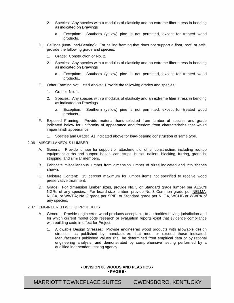
▪ DIVISION 06 WOODS AND PLASTICS ▪
▪ PAGE 9 ▪
RESIDENCE INN BY MARRIOTT - LITTLETON, COLORADO
2. Species: Any species with a modulus of elasticity and an extreme fiber stress in bending as indicated on Drawings
a. Exception: Southern (yellow) pine is not permitted, except for treated wood products.
D. Ceilings (Non-Load-Bearing): For ceiling framing that does not support a floor, roof, or attic, provide the following grade and species:
1. Grade: Construction or No. 2.
2. Species: Any species with a modulus of elasticity and an extreme fiber stress in bending as indicated on Drawings
a. Exception: Southern (yellow) pine is not permitted, except for treated wood products..
E. Other Framing Not Listed Above: Provide the following grades and species:
1. Grade: No. 1.
2. Species: Any species with a modulus of elasticity and an extreme fiber stress in bending as indicated on Drawings
a. Exception: Southern (yellow) pine is not permitted, except for treated wood products..
F. Exposed Framing: Provide material hand-selected from lumber of species and grade indicated below for uniformity of appearance and freedom from characteristics that would impair finish appearance.
1. Species and Grade: As indicated above for load-bearing construction of same type.
2.06 MISCELLANEOUS LUMBER
A. General: Provide lumber for support or attachment of other construction, including rooftop equipment curbs and support bases, cant strips, bucks, nailers, blocking, furring, grounds, stripping, and similar members.
B. Fabricate miscellaneous lumber from dimension lumber of sizes indicated and into shapes shown.
C. Moisture Content: 15 percent maximum for lumber items not specified to receive wood preservative treatment.
D. Grade: For dimension lumber sizes, provide No. 3 or Standard grade lumber per ALSC's NGRs of any species. For board-size lumber, provide No. 3 Common grade per NELMA, NLGA, or WWPA; No. 2 grade per SPIB; or Standard grade per NLGA, WCLIB or WWPA of any species.
2.07 ENGINEERED WOOD PRODUCTS
A. General: Provide engineered wood products acceptable to authorities having jurisdiction and for which current model code research or evaluation reports exist that evidence compliance with building code in effect for Project.
1. Allowable Design Stresses: Provide engineered wood products with allowable design stresses, as published by manufacturer, that meet or exceed those indicated. Manufacturer's published values shall be determined from empirical data or by rational engineering analysis, and demonstrated by comprehensive testing performed by a qualified independent testing agency.
MARRIOTT TOWNEPLACE SUITES OWENSBORO, KENTUCKY
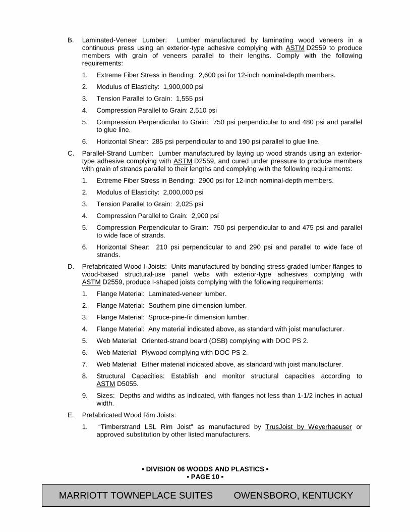
▪ DIVISION 06 WOODS AND PLASTICS ▪
▪ PAGE 10 ▪
RESIDENCE INN BY MARRIOTT - LITTLETON, COLORADO
B. Laminated-Veneer Lumber: Lumber manufactured by laminating wood veneers in a continuous press using an exterior-type adhesive complying with ASTM D2559 to produce members with grain of veneers parallel to their lengths. Comply with the following requirements:
1. Extreme Fiber Stress in Bending: 2,600 psi for 12-inch nominal-depth members.
2. Modulus of Elasticity: 1,900,000 psi
3. Tension Parallel to Grain: 1,555 psi
4. Compression Parallel to Grain: 2,510 psi
5. Compression Perpendicular to Grain: 750 psi perpendicular to and 480 psi and parallel to glue line.
6. Horizontal Shear: 285 psi perpendicular to and 190 psi parallel to glue line.
C. Parallel-Strand Lumber: Lumber manufactured by laying up wood strands using an exterior-type adhesive complying with ASTM D2559, and cured under pressure to produce members with grain of strands parallel to their lengths and complying with the following requirements:
1. Extreme Fiber Stress in Bending: 2900 psi for 12-inch nominal-depth members.
2. Modulus of Elasticity: 2,000,000 psi
3. Tension Parallel to Grain: 2,025 psi
4. Compression Parallel to Grain: 2,900 psi
5. Compression Perpendicular to Grain: 750 psi perpendicular to and 475 psi and parallel to wide face of strands.
6. Horizontal Shear: 210 psi perpendicular to and 290 psi and parallel to wide face of strands.
D. Prefabricated Wood I-Joists: Units manufactured by bonding stress-graded lumber flanges to wood-based structural-use panel webs with exterior-type adhesives complying with ASTM D2559, produce I-shaped joists complying with the following requirements:
1. Flange Material: Laminated-veneer lumber.
2. Flange Material: Southern pine dimension lumber.
3. Flange Material: Spruce-pine-fir dimension lumber.
4. Flange Material: Any material indicated above, as standard with joist manufacturer.
5. Web Material: Oriented-strand board (OSB) complying with DOC PS 2.
6. Web Material: Plywood complying with DOC PS 2.
7. Web Material: Either material indicated above, as standard with joist manufacturer.
8. Structural Capacities: Establish and monitor structural capacities according to ASTM D5055.
9. Sizes: Depths and widths as indicated, with flanges not less than 1-1/2 inches in actual width.
E. Prefabricated Wood Rim Joists:
1. “Timberstrand LSL Rim Joist” as manufactured by TrusJoist by Weyerhaeuser or approved substitution by other listed manufacturers.
MARRIOTT TOWNEPLACE SUITES OWENSBORO, KENTUCKY

▪ DIVISION 06 WOODS AND PLASTICS ▪
▪ PAGE 11 ▪
RESIDENCE INN BY MARRIOTT - LITTLETON, COLORADO
2. Construction: Solid 1-1/4” thick piece of laminated strand lumber sized to match depth of joist.
3. Design Values:
a. MOE = 1.3 x 10⁶
b. Vertical Load transfer = 4,250 plf (Governed by most restrictive capacity of member or wood plate below)
c. Lateral Load transfer = 240 plf
4. (Case 1) and 180 plf (Case 3), as governed by horizontal diaphragm.
F. Microllam LVL Beams:
1. “Microllam LVL” as manufactured by TrusJoist by Weyerhaeuser or approved substitution by other listed manufacturers.
2. Construction: Continuous laminated veneer lumber free from finger or scarf joints. Stress graded veneers bonded with waterproof adhesive with face grain parallel to each adjacent layer. Provide Watershed Overlay coating and edge seal to prevent cupping and moisture damage.
3. Design Values:
a. MOE = 1.9 x 10⁶ psi
b. Fb = 2600 psi (for 12” depth)
c. Fc1 = 750 psi
d. Fv = 285 psi.
G. Parallam PSL Beams:
1. “Parallam PSL” as manufactured by TrusJoist by Weyerhaeuser, or approved substitution by other listed manufacturers.
2. Construction: Continuous parallel strand lumber bonded with waterproof adhesives and formed into billets. Beams shall be of single ply construction and free from finger joints or splices for full length of span.
3. Design Values:
a. MOE = 2.0 x 10⁶ psi
b. Fb - 2900 psi (for 12” depth)
c. Fc1 = 750 psi
d. Fv = 290 psi.
H. Laminated Strand Lumber (LSL) Headers:
1. “Timberstrand LSL Headers” as manufactured by TrusJoist by Weyerhaeuser, or approved substitution by other listed manufacturers.
2. Construction: Laminated strand lumber; strands of aspen or yellow poplar bonded with waterproof resins; cured using a steam injection process.
3. Design Values for depths 9.25” or greater:
a. MOE = 1.5 x 10⁶ psi
b. Fb = 2250 psi (for 12” depth)
MARRIOTT TOWNEPLACE SUITES OWENSBORO, KENTUCKY
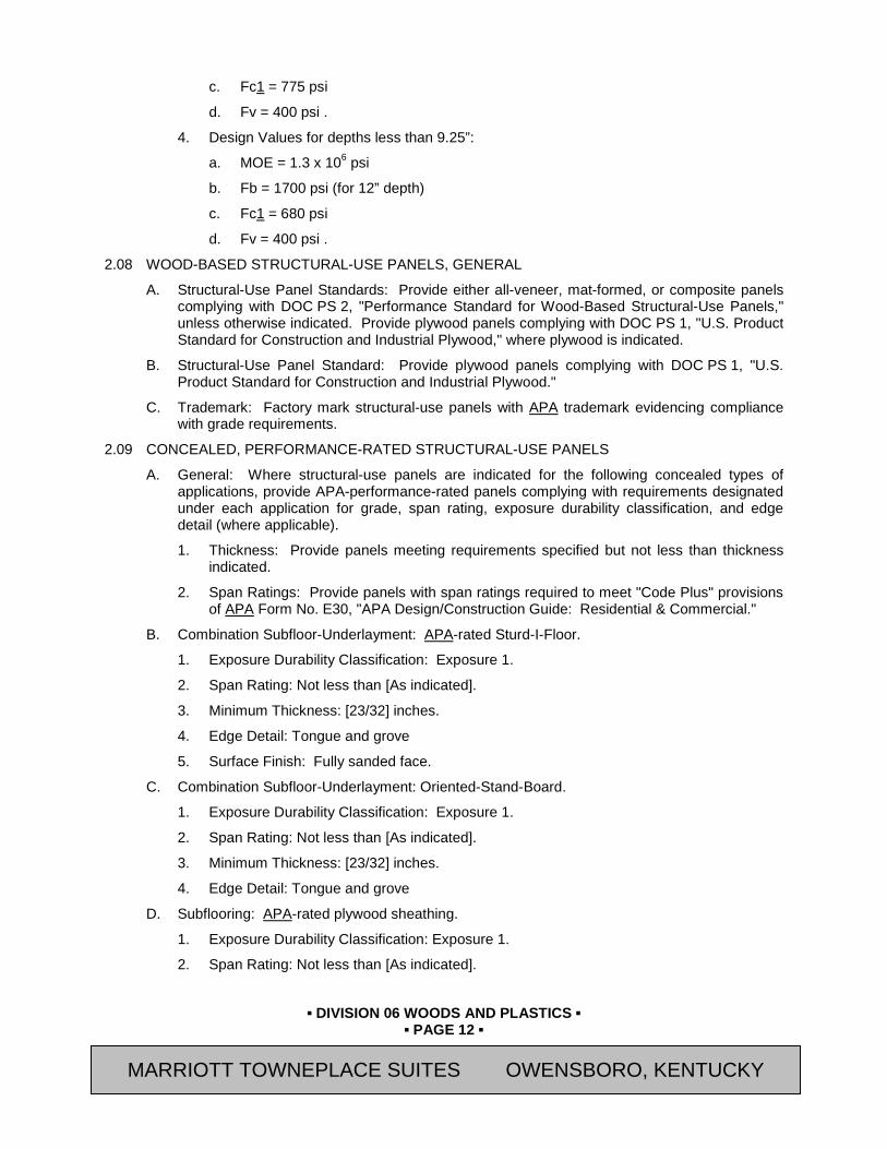
▪ DIVISION 06 WOODS AND PLASTICS ▪
▪ PAGE 12 ▪
RESIDENCE INN BY MARRIOTT - LITTLETON, COLORADO
c. Fc1 = 775 psi
d. Fv = 400 psi .
4. Design Values for depths less than 9.25”:
a. MOE = 1.3 x 10⁶ psi
b. Fb = 1700 psi (for 12” depth)
c. Fc1 = 680 psi
d. Fv = 400 psi .
2.08 WOOD-BASED STRUCTURAL-USE PANELS, GENERAL
A. Structural-Use Panel Standards: Provide either all-veneer, mat-formed, or composite panels complying with DOC PS 2, "Performance Standard for Wood-Based Structural-Use Panels," unless otherwise indicated. Provide plywood panels complying with DOC PS 1, "U.S. Product Standard for Construction and Industrial Plywood," where plywood is indicated.
B. Structural-Use Panel Standard: Provide plywood panels complying with DOC PS 1, "U.S. Product Standard for Construction and Industrial Plywood."
C. Trademark: Factory mark structural-use panels with APA trademark evidencing compliance with grade requirements.
2.09 CONCEALED, PERFORMANCE-RATED STRUCTURAL-USE PANELS
A. General: Where structural-use panels are indicated for the following concealed types of applications, provide APA-performance-rated panels complying with requirements designated under each application for grade, span rating, exposure durability classification, and edge detail (where applicable).
1. Thickness: Provide panels meeting requirements specified but not less than thickness indicated.
2. Span Ratings: Provide panels with span ratings required to meet "Code Plus" provisions of APA Form No. E30, "APA Design/Construction Guide: Residential & Commercial."
B. Combination Subfloor-Underlayment: APA-rated Sturd-I-Floor.
1. Exposure Durability Classification: Exposure 1.
2. Span Rating: Not less than [As indicated].
3. Minimum Thickness: [23/32] inches.
4. Edge Detail: Tongue and grove
5. Surface Finish: Fully sanded face.
C. Combination Subfloor-Underlayment: Oriented-Stand-Board.
1. Exposure Durability Classification: Exposure 1.
2. Span Rating: Not less than [As indicated].
3. Minimum Thickness: [23/32] inches.
4. Edge Detail: Tongue and grove
D. Subflooring: APA-rated plywood sheathing.
1. Exposure Durability Classification: Exposure 1.
2. Span Rating: Not less than [As indicated].
MARRIOTT TOWNEPLACE SUITES OWENSBORO, KENTUCKY
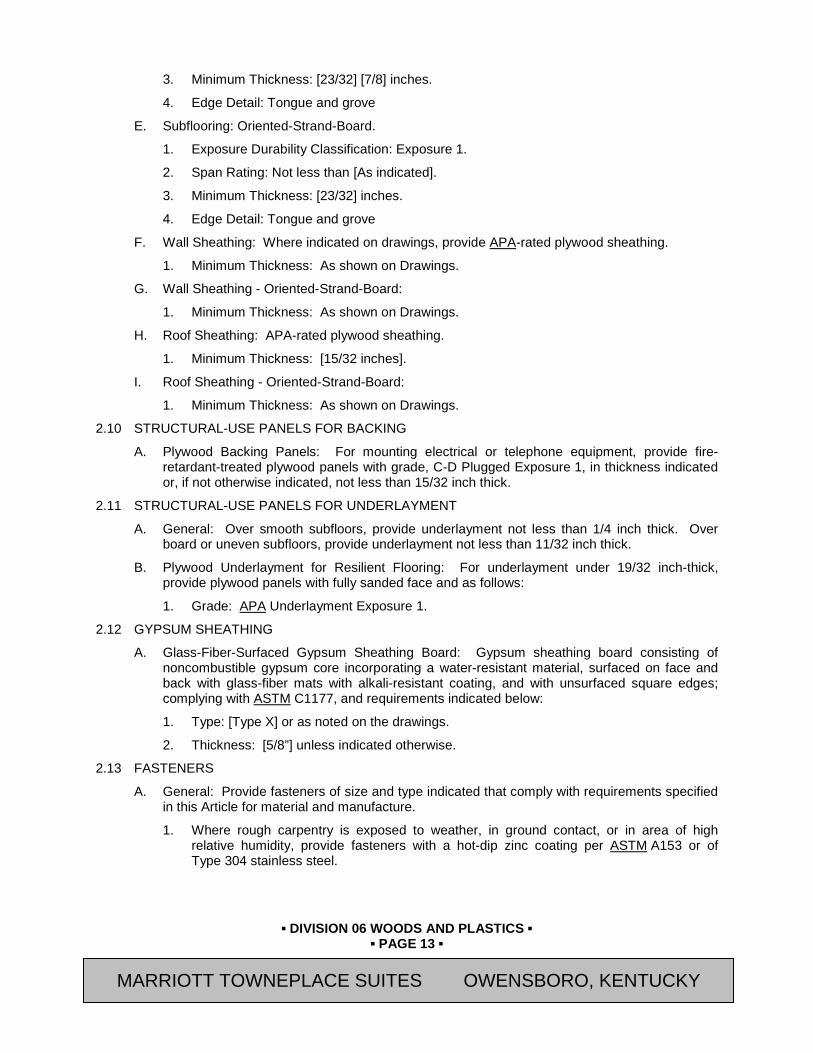
▪ DIVISION 06 WOODS AND PLASTICS ▪
▪ PAGE 13 ▪
RESIDENCE INN BY MARRIOTT - LITTLETON, COLORADO
3. Minimum Thickness: [23/32] [7/8] inches.
4. Edge Detail: Tongue and grove
E. Subflooring: Oriented-Strand-Board.
1. Exposure Durability Classification: Exposure 1.
2. Span Rating: Not less than [As indicated].
3. Minimum Thickness: [23/32] inches.
4. Edge Detail: Tongue and grove
F. Wall Sheathing: Where indicated on drawings, provide APA-rated plywood sheathing.
1. Minimum Thickness: As shown on Drawings.
G. Wall Sheathing - Oriented-Strand-Board:
1. Minimum Thickness: As shown on Drawings.
H. Roof Sheathing: APA-rated plywood sheathing.
1. Minimum Thickness: [15/32 inches].
I. Roof Sheathing - Oriented-Strand-Board:
1. Minimum Thickness: As shown on Drawings.
2.10 STRUCTURAL-USE PANELS FOR BACKING
A. Plywood Backing Panels: For mounting electrical or telephone equipment, provide fire-retardant-treated plywood panels with grade, C-D Plugged Exposure 1, in thickness indicated or, if not otherwise indicated, not less than 15/32 inch thick.
2.11 STRUCTURAL-USE PANELS FOR UNDERLAYMENT
A. General: Over smooth subfloors, provide underlayment not less than 1/4 inch thick. Over board or uneven subfloors, provide underlayment not less than 11/32 inch thick.
B. Plywood Underlayment for Resilient Flooring: For underlayment under 19/32 inch-thick, provide plywood panels with fully sanded face and as follows:
1. Grade: APA Underlayment Exposure 1.
2.12 GYPSUM SHEATHING
A. Glass-Fiber-Surfaced Gypsum Sheathing Board: Gypsum sheathing board consisting of noncombustible gypsum core incorporating a water-resistant material, surfaced on face and back with glass-fiber mats with alkali-resistant coating, and with unsurfaced square edges; complying with ASTM C1177, and requirements indicated below:
1. Type: [Type X] or as noted on the drawings.
2. Thickness: [5/8”] unless indicated otherwise.
2.13 FASTENERS
A. General: Provide fasteners of size and type indicated that comply with requirements specified in this Article for material and manufacture.
1. Where rough carpentry is exposed to weather, in ground contact, or in area of high relative humidity, provide fasteners with a hot-dip zinc coating per ASTM A153 or of Type 304 stainless steel.
MARRIOTT TOWNEPLACE SUITES OWENSBORO, KENTUCKY
▪ DIVISION 06 WOODS AND PLASTICS ▪
▪ PAGE 14 ▪
RESIDENCE INN BY MARRIOTT - LITTLETON, COLORADO
2. For fasteners and hardware used with treated wood products, comply with manufacturer’s recommendations for their intended use.
B. Nails, Wire, Brads, and Staples: ASTM F1667.
C. Power-Driven Fasteners: NES NER-272.
D. Wood Screws: ASME B18.6.1.
E. Screws for Fastening Wood Structural Panels to Cold-Formed Metal Framing: ASTM C954, except with wafer heads and reamer wings, length as recommended by screw manufacturer for material being fastened.
1. For wall and roof sheathing panels, provide screws with organic-polymer or other corrosion-protective coating having a salt-spray resistance of more than 800 hours according to ASTM B117.
F. Screws for Fastening Gypsum Sheathing to Cold-Formed Metal Framing: Steel drill screws, in length recommended by sheathing manufacturer for thickness of sheathing board to be attached, with organic-polymer or other corrosion-protective coating having a salt-spray resistance of more than 800 hours according to ASTM B117. Attach sheathing to comply with ASTM C954.
G. Lag Bolts: ASME B18.2.1.
H. Bolts: Steel bolts complying with ASTM A307, Grade A; with ASTM A563 hex nuts and, where indicated, flat washers.
2.14 METAL FRAMING ANCHORS
A. General: Provide galvanized steel framing anchors of structural capacity, type, and size indicated and as follows:
1. Research or Evaluation Reports: Provide products for which model code research or evaluation reports exist that are acceptable to authorities having jurisdiction and that evidence compliance of metal framing anchors for application indicated with building code in effect for Project.
2. Allowable Design Loads: Provide products with allowable design loads, as published by manufacturer, that meet or exceed those indicated. Manufacturer's published values shall be determined from empirical data or by rational engineering analysis, and demonstrated by comprehensive testing performed by a qualified independent testing agency.
3. For metal framing anchors used with treated wood products, comply with manufacturer’s recommendations for their intended use.
B. Galvanized Steel Sheet: Hot-dip, zinc-coated steel sheet complying with ASTM A653, G60 coating designation; structural, commercial, or lock-forming quality, as standard with manufacturer for type of anchor indicated.
C. Joist Hangers: U-shaped joist hangers with 2-inch-long seat and 1-1/4-inch-wide nailing flanges at least 85 percent of joist depth.
D. Top Flange Hangers: U-shaped joist hangers, full depth of joist, formed from metal strap with tabs bent to extend over and be fastened to supporting member.
1. Designed for connection of engineered wood products, sized to support design loads.
E. Bridging: Rigid, V-section, nailless type, 0.064 inch thick, length to suit joist size and spacing.
MARRIOTT TOWNEPLACE SUITES OWENSBORO, KENTUCKY

▪ DIVISION 06 WOODS AND PLASTICS ▪
▪ PAGE 15 ▪
RESIDENCE INN BY MARRIOTT - LITTLETON, COLORADO
F. Post Bases: Adjustable-socket type for bolting in place with standoff plate to raise post 1 inch above base and with 2-inch minimum side cover, socket 0.064 inch thick, standoff and adjustment plates 0.108 inch thick.
G. Joist Ties: Flat straps, with holes for fasteners, for tying joists together over supports.
1. Length: As indicated.
H. Rafter Tie-Downs (Hurricane Ties): Bent strap tie for fastening rafters or roof trusses to wall studs below, 1-5/8 inches wide by 0.052 inch thick.
I. Floor-to-Floor Ties: Flat straps, with holes for fasteners, for tying upper floor wall studs to band joists and lower floor studs, 1-1/4 inches wide by 0.052 inch thick by 36 inches long.
J. Hold-Downs: Brackets for bolting to wall studs and securing to foundation walls with anchor bolts or to other hold-downs with threaded rods and designed with first of 2 bolts placed 7 bolt diameters from reinforced base.
K. Wall Bracing: Angle bracing made for letting into studs in saw kerf, 15/16 by 15/16 by 0.040 inch thick with hemmed edges.
2.15 MISCELLANEOUS MATERIALS
A. Sill-Sealer Gaskets: Glass-fiber-resilient insulation, fabricated in strip form, for use as a sill sealer; 1-inch nominal thickness, compressible to 1/32 inch; selected from manufacturer's standard widths to suit width of sill members indicated.
B. Adhesives for Field Gluing Panels to Framing: Formulation complying with APA AFG-01 that is approved for use with type of construction panel indicated by both adhesive and panel manufacturers.
C. Water-Repellent Preservative: NWWDA-tested and -accepted formulation containing 3-iodo-2-propynyl butyl carbonate (IPBC) as its active ingredient.
PART 3 EXECUTION 3.01 INSTALLATION, GENERAL
A. Discard units of material with defects that impair quality of rough carpentry and that are too small to use with minimum number of joints or optimum joint arrangement.
B. Set rough carpentry to required levels and lines, with members plumb, true to line, cut, and fitted.
C. Fit rough carpentry to other construction; scribe and cope as required for accurate fit. Correlate location of furring, nailers, blocking, grounds, and similar supports to allow attachment of other construction.
D. Apply field treatment complying with AWPA M4 to cut surfaces of preservative-treated lumber and plywood.
E. Securely attach rough carpentry work to substrate by anchoring and fastening as indicated, complying with the following:
1. Engineered Structural drawings
F. Secure blocking for roof edge systems, such as copings or gravel stops, in accordance with SPRI Wind Design Standards as specified in Section 07 62 00 “Flashing and Sheet Metal” and the requirements of the International Building Code.
MARRIOTT TOWNEPLACE SUITES OWENSBORO, KENTUCKY
▪ DIVISION 06 WOODS AND PLASTICS ▪
▪ PAGE 16 ▪
RESIDENCE INN BY MARRIOTT - LITTLETON, COLORADO
G. Use common wire nails, unless otherwise indicated. Use finishing nails for finish work. Select fasteners of size that will not fully penetrate members where opposite side will be exposed to view or will receive finish materials. Make tight connections between members. Install fasteners without splitting wood; predrill as required.
H. Use hot-dip galvanized or stainless-steel nails where rough carpentry is exposed to weather, in ground contact, or in area of high relative humidity.
I. Countersink nail heads on exposed carpentry work and fill holes with wood filler.
3.02 WOOD GROUNDS, NAILERS, BLOCKING, AND SLEEPERS
A. Install wood grounds, nailers, blocking, and sleepers where shown and where required for screeding or attaching other work. Form to shapes shown and cut as required for true line and level of attached work. Coordinate locations with other work involved.
1. Wood blocking or nailers used to attach roof edge system components shall be designed and installed to resist the design wind load and shall be firmly attached to the masonry structure to provide a continuous load path in accordance with SPRI Wind Design Standards. For wood nailers wider than 6-inches fasteners shall be staggered to avoid splitting the wood.
B. Attach to substrates to support applied loading. Recess bolts and nuts flush with surfaces, unless otherwise indicated. Build into masonry during installation of masonry work. Where possible, anchor to formwork before concrete placement.
C. Install permanent grounds of dressed, preservative-treated, key-beveled lumber not less than 1-1/2 inches wide and of thickness required to bring face of ground to exact thickness of finish material. Remove temporary grounds when no longer required.
3.03 WOOD FURRING
A. Install plumb and level with closure strips at edges and openings. Shim with wood as required for tolerance of finish work.
1. Firestop furred spaces of walls at each floor level and at ceiling with wood blocking or noncombustible materials, accurately fitted to close furred spaces.
B. Furring to Receive Plywood Paneling: Install 1-by-3-inch nominal-size furring at 24 inches o.c., horizontally and vertically. Select furring with no knots capable of producing bent-over nails and damage to paneling.
C. Furring to Receive Gypsum Board: Install 1-by-2-inch nominal-size furring at 16 inches o.c., vertically.
3.04 WOOD FRAMING, GENERAL
A. Framing Standard: Comply with AFPA's "Manual for Wood Frame Construction," unless otherwise indicated.
B. Framing with Engineered Wood Products: Install engineered wood products to comply with manufacturer's written instructions.
C. Install framing members of size and at spacing indicated.
D. Do not splice structural members between supports.
E. Firestop concealed spaces of wood-framed walls and partitions at each floor level and at ceiling line of top story. Where firestopping is not inherent in framing system used, provide closely fitted wood blocks of 2-inch nominal-thickness lumber of same width as framing members.
MARRIOTT TOWNEPLACE SUITES OWENSBORO, KENTUCKY

▪ DIVISION 06 WOODS AND PLASTICS ▪
▪ PAGE 17 ▪
RESIDENCE INN BY MARRIOTT - LITTLETON, COLORADO
F. Comply with Table 2304.9.1 and Section 2304 of the International Building Code for minimum fastening requirements of wood members, and published requirements of metal fastener manufacturer, whichever is more stringent.
3.05 WALL AND PARTITION FRAMING
A. General: Arrange studs so that wide face of stud is perpendicular to direction of wall or partition and narrow face is parallel. Provide single bottom plate and double top plates using members of 2-inch nominal thickness whose widths equal that of studs; except single top plate may be used for non-load-bearing partitions. Nail or anchor plates to supporting construction, unless otherwise indicated.
B. Construct corners and intersections with 3 or more studs. Provide miscellaneous blocking and framing as shown and as required to support facing materials, fixtures, specialty items, and trim.
1. Provide continuous horizontal blocking at midheight of single-story partitions and multistory partitions, using members of 2-inch nominal thickness and of same width as wall or partitions.
C. Frame openings with multiple studs and headers. Provide nailed header members of thickness equal to width of studs. Set headers on edge and support on jamb studs.
1. For non-load-bearing partitions, provide double-jamb studs with headers not less than 4-inch nominal depth for openings 36 inches and less in width, and not less than 6-inch nominal depth for wider openings.
2. For load-bearing walls, provide double-jamb studs for openings 72 inches and less in width, and triple-jamb studs for wider openings. Provide headers of depth shown or, if not shown, as recommended by AFPA's "Manual for Wood Frame Construction."
D. Provide bracing in exterior walls, at both walls of each external corner, full-story height, unless otherwise indicated. Provide one of the following:
E. Provide bracing in walls, at locations indicated, full-story height, unless otherwise indicated. Provide one of the following:
1. Diagonal bracing at 45-degree angle using let-in 1-by-4-inch nominal-size boards or using metal bracing.
2. Plywood panels, not less than 48 by 96 inches applied vertically.
3. Performance-rated structural-use panels, not less than 48 by 96 inches applied vertically.
4. Particleboard sheathing panels, not less than 48 by 96 inches applied vertically.
5. In lieu of bracing at corners or at locations indicated, continuous gypsum sheathing may be provided in panels not less than 48 by 96 inches applied vertically.
6. In lieu of bracing at corners or at locations indicated, continuous fiberboard sheathing, intermediate type, may be provided in panels not less than 48 by 96 inches applied vertically.
3.06 FLOOR JOIST FRAMING
A. General: Install floor joists with crown edge up and support ends of each member with not less than 1-1/2 inches of bearing on wood or metal, or 3 inches on masonry. Attach floor joists as follows:
1. Where supported on wood members, by toe nailing or by using metal framing anchors.
2. Where framed into wood supporting members, by using wood ledgers as shown or, if not shown, by using metal joist hangers.
MARRIOTT TOWNEPLACE SUITES OWENSBORO, KENTUCKY
▪ DIVISION 06 WOODS AND PLASTICS ▪
▪ PAGE 18 ▪
RESIDENCE INN BY MARRIOTT - LITTLETON, COLORADO
B. Fire Cuts: At joists built into masonry, bevel cut ends 3 inches and do not embed more than 4 inches.
C. Frame openings with headers and trimmers supported by metal joist hangers; double headers and trimmers where span of header exceeds 48 inches.
D. Do not notch in middle third of joists; limit notches to 1/6 depth of joist, 1/3 at ends. Do not bore holes larger than 1/3 depth of joist; do not locate closer than 2 inches from top or bottom.
E. Provide solid blocking of 2-inch nominal thickness by depth of joist at ends of joists unless nailed to header or band.
F. Lap members framing from opposite sides of beams, girders, or partitions not less than 4 inches or securely tie opposing members together. Provide solid blocking of 2-inch nominal thickness by depth of joist over supports.
G. Anchor members paralleling masonry with 1/4-by-1-1/4-inch metal strap anchors spaced not more than 96 inches o.c. extending over and fastening to 3 joists. Embed anchors at least 4 inches into masonry with ends bent at right angles 4 inches into grouted masonry.
H. Under jamb studs at openings, provide solid blocking between joist.
I. Under non-load-bearing partitions, provide double joists separated by solid blocking equal to depth of studs above.
1. Provide triple joists separated as above, under partitions receiving ceramic tile and similar heavy finishes or fixtures.
J. Provide bridging of type indicated below, at intervals of 96 inches o.c., between joists.
1. Diagonal wood bridging formed from bevel cut 1-by-3-inch nominal-size lumber, double-crossed and nailed both ends to joists.
2. Steel bridging installed to comply with bridging manufacturer's written instructions.
3. Bridging may be omitted where joist depth is 12-inch nominal size or less, and where indicated live load is 40 psf or less.
K. Prefabricated Wood I-Joists:
1. Comply with manufacturer’s written instructions for design, installation, and fastening.
2. Design Loads: Joists shall be sized to support loads indicated on drawings and reviewed by a Registered Engineer in the employ of the joist manufacturer.
3. Allowable deflection:
a. Floor Joists: L/480 live load deflection; L/240 total load deflection.
4. Permanently bond the subfloor to the joists using waterproof construction adhesive and nails.
5. End Bearing: 1-3/4” minimum bearing with Timberstrand LSL rim joist.
6. Intermediate bearing: 3-1/2” minimum bearing. Blocking panels shall be installed between the joists when load bearing walls are located above the bearing point.
L. Engineered Wood Beams
1. Comply with manufacturer’s written instructions for design, installation, and fastening.
2. Design Loads: Beams shall be sized to support loads indicated on drawings.
3. Allowable deflection:
a. Floor Beams: L360 live load deflection; L240 total load deflection.
MARRIOTT TOWNEPLACE SUITES OWENSBORO, KENTUCKY
▪ DIVISION 06 WOODS AND PLASTICS ▪
▪ PAGE 19 ▪
RESIDENCE INN BY MARRIOTT - LITTLETON, COLORADO
b. Roof Beams: L/180 total load deflection.
4. Protect wood members from direct contact with concrete or masonry.
5. Refer to manufacturers literature for connection of multiple plies of side loaded beams.
3.07 RAFTER AND CEILING JOIST FRAMING
A. Ceiling Joists: Install ceiling joists with crown edge up and complying with requirements specified above for floor joists. Face nail to ends of parallel rafters.
1. Where ceiling joists are at right angles to rafters, provide additional short joists perpendicular to rafters from wall plate to first joist; nail to ends of rafters and to top plate and nail to first joist or anchor with framing anchors or metal straps. Provide 1-by-8-inch nominal-size or 2-by-4-inch nominal-size stringers spaced 48 inches o.c. crosswise over main ceiling joists.
B. Rafters: Notch to fit exterior wall plates and toe nail or use metal framing anchors. Double rafters to form headers and trimmers at openings in roof framing, if any, and support with metal hangers. Where rafters abut at ridge, place directly opposite each other and nail to ridge member or use metal ridge hangers.
1. At valleys, provide double-valley rafters of size shown or, if not shown, of same thickness as regular rafters and 2 inches deeper. Bevel ends of jack rafters for full bearing against valley rafters.
2. At hips, provide hip rafter of size shown or, if not shown, of same thickness as regular rafters and 2 inches deeper. Bevel ends of jack rafters for full bearing against hip rafter.
C. Provide collar beams (ties) as shown or, if not shown, provide 1-by-6-inch nominal-size boards between every third pair of rafters, but not more than 48 inches o.c. Locate below ridge member, at third point of rafter span. Cut ends to fit roof slope and nail to rafters.
D. Provide special framing as shown for eaves, overhangs, dormers, and similar conditions, if any.
E. Prefabricated Wood I-Joists:
1. Comply with manufacturer’s written instructions for design, installation, and fastening.
2. Design Loads: Joists shall be sized to support loads indicated on drawings and reviewed by a Registered Engineer in the employ of the joist manufacturer.
3. Allowable deflection:
a. Roof Joists: L/360 live load deflection; L/240 total load deflection
4. Permanently bond the subfloor to the joists using waterproof construction adhesive and nails.
5. End Bearing: 1-3/4” minimum bearing with Timberstrand LSL rim joist.
6. Intermediate bearing: 3-1/2” minimum bearing. Blocking panels shall be installed between the joists when load bearing walls are located above the bearing point.
F. Engineered Wood Beams
1. Comply with manufacturer’s written instructions for design, installation, and fastening.
2. Design Loads: Beams shall be sized to support loads indicated on drawings.
3. Allowable deflection:
a. Floor Beams: L360 live load deflection; L240 total load deflection.
b. Roof Beams: L/180 total load deflection.
MARRIOTT TOWNEPLACE SUITES OWENSBORO, KENTUCKY

▪ DIVISION 06 WOODS AND PLASTICS ▪
▪ PAGE 20 ▪
RESIDENCE INN BY MARRIOTT - LITTLETON, COLORADO
4. Protect wood members from direct contact with concrete or masonry.
5. Refer to manufacturers literature for connection of multiple plies of side loaded beams.
3.08 STAIR FRAMING
A. Provide stair framing members of size, space, and configuration indicated or, if not otherwise indicated, to comply with the following requirements:
1. Stringer Size: 2-by-12-inch nominal-size minimum.
2. Notching: Notch stringers to receive treads, risers, and supports; leave at least 3-1/2 inches of effective depth.
3. Stringer Spacing: At least 3 stringers for each 36-inch clear width of stair.
B. Provide stair framing that does not exceed the following variations between treads and risers within each flight:
1. Adjacent Treads and Risers: 3/16 inch.
2. Between Largest and Smallest Treads and Risers: 3/8 inch.
3.09 INSTALLATION OF STRUCTURAL-USE PANELS
A. General: Comply with applicable recommendations contained in APA Form No. E30K, "APA Design/Construction Guide: Residential & Commercial," for types of structural-use panels and applications indicated.
1. Comply with "Code Plus" provisions of above-referenced guide.
B. Securely attach to substrate by fastening as indicated, complying with the following:
1. ICC NER-272 for power-driven fasteners.
2. Table 2304.9.1, "Fastening Schedule," in ICC's "International Building Code."
C. Do not bridge building expansion joints; cut and space edges of panels to match spacing of structural support elements.
D. Coordinate sheathing installation with installation of materials installed over sheathing so sheathing is not exposed to precipitation or left exposed at end of the workday when rain is forecast.
E. Fastening Methods: Fasten panels as indicated below:
1. Subflooring: Glue and nail to framing throughout.
a. Space panels 1/8 inch at edges and ends.
2. Sheathing:
a. Nail to wood framing.
b. Space panels 1/8 inch at edges and ends.
3. Underlayment: Nail to subflooring.
a. Space panels 1/32 inch at edges and ends.
b. Fill and sand edge joints of underlayment receiving resilient flooring just before installing flooring.
4. Plywood Backing Panels: Nail or screw to supports.
5. Lay-out panels with face grain oriented perpendicular to the supporting members.
6. Install roof sheathing with panel cups at all edges.
MARRIOTT TOWNEPLACE SUITES OWENSBORO, KENTUCKY
▪ DIVISION 06 WOODS AND PLASTICS ▪
▪ PAGE 21 ▪
RESIDENCE INN BY MARRIOTT - LITTLETON, COLORADO
3.10 GYPSUM SHEATHING
A. General: Install gypsum sheathing to comply with manufacturer’s instructions, GA-253, and the following:
1. Cut boards at penetrations, edge, and other obstructions of the work. Fit tightly against abutting construction, except provide a 3/8” setback where non-load-bearing construction abuts structural elements.
2. Coordinate sheathing installation with flashing and joint sealant installation so that these combined materials are installed in the sequence and manner that prevents exterior moisture from passing through completed exterior wall assembly.
3. Apply fasteners so that screw heads bear tightly against face of gypsum sheathing boards, but do not cut into face paper.
4. Do not bridge building expansion joints with gypsum sheathing. Cut and space edges to match spacing of structural support elements.
B. Vertical Installation: Install four-foot-wide gypsum sheathing boards vertically with vertical edges centered over flanges of studs. Abut ends and edges of each board with those of adjoining boards. Screw-attach boards at perimeter and within field of board to each steel stud a follows:
1. Fasteners spaced approximately 8” o.c. and set-back 3/8” minimum from edges and ends of boards.
3.11 FIBERBOARD SHEATHING INSTALLATION
A. Comply with ASTM C846 and with manufacturer's written instructions.
1. Fasten fiberboard sheathing panels to intermediate supports and then at edges and ends. Use galvanized roofing nails[ or galvanized staples]; comply with manufacturer's recommended spacing and referenced fastening schedule. Drive fasteners flush with surface of sheathing and locate perimeter fasteners at least 3/8 inch from edges and ends.
2. Install sheathing vertically with long edges parallel to, and centered over, studs. Install solid wood blocking where end joints do not occur over framing. Allow 1/8-inch open space between edges and ends of adjacent units. Stagger horizontal joints if any.
3. Cover sheathing as soon as practical after installation to prevent deterioration from wetting.
3.12 PROTECTION
A. Protect wood that has been treated with inorganic boron from weather. If inorganic boron treated wood becomes wet, apply EPA registered borate treatment to wood surfaces in accordance with manufacturers recommendations.
B. Protect Gypsum Sheathing from weather by covering exposed exterior surface, if required by manufacturer of gypsum sheathing.
END OF SECTION
Revision Log
MARRIOTT TOWNEPLACE SUITES OWENSBORO, KENTUCKY
▪ DIVISION 06 WOODS AND PLASTICS ▪
▪ PAGE 22 ▪
RESIDENCE INN BY MARRIOTT - LITTLETON, COLORADO
SECTION 06 17 53 (06175) - SHOP-FABRICATED WOOD TRUSSES SHOP-FABRICATED WOOD TRUSSES
PART 4 GENERAL 4.01 SUMMARY
A. Section Includes:
1. Triangular-Pitched Roof Trusses
2. Scissor Roof Trusses
3. Parallel-Chord Roof Trusses, Top-Chord Bearing
4. Parallel-Chord Roof Trusses, Bottom-Chord Bearing
5. Girder Trusses
6. Parallel-Chord Floor Trusses, Top-Chord Bearing
7. Parallel-Chord Floor Trusses, Bottom-Chord Bearing
8. Truss Accessories
B. Related Sections:
1. Section 05 50 00 (05500) - Metal Fabrications
2. Section 06 10 00 (06100) - Rough Carpentry permanent bracing
4.02 REFERENCES
A. ASTM International Publications:
1. A153 "Standard Specification for Zinc Coating (Hot-Dip) on Iron and Steel Hardware"
2. A307 "Standard Specification for Carbon Steel Bolts and Studs, 60 000 PSI Tensile Strength"
3. A563 "Standard Specification for Carbon and Alloy Steel Nuts"
4. A591 "Standard Specification for Steel Sheet, Electrolytic Zinc-Coated, for Light Coating Weight [Mass] Applications"
5. A653 "Standard Specification for Steel Sheet, Zinc-Coated (Galvanized) or Zinc-Iron Alloy-Coated (Galvannealed) by the Hot-Dip Process"
6. A666 "Standard Specification for Annealed or Cold-Worked Austenitic Stainless Steel Sheet, Strip, Plate, and Flat Bar"
7. A780 "Standard Practice for Repair of Damaged and Uncoated Areas of Hot-Dip Galvanized Coatings"
8. A792 "Standard Specification for Steel Sheet, 55 % Aluminum-Zinc Alloy-Coated by the Hot-Dip Process"
9. F1667 "Standard Specification for Driven Fasteners: Nails, Spikes, and Staples"
B. The American Society of Mechanical Engineers (ASME) Publications:
1. B18.2.1 "Square and Hex Bolts and Screws, Inch Series"
C. American Wood-Preservers's Association (AWPA) Publications:
1. C2 "Lumber, Timber, Bridge Ties and Mine Ties - Preservative Treatment by Pressure Processes"
MARRIOTT TOWNEPLACE SUITES OWENSBORO, KENTUCKY
▪ DIVISION 06 WOODS AND PLASTICS ▪
▪ PAGE 23 ▪
RESIDENCE INN BY MARRIOTT - LITTLETON, COLORADO
2. C9 "Plywood - Preservative Treatment by Pressure Process Document Number"
3. M4 "Standard for the Care of Preservative-Treated Wood Products Document Number"
D. Truss Plate Institute (TPI) / American National Standards Institute (ANSI) Publications:
1. ANSI/TP1 1, "National Design Standard for Metal-Plate-Connected Wood Truss Construction."
2. TPI HIB "Commentary and Recommendations for Handling Installing & Bracing Metal Plate Connected Wood Trusses."
3. TPI DSB "Recommended Design Specification for Temporary Bracing of Metal Plate Connected Wood Trusses."
4.03 DEFINITIONS
A. Metal-plate-connected wood trusses include planar structural units consisting of metal-plate-connected members fabricated from dimension lumber and cut and assembled before delivery to Project site.
4.04 PERFORMANCE REQUIREMENTS
A. Structural Performance: Engineer, fabricate, and erect metal-plate-connected wood trusses to withstand design loads within limits and under conditions required.
1. Design Loads: As indicated.
2. Design trusses to withstand design loads without deflections greater than the following:
a. Roof Trusses: Vertical deflection of 1/240 of span due to total load.
b. Roof Trusses: Horizontal deflection at reactions of 1-1/4 inches due to total load.
c. Floor Trusses: Vertical deflection of 1/480 of span due to live load.
B. Engineering Responsibility: Engage a fabricator who uses a qualified professional engineer to prepare calculations, Shop Drawings, and other structural data for metal-plate-connected wood trusses.
4.05 SUBMITTALS
A. General: Submit the following in accordance with Conditions of Contract and Division 01 Specification Sections.
B. Product Data: For lumber, metal-plate connectors, metal framing connectors, bolts, and fasteners.
1. Submit “Letter of Conformance” in accordance with Section 01 33 00 (01330) indicating specified items selected for use in project.
C. Shop Drawings detailing location, pitch, span, camber, configuration, and spacing for each type of truss required; species, sizes, and stress grades of lumber to be used; splice details; type, size, material, finish, design values, and orientation and location of metal connector plates; and bearing details.
1. To the extent truss design considerations are indicated as fabricator's responsibility, include structural analysis data signed and sealed by the qualified professional engineer responsible for their preparation.
2. Include truss Shop Drawings signed and sealed by the qualified professional engineer responsible for their preparation.
MARRIOTT TOWNEPLACE SUITES OWENSBORO, KENTUCKY
▪ DIVISION 06 WOODS AND PLASTICS ▪
▪ PAGE 24 ▪
RESIDENCE INN BY MARRIOTT - LITTLETON, COLORADO
D. Product certificates signed by officer of truss fabricating firm certifying that metal-plate-connected wood trusses supplied for Project comply with specified requirements and Shop Drawings.
E. Qualification data for firms and persons specified in "Quality Assurance" Article to demonstrate their capabilities and experience. Include lists of completed projects with project names and addresses, names and addresses of architects and owners, and other information specified.
F. Material test reports from a qualified independent testing agency indicating and interpreting test results relative to compliance of fire-retardant-treated wood products with requirements indicated.
G. Warranty of chemical treatment manufacturer for each type of treatment.
H. Material certificates for dimension lumber specified to comply with minimum allowable unit stresses. Indicate species and grade selected for each use and design values approved by the American Lumber Standards Committee (ALSC) Board of Review.
I. Wood treatment data as follows, including chemical treatment manufacturer's instructions for handling, storing, installing, and finishing treated materials:
1. For each type of preservative-treated wood product, include certification by treating plant stating type of preservative solution and pressure process used, net amount of preservative retained, and compliance with applicable standards.
2. For waterborne-treated products, include statement that moisture content of treated materials was reduced to levels indicated before shipment to truss fabricator.
3. For fire-retardant-treated wood products, include certification by treating plant that treated materials comply with specified standard and other requirements as well as data relative to bending strength, stiffness, and fastener-holding capacities of treated materials, all tested in accordance with ASTM D5664.
J. Research or evaluation reports of the model code organization acceptable to authorities having jurisdiction that evidence the following products' compliance with building code in effect for Project.
1. Fire-retardant-treated wood
2. Metal-plate connectors
3. Metal framing connectors
4.06 QUALITY ASSURANCE
A. Installer Qualifications: An experienced installer with a minimum of five years of experience, who has completed wood truss projects similar in material, design, and extent to that indicated for this Project and with a record of successful in-service performance.
B. Fabricator's Qualifications: Engage a firm that complies with the following requirements for quality control and is experienced in fabricating metal-plate-connected wood trusses similar to those indicated for this Project and with a record of successful in-service performance:
1. Fabricator participates in a recognized quality-assurance program that involves inspection by SPIB; Timber Products Inspection, Inc.; Truss Plate Institute (TPI); or other independent inspecting and testing agency acceptable to Architect and authorities having jurisdiction.
C. Comply with applicable requirements and recommendations of the following Truss Plate Institute (TPI) / American National Standards Institute (ANSI) publications:
MARRIOTT TOWNEPLACE SUITES OWENSBORO, KENTUCKY
▪ DIVISION 06 WOODS AND PLASTICS ▪
▪ PAGE 25 ▪
RESIDENCE INN BY MARRIOTT - LITTLETON, COLORADO
1. ANSI/TP1 1, "National Design Standard for Metal-Plate-Connected Wood Truss Construction."
2. TPI HIB "Commentary and Recommendations for Handling Installing & Bracing Metal Plate Connected Wood Trusses."
3. TPI DSB "Recommended Design Specification for Temporary Bracing of Metal Plate Connected Wood Trusses."
D. Metal-Plate Connector Manufacturer's Qualifications: A manufacturer that is a member of TPI and that complies with TPI quality-control procedures for manufacture of connector plates published in ANSI/TP1 1.
E. Single-Source Responsibility for Connector Plates: Provide metal connector plates from one source and by a single manufacturer.
F. Wood Structural Design Standard: Comply with applicable requirements of AFPA's "Manual for The Wood Frame Construction Manual (WFCM) for One- and Two-Family Dwellings."
G. Single-Source Engineering Responsibility: Provide trusses engineered by metal-plate connector manufacturer to support superimposed dead and live loads indicated, with design approved and certified by a qualified professional engineer.
H. Professional Engineer Qualifications: A professional engineer who is legally authorized to practice in the jurisdiction where Project is located and who is experienced in providing engineering services of the kind indicated that have resulted in installing metal-plate-connected wood trusses similar to those indicated for this Project and with a record of successful in-service performance.
4.07 DELIVERY, STORAGE, AND HANDLING
A. Handle and store trusses with care and comply with manufacturer's written instructions and TPI recommendations to avoid damage and lateral bending.
B. Inspect trusses showing discoloration, corrosion, or other evidence of deterioration. Discard and replace trusses that are damaged or defective.
4.08 SEQUENCING AND SCHEDULING
A. Time delivery and erection of trusses to avoid extended on-site storage and to avoid delaying progress of other trades whose work must follow erection of trusses.
PART 5 PRODUCTS 5.01 MANUFACTURERS
A. Avendra, LLC Preferred Manufacturers:
1. Fire-Retardant-Treated Materials, Interior Type A:
a. None
2. Fire-Retardant-Treated Materials, Exterior Type:
a. None
3. Metal Connector Plates:
a. None
4. Metal Framing Anchors:
a. None
B. Approved Manufacturers:
MARRIOTT TOWNEPLACE SUITES OWENSBORO, KENTUCKY
▪ DIVISION 06 WOODS AND PLASTICS ▪
▪ PAGE 26 ▪
RESIDENCE INN BY MARRIOTT - LITTLETON, COLORADO
1. Fire-Retardant-Treated Materials, Interior Type A:
a. "FirePRO"; Osmose, Inc. (800-241-0240)
b. Hoover Treated Wood Products, Inc. (877-722-6292), ext. 211
2. Fire-Retardant-Treated Materials, Exterior Type:
a. Hoover Treated Wood Products, Inc. (877-722-6292), ext. 211
3. Metal Connector Plates:
a. Alpine Engineered Products, Inc. (800-735-8055)
b. Mitek Industries, Inc. (800-325-8075)
c. Truswal Systems Corporation (800-521-9790)
d. USP Lumber Connectors (800-328-5934)
e. Approved substitution
4. Metal Framing Anchors:
a. Hilti, Inc. (800-879-8000)
b. Mitek Industries, Inc. (800-325-8075)
c. Truswal Systems Corporation (800-521-9790)
d. USP Lumber Connectors (800-328-5934)
e. Simpson Strong-Tie Company, Inc. (800-999-5099)
f. Approved substitution
5.02 DIMENSION LUMBER
A. Lumber Standards: Comply with DOC PS 20, "American Softwood Lumber Standard," and with applicable grading rules of inspection agencies certified by ALSC's Board of Review.
B. Lumber Standards: Comply with DOC PS 20, "American Softwood Lumber Standard," and with applicable grading rules of inspection agencies certified by ALSC's Board of Review.
1. NELMA - Northeastern Lumber Manufacturers Association
2. NLGA - National Lumber Grades Authority (Canadian)
3. SPIB - Southern Pine Inspection Bureau
4. WCLIB - West Coast Lumber Inspection Bureau
5. WWPA - Western Wood Products Association
C. Grade Stamps: Provide lumber with each piece factory marked with grade stamp of inspection agency evidencing compliance with grading rule requirements and identifying grading agency, grade, species, moisture content at time of surfacing, and mill.
D. Provide dressed lumber, S4S, manufactured to actual sizes required by DOC PS 20 for moisture content specified, to comply with requirements indicated below:
1. Provide dry lumber with 19 percent maximum moisture content at time of dressing.
E. Grade and Species: Provide dimension lumber of any species for truss chord and web members, graded visually or mechanically, and capable of supporting required loads without exceeding allowable design values according to AFPA's "National Design Specification for Wood Construction" and its "Supplement."
MARRIOTT TOWNEPLACE SUITES OWENSBORO, KENTUCKY
▪ DIVISION 06 WOODS AND PLASTICS ▪
▪ PAGE 27 ▪
RESIDENCE INN BY MARRIOTT - LITTLETON, COLORADO
5.03 WOOD-PRESERVATIVE-TREATED MATERIALS
A. General: Where lumber is indicated as preservative treated or is specified to be treated, comply with applicable requirements of AWPA C2 (lumber). Mark each treated item with the Quality Mark Requirements of an inspection agency approved by ALSC's Board of Review.
1. Lumber that is not in contact with the ground and is not used in areas subject to water comply with AWPA C31 with inorganic boron (SBX).
2. Do not use chemicals containing chromium or arsenic.
B. Pressure treat aboveground items with waterborne preservatives to a minimum retention of 0.25 lb/cu. ft. After treatment, kiln-dry lumber to a maximum moisture content of 19 percent.
C. Complete fabrication of treated items before treatment, where possible. If cut after treatment, apply field treatment complying with AWPA M4 to cut surfaces. Inspect each piece of lumber after drying and discard damaged or defective pieces.
5.04 FIRE-RETARDANT-TREATED MATERIALS
A. General: Where fire-retardant-treated wood is indicated, comply with applicable requirements of AWPA C20 (lumber). Identify fire-retardant-treated wood with appropriate classification marking of UL, U.S. Testing, Timber Products Inspection, or another testing and inspecting agency acceptable to authorities having jurisdiction.
1. Research or Evaluation Reports: Provide fire-retardant-treated wood acceptable to authorities having jurisdiction and for which a current model code research or evaluation report exists that evidences compliance of fire-retardant-treated wood for application indicated.
B. Interior Type A: For interior locations, use chemical formulation that produces treated lumber with the following properties under conditions present after installation:
1. Bending strength, stiffness, and fastener-holding capacities are not reduced below values published by manufacturer of chemical formulation under elevated temperature and humidity conditions simulating installed conditions when tested by a qualified independent testing agency.
2. No form of degradation occurs due to acid hydrolysis or other causes related to treatment.
3. Contact with treated wood does not promote corrosion of metal fasteners.
C. Exterior Type: Use for exterior locations and where indicated.
D. Inspect each piece of treated lumber after drying and discard damaged or defective pieces.
5.05 METAL CONNECTOR PLATES
A. General: Fabricate connector plates from metal complying with requirements indicated below.
B. Interior locations:
1. Hot-Dip Galvanized Steel Sheet: Structural-quality steel sheet, zinc coated by hot-dip process complying with ASTM A653, Structural Steel, (SS), high strength low alloy steel, Type A, G60 coating designation; Grade 33 and not less than 0.0359 inch thick.
2. Electrolytic Zinc-Coated Steel Sheet: ASTM A591, structural-(physical) quality steel sheet, zinc coated by electrodeposition; 33,000-psi minimum yield strength, coating class C, and not less than 0.0474 inch thick.
C. Exterior Locations, or where otherwise indicated:
MARRIOTT TOWNEPLACE SUITES OWENSBORO, KENTUCKY

▪ DIVISION 06 WOODS AND PLASTICS ▪
▪ PAGE 28 ▪
RESIDENCE INN BY MARRIOTT - LITTLETON, COLORADO
1. Stainless-Steel Sheet: ASTM A666, Type 304 or 316, chromium nickel steel sheet; 33,000-psi minimum yield strength and not less than 0.035 inch thick.
5.06 FASTENERS
A. General: Provide fasteners of size and type indicated that comply with requirements specified below for material and manufacture.
1. Where truss members are exposed to weather, in ground contact or in high humidity areas, provide fasteners of stainless steel, Type 304 or 316.
B. Nails, Wire, Brads, and Staples: ASTM F1667.
C. Power-Driven Fasteners: ICC NER-272.
D. Wood Screws: ASME B18.2.1.
E. Lag Bolts and Screws: ASME B18.2.1.
F. Bolts: Steel bolts complying with ASTM A307, Grade A; with ASTM A563 hex nuts and, where indicated, flat washers.
G. Truss Tie-Downs: As per Engineered Structural Drawings
H. Roof Truss Clips: As per Engineered Structural Drawings
I. Floor Truss Hangers: As per Engineered Structural Drawings
5.07 METAL FRAMING ANCHORS
A. General: Provide metal framing anchors of structural capacity, type, size, metal, and finish indicated that comply with requirements specified, including the following:
1. Research or Evaluation Reports: Provide products for which model code research or evaluation reports exist that are acceptable to authorities having jurisdiction and that evidence compliance of metal framing anchors for application indicated with building code in effect for this Project.
2. Allowable Design Loads: Provide products with allowable design loads, as published by manufacturer, that meet or exceed those indicated. Manufacturer's published values shall be determined from empirical data or by rational engineering analysis, and demonstrated by comprehensive testing performed by a qualified independent testing agency.
B. Galvanized Steel Sheet: Hot-dip, zinc-coated steel sheet complying with ASTM A653, G60 coating designation; structural, commercial, or lock-forming quality, as standard with manufacturer for type of anchor indicated.
C. Stainless-Steel Sheet: ASTM A666, Type 304 or 316, chromium nickel steel sheet; 33,000-psi minimum yield strength.
5.08 MISCELLANEOUS MATERIALS
A. Galvanizing Repair Paint: SSPC-Paint 20 or DOD-P-21035, with dry film containing a minimum of 94 percent zinc dust by weight.
5.09 FABRICATION
A. Cut truss members to accurate lengths, angles, and sizes to produce close-fitting joints.
B. Fabricate metal connector plates to size, configuration, thickness, and anchorage details required to withstand design loadings for types of joint designs indicated.
MARRIOTT TOWNEPLACE SUITES OWENSBORO, KENTUCKY
▪ DIVISION 06 WOODS AND PLASTICS ▪
▪ PAGE 29 ▪
RESIDENCE INN BY MARRIOTT - LITTLETON, COLORADO
C. Assemble truss members in design configuration indicated using jigs or other means to ensure uniformity and accuracy of assembly with joints closely fitted to comply with tolerances of ANSI/TP1 1. Position members to produce design camber indicated.
1. Fabricate wood trusses within manufacturing tolerances of ANSI/TP1 1.
D. Connect truss members by metal connector plates located and securely embedded simultaneously into both sides of wood members by air or hydraulic press.
PART 6 EXECUTION 6.01 INSTALLATION
A. Do not install wood trusses until supporting construction is in place and is braced and secured.
B. Before installing, splice trusses delivered to Project site in more than one piece.
C. Hoist trusses in place by lifting equipment suited to sizes and types of trusses required, exercising care not to damage truss members or joints by out-of-plane bending or other causes.
D. Install and brace trusses according to recommendations of TPI and as indicated.
E. Install trusses plumb, square, and true to line and securely fasten to supporting construction.
F. Space, adjust, and align trusses in location before permanently fastening and as indicated on drawings.
G. Anchor trusses securely at all bearing points using metal framing anchors. Install fasteners through each fastener hole in metal framing anchor according to manufacturer's fastening schedules and written instructions.
H. Securely connect each truss ply required for forming built-up girder trusses.
1. Anchor trusses to girder trusses as indicated.
I. Install and fasten permanent bracing during truss erection and before construction loads are applied. Anchor ends of permanent bracing where terminating at walls or beams.
1. Install and fasten strongback bracing vertically against vertical web of parallel-chord floor trusses at centers indicated on Drawings.
J. Install wood trusses within installation tolerances of ANSI/TP1 1.
K. Do not cut or remove truss members.
L. Return wood trusses that are damaged or do not meet requirements to fabricator and replace with trusses that do meet requirements.
1. Do not alter trusses in the field.
6.02 REPAIRS AND PROTECTION
A. Repair damaged galvanized coatings on exposed surfaces with galvanized repair paint according to ASTM A780 and manufacturer's written instructions.
B. Protective Coating: Clean and prepare exposed surfaces of embedded-metal connector plates. Brush apply primer, when part of coating system, and one coat of protective coating.
1. Apply materials to provide minimum dry film thickness recommended by manufacturer of coating system.
END OF SECTION
MARRIOTT TOWNEPLACE SUITES OWENSBORO, KENTUCKY

▪ DIVISION 06 WOODS AND PLASTICS ▪
▪ PAGE 30 ▪
RESIDENCE INN BY MARRIOTT - LITTLETON, COLORADO
SECTION 06 20 00 (06200) - FINISH CARPENTRY
SCHEDULE 0 - GENERAL PRODUCT DATA SHEET 0 - SUMMARY
1.1 Section Includes:
A. Wood Millwork
1. Interior Standing and Running Trim
2. Exterior Standing and Running Trim
B. Wood Shelving
1.2 Related Sections:
1. Section 32 31 29 (02825) - Wood Fences and Gates
A. Section 06 10 00 (06100) - Rough Carpentry
B. Section 07 46 46 (07460) – Fiber-Cement Siding
C. Section 09 21 16 (09255) - Gypsum Board Assemblies
D. Section 09 90 00 (09900) - Painting
E. Section 12 30 00 (06400) - Architectural Woodwork
PRODUCT DATA SHEET 1 - REFERENCES
1.1 American Wood Council / American Forest & Paper Association (AF&PA) Publications:
A. ANSI/AF&PA NDS-2005: "National Design Specification (NDS) for Wood Construction".
1.2 Architectural Woodwork Institute (AWI) Publications:
A. "Architectural Woodwork Quality Standards"
1.3 American Wood-Preservers's Association (AWPA) Publications:
A. C20 "Structural Lumber - Fire-Retardant Treatment by Pressure Processes"
1.4 ASTM International Publications:
A. E84-03: Test Method for Surface-Burning Characteristics of Building Materials
B. A153 "Standard Specification for Zinc Coating (Hot-Dip) on Iron and Steel Hardware"
C. C1185 "Standard Test Methods for Sampling and Testing Non-Asbestos Fiber-Cement Flat Sheet, Roofing and Siding Shingles, and Clapboards."
D. C1186 "Standard Specification for Flat Non-Asbestos Fiber-Cement Sheets."
1.5 U.S. Department of Commerce, National Institute of Standards and Technology (NIST)
A. DOC PS 1 "Construction and Industrial Plywood"
B. DOC PS 20 "American Softwood Lumber Standard"
1.6 Hardwood Plywood & Veneer Association (HPVA)
A. ANSI/HPVA HP-1: "American National Standard for Hardwood and Decorative Plywood"
MARRIOTT TOWNEPLACE SUITES OWENSBORO, KENTUCKY
▪ DIVISION 06 WOODS AND PLASTICS ▪
▪ PAGE 31 ▪
RESIDENCE INN BY MARRIOTT - LITTLETON, COLORADO
PRODUCT DATA SHEET 2 - SUBMITTALS
1.1 General: Submit the following in accordance with Conditions of Contract and Division 01 Specification Sections.
1.2 Submit “Letter of Conformance” in accordance with Section 01 33 00 (01330) indicating specified items selected for use in project with the following supporting data.
A. Product Data indicating component profiles and fastening and joining details.
B. Samples for initial selection of the following in the form of manufacturer's color charts consisting of actual units or sections of units showing the full range of colors, textures, and patterns available for each type of material indicated.
C. Samples for verification of the following:
1. Lumber products with factory-applied finish, 50 sq. in. for lumber for each finish system and color.
2. Linear Moldings: 2-foot-long section with finished joint. Show complete pattern.
3. Nonlinear Shapes: Full-size unit.
D. Shop Drawings: Show profiles, thicknesses, finishes, joints, ornamentation, installation tolerances, and anchorage details. Indicate attachment methods, embedded supports, reinforcement, fabrication methods, joint treatments, clearances, and supports.
1. Show connection to suspension system and cutouts for sprinklers, diffusers, grilles, speakers, and lighting fixtures.
PRODUCT DATA SHEET 3 - QUALITY ASSURANCE
1.1 Factory-mark each piece of lumber and plywood with type, grade, mill, and grading agency identification; except omit marking from surfaces to receive transparent finish, and submit mill certificate that material has been inspected and graded in accordance with requirements if it cannot be marked on a concealed surface.
1.2 Perform finish carpentry work in accordance with AWI Quality Standards, Custom Grade.
1.3 Fire-Test-Response Characteristics: Provide glass-reinforced gypsum fabrications with the following surface-burning characteristics as determined by testing identical products per ASTM E84 by UL or another independent testing and inspecting agency acceptable to authorities having jurisdiction:
A. Flame Spread: 25 or less.
B. Smoke Developed: 450 or less.
PRODUCT DATA SHEET 4 - DELIVERY, STORAGE, AND HANDLING
1.1 Protect finish carpentry materials during transit, delivery, storage, and handling to prevent damage, soiling, and deterioration.
1.2 Do not deliver finish carpentry materials, until painting, wet work, grinding, and similar operations which could damage, soil, or deteriorate woodwork have been completed in installation areas. If, due to unforeseen circumstances, finish carpentry materials must be stored in other than installation areas, store only in areas meeting requirements specified for installation areas.
1.3 Ship and store glass-reinforced gypsum fabrications in factory-wrapped crates, packaged to keep units dry. Avoid cracking, warping, or staining the units.
MARRIOTT TOWNEPLACE SUITES OWENSBORO, KENTUCKY
▪ DIVISION 06 WOODS AND PLASTICS ▪
▪ PAGE 32 ▪
RESIDENCE INN BY MARRIOTT - LITTLETON, COLORADO
PRODUCT DATA SHEET 5 - PROJECT CONDITIONS
1.1 Conditioning: Installer shall advise Contractor of temperature and humidity requirements for finish carpentry installation areas.
1.2 Environmental Limitations: Do not deliver or install interior finish carpentry until building is enclosed and weatherproof, wet-work in space is completed and nominally dry, and HVAC system is operating and will maintain temperature and relative humidity at occupancy levels throughout the remainder of construction period.
A. Maintain temperature and humidity in installation area as required to maintain moisture content of installed finish carpentry within a 1.0 percent tolerance of optimum moisture content, from date of installation through remainder of construction period. The fabricator of woodwork shall determine optimum moisture content and required temperature and humidity.
B. Acclimatize glass-reinforced gypsum fabrications to ambient temperature and humidity of spaces in which they will be installed. Remove packaging and move units into installation spaces not less than 48 hours before installing them.
1.3 Weather Limitations: Proceed with installing exterior finish carpentry only when existing and forecasted weather conditions will permit work to be performed according to manufacturer's recommendations and warranty requirements and at least one coat of specified finish to be applied without exposure to rain, snow, or dampness.
1.4 Field Measurements: Where glass-reinforced gypsum fabrications are indicated to fit to other construction, verify dimensions of other construction by field measurements before fabrication and indicate measurements on Shop Drawings. Coordinate fabrication schedule with construction progress to avoid delaying the Work.
PRODUCT DATA SHEET 6 - COORDINATION
1.1 Coordinate layout and installation of glass-reinforced gypsum fabrications and suspension system components with other construction, including ceilings, light fixtures, HVAC equipment, fire-suppression-system components, and partition assemblies.
SCHEDULE 1 - PRODUCTS PRODUCT DATA SHEET 0 - MATERIALS, GENERAL
1.1 Lumber Standards: Comply with DOC PS 20, "American Softwood Lumber Standard," and with applicable grading rules of inspection agencies certified by ALSC's Board of Review.
1.2 Inspection Agencies: Inspection agencies, and the abbreviations used to reference them, include the following:
A. Northeastern Lumber Manufacturers Association (NeLMA)
B. National Lumber Grades Authority (Canadian) (NLGA)
C. Redwood Inspection Service (RIS)
D. SPIB - Southern Pine Inspection Bureau
E. West Coast Lumber Inspection Bureau (WCLIB)
F. Western Wood Products Association (WWPA)
1.3 Grade Stamps: Provide lumber with each piece factory marked with grade stamp of inspection agency evidencing compliance with grading rule requirements and identifying grading agency, grade, species, moisture content at time of surfacing, and mill.
MARRIOTT TOWNEPLACE SUITES OWENSBORO, KENTUCKY
▪ DIVISION 06 WOODS AND PLASTICS ▪
▪ PAGE 33 ▪
RESIDENCE INN BY MARRIOTT - LITTLETON, COLORADO
A. For exposed lumber, furnish pieces with grade stamps applied to ends or back of each piece, or omit grade stamps entirely and provide certificates of grade compliance issued by inspection agency.
1.4 Softwood Plywood: Comply with DOC PS 1, "U.S. Product Standard for Construction and Industrial Plywood."
1.5 Hardwood Plywood: Comply with ANSI/HPVA HP-1, "Interim Voluntary Standard for Hardwood and Decorative Plywood."
PRODUCT DATA SHEET 1 - INTERIOR STANDING AND RUNNING TRIM
1.1 Hardwood Lumber: PS 58; Premium Grade in accordance with AWI; maximum moisture content of 15 percent.
A. Stained Interior Wood Trim and Millwork: Species as shown below, solid lumber stock, sizes and shapes shown on Drawings, of grain type sufficient to receive stained finish, smooth surfaced.
1. In all Public Areas, species of wood used for Stained Interior Wood Trim and Millwork shall match species of wood used for wood doors. Refer to Section 08 14 00 (08200) Provide one of the following:
a. Hard Maple - "Select White" (Sapwood), Grade 1
b. Yellow Birch - "Select White" (Sapwood), Grade 1
B. Painted Interior Wood Trim and Millwork: Species as shown below, solid lumber stock, sizes and shapes shown on Drawings, of grain type sufficient to receive painted finish, smooth surfaced.
1. Poplar, Paint Grade.
1.2 Nominal sizes are indicated, except as shown by detailed dimensions. Provide dressed or worked and dressed lumber, as applicable, manufactured to the actual sizes as required by PS 20 or to actual sizes and patterns as shown, unless otherwise indicated.
PRODUCT DATA SHEET 2 - WOOD EXTERIOR STANDING AND RUNNING TRIM
1.1 Lumber Trim: Provide finished lumber and moldings complying with the following requirements including those of the grading agency listed with species:
A. Species: Redwood or Western Red Cedar; WCLIB, grade as follows:
1. Cedar Grade: Select and Quality Knotty
B. Texture: Smooth surfaced
C. Lumber for Transparent Finish (Stained or Clear): Solid lumber stock.
1.2 Nominal sizes are indicated, except as shown by detailed dimensions. Provide dressed or worked and dressed lumber, as applicable, manufactured to the actual sizes as required by PS 20 or to actual sizes and patterns as shown, unless otherwise indicated.
PRODUCT DATA SHEET 3 - MISCELLANEOUS MATERIALS
1.1 Fasteners and Anchorages: Provide nails, screws, and other anchoring devices of the type, size, material, and finish required for application indicated to provide secure attachment, concealed where possible, and complying with applicable Federal Specifications. Provide in sufficient length to penetrate minimum of 1-1/2 inches into substrate, unless otherwise recommended by manufacturer.
MARRIOTT TOWNEPLACE SUITES OWENSBORO, KENTUCKY
▪ DIVISION 06 WOODS AND PLASTICS ▪
▪ PAGE 34 ▪
RESIDENCE INN BY MARRIOTT - LITTLETON, COLORADO
A. Where finish carpentry is exposed on exterior or in areas of high relative humidity, provide fasteners and anchorages with a hot-dipped zinc coating complying with ASTM A153, or stainless steel.
PRODUCT DATA SHEET 4 - SHEET MATERIALS
1.1 Shelving: 3/4" thick by width shown on Drawings, Hardwood Plywood; custom grade in accordance with AWI; core material of veneer; type of bond recommended for application; with minimum 3/4" x 1-1/4" hardwood nosing.
1.2 Softwood Plywood: DOC PS 1, Medium Density Overlay.
PRODUCT DATA SHEET 5 - FIRE RETARDANT TREATED (FRT) LUMBER
1.1 Avendra, LLC Preferred Manufacturers:
A. None
1.2 Approved Manufacturers:
A. Lumber:
1. Dricon FRT"; Lonza Wood Protection (678-627-2000)
2. "Pyro-Guard”; Hoover Treated Wood Products, Inc. (877-722-6292, ext. 211)
3. "FirePRO FR Lumber"; Osmose Wood Preserving, Inc. (404-228-8434)
B. Plywood:
1. “FRX Exterior FRT"; Lonza Wood Protection (678-627-2000)
2. "Exterior Fire-X"; Hoover Treated Wood Products, Inc. (877-722-6292, ext. 211)
1.3 Comply with performance requirements in AWPA C20, Exterior type. Kiln dry after treatment to a maximum moisture content of 19 percent.
1.4 Flamespread and smoke developed ratings of 25 or less by ASTM E84, with no sign of progressive combustion when test is extended to 30 minutes.
1.5 Toxicity/IEQ: Fire-retardant-treated wood products shall be free of halogens, sulfates, ammonium phosphate and formaldehyde.
PRODUCT DATA SHEET 6 - FABRICATION – WOOD FINISH CARPENTRY
1.1 Wood Moisture Content: Comply with requirements of specified inspection agencies and manufacturer's recommendations for moisture content of finish carpentry on relative humidity conditions existing during time of fabrication and in installation areas.
1.2 Fabricate finish carpentry to dimensions, profiles, and details indicated.
A. Back out or kerf backs of the following members, except members with ends exposed in finished work:
1. Interior standing and running trim, except shoe mold and crown mold.
B. Ease edges of lumber less than 1 inch (25 mm) in nominal thickness to 1-1/6 inch (1.5 mm) radius.
SCHEDULE 2 - EXECUTION PRODUCT DATA SHEET 0 - EXAMINATION
1.1 Examine substrates, with Installer present, for compliance with requirements for installation tolerance and other conditions affecting installation and performance of finish carpentry. Do not proceed with installation until unsatisfactory conditions have been corrected.
MARRIOTT TOWNEPLACE SUITES OWENSBORO, KENTUCKY

▪ DIVISION 06 WOODS AND PLASTICS ▪
▪ PAGE 35 ▪
RESIDENCE INN BY MARRIOTT - LITTLETON, COLORADO
PRODUCT DATA SHEET 1 - PREPARATION
1.1 Clean substrates of projections and substances detrimental to application.
1.2 Condition finish carpentry to average prevailing humidity conditions in installation areas before installation, for a minimum of 24 hours unless longer conditioning is recommended by manufacturer.
1.3 Prime and backprime lumber for painted finish exposed on the exterior not indicated as factory prefinished. Comply with requirements for surface preparation and application in Division 09 Section "Painting."
1.4 Ensure that all electrical or other services are in place.
PRODUCT DATA SHEET 2 - INSTALLATION – FINISH CARPENTRY
1.1 Discard units of material which are unsound, warped, bowed, twisted improperly treated, not adequately seasoned or too small to fabricate work with minimum of joints or optimum jointing arrangements. Do not use manufactured units with defective surfaces, sizes, or patterns.
1.2 Install the work plumb, level, true, and straight with no distortions. Shim as required using concealed shims. Install to a tolerance of 1/8" in 8'-0" for plumb and level countertops; and with 1/16" maximum offset in flush adjoining 1/8" maximum offsets in revealed adjoining surfaces.
1.3 Scribe and cut work to fit adjoining work, and refinish cut surfaces or repair damaged finish at cuts.
1.4 Countersink nails, fill surface flush, and sand where face nailing is unavoidable.
1.5 Install to tolerance of 1/8 inch in 96 inches for plumb and level. Install adjoining finish carpentry with 1/32 inch maximum offset for flush installation and 1/16 inch maximum offset for reveal installation.
1.6 Coordinate finish carpentry with materials and systems in or adjacent to standing and running trim and rails. Provide cutouts for mechanical and electrical items that penetrate exposed surfaces of trim and rails.
1.7 Finish according to specified requirements.
1.8 Anchor finish carpentry work to anchorage devices or blocking built-in or directly attached to substrates. Secure to grounds, stripping and blocking with countersunk, concealed fasteners and blind nailing as required for a complete installation. Except where prefinished matching fastener heads are required, use fine finishing nails for exposed nailings, countersunk and filled flush with finished surface, and matching final finish where transparent is indicated.
PRODUCT DATA SHEET 3 - STANDING AND RUNNING TRIM INSTALLATION
1.1 Install with minimum number of joints practical, using full-length pieces from maximum lengths of lumber available. Do not use pieces less than 24 inches (610 mm) long, except where necessary. Stagger joints in adjacent and related standing and running trim. Cope at returns and miter at corners to produce tight-fitting joints with full-surface contact throughout length of joint. Use scarf joints for end-to-end joints. Plane backs of casings to provide uniform thickness across joints, if required.
A. Match color and grain pattern across joints.
B. Install trim after gypsum board joint finishing operations are completed.
C. Drill pilot holes in hardwood before fastening to prevent spitting. Fasten to prevent movement or warping. Countersink fastener heads on exposed carpentry work and fill holes.
D. Fit exterior joints to exclude water. Apply flat grain lumber with bark side exposed to weather.
MARRIOTT TOWNEPLACE SUITES OWENSBORO, KENTUCKY
▪ DIVISION 06 WOODS AND PLASTICS ▪
▪ PAGE 36 ▪
RESIDENCE INN BY MARRIOTT - LITTLETON, COLORADO
PRODUCT DATA SHEET 4 - ADJUSTMENT, CLEANING, FINISHING, AND PROTECTION
1.1 Repair damaged and defective finish carpentry work wherever possible to eliminate defects functionally and visually; where not possible to repair properly, replace woodwork. Adjust joinery for uniform appearance.
1.2 Clean finish carpentry work on exposed and semi-exposed surfaces. Touch-up factory-applied finishes to restore damaged or soiled areas.
1.3 Preparation for Finishing: Sand work smooth and set all nails and screws. Apply wood filler in exposed nail and screw indentations.
1.4 Cleaning: Keep premises in a neat, safe, and orderly condition at all times during execution of this portion of the work, free from the accumulation of sawdust, cut-ends, and debris.
1.5 Refer to Division 09 sections for final finishing of installed finish carpentry work.
1.6 Protection: Installer of finish carpentry work shall advise Contractor of final protection and maintained conditions necessary to ensure that work will be without damage or deterioration at time of acceptance.
END OF SECTION
Revision Log
MARRIOTT TOWNEPLACE SUITES OWENSBORO, KENTUCKY
▪ DIVISION 06 WOODS AND PLASTICS ▪
▪ PAGE 37 ▪
RESIDENCE INN BY MARRIOTT - LITTLETON, COLORADO
SECTION 06 26 13.13 (06260) - SOLID MINERAL PROFILE BOARD PANELING
PART 7 GENERAL 7.01 SUMMARY
A. Section Includes:
1. Decorative Solid Mineral Profile Panels.
B. Related Sections: Note: Edit list below to suit Project.
1. Section 06 10 00 (06100) - Rough Carpentry
2. Section 06 20 00 (06200) - Finish Carpentry
3. Section 09 21 16 (09255) - Gypsum Board Assemblies: Substrate and Seam Finishing
4. Section 09 90 00 (09900) - Painting
7.02 REFERENCES
A. ASTM International (ASTM) Publications: (Former American Society for Testing and Materials)
1. C840 “Standard Specification for Application and Finishing of Gypsum Board”
2. D256-"Standard Test Methods for Determining the Izod Pendulum Impact Resistance of Plastics"
3. D638 “Standard Test Method for Tensile Properties of Plastics”
4. D696 "Standard Test Method for Coefficient of Linear Thermal Expansion of Plastics Between -30°C and 30°C With a Vitreous Silica Dilatometer"
5. D790 “Standard Test Methods for Flexural Properties of Unreinforced and Reinforced Plastics and Electrical Insulating Materials”
6. D2583-95(2001)e1 "Standard Test Method for Indentation Hardness of Rigid Plastics by Means of a Barcol Impressor"
7. E84 "Standard Test Method for Surface Burning Characteristics of Building Materials"
B. Architectural Woodwork Institute (AWI) Publications:
1. "Architectural Woodwork Quality Standards"
7.03 DEFINITIONS
A. Sculptural Panels shall include all items to provide a complete continuous sculptural surface as specified.
7.04 SUBMITTALS
A. General: Submit the following in accordance with Conditions of Contract and Division 01 Specification Sections.
B. Submit “Letter of Conformance” in accordance with Section 01 33 00 (01330) indicating specified items selected for use in project with the following supporting data.
1. Product Data: Indicate Decorative Solid Mineral Profile Panel product description, fabrication information, and compliance with specified performance requirements.
MARRIOTT TOWNEPLACE SUITES OWENSBORO, KENTUCKY
▪ DIVISION 06 WOODS AND PLASTICS ▪
▪ PAGE 38 ▪
RESIDENCE INN BY MARRIOTT - LITTLETON, COLORADO
2. Samples for Verification: Submit minimum 15 inch by 15 inch design sample representing actual product for each design specified.
7.05 QUALITY ASSURANCE
A. Qualifications:
1. Manufacturer Qualifications: Minimum five years experience in producing mineral profile paneling.
2. Installer Qualifications: Minimum three years experience in finish carpentry/architectural woodwork installation.
B. Perform finish carpentry work in accordance with AWI "Architectural Woodwork Quality Standards", Custom Grade.
C. Pre-Installation Meeting:
1. Convene meeting at project site within one week of scheduled start of installation with representatives of the following in attendance: Owner’s Representative General Contractor, Installer, Finisher, and Painter.
2. Review substrate conditions, requirements of related work, installation, seam finishing, and painting instructions, and storage and handling procedures.
7.06 DELIVERY, STORAGE, AND HANDLING
A. Packing and Shipping: Delivery in original unopened packaging with legible manufacturer’s identification.
1. Do not deliver Decorative Solid Mineral Profile Panel materials, until gypsum board systems, wet work, grinding, and similar operations which could damage, soil, or deteriorate panels have been completed in installation areas.
B. Storage and Protection: Store Decorative Solid Mineral Profile Panels in accordance with manufacturer’s recommendations.
1. Store Decorative Solid Mineral Profile Panels in a fully enclosed space. Protect against damage from moisture, direct sunlight, and surface contamination. Store vertically in shipping crates until used. Remove crate lid to avoid condensation or trapped moisture.
2. Do not stack or lean against walls.
3. Store panels in area of installation minimum 24 hours prior to installation.
C. Handle Decorative Solid Mineral Profile Panels to prevent damage to panel faces. Provide protective coverings to prevent damage, or staining following installation for duration of project.
7.07 PROJECT CONDITIONS
A. Environmental requirements; Do not install Decorative Solid Mineral Profile Panels until site is enclosed, with humidity stabilized between 35 to 67 percent RH. Maintain ambient temperature at levels indicated for Project when occupied for its intended use.
B. Lighting: Install Decorative Solid Mineral Profile Panels only under final Project lighting conditions, including any special lighting used to highlight the profiled panels, must be operational prior to seam finishing.
PART 8 PRODUCTS 8.01 MANUFACTURERS
A. Avendra, LLC Preferred Manufacturers:
MARRIOTT TOWNEPLACE SUITES OWENSBORO, KENTUCKY
▪ DIVISION 06 WOODS AND PLASTICS ▪
▪ PAGE 39 ▪
RESIDENCE INN BY MARRIOTT - LITTLETON, COLORADO
1. None
B. Approved Manufacturers:
1. modularArts, Inc. (206-788-4210)
8.02 MATERIALS
A. Direct applied Decorative Solid Mineral Profile Panels: Product as indicated in the Interior Finish Index.
1. Decorative Solid Mineral Profile Panels: 32 inch by 32 inch smooth surface solid mineral composite panel containing no retardants, accelerators, release agents, or plastics. a. Tensile Strength: ASTM D638 960 psi b. Modulus of Elasticity: ASTM D638 1970 ksi c. Flexural Strength: ASTM D790 550 psi d. Flexural Modulus ASTM D790 360 ksi e. Izod Impact Strength ASTM D256 9.4 ft-lb/in2 f. Hardness: ASTM D2583 60 Barcol g. Thermal Expansion ASTM D696 3.8x10⁻⁷in/in °F h. Compressive Strength ASTM D696 2.3 ksi i. Flame Spread Index ASTM E84 0 j. Smoke Development Index ASTM E84 0 k. Weight 2.5 psf
2. Panel surfaces shall be smooth, true, square, and identical.
3. Panels shall be composed entirely of nontoxic mineral that are not subject to hazardous polymerization. They shall contain no accelerators, retardants, or release agents
B. ACCESSORIES
1. Anchors: 30 lb self-drilling, drywall anchor.
2. Screws: Coarse thread, drywall type, length as required by panel design and in accordance with Manufacturer's Installation Instructions.
3. Dry Mix Joint Compound / Acrylic Fortifier: As recommended by Panel Manufacturer.
4. Construction Adhesive: “Low-VOC Installation Kit” as provided or recommended by Panel Manufacturer.
5. Primer Sealer: As recommended by Panel Manufacturer.
C. Fabrication:
1. Fabrication Tolerances:
a. Dimensions, length and width: +/- 1/16 inch.
b. Thickness: +/- 1/16 inch.
c. Weight: +/- 0.5 lb
PART 9 EXECUTION 9.01 EXAMINATION
A. Verification of Conditions: Examine areas, and conditions under which work is to be performed. Identify conditions detrimental to proper or timely completion.
1. Verify that substrate is a material listed as an acceptable substrate by the panel manufacturer.
MARRIOTT TOWNEPLACE SUITES OWENSBORO, KENTUCKY
▪ DIVISION 06 WOODS AND PLASTICS ▪
▪ PAGE 40 ▪
RESIDENCE INN BY MARRIOTT - LITTLETON, COLORADO
2. Verify that permanent project lighting is in place and operational prior to start of seam finishing.
3. Do not proceed until unsatisfactory conditions have been corrected. Commencement of work by installer is acceptance of substrate conditions.
9.02 INSTALLATION
A. Install Decorative Solid Mineral Profile Panels in accordance with manufacturer’s printed instructions and submittals. Confirm perimeter details and opening sizes before starting.
B. Install Decorative Solid Mineral Profile Panels accurately, in the required locations, plumb, level, and aligned. Variation from plane along panel edges or surfaces must not exceed +/- 1/32 inch. Joints shall be flush, with the proper patterns and textures matching so a monolithic sculptural surface can be achieved according to manufacturer’s recommendations.
C. Seam finishing shall be in accordance with manufacturer’s recommendations.
D. Seal and paint Decorative Solid Mineral Profile Panels with spray equipment in compliance with ASTM C840 specifications for new wallboard.
1. Painting contractor shall seal all surfaces with a minimum two coats of PVA sealer in compliance with ASTM C840 specifications to insure that joints do not read through after painting.
9.03 CLEANING
A. Clean exposed surfaces, and comply with manufacturer’s instructions for cleaning, and touch-up of minor finish damage. Remove and replace work that cannot be successfully cleaned. All repair work must permanently eliminate evidence of damage.
END OF SECTION
Revision Log
MARRIOTT TOWNEPLACE SUITES OWENSBORO, KENTUCKY
▪ DIVISION 06 WOODS AND PLASTICS ▪
▪ PAGE 41 ▪
RESIDENCE INN BY MARRIOTT - LITTLETON, COLORADO
SECTION 06 61 13 (06610) - CULTURED MARBLE FABRICATIONS
PART 10 GENERAL 10.01 SUMMARY
A. Section Includes:
1. Cast Polymer
a. Tub and Shower Surrounds
B. Related Sections:
1. Section 06 10 00 (06100) - Rough Carpentry
2. Section 06 20 00 (06200) - Finish Carpentry
3. Section 10 28 19.21 – Tub and Shower Doors
4. Section 12 30 00 (06400) - Architectural Woodwork
5. Section 12 36 40 (09380) - Cut Natural Stone Tile: Granite Countertops
6. Section 12 36 61 (09385) - Engineered Stone Countertops
7. Section 12 36 61.13 (06610) – Cultured Marble Countertops
8. Division 22 (15) for Plumbing Fixtures
10.02 REFERENCES
A. ASTM International (ASTM) Publications:
1. E84 "Standard Test Method for Surface Burning Characteristics of Building Materials"
B. Architectural Woodwork Institute (AWI) Publications:
1. "Architectural Woodwork Quality Standards"
C. Federal Specifications (FS) Publications:
1. FS MMM-A-130 - Adhesive, Contact
10.03 SUBMITTALS
A. General: Submit the following in accordance with Conditions of Contract and Division 01 Specification Sections.
B. Submit “Letter of Conformance” in accordance with Section 01 33 00 (01330) indicating specified items selected for use in project with the following supporting data.
1. Include materials, component profiles, fastening methods, assembly methods, joint details, accessory listings, and schedule of finishes.
a. Include data for fire-retardant treatment from chemical treatment manufacturer and certification by treating plant that treated materials comply with requirements.
10.04 QUALITY ASSURANCE
A. Tub/Shower surrounds, window stools, and lavatory/vanity countertops shall be supplied by one manufacturer. Where shown to be the same color, the color of the components shall match for all items. Refer to Interior Finish Index for colors.
B. Allowable Tolerances:
MARRIOTT TOWNEPLACE SUITES OWENSBORO, KENTUCKY

▪ DIVISION 06 WOODS AND PLASTICS ▪
▪ PAGE 42 ▪
RESIDENCE INN BY MARRIOTT - LITTLETON, COLORADO
1. Variation in component size: +/- 1/8 inch.
2. Location of openings: +/- 1/8 inch from indicated location.
C. Perform work to (custom) quality in accordance with "Quality Standards" of the Architectural Woodwork Institute (AWI).
D. Fire-Test-Response Characteristics: Where fire-retardant materials or products are indicated, provide materials and products with specified fire-test-response characteristics as determined by testing identical products per test method indicated by UL, ITS, or another testing and inspecting agency acceptable to authorities having jurisdiction. Identify with appropriate markings of applicable testing and inspecting agency in the form of separable paper label or, where required by authorities having jurisdiction, imprint on surfaces of materials that will be concealed from view after installation.
10.05 DELIVERY, STORAGE, AND HANDLING
A. Do not deliver cast polymer materials until painting and similar operations that could damage synthetic marble have been completed in installation areas. If cast polymer materials must be stored in other than installation areas, store only in areas where environmental conditions comply with requirements specified in "Project Conditions" Article.
B. Handle materials to prevent damage to finished surfaces. Provide protective coverings to prevent physical damage or staining following installation for duration of project.
10.06 PROJECT CONDITIONS
A. Environmental Limitations: Do not deliver or install cast polymer materials until building is enclosed, wet work is complete, and HVAC system is operating and maintaining temperature and relative humidity at occupancy levels during the remainder of the construction period.
B. Field Measurements: Where cast polymer materials are indicated to fit to other construction, verify dimensions of other construction by field measurements before fabrication and indicate measurements on Shop Drawings. Coordinate fabrication schedule with construction progress to avoid delaying the Work.
1. Locate concealed framing, blocking, and reinforcements that support cast polymer materials work by field measurements before being enclosed and indicate measurements on Shop Drawings.
10.07 SPECIAL WARRANTY
A. Cast polymer materials:
1. Provide one (1) year Warranty against manufacturing defects.
PART 11 PRODUCTS 11.01 CAST POLYMER
A. Manufacturers:
1. Avendra, LLC Preferred Manufacturers:
a. Simulated Tile Tub/Shower Surrounds:
1) None.
2. Approved Manufacturers:
a. Simulated Tile Tub/Shower Surrounds:
1) Mincey Marble Manufacturing Co. (800-533-1806)
2) MPL Corporation (317-835-9000)
MARRIOTT TOWNEPLACE SUITES OWENSBORO, KENTUCKY

▪ DIVISION 06 WOODS AND PLASTICS ▪
▪ PAGE 43 ▪
RESIDENCE INN BY MARRIOTT - LITTLETON, COLORADO
B. Fire Hazard Ratings:
1. Classified in accordance local codes and ordinances, ASTM E84 and the following:
a. Class [A] [ I ] [C] [ III ]
b. Flame Spread: [Class A: 0 - 25] [Class I: 0 - 25] [Class C: 76 - 200]
c. Smoke Developed: 0-450
2. Subject to compliance with requirements, all products shall be permanently marked on the back side and provided with a temporary removable label on the front side with language clearly certifying compliance with ASTM E84 and indentifying the required Flame Spread Class Rating.
C. Tub/Shower Surrounds:
1. Homogeneous minimum 1/4" thick molded panels. Surrounds to be cast polymer wall panels; installed as indicated on Drawings.. Provide one piece for each wall. Joints will be permitted at corners only. Sizes as shown on Drawings. Color as shown on Interior Finish Index.
a. Surround Pattern:
1) Provide custom pattern as shown on Drawings and Interior Finish Index.
11.02 INSTALLATION MATERIALS
A. Anchors: Select material, type, size, and finish required for each substrate for secure anchorage. Provide nonferrous-metal or hot-dip galvanized anchors and inserts on inside face of exterior walls and elsewhere as required for corrosion resistance. Provide toothed-steel or lead expansion sleeves for drilled-in-place anchors.
B. Adhesive and Sealant (Installer to verify products are approved by Cast polymer materials Manufacturer):
1. Avendra, LLC Preferred Manufacturers:
a. None
2. Approved Manufacturers:
a. "OSI SF400"; OSI Sealants, Inc. (800-999-8920)
1) VOC Content: <50 g/L
b. "PL Premium ‘Polyurethane’ Adhesive"; OSI Sealants, Inc. (800-999-8920)
1) VOC Content: <50 g/L
c. "LN-902 Liquid Nails", Liquid Nails, Macco Division of ICI Paints, (800-634-0015)
1) VOC Content: <20 g/L
d. "DAP 27404", DAP, Inc. (888-327-8477)
1) VOC Content: <12.1 g/L
e. Or as recommended by cast polymer manufacturer.
11.03 FABRICATION
A. General:
1. Shop assemble cast polymer materials for delivery to site in units easily handled and to permit passage through building openings.
MARRIOTT TOWNEPLACE SUITES OWENSBORO, KENTUCKY

▪ DIVISION 06 WOODS AND PLASTICS ▪
▪ PAGE 44 ▪
RESIDENCE INN BY MARRIOTT - LITTLETON, COLORADO
2. Shop cut openings, to maximum extent possible, to receive hardware, appliances, plumbing fixtures, electrical work, and similar items. Locate openings accurately and use templates or roughing-in diagrams to produce accurately sized and shaped openings.
a. Rout and finish component edges with clean, sharp returns. Rout cutouts, radii and contours to template. Smooth edges. Repair or reject defective and inaccurate work.
3. When necessary to cut and fit on site, provide materials with ample allowance for cutting. Provide trip for scribing and site cutting.
4. Provide cutouts for plumbing fixtures, inserts, appliances, outlet boxes, and other fixtures and fittings.
5. Provide for mounting of soap dishes, grab rails, etc., as indicated on the Drawings.
PART 12 EXECUTION 12.01 INSPECTION
A. Verify adequacy of backing and support framing.
12.02 PREPARATION
A. Condition cast polymer materials to average prevailing humidity conditions in installation areas before installation.
12.03 INSTALLATION
A. All surrounds shall be installed as shown on Drawings and as specified by manufacturer.
B. Install components plumb, level and rigid, scribed to adjacent finishes, in accordance with approved shop drawings and product data.
C. Tub/Shower Surrounds:
1. Remove all dust and other contaminants from the back side of all panels before installation.
2. Secure soap dishes to panels with adhesive as recommended by Manufacturer.
3. Hold bottom edge of wall panel above rim of tub and shower for application of sealant as shown on Drawings.
12.04 ADJUSTING AND CLEANING
A. Keep components clean during installation. Remove adhesives, sealants and other stains. Keep clean until Date of Substantial Completion. Replace stained and damaged components.
B. Protect surfaces from damage until Date of Substantial Completion. Repair work or replace damaged work which cannot be repaired to Owner's Representative's satisfaction.
END OF SECTION
Revision Log
MARRIOTT TOWNEPLACE SUITES OWENSBORO, KENTUCKY
▪ DIVISION 06 WOODS AND PLASTICS ▪
▪ PAGE 45 ▪
RESIDENCE INN BY MARRIOTT - LITTLETON, COLORADO
SECTION 06 64 00 (06600) - PLASTIC PANELING
PART 13 GENERAL 13.01 SUMMARY
A. Section Includes
1. Decorative Acrylic Resin Panels.
2. Decorative High Impact Thermoplastic Panels.
B. Related Sections:
1. Section 06 82 00 (09541) Glass-fiber reinforced plastic (FRP): For (FRP) wall paneling and trim accessories.
2. Section 06 40 00 (06400) Architectural Woodwork for wood trim frames for decorative plastic paneling.
13.02 REFERENCES
A. ASTM International (ASTM) Publications: (Former American Society for Testing and Materials)
1. E84 "Standard Test Method for Surface Burning Characteristics of Building Materials"
13.03 SUBMITTALS
A. General: Submit the following in accordance with Conditions of Contract and Division 01 Specification Sections.
B. Submit “Letter of Conformance” in accordance with Section 01 33 00 (01330) indicating specified items selected for use in project with the following supporting data.
1. Product Data: For each type of product indicated.
2. Samples for Initial Selection: For plastic paneling and trim accessories.
3. Samples for Verification: For plastic paneling and trim accessories, in manufacturer's standard sizes.
13.04 QUALITY ASSURANCE
A. Source Limitations: Obtain plastic paneling and trim accessories from single manufacturer.
B. Surface-Burning Characteristics: As determined by testing identical products according to ASTM E84 by a qualified testing agency. Identify products with appropriate markings of applicable testing agency.
1. Flame-Spread Index: As indicated.
2. Smoke-Developed Index: As indicated.
3. Testing Agency: Acceptable to authorities having jurisdiction.
13.05 PROJECT CONDITIONS
A. Environmental Limitations: Do not deliver or install plastic paneling until spaces are enclosed and weathertight and temporary HVAC system is operating and maintaining ambient temperature and humidity conditions at occupancy levels during the remainder of the construction period.
MARRIOTT TOWNEPLACE SUITES OWENSBORO, KENTUCKY

▪ DIVISION 06 WOODS AND PLASTICS ▪
▪ PAGE 46 ▪
RESIDENCE INN BY MARRIOTT - LITTLETON, COLORADO
PART 14 PRODUCTS 14.01 DECORATIVE ACRYLIC RESIN PANELS:
A. General Engineered polyester resin, glycol modified panels.
B. Manufacturers:
1. Avendra, LLC Preferred Manufacturers:
a. None
2. Approved Manufacturers:
a. 3Form, Inc. (800-726-0126)
b. Lumicor (888-586-4267)
c. Light Blocks (603-889-1115)
d. Veritas (877-411-8008)
e. DesignTex, A Steelcase Company (202-638-6006)
C. Material:
1. Sheet Size: As indicated on Drawings
2. Nominal Thickness: As indicated on Drawings and Interior Finish Index
3. Interlayer: As indicated on Drawings and Interior Finish Index
4. Surface Finish: As indicated on Interior Finish Index
5. Color and Pattern: As indicated on Interior Finish Index
6. Flame-Spread Index: Class “B”, 75 or less
7. Smoke-Developed Index: 450 or less
D. Accessories
1. Trim Accessories:
a. Manufacturer's standard one-piece vinyl extrusions designed to retain and cover edges of panels. Provide division bars, inside corners, outside corners, and caps as needed to conceal edges.
1) Color and Finish: As shown in Interior Finish Index or on Drawings.
b. Manufacturer's standard two-piece, snap-on vinyl extrusions designed to cover edges of panels. Provide division bars, inside corners, outside corners, and caps as needed to conceal edges.
1) Color and Finish: As shown in Interior Finish Index or on Drawings.
c. Manufacturer's standard aluminum extrusions designed to retain and cover edges of panels or approved substitution by listed manufacturer:
1) Color and Finish: As shown in Interior Finish Index or on Drawings.
2. Exposed Fasteners: Nylon drive rivets recommended by panel manufacturer.
14.02 DECORATIVE HIGH IMPACT THERMOPLASTIC PANELS
A. Manufacturers:
1. Avendra, LLC Preferred Manufacturers:
MARRIOTT TOWNEPLACE SUITES OWENSBORO, KENTUCKY
▪ DIVISION 06 WOODS AND PLASTICS ▪
▪ PAGE 47 ▪
RESIDENCE INN BY MARRIOTT - LITTLETON, COLORADO
a. None
2. Approved Manufacturers:
a. “Dimension Walls”; MDC Wallcoverings (800-486-9800)
B. Material:
1. Sheet Size: As indicated on Drawings
2. Nominal Thickness: 1/32 inch prior to forming.
3. Color and Pattern: As indicated on Interior Finish Index
4. Flame-Spread Index: ASTM E84, Class “A”
5. Smoke-Developed Index: 450 or less
6. VOC Content: Panels shall not emit VOC’s.
C. Accessories:
1. Adhesive:
a. Avendra, LLC Preferred Manufacturers:
1) None
b. Approved Manufacturers:
1) “Durabond D745 Fire Retardant Water-Based Wall Adhesive”; Bostick, Inc. (800-726-7845)
2) No substitutions permitted.
2. Trim Molding: Refer to Drawings.
PART 15 EXECUTION 15.01 EXAMINATION
A. Examine substrates and conditions, with Installer present, for compliance with requirements for installation tolerances and other conditions affecting performance of the Work.
B. Proceed with installation only after unsatisfactory conditions have been corrected.
15.02 INSTALLATION OF DECORATIVE ACRYLIC RESIN PANELS
A. Provide panels in sizes and locations as indicated on drawings. Install units plumb, level and true. Secure rigidly in place in accordance with manufacturer’s instructions.
B. Securely mount panels in accordance with manufacturer's instructions, with concealed fasteners.
15.03 INSTALLATION OF DECORATIVE HIGH IMPACT THERMOPLASTIC PANELS
A. Surface Preparation: Surfaces shall be dust free, smooth, dry, firm and uniformly colored. Do not install over non-porous surfaces. Do not install panels over new plaster or un-primed walls. All surfaces shall be reviewed by the installer to determine that surface is suitable for adherence of adhesives.
B. Prime walls as recommended by panel manufacturer.
C. Provide panels in sizes and locations as indicated on drawings. Install units plumb, level and true. Cut panels in strict accordance with manufacturer’s recommendations. Secure rigidly in place in accordance with manufacturer’s instructions.
MARRIOTT TOWNEPLACE SUITES OWENSBORO, KENTUCKY
▪ DIVISION 06 WOODS AND PLASTICS ▪
▪ PAGE 48 ▪
RESIDENCE INN BY MARRIOTT - LITTLETON, COLORADO
15.04 CLEANING
A. At completion of work, clean surfaces and trim, leaving ready for use.
B. Verify that all trim and accessories are installed as required for each unit.
END OF SECTION Revision Log
MARRIOTT TOWNEPLACE SUITES OWENSBORO, KENTUCKY
▪ DIVISION 07 THERMAL AND MOISTURE PROTECTION ▪
▪ PAGE 1 ▪
RESIDENCE INN BY MARRIOTT - LITTLETON, COLORADO
SECTION 07 10 00 (07100) - DAMPPROOFING AND WATERPROOFING
PART 1 GENERAL 1.01 SUMMARY
A. Section Includes:
1. Sheet Membrane Waterproofing
2. Under-Slab-On-Grade Vapor Retarder
B. Related Sections:
1. Section 03 30 00 (03300) - Cast-In-Place Concrete
2. Section 04 20 00 (04200) - Unit Masonry
3. Section 07 20 00 (07200) – Thermal Protection
1.02 REFERENCES
A. ASTM International Publications:
1. D4263 "Standard Test Method for Indicating Moisture in Concrete by the Plastic Sheet Method"
2. D6506 “Standard Specification for Asphalt Based Protection for Below Grade Waterproofing”
3. E1745 "Standard Specification for Water Vapor Retarders Used in Contact with Soil or Granular Fill under Concrete Slabs"
4. E1643 “Standard Practice for Selection, Design, Installation, and Inspection of Water Vapor Retarders Used in Contact with Earth or Granular Fill Under Concrete Slabs”
1.03 SYSTEM DESCRIPTION
A. General: Provide waterproofing that prevents the passage of liquid water under hydrostatic pressure and complies with requirements as demonstrated by testing performed by an independent testing agency of manufacturer’s current sheet membrane.
1.04 SUBMITTALS
A. Submit "Letter of Conformance" in accordance with Section 01 33 00 (01330) with the following supporting data:
1. Include product data on each type of dampproofing and waterproofing product specified, including data substantiating that materials comply with specified requirements.
a. Mark each copy to identify applicable products, characteristics, models, options and other supplemental data to clearly communicate information specific to this project.
B. Samples, 3 x 6 inches minimum size, of each fluid-applied and sheet membrane waterproofing material specified for Project.
1.05 QUALITY ASSURANCE
A. Installer Qualifications: Engage an experienced Installer who has completed fluid-applied and sheet membrane waterproofing applications similar in material, design, and extent to that indicated for Project and that has resulted in construction with a record of successful in-service performance.
1. Assign work closely associated with waterproofing, including (but not limited to) waterproofing accessories, and flashings used in conjunction with waterproofing,
MARRIOTT TOWNEPLACE SUITES OWENSBORO, KENTUCKY
▪ DIVISION 07 THERMAL AND MOISTURE PROTECTION ▪
▪ PAGE 2 ▪
RESIDENCE INN BY MARRIOTT - LITTLETON, COLORADO
expansion joints in membrane, insulation, and protection course on membrane, to Installer of fluid-applied waterproofing, for single, undivided responsibility.
B. Single-Source Responsibility: Obtain primary waterproofing materials of each type required from a single manufacturer.
C. Pre-Installation Conference: A pre-installation conference shall be held prior to commencement of field operations to establish procedures to maintain optimum working conditions and to coordinate this work with related and adjacent work. Agenda for meeting shall include review of special details and flashing.
1.06 DELIVERY, STORAGE, AND HANDLING
A. Deliver materials to Project site in original packages with seals unbroken, labeled with manufacturer'’ name, product, date of manufacturer, and directions for storage.
B. Store materials in their original undamaged packages in a clean, dry, protected location and within temperature range required by waterproofing manufacturer. Protect stored materials from direct sunlight.
1.07 PROJECT CONDITIONS
A. Environmental Conditions: Apply waterproofing within range of ambient and substrate temperatures recommended by waterproofing manufacturer. Do not apply waterproofing to a damp or wet substrate.
1. Do not apply waterproofing in snow, rain, fog, or mist.
B. Maintain adequate ventilation during penetration and application of waterproofing materials.
PART 2 PRODUCTS 2.01 MATERIALS, GENERAL
A. General Compatibility: Provide products that are recommended by manufacturer to be fully compatible with indicated substrates.
2.02 SHEET MEMBRANE WATERPROOFING
A. Avendra, LLC Preferred Manufacturers:
1. None
B. Approved Manufacturers:
1. “Bituthene 4000”; Grace Construction Products (800-444-6459)
2. "CCW MiraDRI 860/861"; Carlisle Coatings and Waterproofing Inc. (800-527-7092)
3. “650 Waterproofing Membrane”; Polyguard Products Inc. (800-541-4994)
2.03 UNDER-SLAB-ON-GRADE VAPOR BARRIER:
A. Vapor Barrier Under-Slabs-On-Grade:
1. Plastic Vapor Retarder: ASTM E1745, Class A, with maximum performance rating of 0.01 perm as tested before and after mandatory conditioning (ASTM E1745 Section 7.1 and sub-paragraphs 7.1.1-7.1.5). Provide in lengths and widths required for least number of seams.
a. Under Slab: 15 mils thick.
2. Accessories:
a. Vapor- Barrier Seam Tape: Pressure-sensitive tape of type recommended by vapor retarder manufacturer for sealing joints and penetrations in vapor retarder.
MARRIOTT TOWNEPLACE SUITES OWENSBORO, KENTUCKY

▪ DIVISION 07 THERMAL AND MOISTURE PROTECTION ▪
▪ PAGE 3 ▪
RESIDENCE INN BY MARRIOTT - LITTLETON, COLORADO
b. Penetrations of Vapor Barrier: Mastic or Vapor Barrier Seam Tape.
c. Perimeter and Edge Seal: Double sided tape, or tape with textured surface. Use of one-sided seaming tape to seal perimeter must be approved by the [Owner’s Representative] [Architect] prior to installation.
3. Manufacturers:
a. “Stego Wrap (15 mil) Vapor Barrier”; Stego Industries, LLC (877-464-7834)
b. "Perminator (15 mil) Underslab Vapor Retarder"; W.R. Meadows, Inc. (800-342-5976)
c. “Griffoyln (15 mil) Griffiolyn a Division of Reef Industries ) (800-231-6074)
d. “Moistop Ultra (15 mil)”; Fortifiber Corporation (800-773-4777)
e. “Viper VaporCheck (16 mil)”; Insulation Solutions, Inc.(866-698-6562)
f. “VaporBlock 15“; Raven Engineered Films Division, Raven Industries (800-635-3456)
2.04 UNDER-SLAB-ON-GRADE VAPOR RETARDER:
A. Vapor Retarder Under-Slabs-On-Grade:
1. Plastic Vapor Retarder: ASTM E1745, Class C, with maximum performance rating of 0.04 perm. Provide in lengths and widths required for least number of seams.
a. Under Slab: 10 mils thick.
2. Vapor-Retarder Tape: Pressure-sensitive tape of type recommended by vapor retarder manufacturer for sealing joints and penetrations in vapor retarder.
3. Manufacturers:
a. “Stego Wrap (10 mil) Vapor Barrier”; Stego Industries, LLC (877-464-7834)
b. "Vapor-Mat (10 mil) Underslab Vapor Retarder"; W.R. Meadows, Inc. (800-342-5976)
c. “Moistop Plus”; Fortifiber Corporation (800-773-4777)
d. “Viper VaporCheck (10 mil)”; Insulation Solutions, Inc.(866-698-6562)
e. “VaporBlock 10“; Raven Engineered Films Division, Raven Industries (800-635-3456)
2.05 MISCELLANEOUS MATERIALS
A. In addition to primary waterproofing materials, provide the following:
1. Primer/Filler/Sealer: As recommended by waterproofing manufacturer.
2. Flashings, Cant Strips, and Accessories: As recommended by waterproofing manufacturer.
3. Protection Course: Board as approved by system manufacturer, premolded, 1/8 inch (3 mm) thick, semirigid board consisting of mineral-stabilized asphalt core sandwiched between layers of asphalt-saturated felt, surface-coated with asphalt and sealed to core under heat and pressure, and provided with polyethylene film facings complying with ASTM D6506.
MARRIOTT TOWNEPLACE SUITES OWENSBORO, KENTUCKY

▪ DIVISION 07 THERMAL AND MOISTURE PROTECTION ▪
▪ PAGE 4 ▪
RESIDENCE INN BY MARRIOTT - LITTLETON, COLORADO
PART 3 EXECUTION 3.01 EXAMINATION
A. Examine substrates, areas, and conditions under which waterproofing systems will be applied, with Installer present, for compliance with requirements. Do not proceed with installation until unsatisfactory conditions have been corrected.
1. Do not proceed with installation until after minimum concrete curing period recommended by waterproofing manufacturer.
2. Verify substrate is visibly dry and free of moisture. Test for capillary moisture by plastic sheet method according to ASTM D4263.
B. Inspect concrete and concrete masonry surfaces for:
1. Contamination: Algae, chalkiness, dirt, dust, efflorescence, form oil, fungus, grease, mildew or other foreign substances.
2. Surface absorption and chalkiness.
3. Cracks: Measure crack width and record location of cracks.
4. Damage and deterioration.
5. Moisture content and moisture damage:
a. Use a moisture meter to determine if the surface is dry enough to receive the air and moisture barrier and record any areas of moisture damage or excess moisture.
6. Compliance with specification tolerances:
a. Record areas that are out of tolerance (greater than 1/4 inch in 8-0 feet deviation in plane).
C. Notify Owner’s Representative in writing of anticipated problems using waterproofing over substrate.
3.02 PREPARATION
A. Clean substrate of projections and substances detrimental to work; comply with instructions of prime materials manufacturer.
B. Install cant strips and similar accessories as shown and as recommended by prime materials manufacturer even though not shown.
C. Fill voids, seal joints, and apply bond breakers as recommended by prime materials manufacturer.
D. Prime substrate as recommended by prime materials manufacturer.
3.03 INSTALLATION - GENERAL
A. Comply with manufacturer's written installation recommendations, including preparation of substrate surfaces, detail coatings of joints and planar changes in substrate, and priming of substrates.
B. Mix separately packaged components in accordance with manufacturer's written recommendations.
3.04 INSTALLATION - SHEET MEMBRANE WATERPROOFING
A. Apply waterproofing membrane material to substrates and adjoining surfaces indicated to receive membrane. Apply in accordance with manufacturer's recommendations to obtain thicknesses specified and using applicators and techniques best suited for slope and type of substrate to which applied.
MARRIOTT TOWNEPLACE SUITES OWENSBORO, KENTUCKY
▪ DIVISION 07 THERMAL AND MOISTURE PROTECTION ▪
▪ PAGE 5 ▪
RESIDENCE INN BY MARRIOTT - LITTLETON, COLORADO
1. If two-coat application is required to obtain membrane thickness specified below, apply second coat only after initial coat has cured as recommended by manufacturer.
2. Provide 60 mil (average) membrane thickness, with minimum 50 mil thickness.
B. Install sheet membrane waterproofing material to substrates and adjoining surfaces indicated to receive membrane. Install in accordance with manufacturer's recommendations using applicators and techniques best suited for type of substrate to which applied.
C. Install sheet-type flashings and joint covers where indicated and as recommended by prime materials manufacturer. Extend flashings onto perpendicular surfaces and other work penetrating substrate to not less than 6 inches beyond finished surface to be applied over waterproofing.
D. Permit membrane to cure under conditions that will not contaminate or deteriorate waterproofing material. Block off traffic and protect membrane from physical damage.
E. Install protection course on cured membrane (after testing, if required) without delay to minimize period of membrane exposure.
1. On vertical surfaces comply with waterproofing manufacturer's recommendations for adhesion of protection course to membrane.
2. In-Place Testing: Before completed membranes on horizontal surfaces are covered by protection course or other work, test for leaks with 2 inch depth of water maintained for 24 hours. Repair any leaks revealed by examination of substructure, and repeat test until no leakage is observed.
F. Provide separation between waterproofing membrane and non-compatible substrates and materials in accordance with manufacturers published instructions.
3.05 INSTALLATION - UNDER-SLAB-ON-GRADE VAPOR RETARDER
A. General: Install vapor barrier in accordance with ASTM E1643. Unroll vapor barrier with the longest dimension parallel with the direction of the concrete placement and face laps away from the expected direction of the placement whenever possible. Extend vapor and moisture barriers to extremities of areas to be protected from vapor transmission. If practicable, terminate it at the top of the slab, otherwise (a) at a point acceptable to the [Owner’s Representative] [Architect] or (b) where obstructed by impediments, such as dowels, waterstops, or any other site condition requiring early termination of the vapor barrier. At the point of termination, seal vapor barrier to the foundation wall, grade beam or slab itself. Extend vapor and moisture barriers to cover miscellaneous voids in insulated substrates, including those which have been stuffed with loose fiber-type insulation.
B. Overlap joints 6” inches and seal with manufacturer’s recommended seam tape. Seal joints caused by pipes, conduits, electrical boxes, and similar items penetrating vapor retarders with vapor-retarder tape of type recommended by vapor retarder manufacturer to create an air-tight seal between penetrating objects and vapor retarder.
C. Repair any tears or punctures in vapor and moisture barriers immediately before concealment by other work. Cover with vapor-retarder tape or another layer of vapor retarder.
D. Refer to Section 07 20 00 for installation of Under-slab-on-grade insulation.
3.06 PROTECTING AND CLEANING
A. Protect waterproofing from damage and wear during application and remainder of construction period, according to manufacturer’s written instructions.
B. Clean spillage and soiling from adjacent construction using cleaning agents and procedures recommended by manufacturer of affected construction.
MARRIOTT TOWNEPLACE SUITES OWENSBORO, KENTUCKY

▪ DIVISION 07 THERMAL AND MOISTURE PROTECTION ▪
▪ PAGE 6 ▪
RESIDENCE INN BY MARRIOTT - LITTLETON, COLORADO
END OF SECTION
Revision Log
MARRIOTT TOWNEPLACE SUITES OWENSBORO, KENTUCKY

▪ DIVISION 07 THERMAL AND MOISTURE PROTECTION ▪
▪ PAGE 7 ▪
RESIDENCE INN BY MARRIOTT - LITTLETON, COLORADO
SECTION 07 19 00 (07190) - WATER REPELLENTS
PART 4 GENERAL 4.01 SUMMARY
A. Section Includes:
1. Water Repellent Coating Applied to All Exterior Exposed Masonry Unit Walls
B. Related Sections:
1. Section 04 20 00 (04200) - Masonry Units
4.02 REFERENCES
A. FS SS-W-110 - Water Repellent, Colorless, Silicone Resin Base.
4.03 SUBMITTALS
A. Submit “Letter of Conformance” in accordance with Section 01 33 00 (01330) with the following supporting data:
1. Submit product data including detailed test results of materials applied to surfaces similar to requirements of this Section.
2. Submit manufacturer's instructions for methods and application procedures.
3. Submit manufacturer's certification indicating water repellent coating conforms to or exceeds requirements stated herein.
4.04 QUALITY ASSURANCE
A. The Contractors involved with work covered by this Section shall have had a minimum of five years experience using specified techniques for water repellent application.
B. Tradesman must be competent and experienced and shall demonstrate reasonable care during performance of operations described in this Section.
C. Tests and Approvals:
1. Sample Area: Contractor shall apply a test area of wall surface from two to four square feet in size for inspection and approval by the Owner’s Representative. Samples of adjacent materials shall be tested for possible reaction with the water repellent. Such samples shall be available for inspection by the Owner’s Representative.
2. If any part of this work shall be found defective (because of improper preparation of surfaces or application of coating) at any time before the final acceptance of the item, the Contractor shall, at his own expense, make good such defect to the satisfaction of the Owner’s Representative.
4.05 PROJECT CONDITIONS
A. Protection:
1. Contractor shall provide, at all times, covered access to premises and necessary utilities, space for storage of material and equipment, etc.
2. All activities shall be in compliance with local and governmental regulations and codes.
3. The surface and atmospheric temperature should be at least 40 degrees F. and rising during application. Surfaces should be dry. Apply only in well ventilated areas. All caulking (sealants) should be applied a minimum of 24 hours prior to application, or as required by sealant manufacturer, whichever is greater, before application of water repellent.
MARRIOTT TOWNEPLACE SUITES OWENSBORO, KENTUCKY

▪ DIVISION 07 THERMAL AND MOISTURE PROTECTION ▪
▪ PAGE 8 ▪
RESIDENCE INN BY MARRIOTT - LITTLETON, COLORADO
4. The Contractor shall require applicators to observe safety precautions as outlined on containers and labels. It is the responsibility of the Contractor to provide well ventilated areas for all workmen as well as to observe safety precautions as stipulated on labels and instructions of all materials used, and as required by governing authorities.
PART 5 PRODUCTS 5.01 MANUFACTURERS
A. Avendra, LLC Preferred Manufacturers:
1. None
B. Approved Manufacturers:
1. “Hydrozo Enviroseal Double 7"; BASF Building Systems (800-433-9517)
2. "Sure Klean Weather Seal Siloxane WB"; ProSoCo, Inc. (800-255-4255)
PART 6 EXECUTION 6.01 PREPARATION
A. Verify surfaces to receive water repellent coatings are clean, free of efflorescence, oil, grease, or other foreign matter detrimental to application.
B. Remove loose particles and foreign matter. Remove grease or oil with a solvent, effective alkaline cleaner, or detergent as instructed by coating manufacturer. Scrub surfaces with water.
C. Allow surfaces to dry prior to application.
D. Protect all surrounding areas as recommended by the manufacturer or as directed by the Owner’s Representative.
1. Windows: Windows shall be protected from contact with materials by masking with polyethylene or other approved techniques.
2. All polished stone, metal, or non-masonry surfaces shall be protected from contact with the material by masking with polyethylene.
3. Masonry surfaces must be in good repair. All new construction or repointed surfaces must be allowed to cure for a minimum of 28 days prior to application. Surfaces must be completely dry.
6.02 APPLICATION
A. Test each surface and/or material to be treated to ensure compatibility and desired water repellency results. The surface to be treated must be clean and free of all foreign matter and as dry as possible to ensure penetration of the water repellent.
B. Apply material as supplied - do not dilute or alter material as packaged. Preferred method of application is with low pressure, airless diaphragm-type spray equipment or with a heavily saturated roller or brush. Apply in coverage rate as recommended by manufacturer for type of material.
C. Protect adjacent surfaces not scheduled to receive coating. If applied on unscheduled surfaces, remove immediately, by manufacturer approved method.
END OF SECTION Revision Log
MARRIOTT TOWNEPLACE SUITES OWENSBORO, KENTUCKY

▪ DIVISION 07 THERMAL AND MOISTURE PROTECTION ▪
▪ PAGE 9 ▪
RESIDENCE INN BY MARRIOTT - LITTLETON, COLORADO
SECTION 07 20 00 (07200) - THERMAL PROTECTION
PART 7 GENERAL 7.01 SUMMARY
A. Section Includes:
1. Batt Insulation
a. Unfaced
b. Faced
2. Sound Attenuation Insulation
a. Mineral Fiber
b. Slag-Wool-Fiber/Rock-Wool-Fiber
3. Foundation Wall and Under Slab Insulation
a. Extruded Polystyrene Foam
4. Masonry Cavity Walls
a. Polyisocyanurate Board
5. Vapor Retarder
6. Insulation Baffles (Eave Ventilation Troughs)
B. Related Sections:
1. Section 04 20 00 (04200) - Unit Masonry
2. Section 05 40 00 (05400) - Cold-Formed Metal Framing
3. Section 06 10 00 (06100) - Rough Carpentry
4. Section 06 20 00 (06200) - Finish Carpentry
5. Section 07 10 00 (07100) – Dampproofing and Waterproofing
6. Section 07 24 00 (07240) - Exterior Insulation and Finish Systems (EIFS)
7. Section 07 24 19 (07241) – Water Drainage Exterior Insulation and Finish Systems (EIFS)
8. Section 07 27 00 (07270) – Air Barriers
9. Section 07 46 46 (07460) – Fiber-Cement Siding
10. Section 07 42 13 (07410) – Metal Wall Panels
11. Section 07 62 00 (07620) - Sheet Metal Flashing and Trim
12. Section 07 84 00 (07840) - Firestopping
13. Section 07 81 29 (07845) - Ceramic Fiber Fireproofing
14. Section 09 21 16 (09255) - Gypsum Board Assemblies
7.02 REFERENCES
A. ASTM International Publications:
1. C578 "Standard Specification for Rigid, Cellular Polystyrene Thermal Insulation"
MARRIOTT TOWNEPLACE SUITES OWENSBORO, KENTUCKY
▪ DIVISION 07 THERMAL AND MOISTURE PROTECTION ▪
▪ PAGE 10 ▪
RESIDENCE INN BY MARRIOTT - LITTLETON, COLORADO
2. C665 "Standard Specification for Mineral-Fiber Blanket Thermal Insulation for Light Frame Construction and Manufactured Housing"
3. D4397 "Standard Specification for Polyethylene Sheeting for Construction, Industrial, and Agricultural Applications"
4. E84 "Standard Test Method for Surface Burning Characteristics of Building Materials"
5. E96 "Standard Test Methods for Water Vapor Transmission of Materials"
6. E119 "Standard Test Methods for Fire Tests of Building Construction and Materials"
7. E136 "Standard Test Method for Behavior of Materials in a Vertical Tube Furnace at 750°C"
8. E1677 "Standard Specification for an Air Retarder (AR) Material or System for Low-Rise Framed Building Walls"
9. E1745 "Standard Specification for Water Vapor Retarders Used in Contact with Soil or Granular Fill under Concrete Slabs"
B. Code of Federal Regulations (CFR) Publications:
1. 40 CFR 763, "Asbestos: Appendix A - Transmission Electron Microscopy Analytical Methods"
C. Underwriter's Laboratories, Inc. (UL) Standards
1. "Fire Resistance Directory"
7.03 DEFINITIONS
A. Thermal Resistivity: Where thermal resistivity properties of insulation materials are designated by r-values, they represent the rate of heat flow through a homogeneous material exactly 1" thick, measured by test method included in referenced material standard or otherwise indicated. They are expressed by the temperature difference in degrees F between the two exposed faces required to cause one BTU to flow through one square foot per hour at mean temperatures indicated.
7.04 SUBMITTALS
A. General: Submit the following in accordance with Conditions of Contract and Division 01 Specification Sections.
B. Product Data: Submit “Letter of Conformance” in accordance with Section 01 33 00 (01330) indicating specified items selected for use in project with the following supporting data.
C. Certified Test Reports: With product data, submit copies of certified test reports showing compliance with specified performance values, including R-values (aged values for plastic insulations), densities, compression strengths, fire performance characteristics, perm ratings, water absorption ratings and similar properties.
7.05 QUALITY ASSURANCE
A. Fire Test Response Characteristics: Provide insulation materials which are identical to those whose fire-test-response characteristics, as listed for each material or assembly of which insulation is a part, have been determined by testing, per methods indicated below, by UL or other testing and inspecting agency acceptable to authorities having jurisdiction.
1. Surface Burning Characteristics: ASTM E84
2. Fire Resistance Ratings: ASTM E119
3. Combustion Characteristics: ASTM E136
MARRIOTT TOWNEPLACE SUITES OWENSBORO, KENTUCKY

▪ DIVISION 07 THERMAL AND MOISTURE PROTECTION ▪
▪ PAGE 11 ▪
RESIDENCE INN BY MARRIOTT - LITTLETON, COLORADO
B. Asbestos Content of Inorganic Insulations: provide insulations composed of mineral fibers or mineral ores which contain no asbestos of any type of mixture of types occurring naturally as impurities as determined by polarized light microscopy test per Appendix A of 40 CFR 763.
C. All insulation in roof and wall assemblies shall be approved for use without an additional thermal barrier in accordance with Local Building Codes.
7.06 DELIVERY, STORAGE, AND HANDLING
A. Deliver insulation in original labeled bundles.
B. General Protection: Protect insulations from physical damage and from becoming wet, soiled, or covered with ice or snow. Comply with manufacturer's recommendations for handling, storage, and protection during installation.
C. Protection for Plastic Insulation:
1. Do not expose to sunlight, except to extent necessary for period of installation and concealment.
2. Protect against ignition at all times. Do not deliver plastic insulating materials to project site ahead of installation time.
3. Complete installation and concealment of plastic materials as rapidly as possible in each area of work.
7.07 PROJECT CONDITIONS
A. The Installer must examine the substrate and the conditions under which insulation work is to be performed and notify the Architect in writing of unsatisfactory conditions. Do not proceed with the work until unsatisfactory conditions have been corrected in a manner acceptable to the Installer.
B. Weather Conditions: Proceed with work only when weather conditions are in compliance with manufacturer's recommended limitations, and when conditions will permit the work to proceed in accordance with requirements and the manufacturer's recommendations.
C. Do not apply insulation to damp, frozen, dirty, dusty, or surfaces unacceptable to manufacturer.
D. Coordinate this work with all trades and protect it after installation.
PART 8 PRODUCTS 8.01 MANUFACTURERS
A. Unfaced Glass Fiber Batt Insulation
1. Avendra, LLC Preferred Manufacturers:
a. None
2. Approved Manufacturers:
a. “ComfortTherm”; Johns-Manville (800-654-3103)
b. “EcoTouch”: Owens-Corning (800-438-7465)
c. “Sustainable Insulation”; CertainTeed Corp (800-223-8990)
d. “EcoBatt”; Knauf Insulation GmbH (800-825-4434)
e. No Substitution.
3. Approved Manufacturers:
MARRIOTT TOWNEPLACE SUITES OWENSBORO, KENTUCKY

▪ DIVISION 07 THERMAL AND MOISTURE PROTECTION ▪
▪ PAGE 12 ▪
RESIDENCE INN BY MARRIOTT - LITTLETON, COLORADO
a. Owens-Corning (800-438-7465)
b. Johns-Manville (800-654-3103)
c. CertainTeed Corp (800-223-8990)
d. Knauf Insulation GmbH (800-825-4434)
e. Approved Substitution
B. Faced Glass Fiber Blanket Insulation:
1. Avendra, LLC Preferred Manufacturers:
a. None
2. Approved Manufacturers:
a. Owens-Corning (800-438-7465)
b. Johns-Manville (800-654-3103)
c. CertainTeed Corp. (800-223-8990)
d. Knauf Insulation GmbH (800-825-4434)
e. Approved Substitution
C. Mineral Fiber Sound-Attenuation Insulation:
1. Avendra, LLC Preferred Manufacturers:
a. None
2. Approved Manufacturers:
a. "Thermafiber SAFB"; Thermafiber (888-834-2371)
D. Slag-Wool-Fiber/Rock-Wool-Fiber Sound-Attenuation Insulation:
1. Avendra, LLC Preferred Manufacturers:
a. None
2. Approved Manufacturers:
a. Thermafiber (888-834-2371)
b. Fibrex Insulations Inc. (800-265-7514)
c. Owens-Corning (800-438-7465)
E. Extruded Polystyrene Foam Board Insulation - Foundation Walls and Under Slab.
1. Avendra, LLC Preferred Manufacturers:
a. None
2. Approved Manufacturers:
a. "Styrofoam Square Edge"; Dow Chemical Company (800-441-4369)
b. "Foamular 250"; Owens-Corning (800-438-7465)
F. Polyisocyanurate Board Insulation - Masonry Cavity Walls
1. Avendra, LLC Preferred Manufacturers:
a. None
2. Approved Manufacturers:
MARRIOTT TOWNEPLACE SUITES OWENSBORO, KENTUCKY

▪ DIVISION 07 THERMAL AND MOISTURE PROTECTION ▪
▪ PAGE 13 ▪
RESIDENCE INN BY MARRIOTT - LITTLETON, COLORADO
a. "THERMAX (ci) Exterior Insulation"; Dow Chemical Company (800-441-4369)
b. “TSX-8500”; Rmax Operating, LLC (972-387-4500)
c. “Hunter Xci Foil”; Hunter Panels (888-746-1114)
G. Vapor Retarders - Walls and Ceilings:
1. Avendra, LLC Preferred Manufacturers:
a. None
2. Approved Manufacturer:
a. “MemBrain Smart Vapor Retarder”; CertainTeed Corp. (800-223-8990).
b. No substitution.
8.02 INSULATING MATERIALS
A. General: Provide insulating materials which comply with requirements indicated for materials, compliance with referenced standards, and other characteristics.
B. Unfaced Glass Fiber Batt Insulation:
1. ASTM C665, Type I (blankets without membrane facing); consisting of fibers; with maximum flame-spread and smoke-developed indexes of 25 and 50, respectively; passing ASTM E136 for combustion characteristics. [Product shall be free of formaldehyde].
C. Faced Mineral-Fiber Blanket Insulation:
1. ASTM C665, Type Type II, Class C, Category 1; consisting of fibers; with maximum flame-spread and smoke-developed indexes of 25 and 50, respectively; passing ASTM E136 for combustion characteristics. [Product shall be free of formaldehyde].
2. Mineral-Fiber Type: Fibers manufactured from glass.
3. Flanged Units: Provide blankets fabricated with facing incorporating 5-inch - wide flanges along edges for attachment to framing members, or Polyethelene Wrapped Batts with stapling flaps.
D. Mineral Fiber Sound-Attenuation Insulation:
1. Unfaced mineral-fiber blanket insulation produced by combining mineral fibers of type described below with thermosetting resins to comply with ASTM C665 for Type I (blankets without membrane facing), passing ASTM E136 for combustion characteristics.
2. Mineral-Fiber Type: Slag Wool-Fiber/Rock-Wool-Fiber.
E. Slag-Wool-Fiber/Rock-Wool-Fiber Sound-Attenuation Insulation:
1. Unfaced, Slag-Wool-Fiber/Rock-Wool-Fiber Blanket Insulation: ASTM C665, Type I (blankets without membrane facing); consisting of fibers; with maximum flame-spread and smoke-developed indexes of 25 and 50, respectively; passing ASTM E136 for combustion characteristics.
2. Faced, Slag-Wool-Fiber/Rock-Wool-Fiber Blanket Insulation: ASTM C665, Type III (blankets with reflective membrane facing), Class A (membrane-faced surface with a flame spread of 25 or less); Category 1 (membrane is a vapor barrier), faced with foil-scrim-kraft, foil-scrim, or foil-scrim-polyethylene vapor-retarder membrane on 1 face.
F. Extruded Polystyrene Board Insulation - Foundation Walls and Under Slab:
1. Rigid, cellular polystyrene thermal insulation with closed-cells and integral high density skin, formed by the expansion of polystyrene base resin in an extrusion process to
MARRIOTT TOWNEPLACE SUITES OWENSBORO, KENTUCKY

▪ DIVISION 07 THERMAL AND MOISTURE PROTECTION ▪
▪ PAGE 14 ▪
RESIDENCE INN BY MARRIOTT - LITTLETON, COLORADO
comply with ASTM C578 for Type indicated; with 5-year aged r-values of 5.4 and 5 at 40 and 75 deg. F., respectively; and as follows:
a. Type IV, 1.6 lb./cu. ft. min. density, unless otherwise indicated.
G. Polyisocyanurate Board Insulation - Masonry Cavity Walls
1. Aluminum-foil-faced, glass-fiber-reinforced, rigid, cellular, polyisocyanurate thermal insulation complying with ASTM C1289, Type I, Class 2. UL Class A.
2. Surface Burning Characteristics in accordance with ASTM E84:
a. Flame Spread: 25
b. Smoke Developed: <450
3. Material shall comply with International Building Code (IBC) Section 2603 for use in exterior walls without an additional thermal barrier.
H. Vapor Retarders – Walls and Ceilings:
1. Polyethylene Vapor Retarder: ASTM D4397, with maximum performance rating of 0.13 perm provide in lengths required for least number of seams.
a. Walls: 6 mils thick
2. Where required by local codes or ordinances, provide fire-retardant, reinforced-polyethylene vapor retarders. Flame spread and smoke developed indicates of not more than 5 and 75, respectively.
3. Vapor-Retarder Accessories:
a. Vapor-Retarder Tape: Pressure-sensitive tape of type recommended by vapor retarder manufacturer for sealing joints and penetrations in vapor retarder.
b. Vapor-Retarder Fasteners: Pancake-head, self-tapping steel drill screws; with fender washers.
I. Eave Ventilation Troughs:
1. Preformed rigid fiberboard or plastic sheets designed and sized to fit between roof framing members and to provide cross ventilation between insulated attic spaces and vented eaves.
PART 9 EXECUTION 9.01 EXAMINATION
A. Require Installer to examine substrates and conditions under which insulation work is to be performed. A satisfactory substrate is one that complies with requirements of the section in which substrate and related work is specified. Obtain Installer's written report listing conditions detrimental to performance of work in this section. Do not proceed with installation of insulation until unsatisfactory conditions have been corrected.
1. Verify adjacent materials are dry and ready to receive insulation.
2. Verify mechanical and electrical services within insulated spaces have been installed and tested.
3. Verify substrate surface is flat, free of honeycomb, fins, irregularities, and materials that will impede adhesive bond.
MARRIOTT TOWNEPLACE SUITES OWENSBORO, KENTUCKY
▪ DIVISION 07 THERMAL AND MOISTURE PROTECTION ▪
▪ PAGE 15 ▪
RESIDENCE INN BY MARRIOTT - LITTLETON, COLORADO
9.02 PREPARATION
A. Clean substrates of substances harmful to insulations or vapor retarders, including removal of projections which might puncture vapor retarders.
9.03 INSTALLATION, GENERAL
A. Comply with manufacturer's instructions for particular conditions of installation in each case. If printed instructions are not available or do not apply to project conditions, consult manufacturer's technical representative for specified recommendations before proceeding with work.
1. Verify insulation boards are unbroken and free of damage.
B. Extend insulation full thickness as shown over entire area to be insulated. Cut and fit tightly around obstructions, and fill voids with insulation. Remove projections which interfere with placement.
C. Apply a single layer of insulation of required thickness, unless otherwise shown or required to make up total thickness.
D. Trim insulation neatly to fit spaces. Use boards free of damage.
E. Fit insulation tight in spaces and tight to exterior side of mechanical and electrical services within the plane of insulation. Leave no gaps or voids.
F. Install all insulation in accordance with manufacturer's specifications.
G. Water-Piping Coordination: If water piping is located within insulated exterior walls, coordinate location of piping to ensure that it is placed on warm side of insulation and insulation encapsulates piping.
9.04 INSTALLATION - PERIMETER AND UNDER-SLAB INSULATION
A. On vertical surfaces, set units in adhesive applied in accordance with manufacturer's instructions. Use type of adhesive recommended by manufacturer of insulation.
B. Protect top surface of horizontal insulation (from damage during concrete work) by application of protection board.
9.05 INSTALLATION - GENERAL BUILDING INSULATION
A. Apply insulation units to substrate by method indicated, complying with manufacturer's recommendations. If no specific method is indicated, bond units to substrate with adhesive or use mechanical anchorage to provide permanent placement and support of units.
B. Set vapor retarder faced units with vapor retarder to warm side of construction, except as otherwise indicated. Do not obstruct ventilation spaces, except for firestopping.
1. Tape joints and ruptures in vapor retarder, and seal each continuous area of insulation to surrounding construction to ensure air-tight installation.
C. Install glass fiber blankets in cavities formed by framing members according to the following requirements.
1. Use blanket widths and lengths that fill cavities formed by framing members. Where more than one length is required to fill cavity, provide lengths that will produce a snug fit between ends.
2. Place blankets in cavities formed by framing members to produce a friction fit between edges of insulation and adjoining framing members.
9.06 INSTALLATION - CAVITY-WALL INSULATION
A. Refer to Section 04 20 00 – Unit Masonry.
MARRIOTT TOWNEPLACE SUITES OWENSBORO, KENTUCKY
▪ DIVISION 07 THERMAL AND MOISTURE PROTECTION ▪
▪ PAGE 16 ▪
RESIDENCE INN BY MARRIOTT - LITTLETON, COLORADO
9.07 INSTALLATION - VAPOR RETARDERS
A. General: Extend vapor retarder to extremities of areas to be protected from vapor transmission. Extend vapor retarder to cover miscellaneous voids in insulated substrates, including those which have been stuffed with loose fiber-type insulation.
B. Seal vertical joints in vapor retarders over framing by lapping not less than 2 wall studs. Fasten vapor retarders to framing at top, end and bottom edges, at perimeter of wall openings, and at lap joints; space fasteners 16" o.c.
C. Seal overlapping joints in vapor retarders with adhesives per vapor retarder manufacturer's printed directions. Seal butt joints and fastener penetrations with tape of type recommended by vapor retarder manufacturer. Locate all joints over framing members or other solid substrates. Firmly attach vapor retarders to substrates with mechanical fasteners or adhesives as recommended by vapor retarder manufacturer.
D. Seal joints caused by pipes, conduits, electrical boxes, and similar items penetrating vapor retarders with vapor-retarder tape of type recommended by vapor retarder manufacturer to create an air-tight seal between penetrating objects and vapor retarder.
E. Repair any tears or punctures in vapor retarders immediately before concealment by other work. Cover with vapor-retarder tape or another layer of vapor retarder.
9.08 PROTECTION
A. General: Protect installed insulation and vapor retarders from harmful weather exposures and from possible physical abuses, where possible by non-delayed installation of concealing work or, where that is not possible, by temporary covering or enclosure.
PART 10 SCHEDULES 10.01 SCHEDULES
A. Attic Insulation: [R=30], [batt fiberglass] insulation.
B. Exterior Wall Insulation: [R=19] batt fiberglass insulation. Completely fill void to thickness of wall to STC requirements required.
C. Acoustic Insulation in Walls: [Unfaced, batt fiberglass] or [Mineral Fiber Sound-Attenuation], batt fiberglass insulation friction fit, completely fill void to thickness of wall to STC requirements required.
D. Acoustic Insulation in Floor/Ceiling assemblies: Faced or Unfaced batt fiberglass insulation to meet [STC-50].
E. Rigid Board Insulation in Foundation Perimeter: [R-Value as required by code].
END OF SECTION
Revision Log
MARRIOTT TOWNEPLACE SUITES OWENSBORO, KENTUCKY

▪ DIVISION 07 THERMAL AND MOISTURE PROTECTION ▪
▪ PAGE 17 ▪
RESIDENCE INN BY MARRIOTT - LITTLETON, COLORADO
SECTION 07 24 19 (07241) - WATER DRAINAGE EXTERIOR INSULATION AND FINISH SYSTEMS
PART 11 GENERAL 11.01 SUMMARY
A. Section Includes:
1. Water Management Exterior Insulation and Finish Coating Systems Application with secondary air/moisture barrier system as described and specified herein.
B. Related Sections:
1. Section 06 10 00 (06100) - Rough Carpentry
2. Section 07 20 00 (07200) - Thermal Protection
3. Section 07 62 00 (07620) - Sheet Metal Flashing and Trim
4. Section 07 92 00 (07920) – Joint Sealants
11.02 REFERENCES
A. ASTM International Publications:
1. B117 "Standard Practice for Operating Salt Spray (Fog) Apparatus"
2. C150 “Standard Specification for Portland Cement“
3. C1063 “Standard Specification for Installation of Lathing and Furring to Receive Interior and Exterior Portland Cement-Based Plaster”
4. C1177/C1177M “Standard Specification for Glass Mat Gypsum Substrate for Use as Sheathing”
5. C1382 Test Method for Determining Tensile Adhesion Properties of Sealants When Used in Exterior Insulation and Finish Systems (EIFS) Joints”
6. C1397 “Standard Practice for Application of Class PB Exterior Insulation and Finish Systems”
7. C1481 “Standard Guide for Use of Joint Sealants with Exterior Insulation and Finish Systems (EIFS)"
8. D578 “Standard Specification for Glass Fiber Strands”
9. D2247 “Standard Practice for Testing Water Resistance of Coatings in 100% Relative Humidity”
10. D3273 "Standard Test Method for Resistance to Growth of Mold on the Surface of Interior Coatings in an Environmental Chamber"
11. D3274 “Standard Test Method for Evaluating Degree of Surface Disfigurement of Paint Films by Fungal or Algal Growth, or Soil and Dirt Accumulation”
12. D1784 “Standard Specification for Rigid Poly(Vinyl Chloride) (PVC) Compounds and Chlorinated Poly(Vinyl Chloride) (CPVC) Compounds”
13. D4258 "Standard Practice for Surface Cleaning Concrete for Coating"
14. D4261“Standard Practice for Surface Cleaning Concrete Unit Masonry for Coating”
15. E84 "Standard Test Method for Surface Burning Characteristics of Building Materials"
MARRIOTT TOWNEPLACE SUITES OWENSBORO, KENTUCKY
▪ DIVISION 07 THERMAL AND MOISTURE PROTECTION ▪
▪ PAGE 18 ▪
RESIDENCE INN BY MARRIOTT - LITTLETON, COLORADO
16. E331 “Standard Test Method for Water Penetration of Exterior Windows, Skylights, Doors, and Curtain Walls by Uniform Static Air Pressure Difference”
17. E2098 “Standard Test Method for Determining Tensile Breaking Strength of Glass Fiber Reinforcing Mesh for Use in Class PB Exterior Insulation and Finish Systems (EIFS), after Exposure to a Sodium Hydroxide Solution”
18. E2110 “Standard Terminology for Exterior Insulation and Finish Systems (EIFS)”
19. E2273 “Standard Test Method for Determining the Drainage Efficiency of Exterior Insulation and Finish Systems (EIFS) Clad Wall Assemblies”
20. E2430 “Standard Specification For Expanded Polystyrene (“EPS”) Thermal Insulation Boards For Use In Exterior Insulation and Finish Systems (“EIFS”)
21. E2485 “Standard Test Method for Freeze/Thaw Resistance of Exterior Insulation and Finish Systems (EIFS) and Water Resistive Barrier Coatings “
22. E2486 “Impact Resistance of Class PB and PI Exterior Insulation and Finish Systems (EIFS)”
23. E2568 “Standard Specification for PB Exterior Insulation and Finish Systems”
24. E2570 “Evaluating Water-Resistive Barrier (WRB) Coatings Used under Exterior Insulation and Finish Systems (EIFS) or EIFS with Drainage”
B. Gypsum Association (GA) Publications:
1. GA-253 "Recommended Specifications for the Application of Gypsum Sheathing"
C. International Code Council (ICC)
D. ICC Evaluation Service Reports:
1. AC235 “Acceptance Criteria for EIFS Clad Drainage Wall Assemblies”
E. National Fire Protection Association (NFPA) Publications:
1. 268 “Standard Test Method for Determining Ignitibility of Exterior Wall Assemblies Using a Radiant Heat Energy Source”
2. 285 “Standard Fire Test Method for Evaluation of Fire Propagation Characteristics of Exterior Non-Load-Bearing Wall Assemblies Containing Combustible Components”
11.03 DEFINITIONS
A. Class PB Exterior Insulation and Finish System (EIFS), per ASTM E2110 are systems applied over insulation board, in which the base coat ranges from not less than 1 /16 in. (1.6 mm) to 1/4 in. (6.4 mm) in dry thickness, depending upon the number of nonmetallic reinforcing mesh layers encapsulated in the base coat. The base coat is then covered with a finish coat of various thickness in a variety of textures and colors.
B. Water-Drainage Exterior Insulation and Finish System (EIFS): EIFS with a means that allows moisture entering into an EIFS assembly to drain to the exterior.
11.04 SYSTEM DESCRIPTION
A. Design Requirements:
1. Polymer-based protective coating 100% pure acrylic resin based materials. No materials using non-acrylic resins in their formulas will be accepted.
2. Exterior insulation and finish system refers to a non-structural exterior wall assembly composed of the following components:
a. An approved substrate.
MARRIOTT TOWNEPLACE SUITES OWENSBORO, KENTUCKY
▪ DIVISION 07 THERMAL AND MOISTURE PROTECTION ▪
▪ PAGE 19 ▪
RESIDENCE INN BY MARRIOTT - LITTLETON, COLORADO
b. An approved air/water-resistive barrier compatible with substrate and with adhesively attached insulation system.
c. UV treated PVC perforated Drainage track.
d. Thermal insulation board adhesively attached to the air/water resistive barrier.
e. Polyethylene, self-adhering flashing tape or fluid applied / reinforced flexible flashing compatible with substrate coatings.
f. A reinforced base coat applied to the insulation board.
g. A 100% acrylic based textured coating applied over the reinforced base coat.
h. Approved sealants are required at all dissimilar materials as well as EIFS to EIFS expansion and control joints, and are specified in Section 07 92 00.
B. Performance Requirements:
1. General: Provide systems that comply with the following performance requirements:
a. Bond Integrity: Free from bond failure within EIFS system components or between system and supporting wall construction, resulting from exposure to fire, wind loads, weather, or other in-service conditions.
b. Weathertightness: Resistant to water penetration from exterior into system and assemblies behind it or through them into interior of building that results in deterioration of thermal-insulating effectiveness or other degradation of system and assemblies behind it, including substrates, supporting wall construction, and interior finish, and including a means that allows water entering into an EIFS assembly to drain to the exterior.
c. Water Penetration: No water penetration when tested in accordance with ASTM E331.
d. Moisture Resistance: No deleterious effects after 14 days when tested in accordance with ASTM D 2247.
e. Drainage: Greater than 90% drainage efficiency when tested in accordance with ASTM E2273.
f. Salt Spray Resistance: No deleterious effects after 300 hours when tested in accordance with ASTM B117.
g. Freeze/Thaw: No deleterious effects when tested in accordance with ASTM E2485.
h. Mildew Resistance: No growth supported during 28 day exposure period when tested in accordance with ASTM D3273 and evaluated according to ASTM D3274.
2. Impact Resistance:
a. ASTM E2486 minimum valves without cracking:
1) Standard Impact Resistance – Adhesive/Base Coat – 25-49 in/lb
2) Medium Impact Resistance - Adhesive/Base Coat – 50-89 in/lb
3) High Impact Resistance – Adhesive/Base Coat – 90-150 in/lb
4) Ultra-High Impact Resistance - Adhesive/Base Coat – >150 in/lb
b. From grade to 2nd floor, a minimum 90-150 inch/pounds impact system is required.
c. From 2nd floor up to a minimum 50-89 in/lb impact system is required.
d. High traffic areas: provide 150 in/lb or greater impact system.
MARRIOTT TOWNEPLACE SUITES OWENSBORO, KENTUCKY

▪ DIVISION 07 THERMAL AND MOISTURE PROTECTION ▪
▪ PAGE 20 ▪
RESIDENCE INN BY MARRIOTT - LITTLETON, COLORADO
11.05 SUBMITTALS
A. Submit “Letter of Conformance” in accordance with Section 01 33 00 (01330) with the following supporting data:
1. Product Data: Submit technical product data, test reports, installation instructions and recommendations from manufacturer, including data that materials comply with requirements.
2. Submit one 1 ft. x 1 ft. sample of the wall system for each finish, color, and texture selected using same tools and techniques as for the actual project.
3. Shop Drawings: Show installation of system including plans, elevations, sections, details of components, joint locations and configurations within system and between system and construction penetrating it, termination details, and attachments to construction behind system which are project-specific.
4. Certifications:
a. Manufacturer’s written certification of installer as qualified to install manufacturer’s system using trained workers.
b. Certification that materials meet or exceed requirements.
c. Provide manufacturers applicable code compliance report stating that the EIFS as installed has been tested per local Code requirements and does not affect the fire rating of the exterior wall assembly.
B. Field-Constructed Mock-Up: Prior to installation of exterior insulation and finish systems, erect mock-ups for each form of wall construction, including typical caulked joints and/or rustication type joints, etc., and finish required to verity selections made under sample submittals. Build mock-ups to comply with the following requirements, using materials indicated for final work:
1. Locate mock-ups on site in location and of size indicated or, if not indicated, as directed by the Owner’s Representative.
2. Obtain the Owner’s Representative] acceptance of mock-up’s visual qualities before start of final work.
C. Closeout Submittals:
1. Affidavits:
a. Where mandated by applicable building codes, provide affidavits from EIFS and sealant applicators confirming full compliance to all manufacturers’ application requirements.
b. Contractor shall submit the following Affidavits as an attachment to the EIFS warranty:
1) Marriott “Exterior Insulation and Finish Affidavit”, completed by the EIFS Applicator, at the end of this Section
2) Marriott “Exterior Sealant Affidavit”, completed by the sealant applicator, at the end of Section 07 92 00 “Joint Sealants”.
2. Field Observation Reports:
a. Copies of all “Field Observation Reports” from the EIFS manufacturer representative shall be submitted as an attachment to the EIFS warranty.
11.06 QUALITY ASSURANCE
A. Qualifications:
MARRIOTT TOWNEPLACE SUITES OWENSBORO, KENTUCKY
▪ DIVISION 07 THERMAL AND MOISTURE PROTECTION ▪
▪ PAGE 21 ▪
RESIDENCE INN BY MARRIOTT - LITTLETON, COLORADO
1. The Applicator, and Insulation Board Manufacturer shall be approved by the manufacturer in writing on company letterhead. Attach this letter to warranty.
2. The manufacturer shall be a member of the Exterior Insulation Manufacturer's Association - EIMA.
3. The manufacturer shall have manufactured Exterior Insulation and Finish Systems in the United States for at least five years.
4. The installer shall have had a minimum of five years experience under the same company name or organization installing the specified product on projects similar in scope, and with a record of successful in-service performance.
B. Design and Detailing:
1. The Manufacturer's approved Applicator shall verify that the proposed Substrate is acceptable type prior to the application of the System.
2. The System shall be installed in accordance with manufacturer's published details and specific recommendations for this project.
C. Approvals, Listings, and Classifications:
1. Fire-Test-Response Characteristics: Provide system assemblies and components with the following fire-test-response characteristics as determined by testing identical products per test method indicated below by UL or another testing and inspecting agency acceptable to authorities having jurisdiction. Identify products with appropriate markings of applicable testing and inspecting agency.
a. Insulation Board: Flame Spread Index of 25 or less and a Smoke Developed Index of 450 or less when tested individually per ASTM E84.
b. Finish Coats: Flame Spread Index of 25 or less and a Smoke Developed Index of 450 or less when tested individually per ASTM E84.
2. Code Approvals:
a. The EIFS system shall maintain a research report with the applicable building codes and agencies within the jurisdiction of the Project. Code compliance must be based on full scale diversified fire testing in its end use configuration by independent agencies whose classifications and requirements have general acceptance as regulator.
b. The EIFS system shall meet or exceed the Energy Standards as set by the applicable building codes and agencies within the jurisdiction of the project. Coordinate all applicable installation conditions and detailing as required to accommodate thickness of exterior continuous insulation that are required by applicable energy codes.
c. The System shall be evaluated, listed, and classified as described in the following documents:
1) ICC Research Report
2) Local Approval
D. Pre Installation meeting: The EIFS installer's foreman or superintendent for this project and a representative of the EIFS system manufacturer shall attend the Pre-installation meeting prior to the start of the EIFS application.
E. The engineered and tested performance of the EIFS shall be the sole responsibility of the EIFS manufacturer. The EIFS installer shall comply with the manufacturer's recommendations.
MARRIOTT TOWNEPLACE SUITES OWENSBORO, KENTUCKY
▪ DIVISION 07 THERMAL AND MOISTURE PROTECTION ▪
▪ PAGE 22 ▪
RESIDENCE INN BY MARRIOTT - LITTLETON, COLORADO
F. Field Observations and Inspections
1. The General Contractor shall coordinate with selected EIFS manufacturer representative for interim site visits to perform “Field Observations” at appropriate milestone stages of the EIFS application or as necessary to review detailing or installation questions.
a. The manufacturer’s representative shall provide final “Field Observation” at the completion of application of the system including contiguous sealant joints.
2. Provide independent third party inspection where required by applicable building codes and agencies within the jurisdiction of the Project.
3. Conduct inspections in accordance with code requirements and contract documents.
11.07 DELIVERY, STORAGE, AND HANDLING
A. Deliver materials in original, unopened packages with manufacturer's labels intact and clearly identifying products.
B. Store materials inside and under cover; keep them dry and protected from the weather, direct sunlight, surface contamination, aging, corrosion, damaging temperatures, construction traffic, and other causes.
1. Protect coatings delivered in pails from freezing and temperatures in excess of 90°F. Store away from direct sunlight.
2. Protect bagged Portland cement based materials from moisture and humidity. Store under cover and off the ground in a dry location.
3. Stack insulation board flat and off the ground.
4. Protect plastic insulation against ignition at all times. Do not deliver plastic insulating materials to Project site before installation time.
5. Complete installation and concealment of plastic materials as rapidly as possible in each area of construction.
11.08 PROJECT CONDITIONS
A. Environmental Limitations: Do not install system when ambient outdoor air and substrate temperatures are 40 deg F and falling unless temporary protection and heat are provided to maintain ambient temperatures above 40 deg F during installation of wet materials and until they have dried thoroughly and become weather resistant, but for at least 24 hours after installation of Air/Water resistive barrier and EIFS.
B. Adjacent materials and the wall system shall be protected during installation, while curing and/or unattended, from weather and other damaging conditions.
11.09 COORDINATION
A. The work of this Section shall be coordinated with the work specified in related Sections.
B. Provide site grading such that the EIFS terminates above finished grade a minimum of 8 inches or as required by governing code.
C. Coordinate installation of foundation waterproofing, roofing membranes, windows, doors and other wall penetrations to provide a continuous air/moisture barrier.
D. Coordinate location of system terminations at adjoining materials and around penetrations to provide a minimum joint size as required by the system manufacturer for application of sealant to a width of 3/4 inches but no less than ½ inches.
E. Provide protection of rough openings through walls per IBC requirements prior to installation of windows, doors and other items which penetrate the exterior walls.
MARRIOTT TOWNEPLACE SUITES OWENSBORO, KENTUCKY
▪ DIVISION 07 THERMAL AND MOISTURE PROTECTION ▪
▪ PAGE 23 ▪
RESIDENCE INN BY MARRIOTT - LITTLETON, COLORADO
F. Coordinate installation of windows and doors so air/moisture barrier components are installed per manufacturer’s recommendations and details.
G. Install window and door head flashing immediately after windows and doors are installed.
H. Install diverter flashings wherever water can enter the wall assembly to direct water to the exterior.
I. Install copings and sealant immediately after installation of the EIFS and when EIFS coatings are dry.
J. Attach penetrations through EIFS to structural support and provide water tight seal at penetrations. Follow EIFS manufacturers recommendations on fastening through the System.
K. Temporary protection shall be provided during the wall system application and prior to the installation of the sealant and flashing systems at all locations that could allow moisture penetration. Do not allow water to penetrate behind EIFS.
L. All joints to be sealed shall be done immediately after completion of field applied wall system.
M. The tops of all walls must immediately be covered with either the final trim or temporary protection to prevent water infiltration behind the system. Coping shall be installed as soon as possible after the installation of the system.
11.10 MAINTENANCE
A. Maintenance Kit:
1. Supply maintenance kit and store at site where directed by Owner’s Representative.
a. Containers of liquids shall be unopened.
2. Maintenance kit shall contain the following components:
a. Printed maintenance instructions
b. One gallon of adhesive
c. Minimum one gallon of finish color coating for each color used
d. 32 square feet of each type reinforcing fabric
e. 32 square feet of insulation board
11.11 WARRANTY
A. EIFS Manufacturer:
1. The EIFS manufacturer shall provide a minimum 10-year limited warranty on the labor and materials associated with the EIFS and 10 year materials and labor moisture drainage warranty. This warranty is exclusive of flashings and shall not be limited for fade resistance or depreciation.
a. EIFS Materials and System are warrantied against:
1) Material defects, including, but not limited to, fading, peeling, cracking, delamination, flaking, or similar failures.
2) Seepage and leakage of water or excessive moisture into the building or wall cavities through a material defect in the Water Drainage EIFS system.
B. EIFS Installer:
1. The EIFS installer shall provide a minimum 3-year warranty for all workmanship related to the EIFS application.
MARRIOTT TOWNEPLACE SUITES OWENSBORO, KENTUCKY
▪ DIVISION 07 THERMAL AND MOISTURE PROTECTION ▪
▪ PAGE 24 ▪
RESIDENCE INN BY MARRIOTT - LITTLETON, COLORADO
2. EIFS Installation shall be warranted against:
a. Failure in an EIFS system component or overall performance including but not limited to
1) Seepage and leakage of water or excessive moisture into the building or wall cavities through improper material mixing or material curing, failure to provide proper protection or installation within temperature limitations.
2) Application not in accordance with contract documents and/or EIFS manufacturer’s recommendations for the Water Drainage EIFS system.
PART 12 PRODUCTS 12.01 MANUFACTURERS
A. Avendra, LLC Preferred Manufacturers:
1. None
B. Approved Manufacturers:
1. “Sto Essence Therm NExT”; Sto Finish Systems Div. (888-786-3437)
2. “Senerflex Channeled Adhesive Design” System; BASF Wall Systems (800-221-9255).
3. "Outsulation Plus MD EIFS"; Dryvit Systems, Inc. (800-556-7752)
4. “Parex WaterMaster EIFS”; Parex USA (866-516-0061)
5. “Master Wall Inc Rollershield Drainage EIFS”; Master Wall Inc (800-755-0825)
12.02 GENERAL:
A. All components of the wall system shall be obtained from one manufacturer. No substitutions or addition of other materials will be allowed.
12.03 MATERIALS
A. Compatibility: Provide substrates, air/moisture barrier, integrated flashing, drainage accessories, adhesive, board insulation, reinforcing meshes, base- and finish-coat materials, and sealants that are compatible with one another and approved for use by system manufacturer for Project.
B. Air/Moisture Barrier: A ready mixed acrylic based, fiber reinforced, water-resistive coating.
1. Install layer of air/water resistive barrier to completely cover sheathing before installation of EIFS system.
2. Air/water resistive Barrier System Accessories: For use at substrate joints and at openings in the substrate and penetrations through the substrate.
a. Joint Treatment: ready mixed acrylic based, flexible joint compound as recommended by the manufacturer for use the air/moisture barrier.
b. Grid Tape: Open weave fiberglass mesh tape with pressure sensitive adhesive.
c. Flashing Tape: Self-adhesive type as recommended by the manufacturer for use with the air/moisture barrier system.
d. Flashing Tape Surface Conditioner: As recommended by manufacturer for use with system flashing tape.
e. Flexible Flashing Materials: Ready mixed, fluid applied with integral reinforcing mesh scrim flexible flashing material; EIFS manufacturer’s standard.
MARRIOTT TOWNEPLACE SUITES OWENSBORO, KENTUCKY

▪ DIVISION 07 THERMAL AND MOISTURE PROTECTION ▪
▪ PAGE 25 ▪
RESIDENCE INN BY MARRIOTT - LITTLETON, COLORADO
C. Insulation Board:
1. Molded-Expanded-Polystyrene Board Insulation: Rigid, cellular thermal insulation formed by expansion of polystyrene resin beads or granules in a closed mold. Comply with system manufacturer's requirements, ASTM C578 for Type I, and ASTM E2430 for more stringent requirements for material performance and qualities of insulation, including dimensions and permissible variations, and the following:
a. Before cutting and shipping, age insulation in block form by air drying for not less than six weeks or by another method approved by EIMA that produces equivalent results.
1) Nominal 1.0 pcf, of the thickness and shape as shown on the Drawings.
2) Flamespread and smoke development shall be less than or equal to 25 and 450 respectively when tested by ASTM E84.
3) Minimum thickness shall be as shown on Drawings and not less than 1”.
4) Maximum thickness: Per building code requirements.
5) Labeling and quality control shall comply with the building code.
D. Adhesive: Factory blended, polymer based adhesive as recommended by the system manufacturer to be compatible with the substrate and insulation being utilized.
E. Reinforcing Mesh: Balanced, alkali-resistant, interlaced open-weave glass-fiber mesh treated for compatibility with other system materials, made from continuous multi-end strands with retained mesh tensile strength of not less than 120 lbf/in per ASTM E2098, complying with ASTM D578 and the following requirements for minimum weight:
1. Standard weight, as recommended by manufacturer to meet “Standard Impact Resistance” , not less than 4.3 oz.
2. Intermediate weight, as recommended by manufacturer to meet “Medium Impact Resistance”, not less than 6 oz.
3. Heavy weight as recommended by manufacturer to meet “Ultra-High Impact Resistance” in locations as shown on Drawings, and as selected below, not less than 20 oz..
F. Base-Coat Materials: Factory blended, polymer based base coat as recommended by the system manufacturer to be compatible with the EPS insulation board and reinforcing mesh.
G. Finish Coat: Materials System manufacturer’s standard mixture, complying with the following requirements for material composition and method of combining materials:
1. Factory mixed acrylic polymer emulsion texture finish with color fast mineral pigments forming integral finish color.
2. Color: Refer to Exterior Finish Index.
H. Wall System:
1. Shall have been tested for the environmental tests specified herein and the properties shall meet or exceed the listed values.
2. Shall have been tested by large scale diversified fire test, Modified ASTM E108 - Results - The wall system does not contribute to vertical or horizontal flame spread propagation nor produce large quantities of smoke.
I. Cement: Type I Portland Cement, ASTM C150.
J. Water:
MARRIOTT TOWNEPLACE SUITES OWENSBORO, KENTUCKY
▪ DIVISION 07 THERMAL AND MOISTURE PROTECTION ▪
▪ PAGE 26 ▪
RESIDENCE INN BY MARRIOTT - LITTLETON, COLORADO
1. Water shall be clean and potable. Water shall be tested by the installer for excessive levels of iron and all other potentially damaging substances prior to its incorporation in accordance with the manufacturer’s published instructions.
K. Sheathing (Vertical and Horizontal Applications):
1. [Type X] Glass Mat Water-Resistant Gypsum Sheathing Board, per Section 06 10 00 (06100). Conform to ASTM C1177.
Note: Delete Mechanical Fasteners if not used as a component of the EIFS System. Verify with specified manufacturers. Most systems are adhesive applied.
L. Mechanical Fasteners: System manufacturer's recommended corrosion-resistant fasteners consisting of thermal cap, standard washer and shaft attachments, and fastener indicated below; selected for properties of pullout, tensile, and shear strength required to resist design loads of application indicated; capable of pulling fastener head below surface of insulation board.
M. Trim Accessories: Type as designated or required to suit conditions indicated and to comply with system manufacturer's written requirements, complying with ASTM C1063.
Note: Drainage/Starter Track is for use with combustible construction only. Delete if wall assembly is required to be non-combustible construction by local codes.
1. Drainage/Starter Track: UV Treated PVC Perforated “J” channel with weep holes, complying with ASTM D1784 and ASTM C1063.
Note A Drainage Strip can be used in lieu of a Drainage Track in certain applications. Review each manufacturer’s product information and standard details for the use of this product. Delete paragraph below if not using Drainage Strips. The Drainage Strip can be used with either combustible or non-combustible construction.
a. Drainage Strip: Corrugated plastic sheet material for use where full backwrapping of horizontal termination edges is selected or required.
N. Elastomeric Sealant Products: Provide system manufacturer's listed and recommended chemically curing, elastomeric sealant that is in accordance with ASTM C1382 and compatible with joint fillers, joint substrates, and other related materials, and complies with requirements for products and testing indicated in ASTM C1481 “Standard Guide for Use of Joint Sealants with Exterior Insulation and Finish Systems (EIFS)" and with requirements in Section 07 92 00 “Joint Sealants" for products.
Note: Edit subparagraph below to coordinate with Project requirements.
1. Colors [as shown on Drawings][as selected by [Architect][Owner’s Representative]].
12.04 MIXING
A. General: Comply with system manufacturer's requirements for combining and mixing materials. Do not introduce admixtures, water, or other materials except as recommended by system manufacturer. Mix materials in clean containers. Use materials within time period specified by system manufacturer or discard.
PART 13 EXECUTION 13.01 EXAMINATION
A. Prior to application of the wall system, the substrate shall be examined by the installer for compliance with the Contract Documents and manufacturer's specifications. The Contractor and Owner’s representative shall be advised of all discrepancies. All substrates shall be free of surface and excessive internal moisture. Work shall not proceed until unsatisfactory conditions are corrected.
MARRIOTT TOWNEPLACE SUITES OWENSBORO, KENTUCKY
▪ DIVISION 07 THERMAL AND MOISTURE PROTECTION ▪
▪ PAGE 27 ▪
RESIDENCE INN BY MARRIOTT - LITTLETON, COLORADO
1. Inspect sheathing application for compliance with GA-253.
13.02 PREPARATION
A. Protect contiguous work from moisture deterioration and soiling caused by application of systems. Provide temporary covering and other protection needed to prevent spattering of exterior finish coats on other work.
B. Protect system, substrates, and wall construction behind them from inclement weather during installation. Prevent infiltration of moisture behind system and deterioration of substrates.
C. Prepare and clean substrates to comply with system manufacturer's written requirements to obtain optimum bond between substrate and adhesive for insulation.
1. Apply primer-sealer over substrates where required by system manufacturer for improving adhesion or for protecting substrates from degradation.
13.03 INSTALLATION
A. Comply with ASTM C1397 and system manufacturer's written instructions for installation of system as applicable to each type of substrate indicated.
1. Avoid all sources of open flame in immediate are of application.
2. Under no circumstances shall accelerators, retarders, or other admixtures be used.
3. Use clean non-metal container, free of all foreign substance, for mixing and preparing material. Do not use container which has been used for or cleaned with a petroleum product.
B. Install Air/water resistive Barrier in accordance with EIFS manufacturer's instructions.
C. Install flashings and drainage accessories over Air/water resistiveBarrier at all openings, penetrations, and other locations as recommended by EIFS manufacturer, to comply with EIFS manufacturer’s instructions.
D. Attach insulation to substrates to comply with ASTM C1397, system manufacturer’s written requirements, and the following:
1. Apply boards over dry substrates in courses.
2. Joints:
a. Stager vertical joints in successive courses to produce running bond pattern.
1) Offset joints of insulation from joining in sheathing.
b. EIFS to ElFS expansion joints, vertical or horizontal: Install insulation board with a clear ¾” space prior to backwrap application. The finish joint shall be ½” clear space to receive sealant. Provide vertical expansion joints at a maximum 70’-0” within EIFS (keep substrate continuous).
c. EIFS to EIFS expansion joints where building frame has expansion joints or underlying substrate will have localized movement.
1) Horizontal expansion joints at floor lines where localized shrinkage of solid wood floor framing members is anticipated.
2) Expansion joints within building structural frame: Same basic installation as an EIFS to EIFS expansion joint above. The width of sealant join is a function of pre-determined expansion joint size. The finish joint width should be ¾ inches or 4 times the anticipated joint movement, whichever is greater.
d. EIFS to Dissimilar materials: (windows, doors, louvers, etc where anticipated movement of sealant joint is static. Installation board shall be installed with a clear
MARRIOTT TOWNEPLACE SUITES OWENSBORO, KENTUCKY
▪ DIVISION 07 THERMAL AND MOISTURE PROTECTION ▪
▪ PAGE 28 ▪
RESIDENCE INN BY MARRIOTT - LITTLETON, COLORADO
3/4” space prior to the backwrap application. Finish sealant joint width to be minimum 1/2” wide.
e. EIFS to Dissimilar materials (strip windows, or louvers etc. where the anticipated movement of sealant joint is dynamic). Similar condition to EIFS to EIFS where movement is anticipated. The width of sealant joint is a function of overall calculated movement of the step window or louvers. The finish joint width should be 4 times the anticipated joint movement.
3. Interlock ends at internal and external corners.
4. Rasp or sand flush any irregularities projecting more than 1/32" from surface of insulation; do not create depressions deeper than 1/16". Fill all gaps within insulation boards greater than 1/16” with slivers of EPS.
5. Cut insulation to fit openings, corners, and projections and to produce edges and shapes conforming to details indicated.
6. Sealants shall be applied to reinforced base coat only. Application to finish coat will not be acceptable.
7. Treat exposed edges of insulation board by encapsulating with base coat, reinforcing fabric, and finish coat.
8. Coordinate flashing installation with installation of insulation.
E. Apply base coat to exposed surfaces of insulation in thickness specified system manufacturer.
1. Minimum thickness of base coat to be sufficient to embed reinforcing mesh, or as required by system manufacturer.
2. Prior to application of base coat, rasp surface of EPS insulation board to remove yellow dust deposits resulting from excessive UV exposure.
F. Fully embed reinforcing fabric of weight indicated below in wet base coat to produce wrinkle free installation so that no mesh color or pattern is visible: Follow system manufacturer’s instructions for reinforcing mesh application.
1. Fabric Weight: Standard Impact Resistance, unless otherwise indicated..
2. High-Impact Resistance: From ground level to minimum 8'-0" high, at all corners of doors and windows, all column surrounds and in other locations as shown on Drawings.
3. Mesh to be continuous at corners and overlapped not less than 2-1/2”. Do not lap reinforcing mesh within 8” of corners.
G. Apply finish coat over dry base coat in thickness required by system manufacturer to produce a uniform finish of texture and color matching approved sample.
13.04 MASONRY AND CONCRETE CEMENTITIOUS COATING
A. Remove surface contaminants per ASTM D4258 and D4261.
B. Repair surface defects including honeycombs, voids or pitted areas with approved patching material.
C. Repair surface cracks per manufacturers recommendations.
D. Apply surface conditioner to chalking or absorbent surfaces.
E. Skim coat entire surface with leveler material to fill all voids and make all mortar joints flush with the surface.
F. Inspect surface to ensure there will be no telegraphing of surface defects to finish coating.
MARRIOTT TOWNEPLACE SUITES OWENSBORO, KENTUCKY
▪ DIVISION 07 THERMAL AND MOISTURE PROTECTION ▪
▪ PAGE 29 ▪
RESIDENCE INN BY MARRIOTT - LITTLETON, COLORADO
G. Apply finish coating to primed surfaces in strict accordance with manufacturer’s specifications.
13.05 INSTALLATION OF JOINT SEALANTS
A. Prepare joints for sealants, of type and at locations indicated, to comply with applicable requirements in Section 07 92 00 (07920) “Joint Sealants" and in ASTM C1481.
1. Clean surfaces to receive sealants to comply with indicated requirements and system manufacturer's written instructions.
2. Joint sealants to be applied after base coat has cured but before applying finish coat.
13.06 CLEANING AND PROTECTING
A. Remove temporary covering and protection of other work. Promptly remove coating materials from window and door frames and other surfaces outside areas indicated to receive system coatings.
B. Provide final protection and maintain conditions, in a manner acceptable to Installer and system manufacturer that ensure system is without damage or deterioration at the time of Substantial Completion.
MARRIOTT TOWNEPLACE SUITES OWENSBORO, KENTUCKY
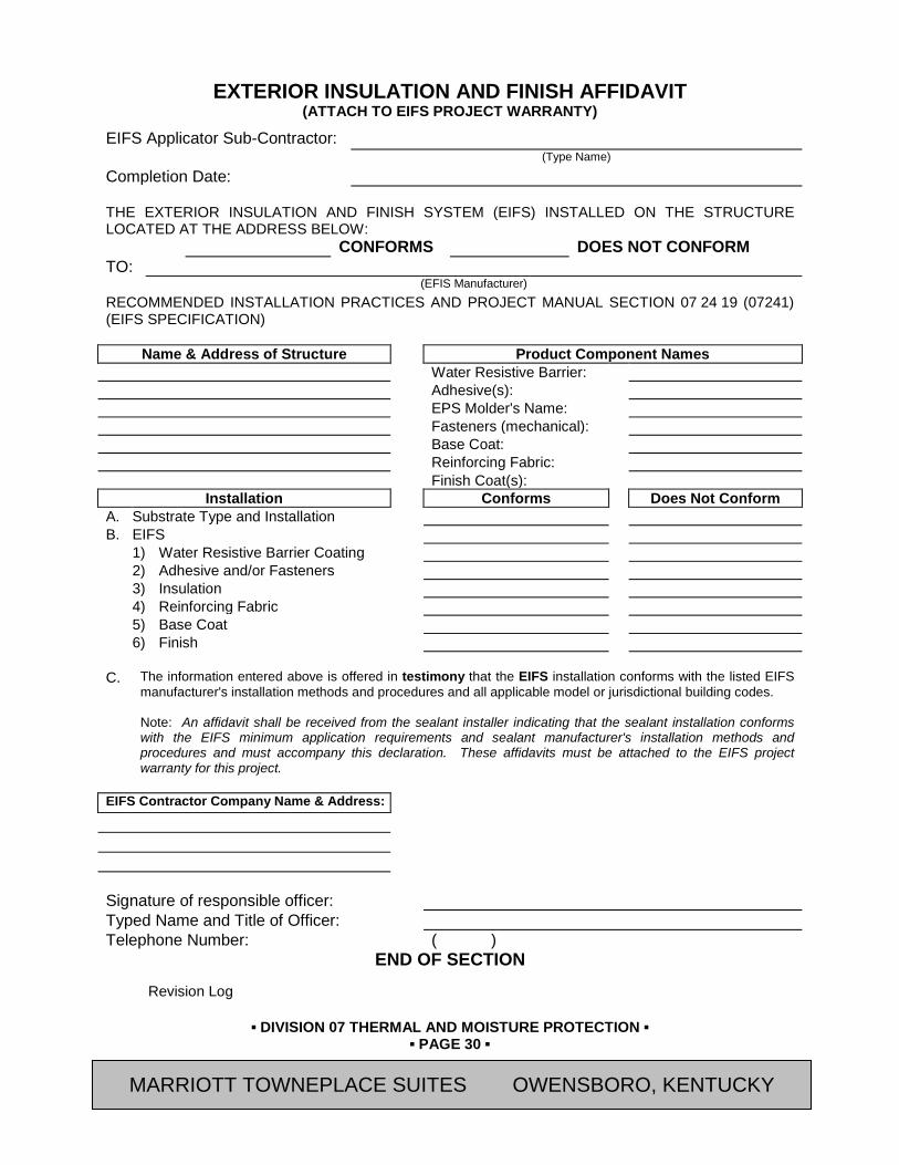
▪ DIVISION 07 THERMAL AND MOISTURE PROTECTION ▪
▪ PAGE 30 ▪
RESIDENCE INN BY MARRIOTT - LITTLETON, COLORADO
EXTERIOR INSULATION AND FINISH AFFIDAVIT (ATTACH TO EIFS PROJECT WARRANTY)
EIFS Applicator Sub-Contractor: (Type Name)
Completion Date: THE EXTERIOR INSULATION AND FINISH SYSTEM (EIFS) INSTALLED ON THE STRUCTURE LOCATED AT THE ADDRESS BELOW: CONFORMS DOES NOT CONFORM TO: (EFIS Manufacturer) RECOMMENDED INSTALLATION PRACTICES AND PROJECT MANUAL SECTION 07 24 19 (07241) (EIFS SPECIFICATION)
Name & Address of Structure Product Component Names Water Resistive Barrier: Adhesive(s): EPS Molder's Name: Fasteners (mechanical): Base Coat: Reinforcing Fabric: Finish Coat(s):
Installation Conforms Does Not Conform A. Substrate Type and Installation B. EIFS 1) Water Resistive Barrier Coating 2) Adhesive and/or Fasteners 3) Insulation 4) Reinforcing Fabric 5) Base Coat 6) Finish C. The information entered above is offered in testimony that the EIFS installation conforms with the listed EIFS
manufacturer's installation methods and procedures and all applicable model or jurisdictional building codes. Note: An affidavit shall be received from the sealant installer indicating that the sealant installation conforms with the EIFS minimum application requirements and sealant manufacturer's installation methods and procedures and must accompany this declaration. These affidavits must be attached to the EIFS project warranty for this project.
EIFS Contractor Company Name & Address: Signature of responsible officer: Typed Name and Title of Officer: Telephone Number: ( )
END OF SECTION Revision Log
MARRIOTT TOWNEPLACE SUITES OWENSBORO, KENTUCKY

▪ DIVISION 07 THERMAL AND MOISTURE PROTECTION ▪
▪ PAGE 31 ▪
RESIDENCE INN BY MARRIOTT - LITTLETON, COLORADO
SECTION 07 27 00 (07270) - AIR BARRIERS
PART 14 GENERAL 14.01 SUMMARY
A. Section Includes:
1. Fluid-Applied Membrane Air Barrier
a. Vapor Permeable
2. Air-Infiltration Barrier
B. Related Sections:
1. Section 04 20 00 - Unit Masonry
2. Section 05 40 00 - Cold-Formed Metal Framing
3. Section 06 10 00 - Rough Carpentry
4. Section 07 10 00 - Dampproofing and Waterproofing
5. Section 07 20 00 - Thermal Protection
6. Section 07 24 19 – Water Drainage Exterior Insulation and Finish Systems (EIFS)
7. Section 07 62 00 - Sheet Metal Flashing and Trim
8. Section 07 92 00 - Joint Sealants
9. Section 09 21 16 - Gypsum Board Assemblies
14.02 REFERENCES
A. ASTM International Publications:
1. C578 "Standard Specification for Rigid, Cellular Polystyrene Thermal Insulation"
2. C665 "Standard Specification for Mineral-Fiber Blanket Thermal Insulation for Light Frame Construction and Manufactured Housing"
3. C1177 “Specification for Glass Mat Gypsum Substrate for Use as Sheathing”
4. C1193 "Standard Guide for Use of Joint Sealants"
5. D522 "Standard Test Methods for Mandrel Bend Test of Attached Organic Coatings"
6. D3273 "Standard Test Method for Resistance to Growth of Mold on the Surface of Interior Coatings in an Environmental Chamber"
7. D4258 "Standard Practice for Surface Cleaning Concrete for Coating"
8. D4397 "Standard Specification for Polyethylene Sheeting for Construction, Industrial, and Agricultural Applications"
9. D4541 “Test Method for Pull-Off Strength of Coatings Using Portable Adhesion Testers”
10. E84 "Standard Test Method for Surface Burning Characteristics of Building Materials"
11. E96 "Standard Test Methods for Water Vapor Transmission of Materials"
12. E119 "Standard Test Methods for Fire Tests of Building Construction and Materials"
13. E136 "Standard Test Method for Behavior of Materials in a Vertical Tube Furnace at 750°C"
MARRIOTT TOWNEPLACE SUITES OWENSBORO, KENTUCKY
▪ DIVISION 07 THERMAL AND MOISTURE PROTECTION ▪
▪ PAGE 32 ▪
RESIDENCE INN BY MARRIOTT - LITTLETON, COLORADO
14. E283 “Standard Test Method for Determining Rate of Air Leakage Through Exterior Windows, Curtain Walls, and Doors Under Specified Pressure Differences Across the Specimen”
15. E331 “Standard Test Method for Water Penetration of Exterior Windows, Skylights, Doors, and Curtain Walls by Uniform Static Air Pressure Difference”
16. E1186 “Standard Practices for Air Leakage Site Detection in Building Envelopes and Air Barrier Systems”
17. E1233 "Standard Test Method for Structural Performance of Exterior Windows, Curtain Walls, and Doors by Cyclic Static Air Pressure Differential"
18. E1677 "Standard Specification for an Air Retarder (AR) Material or System for Low-Rise Framed Building Walls"
19. E1745 "Standard Specification for Water Vapor Retarders Used in Contact with Soil or Granular Fill under Concrete Slabs"
20. E1827 “Standard Test Methods for Determining Air tightness of Buildings Using an Orifice Blower Door”
21. E2178 “Test Method for Air Permeance of Building Materials”
22. E2247 "Standard Practice for Environmental Site Assessments: Phase I Environmental Site Assessment Process for Forestland or Rural Property"
23. E2357 “Standard Test Method for Determining Air Leakage of Air Barrier Assemblies”
B. Gypsum Association (GA) Publications:
1. GA-600 "Fire Resistance Design Manual"
2. GA-253 "Recommended Specifications for the Application of Gypsum Sheathing"
3. GA-254 "Fire-Resistant Gypsum Sheathing"
C. The Engineered Wood Association (APA) Publications:
1. Form No. E30, "APA Engineered Wood Construction Guide"
D. American Association of Textile Chemists and Colorists (AATCC)
1. Test Method 127 "Water Resistance: Hydrostatic Pressure Test"
E. American Association of Textile Chemists and Colorists (AATCC) Publications:
1. Test Method 127 "Water Resistance: Hydrostatic Pressure Test"
F. ICC Evaluation Service Reports:
1. ES AC212 “ICC Acceptance Criteria for Water-Resistive Coatings Used as Water-Resistive Barriers over Exterior Sheathing”
G. Technical Association of the Pulp and Paper Industry (TAPPI) Publications:
1. Test Method T-410; Grammage of Paper and Paperboard (Weight per Unit Area)
2. Test Method T-460; Air Resistance of Paper (Gurley Hill Method)
14.03 PERFORMANCE REQUIREMENTS
A. General: Function as a continuous vapor-permeable air barrier system and as a liquid-water drainage plane flashed to discharge condensation or water penetration to the exterior.
B. Deflection Criteria: Maximum allowable deflection normal to the plane of the wall: L/240
MARRIOTT TOWNEPLACE SUITES OWENSBORO, KENTUCKY

▪ DIVISION 07 THERMAL AND MOISTURE PROTECTION ▪
▪ PAGE 33 ▪
RESIDENCE INN BY MARRIOTT - LITTLETON, COLORADO
C. Wind Load: Conform to local code requirements.
14.04 SUBMITTALS
A. General: Submit the following in accordance with Conditions of Contract and Division 01 Specification Sections.
B. Product Data: Submit “Letter of Conformance” in accordance with Section 01 33 00 (01330) indicating specified items selected for use in project with the following supporting data.
1. Include manufacturer's written technical data and installation instructions.
2. Certified Test Reports: With product data, submit copies of certified test reports showing compliance with specified performance values, perm ratings, and similar properties.
C. Manufacturer’s Field Service Reports: Provide site reports from authorized field service representative, indicating observation of weather barrier assembly installation.
D. Air-Infiltration Barrier Warranty: Manufacturer’s executed warranty form with authorized signatures and endorsements indicating date of Substantial Completion.
14.05 QUALITY ASSURANCE
A. Applicator Qualifications: A firm experienced in applying air barrier materials similar in material, design, and extent to those indicated for this Project, whose work has resulted in applications with a record of successful in-service performance.
1. Installer shall be trained and certified for installation by manufacturer.
B. Source Limitations: Provide air barrier and accessory materials produced by single manufacturer.
C. Mockups: Before beginning installation of air barrier, build mockups of exterior wall assembly for approval by [Owner's Representative], 150 sq. ft., incorporating backup wall construction, external cladding, window, door frame and sill, insulation, and flashing to demonstrate surface preparation, crack and joint treatment, and sealing of gaps, terminations, and penetrations of air barrier membrane.
1. Approved mockups may become part of the completed Work if undisturbed at time of Substantial Completion.
2. Contact manufacturer’s designated representative prior to air infiltration barrier assembly installation, to perform required mock-up visual inspection and analysis as required for warranty.
D. Preinstallation Conference: Conduct conference at Project site.
1. Attendees shall include Contractor, Architect, Engineer, Consultant, Installer, Owner’s Representative, and [Air Infiltration Barrier Manufacturer’s Designated Representative][and][Fluid-Applied Membrane Air Barrier Manufacturer’s Designated Representative]
2. Include installers of other construction connecting to air barrier, including roofing, waterproofing, masonry, sealants, windows, aluminum storefront, and door frames.
3. Review air barrier requirements including surface preparation, substrate condition and pretreatment, minimum substrate curing period, forecasted weather conditions, special details and sheet flashings, mockups, installation procedures, sequence of installation, testing and inspecting procedures, and protection and repairs.
14.06 DELIVERY, STORAGE, AND HANDLING
A. Store liquid materials in their original undamaged packages in a clean, dry, protected location and within temperature range required by air barrier manufacturer.
MARRIOTT TOWNEPLACE SUITES OWENSBORO, KENTUCKY
▪ DIVISION 07 THERMAL AND MOISTURE PROTECTION ▪
▪ PAGE 34 ▪
RESIDENCE INN BY MARRIOTT - LITTLETON, COLORADO
B. Remove and replace liquid materials that cannot be applied within their stated shelf life.
C. Store rolls according to manufacturer's written instructions.
D. Protect stored materials from direct sunlight, freezing temperatures, and temperatures in excess of 90 degrees F.
14.07 PROJECT CONDITIONS
A. The Installer must examine the substrate and the conditions under which insulation work is to be performed and notify the Architect in writing of unsatisfactory conditions. Do not proceed with the work until unsatisfactory conditions have been corrected in a manner acceptable to the Installer.
B. Weather Conditions: Proceed with work only when weather conditions are in compliance with manufacturer's recommended limitations, and when conditions will permit the work to proceed in accordance with requirements and the manufacturer's recommendations.
C. Do not apply air barrier and components to damp, frozen, dirty, dusty, or surfaces unacceptable to manufacturer.
1. Maintain ambient and surface temperatures above 40 degrees F. during application and drying period, minimum 24 hours after application of air and moisture barrier
2. Provide supplementary heat for installation in temperatures less than 40 degrees F. or if surface temperature is likely to fall below 40 degrees F.
D. Coordinate this work with all trades and protect it after installation.
14.08 SEQUENCING
A. Coordinate installation of [foundation waterproofing], roofing membrane, windows, doors and other wall penetrations to provide a continuous air barrier.
B. Provide sill flashing to direct water to the exterior before windows and doors are installed.
C. Install window and door head flashing immediately after windows and doors are installed.
D. Install diverter flashings wherever water can enter the assembly to direct water to the exterior.
PART 15 PRODUCTS 15.01 FLUID-APPLIED MEMBRANE AIR BARRIER - ABOVE GRADE
A. Avendra, LLC Preferred Manufacturers:
1. None
B. Approved Manufacturers
1. “DuPont Tyvek Fluid Applied WB System”; DuPont Company (800-448-9835)
a. Joint Treatment: "Tyvek Fluid Applied Flashing and Joint Compound, Trowel Grade"
b. Membrane Air Barrier Coating: "DuPont Tyvek Fluid Applied System"
c. Flashing System: "Tyvek FlexWrap" and "Tyvek StraightFlash"
d. Sealant for use with System: “Dupont Sealant for Tyvek Fluid Applied System”
2. "Sto Guard"; Sto Corporation (800-221-2397)
a. Joint Treatment: "Sto Gold Coat with StoGuard Fabric"
b. Membrane Air Barrier Coating: "Sto Gold Coat"
c. Flashing System: "Sto Gold Coat with StoGuard Fabric"
MARRIOTT TOWNEPLACE SUITES OWENSBORO, KENTUCKY

▪ DIVISION 07 THERMAL AND MOISTURE PROTECTION ▪
▪ PAGE 35 ▪
RESIDENCE INN BY MARRIOTT - LITTLETON, COLORADO
3. "R GUARD Spray Wrap"; PROSOCO (800-255-4244)
a. Joint Treatment: “R-GUARD Joint and Seam Filler”
b. Membrane Air Barrier Coating: "R-GUARD Spray Wrap"
c. Flashing System: “R-GUARD FastFlash”
4. "Perm-A-Barrier VP”; Grace Construction Products (866-333-3726)
a. Joint Treatment: "Bituthene Liquid Membrane"
b. Membrane Air Barrier Coating: "Perm-A-Barrier VP"
c. Flashing System: “Perm-A-Barrier Wall Flashing”
5. "Backstop NT"; Dryvit Systems, Inc. (800-556-7752)
a. Joint Treatment: "Dryvit Grid Tape and Surface Conditioner / Backstop NT Texture"
b. Membrane Air Barrier Coating: "Backstop NT"
c. Flashing System: "AquaFlash Liquid with AquaFlash Tape"
C. Fluid-Applied Membrane Air Barrier: Acrylic-based weather resistive, vapor permeable coating over [exterior sheathing] walls above grade.
D. Performance Characteristics:
1. Maximum air permeability: 0.004 cfm/SF under a pressure differential of 0.3 in water (1.57 psf) when tested in accordance with ASTM E2178.
2. Aging/Water Penetration Resistance
a. Method: AATCC 127 (Water Column) and ASTM E331
b. Criteria: Resist 21.6 inches water for 5 hours before and after aging
c. Results: No water penetration before and after aging
3. Structural Loading/Water Penetration Testing
a. Method: ASTM E1233 / ASTM E331
b. Criteria: No water at exterior plane of sheathing after 10 cycles @ 80% design load and 75 minutes water spray at 6.24 psf differential
c. Results: No water penetration
4. Cyclic Pressure/Water Penetration Testing
a. Method: ASTM E283 / ASTM E331
b. Criteria: No water penetration or evidence of elevated moisture levels in plywood sheathing after 10 cycles of conditioning at 299 Pa positive and negative pressure followed by 75 minutes water spray at 6.24 psf pressure differential with water spray rate of 5 gal/ft2·hr.
c. Results: No water penetration, no elevated moisture levels
5. Water Resistance Testing
a. Method: ASTM D2247
b. Results: No deleterious effects after 14 day exposure
6. Resistance to Mold Growth
a. Method: ASTM D3273
MARRIOTT TOWNEPLACE SUITES OWENSBORO, KENTUCKY
▪ DIVISION 07 THERMAL AND MOISTURE PROTECTION ▪
▪ PAGE 36 ▪
RESIDENCE INN BY MARRIOTT - LITTLETON, COLORADO
b. Results: No mold growth after 28 days
7. Water Vapor Transmission
a. Method: ASTM E96 Method B (Water Method)
b. Results: Meets criteria
8. Flexibility
a. Method: ASTM D522
b. Criteria: No cracking or delamination using 1/8” mandrel at 14°F before and after aging
c. Results: No cracking or delamination before and after aging
9. Surface Burning
a. Method: ASTM E84
b. Criteria:
1) Flame Spread: <25
2) Smoke Developed: <450
10. Fire Resistance
a. Method: ASTM E119
b. Criteria: Meets criteria for 1-hour fire resistance rating when installed over I hour fire resistance rated sheathing
E. Accessory Materials:
1. Provide accessory materials as recommended by the membrane air barrier manufacturer as recommended for complete installation, including but not limited to joint reinforcing strips, adhesives, tapes, primers, and sealants.
15.02 AIR-INFILTRATION BARRIERS:
A. Avendra, LLC Preferred Manufacturers:
1. None
B. Approved Manufacturers:
1. “Tyvek CommercialWrap”; DuPont Company (800-448-9835)
2. “Typar StormWrap”; Fiberweb, Inc. (800-284-2780)
3. “Tyvek StuccoWrap or DrainWrap”; DuPont Company (800-448-9835)
C. Air-Infiltration Barrier
1. Air retarder complying with ASTM E1677; made from polyolefins; either cross-laminated films, woven strands, or spunbonded fibers; coated or uncoated; with or without perforations to transmit water vapor but not liquid water; and as follows:
a. Minimum Thickness: 3 mils.
b. Minimum Water-Vapor Transmission: 28 perms when tested according to ASTM E96, Procedure B.
c. Air Resistance: Air infiltration at >1500 seconds, when tested in accordance with TAPPI Test Method T-460.
MARRIOTT TOWNEPLACE SUITES OWENSBORO, KENTUCKY

▪ DIVISION 07 THERMAL AND MOISTURE PROTECTION ▪
▪ PAGE 37 ▪
RESIDENCE INN BY MARRIOTT - LITTLETON, COLORADO
d. Maximum Flame Spread: 25 per ASTM E84.
e. Minimum Allowable Exposure Time: 3 months.
f. Membrane shall be free from holes and breaks other than those created by fasteners and construction system due to attachment.
2. Building Wrap Tape: Pressure-sensitive plastic tape recommended by building wrap manufacturer for sealing joints and penetrations in building wrap.
3. Fasteners:
a. Recommended Fasteners for Wood Framed construction:
1) Nails with large heads or plastic washers.
b. Recommended Fastening to Masonry:
1) Polyurethane or elastomeric adhesives.
D. Accessories:
1. Nails and Staples: Steel wire, galvanized, type and size to suit application.
2. Tape: Polyethylene or Polyester, self-adhering type, 2 inches wide.
3. Adhesives: As recommended in manufacturer's written instructions.
PART 16 EXECUTION 16.01 EXAMINATION
A. Require Installer to examine substrates and conditions under which air barrier work is to be performed. A satisfactory substrate is one that complies with requirements of the sections in which substrate and related work is specified. Obtain Installer's written report listing conditions detrimental to performance of work in this section. Do not proceed with installation of insulation until unsatisfactory conditions have been corrected.
1. Verify adjacent materials are dry, free of contaminants and ready to receive barrier system.
2. Verify substrate surface is flat, free of honeycomb, fins, irregularities, and materials that will impede adhesive bond.
16.02 PREPARATION
A. Clean substrates of substances harmful to membranes, including removal of projections which might puncture vapor retarders.
B. Inspect sheathing application for compliance with applicable requirement:
1. Exterior gypsum sheathing: GA-253
2. Glass mat faced gypsum sheathing: Consult manufacturer’s published recommendations.
3. Remove surface contaminants and replace damaged sheathing.
4. Spot surface defects in sheathing with joint treatment as recommended by membrane manufacturer.
5. Repair cracks, spalls, or other damage in concrete or concrete masonry surfaces
MARRIOTT TOWNEPLACE SUITES OWENSBORO, KENTUCKY
▪ DIVISION 07 THERMAL AND MOISTURE PROTECTION ▪
▪ PAGE 38 ▪
RESIDENCE INN BY MARRIOTT - LITTLETON, COLORADO
16.03 INSTALLATION, GENERAL
A. Comply with manufacturer's instructions for particular conditions of installation in each case. If printed instructions are not available or do not apply to project conditions, consult manufacturer's technical representative for specified recommendations before proceeding with work.
16.04 INSTALLATION - FLUID-APPLIED MEMBRANE AIR BARRIER
A. Install Fluid-Applied Membrane Air Barrier in strict accordance with manufacturers written instructions.
1. Coordinate work with other trades to ensure air barrier continuity with connections at foundation, floor lines, flashings, lintels and shelf angles, openings and penetrations such as pipes, vents, windows and doors, masonry anchors, rafters or beams, joints in construction, projections such as decks and balconies, and roof line.
B. Prepare and treat joints as recommended by manufacturer and in accordance with ASTM C1193.
1. Gypsum Sheathing: All joints greater than 1/16 inch shall be filled with joint sealer as recommended by membrane air barrier manufacturer.
a. No joint treatment required for joints up to 1/16 inch.
b. Joints 1/16 to 1/4 inch: Fluid-applied joint compound applied to form a 1 inch width on each side of sheathing joint; smooth joint compound across sheathing joint. Thickness shall be 15 to 25 mils.
c. Joints 1/16 to 1/2 inch: Apply joint tape to bridge both sides of joint equally. Apply fluid-applied joint compound and trowel smooth embedding joint compound uniformly into joint tape to form a 1 inch width on each side of sheathing joint at a consistent thickness of 15 to 25 mils.
d. Joints 1/2 to 1 inch: Apply sheet flashing primer above and below sheathing joint. Center sheet flashing over sheathing joint and press firmly in place per manufacturer’s recommendations.
2. Non-movement joints in masonry and transitions to columns and beams:
a. Joints 1/4 inch wide or less: Apply fluid-applied joint compound a minimum of 2 inches wide by 60 mils thick to each side of joint or crack.
C. Install transition strips and other accessory materials according to membrane air barrier manufacturer's instructions to form a continuous seal with all adjacent materials.
D. Corners: Apply fluid-applied joint compound, in thickness as recommended by manufacturer, to outside and inside corners. Joint compound shall extend 2 inches from corner for full height of corner, or apply primer to outside and inside corners, extend 2 inches on each side of corner. Center sheet flashing over corner and press firmly in place per manufacturer’s recommendations.
E. Membrane system shall be extended into all wall openings such as doors and windows to form a complete seal at perimeters.
1. Refer to Section 07 62 00 “Sheet Metal Flashing and Trim” for flashings at Wall Openings such as windows and doors.
F. All through wall flashings shall be sealed at top with counterflashings as recommended by membrane air barrier manufacturer.
G. Repair all damaged locations including punctures, voids, deficient seams, fishmouths and blisters.
MARRIOTT TOWNEPLACE SUITES OWENSBORO, KENTUCKY
▪ DIVISION 07 THERMAL AND MOISTURE PROTECTION ▪
▪ PAGE 39 ▪
RESIDENCE INN BY MARRIOTT - LITTLETON, COLORADO
16.05 INSTALLATION - AIR-INFILTRATION BARRIER
A. Cover sheathing with air-infiltration barrier as follows:
1. Apply air-infiltration barrier to comply with air-infiltration barrier manufacturer's written instructions and as coordinated with siding manufacturer's recommendations.
B. Install Air Infiltration Barrier over exterior side of exterior wall sheathing.
1. Install Air Infiltration Barrier after sheathing is installed and before windows and doors are installed. Install lower level barrier prior to upper layers to ensure proper shingling of layers. Maintain weather barrier plumb and level.
2. Overlap Air Infiltration Barrier at corners of building by a minimum of 12 inches.
3. Overlap Air Infiltration Barrier vertical seams by a minimum of 6 inches.
4. Sill Plate Interface: Extend lower edge of weather barrier over sill plate interface 3 to 6 inches. Secure to foundation with elastomeric sealant as recommended by weather barrier manufacturer
5. Ensure barrier is plum and level with foundation, and unroll extending Air Infiltration Barrier over window and door openings.
6. Attach Air Infiltration Barrier to wood, or exterior gypsum sheathings, through exterior sheathing with manufacturer recommended fasteners every 12” to 18” on vertical stud line and 24 inches on center maximum horizontally.
C. Refer to Section 07 62 00 “Sheet Metal Flashing and Trim” for flashings at Wall Openings such as windows and doors.
D. Tape all overlapping horizontal and vertical seams of Air Infiltration Barrier.
E. Tape a patch over all tears and cuts in Air Infiltration Barrier.
16.06 FIELD QUALITY CONTROL
A. Notify Fluid Applied Air Barrier manufacturer’s designated representative to obtainperiodic observations of Fluid Applied Air Barrier system installation.
B. Inspections: Fluid Applied Air Barrier materials, accessories, and installation are subject to inspection for compliance with performance requirements.
C. Fluid Applied Air Barrier assemblies will be considered defective upon failure of inspections and specific project testing required.
1. Apply additional fluid-applied air barrier material, in accordance with manufacturer's instructions, where inspection results indicate insufficient thickness, voids, skips, pinholes or other defects as recommended by weather barrier manufacturer.
2. Remove and replace deficient weather barrier system components for retesting as specified above.
D. Repair damage to weather barriers caused by destructive testing; follow manufacturer's written instructions.
16.07 PROTECTION
A. General: Protect installed membranes and barriers from harmful weather exposures and from possible physical abuses, where possible by non-delayed installation of concealing work or, where that is not possible, by temporary covering or enclosure. Remove and replace membranes or barriers where exposed for greater than 60 days.
END OF SECTION
MARRIOTT TOWNEPLACE SUITES OWENSBORO, KENTUCKY

▪ DIVISION 07 THERMAL AND MOISTURE PROTECTION ▪
▪ PAGE 40 ▪
RESIDENCE INN BY MARRIOTT - LITTLETON, COLORADO
Revision Log
MARRIOTT TOWNEPLACE SUITES OWENSBORO, KENTUCKY

▪ DIVISION 07 THERMAL AND MOISTURE PROTECTION ▪
▪ PAGE 41 ▪
RESIDENCE INN BY MARRIOTT - LITTLETON, COLORADO
SECTION 07 46 46 (07460) - FIBER-CEMENT SIDING
PART 17 GENERAL 17.01 SUMMARY
A. Section Includes:
1. Exterior, Panelized Fiber Cement Cladding System and Accessories to Complete a Drained and Back-Ventilated Rainscreen
2. Continuous Soffit Vent
B. Related Sections:
1. Section 06 10 00 (06100) - Rough Carpentry
2. Section 06 20 00 (06200) - Finish Carpentry
3. Section 07 20 00 (09900) – Thermal Protection
4. Section 07 27 00 (07270) - Air Barriers
5. Section 07 92 00 (07900) – Joint Sealants
6. Section 09 90 00 (09900) – Painting
17.02 REFERENCES
A. American Architectural Manufacturers Association (AAMA) Publications:
1. 509 “Voluntary Test and Classification Method of Drained and Back Ventilated Rain Screen Wall Cladding Systems”
B. ASTM International (ASTM) Publications: (Former American Society for Testing and Materials)
1. C518 "Standard Test Method for Steady-State Thermal Transmission Properties by Means of the Heat Flow Meter Apparatus"
2. C1185 "Standard Test Methods for Sampling and Testing Non-Asbestos Fiber-Cement Flat Sheet, Roofing and Siding Shingles, and Clapboards"
3. C1186 "Standard Specification for Flat Non-Asbestos Fiber-Cement Sheets"
4. D3359 “Standard Test Methods for Measuring Adhesion by Tape Test”
5. E84 "Standard Test Method for Surface Burning Characteristics of Building Materials"
6. E119 “Standard Test Methods for Fire Tests of Building Construction and Materials”
7. E136 "Standard Test Method for Behavior of Materials in a Vertical Tube Furnace at 750°C"
8. E228 ‘Standard Test Method for Linear Thermal Expansion of Solid Materials with a Vitreous Silica Dilatometer”
9. E330 “Standard Test Method for Structural Performance of Exterior Windows, Doors, Skylights and Curtain Walls by Uniform Static Air Pressure Difference”
10. E331 “Standard Test Method for Water Penetration of Exterior Windows, Skylights, Doors, and Curtain Walls by Uniform Static Air Pressure Difference”
11. G23 (Replaces G152-00ae1, ASTM G153-00ae1, ASTM G25-70(1975) and ASTM E188-70) -
C. D. National Fire Protection Association (NFPA) Publications:
MARRIOTT TOWNEPLACE SUITES OWENSBORO, KENTUCKY
▪ DIVISION 07 THERMAL AND MOISTURE PROTECTION ▪
▪ PAGE 42 ▪
RESIDENCE INN BY MARRIOTT - LITTLETON, COLORADO
1. 268 “Standard Test Method for Determining Ignitibility of Exterior Wall Assemblies Using a Radiant Heat Energy Source”
2. 285 “Standard Fire Test Method for Evaluation of Fire Propagation Characteristics of Exterior Non-Load-Bearing Wall Assemblies Containing Combustible Components”
17.03 SUBMITTALS
A. General: Submit the following in accordance with Conditions of Contract and Division 01 Specification Sections.
B. Product Data: For each type of product specified.
1. Submit Product Data and Shop Drawings indicating component profiles and fastening and joining details.
2. Product Test Reports and Code Compliance: Documents demonstrating product compliance with local building code, such as test reports or Evaluation Reports from qualified, independent testing agencies.
3. Samples for initial selection of the following in the form of manufacturer's color charts consisting of actual units or sections of units showing the full range of colors, textures, and patterns available for each type of material indicated.
4. Samples for verification of the following:
5. For each finish product specified, two samples, minimum size 4 by 6 inches, representing actual product, color, and patterns.
C. Shop Drawings
1. Submit drawings including plans, sections, showing installation details that demonstrate product dimensions, edge/termination conditions/treatments, compression and control joints, corners, openings, and penetrations.
D. Samples:
1. Samples for initial selection of the following in the form of manufacturer's color charts consisting of actual units or sections of units showing the full range of colors, textures, and patterns available for each type of material indicated.
2. Samples for verification of the following:
a. For each finish product specified, two samples, minimum size 4 by 6 inches, representing actual product, color, and patterns. .
E. Fiber-cement siding shall be labeled and tested in accordance with ASTM C1186.
F. Manufacturer Qualifications:
1. All fiber cement panels specified in this section must be supplied by a manufacturer with a minimum of 10 years of experience in fabricating and supplying fiber cement cladding systems.
G. Siding Installer Qualifications: Engage an experienced Installer who has completed siding similar in material, design, and extent to that indicated for this Project and with a record of successful in-service performance.
17.04 PERFORMANCE REQUIREMENTS
A. Structural:
1. Flexural strength per ASTM C1185: 1850 length direction; 2500 transverse direction of sheet.
MARRIOTT TOWNEPLACE SUITES OWENSBORO, KENTUCKY
▪ DIVISION 07 THERMAL AND MOISTURE PROTECTION ▪
▪ PAGE 43 ▪
RESIDENCE INN BY MARRIOTT - LITTLETON, COLORADO
2. Wind Load per ASTM E330: Contact manufacturer for ultimate test pressure data corresponding to framing type, dimensions, fastener type, and attachment clips. Project engineer(s) must determine Zone 4 and 5 design pressures based on project specifics.
a. Minimum lateral deflection: L/120.
B. Thermal resistance: Minimum R-values of 0.15 for Siding materials and 0-.13 for Soffit materials.
C. Water Resistance:
1. Water Penetration per ASTM E331: No water leakage observed into wall cavity.
2. Weather Resistant per ASTM G23: No cracking, checking, crazing, erosion, or other detrimental effects observed.
3. Water Tightness: No water droplets observed on any specimen.
4. Freeze-thaw: No damage or defects observed.
5. Warm Water: No evidence of cracking, delamination, swelling, or other defects observed.
6. Heat-Rain: No crazing, cracking, or other deleterious effects, surface or joint changes observed in any specimen.
D. Fire Resistance:
1. Flame Spread Index of less than 25 and Smoke Generation Number of “0” in accordance with ASTM E84.
2. Fire Resistant per ASTM E119: The wall assembly must successfully endure 60-minute fire exposure without developing excessive unexposed surface temperature or allowing flaming on the unexposed side of the assembly.
3. Ignition Resistance per NFPA 268: No sustained flaming of panels, assembly when subjected to a minimum radiant heat flux of 12.5 kW/m2 ± 5% in the presence of a pilot ignition source for a 20-minute period.
17.05 DELIVERY, STORAGE, AND HANDLING
A. Protect siding materials during transit, delivery, storage, and handling to prevent damage, soiling, and deterioration.
B. Store fiber-cement materials in accordance with manufacturer’s recommendations.
17.06 PROJECT CONDITIONS
A. Weather Limitations: Proceed with installing fiber-cement products only when existing and forecasted weather conditions will permit work to be performed according to manufacturer's recommendations and warranty requirements and at least one coat of specified finish to be applied without exposure to rain, snow, or dampness.
17.07 SPECIAL WARRANTY
A. All materials shall be free from manufacturing defects and defects in installation workmanship. Any material or workmanship judged defective during this period shall be removed and replaced at no cost to the Owner
B. The work of this Section shall be warranteed by the manufacturer for structural failures including cracking and deforming.
1. Warranty Period: 10 years from date of Substantial Completion.
MARRIOTT TOWNEPLACE SUITES OWENSBORO, KENTUCKY
▪ DIVISION 07 THERMAL AND MOISTURE PROTECTION ▪
▪ PAGE 44 ▪
RESIDENCE INN BY MARRIOTT - LITTLETON, COLORADO
PART 18 PRODUCTS 18.01 FIBER-CEMENT BOARD SIDING
A. Avendra, LLC Preferred Manufacturers:
1. None
B. Approved Manufacturers:
1. Basis-of-Design Product: Subject to compliance with requirements, provide the following types of fiber cement Board products by Nichiha USA, Inc. (800-338-3355) or comparable product by one of the following manufacturers:
a. No Substitutions
b. Contact: Email [email protected]
2. Product Description:
a. “Illumination Series”
1) Color [As shown on the Exterior Finish Index], Satin Finish. Factory sealed on six (6) sides.
2) Profile: 18” x [6’Panel, smooth without score line.
b. “RoughSawn Series”
1) Color [As shown on the Exterior Finish Index], Sawn Wood Textured matte finish, sealed on six (6) sides.
2) Profile: 18” x 10’ Panel. Sawn wood texture with the appearance of three planks; grooves between planks to be 3/8” wide, running lengthwise, spaced 4-1/8” apart.
3) Panel Thickness: 5/8 inch Note: Review fiber cement board panels which are manufactured in metric sizes to coordinate
with Imperial (feet and inches) dimensions of structure. Pay particular attention to window sizes.
c. Accessory/Component Options:
1) Manufactured Corners with 3-1/2” returns in matching colors.
2) Aluminum trim to be painted per finish schedule to match adjacent coior(s).: Outside corners (Corner Key, Open Outside Corner), vertical joints (Bead Reveal, H-Mold), terminations (J-Mold, L-Mold).
3) Flashing System: Manufacturers Starter, Compression Joint, Overhang.
4) Panels profiled along all four edges, such that both horizontal and vertical joints between the installed panels are ship-lapped.
5) Factory-applied sealant gasket added to top and right panel edges; all joints contain a factory sealant.
C. Materials:
1. All materials shall come from the factory prefinished with colors as shown.
2. Type: Non-combustible fiber cement, exterior grade siding and soffit board complying with ASTM C1186, Grade II, Type A. No asbestos fibers shall be contained in products.
D. Trim:
MARRIOTT TOWNEPLACE SUITES OWENSBORO, KENTUCKY
▪ DIVISION 07 THERMAL AND MOISTURE PROTECTION ▪
▪ PAGE 45 ▪
RESIDENCE INN BY MARRIOTT - LITTLETON, COLORADO
1. Provide lineal trim, corner inserts, square and cove type; other trim pieces necessary to complete installation.
E. Accessories:
1. Fasteners:
a. General: Corrosion resistant fasteners, such as hot-dipped galvanized screws appropriate to local building codes and practices must be used. Use Stainless Steel fasteners in high humidity and high-moisture regions. Panel manufacturer is not liable for corrosion resistance of fasteners. Do not use aluminum fasteners, staples or fasteners that are not rated or designed for intended use. See manufacturer’s instructions for appropriate fasteners for construction method used.
b. Wood Framing: Corrosion resistant, shank head siding nails, size as recommended by manufacturer of siding.
2. Flashing System:
a. “Nichiha Flashing System”, or approved substitution by other listed manufacturers.
1) Starter – main segments, inside corners, outside corners
2) Compression Joint – main segments.
3) Overhang – main segments, inside corners, outside corners, joint clips
4) Flashing: Flash all areas specified in manufacturer’s instructions. Do not use raw aluminum flashing. Flashing must be galvanized, anodized, or PVC coated.
3. Rain Screen Attachment System:
a. Nichiha “Ultimate Clip System”, or approved substitution by other listed manufacturers:
b. Starter Track:
1) Horizontal Panel Installations: Model “FA 700” – 10’ galvalume.
2) Vertical Panel Installations (10’ panels only) – Model “FA 710T” – 10’ galvalume.
c. Panel Clips: Modle ‘Ultimate Clip’ Model “JEL 777” (10mm rainscreen for 5/8” AWP) – 400 series stainless steel.
1) Joint Tab Attachments (included) are not needed with 10’ AWP.
d. Single Flange Sealant Backer – Model “FHK 1017” – 6.5’ (l) fluorine coated galvalume.
e. Double Flange Sealant Backer – Model “FH 1020” – 10’ (l) fluorine coated galvalume.
f. Corrugated Spacer: Models “FS 1005”, and “FS 1010 (10mm) – 4’ (l).
g. Finish Clip: Model “JE310”
4. Cement patch: As approved by manufacturer of fiber-cement siding.
5. Sealants or Caulking Compounds: Refer to Section 07 92 00. Only use products as approved by fiber-cement siding manufacturer.
18.02 FINISHES
A. Field Applied Finish:
MARRIOTT TOWNEPLACE SUITES OWENSBORO, KENTUCKY
▪ DIVISION 07 THERMAL AND MOISTURE PROTECTION ▪
▪ PAGE 46 ▪
RESIDENCE INN BY MARRIOTT - LITTLETON, COLORADO
1. Factory Primer: Provide factory applied universal primer.
2. Topcoat: Refer to Section 09 90 00 “Painting” and Exterior Finish Index.
B. Factory Applied Finish:
1. Factory Finish Color for Siding Colors:
a. Refer to Exterior Finish Index.
2. Finishing system shall include pre-packaged touch-up kit provided by fiber cement manufacturer
PART 19 EXECUTION 19.01 EXAMINATION
A. Examine substrates, with Installer present, for compliance with requirements for installation tolerance and other conditions affecting installation and performance of fiber-cement products. Do not proceed with installation until unsatisfactory conditions have been corrected.
19.02 PREPARATION
A. Clean substrates of projections and substances detrimental to application.
B. Do not install panels or components that appear to be damaged or defective. Do not install wet panels.
C. Air Infiltration Barrier Installation:
1. One layer of air infiltration barrier shall be installed horizontally on walls. Weatherlap edges and ends minimum 6". Refer to Section 07 20 00.
2. Stagger vertical joints.
3. Install in accordance with air infiltration barrier manufacturer's recommendations.
19.03 INSTALLATION - GENERAL
A. Discard units of material which are unsound, warped, bowed, twisted improperly treated, not adequately seasoned or too small to fabricate work with minimum of joints or optimum jointing arrangements. Do not use manufactured units with defective surfaces, sizes, or patterns.
B. Install the work plumb, level, true, and straight with no distortions. Shim as required using concealed shims. Install to a tolerance of 1/8" in 8'-0" for plumb and level countertops; and with 1/16" maximum offset in flush adjoining 1/8" maximum offsets in revealed adjoining surfaces.
C. Scribe and cut work to fit adjoining work, and refinish cut surfaces or repair damaged finish at cuts.
D. Countersink nails, fill surface flush, and sand where face nailing is unavoidable.
E. Install to tolerance of 1/8 inch in 96 inches for plumb and level. Install adjoining fiber-cement siding or trim with 1/32 inch maximum offset for flush installation and 1/16 inch maximum offset for reveal installation.
F. Coordinate fiber-cement siding with materials and systems in or adjacent to standing and running trim. Provide cutouts for mechanical and electrical items that penetrate exposed surfaces of siding or trim.
G. Finish according to specified requirements.
MARRIOTT TOWNEPLACE SUITES OWENSBORO, KENTUCKY
▪ DIVISION 07 THERMAL AND MOISTURE PROTECTION ▪
▪ PAGE 47 ▪
RESIDENCE INN BY MARRIOTT - LITTLETON, COLORADO
H. Anchor fiber-cement siding and trim work to anchorage devices or blocking built-in or directly attached to substrates. Secure to grounds, stripping and blocking with countersunk, concealed fasteners and blind nailing as required for a complete installation. Except where prefinished matching fastener heads are required, use fine finishing nails for exposed nailings, countersunk and filled flush with finished surface, and matching final finish where transparent is indicated.
19.04 FIBER-CEMENT PANEL INSTALLATION
A. Air Infiltration Barrier Installation:
1. One layer of air infiltration barrier shall be installed horizontally on walls. Weatherlap edges and ends minimum 6". Refer to Section 07 20 00.
2. Stagger vertical joints.
3. Install in accordance with air infiltration barrier manufacturer's recommendations.
B. Installation of Siding:
1. Install panel siding and accessories in accordance with manufacturer's directions.
2. Install panel siding level and plumb. Install for natural shed of water. Position cut ends over bearing surfaces. Sand cut edges smooth and clean. Maintain clearance between siding materials and adjacent finished grade as recommended by manufacturer.
3. Fasten through siding and/or trim into structural framing. Fasteners must penetrate a minimum of ¾”. Place fasteners as recommended by siding manufacturer.
4. Provide for expansion and contraction of siding at location of installation. Do not drive nail heads tight against nailing lock. Size nails in accordance with manufacturer's printed literature. Refer to Manufacturer’s Recommendations for Vertical Control/Expansion Joints and/or Horizontal/Compression Joints that will be required.
5. Install flashings as indicated on Drawings and as recommended by siding manufacturer at all wall openings.
6. Locate splices at lest one stud cavity away from window and door openings.
7. Hold siding 1/4" away from floors, soffits, doors, windows, and louver frames for sealant application. Refer to Section 07 92 00 (07900) “Joint Sealants". Provide sealants at all locations recommended by manufacturer and provide sealant as approved by manufacturer of siding.
19.05 ADJUSTMENT, CLEANING, FINISHING, AND PROTECTION
A. Repair damaged and defective fiber-cement siding or trim work wherever possible to eliminate defects functionally and visually; where not possible to repair properly, replace woodwork. Adjust joinery for uniform appearance.
B. Clean fiber-cement panel, soffit and trim work on exposed and semi-exposed surfaces. Touch-up factory-applied finishes to restore damaged or soiled areas.
C. Cleaning: Keep premises in a neat, safe, and orderly condition at all times during execution of this portion of the work, free from the accumulation of sawdust, cut-ends, and debris.
D. Refer to Division 09 sections for final finishing of installed fiber-cement siding or trim work.
E. Protection: Installer of finish carpentry work shall advise Contractor of final protection and maintained conditions necessary to ensure that work will be without damage or deterioration at time of acceptance.
MARRIOTT TOWNEPLACE SUITES OWENSBORO, KENTUCKY
▪ DIVISION 07 THERMAL AND MOISTURE PROTECTION ▪
▪ PAGE 48 ▪
RESIDENCE INN BY MARRIOTT - LITTLETON, COLORADO
END OF SECTION
Revision Log
SECTION 07 61 00 (07610) - SHEET METAL ROOFING
PART 20 GENERAL 20.01 SUMMARY
A. Section Includes:
1. Extent of metal roofing is shown on the Drawings and indicated by provisions of this Section.
2. The following types of work are specified in this Section:
a. Standing Seam Roof System
b. Flashings
c. Matching Fascia
d. Underlayment.
1) Self-Adhering Sheet Underlayment
B. Related Sections:
1. Section 05 31 00 (05300) - Metal Deck
2. Section 05 40 00 (05400) - Cold-Formed Metal Framing
3. Section 06 10 00 (06100) - Rough Carpentry
4. Section 07 20 00 (07200) - Thermal Protection
5. Section 07 42 13 (07410) – Metal Wall Panels
6. Section 07 62 00 (07620) - Sheet Metal Flashing and Trim
20.02 REFERENCES
A. ASTM International Publications:
1. A653 “Standard Specification for Steel Sheet, Zinc-Coated (Galvanized) or Zinc-Iron Alloy-Coated (Galvannealed) by the Hot-Dip Process”
2. D1970 “Standard Specification for Self-Adhering Polymer Modified Bituminous Sheet Materials Used as Steep Roofing Underlayment for Ice Dam Protection”
3. E1646 “Standard Test Method for Water Penetration of Exterior Metal Roof Panel Systems by Uniform Static Air Pressure Difference”
4. E1680 “Standard Test Method for Rate of Air Leakage Through Exterior Metal Roof Panel Systems”
B. Sheet Metal and Air Conditioning Contractors' National Association (SMACNA) Publications:
MARRIOTT TOWNEPLACE SUITES OWENSBORO, KENTUCKY
▪ DIVISION 07 THERMAL AND MOISTURE PROTECTION ▪
▪ PAGE 49 ▪
RESIDENCE INN BY MARRIOTT - LITTLETON, COLORADO
1. "Architectural Sheet Metal Manual", Current Edition
C. American Institute of Steel Construction Inc. (AISC) Standards.
D. Underwriter's Laboratories, Inc. (UL) Standards:
1. 580 "Tests for Uplift Resistance of Roof Assemblies"
20.03 SYSTEM DESCRIPTION
A. General: Provide complete sheet metal roofing system, including, but not limited to metal roof panels, cleats, clips, anchors and fasteners, sheet metal flashing integral with sheet metal roofing, drainage components related to sheet metal roofing, fascia panels, trim, underlayment, and accessories as indicated and as required for a weathertight installation.
B. Design Loads: The basic design loads shall include roof live and snow (where applicable), wind (both external and internal), and earthquake (where applicable), in addition to dead load. All other foreign loads, whether they be of static, dynamic, or kinetic nature, shall be considered as auxiliary loads. Refer to Drawings for design loads.
C. Air Infiltration: Provide Roof Panel System with no air leakage of not more than 0.09 cfm/sq. ft. of fixed roof area when tested in accordance with ASTM E1680 at a static-air-pressure difference of 4.0 lbf/sq. ft.
D. Water Penetration: Provide Roof Panel System with no water penetration as defined in the test method when tested with ASTM E1646 at a minimum differential pressure of 20 percent of inward acting, wind-load design pressure of not less than 6.24 PSF and not more than 12.0 PSF.
E. Metal roof system shall be grounded in accordance with local Codes, as approved by the Building Department. This Contractor shall provide a provision for connection of roof grounding system to building ground system by Electrical Contractor. Coordinate with Electrical Contractor as required for complete grounding system.
20.04 SUBMITTALS
A. General: Submit the following in accordance with Conditions of Contract and Division 01 Specification Sections.
B. Product Data: Submit “Letter of Conformance” in accordance with Section 01 33 00 (01330) indicating specified items selected for use in project with the following supporting data.
1. Submit metal manufacturers and fabricator's specifications, installation instructions, and general recommendations for roofing applications. Include certification or other data substantiating that materials comply with requirements.
2. Samples: 12 inches long by actual width of unit, including finished seam and in required profile. Include fasteners, cleats, clips, and other attachments.
C. Shop Drawings: Show fabrication and installation layouts of sheet metal roofing, including plans, elevations, and keyed references to termination points. Distinguish between shop- and field-assembled work. Include the following:
1. Details for forming sheet metal roofing, including seams and dimensions.
2. Details for joining and securing sheet metal roofing, including layout of fasteners, clips, and other attachments. Include pattern of seams.
3. Details of termination points and assemblies, including fixed points.
4. Details of expansion joints, including showing direction of expansion and contraction.
5. Details of edge conditions, including eaves and counterflashings.
MARRIOTT TOWNEPLACE SUITES OWENSBORO, KENTUCKY
▪ DIVISION 07 THERMAL AND MOISTURE PROTECTION ▪
▪ PAGE 50 ▪
RESIDENCE INN BY MARRIOTT - LITTLETON, COLORADO
6. Details of special conditions.
7. Details of connections to adjoining work.
a. .
20.05 QUALITY ASSURANCE
A. Installer: A firm with five years of prior successful experience with installation of metal roofing of type and scope equivalent to work of this Section. Installer shall be certified in writing by the manufacturer to be an authorized and franchised dealer of the system to be furnished. Certification shall state date on which authorization was granted.
B. Industry Standard: Except as otherwise shown or specified, comply with applicable recommendations and details of the SMACNA "Architectural Sheet Metal Manual”. Conform to dimensions and profiles shown.
C. The intent of these Specifications is to establish a quality and performance level for structural design, material, durability, and workmanship.
D. All bidders must conform strictly to these Specifications in their Bid.
E. The metal roofing manufacturer shall be United States based and demonstrate it has been in the business of furnishing (and/or erecting) complete building systems of similar size and complexity for a minimum of ten (10) years.
1. Building system manufacturer shall be American Institute of Steel Construction Inc. (AISC), Category MB Certified.
2. All materials shall be new, unused, free from defect.
F. The following criteria shall also be applicable in other phases of design:
1. Building Code having jurisdiction over the area in which the site is located.
2. Structural Steel Painting Council Standards
3. Federal, Military, and Commercial Standards
4. ASTM Standards
5. Written Certification of Rating by: Underwriter's Laboratories, Inc. (UL) Class 90 Rating (UL. Test 580). Factory Mutual Engineering Association: Class 1 and 1-90 Windstorm Classification.
G. Certification: Submit written certification prepared and signed by a professional engineer registered to practice in the State in which the Project is located, verifying that the system design (including panels, clips, and support system components) meet indicated loading requirements and codes of authorities having jurisdiction.
H. Mockups: Build mockups to verify selections made under sample submittals and to demonstrate aesthetic effects and qualities of materials and execution.
1. Build mockup of typical roof area, as shown on Drawings; approximately 48 inches square by full thickness, including attachments, underlayment, and accessories.
2. Approval of mockups does not constitute approval of deviations from the Contract Documents contained in mockups unless such deviations are specifically approved by Architect in writing.
3. Approved mockups may become part of the completed Work if undisturbed at time of Substantial Completion.
MARRIOTT TOWNEPLACE SUITES OWENSBORO, KENTUCKY
▪ DIVISION 07 THERMAL AND MOISTURE PROTECTION ▪
▪ PAGE 51 ▪
RESIDENCE INN BY MARRIOTT - LITTLETON, COLORADO
20.06 DELIVERY, STORAGE, AND HANDLING
A. Materials shall be delivered to the site in a dry and undamaged condition and stored out of contact with the ground. Materials other than framing and structural members shall be covered with weathertight coverings and kept dry. Storage accommodations for roof and wall covering shall provide good air circulation and protection from surface staining.
20.07 WARRANTY
A. The following guarantees shall be provided by the metal roofing manufacturer:
1. Durability of the roof panels against rupture, structural failure, or perforation shall be guaranteed for a period of ten (10) years.
2. The color finish for the roof and wall panels shall be guaranteed by the building manufacturer for standard term against blistering, peeling, cracking, flaking, checking, and chipping. Excessive color change and chalking shall be guaranteed for ten (10) years.
B. Provide manufacturer's written weathertightness warranty for a maximum of ten (10) years against leaks in roofing system. Warranty shall be signed by both the manufacturer of the metal roofing system and the metal roofing system installer.
PART 21 PRODUCTS 21.01 ACCEPTABLE MANUFACTURERS
A. Avendra, LLC Preferred Manufacturers:
1. None
B. Approved Manufacturers:
1. "Standing Seam Tee-Panel System"; Berridge Manufacturing Company (800-231-8127)
2. "Dutch Seam (MRD) Panel System"; ATAS International, Inc. (800-468-1441)
3. “Snap-On-Seam SS10-12 Panel System”; Dimensional Metals Inc. (DMI) (800-828-1510)
4. "Snap-Clad Panels"; Petersen Aluminum Corporation (PAC-CLAD) (800-722-7150)
21.02 DESIGN LOADS
A. The basic design loads shall include roof live and snow (where applicable), wind (both external and internal), and earthquake (where applicable), in addition to dead load. All other foreign loads, whether they be of static, dynamic, or kinetic nature, shall be considered as auxiliary loads. Refer to Drawings for design loads.
21.03 ROOF COVERING
A. All roof constructions shall carry the Underwriter's Laboratories, Inc. (UL) Construction (Uplift) rating of not less than Class 90.
B. Roof System
1. The roof system shall be composed of the following:
a. Panels shall be nominal [11”][12-3/4"] seam on center with snap-on seam. Fabricate from 0.032 inch Aluminum Coil Coated Sheet, ASTM B209 Alloy, smooth surface.
b. Flouropolymer finish to be Kynar 500. Coating to be two-coat, thermo-cured, full-strength 70% "Kynar 500" fluouropolymer coating. Manufacturer warrants that coating shall not blister, peel, crack, chip, or experience rust-through for ten (10) years.
MARRIOTT TOWNEPLACE SUITES OWENSBORO, KENTUCKY
▪ DIVISION 07 THERMAL AND MOISTURE PROTECTION ▪
▪ PAGE 52 ▪
RESIDENCE INN BY MARRIOTT - LITTLETON, COLORADO
c. Custom panel widths at both ends of panel run to provide a continuous panel formed to the shape of the substrate allowing the panel leg to extend vertically and counterflash at the rake condition.
d. All panels to be in one continuous length without lap joints within the individual run.
e. Color: As shown on Exterior Finish Index.
2. Deflection of the roof panel shall not exceed L/180 of its span when supporting the applicable vertical live loads previously prescribed.
C. Roof Openings
1. Openings 12" or smaller shall be flashed by the metal roofing manufacturer.
21.04 UNDERLAYMENT MATERIALS
A. Self-Adhering Sheet Underlayment:
1. Type 2 (Heat Resistant Type):
a. Self-Adhering Sheet Underlayment, Polyethylene Faced: ASTM D1970, minimum of 30 mils thick; slip-resisting, polyethylene-film-reinforced top surface laminated to a heat resistive adhesive, with release-paper backing; cold applied. Provide primer when recommended by underlayment manufacturer.
b. Approved Products:
1) "CCW WIP 300HT"; Carlisle Coatings & Waterproofing, Div. of Carlisle Companies Inc. (888-229-0199)
2) "Grace Ultra"; W. R. Grace & Co. (866-333-3726)
B. Slip Sheet: Building paper, minimum 3 lb/100 sq. ft., rosin sized.
21.05 MISCELLANEOUS MATERIALS
A. Accessories: Except as indicated as work of another specification section, provide components required for a complete roof and wall panel system, including gable and other trim, perforated and non-perforated soffit panels, closures, clips, seam covers, battens, flashings, sealants, gaskets, fillers, and similar items. Match materials and finishes of panels.
1. This Contractor shall provide and install all additional structural material required to install the roof and wall systems that has not been shown on the Drawings.
2. Refer to Section 07 60 00 (07600) for additional flashing requirements.
B. Unless noted otherwise, provide the following sheet metal accessories, factory-formed of the same material in the same finish as roof panels:
1. Ridge Covers
2. Vented Ridge Cap
3. Fascias
4. Soffit System
5. Flashings
6. Gutters (When adjacent to metal roofing)
C. Sealing Tape: Pressure-sensitive, 100 percent solids gray polyisobutylene compound sealing tape with release paper backing. Provide permanently elastic, nonsag, nontoxic, nonstaining tape 1/2" wide and 1/8" thick.
MARRIOTT TOWNEPLACE SUITES OWENSBORO, KENTUCKY
▪ DIVISION 07 THERMAL AND MOISTURE PROTECTION ▪
▪ PAGE 53 ▪
RESIDENCE INN BY MARRIOTT - LITTLETON, COLORADO
D. Joint Sealant: One-part elastomeric polyurethane, polysulfide, or silicone rubber sealant, as recommended by the building manufacturer.
PART 22 EXECUTION 22.01 PREPARATION
A. Coordinate metal roofing and wall system with rain drainage work, flashing, trim and construction of decks, parapets, walls, and other adjoining work, to provide a permanently leakproof, secure and non-corrosive installation.
22.02 INSTALLATION - UNDERLAYMENT
A. Self-Adhering Sheet Underlayment: Install self-adhering sheet underlayment, wrinkle free, on roof sheathing under sheet metal roofing. Apply primer if required by underlayment manufacturer. Comply with temperature restrictions of underlayment manufacturer for installation; use primer rather than nails for installing underlayment at low temperatures. Apply over entire roof, in shingle fashion to shed water, with end laps of not less than 6 inches staggered 24 inches between courses. Overlap side edges not less than 3-1/2 inches. Roll laps with roller. Cover underlayment within 14 days.
B. Install flashings to cover underlayment to comply with requirements specified in Division 07 Section "Sheet Metal Flashing and Trim."
C. Apply slip sheet over underlayment before installing sheet metal roofing.
22.03 INSTALLATION - SHEET METAL ROOFING
A. Manufacturer's Recommendations: Except as otherwise shown or specified, comply with recommendations and instructions of manufacture of sheet metal being fabricated and installed.
B. Separate dissimilar metals from each other by painting each metal surface in area of contact with a bituminous coating, or by applying adhesive polyethylene underlayment to each metal surface, or by other permanent separation as recommended by manufacturers of dissimilar metals.
C. Form and fabricate sheets, seams, strips, cleats, valleys, ridges, edge treatments, integral flashings and other components of metal roofing to profiles, patterns and drainage arrangements shown, and as required for permanently leakproof construction. Provide for thermal expansion and contraction of the work. Seal joints as shown, and as required for leakproof construction. Shop fabricate materials to greatest extent possible.
D. Sealant Type Joints: Where sealant filled joints are used, embed hooked flanges of joint members not less than 1" into sealant. Form joints to completely conceal sealant. When ambient temperature is moderate at time of installation (40 deg. to 70 deg. F), set joint members for 50% movement either way. Adjust setting proportionately for installation at higher ambient temperatures. Do not install sealant type joints at temperatures below 40 deg. F. Comply with requirements of Division 07 - Sealant section for the handling and installation of sealants.
E. Fabricate and install work with lines and corners of exposed units true and accurate. Form exposed faces flat and free of buckles, excessive waves and avoidable tool marks considering temper and reflectivity of metal. Provide uniform, neat seams with minimum exposure of solder, welds, and sealant. Except as otherwise shown, fold back sheet metal to form a hem on concealed side of exposed edges.
F. Conceal fasteners and expansion provisions where possible in exposed work, and locate so as to minimize possibility of leakage. Cover and seal fasteners and anchors as required for a tight installation.
MARRIOTT TOWNEPLACE SUITES OWENSBORO, KENTUCKY

▪ DIVISION 07 THERMAL AND MOISTURE PROTECTION ▪
▪ PAGE 54 ▪
RESIDENCE INN BY MARRIOTT - LITTLETON, COLORADO
G. Erection shall be in accordance with the approved erection instructions and Drawings and the requirements herein.
H. Sheets with improper or mislocated drill holes will be rejected.
I. Exposed surfaces shall be kept clean and free from sealant, metal cuttings, and other foreign materials.
J. Field cutting or burning of misaligned connections, openings and/or wall framing shall not be permitted.
K. Stained, discolored, or damaged sheets shall be removed from the site.
L. Arrange and next side-lap joints so prevailing winds blow over, not into, lapped joints. Lap ribbed or fluted sheets one full rib corrugation. Apply panels and associated items for neat and weathertight enclosure. Avoid "panel creep" or application not true to line. Protect factory finishes from damage.
1. Provide weatherseal under ridge cap. Flash and seal roof panels at eave and rake with rubber, neoprene, or other closures to exclude weather.
M. Roof System: Fasten panels in accordance with the manufacturer's instructions.
N. All exposed fasteners shall be approved in advance by the Architect.
O. Side laps and end laps of roof and wall covering and joints at accessories shall be sealed.
P. Exposed fasteners shall be driven normal to the surface and to a uniform depth to properly seat the gasketed washers.
Q. Accessories shall be fastened into framing members, except as otherwise approved.
R. Provide expansion joints in the roofing and/or roof framing as required to prevent damage and distress due to temperature changes.
S. Flashing and Trim: Comply with performance requirements, manufacturer's written installation instructions, and SMACNA’s "Architectural Sheet Metal Manual." Provide concealed fasteners where possible, and set units true to line and level as indicated. Install work with laps, joints, and seams that will be permanently watertight and weather resistant.
T. Sheet Metal Accessories: Install curbs and other sheet metal accessories in accordance with manufacturer's recommendations for positive anchorage to building and weathertight mounting.
22.04 CLEANING AND PROTECTION
A. Remove protective film (if any) from exposed surfaces of metal roofing, promptly upon installation. Strip with care to avoid damage to finishes.
B. Cleaning and Touch-up: Clean component surfaces of matter that could preclude paint bond. Touch up abrasions, marks, skips, or other defects to shop-primed surfaces with same type material as shop primer.
C. Replace panels that have been damaged or have deteriorated beyond successful repair by finish touchup or similar minor repair procedures.
D. Provide final protection in a manner acceptable to installer, which ensures metal roofing being without damage or deterioration at time of substantial completion.
END OF SECTION
MARRIOTT TOWNEPLACE SUITES OWENSBORO, KENTUCKY

▪ DIVISION 07 THERMAL AND MOISTURE PROTECTION ▪
▪ PAGE 55 ▪
RESIDENCE INN BY MARRIOTT - LITTLETON, COLORADO
Revision Log
MARRIOTT TOWNEPLACE SUITES OWENSBORO, KENTUCKY
▪ DIVISION 07 THERMAL AND MOISTURE PROTECTION ▪
▪ PAGE 56 ▪
RESIDENCE INN BY MARRIOTT - LITTLETON, COLORADO
SECTION 07 62 00 (07620) - SHEET METAL FLASHING AND TRIM
PART 23 GENERAL 23.01 SUMMARY
A. Section Includes:
1. Flashing at Roof, Windows, Doors, and other locations as shown on Drawings.
2. Roof Drainage Systems:
a. Gutters
b. Downspouts
3. Aluminum Soffit
4. Vinyl Soffit
5. Gable End Louvers
6. Aluminum Formed Cap Flashings (Copings)
7. Fasteners
B. Related Sections:
1. Section 06 10 00 (06100) - Rough Carpentry
2. Section 07 20 00 (07200) - Thermal Protection
3. Section 07 24 00 (07240) - Exterior Insulation and Finish Systems (EIFS)
4. Section 07 27 00 (07270) – Air Barriers
5. Section 07 31 13 (07311) - Asphalt Shingles
6. Section 07 42 13 (07410) – Metal Wall Panels
7. Section 07 46 00 (07460) - Siding
8. Section 07 51 16 (07512) - Built-Up Coal Tar Roofing
9. Section 07 53 21 (07530) - Elastomeric Membrane Roofing
10. Section 07 61 00 (07610) - Sheet Metal Roofing
11. Section 07 72 33 (07720) - Roof Specialties: Roof Hatches
12. Section 07 92 00 (07920) – Joint Sealants
13. Section 08 11 13 (08110) - Steel Doors and Frames
14. Section 08 32 13 (08163) - Sliding Aluminum-Framed Glass Doors
15. Section 08 41 13 (08410) - Aluminum Entrances and Storefronts
16. Section 08 42 29 (08460) - Automatic Entrance Doors
17. Section 08 51 13 (08520) - Aluminum Windows
18. Section 08 53 00 (08560) - Plastic Windows
19. Section 23 81 13 (15735) - Packaged Terminal Air-Conditioning Units
20. Section 23 37 00 (15850) - Air Inlets & Outlets
MARRIOTT TOWNEPLACE SUITES OWENSBORO, KENTUCKY

▪ DIVISION 07 THERMAL AND MOISTURE PROTECTION ▪
▪ PAGE 57 ▪
RESIDENCE INN BY MARRIOTT - LITTLETON, COLORADO
23.02 REFERENCES
A. ASTM International Publications:
1. B32 "Standard Specification for Solder Metal"
2. B117 "Standard Practice for Operating Salt Spray (Fog) Apparatus"
3. B209 "Standard Specification for Aluminum and Aluminum-Alloy Sheet and Plate"
4. D226 “Standard Specification for Asphalt-Saturated Organic Felt Used in Roofing and Waterproofing”
5. C920 “Standard Specification for Elastomeric Joint Sealants”
6. D523 “Standard Test Method for Specular Gloss”
7. D1079 “Standard Terminology Relating to Roofing, Waterproofing, and Bituminous Materials”
8. D1970 “Standard Specification for Self-Adhering Polymer Modified Bituminous Sheet Materials Used as Steep Roofing Underlayment for Ice Dam Protection”
9. D2244 “Standard Practice for Calculation of Color Tolerances and Color Differences from Instrumentally Measured Color Coordinates”
10. D2247 “Standard Practice for Testing Water Resistance of Coatings in 100% Relative Humidity”
11. D2843 “Standard Test Method for Density of Smoke from the Burning or Decomposition of Plastics”
12. D3359 “Standard Test Methods for Measuring Adhesion by Tape Test”
13. D6221 “Standard Specification for Reinforced Bituminous Flashing Sheets for Roofing and Waterproofing”
B. American Architectural Manufacturers Association (AAMA) Publications:
1. 1402 “Standard Specifications for Aluminum Siding, Soffit and Fascia”
2. 2603 “Voluntary Specification, Performance Requirements and Test Procedures for Pigmented Organic Coatings on Aluminum Extrusions and Panels”
3. 2604 “Voluntary Specification, Performance Requirements and Test Procedures for High Performance Organic Coatings on Aluminum Extrusion and Panels”
C. FM Global (FMG) Standards
D. Sheet Metal and Air Conditioning Contractors' National Association (SMACNA) Publications:
1. "Architectural Sheet Metal Manual", Current Edition
E. Single Ply Roofing Industry (SPRI) Publications:
1. ANSI/SPRI ES-1 “Wind Design Standard for Edge Systems Used with Low Slope Roofing Systems”
F. The Society for Protective Coatings (SSPC) Publications:
1. “SSPC Painting Manual”
2. Paint 12, Cold-Applied Asphalt Mastic (Extra Thick Film)
G. National Association of Architectural Metal Manufacturers (NAAMM) Publications:
1. "Metal Finishes Manual"
MARRIOTT TOWNEPLACE SUITES OWENSBORO, KENTUCKY
▪ DIVISION 07 THERMAL AND MOISTURE PROTECTION ▪
▪ PAGE 58 ▪
RESIDENCE INN BY MARRIOTT - LITTLETON, COLORADO
23.03 PERFORMANCE REQUIREMENTS
A. General: Install sheet metal flashing and trim to withstand wind loads, structural movement, thermally induced movement, and exposure to weather without failing.
B. Copings and roof edge flashings, except for gutters, shall be designed and installed in accordance with Chapter 16 of the International Building Code (IBC) and tested for resistance in accordance with ANSI/SPRI ES-1
C. Thermal Movements: Provide sheet metal flashing and trim that allow for thermal movements resulting from the following maximum range in ambient and surface temperatures by preventing buckling, opening of joints, hole elongation, overstressing of components, failure of joint sealants, failure of connections and other detrimental effects. Provide clips that resist rotation and avoid sheer stress as a result of sheet metal and trim thermal movements.
1. Temperature Change (Range): 120 Degree F ambient; 180 Degree F material surfaces.
D. Water Infiltration: Provide sheet metal flashing and trim that do not allow water infiltration to building interior
23.04 SUBMITTALS
A. General: Submit the following in accordance with Conditions of Contract and Division 01 Specification Sections.
B. Product Data: Submit “Letter of Conformance” in accordance with Section 01 33 00 (01330) indicating specified items selected for use in project with the following supporting data.
1. Submit Shop Drawings, color samples, product information, and samples clearly detailing shaping, jointing, length of sections, fastening, and installation details.
2. Manufacturer’s standard color charts for selection purposes.
23.05 QUALITY ASSURANCE
A. Installer Qualifications: Engage an experienced installer who has completed sheet metal flashing and trim work similar in material, design, and extent to that indicated for this project and with a record of successful in-service performance.
B. Do not proceed with the installation of flashing and sheet metal work until curb and substrate construction, cant strips, blocking, reglets, and other construction to receive the work is completed.
C. Flashing and sheet metal shall be installed in accordance with:
1. FM Global (FMG) Standards (Factory Mutual Engineering and Research Requirements)
2. SMACNA’s Architectural Sheet Metal Manual”
3. Conform to dimensions and profiles shown unless more stringent requirements are indicated.
D. The installer must examine the substrate and the conditions under which flashing and sheet metal work is to be performed, and notify the [Owner's Representative] in writing of unsatisfactory conditions. Do not proceed with the work until unsatisfactory conditions have been corrected in a manner acceptable to the installer.
23.06 PROJECT CONDITIONS
A. Existing Conditions:
1. Exercise care when working on or about roof surfaces to avoid damaging or puncturing membrane or flexible flashings.
MARRIOTT TOWNEPLACE SUITES OWENSBORO, KENTUCKY
▪ DIVISION 07 THERMAL AND MOISTURE PROTECTION ▪
▪ PAGE 59 ▪
RESIDENCE INN BY MARRIOTT - LITTLETON, COLORADO
2. Place plywood panels on roof surfaces adjacent to work of this Section and on access routes. Keep in place until completion of work.
B. Roofing and flashing shall not be applied during precipitation and shall not be started in the event there is a probability of precipitation during application. Metal faced flashing shall not be applied when ambient temperature is below 35 degrees F.
C. Do not install Membrane Flashing Systems on wet or damp surfaces. Surfaces should also be free from dirt, oils, lubricants or other debris that may inhibit adhesion of the flashing tape to the substrate. After precipitation, allow a minimum of 24 hours for drying before installing the flashing tape. For optimal performance, install at temperatures above 40 degrees F.
D. Coordinate Work of this Section with interfacing and adjoining Work for proper sequencing of each installation. Ensure best possible weather resistance, durability of Work, and protection of materials and finishes.
23.07 DELIVERY, STORAGE, AND HANDLING
A. Delivery: Deliver materials in manufacturer’s original, unopened, undamaged containers with identification labels intact.
B. Storage and Protection: Protect materials from rain and physical damage. Provide cover on top and on all sides, allowing for adequate ventilation. Store flashing where temperatures will not exceed 90 degrees F for extended periods. Store all products in a dry area away from high heat, flames or sparks.
C. Store Membrane Flashing System products in manufacturer’s unopened packaging until ready for installation and dispense the needed amounts of materials from the manufacturer box.
23.08 WARRANTY
A. Provide Owner with warranty stating that flashing material and metal wall fascia will properly shed water and protect roof and wall from physical damage for a minimum period of five years from date of Substantial Completion and the damage resulting from failure to provide above stated performances will be repaired to satisfaction of Owner at no additional cost.
PART 24 PRODUCTS 24.01 ALUMINUM FLASHING AND SHEET METAL
A. Materials:
1. Aluminum Sheet: ASTM B209, Alloy 3003, Temper H14, AA-C22A41, minimum .032 inch thick (20 ga) sheet.
a. Finish: 5-year Fluoropolymer 2-Coat System: Manufacturer's standard 2-coat, thermocured system consisting of specially formulated inhibitive primer and fluouropolymer color topcoat containing not less than 70 percent polyvinylidene fluoride resin by weight; complying with AAMA 2604 where exposed.
2. Fasteners: Concealed type; of same material as flashings; sized to suit application.
3. Size and shape as shown on Drawings.
4. Color: Refer to Exterior Finish Index.
24.02 MEMBRANE FLASHING
A. Wall Flashing:
1. Avendra, LLC Preferred Manufacturers:
a. None
MARRIOTT TOWNEPLACE SUITES OWENSBORO, KENTUCKY

▪ DIVISION 07 THERMAL AND MOISTURE PROTECTION ▪
▪ PAGE 60 ▪
RESIDENCE INN BY MARRIOTT - LITTLETON, COLORADO
2. Approved Manufacturers:
a. "Perm-A-Barrier" wall flashing and "Perm-A-Barrier" primer and Stainless Steel Termination Bars; W.R. Grace & Company (800-778-2880)
b. “Hyload S/A w/o Drip”; Hyload Cloaked Flashing System (800-457-4056)
c. “Flex Flash SA with Stainless Steel Termination Bars”; Hohman and Bernard, Inc. (800-645-0616)
d. “York Seal Self-Adhering Wall Flashing with T-96 Stainless Steel Termination Bars”, York Manufacturing, Inc. (800-551-2828)
3. Provide fasteners, Type 304 stainless steel termination bars, primers, sealants, and adhesives for bonding flashing sheets to each other and to substrates as approved by manufacturer, as required.
a. System shall include three-dimensional preformed shapes such as inside and outside corners, end dams, level changes, stop ends, and others shapes to coordinate with flashing configurations.
B. Thru-Wall Flashing:
1. Avendra, LLC Preferred Manufacturers:
a. None
2. Approved Manufacturers:
a. "Perm-A-Barrier" wall flashing and "Perm-A-Barrier" primer and stainless steel drip edge as manufactured by W.R. Grace & Company (800-778-2880)
b. “Hyload SA with Stainless Steel Drip Edge”, Hyload Cloaked Flashing System (800-457-4056)
c. “Flex Flashing with Flex Flash Stainless Steel Drip Edge”, Hohman and Bernard, Inc. (800-645-0616)
d. “DuPont Thru-Wall Flashing System with Integrated Drip Edge”; DuPont Company (800-448-9835).
1) System to include preformed inside/outside corners and end dams to match the wall design.
e. “5 oz. Copper Flashing with Stainless Steel Drip Edge”, York Manufacturing, Inc. (800-551-2828)
3. Provide fasteners, Type 304 stainless steel termination bars, primers, sealants, and adhesives for bonding flashing sheets to each other and to substrates as approved by manufacturer, as required.
a. System shall include three-dimensional preformed shapes such as inside and outside corners, end dams, level changes, stop ends, and others shapes to coordinate with flashing configurations.
C. Door & Window Opening Flashing System
1. Manufacturer:
a. Avendra, LLC Preferred Manufacturers:
1) None
b. Approved Manufacturers:
MARRIOTT TOWNEPLACE SUITES OWENSBORO, KENTUCKY
▪ DIVISION 07 THERMAL AND MOISTURE PROTECTION ▪
▪ PAGE 61 ▪
RESIDENCE INN BY MARRIOTT - LITTLETON, COLORADO
1) "Tyvek FlexWrap" and "Tyvek StraightFlash"; DuPont Company (800-448-9835)
2) “Hyload Jamb Closure Membrane”, Hyload Flashing (800-457-4056)
3) “York HomeSeal Self-Adhering Flashing Membrane”, York Manufacturing, Inc. (800-551-2828)
4) “StoGuard Tape”, Sto Corporation (800-221-2397)
2. Accessories:
a. Sealing Tape:
1) Material: Pressure sensitive, polypropylene substrate with acrylic based adhesive. Provides permanently elastic, nonsag, nontoxic, nonstaining tape, which is compatible with Tyvek Weatherization Systems products.
b. Fasteners:
1) Material: 1" diameter plastic cap, nail length (1", 11/2", 2") for wood frame construction, or 2" diameter plastic cap with 1 5/8" drill point self tapping screw for metal stud applications, designed to withstand designed loads.
c. Sealants: ASTM C920, elastomeric polymer sealant, of type, grade, class, and use classifications required to seal joints and remain watertight and are compatible with flashing membrane.
d. Primer:
1) As approved and recommended by the flashing manufacturer.
e. End Dams:
1) 4” preformed end dams as approved and recommended by the flashing manufacturer.
24.03 GUTTERS & DOWNSPOUTS
A. Avendra, LLC Preferred Manufacturers:
1. None
B. Approved Manufacturers:
1. Alcoa Building Products (800-962-6973)
2. Alside, Inc. (800-257-4335)
3. Approved substitution
C. Materials:
1. Seamless, continuous, gutters to be minimum 032" thick, downspouts to be minimum .024" thick, sheet aluminum conforming to requirements of ASTM B209, Alloy 3003, Temper H14, finish to be thermo-setting acrylic enamel conforming to AAMA 603.8.
2. Color: As shown on Exterior Finish Index.
3. Size and Shape:
a. Gutters: Minimum nominal 6” top and 4-3/4” height] verify with contractor
b. Downspouts: Minimum [3-3/4" x 5"] rectangular [corrugated] shape,
4. Accessories:
MARRIOTT TOWNEPLACE SUITES OWENSBORO, KENTUCKY

▪ DIVISION 07 THERMAL AND MOISTURE PROTECTION ▪
▪ PAGE 62 ▪
RESIDENCE INN BY MARRIOTT - LITTLETON, COLORADO
a. Gutters:
1) End caps
2) Hangers: Concealed
3) Non-corrosive leaf screens at gutters.
b. Downspouts:
1) Elbows
2) Straps: Minimum two per downspout
3) Strainers
c. Transition from downspout to underground storm piping: Advanced Drainage Systems, Inc. (800-821-6710), Model 4-465.
1) Provide splash-blocks where required. Units shall be concrete, minimum 3,000 psi at 28 days with 5% air entrainment. Size and profile to suit application.
24.04 VINYL SOFFITS
A. Manufacturers:
1. Avendra, LLC Preferred Manufacturers:
a. None
2. Approved Manufacturers:
a. “Pro-Tech Plus”; Alcoa Building Products (800-962-6973)
b. “Universal Triple 4 Exposure”; Wolverine Vinyl Siding, CertainTeed Corp. (888-838-8100)
c. Approved substitution by Alside, Inc. (800-257-4335)
B. Materials:
1. Perforated solid vinyl material complying with the provisions of ASTM D3679 and ASTM D4477 for extruded rigid compounds.
2. Fire-resistance ratings:
a. Flame spread: less than 25
b. Fuel Contribution (ASTM E84): 0
c. Smoke Density (ASTM E84): 480
1) ASTM D2843 (UBC 52-2): 48
3. Dimensions:
a. Thickness: Average thickness of .035, +/- .004
b. Width: Triple 4” - 12” exposure
c. Length: 12’-6”
4. Ventilation: Perforated design
a. Free Air Space area: 5.87 sq. in.
C. Accessories: Provide as required for a complete installation as indicated and specified.
1. “J” Channel
MARRIOTT TOWNEPLACE SUITES OWENSBORO, KENTUCKY
▪ DIVISION 07 THERMAL AND MOISTURE PROTECTION ▪
▪ PAGE 63 ▪
RESIDENCE INN BY MARRIOTT - LITTLETON, COLORADO
2. “F” Channel
3. “T” Trim
4. Pre-finished 0.019” aluminum coil material.
5. Nails: Manufacturers standard aluminum nails of 5056 or 6010 alloy.
D. Finishes:
1. Color: As shown on Exterior Finish Index.
2. Texture: “Non-Wood Grain”, smooth matte texture.
24.05 GABLE END LOUVERS
A. Avendra, LLC Preferred Manufacturers:
1. None
B. Approved Manufacturers:
1. “Model SLX4.KB-45”; Cesco Products (888-422-3726)
C. Provide channel frame design, 45-degree blade angle, extruded aluminum stationary louver.
D. Color: Refer to Exterior Finish Index.
24.06 MISCELLANEOUS MATERIALS AND ACCESSORIES
A. Bituminous Paint: Acid and alkali-resistant type; black color; FS TT-C-494 or SSPC-Paint 12 solvent type, nominally free of sulfur, compounded for 15-mil dry film thickness per coat.
B. Fasteners: Same metal as sheet metal flashing or other noncorrosive metal as recommended by sheet metal manufacturer. Match finish of exposed heads with material being fastened.
C. Elastomeric Sealant: Generic type recommended by sheet metal manufacturer and fabricator of components being sealed and complying with requirements for joint sealants as specified in Division 07 Section " Joint Sealants".
D. Epoxy Seam Sealer: Two-part, noncorrosive, aluminum seam-cementing compound, recommended by aluminum manufacturer for exterior and interior nonmoving joints, including riveted joints.
E. Adhesives: Type recommended by flashing sheet metal manufacturer for waterproof and weather-resistant seaming and adhesive application of flashing sheet metal.
F. Metal Accessories: Provide sheet metal clips, straps, anchoring devices, and similar accessory units as required for installation of work, matching or compatible with material being installed; noncorrosive; size and thickness required for performance.
24.07 FABRICATION, GENERAL
A. Sheet Metal Fabrication Standard: Fabricate sheet metal flashing and trim to comply with recommendations of SMACNA's "Architectural Sheet Metal Manual" that apply to the design, dimensions, metal, and other characteristics of the item indicated.
B. Comply with details shown to fabricate sheet metal flashing and trim that fit substrates and result in waterproof and weather-resistant performance once installed. Verify shapes and dimensions of surfaces to be covered before fabricating sheet metal.
C. Form exposed sheet metal work that is without excessive oil canning, buckling, and tool marks and that is true to line and levels indicated, with exposed edges folded back to form hems.
D. Seams: Fabricate nonmoving seams in aluminum with flat-lock seams. Form seams and seal with epoxy seam sealer. Rivet joints for additional strength.
MARRIOTT TOWNEPLACE SUITES OWENSBORO, KENTUCKY

▪ DIVISION 07 THERMAL AND MOISTURE PROTECTION ▪
▪ PAGE 64 ▪
RESIDENCE INN BY MARRIOTT - LITTLETON, COLORADO
E. Expansion Provisions: Comply with SMACNA standards. Space movement joints at maximum of 10 feet with no joints allowed within 24 inches of corner or intersection. Where lapped or bayonet-type expansion provisions in work cannot be used or would not be sufficiently weatherproof and waterproof, form expansion joints of intermeshing hooked flanges, not less than 1 inch deep, filled with mastic sealant (concealed within joints).
F. Sealed Joints: Form nonexpansion, but movable, joints in metal to accommodate elastomeric sealant to comply with SMACNA standards.
G. Separate metal from noncompatible metal or corrosive substrates by coating concealed surfaces at locations of contact with asphalt mastic or other permanent separation as recommended by manufacturer.
H. Conceal fasteners and expansion provisions where possible. Exposed fasteners are not allowed on faces of sheet metal exposed to public view.
I. Fabricate cleats and attachment devices from same material as sheet metal component being anchored or from compatible, noncorrosive metal recommended by sheet metal manufacturer.
1. Size: As recommended by SMACNA manual or sheet metal manufacturer for application, but never less than thickness of metal being secured.
J. Form gutters and downspouts of profiles and sizes indicated and as required to properly collect and remove water. Fabricate complete with required connection pieces.
1. Form sections square, true, and accurate in size, in maximum possible lengths and free of distortions and defects detrimental to appearance or performance hem exposed edges. Allow for expansion at joints. Miter gutter corners.
24.08 FABRICATION - FLASHINGS
A. Form sections square true, and accurate to size, free from distortion and other defects detrimental to appearance or performance.
B. Form sections in maximum lengths. Make allowances for expansion at joints.
C. Seams are to be standing lock or batten type except corners. Fabricate corners minimum 18 inches mitered, soldered, or welded, and sealed as one piece.
D. Wipe and wash clean, soldered joints, to remove traces of flux immediately after soldering.
E. Hem exposed edges of flashings on underside 1/2 inch.
F. Backpaint flashings with bituminous paint where expected to be in contact with cementitious materials or dissimilar metals.
PART 25 EXECUTION 25.01 INSTALLATION - GENERAL
A. Comply with manufacturer's instructions and recommendations for handling and installation of flashing and sheet metal work.
B. Performance: Coordinate the work with other work for the correct sequencing of items which make up the entire membrane or system of weatherproofing or waterproofing and rain drainage. It is required that the flashing and sheet metal work be permanently watertight, and not deteriorate in excess of manufacturer's published limitations.
C. Examine substrates and conditions under which sheet metal flashing and trim are to be installed and verify that work may properly commence. Do not proceed with installation until unsatisfactory conditions have been corrected.
MARRIOTT TOWNEPLACE SUITES OWENSBORO, KENTUCKY

▪ DIVISION 07 THERMAL AND MOISTURE PROTECTION ▪
▪ PAGE 65 ▪
RESIDENCE INN BY MARRIOTT - LITTLETON, COLORADO
25.02 INSTALLATION – SHEET METAL
A. General: Unless otherwise indicated, install sheet metal flashing and trim to comply with performance requirements, manufacturer's installation instructions, and SMACNA's "Architectural Sheet Metal Manual". Anchor units of work securely in place by methods indicated, providing for thermal expansion of metal units; conceal fasteners where possible, and set units true to line and level as indicated. Install work with laps, joints, and seams that will be permanently watertight and weatherproof.
B. Install exposed sheet metal work that is without excessive oil canning, buckling, and tool marks and that is true to line and levels indicated, with exposed edges folded back to form hems. Install sheet metal flashing and trim to fit substrates and to result in waterproof and weather-resistant performance. Verify shapes and dimensions of surfaces to be covered before fabricating sheet metal.
C. Sealed Joints: Form nonexpansion, but movable, joints in metal to accommodate elastomeric sealant to comply with SMACNA standards. Fill joint with sealant and form metal to completely conceal sealant.
1. Use joint adhesive for nonmoving joints specified not to be soldered.
D. Seams: Fabricate nonmoving seams in sheet metal with flat-lock seams. Tin edges to be seamed, form seams, and solder. Fabricate nonmoving seams in aluminum with flat-lock seams. Form seams and seal with epoxy seam sealer. Rivet joints for additional strength.
E. Separations: Separate metal from noncompatible metal or corrosive substrates by coating concealed surfaces, at locations of contact, with asphalt mastic or other permanent separation as recommended by manufacturer.
F. Counter-flash mechanical, electrical, and other items projecting through membrane roofing.
1. Pipes and Conduit Penetrations:
a. Flash with lead sheet extending flanges 9" from wall or pipe.
b. Extend flashing up pipe and turn down inside pipe a minimum 2".
c. On tall pipe extend flashing a minimum of 9" up side of pipe and cover with galvanized malleable iron collar with draw band; seal top of collar against vent pipe.
d. Set flanges on top of sheet roofing and strip in with a 12" wide section of roofing.
G. Roof-Drainage System: Install drainage items fabricated from sheet metal, with straps, adhesives, and anchors recommended by SMACNA's Manual or the item manufacturer, to drain roof in the most efficient manner. Coordinate roof-drain flashing installation with roof-drainage system installation. Spike type anchors will not be permitted. Coordinate flashing and sheet metal items for steep-sloped roofs with roofing installation.
25.03 INSTALLATION - WALL FLASHINGS
A. Refer to Section 04 20 00 “Unit Masonry” for masonry flashing requirements.
B. Membrane Wall Flashing:
1. Install at all windows, doors, and other locations as shown on Drawings in strict accordance with manufacturer's specifications to provide a watertight enclosure.
2. Substrate must be smooth, clean, dry and free of voids, spalled areas, loose substrate, loose nails, other sharp protrusions or other matter that will hinder the adhesion or regularity of the flashing tape installation. Clean loose dust or dirt from surface wherever flashing tape is to be applied as recommended by flashing manufacturer.
MARRIOTT TOWNEPLACE SUITES OWENSBORO, KENTUCKY

▪ DIVISION 07 THERMAL AND MOISTURE PROTECTION ▪
▪ PAGE 66 ▪
RESIDENCE INN BY MARRIOTT - LITTLETON, COLORADO
3. Apply membrane over approved primer. Membrane wall flashings shall overlap one to two inches, as recommended by manufacturer. All membrane overlaps shall be firmly rolled immediately following installation to minimize bubbles caused by outgassing air vapor.
4. Apply a bead of sealant along top edge of flashing membrane and along seams and cuts as required.
C. Install window and door flashings AFTER installation of Air Infiltration Barrier as follows:
1. Prepare Air Infiltration Barrier for window or door installation.
2. Make a modified “I-cut” in the Air Infiltration Barrier.
3. Cut a flap above the rough opening to allow head flashing installation.
4. Fold side and bottom flaps into rough opening and secure. Flip head flap up and temporarily secure.
5. Cut Elasticized Flexible Flashing Tape at least 12” longer than width of rough opening sill.
6. Remove first piece of release paper, align edge of sill flashing with inside edge of sill, and adhere into rough opening across sill and up jambs (minimum 6”). Sill flashing should not wrap onto interior surface of framing.
7. Remove the second release paper.
8. Fan Elasticized Flexible Flashing Tape at bottom corners onto face of wall.
9. Firmly press sill flashing to insure full adhesion.
10. Secure edges of bottom corners with approved sealing tape or mechanical fasteners.
11. Apply continuous bead of sealant to wall or backside of window mounting flange across jambs and head. Do NOT apply sealant across sill.
12. Install window or door in to opening.
13. Remove release paper and install Straight Polyethylene Laminate Flashing Tape jamb flashings overlapping entire mounting flange of both jambs. Extend jamb flashings 6-inches above top of rough opening to below bottom of sill flashing.
14. Remove release paper and install Straight Polyethylene Laminate Flashing Tape as head flashing overlapping entire mounting flange. Head flashing should extend beyond outside edges of both jamb flashings.
15. Flip head flap down over the head flashing.
16. Secure flap above window with approved sealing tape.
17. Install Sealant (using backer rod if necessary) to seal rear of window/door frame to rough opening.
D. Door Head Flashing:
1. Cut head flashing at least 12” longer than the arc length of Door Head.
2. Remove both release papers and install conforming around top of door, covering entire mounting flange. Head flashing should overlap jamb flashings at least 6”.
3. To facilitate installation to door heads, remove short lengths of release papers, begin installation, and repeat to work flashing into position and complete installation.
4. Secure outer edges of head flashing with approved sealing tape or mechanical fasteners.
5. Secure flap above door head with approved sealing tape.
MARRIOTT TOWNEPLACE SUITES OWENSBORO, KENTUCKY

▪ DIVISION 07 THERMAL AND MOISTURE PROTECTION ▪
▪ PAGE 67 ▪
RESIDENCE INN BY MARRIOTT - LITTLETON, COLORADO
E. Other Openings and Penetrations: Provide flashings for other openings as required to provide weathertight barrier. Install lapped components to direct water to exterior of building.
25.04 INSTALLATION - SOFFITS
A. Install soffits and accessories in accordance with manufacturer's standard published details and installation instructions.
B. Installation of materials specified within this Section shall be in accordance with the best practice, with all joint members true and plumb.
C. Provide for expansion and contraction. Do not drive nail heads tight against nailing lock. Nail size shall be in accordance with the manufacturer's printed instruction.
D. Provide sealant applications at all locations as recommended by the soffit manufacturer.
25.05 CLEANING AND PROTECTION
A. Clean exposed metal surfaces, removing substances that might cause corrosion of metal or deterioration of finishes.
B. Provide final protection and maintain conditions that ensure sheet metal flashing and trim work during construction is without damage or deterioration other than natural weathering at the time of Substantial Completion.
END OF SECTION
Revision Log
MARRIOTT TOWNEPLACE SUITES OWENSBORO, KENTUCKY
▪ DIVISION 07 THERMAL AND MOISTURE PROTECTION ▪
▪ PAGE 68 ▪
RESIDENCE INN BY MARRIOTT - LITTLETON, COLORADO
SECTION 07 72 33 (07720) - ROOF HATCHES
PART 26 GENERAL 26.01 SUMMARY
A. Section Includes:
1. Prefabricated roof hatches with integral support curbs, operable hardware, and counterflashings.
2. Prefabricated Rail System
3. Ladder Safety Post
B. Related Sections:
1. Section 07 53 23 (07530) - Ethylene-Propylene-Diene-Monomer (EPDM) Roofing
2. Section 07 62 00 (07620) - Sheet Metal Flashing and Trim
26.02 SUBMITTALS
A. Submit “Letter of Conformance” in accordance with Section 01 33 00 (01330) with the following supporting data:
1. Submit product data which shall include general construction, configurations, jointing methods, and locations when applicable, and fastening methods. Include manufacturer's instructions.
26.03 QUALITY ASSURANCE
A. Standards: Comply with the following:
1. SMACNA’s Architectural Sheet Metal Manual” details for fabrication of units, including flanges and cap flashing to coordinate with type of roofing indicated.
2. NRCA’s “Roofing and Waterproofing Manual” details for installing units.
26.04 PROJECT CONDITIONS
A. Verify that other trades with related work are complete before installing roof hatch and rail system. Coordinate installation with roof membrane and roof insulation manufacturer’s instructions.
B. Refer to the Construction Documents, shop drawings, and manufacturer’s installation instructions.
C. Mounting surfaces shall be straight and secure; substrates shall be of proper width.
D. Observe all appropriate OSHA safety guidelines for this work
E. Coordinate layout and installation of roof accessories with interfacing and adjoining construction to provide a leak-proof, weather-tight, secure, and non-corrosive installation.
1. With [Architect's] [Owner’s Representative] approval, adjust location of roof accessories that would interrupt roof drainage routes
PART 27 PRODUCTS 27.01 MANUFACTURERS
A. Avendra, LLC Preferred Manufacturers:
1. None
B. Approved Manufacturers:
MARRIOTT TOWNEPLACE SUITES OWENSBORO, KENTUCKY

▪ DIVISION 07 THERMAL AND MOISTURE PROTECTION ▪
▪ PAGE 69 ▪
RESIDENCE INN BY MARRIOTT - LITTLETON, COLORADO
1. The Bilco Company (203-934-6363)
2. Milcor, Inc., a brand of Commercial Products Group of Hart & Cooley, Inc. (800-624-8642)
3. O'Keeffe's, Inc. (888-653-3333)
4. Nystrom Building Products, Inc. (800-547-2635)
5. Approved Substitution.
27.02 ROOF HATCHES
A. Unit: conforming to UL 790, Class A, with "LadderUp" Model LU-1 Safety Post, as manufactured by Bilco or approved substitution by listed manufacturer.
B. Curb: 12” height, 11 gauge aluminum, mill finish, with one inch rigid insulation; integral cap flashing to receive roof flashing system; extended flange for mounting.
C. Cover: 11 gauge aluminum with one inch glass fiber insulation retained by 18 gauge inner liner. Continuous gasket to provide weatherproof seal.
D. Hardware: Manufacturer's standard manually operated type with compression spring operators, positive snap latch with turn handles inside and out and padlock hasp inside; automatic hold-open arm with vinyl covered grip handle for easy release, cadmium plated finish.
E. Hinges: Manufacturer's recommended type.
F. Insulation: Manufacturer’s standard rigid or semirigid glass-fiber board of thickness indicated.
27.03 ACCESSORIES
A. Wood Nailers: Softwood lumber, pressure treated with waterborne preservatives for aboveground use, complying with AWPA C2; not less than 1-1/2” thick.
B. Fasteners: Same metal as metals being fastened, or nonmagnetic stainless steel or other noncorrosive metal as recommended by manufacturer. Match finish of exposed fasteners with finish of material being fastened.
1. Where removing exterior exposed fasteners affords access to building, provide nonremoveable fastener heads.
C. Bituminous Coating: SSPC-Paint 12, solvent-type bituminous mastic, nominally free of sulfur and containing no asbestos fibers, compounded for 15-mil dry film thickness per coating.
PART 28 EXECUTION 28.01 INSTALLATION
A. General: Comply with manufacturer’s written instructions. Coordinate installation of roof accessories with installation of roof deck, roof insulation, flashing, roofing membranes, penetrations, equipment, and other construction involving roof accessories to ensure that each element of the Work performs properly and that combined elements are waterproof and weathertight. Anchor roof accessories securely to supporting structural substrates so they are capable of withstanding lateral and thermal stresses, and inward and outward loading pressures.
B. Install roof accessory items according to construction details of NRCA’s “Roofing and Waterproofing Manual,” unless otherwise indicated.
C. Separation: Separate metal from incompatible metal or corrosive substrates, including wood, by coating concealed surfaces, at locations of contact, with bituminous coating or providing other permanent separation.
MARRIOTT TOWNEPLACE SUITES OWENSBORO, KENTUCKY
▪ DIVISION 07 THERMAL AND MOISTURE PROTECTION ▪
▪ PAGE 70 ▪
RESIDENCE INN BY MARRIOTT - LITTLETON, COLORADO
D. Cap Flashing: Where required as component of accessory, install cap flashing to provide waterproof overlap with roofing or roof flashing (as counterflashing). Seal overlap with thick bead of mastic sealant.
E. Operational Units: Test-operate units with operable components. Clean and lubricate joints and hardware. Adjust for proper operation.
28.02 CLEANING AND PROTECTION
A. Clean exposed surfaces according to manufacturer’s written instructions. Touch up damaged metal coatings.
END OF SECTION
Revision Log
MARRIOTT TOWNEPLACE SUITES OWENSBORO, KENTUCKY
▪ DIVISION 07 THERMAL AND MOISTURE PROTECTION ▪
▪ PAGE 71 ▪
RESIDENCE INN BY MARRIOTT - LITTLETON, COLORADO
SECTION 07 81 00 (07810) - APPLIED FIREPROOFING
PART 29 GENERAL 29.01 SUMMARY
A. Section Includes:
1. Concealed Sprayed-on Fireproofing
a. New structural steel, unpainted.
2. Protection of Adjacent Surfaces from Overspraying
B. Related Sections:
1. Section 05 12 00 (05120) - Structural Steel
2. Section 05 31 00 (05310) - Steel Deck
29.02 QUALITY ASSURANCE
A. Fire-Test-Response Characteristics: Provide sprayed-on fireproofing products identical to those used in assemblies tested for the following fire-test-response characteristics, per test method indicated below, by UL or another testing and inspecting agency acceptable to authorities having jurisdiction. Identify packages (bags) containing fireproofing with appropriate classification markings of applicable testing and inspecting agency.
1. Fire-Resistance Ratings: As indicated by reference to fire-resistive designs listed in UL "Fire Resistance Directory", or in the comparable publication of another testing and inspecting agency acceptable to authorities having jurisdiction, for fire-resistive assemblies where sprayed-on fireproofing serves as direct-applied protection, tested per ASTM E119.
2. Surface-burning Characteristics: As indicated for each sprayed-on fireproofing product required, tested per ASTM E84.
B. Installer Qualifications: Engage an experienced installer certified, licensed, or otherwise qualified by the sprayed-on fireproofing manufacturer as having the necessary experience, staff, and training to install manufacturer's products per specified requirements. A manufacturer's willingness to sell its sprayed-on fireproofing products to the Contractor or to an installer engaged by the Contractor does not in itself confer qualification on the buyer.
C. Single-Source Responsibility: Obtain sprayed-on fireproofing materials from a single manufacturer for each different product required.
D. Provide fireproofing products containing no detectable asbestos as determined according to the method specified in 40 CFR Part 763, Subpart F, Appendix A, Section 1, Polarized Light Microscopy.
29.03 REFERENCES
A. ASTM International Publications:
1. E84 "Standard Test Method for Surface Burning Characteristics of Building Materials"
2. E119 "Standard Test Methods for Fire Tests of Building Construction and Materials"
3. E605 “Standard Test Methods for Thickness and Density of Sprayed Fire-Resistive Material (SFRM) Applied to Structural Members”
MARRIOTT TOWNEPLACE SUITES OWENSBORO, KENTUCKY

▪ DIVISION 07 THERMAL AND MOISTURE PROTECTION ▪
▪ PAGE 72 ▪
RESIDENCE INN BY MARRIOTT - LITTLETON, COLORADO
4. E736 “Standard Test Method for Cohesion/Adhesion of Sprayed Fire-Resistive Materials Applied to Structural Members”
5. E759 “Standard Test Method for Effect of Deflection on Sprayed Fire-Resistive Material Applied to Structural Members”
6. E760 “Standard Test Method for Effect of Impact on Bonding of Sprayed Fire-Resistive Material Applied to Structural Members”
7. E761 “Standard Test Method for Compressive Strength of Sprayed Fire-Resistive Material Applied to Structural Members”
8. E859 “Standard Test Method for Air Erosion of Sprayed Fire-Resistive Materials (SFRMs) Applied to Structural Members”
9. E937 “Standard Test Method for Corrosion of Steel by Sprayed Fire-Resistive Material (SFRM) Applied to Structural Members”
B. Association of the Wall and Ceiling Industry (AWCI) Publications:
1. Technical Manual 12-A, “Standard Practice for the Testing and Inspection of Field Applied Sprayed Fire-Resistive Materials”
C. Code of Federal Regulations (CFR) Publications:
1. 40 CFR 763, Subpart F, Appendix A, Section 1 “Polarized Light Microscopy"
D. Underwriter's Laboratories, Inc. (UL) Standards”
1. (UL) Fire Resistance Directory.
29.04 QUALITY ASSURANCE
A. Fire-Test-Response Characteristics: Provide sprayed-on fireproofing products identical to those used in assemblies tested for the following fire-test-response characteristics, per test method indicated below, by UL or another testing and inspecting agency acceptable to authorities having jurisdiction. Identify packages (bags) containing fireproofing with appropriate classification markings of applicable testing and inspecting agency.
1. Fire-Resistance Ratings: As indicated by reference to fire-resistive designs listed in UL "Fire Resistance Directory", or in the comparable publication of another testing and inspecting agency acceptable to authorities having jurisdiction, for fire-resistive assemblies where sprayed-on fireproofing serves as direct-applied protection, tested per ASTM E119.
2. Surface-burning Characteristics: As indicated for each sprayed-on fireproofing product required, tested per ASTM E84.
B. Installer Qualifications: Engage an experienced installer certified, licensed, or otherwise qualified by the sprayed-on fireproofing manufacturer as having the necessary experience, staff, and training to install manufacturer's products per specified requirements. A manufacturer's willingness to sell its sprayed-on fireproofing products to the Contractor or to an installer engaged by the Contractor does not in itself confer qualification on the buyer.
C. Single-Source Responsibility: Obtain sprayed-on fireproofing materials from a single manufacturer for each different product required.
D. Provide fireproofing products containing no detectable asbestos as determined according to the method specified in 40 CFR Part 763, Subpart F, Appendix A, Section 1, Polarized Light Microscopy.
MARRIOTT TOWNEPLACE SUITES OWENSBORO, KENTUCKY
▪ DIVISION 07 THERMAL AND MOISTURE PROTECTION ▪
▪ PAGE 73 ▪
RESIDENCE INN BY MARRIOTT - LITTLETON, COLORADO
29.05 SUBMITTALS
A. General: Submit the following in accordance with Conditions of Contract and Division 01 Specification Sections.
B. Submit “Letter of Conformance” in accordance with Section 01 33 00 (01330) indicating specified items selected for use in project with the following supporting data.
1. Product data for each product indicated, including manufacturer's instructions for bonding and applying sprayed fireproofing.
2. Provide manufacturer's certification or independent test reports confirming that materials meet or exceed performance criteria specified and reports from reputable independent testing agencies, of product proposed for use, which indicated conformance to ASTM E84 and E119.
a. Include certification by manufacturer that products supplied comply with local regulations controlling use of volatile organic compounds (VOC).
3. Provide submittal stating that fireproofing materials meet or exceed specified requirements include the following:
a. Where and what kinds of surface preparations are required before applying fireproofing.
b. Extent of sprayed-on fireproofing for each different construction and fire-resistance rating including the following:
1) Applicable fire-resistive design designations of inspecting and testing agency acceptable to authorities having jurisdiction.
2) Minimum thicknesses needed to achieve required fire-resistance ratings of structural components and assemblies.
3) Treatment of fireproofing after its application.
4. Product certificates from fireproofing manufacturers that each sprayed-on fireproofing product indicated for project complies with specified requirements including those for fire-test-response characteristics and compatibility with adhesives, primers, and other surface coatings on substrates indicated to receive fireproofing.
29.06 DELIVERY, STORAGE, AND HANDLING
A. Deliver materials in original unopened packages bearing the name of the manufacturer, the brand and proper Underwriters Laboratories, Inc. labels for fire hazard and fire resistance classifications.
B. Keep materials dry, off the ground, under cover, and away from sweating walls and other damp surfaces until ready for use. Bags exposed to water before use shall be discarded. Rotate stock material and use before expiration date.
29.07 ENVIRONMENT REQUIREMENTS
A. Maintain an air and substrate temperature of 40 deg. F. for 24 hours before and a minimum of 24 hours after application of the fireproofing. Air temperature and available ventilation based on job conditions will determine length of drying time required following initial application of the product.
B. In areas lacking natural ventilation, provide forced air circulation.
MARRIOTT TOWNEPLACE SUITES OWENSBORO, KENTUCKY
▪ DIVISION 07 THERMAL AND MOISTURE PROTECTION ▪
▪ PAGE 74 ▪
RESIDENCE INN BY MARRIOTT - LITTLETON, COLORADO
29.08 WARRANTY
A. General: The warranty specified in this Article shall not deprive the Owner of other rights the Owner may have under other provisions of the Contract Documents and shall be in addition to and run concurrent with other warranties made by the Contractor under requirements of the Contract Documents.
B. Warranty: Submit a written warranty, executed by Contractor and cosigned by installer, agreeing to repair or replace sprayed-on fireproofing that has failed within the specified warranty period. Failures include, but are not limited to, the following:
1. Cracking, flaking, eroding in excess of specified requirements, peeling, and delaminating of sprayed-on fireproofing from substrates due to defective materials and workmanship within the specified warranty period.
2. Not covered under the warranty are failures attributable to damage by occupants and Owner's maintenance personnel, exposure to environmental conditions other than those investigated and approved during fire-response testing, and to other causes not reasonably foreseeable under conditions of normal use.
C. Warranty Period: Two years from date of Substantial Completion.
PART 30 PRODUCTS 30.01 CONCEALED SPRAYED-ON FIREPROOFING MATERIALS
A. Manufacturers:
1. Avendra, LLC Preferred Manufacturers:
a. None
2. Approved Manufacturers
a. "Monokote Type MK-6"; Grace Construction Products, W.R. Grace & Co. (800-778-2880)
B. General: For concealed applications of sprayed-on fireproofing, provide manufacturer's standard products complying with requirements indicated in this article for material composition and physical properties representative of installed products.
C. Material Composition: Composition indicated below:
1. Cementitious fireproofing consisting of factory-mixed, dry formulation of gypsum or portland cement binders and lightweight mineral or synthetic aggregates mixed with water at project site to form a slurry or mortar for conveyance and application.
D. Physical Properties: Minimum values, unless otherwise indicated, or higher values required to attain designated fire-resistance ratings, measured per standard test methods referenced with each property listed below:
1. Bond Strength: 150 lbf per sq. ft. as determined per ASTM E736 under the following conditions:
a. Field-test sprayed-on fireproofing that is applied to flanges of wide-flange structural steel members on surfaces matching those that will exist for remainder of steel receiving fireproofing.
b. Minimum sprayed-on fireproofing thickness tested in laboratory shall be 0.75 inch.
2. Compressive Strength: 5.21 lbf per sq. inch as determined in the laboratory per ASTM E761. Minimum sprayed-on fireproofing thickness tested shall be 0.75 inch and the minimum dry density shall be as specified, but not less than 15 pcf.
MARRIOTT TOWNEPLACE SUITES OWENSBORO, KENTUCKY
▪ DIVISION 07 THERMAL AND MOISTURE PROTECTION ▪
▪ PAGE 75 ▪
RESIDENCE INN BY MARRIOTT - LITTLETON, COLORADO
3. Corrosion Resistance: No evidence of corrosion as determined per ASTM E937.
4. Deflection: No cracking, spalling, delamination or the like as determined per ASTM E759.
5. Effect of Impact on Bonding: No cracking, spalling, delamination or the like as determined per ASTM E760.
6. Air Erosion: Maximum weight loss of 0.025 gram per sq. ft. in 24 hours as determined per ASTM E859. For laboratory tests, the minimum sprayed-on fireproofing thickness is 0.75 inch, the maximum dry density is 15 pcf, test specimens are not pre-purged by mechanically-induced air velocities, and tests are terminated after 24 hours.
7. Dry Density: 15 pcf for average and individual densities regardless of density indicated in referenced fire-resistive design, or greater if required to attain fire-resistance ratings indicated as determined per ASTM E 605 or Appendix A "Alternate Method for Density Determination" of AWCI Technical Manual 12-A.
8. Thickness: Provide minimum average thickness required for fire-resistive design indicated according to the following criteria, but not less than 0.375 inch, as determined per ASTM E605.
a. Where the referenced fire-resistive design lists a thickness of one inch or greater, the minimum allowable individual sprayed-on fireproofing thickness is the design thickness minus 0.25 inch.
b. Where the referenced fire-resistive design lists a thickness of less than one inch, but more than 0.375 inch, the minimum allowable individual sprayed-on fireproofing thickness is the greater of 0.375 inch or 75 percent of the design thickness.
c. No reduction in average thickness is permitted for those fire-resistive designs whose fire resistance ratings were established at densities of less than 15 pcf.
9. Surface-burning Characteristics: Maximum flame-spread value of 10 and smoke-developed value of 0.
E. Reinforcing Mesh: Metallic mesh reinforcement of type, weight, and form required to comply with fire-resistive designs indicated, approved by manufacturer of intumescent mastic fire-resistive material. Include pins and attachment.
F. Mixing water shall be clean, fresh, and suitable for domestic consumption and free from such amounts of mineral or organic substances as would affect the set of the fireproofing material.
G. Sprayed fireproofing materials shall be free of all forms of asbestos and asbestos contamination, including actinolite, amosite, anthophyllite, chrysotile, crocidolite and tremolite.
PART 31 EXECUTION 31.01 EXAMINATION
A. Examine substrates with installer present to determine if they are in satisfactory condition to receive sprayed-on fireproofing. A substrate is in satisfactory condition if it complies with the following:
1. Substrates comply with requirements in the Section where the substrate and related materials and construction are specified.
2. Substrates are free of oil, grease, rolling compounds, incompatible primers, loose mill scale, dirt, or other foreign substances capable of impairing bond of fireproofing with substrate under conditions of normal use or fire exposure.
3. Objects penetrating fireproofing, including clips, hangers, support sleeves, and similar items, are securely attached to substrates.
MARRIOTT TOWNEPLACE SUITES OWENSBORO, KENTUCKY

▪ DIVISION 07 THERMAL AND MOISTURE PROTECTION ▪
▪ PAGE 76 ▪
RESIDENCE INN BY MARRIOTT - LITTLETON, COLORADO
4. Substrates are not obstructed by ducts, piping, equipment, and other suspended construction that will interfere with applying the fireproofing.
5. Verify that ducts, piping, equipment, or other items which would interfere with application of fireproofing materials are not positioned until fireproofing work is complete.
6. Fill voids and cracks in substrate, remove projections and level where sprayed fireproofing is exposed to view as finish material.
7. Remove incompatible materials which may affect bond of sprayed fireproofing.
8. Conduct tests according to sprayed-on fireproofing manufacturer's recommendations to verify that substrates are free of oil, rolling compounds, and other substances capable of interfering with bond where there is any doubt as to their presence.
9. Do not proceed with installation of fireproofing until unsatisfactory conditions have been corrected.
10. Starting of installation indicates acceptance of substrate by installer of fireproofing.
31.02 PREPARATION
A. Clean substrates of substances that could impair bond of fireproofing, including oil, grease, rolling compounds, incompatible primers, and loose mill scale.
31.03 INSTALLATION, GENERAL
A. Comply with fireproofing manufacturer's instructions for mixing materials, application procedures, and types of equipment used to convey and spray on fireproofing materials, as applicable to the particular conditions of installation and as required to achieve fire-resistance ratings indicated.
B. Apply sprayed-on fireproofing that is identical to products tested as specified in Part 1 under "Test Reports" in "Submittals" article, with respect to rate of application, use of sealers, topcoats, tamping, troweling, water overspray, or other materials and procedures affecting test results.
1. Apply fireproofing in sufficient thickness to achieve rating with as many passes as necessary to cover with monolithic blanket of uniform density and texture.
C. Extend fireproofing in full thickness over entire area of each substrate to be protected. Unless otherwise recommended by fireproofing manufacturer, install body of fireproof covering in a single course.
D. Apply fireproofing materials by sprayed-on method to maximum extent possible. Following the spraying operation in each area, complete the coverage by trowel application or other placement method recommended by manufacturer.
E. Where sealers are used, apply products that are tinted to differentiate it from the sprayed-on fireproofing over which it is applied.
31.04 PROTECTION
A. Protect adjacent surfaces and equipment from damage by overspray fallout and dusting.
B. Close-off and seal ductwork in areas where fireproofing is being applied.
C. Protect applied sprayed fireproofing from damage.
31.05 FIELD QUALITY CONTROL
A. Verify the thickness and density of the fireproofing in accordance with provisions of ASTM E605 or in accordance with governing Building Code
B. Correct unacceptable work and provide inspection to verify compliance with requirements.
MARRIOTT TOWNEPLACE SUITES OWENSBORO, KENTUCKY

▪ DIVISION 07 THERMAL AND MOISTURE PROTECTION ▪
▪ PAGE 77 ▪
RESIDENCE INN BY MARRIOTT - LITTLETON, COLORADO
31.06 CLEANING, REPAIR, AND PROTECTION
A. Cleaning: Immediately after completing spraying operations in each containable area of project, remove material over-spray and fallout from surfaces of other construction and clean exposed surfaces to remove evidence of soiling.
B. Cure exposed cementitious fireproofing materials according to fireproofing manufacturer's recommendations to prevent premature drying.
C. Protect fireproofing, according to advice of fireproofing manufacturer and installer, from damage resulting from construction operations or other causes so that fireproofing will be without damage or deterioration at time of Substantial Completion.
D. Coordinate installation of fireproofing with other construction to minimize the need to cut or remove fireproofing. As installation of other construction proceeds, inspect fireproofing and patch any areas where fireproofing was removed or damaged.
1. Repair or replace work that has not been successfully protected.
E. Remove fireproofing from materials and surfaces not specifically required to be fireproofed.
END OF SECTION Revision Log
MARRIOTT TOWNEPLACE SUITES OWENSBORO, KENTUCKY

▪ DIVISION 07 THERMAL AND MOISTURE PROTECTION ▪
▪ PAGE 78 ▪
RESIDENCE INN BY MARRIOTT - LITTLETON, COLORADO
SECTION 07 81 33 (07845) - MINERAL-FIBER FIREPROOFING
PART 32 GENERAL 32.01 SUMMARY
A. Section Includes:
1. Mineral Fiber Blanket Fireproofing.
B. Related Sections:
1. Section 07 84 00 (07840) - Firestopping
2. Section 23 31 13 (15185) – Metal Ducts
3. Division 23 Sections for additional requirements
32.02 REFERENCES
A. ASTM International (ASTM) Publications: (Former American Society for Testing and Materials):
1. C1338 “Standard Test Method for Determining Fungi Resistance of Insulation Materials and Facings
2. E84 "Standard Test Method for Surface Burning Characteristics of Building Materials"
3. E119 (UL 263) “Standard Test Methods for Fire Tests of Building Construction and Materials”
4. E814 (UL 1479) “Standard Test Method for Fire Tests of Penetration Firestop Systems”
5. E2336 “Standard Test Methods for Fire Resistive Grease Duct Enclosure Systems”
B. International Standards Organization (ISO):
1. 6944 “Fire Resistive Tests - Ventilation Ducts”
C. National Fire Protection Association (NFPA) Publications:
1. 96 “Standard for Ventilation Control and Fire Protection of Commercial Cooking Operations”
D. Underwriter's Laboratories, Inc. (UL) Standards:
1. 723 “Test for Surface Burning Characteristics of Building Materials”
2. 1479 “Standard for Fire Tests of Through-Penetration Firestops”
3. 2221 “Standard for Tests of Fire Resistive Grease Duct Enclosure Assemblies”
32.03 SYSTEM DESCRIPTION
A. Performance Requirements:
1. Fireproofing System: Provide a fire rated assembly rating for grease duct assembly. Grease duct enclosure shall have been tested in accordance with an approved testing agency acceptable to local code jurisdiction, and shall be listed in UL Fire Protection Equipment Directory as an approved Grease Duct Enclosure.
MARRIOTT TOWNEPLACE SUITES OWENSBORO, KENTUCKY
▪ DIVISION 07 THERMAL AND MOISTURE PROTECTION ▪
▪ PAGE 79 ▪
RESIDENCE INN BY MARRIOTT - LITTLETON, COLORADO
32.04 QUALITY ASSURANCE
A. Fire Performance Characteristics: Provide ceramic fiber blanket fireproofing identical to those whose specified fire performance characteristics have been determined per test method indicated below, by UL or other testing and inspecting organization acceptable to authorities having jurisdiction.
1. Surface Burning Characteristics: ASTM E84.
2. Fire Resistance Ratings: ASTM E2336 for grease ducts and ISO 6944 for HVAC ducts, provide UL-labeled units listed for application indicated.
3. ICC ES Report that includes proof of testing and code compliance to ASTM E2336.
32.05 SUBMITTALS
A. General: Submit the following in accordance with Conditions of Contract and Division 01 Specification Sections.
B. Submit “Letter of Conformance” in accordance with Section 01 33 00 (01330) indicating specified items selected for use in project with the following supporting data.
1. Product data for each product indicated, including manufacturer's installation instructions.
2. Provide manufacturer's certification or independent test reports confirming that materials meet or exceed performance criteria specified and reports from reputable independent testing agencies, of product proposed for use, which indicated conformance to ASTM E84 and E119.
a. Include certification by manufacturer that products supplied comply with local regulations controlling use of volatile organic compounds (VOC).
32.06 SEQUENCING
A. Sequence and coordinate installation of duct wrap fireproofing with other, related construction specified in other sections to comply the following requirements:
1. Avoid unnecessary exposure of duct wrap fireproofing to abrasion and other damage likely to occur during construction operations subsequent to its application.
2. Do not install enclosing or concealing construction until after duct wrap fireproofing has been applied and inspected by authorities having jurisdiction.
PART 33 PRODUCTS 33.01 MANUFACTURER
A. Avendra, LLC Preferred Manufacturers:
1. None
B. Approved Manufacturers:
1. "3M Fire Barrier Duct Wrap 615+"; 3M Building and Commercial Services Division (800-328-1687)
2. “Thermal Ceramics FireMaster FastWrap XL or Pyroscat DuctWrap XL”; Thermal Ceramics Inc. (706-796-4306
3. “FyreWrap”; Unifrax (716-278-3800)
4. Approved Substitution.
MARRIOTT TOWNEPLACE SUITES OWENSBORO, KENTUCKY
▪ DIVISION 07 THERMAL AND MOISTURE PROTECTION ▪
▪ PAGE 80 ▪
RESIDENCE INN BY MARRIOTT - LITTLETON, COLORADO
33.02 MATERIALS
A. Duct Wrap: Fire resistant wrap with an inorganic blanket encapsulated with a scrim-reinforced-foil facing; with flame and smoke developed ratings of 0.
1. Thickness: For kitchen exhaust grease ducts, regardless of fire rating, provide two layers of 1.50-inches thick per layer with 3-inch overlaps or butt joints as per UL listing and manufacturer’s installation instructions.
B. Accessories
1. Duct wrap collar
2. Tapes
a. High Performance Filament: 1” wide as approved by fire blanket manufacturer.
b. Aluminum Foil Tape: Minimum 3” wide to seal cut blanket edges.
3. Banding Material
a. Carbon steel banding for 1-hour ratings, ½” to ¾” wide x 0.015” thick minimum.
b. Carbon steel 304 banding for 2-hour ratings, ½” x ¾” wide x 0.015” thick minimum.
4. Insulation Pins/Washers
a. Pins: 12 Gauge, 4” to 5” long, copper coated steel; Washers: 1.5” x 1.5” or 1.5” diameter galvanized steel speed clip.
5. Through-Penetration Fire Stop Materials
a. As Recommended by Manufacturer.
6. Grease Duct Access Door
a. UL Listed duct Access Door and insulation cover as complete system tested per UL1978 and ASTM E2336 from same manufacturer as grease duct wrap.
C. Anchorage Accessories: For each fire resistive assembly in which duct wrap serves as fireproofing, provide manufacturer's standard blanket-anchorage system complying with related design of UL or other testing and inspecting organization acceptable to authorities having jurisdiction.
PART 34 EXECUTION 34.01 EXAMINATION
A. Examine surfaces and adjacent areas in which Work under this Section is to be performed. Report in writing to the Owner’s Representative] prevailing conditions that may adversely affect satisfactory execution of Work. Do not proceed with Work until unsatisfactory conditions have been corrected.
B. Starting Work constitutes acceptance of the existing conditions and this Contractor shall then, at their expense, be responsible for correcting all unsatisfactory and defective Work encountered.
34.02 INSTALLATION
A. Comply with manufacturer's instructions for particular conditions of installation in each case. Consult with manufacturer's technical representative for conditions not covered by printed instructions.
MARRIOTT TOWNEPLACE SUITES OWENSBORO, KENTUCKY
▪ DIVISION 07 THERMAL AND MOISTURE PROTECTION ▪
▪ PAGE 81 ▪
RESIDENCE INN BY MARRIOTT - LITTLETON, COLORADO
B. Install continuous layer of fireproofing blanket to comply with requirements for thicknesses, number of courses (layers), construction of joints and corners, and anchorage methods that apply to fire resistance rated assemblies indicated.
C. Install fireproofing blanket in direct contact with the duct it encloses. Overlap both perimeter and longitudinal joints minimum of 3” per layer of material.
Note: Edit below to suit project conditions.
D. Locate grease duct access doors at horizontal cleanouts as required by local codes. Protect on all sides and in accordance with manufacturer’s instructions.
E. Protect floor and wall penetrations with an approved through-penetration system having an F and T hourly rating not less than that of assembly penetrated and installed in accordance with manufacturer’s instructions.
F. Where kitchen exhaust hoods are located within a fire rated area or zone, begin application of duct wrap insulation inside fire rated area 6" from face of fire rated wall or ceiling assembly for non-combustible fire separations, and 18” from face of wall or ceiling surface inside fire rated area for combustible fire separations, or as indicated on the Drawings. Apply two layers of duct wrap continuously to ductwork through fire separation for distance indicated on the Drawings.
34.03 PROTECTION
A. Coordinate installation of fireproofing with other construction to minimize cutting into, or removal of, installed fireproofing. As other construction is successively completed, replace or repair fireproofing installations which have been cut away to facilitate this other construction. Maintain complete coverages of full thickness on members and substrates protected by fireproofing.
B. Provide final protection and maintain conditions in a manner acceptable to Installer, Manufacturer, and authorities having jurisdiction that ensures duct wrap fireproofing being without damage or deterioration at time of Substantial Completion.
END OF SECTION
Revision Log
MARRIOTT TOWNEPLACE SUITES OWENSBORO, KENTUCKY
▪ DIVISION 07 THERMAL AND MOISTURE PROTECTION ▪
▪ PAGE 82 ▪
RESIDENCE INN BY MARRIOTT - LITTLETON, COLORADO
SECTION 07 84 00 (07840) - FIRESTOPPING
PART 35 GENERAL 35.01 SUMMARY
A. Section Includes:
1. Penetrations through fire-resistance-rated floor and roof construction, including both empty openings and openings containing cables, pipes, ducts, conduits, and other penetrating items.
2. Penetrations through fire-resistance-rated walls and partitions, including both empty openings and openings containing cables, pipes, ducts, conduits, and other penetrating items.
3. Joints at walls, floors, top of wall (head of wall) at floor and roof assemblies, edge of floor slabs at exterior walls, and openings around structural members which penetrate floor and wall assemblies.
B. Related Sections:
1. Section 07 81 33 (07265) - Mineral Fiber Fireproofing
2. Refer to Divisions 21/22/23 and 26/27 Sections for additional requirements.
35.02 REFERENCES
A. ASTM International Publications:
1. E119 "Standard Test Methods for Fire Tests of Building Construction and Materials"
2. E814 “Standard Test Method for Fire Tests of Through-Penetration Fire Stops”
3. E1966, “Standard Test Method for Fire Resistive Joint Systems”
4. E2174, “Standard Practice for On-site Inspection of Installed Fire Stops”
5. E2307, “Standard Test Method for Determining Fire Resistance of Perimeter Fire Barrier Systems Using Intermediate-Scale, Multi-story Test Apparatus”
B. Code of Federal Regulations (CFR) Publications:
1. 40 CFR 763, Subpart F, Appendix A, Section 1 “Polarized Light Microscopy"
C. Underwriter's Laboratories, Inc. (UL) Standards
1. "Fire Resistance Directory"
2. 1479 “Fire Tests of Through-Penetration Firestops”
3. 2079 “Tests for Fire Resistance of Building Joint Systems”
D. Warnock Hersey, ETL SEMKO division of Intertek (WHI) Publications:
1. "Certification Listings"
E. Omega Point Laboratories, Inc. ETL SEMKO division of Intertek (OPL) Publications:
1. “Directory of Listed Building Products, Materials and Assemblies”
F. South Coast Air Quality Management District (SCAQMD):
1. “South Coast Rule #1168 Architectural Coatings”
MARRIOTT TOWNEPLACE SUITES OWENSBORO, KENTUCKY
▪ DIVISION 07 THERMAL AND MOISTURE PROTECTION ▪
▪ PAGE 83 ▪
RESIDENCE INN BY MARRIOTT - LITTLETON, COLORADO
35.03 SYSTEM DESCRIPTION
A. General: Provide firestopping systems that are produced and installed to resist the spread of fire, according to requirements indicated, and the passage of smoke and other gases.
B. System Performance Requirements:
1. F-Rated Through-Penetration Firestop Systems: Provide through-penetration firestop systems with F ratings indicated, as determined per ASTM E814, but not less than that equaling or exceeding the fire-resistance rating of the constructions penetrated.
2. T-Rated Through-Penetration Firestop Systems: Provide through-penetration firestop systems with T ratings, in addition to F ratings, as determined per ASTM E814, where indicated and where systems protect penetrating items exposed to contact with adjacent materials in occupiable floor areas. T-rated assemblies are required where the following conditions exist:
a. Where firestop systems protect penetrations located outside of wall cavities.
b. Where firestop systems protect penetrations located outside fire-resistive shaft enclosures.
c. Where firestop systems protect penetrations located in construction containing doors required to have a temperature-rise rating.
d. Where firestop systems protect penetrating items larger than a 4-inch-diameter nominal pipe or 16 sq. in. in overall cross-sectional area.
3. Fire-Resistive Joint Sealants: Provide joint sealants with fire-resistance ratings indicated, as determined per ASTM E119, but not less than that equaling or exceeding the fire-resistance rating of the construction in which the joint occurs.
4. For firestopping exposed to view, traffic, moisture, and physical damage, provide products that do not deteriorate when exposed to these conditions.
a. For piping penetrations for plumbing and wet-pipe sprinkler systems, provide moisture-resistant through-penetration firestop systems.
b. For floor penetrations with annular spaces exceeding 4 inches or more in width and exposed to possible loading and traffic, provide firestop systems capable of supporting the floor loads involved either by installing floor plates or by other means.
C. For penetrations involving insulated piping, provide through-penetration firestop systems not requiring removal of insulation.
35.04 SUBMITTALS
A. General: Submit the following in accordance with Conditions of Contract and Division 01 Specification Sections.
1. Product Data: Submit “Letter of Conformance” in accordance with Section 01 33 00 (01330) indicating specified items selected for use in project with the following supporting data.
a. Certification by firestopping manufacturer that products supplied comply with local regulations controlling use of volatile organic compounds (VOCs) and are nontoxic to building occupants.
2. Provide product certificates signed by manufacturers of firestopping products certifying that their products comply with specified requirements.
MARRIOTT TOWNEPLACE SUITES OWENSBORO, KENTUCKY

▪ DIVISION 07 THERMAL AND MOISTURE PROTECTION ▪
▪ PAGE 84 ▪
RESIDENCE INN BY MARRIOTT - LITTLETON, COLORADO
3. Provide product test reports from, and based on tests performed by, a qualified testing and inspecting agency evidencing compliance of firestopping with requirements based on comprehensive testing of current products.
4. Provide manufacturer's engineering judgment identification number and drawing details when there is no UL, Warnock Hersey or OPL system available for an application. Engineering judgment must include both Project name and the contractor’s name who will install firestop system as described in judgment drawing.
35.05 QUALITY ASSURANCE
A. Fire-Test-Response Characteristics: Provide firestopping that complies with the following requirements and those specified under the "System Performance Requirements" article:
1. Firestopping tests are performed by a qualified testing and inspecting agency. A qualified testing and inspecting agency is UL, Warnock Hersey, OPL, or another agency performing testing and follow-up inspection services for firestop systems that is acceptable to authorities having jurisdiction.
2. Through-penetration firestop systems are identical to those tested per ASTM E814 under conditions where positive furnace pressure differential of at least 0.01 inch of water is maintained at a distance of 0.78 inch below the fill materials surrounding the penetrating items in the test assembly. Provide rated systems complying with the following requirements:
a. Through-penetration firestop system products bear classification marking of qualified testing and inspecting agency.
b. Through-penetration firestop systems correspond to those indicated by reference to through-penetration firestop system designations listed by UL in their "Fire Resistance Directory", by Warnock Hersey, OPL or by another qualified testing and inspecting agency.
B. Information within construction documents referring to specific design designations of through-penetration firestop systems is intended to establish requirements for performance based on conditions that are expected to exist during installation. Any changes in conditions and designated systems require the Architect's prior approval. Submit documentation showing that the performance of proposed substitutions equals or exceeds that of the systems they would replace and are acceptable to authorities having jurisdiction.
C. Single-Source Responsibility: Obtain through-penetration firestop systems for each kind of penetration and construction condition indicated from a single manufacturer.
D. Provide firestopping products containing no detectable asbestos as determined by the method specified in 40 CFR Part 763, Subpart F, Appendix A, Section 1, "Polarized Light Microscopy".
E. Coordinate Work: Coordinate construction of openings and penetrating items to ensure that designated through-penetration and joint firestop systems are installed per specified requirements.
F. A manufacturer's direct representative shall be on-site during initial installation of firestop systems to train appropriate contractor personnel in proper selection and installation procedures per manufacturer's written recommendations.
G. Engineering Judgements:
1. For those firestop applications that exist for which no UL tested system is available through a manufacturer, an engineering judgment derived from similar UL system designs or other tests shall be submitted to local authorities having jurisdiction for their review and approval prior to installation. Engineering judgment drawings must follow requirements set forth by the International Firestop Council.
MARRIOTT TOWNEPLACE SUITES OWENSBORO, KENTUCKY
▪ DIVISION 07 THERMAL AND MOISTURE PROTECTION ▪
▪ PAGE 85 ▪
RESIDENCE INN BY MARRIOTT - LITTLETON, COLORADO
35.06 DELIVERY, STORAGE, AND HANDLING
A. Deliver firestopping products to project site in original, unopened containers or packages with intact and legible manufacturers' labels identifying product and manufacturer, date of manufacture, lot number, shelf life, if applicable, qualified testing and inspecting agency's classification marking applicable to project, curing time, and mixing instructions for multicomponent materials.
B. Store and handle firestopping materials to prevent their deterioration or damage due to moisture, temperature changes, contaminants, or other causes.
35.07 PROJECT/SITE CONDITIONS
A. Environmental Conditions: Do no install firestopping when ambient or substrate temperatures are outside limits permitted by firestopping manufacturers or when substrates are wet due to rain, frost, condensation, or other causes.
B. Ventilation: Ventilate firestopping per firestopping manufacturers' instructions by natural means or, where this is inadequate, forced air circulation.
PART 36 PRODUCTS 36.01 APPROVED MANUFACTURERS:
A. Avendra, LLC Preferred Manufacturers:
1. None
B. Approved Manufacturers:
1. 3M Brand Fire Protection Products (800-328-1687)
2. Hilti, Inc. (800-879-6000)
3. Specified Technologies Inc. (STI) (800-992-1180)
4. ProSet Systems, Inc. (800-262-5355)
36.02 FIRESTOPPING - GENERAL
A. Use only firestop products that have been UL 1479 or ASTM E814 tested for specific fire-rated construction conditions conforming to construction assembly type, penetrating item type, annular space requirements, and fire-rating involved for each separate instance.
B. Compatibility: Provide firestopping composed of components that are compatible with each other, the substrates forming openings, and the items, if any, penetrating the firestopping under conditions of service and application, as demonstrated by firestopping manufacturer based on testing and field experience.
1. For penetrations involving CPVC piping, provide through-penetration firestop systems which include materials that have been tested to be compatible with CPVC piping.
C. Accessories: Provide components for each firestopping system that are needed to install fill materials and to comply with the "System Performance Requirements" paragraph under “System Description” in Part 1. Use only components specified by the firestopping manufacturer and approved by the qualified testing and inspecting agency for the designated fire-resistance-rated systems. Accessories include, but are not limited to, the following items:
1. Permanent Forming/Damming/Backing Materials, Including the following:
a. Semi-refractory Fiber (mineral wool) Insulation
b. Ceramic Fiber
MARRIOTT TOWNEPLACE SUITES OWENSBORO, KENTUCKY
▪ DIVISION 07 THERMAL AND MOISTURE PROTECTION ▪
▪ PAGE 86 ▪
RESIDENCE INN BY MARRIOTT - LITTLETON, COLORADO
c. Sealants Used in Combination with Other Forming/Damming Materials to Prevent Leakage of Fill Materials in Liquid State
d. Fire-rated Formboard
2. Temporary Forming materials
3. Substrate Primers
4. Collars
5. Steel Sleeves
D. Under normal environmental conditions, all material used shall be non-corrosive to metal and compatible with synthetic cable jackets.
E. Provide all miscellaneous items required to attach materials as specified and shown on Drawings.
36.03 INSTALLATION DETAILS
A. Refer to Details on Drawings.
B. Systems shall include all necessary items for use in areas as shown on the Drawings.
PART 37 EXECUTION 37.01 EXAMINATION
A. Examine substrates and conditions, with installer present, for compliance with requirements for opening configurations, penetrating items, substrates, and other conditions affecting performance of firestopping. Do not proceed with installation until unsatisfactory conditions have been corrected.
37.02 PREPARATION
A. Surface Cleaning: Clean out openings and joints immediately prior to installing firestopping to comply with recommendations of firestopping manufacturer and the following requirements:
1. Remove all foreign materials from surfaces of opening and joint substrates and from penetrating items that could interfere with adhesion of firestopping.
2. Clean opening and joint substrates and penetrating items to produce clean, sound surfaces capable of developing optimum bond with firestopping. Remove loose particles remaining from cleaning operation.
3. Remove laitance and form release agents from concrete.
B. Priming: Prime substrates where recommended by firestopping manufacturer using that manufacturer's recommended products and methods. Confine primers to areas of bond. Do not allow spillage and migration onto exposed surfaces.
C. Masking Tape: Use masking tape to prevent firestopping from contacting adjoining surfaces that will remain exposed upon completion of work and that would otherwise be permanently stained or damaged by such contact or by cleaning methods used to remove smears from firestopping materials. Remove tape as soon as it is possible to do so without disturbing firestopping's seal with substrates.
37.03 INSTALLATION - THROUGH-PENETRATION FIRESTOPS
A. General: Comply with the "System Performance Requirements" paragraph under “System Description” in Part 1, and the firestop manufacturer's installation instructions and drawings pertaining to products and applications indicated.
MARRIOTT TOWNEPLACE SUITES OWENSBORO, KENTUCKY

▪ DIVISION 07 THERMAL AND MOISTURE PROTECTION ▪
▪ PAGE 87 ▪
RESIDENCE INN BY MARRIOTT - LITTLETON, COLORADO
B. Install forming/damming materials and other accessories of types required to support fill materials during their application and in the position needed to produce the cross-sectional shapes and depths required to achieve fire ratings of designated through-penetration firestop systems. After installing fill materials, remove combustible forming materials and other accessories not indicated as permanent components of firestop systems.
C. Install fill materials for through-penetration firestop systems by proven techniques to produce the following results:
1. Completely fill voids and cavities formed by openings, forming materials, accessories, and penetrating items.
2. Apply materials so they contact and adhere to substrates formed by openings and penetrating items.
3. For fill materials that will remain exposed after completing work, finish to produce smooth, uniform surfaces that are flush with adjoining finishes.
37.04 FIELD QUALITY CONTROL
A. Examine sealed penetration areas to ensure proper installation before concealing or enclosing areas.
B. Keep areas of work accessible until inspection by applicable code authorities.
C. Inspection of through-penetration firestopping shall be performed in accordance with ASTM E2174, “Standard Practice for On-Site Inspection of Installed Fire Stops” or other recognized standard.
D. Perform under this section patching and repairing of firestopping caused by cutting or penetrating of existing firestop systems already installed by other trades.
37.05 CLEANING
A. Clean-off excess fill materials and sealants adjacent to openings and joints as work progresses by methods and with cleaning materials approved by manufacturers of firestopping products and of products in which opening and joints occur.
B. Protect firestopping during and after curing period from contact with contaminating substances or from damage resulting from construction operations or other causes so that they are without deterioration or damage at time of Substantial Completion. If, despite such protection, damage or deterioration occurs, cut out and remove damaged or deteriorated firestopping immediately and install new materials to produce firestopping complying with specified requirements.
C. Promptly remove any excess materials from any exposed finish surfaces. Repair floors, walls, or other surfaces which have been stained, marred, or otherwise damaged during installation of fire barrier materials.
END OF SECTION
Revision Log
MARRIOTT TOWNEPLACE SUITES OWENSBORO, KENTUCKY

▪ DIVISION 07 THERMAL AND MOISTURE PROTECTION ▪
▪ PAGE 88 ▪
RESIDENCE INN BY MARRIOTT - LITTLETON, COLORADO
SECTION 07 92 00 (07920) - JOINT SEALANTS
PART 38 GENERAL 38.01 SUMMARY
A. Section Includes:
1. Clean and Prepare Joint Surfaces
2. Sealant and Backing Materials including primers, backer rods, bond breakers and accessories.
B. Related Sections:
1. Section 04 20 00 (04200) - Unit Masonry
2. Section 07 24 19 (07241) - Water Drainage Exterior Insulation and Finish Systems (EIFS)
3. Section 07 62 00 (07600) - Sheet Metal Flashing and Trim
4. Section 07 84 00 (07840) - Firestopping
5. Section 08 11 13 (08110) - Steel Doors and Frames
6. Section 08 32 13 (08163) - Sliding Aluminum-Framed Glass Doors
7. Section 08 14 00 (08200) - Wood and Plastic Doors
8. Section 08 41 13 (08410) - Aluminum Framed Entrances and Storefronts
9. Section 08 51 13 (08520) - Aluminum Windows
10. Section 08 80 00 (08800) - Glazing
11. Section 09 21 16 (09255) - Gypsum Board Assemblies
12. Section 09 30 00 (09310) - Tiling
13. Section 09 72 00 (09950) - Wall Coverings
14. Section 09 90 00 (09900) - Painting
38.02 REFERENCES
A. ASTM International Publications:
1. C834 “Standard Specification for Latex Sealants”
2. C920 “Standard Specification for Elastomeric Joint Sealants”
3. C1193 "Standard Guide for Use of Joint Sealants"
4. C1248 “Standard Test Method for Staining of Porous Substrate by Joint Sealants”
5. ASTM D1056 “Standard Specification for Flexible Cellular Materials-Sponge or Expanded Rubber”
B. Code of Federal Regulations (CFR) Publications:
1. 21 CFR, Part 177 “Indirect Food Additives: Polymers”
C. Federal Specifications (FS) Publications:
1. TT-S-1543B Sealing Compound; Silicone Rubber Base (For Caulking, Sealing)
D. Underwriter's Laboratories, Inc. (UL) Standards
MARRIOTT TOWNEPLACE SUITES OWENSBORO, KENTUCKY
▪ DIVISION 07 THERMAL AND MOISTURE PROTECTION ▪
▪ PAGE 89 ▪
RESIDENCE INN BY MARRIOTT - LITTLETON, COLORADO
1. "Fire Resistance Directory"
E. Warnock Hersey, ETL SEMKO division of Intertek (WHI) Publications:
1. "Certification Listings"
38.03 SYSTEM DESCRIPTION
A. Work shall include providing sealant at intersection of construction components within and exterior to building, including, but not limited to the following:
1. Exterior joints in the following vertical surfaces and nontraffic horizontal surfaces:
a. Control and expansion joints in cast-in-place concrete.
b. Joints between architectural precast concrete units.
c. Control and expansion joints in unit masonry.
d. Joints in exterior insulation and finish systems (EIFS).
e. Joints between metal panels.
f. Joints between different materials listed above.
g. Perimeter joints between materials listed above and frames of doors and windows.
h. Control and expansion joints in ceiling and overhead surfaces.
i. Under thresholds.
j. Refrigerant lines and other Div. 22/23 (15) and 26 (16) items entering building.
k. Joints in coping caps and exposed roof counter flashing.
l. Other joints as indicated.
2. Exterior joints in the following horizontal traffic surfaces:
a. Control, expansion, and isolation joints in cast-in-place concrete slabs.
b. Tile control and expansion joints.
c. Joints between different materials listed above.
d. Other joints as indicated.
3. Interior joints in the following vertical surfaces and horizontal nontraffic surfaces:
a. Control and expansion joints on exposed interior surfaces of exterior walls.
b. Perimeter joints of exterior openings where indicated.
c. Tile control and expansion joints.
d. Vertical control joints on exposed surfaces of interior unit masonry and concrete walls and partitions.
e. Joints on underside of precast beams and planks.
f. Perimeter joints between interior wall surfaces and frames of interior doors, windows, and elevator entrances.
g. Joints between plumbing fixtures and adjoining walls, floors, and counters.
h. Edge of all vinyl wallcovering installations at junctions with other materials, including ceiling joint.
i. Bottom edge of mirror channels
MARRIOTT TOWNEPLACE SUITES OWENSBORO, KENTUCKY

▪ DIVISION 07 THERMAL AND MOISTURE PROTECTION ▪
▪ PAGE 90 ▪
RESIDENCE INN BY MARRIOTT - LITTLETON, COLORADO
j. Top of tub surround
k. Other joints as indicated
4. Interior joints in the following horizontal traffic surfaces:
a. Control and expansion joints in cast-in-place concrete slabs.
b. Control and expansion joints in tile flooring.
c. Joints at countertops, vanities.
d. Under thresholds except marble.
e. Door bucks not flush with thresholds.
f. Tubs, lavatories, water closets, and other plumbing fixtures.
g. Perimeters of fixed kitchen equipment.
h. Joints of mirrors in wet areas.
i. Other joints as indicated.
38.04 SUBMITTALS
A. General: Submit the following in accordance with Conditions of Contract and Division 01 Specification Sections.
1. Product Data: Submit “Letter of Conformance” in accordance with Section 01 33 00 (01330) indicating specified items selected for use in project with the following supporting data.
a. Include manufacturer's surface preparation and installation instructions.
b. List of primers recommended for each application.
2. Submit samples of each color required for each type of joint sealer exposed to view in duplicate.
3. Certifications: Indicate compliance with standards specified in duplicate.
B. Where required by local building codes, provide certification from sealant manufacturer that sealants used in conjunction with EIFS installations is in compliance with EIFS manufacturers requirements.
1. Affidavit Form at end of this Section shall be completed by sealant applicator and submitted with EIFS warranty.
38.05 QUALITY ASSURANCE
A. Installer Qualifications: An experienced installer who has specialized in installing joint sealants similar in material, design, and extent to those indicated for this Project and whose work has resulted in joint-sealant installations with a record of successful in-service performance.
B. Source Limitations: Obtain each type of joint sealant through one source from a single manufacturer.
C. All materials shall be verified by this Contractor to be compatible with adjacent materials.
38.06 DELIVERY, STORAGE, AND HANDLING
A. Deliver materials to Project site in original unopened containers or bundles with labels indicating manufacturer, product name and designation, color, expiration date, pot life, curing time, and mixing instructions for multicomponent materials.
MARRIOTT TOWNEPLACE SUITES OWENSBORO, KENTUCKY

▪ DIVISION 07 THERMAL AND MOISTURE PROTECTION ▪
▪ PAGE 91 ▪
RESIDENCE INN BY MARRIOTT - LITTLETON, COLORADO
B. Store and handle materials in compliance with manufacturer's written instructions to prevent their deterioration or damage due to moisture, high or low temperatures, contaminants, or other causes.
38.07 PROJECT CONDITIONS
A. Environmental Limitations: Do not proceed with installation of joint sealants under the following conditions:
1. When ambient and substrate temperature conditions are outside limits permitted by joint sealant manufacturer or are below 40 degrees F. and greater than 100 degrees F.
2. When joint substrates are wet.
B. Joint-Width Conditions: Do not proceed with installation of joint sealants where joint widths are less than, or greater than, those allowed by joint sealant manufacturer for applications indicated.
38.08 WARRANTY
A. Special Warranty:
1. Submit two copies of a written guarantee agreeing to repair or replace joint sealers which fail to perform as air tight and water-tight joints; or fail in joint adhesion, cohesion, abrasion resistance weather resistance, or general durability; or appear to deteriorate or become unserviceable or causing an objectionable appearance resulting from either defective or non-conforming materials and workmanship or in any other manner not clearly specified by submitted manufacturer's data as an inherent quality of the material for the exposure indicated. Provide one-year Warranty.
a. Defects shall include, but are not limited to:
1) Staining from abutting materials or filler.
2) Migrating, bleeding into, or staining abutting materials.
3) Unsightly surface deformation by causes other than movement.
4) Excessive color change, chalking, or dust pick-up.
5) Railing adhesively or cohesively where maximum elongation is less than 25% of designed width of exposed joints.
6) Hardening to more than 25% over specified hardness.
b. Replace sealants which fail because of loss of cohesion or adhesion or do not cure.
PART 39 PRODUCTS 39.01 MANUFACTURERS
A. Products listed below shall be as offered by one of the following manufacturers:
1. Avendra, LLC Preferred Manufacturers:
a. None
2. Approved Manufacturers:
a. Dow Corning Corp. (800-248-2481)
b. General Electric (GE) Silicones (800-255-8886)
c. BASF Building Systems (952-496-6000)
d. Bostik Inc. (800-523-2678)
MARRIOTT TOWNEPLACE SUITES OWENSBORO, KENTUCKY

▪ DIVISION 07 THERMAL AND MOISTURE PROTECTION ▪
▪ PAGE 92 ▪
RESIDENCE INN BY MARRIOTT - LITTLETON, COLORADO
e. Pecora Corp. (800-523-6688)
f. Tremco, Inc., an RPM Company (800-562-2728)
39.02 JOINT SEALANTS
A. General:
1. Colors: As shown on Interior Finish Index and Exterior Finish Index, or if not shown, match sealant material to colors of adjacent materials, as approved by [Owner's Representative], unless indicated otherwise.
2. Elastomeric Sealant Standard: Comply with ASTM C920 and other requirements indicated for each liquid-applied chemically curing sealant, including those referencing ASTM C920 classifications for type, grade, class, and uses.
3. Stain-Test-Response Characteristics: Where elastomeric sealants are specified to be nonstaining to porous substrates, provide products that have undergone testing according to ASTM C1248 and have not stained porous joint substrates indicated for Project.
4. Suitability for Contact with Food: Where elastomeric sealants are indicated for joints that will come in repeated contact with food, provide products that comply with 21 CFR 177.2600.
B. Sanitary Sealant, Interior Use:
1. One component silicone rubber sealant, complying with ASTM C920, Type S, Grade NS, for Use NT, Class 25. Provide acid cure, nonporous bond type, mildew resistant silicone rubber where both joint faces are metal, glass, plastic, tile, or other non-porous material.
2. Acceptable Products:
a. "786 Mildew Resistant“; Dow Corning Corp. (800-248-2481)
b. “Sanitary SCS1700”; General Electric (GE) Silicones (800-255-8886)
c. “Tremsil 200 Sanitary”; Tremco, Inc., an RPM Company (800-562-2728)
d. “898”; Pecora Corp. (800-523-6688)
C. Interior Joints not subject to Movement:
1. One part, gun grade, acrylic latex meeting the requirements of ASTM C834, Type OP, Grade NF, with 10 year life expectancy.
2. Acceptable Products:
a. "Chem-Calk 600"; Bostik Inc. (800-523-2678)
b. "AC-20+"; Pecora Corp. (800-523-6688)
c. "Tremflex 834”; Tremco, Inc., an RPM Company (800-562-2728)
D. Exterior joints greater than 1/2" (except E.I.F.S. areas):
1. Two-part non-sag, polyurethane type, meeting ASTM C920, Type M, Grade NS, Class 50, Use NT, with 20 year life expectancy.
2. Acceptable Products:
a. "Chem-Calk 2000"; Bostik Inc. (800-523-2678)
b. "Dymeric 240 or 240FC" ; Tremco, Inc., an RPM Company (800-562-2728)
c. "Dynatrol II"; Pecora Corp. (800-523-6688)
MARRIOTT TOWNEPLACE SUITES OWENSBORO, KENTUCKY
▪ DIVISION 07 THERMAL AND MOISTURE PROTECTION ▪
▪ PAGE 93 ▪
RESIDENCE INN BY MARRIOTT - LITTLETON, COLORADO
d. "MasterSeal NP2"; BASF Building Systems (952-496-6000)
E. Exterior joints less than 1/2" (except E.I.F.S. areas):
1. One-part, non-sag acrylic Terpolymer formulation meeting the requirements of ASTM C920, Type S, Grade NS, Class 25, Use FT, with 20-year life expectancy.
2. Acceptable Products:
a. “Dynatrol I-XL”; Pecora Corp. (800-523-6688)
b. "Dymonic"; Tremco, Inc., an RPM Company (800-562-2728)
c. “Vulkem 116”; Tremco, Inc. , an RPM Company (800-562-2728)
d. "MasterSeal NP1"; BASF Building Systems (952-496-6000)
F. Exterior Joints at E.I.F.S. Areas:
1. The following sealant materials are known to be compatible with the exterior insulation finish system (E.I.F.S.) specified in Section 07 24 00 (07240). Product utilized shall be verified by this Contractor for approval with E.I.F.S. manufacturer utilized on this Project.
a. Tremco, Inc., an RPM Company (800-562-2728)
1) Primer: “No. P1”
2) Sealant: "Dymeric 240 or Dymeric 240FC"
b. BASF Building Systems (952-496-6000)
1) Primer: “No. 733”
2) Sealant: “MasterSeal NP 2”
c. Pecora Corp. (800-523-6688)
1) Primer: “P-75”
2) Sealant: “Dynatrol II”
G. Sealant Materials – Glazing (Installed in Field):
1. Sealant composition shall be a silicone base, single component, solvent curing, capable of withstanding movement of up to 50 percent of joint width and shore a hardness of 26. Sealant shall conform to ASTM C920, TTS-S-001543A and TT-S-00230C (COM-NBS).
2. Acceptable Products:
a. “SILGLAZE N"; General Electric (GE) Silicones (800-255-8886)
b. "SPECTRUM 2"; Tremco, Inc., an RPM Company (800-562-2728)
39.03 ACCESSORIES
A. Primer: Non-staining type, recommended by sealant manufacturer to suit application.
B. Joint Cleaner: Non-corrosive and non-staining type, recommended by sealant manufacturer; compatible with joint forming materials.
C. Joint Filler Backer Rod: ASTM C1330; round, closed cell polyethylene, non-gassing rod, with surface skin, sized to produce 25% compression when installed in joint.
1. Avendra, LLC Preferred Manufacturers:
a. None
2. Approved Manufacturers:
MARRIOTT TOWNEPLACE SUITES OWENSBORO, KENTUCKY
▪ DIVISION 07 THERMAL AND MOISTURE PROTECTION ▪
▪ PAGE 94 ▪
RESIDENCE INN BY MARRIOTT - LITTLETON, COLORADO
a. “Soft Backer Rod”; BASF Building Systems (952-496-6000)
b. “Sof Rod”; Nomaco Inc. (800-345-7279)
c. "Ethafoam Rod"; Dow Chemical (800-447-4361)
D. Bond Breaker Tape:
1. Avendra, LLC Preferred Manufacturers:
a. None
2. Approved Manufacturers:
a. Pressure Sensitive 470 or 481 Polyethylene"; 3M Adhesives, Coatings and Sealers Div., (800-328-1687)
b. Approved Substitution
E. Cleaners for Nonporous Surfaces: Provide nonstaining, chemical cleaners of type which are acceptable to manufacturers of sealants and sealant backing materials, which are not harmful to substrates and adjacent nonporous materials, and which do not leave oily residues or otherwise have a detrimental effect on sealant adhesion or in-service performance.
1. Provide cleaner conditioner required for glass and glazed surfaces as recommended by sealant manufacturer.
F. Masking Tape: Provide nonstaining, nonabsorbent type compatible with joint sealants and to surfaces adjacent to joints.
PART 40 EXECUTION 40.01 EXAMINATION
A. Examine joints indicated to receive joint sealers, with Installer present, for compliance with requirements for joint configuration, installation tolerances and other conditions affecting joint sealer performance. Do not proceed with installation of joint sealers until unsatisfactory conditions have been corrected. Beginning of Installation means acceptance of all existing conditions making this Contractor responsible for correcting all unsatisfactory and defective work encountered at his expense.
40.02 PREPARATION
A. Surface Cleaning of Joints: Clean out joints immediately before installing joint sealers to comply with recommendations of joint sealer manufacturers and the following requirements:
1. Remove all foreign material from joint substrates which could interfere with adhesion of joint sealer, including dust; paints, except for permanent, protective coatings tested and approved for sealant adhesion and compatibility by sealant manufacturer; old joint sealers; oil; grease; waterproofing; water repellents; water; surface dirt; and frost.
2. Clean concrete, masonry, unglazed surfaces of ceramic tile and similar porous joint substrate surfaces, by brushing, grinding, blast cleaning, mechanical abrading, or a combination of these methods to produce a clean, sound substrate capable of developing optimum bond with joint sealers. Remove loose particles remaining from above cleaning operations by vacuuming or blowing out joints with oil-free compressed air. Remove laitance and form release agents from concrete.
B. Joint Priming: Prime joint substrates where indicated or where recommended by joint sealer manufacturer based on preconstruction joint sealer-substrate tests or prior experience. Apply primer to comply with joint sealer manufacturer's recommendations. Confine primers to areas of joint sealer bond, do not allow spillage or migration onto adjoining surfaces.
MARRIOTT TOWNEPLACE SUITES OWENSBORO, KENTUCKY
▪ DIVISION 07 THERMAL AND MOISTURE PROTECTION ▪
▪ PAGE 95 ▪
RESIDENCE INN BY MARRIOTT - LITTLETON, COLORADO
C. Masking Tape: Use masking tape where required to prevent contact of sealant with adjoining surfaces which otherwise would be permanently stained or damaged by such contact or by cleaning methods required to remove sealant smears such as masonry or EIFS materials. Remove tape immediately after tooling without disturbing joint seal.
40.03 INSTALLATION - JOINT SEALERS
A. General: Comply with joint sealer manufacturers' printed installation instructions applicable to products and applications indicated, except where more stringent requirements apply. Surfaces and air temperature shall be greater than 30 degrees F and less than 100 degrees F.
B. Joint Priming: Prime joint substrates where recommended in writing by joint sealant manufacturer, based on reconstruction joint-sealant-substrate tests or prior experience. Apply primer to comply with joint sealant manufacturer's written instructions. Confine primers to areas of joint-sealant bond; do not allow spillage or migration onto adjoining surfaces.
1. Ensure that primer fully covers surfaces to which sealant is to adhere.
2. Apply with bristle brush. Do not flood surfaces.
3. Allow primer to dry 30 minutes minimum or as recommended by manufacturer prior to application of backing rod and sealant.
C. Install sealant backings of type indicated to support sealants during application and at position required to produce cross-sectional shapes and depths of installed sealants relative to joint widths that allow optimum sealant movement capability.
1. Do not leave gaps between ends of sealant backings.
2. Do not stretch, twist, puncture, or tear sealant backings.
3. Remove absorbent sealant backings that have become wet before sealant application and replace them with dry materials.
D. Install bond breaker tape between sealants and joint fillers, compression seals, or back of joints where adhesion of sealant to surfaces at back of joints would result in sealant failure. Bond breaker must be used in all conditions where three-sided adhesion may be possible.
E. Install sealants by proven techniques to comply with the following and at the same time backings are installed:
1. Place sealants so they directly contact and fully wet joint substrates.
2. Completely fill recesses provided for each joint configuration.
3. Produce uniform, cross-sectional shapes and depths relative to joint widths that allow optimum sealant movement capability.
4. Joint Size:
a. Depth of joint shall not exceed width of joint.
b. Minimum depth: ¼”
c. Maximum depth: ½”
F. Tooling of Nonsag Sealants: Immediately after sealant application and before skinning or curing begins, tool sealants according to requirements specified below to form smooth, uniform beads of configuration indicated; to eliminate air pockets; and to ensure contact and adhesion of sealant with sides of joint.
1. Remove excess sealants from surfaces adjacent to joint.
2. Use tooling agents that are approved in writing by sealant manufacturer and that do not discolor sealants or adjacent surfaces.
MARRIOTT TOWNEPLACE SUITES OWENSBORO, KENTUCKY
▪ DIVISION 07 THERMAL AND MOISTURE PROTECTION ▪
▪ PAGE 96 ▪
RESIDENCE INN BY MARRIOTT - LITTLETON, COLORADO
a. Provide concave joint configuration per Figure 5A in ASTM C 1193, unless otherwise indicated.
b. Provide flush joint configuration, per Figure 5B in ASTM C 1193, where indicated.
c. Provide recessed joint configuration, per Figure 5C in ASTM C 1193, of recess depth and at locations indicated.
1) Use masking tape to protect adjacent surfaces of recessed tooled joints.
2) All joints shall be free of air pockets, foreign embedded matter, ridges, and sags.
40.04 CURE:
A. Cure sealant in compliance with manufacturer's instructions and recommendations to obtain high, early bond strength, internal cohesion strength and surface durability.
40.05 CLEANING:
A. Clean off excess sealants or sealant smears adjacent to joints as work progresses by methods and with cleaning materials approved by manufacturers of joint sealers and of products in which joints occur. Remove masking material immediately following sealant application.
40.06 PROTECTION:
A. Protect joint sealers during and after curing period from contact with contaminating substances or from damage resulting from construction operations or other causes so that they are without deterioration or damage at time of Substantial Completion. If, despite such protection, damage and deterioration occurs, cut out and remove damaged or deteriorated joint sealers immediately and reseal joints with new materials to produce joint sealer installations with repaired areas indistinguishable from original work.
MARRIOTT TOWNEPLACE SUITES OWENSBORO, KENTUCKY
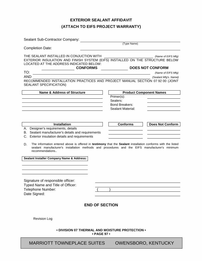
▪ DIVISION 07 THERMAL AND MOISTURE PROTECTION ▪
▪ PAGE 97 ▪
RESIDENCE INN BY MARRIOTT - LITTLETON, COLORADO
EXTERIOR SEALANT AFFIDAVIT (ATTACH TO EIFS PROJECT WARRANTY)
Sealant Sub-Contractor Company: (Type Name)
Completion Date: THE SEALANT INSTALLED IN CONJUCTION WITH (Name of EIFS Mfg) EXTERIOR INSULATION AND FINISH SYSTEM (EIFS) INSTALLED ON THE STRUCTURE BELOW LOCATED AT THE ADDRESS INDICATED BELOW: CONFORMS DOES NOT CONFORM TO: (Name of EIFS Mfg) AND (Sealant Mfg's. Name) RECOMMENDED INSTALLATION PRACTICES AND PROJECT MANUAL SECTION 07 92 00 (JOINT SEALANT SPECIFICATION)
Name & Address of Structure Product Component Names Primer(s): Sealers: Bond Breakers: Sealant Material:
Installation Conforms Does Not Conform A. Designer's requirements, details B. Sealant manufacturer's details and requirements C. Exterior insulation details and requirements D. The information entered above is offered in testimony that the Sealant installation conforms with the listed
sealant manufacturer's installation methods and procedures and the EIFS manufacturer's minimum recommendations..
Sealant Installer Company Name & Address: Signature of responsible officer: Typed Name and Title of Officer: Telephone Number: ( ) Date Signed:
END OF SECTION
Revision Log
MARRIOTT TOWNEPLACE SUITES OWENSBORO, KENTUCKY

▪ DIVISION 08 OPENINGS ▪
▪ PAGE 1 ▪
RESIDENCE INN BY MARRIOTT - LITTLETON, COLORADO
SECTION 08 11 13 (08110) - HOLLOW METAL DOORS AND FRAMES
PART 1 GENERAL 1.01 SUMMARY
A. Section Includes:
1. Interior Hollow Metal Doors and Frames
2. Exterior Hollow Metal Doors and Frames
B. Related Sections:
1. Section 07 92 00 (07920) – Joint Sealants
2. Section 08 14 00 (08200) - Wood Doors
3. Section 08 71 00 (08710) - Door Hardware
4. Section 08 80 00 (08800) - Glazing
5. Section 09 90 00 (09900) - Painting
1.02 REFERENCES
A. ASTM International (ASTM) Publications:
1. A153 "Standard Specification for Zinc Coating (Hot-Dip) on Iron and Steel Hardware"
2. A568 "Standard Specification for Steel Sheet, Carbon, and High-Strength, Low-Alloy, Hot-Rolled and Cold-Rolled, General Requirements for"
3. A591 "Standard Specification for Steel Sheet, Zinc-Coated (Galvanized) or Zinc-Iron Alloy-Coated (Galvannealed) by the Hop-Dip Process"
4. A653 "Standard Specification for Steel Sheet, Zinc-Coated (Galvanized) or Zinc-Iron Alloy-Coated (Galvannealed) by the Hot-Dip Process"
5. A924 "Standard Specification for General Requirements for Steel Sheet, Metallic-Coated by the Hot-Dip Process"
6. A1008 "Standard Specification for Steel Sheet, Cold-Rolled, Carbon, Structural, High-Strength Low-Alloy and High-Strength Low-Alloy with Improved Formability"
7. A1011 "Standard Specification for Steel Sheet and Strip, Hot-Rolled, Carbon, Structural, High-Strength Low-Alloy and High-Strength Low-Alloy with Improved Formability"
8. C143 “Standard Test Method for Slump of Hydraulic Cement Concrete”
9. C476 “Standard Specification for Grout for Masonry”
10. E90 "Standard Test Method for Laboratory Measurement of Airborne Sound Transmission Loss of Building Partitions and Elements"
11. E413 “Classification for Rating Sound Insulation”
12. E2074 "Standard Test Method for Fire Tests of Door Assemblies, Including Positive Pressure Testing of Side-Hinged and Pivoted Swinging Door Assemblies"
B. American National Standards Institute (ANSI) Publications:
1. ANSI/SDI A250.3 "Test Procedure and Acceptance Criteria for Factory Applied Finish Painted Steel Surfaces for Steel Doors and Frames"
MARRIOTT TOWNEPLACE SUITES OWENSBORO, KENTUCKY

▪ DIVISION 08 OPENINGS ▪
▪ PAGE 2 ▪
RESIDENCE INN BY MARRIOTT - LITTLETON, COLORADO
2. ANSI/SDI A250.4 "Test Procedure and Acceptance Criteria for Physical Endurance for Steel Doors, Frames, Frame Anchors and Hardware Reinforcings"
3. ANSI/SDI A250.6 "Recommended Practice for Hardware Reinforcing on Standard Steel Doors and Frames"
4. ANSI/SDI A250.8 - SDI-100 "Recommended Specifications for Standard Steel Doors and Frames"
5. ANSI/SDI A250.10 "Test Procedure and Acceptance Criteria for Prime Painted Steel Surfaces for Steel Doors and Frames"
6. ANSI/SDI A250.11 "Recommended Erection Instructions for Steel Frames (Formerly SDI-105)"
C. ANSI/DHI Publications:
1. DHI A115.1G "Installation Guide for Doors and Hardware"
D. Commercial Standards
1. CS-242-62
E. National Association of Architectural Metal Manufacturers (NAAMM) Publications:
1. "Metal Finishes Manual for Architectural and Metal Products"
F. National Fire Protection Association (NFPA) Publications:
1. NFPA 80 "Standard for Fire Doors and Windows"
2. NFPA 105 "Hot Smoke Test"
3. NFPA 252 “Standard Methods of Fire Tests of Door Assemblies”
G. National Association of Architectural Metal Manufacturers (NAAMM) Publications:
1. "Metal Finishes Manual for Architectural and Metal Products"
H. Steel Door Institute (SDI) Publications:
1. SDI 105 through 128
I. Underwriter's Laboratories, Inc. (UL) Standards
1. UL Building Materials Directory; Underwriters Laboratories Inc.
2. UL 10B "Standard for Fire Tests of Door Assemblies"
3. UL 10C "Positive Pressure Fire Tests of Door Assemblies"
4. UL 1784 "Air Leakage Tests of Door Assemblies"
5. Procedure No. R-3791
6. Procedure No. R-3821
J. Warnock Hersey, ETL SEMKO division of Intertek (WHI) Publications:
1. "Certification Listings"
1.03 DEFINITIONS
A. Steel Sheet Thicknesses: Thickness dimensions, including those referenced in ANSI A250.8, are minimums as defined in referenced ASTM standards for both uncoated steel sheet and the uncoated base metal of metallic-coated steel sheets.
MARRIOTT TOWNEPLACE SUITES OWENSBORO, KENTUCKY

▪ DIVISION 08 OPENINGS ▪
▪ PAGE 3 ▪
RESIDENCE INN BY MARRIOTT - LITTLETON, COLORADO
1.04 SUBMITTALS
A. General: Submit the following in accordance with Conditions of Contract and Division 01 Specification Sections.
B. Submit “Letter of Conformance” in accordance with Section 01 33 00 (01330) indicating specified items selected for use in project with the following supporting data.
1. Product Data: Include construction details, material descriptions, core descriptions, label compliance, fire-resistance and temperature-rise ratings, and finishes for each type of steel door and frame specified.
2. Submit Shop Drawings and product data indicating pertinent dimensioning, construction, component connections and locations, anchorage methods and locations, hardware locations and installation details, and the following:
a. Elevations of each door design.
b. Details of doors including vertical and horizontal edge details.
c. Frame details for each frame type including dimensioned profiles.
d. Details and locations of reinforcement and preparations for hardware.
e. Details of each different wall opening condition.
f. Details of anchorages, accessories, joints, and connections.
g. Coordination of glazing frames and stops with glass and glazing requirements.
3. Door Schedule: Submit schedule of doors and frames using same reference numbers for details and openings as those on Contract Drawings.
a. Indicate coordination of glazing frames and stops with glass and glazing requirements.
1.05 QUALITY ASSURANCE
A. Hollow metal doors and frames shall be fabricated in accordance with standards and specifications established by Steel Door Institute, complying with ANSI A250.8-1998 (SDI-100) “Recommended Specifications for Standard Steel Doors and Frames” and as specified.
B. Acoustical qualities: Doors shall have a minimum sound transmission classification (STC) of 29 per ASTM E413. when tested in a fixed position according to ASTM E90..
C. Fire-Rated Door Assemblies: Units that comply with NFPA 80 are identical to door and frame assemblies tested for fire-test-response characteristics per ASTM E2074, and are labeled and listed by UL, Warnock Hersey, or another testing and inspecting agency acceptable to authorities having jurisdiction for fire-protection ratings indicated. Test pressure shall be tested in accordance with NFPA 252, or UL 10C to comply with local code requirements.
D. Opening assemblies shall meet the requirements of NFPA 105 Hot Smoke Test.
E. All stairwell doors and other doors as may be shown on the Drawings shall comply with the temperature-rise rating of 450 degrees F. maximum in 30 minutes of fire exposure.
F. Installer Qualifications: Installer experienced in performing work of this section who has specialized in the installation of work similar to that required for this project.
1. Assembly and installation shall be performed by qualified personnel who have successfully completed manufacturer’s prefinished steel door frame installation course and have been approved by the manufacturer.
2. Certificate: When requested, submit certificate indicating qualification.
MARRIOTT TOWNEPLACE SUITES OWENSBORO, KENTUCKY

▪ DIVISION 08 OPENINGS ▪
▪ PAGE 4 ▪
RESIDENCE INN BY MARRIOTT - LITTLETON, COLORADO
G. Inspection: General Contractor shall provide in writing to Owner an inspection of all steel doors and frames for conformance to specifications. Inspection shall include checking for fit tolerance plumb and level as well as proper hardware and operation.
1. Comply with the requirements of the International Building Code with testing in accordance with UL 10C for positive pressure door test.
a. Test Pressure: After 5 minutes into the test, the neutral pressure level in furnace shall be established at 40 inches or less above the sill.
b. Doors shall be labeled to certify compliance.
c. Provide installation instructions attached to each door in a manner that assures
H. Fire-Rated, Borrowed Light Frame Assemblies: Assemblies complying with NFPA 80 that are listed and labeled by a testing and inspecting agency acceptable to authorities having jurisdiction, for fire ratings indicated, based on testing according to NFPA 257, or UL 9.
1.06 DELIVERY, STORAGE, AND HANDLING
A. Deliver hollow metal work cardboard wrapped or crated to provide protection during transit and job storage.
1. Provide additional protection to prevent damage to finish of factory-finished doors and frames.
2. Deliver welded frames with two removable spreader bars across bottom of frames.
B. Label each item, before shipping, with metal or plastic tags to show their location, size, door swing, and other pertinent information.
C. Inspect doors and frames on delivery for damage, and notify shipper and supplier if damage is found. Minor damages may be repaired provided refinished items match new work and are acceptable to [Owner's Representative]. Remove and replace damaged items that cannot be repaired as directed.
D. Store doors and frames at building site under cover. Place units on minimum 4-inch-high wood blocking. Avoid using non-vented plastic or canvas shelters that could create a humidity chamber. If door packaging becomes wet, remove cartons immediately. Provide minimum 1/4-inch spaces between stacked doors to permit air circulation.
1.07 PROJECT CONDITIONS
A. Field Measurements: Verify openings by field measurements before fabrication and indicate measurements on Shop Drawings.
B. Maintain environmental conditions (temperature, humidity, and ventilation) recommended by manufacturer for optimum results. Do not install products environmental conditions outside manufacturer's absolute limits.
1.08 COORDINATION
A. Coordinate installation of anchorages for standard steel frames. Furnish setting drawings, templates, and directions for installing anchorages, including sleeves, concrete inserts, anchor bolts, and items with integral anchors, that are to be embedded in concrete or masonry. Deliver such items to Project site in time for installation.
PART 2 PRODUCTS 2.01 DISTRIBUTOR
A. Avendra, LLC Preferred Manufacturers:
1. Contract Hardware, Inc. (404-350-9408)
MARRIOTT TOWNEPLACE SUITES OWENSBORO, KENTUCKY

▪ DIVISION 08 OPENINGS ▪
▪ PAGE 5 ▪
RESIDENCE INN BY MARRIOTT - LITTLETON, COLORADO
a. Contact: Mark Tew
2.02 MANUFACTURERS
A. Avendra, LLC Preferred Manufacturers:
1. None
B. Approved Manufacturers:
1. Steelcraft, an Allegion Brand (888-758-9823)
2. Ceco Door, an ASSA ABLOY Group Company (615-661-5030)
3. Republic Doors and Frames (800-733-3667)
4. CURRIES, an ASSA ABLOY Group Company (800-377-3948)
2.03 MATERIALS
A. Hot-Rolled Steel Sheets: ASTM A1011 and A568, Commercial Steel (CS), Type B; free of scale, pitting, or surface defects; pickled and oiled.
B. Cold-Rolled Steel SheetsASTM A1008 and A568, Commercial Steel (CS), Type B; suitable for exposed applications.
C. Electrolytic Zinc-Coated Steel Sheet: ASTM A591, Commercial Steel (CS), Class B coating; mill phosphatized; suitable for unexposed applications; stretcher-leveled standard of flatness where used for face sheets.
D. Hot dipped zinc coated steel shall be of the alloyed type and comply with ASTM A924 and A653.
E. Supports and Anchors: After fabricating, galvanize units to be built into exterior walls according to ASTM A153, Class B.
F. Inserts, Bolts, and Fasteners: Provide items to be built into exterior walls, hot-dip galvanized according to to ASTM A153.
G. Grout: ASTM C476, except with a maximum slump of 4 inches, as measured according to ASTM C143.
H. Bituminous Coating: Cold-applied asphalt mastic, SSPC-Paint 12, compounded for 15-mil dry film thickness per coat. Provide inert-type noncorrosive compound free of asbestos fibers, sulfur components, and other deleterious impurities.
I. Galvanizing Repair Paint: High zinc dust content paint for regalvanizing welds in galvanized steel, with dry film containing not less than 94 percent zinc dust by weight, and complying with DOD-P-21035 or SSPC Paint 20.
J. Hardware reinforcing on doors and frames shall comply with ANSI/SDI A250.6. The physical performance levels shall be in accordance with ANSI/SDI A250.4.
2.04 HOLLOW METAL FRAMES
A. General:
1. Fabricate steel frame units to comply with ANSI/SDI A250.8 and to be rigid, neat in appearance, and free from defects including warp and buckle. Where practical, fit and assemble units in manufacturer's plant. Clearly identify work that cannot be permanently factory assembled before shipment, to assure proper assembly at Project site. Conceal fastenings, unless otherwise indicated.
MARRIOTT TOWNEPLACE SUITES OWENSBORO, KENTUCKY
▪ DIVISION 08 OPENINGS ▪
▪ PAGE 6 ▪
RESIDENCE INN BY MARRIOTT - LITTLETON, COLORADO
A. Location and Type: All metal frames for doors shall be formed of steel to sizes and shapes indicated. Frames shall be fabricated with continuously welded corners unit type construction at joints [, unless noted otherwise for Prefinished Frames]. Frames shall be furnished with Underwriter's Laboratories label, as required, at the place of manufacturer.
B. Type and Gauges of Metal: Metal for frames shall be cold-rolled or hot-rolled, pickled and oiled, steel sheets with clean, smooth surfaces. Except where other gauges are indicated or specified, frames shall be fabricated from steel, not lighter than the standard Manufacturers Standard Gauge (MSG) as referenced in ANSI A250.8 :
1. Interior Frames of 16-gauge (0.053-inch) thick steel sheet for:
a. Door openings wider than 48 inches.
b. Level 2 steel doors.
c. Wood doors, unless otherwise indicated.
2. Exterior Frames of 16-gauge (0.053-inch) thick steel sheet for:
a. Door openings wider than 48 inches.
b. Level 2 steel doors.
c. Level 3 steel doors.
3. Exterior frames shall be 0.30 per square foot per side, hot-dipped galvanized or electrolytic zinc-coated steel with a stretcher level degree of flatness.
C. Workmanship and Design: The finished work shall be strong and rigid, neat in appearance, and free from defects. Fabricate members straight and true with corner joints well-formed, in true alignment and fastenings concealed where practicable.
D. Drywall Frames (Interior Guestroom Door Frames):
1. Drywall frames shall be the same as flush frames except:
2. Frames shall be formed with double return backbends to prevent cutting into drywall surface. Frames shall be knocked down, designed to be securely installed in the rough opening after wallboard is applied. Mitered corners shall be reinforced with a wedge lock corner clip to provide a firm interlock of jambs to head.
3. Each jamb shall have an adjustable anchor located 4" from the top of the door opening to hold frame in rigid alignment. Frames shall have a welded-in base anchor attaching plate in each jamb for field installation of loose base anchors or frames shall have two (2) dimpled holes in each jamb for anchoring base of frame with screws.
E. Forming Corner Joints: Joints for welded-type frames shall be mitered and continuously arc-welded for full depth and width of frame and trim. All contact edges shall be closed tight and all welds on exposed surfaces dressed smooth and flush.
F. Provision for Hardware: Frames shall be prepared at the factory for the installation of hardware. Comply with applicable requirements in ANSI A250.6 and ANSI A115 Series specifications for door and frame preparation for hardware, unless more stringent requirements are indicated. Welding of hinges to frames will not be permitted. Frames shall be mortised, reinforced, drilled, and tapped to templates to receive all mortised hardware. Provide cover boxes in back of all hardware cut-outs. Lock strikes shall be set out and adjusted to provide clearance for silencers.
1. Provide preparation for rubber silencers on interior room door frames; three per strike jamb at single doors.
MARRIOTT TOWNEPLACE SUITES OWENSBORO, KENTUCKY
▪ DIVISION 08 OPENINGS ▪
▪ PAGE 7 ▪
RESIDENCE INN BY MARRIOTT - LITTLETON, COLORADO
2. Provide concealed metal reinforcements for hardware as required. The gauges of metal for reinforcement shall be in accordance with the manufacturer's recommendations for the type of hardware and the thickness and width of doors to be hung in the frame, provided that the gauges used are not lighter than those required by Commercial Standard CS-242-62.
a. Galvanized for exterior doors.
3. All frames shall have a security anchor system installed on strike jamb consisting of a compression anchor at 3-1/2” from head of door frame and a “Z” type security anchor at 45” above floor.
G. Wall Anchors: Provide metal anchors of shapes and sizes required for the adjoining type of wall construction. Locate anchors on jambs near the top and bottom of each frame and at intermediate points not over 24 inches apart. Galvanized anchors for exterior frames.
1. Anchor types shall be varied to provide positive fastening to adjacent construction.
2. Provide UL approved anchors for UL labeled frames. Anchorage of UL label frames shall conform to printed UL test report for door frame manufactured.
H. Plaster Guards: Provide 0.016-inch-thick, steel sheet plaster guards or mortar boxes to close off interior of openings; place at back of hardware cutouts where mortar or other materials might obstruct hardware operation. Required at all door strikes.
I. Floor Anchors: Provide floor clips of not less than 16-gauge steel and fasten to bottom of each jamb member for anchoring frame to floor construction. Clips shall be adjustable and drilled for 3/8" diameter anchor bolts.
J. Shipment: For welded type frames, provide temporary steel spreaders fastened across bottom of frames. Where construction will permit concealment, leave spreaders in place after installation. Otherwise, remove spreaders after frames are set and anchored. In place of spreaders, frames may be strapped together in pairs with heads inverted for bracing during shipment. Before shipping, label each frame with metal or plastic tapes to show their location, size, door swing, and other pertinent information.
2.05 PREFINISHED FRAMES (PF)
A. Manufacturers:
1. Avendra, LLC Preferred Manufacturers:
a. None
2. Approved Manufacturers:
a. "C-Series Frames"; Timely Industries, Inc. (800-247-6242)
b. Rediframe Products Division, Dunbarton Corporation, Inc. (800-633-7553)
B. Materials:
1. Frame: Provide minimum 18 gauge, cold-rolled steel sheet conforming to ASTM A366.
2. Fasteners: Types and sizes specified in manufacturer's installation instructions for project conditions.
3. Workmanship and Design: The finished work shall be strong and rigid, neat in appearance, and free from defects. Fabricate members straight and true with corner joints well-formed, in true alignment and fastenings concealed where practicable.
4. Provision for Hardware: Frames shall be prepared at the factory for the installation of hardware. Welding of hinges to frames will not be permitted. Frames shall be mortised, reinforced, drilled, and tapped to templates to receive all mortised hardware. Provide
MARRIOTT TOWNEPLACE SUITES OWENSBORO, KENTUCKY
▪ DIVISION 08 OPENINGS ▪
▪ PAGE 8 ▪
RESIDENCE INN BY MARRIOTT - LITTLETON, COLORADO
cover boxes in back of all hardware cut-outs. Lock strikes shall be set out and adjusted to provide clearance for silencers.
a. Provide preparation for rubber silencers on interior room door frames; three per strike jamb at single doors.
b. Provide concealed metal reinforcements for hardware as required. The gauges of metal for reinforcement shall be in accordance with the manufacturer's recommendations for the type of hardware and the thickness and width of doors to be hung in the frame, provided that the gauges used are not lighter than those required by Commercial Standard CS-242-62.
c. All frames shall have a security anchor system installed on strike jamb
1) Provide safeguard at strike to prevent entry by prying.
5. Wall Anchors: Provide metal anchors of shapes and sizes required for the adjoining type of wall construction. Locate anchors on jambs near the top and bottom of each frame and at intermediate points not over 24 inches apart. Anchor the frame to the wall with fasteners every 11-inches around the perimeter of the frame.
a. Anchor types shall be varied to provide positive fastening to adjacent construction.
6. Provide UL approved anchors for UL labeled frames. Anchorage of UL label frames shall conform to printed UL test report for door frame manufactured.
7. Finishes:
a. Factory-Applied Paint Finish: Manufacturer's standard, factory-applied baked enamel paint finish complying with ANSI A250.3 for performance and acceptance criteria.
1) Color: [Standard] color to match color as shown on Interior Finish Index.
2.06 FRAME INSULATION
A. Glass fiber, semi-rigid board, 2” thickness, unfaced, 3 lb. density.
1. Avendra, LLC Preferred Manufacturers:
a. None
2. Approved Manufacturers:
a. “Type 703” - Owens-Corning Fiberglass Corp (800-438-7465)
b. Substitutions: None accepted
2.07 HOLLOW METAL DOORS
A. General:
1. Fabricate steel door units to comply with ANSI/SDI A250.8. and to be rigid, neat in appearance, and free from defects including warp and buckle. Where practical, fit and assemble units in manufacturer's plant. Clearly identify work that cannot be permanently factory assembled before shipment, to assure proper assembly at Project site.
B. Hollow Metal Doors:
1. Interior Doors: Provide doors complying with requirements indicated below by referencing ANSI/SDI A250.8.for level and model and ANSI/SDI A250.4 for physical-endurance level.
2. Interior Flush Door:
MARRIOTT TOWNEPLACE SUITES OWENSBORO, KENTUCKY
▪ DIVISION 08 OPENINGS ▪
▪ PAGE 9 ▪
RESIDENCE INN BY MARRIOTT - LITTLETON, COLORADO
a. Model: “L Series”; Steelcraft, an Allegion Brand, or approved substitution by other listed manufacturers.
b. Level 2, Heavy Duty, 18-gage, and Physical Performance Level B (Heavy Duty), Model 2 (Seamless).
c. Thickness: 1-3/4”
d. Cores: Per ANSI/SDI A250.8
1) Doors shall be reinforced, stiffened, sound deadened and insulated with impregnated Kraft honeycomb core completely filling the inside of the doors and laminated to inside faces of both panels using contact adhesive applied to both panels and honeycomb core.
e. Minimum hardware reinforcing gages shall comply with Table 4 of ANSI/SDI A250.8.
3. Interior Temperature Rise Doors
a. Temperature rise doors shall be the same as flush door construction except core material shall be designed to produce the 450 degree temperature rise rating.
b. Cores: Per ANSI/SDI A250.8:
c. Mineral-Fiber Board: For labeled doors if a temperature-rise limit is required.
4. Exterior Doors: Provide doors complying with requirements indicated below by referencing ANSI/SDI A250.8 for level and model and ANSI/SDI A250.4 for physical-endurance level:
a. Flush Door:
1) Thickness: 1-3/4”
2) Model: “L Series”; Steelcraft, an Allegion Brand, or approved substitution by other listed manufacturers.
3) Level 3, Extra Heavy Duty, 16-gage, and Physical Performance Level B (Extra Heavy Duty), Model 2 (Seamless).
b. Exterior doors shall be fabricated as thermal insulating door and frame assemblies and tested in accordance with ASTM C236 or ASTM C976 on fully operable door assemblies. Provide thermal-rated assemblies with U-factor of 0.24 or better. Hot-dipped galvanized or electrolytic zinc-coated steel with a stretcher level degree of flatness.
c. All exterior swing-out doors shall have the top and bottoms closed to eliminate moisture penetration. Door tops shall not have holes or openings.
C. Door Louvers:
1. Furnish and install louvers for interior doors, where indicated, that comply with SDI 111C, with blades or baffles formed of 0.020-inch thick, cold-rolled steel sheet set into 0.032-inch thick steel frame.
a. Provide stationary sight-proof louvers with inverted V-Shaped or Y-Shaped blades of sizes and locations as shown on the Drawings.
b. Provide Fire-Rated Automatic Louvers of sizes and locations as shown on the Drawings at fire-rated openings.
MARRIOTT TOWNEPLACE SUITES OWENSBORO, KENTUCKY
▪ DIVISION 08 OPENINGS ▪
▪ PAGE 10 ▪
RESIDENCE INN BY MARRIOTT - LITTLETON, COLORADO
1) Louvers to be constructed with movable blades closed by actuating fusible links and listed and labeled for use in fire-rated door assemblies of type and fire-resistance rating indicated by the same testing and inspecting agency that established fire-resistance rating of door assembly.
D. Door Fabrication:
1. Fabricate doors and frames in accordance with ANSI/SDI A250.8.
2. Workmanship: The finished work shall be rigid, neat in appearance, and free from defects; form molding members straight and true with joints coped or mitered, well formed and in true alignment. All welded joints on exposed surfaces shall be dressed smooth so they are invisible after finishing.
3. Door Sizes and Clearances: Doors shall be of type, sizes, and design indicated. The clearances for doors shall be 1/8" at jambs and heads and 3/4" at bottom, unless indicated or specified otherwise. Clearances at meeting edges of pairs of doors shall be 1/4" (1/8" on fire doors).
a. Clearances for Fire-Rated Doors: As required by ANSI/NFPA 80.
4. Exterior Doors: Provide weep-hole openings in bottom of exterior doors to permit moisture to escape. Seal joints in top edges of doors against water penetration.
5. Provisions for Hardware: Mortise, reinforce, drill, and tap doors at factory to receive all mortise-type hardware. Provide reinforcing only for doors to receive surface-applied hardware, except push plates and kick plates; drilling and tapping for surface-applied hardware will be done in the field. Provide metal reinforcing plates for surface-applied hardware as required. The gauges of metal for reinforcing plates shall comply with manufacturer's recommendation for the type of hardware used and the size and thickness of doors, provided that the minimum requirements are as follows:
a. Hinge Reinforcement - 3/16 Inch
b. Strike Reinforcement - 11 Gauge
c. Closers and Bracket Reinforcement - 12 Gauge
d. Mortise Covers - 26 Gauge
e. The gauges used shall not be lighter than those required by Commercial Standard CS 242-62.
6. Glazing Preparation:
a. Doors indicated to have glass shall have non-removable glazing stops on the exterior sides of the openings and removable or snap-on type stops on the inside of the openings.
b. Provide manufacturer's vision lites of sizes and locations as shown on Drawings, recessed into the door face similar to "Dezigner Trim" by Steelcraft, or approved substitution by listed manufacturers.
c. Stops shall be UL approved for UL labeled doors.
E. Doors with labels shall carry Underwriters label on the door and on the frame. They shall be constructed to meet Procedure No. R-3791 and R-3821, as listed by Underwriters Laboratories.
2.08 PREHUNG MIRRORED CLOSET DOOR
A. Aluminum Framed Mirror Guestroom Closet Door Complete with Door Hardware
1. Avendra, LLC Preferred Manufacturers:
MARRIOTT TOWNEPLACE SUITES OWENSBORO, KENTUCKY
▪ DIVISION 08 OPENINGS ▪
▪ PAGE 11 ▪
RESIDENCE INN BY MARRIOTT - LITTLETON, COLORADO
a. Mirrored Doors:
1) None
2. Approved Manufacturers:
a. Mirrored Doors:
1) “Model ALCO-1904”; Alco Doors (800-747-9663)
2) "Slimfold Model 4175 Double-Sided Mirror Door with Pre-Hung Aluminum Frame"; Dunbarton Corporation, Inc. (800-633-7553)
3. Comply with the following requirements:
a. Door is constructed of double sided mirror with 1” Anodized Aluminum Frame.
b. Mirror:
1) Mirror Facing: Smooth-edged, silvered, mirrored, vinyl-backed safety glass complying with CPSC 16 CFR 1201 for Category II safety glass with ANSI Z97.1 test procedures; with ASTM C1036 for Type I (transparent, flat), Class 1(clear), Quality q2 (mirror) annealed float glass; with FS DD-M-411 for coating system applied to second glass surface; and with the following:
2) Glass Thickness: 1/8” thickness each
3) Provide two (2) layers of mirrors back-to-back.
c. Hardware (ALCO Door):
1) Hinges: 3 each ALCO-124FH Flag Hinge x US26
2) Ball Catch: 1 each ALCO-3W, Brushed Stainless Chrome finish
3) Pull: 1 each ALCO-4000128 Custom Hand Pull, 5-5/8” H x 1-9/16” D x 5/8” square, 5” center to center for screw holes. Brushed Stainless Steel finish.
d. Hardware (Slimfold Door):
1) Hinges: 3 each Flag Hinge x US26
2) Ball Catch: 1 each Adjustable, Brushed Stainless Chrome finish
3) Pull: 1 each Hand Pull, 5-9/16" H x 1-3/8" D, 4" center to center for screw holes. Brushed Stainless Steel finish.
2.09 FINISHES
A. General: Comply with NAAMM's "Metal Finishes Manual for Architectural and Metal Products" for recommendations for applying and designating finishes.
1. Finish steel doors and frames after assembly.
B. Factory Prime Coating for Field Painted Finish: Unless specified otherwise, provide manufacturer's standard, factory-applied coat of rust-inhibiting primer complying with ANSI/SDI A250.10 for acceptance criteria.
1. Clean and chemically treat metal surfaces to assure maximum paint adherence. Follow with a dip or spray coat of lead-free, rust-inhibitive metallic oxide, zinc chromate, or synthetic resin primer on all exposed surfaces. Finished surfaces shall be smooth and free from irregularities and rough spots.
MARRIOTT TOWNEPLACE SUITES OWENSBORO, KENTUCKY

▪ DIVISION 08 OPENINGS ▪
▪ PAGE 12 ▪
RESIDENCE INN BY MARRIOTT - LITTLETON, COLORADO
PART 3 EXECUTION 3.01 EXAMINATION
A. Examine substrates, areas, and conditions, with Installer present, for compliance with requirements for installation tolerances and other conditions affecting performance of standard steel doors and frames.
1. Examine roughing-in for embedded and built-in anchors to verify actual locations of standard steel frame connections before frame installation.
3.02 GENERAL
A. Fabricate and install hollow metal units and their accessories in strict accordance with these Specifications and manufacturer's data.
B. Hardware: For installation see Division 08, "Door Hardware" Section of these Specifications.
3.03 PLACING FRAMES
A. Comply with the provisions of the "Steel Door Institute" 105, unless otherwise indicated.
B. Set frames accurately in position, plumbed, aligned, and braced until permanent anchors are set.
1. Except for frames located in existing walls or partitions, place frames before construction of enclosing walls and ceilings.
C. Field apply bituminous coating to backs of frames that will be filled with grout. Install door silencers in frames before grouting.
D. Where grouting is required in masonry installations, frames shall be braced or fastened in such a way that will prevent the pressure of the grout from deforming the frame members. Grout shall be mixed to provide a 4 inch maximum slump consistency, hand trowelled into place. Grout mixed to a thin “pumpable” consistency shall not be used.
E. Frame Insulation: Install insulation in frames of gypsum board partitions. Cut insulation to full width of frame throat and friction fit within the jamb and head. Pack solid around perimeter of the frame.
F. Anchor bottom of frames to floors with expansion bolts, or with power fasteners. Build wall anchors into walls or secure to adjoining construction as indicated or specified. Where frames require ceiling struts or other structural overhead bracing, they shall be anchored securely to ceiling or structural framing above as indicated and specified.
1. In masonry construction, provide at least three wall anchors per jamb; install adjacent to hinge location on hinge jamb and at corresponding heights on strike jamb. Acceptable anchors include masonry wire anchors and masonry T-shaped anchors.
2. In metal-stud partitions, provide at least three wall anchors per jamb; install adjacent to hinge location on hinge jamb and at corresponding heights on strike jamb. Attach wall anchors to studs with screws.
3. For openings 90 inches or more in height, install an additional anchor at hinge and strike jambs.
G. Install fire-rated frames in accordance with NFPA Standard No. 80.
H. Casings:
1. Install casings in accordance with manufacturer's printed instructions.
MARRIOTT TOWNEPLACE SUITES OWENSBORO, KENTUCKY

▪ DIVISION 08 OPENINGS ▪
▪ PAGE 13 ▪
RESIDENCE INN BY MARRIOTT - LITTLETON, COLORADO
3.04 DOOR INSTALLATION
A. Door Installation: Comply with ANSI A250.8. Fit hollow metal doors accurately in their respective frames within clearances specified in ANSI A250.8. Shim as necessary to comply with SDI 122 and ANSI/DHI A115.1G .
B. Place fire-rated doors with clearances as specified in NFPA Standard No. 80.
C. Smoke-Control Doors: Install to comply with NFPA 105.
3.05 ADJUSTMENT
A. Check and re-adjust operating finish hardware items in hollow metal work just prior to final inspection.
B. Remove and replace defective work including doors or frames which are warped, bowed, or otherwise damaged.
C. Finished Doors: Refinish or replace doors damaged during installation.
D. Protect doors as recommended by door manufacturer to ensure that doors will be without damage or deterioration at time of Substantial Completion.
3.06 TOUCH-UP
A. Prime-Coat Touchup: Immediately after installation, sand smooth any rusted or damaged areas of prime coat and apply touch up of compatible air-drying primer.
B. Repairs: Fill surface depressions with metallic paste filler, allow to cure, and sand flush for invisible joint with adjacent metal surfaces. Sand rust areas and apply touch-up paint using air drying paints compatible with shop finish. Damaged doors or frames that cannot be repaired shall be replaced.
3.07 CLEANING:
A. Protection Removal: Immediately before final inspection, remove protective wrappings from doors and frames.
B. Upon completion, metal surfaces of doors and frames that are completely factory finished shall be thoroughly cleaned and touched-up as recommended by the door manufacturer.
END OF SECTION
Revision Log
MARRIOTT TOWNEPLACE SUITES OWENSBORO, KENTUCKY
▪ DIVISION 08 OPENINGS ▪
▪ PAGE 14 ▪
RESIDENCE INN BY MARRIOTT - LITTLETON, COLORADO
SECTION 08 14 00 (08200) - WOOD DOORS
PART 4 GENERAL 4.01 SUMMARY
A. Section Includes:
1. Types of doors required include the following:
a. Wood Doors with Wood Veneer Faces:
1) Solid Core Flush Doors at Back-of House (except where shown as 2-Panel).
b. Composite Wood Doors:
1) Two-Panel Design at Public Space, Back-of-House (except where shown as Flush), Guestroom Entry, and Guestroom Connecting Doors.
2) Two-Panel Design at Guestroom Bath, Bedroom, and Closet Doors.
3) Two-Panel Design on Bathroom side, and flush with surface-applied Mirror on Bedroom Side, at Accessible Guestroom Baths.
4) Three-Panel Sliding Door with Glass Lites at Breakfast Room to Serving.
c. Interior Stile and Rail Wood Doors
1) Two-Panel Design at Public Space, Back-of-House (except where shown as Flush), Guestroom Entry, and Guestroom Connecting Doors.
2) Two-Panel Design at Guestroom Bath, Bedroom, and Closet Doors.
3) One-Panel Design with Inset Mirror on Bedroom Side at Accessible Guestroom Bath.
4) Three-Panel Sliding Door with Glass Lites at Breakfast Room to Serving.
2. Types of Wood Frames required include the following:
a. Pre-Finished Wood Frames (Option)
B. Related Sections:
1. Section 06 10 00 (06100) - Rough Carpentry
2. Section 06 20 00 (06200) - Finish Carpentry
3. Section 08 11 13 (08110) – Hollow Metal Doors and Frames
4. Section 08 41 13 (08410) – Aluminum Framed Entrances and Storefronts
5. Section 08 71 00 (08710) - Door Hardware
6. Section 08 80 00 (08800) - Glazing
7. Section 09 90 00 (09900) - Painting
4.02 REFERENCES
A. Window and Door Manufacturers Association (WDMA) Publications:
1. I.S.1-A "Architectural Wood Flush Doors"
2. I.S.6, "Industry Standard for Wood Stile and Rail Doors"
B. Architectural Woodwork Institute (AWI) Publications:
MARRIOTT TOWNEPLACE SUITES OWENSBORO, KENTUCKY
▪ DIVISION 08 OPENINGS ▪
▪ PAGE 15 ▪
RESIDENCE INN BY MARRIOTT - LITTLETON, COLORADO
1. "Architectural Woodwork Quality Standards"
C. American National Standards Institute (ANSI) Publications:
1. ANSI/AHA A135.4 "Basic Hardboard"
2. ANSI 208.1 "Standards for the Performance of Particleboard"
3. ANSI Z97.1 "Performance Specifications and Methods of Test for Safety Glazing Materials Used in Buildings"
D. ASTM International (ASTM) Publications:
1. C920 “Standard Specification for Elastomeric Joint Sealants”
2. C1036 “Standard Specification for Flat Glass”
3. E90 “Standard Test Method for Laboratory Measurement of Airborne Sound Transmission Loss of Building Partitions and Elements”
4. E413 “Classification for Rating Sound Insulation”
E. Door and Hardware Institute (DHI) Publications:
1. DHI-WDHS-3 "Recommended Hardware Locations for Wood Flush Doors"
2. DHI A115 "Steel Door Preparation Standards"
F. National Fire Protection Association (NFPA) Publications:
1. NFPA 80 “Standard for Fire Doors, Fire Windows”
G. Underwriter's Laboratories, Inc. (UL) Standards
1. UL 10B "Standard for Fire Tests of Door Assemblies"
2. UL 10C "Positive Pressure Fire Tests of Door Assemblies"
4.03 SUBMITTALS
A. General: Submit the following in accordance with Conditions of Contract and Division 01 Specification Sections.
B. Submit “Letter of Conformance” in accordance with Section 01 33 00 (01330) indicating specified items selected for use in project with the following supporting data.
1. Product Data: Door manufacturer's technical data for each type of door, including details of core and edge construction, trim for openings and louvers, and factory-finishing specifications.
2. Shop Drawings: Submit Shop Drawings indicating location and size of each door, elevation of each kind of door, details of construction, location and extent of hardware blocking, fire ratings, requirements for factory finishing and other pertinent data.
a. Submittals shall use the same designations for door and hardware numbers as shown on the Drawings.
4.04 QUALITY ASSURANCE
A. Quality Standards: Comply with the following standards:
1. WDMA Quality Standard: I.S.1-A "Architectural Wood Flush Doors", and I.S.6, "Industry Standard for Wood Stile and Rail Doors" of Window and Door Manufacturers Association (WDMA).
2. AWI Quality Standard: "Architectural Woodwork Quality Standards", including Section 1300 "Architectural Flush Doors", and Section 100-S-3 "Moisture Content", of
MARRIOTT TOWNEPLACE SUITES OWENSBORO, KENTUCKY

▪ DIVISION 08 OPENINGS ▪
▪ PAGE 16 ▪
RESIDENCE INN BY MARRIOTT - LITTLETON, COLORADO
Architectural Woodwork Institute (AWI) for grade of door, core construction, finish and other requirements exceeding those of WDMA quality standard.
B. Sound Transmission Class:
1. All guestroom entrance doors from interior corridors, together with their perimeter seals shall have a minimum Sound Transmission Class (STC) of [31] per ASTM E413. when tested in an operable condition according to ASTM E90.
2. All guestroom communicating doors, at each of the two doors in the opening, together with their perimeter seals shall have a minimum Sound Transmission Class (STC) of [35] per ASTM E413. when tested in an operable condition according to ASTM E90.
3. All other entrance doors from interior corridors, together with their perimeter seals shall have a minimum Sound Transmission Class (STC) of [26] per ASTM E413. when tested in a fixed position according to ASTM E90.
C. Safety Glass: Provide products complying with ANSI Z97.1 and testing requirements of 16 CFR, Part 1201, for Category II materials, unless those of Category I are expressly indicated and permitted.
D. Fire-Rated Wood Doors: Provide wood doors that comply with NFPA 80, are identical in materials and construction to units tested in door and frame assemblies per ASTM E152, and which are labeled and listed for ratings indicated by Underwriters Laboratory (UL), Warnock Hersey, ETL SEMKO division of Intertek (WHI), or other testing and inspection agency acceptable to authorities having jurisdiction.
1. Provide rated stiles on fire rated doors.
2. Comply with the requirements of the International Building Code with testing in accordance with UL 10C for positive pressure door test.
a. Test Pressure: After 5 minutes into the test, the neutral pressure level in furnace shall be established at 40 inches or less above the sill.
b. Doors shall be labeled to certify compliance.
c. Provide installation instructions attached to each door in a manner that assures availability to the installer and building official.
E. Manufacturer: Obtain doors from one source.
F. Inspection: General Contractor shall provide in writing to [Owner’s Representative], an inspection of all doors and frames for conformance to specifications. Inspection shall include checking for fit tolerance, plumb and level, as well as proper hardware and operation.
4.05 PRODUCT DELIVERY, STORAGE, AND HANDLING
A. Protect doors during transit, storage and handling to prevent damage, soiling and deterioration. Comply with requirements of referenced standards and recommendations of WDMA pamphlet "How to Store, Handle, Finish, Install, and Maintain Wood Doors", as well as with manufacturer's instructions.
1. Individually Package doors in vented poly bags with identifying marks prior to shipment. Doors shall not be removed from bags until ready to hang. After hanging, bags shall be placed over doors to provide protection until area in which doors are hung is free of construction traffic.
2. Store doors off the floor at least 3" in an area that is not susceptible to standing water or high moisture. Store doors in an upright position with spacers or corner caps separating each door.
MARRIOTT TOWNEPLACE SUITES OWENSBORO, KENTUCKY

▪ DIVISION 08 OPENINGS ▪
▪ PAGE 17 ▪
RESIDENCE INN BY MARRIOTT - LITTLETON, COLORADO
B. Identify each door with individual opening numbers which correlate with designation system used on Shop Drawings for door, frames, and hardware, using temporary, removable or concealed markings.
4.06 PROJECT CONDITIONS
A. Conditioning: Do not deliver or install doors until building is enclosed, wet work is complete, and conditions for temperature and relative humidity have been stabilized and will be maintained in storage and installation areas during remainder of construction period to comply with the following requirements applicable to Project's geographical location:
1. Referenced AWI quality standard including Section 100-S-11, "Relative Humidity and Moisture Content".
4.07 SPECIAL WARRANTY
A. General: Warranties shall be in addition to and run concurrent with, and not be a limitation of, other rights the Owner may have under the Contract Documents.
B. Door Manufacturer's Warranty: Submit written agreement on door manufacturer's standard form signed by manufacturer, Installer and General Contractor, agreeing to repair or replace defective doors that have warped (bow, cup or twist) more than 1/4 inch in a 42" x 84" section, or that show telegraphing of core construction in face veneers exceeding 0.01 inch in a 3 inch span, or do not conform to tolerance limitations of referenced quality standards.
1. Warranty shall also include reinstallation and finishing that may be required due to repair or replacement of defective doors where defect was not apparent prior to hanging.
2. Warranty shall be in effect during the following period after date of Substantial Completion:
a. Solid-Core and Composite Wood Interior Doors: Life of installation.
b. Solid Core Exterior Wood Doors: [Two years] from date of Substantial Completion.
c. Stile & Rail Interior Wood Doors:
1) Non-Rated: Life of installation.
2) 20 minute Fire Rated: Life of installation.
3) 45, 60, or 90 minute Fire Rated: One year from date of Substantial Completion.
C. Contractor's Responsibilities: Replace or refinish doors where Contractor's work contributed to rejection or to voiding of manufacturer's Warranty.
PART 5 PRODUCTS 5.01 DISTRIBUTORS
A. Avendra, LLC Preferred Distributor:
1. Contract Hardware, Inc. (800-266-3418)
a. Contact: Mark Tew
5.02 INTERIOR FLUSH WOOD DOORS
A. Manufacturers:
1. Avendra, LLC Preferred Manufacturers:
a. None
2. Approved Manufacturers:
MARRIOTT TOWNEPLACE SUITES OWENSBORO, KENTUCKY
▪ DIVISION 08 OPENINGS ▪
▪ PAGE 18 ▪
RESIDENCE INN BY MARRIOTT - LITTLETON, COLORADO
a. VT Industries Inc. (800-827-1615)
b. Mohawk Flush Doors, a Masonite Company (570-473-3557)
c. Eggers Industries (920-793-1351)
d. Marshfield DoorSystems, a Masonite Company (800-869-3667)
B. Solid Core Doors for Transparent Finish: Comply with the following requirements:
1. Faces: Select White, Plain Sliced Birch, ANSI/HPVA A Grade, Pair and Book-Matched for uniform color and grain pattern.
2. AWI Grade: Custom
3. Construction: 5-Ply
a. Solid Core Doors: Particleboard, ANSI/208.1, 1-LD-2
4. Thickness: 1-3/4"
5. Factory seal top and bottom rails.
C. Blocking: Provide either hardwood or Structural Composite Lumber (SCL) wood blocking in particleboard-core doors as follows:
1. Top Rail (No Closer): Minimum 1-1/8 inch.
2. Top Rail (Closer): Minimum 5-inch with remaining after installation, or as required to provide proper blocking surface mounted hardware to avoid through-bolts and maintain warranty. Verify with closer manufacturer.
3. Bottom Rail: Minimum 1-1/8 inch after undercut; 5-inch bottom-rail in doors indicated to have kick, mop, or armor plates.
4. Midrail: 5-inch midrail blocking, in doors indicated to have exit devices at location of exit device.
5. Stiles: Provide stiles consisting of two plys.
a. The inner ply shall be minimum 1-1/8 inches of hardwood or LSL engineered lumber.
b. The outer ply shall be of hardwood lumber of the same species as the face veneer.
c. Bond stiles and rails to core, then sand entire unit prior to applying crossbanding and face veneers
D. Fire-Rated Solid Core Doors: Comply with the following requirements.
1. Faces and AWI Grade: Provide faces and grade to match non-rated doors in same area of building, unless otherwise indicated.
a. Construction: Manufacturer's core construction as required to provide fire-resistance rating indicated.
2. Blocking: Provide either hardwood or structural composite lumber wood blocking in particleboard-core doors or as required to meet specified fire rating and as follows:
a. Top Rail (No Closer): Minimum 1-1/8 inch.
b. Top Rail (Closer): Minimum 5-inch with remaining after installation, or as required to provide proper blocking surface mounted hardware to avoid through-bolts and maintain warranty. Verify with closer manufacturer.
c. Bottom Rail: Minimum 1-1/8 inch after undercut.
MARRIOTT TOWNEPLACE SUITES OWENSBORO, KENTUCKY
▪ DIVISION 08 OPENINGS ▪
▪ PAGE 19 ▪
RESIDENCE INN BY MARRIOTT - LITTLETON, COLORADO
d. Bottom Rail: 5-inch bottom-rail in doors indicated to have kick, mop, or armor plates.
e. Midrail: 5-inch midrail blocking, in doors indicated to have exit devices at location of exit device.
3. Stiles: Provide stiles consisting of two plys.
a. The inner-ply shall be minimum 1-1/8 inches Structural Composite Lumber (SCL) or approved non-combustible material on 20 minute rated doors, On 45, 60, and 90 minute rated doors, the inner-ply shall be 1-inch of Structural Composite lumber or approved combustible material.
b. Bond stiles and rails to core, then sand entire unit prior to applying crossbanding and face veneers.
5.03 INTERIOR STILE AND RAIL WOOD DOORS
A. Avendra, LLC Preferred Manufacturers:
1. Two-Panel and Three-Panel Doors:
a. None
B. Approved Manufacturers:
1. Two-Panel and Three-Panel Doors:
a. VT Industries Inc. (800-827-1615)
b. Mohawk Flush Doors, a Masonite Company (570-473-3557)
c. Eggers Industries (920-793-1351)
d. Marshfield DoorSystems, a Masonite Company (800-869-3667)
e. Supa Doors, Inc. (888-787-2366)
C. Type: Interior doors, meeting AWI Quality Standards, Section 1400.
1. Stile and Rail Construction for Transparent Finish:
a. Plain Sliced Birch, unless shown otherwise
2. AWI Grade: Custom
3. Size: Size as shown on Drawings.
4. Stile and Rail Widths: As indicated
5. Thickness: 1-3/4"
6. Molding Profile: As indicated.
D. Two-Panel and Three-Panel, Flat Panel Square Edge Doors:
1. Approved Manufacturers:
a. VT Industries Inc. (800-827-1615)
1) Two-Panel: “1000 Series, Model SS1021 Marriott Residence Inn”
2) Three-Panel: “1000 Series, Model SS1032 Marriott Residence Inn”
3) Single-Panel with Inset Mirror (Accessible Guestroom Bath): “1000 Series, Model SS1011 MDF” with full panel mirror inset.
b. Supa Doors, Inc. (888-787-2366)
MARRIOTT TOWNEPLACE SUITES OWENSBORO, KENTUCKY
▪ DIVISION 08 OPENINGS ▪
▪ PAGE 20 ▪
RESIDENCE INN BY MARRIOTT - LITTLETON, COLORADO
1) Two-Panel: Guestroom Entrance and Communicating Door “Model MRIE” / Closet Door “Model MRIC”
2) Three-Panel: “Model MRIBA-300”
3) Two-Panel/Flush with Inset Mirror (Accessible Guestroom Bath): “Model MRIB”. Full panel mirror inset on bathroom side, two panel on other side.
c. Eggers Industries (920-793-1351)
1) Approved Substitution
d. Algoma Hardwoods, a Masonite Company (800-678-8910)
1) Approved Substitution
e. Marshfield DoorSystems, a Masonite Company (800-869-3667)
1) Approved Substitution
2. Construction for Opaque Finish:
a. Outer Stile and Rail: Hardwood or structural composite lumber with HDF Faces. Edges shall match faces.
b. Panels: MDF
c. Factory Finish: Primed, Top and bottom rails factory sealed. Color as shown on Interior Finish Index
3. Grade: WDMA I.S. 6-A, Custom
4. Size: Size as shown on Drawings.
5. Thickness: 1-3/4"
6. Stile Width: 6 inch, unless otherwise noted.
7. Mullion Width: 3 inches, unless otherwise noted.
8. Rails:
a. Top Rail Width: 6 inch, unless otherwise noted.
b. Lock Rail Width: 8-3/4 inch, unless otherwise noted.
c. Cross Rail Width: 3 inch, unless otherwise noted.
d. Bottom Rail Width: 10 inch, unless otherwise noted.
9. Panel Thickness: 5/8 inch
10. Panel Type: Flat
11. Door Top: Square
12. Top Panel: Square.
13. Sticking Used with Panels: Square
14. Mirror:
a. Mirror Facing: Smooth-edged, silvered, mirrored, vinyl-backed safety glass complying with CPSC 16 CFR 1201 for Category II safety glass with ANSI Z97.1 test procedures; with ASTM C1036 for Type I (transparent, flat), Class 1(clear), Quality q2 (mirror) annealed float glass; with FS DD-M-411 for coating system applied to second glass surface; and with the following:
MARRIOTT TOWNEPLACE SUITES OWENSBORO, KENTUCKY
▪ DIVISION 08 OPENINGS ▪
▪ PAGE 21 ▪
RESIDENCE INN BY MARRIOTT - LITTLETON, COLORADO
b. Glass Thickness: 1/8” thickness
c. Mirror to be secured to door with adhesive as recommended by door and mirror manufacturer.
E. Glazing:
1. Interior Doors: 1/4" Uncoated, clear, fully tempered float glass by manufacturer.
2. At fire-rated doors glazing to be Fire-Resistive Glazing, refer to Section 08 80 00 (08800).
a. Where shown as divided lite type doors, provide simulated divided lite doors with muntin bars permanently attached to both sides of door glazing.
F. Fire-Rated Doors: Comply with the following requirements.
1. Faces and AWI Grade: Provide faces and grade to match non-rated doors in same area of building, unless otherwise indicated.
a. Construction: Manufacturer's standard core construction as required to provide fire-resistance rating indicated.
5.04 COMPOSITE WOOD DOORS
A. Avendra, LLC Preferred Manufacturers:
1. Two-Panel and Three-Panel Doors:
a. None
B. Approved Manufacturers:
1. Two-Panel and Three-Panel Doors:
a. Marshfield DoorSystems, a Masonite Company (800-869-3667)
C. Two-Panel and Three-Panel Routed Composite Wood Doors:
1. Approved Manufacturers:
a. Marshfield DoorSystems, a Masonite Company (800-869-3667)
1) Guestroom Entrance Doors, Guestroom Connector Doors, and Public Space Doors: Two-Panel Fire-Rated 1-3/4” Doors, 1-1/4” Thick Flat Panels: “Carte Blanche, Model CBPN20-201”
2) Guestroom Bedroom and Bath Doors: Two-Panel 1-3/8” Doors, 7/8” Thick Flat Panels: “Carte Blanche, Model CBPN-201”
3) Guestroom Closet Doors: Two-Panel 1-3/8” Doors, 7/8” Thick Flat Panels: “Carte Blanche, Model CBPN-201”
4) Breakfast Room to Serving Sliding Doors: Three-Panel 1-3/4” Doors, 1-1/4” Thick Flat Panels: “Carte Blanche, Model CBPN-301”
5) Two-Panel/Flush with Surface Applied Mirror with trim molding (Accessible Guestroom Bath): “Carte Blanche, Model CBPN-MA with Trim Molding”. Full panel mirror on flush vanity side, two panel on other side. Note, mirror and moldings provided by others in lieu of factory installation.
2. Door Construction:
a. Outer Stile and Rail: Hinge style to be modified to include wood inserts or modified MDF edge as required for proper screw holding. Edges shall match faces.
b. Factory Finish: Primed, Top and bottom rails factory sealed.
MARRIOTT TOWNEPLACE SUITES OWENSBORO, KENTUCKY
▪ DIVISION 08 OPENINGS ▪
▪ PAGE 22 ▪
RESIDENCE INN BY MARRIOTT - LITTLETON, COLORADO
3. Size: Size as shown on Drawings.
4. Thickness: 1-3/4 inches and 1-3/8 inches, as indicated.
5. Stile Width: 6 inch, unless otherwise noted.
6. Mullion Width: 3 inches, unless otherwise noted.
7. Rails:
a. Top Rail Width: 6 inch, unless otherwise noted.
b. Lock Rail Width: 8-3/4 inch, unless otherwise noted.
c. Cross Rail Width: 3 inch, unless otherwise noted.
d. Bottom Rail Width: 10 inch, unless otherwise noted.
8. Routed Panel Thickness: As indicated. Panel corners to be squared.
9. Panel Type: Flat
10. Door Top: Square
11. Top Panel: Square.
12. Finish: Factory Primed.
13. Mirror:
a. Mirror Facing: Smooth-edged, silvered, mirrored, vinyl-backed safety glass complying with CPSC 16 CFR 1201 for Category II safety glass with ANSI Z97.1 test procedures; with ASTM C1036 for Type I (transparent, flat), Class 1(clear), Quality q2 (mirror) annealed float glass; with FS DD-M-411 for coating system applied to second glass surface; and with the following:
b. Glass Thickness: 1/8” thickness
c. Mirror to be secured to door with adhesive as recommended by door and mirror manufacturer.
D. Glazing:
1. Interior Doors: 1/4" Uncoated, clear, fully tempered float glass by manufacturer.
2. At fire-rated doors glazing to be Fire-Resistive Glazing, refer to Section 08 80 00 (08800)
a. Where shown as divided lite type doors, provide simulated divided lite doors with muntin bars permanently attached to both sides of door glazing.
E. Fire-Rated Doors: Comply with the following requirements.
1. Faces: Provide faces to match non-rated doors in same area of building, unless otherwise indicated.
a. Construction: Manufacturer's standard core construction as required to provide fire-resistance rating indicated.
5.05 LOUVERS AND LIGHT FRAMES
A. Wood Louvers (except at full louver doors): Door manufacturer's standard solid-wood louvers, unless otherwise indicated. Size as indicated on Mechanical Drawings.
B. Fire Door Louvers: Metal louvers with fusible link and closing device, listed and labeled for use in doors with fire rating of one and one-half hours and less. Size as indicated on Mechanical Drawings.
MARRIOTT TOWNEPLACE SUITES OWENSBORO, KENTUCKY
▪ DIVISION 08 OPENINGS ▪
▪ PAGE 23 ▪
RESIDENCE INN BY MARRIOTT - LITTLETON, COLORADO
1. Metal and Finish: Galvanized steel, 0.0396 inch thick, hot-dip zinc coated and factory primed for paint finish.
C. Wood Beads for Light Openings in Wood Doors:
1. Wood Species: Same species as door faces, painted to match laminate at laminate doors.
2. Profile: Flush rectangular beads.
3. At 20-minute, fire-rated, wood-core doors, provide wood beads and metal glazing clips approved for such use.
D. Wood-Veneered Beads for Light Openings in Fire Doors: At fire-rated door locations except, 20-minute rated doors, provide manufacturer's standard wood-veneered noncombustible beads matching veneer species of door faces and approved for use in doors of fire rating indicated. Include concealed metal glazing clips where required for opening size and fire rating indicated.
E. Refer to Section 08 80 00 (08800) for glazing.
5.06 PRE-FINISHED WOOD FRAMES
A. Avendra, LLC Preferred Manufacturers:
1. None
B. Approved Manufacturers:
1. “Profile LWM 493”; Teton Sales Co., LLC (208-459-6334)
2. Approved Substitution
C. Finish to match prefinished doors.
5.07 FABRICATION - GENERAL
A. Fabricate wood doors to produce doors complying with following requirements:
1. Fabricate fire rated doors in accordance with AWI Quality Standards and to UL or Warnock Hersey requirements. Attach fire rating label to door and frame.
2. Stiles, rails and core shall be fully bonded together with adhesive and sanded smooth prior to laminating of face veneer.
3. Cross bands and faces for PC and FD type doors shall be laminated to core by the hot or cold plate process.
4. Solid Core Doors for Laminate Finish:
a. Vertical Exposed Edge of Stiles: Plastic laminate same as door facing.
b. Laminate edge to be applied before the face laminate.
5. Factory-prefit and pre-machine doors to fit frame opening sizes indicated with the following uniform clearances and bevels:
a. Coordinate measurements of hardware mortises in metal frames to verify dimensions and alignment before proceeding with factory pre-machining.
b. Comply with clearance requirements of referenced quality standard for fitting. Comply with requirements in NFPA 80 for fire-rated doors.
c. Locate hardware to comply with Door and Hardware Institute (DHI) DHI-WDHS-3. Comply with final hardware schedules, door frame Shop Drawings, DHI A115-W series standards, and hardware templates.
MARRIOTT TOWNEPLACE SUITES OWENSBORO, KENTUCKY
▪ DIVISION 08 OPENINGS ▪
▪ PAGE 24 ▪
RESIDENCE INN BY MARRIOTT - LITTLETON, COLORADO
d. Factory drill pilot holes for hinge and lock face plate screws.
e. Coordinate measurements of hardware mortises in metal frames to verify dimensions and alignment before proceeding with factory pre-machining.
6. Undercut:
1) Guestroom Entry Door = 1/4" above threshold.
2) Guestroom Connector = 1/2" above threshold as coordinated with door bottom. (15/16" above concrete)
3) Guest Bathroom Door = 3/8" above threshold.
4) Doors swinging over carpet = 3/4" above top of concrete subfloor.
B. Openings: Cut and trim openings through doors to comply with applicable requirements of referenced standards for kind(s) of doors required.
1. Light Openings: Trim openings with moldings of material and profile indicated.
2. Louvers: Factory install louvers in prepared openings.
C. Transom and Side Panels: Fabricate matching panels with same construction, exposed surfaces, and finish as specified for associated doors. Finish bottom edges of transoms and top edges of rabbeted doors same as door stiles.
1. Fabricate door and transom panels with full-width, solid-lumber, rabbeted, meeting rails.
D. Pre-Assembled Doors and Frames:
1. Coordinate with Section 08 71 00 (08710) for all hardware requirements, including installation.
5.08 FABRICATION - STILE AND RAIL WOOD DOORS
A. Factory fit doors to suit frame-opening sizes indicated, with the following uniform clearances and bevels, unless otherwise indicated:
1. Clearances: Provide 1/8 inch at heads. Provide 3/32 inch at jambs, and between pairs of doors. Provide 1/2 inch from bottom of door to top of decorative floor finish or covering. Where threshold is shown or scheduled, provide 3/8 inch from bottom of door to top of threshold.
a. Comply with NFPA 80 for fire-rated doors.
2. Bevel fire-rated doors 1/8 inch in 2 inches on lock edge; trim stiles and rails only to extent permitted by labeling agency.
a. Undercut: [1-inch] above top of concrete subfloor.
B. Door shall be assembled with mortise and tenon or doweled joints.
C. Pre-machining: Pre-machine and pre-fit door for hardware specified in Section 08 71 00 (08700) - Hardware.
D. Glazed Openings: Glaze doors at factory with glass of type and thickness indicated, complying with Division 08 Section "Glazing." Install glass using manufacturer's standard elastomeric glazing sealant complying with ASTM C920. Secure glass in place with removable wood stops.
E. Transom and Side Panels: Fabricate panels to match adjoining doors in materials, finish, and quality of construction.
MARRIOTT TOWNEPLACE SUITES OWENSBORO, KENTUCKY
▪ DIVISION 08 OPENINGS ▪
▪ PAGE 25 ▪
RESIDENCE INN BY MARRIOTT - LITTLETON, COLORADO
5.09 SHOP PRIMING
A. Doors for Opaque (Painted) Finish:
1. Shop prime faces and edges of doors, including cutouts, with two coat of wood primer specified in Section 09 90 00 (09900) "Painting".
a. Match primer-sealer color to color of finish coats; refer to Finish Index on Drawings for paint color.
B. Doors for Transparent (Stained) Finish:
1. Shop seal faces and edge of doors, including cutouts, with stain (if required), other required pretreatments, and first coat of finish as specified in Section 09 90 00 (09900) "Painting".
5.10 FACTORY FINISHING
A. Transparent (Stain) Finish:
1. Factory-applied by Manufacturer following AWI Section 1500 requirements for Custom Grade "TR-6". Finish shall consist of a four-coat process with a minimum 3-mil dry film thickness on all surfaces.
a. Apply vinyl wash coat by spray or roller; fully pad into surfaces and wipe off.
b. Apply stain by spray or roller; fully pad surfaces and wipe off.
c. Sand lightly using 220-grit paper.
d. Apply final finish of two coats of clear, transparent, catalyzed vinyl resin by spray or roller.
e. Stain Color: Satin-finish stain in color as approved by the Marriott Representative to match a finished stain sample in color as shown on Interior Finish Index.
B. Opaque (Painted) Finish:
1. Factory-applied by Manufacturer following AWI Section 1500 requirements for Custom Grade. Color as shown on Interior Finish Index
PART 6 EXECUTION 6.01 EXAMINATION
A. Examine installed door frames prior to hanging door.
1. Verify that frames comply with indicated requirements for type, size, location, and swing characteristics and have been installed with plumb jambs and level heads.
2. Reject doors with defects.
B. Do not proceed with installation until unsatisfactory conditions have been corrected.
6.02 INSTALLATION
A. Hardware: For installation see Section 08 71 00 “Door Hardware”.
B. Manufacturer's Instructions: Install wood doors to comply with manufacturer's instructions and of referenced AWI standard and as indicated.
1. Install fire-rated doors in corresponding fire-rated frames in accordance with requirements of NFPA 80.
C. Job-Fit Doors:
MARRIOTT TOWNEPLACE SUITES OWENSBORO, KENTUCKY
▪ DIVISION 08 OPENINGS ▪
▪ PAGE 26 ▪
RESIDENCE INN BY MARRIOTT - LITTLETON, COLORADO
1. Field-verify dimensions of each new installed door frame; trim each door as required to properly fit each frame within specified dimensional tolerances; unequal trimming may be required.
2. Align and fit doors in frames with uniform clearances and bevels as indicated below; do not trim stiles and rails in excess of limits set by manufacturer or permitted with fire-rated doors. Machine doors for hardware. Seal cut surfaces after fitting and matching.
a. Trim non-rated doors equally from both sides when fitting for width and from top and bottom when fitting for height. Do not trim more than 3/4" from each edge.
3. Fitting Clearances for Non-Rated Doors: Provide 1/8" at jambs and heads; 1/16" per leaf at meeting stiles for pairs of doors; and 1/8" from bottom of door to top of decorative floor finish or covering. Where threshold is shown or scheduled, provide 1/4" clearance from bottom of door to top of threshold.
4. Fitting Clearances for Fire-Rated Doors: Complying with NFPA 80.
5. Bevel non-rated doors 1/8" in 2" at lock and hinge edges.
6. Bevel fire-rated doors 1/8" in 2" at lock edge, trim stiles and rails only to extent permitted by labeling agency.
D. Hang doors and adjust for proper clearances and smooth operation without binding.
1. Factory-Fitted Doors: Align in frames for uniform clearance at each edge.
2. Factory-Finished Doors: Restore finish before installation if fitting or machining is required at Project site.
E. Field-Finished Doors: Refer to the following for finishing requirements:
1. Section 09 90 00 (09900), "Painting"
2. Seal field cuts in top and bottom rails and for hardware with 2 coats of a VOC compliant paint or varnish.
6.03 ADJUSTING, CLEANING, AND PROTECTION
A. Operation: Rehang or replace doors which do not swing or operate freely.
B. Finished Doors: Refinish or replace doors damaged during installation.
C. Clean door and dry wipe with a soft cloth.
D. After installation, protect doors from damage as recommended by manufacturer during subsequent construction activities. Damaged doors will be rejected and shall be replaced at no additional cost to Owner.
E. Clean mirrors using cleaning compounds that will not damage mirrors, door finishes or adjacent materials.
F. Protect mirrors and doors from damage. Replace damaged units at no cost to the Owner.
END OF SECTION
MARRIOTT TOWNEPLACE SUITES OWENSBORO, KENTUCKY
▪ DIVISION 08 OPENINGS ▪
▪ PAGE 27 ▪
RESIDENCE INN BY MARRIOTT - LITTLETON, COLORADO
SECTION 08 31 00 (08310) - ACCESS DOORS AND PANELS
PART 7 GENERAL 7.01 SUMMARY
A. Section Includes:
1. Access Doors and Frames of the Following Types:
a. Wall Access Doors
b. Moisture Resistant Access Doors
c. Ceiling Access Doors
d. Floor/Ceiling System Access Doors
e. Sprinkler System Access Doors
B. Related Sections:
1. Section 04 20 00 (4200) - Unit Masonry
2. Section 09 21 16 (09255) - Gypsum Board Assemblies
3. Section 09 21 16.23 (09265) - Gypsum Board Shaft-Wall Assemblies
4. Section 09 51 23 (09512) - Acoustical Tile Ceilings
5. Section 09 90 00 (09900) - Painting
6. Division 21, 22 and 23 Sections for coordination of access to valves and other concealed items.
7.02 REFERENCES
A. ASTM International (ASTM) Publications:
1. E119 "Standard Test Methods for Fire Tests of Building Construction and Materials"
B. National Association of Architectural Metal Manufacturers (NAAMM) Publications:
1. "Metal Finishes Manual"
C. National Fire Protection Association (NFPA) Publications:
1. NFPA 80 “Standard for Fire Doors, Fire Windows”
2. NFPA 252 “Standard Methods of Fire Tests of Door Assemblies”
D. Underwriter's Laboratories, Inc. (UL) Standards
1. UL 10B "Standard for Fire Tests of Door Assemblies"
2. UL 263 "Standard for Fire Tests of Building Construction and Materials"
7.03 SUBMITTALS
A. General: Submit the following in accordance with Conditions of Contract and Division 01 Specification Sections.
B. Submit “Letter of Conformance” in accordance with Section 01 33 00 (01330) indicating specified items selected for use in project with the following supporting data.
1. Shop Drawings and Samples:
MARRIOTT TOWNEPLACE SUITES OWENSBORO, KENTUCKY
▪ DIVISION 08 OPENINGS ▪
▪ PAGE 28 ▪
RESIDENCE INN BY MARRIOTT - LITTLETON, COLORADO
a. Submit copies of Shop Drawings of all items specified herein to [Architect] [Owner's Representative] for approval. Obtain approval of Drawings prior to proceeding with manufacturing. Shop Drawings shall indicate: Elevations of each door type; Details of each frame type; Location in the building for each item; Conditions at openings with various wall thicknesses and material; Typical and special details of construction; Methods of assembling sections; Locations and installation requirements for hardware; Size, shape, and thickness of materials; Joints and connections.
7.04 QUALITY ASSURANCE
A. Access doors shall be fabricated in accordance with standards and specifications established by Steel Door Institute.
B. Fire Rated Access Doors and Frames: Comply with NFPA 80. Provide products listed by UL or another testing agency acceptable to local jurisdictions on each fire rated access door. Where required by local codes comply with the following:
1. ASTM E119
2. NFPA 252
3. UL 10B
4. UL 263
C. Access panels shall be flush with finished wall or ceilings, except where panels are located in acoustic tile or paneling, the door shall be recessed to receive adjacent finish material.
D. Access panel finishes shall be coordinated with the finish treatment of the area.
7.05 DELIVERY, STORAGE, AND HANDLING
A. Deliver access doors cartooned or crated to provide protection during transit and job storage.
PART 8 PRODUCTS 8.01 SHOP PAINTING
A. Apply a primed finish to all ferrous metal surfaces furnished under this Section. Clean and chemically treat metal surfaces to assure maximum paint adherence. Follow with a dip or spray coat of rust-inhibitive metallic oxide, zinc chromate, or synthetic resin primer on all exposed surfaces. Finished surfaces shall be smooth and free from irregularities and rough spots. Each coat of paint shall be separately baked or oven dried. The time and temperature for drying shall be in accordance with manufacturer's recommendations for developing maximum hardness and resistance to abrasion.
8.02 ACCESS UNITS
A. Wall Access Doors (Non-rated):
1. Avendra, LLC Preferred Manufacturers:
a. None
2. Approved Manufacturers:
a. "WB Series”; J.L. Industries (800-554-6077)
b. "Type RDW"; Karp Associates, Inc. (800-888-4212)
c. "Model NW Series”; Nystrom Building Products (800-547-2635)
d. "Style DW"; Milcor, Inc., a brand of Commercial Products Group of Hart & Cooley, Inc. (800-624-8642)
MARRIOTT TOWNEPLACE SUITES OWENSBORO, KENTUCKY

▪ DIVISION 08 OPENINGS ▪
▪ PAGE 29 ▪
RESIDENCE INN BY MARRIOTT - LITTLETON, COLORADO
3. Door Size: Select from manufacturer’s standard sizes to suit required opening.
4. Designed for flush installation in wall construction. Construct of metal with concealed continuous hinge, having recessed screwdriver latch, size as indicated.
B. Wall Access Doors (Fire-Rated):
1. Avendra, LLC Preferred Manufacturers:
a. None
2. Approved Manufacturers:
a. "FDWB Series”; J.L. Industries (800-554-6077)
b. "Type KRP-450 FR"; Karp Associates, Inc. (800-888-4212)
c. "IW Model Series”; Nystrom Building Products (800-547-2635)
3. Door Size: Select from manufacturer’s standard sizes to suit required opening.
4. Fire Rating: [1] [1-1/2] hour labeled.
C. Moisture Resistant Access Doors (Non-rated):
1. Avendra, LLC Preferred Manufacturers:
a. None
2. Approved Manufacturers:
a. Larsen "L-MPSS" stainless steel frame and "L-MPSS" stainless steel door, by Larsen's Manufacturing Co, with continuous, offset and concealed hinge, security fastener. (800-527-7367)
D. Ceiling Access Doors (Non-rated):
1. Avendra, LLC Preferred Manufacturers:
a. None
2. Approved Manufacturers:
a. “Model RDW”; Karp Associates, Inc.. (800-888-4212)
b. "Style DW"; Milcor, Inc., a brand of Commercial Products Group of Hart & Cooley, Inc. (800-624-8642)
c. Model WB-DW; Williams Brothers Corporation of America (800-255-5515)
d. “WB Series”; J.L. Industries (800-554-6077)
e. “NW Series”; Nystrom Building Products (800-447-2635)
3. Performance Criteria
a. Door Size: Select from manufacturer’s standard sizes to suit required opening.
b. Sheet metal construction with concealed continuous hinge, flush design. Provide each door with self-closing mechanism and standard flush design “self-latching” latch.
E. Ceiling Access Doors (Fire-Rated):
1. Avendra, LLC Preferred Manufacturers:
a. None
2. Approved Manufacturers:
MARRIOTT TOWNEPLACE SUITES OWENSBORO, KENTUCKY

▪ DIVISION 08 OPENINGS ▪
▪ PAGE 30 ▪
RESIDENCE INN BY MARRIOTT - LITTLETON, COLORADO
a. “Model KRP-350FR”; Karp Associates, Inc. (800-888-4212)
b. "Model WB-FRC"; Williams Brothers Corporation of America (800-255-3515)
c. "FDWB Series”; J.L. Industries (800-554-6077)
d. "IW Series”; Nystrom Building Products (800-447-2635)
3. Performance Criteria:
a. Door Size: Select from manufacturer’s standard sizes to suit required opening.
b. Fire Rating: Reference door schedule.
c. Sheet metal construction with concealed continuous hinge, flush design. Provide each door with self-closing mechanism and standard flush design “self-latching” latch.
F. Floor/Ceiling System Access Doors (Fire Rated)
1. Avendra, LLC Preferred Manufacturers:
a. None
2. Approved Manufacturers:
a. “Model 3210”; Milcor, Inc., a brand of Commercial Products Group of Hart & Cooley, Inc. (800-624-8642)
b. Approved substitution by Williams Brothers Corporation of America
c. Approved substitution by J.L. Industries (800-554-6077)
d. Approved substitution by Nystrom Building Products (800-447-2635)
e. Approved Substitution by Karp Associates, Inc. (800-888-4212)
3. Performance Criteria:
a. Size: Select from manufacturer's standard sizes to suit required opening.
b. Fire Rating: Reference door schedule
c. Sheet metal construction with concealed continuous hinge, flush design. Provide each door with self-closing mechanism and standard flush design "self-latching" latch.
d. Finish: Bonderized galvanized steel.
G. Sprinkler System Access Doors (Fire-rated)
1. Performance Criteria:
a. UL B (1-1/2 hr.) rated with automatic closer, UL rated anchors for construction in which door will be installed, and lockset with knob released keyed as directed by Owner.
2. Avendra, LLC Preferred Manufacturers:
a. None
3. Approved Manufacturers:
a. Milcor, Inc., a brand of Commercial Products Group of Hart & Cooley, Inc. (800-624-8642)
b. Karp Associates, Inc. (718-784-2105)
MARRIOTT TOWNEPLACE SUITES OWENSBORO, KENTUCKY
▪ DIVISION 08 OPENINGS ▪
▪ PAGE 31 ▪
RESIDENCE INN BY MARRIOTT - LITTLETON, COLORADO
c. Williams Brothers Corporation of America (309-796-2371)
8.03 MATERIALS
8.04 FABRICATION
A. Grind exposed welds smooth and flush with adjacent surfaces.
B. Provide all required attachment devices and fasteners to secure units to substrates.
8.05 FINISHES
A. Base Metal Protection: Factory prime coat units with electrostatic baked on electrostatic powder. Prime exposed edges with coat of white rust-inhibitive paint.
1. For steel finishes comply with NAAMM's "Metal Finishes Manual for Architectural and Metal Products".
B. For fire-rated access doors, furnish units with ceramic fiberboard panel insert, attach to outside face of door, ready for field painting.
PART 9 EXECUTION 9.01 GENERAL
A. Verify rough openings for door and frame are correctly sized and located.
B. Beginning of installation means acceptance of existing conditions.
9.02 INSTALLATION
A. Install units and their accessories in accordance with final Shop Drawings, manufacturer's data, and as herein specified.
B. Install frame plumb and level in wall and ceiling openings. Position to provide convenient access to concealed work requiring access. Secure rigidly in place.
9.03 ADJUSTMENT
A. Check and readjust operating finish hardware items in work just prior to final inspection.
B. Remove and replace defective work including doors or frames which are warped, bowed, or otherwise damaged.
9.04 TOUCH-UP
A. Immediately after erection of work, sand smooth any rusted or damaged areas of prime coat and touch-up of compatible air drying primer.
9.05 PROTECTION:
A. Protect doors and frames from damage during transportation and at the job site; store at the site under cover on wood blocking or on suitable floors. After installation, protect doors and frames from damage during subsequent construction activities. Damaged work will be rejected and shall be replaced with new work. Factory enameled finished work shall be shipped in cartons or other suitable containers.
9.06 CLEANING:
A. Upon completion, metal surfaces of doors and frames that are completely factory finished shall be thoroughly cleaned and touched-up as recommended by the door manufacturer.
END OF SECTION
MARRIOTT TOWNEPLACE SUITES OWENSBORO, KENTUCKY
▪ DIVISION 08 OPENINGS ▪
▪ PAGE 32 ▪
RESIDENCE INN BY MARRIOTT - LITTLETON, COLORADO
Revision Log
MARRIOTT TOWNEPLACE SUITES OWENSBORO, KENTUCKY
▪ DIVISION 08 OPENINGS ▪
▪ PAGE 33 ▪
RESIDENCE INN BY MARRIOTT - LITTLETON, COLORADO
SECTION 08 41 13 (08410) - ALUMINUM-FRAMED ENTRANCES AND STOREFRONTS
PART 10 GENERAL 10.01 SUMMARY
A. Section Includes:
1. Interior and Exterior Aluminum Storefront Framing, Doors, Door Frames, Lights, and Fixed Windows.
2. Anchors, Brackets, and Attachments
3. Door Hardware
4. Perimeter Sealant
B. Work Installed but Furnished Under Other Sections:
1. Section 08 71 00 (08710) - Door Hardware: Additional Door hardware items other than specified in this Section, and keying requirements.
C. Related Sections:
1. Section 07 92 00 (07920) - Joint Sealants
2. Section 08 51 13 (08520) - Aluminum Windows
3. Section 08 71 00 (08710) - Door Hardware
4. Section 08 80 00 (08800) - Glazing
10.02 REFERENCES
A. American Architectural Manufacturers Association (AAMA) Publications:
1. AAMA “Storefront and Entrance Manual”
2. 10 "Care and Handling of Architectural Aluminum from Shop to Site"
3. 609 / 610-02 "Cleaning and Maintenance Guide for Architecturally Finished Aluminum"
4. 611 “Voluntary Specification for Anodized Architectural Aluminum”
5. 2603 "Voluntary Specification, Performance Requirements and Test Procedures for Pigmented Organic Coatings on Aluminum Extrusions and Panels"
6. 2604 "Voluntary Specification, Performance Requirements and Test Procedures for High Performance Organic Coatings on Aluminum Extrusions and Panels"
7. 2605 "Voluntary Specification, Performance Requirements and Test Procedures for Superior Performing Organic Coatings on Aluminum Extrusions and Panels"
B. American National Standards Institute (ANSI) Publications:
1. ANSI/AAMA 101 "Voluntary Specifications for Aluminum, Vinyl (PVC) and Wood Windows and Glass Doors"
C. ASTM International (ASTM) Publications:
1. A36 “Standard Specification for Carbon Structural Steel”
2. A123 “Standard Specification for Zinc (Hot-Dip Galvanized) Coatings on Iron and Steel Products’
MARRIOTT TOWNEPLACE SUITES OWENSBORO, KENTUCKY

▪ DIVISION 08 OPENINGS ▪
▪ PAGE 34 ▪
RESIDENCE INN BY MARRIOTT - LITTLETON, COLORADO
3. A653 "Standard Specification for Steel Sheet, Zinc-Coated (Galvanized) or Zinc-Iron Alloy-Coated (Galvannealed) by the Hot-Dip Process"
4. B221 "Standard Specification for Aluminum and Aluminum-Alloy Extruded Bars, Rods, Wire, Profiles, and Tubes"
5. E236 "Standard Specification for Apparatus For Microdetermination Of Alkoxyl Groups"
6. E283 “Standard Test Method for Determining Rate of Air Leakage Through Exterior Windows, Curtain Walls, and Doors Under Specified Pressure Differences Across the Specimen”
7. E330 “Standard Test Method for Structural Performance of Exterior Windows, Doors, Skylights and Curtain Walls by Uniform Static Air Pressure Difference”
8. E331 “Standard Test Method for Water Penetration of Exterior Windows, Skylights, Doors, and Curtain Walls by Uniform Static Air Pressure Difference”
D. National Fenestration Rating Council (NFRC)
E. Underwriter's Laboratories, Inc. (UL) Standards
10.03 SUBMITTALS
A. General: Submit the following in accordance with Conditions of Contract and Division 01 Specification Sections.
B. Submit “Letter of Conformance” in accordance with Section 01 33 00 (01330) indicating specified items selected for use in project with the following supporting data.
1. Submit Shop Drawings and product data and manufacturer's installation instructions. Include system and component dimensions; components within assembly; framed opening requirements and tolerances; anchorage and fasteners; glass and infills; door hardware requirements; and affected related work.
10.04 QUALITY ASSURANCE
A. System to provide for expansion and contraction within system components caused by a cycling temperature range of 170 degrees F. without causing detrimental effects to system or components.
B. Design for windload of 30 PSF with maximum deflection in both vertical and horizontal mullions not to exceed 1/175 of span.
C. Comply with the applicable standards of ANSI/AAMA 101 and the following:
1. AAMA 10
2. AAMA 2603
3. AAMA 609/610
D. Certify that the proposed products have been tested to the following performance standards at an Independent Testing Laboratory accredited by AAMA and using the referenced ASTM standards:
1. Water Penetration: ASTM E331 no water penetration at a test pressure of 6.24 PSF.
2. Structural Properties: 30 PSF acting inward and outward per ASTM E330. Deflection not to exceed 1/175 of span.
3. Air Leakage per ASTM E283:
a. Fixed window walls - maximum of 0.06 CFM per sq. ft. of total exterior surface areas.
MARRIOTT TOWNEPLACE SUITES OWENSBORO, KENTUCKY

▪ DIVISION 08 OPENINGS ▪
▪ PAGE 35 ▪
RESIDENCE INN BY MARRIOTT - LITTLETON, COLORADO
4. Thermal Performance: Composite glass wall shall meet or exceed the "U" value shown on the Drawings and as tested per ASTM E236.
E. Drain water entering joints, condensation occurring in glazing channels, or migrating moisture occurring within system, to exterior.
F. System to accommodate, without damage to system or components, or deterioration of perimeter seal: Movement within system; movement between system and perimeter framing components; dynamic loading and release of loads; and deflection of structural support framing.
10.05 DELIVERY, STORAGE, AND HANDLING
A. Transportation and Handling: Transport products by methods to avoid product damage; deliver in undamaged condition in manufacturer's unopened containers or packaging, dry. Provide equipment and personnel to handle products by method to prevent soiling or damage. Promptly inspect shipments to assure that products comply with requirements, quantities are correct, and products are undamaged.
B. Storage and Protection: Store products in accordance with manufacturer's instructions, with seals and labels intact and legible. Store sensitive products in weather-tight enclosures; maintain within temperature and humidity ranges required by manufacturer's instructions.
10.06 SPECIAL WARRANTY
A. The work of this Section shall be jointly guaranteed by the manufacturer for a period of five (5) years after the date of Substantial Completion.
B. All materials shall be free from manufacturing defects and defects in installation workmanship. Any material or workmanship judged defective during this period shall be removed and replaced at no cost to the Owner.
PART 11 PRODUCTS 11.01 MANUFACTURERS
A. For purpose of designating design and quality of aluminum storefront system, fixed window system, Drawings and Specifications are based on the following:
1. Storefront and Fixed Window Framing System: Insulated Glazing (Tempered)
a. Avendra, LLC Preferred Manufacturers:
1) None
b. Approved Manufacturers:
1) "Trifab VersaGlaze 451T", Kawneer North America, an Alcoa Company. (770-449-5555)
2) “FG-3000 MultiPlane", Oldcastle BuildingEnvelope (formally Vistawall) (866-653-2278)
3) “System 403 T”, EFCO Corporation (800-221-4169)
2. Entry Doors:
a. Style and rail tubular member door framing system by same manufacturer of storefront framing system, compatible with specified framing system.
b. Style: as indicated on Drawings.
c. Provide nonremovable glazing stops on outside of door.
MARRIOTT TOWNEPLACE SUITES OWENSBORO, KENTUCKY
▪ DIVISION 08 OPENINGS ▪
▪ PAGE 36 ▪
RESIDENCE INN BY MARRIOTT - LITTLETON, COLORADO
11.02 MATERIALS
A. All framing members shall be extruded aluminum of 6063T-5 alloy and shall be of the size, shape, and intended function as shown on the Drawings. Performance requirements shall conform to standards established by the Architect in relation to wind load and deflection limits.
B. Fasteners: Stainless Steel
11.03 FINISH:
A. Comply with NAAMM's "Metal Finishes Manual for Architectural and Metal Products" for recommendations for applying and designating finishes.
B. All exposed aluminum surfaces shall have a manufactured-applied, [10] year warrantied,
Fluoropolymer free from blemishes and surface defects.
1. Color: Refer to Exterior Finish Index.
C. All aluminum surfaces shall be Class II, Clear Anodic Finish: AA-M12C22A31 (Mechanical Finish: nonspecular as fabricated; Chemical Finish: etched, medium matte; Anodic Coating: Architectural Class II, clear coating 0.010 mm or thicker) complying with AAMA 611.
11.04 FABRICATION
A. Aluminum door shall have tight hairline joints where rails are fitted against stiles and shall be fastened by means of tensioned steel tie rods in top and bottom rails. Doors shall have an adjusting mechanism in the toprail to provide for minor clearance adjustments. Glass stops shall be snap-in type with bulb type glazing strips. Weather stripping shall be pile.
B. Store front sections shall be square cut and assembled with the proper clips and screws as provided by the manufacturer to form neat hairline joints. All fastenings shall be concealed except those specifically detailed by the Architect at certain transition areas. All glazing gaskets shall be cut over length and installed in slight linear compression to prevent shrinkage from the corners. All framing shall be erected square and true into correct size rough openings prepared by others and in strict accord with the Architectural Drawings.
C. Doors: Reinforce doors as required for installing hardware, including electronic strikes and card readers.
1. At pairs of exterior doors, provide sliding weather stripping retained in adjustable strip mortised into door edge.
2. At exterior doors, provide weather sweeps applied to door bottoms.
D. Hardware Installation: Factory install hardware to the greatest extent possible. Cut, drill, and tap for factory-installed hardware before applying finishes.
11.05 HARDWARE
A. Entrance door hardware shall be supplied with doors as follows, unless indicated otherwise:
1. Continuous Hinges, 780-112 HD, Hager, Kynar finish, color to match door.
2. Push/Pull, Style “CO-12” by Kawneer, or approved substitution by other listed manufacturer, No. 26D Finish.
3. Closers, surface mounted type, LCN 4041-CUSH, cover to be 689 finish.
4. Weather Stripping (3 sides)
5. Bottom Sweep
6. Handicapped Threshold, clear aluminum mill finish.
MARRIOTT TOWNEPLACE SUITES OWENSBORO, KENTUCKY

▪ DIVISION 08 OPENINGS ▪
▪ PAGE 37 ▪
RESIDENCE INN BY MARRIOTT - LITTLETON, COLORADO
7. Provide construction cylinder and replace with final cylinder specified in Section 08 71 00 (08710).
8. Final cylinders, panic devices, electric strikes and card readers by Section 08 71 00 (08710).
11.06 JOINT SEALANTS
A. For metal to metal joints use Standard Products Company Stan Pro Urethane Epoxy Sealant No. 103, Dow Corning Silicone Rubber Sealant, or other as acceptable to [Owner’s Representative], color to match finish of aluminum to which applied.
B. For perimeter of framing members, refer to Section 07 92 00 (07920) – Joint Sealants.
PART 12 EXECUTION 12.01 INSPECTION
A. Verify wall openings and adjoining air and vapor seal materials are ready to receive work of this Section.
B. Beginning of installation means acceptance of existing conditions.
12.02 INSTALLATION
A. Install doors, frames, glazing and hardware in accordance with manufacturer's instructions and AAMA “Storefront and Entrance Manual” guide specifications.
B. Use anchorage devices to securely attach frame assembly to structure.
C. Align assembly plumb and level, free of warp or twist. Maintain assembly dimensional tolerances, aligning with adjacent work.
D. Coordinate attachment and seal of air and vapor barrier materials. Install sill flashings where required.
E. Weathertight Construction: Install sill members and other members in a bed of sealant or with joint filler or gaskets, to provide weathertight construction.
1. Refer to Section 07 92 00 “Joint Sealants” for installation requirements.
F. Apply one coat of bituminous paint to concealed aluminum and steel surfaces in contact with cementitious, stone or other dissimilar materials.
G. Install glass and infill panels in accordance with Section 08 80 00 (08800) using exterior wet method of glazing.
H. Install perimeter non-hardening, non-skinning type sealant, and installation requirements in accordance with Section 07 92 00 (07920).
I. Adjust operating hardware
12.03 TOLERANCES
A. Variation from Plane: 0.03 inches per foot maximum or 0.25 inches per 30 feet, whichever is less.
B. Misalignment of Two Adjoining Members Abutting in Plane: 0.015 inches.
12.04 CLEANING
A. Remove protective material from prefinished aluminum surfaces.
B. Wash-down exposed surfaces using a solution of mild detergent in warm water, applied with soft, clean wiping cloths. Take care to remove dirt from corners. Wipe surfaces clean.
MARRIOTT TOWNEPLACE SUITES OWENSBORO, KENTUCKY
▪ DIVISION 08 OPENINGS ▪
▪ PAGE 38 ▪
RESIDENCE INN BY MARRIOTT - LITTLETON, COLORADO
C. Remove excess sealant by moderate use of mineral spirits or other solvent acceptable to sealant manufacturer.
END OF SECTION Revision Log
MARRIOTT TOWNEPLACE SUITES OWENSBORO, KENTUCKY
▪ DIVISION 08 OPENINGS ▪
▪ PAGE 39 ▪
RESIDENCE INN BY MARRIOTT - LITTLETON, COLORADO
SECTION 08 42 29 (08460) - AUTOMATIC ENTRANCES
PART 13 GENERAL 13.01 SUMMARY
A. Section Includes:
1. [Bi-parting] Sliding Unit, with Fixed Sidelites
B. Related Sections:
1. Section 07 92 00 (07920) - Joint Sealants
2. Section 08 41 13 (08410) - Aluminum Entrances and Storefront
3. Section 08 71 00 (08710) - Door Hardware
4. Section 08 80 00 (08800) - Glazing
5. Division 26 (16) - Electrical: Wiring
13.02 REFERENCES
A. American Architectural Manufacturers Association (AAMA) Publications:
1. 2604 "Voluntary Specification, Performance Requirements and Test Procedures for High Performance Organic Coatings on Aluminum Extrusions and Panels"
2. 2605 "Voluntary Specification, Performance Requirements and Test Procedures for Superior Performing Organic Coatings on Aluminum Extrusions and Panels"
B. American Society of Civil Engineers (ASCE) Publications:
1. 7 "Minimum Design Loads for Buildings and Other Structures"
C. ASTM International (ASTM) Publications:
1. B209 "Standard Specification for Aluminum and Aluminum-Alloy Sheet and Plate"
2. B221 "Standard Specification for Aluminum and Aluminum-Alloy Extruded Bars, Rods, Wire, Profiles, and Tubes"
3. E283 “Standard Test Method for Determining Rate of Air Leakage Through Exterior Windows, Curtain Walls, and Doors Under Specified Pressure Differences Across the Specimen”
D. American National Standards Institute (ANSI) /Builders Hardware Manufacturers Association (BHMA) Publications:
1. ANSI/BHMA A156.10, "Power Operated Pedestrian Doors"
2. ANSI/BHMA A156.19 – “Power Assist and Low Energy Power Operated Doors”
E. American Welding Society (AWS) Publications:
1. D1.2 "Structural Welding Code--Aluminum"
2. A5.10 "Specification For Bare Aluminum And Aluminum-Alloy Welding Electrodes And Rods"
3. BHMA A156.19 – American National Standard for Power Assist and Low Energy Power Operated Doors.
F. National Fire Protection Association (NFPA) Publications:
1. 70 "National Electric Code"
MARRIOTT TOWNEPLACE SUITES OWENSBORO, KENTUCKY
▪ DIVISION 08 OPENINGS ▪
▪ PAGE 40 ▪
RESIDENCE INN BY MARRIOTT - LITTLETON, COLORADO
G. The Society for Protective Coatings (SSPC) Publications:
1. Paint 12, Cold-Applied Asphalt Mastic (Extra Thick Film)
13.03 DEFINITIONS
A. Refer to BHMA A156.10 for definitions of terms.
B. Activation Device: Device that, when actuated, sends an electrical signal to the door operator to open the door.
C. Fixed Sidelight System: Exterior sliding active leaves swing out from any position in sliding mode.
D. Full Breakout System: Interior sliding active leave and sidelites swing out from any position in sliding mode.
E. Safety Device: Device that prevents a door from opening or closing.
13.04 PERFORMANCE REQUIREMENTS
A. General: Provide automatic entrance door systems that have the following capabilities based on testing manufacturer's standard units in assemblies similar to those indicated for this Project:
1. Thermal Movements: Provide automatic entrance doors that allow for thermal movements resulting from the following maximum change (range) in ambient and surface temperatures by preventing buckling, opening of joints, overstressing of components, failure of joint sealants, failure of connections, and other detrimental effects. Base engineering calculation on surface temperatures of materials due to both solar heat gain and nighttime-sky heat loss.
a. Temperature Change (Range): [120] deg F, ambient; [180] deg F, material surfaces.
2. Operating Temperature Range: Provide automatic entrance door operators capable of operating between minus [10] deg F and plus [120] deg F.
3. Structural Performance: Provide automatic entrance doors capable of withstanding the effects of gravity loads and the following loads and stresses within limits and under conditions indicated:
a. Basic Wind Speed: As indicated in miles per hour (meters per second) at 33 feet (10 m) above grade. Determine wind loads and resulting design pressures applicable to Project according to the following, based on mean roof heights above grade as indicated on Drawings:
1) Wind Loads: ASCE 7, "Minimum Design Loads for Buildings and Other Structures": Section 6.4.2, "Analytic Procedure."
4. Air Infiltration:
a. Maximum air leakage through fixed glazing and framing areas of 1.25 cfm/sq. ft. of door area when tested at an inward pressure differential of 1.57 lb/sq. ft. according to ASTM E283.
b. Maximum air leakage for full breakout glazing and framing areas of 1.30 cfm/sq. ft. of door area when tested at an inward pressure differential of 1.57 lb/sq. ft. according to ASTM E283.
5. Opening Force: Maximum opening force of [5] lbf in accordance with [Americans with Disabilities Act (ADA)] Not more than [50] lbf required to manually set door in motion of power fails, and not more than [15] lbf required to open door to minimum required width.
MARRIOTT TOWNEPLACE SUITES OWENSBORO, KENTUCKY
▪ DIVISION 08 OPENINGS ▪
▪ PAGE 41 ▪
RESIDENCE INN BY MARRIOTT - LITTLETON, COLORADO
6. Entrapment Force Requirements: Not more than [30] lbf required to prevent stopped door from closing.
13.05 SUBMITTALS
A. General: Submit the following in accordance with Conditions of Contract and Division 01 Specification Sections.
B. Submit “Letter of Conformance” in accordance with Section 01 33 00 (01330) indicating specified items selected for use in project with the following supporting data.
1. Product Data: Include construction details, material descriptions, dimensions of individual components and profiles, and finishes for automatic entrance doors.
2. Product Certificates: Signed by manufacturers of automatic entrance doors certifying that products furnished comply with emergency exit door requirements.
3. Maintenance Data: For door operators and control systems to include in maintenance manuals specified in Division 01. Include instructions on how to perform safety tests, and the name, address, and telephone number of nearest authorized service representative.
C. Shop Drawings: Include plans, elevations, sections, details, hardware mounting heights, and attachments to other Work.
1. For installed products indicated to comply with design loads, include structural analysis data signed and sealed by the qualified professional engineer responsible for their preparation.
2. Wiring Diagrams: Detail wiring for power, signal, and control systems and differentiate between manufacturer-installed and field-installed wiring.
3. Design Calculations: Calculate requirements for seismic restraints.
13.06 QUALITY ASSURANCE
A. Installer Qualifications: An experienced installer who is an authorized representative of the automatic entrance door manufacturer for both installation and maintenance of units required for this Project.
1. Maintenance Proximity: Not more than two hours' normal travel time from Installer's place of business to Project site.
B. Source Limitations: Obtain automatic entrance doors through one source from a single manufacturer.
C. Welding Standards: Comply with AWS D1.2, "Structural Welding Code--Aluminum."
D. Comply with ANSI/BHMA A156.10, "Power Operated Pedestrian Doors."
E. Electrical Componenets, Devices and Accessories: Listed and labeled as defined in NFPA 70, Article 100, by a testing agency acceptable to authorities having jurisdiction, and marked for intended use.
F. Emergency Exit Door Requirements: Comply with requirements of authorities having jurisdiction for automatic entrance doors serving as a required means of egress.
13.07 PROJECT CONDITIONS
A. Field Measurements: Verify automatic entrance door openings by field measurements before fabrication and indicate measurements on Shop Drawings. Coordinate fabrication schedule with construction progress to avoid delaying the Work.
MARRIOTT TOWNEPLACE SUITES OWENSBORO, KENTUCKY
▪ DIVISION 08 OPENINGS ▪
▪ PAGE 42 ▪
RESIDENCE INN BY MARRIOTT - LITTLETON, COLORADO
13.08 COORDINATION
A. Coordinate size and location of recesses in concrete floors for recessed sliding tracks. Concrete, reinforcement, and formwork requirements are specified in Section 03 30 00 - "Cast-in-Place Concrete."
B. Electrical System Rough-In: Coordinate layout and installation of automatic entrance door assemblies with connections to power supplies and security access control system.
13.09 WARRANTY
A. General Warranty: Special warranty specified in this Article shall not deprive Owner of other rights Owner may have under other provisions of the Contract Documents and shall be in addition to, and run concurrent with, other warranties made by Contractor under requirements of the Contract Documents.
B. Special Warranty: Written warranty, executed by manufacturer agreeing to repair or replace components of the automatic entrance door system that fail in materials or workmanship within specified warranty period. Failures include, but are not limited to, the following:
1. Lateral deflection of glass lite edges in excess of 1/175 of their length or 3/4 inch, whichever is less.
2. Excessive air leakage.
3. Faulty operation of operators and hardware.
4. Deterioration of metals, metal finishes, and other materials beyond normal weathering.
C. Warranty Period: Two years from date of Substantial Completion.
13.10 MAINTENANCE SERVICE
A. Maintenance: Beginning at Substantial Completion, provide [12] months' full maintenance by skilled employees of automatic entrance door Installer. Include bi-annual planned and preventive maintenance, repair or replacement of worn or defective components, lubrication, cleaning, and adjusting as required for proper entrance door operation at rated speed and capacity. Provide parts and supplies as used in the manufacture and installation of original equipment.
1. Perform maintenance, including emergency callback service, during normal working hours.
PART 14 PRODUCTS 14.01 MANUFACTURERS
A. Avendra, LLC Preferred Manufacturers:
1. "Unislide OHC Series [Bi-Parting] [Single-Slide]"; Besam, An Assa Abloy Group Company (866-237-2687)
a. Exterior: "Unislide OC-S"
b. Interior: "Unislide OC-A" with Access Control Package
B. Approved Manufacturers:
1. “Dura-Glide, Series 2000, Bi-Parting”; Stanley Access Technologies LLC, Security Solutions Product Group (860-677-2861)
a. Exterior: “Model 7-2260”
b. Interior: “Model 7-2260”
MARRIOTT TOWNEPLACE SUITES OWENSBORO, KENTUCKY
▪ DIVISION 08 OPENINGS ▪
▪ PAGE 43 ▪
RESIDENCE INN BY MARRIOTT - LITTLETON, COLORADO
2. “Dura-Glide, Series 3000 - Single-Slide”; Stanley Access Technologies LLC, Security Solutions Product Group (860-677-2861)
a. Exterior: “Model 313834”
b. Interior: “Model 313834”
3. "Series 2003 Belt Drive, Bi-Parting"; Horton Automatics, Division of Overhead Door Corporation (800-531-3111)
a. Exterior: "Type 310, Model O-X-X-O"
b. Interior: "Type 310, Model O-X-X-O"
4. "Series 2003 Belt Drive, Single-Slide"; Horton Automatics, Division of Overhead Door Corporation (800-531-3111)
a. Exterior: "Type 310, Model O-SX,SX-O"
b. Interior: "Type 310, Model O-SX,SX-O with optional muntin"
14.02 AUTOMATIC SLIDING ENTRANCE SYSTEM
A. System shall consist of sliding aluminum doors and sidelights, header, operator, cylinders, actuating controls, and directional motion sensors.
1. Exterior: Model as shown above with half-beveled threshold.
2. Interior: Model as shown above with electronic access control fail secure lock, panic exit devise on active door leaves Provide manufacturer's standard switch to allow an exit only "night-time" mode to engage the electronic access lock system.
B. Automatic Sliding Door System: The system shall consist of sliding aluminum doors, sidelights, header, operator, and actuating controls. All components shall be factory assembled in the header, adjusted and tested.
C. Sliding Aluminum Doors: Provide door units to dimension heights and widths with corresponding glazing as shown on Drawings with standard narrow stile. Door holders shall be provided for all panels to control the doors as they swing in the direction of egress. All door panels shall have security glass stops. All doors shall have intermediate rails. The bi-part sliding door system shall include a two-point lock securing the lead edges of the door stiles together and to the hanger assembly.
D. Door Operation: Shall be [bi-parting] directional operation. In compliance with NFPA 101, the sliding door panels shall allow “breakout” to the full open position to provide instant egress at any point in the door’s movement. To allow safe egress, automatic operation shall be discontinued when the sliding panel is in the “breakout” mode. Doors and sidelights shall be sized to prevent pinch points at meeting stiles.
1. Emergency Breakaway Capability: [Sliding leaves only]
2. Safety Search Circuitry: Shall be provided which will recycle the doors when an object is encountered during the closing cycle. The circuitry shall search for that object on the next closing cycle by reducing the door speed at the position the object was previously encountered, and will continue to close in check speed until the doors are fully closed, at which time the doors will reset to normal speed. If the obstruction is encountered again, the doors shall come to a full stop. The door shall remain stopped until the obstruction is removed and an operate signal is given, resetting the door to its normal speed.
3. The doors shall be provided with a "Fail-Secure Electric Carriage Lock" in the header to prevent the doors from sliding in the night mode. This device shall not interfere with emergency breakout function.
MARRIOTT TOWNEPLACE SUITES OWENSBORO, KENTUCKY
▪ DIVISION 08 OPENINGS ▪
▪ PAGE 44 ▪
RESIDENCE INN BY MARRIOTT - LITTLETON, COLORADO
E. The doorway presence-sensing device shall be the "BEA Wizard Threshold" by Besam, “STAN-GUARD Threshold Sensor” by Stanley, or "Optional Sensor with added threshold scan", by Horton. The sensor shall be factory-installed to the underside of the header. The interior door sensing device shall be disabled (night mode) by a key switch furnished by others and installed by Division 08 71 00 (08710).
F. Interior Door to be activated during night-mode by remote card reader or push button override located at the front desk furnished by Others. Refer to Section 08 71 00 (08710).
G. Glazing: Refer to Section 08 80 00 (08800). Match adjacent storefront system
14.03 MATERIALS
A. Aluminum: Alloy and temper recommended by manufacturer for type of use and finish indicated.
1. Extruded Bars, Rods, Profiles, and Tubes: ASTM B221.
2. Sheet and Plate: ASTM B209.
3. Welding Rods and Bare Electrodes: AWS A5.10.
B. Glazing: Refer to Section 08 80 00. Match adjacent storefront system.
C. Sealants and Joint Fillers: Refer to Section 07 92 00 “Joint Sealants.”
D. Bituminous Paint: Cold-applied, asphalt-mastic paint complying with SSPC-Paint 12 requirements, except containing no asbestos; formulated for 30-mil thickness per coat.
14.04 COMPONENTS
A. Framing Members: Manufacturer's standard extruded aluminum, minimum 0.125 inch thick and reinforced as required to support imposed loads.
B. Stile and Rail Doors: Manufacturer's standard 1-3/4-inch-thick glazed doors with minimum 0.125-inch-thick, extruded-aluminum tubular stile and rail members. Mechanically fasten corners with reinforcing brackets that are welded, or incorporate concealed tie-rods that span full length of top and bottom rails.
C. Sidelites: Manufacturer's standard 1-3/4-inch-deep sidelites with minimum 0.125-inch-thick, extruded-aluminum tubular stile and rail members matching door design.
D. Headers: Fabricated from minimum 0.125-inch-thick extruded aluminum and extending full width of automatic entrance door units to conceal door operators, carrier assemblies, and roller tracks. Provide hinged or removable access panels for service and adjustment of door operators and controls. Secure panels to prevent unauthorized access.
E. Carrier Assemblies and Overhead Roller Tracks: Manufacturer's standard carrier assembly that allows vertical adjustment; consisting of nylon- or delrin-covered ball-bearing-center steel wheels operating on a continuous roller track, or ball-bearing-center steel wheels operating on a nylon- or delrin-covered continuous roller track. Support doors from carrier assembly by cantilever and pivot assembly.
F. Threshold: Manufacturer's standard threshold members and bottom-guide track system, with stainless-steel ball-bearing-center roller wheels.
G. Brackets and Reinforcements: Manufacturer's standard high-strength aluminum with nonstaining, nonferrous shims for aligning system components.
H. Fasteners and Accessories: Manufacturer's standard corrosion-resistant, nonstaining, nonbleeding fasteners and accessories compatible with adjacent materials.
I. Emergency Breakaway Sign: ANSI/BHMA A156.10; red background with 1-inch high contrasting letters with the words "IN EMERGENCY PUSH TO OPEN."
MARRIOTT TOWNEPLACE SUITES OWENSBORO, KENTUCKY
▪ DIVISION 08 OPENINGS ▪
▪ PAGE 45 ▪
RESIDENCE INN BY MARRIOTT - LITTLETON, COLORADO
14.05 FABRICATION
A. General: Fabricate automatic entrance door system components to designs, sizes, and thicknesses specified and to comply with indicated standards.
B. Prefabrication: Provide automatic entrance doors as prefabricated assemblies. Complete fabrication, assembly, finishing, hardware application, and other work before shipment to Project site.
1. Do not drill and tap for surface-mounted hardware items until time of installation at Project site.
2. Perform fabrication operations, including cutting, fitting, forming, drilling, and grinding of metalwork in manner that prevents damage to exposed finish surfaces. For hardware, perform these operations before applying finishes.
3. Form shapes with sharp profiles, straight and free of defects or deformations, before finishing.
4. Prepare components to receive concealed fasteners and anchor and connection devices.
5. Fabricate components with accurately fitted joints with ends coped or mitered to produce hairline joints free of burrs and distortion.
14.06 FINISHES
A. High-Performance Organic Finish: AA-C12C42R1x (Chemical Finish: cleaned with inhibited chemicals; Chemical Finish: acid-chromate-fluoride-phosphate conversion coating; Organic Coating: as specified below). Prepare, pretreat, and apply coating to exposed metal surfaces to comply with coating and resin manufacturers' written instructions.
1. Fluoropolymer Two-Coat System: Manufacturer's standard two-coat, thermocured system consisting of specially formulated inhibitive primer and fluoropolymer color topcoat containing not less than 70 percent polyvinylidene fluoride resin by weight; complying with AAMA 2604 and 2605.
2. Color: As shown on Exterior Finish Index.
PART 15 EXECUTION 15.01 INSPECTION
A. The automatic entrance door installer must examine the areas and conditions under which the automatic entrances are to be installed and notify the General Contractor in writing of conditions detrimental to the proper functioning of the entrance and the timely completion of the work. Do not proceed with the work until unsatisfactory conditions have been corrected in a manner acceptable to the installer.
15.02 INSTALLATION
A. Comply with manufacturer's specifications and recommendations. Set units plumb, level, and true. Fit frame joints to produce hairline joints free of burrs and distortion. Rigidly secure non-movement joints. Seal joints watertight.
1. Where aluminum will contact dissimilar metals, protect against galvanic action by painting contact surfaces with primer or by applying sealant or tape recommended by manufacturer for this purpose.
2. Where aluminum will contact concrete or masonry, protect against corrosion by painting contact surfaces with bituminous paint.
B. Sealants:
MARRIOTT TOWNEPLACE SUITES OWENSBORO, KENTUCKY
▪ DIVISION 08 OPENINGS ▪
▪ PAGE 46 ▪
RESIDENCE INN BY MARRIOTT - LITTLETON, COLORADO
1. Set framing members, thresholds, bottom-guide track system, and flashings in full sealant bed.
2. Seal perimeter of framing members with sealant.
15.03 ADJUST AND CLEAN
A. After repeated operation of completed installation, readjust door operators and controls for optimum operating condition and safety, comply with requirements in BHMA A156.10. Clean glass and aluminum surfaces promptly after installation. Advise General Contractor of protective treatment and other precautions required through the remainder of the construction period to ensure that automatic entrances will be without damage or deterioration (other than normal weathering) at the time of acceptance.
B. Readjust door operators and controls after repeated operation of completed installation equivalent to three days' use by normal traffic (100 to 300 cycles). Lubricate hardware, operating equipment, and other moving parts.
END OF SECTION
Revision Log
MARRIOTT TOWNEPLACE SUITES OWENSBORO, KENTUCKY

▪ DIVISION 08 OPENINGS ▪
▪ PAGE 47 ▪
RESIDENCE INN BY MARRIOTT - LITTLETON, COLORADO
SECTION 08 51 13 (08520) - ALUMINUM WINDOWS
PART 16 GENERAL 16.01 SUMMARY
A. Section Includes:
1. Operating and Fixed Aluminum Window Units
a. Horizontal Sliding Units
2. Perimeter Sealant
3. Glass and Glazing
4. Wood Blocking, Shims, Anchors, Clips, and all accessories necessary for a complete installation.
5. All Aluminum Trim and Closure Pieces
6. All Operable Window and Door Hardware
B. Related Sections:
1. Section 07 62 00 (07620) - Sheet Metal Flashing and Trim
2. Section 0792 00 (07920) – Joint Sealants
3. Section 08 32 13 (08163) – Sliding Aluminum Framed Glass Doors
4. Section 08 41 13 (08410) - Aluminum Entrances and Storefront
5. Section 08 80 00 (08800) - Glazing
16.02 REFERENCES
A. The Aluminum Association (AA)
1. "Aluminum Design Manual 2000: Specifications for Aluminum Structures"
B. American Architectural Manufacturers Association (AAMA) Publications:
1. 611 “Voluntary Specification for Anodized Architectural Aluminum”
2. 1503 "Voluntary Test Method for Thermal Transmittance and Condensation Resistance of Windows, Doors and Glazed Wall Sections"
3. 2400 "Standard Practice for Installation of Windows with a Mounting Flange in Stud Frame Construction"
4. 2604 "Voluntary Specification, Performance Requirements and Test Procedures for High Performance Organic Coatings on Aluminum Extrusions and Panels"
5. 2605 "Voluntary Specification, Performance Requirements and Test Procedures for Superior Performing Organic Coatings on Aluminum Extrusions and Panels"
C. American National Standards Institute (ANSI) Publications:
1. ICC A117.1-2009 “Accessible and Useable Buildings and Facilities”
2. Z97.1 "Performance Specifications and Methods of Test for Safety Glazing Materials Used in Buildings"
D. Americans with Disabilities Act (ADA)
MARRIOTT TOWNEPLACE SUITES OWENSBORO, KENTUCKY
▪ DIVISION 08 OPENINGS ▪
▪ PAGE 48 ▪
RESIDENCE INN BY MARRIOTT - LITTLETON, COLORADO
E. ASTM International (ASTM) Publications:
1. C1036 “Standard Specification for Flat Glass”
2. C1048 “Standard Specification for Heat-Treated Flat Glass—Kind HS, Kind FT Coated and Uncoated Glass”
3. E90 “Standard Test Method for Laboratory Measurement of Airborne Sound Transmission Loss of Building Partitions and Elements”
4. E283 “Standard Test Method for Determining Rate of Air Leakage Through Exterior Windows, Curtain Walls, and Doors Under Specified Pressure Differences Across the Specimen”
5. E330 “Standard Test Method for Structural Performance of Exterior Windows, Doors, Skylights and Curtain Walls by Uniform Static Air Pressure Difference”
6. E331 “Standard Test Method for Water Penetration of Exterior Windows, Skylights, Doors, and Curtain Walls by Uniform Static Air Pressure Difference”
7. E413 “Classification for Rating Sound Insulation”
8. E547 "Standard Test Method for Water Penetration of Exterior Windows, Skylights, Doors, and Curtain Walls by Cyclic Static Air Pressure Difference"
9. E774 “Standard Specification for Sealed Insulating Glass Units”
10. E1886 "Standard Test Method for Performance of Exterior Windows, Curtain Walls, Doors, and Impact Protective Systems Impacted by Missile(s) and Exposed to Cyclic Pressure Differentials"
11. E1996 "Standard Specification for Performance of Exterior Windows, Curtain Walls, Doors and Impact Protective Systems Impacted by Windborne Debris in Hurricanes"
12. F588 "Standard Test Methods for Measuring the Forced Entry Resistance of Window Assemblies, Excluding Glazing Impact"
F. Glass Association of North America (GANA)
1. "GANA Glazing Manual"
G. Federal Specifications (FS) Publications:
1. FS-RR-W-365A "Wire Fabric (Insect Screening)"
H. Insulating Glass Certification Council (IGCC)
I. Insulating Glass Manufacturers Alliance (IGMA) Publications:
1. Glazing Guidelines
J. National Fenestration Rating Council (NFRC)
K. Screen Manufacturers Association (SMA) Publications:
1. 1004 "Specifications for Aluminum Tubular Frame Screens for Windows"
L. U.S. Consumer Product Safety Commission (CPSC) Publications:
1. 16 CFR Part 1201 "Safety Standard For Architectural Glazing Materials"
M. Window and Door Manufacturers Association (WDMA) Publications:
1. ANSI/AAMA/WDMA 101/I.S.2/NAFS-02 “Voluntary Performance Specification for Windows, Skylights and Glass Doors”
MARRIOTT TOWNEPLACE SUITES OWENSBORO, KENTUCKY
▪ DIVISION 08 OPENINGS ▪
▪ PAGE 49 ▪
RESIDENCE INN BY MARRIOTT - LITTLETON, COLORADO
2. AAMA/WDMA/CSA 101/I.S.2/A440-08 “Standard/Specification for Windows, Doors and Unit Skylights
16.03 SUBMITTALS
A. General: Submit the following in accordance with Conditions of Contract and Division 01 Specification Sections.
B. Submit “Letter of Conformance” in accordance with Section 01 33 00 (01330) indicating specified items selected for use in project with the following supporting data.
1. Product data for each type of aluminum window specified, including standard construction details, dimensions of individual components, profiles, finishes, hardware, and accessories.
2. Shop drawings for each type of window specified, including 1/4-inch scale wall elevations, typical unit elevations at 3/4 inch scale glazing details, full-size details of typical composite members and the following:
a. Panning Details.
b. Flashing and drainage details.
c. Mullion details, including reinforcement and stiffeners.
d. Joinery details.
3. Samples: Provide full-size or partial-size sample of window illustrating glazing system, quality of construction and finish.
a. Hardware: Full-size units with factory-applied finish.
4. Product certificates signed by the window manufacturer certifying that window units comply with specified performance requirements.
16.04 DEFINITIONS
A. Performance grade number, included as part of the AAMA/WDMA/CSA 101/I.S.2/A440-08 product designation code, is the actual design pressure in pounds force per square foot used to determine structural test pressure and water test pressure.
16.05 QUALITY ASSURANCE
A. All window units shall be manufactured by a single source.
1. All windows in any one project must be by the same manufacturer and with comparable frame depth, profile, glazing bite and installation requirements. Manufacturer must provide a window system that can incorporate all window configurations used on the project.
a. Sections 08 41 13, 08 51 13, and 08 80 00 to be furnished by single source insuring product compatibility and coordination.
2. Standards: Requirements for aluminum windows, terminology and standard of performance, and fabrication workmanship are those specified and recommended in AAMA/WDMA/CSA 101/I.S.2/A440-08 and The Aluminum Association (AA).
a. All window units shall be labeled as conforming to AAMA/WDMA/CSA 101/I.S.2/A440-08. The label shall state the name of the manufactuer, the approved labeling agency and the product designation as specified in AAMA/WDMA/CSA 101/I.S.2/A440-08.
b. All testing shall be conducted using AAMA/WDMA/CSA 101/I.S.2/A440-08 Gateway Performance minimum specified test sizes.
MARRIOTT TOWNEPLACE SUITES OWENSBORO, KENTUCKY
▪ DIVISION 08 OPENINGS ▪
▪ PAGE 50 ▪
RESIDENCE INN BY MARRIOTT - LITTLETON, COLORADO
3. Provide aluminum windows of the performance class and grade indicated that comply with AAMA/WDMA/CSA 101/I.S.2/A440-08.
B. Certify that windows have been tested in accordance with American Architectural Manufacturers Association (AAMA/WDMA) Specification for Performance Class specified complying with the following performance standards:
1. AAMA/WDMA/CSA 101/I.S.2/A440-08 Performance Requirements: Provide aluminum windows of the performance class and grade indicated that comply with AAMA/WDMA/CSA 101/I.S.2/A440-08.
a. Performance Class: CW
b. Performance Grade: [35] [40] [45]
2. Uniform Structural Properties (ASTM E330): Pressure acting inward and outward. Window to be operable and maximum .4% permanent deformation, per member, when tested at a static air pressure difference of the following:
a. Class CW-45: 67.5 PSF
b. Class CW-40: 60.0 PSF
c. Class CW-35: 45.0 PSF
3. Water Resistance (ASTM E331 and ASTM E547): No water penetration at test pressures indicated.
a. Class CW-45: 6.75 PSF
b. Class CW-40: 6.00 PSF
c. Class CW-35: 4.50 PSF
4. Air Leakage (ASTM E283):
a. Sliding Windows: Maximum 0.37 CFM per sq./ft. of total exterior surface area, when tested at a static air pressure difference of 1.57 PSF minimum .
b. Fixed Windows: Maximum 0.15 CFM per sq. ft. of total exterior surface area, when tested at a static air pressure difference of 1.57 PSF minimum.
c. Forced Entry Resistance (ASTM F588): To performance level 10.
C. Accessibility:
1. Conform to [2010 ADA Standards] [ANSI ICC A117.1-2009] for positioning requirements for the Disabled.
2. Operation of Operable Parts: The maximum force for pushing or pulling open windows in Accessible Rooms shall be [5] pounds in accordance with [2010 ADA Standards] [ANSI ICC A117.1-2009]
D. Sound-Insulation Construction: Provide window units certified to provide a Sound Transmission Class (STC) rating of at least valves shown below when tested according to ASTM E90 and classified according to ASTM E 413.
1. All Fixed and Operable Window Units: STC- [Insert value].
E. Hurricane Missile Impact Protection: Provide window units certified to comply with the [2015] International Building Code, Section 1609.1.4, ASTM E1996 and ASTM E1886 and with one of the following:
1. Glazed Openings located within 30 feet of grade shall meet the requirements of the Large Missile Test of ASTM E1996.
MARRIOTT TOWNEPLACE SUITES OWENSBORO, KENTUCKY

▪ DIVISION 08 OPENINGS ▪
▪ PAGE 51 ▪
RESIDENCE INN BY MARRIOTT - LITTLETON, COLORADO
2. Glazed Openings located more than 30 feet above grade shall meet the requirements of the Small Missile Test of ASTM E1996.
3. Current Miami-Dade County Protocols: PA 201, 202 and 203 (as applicable).
a. Low-Missile Impact Rating, 120 psf wind speed.
4. Hurricane Missile Impact Protection shall be provided for all exterior glazed openings, including windows, doors, and storefronts.
5. Each unit shall bear a permanent label with the manufacturer's name or logo, city, state and the following statement: "Hurricane Missile Impact Protection Approved" followed by the code agency test method (i.e. "Dade County Product Control Approved")
F. Glazing Standards: Comply with recommendations of Glass Association of North America (GANA) "Glazing Manual" and "Sealant Manual" except where more stringent requirements are indicated. Refer to those publications for definitions of glass and glazing terms not otherwise defined in this section or other referenced standards.
1. Safety Glazing Products: Comply with testing requirements in CPSC 16 CFR Part 1201.
a. Subject to compliance with requirements, obtain safety glazing products permanently marked with certification label of the Safety Glazing Certification Council or another certification agency acceptable to authorities having jurisdiction.
2. Insulating glass shall comply with standard for construction and insulating value as established by:
a. Insulating Glass Manufacturers Alliance (IGMA).
b. Insulating Glass Certification Council (IGCC)
3. Glazing and Sealant: Per manuals published by the Flat Glass Marketing Association (FGMA). Glazing and sealant to match approved colors for all aluminum framing.
16.06 DELIVERY, STORAGE, AND HANDLING
A. Transportation and Handling: Transport products by methods to avoid product damage; deliver in undamaged condition in manufacturer's unopened containers or packaging. Provide equipment and personnel to handle products by method to prevent soiling or damage. Promptly inspect shipments to assure that products comply with requirements, quantities are correct, and products are undamaged.
B. Storage and Protection: Store products in accordance with manufacturer's instructions, with seals and labels intact and legible. Store sensitive products in weather-tight enclosures; maintain with temperature and humidity ranges required by manufacturer's instruction.
PART 17 PRODUCTS 17.01 MATERIALS
A. Window Units:
1. Avendra, LLC Preferred Manufacturers:
a. None
2. Approved Manufacturers:
a. Traco, A Division of Kawneer, a part of Alcoa Building & Construction Systems (800-837-7002)
1) Horizontal Sliding: TR-6400 Series
MARRIOTT TOWNEPLACE SUITES OWENSBORO, KENTUCKY

▪ DIVISION 08 OPENINGS ▪
▪ PAGE 52 ▪
RESIDENCE INN BY MARRIOTT - LITTLETON, COLORADO
2) Fixed Units: TR-7400 Series
b. Quaker Window Products Company, Inc. (800-347-0438)
1) Horizontal Sliding: “K200 SL Series”
2) Fixed: “K200 DS Series”
c. Wojan Window and Door Corporation (800-632-9827)
1) Horizontal Sliding: “M-85 Series”
2) Fixed: “M-85 Series”
B. All fasteners, tools, equipment, and other materials necessary for a complete installation shall be furnished by this Contractor.
1. Aluminum, nonmagnetic stainless steel, epoxy adhesive, or other materials warranted by manufacturer to be noncorrosive and compatible with all window members, cladding, trim, hardware, anchors, and other components
C. Insect Screens: Provide removable insect screen panel for each moveable glazed sash.
1. Screen Fabric: 18 by 16 mesh of 0.013" diameter aluminum wire. Comply with FS-RRW-365, Type VII, except black anodized or "gun metal" coating on wire.
2. Screen Frame: Provide formed or extruded aluminum frames and removable vinyl fabric-retainer spline.
a. Finish shall match window.
D. Accessories:
1. Safety Device Stops: For operable windows, provide stops to prevent opening greater than 4". Stops shall be constructed of stock window frame, or durometer material and attached with tamper-resistant screw.
a. If local code requires window units to open fully, provide the following:
1) “Charlie-Bar” security device by Charles Bar-Lok Corp. (708-333-0071).
2) Size to fit window opening, [Aluminum] [Bronze] finish.
2. Provide track bar at dual sash units to lift both sash at same time.
3. Sills: Manufacturer's standard exterior sills type as shown on Drawings.
a. [Nailing fin: manufacturer's standard nailing fin.]
4. Muntins: Integral muntins, pattern and locations as shown on Drawings. Color to match windows.
5. Mullions: Provide mullions and cover plates as shown, matching window units, complete with anchors for support to structure and installation of window units. Allow for erection tolerances and provide for movement of window units due to thermal expansion and building deflections, as indicated. Provide mullions and cover plates capable of withstanding design loads of window units.
E. Hardware:
1. Sash lock: Manufacturers' standard.
2. Wheels and Sliding Mechanism: Manufacturer's standard.
F. Maximum operating force: once sash in motion:
1. Horizontal Sliding Windows: 20 LBF
MARRIOTT TOWNEPLACE SUITES OWENSBORO, KENTUCKY
▪ DIVISION 08 OPENINGS ▪
▪ PAGE 53 ▪
RESIDENCE INN BY MARRIOTT - LITTLETON, COLORADO
G. Operating sash in guest rooms to be located closest to center of room.
17.02 GLASS MATERIALS
A. Glass [I]: Clear Float Glass: ASTM C1036, Type 1 (transparent glass, flat), Class 1 (clear), Quality q3 (glazing select), as manufactured by one of the following:
1. Approved Manufacturers:
a. PPG Industries Inc., Glass Group (800-377-5267)
b. Pilkington North America (800-221-0444)
c. AFG Industries, Inc. (800-251-0441)
d. Old Castle Glass, a CRH Company (800-899-8455)
e. Viracon, Inc. (800-533-2080)
f. Guardian Industries, (248-340-1800)
g. Approved Substitution by Window Manufacturer.
B. Glass [II]: Tempered Glass: Condition A (uncoated surfaces), Type 1 (transparent glass, flat), Class 1 (clear), Quality q3, clear, fully tempered safety glass (meet requirements of ANSI Z97.1).
1. All tempered glass shall conform to ASTM C1048, ANSI Z97.1, and CPSC 16 CFR Part 1201. Tempered glass shall bear permanent monogram indicating tempered quality. Fabrication marks on tempered glass shall be located to be concealed in completed installation.
2. Color: Clear to match aluminum windows glazing, Section 08 51 13.
C. Glass [III]: Coated Low Emissitivity Glass: Condition C (other coated glass), Type I (transparent glass, flat), Class I (clear), Quality q3 (glazing select), with coating type and performance characteristics complying with requirements specified below:
1. Low E Coating: Side [2] [3] on insulated units.
2. Approved Manufacturers:
a. "Sungate 500 Low-E Glass"; PPG Industries Inc., Glass Group (800-377-5267)
b. "Energy Advantage Low-E"; Pilkington North America (419-247-3201)
c. "Comfort E2"; AFG Industries, Inc. (800-251-0441)
d. Approved Substitution by Window Manufacturer.
D. Windows shall be glazed as follows:
1. Insulating Glass: Manufacturer's [standard] low "E" units consisting of manufacturer’s special design to conform to required STC and thermal ratings, as approved by the Architect.
a. Provide preassembled units consisting of organically sealed panes of glass enclosing a hermetically sealed dehydrated air space and complying with ASTM E774 for performance classification indicated as well as with other requirements specified for glass characteristics, air, space, sealing system, sealant, space material, and desiccants.
1) Total Thickness: [5/8"]
2) Thickness of Each Pane: [1/4"].
MARRIOTT TOWNEPLACE SUITES OWENSBORO, KENTUCKY
▪ DIVISION 08 OPENINGS ▪
▪ PAGE 54 ▪
RESIDENCE INN BY MARRIOTT - LITTLETON, COLORADO
3) Air Space Thickness: [3/8"]
a. Thermal Performance (Full Frame Performance): Minimum Winter U-Value: [0.42]
b. Exterior Pane of Glass:
1) Provide Tempered Glass where shown on Drawings and as required by local Codes and Ordinances.
c. Sealing System: Manufacturer's Standard Dual Seal
1) Desiccant: Manufacturer's Standard - Either Molecular Sieve or Silica Gel or Blend of Both
2) Spacer Material: Manufacturer's Standard Metal, with [Clear Anodized Finish]
17.03 FINISHES
A. All aluminum surfaces shall be Class I, Clear Anodic Finish: AA-M12C22A41 (Mechanical Finish: nonspecular as fabricated; Chemical Finish: etched, medium matte; Anodic Coating: Architectural Class I, clear coating 0.018 mm or thicker) complying with AAMA 611.
17.04 JOINT SEALANTS – FRAMING SYSTEM
A. For metal to metal joints use Manufacturer’s standard, recommended by manufacturer for joint type, color to match finish of aluminum to which applied.
B. For perimeter of framing members, refer to Section 07 92 00 (07920) – Joint Sealants.
17.05 FABRICATION
A. Fabricate windows allowing for minimum clearances and shim spacing around perimeter of assembly, yet enabling installation.
B. Rigidly fit joints and corners. Accurately fit and secure corners tight. Make corner joints flush, hairline, and weatherproof. Seal corner joints with sealant.
C. Develop drainage holes with moisture pattern to exterior.
D. Prepare components to receive anchor devices. Fabricate anchorage items.
PART 18 EXECUTION 18.01 INSTALLATION - GENERAL
A. Installation Details: Before proceeding with the manufacturing of the windows and doors, the Window Contractor shall submit complete installation details for approval by the [Owner's Representative]. These Drawings shall show elevations of windows, full-sized details of all sections of windows, collateral materials and details of anchorage. Supplemental data shall contain calculations of moments of inertia on frames and mullion connections plus instructions for storage, handling, and erection of windows and sliding doors. Conform to AAMA 2400 for Nail Fin Installation.
B. Verify wall openings and adjoining air and vapor seal materials are ready to receive work of this Section.
C. Beginning of installation means acceptance of existing conditions.
D. Align window frame plumb and level, free of wrap or twist. Maintain dimensional tolerances, aligning with adjacent work.
E. Coordinate attachment and seal of air and vapor barrier materials. Install under sill flashings, if required.
F. Pack fibrous insulation in shim spaces at perimeter to maintain continuity of thermal barrier.
MARRIOTT TOWNEPLACE SUITES OWENSBORO, KENTUCKY

▪ DIVISION 08 OPENINGS ▪
▪ PAGE 55 ▪
RESIDENCE INN BY MARRIOTT - LITTLETON, COLORADO
G. Install perimeter sealant, backing materials, and installation requirements in accordance with Section 07 92 00 (07920). Apply sealant to ends of sill for watertight seal.
H. Windows shall be installed by experienced workmen in exact accordance with the manufacturer's instructions and approved Shop Drawings.
I. Erection Tolerances:
1. Maximum deviation from established vertical or horizontal reference lines:
a. 1/8 inch per 12 feet of length of any member.
b. 1/4 inch in any continuous run.
2. Maximum offset from true alignment between two adjoining members in line, end to end, 1/16 inch.
J. Adequately anchor frames to surrounding construction. Place anchors at 2'-0" on center maximum or as required to maintain position of frames when subjected to thermal and building movement and specified wind load.
1. Anchorage method to be integral nailing fin. Alternate anchoring methods will not be acceptable.
18.02 ADJUSTING AND CLEANING
A. After completion of window installation, windows shall be inspected, adjusted, put into working order and left clean, free of labels, dirt, etc. Protection from this point shall be responsibility of General Contractor.
B. Remove protective material from prefinished aluminum surfaces.
C. Wash down exposed surfaces using a solution of mild detergent in warm water, applied with soft, clean wiping cloths. Take care to remove dirt from corners. Wipe surfaces clean.
D. Remove excess sealant by moderate use of mineral spirits or other solvent acceptable to sealant manufacturer.
END OF SECTION
Revision Log
MARRIOTT TOWNEPLACE SUITES OWENSBORO, KENTUCKY

▪ DIVISION 08 OPENINGS ▪
▪ PAGE 56 ▪
RESIDENCE INN BY MARRIOTT - LITTLETON, COLORADO
SECTION 08 53 00 (08560) - PLASTIC WINDOWS
PART 19 GENERAL 19.01 SUMMARY
A. Section Includes:
1. Horizontal Sliding and Fixed Vinyl Window Units
2. Perimeter Sealant
3. Glass and Glazing
4. Wood Blocking, Shims, Anchors, Clips, and all accessories necessary for a complete installation.
5. All Trim and Closure Pieces
6. All Operable Window Hardware
B. Related Sections:
1. Section 07 46 00 (07460) - Siding
2. Section 07 62 00 (07620) - Sheet Metal Flashing and Trim
3. Section 07 92 00 (07920) – Joint Sealants
19.02 REFERENCES
A. Glass Association of North America (GANA)
1. "GANA Glazing Manual"
B. Insulating Glass Certification Council (IGCC)
C. Insulating Glass Manufacturers Alliance (IGMA) Publications:
1. Glazing Guidelines
D. National Fenestration Rating Council (NFRC)
E. Screen Manufacturers Association (SMA) Publications:
1. 1004 "Specifications for Aluminum Tubular Frame Screens for Windows"
F. Window and Door Manufacturers Association (WDMA) Publications:
1. ANSI/AAMA/WDMA 101/I.S.2/NAFS-02 “Voluntary Performance Specification for Windows, Skylights and Glass Doors”
2. AAMA/WDMA/CSA 101/I.S.2/A440-08 “Standard/Specification for Windows, Doors and Unit Skylights
19.03 SUBMITTALS
A. Submit “Letter of Conformance” in accordance with Section 01 33 00 (01330) indicating specified items selected for use in project with the following supporting data.
1. Submit Shop Drawings and product data that include wall opening and component dimensions; wall opening tolerances required; anchorage and fasteners; affected related work; and installation requirements and instructions.
a. Provide samples of materials as may be requested without cost to Owner, i.e., metal, glass, fasteners, anchors, frame sections, mullion section, etc.
MARRIOTT TOWNEPLACE SUITES OWENSBORO, KENTUCKY

▪ DIVISION 08 OPENINGS ▪
▪ PAGE 57 ▪
RESIDENCE INN BY MARRIOTT - LITTLETON, COLORADO
b. Flashing and drainage details.
c. Mullion details, including reinforcement and stiffeners.
d. Joinery details.
2. Manufacturer shall approve Shop Drawings in writing to insure proper product application.
19.04 QUALITY ASSURANCE
A. All window units shall be manufactured by a single source.
1. All windows in any one project must be by the same manufacturer and with comparable frame depth, profile, glazing bite and installation requirements. Manufacturer must provide a window system that can incorporate all window configurations used on the project.
B. Standards: Performance requirements for structural performance, air infiltration, and water penetration for vinyl windows are those specified in AAMA/WDMA/CSA 101/I.S.2/A440-08.
C. Standards: Performance requirements for thermal properties are those established by the National Fenestration Rating Council (NFRC).
1. Thermal Properties: U-Value - NFRC 100
2. Solar Heat Gain Coefficient: SHGC - NFRC 200
D. All windows shall meet the requirements of the U.S. Department of Energy - Energy Star Program and shall bear the Energy Star Conformance Label.
E. Glazing Standards: Comply with recommendations of Glass Association of North America (GANA) "Glazing Manual" and "Sealant Manual" except where more stringent requirements are indicated. Refer to those publications for definitions of glass and glazing terms not otherwise defined in this section or other referenced standards.
1. Safety Glazing Products: Comply with testing requirements in CPSC 16 CFR Part 1201.
a. Subject to compliance with requirements, obtain safety glazing products permanently marked with certification label of the Safety Glazing Certification Council or another certification agency acceptable to authorities having jurisdiction.
2. Insulating glass shall comply with standard for construction and insulating value as established by:
a. Insulating Glass Manufacturers Alliance (IGMA).
b. Insulating Glass Certification Council (IGCC)
F. Glazing and Sealant: Per manuals published by the Flat Glass Marketing Association (FGMA). Glazing and sealant to match approved colors for all framing.
19.05 DELIVERY, STORAGE, AND HANDLING
A. Transportation and Handling: Transport products by methods to avoid product damage; deliver in undamaged condition in manufacturer's unopened containers or packaging. Provide equipment and personnel to handle products by method to prevent soiling or damage. Promptly inspect shipments to assure that products comply with requirements, quantities are correct, and products are undamaged.
B. Storage and Protection: Store products in accordance with manufacturer's instructions, with seals and labels intact and legible. Store sensitive products in weather-tight enclosures; maintain with temperature and humidity ranges required by manufacturer's instruction.
MARRIOTT TOWNEPLACE SUITES OWENSBORO, KENTUCKY
▪ DIVISION 08 OPENINGS ▪
▪ PAGE 58 ▪
RESIDENCE INN BY MARRIOTT - LITTLETON, COLORADO
PART 20 PRODUCTS 20.01 MATERIALS
A. Window Units
1. Avendra, LLC Preferred Manufacturers:
a. None
2. Approved Manufacturers:
a. Quaker Window Products Company, Inc. (800-347-0438)
1) Horizontal Sliding: “The Manchester Series”
2) Fixed Windows: The Manchester Series”
3) Glazing: ¾” insulating glass
b. MI Windows and Doors, Inc. (717-365-3300)
1) Horizontal Sliding: "9000 Series or New Castle III"
2) Fixed Windows: "9000 Series or New Castle III "
3) Glazing: 3/4” insulating glass
c. Alside, Inc. (800-257-4335 Ext 5350)
1) Horizontal Sliding: "Performance Series Model 0102"
2) Fixed Windows: "Performance Series Model 0104"
3) Glazing: 3/4” insulating glass
B. All fasteners, tools, equipment, and other materials necessary for a complete installation shall be furnished by this Contractor.
1. Aluminum, nonmagnetic stainless steel, epoxy adhesive, or other materials warranted by manufacturer to be noncorrosive and compatible with all window members, cladding, trim, hardware, anchors, and other components
C. Insect Screens: Provide removable insect screen panel for each moveable glazed sash.
1. Screen Fabric: 14 by 18 mesh of glass fiber strands.
2. Screen Frame: Provide manufacturer's standard PVC or aluminum extrusion frames and removable vinyl retainer spline.
a. Finish shall match window.
D. Accessories:
1. Safety Device Stops: For operable windows, provide stops to prevent opening greater than 4". Stops shall be constructed of stock window frame material and attached with tamper-resistant screws.
a. If local code requires window units to open fully, provide “Charlie-Bar” security device by Charles Bar-Lok Corp. (708-333-0071). Size to fit window opening, Bronze finish.
2. Sills: Manufacturer's standard exterior sills type as shown on Drawings.
a. Nailing fin: manufacturers standard nailing fin.
3. Trim: Manufacturer's standard interior trims, type as shown on Drawings.
E. Hardware:
MARRIOTT TOWNEPLACE SUITES OWENSBORO, KENTUCKY
▪ DIVISION 08 OPENINGS ▪
▪ PAGE 59 ▪
RESIDENCE INN BY MARRIOTT - LITTLETON, COLORADO
1. Sash lock: Manufacturers standard.
2. Wheels and Sash Mechanism: Manufacturers standard.
20.02 GLASS MATERIALS
A. Windows shall be glazed as follows:
1. Insulating Glass: Manufacturer's standard low "E" units consisting of manufacturers special design to conform to required STC and thermal ratings, as approved by the Architect.
a. Outer Light: Clear Glass
1) Provide Tempered Glass where shown on Drawings and as required by local Codes and Ordinances.
b. Air Chamber: Hermetically sealed space between panes, low-conductance spacer, desiccated butyl or polyisobutylene chamber sealant, Argon gas filled to minimum 90 percent initial fill.
c. Inner Light: Clear Glass
d. Glaze fixed window units with removable vinyl glazing beads utilizing a closed cell foam or butyl tape.
e. Thermal Performance: Minimum U-Value of 0.31
f. Solar Heat Gain Coefficient: Maximum SHGC of 0.34
g. Warranty: Ten year
20.03 FINISHES
A. Color to be as shown on Exterior Finish Schedule.
20.04 JOINT SEALANTS – FRAMING SYSTEM
A. For joints use Manufacturer’s standard sealant, recommended by manufacturer for joint type, color to match finish of material to which applied.
B. For perimeter of framing members, refer to Section 07 92 00 (07920) – Joint Sealants.
20.05 FABRICATION
A. Fabricate windows allowing for minimum clearances and shim spacing around perimeter of assembly, yet enabling installation.
B. Rigidly fit and fusion weld joints and corners. Accurately fit and secure mitered corners tight. Make corner joints flush, hairline, and weatherproof. Seal corner joints with sealant, where required.
C. Develop drainage holes with moisture pattern to exterior.
D. Prepare components to receive anchor devices. Fabricate anchorage items. Provide pre-punched nailing fin on all four sides and integral 'J' channel to accept exterior siding where required.
MARRIOTT TOWNEPLACE SUITES OWENSBORO, KENTUCKY
▪ DIVISION 08 OPENINGS ▪
▪ PAGE 60 ▪
RESIDENCE INN BY MARRIOTT - LITTLETON, COLORADO
PART 21 EXECUTION 21.01 INSTALLATION - GENERAL
A. Installation Details: Before proceeding with the manufacturing of the windows and doors, the Window Contractor shall submit complete installation details for the [Owner's Representative] approval. These Drawings shall show elevations of windows, full-sized details of all sections of windows, collateral materials and details of anchorage. Supplemental data shall contain calculations of moments of inertia on frames and mullion connections plus instructions for storage, handling, and erection of windows and sliding doors.
B. Verify wall openings and adjoining air and vapor seal materials are ready to receive work of this Section.
C. Beginning of installation means acceptance of existing conditions.
D. Align window frame plumb and level, free of wrap or twist. Maintain dimensional tolerances, aligning with adjacent work.
E. Coordinate attachment and seal of air and vapor barrier materials. Install under sill flashings, if required.
F. Pack fibrous insulation in shim spaces at perimeter to maintain continuity of thermal barrier.
G. Install perimeter sealant, backing materials, and installation requirements in accordance with Section 07 92 00. Apply sealant to ends of sill for watertight seal.
H. Windows shall be installed by experienced workmen in exact accordance with the manufacturer's instructions and approved Shop Drawings.
I. Erection Tolerances:
1. Maximum deviation from established vertical or horizontal reference lines:
a. 1/8 inch per 12 feet of length of any member.
b. 1/4 inch in any continuous run.
2. Maximum offset from true alignment between two adjoining members in line, end to end, 1/16 inch.
J. Adequately anchor frames to surrounding construction. Place anchors at 2'-0" on center maximum or as required to maintain position of frames when subjected to thermal and building movement and specified wind load.
1. Anchorage method to be integral nailing fin. Alternate anchoring methods will not be acceptable.
21.02 ADJUSTING AND CLEANING
A. After completion of window installation, windows shall be inspected, adjusted, put into working order and left clean, free of labels, dirt, etc. Protection from this point shall be responsibility of General Contractor.
B. Remove protective material from prefinished aluminum surfaces.
C. Wash down exposed surfaces using a solution of mild detergent in warm water, applied with soft, clean wiping cloths. Take care to remove dirt from corners. Wipe surfaces clean.
D. Remove excess sealant by moderate use of mineral spirits or other solvent acceptable to sealant manufacturer.
END OF SECTION
MARRIOTT TOWNEPLACE SUITES OWENSBORO, KENTUCKY

▪ DIVISION 08 OPENINGS ▪
▪ PAGE 61 ▪
RESIDENCE INN BY MARRIOTT - LITTLETON, COLORADO
SECTION 08 71 00 (08710) - DOOR HARDWARE
PART 22 GENERAL 22.01 SUMMARY
A. Section Includes:
1. All the finish hardware including all screws, bolts, and other devices required to complete the work.
2. Lock cylinders for locks specified in other Sections.
3. Miscellaneous hardware.
4. Hardware furnished for shop or factory installation on doors and frames.
5. Keys and Keying.
B. Related Sections:
1. Section 08 11 13 - Steel Doors and Frames
2. Section 08 14 00 - Wood and Plastic Doors
3. Section 25 51 10 – Integrated Automation Control of Guestroom Equipment
4. Division 26 Sections - Coordination with items requiring electrical connections.
22.02 REFERENCES
A. Perform all work in accordance with the following:
1. American National Standards Institute (ANSI) Publications:
a. ICC A117.1-2009 “Accessible and Useable Buildings and Facilities”
b. ANSI/BHMA A 156.1 "Butts & Hinges"
c. ANSI/BHMA A 156.2 "Bored and Preassembled Locks and Latches"
d. ANSI/BHMA A 156.3 "Exit Devices"
e. ANSI/BHMA A 156.4 "Door Controls - Closers"
f. ANSI/BHMA A 156.5 "Auxiliary Locks and Associated Products"
g. ANSI/BHMA A 156.6 "Architectural Door Trim"
h. ANSI/BHMA A 156.13 "Mortise Locks & Latches"
i. ANSI/BHMA A 156.17 "Self-Closing Hinges & Pivots"
j. ANSI/BHMA A 156.18 "Materials & Finishes"
k. ANSI/BHMA A 156.21 "Thresholds"
l. ANSI/BHMA A 156.22 "Gasketing and Edge Seal Systems"
m. ANSI/BHMA A 156.23 "Electromagnetic Locks"
n. ANSI/BHMA A 156.25 “Electrified Locking Devices”
o. ANSI/BHMA A 156.26 "Continuous Hinges"
p. ANSI/BHMA A 156.28 "Keying Systems"
2. ANSI/DHI Publications:
MARRIOTT TOWNEPLACE SUITES OWENSBORO, KENTUCKY
▪ DIVISION 08 OPENINGS ▪
▪ PAGE 62 ▪
RESIDENCE INN BY MARRIOTT - LITTLETON, COLORADO
a. ANSI/DHI A115.1G "Installation Guide for Doors and Hardware"
3. Builders Hardware Manufacturers Association (BHMA)
4. Door and Hardware Institute (DHI) Publications:
a. DHI-WDHS-3 "Recommended Hardware Locations for Wood Flush Doors"
b. "Recommended Locations for Builders Hardware for Standard Steel Doors and Frames"
5. National Fire Protection Association (NFPA) Publications:
a. 80 “Standard for Fire Doors, Fire Windows”
b. 101 "Life Safety Code"
c. 252 “Standard Methods of Fire Tests of Door Assemblies”
6. Underwriter's Laboratories, Inc. (UL) Standards
a. 10B "Standard for Fire Tests of Door Assemblies"
b. 10C "Positive Pressure Fire Tests of Door Assemblies"
c. 305 "Panic Hardware"
7. Window and Door Manufacturers Association (WDMA)
B. Regulatory Requirements:
1. Conform to NFPA 80, and other applicable codes for requirements applicable to fire rated doors and frames.
2. Products Requiring Electrical Connection: Listed and classified by Underwriters' Laboratories, Inc., and acceptable to the public authority as suitable for the purpose specified and indicated.
3. Conform to requirements of ADA (Americans with Disabilities Act)
4. Accessibility: Hardware for doors used by the disabled shall comply with all state and local codes which shall supersede this Section. [Notify the Architect] [Owner’s Representative] of conflicts between regulations and this specification prior to providing hardware.
a. Provide operating devices that do not require tight grasping, pinching, or twisting of the wrist and that operate with a force of not more than 5 lbf.
b. Adjust door closer sweep periods so that, from an open position of 70 degrees, the door will take at least 3 seconds to move to a point 3 inches from the latch, measured to the leading edge of the door.
22.03 SUBMITTALS
A. General: Submit the following in accordance with Conditions of Contract and Division 01 Specification Sections.
B. Submit “Letter of Conformance” in accordance with Section 01 33 00 (01330) indicating specified items selected for use in project with the following supporting data.
1. Product data including manufacturers' technical product data for each item of door hardware, installation instructions, maintenance of operating parts and finish, and other information necessary to show compliance with requirements.
2. Final hardware schedule coordinated with doors, frames, and related work to ensure proper size, thickness, hand, function, and finish of door hardware.
MARRIOTT TOWNEPLACE SUITES OWENSBORO, KENTUCKY
▪ DIVISION 08 OPENINGS ▪
▪ PAGE 63 ▪
RESIDENCE INN BY MARRIOTT - LITTLETON, COLORADO
a. Final Hardware Schedule Content: Based on hardware indicated, organize schedule into "hardware sets" indicating complete designations of every item required for each door or opening. Include the following information:
1) Type, style, function, size, and finish of each hardware item.
2) Name and manufacturer of each item.
3) Fastenings and other pertinent information.
4) Location of each hardware set cross referenced to indications on Drawings both on floor plans and in door and frame schedule. Submittals shall use the same designations for door and hardware numbers as shown on the Drawings.
5) Explanation of all abbreviations, symbols, and codes contained in schedule.
6) Mounting locations for hardware.
7) Door and frame sizes and materials.
8) Keying information.
3. Submittal Sequence: Submit final schedule at earliest possible date particularly where acceptance of hardware schedule must precede fabrication of other work that is critical in the Project construction schedule. Include with schedule the product data, samples, Shop Drawings of other work affected by door hardware, and other information essential to the coordinated review of schedule.
4. Keying Schedule: Submit separate detailed schedule indicating clearly how the Owner's final instructions on keying of locks has been fulfilled.
5. Templates for doors, frames, and other work specified to be factory-prepared for the installation of door hardware. Check Shop Drawings of other work to confirm that adequate provisions are made for locating and installing door hardware to comply with indicated requirements.
22.04 QUALITY ASSURANCE
A. Supplier Qualifications: A recognized architectural door hardware supplier, with warehousing facilities in the Project's vicinity, that has a record of successful in-service performance for supplying door hardware similar in quantity, type, and quality to that indicated for this Project and that employs an experienced Architectural Hardware Consultant (AHC) who is available at reasonable times during the course of the work, for consultation about Project’s hardware requirements.
1. Require supplier to meet with Owner to finalize keying requirements and to obtain final instructions in writing.
2. The Guest Room security system shall be installed by a Contractor certified by the manufacturer of the system.
3. Hardware supplier for Guest Room security system shall provide supervision during installation as well as training for Courtyard personnel prior to opening of facility.
B. Fire-rated Openings: Provide door hardware for fire-rated openings that complies with NFPA 80, based on testing per NFPA 252, and requirements of authorities having jurisdiction. Provide only items of door hardware that are listed and are identical to products tested by Underwriter's Laboratories, Inc. (UL), Warnock Hersey, ETL SEMKO division of Intertek (WHI), FM Global (FMG), or other testing and inspecting organization acceptable to authorities having jurisdiction for use on types and sizes of doors indicated in compliance with requirements of fire-rated door and door frame labels.
MARRIOTT TOWNEPLACE SUITES OWENSBORO, KENTUCKY
▪ DIVISION 08 OPENINGS ▪
▪ PAGE 64 ▪
RESIDENCE INN BY MARRIOTT - LITTLETON, COLORADO
1. Comply with the requirements of the International Building Code with testing in accordance with UL 10C for positive pressure door test.
C. Accessibility
1. All work shall conform to the [2010 ADA Standards]
2. Opening Force: The maximum force for pushing or pulling open doors shall be [5] pounds in accordance with [2010 ADA Standards]
D. Inspection: General Contractor shall provide in writing to [Architect] [Owner's Representative] an inspection of all doors and frames for conformance to specifications. Inspection shall include checking for fit tolerance plumb and level as well as proper hardware and operation.
22.05 MAINTENANCE
A. Maintenance Tools and Instructions: Furnish a complete set of specialized tools and maintenance instructions as needed for Owner's continued adjustment, maintenance, and removal and replacement of door hardware.
22.06 CERTIFICATIONS
A. Conform to governing Building Codes for requirements applicable to the work specified herein.
B. Conform to NFPA 101 with regard to requirements for fire-rated doors and frames.
C. Hardware for doors in accessible locations as defined by the Americans with Disability Act (ADA) shall comply with all state and local codes which shall supersede this section. The [Architect] shall be notified of any conflicts between regulations and the specifications prior to the purchase and installation of any hardware.
22.07 SCHEDULING
A. Reinforcement for all hardware for metal doors and frames shall be installed at the factory and be made to template and furnished with machine screws. The face of locks shall be beveled to match the bevel edge of metal doors. All hardware for the metal doors shall be ordered as soon as possible after the Contract is awarded.
22.08 DELIVERY, STORAGE AND HANDLING
A. Legibly mark and label each package, indicating item and location for which it is intended. Each marking shall correspond to the number shown on the approved hardware schedule. Each package shall contain all the required screws, bolts and fasteners necessary for installation of each hardware item.
1. Packaging of door hardware is responsibility of supplier. As material is received by hardware supplier from various manufacturers, sort and repackage in containers clearly marked with appropriate hardware set number to match set numbers of approved hardware schedule. Two or more identical sets may be packed in same container.
2. Include basic installation instructions with each item or package.
B. Construction keys: Tagged and plainly marked on face of envelope with the key change number, door designation and all other required information and mailed directly to the Owner.
C. Permanent keys: Identified by lock manufacturer and opening to which they apply. Lock manufacturer shall place each set of keys into an envelope and label same with door numbers for rooms or areas. Mark boxes of keys with project name and location and ship Change Keys, Master Keys, and Grandmaster Keys via prepaid registered mail to Owner.
D. Guest Room Security Systems: Guest room card keys, master keys, and maids keys to be keyed in accordance with instructions provided by Owner's Loss Prevention Technical Service Department.
MARRIOTT TOWNEPLACE SUITES OWENSBORO, KENTUCKY

▪ DIVISION 08 OPENINGS ▪
▪ PAGE 65 ▪
RESIDENCE INN BY MARRIOTT - LITTLETON, COLORADO
22.09 SPARE MATERIALS
A. Refer to Section 01 78 43 (01790).
22.10 WARRANTY
A. Furnish a written guarantee which shall cover the periods stated below from and after the completion of the building and its acceptance by the Owner.
B. For a period of one (1) year after final acceptance by the Owner. Hardware failing to comply with warranty shall be removed and replaced with new material including labor at no cost to Owner.
C. Provide the following special warranties starting from the date of substantial completion:
1. Door Locksets: Two (2) years.
2. Computer Systems: Two (2) years.
3. Card Readers and other electrical equipment: Two (2) years.
PART 23 PRODUCTS 23.01 DISTRIBUTORS
A. Avendra, LLC Preferred Manufacturers:
1. Contract Hardware, Inc. (800-266-3418)
a. Contact: Mark Tew
23.02 MANUFACTURERS
A. Hardware manufacturers are specified for each hardware item to establish a standard of quality and minimum functional requirements. In the hardware schedule at the end of this Section, product model numbers are used as part of this description to assist in identifying individual items.
B. Items of a particular hardware category, i.e., locksets, closers, hinges shall be of the same manufacturer.
C. Avendra, LLC Preferred Manufacturers: 1. None
D. Approved Manufacturers and Abbreviations: 1. ABH Architectural Builders Hardware Mfg., Inc. (630-875-9900)
2.. ARM Adams Rite Manufacturing Co., An ASSA ABLOY Group Company
(800-872-3267)
3. AIP Aiphone Corporation (800-692-0200)
4. CBL Charles Bar-Lok Corp. (708-333-0071)
5. DE Detex Corp. (800-729-3839)
6. DCI Door Controls International (800-742-3634)
7. DOR DORMA Americas (800-523-8483)
8. EDL J. G. Edelen Company, Inc. (410-918-1200)
9. FAS Folger Adam EDC, An ASSA ABLOY Group Company (800-260-9001)
10. HAG Hager Companies (800-255-3590)
MARRIOTT TOWNEPLACE SUITES OWENSBORO, KENTUCKY
▪ DIVISION 08 OPENINGS ▪
▪ PAGE 66 ▪
RESIDENCE INN BY MARRIOTT - LITTLETON, COLORADO
11 HES HES, An ASSA ABLOY Group Company (800-626-7590)
12. IVES Ives, an Allegion Brand (888-758-9823)
13. JOH Johnson Hardware (800-837-5664)
14. LCN LCN Closers, an Allegion Brand (888-758-9823)
15. MCK McKinney Products Company, An ASSA ABLOY Group Company
(800-346-7707)
16. NGP National Guard Products, Inc. (NGP) (800-647-7874)
17. NOR Norton Door Controls, An ASSA ABLOY Group Company (800-438-1951)
18. PDQ PDQ Manufacturing (800-441-9692)
19. PEM Pemko Manufacturing Company, an ASSA ABLOY Group Company
(800-283-9988)
20. PRE Precision Hardware, Stanley Security Solutions, Inc (317-849-2250)
21. PUL JAI PULNiX America, Inc. (800-445-5444)
22. RIC Richelieu Hardware (800-619-5446)
23. RIX Rixson Specialty Door Controls An ASSA ABLOY Group Company
(800-457-5670)
24. RO Rockwood Manufacturing Co., An ASSA ABLOY Group Company
(800-458-2424)
25. SAF Saflok, a Kaba Group Company (800-999-6213)
26. SAR Sargent Manufacturing Co., An ASSA ABLOY Group Company
(800-727-5477)
27. SCH Schlage, an Allegion Brand (888-758-9823)
28. SCE Schlage Electronics, an Allegion Brand (888-758-9823)
29. SIM SimplexGrinnell, A Tyco Company (800-746-7539)
30. STA Stanley Commercial Hardware (860-225-5111)
31. TEL Telkee, Inc (800-950-3226)
32. TLM Tell Manufacturing, Inc (800-433-4047)
33. TRM Trimco/BBW (323-262-4191)
34. VDI Von Duprin, an Allegion Brand (888-758-9823)
35. YAL Yale Commercial Locks & Hardware, An ASSA ABLOY Group Company
(800-438-1951)
36. WIT WingIts (877-894-6448)
23.03 GENERAL REQUIREMENTS
A. Electronic Security Lock System Description
1. General:
a. Install an electronic lock system, complete and including without limitation, the following components:
b. Lock Technology: RFID (radio-frequency identification), proximity activated, network ready.
MARRIOTT TOWNEPLACE SUITES OWENSBORO, KENTUCKY
▪ DIVISION 08 OPENINGS ▪
▪ PAGE 67 ▪
RESIDENCE INN BY MARRIOTT - LITTLETON, COLORADO
1) Marriott Mobile Key Certified Model with Blue Tooth Low Energy (BLE) proximity activated lock is required.
2. Avendra, LLC Preferred Manufacturers:
a. None
3. Approved Manufacturers:
a. “Quantum RFID Lock x Gala Lever”; Saflok, a Kaba Group Company (800-523-9605)
1) Provide Auto Deadbolt Option (ADB) at all Guestroom Entry Doors.
b. No Substitutions
4. Guest Room Locking System, Front Desk System
a. Avendra, LLC Preferred Manufacturers:
1) None
b. Approved Manufacturers:
1) Basis-of-Design Product: Subject to compliance with requirements, provide “System 6000” by Saflok, a Kaba Group Company, or one of the following:
2) No Substitutions
c. Microprocessor based Front Desk Controller System shall be a PC base network RFID encoding, handheld key encoding system with remote system printer and lock integration (LPI) feature. Include the following:
1) Main PC Base computer, RS232 Cable and support hardware.
2) [2] or [1] Each Network RFID keycard encoder station and power supply. Verify quantity with owner
3) 1 Each Basic System Items: Manuals, etc.
4) 1 Each System Printer with Serial Cable
5) Keycards: Generic reusable plastic RFID keycards. Quantity: 2000.
d. System shall be designed for the following features:
1) Password access to front desk system
2) Transaction log of last 4,000 transactions
3) Simple three-step check in progress
4) Encoder must encode and validate cards
5) Encoder must be able to "read a card"
6) Fail-safe key cards in case of catastrophic power failure
7) Handheld Unit: Password protected and be able to program up to 50 locks. In addition HHU associated with the Front Desk System. This unit will be used for lock interrogation, diagnostics and programming. Program shall include:
(a) Set time clock (b) Perform diagnostic check (c) Interrogate up to last 100 entries: time, date and card identification
MARRIOTT TOWNEPLACE SUITES OWENSBORO, KENTUCKY

▪ DIVISION 08 OPENINGS ▪
▪ PAGE 68 ▪
RESIDENCE INN BY MARRIOTT - LITTLETON, COLORADO
e. Guest Room: Locks shall be opened by a correctly coded card, upon placement of card on the RFID reader. Use of a newly issued card shall automatically re-key the lock to void the previous card, and guest cards shall additionally self-cancel by date and time automatically. Perimeter door reader to allow authorized guest cards. Canceled cards must not access perimeter reader.
1) Audit trail in lock of last 100 entries - time, date, and card identification
2) Office/passage function by card for offices, entry doors or hospitality suites
3) Reusable ABA or ISO 14443 standard Mifare cards
4) Three (3) or Four (4) standard AA batteries or a Four (4) battery pack.
5) Non-volatile memory lock will not lose program even if the batteries are removed
6) Up to Four (4) levels of master/staff cards; 50 masters per level
7) Staff cards shall be individualized to identify individual card holder via lock audit
8) All cards are time limited
9) For Finish and Lever design see hardware sets
10) Deadbolt override cards for emergency level.
11) Simultaneous retraction of deadbolt and latchbolt (1" steel dead bolt with security pins and 3/4" anti-friction latch bolt).
12) Intelligent power shutdown feature. Batteries remain deactivated until keycard is inserted. Master level card key will activate a flashing LED “Low Battery” light warning system 30 days in advance of battery failure.
13) Mortise lockset to conform to BHMP Grade One, and meet UL Fire Rating C (3/4-Hour) through A (3-Hour).
14) Exterior door applications shall have special weather protection stand.
15) ANSI grade entry/egress/door ajar tracking mortise.
B. Intercom System:
1. Products:
a. Avendra, LLC Preferred Manufacturers:
1) None
b. Basis-of-Design Product: Subject to compliance with requirements, provide “LEM-1 DLS System” by Aiphone Corporation.
1) No Substitutions
2. Complete intercom system including, but not limited to, master unit, door station, power supply and substations, if applicable.
a. Master Unit LEM-1
b. Door Station Transmitter L-ED
c. Power Supply PT120NS
MARRIOTT TOWNEPLACE SUITES OWENSBORO, KENTUCKY
▪ DIVISION 08 OPENINGS ▪
▪ PAGE 69 ▪
RESIDENCE INN BY MARRIOTT - LITTLETON, COLORADO
C. Butt Hinges: Unless otherwise scheduled, shall be five-knuckle, full mortise template, ball bearing type with non-rising loose pin, flat button tip. Exterior hinges, and certain others as scheduled, shall have non-removable pins by use of set screw in the barrel. These are identified in the schedule as "NRP".
1. Products:
a. Avendra, LLC Preferred Manufacturers:
1) None
b. Basis-of-Design Product: Subject to compliance with requirements, provide Butt Hinges listed in hardware sets by McKinney Products Company, An ASSA ABLOY Group Company, or comparable product by one of the following:
1) Hager Companies
2) Stanley Commercial Hardware
2. Sizes:
a. Size of hinges to be 3-1/2" x 3-1/2" for 1-3/8" doors
b. Size of hinges to be 4-1/2" x 4-1/2" for 1-3/4" doors up to 36" wide; 37" to 48 hinges to be 5" x 4-1/2" unless listed otherwise in hardware sets.
D. Standard Locks and Latches: Locks shall utilize standard cutouts to facilitate interchange without further mortising. Strikes for locks and latches shall have only the minimum lip projection required to protect trim. Lock and trim shall conform to ANSI/BHMA A156.2. Levers shall match Electronic Lock Levers.
1. Products:
a. Avendra, LLC Preferred Manufacturers:
1) None
b. Basis-of-Design Product: Subject to compliance with requirements, provide Butt Standard Locks and Latches listed in hardware sets by TownSteel, Inc., or listed product by one of the following:
1) Schlage, an Allegion Brand
2) Yale Commercial Locks & Hardware, An ASSA ABLOY Group Company
2. Products:
a. Avendra, LLC Preferred Manufacturers:
1) None
b. Basis-of-Design Product: Subject to compliance with requirements, provide Butt Standard Locks and Latches listed in hardware sets by Schlage, an IR Ingersoll-Rand Business, or comparable product by one of the following:
1) PDQ Manufacturing
2) Hager Companies
3) Sargent Manufacturing Co., An ASSA ABLOY Group Company
4) Schlage, an Allegion Brand
5) Yale Commercial Locks & Hardware, An ASSA ABLOY Group Company
6) Stanley Commercial Hardware
MARRIOTT TOWNEPLACE SUITES OWENSBORO, KENTUCKY
▪ DIVISION 08 OPENINGS ▪
▪ PAGE 70 ▪
RESIDENCE INN BY MARRIOTT - LITTLETON, COLORADO
E. Exit Devices for Exterior Doors and High-Frequency Doors: Shall be listed under "Panic Hardware" in accident equipment lists of Underwriters Laboratories. Where labeled fire doors are used as exits, they shall be equipped with labeled "Fire Exit Hardware". Exit devices shall conform to ANSI/BHMA A156.3
1. Products:
a. Avendra, LLC Preferred Manufacturers:
1) None
b. Basis-of-Design Product: Subject to compliance with requirements, provide Exit Devices listed in hardware sets by Von Duprin, an Allegion Brand, or comparable product by one of the following:
1) Precision Hardware, Stanley Security Solutions, Inc
2) Sargent Manufacturing Co., An ASSA ABLOY Group Company
3) Yale Commercial Locks & Hardware, An ASSA ABLOY Group Company
c. All exit devices with Electric Latch Retraction feature shall be fail secure unless noted otherwise.
F. Exit Devices for Interior Doors and Standard-Frequency Doors: Shall be listed under "Panic Hardware" in accident equipment lists of Underwriters Laboratories. Where labeled fire doors are used as exits, they shall be equipped with labeled "Fire Exit Hardware". Exit devices shall conform to ANSI/BHMA A156.3
1. Products:
a. Avendra, LLC Preferred Manufacturers:
1) None
b. Basis-of-Design Product: Subject to compliance with requirements, provide Exit Devices listed in hardware sets by Von Duprin, an Allegion Brand , or comparable product by one of the following:
1) Precision Hardware, Stanley Security Solutions, Inc
2) Sargent Manufacturing Co., An ASSA ABLOY Group Company
3) Yale Commercial Locks & Hardware, An ASSA ABLOY Group Company
G. Push/Pulls
1. Products:
a. Avendra, LLC Preferred Manufacturers:
1) None
b. Basis-of-Design Product: Subject to compliance with requirements, provide Psuh/Pulls listed in hardware sets by Trimco/BBW, or comparable product by one of the following:
1) Ives, an Allegion Brand
2) Rockwood Manufacturing Co., An ASSA ABLOY Group Company
3) Hager Companies
H. Electric Strikes
1. Products:
MARRIOTT TOWNEPLACE SUITES OWENSBORO, KENTUCKY

▪ DIVISION 08 OPENINGS ▪
▪ PAGE 71 ▪
RESIDENCE INN BY MARRIOTT - LITTLETON, COLORADO
a. Avendra, LLC Preferred Manufacturers:
1) None
b. Basis-of-Design Product: Subject to compliance with requirements, provide Electric Strikes listed in hardware sets by Folger Adam EDC, An ASSA ABLOY Group Company, or comparable product by one of the following:
1) HES, An ASSA ABLOY Group Company
2) Von Duprin, an Allegion Brand
c. All electric strikes shall be fail secure unless noted otherwise.
I. Electromagnetic Hold-Open
1. Products:
a. Avendra, LLC Preferred Manufacturers:
1) None
b. Basis-of-Design Product: Subject to compliance with requirements, provide Electromagnetic Hold-Opens listed in hardware sets by Rixson Specialty Door Controls An ASSA ABLOY Group Company, or comparable product by one of the following:
1) Architectural Builders Hardware Mfg., Inc.
2) LCN Closers, an Allegion Brand
3) Sargent Manufacturing Co., An ASSA ABLOY Group Company
4) Hager Companies
J. Electric Power Transfer Devices
1. Electric power transfer devices shall be used that may contain one of the following combinations of conductors:
a. Ten (10) or more conductors minimum 24AWG
b. Two (2) conductors 18AWG and four (4) conductors minimum 24AWG
2. Power transfer device shall be concealed
3. The power transfer device shall be separate from the door hinges and shall not support any of the door weight.
K. Door Closers(Except for Concealed): Except where other device for automatically closing and controlling the action of swing doors is noted, shall be hydraulic type of rack and pinion design with working parts enclosed in a cast iron or aluminum case. For doors subject to positive or negative HVAC pressures, closer size shall be adjusted accordingly. All Closers shall NOT be fastened with Through Bolts through doors. All Wood Doors with closers to be provided with 5" wood top block.
1. Products:
a. Avendra, LLC Preferred Manufacturers:
1) None
b. Basis-of-Design Product: Subject to compliance with requirements, provide Door Closers listed in hardware sets by Yale Commercial Locks & Hardware, An ASSA ABLOY Group Company, or comparable product by one of the following:
MARRIOTT TOWNEPLACE SUITES OWENSBORO, KENTUCKY

▪ DIVISION 08 OPENINGS ▪
▪ PAGE 72 ▪
RESIDENCE INN BY MARRIOTT - LITTLETON, COLORADO
1) LCN Closers, an Allegion Brand
2) Sargent Manufacturing Co., An ASSA ABLOY Group Company
3) Hager Companies
4) DORMA Americas
5) Norton Door Controls, An ASSA ABLOY Group Company
6) Stanley Commercial Hardware
2. Materials and Features:
a. ANSI/BHMA A156.4, Grade 1
b. ICC/ANSI A117.1-2003
c. UL. listed. Provide closers for fire rated openings in compliance with NFPA 80, NFPA 101, and local building codes.
d. Provide closers with full molded plastic covers
e. Extreme temperature fluid (temperature range from -30 degrees F to 120 degrees F.)
f. Provide delayed action closers where required by code
g. Provide sex nuts and bolts (SNB) or thru bolts (TB) on all labeled mineral core doors.
h. Finish: Provide factory painted or powder finish on exposed metal to match hardware, unless indicated otherwise.
i. Mounting: Hinge face mounting, unless otherwise indicated. Do not mount closers on exterior of building.
j. Size and mount units indicated or, if not indicated, to comply with manufacturer's recommendations for exposure conditions. Reinforce substrate as recommended.
k. Closers to be installed to allow direction of door swing as shown on Drawings and as required to meet field conditions.
l. Door pull force:
1) Exterior Doors: Maximum 8.5 lbs.
2) Interior Doors: Maximum 5.0 lbs.
m. Provide mounting or drop plates as required by job conditions.
L. Door Closers (Concealed): Rack-and-pinion hydraulic type with adjustable sweep and latch speeds controlled by key-operated valves. Comply with manufacturer's written recommendations for size of door closers depending on size of door, exposure to weather, and anticipated frequency of use. Provide factory-sized closers, adjustable to meet field conditions and requirements for opening force.
1. Products:
a. Avendra, LLC Preferred Manufacturers:
1) None
b. Basis-of-Design Product: Subject to compliance with requirements, provide Concealed Door Closers listed in hardware sets by Rixson Specialty Door Controls An ASSA ABLOY Group Company, or comparable product by one of the following:
MARRIOTT TOWNEPLACE SUITES OWENSBORO, KENTUCKY
▪ DIVISION 08 OPENINGS ▪
▪ PAGE 73 ▪
RESIDENCE INN BY MARRIOTT - LITTLETON, COLORADO
1) LCN Closers, an Allegion Brand
2) Sargent Manufacturing Co., An ASSA ABLOY Group Company
3) Yale Commercial Locks & Hardware, An ASSA ABLOY Group Company
2. Materials and Features:
a. ANSI/BHMA A156.4, Grade 1
b. ICC/ANSI A117.1-2003
c. UL. listed. Provide closers for fire rated openings in compliance with NFPA 80, NFPA 101, and local building codes.
d. Extreme temperature fluid (temperature range from -30 degrees F to 120 degrees F.)
e. Provide delayed action closers where required by code
f. Concealed Overhead Closer: Mortised into head frame; with cast-metal body and exposed cover plate.
g. Size and mount units indicated or, if not indicated, to comply with manufacturer's recommendations for exposure conditions. Reinforce substrate as recommended.
h. Closers to be installed to allow direction of door swing as shown on Drawings and as required to meet field conditions.
i. Door pull force:
1) Exterior Doors: Maximum 8.5 lbs.
2) Interior Doors: Maximum 5.0 lbs.
M. Door Stops: Wall type door bumpers shall be in accordance with ANSI/BHMA A156.16 and provided for all openings where conditions permit. In the event a wall type bumper cannot be used, a floor stop shall be provided.
1. Products:
a. Avendra, LLC Preferred Manufacturers:
1) None
b. Basis-of-Design Product: Subject to compliance with requirements, provide Wall or Floor Stops listed in hardware sets by Trimco/BBW, or comparable product by one of the following:
1) Ives, an Allegion Brand
2) McKinney Products Company, An ASSA ABLOY Group Company
3) Rockwood Manufacturing Co., An ASSA ABLOY Group Company
4) Hager Companies
2. Door Stop Mounting: Methods to suit substrates encountered (plastic anchor, drywall anchor, expansion shield, etc.)
3. Provide gray rubber exposed resilient parts
4. Do not furnish aluminum floor stops
5. Adjust height of floor stops to suit undercut of adjacent door.
N. Manual Flush Bolts:
MARRIOTT TOWNEPLACE SUITES OWENSBORO, KENTUCKY

▪ DIVISION 08 OPENINGS ▪
▪ PAGE 74 ▪
RESIDENCE INN BY MARRIOTT - LITTLETON, COLORADO
1. Manual Flush Bolts: ANSI/BHMA A156.16; minimum 3/4-inch throw; designed for mortising into door edge.
2. Manual-Extension Flush Bolts: Grade 1, fabricated from extruded brass or aluminum, with 12-inch rod actuated by flat lever; listed and labeled for fire-rated doors, where required. Provide with dustproof strike.
3. Slide Flush Bolts: Grade 1, cast brass, with rod actuated by slide. Provide with dustproof strike.
4. Dustproof Strikes: Grade 1, polished wrought brass, with 3/4-inch- diameter, spring-tension plunger.
O. Automatic And Self-Latching Flush Bolts:
1. Automatic Flush Bolts: Grade 1, fabricated from steel and brass components, with spring-activated bolts that automatically retract when active leaf is opened and that automatically engage when active door depresses bolt trigger; listed and labeled for fire-rated doors where required. Provide brass or stainless-steel cover plate, top and bottom dustproof strikes, guides, guide supports, wear plates, and shims.
2. Self-Latching Flush Bolts: Grade 1, fabricated from steel and brass components, with spring-activated bolts that automatically engage when active door depresses trigger; listed and labeled for fire-rated doors where required. Bolts are manually retracted by a slide in the bolt face. Provide brass or stainless-steel cover plate, dustproof top and bottom strikes, guides, guide supports, wear plates, and shims.
3. Dustproof Strikes: Grade 1, polished wrought brass, with 3/4-inch- diameter, spring-tension plunger.
P. Door Viewers:
1. 190 degree angle of view. Provide rotating metal cover to match viewer at guestrooms.
2. Products:
a. Avendra, LLC Preferred Manufacturers:
1) None
b. Basis-of-Design Product: Subject to compliance with requirements, provide Door Viewers listed in hardware sets by Rockwood Manufacturing Co., An ASSA ABLOY Group Company, or comparable product by one of the following:
1) “Model DT101589”; Tell Manufacturing, Inc.
2) No Substitutions
Q. Door Guards: Provide all guest room entry door guards.
1. Products:
a. Avendra, LLC Preferred Manufacturers:
1) None
b. Basis-of-Design Product: Subject to compliance with requirements, provide Door Guards listed in hardware sets by Rockwood Manufacturing Co., An ASSA ABLOY Group Company, or comparable product by one of the following:
1) Pemko Manufacturing Company, an ASSA ABLOY Group Company
R. Thresholds:
MARRIOTT TOWNEPLACE SUITES OWENSBORO, KENTUCKY
▪ DIVISION 08 OPENINGS ▪
▪ PAGE 75 ▪
RESIDENCE INN BY MARRIOTT - LITTLETON, COLORADO
1. Thresholds at all doors usable by the handicapped shall not exceed 1/2" in height above finished floor with a maximum slope of 1:2 in accordance with ADA, and shall be in accordance with ANSI/BHMA 156.21.
2. Products:
a. Avendra, LLC Preferred Manufacturers:
1) None
b. Basis-of-Design Product: Subject to compliance with requirements, provide Door Thresholds listed in hardware sets by Pemko Manufacturing Company, an ASSA ABLOY Group Company, or comparable product by one of the following:
1) National Guard Products, Inc. (NGP)
2) Hager Companies
S. Weatherstrip, Sound Seals, Door Sweeps and Astragals.
1. Products:
a. Avendra, LLC Preferred Manufacturers:
1) None
b. Basis-of-Design Product: Subject to compliance with requirements, provide weatherstrip, sound seals, door sweeps and astragals listed in hardware sets by Pemko Manufacturing Company, an ASSA ABLOY Group Company, or comparable product by one of the following:
1) National Guard Products, Inc. (NGP)
T. Protective Plates and Trim: Materials: Protection plates conforming to ANSI/BHMA 156.6, .050 minimum thickness, beveled edges (B4E) four sides. Mount centered, flush with bottom of door. Screws: Phillips head sheet metal screws plated to match plate.
1. Products:
a. Avendra, LLC Preferred Manufacturers:
1) None
b. Basis-of-Design Product: Subject to compliance with requirements, provide Protective Plates and Trim listed in hardware sets by Trimco/BBW, or comparable product by one of the following:
1) Ives, an Allegion Brand
2) Rockwood Manufacturing Co., An ASSA ABLOY Group Company
3) Hager Companies
U. Silencers for Metal Door Frames: ANSI/BHMA 156.16 Grade 1; neoprene or rubber, minimum diameter 1/2-inch; fabricated for drilled application to frame.
V. Safety Device: For operable patio doors, provide stops to prevent opening greater than 4". Stops shall be constructed of stock window frame, or durometer material and attached with tamper-resistant screw.
a. Avendra, LLC Preferred Manufacturers:
1) None
b. Basis-of-Design Product: Subject to compliance with requirements, provide “Charlie-Bar” security device by Charles Bar-Lok Corp.
MARRIOTT TOWNEPLACE SUITES OWENSBORO, KENTUCKY

▪ DIVISION 08 OPENINGS ▪
▪ PAGE 76 ▪
RESIDENCE INN BY MARRIOTT - LITTLETON, COLORADO
1) No Substitutions
c. Size to fit door opening.
W. Bi-passing Sliding Door System:
a. Avendra, LLC Preferred Manufacturers:
1) None
b. Basis-of-Design Product: Subject to compliance with requirements, provide Bi-passing Sliding Door System by Häfele America Co.
1) No Substitutions
X. Key Control Box:
1. Products:
a. Avendra, LLC Preferred Manufacturers:
1) None
b. Basis-of-Design Product: Subject to compliance with requirements, provide Model “Regent RWC Series” by Telkee, Inc.
1) No Substitutions
2. Wall mounted lockable key cabinet complying with ANSI/BHMA A156.5.
3. Size: Sized for actual quantities of keys, plus 25%, plus additional capacity for 12 housekeeper pouches.
4. One wall mounted lockable key cabinet for four (4) key rings.
5. One key control log book.
6. Provide two (2) sets of color coded and numbered tags for key ring identification.
23.04 CYLINDERS AND KEYING
A. Hotel System-Permanent Keying:
1. Products:
a. Avendra, LLC Preferred Manufacturers:
1) None
b. Basis-of-Design Product: Subject to compliance with requirements, provide Cylinder Model “VA” by Sargent Manufacturing Co., An ASSA ABLOY Group Company, or comparable product by one of the following:
1) “1345”; Schlage Electronics, an Allegion Brand
2. All locksets shall have manufacturer’s restricted keyway, reserved for Owner's use only.
3. All locksets shall be construction masterkeyed.
4. Owner will provide keying requirements for hotel system.
5. Locksets and cylinders shall contain 6-pin tumblers.
6. Furnish the following quantities of keys:
a. Grandmaster Keys (GMK) 10 each
b. Master Keys (each MK set) 5 each
MARRIOTT TOWNEPLACE SUITES OWENSBORO, KENTUCKY

▪ DIVISION 08 OPENINGS ▪
▪ PAGE 77 ▪
RESIDENCE INN BY MARRIOTT - LITTLETON, COLORADO
c. Change Keys per lock 3 each
d. Keyed alike sets (each set) 4 each
e. Removable core control keys 4 each
7. Hotel System-Master Keying: Coordinate with Owner based upon the following general requirements.
a. Administrative Master Key "AA" - Operates all locks in the administrative and office areas of the hotel.
b. Engineering Master Key "AB" - Operates all locks in the engineering and maintenance areas, (i.e., engineer's office, entire maintenance section, mechanical and electrical rooms, utility closets, janitors closets, and all exterior doors, including the roof).
c. Food and Beverage Master Key "AC" - Operates all locks under the direct supervision of the steward, (i.e. kitchen, banquet rooms, food storage rooms, dining rooms and kitchen offices).
d. Housekeeping Master Key "AD" - Operates all locks under the direct supervision of the housekeeper, (i.e., housekeeper's office, pantries, linen rooms and linen chutes on guest floors and laundry room area).
e. Health and Exercise Master Key "AE" - Operates all locks in the health/exercise areas, (i.e., swimming pool, exercise room, pool lockers and game room).
f. Grand Master Key “A” – Operates locks as noted in paragraphs a through e above. Upon authorization of the Owner, keyblanks shall be sold only by direct main from the door lock manufacturer.
g. Keyed alike in sets, each set different.
1) Electrical and telephone closets.
2) Two or more doors to or from the same room area or space.
3) Public meeting room doors in accordance to areas subdivided by operable partitions.
4) Linen rooms and chute area doors.
B. Hotel System - Temporary Construction Keying:
1. Furnish temporary construction keying for use during construction. Prior to Owner occupancy of the building, the General Contractor with the Owner's Representative shall void out the construction keys.
2. Furnish 25 Construction Master Keys.
23.05 MISCELLANEOUS REQUIREMENTS
A. The hardware shall be the proper kind for its required use and shall fit its intended location. Should any hardware, as specified, fail to meet the intended requirements or require modification to suit the intended location, this matter, or any other necessary advance information, shall be brought to the attention of the [Architect] for correction or decision in ample time to avoid delay in the manufacture and delivery of hardware.
MARRIOTT TOWNEPLACE SUITES OWENSBORO, KENTUCKY

▪ DIVISION 08 OPENINGS ▪
▪ PAGE 78 ▪
RESIDENCE INN BY MARRIOTT - LITTLETON, COLORADO
B. The finish hardware listed herein shall not be construed as necessarily being a complete hardware schedule, but shall be considered as an indication of the hardware requirements desired by the Architect. It shall be the Contractor's responsibility to examine the Drawings and door schedules and provide all necessary or additional hardware as required but not scheduled herein. Such items of hardware shall be of the same type, quality, and quantity as that scheduled for similar doors or similar purposes.
C. In the accompanying hardware list, catalog numbers used are those of specific manufacturers, used to establish a minimum standard of quality and requirements as to type, weight, mechanical construction and operation to which hardware shall conform. That list indicates manufacturers on which catalog numbers are based, as well as acceptable equivalent manufacturers.
D. Proposals shall be based on specified (base or acceptable equivalent) brands. If the Contractor wishes to submit other brands as equivalent to those specified, they shall enter such proposed substitutions separately from their basic proposal. For each item proposed, they shall enter the amount to be added to or deducted from his base bid in the event the proposed substitution is accepted by the Owner's representative. Substitute items shall not be used without the approval of Marriott International.
E. Finish:
1. All hardware items not otherwise scheduled shall have the following finish:
a. Refer to Hardware Sets in Hardware Schedule
2. Finish and Base Material Designations: Numbers indicate ANSI/BHMA A156.18 Finish Standards, or nearest traditional U.S. Commercial Finish Standards, or manufacturer's finish designation.
PART 24 EXECUTION 24.01 INSPECTION
A. Verify that doors and frames are ready to receive work and dimensions, are as indicated on Shop Drawings, and as instructed by the manufacturer.
B. Beginning of installation means acceptance of existing conditions.
24.02 INSTALLATION
A. Install each hardware item in compliance with manufacturer's instructions and recommendations. Wherever cutting and fitting is required to install hardware onto or into surfaces which are later to be painted or finished in another way, install each item completely and then remove and store in a secure place during the finish application. After completion of the finished, reinstall each item. Do not install surface-mounted items until finishes have been completed on the substrate.
B. Conform to [2010 ADA Standards] and [ANSI ICC A117.1-2009] for positioning requirements for the Disabled.
C. All door closers shall be installed out of public sight wherever possible.
24.03 FASTENINGS
A. Suitable size, quantity, and material with finish to match the hardware.
B. Machine screws for attaching hardware to metal.
C. Self-tapping screws for attaching kickplate to hollow metal or wood mineral core doors.
D. Full thread type screws for attaching butt hinges to wood or mineral core doors.
MARRIOTT TOWNEPLACE SUITES OWENSBORO, KENTUCKY
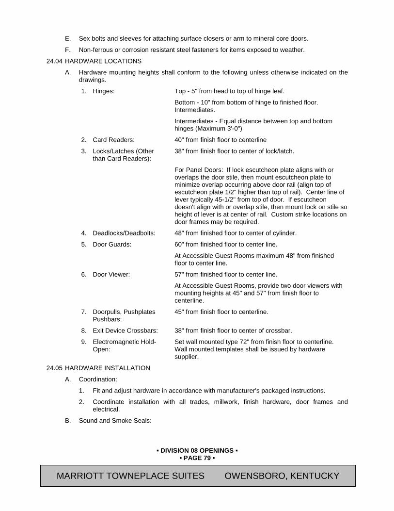
▪ DIVISION 08 OPENINGS ▪
▪ PAGE 79 ▪
RESIDENCE INN BY MARRIOTT - LITTLETON, COLORADO
E. Sex bolts and sleeves for attaching surface closers or arm to mineral core doors.
F. Non-ferrous or corrosion resistant steel fasteners for items exposed to weather.
24.04 HARDWARE LOCATIONS
A. Hardware mounting heights shall conform to the following unless otherwise indicated on the drawings.
1. Hinges: Top - 5" from head to top of hinge leaf.
Bottom - 10" from bottom of hinge to finished floor. Intermediates.
Intermediates - Equal distance between top and bottom hinges (Maximum 3'-0")
2. Card Readers: 40" from finish floor to centerline
3. Locks/Latches (Other than Card Readers):
38" from finish floor to center of lock/latch.
For Panel Doors: If lock escutcheon plate aligns with or overlaps the door stile, then mount escutcheon plate to minimize overlap occurring above door rail (align top of escutcheon plate 1/2" higher than top of rail). Center line of lever typically 45-1/2" from top of door. If escutcheon doesn't align with or overlap stile, then mount lock on stile so height of lever is at center of rail. Custom strike locations on door frames may be required.
4. Deadlocks/Deadbolts: 48" from finished floor to center of cylinder.
5. Door Guards: 60" from finished floor to center line.
At Accessible Guest Rooms maximum 48" from finished floor to center line.
6. Door Viewer: 57" from finished floor to center line.
At Accessible Guest Rooms, provide two door viewers with mounting heights at 45" and 57" from finish floor to centerline.
7. Doorpulls, Pushplates Pushbars:
45" from finish floor to centerline.
8. Exit Device Crossbars: 38" from finish floor to center of crossbar.
9. Electromagnetic Hold-Open:
Set wall mounted type 72" from finish floor to centerline. Wall mounted templates shall be issued by hardware supplier.
24.05 HARDWARE INSTALLATION
A. Coordination:
1. Fit and adjust hardware in accordance with manufacturer's packaged instructions.
2. Coordinate installation with all trades, millwork, finish hardware, door frames and electrical.
B. Sound and Smoke Seals:
MARRIOTT TOWNEPLACE SUITES OWENSBORO, KENTUCKY

▪ DIVISION 08 OPENINGS ▪
▪ PAGE 80 ▪
RESIDENCE INN BY MARRIOTT - LITTLETON, COLORADO
1. Install adhesive seals per manufacturer's instructions. Pre-cut pieces to fit before installing. Do not install as one continuous piece. Install jamb pieces first and header piece last. Position jamb pieces on the door frame rabbet 1/16" from the header rabbet to allow for header piece clearance. Install header piece on the header rabbet with ends overlapping and fitting above jamb piece.
2. Install adhesive seals on astragal of double doors.
C. Door Viewers: 190 degree viewers at Guest Room doors. 190 degree extra wide angle view at ballroom and meeting room doors.
D. Door Guards: Guest Room entry door guards shall have strike plate furnished standard with door guard.
24.06 ADJUSTING
A. Adjustments:
1. Weatherstripping and sound/smoke seals shall not interfere with operation of doors and shall be adjusted accordingly.
2. Secure door bottom in strict accordance with manufacturer's printed instructions and as required to seal door to threshold.
3. Door seals to provide intended functions. Replace seals which do not perform.
4. Adjust door so that lockset can be easily opened with a key/card key without binding between the latchbolt and strike. Doors too tight (or too loose) will not be accepted.
5. Clearances between door and frame, at jambs and head: No greater than 1/8" +/- 1/16".
6. Prior to Owner's "soft opening" replace Guest Room battery power supply units with new alkaline batteries.
24.07 PROTECTION
A. Reinstall wrappings furnished by manufacturer for protecting items such as levers, handles and pulls.
B. Do not remove manufacturer's protective covering of flat items such as kickplates and push plates until just prior to final acceptance of the building.
24.08 CLEANING
A. After installation, clean metal surfaces on both interior and exterior of all mortar, plaster, paint and other contaminants. After cleaning, protect work against damage.
24.09 FINAL ADJUSTMENT
A. Whenever hardware is installed more than one month prior to acceptance or occupancy of a space or area, return during the week prior to acceptance or occupancy and make a final check and adjustment of all hardware items in such space or area.
B. At the completion of the project, manufacturers' suppliers or representatives shall inspect their hardware and make any corrections required due to errors or improper installation.
MARRIOTT TOWNEPLACE SUITES OWENSBORO, KENTUCKY

▪ DIVISION 08 OPENINGS ▪
▪ PAGE 81 ▪
RESIDENCE INN BY MARRIOTT - LITTLETON, COLORADO
PART 25 HARDWARE SCHEDULE Note: The following hardware sets are for the Generation 4 “TurningPointS 2.0 or 3.5 “TurningPointS”
Décor Scheme
25.01 HW SET - T01 GUEST ENTRY SINGLE DOORS 01 EACH DOOR TO HAVE:
3 EA HINGES TA2714 4.5 X 4.5 US15 MCK 1 EA LOCK QUANTUM RFID X BLE X ADB X GALA US15 SAF 1 EA CLOSER 2701 689 YAL 1 EA KICKPLATE K0050 8” X 2” LDW US32D TRM 1 EA DOOR GUARD 607 PDL B15 RO 1 EA DOOR VIEWER 628 (WITH HINGED COVER) US26D RO 1 EA WALL STOP 1270WV 619 TRM
Note: Use floor stop below, in lieu of wall stop, when mirror is mounted to wall behind door. Locate adequately to avoid door hitting the mirror. 1 EA FLOOR STOP WXEDSSN (REFER TO TOILET ACCESSORY MARK NO. 460) US15 WIT 1 SET DOOR SEALS S773D PEM 1 EA AUTO DOOR 411APKL (ROUTED INTO BOTTOM BOTTOM OF DOOR) PEM 1 EA MAG SWITCH REFER TO SECTION 25 51 10 NOTE: AT LOCKOUT DOORS ONLY: PROVIDE FUNCTION THAT ALLOWS DOOR TO BE
UNLOCKED AT ALL TIMES BY CODING RFID CARD. USING INSIDE DEADBOLT OVERIDES AND LOCKS DOOR 25.02 HW SET – T01A ACCESSIBLE GUEST ENTRY
SINGLE DOORS 01A (36” DOORS) EACH DOOR TO HAVE:
3 EA HINGES TA2714 4.5 X 4.5 US15 MCK 1 EA LOCK QUANTUM RFID X BLE X ADB X GALA US15 SAF 1 EA CLOSER 2701 689 YAL 1 EA KICKPLATE K0050 8” X 2” LDW US32D TRM 1 EA DOOR GUARD 607 PDL B15 RO 2 EA DOOR VIEWER 628 (WITH HINGED COVER) US26D RO 1 EA WALL STOP 1270WV 619 TRM
Note: Use floor stop below, in lieu of wall stop, when mirror is mounted to wall behind door. Locate adequately to avoid door hitting the mirror. 1 EA FLOOR STOP WXEDSSN (REFER TO TOILET ACCESSORY MARK NO. 460) US15 WIT 1 SET DOOR SEALS S773D PEM 1 EA AUTO DOOR 411APKL (ROUTED INTO BOTTOM BOTTOM OF DOOR) PEM 1 EA MAG SWITCH REFER TO SECTION 25 51 10
MARRIOTT TOWNEPLACE SUITES OWENSBORO, KENTUCKY
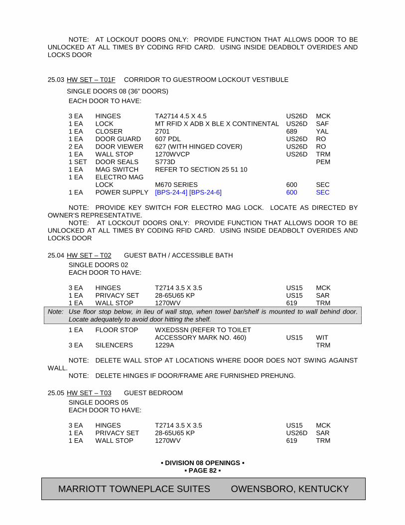
▪ DIVISION 08 OPENINGS ▪
▪ PAGE 82 ▪
RESIDENCE INN BY MARRIOTT - LITTLETON, COLORADO
NOTE: AT LOCKOUT DOORS ONLY: PROVIDE FUNCTION THAT ALLOWS DOOR TO BE UNLOCKED AT ALL TIMES BY CODING RFID CARD. USING INSIDE DEADBOLT OVERIDES AND LOCKS DOOR
25.03 HW SET – T01F CORRIDOR TO GUESTROOM LOCKOUT VESTIBULE
SINGLE DOORS 08 (36” DOORS) EACH DOOR TO HAVE:
3 EA HINGES TA2714 4.5 X 4.5 US26D MCK 1 EA LOCK MT RFID X ADB X BLE X CONTINENTAL US26D SAF 1 EA CLOSER 2701 689 YAL 1 EA DOOR GUARD 607 PDL US26D RO 2 EA DOOR VIEWER 627 (WITH HINGED COVER) US26D RO 1 EA WALL STOP 1270WVCP US26D TRM 1 SET DOOR SEALS S773D PEM 1 EA MAG SWITCH REFER TO SECTION 25 51 10 1 EA ELECTRO MAG LOCK M670 SERIES 600 SEC 1 EA POWER SUPPLY [BPS-24-4] [BPS-24-6] 600 SEC NOTE: PROVIDE KEY SWITCH FOR ELECTRO MAG LOCK. LOCATE AS DIRECTED BY
OWNER’S REPRESENTATIVE. NOTE: AT LOCKOUT DOORS ONLY: PROVIDE FUNCTION THAT ALLOWS DOOR TO BE
UNLOCKED AT ALL TIMES BY CODING RFID CARD. USING INSIDE DEADBOLT OVERIDES AND LOCKS DOOR 25.04 HW SET – T02 GUEST BATH / ACCESSIBLE BATH
SINGLE DOORS 02 EACH DOOR TO HAVE:
3 EA HINGES T2714 3.5 X 3.5 US15 MCK 1 EA PRIVACY SET 28-65U65 KP US15 SAR 1 EA WALL STOP 1270WV 619 TRM
Note: Use floor stop below, in lieu of wall stop, when towel bar/shelf is mounted to wall behind door. Locate adequately to avoid door hitting the shelf. 1 EA FLOOR STOP WXEDSSN (REFER TO TOILET ACCESSORY MARK NO. 460) US15 WIT 3 EA SILENCERS 1229A TRM NOTE: DELETE WALL STOP AT LOCATIONS WHERE DOOR DOES NOT SWING AGAINST
WALL. NOTE: DELETE HINGES IF DOOR/FRAME ARE FURNISHED PREHUNG.
25.05 HW SET – T03 GUEST BEDROOM SINGLE DOORS 05 EACH DOOR TO HAVE:
3 EA HINGES T2714 3.5 X 3.5 US15 MCK 1 EA PRIVACY SET 28-65U65 KP US26D SAR 1 EA WALL STOP 1270WV 619 TRM
MARRIOTT TOWNEPLACE SUITES OWENSBORO, KENTUCKY
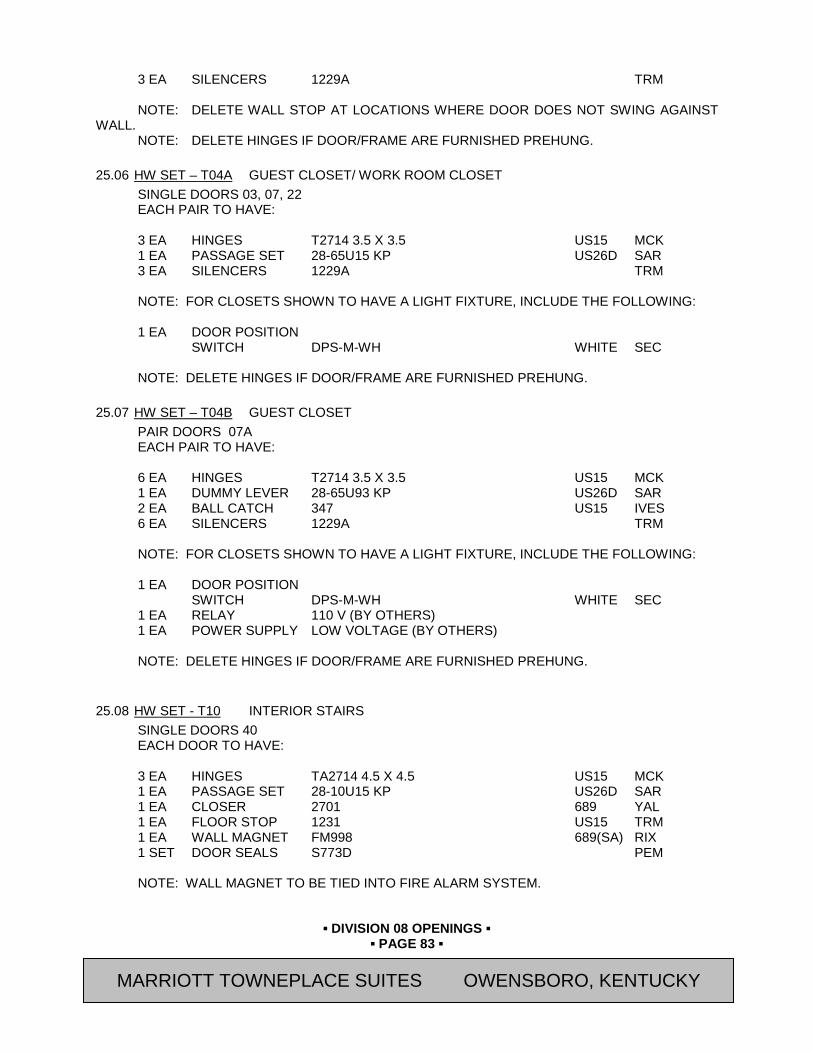
▪ DIVISION 08 OPENINGS ▪
▪ PAGE 83 ▪
RESIDENCE INN BY MARRIOTT - LITTLETON, COLORADO
3 EA SILENCERS 1229A TRM NOTE: DELETE WALL STOP AT LOCATIONS WHERE DOOR DOES NOT SWING AGAINST
WALL. NOTE: DELETE HINGES IF DOOR/FRAME ARE FURNISHED PREHUNG.
25.06 HW SET – T04A GUEST CLOSET/ WORK ROOM CLOSET
SINGLE DOORS 03, 07, 22 EACH PAIR TO HAVE:
3 EA HINGES T2714 3.5 X 3.5 US15 MCK 1 EA PASSAGE SET 28-65U15 KP US26D SAR 3 EA SILENCERS 1229A TRM NOTE: FOR CLOSETS SHOWN TO HAVE A LIGHT FIXTURE, INCLUDE THE FOLLOWING: 1 EA DOOR POSITION SWITCH DPS-M-WH WHITE SEC NOTE: DELETE HINGES IF DOOR/FRAME ARE FURNISHED PREHUNG.
25.07 HW SET – T04B GUEST CLOSET
PAIR DOORS 07A EACH PAIR TO HAVE:
6 EA HINGES T2714 3.5 X 3.5 US15 MCK 1 EA DUMMY LEVER 28-65U93 KP US26D SAR 2 EA BALL CATCH 347 US15 IVES 6 EA SILENCERS 1229A TRM NOTE: FOR CLOSETS SHOWN TO HAVE A LIGHT FIXTURE, INCLUDE THE FOLLOWING: 1 EA DOOR POSITION SWITCH DPS-M-WH WHITE SEC 1 EA RELAY 110 V (BY OTHERS) 1 EA POWER SUPPLY LOW VOLTAGE (BY OTHERS) NOTE: DELETE HINGES IF DOOR/FRAME ARE FURNISHED PREHUNG.
25.08 HW SET - T10 INTERIOR STAIRS
SINGLE DOORS 40 EACH DOOR TO HAVE: 3 EA HINGES TA2714 4.5 X 4.5 US15 MCK 1 EA PASSAGE SET 28-10U15 KP US26D SAR 1 EA CLOSER 2701 689 YAL 1 EA FLOOR STOP 1231 US15 TRM 1 EA WALL MAGNET FM998 689(SA) RIX 1 SET DOOR SEALS S773D PEM NOTE: WALL MAGNET TO BE TIED INTO FIRE ALARM SYSTEM.
MARRIOTT TOWNEPLACE SUITES OWENSBORO, KENTUCKY
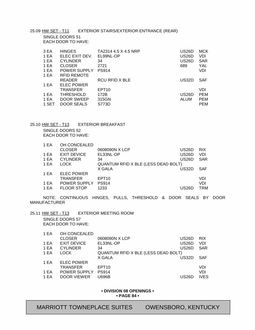
▪ DIVISION 08 OPENINGS ▪
▪ PAGE 84 ▪
RESIDENCE INN BY MARRIOTT - LITTLETON, COLORADO
25.09 HW SET - T11 EXTERIOR STAIRS/EXTERIOR ENTRANCE (REAR)
SINGLE DOORS 51 EACH DOOR TO HAVE: 3 EA HINGES TA2314 4.5 X 4.5 NRP US26D MCK 1 EA ELEC EXIT DEV. EL99NL-OP US26D VDI 1 EA CYLINDER 34 US26D SAR 1 EA CLOSER 2721 689 YAL 1 EA POWER SUPPLY PS914 VDI 1 EA RFID REMOTE READER RCU RFID X BLE US32D SAF 1 EA ELEC POWER TRANSFER EPT10 VDI 1 EA THRESHOLD 172B US26D PEM 1 EA DOOR SWEEP 315GN ALUM PEM 1 SET DOOR SEALS S773D PEM
25.10 HW SET - T13 EXTERIOR BREAKFAST SINGLE DOORS 52 EACH DOOR TO HAVE: 1 EA OH CONCEALED CLOSER 0608090N X LCP US26D RIX 1 EA EXIT DEVICE EL33NL-OP US26D VDI 1 EA CYLINDER 34 US26D SAR 1 EA LOCK QUANTUM RFID X BLE (LESS DEAD BOLT) X GALA US32D SAF 1 EA ELEC POWER TRANSFER EPT10 VDI 1 EA POWER SUPPLY PS914 VDI 1 EA FLOOR STOP 1233 US26D TRM NOTE: CONTINUOUS HINGES, PULLS, THRESHOLD & DOOR SEALS BY DOOR
MANUFACTURER
25.11 HW SET - T13 EXTERIOR MEETING ROOM SINGLE DOORS 57 EACH DOOR TO HAVE: 1 EA OH CONCEALED CLOSER 0608090N X LCP US26D RIX 1 EA EXIT DEVICE EL33NL-OP US26D VDI 1 EA CYLINDER 34 US26D SAR 1 EA LOCK QUANTUM RFID X BLE (LESS DEAD BOLT) X GALA US32D SAF 1 EA ELEC POWER TRANSFER EPT10 VDI 1 EA POWER SUPPLY PS914 VDI 1 EA DOOR VIEWER U696B US26D IVES
MARRIOTT TOWNEPLACE SUITES OWENSBORO, KENTUCKY

▪ DIVISION 08 OPENINGS ▪
▪ PAGE 85 ▪
RESIDENCE INN BY MARRIOTT - LITTLETON, COLORADO
1 EA FLOOR STOP 1233 US26D TRM 1 EA THRESHOLD 172G ALUM PEM 1 EA DOOR SWEEP 315GN ALUM PEM 1 SET DOOR SEALS S773D PEM
25.12 HW SET - T15 EXTERIOR VESTIBULE ENTRY (AUTOMATIC SLIDING DOORS) SINGLE SLIDE DOOR 50 EACH PAIR TO HAVE:
NOTE: AUTOMATIC DOOR HARDWARE & ACCESSORIES BY DOOR MANUFACTURER
25.13 HW SET - T15A INTERIOR VESTIBULE ENTRY (AUTOMATIC SLIDING DOORS) SINGLE SLIDE DOOR 10 EACH PAIR TO HAVE: 1 EA PUSH BUTTON RELEASE MUSHROOM BUTTON 32310 SAF 1 EA KEYSWITCH 653-04 US32D SCE 1 EA CYLINDER 41 (@ KEYSWITCH) US32D SAR 1 EA REMOTE CONTROL UNIT FLUSH MTD. 94770 RFID X BLE SAF 1 EA POWER SUPPLY 32280 SAF 1 EA AIPHONE INTERCOM SYSTEM LEM-1 DLS AIP NOTE: AUTOMATIC DOOR HARDWARE & ACCESSORIES BY DOOR MANUFACTURER PEM
25.14 HW SET - T16 ELECTRICAL / SERVER CLOSET / MEETING ROOM STORAGE / IN-A-PINCH STORAGE / LAUNDRY STORAGE/ WORKROOM CLOSET SINGLE DOORS 17, 18, 20, 21, 24, 27 EACH DOOR TO HAVE:
3 EA HINGES TA2714 4.5 X 4.5 US15 MCK 1 EA LOCK QUANTUM RFID X BLE (LESS DEAD BOLT) X GALA US15 SAF 1 EA CLOSER 2721 689 YAL 1 EA WALL STOP 1270WVCP US15 TRM 1 SET DOOR SEALS S773D PEM
25.15 HW SET - T17 LINEN STORAGE / LINEN CHUTE / STORAGE
SINGLE DOORS 30, 31 EACH DOOR TO HAVE: 3 EA HINGES TA2714 4.5 X 4.5 US15 MCK 1 EA LOCK QUANTUM RFID X BLE (LESS DEAD BOLT) X GALA US15 SAF 1 EA CLOSER 2701 689 YAL 1 EA WALL STOP 1270WVCP US15 TRM
MARRIOTT TOWNEPLACE SUITES OWENSBORO, KENTUCKY
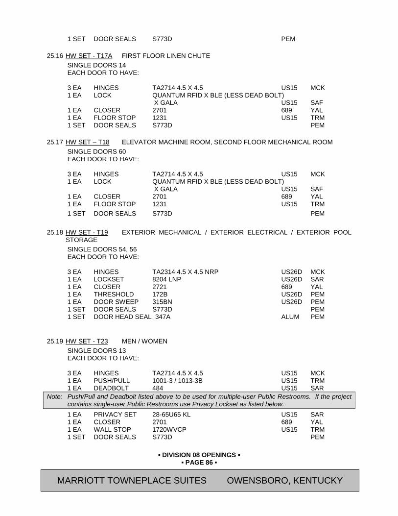
▪ DIVISION 08 OPENINGS ▪
▪ PAGE 86 ▪
RESIDENCE INN BY MARRIOTT - LITTLETON, COLORADO
1 SET DOOR SEALS S773D PEM 25.16 HW SET - T17A FIRST FLOOR LINEN CHUTE
SINGLE DOORS 14 EACH DOOR TO HAVE: 3 EA HINGES TA2714 4.5 X 4.5 US15 MCK 1 EA LOCK QUANTUM RFID X BLE (LESS DEAD BOLT) X GALA US15 SAF 1 EA CLOSER 2701 689 YAL 1 EA FLOOR STOP 1231 US15 TRM 1 SET DOOR SEALS S773D PEM
25.17 HW SET – T18 ELEVATOR MACHINE ROOM, SECOND FLOOR MECHANICAL ROOM
SINGLE DOORS 60 EACH DOOR TO HAVE: 3 EA HINGES TA2714 4.5 X 4.5 US15 MCK 1 EA LOCK QUANTUM RFID X BLE (LESS DEAD BOLT) X GALA US15 SAF 1 EA CLOSER 2701 689 YAL 1 EA FLOOR STOP 1231 US15 TRM 1 SET DOOR SEALS S773D PEM
25.18 HW SET - T19 EXTERIOR MECHANICAL / EXTERIOR ELECTRICAL / EXTERIOR POOL
STORAGE SINGLE DOORS 54, 56 EACH DOOR TO HAVE: 3 EA HINGES TA2314 4.5 X 4.5 NRP US26D MCK 1 EA LOCKSET 8204 LNP US26D SAR 1 EA CLOSER 2721 689 YAL 1 EA THRESHOLD 172B US26D PEM 1 EA DOOR SWEEP 315BN US26D PEM 1 SET DOOR SEALS S773D PEM 1 SET DOOR HEAD SEAL 347A ALUM PEM
25.19 HW SET - T23 MEN / WOMEN SINGLE DOORS 13 EACH DOOR TO HAVE: 3 EA HINGES TA2714 4.5 X 4.5 US15 MCK 1 EA PUSH/PULL 1001-3 / 1013-3B US15 TRM 1 EA DEADBOLT 484 US15 SAR
Note: Push/Pull and Deadbolt listed above to be used for multiple-user Public Restrooms. If the project contains single-user Public Restrooms use Privacy Lockset as listed below. 1 EA PRIVACY SET 28-65U65 KL US15 SAR 1 EA CLOSER 2701 689 YAL 1 EA WALL STOP 1720WVCP US15 TRM 1 SET DOOR SEALS S773D PEM
MARRIOTT TOWNEPLACE SUITES OWENSBORO, KENTUCKY
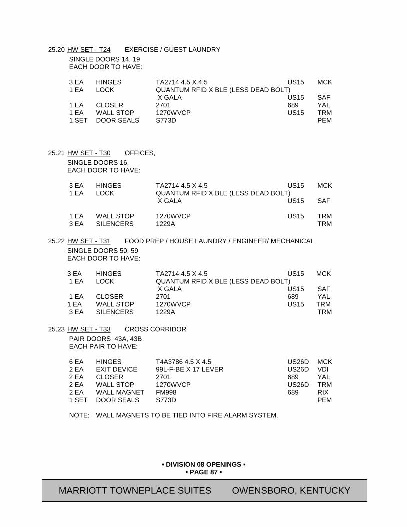
▪ DIVISION 08 OPENINGS ▪
▪ PAGE 87 ▪
RESIDENCE INN BY MARRIOTT - LITTLETON, COLORADO
25.20 HW SET - T24 EXERCISE / GUEST LAUNDRY
SINGLE DOORS 14, 19 EACH DOOR TO HAVE: 3 EA HINGES TA2714 4.5 X 4.5 US15 MCK 1 EA LOCK QUANTUM RFID X BLE (LESS DEAD BOLT) X GALA US15 SAF 1 EA CLOSER 2701 689 YAL 1 EA WALL STOP 1270WVCP US15 TRM 1 SET DOOR SEALS S773D PEM
25.21 HW SET - T30 OFFICES, SINGLE DOORS 16, EACH DOOR TO HAVE:
3 EA HINGES TA2714 4.5 X 4.5 US15 MCK 1 EA LOCK QUANTUM RFID X BLE (LESS DEAD BOLT) X GALA US15 SAF 1 EA WALL STOP 1270WVCP US15 TRM 3 EA SILENCERS 1229A TRM
25.22 HW SET - T31 FOOD PREP / HOUSE LAUNDRY / ENGINEER/ MECHANICAL SINGLE DOORS 50, 59 EACH DOOR TO HAVE: 3 EA HINGES TA2714 4.5 X 4.5 US15 MCK 1 EA LOCK QUANTUM RFID X BLE (LESS DEAD BOLT) X GALA US15 SAF 1 EA CLOSER 2701 689 YAL 1 EA WALL STOP 1270WVCP US15 TRM 3 EA SILENCERS 1229A TRM
25.23 HW SET - T33 CROSS CORRIDOR PAIR DOORS 43A, 43B EACH PAIR TO HAVE:
6 EA HINGES T4A3786 4.5 X 4.5 US26D MCK 2 EA EXIT DEVICE 99L-F-BE X 17 LEVER US26D VDI 2 EA CLOSER 2701 689 YAL 2 EA WALL STOP 1270WVCP US26D TRM 2 EA WALL MAGNET FM998 689 RIX 1 SET DOOR SEALS S773D PEM NOTE: WALL MAGNETS TO BE TIED INTO FIRE ALARM SYSTEM.
MARRIOTT TOWNEPLACE SUITES OWENSBORO, KENTUCKY
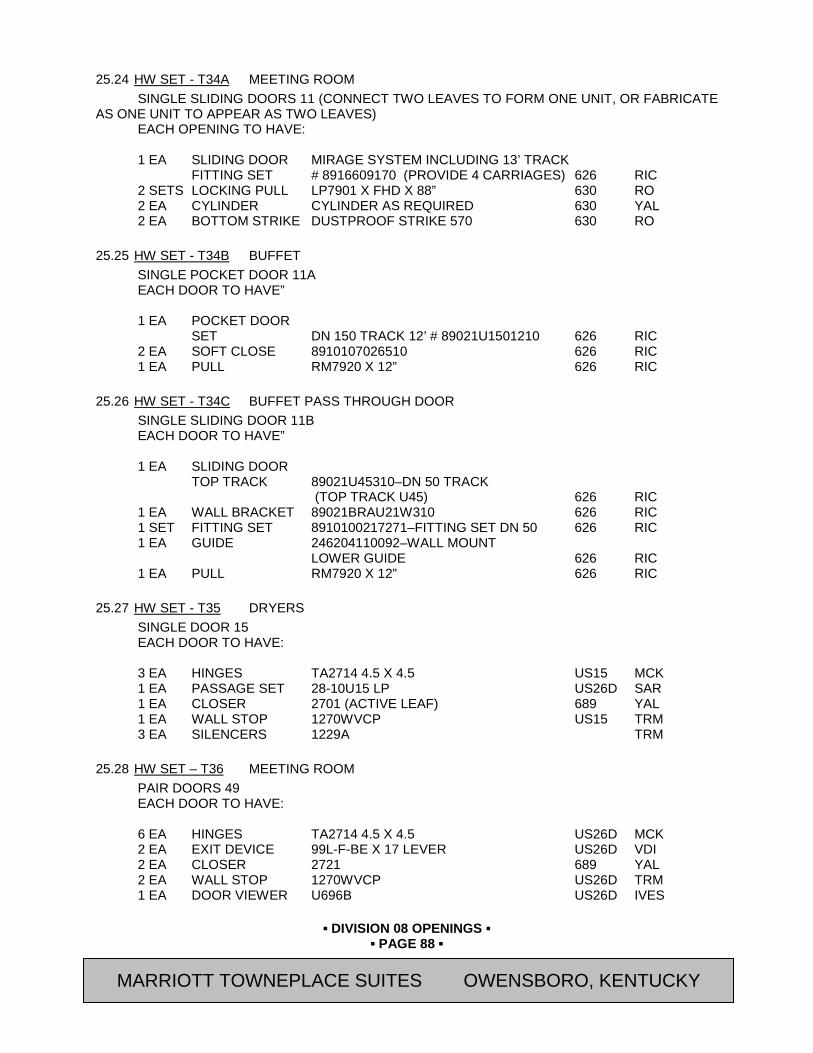
▪ DIVISION 08 OPENINGS ▪
▪ PAGE 88 ▪
RESIDENCE INN BY MARRIOTT - LITTLETON, COLORADO
25.24 HW SET - T34A MEETING ROOM SINGLE SLIDING DOORS 11 (CONNECT TWO LEAVES TO FORM ONE UNIT, OR FABRICATE
AS ONE UNIT TO APPEAR AS TWO LEAVES) EACH OPENING TO HAVE: 1 EA SLIDING DOOR MIRAGE SYSTEM INCLUDING 13’ TRACK FITTING SET # 8916609170 (PROVIDE 4 CARRIAGES) 626 RIC 2 SETS LOCKING PULL LP7901 X FHD X 88” 630 RO 2 EA CYLINDER CYLINDER AS REQUIRED 630 YAL 2 EA BOTTOM STRIKE DUSTPROOF STRIKE 570 630 RO
25.25 HW SET - T34B BUFFET SINGLE POCKET DOOR 11A EACH DOOR TO HAVE” 1 EA POCKET DOOR SET DN 150 TRACK 12’ # 89021U1501210 626 RIC 2 EA SOFT CLOSE 8910107026510 626 RIC 1 EA PULL RM7920 X 12” 626 RIC
25.26 HW SET - T34C BUFFET PASS THROUGH DOOR SINGLE SLIDING DOOR 11B EACH DOOR TO HAVE” 1 EA SLIDING DOOR TOP TRACK 89021U45310–DN 50 TRACK (TOP TRACK U45) 626 RIC 1 EA WALL BRACKET 89021BRAU21W310 626 RIC 1 SET FITTING SET 8910100217271–FITTING SET DN 50 626 RIC 1 EA GUIDE 246204110092–WALL MOUNT LOWER GUIDE 626 RIC 1 EA PULL RM7920 X 12” 626 RIC
25.27 HW SET - T35 DRYERS SINGLE DOOR 15 EACH DOOR TO HAVE:
3 EA HINGES TA2714 4.5 X 4.5 US15 MCK 1 EA PASSAGE SET 28-10U15 LP US26D SAR 1 EA CLOSER 2701 (ACTIVE LEAF) 689 YAL 1 EA WALL STOP 1270WVCP US15 TRM 3 EA SILENCERS 1229A TRM
25.28 HW SET – T36 MEETING ROOM PAIR DOORS 49 EACH DOOR TO HAVE:
6 EA HINGES TA2714 4.5 X 4.5 US26D MCK 2 EA EXIT DEVICE 99L-F-BE X 17 LEVER US26D VDI 2 EA CLOSER 2721 689 YAL 2 EA WALL STOP 1270WVCP US26D TRM 1 EA DOOR VIEWER U696B US26D IVES
MARRIOTT TOWNEPLACE SUITES OWENSBORO, KENTUCKY

▪ DIVISION 08 OPENINGS ▪
▪ PAGE 89 ▪
RESIDENCE INN BY MARRIOTT - LITTLETON, COLORADO
1 EA WALL MAGNET FM998 US32D RIX 1 SET DOOR SEALS S773D PEM NOTE: WALL MAGNET TO BE TIED INTO FIRE ALARM SYSTEM. NOTE: DOOR VIEWER TO VIEW IN TO ROOM FROM CORRIDOR
25.29 HW SET - T36A MEETING ROOM CLOSET
PAIR DOORS 53 EACH DOOR TO HAVE:
6 EA HINGES T2714 4.5 X 4.5 US26D MCK 1 EA DUMMY LEVER 28-65U93 KP US26D SAR 2 EA BALL CATCH 347 US15 IVES 2 EA WALL STOP 1270WVCP US26D TRM 6 EA SILENCERS 1229A PEM
25.30 HW SET - T41 EXTERIOR GATES
SINGLE GATE [ ] EACH GATE TO HAVE: 1 EA EXIT DEVICE QUANTUM RFID X BLE SERIES (LESS DEAD BOLT) X GALA X F18-R US26D SAF/MN NOTE: LATCH TO BE CHILDPROOF. NOTE: QUANTUM RFID IS BATTERY OPERATED CARD LOCK. F-18-R MECHANICAL RIM
DEVICE CAN BE CUT DOWN TO SIZE IN FIELD. DIMENSIONS OF INSIDE LATCH ARE 2-1/2”W X 8-1/2” H.
NOTE: HINGES AND CLOSER PROVIDED BY GATE MANUFACTURER.
END OF SECTION Revision Log
MARRIOTT TOWNEPLACE SUITES OWENSBORO, KENTUCKY

▪ DIVISION 08 OPENINGS ▪
▪ PAGE 90 ▪
RESIDENCE INN BY MARRIOTT - LITTLETON, COLORADO
SECTION 08 80 00 (08800) - GLAZING
PART 26 GENERAL 26.01 SUMMARY
A. Section Includes:
1. Section includes glass and glazing for:
a. Float Glass
b. Tempered Glass
c. Insulated Units
d. Fire Protective Rated Safety Glass
B. Related Sections:
1. Section 07 92 00 (07920) – Joint Sealants
2. Section 08 11 13 (08110) - Steel Doors and Frames
3. Section 08 14 00 (08200) - Wood Doors
4. Section 08 41 13 (08410) - Aluminum-Framed Entrances and Storefronts
5. Section 08 42 29 (08460) – Automatic Entrance Doors
6. Section 08 51 13 (08520) - Aluminum Windows
7. Section 08 53 00 (08560) – Plastic Windows
26.02 REFERENCES
A. American Architectural Manufacturers Association (AAMA) Publications:
1. 800-92 “Voluntary Specifications and Test Methods for Sealants”
B. American National Standards Institute (ANSI) Publications:
1. ANSI/AAMA 101 "Voluntary Specifications for Aluminum, Vinyl (PVC) and Wood Windows and Glass Doors"
C. ASTM International (ASTM) Publications:
1. C920 “Standard Specification for Elastomeric Joint Sealants”
2. C1036 “Standard Specification for Flat Glass”
3. C1048 “Standard Specification for Heat-Treated Flat Glass—Kind HS, Kind FT Coated and Uncoated Glass”
4. C1172 “Standard Specification for Laminated Architectural Flat Glass” 5. C1376 “Standard Specification for Pyrolytic and Vacuum Deposition Coatings on Glass”
6. E1300 “Standard Practice for Determining Load Resistance of Glass in Buildings” 7. E2190 “Standard Specification for Insulating Glass Unit Performance and Evaluation”
D. Consumer Product Safety Commission (CPSC) Publications:
1. 16 CFR 1201 - “Safety Standard for Architectural Glazing Materials “
MARRIOTT TOWNEPLACE SUITES OWENSBORO, KENTUCKY

▪ DIVISION 08 OPENINGS ▪
▪ PAGE 91 ▪
RESIDENCE INN BY MARRIOTT - LITTLETON, COLORADO
E. Glass Association of North America (GANA)
1. "GANA Glazing Manual"
2. "FGMA Sealant Manual"
F. Insulating Glass Manufacturers Alliance (IGMA) Publications:
1. SIGMA TM-3000, "Glazing Guidelines for Sealed Insulating Glass Units"
G. National Fenestration Rating Council (NFRC)
H. National Glass Association (NGA)
1. Glazier Certification Program
I. Underwriter's Laboratories, Inc. (UL) Standards:
1. 10C "Positive Pressure Fire Tests of Door Assemblies"
26.03 SUBMITTALS
A. General: Submit the following in accordance with Conditions of Contract and Division 01 Specification Sections.
B. Submit “Letter of Conformance” in accordance with Section 01 33 00 (01330) indicating specified items selected for use in project with the following supporting data.
1. Product Data: Submit manufacturer's technical data for each glazing material and fabricated glass product required, including installation and maintenance instructions.
2. Compatibility and Adhesion Test Report: Submit statement from sealant manufacturer indicating that glass and glazing materials have been tested for compatibility and adhesion with glazing sealants and interpreting test results relative to material performance, including recommendations for primers and substrate preparation needed to obtain adhesion.
C. Samples: Submit, for verification purposes, 12" square samples of each type of glass indicated except for clear single pane units, and 12" long samples of each color required (except black) for each type of sealant or gasket exposed to view. Install sealant or gasket sample between two strips of material representative of adjoining framing system in color. Sample requirement may be waived by Owner’s Representative at their discretion.
26.04 QUALITY ASSURANCE
A. Glazing Standards: Comply with recommendations of the Glass Association of North America (GANA) "Glazing Manual" and "Sealant Manual" except where more stringent requirements are indicated. Refer to those publications for definitions of glass and glazing terms not otherwise defined in this section or other referenced standards.
B. Installer Qualifications: An experienced installer who has completed glazing similar in material, design, and extent to that indicated for this Project; whose work has resulted in glass installations with a record of successful in-service performance; and who employs glass installers for this Project who are certified under the National Glass Association Glazier Certification Program as Level 2 (Senior Glaziers) or Level 3 (Master Glaziers).
C. Safety Glazing Products: Comply with testing requirements in 16 CFR 1201.
1. Subject to compliance with requirements, obtain safety glazing products permanently marked with certification label of the Safety Glazing Certification Council (SGCC) or another certification agency acceptable to authorities having jurisdiction.
MARRIOTT TOWNEPLACE SUITES OWENSBORO, KENTUCKY

▪ DIVISION 08 OPENINGS ▪
▪ PAGE 92 ▪
RESIDENCE INN BY MARRIOTT - LITTLETON, COLORADO
D. Glazing Publications: Comply with published recommendations of glass product manufacturers and organizations below, unless more stringent requirements are indicated. Refer to these publications for glazing terms not otherwise defined in this Section or in referenced standards.
1. IGMA Publication for Insulating Glass: SIGMA TM-3000, "Glazing Guidelines for Sealed Insulating Glass Units."
E. Single Source Responsibility for Glass: To ensure consistent quality of appearance and performance, provide materials produced by a single manufacturer or fabricator for each kind and condition of glass indicated and composed of primary glass obtained from a single source for each type and class required.
26.05 DELIVERY, STORAGE, AND HANDLING
A. Protect glass and glazing materials during delivery, storage and handling to comply with manufacturer's directions and as required to prevent edge damage to glass, and damage to glass and glazing materials from effects of moisture including condensation, of temperature changes, of direct exposure to sun, and from other causes.
26.06 PROJECT CONDITIONS
A. Environmental Conditions: Do not proceed with glazing when ambient and substrate temperature conditions are outside the limits permitted by glazing material manufacturer or when joint substrates are wet due to rain, frost, condensation or other causes.
26.07 WARRANTY
A. General: Warranties shall be in addition to, and not a limitation of, other rights the Owner may have under the Contract Documents.
B. All material shall be free from manufacturer defects and installation workmanship. Any material or workmanship judged to be defective shall be replaced at no cost to the Owner.
C. Insulating glass units shall be jointly guaranteed for a period of ten (10) years by the manufacturer and installer against obstruction of vision between interior glass surfaces caused by failure of the hermetic seal. Units damaged during guarantee period shall be replaced at no cost to the Owner.
PART 27 PRODUCTS 27.01 ACCEPTABLE GLASS MANUFACTURERS
A. All glass shall be new material, graded under ASTM 1036.
B. All glass in related area shall be from one manufacturer.
27.02 GLASS MATERIALS
A. Refer to Drawings for location of glass.
B. Glass [I]: Clear Float Glass: ASTM C1036, Type 1 (transparent glass, flat), Class 1 (clear), Quality q3 (glazing select), as manufactured by one of the following:
1. Avendra, LLC Preferred Manufacturers:
a. None
2. Approved Manufacturers:
a. PPG Industries (800-377-5267)
b. Pilkington North America (800-221-0444)
c. Old Castle Glass, a CRH Company (800-899-8455)
MARRIOTT TOWNEPLACE SUITES OWENSBORO, KENTUCKY
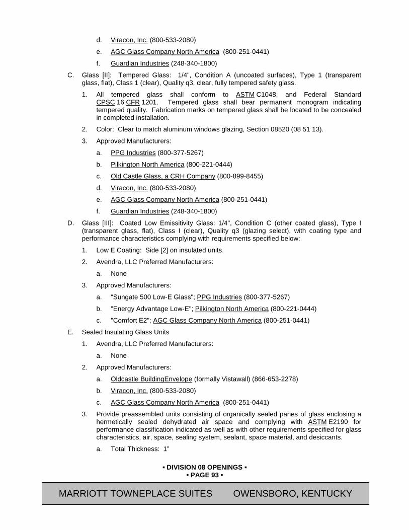
▪ DIVISION 08 OPENINGS ▪
▪ PAGE 93 ▪
RESIDENCE INN BY MARRIOTT - LITTLETON, COLORADO
d. Viracon, Inc. (800-533-2080)
e. AGC Glass Company North America (800-251-0441)
f. Guardian Industries (248-340-1800)
C. Glass [II]: Tempered Glass: 1/4", Condition A (uncoated surfaces), Type 1 (transparent glass, flat), Class 1 (clear), Quality q3, clear, fully tempered safety glass.
1. All tempered glass shall conform to ASTM C1048, and Federal Standard CPSC 16 CFR 1201. Tempered glass shall bear permanent monogram indicating tempered quality. Fabrication marks on tempered glass shall be located to be concealed in completed installation.
2. Color: Clear to match aluminum windows glazing, Section 08520 (08 51 13).
3. Approved Manufacturers:
a. PPG Industries (800-377-5267)
b. Pilkington North America (800-221-0444)
c. Old Castle Glass, a CRH Company (800-899-8455)
d. Viracon, Inc. (800-533-2080)
e. AGC Glass Company North America (800-251-0441)
f. Guardian Industries (248-340-1800)
D. Glass [III]: Coated Low Emissitivity Glass: 1/4", Condition C (other coated glass), Type I (transparent glass, flat), Class I (clear), Quality q3 (glazing select), with coating type and performance characteristics complying with requirements specified below:
1. Low E Coating: Side [2] on insulated units.
2. Avendra, LLC Preferred Manufacturers:
a. None
3. Approved Manufacturers:
a. "Sungate 500 Low-E Glass"; PPG Industries (800-377-5267)
b. "Energy Advantage Low-E"; Pilkington North America (800-221-0444)
c. "Comfort E2"; AGC Glass Company North America (800-251-0441)
E. Sealed Insulating Glass Units
1. Avendra, LLC Preferred Manufacturers:
a. None
2. Approved Manufacturers:
a. Oldcastle BuildingEnvelope (formally Vistawall) (866-653-2278)
b. Viracon, Inc. (800-533-2080)
c. AGC Glass Company North America (800-251-0441)
3. Provide preassembled units consisting of organically sealed panes of glass enclosing a hermetically sealed dehydrated air space and complying with ASTM E2190 for performance classification indicated as well as with other requirements specified for glass characteristics, air, space, sealing system, sealant, space material, and desiccants.
a. Total Thickness: 1”
MARRIOTT TOWNEPLACE SUITES OWENSBORO, KENTUCKY
▪ DIVISION 08 OPENINGS ▪
▪ PAGE 94 ▪
RESIDENCE INN BY MARRIOTT - LITTLETON, COLORADO
b. Thickness of Each Pane: 1/4"
c. Air Space Thickness: 1/2"
d. Thermal Performance (Full Frame Performance): Minimum Winter U-Value: [0.42]
e. Exterior Pane of Glass: Glass Type [I] tempered in locations shown on Drawings
f. Interior Pane of Glass: Glass [I] tempered in locations shown on Drawings.
g. Sealing System: Manufacturer's Standard Dual Seal.
1) Desiccant: Manufacturer's Standard - Either Molecular Sieve or Silica Gel or Blend of Both.
2) Spacer Material: Manufacturer's Standard Metal, with [Clear Anodized Finish] Note: The sealing system in paragraph above is a standard metal based spacer. Insulating Glass units
with Thermal Plastic Spacers (TPS) have up to 57% less thermal conductivity at the edge zone than IG units made with conventional aluminum spacers. Total heat loss of units with TPS spacer is reduced by up to 12%. Choose standard system above or TPS system below. Delete sealing system not used.
Note: Include TPS Spacer below for use with CFRST LEED Volume Program. Delete Manufacturer’s standard Dual-Seal paragraphs above.
h. Sealing System:
1) Spacer Material: Thermal Plastic Spacer (TPS), IGMAC approved low-conductance spacer bar material with integrated desiccant.
2) Approved Manufacturers:
(a) “TPS Warm edge spacer”; Traco, A Division of Kawneer, a part of Alcoa Building & Construction Systems (800-837-7002)
(b) “SureSeal TPS Spacer Bar”; Virginia Glass and Mirror (800-368-3011)
(c) “TPS Warm Edge Glass”; Floral Glass and Mirror (631 851-0561 )
(d) “Warm Edge Spacer”; Technoform North America (330-487-6600 )
27.03 FIRE-PROTECTIVE GLAZING PRODUCTS
A. Fire-Protective, Ceramic Glazing Material: Proprietary product in the form of two plies of laminated clear ceramic flat sheets, permanently labeled with appropriate marks of testing and inspecting agency, acceptable to authorities having jurisdiction, showing product complies with fire-protective installation indicated, and as follows:
1. Safety Glass: Shall conform to ASTM C1048, and Federal Standard CPSC 16 CFR 1201.
2. Polished on both surfaces, transparent with minimum visible light transmission of 85 percent.
3. Positive Pressure: Shall meet requirements of positive pressure test standards UL 10C.
4. NFPA 252 for Door Assemblies.
5. NFPA 257 for Window Assemblies.
6. Manufacturers:
a. Avendra, LLC Preferred Manufacturers:
MARRIOTT TOWNEPLACE SUITES OWENSBORO, KENTUCKY

▪ DIVISION 08 OPENINGS ▪
▪ PAGE 95 ▪
RESIDENCE INN BY MARRIOTT - LITTLETON, COLORADO
1) None
b. Approved Manufacturers:
1) 5/16" thick, "Premium FireLite Plus" distributed by Technical Glass Products (800-426-0279).
2) 5/16” thick, “SGG Keralite FR-L”; Vetrotech Saint-Gobain (888-803-9533)
3) 5/16” thick, “PYRAN Star L”; Schott North America, Inc. (800-657-4439)
4) 5/16” thick, “PYRAN Platinum L”; Schott North America, Inc. (800-657-4439)
B. Fire-Protective, Filmed Glazing Material: Proprietary product in the form of one ply of clear ceramic flat sheet with clear safety film, permanently labeled with appropriate marks of testing and inspecting agency, acceptable to authorities having jurisdiction, showing product complies with fire-protective installation indicated, and as follows:
1. Safety Glass: Shall conform to ASTM C1048, and Federal Standard CPSC 16 CFR 1201.
2. Polished on both surfaces, transparent with minimum visible light transmission of 85 percent.
3. Positive Pressure: Shall meet requirements of positive pressure test standards UL 10C.
4. NFPA 252 for Door Assemblies.
5. NFPA 257 for Window Assemblies.
6. Manufacturers:
a. Avendra, LLC Preferred Manufacturers:
1) None
b. Approved Manufacturers:
1) 3/16” thick, “Superlite C/SP”; SAFTI First (800-653-3333)
2) 3/16" thick, "FireLite NT" distributed by Technical Glass Products (800-426-0279).
3) 3/16” thick, “SGG Keralite FR-F”; Vetrotech Saint-Gobain (888-803-9533)
4) 3/16” thick, “PYRAN Star F”; Schott North America, Inc. (800-657-4439)
27.04 MIRRORS - UNFRAMED
A. Avendra, LLC Preferred Manufacturers:
1. None
B. Approved Manufacturers:
1. Binswanger Mirror, Division of Vitro America (800-238-6057)
2. Guardian Consolidated, (276-236-5196)
3. Gardner Glass Products (800-334-7267)
C. Mirror glazing "select" quality float glass complying with ASTM C1036 and CPSC 16 CFR 1201, 1/4" thick.
D. Silvering: Provide electro-deposited silvering in two coats.
E. Exposed edges ground smooth and polished.
MARRIOTT TOWNEPLACE SUITES OWENSBORO, KENTUCKY
▪ DIVISION 08 OPENINGS ▪
▪ PAGE 96 ▪
RESIDENCE INN BY MARRIOTT - LITTLETON, COLORADO
F. Mirror sizes indicated on the drawings. Extend mirror to within 1" of adjacent walls, on each end, in one piece.
G. Mirror Adhesive System:
1. Avendra, LLC Preferred Manufacturers:
a. None
2. Approved Manufacturers:
a. Edge Seal:
1) "UC-4401" - PPG Industries Inc., Glass Group; (800-377-5267)
2) “Seal-Kwik Edge Sealer” Gunther Mirror Mastics, a Royal Adhesives and Sealants, LLC Company (800-227-6181)
3) Approved Substitution as recommended by mirror manufacturer.
b. Adhesive:
1) “Mirror-Mastic”; Palmer Products Corp (800-431-6151)
2) “Premier Mirror Mastic” Gunther Mirror Mastics, a Royal Adhesives and Sealants, LLC Company (800-227-6181)
3) Approved Substitution as recommended by mirror manufacturer.
3. Provide products containing no detectable asbestos as determined by the method specified in 40 CFR Part 763, Subpart F, Appendix A, Section 1, "Polarized Light Microscopy".
H. Exposed Mirror Clips:
1. Avendra, LLC Preferred Manufacturers:
a. None
2. Approved Manufacturers:
a. Top Clip: 9/16” wide x 1-1/4” long; Model No. 318; Knape & Vogt (800-253-1561)
b. Bottom Channel: Continuous low profile channel at base.
c. Approved substitution
27.05 ELASTOMERIC GLAZING SEALANTS AND PREFORMED GLAZING TAPES
A. General: Provide products of type indicated and complying with the following requirements:
1. Compatibility: Select glazing sealants and tapes of proven compatibility with other materials with which they will come into contact, including glass products, seals of insulating glass units, and glazing channel substrates, under conditions of installation and service, as demonstrated by testing and field experience.
2. Suitability: Comply with recommendations of sealant and glass manufacturers for selection of glazing sealants and tapes which have performance characteristics suitable for applications indicated and conditions at time of installation.
3. Elastomeric Sealant Standard: Provide manufacturer's standard chemically curing, elastomeric sealant of base polymer indicated which complies with ASTM C920 requirements, including those for Type, Grade, Class and Uses.
4. Colors: Provide color of exposed sealants indicated or, if not otherwise indicated, as selected by Owner’s Representative from manufacturer's standard colors.
MARRIOTT TOWNEPLACE SUITES OWENSBORO, KENTUCKY

▪ DIVISION 08 OPENINGS ▪
▪ PAGE 97 ▪
RESIDENCE INN BY MARRIOTT - LITTLETON, COLORADO
B. Preformed Butyl-Polyisobutylene Glazing Tape: Provide manufacturer's standard solvent-free butyl-polyisobutylene formulation with a solids content of 100 percent; complying with AAMA A 804.1; in extruded tape form; non-staining and non-migrating in contact with nonporous surfaces; packaged on rolls with a release paper on one side; with or without continuous spacer rod as recommended by manufacturers of tape and glass for application indicated.
C. Sealants: Provide structural and weatherseal sealants recommended by the manufacturer of the glazing system.
1. As manufactured by the following:
a. GE Silicones (800-255-8886)
b. Tremco, Inc., Sealant/Weatherproofing Division, an RPM Company (800-562-2728)
2. Refer to Section 07 92 00 (07920) - for requirements.
D. Spacers, Setting Blocks, Gaskets, and Bond Breakers: Provide the curtain wall manufacturer's permanent nonmigrating types compatible with sealants and suitable for joint movement and sealing requirements.
27.06 MISCELLANEOUS GLAZING MATERIALS
A. Compatibility: Provide materials with proven record of compatibility with surfaces contacted in installation.
B. Cleaners, Primers and Sealers: Type recommended by sealant or gasket manufacturer.
C. Setting Blocks: Neoprene, EPDM or silicone blocks as required for compatibility with glazing sealants, 80 to 90 Shore A durometer hardness.
D. Spacers: Neoprene, EPDM or silicone blocks, or continuous extrusions, as required for compatibility with glazing sealant, of size, shape and hardness recommended by glass and sealant manufacturers for application indicated.
E. Edge Blocks: Neoprene, EPDM or silicone blocks as required for compatibility with glazing sealant, of size and hardness required to limit lateral movement (side-walking) of glass.
F. Compressible Filler Rods: Closed-cell or waterproof-jacketed rod stock of synthetic rubber or plastic foam, flexible and resilient, with 5-10 psi compression strength for 25 percent deflection.
PART 28 EXECUTION 28.01 EXAMINATION: Require Glazier to inspect work of glass framing erector for compliance with
manufacturing and installation tolerances, including those for size, squareness, offsets at corners; for presence and functioning of weep system; for existence of minimum required face or edge clearances; and for effective sealing of joinery. Obtain Glazier's written report listing conditions detrimental to performance of glazing work. Do not allow glazing work to proceed until unsatisfactory conditions have been corrected.
28.02 PREPARATION: Clean glazing channels and other framing members to receive glass, immediately before glazing. Remove coatings which are not firmly bonded to substrates. Remove lacquer from metal surfaces where elastomeric sealants are indicated for use.
28.03 GLAZING - GENERAL
A. Comply with combined printed recommendations of glass manufacturers, of manufacturers of sealants, gaskets and other glazing materials, except where more stringent requirements are indicated, including those of referenced glazing standards.
MARRIOTT TOWNEPLACE SUITES OWENSBORO, KENTUCKY
▪ DIVISION 08 OPENINGS ▪
▪ PAGE 98 ▪
RESIDENCE INN BY MARRIOTT - LITTLETON, COLORADO
B. Protect glass from edge damage during handling and installation; use a rolling block in rotating glass units to prevent damage to glass corners. Do not impact glass with metal framing. Use suction cups to shift glass units within openings; do not raise or drift glass with a pry bar. Rotate glass with flares or bevels along one horizontal edge which would occur in vicinity of setting blocks so that these are located at top of opening. Remove from project and dispose of glass units with edge damage or other imperfections of kind that, when installed, weakens glass and impairs performance and appearance.
C. Apply primers to joint surfaces where required for adhesion of sealants, as determined by preconstruction sealant-substrate testing.
D. Anchor components securely in place in the manner indicated. Shim and allow for movement resulting from changes in thermal conditions. Provide separators and isolators to prevent corrosion, electrolytic deterioration, and "freeze-up" of moving joints.
E. Glazing: Inspect glass and framing for compliance with manufacturing and installation tolerances, including size, squareness, and offsets at corners; for existence of minimum face or edge clearances; and for effective sealing of joinery.
1. Avoid point loading of glass. Do not proceed with glazing work until unsatisfactory conditions have been corrected. Do not field-cut glass.
2. Field-Glazed Structural Silicone Glazing Work: Clean frames and glass surfaces with an approved solvent. Prime surfaces and apply structural sealant in accordance with manufacturer's recommendations. Clean excess structural sealant before curing. Mechanically hold glass firmly in place until sealant is sufficiently cured. Install compressible backer rods in joint before applying weatherseal sealant.
F. Erection Tolerances: Install curtain wall components plumb, level, accurately aligned, and located in reference to column lines and floor levels. Erection tolerances indicated below are the maximum allowable for both no-load and full-load conditions and are not cumulative. Adjust work to conform to the following tolerances:
1. Plumb: 1/8 inch in 10 feet; 1/4 inch in 40 feet.
2. Level: 1/8 inch in 20 feet; 1/4 inch in 40 feet.
3. Alignment: Limit offset of member alignment to 1/16 inch where surfaces are flush or less than 1/2 inch out of flush and separated by less than 3 inches by protruding work; otherwise limit offsets to 1/8 inch.
4. Location: 3/8 inch maximum deviation from the measured theoretical location of any member at any location.
28.04 GLAZING - INSTALLATION
A. Install setting blocks of proper size in sill rabbet, located one quarter of glass width from each corner, but with edge nearest corner not closer than 6" from corner, unless otherwise required. Set blocks in thin course of sealant which is acceptable for heel bead use.
B. Provide spacers inside and out, of correct size and spacing to preserve required face clearances, for glass sizes larger than 50 united inches (length plus height), except where gaskets or glazing tapes with continuous spacer rods are used for glazing. Provide 1/8" minimum bite of spacers on glass and use thickness equal to sealant width, except with sealant tape use thickness slightly less than final compressed thickness of tape.
C. Provide edge blocking to comply with requirements of referenced glazing standard, except where otherwise required by glass unit manufacturer. Set units of glass in each series with uniformity of pattern, draw, bow and similar characteristics.
MARRIOTT TOWNEPLACE SUITES OWENSBORO, KENTUCKY

▪ DIVISION 08 OPENINGS ▪
▪ PAGE 99 ▪
RESIDENCE INN BY MARRIOTT - LITTLETON, COLORADO
D. Provide compressible filler rods or equivalent back-up material, as recommended by sealant and glass manufacturers, to prevent sealant from extruding into glass channel weep systems and from adhering to joints back surface as well as to control depth of sealant for optimum performance, unless otherwise indicated. Force sealants into glazing channels to eliminate voids and to ensure complete "wetting" or bond of sealant to glass and channel surfaces.
28.05 MIRROR - INSTALLATION
A. Do not install mirrors on new plaster, freshly painted walls, or where airborne solvents, heavy-duty cleaners, etc., are in the air. Sub-surfaces shall be allowed to cure for a minimum of 72 hours.
B. Use exposed clips at top and continuous bottom clip at base of mirror.
C. Seal bottom edges of mirror track with clear sanitary sealant. Refer to Section 07 92 00 (07920). Allow to dry.
D. Apply adhesive to 60% of back of mirror.
E. Set mirror supported by setting blocks and press against substrate to ensure bond of adhesive.
F. Hold mirror in place until adhesive fully sets.
28.06 PROTECTION AND CLEANING
A. Protect exterior glass from breakage immediately upon installation by use of crossed streamers attached to framing and held away from glass. Do not apply markers to surfaces of glass. Remove nonpermanent labels and clean surfaces.
B. Protect glass from contact with contaminating substances resulting from construction operations. If, despite such protection, contaminating substances do come into contact with glass, remove immediately by method recommended by glass manufacturer.
C. Examine glass surfaces adjacent to or below exterior concrete and other masonry surfaces at frequent intervals during construction, but not less often than once a month, for build-up of dirt, scum, alkali deposits or staining. When examination reveals presence of these forms of residue, remove by method recommended by glass manufacturer.
D. Remove and replace glass which is broken, chipped, cracked, abraded or damaged in other ways during construction period, including natural causes, accidents and vandalism.
E. Wash glass on both faces not more than 4 days prior to date scheduled for inspections intended to establish date of substantial completion.
END OF SECTION
Revision Log
MARRIOTT TOWNEPLACE SUITES OWENSBORO, KENTUCKY
▪ DIVISION 09 FINISHES ▪
▪ PAGE 1 ▪
RESIDENCE INN BY MARRIOTT - LITTLETON, COLORADO
SECTION 09 21 16.23 (09265) - GYPSUM BOARD SHAFT WALL ASSEMBLIES
PART 1 GENERAL 1.01 SUMMARY
A. Section Includes:
1. Shaft Enclosures
2. Chase Enclosures
3. Stair Enclosures
B. Related Sections:
1. Section 07 84 00 (07480) - Firestopping
2. Section 07 92 00 (07920) – Joint Sealants
3. Section 09 21 16 (09255) - Gypsum Board Assemblies
4. Section 09 90 00 (09900) - Painting
1.02 DEFINITIONS
A. Gypsum Board Construction Terminology: Refer to ASTM C1396 for definitions of terms for gypsum board construction not defined in this Section or in other referenced standards.
1.03 REFERENCES
A. ASTM International (ASTM) Publications:
1. A653 "Standard Specification for Steel Sheet, Zinc-Coated (Galvanized) or Zinc-Iron Alloy-Coated (Galvannealed) by the Hot-Dip Process"
2. C442 “Standard Specification Gypsum Backing Board, Gypsum Coreboard, and Gypsum Shaftliner Board”
3. C475 “Standard Specification for Joint Compound and Joint Tape for Finishing Gypsum Board”
4. C645 “Standard Specification for Nonstructural Steel Framing Members“
5. C754 “Standard Specification for Installation of Steel Framing Members to Receive Screw-Attached Gypsum Panel Products”
6. C834 “Standard Specification for Latex Sealants”
7. C840 “Standard Specification for Application and Finishing of Gypsum Board”
8. C919 “Standard Practice for Use of Sealants in Acoustical Applications
9. C954 “Standard Specification for Steel Drill Screws for the Application of Gypsum Panel Products or Metal Plaster Bases to Steel Studs from 0.033 in. to 0.112 in. in Thickness”
10. C1002 “Standard Specification for Steel Self-Piercing Tapping Screws for the Application of Gypsum Panel Products or Metal Plaster Bases to Wood Studs or Steel Studs”
11. C1047 “Standard Specification for Accessories for Gypsum Wallboard and Gypsum Veneer Base”
12. C1278 “Standard Specification for Fiber-Reinforced Gypsum Panel"
MARRIOTT TOWNEPLACE SUITES OWENSBORO, KENTUCKY
▪ DIVISION 09 FINISHES ▪
▪ PAGE 2 ▪
RESIDENCE INN BY MARRIOTT - LITTLETON, COLORADO
13. C1325 “Standard Specification for Non-Asbestos Fiber-Mat Reinforced Cement Interior Substrate Sheets”
14. C1396 “Standard Specification for Gypsum Board”
15. D3273 "Standard Test Method for Resistance to Growth of Mold on the Surface of Interior Coatings in an Environmental Chamber"
16. E72 “Standard Test Methods of Conducting Strength Tests of Panels for Building Construction”
17. E84 “Standard Test Method for Surface Burning Characteristics of Building Materials”
18. E90 “Standard Test Method for Laboratory Measurement of Airborne Sound Transmission Loss of Building Partitions and Elements”
19. E119 "Standard Test Methods for Fire Tests of Building Construction and Materials"
20. E413 “Classification for Rating Sound Insulation”
B. FM Global (FM) Standards:
1. "Approval Guide, Building Products"
C. Underwriters Laboratory (UL):
1. "Fire Resistance Directory"
2. UL 723 “Test for Surface Burning Characteristics of Building Materials”
D. United States Gypsum Co. (USG):
1. "Gypsum Construction Handbook"
E. U.S. Consumer Product Safety Commission (CPSC):
1. “CPSC Staff Preliminary Evaluation of Drywall Chamber Test Results” by the Lawrence Berkeley National Laboratory (LBNL).
1.04 PERFORMANCE REQUIREMENTS
A. Structural Performance:
1. Provide gypsum board shaft-wall assemblies capable of withstanding the full air-pressure loads indicated for maximum heights of partitions without failing and while maintaining an airtight and smoke-tight seal. Evidence of failure includes deflections exceeding limits indicated, bending stresses causing studs to break or to distort, and end-reaction shear causing track (runners) to bend or to shear and studs to become crippled.
1.05 SUBMITTALS
A. General: Submit the following in accordance with Conditions of Contract and Division 01 Specification Sections.
B. Product Data: Submit “Letter of Conformance” in accordance with Section 01 33 00 (01330) indicating specified items selected for use in project with the following supporting data.
1. Fire-Test-Response Reports: From a qualified independent testing and inspecting agency substantiating each gypsum board shaft-wall assembly's required fire-resistance rating.
a. Include data substantiating that elevator entrances and other items that penetrate each gypsum board shaft-wall assembly do not negate fire-resistance rating.
MARRIOTT TOWNEPLACE SUITES OWENSBORO, KENTUCKY

▪ DIVISION 09 FINISHES ▪
▪ PAGE 3 ▪
RESIDENCE INN BY MARRIOTT - LITTLETON, COLORADO
1.06 QUALITY ASSURANCE
A. Fire-Resistance Ratings: Where indicated, provide materials and construction which are identical to those of assemblies whose fire-resistance rating has been determined per ASTM E119 by a testing and inspecting organization acceptable to authorities having jurisdiction.
1. Provide fire-resistance-rated assemblies identical to those indicated by reference to GA 600 "Fire Resistance Design Manual", to design designations in U.L. "Fire Resistance Directory", to FMG’s “Approval Guide, Building Products”, or in listing of other testing and agencies acceptable to authorities having jurisdiction.
B. Sound Transmission Characteristics: For gypsum board shaft-wall assemblies indicated to have STC ratings, provide assembly materials and construction complying with requirements of assemblies whose STC ratings were determined per ASTM E90 and classified per ASTM E413 by a qualified independent testing agency.
C. Gypsum board products shall contain low or no detectable emissions of hydrogen sulfide or other harmful chemicals as determined according to testing by the U.S. Consumer Product Safety Commission (CPSC)
1.07 DELIVERY, STORAGE, AND HANDLING
A. Deliver materials in original packages, containers, and bundles bearing brand name and identification of manufacturer or supplier.
B. Store materials inside under cover and keep them dry and protected against damage from weather, direct sunlight, surface contamination, corrosion, construction traffic, and other causes. Stack gypsum panels flat on leveled supports off the ground to prevent sagging.
C. Handle gypsum board to prevent damage to edges, ends, and surfaces. Do not bend or otherwise damage metal corner beads and trim.
D. Protect cold-formed metal framing from corrosion, deformation, and other damage during delivery, storage, and handling as required in AISI's " Code of Standard Practice for Cold-Formed Steel Structural Framing".
1.08 PROJECT CONDITIONS
A. Comply with requirements for environmental conditions, room temperatures, and ventilation specified in Section 09 21 16 (09255) - Gypsum Board Assemblies.
PART 2 PRODUCTS 2.01 MANUFACTURERS
A. Avendra, LLC Preferred Manufacturers:
1. None
B. Approved Manufacturers:
1. G-P Gypsum Corporation (800-225-6119)
2. National Gypsum Company, Gold Bond Building Products Div. (800-628-4662)
3. United States Gypsum Co. (800-950-3839)
4. CertainTeed Corporation, a subsidiary of Saint-Gobain (800-233-8990)
5. Temple-Inland Forest Products Corp. - Gypsum Products (800-231-6060)
6. ClarkDietrich Building Systems LLC (513-870-1100)
MARRIOTT TOWNEPLACE SUITES OWENSBORO, KENTUCKY

▪ DIVISION 09 FINISHES ▪
▪ PAGE 4 ▪
RESIDENCE INN BY MARRIOTT - LITTLETON, COLORADO
2.02 ASSEMBLY MATERIALS
A. General: Provide materials and components complying with requirements of fire-resistance-rated assemblies indicated.
1. Provide panels in maximum lengths available to eliminate or minimize end-to-end butt joints.
2. Provide auxiliary materials complying with gypsum board shaft-wall assembly manufacturer's written recommendations.
B. Backing Plate: Proprietary fire-resistance-treated blocking and bracing in width indicated.
C. Flat Strap and Backing Plate: Steel sheet for blocking and bracing in length and width indicated.
1. Minimum Base-Metal Thickness: [As indicated on Drawings] [0.0179 inch] [0.0296 inch].
D. Gypsum Shaft-Liner Panels:
1. Acceptable Manufacturer:
a. “Dens-Glass Ultra Shaftliner”; G-P Gypsum Corporation
b. “Sheetrock Gypsum Liner Panels – Mold Tough”; United States Gypsum Co
c. “GreenGlass Liner Panels”; Temple-Inland Forest Products Corp. - Gypsum Products (800-231-6060)
2. Type “X” or “SLX”, 1” thick water resistant gypsum core surfaced with coated glass mat facings that resist growth of mold and mildew and does not support fungus growth per ASTM D3273 "Standard Test Method for Resistance to Growth of Mold on the Surface of Interior Coatings in an Environmental Chamber".
E. Gypsum Wallboard: ASTM C1396, core type as required by fire-resistance-rated assembly indicated.
1. Refer to Section 09 21 16 (09255) - Gypsum Board Assemblies
F. Accessories: Cornerbead, edge trim, and control joints of material and shapes specified in Section 09 21 16 (09255) - Gypsum Board Assemblies, that comply with gypsum board shaft-wall assembly manufacturer's written recommendations for application indicated.
G. Gypsum Wallboard Joint-Treatment Materials: ASTM C475 and as specified in Section 09 21 16 (09255) - Gypsum Board Assemblies.
H. Steel Drill Screws: ASTM C1002, unless otherwise indicated.
1. Use screws complying with ASTM C954 for fastening panels to steel members from 0.033 to 0.112 inch thick.
I. Track (Runner) Fasteners: Power-driven fasteners of size and material required to withstand loading conditions imposed on shaft-wall assemblies without exceeding allowable design stress of track, fasteners, or structural substrates in which anchors are embedded.
J. Acoustical Sealant: As specified in Section 09 21 16 (09255) - Gypsum Board Assemblies.
2.03 GYPSUM BOARD SHAFT WALL
A. Basis-of-Design Product: As indicated on Drawings by design designation of a qualified testing and inspecting agency.
B. STC Rating: As indicated on Drawings.
MARRIOTT TOWNEPLACE SUITES OWENSBORO, KENTUCKY
▪ DIVISION 09 FINISHES ▪
▪ PAGE 5 ▪
RESIDENCE INN BY MARRIOTT - LITTLETON, COLORADO
PART 3 EXECUTION 3.01 EXAMINATION
A. Examine substrates to which gypsum board shaft-wall assemblies attach or abut, with Installer present, including hollow-metal frames, elevator hoistway door frames, cast-in anchors, and structural framing. Examine for compliance with requirements for installation tolerances and other conditions affecting performance. Proceed with installation only after unsatisfactory conditions have been corrected.
3.02 INSTALLATION
A. General: Install gypsum board shaft-wall assemblies to comply with requirements of fire-resistance-rated assemblies indicated, manufacturer's written installation instructions, and the following:
1. ASTM C754 for installing steel framing.
2. Section 09 21 16 (09255) - Gypsum Board Assemblies, for applying and finishing panels.
B. Do not bridge building expansion joints with shaft-wall assemblies; frame both sides of joints with furring and other support.
C. Install supplementary framing in gypsum board shaft-wall assemblies around openings and as required for blocking, bracing, and support of gravity and pullout loads of fixtures, equipment, services, heavy trim, furnishings, and similar items that cannot be supported directly by shaft-wall assembly framing.
1. At elevator hoistway door frames, provide jamb struts on each side of door frame.
2. Where handrails directly attach to gypsum board shaft-wall assemblies, provide galvanized steel reinforcing strip, accurately positioned and secured behind at least 1 face-layer panel. Size of reinforcing plate as shown on Drawings.
D. Integrate stair hanger rods with gypsum board shaft-wall assemblies by locating cavity of assemblies where required to enclose rods.
E. At penetrations in shaft wall, maintain fire-resistance rating of shaft-wall assembly by installing supplementary steel framing around perimeter of penetration and fire protection behind boxes containing wiring devices, elevator call buttons, elevator floor indicators, and similar items.
F. Isolate gypsum finish panels from building structure to prevent cracking of finish panels while maintaining continuity of fire-rated construction.
G. Install control joints to maintain fire-resistance rating of assemblies.
H. Seal gypsum board shaft walls with acoustical sealant at perimeter of each assembly where it abuts other work and at joints and penetrations within each assembly. Install acoustical sealant to withstand dislocation by air-pressure differential between shaft and external spaces; maintain an airtight and smoke-tight seal; and comply with manufacturer's written instructions or ASTM C919, whichever is more stringent.
I. In elevator shafts where gypsum board shaft-wall assemblies cannot be positioned within 2 inches of the shaft face of structural beams, floor edges, and similar projections into shaft, install 5/8-inch-thick, gypsum board cants covering tops of projections.
1. Slope cant panels at least 75 degrees from horizontal. Set base edge of panels in adhesive and secure top edges to shaft walls at 24 inches o.c. with screws fastened to shaft-wall framing.
2. Where steel framing is required to support gypsum board cants, install framing at 24 inches o.c. and extend studs from the projection to the shaft-wall framing.
MARRIOTT TOWNEPLACE SUITES OWENSBORO, KENTUCKY

▪ DIVISION 09 FINISHES ▪
▪ PAGE 6 ▪
RESIDENCE INN BY MARRIOTT - LITTLETON, COLORADO
END OF SECTION
Revision Log
MARRIOTT TOWNEPLACE SUITES OWENSBORO, KENTUCKY
▪ DIVISION 09 FINISHES ▪
▪ PAGE 7 ▪
RESIDENCE INN BY MARRIOTT - LITTLETON, COLORADO
SECTION 09 21 16 (09255) - GYPSUM BOARD ASSEMBLIES
PART 4 GENERAL 4.01 SUMMARY
1. Non-Load Bearing Interior Steel Framing
a. Interior Partitions
b. Suspended and Furred Ceilings
2. Gypsum Board, Screw-Attached to Wood Framing and Furring Members, and Required Accessories
3. Gypsum Board, Screw-Attached to Steel Framing and Furring Members, and Required Accessories
4. Glass-Mat, Mold & Mildew Resistant Interior Wall Panel
5. Sound Deadening Boards
6. Exterior Cement Board Ceilings.
7. Tile-Backer Boards
8. Glass Fiber Reinforced Gypsum Soffits
9. Clothes Dryer Recessed Vent Box.
B. Related Sections:
1. Section 01 35 16 (01120) – Alteration Project Procedures
2. Section 01 73 29 (01730) – Cutting and Patching.
3. Section 02 41 19 (01738) – Selective Structure Demolition
4. Section 05 40 00 (05400) – Cold-Formed Metal Framing
5. Section 06 10 00 (06100) - Rough Carpentry
6. Section 06 20 00 (06200) - Finish Carpentry
7. Section 07 20 00 (07200) - Thermal Protection
8. Section 07 84 00 (07480) - Firestopping
9. Section 07 92 00 (07920) – Joint Sealants
10. Section 09 21 16.23 (09265) - Gypsum Board Shaft-Wall Assemblies
11. Section 09 30 00 (09310) - Tiling
12. Section 09 94 13 (09941) - Textured Finishing
13. Section 09 51 23 (09512) - Acoustical Tile Ceilings
14. Section 09 72 00 (09950) – Wall Coverings
15. Section 09 90 00 (09900) - Painting
4.02 REFERENCES
A. American Iron and Steel Institute (AISI) Publications:
1. “AISI’s Code of Standard Practice for Cold-Formed Steel Structural Framing”
MARRIOTT TOWNEPLACE SUITES OWENSBORO, KENTUCKY

▪ DIVISION 09 FINISHES ▪
▪ PAGE 8 ▪
RESIDENCE INN BY MARRIOTT - LITTLETON, COLORADO
2. "North American Specification for the Design of Cold Formed Steel Structural Members"
B. American National Standards Institute (ANSI) Publications:
1. A108/A118/A136.1 “American National Standards for the Installation of Ceramic Tile”
2. A118.9 “Specifications for Cementitious Backer Units (included in ANSI A108)”
C. ASTM International (ASTM) Publications:
1. A510 “Standard Specification for General Requirements for Wire Rods and Coarse Round Wire, Carbon Steel”
2. A653 “Standard Specification for Steel Sheet, Zinc-Coated (Galvanized) or Zinc-Iron Alloy-Coated (Galvannealed) by the Hot-Dip Process”
3. A641 “Standard Specification for Zinc-Coated (Galvanized) Carbon Steel Wire”
4. A1003 “Standard Specification for Steel Sheet, Carbon, Metallic- and Nonmetallic-Coated for Cold-Formed Framing Members”
5. C475 “Standard Specification for Joint Compound and Joint Tape for Finishing Gypsum Board”
6. C514 “Standard Specification for Nails for the Application of Gypsum Board”
7. C557 “Standard Specification for Adhesives for Fastening Gypsum Wallboard to Wood Framing”
8. C645 “Standard Specification for Nonstructural Steel Framing Members“
9. C754 “Standard Specification for Installation of Steel Framing Members to Receive Screw-Attached Gypsum Panel Products”
10. C834 “Standard Specification for Latex Sealants”
11. C840 “Standard Specification for Application and Finishing of Gypsum Board”
12. C919 “Standard Practice for Use of Sealants in Acoustical Applications”
13. C954 “Standard Specification for Steel Drill Screws for the Application of Gypsum Panel Products or Metal Plaster Bases to Steel Studs from 0.033 in. to 0.112 in. in Thicknes”
14. C1002 “Standard Specification for Steel Self-Piercing Tapping Screws for the Application of Gypsum Panel Products or Metal Plaster Bases to Wood Studs or Steel Studs”
15. C1047 “Standard Specification for Accessories for Gypsum Wallboard and Gypsum Veneer Base”
16. C1177 “Standard Specification for Glass Mat Gypsum Substrate for Use as Sheathing”
17. C1178 “Standard Specification for Glass Mat Water-Resistant Gypsum Backing Panel”
18. C1396 “Standard Specification for Gypsum Board”
19. C1658 “Standard Specification for Glass Mat Gypsum Panels”
20. D3273 “Standard Test Method for Resistance to Growth of Mold on the Surface of Interior Coatings in an Environmental Chamber”
21. E84 “Standard Test Method for Surface Burning Characteristics of Building Materials”
22. E90 “Standard Test Method for Laboratory Measurement of Airborne Sound Transmission Loss of Building Partitions and Elements”
23. E119 “Standard Test Methods for Fire Tests of Building Construction and Materials”
MARRIOTT TOWNEPLACE SUITES OWENSBORO, KENTUCKY
▪ DIVISION 09 FINISHES ▪
▪ PAGE 9 ▪
RESIDENCE INN BY MARRIOTT - LITTLETON, COLORADO
24. E413 “Classification for Rating Sound Insulation”
25. E488 “Standard Test Methods for Strength of Anchors in Concrete and Masonry Elements”
26. E736 “Standard Test Method for Cohesion/Adhesion of Sprayed Fire-Resistive Materials Applied to Structural Members”
27. E 759 “Standard Test Method for Effect of Deflection on Sprayed Fire-Resistive Material Applied to Structural Members”
28. E761 “Standard Test Method for Compressive Strength of Sprayed Fire-Resistive Material Applied to Structural Members”
D. Gypsum Association (GA) Publications:
1. GA-214 “Recommended Levels of Gypsum Board Finish”
2. GA-216 “Application and Finishing Of Gypsum Panel Products”
3. GA-505 for definitions of terms for gypsum board assemblies not defined in this Section
4. GA-600 "Fire Resistance Design Manual"
E. FM Global (FMG):
1. “Approval Guide, Building Products”
F. ICC Evaluation Service Reports:
1. ES-AC86 “Cold-formed Steel Framing Members---Interior Nonload-bearing Wall Assemblies”
G. Underwriters Laboratory (UL):
1. "Fire Resistance Directory"
2. 723 “Test for Surface Burning Characteristics of Building Materials”
H. United States Gypsum Co. (USG):
1. "Gypsum Construction Handbook"
I. U.S. Consumer Product Safety Commission (CPSC):
1. “CPSC Staff Preliminary Evaluation of Drywall Chamber Test Results” by the Lawrence Berkeley National Laboratory (LBNL).
4.03 DEFINITIONS
A. Gypsum Board Construction Terminology: Refer to ASTM C1396 and GA-505 for definitions of terms for gypsum board construction not otherwise defined in this Section or other referenced standards.
4.04 SUBMITTALS
A. General: Submit the following in accordance with Conditions of Contract and Division 01 Specification Sections.
B. Product Data: Submit “Letter of Conformance” in accordance with Section 01 33 00 (01330) indicating specified items selected for use in project with the following supporting data.
MARRIOTT TOWNEPLACE SUITES OWENSBORO, KENTUCKY

▪ DIVISION 09 FINISHES ▪
▪ PAGE 10 ▪
RESIDENCE INN BY MARRIOTT - LITTLETON, COLORADO
4.05 QUALITY ASSURANCE
A. Fire-Resistance Ratings: Where indicated, provide materials and construction which are identical to those of assemblies whose fire-resistance rating has been determined per ASTM E119 by a testing and inspecting organization acceptable to authorities having jurisdiction.
1. Provide fire-resistance-rated assemblies identical to those indicated by reference to GA 600 "Fire Resistance Design Manual", to design designations in U.L. "Fire Resistance Directory", to FMG’s “Approval Guide, Building Products”, or in listing of other testing and agencies acceptable to authorities having jurisdiction.
B. Single-Source Responsibility for Steel Framing: Obtain steel framing members for gypsum board assemblies from a single manufacturer, unless otherwise indicated.
C. Single-Source Responsibility for Panel Products: Obtain each type of gypsum board and other panel products from a single manufacturer.
D. Single-Source Responsibility for Finishing Materials: Obtain finishing materials from either the same manufacturer that supplies gypsum board and other panel products or from a manufacturer acceptable to gypsum board manufacturer.
E. Sound Transmission Characteristics: For gypsum board assemblies indicated to have STC ratings, provide materials and construction identical to those of assemblies whose STC ratings were determined per ASTM E90 and classified per ASTM E413 by a qualified independent testing agency.
F. Gypsum board products shall contain low or no detectable emissions of hydrogen sulfide or other harmful chemicals as determined according to testing by the U.S. Consumer Product Safety Commission (CPSC)
4.06 DELIVERY, STORAGE, AND HANDLING
A. Deliver materials in original packages, containers, or bundles bearing brand name and identification of manufacturer or supplier.
B. Store materials inside under cover and keep them dry and protected against damage from weather, direct sunlight, surface contamination, corrosion, construction traffic, and other causes. Neatly stack gypsum panels flat to prevent sagging.
C. Handle gypsum board to prevent damage to edges, ends, and surfaces. Do not bend or otherwise damage metal corner beads and trim.
D. Steel framing and related accessories shall be stored and handled in accordance with “AISI’s Code of Standard Practice for Cold-Formed Steel Structural Framing”.
4.07 PROJECT CONDITIONS
A. Environmental Conditions, Gypsum Board, General: Establish and maintain environmental conditions for application and finishing gypsum board to comply with ASTM C840 and with gypsum board manufacturer's recommendations.
B. Room Temperatures: For nonadhesive attachment of gypsum board to framing, maintain not less than 40 deg. F. For adhesive attachment and finishing of gypsum board maintain not less than 50 deg. F. for 48 hours prior to application and continuously thereafter until drying is complete. Do not exceed 95 deg. F when using temporary heat sources.
C. Ventilate building spaces to remove water not required for drying joint treatment materials. Avoid drafts during dry, hot weather to prevent materials from drying too rapidly.
1. Provide adequate ventilation to permit drying during curing.
MARRIOTT TOWNEPLACE SUITES OWENSBORO, KENTUCKY
▪ DIVISION 09 FINISHES ▪
▪ PAGE 11 ▪
RESIDENCE INN BY MARRIOTT - LITTLETON, COLORADO
D. Environmental Conditions, Textured Finish: Comply with manufacturers recommendations as to environmental conditions under which coating can be applied.
1. Maintain temperature at not less than 55 degrees F during installation.
PART 5 PRODUCTS 5.01 GYPSUM BOARD PRODUCTS
A. General: Provide gypsum board of types indicated in maximum lengths available that will minimize joints in each area and correspond with support system indicated.
1. Thickness: Provide gypsum board in widths of 48 inches and thickness indicated or, if not otherwise indicated, in 5/8 inch thickness to comply with ASTM C840 for application system and support spacing indicated.
B. Gypsum Wallboard: ASTM C1396 and as follows:
1. Avendra, LLC Preferred Manufacturers:
a. None
2. Approved Manufacturers:
a. G-P Gypsum Corporation (800-225-6119)
b. National Gypsum Company. (800-628-4662)
c. United States Gypsum Co. (800-950-3839)
d. CertainTeed Corporation, a subsidiary of Saint-Gobain (800-233-8990)
e. Continental Building Products (Lafarge North America Inc.) (866-349-7786)
f. Temple-Inland Forest Products Corp. - Gypsum Products (800-231-6060)
3. [Type: Regular for vertical surfaces, unless otherwise indicated]
4. Type: Type X [where required for fire-resistance-rated assemblies].
5. Type: Type C [where required for fire-resistance-rated assemblies] [where required for sound rated wall assemblies].
6. Type: Sag-resistant Type for Ceiling Surfaces
7. Edges: Tapered and Featured (rounded or beveled) for prefilling.
C. Glass-Mat, Mold & Mildew Resistant Interior Wall Panel
1. Avendra, LLC Preferred Manufacturers:
a. None
2. Approved Manufacturers:
a. "DensArmor Plus Interior Guard"; G-P Gypsum Corporation (800-225-6119)
b. “GreenGlass Interior Gypsum Board”; Temple-Inland Forest Products Corp. - Gypsum Products (800-231-6060)
c. “Sheetrock Brand Glass-Mat Panels Mold Tough Firecode X”; United States Gypsum Co. (800-950-3839)
3. ASTM C1658, glass-mat faced, enhanced mold & mildew resistant gypsum core wallboard. Conforming to the physical properties of ASTM C1396 and ASTM C1177. Rating of 10 "No Mold Growth" as tested for 4 weeks according to ASTM D3273.
a. Surfaces to be Painted: Coated inorganic glass mat-faced back front.
MARRIOTT TOWNEPLACE SUITES OWENSBORO, KENTUCKY
▪ DIVISION 09 FINISHES ▪
▪ PAGE 12 ▪
RESIDENCE INN BY MARRIOTT - LITTLETON, COLORADO
b. Surfaces to be covered with Wallcovering or other finish: Coated inorganic glass mat-faced back and front.
D. Flexible Gypsum Wallboard: ASTM C1396, manufactured to bend to fit tight radii and to be more flexible than standard regular-type panels of the same thickness.
1. Thickness: 1/4 inch
2. Long Edges: Tapered.
3. Location: [As indicated]
E. Tile-Backer Boards
1. Glass-Mat, Water-Resistant Gypsum Backing Board: ASTM C1178, of type and thickness indicated below:
a. Type and Thickness: Type X, 5/8 inch thick, where required for fire-resistance-rated assemblies and where indicated.
2. Avendra, LLC Preferred Manufacturers:
a. None
3. Approved Manufacturers:
a. “Dens-Shield TileGuard”; G-P Gypsum Corporation (800-225-6119)
b. “Diamondback GlasRoc Tile Backer”; CertainTeed Corporation, a subsidiary of Saint-Gobain (800-233-8990)
F. Cement Board: ANSI A118.9.
1. Avendra, LLC Preferred Manufacturers:
a. None
2. Approved Manufacturers:
a. “DUROCK Cement Board”; United States Gypsum Co (800-950-3839)
b. “Wonderboard”; Custom Building Products (800-272-8786)
c. “PermaBase”; National Gypsum Company. (800-628-4662)
3. Thickness: As shown on Drawings.
G. Sound Damping Composite Gypsum Board:
1. Avendra, LLC Preferred Manufacturers:
a. None
2. Approved Manufacturers:
a. “QuietRock”; Serious Materials Inc. (800-797-8159)
1) “QuietRock 527”: 5/8-inch, Type X.
2) “QuietRock ES”: 5/8-inch, Type X.
3) QuietRock Dens ArmorPlus 528”: 5/8-inch, Type X Mold Resistant, Glass-faced.
b. “Gold Bond SoundBreak XP Gypsum Board”; National Gypsum Company. (800-628-4662)
1) 5/8-inch, Type X.
MARRIOTT TOWNEPLACE SUITES OWENSBORO, KENTUCKY
▪ DIVISION 09 FINISHES ▪
▪ PAGE 13 ▪
RESIDENCE INN BY MARRIOTT - LITTLETON, COLORADO
c. “SilentFX Noise Reducing Gypsum Board”; CertainTeed Corporation, a subsidiary of Saint-Gobain (800-233-8990)
1) 5/8-inch, Type X.
5.02 TRIM ACCESSORIES
A. Accessories for Interior Installation: Corner beads, edge trim, and control joints complying with ASTM C1047 and requirements indicated below:
1. Avendra, LLC Preferred Manufacturers:
a. None
2. Approved Manufacturer
a. “Paper Faced Metal Bead and Trim Series” United States Gypsum Co (800-950-3839)
b. “Goldline Platinum Tape-On Drywall Trims”; ClarkDietrich Building Systems LLC (513-870-1100)
c. No Substitutions
3. Material: Formed metal combined with paper, with metal complying with the following requirement:
a. Sheet steel zinc-coated by hot-dip process.
4. Shapes indicated below by reference to Fig. 1 designations in ASTM C1047:
a. Cornerbead on outside corners, unless otherwise indicated.
b. LC-bead (J-Bead) with both face and back flanges; face flange formed to receive joint compound. Use LC-beads at exposed panel edges unless otherwise indicated.
c. L-bead with face flange only; face flange formed to receive joint compound. Use L-bead where indicated.
d. U-bead with face and back flanges; face flange formed to be left without application of joint compound. Use U-bead where indicated.
e. One-piece control joint formed with V-shaped slot, with removable strip covering slot opening. Use where indicated.
5. Vinyl Trim Members
a. Avendra, LLC Preferred Manufacturers:
1) None
b. Approved Manufacturers:
1) Trim-Tex Inc.; (800-874-2333)
c. Performance Requirements:
1) Furnish materials with at least 50 percent recycled content.
2) Self-Extinguishing: Shall not continue to support combustion once flame source is removed.
3) Impervious to rust, galvanic corrosion, electrolysis and resistant to most chemicals.
d. Meet or exceed following Standards:
MARRIOTT TOWNEPLACE SUITES OWENSBORO, KENTUCKY
▪ DIVISION 09 FINISHES ▪
▪ PAGE 14 ▪
RESIDENCE INN BY MARRIOTT - LITTLETON, COLORADO
1) Achieve Class A rating for Smoke and Flame Spread per ASTM E84.
2) ASTM C1047 - Standard Specification for Accessories for Gypsum Wallboard.
3) ASTM D1784 - Standard Specification for Rigid Poly (Vinyl Chloride) (PVC) Compounds and Chlorinated Poly (Vinyl Chloride) (CPCV) Compounds.
4) ASTM D3678 - Standard Specification for Rigid Poly (Vinyl Chloride) (PVC) Interior-Profile Extrusions.
5) Gypsum Association (GA): GA-216 – Gypsum Association
e. Shapes and sizes: As shown on Drawings
f. Color: Refer to the Interior Finish Index.
6. Wall Reveal: Metal edge trims to provide reveal in gypsum board.
a. Extruded aluminum or plastic trim at gypsum board walls or ceilings. Refer to details on Drawings.
b. Avendra, LLC Preferred Manufacturers:
1) None
c. Approved Manufacturer
1) “SWR-050U-050”; Pittcon Softforms, LLC (800-637-7638)
2) “F Reveal Molding DRMF-50-50”; Fry Reglet Corporation (800-237-9773)
d. Material:
1) Reveal Depth: 1/2”
2) Reveal Width: 1/2”
e. Color: Factory Primed.
7. Curved Trim: Metal edge trims to provide inside and outside curves.
a. Flexible metal trim at curved track in gypsum board ceilings. Refer to details on Drawings.
b. Avendra, LLC Preferred Manufacturers:
1) None
c. Approved Manufacturer
1) “STF Series-Flexible Trim”; by Pittcon Softforms, LLC (800-637-7638)
d. Material:
1) Face dimension: 7/8”
2) Edge dimension: 5/8”
8. Curved Ceiling Reveal Trim: Metal edge trims to provide transition from gypsum board to acoustical ceiling tile system.
a. Curved anodized aluminum trim at gypsum board ceilings or bulkheads. Refer to details on Drawings.
b. Avendra, LLC Preferred Manufacturers:
1) None
c. Approved Manufacturer
MARRIOTT TOWNEPLACE SUITES OWENSBORO, KENTUCKY
▪ DIVISION 09 FINISHES ▪
▪ PAGE 15 ▪
RESIDENCE INN BY MARRIOTT - LITTLETON, COLORADO
1) “W Reveal Molding WDM-75-75”; by Fry Reglet Corporation (800-237-9773)
d. Material:
1) Reveal Depth: 3/4”
2) Reveal Width: 3/4”
e. Color: Match Acoustical Ceiling Tile Grid.
B. Zinc Accessories for Exterior Installations: Corner beads, edge trim, and control joints formed from rolled zinc complying with ASTM C1047, in shapes indicated below by reference to ASTM C1047:
1. Corner bead on outside corners, unless otherwise indicated.
2. Shape LC-Bead (J-Bead), use at exposed panel edges, unless otherwise indicated.
3. One-piece control joint formed with V-shaped slot, with removable strip covering slot opening. Use where indicated.
C. Clothes Dryer Recessed Vent Box:
1. Avendra, LLC Preferred Manufacturers:
a. None
2. Approved Manufacturers:
a. “The Dryerbox Model [DB-425][DB-350]”; In-O-Vate Technologies, Inc. (888-443-7937)
3. Recessed 22 gage molded steel dryer box for use in providing a receptacle in the wall to house dryer flex transition hose. Dryer Box shall be approved as a UL Through Penetration Firestop receptacle where required for use in fire-rated assemblies.
5.03 JOINT TREATMENT MATERIALS
A. General: Provide materials complying with ASTM C475, ASTM C840, and recommendations of manufacturer of both gypsum board and joint treatment materials for the application indicated.
B. Joint Tape: ASTM C475, 2-inch nominal width, paper reinforcing tape, unless otherwise indicated.
C. Joint Compound for Interior Gypsum Board
1. General: For each coat use formulation that is compatible with other compounds applied on previous or for successive coats. Products shall not contain asbestos.
2. Setting-Type Joint Compounds for Gypsum Board: Factory-packaged, job-mixed, chemical-hardening powder products formulated for uses indicated.
a. Avendra, LLC Preferred Manufacturers:
1) None
b. Approved Manufacturers:
1) “SHEETROCK Brand DURABOND Setting-Type Joint Compounds”; United States Gypsum Co. (800-950-3839)
2) “SHEETROCK Brand Easy Sand Lightweight Setting-Type Joint Compounds”; United States Gypsum Co. (800-950-3839)
3) “ToughRock Setting Compounds”; G-P Gypsum Corporation (800-225-6119)
MARRIOTT TOWNEPLACE SUITES OWENSBORO, KENTUCKY

▪ DIVISION 09 FINISHES ▪
▪ PAGE 16 ▪
RESIDENCE INN BY MARRIOTT - LITTLETON, COLORADO
4) “ToughRock Sandable Setting Compounds”; G-P Gypsum Corporation (800-225-6119)
5) “Lafarge Rapid Joint Lightweight Setting Compound”; Continental Building Products (Lafarge North America Inc.) (866-349-7786)
6) “ProForm Brand Sta-Smooth Joint Compound”; National Gypsum Company. (800-628-4662)
7) “ProForm Brand Sta-Smooth Lite Joint Compound”; National Gypsum Company. (800-628-4662)
3. Drying Type Joint Compound: Vinyl type factory pre-mixed compound; formulated for uses indicated.
a. Avendra, LLC Preferred Manufacturers:
1) None
b. Approved Manufacturers:
1) “SHEETROCK Brand All-Purpose Joint Compound”; United States Gypsum Co. (800-950-3839)
2) “SHEETROCK Brand Plus 3 Lightweight All-Purpose Joint Compound”; United States Gypsum Co. (800-950-3839)
3) “ToughRock Ready-Mix All-Purpose Joint Compound”; G-P Gypsum Corporation (800-225-6119)
4) “ToughRock Lightweight Joint Compound”; G-P Gypsum Corporation (800-225-6119)
5) “Lafarge Rapid Coat All Purpose Compound”; Continental Building Products (Lafarge North America Inc.) (866-349-7786)
6) “ProForm Brand All Purpose Joint Compound”; National Gypsum Company. (800-628-4662)
7) “ProForm Lite Ready Mix Joint Compound”; National Gypsum Company. (800-628-4662)
4. Joint Compound for Paper Faced Gypsum Board:
a. Prefilling: At open joints and damaged surface areas, use setting-type taping compound.
b. Embedding and First Coat: For embedding tape and first coat on joints, fasteners, and trim flanges, use setting-type topping, or non-lightweight drying-type all purpose compound.
c. Fill Coat: For second coat, use setting-type, sandable topping or drying-type all purpose compound.
d. Finish Coat: For third coat, use setting-type, sandable topping or drying-type all purpose compound.
e. Skim Coat: For final coat of Level 5 finish, use setting-type, sandable topping or drying-type all purpose compound.
5. Joint Compound for Glass-Mat Faced Gypsum Board:
a. Prefilling: At open joints and damaged surface areas, use setting-type taping compound.
MARRIOTT TOWNEPLACE SUITES OWENSBORO, KENTUCKY
▪ DIVISION 09 FINISHES ▪
▪ PAGE 17 ▪
RESIDENCE INN BY MARRIOTT - LITTLETON, COLORADO
1) For filling joints and treating fasteners of water-resistant gypsum backing board behind base for ceramic tile, use formulation recommended by the gypsum board manufacturer for this purpose.
2) Apply water resistant tile adhesive to all cut or exposed edges, utility holes, and joints including those at wall intersections when installing moisture-resistant gypsum board panels.
b. Embedding and First Coat: For embedding tape and first coat on joints, fasteners, and trim flanges, use setting-type taping compound.
c. Fill Coat: For second coat, use setting-type, sandable topping compound.
d. Finish Coat: For third coat, use setting-type, sandable topping compound.
e. Skim Coat: For final coat of Level 5 finish, use setting-type, sandable topping compound.
D. Spray-Applied Skim Coat Primer-Surfacer:
1. Avendra, LLC Preferred Manufacturers:
a. None
2. Approved Manufacturers:
a. “Sheetrock Brand Tuff-Hide Primer-Surfacer”; United States Gypsum Co. (800-950-3839)
b. No substitutions
3. Provide spray-applied dual-purpose acrylic latex-based coating, in lieu of skim coat of joint compound for Level 5 gypsum board finish at the following locations:
a. Pubic lobby area
b. Glass-Mat, Mold & Mildew Resistant Interior Wall Ceiling Panels where glass mat facing is exposed, over Level 5 Skim Coat.
c. Other locations as shown on the Drawings
4. Contractor's option to use this product at other areas requiring Level 5 gypsum board finish.
5.04 CEMENT BOARD ACCESSORY MATERIALS
A. Fasteners: Provide the kind, type, and size recommended by the cement board manufacturer for the application shown.
B. Joint Reinforcement: 2-inch wide glass fiber, open-weave tape, Durock Type P, as manufactured by United States Gypsum Co., or approved substitution.
C. Joint sealer and joint compound as recommended by manufacturer for the application shown.
5.05 ACOUSTICAL SEALANT
A. Avendra, LLC Preferred Manufacturers:
1. Acoustical Sealant for Exposed and Concealed Joints:
a. None
B. Approved Manufacturers:
1. Acoustical Sealant for Exposed and Concealed Joints:
a. Approved Manufacturers:
MARRIOTT TOWNEPLACE SUITES OWENSBORO, KENTUCKY
▪ DIVISION 09 FINISHES ▪
▪ PAGE 18 ▪
RESIDENCE INN BY MARRIOTT - LITTLETON, COLORADO
1) “AC-20 FTR Acoustical and Insulation Sealant”; Pecora Corp. (800-523-6688) / VOC Level: 31 g/L.
2) “SHEETROCK Acoustical Sealant”; United States Gypsum Co. (800-950-3839) / VOC Level: 65 g/L.
C. Latex Acoustical Sealant: Manufacturer's standard nonsag, paintable, nonstaining latex sealant complying with ASTM C834 and the following requirements:
1. Product is effective in reducing airborne sound transmission through perimeter joints and openings in building construction as demonstrated by testing representative assemblies per ASTM E90.
2. Product has flame-spread and smoke-developed ratings of less than 25 per ASTM E84.
5.06 MISCELLANEOUS MATERIALS
A. General: Provide auxiliary materials for gypsum drywall construction which comply with referenced installation standards and the recommendations of the manufacturer of the gypsum board.
B. Laminating Adhesive: Adhesive or joint compound recommended for directly adhering gypsum boards to continuous substrates.
C. Spot Grout: ASTM C475, setting-type joint compound of type recommended for spot grouting hollow metal door frames.
D. Fastening Adhesive for Wood: ASTM C557.
E. Fastening Adhesive for Metal: Special adhesive recommended for attaching gypsum panels to steel framing.
F. Steel drill screws complying with ASTM C1002 for the following applications:
1. Fastening gypsum board to steel members less than 0.03 inch thick.
2. Fastening gypsum board to wood members.
3. Fastening gypsum board to gypsum board.
G. Steel drill screws complying with ASTM C954 for fastening gypsum board to steel members from 0.033 to 0.112 inch thick.
H. Gypsum Board Nails: ASTM C514.
I. Water: All water used in joint system shall be clean and free from deleterious amounts of foreign material.
J. Other Materials: All other materials not specifically described but required for a complete and proper installation of gypsum drywall shall be as selected by the Contractor, subject to approval by the [Owner’s representative].
5.07 GLASS FIBER REINFORCED SOFFITS
A. Manufacturers:
1. Avendra, LLC Preferred Manufacturers:
a. None
2. Approved Manufacturers:
a. Formglas Inc. (416-635-8030)
b. Approved Substitution by Marriott International
MARRIOTT TOWNEPLACE SUITES OWENSBORO, KENTUCKY
▪ DIVISION 09 FINISHES ▪
▪ PAGE 19 ▪
RESIDENCE INN BY MARRIOTT - LITTLETON, COLORADO
B. Steel Framing Components
1. Framing Components: As indicated and that comply with steel framing components specified in this Section.
2. Wire Hangers: ASTM A641, Class 1 zinc coating, soft temper, 0.162-inch diameter.
3. Hanger Rods: Mild steel and zinc coated or protected with rust-inhibitive paint.
4. Flat Hangers: Mild steel and zinc coated or protected with rust-inhibitive paint.
5. Channels: Cold-rolled steel, 0.0598-inch minimum thickness of base (uncoated) metal and 7/16-inch-wide flanges, and as follows:
a. Furring Channels: 3/4 inch deep, 300 lb/1000 feet, unless otherwise indicated.
b. Finish: [Rust-inhibitive paint]
6. Powder-Actuated Fasteners in Concrete: Fastener system of type suitable for application indicated, fabricated from corrosion-resistant materials, with clips or other accessory devices for attaching hangers of type indicated and with capability to sustain, without failure, a load equal to 10 times that imposed by ceiling construction, as determined by testing according to ASTM E 1190 conducted by a qualified independent testing agency.
a. Thickness: As indicated.
b. Depth: As indicated.
c. Protective Coating: ASTM A653 or ASTM A1003, G40 hot-dip galvanized coating.
7. Fasteners for Metal Framing: Provide fasteners of type, material, size, corrosion resistance, holding power, and other properties required to fasten steel framing members securely to substrates.
C. Glass-Reinforced Gypsum Fabrication Materials
1. Glass-Reinforced Gypsum Fabrications: ASTM C1355.
a. Properties:
1) Shell Thickness: 1/8” to 3/16”, as shown on Drawings.
2) Perimeter Edge Thickness: ¾” or 1”, as shown on Drawings.
3) Weight (depending on reinforcing): 2 – 3 lbs/sf.
4) Density: 110 lbs/sf.
5) Ultimate Tensile Strength: 1200 – 1400 psi.
6) Modulus of Elasticity in Tension: 2.7 – 3.8 x 10⁶ psi.
7) Modulus of Elasticity in Flexure: 2.1 – 2.2 x 10⁵ psi.
8) Flame Spread, Smoke Index & Fuel Contribution (ASTM E84): 0
2. Embedments: As standard with glass-reinforced gypsum fabrication manufacturer and as required for reinforcement and for anchorage to substrates and framing.
D. Auxiliary Materials
1. Adhesives: As recommended in manufacturer's written instructions.
2. Steel Drill Screws: Provide fasteners, complying with the following requirements, that are of sufficient length and size to securely fasten gypsum-reinforced fabrications to framing members:
MARRIOTT TOWNEPLACE SUITES OWENSBORO, KENTUCKY
▪ DIVISION 09 FINISHES ▪
▪ PAGE 20 ▪
RESIDENCE INN BY MARRIOTT - LITTLETON, COLORADO
3. Joint Treatment Materials: Provide materials complying with ASTM C475 and with the recommendations of the manufacturers of both glass-reinforced gypsum fabrications and joint treatment materials for each application indicated.
4. Control Joints: One-piece control joint with V-shaped slot and removable strip covering slot opening, formed from steel sheet zinc-coated by hot-dip process or from rolled zinc, and complying with ASTM C1047.
E. Fabrication
1. Fabricate glass-reinforced gypsum units from molds constructed of rigid materials that will result in smooth-finished surfaces conforming to profiles, dimensions, and tolerances indicated. Provide units as large as practical to minimize joints.
2. Remove units from molds and repair hollows, voids, scratches, and other surface imperfections.
3. Material Compatibility: Fabricate glass-reinforced gypsum fabrications with surface characteristics required for a high-gloss paint finish.
4. Embedments: Incorporate embedments so they develop the full strength of glass-reinforced gypsum fabrications. Cover embedments with glass-reinforced gypsum composite not less than 3/16 inch thick.
5. Connection Hardware: Custom designed and fabricated to support and connect glass-reinforced gypsum fabrications to hangers, support framing, and substrates.
6. Dimensional Tolerances of Units: As follows:
a. Factory-Finished Edge Straightness: Plus or minus 1/8 inch.
b. Plane Surface Straightness: Plus or minus 1/8 inch.
c. Overall Assembled Length and Width: Plus or minus 1/8 inch per 10 feet .
d. Chords, Radii, and Diameters: Plus or minus 1/8 inch.
e. Squareness: Not more than 1/4-inch difference between diagonals in 16 sq. ft.
PART 6 EXECUTION 6.01 EXAMINATION
A. Examine substrates with Installer present, to which gypsum board assemblies attach or abut, installed hollow metal frames, cast-in-anchors, and structural framing, with Installer present, for compliance with requirements for installation tolerances and other conditions affecting performance of assemblies specified in this Section. Do not proceed with installation until unsatisfactory conditions have been corrected.
6.02 CEILING ANCHORAGES
A. Coordinate installation of ceiling suspension systems with installation of overhead structural assemblies to ensure that inserts and other provisions for anchorages to building structure have been installed to receive ceiling hangers that will develop their full strength and at spacing required to support ceilings.
Note: Delete Article below if no Steel Framing.
6.03 INSTALLATION - STEEL FRAMING, GENERAL
A. Steel Framing Installation Standard: Install steel framing to comply with ASTM C754 and with ASTM C840 requirements that apply to framing installation.
MARRIOTT TOWNEPLACE SUITES OWENSBORO, KENTUCKY
▪ DIVISION 09 FINISHES ▪
▪ PAGE 21 ▪
RESIDENCE INN BY MARRIOTT - LITTLETON, COLORADO
B. Install supplementary fire-treated wood framing, blocking, and bracing at terminations in the work and for support of fixtures, equipment services, heavy trim, grab bars, toilet accessories, furnishings, and similar construction to comply with details indicated and with recommendations of gypsum board manufacturer, or if none available, with "Gypsum Construction Handbook" published by United States Gypsum Co.
C. Do not bridge building expansion and control joints with steel framing or furring members. Independently frame both sides of joints with framing of furring members or a indicated.
D. Isolate steel framing from building structure at locations indicated to prevent transfer of loading imposed by structural movement. Comply with details shown on Drawings.
6.04 INSTALLATION - CEMENT BOARD
A. Install cement board on ceiling suspension system in locations shown on Drawings. Install to soffit vent moldings at perimeters. Apply long dimension parallel to or across framing. Center end or edge joints on framing and stagger joints in adjacent rows. Fit ends closely, but not forced together.
B. Fasten to framing per manufacturer's recommendations for fastening, but do not exceed 6 inches o.c. spacing. Space perimeter fasteners at least 3/8" from edge of board.
6.05 INSTALLATION - GLASS FIBER REINFORCED SOFFITS
A. Steel Framing Installation
1. Steel Framing Installation Standard: Install steel framing to comply with ASTM C754 and with details indicated. Select framing components of type, size, and spacing needed to support weight of glass-reinforced gypsum fabrications and to maintain erection tolerances.
2. Supplementary Framing, Blocking, and Bracing: Install supplementary framing as required not only to support glass-reinforced gypsum fabrications but also fixtures and other items penetrating glass-reinforced gypsum fabrications.
B. Glass-Reinforced Gypsum Fabrication Installation
1. Install glass-reinforced gypsum fabrications level, plumb, true, and aligned with adjacent materials. Use concealed shims where required for alignment.
a. Lift units with suitable devices as recommended by manufacturer.
2. Predrill fastener holes in glass-reinforced gypsum fabrications. Clean fastener holes to remove dirt and oil.
3. Attach glass-reinforced gypsum fabrications to framing and substrates with steel drill screws. Do not use pneumatic staple guns. Countersink screw heads below adjoining finished surface.
4. Fasten as required to comply with dimensional tolerances and not less than 5/16 inch from edge to end.
5. Cover screw heads with joint compound to produce flush, smooth, and level finished surfaces.
6. Attach glass-reinforced gypsum fabrications at joints with adhesive, and band or brace together until adhesive is cured. Cure adhesive according to glass-reinforced gypsum fabrication manufacturer's written instructions.
7. Install control joints where indicated.
8. Joint Finishing: Comply with ASTM C840 for the following finish level:
a. Level 5.
MARRIOTT TOWNEPLACE SUITES OWENSBORO, KENTUCKY
▪ DIVISION 09 FINISHES ▪
▪ PAGE 22 ▪
RESIDENCE INN BY MARRIOTT - LITTLETON, COLORADO
C. Erection and Location Tolerances
1. Erection Tolerances: Install glass-reinforced gypsum fabrications so each unit complies with the following dimensional requirements:
a. Plane Alignment (Panel to Panel): 1/16 inch.
b. Variation from Plumb: Plus or minus 1/8 inch per 10 feet.
c. Variation from Straightness: Plus or minus 1/4 inch per 25 feet.
d. Assembly Deflection: Not greater than the length of the assembly divided by 240.
e. Joint Alignment: Not more than 1/8 inch.
f. Joint Width: Not more than 3/8 inch.
6.06 APPLICATION AND FINISHING OF GYPSUM BOARD, GENERAL
A. Gypsum Board Application and Finishing Standards: Install and finish gypsum board to comply with ASTM C840 and GA-216.
B. Install sound attenuation blankets where indicated, prior to gypsum board unless readily installed after board has been installed on one side.
C. Locate exposed end-butt joints as far from center of walls and ceilings as possible and stagger not less than 24 inches in alternate courses of board.
D. Install ceiling boards across framing in the manner which minimizes the number of end-butt joints and which avoids end joints in the central area of each ceiling. Stagger end joints at least 24 inches, but not less than one framing member.
E. Install wall/partition boards in manner which minimizes the number of end-butt joints or avoids them entirely where possible. At stairwells and similar high walls, install boards horizontally with end joints staggered over studs. Gypsum boards shall extend tight to floors and ceilings with no gaps.
F. Install exposed gypsum board with face side out. Do not install imperfect, damaged, or damp boards. Butt boards together for a light contact at edges and ends with not more than 1/16 inch open space between boards. Do not force into place.
G. Locate either edge or end joints over supports, except in horizontal applications where intermediate supports or gypsum board back-blocking is provided behind end joints. Position boards so that like edges abut, tapered edges against tapered edges and mill-cut or field-cut ends against mill-cut or field-cut ends. Do not place tapered edges against cut edges or ends. Stagger vertical joints over different studs on opposite sides of partitions.
H. Attach gypsum board to steel studs so that leading edge or end of each board is attached to open (unsupported) edge of stud flanged first.
I. Attach gypsum board to supplementary framing and blocking provided for additional support at openings and cutouts.
J. Form control joints and expansion joints at locations indicated, with space between edges of boards, prepared to receive trim accessories. If not shown on Drawings, control joints shall be installed as follows, in locations as approved by [Architect] [Owner’s Representative]:
1. A control joint shall be installed where a partition, wall, or ceiling traverses a construction joint (expansion, seismic, or building control element) in the base building structure.
2. Control joints shall be installed where a wall or partition runs in an uninterrupted straight plane exceeding 30 linear feet.
MARRIOTT TOWNEPLACE SUITES OWENSBORO, KENTUCKY
▪ DIVISION 09 FINISHES ▪
▪ PAGE 23 ▪
RESIDENCE INN BY MARRIOTT - LITTLETON, COLORADO
3. Control joints in interior ceilings with perimeter relief shall be installed so that linear dimensions between control joints do not exceed 50 feet and total area between control joints does not exceed 2500 sq. ft.
4. Control joints in interior ceilings without perimeter relief shall be installed so that linear dimensions between control joints do not exceed 30 feet and total area between control joints does not exceed 900 sq. ft.
5. A control joint or intermediate blocking shall be installed where ceiling framing members change direction.
K. Where a control joint occurs in an acoustical or firerated system, blocking shall be provided behind the control joint by using a backing material consisting of 5/8" type X gypsum board.
L. Isolate perimeter of non-load-bearing drywall partitions at structural abutments. Provide 1/4 inch to 1/2 inch space and trim edge with "U" bead edge trim. Seal joints with acoustical sealant.
M. Where STC-rated gypsum board assemblies are indicated, seal construction at perimeters, control and expansion joints, openings and penetrations with a continuous bead of acoustical sealant including a bead at both faces of partitions. Comply with ASTM C919 and manufacturer's recommendations for location of edge trim and close off sound-flanking paths around or through construction, including sealing of partitions above acoustical ceilings.
N. Space fasteners in gypsum boards in accordance with referenced gypsum board application and finishing standard and manufacturer's recommendations.
6.07 INSTALLATION - GYPSUM BOARD
A. Single-Layer Application: Install gypsum wallboard as follows:
1. On ceilings, apply gypsum board prior to wall/partition board application to the greatest extent possible, and at right angles to framing, unless noted otherwise.
2. On partitions/walls, apply gypsum board vertically (parallel to framing), unless otherwise indicated, and provide sheet lengths which will minimize end joints.
B. Multi-layer Application: Install gypsum backing board for base layer and gypsum wallboard for face layer.
1. On ceilings, apply base layer prior to applying base layer on walls/partitions; apply face layers in same sequence. Offset face-layer joints one framing member, but not less than 16 inches from parallel base-layer joints. Apply base layers at right angles to framing members unless otherwise indicated.
2. On partitions/wall, apply base layer and face layers vertically (parallel to framing) with joints of base layer over supports and face layer joints offset at least, one stud or furring member, not less than 10 inches with base layer joints.
3. On Z-furring members, apply base layer vertically (parallel to framing) and face layer either vertically (parallel to framing) or horizontally (perpendicular to framing) with vertical joints offset at least one furring member. Locate edge joints of base layer over furring members.
C. Single-Layer Fastening Methods: Apply gypsum boards to supports with steel drill screws.
D. Multi-Layer Fastening Methods: Apply base layer of gypsum board and face layer to base layer as follows:
1. Fasten both base layers and face layers separately to supports with screws.
MARRIOTT TOWNEPLACE SUITES OWENSBORO, KENTUCKY
▪ DIVISION 09 FINISHES ▪
▪ PAGE 24 ▪
RESIDENCE INN BY MARRIOTT - LITTLETON, COLORADO
E. Direct-Bonding (Laminating) to Substrate: Where gypsum panels are indicated as directly adhered to a substrate (other than studs, joists, furring members or base layer of gypsum board), comply with gypsum board manufacturer's recommendations, and temporarily brace or fasten gypsum panels until fastening adhesive has set.
F. Install gypsum wallboard panels with tapered edges taped and finished to produce a flat surface except at showers, tubs, and other locations indicated to receive water-resistant panels.
G. Wall Tile Substrates: For substrates indicated to receive thin-set ceramic tile and similar rigid applied wall finishes, comply with the following:
1. Install water-resistant Tile-Backer Board panels at [showers, tubs, and where indicated] to receive tile.
2. Tile Backing Panels:
a. Cementitious Backer Units: ANSI A108.11, at [showers, tubs, indoor pools, and where indicated]
b. Guestroom Bath Areas Not Subject to Wetting: Install Glass-Mat, Mold & Mildew Resistant Interior Wall Panel to product a flat surface except at locations to receive water-resistant backing panels.
c. All Other Areas Not Subject to Wetting: Install standard gypsum wallboard panels to product a flat surface, except at locations to receive water-resistant backing panels or Glass-Mat, Mold & Mildew Resistant Wall Panels.
d. Where tile backing panels abut other types of panels in the same plane, shim surface to produce a uniform plane across panel surfaces.
H. Curved Partitions:
1. Install panels horizontally and unbroken, to the extent possible, across curved surface plus 12-inch-long straight sections at ends of curves and tangent to them.
2. Wet gypsum panels on surfaces that will become compressed where curve radius prevents using dry panels. Comply with gypsum board manufacturer's written recommendations for curve radii, wetting methods, stacking panels after wetting, and other preparations that precede installing wetted gypsum panels.
3. On convex sides of partitions, begin installation at one end of curved surface and fasten gypsum panels to studs as they are wrapped around curve. On concave side, start fastening panels to stud at center of curve and work outward to panel ends. Fasten panels to framing with screws spaced 12 inches o.c.
4. For double-layer construction, fasten base layer to studs with screws 16 inches o.c. Center gypsum board face layer over joints in base layer, and fasten to studs with screws spaced 12 inches o.c.
5. Allow wetted gypsum panels to dry before applying joint treatment.
6.08 INSTALLATION - TRIM ACCESSORIES
A. General: Where feasible, use the same fasteners to anchor trim accessory flanges as required to fasten gypsum board to the supports. Otherwise, fasten flanges to comply with manufacturer's recommendations.
1. Install vinyl trim members in accordance with manufacture's written installation instructions. When manufacturer's installation instructions do not specifically cover applicable installation; comply with ASTM C754, Gypsum Association (GA) GA-216 and GA-600.
MARRIOTT TOWNEPLACE SUITES OWENSBORO, KENTUCKY

▪ DIVISION 09 FINISHES ▪
▪ PAGE 25 ▪
RESIDENCE INN BY MARRIOTT - LITTLETON, COLORADO
a. Secure trim members to substrate with staples and spray adhesive in accordance with trim manufacturer's written instructions.
b. Install factory fabricated accessories at joints in trim members with durable:
1) Straight edges.
2) Straight corners.
3) Smooth curvatures.
4) True arches.
2. Install corner beads at external corners.
B. Install edge trim where edge of gypsum panels would otherwise be exposed or semi-exposed. Provide edge trim type with face flange formed to receive joint compound except where other types are indicated.
C. Install edge trim where edge of gypsum board would otherwise be exposed or semi-exposed. Provide edge trim-type with face flange to receive joint compound except where other types are indicated.
1. Install "LC" bead where gypsum panels are tightly abutted to other construction and back flange can be attached to framing or supporting substrate.
2. Install "L" bead where edge trim can only be installed after gypsum board is installed.
3. Install U-type trim where edge is exposed, revealed, gasketed, or sealant-filled (including expansion joints).
6.09 FINISHING OF GYPSUM BOARD ASSEMBLIES
A. General: Apply joint treatment at gypsum board joints (both directions), flanges of corner bead, edge trim, and control joints, penetrations, fastener heads, surface defects and elsewhere as required to prepare work for decoration and level of gypsum board finish indicated.
1. Prefill open joints, rounded or beveled edges, and damaged areas, using setting-type joint compound.
2. Apply joint tape over gypsum board joints except those with trim accessories having concealed face flanges not requiring taping to prevent cracks from developing in joint treatment at flange edges.
B. Levels of Gypsum Board Finish: Provide the following levels of gypsum board finish per GA-214.
1. Level 1 for ceiling plenum areas, concealed areas, and where indicated, unless a higher level of finish is required for fire-resistive-rated assemblies and sound-rated assemblies.
2. Level 2 where water-resistant gypsum backing board panels form substrates for tile, and where indicated.
3. Level 4 for gypsum board surfaces indicated to receive light-textured finishes, wallcoverings, and flat paints over light textures.
4. Level 4 for gypsum board surfaces indicated to receive gloss and semi-gloss enamels, nontextured flat paints, and where indicated.
5. Level 5 for gypsum board exposed ceilings to receive paint, or wall surfaces indicated to receive graphic wall covering murals.
MARRIOTT TOWNEPLACE SUITES OWENSBORO, KENTUCKY
▪ DIVISION 09 FINISHES ▪
▪ PAGE 26 ▪
RESIDENCE INN BY MARRIOTT - LITTLETON, COLORADO
C. For Level 4 gypsum board finish, embed tape in finishing compound plus two separate coats applied over joints, angles, fastener heads, and trim accessories using one of the following combinations of joint compounds (not including prefill), and sand between coats and after last coat.
D. Where Level 5 gypsum board finish is indicated, apply joint compound combination specified for Level 4 plus a thin, uniform skim coat of joint compound over entire surface. Use joint compound specified for the finish (third coat) or a product specially formulated for this purpose and acceptable to gypsum board manufacturer. Produce surfaces free of tool marks and ridges ready for decoration of type indicated.
E. Where Level 2 gypsum board finish is indicated, apply joint specified for first coat in addition to embedding coat.
F. Where Level 1 gypsum board finish is indicated, apply joint compound specified for embedding coat.
G. Allow not less than 24 hours drying time between coats.
H. Glass-Mat Gypsum Interior Wall Panel:
1. Finish according to manufacturer's written instructions for use in interior applications.
6.10 SPRAY APPLIED SKIM COAT PRIMER SURFACER APPLICATION
A. Preparation:
1. General: Remove hardware and hardware accessories, plates, machined surfaces, light fixtures, and similar items already installed that are not to be coated. If removal is impractical or impossible because of size or weight of item, provide surface-applied protection before surface preparation and coating.
a. After completing coating operations in each area, reinstall items removed using workers skilled in trades involved.
2. Cleaning: Before applying coatings or other surface treatments, clean substrates of substances that could impair bond of coating systems. Remove oil and grease before cleaning.
a. Schedule cleaning and coating application so dust and other contaminants from cleaning operations will not fall on wet, newly coated surfaces.
3. Surface Preparation: Clean and prepare surfaces to be coated according to the manufacturer's written instructions for the particular substrate conditions, and as specified.
a. Gypsum Board Preparation:
1) Treat joints and fastener heads in accordance with United States Gypsum Co instructions for a minimum Level 4 wallboard finish.
2) Fill and smooth scratches and scuffs in gypsum board surfaces.
3) Allow gypsum board joint treatment and fillers to thoroughly dry before application.
b. Install sealant in joints. Refer to Section 07 92 00 (07920).
c. Material Preparation: Carefully mix and prepare materials according to the manufacturer's written instructions.
B. Application:
1. General: Apply finish to exposed surfaces indicated.
MARRIOTT TOWNEPLACE SUITES OWENSBORO, KENTUCKY

▪ DIVISION 09 FINISHES ▪
▪ PAGE 27 ▪
RESIDENCE INN BY MARRIOTT - LITTLETON, COLORADO
a. Primer-Surfacer Application: Mix and apply finish to gypsum panels indicated to receive finish according to finish manufacturer's directions. Using power spray equipment acceptable to finish manufacturer, produce a uniform thickness, free of starved spots, pin-holes, or other evidence of thin application or of application patterns, and free of excessive globules.
b. Prevent spray-applied finishes from coming into contact with surfaces not indicated to receive texture finish by covering them with masking agents, polyethylene film, or other means. If despite these precautions, finishes contact these surfaces, immediately remove droppings and overspray as recommended by finish manufacturer to prevent damage.
c. Color to be White.
C. Minimum Coating Thickness: Apply each material at not less than the manufacturer's recommended spreading rate. Provide total cured material thickness indicated or as recommended by the manufacturer.
6.11 CEMENT BOARD FINISHING
A. Seal cement board per manufacturer's recommendations.
B. Embed fiberglass reinforcement tape over joints and treat fasteners with joint compound as specified in Paragraph 3.11.
C. Do not apply joint treatment over unsealed board.
D. Apply skim coating of “Durabond 210 Joint Compound” by United States Gypsum Co, or approved substitution, over entire cement board surface. All joints, fasteners, and imperfections shall be covered provide smooth level surface for final finish.
6.12 ADJUST AND CLEAN
A. Cut, patch, repair, and point-up gypsum board as required. Repair cracks and indented surfaces.
B. Promptly remove compound from door frames, windows, and other surfaces. Repair floors, walls, and other surfaces which have been stained, marred, or otherwise damaged during the framing and gypsum board work. Daily remove unused materials, containers, and equipment. Clean floors of all gypsum board and wood debris and leave broom clean.
C. Clean spilled or splattered materials from adjacent surfaces not to be coated, immediately before coating has achieved an initial set. Do not scratch or damage adjacent finished surfaces.
6.13 PROTECTION
A. Provide final protection and maintain conditions, in a manner suitable to installer, which ensures gypsum drywall construction being without damage or deterioration at time of Substantial Completion.
END OF SECTION
Revision Log
MARRIOTT TOWNEPLACE SUITES OWENSBORO, KENTUCKY
▪ DIVISION 09 FINISHES ▪
▪ PAGE 28 ▪
RESIDENCE INN BY MARRIOTT - LITTLETON, COLORADO
SECTION 09 30 00 (09310) - TILING
PART 7 GENERAL 7.01 SUMMARY
A. Section Includes:
1. Floor and Wall Tile and Accessories
2. Crack Suppression Membrane
3. Leveling Coat, Mortar, Grouts, and Adhesives
4. Shower Pan Liners
B. Related Sections:
1. Section 03 30 00 (07920) – Cast-In-Place Concrete
2. Section 07 92 00 (07920) – Joint Sealants
3. Section 09 21 16 (09255) - Gypsum Board Assemblies
4. Section 12 36 40 (09380) – Stone Countertops
5. Section 12 36 61 (09385) - Simulated Stone Countertops
6. Section 12 36 61.13 (09385) – Cultured Marble Countertops
7. Section 13 11 00.01 (13151) - Swimming Pools - Exterior
8. Section 13 11 00.02 (13152) - Swimming Pools - Interior
9. Division 22 (15) for Plumbing Fixtures
7.02 REFERENCES
A. Tile Council of North America, Inc. (TCNA):
1. "Hand Book for Ceramic, Glass, and Stone Tile Installation", 2015 Edition or later.
2. TCNA Technical Bulletin: “ Coefficient of Friction and the DCOF AcuTest”, 2013
B. American National Standards Institute (ANSI)
1. A108/A118/A136.1 - “American Standard Specification for the Installation of Ceramic Tile”.
2. A108.5 - Ceramic Tile Installed with Dry-Set Portland Cement Mortar.
3. A108.6 - Specifications for Ceramic Tile Installed with Chemical-Resistant, Water-Cleanable Tile-Setting and -Grouting Epoxy
4. A108.10 - Specifications for Installation of Grout in Tilework.
5. A118 - Latex-Portland Cement Mortar4
6. A118.1 - Dry-Set Portland Cement Mortar
7. A118.3 - Chemical-Resistant, Water-Cleanable, Tile-Setting and -Grouting Epoxy and Water-Cleanable Tile-Setting Epoxy Adhesive
8. A118.4 – “Latex-Portand Cement Mortar”
9. A118.7 – “Polymer Modified Cement Grouts”
MARRIOTT TOWNEPLACE SUITES OWENSBORO, KENTUCKY

▪ DIVISION 09 FINISHES ▪
▪ PAGE 29 ▪
RESIDENCE INN BY MARRIOTT - LITTLETON, COLORADO
10. A118.12 “Crack Isolation Membranes for Thin-set Ceramic Tile and Dimension Stone Installation”
11. A136.1 - Organic Adhesives for Installation of Ceramic Tile
12. A137.1 - Recommended Standard Specifications for Ceramic Tile
C. ASTM International (ASTM) Publications: (Former American Society for Testing and Materials)
1. C241 “Standard Test Method for Abrasion Resistance of Stone Subjected to Foot Traffic”
2. C503 “Standard Specification for Marble Dimension Stone (Exterior)”
3. C627 “Standard Test Method for Evaluating Ceramic Floor Tile Installation Systems Using the Robinson-Type Floor Tester”
4. C1028 “Standard Test Method for Determining the Static Coefficient of Friction of Ceramic Tile and Other Like Surfaces by the Horizontal Dynamometer Pull-Meter Method”
D. International Organization for Standards (ISO) Publications:
1. ISO 13007-1, “Ceramic tiles -- Grouts and adhesives -- Part 1: Terms, definitions and specifications for adhesives”
2. ISO 13007-2, “Ceramic tiles -- Grouts and adhesives -- Part 2: Test methods for adhesives”
3. ISO 13007-3, “Ceramic tiles -- Grouts and adhesives -- Part 3: Terms, definitions and specifications for grouts”
4. ISO 13007-4, “Ceramic tiles -- Grouts and adhesives -- Part 4: Test methods for grouts”
E. International Association of Plumbing & Mechanical Officials (IAMPO) Publications:
1. PS 106 “Prefabricated, Tileable Shower Receptors”
7.03 SUBMITTALS
A. General: Submit the following in accordance with Conditions of Contract and Division 01 Specification Sections.
B. Product Data: Submit “Letter of Conformance” in accordance with Section 01 33 00 (01330) indicating specified items selected for use in project with the following supporting data.
7.04 DEFINITIONS
A. Large Format Tiles (LFT): Tiles with at least one side greater than 15-inches long.
B. Wet Area: Includes tile surfaces that are either soaked, saturated, or regularly and frequently subjected to moisture such as tub enclosures, showers, swimming pools, commercial kitchens and exterior areas.
7.05 QUALITY ASSURANCE
A. In addition to complying with all pertinent codes and regulations, conform to ANSI A108/A118/A136.1 – “American Standard Specification for the Installation of Ceramic Tile” and ISO Classifications for Ceramic Tiles, Grouts and Adhesives.
B. Source Limitations:
1. Obtain tile of each type and color form same production run. All tiles within the same area shall be of consistent quality in appearance and shall have the same physical characteristics.
MARRIOTT TOWNEPLACE SUITES OWENSBORO, KENTUCKY
▪ DIVISION 09 FINISHES ▪
▪ PAGE 30 ▪
RESIDENCE INN BY MARRIOTT - LITTLETON, COLORADO
2. A single manufacturer shall produce all tile accessories. Obtain setting and grouting materials from a single manufacturer.
3. Provide surface preparation products in combination with crack isolation and waterproof, setting mortar, and grout from a single manufacturer [to provide a single source system warranty].
C. Performance Requirements:
1. DCOF AcuTest: For tile installed on walkway surfaces, provide products with the following values as determined by testing identical products per ASTM A137.1-2012:
a. All horizontal Surfaces: COF ≥ 0.42 when wet.
7.06 DELIVERY, STORAGE, AND HANDLING:
A. Deliver packaged materials and store in original containers with seals unbroken and labels intact until time of use in accordance with manufacturer's directions. Protect adhesives from freezing or overheating in accordance with manufacturer's instructions.
B. Comply with ANSI A137.1 for labeling sealed tile packages.
C. Prevent damage or contamination to materials by water, freezing, foreign matter, and other causes.
7.07 PROJECT CONDITIONS
A. Substrate shall be prepared to receive new tile in a manner acceptable to the tile manufacturer; and in accordance with ANSI Standard Installation Specification A108.1 through A108.13; and TCNA’s “Handbook for Ceramic, Glass, and Stone Tile Installation”.
B. Environmental Limitations: Do not install tile until construction in spaces is completed and ambient temperature and humidity conditions are being maintained to comply with referenced standards and manufacturer’s written instructions.
7.08 EXTRA MATERIALS
A. Refer to Section 01 78 43 (01790)
PART 8 PRODUCTS 8.01 FLOOR AND WALL TILE
A. Avendra, LLC Preferred Manufacturers:
1. None
B. Approved Manufacturers:
1. Ceramic Technics Ltd. (770-740-0050)
2. Caesar Ceramics USA, Inc. (Ceramiche Caesar) (732-610-6967)
3. Crossville, Inc. (931-484-2110)
4. Dal-Tile Corporation (630-789-1479)
5. Designer Tile & Stone (800-959-8453)
6. Florida Tile Industries, Inc. (301-929-8453)
7. Global Architectural Products, Div. of Global Granite & Marble (314-743-1081)
8. GranitiFiandre (727-522-6655)
9. Latco Products (800-422-6860)
MARRIOTT TOWNEPLACE SUITES OWENSBORO, KENTUCKY
▪ DIVISION 09 FINISHES ▪
▪ PAGE 31 ▪
RESIDENCE INN BY MARRIOTT - LITTLETON, COLORADO
10. Porcelanosa USA (201-995-1310)
11. Roca Tile Group (800-321-0684)
12. Trans Ceramica, Ltd., A GranitiFiandre Company (888-903-4263)
C. Floor Tile: Refer to Interior Finish Index
D. Wall Tile: Refer to Interior Finish Index
E. Tile Base and Accessories: Provide special shapes such as bull-nose edges and other accessories as required, to match wall tile.
1. Provide matching bull-nose tile at all exposed edges.
8.02 CRACK SUPPRESSION MEMBRANE
A. Avendra, LLC Preferred Manufacturers:
1. Sheet Membrane:
a. None
B. Approved Manufacturers:
1. Sheet Membrane:
a. “Dal-Seal TS”, Dal-Tile (800-933-Tile).
b. “Laticrete 170 Sound & Crack Isolation Mat”; Laticrete International Inc. (800-243-4788).
c. “Mapeguard 2, Crack Isolation and Sound Control”; Mapei Corp. (800-426-2734).
d. “ECB Green Anti-Fracture Membrane” National Applied Construction Products, Inc., (800-633-4622).
e. “Nobleseal CIS Crack Isolation Sheet”, The Noble Co., (800-878-5788).
f. “TEC Hydraflex Waterproofing Crack IsolationMembrane”, TEC Specialty Products, H.B. Fuller Construction Products, Inc. (800-832-9023).
C. General: Product that complies with ANSI A118.12 and is recommended by the manufacturer for the application indicated. Include reinforcement and accessories recommended by manufacturer.
D. Provide self-bonding elastomeric membrane capable of heavy-duty service per ASTM C627. Liquid-applied products will not be allowed.
E. Primer: As required by the membrane manufacturer.
F. Furnish in 12 inch and 36 inch wide sheets in lengths required.
8.03 LEVELING COAT
A. Concrete Leveling and Patching Compounds:
1. Verify with manufacturer of the setting materials that the product utilized is compatible with their products.
2. For areas up to 4 square feet:
a. Feather finish, use to smooth ridges, fill cracks, gouges and joints.
1) "SD-F"; Ardex (724-203-5000)
2) “Planiprep FF”; Mapei Corp. (800-426-2734)
MARRIOTT TOWNEPLACE SUITES OWENSBORO, KENTUCKY
▪ DIVISION 09 FINISHES ▪
▪ PAGE 32 ▪
RESIDENCE INN BY MARRIOTT - LITTLETON, COLORADO
3) “Versa Patch”; TEC Specialty Products, H.B. Fuller Construction Products, Inc. (800-832-9023)
4) “NXT Level Plus with NXT Primer”; Laticrete International Inc. (800-243-4788)
b. Trowelable underlayment patch for thickness from feather edge to 3 inch without aggregate
1) “Quickpatch”; Mapei Corp. (800-426-2734)
2) “Fast Set Deep Patch”; TEC Specialty Products, H.B. Fuller Construction Products, Inc. (800-832-9023)
3) “NXT Level Plus with NXT Primer”; Laticrete International Inc. (800-243-4788)
c. Trowelable underlayment patch for thickness up to ½ inch without aggregate; up to 1 inch with aggregate. Can be feather edged.
1) "SD-P/ Primer P-82"; Ardex (724-203-5000)
3. For areas exceeding 4 square feet:
a. Self-leveling, pourable or pumpable underlayment for thicknesses up to 5 inches. Can be feather edged. Must be installed a minimum of 1/4 inch.
1) "K-15/Primer P-51"; Ardex (724-203-5000)
2) “Novoplan 2/Primer”; Mapei Corp. (800-426-2734) (Note: Refer to product datasheet for specific requirements based on substrates).
3) “EZ Level TA-323/Multi Purpose Primer”; TEC Specialty Products, H.B. Fuller Construction Products, Inc. (800-832-9023)
4) “NXT Level with NXT Primer”; Laticrete International Inc. (800-243-4788)
B. Maximum variation in surface of leveling coat shall not exceed 1/8" in 8'-0" from required plane.
C. Leveling coat shall be cured at least 24 hours before tile is applied.
D. Surface to which leveling coat is to be applied shall be free of any coatings, oil, and wax.
8.04 MORTAR MATERIALS: FLOOR TILE
A. Avendra, LLC Preferred Manufacturers:
1. None
B. Approved Manufacturers:
1. Laticrete International Inc. (800-243-4788)
2. Mapei Corp. (800-426-2734)
3. Bonsal America, Inc., A division of Oldcastle APG (800-738-1621)
4. Custom Building Products (800-272-8786)
5. Hydroment (Bostick Findley,Inc.) (800-523-2678)
6. TEC Specialty Products, H.B. Fuller Construction Products, Inc. (800-832-9023)
7. Ardex (724-203-5000)
C. Acceptable Products: Refer to Setting and Grout Material Schedule at end of this Section.
D. Bond Coat: Thin Set Mortar with Polymer or Acrylic/Latex Additive
MARRIOTT TOWNEPLACE SUITES OWENSBORO, KENTUCKY

▪ DIVISION 09 FINISHES ▪
▪ PAGE 33 ▪
RESIDENCE INN BY MARRIOTT - LITTLETON, COLORADO
8.05 MORTAR MATERIALS: GLASS TILE
A. Avendra, LLC Preferred Manufacturers:
1. None
B. Approved Manufacturers:
1. Laticrete International Inc. (800-243-4788)
2. Mapei Corp. (800-426-2734)
3. Bonsal America, Inc., A division of Oldcastle APG (800-738-1621)
4. Custom Building Products (800-272-8786)
5. Hydroment (Bostick Findley,Inc.) (800-523-2678)
6. TEC Specialty Products, H.B. Fuller Construction Products, Inc. (800-832-9023)
7. Ardex (724-203-5000)
C. Acceptable Products: Refer to Setting and Grout Material Schedule at end of this Section.
D. Bond Coat: Thin Set Mortar with Latex Additive
8.06 WALL ADHESIVE MATERIALS - CERAMIC TILE – MASTIC TYPE
A. High strength latex-based, non-flammable adhesive formulated to meet or exceed the requirements of ANSI A136.1, Type 1 and ISO 13007 D2TE.
B. Gypsum Wallboard:
1. Avendra, LLC Preferred Manufacturers:
a. None
2. Approved Manufacturers:
a. Laticrete International Inc. (800-243-4788)
b. Mapei Corp. (800-426-2734)
c. Bonsal America, Inc., A division of Oldcastle APG (800-738-1621)
d. Custom Building Products (800-272-8786)
e. Hydroment (Bostick Findley,Inc.) (800-523-2678)
f. TEC Specialty Products, H.B. Fuller Construction Products, Inc. (800-832-9023)
g. Ardex (724-203-5000)
3. Acceptable Products: Refer to Setting and Grout Material Schedule at end of this Section.
a. Ardex (724-203-5000)
8.07 GROUT MATERIALS
A. Latex Portland Cement Grout consisting of mortar with an acrylic latex or polymer epoxy additive. Use in conformance with ANSI A108.5 and ANSI A108.10 Materials shall conform to ANSI A118.3 and ANSI A118.7.
1. [Color as shown on Interior Finish Index].
B. Avendra, LLC Preferred Manufacturers:
1. None
MARRIOTT TOWNEPLACE SUITES OWENSBORO, KENTUCKY
▪ DIVISION 09 FINISHES ▪
▪ PAGE 34 ▪
RESIDENCE INN BY MARRIOTT - LITTLETON, COLORADO
C. Approved Manufacturers:
1. Laticrete International Inc. (800-243-4788)
a. Epoxy Grout (All Joint Widths - Floor and Wall)
1) All areas except Swimming Pool Decks and Prep-Kitchens: “SpectraLOCK Pro Epoxy Grout”
2) Swimming Pool Decks and Prep-Kitchens: “SpectraLOCK 2000 IG”
2. Mapei Corp. (800-426-2734)
a. Epoxy Grout (All Joint Widths - Floor and Wall)
1) All areas except Swimming Pool Decks and Prep-Kitchens: “Kerapoxy CQ”
D. Avendra, LLC Preferred Manufacturers:
1. None
E. Approved Manufacturers:
1. Laticrete International Inc. (800-243-4788)
a. All joints 1/8" or greater:
1) "Permacolor Grout"
b. All joints widths less than 1/8":
1) "Permacolor Grout"
2. Mapei Corp. (800-426-2734)
a. All joints 1/8" or greater:
1) “Ultracolor Plus” (Sanded)
b. All joints widths less than 1/8":
1) “Keracolor U” (unsanded)
c. Ready to use Grout for joints widths from 1/16” to 1/2":
1) “Flexcolor CQ”
d. Epoxy Grout (All Joint Widths - Floor Only)
1) “Kerapoxy IEG” Epoxy Grout
3. Custom Building Products (800-272-8786)
a. All joints 1/8" or greater:
1) "Polyblend Sanded Tile Grout" (sanded)"
b. All joints widths less than 1/8":
1) "Polyblend Non-Sanded Tile Grout" (unsanded)
c. Epoxy Grout (All Joint Widths - Floor Only)
1) “100% Solids Epoxy Grout”
4. Hydroment (Bostick findley, Inc.) (800-523-2678)
a. All joints 1/8" or greater:
1) "Ceramic Tile Grout / #425 Multi Purpose Acrylic Latex Additive" (sanded)
MARRIOTT TOWNEPLACE SUITES OWENSBORO, KENTUCKY
▪ DIVISION 09 FINISHES ▪
▪ PAGE 35 ▪
RESIDENCE INN BY MARRIOTT - LITTLETON, COLORADO
b. All joints widths less than 1/8":
1) "Dry Tile Grout / #425 Multi Purpose Acrylic Latex Additive" (unsanded)
c. Epoxy Grout (All Joint Widths - Floor Only)
1) “Hydroment Color-Poxy”
5. TEC Specialty Construction Brands (800-832-9023)
a. All joints 1/8" or greater:
1) "TEC Accucolor Sanded Grout / 869 Latex Additive"
b. All joints widths less than 1/8":
1) "TEC Accucolor Unsanded Grout / 869 Latex Additive"
c. Epoxy Grout (Joints 1/16”-1/2” - Floor Only)
1) “TA470 Epoxy Grout and Mortar”
8.08 SHOWER FLOOR PAN LINER WATERPROOF MEMBRANE
A. Waterproof Membrane Material for lining concrete subfloor of tile showers that comply with ANSI 118.10, in locations shown on Drawings shall be one of the following products:
1. Avendra, LLC Preferred Manufacturers:
a. None
2. Approved Manufacturers:
a. “Laticrete HydroBan"; Laticrete International Inc. (800-243-4788)
b. “Mapelastic AquaDefense”; Mapei Corp. (800-426-2734)
c. "Chloraloy"; The Noble Co. (800-878-5788)
d. "DITRA"; Schluter Systems L.P. (800-472-4588)
e. “TEC Hydraflex Waterproofing Crack Isolation Membrane”, TEC Specialty Construction Brands (800-832-9023).
f. "Bituthene 3100"; W.R. Grace Masonry Products (800-558-7006)
B. Provide all required accessories including preformed inside and outside corners, cap strips, and pipe protrusion collars.
8.09 PREFABRICATED SHOWER FLOOR PAN
A. Prefabricated Shower Pan and Curb system for use in locations shown on Drawings shall be one of the following products:
1. Avendra, LLC Preferred Manufacturers:
a. None
2. Approved Manufacturers:
a. “Tile Ready”; Tile-Redi USA LLC (800-232-6156)
b. “HydroBan Shower System”; Laticrete International Inc. (800-243-4788)
B. Materials:
1. “Tile Redi “Tile Ready”System:
MARRIOTT TOWNEPLACE SUITES OWENSBORO, KENTUCKY

▪ DIVISION 09 FINISHES ▪
▪ PAGE 36 ▪
RESIDENCE INN BY MARRIOTT - LITTLETON, COLORADO
a. Prefabricated shower pan and curb system with fully integrated drains shall be one-piece molded polyurethane receptor listed by UL as plastic plumbing fixtures, and in conformance with ASTM F462. Where installed in Accessible Roll-In Showers, conform to ANSI A117.1 and all local codes.
1) Size: Size] and configuration as shown on Drawings.
2) Provide all required accessories including epoxy setting materials. Provide “Redi Flash” flashing material to waterproof junctions between shower pan and wall board. All as recommended by shower pan manufacturer.
2. Laticrete “HydroBan Shower System”:
a. Prefabricated and pre-sloped shower pan and curb system with fully integrated drains shall be one-piece lightweight high-density expanded polystyrene pan, and in conformance with IAMPO PS 106 and ANSI A118.10. Where installed in Accessible Roll-In Showers, conform to ANSI A117.1 and all local codes.
1) Size and configuration as shown on Drawings.
2) Provide all required accessories including Laticrete “HydroBan” Adhesive and Sealant materials. To install curb and to waterproof junctions between shower pan and wall board. All as recommended by shower pan manufacturer.
3. Mapei “Shower Perfect”:
a. Prefabricated and pre-sloped shower pan and curb system with fully integrated drains shall be one-piece lightweight high-density expanded polystyrene pan, and in conformance with ANSI A118.10. Where installed in Accessible Roll-In Showers, conform to ANSI A117.1 and all local codes.
1) Size and configuration as shown on Drawings.
2) Provide all required accessories as recommended by shower pan manufactuer, including sealant materials.
8.10 THRESHOLDS
A. Refer to Section [12 36 61 “Simulated Stone Countertops”].
8.11 ACCESSORIES
A. Edging and Transition Strips for floor tile:
1. Avendra, LLC Preferred Manufacturers:
a. None
2. Approved Manufacturers:
a. Schluter Systems (800-574-8481)
b. Ceramic Tool Company, Inc. (800-236-5230)
c. Approved Substitution by Marriott International
3. Miter corners and angles. Install in longest lengths possible with closely fitted and aligned butt joints, and with horizontal leg keyed into the mortar bed. Top edge shall be set flush with finished floor tile. Clean and remove any mortar stains.
4. Model: [Refer to Interior Finish Index]
5. Material: [Refer to Interior Finish Index]
6. Color: [Refer to Interior Finish Index]
MARRIOTT TOWNEPLACE SUITES OWENSBORO, KENTUCKY
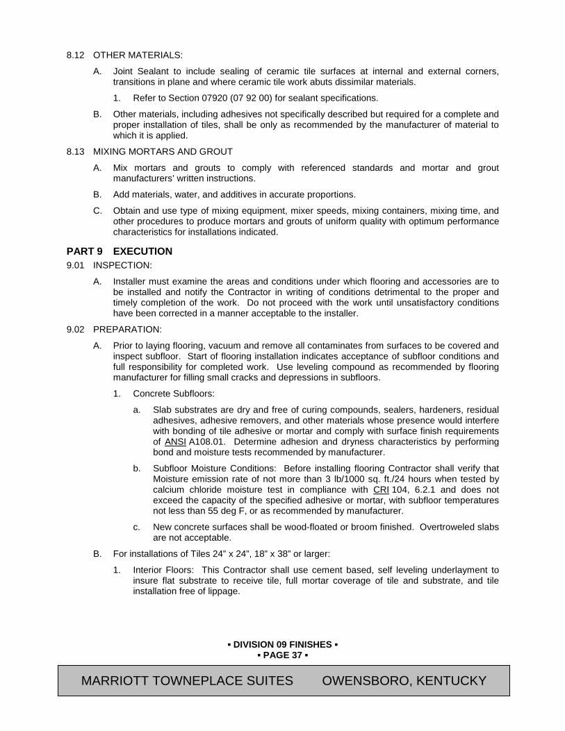
▪ DIVISION 09 FINISHES ▪
▪ PAGE 37 ▪
RESIDENCE INN BY MARRIOTT - LITTLETON, COLORADO
8.12 OTHER MATERIALS:
A. Joint Sealant to include sealing of ceramic tile surfaces at internal and external corners, transitions in plane and where ceramic tile work abuts dissimilar materials.
1. Refer to Section 07920 (07 92 00) for sealant specifications.
B. Other materials, including adhesives not specifically described but required for a complete and proper installation of tiles, shall be only as recommended by the manufacturer of material to which it is applied.
8.13 MIXING MORTARS AND GROUT
A. Mix mortars and grouts to comply with referenced standards and mortar and grout manufacturers’ written instructions.
B. Add materials, water, and additives in accurate proportions.
C. Obtain and use type of mixing equipment, mixer speeds, mixing containers, mixing time, and other procedures to produce mortars and grouts of uniform quality with optimum performance characteristics for installations indicated.
PART 9 EXECUTION 9.01 INSPECTION:
A. Installer must examine the areas and conditions under which flooring and accessories are to be installed and notify the Contractor in writing of conditions detrimental to the proper and timely completion of the work. Do not proceed with the work until unsatisfactory conditions have been corrected in a manner acceptable to the installer.
9.02 PREPARATION:
A. Prior to laying flooring, vacuum and remove all contaminates from surfaces to be covered and inspect subfloor. Start of flooring installation indicates acceptance of subfloor conditions and full responsibility for completed work. Use leveling compound as recommended by flooring manufacturer for filling small cracks and depressions in subfloors.
1. Concrete Subfloors:
a. Slab substrates are dry and free of curing compounds, sealers, hardeners, residual adhesives, adhesive removers, and other materials whose presence would interfere with bonding of tile adhesive or mortar and comply with surface finish requirements of ANSI A108.01. Determine adhesion and dryness characteristics by performing bond and moisture tests recommended by manufacturer.
b. Subfloor Moisture Conditions: Before installing flooring Contractor shall verify that Moisture emission rate of not more than 3 lb/1000 sq. ft./24 hours when tested by calcium chloride moisture test in compliance with CRI 104, 6.2.1 and does not exceed the capacity of the specified adhesive or mortar, with subfloor temperatures not less than 55 deg F, or as recommended by manufacturer.
c. New concrete surfaces shall be wood-floated or broom finished. Overtroweled slabs are not acceptable.
B. For installations of Tiles 24” x 24”, 18” x 38” or larger:
1. Interior Floors: This Contractor shall use cement based, self leveling underlayment to insure flat substrate to receive tile, full mortar coverage of tile and substrate, and tile installation free of lippage.
MARRIOTT TOWNEPLACE SUITES OWENSBORO, KENTUCKY

▪ DIVISION 09 FINISHES ▪
▪ PAGE 38 ▪
RESIDENCE INN BY MARRIOTT - LITTLETON, COLORADO
2. Interior Walls: This Contractor shall use cement based trowelable patch to remedy all wall surfaces to receive large unit tile. Install tile with minimum 95% mortar coverage to tile & substrate. Tile installation shall be free of lippage.
C. Apply concrete slab primer for ceramic tile, if recommended by flooring manufacturer, prior to application of adhesive. Apply in compliance with manufacturer's directions.
9.03 CRACK SUPPRESSION MEMBRANE
A. Install membrane in strict accordance with manufacturer's specifications and ANSI A108.17.
B. Provide width of membrane as recommended by membrane manufacturer, but no less than three (3) times the width of the tile used at all control joints, existing cracks in concrete floor and other locations as required to comply with TCNA’s “Handbook for Ceramic Tile Installation”.
9.04 TILE INSTALLATION - GENERAL
A. Comply with the ANSI A108 Series and TCNA’s “Handbook for Ceramic, Glass, and Stone Tile Installation”.
B. Handle, store, mix, and apply mortar and grout in compliance with manufacturer's instructions.
C. Extend tile work into recesses and under equipment and fixtures to form a complete covering without interruptions. Terminate work neatly at obstructions, edges, and corners without disruption of pattern, joint alignment, or bridging of Expansion Joints or Control Joints.
D. Install tile after finishing operations, including painting, have been completed. Moisture content of concrete slabs, building air temperature, and relative humidity must be within limits recommended by the flooring manufacturer.
E. Expansion Joints: Provide expansion joints, control joints and pressure relieving joints of widths and locations according to TCNA Handbook Construction No. EJ171, and as approved by [Owner's Representative] [Architect]. Do not saw cut joints after application.
F. Lay tile from center marks established from center of area so that tile at opposing edges of the area are of equal width. Adjust as necessary to avoid use of cut widths less than 1/2 tile at edge perimeters. Lay tile square to room axis unless otherwise shown.
G. Match tiles for color and pattern by using tile from cartons in same sequence as manufactured and packaged. Cut tile neatly in and around all fixtures. Broken, cracked, chipped, or deformed tile are not acceptable.
H. Lay tile with grain in tile running in same direction. Accurately form intersections and returns. Perform cutting and drilling of tile without marring visible surfaces. Grind cut edges of tile abutting trim, finish, or built-in items.
I. Sound tile after setting and replace hollow sounding units.
J. Grout tile to comply with the requirements of the ANSI A18.10 tile installation standards:
9.05 SHOWER FLOOR PAN LINER WATERPROOF MEMBRANE INSTALLATION
A. Install materials to comply with and ANSI A108.13 and as directed by manufacturer to provide a concealed waterproof membrane. All seams shall be adhered to prevent delamination as specified by manufacturer. Upon completion, test for leaks by plugging the drain and filling with water. Make necessary adjustments to stop all leakage and retest until watertight, before top layers are installed.
1. Do not install tile or setting materials over waterproof membrane until waterproofing has cured and been tested to determine that it is watertight.
MARRIOTT TOWNEPLACE SUITES OWENSBORO, KENTUCKY
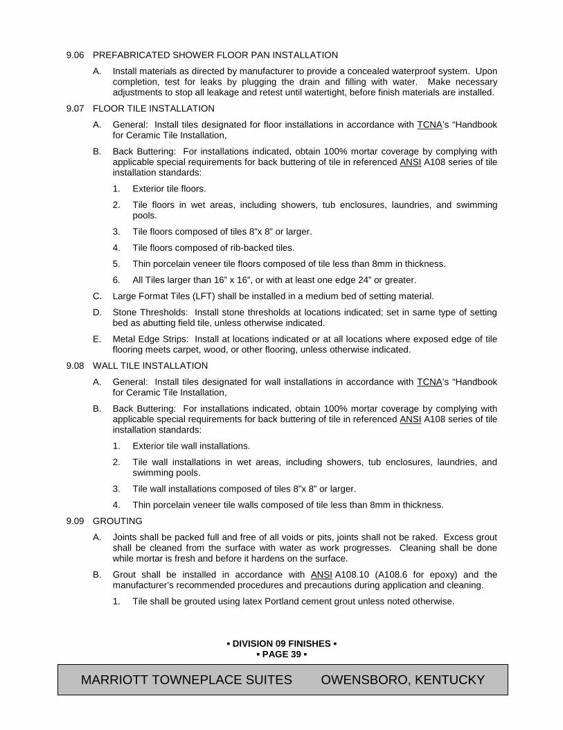
▪ DIVISION 09 FINISHES ▪
▪ PAGE 39 ▪
RESIDENCE INN BY MARRIOTT - LITTLETON, COLORADO
9.06 PREFABRICATED SHOWER FLOOR PAN INSTALLATION
A. Install materials as directed by manufacturer to provide a concealed waterproof system. Upon completion, test for leaks by plugging the drain and filling with water. Make necessary adjustments to stop all leakage and retest until watertight, before finish materials are installed.
9.07 FLOOR TILE INSTALLATION
A. General: Install tiles designated for floor installations in accordance with TCNA’s “Handbook for Ceramic Tile Installation,
B. Back Buttering: For installations indicated, obtain 100% mortar coverage by complying with applicable special requirements for back buttering of tile in referenced ANSI A108 series of tile installation standards:
1. Exterior tile floors.
2. Tile floors in wet areas, including showers, tub enclosures, laundries, and swimming pools.
3. Tile floors composed of tiles 8”x 8” or larger.
4. Tile floors composed of rib-backed tiles.
5. Thin porcelain veneer tile floors composed of tile less than 8mm in thickness.
6. All Tiles larger than 16” x 16”, or with at least one edge 24” or greater.
C. Large Format Tiles (LFT) shall be installed in a medium bed of setting material.
D. Stone Thresholds: Install stone thresholds at locations indicated; set in same type of setting bed as abutting field tile, unless otherwise indicated.
E. Metal Edge Strips: Install at locations indicated or at all locations where exposed edge of tile flooring meets carpet, wood, or other flooring, unless otherwise indicated.
9.08 WALL TILE INSTALLATION
A. General: Install tiles designated for wall installations in accordance with TCNA’s “Handbook for Ceramic Tile Installation,
B. Back Buttering: For installations indicated, obtain 100% mortar coverage by complying with applicable special requirements for back buttering of tile in referenced ANSI A108 series of tile installation standards:
1. Exterior tile wall installations.
2. Tile wall installations in wet areas, including showers, tub enclosures, laundries, and swimming pools.
3. Tile wall installations composed of tiles 8”x 8” or larger.
4. Thin porcelain veneer tile walls composed of tile less than 8mm in thickness.
9.09 GROUTING
A. Joints shall be packed full and free of all voids or pits, joints shall not be raked. Excess grout shall be cleaned from the surface with water as work progresses. Cleaning shall be done while mortar is fresh and before it hardens on the surface.
B. Grout shall be installed in accordance with ANSI A108.10 (A108.6 for epoxy) and the manufacturer’s recommended procedures and precautions during application and cleaning.
1. Tile shall be grouted using latex Portland cement grout unless noted otherwise.
MARRIOTT TOWNEPLACE SUITES OWENSBORO, KENTUCKY

▪ DIVISION 09 FINISHES ▪
▪ PAGE 40 ▪
RESIDENCE INN BY MARRIOTT - LITTLETON, COLORADO
2. Tile in kitchen and associated adjacent areas shall be grouted using chemical resistant epoxy grout.
C. Grout Sealer: Apply grout sealer to grout joints according to grout-sealer manufacturer's written instructions. As soon as grout sealer has penetrated grout joints, remove excess sealer and sealer from tile faces by wiping with soft cloth.
9.10 ADJUST AND CLEAN
A. Clean grout and setting material from face of tile while materials are workable. Leave tile face clean and free of all foreign matter.
B. Leave finished installation clean and free of cracked, chipped, broken, unbonded, or otherwise defective work.
C. Protection: When recommended by tile manufacturer, apply a protective coat of neutral protective cleaner to completed surface. Protect installed tile work with Kraft paper or other heavy covering during the construction period to prevent damage. Prohibit all foot and wheel traffic from using tiled floors for at least 3 days, preferably 7 days.
D. Before final inspection, remove protective coverings and rinse neutral cleaner from all tile surfaces.
9.11 SETTING AND GROUT MATERIAL SCHEDULE Tile
(< 8” x 8”)
Large Format Tile
(≥ 8” x 8”)
Indoor Pool/Spa (< 8” x 8”)
Prep Kitchen
(< 8” x 8”) A. Laticrete International Mortar - Floor “Laticrete 254
Platinum Multipurpose Thinset Mortar”
"Laticrete 255 MultiMax MultiPurpose Thinset Mortar” or “Laticrete 4XLT Thinset (Regular or Rapid)”
“Laticrete 254 Platinum Multipurpose Thinset Mortar”
“Laticrete 254 Platinum Multipurpose Thinset Mortar”
Adhesive – Gypsum Wall Board
“Laticrete 15 Premium Multi-Mastic Adhesive”
"Laticrete 255 MultiMax MultiPurpose Thinset Mortar” or “Laticrete 4XLT Thinset (Regular or Rapid)”
“Laticrete 254 Platinum Multipurpose Thinset Mortar”
“Laticrete 254 Platinum Multipurpose Thinset Mortar”
Adhesive – Gypsum Wall Board (LVP)
"Laticrete 255 MultiMax MultiPurpose Thinset Mortar” or “Laticrete 4XLT Thinset (Regular or Rapid)”
"Laticrete 255 MultiMax MultiPurpose or “Laticrete 4XLT Thinset (Regular or Rapid)”
“Laticrete 254 Platinum Multipurpose Thinset Mortar”
“Laticrete 254 Platinum Multipurpose Thinset Mortar”
Grout “Spectra LOCK Pro Epoxy
“Spectra LOCK Pro Epoxy
“Spectra LOCK 2000 IG”
“Spectra LOCK 2000 IG”
MARRIOTT TOWNEPLACE SUITES OWENSBORO, KENTUCKY
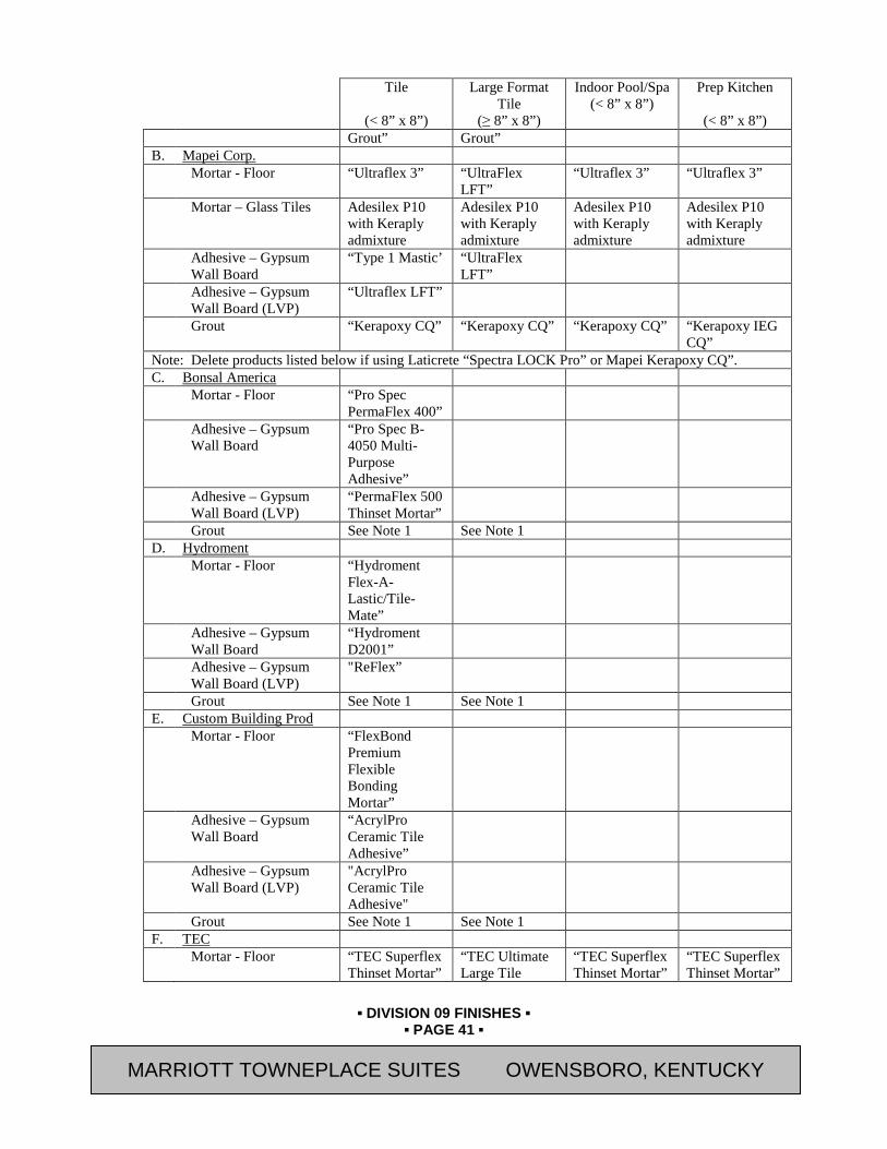
▪ DIVISION 09 FINISHES ▪
▪ PAGE 41 ▪
RESIDENCE INN BY MARRIOTT - LITTLETON, COLORADO
Tile
(< 8” x 8”)
Large Format Tile
(≥ 8” x 8”)
Indoor Pool/Spa (< 8” x 8”)
Prep Kitchen
(< 8” x 8”) Grout” Grout”
B. Mapei Corp. Mortar - Floor “Ultraflex 3” “UltraFlex
LFT” “Ultraflex 3” “Ultraflex 3”
Mortar – Glass Tiles Adesilex P10 with Keraply admixture
Adesilex P10 with Keraply admixture
Adesilex P10 with Keraply admixture
Adesilex P10 with Keraply admixture
Adhesive – Gypsum Wall Board
“Type 1 Mastic’ “UltraFlex LFT”
Adhesive – Gypsum Wall Board (LVP)
“Ultraflex LFT”
Grout “Kerapoxy CQ” “Kerapoxy CQ” “Kerapoxy CQ” “Kerapoxy IEG CQ”
Note: Delete products listed below if using Laticrete “Spectra LOCK Pro” or Mapei Kerapoxy CQ”. C. Bonsal America Mortar - Floor “Pro Spec
PermaFlex 400”
Adhesive – Gypsum Wall Board
“Pro Spec B-4050 Multi-Purpose Adhesive”
Adhesive – Gypsum Wall Board (LVP)
“PermaFlex 500 Thinset Mortar”
Grout See Note 1 See Note 1 D. Hydroment Mortar - Floor “Hydroment
Flex-A-Lastic/Tile-Mate”
Adhesive – Gypsum Wall Board
“Hydroment D2001”
Adhesive – Gypsum Wall Board (LVP)
"ReFlex”
Grout See Note 1 See Note 1 E. Custom Building Prod Mortar - Floor “FlexBond
Premium Flexible Bonding Mortar”
Adhesive – Gypsum Wall Board
“AcrylPro Ceramic Tile Adhesive”
Adhesive – Gypsum Wall Board (LVP)
"AcrylPro Ceramic Tile Adhesive"
Grout See Note 1 See Note 1 F. TEC Mortar - Floor “TEC Superflex
Thinset Mortar” “TEC Ultimate Large Tile
“TEC Superflex Thinset Mortar”
“TEC Superflex Thinset Mortar”
MARRIOTT TOWNEPLACE SUITES OWENSBORO, KENTUCKY

▪ DIVISION 09 FINISHES ▪
▪ PAGE 42 ▪
RESIDENCE INN BY MARRIOTT - LITTLETON, COLORADO
Tile
(< 8” x 8”)
Large Format Tile
(≥ 8” x 8”)
Indoor Pool/Spa (< 8” x 8”)
Prep Kitchen
(< 8” x 8”) Mortar”
Adhesive – Gypsum Wall Board
“TEC Double Duty Plus”
“TEC 3N1 Performance Mortar”
Adhesive – Gypsum Wall Board (LVP)
“TEC Double Duty Plus”
Grout
See Note 1 See Note 1
G. ARDEX Mortar - Floor “ARDEX X-5” “ARDEX X-5” “ARDEX X-5” “ARDEX X-5” Adhesive – Gypsum
Wall Board “ARDEX D14 Type I Premixed Tile Adhesive (Mastic)”
“ARDEX X 5 Flexible Thinset Mortar”
“ARDEX X 5 Flexible Thinset Mortar”
“ARDEX X 5 Flexible Thinset Mortar”
Adhesive – Gypsum Wall Board (LVP)
“ARDEX X 5 Flexible Thinset Mortar”
“ARDEX X 5 Flexible Thinset Mortar”
“ARDEX X 5 Flexible Thinset Mortar”
“ARDEX X 5 Flexible Thinset Mortar”
Grout See Note 1 See Note 1 Note 1: Laticrete "Spectra LOCK Pro Grout" and Mapei “Opticolor” are the grout products recommended
by Marriott
END OF SECTION
Revision Log
MARRIOTT TOWNEPLACE SUITES OWENSBORO, KENTUCKY

▪ DIVISION 09 FINISHES ▪
▪ PAGE 43 ▪
RESIDENCE INN BY MARRIOTT - LITTLETON, COLORADO
SECTION 09 51 23 (09512) - ACOUSTICAL TILE CEILINGS
PART 10 GENERAL 10.01 SUMMARY
A. Section Includes:
1. Suspended Metal Grid Systems Complete With Wall Trim
2. Ceiling Tiles
B. Related Sections:
1. Divisions 21 (13), 23 (15), and 26 (13) Sections for light fixtures, sprinklers, and air-distribution components.
10.02 REFERENCES
A. ASTM International Publications:
1. E84 "Standard Test Method for Surface Burning Characteristics of Building Materials"
2. C635 “Standard Specification for the Manufacture, Performance, and Testing of Metal Suspension Systems for Acoustical Tile and Lay-in Panel Ceilings”
3. C636 “Standard Practice for Installation of Metal Ceiling Suspension Systems for Acoustical Tile and Lay-In Panels”
4. E1264 “Standard Classification for Acoustical Ceiling Products”
B. United States Department of Agriculture Food Safety and Inspection Service (USDA FSIS) Requirements
10.03 SUBMITTALS
A. General: Submit the following in accordance with Conditions of Contract and Division 01 Specification Sections.
B. Product Data: Submit “Letter of Conformance” in accordance with Section 01 33 00 (01330) indicating specified items selected for use in project with the following supporting data.
1. Manufacturer's product and maintenance data for each type of ceiling system and accessory.
2. Samples: Min 6” x 6” samples of specified acoustical panel, 8” long samples of exposed wall molding, trim and suspension system (main runner and cross-tee).
10.04 QUALITY ASSURANCE
A. Qualifications of Installers:
1. The suspended ceiling Subcontractor shall have a record of successful installations of similar ceilings acceptable to the Architect.
2. For the actual fabrication and installation of all components of the system, use only personnel who are thoroughly trained and experienced in the skills required and completely familiar with the requirements established for this work.
B. In addition to complying with all pertinent codes and regulations, suspension system shall be installed according to ASTM C636, Installation of Metal Ceiling Suspension System for Acoustical Tile and Lay-in Panels.
MARRIOTT TOWNEPLACE SUITES OWENSBORO, KENTUCKY
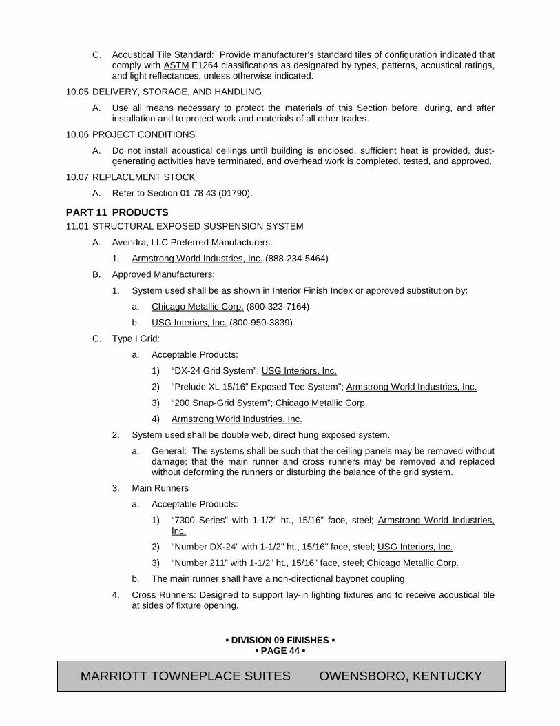
▪ DIVISION 09 FINISHES ▪
▪ PAGE 44 ▪
RESIDENCE INN BY MARRIOTT - LITTLETON, COLORADO
C. Acoustical Tile Standard: Provide manufacturer's standard tiles of configuration indicated that comply with ASTM E1264 classifications as designated by types, patterns, acoustical ratings, and light reflectances, unless otherwise indicated.
10.05 DELIVERY, STORAGE, AND HANDLING
A. Use all means necessary to protect the materials of this Section before, during, and after installation and to protect work and materials of all other trades.
10.06 PROJECT CONDITIONS
A. Do not install acoustical ceilings until building is enclosed, sufficient heat is provided, dust-generating activities have terminated, and overhead work is completed, tested, and approved.
10.07 REPLACEMENT STOCK
A. Refer to Section 01 78 43 (01790).
PART 11 PRODUCTS 11.01 STRUCTURAL EXPOSED SUSPENSION SYSTEM
A. Avendra, LLC Preferred Manufacturers:
1. Armstrong World Industries, Inc. (888-234-5464)
B. Approved Manufacturers:
1. System used shall be as shown in Interior Finish Index or approved substitution by:
a. Chicago Metallic Corp. (800-323-7164)
b. USG Interiors, Inc. (800-950-3839)
C. Type I Grid:
a. Acceptable Products:
1) “DX-24 Grid System”; USG Interiors, Inc.
2) “Prelude XL 15/16” Exposed Tee System”; Armstrong World Industries, Inc.
3) “200 Snap-Grid System”; Chicago Metallic Corp.
4) Armstrong World Industries, Inc.
2. System used shall be double web, direct hung exposed system.
a. General: The systems shall be such that the ceiling panels may be removed without damage; that the main runner and cross runners may be removed and replaced without deforming the runners or disturbing the balance of the grid system.
3. Main Runners
a. Acceptable Products:
1) “7300 Series” with 1-1/2" ht., 15/16" face, steel; Armstrong World Industries, Inc.
2) “Number DX-24” with 1-1/2" ht., 15/16" face, steel; USG Interiors, Inc.
3) “Number 211” with 1-1/2" ht., 15/16" face, steel; Chicago Metallic Corp.
b. The main runner shall have a non-directional bayonet coupling.
4. Cross Runners: Designed to support lay-in lighting fixtures and to receive acoustical tile at sides of fixture opening.
MARRIOTT TOWNEPLACE SUITES OWENSBORO, KENTUCKY

▪ DIVISION 09 FINISHES ▪
▪ PAGE 45 ▪
RESIDENCE INN BY MARRIOTT - LITTLETON, COLORADO
a. Acceptable Products:
1) “Number XL-7328/7348 Cross Tee”; Armstrong World Industries, Inc.
2) “DX-216/416 Cross Tee”; USG Interiors, Inc.
3) “Number 226/209 Cross Tee”; Chicago Metallic Corp.
5. Perimeter Wall Angles: Hemmed edge, 7/8" x 7/8".
6. Accessories: Provide all accessories needed for proper installation of system.
7. Finish: All exposed surfaces shall be finished white.
11.02 CUSTOM PERIMETER TRIM
A. Manufacturer:
1. Avendra, LLC Preferred Manufacturers:
a. “Axiom-Classic Custom Perimeter Trim”; Armstrong World Industries, Inc. (888-234-5464)
2. Approved Manufacturers:
a. Approved Substitution
B. Components: Edge trim system for suspended ceiling system, extruded aluminum alloy 6063 trim channel, 10 foot curved profiles outside radii for acoustical and for drywall applications.
1. Trim Channel: Provide face width as shown on Drawings with 3/4 inch horizontal legs, curved sections with special bosses formed for attachment to the Axiom tee-bar connection clip or hanging clip; commercial quality, extruded aluminum, factory-finished in factory-applied baked polyester paint to match color of ceiling tile or gypsum board paint as shown on Interior Finish Index.
2. Accessories:
a. Hanging clip, commercial quality aluminum, unfinished, used when suspension wires must be attached directly to the trim sections.
b. Splice with set screws, galvanized steel, unfinished, used to attach joints between sections of trim.
c. T-bar Connector Clip, galvanized steel, unfinished, used to attach channel trim to supporting suspension members.
d. Perimeter Trim Hold Down Clip used to secure cut edges of metal panels at the Axiom trim.
e. Drywall Bottom Trim Curved, extruded aluminum, 120 inches x 1-9/64 inch x 27/32 inch, used to finish edges of 5/8 inch drywall that is applied to the bottom surface of the Axiom.
11.03 ACOUSTICAL MATERIALS
A. Product: Refer to Interior Finish Index.
MARRIOTT TOWNEPLACE SUITES OWENSBORO, KENTUCKY
▪ DIVISION 09 FINISHES ▪
▪ PAGE 46 ▪
RESIDENCE INN BY MARRIOTT - LITTLETON, COLORADO
11.04 LIGHTING: Contractor shall be responsible for providing sufficient support on grid systems to support light fixtures. All fixtures shall be supported at each and every corner.
PART 12 EXECUTION 12.01 SURFACE CONDITIONS
A. Inspection: Prior to all work of this Section, carefully inspect the installed work of all other trades and verify that all such work is complete to the point where this installation may properly commence. Verify that suspended ceiling systems are installed in strict accordance with all pertinent codes and regulations, and the manufacturer's recommendations.
B. Discrepancies: In the event of discrepancy, immediately notify the Owner’s Representative. Do not proceed in areas of discrepancy until all such discrepancies have been fully resolved.
12.02 INSTALLATION
A. General:
1. Install acoustical panel, suspension system and accessories in compliance with manufacturers instructions and requirements of ASTM C636.
2. Install ceiling system in a true and even plane with straight line courses laid out symmetrically about center lines of area or as indicated. Border tile shall be minimum 6" wide and neatly fit against vertical surfaces to form a tight fit.
3. Provide metal edge angle at perimeter of units as detailed on Drawings. Cut and fit around light fixtures, diffusers, etc.
B. Lay-In Ceiling System:
1. Hanging main tees parallel in a flat plane by means of #10 gauge wire hangers attached to construction above. Hangers shall be spaced not over 4'-0" along the main tees and within 6" of the ends and splices of main tees, and other interruptions. Main tees shall be spaced 2'- 0" o.c. Cross tees shall be interlocked to main tees and spaced as required to support tile edges.
2. Attachment to ducts, pipes, etc. will not be permitted. Bridge under obstructions with a grid of 1-1/2" cold rolled channels or other suitable members to support ceiling grid.
3. Install wall angle at perimeter of walls, partitions, columns, pipes, and other obstructions that extend above the ceiling. Securely attach with appropriate fastening devices at maximum 16" o.c. Form reveal of same depth and width as that formed between edge of panel and flange at exposed suspension grid. Neatly cut and fit around light fixtures, diffusers, etc. Provide wall angles fabricated to diameter required to fit penetrations.
4. Insert ceiling panels, installing hold down clips on panels extending over partitions and where required to maintain fire ratings.
5. At all locations where ceiling tiles are cut, the cut edges of the tiles shall match the premanufactured edges (i.e. cut edges are to be beveled to match beveled edged tiles). Exposed cut edges are to be painted to match face of tile with paint as approved by tile manufacturer.
12.03 ADJUSTING AND CLEANING
A. Completely remove all finger prints and traces of soil and damage from the surfaces of grid and acoustical materials, using only those cleaning materials recommended for that purpose by the manufacturer of the material being cleaned.
B. Replace units which are damaged or improperly installed.
MARRIOTT TOWNEPLACE SUITES OWENSBORO, KENTUCKY

▪ DIVISION 09 FINISHES ▪
▪ PAGE 47 ▪
RESIDENCE INN BY MARRIOTT - LITTLETON, COLORADO
END OF SECTION
Revision Log
MARRIOTT TOWNEPLACE SUITES OWENSBORO, KENTUCKY

▪ DIVISION 09 FINISHES ▪
▪ PAGE 48 ▪
RESIDENCE INN BY MARRIOTT - LITTLETON, COLORADO
SECTION 09 62 19 (09627) - LAMINATE FLOORING
PART 13 GENERAL 13.01 SUMMARY
A. Section Includes:
1. High-Pressure Plastic-Laminate Flooring
B. Related Sections:
1. Section 09 30 00 (09310) - Tiling
2. Section 09 65 00 (09650) - Resilient Flooring
3. Section 09 68 00 (09680) - Carpeting
13.02 REFERENCES
A. ASTM International Publications:
1. F710 “Standard Practice for Preparing Concrete Floors to Receive Resilient Flooring”
13.03 SUBMITTALS
A. General: Submit the following in accordance with Conditions of Contract and Division 01 Specification Sections.
B. Submit “Letter of Conformance” in accordance with Section 01 33 00 (01330) indicating specified items selected for use in project with the following supporting data.
1. Submit manufacturer's product and maintenance data for each type of flooring and accessory.
a. Certification by flooring manufacturer that products supplied for flooring installation comply with local regulations controlling use of volatile organic compounds (VOCS).
2. Submit color selection in the form of actual sections of flooring, including accessories, for each type of plastic-laminate flooring required showing full range of colors and patterns available.
13.04 QUALITY ASSURANCE
A. Single-Source Responsibility for Flooring: Obtain each type, color and pattern of flooring from a single source with resources to provide products of consistent quality in appearance and physical properties without delaying progress of the work.
B. Installer Qualifications: Firm experienced in installation or application of systems similar in complexity to those required for this Project, including specific requirements indicated.
1. Acceptable to or licensed by manufacturer.
C. Field Samples Prepare field samples for Owner's review and to establish requirements for ratings and finish texture.
1. Correct areas or modify method of installation as directed by Owner's Representative to comply with specified requirements.
2. Maintain field samples accessible to serve as a standard of quality for this Section.
3. Field samples shall consists of a 10 foot square panel for review by Owner's Representative.
MARRIOTT TOWNEPLACE SUITES OWENSBORO, KENTUCKY

▪ DIVISION 09 FINISHES ▪
▪ PAGE 49 ▪
RESIDENCE INN BY MARRIOTT - LITTLETON, COLORADO
13.05 DELIVERY, STORAGE, AND HANDLING
A. Deliver tiles and installation accessories to Project site in original manufacturer's unopened cartons and containers each bearing names of product and manufacturer, Project identification, and shipping and handling instructions.
B. Store flooring materials in dry spaces protected from the weather with ambient temperatures maintained between 50 degrees F. and 90 degrees F. Store flooring on flat surfaces. Move flooring and installation accessories into spaces where they will be installed at least 48 hours in advance of installation.
13.06 PROJECT CONDITIONS
A. Maintain a minimum temperature of 70 degrees F. in spaces to receive tiles for at least 48 hours prior to installation, during installation, and for not less than 48 hours after installation. After this period, maintain a temperature and humidity of not less than range planned for building occupants.
B. Do not install flooring until they are at the same temperature as the space where they are to be installed. Close spaces to traffic during tile installation.
13.07 SEQUENCING AND SCHEDULING
A. Do not install flooring materials over concrete slabs until the slabs have cured and are sufficiently dry to bond with adhesive as determined by tile manufacturer's recommended bond and moisture test.
13.08 SPECIAL WARRANTY
A. Furnish manufacturer’s 5-year commercial warranty for wear, staining, and fading.
13.09 EXTRA MATERIALS
A. Refer to Section 01 79 00 (01790).
PART 14 PRODUCTS 14.01 MANUFACTURERS:
A. Avendra, LLC Preferred Manufactures:
1. None
B. Approved Manufacturers:
1. WilsonArt International, Inc. (800-433-3222)
14.02 HIGH PRESSURE DECORATIVE LAMINATE FLOORING
A. Composite panel consisting of high-pressure laminate surfacing and high pressure laminate balancing backer bonded to high density fiberboard (HDF) core with moisture resistant adhesive.
B. Color & Pattern: Refer to Interior Finish Index.
C. All flooring shall be the maximum extent possible of a single batch number.
14.03 RESILIENT BASE
A. Refer to Section 09 65 00 (09650).
14.04 INSTALLATION ACCESSORIES
A. Trowelable Underlayments and Patching Compounds: Latex-modified, portland-cement-based formulation provided or approved by tile manufacturer for applications indicated.
MARRIOTT TOWNEPLACE SUITES OWENSBORO, KENTUCKY
▪ DIVISION 09 FINISHES ▪
▪ PAGE 50 ▪
RESIDENCE INN BY MARRIOTT - LITTLETON, COLORADO
B. Vapor Retarder: ASTM D4397, polyethylene sheet not less than 8.0 mils (0.15 mm) thick.
C. Foam Padding: Extruded polyethylene foam.
D. Adhesive: As recommended by manufacturer.
E. Baseboard and Quarter Round:
1. Solid Wood:
2. Vinyl Wrapped Wood:
F. Decorative Laminate Trim:
1. Stair Nosing:
2. T Expansion:
3. End Cap:
4. Transition Strip:
G. Solid Vinyl Trim:
1. End Cap:
2. Standard Expansion:
3. 1/8 Inch Transition:
4. Full Transition
H. Universal/Expansion Divider Track
I. Vents: Manufacturer’s custom wood fabrications.
J. Other materials, including edge strips not specifically described, but required for a complete and proper installation of plastic-laminate flooring, shall be only as recommended by the manufacturer of material to which it is applied.
PART 15 EXECUTION 15.01 INSPECTION:
A. Installer must examine the areas and conditions under which plastic-laminate flooring and accessories are to be installed and notify the Contractor in writing of conditions detrimental to the proper and timely completion of the work. Do not proceed with the work until unsatisfactory conditions have been corrected in a manner acceptable to the Installer.
15.02 CONCRETE SUBFLOORS:
A. Verify that concrete slabs comply with ASTM F710 and the following:
1. Slab substrates are dry and free of curing compounds, sealers, hardeners, and other materials whose presence would interfere with bonding of adhesive. Determine adhesion and dryness characteristics by performing bond and moisture tests recommended by tile manufacturer.
2. Finishes of subfloors comply with tolerances and other requirements specified in Division 03 Section, "Cast-In-Place Concrete" for slabs receiving resilient flooring.
3. Subfloor Moisture Conditions: Before installing flooring Contractor shall verify that Moisture emission rate of not more than 3 lb/1000 sq. ft./24 hours when tested by calcium chloride moisture test in compliance with CRI 104, 6.2.1, with subfloor temperatures not less than 55 deg F, or as recommended by manufacturer.
MARRIOTT TOWNEPLACE SUITES OWENSBORO, KENTUCKY

▪ DIVISION 09 FINISHES ▪
▪ PAGE 51 ▪
RESIDENCE INN BY MARRIOTT - LITTLETON, COLORADO
15.03 PREPARATION
A. General: Comply with manufacturer's installation specifications for preparing substrates to receive products indicated.
B. Prior to laying flooring, vacuum surfaces to be covered and inspect subfloor. Start of flooring installation indicates acceptance of subfloor and full responsibility for completed work.
C. This Contractor to remove coatings, including curing compounds, adhesives, plastics, and other substances that are incompatible with flooring adhesives and that contain soap, wax, oil, or silicone, by using a terrazzo or concrete grinder, a drum sander, or a polishing machine equipped with a heavy-duty wire brush. Surface to receive new flooring shall be prepared, including removal of existing materials not acceptable for proper installation of new materials, as required by manufacturer.
D. Use leveling compound as recommended by flooring manufacturer for filling small cracks and depressions in subfloors.
1. Wood Subfloors: Fill voids to provide a maximum 3/16-inch deviation in any direction when checked with a 10-foot straight edge.
E. Apply concrete slab primer, if recommended by flooring manufacturer, prior to application of adhesive. Apply in compliance with manufacturer's directions.
15.04 INSTALLATION - GENERAL:
A. Verify strip flooring direction with Owner's Representative before starting installation.
B. Install flooring after finishing operations, including painting, have been completed. Moisture content of concrete slabs, building air temperature, and relative humidity must be within limits recommended by flooring manufacturer's directions.
C. Patch and repair floors and walls to receive flooring for proper installation of flooring, stair accessories, and base.
D. Place flooring in strict compliance with manufacturer's recommendations. Butt tightly to vertical surfaces and edgings. Scribe around obstructions and to produce neat joints, laid tight, even, and straight. Extend flooring into toe spaces.
E. Maintain reference markers, holes, or openings that are in place or plainly marked for future cutting by repeating on finish flooring as marked on subfloor. Use chalk or other non-permanent marking device.
F. Install flooring on covers for telephone and electrical ducts and other such items as occur within finished floor areas. Maintain overall continuity of color and pattern with pieces of flooring installed in these covers. Tightly cement edges to perimeter of floor around covers and to covers.
G. Vapor Retarder: At new concrete slabs, install a layer of polyethylene sheet according to flooring manufacturer’s written instructions. Lap seams 16 inches and do not tape
H. Fit flooring neatly to vertical interruptions. Follow shape of interrupting item when joint will remain exposed.
I. Install divider strips where flooring terminates at centerline of doors and adjacent to other materials or unfinished floor areas.
J. Expansion Space: Provide expansion space at walls and other obstructions and terminations of flooring of not less than ¼ inch, unless otherwise indicated on Drawings.
K. FLOATING FLOOR INSTALLATION
MARRIOTT TOWNEPLACE SUITES OWENSBORO, KENTUCKY
▪ DIVISION 09 FINISHES ▪
▪ PAGE 52 ▪
RESIDENCE INN BY MARRIOTT - LITTLETON, COLORADO
1. Comply with flooring manufacturer’s written instructions. Tongue and groove joint shall be sealed with glue for moisture proof installation.
2. Install foam padding and tape joints with masking tape.
3. Install flooring over foam pad.
MARRIOTT TOWNEPLACE SUITES OWENSBORO, KENTUCKY
▪ DIVISION 09 FINISHES ▪
▪ PAGE 53 ▪
RESIDENCE INN BY MARRIOTT - LITTLETON, COLORADO
15.05 INSTALLATION - STRIP FLOORING:
A. Lay strip flooring square to room axis unless otherwise indicated.
B. Match strips for color and pattern by using tile from cartons in same sequence as manufactured and packaged. Cut tile neatly in and around all fixtures. Broken, cracked, chipped, or deformed strip flooring planks are not acceptable.
15.06 ACCESSORIES:
A. Install accessories as indicated or required.
B. Nail baseboard to wall and nail shoe molding or other trim to baseboard; do not nail to flooring.
C. Seal flooring penetrations and perimeters at wet areas with silicon sealant
D. At areas where base is required, apply resilient base to walls, columns, pilasters, casework, and other permanent fixtures, as coordinated with type of flooring. Install base in as long lengths as practicable. Tightly bond base to backing throughout the length of each piece with continuous contact at horizontal and vertical surfaces. On irregular surfaces, fill voids along top edge of resilient wall base with manufacturer's recommended adhesive filler material..
15.07 CLEANING AND PROTECTION:
A. Remove any excess adhesive or other surface blemishes using neutral type cleaners as recommended by floor manufacturer.
B. Protect flooring against mars, marks, indentations, and other damage from construction operations and placement of equipment and fixtures during remainder of construction period. Use protection methods indicated or recommended by manufacturer of plastic-laminate product involved.
C. Clean products specified in this Section not more than four days prior to dates scheduled for inspections intended to establish date of Substantial Completion in each area of Project. Clean products using method recommended by manufacturer. Strip protective floor polish that was applied after completing installation, prior to cleaning.
15.08 FINISHING:
A. After completion of project and just prior to final inspection of work, thoroughly clean floors and accessories in compliance with flooring manufacturer's instructions.
END OF SECTION
Revision Log
MARRIOTT TOWNEPLACE SUITES OWENSBORO, KENTUCKY

▪ DIVISION 09 FINISHES ▪
▪ PAGE 54 ▪
RESIDENCE INN BY MARRIOTT - LITTLETON, COLORADO
SECTION 09 65 00 (09650) - RESILIENT FLOORING
PART 16 GENERAL 16.01 SUMMARY
A. Section Includes:
1. Vinyl Composition Tile
2. Sheet Vinyl Flooring
3. Resilient Base
4. PVC Thresholds
5. Solid Vinyl Transition Edges
6. Stair Nosings
B. Related Sections:
1. Section 09 30 00 (09310) - Tiling
2. Section 09 68 00 (09680) - Carpeting
3. Section 14 24 23 (14240) - Hydraulic Elevators
16.02 REFERENCES
A. ASTM International Publications:
1. C241 “Standard Test Method for Abrasion Resistance of Stone Subjected to Foot Traffic”
2. C503 “Standard Specification for Marble Dimension Stone (Exterior)”
3. D2047 “Standard Test Method for Static Coefficient of Friction of Polish-Coated Flooring Surfaces as Measured by the James Machine”
4. D2240 “Standard Test Method for Rubber Property—Durometer Hardness”
5. D3389 “Standard Test Method for Coated Fabrics Abrasion Resistance (Rotary Platform, Double-Head Abrader)”
6. E648/NFPA 253 “Standard Test Method for Critical Radiant Flux of Floor-Covering Systems Using a Radiant Heat Energy Source”
7. E662/NFPA 258 “Standard Test Method for Specific Optical Density of Smoke Generated by Solid Materials”
8. F710 “Standard Practice for Preparing Concrete Floors to Receive Resilient Flooring”
9. F1066 “Standard Specification for Vinyl Composition Floor Tile”
B. Carpet & Rug Institute (CRI)
1. Standard for Installation of Commercial Carpet CRI 104, Current Edition
C. Code of Federal Regulations (CFR)
1. 40 CFR 763 - Asbestos: Appendix A - Transmission Electron Microscopy Analytical Methods
MARRIOTT TOWNEPLACE SUITES OWENSBORO, KENTUCKY

▪ DIVISION 09 FINISHES ▪
▪ PAGE 55 ▪
RESIDENCE INN BY MARRIOTT - LITTLETON, COLORADO
D. Occupational Safety & Health Administration (OSHA) Regulations:
1. OSHA Regulation 29 CFR Toxic and Hazardous Substances 1910-1200 Hazard Communication
16.03 SUBMITTALS
A. General: Submit the following in accordance with Conditions of Contract and Division 01 Specification Sections.
B. Submit “Letter of Conformance” in accordance with Section 01 33 00 (01330) indicating specified items selected for use in project with the following supporting data.
1. Submit manufacturer's product and maintenance data for each type of resilient flooring and accessory.
a. Certification by resilient flooring manufacturer that products supplied for flooring installation comply with local regulations controlling use of volatile organic compounds (VOCS).
b. Asbestos Content: Provide written certification that tile and adhesive materials contain no asbestos of any type of mixture of types occurring naturally as impurities as determined by polarized light microscopy test per Appendix A of 40 CFR 763 will be utilized on this Project.
2. Submit color selection in the form of actual sections of resilient flooring, including accessories, for each type of resilient flooring required showing full range of colors and patterns available.
3. Submit shop drawings, seaming plan, and coving details for flooring and accessories.
C. Installer Certificates: Signed by sheet vinyl flooring system manufacturer certifying that Installer is approved, authorized, or licensed by manufacturer to install sheet vinyl flooring system.
16.04 QUALITY ASSURANCE
A. Single-Source Responsibility for Flooring: Obtain each type, color and pattern of flooring from a single source with resources to provide products of consistent quality in appearance and physical properties without delaying progress of the work.
B. Installer: A firm with not less than five years of successful experience in installation of sheet vinyl flooring systems with chemically welded seams similar to those required for this project and which is certified by manufacturer of the sheet vinyl materials.
C. Fire-Test-Response Characteristics: Provide products with the following fire-test-response characteristics as determined by testing identical products per test method indicated below by a testing and inspecting agency acceptable to authorities having jurisdiction.
1. Critical Radiant Flux: 0.45 W/sq. cm or greater when tested per ASTM E648.
2. Smoke Density: Maximum specific optical density of 450 or less when tested per ASTM E662.
16.05 DELIVERY, STORAGE, AND HANDLING
A. Deliver tiles and installation accessories to Project site in original manufacturer's unopened cartons and containers each bearing names of product and manufacturer, Project identification, and shipping and handling instructions.
MARRIOTT TOWNEPLACE SUITES OWENSBORO, KENTUCKY

▪ DIVISION 09 FINISHES ▪
▪ PAGE 56 ▪
RESIDENCE INN BY MARRIOTT - LITTLETON, COLORADO
B. Store flooring materials in dry spaces protected from the weather with ambient temperatures maintained between 65 degrees F. and 90 degrees F. Store tile flooring materials on flat surfaces. Move resilient flooring and installation accessories into spaces where they will be installed at least 48 hours in advance of installation.
C. Store sheet vinyl rolls upright. Move sheet vinyl floor coverings and installation accessories into spaces where they will be installed at least 48 hours before installation, unless longer conditioning periods are recommended in writing by manufacturer.
16.06 PROJECT CONDITIONS
A. Maintain a minimum temperature of 70 degrees F. in spaces to receive tiles for at least 48 hours prior to installation, during installation, and for not less than 48 hours after installation. After this period, maintain a temperature of not less than 55 degrees F.
B. Do not install resilient flooring until they are at the same temperature as the space where they are to be installed. Close spaces to traffic during resilient flooring installation.
C. Protect all materials from the direct flow of heat from hot-air registers, radiators, or other heating fixtures and appliances.
16.07 SEQUENCING AND SCHEDULING
A. Do not install resilient flooring materials over concrete slabs until the slabs have cured and are sufficiently dry to bond with adhesive as determined by tile manufacturer's recommended bond and moisture test.
16.08 EXTRA MATERIALS
A. Refer to Section 01 78 43 (01790)
PART 17 PRODUCTS 17.01 VINYL COMPOSITION TILES:
A. Avendra, LLC Preferred Manufactures:
1. Armstrong World Industries, Inc. (800-442-4212 x 2)
B. Approved Manufacturers:
1. Tarkett (800-899-8916)
a. To access the Tarkett National Account Program set up for Marriott inventory & pricing, you must order through the online portal at:
http://mobileb2b.tarkettna.com/DistributorPortal/externalredirect/cep.
b. After registering and setting up your password, orders can then be placed. You will be required to provide the Program Code and Program Access codes listed below to register. All orders should be placed directly with Tarkett via this portal and will be serviced via their authorized service channel provider nationally.
1) Program Code: 152798
2) Program Access Code #776630. c. Please ensure that only those authorized to be a partner and participate in the
Marriott International National Account Program have access to this information.
d. For problems contact Theresa Thomas (440-708-9318) or Kevin Tierney (713-204-7664).
MARRIOTT TOWNEPLACE SUITES OWENSBORO, KENTUCKY
▪ DIVISION 09 FINISHES ▪
▪ PAGE 57 ▪
RESIDENCE INN BY MARRIOTT - LITTLETON, COLORADO
C. All vinyl tile shall be the maximum extent possible of a single batch number. Tile should have uniform disbursement of color and texture throughout the thickness of the tile. Comply with ASTM F1066, Composition 1 (nonasbestos formulated).
D. Product, Size and Color: Refer to Interior Finish Index.
17.02 SHEET VINYL FLOORING: All sheet vinyl shall be the maximum extent possible of a single batch number.
A. Avendra, LLC Preferred Manufactures:
1. Armstrong World Industries, Inc. (800-442-4212 x 2)
B. Approved Manufacturers:
1. Mannington Mills, Inc. (706-629-7301)
2. Shaw Industries, Inc. (800-441-7429)
3. Substitution as approved by Marriott International
C. Sheet Vinyl:
1. Vinyl sheet flooring shall meet ASTM F1303, Type I, Grade 1, with Class B backing.
2. Sheet Width: Refer to Interior Finish Index
3. Nominal Thickness: Refer to Interior Finish Index
4. Size: As shown on Drawings.
5. Color and Pattern: As shown in Interior Finish Index
6. Seams: Install seamless installation unless otherwise approved by Owner’s Representative.
7. Static Load Limit: ASTM F970 (modified) 750 psi (52.73 kg/sq cm) (Modified by specifying a higher load on a smaller diameter tip. All other conditions are standard).
8. Meet the following fire test performance criteria as tested by a recognized independent testing laboratory:
a. Flame Spread Rating: 75 or less by ASTM E84.
b. Smoke Density: Less than 450 by ASTM E662.
c. Critical Radiant Flux: 0.45 minimum by ASTM E468.
17.03 RESILIENT BASE
A. Avendra, LLC Preferred Manufactures:
1. None
B. Approved Manufacturers:
1. Johnsonite, a Tarkett Group Company (800-899-8916)
a. To access the Tarket National Account Program set up for Marriott inventory & pricing, you must order through the online portal at:
http://mobileb2b.tarkettna.com/DistributorPortal/externalredirect/cep.
b. After registering and setting up your password, orders can then be placed. You will be required to provide the Program Code and Program Access codes listed below to register. All orders should be placed directly with Tarkett via this portal and will be serviced via their authorized service channel provider nationally.
MARRIOTT TOWNEPLACE SUITES OWENSBORO, KENTUCKY

▪ DIVISION 09 FINISHES ▪
▪ PAGE 58 ▪
RESIDENCE INN BY MARRIOTT - LITTLETON, COLORADO
1) Program Code: 152798
2) Program Access Code #776630. c. Please ensure that only those authorized to be a partner and participate in the
Marriott International National Account Program have access to this information.
d. For problems contact Theresa Thomas (440-708-9318) or Kevin Tierney (713-204-7664).
2. Burke Mercer Flooring Products, A Division of Burke Industries (800-669-7010).
C. Resilient bases shall be 1/8" thick, size as shown in Interior Finish Index. Provide cove type at sheet vinyl, resilient tile flooring, and other hard surfaces. Job mitering of corners will not be permitted.
D. Color: Refer to Interior Finish Index.
17.04 PVC THRESHOLD:
A. Avendra, LLC Preferred Manufactures:
1. None
B. Approved Manufacturers:
1. "Carpet Insert Threshold Mouldings"; Johnsonite, a Tarkett Group Company (800-899-8916)
a. To access the Tarkett National Account Program set up for Marriott inventory & pricing, you must order through the online portal at:
http://mobileb2b.tarkettna.com/DistributorPortal/externalredirect/cep.
b. After registering and setting up your password, orders can then be placed. You will be required to provide the Program Code and Program Access codes listed below to register. All orders should be placed directly with Tarkett via this portal and will be serviced via their authorized service channel provider nationally.
1) Program Code: 152798
2) Program Access Code #776630. c. Please ensure that only those authorized to be a partner and participate in the
Marriott International National Account Program have access to this information.
d. For problems contact Theresa Thomas (440-708-9318) or Kevin Tierney (713-204-7664).
C. Products:
a. Guestroom Entry Door: Refer to Interior Finish index and Design Guide Drawings.
a. Guestroom Connecting Door: Refer to Interior Finish index and Design Guide Drawings.
2. Approved Substitution by Marriott International
D. Manufactured from a homogeneous composition of polyvinyl chloride (PVC), high quality additives, and colorants. All Threshold Mouldings shall comply with A.D.A. requirements of Section 4.5.2 Changes of Level. Standard formulation exceeds ASTM E648 Class 1 Flammability requirements.
1. Hardness - ASTM D2240 - Not less than 85 Shore A
2. Abrasion Resistance - ASTM D3389 - 0.22 mg/cycle
MARRIOTT TOWNEPLACE SUITES OWENSBORO, KENTUCKY

▪ DIVISION 09 FINISHES ▪
▪ PAGE 59 ▪
RESIDENCE INN BY MARRIOTT - LITTLETON, COLORADO
3. Slip Resistance - ASTM D2047 - Exceeds Federal Standards and ADA requirements of 0.6 for flat surfaces.
4. Fire Resistance:
a. ASTM E648/NFPA 253 (Critical Radiant Flux) - Class 1.
b. ASTM E662/NFPA 258 (Smoke Density) - 450 or less.
5. Adhesive: As recommended by Manufacturer for use intended.
6. Color: Refer to Interior Finish Index for color and other additional requirements.
17.05 TRANSITION EDGES:
A. Avendra, LLC Preferred Manufactures:
1. Resilient Edge Trims and Transitions:
a. None
2. Straight Metal Edge Trims:
a. None
3. Curved Metal Edge Trims:
a. None
B. Approved Manufacturers:
1. Resilient Edge Trims and Transitions:
a. Marley Flexco Co., A Soflex Company (800-633-3151)
b. Johnsonite, a Tarkett Group Company (800-899-8916)
1) To access the Tarkett National Account Program set up for Marriott inventory & pricing, you must order through the online portal at:
http://mobileb2b.tarkettna.com/DistributorPortal/externalredirect/cep.
2) After registering and setting up your password, orders can then be placed. You will be required to provide the Program Code and Program Access codes listed below to register. All orders should be placed directly with Tarkett via this portal and will be serviced via their authorized service channel provider nationally.
Program Code: 152798
Program Access Code #776630. 3) Please ensure that only those authorized to be a partner and participate in the
Marriott International National Account Program have access to this information.
4) For problems contact Theresa Thomas (440-708-9318) or Kevin Tierney (713-204-7664).
c. Burke Mercer Flooring Products, A Division of Burke Industries (800-669-7010).
2. Straight Metal Edge Trims:
a. Schluter Systems (800-574-8481)
b. Ceramic Tool Company, Inc. (CTC) (800-236-5230)
3. Curved Metal Edge Trims:
MARRIOTT TOWNEPLACE SUITES OWENSBORO, KENTUCKY
▪ DIVISION 09 FINISHES ▪
▪ PAGE 60 ▪
RESIDENCE INN BY MARRIOTT - LITTLETON, COLORADO
a. Schluter Systems (800-574-8481) Note: Edit list below to suit Project requirements.
C. Model, Size and Color: Refer to Interior Finish Index.
D. Furnish transition edges at the following locations: Note: Edit list below to suit Project requirements.
1. Vinyl Composition Tile to Concrete
2. Vinyl Composition Tile to Carpet
3. Sheet Vinyl Flooring to Concrete
4. Sheet Vinyl Flooring to Carpet
5. Carpet to Carpet (Where thickness varies)
6. Carpet to Ceramic Tile
17.06 RESILIENT STAIR ACCESSORIES
A. Stair Nosings:
1. Avendra, LLC Preferred Manufactures:
a. None
2. Approved Manufacturers:
a. Johnsonite, a Tarkett Group Company (800-899-8916)
1) To access the Tarkett National Account Program set up for Marriott inventory & pricing, you must order through the online portal at:
http://mobileb2b.tarkettna.com/DistributorPortal/externalredirect/cep.
2) After registering and setting up your password, orders can then be placed. You will be required to provide the Program Code and Program Access codes listed below to register. All orders should be placed directly with Tarkett via this portal and will be serviced via their authorized service channel provider nationally.
Program Code: 152798
Program Access Code #776630. 3) Please ensure that only those authorized to be a partner and participate in the
Marriott International National Account Program have access to this information.
4) For problems contact Theresa Thomas (440-708-9318) or Kevin Tierney (713-204-7664).
b. Burke Mercer Flooring Products, A Division of Burke Industries (800-669-7010).
c. Roppe Corporation (800-537-9527)
B. Model, Size and Color: Refer to Interior Finish Index.
17.07 INSTALLATION ACCESSORIES
A. Concrete Leveling and Patching compounds:
1. For areas up to 4 square feet:
MARRIOTT TOWNEPLACE SUITES OWENSBORO, KENTUCKY
▪ DIVISION 09 FINISHES ▪
▪ PAGE 61 ▪
RESIDENCE INN BY MARRIOTT - LITTLETON, COLORADO
a. Feather finish, use to smooth ridges, fill cracks, gouges and joints.
1) "SD-F"; Ardex (724-203-5000)
2) “Planiprep FF”; Mapei Corp. (800-426-2734)
3) “Versa Patch”; TEC Specialty Products, H.B. Fuller Construction Products, Inc. (800-832-9023)
4) “NXT Level Plus with NXT Primer”; Laticrete International Inc. (800-243-4788)
b. Trowelable underlayment patch for thickness from feather edge to 3 inch without aggregate
1) “Quickpatch”; Mapei Corp. (800-426-2734)
2) “Fast Set Deep Patch”; TEC Specialty Products, H.B. Fuller Construction Products, Inc. (800-832-9023)
3) “NXT Level Plus with NXT Primer”; Laticrete International Inc. (800-243-4788)
c. Trowelable underlayment patch for thickness up to ½ inch without aggregate; up to 1 inch with aggregate. Can be feather edged.
1) "SD-P/ Primer P-82"; Ardex (724-203-5000)
2. For areas exceeding 4 square feet:
a. Self-leveling, pourable or pumpable underlayment for thicknesses up to 5 inches. Can be feather edged.
1) "K-15/Primer P-51"; Ardex (724-203-5000)
2) “Novoplan 2/Primer”; Mapei Corp. (800-426-2734) (Note: Refer to product datasheet for specific requirements based on substrates)
3) “EZ Level TA-323/Multi Purpose Primer”; TEC Specialty Products, H.B. Fuller Construction Products, Inc. (800-832-9023)
4) “NXT Level with NXT Primer”; Laticrete International Inc. (800-243-4788)
B. Concrete Slab Primer:
1. Vinyl Composition Tiles
a. Non-staining type as recommended by flooring manufacturer.
2. Sheet Vinyl Flooring:
a. Avendra, LLC Preferred Manufactures:
1) "S-185 Latex Primer and Additive"; Armstrong World Industries, Inc. (800-442-4212 x 2)
b. Approved Manufacturers:
1) Approved Substitution
C. Trowelable Underlayments and Patching Compounds: Latex-modified, portland-cement-based formulation provided or approved by manufacturer for applications indicated.
1. Vinyl Composition Tiles
a. As recommended by flooring manufacturer.
2. Sheet Vinyl Flooring:
a. Avendra, LLC Preferred Manufactures:
MARRIOTT TOWNEPLACE SUITES OWENSBORO, KENTUCKY
▪ DIVISION 09 FINISHES ▪
▪ PAGE 62 ▪
RESIDENCE INN BY MARRIOTT - LITTLETON, COLORADO
1) "S-184 Fast-Setting Cement-Based Patch and Skim Coat"; Armstrong World Industries, Inc. (800-442-4212 x 2)
b. Approved Manufacturers:
1) Approved Substitution
D. Sheet Vinyl Adhesives:
1. Avendra, LLC Preferred Manufactures:
a. "S-599 Premium Vinyl-Back Flooring Adhesive"; Armstrong World Industries, Inc. (800-442-4212 x 2)
2. Approved Manufacturers:
a. Approved Substitution
E. Sheet Vinyl Seam Sealing Adhesive:
1. Avendra, LLC Preferred Manufactures:
a. "S-553 Seam Sealing Adhesive "; Armstrong World Industries, Inc. (800-442-4212 x 2)
2. Approved Manufacturers:
a. Approved Substitution
F. Resilient Floor Tile Adhesives: Provide water-resistant type recommended by tile manufacturer to suit floor tile and substrate conditions indicated.
1. Avendra, LLC Preferred Manufactures:
a. None
2. Approved Manufacturers:
a. “Ultrabond ECO 360”; Mapei Corp. (800-426-2734)
b. Approved Substitution as approved by tile manufacturer.
G. Resilient Base Adhesives to be Non-Toxic, Low Odor, and Solvent Free with no alcohol, glycol, or ammonia. Adhesive shall be antimicrobial with no hazardous vapors and contain no carcinogenic materials, per OSHA Regulation 29 CFR 1910-1200. Provide product as recommended for intended installation, as approved by resilient base manufacturer.
1. Avendra, LLC Preferred Manufactures:
a. None
2. Approved Manufacturers:
a. “Ultrabond ECO 575”; Mapei Corp. (800-426-2734)
b. Approved Substitution as approved by resilient base manufacturer.
H. Other materials, including edge strips not specifically described, but required for a complete and proper installation of resilient flooring, shall be only as recommended by the manufacturer of material to which it is applied.
MARRIOTT TOWNEPLACE SUITES OWENSBORO, KENTUCKY

▪ DIVISION 09 FINISHES ▪
▪ PAGE 63 ▪
RESIDENCE INN BY MARRIOTT - LITTLETON, COLORADO
PART 18 EXECUTION 18.01 INSPECTION
A. Installer must examine the areas and conditions under which resilient flooring and accessories are to be installed and notify the Contractor in writing of conditions detrimental to the proper and timely completion of the work. Do not proceed with the work until unsatisfactory conditions have been corrected in a manner acceptable to the Installer.
1. Visually inspect for evidence of moisture, alkaline salts, carbonation, dusting, mold, or mildew.
2. Failure to call attention to defects or imperfections will be construed as acceptance and approval of the subfloor. Installation indicates acceptance of substrates with regard to conditions existing at the time of installation.
18.02 CONCRETE SUBFLOORS OR GYPSUM CEMENT FLOOR UNDERLAYMENT
A. Verify that concrete slabs comply with ASTM F710 and the following:
1. Slab substrates are dry and free of curing compounds, sealers, hardeners, residual adhesives, adhesive removers, and other materials whose presence would interfere with bonding of adhesive. Determine adhesion and dryness characteristics by performing bond and moisture tests recommended by manufacturer.
2. Finishes of subfloors comply with tolerances and other requirements specified in Division 03 Section, "Cast-In-Place Concrete" for slabs receiving resilient flooring.
3. Subfloor Moisture Conditions: Before installing flooring Contractor shall verify that Moisture emission rate of not more than 3 lb/1000 sq. ft./24 hours when tested by calcium chloride moisture test in compliance with CRI 104, 6.2.1, with subfloor temperatures not less than 55 deg F, or as recommended by manufacturer.
4. Subfloor Alkalinity Conditions: Before installing flooring Contractor shall verify that a pH range of 5 to 9 when subfloor is wetted with potable water and pHydrion paper is applied
18.03 PREPARATION
A. General: Comply with manufacturer's installation specifications for preparing substrates to receive products indicated.
1. Comply with Armstrong Guaranteed Installation Manual F-5061, or equivalent by other listed manufacturers.
B. Sweep and vacuum clean substrates to be covered by floor coverings immediately before installation. After cleaning, examine substrates for moisture, alkaline salts, carbonation, and dust. Proceed with installation only after unsatisfactory conditions have been corrected.
C. This Contractor to remove coatings, including curing compounds, adhesives, plastics, and other substances that are incompatible with flooring adhesives and that contain soap, wax, oil, or silicone, by using a terrazzo or concrete grinder, a drum sander, or a polishing machine equipped with a heavy-duty wire brush. Surface to receive new flooring shall be fully prepared, including removal of existing materials not acceptable for proper installation of new materials, as required by manufacturer. Do not use solvents.
1. Prep floor according to ASTM F710 criteria.
D. Slab Primers:
1. Gypsum Cement Floor Underlayment: Apply Armstrong "S-185 Latex Primer and Additive", or approved substitution, to gypsum subfloor liberally with a short nap paint roller or a coarse fiber brush. Avoid puddling. Use at full strength, DO NOT DILUTE.
MARRIOTT TOWNEPLACE SUITES OWENSBORO, KENTUCKY

▪ DIVISION 09 FINISHES ▪
▪ PAGE 64 ▪
RESIDENCE INN BY MARRIOTT - LITTLETON, COLORADO
2. 2. Allow to dry thoroughly before skimming with floor patch
E. Underlayment or Leveling Compound: Use leveling compound as recommended by flooring manufacturer for filling small cracks and depressions in subfloors. All rough areas, projections, ridges, and bumps shall be removed.
1. Vinyl Composition Floor Tile: Apply underlayment or leveling compound in compliance with manufacturer's directions.
2. Sheet Vinyl Flooring: Skim coat the entire subfloor with Armstrong "S-184 Fast-Setting Cement-Based Patch and Skim Coat", or approved substitution, using a smooth-edge finishing trowel filling in the recessed areas to provide a smooth finished substrate to receive the sheet vinyl.
18.04 INSTALLATION - GENERAL
A. Install flooring after finishing operations, including painting, have been completed. Moisture content of concrete slabs, building air temperature, and relative humidity must be within limits recommended by flooring manufacturer's directions.
B. Patch and repair floors and walls to receive flooring for proper installation of flooring, stair accessories, and base.
C. Place flooring with adhesive cement in strict compliance with manufacturer's recommendations. Butt tightly to vertical surfaces and edgings. Scribe around obstructions and to produce neat joints, laid tight, even, and straight. Extend flooring into toe spaces.
D. Maintain reference markers, holes, or openings that are in place or plainly marked for future cutting by repeating on finish flooring as marked on subfloor. Use chalk or other non-permanent marking device.
E. Install flooring on covers for telephone and electrical ducts and other such items as occur within finished floor areas.
F. Maintain overall continuity of color and pattern with pieces of flooring installed in these covers. Tightly cement edges to perimeter of floor around covers and to covers.
G. Tightly cement flooring to subbase without open cracks, voids, raising and puckering at joints, telegraphing of adhesive spreader marks, or other surface imperfections.
18.05 INSTALLATION - VINYL COMPOSITION TILE FLOORS
A. Lay tile from center marks established from center of area so that tile at opposite edges of the area are of equal width. Adjust as necessary to avoid use of cut widths less than 1/2 tile at edge perimeters. Lay tile square to room axis unless otherwise indicated.
B. Match tiles for color and pattern by using tile from cartons in same sequence as manufactured and packaged. Cut tile neatly in and around all fixtures. Broken, cracked, chipped, or deformed tiles are not acceptable. Lay tile with grain in tile running in same direction.
C. Scribe, cut, and fit tiles to butt neatly and tightly to vertical surfaces and permanent fixtures including built-in furniture, cabinets, pipes, outlets, edgings, door frames, thresholds, and nosings.
D. Extend tiles into toe spaces, door reveals, closets, and similar openings.
E. Maintain reference markers, holes, and openings that are in place or marked for future cutting by repeating on floor tiles as marked on substrates. Use chalk or other nonpermanent, nonstaining marking device.
F. Adhere tiles to flooring substrates using a full spread of adhesive applied to substrate to produce a completed installation without open cracks, voids, raising and puckering at joints, telegraphing of adhesive spreader marks, and other surface imperfections.
MARRIOTT TOWNEPLACE SUITES OWENSBORO, KENTUCKY
▪ DIVISION 09 FINISHES ▪
▪ PAGE 65 ▪
RESIDENCE INN BY MARRIOTT - LITTLETON, COLORADO
18.06 INSTALLATION - SHEET VINYL FLOORING
A. General: Comply with sheet vinyl floor covering manufacturer's written installation instructions.
1. Install flooring in strict accordance with the latest edition of "Armstrong Guaranteed Installation System", F-5061, or equivalent by other listed manufacturers.
B. Unroll sheet vinyl floor coverings and allow them to stabilize before cutting and fitting, if recommended in writing by manufacturer.
C. Lay out sheet vinyl floor coverings to comply with the following requirements:
1. Maintain uniformity of sheet vinyl floor covering direction.
2. Arrange for a minimum number of seams and place them in inconspicuous and low-traffic areas, and not less than 6 inches away from parallel joints in flooring substrates.
3. Match edges of sheet vinyl floor coverings for color shading and pattern at sump according to manufacturer's written recommendations.
4. Avoid cross seams.
D. Install flooring wall-to-wall before the installation of floor-set cabinets, casework, furniture, equipment, moveable partitions and similar moveable objects.
E. Scribe, cut, and fit or flash cove to permanent fixtures, built-in furniture and cabinets, pipes and outlets, and permanent columns, walls, and partitions as shown on Drawings.
F. Extend sheet vinyl floor coverings into toe spaces, door reveals, closets, and similar openings.
G. Maintain reference markers, holes, and openings that are in place or marked for future cutting by repeating on finish flooring as marked on subfloor. Use chalk or other nonpermanent, nonstaining marking device.
H. Install sheet vinyl floor coverings on covers for telephone and electrical ducts, and similar items in finished floor areas. Maintain overall continuity of color and pattern with pieces of flooring installed on covers. Tightly adhere edges to perimeter of floor around covers and to covers.
I. Adhere sheet vinyl floor coverings to flooring substrates to comply with floor covering manufacturer's written instructions, including those for trowel notching, adhesive mixing, and adhesive open and working times.
1. Produce completed installation without open cracks, voids, raising and puckering at joints, telegraphing of adhesive spreader marks, and other surface imperfections.
J. Chemically-Welded Seams: Chemically weld seams with Armstrong "S-553 Seam Sealer" into a seamless floor covering. Prepare, weld, and finish seams according to manufacturers written instructions and ASTM F1516 to produce surfaces flush with adjoining floor covering surfaces.
K. Hand roll sheet vinyl floor coverings directions with a 100 pound roller in both directions from center out to embed floor coverings in full spread of adhesive and eliminate trapped air. At walls, door casings, and other locations where access by roller is impractical, press floor coverings firmly in place with flat-bladed instrument.
B. Do not reverse pieces (TM edge to non-TM edge)., if a seam is needed, seams should be positioned so that the ends of the planks are offset 3” to 6”. Install with Full Spread of Armstrong "S-575" adhesive using a fine notched trowel 1/32” deep x 1/16” wide x 5/64” apart.
MARRIOTT TOWNEPLACE SUITES OWENSBORO, KENTUCKY

▪ DIVISION 09 FINISHES ▪
▪ PAGE 66 ▪
RESIDENCE INN BY MARRIOTT - LITTLETON, COLORADO
18.07 RESILIENT WALL BASE INSTALLATION
A. At areas where base is required, apply resilient base to walls, columns, pilasters, casework, and other permanent fixtures, as coordinated with type of flooring. Install base in as long lengths as practicable. Tightly bond base to backing throughout the length of each piece with continuous contact at horizontal and vertical surfaces. On irregular surfaces, fill voids along top edge of resilient wall base with manufacturer's recommended adhesive filler material.
B. Job-Formed Corners:
1. Outside Corners: Use straight pieces of maximum lengths possible. Form without producing discoloration (whitening) at bends. Shave back of base at points where bends occur and remove strips perpendicular to length of base that are only deep enough to produce a snug fit without removing more than half the wall base thickness.
2. Inside Corners: Use straight pieces of maximum lengths possible. Form by cutting an inverted V-shaped notch in toe of wall base at the point where corner is formed. Shave back of base where necessary to produce a snug fit to substrate.
18.08 ACCESSORIES
A. Place resilient edge strips tightly butted to adjacent materials of type indicated and bond to substrates with adhesive. Install edging strips at all unprotected edges of flooring unless otherwise shown. Apply resilient accessories to stairs and risers as indicated and according to manufacturer's installation instructions.
B. Stair Nosings:
1. Use stair-tread-nose filler, according to resilient tread manufacturer's written instructions, to fill nosing substrates that do not conform to tread contours.
2. Apply resilient products to stairs as indicated and according to manufacturer's written installation instructions.
18.09 CLEANING AND PROTECTION
A. Perform the following operations immediately after installing resilient floor coverings:
1. Remove adhesive and other surface blemishes using cleaner recommended by floor covering manufacturer.
2. Sweep or vacuum floor thoroughly.
3. Do not wash floor covering until after time period recommended by floor covering manufacturer.
4. Damp-mop floor to remove marks and soil.
B. Protect flooring against mars, marks, indentations, and other damage from construction operations and placement of equipment and fixtures during remainder of construction period. Use protection methods indicated or recommended by manufacturer of resilient product involved.
C. Cover sheet vinyl floor coverings with undyed, untreated building paper or the application of two coats of a high quality acrylic floor finish such as Ecolabs "Gemini Gemstar" or Armstrong "S-480 Commercial Floor Polish "can be applied to protect the floor during construction until inspection for Substantial Completion. [Do NOT apply floor polish to Amtico International flooring materials.]
D. Clean products specified in this Section not more than four days prior to dates scheduled for inspections intended to establish date of Substantial Completion in each area of Project. Clean products using method recommended by manufacturer. Strip protective floor polish that was applied after completing installation, prior to cleaning.
MARRIOTT TOWNEPLACE SUITES OWENSBORO, KENTUCKY
▪ DIVISION 09 FINISHES ▪
▪ PAGE 67 ▪
RESIDENCE INN BY MARRIOTT - LITTLETON, COLORADO
E. Do not move heavy and sharp objects directly over resilient floor coverings. Place plywood or hardboard panels over floor coverings and under objects while they are being moved. Slide or roll objects over panels without moving panels.
18.10 FINISHING
A. After completion of project and just prior to final inspection of work, thoroughly clean floors and accessories.
1. Vinyl Composition Tile: Apply wax and buff with type of wax, number of coats, and buffing procedures in compliance with flooring manufacturer's instructions.
2. For Amtico International flooring materials, follow strict instructions by manufacturer. Do NOT apply wax coating.
B. Sheet Vinyl Flooring: Apply two (2) coats of a high quality acrylic floor matte shine finish (high gloss is not permitted) such as "Taski’s Ombra Matte Shine Floor Finish" by Lever Industrial (800-827-5487), or approved substitution by Ecolabs, as approved by flooring manufacturer.
END OF SECTION
Revision Log
MARRIOTT TOWNEPLACE SUITES OWENSBORO, KENTUCKY

▪ DIVISION 09 FINISHES ▪
▪ PAGE 68 ▪
RESIDENCE INN BY MARRIOTT - LITTLETON, COLORADO
SECTION 09 65 66 (09620) - RESILIENT ATHLETIC FLOORING
PART 19 GENERAL 19.01 SUMMARY
A. Section Includes:
1. Resilient Athletic Flooring
a. Adhesive and Accessories
B. Related Sections:
1. Section 09 65 00 (09650) – Resilient Flooring
19.02 REFERENCES
A. ASTM International (ASTM) Publications: (Former American Society for Testing and Materials)
1. D2047 “Standard Test Method for Static Coefficient of Friction of Polish-Coated Flooring Surfaces as Measured by the James Machine”
2. D2240 “Standard Test Method for Rubber Property—Durometer Hardness”
3. D5516 “Standard Test Method for Evaluating the Flexural Properties of Fire-Retardant Treated Softwood Plywood Exposed to Elevated Temperatures”
4. E648/NFPA 253 “Standard Test Method for Critical Radiant Flux of Floor-Covering Systems Using a Radiant Heat Energy Source”
5. E662/NFPA 258 “Standard Test Method for Specific Optical Density of Smoke Generated by Solid Materials”
6. E1745 "Standard Specification for Water Vapor Retarders Used in Contact with Soil or Granular Fill under Concrete Slabs"
7. F710 “Standard Practice for Preparing Concrete Floors to Receive Resilient Flooring”
8. F970-00 “Standard Test Method for Static Load Limit”
9. F1869 “Standard Test Method for Measuring Moisture Vapor Emission Rate of Concrete Subfloor Using Anhydrous Calcium Chloride”
10. G21-96 “Standard Practice for Determining Resistance of Synthetic Polymeric Materials to Fungi”
B. Carpet & Rug Institute (CRI) Publications:
Standard for Installation of Commercial Carpet CRI 104, Current Edition
C. Occupational Safety & Health Administration (OSHA) Regulations:
1. OSHA Regulation 29 CFR Toxic and Hazardous Substances 1910-1200 Hazard Communication
19.03 SUBMITTALS
A. General: Submit the following in accordance with Conditions of Contract and Division 01 Specification Sections.
B. Submit “Letter of Conformance” in accordance with Section 01 33 00 (01330) indicating specified items selected for use in project with the following supporting data.
MARRIOTT TOWNEPLACE SUITES OWENSBORO, KENTUCKY
▪ DIVISION 09 FINISHES ▪
▪ PAGE 69 ▪
RESIDENCE INN BY MARRIOTT - LITTLETON, COLORADO
1. Submit manufacturer's product and maintenance data for each type of Resilient Athletic Flooring and accessory.
a. Certification by Resilient Athletic Flooring manufacturer that products supplied for flooring installation comply with local regulations controlling use of volatile organic compounds (VOCS).
2. Submit color selection in the form of actual sections of Resilient Athletic Flooring, including accessories, for each type of Resilient Athletic Flooring required showing full range of colors and patterns available.
19.04 QUALITY ASSURANCE
A. Single-Source Responsibility for Flooring: Obtain each type, color and pattern of flooring from a single source with resources to provide products of consistent quality in appearance and physical properties without delaying progress of the work.
B. Fire-Test-Response Characteristics: Provide products with the following fire-test-response characteristics as determined by testing identical products per test method indicated below by a testing and inspecting agency acceptable to authorities having jurisdiction.
1. Critical Radiant Flux: 0.45 W/sq. cm or greater when tested per ASTM E648.
2. Smoke Density: Maximum specific optical density of 450 or less when tested per ASTM E662.
19.05 DELIVERY, STORAGE, AND HANDLING
A. Deliver Resilient Athletic Flooring and installation accessories to Project site in original manufacturer's unopened containers each bearing names of product and manufacturer, Project identification, and shipping and handling instructions.
B. Store flooring materials in dry spaces protected from the weather with ambient temperatures maintained between 50 degrees F. and 90 degrees F. Store flooring materials on flat surfaces. Move Resilient Athletic Flooring and installation accessories into spaces where they will be installed at least 48 hours in advance of installation.
19.06 PROJECT CONDITIONS
A. Maintain a minimum temperature of 70 degrees F. in spaces to receive tiles for at least 48 hours prior to installation, during installation, and for not less than 48 hours after installation. After this period, maintain a temperature of not less than 55 degrees F.
B. Do not install Resilient Athletic Flooring until they are at the same temperature as the space where they are to be installed. Close spaces to traffic during Resilient Athletic Flooring installation.
19.07 SEQUENCING AND SCHEDULING
A. Do not install Resilient Athletic Flooring materials over concrete slabs until the slabs have cured and are sufficiently dry to bond with adhesive as determined by tile manufacturer's recommended bond and moisture test.
19.08 EXTRA MATERIALS
A. Refer to Section 01 78 43 (01790)
PART 20 PRODUCTS 20.01 RESILIENT ATHLETIC FLOORING:
A. Avendra, LLC Preferred Manufactures:
1. None
MARRIOTT TOWNEPLACE SUITES OWENSBORO, KENTUCKY
▪ DIVISION 09 FINISHES ▪
▪ PAGE 70 ▪
RESIDENCE INN BY MARRIOTT - LITTLETON, COLORADO
B. Approved Manufacturers:
1. Mondo America Inc. (800-361-3747)
2. ECOsurfaces Commercial Flooring (877-326-7873)
3. Johnsonite (800-899-8916).
C. All Resilient Athletic Flooring shall be the maximum extent possible of a single batch number.
D. Product, Size, Thickness, Finish and Color: Refer to Interior Finish Index.
20.02 INSTALLATION ACCESSORIES
A. Concrete Slab Primer: Nonstaining type as recommended by flooring manufacturer.
B. Trowelable Underlayments and Patching Compounds: to be supplied and/or recommended and approved by rubber athletic flooring Manufacturer for applications indicated.
C. Concrete Leveling and Patching compounds:
1. For areas up to 4 square feet:
a. Feather finish, use to smooth ridges, fill cracks, gouges and joints.
1) "SD-F"; Ardex (724-203-5000)
2) “Planiprep FF”; Mapei Corp. (800-426-2734)
3) “Versa Patch”; TEC Specialty Products, H.B. Fuller Construction Products, Inc. (800-832-9023)
4) “NXT Level Plus with NXT Primer”; Laticrete International Inc. (800-243-4788)
b. Trowelable underlayment patch for thickness from feather edge to 3 inch without aggregate
1) “Quickpatch”; Mapei Corp. (800-426-2734)
2) “Fast Set Deep Patch”; TEC Specialty Products, H.B. Fuller Construction Products, Inc. (800-832-9023)
3) “NXT Level Plus with NXT Primer”; Laticrete International Inc. (800-243-4788)
c. Trowelable underlayment patch for thickness up to ½ inch without aggregate; up to 1 inch with aggregate. Can be feather edged.
1) "SD-P/ Primer P-82"; Ardex (724-203-5000)
2. For areas exceeding 4 square feet:
a. Self-leveling, pourable or pumpable underlayment for thicknesses up to 5 inches. Can be feather edged.
1) "K-15/Primer P-51"; Ardex (724-203-5000)
2) “Novoplan 2/Primer”; Mapei Corp. (800-426-2734) (Note: Refer to product datasheet for specific requirements based on substrates)
3) “EZ Level TA-323/Multi Purpose Primer”; TEC Specialty Products, H.B. Fuller Construction Products, Inc. (800-832-9023)
4) “NXT Level with NXT Primer”; Laticrete International Inc. (800-243-4788)
D. Resilient Athletic Flooring Adhesives to be certified by the flooring manufacturer to suit flooring and substrate conditions.
MARRIOTT TOWNEPLACE SUITES OWENSBORO, KENTUCKY
▪ DIVISION 09 FINISHES ▪
▪ PAGE 71 ▪
RESIDENCE INN BY MARRIOTT - LITTLETON, COLORADO
E. Other materials, including edge strips not specifically described, but required for a complete and proper installation of Resilient Sport Flooring, shall be only as recommended by the manufacturer of material to which it is applied.
PART 21 EXECUTION 21.01 INSPECTION:
A. Installer must examine the areas and conditions under which resilient flooring and accessories are to be installed and notify the Contractor in writing of conditions detrimental to the proper and timely completion of the work. Do not proceed with the work until unsatisfactory conditions have been corrected in a manner acceptable to the Installer.
1. Visually inspect for evidence of moisture, alkaline salts, carbonation, dusting, mold, or mildew.
2. Failure to call attention to defects or imperfections will be construed as acceptance and approval of the subfloor. Installation indicates acceptance of substrates with regard to conditions existing at the time of installation.
21.02 PREPARATION
A. General: Comply with manufacturer's installation specifications for preparing substrates to receive products indicated.
B. Sweep and vacuum clean substrates to be covered by floor coverings immediately before installation. After cleaning, examine substrates for moisture, alkaline salts, carbonation, and dust. Proceed with installation only after unsatisfactory conditions have been corrected.
C. This Contractor to remove coatings, including curing compounds, adhesives, plastics, and other substances that are incompatible with flooring adhesives and that contain soap, wax, oil, or silicone, by using a terrazzo or concrete grinder, a drum sander, or a polishing machine equipped with a heavy-duty wire brush. Surface to receive new flooring shall be prepared, including removal of existing materials not acceptable for proper installation of new materials, as required by manufacturer. Do not use solvents.
1. Prep floor according to ASTM F710 criteria.
D. Use leveling compound as recommended by flooring manufacturer for filling small cracks and depressions in subfloors.
E. Apply concrete slab primer, if recommended by flooring manufacturer, prior to application of adhesive. Apply in compliance with manufacturer's directions.
21.03 CONCRETE SUBFLOORS
A. Concrete subfloors to be placed a minimum of twenty-eight (28) days prior to the installation of rubber athletic flooring.
B. Verify that concrete slabs comply with ASTM F710 and the following:
1. Slab substrates are dry and free of curing compounds, sealers, hardeners, residual adhesives, adhesive removers, and other materials whose presence would interfere with bonding of adhesive. Determine adhesion and dryness characteristics by performing bond and moisture tests recommended by manufacturer.
2. Finishes of subfloors comply with tolerances and other requirements specified in Division 03 Section, "Cast-In-Place Concrete" for slabs receiving resilient flooring.
3. Subfloor Moisture Conditions: Before installing flooring Contractor shall verify that Moisture emission rate of not more than 3 lb/1000 sq. ft./24 hours when tested by calcium chloride moisture test in compliance with CRI 104, 6.2.1 and does not exceed the
MARRIOTT TOWNEPLACE SUITES OWENSBORO, KENTUCKY

▪ DIVISION 09 FINISHES ▪
▪ PAGE 72 ▪
RESIDENCE INN BY MARRIOTT - LITTLETON, COLORADO
capacity of the specified adhesive, with subfloor temperatures not less than 55 deg F, or as recommended by manufacturer.
4. Subfloor Alkalinity Conditions: Before installing flooring Contractor shall verify that a pH range of 7 to 8.5 when subfloor is wetted with potable water and pHydrion paper is applied.
21.04 INSTALLATION
A. Install flooring after finishing operations, including painting, have been completed. Moisture content of concrete slabs, building air temperature, and relative humidity must be within limits recommended by flooring manufacturer's directions.
B. Patch and repair floors and walls to receive flooring for proper installation of flooring, stair accessories, and base.
C. Place flooring with adhesive cement in strict compliance with manufacturer's recommendations. Butt tightly to vertical surfaces and edgings. Scribe around obstructions and to produce neat joints, laid tight, even, and straight. Extend flooring into toe spaces.
D. Maintain reference markers, holes, or openings that are in place or plainly marked for future cutting by repeating on finish flooring as marked on subfloor. Use chalk or other non-permanent marking device.
E. Install flooring on covers for telephone and electrical ducts and other such items as occur within finished floor areas.
F. Maintain overall continuity of color and pattern with pieces of flooring installed in these covers. Tightly cement edges to perimeter of floor around covers and to covers.
G. Tightly cement flooring to subbase without open cracks, voids, raising and puckering at joints, telegraphing of adhesive spreader marks, or other surface imperfections.
21.05 CLEANING AND PROTECTION
A. Perform the following operations immediately after installing resilient floor coverings:
1. Remove adhesive and other surface blemishes using cleaner recommended by floor covering manufacturer.
2. Sweep or vacuum floor thoroughly.
3. Do not wash floor covering until after time period recommended by floor covering manufacturer.
a. Initial cleaning should only be performed 72 hours after the rubber athletic surface has been completely installed.
4. Damp-mop floor to remove marks and soil.
B. Protect flooring against mars, marks, indentations, and other damage from construction operations and placement of equipment and fixtures during remainder of construction period. Use protection methods indicated or recommended by manufacturer of resilient product involved.
C. Initial cleaning should only be performed 72 hours after the rubber athletic surface has been completely installed.
D. Clean products specified in this Section not more than four days prior to dates scheduled for inspections intended to establish date of Substantial Completion in each area of Project. Clean products using method recommended by manufacturer. Strip protective floor polish that was applied after completing installation, prior to cleaning.
MARRIOTT TOWNEPLACE SUITES OWENSBORO, KENTUCKY

▪ DIVISION 09 FINISHES ▪
▪ PAGE 73 ▪
RESIDENCE INN BY MARRIOTT - LITTLETON, COLORADO
E. Do not move heavy and sharp objects directly over floor coverings. Place plywood or hardboard panels over floor coverings and under objects while they are being moved. Slide or roll objects over panels without moving panels.
21.06 FINISHING:
A. After completion of project and just prior to final inspection of work, thoroughly clean floors and accessories in accordance with Manufacturer’s recommendations.
END OF SECTION
Revision Log SECTION 09 68 00 (09680) - CARPETING
PART 22 GENERAL 22.01 SUMMARY
A. Section Includes:
1. Preparation of Surfaces to Receive Carpeting.
2. Carpet:
a. Furnished by Owner, installed by Contractor
b. Stretch-in Installation
c. Direct-Glue-Down Installation
d. Double-Glue-Down Installation
e. Carpet with Attached-Cushion Installation
f. Carpet with Preapplied Adhesive Installation
3. Carpet Cushion:
a. Furnished by Owner, installed by Contractor
4. Accessories, including tack strips, adhesives tapes and all other required accessories.
5. Transition edges
6. Carpet stair nosings
B. Related Documents:
1. Seam Layout Drawings provided by Marriott International
2. Marriott International FF & E Specification Manual.
C. Related Sections:
1. Section 03 30 00 (03300) - Cast-in-Place Concrete
2. Section 03 54 13 (03500) - Cementitious Decks and Underlayment
3. Section 09 65 00 (09650) - Resilient Flooring
MARRIOTT TOWNEPLACE SUITES OWENSBORO, KENTUCKY

▪ DIVISION 09 FINISHES ▪
▪ PAGE 74 ▪
RESIDENCE INN BY MARRIOTT - LITTLETON, COLORADO
22.02 REFERENCES
A. ASTM International (ASTM) Publications: (Former American Society for Testing and Materials):
1. D5116 “Standard Guide for Small-Scale Environmental Chamber Determinations of Organic Emissions From Indoor Materials/Products”
1. F710 “Standard Practice for Preparing Concrete Floors to Receive Resilient Flooring“
2. F1869 “Standard Test Method for Measuring Moisture Vapor Emission Rate of Concrete Subfloor Using Anhydrous Calcium Chloride”
B. Federal Specifications (FS)
1. FS DDD-C-0095 Carpet and rugs, wool, nylon, acrylic, modacrylic, polyester, polypropylene
C. Carpet & Rug Institute (CRI) Publications:
1. CRI 104 Carpet Installation Standard
D. Occupational Safety & Health Administration (OSHA) Regulations:
1. OSHA Regulation 29 CFR Toxic and Hazardous Substances 1910-1200 Hazard Communication
E. U.S. Department of Commerce (DOC) Publications:
1. Federal Flammability Standard DOC FF 1-70 (Methenamine Pill test ASTM D2859).
22.03 SUBMITTALS
A. General: Submit the following in accordance with Conditions of Contract and Division 01 Specification Sections.
B. Submit “Letter of Conformance” in accordance with Section 01 33 00 (01330) indicating specified items selected for use in project with the following supporting data.
1. A copy of the manufacturer's printed installation manual shall accompany Bid for review and approval by the Owner's Representative.
2. Shop Drawings showing layout and seaming diagrams. Indicate pile or pattern direction and locations and types of edge strips. Indicate columns, doorways, enclosing walls or partitions, built-in cabinets, and locations where cutouts are required in carpet. Show installation details at special conditions.
1)
22.04 QUALITY ASSURANCE
A. Installer Qualifications: Firm with not less than 5 years of experience in installation of commercial carpeting of type, quantity, and installation methods similar to work of this Section, or can demonstrate compliance with its certification program requirements.
B. Successful vendor shall be responsible for field measurements to determine carpet layout.
C. Carpet Surface Burning Characteristics: Provide carpet identical to that tested for the following fire performance characteristics, per test method indicated below, by UL, ASTM E648, or other testing and inspecting organizations acceptable to authorities having jurisdiction. Identify carpet with appropriate markings of applicable testing and inspecting organization.
1. Test Method: DOC FF 1-70
2. Rating: Pass
MARRIOTT TOWNEPLACE SUITES OWENSBORO, KENTUCKY
▪ DIVISION 09 FINISHES ▪
▪ PAGE 75 ▪
RESIDENCE INN BY MARRIOTT - LITTLETON, COLORADO
D. The carpet contractor is responsible for reviewing carpet manufacturer's published installation instructions prior to installation. This includes understanding dye lots, pattern sequencing, pattern matching and any special instructions. Failure to abide by the manufacturer's instructions could result in a backcharge to contractor for corrections to the installation.
E. Contractor is responsible for damages to work performed by others including but not limited to telephone or television wires placed in front of the tack-strip running the perimeter of the room.
F. The installation contractor is responsible for verification of quantities within [fourteen (14) days] on new construction. The contractor shall provide take-offs of all carpet and padding, as required for a complete installation. No compensation will be allowed to the installation contractor for materials and labor that may be required to install additional carpeting because of incorrect quantity takeoffs.
22.05 DELIVERY, STORAGE, AND HANDLING
A. General: Comply with the Carpet and Rug Institute's CRI 104, Section 05: "Storage and Handling”.
B. Do not deliver carpet until areas of building are ready for carpet installation. Provide protection from loss or damage.
C. Store materials in original undamaged packages and containers, inside well-ventilated, dry area protected from weather, moisture, soilage, extreme temperatures and humidity. Lay flat, blocked off ground. Maintain minimum temperature of 68 degrees F. (20 degrees C.) at least three days prior to and during installation in area where materials are stored. Never stack carpet more than two rolls high or stand up on roll ends on job site. Do not bend or fold carpet in storing.
D. Carpet shall never be stacked more than five (5) rolls high.
22.06 PROJECT CONDITIONS
A. General: Comply with CRI 104, Section 07: "Site Conditions”.
B. Do not commence with carpet installation until painting and finishing work is complete and ceilings and overhead work has been tested, approved, and completed.
C. In areas to receive carpet, room temperatures shall be maintained at 65-90 degrees F and with relative humidity ranging between 20 and 65 percent minimum for 72 hours prior to, during, and 72 hours following application. Materials shall be conditioned at application temperature and humidity at least 24 hours prior to application. Provide sufficient lighting for carpet installation.
D. Contractor shall provide method approved by the [Owner's Representative] to mechanically exhaust all spaces to receive carpet to the exterior during installation and a minimum of 72 continuous hours, or length of time required by the manufacturer or Owner after installation.
E. Subfloor Moisture Conditions: Before installing carpet Contractor shall verify that Moisture emission rate of not more than 3 lb/1000 sq. ft./24 hours when tested by calcium chloride moisture test in compliance with CRI 104, 6.2.1, with subfloor temperatures not less than 55 deg F, or as recommended by manufacturer.
F. Subfloor Alkalinity Conditions: Before installing carpet Contractor shall verify that a pH range of 5 to 9 when subfloor is wetted with potable water and pHydrion paper is applied.
22.07 WARRANTY
A. Stretch-in installation labor shall be guaranteed for one (1) year. Sixty days after installation, the Subcontractor is to re-stretch all carpet where necessary and as directed by Marriott Representative.
MARRIOTT TOWNEPLACE SUITES OWENSBORO, KENTUCKY
▪ DIVISION 09 FINISHES ▪
▪ PAGE 76 ▪
RESIDENCE INN BY MARRIOTT - LITTLETON, COLORADO
B. Tred-Mor Dubl-Stik installation labor shall be guaranteed for five (5) years.
C. The adhesive manufacturers offer five (5) year warranty on their adhesives used on a Tred-Mor Dubl-Stik installation.
D. It is the carpet Contractors responsibility to fill out the adhesive manufacturer warranties. The warranty must be returned to the adhesive manufacturer and a copy sent to the Contractor’s representative.
22.08 EXTRA MATERIALS
A. Refer to Section 01 78 43 (01790) for requirements.
PART 23 PRODUCTS 23.01 MATERIALS
A. Carpet: Refer to Interior Finish Index
23.02 CARPET CUSHIONS
A. The following carpet cushion information is provided solely for use by the Contractor to determine locations.
B. Rubber padding - 50 oz. Badger waffle type pad shall be installed in Guest Rooms and suites unless TredMor pad is specified.
C. Rubber padding - 68 oz. Granite IV flat type pad shall be installed in Public Areas and Guest Room Corridors unless Tred-Mor pad or direct glue-down is specified.
1. Rubber padding shall be cemented to the floor with a liquid mastic around the perimeter and in an use pattern across the field.
2. Rubber padding joints shall be at a right angle to all carpet seams. When this is not practical, shift the pad so that the joints are several inches from the carpet seams. All padding joints shall be taped.
D. Tred-Mor Padding:
1. 1562 used in Ambulatory Guest Rooms (except at ADA accessible Guest Rooms)
2. 2568 used in Guest Room Corridors and other Public Areas not listed below
3. 2580 used in Assembly Areas
23.03 ACCESSORIES
A. Seaming: Hot-melt seaming adhesive or similar product recommended by carpet manufacturer for taping seams and buttering cut edges at backing to form secure seams and prevent pile loss at seams.
B. Hot melt tape – (all stretch installation areas except Dubl-Stik installations)
1. Avendra, LLC Preferred Manufacturers:
a. None
2. Approved Manufacturers:
a. “6 inch - Super 3S Tape”; ORCON (800-227-0601)
C. Carpet and Accessory Adhesives: (All direct glue-down areas except double-stik installations)
1. Non-staining type as recommended by carpet manufacturer for use intended, complying with the following:
MARRIOTT TOWNEPLACE SUITES OWENSBORO, KENTUCKY

▪ DIVISION 09 FINISHES ▪
▪ PAGE 77 ▪
RESIDENCE INN BY MARRIOTT - LITTLETON, COLORADO
a. Adhesive: As recommended by carpet manufacturer for use intended, complying with the following: Adhesive shall be antimicrobial with no hazardous vapors and contain no carcinogenic materials, per OSHA Regulation 29 CFR 1910-1200. All containers shall contain material safety data sheets (MSDS) and be available at job site for inspection.
D. Carpet Adhesive - Dubl-Stik Installation
1. Avendra, LLC Preferred Manufacturers:
a. None
2. Approved Manufacturers:
a. “SS-5” ("Safe-Set"); CHAPCO (Chicago Adhesive Products, Co.) (800-621-0220)
b. “Parabond” Dubl-Stik DS-902; Para-Chem, Inc. (800-763-7272)
c. “ECO 220”; Mapei Corp. (800-426-2734)
E. Carpet Seam Adhesive - Dubl-Stik Installation
1. This product shall be used to join the primary backs of tufted carpet and the woven backs of Axminster carpet together.
a. All seam adhesives shall be latex type.
2. Avendra, LLC Preferred Manufacturers:
a. None
3. Approved Manufacturers:
a. “Seam Cement #112”; CHAPCO (Chicago Adhesive Products, Co.) (800-621-0220)
b. “Parabond Premium Latex Seam Sealer M267”; Para-Chem, Inc. (800-763-7272)
c. “Ultrabond ECO 2085”; Mapei Corp. (800-426-2734)
d. Substitution as approved by Marriott International
F. Hot Melt Tape - Dubl-Stik Installation
1. Avendra, LLC Preferred Manufacturers:
a. None
2. Approved Manufacturers:
a. “CT-7DS”; ORCON (800-227-0601)
3. NOTE: MANDATORY USE WITH BRINTONS AND COURISTAN CARPETS
4. The use of hot melt tape is optional and depends on the carpet installer's preference. There are instances during some installations, such as pattern matching, where the hot melt tape may simplify and speed up installation.
5. CAUTION: DO NOT USE A SILICONE TREATED TAPE. THE SILICON WILL PREVENT THE ADHESIVE FROM ADHERING TO THE BACK SIDE OF THE TAPE.
G. Tack Strips:
1. Water-resistant plywood strips as required to match pad thickness and in compliance with CRI 104, Section 11.3.
2. Commercial with 3 rows of pins.
a. Type 1: Pre-nailed (Concrete) for anchoring into concrete sub-floor.
MARRIOTT TOWNEPLACE SUITES OWENSBORO, KENTUCKY
▪ DIVISION 09 FINISHES ▪
▪ PAGE 78 ▪
RESIDENCE INN BY MARRIOTT - LITTLETON, COLORADO
b. Type 2: Extra long nails for cementitious leveling bed over plywood sub-floor.
H. Concrete Leveling and Patching compounds:
1. For areas up to 4 square feet:
a. Feather finish, use to smooth ridges, fill cracks, gouges and joints.
1) "SD-F"; Ardex (724-203-5000)
2) “Planiprep FF”; Mapei Corp. (800-426-2734)
3) “Versa Patch”; TEC Specialty Products, H.B. Fuller Construction Products, Inc. (800-832-9023)
4) “NXT Level Plus with NXT Primer”; Laticrete International Inc. (800-243-4788)
b. Trowelable underlayment patch for thickness from feather edge to 3 inch without aggregate
1) “Quickpatch”; Mapei Corp. (800-426-2734)
2) “Fast Set Deep Patch”; TEC Specialty Products, H.B. Fuller Construction Products, Inc. (800-832-9023)
3) “NXT Level Plus with NXT Primer”; Laticrete International Inc. (800-243-4788)
c. Trowelable underlayment patch for thickness up to ½ inch without aggregate; up to 1 inch with aggregate. Can be feather edged.
1) "SD-P/ Primer P-82"; Ardex (724-203-5000)
2. For areas exceeding 4 square feet:
a. Self-leveling, pourable or pumpable underlayment for thicknesses up to 5 inches. Can be feather edged.
1) "K-15/Primer P-51"; Ardex (724-203-5000)
2) “Novoplan 2/Primer”; Mapei Corp. (800-426-2734) (Note: Refer to product datasheet for specific requirements based on substrates)
3) “EZ Level TA-323/Multi Purpose Primer”; TEC Specialty Products, H.B. Fuller Construction Products, Inc. (800-832-9023)
4) “NXT Level with NXT Primer”; Laticrete International Inc. (800-243-4788)
23.04 TRANSITION EDGES
A. Carpet Transition Edges: Refer to Interior Finish Index and Section 09 65 00 (09650).
PART 24 EXECUTION 24.01 EXAMINATION
A. Examine substrates, areas, and conditions for compliance with requirements for maximum moisture content, alkalinity range, installation tolerances, and other conditions affecting carpet performance. Verify that substrates and conditions are satisfactory for carpet installation and comply with requirements specified.
B. Concrete Subfloors: General Contractor shall verify that concrete slabs comply with ASTM F710 and the following:
1. Slab substrates are dry and free of curing compounds, sealers, hardeners, and other materials that may interfere with adhesive bond. Determine adhesion and dryness characteristics by performing bond and moisture tests recommended by the carpet and
MARRIOTT TOWNEPLACE SUITES OWENSBORO, KENTUCKY

▪ DIVISION 09 FINISHES ▪
▪ PAGE 79 ▪
RESIDENCE INN BY MARRIOTT - LITTLETON, COLORADO
carpet cushion manufacturers, including ASTM F1869. It is essential that moisture tests be taken on all concrete floors regardless of age and grade level. The test should be in accordance with ASTM F1869 Standard Test Method for Measuring Moisture Vapor Emission Rate of Concrete Subfloor Using Anhydrous Calcium Chloride. One test should be conducted for every 1000 sq. ft. of flooring and the results not exceed 3 lbs. Per 1000 sq. ft. in 24 hours. If the test results exceed the limitations, the installation must not proceed until the problem has been corrected.
2. Subfloor Alkalinity Conditions: Before installing carpet Contractor shall verify that a pH range of 5 to 9 when subfloor is wetted with potable water and pHydrion paper is applied.
3. Subfloor finishes comply with requirements specified in Division 03 Section “Cast-in-Place Concrete” for slabs receiving carpet.
4. Subfloors are free of cracks, ridges, depressions, scale and foreign deposits. Sand smooth or fill voids to obtain a smooth level substrate, any noticeable deviation in flooring may be rejected.
5. Ensure floors are level with maximum surface variation of ¼” in 10’.
C. Report conditions contrary to Contract requirements which would prevent a satisfactory installation. Proceed with installation only after unsatisfactory conditions have been corrected, as approved by General Contractor.
1. Failure to call attention to any defects or imperfections will be construed as acceptance and approval of the subfloor.
2. Installation indicates acceptance of substrate conditions at the time of installation.
24.02 SITE ENVIRONMENTAL PROCEDURES
A. Indoor Air Quality:
1. Temporary ventilation:
a. Ventilate products prior to installation. Remove from packaging and ventilate in a secure, dry, well-ventilated space free from strong contaminant sources and residues. Provide a temperature range of 60 degrees F minimum to 90 degrees F maximum for minimum 72 hours. Do not ventilate within limits of Work unless otherwise approved by Architect.
2. Immediately after installation, clean carpet thoroughly with a high-efficiency particulate air (HEPA) filtration vacuum.
24.03 PREPARATION
A. General: Comply with CRI 104, Section 6.2, “Site Conditions; Floor Preparation,” and carpet manufacturer’s written instructions for preparing substrates indicated to receive carpet installation.
B. Use trowelable leveling and patching compounds, according to manufacturer’s written instructions, to fill cracks, holes, and depressions in substrates.
1. Level subfloor within 1/4" in 10', noncumulative, in all directions. Sand or grind protrusions, bumps, and ridges. Patch and repair cracks and rough areas. Fill depressions.
C. Remove coatings, including curing compounds, and other substances that are incompatible with adhesives and that contain soap, wax, oil, or silicone, without using solvents. Use mechanical methods recommended in writing by the following:
1. Carpet manufacturer
MARRIOTT TOWNEPLACE SUITES OWENSBORO, KENTUCKY

▪ DIVISION 09 FINISHES ▪
▪ PAGE 80 ▪
RESIDENCE INN BY MARRIOTT - LITTLETON, COLORADO
2. Carpet cushion manufacturer
24.04 INSTALLATION
A. Direct-Glue-Down Installation: Comply with CRI 104, Section 8, “Direct Glue-Down Installation”
1. In the case of direct glue-down, carpet glued to floor, no padding required, follow the manufacturers specifications.
2. Milliken modular carpets and Collins & Aikman uniback carpet requires the use of their own adhesives when installing their products.
B. Double-Glue-Down Installation: Comply with CRI 104, Section 9, “Double Glue-Down Installation”
C. Carpet with Attached-Cushion Installation: Comply with CRI 104, Section 10, “Attached Cushion”
D. Carpet with Preapplied Adhesive Installation: Comply with CRI 104, Section 10.4, “Pre-Applied Adhesive Systems”
E. Stretch-In Installation: Comply with CRI 104, Section 11, “Stretch-In Installation”
1. Install tack strip with adhesive, drill and pin, or nailing, or combination, where required for adequate strength.
2. Locate Tack strip 1/4 inch from wall to conceal carpet edge between stripping and base of wall. Strip entire perimeter of each carpeted space and at obstructions and cutouts.
3. Tap down tackstrip pins in Guestrooms at Entrances, Bathroom, Closets, and Balconies.
4. Tred-Mor Pad Installation
a. Refer to Scope of Work, and the Interior Design Drawings, for Tred-Mor pad locations. Tred-Mor padding will be installed using the stretch-in installation method listed above unless Tred-Mor Dubl-Stik is specified.
5. Power stretch carpet uniformly in both directions the exact amount recommended by carpet manufacturer; trim edges, secure to stripping and conceal behind edge of stripping.
a. Stretch-in installations must be power stretched uniformly length and width 1% to 1.5% using a power stretcher.
b. When Graphic Action Back Carpet is specified, a uniform length and width power stretch of .75 % to 1% is acceptable.
6. Use a carpet covered minimum 48 inch long 4 x 4 buffer block between power stretcher and wall to prevent damage to wall. Use a wall trimmer to trim carpet along walls and abutments. This Contractor shall be responsible for wall damage caused by installation Work.
a. Trimmer must be adjusted to leave sufficient excess carpet to tuck into gullies.
F. Stair Installation: Comply with CRI 104, Section 12, “Carpet on Stairs”
G. Comply with carpet manufacturer’s written recommendations for seam locations and direction of carpet; maintain uniformity of carpet direction and lay of pile. At doorways, center seams under the door in closed position.
1. Level adjoining border edges
H. Do not bridge building expansion joints with carpet.
MARRIOTT TOWNEPLACE SUITES OWENSBORO, KENTUCKY
▪ DIVISION 09 FINISHES ▪
▪ PAGE 81 ▪
RESIDENCE INN BY MARRIOTT - LITTLETON, COLORADO
I. Cut and fit carpets to butt tightly to vertical surfaces, permanent fixtures, and built-in furniture including cabinets, pipes, outlets, edgings, thresholds, and nosings. Bind or seal cut edges as recommended by carpet manufacturer.
1. Check matching of carpet before cutting and ensure there is no visible variation between cut pieces.
2. Cut carpet, where required, in a manner to allow proper seam and pattern match. Ensure cuts are straight and true and unfrayed.
J. Carpet shall extend to the back of all toe spaces, under all millwork, cabinetwork, convectors, bookshelving, and similar items to the limiting planes of the floor surface. Where carpet terminates at a doorway, termination of carpet shall occur under the edge of the closed door, or at the side of the threshold where this is required. Cut and fit carpeting to all obstructions protruding from the floor surface, such as columns, pipes, thresholds, electrical, and telephone outlets, etc. All raw edges shall be sealed and securely and neatly tucked into place.
K. Maintain reference markers, holes, and openings that are in place or marked for future cutting by repeating on finish flooring as marked on subfloor. Use nonpermanent, nonstaining marking device.
L. Install pattern parallel to walls and borders.
M. Carpet shall be installed by experienced carpet layers in an approved manner, using Marriott’s recommended adhesive and procedures, as approved by carpet manufacturer. Install carpet with pile running in the same direction, unless specifically directed to do otherwise.
N. Install carpet cushion seams at 90-degree angle with carpet seams.
O. The final carpet pattern, layout, edge binding locations shall be as directed and approved by Owner's Representative. All associated installation shall be by this Contractor.
24.05 INSTALLATION - TRED-MOR DUBL-STIK
A. Glue-Down Cushion - Pressure Sensitive Adhesive:
1. After all floor preparation is completed, the layout of the cushion should be planned. Cushion should be installed in longest lengths possible with consideration for traffic patterns and seam placement. Cushions seams should not be directly under carpet seams and generally should be at right angles to them. When this is not possible, shift cushion or carpet so that cushion seams are at least 6" to one side of carpet seams. After completing the cutting and fitting, begin gluing. Fold back the cushion and begin applying the adhesive to the floor. Refer to adhesive manufacturer's instructions for trowel size. Coat the floor with a continuous thin film of adhesive. A thick film will not be permitted. The optimum time to install cushion onto the adhesive is after the adhesive has become tacky dry. Do not lay the cushion into wet pressure sensitive adhesive.
2. Gluing Cushion to Floor:
a. Pressure Sensitive Adhesive: For most installations, a 1/32" x 1/32" x 1/32" trowel size will be sufficient. However, if floor is very porous (rough concrete, particle board, plywood, etc.), a larger trowel notch may be required. Some pressure sensitive adhesives can be applied more quickly to smooth subfloors by using a short nap paint roller. Comply with the adhesive manufacturer's instructions covering the specific adhesive. After adhesive application has been completed, place the cushion onto the adhesive and adjust where necessary to ensure there are no gaps at seams and whether full contact is made with adhesive. Smooth out air bubbles with a 2' piece of carpet core or the bottom of a tool box shelf.
3. Glue Down Carpet to Cushion:
MARRIOTT TOWNEPLACE SUITES OWENSBORO, KENTUCKY
▪ DIVISION 09 FINISHES ▪
▪ PAGE 82 ▪
RESIDENCE INN BY MARRIOTT - LITTLETON, COLORADO
a. Multipurpose - Carpet Adhesive - Premium Quality: For use between the cushion and tufted carpets with a secondary back or woven carpets, only a quality Brand Premium Adhesive should be used. Conform to manufactures recommendations and spread with a properly selected notched trowel. Maintain proper notch size throughout the installation.
b. Laying Out Carpet and Installing: Follow industry accepted methods for a glue-down installation. All carpet should be spread in the room 24 hours prior to actual installation with room temperature between 65 degrees and 95 degrees F. Open carpet and spread it out over cushion. Roughly locate the carpet three to four inches longer than the area measurement. Align all breadths in their proper positions and trim the seams. All seam edges must be trimmed using the appropriate seam cutting tools, according to the carpet manufacturer's recommendations, before spreading the adhesives. Do not double cut carpet seams where cutting tool will penetrate the cushion; this can weaken the finished seam. Select the appropriate adhesive and trowel notching, as recommended for the coarseness of the carpet backing. On tufted carpets with a secondary back and on woven carpets, the trowel notch shall be large enough for the adhesive to make good contact with the recessed areas of the backing. Very coarse textured backings, rough porous concrete surfaces, or other unusual conditions, can require a trowel with deeper notches as recommended by the adhesive manufacturer. Lack of adhesion caused either by a lower quality adhesive or wrong trowel selection is the number one cause of installation failure.
c. The adhesive is to be spread uniformly over the cushion with selected trowel. After sufficient open time, the carpet should be pressed down into the adhesive using a 2-foot section of carpet tube or a stiff bristlebroom (not nylon), or a roller weighing no more than 35 pounds.
d. The following types of carpet can be glued down to cushion: woven wilton, woven axminster, tufted with secondary backing of jute or synthetic, tufted carpet with no secondary backing (unitary backing), tufted carpet with thermo-plastic (hot melt) application of secondary backing of jute or polypropylene, or cushion-bonded.
e. Floor preparation and testing, as well as cutting, fitting and laying of cushion and carpet are essentially the same for all types. However, the type of adhesive and the depth of the notches in the trowel (which controls the amount of adhesive being applied) depends on whether you are installing cushion or the carpet and on what type floor and carpet backing. Refer to carpet manufacturer or adhesive manufacturer's instructions for recommendations.
24.06 SEALING CUT EDGES
A. To prevent fraying and raveling at all seams and transition areas, a continuous bead of seam adhesive must be applied to the first edge where the face yarn enters the backing.
B. On woven carpet, all cut edges at seams and transition areas must be secured with a latex seam adhesive immediately following the seam trimming.
24.07 SEAMING
A. Install pad and carpet seams in accordance with manufacturer's published instructions.
B. Locate pad seams at right angles to carpet seams. Where not possible to locate at right angles, locate pad seam minimum 6 inches away from carpet seams. Butt pad edges tightly together to form seams without gaps. Tape pad seams.
C. Maintain uniformity of carpet direction and lay of pile. At doors, center seams under doors; do not place seams in traffic direction at doorways.
MARRIOTT TOWNEPLACE SUITES OWENSBORO, KENTUCKY
▪ DIVISION 09 FINISHES ▪
▪ PAGE 83 ▪
RESIDENCE INN BY MARRIOTT - LITTLETON, COLORADO
D. Orcon Super 3S Wide tape will be used on all public area seams specifying hot melt tape.
E. The seaming iron with heat shield must be of proper size, matching the hot melt tape being used.
F. The proper head setting and exposure time must be used to assure proper transfer without creating damage to backing or pile yarn.
G. Orcon Super 3S tape will be used in Guest Rooms and suites where seams are specified.
H. Cutting and Seaming Plan:
1. Guest Room and Suites: Refer to the Interior Design Drawings seaming layouts.
a. If the Marriott Regional Warehouse is used, the carpet will arrive pre-cut and labeled.
b. Public Areas: Refer to the Interior Design Drawings seaming layouts and the carpet suppliers seaming layouts.
c. If the Marriott Regional Warehouse is used, the Public Area carpet will arrive in full uncut rolls.
I. Where conflicts between Owner’s requirements and manufacturer’s requirements occur, use Owner’s requirements.
24.08 ACCESSORIES
A. Provide carpet edge guard where edge of carpet is exposed; anchor guards to substrate. Edge guard shall be used in all doorways or openings where no sill is installed or as required.
B. Stair Nosing: Coordinate with installation of carpet so that edge of the carpet is installed under edge of nosing or otherwise protected from unraveling.
C. Base (in corridors): Carpet Base, to match adjacent floor.
1. Install carpet base prior to installing carpet, aligned straight and level. Neatly fit against floor carpet.
2. Fix the carpet base to walls using a manufacturer approved adhesive. Mechanically attach the base to the wall at the bottom edge of surging when required. Staples shall not be permitted.
24.09 ADJUSTING
A. Stretch-In Installation: Restretch carpet sixty days after Substantial Completion, as directed by Owner.
24.10 CLEANING AND PROTECTION
A. Comply with CRI 104, Section 15, “Protection of Indoor Installation”.
B. Remove and dispose of debris and unusable scraps daily.
C. Vacuum carpet daily using commercial machine with face-beater element. Remove spots and replace carpet where spots cannot be removed. Remove any protruding face yarn using sharp scissors. Knock down tacks at entries to baths and guest rooms (to protect feet).
D. Maintenance Materials: Deliver specified overrun (if any) and usable scraps of carpet to Owner's designated storage space, properly packaged (paper wrapped) and identified. Usable scraps are defined to include roll ends of less than 9'-0" length, and 3'-0" wide. Dispose of smaller pieces as "construction waste".
MARRIOTT TOWNEPLACE SUITES OWENSBORO, KENTUCKY
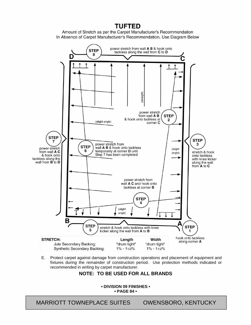
▪ DIVISION 09 FINISHES ▪
▪ PAGE 84 ▪
RESIDENCE INN BY MARRIOTT - LITTLETON, COLORADO
E. Protect carpet against damage from construction operations and placement of equipment and fixtures during the remainder of construction period. Use protection methods indicated or recommended in writing by carpet manufacturer.
NOTE: TO BE USED FOR ALL BRANDS
MARRIOTT TOWNEPLACE SUITES OWENSBORO, KENTUCKY
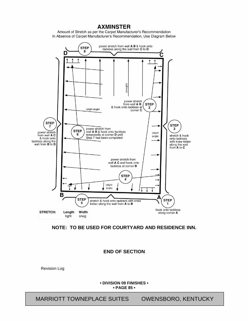
▪ DIVISION 09 FINISHES ▪
▪ PAGE 85 ▪
RESIDENCE INN BY MARRIOTT - LITTLETON, COLORADO
NOTE: TO BE USED FOR COURTYARD AND RESIDENCE INN.
END OF SECTION
Revision Log
MARRIOTT TOWNEPLACE SUITES OWENSBORO, KENTUCKY
▪ DIVISION 09 FINISHES ▪
▪ PAGE 86 ▪
RESIDENCE INN BY MARRIOTT - LITTLETON, COLORADO
SECTION 09 72 00 (09950) - WALL COVERINGS
PART 25 GENERAL 25.01 SUMMARY
A. Section Includes:
1. Vinyl Wall Covering
2. Prime Coat on Walls
3. Adhesives and Cleaning of Adjacent Surfaces
4. All accessories for complete installation
B. Related Sections:
1. Section 09 21 16 (09255) - Gypsum Board Assemblies
2. Section 09 90 00 (09900) - Painting
25.02 REFERENCES
A. ASTM International (ASTM) Publications:
1. E84 "Standard Test Method for Surface Burning Characteristics of Building Materials"
2. F793 “Standard Classification of Wall-covering by Durability Characteristics”
B. Gypsum Association (GA) Publications:
1. Recommended Levels of Gypsum Board Finish - GA-214-M-97
C. National Fire Protection Association (NFPA) Publications:
1. NFPA 265: Standard Methods of Fire Tests for Evaluating Room Fire Growth Contribution of Textile Coverings on Full Height Panels and Walls
25.03 SYSTEM DESCRIPTION
A. Contractor is responsible for receiving and handling on site and installing wall covering material furnished by Owner and will fill out and process all receiving reports furnished by Owner.
B. Provide strippable adhesive and primer for all wall covering.
C. Contractor shall provide wall covering quantity take-offs to the Owner within 45 days of award of the contract.
25.04 SUBMITTALS
A. General: Submit the following in accordance with Conditions of Contract and Division 01 Specification Sections.
B. Submit “Letter of Conformance” in accordance with Section 01 33 00 (01330) indicating specified items selected for use in project with the following supporting data.
1. Provide certification by the manufacturer that products supplied comply with local regulations controlling use of volatile organic compounds (VOC's).
2. Provide maintenance data including methods for maintaining wallcovering as well as precautions for use of cleaning materials and methods that could be detrimental to finishes and performance.
MARRIOTT TOWNEPLACE SUITES OWENSBORO, KENTUCKY

▪ DIVISION 09 FINISHES ▪
▪ PAGE 87 ▪
RESIDENCE INN BY MARRIOTT - LITTLETON, COLORADO
25.05 QUALITY ASSURANCE
A. Installer Qualifications: Engage an experienced installer who has completed five projects similar in material, design, and extent to that indicated for this Project and with a record of successful in-service performance.
B. Single Source Responsibility: Provide adhesives and primers produced by the same manufacturer.
C. Coordination of Work: Review Sections in which primers are provided to ensure compatibility of the total systems for various substrates.
1. Notify the Owner’s Representative of problems anticipated using the materials specified.
D. Mockups: Provide a sample application in one Guest Room for acceptance by the Owner's representative and to serve as a sample standard of quality for the balance of the work. Rework sample room if necessary to obtain Owner's acceptance.
25.06 DELIVERY, STORAGE, AND HANDLING
A. Store wall-covering in clean and dry area where temperatures are maintained at minimum 40 degrees F. with normal humidity. Do not store in upright position.
B. Take precautionary measures to prevent fire hazards with adhesives and solvents.
C. Where toxic materials and both toxic and explosive solvents and adhesives are used, appropriate precautions and proper ventilation must be provided.
D. Handle and store materials at the project site in original packages or containers clearly labeled to identify manufacturer, brand name, quality or grade, and fire hazard classifications.
E. Contractor is responsible for theft or damage to stored materials. Exercise care to prevent damage during delivery, handling and storage.
25.07 PROJECT CONDITIONS
A. Space Enclosure and Environmental Limitations: Do not install wall covering until space is enclosed and weatherproof, wet-work in space is completed and nominally dry, work above ceilings is complete, and ambient temperature and humidity conditions are and will be continuously maintained at values near those indicated for final occupancy.
1. Maintain surfaces and materials at constant minimum temperature of 60 degrees F and max temperature of 90 degrees F in areas of installation for at least 72 hours before and 48 hours after the application of materials.
2. Install only when humidity conditions approximate building design humidity.
B. Lighting: Do not install wall covering until a lighting level of not less than 15 foot-candles (160 lux) is provided on the surfaces to receive wall covering.
C. Ventilation: Provide continuous ventilation during installation and for not less than the time recommended by the wall covering manufacturer for full drying or curing.
D. Remove wall covering from its packaging and allow to acclimatize to the area of installation 24 hours.
E. Ensure maximum surface moisture conforms to wallcovering manufacturer's requirements and surface exhibits negative alkalinity.
25.08 EXTRA MATERIALS
A. Refer to Section 01 78 43 (01790) for requirements.
MARRIOTT TOWNEPLACE SUITES OWENSBORO, KENTUCKY

▪ DIVISION 09 FINISHES ▪
▪ PAGE 88 ▪
RESIDENCE INN BY MARRIOTT - LITTLETON, COLORADO
PART 26 MATERIALS 26.01 MATERIALS
A. Wallcovering: Refer to Interior Finish Index.
26.02 FIRE HAZARD CLASSIFICATION
A. Provide materials bearing the UL label and marking, indicating the fire hazard classification of the wall covering as determined by ASTM E84.
26.03 WALL COVERING PRIMER/ADHESIVE
A. Approved Manufacturers:
1. Avendra, LLC Preferred Manufactures:
a. None
2. Approved Manufacturers:
a. U.S. Vinyl Manufacturing Corporation (800-633-6425)
b. Roman Decorating Products (800-488-6117)
c. Gardner-Gibson, Inc. (813-248-2101)
B. Manufacturer's recommended Mildew-resistant, nonstaining[, strippable adhesive, primer, and sealer manufactured expressly for use with the selected wallcovering. Provide materials that contain mildew inhibitors that are nonstaining to the wall-covering.
C. New wallcovering over new gypsum board (except at Guestbaths): MANUFACTURER PRIMER ADHESIVE 1. Roman Decorating
Products “UltraPrime 909” “Ultra Pro 880”
or “Clear Strippable Pro 870” for use with pasting machine
2. Gardner-Gibson Not needed Dynamite 234 Premium Clear/Strippable or Dynamite 780 Flowable Clear/Strippable
3. U.S. Vinyl Not needed H. D. Clear Strippable 3000 D. New wallcovering over new gypsum board (at Guestbaths):
MANUFACTURER PRIMER ADHESIVE 1. Roman Decorating
Products Pro-977 “Ultra Pro 880”
or “Clear Strippable Pro 870” for use with pasting machine
2. Gardner-Gibson Dynamite 222.1 Acrylic Primer
Dynamite 234 Premium Clear/Strippable or Dynamite 780 Flowable Clear/Strippable
3. U.S. Vinyl Not needed H. D. Clear Strippable 3000 26.04 ACCESSORIES
A. Masking Tape:
1. Avendra, LLC Preferred Manufactures:
MARRIOTT TOWNEPLACE SUITES OWENSBORO, KENTUCKY
▪ DIVISION 09 FINISHES ▪
▪ PAGE 89 ▪
RESIDENCE INN BY MARRIOTT - LITTLETON, COLORADO
a. None
2. Approved Manufacturers:
a. "General Purpose Type"; 3M Adhesives, Coatings and Sealers Div. (612-733-1140)
26.05 GRAPHIC WALL COVERING PRIMER/ADHESIVE
A. Manufacturer's recommended adhesive, primer, and sealer manufactured expressly for use with the selected Graphic wallcovering. Provide materials that contain mildew inhibitors that are nonstaining to the wall-covering.
1. Avendra, LLC Preferred Manufactures:
a. None
2. Approved Manufacturers:
a. U.S. Vinyl Manufacturing Corporation (800-633-6425)
b. Roman Decorating Products (800-488-6117)
1) Primer: “UltraPrime 977”
2) Adhesive: “Ultra Pro 880” or “Clear Strippable Pro 870” for use with pasting machine.
PART 27 EXECUTION 27.01 INSPECTION
A. Examine substrates for compliance with requirements for moisture content and other conditions affecting performance of Work of this Section. Do not proceed with installation until unsatisfactory conditions have been corrected.
1. Refer to Section 09 21 16 (09255) - Gypsum Board Assemblies for the levels of gypsum board finish per GA-214 required for a proper substrate to apply the wall coverings.
a. Wall Covering: Level 4 Finish required.
b. Graphic Wall Cover: Level 5 Finish required.
B. Ensure surfaces to receive all covering are clean, true, and free to irregularities. Inspect surfaces before commencing work and report defects in writing to the Owner's representative.
C. Ensure wall surface flatness tolerances do not vary more than 1/8" in 10 feet, nor vary at a rate greater than 1/16" per running foot.
D. Schedule installation of wallcovering as late as possible in the construction schedule to prevent damage during construction and movement of materials.
E. Inspect wall covering for defects. Do not install defective wall covering. Notify Owner's representative of any defects immediately.
1. Notify the [Owner's Representative] of variations in color or pattern match. Do not continue with work until instructed by [Owner's Representative].
27.02 PREPARATION
A. Comply with manufacturers written instructions for surface preparation.
B. Test surfaces to receive wallcovering with a moisture meter. Do not install wallcovering on surfaces with a moisture content exceeding 4%.
C. Clean substrates of substances that could impair wall covering's bond, including mold, mildew, oil, grease, incompatible primers, and dirt.
MARRIOTT TOWNEPLACE SUITES OWENSBORO, KENTUCKY
▪ DIVISION 09 FINISHES ▪
▪ PAGE 90 ▪
RESIDENCE INN BY MARRIOTT - LITTLETON, COLORADO
D. Check painted surfaces for pigment bleeding. Sand gloss, semigloss, and eggshell finishes with fine sandpaper.
E. Acclimatize wall-covering materials by removing them from packaging in the installation areas not less than 24 hours before installation.
27.03 INSTALLATION - GENERAL
A. General: Comply with wall-coverings manufacturers' written installation instructions applicable to products and applications indicated, except where more stringent requirements apply.
27.04 INSTALLATION - PRIMER
A. Prime all new gypsum board with primer recommended by wall covering manufacturer. Apply primers full strength, no thinning permitted. .
27.05 INSTALLATION - WALLCOVERING
A. Install wall-covering prior to installation of all wall mounted plumbing, cabinets, molding and electrical fixtures.
B. Cut wall-covering panels in roll number sequence. Change run numbers at partition breaks and corners only. Install wall covering with no gaps or overlaps. Match pattern 72 inches above finish floor. Install seams vertical and plumb at least 6 inches from outside corners and 3 inches from inside corners. No horizontal seams. Remove air bubbles, wrinkles, blisters, and other defects. Trim edges for color uniformity, pattern match, and tight closure at seams and edges. Double cut seams.
1. Install non-match panels on the hanging surface, reversing every other panel unless otherwise recommended by the manufacturer. Match side joints for continuity.
2. Fill in over doors and windows as work progresses with panels cut in consecutive order from the roll.
3. Do not allow vertical joints to occur closer than 6 inches from outside corners not indicted to receive new corner guards.
a. Outside corners receiving corner guards should be used as a location to adjust wall-covering needing realignment due to “out of–plumb” walls.
C. Notify the Owner’s Representative immediately of variations in color or pattern match. Do not continue with work until instructed by the Owner’s Representative.
D. Refer to Joint Sealants Section 07 92 00 (07920) for sealant application at edges of wallcoverings where the wallcovering meets other materials.
27.06 CLEANING
A. Remove all excess adhesive from joints, wall mounted equipment, door frames, and other similar items. Use cleaning methods recommended by the wall-covering manufacturer. Replace strips that can not be cleaned.
END OF SECTION
Revision Log
MARRIOTT TOWNEPLACE SUITES OWENSBORO, KENTUCKY
▪ DIVISION 09 FINISHES ▪
▪ PAGE 91 ▪
RESIDENCE INN BY MARRIOTT - LITTLETON, COLORADO
SECTION 09 90 00 (09900) - PAINTING
PART 28 GENERAL 28.01 SUMMARY
A. Section Includes:
1. This Section includes surface preparation and the application of paint materials to exposed interior and exterior items and surfaces scheduled. Surface preparation, prime and finish coats specified are in addition to shop-priming and surface treatments.
2. Paint all exposed surfaces, whether or not colors are designated, except where a surface or material is indicated not to be painted or is to remain natural. Where an item or surface is not mentioned, paint the same color as similar adjacent materials or surfaces. If color or finish is not designated, the Owner will select from standard colors or finishes available.
3. Except in mechanical and electrical rooms, paint all exposed plumbing, heating, fire protection, and electrical material to match the walls and ceilings of that area unless noted otherwise. This shall include, but not be limited to, pipes, sprinkler piping, insulation, conduit, ducts, access panels, grilles, diffusers, hangers, exposed steel and iron supports, HVAC and electrical equipment that do not have a factory applied finish, whether the adjacent surfaces receive paint or not, and the like. Include dampers or baffles behind grilles.
4. Unless noted otherwise, painting is not required on pre-finished items, finished metal surfaces, concealed surfaces, operating parts, sprinkler heads, or labels.
a. All louvers and grilles to be painted to] [color as shown in Interior Finish Index] [.]
b. Labels: Do not paint over Underwriter's Laboratories, FMG or other code-required labels, or equipment name, identification, performance rating, or nomenclature plates.
B. Related Sections:
1. Section 08 11 13 (08110) - Steel Doors and Frames: Prime coat on new hollow metal work shall be furnished under this Section.
2. Prime coat on lintels shall be furnished under the Division 05 Sections.
3. Section 09 21 16 (09255) - Gypsum Board Assemblies: Spray applied textured coating specified in).
4. Section 09 96 00 (09960) - High-Performance Coatings: Prime and finish coat for exposed exterior ferrous metal items [and ferrous metal items located within Interior Pool areas] shall be furnished under that Section. Refer to that Section for items included.
28.02 REFERENCES
A. Underwriter's Laboratories, Inc. (UL) Standards
B. FM Global (FMG): Standards
C. ASTM International (ASTM) Publications:
1. D16 “Standard Terminology for Paint, Related Coatings, Materials, and Applications”
2. D2824 “Standard Specification for Aluminum-Pigmented Asphalt Roof Coatings, Nonfibered, Asbestos Fibered, and Fibered without Asbestos”
3. D1187 “Standard Specification for Asphalt-Base Emulsions for Use as Protective Coatings for Metal; 1997 (Re-approved 2002)”
MARRIOTT TOWNEPLACE SUITES OWENSBORO, KENTUCKY
▪ DIVISION 09 FINISHES ▪
▪ PAGE 92 ▪
RESIDENCE INN BY MARRIOTT - LITTLETON, COLORADO
D. Society of Protective Coatings (SSPC)
1. Surface Preparation Standards and Specifications
a. SSPC-SP 1, “Solvent Cleaning”
b. SSPC-SP 11, “Power Tool Cleaning to Bare Metal”
E. The Painting and Decorating Contractors of America (PDCA)
1. PDCA P5-94 “Benchmark Sample Procedures for Paint and Other Decorative Coating Systems”
F. Master Painter’s Institute, Inc. Publications:
1. MPI Architectural Painting Specification Manual"
G. Code of Federal Regulations (CFR) Publications:
1. 40 CFR, Part 59, Subpart D 2001, "National Volatile Organic Compound Emission Standards for Architectural Coatings"
H. Green Seal, Inc. Publications:
1. GS-11 “Green Seal Environmental Standard for Paints”, First Edition 1993.
I. U.S. Green Building Council's (USGBC) Publications:
1. (LEED-NC) Version 2.2 “LEED for New Construction and Major Renovations”
28.03 DEFINITIONS:
A. General: Standard coating terms defined in ASTM D16 apply to this Section.
B. "Paint" includes coating systems materials, primers, emulsions, enamels, stains, sealers and fillers, and other applied materials whether used as prime, intermediate or finish coats.
28.04 SUBMITTALS
A. General: Submit the following in accordance with Conditions of Contract and Division 01 Specification Sections.
B. Submit “Letter of Conformance” in accordance with Section 01 33 00 (01330) indicating specified items selected for use in project with the following supporting data.
1. Product Data: Submit manufacturer's technical information, label analysis, and application instructions for each paint material proposed for use.
2. Samples: Submit two representative samples of each major type of surface or material. Do not proceed with final painting until samples are approved.
3. Color Charts: In duplicate, for all paints, stains and special coatings. Identify with numbers used on the “Interior Finish Index” or on the Drawings.
4. Painting Schedule: In a form similar to the schedule herein outlining the type of paint to be used for each category, application, and color. Indicate each material and cross-reference specific coating, finish system, and application. Identify each material by manufacturer's catalog number and general classification.
5. Quality Control Submittals:
a. Certifications: Manufacturer's statement that paint materials conform to current regulations relating to lead content and air pollution emission requirements.
C. Written Permission in writing by the Owner's Representative for the use of Mechanical application methods.
MARRIOTT TOWNEPLACE SUITES OWENSBORO, KENTUCKY
▪ DIVISION 09 FINISHES ▪
▪ PAGE 93 ▪
RESIDENCE INN BY MARRIOTT - LITTLETON, COLORADO
1. Submit Green Seal Certification to GS-11 and description of the basis for certification.
2. Submit environmental data in accordance with Table 1 of E2129 for products provided under work of this Section.
3. Emission Test Reports.
28.05 QUALITY ASSURANCE
A. Single Source Responsibility: Provide primers and undercoat paint produced by the same manufacturer as the finish coats.
B. The Painting subcontractor shall have a minimum of five (5) years proven satisfactory experience and shall show proof before commencement of work that he will maintain a qualified crew of painters throughout the duration of the work.
C. Coordination of Work: Review Sections in which primers are provided to ensure compatibility of the total systems for various substrates.
D. Material Quality: Provide the manufacturer's best quality trade sale type paint material of the various types specified. Paint material containers not displaying manufacturer's product identification will not be acceptable. Proprietary names used to designate colors or materials are not intended to imply that products named are required or to exclude of equal products of other manufacturers.
E. Conform to requirements of local authorities having jurisdiction in regard to the storage, mixing, application and disposal of all paint and related waste materials.
F. Mockup:
1. When requested by the [Owner’s Representative], prepare and paint designated surface, area, room or item (in each color scheme) to requirements specified herein, with specified paint or coating showing selected colors, gloss / sheen, textures and workmanship to the specified standards for review and approval. When approved, surface, area, room and/or items shall become acceptable standard of finish quality and workmanship for similar on-site work.
28.06 DELIVERY AND STORAGE
A. Deliver materials to the job site in manufacturer's original, unopened packages and containers bearing manufacturer's name and label with trade name and manufacturer's instructions.
1. Product Name or Title of Material
2. Product Description (Generic Classification or Binder Type)
3. Manufacturer's Stock Number and Date of Manufacture
4. Contents by Volume, for Pigment and Vehicle Constituents
5. Thinning Instructions
6. Application Instructions
7. Color Name and Number
8. VOC Content
B. Approved materials without the above information will NOT be allowed on the Project site.
C. Store materials not in actual use in tightly covered containers at a minimum ambient temperature of 50 degrees F. in a well-ventilated area. Maintain containers used in storage of coatings in a clean condition, free of foreign materials and residue.
MARRIOTT TOWNEPLACE SUITES OWENSBORO, KENTUCKY
▪ DIVISION 09 FINISHES ▪
▪ PAGE 94 ▪
RESIDENCE INN BY MARRIOTT - LITTLETON, COLORADO
1. Protect from freezing. Keep storage area neat and orderly. Remove oily rags and waste daily. Take necessary precautionary measures to ensure that workmen and work areas are adequately protected from fire hazards and health hazards resulting from handling, mixing, and application of coatings.
28.07 PROJECT CONDITIONS:
A. Do not apply coatings in snow, rain, fog, or mist, or when the relative humidity exceeds 85 percent, or at temperatures less than 5 degrees F. above the dew point, or to damp or wet surfaces, unless otherwise permitted by manufacturer's printed instructions. Allow wet surfaces to dry thoroughly and attain the temperature and conditions specified before proceeding with or continuing the coating operation.
1. Unless specifically pre-approved by [Owner’s Representative], and the applied product manufacturer, perform no painting or decorating work when the ambient air and substrate temperatures are below 50° F for both interior and exterior work.
2. Perform no painting work when the maximum moisture content of the substrate exceeds:
a. 15% for wood.
b. 12 % for plaster and gypsum board.
28.08 WASTE MANAGEMENT AND DISPOSAL
A. Paint, stain and wood preservative finishes and related materials (thinners, solvents, etc.) are regarded as hazardous products and are subject to regulations for disposal. Obtain information on these controls from applicable government agencies having jurisdiction
B. All waste materials shall be separated and recycled. Where paint recycling is available, collect waste paint by type and provide for delivery to recycling or collection facility. Materials that cannot be reused must be treated as hazardous waste and disposed of in an appropriate manner.
C. To reduce the amount of contaminants entering waterways, sanitary/storm drain systems or into the ground the following procedures shall be strictly adhered to:
1. Retain cleaning water for water-based materials to allow sediments to be filtered out. In no case shall equipment be cleaned using free draining water.
2. Retain cleaners, thinners, solvents and excess paint and place in designated containers and ensure proper disposal.
3. Return solvent and oil soaked rags used during painting operations for contaminant recovery, proper disposal, or appropriate cleaning and laundering.
4. Dispose of contaminants in an approved legal manner in accordance with hazardous waste regulations.
5. Empty paint cans are to be dry prior to disposal or recycling (where available).
6. Close and seal tightly partly used cans of materials including sealant and adhesive containers and store protected in well ventilated fire-safe area at moderate temperature.
D. Set aside and protect surplus and uncontaminated finish materials not required by the Owner and deliver or arrange collection for verifiable re-use or re-manufacturing.
PART 29 PRODUCTS 29.01 MANUFACTURERS
A. Except where noted otherwise, all finishing materials, thinners, etc., shall be the best quality, first line materials as manufactured by one of the following manufacturers:
MARRIOTT TOWNEPLACE SUITES OWENSBORO, KENTUCKY

▪ DIVISION 09 FINISHES ▪
▪ PAGE 95 ▪
RESIDENCE INN BY MARRIOTT - LITTLETON, COLORADO
1. Avendra,LLC. Preferred Manufacturers:
a. Sherwin-Williams Co. (S-W) (800-321-8194)
2. Approved Manufacturers:
a. Benjamin Moore & Co. (BM) (888-236-6667)
b. Glidden Professional, a PPG Industries Brand (888-615-8169)
c. PPG Architectural Finishes, Inc. - Pittsburgh Paints (888-441-9695)
29.02 PAINT MATERIALS - GENERAL
A. Material Compatibility: Provide block fillers, primers, and finish-coat materials that are compatible with one another and with the substrates indicated under conditions of service and application, as demonstrated by manufacturer based on testing and field experience.
B. Material Quality: Provide manufacturer's best-quality paint material of the various coating types specified that are factory formulated and recommended by manufacturer for application indicated.
1. Paint-material containers not displaying manufacturer's product identification will NOT be acceptable.
a. Recycled content paints and primers will not be permitted for interior or exterior application.
b. Toxicity/IEQ: Comply with applicable regulations regarding toxic and hazardous materials, and as specified. Paints and coatings must meet or exceed the VOC and chemical component limits of Green Seal requirements.
1) Interior paint: Comply with Green Seal GS-11.
2) Exterior paint: Comply with Green Seal GS-11.
c. All materials used shall be lead and mercury free.
C. Raw linseed oil, turpentine, benzene, gloss oil, or coal oil shall not be used in any of the materials for painting work.
D. Chemical Components of Interior Paints and Coatings: Provide products that comply with the following limits for VOC content when calculated according to 40 CFR 59, Subpart D (EPA Method 24) and the following chemical restrictions: Flat Paints, Coatings and Primers: Not more that 50 g/L.
1. Non-Flat Paints, Coatings and Primers: Not more than 150 g/L
2. Anti-Corrosive and Anti-Rust Paints Applied to Ferrous Metals:
Not more than 250 g/L
3. Floor Coatings: Not more than 250 g/L
4. Stains: Not more than 250 g/L
5. Clear Wood Finishes, Varnishes and Sanding Sealers: Not more than 350 g/L
6. Clear Wood Finishes, Lacquers: Not more than 550 g/L
7. Exterior Flat Paints, Coatings and Primers: Not more than 100 g/L
8. Exterior Non-Flat Paints, Coatings and Primers: Not more than 150 g/L
MARRIOTT TOWNEPLACE SUITES OWENSBORO, KENTUCKY

▪ DIVISION 09 FINISHES ▪
▪ PAGE 96 ▪
RESIDENCE INN BY MARRIOTT - LITTLETON, COLORADO
9. Aromatic Compounds: Paints and coatings shall not contain more than 1.0 percent by weight of total aromatic compounds (hydrocarbon compounds containing one or more benzene rings).
10. Restricted Components: Paints and coatings shall not contain any of the following:
a. Acrolein.
b. Acrylonitrile.
c. Antimony.
d. Benzene.
e. Butyl benzyl phthalate.
f. Cadmium.
g. Di (2-ethylhexyl) phthalate.
h. Di-n-butyl phthalate.
i. Di-n-octyl phthalate.
j. 1,2-dichlorobenzene.
k. Diethyl phthalate.
l. Dimethyl phthalate.
m. Ethylbenzene.
n. Formaldehyde.
o. Hexavalent chromium.
p. Isophorone.
q. Lead.
r. Mercury.
s. Methyl ethyl ketone.
t. Methyl isobutyl ketone.
u. Methylene chloride.
v. Naphthalene.
w. Toluene (methylbenzene).
x. 1,1,1-trichloroethane.
y. Vinyl chloride.
29.03 SPAR VARNISH
A. Modified alkyd resin meeting federal regulations for lead and other heavy metals.
B. Clear, gloss finish.
C. Apply varnish on exposed ends of millwork as required in Section 12 30 00 (06400) - Architectural Woodwork and all field cuts in top and bottom rails of wood doors shall be sealed with two coats of varnish.
29.04 PROTECTIVE COATINGS
A. Bituminous Paint: Acid and alkali resistant type conforming to ASTM D1187.
MARRIOTT TOWNEPLACE SUITES OWENSBORO, KENTUCKY

▪ DIVISION 09 FINISHES ▪
▪ PAGE 97 ▪
RESIDENCE INN BY MARRIOTT - LITTLETON, COLORADO
B. Zinc Chromate Primer: Standard zinc chromate primer, selected from manufacturers listed in this Section.
C. Aluminum Pigmented Paint: Fibrated aluminum complying with ASTM D2824, Type IV.
D. Apply protective coating, bituminous paint, to isolate aluminum member as required.
29.05 PAINT SCHEDULE
A. Detailed specifications for the various surfaces are shown in the Paint Schedule. If these specifications conflict with the recommendations of the manufacturer, this discrepancy shall be brought to the attention of the Owner’s Representative, the Owner’s Representative shall decide which method shall be followed.
B. Refer to Paint Schedule at the end of this Section.
29.06 COLOR SAMPLES:
A. The Contractor shall furnish samples of all finishes in triplicate and obtain the approval of color match before starting work. Final colors must match exactly with the approved sample. Colors selection and quantity of different colors, as shown on Drawings, and approved by Owner's Representative.
B. Colors: Refer to the Interior Finish Index.
1. Where a different manufacturer is utilized that product identified in Interior Finish Index, color must match listed name or number.
29.07 MIXING AND TINTING
A. Unless otherwise specified herein or pre-approved, all paint shall be ready-mixed and pre-tinted. Re-mix all paint in containers prior to and during application to ensure break-up of lumps, complete dispersion of settled pigment, and color and gloss uniformity.
B. Paste, powder or catalyzed paint mixes shall be mixed in strict accordance with manufacturer's written instructions.
C. Where thinner is used, addition shall not exceed paint manufacturer's recommendations. Do not use kerosene or any such organic solvents to thin water-based paints.
PART 30 EXECUTION 30.01 EXAMINATION
A. Examine substrates and conditions under which painting will be performed for compliance with requirements. Do not begin application until unsatisfactory conditions have been corrected.
1. Start of painting will be construed as Applicator's acceptance of surfaces and conditions within a particular area.
30.02 SURFACES TO BE COATED
A. Unless noted otherwise, paint access doors, panels, registers, diffusers, light fixture trim, metal speaker covers and grilles the same color as adjacent surfaces. Paint access doors and panels in open position.
B. Paint interiors of ducts showing through registers and grilles flat black.
C. Paint prime coated or previously painted hinges the same as door frame to which they are attached.
D. Finish edges of doors to match faces.
E. Do not paint electrical device face plates or devices, sprinkler heads, smoke alarms or thermostats/covers.
MARRIOTT TOWNEPLACE SUITES OWENSBORO, KENTUCKY

▪ DIVISION 09 FINISHES ▪
▪ PAGE 98 ▪
RESIDENCE INN BY MARRIOTT - LITTLETON, COLORADO
F. Unless otherwise directed, remove and spray paint metal items/products that are removable such as vents, registers, access panels, covers, louvers and diffusers. Reinstall upon completion.
30.03 PREPARATION:
A. Remove hardware and hardware accessories, plates, machined surfaces, lighting fixtures, and items in place that are not to be painted, or provide protection prior to surface preparation and painting. Remove items if necessary for complete painting of the items and adjacent surfaces. Doors shall be removed before painting to paint bottom and top edges and then re-hung. Following completion of painting, reinstall items removed using workmen skilled in the trades involved.
B. Clean surfaces before applying paint or surface treatments. Schedule cleaning and painting so dust and other contaminants will not fall on wet, newly painted surfaces.
C. Provide protection for adjacent surfaces as necessary to prevent paint from coming into contact with adjacent materials not scheduled for painting.
30.04 SURFACE PREPARATION:
A. Clean and prepare surfaces to be painted in accordance with manufacturer's instructions for each particular substrate condition. Notify Architect in writing of problems anticipated using specified finish coat material with substrates primed by others.
B. Cementitious Surfaces: Prepare concrete, concrete masonry, cement plaster and similar surfaces to be painted by removing efflorescence, chalk, dust, dirt, grease, oils, and release agents. Roughen as required to remove glaze.
1. Determine alkalinity and moisture content of surfaces to be painted. Do not paint surfaces where moisture content exceeds that permitted in manufacturer's printed directions.
2. If hardeners or sealers have been used to improve curing, use mechanical methods of surface preparation.
a. Use abrasive blast-cleaning methods if recommended by paint manufacturer.
b. Determine alkalinity and moisture content of surfaces by performing appropriate tests. If surfaces are sufficiently alkaline to cause the finish paint to blister and burn, correct this condition before application. Do not paint surfaces if moisture content exceeds that permitted in manufacturer's written instructions.
c. Clean concrete floors to be painted with a 5 percent solution of muriatic acid or other etching cleaner. Flush the floor with clean water to remove acid, neutralize with ammonia, rinse, allow to dry, and vacuum before painting.
3. At areas to receive epoxy paint, clean concrete with muriatic acid, wash per manufacturers recommendations.
C. Ferrous Metals: Clean non-galvanized ferrous metal surfaces that have not been shop-coated; remove oil, grease, dirt, loose mill scale and other foreign substances. Use solvent or mechanical cleaning methods that comply with recommendations of the Steel Structures Painting Council.
1. Touch-up shop-applied prime coats that have been damaged, and bare areas. Wire-brush, clean with solvents, and touch-up with the same primer as the shop coat.
2. At areas to receive epoxy paint, prepare steel surfaces to SSPC-SPII power tool clean.
MARRIOTT TOWNEPLACE SUITES OWENSBORO, KENTUCKY
▪ DIVISION 09 FINISHES ▪
▪ PAGE 99 ▪
RESIDENCE INN BY MARRIOTT - LITTLETON, COLORADO
D. Galvanized Surfaces: Utilize SSPC-SP1 solvent cleaning and chemical wash (tri-sodium phosphate). Power wash with tri-sodium phosphate type cleaner (5% solution at 140 degrees F.) and solvent clean after rinsing and drying with a non-petroleum based solvent cleaner so that surface is free of oil and surface contaminants. Remove pretreatment from galvanized sheet metal fabricated from coil stock, by mechanical methods.
1. Touch-up shop-applied prime coats that have been damaged, and bare areas. Wire-brush clean with solvents, and touch-up with the same primer as the shop coat.
E. Wood Surfaces:
1. General:
a. Clean surfaces of dirt, oil, and other foreign substances with scrapers, mineral spirits, and sandpaper, as required. Sand surfaces exposed to view smooth and dust off.
b. Scrape and clean small, dry, seasoned knots, and apply a thin coat of white shellac or other recommended knot sealer before applying primer. After priming, fill holes and imperfections in finish surfaces with putty or plastic wood filler. Sand smooth when dried.
c. Delete subparagraphs below if these requirements are specified in other Sections.
d. Prime, stain, or seal wood to be painted immediately on delivery. Prime edges, ends, faces, undersides, and backsides of wood, including cabinets, counters, cases, and paneling.
e. When transparent finish is required, backprime with spar varnish.
f. Backprime paneling on interior partitions where masonry, plaster, or other wet wall construction occurs on backside.
g. Seal tops, bottoms, and cutouts of unprimed wood doors with a heavy coat of varnish or sealer immediately on delivery.
30.05 MATERIALS PREPARATION
A. Mix and prepare paint in accordance with manufacturer's directions.
B. Stir material before application to produce a mixture of uniform density; stir as required during application. Do not stir surface film into material. Remove film and, if necessary, strain before using.
C. Use only thinners approved by manufacturer, and only within recommended limits.
30.06 APPLICATION
A. Apply paint in accordance with manufacturer's directions. Use applicators and techniques best suited for substrate and type of material being applied. Do not paint over dirt, rust, scale, grease, moisture, scuffed surfaces, or conditions detrimental to formation of a durable paint film.
B. Paint colors, surface treatments, and finishes are indicated in "schedules."
C. The number of coats and film thickness required is the same regardless of application method. Do not apply succeeding coats until previous coat has cured. Sand between applications where required to produce a smooth, even surface. Apply additional coats when undercoats or other conditions show through final coat, until paint film is of uniform finish, color, and appearance.
MARRIOTT TOWNEPLACE SUITES OWENSBORO, KENTUCKY

▪ DIVISION 09 FINISHES ▪
▪ PAGE 100 ▪
RESIDENCE INN BY MARRIOTT - LITTLETON, COLORADO
D. The term "exposed surfaces" includes areas visible when permanent or built-in items are in place. Extend coatings in these areas to maintain system integrity and provide desired protection.
E. Paint back sides of access panels and removable or hinged covers to match exposed surfaces.
F. Omit primer on metal surfaces that have been shop-primed, unless primer becomes worn, damaged, or more than six months old from date of delivery to job site.
G. Paint all edges of every door to match faces, including top and bottoms.
30.07 MINIMUM COATING THICKNESS
A. Apply materials at the manufacturer's recommended spreading rate. Provide total dry film thickness of the system as recommended by the manufacturer.
30.08 BLOCK FILLERS:
A. Apply block fillers at a rate to ensure complete coverage with pores filled.
30.09 PRIME COATS:
A. Before application of finish coats, apply a prime coat as recommended by the manufacturer to material required to be painted or finished, and has not been prime coated by others.
B. Tinting of primers will not be permitted.
C. Re-coat primed and sealed substrates where there is evidence of suction spots or unsealed areas in the first coat to assure a finish coat with no burn-through or other defects due to insufficient sealing.
D. Back Priming:
1. All wood trim shall be back primed before installation. Spot prime all ends of trim.
a. Backprime and paint face and edges of plywood service panels for telephone and electrical equipment before installation to match adjacent wall surface.
30.10 BRUSH APPLICATION:
A. Brush-out and work brush coats into surfaces in an even film. Eliminate cloudiness, spotting, holidays, laps, brush marks, runs, sags, ropiness, or other surface imperfections. Draw neat glass lines and color breaks. Apply primers and first coats by brush unless manufacturer's instructions permit use of mechanical applicators.
30.11 ROLLER APPLICATION
A. Rollers: Use rollers of carpet, velvet-back, or high-pile sheep's wool as recommended by manufacturer for material and texture required.
30.12 MECHANICAL APPLICATIONS:
A. Mechanical methods for paint application will ONLY be permitted by written permission of the Architect. All suite entry doors must be brush applied.
30.13 FIELD QUALITY CONTROL
A. Match approved samples for color, texture and coverage. Remove, refinish or repaint work not in compliance with specified requirements.
B. Where touch-ups occur, match color and sheen of existing surface. Touch-ups must blend invisibly, or painting must be extended to nearest corner or other termination point, as acceptable to the Owner’s Representative.
MARRIOTT TOWNEPLACE SUITES OWENSBORO, KENTUCKY
▪ DIVISION 09 FINISHES ▪
▪ PAGE 101 ▪
RESIDENCE INN BY MARRIOTT - LITTLETON, COLORADO
C. Painted exterior and interior surfaces shall be considered to lack uniformity and soundness if any of the following defects are apparent to the Owner’s Representative:
1. Brush / roller marks, streaks, laps, runs, sags, drips, heavy stippling, hiding or shadowing by inefficient application methods, skipped or missed areas, and foreign materials in paint coatings.
2. Evidence of poor coverage at rivet heads, plate edges, lap joints, crevices, pockets, corners and re-entrant angles.
3. Damage due to touching before paint is sufficiently dry or any other contributory cause.
4. Damage due to application on moist surfaces or caused by inadequate protection from the weather.
5. Damage and/or contamination of paint due to blown contaminants (dust, spray paint, etc.).
6. Visible defects are evident on vertical surfaces when viewed at normal viewing angles from a distance of not less than 48”.
7. Visible defects are evident on horizontal surfaces when viewed at normal viewing angles from a distance of not less than 48”.
8. Visible defects are evident on ceiling, soffit and other overhead surfaces when viewed at normal viewing angles.
9. When the final coat on any surface exhibits a lack of uniformity of color, sheen, texture,
D. Owner reserves the right to invoke the following test procedure at any time and as often as Owner deems necessary during the period when paint is being applied:
1. Owner will engage a qualified independent testing agency to sample paint material being used. Samples of material delivered to Project will be taken, identified, sealed, and certified in the presence of Contractor.
2. Testing agency will perform appropriate tests for the following characteristics as required by Owner:
a. Dry Film Thickness.
b. Volume Solids
c. Content of the material actually delivered to the site as compared to the product's published label analysis
3. Owner may direct Contractor to stop painting if test results show material being used does not comply with specified requirements. Contractor shall remove noncomplying paint from Project site, pay for testing, and repaint surfaces previously coated with the noncomplying paint. If necessary, Contractor may be required to remove noncomplying paint from previously painted surfaces if, on repainting with specified paint, the two coatings are incompatible.
30.14 CLEANING
A. At the end of each work day, remove empty cans, rags, rubbish, and other discarded paint materials from the site.
1. Clean equipment and dispose of wash water / solvents as well as all other cleaning and protective materials (e.g. rags, drop cloths, masking papers, etc.), paints, thinners, paint removers / strippers in accordance with the safety requirements of authorities having jurisdiction
MARRIOTT TOWNEPLACE SUITES OWENSBORO, KENTUCKY

▪ DIVISION 09 FINISHES ▪
▪ PAGE 102 ▪
RESIDENCE INN BY MARRIOTT - LITTLETON, COLORADO
B. Upon completion of painting, clean glass and paint-spattered surfaces. Remove spattered paint by washing, scraping, or other proper methods, using care not to scratch or damage adjacent finished surfaces.
C. Protect work of other trades, whether to be painted or not, against damage from painting. Correct damage by cleaning, repairing or replacing, and repainting, as acceptable to Architect.
D. Provide "Wet Paint" signs to protect newly-painted finishes. Remove temporary protective wrappings provided by others for protection of their work after completion of painting operations. At completion of construction activities of other trades, touch-up and restore damaged or defaced painted surfaces.
END OF SECTION
Revision Log
MARRIOTT TOWNEPLACE SUITES OWENSBORO, KENTUCKY
▪ DIVISION 09 FINISHES ▪
▪ PAGE 103 ▪
RESIDENCE INN BY MARRIOTT - LITTLETON, COLORADO
SECTION 09 94 13 (09941) - TEXTURED FINISHING
PART 31 GENERAL 31.01 SUMMARY
A. Section Includes:
1. Spray Applied Textured Finish and Primer
a. Textured Finish for Ceilings.
b. Textured Finish for Walls.
B. Related Sections:
1. Section 01 35 16 (01120) – Alteration Project Procedures
2. Section 06 20 00 (06200) - Finish Carpentry
3. Section 07 92 00 (07920) – Joint Sealants
4. Section 09 21 16 (09255) – Gypsum Board Assemblies
5. Section 09 21 16.23 (09265) - Gypsum Board Shaft-Wall Assemblies
6. Section 09 72 00 (09950) – Wall Coverings
7. Section 09 90 00 (09900) - Painting
31.02 REFERENCES
A. ASTM International (ASTM) Publications:
1. C11 “Standard Terminology Relating to Gypsum and Related Building Materials and Systems”
2. C475 “Standard Specification for Joint Compound and Joint Tape for Finishing Gypsum Board”
3. C840 “Standard Specification for Application and Finishing of Gypsum Board”
4. E84 “Standard Test Method for Surface Burning Characteristics of Building Materials”
5. E90 “Standard Test Method for Laboratory Measurement of Airborne Sound Transmission Loss of Building Partitions and Elements”
6. E119 “Standard Test Methods for Fire Tests of Building Construction and Materials”
7. E413 “Classification for Rating Sound Insulation”
B. Gypsum Association (GA) Publications:
1. GA-214 “Recommended Levels of Gypsum Board Finish”
2. GA-216 “Application and Finishing Of Gypsum Panel Products”
3. GA-505 for definitions of terms for gypsum board assemblies not defined in this Section
C. United States Gypsum Co. (USG):
1. "Gypsum Construction Handbook"
MARRIOTT TOWNEPLACE SUITES OWENSBORO, KENTUCKY
▪ DIVISION 09 FINISHES ▪
▪ PAGE 104 ▪
RESIDENCE INN BY MARRIOTT - LITTLETON, COLORADO
31.03 DEFINITIONS
A. Gypsum Board Construction Terminology: Refer to ASTM C11 and GA-505 for definitions of terms for gypsum board construction not otherwise defined in this Section or other referenced standards.
31.04 SUBMITTALS
A. General: Submit the following in accordance with Conditions of Contract and Division 01 Specification Sections.
B. Submit “Letter of Conformance” in accordance with Section 01 33 00 (01330) indicating specified items selected for use in project with the following supporting data.
1. Submit Product Data for each type of product specified.
2. Samples: Submit two representative samples of each major type of surface or material. Do not proceed with final application of textured finish until samples are approved.
3. Shop Drawings: Show locations, fabrication, and installation of control and expansion joints including plans, elevations, sections, details of components, and attachments to other units of Work.
4. Written Certification by the manufacturer of applicator's certification to install textured finish system.
31.05 QUALITY ASSURANCE
A. Spray applied textured finish installers shall have successfully completed within last three years, at least three textured coating applications similar in type and size of this project [and which is approved and certified by manufacturer of textured finish system materials].
B. Coordination:
1. Review other sections of these specifications in which prime paints, raw substrates, or other substances might be present to ensure compatibility of total coatings system. Upon request from other trades, furnish information, or characteristics of coating materials to ensure compatible substrate materials and finishes are used.
31.06 DELIVERY, STORAGE, AND HANDLING
A. Deliver materials in original packages, containers, or bundles bearing brand name and identification of manufacturer or supplier.
1. Product Name or Title of Material
2. Product Description (Generic Classification or Binder Type)
3. Manufacturer's Stock Number and Date of Manufacture
4. Contents by Volume, for Pigment and Vehicle Constituents
5. Application Instructions
6. Color Name and Number
7. VOC Content
B. Approved materials without the above information will NOT be allowed on the Project site.
C. Store materials inside under cover and keep them dry and protected against damage from weather, direct sunlight, surface contamination, corrosion, construction traffic, and other causes in strict accordance with manufacturer’s recommendations.
MARRIOTT TOWNEPLACE SUITES OWENSBORO, KENTUCKY
▪ DIVISION 09 FINISHES ▪
▪ PAGE 105 ▪
RESIDENCE INN BY MARRIOTT - LITTLETON, COLORADO
31.07 PROJECT CONDITIONS
A. Environmental Conditions, General: Establish and maintain environmental conditions for finishing gypsum board to comply with ASTM C840 manufacturers recommendations as to environmental conditions under which coating can be applied, whichever are more stringent.
B. Room Temperatures: Maintain temperature at not less than 65 degrees F during installation. Do not exceed 95 deg. F when using temporary heat sources.
C. Ventilate building spaces to remove water not required for drying joint treatment materials. Avoid drafts during dry, hot weather to prevent materials from drying too rapidly.
1. Provide adequate ventilation to permit drying during curing.
31.08 EXTRA MATERIALS
A. Furnish extra textured top coating materials from the same production run as the materials applied in the quantities described below. Package textured coating materials in unopened, factory-sealed containers for storage.
1. Quantity: Furnish the Owner with two gallons of each material and color applied in addition to any leftover amounts.
2. All cans shall be labeled with color names and color formula numbers.
31.09 WARRANTY
A. Special Warranty:
1. Warranty period is 5 years after date of Substantial Completion for labor and material against Mold, Mildew and Algae.
PART 32 PRODUCTS 32.01 SPRAY APPLIED TEXTURED FINISH
A. Texture finish for Ceilings:
1. Avendra, LLC Preferred Manufacturers:
a. None
2. Approved Manufacturers:
a. “Sheetrock Brand Wall and Ceiling Spray Texture QT”; United States Gypsum Co. (800-950-3839)
b. "ProForm Perfect Spray"; National Gypsum Company, Gold Bond Building Products Div. (800-628-4662)
3. Texture: Refer to Interior Finish Index.
4. Finish color: Refer to Interior Finish Index.
5. Uniform color with no areas or spots of discoloration.
B. Texture Finish for Walls:
1. Avendra, LLC Preferred Manufacturers:
a. None
2. Approved Manufacturers:
a. "Sheetrock Brand Wall and Ceiling Spray Texture - Unaggregated "Tuf Tex" - Spatter Knockdown, United States Gypsum Co. (312-606-4000)
MARRIOTT TOWNEPLACE SUITES OWENSBORO, KENTUCKY
▪ DIVISION 09 FINISHES ▪
▪ PAGE 106 ▪
RESIDENCE INN BY MARRIOTT - LITTLETON, COLORADO
b. "ProForm Perfect Spray EM" Spatter Knockdown; National Gypsum Company, Gold Bond Building Products Div. (800-628-4662)
3. Texture: Refer to Interior Finish Index.
4. Finish color: Refer to Interior Finish Index.
5. Uniform color with no areas or spots of discoloration.
C. Textured Finish for Walls – Mildew Prone Locations (Except Pools):
1. General: Rating of 10 "No Mold Growth" as tested for 4 weeks according to ASTM D3273.
a. Texture: Refer to Interior Finish Index.
b. Finish color: Refer to Interior Finish Index.
c. Uniform color with no areas or spots of discoloration.
d. System must have integral color throughout thickness of system.
2. Avendra, LLC Preferred Manufacturers:
a. None
3. Approved Manufacturers:
a. "Texturi Systems 3"; Comex Paints USA (210-639-6069)
1) VOC: <50 g/L
2) Total System Dry Film Thickness (DFT): 15 to 20 mils
b. "Supreme-Tex Acrylic Textures"; U.S. Textures, Inc. (800-414-8805)
1) VOC: <50 g/L
2) Total System Dry Film Thickness (DFT): 16 to 25 mils
c. “Commercial Texture System 3000”; Litex Finishing Systems, Inc. (800-340-0361)
1) VOC: <50 g/L
2) Total System Dry Film Thickness (DFT): 12 to 20 mils
D. Textured Finish Auxiliary Materials:
1. General: Provide auxiliary materials for textured finish materials to comply with referenced installation standards and the recommendations of the manufacturer of the textured finishes.
2. Primer: Of type recommended by texture finish manufacturer.
3. Polystyrene Aggregated Finish for Ceilings: Factory-packaged proprietary powder product formulated with polystyrene aggregates for mixing with water at Project site to produce the texture indicated below by spray application, with flame-spread and smoke-developed ratings of not more than 25 per ASTM E84:
a. Texture: Refer to Interior Finish Index.
b. Finish color: Refer to Interior Finish Index
c. Flat finish - no gloss.
d. Uniform color with no areas or spots of discoloration.
MARRIOTT TOWNEPLACE SUITES OWENSBORO, KENTUCKY
▪ DIVISION 09 FINISHES ▪
▪ PAGE 107 ▪
RESIDENCE INN BY MARRIOTT - LITTLETON, COLORADO
4. Water: All water used in system shall be clean and free from deleterious amounts of foreign material.
5. Other Materials: All other materials not specifically described but required for a complete and proper installation of the textured finish shall be as selected by the Contractor, subject to approval by the [Owner’s Representative].
PART 33 EXECUTION 33.01 EXAMINATION
A. Examine substrates with Installer present, to which textured finish will be applied, for compliance with requirements for installation tolerances and other conditions affecting performance of finishes specified in this Section.
B. Installer shall examine areas and conditions under which coating work is to be applied and notify the Contractor in writing of conditions detrimental to proper and timely completion of the work.
C. Do not proceed with installation until unsatisfactory conditions have been corrected.
33.02 PREPARATION - SPRAY APPLIED TEXTURED FINISH
A. General: Remove hardware and hardware accessories, plates, machined surfaces, light fixtures, and similar items already installed that are not to be coated. If removal is impractical or impossible because of size or weight of item, provide surface-applied protection before surface preparation and coating.
1. After completing coating operations in each area, reinstall items removed using workers skilled in trades involved.
B. Cleaning: Before applying coatings or other surface treatments, clean substrates of substances in accordance with manufacturer’s recommendations that could impair bond of coating systems. Remove oil and grease before cleaning.
1. Schedule cleaning and coating application so dust and other contaminants from cleaning operations will not fall on wet, newly coated surfaces.
C. Surface Preparation: Clean and prepare surfaces to be coated according to the manufacturer's written instructions for the particular substrate conditions, and as specified.
1. Surface Preparation and Primer: Prepare and apply primer to gypsum panels and other surfaces receiving texture finishes according to texture finish manufacturer's instructions. Apply primer only to surfaces that are clean, dry, and smooth. Primer: Apply at not less than manufacturer's recommended spreading rate, to establish a total dry film thickness recommended by coating manufacturer.
2. Accent Walls may require special wall preparation, refer to manufacturer’s recommendations.
3. Gypsum Board Preparation:
a. Treat joints and fastener heads in accordance with spray applied finish manufacturer’s recommendations and Section 09 21 16 “Gypsum Board Assemblies”.
b. Fill and smooth scratches and scuffs in gypsum board surfaces.
c. Allow gypsum board joint treatment and fillers to thoroughly dry before application.
4. Cementitious Surfaces: Prepare concrete, concrete masonry, precast concrete, and similar surfaces to be coated. Remove efflorescence, chalk, dust, dirt release agents,
MARRIOTT TOWNEPLACE SUITES OWENSBORO, KENTUCKY

▪ DIVISION 09 FINISHES ▪
▪ PAGE 108 ▪
RESIDENCE INN BY MARRIOTT - LITTLETON, COLORADO
grease, oil, and similar substances by abrasive or water blasting, followed by a clear-water rinse.
a. Remove mildew and neutralize surfaces according to the manufacturer's written recommendations before patching materials are applied.
b. Roughen to remove glaze. Use abrasive blast-cleaning methods if recommended by coating manufacturer.
c. If hardeners or sealers have been used to improve curing, use mechanical methods of surface preparation.
d. All holes in precast concrete planks shall be filled to prevent dark colored pin-holes in finished application.
e. Remove any projections from precast concrete that will telegraph through new finish.
f. Prime surface of concrete with primer as recommended by manufacturer of finish. Utilize stain blocking type.
g. Crack Repair: Repair cracks according to the manufacturer's written recommendations before coating surfaces.
h. Cracks Larger than 1/32": Cut out static cracks, voids, or honeycombing larger than 1/32" and patch with materials recommended by the coating manufacturer. Identify dynamic cracks and treat according to the manufacturer's written recommendations before beginning application.
5. Install sealant in joints. Refer to Section 07 92 00 “Joint Sealants”.
6. Material Preparation: Carefully mix and prepare materials according to the manufacturer's written instructions to achieve a smooth, heavy-batter consistency. Mixing of paint with texture finish as recommended by the manufacturer or applying paint to substrate prior to applying texture finish as recommended by the manufacturer is suggested to achieve uniform color without dark spots from holes without staining.
33.03 INSTALLATION - SPRAY APPLIED TEXTURED FINISH
A. General: Apply finish to exposed surfaces indicated.
1. Textured Finish Application: Mix and apply finish to gypsum panels, concrete, and other surfaces indicated to receive texture finish according to texture finish manufacturer's directions. Using power spray equipment acceptable to texture finish manufacturer, produce a uniform texture matching approved field samples, free of starved spots, pin-holes, or other evidence of thin application or of application patterns, and free of excessive globules.
2. Prevent textured finishes from coming into contact with surfaces not indicated to receive texture finish by covering them with masking agents, polyethylene film, or other means. If despite these precautions, texture finishes contact these surfaces, immediately remove droppings and overspray as recommended by texture finish manufacturer to prevent damage.
3. Minimum Coating Thickness: Apply each material at not less than the manufacturer's recommended spreading rate. Provide total cured material thickness indicated or as recommended by the manufacturer.
a. Coverage shall be complete including precast joints.
b. Dark accent colored walls may require additional application methods. Include all work as required to achieve approved colors and textures.
MARRIOTT TOWNEPLACE SUITES OWENSBORO, KENTUCKY
▪ DIVISION 09 FINISHES ▪
▪ PAGE 109 ▪
RESIDENCE INN BY MARRIOTT - LITTLETON, COLORADO
4. Lightly sand the entire surface with extra fine grit paper 24 hours after application to remove all rough spots or abrasive burrs and then remove dust.
5. Remove masking tape and clean all adjacent surfaces at the end of each work day. Do not leave masking tape or waste materials in place for more than thirty-six (36) hours
B. Application Procedures - Spatter Knockdown Finish:
1. Apply primer to wallboard after all wallboard joints are finished, prior to spatter application.
2. Mix spatter to heavy latex paint-like consistency. Do not add paint to spatter mixture.
3. Paint is to be applied after texturing has been completed.
4. When primer is fully dry, apply spatter with spray gun in a rapid random fashion standing approximately six-feet from surface.
5. For Knockdown Finish: After splattering surface, wait 3 to 20 minutes, then lightly flatten only tops of spatters with clear knockdown blade, flat blade or flat hand trowel. Application may vary based on wall conditions, projects conditions, and selected finish.
6. Amount, size or density of spatters depends on pressures used, preference and humidity. Final texture as approved by the [Owner’s Representative].
33.04 ADJUST AND CLEAN
A. Touch-up, repair or replace damaged finishes as necessary to restore coating work to a new and unblemished condition.
B. Clean spilled or splattered materials from adjacent surfaces not to be coated, immediately before coating has achieved an initial set. Do not scratch or damage adjacent finished surfaces.
C. Repair floors, walls, and other surfaces which have been stained, marred, or otherwise damaged during the textured finish application. Daily remove unused materials, containers, and equipment. Clean floors and leave broom clean.
1. When installing more than one batch, definable areas where each batch was applied. Then, retain an appropriate amount of this material to complete punch-out touch ups.
33.05 PROTECTION
A. Provide final protection and maintain conditions, in a manner suitable to installer, which ensures textured finishes being without damage or deterioration at time of Substantial Completion.
END OF SECTION Revision Log
MARRIOTT TOWNEPLACE SUITES OWENSBORO, KENTUCKY

▪ DIVISION 09 FINISHES ▪
▪ PAGE 110 ▪
RESIDENCE INN BY MARRIOTT - LITTLETON, COLORADO
SECTION 09 96 00 (09960) - HIGH-PERFORMANCE COATINGS
PART 34 GENERAL 34.01 SUMMARY
A. Section Includes:
1. Special coating for exterior [and] [, indoor pool area] [and] exposed ferrous metals.
2. Epoxy Floor Coating
3. Concrete Stain/Sealer
4. This Section includes surface preparation and the application of special coating materials to items scheduled.
a. Surface preparation, prime and finish coats specified are in addition to shop-priming and surface treatments.
5. Paint all exposed surfaces, whether or not colors are designated, except where a surface or material is indicated not to be painted or is to remain natural. Where an item or surface is not mentioned, paint the same color as similar adjacent materials or surfaces. If color or finish is not designated, the [Owner’s Representative] will select from standard colors or finishes available.
6. Painting is not required on pre-finished items, operating parts, or labels.
a. Labels: Do not paint over Underwriter's Laboratories, Factory Mutual or other code-required labels, or equipment name, identification, performance rating, or nomenclature plates.
B. Related Sections:
1. Section 03 30 00 (03300) - Cast-in-Place Concrete
2. Section 03 54 13 (03500) - Cementitious Decks and Underlayment
3. Section 05 52 00 (05520) - Handrails and Railings
4. Section 08 11 13 (08110) - Steel Doors and Frames
5. Section 09 90 00 (09900) - Painting
34.02 REFERENCES
A. ASTM International (ASTM) Publications:
1. D16 “Standard Terminology for Paint, Related Coatings, Materials, and Applications”
B. The Society for Protective Coatings (SSPC) Publications:
1. SP - Surface Preparation Standards and Specifications
a. SSPC-SP 1, “Solvent Cleaning”
b. SSPC-SP 3 "Power Tool Cleaning"
c. SSPC-SP 6/NACE No. 3, “Commercial Blast Cleaning”
d. SSPC-SP 10/NACE No. 2, “Near-White Blast Cleaning”
e. SSPC-SP 11, “Power Tool Cleaning to Bare Metal”
C. The Painting and Decorating Contractors of America (PDCA)
MARRIOTT TOWNEPLACE SUITES OWENSBORO, KENTUCKY
▪ DIVISION 09 FINISHES ▪
▪ PAGE 111 ▪
RESIDENCE INN BY MARRIOTT - LITTLETON, COLORADO
1. PDCA P5-94 “Benchmark Sample Procedures for Paint and Other Decorative Coating Systems”
34.03 DEFINITIONS:
A. "Special Coatings" includes coating systems materials, primers, emulsions, enamels, stains, sealers and fillers, and other applied materials whether used as prime, intermediate or finish coats.
34.04 SUBMITTALS
A. General: Submit the following in accordance with Conditions of Contract and Division 01 Specification Sections.
B. Submit “Letter of Conformance” in accordance with Section 01 33 00 (01330) indicating specified items selected for use in project with the following supporting data.
1. Product Data: Submit manufacturer's technical information, including basic materials analysis and application instructions for each coating material specified.
a. List each material and cross-reference the specific coating and finish system and application. Identify each material by the manufacturer's catalog number and general classification.
2. Color Charts: In duplicate, for all paints, stains and special coatings. Identify with numbers used on the “Finish Index” on Drawings.
3. Ferrous Metal: Provide two 4" square samples of metal surfaces for each type of color and finish. Define by steps.
34.05 QUALITY ASSURANCE
A. Single Source Responsibility: Provide primers and undercoat paint produced by the same manufacturer, unless noted otherwise. Use only thinners recommended by the manufacturer, and only within recommended limits.
B. Coordination of Work: Review sections in which other coatings are provided to ensure compatibility of the total systems for various substrates.
1. Notify the Owner’s Representative of problems anticipated using the materials specified.
C. All ferrous metal shall be inspected for conformance with these Specifications and manufacturer specifications shall be for:
1. Surface Preparation
2. Prime and Intermediate Coats
34.06 DELIVERY, STORAGE, AND HANDLING
A. Deliver materials to the job site in manufacturer's original, unopened packages and containers bearing manufacturer's name and label with trade name and manufacturer's instructions.
1. Product Name or Title of Material
2. Product Description (Generic Classification or Binder Type)
3. Manufacturer's Stock Number and Date of Manufacture
4. Contents by Volume, for Pigment and Vehicle Constituents
5. Thinning Instructions
6. Application Instructions
7. Color Name and Number
MARRIOTT TOWNEPLACE SUITES OWENSBORO, KENTUCKY

▪ DIVISION 09 FINISHES ▪
▪ PAGE 112 ▪
RESIDENCE INN BY MARRIOTT - LITTLETON, COLORADO
8. VOC Content
B. Store materials not in actual use in tightly covered containers at a minimum ambient temperature of 50 degrees F. in a well-ventilated area. Maintain containers used in storage of coatings in a clean condition, free of foreign materials and residue.
1. Protect from freezing. Keep storage area neat and orderly. Remove oily rags and waste daily. Take necessary precautionary measures to ensure that workmen and work areas are adequately protected from fire hazards and health hazards resulting from handling, mixing, and application of coatings.
34.07 PROJECT CONDITIONS
A. Apply coatings only when the temperature of surfaces to be coated and surrounding air temperatures are above 50 degrees F., unless otherwise permitted by manufacturer's printed instructions. High solids products require temperature range of 70-90 degrees F.
B. Do not apply coatings in snow, rain, fog, or mist, or when the relative humidity exceeds 85 percent, or at temperatures less than 5 degrees F. above the dew point, or to damp or wet surfaces, unless otherwise permitted by manufacturer's printed instructions. Allow wet surfaces to dry thoroughly and attain the temperature and conditions specified before proceeding with or continuing the coating operation.
34.08 WASTE MANAGEMENT AND DISPOSAL
A. Paint, stain and wood preservative finishes and related materials (thinners, solvents, etc.) are regarded as hazardous products and are subject to regulations for disposal. Obtain information on these controls from applicable government agencies having jurisdiction
B. All waste materials shall be separated and recycled. Where paint recycling is available, collect waste paint by type and provide for delivery to recycling or collection facility. Materials that cannot be reused must be treated as hazardous waste and disposed of in an appropriate manner.
C. Set aside and protect surplus and uncontaminated finish materials not required by the Owner and deliver or arrange collection for verifiable re-use or re-manufacturing.
34.09 WARRANTY
A. Provide a five-year material and labor warranty from the manufacturer and the applicator.
PART 35 PRODUCTS 35.01 MANUFACTURERS
A. Avendra, LLC Preferred Manufacturers:
1. Exterior [and Interior Pool] Exposed Ferrous Metals:
a. The Sherwin-Williams Company (800-321-8194)
2. Epoxy Coating for Concrete Floors (Interior):
a. The Sherwin-Williams Company (800-321-8194)
3. Concrete Stain/Sealer
a. The Sherwin-Williams Company (800-321-8194)
B. Approved Manufacturers:
1. and Interior Pool] Exposed Ferrous Metals:
a. Tnemec Company, Inc. (800-356-3041)
MARRIOTT TOWNEPLACE SUITES OWENSBORO, KENTUCKY

▪ DIVISION 09 FINISHES ▪
▪ PAGE 113 ▪
RESIDENCE INN BY MARRIOTT - LITTLETON, COLORADO
2. Epoxy Coating for Concrete Floors (Interior):
a. Euclid Chemical Co, An RPM Company (877-438-3826 or 800-321-7628)
b. Selby, BASF Building Systems (800-433-9517)
c. Dur-A-Flex, Inc. (800-253-3539)
3. Concrete Stain/Sealer
a. “Col-R-Tone III”; Kemiko, Epmar Corporation, a Subsidiary of Quaker Chemical Corporation (562-946-8781)
b. Approved Substitution; L. M. Scofield (800-800-9900)
c. Approved Substitution; lncrete Systems (800-752-4626)
35.02 MATERIALS
A. Material Compatibility: Provide block fillers, primers, finish coats, and related materials that are compatible with one another and the substrates indicated under conditions of service and application as demonstrated by the manufacturer based on testing and field experience.
B. Material Quality: Provide manufacturer's best-quality paint material of the various coating types specified that are factory formulated and recommended by manufacturer for application indicated.
1. Paint-material containers not displaying manufacturer's product identification will NOT be acceptable.
a. Recycled content paints and primers will not be permitted for interior or exterior application.
C. Exterior [and] [Interior Pool] [and Ferrous Metals]: All structural steel and metal fabrications, miscellaneous metal (including Lintels), handrails, uninsulated piping, mechanical and electrical equipment at exterior (including all component parts, but not including stainless steel or prefinished aluminum):
1. Shop Priming:
a. SSPC-S 6 Commercial Blast
b. Primer:
1) “Series 901K-97 Tnemec-Zinc” at 3.0 mils DFT; Tnemec.
2. Field Application:
a. SSPC-SP 3 power tool clean
b. Spot Prime:
1) “Series 901K-97, Tneme-Zinc”; Tnemec.
c. Finish (required at exposed items only). Color as selected by Owner's Representative. Apply one coat if spray applied, two coats if brush or roller applied.
1) “Series 113 (color) Tneme-Tufcoat” 5.0 – 6.0 mils DFT; Tnemec.
D. Exterior Steel Doors and Frames (Galvanized):
1. Factory Primer (By Door Manufacturer)
a. To be sanded or abraded as recommended by coating manufacturer.
MARRIOTT TOWNEPLACE SUITES OWENSBORO, KENTUCKY
▪ DIVISION 09 FINISHES ▪
▪ PAGE 114 ▪
RESIDENCE INN BY MARRIOTT - LITTLETON, COLORADO
2. Tie Coat:
a. “Clean ‘n Etch” pretreatment solution by Great Lakes Laboratories (800-888-1105).
3. Back-prime frames and all edges with one of the following:
a. “Series 66 HB Epoxoline” at 2.0 mils DFT; Tnemec
b. “Macropoxy 646-100 B58 Series”; The Sherwin-Williams Company
4. Finish: One coat
a. “Series 113 Tneme-Tufcoat” (Semi-Gloss Color) at 3.0 mils DFT; Tnemec
b. “Water-Based Acrolon 100 Polyurethane Series 65”; The Sherwin-Williams Company
E. Decorative Epoxy Coating for Concrete Floors:
1. Prepare surface as recommended by manufacturer. Use abrasive blast cleaning method if requested.
2. Two Part Epoxy Coating:
a. Avendra, LLC Preferred Manufacturers:
1) “ArmorSeal 650 SL/RC B58-650/B60 Hardener – Broadcast with Quartz”; The Sherwin-Williams Company (800-321-8194)
b. Approved Manufacturers:
1) "Eucopoxy Tufcoat DBS Pigmented Resin System with Color Quartz Aggregate"; Euclid Chemical Co, An RPM Company
3. Comply with flooring system manufacturer's recommendations for installation.
4. Provide a minimum of two coats with total dry film thickness of nominal 20 - 25 mils, as recommended by manufacturer.
5. Color as shown on Interior Finish Index.
F. Clear Sealer for Concrete Floors
1. Refer to Section 03 30 00 (03300) and Interior Finish Index.
35.03 COLOR SAMPLES
A. The Contractor shall furnish samples of all finishes in triplicate and obtain the approval of color match before starting work. Final colors must match exactly with the approved sample. Colors selection and quantity of different colors, as shown on Drawings, and approved by Owner's Representative.
B. Where a different manufacturer is utilized that product identified in Interior Finish Index, color must match listed name or number.
PART 36 EXECUTION 36.01 EXAMINATION
A. Examine substrates and conditions under which painting will be performed for compliance with requirements. Do not begin application until unsatisfactory conditions have been corrected.
B. Start of coating work will be construed as the applicator's acceptance of surfaces within particular area.
MARRIOTT TOWNEPLACE SUITES OWENSBORO, KENTUCKY
▪ DIVISION 09 FINISHES ▪
▪ PAGE 115 ▪
RESIDENCE INN BY MARRIOTT - LITTLETON, COLORADO
36.02 PREPARATION
A. Remove hardware and hardware accessories, plates, machined surfaces, lighting fixtures, and items in place that are not to be painted, or provide protection prior to surface preparation and coating. Remove items, if necessary, for complete painting of the items and adjacent surfaces. Following completion of coating operation, reinstall items removed using workmen skilled in the trades involved.
36.03 SURFACE PREPARATION
A. Clean and prepare surfaces to be painted in accordance with manufacturer's instructions for each particular substrate condition.
B. Ferrous Metal: Clean ungalvanized ferrous metal surfaces that have not been shop-coated. Remove oil, grease, dirt, loose mill scale and other foreign substances. Use solvent or mechanical cleaning methods that comply with the recommendations of the Steel Structures Painting Council.
1. Blast-clean steel surfaces as recommended by the coating system manufacturer and according to the requirements of SSPC Specification SSPC-SP 10.
C. Galvanized Steel/Non Ferrous Metals: Utilize SSPC Specification SSPC-SP 1 solvent cleaning and chemical power wash (tri-sodium phosphate) to remove solvent and non-solvent soluble sealers and other substrate contaminants.
1. Touch-up shop-applied prime coats that have been damaged and bare areas. Wire-brush, solvent clean, and touch-up with the same primer as the shop coat.
D. Material Preparation: Carefully mix and prepare materials according to the coating manufacturer's directions.
1. Maintain containers used in mixing and application of coatings according to the manufacturer's directions.
2. Stir materials before applying to produce a mixture of uniform density. Stir as required during application. Do not stir surface film into the material. Remove film and, if necessary, strain the coating material before using.
36.04 APPLICATION
A. General: Apply special coatings by brush, roller, spray, squeegee, or other applicators according to the manufacturer's directions. Use brushes best suited for the material being applied. Use rollers of carpet, velvet back, or high-pile sheep's wool as recommended by the manufacturer for the material and texture required.
1. Do not apply coatings over dirt, rust, scale, grease, moisture, scuffed surfaces, or conditions detrimental to forming a durable coating film.
2. Provide finish coats compatible with the primers used.
B. The number of coats and film thickness required is the same regardless of the application method. Do not apply succeeding coats until the previous coat has cured as recommended by the manufacturer. Where sanding is required, according to the manufacturer's directions, sand between applications to produce a smooth, even surface.
C. The term "exposed surfaces" includes areas visible when permanent or built-in. Extend coatings in these areas, as required, to maintain the system integrity and provide desired protection.
1. Coat surfaces behind movable equipment and furniture the same as similar exposed surfaces.
MARRIOTT TOWNEPLACE SUITES OWENSBORO, KENTUCKY
▪ DIVISION 09 FINISHES ▪
▪ PAGE 116 ▪
RESIDENCE INN BY MARRIOTT - LITTLETON, COLORADO
2. Coat the back sides of access panels, removable or hinged covers, and similar hinged items to match exposed surfaces.
D. Minimum Coating Thickness: Apply each material no thinner than the manufacturer's recommended spreading rate. Provide total dry film thickness (DFT) of the entire system as recommended by the manufacturer.
E. Prime Coats: Before applying finish coats, apply a prime coat of material, as recommended by the manufacturer, to the material required to be coated or finished that has not been prime-coated by others.
1. Recoat primed and sealed substrates where there is evidence of suction spots or unsealed areas in the first coat to ensure a finish coat with no burn-through or other defects caused by insufficient sealing.
F. Brush Application: Brush-out and work brush coats into surfaces in an even film. Eliminate cloudiness, spotting, holidays, laps, brush marks, runs, sags, ropiness, or other surface imperfections. Neatly draw glass lines and color breaks.
1. Apply primers and first coats by brush unless the manufacturer's instructions permit using mechanical applicators.
G. Mechanical Applications: Use mechanical methods to apply coating when permitted by the manufacturer's recommendations and governing regulations, only when approved by Architect.
1. Wherever using spray application, apply each coat to provide the equivalent hiding of brush-applied coats. Do not double-back with spray equipment building-up film thickness of two coats in one pass, unless recommended by the manufacturer.
H. All field connections such as bolts, nuts, and other fasteners shall be totally encapsulated with special coating system to match adjacent material.
36.05 FIELD QUALITY CONTROL
A. Applicator to maintain accurate records of the application and provide copies of the records to the manufacturer, if requested.
1. Minimum information required in the records:
a. Daily temperatures - morning and evening
b. Weather conditions
c. Total area applied daily
d. Amount of materials used daily
e. Computed square foot coverage rate
B. Manufacturer's written instructions will be kept at job site. Before application begins, all personnel involved will read these instructions.
36.06 COMPLETED WORK
A. Match approved samples for color, texture, and coverage. Remove, refinish, or repaint work not in compliance with specified requirements.
36.07 FIELD QUALITY CONTROL
A. The Owner reserves the right to engage the services of an independent testing laboratory to sample paint material being used. Samples of material delivered to the project will be taken, identified, sealed, and certified in the presence of the Contractor.
B. The testing laboratory will perform appropriate tests as required by the Owner.
MARRIOTT TOWNEPLACE SUITES OWENSBORO, KENTUCKY
▪ DIVISION 09 FINISHES ▪
▪ PAGE 117 ▪
RESIDENCE INN BY MARRIOTT - LITTLETON, COLORADO
C. If tests shown that material being used does not comply with specified requirements, the Contractor may be directed to stop painting and remove non-complying paint, pay for testing, repaint surfaces coated with rejected paint, remove rejected paint from previously painted surfaces if, upon repainting with specified paint, the two coatings are non-compatible.
36.08 CLEAN-UP
A. At the end of each work day, remove empty cans, rags, rubbish, and other discarded paint materials from the site.
B. Upon completion of painting, clean glass and paint-spattered surfaces. Remove spattered paint by washing, scraping, or other proper methods, using care not to scratch or damage adjacent finished surfaces.
C. Protect work of other trades, whether to be painted or not, against damage from painting. Correct damage by cleaning, repairing or replacing, and repainting, as acceptable to Owner’s Representative.
D. Provide "Wet Paint" signs to protect newly-painted finishes. Remove temporary protective wrappings provided by others for protection of their work after completion of painting operations.
1. At completion of construction activities of other trades, touch-up and restore damaged or defaced painted surfaces.
END OF SECTION
Revision Log
MARRIOTT TOWNEPLACE SUITES OWENSBORO, KENTUCKY

▪ DIVISION 10 SPECIALTIES ▪
▪ PAGE 1 ▪
RESIDENCE INN BY MARRIOTT - LITTLETON, COLORADO
SECTION 10 11 00 (10100) - VISUAL DISPLAY SURFACES
PART 1 GENERAL 1.01 SUMMARY
A. Section Includes:
1. Decorative Merchandising Slotted Display Wall.
1.02 SUBMITTALS
A. Submit “Letter of Conformance” in accordance with Section 01 33 00 (01330) with the following supporting data:
1. Submit product data which shall include physical dimensions, operational features, color and finish, anchorage details, rough-in measurements, location, and details.
2. Submit manufacturer's installation instructions.
PART 2 PRODUCTS 2.01 MANUFACTURERS
A. Avendra, LLC Preferred Manufacturers:
1. None
B. Approved Manufacturers:
1. “MegaWall Aluminum Slatwall”; MegaWall, Inc. (616-647-4190)
2. Approved Substitution
2.02 DISPLAY WALL
A. 1-sided Aluminum Panel Color: Powdercoated finish, custom color as shown on Drawings.
B. Panel Groove Insert Color: Color as shown on Drawings.
C. Overall Panel Dimension: As shown on Drawings.
D. Groove Spacing: 1-inch on centers.
E. Installation Method: Hidden Fastener system.
PART 3 EXECUTION 3.01 INSTALLATION
A. Install unit and level on wall. Secure rigidly in place in accordance with manufacturer's instructions.
END OF SECTION
Revision Log
MARRIOTT TOWNEPLACE SUITES OWENSBORO, KENTUCKY

▪ DIVISION 10 SPECIALTIES ▪
▪ PAGE 2 ▪
RESIDENCE INN BY MARRIOTT - LITTLETON, COLORADO
SECTION 10 14 00 (10400) - SIGNAGE
PART 4 GENERAL 4.01 SUMMARY
A. Section Includes:
1. Interior and Exterior Graphic Plaques, Characters and Accessories.
a. [Furnished by Owner, installed by Contractor:]
1) Directional Signage
2) Identification Signage
3) Projection Mounted Signage
4) Stair and Elevator Signage
5) Informational Signage
6) Letters and Graphics
7) Parking Lot Signage
8) Key Card Signage
9) Porte Cochere Signage
10) Guest Room Signage
11) Exercise Room Signage
12) Pool Signage
13) Fire Pit Emergency Shutoff Signage
14) Fire Pit Warning Plaque Signage
2. Exterior Signs:
a. [Furnished by Owner, installed by Contractor:]
1) Channel Letter Signs
2) Single-Faced, Wall Mounted Signs
3) Monument Signs
4) Pylon Signs
3. Mounting Devices and Fittings.
4. Preparation of camera-ready artwork needed to produce the complete graphics package, unless otherwise noted.
B. Related Sections:
1. Sign Manual – Interior Graphics Package
2. Sign Manual – Exterior Graphics Package
3. Section 10 31 00 – Manufactured Fireplaces: For Emergency Shut Off and Warning Plaque signage installed at Fire Pit
MARRIOTT TOWNEPLACE SUITES OWENSBORO, KENTUCKY

▪ DIVISION 10 SPECIALTIES ▪
▪ PAGE 3 ▪
RESIDENCE INN BY MARRIOTT - LITTLETON, COLORADO
4. Section 14 21 23 – Electric Traction Passenger Elevators: For code required elevator signage.
5. Section 14 24 23 – Hydraulic Passenger Elevators: For code required elevator signage.
6. Section 26 51 00 – Interior Lighting: For Exit Lighting.
7. Division 26 Sections: For electrical service and connections for illuminated signs.
4.02 REFERENCES
A. American National Standards Institute, Inc.(ANSI) Publications:
1. A117.1 “American National Standard for Buildings and Facilities Providing Accessibility and Usability for Physically Handicapped People”
B. Americans with Disabilities Act Accessibility Guidelines (ADAAG)
C. ASTM International (ASTM) Publications:
1. B117 “Standard Practice for Operating Salt Spray (Fog) Apparatus”
2. D1735 “Standard Practice for Testing Water Resistance of Coatings Using Water Fog Apparatus”
D. American Welding Society (AWS)
4.03 SUBMITTALS
A. General: Submit the following in accordance with Conditions of Contract and Division 01 Specification Sections.
B. Submit “Letter of Conformance” in accordance with Section 01 33 00 (01330) indicating specified items selected for use in project with the following supporting data.
1. A copy of the manufacturer's printed installation manual shall accompany Bid for review and approval by the Owner's Representative.
2. Shop Drawings showing sign layout, lettering style, materials, and other pertinent information.
a. Post and panel/pylon signage: Include plans, elevations, sections, details, and attachments to other work.
b. Show locations of electrical service connections.
4.04 QUALITY ASSURANCE
A. Graphic signs, including materials, fabrication, mounting and installation, shall conform to state and local code regulations and requirements.
B. All items shall utilize the highest standards of professional workmanship and practices.
4.05 DELIVERY, STORAGE AND HANDLING
A. Coordinate delivery of materials comprising the complete graphics package. Store materials upon approval of Owner. Take precautions to protect materials and be responsible for same until installed, inspected and accepted in writing by Owner.
4.06 PROJECT CONDITIONS
A. Coordinate work with all trades affected by Contractor's work and be fully cognizant of their requirements as pertaining to Contractor's work.
MARRIOTT TOWNEPLACE SUITES OWENSBORO, KENTUCKY
▪ DIVISION 10 SPECIALTIES ▪
▪ PAGE 4 ▪
RESIDENCE INN BY MARRIOTT - LITTLETON, COLORADO
4.07 WARRANTIES
A. Special Warranty: All materials, finishes and workmanship shall be warranted for a period of two (2) years after final acceptance of the work. If during the warranty period, any defects or faulty materials are found, the Contractor shall immediately proceed at his own expense to replace and/or repair same at not cost to Owner.
PART 5 PRODUCTS 5.01 INTERIOR SIGNAGE MANUFACTURER/FABRICATOR
A. Avendra, LLC Preferred Manufacturers:
1. None
B. Approved Manufacturers:
1. Graphic Systems Inc.; (316-267-4171)
a. Contact: Jackie Diffenbaugh
2. Cornelius Brand Signage, a Forms + Surfaces Company (800-553-7722)
a. Contact: Jessica Nagoda (800-451-0410 x 5332; [email protected]
3. HOTELSIGNS.com; (888-273-8726)
a. Contact: Crystal Simpson (888-273-8726)
b. Contact: Kristin Alexin (888-273-8726)
4. Approved Substitution by Marriott International
5.02 MATERIALS – INTERIOR SIGNAGE
A. Basis of Design: Refer to “Sign Manual – Interior Graphics Package” for sign types, designs, and graphic information.
B. Acrylic: Produced by Rohm and Haas or approved substitution. Acrylic shall be cut straight and true, free of saw marks, burrs, scratches or other imperfections.
C. Vinyl: Pressure sensitive adhesive backed vinyl with integral color as manufactured by one of the following:
1. Avendra, LLC Preferred Manufacturers:
a. None
2. Approved Manufacturers:
a. 3M (888-364-3577)
b. Approved substitution
D. Polycarbonate Sheet: Manufactured by extrusion process, coated on both surfaces with abrasion-resistant coating.
E. Finishes:
1. Signs: Produced by photographic silk-screen stencils unless otherwise noted. Hand-cut, frisketed, or die-cut images will not be accepted.
2. Silk-screening inks: As manufactured by one of the following:
a. Avendra, LLC Preferred Manufacturers:
1) None
MARRIOTT TOWNEPLACE SUITES OWENSBORO, KENTUCKY
▪ DIVISION 10 SPECIALTIES ▪
▪ PAGE 5 ▪
RESIDENCE INN BY MARRIOTT - LITTLETON, COLORADO
b. Approved Manufacturers:
1) Naz-Dar Company (800-767-9942)
2) Approved substitution
3. Ink and paint: Mixed in sufficient quantities to assure consistent coloration throughout project.
F. Adhesive: Colorless adhesive used in strict accordance with manufacturer's recommendations for conformance to the manufacturer's product warranty, as manufactured by one of the following:
1. Avendra, LLC Preferred Manufacturers:
a. None
2. Approved Manufacturers:
a. General Electric
b. Dow Corning, Inc. (800-248-2481)
c. Approved substitution
G. Fasteners: Non-corrosive, physically compatible with material fastened. Size, shape and type as recommended by the fabricator. Owner maintains the right to review fastening techniques to assure aesthetic conformance to design drawings.
5.03 EXTERIOR BUILDING, MONUMENT AND PYLON SIGNS MANUFACTURER/FABRICATOR
A. Avendra, LLC Preferred Manufacturers:
1. None
B. Approved Manufacturers:
1. Chandler Signs (214-902-2000)
a. Dallas, TX
b. Contact: Doug Shirley ([email protected]) or Bill Teel ([email protected])
2. Persona Inc. (800-843-9888)
a. Watertown, SD
b. Contact: Mike Peterson ([email protected])
3. Visual Products Corp. dba Transworld Signs –Visual Products Group (888-808-8030)
a. US or Canadian Sales Contact: Scott Gabrisch (281-812-4987) ([email protected])
4. Coast Sign Inc. (714-520-9144)
a. Anaheim, CA
b. Contact: Fred Siavoshi ([email protected])
5. Cummings Signs (800-489-7446)
a. Nashville, TN
b. Contact: Stan Bell ([email protected])
6. Entera (800-868-0284)
MARRIOTT TOWNEPLACE SUITES OWENSBORO, KENTUCKY
▪ DIVISION 10 SPECIALTIES ▪
▪ PAGE 6 ▪
RESIDENCE INN BY MARRIOTT - LITTLETON, COLORADO
a. Panama City, FL
b. Contact: John Collins (850-392-0823) ([email protected])
5.04 MATERIALS – EXTERIOR SIGNAGE
A. Basis of Design: Refer to “Sign Manual – Exterior Graphics Package” for sign types, designs, and graphic information.
B. Standard approved signage. Coordinate mounting with building construction and site layout.
5.05 EXTERIOR ADA PARKING SIGNS
A. Provide exterior ADA Parking signs where indicated on the Drawings.
B. Steel Posts: Type II round post shall be manufactured from cold rolled steel, welded and have a minimum yield strength of 50,000 psi given corrosion protection by an exterior triple coating consisting on zinc-applied before of after welding, chromate conversion and a clear polymer overcoat.
1. The inside surface shall be given corrosion protection. The internal coating shall be applied before or after welding and shall protect the metal from corrosion when subjected to the following: ASTM Exposure Time End Point Salt spray (fog) B117 300 hours 5% Red Rust
2. The external coating shall meet the following requirements. ASTM Exposure Time End Point Salt spray (fog) B117 12,000 hours 5% Red Rust Water (fog) D1735 500 hours 1st Red Rust
3. Each steel post shall have an ornamental top of galvanized steel or aluminum alloy designed to fit snugly over the post to exclude moisture. The top shall have a method of securing it to the post to prevent easy removal.
C. Drive Posts: Drive posts shall meet Local DOT requirements, post size No. 3.
D. Sign Type: Accessible Parking: Shall meet Local DOT requirements
E. Mixes:
1. Concrete for Foundations: meet Local DOT requirements.
2. Quantity: Provide ADA signs in locations as shown on the Drawings.
PART 6 EXECUTION 6.01 PREPARATION
A. Examination:
1. Examine areas for conditions detrimental to completion of the delivery and installation work. Report findings to the [Architect][Owner’s Representative] immediately. Do not proceed with work until unsatisfactory conditions have been corrected or until advised in writing by the Owner.
2. Starting work constitutes acceptance of conditions under which the work is to be performed. After such acceptance Contractor shall, at his own expense, be responsible for correcting all unsatisfactory and defective work resulting from such unsatisfactory conditions.
MARRIOTT TOWNEPLACE SUITES OWENSBORO, KENTUCKY

▪ DIVISION 10 SPECIALTIES ▪
▪ PAGE 7 ▪
RESIDENCE INN BY MARRIOTT - LITTLETON, COLORADO
6.02 INSTALLATION
A. Perform all cutting and fitting necessary for installation and completion of the work while accommodating the work of other trades. Immediately repair damage to existing surfaces or finishes caused by work of this Contractor at no cost to Owner.
B. Site Verification of Conditions: Verify installation conditions previously established under other sections are acceptable for product installation in accordance with manufacturer's instructions
C. General: Locate sign units and accessories where indicated, using mounting methods of the type described and in compliance with the manufacturer's instructions.
1. Install signs level, plumb, and at the height indicated, with sign surfaces free from distortion or other defects in appearance.
D. Interior Signage:
1. Install at locations as directed by Owner's Representative.
2. Install in strict accordance to manufacturer's recommended procedures.
3. Signs indicated to be door mounted shall use a combination of vinyl tape and silastic adhesive for a permanent bond.
4. Signs indicated to be installed on the wall adjacent to the latch side of the door shall have a mounting height of 60" above finished floor to centerline of sign. Mounting location shall be so that a person may approach within 3" of signage without encountering protruding objects or standing within the swing of a door.
5. Insure level installation.
E. Exterior Signage:
1. Install exterior signage and cabinet as indicated on Drawings.
2. Install Accessible Parking signs as indicated on the Drawings. Locations and heights to meet ADA.
6.03 CLEANING AND PROTECTION
A. After installation, clean soiled sign surfaces according to the manufacturer's instructions. Protect units from damage until acceptance by the Owner.
B. Provide cleanup and removal of debris resulting from the installation work.
END OF SECTION Revision Log
MARRIOTT TOWNEPLACE SUITES OWENSBORO, KENTUCKY
▪ DIVISION 10 SPECIALTIES ▪
▪ PAGE 8 ▪
RESIDENCE INN BY MARRIOTT - LITTLETON, COLORADO
SECTION 10 21 13 (10165) - TOILET COMPARTMENTS
PART 7 GENERAL 7.01 SUMMARY
A. Section Includes:
1. Extent of toilet partitions is indicated on Drawings.
2. Styles of toilet compartments include:
a. Plastic Laminate Finished, Floor-Anchored, Overhead Braced
3. Styles of Screens include:
a. Plastic Laminate Finished, Floor-Anchored
B. Related Sections:
1. Section 09 21 16 (09255) - Gypsum Board Assemblies
2. Section 09 30 00 (09310) - Tiling
3. Section 10 28 00 (10800) - Toilet, Bath, and Laundry Accessories
7.02 REFERENCES
A. Americans with Disabilities Act (ADA) II Public Accommodations
1. Americans with Disabilities Act Accessibility Guidelines (ADAAG)
B. ASTM International (ASTM) Publications:
1. A167 “Standard Specification for Stainless and Heat-Resisting Chromium-Nickel Steel Plate, Sheet, and Strip”
C. National Electrical Manufacturer’s Association (NEMA) Standards Publications:
1. LD 3 - 2000 “High Pressure Decorative Laminates (HPDL)”
7.03 SUBMITTALS
A. General: Submit the following in accordance with Conditions of Contract and Division 01 Specification Sections.
B. Submit “Letter of Conformance” in accordance with Section 01 33 00 (01330) indicating specified items selected for use in project with the following supporting data.
1. Product Data: Submit manufacturer's detailed technical data for materials, fabrication, and installation, including catalog cuts of anchors, hardware, fastenings, and accessories.
2. Shop Drawings: Submit shop drawings for fabrication and erection of toilet partition assemblies not fully described by product drawings, templates, and instructions for installation of anchorage devices built into other work.
7.04 QUALITY ASSURANCE
A. Field Measurements: Take field measurements prior to preparation of shop drawings and fabrication where possible, to ensure proper fitting of work. However, allow for adjustments within specified tolerances wherever taking field measurements before fabrication might delay work.
MARRIOTT TOWNEPLACE SUITES OWENSBORO, KENTUCKY
▪ DIVISION 10 SPECIALTIES ▪
▪ PAGE 9 ▪
RESIDENCE INN BY MARRIOTT - LITTLETON, COLORADO
B. Coordination: Furnish inserts and anchorages which must be built into other work for installation of toilet partitions and related work; coordinate delivery with other work to avoid delay.
PART 8 PRODUCTS 8.01 MANUFACTURERS
A. Avendra, LLC Preferred Manufacturers:
1. None
B. Approved Manufacturers:
1. Accurate Partitions Corp. (708-442-6800)
a. Toilet Compartments: “Floor Anchored/Overhead Braced Mounting Style”
b. Urinal Screens: Floor mounted with post supports.
2. Knickerbocker Partition Corp. (516-546-0550)
a. Toilet Comp: “Metropolitan:
b. Urinal Screens: Floor mounted with post supports.
3. Metpar Corporation (888-638-7271)
a. Toilet Compartments: "Corinthian FP-500"
b. Urinal Screens: Type "PF"
4. Flush-Metal Partition Corporation (718-784-3380)
a. Toilet Compartments: "Flushite"
b. Urinal Screens: "PS-Post Supported"
5. Bobrick Washroom Equipment (818-764-1000)
a. Toilet Compartments: No. 1042 Series, Overhead Braced
b. Urinal Screens: No. 1043 Designer Series: 1541 Classic Series, Floor-Anchored.
6. Global Partitions (516-586-3330)
a. Toilet Compartments: “Floor Anchored/Overhead Braced”
b. Urinal Screens: Floor mounted with Post Support
7. Hadrian Manufacturing, Inc. (800-536-1469)
a. Toilet Compartments: "Headrail Braced"
b. Urinal Screens: Floor mounted with Post Support
8.02 MATERIALS
A. General: Provide materials which have been selected for surface flatness and smoothness. Exposed surfaces which exhibit pitting, seam marks, roller marks, stains, discolorations, telegraphing of core material, or other imperfections on finished units are not acceptable.
B. Plastic Laminate: NEMA std. LD-3, minimum 0.050 inch thick, color and pattern as indicated in Interior Finish Index.
C. Core Material for Plastic Laminate: Manufacturer's standard plywood or particleboard in thickness to provide normal dimension of 1 inch minimum for all components.
D. Concealed Anchorage Reinforcement: Minimum 12 gauge galvanized steel sheet.
MARRIOTT TOWNEPLACE SUITES OWENSBORO, KENTUCKY
▪ DIVISION 10 SPECIALTIES ▪
▪ PAGE 10 ▪
RESIDENCE INN BY MARRIOTT - LITTLETON, COLORADO
E. Concealed Tapping Reinforcement: Minimum 14 gauge galvanized steel sheet.
F. Pilaster Shoes: ASTM A167, Type 304 stainless steel, not less than 3" high, 20-gauge, finished to match hardware.
G. Stirrup Brackets: Manufacturer's standard design for attaching panels to walls and pilasters, either chromium-plated non-ferrous cast alloy ("Zamac") or anodized aluminum.
H. Hardware and Accessories: Manufacturer's standard design, heavy-duty operating hardware and accessories of stainless steel.
1. Anchorages and Fasteners: Manufacturer's standard exposed fasteners of stainless steel, finished to match hardware, with theft-resistant type heads and nuts. For concealed anchors, use hot-dip galvanized, cadmium-plated, or other rust-resistant protective-coated steel.
I. Overhead Bracing: Continuous extruded aluminum, antigrip profile, with clear anodized finish.
8.03 FABRICATION
A. General: Furnish standard doors, panels, and pilasters fabricated for partition system, unless otherwise indicated. Furnish units with cutouts, drilled holes, and internal reinforcement to receive partition-mounted hardware, accessories, and grab bars, as indicated. Fabricate to fit dimensions shown on Drawings.
B. Door Dimensions: Unless otherwise indicated, furnish 24" wide in swinging doors for standard toilet compartments and 36" wide (32” clear opening) outswinging doors at stalls equipped for compartments shown as wheelchair accessible. [Provide 34” (32” clear opening) wide out-swinging doors for compartments shown as ambulatory compartments.]
C. Plastic Laminate Compartments and Screens: Pressure-laminate one-piece face sheets to core material with no splices or joints and with edges straight and sealed. Seal exposed core material at cutouts to protect against moisture.
D. Overhead-Braced Compartments: Furnish galvanized steel supports and leveling bolts at pilasters as recommended by manufacturer to suit floor conditions. Make provisions for setting and securing continuous, extruded, aluminum, antigrip, overhead bracing at top of each pilaster.
1. Furnish galvanized steel anchorage devices complete with threaded rods, lock washers, and leveling adjustment nuts at pilasters to permit structural connection at floor. Provide shoe at each pilaster to conceal anchorage.
E. Hardware: Furnish hardware for each compartment in partition system, as follows:
1. Hinges: Cutout inset type, adjustable to hold door open at any angle up to 90 degrees. Provide gravity type, spring-action cam type, or concealed torsion rod type, to suit manufacturer's standards.
2. Latch and Keeper: Manufacturer's standard surface-mounted latch unit, designed for emergency access, with combination rubber-faced door strike and keeper.
3. Coat Hook: Manufacturer's standard unit, combination hook and rubber-tipped bumper, sized to prevent door hitting mounted accessories.
4. Door Pull: Manufacturer's standard unit for out-swing doors. Provide pulls on both faces of handicap compartment doors. Design shall be in conformance with ADA requirements.
8.04 FINISHES
A. Color: As indicated in Interior Finish Index.
MARRIOTT TOWNEPLACE SUITES OWENSBORO, KENTUCKY
▪ DIVISION 10 SPECIALTIES ▪
▪ PAGE 11 ▪
RESIDENCE INN BY MARRIOTT - LITTLETON, COLORADO
PART 9 EXECUTION 9.01 INSTALLATION
A. General: Comply with manufacturer's recommended procedures and installation sequence. Install partitions rigid, straight, plumb, and level. Provide clearances of not more than 1/2" between pilasters and panels, and not more than 1" between panels and walls. Secure panels to walls with not less than two stirrup brackets attached near top and bottom of panel. Locate wall brackets so that holes for wall anchorages occur in masonry or tile joints. Secure panels to pilasters with not less than two stirrup brackets located to align with stirrup brackets at wall. Secure panels in position with manufacturer's recommended anchoring devices.
B. Floor Supported Partitions and Screens: Set pilaster units with anchorages having not less than 2" penetration into structural floor, unless otherwise recommended by partition manufacturer. Level, plumb, and tighten installation with devices furnished. Hang doors and adjust so that tops of doors are level with tops of pilasters when doors are in closed position.
C. Overhead Braced Compartments: Secure overhead brace to each pilaster with not less than two stirrup brackets. Hang doors and adjust so that top of doors are parallel with overhead brace when doors are in closed position.
D. Screens: Attach with anchoring devices as recommended by manufacturer to suit supporting structure set units to provide support and to resist lateral impact.
9.02 ADJUST AND CLEAN
A. Hardware Adjustment: Adjust and lubricate hardware for proper operation. Set hinges on inswinging doors to hold open approximately 30 degrees from closed position when unlatched. Set hinges on outswinging doors (and entrance swing doors) to return to fully closed position.
B. Clean exposed surfaces of partition systems using materials and methods recommended by manufacturer, and provide protection as necessary to prevent damage during remainder of construction period.
END OF SECTION
Revision Log
MARRIOTT TOWNEPLACE SUITES OWENSBORO, KENTUCKY
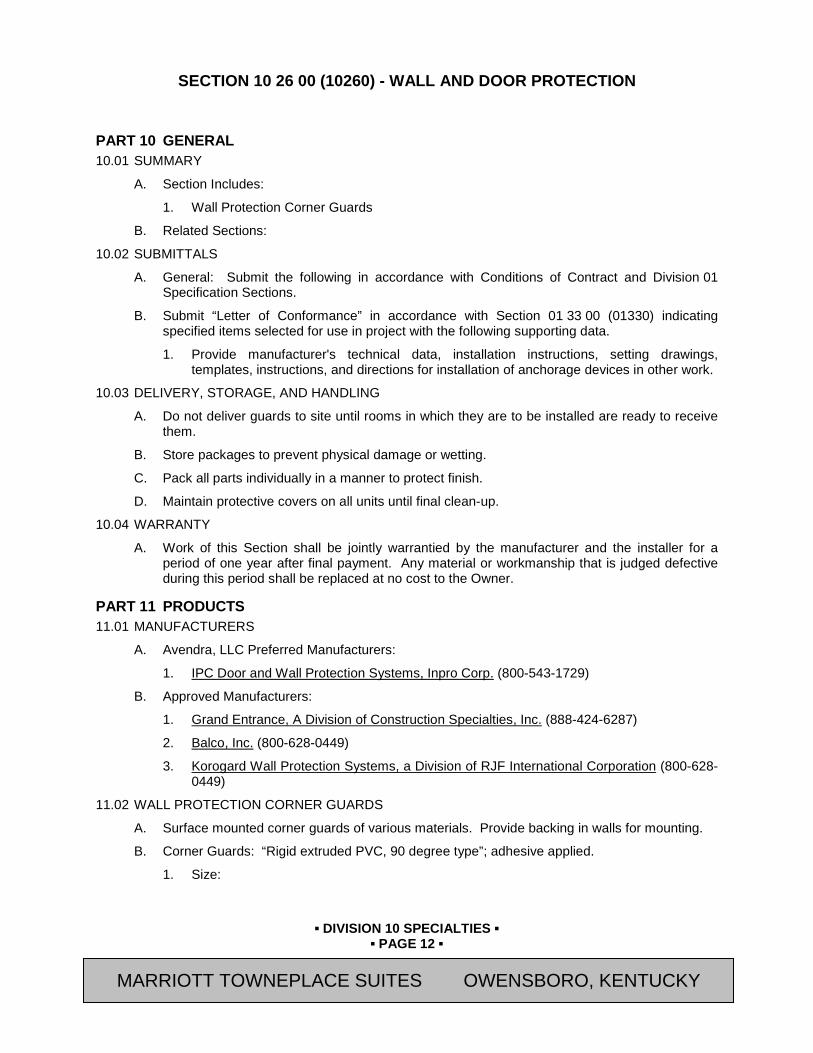
▪ DIVISION 10 SPECIALTIES ▪
▪ PAGE 12 ▪
RESIDENCE INN BY MARRIOTT - LITTLETON, COLORADO
SECTION 10 26 00 (10260) - WALL AND DOOR PROTECTION
PART 10 GENERAL 10.01 SUMMARY
A. Section Includes:
1. Wall Protection Corner Guards
B. Related Sections:
10.02 SUBMITTALS
A. General: Submit the following in accordance with Conditions of Contract and Division 01 Specification Sections.
B. Submit “Letter of Conformance” in accordance with Section 01 33 00 (01330) indicating specified items selected for use in project with the following supporting data.
1. Provide manufacturer's technical data, installation instructions, setting drawings, templates, instructions, and directions for installation of anchorage devices in other work.
10.03 DELIVERY, STORAGE, AND HANDLING
A. Do not deliver guards to site until rooms in which they are to be installed are ready to receive them.
B. Store packages to prevent physical damage or wetting.
C. Pack all parts individually in a manner to protect finish.
D. Maintain protective covers on all units until final clean-up.
10.04 WARRANTY
A. Work of this Section shall be jointly warrantied by the manufacturer and the installer for a period of one year after final payment. Any material or workmanship that is judged defective during this period shall be replaced at no cost to the Owner.
PART 11 PRODUCTS 11.01 MANUFACTURERS
A. Avendra, LLC Preferred Manufacturers:
1. IPC Door and Wall Protection Systems, Inpro Corp. (800-543-1729)
B. Approved Manufacturers:
1. Grand Entrance, A Division of Construction Specialties, Inc. (888-424-6287)
2. Balco, Inc. (800-628-0449)
3. Korogard Wall Protection Systems, a Division of RJF International Corporation (800-628-0449)
11.02 WALL PROTECTION CORNER GUARDS
A. Surface mounted corner guards of various materials. Provide backing in walls for mounting.
B. Corner Guards: “Rigid extruded PVC, 90 degree type”; adhesive applied.
1. Size:
MARRIOTT TOWNEPLACE SUITES OWENSBORO, KENTUCKY
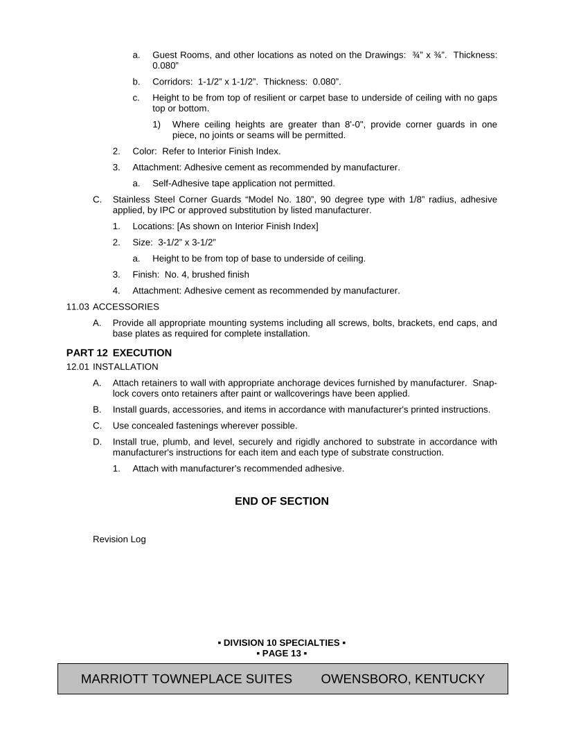
▪ DIVISION 10 SPECIALTIES ▪
▪ PAGE 13 ▪
RESIDENCE INN BY MARRIOTT - LITTLETON, COLORADO
a. Guest Rooms, and other locations as noted on the Drawings: ¾” x ¾”. Thickness: 0.080”
b. Corridors: 1-1/2” x 1-1/2”. Thickness: 0.080”.
c. Height to be from top of resilient or carpet base to underside of ceiling with no gaps top or bottom.
1) Where ceiling heights are greater than 8'-0", provide corner guards in one piece, no joints or seams will be permitted.
2. Color: Refer to Interior Finish Index.
3. Attachment: Adhesive cement as recommended by manufacturer.
a. Self-Adhesive tape application not permitted.
C. Stainless Steel Corner Guards “Model No. 180”, 90 degree type with 1/8” radius, adhesive applied, by IPC or approved substitution by listed manufacturer.
1. Locations: [As shown on Interior Finish Index]
2. Size: 3-1/2” x 3-1/2”
a. Height to be from top of base to underside of ceiling.
3. Finish: No. 4, brushed finish
4. Attachment: Adhesive cement as recommended by manufacturer.
11.03 ACCESSORIES
A. Provide all appropriate mounting systems including all screws, bolts, brackets, end caps, and base plates as required for complete installation.
PART 12 EXECUTION 12.01 INSTALLATION
A. Attach retainers to wall with appropriate anchorage devices furnished by manufacturer. Snap-lock covers onto retainers after paint or wallcoverings have been applied.
B. Install guards, accessories, and items in accordance with manufacturer's printed instructions.
C. Use concealed fastenings wherever possible.
D. Install true, plumb, and level, securely and rigidly anchored to substrate in accordance with manufacturer's instructions for each item and each type of substrate construction.
1. Attach with manufacturer’s recommended adhesive.
END OF SECTION
Revision Log
MARRIOTT TOWNEPLACE SUITES OWENSBORO, KENTUCKY

▪ DIVISION 10 SPECIALTIES ▪
▪ PAGE 14 ▪
RESIDENCE INN BY MARRIOTT - LITTLETON, COLORADO
SECTION 10 28 00 (10800) - TOILET, BATH, AND LAUNDRY ACCESSORIES
PART 13 GENERAL 13.01 SUMMARY
A. Section Includes:
1. Toilet Accessories
2. Bath Accessories
3. Attachment hardware
B. Related Sections:
1. Section 05 50 00 (05500) - Metal Fabrications
2. Section 06 10 00 (06100) - Rough Carpentry: Blocking
3. Section 08 80 00 (08800) - Glazing: Unframed mirrors, tub and shower glass
4. Section 09 30 00 (09310) - Tiling: Coordinate installation of accessories
5. Section 10 21 13 (10165) - Toilet Compartments: Coordinate installation of accessories
6. Section 10 28 19.21 – Tub and Shower Doors: Coordinate installation
13.02 REFERENCES
A. ASTM International Publications:
1. A167 - “Standard Specification for Stainless and Heat-Resisting Chromium-Nickel Steel Plate, Sheet, and Strip”
2. A666 “Standard Specification for Annealed or Cold-Worked Austenitic Stainless Steel Sheet, Strip, Plate, and Flat Bar”
B. American National Standards Institute (ANSI)
1. ICC/ANSl A117.1-2009 , “Accessible and Useable Buildings and Facilities”
C. Americans with Disabilities Act (ADA) II Public Accommodations
13.03 SUBMITTALS
A. General: Submit the following in accordance with Conditions of Contract and Division 01 Specification Sections.
B. Submit “Letter of Conformance” in accordance with Section 01 33 00 (01330) indicating specified items selected for use in project with the following supporting data.
1. Product Data: Mark each copy to identify applicable products, characteristics, models, options and other supplemental data to clearly communicate information specific to this project.
13.04 QUALITY ASSURANCE
A. Provide products of the same manufacturer for each type of accessory unit and for units exposed in the same area.
13.05 DELIVERY, STORAGE, AND HANDLING
A. Do not deliver accessories to site until rooms in which they are to be installed are ready to receive them.
MARRIOTT TOWNEPLACE SUITES OWENSBORO, KENTUCKY

▪ DIVISION 10 SPECIALTIES ▪
▪ PAGE 15 ▪
RESIDENCE INN BY MARRIOTT - LITTLETON, COLORADO
B. Store packages to prevent physical damage or wetting.
C. Pack accessories individually in a manner to protect accessory and its finish.
D. Maintain protective covers on all units until final clean-up.
E. Protection: Protect adjacent or adjoining finished surfaces and work from damage during installation of work of this Section.
13.06 WARRANTY
A. Work of this Section shall be jointly warrantied by the manufacturer and the installer for a period of one year after final payment. Any material or workmanship that is judged defective during this period shall be replaced at no cost to the Owner.
PART 14 PRODUCTS 14.01 DISTRIBUTORS
A. Avendra, LLC Preferred Distributor:
1. Contract Hardware, Inc. (800-266-3418)
a. Contact: Mark Tew
2. Home Depot Supply
a. Contact: Rajan Batra (703-404-4567)
14.02 MANUFACTURERS
A. See Toilet & Bath Accessory Matrix for list of which Manufacturer's are approved for use on a specific item.
B. Avendra, LLC Preferred Manufacturers:
1. Franklin Brass, Liberty Hardware Manufacturing Corp., A Masco Company (800-421-3375)
2. WingIts LLC (877-894-6448)
C. Approved Manufacturers:
1. American Specialties, Inc. (ASI) (914-476-9000)
2. Bobrick Washroom Equipment, Inc. (818-503-1630)
3. Gamco, A Bobrick Company (800-421-3375)
4. Hafele America Co. (HEWI) (336-889-2322)
5. Preferred Bath Accessories LLC. (336-575-0080)
6. Mincey Marble Manufacturing Co. (800-533-1806)
7. Shower Solutions USA, Inc. (407-314-2176)
8. Symmons Industries, Inc. (800-796-6667)
14.03 MATERIALS - TOILET ACCESSORIES
A. 18-8 (Type 302) stainless steel alloy of at least 22 gauge in all elements of cabinet work. Unless shown otherwise, all exposed stainless steel to have a #4 Satin finish or Satin chrome finish where applicable with all elements of a unit to have brushing in one direction.
B. Exposed surfaces to be protected with a factory applied PVC film to be left in place until final clean-up.
MARRIOTT TOWNEPLACE SUITES OWENSBORO, KENTUCKY

▪ DIVISION 10 SPECIALTIES ▪
▪ PAGE 16 ▪
RESIDENCE INN BY MARRIOTT - LITTLETON, COLORADO
C. Mirrors to be 1/4" polished plate glass with 10-year guarantee against silver spoilage.
D. Stainless steel tubing: 18 ga., Type 304, seamless welded.
E. Fasteners, screws, and bolts: Hot dip galvanized. Expansion shields: Fiber, lead, or rubber as recommended by accessory manufacturer for component substrate.
F. Adhesive: Epoxy type contact cement.
14.04 FINISHES
A. Guest Rooms: Refer to Toilet & Bath Accessory Matrix for Finishes.
B. Employee and Public Toilet Rooms: Refer to Toilet & Bath Accessory Matrix for Finishes.
C. Exposed heads of fasteners shall match finish of accessory.
14.05 FABRICATION - TOILET ACCESSORIES
A. Provide steel anchor plates and anchor components for installation on building finishes.
B. Form surfaces flat without distortion. Maintain flat surface without scratches or dents.
C. Back paint components where contact is made with building finishes to prevent electrolysis.
D. Hot dip galvanize ferrous metal anchors and fastening devices.
E. Shop assemble components and package complete with anchors and fittings.
PART 15 EXECUTION 15.01 PREPARATION
A. Deliver inserts and rough-in frames to job site and in appropriate time for building-in. Provide templates and rough-in measurements as required.
B. Before starting work, notify Owner’s Representative in writing of any conflicts detrimental to installation or operation of units.
C. Verify with Owner’s Representative exact location of accessories.
15.02 INSTALLATION
A. Install fixtures, accessories, and items in accordance with manufacturer's printed instructions.
B. Use concealed fastenings wherever possible.
C. Install true, plumb, and level, securely and rigidly anchored to substrate in accordance with manufacturer's instructions for each item and each type of substrate construction.
1. Wood blocking shall be provided at grab bars and fold down shower seats, and as shown on Drawings.
2. Strap metal may be used for all other areas, as approved by Owner’s Representative, unless indicated otherwise.
D. Fasteners for all accessory mounting to be theft-resistant.
PART 16 ACCESSORY SCHEDULE END OF SECTION
Revision Log
MARRIOTT TOWNEPLACE SUITES OWENSBORO, KENTUCKY

▪ DIVISION 10 SPECIALTIES ▪
▪ PAGE 17 ▪
RESIDENCE INN BY MARRIOTT - LITTLETON, COLORADO
SECTION 10 28 19 - TUB AND SHOWER ENCLOSURES
PART 17 GENERAL 17.01 SUMMARY
A. Section Includes:
1. Fixed Glass Panel at Shower
2. Attachment hardware
B. Related Sections:
1. Section 05 50 00 (05500) - Metal Fabrications
2. Section 06 10 00 (06100) - Rough Carpentry: Blocking
3. Section 06 61 13 (06610) -Cultured Marble Fabrications
4. Section 08 80 00 (08800) - Glazing: Unframed mirrors, tub and shower glass
5. Section 09 30 00 (09310) - Tiling: Coordinate installation of accessories
6. Section 10 21 13 (10165) - Toilet Compartments: Coordinate installation of accessories
7. Section 10 28 00 (10800) - Toilet Bath And Laundry Accessories
17.02 REFERENCES
A. ASTM International Publications:
1. A167 - “Standard Specification for Stainless and Heat-Resisting Chromium-Nickel Steel Plate, Sheet, and Strip”
2. A666 “Standard Specification for Annealed or Cold-Worked Austenitic Stainless Steel Sheet, Strip, Plate, and Flat Bar”
B. American National Standards Institute (ANSI)
1. ICC/ANSl A117.1-2009 , “Accessible and Useable Buildings and Facilities”
C. Americans with Disabilities Act (ADA) II Public Accommodations
17.03 SUBMITTALS
A. General: Submit the following in accordance with Conditions of Contract and Division 01 Specification Sections.
B. Submit “Letter of Conformance” in accordance with Section 01 33 00 (01330) indicating specified items selected for use in project with the following supporting data.
1. Product Data: Mark each copy to identify applicable products, characteristics, models, options and other supplemental data to clearly communicate information specific to this project.
2. Shop Drawings: For tub and shower doors and enclosures.
17.04 QUALITY ASSURANCE
A. Provide products of the same manufacturer for each type of accessory unit and for units exposed in the same area.
B. Coordinate with Tub and Shower Surrounds specified in Section 06 61 13 “Cultured Marble Fabrications”.
MARRIOTT TOWNEPLACE SUITES OWENSBORO, KENTUCKY

▪ DIVISION 10 SPECIALTIES ▪
▪ PAGE 18 ▪
RESIDENCE INN BY MARRIOTT - LITTLETON, COLORADO
C. Mockups: Build mockups to demonstrate aesthetic effects and to set quality standards for fabrication and installation.
1. Build mockup of tub and shower doors and enclosure as shown on Drawings.
2. Approval of mockups does not constitute approval of deviations from the Contract Documents contained in mockups unless Architect specifically approves such deviations in writing.
3. Subject to compliance with requirements, approved mockups may become part of the completed Work if undisturbed at time of Substantial Completion.
17.05 DELIVERY, STORAGE, AND HANDLING
A. Do not deliver components to site until rooms in which they are to be installed are ready to receive them.
B. Store all materials to prevent physical damage or wetting.
C. Maintain protective covers on all units until final clean-up.
D. Protection: Protect adjacent or adjoining finished surfaces and work from damage during installation of work of this Section.
17.06 WARRANTY
A. Work of this Section shall be jointly warrantied by the manufacturer and the installer for a period of one year after final payment. Any material or workmanship that is judged defective during this period shall be replaced at no cost to the Owner.
PART 18 PRODUCTS 18.01 MANUFACTURERS
A. Avendra, LLC Preferred Manufacturers:
1. None
B. Approved Manufacturers:
1. Continental Group (614-679-1201)
2. ProjectStone by Belstone (877-667-8663)
3. Mincey Marble Manufacturing Co. (800-533-1806)
18.02 MATERIALS
A. 18-8 (Type 302) stainless steel alloy of at least 22 gauge. Unless shown otherwise, all exposed stainless steel to have a #4 Satin finish or Satin chrome finish where applicable with all elements of a unit to have brushing in one direction.
B. Exposed surfaces to be protected with a factory applied PVC film to be left in place until final clean-up.
C. Stainless steel tubing: 18 ga., Type 304, seamless welded.
D. Glazing: Safety glazing materials complying with 16 CFR 1201, Category II, with permanently etched identification acceptable to authorities having jurisdiction.
E. Provide frameless glass panels with mounting and operating hardware of types and sizes required to support imposed loads.
F. Fasteners, screws, and bolts: Hot dip galvanized. Expansion shields: Fiber, lead, or rubber as recommended by accessory manufacturer for component substrate.
MARRIOTT TOWNEPLACE SUITES OWENSBORO, KENTUCKY
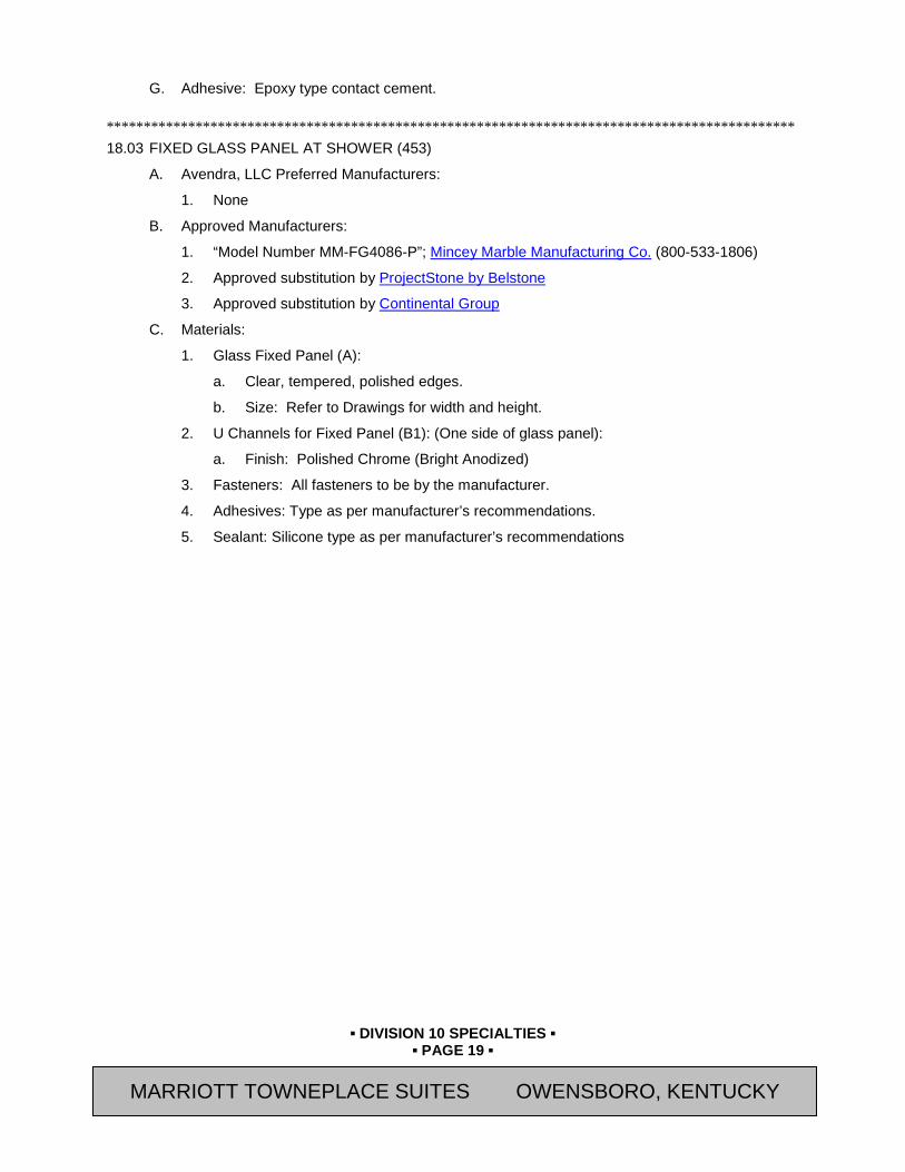
▪ DIVISION 10 SPECIALTIES ▪
▪ PAGE 19 ▪
RESIDENCE INN BY MARRIOTT - LITTLETON, COLORADO
G. Adhesive: Epoxy type contact cement. ********************************************************************************************* 18.03 FIXED GLASS PANEL AT SHOWER (453)
A. Avendra, LLC Preferred Manufacturers:
1. None
B. Approved Manufacturers:
1. “Model Number MM-FG4086-P”; Mincey Marble Manufacturing Co. (800-533-1806)
2. Approved substitution by ProjectStone by Belstone
3. Approved substitution by Continental Group
C. Materials:
1. Glass Fixed Panel (A):
a. Clear, tempered, polished edges.
b. Size: Refer to Drawings for width and height.
2. U Channels for Fixed Panel (B1): (One side of glass panel):
a. Finish: Polished Chrome (Bright Anodized)
3. Fasteners: All fasteners to be by the manufacturer.
4. Adhesives: Type as per manufacturer’s recommendations.
5. Sealant: Silicone type as per manufacturer’s recommendations
MARRIOTT TOWNEPLACE SUITES OWENSBORO, KENTUCKY
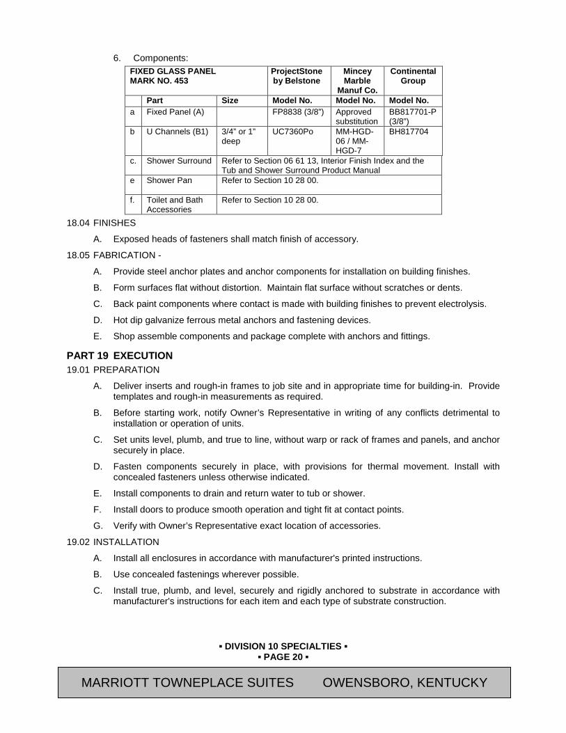
▪ DIVISION 10 SPECIALTIES ▪
▪ PAGE 20 ▪
RESIDENCE INN BY MARRIOTT - LITTLETON, COLORADO
6. Components: FIXED GLASS PANEL MARK NO. 453
ProjectStone by Belstone
Mincey Marble
Manuf Co.
Continental Group
Part Size Model No. Model No. Model No. a
Fixed Panel (A) FP8838 (3/8”) Approved
substitution BB817701-P (3/8”)
b U Channels (B1) 3/4” or 1”
deep UC7360Po MM-HGD-
06 / MM-HGD-7
BH817704
c. Shower Surround Refer to Section 06 61 13, Interior Finish Index and the Tub and Shower Surround Product Manual
e Shower Pan Refer to Section 10 28 00.
f. Toilet and Bath Accessories
Refer to Section 10 28 00.
18.04 FINISHES
A. Exposed heads of fasteners shall match finish of accessory.
18.05 FABRICATION -
A. Provide steel anchor plates and anchor components for installation on building finishes.
B. Form surfaces flat without distortion. Maintain flat surface without scratches or dents.
C. Back paint components where contact is made with building finishes to prevent electrolysis.
D. Hot dip galvanize ferrous metal anchors and fastening devices.
E. Shop assemble components and package complete with anchors and fittings.
PART 19 EXECUTION 19.01 PREPARATION
A. Deliver inserts and rough-in frames to job site and in appropriate time for building-in. Provide templates and rough-in measurements as required.
B. Before starting work, notify Owner’s Representative in writing of any conflicts detrimental to installation or operation of units.
C. Set units level, plumb, and true to line, without warp or rack of frames and panels, and anchor securely in place.
D. Fasten components securely in place, with provisions for thermal movement. Install with concealed fasteners unless otherwise indicated.
E. Install components to drain and return water to tub or shower.
F. Install doors to produce smooth operation and tight fit at contact points.
G. Verify with Owner’s Representative exact location of accessories.
19.02 INSTALLATION
A. Install all enclosures in accordance with manufacturer's printed instructions.
B. Use concealed fastenings wherever possible.
C. Install true, plumb, and level, securely and rigidly anchored to substrate in accordance with manufacturer's instructions for each item and each type of substrate construction.
MARRIOTT TOWNEPLACE SUITES OWENSBORO, KENTUCKY

▪ DIVISION 10 SPECIALTIES ▪
▪ PAGE 21 ▪
RESIDENCE INN BY MARRIOTT - LITTLETON, COLORADO
1. Wood blocking shall be provided at grab bars and fold down shower seats, and as shown on Drawings.
END OF SECTION Revision Log
MARRIOTT TOWNEPLACE SUITES OWENSBORO, KENTUCKY

▪ DIVISION 10 SPECIALTIES ▪
▪ PAGE 22 ▪
RESIDENCE INN BY MARRIOTT - LITTLETON, COLORADO
SECTION 10 31 00 (10305) - MANUFACTURED FIREPLACES
PART 20 GENERAL 20.01 SUMMARY
A. Section Includes:
1. Fire Pit Insert
2. All Required Accessories
B. Related Sections:
1. Section 10 14 00 (10400) – Signage: for Fire Pit Emergency Shut Off and Warning Plaque signage.
2. Division 23 Sections:
a. Gas pipe to fire pit and connection to fire pit burner.
3. Division 26 Sections: Wall switch connected to gas log electronic ignition.
20.02 SUBMITTALS
A. Submit "Letter of Conformance" in accordance with Section 01 33 00 (01330) with the following supporting data:
1. Submit product data, mark each copy to identify applicable products, characteristics, models, options and other supplemental data to clearly communicate information specific to this project.
2. Shop Drawings and Samples: Submit copies of Shop Drawings of all items specified herein to Architect for approval. Obtain approval of drawings prior to proceeding with manufacturing. Shop Drawings shall indicate: elevations; details; location in the building of each item; conditions at openings with various wall thicknesses and materials; typical and special details of construction; methods of assembling sections; locations and installations requirements for hardware; size, shape, and thickness of materials; and joints and connections.
20.03 QUALITY ASSURANCE
A. Installer Qualifications: Firm with not less than 5 years of experience in installation of fireplace units of type, quantity, and installation methods similar to work of this Section.
B. All materials shall be installed in accordance with the manufacturer's printed directions.
C. Comply with the fire-resistance ratings as indicated and as required by governing authority and codes. Provide materials, accessories, and application procedures which have been listed by UL.
D. Verify that components and proposed installation comply with local and state requirements for both gas and wood burning fireplaces.
20.04 DELIVERY, STORAGE, AND HANDLING
A. All materials shall be delivered in their original unopened packages and stored in an enclosed shelter providing protection from damage and exposure to the elements. Damaged or deteriorated materials shall be removed from the premises.
MARRIOTT TOWNEPLACE SUITES OWENSBORO, KENTUCKY

▪ DIVISION 10 SPECIALTIES ▪
▪ PAGE 23 ▪
RESIDENCE INN BY MARRIOTT - LITTLETON, COLORADO
PART 21 PRODUCTS 21.01 FIRE PIT INSERT
A. Avendra, LLC Preferred Manufacturers:
1. None
B. Approved Manufacturers:
1. “Model 24FSS-HWI-SQ-NG ”; Hearth Products Controls, Dayton, OH
a. [Natural Gas
C. Gas Fire Pit Kit:
1. Provide Square Fire Pit Insert Kit complete with stainless steel ring, burner pan, and electronic ignition control and box in location shown on Drawings.
D. Accessories/Components:
1. Lava Rock
2. Emergency Flame Shut-Off Switch: Weatherproof maintained contact red mushroom head pushbutton switch with cover labeled “EMERGENCY SHUTOFF,” suitable for wiring in series in low-voltage gas control circuit.
a. Cutler-Hammer Div. Eaton Industries, HT800 Series two-position maintained push-pull button, Catalog HT8CBRB, mounted in recessed weathertight enclosure.
b. Refer to Section 10 14 00 “Signage (Interior Signage Manual)” for sign adjacent to Emergency Shutoff Switch.
3. Custom fabricated stainless steel supports around edge of pan.
4. Custom fabricated stainless steel collar surrounding entire pan system. Refer to Drawings for size and location.
5. All other components required for complete installation.
6. Warning Plaques: Warning plaques, located on top of stone at locations as shown on Drawings, with text as follows oriented to be read from adjoining walking surfaces:
a. “NOTICE: DO NOT LEAVE CHILDREN UNATTENDED.”
b. Refer to Section 10 14 00 “Signage (Interior Signage Manual)” for warning plaques.
PART 22 EXECUTION 22.01 GENERAL
A. Contractor shall inspect site conditions to which work is to be installed. Report discrepancies to Architect in writing.
B. Examine roughing-in for gas piping and electrical control wiring to verify actual locations of connections before equipment installation.
1. Provide underground gas line and associated trenching and filling in compliance with Division 33 Sections or the requirements of the local natural gas utility supplier and authorities having jurisdiction. Comply with requirements of Section 23 11 23 - Facility Natural Gas Piping for piping inside of building.
C. Verify that Fire Pit dimensions, clearances, combustion air ventilation and drainage are in accordance with manufacturer’s published directions and listing requirements of the equipment being installed.
MARRIOTT TOWNEPLACE SUITES OWENSBORO, KENTUCKY
▪ DIVISION 10 SPECIALTIES ▪
▪ PAGE 24 ▪
RESIDENCE INN BY MARRIOTT - LITTLETON, COLORADO
22.02 INSTALLATION – FIRE PIT INSERT
A. Install fire pit insert equipment in strict accordance with manufacturer's instructions and as required by appropriate fire authorities.
B. Make connections to burner assembly in accordance with manufacturer instructions and as follows:
1. Provide electrical connectors listed and labeled for wet locations and suitable for use without supplemental applications of electrical tape.
2. Provide corrosion-resistant gas connectors and fittings suitable for exterior use. Provide flexible connector of appropriate length to allow for maintenance access to fire pit.
C. Install primary control station within unobstructed line of sight of the fire pit insert.
D. Install true, plumb, and level. When required by manufacturers instructions securely and rigidly anchor components to substrate in accordance with manufacturer's instructions for each item and each type of substrate construction.
E. Installed gas piping, control wiring, tubing, hoses and clamps, must be hidden from view.
END OF SECTION
Revision Log
MARRIOTT TOWNEPLACE SUITES OWENSBORO, KENTUCKY
▪ DIVISION 10 SPECIALTIES ▪
▪ PAGE 25 ▪
RESIDENCE INN BY MARRIOTT - LITTLETON, COLORADO
SECTION 10 44 00 (10520) - FIRE PROTECTION SPECIALTIES
PART 23 GENERAL 23.01 SUMMARY
A. Section Includes:
1. Fire Extinguishers and Brackets
2. Fire Extinguisher Cabinets
3. Fire Hose and Valve Cabinet
4. Accessories
B. Related Sections:
23.02 REFERENCES
A. National Fire Protection Association (NFPA) Publications:
1. 10 “Portable Fire Extinguishers”
B. Underwriter's Laboratories, Inc. (UL) Standards:
1. 4A-“60BC classification”
23.03 SUBMITTALS
A. General: Submit the following in accordance with Conditions of Contract and Division 01 Specification Sections.
B. Submit “Letter of Conformance” in accordance with Section 01 33 00 (01330) indicating specified items selected for use in project with the following supporting data.
1. Submit product data which shall include physical dimensions, operational features, color and finish, anchorage details, rough-in measurements, location, and details.
2. Submit manufacturer's installation instructions.
23.04 QUALITY ASSURANCE
A. Conform to NFPA 10 requirements for extinguishers.
23.05 OPERATION AND MAINTENANCE DATA
A. Do not install extinguishers when ambient temperatures may cause freezing.
PART 24 PRODUCTS 24.01 ACCEPTABLE MANUFACTURERS
A. Avendra, LLC Preferred Manufacturers:
1. None
B. Approved Manufacturers:
1. Larsen's Manufacturing Company (800-527-7367).
2. JL Industries, an Activar Inc. Company (800-554-6077).
3. Modern Metal Products, a Division of Technico, Inc. (800-435-5544)
MARRIOTT TOWNEPLACE SUITES OWENSBORO, KENTUCKY

▪ DIVISION 10 SPECIALTIES ▪
▪ PAGE 26 ▪
RESIDENCE INN BY MARRIOTT - LITTLETON, COLORADO
24.02 EXTINGUISHERS:
A. Multi-Purpose, Dry-Chemical Type: Steel Tank, pressurized, including hose and nozzle; 10-pound, ABC classification, UL 4A/60BC.
24.03 BRACKET:
A. Furnish wall mount bracket where shown on Drawings complete with mounting hardware. 24.04 CABINETS:
A. Items specified below are by Larsen's Manufacturing Co. Equivalent products by listed manufacturer will be acceptable. Verify type with Contractor.
1. Wall mounted on Bracket (FE): "MP10" Extinguisher with "B2" bracket.
2. Semi-recessed Fire Extinguisher Cabinet (FEC-1): "MP10" Extinguisher with “Gemini Series Model [FS-]G-2409-6R"; semi-recessed cabinet, projecting 2-1/2", rough opening of 10-1/2"W x 25"H x 4"D.
3. Surface Mounted Fire Extinguisher Cabinet (FEC-2): "MP10" Extinguisher with “Gemini Series Model [FS-]G-2409-SM "; surface-mounted cabinet.
4. Recessed Fire Hose and Valve Cabinet with Fire Extinguisher (FVC-1): "MP10" Extinguisher with "[FS-]G-3238-R"; Recessed Fire Hose and Valve Cabinet, projecting 2-1/2", rough opening of 34-1/8"W x 40-1/8"H x 9-1/8"D.
5. Semi-recessed Fire Hose and Valve Cabinet with Fire Extinguisher (FVC-2): "MP10" Extinguisher with "[FS-]G-3238-RL"; Semi-Recessed Fire Hose and Valve Cabinet, projecting 2-1/2", rough opening of 33"W x 39"H x 6"D.
B. Cabinet:
1. Semi-Recessed Fire Extinguisher Cabinet: 18 gauge steel with acrylic thermosetting enamel finish box construction, rolled-edge trim type, matching continuous hinge, pull handle, 1/4” Frameless Acrylic door, baked enamel coated steel trim.
a. Door Style to be Larson “Gemini" series door with black vertical letters on white background stating equipment in cabinet, or approved substitution by other listed manufacturers.
1) Provide lock similar to “Larsen-Loc” on all cabinets.
b. Finish: White finish for box and trim.
c. Provide black text “FIRE EXTINGUISHER” on side of cabinet where required by code.
2. Surface Mounted Fire Extinguisher Cabinet: 18 gauge steel with acrylic thermosetting enamel finish box construction, matching continuous hinge, pull handle, 1/4” Frameless Acrylic door, baked enamel coated steel trim..
a. Door Style to be Larson “Gemini" series door with black vertical letters on white background stating equipment in cabinet, or approved substitution by other listed manufacturers.
1) Provide lock similar to “Larsen-Loc” on all cabinets.
b. Finish: White finish for box and trim.
3. Recessed Fire Hose and Valve Cabinet: 18 gauge steel with acrylic thermosetting enamel finish box construction, flat trim type, matching continuous hinge, pull handle, 1/4” Frameless Acrylic door, baked enamel coated steel trim.
MARRIOTT TOWNEPLACE SUITES OWENSBORO, KENTUCKY
▪ DIVISION 10 SPECIALTIES ▪
▪ PAGE 27 ▪
RESIDENCE INN BY MARRIOTT - LITTLETON, COLORADO
a. Door Style to be Larson “Full Glass”, or approved substitution by other listed manufacturers. Glazing to be Clear Tempered Safety Glass.
1) Provide lock similar to “Larsen-Loc” on all cabinets.
b. Finish: White finish for box and trim.
c. Provide black text “FIRE EXTINGUISHER” on front of glass where required by code.
4. Semi-recessed Fire Hose and Valve Cabinet: 18 gauge steel with acrylic thermosetting enamel finish box construction, rolled-edge trim type, matching continuous hinge, pull handle, 1/4” Frameless Acrylic door, baked enamel coated steel trim.
a. Door Style to be Larson “Full Glass”, or approved substitution by other listed manufacturers. Glazing to be Clear Tempered Safety Glass.
1) Provide lock similar to “Larsen-Loc” on all cabinets.
b. Finish: White finish for box and trim.
c. Provide text “FIRE EXTINGUISHER” on side of cabinet where required by code.
C. Mounting Hardware: Appropriate to Cabinet
D. Fabrication
1. Form body of cabinet with tight inside corners and seams.
2. Pre-drill holes for anchorage.
3. Form perimeter trim and door stiles by welding, filling, and grinding smooth.
4. Hinge doors for 180 degree opening with continuous piano hinge. Provide pull handle and roller type catch.
24.05 FINISHES
A. Extinguishers: Red Enamel
PART 25 EXECUTION 25.01 INSPECTION
A. Verify rough openings for cabinet are correctly sized and located.
B. Beginning of installation means acceptance of existing conditions.
25.02 INSTALLATION
A. Install cabinets plumb and level in wall openings. Secure rigidly in place in accordance with manufacturer's instructions.
END OF SECTION
Revision Log
MARRIOTT TOWNEPLACE SUITES OWENSBORO, KENTUCKY
▪ DIVISION 10 SPECIALTIES ▪
▪ PAGE 28 ▪
RESIDENCE INN BY MARRIOTT - LITTLETON, COLORADO
SECTION 10 51 13 (10500) - METAL LOCKERS
PART 26 GENERAL 26.01 SUMMARY
A. Section Includes:
1. Locker Units with Hinged Doors
2. Base, Top, and Filler Panels
3. Hooks, Latches, and Hardware
4. Attachment Hardware
B. Related Sections:
1. Section 06 10 00 (06100) - Rough Carpentry: Blocking for attachment
26.02 SYSTEM DESCRIPTION
A. Lockers: Three-tier locker. Provide standard recessed padlock handle, number plate bases, end panels, filler panels, matching sloped top and top filler panels.
26.03 SUBMITTALS
A. General: Submit the following in accordance with Conditions of Contract and Division 01 Specification Sections.
B. Submit “Letter of Conformance” in accordance with Section 01 33 00 (01330) indicating specified items selected for use in project with the following supporting data.
1. Submit Shop Drawings and product data that clearly indicate locker types, sizes, configurations, layout of groups of lockers, benches, accessories, and numbering plan.
2. Submit manufacturer's installation instructions and actual color samples, on squares of same metal to be used for fabrication.
26.04 DELIVERY, STORAGE, AND HANDLING
A. Store and protect locker finishes and adjacent surfaces from damage during installation.
PART 27 PRODUCTS 27.01 MANUFACTURERS
A. Avendra, LLC Preferred Manufacturers:
1. None
B. Approved Manufacturers:
1. “Industrial”; Lyon Workspace Products LLC (800-433-8488)
a. Color: No. BN 931 – B6
2. “Standard Lockers”; Republic Storage Systems Company (800-477-1255)
a. Color: No. 89 Cork
3. “Vanguard Lockers”; Penco Products, Inc. (800-562-1000)
a. Color: No. 073 Champagne
4. “Emperor Locker System”; Hadrian Manufacturing, Inc. (905-333-0300)
MARRIOTT TOWNEPLACE SUITES OWENSBORO, KENTUCKY
▪ DIVISION 10 SPECIALTIES ▪
▪ PAGE 29 ▪
RESIDENCE INN BY MARRIOTT - LITTLETON, COLORADO
a. Color: No. 603 Almond
27.02 LOCKER MATERIALS
A. Sheet Steel: ASTM A1008, Mild, stretcher-leveled cold-rolled carbon sheet steel free of buckling, scale, and surface imperfections of the following minimum thicknesses:
1. Body and Shelf: 24 Gauge
2. Doors: 16 Gauge
3. Door Frames: 16 Gauge
4. Hinges: Minimum 2" wide, full loop, tight pin type.
27.03 LOCKER ACCESSORIES
A. Provide each locker with metal number plate, rubber bumpers, and hat/bookshelf.
27.04 LOCKER FABRICATION
A. Locker Units: Provide the following types in locations shown on the Drawings:
1. Three tier units, each locker to be 12" wide x 15" deep x 24" high.
B. Bodies: Formed and flanged with stiffener ribs; electrically spot welded.
C. Door Frame: Formed channel shape, welded and ground flush, welded to body.
D. Doors: Welded inner and outer faces; channel reinforced top and bottom with intermediate stiffener ribs. Finish edges smooth.
E. Hinges: Three full loop hinges. Weld securely to unit body and secure to door with no fewer than 2 factory installed fasteners that are completely concealed and tamperproof when door is closed.
F. Recessed Handle and Latch: Manufacturer's standard housing to form a recess for latch lifter and locking devices; non-protruding latch lifter containing strike and eye for padlock; and automatic, pre-locking, pry-resistant latch with latching action with not less than three-point latching. Locking device supplied by Owner.
G. Provide finished filler panels, end panels, continuous sloped 20-gauge metal tops and top filler panels to close off all openings, finished to match lockers.
1. Sloped tops are to be in lengths as long as practicable, but not less than four lockers.
H. Provide matching 12 gage, "Z" type base, 4" high at non-recessed lockers.
I. Trim: 3", 18 gauge steel matching trim for recessed lockers.
J. Provide full perimeter concealed ventilation system.
K. Finish edges smooth without burrs.
L. Provide number plates.
M. Fabricate lockers square, rigid, and without warp, with metal faces flat and free of dents or distortion. Make exposed metal edges free of sharp edges and burrs, and safe to touch. Weld frame members together to form a rigid, one-piece structure.
1. Form locker body panels, doors, shelves and accessories from one-piece steel sheet unless otherwise indicated.
N. Accessible Lockers:
1. Accessible Locker to meet ICC/ANSI A117.1-2003-Side Reach Requirement: Single tier lockers shall have a hat/book shelf and coat hooks located no more than 46-inches
MARRIOTT TOWNEPLACE SUITES OWENSBORO, KENTUCKY

▪ DIVISION 10 SPECIALTIES ▪
▪ PAGE 30 ▪
RESIDENCE INN BY MARRIOTT - LITTLETON, COLORADO
above the finished floor. One additional shelf shall be placed near the bottom of the locker so that it is no lower than 15-inches above finished floor.
2. Apply a decal with the international symbol of accessibility to the face of the designated handicapped accessible single tier locker, refer to Drawings for location.
27.05 FINISHES
A. Clean, degrease, and neutralize metal; prime and finish with two coats of baked enamel, color as selected by Architect from standard colors.
B. Comply with NAAMM "Metal Finishes Manual" for recommendations relative to applying and designating finishes.
C. Finish all steel surfaces and accessories, except prefinished stainless-steel and chrome-plated surfaces.
D. Protect mechanical finishes on exposed surfaces from damage by applying strippable, temporary protective covering prior to shipment.
E. Appearance of Finished Work: Variations in appearance of abutting or adjacent pieces are acceptable if they are within 1/2 of the range of approved samples. Noticeable variations in the same piece are not acceptable. Variations in appearance of other components are acceptable if they are within the range of approved samples and they are assembled or installed to minimize contrast.
PART 28 EXECUTION 28.01 PREPARATION
A. Verify bases are properly sized and located.
28.02 INSTALLATION
A. Install metal lockers complete with accessories according to manufacturer's recommendations. Install plumb, level, rigid, flush and in-line.
B. Anchor lockers with appropriate anchor devices to suit materials encountered, to floor and walls. Apply fasteners through back-up reinforcing plates where necessary to avoid metal distortion, using concealed fasteners.
C. Bolt adjoining locker units together to provide rigid installation.
D. Install end panels, filler panels, and tops to completely close-off all openings.
E. Anchor lockers to floors and walls at intervals recommended by manufacturer but no greater than 36 inches (910 mm). Install anchors through back-up reinforcing plates where necessary to avoid metal distortion, using concealed fasteners.
1. Install recess trim to recessed lockers using concealed fasteners. Provide hairline joints and concealed splice plates.
2. Install sloping top units to lockers using concealed fasteners. Provide hairline joints and concealed splice plates.
3. Install finished end panels to conceal exposed ends of non-recessed lockers.
28.03 ADJUST AND CLEAN
A. Adjust doors and latches to operate easily without bending. Verify that integral locking devices are operating properly.
MARRIOTT TOWNEPLACE SUITES OWENSBORO, KENTUCKY
▪ DIVISION 10 SPECIALTIES ▪
▪ PAGE 31 ▪
RESIDENCE INN BY MARRIOTT - LITTLETON, COLORADO
B. Touch-up marred finishes, but replace units that cannot be restored to factory-finished appearance. Use only materials and procedures recommended or furnished by locker manufacturer.
C. Clean interior and exposed exterior surfaces and polish steel and non-ferrous metal surfaces.
D. Protect lockers from damage, abuse, dust, dirt, stain, or paint. Do not permit locker use during construction.
END OF SECTION
Revision Log
MARRIOTT TOWNEPLACE SUITES OWENSBORO, KENTUCKY
▪ DIVISION 10 SPECIALTIES ▪
▪ PAGE 32 ▪
RESIDENCE INN BY MARRIOTT - LITTLETON, COLORADO
SECTION 10 56 13 (10670) - METAL STORAGE SHELVING
PART 29 GENERAL 29.01 SUMMARY
A. Section Includes:
1. Metal Storage Shelving
29.02 SUBMITTALS
A. Submit "Letter of Conformance" in accordance with Section 01 33 00 (01330) with the following supporting data:
1. Mark each copy to identify applicable products, characteristics, models, options and other supplemental data to clearly communicate information specific to this project.
2. Color Chart: Each product specified.
29.03 QUALITY ASSURANCE
A. Installer Qualifications: Manufacturer's authorized representative who is trained and approved for installation of units required for this Project.
B. Source Limitations: Obtain metal storage shelving through one source from a single manufacturer.
29.04 DELIVERY, STORAGE, AND HANDLING
A. Deliver metal storage shelving palleted, wrapped, or crated to provide protection during transit and Project-site storage.
29.05 PROJECT CONDITIONS
A. Environmental Limitations: Do not deliver or install metal storage shelving until spaces are enclosed and weatherproof, wet work in spaces is completed and dry, and ambient temperature is being maintained at the levels indicated for Project when occupied for its intended use.
29.06 COORDINATION
A. Coordinate locations and installation of metal storage shelving that may interfere with ceiling systems including lighting, HVAC, and sprinklers.
PART 30 PRODUCTS 30.01 STORAGE SHELVING
A. Avendra, LLC Preferred Manufacturers:
1. None
B. Approved Manufacturers:
1. "Open Clip Type Shelving" - Republic Storage Systems Company (800-477-1255)
2. "Clip - Support Shelving" - Adapto Storage Products, (800-923-2786)
3. "8000 Series" - - Lyon Workspace Products, LLC (800-433-8488)
4. "Clipper Shelving" - Penco Products, Inc (800-562-1000)
MARRIOTT TOWNEPLACE SUITES OWENSBORO, KENTUCKY
▪ DIVISION 10 SPECIALTIES ▪
▪ PAGE 33 ▪
RESIDENCE INN BY MARRIOTT - LITTLETON, COLORADO
C. Design:
1. Stand alone clip type consisting of 4 angle posts, 2 back sway braces, 4 side sway braces and 6 shelves.
a. 3'-0" Long Units: Minimum 800 pounds load capacity per shelf.
b. 4'-0" Long Units: Minimum 550 pounds load capacity per shelf.
D. Components:
1. Angle posts; 13 gage steel, with slots to receive shelf clips.
2. Shelves: 18 gage steel. Front and back shelf flanges turned down to accommodate 1" x 1" x 1/8" reinforcing angles.
3. Shelf Clips: Type recommended and used by shelving manufacturer for required loading.
4. Sway Braces: 1" x 1/8" band iron with holes at ends for attachment to shelving units.
5. Accessories: As required by classification, design and installation requirements.
E. Finish:
1. Factory finish in manufacturers standard color selected by Owner’s representative.
F. Size and layout as indicated on the Drawings.
PART 31 EXECUTION 31.01 INSTALLATION
A. Set units plumb, level and square. Do not secure to adjacent walls. Adjust for rigidity.
END OF SECTION
Revision Log
MARRIOTT TOWNEPLACE SUITES OWENSBORO, KENTUCKY
▪ DIVISION 10 SPECIALTIES ▪
▪ PAGE 34 ▪
RESIDENCE INN BY MARRIOTT - LITTLETON, COLORADO
SECTION 10 57 23.13 (10670) - WIRE CLOSET AND UTILITY SHELVING
PART 32 GENERAL 32.01 SUMMARY
A. Section Includes:
1. Wire Closet Shelves
a. Furnished by Owner, installed by Contractor
B. Related Sections:
1. Section 06 10 00 (06100) - Rough Carpentry
32.02 SYSTEM DESCRIPTION
A. Contractor is responsible for receiving and handling on site and installing wire closet shelving materials furnished by Owner and will fill out and process all receiving reports furnished by Owner.
32.03 QUALITY ASSURANCE
A. Installer Qualifications: Engage an experienced installer who has completed five projects similar in material, design, and extent to that indicated for this Project and with a record of successful in-service performance.
B. Source Limitations: Obtain metal storage shelving through one source from a single manufacturer.
C. Mockups: Provide a sample application in one Guest Room for acceptance by the Owner's representative and to serve as a sample standard of quality for the balance of the work. Rework sample room if necessary to obtain Owner's acceptance.
32.04 DELIVERY, STORAGE, AND HANDLING
A. Deliver storage shelving palleted, wrapped, or crated to provide protection during transit and Project-site storage.
32.05 PROJECT CONDITIONS
A. Environmental Limitations: Do not deliver or install metal storage shelving until spaces are enclosed and weatherproof, wet work in spaces is completed and dry, and ambient temperature is being maintained at the levels indicated for Project when occupied for its intended use.
PART 33 PRODUCTS 33.01 WIRE CLOSET SHELVES
A. Avendra, LLC Preferred Manufacturers:
1. None
B. Approved Manufacturers:
1. The Container Store
a. Contact: Brandon Leonard (972-538-6547)
C. Materials:
1. Furnished by the Owner.
a. Refer to the Interior Design Specification Manual for product information
MARRIOTT TOWNEPLACE SUITES OWENSBORO, KENTUCKY

▪ DIVISION 10 SPECIALTIES ▪
▪ PAGE 35 ▪
RESIDENCE INN BY MARRIOTT - LITTLETON, COLORADO
PART 34 EXECUTION 34.01 INSTALLATION
A. Install in accordance with manufacturer's published instructions, square and plumb, secured rigidly in position.
1. Layout scheduled components prior to installation to verify wall to wall and floor to ceiling heights, widths, plumb and flatness of surfaces.
2. Prepare anchor locations and select anchor types using the methods recommended by the manufacturer for achieving the best result for the substrate under the project conditions.
END OF SECTION
Revision Log
MARRIOTT TOWNEPLACE SUITES OWENSBORO, KENTUCKY
▪ DIVISION 10 SPECIALTIES ▪
▪ PAGE 36 ▪
RESIDENCE INN BY MARRIOTT - LITTLETON, COLORADO
SECTION 10 75 00 (10350) - FLAGPOLES
PART 35 GENERAL 35.01 SUMMARY
A. Section Includes:
1. Ground Set Aluminum Flagpoles and Accessories
B. Related Sections:
1. Section 03 30 00 (03300) - Cast-in-Place Concrete: For concrete footings for flagpoles, if any, and if not specified in this Section.
2. Div. 26 (16) Section for Exterior Lighting
35.02 SYSTEM DESCRIPTION
A. Performance Requirements:
1. Structural Performance: Provide flagpoles capable of withstanding the effects of wind loads as determined according to the building code in effect for this Project or NAAMM FP 1001, "Guide Specifications for Design Loads of Metal Flagpoles," whichever is more stringent.
2. Base flagpole design on maximum standard-size flag suitable for use with pole or flag size indicated, whichever is more stringent.
35.03 SUBMITTALS
A. Submit “Letter of Conformance” in accordance with Section 01 33 00 (01330) with the following supporting data:
1. Product Data: For each type of flagpole required. Include installation instructions.
2. Shop Drawings: Show general layout, jointing, grounding method, and anchoring and supporting systems. Include details of foundation system for ground-set poles.
35.04 QUALITY ASSURANCE
A. Source Limitations: Obtain each flagpole as a complete unit from a single manufacturer, including fittings, accessories, bases, and anchorage devices.
B. Certify that pole will withstand 90 mph winds with 8' x 12' flag.
C. Design Data:
1. The engineering design of the flagpole foundation is the manufacturer’s responsibility. Submit design analysis calculations.
2. Shop drawings and calculations shall be signed and stamped by a structural engineer licensed in the state where project is located.
35.05 DELIVERY, STORAGE, AND HANDLING
A. General: Spiral wrap flagpoles with heavy kraft paper or other weathertight wrapping and enclose in a hard fiber tube or other protective container.
PART 36 PRODUCTS 36.01 MANUFACTURERS
A. Avendra, LLC Preferred Manufacturers:
1. None
MARRIOTT TOWNEPLACE SUITES OWENSBORO, KENTUCKY
▪ DIVISION 10 SPECIALTIES ▪
▪ PAGE 37 ▪
RESIDENCE INN BY MARRIOTT - LITTLETON, COLORADO
B. Approved Manufacturers:
1. ACME Flagpole Co. (800-260-1897)
2. Baartol Co., Inc. (800-537-4143)
3. Concord Industries, Inc. (800-527-3902)
4. Eder Flagpole Co. (A Division of Eder Flag Manufacturing Company, Inc.). (800-558-6044)
5. Ewing Flagpoles (716-833-3278)
6. American Flagpole, Inc. (800-368-7171)
7. Michigan Flagpole, Inc. (800-875-3524)
36.02 FLAGPOLES
A. Pole Construction, General: Construct poles and ship to Project site in one piece, if possible. If more than one piece is necessary, provide snug-fitting precision joints with self-aligning, internal splicing sleeve arrangement for weathertight, hairline field joints.
1. Provide the following above grade nominal heights, in locations shown on drawings.
a. 30 feet high
B. Aluminum Flagpoles: Fabricate from seamless, extruded tubing complying with ASTM B241 alloy 6063, with a minimum wall thickness of 3/16 inch. Heat treat after fabrication to comply with ASTM B597, temper T6.
1. Provide cone-tapered aluminum flagpoles.
C. Foundation Tube: Galvanized corrugated-steel foundation tube, 0.0635" minimum wall thickness, sized to suit flagpole and installation. Provide with 3/16" steel bottom plate and support plate; 3/4" diameter, steel ground spike; and steel centering wedges all welded together. Galvanize steel parts, including foundation tube, after assembly. Provide loose hardwood wedges at top of foundation tube for plumbing pole.
36.03 FITTINGS
A. Finial Ball: Manufacturer's standard flush-seam ball, 5" to 6" diameter, gold anodized.
B. Internal Halyard: Ball-bearing, nonfouling, revolving truck assemblies of cast metal with continuous 5/16" (8 mm) diameter, braided polypropylene halyards and 9" cast-metal cleats with fasteners.
1. Provide one halyard and one cleat at each flagpole.
2. Provide halyard protectors consisting of a 2" (50 mm) channel, 60" (1500 mm) long, finished to match flagpole.
C. Halyard Flag Snaps: Provide 2 swivel snap hooks per halyard.
D. Winch: Stainless steel, direct drive, self-locking.
E. Lightning Rod: 3/4" diameter galvanized lightning spike welded to base steel plate.
36.04 MISCELLANEOUS MATERIALS
A. Concrete: Comply with requirements of Division 03 Section "Cast-in-Place Concrete" with 28-day compressive strength of not less than 3000 psi, complying with ASTM C 94.
MARRIOTT TOWNEPLACE SUITES OWENSBORO, KENTUCKY
▪ DIVISION 10 SPECIALTIES ▪
▪ PAGE 38 ▪
RESIDENCE INN BY MARRIOTT - LITTLETON, COLORADO
36.05 FINISHES
A. Comply with NAAMM's "Metal Finishes Manual for Architectural and Metal Products" for recommendations relative to applying and designating finishes.
B. Finish: Clear anodized AA-M32C22A41 and waxed.
PART 37 EXECUTION 37.01 PREPARATION
A. Prepare in-ground flagpoles by painting below-grade portions with a heavy coat of bituminous paint.
B. Excavation: For foundation, excavate to neat clean lines in undisturbed soil. Remove loose soil and foreign matter from excavation and moisten earth before placing concrete.
C. Provide forms where required due to unstable soil conditions and for perimeter of flagpole base at grade. Secure forms, foundation tube, fiberglass sleeve, or anchor bolts in position, braced to prevent displacement during concreting.
D. Place concrete immediately after mixing. Compact concrete in place by using vibrators. Moist-cure exposed concrete for not less than 7 days or use a nonstaining curing compound. Trowel exposed concrete surfaces to a smooth, dense finish, free of trowel marks, and uniform in texture and appearance. Provide positive slope for water runoff to base perimeter.
37.02 FLAGPOLE INSTALLATION
A. General: Install flagpoles where shown and according to Shop Drawings and manufacturer's written instructions.
B. Foundation-Tube Installation: Install flagpole in foundation tube, seated on bottom plate between steel centering wedges. Plumb flagpole and install hardwood wedges to secure flagpole in place. Place and compact sand in foundation tube and remove hardwood edges. Seal top of foundation tube with a 2" layer of elastomeric sealant and cover with flashing collar.
END OF SECTION
Revision Log
MARRIOTT TOWNEPLACE SUITES OWENSBORO, KENTUCKY
▪ DIVISION 11 EQUIPMENT ▪
▪ PAGE 1 ▪
RESIDENCE INN BY MARRIOTT - LITTLETON, COLORADO
SECTION 11 23 00 (11110) - COMMERCIAL LAUNDRY AND DRY CLEANING EQUIPMENT
PART 1 GENERAL 1.01 SUMMARY
A. Section Includes:
1. Laundry and Dry Cleaning Equipment.
B. Related Sections:
1. Section 06 10 00 (06100) - Rough Carpentry.
2. Section 10 28 00 (10800) - Toilet, Bath, and Laundry Accessories: Coordinate equipment lists and schedules.
3. Section 12 30 00 (06400) - Architectural Woodwork.
4. Division 23 (15) - Mechanical
5. Division 26 (16) - Electrical
6. Food Service & Laundry Equipment Product Manual
1.02 SUBMITTALS
A. Submit "Letter of Conformance" in accordance with Section 01 33 00 (01330) with the following supporting data:
1. Product Data: Mark each copy to identify applicable products, characteristics, models, options and other supplemental data to clearly communicate information specific to this Project.
2. Shop Drawings:
a. Indicate cabinet sizes, materials, details of construction, methods of fastening, location of built-in appliances and erection details.
b. Indicate locations of plumbing and electrical rough-ins.
3. Samples: Submit samples of wood finish.
1.03 QUALITY ASSURANCE
A. Reference Standards: Applicable requirements of standards and specifications referenced herein apply to the work of this Section.
B. Regulatory Requirements:
1. Conform to all applicable codes for utility requirements.
2. Products Requiring Electrical Connection: Listed and classified by UL as suitable for the purpose specified and indicated.
3. All gas-fired equipment shall be AGA-Approved and provided with 100% safety pilot lights. Any electric ignition devices or high-heat sensors shall be UL Listed and AGA-Approved.
1.04 DELIVERY, STORAGE, AND HANDLING
A. Store products clear of floor in a manner to prevent damage.
B. Coordinate size of access and route to place of installation.
MARRIOTT TOWNEPLACE SUITES OWENSBORO, KENTUCKY
▪ DIVISION 11 EQUIPMENT ▪
▪ PAGE 2 ▪
RESIDENCE INN BY MARRIOTT - LITTLETON, COLORADO
1.05 PROJECT CONDITIONS
A. Coordinate the work with location and placement of utilities. Coordinate characteristics of utilities with requirements of food service equipment.
B. Schedule Work to immediately follow installation of utilities and precede installation of room finishes.
C. Sequence installation to ensure utility connections are achieved in an orderly and expeditious manner.
PART 2 PRODUCTS 2.01 EQUIPMENT
A. Refer to Food Service & Laundry Equipment Product Manual
PART 3 EXECUTION 3.01 EXAMINATION
A. Verify condition of existing conditions before starting work. Verify ventilation outlets, service connections, and supports are correct and in required location. Verify that electric power is available and of the correct characteristics.
3.02 INSTALLATION
A. Install items in accordance with manufacturers' instructions. Verify water and drains are correct and in the required locations.
B. Insulate to prevent electrolysis between dissimilar metals.
C. Weld and grind joints in steel work tight, without open seams, where necessary due to limitations of sheet sizes or installation requirements.
D. Sequence installation and erection to ensure correct mechanical and electrical utility connections are achieved.
E. Cut, fit, and patch where necessary. Provide cutting and patching of items of this section required for installation or services of equipment. Any field cutting, joining, or patching shall be shop quality, match the surrounding material, and be fully finished and regrained.
F. Cut and drill components for service outlets, fixtures, and fittings.
G. Use anchoring devices appropriate for equipment and expected usage. Wall blocking to be provided of a size and strength necessary to support all wall mounted equipment.
H. Provide clear silicone sealant to achieve clean joint with adjacent building finishes and between abutting components.
3.03 ADJUSTING
A. Adjust equipment and apparatus to ensure proper working order and conditions.
B. Remove and replace equipment creating excessive noise or vibration.
3.04 CLEANING
A. Remove masking or protective covering from stainless steel and other finished surfaces.
B. Wash and clean equipment.
C. Polish glass, plastic, hardware, accessories, fixtures, and fittings. END OF SECTION
Revision Log
MARRIOTT TOWNEPLACE SUITES OWENSBORO, KENTUCKY
▪ DIVISION 11 EQUIPMENT ▪
▪ PAGE 3 ▪
RESIDENCE INN BY MARRIOTT - LITTLETON, COLORADO
SECTION 11 25 13 (11080) - REGISTRATION EQUIPMENT
PART 4 GENERAL 4.01 SUMMARY
A. Section Includes:
1. Deposit Boxes
B. Related Sections:
1. Section 05 50 00 (05500) - Metal Fabrications:
2. Section 06 10 00 (06100) - Rough Carpentry:
3. Section 12 30 00 (06400) - Architectural Woodwork:
4.02 SUBMITTALS
A. Submit "Letter of Conformance" in accordance with Section 01 33 00 (01330) with the following supporting data:
1. Mark each copy to identify applicable products, characteristics, models, options and other supplemental data to clearly communicate information specific to this Project.
PART 5 PRODUCTS 5.01 DEPOSIT BOXES
A. Avendra, LLC Preferred Manufacturers:
1. None
B. Approved Manufacturers:
1. Amphion, a Division of Executive Safe and Security Corporation (800-520-2677)
a. Model TPS-9LT without envelope slot
b. Model TPS-9SLT with envelope slot (Option)
2. Approved Substitution
C. Custom Sizes and Configuration:
1. Model TPS-9LT: Provide 4 Openings 5” x 5”, 2 openings 5” x 10-3/8”, 2 openings 5” x 16-1/2” for laptop and 1 opening 10-1/8” x 10-3/8” without slotted door and anti-flush baffles.
2. Model TPS-9SLT: Provide 4 Openings 5” x 5”, 2 openings 5” x 10-3/8”, 2 openings 5” x 16-1/2” for laptop and 1 opening 10-1/8” x 10-3/8” with slotted door and anti-flush baffles.
D. Overall Dimensions: 31” H x 16-1/2” x 24”D
E. Door Face Material: Polished Aluminum with black filled numbers.
PART 3 EXECUTION 3.01 INSTALLATION
A. Install in accordance with equipment manufacturer's instructions.
B. Coordinate with approved shop drawings for millwork and Section 12 30 00 (06400) - Architectural Woodwork.
C. Refer to Section 11 25 13.01 for cut sheet of registration equipment.
MARRIOTT TOWNEPLACE SUITES OWENSBORO, KENTUCKY
▪ DIVISION 11 EQUIPMENT ▪
▪ PAGE 4 ▪
RESIDENCE INN BY MARRIOTT - LITTLETON, COLORADO
END OF SECTION Revision Log
SECTION 11 31 00 - RESIDENTIAL APPLIANCES
PART 4 GENERAL 4.01 SUMMARY
A. Section Includes:
1. Cooktops
a. Ceran-Glass Type
b. Glass Type
2. Range Hood
3. Ranges:
a. Glass Ceramic Top Type
4. Microwave Ovens:
a. Over the Range Mounted
b. Countertop Mounted
5. Refrigerator with Ice Maker
6. Disposals
7. Dishwashers:
a. 24 Inch Unit
b. 18 Inch Unit
8. Built-in Barbeque at Patio
B. Related Sections:
1. Section 06 10 00 (06100) - Rough Carpentry
2. Section 12 30 00 (06400) - Architectural Woodwork
3. Section 10 28 00 (10800) - Toilet, Bath, and Laundry Accessories
4. Section 11 23 00 (11110) - Commercial Laundry and Dry Cleaning Equipment
5. Div. 22 (15) Sections: Plumbing Fixtures and Equipment
6. Div. 26 (16) Sections: Basic Electrical Materials and Methods
4.02 REFERENCES
A. National Fire Protection Association (NFPA) Publications:
1. 70 "National Electric Code"
B. US Environmental Protection Agency (EPA)/US Department of Energy Program:
1. ENERGY STAR Performance Rating System
MARRIOTT TOWNEPLACE SUITES OWENSBORO, KENTUCKY

▪ DIVISION 11 EQUIPMENT ▪
▪ PAGE 5 ▪
RESIDENCE INN BY MARRIOTT - LITTLETON, COLORADO
4.03 SUBMITTALS
A. Submit “Letter of Conformance” in accordance with Section 01 33 00 (01330) and with the following supporting data:
1. Product Data: For each appliance type required indicating compliance with requirements, include complete operating and maintenance instructions for each appliance.
2. Appliance Schedule: Submit schedule of appliances, using the same room designations on Drawings.
4.04 QUALITY ASSURANCE
A. Installer Qualifications: An experienced installer who is an authorized representative of the residential appliance manufacturer for installation of appliances required for this Project.
B. Source Limitations: Obtain residential appliances through one source.
C. Electrical Appliances: Listed and labeled as defined in NFPA 70, Article 100, by a testing agency acceptable to authorities having jurisdiction.
D. UL and NEMA Compliance: Provide electrical components required as part of residential appliances that are listed and labeled by UL and that comply with applicable NEMA standards.
E. Deliver appliances only after utility rough-in is complete and construction in the spaces to receive appliances is substantially complete and ready for installation.
F. ENERGY STAR Performance Rating: Where indicated, provide ENERGY STAR qualified products that meet the energy efficiency requirements set forth in ENERGY STAR product specifications.
4.05 PROJECT CONDITIONS
A. Coordinate the work with location and placement of utilities. Coordinate characteristics of utilities with requirements of residential appliances.
PART 5 PRODUCTS 5.01 PRODUCTS
A. Products: Subject to compliance with requirements, provide one of the appliances indicated for each designation in the Residential Appliance Schedule at the end of Part 3.
5.02 MANUFACTURERS (AS IDENTIFIED IN THE APPLIANCE SCHEDULE)
A. Avendra, LLC Preferred Manufacturers:
1. None
B. Approved Manufacturers:
1. GE Appliances Sales (800-770-4651)
a. Contact: Lester Baldwin (800-551-5146 x 5058)
2. Broan-NuTone LLC, A Nortek Company (800-558-1711)
3. Kenyon International, Inc.
a. Contact: Suzanne Owens (860-664-4906)
4. Whirlpool Corporation
a. Contact: Adrian Nelson (800-551-5146 x 5127)
5. KitchenAid Home Appliances, a Whirlpool Brand (800-551-5146 x 5058)
MARRIOTT TOWNEPLACE SUITES OWENSBORO, KENTUCKY
▪ DIVISION 11 EQUIPMENT ▪
▪ PAGE 6 ▪
RESIDENCE INN BY MARRIOTT - LITTLETON, COLORADO
6. Viking Range Corporation (662-455-1200)
7. Vermont Castings, a Brand of Monessen Hearth Systems Co. (800-867-0454)
5.03 FINISHES
A. Exterior Finish: Provide manufacturer's standard factory-applied exterior finish, impervious to cleaning materials commonly used on kitchen appliances, over cleaned and pretreated steel sheet.
1. Color and Gloss: As indicated by manufacturer's designations.
PART 6 EXECUTION 6.01 EXAMINATION
A. Examine roughing-in for plumbing, mechanical, and electrical services, with Installer present, to verify actual locations of services before residential appliance installation.
1. Proceed with installation only after unsatisfactory conditions have been corrected.
6.02 INSTALLATION
A. General: Comply with manufacturer's written instructions.
B. Built-in Equipment: Securely anchor units to supporting cabinets or countertops with concealed fasteners. Verify that clearances are adequate for proper functioning and rough openings are completely concealed.
C. Freestanding Equipment: Place units in final locations after finishes have been completed in each area. Verify that clearances are adequate to properly operate equipment.
D. Utilities: Refer to Division 22 and 26 for plumbing and electrical requirements.
6.03 ADJUSTING AND CLEANING
A. Test each item of residential appliances to verify proper operation. Make necessary adjustments.
B. Verify that accessories required have been furnished and installed.
C. Remove packing material from residential appliances and leave units in clean condition, ready for operation.
PART 7 RESIDENTIAL APPLIANCE SCHEDULE 7.01 APPLIANCES
A. Dishwasher - 18-inch (K10):
1. Description:
a. Standard Wash System with 4 Wash Levels and Food Disposer; Variable Cycles and Options.
2. Location:
a. Studio A
b. Connector Studio
c. Studio A – Accessible
d. Studio C
e. One Bedroom – Inline
f. One Bedroom – End Unit
MARRIOTT TOWNEPLACE SUITES OWENSBORO, KENTUCKY

▪ DIVISION 11 EQUIPMENT ▪
▪ PAGE 7 ▪
RESIDENCE INN BY MARRIOTT - LITTLETON, COLORADO
g. One Bedroom – End Unit - Accessible
h. Two Bedroom – Optional
i. Two Bedroom – Accessible
j. Queen Queen - Optional
k. Queen Queen - Accessible
3. Product:
a. “Spacemaker Model No.”GSM1860FSS”; GE Appliance Sales
1) EPA/DOE ENERGY STAR Labeled: Yes
2) ADA Compliant: Yes
b. “Model No. WDF518SAAM”; Whirlpool Corporation
1) EPA/DOE ENERGY STAR Labeled: Yes
2) ADA Compliant: Yes
4. Size (W x D x H):
a. GE: 18" x 22-1/2" x 32-1/2" minimum/35” maximum
b. Whirlpool: 17-1/2” x 22" x 32-1/2" minimum/35” maximum
5. Electrical:
a. 120V; 60Hz; 9.0A
b. Whirlpool: 120V; 60Hz; 15.0A
6. Color:
a. GE: Stainless Steel (Black Control Panel)
b. Whirlpool: Monochromatic Stainless Steel
B. Dishwasher (K12):
1. Description:
a. Standard Wash System with 2 to 5 Wash Levels and Food Disposer; 4 or 7 Cycles.
2. Location:
a. Employee Break Room
3. Product:
a. “GE Tall Tub Built-in Model No. GDDA696FSS”; GE Appliance Sales
1) EPA/DOE ENERGY STAR Labeled: Yes.
2) ADA Compliant: Yes
b. “Model No. WDF550SAAS”; Whirlpool Corporation
1) EPA/DOE ENERGY STAR Labeled: Yes.
2) ADA Compliant: Yes
4. Size (W x D x H):
a. GE: 24" x 24" x 32-7/20” minimum/34-1/2” maximum
b. Whirlpool: 23-9/16” x 24" x 32-1/2" minimum/34-1/2” maximum
MARRIOTT TOWNEPLACE SUITES OWENSBORO, KENTUCKY

▪ DIVISION 11 EQUIPMENT ▪
▪ PAGE 8 ▪
RESIDENCE INN BY MARRIOTT - LITTLETON, COLORADO
5. Electrical:
a. GE: 120V; 60Hz; 9.1A
b. Whirlpool: 120V; 60Hz; 15.0A
6. Color:
a. GE: Stainless Steel (Black Control Panel)
b. Whirlpool: Stainless Steel (Black Control Panel)
C. Disposal (K21):
1. Description:
a. 1/3 Horsepower Motor, 1725 or 2500 RPM; Line Cord Power Connection; Standard Sound Insulation Package
2. Locations:
a. All Guestrooms
b. Employee Break Room
3. Product:
a. “Model No. GFC325V”; GE Appliance Sales
1) EPA/DOE ENERGY STAR Labeled: No
b. “Whirlpool Model No. GC1000PE”; Whirlpool Corporation
1) EPA/DOE ENERGY STAR Labeled: No.
4. Electrical:
a. 120V; 60Hz; 4.0A
b. Wall switch control (by others) with 6' long cord and male plug.
5. Size (W x H):
a. GE: 5-3/16” x 12-11/16"
b. Whirlpool: 6-5/8” x 11-3/8"
6. Color:
a. N/A
D. Microwave – Countertop (K31):
1. Description:
a. 1.6 or 2.2 Cu. Ft Capacity Countertop Microwave Oven; 1100 or 1200 watts; turntable; 10 power levels.
2. Locations:
a. Studio A - Accessible
b. One Bedroom – End Unit - Accessible
c. Two Bedroom – Accessible
d. Queen Queen - Accessible
3. Product:
MARRIOTT TOWNEPLACE SUITES OWENSBORO, KENTUCKY

▪ DIVISION 11 EQUIPMENT ▪
▪ PAGE 9 ▪
RESIDENCE INN BY MARRIOTT - LITTLETON, COLORADO
a. “GE Profile Model No. PEB7226SFSS”; GE Appliance Sales
1) EPA/DOE ENERGY STAR Labeled: No
b. ”Whirlpool Model No. WMC30516FAS”; Whirlpool Corporation
1) EPA/DOE ENERGY STAR Labeled: No.
4. Electrical:
a. GE: 120V; 60Hz; 13.6A; 1100 Watts
b. Whirlpool: 120V; 60Hz; 15A; 1200 Watts
5. Size (W x D x H):
a. GE: 24” x 19-3/8” x 13-3/4”
b. Whirlpool: 21-3/4” x 17-1/4” x 13”
6. Color:
a. GE: Black on Stainless Steel
b. Whirlpool: Black on Stainless Steel
E. Microwave – Countertop (K32):
1. Description:
a. 1.1 or 1.6 Cu. Ft Capacity Countertop Microwave Oven; 1100 or 1200 watts; turntable; 10 power levels.
2. Locations:
a. Employee Break Room
b. Two Bedroom – Optional
3. Product:
a. “Model No.JES1145SHSS”; GE Appliance Sales
1) EPA/DOE ENERGY STAR Labeled: No
b. “Model No. WMC30516FAS; Whirlpool Corporation
1) EPA/DOE ENERGY STAR Labeled: No
4. Electrical:
a. GE: 120V; 60Hz; 13.7A; 1200 Watts
b. Whirlpool: 120V; 60Hz; 15.0A; 1100 Watts
5. Size (W x D x H):
a. GE: 21-7/32” x 15-11/16” x 11-15/16”
b. Whirlpool: 21-3/4” x 17-1/4” x 13”
6. Color:
a. GE: Stainless Steel
b. Whirlpool: Black on Stainless Steel
F. Microwave - Over-The-Range (K34):
1. Description:
MARRIOTT TOWNEPLACE SUITES OWENSBORO, KENTUCKY

▪ DIVISION 11 EQUIPMENT ▪
▪ PAGE 10 ▪
RESIDENCE INN BY MARRIOTT - LITTLETON, COLORADO
a. 1.7 Cu. Ft Capacity Over-The-Range Microwave Oven with Recirculating Charcoal Filter Kit; 1000 watts; turntable, removable oven rack; 10 power levels.
2. Locations:
a. Studio A
b. Connector Studio
c. Studio C
d. One Bedroom – Inline
e. One Bedroom – End Unit
f. Queen Queen - Optional
3. Product:
a. “Spacemaker Model No. JVM6172SFSS”; GE Appliance Sales
1) EPA/DOE ENERGY STAR Labeled: No
b. “Model No. WMH31017AS”; Whirlpool Corporation
1) EPA/DOE ENERGY STAR Labeled: No
4. Electrical:
a. GE: 120V; 60Hz; 15A; 1600 Watts
b. Whirlpool: 120V; 60Hz; 15A; 1000 Watts
5. Size (W x D x H):
a. GE: 29-7/8" x 15” x 16-1/2”
b. Whirlpool: 29-15/16" x 16-1/8” x 17-1/4"
6. Color: Black on Stainless Steel.
G. Range (Glass Ceramic Top) (K37):
1. Description:
a. GE: 30” Free-Standing 5.3 Cu. Ft. Electric Range, Glass Ceramic Cooktop, Two 6” (1500 Watt) / One 8” (2000 Watt) / One 6/9” (3000 Watt) Radiant Heating Elements
b. Whirlpool: 30” Free-Standing 4.8 Cu. Ft. Electric Range, Glass Ceramic Cooktop, Two 6” (1200 Watt) / One 9”/6” (3000/1400 Watt) / One 9” (2500 Watt) Radiant Heating Elements
2. Locations:
a. One Bedroom – End Unit
b. Two Bedroom – Optional
3. Product:
a. “Model No.JB640SFSS”; GE Appliance Sales
1) EPA/DOE ENERGY STAR Labeled: No
2) ADA Compliant: No
b. “Model No. WFE320M0AS”; Whirlpool Corporation
1) EPA/DOE ENERGY STAR Labeled: No
MARRIOTT TOWNEPLACE SUITES OWENSBORO, KENTUCKY
▪ DIVISION 11 EQUIPMENT ▪
▪ PAGE 11 ▪
RESIDENCE INN BY MARRIOTT - LITTLETON, COLORADO
2) ADA Compliant: No
4. Size (W x D x H):
a. GE: 29-7/8" x 28” x 47”
b. Whirlpool: 29-7/8" x 27-3/4” x 46-7/8"
5. Electrical:
a. 208V/240V; 40A
b. Pigtail: Underwriters' Laboratories listed standard 3 or 4 pron. Verify with Local Codes. Coordinate configuration of receptacle.
6. Color:
a. Stainless Steel / Black
H. Range (Glass Ceramic Top) (K37-UPG):
1. Description:
a. GE: 30” Free-Standing 5.3 Cu. Ft. Electric Range; Self-Cleaning Oven; Two 6” (1500 watt) /One 8” (2000 Watt)/One 6”/9” (3000 Watt) Heating Elements
b. Whirlpool: 30” Free-Standing 5.3 Cu. Ft. Electric Range; Self-Cleaning Oven; Two 6” (1200 watt) /One 6”/9” (1200/2500 Watt)/One 12” (3000 Watt) Heating Elements
2. Locations:
a. One Bedroom – End Unit
b. Two Bedroom – Optional
3. Product:
a. “Model No. JB640SFSS”; GE Appliance Sales
1) EPA/DOE ENERGY STAR Labeled: No
2) ADA Compliant: No
b. “Model No.WFE530C0ES”; Whirlpool Corporation
1) EPA/DOE ENERGY STAR Labeled: No
2) ADA Compliant: No
4. Size (W x D x H):
a. GE: 29-7/8" x 28” x 47”
b. Whirlpool: 29-7/8" x 27-3/4” x 46-7/8"
5. Electrical:
a. 208V/240V; 40A
b. Pigtail: Underwriters' Laboratories listed standard 3 or 4 pron. Verify with Local Codes. Coordinate configuration of receptacle.
6. Color:
a. Stainless Steel
I. Range – Free Standing (K38):
1. Description:
MARRIOTT TOWNEPLACE SUITES OWENSBORO, KENTUCKY
▪ DIVISION 11 EQUIPMENT ▪
▪ PAGE 12 ▪
RESIDENCE INN BY MARRIOTT - LITTLETON, COLORADO
a. 24” Free-Standing Electric Range; Standard Oven; Glass top Cooktop, Four Heating Elements
2. Locations:
a. One Bedroom – End Unit
b. Two Bedroom – Optional
3. Product:
a. “Model No. DER241BS”; Avanti Products
1) EPA/DOE ENERGY STAR Labeled: No
4. Size (W x D x H):
a. 23.5" x 25.75" x 39.5”
5. Electrical:
a. 220V
6. Color:
a. Black/Stainless
J. Cooktop (K40):
1. Description:
a. Built-In Electric Ceran-Glass Cooktop, One 6” (1200 Watt) / One 8” (1800 Watt) or One 6”/9” (2500 Watt) Heating Elements
2. Locations:
a. Studio A
b. Connector Studio
c. Studio A - Accessible
d. Studio C
e. One Bedroom – Inline
f. Queen Queen - Optional
g. Queen Queen - Accessible
3. Product:
a. “Model No. KECC056RBL”; KitchenAid
1) EPA/DOE ENERGY STAR Labeled: No
b. “Model No. JP256BMBB”; GE Appliance Sales
1) EPA/DOE ENERGY STAR Labeled: No
4. Size (W x D x H):
a. KitchenAid: 21-5/16" x 16-9/16" x 2-7/8"
b. GE: 21-1/2” x 17-1/8” x 3”
5. Electrical:
a. 208/240V; 20A
MARRIOTT TOWNEPLACE SUITES OWENSBORO, KENTUCKY
▪ DIVISION 11 EQUIPMENT ▪
▪ PAGE 13 ▪
RESIDENCE INN BY MARRIOTT - LITTLETON, COLORADO
6. Color:
a. Black
K. Cooktop (K40-UPG):
1. Description:
a. Built-In Electric Glass Cooktop, Two Burner Trimline Unit with 6-1/2” (1200 watt) Radiant Heating Elements
2. Locations:
a. Studio A
b. Connector Studio
c. Studio A - Accessible
d. Studio C
e. One Bedroom – Inline
3. Product:
a. “Mediterranean Model No. B41515 or B41516”; Kenyon Appliances
1) EPA/DOE ENERGY STAR Labeled: No
4. Size (W x D x H):
a. 21" x 12" x 2-5/8"
5. Electrical:
a. Model B41515: 120V; 20A, 1200W
b. Model B41516: 240V; 10A, 1200W
6. Color:
a. Black
L. Range Hood (K50):
1. Description:
a. Two or Three-Speed; Non-Ducted Range Hood with Charcoal Filter; 2850 RPM, 190 CFM, Incandescent Task Light.
2. Locations:
a. Studio A Accessible
b. One Bedroom – End Unit - Accessible
c. Two Bedroom – Accessible
d. Queen Queen - Accessible
3. Product:
a. “Model No. JN327HBB”; GE Appliance Sales
1) EPA/DOE ENERGY STAR Labeled: No
b. "Model No. 413004"; Broan-NuTone LLC
1) EPA/DOE ENERGY STAR Labeled: No
MARRIOTT TOWNEPLACE SUITES OWENSBORO, KENTUCKY
▪ DIVISION 11 EQUIPMENT ▪
▪ PAGE 14 ▪
RESIDENCE INN BY MARRIOTT - LITTLETON, COLORADO
c. "Model No. UXT4030ADS"; Whirlpool Corporation
1) EPA/DOE ENERGY STAR Labeled: No
4. Electrical:
a. 120V; 2.0A
5. Size (W x D x H):
a. GE: 29-7/8” x 17-1/2" x 5-1/2”
b. Broan: 30" x 18-1/2" x 6"
c. Whirlpool: 29-15/16” x 18-5/8" x 4-5/16"
6. Color:
a. Stainless Steel
M. Refrigerator (K60):
1. Description:
a. Frost Free Top-Freezer Refrigerator; Reversible Door Swing
2. Locations:
a. Connector Studio
b. Studio A - Accessible
c. One Bedroom – End Unit - Accessible
d. Two Bedroom – Accessible
3. Product:
a. 10.3 Cu. Ft: “Model No. ARD1033FS”; Absocold
1) EPA/DOE ENERGY STAR Labeled: Yes.
2) ADA Compliant: Yes
3) Note: Absocold requires 60 day lead time for this item.
4. Size (W x D x H): (Depth less door handle)
a. Absocold: 23-5/8” x 26-3/4” x 58-3/4”
5. Electrical:
a. 120V; 60 Hz; 15A
6. Color:
a. Absocold: “Black/Stainless Steel Door
N. Refrigerator (K70):
1. Description:
a. Frost Free Top-Freezer Refrigerator with factory installed icemaker; Reversible Door Swing
b. Provide 10’-0” additional copper tubing coiled behind unit to allow maintenance. Use 90 degree elbow brass fitting to attach copper tubing to allow coiled copper to lie flat against back of unit.
2. Locations:
MARRIOTT TOWNEPLACE SUITES OWENSBORO, KENTUCKY
▪ DIVISION 11 EQUIPMENT ▪
▪ PAGE 15 ▪
RESIDENCE INN BY MARRIOTT - LITTLETON, COLORADO
a. Employee Break Room
3. Product:
a. 18.2 Cu. Ft. “Model No. GIE18ISHSS”; GE Appliance Sales
1) EPA/DOE ENERGY STAR Labeled: Yes
2) ADA Compliant: Yes
b. 18.0 Cu. Ft. Model No. WRT138FZDM w/Icemaker Kit ECKMFEZ2”; Whirlpool Corporation
1) EPA/DOE ENERGY STAR Labeled: Yes
2) ADA Compliant: Yes
4. Size (W x D x H): (Depth less door handle)
a. GE: 29-1/2" x 30-1/4" x 66-5/8"
b. Whirlpool: 29-3/4” x 31-3/8” x 65-7/8”
5. Electrical:
a. 120V; 60Hz; 15A
6. Color:
a. GE: Stainless Steel (CleanSteel) with Stainless Steel Handle
b. Whirlpool: Stainless Steel
O. Refrigerator (K71):
1. Description:
a. Frost Free Top-Freezer Refrigerator Reversible Door Swing
b. Provide 10’-0” additional copper tubing coiled behind unit to allow maintenance. Use 90 degree elbow brass fitting to attach copper tubing to allow coiled copper to lie flat against back of unit.
2. Locations:
a. Studio A
b. Studio C
c. One Bedroom – Inline
d. One Bedroom – End Unit
e. Two Bedroom – Optional
f. Queen Queen - Optional
g. Queen Queen - Accessible
3. Product:
a. 15.5 Cu. Ft. “Model No. GTE16GSHSSGE Appliance Sales
1) EPA/DOE ENERGY STAR Labeled: Yes
2) ADA Compliant: Yes
b. 18.0 Cu. Ft. Model No. WRT138FZDMWhirlpool Corporation
1) EPA/DOE ENERGY STAR Labeled: Yes
MARRIOTT TOWNEPLACE SUITES OWENSBORO, KENTUCKY
▪ DIVISION 11 EQUIPMENT ▪
▪ PAGE 16 ▪
RESIDENCE INN BY MARRIOTT - LITTLETON, COLORADO
2) ADA Compliant: Yes
4. Size (W x D x H): (Depth less Door Handle)
a. GE: 28" x 29-1/2” x 64-3/4”
b. Whirlpool: 29 3/4” x 33-1/2” x 65 7/8”
5. Electrical:
a. 120V; 60Hz; 15A
6. Color:
a. GE: Stainless Steel (CleanSteel) with Stainless Steel Handle
b. Whirlpool: Stainless Steel
P. Built-in Barbeque (K80): Verify with contractor
1. Description:
a. Commercial Type Grill. [Two stainless steel grill burners] or [Three stainless steel grill burners]. Push-button electronic ignition powered by a 9-volt battery.
2. Locations:
a. Exterior Patio – Built-in, refer to Drawings.
3. Gas:
a. ½” ID Natural Gas Service Line
4. Electrical:
a. 120V grounded plug for Rotisserie motor.
5. Size (W x D x H): Verify with Contractor
6. Color:
a. Stainless Steel
7. Provide an insulated jacket when installing grill in combustible material.
END OF SECTION Revision Log
MARRIOTT TOWNEPLACE SUITES OWENSBORO, KENTUCKY
▪ DIVISION 11 EQUIPMENT ▪
▪ PAGE 17 ▪
RESIDENCE INN BY MARRIOTT - LITTLETON, COLORADO
SECTION 11 33 00 (10050) - RETRACTABLE STAIRS
PART 8 GENERAL 8.01 SUMMARY
A. Section Includes:
1. Pull Down, Folding Type, Access Ladder
B. Related Sections:
1. Section 06 10 00 (06100) - Rough Carpentry
8.02 SUBMITTALS
A. Submit “Letter of Conformance” in accordance with Section 01 33 00 (01330) with the following supporting data:
1. Provide manufacturer's technical data and installation instructions for each item of equipment. Provide setting drawings, templates, instructions, and directions for installation of anchorage devices in other work.
8.03 QUALITY ASSURANCE
A. Provide products of the same manufacturer for each type of unit and for units exposed in the same area.
8.04 DELIVERY, STORAGE, AND HANDLING
A. Do not deliver equipment to site until rooms in which they are to be installed are ready to receive them.
B. Store packages to prevent physical damage or wetting.
C. Pack accessories individually in a manner to protect accessory and its finish.
D. Maintain protective covers on all units until final clean-up.
E. Protection:
1. Protect adjacent or adjoining finished surfaces and work from damage during installation of work of this Section.
8.05 WARRANTEE
A. Work of this Section shall be jointly guaranteed by the manufacturer and the installer for a period of one year after final payment. Any material or workmanship that is judged defective during this period shall be replaced at no cost to the Owner.
PART 9 PRODUCTS 9.01 PULL DOWN ACCESS LADDER
A. Avendra, LLC Preferred Manufacturers:
1. None
B. Approved Manufacturers:
1. "Attic Master Model No. A2512"; Werner Co. (888-523-3371)
2. Approved Substitution
MARRIOTT TOWNEPLACE SUITES OWENSBORO, KENTUCKY
▪ DIVISION 11 EQUIPMENT ▪
▪ PAGE 18 ▪
RESIDENCE INN BY MARRIOTT - LITTLETON, COLORADO
C. Premanufactured aluminum pull-down, folding-type access ladder, with plywood cover panel and all accessories as required for complete installation.
1. Rough opening: 22-1/2" x 54"
2. Maximum Capacity: 300 lbs.
3. Floor to Ceiling Height: Refer to Drawings.
D. Accessories to be included with access ladders:
1. Push/pull down rod and hook assemblies.
2. Trim Kit: pre-mitered pine trim.
3. Slip resistant tape for installation on steps of ladder.
4. Fire retardant 3/8” thick door panel, flame spread of 25 or less.
PART 10 EXECUTION 10.01 PREPARATION
A. Deliver inserts and rough-in frames to job site and in appropriate time for building-in. Provide templates and rough-in measurements as required.
B. Before starting work, notify Owner’s Representative in writing of any conflicts detrimental to installation or operation of units.
C. Verify with Owner’s Representative exact location of units.
10.02 INSTALLATION - GENERAL
A. Install units and accessories, in accordance with manufacturer's printed instructions.
B. Use concealed fastenings wherever possible.
C. Install true, plumb, and level, securely and rigidly anchored to substrate in accordance with manufacturer's instructions for each item and each type of substrate construction.
END OF SECTION
Revision Log
MARRIOTT TOWNEPLACE SUITES OWENSBORO, KENTUCKY
▪ DIVISION 11 EQUIPMENT ▪
▪ PAGE 19 ▪
RESIDENCE INN BY MARRIOTT - LITTLETON, COLORADO
SECTION 11 40 00 (11400) - FOOD SERVICE EQUIPMENT
PART 11 GENERAL 11.01 SUMMARY
A. Section Includes:
1. Food Service Equipment
2. Vending Equipment
3. Buffet Shield System (Sneeze Guard)
B. Related Sections:
1. Section 01 79 00 (01820) - Training
2. Section 06 10 00 (06100) - Rough Carpentry
3. Section 10 28 00 (10800) - Toilet, Bath, and Laundry Accessories
4. Section 12 36 06 (06415) – Metal Countertops: Stainless Steel Countertops not associated with Food Service Equipment.
5. Section 12 32 13 (06400) - Manufactured Wood-Veneer-Faced Casework
6. Section 12 32 16 (06400) - Manufactured Plastic Laminate Clad Casework
7. Division 23 (15) Sections: Plumbing Fixtures and Equipment
8. Division 26 (16) Sections: Basic Electrical Materials and Methods
9. Food Service & Laundry Equipment Product Manual
11.02 QUALITY ASSURANCE
A. Reference Standards: Applicable requirements of standards and specifications referenced herein apply to the work of this Section.
B. Regulatory Requirements:
1. Conform to all applicable codes for utility requirements.
2. Products Requiring Electrical Connection: Listed and classified by UL as suitable for the purpose specified and indicated.
All gas-fired equipment shall be AGA-Approved and provided with 100% safety pilot lights. Any electric ignition devices or high-heat sensors shall be UL Listed and AGA-Approved.
11.03 DELIVERY, STORAGE, AND HANDLING
A. Store products clear of floor in a manner to prevent damage.
B. Coordinate size of access and route to place of installation.
11.04 PROJECT CONDITIONS
A. Coordinate the work with location and placement of utilities. Coordinate characteristics of utilities with requirements of food service equipment.
B. Schedule Work to immediately follow installation of utilities and precede installation of room finishes. Coordinate with Owner.
C. Sequence installation to ensure utility connections are achieved in an orderly and expeditious manner.
MARRIOTT TOWNEPLACE SUITES OWENSBORO, KENTUCKY

▪ DIVISION 11 EQUIPMENT ▪
▪ PAGE 20 ▪
RESIDENCE INN BY MARRIOTT - LITTLETON, COLORADO
PART 12 PRODUCTS 12.01 FOOD SERVICE EQUIPMENT
A. Refer to Food Service & Laundry Equipment Product Manual
12.02 VENDING EQUIPMENT
A. Refer to Food Service & Laundry Equipment Product Manual
12.03 BUFFET SHIELD SYSTEM (SNEEZE GUARD)
A. Refer to Food Service & Laundry Equipment Product Manual
PART 13 EXECUTION 13.01 EXAMINATION
A. Verify condition of existing conditions before starting work. Verify ventilation outlets, service connections, and supports are correct and in required location. Verify that electric power is available and of the correct characteristics.
13.02 INSTALLATION
A. Install items in accordance with manufacturers' instructions. Verify water and drains are correct and in the required locations.
B. Insulate to prevent electrolysis between dissimilar metals.
C. Weld and grind joints in steel work tight, without open seams, where necessary due to limitations of sheet sizes or installation requirements.
D. Sequence installation and erection to ensure correct mechanical and electrical utility connections are achieved.
E. Cut, fit, and patch where necessary. Provide cutting and patching of items of this section required for installation or services of equipment. Any field cutting, joining, or patching shall be shop quality, match the surrounding material, and be fully finished and regrained.
F. Cut and drill components for service outlets, fixtures, and fittings.
G. Use anchoring devices appropriate for equipment and expected usage. Wall blocking to be provided of a size and strength necessary to support all wall mounted equipment.
H. Provide clear silicone sealant to achieve clean joint with adjacent building finishes and between abutting components.
13.03 ADJUSTING
A. Adjust equipment and apparatus to ensure proper working order and conditions.
B. Remove and replace equipment creating excessive noise or vibration.
MARRIOTT TOWNEPLACE SUITES OWENSBORO, KENTUCKY

▪ DIVISION 11 EQUIPMENT ▪
▪ PAGE 21 ▪
RESIDENCE INN BY MARRIOTT - LITTLETON, COLORADO
13.04 CLEANING
A. Remove masking or protective covering from stainless steel and other finished surfaces.
B. Wash and clean equipment.
C. Polish glass, plastic, hardware, accessories, fixtures, and fittings. END OF SECTION
Revision Log
MARRIOTT TOWNEPLACE SUITES OWENSBORO, KENTUCKY
▪ DIVISION 11 EQUIPMENT ▪
▪ PAGE 22 ▪
RESIDENCE INN BY MARRIOTT - LITTLETON, COLORADO
SECTION 11 52 13 (11132) - PROJECTION SCREENS
PART 14 GENERAL 14.01 SUMMARY
A. Section Includes:
1. Manually Operated Front Projection Screens
B. Related Sections:
1. Section 06 10 00 (06100) - Rough Carpentry
2. Section 06 20 00 (06200) - Finish Carpentry
3. Section 09 51 23 (09512) - Acoustical Tile Ceilings
14.02 PERFORMANCE REQUIREMENTS
A. Structural Performance: Engineer structural steel connections required by the Contract Documents to be selected or completed by the fabricator to withstand design loadings indicated.
B. Engineering Responsibility: Engage a fabricator who utilizes a qualified professional engineer to prepare calculations, Shop Drawings, and other structural data for structural steel connections.
14.03 SUBMITTALS
A. Submit “Letter of Conformance” in accordance with Section 01 33 00 (01330) indicating specified items selected for use in project with the following supporting data:
1. Product Data: For each type of product specified.
2. Submit Shop Drawings clearly indicating screen sizes and layout, method of attachment, accessories, trim profiles details, finish, and manufacturer's installation instructions.
14.04 QUALITY ASSURANCE
A. Single Source Responsibility: Obtain each type of projection screen required from a single manufacturer as a complete unit, including necessary mounting hardware and accessories.
B. Coordination of Work: Coordinate layout and installation of projection screens with other construction supported by, or penetrating through, ceilings, including light fixtures, HVAC equipment, fire suppression system, and partitions.
14.05 DELIVERY, STORAGE, AND HANDLING
A. Do not deliver projection screens until building is enclosed, other construction within spaces where screens will be installed are substantially complete, and installation of screens is ready to take place.
B. Protect screens from damage during delivery, handling, storage, and installation.
PART 15 PRODUCTS 15.01 MANUAL-OPERATED WALL PROJECTION SCREEN
A. General: Provide wall or ceiling-mounted projection screen. Screen to have steel case with flat back and baked enamel finish and fitted with power-coated steel end caps concealing roller ends with integral bearing surface to support roller.
MARRIOTT TOWNEPLACE SUITES OWENSBORO, KENTUCKY
▪ DIVISION 11 EQUIPMENT ▪
▪ PAGE 23 ▪
RESIDENCE INN BY MARRIOTT - LITTLETON, COLORADO
B. Screen: Fabric shall be formed into a pocket holding tubular metal slat. Unit to be furnished with pull cord, metal bumper stops, padded with sponge rubber, and shall be built into case to prevent slat wedging inside case.
C. Material: Fiberglass, Matt White, fire-retardant, and mildew resistant.
D. Accessories:
1. Fixed Projected Mounting Brackets with a 6 inch clearance from wall. Mounting brackets to have power-coated finish.
2. Pull Rod: Minimum 38” Long
E. Size: Nominal screen size 84”H x 84”W.
F. Manufacturers: Roller-Operated Screens
1. "Model B Square Format with Mounting Kit #98035 and 38” Pull Rod #74689"; Da-Lite Screen Company, Inc (800-622-3737)
2. "Luma Square Format with Mounting Kit #227213 and 48” Operating Pole #227008"; Draper, Inc. (765-987-7999)
PART 16 EXECUTION 16.01 INSTALLATION
A. General: Install projection screens at locations indicated in compliance with screen manufacturer's instructions.
B. Install front projection screens within ceiling alcove, with screen cases in position and relationship to adjoining construction as indicated, securely anchored to supporting substrate, and in manner that produces a smoothly operating screen with plumb and straight vertical edges and plumb and flat viewing surfaces when screen is lowered.
16.02 PROTECTION AND CLEANING
A. Protect projection screens after installation from damage during construction. If, despite such protection, damage occurs, remove and replace damaged components or entire unit as required to provide units in their original, undamaged condition.
END OF SECTION
Revision Log
MARRIOTT TOWNEPLACE SUITES OWENSBORO, KENTUCKY
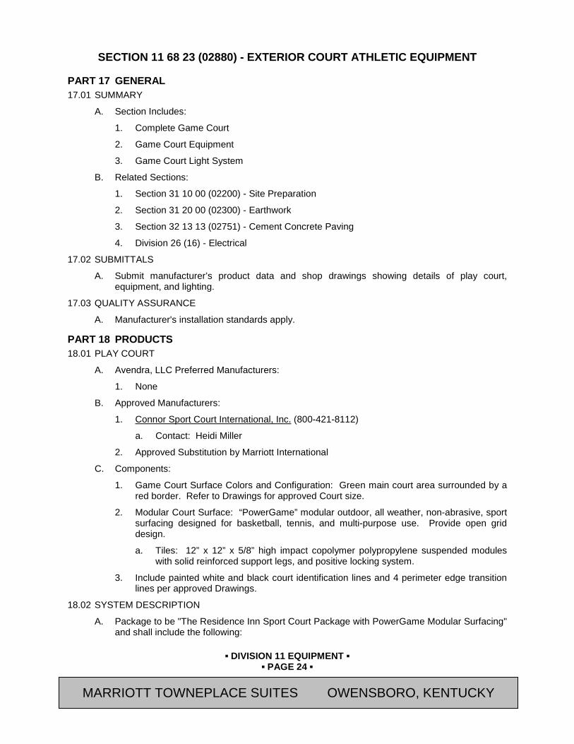
▪ DIVISION 11 EQUIPMENT ▪
▪ PAGE 24 ▪
RESIDENCE INN BY MARRIOTT - LITTLETON, COLORADO
SECTION 11 68 23 (02880) - EXTERIOR COURT ATHLETIC EQUIPMENT
PART 17 GENERAL 17.01 SUMMARY
A. Section Includes:
1. Complete Game Court
2. Game Court Equipment
3. Game Court Light System
B. Related Sections:
1. Section 31 10 00 (02200) - Site Preparation
2. Section 31 20 00 (02300) - Earthwork
3. Section 32 13 13 (02751) - Cement Concrete Paving
4. Division 26 (16) - Electrical
17.02 SUBMITTALS
A. Submit manufacturer’s product data and shop drawings showing details of play court, equipment, and lighting.
17.03 QUALITY ASSURANCE
A. Manufacturer's installation standards apply.
PART 18 PRODUCTS 18.01 PLAY COURT
A. Avendra, LLC Preferred Manufacturers:
1. None
B. Approved Manufacturers:
1. Connor Sport Court International, Inc. (800-421-8112)
a. Contact: Heidi Miller
2. Approved Substitution by Marriott International
C. Components:
1. Game Court Surface Colors and Configuration: Green main court area surrounded by a red border. Refer to Drawings for approved Court size.
2. Modular Court Surface: “PowerGame” modular outdoor, all weather, non-abrasive, sport surfacing designed for basketball, tennis, and multi-purpose use. Provide open grid design.
a. Tiles: 12” x 12” x 5/8” high impact copolymer polypropylene suspended modules with solid reinforced support legs, and positive locking system.
3. Include painted white and black court identification lines and 4 perimeter edge transition lines per approved Drawings.
18.02 SYSTEM DESCRIPTION
A. Package to be "The Residence Inn Sport Court Package with PowerGame Modular Surfacing" and shall include the following:
MARRIOTT TOWNEPLACE SUITES OWENSBORO, KENTUCKY

▪ DIVISION 11 EQUIPMENT ▪
▪ PAGE 25 ▪
RESIDENCE INN BY MARRIOTT - LITTLETON, COLORADO
1. Basketball: “Solid Slam System” - Provide 2 each.
a. Pole Size: 6” x 6” x 3/16” with U-bolt anchor.
b. Backboard Size: 42” x 60”; ½” acrylic, framed with extruded aluminum.
c. Arm Size: Standard 6” x 6” x 3/16”.
d. Weight: 360 lbs. (does not include rim)
e. Wind Speed: Standard 110 mph, exposure 3.
f. Overhang: At 10’: 36”.
g. Finish: Black powder coated with substrate phosphate protection package.
2. Net: 1 each [18’-6”] Multi-Sport net with cable.
3. Net adjustment system, black – provide 1 each.
4. Net pole with cap. Provide 1 pole.
5. Rebounder Unit, 10’ x 20’: Provide two (2) units, black.
6. Gear: “Fun Pak”
a. Tennis Balls Low Energy 3 count: 2 each
b. Atomic Paddles: 4 each
c. Basketball: 1 each
d. Basketball, women/youth: 1 each
e. Fun Ball, white: 3 each
f. Volleyball: 1 each
g. Wacketball, yellow: 6 each
h. Tennis Racquets: 4 each
i. Air Pump: 1 each
j. Sports Bag, 27”: 1 each
7. Light System: Single light unit “Sport Court Light”
a. Pole: 3-1/2” x 3-1/2” x 3/16” structural steel. Black powder coat finish, U-Bolt anchor.
b. Light Trough
c. Light Fixtures: 1000 Watt, 277 V, Pre-wired, multi-tap ballast (120 V / 9.0 A, 240 V / 5.2 A, 277 V / 3.9 A) per fixture. Provide fully adjustable fixtures, black finish.
d. Provide lamps, trough, pole support base and anchors
e. Pre-wired internal wiring, accessible behind cover plate.
f. Wind Load: 100 mph, exposure C.
g. Guest activated 30-minute timer (provided by others).
MARRIOTT TOWNEPLACE SUITES OWENSBORO, KENTUCKY

▪ DIVISION 11 EQUIPMENT ▪
▪ PAGE 26 ▪
RESIDENCE INN BY MARRIOTT - LITTLETON, COLORADO
PART 19 EXECUTION 19.01 INSTALLATION - GENERAL
A. Install surfacing and equipment in accordance with manufacturer's instructions. Refer to manufacturers drawings for placement of equipment bases, sleeves, and foundations. Contractor shall contact an authorized dealer of approved system to confirm proper installation procedures prior to installing the concrete pad.
B. The concrete pad shall be crowned at net line between poles with a 0.5% slope (1" per 16').
C. Electrician shall install conduit and wire from service panel to base of light pole and make connections.
19.02 INSTALLATION - EQUIPMENT
A. Comply with manufacturer’s assembly instructions.
B. For specific items, see listing below. General requirements for setting posts and poles into concrete footings: set items into concrete footing so that footing projects 4" above pad, plumb to within 1/8" in 10'. Provident conduit stubbed into footings for light pole placement. Set sleeves into concrete; centered into footing. Lubricate sleeves, slide poles into sleeves, adjust and lock with set bolt.
C. Basketball Systems: Locate on either end of court, placed outside of pad construction and centered on poured footing. Footing size: 3’ x 3’ x 48” deep.
D. Light Pole: Locate opposite Net Pole at center of court; placed outside of pad construction and centered on poured footing. Footing size: 24” x 24” x 36” deep. Provide conduit. Connect fixture to power per approved drawings.
E. Net Pole: Locate pole opposite light pole at center court, outside of pad construction and centered on poured footing. Footing size: 24” x 24” x 36” deep per approved drawings.
F. U-Bolt Anchor Basketball Poles: Set anchor bolts with template provided by manufacturer. Footing shall be minimum 24” wide by 48” deep. Install per approved drawings
G. Rebounder Units: Erect units at end of pad after completion of the pad. Two outside sleeves shall be 10’-3” apart on center, and set 3” inside pad. Assemble and place 3 each 18" sleeve onto frame and secure temporarily. Raise frame and set into holes. Plumb frame. Once set, add bottom apron and white line marker.
H. Ball Containment Panels: Provide required foundation and sleeves for the installation of panels at each side of rebounder unit, plus opposite of court, and return wings at each end of court.
END OF SECTION
Revision Log
MARRIOTT TOWNEPLACE SUITES OWENSBORO, KENTUCKY
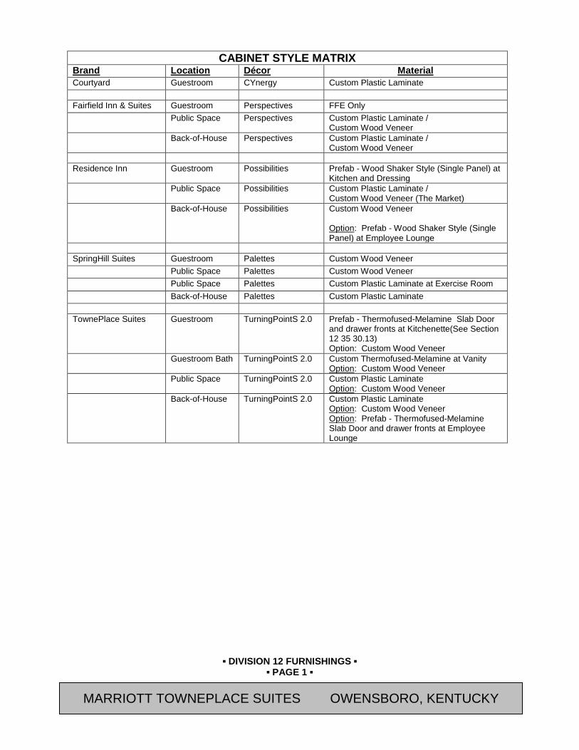
▪ DIVISION 12 FURNISHINGS ▪
▪ PAGE 1 ▪
RESIDENCE INN BY MARRIOTT - LITTLETON, COLORADO
CABINET STYLE MATRIX Brand Location Décor Material Courtyard Guestroom CYnergy Custom Plastic Laminate Fairfield Inn & Suites Guestroom Perspectives FFE Only Public Space Perspectives Custom Plastic Laminate /
Custom Wood Veneer Back-of-House Perspectives Custom Plastic Laminate /
Custom Wood Veneer Residence Inn Guestroom Possibilities Prefab - Wood Shaker Style (Single Panel) at
Kitchen and Dressing Public Space Possibilities Custom Plastic Laminate /
Custom Wood Veneer (The Market) Back-of-House Possibilities Custom Wood Veneer
Option: Prefab - Wood Shaker Style (Single Panel) at Employee Lounge
SpringHill Suites Guestroom Palettes Custom Wood Veneer Public Space Palettes Custom Wood Veneer Public Space Palettes Custom Plastic Laminate at Exercise Room Back-of-House Palettes Custom Plastic Laminate TownePlace Suites Guestroom TurningPointS 2.0
Prefab - Thermofused-Melamine Slab Door and drawer fronts at Kitchenette(See Section 12 35 30.13) Option: Custom Wood Veneer
Guestroom Bath TurningPointS 2.0 Custom Thermofused-Melamine at Vanity Option: Custom Wood Veneer
Public Space TurningPointS 2.0
Custom Plastic Laminate Option: Custom Wood Veneer
Back-of-House TurningPointS 2.0
Custom Plastic Laminate Option: Custom Wood Veneer Option: Prefab - Thermofused-Melamine Slab Door and drawer fronts at Employee Lounge
MARRIOTT TOWNEPLACE SUITES OWENSBORO, KENTUCKY

▪ DIVISION 12 FURNISHINGS ▪
▪ PAGE 2 ▪
RESIDENCE INN BY MARRIOTT - LITTLETON, COLORADO
SECTION 12 32 13 (06400) - MANUFACTURED WOOD-VENEER-FACED CASEWORK
PART 1 GENERAL 1.01 SUMMARY
A. Section Includes:
1. Custom Cabinet Units
a. Wood, Transparent Finish, Custom Cabinet Units
2. Cabinet Hardware
3. Decorative Glass for Guestroom Cabinets
B. Related Sections:
1. Section 06 61 00 (06100) - Rough Carpentry
2. Section 06 20 00 (06200) - Finish Carpentry
3. Section 08 80 00 (08800) – Glazing
4. Section 12 32 16 (06400) – Manufactured Plastic Laminate Clad Casework
5. Section 12 35 30.13 (06400) – Kitchen Casework
6. Section 12 36 23 (09415) - Plastic Countertops
7. Section 12 36 40 (09380) - Stone Countertops
8. Section 12 36 61 (09835) – Simulated Stone Countertops
9. Section 12 36 61.13 (06620) – Cultured Marble Countertops
10. Section 12 36 61.16 (06620) – Solid Surfacing Countertops
11. Division 22 (15) for Plumbing Fixtures
1.02 REFERENCES
A. Architectural Woodwork Institute (AWI) / Architectural Woodwork Manufacturers Association of Canada (AWMAC) /Woodwork Institute (WI) Publications:
1. "Architectural Woodwork Standards (AWS)"
B. ASTM International (ASTM) Publications:
1. C1048 “Standard Specification for Heat-Treated Flat Glass—Kind HS, Kind FT Coated and Uncoated Glass”
2. D523 “Standard Test Method for Specular Gloss”
3. E84 "Standard Test Method for Surface Burning Characteristics of Building Materials"
C. American National Standards Institute (ANSI) Publications:
1. A135.4 Basic Hardboard
2. ANSI/KCMA A161.1 “Performance and Construction Standard for Kitchen and Vanity Cabinets
3. A161.2 “Standards for Fabricated High Pressure Decorative Laminate Countertops”
MARRIOTT TOWNEPLACE SUITES OWENSBORO, KENTUCKY
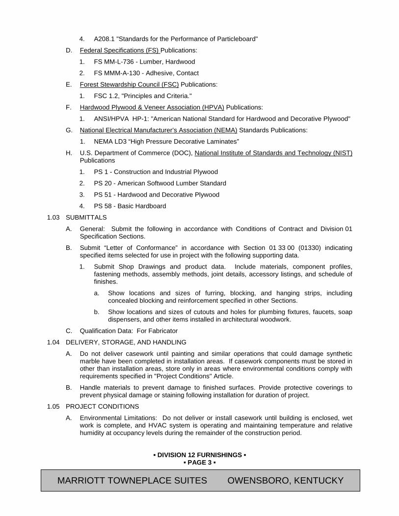
▪ DIVISION 12 FURNISHINGS ▪
▪ PAGE 3 ▪
RESIDENCE INN BY MARRIOTT - LITTLETON, COLORADO
4. A208.1 "Standards for the Performance of Particleboard"
D. Federal Specifications (FS) Publications:
1. FS MM-L-736 - Lumber, Hardwood
2. FS MMM-A-130 - Adhesive, Contact
E. Forest Stewardship Council (FSC) Publications:
1. FSC 1.2, "Principles and Criteria."
F. Hardwood Plywood & Veneer Association (HPVA) Publications:
1. ANSI/HPVA HP-1: "American National Standard for Hardwood and Decorative Plywood"
G. National Electrical Manufacturer’s Association (NEMA) Standards Publications:
1. NEMA LD3 “High Pressure Decorative Laminates”
H. U.S. Department of Commerce (DOC), National Institute of Standards and Technology (NIST) Publications
1. PS 1 - Construction and Industrial Plywood
2. PS 20 - American Softwood Lumber Standard
3. PS 51 - Hardwood and Decorative Plywood
4. PS 58 - Basic Hardboard
1.03 SUBMITTALS
A. General: Submit the following in accordance with Conditions of Contract and Division 01 Specification Sections.
B. Submit “Letter of Conformance” in accordance with Section 01 33 00 (01330) indicating specified items selected for use in project with the following supporting data.
1. Submit Shop Drawings and product data. Include materials, component profiles, fastening methods, assembly methods, joint details, accessory listings, and schedule of finishes.
a. Show locations and sizes of furring, blocking, and hanging strips, including concealed blocking and reinforcement specified in other Sections.
b. Show locations and sizes of cutouts and holes for plumbing fixtures, faucets, soap dispensers, and other items installed in architectural woodwork.
C. Qualification Data: For Fabricator
1.04 DELIVERY, STORAGE, AND HANDLING
A. Do not deliver casework until painting and similar operations that could damage synthetic marble have been completed in installation areas. If casework components must be stored in other than installation areas, store only in areas where environmental conditions comply with requirements specified in "Project Conditions" Article.
B. Handle materials to prevent damage to finished surfaces. Provide protective coverings to prevent physical damage or staining following installation for duration of project.
1.05 PROJECT CONDITIONS
A. Environmental Limitations: Do not deliver or install casework until building is enclosed, wet work is complete, and HVAC system is operating and maintaining temperature and relative humidity at occupancy levels during the remainder of the construction period.
MARRIOTT TOWNEPLACE SUITES OWENSBORO, KENTUCKY

▪ DIVISION 12 FURNISHINGS ▪
▪ PAGE 4 ▪
RESIDENCE INN BY MARRIOTT - LITTLETON, COLORADO
B. Field Measurements: Where casework is indicated to fit to other construction, verify dimensions of other construction by field measurements before fabrication and indicate measurements on Shop Drawings. Coordinate fabrication schedule with construction progress to avoid delaying the Work.
1. Locate concealed framing, blocking, and reinforcements that support casework by field measurements before being enclosed and indicate measurements on Shop Drawings.
PART 2 PRODUCTS 2.01 APPROVED MANUFACTURERS
A. Avendra, LLC Preferred Manufacturers:
1. None
B. Approved Manufacturers:
1. MillRock RiverRun Casework (540-438-5973)
2. R.B. Woodcraft, Inc. (315-474-2429)
3. J. Suss Industries Inc. (866-769-5666)
2.02 WOOD, TRANSPARENT FINISH CUSTOM BOX CABINET UNITS - GENERAL
A. Quality Standard:
1. Perform work to meet the requirements of Custom Grade in accordance with the "Architectural Woodwork Standards (AWS)", unless noted otherwise manufactured from solid stock meeting the following requirements:
a. Minor warp which can be held flat and straight with normal nailing.
b. Natural and manufacturing defects in excess of those permitted in the grade specified are permitted if such defects are to be covered by adjoining members or otherwise concealed.
c. Trim members for application on flat surfaces shall have the reverse side "backed out", except members with exposed ends.
d. "Custom grade" pieces shall be smoothly machined with top flat surfaces machine sanded. Depressed flat surfaces and molded contours shall be smoothly machined.
B. Design:
1. Style of face construction for base, wall, and full-height units, if any, with drawer fronts, doors, and fixed panels as follows:
a. Face Frame or Frameless.
1) All cabinets shall be the same construction type for the entire Project.
b. Cabinet and Door Interface: Flush (Full) Overlay.
c. Flush Panel Doors.
d. Flush Panel Drawer Fronts.
e. Color: Refer to Interior Finish Index
2. Grain Direction:
a. Vertical on doors, horizontal on drawer fronts.
b. Lengthwise on face frame members.
MARRIOTT TOWNEPLACE SUITES OWENSBORO, KENTUCKY
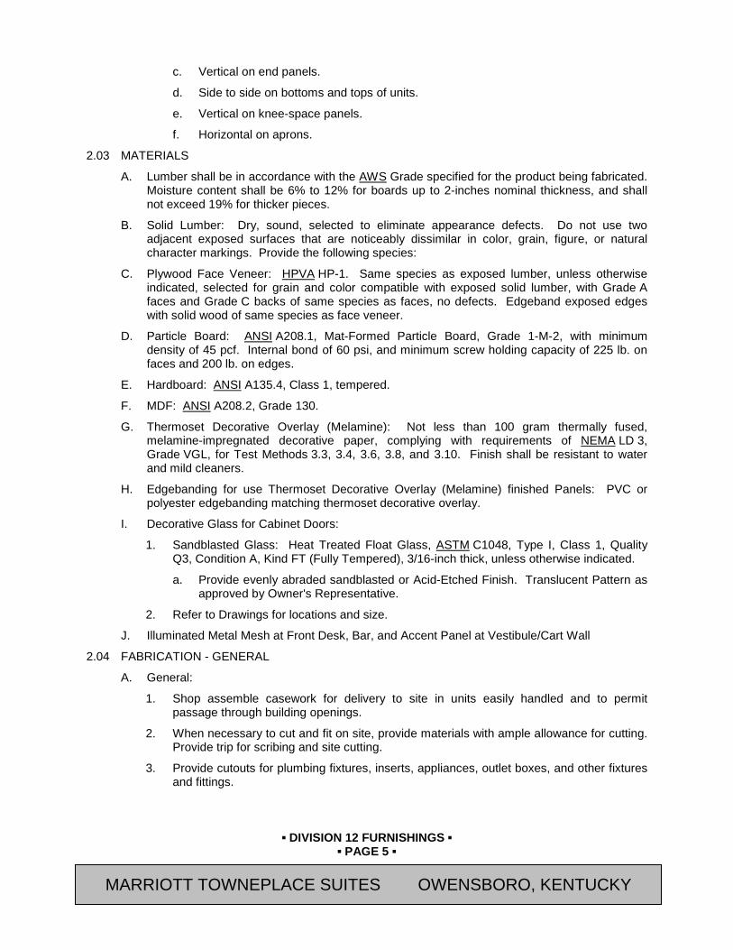
▪ DIVISION 12 FURNISHINGS ▪
▪ PAGE 5 ▪
RESIDENCE INN BY MARRIOTT - LITTLETON, COLORADO
c. Vertical on end panels.
d. Side to side on bottoms and tops of units.
e. Vertical on knee-space panels.
f. Horizontal on aprons.
2.03 MATERIALS
A. Lumber shall be in accordance with the AWS Grade specified for the product being fabricated. Moisture content shall be 6% to 12% for boards up to 2-inches nominal thickness, and shall not exceed 19% for thicker pieces.
B. Solid Lumber: Dry, sound, selected to eliminate appearance defects. Do not use two adjacent exposed surfaces that are noticeably dissimilar in color, grain, figure, or natural character markings. Provide the following species:
C. Plywood Face Veneer: HPVA HP-1. Same species as exposed lumber, unless otherwise indicated, selected for grain and color compatible with exposed solid lumber, with Grade A faces and Grade C backs of same species as faces, no defects. Edgeband exposed edges with solid wood of same species as face veneer.
D. Particle Board: ANSI A208.1, Mat-Formed Particle Board, Grade 1-M-2, with minimum density of 45 pcf. Internal bond of 60 psi, and minimum screw holding capacity of 225 lb. on faces and 200 lb. on edges.
E. Hardboard: ANSI A135.4, Class 1, tempered.
F. MDF: ANSI A208.2, Grade 130.
G. Thermoset Decorative Overlay (Melamine): Not less than 100 gram thermally fused, melamine-impregnated decorative paper, complying with requirements of NEMA LD 3, Grade VGL, for Test Methods 3.3, 3.4, 3.6, 3.8, and 3.10. Finish shall be resistant to water and mild cleaners.
H. Edgebanding for use Thermoset Decorative Overlay (Melamine) finished Panels: PVC or polyester edgebanding matching thermoset decorative overlay.
I. Decorative Glass for Cabinet Doors:
1. Sandblasted Glass: Heat Treated Float Glass, ASTM C1048, Type I, Class 1, Quality Q3, Condition A, Kind FT (Fully Tempered), 3/16-inch thick, unless otherwise indicated.
a. Provide evenly abraded sandblasted or Acid-Etched Finish. Translucent Pattern as approved by Owner's Representative.
2. Refer to Drawings for locations and size.
J. Illuminated Metal Mesh at Front Desk, Bar, and Accent Panel at Vestibule/Cart Wall
2.04 FABRICATION - GENERAL
A. General:
1. Shop assemble casework for delivery to site in units easily handled and to permit passage through building openings.
2. When necessary to cut and fit on site, provide materials with ample allowance for cutting. Provide trip for scribing and site cutting.
3. Provide cutouts for plumbing fixtures, inserts, appliances, outlet boxes, and other fixtures and fittings.
MARRIOTT TOWNEPLACE SUITES OWENSBORO, KENTUCKY
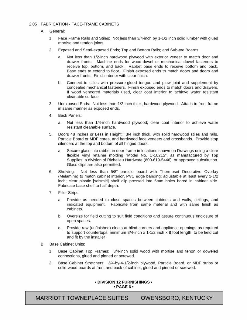
▪ DIVISION 12 FURNISHINGS ▪
▪ PAGE 6 ▪
RESIDENCE INN BY MARRIOTT - LITTLETON, COLORADO
2.05 FABRICATION - FACE-FRAME CABINETS
A. General:
1. Face Frame Rails and Stiles: Not less than 3/4-inch by 1-1/2 inch solid lumber with glued mortise and tendon joints.
2. Exposed and Semi-exposed Ends; Top and Bottom Rails; and Sub-toe Boards:
a. Not less than 1/2-inch hardwood plywood with exterior veneer to match door and drawer fronts. Machine ends for wood-dowel or mechanical dowel fasteners to receive top, bottom, and back. Rabbet base ends to receive bottom and back. Base ends to extend to floor. Finish exposed ends to match doors and doors and drawer fronts. Finish interior with clear finish.
b. Connect to stiles with pressure-glued tongue and plow joint and supplement by concealed mechanical fasteners. Finish exposed ends to match doors and drawers. If wood veneered materials used, clear coat interior to achieve water resistant cleanable surface.
3. Unexposed Ends: Not less than 1/2-inch thick, hardwood plywood. Attach to front frame in same manner as exposed ends.
4. Back Panels:
a. Not less than 1/4-inch hardwood plywood; clear coat interior to achieve water resistant cleanable surface.
5. Doors 48 Inches or Less in Height: 3/4 inch thick, with solid hardwood stiles and rails, Particle Board or MDF cores, and hardwood face veneers and crossbands. Provide stop silencers at the top and bottom of all hinged doors.
a. Secure glass into rabbet in door frame in locations shown on Drawings using a clear flexible vinyl retainer molding “Model No. C-10215”, as manufactured by Top Supplies, a division of Richelieu Hardware (800-619-5446), or approved substitution. Glass clips are also permitted.
6. Shelving: Not less than 5/8” particle board with Thermoset Decorative Overlay (Melamine) to match cabinet interior, PVC edge banding; adjustable at least every 1-1/2 inch; clear plastic [seismic] shelf clip pressed into 5mm holes bored in cabinet side. Fabricate base shelf to half depth.
7. Filler Strips:
a. Provide as needed to close spaces between cabinets and walls, ceilings, and indicated equipment. Fabricate from same material and with same finish as cabinets.
b. Oversize for field cutting to suit field conditions and assure continuous enclosure of open spaces.
c. Provide raw (unfinished) cleats at blind corners and appliance openings as required to support countertops, minimum 3/4-inch x 1-1/2 inch x 8 foot length, to be field cut and fit by the installer
B. Base Cabinet Units:
1. Base Cabinet Top Frames: 3/4-inch solid wood with mortise and tenon or doweled connections, glued and pinned or screwed.
2. Base Cabinet Stretchers: 3/4-by-4-1/2-inch plywood, Particle Board, or MDF strips or solid-wood boards at front and back of cabinet, glued and pinned or screwed.
MARRIOTT TOWNEPLACE SUITES OWENSBORO, KENTUCKY

▪ DIVISION 12 FURNISHINGS ▪
▪ PAGE 7 ▪
RESIDENCE INN BY MARRIOTT - LITTLETON, COLORADO
a. Base Cabinet Stretchers may be provided as an option to base cabinet top frames.
3. Front Frame Drawer Rails: Not less than 3/4-inch solid wood mortised and fastened into face frame.
4. Bottoms: Not less than 1/2-inch hardwood plywood with exterior veneer to match door and drawer fronts, fully supported by and secured in rabbets in end panels, front frame, and back bottom rail.
5. Corner Blocks: Glued and fastened in each of four top corners to maintain cabinet squareness and rigidity.
6. Drawers:
a. Provide box-type construction with sub-front and back joined with glued dovetail or rabbeted into sides and secured with glue and mechanical fasteners. Clear coat all exposed surfaces. Match color of sides and bottoms with drawer fronts.
b. Drawer Fronts: 3/4-inch Particle Board-core hardwood veneered plywood or solid hardwood.
c. Drawer Sides Sub-fronts, and Backs: Not less than 1/2-inch solid hardwood or veneered plywood.
d. Exposed fronts fastened to Sub-fronts with mounting screws from interior of body.
e. Drawer bottom of not less than 1/4-inch veneer hardboard, set into rabbets in back, sides, and sub-fronts.
C. Wall Cabinet Units:
1. Tops and Bottoms: Not less than 1/2-inch hardwood veneered plywood with exterior veneer to match door fronts, fully supported by and secured in rabbets in end panels, front frame, and back rail.
2.06 FABRICATION – FRAMELESS CABINETS
A. General:
1. Exposed and Semi-exposed Ends; Top and Bottom Rails; and Sub-toe Boards:
a. Not less than 3/4-inch Particle Board with Thermoset Decorative Overlay (Melamine) to match door and drawer fronts. Ma chine ends for wood-dowel or mechanical dowel fasteners to receive top, bottom, and back. Base ends to extend to floor. Finish exposed ends to match doors and doors and drawer fronts.
2. Unexposed Ends: Not less than 3/4-inch hardboard or particle board; finished with Thermoset Decorative Overlay (Melamine). Attach to front frame in same manner as exposed ends.
3. Back Panels:
a. Not less than 1/4-inch tempered hardboard or MDF; finished with Thermoset Decorative Overlay (Melamine).
4. Doors 48 Inches or Less in Height:
a. Flush (Slab) Style Doors: 3/4 inch thick, Particle Board or MDF cores, and hardwood face veneers and edge tape.
b. Single Fixed Panel Stile and Rail Style Doors: 3/4 inch thick, with solid hardwood stiles and rails, Particle Board or MDF cores, and hardwood face veneers and crossbands.
c. Provide stop silencers at the top and bottom of all hinged doors.
MARRIOTT TOWNEPLACE SUITES OWENSBORO, KENTUCKY
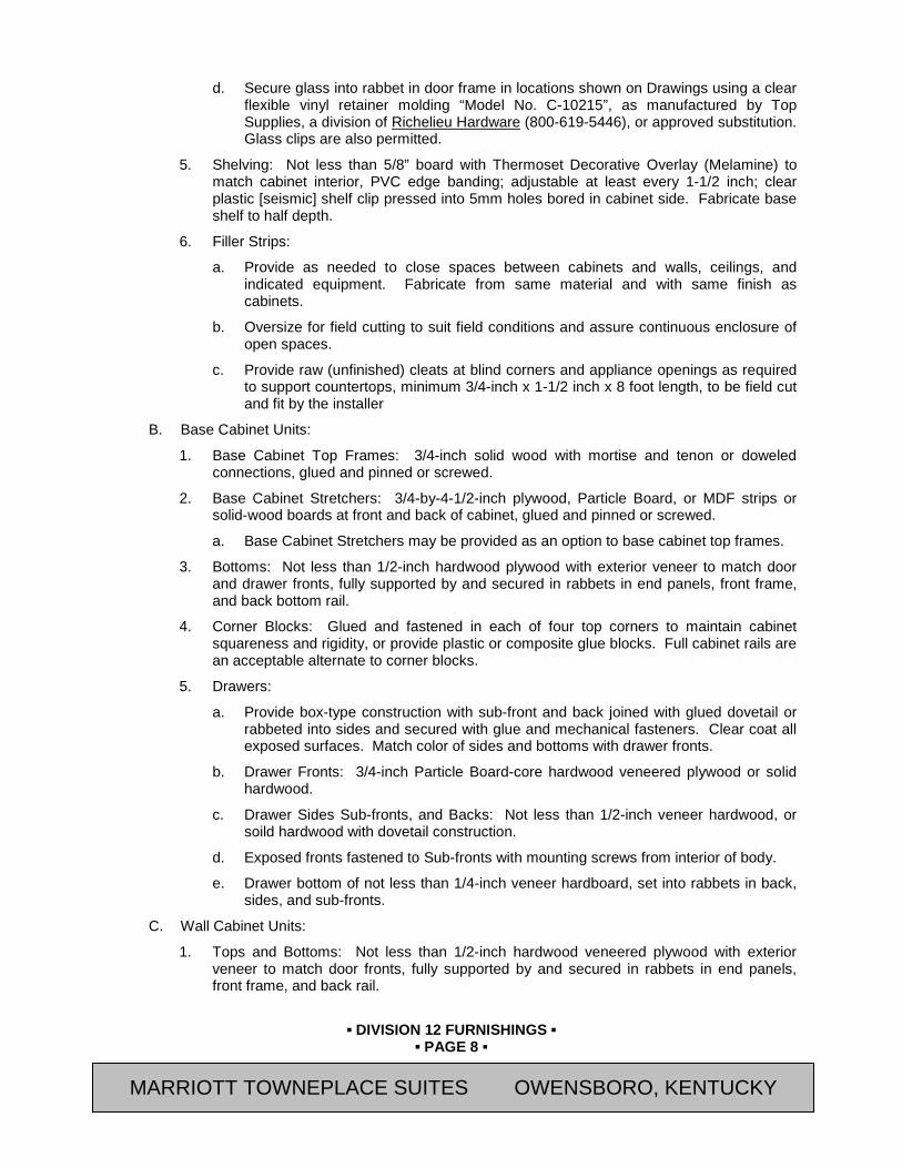
▪ DIVISION 12 FURNISHINGS ▪
▪ PAGE 8 ▪
RESIDENCE INN BY MARRIOTT - LITTLETON, COLORADO
d. Secure glass into rabbet in door frame in locations shown on Drawings using a clear flexible vinyl retainer molding “Model No. C-10215”, as manufactured by Top Supplies, a division of Richelieu Hardware (800-619-5446), or approved substitution. Glass clips are also permitted.
5. Shelving: Not less than 5/8” board with Thermoset Decorative Overlay (Melamine) to match cabinet interior, PVC edge banding; adjustable at least every 1-1/2 inch; clear plastic [seismic] shelf clip pressed into 5mm holes bored in cabinet side. Fabricate base shelf to half depth.
6. Filler Strips:
a. Provide as needed to close spaces between cabinets and walls, ceilings, and indicated equipment. Fabricate from same material and with same finish as cabinets.
b. Oversize for field cutting to suit field conditions and assure continuous enclosure of open spaces.
c. Provide raw (unfinished) cleats at blind corners and appliance openings as required to support countertops, minimum 3/4-inch x 1-1/2 inch x 8 foot length, to be field cut and fit by the installer
B. Base Cabinet Units:
1. Base Cabinet Top Frames: 3/4-inch solid wood with mortise and tenon or doweled connections, glued and pinned or screwed.
2. Base Cabinet Stretchers: 3/4-by-4-1/2-inch plywood, Particle Board, or MDF strips or solid-wood boards at front and back of cabinet, glued and pinned or screwed.
a. Base Cabinet Stretchers may be provided as an option to base cabinet top frames.
3. Bottoms: Not less than 1/2-inch hardwood plywood with exterior veneer to match door and drawer fronts, fully supported by and secured in rabbets in end panels, front frame, and back bottom rail.
4. Corner Blocks: Glued and fastened in each of four top corners to maintain cabinet squareness and rigidity, or provide plastic or composite glue blocks. Full cabinet rails are an acceptable alternate to corner blocks.
5. Drawers:
a. Provide box-type construction with sub-front and back joined with glued dovetail or rabbeted into sides and secured with glue and mechanical fasteners. Clear coat all exposed surfaces. Match color of sides and bottoms with drawer fronts.
b. Drawer Fronts: 3/4-inch Particle Board-core hardwood veneered plywood or solid hardwood.
c. Drawer Sides Sub-fronts, and Backs: Not less than 1/2-inch veneer hardwood, or soild hardwood with dovetail construction.
d. Exposed fronts fastened to Sub-fronts with mounting screws from interior of body.
e. Drawer bottom of not less than 1/4-inch veneer hardboard, set into rabbets in back, sides, and sub-fronts.
C. Wall Cabinet Units:
1. Tops and Bottoms: Not less than 1/2-inch hardwood veneered plywood with exterior veneer to match door fronts, fully supported by and secured in rabbets in end panels, front frame, and back rail.
MARRIOTT TOWNEPLACE SUITES OWENSBORO, KENTUCKY

▪ DIVISION 12 FURNISHINGS ▪
▪ PAGE 9 ▪
RESIDENCE INN BY MARRIOTT - LITTLETON, COLORADO
2.07 CABINET HARDWARE
A. See Cabinet Hardware Schedule for list of which Manufacturer's are approved for use on a specific item.
B. Avendra, LLC Preferred Manufacturers:
1. None
C. Approved Manufacturers
1. Accuride International (562-903-0200)
2. Blum, Inc. (800-438-6788)
3. CompX Timberline (847-752-2600)
4. Corbin Russwin Architectural Hardware, an ASSA ABLOY Group (800-543-3658)
5. Epco, The Engineered Products Co. (810-767-2050)
6. Franklin Fixtures (508-291-1475)
7. Grass America, Inc. (800-334-3512)
8. Hafele America Co. (800-423-3531)
9. H.B. Ives, an Ingersoll-Rand Company (800-820-5542)
10. Hercules Casters and Wheels (800-942-8717)
11. Hettich America, LP (800-777-1772)
12. J. G. Edelen Company, Inc. (410-918-1200)
13. Knape & Vogt Manufacturing Co. (800-253-1561) (KV)
14. Doug Mockett & Company, Inc. (800-523-1269)
15. Outwater Plastics Industries, Inc. (800-631-8375)
16. Polar Ware Company (800-237-3655)
17. Rockler Companies, Inc. (800-279-4441)
18. Selby Furniture Hardware Co., Inc. (718-993-3700)
19. Shepherd Caster Corporation (800-253-0868)
20. Stanley Hardware, Div. of the Stanley Works (800-493-5263)
21. Stylmark, Inc. (Garcy Corp.) (800-328-2495)
22. Victory Display & Store Fixture Mfg. (800-262-1126)
D. General: Provide cabinet hardware and accessory materials associated with architectural cabinets. Coordinate finishes of exposed cabinet hardware with adjacent finish hardware as specified in Section 08 71 00 (08710).
E. Cabinet Hardware Schedule: ITEM MODEL NO. MANUFACTURER THE MARKET Cabinet Pulls DP41-A-3 EPCO Cabinet Locks 280 Series (Drawers)
290 Series (Doors) C700LP-15 Plugs (This item keyed separately- See Note 2)
CompX-Timberline
MARRIOTT TOWNEPLACE SUITES OWENSBORO, KENTUCKY
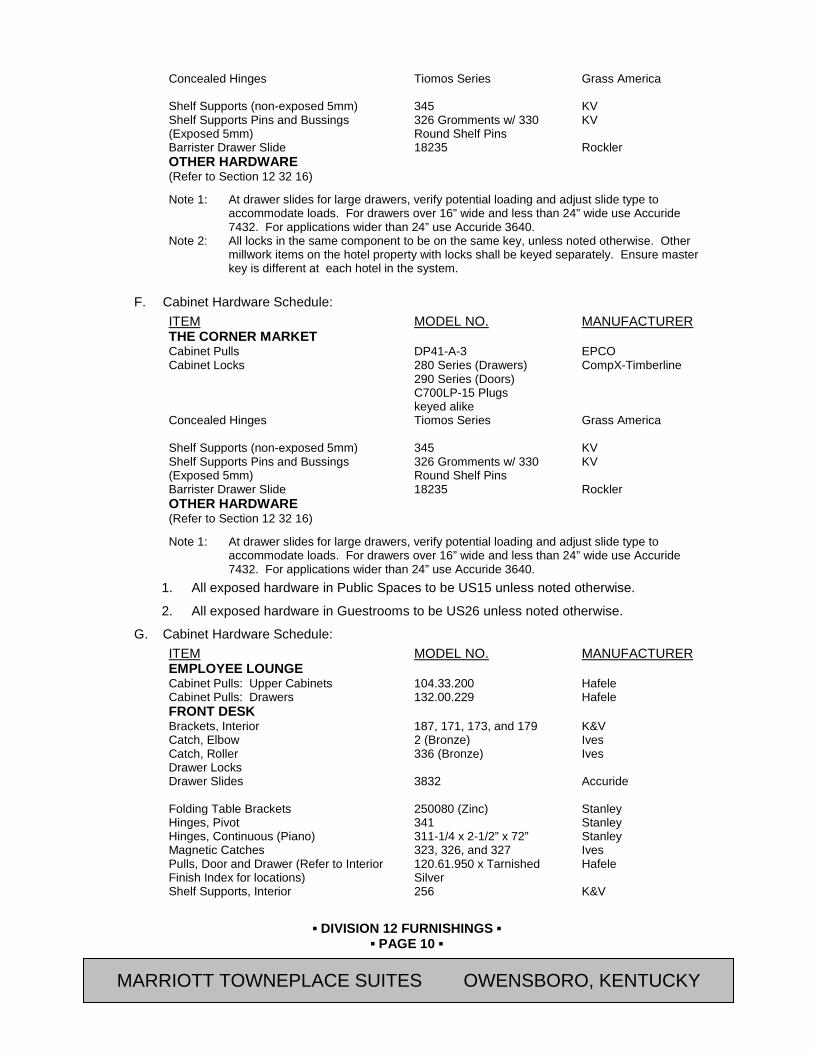
▪ DIVISION 12 FURNISHINGS ▪
▪ PAGE 10 ▪
RESIDENCE INN BY MARRIOTT - LITTLETON, COLORADO
Concealed Hinges Tiomos Series
Grass America
Shelf Supports (non-exposed 5mm) 345 KV Shelf Supports Pins and Bussings (Exposed 5mm)
326 Gromments w/ 330 Round Shelf Pins
KV
Barrister Drawer Slide 18235 Rockler OTHER HARDWARE (Refer to Section 12 32 16) Note 1: At drawer slides for large drawers, verify potential loading and adjust slide type to
accommodate loads. For drawers over 16” wide and less than 24” wide use Accuride 7432. For applications wider than 24” use Accuride 3640.
Note 2: All locks in the same component to be on the same key, unless noted otherwise. Other millwork items on the hotel property with locks shall be keyed separately. Ensure master key is different at each hotel in the system.
F. Cabinet Hardware Schedule:
ITEM MODEL NO. MANUFACTURER THE CORNER MARKET Cabinet Pulls DP41-A-3 EPCO Cabinet Locks 280 Series (Drawers)
290 Series (Doors) C700LP-15 Plugs keyed alike
CompX-Timberline
Concealed Hinges Tiomos Series
Grass America
Shelf Supports (non-exposed 5mm) 345 KV Shelf Supports Pins and Bussings (Exposed 5mm)
326 Gromments w/ 330 Round Shelf Pins
KV
Barrister Drawer Slide 18235 Rockler OTHER HARDWARE (Refer to Section 12 32 16) Note 1: At drawer slides for large drawers, verify potential loading and adjust slide type to
accommodate loads. For drawers over 16” wide and less than 24” wide use Accuride 7432. For applications wider than 24” use Accuride 3640.
1. All exposed hardware in Public Spaces to be US15 unless noted otherwise.
2. All exposed hardware in Guestrooms to be US26 unless noted otherwise.
G. Cabinet Hardware Schedule: ITEM MODEL NO. MANUFACTURER EMPLOYEE LOUNGE Cabinet Pulls: Upper Cabinets 104.33.200 Hafele Cabinet Pulls: Drawers 132.00.229 Hafele FRONT DESK Brackets, Interior 187, 171, 173, and 179 K&V Catch, Elbow 2 (Bronze) Ives Catch, Roller 336 (Bronze) Ives Drawer Locks Drawer Slides 3832 Accuride Folding Table Brackets 250080 (Zinc) Stanley Hinges, Pivot 341 Stanley Hinges, Continuous (Piano) 311-1/4 x 2-1/2” x 72” Stanley Magnetic Catches 323, 326, and 327 Ives Pulls, Door and Drawer (Refer to Interior Finish Index for locations)
120.61.950 x Tarnished Silver
Hafele
Shelf Supports, Interior 256 K&V
MARRIOTT TOWNEPLACE SUITES OWENSBORO, KENTUCKY
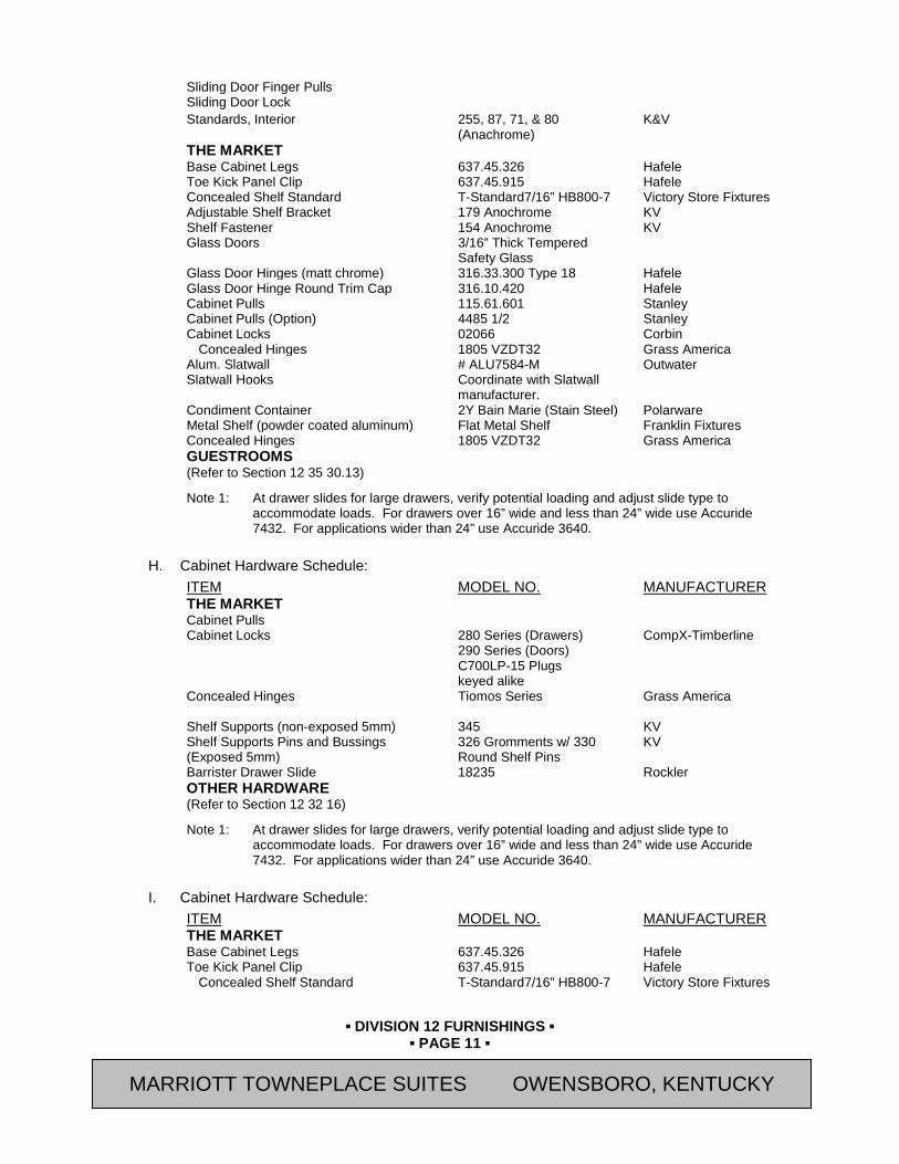
▪ DIVISION 12 FURNISHINGS ▪
▪ PAGE 11 ▪
RESIDENCE INN BY MARRIOTT - LITTLETON, COLORADO
Sliding Door Finger Pulls Sliding Door Lock Standards, Interior 255, 87, 71, & 80
(Anachrome) K&V
THE MARKET Base Cabinet Legs 637.45.326 Hafele Toe Kick Panel Clip 637.45.915 Hafele Concealed Shelf Standard T-Standard7/16” HB800-7 Victory Store Fixtures Adjustable Shelf Bracket 179 Anochrome KV Shelf Fastener 154 Anochrome KV Glass Doors 3/16” Thick Tempered
Safety Glass
Glass Door Hinges (matt chrome) 316.33.300 Type 18 Hafele Glass Door Hinge Round Trim Cap 316.10.420 Hafele Cabinet Pulls 115.61.601 Stanley Cabinet Pulls (Option) 4485 1/2 Stanley Cabinet Locks 02066 Corbin
Concealed Hinges 1805 VZDT32 Grass America Alum. Slatwall # ALU7584-M Outwater Slatwall Hooks Coordinate with Slatwall
manufacturer.
Condiment Container 2Y Bain Marie (Stain Steel) Polarware Metal Shelf (powder coated aluminum) Flat Metal Shelf Franklin Fixtures Concealed Hinges 1805 VZDT32 Grass America GUESTROOMS (Refer to Section 12 35 30.13) Note 1: At drawer slides for large drawers, verify potential loading and adjust slide type to
accommodate loads. For drawers over 16” wide and less than 24” wide use Accuride 7432. For applications wider than 24” use Accuride 3640.
H. Cabinet Hardware Schedule:
ITEM MODEL NO. MANUFACTURER THE MARKET Cabinet Pulls Cabinet Locks 280 Series (Drawers)
290 Series (Doors) C700LP-15 Plugs keyed alike
CompX-Timberline
Concealed Hinges Tiomos Series
Grass America
Shelf Supports (non-exposed 5mm) 345 KV Shelf Supports Pins and Bussings (Exposed 5mm)
326 Gromments w/ 330 Round Shelf Pins
KV
Barrister Drawer Slide 18235 Rockler OTHER HARDWARE (Refer to Section 12 32 16) Note 1: At drawer slides for large drawers, verify potential loading and adjust slide type to
accommodate loads. For drawers over 16” wide and less than 24” wide use Accuride 7432. For applications wider than 24” use Accuride 3640.
I. Cabinet Hardware Schedule:
ITEM MODEL NO. MANUFACTURER THE MARKET Base Cabinet Legs 637.45.326 Hafele Toe Kick Panel Clip 637.45.915 Hafele
Concealed Shelf Standard T-Standard7/16” HB800-7 Victory Store Fixtures
MARRIOTT TOWNEPLACE SUITES OWENSBORO, KENTUCKY

▪ DIVISION 12 FURNISHINGS ▪
▪ PAGE 12 ▪
RESIDENCE INN BY MARRIOTT - LITTLETON, COLORADO
Adjustable Shelf Bracket 179 Anochrome KV Shelf Fastener 154 Anochrome KV Glass Doors 3/16” Thick Tempered
Safety Glass
Glass Door Hinges (matt chrome) 316.33.300 Type 18 Hafele Glass Door Hinge Round Trim Cap 316.10.420 Hafele Cabinet Pulls 115.61.601 Stanley Cabinet Pulls (Option) 4485 1/2 Stanley Cabinet Locks 02066 Corbin Concealed Hinges 1805 VZDT32 Grass America Alum. Slatwall # ALU7584-M Outwater Slatwall Hooks Coordinate with Slatwall
manufacturer.
Condiment Container 2Y Bain Marie (Stain Steel) Polarware Metal Shelf (powder coated aluminum) Flat Metal Shelf Franklin Fixtures Concealed Hinges 1805 VZDT32 Grass OTHER HARDWARE (Refer to Section 12 32 16) Note 1: At drawer slides for large drawers, verify potential loading and adjust slide type to
accommodate loads. For drawers over 16” wide and less than 24” wide use Accuride 7432. For applications wider than 24” use Accuride 3640.
J. Cabinet Hardware Schedule:
1. Refer to Section 12 35 30.13 – Kitchen Casework. for Guestroom, and Employee Lounge cabinet hardware.
K. Exposed Wall Shelving: “No. 80 x No. 182”; Knape & Vogt Manufacturing Co.; inset type, adjustable on 1" centers.
L. Cash Drawer With Lock
1. Furnished by Owner. Contractor shall coordinate size.
a. Provide 1/8” clearance around all four sides, or as recommended by manufacturer.
2.08 INSTALLATION MATERIALS
A. Furring, Blocking, SNote:hims, and Hanging Strips: Fire-retardant-treated Softwood or hardwood lumber, kiln-dried to less than 15 percent moisture content.
B. Anchors: Select material, type, size, and finish required for each substrate for secure anchorage. Provide nonferrous-metal or hot-dip galvanized anchors and inserts on inside face of exterior walls and elsewhere as required for corrosion resistance. Provide toothed-steel or lead expansion sleeves for drilled-in-place anchors.
1. Adhesives: Installation adhesives as recommended by manufacturer for use intended.
2.09 SHOP FINISHING
A. Quality Standard: Comply with AWS Appendix B, unless otherwise indicated.
B. General: Finish casework at fabrication shop as specified in this Section. Defer only final touchup, cleaning, and polishing until after installation.
C. Backpriming: Apply one coat of sealer or primer, compatible with finish coats, to concealed surfaces of woodwork. Apply two coats to back of paneling.
D. Transparent Finish: Comply with requirements indicated below for grade, finish system, staining, and sheen, with sheen measured on 60-degree gloss meter per ASTM D523:
1. Grade: Custom.
MARRIOTT TOWNEPLACE SUITES OWENSBORO, KENTUCKY
▪ DIVISION 12 FURNISHINGS ▪
▪ PAGE 13 ▪
RESIDENCE INN BY MARRIOTT - LITTLETON, COLORADO
2. Finish System: TR-2 (custom), catalyzed lacquer.
a. Stain Color: Refer to Interior Finish Index.
b. 1 Coat precatalyzed sanding sealer
c. Sand (240 Grit)
d. 1 Coat colored sealer
e. 1 Coat precatalyzed sealer
f. Sand (320 Grit)
g. 1 Coat precatalyzed lacquer - 30% Sheen (semi-gloss) to match approved sample provided by Marriott.
PART 3 EXECUTION 3.01 INSPECTION
A. Verify adequacy of backing and support framing.
3.02 INSTALLATION
A. All cabinets and shelving shall be installed as shown on Drawings and as specified by manufacturer.
B. Set and secure casework in place rigid, plumb, and level.
C. Cabinets: Install without distortion so doors and drawers fit openings properly and are accurately aligned. Adjust hardware to center doors and drawers in openings and to provide unencumbered operation. Complete installation of hardware and accessory items as indicated.
1. Secure cabinet and counter bases to floor using appropriate angles and anchorages.
2. Install cabinets with no more than 1/8 inch in 96-inch sag, bow, or other variation from a straight line.
3. Maintain veneer sequence matching of cabinets with transparent finish.
4. Carefully scribe casework which is against other building materials, leaving gaps of 1/32 inch maximum. Do not use additional overly trim for this purpose.
5. Carefully fit equipment to be installed into millwork. Provide filler pieces when required.
D. Fasteners:
1. Use purpose designed fixture attachments at concealed locations for wall-mounted components.
2. Use threaded steel concealed joint fasteners to align and secure adjoining cabinet units and counter tops.
3. Countersink anchorage devices at exposed locations used to wall-mount components, and conceal with solid plugs of species to match surrounding wood. Finish flush with surrounding surfaces.
4. Install countertops with no more than 1/8 inch in 96-inch sag, bow, or other variation from a straight line.
MARRIOTT TOWNEPLACE SUITES OWENSBORO, KENTUCKY
▪ DIVISION 12 FURNISHINGS ▪
▪ PAGE 14 ▪
RESIDENCE INN BY MARRIOTT - LITTLETON, COLORADO
SECTION 12 32 16 (06400) - MANUFACTURED PLASTIC LAMINATE CLAD CASEWORK
PART 4 GENERAL 4.01 SUMMARY
A. Section Includes:
1. Custom Cabinet Units
a. Plastic Laminate Clad Custom Cabinet Units
2. Cabinet Hardware
B. Related Sections:
1. Section 06 61 00 (06100) - Rough Carpentry
2. Section 06 20 00 (06200) - Finish Carpentry
3. Section 12 32 13 (06400) – Manufactured Wood-Veneer-Faced Casework
4. Section 12 35 30.13 (06400) – Kitchen Casework
5. Section 12 36 23 (09415) - Plastic Countertops
6. Section 12 36 40 (09380) - Stone Countertops
7. Section 12 36 61 (09835) – Simulated Stone Countertops
8. Section 12 36 61.13 (06620) – Cultured Marble Countertops
9. Section 12 36 61.16 (06620) – Solid Surfacing Countertops
10. Division 22 (15) for Plumbing Fixtures
4.02 REFERENCES
A. Architectural Woodwork Institute (AWI) / Architectural Woodwork Manufacturers Association of Canada (AWMAC) /Woodwork Institute (WI) Publications:
1. "Architectural Woodwork Standards (AWS)"
B. ASTM International (ASTM) Publications:
1. C1048 “Standard Specification for Heat-Treated Flat Glass—Kind HS, Kind FT Coated and Uncoated Glass”
2. D523 “Standard Test Method for Specular Gloss”
3. E84 "Standard Test Method for Surface Burning Characteristics of Building Materials"
C. American National Standards Institute (ANSI) Publications:
1. A135.4 Basic Hardboard
2. ANSI/KCMA A161.1 “Performance and Construction Standard for Kitchen and Vanity Cabinets
3. A161.2 “Standards for Fabricated High Pressure Decorative Laminate Countertops”
4. A208.1 "Standards for the Performance of Particleboard"
D. Federal Specifications (FS) Publications:
1. FS MM-L-736 - Lumber, Hardwood
2. FS MMM-A-130 - Adhesive, Contact
MARRIOTT TOWNEPLACE SUITES OWENSBORO, KENTUCKY
▪ DIVISION 12 FURNISHINGS ▪
▪ PAGE 15 ▪
RESIDENCE INN BY MARRIOTT - LITTLETON, COLORADO
E. Forest Stewardship Council (FSC) Publications:
1. FSC 1.2, "Principles and Criteria."
F. National Electrical Manufacturer’s Association (NEMA) Standards Publications:
1. NEMA LD3 “High Pressure Decorative Laminates”
a. Grade HGS (GP 50): Horizontal grade
b. Grade VGS (GP-28): Vertical Grade
c. Grade CLS (CL 20): Cabinet liner
d. Grade BKL (BK 20): Backing sheet
e. Grade HGF (FR 50): Horizontal application, fire retardant material
f. Grade VGF (FR 32): Vertical application, fire retardant material
G. U.S. Department of Commerce (DOC), National Institute of Standards and Technology (NIST) Publications
1. PS 1 - Construction and Industrial Plywood
2. PS 20 - American Softwood Lumber Standard
3. PS 51 - Hardwood and Decorative Plywood
4. PS 58 - Basic Hardboard
4.03 SUBMITTALS
A. General: Submit the following in accordance with Conditions of Contract and Division 01 Specification Sections.
B. Submit “Letter of Conformance” in accordance with Section 01 33 00 (01330) indicating specified items selected for use in project with the following supporting data.
1. Submit Shop Drawings and product data. Include materials, component profiles, fastening methods, assembly methods, joint details, accessory listings, and schedule of finishes.
a. Show locations and sizes of furring, blocking, and hanging strips, including concealed blocking and reinforcement specified in other Sections.
b. Show locations and sizes of cutouts and holes for plumbing fixtures, faucets, soap dispensers, and other items installed in architectural woodwork.
C. Qualification Data: For Fabricator
4.04 DELIVERY, STORAGE, AND HANDLING
A. Do not deliver casework until painting and similar operations that could damage synthetic marble have been completed in installation areas. If casework components must be stored in other than installation areas, store only in areas where environmental conditions comply with requirements specified in "Project Conditions" Article.
B. Handle materials to prevent damage to finished surfaces. Provide protective coverings to prevent physical damage or staining following installation for duration of project.
4.05 PROJECT CONDITIONS
A. Environmental Limitations: Do not deliver or install casework until building is enclosed, wet work is complete, and HVAC system is operating and maintaining temperature and relative humidity at occupancy levels during the remainder of the construction period.
MARRIOTT TOWNEPLACE SUITES OWENSBORO, KENTUCKY
▪ DIVISION 12 FURNISHINGS ▪
▪ PAGE 16 ▪
RESIDENCE INN BY MARRIOTT - LITTLETON, COLORADO
B. Field Measurements: Where casework is indicated to fit to other construction, verify dimensions of other construction by field measurements before fabrication and indicate measurements on Shop Drawings. Coordinate fabrication schedule with construction progress to avoid delaying the Work.
1. Locate concealed framing, blocking, and reinforcements that support casework by field measurements before being enclosed and indicate measurements on Shop Drawings.
PART 5 PRODUCTS 5.01 APPROVED MANUFACTURERS
A. Avendra, LLC Preferred Manufacturers:
1. None
B. Approved Manufacturers:
1. MillRock RiverRun Casework (540-438-5973)
2. R.B. Woodcraft, Inc. (315-474-2429)
3. J. Suss Industries Inc. (866-769-5666)
5.02 PLASTIC LAMINATE CUSTOM BOX CABINET UNITS
A. Quality Standard:
1. Perform work to meet the requirements of Custom Grade in accordance with the "Architectural Woodwork Standards (AWS)", unless noted otherwise manufactured from solid stock meeting the following requirements:.
a. Minor warp which can be held flat and straight with normal nailing.
b. Natural and manufacturing defects in excess of those permitted in the grade specified are permitted if such defects are to be covered by adjoining members or otherwise concealed.
c. Trim members for application on flat surfaces shall have the reverse side "backed out", except members with exposed ends.
B. Design:
1. Style of face construction for base, wall, and full-height units, if any, with drawer fronts, doors, and fixed panels as follows:
a. Face Frame or Frameless.
1) All cabinets shall be the same construction type for the entire Project.
b. Flush Panel Doors.
c. Flush Panel Drawer Fronts.
2. Grain Direction:
a. Vertical on doors, horizontal on drawer fronts.
b. Lengthwise on face frame members.
c. Vertical on end panels.
d. Side to side on bottoms and tops of units.
e. Vertical on knee-space panels.
f. Horizontal on aprons.
MARRIOTT TOWNEPLACE SUITES OWENSBORO, KENTUCKY
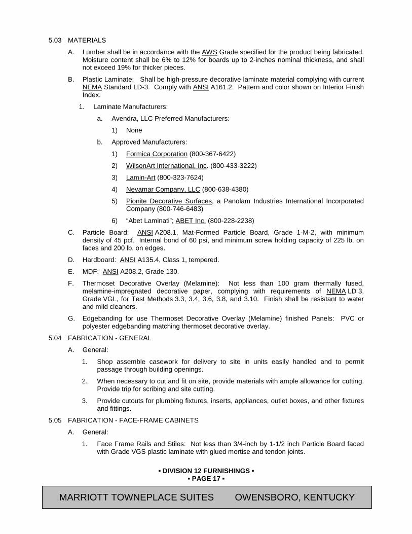
▪ DIVISION 12 FURNISHINGS ▪
▪ PAGE 17 ▪
RESIDENCE INN BY MARRIOTT - LITTLETON, COLORADO
5.03 MATERIALS
A. Lumber shall be in accordance with the AWS Grade specified for the product being fabricated. Moisture content shall be 6% to 12% for boards up to 2-inches nominal thickness, and shall not exceed 19% for thicker pieces.
B. Plastic Laminate: Shall be high-pressure decorative laminate material complying with current NEMA Standard LD-3. Comply with ANSI A161.2. Pattern and color shown on Interior Finish Index.
1. Laminate Manufacturers:
a. Avendra, LLC Preferred Manufacturers:
1) None
b. Approved Manufacturers:
1) Formica Corporation (800-367-6422)
2) WilsonArt International, Inc. (800-433-3222)
3) Lamin-Art (800-323-7624)
4) Nevamar Company, LLC (800-638-4380)
5) Pionite Decorative Surfaces, a Panolam Industries International Incorporated Company (800-746-6483)
6) “Abet Laminati”; ABET Inc. (800-228-2238)
C. Particle Board: ANSI A208.1, Mat-Formed Particle Board, Grade 1-M-2, with minimum density of 45 pcf. Internal bond of 60 psi, and minimum screw holding capacity of 225 lb. on faces and 200 lb. on edges.
D. Hardboard: ANSI A135.4, Class 1, tempered.
E. MDF: ANSI A208.2, Grade 130.
F. Thermoset Decorative Overlay (Melamine): Not less than 100 gram thermally fused, melamine-impregnated decorative paper, complying with requirements of NEMA LD 3, Grade VGL, for Test Methods 3.3, 3.4, 3.6, 3.8, and 3.10. Finish shall be resistant to water and mild cleaners.
G. Edgebanding for use Thermoset Decorative Overlay (Melamine) finished Panels: PVC or polyester edgebanding matching thermoset decorative overlay.
5.04 FABRICATION - GENERAL
A. General:
1. Shop assemble casework for delivery to site in units easily handled and to permit passage through building openings.
2. When necessary to cut and fit on site, provide materials with ample allowance for cutting. Provide trip for scribing and site cutting.
3. Provide cutouts for plumbing fixtures, inserts, appliances, outlet boxes, and other fixtures and fittings.
5.05 FABRICATION - FACE-FRAME CABINETS
A. General:
1. Face Frame Rails and Stiles: Not less than 3/4-inch by 1-1/2 inch Particle Board faced with Grade VGS plastic laminate with glued mortise and tendon joints.
MARRIOTT TOWNEPLACE SUITES OWENSBORO, KENTUCKY

▪ DIVISION 12 FURNISHINGS ▪
▪ PAGE 18 ▪
RESIDENCE INN BY MARRIOTT - LITTLETON, COLORADO
2. Exposed Ends: Grade VGS plastic laminate or minimum 0.030-inch thick PVC edgebanding. Color to match exposed faces.
3. Semi-exposed Ends; Grade VGS plastic laminate or minimum 0.030-inch thick PVC edgebanding. Color to match exposed faces.
4. Top and Bottom Rails; and Sub-toe Boards:
a. Not less than 3/4-inch particle board faced with Grade VGS plastic laminate to match door and drawer fronts. Machine ends for wood-dowel or mechanical dowel fasteners to receive top, bottom, and back. Base ends to extend to floor. Finish exposed ends to match doors and doors and drawer fronts.
5. Unexposed Ends: Not less than 3/4-inch particle board or MDF; finished with Thermoset Decorative Overlay (Melamine). Attach to front frame in same manner as exposed ends.
6. Back Panels:
a. Not less than 1/4-inch tempered hardboard; finished with Thermoset Decorative Overlay (Melamine).
7. Doors 48 Inches or Less in Height: 3/4 inch thick, Particle Board cores. Front faces to be Grade VGS plastic laminate overlay, and back faces to be Thermoset Decorative Overlay (melamine). Provide stop silencers at the top and bottom of all hinged doors.
8. Shelving: Not less than 5/8” particle board with Thermoset Decorative Overlay (Melamine) to match cabinet interior, PVC edge banding; adjustable at least every 1-1/2 inch; clear plastic [seismic] shelf clip pressed into 5mm holes bored in cabinet side. Fabricate base shelf to half depth.
9. Filler Strips:
a. Provide as needed to close spaces between cabinets and walls, ceilings, and indicated equipment. Fabricate from same material and with same finish as cabinets.
b. Oversize for field cutting to suit field conditions and assure continuous enclosure of open spaces.
c. Provide raw (unfinished) cleats at blind corners and appliance openings as required to support countertops, minimum 3/4-inch x 1-1/2 inch x 8 foot length, to be field cut and fit by the installer
10. Interior Cabinet Finish:
a. Public Space Casework: Interior face of cabinet units that have surfaces that are exposed shall be Medium Wood Grain Thermoset Decorative Overlay (melamine).
b. Public Space Casework Wet Areas: Interior unexposed face of units that are likely to become wet (such as cabinets housing refrigerated cold pans) should be constructed of polyester overlaid plywood cabinet liner materials:
1) Approved Manufacturer: “Cabinet Liner Industrial Panel”; Olympic Panel Products, LLC (800-782-7265), or approved substitution.
c. Back-of-House Casework: Interior face of exposed units shall be Medium Wood Grain Thermoset Decorative Overlay (melamine).
B. Base Cabinet Units:
1. Base Cabinet Top Frames: 3/4-inch solid wood with mortise and tenon or doweled connections, glued and pinned or screwed.
MARRIOTT TOWNEPLACE SUITES OWENSBORO, KENTUCKY

▪ DIVISION 12 FURNISHINGS ▪
▪ PAGE 19 ▪
RESIDENCE INN BY MARRIOTT - LITTLETON, COLORADO
2. Base Cabinet Stretchers: 3/4-by-4-1/2-inch plywood, Particle Board, or MDF strips or solid-wood boards at front and back of cabinet, glued and pinned or screwed.
a. Base Cabinet Stretchers may be provided as an option to base cabinet top frames.
3. Front Frame Drawer Rails: Not less than 3/4-inch lumber mortised and fastened into face frame.
4. Bottoms: Not less than 1/2-inch hardwood plywood faced with Thermoset Decorative Overlay (Melamine) to match door and drawer fronts, fully supported by and secured in rabbets in end panels, front frame, and back bottom rail.
5. Corner Blocks: Glued and fastened in each of four top corners to maintain cabinet squareness and rigidity.
6. Drawers:
a. Provide box-type construction with sub-front and back joined with glued dovetail or rabbeted into sides and secured with glue and mechanical fasteners. Clear coat all exposed surfaces. Match color of sides and bottoms with drawer fronts.
b. Drawer Fronts: 3/4 inch thick, Particle Board cores. Front faces to be Grade VGS plastic laminate overlay, and back faces to be Thermoset Decorative Overlay (melamine).
c. Drawer Sides Sub-fronts, and Backs: Not less than 1/2-inch hardwood dovetail construction, or 3/4-inch thick Particle Board faced with Thermoset Decorative Panel overlay (melamine). Provide PVC edge banding to match finish of fronts.
d. Exposed fronts fastened to Sub-fronts with mounting screws from interior of body.
e. Drawer bottom of not less than 1/4-inch thick MDF, tempered hardboard, or plywood faced with Thermoset Decorative Overlay (melamine), set into rabbets in back, sides, and sub-fronts.
C. Wall Cabinet Units:
1. Tops and Bottoms: Not less than 1/2-inch hardwood plywood faced with Thermoset Decorative Overlay (Melamine) to match door and drawer fronts, fully supported by and secured in rabbets in end panels, front frame, and back rail.
5.06 FABRICATION – FRAMELESS CABINETS
A. General:
1. Exposed Ends: Grade VGS plastic laminate or minimum 0.030-inch thick PVC edgebanding. Color to match exposed faces.
2. Semi-exposed Ends; Grade VGS plastic laminate or minimum 0.030-inch thick PVC edgebanding. Color to match exposed faces.
3. Top and Bottom Rails; and Sub-toe Boards:
a. Not less than 3/4-inch particle board faced with Grade VGS plastic laminate to match door and drawer fronts. Machine ends for wood-dowel or mechanical dowel fasteners to receive top, bottom, and back. Base ends to extend to floor. Finish exposed ends to match doors and doors and drawer fronts.
4. Unexposed Ends: Not less than 3/4-inch tempered hardboard; finished with Thermoset Decorative Overlay (Melamine). Attach to front frame in same manner as exposed ends.
5. Back Panels:
MARRIOTT TOWNEPLACE SUITES OWENSBORO, KENTUCKY
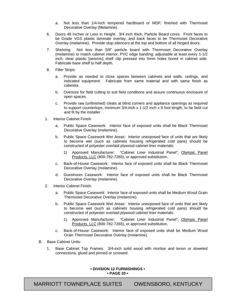
▪ DIVISION 12 FURNISHINGS ▪
▪ PAGE 20 ▪
RESIDENCE INN BY MARRIOTT - LITTLETON, COLORADO
a. Not less than 1/4-inch tempered hardboard or MDF; finished with Thermoset Decorative Overlay (Melamine).
6. Doors 48 Inches or Less in Height: 3/4 inch thick, Particle Board cores. Front faces to be Grade VGS plastic laminate overlay, and back faces to be Thermoset Decorative Overlay (melamine). Provide stop silencers at the top and bottom of all hinged doors.
7. Shelving: Not less than 5/8” particle board with Thermoset Decorative Overlay (melamine) to match cabinet interior, PVC edge banding; adjustable at least every 1-1/2 inch; clear plastic [seismic] shelf clip pressed into 5mm holes bored in cabinet side. Fabricate base shelf to half depth.
8. Filler Strips:
a. Provide as needed to close spaces between cabinets and walls, ceilings, and indicated equipment. Fabricate from same material and with same finish as cabinets.
b. Oversize for field cutting to suit field conditions and assure continuous enclosure of open spaces.
c. Provide raw (unfinished) cleats at blind corners and appliance openings as required to support countertops, minimum 3/4-inch x 1-1/2 inch x 8 foot length, to be field cut and fit by the installer
1. Interior Cabinet Finish:
a. Public Space Casework: Interior face of exposed units shall be Black Thermoset Decorative Overlay (melamine).
b. Public Space Casework Wet Areas: Interior unexposed face of units that are likely to become wet (such as cabinets housing refrigerated cold pans) should be constructed of polyester overlaid plywood cabinet liner materials:
1) Approved Manufacturer: “Cabinet Liner Industrial Panel”; Olympic Panel Products, LLC (800-782-7265), or approved substitution.
c. Back-of-House Casework: Interior face of exposed units shall be Black Thermoset Decorative Overlay (melamine).
d. Guestroom Casework: Interior face of exposed units shall be Black Thermoset Decorative Overlay (melamine).
2. Interior Cabinet Finish:
a. Public Space Casework: Interior face of exposed units shall be Medium Wood Grain Thermoset Decorative Overlay (melamine).
b. Public Space Casework Wet Areas: Interior unexposed face of units that are likely to become wet (such as cabinets housing refrigerated cold pans) should be constructed of polyester overlaid plywood cabinet liner materials:
1) Approved Manufacturer: “Cabinet Liner Industrial Panel”; Olympic Panel Products, LLC (800-782-7265), or approved substitution.
c. Back-of-House Casework: Interior face of exposed units shall be Medium Wood Grain Thermoset Decorative Overlay (melamine).
B. Base Cabinet Units:
1. Base Cabinet Top Frames: 3/4-inch solid wood with mortise and tenon or doweled connections, glued and pinned or screwed.
MARRIOTT TOWNEPLACE SUITES OWENSBORO, KENTUCKY
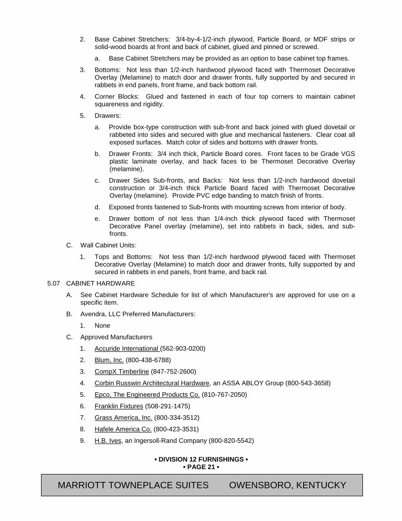
▪ DIVISION 12 FURNISHINGS ▪
▪ PAGE 21 ▪
RESIDENCE INN BY MARRIOTT - LITTLETON, COLORADO
2. Base Cabinet Stretchers: 3/4-by-4-1/2-inch plywood, Particle Board, or MDF strips or solid-wood boards at front and back of cabinet, glued and pinned or screwed.
a. Base Cabinet Stretchers may be provided as an option to base cabinet top frames.
3. Bottoms: Not less than 1/2-inch hardwood plywood faced with Thermoset Decorative Overlay (Melamine) to match door and drawer fronts, fully supported by and secured in rabbets in end panels, front frame, and back bottom rail.
4. Corner Blocks: Glued and fastened in each of four top corners to maintain cabinet squareness and rigidity.
5. Drawers:
a. Provide box-type construction with sub-front and back joined with glued dovetail or rabbeted into sides and secured with glue and mechanical fasteners. Clear coat all exposed surfaces. Match color of sides and bottoms with drawer fronts.
b. Drawer Fronts: 3/4 inch thick, Particle Board cores. Front faces to be Grade VGS plastic laminate overlay, and back faces to be Thermoset Decorative Overlay (melamine).
c. Drawer Sides Sub-fronts, and Backs: Not less than 1/2-inch hardwood dovetail construction or 3/4-inch thick Particle Board faced with Thermoset Decorative Overlay (melamine). Provide PVC edge banding to match finish of fronts.
d. Exposed fronts fastened to Sub-fronts with mounting screws from interior of body.
e. Drawer bottom of not less than 1/4-inch thick plywood faced with Thermoset Decorative Panel overlay (melamine), set into rabbets in back, sides, and sub-fronts.
C. Wall Cabinet Units:
1. Tops and Bottoms: Not less than 1/2-inch hardwood plywood faced with Thermoset Decorative Overlay (Melamine) to match door and drawer fronts, fully supported by and secured in rabbets in end panels, front frame, and back rail.
5.07 CABINET HARDWARE
A. See Cabinet Hardware Schedule for list of which Manufacturer's are approved for use on a specific item.
B. Avendra, LLC Preferred Manufacturers:
1. None
C. Approved Manufacturers
1. Accuride International (562-903-0200)
2. Blum, Inc. (800-438-6788)
3. CompX Timberline (847-752-2600)
4. Corbin Russwin Architectural Hardware, an ASSA ABLOY Group (800-543-3658)
5. Epco, The Engineered Products Co. (810-767-2050)
6. Franklin Fixtures (508-291-1475)
7. Grass America, Inc. (800-334-3512)
8. Hafele America Co. (800-423-3531)
9. H.B. Ives, an Ingersoll-Rand Company (800-820-5542)
MARRIOTT TOWNEPLACE SUITES OWENSBORO, KENTUCKY
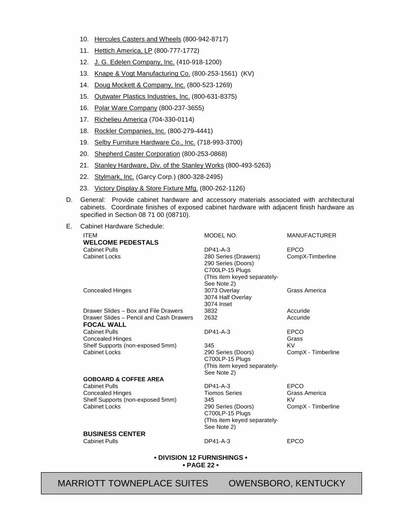
▪ DIVISION 12 FURNISHINGS ▪
▪ PAGE 22 ▪
RESIDENCE INN BY MARRIOTT - LITTLETON, COLORADO
10. Hercules Casters and Wheels (800-942-8717)
11. Hettich America, LP (800-777-1772)
12. J. G. Edelen Company, Inc. (410-918-1200)
13. Knape & Vogt Manufacturing Co. (800-253-1561) (KV)
14. Doug Mockett & Company, Inc. (800-523-1269)
15. Outwater Plastics Industries, Inc. (800-631-8375)
16. Polar Ware Company (800-237-3655)
17. Richelieu America (704-330-0114)
18. Rockler Companies, Inc. (800-279-4441)
19. Selby Furniture Hardware Co., Inc. (718-993-3700)
20. Shepherd Caster Corporation (800-253-0868)
21. Stanley Hardware, Div. of the Stanley Works (800-493-5263)
22. Stylmark, Inc. (Garcy Corp.) (800-328-2495)
23. Victory Display & Store Fixture Mfg. (800-262-1126)
D. General: Provide cabinet hardware and accessory materials associated with architectural cabinets. Coordinate finishes of exposed cabinet hardware with adjacent finish hardware as specified in Section 08 71 00 (08710).
E. Cabinet Hardware Schedule: ITEM MODEL NO. MANUFACTURER WELCOME PEDESTALS Cabinet Pulls DP41-A-3 EPCO Cabinet Locks 280 Series (Drawers)
290 Series (Doors) C700LP-15 Plugs (This item keyed separately- See Note 2)
CompX-Timberline
Concealed Hinges 3073 Overlay 3074 Half Overlay 3074 Inset
Grass America
Drawer Slides – Box and File Drawers 3832 Accuride Drawer Slides – Pencil and Cash Drawers 2632 Accuride FOCAL WALL Cabinet Pulls DP41-A-3 EPCO Concealed Hinges Grass Shelf Supports (non-exposed 5mm) 345 KV Cabinet Locks 290 Series (Doors)
C700LP-15 Plugs (This item keyed separately- See Note 2)
CompX - Timberline
GOBOARD & COFFEE AREA Cabinet Pulls DP41-A-3 EPCO Concealed Hinges Tiomos Series Grass America Shelf Supports (non-exposed 5mm) 345 KV Cabinet Locks 290 Series (Doors)
C700LP-15 Plugs (This item keyed separately- See Note 2)
CompX - Timberline
BUSINESS CENTER Cabinet Pulls DP41-A-3 EPCO
MARRIOTT TOWNEPLACE SUITES OWENSBORO, KENTUCKY
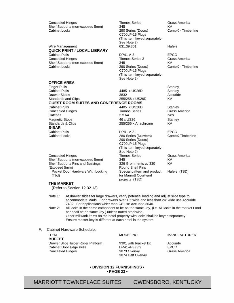
▪ DIVISION 12 FURNISHINGS ▪
▪ PAGE 23 ▪
RESIDENCE INN BY MARRIOTT - LITTLETON, COLORADO
Concealed Hinges Tiomos Series Grass America Shelf Supports (non-exposed 5mm) 345 KV Cabinet Locks 290 Series (Doors)
C700LP-15 Plugs (This item keyed separately- See Note 2)
CompX - Timberline
Wire Management 631.39.301 Hafele QUICK PRINT / LOCAL LIBRARY Cabinet Pulls DP41-A-3 EPCO Concealed Hinges Tiomos Series 3 Grass America Shelf Supports (non-exposed 5mm) 345 KV Cabinet Locks 290 Series (Doors)
C700LP-15 Plugs (This item keyed separately- See Note 2)
CompX - Timberline
OFFICE AREA Finger Pulls Stanley Cabinet Pulls 4485 x US26D Stanley Drawer Slides 3832 Accuride Standards and Clips 255/256 x US26D KV GUEST ROOM SUITES AND CONFERENCE ROOMS Cabinet Pulls 4485 x US26D Stanley Concealed Hinges Tiomos Series Grass America Catches 2 x A4 Ives Magnetic Stops 46 x US26 Stanley Standards & Clips 255/256 x Anachrome KV S-BAR Cabinet Pulls DP41-A-3 EPCO Cabinet Locks 280 Series (Drawers)
290 Series (Doors) C700LP-15 Plugs (This item keyed separately- See Note 2)
CompX-Timberline
Concealed Hinges Tiomos Series Grass America Shelf Supports (non-exposed 5mm) 345 KV Shelf Supports Pins and Bussings (Exposed 5mm)
326 Gromments w/ 330 Round Shelf Pins
KV
Pocket Door Hardware With Locking (Tbd)
Special pattern and product for Marriott Courtyard projects (TBD)
Hafele (TBD)
THE MARKET (Refer to Section 12 32 13)
Note 1: At drawer slides for large drawers, verify potential loading and adjust slide type to
accommodate loads. For drawers over 16” wide and less than 24” wide use Accuride 7432. For applications wider than 24” use Accuride 3640.
Note 2: All locks in the same component to be on the same key, (i.e. All locks in the market t and bar shall be on same key.) unless noted otherwise. Other millwork items on the hotel property with locks shall be keyed separately. Ensure master key is different at each hotel in the system.
F. Cabinet Hardware Schedule:
ITEM MODEL NO. MANUFACTURER BUFFET Drawer Slide Juicer Roller Platform 9301 with bracket kit Accuride Cabinet Door Edge Pulls DP41-A-3 (3”) EPCO Concealed Hinges 3073 Overlay
3074 Half Overlay Grass America
MARRIOTT TOWNEPLACE SUITES OWENSBORO, KENTUCKY

▪ DIVISION 12 FURNISHINGS ▪
▪ PAGE 24 ▪
RESIDENCE INN BY MARRIOTT - LITTLETON, COLORADO
3074 Inset Tension Ball Catch 1012-DC (Dull Chrome) EPCO FRONT DESK Cabinet Door Edge Pulls DP41-A-3 (3”) EPCO Cabinet Locks 280 Series (Drawers)
290 Series (Doors) C700LP-15 Plugs keyed alike
CompX-Timberline
Concealed Hinges Tiomos Series Grass America Drawer Slides – Box and File Drawers 3832 Accuride Drawer Slides – Pencil and Cash Drawers 2632 Accuride FITNESS CENTER Shelf Supports (non-exposed 5mm) 345 KV Shelf Supports Pins and Bussings (Exposed 5mm)
326 Gromments w/ 330 Round Shelf Pins
KV
Tension Ball Catch 1012-DC (Dull Chrome) EPCO Concealed Hinges Tiomos Series Grass America Cabinet Door Edge Pull DP41-BL-3 (3”) EPCO THE CORNER MARKET
(Refer to Section 12 32 13) Note 1: At drawer slides for large drawers, verify potential loading and adjust slide type to
accommodate loads. For drawers over 16” wide and less than 24” wide use Accuride 7432. For applications wider than 24” use Accuride 3640.
Note 2: All locks in the same component to be on the same key, (i.e. All locks in the market t and bar shall be on same key.) unless noted otherwise. Other millwork items on the hotel property with locks shall be keyed separately. Ensure master key is different at each hotel in the system.
G. Cabinet Hardware Schedule:
1. Refer to Section 12 32 13 – Manufactured Wood Veneer Faced Casework.
H. Cabinet Hardware Schedule: ITEM MODEL NO. MANUFACTURER GUESTROOMS: Refer to Drawings BUFFET Flipper Pocket Doors XL-Slide System Hafele Magnetic Pressure Catch 245.75.310 / 246.36.390 Hafele Concealed Hinges Tiomos Series Grass America Note: No Pulls Required COFFEE BAR Magnetic Pressure Catch 245.75.310 / 246.36.390 Hafele Concealed Hinges 73T5880 Blum Note: No Pulls Required FRONT DESK: Pulls DP105A/4 Mocket Cabinet and Cash Drawer Locks Drawer Slides at Small Drawer 3832 Accuride Drawer Slides at Large Drawer 7432 Accuride Grant Concealed Hinges Tiomos Series Grass America Standards & Clips 255/256 x US26D KV Magnetic Catch 41 x US26D Stanley Bullet Catches Stanley Pull Out Top Mount Waste Container PDMTM KV Magnetic Pressure Catch at Guest Deposit 245.75.310 / 246.36.390 Hafele
MARRIOTT TOWNEPLACE SUITES OWENSBORO, KENTUCKY
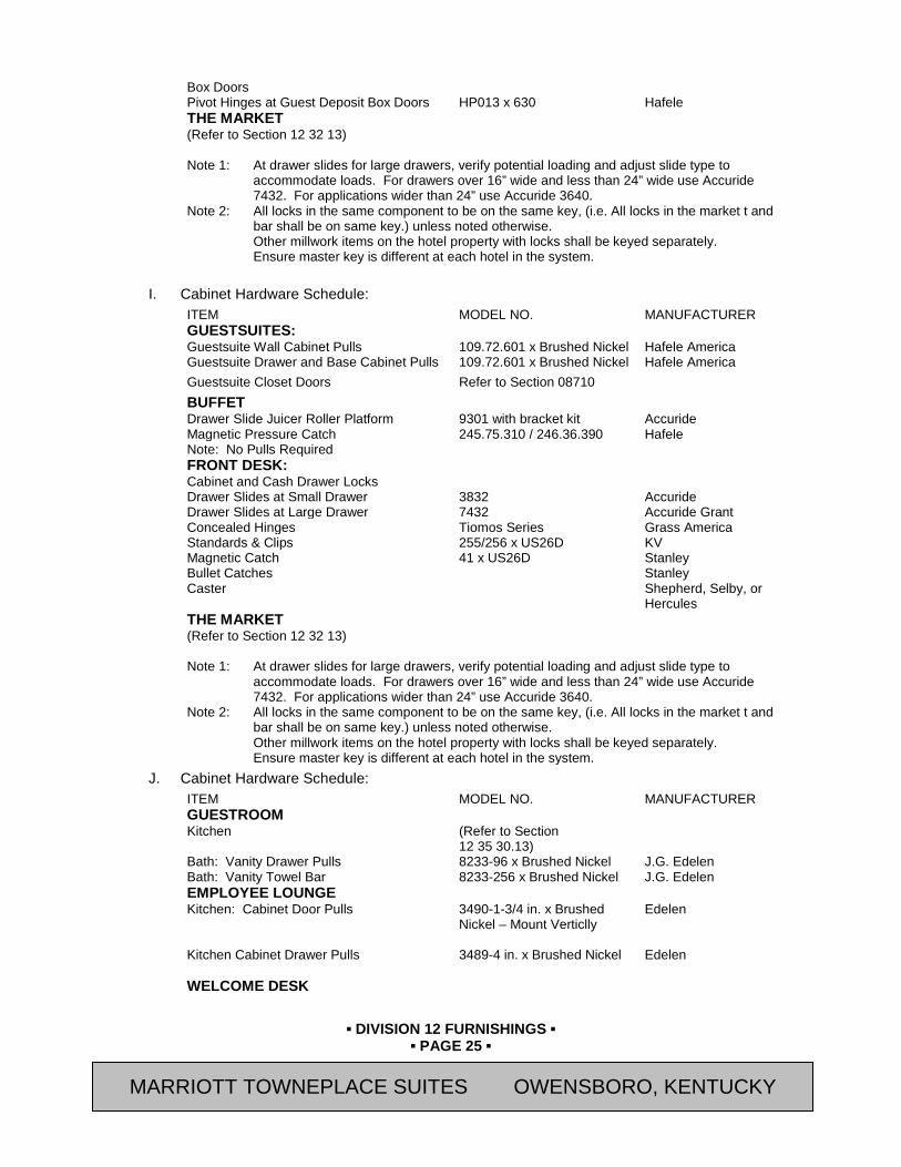
▪ DIVISION 12 FURNISHINGS ▪
▪ PAGE 25 ▪
RESIDENCE INN BY MARRIOTT - LITTLETON, COLORADO
Box Doors Pivot Hinges at Guest Deposit Box Doors HP013 x 630 Hafele THE MARKET (Refer to Section 12 32 13) Note 1: At drawer slides for large drawers, verify potential loading and adjust slide type to
accommodate loads. For drawers over 16” wide and less than 24” wide use Accuride 7432. For applications wider than 24” use Accuride 3640.
Note 2: All locks in the same component to be on the same key, (i.e. All locks in the market t and bar shall be on same key.) unless noted otherwise. Other millwork items on the hotel property with locks shall be keyed separately. Ensure master key is different at each hotel in the system.
I. Cabinet Hardware Schedule:
ITEM MODEL NO. MANUFACTURER GUESTSUITES: Guestsuite Wall Cabinet Pulls 109.72.601 x Brushed Nickel Hafele America Guestsuite Drawer and Base Cabinet Pulls 109.72.601 x Brushed Nickel Hafele America Guestsuite Closet Doors Refer to Section 08710 BUFFET Drawer Slide Juicer Roller Platform 9301 with bracket kit Accuride Magnetic Pressure Catch 245.75.310 / 246.36.390 Hafele Note: No Pulls Required FRONT DESK: Cabinet and Cash Drawer Locks Drawer Slides at Small Drawer 3832 Accuride Drawer Slides at Large Drawer 7432 Accuride Grant Concealed Hinges Tiomos Series Grass America Standards & Clips 255/256 x US26D KV Magnetic Catch 41 x US26D Stanley Bullet Catches Stanley Caster Shepherd, Selby, or
Hercules THE MARKET (Refer to Section 12 32 13) Note 1: At drawer slides for large drawers, verify potential loading and adjust slide type to
accommodate loads. For drawers over 16” wide and less than 24” wide use Accuride 7432. For applications wider than 24” use Accuride 3640.
Note 2: All locks in the same component to be on the same key, (i.e. All locks in the market t and bar shall be on same key.) unless noted otherwise. Other millwork items on the hotel property with locks shall be keyed separately. Ensure master key is different at each hotel in the system.
J. Cabinet Hardware Schedule: ITEM MODEL NO. MANUFACTURER GUESTROOM Kitchen (Refer to Section
12 35 30.13)
Bath: Vanity Drawer Pulls 8233-96 x Brushed Nickel J.G. Edelen Bath: Vanity Towel Bar 8233-256 x Brushed Nickel J.G. Edelen EMPLOYEE LOUNGE Kitchen: Cabinet Door Pulls 3490-1-3/4 in. x Brushed
Nickel – Mount Verticlly
Edelen
Kitchen Cabinet Drawer Pulls 3489-4 in. x Brushed Nickel
Edelen
WELCOME DESK
MARRIOTT TOWNEPLACE SUITES OWENSBORO, KENTUCKY
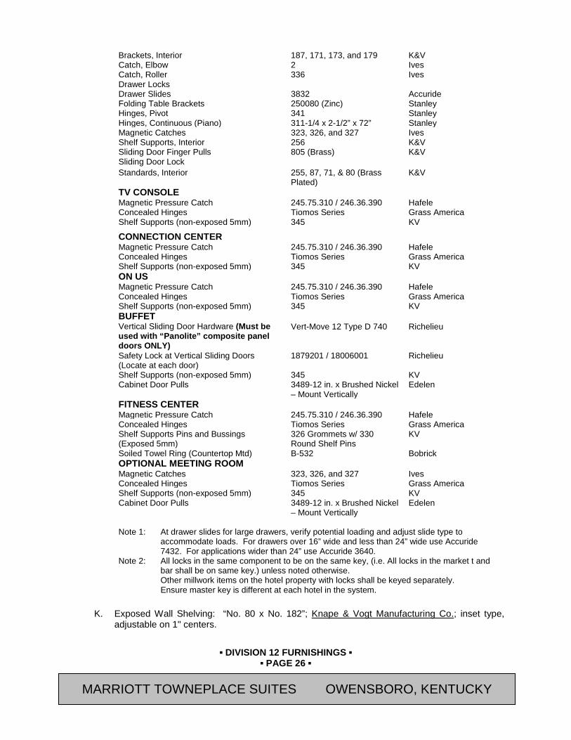
▪ DIVISION 12 FURNISHINGS ▪
▪ PAGE 26 ▪
RESIDENCE INN BY MARRIOTT - LITTLETON, COLORADO
Brackets, Interior 187, 171, 173, and 179 K&V Catch, Elbow 2 Ives Catch, Roller 336 Ives Drawer Locks Drawer Slides 3832 Accuride Folding Table Brackets 250080 (Zinc) Stanley Hinges, Pivot 341 Stanley Hinges, Continuous (Piano) 311-1/4 x 2-1/2” x 72” Stanley Magnetic Catches 323, 326, and 327 Ives Shelf Supports, Interior 256 K&V Sliding Door Finger Pulls 805 (Brass) K&V Sliding Door Lock Standards, Interior 255, 87, 71, & 80 (Brass
Plated) K&V
TV CONSOLE Magnetic Pressure Catch 245.75.310 / 246.36.390 Hafele Concealed Hinges Tiomos Series Grass America Shelf Supports (non-exposed 5mm) 345 KV
CONNECTION CENTER Magnetic Pressure Catch 245.75.310 / 246.36.390 Hafele Concealed Hinges Tiomos Series Grass America Shelf Supports (non-exposed 5mm) 345 KV ON US Magnetic Pressure Catch 245.75.310 / 246.36.390 Hafele Concealed Hinges Tiomos Series Grass America Shelf Supports (non-exposed 5mm) 345 KV BUFFET Vertical Sliding Door Hardware (Must be used with “Panolite” composite panel doors ONLY)
Vert-Move 12 Type D 740 Richelieu
Safety Lock at Vertical Sliding Doors (Locate at each door)
1879201 / 18006001 Richelieu
Shelf Supports (non-exposed 5mm) 345 KV Cabinet Door Pulls 3489-12 in. x Brushed Nickel
– Mount Vertically Edelen
FITNESS CENTER Magnetic Pressure Catch 245.75.310 / 246.36.390 Hafele Concealed Hinges Tiomos Series Grass America Shelf Supports Pins and Bussings (Exposed 5mm)
326 Grommets w/ 330 Round Shelf Pins
KV
Soiled Towel Ring (Countertop Mtd) B-532 Bobrick OPTIONAL MEETING ROOM Magnetic Catches 323, 326, and 327 Ives Concealed Hinges Tiomos Series Grass America Shelf Supports (non-exposed 5mm) 345 KV Cabinet Door Pulls 3489-12 in. x Brushed Nickel
– Mount Vertically Edelen
Note 1: At drawer slides for large drawers, verify potential loading and adjust slide type to
accommodate loads. For drawers over 16” wide and less than 24” wide use Accuride 7432. For applications wider than 24” use Accuride 3640.
Note 2: All locks in the same component to be on the same key, (i.e. All locks in the market t and bar shall be on same key.) unless noted otherwise. Other millwork items on the hotel property with locks shall be keyed separately. Ensure master key is different at each hotel in the system.
K. Exposed Wall Shelving: “No. 80 x No. 182”; Knape & Vogt Manufacturing Co.; inset type,
adjustable on 1" centers.
MARRIOTT TOWNEPLACE SUITES OWENSBORO, KENTUCKY

▪ DIVISION 12 FURNISHINGS ▪
▪ PAGE 27 ▪
RESIDENCE INN BY MARRIOTT - LITTLETON, COLORADO
L. Cash Drawer With Lock
1. Furnished by Owner. Contractor shall coordinate size.
a. Provide 1/8” clearance around all four sides, or as recommended by manufacturer.
5.08 INSTALLATION MATERIALS
A. Furring, Blocking, Shims, and Hanging Strips: Fire-retardant-treated Softwood or hardwood lumber, kiln-dried to less than 15 percent moisture content.
B. Anchors: Select material, type, size, and finish required for each substrate for secure anchorage. Provide nonferrous-metal or hot-dip galvanized anchors and inserts on inside face of exterior walls and elsewhere as required for corrosion resistance. Provide toothed-steel or lead expansion sleeves for drilled-in-place anchors.
1. Adhesives: Installation adhesives as recommended by manufacturer for use intended.
PART 6 EXECUTION 6.01 INSPECTION
A. Verify adequacy of backing and support framing.
6.02 INSTALLATION
A. All cabinets and shelving shall be installed as shown on Drawings and as specified by manufacturer.
B. Set and secure casework in place rigid, plumb, and level.
C. Cabinets: Install without distortion so doors and drawers fit openings properly and are accurately aligned. Adjust hardware to center doors and drawers in openings and to provide unencumbered operation. Complete installation of hardware and accessory items as indicated.
1. Secure cabinet and counter bases to floor using appropriate angles and anchorages.
2. Install cabinets with no more than 1/8 inch in 96-inch sag, bow, or other variation from a straight line.
3. Maintain veneer sequence matching of cabinets with transparent finish.
4. Carefully scribe casework which is against other building materials, leaving gaps of 1/32 inch maximum. Do not use additional overly trim for this purpose.
5. Carefully fit equipment to be installed into millwork. Provide filler pieces when required.
D. Fasteners:
1. Use purpose designed fixture attachments at concealed locations for wall-mounted components.
2. Use threaded steel concealed joint fasteners to align and secure adjoining cabinet units and counter tops.
3. Countersink anchorage devices at exposed locations used to wall-mount components, and conceal with solid plugs of species to match surrounding wood. Finish flush with surrounding surfaces.
4. Install countertops with no more than 1/8 inch in 96-inch sag, bow, or other variation from a straight line.
MARRIOTT TOWNEPLACE SUITES OWENSBORO, KENTUCKY

▪ DIVISION 12 FURNISHINGS ▪
▪ PAGE 28 ▪
RESIDENCE INN BY MARRIOTT - LITTLETON, COLORADO
6.03 ADJUSTING AND CLEANING
A. Adjust doors, drawers, hardware, fixtures and other moving or operating parts to function smoothly and correctly.
B. Clean casework, shelves, hardware, fittings and fixtures.
END OF SECTION Revision Log
MARRIOTT TOWNEPLACE SUITES OWENSBORO, KENTUCKY
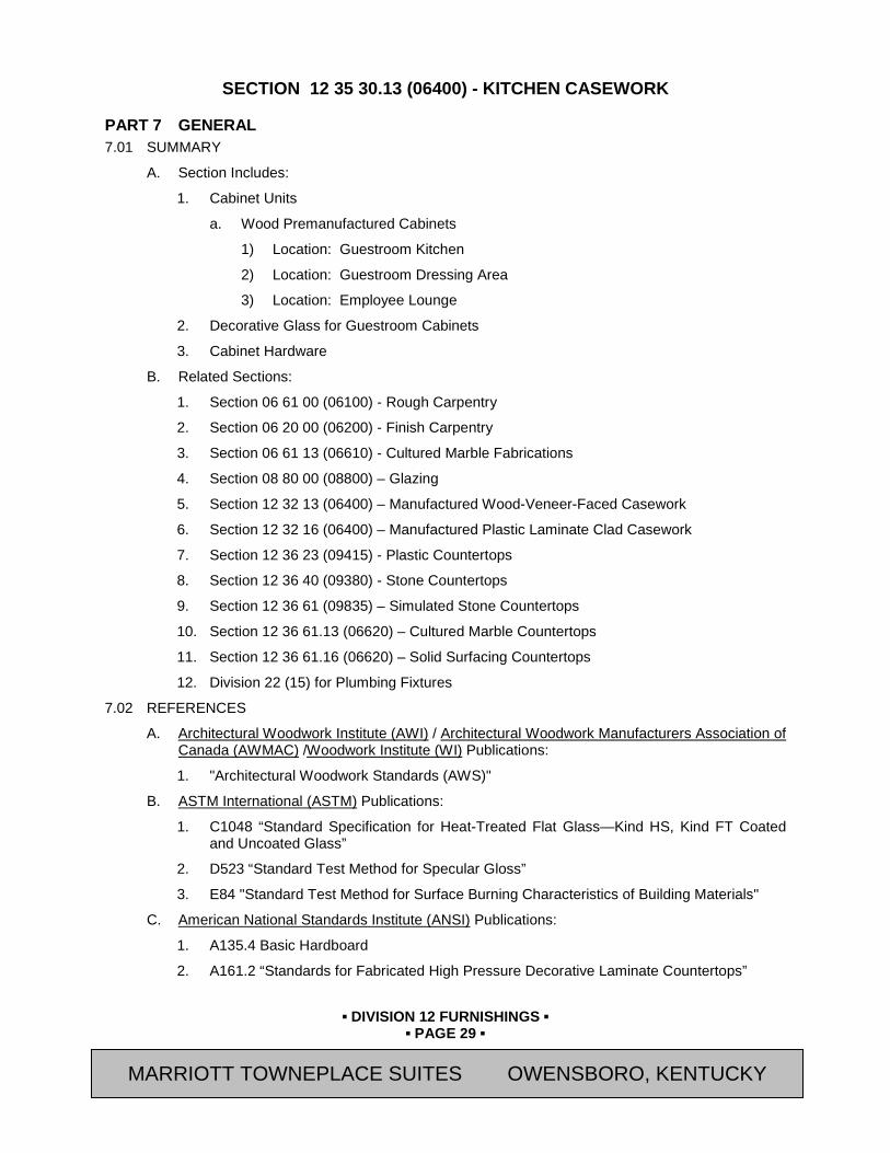
▪ DIVISION 12 FURNISHINGS ▪
▪ PAGE 29 ▪
RESIDENCE INN BY MARRIOTT - LITTLETON, COLORADO
SECTION 12 35 30.13 (06400) - KITCHEN CASEWORK
PART 7 GENERAL 7.01 SUMMARY
A. Section Includes:
1. Cabinet Units
a. Wood Premanufactured Cabinets
1) Location: Guestroom Kitchen
2) Location: Guestroom Dressing Area
3) Location: Employee Lounge
2. Decorative Glass for Guestroom Cabinets
3. Cabinet Hardware
B. Related Sections:
1. Section 06 61 00 (06100) - Rough Carpentry
2. Section 06 20 00 (06200) - Finish Carpentry
3. Section 06 61 13 (06610) - Cultured Marble Fabrications
4. Section 08 80 00 (08800) – Glazing
5. Section 12 32 13 (06400) – Manufactured Wood-Veneer-Faced Casework
6. Section 12 32 16 (06400) – Manufactured Plastic Laminate Clad Casework
7. Section 12 36 23 (09415) - Plastic Countertops
8. Section 12 36 40 (09380) - Stone Countertops
9. Section 12 36 61 (09835) – Simulated Stone Countertops
10. Section 12 36 61.13 (06620) – Cultured Marble Countertops
11. Section 12 36 61.16 (06620) – Solid Surfacing Countertops
12. Division 22 (15) for Plumbing Fixtures
7.02 REFERENCES
A. Architectural Woodwork Institute (AWI) / Architectural Woodwork Manufacturers Association of Canada (AWMAC) /Woodwork Institute (WI) Publications:
1. "Architectural Woodwork Standards (AWS)"
B. ASTM International (ASTM) Publications:
1. C1048 “Standard Specification for Heat-Treated Flat Glass—Kind HS, Kind FT Coated and Uncoated Glass”
2. D523 “Standard Test Method for Specular Gloss”
3. E84 "Standard Test Method for Surface Burning Characteristics of Building Materials"
C. American National Standards Institute (ANSI) Publications:
1. A135.4 Basic Hardboard
2. A161.2 “Standards for Fabricated High Pressure Decorative Laminate Countertops”
MARRIOTT TOWNEPLACE SUITES OWENSBORO, KENTUCKY

▪ DIVISION 12 FURNISHINGS ▪
▪ PAGE 30 ▪
RESIDENCE INN BY MARRIOTT - LITTLETON, COLORADO
3. A208.1 "Standards for the Performance of Particleboard"
D. Hardwood Plywood & Veneer Association (HPVA) Publications:
1. ANSI/HPVA HP-1: "American National Standard for Hardwood and Decorative Plywood"
E. Kitchen Cabinet Manufacturers Association (KCMA)
1. ANSI/KCMA A161.1 “Performance & Construction Standard for Kitchen and Vanity Cabinets”
F. National Electrical Manufacturer’s Association (NEMA) Standards Publications:
1. NEMA LD3 “High Pressure Decorative Laminates”
G. U.S. Department of Commerce (DOC), National Institute of Standards and Technology (NIST) Publications
1. PS 1 - Construction and Industrial Plywood
2. PS 20 - American Softwood Lumber Standard
3. PS 51 - Hardwood and Decorative Plywood
4. PS 58 - Basic Hardboard
7.03 SUBMITTALS
A. General: Submit the following in accordance with Conditions of Contract and Division 01 Specification Sections.
B. Submit “Letter of Conformance” in accordance with Section 01 33 00 (01330) indicating specified items selected for use in project with the following supporting data.
1. Submit Shop Drawings and product data. Include materials, component profiles, fastening methods, assembly methods, joint details, accessory listings, and schedule of finishes.
a. Show locations and sizes of furring, blocking, and hanging strips, including concealed blocking and reinforcement specified in other Sections.
b. Show locations and sizes of cutouts and holes for plumbing fixtures, faucets, soap dispensers, and other items installed in architectural woodwork.
C. Qualification Data: For Fabricator
7.04 DELIVERY, STORAGE, AND HANDLING
A. General Contractor shall allow a minimum delivery lead time of [10] weeks after final approval of Shop Drawings and Samples for import production.
B. Do not deliver casework until painting and similar operations that could damage synthetic marble have been completed in installation areas. If casework components must be stored in other than installation areas, store only in areas where environmental conditions comply with requirements specified in "Project Conditions" Article.
C. Handle materials to prevent damage to finished surfaces. Provide protective coverings to prevent physical damage or staining following installation for duration of project.
7.05 PROJECT CONDITIONS
A. Environmental Limitations: Do not deliver or install casework until building is enclosed, wet work is complete, and HVAC system is operating and maintaining temperature and relative humidity at occupancy levels during the remainder of the construction period.
MARRIOTT TOWNEPLACE SUITES OWENSBORO, KENTUCKY
▪ DIVISION 12 FURNISHINGS ▪
▪ PAGE 31 ▪
RESIDENCE INN BY MARRIOTT - LITTLETON, COLORADO
B. Field Measurements: Where casework is indicated to fit to other construction, verify dimensions of other construction by field measurements before fabrication and indicate measurements on Shop Drawings. Coordinate fabrication schedule with construction progress to avoid delaying the Work.
1. Locate concealed framing, blocking, and reinforcements that support casework by field measurements before being enclosed and indicate measurements on Shop Drawings.
PART 8 PRODUCTS 8.01 APPROVED MANUFACTURERS
A. Avendra, LLC Preferred Manufacturers:
1. None
B. Approved Manufacturers:
1. MillRock RiverRun Casework (540-438-5973)
a. Residence Inn Gen 9 Possibilities Décor Package: “Possibilities Shaker Style” [Frameless] Construction.
2. J Suss Industries (866-769-5666)
a. Residence Inn Gen 9 Possibilities Décor Package: “EuroPossibilities Style” Framelesss Construction.
8.02 ABINET UNITS - GENERAL
A. Quality Standard:
1. Provide cabinets that comply with KCMA A161.1, unless noted otherwise manufactured meeting the following requirements:
a. Minor warp which can be held flat and straight with normal nailing.
b. Natural and manufacturing defects in excess of those permitted in the grade specified are permitted if such defects are to be covered by adjoining members or otherwise concealed.
c. Trim members for application on flat surfaces shall have the reverse side "backed out", except members with exposed ends.
B. Design:
1. Style of face construction for base, wall, and full-height units, if any, with drawer fronts, doors, and fixed panels as follows:
a. Face Frame or Frameless.
1) All cabinets shall be the same construction type for the entire Project.
b. Cabinet and Door Interface: Flush (Full) Overlay.
c. Single Fixed Panel Doors.
d. Flush Panel Drawer Fronts.
e. Interior Finish: Classic Maple Thermoset Decorative Overlay (Melamine)
2. Grain Direction:
a. Vertical on doors, horizontal on drawer fronts.
b. Lengthwise on face frame members.
MARRIOTT TOWNEPLACE SUITES OWENSBORO, KENTUCKY

▪ DIVISION 12 FURNISHINGS ▪
▪ PAGE 32 ▪
RESIDENCE INN BY MARRIOTT - LITTLETON, COLORADO
c. Vertical on end panels.
d. Side to side on bottoms and tops of units.
e. Vertical on knee-space panels.
f. Horizontal on aprons.
8.03 MATERIALS
A. Solid Lumber: Dry, sound, selected to eliminate appearance defects, of the following species: Moisture content shall be 6% to 12%. Do not use two adjacent exposed surfaces that are noticeably dissimilar in color, grain, figure, or natural character markings.
1. [Hard Maple - "Select White" (Sapwood)] [or] [Yellow Birch - "Select White" (Sapwood)], plain (flat) sliced, custom grade.
B. Plywood Face Veneer: HPVA HP-1. Same species as exposed lumber, unless otherwise indicated, selected for grain and color compatible with exposed solid lumber, with Grade A faces and Grade C backs of same species as faces, no defects. Edgeband exposed edges with solid wood of same species as face veneer.
1. [Hard Maple - "Select White" (Sapwood), plain (flat) sliced] [or] [Yellow Birch - "Select White" (Sapwood), rotary sliced], custom grade.
C. Particle Board: ANSI A208.1, Mat-Formed Particle Board, Grade 1-M-2, with minimum density of 45 pcf. Internal bond of 60 psi, and minimum screw holding capacity of 225 lb. on faces and 200 lb. on edges.
D. Hardboard: ANSI A135.4, Class 1, tempered.
E. MDF: ANSI A208.2, Grade 130.
F. Thermoset Decorative Overlay (Melamine): Not less than 100 gram thermally fused, melamine-impregnated decorative paper, complying with requirements of NEMA LD 3, Grade VGL, for Test Methods 3.3, 3.4, 3.6, 3.8, and 3.10. Finish shall be resistant to water and mild cleaners.
G. Edgebanding for use Thermoset Decorative Overlay (Melamine) finished Panels: PVC or polyester edgebanding matching thermoset decorative overlay.
H. Decorative Glass for Cabinet Doors:
I. Sandblasted Glass: Heat Treated Float Glass, ASTM C1048, Type I, Class 1, Quality Q3, Condition A, Kind FT (Fully Tempered), 3/16-inch thick, unless otherwise indicated.
1. Provide evenly abraded sandblasted or Acid-Etched, Non-Marking (no fingerprint) Finish. Translucent Pattern as approved by Owner's Representative.
2. Refer to Drawings for locations and size.
8.04 FABRICATION - GENERAL
A. General:
1. Shop assemble, package, and label casework for delivery to site in units easily handled and to permit passage through building openings.
2. When necessary to cut and fit on site, provide materials with ample allowance for cutting. Provide trip for scribing and site cutting.
3. Allow adequate clearance to supports at cutouts. Do not cut through support members.
8.05 FABRICATION - FACE-FRAME CABINETS
A. General:
MARRIOTT TOWNEPLACE SUITES OWENSBORO, KENTUCKY
▪ DIVISION 12 FURNISHINGS ▪
▪ PAGE 33 ▪
RESIDENCE INN BY MARRIOTT - LITTLETON, COLORADO
1. Face Frame Rails and Stiles: Not less than 3/4-inch by 1-1/2 inch solid lumber with glued mortise and tendon joints.
2. Exposed and Semi-exposed Ends; Top and Bottom Rails; and Sub-toe Boards:
a. Not less than 1/2-inch hardwood plywood with exterior veneer, with stained and clear finish to match doors and drawer faces and with clear finish on interior;;or not less than 3/4-inch Particle Board with medium wood grain Thermoset Decorative Overlay (Melamine), to match door and drawer fronts. Machine ends for wood-dowel fasteners to receive top, bottom, and back. Rabbet base ends to receive bottom and back. Base ends to extend to floor. Finish exposed ends to match doors and doors and drawer fronts.
b. Connect to stiles with pressure-glued tongue and plow joint and supplement by concealed mechanical fasteners. Finish exposed ends to match doors and drawers. If wood veneered materials used, clear coat interior to achieve water resistant cleanable surface.
3. Unexposed Ends: Not less than 1/2-inch hardwood plywood, or not less than 3/4-inch hardboard; finished with Thermoset Decorative Overlay (Melamine). Attach to front frame in same manner as exposed ends.
4. Back Panels:
a. Not less than 1/4-inch hardwood plywood, or not less than 1/4-inch MDF faced with Thermoset Decorative Overlay (Melamine). If wood veneered materials, clear coat interior to achieve water resistant cleanable surface.
5. Doors 48 Inches or Less in Height: 3/4 inch thick, with solid hardwood stiles and rails, center panel of Particle Board or MDF cores, and hardwood face veneers and crossbands. Provide stop silencers at the top and bottom of all hinged doors.
a. Secure glass into rabbet in door frame in locations shown on Drawings using a clear flexible vinyl retainer molding “Model No. C-10215”, as manufactured by Top Supplies, a division of Richelieu Hardware (800-619-5446), or approved substitution.
6. Shelving: not less than 5/8” Particle Board with Thermoset Decorative Overlay (melamine) to match cabinet interior, PVC edge banding; adjustable at least every 1-1/2 inch; clear plastic [seismic] shelf clip pressed into 5mm holes bored in cabinet side. Fabricate base shelf to half or three-quarter depth.
7. Filler Strips:
a. Provide as needed to close spaces between cabinets and walls, ceilings, and indicated equipment. Fabricate from same material and with same finish as cabinets.
b. Oversize for field cutting to suit field conditions and assure continuous enclosure of open spaces.
c. Provide raw (unfinished) cleats at blind corners and appliance openings as required to support countertops, minimum 3/4-inch x 1-1/2 inch x 8 foot length, to be field cut and fit by the installer
8. Interior Cabinet Finish:
a. Interior face of cabinet units that have surfaces that are exposed shall be wood grain, medium stock color Thermoset Decorative Overlay (melamine), or clear finish where hardwood plywood is provided.
B. Base Cabinet Units:
MARRIOTT TOWNEPLACE SUITES OWENSBORO, KENTUCKY

▪ DIVISION 12 FURNISHINGS ▪
▪ PAGE 34 ▪
RESIDENCE INN BY MARRIOTT - LITTLETON, COLORADO
1. Base Cabinet Top Frames: 3/4-inch thickness of same material as side panels with mortise and tenon or doweled connections, glued and pinned or screwed.
2. Base Cabinet Stretchers: 3/4-by-4-1/2-inch plywood, Particle Board, or MDF strips or solid-wood boards at front and back of cabinet, glued and pinned or screwed.
a. Base Cabinet Stretchers may be provided as an option to base cabinet top frames.
3. Front Frame Drawer Rails: Not less than 3/4-inch solid wood mortised and fastened into face frame.
4. Bottoms: Not less than 1/2-inch hardwood plywood with exterior veneer, or not less than 5/8-inch particle board with Thermoset Decorative Overlay (Melamine), to match door and drawer fronts, fully supported by and secured in rabbets in end panels, front frame, and back bottom rail.
5. Corner Blocks: Glued and fastened in each of four top corners to maintain cabinet squareness and rigidity, or provide plastic or composite glue blocks. Full cabinet rails are an acceptable alternate to corner blocks.
6. Drawers:
a. Provide box-type construction with sub-front and back joined with glued dovetail or rabbeted into sides and secured with glue and mechanical fasteners. Clear coat all exposed surfaces.
1) Optional Drawer sides by “Metabox Drawer System” are acceptable. Sides to be epoxy coated to match interior Thermoset Decorative Overlay (Melamine) color.
b. Drawer Fronts: 3/4-inch Particle Board-core hardwood veneered plywood or solid hardwood.
c. Drawer Sides Sub-fronts, and Backs: Not less than 1/2-inch solid hardwood, or veneered plywood, or not less than 1/2 thick particle board with Thermoset Decorative Overlay (Melamine).
d. Exposed fronts fastened to Sub-fronts with mounting screws from interior of body.
e. Drawer bottom of not less than 1/4-inch veneer hardboard, or not less than 1/4-inch MDF faced with Thermoset Decorative Overlay (Melamine), set into rabbets in back, sides, and sub-fronts.
C. Wall Cabinet Units:
1. Tops and Bottoms: Not less than 1/2-inch hardwood veneered plywood with exterior veneer, or not less than 5/8-inch thick particle board with Thermoset Decorative Overlay (Melamine), to match door fronts, fully supported by and secured in rabbets in end panels, front frame, and back rail.
8.06 FABRICATION – FRAMELESS CABINETS
A. General:
1. Exposed and Semi-exposed Ends; Top and Bottom Rails; and Sub-toe Boards:
a. Not less than 5/8-inch Particle Board with Thermoset Decorative Overlay (Melamine) to match door and drawer fronts. Ma chine ends for wood-dowel fasteners to receive top, bottom, and back. Base ends to extend to floor. Finish exposed ends to match doors and drawer fronts.
2. Unexposed Ends: Not less than 3/4-inch hardboard; finished with Thermoset Decorative Overlay (Melamine). Attach to front frame in same manner as exposed ends.
MARRIOTT TOWNEPLACE SUITES OWENSBORO, KENTUCKY

▪ DIVISION 12 FURNISHINGS ▪
▪ PAGE 35 ▪
RESIDENCE INN BY MARRIOTT - LITTLETON, COLORADO
3. Back Panels:
a. Not less than 1/4-inch tempered hardboard; finished with Thermoset Decorative Overlay (Melamine), or not less than 1/8-inch MDF faced with Thermoset Decorative Overlay (Melamine).
4. Doors 48 Inches or Less in Height: 3/4 inch thick, with solid hardwood stiles and rails, center panel of Particle Board or MDF cores, and hardwood face veneers and crossbands. Provide stop silencers at the top and bottom of all hinged doors.
a. Secure glass into rabbet in door frame in locations shown on Drawings using a clear flexible vinyl retainer molding “Model No. C-10215”, as manufactured by Top Supplies, a division of Richelieu Hardware (800-619-5446), or approved substitution. Glass clips are also permitted.
5. Shelving: not less than 5/8-inch Particle Board with Thermoset Decorative Overlay (Melamine) to match cabinet interior, PVC edge banding; adjustable at least every 1-1/2 inch; clear plastic [seismic] shelf clip pressed into 5mm holes bored in cabinet side. Fabricate base shelf to half or three-quarter depth.
6. Filler Strips:
a. Provide as needed to close spaces between cabinets and walls, ceilings, and indicated equipment. Fabricate from same material and with same finish as cabinets.
b. Oversize for field cutting to suit field conditions and assure continuous enclosure of open spaces.
c. Provide raw (unfinished) cleats at blind corners and appliance openings as required to support countertops, minimum 3/4-inch x 1-1/2 inch x 8 foot length, to be field cut and fit by the installer
7. Interior Cabinet Finish:
a. Interior face of exposed units shall be wood grain, medium stock color Thermoset Decorative Overlay (melamine).
B. Base Cabinet Units:
1. Base Cabinet: 3/4-inch solid wood, or material to match cabinet sides, with mortise and tenon or doweled connections, glued and dowelled.
2. Base Cabinet Stretchers: 3/4-by-4-1/2-inch plywood, Particle Board, or MDF strips or solid-wood boards at front and back of cabinet, glued and pinned or screwed.
a. At sink base cabinet provide stretcher at vertical location in front of cabinet where horizontal location interferes with cut out for sink, or 2-1/2 inch wide horizontal stretcher at front.
3. Bottoms: Not less than 1/2-inch hardwood plywood with exterior veneer, or not less than 5/8-inch particle board with Thermoset Decorative Overlay (Melamine), to match door and drawer fronts, fully supported by and secured in rabbets or dowelled in end panels, and front frame.
4. Corner Blocks: Glued and fastened in each of four top corners to maintain cabinet squareness and rigidity, or provide plastic or composite glue blocks. Full cabinet rails are an acceptable alternate to corner blocks.
5. Drawers:
MARRIOTT TOWNEPLACE SUITES OWENSBORO, KENTUCKY
▪ DIVISION 12 FURNISHINGS ▪
▪ PAGE 36 ▪
RESIDENCE INN BY MARRIOTT - LITTLETON, COLORADO
a. Provide box-type construction with sub-front and back joined with glued dovetail or rabbeted into sides and secured with glue and mechanical fasteners. Clear coat all exposed surfaces.
1) Optional Drawer sides by “Metabox Drawer System” are acceptable. Sides to be epoxy coated to match interior Thermoset Decorative Overlay (Melamine) color.
b. Drawer Fronts: 3/4-inch Particle Board-core solid hardwood, or veneered plywood.
c. Drawer Sides Sub-fronts, and Backs: Not less than 1/2-inch hardwood veneered plywood, or not less than 5/8-inch thick particle board with Thermoset Decorative Overlay (Melamine).
d. Exposed fronts fastened to Sub-fronts with mounting screws from interior of body.
e. Drawer bottom of not less than 1/4-inch veneer hardboard, or not less than 1/4-inch MDF faced with Thermoset Decorative Overlay (Melamine), set into rabbets in back, sides, and sub-fronts.
C. Wall Cabinet Units:
1. Tops and Bottoms: Not less than 1/2-inch hardwood veneered plywood with exterior veneer, or not less than 1/2 thick particle board with Thermoset Decorative Overlay (Melamine), to match door fronts, fully supported by and secured in rabbets, or dowelled in end panels, front frame, and back rail.
2. On cabinets with glass doors, the color of the interior and shelves Thermoset Decorative Overlay (Melamine) shall match exterior color.
8.07 CABINET HARDWARE
A. General: Provide cabinet hardware and accessory materials associated with architectural cabinets. Coordinate finishes of exposed cabinet hardware with adjacent finish hardware as specified in Section 08 71 00 (08710).
B. All exposed hardware to be US26D (BMHA 626 Bronze) unless noted otherwise.
C. Cabinet Hardware Schedule: ITEM MODEL NO. MANUFACTURER GUESTROOM
Possibilities: Kitchen Cabinet Door Pulls 4000-128 J.G. Edelen Possibilities: Kitchen Cabinet Drawer Pulls
4000-288 J.G. Edelen
Possibilities: Dressing Area Drawer Base
4000-672 J.G. Edelen
EMPLOYEE LOUNGE Cabinet Pulls: Upper Cabinets 104.33.200 Hafele Cabinet Pulls: Drawers 132.00.229 Hafele
1. Doors Hinges: Concealed hinges, Self Closing.
2. Drawer Slides: Side Mount, 75 lb. load capacity, epoxy coated, self closing.
D. ADA Accessible Guest Room:
1. Door hardware at kitchen sink: Provide Flipper type "Pocket Door" retractable doors, hardware system, by Julius Blum, or approved substitution.
a. Cabinet to be sized for a minimum knee clearance clear opening of 30-inches wide and 27-inches high, after flipper doors are retracted into sides of cabinet, complying with 2010 ADA, as approved by [Owner’s Representative]
MARRIOTT TOWNEPLACE SUITES OWENSBORO, KENTUCKY
▪ DIVISION 12 FURNISHINGS ▪
▪ PAGE 37 ▪
RESIDENCE INN BY MARRIOTT - LITTLETON, COLORADO
b. Eliminate toe kick base of sink cabinet with flipper doors..
2. Finish all interior surfaces to match doors and drawers.
8.08 INSTALLATION MATERIALS
A. Furring, Blocking, Shims, and Hanging Strips: Fire-retardant-treated Softwood or hardwood lumber, kiln-dried to less than 15 percent moisture content.
B. Anchors: Select material, type, size, and finish required for each substrate for secure anchorage. Provide nonferrous-metal or hot-dip galvanized anchors and inserts on inside face of exterior walls and elsewhere as required for corrosion resistance. Provide toothed-steel or lead expansion sleeves for drilled-in-place anchors.
1. Adhesives: Installation adhesives as recommended by manufacturer for use intended.
8.09 SHOP FINISHING
A. General: Finish casework at fabrication shop as specified in this Section. Defer only final touchup, cleaning, and polishing until after installation.
PART 9 EXECUTION 9.01 INSPECTION
A. Verify adequacy of backing and support framing.
9.02 INSTALLATION
A. All cabinets and shelving shall be installed as shown on Drawings and as specified by manufacturer.
B. Set and secure casework in place rigid, plumb, and level.
C. Cabinets: Install without distortion so doors and drawers fit openings properly and are accurately aligned. Adjust hardware to center doors and drawers in openings and to provide unencumbered operation. Complete installation of hardware and accessory items as indicated.
1. Secure cabinet and counter bases to floor using appropriate angles and anchorages.
2. Install cabinets with no more than 1/8 inch in 96-inch sag, bow, or other variation from a straight line.
3. Maintain veneer sequence matching of cabinets with transparent finish.
4. Carefully scribe casework which is against other building materials, leaving gaps of 1/32 inch maximum. Do not use additional overly trim for this purpose.
5. Carefully fit equipment to be installed into millwork. Provide filler pieces when required.
6. Provide cutouts for plumbing fixtures, inserts, appliances, outlet boxes, and other fixtures and fittings.
D. Fasteners:
1. Use purpose designed fixture attachments at concealed locations for wall-mounted components.
2. Use threaded steel concealed joint fasteners to align and secure adjoining cabinet units and counter tops.
3. Countersink anchorage devices at exposed locations used to wall-mount components, and conceal with solid plugs of species to match surrounding wood. Finish flush with surrounding surfaces.
MARRIOTT TOWNEPLACE SUITES OWENSBORO, KENTUCKY
▪ DIVISION 12 FURNISHINGS ▪
▪ PAGE 38 ▪
RESIDENCE INN BY MARRIOTT - LITTLETON, COLORADO
4. Install countertops with no more than 1/8 inch in 96-inch sag, bow, or other variation from a straight line.
9.03 INSTALLATION - GLAZING
A. Refer to Section 08 80 00 (08800) - Glazing, for installation methods.
B. Glass at cabinet doors shall be factory installed, prior to shipment.
9.04 ADJUSTING AND CLEANING
A. Adjust doors, drawers, hardware, fixtures and other moving or operating parts to function smoothly and correctly.
B. Clean casework, shelves, hardware, fittings and fixtures.
END OF SECTION Revision Log
MARRIOTT TOWNEPLACE SUITES OWENSBORO, KENTUCKY

▪ DIVISION 12 FURNISHINGS ▪
▪ PAGE 39 ▪
RESIDENCE INN BY MARRIOTT - LITTLETON, COLORADO
SECTION 12 36 16 (06415) - METAL COUNTERTOPS
PART 10 GENERAL 10.01 SUMMARY
A. Section Includes:
1. Metal Laminated to Wood Core
a. Countertops and Backsplashes
b. Aprons
B. Related Sections:
1. Section 06 10 00 (06100) - Rough Carpentry
2. Section 06 20 00 (06200) - Finish Carpentry
3. Section 06 61 13 (06610) – Cultured Marble Fabrications
4. Section 11 40 00 (11400) – Food Service Equipment: For all Countertops related to Food Service Equipment
5. Section 11 31 00 (11450) – Residential Appliances
6. Section 12 30 00 (06400) - Architectural Woodwork
7. Section 12 36 23 (06415) – Plastic Countertops
8. Section 12 36 40 (09380) - Stone Countertops
9. Section 12 36 61 (09385) - Engineered Stone Countertops
10. Section 12 36 61.13 (09385) – Cultured Marble Countertops
11. Division 23 (15) Sections: Plumbing Fixtures and Equipment
12. Division 26 (16) Sections: Basic Electrical Materials and Methods
10.02 REFERENCES
A. Code of Federal Regulations (CFR) Publications:
1. 40 CFR, Part 59, Subpart D 2001, "National Volatile Organic Compound Emission Standards for Architectural Coatings"
B. American National Standards Institute (ANSI) Publications:
1. A208.1 Mat-Formed Wood Particleboard
C. ASTM International (ASTM) Publications: (Former American Society for Testing and Materials)
1. A240/A 240M “Standard Specification for Chromium and Chromium-Nickel Stainless Steel Plate, Sheet, and Strip for Pressure Vessels and for General Applications”
2. A666 “Standard Specification for Annealed or Cold-Worked Austenitic Stainless Steel Sheet, Strip, Plate, and Flat Bar”
3. E84 "Standard Test Method for Surface Burning Characteristics of Building Materials"
D. Architectural Woodwork Institute (AWI) Publications:
1. "Architectural Woodwork Quality Standards"
MARRIOTT TOWNEPLACE SUITES OWENSBORO, KENTUCKY

▪ DIVISION 12 FURNISHINGS ▪
▪ PAGE 40 ▪
RESIDENCE INN BY MARRIOTT - LITTLETON, COLORADO
10.03 SUBMITTALS
A. Submit “Letter of Conformance” in accordance with Section 01 33 00 (01330) with the following supporting data:
1. Submit Shop Drawings and product data. Include materials, component profiles, fastening methods, assembly methods, joint details, accessory listings, and schedule of finishes.
2. Submit samples of metal finishes, including fabricated, welded, and finished corner.
10.04 QUALITY ASSURANCE
A. All work and materials in full accordance with the latest rules of U.S. Public Health Service, and local or state ordinances.
B. Wood Substrate Fabrication and Installation: Perform work to (custom) quality in accordance with "Architectural Woodwork Quality Standards" of the Architectural Woodwork Institute AWI.
10.05 DELIVERY, STORAGE, AND HANDLING
A. Do not deliver countertops until painting and similar operations that could damage synthetic marble have been completed in installation areas. If countertops must be stored in other than installation areas, store only in areas where environmental conditions comply with requirements specified in "Project Conditions" Article.
B. Handle materials to prevent damage to finished surfaces. Provide protective coverings to prevent physical damage or staining following installation for duration of project.
10.06 PROJECT CONDITIONS
A. Environmental Limitations: Do not deliver or install countertops until building is enclosed, wet work is complete, and HVAC system is operating and maintaining temperature and relative humidity at occupancy levels during the remainder of the construction period.
B. Field Measurements: Where countertop work is indicated to fit to other construction, verify dimensions of other construction by field measurements before fabrication and indicate measurements on Shop Drawings. Coordinate fabrication schedule with construction progress to avoid delaying the Work.
1. Locate concealed framing, blocking, and reinforcements that support countertops by field measurements before being enclosed and indicate measurements on Shop Drawings.
PART 11 PRODUCTS 11.01 MATERIALS
A. Stainless-Steel Sheet: ASTM A240/A240M or ASTM A666, Type 304, stretcher-leveled standard of flatness, minimum 0.050-inch thick (18 gauge).
B. Filler Materials and Electrodes: Provide type and alloy of filler metal and electrodes as recommended by producer of metal to be welded or brazed and as necessary for strength, corrosion resistance, and compatibility in fabricated items.
1. Use filler metals that will match the color of metal being joined and will not cause discoloration.
C. Particleboard Core:
1. ANSI A208.1, Grade M-2.
D. Fire-Retardant Core:
MARRIOTT TOWNEPLACE SUITES OWENSBORO, KENTUCKY
▪ DIVISION 12 FURNISHINGS ▪
▪ PAGE 41 ▪
RESIDENCE INN BY MARRIOTT - LITTLETON, COLORADO
1. Particleboard, complying with ANSI A208.1, 45-lb. density, minimum 3/4" thick fire retardant type in accordance with ASTM E84 and the following:
a. Flame Spread: 25 maximum
b. Smoke Developed: 25 maximum
c. Fuel Contributed: 25 maximum
E. Preservative-Treated Plywood Core:
1. Plywood: DOC PS 1, Exterior, C-C Plugged.
2. Preservative Treatment by Pressure Process: AWPA C9.
a. Preservative Chemicals: Acceptable to authorities having jurisdiction and containing no arsenic or chromium.
F. Adhesives:
1. Wood Glue: Waterproof types as recommended by AWI standards for the particular application.
2. Laminating Adhesive: Compatible with substrate; heat resistant and noncombustible after curing, as recommended by adhesive manufacturer for materials being joined.
a. For adhesives used on-site comply with the following:
1) Contact Adhesive: VOC content of not more than 80 g/L when calculated according to 40 CFR 59, Subpart D (EPA method 24).
2) Metal-to-metal Adhesive: VOC content of not more than 30 g/L when calculated according to 40 CFR 59, Subpart D (EPA method 24).
3) Special-Purpose Contact Adhesive (contact adhesive used to bond melamine-covered board, metal, unsupported vinyl, Teflon, ultra-high molecular weight polyethylene, and rubber or wood veneer, 1/16 inch or less in thickness, to any surface): 250 g/L.
11.02 COUNTERTOPS
A. Stainless Steel Countertops: Formed with integral edges and backsplashes of stainless steel sheet in minimum thickness indicated with fully welded, ground smooth and blended joints, laminated after fabrication to core material.
1. Stainless Steel Finish: No. 4, with grain pattern running in long direction of item.
2. Welding: Weld seams and joints continuously. Control welding processes and temperatures to avoid metal discoloration. Grind joints smooth and blend metal surface finish to match adjoining surfaces.
3. Countertop Cores: Laminated [particleboard] of thickness required, but not less than indicated, fabricated to completely support underside of stainless steel surfaces.
4. Countertop Cores: Laminated Preservative-Treated Plywood Core of thickness required, but not less than indicated, fabricated to completely support underside of stainless steel surfaces.
11.03 INSTALLATION MATERIALS
A. Furring, Blocking, Shims, and Hanging Strips: Fire-retardant-treated Softwood or hardwood lumber, kiln-dried to less than 15 percent moisture content.
MARRIOTT TOWNEPLACE SUITES OWENSBORO, KENTUCKY

▪ DIVISION 12 FURNISHINGS ▪
▪ PAGE 42 ▪
RESIDENCE INN BY MARRIOTT - LITTLETON, COLORADO
B. Anchors: Select material, type, size, and finish required for each substrate for secure anchorage. Provide nonferrous-metal or hot-dip galvanized anchors and inserts on inside face of exterior walls and elsewhere as required for corrosion resistance. Provide toothed-steel or lead expansion sleeves for drilled-in-place anchors.
11.04 FABRICATION
A. General:
1. Shop-fabricate and assemble countertops in one piece. Fabricate based on templates and field measurements to fit tightly to adjoining construction.
2. When necessary to cut and fit on site, provide materials with ample allowance for cutting and scribing. Provide trip by fabricator for on-site scribing, cutting, and finish repairs as required.
3. Provide cutouts for plumbing fixtures, inserts, appliances, outlet boxes, and other fixtures and fittings.
4. Finish all metal edges to a uniform radius. Roll and hem unsupported edges.
5. Provide finished cutouts with fabricated, fully returned and hemmed metal edging for trash cutouts.
6. Provide protective coating where required to prevent electrolysis between dissimilar metals.
7. Provide temporary surface film protection following fabrication of all finished metal surfaces.
PART 12 EXECUTION 12.01 INSPECTION
A. Verify adequacy of backing and support framing.
12.02 INSTALLATION
A. All countertops and shelving shall be installed as shown on Drawings and as specified by manufacturer.
B. Set and secure countertops in place rigid, plumb, and level.
C. Anchor securely by screwing through corner blocks of base cabinets or other supports into underside of countertop.
D. Fasteners:
1. Use purpose designed fixture attachments at concealed locations for wall-mounted components.
2. Use threaded steel concealed joint fasteners to align and secure adjoining counter tops.
3. Install countertops with no more than 1/8 inch in 96-inch sag, bow, or other variation from a straight line.
12.03 ADJUSTING AND CLEANING
A. Verify that installed countertops are free from surface blemishes, and scratches, that metal surfaces remain fully bonded to supporting substrates, and that supporting substrates are not damaged from handling, installation, or exposure to excessive amounts of moisture. Perform minor repairs and touch-up damaged finishes that can be adequately performed in the field. Return damaged metal countertops to fabricator for repair or replacement if damaged product cannot be repaired to a like new and undamaged condition in the field.
MARRIOTT TOWNEPLACE SUITES OWENSBORO, KENTUCKY
▪ DIVISION 12 FURNISHINGS ▪
▪ PAGE 43 ▪
RESIDENCE INN BY MARRIOTT - LITTLETON, COLORADO
B. Remove surface protection films and clean surfaces using non-petroleum based cleaning products recommended by fabricators of metal surfaces. Protect surfaces until substantial completion.
Revision Log
END OF SECTION
MARRIOTT TOWNEPLACE SUITES OWENSBORO, KENTUCKY

▪ DIVISION 12 FURNISHINGS ▪
▪ PAGE 44 ▪
RESIDENCE INN BY MARRIOTT - LITTLETON, COLORADO
SECTION 12 36 23 (06415) - PLASTIC COUNTERTOPS
PART 13 GENERAL 13.01 SUMMARY
A. Section Includes:
1. Plastic Laminate
a. Countertops and Backsplashes
b. Aprons
B. Related Sections:
1. Section 06 10 00 (06100) - Rough Carpentry
2. Section 06 20 00 (06200) - Finish Carpentry
3. Section 06 61 13 (06610) – Cultured Marble Fabrications
4. Section 12 30 00 (06400) - Architectural Woodwork
5. Section 12 36 40 (09380) - Stone Countertops
6. Section 12 36 61 (09385) - Engineered Stone Countertops
7. Section 12 36 61.13 (09385) – Cultured Marble Countertops
13.02 REFERENCES
A. American National Standards Institute (ANSI) Publications:
1. A161.2 “Performance Standards for Fabricated High Pressure Decorative Laminate Countertops”
2. A208.1 “Particleboard”
B. ASTM International (ASTM) Publications:
1. E84 "Standard Test Method for Surface Burning Characteristics of Building Materials"
C. Federal Specifications (FS) Publications:
1. MM-L-736 “Lumber, Hardwood”
2. MMM-A-130 “Adhesive, Contact”
D. National Electrical Manufacturer’s Association (NEMA) Standards Publications:
1. LD3 “High Pressure Decorative Laminates”
E. National Institute of Standards and Technology (NIST)
1. PS 1 “Construction and Industrial Plywood”
2. PS 20 “American Softwood Lumber Standard”
3. PS 51 “Hardwood and Decorative Plywood”
4. PS 58 “Basic Hardboard”
13.03 SUBMITTALS
A. General: Submit the following in accordance with Conditions of Contract and Division 01 Specification Sections.
MARRIOTT TOWNEPLACE SUITES OWENSBORO, KENTUCKY
▪ DIVISION 12 FURNISHINGS ▪
▪ PAGE 45 ▪
RESIDENCE INN BY MARRIOTT - LITTLETON, COLORADO
B. Submit “Letter of Conformance” in accordance with Section 01 33 00 (01330) indicating specified items selected for use in project with the following supporting data.
1. Submit Shop Drawings and product data. Include materials, component profiles, fastening methods, assembly methods, joint details, accessory listings, and schedule of finishes.
13.04 QUALITY ASSURANCE
A. Perform work to (custom) quality in accordance with "Architectural Woodwork Quality Standards" of the Architectural Woodwork Institute AWI
B. Plastic Laminate Materials shall comply with NEMA LD-3 as follows:
1. GP 50: Horizontal grade
2. CL 20: Cabinet liner
3. BK 20: Backing sheet
4. PF-40: Post Forming Grade
5. FR 50: Horizontal application, fire retardant material
6. FR 32: Vertical application, fire retardant material
13.05 DELIVERY, STORAGE, AND HANDLING
A. Do not deliver countertops until painting and similar operations that could damage synthetic marble have been completed in installation areas. If countertops must be stored in other than installation areas, store only in areas where environmental conditions comply with requirements specified in "Project Conditions" Article.
B. Handle materials to prevent damage to finished surfaces. Provide protective coverings to prevent physical damage or staining following installation for duration of project.
13.06 PROJECT CONDITIONS
A. Environmental Limitations: Do not deliver or install countertops until building is enclosed, wet work is complete, and HVAC system is operating and maintaining temperature and relative humidity at occupancy levels during the remainder of the construction period.
B. Field Measurements: Where countertop work is indicated to fit to other construction, verify dimensions of other construction by field measurements before fabrication and indicate measurements on Shop Drawings. Coordinate fabrication schedule with construction progress to avoid delaying the Work.
1. Locate concealed framing, blocking, and reinforcements that support countertops by field measurements before being enclosed and indicate measurements on Shop Drawings.
PART 14 PRODUCTS 14.01 MATERIALS:
A. Plastic Laminate: Shall be standard grade, 1/16" thick, general purpose material complying with current NEMA LD-3 Grade HGS for flat countertops [and HGP for postformed]. Comply with ANSI A161.2. Pattern and color shown in [Interior Finish Index].
1. Approved Manufacturers:
a. Lamin-Art (800-323-7624)
b. Nevamar Company, LLC (800-638-4380)
MARRIOTT TOWNEPLACE SUITES OWENSBORO, KENTUCKY
▪ DIVISION 12 FURNISHINGS ▪
▪ PAGE 46 ▪
RESIDENCE INN BY MARRIOTT - LITTLETON, COLORADO
c. Pionite Decorative Surfaces, a Panolam Industries International Incorporated Company (800-746-6483)
d. Formica Corporation (800-367-6422)
e. WilsonArt International, Inc. (800-433-3222)
B. Particleboard Core:
1. ANSI A208.1, Grade M-2.
C. Fire-Retardant Core:
1. Shall be Particleboard, complying with ANSI A208.1, 45-lb. density, minimum 3/4" thick fire retardent type in accordance with ASTM E84 and the following:
a. Flame Spread: 25 maximum
b. Smoke Developed: 25 maximum
c. Fuel Contributed: 25 maximum
D. Adhesives:
1. Wood Glue: Waterproof types as recommended by AWI standards for the particular application.
2. Plastic Laminate: Non-Flammable Type:
a. Approved Manufacturers:
1) "DAP Weld-Wood, Non-Flammable Type" - DAP, Inc. (888-327-8477)
2) Approved substitution.
3. Installation adhesives as recommended by manufacturer for use intended.
14.02 COUNTERTOPS
A. Countertops and Edging: [3/4" B-C particleboard (except at sinks, use exterior grade plywood only)] with plastic laminate bonded to tops.
1. In locations as required by local codes or ordinances, provide fire retardant countertop assemblies, as tested in accordance with ASTM E 84.
B. Plastic Laminate Work:
1. Where shown as self edged, countertops shall have 3/4" x 4" high square-edged separate matching backsplash and matching aprons with same grade of laminate as top surface unless indicated otherwise.
a. Apply trim and edging prior to surface sheet.
b. Apply veneers or plastic laminate finish in full uninterrupted sheets consistent with manufactured sizes. Make corners and joints hairline. Locate counter butt joints minimum 2 feet from sink cut-outs.
2. Counters and work tops with sinks: Substrate for back splashes and at edges shall be trimmed lumber. Use only exterior grade or marine grade Plywood near wet areas. All adhesives used near water shall be formulated to be specially water-resistant.
C. ADA Accessible Guest Room:
1. Meet all local and national requirements for access. Minimum work surface shall be as follows:
a. Sink Area: Minimum 28" to 34" maximum above finished floor x 30" in length.
MARRIOTT TOWNEPLACE SUITES OWENSBORO, KENTUCKY
▪ DIVISION 12 FURNISHINGS ▪
▪ PAGE 47 ▪
RESIDENCE INN BY MARRIOTT - LITTLETON, COLORADO
b. Countertop: Minimum 28" to 34" maximum above finished floor x 30" in length.
2. For units which have exposed sides and ends due to placement of accessible units, provide durable, nonabsorbent materials for finish.
3. Provide wall brackets and standards of the type capable of loads of 250 pounds per linear foot of horizontal work surface.
4. Provide brackets capable of supporting work surfaces and loads without leading edge deflection greater than 1/2".
14.03 INSTALLATION MATERIALS
A. Furring, Blocking, Shims, and Hanging Strips: Fire-retardant-treated Softwood or hardwood lumber, kiln-dried to less than 15 percent moisture content.
B. Anchors: Select material, type, size, and finish required for each substrate for secure anchorage. Provide nonferrous-metal or hot-dip galvanized anchors and inserts on inside face of exterior walls and elsewhere as required for corrosion resistance. Provide toothed-steel or lead expansion sleeves for drilled-in-place anchors.
14.04 FABRICATION
A. General:
1. Shop assemble countertops for delivery to site in units easily handled and to permit passage through building openings.
2. When necessary to cut and fit on site, provide materials with ample allowance for cutting. Provide trip for scribing and site cutting.
3. Provide cutouts for plumbing fixtures, inserts, appliances, outlet boxes, and other fixtures and fittings.
PART 15 EXECUTION 15.01 INSPECTION
A. Verify adequacy of backing and support framing.
15.02 INSTALLATION
A. All countertops and shelving shall be installed as shown on Drawings and as specified by manufacturer.
B. Set and secure countertops in place rigid, plumb, and level.
C. Anchor securely by screwing through corner blocks of base cabinets or other supports into underside of countertop.
D. Fasteners:
1. Use purpose designed fixture attachments at concealed locations for wall-mounted components.
2. Use threaded steel concealed joint fasteners to align and secure adjoining counter tops.
3. Install countertops with no more than 1/8 inch in 96-inch sag, bow, or other variation from a straight line.
15.03 PLASTIC LAMINATE
A. Installation:
1. The plastic laminate shall be bonded to a suitable substrate. Rigid setting type adhesive is recommended. The temperature of the materials, surfacing, substrate, and adhesive,
MARRIOTT TOWNEPLACE SUITES OWENSBORO, KENTUCKY
▪ DIVISION 12 FURNISHINGS ▪
▪ PAGE 48 ▪
RESIDENCE INN BY MARRIOTT - LITTLETON, COLORADO
and the area in which the actual fabrication is to be done shall not be less than 65 degrees F. with a relative humidity of not less than 35% and not more than 85%. All inside corners of cutouts in plastic laminate shall be radiused as large as possible with 1/8"R minimum. File edges of the radius smooth and free of cracks and crazes.
B. Method:
1. Assembly of components should be accomplished using approved procedures, materials, and equipment, and the workmanship should conform to established industry practices, conditions, procedures, and recommendations.
C. Use single sheet at corners. Seams will not be permitted at corners, unless otherwise approved by [Owner’s Representative].
D. Arrange joints in vertical edges away from common view.
15.04 ADJUSTING AND CLEANING
A. Clean surfaces of plastic laminate with a damp cloth or ordinary bar soap and water. Harsh abrasive cleansers shall not be used. Stubborn dirt may be removed with lacquer thinner, methlethyl Ketone, contact adhesive solvents or cleaner waxes.
END OF SECTION
Revision Log
MARRIOTT TOWNEPLACE SUITES OWENSBORO, KENTUCKY
▪ DIVISION 12 FURNISHINGS ▪
▪ PAGE 49 ▪
RESIDENCE INN BY MARRIOTT - LITTLETON, COLORADO
SECTION 12 36 40 (09380) - STONE COUNTERTOPS
PART 16 GENERAL 16.01 SUMMARY
A. Section Includes:
1. Interior Granite
a. Vanity Tops
b. Countertops
c. Backsplashes
d. Aprons
e. Tub Seat
f. Whirlpool Built-In Tops
g. Casework Faces (Vertical)
h. Credenza Tops
i. Accent / Border Tile
j. Wall Base
k. Sills
l. Thresholds
B. Related Sections:
1. Section 06 10 00 (06100) - Rough Carpentry
2. Section 06 20 00 (06200) - Finish Carpentry
3. Section 07 92 00 (07920) - Joint Sealants
4. Section 09 30 00 (09310) - Tiling
5. Section 12 32 13 (06400) - Manufactured Wood-Veneer-Faced Casework
6. Section 12 32 16 (06400) - Manufactured Plastic Laminate Clad Casework
7. Section 12 36 23 (06415) – Plastic Countertops
8. Section 12 36 61 (09385) - Simulated Stone Countertops
9. Section 12 36 61.13 (09385) – Cultured Marble Countertops
10. Division 22 (15) for Plumbing Fixtures
16.02 REFERENCES
A. ASTM International (ASTM) Publications:
1. C503 “Standard Specification for Marble Dimension Stone (Exterior)”
2. C615 “Standard Specification for Granite Dimension Stone”
B. American National Standards Institute (ANSI) Publications.
MARRIOTT TOWNEPLACE SUITES OWENSBORO, KENTUCKY

▪ DIVISION 12 FURNISHINGS ▪
▪ PAGE 50 ▪
RESIDENCE INN BY MARRIOTT - LITTLETON, COLORADO
1. A118.3 “water-cleanable, tile-setting epoxy adhesive”
C. Marble Institute of America (MIA) Publications:
1. "Dimension Stone Design Manual"
D. National Building Granite Quarries Association's (NBGQA) Publications:
1. "Specifications for Architectural Granite"
16.03 SYSTEM DESCRIPTION
A. MARRIOTT STONE SUPPLIER PROGRAM: Marriott International has negotiated a strategic national pricing/delivery commitment agreement with the listed Program Suppliers.
1. Participating Program Suppliers require the following procedures in order to meet the core criteria of lead time, pricing and quality:
a. General Contractor shall allow a minimum delivery lead time of [8 to 10] weeks after final approval of Shop Drawings and Samples.
b. In order for the Project to procure strategic national pricing, the award of the contract to the Program Supplier must be completed a minimum of [12] week prior to delivery of products.
2. Participating Program Suppliers shall:
a. Supply all stone items for Guestroom Sample Room. Program Suppliers shall coordinate with the General Contractor to allow for appropriate time period in Construction Schedule.
1) Refer to Section 01 11 00 “Summary of Work” for Sample Room Requirements.
b. Furnish a minimum of three percent (3%) of additional stone material to account for damaged materials during shipment.
c. State the following in their bids:
1) If plywood subtops are included, or not included.
2) If their bid includes field measurements, or not included.
3) If their bid includes sealer pre-applied to stone.
16.04 SUBMITTALS
A. General: Submit the following in accordance with Conditions of Contract and Division 01 Specification Sections.
B. Submit “Letter of Conformance” in accordance with Section 01 33 00 (01330) indicating specified items selected for use in project with the following supporting data.
1. Product data for each type of stone, stonework accessory, and other manufactured products required.
2. Shop Drawings detailing fabrication and installation of stone. Include cutting and setting Drawings indicating sizes, dimensions, sections, and profiles of stones, arrangement and provisions for jointing, supporting, anchoring, and bonding stonework, and details showing relationship with, attachment to, and reception of related work.
a. Include large-scale details of decorative surfaces and inscriptions.
3. Samples for verification purposes of stone in form of sets for each color, grade, finish, type, and variety of stone required and consisting of stones not less than 12 inches square. Include two or more stones in each set of samples showing the full range of variations in appearance characteristics to be expected in completed work.
MARRIOTT TOWNEPLACE SUITES OWENSBORO, KENTUCKY
▪ DIVISION 12 FURNISHINGS ▪
▪ PAGE 51 ▪
RESIDENCE INN BY MARRIOTT - LITTLETON, COLORADO
4. Maintenance Data: For stone tile to include in maintenance manuals.
16.05 QUALITY ASSURANCE
A. Single-Source Responsibility for Stone: Obtain each color, grade, finish, type, and variety of stone from a supplier with resources to provide materials of consistent quality in appearance and physical properties, including the capacity to cut and finish material without delaying the progress of the work.
B. Single-Source Responsibility for Other Materials: Obtain each type of stone accessory, sealant, and other materials from one manufacturer for each product.
C. Installer Qualifications; Engage an experienced installer who have completed stone countertops similar in material, design, and extent to that indicated for project that has resulted in construction with a record of successful in-service performance.
D. The Contractor is responsible for verification of delivered stone materials for quantities, defects, or damage within [ten (10) days] after delivery. No compensation will be allowed to the contractor for materials and labor that may be required to replace materials after this time period.
E. Allowable Tolerances:
1. Variation in component size: +/- 1/8 inch in 8 feet.
2. Maximum height of abrupt irregularities: 1/32 inch.
3. Location of openings: +/- 1/8 inch from indicated location.
F. Granite materials shall not contain unsafe levels of radioactive materials.
16.06 DELIVERY, STORAGE, AND HANDLING
A. Do not deliver countertop materials until painting and similar operations that could damage stone materials have been completed in installation areas. If stone materials must be stored in other than installation areas, store only in areas where environmental conditions comply with requirements specified in "Project Conditions" Article.
B. Deliver materials to project site in undamaged condition.
C. Store and handle stone and related materials to prevent their deterioration or damage due to moisture, temperature changes, contaminants, corrosion, breakage, chipping, or other causes.
1. Do not use pinch or wrecking bars.
2. Lift with wide-belt-type slings where possible. Do not use wire rope or ropes containing tar or other substances that might cause staining. If required to move stone, use wood rollers with cushions at end of wood slides.
3. Store stone on wood skids or pallets covered with nonstaining, waterproof membrane. Place and stack skids and stones to distribute weight evenly and to prevent breakage or cracking of stones.
4. Protect stored stone from weather with waterproof, nonstaining covers or enclosures, but allow air to circulate around stones.
5. Store cementitious materials off the ground, under cover, and in dry location.
D. General Contractor is responsible for theft or damage to stored materials. Exercise care to prevent damage during delivery, handling and storage.
MARRIOTT TOWNEPLACE SUITES OWENSBORO, KENTUCKY
▪ DIVISION 12 FURNISHINGS ▪
▪ PAGE 52 ▪
RESIDENCE INN BY MARRIOTT - LITTLETON, COLORADO
16.07 PROJECT CONDITIONS
A. Environmental Limitations: Do not deliver or install stone materials until building is enclosed, wet work is complete, and HVAC system is operating and maintaining temperature and relative humidity at occupancy levels during the remainder of the construction period.
1. Maintain ambient temperature between 50 and 95 degrees F for 48 hours before, during and for minimum 7 days after installation.
B. Field Measurements: Verify dimensions of construction to receive stone countertops by field measurements before fabrication and indicate measurements on Shop Drawings. Coordinate fabrication schedule with construction progress to avoid delaying the work.
1. Established Dimensions: Where field measurements cannot be made without delaying the work, establish dimensions and proceed with fabricating countertops without field measurements. Provide allowance for trimming at site and coordinate construction to ensure actual dimensions correspond to established dimensions.
16.08 SPECIAL WARRANTY
A. Stone:
1. Provide minimum One (1) year Warranty against defects in materials and workmanship.
PART 17 PRODUCTS 17.01 MATERIALS, GENERAL
A. Comply with referenced standards and other requirements indicated applicable to each type of material required.
B. Provide matched slabs, coordinated for each type, variety, color, and quality of stone required.
C. The use of colored tints, dyes, or waxes applied to stone shall NOT be permitted
17.02 GRANITE
A. Granite Building Stone Standard: ASTM C615, free from cracks, chips, stains, or other defects, uniform in tone and coloring.
B. Manufacturers:
1. Avendra, LLC Preferred Manufacturers:
a. None
2. Marriott Stone Supplier Program Manufacturers:
a. Granite Tech, Inc. (610-274-1494)
1) Contact: Bill Skalish (610-274-1494)
b. Belstone, a ProjectStone Company (877-667-8663)
1) Contact: Scott Smith (818-373-4900)
2) Contact: Jacqui Ford (240-423-2296)
c. J.G. Edelen Company, Inc. (410-918-1200)
1) Contact: Dino Arcuri (570-650-0196)
2) Contact: Kelly Smith (410-918-1200)
d. MeridienStone (866-342-0001)
1) Contact: Drew Murray (706-837-0008)
MARRIOTT TOWNEPLACE SUITES OWENSBORO, KENTUCKY
▪ DIVISION 12 FURNISHINGS ▪
▪ PAGE 53 ▪
RESIDENCE INN BY MARRIOTT - LITTLETON, COLORADO
3. Approved Manufacturers:
a. None
4. Materials, Finish and Color: Refer to Interior Finish Index.
17.03 MARBLE
A. Marble Building Stone Standard: ASTM C503, free from cracks, chips, stains, or other defects, uniform in tone and coloring.
B. Manufacturers:
1. Avendra, LLC Preferred Manufacturers:
a. None
2. Marriott Stone Supplier Program Manufacturers:
a. Granite Tech, Inc. (610-274-1494)
1) Contact: Bill Skalish (610-274-1494)
b. Belstone, a ProjectStone Company (877-667-8663)
1) Contact: Scott Smith (818-373-4900)
2) Contact: Jacqui Ford (240-423-2296)
c. J.G. Edelen Company, Inc. (410-918-1200)
1) Contact: Dino Arcuri (570-650-0196)
2) Contact: Kelly Smith (410-918-1200)
d. MeridienStone (866-342-0001)
1) Contact: Drew Murray (706-837-0008)
3. Approved Manufacturers:
a. None
4. Materials, Finish and Color: Refer to Interior Finish Index.
17.04 ADHESIVES, SEALANTS AND SEALERS
A. Stone Seam Adhesive: 2-part, epoxy or polyester stone adhesive formulated specifically for bonding stone to stone, with an initial set time of not more than 2 hours at 70 deg F.
1. Water-cleanable Epoxy Adhesive: ANSI A118.3, water-cleanable, tile-setting epoxy adhesive.
B. Manufacturers:
1. Avendra, LLC Preferred Manufacturers:
a. None
2. Approved Manufacturers:
a. Inno Chem LLC, Member of Akemi Group (877-462-5364).
1) Epoxy Adhesive: "Akepox”
2) Polyester Adhesive: "Platinum Clear Polyester Adhesive”
b. Approved Substitution by Laticrete International Inc. (800-243-4788)
c. Approved Substitution by Custom Building Products (800-272-8786)
MARRIOTT TOWNEPLACE SUITES OWENSBORO, KENTUCKY
▪ DIVISION 12 FURNISHINGS ▪
▪ PAGE 54 ▪
RESIDENCE INN BY MARRIOTT - LITTLETON, COLORADO
17.05 STONE SEALANTS
A. Sealant for Countertops: Clear silicone sealant complying with requirements of Section 07 92 00 "Joint Sealants".
17.06 STONE SEALERS
A. Penetrating Sealer: Penetrating sealer that protects the exposed faces of stone and grout from staining. Sealer shall be UV transparent; non-yellowing; VOC compliant; mold and mildew resistant; and USDA approved as safe on food handling surfaces. Material shall exceed ADA standards for slip resistance at traffic areas.
1. Avendra, LLC Preferred Manufacturers:
a. None
2. Approved Manufacturers:
a. “511 Porous Plus”; Miracle Sealants Company (800-350-1901)
1) VOC: 737 g/L
b. “DuPont StoneTech Professional BulletProof Stone Sealer”; DuPont (877-786-6383)
1) VOC: <400 g/L
17.07 STONE COUNTERTOP FABRICATION
A. General: Fabricate stone countertops in sizes and shapes required to comply with requirements indicated, including details on Drawings and approved Shop Drawings.
1. Granite: Comply with recommendations in NBGQA's "Specifications for Architectural Granite”.
2. Marble: Comply with recommendations in MIA’s "Dimension Stone – Design Manual VI”.
B. Thickness: Provide thickness indicated, but not less than the following:
1. Countertop: [3/4] inches
2. Back and End Splashes: 3/4 inch, unless shown otherwise.
3. Thresholds: Fabricate to size and profile as indicated or required to provide transition between adjacent floor finishes.
4. Refer to Drawings and Interior Finish Index for additional requirements.
C. Edge Detail:
1. Countertops:
a. [As shown on Drawings] and [As Shown on Interior Finish Index]
2. Thresholds:
a. Bevel edges of thresholds at 1:2 slope, aligning lower edge of bevel with adjacent floor finish. Limit height of bevel to 1/2 inch or less, and finish bevel to match face of threshold.
D. Seams: Fabricate countertops without seams, if seams are required, fabricate sections indicated for joining in field, with seams as follows:
1. Bonded Seams: 1/32 inch or less in width.
E. Cutouts and Holes for Lavatories, Sinks, and Fittings:
MARRIOTT TOWNEPLACE SUITES OWENSBORO, KENTUCKY
▪ DIVISION 12 FURNISHINGS ▪
▪ PAGE 55 ▪
RESIDENCE INN BY MARRIOTT - LITTLETON, COLORADO
1. Undercounter Lavatories: Make cutouts for undercounter lavatories in shop using template or pattern furnished by lavatory manufacturer. Form cutouts to smooth, even curves with edges at right angles to top. Ease juncture of cutout edges with tops, and finish edges to match tops.
2. Fittings: Drill countertops in shop for plumbing fittings, undercounter soap dispensers, and similar items.
PART 18 EXECUTION 18.01 EXAMINATION
A. Examine surfaces to receive stone materials, and conditions under which stonework will be installed, with installer present, for compliance with requirements for installation tolerances and other conditions affecting performance of stonework. Do not proceed with installation until unsatisfactory conditions have been corrected.
B. Verify adequacy of backing and support framing.
18.02 PREPARATION
A. Advise installers of other work about specific requirements relating to placement of inserts, flashing reglets, and similar items to be used by stonework installer for anchoring, supporting, and flashing of dimension stonework. Furnish installers of other work with Drawings or templates showing locations of these items.
B. Clean stone surfaces that have become dirty or stained prior to setting to remove soil, stains, and foreign materials. Clean stones by thoroughly scrubbing stones with fiber brushes followed by clear water. Use only mild cleaning compounds that contain no caustic or harsh filler or abrasives. Allow stone to dry before installing.
18.03 INSTALLATION - COUNTERTOPS
A. General: Install countertops, except for vanities, over plywood subtops with a full spread of water-cleanable epoxy adhesive.
B. Install components plumb, level and rigid, scribed to adjacent finishes, in accordance with approved shop drawings and product data.
1. Tops:
a. Flat and true to within 1/8" of a flat surface over a 10' length.
b. Allow a minimum of 1/16" to a maximum of 1/8" clearance between surface and each wall.
C. Fit countertops around projections and to adjacent construction. Smooth and clean field cut edges. Ensure that trim will completely cover cut edges.
D. Bond seams with stone seam adhesive and draw tight as countertops are set. Mask areas of countertops adjacent to seams to prevent adhesive smears. Use clamps to ensure countertop units are properly aligned and seams are minimum width.
E. Complete cutouts not finished in shop. Mask areas of countertops adjacent to cutouts while cutting to prevent damage.
F. Install backsplash and end splash by adhering to wall with water-cleanable epoxy adhesive. Leave 1/16-inch gap between countertop and splash for filling with sealant. Use temporary shims to ensure uniform spacing.
G. Apply sealant to seams and to gap between countertops and splashes; comply with Section 07 92 00 (07920) "Joint Sealants."
MARRIOTT TOWNEPLACE SUITES OWENSBORO, KENTUCKY
▪ DIVISION 12 FURNISHINGS ▪
▪ PAGE 56 ▪
RESIDENCE INN BY MARRIOTT - LITTLETON, COLORADO
18.04 INSTALLATION – STONE THRESHOLDS
A. Install stone thresholds in same type of setting bed as adjacent floor unless otherwise indicated. Refer to Section 07 92 00 “Tiling” for setting materials.
18.05 ADJUSTING AND CLEANING
A. Remove and replace or repair stonework of the following description:
1. Broken, chipped, stained, or otherwise damaged stones. Broken, chipped, stained, or otherwise damaged stone may be repaired, providing the methods and results are acceptable to Owner’s Representative.
2. Defective joints.
3. Stones and joints not matching approved samples.
4. Stonework not complying with other requirements indicated.
B. Replace in manner that results in stonework matching approved samples and field-constructed mock-ups, complying with other requirements, and showing no evidence of replacement.
C. Clean stone countertops not less than six days after completion of work, using clean water and stiff and soft rags. Do not use wire brushes, acid-type cleaning agents, cleaning compounds with caustic or harsh fillers, or other materials or methods that could damage stone.
18.06 SEALER APPLICATION
A. All surfaces must be clean and free from all loose grit and debris, satins, dirt, and wax coatings. Surfaces shall remain dry for a minimum of 24 hours before the application of sealer and remain dry for 24 hours after the application of sealer.
B. Floor surface temperature must be above 50° F. and below 90° F.
C. Test on a small area before using to determine if the product is acceptable with type of stone.
D. Two (2) uniform coatings of sealer shall be applied before or after installation of stone materials. If prior to installation, adequate documentation shall be included with the material confirming it has been sealed. If after installation, install in strict accordance with Sealer manufacturer’s recommendations.
18.07 PROTECTION
A. Provide final protection and maintain conditions in a manner acceptable to fabricator and installer ensuring dimension stonework being without damage or deterioration at time of Substantial Completion.
END OF SECTION
Revision Log
MARRIOTT TOWNEPLACE SUITES OWENSBORO, KENTUCKY
▪ DIVISION 12 FURNISHINGS ▪
▪ PAGE 57 ▪
RESIDENCE INN BY MARRIOTT - LITTLETON, COLORADO
SECTION 12 36 61.13 (06610) - CULTURED MARBLE COUNTERTOPS
PART 19 GENERAL 19.01 SUMMARY
A. Section Includes:
1. Cast Polymer
a. Window Stools (Interior Sills)
B. Related Sections:
1. Section 06 10 00 (06100) - Rough Carpentry
2. Section 06 20 00 (06200) - Finish Carpentry
3. Section 06 61 13 (06610) – Cultured Marble Fabrications
4. Section 12 30 00 (06400) - Architectural Woodwork
5. Section 12 36 23 (06415) – Plastic Countertops
6. Section 12 36 40 (09380) - Stone Countertops
7. Section 12 36 61 (09385) - Engineered Stone Countertops
19.02 REFERENCES
A. Federal Specifications (FS) Publications:
1. FS MMM-A-130 - Adhesive, Contact
B. Architectural Woodwork Institute (AWI) Publications:
1. "Architectural Woodwork Quality Standards"
C. ASTM International (ASTM) Publications: (Former American Society for Testing and Materials)
1. E84 "Standard Test Method for Surface Burning Characteristics of Building Materials"
19.03 SUBMITTALS
A. General: Submit the following in accordance with Conditions of Contract and Division 01 Specification Sections.
B. Submit “Letter of Conformance” in accordance with Section 01 33 00 (01330) indicating specified items selected for use in project with the following supporting data.
1. Submit Shop Drawings and product data. Include materials, component profiles, fastening methods, assembly methods, joint details, accessory listings, and schedule of finishes.
a. Include data for fire-retardant treatment from chemical treatment manufacturer and certification by treating plant that treated materials comply with requirements.
19.04 QUALITY ASSURANCE
A. Tub/Shower surrounds, window stools and lavatory/vanity countertops shall be supplied by one manufacturer. Where shown to be the same color, the color of the components shall match for all items. Refer to Interior Finish Index for colors.
B. Allowable Tolerances:
1. Variation in component size: +/- 1/8 inch.
MARRIOTT TOWNEPLACE SUITES OWENSBORO, KENTUCKY
▪ DIVISION 12 FURNISHINGS ▪
▪ PAGE 58 ▪
RESIDENCE INN BY MARRIOTT - LITTLETON, COLORADO
2. Location of openings: +/- 1/8 inch from indicated location.
C. Perform work to (custom) quality in accordance with "Quality Standards" of the Architectural Woodwork Institute (AWI).
D. Fire-Test-Response Characteristics: Where fire-retardant materials or products are indicated, provide materials and products with specified fire-test-response characteristics as determined by testing identical products per test method indicated by UL, ITS, or another testing and inspecting agency acceptable to authorities having jurisdiction. Identify with appropriate markings of applicable testing and inspecting agency in the form of separable paper label or, where required by authorities having jurisdiction, imprint on surfaces of materials that will be concealed from view after installation.
19.05 DELIVERY, STORAGE, AND HANDLING
A. Do not deliver cast polymer materials until painting and similar operations that could damage synthetic marble have been completed in installation areas. If cast polymer materials must be stored in other than installation areas, store only in areas where environmental conditions comply with requirements specified in "Project Conditions" Article.
B. Handle materials to prevent damage to finished surfaces. Provide protective coverings to prevent physical damage or staining following installation for duration of project.
19.06 PROJECT CONDITIONS
A. Environmental Limitations: Do not deliver or install cast polymer materials until building is enclosed, wet work is complete, and HVAC system is operating and maintaining temperature and relative humidity at occupancy levels during the remainder of the construction period.
B. Field Measurements: Where cast polymer materials are indicated to fit to other construction, verify dimensions of other construction by field measurements before fabrication and indicate measurements on Shop Drawings. Coordinate fabrication schedule with construction progress to avoid delaying the Work.
1. Locate concealed framing, blocking, and reinforcements that support cast polymer materials work by field measurements before being enclosed and indicate measurements on Shop Drawings.
19.07 SPECIAL WARRANTY
A. Cast polymer materials:
1. Provide one (1) year Warranty against manufacturing defects.
PART 20 PRODUCTS 20.01 CAST POLYMER:
A. Manufacturers:
1. Avendra, LLC Preferred Manufacturers:
a. Window Stools:
1) None.
2. Approved Manufacturers:
a. Window Stools:
1) Mincey Marble Manufacturing Co. (800-533-1806)
2) MPL Corporation (317-835-9000)
B. Fire Hazard Ratings:
MARRIOTT TOWNEPLACE SUITES OWENSBORO, KENTUCKY
▪ DIVISION 12 FURNISHINGS ▪
▪ PAGE 59 ▪
RESIDENCE INN BY MARRIOTT - LITTLETON, COLORADO
1. Classified in accordance local codes and ordinances, ASTM E84
a. Smoke Developed: 0-450
C. Window Stools (Interior Sills):
1. Homogeneous cast polymer window stools, ½-inch or ¾-inch thick, size as shown on Drawings. Ease exposed edges. Color as shown on Interior Finish Index.
20.02 INSTALLATION MATERIALS
A. Anchors: Select material, type, size, and finish required for each substrate for secure anchorage. Provide nonferrous-metal or hot-dip galvanized anchors and inserts on inside face of exterior walls and elsewhere as required for corrosion resistance. Provide toothed-steel or lead expansion sleeves for drilled-in-place anchors.
B. Sink/Lavatory Mounting Hardware: Manufacturer's standard bowl clips, panel inserts and fasteners for attachment of undermount sinks/lavatories.
C. Adhesive and Sealant (Installer to verify products are approved by Cast polymer materials Manufacturer):
1. Avendra, LLC Preferred Manufacturers:
a. None
2. Approved Manufacturers:
a. "OSI SF400"; OSI Sealants, Inc. (800-999-8920)
1) VOC Content: <50 g/L
b. "PL Premium ‘Polyurethane’ Adhesive"; OSI Sealants, Inc. (800-999-8920)
1) VOC Content: <50 g/L
c. "LN-902 Liquid Nails", Liquid Nails, Macco Division of ICI Paints, (800-634-0015)
1) VOC Content: <20 g/L
d. "DAP 27404", DAP, Inc. (888-327-8477)
1) VOC Content: <12.1 g/L
e. Or as recommended by cast polymer manufacturer.
20.03 FABRICATION
A. General:
1. Shop assemble cast polymer materials for delivery to site in units easily handled and to permit passage through building openings.
2. Shop cut openings, to maximum extent possible, to receive hardware, appliances, plumbing fixtures, electrical work, and similar items. Locate openings accurately and use templates or roughing-in diagrams to produce accurately sized and shaped openings.
a. Rout and finish component edges with clean, sharp returns. Rout cutouts, radii and contours to template. Smooth edges. Repair or reject defective and inaccurate work.
3. When necessary to cut and fit on site, provide materials with ample allowance for cutting. Provide trip for scribing and site cutting.
4. Provide cutouts for plumbing fixtures, inserts, appliances, outlet boxes, and other fixtures and fittings.
MARRIOTT TOWNEPLACE SUITES OWENSBORO, KENTUCKY
▪ DIVISION 12 FURNISHINGS ▪
▪ PAGE 60 ▪
RESIDENCE INN BY MARRIOTT - LITTLETON, COLORADO
PART 21 EXECUTION 21.01 INSPECTION
A. Verify adequacy of backing and support framing.
21.02 PREPARATION
A. Condition cast polymer materials to average prevailing humidity conditions in installation areas before installation.
21.03 INSTALLATION
A. All window stools, shall be installed as shown on Drawings and as specified by manufacturer.
B. Install components plumb, level and rigid, scribed to adjacent finishes, in accordance with approved shop drawings and product data.
C. Window Stools:
1. Quality Standard: Comply with AWI Section 400 requirements for countertops.
2. Install window stools with no more than 1/8 inch in 96-inch sag, bow, or other variation from a straight line.
21.04 ADJUSTING AND CLEANING
A. Keep components clean during installation. Remove adhesives, sealants and other stains. Keep clean until Date of Substantial Completion. Replace stained and damaged components.
B. Protect surfaces from damage until Date of Substantial Completion. Repair work or replace damaged work which cannot be repaired to Owner's Representative's satisfaction.
END OF SECTION
Revision Log
MARRIOTT TOWNEPLACE SUITES OWENSBORO, KENTUCKY
▪ DIVISION 12 FURNISHINGS ▪
▪ PAGE 61 ▪
RESIDENCE INN BY MARRIOTT - LITTLETON, COLORADO
SECTION 12 36 61 (09385) - SIMULATED STONE COUNTERTOPS
PART 22 GENERAL 22.01 SUMMARY
A. Section Includes:
1. Engineered Stone
a. Vanity Tops
b. Countertops
c. Backsplashes
d. Aprons
e. Tub Seat
f. Whirlpool Built-In Tops
g. Casework Faces (Vertical)
h. Credenza Tops
i. Accent / Border Tile
j. Wall Base
k. Sills
l. Thresholds
B. Engineered Glass
a. Countertops
b. Backsplashes
C. Related Sections:
1. Section 06 10 00 (06100) - Rough Carpentry
2. Section 06 20 00 (06200) - Finish Carpentry
3. Section 07 92 00 (07920) - Joint Sealants
4. Section 09 30 00 (09310) - Tiling
5. Section 12 32 13 (06400) - Manufactured Wood-Veneer-Faced Casework
6. Section 12 32 16 (06400) - Manufactured Plastic Laminate Clad Casework
7. Section 12 36 23 (06415) – Plastic Countertops
8. Section 12 36 40 (09380) - Stone Countertops
9. Section 12 36 61.13 (09385) – Cultured Marble Countertops
10. Division 22 (15) for Plumbing Fixtures
22.02 REFERENCES
A. ASTM International (ASTM) Publications: (Former American Society for Testing and Materials)
1. C97 - Test Method for Absorption and Bulk Specific Gravity of Dimensional Stone.
2. C99 - Test Method for Modulus of Rupture of Dimension Stone.
MARRIOTT TOWNEPLACE SUITES OWENSBORO, KENTUCKY

▪ DIVISION 12 FURNISHINGS ▪
▪ PAGE 62 ▪
RESIDENCE INN BY MARRIOTT - LITTLETON, COLORADO
3. C241 - Test Method for Abrasion Resistance of Stone Subjected to Foot Traffic.
4. C373 - Test Method for Water Absorption, Bulk Density, Apparent Porosity, and Apparent Specific Gravity of Fined Whiteware Products.
5. C482 - Test Method for Bond Strength of Ceramic Tile to Portland Cement.
6. C484 - Test Method for Thermal Shock Resistance of Glazed Ceramic Tile.
7. C531 - Test Method for Linear Shrinkage and Coefficient of Thermal Expansion of Chemical-Resistant Mortars, Grouts, and Monolithic Surfacings.
8. C648 - Test Method for Breaking Strength of Ceramic Tile.
9. C650 - Test Method for Resistance of Ceramic Tile to Chemical Substances.
10. C672 - Test Method for Scaling Resistance of Concrete Surfaces Exposed to Deicing Chemicals.
11. C880 - Test Method for Flexural Strength of Dimensional Stone.
12. C1026 - Test Method for Measuring Frost Resistance of Ceramic Tile to Freeze Thaw Cycling.
13. E84 - Test Method for Surface Burning Characteristics of Building Materials.
B. NSF International (NSF) Publications:
1. NSF
2. NSF/ANSI 51 "Food Equipment Materials"
C. NFS International (NFS) Publications:
1. NFS 22.03 SYSTEM DESCRIPTION
A. MARRIOTT STONE SUPPLIER PROGRAM: Marriott International has negotiated a strategic national pricing/delivery commitment agreement with the listed Program Suppliers.
1. Participating Program Suppliers require the following procedures in order to meet the core criteria of lead time, pricing and quality:
a. General Contractor shall allow a minimum delivery lead time of [8 to 10] weeks after final approval of Shop Drawings and Samples.
b. In order for the Project to procure strategic national pricing, the award of the contract to the Program Supplier must be completed a minimum of [12] week prior to delivery of products.
2. Participating Program Suppliers shall:
a. Supply all simulated stone items for Guestroom Sample Room. Program Suppliers shall coordinate with the General Contractor to allow for appropriate time period in Construction Schedule.
1) Refer to Section 01 11 00 “Summary of Work” for Sample Room Requirements.
b. Furnish a minimum of three percent (3%) of additional engineered stone material to account for damaged materials during shipment.
c. State the following in their bids:
1) If their bid includes field measurements, or not included.
MARRIOTT TOWNEPLACE SUITES OWENSBORO, KENTUCKY
▪ DIVISION 12 FURNISHINGS ▪
▪ PAGE 63 ▪
RESIDENCE INN BY MARRIOTT - LITTLETON, COLORADO
22.04 SUBMITTALS
A. General: Submit the following in accordance with Conditions of Contract and Division 01 Specification Sections.
B. Submit “Letter of Conformance” in accordance with Section 01 33 00 (01330) indicating specified items selected for use in project with the following supporting data.
1. Submit Shop Drawings and product data. Include materials, component profiles, fastening methods, assembly methods, joint details, accessory listings, and schedule of finishes.
2. Samples for verification purposes for each color, finish, type, and variety of simulated stone required and consisting of samples not less than 4 inches square.
22.05 QUALITY ASSURANCE
A. Simulated Stone Countertops shall be supplied by one manufacturer. Color shall match for all items.
B. Installer Qualifications: Trained and approved by countertop manufacturer who has completed countertops similar in material, design, and extent to that indicated for project that has resulted in construction with a record of successful in-service performance.
C. The Contractor is responsible for verification of delivered stone materials for quantities, defects, or damage within [ten (10) days] after delivery. No compensation will be allowed to the contractor for materials and labor that may be required to replace materials after this time period.
D. Allowable Tolerances:
1. Variation in component size: +/- 1/8 inch in 8 feet.
2. Maximum height of abrupt irregularities: 1/32 inch.
3. Location of openings: +/- 1/8 inch from indicated location.
22.06 DELIVERY, STORAGE, AND HANDLING
A. Do not deliver countertop materials until painting and similar operations that could damage engineered stone materials have been completed in installation areas. If engineered stone materials must be stored in other than installation areas, store only in areas where environmental conditions comply with requirements specified in "Project Conditions" Article.
B. Handle materials to prevent damage to finished surfaces. Provide protective coverings to prevent physical damage or staining following installation for duration of project.
C. General Contractor is responsible for theft or damage to stored materials. Exercise care to prevent damage during delivery, handling and storage.
22.07 PROJECT CONDITIONS
A. Environmental Limitations: Do not deliver or install simulated stone materials until building is enclosed, wet work is complete, and HVAC system is operating and maintaining temperature and relative humidity at occupancy levels during the remainder of the construction period.
1. Maintain ambient temperature between 50 and 95 degrees F for 48 hours before, during and for minimum 7 days after installation.
B. Field Measurements: Where simulated stone materials are indicated to fit to other construction, verify dimensions of other construction by field measurements before fabrication and indicate measurements on Shop Drawings. Coordinate fabrication schedule with construction progress to avoid delaying the Work.
MARRIOTT TOWNEPLACE SUITES OWENSBORO, KENTUCKY

▪ DIVISION 12 FURNISHINGS ▪
▪ PAGE 64 ▪
RESIDENCE INN BY MARRIOTT - LITTLETON, COLORADO
1. Locate concealed framing, blocking, and reinforcements that support simulated stone work by field measurements before being enclosed and indicate measurements on Shop Drawings.
22.08 SPECIAL WARRANTY
A. Quartz Engineered Stone:
1. Provide minimum One (1) year Warranty against defects in materials and workmanship.
PART 23 PRODUCTS 23.01 ENGINEERED STONE MATERIALS:
1. Avendra, LLC Preferred Manufacturers:
a. None
2. Marriott Stone Supplier Program Manufacturers:
a. Granite Tech, Inc. (610-274-1494)
1) Contact: Bill Skalish (610-274-1494)
2) NSF/ANSI 51 Certification: No
b. Belstone(877-667-8663)
1) Product: “ecoQUARTZ”
2) Contact: Scott Smith (818-373-4900)
3) Contact: Jacqui Ford (240-423-2296)
4) NSF/ANSI 51 Certification: Yes
c. J.G. Edelen Company, Inc. (410-918-1200)
1) Contact: Dino Arcuri (570-650-0196)
2) Contact: Kelly Smith (410-918-1200)
3) NSF/ANSI 51 Certification: No
d. MeridienStone (866-342-0001)
1) Contact: Drew Murray (706-837-0008)
2) NSF/ANSI 51 Certification: No
3. Approved Manufacturers:
a. None
23.02 ENGINEERED GLASS MATERIALS:
1. Avendra, LLC Preferred Manufacturers:
a. None
2. Marriott Stone Supplier Program Manufacturers:
a. Granite Tech, Inc. (610-274-1494)
1) Product: “Milk Glass”
2) Contact: Bill Skalish (610-274-1494)
3) NSF/ANSI 51 Certification: No
MARRIOTT TOWNEPLACE SUITES OWENSBORO, KENTUCKY
▪ DIVISION 12 FURNISHINGS ▪
▪ PAGE 65 ▪
RESIDENCE INN BY MARRIOTT - LITTLETON, COLORADO
b. Belstone(877-667-8663)
1) Product: “Milk Glass Stone”
2) Contact: Scott Smith (818-373-4900)
3) Contact: Jacqui Ford (240-423-2296)
4) NSF/ANSI 51 Certification: Yes
23.03 COUNTERTOP MATERIALS
A. Engineered Stone Countertops
1. Composition: Quartz aggregate, resin, and color pigments formed into flat slabs. Slabs shall contain a minimum of 93% quartz.
2. Physical characteristics:
a. Water absorption: Maximum 0.04 percent, tested per ASTM C97.
b. Bond strength: Average of 211 PSI (1.4 MPa), tested per ASTM C482.
c. Modulus of rupture: Average of 6200 PSI (51.1 MPa), tested per ASTM C99.
d. Flexural strength: 5620 PSI (50.3 MPa), tested per ASTM C880.
e. Abrasion index: Minimum 62, tested per ASTM C241.
f. Thermal shock: Pass 5 cycles, tested per ASTM C484.
g. Flame spread: Class 1 (FS-25 or less), tested per ASTM E84.
h. Mohs hardness: 6 to 6.5.
i. Stain resistance: Stains completely removed, tested per ASTM C650, excluding hydroxide.
23.04 INSTALLATION MATERIALS
A. Anchors: Select material, type, size, and finish required for each substrate for secure anchorage. Provide nonferrous-metal or hot-dip galvanized anchors and inserts on inside face of exterior walls and elsewhere as required for corrosion resistance. Provide toothed-steel or lead expansion sleeves for drilled-in-place anchors.
B. Adhesive and Sealant as recommended by engineered stone manufacturer.
C. Sink/bowl mounting hardware:
1. Manufacturer’s approved bowl clips, brass inserts and fasteners for attachment of undermount sinks/bowls.
23.05 FABRICATION
A. General:
1. Fabricate components to greatest extent practical to sizes and shapes indicated, in accordance with approved shop drawings and manufacturer’s printed instructions.
2. Clean surfaces to remove loose and foreign matter that could impair adhesion.
3. Remove ridges and projections. Fill voids and depressions with patching compound compatible with setting materials.
4. Shop cut openings, to maximum extent possible, to receive hardware, appliances, plumbing fixtures, electrical work, and similar items. Locate openings accurately and use templates or roughing-in diagrams to produce accurately sized and shaped openings.
MARRIOTT TOWNEPLACE SUITES OWENSBORO, KENTUCKY

▪ DIVISION 12 FURNISHINGS ▪
▪ PAGE 66 ▪
RESIDENCE INN BY MARRIOTT - LITTLETON, COLORADO
a. Rout and finish component edges with clean, sharp returns. Rout cutouts, radii and contours to template. Smooth edges. Repair or reject defective and inaccurate work.
5. When necessary to cut and fit on site, provide materials with ample allowance for cutting. Provide trip for scribing and site cutting.
B. Thickness: Provide thickness indicated, but not less than the following:
1. Countertop: [3/4] inch
2. Back and End Splashes: 3/4 inch, unless shown otherwise.
3. Thresholds: Fabricate to size and profile as indicated or required to provide transition between adjacent floor finishes.
4. Refer to Drawings and Interior Finish Index for additional requirements.
C. Edge Detail:
1. Countertops:
a. [As shown on Drawings] & [As Shown on Interior Finish Index]
2. Thresholds:
a. Bevel edges of thresholds at 1:2 slope, aligning lower edge of bevel with adjacent floor finish. Limit height of bevel to 1/2 inch or less, and finish bevel to match face of threshold.
D. Seams: Fabricate countertops without seams, if seams are required, fabricate sections indicated for joining in field.
E. Cutouts and Holes for Lavatories, Sinks, and Fittings:
1. Undercounter Lavatories: Make cutouts for undercounter lavatories in shop using template or pattern furnished by lavatory manufacturer. Form cutouts to smooth, even curves with edges at right angles to top. Ease juncture of cutout edges with tops, and finish edges to match tops.
2. Fittings: Drill countertops in shop for plumbing fittings, undercounter soap dispensers, and similar items.
PART 24 EXECUTION 24.01 EXAMINATION
A. Examine surfaces to receive simulated stone materials, and conditions under which work will be installed, with installer present, for compliance with requirements for installation tolerances and other conditions affecting performance of work. Do not proceed with installation until unsatisfactory conditions have been corrected.
B. Verify adequacy of backing and support framing.
24.02 PREPARATION
A. Condition engineered stone to average prevailing humidity conditions in installation areas before installation.
24.03 INSTALLATION - COUNTERTOPS
A. All countertops and other locations, shall be installed as shown on Drawings and as specified by manufacturer.
B. Install components plumb, level and rigid, scribed to adjacent finishes, in accordance with approved shop drawings and product data.
MARRIOTT TOWNEPLACE SUITES OWENSBORO, KENTUCKY

▪ DIVISION 12 FURNISHINGS ▪
▪ PAGE 67 ▪
RESIDENCE INN BY MARRIOTT - LITTLETON, COLORADO
1. Tops:
a. Flat and true to within 1/8" of a flat surface over a 10' length.
b. Allow a minimum of 1/16" to a maximum of 1/8" clearance between surface and each wall.
C. Fit countertops around projections and to adjacent construction. Smooth and clean field cut edges. Ensure that trim will completely cover cut edges.
D. Secure joints between adjacent pieces with manufacturer’s recommended adhesive with joint widths no greater than 1/8" in finished work.
E. Fill joints between countertops and adjacent construction with joint sealant. Finish smooth and flush. Comply with Section 07 92 00 (07920) "Joint Sealants."
F. Adhere sinks and lavatory bowls to tops using manufacturer's recommended sealant, adhesive and mounting hardware.
G. Provide backsplashes, sidesplashes, and aprons as indicated on the Drawings. Adhere to tops using manufacturer's recommended adhesive.
24.04 INSTALLATION – ENGINEERED STONE THRESHOLDS
A. Install engineered stone thresholds in same type of setting bed as adjacent floor unless otherwise indicated. Refer to Section 07 92 00 “Tiling” for setting materials.
24.05 ADJUSTING, CLEANING & PROTECTION
A. Keep components clean during installation. Remove adhesives, sealants and other stains. Keep clean until Date of Substantial Completion. Replace stained and damaged components.
B. Protect surfaces from damage until Date of Substantial Completion. Repair work or replace damaged work which cannot be repaired to Marriott Representative's satisfaction.
END OF SECTION
Revision Log
MARRIOTT TOWNEPLACE SUITES OWENSBORO, KENTUCKY
▪ DIVISION 12 FURNISHINGS ▪
▪ PAGE 68 ▪
RESIDENCE INN BY MARRIOTT - LITTLETON, COLORADO
SECTION 12 54 13.13 (12505) - HOSPITALITY FURNITURE INSTALLATION
PART 25 GENERAL 25.01 SUMMARY
A. Section Includes:
1. The complete installation of all furniture and fixtures which are furnished by Owner.
B. Related Sections:
1. Section 06 10 00 (06100) - Rough Carpentry: Blocking for wall mounted furniture and fixtures.
25.02 QUALITY ASSURANCE
A. Qualified installer shall have experience in installation methods similar to work of this section.
25.03 DELIVERY, STORAGE AND HANDLING
A. The Contractor shall receive and store all items furnished by Owner.
B. The storage area shall be secure and dry with temperatures maintained above 40 degrees F. at all times.
C. For each delivery, the Contractor shall fill out receiving reports. Each delivery shall be inspected for damage. All damage shall be noted on the carriers delivery slip as well as the receiving report. Receiving reports and carriers delivery slips shall be forwarded to the Owner immediately upon receipt of delivery. If damaged material is not reported when discovered, the Contractor assumes full responsibility.
PART 26 PRODUCTS 26.01 MATERIALS
A. Headboard Mounting Items:
1. 2 ea 3" x 3/16" toggle bolts.
2. Silicone adhesive.
3. Lead shields (concrete walls only).
4. 2 ea 2" #10 pan head screws for each cleat.
B. Box Spring and Bed Frame Mounting Items:
1. 4 ea #10 x 3/4" pan headed screws.
C. Artwork and Framed Mirror Mounting Items:
1. 2 ea 1/8" x 3" toggle bolts for each item.
2. Lead shields (concrete walls only)
3. 2 each 2" #10 pan head screws (concrete walls only).
PART 27 EXECUTION 27.01 INSTALLATION
A. Contractor shall exercise care when installing items so as not to damage or soil adjacent areas and surface.
MARRIOTT TOWNEPLACE SUITES OWENSBORO, KENTUCKY

▪ DIVISION 12 FURNISHINGS ▪
▪ PAGE 69 ▪
RESIDENCE INN BY MARRIOTT - LITTLETON, COLORADO
B. Headboard Installation:
1. Mount cleat to wall using toggle bolts as required.
2. Apply three (3) 1" spots of silicone adhesive to bottom rail of headboard.
3. Set headboard on wall cleat and press firmly into place.
4. Clean excess adhesive from wall with approved cleaner.
C. Box Spring and Bed Frame Installation:
1. Be sure box spring is properly set in bed frame.
2. Drill 4 ea. - (2 to each side of box springs). Three holes provided in bed frame.
3. Install screw to each hole and tighten in a workmanship manner until box spring is secured to frame.
D. Artwork: Install using picture wire, or security cleats and silicone adhesive.
E. Lamps and shades: Install complete with bulbs, if directed by Owner’s representative, staple excess lamp cord to the back of furniture.
END OF SECTION
Revision Log
MARRIOTT TOWNEPLACE SUITES OWENSBORO, KENTUCKY

▪ DIVISION 12 FURNISHINGS ▪
▪ PAGE 70 ▪
RESIDENCE INN BY MARRIOTT - LITTLETON, COLORADO
SECTION 12 93 00 (12930) - SITE FURNITURE
PART 28 GENERAL 28.01 SUMMARY
A. Section includes:
1. Bicycle Racks
B. Related Sections include the following:
1. Section 03 30 00 (03300) - Cast-in-Place Concrete
28.02 REFERENCES
A. ASTM International (ASTM) Publications: (Former American Society for Testing and Materials)
1. A36 “Standard Specification for Carbon Structural Steel”
2. A53 "Standard Specification for Pipe, Steel, Black and Hot-Dipped, Zinc-Coated, Welded and Seamless"
3. A135 “Standard Specification for Electric-Resistance-Welded Steel Pipe”
4. A500 "Standard Specification for Cold-Formed Welded and Seamless Carbon Steel Structural Tubing in Rounds and Shapes"
5. A513 Standard Specification for Electric-Resistance-Welded Carbon and Alloy Steel Mechanical Tubing
6. A1011 "Standard Specification for Steel Sheet and Strip, Hot-Rolled, Carbon, Structural, High-Strength Low-Alloy and High-Strength Low-Alloy with Improved Formability"
B. National Association of Architectural Metal Manufacturers (NAAMM) Publications:
1. "Metal Finishes Manual for Architectural and Metal Products"
28.03 SUBMITTALS
A. General: Submit the following in accordance with Conditions of Contract and Division 01 Specification Sections.
1. Product Data: For each type of product indicated.
2. Samples for Verification: For each type of exposed finish required, prepared on Samples of size indicated below.
a. Size: Not less than 6-inch long linear components.
3. Material Certificates: For site furnishings, signed by manufacturers.
4. Maintenance Data: For site furnishings to include in maintenance manuals.
B. LEED Submittals:
1. Credit MRc4.1 and 4.2: Recycled Content:
a. List of proposed materials with recycled content.
b. Product Data or other documentation for each product/material highlighting recycled content information.
c. Complete the LEED Materials Submittal Form as provided in Section 01 33 00 “Submittal and Substitution Procedures, for products in this Section.
MARRIOTT TOWNEPLACE SUITES OWENSBORO, KENTUCKY
▪ DIVISION 12 FURNISHINGS ▪
▪ PAGE 71 ▪
RESIDENCE INN BY MARRIOTT - LITTLETON, COLORADO
28.04 QUALITY ASSURANCE
A. Source Limitations: Obtain each type of site furnishing(s) through one source from a single manufacturer.
28.05 WARRANTY
A. The manufacturer’s standard 20 year structural warranty.
PART 29 PRODUCTS 29.01 MATERIALS
A. Steel and Iron: Free of surface blemishes and complying with the following:
1. Plates, Shapes, and Bars: ASTM A36/A 36M.
2. Steel Pipe: Standard-weight steel pipe complying with ASTM A53, or electric-resistance-welded pipe complying with ASTM A135.
3. Tubing: Cold-formed steel tubing complying with ASTM A500.
4. Mechanical Tubing: Cold-rolled, electric-resistance-welded carbon or alloy steel tubing complying with ASTM A513, or steel tubing fabricated from steel complying with ASTM A1011 and complying with dimensional tolerances in ASTM A500; zinc coated internally and externally.
5. Sheet: Commercial steel sheet complying with ASTM A1011.
B. Plastic: Color impregnated, color and UV-light stabilized, and mold resistant.
1. Recycled Polyethylene: Fabricated from not less than 97 percent recycled, purified, fractional-melt plastic resin with not less than 73 percent recycled postconsumer waste by weight HDPE.
2. Anchors, Fasteners, Fittings, and Hardware: Installer to provide Anchors per manufacturer’s recommendations.
29.02 BICYCLE RACKS
A. Avendra, LLC Preferred Manufacturers:
1. None
B. Approved Manufacturers:
1. “Multi-Loop Bike Rack, Model #WA2-07-SM-MF”; BRP Enterprises, Inc. (888-438-5311)
2. “RB-07”; AAA Ribbon Rack Co., Division of Brandir Interanational, Inc. (800-849-3488)
3. “BRCS-107”; Secure Site Design LLC, an affiliate of Victor Stanley, Inc. (800-368-2573)
C. Bicycle Rack Construction:
1. Frame:
a. [7] Bicycles
b. Dimensions: 3”d x 40”h x 60”
c. Material: Steel
d. Pipe O.D: Minimum 2-3/8-inches
e. Pipe wall thickness: 0.154-inch
f. Style: Wave
MARRIOTT TOWNEPLACE SUITES OWENSBORO, KENTUCKY
▪ DIVISION 12 FURNISHINGS ▪
▪ PAGE 72 ▪
RESIDENCE INN BY MARRIOTT - LITTLETON, COLORADO
2. Installation Method:
a. Embeded in concrete
3. Finish: Powder coat finish
4. Color: As selected by [Architect][Owner’s Representative] from manufacturer’s full range of standard colors.
D. Provide bicycle racks as indicated on Drawings.
29.03 FABRICATION
A. Metal Components: Form to required shapes and sizes with true, consistent curves, lines, and angles. Separate metals from dissimilar materials to prevent electrolytic action.
B. Welded Connections: Weld connections continuously. Weld solid members with full-length, full-penetration welds and hollow members with full-circumference welds. At exposed connections, finish surfaces smooth and blended so no roughness or unevenness shows after finishing and welded surface matches contours of adjoining surfaces.
C. Exposed Surfaces: Polished, sanded, or otherwise finished; all surfaces smooth, free of burrs, barbs, splinters, and sharpness; all edges and ends rolled, rounded, or capped.
D. Factory Assembly: Assemble components in the factory to greatest extent possible to minimize field assembly. Clearly mark units for assembly in the field.
29.04 FINISHES
A. General:
Comply with NAAMM's "Metal Finishes Manual for Architectural and Metal Products" for recommendations for applying and designating finishes.
1. Appearance of Finished Work: Variations in appearance of abutting or adjacent pieces are acceptable if they are within one-half of the range of approved Samples. Noticeable variations in the same piece are not acceptable. Variations in appearance of other components are acceptable if they are within the range of approved Samples and are assembled or installed to minimize contrast.
B. Steel and Galvanized Steel Finishes:
1. Baked-Enamel, Powder-Coat Finish: Manufacturer's standard, baked, polyester, powder-coat finish complying with finish manufacturer's written instructions for surface preparation, including pretreatment, application, baking, and minimum dry film thickness.
PART 30 EXECUTION 30.01 EXAMINATION
A. Examine areas and conditions, with Installer present, for compliance with requirements for correct and level finished grade, mounting surfaces, installation tolerances, and other conditions affecting performance.
1. Proceed with installation only after unsatisfactory conditions have been corrected.
30.02 INSTALLATION - GENERAL
A. Comply with manufacturer's written installation instructions unless more stringent requirements are indicated. Complete field assembly of site furnishings where required.
B. Unless otherwise indicated, install site furnishings after landscaping and paving have been completed.
MARRIOTT TOWNEPLACE SUITES OWENSBORO, KENTUCKY

▪ DIVISION 12 FURNISHINGS ▪
▪ PAGE 73 ▪
RESIDENCE INN BY MARRIOTT - LITTLETON, COLORADO
C. Install site furnishings level, plumb, true, and securely anchored at locations indicated on Drawings.
30.03 CLEANING
A. After completing site furnishing installation, inspect components. Remove spots, dirt, and debris. Repair damaged finishes to match original finish or replace component.
END OF SECTION
Revision Log
MARRIOTT TOWNEPLACE SUITES OWENSBORO, KENTUCKY

▪ DIVISION 13 SPECIAL CONSTRUCTION ▪
▪ PAGE 1 ▪
RESIDENCE INN BY MARRIOTT - LITTLETON, COLORADO
SECTION 13 11 00.02 (13152) - SWIMMING POOLS - INDOOR
PART 1 GENERAL 1.01 SUMMARY
A. Section Includes:
1. Pool & Spa Constructed of Gunite and Shotcrete System.
a. The Pool Contractor shall be responsible for design and installation of indoor pool and spa system.
2. Pool Contractor shall be responsible for submitting and securing necessary approvals and permits, including payment of fees, and expenses for the preparation of any required documentation.
B. Related Sections:
1. Section 07 92 00 (07920) - Joint Sealants
2. Section 09 30 00 (09310) - Tiling
3. Division 22 (15) and 26 (16) Specifications for the following:
a. Excavation for electrical and plumbing lines.
b. Pool deck hose bibs.
c. Cold water supply within pool equipment room.
d. Gas line for pool heaters.
e. Conduit wiring, receptacles and disconnects to the pool equipment room.
f. Pool heater flues.
g. Filter room, decks, sealing of joints between pool and deck, shall be provided as work of other sections.
h. Connection of floor & deck drains and hose bibs is specified in Division 22.
i. Connection of pool heater to gas source and heater vent piping in equipment room shall be performed by Contractor.
j. Provisions for combustion air.
k. Connection of automatic water fill system and fill spout cold water lines from water source in equipment room is specified in Division 22.
l. Connection of all pool equipment, starters and switches; grounding of pool, pool equipment, pool lights and niches, and wiring of pool & spa lights from electrical panel in equipment room is specified in Division 26.
m. On Projects that include emergency generator, the underwater pool niche lights shall be connected to emergency power.
4. Section 31 20 00 (02300) - Earthwork
5. Section 33 10 00 (02500) - Utility Services
MARRIOTT TOWNEPLACE SUITES OWENSBORO, KENTUCKY
▪ DIVISION 13 SPECIAL CONSTRUCTION ▪
▪ PAGE 2 ▪
RESIDENCE INN BY MARRIOTT - LITTLETON, COLORADO
1.02 REFERENCES
A. Applicable requirements of the following Specifications and Codes apply to work of this Section:
1. Local building and health codes.
2. American National Standards Institute (ANSI) Publications:
a. ANSI/APSP-1 “Standard for Public Swimming Pools”
b. ANSI/APSP-7 “American National Standard for Suction Entrapment Avoidance in Swimming Pools, Wading Pools, Spas, Hot Tubs, and Catch Basins”
c. ANSI/APSP-11 “Standards for Water Quality in Public Pools and Spas”
3. American Society for Testing and Materials (ASTM): Publications
a. A615 "Standard Specification for Deformed and Plain Billet-Steel Bars for Concrete Reinforcement"
b. C33 “Standard Specification for Concrete Aggregates”
c. C150 “Standard Specification for Portland Cement“
4. American Society of Mechanical Engineers (ASME) Publication
a. “Coding and Labeling”
5. Gunite Contractors Association (GCA): Publication
a. G-84, “Gunite and Shotcrete”
6. Association of Pool & Spa Professionals (APSP)
7. National Fire Protection Association (NFPA) Publication:
a. 70 "National Electric Code"
8. National Sanitation Foundation (NSF): Seal of approval program.
9. Tile Council of America, Inc. Publication
a. "Handbook for Ceramic Tile Installation".
1.03 SYSTEM DESCRIPTION
A. System shall include:
1. Provide systems of fully compatible components and construction methods required for complete and operable systems for indoor swimming pool & spa including but not limited to excavation, dewatering of construction area and removal of excess earth from site.
2. Gunite and shotcrete shell.
a. Finish Plaster Mix (Diamond Rite).
3. Excavating, hauling, backfilling, grading and incidental earthwork in conjunction with the construction of the swimming pool.
a. Handle and dispose of excess material, regardless of type, character, or composition.
4. Connections of water and gas to pool equipment.
5. Connection of motors, pumps, compressors, switches and timers, lights, and wiring necessary for interfacing of equipment.
MARRIOTT TOWNEPLACE SUITES OWENSBORO, KENTUCKY
▪ DIVISION 13 SPECIAL CONSTRUCTION ▪
▪ PAGE 3 ▪
RESIDENCE INN BY MARRIOTT - LITTLETON, COLORADO
6. Pool Equipment.
a. Filter Systems
b. Flow Meters
c. Water Treatment Systems
d. Heaters
e. Recirculation Pumps and Motora
f. Piping
g. Fittings, Lights and Accessories
h. Deck Drain System
1) Automatic Water Fill System and Fill Spout
7. All pools and spas, including equipment, shall be designed and constructed to avoid entrapment of clothes, hair and people and shall comply with the U.S. Pool Safety Act (Virginia Graeme Baker Pool and Spa Safety Act) and ANSI/APSP-7 "American National Standard for Suction Entrapment Avoidance in Swimming Pools, Wading Pools, Spas, Hot Tubs, and Catch Basins".
1.04 SUBMITTALS
A. General: Submit the following in accordance with Conditions of Contract and Division 01 Specification Sections.
B. Submit “Letter of Conformance” in accordance with Section 01 33 00 (01330) indicating specified items selected for use in project with the following supporting data.
1. Product Data:
a. Manufacturer's technical literature with installation and storage instructions for each product specified.
b. Pumps: Pump performance curves indicating GPM vs. TDH, maximum efficiency point, and maximum a amperage draw, together with current characteristics and service factor of motor.
C. Shop Drawings
1. Submit the following Shop Drawings to the [Architect][Owner’s Representative]for approval:
a. Complete design of swimming pool, including all component parts, attachments, devices, or other work, filtration filter, size, turn-over capacity, and supporting calculations.
b. Foundation plan and details and Sections through pool shall be included.
c. Mechanical schematic.
d. Detail for ladder and pool wall interface.
2. Show all shop erection details.
3. All Shop Drawings shall be certified and sealed by a Professional Engineer, registered in the state in which project is being submitted.
MARRIOTT TOWNEPLACE SUITES OWENSBORO, KENTUCKY
▪ DIVISION 13 SPECIAL CONSTRUCTION ▪
▪ PAGE 4 ▪
RESIDENCE INN BY MARRIOTT - LITTLETON, COLORADO
4. The pool manufacturer shall certify to the Owner that the depth and configuration of the pool is acceptable and compatible with all known safety standards for the manufacturer's designed product.
D. Samples:
1. Precast concrete pool coping deck and in pool and spa deck, One-12" long section of coping, complete with stenciled depth marking.
2. Submit three (3) samples of each type and color of tile required.
E. Quality Control:
1. Design Data:
a. Hydraulic analysis: Engineer's sealed calculations and total dynamic head (TDH) for swimming pool system for equipment other than that specified.
b. Structural analysis: Engineer's sealed calculations and analysis for pool concrete design.
F. At the completion of the work, the Pool Contractor shall furnish to the Owner two bound copies of an operation manual. Minimum content of these manuals shall be:
1. Operating Instructions
2. Equipment Literature with Parts List of all Equipment
3. Water Chemistry Procedures
4. Suggested Safety Procedures
5. Repainting/Refinishing Procedures
6. Include chemical analysis of source/make-up water supply
7. Copies of all manufacturer's warranties
8. Test reports
9. Sealed Engineer's drawings.
10. Certificates: From local authorities indicating that pool construction and performance conform to requirements of respective authorities.
1.05 QUALITY ASSURANCE
A. All work under this Section must be performed by a Contractor experienced and regularly engaged in building, commercial swimming pools. Contractors bidding this work must have completed five (5) projects within the past ten years equal to or larger than this project.
B. Pool specification and related pool drawings are to be considered as performance guidelines only meeting minimum requirements which may change as result of local code and health department requirements.
1. The project Drawings and Specifications supplement each other. In the event of a conflict, the Specifications shall govern. Piping locations are schematic. Precise locations of piping shall be determined by actual field condition. Fittings are not shown. The Pool Contractor shall include all fittings normally required for a completed system.
2. This Contractor shall be responsible for reviewing the complete set of Contract Documents and coordinate work with other trades.
C. All work under this Section shall be inspected and installed in accordance with all current local and state codes and regulations.
MARRIOTT TOWNEPLACE SUITES OWENSBORO, KENTUCKY
▪ DIVISION 13 SPECIAL CONSTRUCTION ▪
▪ PAGE 5 ▪
RESIDENCE INN BY MARRIOTT - LITTLETON, COLORADO
1. The Pool Contractor shall obtain the following:
a. Board of Health Design Approvals
b. State Board of Health Inspections and Final Approval
c. Structural and Electrical Inspections and Final Approvals on his Portion of the Work
D. The standards of these Plans and Specifications are intended to provide the Owner with a low maintenance pool.
E. Pool Contractor to be responsible for design and installation of pools, including layouts, routing of piping, as well as the proper location and quantities of required accessories. Responsibilities also include necessary valves, devices, and controls for pool system as required.
F. Contractor's design drawings must be sealed and signed by a licensed Engineer registered in State in which project is being constructed.
G. Contractor shall submit, on his letterhead, a list of all variations and deviations he finds that differ between local code requirements and bid drawings.
H. At the completion of the work, the Pool Contractor shall fill the pool with water and instruct the Owner's operating personnel in the operation of all equipment.
1.06 PROJECT CONDITIONS
A. Coordination: Coordinate this work with the work of other Sections to avoid any delay or interference with other work.
1. Filter room, decks, sealing of joints between pool and deck, fencing and landscaping shall be provided as work by other Sections.
2. Connection of all pool equipment, starters and switches; grounding of pool, pool equipment, pool lights and niches, and wiring of pool lights shall be performed by Pool Subcontractor from electrical panel in equipment room.
3. Connection of floor drains, deck drains and hose bibs shall be provided as work of other Sections.
4. Connection of pool heater to gas source and heater vent piping in equipment room shall be performed by [Pool Subcontractor]
5. Provisions for combustion air will be provided as work by other Sections.
6. Connection of automatic water fill system and fill spout cold water lines from water source in equipment room shall be performed by Pool Subcontractor.
B. Lines, Grades, and Elevations:
1. The General Contractor shall establish a bench mark for elevations and control points for measurements and layouts. The Pool Contractor shall be responsible for lines, grades, and measurements from these points required for the installation of the pool.
C. Utilities:
1. The Contractor shall supply the water required for construction and filling and testing of the pool from permanent accepted system.
D. The Pool Contractor shall test the Owner's natural water supply and furnish and supply start-up chemicals as required for start-up, including chlorine and requirements to balance total alkalinity and calcium hardness, and shall obtain same.
MARRIOTT TOWNEPLACE SUITES OWENSBORO, KENTUCKY
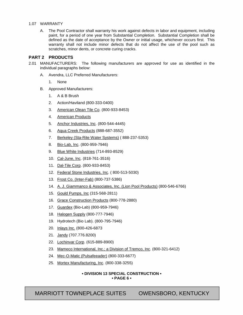
▪ DIVISION 13 SPECIAL CONSTRUCTION ▪
▪ PAGE 6 ▪
RESIDENCE INN BY MARRIOTT - LITTLETON, COLORADO
1.07 WARRANTY
A. The Pool Contractor shall warranty his work against defects in labor and equipment, including paint, for a period of one year from Substantial Completion. Substantial Completion shall be defined as the date of acceptance by the Owner or initial usage, whichever occurs first. This warranty shall not include minor defects that do not affect the use of the pool such as scratches, minor dents, or concrete curing cracks.
PART 2 PRODUCTS 2.01 MANUFACTURERS: The following manufacturers are approved for use as identified in the
individual paragraphs below:
A. Avendra, LLC Preferred Manufacturers:
1. None
B. Approved Manufacturers:
1. A & B Brush
2. Action/Haviland (800-333-0400)
3. American Olean Tile Co. (800-933-8453)
4. American Products
5. Anchor Industries, Inc. (800-544-4445)
6. Aqua Creek Products (888-687-3552)
7. Berkeley (Sta-Rite Water Systems) ( 888-237-5353)
8. Bio-Lab, Inc. (800-959-7946)
9. Blue White Industries (714-893-8529)
10. Cal-June, Inc. (818-761-3516)
11. Dal-Tile Corp. (800-933-8453)
12. Federal Stone Industries, Inc. ( 800-513-5030)
13. Frost Co. (Inter-Fab) (800-737-5386)
14. A. J. Giammanco & Associates, Inc. (Lion Pool Products) (800-546-6766)
15. Gould Pumps, Inc (315-568-2811)
16. Grace Construction Products (800-778-2880)
17. Guardex (Bio-Lab) (800-959-7946)
18. Halogen Supply (800-777-7946)
19. Hydrotech (Bio Lab). (800-795-7946)
20. Inlays Inc. (800-426-6873
21. Jandy (707.776.8200)
22. Lochinvar Corp. (615-889-8900)
23. Mameco International, Inc.; a Division of Tremco, Inc. (800-321-6412)
24. Mec-O-Matic (Pulsafeeader) (800-333-6677)
25. Mortex Manufacturing, Inc. (800-338-3255)
MARRIOTT TOWNEPLACE SUITES OWENSBORO, KENTUCKY

▪ DIVISION 13 SPECIAL CONSTRUCTION ▪
▪ PAGE 7 ▪
RESIDENCE INN BY MARRIOTT - LITTLETON, COLORADO
26. Omni (Div. Bio-Lab) (800-959-7946)
27. PAC-FAB, Inc. (see Paragon Aquatics) (800-983-7665)
28. Paragon Aquatics, a Division of Pentair, Inc. (845-463-7200) .
29. Pentair Pool Products (800-843-5628)
30. Purex (see Pentair Products)
31. Quaker Plastic Corporation (888-288-6644)
32. Rainbow, a Brand of Pentair, Inc. (800-831-7133)
33. Raypak, Inc (818-889-1500)
34. George Fischer Signet Scientific Co. (800-854-4090)
35. S.R. Smith, LLC (800-824-4387)
36. Spectrum Products (800-791-8057)
37. StaRite Pool and Spa Group a Pentair Company (800-843-5628)
38. Stenner
39. Swimquip (See Sta-Rite Pool Spa Group) (800-752-0183)
40. Taylor Technologies. (800-837-8548)
41. Telodyne Laars (415-382-8220)
42. Whitten (Aquatic Development Group) (518-783-0038)
43. W. R. Meadows, Pool Deck Construction Products (800-542-7665)
44. VAK PAK (800-877-1824)
2.02 POOL AND SPA STRUCTURE - GENERAL
A. Size of pool shall be as shown on Drawings.
B. Joint sealant shall be polyurethane, Mameco Vulkem No. 45.
C. Ceramic Tiling: Tile used in conjunction with surfaces in contact with water shall be furnished and installed by pool Contractor.
D. Perimeter and general purpose sealants shall be polyurethane, refer to Section 07 92 00 (07920)
2.03 POOL & SPA MATERIALS
A. Concrete:
1. Definitions:
a. Gunite: Dry-mix. Originally a trade name used to designate a mixture of Portland cement and sand thoroughly mixed dry, passed through a cement gun and conveyed by air through a flexible tube, hydrated at the nozzle and placed by air pressure.
b. Shotcrete: Wet-mix. transit-mix (ready-mix) combination of Portland cement, aggregates and water, pumped in a plastic state to the nowle, where air is added to place the material.
2. Materials and mixes for "Gunite" and shotcrete shall conform to GCA publication G-84.
MARRIOTT TOWNEPLACE SUITES OWENSBORO, KENTUCKY
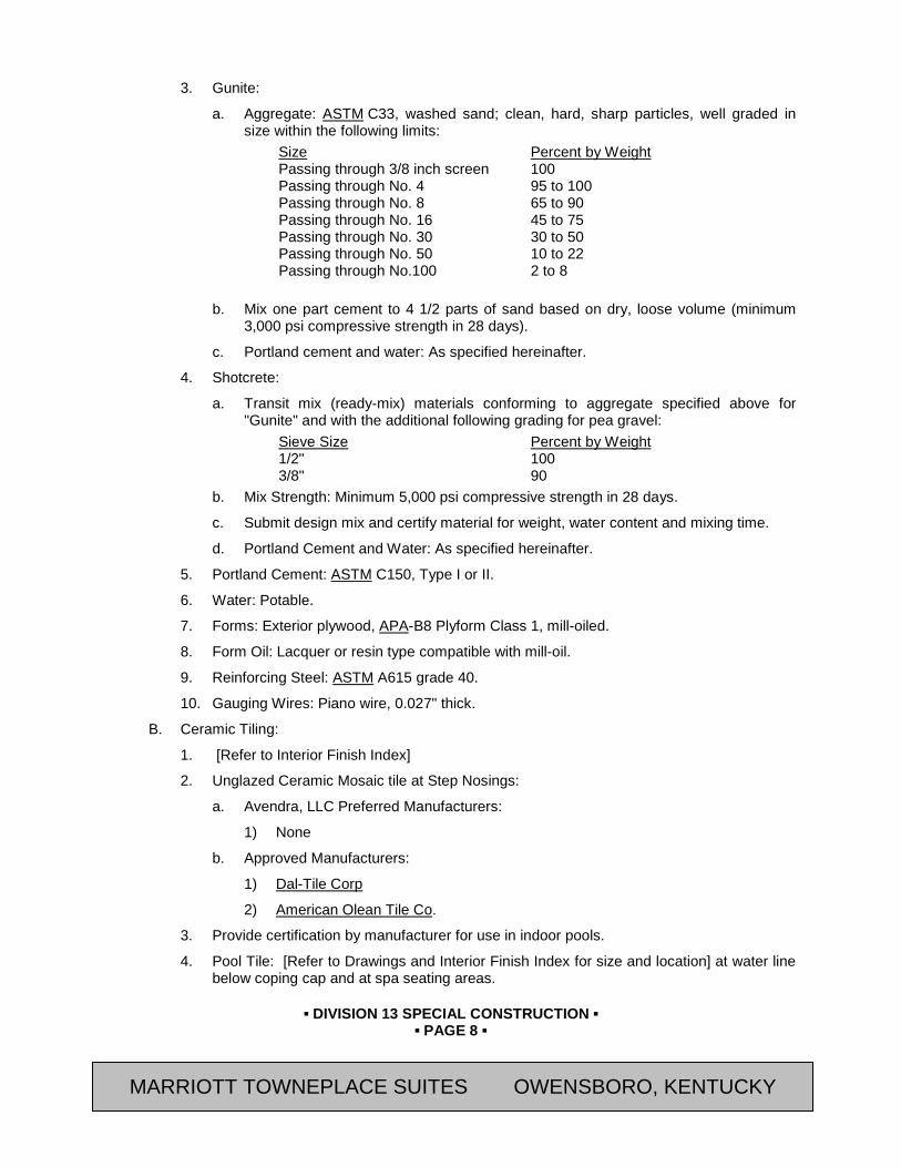
▪ DIVISION 13 SPECIAL CONSTRUCTION ▪
▪ PAGE 8 ▪
RESIDENCE INN BY MARRIOTT - LITTLETON, COLORADO
3. Gunite:
a. Aggregate: ASTM C33, washed sand; clean, hard, sharp particles, well graded in size within the following limits:
Size Percent by Weight Passing through 3/8 inch screen 100 Passing through No. 4 95 to 100 Passing through No. 8 65 to 90 Passing through No. 16 45 to 75 Passing through No. 30 30 to 50 Passing through No. 50 10 to 22 Passing through No.100 2 to 8
b. Mix one part cement to 4 1/2 parts of sand based on dry, loose volume (minimum
3,000 psi compressive strength in 28 days).
c. Portland cement and water: As specified hereinafter.
4. Shotcrete:
a. Transit mix (ready-mix) materials conforming to aggregate specified above for "Gunite" and with the additional following grading for pea gravel:
Sieve Size Percent by Weight 1/2" 100 3/8" 90
b. Mix Strength: Minimum 5,000 psi compressive strength in 28 days.
c. Submit design mix and certify material for weight, water content and mixing time.
d. Portland Cement and Water: As specified hereinafter.
5. Portland Cement: ASTM C150, Type I or II.
6. Water: Potable.
7. Forms: Exterior plywood, APA-B8 Plyform Class 1, mill-oiled.
8. Form Oil: Lacquer or resin type compatible with mill-oil.
9. Reinforcing Steel: ASTM A615 grade 40.
10. Gauging Wires: Piano wire, 0.027" thick.
B. Ceramic Tiling:
1. [Refer to Interior Finish Index]
2. Unglazed Ceramic Mosaic tile at Step Nosings:
a. Avendra, LLC Preferred Manufacturers:
1) None
b. Approved Manufacturers:
1) Dal-Tile Corp
2) American Olean Tile Co.
3. Provide certification by manufacturer for use in indoor pools.
4. Pool Tile: [Refer to Drawings and Interior Finish Index for size and location] at water line below coping cap and at spa seating areas.
MARRIOTT TOWNEPLACE SUITES OWENSBORO, KENTUCKY

▪ DIVISION 13 SPECIAL CONSTRUCTION ▪
▪ PAGE 9 ▪
RESIDENCE INN BY MARRIOTT - LITTLETON, COLORADO
5. [3" x 3"] non-slip unglazed ceramic mosaic tile in color as shown in Interior Finish Index at step nosings forming a 3”] horizontal and 3”] vertical band. Refer to Interior Finish Index.
6. Special Tiles:
a. Avendra, LLC Preferred Manufacturers:
1) None
b. Approved Manufacturers:
1) Inlays Inc. (800-426-6873
7. Pool Depth Markings: 6" x 6" tile with 4" high lettering depth marking in both feet and meters for skim line (smooth) and deck (non-slip), as required by local and state public swimming pool codes.
a. Numbers with Small FT and Small M Tiles: “Ceramic FT & MDM Series”; Inlays Inc.
8. No Diving Sign Tile: Adjacent to each depth marker, provide international symbol "No Diving" sign tile. "No Diving" tile shall be 6” x 6” for skim-line and 6" x 6" for deck (non-slip) white ceramic with black lettering and markings and a red circle with cross hatch, as required by local and state public swimming pool codes.. Where shown on Drawings, provide 6” x 12” tile with 4" high lettering with text “NO DIVING”.
a. International Symbol No Diving Tiles: “Ceramic MG Series”; Inlays Inc.
b. Letters Only Tiles “No Diving”: “Ceramic TMG Series”; Inlays Inc.
9. Depth marking and no diving tiles shall be placed on the vertical pool walls as part of the 6” tile band below the coping so as to be easily readable from the water side. Depth marking and "No Diving" tiles on the horizontal surface of deck, shall be within 18" of the water edge and positioned to be read while standing on the deck facing the water. Pool markings shall be placed at maximum and minimum depths, all points of slope change, at every one foot of depth increment, and at major deviations in shape. Markers shall be spaced at no more than 10 foot intervals and arranged to be uniformly located.
10. Tile Mortar and Grout: As specified in Section 09 30 00 (09310) – Tiling.
11. Refer to Interior Finish Index for colors.
C. Finish Plaster Mix:
1. Avendra, LLC Preferred Manufacturers:
a. None
2. Approved Manufacturers:
a. “Diamond Brite” Pool Finish; SGM (Southern Grouts & Mortars, Inc.) (800-641-9247)
b. No Substitutions
3. Finish and Color: Selected by Owner’s Representative
D. Sealant and Back-Up Material: See Section 07 92 00 (07920) - Joint Sealants
E. Precast Concrete Pool and Spa Coping:
1. Avendra, LLC Preferred Manufacturers:
a. None
MARRIOTT TOWNEPLACE SUITES OWENSBORO, KENTUCKY
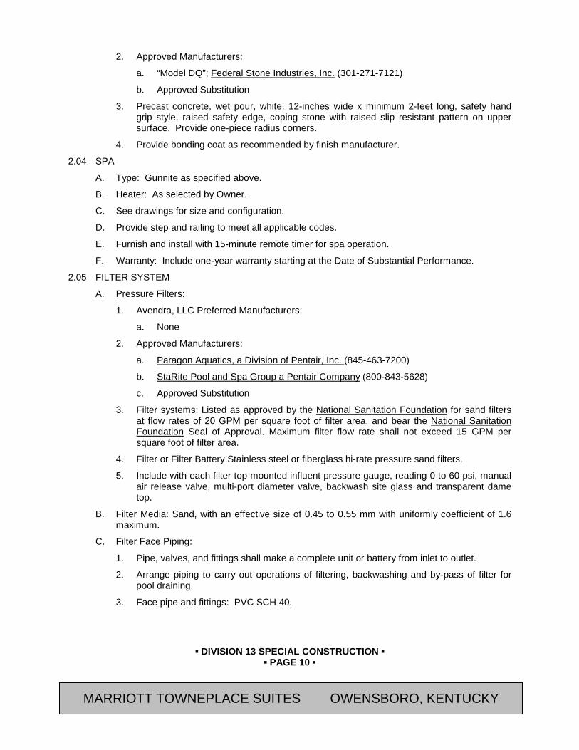
▪ DIVISION 13 SPECIAL CONSTRUCTION ▪
▪ PAGE 10 ▪
RESIDENCE INN BY MARRIOTT - LITTLETON, COLORADO
2. Approved Manufacturers:
a. “Model DQ”; Federal Stone Industries, Inc. (301-271-7121)
b. Approved Substitution
3. Precast concrete, wet pour, white, 12-inches wide x minimum 2-feet long, safety hand grip style, raised safety edge, coping stone with raised slip resistant pattern on upper surface. Provide one-piece radius corners.
4. Provide bonding coat as recommended by finish manufacturer.
2.04 SPA
A. Type: Gunnite as specified above.
B. Heater: As selected by Owner.
C. See drawings for size and configuration.
D. Provide step and railing to meet all applicable codes.
E. Furnish and install with 15-minute remote timer for spa operation.
F. Warranty: Include one-year warranty starting at the Date of Substantial Performance.
2.05 FILTER SYSTEM
A. Pressure Filters:
1. Avendra, LLC Preferred Manufacturers:
a. None
2. Approved Manufacturers:
a. Paragon Aquatics, a Division of Pentair, Inc. (845-463-7200)
b. StaRite Pool and Spa Group a Pentair Company (800-843-5628)
c. Approved Substitution
3. Filter systems: Listed as approved by the National Sanitation Foundation for sand filters at flow rates of 20 GPM per square foot of filter area, and bear the National Sanitation Foundation Seal of Approval. Maximum filter flow rate shall not exceed 15 GPM per square foot of filter area.
4. Filter or Filter Battery Stainless steel or fiberglass hi-rate pressure sand filters.
5. Include with each filter top mounted influent pressure gauge, reading 0 to 60 psi, manual air release valve, multi-port diameter valve, backwash site glass and transparent dame top.
B. Filter Media: Sand, with an effective size of 0.45 to 0.55 mm with uniformly coefficient of 1.6 maximum.
C. Filter Face Piping:
1. Pipe, valves, and fittings shall make a complete unit or battery from inlet to outlet.
2. Arrange piping to carry out operations of filtering, backwashing and by-pass of filter for pool draining.
3. Face pipe and fittings: PVC SCH 40.
MARRIOTT TOWNEPLACE SUITES OWENSBORO, KENTUCKY
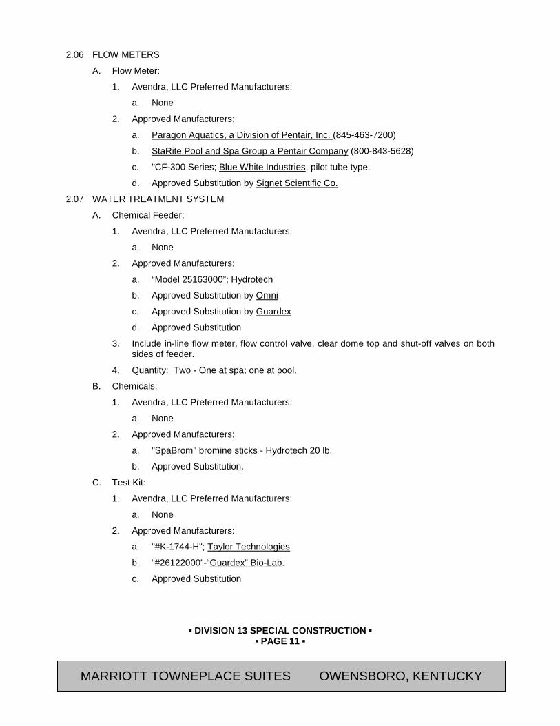
▪ DIVISION 13 SPECIAL CONSTRUCTION ▪
▪ PAGE 11 ▪
RESIDENCE INN BY MARRIOTT - LITTLETON, COLORADO
2.06 FLOW METERS
A. Flow Meter:
1. Avendra, LLC Preferred Manufacturers:
a. None
2. Approved Manufacturers:
a. Paragon Aquatics, a Division of Pentair, Inc. (845-463-7200)
b. StaRite Pool and Spa Group a Pentair Company (800-843-5628)
c. "CF-300 Series; Blue White Industries, pilot tube type.
d. Approved Substitution by Signet Scientific Co.
2.07 WATER TREATMENT SYSTEM
A. Chemical Feeder:
1. Avendra, LLC Preferred Manufacturers:
a. None
2. Approved Manufacturers:
a. “Model 25163000”; Hydrotech
b. Approved Substitution by Omni
c. Approved Substitution by Guardex
d. Approved Substitution
3. Include in-line flow meter, flow control valve, clear dome top and shut-off valves on both sides of feeder.
4. Quantity: Two - One at spa; one at pool.
B. Chemicals:
1. Avendra, LLC Preferred Manufacturers:
a. None
2. Approved Manufacturers:
a. "SpaBrom" bromine sticks - Hydrotech 20 lb.
b. Approved Substitution.
C. Test Kit:
1. Avendra, LLC Preferred Manufacturers:
a. None
2. Approved Manufacturers:
a. "#K-1744-H"; Taylor Technologies
b. “#26122000”-“Guardex” Bio-Lab.
c. Approved Substitution
MARRIOTT TOWNEPLACE SUITES OWENSBORO, KENTUCKY
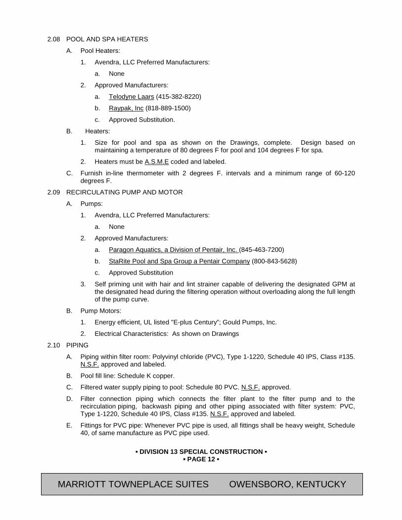
▪ DIVISION 13 SPECIAL CONSTRUCTION ▪
▪ PAGE 12 ▪
RESIDENCE INN BY MARRIOTT - LITTLETON, COLORADO
2.08 POOL AND SPA HEATERS
A. Pool Heaters:
1. Avendra, LLC Preferred Manufacturers:
a. None
2. Approved Manufacturers:
a. Telodyne Laars (415-382-8220)
b. Raypak, Inc (818-889-1500)
c. Approved Substitution.
B. Heaters:
1. Size for pool and spa as shown on the Drawings, complete. Design based on maintaining a temperature of 80 degrees F for pool and 104 degrees F for spa.
2. Heaters must be A.S.M.E coded and labeled.
C. Furnish in-line thermometer with 2 degrees F. intervals and a minimum range of 60-120 degrees F.
2.09 RECIRCULATING PUMP AND MOTOR
A. Pumps:
1. Avendra, LLC Preferred Manufacturers:
a. None
2. Approved Manufacturers:
a. Paragon Aquatics, a Division of Pentair, Inc. (845-463-7200)
b. StaRite Pool and Spa Group a Pentair Company (800-843-5628)
c. Approved Substitution
3. Self priming unit with hair and lint strainer capable of delivering the designated GPM at the designated head during the filtering operation without overloading along the full length of the pump curve.
B. Pump Motors:
1. Energy efficient, UL listed "E-plus Century”; Gould Pumps, Inc.
2. Electrical Characteristics: As shown on Drawings
2.10 PIPING
A. Piping within filter room: Polyvinyl chloride (PVC), Type 1-1220, Schedule 40 IPS, Class #135. N.S.F. approved and labeled.
B. Pool fill line: Schedule K copper.
C. Filtered water supply piping to pool: Schedule 80 PVC. N.S.F. approved.
D. Filter connection piping which connects the filter plant to the filter pump and to the recirculation piping, backwash piping and other piping associated with filter system: PVC, Type 1-1220, Schedule 40 IPS, Class #135. N.S.F. approved and labeled.
E. Fittings for PVC pipe: Whenever PVC pipe is used, all fittings shall be heavy weight, Schedule 40, of same manufacture as PVC pipe used.
MARRIOTT TOWNEPLACE SUITES OWENSBORO, KENTUCKY

▪ DIVISION 13 SPECIAL CONSTRUCTION ▪
▪ PAGE 13 ▪
RESIDENCE INN BY MARRIOTT - LITTLETON, COLORADO
F. NOTE: The first 24" of piping coming from pool heater shall be copper. Where the copper connects to PVC piping, after the 24", provide a copper to PVC transition connection.
G. Valves:
1. Small Valves (up to and including 2-1/2" in size): Gate valves, all brass with threaded ends for ferrous pipe, 125 lb. non-rising stem type.
2. Large valves (larger than 2-1/2"): Rubber lined, cast iron, water type butterfly valves. Valves shall be hand operated with cadmium plated ductile iron discs, stainless steel stems and pins, and Buna-N seats and rated for 125 psi.
3. Valve extension stems and keys: Provide as required to operate the system.
4. Pipe identification: Plastic tags for valves in filter room.
H. Pipe Joints:
1. Cement and thinners: Use for making solvent welded joints. Of type compatible with kind of piping used.
2. Teflon tape (.003" min thickness): Use on the male threads of threaded pipe joints.
I. Fillers and levelers: Provide instrumentation sensors and valves to automatically fill and maintain level of pool complete with wiring and controls.
J. Chemical feed and heater controls: Provide instrumentation sensors and valves to automatically feed chemicals and maintain temperature of pool complete with wiring and controls.
2.11 SCHEDULES OF POOL FITTINGS' LIGHTS AND EQUIPMENT ACCESSORIES
Description Manufacturer Model Number A. Pool Fittings
1. Floor Inlet Frost A-41014 2. Pool Wall Inlet Swimquip 8429 3. Auto Water Level Control Mar-Max LTC 0024S 4. 1-1/2" Hydrostat Valve Frost A-41452 5. 1-1/2" Hydrostat Tube Swimquip 7017-157 6. 1-1/2" Skimmer American Prod 844201 7. 1" Fill Spout Frost A-41240 8. Pool Main Drain Sump Swimquip 7017-0103 9. Pool Main Drain Grate Swimquip 7010741
B. Underwater Lights: (Coordinate with Section 16510(26 51 00))
1. 100W/300W/12V Light (Two) Pac-Fab PHL-301/PHL-300
2. Light Niche Pac-Fab 425.4
C. Deck Fittings: 1. Grab Rail, 1.90-1/2” OD x .065
Stainless Steel with smooth grip finish S. R. Smith
2. Deck Anchor S. R. Smith AS-100B 3. Escutcheon Plate S. R. Smith IEP-100 4. Ladder 3 tread 1.90” OD x .065”
Stainless Steel with mirror finish. Provide every 75’ at perimeter
S. R. Smith SRS 506
MARRIOTT TOWNEPLACE SUITES OWENSBORO, KENTUCKY
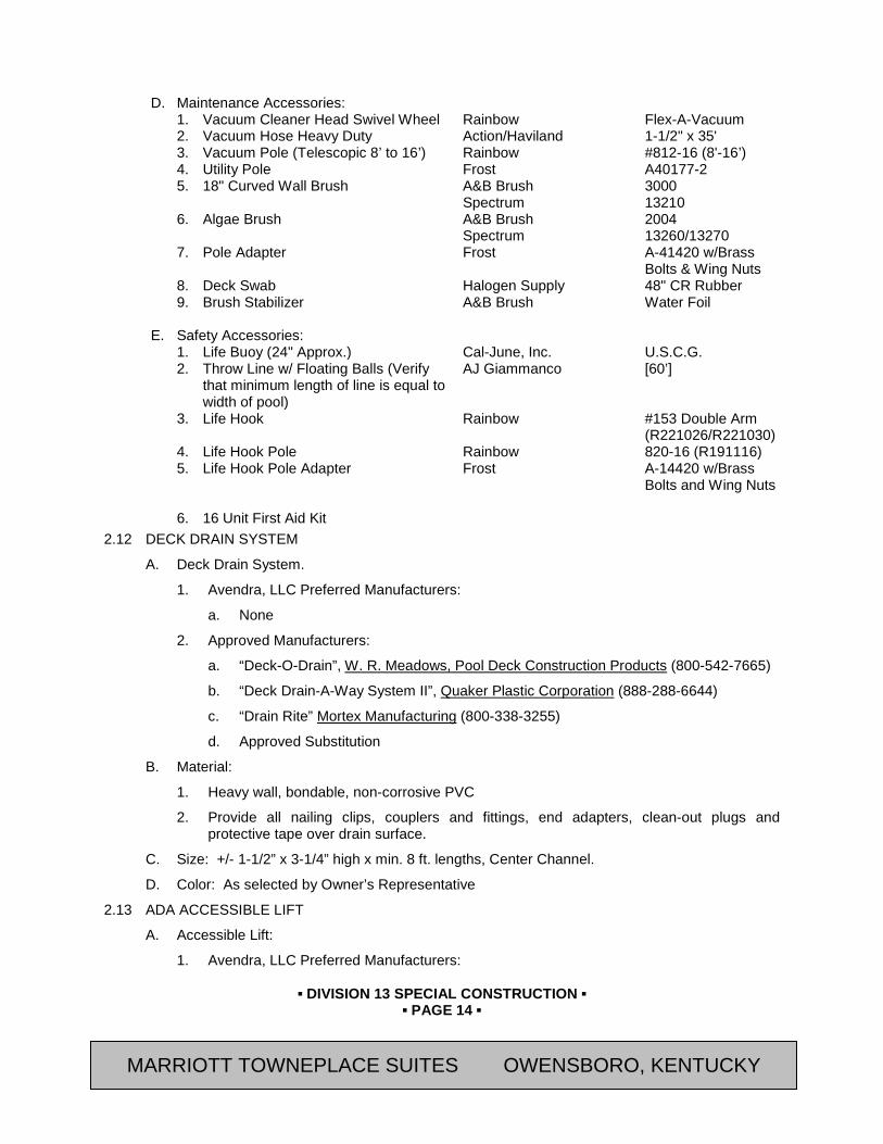
▪ DIVISION 13 SPECIAL CONSTRUCTION ▪
▪ PAGE 14 ▪
RESIDENCE INN BY MARRIOTT - LITTLETON, COLORADO
D. Maintenance Accessories:
1. Vacuum Cleaner Head Swivel Wheel Rainbow Flex-A-Vacuum 2. Vacuum Hose Heavy Duty Action/Haviland 1-1/2" x 35' 3. Vacuum Pole (Telescopic 8’ to 16’) Rainbow #812-16 (8'-16’) 4. Utility Pole Frost A40177-2 5. 18" Curved Wall Brush A&B Brush 3000 Spectrum 13210 6. Algae Brush A&B Brush 2004 Spectrum 13260/13270 7. Pole Adapter Frost A-41420 w/Brass
Bolts & Wing Nuts 8. Deck Swab Halogen Supply 48" CR Rubber 9. Brush Stabilizer A&B Brush Water Foil
E. Safety Accessories: 1. Life Buoy (24" Approx.) Cal-June, Inc. U.S.C.G. 2. Throw Line w/ Floating Balls (Verify
that minimum length of line is equal to width of pool)
AJ Giammanco [60’]
3. Life Hook Rainbow #153 Double Arm (R221026/R221030)
4. Life Hook Pole Rainbow 820-16 (R191116) 5. Life Hook Pole Adapter Frost A-14420 w/Brass
Bolts and Wing Nuts 6. 16 Unit First Aid Kit
2.12 DECK DRAIN SYSTEM
A. Deck Drain System.
1. Avendra, LLC Preferred Manufacturers:
a. None
2. Approved Manufacturers:
a. “Deck-O-Drain”, W. R. Meadows, Pool Deck Construction Products (800-542-7665)
b. “Deck Drain-A-Way System II”, Quaker Plastic Corporation (888-288-6644)
c. “Drain Rite” Mortex Manufacturing (800-338-3255)
d. Approved Substitution
B. Material:
1. Heavy wall, bondable, non-corrosive PVC
2. Provide all nailing clips, couplers and fittings, end adapters, clean-out plugs and protective tape over drain surface.
C. Size: +/- 1-1/2” x 3-1/4” high x min. 8 ft. lengths, Center Channel.
D. Color: As selected by Owner’s Representative
2.13 ADA ACCESSIBLE LIFT
A. Accessible Lift:
1. Avendra, LLC Preferred Manufacturers:
MARRIOTT TOWNEPLACE SUITES OWENSBORO, KENTUCKY

▪ DIVISION 13 SPECIAL CONSTRUCTION ▪
▪ PAGE 15 ▪
RESIDENCE INN BY MARRIOTT - LITTLETON, COLORADO
a. None
2. Approved Manufacturers:
a. Hydraulic Powered, Fixed Lift: "Swim-Lift Model Gallatin - ADA Handicap Pool/Spa Lift"; Spectrum Aquatics (800-791-8057) including the following accessories:
1) 400 lbs weight capacity
2) “Preset Anchor” for new construction applications.
3) “Water Box for Water Powered Pool Lift”
4) Model 27364 Cover”
b. Rechargeable Battery Powered, Fixed Lift: "Swim-Lift Model 57961 Anchored Freedom - ADA Handicap Pool/Spa Lift"; Spectrum Aquatics (800-791-8057) including the following accessories:
1) 350 lbs weight capacity
2) One watertight remote control, battery and battery charger, footrest, deck anchor, seat belt.
3) Model 47949 Cover” Note: The three models below are available from Aqua Creek Products. The “Revolution Lift” has a 500
lbs weight capacity and can be used at both pool and spa. The “Scout Lift has a 350 lbs weight capacity and can be used at pools only. The “Scout HI-Lift” has a 350 lbs weight capacity and is for use at spas to lift over spa steps and walls. Check with Aqua Creek for design information and select one of three models below. Delete model(s) not used.
c. Rechargeable Battery Powered, Fixed Lift: “The Revolution Lift Model F-700RL”; Aqua Creek Products (888-687-3552), including the following accessories:
1) 500 lbs weight capacity
2) Secondary Anchor Kit”
3) “Model F-720RLC Cover”
d. Rechargeable Battery Powered, Fixed Lift: “The Scout Lift Model F-8005SC”; Aqua Creek Products (888-687-3552), including the following accessories:
1) 350 lbs weight capacity
2) “Model F-450SC Cover”
e. Rechargeable Battery Powered, Fixed Lift: “The Scout Hi-Lift Model F-802SCNA-HLD”; Aqua Creek Products (888-687-3552), including the following accessories:
1) “350 lbs weight capacity
2) Model F-450SC Cover”
f. Approved substitution.
B. Provide lifter, anchor assemblies, and all other components required for a complete and operational installation. Provide sleeves in deck at pool and at spa if required.
1. For Hydraulic powered system, furnish and install a stainless steel water box in the pool deck adjacent to the installation site of the lift. A hose spigot shall be plumbed into the box to allow for the connection of a flexible hose.
MARRIOTT TOWNEPLACE SUITES OWENSBORO, KENTUCKY
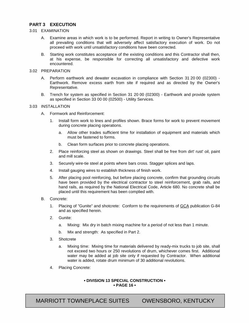
▪ DIVISION 13 SPECIAL CONSTRUCTION ▪
▪ PAGE 16 ▪
RESIDENCE INN BY MARRIOTT - LITTLETON, COLORADO
PART 3 EXECUTION 3.01 EXAMINATION
A. Examine areas in which work is to be performed. Report in writing to Owner's Representative all prevailing conditions that will adversely affect satisfactory execution of work. Do not proceed with work until unsatisfactory conditions have been corrected.
B. Starting work constitutes acceptance of the existing conditions and this Contractor shall then, at his expense, be responsible for correcting all unsatisfactory and defective work encountered.
3.02 PREPARATION
A. Perform earthwork and dewater excavation in compliance with Section 31 20 00 (02300) - Earthwork. Remove excess earth from site if required and as directed by the Owner's Representative.
B. Trench for system as specified in Section 31 20 00 (02300) - Earthwork and provide system as specified in Section 33 00 00 (02500) - Utility Services.
3.03 INSTALLATION
A. Formwork and Reinforcement:
1. Install form work to lines and profiles shown. Brace forms for work to prevent movement during concrete placing operations.
a. Allow other trades sufficient time for installation of equipment and materials which must be fastened to forms.
b. Clean form surfaces prior to concrete placing operations.
2. Place reinforcing steel as shown on drawings. Steel shall be free from dirt' rust' oil, paint and mill scale.
3. Securely wire-tie steel at points where bars cross. Stagger splices and laps.
4. Install gauging wires to establish thickness of finish work.
5. After placing pool reinforcing, but before placing concrete, confirm that grounding circuits have been provided by the electrical contractor to steel reinforcement, grab rails, and hand rails, as required by the National Electrical Code, Article 680. No concrete shall be placed until this requirement has been complied with.
B. Concrete:
1. Placing of "Gunite" and shotcrete: Conform to the requirements of GCA publication G-84 and as specified herein.
2. Gunite:
a. Mixing: Mix dry in batch mixing machine for a period of not less than 1 minute.
b. Mix and strength: As specified in Part 2.
3. Shotcrete
a. Mixing time: Mixing time for materials delivered by ready-mix trucks to job site, shall not exceed two hours or 250 revolutions of drum, whichever comes first. Additional water may be added at job site only if requested by Contractor. When additional water is added, rotate drum minimum of 30 additional revolutions.
4. Placing Concrete:
MARRIOTT TOWNEPLACE SUITES OWENSBORO, KENTUCKY
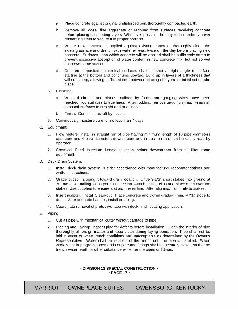
▪ DIVISION 13 SPECIAL CONSTRUCTION ▪
▪ PAGE 17 ▪
RESIDENCE INN BY MARRIOTT - LITTLETON, COLORADO
a. Place concrete against original undisturbed soil, thoroughly compacted earth.
b. Remove all loose, fine aggregate or rebound from surfaces receiving concrete before placing succeeding layers. Whenever possible, first layer shall entirely cover reinforcing steel to secure it in proper position.
c. Where new concrete is applied against existing concrete, thoroughly clean the existing surface and drench with water at least twice on the day before placing new concrete. Surfaces upon which concrete will be applied shall be sufficiently damp to prevent excessive absorption of water content in new concrete mix, but not so wet as to overcome suction.
d. Concrete deposited on vertical surfaces shall be shot at right angle to surface starting at the bottom and continuing upward. Build up in layers of a thickness that will not slump, allowing sufficient time between placing of layers for initial set to take place.
5. Finishing:
a. When thickness and planes outlined by forms and gauging wires have been reached, rod surfaces to true lines. After rodding, remove gauging wires. Finish all exposed surfaces to straight and true lines.
b. Finish: Gun finish as left by nozzle.
6. Continuously moisture cure for no less than 7 days.
C. Equipment:
1. Flow meters: Install in straight run of pipe having minimum length of 10 pipe diameters upstream and 4 pipe diameters downstream and in position that can be easily read by operator.
2. Chemical Feed injection: Locate Injection points downstream from all filter room equipment.
D. Deck Drain System:
1. Install deck drain system in strict accordance with manufacturer recommendations and written instructions.
2. Grade subsoil, sloping it toward drain location. Drive 3-1/2” short stakes into ground at 30” o/c – two nailing strips per 10 ft. section. Attach nailing clips and place drain over the stakes. Use couplers to ensure a straight even line. After aligning, nail firmly to stakes.
3. Insert adapter. Install Clean-out. Place concrete and trowel gradual (min. ¼”/ft.) slope to drain. After concrete has set, install end plug.
4. Coordinate removal of protective tape with deck finish coating application.
E. Piping:
1. Cut all pipe with mechanical cutter without damage to pipe.
2. Placing and Laying: Inspect pipe for defects before installation. Clean the interior of pipe thoroughly of foreign matter and keep clean during laying operation. Pipe shall not be laid in water or when trench conditions are unacceptable as determined by the Owner's Representative. Water shall be kept out of the trench until the pipe is installed. When work is not in progress, open ends of pipe and fittings shall be securely closed so that no trench water, earth or other substance will enter the pipes or fittings.
MARRIOTT TOWNEPLACE SUITES OWENSBORO, KENTUCKY
▪ DIVISION 13 SPECIAL CONSTRUCTION ▪
▪ PAGE 18 ▪
RESIDENCE INN BY MARRIOTT - LITTLETON, COLORADO
3. Threaded Joints: After cutting and before threading the pipe shall be reamed and shall have burrs removed. Screw joints shall be made with graphite or inert filter and oil or with an approved graphite compound applied to male threads only. Threads shall be full-cut and not more than 3 threads on the pipe remain exposed. Use Teflon 11 tape on the male threads of all threaded pipe joints. Caulking of threaded joints to stop or prevent leaks will not be permitted. Unions shall be provided where required for disconnection of exposed piping. Unions will be permitted where access is provided.
4. Solvent welded joints shall be made in accordance with the manufacturer's printed instructions and the following minimum standards:
a. Fittings shall fit easily on the pipe before applying cement. The outer surface area of pipe and inner wall of fitting shall be dry and dean. Thinner is to be applied to the outer surface of the pipe and to the inner surface of the fitting. Cement is to be applied to the outer surface of the pipe, or on the male section of fittings only. When the outside surface area of the pipe is satisfactorily covered with cement allow ten (10) seconds open time to elapse before inserting pipe end into fitting. After full insertion of pipe into fitting, turn fitting about the pipe end approximately 1/8 to 1/4 of a turn. Wipe off excess cement at the joint in a neat cove bead.
b. Joints shall remain undisturbed for a minimum of 10 minutes from time of jointing the pipe and fitting. If necessary to apply pressure to a newly made joint, limit to 10% of rated pipe pressure, during the first 24 hours after the joint has been made.
c. Full working pressure shall not be applied until the joints have set for a period of 24 hours.
d. Make provisions for expansion and contraction by way of swing joints or snaking.
e. Protect plastic pipe from exposure to aromatic hydro-carbons, halogenated hydra carbons, and most of esters and ketones that attack the material. Protect all pipe from mechanical damage and long exposure to sunlight during storage.
5. Install piping without cross connections or inter-connection between distribution supply for drinking purposes and swimming pool that will permit backflow of water into potable water supply. Pipe openings shall be closed with caps or plugs during installation. Equipment and pool fittings shall be tightly covered and protected against dirt, water and chemical or mechanical injury. At completion of work fittings, materials and equipment shall be thoroughly clean and adjusted for proper operation.
6. Filter Face Piping: Arrange to carry out operations of filtering backwashing and filter draining.
7. Valve identification: Label all valves.
8. Testing and Flushing:
a. Pressure Piping: After the pipe is laid, the joints completed, and the trench partially backfilled leaving joints exposed for examination, subject new lines to a hydrostatic pressure of not less than 50 pounds per square inch. Joints shall remain watertight under this pressure for a period of two hours.
b. Gravity Lines: A water test shall be applied to all gravity drain piping system, either in their entirety or in sections. All openings shall be tightly plugged and each system filled with water and tested with at least a 10 foot head of water. Water shall be kept in the system, or in the portion under test's for at least 15 minutes before inspection starts. System shall be tight at all joints.
MARRIOTT TOWNEPLACE SUITES OWENSBORO, KENTUCKY
▪ DIVISION 13 SPECIAL CONSTRUCTION ▪
▪ PAGE 19 ▪
RESIDENCE INN BY MARRIOTT - LITTLETON, COLORADO
c. Flushing: Pipelines leading to the pool shall be thoroughly flushed clean with chlorinated water before the pool is filled and placed in use.
F. Plaster Finish:
1. Finish concrete surfaces in pool with a wood float finish to a smooth consistent finish acceptable to Owner Representative.
2. Fill uneven surfaces and depressions with [manufacturer's recommendations Wash all pool surfaces thoroughly with dilute solution of muriatic acid and flush with fresh water to assure a clean surface free of loose materials, dust, and foreign matter.
3. Plaster installation:
a. Apply in accordance with manufacturer's installation instructions.
4. Trowel to smooth, dense, impervious surface free of stains and uniform white color consistency.
5. Fill pool as plaster work progresses.
G. Tile Installation: Where shown on Drawings, use setting materials and grout in accordance with Section 09310 (09 30 13).
3.04 FIELD QUALITY CONTROL
A. For Gunite Shotcrete Work:
1. Compressive strength test: Take 1 sample for pool floor construction and 1 sample for wall construction but no less than a minimum test for each 50 cu. yd. of concrete.
2. Submit copy of test results to Owner's Representative.
B. Water Treatment
1. Obtain a chemical analysis of the source/make-up water supply and submit to Owner's Representative. Include the following:
a. Total alkalinity/ppm
b. Calcium hardness/ppm
c. Chlorine/ppm
d. pH
e. Iron
f. Copper
2. Treat and balance pool water prior to turnover of pool to Owner's Operations Division.
3. Balance water to establish: Total alkalinity: 80-100 ppm Calcium hardness: 20~275 ppm Total Available CHL (Pool): 1.5 ppm Free Available CHL (Pool: 1.5 ppm Total Available CHL (Spa): 3.0 ppm Free Available CHL (Spa): 3.0 ppm pH: 7.4 - 7.6 Iron content: 0.0 ppm Copper content: 0.0 ppm Saturation Index -.3- +.3
MARRIOTT TOWNEPLACE SUITES OWENSBORO, KENTUCKY

▪ DIVISION 13 SPECIAL CONSTRUCTION ▪
▪ PAGE 20 ▪
RESIDENCE INN BY MARRIOTT - LITTLETON, COLORADO
4. Stabilization (outdoor pool) 40 ppm
END OF SECTION Revision Log
MARRIOTT TOWNEPLACE SUITES OWENSBORO, KENTUCKY
▪ DIVISION 14 CONVEYING EQUIPMENT ▪
▪ PAGE 1 ▪
RESIDENCE INN BY MARRIOTT - LITTLETON, COLORADO
SECTION 14 24 23 (14240) - HYDRAULIC PASSENGER ELEVATORS
PART 1 GENERAL 1.01 SUMMARY
A. Section Includes:
1. Furnish and install a complete new [in-ground] hydraulic passenger elevator system including, but not limited to, the elevator cab, elevator entrances, hydraulic cylinder assembly, motor, pump, and controls. The new elevator system shall be furnished and installed in complete accordance with the Specifications and Drawings.
B. Work Included in Other Sections:
1. General Contractor to provide the following:
a. Confirm length, width, and clear overhead dimensions for hoistway, and provide size as required, as approved by Architect and elevator manufacturer.
b. Provide all structural supports for guide rails and other mechanisms, as located by elevator manufacturer.
c. Sill supports and grouting inside of hoistway for doors.
2. Telephone Cable by Division 27 (16).
3. Electrical
a. Include auxiliary contact in mainline electrical disconnect switch to signal elevator controller loss of power is shutoff of disconnect switch.
C. Related Sections:
1. Section 04 20 00 (04200) - Masonry Units
2. Section 05 12 00 (05120) - Structural Steel: Hoisting Beam
3. Section 05 50 00 (05500) - Metal Fabrications: Pit Ladders, Sump Pit Cover
4. Section 09 90 00 (09900) - Painting
5. Division 23 (15) - Heating, Ventilation, and Air Conditioning
a. Ventilation and temperature control of elevator equipment room.
6. Division 26 (16) - Electrical
a. Electrical service to main disconnect in elevator machine room, electrical power for elevator installation and testing, electrical disconnecting device to elevator equipment prior to activation of sprinkler system, electrical service for machine room, machine room and pit receptacles with ground fault current protection, lighting in machine room and pit, wiring for telephone service to machine room.
b. Telephone Systems; ADAAG-required emergency communications equipment.
7. Division 28 (13) - Fire Protection
a. Fire and smoke detectors; fire alarm signal lines to contacts in the machine room.
1.02 REFERENCES
A. Americans with Disabilities Act (ADA) II Public Accommodations
1. “Americans with Disabilities Act Accessibility Guidelines “(ADAAG)
MARRIOTT TOWNEPLACE SUITES OWENSBORO, KENTUCKY

▪ DIVISION 14 CONVEYING EQUIPMENT ▪
▪ PAGE 2 ▪
RESIDENCE INN BY MARRIOTT - LITTLETON, COLORADO
B. American National Standards Institute (ANSI) Publications:
1. ANSI/ASME 17.1 “Safety Code for Elevators and Escalators”
C. American Society for Testing and Materials (ASTM):
1. A36 “Standard Specification for Carbon Structural Steel”
2. A167 “Standard Specification for Stainless and Heat-Resisting Chromium-Nickel Steel Plate, Sheet, and Strip”
3. A1008 "Standard Specification for Steel, Sheet, Cold-Rolled, Carbon, Structural, High-Strength Low-Alloy and High-Strength Low-Alloy with Improved Formability"
4. A1011 "Standard Specification for Steel Sheet and Strip, Hot-Rolled, Carbon, Structural, High-Strength Low-Alloy and High-Strength Low-Alloy with Improved Formability"
5. B221 “Aluminum-Alloy Extruded Bars, Rods, Shapes, Tubes”
6. B209 “Aluminum-Alloy Sheet and Plate”
7. A167 “Stainless and Heat-Resisting Chromium-Nickel Steel Plate, Sheet and Strip”
8. A526 “Steel Sheet, Zinc-Coated, (Galvanized) by the Hot Dip Process, Commercial Quality”.
9. E84 "Standard Test Method for Surface Burning Characteristics of Building Materials"
D. National Electrical Manufacturer’s Association (NEMA) Standards Publications:
1. LD3 “High Pressure Decorative Laminates”
E. National Fire Protection Association (NFPA) Publications:
1. 80 “Standard for Fire Doors, Fire Windows”
F. National Institute of Standards and Technology (NIST)
1. PS-1 “Construction and Industrial Plywood”
G. Federal Specifications (FS) Publications:
1. FS L-P-508 “Plastic Sheet, Laminated, Decorative, and Nondecorative”
H. American Welding Society (AWS)
1. D1.1 “Structural Welding Code”
1.03 DEFINITIONS
A. Hydraulic Elevators: Elevators in which cars are hoisted either directly or indirectly by action of a hydraulic plunger and cylinder (jack); with other components of the Work, including fluid storage tank, pump, piping, valves, car enclosures, hoistway entrances, operation systems, signal equipment, guide rails, electrical wiring, roping (roped hydraulic applications), buffers, and devices for operations, safety, security, required performance at rated speed and capacity, and for complete elevator installation.
B. Definitions in ASME A17.1 apply to work of this Section.
C. Defective Elevator Work: Operation or control system failures; performances below specified ratings; excessive wear; unusual deterioration or aging of materials or finishes; unsafe conditions; the need for excessive maintenance; abnormal noise or vibration; and similar unusual, unexpected, and unsatisfactory conditions.
MARRIOTT TOWNEPLACE SUITES OWENSBORO, KENTUCKY

▪ DIVISION 14 CONVEYING EQUIPMENT ▪
▪ PAGE 3 ▪
RESIDENCE INN BY MARRIOTT - LITTLETON, COLORADO
1.04 SYSTEM DESCRIPTION
A. The work of this Section includes new [holeless] hydraulic passenger elevators to comply with the Americans with Disabilities Act (ADA). Elevator characteristics are as follow:
1. Quantity and Type One Hydraulic Passenger Elevator
2. Capacity [3500] Pounds
3. Speed 125 Feet per Minute
4. Landings [Four (4)]
5. Openings Number of Openings: [Three (3)]
Front: 2
Rear: 1
6. Operation [Duplex] Selective Collective
7. Clear Car Inside Size:
3500 Pounds: Nominal, Minimum [6'-8"] Wide x [5'-5"] Deep x [8'-0"] [9’-0”] High, and also in accordance with American with Disabilities Act (ADA)
8. Hoistway Entrances (Size) 3'-6" Wide x 7'-0" High (Type) Side Opening
(Fire Rating) 1-1/2 HR
9. Power Supply [250] [480] Volts, 3 Phase, 60 Hertz
10. Signals Illuminated car and hall buttons, car position indicator with audible signal, car direction sign with dual stroke gong and as specified herein.
11. `Additional Features Complete provisions for the handicapped, infrared screen type detector, emergency light, telephone cabinet, [Voice announcing,] [Electronic start,] [Safety valve,] and as specified herein.
1.05 SUBMITTALS
A. General: Submit the following in accordance with Conditions of Contract and Division 01 Specification Sections.
B. Submit “Letter of Conformance” in accordance with Section 01 33 00 (01330) indicating specified items selected for use in project with the following supporting data.
1. Submit Shop Drawings and product data that clearly indicate space requirements, general arrangement of elevator equipment, and material being supplied. Show connections, attachments, reinforcing, anchorage and location of exposed fastenings, and location and amount of loads and reactions to be carried on the building structure.
2. Submit descriptive brochures or detail Drawings of landing buttons, hall fixtures, car position indicators, and car operating panels, car interior, and hoistway doors and frames for review.
3. Samples of exposed finishes for car, hoistway doors and entrances, and operating and signal equipment; 3-inch square samples of sheet materials; and 4-inch lengths of running trim members.
MARRIOTT TOWNEPLACE SUITES OWENSBORO, KENTUCKY
▪ DIVISION 14 CONVEYING EQUIPMENT ▪
▪ PAGE 4 ▪
RESIDENCE INN BY MARRIOTT - LITTLETON, COLORADO
4. Certification that a service office of the manufacturer is located within [100] [50] miles of the Project and that a parts warehouse is located within [100] [50] miles of the Project.
5. Submit repair parts catalogs, instruction manuals, and wiring diagrams specific to this project.
6. Record Documents: Refer to Section 01 78 39 (01785) - Project Record Documents for required closeout documents to be provided at completion of Project.
a. Maintenance manuals for each different hydraulic elevator, including operation and maintenance instructions, parts listing with sources indicated, recommended parts inventory listing, emergency instructions, and similar information. Include all diagnostic and repair information available to manufacturer's and Installer's maintenance personnel. Submit for Owner's information at project closeout as specified in Division 01.
C. Inspection and acceptance certificates and operating permits as required by governing authorities for normal, unrestricted elevator use.
1.06 QUALITY ASSURANCE
A. Installer Qualifications: Engage the elevator manufacturer or an experienced Installer approved by the elevator manufacturer who has completed a minimum of 5 years of experience with elevator installations similar in material, design, and extent to that indicated for this Project and a record of successful in-service performance.
B. Regulatory Requirements:
1. Conform to:
a. The American Society of Mechanical Engineers (ASME) Publications:
1) A-17.1 “Safety Code for Elevators, and Escalators”
2) A-17.2 “Guide for Inspection of Elevators, Escalators, and Moving Walks”
b. American National Standards Institute (ANSI) Publications:
1) C1 “National Electric Code”
c. Local and State Codes
d. Americans with Disabilities Act (ADA) II Public Accommodations
1) “Americans with Disabilities Act Accessibility Guidelines “(ADAAG)
e. American Society of Civil Engineers (ASCE) Publications:
1) ASCE 7, "Minimum Design Loads for Buildings and Other Structures" for elevator design requirements for earthquake loads.
2. The Elevator Contractor shall obtain and pay for all required inspections and permits and perform tests as called for by regulations of governing authorities.
C. Fire-Rated Hoistway Entrance Assemblies: Door and frame assemblies complying with NFPA 80 that are listed and labeled by a testing and inspecting agency acceptable to authorities having jurisdiction, for fire-protection ratings indicated, based on testing at as close to neutral pressure as possible according to NFPA 252 or UL 10B.
D. Proprietary Components
1. Processors or other equipment which can only be serviced by the manufacturer are prohibited, unless a non-expiring service/adjustment tool and instructions are provided to Owner at no additional cost.
MARRIOTT TOWNEPLACE SUITES OWENSBORO, KENTUCKY
▪ DIVISION 14 CONVEYING EQUIPMENT ▪
▪ PAGE 5 ▪
RESIDENCE INN BY MARRIOTT - LITTLETON, COLORADO
1.07 DELIVERY, STORAGE, AND HANDLING
A. Deliver items or materials to site after area in which they are to be installed is ready to receive them in their place of final installation.
B. Store materials in allotted storage area, and in such a manner as to prevent deterioration, damage, or loss of their essential properties.
1. Fully protect movable and operating equipment from weather.
2. Wrap and create factory finished materials in manner to protect their finishes.
1.08 PROJECT CONDITIONS
A. Temporary Use of Elevators:
1. The elevator shall not be used for building construction purposes except as directed after acceptance of the complete installation or after signing of Contractor's "Temporary Acceptance" form.
B. Changes to Drawings and Specification:
1. Review shaft size, machine room size, pit and over-travel dimensions shown on the Drawings and state in a letter with the bid if changes are required to accommodate manufacturer's standard equipment.
2. Failure to furnish such statements will be interpreted to mean that this Contractor agrees to meet all requirements under this Section, and conflicts with the work of other trades will not result in added expense to Owner.
1.09 MAINTENANCE
A. Maintenance Service:
1. Provide a separate proposal to Owner to maintain entire elevator installation for 12 months after date of Substantial Completion of Work. Use only competent and trained employees of the manufacturer. Provide 24-hour Emergency Call-Back Service during maintenance period.
2. Include systematic examination, adjustment, and lubrication of elevator equipment, repair, or replace worn electrical and mechanical parts of the elevator equipment using only genuine standard parts produced by manufacturer of equipment concerned.
3. Replace seals, packing, and valves to maintain required factor of safety.
4. Perform work without removing cars during peak traffic periods.
5. Ensure that competent personnel handle maintenance service. Maintain locally an adequate stock of parts for replacement or emergency purposes and have qualified personnel available at such places to ensure the fulfillment of this service without unreasonable loss of time.
6. Indicate amount included in the proposal for this maintenance service. [The Owner may elect to pay in 12 equal monthly amounts over the period of service.]
B. Maintenance Proposal:
1. Provide separate amount for maintenance of installed elevator work for a period of one year after termination of regular maintenance as required in the preceding Paragraph.
2. Proposal shall include stipulated sum for above stated time period with premiums due quarterly.
MARRIOTT TOWNEPLACE SUITES OWENSBORO, KENTUCKY
▪ DIVISION 14 CONVEYING EQUIPMENT ▪
▪ PAGE 6 ▪
RESIDENCE INN BY MARRIOTT - LITTLETON, COLORADO
PART 2 PRODUCTS 2.01 MANUFACTURERS
A. Avendra, LLC Preferred Manufacturers:
1. None
B. Approved Manufacturers:
1. "Holed Hydraulic"; Otis Elevator Co. (800-441-6847)
2. "Marquis 25"; ThyssenKrupp Elevator (800-824-9666)
3. "Series 330A"; Schindler Elevator Co. (973-397-6500)
2.02 MATERIALS
A. Steel
1. Sheet Steel for Exposed Work: Stretcher-leveled, cold-rolled, commercial-quality carbon steel, complying with ASTM A1008, matte finish.
2. Sheet Steel for Unexposed Work: Hot-rolled, commercial-quality carbon steel, pickled and oiled, complying with ASTM A1011.
3. Structural Steel Shapes and Plates: ASTM A36.
B. Stainless Steel:
1. Type 300 Series complying with ASTM A167
C. Aluminum:
1. Extrusions per ASTM B221; sheet and plate per ASTM B209.
D. Plastic Laminate
1. Materials shall comply with NEMA LD-3:
a. Approved Manufacturers:
1) Lamin-Art (800-323-7624)
2) Nevamar Company, LLC (800-638-4380)
3) Pionite Decorative Surfaces, a Panolam Industries International Incorporated Company (800-746-6483)
4) Formica Corporation (800-367-6422)
5) WilsonArt International, Inc. (800-433-3222)
2. Installation adhesives as recommended by manufacturer for use intended.
a.
E. Fire-Retardant Treated Particleboard Panels:
1. Minimum ½-inch thick backup for plastic laminate veneered panels, provided with suitable anti-warp backing; to meet ASTM E84 Class “A” rating with flame-spread rating of 25 or less.
MARRIOTT TOWNEPLACE SUITES OWENSBORO, KENTUCKY

▪ DIVISION 14 CONVEYING EQUIPMENT ▪
▪ PAGE 7 ▪
RESIDENCE INN BY MARRIOTT - LITTLETON, COLORADO
2.03 CAR ENCLOSURE
A. The elevator cab(s) shall meet the requirements of the ASME A-17.1 Elevator Code, and all Elevator Code Supplements issued to date, including Code restrictions pertaining to flame spread and smoke generation.
B. The car shall be manufacturer's standard car, with finishes as shown below: :
1. Refer to Interior Finish Index for the following:
a. Ceiling
b. Front Return Walls
c. Rear and Side Walls
d. Base
e. Entrance Columns
f. Transom
g. Car Doors
h. Car Sills
2. Handrails - on rear wall only, Stainless Steel No. 4 Finish, ADA acceptable profile as selected by Owner's Representative, spaced 1-1/2" from the car wall at 32" above car floor.
3. Protective pads and hooks - for side and rear walls.
4. Lighting - The minimum illumination in the car shall be in accordance with the latest edition of ANSI/ASME A-17.1 Elevator Code.
5. Floor - Carpet to be installed at site, furnished by [Owner].
6. Signage: Provide engraved sign "Do Not use Elevator in case of Fire - Use Stairs" within cab and beside elevator entrance on each floor. Provide engraved sign "Elevator not to be used by construction personnel" and "Elevator permit on file with manager" in cab.
7. Provide stainless steel license holder in each elevator car to suit certificate issued. Design holder with non-visible tamper-proof fastenings.
8. Provide reinforced structure at ceiling in conformance with ASME A-17.1.
2.04 CAR FRAME AND PLATFORM
A. The car frame which supports the elevator platform and enclosure shall be made of structural steel members. Platform shall be manufacturer's standard with a suitable sub-floor and a finished floor of carpet by others. Underside of platform shall be properly fireproofed.
2.05 HOISTWAY ENTRANCES AND DOORS
A. Hoistway entrances of the hollow metal, horizontal sliding, [side] opening type shall be provided at each of the hoistway openings. Size shall be as indicated in Specification.
B. Fire Rating: Comply with NFPA 80 and Underwriter's Laboratories, Inc. (UL) label or other as accepted by governing authorities, for rating as indicated on Drawings.
C. Finish: Refer to Interior Finish Index for the following, unless shown otherwise:
1. Entrance Frame Profile: [Square Jamb]
2. Entrance Frame Material and Finish: [No. 4 Stainless Steel]
3. Door Panels and Sight Guards: [No. 4 Stainless Steel]
MARRIOTT TOWNEPLACE SUITES OWENSBORO, KENTUCKY
▪ DIVISION 14 CONVEYING EQUIPMENT ▪
▪ PAGE 8 ▪
RESIDENCE INN BY MARRIOTT - LITTLETON, COLORADO
4. Entrance Sills: [Extruded Aluminum]
D. Master Door Operator:
1. A Master Closed Loop, Door Operator shall be provided to open and close the car and hoistway doors simultaneously. Opening speed shall not be less than 2-1/2 feet per second. Closing speed shall not exceed the limitations set by ASME A-17.1. Door movement shall be cushioned or checked at both limits of travel. An electro mechanical interlock shall be provided on each hoistway door to prevent the operation of the elevator unless all doors are closed and locked. An electric contact shall be provided on the car door to prevent the operation of the elevator unless the car door is closed.
2. The door operator shall be arranged so that, in case of interruption or failure of electric power from any cause, the doors can not be readily opened by hand from within the car, unless the car is within 18 inches of a landing. Emergency devices and keys for opening the doors from the landing shall be provided if allowed by the local codes.
3. The doors shall open automatically when the car is leveling at the respective landings, and shall close after a predetermined time interval or immediately on pressing a car button. A "Door Open" button shall be provided in the car, the momentary pressing of which shall reopen the doors and reset the time interval.
E. Infrared Door Reopening Device: Black, fully enclosed device. Full screen infrared matrix or multiple beams extending vertically along edge of each leading door panel to a minimum height of 7'-0" above finished floor. Device shall prevent doors from closing and reverse doors at normal opening speed if beams are obstructed while doors are closing, except during nudging operation. If device fails, provide for automatic shutdown of car at floor level with doors open.
1. Acceptable Products:
a. "Microlite"; ThyssenKrupp Elevator
b. "Lambda"; Otis Elevator Co
c. "Microscan E"; T.L. Jones
d. "Pana194 Plus" Janus
e. "Magic Edge"; Tri-Tronics
f. "GateKeeper 2000"; Adams
F. Door Hangers and Tracks:
1. Hangers and tracks shall be provided at each car and hoistway entrance. Tracks shall be of bar or formed steel with the working surface contoured to match the hanger rollers. The hangers shall be designed for power operation and have provisions for vertical and lateral adjustment. Hangers shall be designed for two point suspension of the door panel.
2. Hanger rollers shall be polyurethane with pre-lubricated and sealed for life bearings. Car door hangers shall have 3-1/4" diameter hanger rollers. Hoistway door hangers shall be 2-1/2" diameter hanger rollers.
3. A cable drive shall be used to transmit motion from one door panel to the other.
G. Hoistway Door Jamb Markings:
1. Floor designation shall be provided on both sides of each hoistway entrance door jamb, visible from within the car and the elevator lobby. Designations shall be Braille and Arabic, 2" high, raised .030" and located 60" above the floor. Include star indication at main egress floor.
MARRIOTT TOWNEPLACE SUITES OWENSBORO, KENTUCKY
▪ DIVISION 14 CONVEYING EQUIPMENT ▪
▪ PAGE 9 ▪
RESIDENCE INN BY MARRIOTT - LITTLETON, COLORADO
2. At the elevator car that accommodates ambulance stretcher, provide international symbol for emergency medical services (Star of Life) placed inside on both sides of the hoistway door frame. The symbol shall not be less than 3-inches high.
2.06 OPERATING EQUIPMENT
A. Power Unit: A power unit especially designed and manufactured for this service shall be furnished. It shall include a constant displacement rotary screw type pump, motor, V belt drive assembly, oil reservoir, hydraulic control unit, fill strainer, tank strainer in the suction line, oil level gauge and drip pan. The power unit shall be located near the hoistway at the lowest landing.
1. Isolate power unit assembly on vibration absorbing materials to isolate the unit from building structure and guard exposed components with sound absorbing panels.
2. Power unit shall be designed for 120 upstarts per hour.
3. Include connections for future addition of an oil cooling unit (air type).
B. Valves: Control valve including safety check valve, up direction valve with high pressure relief including up leveling and soft stop features, lowering valve including down leveling and manual leveling feature shall be mounted in a compact unit assembly. Control valves shall be solenoid operated and designed to open and close gradually to give smooth control. All valves shall be readily accessible for adjustment.
C. Automatic Two-Way Leveling: An automatic two-way leveling device shall be provided so that the car will approach landing stops at reduced speed from either direction of travel. The leveling device shall, within its zone, be entirely independent of the operating device and shall automatically stop and maintain the car approximately level with the landing, regardless of change in load.
D. Plunger: The plunger shall be accurately ground and polished seamless steel. The bottom of the plunger shall be fitted with a heavy steel disc welded in place and provided with a suitable extended edge to provide a positive stop designed to prevent the plunger from leaving the cylinder.
E. Cylinder: The cylinder shall be machined from steel pipe with a machined flange at the upper end and a heavy steel bulkhead welded in the lower end. The cylinder shall be provided with a suitable steel fitting for connecting to oil line and with an air bleeder.
F. Cylinder Casings: Protective casings 2 inches (50 mm) larger than cylinders, fabricated from Schedule 40 or 80 PVC pipe complying with ASTM D1785, with bottoms of casings sealed with end caps complying with ASTM D2467 and attached with solvent cement complying with ASTM D2564 shall be provided when cylinders are in ground.
G. Packing Gland: A steel packing gland with bronze guide bearing, wiper ring and packing especially designed for hydraulic elevator service shall be provided. An oil collector ring and drain hole shall be furnished.
H. Piping and Oil: Piping shall be provided from power unit to cylinder complete with necessary fittings. Oil of proper grade for this service shall be provided.
I. A shut off valve (stop cock) shall be provided in the oil line designed to shut off the flow of oil between the cylinder and the power unit. Provide one stop cock in the elevator machine room, and one in the elevator pit. Also, provide a pressure sensitive, mechanically-actuated safety valve conforming to ASME A-17.1 Rule 2410.C.
J. Hydraulic Muffler: A muffler shall be provided in the oil line near the power unit. The muffler shall be designed to reduce pulsation and noise which may be present in the flow of the hydraulic fluid.
MARRIOTT TOWNEPLACE SUITES OWENSBORO, KENTUCKY

▪ DIVISION 14 CONVEYING EQUIPMENT ▪
▪ PAGE 10 ▪
RESIDENCE INN BY MARRIOTT - LITTLETON, COLORADO
K. Platen Plate Isolation: The platen plate shall be mounted on suitable sound dampeners designed to isolate the platen plate from the car frame.
L. Power Unit Isolation: The power unit shall be mounted on vibration sound dampeners designed to isolate the unit from the building structure.
M. Low Oil Control:
1. A low oil control feature shall be provided designed to automatically cause an up traveling car to descend to the lowest terminal landing if the system does not have a sufficient reservoir of oil.
2. If power operated doors are used, the car and hoistway doors shall automatically open at the lowest terminal landing to permit passengers to egress. The doors shall then automatically close and all control buttons, except the Door Open button in the car operating panel, shall be made ineffective.
3. The oil reservoir should be refilled before the elevator is returned to service.
N. Guide Rails: Elevator "T" Section guide rails shall be provided and erected plumb and securely fastened to the hoistway framing.
O. Car Guide Shoes: The top and bottom of the car frame shall be provided with suitable roller guide shoes.
P. Buffers: Spring buffers shall be provided in the elevator pit.
2.07 CONTROLS AND INDICATORS
A. Microprocessor Elevator Logic Control: The operation shall be accomplished utilizing microprocessor computer logic control. The elevator control program shall be contained in nonvolatile, programmable, read only memory. Control shall be constructed such that future alterations in elevator operation may readily be made by altering the read only memory. Safety circuits shall be monitored and controlled by the programmable logic control with redundant protection. The microprocessor elevator logic control shall be contained in a Cabinet.
B. Controller:
1. The controller shall control starting, stopping, and prevent damage to the motor from overload or from excess current. It shall automatically cut off the power supply and bring car to rest in the event of operation of any of the safety devices. The controller shall be enclosed in a cabinet within the Machine Room.
2. Provide solid-state, SCR, closed transition motor starting.
C. Selective Collective Operation:
1. Pressure upon one or more Car Buttons shall send the car to the designated landings in the order in which the landings are reached by the car, irrespective of the sequence in which the buttons are pressed, provided the hoistway door interlock and car door switch circuits are completed. During this operation, the car shall also answer calls from the landings which are in the prevailing direction of travel. Each landing call shall be cancelled when answered.
2. Pressure upon a Hall Button at a floor above the car location shall cause the car to start Up and answer any Up calls as they are reached by the car irrespective of the sequence in which the buttons had been pressed. The car shall not stop at floors where Down buttons only had been pressed. If no further Car or Up Hall calls are registered, the car shall reverse its direction preference for response to Car Calls or Down Hall calls.
MARRIOTT TOWNEPLACE SUITES OWENSBORO, KENTUCKY

▪ DIVISION 14 CONVEYING EQUIPMENT ▪
▪ PAGE 11 ▪
RESIDENCE INN BY MARRIOTT - LITTLETON, COLORADO
3. The car shall start Down to answer calls below the car and shall not stop where Up calls only are registered. When traveling Up, the car shall reverse at the highest call and proceed to answer calls below it. When traveling Down, the car shall reverse at the lowest call and answer calls above it.
4. Should both an Up and a Down call be registered at an intermediate landing, only the call corresponding to the direction in which the car is traveling shall be cancelled upon the stopping of the car at the landing. Terminal limit switches shall be provided in the hoistway designed to automatically stop the car at or near the closest terminal landing.
D. Emergency Stop Switch: An emergency stop switch shall be provided in the car, in the pit, and on top of the car as required by ANSI A-17.1, designed to cut off current supply to motor and down direction valves and bring the car to rest independent of the regular operating devices.
E. Car Operating Panel: A flush-mounted operating panel shall be furnished in the car containing registration push buttons for each floor, alarm button, door open and close push buttons, light switch, independent service switch, emergency personnel operation key switch to accommodate the Owner's interior core keying system.
1. Each car registration button shall illuminate when pressed, signaling that the car has been registered. Each button will remain illuminated until the call has been answered.
2. Tactile car control symbols shall be placed adjacent to the emergency stop switch, door open, door close, alarm bell, and all call registration buttons.
3. The car operating panel shall be mounted at Code required handicap levels.
F. Emergency Communication System: Provide hands-free audio Telephone ("Push to Talk") system conforming to ADA recommendations and shall automatically dial [Front Desk]
1. Include automatic dialing (minimum rollover for 2 numbers), tracking and recall features with shielded wiring between the car and controller in the machine room (Cable by Div. 16).
2. Use alarm button or separate button for the "Push to Talk" control.
3. Button or adjacent light jewel shall illuminate and flash when call is acknowledged. Button shall match floor pushbutton design. Provide uppercase "Push to Call", "Help on the Way" engraved signage Sans Serif or simple Serif type.
4. Provide Braille, "Telephone" and tactile symbol engraved signage adjacent to button.
5. System shall be included as part of the car station faceplate and shall include instructions for use, and battery back-up power supply.
G. Emergency Light: A battery powered emergency light shall be provided in the elevator car.
H. Car Position Indicator: A digital electric position indicator shall be provided in the elevator car. The position of the car and the hoistway shall be indicated by the illumination of the numeral corresponding to the floor at which the elevator is stopped or passing. An audible signal shall sound to indicate the car is stopping at or passing a floor.
1. Provide similar position indicator at the primary egress floor as directed by the Owner's Representative.
I. Car Direction Signs: A car direction sign with visual and audible signal shall be provided in the car jamb, located 6'-0" above the car floor. The car direction sign shall be visible from the proximity of the hall push button fixture to indicate to the waiting passenger the direction the car will gravel. Two car direction signs shall be provided for each elevator car entrance. Finish to be #4 Stainless Steel.
MARRIOTT TOWNEPLACE SUITES OWENSBORO, KENTUCKY
▪ DIVISION 14 CONVEYING EQUIPMENT ▪
▪ PAGE 12 ▪
RESIDENCE INN BY MARRIOTT - LITTLETON, COLORADO
1. The visual signal lens size shall be at least 2-1/2" in the smallest dimension. The audible signal shall sound once for the up direction and twice for the down direction.
J. Hall Push Buttons: A hall push button station shall be provided for each elevator landing, containing a single push button at the terminal landings and two push buttons at the intermediate landings. Each push button shall illuminate when a call is registered, and shall extinguish when the call is answered. The hall push button fixture shall be mounted at the handicapped required height. Finish to be #4 Stainless Steel.
K. Hall Lantern: Provide at each entrance to indicate travel direction of arriving elevator. Located above the hall push buttons, 6'-0" above the car floor. Illuminate indicators with shielded LED lights. Illuminate up or down lights and sound tone, twice for down direction travel, prior to car arrival at floor. Sound level to be adjustable from 20 - 80 dB measured at 5'-0" in front of corridor pushbutton and 3'-0" off floor. Illuminate light until the elevator doors start to close. Provide advanced hall lantern notification to comply with ADA corridor call notification time. Minimum 2-1/2" in the smallest dimension, arrow lenses with faceplates. Combine lantern with First Floor position indicator. Finish to be #4 Stainless Steel.
L. Fire Emergency Service: Provide in conformance with ASME A-17.1
M. Battery Standby Power Transfer (Emergency Return Unit): Upon loss of normal power, provide controls to automatically lower the car(s) nonstop to the lowest landing. Upon arrival at the lowest landing, the elevator doors shall open automatically and remain open until regular door time has expired. The elevator shall then become deactivated. The standby power source shall be provided via 12-volt D.C. battery units installed in machine room, including solid-state charger and testing means mounted in a common metal container. Battery to be rechargeable lead acid or nickel cadmium with a 10-year life expectancy.
1. Upon restoration of normal power, the elevator shall automatically resume normal operation.
PART 3 EXECUTION 3.01 INSPECTION
A. Examine work of other Sections on which the work of this Section depends. Report defects to Owner's representative in writing which may affect work of this Section or equipment operation.
1. Review shaft size, machine room size, pit and over-travel dimensions shown on the Drawings and report in writing if changes are required to accommodate manufacturer's standard equipment.
2. Failure to furnish such statements will be interpreted to mean that this Contractor agrees to meet all requirements under this Section, and conflicts with the work of other trades will not result in added expense to Owner.
B. Ensure that shafts and openings for moving equipment are plumb, level, and in-line and that pit is to proper depth with ladder.
C. Ensure that Machine Room is properly illuminated, heated, and ventilated and equipment foundations correctly located, complete with floor and access door.
3.02 PREPARATION
A. Before fabrication of controls, take necessary job site measurements and verify where work is governed by other Sections. Check measurement of space for equipment and means of access for installation and operation. Obtain dimensions from site for preparation of Shop Drawings.
MARRIOTT TOWNEPLACE SUITES OWENSBORO, KENTUCKY
▪ DIVISION 14 CONVEYING EQUIPMENT ▪
▪ PAGE 13 ▪
RESIDENCE INN BY MARRIOTT - LITTLETON, COLORADO
B. Ensure the following preparatory work, provided under other Sections has been properly completed to receive the elevator work:
1. Supply of electric feeder wires to the terminals of the elevator control panel, including fused main line switch or circuit breaker. Provision of hoistway outlets for car light, and for light in pit and outlets in machine room for light. Furnishing of electric power for testing and adjusting elevator equipment.
2. Provision of hoistway outlet for telephone.
3. Supply of power for emergency cab lighting and ventilation from power panel specified in Division 26 and fed by the building emergency circuits.
4. Machine room enclosed and protected from moisture, with lockable door.
C. Supply in ample time for installation, inserts, anchors, pipe sleeves, bearing plates, brackets, supports and bracing including setting templates and diagrams for placement.
3.03 INSTALLATION
A. Perform work with competent mechanics skilled in this work and under the direct control and supervision of the elevator manufacturer's experienced foreman.
B. Set hoistway entrances in alignment with car openings and true with plumb sill lines.
C. Install machinery, guides, controls, car, and equipment and accessories in accordance with manufacturer's instructions, applicable codes, and standards to provide a quiet, smoothly operating installation, free from sideway, oscillation, or vibration.
D. Mount machine immediately adjacent to hoistway on concrete foundation. Isolate and dampen machine vibration with properly sized sound-reducing anti-vibration pads.
E. Install and hook-up piping between machine and cylinder.
3.04 FIELD QUALITY CONTROL
A. Obtain and pay for inspections and permits and make such tests as are required by regulations of authorities. Make tests in presence of Owner's Representative.
B. Final inspection shall be after elevator installation, hoisting enclosure, and machine room are complete.
C. Inspect installation in accordance with ASME A-17.2.
D. Deliver test certificates and permits to Owner.
3.05 ADJUSTING AND CLEANING
A. Make necessary adjustments of equipment to ensure elevator operates smoothly and accurately.
B. Prior to final acceptance, remove protection from exposed surfaces and clean and polish surfaces with due regard to type of material.
C. At completion of work of this Section, except for special tools and diagnostic equipment, remove tools, equipment and surplus materials from site.
3.06 TRAINING
A. Engage a factory-authorized service representative to train Owner's maintenance personnel to adjust, operate, and maintain units.
1. Train Owner's maintenance personnel on procedures and schedules for troubleshooting, servicing, and maintaining system.
MARRIOTT TOWNEPLACE SUITES OWENSBORO, KENTUCKY
▪ DIVISION 14 CONVEYING EQUIPMENT ▪
▪ PAGE 14 ▪
RESIDENCE INN BY MARRIOTT - LITTLETON, COLORADO
END OF SECTION
Revision Log
MARRIOTT TOWNEPLACE SUITES OWENSBORO, KENTUCKY
▪ DIVISION 14 CONVEYING EQUIPMENT ▪
▪ PAGE 15 ▪
RESIDENCE INN BY MARRIOTT - LITTLETON, COLORADO
SECTION 14 91 33 (14560) - LAUNDRY AND LINEN CHUTES
PART 4 GENERAL 4.01 SUMMARY
A. Section Includes:
1. Linen (laundry) Chutes
B. Related Documents:
1. Marriott’s Fire Protection and Life Safety Design Standards (Module 14).
C. Related Sections:
1. Section 07 62 00 (07620) - Sheet Metal Flashing and Trim
2. Section 21 10 00 (13900) - Fire Suppression
3. Division 22 and 26: Hook-ups for water and electrical services.
4.02 REFERENCE STANDARDS
A. American National Standards Institute (ANSI) Publications
B. National Fire Protection Association (NFPA) Publications:
1. 13 “Installation of Sprinkler Systems”
2. 82. “Standard on Incinerators and Waste and Linen Handling Systems and Equipment”
C. Underwriter's Laboratories, Inc. (UL)
4.03 SUBMITTALS
A. General: Submit the following in accordance with Conditions of Contract and Division 01 Specification Sections.
B. Submit “Letter of Conformance” in accordance with Section 01 33 00 (01330) indicating specified items selected for use in project with the following supporting data.
1. Mark each copy to identify applicable products, characteristics, models, options and other supplemental data to clearly communicate information specific to this project.
2. Product Data: Submit manufacturer's product specifications, standard details, installation instructions and general recommendations for total pre-engineered chute system. Mark-up data sheets to indicate actual selections for sizes and other details of installation.
3. Shop Drawings: Submit 1/4" scale section/elevation drawing, 1/2" scale typical landing plans, and 1-1/2" scale details of chute fabrication. Distinguish between factory fabrication and field assembly work. Show required piping, wiring connections and conduit runs for wiring.
4. Quality Control Submittals:
a. Test Reports: Fire rating, in duplicate.
5. Certifications:
a. Contractor’s Certification that:
1) Manufacturer’s certification that installer of manufacturer’s product is approved.
b. Applicable standards: NFPA 82, standards as referenced herein.
MARRIOTT TOWNEPLACE SUITES OWENSBORO, KENTUCKY

▪ DIVISION 14 CONVEYING EQUIPMENT ▪
▪ PAGE 16 ▪
RESIDENCE INN BY MARRIOTT - LITTLETON, COLORADO
4.04 QUALITY ASSURANCE
A. Reference Standards: Applicable requirements of standards and specifications referenced herein apply to the Work of this Section.
B. Chute and Accessories: Conform to NFPA, UL and Local Code requirements.
C. Sprinklers: Comply with requirements of NFPA 13 and NFPA 82.
4.05 DELIVERY, STORAGE AND HANDLING
A. Deliver materials to job site in unopened containers bearing manufacturer's name and content identification.
B. Store materials as recommended by the manufacturer.
4.06 PROJECT CONDITIONS
A. Coordination: Coordinate this Work with the Work of other Sections to avoid any delay or interference with other Work.
PART 5 PRODUCTS 5.01 MANUFACTURERS
A. Avendra, LLC Preferred Manufacturers:
1. None
B. Approved Manufacturers:
1. Chute Source LLC, (330-733-3996)
2. Midland Chutes (847-678-4007)
3. US Chutes Corp. (800-872-4883)
4. Chutes International (800-882-4883)
5.02 LINEN CHUTE
A. Chute Sections: 16 gage aluminized steel per NFPA 82, 24" diameter.
1. Factory assemble sections to greatest extent possible. Disassemble only as necessary for shipping and handling limitations. Clearly mark for reassembly and coordinated installation.
2. Design sections to flash inside sections below, with no bolts, clips or other projections inside chute to snag flow of materials.
3. Except for joints required for shipment and installation, provide factory welded or lock-seamed tight joints.
4. Provide expansion joint in chute between supporting grid floor frames.
B. Vent: Extend full diameter chute section through roof; [terminate top 4'-0" above roof]. Equip 16 gage aluminized steel vent cap with ventilation air space around full diameter of vent riser, insect screen, condensation gutter, roof flashing. [Provide roof curb at low slope roofs, installed by roofing contractor.]
C. Door Units:
1. UL Labeled Door Units: Provide UL 1-1/2 hour labeled door units with 30-minute temperature rise of 250 deg. F., (139 deg. C.), complete with closers.
2. Chute Intake Door/Frame Units: Provide self-closing units at each landing and at heights above floor as indicated. Use manufacturer’s recommended heights if not otherwise
MARRIOTT TOWNEPLACE SUITES OWENSBORO, KENTUCKY

▪ DIVISION 14 CONVEYING EQUIPMENT ▪
▪ PAGE 17 ▪
RESIDENCE INN BY MARRIOTT - LITTLETON, COLORADO
shown. Provide 21 inch x 18 inch door size. Equip doors with positive latch, latch handle, and manufacturer's standard keyed cylinder locks. [Key outside opens door, but when removed locks door.] Provide manufacturer's standard stainless steel door units, ANSI Type 302/304 with standard satin finish or No. 3 directional polish.
a. Factory Bolt Doors to Intake Throat.
3. Discharge Hopper: UL 1-1/2 hour labeled, spring counterbalanced with fusible link. Provided with required offsets and reinforcing, structural angle door around discharged opening, 2" IPS drain at low point of hopper, pipe pedestal support, 28" wide x 36" high x 14 gage stainless steel hopper door, manufacturer's standard self-latching devices.
4. Accessories:
a. Flushing Spray Head: 3/4" IPS; installed above top intake door.
b. Sprinkler Heads: 1/2 IPS; located at or above top service opening of chute, at alternate floor levels in buildings over two stories in height, and at lowest service area, unless otherwise required by local code.
1) Recess heads out of chute area through which linen travels, with recessed area designed to avoid collection of foreign matter.
c. Offsets (bends) in the chute, if required, shall be made the same diameter as the chute of 16 gage aluminized steel and have an additional layer of 13 gage aluminized steel reinforcing the impact area. Offsets are not to deviate more than 15 degrees off the vertical axis of the chute.
5. Electrical Interlocks: Equip the intake door units with electrical interlocks. All doors are normally unlocked. When system is energized by opening one door, the remaining doors shall be automatically locked until system is de-energized. Provide manual control switch stations where indicated.
PART 6 EXECUTION 6.01 EXAMINATION
A. Examine areas in which Work is to be performed. Report in writing, to Owner’s Representative, all prevailing conditions that will adversely affect satisfactory execution of Work. Do not proceed with work until unsatisfactory conditions have been corrected.
B. Starting Work constitutes acceptance of the existing conditions and this Contractor shall then, at their expense, be responsible for correcting all unsatisfactory and defective Work encountered.
6.02 INSTALLATION
A. General: Comply with chute manufacturer's instructions and recommendations. Assemble components with tight, non-leaking joints and anchor securely to supporting structure with sufficient anchorages to withstand impact and wind loading stresses on vent units. Provide for thermal expansion movement of chute sections. Except as otherwise indicated, install chutes plumb, without offsets of obstructions, for free fall of materials within chutes. Install chute systems complete with doors, and with safety and fire-resistive components and accessories.
B. Intake and Discharge Doors: Install doors at heights and locations indicated. Provide anchorages, wall/chute interfaces, self-closing operation, self-latching and similar features of installation to comply with labeling and fire-resistive requirements for fire-resistive door construction. Interface door units with throat sections of chutes in a manner which will ensure safe, snag-proof, sanitary depositing of materials in chutes by users.
1. Coordinate foot-pedal door operator installation with door and enclosure wall installation.
MARRIOTT TOWNEPLACE SUITES OWENSBORO, KENTUCKY
▪ DIVISION 14 CONVEYING EQUIPMENT ▪
▪ PAGE 18 ▪
RESIDENCE INN BY MARRIOTT - LITTLETON, COLORADO
6.03 TESTING, ADJUSTING, CLEANING
A. Test operate components of chute system upon completion of installation; demonstrate use and safety features to Owner's personnel. Operate doors, locks and interlock system to demonstrate that hardware is adjusted and electrical wiring is connected correctly. Where possible, complete test operations prior to installation of shaft enclosures.
B. Cleaning: Following completion of enclosure walls and ceilings, clean exposed surfaces of finished metal components of chute system. Remove foreign substances and repair imperfections in finishes, but do not remove UL labels.
6.04 DEMONSTRATION
A. Arrange demonstration of system operation, conducted by manufacturer’s representative, to Owner’s maintenance personnel
END OF SECTION
Revision Log
MARRIOTT TOWNEPLACE SUITES OWENSBORO, KENTUCKY
▪ DIVISION 21 FIRE SUPRESSION ▪
▪ PAGE 1 ▪
RESIDENCE INN BY MARRIOTT - LITTLETON, COLORADO
SECTION 21 05 00 (15050) - COMMON WORK RESULTS FOR FIRE SUPPRESSION
PART 1 GENERAL 1.01 SUMMARY
A. Section Includes:
1. Piping Materials and Fittings
2. Joining Materials
3. Dielectric Fittings
4. Mechanical Sleeve Seals
5. Piping Specialties
6. Piping Installation
7. Equipment Installation
8. Concrete Bases.
9. Erection of Metal Supports
10. Erection of Wood Supports
11. Cutting and Patching
12. Grouting
B. Related Documents:
1. Marriott’s Fire Protection and Life Safety Design Standards (Module 14):
a. Marriott’s Fire Protection and Life Safety Design Standards apply to all Marriott International Brands as well as Owned, Managed and Franchised properties.
b. Marriott’s Fire Protection and Life Safety Design Standards include Design Standards, performance criteria, reference standards and life safety process verification that define a comprehensive fire protection program.
C. Related Sections:
1. Section 21 10 00 (13900) – Fire Suppression Systems
1.02 DEFINITIONS
A. Finished Spaces: Spaces other than mechanical and electrical equipment rooms, furred spaces, pipe and duct shafts, unheated spaces immediately below roof, spaces above ceilings, unexcavated spaces, crawl spaces, and tunnels.
B. Exposed, Interior Installations: Exposed to view indoors. Examples include finished occupied spaces and mechanical equipment rooms.
C. Exposed, Exterior Installations: Exposed to view outdoors, or subject to outdoor ambient temperatures and weather conditions. Examples include rooftop locations.
D. Concealed, Interior Installations: Concealed from view and protected from physical contact by building occupants. Examples include above ceilings and in duct shafts.
E. Concealed, Exterior Installations: Concealed from view and protected from weather conditions and physical contact by building occupants, but subject to outdoor ambient temperatures. Examples include installations within unheated shelters.
MARRIOTT TOWNEPLACE SUITES OWENSBORO, KENTUCKY

▪ DIVISION 21 FIRE SUPRESSION ▪
▪ PAGE 2 ▪
RESIDENCE INN BY MARRIOTT - LITTLETON, COLORADO
F. The following are industry abbreviations for plastic materials:
1. ABS: Acrylonitrile-butadiene-styrene plastic.
2. CPVC: Chlorinated polyvinyl chloride plastic.
3. PVC: Polyvinyl chloride plastic.
1.03 SUBMITTALS
A. General: Submit the following in accordance with Conditions of Contract and Division 01 Specification Sections.
B. Submit “Letter of Conformance” in accordance with Section 01 33 00 (01330) indicating specified items selected for use in project with the following supporting data.
1. Product Data: For dielectric fittings, flexible connectors, mechanical sleeve seals, and identification materials and devices.
2. Coordination Drawings: Detail major elements, components, and systems of fire suppression equipment and materials in relationship with other systems, installations, and building components. Show space requirements for installation and access. Indicate if sequence and coordination of installations are important to efficient flow of the Work. Include the following:
a. Planned piping layout, including valve and specialty locations and valve-stem movement.
b. Clearances for installing and maintaining installation.
c. Clearances for servicing and maintaining equipment, accessories, and specialties, including space for disassembly required for periodic maintenance.
d. Equipment and accessory service connections and support details.
e. Exterior wall and foundation penetrations.
f. Fire-rated wall and floor penetrations.
g. Sizes and location of required concrete pads and bases.
h. Scheduling, sequencing, movement, and positioning of large equipment into building during construction.
i. Floor plans, elevations, and details to indicate penetrations in floors, walls, and ceilings and their relationship to other penetrations and installations.
j. Reflected ceiling plans to coordinate and integrate installation of air outlets and inlets, light fixtures, communication system components, sprinklers, and other ceiling-mounted items.
1.04 DELIVERY, STORAGE, AND HANDLING
A. Deliver pipes and tubes with factory-applied end caps. Maintain end caps through shipping, storage, and handling to prevent pipe end damage and prevent entrance of dirt, debris, and moisture.
B. Protect stored pipes and tubes from moisture and dirt. Elevate above grade. Do not exceed structural capacity of floor, if stored inside.
C. Protect flanges, fittings, and piping specialties from moisture and dirt.
1.05 SEQUENCING AND SCHEDULING
A. Coordinate fire suppression equipment installation with other building components.
MARRIOTT TOWNEPLACE SUITES OWENSBORO, KENTUCKY
▪ DIVISION 21 FIRE SUPRESSION ▪
▪ PAGE 3 ▪
RESIDENCE INN BY MARRIOTT - LITTLETON, COLORADO
B. Arrange for pipe spaces, chases, slots, and openings in building structure during progress of construction to allow for fire suppression installations.
C. Coordinate installation of required supporting devices and set sleeves in poured-in-place concrete and other structural components, as they are constructed.
D. Sequence, coordinate, and integrate installations of fire suppression materials and equipment for efficient flow of the Work. Coordinate installation of large equipment requiring positioning before closing in building.
E. Coordinate requirements for access panels and doors if fire suppression items requiring access are concealed behind finished surfaces. Access panels and doors are specified in Section 08 31 00 - "Access Doors and Panels."
F. Coordinate installation of identifying devices after completing covering and painting, if devices are applied to surfaces. Install identifying devices before installing acoustical ceilings and similar concealment.
1.06 Posted Operating Instructions
A. Provide and post operating instructions for all fire suppression systems.
PART 2 PRODUCTS 2.01 JOINING MATERIALS
A. Refer to individual Division 22 piping Sections for special joining materials not listed below.
B. Pipe-Flange Gasket Materials: Suitable for chemical and thermal conditions of piping system contents.
1. ASME B16.21, nonmetallic, flat, asbestos-free, 1/8-inch maximum thickness, unless thickness or specific material is indicated.
a. Full-Face Type: For flat-face, Class 125, cast-iron and cast-bronze flanges.
b. Narrow-Face Type: For raised-face, Class 250, cast-iron and steel flanges.
2. AWWA C110, rubber, flat face, 1/8 inch thick, unless otherwise indicated; and full-face or ring type, unless otherwise indicated.
C. Flange Bolts and Nuts: ASME B18.2.1, carbon steel, unless otherwise indicated.
D. Plastic, Pipe-Flange Gasket, Bolts, and Nuts: Type and material recommended by piping system manufacturer, unless otherwise indicated.
E. Solder Filler Metals: ASTM B32.
1. Alloy Sn95 or Alloy Sn94: Approximately 95 percent tin and 5 percent silver, with 0.10 percent lead content.
2. Alloy E: Approximately 95 percent tin and 5 percent copper, with 0.10 percent maximum lead content.
3. Alloy HA: Tin-antimony-silver-copper zinc, with 0.10 percent maximum lead content.
4. Alloy HB: Tin-antimony-silver-copper nickel, with 0.10 percent maximum lead content.
5. Alloy Sb5: 95 percent tin and 5 percent antimony, with 0.20 percent maximum lead content.
F. Brazing Filler Metals: AWS A5.8.
1. BCuP Series: Copper-phosphorus alloys.
2. BAg1: Silver alloy.
MARRIOTT TOWNEPLACE SUITES OWENSBORO, KENTUCKY

▪ DIVISION 21 FIRE SUPRESSION ▪
▪ PAGE 4 ▪
RESIDENCE INN BY MARRIOTT - LITTLETON, COLORADO
3. Welding Filler Metals: Comply with AWS D10.12 for welding materials appropriate for wall thickness and chemical analysis of steel pipe being welded.
G. Solvent Cements: Manufacturer's standard solvent cements for the following:
1. ABS Piping: ASTM D2235.
2. CPVC Piping: ASTM F493.
3. PVC Piping: ASTM D2564. Include primer according to ASTM F656.
4. PVC to ABS Piping Transition: ASTM D3138.
H. Plastic Pipe Seals: ASTM F477, elastomeric gasket.
I. Flanged, Ductile-Iron Pipe Gasket, Bolts, and Nuts: AWWA C110, rubber gasket, carbon-steel bolts and nuts.
J. Couplings: Iron-body sleeve assembly, fabricated to match OD of plain-end, pressure pipes.
1. Sleeve: ASTM A126, Class B, gray iron.
2. Followers: ASTM A47 malleable iron or ASTM A536 ductile iron.
3. Gaskets: Rubber.
4. Bolts and Nuts: AWWA C111.
5. Finish: Enamel paint.
2.02 DIELECTRIC FITTINGS
A. Approved Manufacturers:
1. Anvil International, Inc., a Subsidiary of Mueller Water Products, Inc. (603-422-8000)
2. Central Plastics Co. (800-654-3872)
3. Grinnell Mechanical Products, A Tyco International Company (800-500-4768)
4. Perfection Corporation (800-544-6344)
5. Mueller Industries, Inc. (800-348-8464)
6. Victaulic Co. of America (800-742-5842)
7. Watts Water Technologies, Inc. (978-688-1811)
8. Zurn Plumbing Products Group of Jacuzzi Brands, Inc. (805-238-7100)
B. General: Assembly or fitting with insulating material isolating joined dissimilar metals, to prevent galvanic action and stop corrosion.
C. Description: Combination of copper alloy and ferrous; threaded, solder, plain, and weld-neck end types and matching piping system materials.
D. Insulating Material: Suitable for system fluid, pressure, and temperature.
E. Dielectric Unions: Factory-fabricated, union assembly, for 250-psig minimum working pressure at 180 deg F.
F. Dielectric Flanges: Factory-fabricated, companion-flange assembly, for 150-psig minimum working pressure as required to suit system pressures.
G. Dielectric-Flange Insulation Kits: Field-assembled, companion-flange assembly, full-face or ring type. Components include neoprene or phenolic gasket, phenolic or polyethylene bolt sleeves, phenolic washers, and steel backing washers.
MARRIOTT TOWNEPLACE SUITES OWENSBORO, KENTUCKY
▪ DIVISION 21 FIRE SUPRESSION ▪
▪ PAGE 5 ▪
RESIDENCE INN BY MARRIOTT - LITTLETON, COLORADO
1. Provide separate companion flanges and steel bolts and nuts for 150-psig minimum working pressure as required to suit system pressures.
H. Dielectric Couplings: Galvanized-steel coupling with inert and non-corrosive, thermoplastic lining; threaded ends; and 300-psig minimum working pressure at 225 deg F.
2.03 MECHANICAL SLEEVE SEALS
A. Approved Manufacturers:
a. Metraflex Inc. (800-621-4347)
b. PSI-Thunderline/Link-Seal (800-423-2410)
B. Description: Modular design, with interlocking rubber links shaped to continuously fill annular space between pipe and sleeve. Include connecting bolts and pressure plates.
2.04 PIPING SPECIALTIES
A. Sleeves: The following materials are for wall, floor, slab, and roof penetrations:
1. Steel Sheet Metal: 0.0239-inch minimum thickness, galvanized, round tube closed with welded longitudinal joint.
2. Steel Pipe: ASTM A53, Type E, Grade A, Schedule 40, galvanized, plain ends.
3. Cast Iron: Cast or fabricated "wall pipe" equivalent to ductile-iron pressure pipe, with plain ends and integral water stop, unless otherwise indicated.
4. Stack Sleeve Fittings: Manufactured, cast-iron sleeve with integral clamping flange. Include clamping ring and bolts and nuts for membrane flashing.
a. Underdeck Clamp: Clamping ring with set screws.
B. Escutcheons: Manufactured wall, ceiling, and floor plates; deep-pattern type if required to conceal protruding fittings and sleeves.
1. ID: Closely fit around pipe, tube, and insulation of insulated piping.
2. OD: Completely cover opening.
3. Cast Brass: Split casting, with concealed hinge and set screw.
a. Finish: Polished chrome-plate.
4. Cast-Iron Floor Plate: One-piece casting.
2.05 GROUT
A. Non-shrink, Nonmetallic Grout: ASTM C1107, Grade B.
1. Characteristics: Post-hardening, volume-adjusting, dry, hydraulic-cement grout, non-staining, non-corrosive, nongaseous, and recommended for interior and exterior applications.
2. Design Mix: 5000-psig, 28-day compressive strength.
3. Packaging: Premixed and factory packaged.
PART 3 EXECUTION 3.01 PIPING SYSTEMS - COMMON REQUIREMENTS
A. General: Install piping as described below, unless piping Sections specifies otherwise. Individual Division 21 piping Sections specifies unique piping installation requirements.
MARRIOTT TOWNEPLACE SUITES OWENSBORO, KENTUCKY
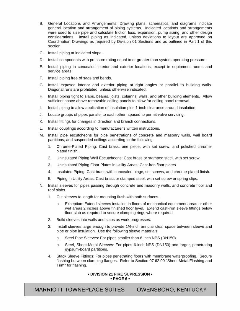
▪ DIVISION 21 FIRE SUPRESSION ▪
▪ PAGE 6 ▪
RESIDENCE INN BY MARRIOTT - LITTLETON, COLORADO
B. General Locations and Arrangements: Drawing plans, schematics, and diagrams indicate general location and arrangement of piping systems. Indicated locations and arrangements were used to size pipe and calculate friction loss, expansion, pump sizing, and other design considerations. Install piping as indicated, unless deviations to layout are approved on Coordination Drawings as required by Division 01 Sections and as outlined in Part 1 of this section.
C. Install piping at indicated slope.
D. Install components with pressure rating equal to or greater than system operating pressure.
E. Install piping in concealed interior and exterior locations, except in equipment rooms and service areas.
F. Install piping free of sags and bends.
G. Install exposed interior and exterior piping at right angles or parallel to building walls. Diagonal runs are prohibited, unless otherwise indicated.
H. Install piping tight to slabs, beams, joists, columns, walls, and other building elements. Allow sufficient space above removable ceiling panels to allow for ceiling panel removal.
I. Install piping to allow application of insulation plus 1-inch clearance around insulation.
J. Locate groups of pipes parallel to each other, spaced to permit valve servicing.
K. Install fittings for changes in direction and branch connections.
L. Install couplings according to manufacturer's written instructions.
M. Install pipe escutcheons for pipe penetrations of concrete and masonry walls, wall board partitions, and suspended ceilings according to the following:
1. Chrome-Plated Piping: Cast brass, one piece, with set screw, and polished chrome-plated finish.
2. Uninsulated Piping Wall Escutcheons: Cast brass or stamped steel, with set screw.
3. Uninsulated Piping Floor Plates in Utility Areas: Cast-iron floor plates.
4. Insulated Piping: Cast brass with concealed hinge, set screws, and chrome-plated finish.
5. Piping in Utility Areas: Cast brass or stamped steel, with set-screw or spring clips.
N. Install sleeves for pipes passing through concrete and masonry walls, and concrete floor and roof slabs.
1. Cut sleeves to length for mounting flush with both surfaces.
a. Exception: Extend sleeves installed in floors of mechanical equipment areas or other wet areas 2 inches above finished floor level. Extend cast-iron sleeve fittings below floor slab as required to secure clamping rings where required.
2. Build sleeves into walls and slabs as work progresses.
3. Install sleeves large enough to provide 1/4-inch annular clear space between sleeve and pipe or pipe insulation. Use the following sleeve materials:
a. Steel Pipe Sleeves: For pipes smaller than 6-inch NPS (DN150).
b. Steel, Sheet-Metal Sleeves: For pipes 6-inch NPS (DN150) and larger, penetrating gypsum-board partitions.
4. Stack Sleeve Fittings: For pipes penetrating floors with membrane waterproofing. Secure flashing between clamping flanges. Refer to Section 07 62 00 "Sheet Metal Flashing and Trim" for flashing.
MARRIOTT TOWNEPLACE SUITES OWENSBORO, KENTUCKY

▪ DIVISION 21 FIRE SUPRESSION ▪
▪ PAGE 7 ▪
RESIDENCE INN BY MARRIOTT - LITTLETON, COLORADO
a. Seal space outside of sleeve fittings with non-shrink, nonmetallic grout.
5. Except for underground wall penetrations, seal annular space between sleeve and pipe or pipe insulation, using elastomeric joint sealant. Refer to Section 07 92 00 "Joint Sealants" for materials.
6. Use Type S, Grade NS, Class 25, Use O, neutral-curing silicone sealant, unless otherwise indicated.
O. Aboveground, Exterior-Wall, Pipe Penetrations: Seal penetrations using sleeves and mechanical sleeve seals. Size sleeve for 1-inch annular clear space between pipe and sleeve for installing mechanical sleeve seals.
1. Install steel pipe for sleeves smaller than 6 inches in diameter.
2. Install cast-iron "wall pipes" for sleeves 6 inches in diameter and larger.
3. Assemble and install mechanical sleeve seals according to manufacturer's written instructions. Tighten bolts that cause rubber sealing elements to expand and make watertight seal.
P. Underground, Exterior-Wall, Pipe Penetrations: Install cast-iron "wall pipes" for sleeves. Seal pipe penetrations using mechanical sleeve seals. Size sleeve for 1-inch annular clear space between pipe and sleeve for installing mechanical sleeve seals.
1. Assemble and install mechanical sleeve seals according to manufacturer's written instructions. Tighten bolts that cause rubber sealing elements to expand and make watertight seal.
Q. Fire-Barrier Penetrations: Maintain indicated fire rating of walls, partitions, ceilings, and floors at pipe penetrations. Seal pipe penetrations with fire stopping materials. Refer to Section 07 84 00 - "Firestopping" for materials.
R. Verify final equipment locations for roughing-in.
S. Refer to equipment specifications in other Sections of these Specifications for roughing-in requirements.
T. Piping Joint Construction: Join pipe and fittings as follows and as specifically required in individual piping specification Sections:
1. Ream ends of pipes and tubes and remove burrs. Bevel plain ends of steel pipe.
2. Remove scale, slag, dirt, and debris from inside and outside of pipe and fittings before assembly.
3. Soldered Joints: Construct joints according to CDA’s "Copper Tube Handbook."
4. Brazed Joints: Construct joints according to AWS’s "Brazing Handbook," Chapter "Pipe and Tube."
5. Threaded Joints: Thread pipe with tapered pipe threads according to ASME B1.20.1. Cut threads full and clean using sharp dies. Ream threaded pipe ends to remove burrs and restore full ID. Join pipe fittings and valves as follows:
a. Note internal length of threads in fittings or valve ends, and proximity of internal seat or wall, to determine how far pipe should be threaded into joint.
b. Apply appropriate tape or thread compound to external pipe threads, unless dry seal threading is specified.
c. Align threads at point of assembly.
MARRIOTT TOWNEPLACE SUITES OWENSBORO, KENTUCKY
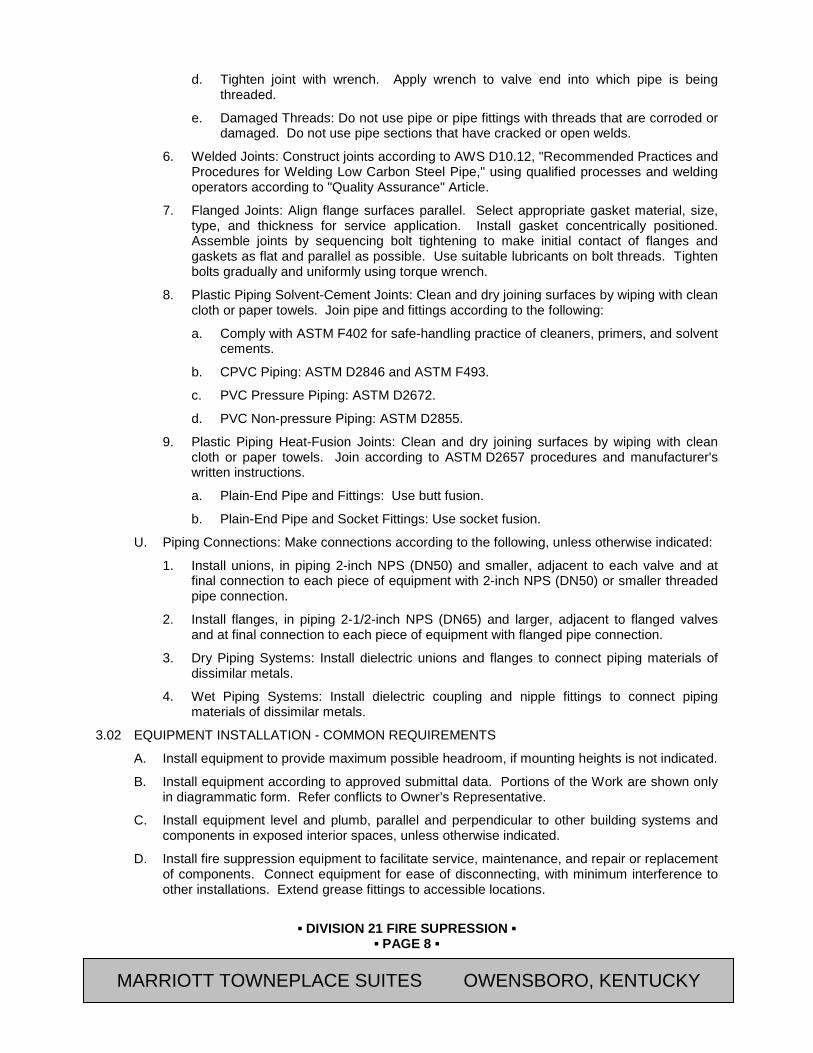
▪ DIVISION 21 FIRE SUPRESSION ▪
▪ PAGE 8 ▪
RESIDENCE INN BY MARRIOTT - LITTLETON, COLORADO
d. Tighten joint with wrench. Apply wrench to valve end into which pipe is being threaded.
e. Damaged Threads: Do not use pipe or pipe fittings with threads that are corroded or damaged. Do not use pipe sections that have cracked or open welds.
6. Welded Joints: Construct joints according to AWS D10.12, "Recommended Practices and Procedures for Welding Low Carbon Steel Pipe," using qualified processes and welding operators according to "Quality Assurance" Article.
7. Flanged Joints: Align flange surfaces parallel. Select appropriate gasket material, size, type, and thickness for service application. Install gasket concentrically positioned. Assemble joints by sequencing bolt tightening to make initial contact of flanges and gaskets as flat and parallel as possible. Use suitable lubricants on bolt threads. Tighten bolts gradually and uniformly using torque wrench.
8. Plastic Piping Solvent-Cement Joints: Clean and dry joining surfaces by wiping with clean cloth or paper towels. Join pipe and fittings according to the following:
a. Comply with ASTM F402 for safe-handling practice of cleaners, primers, and solvent cements.
b. CPVC Piping: ASTM D2846 and ASTM F493.
c. PVC Pressure Piping: ASTM D2672.
d. PVC Non-pressure Piping: ASTM D2855.
9. Plastic Piping Heat-Fusion Joints: Clean and dry joining surfaces by wiping with clean cloth or paper towels. Join according to ASTM D2657 procedures and manufacturer's written instructions.
a. Plain-End Pipe and Fittings: Use butt fusion.
b. Plain-End Pipe and Socket Fittings: Use socket fusion.
U. Piping Connections: Make connections according to the following, unless otherwise indicated:
1. Install unions, in piping 2-inch NPS (DN50) and smaller, adjacent to each valve and at final connection to each piece of equipment with 2-inch NPS (DN50) or smaller threaded pipe connection.
2. Install flanges, in piping 2-1/2-inch NPS (DN65) and larger, adjacent to flanged valves and at final connection to each piece of equipment with flanged pipe connection.
3. Dry Piping Systems: Install dielectric unions and flanges to connect piping materials of dissimilar metals.
4. Wet Piping Systems: Install dielectric coupling and nipple fittings to connect piping materials of dissimilar metals.
3.02 EQUIPMENT INSTALLATION - COMMON REQUIREMENTS
A. Install equipment to provide maximum possible headroom, if mounting heights is not indicated.
B. Install equipment according to approved submittal data. Portions of the Work are shown only in diagrammatic form. Refer conflicts to Owner’s Representative.
C. Install equipment level and plumb, parallel and perpendicular to other building systems and components in exposed interior spaces, unless otherwise indicated.
D. Install fire suppression equipment to facilitate service, maintenance, and repair or replacement of components. Connect equipment for ease of disconnecting, with minimum interference to other installations. Extend grease fittings to accessible locations.
MARRIOTT TOWNEPLACE SUITES OWENSBORO, KENTUCKY
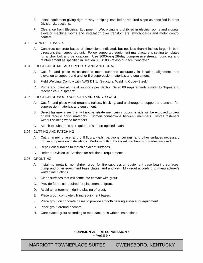
▪ DIVISION 21 FIRE SUPRESSION ▪
▪ PAGE 9 ▪
RESIDENCE INN BY MARRIOTT - LITTLETON, COLORADO
E. Install equipment giving right of way to piping installed at required slope as specified in other Division 21 sections.
F. Clearance from Electrical Equipment: Wet piping is prohibited in electric rooms and closets, elevator machine rooms and installation over transformers, switchboards and motor control centers.
3.03 CONCRETE BASES
A. Construct concrete bases of dimensions indicated, but not less than 4 inches larger in both directions than supported unit. Follow supported equipment manufacturer's setting templates for anchor bolt and tie locations. Use 3000-psig 28-day compressive-strength concrete and reinforcement as specified in Section 03 30 00 - "Cast-in-Place Concrete."
3.04 ERECTION OF METAL SUPPORTS AND ANCHORAGE
A. Cut, fit, and place miscellaneous metal supports accurately in location, alignment, and elevation to support and anchor fire suppression materials and equipment.
B. Field Welding: Comply with AWS D1.1, "Structural Welding Code--Steel."
C. Prime and paint all metal supports per Section 09 90 00 requirements similar to “Pipes and Mechanical Equipment”.
3.05 ERECTION OF WOOD SUPPORTS AND ANCHORAGE
A. Cut, fit, and place wood grounds, nailers, blocking, and anchorage to support and anchor fire suppression materials and equipment.
B. Select fastener sizes that will not penetrate members if opposite side will be exposed to view or will receive finish materials. Tighten connections between members. Install fasteners without splitting wood members.
C. Attach to substrates as required to support applied loads.
3.06 CUTTING AND PATCHING
A. Cut, channel, chase, and drill floors, walls, partitions, ceilings, and other surfaces necessary for fire suppression installations. Perform cutting by skilled mechanics of trades involved.
B. Repair cut surfaces to match adjacent surfaces.
C. Refer to Division 01 Sections for additional requirements.
3.07 GROUTING
A. Install nonmetallic, non-shrink, grout for fire suppression equipment base bearing surfaces, pump and other equipment base plates, and anchors. Mix grout according to manufacturer's written instructions.
B. Clean surfaces that will come into contact with grout.
C. Provide forms as required for placement of grout.
D. Avoid air entrapment during placing of grout.
E. Place grout, completely filling equipment bases.
F. Place grout on concrete bases to provide smooth bearing surface for equipment.
G. Place grout around anchors.
H. Cure placed grout according to manufacturer's written instructions.
MARRIOTT TOWNEPLACE SUITES OWENSBORO, KENTUCKY
▪ DIVISION 21 FIRE SUPRESSION ▪
▪ PAGE 10 ▪
RESIDENCE INN BY MARRIOTT - LITTLETON, COLORADO
END OF SECTION Revision Log
MARRIOTT TOWNEPLACE SUITES OWENSBORO, KENTUCKY
▪ DIVISION 21 FIRE SUPRESSION ▪
▪ PAGE 11 ▪
RESIDENCE INN BY MARRIOTT - LITTLETON, COLORADO
SECTION 21 10 00 (13900) - FIRE SUPPRESSION SYSTEMS
PART 4 GENERAL 4.01 SUMMARY
A. Section Includes:
1. Pipe and Fittings.
2. Sprinklers.
B. Related Documents:
1. Marriott’s Fire Protection and Life Safety Design Standards (Module 14):
a. Marriott’s Fire Protection and Life Safety Design Standards apply to all Marriott International Brands as well as Owned, Managed and Franchised properties.
b. Marriott’s Fire Protection and Life Safety Design Standards include Design Standards, performance criteria, reference standards and life safety process verification that define a comprehensive fire protection program.
C. Related Sections:
1. Section 21 05 00 (15050) – Common Work Results for Fire Suppression
2. Section 28 31 00 (13850) - Fire Alarm and Detection Systems: Wire and connection of sprinkler flow and tamper switches
4.02 SYSTEM DESCRIPTION
A. The Fire Protection Subcontractor is responsible for code compliance, research, design, coordination, and installation of a complete and functional hydraulically calculated sprinkler system (and standpipe system, if required) that meets the approval of and is in accordance with all applicable regulations and requirements of the following and as further specified:
1. Current editions of NFPA 13, 14, 20, 25, and 96.
2. Applicable Codes.
3. Authorities having jurisdiction.
B. Alarm system devices including alarm valves, flow switches, pressure switches, tamper switches and coordination with Fire Alarm and Detection Subcontractor.
C. Shop drawings and calculations prepared and submitted in accordance with the requirements of all Authorities Having Jurisdiction.
D. Obtaining all permits and approvals of the fire protection system.
E. Field acceptance testing.
4.03 SUBMITTALS
A. Submit “Letter of Conformance” in accordance with Section 01 33 00 with the following supporting data:
1. Product Data:
a. Mark each copy to identify applicable products, characteristics, models, options and other supplemental data to clearly communicate information specific to this project.
b. Submit separate "Letter of Conformance" for each specified item.
MARRIOTT TOWNEPLACE SUITES OWENSBORO, KENTUCKY

▪ DIVISION 21 FIRE SUPRESSION ▪
▪ PAGE 12 ▪
RESIDENCE INN BY MARRIOTT - LITTLETON, COLORADO
2. Shop Drawings and calculations sealed by a registered Professional Engineer, NICET III or IV Sprinkler Designer, licensed in the state where the project is located.
3. Be responsible for code research and obtaining all required flow test data and hydraulically designing a fire protection system that meets all applicable requirements. Arrange for, and conduct the flow test.
4. Fire protection submittal data shall include the following:
5. Flow Test Data.
6. Complete Hydraulic Calculations.
7. Complete Stamped and Coordinated Shop Drawings.
8. Pipe and Fittings.
9. Valves.
10. Sprinkler Heads.
11. Escutcheons.
12. All Applicable Devices, Alarms, and Specialties.
13. Air Compressor and Accessories (If required)
14. Applicable Control/Wiring Diagrams.
15. Fire Department Connections
16. Valve Cabinets
17. Backflow Preventers.
18. Fire pump, fire pump data, controller or transfer switch data.
B. Submittal data shall be bound sets and be submitted at one time in accordance with Section 01330 (01 33 00) - Submittals and Substitutions.
C. Transmit fire protection submittal data to Zurich Services Corporation, Marriott’s Fire Protection Department, and to the local and state Authorities having jurisdiction and licensing agencies for approval.
1. Mailing Addresses:
a. Marriott International, Inc. Marriott Corporate Fire Protection, Dept. 52/924.36 1 Marriott Drive Washington, D.C. 20058
b. Zurich Services Corporation Risk Engineering Department 1818 Market Street, 21st Floor Philadelphia, PA 19103 Attn: Mr. Richard Gallagher, Sr. Risk Engineer Consultant
D. Do not proceed with work without final approved submittal data bearing all approval stamps including Marriott’s Fire Protection Department approval stamp.
E. Be responsible for delays caused by not following the above procedure and/or not completing the design portion of the work in a timely manner.
F. Record Documents:
MARRIOTT TOWNEPLACE SUITES OWENSBORO, KENTUCKY
▪ DIVISION 21 FIRE SUPRESSION ▪
▪ PAGE 13 ▪
RESIDENCE INN BY MARRIOTT - LITTLETON, COLORADO
1. Refer to Section 01 78 39 - Project Record Documents and Section 01 78 23 - Operating and Maintenance Data for required closeout documents to be provided at completion of Project. In addition to the documents listed in these Sections, the following documents shall be included:
a. Provide above/below ground test certificates.
b. Record Documents shall include System Drawings, Equipment Data and Operation Instructions, and Maintenance Instruction Manuals.
4.04 QUALITY ASSURANCE
A. Refer to Section 21 05 00 (15050) – Common Work Results for Fire Suppression.
B. MANUFACTURERS
1. All sprinkler system equipment is to be UL Listed.
4.05 DESIGN
A. Zoning: At a minimum, the system shall be zoned by floor or as required to meet the approval of all applicable Codes and Authorities, whichever is most stringent.
B. Inspectors test connections: Locate at the remote end of each zone with discharge pipe to exterior.
C. Low-Rise Buildings: Connect sprinkler piping to riser at each zone. Provide control valve, flow and tamper switches at each connection monitored on the fire alarm system. Locate inspector’s test assembly at remote end of zone with discharge piped to exterior drain.
D. Design densities (based on NFPA 13 requirements):
1. Guest Rooms: Wet pipe system with 0.10 gpm per square foot, all heads (up to a maximum of 5) in the largest most remote guestroom plus 100 gpm for hose.
2. Public Spaces, Offices, and Dining Room: Wet pipe system with 0.10 gpm per square foot over the most remote 1,500 square feet plus 100 gpm for hose.
3. Kitchen Areas: Wet pipe system with 0.15 gpm per square foot over the most remote 1,500 square feet area plus 100 gpm for hose.
4. Mechanical rooms, Laundry, Storage, and Service Areas: Wet pipe system with 0.13 gpm per square foot over 2,500 square feet plus 100 gpm for hose.
5. Kitchen Exhaust Ductwork: Wet pipe system with 0.15 gpm per square foot over the entire cooking hood and duct plan area plus 100 gpm for hose.
6. Attics: Light hazard wet pipe system with 0.10 gpm per square foot to the most remote 1,500 square feet plus 100 gpm for hose.
-or- Light hazard-Dry pipe system with 0.10 gpm per square foot over the most remote 1,950 square feet plus 100 gpm for hose.
7. Attics: Ordinary Hazard and Service Equipment Areas: Wet pipe system with 0.15 gpm per square feet over the most remote 1,500 square foot area plus 100 gpm for hose.
-or- Ordinary Hazard-Dry Pipe System with 0.15 gpm per square foot over the most remote 1,950 square feet area plus 100 gpm for hose.
8. Parking Garages: Wet Pipe System with 0.13 gpm per square foot over the most remote 2,500 square feet plus 100 gpm for hose.
-or-
MARRIOTT TOWNEPLACE SUITES OWENSBORO, KENTUCKY
▪ DIVISION 21 FIRE SUPRESSION ▪
▪ PAGE 14 ▪
RESIDENCE INN BY MARRIOTT - LITTLETON, COLORADO
Dry Pipe System with 0.13 gpm per square foot over the most remote 3,500 square feet plus 100 gpm for hose.
4.06 COORDINATION
A. The Fire Protection Subcontractor shall be responsible for reviewing the complete set of Contract Documents and coordinating his work with all other trades involved including building design loads.
B. The fire protection piping and head layout shall function in such a manner so as not to interfere with lighting fixtures, air distribution devices, equipment, piping, beams, and ductwork. The work under this section shall yield to all other trades.
4.07 SPRINKLER/STANDPIPE SYSTEM
A. Provide the building with a complete, approved, operational sprinkler system in all areas.
B. Provide wet-pipe sprinklers for habitable spaces such as guestrooms, guestroom corridors, [restaurants,] [ballrooms,] [meeting rooms] and public areas.
C. Design documents are for information only. The Sprinkler subcontractor shall be responsible for the actual layouts, routing of piping, and additional sprinkler heads to meet all requirements of the authority having jurisdiction [ . ] [ as well as the provision of a fire pump as required.]
D. Be responsible for freeze protection as follows:
1. A dry pipe system shall be provided in the attics and in any other unheated areas where necessary so as to prevent freezing. The dry pipe system shall be complete with a tank mounted air compressor, storage tank, controls, valves, galvanized steel pipe, and all necessary appurtenances for a complete, functional system. Dry pipe system shall be pitched to avoid freezing. Termination of drains shall be approved by Marriott’s Fire Protection Department.
a. The entire dry pipe system must utilize galvanized steel pipe.
2. Dry type heads may be provided off the wet system in unheated areas such as the landscape storage room or laundry dryer enclosure.
3. Wet piping shall not be routed through unheated areas, such as attics, etc.
4. For repairing and/or all costs incurred from damage caused by freezing of the fire protection system.
5. Use of Heat-tape is not acceptable.
6. The dry pipe system is required to deliver water to the system test connection within 60 seconds, starting at the normal air pressure on the system and at the time of fully opened inspection test connection.
7. Anti-Freeze systems are not acceptable.
E. Provide a Fire Department standpipe system where required by code.
F. Provide a combination sprinkler/standpipe riser system where standpipes are required by code.
G. The sprinkler layout for the guest rooms, suites, and corridors shall be as required to meet the approval of all applicable Codes, and Local Authorities whichever is most stringent.
H. Note: Coordinate the following paragraph with Section 06 61 13 “Cultured Marble Fabrications” or 09 30 00 “Tiling” for type of tub and shower surrounds used.
MARRIOTT TOWNEPLACE SUITES OWENSBORO, KENTUCKY
▪ DIVISION 21 FIRE SUPRESSION ▪
▪ PAGE 15 ▪
RESIDENCE INN BY MARRIOTT - LITTLETON, COLORADO
I. Guest Room Bathrooms: Sprinklers not required if less than 55 square feet unless combustible (with flame spread rating of greater than 25; i.e., fiberglass or plastic) tubs or shower enclosures are used.
J. Pressure Reducing Valves: Design system within maximum pressure of 175 psi without use of pressure reducing valves. If this is not possible and pressure reducing valves are required, consult Marriott Fire Protection.
K. Safety Factor: Provide a 10% hydraulic safety factor up to a maximum of 10 psi.
PART 5 PRODUCTS 5.01 MANUFACTURERS
A. All sprinkler system equipment is to be UL Listed.
5.02 PIPE AND FITTINGS
A. Piping - Class I, Schedule 40 ASTM black steel piping for branches and Class I Schedule 10 ASTM black steel for mains..
1. Piping (piping only, excluding fittings) for dry systems shall be galvanized steel.
2. Alternate: CPVC or XL Thin-wall for wet sprinkler pipe.
B. Exposed piping and fittings in kitchen shall be chrome-plated.
5.03 KITCHEN HOOD AND DUCT FIRE SUPPRESSION
A. Provide a complete "Ansul Piranha” automatic, water-assisted, wet chemical, fier suppression system by Tyco Fire & Security for protection of the exhaust duct and all grease-producing cooking surfaces located under canopy hoods. The system, including all of its components shall be UL Standard 300 listed.
B. Kitchen hood and duct system flow switch (or control units of the Ansul fire suppression system) to perform these functions:
1. Send fire alarm signal to FACP
2. Disconnect gas and all electric for cooking appliances and lighting under the hood (manual reset is required).
3. Shut-off kitchen hood make-up air handler.
5.04 SPRINKLERS
A. Sprinkler heads shall be UL Listed.
B. Sprinkler heads and escutcheons shall have a white finish unless noted otherwise.
1. Concealed sprinklers are not acceptable.
C. Sprinklers: Fast-response 68 degrees C – 74 degrees C (155 degrees F – 165 degrees F), recessed or semi-recessed type heads throughout, except as follows: Room/Space Head Type Temp. Rating Attic Systems Quick Response – ventilated 100 degrees C (212 degrees F) Quick Response –
unventilated 141 degrees C (286 degrees F)
Drypipe Systems Quick Response 100 degrees C (212 degrees F) Mech./Elect. Quick Response 68 degrees C – 74 degrees C Elevator Machinery Quick Response 100 degrees C (212 degrees F) Swimming Pools Corrosion - proof- 68 degrees C – 77degrees C Quick response (155 degrees F –170 degrees F) Porches Dry-side wall, corrosion- 100 degrees C (212 degrees F)
MARRIOTT TOWNEPLACE SUITES OWENSBORO, KENTUCKY
▪ DIVISION 21 FIRE SUPRESSION ▪
▪ PAGE 16 ▪
RESIDENCE INN BY MARRIOTT - LITTLETON, COLORADO
proof / Quick response Balcony (combustible) Dry-side wall, corrosion-
resistant / Quick response 100 degrees C (212 degrees F)
Sauna/Steam Rooms Corrosion-proof / Quick Response
141 degrees C (286 degrees F)
Walk-in Coolers/Freezers
Dry pendent / Quick response
74 degrees C (165 degrees F)
Parking Structures Quick Response 100 degrees C (212 degrees F)
PART 6 EXECUTION 6.01 INSTALLATION
A. Install and support fire protection system to resist all applicable seismic forces per requirements.
B. Locate wet pipe and dry pipe inspector test valves and associated sight glasses at remote ends of system, in accessible locations. Provide drain pipes to exterior. Do not discharge onto sidewalks or landscaping.
C. Under no circumstance shall wet sprinkler pipes be routed through attics or other unheated spaces.
D. Access panels for service and access to valves in enclosed ceiling and walls.
6.02 TESTING
A. Before a property is opened to the public, the fire protection system shall be fully operational, contractor tested, and approval obtained from Marriott’s Fire Protection Department. In order to obtain Marriott’s approval, the fire protection system shall be operated by the contractor under simulated emergency conditions in the presence of Marriott Fire Protection personnel and the contractor shall demonstrate compliance with Marriott’s standards.
B. Automatic Sprinkler System:
1. Contractor shall flush and pressure test system prior to Marriott’s observation of the test of water flow and tamper switches.
C. Kitchen Hood and Duct Fire Suppression:
1. Contractor shall pre-test all coordinated components by activation of kitchen hood and duct flow switch or control unit.
2. Contractor shall demonstrate compliance by operating initiating devices, activating coordinated alarms, gas, electric, and hood supply air fan shut-downs.
D. Provide all equipment necessary to perform test.
E. Refer to Submittals Paragraph for required certifications and documents to be provided with closeout documents.
6.03 TRAINING
A. Conduct training as specified in Section 01 79 00 (01820) - "Training”.
B. Train Owner's maintenance personnel on procedures and schedules for troubleshooting, servicing, and maintaining system.
C. Schedule training with Owner with at least seven days’ advance notice. Note: Delete paragraph below if fire pump is not required.
MARRIOTT TOWNEPLACE SUITES OWENSBORO, KENTUCKY
▪ DIVISION 21 FIRE SUPRESSION ▪
▪ PAGE 17 ▪
RESIDENCE INN BY MARRIOTT - LITTLETON, COLORADO
D. Engage a factory-authorized service representative to train Owner's maintenance personnel to operate and maintain fire pump.
END OF SECTION Revision Log
MARRIOTT TOWNEPLACE SUITES OWENSBORO, KENTUCKY
▪ DIVISION 22 PLUMBING ▪
▪ PAGE 1 ▪
RESIDENCE INN BY MARRIOTT - LITTLETON, COLORADO
SECTION 22 05 00 (15050) - COMMON WORK RESULTS FOR PLUMBING
PART 1 GENERAL 1.01 SUMMARY
A. Section Includes:
1. Piping materials and fittings.
2. Joining materials.
3. Dielectric fittings.
4. Mechanical sleeve seals.
5. Piping Specialties
6. Grouting
7. Piping Insulation.
8. Equipment Installation.
9. Concrete Bases.
10. Erection of Metal Supports.
11. Erection of Wood Supports
12. Cutting and Patching
B. Related Sections:
1. Section 01 31 00 - Project Management and Coordination
2. Section 01 73 29 - Cutting and Patching
3. Section 01 78 43 - Spare Parts and Materials
4. Section 01 79 00 - Training
5. Section 01 78 23 - Operating and Maintenance Data
6. Section 03 30 00 - Cast-in-Place Concrete
7. Section 06 10 00 - Rough Carpentry
8. Section 07 62 00 - Sheet Metal Flashing and Trim
9. Section 07 84 00 - Firestopping
10. Section 08 31 00 - Access Doors
11. Section 09 90 00 - Painting
12. Section 22 05 53 – Identification for Plumbing Piping and Equipment: Labeling and identifying plumbing systems and equipment.
13. Section 31 20 00 – Earth Moving
1.02 REFERENCES
A. The American Society of Mechanical Engineers (ASME) Publications:
1. B1.20.1 "Pipe Threads, General Purpose, Inch"
2. B16.21 "Nonmetallic Flat Gaskets for Pipes Flanges"
MARRIOTT TOWNEPLACE SUITES OWENSBORO, KENTUCKY

▪ DIVISION 22 PLUMBING ▪
▪ PAGE 2 ▪
RESIDENCE INN BY MARRIOTT - LITTLETON, COLORADO
3. B18.2.1 "Square and Hex Bolts and Screws, Inch Series"
B. ASTM International (ASTM) Publications: (Former American Society for Testing and Materials)
1. A53 "Standard Specification for Pipe, Steel, Black and Hot-Dipped, Zinc-Coated, Welded and Seamless"
2. A536 "Standard Specification for Ductile Iron Castings"
3. B32 "Standard Specification for Solder Metal"
4. C1107 "Standard Specification for Packaged Dry, Hydraulic-Cement Grout (Nonshrink)"
5. D2235 "Standard Specification for Solvent Cement for Acrylonitrile-Butadiene-Styrene (ABS) Plastic Pipe and Fittings"
6. D2657 "Standard Practice for Heat Fusion Joining of Polyolefin Pipe and Fittings"
7. D2672 "Standard Specification for Joints for IPS PVC Pipe Using Solvent Cement"
8. D2846 "Standard Specification for Chlorinated Poly(Vinyl Chloride) (CPVC) Plastic Hot- and Cold-Water Distribution Systems"
9. D2855 "Standard Practice for Making Solvent-Cemented Joints with Poly(Vinyl Chloride) (PVC) Pipe and Fittings"
10. D3138 "Standard Specification for Solvent Cements for Transition Joints Between Acrylonitrile-Butadiene-Styrene (ABS) and Poly(Vinyl Chloride) (PVC) Non-Pressure Piping Components"
11. F402 "Standard Practice for Safe Handling of Solvent Cements, Primers, and Cleaners Used for Joining Thermoplastic Pipe and Fittings"
12. F477 "Standard Specification for Elastomeric Seals (Gaskets) for Joining Plastic Pipe"
13. F493 "Standard Specification for Solvent Cements for Chlorinated Poly(Vinyl Chloride) (CPVC) Plastic Pipe and Fittings"
14. F656 "Standard Specification for Primers for Use in Solvent Cement Joints of Poly(Vinyl Chloride) (PVC) Plastic Pipe and Fittings"
C. American Welding Society (AWS) Publications:
1. BRH "Brazing Handbook"
2. A5.8 "Specification for Filler Metals For Brazing And Braze Welding"
3. D1.1 "Structural Welding Code - Steel"
4. D10.12 "Guide for Welding Mild Steel Pipe"
D. American Water Works Association (AWWA) Publications:
1. C110/ANSI A21.10 " Standard for Ductile-Iron and Gray-Iron Fittings, 3 In.-48 In. (76 mm-1,219 mm), for Water "
2. C111/ANSI A21.11 "Standard for Rubber-Gasket Joints for Ductile-Iron Pressure Pipe and Fittings"
E. Copper Development Association (CDA) Publications:
1. "Copper Tube Handbook"
MARRIOTT TOWNEPLACE SUITES OWENSBORO, KENTUCKY
▪ DIVISION 22 PLUMBING ▪
▪ PAGE 3 ▪
RESIDENCE INN BY MARRIOTT - LITTLETON, COLORADO
1.03 DEFINITIONS
A. Finished Spaces: Spaces other than mechanical and electrical equipment rooms, furred spaces, pipe and duct shafts, unheated spaces immediately below roof, spaces above ceilings, unexcavated spaces, crawl spaces, and tunnels.
B. Exposed, Interior Installations: Exposed to view indoors. Examples include finished occupied spaces and mechanical equipment rooms.
C. Exposed, Exterior Installations: Exposed to view outdoors, or subject to outdoor ambient temperatures and weather conditions. Examples include rooftop locations.
D. Concealed, Interior Installations: Concealed from view and protected from physical contact by building occupants. Examples include above ceilings and in duct shafts.
E. Concealed, Exterior Installations: Concealed from view and protected from weather conditions and physical contact by building occupants, but subject to outdoor ambient temperatures. Examples include installations within unheated shelters.
F. The following are industry abbreviations for plastic materials:
1. ABS: Acrylonitrile-butadiene-styrene plastic.
2. CPVC: Chlorinated polyvinyl chloride plastic.
3. PVC: Polyvinyl chloride plastic.
1.04 SUBMITTALS
A. General: Submit the following in accordance with Conditions of Contract and Division 01 Specification Sections:
B. Submit “Letter of Conformance” in accordance with Section 01 33 00 (01330) indicating specified items selected for use in project with the following supporting data.
1. Product Data: For dielectric fittings, flexible connectors, plumbing sleeve seals, and identification materials and devices.
2. Coordination Drawings: Detail major elements, components, and systems of plumbing equipment and materials in relationship with other systems, installations, and building components. Show space requirements for installation and access. Indicate if sequence and coordination of installations are important to efficient flow of the Work. Include the following:
a. Planned piping layout, including valve and specialty locations and valve-stem movement.
b. Clearances for installing and maintaining insulation.
c. Clearances for servicing and maintaining equipment, accessories, and specialties, including space for disassembly required for periodic maintenance.
d. Equipment and accessory service connections and support details.
e. Exterior wall and foundation penetrations.
f. Fire-rated wall and floor penetrations.
g. Sizes and location of required concrete pads and bases.
h. Scheduling, sequencing, movement, and positioning of large equipment into building during construction.
i. Floor plans, elevations, and details to indicate penetrations in floors, walls, and ceilings and their relationship to other penetrations and installations.
MARRIOTT TOWNEPLACE SUITES OWENSBORO, KENTUCKY
▪ DIVISION 22 PLUMBING ▪
▪ PAGE 4 ▪
RESIDENCE INN BY MARRIOTT - LITTLETON, COLORADO
1.05 QUALITY ASSURANCE
A. Equipment Selection: Equipment of higher electrical characteristics, physical dimensions, capacities, and ratings may be furnished provided such proposed equipment is approved in writing and connecting plumbing and electrical services, circuit breakers, conduit, motors, bases, and equipment spaces are increased. Additional costs shall be approved in advance by appropriate Contract Modification for these increases.
1. If minimum energy ratings or efficiencies of equipment are specified, equipment must meet design requirements. See drawings for equipment schedules and requirements.
1.06 DELIVERY, STORAGE, AND HANDLING
A. Deliver pipes and tubes with factory-applied end caps. Maintain end caps through shipping, storage, and handling to prevent pipe end damage and prevent entrance of dirt, debris, and moisture.
B. Protect stored pipes and tubes from moisture and dirt. Elevate above grade. Do not exceed structural capacity of floor, if stored inside.
C. Protect flanges, fittings, and piping specialties from moisture and dirt.
D. Store plastic pipes protected from direct sunlight. Support to prevent sagging and bending.
1.07 SEQUENCING AND SCHEDULING
A. Coordinate plumbing equipment installation with other building components.
B. Arrange for pipe spaces, chases, slots, and openings in building structure during progress of construction to allow for plumbing installations.
C. Coordinate installation of required supporting devices and set sleeves in poured-in-place concrete and other structural components, as they are constructed.
D. Sequence, coordinate, and integrate installations of plumbing materials and equipment for efficient flow of the Work. Coordinate installation of large equipment requiring positioning before closing in building.
E. Coordinate connection of plumbing systems with exterior underground and overhead utilities and services. Comply with requirements of governing regulations, franchised service companies, and controlling agencies.
F. Coordinate requirements for access panels and doors if plumbing items requiring access are concealed behind finished surfaces. Access panels and doors are specified in Section 08 31 13 - "Access Doors and Frames."
G. Coordinate installation of identifying devices after completing covering and painting, if devices are applied to surfaces. Install identifying devices before installing acoustical ceilings and similar concealment.
1.08 Posted Operating Instructions
A. Provide and post operating instructions for all plumbing systems.
PART 2 PRODUCTS 2.01 MANUFACTURERS
A. Avendra, LLC Preferred Manufacturers:
1. Dielectric Unions:
a. None
2. Dielectric Flanges:
MARRIOTT TOWNEPLACE SUITES OWENSBORO, KENTUCKY

▪ DIVISION 22 PLUMBING ▪
▪ PAGE 5 ▪
RESIDENCE INN BY MARRIOTT - LITTLETON, COLORADO
a. None
3. Dielectric-Flange Insulating Kits:
a. None
4. Dielectric Couplings:
a. None
5. Dielectric Nipples:
a. None
6. Plumbing Sleeve Seals:
a. None
B. Approved Manufacturers:
1. Dielectric Unions:
a. Hart Industries, International, Inc. (800-769-0503)
b. Watts Water Technologies, Inc. (978-688-1811)
c. Zurn Plumbing Products Group of Jacuzzi Brands, Inc. (805-238-7100)
2. Dielectric Flanges:
a. Capitol Manufacturing Company, A member of The Phoenix Forge Group (800-848-1100)
b. Central Plastics Co. (800-654-3872)
c. Watts Water Technologies, Inc. (978-688-1811)
3. Dielectric-Flange Insulating Kits:
a. Central Plastics Co. (800-654-3872)
4. Dielectric Couplings:
a. Lochinvar Corp. (615-889-8900)
5. Dielectric Nipples:
a. Grinnell Mechanical Products, A Tyco International Company (800-500-4768)
b. Perfection Corporation (800-544-6344)
c. Victaulic Co. of America (800-742-5842)
6. Plumbing Sleeve Seals:
a. Metraflex Inc. (800-621-4347)
b. PSI-Thunderline/Link-Seal (800-423-2410)
2.02 PIPE AND PIPE FITTINGS
A. Refer to individual Divisions 22 piping Sections for pipe and fitting materials and joining methods.
1. Section 22 11 16 - Domestic Water Piping.
2. Section 22 13 16 – Sanitary Waste and Vent Piping.
3. Section 23 11 23 – Facility Natural Gas Piping.
MARRIOTT TOWNEPLACE SUITES OWENSBORO, KENTUCKY
▪ DIVISION 22 PLUMBING ▪
▪ PAGE 6 ▪
RESIDENCE INN BY MARRIOTT - LITTLETON, COLORADO
B. Pipe Threads: ASME B1.20.1 for factory-threaded pipe and pipe fittings.
2.03 JOINING MATERIALS
A. Refer to individual Division 22 piping Sections for special joining materials not listed below.
B. Pipe-Flange Gasket Materials: Suitable for chemical and thermal conditions of piping system contents.
1. ASME B16.21, nonmetallic, flat, asbestos-free, 1/8-inch maximum thickness, unless thickness or specific material is indicated.
a. Full-Face Type: For flat-face, Class 125, cast-iron and cast-bronze flanges.
b. Narrow-Face Type: For raised-face, Class 250, cast-iron and steel flanges.
2. AWWA C110, rubber, flat face, 1/8 inch thick, unless otherwise indicated; and full-face or ring type, unless otherwise indicated.
C. Flange Bolts and Nuts: ASME B18.2.1, carbon steel, unless otherwise indicated.
D. Plastic, Pipe-Flange Gasket, Bolts, and Nuts: Type and material recommended by piping system manufacturer, unless otherwise indicated.
E. Solder Filler Metals: ASTM B32.
1. Alloy Sn95 or Alloy Sn94: Approximately 95 percent tin and 5 percent silver, with 0.10 percent lead content.
2. Alloy E: Approximately 95 percent tin and 5 percent copper, with 0.10 percent maximum lead content.
3. Alloy HA: Tin-antimony-silver-copper zinc, with 0.10 percent maximum lead content.
4. Alloy HB: Tin-antimony-silver-copper nickel, with 0.10 percent maximum lead content.
5. Alloy Sb5: 95 percent tin and 5 percent antimony, with 0.20 percent maximum lead content.
F. Brazing Filler Metals: AWS A5.8.
1. BCuP Series: Copper-phosphorus alloys.
2. BAg1: Silver alloy.
3. Welding Filler Metals: Comply with AWS D10.12 for welding materials appropriate for wall thickness and chemical analysis of steel pipe being welded.
G. Solvent Cements: Manufacturer's standard solvent cements for the following:
1. ABS Piping: ASTM D2235.
2. CPVC Piping: ASTM F493.
3. PVC Piping: ASTM D2564. Include primer according to ASTM F656.
4. PVC to ABS Piping Transition: ASTM D3138.
H. Plastic Pipe Seals: ASTM F477, elastomeric gasket.
I. Flanged, Ductile-Iron Pipe Gasket, Bolts, and Nuts: AWWA C110, rubber gasket, carbon-steel bolts and nuts.
J. Couplings: Iron-body sleeve assembly, fabricated to match OD of plain-end, pressure pipes.
1. Sleeve: ASTM A126, Class B, gray iron.
2. Followers: ASTM A47 malleable iron or ASTM A536 ductile iron.
MARRIOTT TOWNEPLACE SUITES OWENSBORO, KENTUCKY

▪ DIVISION 22 PLUMBING ▪
▪ PAGE 7 ▪
RESIDENCE INN BY MARRIOTT - LITTLETON, COLORADO
3. Gaskets: Rubber.
4. Bolts and Nuts: AWWA C111.
5. Finish: Enamel paint.
2.04 DIELECTRIC FITTINGS
A. General: Assembly or fitting with insulating material isolating joined dissimilar metals, to prevent galvanic action and stop corrosion.
1. Description: Combination of copper alloy and ferrous; threaded, solder, plain, and weld-neck end types and matching piping system materials.
2. Insulating Material: Suitable for system fluid, pressure, and temperature.
B. Dielectric Unions: Factory-fabricated, union assembly, for 250-psig minimum working pressure at 180 deg F.
C. Dielectric Flanges: Factory-fabricated, companion-flange assembly, for 150-psig minimum working pressure as required to suit system pressures.
D. Dielectric-Flange Insulation Kits: Field-assembled, companion-flange assembly, full-face or ring type. Components include neoprene or phenolic gasket, phenolic or polyethylene bolt sleeves, phenolic washers, and steel backing washers.
1. Provide separate companion flanges and steel bolts and nuts for 150-psig minimum working pressure as required to suit system pressures.
E. Dielectric Couplings: Galvanized-steel coupling with inert and non-corrosive, thermoplastic lining; threaded ends; and 300-psig minimum working pressure at 225 deg F.
2.05 Plumbing Sleeves
A. Sleeves: The following materials are for wall, floor, slab, and roof penetrations:
1. Steel Sheet Metal: 0.0239-inch minimum thickness, galvanized, round tube closed with welded longitudinal joint.
2. Steel Pipe: ASTM A53, Type E, Grade A, Schedule 40, galvanized, plain ends.
3. Cast Iron: Cast or fabricated "wall pipe" equivalent to ductile-iron pressure pipe, with plain ends and integral water stop, unless otherwise indicated.
4. Stack Sleeve Fittings: Manufactured, cast-iron sleeve with integral clamping flange. Include clamping ring and bolts and nuts for membrane flashing.
a. Underdeck Clamp: Clamping ring with set screws.
2.06 PLUMBING SLEEVE SEALS
A. Description: Modular design, with interlocking rubber links shaped to continuously fill annular space between pipe and sleeve. Include connecting bolts and pressure plates.
2.07 PIPING SPECIALTIES
A. Escutcheons: Manufactured wall, ceiling, and floor plates; deep-pattern type if required to conceal protruding fittings and sleeves.
1. ID: Closely fit around pipe, tube, and insulation of insulated piping.
2. OD: Completely cover opening.
3. Cast Brass: Split casting, with concealed hinge and set screw.
a. Finish: Polished chrome-plate.
MARRIOTT TOWNEPLACE SUITES OWENSBORO, KENTUCKY

▪ DIVISION 22 PLUMBING ▪
▪ PAGE 8 ▪
RESIDENCE INN BY MARRIOTT - LITTLETON, COLORADO
4. Cast-Iron Floor Plate: One-piece casting.
B. Grout:
1. Non-shrink, Nonmetallic Grout: ASTM C1107, Grade B.
a. Characteristics: Post-hardening, volume-adjusting, dry, hydraulic-cement grout, non-staining, non-corrosive, nongaseous, and recommended for interior and exterior applications.
b. Design Mix: 5000-psig, 28-day compressive strength.
c. Packaging: Premixed and factory packaged.
PART 3 EXECUTION 3.01 PIPING SYSTEMS - COMMON REQUIREMENTS
A. General: Install piping as described below, unless piping Sections specifies otherwise. Individual Division 22 piping Sections specifies unique piping installation requirements.
B. General Locations and Arrangements: Drawing plans, schematics, and diagrams indicate general location and arrangement of piping systems. Indicated locations and arrangements were used to size pipe and calculate friction loss, expansion, pump sizing, and other design considerations. Install piping as indicated, unless deviations to layout are approved on Coordination Drawings as required by Division 01 Sections and as outlined in Part 1 of this section.
C. Install piping at indicated slope.
D. Install components with pressure rating equal to or greater than system operating pressure.
E. Install piping in concealed interior and exterior locations, except in equipment rooms and service areas.
F. Install piping free of sags and bends.
G. Install exposed interior and exterior piping at right angles or parallel to building walls. Diagonal runs are prohibited, unless otherwise indicated.
H. Install piping tight to slabs, beams, joists, columns, walls, and other building elements. Allow sufficient space above removable ceiling panels to allow for ceiling panel removal.
I. Install piping to allow application of insulation plus 1-inch clearance around insulation.
J. Locate groups of pipes parallel to each other, spaced to permit valve servicing.
K. Install fittings for changes in direction and branch connections.
L. Install couplings according to manufacturer's written instructions.
M. Install pipe escutcheons for pipe penetrations of concrete and masonry walls, wall board partitions, and suspended ceilings according to the following:
1. Chrome-Plated Piping: Cast brass, one piece, with set screw, and polished chrome-plated finish.
2. Uninsulated Piping Wall Escutcheons: Cast brass or stamped steel, with set screw.
3. Uninsulated Piping Floor Plates in Utility Areas: Cast-iron floor plates.
4. Insulated Piping: Cast brass with concealed hinge, set screws, and chrome-plated finish.
5. Piping in Utility Areas: Cast brass or stamped steel, with set-screw or spring clips.
MARRIOTT TOWNEPLACE SUITES OWENSBORO, KENTUCKY

▪ DIVISION 22 PLUMBING ▪
▪ PAGE 9 ▪
RESIDENCE INN BY MARRIOTT - LITTLETON, COLORADO
N. Install sleeves for pipes passing through concrete and masonry walls, and concrete floor and roof slabs.
1. Cut sleeves to length for mounting flush with both surfaces.
a. Exception: Extend sleeves installed in floors of plumbing equipment areas or other wet areas 2 inches above finished floor level. Extend cast-iron sleeve fittings below floor slab as required to secure clamping rings where required.
2. Build sleeves into walls and slabs as work progresses.
3. Install sleeves large enough to provide 1/4-inch annular clear space between sleeve and pipe or pipe insulation. Use the following sleeve materials:
a. Steel Pipe Sleeves: For pipes smaller than 6-inch NPS (DN150).
b. Steel, Sheet-Metal Sleeves: For pipes 6-inch NPS (DN150) and larger, penetrating gypsum-board partitions.
4. Stack Sleeve Fittings: For pipes penetrating floors with membrane waterproofing. Secure flashing between clamping flanges. Install section of cast-iron soil pipe to extend sleeve to 2 inches above finished floor level. Refer to Section 07 62 00 "Sheet Metal Flashing and Trim" for flashing.
a. Seal space outside of sleeve fittings with non-shrink, nonmetallic grout.
5. Except for underground wall penetrations, seal annular space between sleeve and pipe or pipe insulation, using elastomeric joint sealant. Refer to Section 07 92 00 "Joint Sealants" for materials.
6. Use Type S, Grade NS, Class 25, Use O, neutral-curing silicone sealant, unless otherwise indicated.
O. Aboveground, Exterior-Wall, Pipe Penetrations: Seal penetrations using sleeves and plumbing sleeve seals. Size sleeve for 1-inch annular clear space between pipe and sleeve for installing plumbing sleeve seals.
1. Install steel pipe for sleeves smaller than 6 inches in diameter.
2. Install cast-iron "wall pipes" for sleeves 6 inches in diameter and larger.
3. Assemble and install plumbing sleeve seals according to manufacturer's written instructions. Tighten bolts that cause rubber sealing elements to expand and make watertight seal.
P. Underground, Exterior-Wall, Pipe Penetrations: Install cast-iron "wall pipes" for sleeves. Seal pipe penetrations using plumbing sleeve seals. Size sleeve for 1-inch annular clear space between pipe and sleeve for installing plumbing sleeve seals.
1. Assemble and install plumbing sleeve seals according to manufacturer's written instructions. Tighten bolts that cause rubber sealing elements to expand and make watertight seal.
Q. Fire-Barrier Penetrations: Maintain indicated fire rating of walls, partitions, ceilings, and floors at pipe penetrations. Seal pipe penetrations with fire stopping materials. Refer to Section 07 84 00 - "Firestopping" for materials.
R. Verify final equipment locations for roughing-in.
S. Refer to equipment specifications in other Sections of these Specifications for roughing-in requirements.
T. Piping Joint Construction: Join pipe and fittings as follows and as specifically required in individual piping specification Sections:
MARRIOTT TOWNEPLACE SUITES OWENSBORO, KENTUCKY

▪ DIVISION 22 PLUMBING ▪
▪ PAGE 10 ▪
RESIDENCE INN BY MARRIOTT - LITTLETON, COLORADO
1. Ream ends of pipes and tubes and remove burrs. Bevel plain ends of steel pipe.
2. Remove scale, slag, dirt, and debris from inside and outside of pipe and fittings before assembly.
3. Soldered Joints: Construct joints according to CDA’s "Copper Tube Handbook."
4. Brazed Joints: Construct joints according to AWS’s "Brazing Handbook," Chapter "Pipe and Tube."
5. Threaded Joints: Thread pipe with tapered pipe threads according to ASME B1.20.1. Cut threads full and clean using sharp dies. Ream threaded pipe ends to remove burrs and restore full ID. Join pipe fittings and valves as follows:
a. Note internal length of threads in fittings or valve ends, and proximity of internal seat or wall, to determine how far pipe should be threaded into joint.
b. Apply appropriate tape or thread compound to external pipe threads, unless dry seal threading is specified.
c. Align threads at point of assembly.
d. Tighten joint with wrench. Apply wrench to valve end into which pipe is being threaded.
e. Damaged Threads: Do not use pipe or pipe fittings with threads that are corroded or damaged. Do not use pipe sections that have cracked or open welds.
6. Welded Joints: Construct joints according to AWS D10.12, "Recommended Practices and Procedures for Welding Low Carbon Steel Pipe," using qualified processes and welding operators according to "Quality Assurance" Article.
7. Flanged Joints: Align flange surfaces parallel. Select appropriate gasket material, size, type, and thickness for service application. Install gasket concentrically positioned. Assemble joints by sequencing bolt tightening to make initial contact of flanges and gaskets as flat and parallel as possible. Use suitable lubricants on bolt threads. Tighten bolts gradually and uniformly using torque wrench.
8. Plastic Piping Solvent-Cement Joints: Clean and dry joining surfaces by wiping with clean cloth or paper towels. Join pipe and fittings according to the following:
a. Comply with ASTM F402 for safe-handling practice of cleaners, primers, and solvent cements.
b. CPVC Piping: ASTM D2846 and ASTM F493.
c. PVC Pressure Piping: ASTM D2672.
d. PVC Non-pressure Piping: ASTM D2855.
9. Plastic Piping Heat-Fusion Joints: Clean and dry joining surfaces by wiping with clean cloth or paper towels. Join according to ASTM D2657 procedures and manufacturer's written instructions.
a. Plain-End Pipe and Fittings: Use butt fusion.
b. Plain-End Pipe and Socket Fittings: Use socket fusion.
U. Piping Connections: Make connections according to the following, unless otherwise indicated:
1. Install unions, in piping 2-inch NPS (DN50) and smaller, adjacent to each valve and at final connection to each piece of equipment with 2-inch NPS (DN50) or smaller threaded pipe connection.
MARRIOTT TOWNEPLACE SUITES OWENSBORO, KENTUCKY
▪ DIVISION 22 PLUMBING ▪
▪ PAGE 11 ▪
RESIDENCE INN BY MARRIOTT - LITTLETON, COLORADO
2. Install flanges, in piping 2-1/2-inch NPS (DN65) and larger, adjacent to flanged valves and at final connection to each piece of equipment with flanged pipe connection.
3. Dry Piping Systems: Install dielectric unions and flanges to connect piping materials of dissimilar metals.
4. Wet Piping Systems: Install dielectric coupling and nipple fittings to connect piping materials of dissimilar metals.
3.02 EQUIPMENT INSTALLATION - COMMON REQUIREMENTS
A. Install equipment to provide maximum possible headroom, if mounting heights is not indicated.
B. Install equipment according to approved submittal data. Portions of the Work are shown only in diagrammatic form. Refer conflicts to Owner’s Representative.
C. Install equipment level and plumb, parallel and perpendicular to other building systems and components in exposed interior spaces, unless otherwise indicated.
D. Install plumbing equipment to facilitate service, maintenance, and repair or replacement of components. Connect equipment for ease of disconnecting, with minimum interference to other installations. Extend grease fittings to accessible locations.
E. Install equipment giving right of way to piping installed at required slope as specified in other Division 22 sections.
F. Clearance from Electrical Equipment: Piping is prohibited in electric rooms and closets, elevator machine rooms and installation over transformers, switchboards and motor control centers.
3.03 CONCRETE BASES
A. Construct concrete bases of dimensions indicated, but not less than 4 inches larger in both directions than supported unit. Follow supported equipment manufacturer's setting templates for anchor bolt and tie locations. Use 3000-psig 28-day compressive-strength concrete and reinforcement as specified in Section 03 30 00 - "Cast-in-Place Concrete."
3.04 ERECTION OF METAL SUPPORTS AND ANCHORAGE
A. Cut, fit, and place miscellaneous metal supports accurately in location, alignment, and elevation to support and anchor plumbing materials and equipment.
B. Field Welding: Comply with AWS D1.1, "Structural Welding Code--Steel."
C. Prime and paint all metal supports per Section 09 90 00 requirements.
3.05 ERECTION OF WOOD SUPPORTS AND ANCHORAGE
A. Cut, fit, and place wood grounds, nailers, blocking, and anchorage to support and anchor plumbing materials and equipment.
B. Select fastener sizes that will not penetrate members if opposite side will be exposed to view or will receive finish materials. Tighten connections between members. Install fasteners without splitting wood members.
C. Attach to substrates as required to support applied loads.
3.06 CUTTING AND PATCHING
A. Cut, channel, chase, and drill floors, walls, partitions, ceilings, and other surfaces necessary for plumbing installations. Perform cutting by skilled mechanics of trades involved.
B. Repair cut surfaces to match adjacent surfaces.
C. Refer to Division 01 Sections for additional requirements.
MARRIOTT TOWNEPLACE SUITES OWENSBORO, KENTUCKY
▪ DIVISION 22 PLUMBING ▪
▪ PAGE 12 ▪
RESIDENCE INN BY MARRIOTT - LITTLETON, COLORADO
3.07 GROUTING
A. Install nonmetallic, non-shrink, grout for plumbing equipment base bearing surfaces, pump and other equipment base plates, and anchors. Mix grout according to manufacturer's written instructions.
B. Clean surfaces that will come into contact with grout.
C. Provide forms as required for placement of grout.
D. Avoid air entrapment during placing of grout.
E. Place grout, completely filling equipment bases.
F. Place grout on concrete bases to provide smooth bearing surface for equipment.
G. Place grout around anchors.
H. Cure placed grout according to manufacturer's written instructions.
END OF SECTION
Revision Log
MARRIOTT TOWNEPLACE SUITES OWENSBORO, KENTUCKY
▪ DIVISION 22 PLUMBING ▪
▪ PAGE 13 ▪
RESIDENCE INN BY MARRIOTT - LITTLETON, COLORADO
SECTION 22 05 13 (15090) - COMMON MOTOR REQUIREMENTS FOR PLUMBING EQUIPMENT
PART 4 GENERAL 4.01 SUMMARY
A. Section Includes:
1. Basic Motor Requirements
2. Polyphase Motors
3. Single Phase Motors
B. Related Sections:
1. Division 22 Sections for application of motors and reference to specific motor requirements for motor-driven equipment.
4.02 REFERENCES
A. Institute of Electrical and Electronics Engineers (IEEE) Publications:
1. 112 “Standard Test Procedure for Polyphase Induction Motors and Generators”
B. National Electrical Manufacturer’s Association (NEMA) Standards Publications:
1. MG 1 “Motors and Generators”
C. National Fire Protection Association (NFPA) Publications:
1. 70 "National Electric Code"
4.03 SUBMITTALS
A. General: Submit the following in accordance with Conditions of Contract and Division 01 Specification Sections.
B. Submit “Letter of Conformance” in accordance with Section 01 33 00 (01330) indicating specified items selected for use in project with the following supporting data.
1. Product Data: Show nameplate data and ratings; characteristics; mounting arrangements; size and location of winding termination lugs, conduit entry, and grounding lug; and coatings.
4.04 QUALITY ASSURANCE
A. Comply with NFPA 70.
B. Listing and Labeling: Provide motors specified in this Section that are listed and labeled.
1. Terms "Listed and Labeled": As defined in the National Electrical Code, Article 100.
PART 5 PRODUCTS 5.01 BASIC MOTOR REQUIREMENTS
A. Basic requirements apply to mechanical equipment motors, unless otherwise indicated.
B. Motors 1/2 HP and Larger: Polyphase.
C. Motors smaller than 1/2 HP: Single phase.
D. Frequency Rating: 60 Hz.
E. Voltage Rating: Determined by voltage of circuit to which motor is connected.
MARRIOTT TOWNEPLACE SUITES OWENSBORO, KENTUCKY
▪ DIVISION 22 PLUMBING ▪
▪ PAGE 14 ▪
RESIDENCE INN BY MARRIOTT - LITTLETON, COLORADO
F. Service Factor: According to NEMA MG 1, general purpose continuous duty, design type “B.”
G. Capacity and Torque Characteristics: Rated for continuous duty and sufficient to start, accelerate, and operate connected loads at designated speeds, in indicated environment, with indicated operating sequence, and without exceeding nameplate ratings or considering service factor.
H. Enclosure: Open drip proof, unless otherwise indicated.
I. Efficiency: Motors shall have a higher efficiency rating than industry standard average motor as delineated in IEEE Standard 112, Test Method 13.
5.02 POLYPHASE MOTORS
A. Description: NEMA MG 1, medium induction motor.
1. Design Characteristics: NEMA MG 1, Design B, unless otherwise indicated.
2. Energy-Efficient Design: Where indicated.
3. Stator: Copper windings, unless otherwise indicated. Multispeed motors have separate winding for each speed.
4. Rotor: Squirrel cage, unless otherwise indicated.
5. Bearings: Double-shielded, prelubricated ball bearings suitable for radial and thrust loading.
6. Temperature Rise: Match insulation rating, unless otherwise indicated.
7. Insulation: Class F, unless otherwise indicated.
B. Motors Used with Reduced-Inrush Controllers: Match wiring connection requirements for indicated controller, with required motor leads brought to motor terminal box to suit control method.
C. Motors Used with Variable-Frequency Controllers: Ratings, characteristics, and features coordinated with and approved by controller manufacturer.
1. Critical vibration frequencies are not within operating range of controller output.
2. Temperature Rise: Match rating for Class B insulation.
3. Insulation: Class H.
4. Thermal Protection: Where indicated, conform to NEMA MG 1 requirements for thermally protected motors.
D. Source Quality Control: Perform the following routine tests according to NEMA MG 1:
1. Measurement of winding resistance.
2. No-load readings of current and speed at rated voltage and frequency.
3. Locked rotor current at rated frequency.
4. High-potential test.
5. Alignment.
5.03 SINGLE-PHASE MOTORS
A. Type: As indicated or selected by manufacturer from one of the following, to suit starting torque and other requirements of specific motor application.
1. Permanent-split capacitor.
MARRIOTT TOWNEPLACE SUITES OWENSBORO, KENTUCKY

▪ DIVISION 22 PLUMBING ▪
▪ PAGE 15 ▪
RESIDENCE INN BY MARRIOTT - LITTLETON, COLORADO
2. Split-phase start, capacitor run.
3. Capacitor start, capacitor run.
B. Shaded-Pole Motors: Do not use, unless motors are smaller than 1/20 hp.
C. Thermal Protection: Where indicated or required, internal protection automatically opens power supply circuit to motor when winding temperature exceeds a safe value calibrated to temperature rating of motor insulation. Thermal protection device automatically resets when motor temperature returns to normal range, unless otherwise indicated.
D. Bearings: Ball-bearing type for belt-connected motors and other motors with high radial forces on motor shaft. Sealed, prelubricated sleeve bearings for other single-phase motors.
PART 6 EXECUTION 6.01 ADJUSTING
A. Use adjustable motor mounting bases for belt-driven motors.
B. Align pulleys and install belts.
C. Tension according to manufacturer's written instructions.
END OF SECTION
Revision Log
MARRIOTT TOWNEPLACE SUITES OWENSBORO, KENTUCKY
▪ DIVISION 22 PLUMBING ▪
▪ PAGE 16 ▪
RESIDENCE INN BY MARRIOTT - LITTLETON, COLORADO
SECTION 22 05 19 (15122) - METERS AND GAUGES FOR PLUMBING PIPING
PART 7 GENERAL 7.01 SUMMARY
A. Section Includes:
1. Thermometers.
2. Pressure Gages.
3. Water Meters.
B. Related Sections:
1. Section 21 10 00 (13900) – Fire Suppression Systems: For fire-pump flow-measuring systems.
2. Section 22 11 23 (15194) - Natural Gas Piping: For gas meters.
3. Division 22 (15) Plumbing Equipment Sections that specify meters and gages as part of factory-fabricated equipment.
4. Section 32 84 00 (02810) - Irrigation Systems: For irrigation water sub-meters outside the buildings.
5. Section 33 00 00 (02500) - Utilities: For water meters outside the building.
7.02 REFERENCES
A. The American Society of Mechanical Engineers (ASME) Publications:
1. B40.100 “Pressure Gauges and Gauge Attachments”
2. B40.5 “Snubbers”
B. ASTM International (ASTM) Publications: (Former American Society for Testing and Materials)
1. E1-03a“Standard Specification for ASTM Thermometers”
C. American Water Works Association (AWWA) Publications:
1. C700-02 AWWA Standard for Cold-Water Meters -- Displacement Type, Bronze Main Case
2. C701-02 Standard for Cold-Water Meters -- Turbine Type, for Customer Service
3. M6 “Water Meters: Selection, Installation, Testing, and Maintenance (M6)”
D. Underwriter's Laboratories, Inc. (UL) Standards:
1. 486A “Standard For Wire Connectors and Soldering Lugs for Use With Copper Conductors”
2. 486B “Standard for Wire Connectors for Use With Aluminum Conductors” 7.03 SUBMITTALS
A. General: Submit the following in accordance with Conditions of Contract and Division 01 Specification Sections.
B. Submit “Letter of Conformance” in accordance with Section 01 33 00 (01330) indicating specified items selected for use in project with the following supporting data.
MARRIOTT TOWNEPLACE SUITES OWENSBORO, KENTUCKY
▪ DIVISION 22 PLUMBING ▪
▪ PAGE 17 ▪
RESIDENCE INN BY MARRIOTT - LITTLETON, COLORADO
1. Product Data: Include scale range, ratings, and calibrated performance curves for each meter, gage, fitting, specialty and accessory specified.
a. Include scale range, ratings, and calibrated performance curves for each meter, gage, fitting, specialty, and accessory specified.
2. Shop Drawings: Include schedule indicating manufacturer's number, scale range, fittings, and location for each meter and gage.
3. Product Certificates: Signed by manufacturers of meters and gages certifying accuracies under specified operating conditions and compliance with specified requirements.
4. Maintenance Data: For meters and gages to include in maintenance manuals specified in Division 01. Include data for the following:
a. Flow-measuring systems.
b. Flow meters.
c. Water meters.
PART 8 PRODUCTS 8.01 MANUFACTURERS
A. Avendra, LLC Preferred Manufacturers:
1. Liquid-in-Glass Thermometers:
a. None.
2. Pressure Gages:
a. None.
B. Approved Manufacturers:
1. Liquid-in-Glass Thermometers:
a. Ashcroft, Inc. (800-328-8258)
b. Marsh Bellofram (800-727-5646)
c. Weiss Instruments, Inc. (631-207-1200)
2. Pressure Gages:
a. Ashcroft, Inc. (800-328-8258)
b. Marsh Bellofram (800-727-5646)
c. Weiss Instruments, Inc. (631-207-1200)
3. Water Meters and Submeters:
a. As required by the local authority having jurisdiction.
8.02 THERMOMETERS, GENERAL
A. Scale Range: Temperature ranges for services listed are as follows:
1. Domestic Hot and Cold Water: 30 to 240 deg F, with 2-degree scale divisions.
B. Accuracy: Plus or minus 1 percent of range span or plus or minus one scale division to maximum of 1.5 percent of range span.
8.03 THERMOMETERS - LIQUID-IN-GLASS
A. Description: ASTM E1-03a.
MARRIOTT TOWNEPLACE SUITES OWENSBORO, KENTUCKY
▪ DIVISION 22 PLUMBING ▪
▪ PAGE 18 ▪
RESIDENCE INN BY MARRIOTT - LITTLETON, COLORADO
B. Case: Die cast and aluminum finished in baked-epoxy enamel, glass front, spring secured, 9 inches long.
C. Adjustable Joint: Finish to match case, 180-degree adjustment in vertical plane, 360-degree adjustment in horizontal plane, with locking device.
D. Tube: Red or blue reading, mercury filled with magnifying lens.
E. Scale: Satin-faced nonreflective aluminum with permanently etched markings.
F. Stem: Brass for separable socket; of length to suit installation.
8.04 PRESSURE GAGES
A. Description: ASME B40.100, phosphor-bronze bourdon-tube type with bottom connection; dry type, unless liquid-filled-case type is indicated.
B. Case: Drawn steel, brass, or aluminum with 4-1/2-inch- diameter, glass lens.
C. Connector: Brass, NPS 1/4 (DN8).
D. Scale: White-coated aluminum with permanently etched markings.
E. Accuracy: Grade A, plus or minus 1 percent of middle 50 percent of scale.
F. Range: Comply with the following:
1. Fluids under Pressure: Two times the operating pressure (or 0 to 160 psi).
8.05 PRESSURE-GAGE FITTINGS
A. Valves: NPS 1/4 (DN8) brass needle type with round knurled handle.
B. Snubbers: ASME B40.5, NPS 1/4 (DN8) extended stem brass bushing with corrosion-resistant porous-metal disc of material suitable for system fluid and working pressure.
8.06 WATER METERS AND SUB-METERS
A. Water Meter shall be provided as required by the local authority having jurisdiction.
B. Provide and install sub-meter for site irrigation system.
C. Description: AWWA C700-02, displacement type, bronze case. Registers flow in gallons (liters) or cubic feet (cubic meters) as required by utility.
D. Description: AWWA C701-02, turbine type. Registers flow in gallons (liters) or cubic feet (cubic meters) as required.
PART 9 EXECUTION 9.01 INSTALLATION - METER AND GAGE, GENERAL
A. Install meters, gages, and accessories according to manufacturer's written instructions for applications where used.
9.02 INSTALLATION - THERMOMETER
A. Install thermometers and adjust vertical and tilted positions.
B. Install in the following locations:
1. Domestic hot water supply main (downstream of storage tank).
2. Domestic hot water return main.
3. Domestic hot water storage tank.
4. Domestic water heater discharge.
MARRIOTT TOWNEPLACE SUITES OWENSBORO, KENTUCKY
▪ DIVISION 22 PLUMBING ▪
▪ PAGE 19 ▪
RESIDENCE INN BY MARRIOTT - LITTLETON, COLORADO
5. Building domestic cold water service entrance.
9.03 INSTALLATION - PRESSURE-GAGE
A. Install pressure gages in piping tees with pressure-gage valve located on pipe at most readable position.
B. Install dry-type pressure gages in the following locations:
1. Upstream and downstream of each pressure-reducing valve.
2. Building water-service entrance.
C. Install liquid-filled-type pressure gages at suction and discharge of each pump.
D. Install pressure-gage needle valve and snubber in piping to pressure gages.
9.04 INSTALLATION - WATER METER
A. Install water meters, piping, and specialties according to AWWA M6 and utility's requirements.
1. Install displacement-type water meters with shutoff valve on water meter inlet. Install valve on water meter outlet and valved bypass around meter, unless prohibited by authorities having jurisdiction.
2. Install compound-type water meters with shutoff valves on water meter inlet and outlet and on valved bypass around meter. Support meters, valves, and piping on brick or concrete piers.
3. Install detector-type water meters with shutoff valves on water meter inlet and outlet and on full-size valved bypass around meter. Support meter, valves, and piping on brick or concrete piers.
B. Rough-In
1. Install roughing-in piping and specialties for domestic water and/or site irrigation water meter installation according to utility's instructions and requirements.
2. See Section 22 11 16 for domestic water piping requirements.
9.05 CONNECTIONS
A. Piping installation requirements are specified in other Division 22 Sections. Drawings indicate general arrangement of piping and specialties. The following are specific connection requirements:
1. Install meters and gages adjacent to equipment to allow service and maintenance.
B. Make electrical connections to power supply and electrically operated meters and devices.
C. Ground electrically operated meters.
1. Tighten electrical connectors and terminals according to manufacturer's published torque-tightening values. If manufacturer's torque values are not indicated, use those specified in UL 486A and UL 486B.
D. Install electrical connections for power and devices.
E. Electrical power, wiring, and connections are specified in Division 26 Sections.
9.06 ADJUSTING AND CLEANING
A. Calibrate meters according to manufacturer's written instructions, after installation.
B. Adjust faces of meters and gages to proper angle for best visibility.
MARRIOTT TOWNEPLACE SUITES OWENSBORO, KENTUCKY
▪ DIVISION 22 PLUMBING ▪
▪ PAGE 20 ▪
RESIDENCE INN BY MARRIOTT - LITTLETON, COLORADO
C. Clean windows of meters and gages and clean factory-finished surfaces. Replace cracked and broken windows, and repair scratched and marred surfaces with manufacturer's touchup paint.
END OF SECTION
Revision Log
MARRIOTT TOWNEPLACE SUITES OWENSBORO, KENTUCKY

▪ DIVISION 22 PLUMBING ▪
▪ PAGE 21 ▪
RESIDENCE INN BY MARRIOTT - LITTLETON, COLORADO
SECTION 22 05 23 (15110) - GENERAL DUTY VALVES FOR PLUMBING PIPING
PART 10 GENERAL 10.01 SUMMARY
A. Section Includes:
1. Valves.
B. Related Sections:
1. Section 22 05 53 (15075) – Identification for Plumbing Piping and Equipment: For valve tags and charts.
2. Division 22 Plumbing Piping System Sections: Special purpose valves
10.02 REFERENCES
A. The American Society of Mechanical Engineers (ASME) Publications:
1. B1.20.1 "Pipe Threads, General Purpose, Inch"
2. B16.1 “Cast Iron Pipe Flanges and Flanged Fittings”
3. B16.5 “Pipe Flanges and Flanged Fittings”
4. B16.18 “Cast Copper Alloy Solder Joint Pressure Fittings”
5. B16.22 “Wrought Copper and Copper Alloy Solder Joint Pressure Fittings”
6. B16.24 “Cast Copper Alloy Pipe Flanges and Flanged Fittings: Classes 150, 300, 400, 600, 900, 1500 and 2500”
7. B31.1 “Power Piping”
8. B31.9 “Building Services Piping”
B. ASTM International (ASTM) Publications: (Former American Society for Testing and Materials)
1. A53 "Standard Specification for Pipe, Steel, Black and Hot-Dipped, Zinc-Coated, Welded and Seamless"
2. A126 "Standard Specification for Gray Iron Castings for Valves, Flanges, and Pipe Fittings"
3. A395 “Standard Specification for Ferritic Ductile Iron Pressure-Retaining Castings for Use at Elevated Temperatures”
4. B62 “Standard Specification for Composition Bronze or Ounce Metal Castings”
5. B209 "Standard Specification for Aluminum and Aluminum-Alloy Sheet and Plate"
6. B283 “Standard Specification for Copper and Copper-Alloy Die Forgings (Hot-Pressed)”
7. B584 “Standard Specification for Copper Alloy Sand Castings for General Applications”
10.03 SUBMITTALS
A. General: Submit the following in accordance with Conditions of Contract and Division 01 Specification Sections.
B. Submit “Letter of Conformance” in accordance with Section 01 33 00 (01330) indicating specified items selected for use in project with the following supporting data.
1. Product Data for each valve type. Include body material, valve design, pressure and temperature classification, end connection details, seating materials, trim material and
MARRIOTT TOWNEPLACE SUITES OWENSBORO, KENTUCKY
▪ DIVISION 22 PLUMBING ▪
▪ PAGE 22 ▪
RESIDENCE INN BY MARRIOTT - LITTLETON, COLORADO
arrangement, dimensions and required clearances, and installation instructions. Include list indicating valve and its application.
2. Maintenance data for valves to include in the operation and maintenance manual specified in Division 01. Include detailed manufacturer's instructions on adjusting, servicing, disassembling, and repairing.
10.04 QUALITY ASSURANCE
A. Single-Source Responsibility: Comply with the requirements specified in Division 01. Provide all valves of the same manufacturer where possible.
1. ASME Compliance: Comply with ASME B31.9 for building services piping and ASME B31.1 for power piping.
B. MSS Compliance: Comply with the various MSS Standard Practice documents referenced.
10.05 DELIVERY, STORAGE, AND HANDLING
A. Prepare valves for shipping as follows:
1. Protect internal parts against rust and corrosion.
2. Protect threads, flange faces, grooves, and weld ends.
3. Set globe and gate valves closed to prevent rattling.
4. Set ball and plug valves open to minimize exposure of functional surfaces.
5. Block check valves in either closed or open position.
B. Use the following precautions during storage:
1. Maintain valve end protection.
2. Store indoors and maintain valve temperature higher than ambient dew-point temperature. If outdoor storage is necessary, store valves off the ground in watertight enclosures.
C. Use a sling to handle large valves. Rig to avoid damage to exposed parts. Do not use handwheels and stems as lifting or rigging points.
PART 11 PRODUCTS 11.01 MANUFACTURERS
A. Avendra, LLC Preferred Manufacturers:
1. Ball and Gate Valves
a. None
2. Balancing Valves
a. None
3. Check Valves
a. None
4. Blending Valves
a. None
5. Digital Reticulating Valves
a. None
MARRIOTT TOWNEPLACE SUITES OWENSBORO, KENTUCKY
▪ DIVISION 22 PLUMBING ▪
▪ PAGE 23 ▪
RESIDENCE INN BY MARRIOTT - LITTLETON, COLORADO
B. Approved Manufacturers:
1. Ball Valves and Gate Valves:
a. Hammond Valve Corporation (800-348-6544)
b. Milwaukee Valve Company, Inc. (262-432-2700)
c. NIBCO Inc. (574-295-3000)
2. Balancing Valves:
a. Victaulic Company (800-742-5842)
b. Hays Fluid Controls, A Romac Industries, Inc. Company (800-354-4297)
3. Check Valves:
a. Hammond Valve Corporation (800-348-6544)
b. Milwaukee Valve Company, Inc. (262-432-2700)
c. NIBCO Inc. (574-295-3000)
4. Blending Valves:
a. Cla-Val (800-942-6326)
5. Digital Recirculating Valve:
a. Armstrong International (269-273-1415)
11.02 GENERAL
A. Design: Rising stem or rising outside screw and yoke stems, except as specified below.
1. Nonrising stem valves may be used only where headroom prevents full extension of rising stems.
B. Pressure and Temperature Ratings: As indicated in the "Application Schedule" of Part 3 of this Section and as required to suit system pressures and temperatures.
C. Sizes: Same size as upstream pipe, unless otherwise indicated.
D. Operators: Use specified operators and handwheels, except provide the following special operator features:
1. Handwheels: For valves other than quarter turn.
2. Lever Handles: For quarter-turn valves 6 inches (DN150) and smaller, except for plug valves, which shall have square heads. Furnish Owner with 1 wrench for every 10 plug valves.
E. Extended Stems: Where insulation is indicated or specified, provide extended stems arranged to receive insulation.
F. Bypass and Drain Connections: Comply with MSS SP-45 bypass and drain connections.
G. Threads: ASME B1.20.1.
H. Flanges: ASME B16.1 for cast iron, ASME B16.5 for steel, and ASME B16.24 for bronze valves.
I. Solder Joint: ASME B16.18.
1. Caution: Where soldered end connections are used, use solder having a melting point below 840 deg F for gate, globe, and check valves; below 421 deg F for ball valves.
MARRIOTT TOWNEPLACE SUITES OWENSBORO, KENTUCKY
▪ DIVISION 22 PLUMBING ▪
▪ PAGE 24 ▪
RESIDENCE INN BY MARRIOTT - LITTLETON, COLORADO
11.03 BALL VALVES
A. Ball Valves, 4 Inches (DN100) and Smaller: MSS SP-110, Class 150, 600-psi CWP, ASTM B584 bronze body and bonnet, 2-piece construction; chrome-plated brass ball, standard port for 1/2-inch (DN15) valves and smaller and conventional port for 3/4-inch (DN20) valves and larger; blowout proof; bronze or brass stem; Teflon seats and seals; threaded or soldered end connections:
1. Operator: Vinyl-covered steel lever handle.
2. Stem Extension: For valves installed in insulated piping.
3. Memory Stop: For operator handles (balancing valves).
11.04 GATE VALVES
A. Gate Valves, 2-1/2 Inches (DN65) and Smaller: MSS SP-80; Class 125, 200-psi cold working pressure (CWP), ASTM B62 cast-bronze body and bonnet, solid-bronze wedge, copper-silicon alloy rising stem, Teflon-impregnated packing with bronze packing nut, threaded or soldered end connections; and with aluminum or malleable-iron handwheel.
B. Gate Valves, 3 Inches (DN80) and Larger: MSS SP-70, Class 125, 200-psi CWP, ASTM A126 cast-iron body and bonnet, solid cast-iron wedge, brass-alloy stem, outside screw and yoke, Teflon-impregnated packing with 2-piece packing glad assembly, flanged end connections; and with cast-iron handwheel.
11.05 BALANCING VALVES
A. Calibrated Balancing Valves: Adjustable, with 2 readout ports and memory setting indicator. Include manufacturer’s standard hoses, fittings, valves, differential pressure meter, and carrying case.
1. 2-inch NPS (DN50) and Smaller: Bronze body with brass ball, adjustment knob, calibrated nameplate, and threaded or solder-joint ends.
2. 2-inch NPS (DN500 and Smaller: Bronze, Y-pattern body with adjustment knob and threaded ends.
B. Memory-Stop Balancing Valves, 2-Inch NPS (DN50) and Smaller: MSS SP-110, ball valve, rated for 400-psig minimum CWP. Include 2-piece, ASTM B62 bronze body with standard port, chrome-plated brass ball, replaceable seats and seals, blowout-proof stem, solder-joint ends, and vinyl-covered steel handle with memory-stop device.
C. Automatic Flow Control Valves (AFCV): Automatic flow control valves shall be factory set to rated flow, and shall automatically control the flow to within 10% of the rated value, over a 40 to 1 differential pressure, operating range, (2 to 80 PSID). Operational temperature shall be rated from fluid freezing, to 225 degree F.
1. "MESURFLO" by Hays Fluid Controls, or approved substitution by listed manufacturers.
a. Automatic Flow Control valve body shall be constructed of hot forged brass UNS C37700 or C36000 per ASTM B283 latest revision, ductile iron per ASTM A395, valve grade cast iron per ASTM B209, or UNS C84400 Cast Semi-Red Brass with inch size pipe thread fittings per ASME B1.20.1, and B31.9. UNS C37700 and UNS C36000 valve bodies are suitable for 600 PSIG Iron, and Cast Brass valve bodies are suitable for 400 PSIG. Working Pressure rating per ASTM A53 threaded joint type. Valve body shall also be available with sweat fittings per ASME B16.22 requirements and are intended for use in Building Services Piping meeting the requirements of ASME B31.9. The Temperature/Pressure Rating of the Solder Joint is dependent upon the type of solder used. ASME Standard B16.22 Pressure Ratings should be reviewed prior to sweating.
MARRIOTT TOWNEPLACE SUITES OWENSBORO, KENTUCKY
▪ DIVISION 22 PLUMBING ▪
▪ PAGE 25 ▪
RESIDENCE INN BY MARRIOTT - LITTLETON, COLORADO
2. "Y-BALL MESURFLO" by Hays Fluid Controls, or approved substitution by listed manufacturers:
a. Ball Valve, combination Automatic Flow Control Valves, shall be made of hot forged brass UNS C37700 per ASTM B283 Latest Revision, using full flow design balls, blowout proof stems, and shall be rated for 600 PSIG WOG.
b. Copper Sweat fittings 1/2, 3/4, 1 & 1 1/4, INCH shall be suitable for 522 PSIG. Working Pressure Rating per ASME B31.9 Building Services Piping.
c. Threaded fittings 1/2, through 1 1/2 INCH shall be suitable for 600 PSIG. Working Pressure Rating per ASTM A53B for threaded joint type extra weight, of the pipe size indicated. (For most Building Services applications, ANSI Class 125 rating.) Flow rates from .5 to 24.0 GPM will have a differential pressure operating range of 2 to 80 PSID. Flow rates shall be field changeable without breaking the piping connections.
3. Valve internal control mechanism shall be of a quiet, clog resistant design and consist of one or more, precision sculptured brass or polyphenylsulfone with high temperature elastomeric diaphragm. Each automatic balancing valve will automatically control the flow rate within 10% of its rated flow, over a temperature range of 32 to 225 degree F, and a pressure differential range of 2-80 PSID. Flow increments shall be available in 0.125 to 0.5 GPM steps for 0.5 to 8.0 GPM, 1.0 to 2.0 GPM steps for 9.0 to 24 GPM, and 5.0 GPM steps for 25 to 200 GPM.
4. Dual pressure/temperature test ports for verifying the pressure differential and system temperature shall be standard.
5. Manufacturer shall provide certified independent laboratory tests verifying accuracy of performance.
6. All valves shall be marked per MMS-SP-25-78 (1983) and shall show as a minimum; controlled flow direction, flow rate, PSID control range, manufacturer and model number.
11.06 CHECK VALVES
A. Swing Check Valves, 2-1/2 Inches (DN65) and Smaller: MSS SP-80; Class 125, 200-psi CWP, or Class 150, 300-psi CWP; horizontal swing, Y-pattern, ASTM B62 cast-bronze body and cap, rotating bronze disc with rubber seat or composition seat, threaded or soldered end connections:
B. Swing Check Valves, 3 Inches (DN80) and Larger: MSS SP-71, Class 125, 200-CWP, ASTM A126 cast-iron body and bolted cap, horizontal-swing bronze disc, flanged or grooved end connections.
11.07 DIGITAL RECIRCULATING VALVE (DRV)
A. Re-circulating Valve shall be digital and of lead free stainless steel/polymer construction.
B. DRV shall have all of the following operational capabilities:
1. +/- 2F degree water temperature control.
2. 2F degree minimum inlet to outlet water temperature differential
3. Automatic shutoff of hot water flow upon cold water inlet supply failure.
4. Automatic shutoff of hot water flow in the event of a power failure.
5. Programmable set point range of 81-158°F (27-70°C)
6. Programmable thermal disinfection mode.
7. Programmable 1st level hi/lo temp alarm display.
MARRIOTT TOWNEPLACE SUITES OWENSBORO, KENTUCKY

▪ DIVISION 22 PLUMBING ▪
▪ PAGE 26 ▪
RESIDENCE INN BY MARRIOTT - LITTLETON, COLORADO
8. Programmable temperature error level for safety shutdown.
C. DRV shall have all of the following connectivity capabilities:
1. SPCO relay outputs which are energized during operation.
2. LCD display which indicates: Set point, delivered temperature, error codes and alarm conditions.
3. MODBUS 485 port for remote set point adjustment and remote operating temperature visibility.
4. RS485 Serial Port for connection to a performance matched hot water monitoring system.
D. DRV shall be compliant with ASME Standard 1017 and CSA B125.3 and so certified and identified.
E. DRV shall be UL listed and identified.
11.08 BLENDING VALVE FOR WATER SOFTENING SYSTEMS
A. Primary, Water Softening, Water Mixing Valves:
B. Standard: 125 psig min, 180°F Max, Ductile Iron ASTM A536 or Bronze ASTM B62, Ductile Iron ASTM A536 or Bronze ASTM B62, Threaded Connections. Exposed- mounting or Cabinet-type,
PART 12 EXECUTION 12.01 EXAMINATION
A. Examine piping system for compliance with requirements for installation tolerances and other conditions affecting performance of valves. Do not proceed with installation until unsatisfactory conditions have been corrected.
B. Examine valve interior for cleanliness, freedom from foreign matter, and corrosion. Remove special packing materials, such as blocks, used to prevent disc movement during shipping and handling.
C. Operate valves from fully open to fully closed positions. Examine guides and seats made accessible by such operation.
D. Examine threads on valve and mating pipe for form and cleanliness.
E. Examine mating flange faces for conditions that might cause leakage. Check bolting for proper size, length, and material. Check gasket material for proper size, material composition suitable for service, and freedom from defects and damage.
F. Do not attempt to repair defective valves; replace with new valves.
12.02 INSTALLATION
A. Install valves as indicated, according to manufacturer's written instructions.
B. Piping installation requirements are specified in other Division 22 Sections. Drawings indicate the general arrangement of piping, fittings, and specialties.
C. Install valves with unions or flanges at each piece of equipment arranged to allow servicing, maintenance, and equipment removal without system shutdown.
D. Locate valves for easy access and provide separate support where necessary.
E. Install valves in horizontal piping with stem at or above the center of the pipe and in a position to allow full stem movement.
F. Installation of Check Valves: Install for proper direction of flow as follows:
MARRIOTT TOWNEPLACE SUITES OWENSBORO, KENTUCKY
▪ DIVISION 22 PLUMBING ▪
▪ PAGE 27 ▪
RESIDENCE INN BY MARRIOTT - LITTLETON, COLORADO
1. Swing Check Valves: Horizontal position with hinge pin level.
G. Sectional Valves: Install sectional gate or ball valves closest to main on each branch and riser serving plumbing fixtures or equipment, and where indicated.
H. Shutoff Valves: Install gate or ball shutoff valve on each water supply to equipment, on each supply to plumbing fixtures without supply stops, and where indicated.
I. Drain Valves: Install drain valves for equipment, at base of each water riser, at low points in horizontal piping, and where required to drain water piping.
1. Install hose-end drain valves with cap and chain at low points in water mains, risers, and branches.
2. Install stop-and-waste drain valves where indicated.
J. Balancing Valves: Install in each hot-water circulation return branch, discharge side of each pump and circulator, and where indicated.
12.03 SOLDERED CONNECTIONS
A. Cut tube square and to exact lengths.
B. Clean end of tube to depth of valve socket with steel wool, sand cloth, or a steel wire brush to a bright finish. Clean valve socket.
C. Apply proper soldering flux in an even coat to inside of valve socket and outside of tube.
D. Open gate and globe valves to fully open position.
E. Remove the cap and disc holder of swing check valves having composition discs.
F. Insert tube into valve socket, making sure the end rests against the shoulder inside valve. Rotate tube or valve slightly to ensure even distribution of the flux.
G. Apply heat evenly to outside of valve around joint until solder melts on contact. Feed solder until it completely fills the joint around tube. Avoid hot spots or overheating valve. Once the solder starts cooling, remove excess amounts around the joint with a cloth or brush.
12.04 THREADED CONNECTIONS
A. Note the internal length of threads in valve ends and proximity of valve internal seat or wall to determine how far pipe should be threaded into valve.
B. Align threads at point of assembly.
C. Apply appropriate tape or thread compound to the external pipe threads, except where dry seal threading is specified.
D. Assemble joint, wrench tight. Wrench on valve shall be on the valve end into which the pipe is being threaded.
12.05 FLANGED CONNECTIONS
A. Align flange surfaces parallel.
B. Assemble joints by sequencing bolt tightening to make initial contact of flanges and gaskets as flat and parallel as possible. Use suitable lubricants on bolt threads. Tighten bolts gradually and uniformly with a torque wrench.
C. For dead-end service, butterfly valves require flanges both upstream and downstream for proper shutoff and retention.
12.06 VALVE END SELECTION
A. Select valves with the following ends or types of pipe/tube connections:
MARRIOTT TOWNEPLACE SUITES OWENSBORO, KENTUCKY
▪ DIVISION 22 PLUMBING ▪
▪ PAGE 28 ▪
RESIDENCE INN BY MARRIOTT - LITTLETON, COLORADO
1. Copper Tube Size, 2-1/2 Inches (DN65) and Smaller: Solder ends.
2. Steel Pipe Sizes, 2-1/2 Inches (DN65) and Smaller: Threaded or grooved end.
3. Steel Pipe Sizes, 3 Inches (DN80) and Larger: Grooved end or flanged.
12.07 APPLICATION SCHEDULE
A. General Application: Use gate and ball, valves for shutoff duty; globe and ball for throttling duty. Refer to piping system Specification Sections for specific valve applications and arrangements.
B. Domestic Water Systems: Use the following valve types:
1. Ball Valves: Class 150, 600-psi CWP, with stem extension.
C. Domestic Hot Water Recirculation Systems: Use the following valve types:
1. Balancing Valves: Automatic or adjustable Ball valves with readout ports.
12.08 ADJUSTING
A. Adjust or replace packing after piping systems have been tested and put into service, but before final adjusting and balancing. Replace valves if leak persists.
END OF SECTION
Revision Log
MARRIOTT TOWNEPLACE SUITES OWENSBORO, KENTUCKY

▪ DIVISION 22 PLUMBING ▪
▪ PAGE 29 ▪
RESIDENCE INN BY MARRIOTT - LITTLETON, COLORADO
SECTION 22 05 29 (15060) - HANGERS AND SUPPORTS FOR PLUMBING PIPING AND EQUIPMENT
PART 13 GENERAL 13.01 SUMMARY
A. Section Includes:
1. Hangers and Supports for Plumbing System Piping and Equipment.
B. Related Sections:
1. Section 05 50 00 (05500) - Metal Fabrications
2. Section 09 90 00 (09900) - Painting
3. Section 21 10 00 (13900) - Fire Suppression Systems
4. Section 22 05 48 (15070) – Vibration and Seismic Control for Plumbing Piping and Equipment
13.02 DEFINITIONS
A. MSS: Manufacturers Standardization Society for the Valve and Fittings Industry.
B. Terminology: As defined in MSS SP-90, "Guidelines on Terminology for Pipe Hangers and Supports.
13.03 REFERENCES
A. The American Society of Mechanical Engineers (ASME) Publications:
1. B31.9 “Building Services Piping”
B. ASTM International (ASTM) Publications: (Former American Society for Testing and Materials)
1. A36 “Standard Specification for Carbon Structural Steel”
2. A780 "Standard Practice for Repair of Damaged and Uncoated Areas of Hot-Dip Galvanized Coatings"
3. C552 “Standard Specification for Cellular Glass Thermal Insulation”
4. C1107 "Standard Specification for Packaged Dry, Hydraulic-Cement Grout (Nonshrink)"
C. American Welding Society (AWS) Publications:
1. D1.1 "Structural Welding Code - Steel"
D. Metal Framers Manufacturing Associations (MFMA) Publications:
1. MFMA-2 “Metal Framing Standards Publication”
13.04 SUBMITTALS
A. General: Submit the following in accordance with Conditions of Contract and Division 01 Specification Sections.
B. Submit “Letter of Conformance” in accordance with Section 01 33 00 (01330) indicating specified items selected for use in project with the following supporting data.
1. Product Data:
a. For each type of pipe hanger, channel support system component, and thermal-hanger shield insert indicated.
MARRIOTT TOWNEPLACE SUITES OWENSBORO, KENTUCKY

▪ DIVISION 22 PLUMBING ▪
▪ PAGE 30 ▪
RESIDENCE INN BY MARRIOTT - LITTLETON, COLORADO
13.05 QUALITY ASSURANCE
A. Engineering Responsibility: Where required by the local authority having jurisdiction design and preparation of Shop Drawings and calculations for each multiple pipe support, trapeze, and seismic restraint by a qualified professional engineer.
1. Professional Engineer Qualifications: A professional engineer who is legally qualified to practice in jurisdiction where Project is located and who is experienced in providing engineering services of the kind indicated. Engineering services are defined as those performed for installations of hangers and supports that are similar to those indicated for this Project in material, design, and extent.
PART 14 PRODUCTS 14.01 MANUFACTURERS
A. Avendra, LLC Preferred Manufacturers:
1. Pipe Hangers, Supports, and Components:
a. None
2. Channel Support Systems:
a. None
3. Thermal-Hanger Shield Inserts:
a. None
4. Powder-Actuated and Mechanical Anchor Fastener Systems:
a. None
B. Approved Manufacturers:
1. Pipe Hangers, Supports, and Components:
a. Unistrut, a part of Atcore International (800-521-7730)
b. Cooper B-Line, Inc. (618-654-2184)
c. Grinnell Mechanical Products, A Tyco International Company (800-500-4768)
d. National Pipe Hanger Corporation (609-261-5353)
2. Channel Support Systems:
a. Unistrut, a part of Atcore International (800-521-7730)
b. Cooper B-Line, Inc. (618-654-2184)
c. Grinnell Mechanical Products, A Tyco International Company (800-500-4768)
d. National Pipe Hanger Corporation (609-261-5353)
3. Thermal-Hanger Shield Inserts:
a. Carpenter & Patterson, Inc. (301.333.4631)
b. Erico (Michigan Hanger) (440-248-0100)
c. PHS Industries, Inc. (800-626-2336)
4. Powder-Actuated and Mechanical Anchor Fastener Systems:
a. Gunnebo Fastening Corp. (800-336-1640)
b. Hilti, Inc.(800-879-8000)
MARRIOTT TOWNEPLACE SUITES OWENSBORO, KENTUCKY

▪ DIVISION 22 PLUMBING ▪
▪ PAGE 31 ▪
RESIDENCE INN BY MARRIOTT - LITTLETON, COLORADO
c. ITW Ramset/Red Head (800-899-7890)
14.02 HANGERS AND SUPPORTS
A. Pipe Hangers, Supports, and Components:
1. MSS SP-58, factory-fabricated components. Refer to "Hanger and Support Applications" Article in Part 3 for where to use specific hanger and support types.
a. Galvanized, Metallic Coatings: For piping and equipment that will not have field-applied finish.
b. Nonmetallic Coatings: On attachments for electrolytic protection where attachments are in direct contact with copper tubing.
B. Channel Support Systems:
1. MFMA-2, factory-fabricated components for field assembly.
2. Coatings: Manufacturer's standard finish.
3. Nonmetallic Coatings: On attachments for electrolytic protection where attachments are in direct contact with copper tubing.
C. Thermal-Hanger Shield Inserts:
1. 100-psi minimum compressive-strength insulation, encased in sheet metal shield.
2. Material for Cold Piping: ASTM C552, Type I cellular glass.
3. Material for Hot Piping: ASTM C552, Type I cellular glass.
4. For Trapeze or Clamped System: Insert and shield cover entire circumference of pipe.
5. For Clevis or Band Hanger: Insert and shield cover lower 180 degrees of pipe.
6. Insert Length: Extend 2 inches beyond sheet metal shield for piping operating below ambient air temperature.
14.03 MISCELLANEOUS MATERIALS
A. Powder-Actuated Drive-Pin Fasteners: Powder-actuated-type, drive-pin attachments with pull-out and shear capacities appropriate for supported loads and building materials where used.
B. Mechanical-Anchor Fasteners: Insert-type attachments with pull-out and shear capacities appropriate for supported loads and building materials where used.
C. Structural Steel: ASTM A36, steel plates, shapes, and bars, black and galvanized.
D. Grout: ASTM C1107, Grade B, factory-mixed and -packaged, non-shrink and nonmetallic, dry, hydraulic-cement grout.
1. Characteristics: Post hardening and volume adjusting; recommended for both interior and exterior applications.
2. Properties: Nonstaining, noncorrosive, and nongaseous.
3. Design Mix: 5000-psi, 28-day compressive strength.
PART 15 EXECUTION 15.01 HANGER AND SUPPORT APPLICATIONS
A. Specific hanger requirements are specified in Sections specifying equipment and systems.
B. Comply with MSS SP-69 for pipe hanger selections and applications that are not specified in piping system Specification Sections.
MARRIOTT TOWNEPLACE SUITES OWENSBORO, KENTUCKY
▪ DIVISION 22 PLUMBING ▪
▪ PAGE 32 ▪
RESIDENCE INN BY MARRIOTT - LITTLETON, COLORADO
C. Horizontal-Piping Hangers and Supports: Unless otherwise indicated and except as specified in piping system Specification Sections, install the following types:
1. Adjustable Steel Clevis Hangers (MSS Type 1): For suspension of noninsulated or insulated stationary pipes, NPS 1/2 to NPS 30.
2. Steel Pipe Clamps (MSS Type 4): For suspension of cold and hot pipes, NPS 1/2 to NPS 24 if little or no insulation is required.
3. Pipe Hangers (MSS Type 5): For suspension of pipes, NPS 1/2 to NPS 4 to allow off-center closure for hanger installation before pipe erection.
4. Adjustable Steel Band Hangers (MSS Type 7): For suspension of noninsulated stationary pipes, NPS 1/2 to NPS 8.
5. Adjustable Band Hangers (MSS Type 9): For suspension of noninsulated stationary pipes, NPS 1/2 to NPS 8.
6. Adjustable Swivel-Ring Band Hangers (MSS Type 10): For suspension of noninsulated stationary pipes, NPS 1/2 to NPS 2.
7. Split Pipe-Ring with or without Turnbuckle-Adjustment Hangers (MSS Type 11): For suspension of noninsulated stationary pipes, NPS 3/8 to NPS 8.
8. Adjustable Pipe Saddle Supports (MSS Type 38): For stanchion-type support for pipes, NPS 2-1/2 to NPS 36 if vertical adjustment is required, with steel pipe base stanchion support and cast-iron floor flange.
D. Vertical-Piping Clamps: Unless otherwise indicated and except as specified in piping system Specification Sections, install the following types:
1. Extension Pipe or Riser Clamps (MSS Type 8): For support of pipe risers, NPS 3/4 to NPS 20 (DN20 to DN500).
E. Hanger-Rod Attachments: Unless otherwise indicated and except as specified in piping system Specification Sections, install the following types:
1. Steel Turnbuckles (MSS Type 13): For adjustment up to 6 inches for heavy loads.
F. Building Attachments: Unless otherwise indicated and except as specified in piping system Specification Sections, install the following types:
1. Top-Beam C-Clamps (MSS Type 19): For use under roof installations with bar-joist construction to attach to top flange of structural shape.
2. Side-Beam or Channel Clamps (MSS Type 20): For attaching to bottom flange of beams, channels, or angles.
3. Welded Beam Attachments (MSS Type 22): For attaching to bottom of beams if loads are considerable and rod sizes are large.
4. C-Clamps (MSS Type 23): For structural shapes.
5. Welded-Steel Brackets: For support of pipes from below or for suspending from above by using clip and rod. Use one of the following for indicated loads:
a. Light (MSS Type 31): 750 lb.
b. Medium (MSS Type 32): 1500 lb.
G. Saddles and Shields: Unless otherwise indicated and except as specified in piping system Specification Sections, install the following types:
1. Steel Pipe-Covering Protection Saddles (MSS Type 39): To fill interior voids with insulation that matches adjoining insulation.
MARRIOTT TOWNEPLACE SUITES OWENSBORO, KENTUCKY
▪ DIVISION 22 PLUMBING ▪
▪ PAGE 33 ▪
RESIDENCE INN BY MARRIOTT - LITTLETON, COLORADO
2. Protection Shields (MSS Type 40): Of length recommended by manufacturer to prevent crushing insulation.
15.02 HANGER AND SUPPORT INSTALLATION
A. Pipe Hanger and Support Installation: Comply with MSS SP-69 and MSS SP-89. Install hangers, supports, clamps, and attachments as required to properly support piping from building structure.
B. Channel Support System Installation: Arrange for grouping of parallel runs of piping and support together on field-assembled channel systems.
1. Field assemble and install according to manufacturer's written instructions.
C. Install building attachments to structural steel. Space attachments within maximum piping span length indicated in MSS SP-69. Install additional attachments at concentrated loads, including valves, flanges, guides, strainers, and expansion joints, and at changes in direction of piping.
D. Install powder-actuated drive-pin fasteners in concrete after concrete is placed and completely cured. Use operators that are licensed by powder-actuated tool manufacturer. Install fasteners according to powder-actuated tool manufacturer's operating manual.
E. Install mechanical-anchor fasteners in concrete after concrete is placed and completely cured. Install fasteners according to manufacturer's written instructions.
F. Install hangers and supports complete with necessary inserts, bolts, rods, nuts, washers, and other accessories.
G. Install hangers and supports to allow controlled thermal and seismic movement of piping systems, to permit freedom of movement between pipe anchors, and to facilitate action of expansion joints, expansion loops, expansion bends, and similar units.
H. Load Distribution: Install hangers and supports so that piping live and dead loads and stresses from movement will not be transmitted to connected equipment.
I. Pipe Slopes: Install hangers and supports to provide indicated pipe slopes and so maximum pipe deflections allowed by ASME B31.9, "Building Services Piping," is not exceeded.
J. Insulated Piping: Comply with the following:
1. Attach clamps and spacers to piping.
a. Piping Operating above Ambient Air Temperature: Clamp may project through insulation.
b. Piping Operating below Ambient Air Temperature: Use thermal-hanger shield insert with clamp sized to match OD of insert.
c. Do not exceed pipe stress limits according to ASME B31.9.
2. Install MSS SP-58, Type 39 protection saddles, if insulation without vapor barrier is indicated. Fill interior voids with insulation that matches adjoining insulation.
3. Install MSS SP-58, Type 40 protective shields on cold piping with vapor barrier. Shields shall span arc of 180 degrees.
4. Shield Dimensions for Pipe: Not less than the following:
a. NPS 1/4 to NPS 3-1/2 (DN8 to DN90): 12 inches long and 0.048 inch thick.
b. NPS 4 (DN100): 12 inches long and 0.06 inch thick.
5. Insert Material: Length at least as long as protective shield.
MARRIOTT TOWNEPLACE SUITES OWENSBORO, KENTUCKY
▪ DIVISION 22 PLUMBING ▪
▪ PAGE 34 ▪
RESIDENCE INN BY MARRIOTT - LITTLETON, COLORADO
15.03 EQUIPMENT SUPPORTS
A. Fabricate structural-steel stands to suspend equipment from structure above or to support equipment above floor.
B. Grouting: Place grout under supports for equipment and make smooth bearing surface.
C. Prime and Paint Equipment Supports as specified in Section 09 90 00 “Painting”.
15.04 METAL FABRICATION
A. Cut, drill, and fit miscellaneous metal fabrications for heavy-duty steel trapezes and equipment supports.
B. Fit exposed connections together to form hairline joints. Field-weld connections that cannot be shop-welded because of shipping size limitations.
C. Field Welding: Comply with AWS D1.1 procedures for shielded metal arc welding, appearance and quality of welds, and methods used in correcting welding work, and with the following:
1. Use materials and methods that minimize distortion and develop strength and corrosion resistance of base metals.
2. Obtain fusion without undercut or overlap.
3. Remove welding flux immediately.
4. Finish welds at exposed connections so no roughness shows after finishing and contours of welded surfaces match adjacent contours.
15.05 ADJUSTING
A. Hanger Adjustment: Adjust hangers to distribute loads equally on attachments, to level equipment, and to achieve indicated slope of pipe.
15.06 PAINTING
A. Touching Up: Cleaning and touchup painting of field welds, bolted connections, and abraded areas of shop paint on miscellaneous metal are specified in Section 09 90 00 “Painting”.
B. Galvanized Surfaces: Clean welds, bolted connections, and abraded areas and apply galvanizing-repair paint to comply with ASTM A780.
END OF SECTION
Revision Log
MARRIOTT TOWNEPLACE SUITES OWENSBORO, KENTUCKY
▪ DIVISION 22 PLUMBING ▪
▪ PAGE 35 ▪
RESIDENCE INN BY MARRIOTT - LITTLETON, COLORADO
SECTION 22 05 48 (15070) - VIBRATION AND SEISMIC CONTROL FOR PLUMBING PIPING AND EQUIPMENT
PART 16 GENERAL 16.01 SUMMARY
A. Section Includes:
1. Vibration Isolators.
2. Seismic Controls.
3. Vibration Isolation Bases.
B. Related Sections:
1. Section 03 30 00 (03300) - Cast-In-Place Concrete
2. Section 09 90 00 (09900) - Painting
3. Section 22 05 00 (15050) – Common Work Results for Plumbing
4. Section 22 05 29 (15060) - Hangers and Supports for Plumbing Piping and Equipment: for pipe hanger restraints.
5. Division 22 Piping Sections for flexible pipe connectors.
16.02 REFERENCES
A. ASTM International (ASTM) Publications: (Former American Society for Testing and Materials)
1. A36 “Standard Specification for Carbon Structural Steel”
16.03 SUBMITTALS
A. General: Submit the following in accordance with Conditions of Contract and Division 01 Specification Sections.
B. Submit “Letter of Conformance” in accordance with Section 01 33 00 (01330) indicating specified items selected for use in project with the following supporting data.
1. Product Data: Indicate types, styles, materials, and finishes for each type of isolator specified. Include load deflection curves.
2. Shop Drawings: Show designs and calculations, certified by a professional engineer, as required by the local authority, for the following:
a. Design Calculations: Calculations for selection of vibration isolators, design of vibration isolation bases, and selection of seismic restraints.
b. Vibration Isolation Base Details: Detail fabrication, including anchorages and attachments to the structure and to the supported equipment. Include auxiliary motor slides and rails, and base weights.
c. Seismic Restraint Details: Detail fabrication and attachment of restraints and snubbers.
C.
16.04 COORDINATION
A. Coordinate layout and installation of vibration isolation and seismic-restraint devices with other construction that penetrates ceilings or is supported by them, including light fixtures, HVAC equipment, fire-suppression-system components, and partition assemblies.
MARRIOTT TOWNEPLACE SUITES OWENSBORO, KENTUCKY
▪ DIVISION 22 PLUMBING ▪
▪ PAGE 36 ▪
RESIDENCE INN BY MARRIOTT - LITTLETON, COLORADO
B. Coordinate size and location of concrete housekeeping and vibration isolation bases. Cast anchor-bolt inserts into base. Concrete, reinforcement, and formwork requirements are specified in Division 03 Sections.
C. Coordinate installation of roof curbs, equipment supports, and roof penetrations. These items are specified in Division 07 Sections.
PART 17 PRODUCTS 17.01 MANUFACTURERS
A. Avendra, LLC Preferred Manufacturers:
1. None
B. Approved Manufacturers:
1. Cooper B-Line Systems, Inc. (800-851-7415)
2. Kinetics Noise Control, Inc. (877-457-2695)
3. Mason Industries, Inc. (631-348-0282)
17.02 VIBRATION ISOLATORS
A. Isolator Pads: Oil and water resistant and factory cut to sizes that match requirements of the equipment supported.
1. Rubber Isolator Pads: Elastomer (neoprene or silicone) arranged in single or multiple layers and molded with a nonslip pattern and steel baseplates of sufficient stiffness to provide uniform loading over the pad area.
2. Load Range: From 10 to 50 psig and a deflection not less than 0.08 inch per 1 inch of thickness. Do not exceed a loading of 50 psig.
B. Rubber Isolator Mounts: Double-deflection type, with molded, oil-resistant rubber or neoprene isolator elements, with encapsulated top- and baseplates. Factory-drilled and tapped top plate for bolted equipment mounting. Factory-drilled baseplate for bolted connection to structure. Color-code to indicate capacity range.
C. Spring Isolators: Freestanding, laterally stable, open-spring-type isolators.
1. Outside Spring Diameter: Not less than 80 percent of the compressed height of the spring at rated load.
2. Minimum Additional Travel: 50 percent of the required deflection at rated load.
3. Lateral Stiffness: More than 1.2 times the rated vertical stiffness.
4. Overload Capacity: Support 200 percent of rated load, fully compressed, without deformation or failure.
5. Baseplates: Factory drilled for bolting to structure and bonded to a 1/4-inch- thick, rubber isolator pad attached to the baseplate underside. Size baseplates to limit floor loading to 100 psig.
6. Top Plates: Provide threaded studs for fastening and leveling equipment.
7. Finishes: Manufacturer's standard corrosive-resistant finish.
D. Restrained Spring Isolators: Vertically restrained, freestanding, laterally stable, steel open-spring-type isolators.
1. Housing: Welded steel with resilient vertical limit stops to prevent spring extension due to wind loads or when weight is removed. Factory-drilled baseplate for bolting to structure
MARRIOTT TOWNEPLACE SUITES OWENSBORO, KENTUCKY
▪ DIVISION 22 PLUMBING ▪
▪ PAGE 37 ▪
RESIDENCE INN BY MARRIOTT - LITTLETON, COLORADO
and bonded to a 1/4-inch thick, rubber isolator pad attached to the baseplate underside. Provide adjustable equipment mounting and leveling bolt.
2. Outside Spring Diameter: Not less than 80 percent of the compressed height of the spring at rated load.
3. Minimum Additional Travel: 50 percent of the required deflection at rated load.
4. Lateral Stiffness: More than 0.8 times the rated vertical stiffness.
5. Overload Capacity: Support 200 percent of rated load, fully compressed, without deformation or failure.
6. Finishes: Baked enamel for metal components on isolators for interior use. Hot-dip galvanized for metal components on isolators for exterior use.
E. Rubber Hangers: Double-deflection type, with molded, oil-resistant rubber or neoprene isolator elements bonded to formed-steel housings with threaded connections for hanger rods. Color-code to indicate capacity range.
F. Spring Hangers: Combination spring and elastomeric hanger with coil spring and elastomeric insert in compression.
1. Frame: Formed steel, fabricated for connection to threaded rods and to allow for 30 degrees of angular hanger rod misalignment without binding or reducing isolation efficiency.
2. Outside Spring Diameter: Not less than 80 percent of the compressed height of the spring at rated load.
3. Minimum Additional Travel: 50 percent of the required deflection at rated load.
4. Elastomeric Element: Molded, oil-resistant rubber or neoprene.
5. Finishes: Baked enamel for metal components. Color-code to indicate capacity range.
17.03 SEISMIC CONTROLS
A. Thrust Restraints: Combination spring and elastomeric restraints with coil spring and elastomeric insert in compression. Factory set for thrust.
1. Frame: Formed steel, fabricated for connection to threaded rods and to allow for 30 degrees of angular hanger rod misalignment without binding or reducing isolation efficiency.
2. Outside Spring Diameter: Not less than 80 percent of the compressed height of the spring at rated load.
3. Minimum Additional Travel: 50 percent of the required deflection at rated load.
4. Elastomeric Element: Molded, oil-resistant rubber or neoprene.
5. Finishes: Baked enamel for metal components. Color-code to indicate capacity range.
B. Manufactured Seismic Snubbers: All-directional, double-acting snubbers.
1. Construction: Interlocking steel members restrained by a 3/4-inch thick, replaceable, shock-absorbing neoprene insert. Maintain 1/8-inch clearance in all directions between rigid and resilient surfaces.
C. Fabricated Seismic Snubbers: Welded structural-steel shapes designed and fabricated to restrain equipment or vibration isolation bases from excessive movement during a seismic event. Design to resist gravity forces identified by authorities having jurisdiction.
1. Construction: Welded steel shapes conforming to ASTM A36.
MARRIOTT TOWNEPLACE SUITES OWENSBORO, KENTUCKY

▪ DIVISION 22 PLUMBING ▪
▪ PAGE 38 ▪
RESIDENCE INN BY MARRIOTT - LITTLETON, COLORADO
2. Resilient Components: 3/4-inch thick, replaceable, shock-absorbing neoprene insert.
17.04 VIBRATION ISOLATION BASES
A. Fabricated Steel Bases: Structural-steel bases and rails designed and fabricated by the isolation equipment manufacturer. Include equipment static loadings, power transmission, component misalignment, and cantilever loadings.
1. Fabricate bases to shapes required, with welded structural-steel shapes, plates, and bars conforming to ASTM A36. Include support brackets to anchor base to isolation units. Include prelocated equipment anchor bolts and auxiliary motor slide bases or rails.
2. Design and fabricate bases to result in the lowest possible mounting height with not less than 1-inch clearance above the floor.
3. Weld steel angles on frame for outrigger isolation mountings, and provide for anchor bolts and equipment support.
4. Factory Finish: Manufacturer's standard corrosive-resistant finish.
PART 18 EXECUTION 18.01 INSTALLATION
A. Install and anchor vibration-, sound-, and seismic-control products according to manufacturer's written instructions and authorities having jurisdiction.
B. Anchor interior mounts, isolators, hangers, and snubbers to vibration isolation bases. Bolt isolator baseplates to structural floors as required by authorities having jurisdiction.
C. Anchor exterior mounts, isolators, hangers, and snubbers to vibration isolation bases. Bolt isolator baseplates to structural supports as required by authorities having jurisdiction.
D. Install pipe connectors at connections for equipment supported on vibration isolators.
18.02 SEISMIC CONTROL
A. Snubbers: Install the required number of seismic snubbers on each spring-mounted piece of equipment. Locate snubbers as close as possible to the vibration isolators and bolt to supporting structure.
18.03 ADJUSTING AND CLEANING
A. Adjust limit stops on restrained spring isolators to mount equipment at normal operating height. After equipment installation is complete, adjust limit stops so they are out of contact during normal operations.
B. Adjust thrust restraints for a maximum of 1/4 inch of movement at start and stop
END OF SECTION
Revision Log
MARRIOTT TOWNEPLACE SUITES OWENSBORO, KENTUCKY
▪ DIVISION 22 PLUMBING ▪
▪ PAGE 39 ▪
RESIDENCE INN BY MARRIOTT - LITTLETON, COLORADO
SECTION 22 05 53 (15075) - IDENTIFICATION FOR PLUMBING PIPING AND EQUIPMENT
PART 19 GENERAL 19.01 SUMMARY
A. Section Includes:
1. Identifying Devices and Labels for Plumbing Piping and Equipment
B. Related Sections:
1. Section 22 05 00 (15050) – Common Work Results for Plumbing
19.02 REFERENCES
A. The American Society of Mechanical Engineers (ASME) Publications:
1. A13.1 “Scheme for the Identification of Piping Systems”
B. ASTM International (ASTM) Publications: (Former American Society for Testing and Materials)
1. C1036 “Standard Specification for Flat Glass”
19.03 SUBMITTALS
A. General: Submit the following in accordance with Conditions of Contract and Division 01 Specification Sections.
B. Submit “Letter of Conformance” in accordance with Section 01 33 00 (01330) indicating specified items selected for use in project with the following supporting data.
1. Product Data: For identification materials and devices.
2. Samples: Of color, lettering style, and graphic representation required for each identification material and device.
19.04 QUALITY ASSURANCE
A. Comply with ASME A13.1, "Scheme for the Identification of Piping Systems" for lettering size, length of color field, colors, and viewing angles of identification devices.
19.05 SEQUENCING AND SCHEDULING
A. Coordinate installation of identifying devices with completion of covering and painting of surfaces where devices are to be applied.
B. Install identifying devices before installing acoustical ceilings and similar concealment.
PART 20 PRODUCTS 20.01 GENERAL
A. General: Products specified are for applications referenced in other Division 22 Sections. If more than single type is specified for listed applications, selection is Installer's option.
B. Pipes Including Insulation: Full-band pipe markers, extending 360 degrees around pipe at each location.
20.02 IDENTIFYING DEVICES AND LABELS
A. Lettering and Graphics:
1. Utilize manufacturer's standard preprinted captions as selected by Owner's Representative.
MARRIOTT TOWNEPLACE SUITES OWENSBORO, KENTUCKY

▪ DIVISION 22 PLUMBING ▪
▪ PAGE 40 ▪
RESIDENCE INN BY MARRIOTT - LITTLETON, COLORADO
2. Coordinate names, abbreviations, and other designations used in plumbing identification with corresponding designations indicated. Use numbers, letters, and terms indicated for proper identification, operation, and maintenance of plumbing systems and equipment.
a. Multiple Systems: Identify individual system number and service if multiple systems of same name are indicated.
3. Use piping system terms indicated and abbreviate only as necessary for each application length.
a. Arrows: Either integrally with piping system service lettering, to accommodate both directions, or as separate unit, on each pipe marker to indicate direction of flow.
B. Plastic Tape: Manufacturer's standard color-coded, pressure-sensitive, self-adhesive, vinyl tape, at least 3 mils thick.
1. Width: 1-1/2 inches on pipes with OD, including insulation, less than 6 inches; 2-1/2 inches for larger pipes.
2. Color: Comply with ASME A13.1, unless otherwise indicated.
C. Valve Tags: Stamped or engraved with 1/4-inch letters for piping system abbreviation and 1/2-inch sequenced numbers. Include 5/32-inch hole for fastener.
1. Material: 0.032-inch thick, polished brass.
2. Size: 1-1/2-inches diameter, unless otherwise indicated.
D. Valve Tag Fasteners: Brass, wire-link chain and S-hooks.
E. Access Panel and Equipment Markers: 1/16-inch thick, engraved plastic-laminate markers, with abbreviated terms and numbers corresponding to concealed valve and equipment identification corresponding to schedules on Drawings. Provide 1/8-inch center hole for attachment.
F. Valve Schedule Frames: Glazed display frame for removable mounting on masonry walls for each page of valve schedule. Include screws.
1. Frame: Extruded aluminum.
2. Glazing: ASTM C1036, Type I, Class 1, Glazing quality B, 2.5-mm, single-thickness glass.
PART 21 EXECUTION 21.01 LABELING AND IDENTIFYING PIPING SYSTEMS
A. Install pipe markers on each system as indicated below. Include arrows showing normal direction of flow.
1. Domestic Cold Water.
2. Domestic Hot Water.
3. Domestic Hot Water Return.
4. Sanitary Drain.
5. Storm Drain.
6. Condensate.
7. Vent.
B. Marker Type: Plastic markers, with application systems. Install on pipe insulation segment where required for hot, noninsulated pipes.
MARRIOTT TOWNEPLACE SUITES OWENSBORO, KENTUCKY
▪ DIVISION 22 PLUMBING ▪
▪ PAGE 41 ▪
RESIDENCE INN BY MARRIOTT - LITTLETON, COLORADO
C. Fasten markers on pipes and insulated pipes by one of following methods:
1. Snap-on application of pretensioned, semirigid plastic pipe marker.
D. Locate pipe markers where piping is exposed in machine rooms; accessible maintenance spaces such as shafts, tunnels, and plenums; and exterior nonconcealed locations according to the following:
1. Near each valve and control device.
2. Near each branch connection, excluding short takeoffs for fixtures and terminal units. Mark each pipe at branch, where flow pattern is not obvious.
3. Near penetrations through walls, floors, ceilings, or nonaccessible enclosures.
4. At access doors, manholes, and similar access points that permit view of concealed piping.
5. Near major equipment items and other points of origination and termination.
6. Spaced at a maximum of 50-foot intervals along each run. Reduce intervals to 25 feet in areas of congested piping and equipment.
7. On piping above removable acoustical ceilings, except omit intermediately spaced markers.
21.02 VALVE TAGS
A. Install on valves and control devices in piping systems, except check valves, valves within factory-fabricated equipment units, plumbing fixture supply stops, shutoff valves, faucets, convenience and lawn-watering hose connections, and similar roughing-in connections of end-use fixtures and units. List tagged valves in valve schedule.
B. Valve Tag Application Schedule: Tag valves according to size, shape, color scheme, and with captions similar to those indicated in the following:
1. Domestic Cold Water
2. Domestic Hot Water
3. Domestic Hot Water Return
4. Gas
C. Tag Material: Brass.
D. Tag Size and Shape: According to the following:
1. Cold Water: 1-1/2 inches round.
2. Hot Water: 1-1/2 inches round.
3. Gas: 1-1/2 inches round.
E. Install framed valve schedule in each major mechanical equipment room.
F. Valve schedule and tag locations shall be shown on record drawings.
21.03 LABELING AND IDENTIFYING PLUMBING EQUIPMENT.
A. Label all plumbing equipment with designations as indicated in plumbing equipment schedules on Drawings.
21.04 ADJUSTING AND CLEANING
A. Relocate plumbing identification materials and devices that have become visually blocked by work of this or other Divisions.
MARRIOTT TOWNEPLACE SUITES OWENSBORO, KENTUCKY
▪ DIVISION 22 PLUMBING ▪
▪ PAGE 42 ▪
RESIDENCE INN BY MARRIOTT - LITTLETON, COLORADO
B. Clean faces of identification devices and glass frames of valve charts.
END OF SECTION
Revision Log
MARRIOTT TOWNEPLACE SUITES OWENSBORO, KENTUCKY

▪ DIVISION 22 PLUMBING ▪
▪ PAGE 43 ▪
RESIDENCE INN BY MARRIOTT - LITTLETON, COLORADO
SECTION 22 07 00 (15083) - PLUMBING INSULATION
PART 22 GENERAL 22.01 SUMMARY
A. Section Includes:
1. Insulation Materials
2. Jackets
3. Accessories and Attachments
4. Vapor Retarders
5. Under Lavatory Pipe Insulation
B. Related Sections:
1. Section 07 84 00 (07840) - Firestopping: Firestopping materials and requirements for penetrations through fire and smoke barriers.
2. Section 22 05 29 (15060) - Hangers and Supports for Plumbing Piping and Equipment: For pipe insulation shields and protection saddles.
22.02 REFERENCES
A. ASTM International (ASTM) Publications:
1. E84 "Standard Test Method for Surface Burning Characteristics of Building Materials"
2. C195 “Standard Specification for Mineral Fiber Thermal Insulating Cement”
3. C196 “Standard Specification for Expanded or Exfoliated Vermiculite Thermal Insulating Cement”
4. C449 “Standard Specification for Mineral Fiber Hydraulic-Setting Thermal Insulating and Finishing Cement”
5. C450 “Standard Practice for Fabrication of Thermal Insulating Fitting Covers for NPS Piping, and Vessel Lagging”
6. C547 “Standard Specification for Mineral Fiber Pipe Insulation”
7. C553 “Standard Specification for Mineral Fiber Blanket Thermal Insulation for Commercial and Industrial Applications”
8. C921 “Standard Practice for Determining the Properties of Jacketing Materials for Thermal Insulation”
22.03 SUBMITTALS
A. General: Submit the following in accordance with Conditions of Contract and Division 01 Specification Sections.
B. Submit “Letter of Conformance” in accordance with Section 01 33 00 (01330) indicating specified items selected for use in project with the following supporting data.
1. Product Data: Identify thermal conductivity, thickness, and jackets (both factory and field applied, if any), for each type of product indicated.
2. Shop Drawings:
a. Submit Manufactures data for each type of insulation used.
MARRIOTT TOWNEPLACE SUITES OWENSBORO, KENTUCKY
▪ DIVISION 22 PLUMBING ▪
▪ PAGE 44 ▪
RESIDENCE INN BY MARRIOTT - LITTLETON, COLORADO
b. Application of field-applied jackets.
22.04 QUALITY ASSURANCE
A. Installer Qualifications: Skilled mechanics who have successfully completed an apprenticeship program or similar industry recognized craft training program.
B. Fire-Test-Response Characteristics: As determined by testing materials identical to those specified in this Section according to ASTM E84, by a testing and inspecting agency acceptable to authorities having jurisdiction. Factory label insulation and jacket materials and sealer and cement material containers with appropriate markings of applicable testing and inspecting agency.
1. Insulation Installed Indoors: Flame-spread rating of 25 or less, and smoke-developed rating of 50 or less.
2. Insulation Installed Outdoors: Flame-spread rating of 75 or less, and smoke-developed rating of 150 or less.
22.05 STORAGE, AND HANDLING
A. Packaging: Ship insulation materials in containers marked by manufacturer with appropriate ASTM specification designation, type and grade, and maximum use temperature.
22.06 COORDINATION
A. Coordinate size and location of supports, hangers, and insulation shields specified in Section 22 05 29 - "Hangers and Supports for Plumbing Piping and Equipment."
B. Coordinate clearance requirements with piping Installer for insulation application.
C. Coordinate installation and testing of electric heat tracing.
22.07 SCHEDULING
A. Schedule insulation application after testing piping systems and, where required, after installing and testing heat-trace tape. Insulation application may begin on segments of piping that have satisfactory test results.
PART 23 PRODUCTS 23.01 MANUFACTURERS
A. Avendra, LLC Preferred Manufacturers:
1. Mineral-Fiber Insulation:
a. None
B. Approved Manufacturers:
1. Mineral-Fiber Insulation:
a. CertainTeed Corp. (610-647-3011)
b. Knauf Insulation. (800-825-4434)
c. Owens-Corning Fiberglas Corp. (800-447-3759)
2. Under Lavatory Pipe Insulation:
a. “Truebro Lav Guard 2”; IPS Corp; (901-583-5001)
23.02 INSULATION MATERIALS
A. Mineral-Fiber Insulation:
MARRIOTT TOWNEPLACE SUITES OWENSBORO, KENTUCKY

▪ DIVISION 22 PLUMBING ▪
▪ PAGE 45 ▪
RESIDENCE INN BY MARRIOTT - LITTLETON, COLORADO
1. Glass fibers bonded with a thermosetting resin complying with the following:
a. Preformed Pipe Insulation: Comply with ASTM C547, Type 1, with factory-applied, all-purpose, vapor-retarder jacket.
b. Blanket Insulation: Comply with ASTM C553, Type II, without facing.
c. Fire-Resistant Adhesive: Comply with MIL-A-3316C in the following classes and grades:
1) Class 1, Grade A for bonding glass cloth and tape to unfaced glass-fiber insulation, for sealing edges of glass-fiber insulation, and for bonding lagging cloth to unfaced glass-fiber insulation.
2) Class 2, Grade A for bonding glass-fiber insulation to metal surfaces.
d. Vapor-Retarder Mastics: Fire- and water-resistant, vapor-retarder mastic for indoor applications. Comply with MIL-C-19565C, Type II.
e. Mineral-Fiber Insulating Cements: Comply with ASTM C195.
f. Expanded or Exfoliated Vermiculite Insulating Cements: Comply with ASTM C196.
g. Mineral-Fiber, Hydraulic-Setting Insulating and Finishing Cement: Comply with ASTM C449.
B. Prefabricated Thermal Insulating Fitting Covers:
1. Comply with ASTM C450 for dimensions used in preforming insulation to cover valves, elbows, tees, and flanges.
23.03 FIELD-APPLIED JACKETS
A. General: ASTM C921, Type 1, unless otherwise indicated.
B. Foil and Paper Jacket: Laminated, glass-fiber-reinforced, flame-retardant kraft paper and aluminum foil.
C. PVC Jacket: High-impact, ultraviolet-resistant PVC; 20 mils thick; roll stock ready for shop or field cutting and forming.
1. Adhesive: As recommended by insulation material manufacturer.
2. PVC Jacket Color: White or gray.
3. PVC Jacket Color: Color-code piping jackets based on materials contained within the piping system.
D. Standard PVC Fitting Covers: Factory-fabricated fitting covers manufactured from 20-mil- thick, high-impact, ultraviolet-resistant PVC.
1. Shapes: 45- and 90-degree, short- and long-radius elbows, tees, valves, flanges, reducers, end caps, soil-pipe hubs, traps, mechanical joints, and P-trap and supply covers for lavatories for the disabled.
2. Adhesive: As recommended by insulation material manufacturer.
23.04 ACCESSORIES
A. Glass Cloth and Tape: Comply with MIL-C-20079H, Type I for cloth and Type II for tape. Woven glass-fiber fabrics, plain weave, presized a minimum of 8 oz./sq. yd.
1. Tape Width: 4 inches.
MARRIOTT TOWNEPLACE SUITES OWENSBORO, KENTUCKY

▪ DIVISION 22 PLUMBING ▪
▪ PAGE 46 ▪
RESIDENCE INN BY MARRIOTT - LITTLETON, COLORADO
23.05 VAPOR RETARDERS
A. Mastics: Materials recommended by insulation material manufacturer that are compatible with insulation materials, jackets, and substrates.
PART 24 EXECUTION 24.01 EXAMINATION
A. Examine substrates and conditions for compliance with requirements for installation and other conditions affecting performance of insulation application.
B. Proceed with installation only after unsatisfactory conditions have been corrected.
24.02 PREPARATION
A. Surface Preparation: Clean and dry pipe and fitting surfaces. Remove materials that will adversely affect insulation application.
24.03 GENERAL APPLICATION REQUIREMENTS
A. Apply insulation materials, accessories, and finishes according to the manufacturer's written instructions; with smooth, straight, and even surfaces; free of voids throughout the length of piping, including fittings, valves, and specialties.
B. Refer to schedules at the end of this Section for materials, forms, jackets, and thicknesses required for each piping system.
C. Use accessories compatible with insulation materials and suitable for the service. Use accessories that do not corrode, soften, or otherwise attack insulation or jacket in either wet or dry state.
D. Apply insulation with longitudinal seams at top and bottom of horizontal pipe runs.
E. Apply multiple layers of insulation with longitudinal and end seams staggered.
F. Do not weld brackets, clips, or other attachment devices to piping, fittings, and specialties.
G. Seal joints and seams with vapor-retarder mastic on insulation indicated to receive a vapor retarder.
H. Keep insulation materials dry during application and finishing.
I. Apply insulation with tight longitudinal seams and end joints. Bond seams and joints with adhesive recommended by the insulation material manufacturer.
J. Apply insulation with the least number of joints practical.
K. Apply insulation over fittings, valves, and specialties, with continuous thermal and vapor-retarder integrity, unless otherwise indicated. Refer to special instructions for applying insulation over fittings, valves, and specialties.
L. Hangers and Anchors: Where vapor retarder is indicated, seal penetrations in insulation at hangers, supports, anchors, and other projections with vapor-retarder mastic.
1. Apply insulation continuously through hangers and around anchor attachments.
2. For insulation application where vapor retarders are indicated, extend insulation on anchor legs at least 12 inches from point of attachment to pipe and taper insulation ends. Seal tapered ends with a compound recommended by the insulation material manufacturer to maintain vapor retarder.
3. Install insert materials and apply insulation to tightly join the insert. Seal insulation to insulation inserts with adhesive or sealing compound recommended by the insulation material manufacturer.
MARRIOTT TOWNEPLACE SUITES OWENSBORO, KENTUCKY
▪ DIVISION 22 PLUMBING ▪
▪ PAGE 47 ▪
RESIDENCE INN BY MARRIOTT - LITTLETON, COLORADO
4. Cover inserts with jacket material matching adjacent pipe insulation. Install shields over jacket, arranged to protect the jacket from tear or puncture by the hanger, support, and shield.
M. Insulation Terminations: For insulation application where vapor retarders are indicated, taper insulation ends. Seal tapered ends with a compound recommended by the insulation material manufacturer to maintain vapor retarder.
N. Apply adhesives and mastics at the manufacturer's recommended coverage rate.
O. Apply insulation with integral jackets as follows:
1. Pull jacket tight and smooth.
2. Circumferential Joints: Cover with 3-inch wide strips, of same material as insulation jacket. Secure strips with adhesive and outward clinching staples along both edges of strip and spaced 4 inches o.c.
3. Longitudinal Seams: Overlap jacket seams at least 1-1/2 inches. Apply insulation with longitudinal seams at bottom of pipe. Clean and dry surface to receive self-sealing lap. Staple laps with outward clinching staples along edge at 4 inches o.c.
a. Exception: Do not staple longitudinal laps on insulation having a vapor retarder.
4. Vapor-Retarder Mastics: Where vapor retarders are indicated, apply mastic on seams and joints and at ends adjacent to flanges, unions, valves, and fittings.
5. At penetrations in jackets for thermometers and pressure gages, fill and seal voids with vapor-retarder mastic.
P. Roof Penetrations: Apply insulation for interior applications to a point even with top of roof flashing.
1. Seal penetrations with vapor-retarder mastic.
2. Apply insulation for exterior applications tightly joined to interior insulation ends.
3. Extend metal jacket of exterior insulation outside roof flashing at least 2 inches below top of roof flashing.
4. Seal metal jacket to roof flashing with vapor-retarder mastic.
Q. Exterior Wall Penetrations: For penetrations of below-grade exterior walls, terminate insulation flush with mechanical sleeve seal. Seal terminations with vapor-retarder mastic.
R. Interior Wall and Partition Penetrations: Apply insulation continuously through walls and floors.
S. Fire-Rated Wall and Partition Penetrations: Apply insulation continuously through penetrations of fire-rated walls and partitions.
1. Firestopping and fire-resistive joint sealers are specified in Section 07 84 00 "Firestopping."
T. Floor Penetrations: Apply insulation continuously through floor assembly.
1. For insulation with vapor retarders, seal insulation with vapor-retarder mastic where floor supports penetrate vapor retarder.
24.04 MINERAL-FIBER INSULATION APPLICATION
A. Apply insulation to straight pipes and tubes as follows:
1. Secure each layer of preformed pipe insulation to pipe with wire, tape, or bands without deforming insulation materials.
MARRIOTT TOWNEPLACE SUITES OWENSBORO, KENTUCKY
▪ DIVISION 22 PLUMBING ▪
▪ PAGE 48 ▪
RESIDENCE INN BY MARRIOTT - LITTLETON, COLORADO
2. Where vapor retarders are indicated, seal longitudinal seams and end joints with vapor-retarder mastic. Apply vapor retarder to ends of insulation at intervals of 15 to 20 feet to form a vapor retarder between pipe insulation segments.
3. For insulation with factory-applied jackets, secure laps with outward clinched staples at 6 inches o.c.
4. For insulation with factory-applied jackets with vapor retarders, do not staple longitudinal tabs but secure tabs with additional adhesive as recommended by the insulation material manufacturer and seal with vapor-retarder mastic.
B. Apply insulation to flanges as follows:
1. Apply preformed pipe insulation to outer diameter of pipe flange.
2. Make width of insulation segment the same as overall width of the flange and bolts, plus twice the thickness of the pipe insulation.
3. Fill voids between inner circumference of flange insulation and outer circumference of adjacent straight pipe segments with mineral-fiber blanket insulation.
4. Apply canvas jacket material with manufacturer's recommended adhesive, overlapping seams at least 1 inch and seal joints with vapor-retarder mastic.
C. Apply insulation to fittings and elbows as follows:
1. Apply premolded insulation sections of the same material as straight segments of pipe insulation when available. Secure according to manufacturer's written instructions.
2. When premolded insulation elbows and fittings are not available, apply mitered sections of pipe insulation, or glass-fiber blanket insulation, to a thickness equal to adjoining pipe insulation. Secure insulation materials with wire, tape, or bands.
3. Cover fittings with standard PVC fitting covers.
D. Apply insulation to valves and specialties as follows:
1. Apply premolded insulation sections of the same material as straight segments of pipe insulation when available. Secure according to manufacturer's written instructions.
2. When premolded insulation sections are not available, apply glass-fiber blanket insulation to valve body. Arrange insulation to permit access to packing and to allow valve operation without disturbing insulation. For check valves, arrange insulation for access to stainer basket without disturbing insulation.
3. Apply insulation to flanges as specified for flange insulation application.
4. Use preformed standard PVC fitting covers for valve sizes where available. Secure fitting covers with manufacturer's attachments and accessories. Seal seams with tape and vapor-retarder mastic.
24.05 PLUMBING PIPING SYSTEM APPLICATIONS
A. Insulation materials and thicknesses are specified in schedules at the end of this Section.
B. Items Not Insulated: Unless otherwise indicated, do not apply insulation to the following systems, materials, and equipment:
1. Flexible connectors.
2. Vibration-control devices.
3. Fire-suppression piping.
4. Below-grade piping, unless otherwise indicated.
MARRIOTT TOWNEPLACE SUITES OWENSBORO, KENTUCKY

▪ DIVISION 22 PLUMBING ▪
▪ PAGE 49 ▪
RESIDENCE INN BY MARRIOTT - LITTLETON, COLORADO
5. Air chambers, unions, strainers, check valves, plug valves, and flow regulators.
24.06 FIELD QUALITY CONTROL
A. Insulation applications will be considered defective if sample inspection reveals noncompliance with requirements. Remove defective Work and replace with new materials according to these Specifications.
B. Reinstall insulation and covers on fittings and valves uncovered for inspection according to these Specifications.
24.07 INTERIOR INSULATION APPLICATION SCHEDULE
A. General:
1. Refer to insulation application schedules for required insulation materials, vapor retarders, and field-applied jackets.
2. Application schedules identify piping system and indicate pipe size ranges and material, thickness, and jacket requirements.
Service Material Thickness Field
Applied Jacket
Vapor Retarder Required
Finish
B. Domestic cold water, hot and recirculated hot water, and condensate drains Operating Temperature: 60 to 140 deg. F.
Mineral fiber with jacket
Copper Piping ALL
sizes: 1/2”
None Yes None
C. Horizontal Rainwater conductors
Mineral fiber or Cellular glass, with jacket
Cast Iron Pipe, ALL sizes: ½”
Foil and paper
Yes None
D. Horizontal Rainwater conductors
Mineral fiber or Cellular glass, with jacket
PVC Pipe, ALL sizes: ½”
Foil and paper
Yes None
E. Roof drain bodies
Mineral fiber or Cellular glass, with jacket
1” None Yes None
F. Exposed sanitary drains and domestic water supplies and stops for fixtures for the disabled
“Truebro Lav-Guard 2” as Manufactured by IPS Corp
PVC P-trap and supply
covers
No White
END OF SECTION
Revision Log
MARRIOTT TOWNEPLACE SUITES OWENSBORO, KENTUCKY
▪ DIVISION 22 PLUMBING ▪
▪ PAGE 50 ▪
RESIDENCE INN BY MARRIOTT - LITTLETON, COLORADO
SECTION 22 08 00 - COMMISSIONING OF PLUMBING
PART 25 GENERAL 25.01 SUMMARY
A. This Section includes the following:
1. The purpose of this section is to specify Division 22 responsibilities in the commissioning process.
a. The systems to be commissioned are listed in Section 01 91 13.
b. Commissioning requires the participation of Division 22 to ensure that all systems are operating in a manner consistent with the Contract Documents. The general commissioning requirements and coordination are detailed in Division 01. Division 22 shall be familiar with all parts of Division 01 and the commissioning plan issued by the CxA and shall execute all commissioning responsibilities assigned to them in the Contract Documents.
B. Related Sections:
1. Section 01 91 13 – General Commissioning Requirements.
2. Section 22 08 00.01 – Plumbing Testing Requirements
3. Section 22 08 00.02 – Plumbing Prefunctional Checklists
4. Section 22 08 00.03 – Plumbing Sample Functional Test Procedures
C. Related Work:
1. Refer to Section 01 91 13 for a listing of all Sections where commissioning requirements are found.
2. Refer to Section 01 91 13 for systems to be commissioned and Sections 22 08 00 through 22 08 00.03 for functional testing requirements.
25.02 RESPONSIBILITIES
A. Plumbing Contractor. The commissioning responsibilities applicable to the Plumbing Contractor of Division 22 are as follows (all references apply to commissioned equipment only):
1. Construction and Acceptance Phases
a. Include and itemize the cost of commissioning in the contract price.
b. In each purchase order or subcontract written, include requirements for submittal data, commissioning documentation, O&M data and training.
c. Attend a commissioning scoping meeting and other meetings necessary to facilitate the Cx process.
d. Provide a copy of the O&M manuals of commissioned equipment, through normal channels, to the CxA for review and approval.
e. Develop a full start-up and initial checkout plan using manufacturer’s start-up procedures and the prefunctional checklists from the CxA for all commissioned equipment. Submit to CxA for review and approval prior to startup. Refer to Section 01 91 13 for further details on start-up plan preparation.
MARRIOTT TOWNEPLACE SUITES OWENSBORO, KENTUCKY

▪ DIVISION 22 PLUMBING ▪
▪ PAGE 51 ▪
RESIDENCE INN BY MARRIOTT - LITTLETON, COLORADO
f. During the startup and initial checkout process, execute the Fire Protection-related portions of the prefunctional checklists for all commissioned equipment.
g. Perform and clearly document all completed startup and system operational checkout procedures, providing a copy to the CxA.
h. Address current A/E punch list items before functional testing.
i. Prepare O&M manuals according to the Contract Documents, including clarifying and updating the original sequences of operation to as-built conditions.
j. Provide training of the Owner’s operating staff using expert qualified personnel, as specified.
k. Coordinate with equipment manufacturers to determine specific requirements to maintain the validity of the warranty.
2. Warranty Period
a. Correct deficiencies and make necessary adjustments to O&M manuals and record drawings for applicable issues identified in any seasonal testing.
PART 26 PRODUCTS 26.01 TEST EQUIPMENT
A. Division 22 shall provide all test equipment necessary to fulfill the testing requirements of this Division.
B. Refer to Section 01 91 13 for additional Division 22 requirements.
PART 27 EXECUTION 27.01 STARTUP
A. The plumbing contractor shall follow the start-up and initial checkout procedures listed in the Responsibilities list in this Section and in Section 01 91 13. Division 22 has start-up responsibility and is required to complete systems and sub-systems so they are fully functional, meeting the design objectives of the Contract Documents. The commissioning procedures and functional testing do not relieve or lessen this responsibility or shift that responsibility partially to the commissioning agent or Owner.
B. Functional testing is intended to begin upon completion of a system. Functional testing may proceed prior to the completion of systems or sub-systems at the discretion of the CxA and GC. Beginning system testing before full completion does not relieve the Contractor from fully completing the system, including all prefunctional checklists as soon as possible.
27.02 FUNCTIONAL PERFORMANCE TESTS
A. Refer to Section 01 91 13 for a list of systems to be commissioned and to Section 01 91 13, Article 3.06 “Documentation, Non-Conformance and Approval Of Tests” for a description of the process and to Sections 22 08 00 through 22 08 00.03 for specific details on the required functional performance tests.
27.03 TESTING DOCUMENTATION, NON-CONFORMANCE AND APPROVALS
A. Refer to Section 01 91 13 for specific details on non-conformance issues relating to prefunctional checklists and tests.
B. Refer to Section 01 91 13 for issues relating to functional performance tests.
27.04 DEFERRED TESTING
A. Refer to Section 01 91 13 for requirements of deferred testing.
MARRIOTT TOWNEPLACE SUITES OWENSBORO, KENTUCKY
▪ DIVISION 22 PLUMBING ▪
▪ PAGE 52 ▪
RESIDENCE INN BY MARRIOTT - LITTLETON, COLORADO
27.05 WRITTEN WORK PRODUCTS
A. Written work products of Contractors will consist of the start-up and initial checkout plan described in Section 01 91 13 and the filled out start-up, initial checkout and prefunctional checklists.
END OF SECTION
Revision Log
MARRIOTT TOWNEPLACE SUITES OWENSBORO, KENTUCKY

▪ DIVISION 22 PLUMBING ▪
▪ PAGE 53 ▪
RESIDENCE INN BY MARRIOTT - LITTLETON, COLORADO
SECTION 22 08 00.01 - PLUMBING TESTING REQUIREMENTS
PART 28 GENERAL 28.01 SUMMARY
A. This Section includes the following:
1. This Section specifies the functional testing requirements for Division 22 systems and equipment.
B. Related Sections:
1. Section 01 91 13 – General Commissioning Requirements.
2. Section 22 08 00 – Commissioning of Plumbing
3. Section 22 08 00.02 – Plumbing Prefunctional Checklists
4. Section 22 08 00.03 – Plumbing Sample Functional Test Procedures
28.02 INCLUDED SYSTEMS AND EQUIPMENT
A. The following is a list of the equipment and system test requirements included in this section:
1. Fuel Fired Domestic Water Heaters
2. Domestic Water Pumps
3. Plumbing Fixtures
4. Sump Pumps
28.03 DESCRIPTION
A. This Section specifies the functional testing requirements for Division 22 systems and equipment. From these requirements, the Commissioning Authority (CxA) shall develop step-by-step procedures to be executed by the Subcontractors or the Commissioning Authority. The general functional testing process, requirements and test method definitions are described in Section 01 91 13. The test requirements for each piece of equipment or system contain the following:
1. The contractors responsible to execute the tests, under the direction of the CxA.
2. A list of the integral components being tested.
3. Prefunctional checklists associated with the components.
4. Functions and modes to be tested.
5. Required conditions of the test for each mode.
6. Special procedures.
7. Required methods of testing.
8. Required monitoring.
9. Acceptance criteria.
10. Sampling strategies allowed.
28.04 PREREQUISITES
A. The following applicable generic prerequisite checklist items are listed on each written functional test form and shall be completed and checked off by CxA prior to functional testing:
MARRIOTT TOWNEPLACE SUITES OWENSBORO, KENTUCKY
▪ DIVISION 22 PLUMBING ▪
▪ PAGE 54 ▪
RESIDENCE INN BY MARRIOTT - LITTLETON, COLORADO
__ All related equipment has been started up and start-up reports and prefunctional
checklists submitted and approved ready for functional testing: __ All control system functions for this and all interlocking systems are programmed and
operable per contract documents, including final setpoints and schedules with debugging, loop tuning and sensor calibrations completed.
__ Piping system flushing complete and required report approved. __ Water treatment system complete and operational. __ Vibration control report approved (if required). __ All A/E punchlist items for this equipment corrected. __ These functional test procedures reviewed and approved by installing contractor. __ Safeties and operating ranges reviewed by the CxA. __ Test requirements and sequences of operation attached. __ Schedules and setpoints attached. __ Sufficient clearance around equipment for servicing. __ Record of all values for pre-test setpoints changed to accommodate testing has been
made and a check box provided to verify return to original values (control parameters, limits, delays, lockouts, schedules, etc.).
__ Other miscellaneous checks of the prefunctional checklist and start-up reports completed successfully.
PART 29 PRODUCTS Not Used.
PART 30 EXECUTION 30.01 DOMESTIC HOT WATER SYSTEM
A. Parties Responsible to Execute Functional Test
1. Plumbing contractor or vendor: assist in testing sequences, correct deficiencies.
2. CxA: perform and document testing.
3. Owners Representative:witness
B. Integral Components or Related Equipment Being Tested Prefunctional Checklist
1. Hot water heaters (heaters, mixing valves, Domestic Hot Water System circulating pumps, recirculation pumps).
C. Prerequisites: The applicable prerequisite checklist items listed in the beginning of Section 22 08 00.01 shall be listed on each functional test form and checked off prior to functional testing. The commissioning agent will also spot-check misc. items and calibrations on the prefunctional checklists previously completed by the installer, before the beginning of functional testing.
D. Functions / Modes Required To Be Tested, Test Methods and Seasonal Test Requirements
1. The following testing requirements are in addition to and do not replace any testing requirements elsewhere in this Division.
1.
MARRIOTT TOWNEPLACE SUITES OWENSBORO, KENTUCKY

▪ DIVISION 22 PLUMBING ▪
▪ PAGE 55 ▪
RESIDENCE INN BY MARRIOTT - LITTLETON, COLORADO
Function / Mode Test Method Manual,
Monitoring, Either or
Both
Required Seasonal
Test
General 1. Test each sequence in the sequence of operations, and other
significant modes and sequences not mentioned; including startup, shutdown, unnoccupied & manual modes and power failure. Test functionality of this piece of equipment or system in all control strategies or interlocks that it is associated with.
Manual
In addition to, or as part of (1) above, the following modes or tests are required: 2. Verify schedules and setpoints to be reasonable and
appropriate
3. Pump operation Either 4. Mixing valve operation and temperature control Either 5. Sensor calibration checks on hot water temperature Manual
E. Special Procedures
1. None
F. Required Monitoring
1. None
G. Acceptance Criteria (referenced by function or mode ID)
1. 1 - 5. For the conditions, sequences and modes tested, the fan’s integral components and related equipment respond to changing conditions and parameters appropriately as expected, as specified and according to acceptable operating practice.
H. Sampling Strategy for Identical Units
1. No sampling. Test all units.
END OF SECTION Revision Log
MARRIOTT TOWNEPLACE SUITES OWENSBORO, KENTUCKY
▪ DIVISION 22 PLUMBING ▪
▪ PAGE 56 ▪
RESIDENCE INN BY MARRIOTT - LITTLETON, COLORADO
SECTION 22 08 00.02 - PLUMBING PREFUNCTIONAL CHECKLIST
PART 31 GENERAL 31.01 SUMMARY
A. This Section includes the following:
1. Prefunctional Checklists (PC) in a form format. The Prefunctional Checklists consist of Instructions Sheets and Record Sheets.
B. Related Sections:
1. Section 01 33 00 - Submittal and Substitution Procedures
2. Section 01 91 13 – General Commissioning Requirements.
3. Section 22 08 00 – Commissioning of Plumbing
4. Section 22 08 00.01 – Plumbing Testing Requirements
5. Section 22 08 00.03 – Plumbing Sample Functional Test Procedures
31.02 DESCRIPTION
A. The PC procedures displayed in a form format here are intended to provide the Contractor with an example of the format and an indication of the rigor of the required prefunctional checklists (Instruction Sheets and Record Sheets) and documentation for various equipment types. Though they were not developed specifically for this project, they are generally applicable.
B. The checklists contain items for both Division 22 and 26 contractors to perform.
C. Those executing the checklists are only responsible to perform items that apply to the specific application at hand. These checklists do not take the place of the manufacturer’s recommended checkout and start-up procedures or report. Some checklist procedures may be redundant of some checkout procedures that will be documented on typical factory field checkout sheets. Double documenting is required in those cases.
D. Refer to Section 01 91 13 for additional requirements regarding prefunctional checklists, startup and initial checkout. Items that do not apply should be noted along with the reasons on the form. If supplied Prefunctional Checklist forms are not used for documenting, one of similar rigor and clarity shall be used. Contractors assigned responsibility for sections of the checklist shall be responsible to see that checklist items by their subcontractors are completed and checked off.
E. The following is a list of the equipment and systems which will require Prefunctional Checklists (Instruction Sheets and Record Sheets) to be completed by the Contractors.
1. Fuel Fired Domestic Water Heaters
2. Domestic Water Pumps
3. Plumbing Fixtures
4. Sump Pumps
F. Refer to Section 01 33 00 - Submittal and Substitution Procedures for Prefunctional Checklists.
PART 32 PRODUCTS Not Used
MARRIOTT TOWNEPLACE SUITES OWENSBORO, KENTUCKY

▪ DIVISION 22 PLUMBING ▪
▪ PAGE 57 ▪
RESIDENCE INN BY MARRIOTT - LITTLETON, COLORADO
PART 33 EXECUTION Not Used
END OF SECTION Revision Log
MARRIOTT TOWNEPLACE SUITES OWENSBORO, KENTUCKY
▪ DIVISION 22 PLUMBING ▪
▪ PAGE 58 ▪
RESIDENCE INN BY MARRIOTT - LITTLETON, COLORADO
SECTION 22 08 00.03 - PLUMBING SAMPLE FUNCTIONAL TEST PROCEDURES
PART 34 GENERAL 34.01 SUMMARY
A. This Section includes the following:
1. This Section contains the Functional Testing Procedures for Plumbing Systems
B. Related Sections:
1. Section 01 33 00 - Submittal and Substitution Procedures
2. Section 01 91 13 – General Commissioning Requirements.
3. Section 22 08 00 – Commissioning of Plumbing
4. Section 22 08 00.01 – Plumbing Testing Requirements
5. Section 22 08 00.02 – Plumbing Prefunctional Checklists
34.02 DESCRIPTION
A. The CxA will use the functional testing requirements in Sections 22 08 00 thru 22 08 00.03 and the testing protocols specified in Section 01 91 13 for developing site-specific functional test procedures and forms for this project. For illustrative purposes, sequences of operation associated with a few pieces of the equipment for which tests are included are also provided.
B. The following is a list of the equipment and systems which will require Prefunctional Checklists (Instruction Sheets and Record Sheets) to be completed by the Contractors.
1. Fuel Fired Domestic Water Heaters
2. Domestic Water Pumps
3. Plumbing Fixtures
4. Sump Pumps
C. Refer to Section 01 33 00 - Submittal and Substitution Procedures for Prefunctional Checklists.
PART 35 PRODUCTS Not Used
PART 36 EXECUTION Not Used
END OF SECTION Revision Log
MARRIOTT TOWNEPLACE SUITES OWENSBORO, KENTUCKY

▪ DIVISION 22 PLUMBING ▪
▪ PAGE 59 ▪
RESIDENCE INN BY MARRIOTT - LITTLETON, COLORADO
SECTION 22 11 16 (15140) - DOMESTIC WATER PIPING
PART 37 GENERAL 37.01 SUMMARY
A. Section Includes:
1. Pipe and Tube Materials.
2. Fittings.
3. Joining Materials.
4. Polyethylene Encasement.
B. Related Sections:
1. Section 22 05 00 (15050) – Common Work Results for Plumbing
2. Section 22 05 29 (15060) - Hangers and Supports for Plumbing Piping and Equipment
3. Section 22 05 23 (15110) – General Duty Valves for Plumbing Piping
4. Section 22 05 19 (15122) - Meters and Gages for Plumbing Piping.
5. Section 22 10 03 (15430) - Plumbing Specialties
6. Section 31 20 00 (02300) - Earthwork
7. Section 33 00 00 (02500) - Utility Services: for exterior water service piping.
37.02 REFERENCES
A. The American Society of Mechanical Engineers (ASME) Publications:
1. B1.20.1 "Pipe Threads, General Purpose, Inch"
2. B16.18 “Cast Copper Alloy Solder Joint Pressure Fittings”
3. B16.22 “Wrought Copper and Copper Alloy Solder Joint Pressure Fittings”
4. B16.24 “Cast Copper Alloy Pipe Flanges and Flanged Fittings: Classes 150, 300, 400, 600, 900, 1500 and 2500”
5. B31.9 “Building Services Piping”
B. ASTM International (ASTM) Publications:
1. A47 "Standard Specification for Ferritic Malleable Iron Castings"
2. A536 "Standard Specification for Ductile Iron Castings"
3. A674 “Standard Practice for Polyethylene Encasement for Ductile Iron Pipe for Water or Other Liquids”
4. B32 "Standard Specification for Solder Metal"
5. B75 “Standard Specification for Seamless Copper Tube”
6. B88 “Standard Specification for Seamless Copper Water Tube”
7. B584 “Standard Specification for Copper Alloy Sand Castings for General Applications”
8. D1785 “Standard Specification for Poly(Vinyl Chloride) (PVC) Plastic Pipe, Schedules 40, 80, and 120”
9. F437 “Standard Specification for Threaded Chlorinated Poly(Vinyl Chloride) (CPVC) Plastic Pipe Fittings, Schedule 80”
MARRIOTT TOWNEPLACE SUITES OWENSBORO, KENTUCKY

▪ DIVISION 22 PLUMBING ▪
▪ PAGE 60 ▪
RESIDENCE INN BY MARRIOTT - LITTLETON, COLORADO
10. F438 “Standard Specification for Socket-Type Chlorinated Poly(Vinyl Chloride) (CPVC) Plastic Pipe Fittings, Schedule 40”
11. F439 “Standard Specification for Chlorinated Poly (Vinyl Chloride) (CPVC) Plastic Pipe Fittings, Schedule 80”
12. F441/F441M “Standard Specification for Chlorinated Poly(Vinyl Chloride) (CPVC) Plastic Pipe, Schedules 40 and 80”
13. F877 “Standard Specification for Crosslinked Polyethylene (PEX) Hot- and Cold-Water Distribution Systems”
14. F1960 “Standard Specification for Cold Expansion Fittings with PEX Reinforcing Rings for Use with Cross-linked Polyethylene (PEX) Tubing”
15. F2080 “Standard Specification for Cold-Expansion Fittings With Metal Compression-Sleeves for Cross-Linked Polyethylene (PEX) Pipe”
C. American Water Works Association (AWWA) Publications:
1. C104/ANSI A21.4-03 “Standard for Cement-Mortar Lining for Ductile-Iron Pipe and Fittings for Water”
2. C105/ANSI A21.5-99 “Standard for Polyethylene Encasement for Ductile-Iron Pipe Systems”
3. C110/ANSI A21.10-03 “Standard for Ductile-Iron and Gray-Iron Fittings, 3 In.-48 In. (76 mm-1,219 mm), for Water”
4. C111/ANSI A21.11-00 “Standard for Rubber-Gasket Joints for Ductile-Iron Pressure Pipe and Fittings”
5. C115/ANSI A21.15-99 “Standard for Flanged Ductile-Iron Pipe with Ductile-Iron or Gray-Iron Threaded Flanges”
6. C151/ANSI A21.51-02 “Standard for Ductile-Iron Pipe, Centrifugally Cast, for Water”
7. C153/ANSI A21.53-00 “Standard for Ductile-Iron Compact Fittings for Water Service”
8. C550 “Protective Epoxy Interior Coatings for Valves and Hydrants”
9. C600 “Installation of Ductile-Iron Water Mains and Their Appurtenances”
10. C606 “Grooved and Shouldered Joints”
11. C651 “Disinfecting Water Mains”
12. C652 “Disinfection of Water-Storage Facilities”
D. American Welding Society (AWS) Publications:
1. A5.8 "Specification For Filler Metals For Brazing And Braze Welding"
37.03 DEFINITIONS
A. Water Service Piping: Water piping outside building that conveys water to building (by Site Subcontractor).
B. Service Entrance Piping: Water piping at entry into building between water service piping and water distribution piping (by Plumbing Subcontractor, beginning at 5’-0” outside of building).
C. Water Distribution Piping: Water piping inside building that conveys water to fixtures and equipment throughout the building.
MARRIOTT TOWNEPLACE SUITES OWENSBORO, KENTUCKY
▪ DIVISION 22 PLUMBING ▪
▪ PAGE 61 ▪
RESIDENCE INN BY MARRIOTT - LITTLETON, COLORADO
37.04 SYSTEM PERFORMANCE REQUIREMENTS
A. Provide components and installation capable of producing piping systems with the following minimum working-pressure ratings, unless otherwise indicated:
1. Combined Fire-Protection and Domestic, Service Entrance Piping: 250 psig (provide only where permitted by the authority having jurisdiction).
2. Service Entrance Piping: 160 psig.
3. Water Distribution Piping: 125 psig.
37.05 SUBMITTALS
A. General: Submit the following in accordance with Conditions of Contract and Division 01 Specification Sections:
B. Submit “Letter of Conformance” in accordance with Section 01 33 00 (01330) indicating specified items selected for use in project with the following supporting data.
1. Product Data: Water Samples, Test Results, and Reports: Specified in "Field Quality Control" and "Cleaning" articles.
37.06 QUALITY ASSURANCE
A. Provide listing/approval stamp, label, or other marking on piping made to specified standards.
B. Comply with ASME B31.9, "Building Services Piping," for materials, products, and installation.
C. Comply with NSF 61, "Drinking Water System Components--Health Effects," Sections 1 through 9 for potable-water piping and components.
PART 38 PRODUCTS 38.01 MANUFACTURERS
A. Avendra, LLC Preferred Manufacturers:
1. CVPC Piping:
a. None
B. Approved Manufacturers:
1. CPVC Piping:
a. “Flowguard Gold”; Lubrizol (440-943-4200)
b. “Corzam”; Lubrizol (440-943-4200)
c. Spears Manufacturing; (800-862-1499)
38.02 PIPE AND TUBE MATERIALS
A. General: Applications of the following pipe and tube materials are indicated in Part 3 "Piping Applications" Article.
B. Soft Copper Tube: ASTM B88, Types K and L, water tube, annealed temper.
C. Hard Copper Tube: ASTM B88, Types L, water tube, drawn temper.
D. Ductile-Iron Pipe: AWWA C151, 250-psig minimum pressure rating with mechanical- or push-on-joint bell, plain spigot end, and AWWA C104 cement-mortar lining. Include AWWA C111 ductile-iron gland, rubber gasket, and steel bolts with mechanical-joint pipe. Include AWWA C111 rubber gasket with push-on-joint pipe.
MARRIOTT TOWNEPLACE SUITES OWENSBORO, KENTUCKY
▪ DIVISION 22 PLUMBING ▪
▪ PAGE 62 ▪
RESIDENCE INN BY MARRIOTT - LITTLETON, COLORADO
E. Flanged, Ductile-Iron Pipe: AWWA C115 ductile-iron barrel with 250-psig pressure rating and AWWA C104 cement-mortar lining. Include Class 150 or 300, iron-alloy threaded flanges that match piping.
F. PEX Distribution System: ASTM F877, SDR 9 tubing
G. CPVC PIPING
1. CPVC Schedule
a. CPVC Schedule 40 Fittings: ASTM F438, socket type.
b. CPVC Schedule 80 Fittings: [ASTM F439, socket] [ASTM F437, threaded] [ASTM F439, socket type or ASTM F437, threaded] type.
38.03 PIPE AND TUBE FITTINGS
A. General: Applications of the following pipe and tube fitting materials are indicated in Part 3 "Piping Applications" Article.
B. Copper, Solder-Joint Pressure Fittings: ASME B16.18 cast-copper alloy or ASME B16.22 wrought copper.
C. Copper, Grooved-End Fittings: ASTM B75 copper tube or ASTM B584 bronze castings.
D. Bronze Flanges: ASME B16.24, Class 150, with solder-joint end. Furnish Class 300 flanges if required to match piping.
E. Copper Unions: ASME B16.18, cast-copper-alloy, hexagonal-stock body with ball-and-socket joint, metal-to-metal seating surfaces, and solder-joint, threaded, or solder-joint and threaded ends. Include threads conforming to ASME B1.20.1 on threaded ends.
F. Ductile-Iron, Mechanical- or Push-on-Joint Fittings: AWWA C110, ductile- or gray-iron standard pattern; or AWWA C153, ductile-iron compact pattern; with 250-psig minimum pressure rating and AWWA C104 cement-mortar lining. Include AWWA C111 ductile- or gray-iron glands, rubber gaskets, and steel bolts with mechanical-joint fittings. Include AWWA C111 rubber gaskets with push-on-joint fittings.
G. PEX TUBE AND FITTINGS
1. PEX Distribution System: ASTM F877, ASTM F1960, SDR 9 tubing.
2. Fittings for PEX Tube: ASTM F1960 and ASTM F2080, metal-insert type with copper or stainless-steel crimp rings and matching PEX tube dimensions.
3. Manifold: Multiple-outlet, copper assembly complying with ASTM F877; with brass or bronze full port ball valve for each outlet. Refer to drawings for exact size and number of outlets per manifold assembly.
H. Ductile-Iron, Flexible Expansion Joints: Compound fitting with combination of flanged and mechanical-joint ends conforming to AWWA C110 or AWWA C153. Include 2 gasketed ball-joint sections, 1 or more gasketed sleeve sections, 250-psig minimum working-pressure rating, and AWWA C550 epoxy interior coating. Assemble components for offset and expansion indicated. Include AWWA C111 ductile-iron glands, rubber gaskets, and steel bolts.
I. Ductile-Iron, Grooved-End Fittings: ASTM A47 malleable-iron castings or ASTM A536 ductile-iron castings with cement-mortar lining or AWWA C550 interior coating and dimensions matching ductile-iron pipe.
J. Ductile-Iron Flanged Fittings: AWWA C110, ductile- or gray-iron standard pattern; with 250-psig minimum pressure rating and AWWA C104 cement-mortar lining.
MARRIOTT TOWNEPLACE SUITES OWENSBORO, KENTUCKY

▪ DIVISION 22 PLUMBING ▪
▪ PAGE 63 ▪
RESIDENCE INN BY MARRIOTT - LITTLETON, COLORADO
K. Ferrous Expansion Joints: Compound, galvanized steel fitting with telescoping body and slip-pipe section. Include 150-psig minimum pressure rating, packing rings, packing, limit rods, chrome-plated finish on slip-pipe section, flanged ends, and AWWA C550 epoxy interior coating.
L. Ferrous, Double Expansion Joints: Compound, galvanized steel fitting with telescoping body and 2 slip-pipe sections. Include 150-psig minimum pressure rating, packing rings, packing, limit rods, chrome-plated finish on slip-pipe sections, flanged ends, and AWWA C550 epoxy interior coating.
38.04 JOINING MATERIALS
A. General: Applications of the following piping joining materials are indicated in Part 3 "Piping Applications" Article.
B. Refer to Section 22 05 00 - "Common Work Results for Plumbing" for commonly used joining materials.
C. Solder: ASTM B32, Alloy Sn95, Sn94, or E; lead free.
D. Brazing Filler Metal: AWS A5.8, BCuP, copper phosphorus or BAg, silver classification.
E. Copper, Keyed Couplings: Copper-tube dimensions and design similar to AWWA C606. Include ferrous housing sections, gasket suitable for hot water, and bolts and nuts.
F. Ductile-Iron, Keyed Couplings: AWWA C606 for ductile-iron-pipe dimensions. Include ferrous housing sections, gasket suitable for hot water, and bolts and nuts.
G. Joints for PEX Piping: Join according to ASTM F1960 and ASTM F2080.
H. Transition Couplings: Coupling or other manufactured fitting same size as, with pressure rating at least equal to, and with ends compatible with piping to be joined.
38.05 POLYETHYLENE ENCASEMENT
A. Polyethylene Encasement for Ductile-Iron Piping: ASTM A674 or AWWA C105 polyethylene film, 0.008-inch minimum thickness, tube or sheet.
PART 39 EXECUTION 39.01 EXCAVATION
A. Refer to Section 31 20 00 - "Earth Moving" for excavating, trenching, and backfilling.
39.02 PIPING APPLICATIONS
A. Transition and special fittings with pressure ratings at least equal to piping pressure rating may be used in applications below, unless otherwise indicated.
B. Flanges may be used on aboveground piping, unless otherwise indicated.
C. Fitting Option: Mechanically formed tee-branch outlets and brazed joints may be used on aboveground copper tubing.
D. Underground, Service Entrance Piping: Do not use flanges or valves underground. Use the following:
1. 2-Inch NPS (DN50) and Smaller: Soft copper tube, Type K (Type A); copper, solder-joint pressure fittings; and soldered joints.
2. 2-1/2- to 3-1/2-Inch NPS (DN65 to DN90): Soft copper tube, Type K (Type A); copper, solder-joint pressure fittings; and soldered joints.
3. 4- to 8-Inch NPS (DN100 to DN200): Ductile-iron pipe and fittings, and mechanical or push-on joints.
MARRIOTT TOWNEPLACE SUITES OWENSBORO, KENTUCKY

▪ DIVISION 22 PLUMBING ▪
▪ PAGE 64 ▪
RESIDENCE INN BY MARRIOTT - LITTLETON, COLORADO
E. Aboveground, Water Distribution Piping: Use the following:
1. PEX Distribution System: ASTM F877, SDR 9 tubing, at all suite locations, as hereinafter specified. PEX tubing shall extend from the copper valve manifold to each fixture supply rough-in/ final connection.
2. 3-1/2-Inch NPS (DN90) and Smaller: Hard copper tube, Type L (Type B); copper, solder-joint fittings; and soldered joints.
3. 4- to 6-Inch NPS (DN100 to DN150): Hard copper tube, Type L (Type B) with grooved ends; copper, grooved-end fittings; and copper, keyed couplings.
F. Underground, Water Distribution Piping: Do not use flanges or valves underground. Use the following:
1. 2-Inch NPS (DN50) and Smaller: Soft copper tube, Type L (Type B); wrought-copper, solder-joint pressure fittings; and soldered joints.
2. 2-1/2- to 4-Inch NPS (DN65 to DN100): Hard copper tube, Type L (Type B); wrought-copper, solder-joint pressure fittings; and soldered joints.
G. Non-Potable-Water Piping: Use the following:
1. 3-1/2-Inch NPS (DN90) and Smaller: Hard copper tube, Type L (Type B); solder-joint pressure fittings; and soldered joints - or - PVC ASTM D1785, schedule 40.
39.03 PIPING INSTALLATION, GENERAL
A. Refer to Section 22 05 00 - "Common Work Results for Plumbing" for basic piping installation.
39.04 SERVICE ENTRANCE PIPING INSTALLATION
A. Extend service entrance piping to exterior water service piping in sizes and locations indicated for service entrances into building. Refer to Section 33 00 00 - "Utilities" for water service piping.
B. Install shutoff valve, hose-end drain valve, strainer, pressure gage, and test tee with valve, inside building at each service entrance pipe per local Utility Code requirements.
C. Install water-pressure regulators downstream from shutoff valves. Refer to Section 22 10 13 - "Plumbing Specialties" for water-pressure regulators.
D. Ductile-Iron, Service Entrance Piping: Comply with AWWA C600. Install buried piping between shutoff valve and connection to water service piping with restrained joints. Anchor pipe to wall or floor at entrance. Include thrust-block supports at vertical and horizontal offsets.
1. Encase piping with polyethylene film according to ASTM A674 or AWWA C105 if required by the local authority having jurisdiction.
E. Install wall penetration system at each service entrance pipe penetration through foundation wall. Make installation watertight. Refer to Section 22 05 00 - "Common Work Results for Plumbing" for wall penetration systems.
39.05 WATER DISTRIBUTION PIPING INSTALLATION
A. Install piping with 0.25 percent slope downward toward drain.
39.06 JOINT CONSTRUCTION
A. Refer to Section 22 05 00 - "Common Work Results for Plumbing" for basic piping joint construction.
B. Grooved Joints: Assemble joints with coupling, gasket, lubricant, and bolts according to coupling and fitting manufacturer's written instructions.
MARRIOTT TOWNEPLACE SUITES OWENSBORO, KENTUCKY
▪ DIVISION 22 PLUMBING ▪
▪ PAGE 65 ▪
RESIDENCE INN BY MARRIOTT - LITTLETON, COLORADO
39.07 HANGER AND SUPPORT INSTALLATION
A. Refer to Section 22 05 29 - "Hangers and Supports for Plumbing Piping and Equipment" for pipe hanger and support devices. Install the following:
1. Riser clamps, MSS Type 8 or Type 42, for vertical runs.
2. Adjustable steel clevis hangers, MSS Type 1, for individual, straight, horizontal runs 100 feet and less.
3. Adjustable roller hangers, MSS Type 43, for individual, straight, horizontal runs longer than 100 feet.
4. Spring cushion rolls, MSS Type 49, if indicated, for individual, straight, horizontal runs longer than 100 feet.
5. Pipe rolls, MSS Type 44, for multiple, straight, horizontal runs 100 feet or longer. Support pipe rolls on trapeze.
6. Spring hangers, MSS Type 52, for supporting base of vertical runs.
B. Install supports according to Section 22 05 29 - "Hangers and Supports for Plumbing Piping and Equipment"
C. Support vertical piping and tubing at base and at each floor.
D. Rod diameter may be reduced one size for double-rod hangers, with 3/8-inch minimum rods.
E. Install hangers for copper tubing with the following maximum spacing and minimum rod diameters:
1. 3/4-Inch NPS (DN20) and Smaller: Maximum horizontal spacing, 60 inches with 3/8-inch minimum rod diameter; maximum vertical spacing, 10 feet.
2. 1-Inch NPS (DN25): Maximum horizontal spacing, 72 inches with 3/8-inch minimum rod diameter; maximum vertical spacing, 10 feet.
3. 1-1/4-Inch NPS (DN32): Maximum horizontal spacing, 72 inches with 3/8-inch minimum rod diameter; maximum vertical spacing, 10 feet.
4. 1-1/2 and 2-Inch NPS (DN40 and DN50): Maximum horizontal spacing, 96 inches with 3/8-inch minimum rod diameter; maximum vertical spacing, 10 feet.
5. 2-1/2-Inch NPS (DN65): Maximum horizontal spacing, 108 inches with 1/2-inch minimum rod diameter; maximum vertical spacing, 10 feet.
6. 3-Inch NPS (DN80): Maximum horizontal spacing, 10 feet with 1/2-inch minimum rod diameter; maximum vertical spacing, 10 feet.
7. 3-1/2-Inch NPS (DN90): Maximum horizontal spacing, 10 feet with 1/2-inch minimum rod diameter; maximum vertical spacing, 10 feet.
8. 4- and 5-Inch NPS (DN100 and DN125): Maximum horizontal spacing, 10 feet with 1/2-inch minimum rod diameter; maximum vertical spacing, 10 feet.
F. Support piping and tubing not listed above according to MSS SP-69 and manufacturer's written instructions.
39.08 CONNECTIONS
A. Connect service entrance piping to exterior water service piping. Use transition fitting to join dissimilar piping materials.
B. Connect water distribution piping to service entrance piping at shutoff valve, and extend to and connect to the following:
MARRIOTT TOWNEPLACE SUITES OWENSBORO, KENTUCKY

▪ DIVISION 22 PLUMBING ▪
▪ PAGE 66 ▪
RESIDENCE INN BY MARRIOTT - LITTLETON, COLORADO
1. Water Heaters: Connect cold-water supply and hot-water outlet piping in sizes indicated, but not smaller than sizes of water heater connections.
2. Plumbing Fixtures: Connect hot- and cold-water supply piping in sizes indicated, but not smaller than required by plumbing code. Refer to Section 22 40 00 - "Plumbing Fixtures."
3. Equipment: Connect hot- and cold-water supply piping as indicated. Provide shutoff valve and union for each connection. Use flanges instead of unions for connections 2-1/2-inch NPS (DN65) and larger.
4. Booster Systems (Where required): Connect cold-water suction and discharge piping.
39.09 FIELD QUALITY CONTROL
A. Inspect service entrance piping and water distribution piping as follows:
1. Do not enclose, cover, or put piping into operation until it is inspected and approved by authorities having jurisdiction.
2. During installation, notify authorities having jurisdiction at least 24 hours before inspection must be made. Perform tests specified below in presence of authorities having jurisdiction.
a. Roughing-In Inspection: Arrange for inspection of piping before concealing or closing-in after roughing-in and before setting fixtures.
b. Final Inspection: Arrange for final inspection by authorities having jurisdiction to observe tests specified below and to ensure compliance with requirements.
3. Reinspection: If authorities having jurisdiction find that piping will not pass test or inspection, make required corrections and arrange for reinspection.
4. Reports: Prepare inspection reports and have them signed by authorities having jurisdiction.
B. Test service entrance piping and water distribution piping as follows:
1. Test for leaks and defects in new piping and parts of existing piping that have been altered, extended, or repaired. If testing is performed in segments, submit separate report for each test, complete with diagram of portion of piping tested.
2. Leave uncovered and unconcealed new, altered, extended, or replaced water piping until it has been tested and approved. Expose work that has been covered or concealed before it has been tested and approved.
3. Cap and subject piping to static water pressure of 50 psig above operating pressure, without exceeding pressure rating of piping system materials. Isolate test source and allow to stand for 4 hours. Leaks and loss in test pressure constitute defects that must be repaired.
4. Repair leaks and defects with new materials and retest piping or portion thereof until satisfactory results are obtained.
5. Prepare reports for tests and required corrective action.
39.10 CLEANING
A. Clean and disinfect service entrance piping and water distribution piping as follows:
1. Purge new piping and parts of existing water piping that have been altered, extended, or repaired before using.
MARRIOTT TOWNEPLACE SUITES OWENSBORO, KENTUCKY

▪ DIVISION 22 PLUMBING ▪
▪ PAGE 67 ▪
RESIDENCE INN BY MARRIOTT - LITTLETON, COLORADO
2. Use purging and disinfecting procedure prescribed by authorities having jurisdiction or, if method is not prescribed, procedure described in either AWWA C651 or AWWA C652 or as described below:
a. Flush piping system with clean, potable water until dirty water does not appear at outlets.
b. Fill and isolate system according to either of the following:
1) Fill system or part thereof with water/chlorine solution with at least 50 ppm of chlorine. Isolate with valves and allow to stand for 24 hours.
2) Fill system or part thereof with water/chlorine solution with at least 200 ppm of chlorine. Isolate and allow to stand for 3 hours.
c. Flush system with clean, potable water until chlorine is no longer in water coming from system after the standing time.
d. Submit water samples in sterile bottles to authorities having jurisdiction. Repeat procedure if biological examination shows contamination.
B. Prepare and submit reports for purging and disinfecting activities.
C. Clean interior of piping system. Remove dirt and debris as work progresses.
39.11 COMMISSIONING
A. Fill water piping. Check components to determine that they are not air bound and that piping is full of water.
B. Perform the following steps before putting into operation:
1. Close drain valves, hydrants, and hose bibbs.
2. Open shutoff valves to fully open position.
3. Open throttling valves to proper setting.
4. Remove plugs used during testing of piping and plugs used for temporary sealing of piping during installation.
5. Remove and clean strainer screens. Close drain valves and replace drain plugs.
6. Remove filter cartridges from housings and verify that cartridges are as specified for application where used and that cartridges are clean and ready for use.
C. Check plumbing equipment and verify proper settings, adjustments, and operation. Do not operate water heaters before filling with water.
D. Check plumbing specialties and verify proper settings, adjustments, and operation.
1. Water-Pressure Regulators: Set outlet pressure at 80 psig maximum, unless otherwise indicated.
E. Energize pumps and verify proper operation.
END OF SECTION Revision Log
MARRIOTT TOWNEPLACE SUITES OWENSBORO, KENTUCKY

▪ DIVISION 22 PLUMBING ▪
▪ PAGE 68 ▪
RESIDENCE INN BY MARRIOTT - LITTLETON, COLORADO
SECTION 22 11 23.13 (15444) - DOMESTIC WATER PACKAGED BOOSTER PUMPS
PART 40 GENERAL 40.01 SUMMARY
A. Section Includes:
1. Packaged Domestic Water Booster Pumps
B. Related Sections:
1. Section 01 81 13 - Sustainable Design Requirements
2. Section 03 30 00 (03300) - Cast-in-Place Concrete: for concrete bases.
3. Section 21 10 00 (13900) - Fire Suppression Systems: for fire-suppression pumps.
4. Section 22 05 00 (15050) – Common Work Results for Plumbing
5. Section 22 05 13 (15090) – Common Motor Requirements for Plumbing Equipment: for general motor requirements.
6. Section 22 05 23 (15110) – General Duty Valves for Plumbing Piping
7. Section 22 11 16 (15140) - Domestic Water Piping
8. Section 22 11 23 (15440) - Domestic Water Pumps
40.02 REFERENCES
A. The American Society of Mechanical Engineers (ASME) Publications:
1. B31.9 “Building Services Piping”
B. ASTM International (ASTM) Publications: (Former American Society for Testing and Materials)
1. A53 "Standard Specification for Pipe, Steel, Black and Hot-Dipped, Zinc-Coated, Welded and Seamless"
2. B88 “Standard Specification for Seamless Copper Water Tube”
3. B584 “Standard Specification for Copper Alloy Sand Castings for General Applications”
C. Hydraulic Institute (HI) Publications:
1. ANSI/HI 1.1-1.5 “Centrifugal Pumps Nomenclature, Definitions, Applications and Operation”
D. National Electrical Manufacturer’s Association (NEMA) Standards Publications:
1. ICS 2 “Industrial Control and Systems Controllers, Contactors and Overload Relays Rated 6000 Volts”
2. ICS 6 “Industrial Control and Systems: Enclosures”
E. National Fire Protection Association (NFPA) Publications:
1. 70 "National Electric Code"
F. Underwriter's Laboratories, Inc. (UL) Standards:
1. 486A “Standard For Wire Connectors and Soldering Lugs for Use With Copper Conductors”
2. 486B “Standard for Wire Connectors for Use With Aluminum Conductors”
MARRIOTT TOWNEPLACE SUITES OWENSBORO, KENTUCKY
▪ DIVISION 22 PLUMBING ▪
▪ PAGE 69 ▪
RESIDENCE INN BY MARRIOTT - LITTLETON, COLORADO
3. 508 “Standard for Industrial Control Equipment”
4. 778 “Standard for Motor-Operated Water Pumps”
40.03 SUBMITTALS
A. General: Submit the following in accordance with Conditions of Contract and Division 01 Specification Sections:
B. Submit “Letter of Conformance” in accordance with Section 01 33 00 (01330) indicating specified items selected for use in project with the following supporting data.
1. Product Data:
a. Include certified performance curves and rated capacities of selected models, furnished specialties, and accessories for each type and size of packaged booster pump indicated.
b. Maintenance Data: For each packaged booster pump to include in maintenance manuals specified in Division 01.
C. Shop Drawings: Show layout and connections for packaged booster pumps. Include setting drawings with templates, directions for installation of foundation and anchor bolts, and other anchorages.
1. Wiring Diagrams: Detail wiring for power, signal, and control systems and differentiate between manufacturer-installed and field-installed wiring.
40.04 QUALITY ASSURANCE
A. Source Limitations: Obtain same type of packaged booster pumps through one source from a single manufacturer.
B. Electrical Components, Devices, and Accessories: Listed and labeled as defined in NFPA 70, Article 100, by a testing agency acceptable to authorities having jurisdiction.
40.05 DELIVERY, STORAGE, AND HANDLING
A. Retain shipping flange protective covers and protective coatings during storage.
B. Protect bearings and couplings against damage.
C. Comply with pump manufacturer's rigging instructions for handling.
PART 41 PRODUCTS 41.01 MANUFACTURERS
A. Avendra, LLC Preferred Manufacturers:
1. Packaged Domestic Water Booster Pumps:
a. None
B. Approved Manufacturers:
1. Packaged Domestic Water Booster Pumps:
a. Aurora Pump (630-859-7000)
b. Peerless Pump Co. (800-879-0182)
c. SynchroFlo, Inc. (770-447-4443)
MARRIOTT TOWNEPLACE SUITES OWENSBORO, KENTUCKY

▪ DIVISION 22 PLUMBING ▪
▪ PAGE 70 ▪
RESIDENCE INN BY MARRIOTT - LITTLETON, COLORADO
41.02 PACKAGED DOMESTIC WATER BOOSTER PUMPS
A. Description: Factory-assembled and -tested, packaged booster pump units; complying with UL 778; suitable for potable-water service. Multiplex packaged unit, with pumps, piping, valves, sensors, hydro-pneumatic tank, and controls for [constant] speed operation.
1. Minimum Pressure Rating: 175 psig.
2. Pump Arrangement: Duplex, with two equal-size pumps.
3. Pumps: Comply with HI 1.1-1.5, "Centrifugal Pumps," for close-coupled, end-suction centrifugal pumps.
a. Construction: Single stage, radially split, bronze fitted.
b. Impeller: ASTM B584, cast bronze; statically and dynamically balanced, closed, overhung, single suction, and keyed to shaft.
4. Pumps: Comply with HI 2.1-2.5, "Vertical Pumps," for multistage barrel pumps.
a. Construction: Multistage, bronze fitted.
b. Impellers: ASTM B584, cast bronze; statically and dynamically balanced, closed or semiopen, and keyed to shaft.
5. Control Valve: Adjustable, automatic, direct-acting, pressure regulator for each pump discharge.
B. Motors: Comply with requirements in Section 22 05 13 "Common Motor Requirements for Plumbing Equipment."
C. Piping: ASME B31.9 for piping materials and installation.
1. NPS 4 (DN100) and Smaller: ASTM B88, Type L, drawn, copper, water tube with copper, solder-joint, pressure fittings and brazed joints.
2. NPS 5 (DN125) and Larger: ASTM A53, Schedule 40, galvanized-steel pipe with threaded, cast-iron fittings and threaded joints.
3. Header End Connections NPS 2 (DN50) and Smaller: Threaded.
4. Header End Connections NPS 2-1/2 (DN65) and Larger: Flanged.
D. Piping Option: Piping, including valves and other components, may have grooved ends for grooved joints.
E. Shutoff Valves, NPS 2 (DN50) and Smaller: MSS SP-80, Class 125, bronze, rising-stem gate valve or MSS SP-110, 600-psig minimum CWP, bronze ball valve with ends matching piping.
F. Shutoff Valves, NPS 2-1/2 (DN65) and Larger: MSS SP-70, Class 125, bronze-trim, OS&Y, cast-iron gate valve with flanged ends or MSS SP-67, Type I for tight shutoff, 175-psig CWP, single-flanged, cast-iron butterfly valve.
G. Check Valves, NPS 2 (DN50) and Smaller: MSS SP-80, Class 125, bronze, swing check valve.
H. Check Valves, NPS 2-1/2 (DN65) and Larger: MSS SP-71, Class 125, bronze-trim, cast-iron, swing check valve.
I. Dielectric Fittings: Assembly or fitting with insulating material isolating joined dissimilar metals, to prevent galvanic action and to stop corrosion.
1. NPS 2 (DN50) and Smaller: Factory-fabricated union assembly, for 250-psig minimum working pressure at 180 deg F.
MARRIOTT TOWNEPLACE SUITES OWENSBORO, KENTUCKY
▪ DIVISION 22 PLUMBING ▪
▪ PAGE 71 ▪
RESIDENCE INN BY MARRIOTT - LITTLETON, COLORADO
2. NPS 2-1/2 (DN65) and Larger: Factory-fabricated, companion-flange assembly; for 150- or 300-psig minimum working pressure as required to suit system pressures.
J. Sensors: Pressure switches.
K. Control Panel: Automatic, with load control and protection functions. Comply with NEMA ICS 2 and UL 508.
1. Mounting and Wiring: Factory installed and connected as an integral part of unit.
2. Enclosure: NEMA ICS 6, Type 12.
3. Motor Controller: Full-voltage, combination-magnetic type with undervoltage release feature, motor-circuit-protector-type disconnect, and short-circuit protective device.
a. Control Voltage: 120-V ac, using integral control power transformer, primary and secondary fuses.
4. Motor Overload Protection: Overload relay in each phase.
5. Starting Devices: Hand-off-automatic selector switch in cover of control panel, plus pilot device for automatic control.
6. Duplex, Automatic Alternating Starter: Switches lead pump to lag main pump and to two-pump operation.
7. Instrumentation: Unit suction and discharge pressure gages.
8. Alarm Signal Device: Sounds audible alarm when backup pumps are operating, alarm light, manual reset.
9. Instrumentation Panel: Unit suction and discharge pressure gages, failure logic and indicating light, auto reset after alarm condition clears.
L. Finish: Manufacturer's standard paint applied to factory-assembled and -tested units before shipping.
M. Manufacturer's Preparation for Shipping: Clean flanges and exposed machined metal surfaces and treat with anticorrosion compound after assembling and testing. Protect flanges, pipe openings, and nozzles.
PART 42 EXECUTION 42.01 EXAMINATION
A. Examine roughing-in of water distribution piping to verify actual locations of connections before packaged booster pump installation.
42.02 CONCRETE
A. Install concrete bases of dimensions indicated for packaged booster pumps. Refer to Section 03 30 00 - "Cast-in-Place Concrete" and Section 22 05 00 - "Common Work Results for Plumbing."
42.03 INSTALLATION
A. Install packaged booster pumps according to manufacturer's written instructions and with access for periodic maintenance, including removing motors, impellers, couplings, and accessories.
1. Install units with total of 7.5 hp or less, with rubber-isolator mount or spring-isolator vibration isolators.
2. Install units with total of more than 7.5 hp, with concrete-filled, inertia-base vibration isolation bases and spring-isolator vibration isolators.
MARRIOTT TOWNEPLACE SUITES OWENSBORO, KENTUCKY
▪ DIVISION 22 PLUMBING ▪
▪ PAGE 72 ▪
RESIDENCE INN BY MARRIOTT - LITTLETON, COLORADO
B. Support connected piping so weight of water distribution piping is not supported by packaged booster pumps.
42.04 CONNECTIONS
A. Piping installation requirements are specified in Section 22 11 16 - "Domestic Water Piping." Drawings indicate general arrangement of piping and specialties. The following are specific connection requirements:
1. Connect water distribution piping to pumps. Install suction and discharge pipe equal to or greater than size of unit suction and discharge headers.
2. Install flexible pipe connectors on piping connections to unit suction and discharge headers. Install flexible pipe connectors same size as piping. Refer to Section 23 05 00 - "Common Work Results for Plumbing " for flexible pipe connectors.
3. Install shutoff valves on piping connections to unit suction and discharge headers. Install valves same size as unit suction and discharge headers. Refer to Section 22 05 23 - "General Duty Valves for Plumbing Piping" for general-duty valves.
B. Install electrical connections for power, controls, and devices.
C. Electrical wiring and connections are specified in Division 26 Sections.
D. Ground equipment.
1. Tighten electrical connectors and terminals according to manufacturer's published torque-tightening values. If manufacturer's torque values are not indicated, use those specified in UL 486A and UL 486B.
42.05 COMMISSIONING
A. Check suction piping connections for tightness.
B. Controls: Set for automatic starting, stopping, sequential, and alarm operations.
C. Final Checks before Starting: Perform the following preventive maintenance operations:
1. Lubricate bearings.
2. Verify that each pump is free to rotate by hand and that pump for handling hot liquids is free to rotate with pump hot and cold. Do not operate pump if it is bound or drags, until cause of trouble is determined and corrected.
3. Verify that pump controls are correct for required application.
D. Starting procedure for pumps is as follows:
1. Prime pumps by opening suction valves and closing drains, and prepare pumps for operation.
2. Open valves if pumps should not be operated against dead shutoff.
3. Start motors.
4. Open discharge valves slowly.
5. Check general mechanical operation of pumps and motors.
6. Close valves once there is sufficient flow through pumps to prevent overheating.
42.06 DEMONSTRATION
A. Engage a factory-authorized service representative to train Owner's maintenance personnel to adjust, operate, and maintain units as specified below:
MARRIOTT TOWNEPLACE SUITES OWENSBORO, KENTUCKY
▪ DIVISION 22 PLUMBING ▪
▪ PAGE 73 ▪
RESIDENCE INN BY MARRIOTT - LITTLETON, COLORADO
1. Conduct training as specified in Division 01 Section”.
2. Train Owner's maintenance personnel on procedures and schedules for starting and stopping, troubleshooting, servicing, and maintaining units.
END OF SECTION
Revision Log
MARRIOTT TOWNEPLACE SUITES OWENSBORO, KENTUCKY

▪ DIVISION 22 PLUMBING ▪
▪ PAGE 74 ▪
RESIDENCE INN BY MARRIOTT - LITTLETON, COLORADO
SECTION 22 11 23 (15440) - DOMESTIC WATER PUMPS
PART 43 GENERAL 43.01 SUMMARY
A. Section Includes:
1. Domestic Water Inline Pumps
B. Related Sections:
1. Section 22 05 23 - General Duty Valves for Plumbing Piping
2. Section 22 05 19 - Meters and Gages for Plumbing Piping
3. Section 22 11 16 - "Domestic Water Piping
4. Section 22 11 23.13 (15444) - Domestic Water Packaged Booster Pumps: for booster systems.
5. Section 22 34 00 (15486) – Fuel-Fired Domestic Water Heaters.
6. Division 26 Sections for power-supply wiring, field-installed disconnects, electrical devices, and motor controllers.
43.02 REFERENCES
A. ASTM International (ASTM) Publications: (Former American Society for Testing and Materials)
1. B36 “Standard Specification for Brass Plate, Sheet, Strip, And Rolled Bar”
2. B584 “Standard Specification for Copper Alloy Sand Castings for General Applications”
B. National Fire Protection Association (NFPA) Publications:
1. 70 "National Electric Code"
C. Underwriter's Laboratories, Inc. (UL) Standards:
1. 486A “Standard For Wire Connectors and Soldering Lugs for Use With Copper Conductors”
2. 486B “Standard for Wire Connectors for Use With Aluminum Conductors”
3. 778 “Standard for Motor-Operated Water Pumps”
43.03 SUBMITTALS
A. General: Submit the following in accordance with Conditions of Contract and Division 01 Specification Sections:
B. Submit “Letter of Conformance” in accordance with Section 01 33 00 (01330) indicating specified items selected for use in project with the following supporting data.
1. Product Data:
a. Include certified performance curves and rated capacities of selected models; shipping, installed, and operating weights; furnished specialties; and accessories for each type and size of pump specified. Indicate pumps' operating point on curves.
2. Maintenance Data: For each pump specified to include in maintenance manuals specified in Division 01.
MARRIOTT TOWNEPLACE SUITES OWENSBORO, KENTUCKY
▪ DIVISION 22 PLUMBING ▪
▪ PAGE 75 ▪
RESIDENCE INN BY MARRIOTT - LITTLETON, COLORADO
43.04 QUALITY ASSURANCE
A. Source Limitations: Obtain same type of pumps through one source from a single manufacturer.
B. Electrical Components, Devices, and Accessories: Listed and labeled as defined in NFPA 70, Article 100, by a testing agency acceptable to authorities having jurisdiction.
43.05 DELIVERY, STORAGE, AND HANDLING
A. Retain shipping flange protective covers and protective coatings during storage.
B. Protect bearings and couplings against damage.
PART 44 PRODUCTS 44.01 MANUFACTURERS
A. Avendra, LLC Preferred Manufacturers:
1. None
B. Approved Manufacturers:
1. Domestic Water Inline Pumps:
a. Grundfos (913-227-3400)
b. Armstrong Pumps, Inc. (716-693-8813)
c. ITT Industires (201-760-9800)
d. Taco, Inc. (401-942-2360)
44.02 GENERAL
A. Description: Factory-assembled and -tested, single-stage, centrifugal pump units; complying with UL 778; suitable for potable-water service; with all-bronze or stainless-steel construction and components in contact with water made of corrosion-resistant materials.
B. Motors: Comply with requirements in Section 22 05 13 "Common Motor Requirements for Plumbing Equipment" with built-in thermal-overload protection appropriate for motor size and duty.
C. End Connections for NPS 2 (DN50) and Smaller: Threaded. Pumps available only with flanged ends may be furnished with threaded companion flanges.
D. End Connections for NPS 2-1/2 (DN65) and Larger: Flanged.
E. Finish: Manufacturer's standard paint applied to factory-assembled and -tested units before shipping.
F. Manufacturer's Preparation for Shipping: Clean flanges and exposed machined metal surfaces and treat with anticorrosion compound after assembly and testing. Protect flanges, pipe openings, and nozzles.
44.03 DOMESTIC WATER IN-LINE PUMPS
A. Description: Horizontal in-line circulator, rated for 125-psig minimum working pressure and minimum continuous water temperature of 225 deg F.
1. Construction: Radially split, all-bronze casing.
2. Impeller: ASTM B36, rolled brass; or ASTM B584, cast bronze; overhung, single suction, and keyed to shaft.
3. Seal: Mechanical.
MARRIOTT TOWNEPLACE SUITES OWENSBORO, KENTUCKY
▪ DIVISION 22 PLUMBING ▪
▪ PAGE 76 ▪
RESIDENCE INN BY MARRIOTT - LITTLETON, COLORADO
4. Shaft and Sleeve: Steel shaft, with oil-lubricated copper sleeve.
5. Pump Bearings: Oil-lubricated, bronze-journal or thrust type.
6. Shaft Coupling: Flexible, capable of absorbing torsional vibration and shaft misalignment.
7. Motor: Single speed, with oil-lubricated bearings, unless otherwise indicated; and resiliently mounted to pump casing.
a. Motor Size: For motors larger than 1/2 hp, select motor size that will not overload through full range of pump performance curve.
PART 45 EXECUTION 45.01 EXAMINATION
A. Examine roughing-in of water distribution piping to verify actual locations of connections before pump installation.
45.02 INSTALLATION
A. Install pumps according to manufacturer's written instructions and with access for periodic maintenance, including removing motors, impellers, couplings, and accessories.
B. Support pumps and piping so weight of each is not supported by the other.
45.03 CONNECTIONS
A. Piping installation requirements are specified in other Division 22 Sections. Drawings indicate general arrangement of piping and specialties. The following are specific connection requirements:
1. Connect water distribution piping to pumps. Install suction and discharge pipe equal to or greater than size of pump nozzles. Refer to Section 22 11 16 - "Domestic Water Piping."
2. Install shutoff valve and strainer on suction side of pumps, and check valve and throttling valve on discharge side of pumps. Install valves same size as connected piping. Refer to Section 22 05 23 - "General Duty Valves for Plumbing Piping" for general-duty valves.
3. Install pressure gages at suction and discharge of pumps. Install at integral pressure-gage tappings where provided or install pressure-gage connectors in suction and discharge piping around pumps. Refer to Section 22 05 19 - "Meters and Gages for Plumbing Piping" for pressure gages and gage connectors.
B. Electrical wiring and connections are specified in Division 26 Sections.
C. Ground equipment.
1. Tighten electrical connectors and terminals according to manufacturer's published torque-tightening values. If manufacturer's torque values are not indicated, use those specified in UL 486A and UL 486B.
45.04 COMMISSIONING
A. Check suction piping connections for tightness.
B. Final Checks before Starting: Perform the following preventive maintenance operations:
1. Lubricate oil-lubricated-type bearings.
2. Verify that pump is free to rotate by hand and that pump for handling hot liquids is free to rotate with pump hot and cold. Do not operate pump if it is bound or drags, until cause of trouble is determined and corrected.
MARRIOTT TOWNEPLACE SUITES OWENSBORO, KENTUCKY
▪ DIVISION 22 PLUMBING ▪
▪ PAGE 77 ▪
RESIDENCE INN BY MARRIOTT - LITTLETON, COLORADO
3. Verify that pump controls are correct for required application.
C. Starting procedure for pumps is as follows:
1. Prime pump by opening suction valves and closing drains, and prepare pump for operation.
2. Open circulating line valve if pump should not be operated against dead shutoff.
3. Open discharge valve slowly.
4. Check general mechanical operation of pump and motor.
5. Close circulating line valve once there is sufficient flow through pump to prevent overheating.
45.05 DEMONSTRATION
A. Engage a factory-authorized service representative to train Owner's maintenance personnel to adjust, operate, and maintain pumps as specified below:
1. Conduct training as specified in Division 01 Sections.
2. Train Owner's maintenance personnel on procedures and schedules for starting and stopping, troubleshooting, servicing, and maintaining pumps.
END OF SECTION
Revision Log
MARRIOTT TOWNEPLACE SUITES OWENSBORO, KENTUCKY
▪ DIVISION 22 PLUMBING ▪
▪ PAGE 78 ▪
RESIDENCE INN BY MARRIOTT - LITTLETON, COLORADO
SECTION 22 13 16 (15150) - SANITARY WASTE AND VENT PIPING
PART 46 GENERAL 46.01 SUMMARY
A. Section Includes:
1. Pipe Materials.
2. Fittings.
3. Joining Materials.
B. Related Sections: Note: Edit list below to suit Project.
1. Section 07 84 00 (07840) - Firestopping: for fire-barrier sealers.
2. Section 08 31 00 (08310) - Access Doors: for access panels to concealed components.
3. Section 09 90 00 (09900) - Painting: for field-applied finishes for piping.
4. Section 11 31 00 (11450) -Residential Appliances: for drainage and vent services for clothes washers.
5. Section 11 40 00 (11400) - Food Service Equipment: for drainage and vent services for food service equipment.
6. Section 22 05 00 (15050) – Common Work Results for Plumbing
7. Section 22 05 29 (15060) - Hangers and Supports for Plumbing Piping and Equipment
8. Section 22 05 53 (15075) – Identification for Plumbing Piping and Equipment.
9. Section 22 07 00 (15083) - Plumbing Insulation.
10. Section 22 30 00 (15430) - Plumbing Equipment.
11. Section 22 40 00 (15410) - Plumbing Fixtures.
12. Section 31 20 00 (02300) – Earth Moving: for excavating, trenching, and backfilling.
13. Section 33 00 00 (02500) - Utilities
14. Section 33 46 00 (02620) - Subdrainage
46.02 REFERENCES
A. The American Society of Mechanical Engineers (ASME) Publications:
1. B31.9 “Building Services Piping”
2. B16.1 “Cast Iron Pipe Flanges and Flanged Fittings”
3. B16.4 “Gray Iron Threaded Fittings: (Classes 125 and 250)”
4. B16.12 “Cast Iron Threaded Drainage Fittings”
5. B16.23 “Cast Copper Alloy Solder Joint Drainage Fittings: DWV”
6. B16.29 “Wrought Copper and Wrought Copper Alloy Solder Joint Drainage Fittings-DWV”
B. ASTM International (ASTM) Publications: (Former American Society for Testing and Materials)
1. A48 "Standard Specification for Gray Iron Castings"
MARRIOTT TOWNEPLACE SUITES OWENSBORO, KENTUCKY

▪ DIVISION 22 PLUMBING ▪
▪ PAGE 79 ▪
RESIDENCE INN BY MARRIOTT - LITTLETON, COLORADO
2. A53 "Standard Specification for Pipe, Steel, Black and Hot-Dipped, Zinc-Coated, Welded and Seamless"
3. A74 “Standard Specification for Cast Iron Soil Pipe and Fittings”
4. A666 “Standard Specification for Annealed or Cold-Worked Austenitic Stainless Steel Sheet, Strip, Plate, and Flat Bar”
5. A674 “Standard Practice for Polyethylene Encasement for Ductile Iron Pipe for Water or Other Liquids”
6. A888 “Standard Specification for Hubless Cast Iron Soil Pipe and Fittings for Sanitary and Storm Drain, Waste, and Vent Piping Applications”
7. B306 “Standard Specification for Copper Drainage Tube (DWV)”
8. C564 “Standard Specification for Rubber Gaskets for Cast Iron Soil Pipe and Fittings”
9. C1173 “Standard Specification for Flexible Transition Couplings for Underground Piping Systems”
10. C1277 “Standard Specification for Shielded Couplings Joining Hubless Cast Iron Soil Pipe and Fittings”
11. D2321 “Standard Practice for Underground Installation of Thermoplastic Pipe for Sewers and Other Gravity-Flow Applications”
12. D2665 “Standard Specification for Poly(Vinyl Chloride) (PVC) Plastic Drain, Waste, and Vent Pipe and Fittings”
13. D3311 “Standard Specification for Drain, Waste, and Vent (DWV) Plastic Fittings Patterns”
14. F402 "Standard Practice for Safe Handling of Solvent Cements, Primers, and Cleaners Used for Joining Thermoplastic Pipe and Fittings"
15. F409 “Standard Specification for Thermoplastic Accessible and Replaceable Plastic Tube and Tubular Fittings”
16. F477 "Standard Specification for Elastomeric Seals (Gaskets) for Joining Plastic Pipe"
17. F891 “Standard Specification for Coextruded Poly(Vinyl Chloride) (PVC) Plastic Pipe With a Cellular Core”
C. American Water Works Association (AWWA) Publications:
1. C105/ANSI A21.5-99 “Standard for Polyethylene Encasement for Ductile-Iron Pipe Systems”
2. C110/ANSI A21.10 " Standard for Ductile-Iron and Gray-Iron Fittings, 3 In.-48 In. (76 mm-1,219 mm), for Water "
3. C111/ANSI A21.11 "Standard for Rubber-Gasket Joints for Ductile-Iron Pressure Pipe and Fittings"
4. C151/ANSI A21.51-02 “Standard for Ductile-Iron Pipe, Centrifugally Cast, for Water”
5. C153/ANSI A21.53-00 “Standard for Ductile-Iron Compact Fittings for Water Service”
6. C600 “Installation of Ductile-Iron Water Mains and Their Appurtenances”
D. Cast Iron Soil Pipe Institute (CISPI) Publications:
1. “Cast Iron Soil Pipe and Fittings Handbook"
MARRIOTT TOWNEPLACE SUITES OWENSBORO, KENTUCKY

▪ DIVISION 22 PLUMBING ▪
▪ PAGE 80 ▪
RESIDENCE INN BY MARRIOTT - LITTLETON, COLORADO
2. 302 “Standard Specification for Hubless Cast Iron Soil Pipe and Fittings for Sanitary and Storm Drain, Waste, and Vent Piping Applications”
E. NFS International (NFS) Publications:
1. NSF/ANSI 14 "Plastics Piping Components and Related Materials"
46.03 DEFINITIONS
A. Sewerage Piping: Building sewer piping outside building that conveys sanitary sewage from building (by Site Contractor).
B. Drainage Piping: Building sewer piping outside building that conveys storm drainage from building (by Plumbing Contractor, beginning at 5’-0” outside of building.)
C. Service Entrance Piping: Drainage piping at entry into building between outside building sewer piping and inside drainage piping (by Site Contractor).
D. Drainage and Vent Piping: Piping inside building that conveys waste water and vapors from fixtures and equipment throughout the building.
E. Force-Main Piping: Drainage piping, under pressure (where required due to local conditions).
F. The following are industry abbreviations for plastic and other piping materials:
1. PVC: Polyvinyl chloride.
46.04 SYSTEM PERFORMANCE REQUIREMENTS
A. Provide components and installation capable of producing piping systems with the following minimum working-pressure ratings, unless otherwise indicated:
1. Soil, Waste, and Vent Systems: 10-foot head of water.
2. Storm Drainage Systems: 10-foot head of water.
3. Sewage, Force-Main Piping Systems: 100 psig (only where required due to local conditions).
46.05 SUBMITTALS
A. General: Submit the following in accordance with Conditions of Contract and Division 01 Specification Sections.
B. Submit “Letter of Conformance” in accordance with Section 01 33 00 (01330) indicating specified items selected for use in project with the following supporting data.
1. Product Data:
2. Test Results and Reports: Specified in "Field Quality Control" Article.
46.06 QUALITY ASSURANCE
A. Provide listing/approval stamp, label, or other marking on piping made to specified standards.
B. Comply with ASME B31.9, "Building Services Piping," for materials, products, and installation.
C. Comply with NSF 14, "Plastics Piping Components and Related Materials," for plastic piping components. Include marking with "NSF-dwv" for plastic drain, waste, and vent piping; "NSF-drain" for plastic drain piping; "NSF-tubular" for plastic continuous waste piping; and "NSF-sewer" for plastic sewer piping.
MARRIOTT TOWNEPLACE SUITES OWENSBORO, KENTUCKY

▪ DIVISION 22 PLUMBING ▪
▪ PAGE 81 ▪
RESIDENCE INN BY MARRIOTT - LITTLETON, COLORADO
PART 47 PRODUCTS 47.01 PIPE MATERIALS
A. General: Applications of the following pipe and tube materials are indicated in Part 3 "Piping Applications" Article.
B. Hub-and-Spigot, Cast-Iron Soil Pipe: ASTM A74, Service weight ASTM C564 rubber gasket.
C. Hubless, Cast-Iron Soil Pipe: ASTM A888 or CISPI 301.
D. PVC Plastic Pipe: ASTM D2665, Schedule 40.
E. Steel Pipe: ASTM A53.
F. Ductile Iron Pipe: AWWA C151.
G. Copper Tubing: ASTM B306.
47.02 JOINING MATERIALS
A. General: Applications of the following piping joining materials are indicated in Part 3 "Piping Applications" Article.
B. Refer to Section 22 95 00 - "Common Work Results for Plumbing" for commonly used joining materials.
C. Hubless, Cast-Iron, Soil-Piping Couplings: ASTM C1277 assembly of metal housing, corrosion-resistant fasteners, and ASTM C564 rubber sleeve or gasket with integral, center pipe stop. Include the following:
1. Heavy-Duty, Stainless-Steel couplings: ASTM A666, Type 304, stainless-steel housing or shield; and stainless-steel clamps. Include gasket.
a. Clamp Width: 3 inches wide with 4 clamps, for piping 1-1/2- to 4-inch NPS.
b. Clamp Width: 4 inches wide with 6 clamps, for piping 5- to 10-inch NPS.
2. Heavy-Duty, FM-Approved, Stainless-Steel Couplings: ASTM A666, Type 304, stainless-steel housing; and stainless-steel clamps. Include gasket or bushing.
a. Clamp Width: 3 inches wide with 2 clamps, for piping 1-1/2- to 4-inch NPS.
b. Clamp Width: 4 inches wide with 2 clamps, for piping 5- to 10-inch NPS.
3. Heavy-Duty, Cast-Iron Couplings: ASTM A48, 2-piece, cast-iron housing; and stainless-steel bolts and nuts. Include gasket.
D. Transition Couplings: Coupling or other manufactured fitting same size as, with pressure rating at least equal to, and with ends compatible with piping to be joined.
E. Flexible, Transition Couplings for Underground, Nonpressure Piping: ASTM C1173 with elastomeric sleeve. Include ends same sizes as piping to be joined and include corrosion-resistant metal band on each end.
1. Sleeve Type for Plain-End Piping: Rubber or elastomeric sleeve and stainless-steel band assembly, fabricated to match outside diameters of piping to be joined. Include the following:
a. Sleeves for Cast-Iron Soil Piping: ASTM C564 rubber.
b. Sleeves for Plastic Piping: ASTM F477 elastomeric seal.
c. Sleeves for Dissimilar Piping: Compatible with piping materials to be joined.
d. Bands: Stainless steel, one at each pipe insert.
MARRIOTT TOWNEPLACE SUITES OWENSBORO, KENTUCKY
▪ DIVISION 22 PLUMBING ▪
▪ PAGE 82 ▪
RESIDENCE INN BY MARRIOTT - LITTLETON, COLORADO
2. Gasket Type for Dissimilar-End Piping: Rubber or elastomeric compression gasket, made to match inside diameter of pipe or hub, and outside diameter of adjoining pipe. Include the following:
a. Gaskets for Cast-Iron Soil Piping: ASTM C564 rubber.
b. Gaskets for Plastic Piping: ASTM F477 elastomeric seal.
c. Gaskets for Dissimilar Piping: Compatible with piping materials to be joined.
47.03 PIPE AND TUBE FITTINGS
A. General: Applications of the following pipe and tube fitting materials are indicated in Part 3 "Piping Applications" Article.
B. Hub-and-Spigot, Cast-Iron, Soil-Pipe Fittings: ASTM A74, Service weighthub and spigot. Include ASTM C564 rubber gasket for each hub.
C. Hubless, Cast-Iron, Soil-Pipe Fittings: CISPI 301.
D. Ferrous Expansion Joints: Compound, galvanized steel fitting with telescoping body and slip-pipe section. Include packing rings, packing, limit rods, chrome-plated finish on slip-pipe section, and flanged ends.
E. Ferrous, Double Expansion Joints: Compound, galvanized steel fitting with telescoping body and 2 slip-pipe sections. Include packing rings, packing, limit rods, chrome-plated finish on slip-pipe sections, and flanged ends.
F. PVC Socket Fittings: ASTM D2665, made to ASTM D3311 drain, waste, and vent pipe patterns.
G. PVC Plastic, Tubular Fittings: ASTM F409 drainage pattern, with ends as required for application.
H. Steel Pipe Fittings:
1. Cast-Iron, Threaded, Drainage Fittings: ASME B16.12 [galvanized].
2. Gray-Iron, Threaded Fittings: ASME B16.4, Class 125, [galvanized,] standard pattern.
3. Cast-Iron Flanges: ASME B16.1, Class 125.
4. Cast-Iron, Flanged Fittings: ASME B 16.1, Class 125 [galvanized].
I. Ductile Iron Pipe Fittings:
1. Mechanical-Joint, Ductile-Iron Fittings: AWWA C110, ductile or gray-iron standard pattern or AWWA C153, ductile-iron compact pattern.
a. Glands, Gaskets, and Bolts: AWWA C111, ductile or gray-iron glands, rubber gaskets, and steel bolts.
J. Copper Tube Fittings:
1. ASME B16.23, cast copper or ASME B16.29 wrought copper, solder-joint fittings.
PART 48 EXECUTION 48.01 EXCAVATION
A. Refer to Section 31 20 00 - "Earth Moving" for excavating, trenching, and backfilling.
48.02 PIPING APPLICATIONS
A. Transition and special fittings with pressure ratings at least equal to piping pressure rating may be used in applications below, unless otherwise indicated.
MARRIOTT TOWNEPLACE SUITES OWENSBORO, KENTUCKY
▪ DIVISION 22 PLUMBING ▪
▪ PAGE 83 ▪
RESIDENCE INN BY MARRIOTT - LITTLETON, COLORADO
B. Flanges may be used on aboveground piping, unless otherwise indicated.
C. Aboveground, Soil, Waste, and Vent Piping: Use the following:
1. 2- to 4-Inch NPS: Hub-and-spigot, cast-iron soil pipe, Service class; hub-and-spigot, cast-iron, soil-pipe fittings, Service class; and compression joints.
2. 2- to 4-Inch NPS: Hubless, cast-iron soil pipe; hubless, cast-iron, soil-pipe fittings; and one of the following hubless, cast-iron, soil-piping couplings:
a. Couplings: Heavy-duty, Type 304, stainless steel.
b. Couplings: Heavy-duty, FM-approved, Type 304, stainless steel.
c. Couplings: Heavy-duty, cast iron.
3. 5- and 6-Inch NPS (DN125 and DN150): Hubless, cast-iron soil pipe; hubless, cast-iron, soil-pipe fittings; and one of the following hubless, cast-iron, soil-piping couplings:
a. Couplings: Heavy-duty, Type 304, stainless steel.
b. Couplings: Heavy-duty, FM-approved, Type 304, stainless steel.
c. Couplings: Heavy-duty, cast iron.
D. Underground, Soil, Waste, and Vent Piping: Use the following:
1. 1-1/2-Inch NPS: Hubless, cast-iron soil pipe; hubless, cast-iron, soil-pipe fittings; and one of the following hubless, cast-iron, soil-piping couplings:
a. Couplings: Heavy-duty, Type 304, stainless steel.
b. Couplings: Heavy-duty, FM-approved, Type 304, stainless steel.
c. Couplings: Heavy-duty, cast iron.
2. 2- to 4-Inch NPS: Hub-and-spigot, cast-iron soil pipe, Service class; hub-and-spigot, cast-iron, soil-pipe fittings, Service class; and compression joints.
3. 2- to 4-Inch NPS: Hub-and-spigot, cast-iron soil pipe, Extra Heavy class; hub-and-spigot, cast-iron, soil-pipe fittings, Extra Heavy class; and compression joints.
4. 2- to 4-Inch NPS: Hubless, cast-iron soil pipe; hubless, cast-iron, soil-pipe fittings; and one of the following hubless, cast-iron, soil-piping couplings:
a. Couplings: Heavy-duty, Type 304, stainless steel.
b. Couplings: Heavy-duty, FM-approved, Type 304, stainless steel.
c. Couplings: Heavy-duty, cast iron.
d. Couplings: Compact, Type 304, stainless steel.
5. 2- to 4-Inch NPS (DN50 to DN100): PVC plastic pipe, PVC socket fittings, and solvent-cemented joints.
6. 5- and 6-Inch NPS (DN125 and DN150): Hub-and-spigot, cast-iron soil pipe, Service class; hub-and-spigot, cast-iron, soil-pipe fittings, Service class; and compression joints.
7. 5- and 6-Inch NPS (DN125 and DN150): Hub-and-spigot, cast-iron soil pipe, Extra Heavy class; hub-and-spigot, cast-iron, soil-pipe fittings, Extra Heavy class; and compression joints.
8. 5- and 6-Inch NPS (DN125 and DN150): Hubless, cast-iron soil pipe; hubless, cast-iron, soil-pipe fittings; and one of the following hubless, cast-iron, soil-piping couplings:
a. Couplings: Heavy-duty, Type 304, stainless steel.
MARRIOTT TOWNEPLACE SUITES OWENSBORO, KENTUCKY

▪ DIVISION 22 PLUMBING ▪
▪ PAGE 84 ▪
RESIDENCE INN BY MARRIOTT - LITTLETON, COLORADO
b. Couplings: Heavy-duty, FM-approved, Type 304, stainless steel.
c. Couplings: Heavy-duty, cast iron.
d. Couplings: Compact, Type 304, stainless steel.
9. 5- and 6-Inch NPS (DN125 and DN150): PVC plastic pipe, PVC socket fittings, and solvent-cemented joints.
10. 8-Inch NPS (DN200): Hub-and-spigot, cast-iron soil pipe, Service class; hub-and-spigot, cast-iron, soil-pipe fittings, Service class; and compression joints.
11. 8-Inch NPS (DN200): Hub-and-spigot, cast-iron soil pipe, Extra Heavy class; hub-and-spigot, cast-iron, soil-pipe fittings, Extra Heavy class; and compression joints.
12. 8-Inch NPS (DN200): Hubless, cast-iron soil pipe; hubless, cast-iron, soil-pipe fittings; and one of the following hubless, cast-iron, soil-piping couplings:
a. Couplings: Heavy-duty, Type 304, stainless steel.
b. Couplings: Heavy-duty, FM-approved, Type 304, stainless steel.
c. Couplings: Heavy-duty, cast iron.
d. Couplings: Compact, Type 304, stainless steel.
13. 8-Inch NPS (DN200): PVC plastic pipe, PVC socket fittings, and solvent-cemented joints.
E. Aboveground, Storm Drainage Piping: Use the following:
1. 2- to 4-Inch NPS (DN50 to DN100): Hub-and-spigot, cast-iron soil pipe, Service class; hub-and-spigot, cast-iron, soil-pipe fittings, Service class; and compression joints.
2. 2- to 4-Inch NPS (DN50 to DN100): Hubless, cast-iron soil pipe; hubless, cast-iron, soil-pipe fittings; and one of the following hubless, cast-iron, soil-piping couplings:
a. Couplings: Heavy-duty, Type 304, stainless steel.
b. Couplings: Heavy-duty, FM-approved, Type 304, stainless steel.
c. Couplings: Heavy-duty, cast iron.
d. Couplings: Heavy-duty, Type 301, stainless steel.
3. 2- to 4-Inch NPS (DN50 to DN100): PVC plastic pipe, PVC socket fittings, and solvent-cemented joints.
4. 5- and 6-Inch NPS (DN125 and DN150): Hub-and-spigot, cast-iron soil pipe, Service class; hub-and-spigot, cast-iron, soil-pipe fittings, Service class; and compression joints.
5. 5- and 6-Inch NPS (DN125 and DN150): Hubless, cast-iron soil pipe; hubless, cast-iron, soil-pipe fittings; and one of the following hubless, cast-iron, soil-piping couplings:
a. Couplings: Heavy-duty, Type 304, stainless steel.
b. Couplings: Heavy-duty, FM-approved, Type 304, stainless steel.
c. Couplings: Heavy-duty, cast iron.
d. Couplings: Heavy-duty, Type 301, stainless steel.
6. 5- and 6-Inch NPS (DN125 and DN150): PVC plastic pipe, PVC socket fittings, and solvent-cemented joints.
F. Underground, Storm Drainage Piping: Use the following:
MARRIOTT TOWNEPLACE SUITES OWENSBORO, KENTUCKY

▪ DIVISION 22 PLUMBING ▪
▪ PAGE 85 ▪
RESIDENCE INN BY MARRIOTT - LITTLETON, COLORADO
1. 3- and 4-Inch NPS (DN80 and DN100): Hub-and-spigot, cast-iron soil pipe, Service class; hub-and-spigot, cast-iron, soil-pipe fittings, Service class; and compression joints.
2. 3- and 4-Inch NPS (DN80 and DN100): Hub-and-spigot, cast-iron soil pipe, Extra Heavy class; hub-and-spigot, cast-iron, soil-pipe fittings, Extra Heavy class; and compression joints.
3. 3- and 4-Inch NPS (DN80 and DN100): Hubless, cast-iron soil pipe; hubless, cast-iron, soil-pipe fittings; and one of the following hubless, cast-iron, soil-piping couplings:
a. Couplings: Heavy-duty, Type 304, stainless steel.
b. Couplings: Heavy-duty, FM-approved, Type 304, stainless steel.
c. Couplings: Heavy-duty, cast iron.
d. Couplings: Compact, Type 304, stainless steel.
4. 3- and 4-Inch NPS (DN80 and DN100): PVC plastic pipe, PVC socket fittings, and solvent-cemented joints.
5. 5- and 6-Inch NPS (DN125 and DN150): Hub-and-spigot, cast-iron soil pipe, Service class; hub-and-spigot, cast-iron, soil-pipe fittings, Service class; and compression joints.
6. 5- and 6-Inch NPS (DN125 and DN150): Hub-and-spigot, cast-iron soil pipe, Extra Heavy class; hub-and-spigot, cast-iron, soil-pipe fittings, Extra Heavy class; and compression joints.
7. 5- and 6-Inch NPS (DN125 and DN150): Hubless, cast-iron soil pipe; hubless, cast-iron, soil-pipe fittings; and one of the following hubless, cast-iron, soil-piping couplings:
a. Couplings: Heavy-duty, Type 304, stainless steel.
b. Couplings: Heavy-duty, FM-approved, Type 304, stainless steel.
c. Couplings: Heavy-duty, cast iron.
d. Couplings: Compact, Type 304, stainless steel.
8. 5- and 6-Inch NPS (DN125 and DN150): PVC plastic pipe, PVC socket fittings, and solvent-cemented joints.
9. 8-Inch NPS (DN200): Hub-and-spigot, cast-iron soil pipe, Extra Heavy class; hub-and-spigot, cast-iron, soil-pipe fittings, Extra Heavy class; and compression joints.
10. 8-Inch NPS (DN200): Hubless, cast-iron soil pipe; hubless, cast-iron, soil-pipe fittings; and one of the following hubless, cast-iron, soil-piping couplings:
a. Couplings: Heavy-duty, Type 304, stainless steel.
b. Couplings: Heavy-duty, FM-approved, Type 304, stainless steel.
c. Couplings: Heavy-duty, cast iron.
d. Couplings: Compact, Type 304, stainless steel.
11. 8-Inch NPS (DN200): PVC plastic pipe, PVC socket fittings, and solvent-cemented joints.
G. Aboveground, Sewage Force Mains: Use the following:
1. 2- to 4-Inch NPS (DN50 and DN100): Hard copper water tube, Type L (Type B); copper, solder-joint pressure fittings; and soldered joints.
2. 2- to 4-Inch NPS (DN50 and DN100): Hard copper water tube, Type L (Type B); copper, grooved-end fittings; and copper, keyed couplings.
MARRIOTT TOWNEPLACE SUITES OWENSBORO, KENTUCKY
▪ DIVISION 22 PLUMBING ▪
▪ PAGE 86 ▪
RESIDENCE INN BY MARRIOTT - LITTLETON, COLORADO
3. 2- to 4-Inch NPS (DN50 to DN100): Galvanized steel pipe and cast-iron, threaded fittings.
4. 2- to 4-Inch NPS (DN50 to DN100): Galvanized steel pipe; steel, grooved-end fittings; and steel, keyed couplings.
5. 5- and 6-Inch NPS (DN125 and DN150): Hard copper water tube, Type L (Type B); copper, grooved-end fittings; and copper, keyed couplings.
6. 5- and 6-Inch NPS (DN125 and DN150): Galvanized steel pipe and cast-iron, threaded fittings.
7. 5- and 6-Inch NPS (DN125 and DN150): Galvanized steel pipe; steel, grooved-end fittings; and steel, keyed couplings.
8. 5- and 6-Inch NPS (DN125 and DN150): Ductile-iron, grooved-end pipe; ductile-iron, grooved-end fittings; and ductile-iron, keyed couplings.
H. Underground, Sewage-Force-Main, Service Entrance Piping: Use the following:
1. 2- to 3-Inch NPS (DN50 to DN80): Soft copper water tube, Type K (Type A); wrought-copper, solder-joint pressure fittings; and soldered joints.
2. 2- to 3-Inch NPS (DN50 to DN80): Soft copper water tube, Type L (Type B); wrought-copper, solder-joint pressure fittings; and soldered joints.
3. 4- and 6-Inch NPS (DN100 and DN150): Ductile-iron pipe; ductile-iron, mechanical- or push-on-joint fittings; rubber gaskets; and mechanical or push-on joints.
48.03 PIPING INSTALLATION, GENERAL
A. Refer to Section 22 95 00 - "Common Work Results for Plumbing" for basic piping installation.
48.04 SERVICE ENTRANCE PIPING INSTALLATION
A. Refer to Section 33 00 00 - "Utilities" for sanitary piping and refer to Section 33 46 00 “Subdrainage” for storm piping.
B. Extend building sanitary drain piping and connect to sanitary sewer piping in sizes and locations indicated for service entrances into building. Install cleanout and extension to grade at connections of building sanitary drains with building sanitary sewers.
C. Extend building storm drain piping and connect to storm sewer piping in sizes and locations indicated for service entrances into building. Install cleanout and extension to grade at connections of building storm drains and building storm sewers.
D. Extend building sanitary drain, force-main piping and connect to sanitary sewer piping in size and location indicated for service entrance into building. Install cleanout, fitting with closure plug or equivalent, inside building.
E. Extend building storm drain, force-main piping and connect to storm sewer piping in size and location indicated for service entrance into building. Install cleanout, fitting with closure plug or equivalent, inside building.
F. Ductile-Iron, Force-Main, Service Entrance Piping: Comply with AWWA C600. Install buried piping inside building between wall and floor penetrations and connection to sewer piping outside building with restrained joints. Anchor pipe to wall or floor. Install thrust-block supports at vertical and horizontal offsets.
1. Encase piping with polyethylene film according to ASTM A674 or AWWA C105 if required due to local conditions.
MARRIOTT TOWNEPLACE SUITES OWENSBORO, KENTUCKY

▪ DIVISION 22 PLUMBING ▪
▪ PAGE 87 ▪
RESIDENCE INN BY MARRIOTT - LITTLETON, COLORADO
G. Install wall penetration system at each service entrance pipe penetration through foundation wall. Make installation watertight. Refer to Section 22 95 00 - "Common Work Results for Plumbing" for wall penetration systems.
48.05 DRAINAGE AND VENT PIPING INSTALLATION
A. Install cast-iron soil piping according to CISPI's "Cast Iron Soil Pipe and Fittings Handbook," Chapter IV, "Installation of Cast Iron Soil Pipe and Fittings."
B. Make changes in direction for drainage and vent piping using appropriate branches, bends, and long-sweep bends. Sanitary tees and short-sweep 1/4 bends may be used on vertical stacks if change in direction of flow is from horizontal to vertical. Use long-turn, double Y-branch and 1/8-bend fittings if 2 fixtures are installed back to back or side by side with common drain pipe. Straight tees, elbows, and crosses may be used on vent lines. Do not make change in direction of flow greater than 90 degrees. Use proper size of standard increasers and reducers if different sizes of piping are connected. Reducing size of drainage piping in direction of flow is prohibited.
C. Lay buried building drain piping beginning at low point of each system. Install true to grades and alignment indicated, with unbroken continuity of invert. Place hub ends of piping upstream. Install required gaskets according to manufacturer's written instructions for use of lubricants, cements, and other installation requirements. Maintain swab in piping and pull past each joint as completed.
D. Install drainage and vent piping at the following minimum slopes, unless otherwise indicated:
1. Sanitary Building Drain: 2 percent downward in direction of flow for piping 3-inch NPS (DN80) and smaller; 1 percent downward in direction of flow for piping 4-inch NPS (DN100) and larger.
2. Horizontal, Sanitary Drainage Piping: 2 percent downward in direction of flow.
3. Storm Building Drain: 1 percent downward in direction of flow.
4. Horizontal, Storm Drainage Piping: 2 percent downward in direction of flow.
5. Vent Piping: 1 percent down toward vertical fixture vent or toward vent stack.
E. Install force mains at elevations indicated if required due to local conditions.
F. Install engineered, sanitary drainage and vent systems in locations indicated and as follows:
1. Combination Waste and Vent: Comply with standards of authorities having jurisdiction.
2. Reduced-Size Venting: Comply with standards of authorities having jurisdiction.
G. Install engineered, controlled-flow, storm drainage systems in locations indicated. Comply with standards of authorities having jurisdiction.
H. Sleeves are not required for cast-iron soil piping passing through concrete slab on grade if slab is without membrane waterproofing.
I. Install PVC plastic drainage piping according to ASTM D2665.
J. Install underground, PVC plastic drainage piping according to ASTM D2321.
48.06 JOINT CONSTRUCTION
A. Refer to Section 22 95 00 - "Common Work Results for Plumbing" for basic piping joint construction.
B. Cast-Iron, Soil-Piping Joints: Make joints according to CISPI's "Cast Iron Soil Pipe and Fittings Handbook," Chapter IV, "Installation of Cast Iron Soil Pipe and Fittings."
1. Compression Joints: Make with rubber gasket matching class of pipe and fittings.
MARRIOTT TOWNEPLACE SUITES OWENSBORO, KENTUCKY
▪ DIVISION 22 PLUMBING ▪
▪ PAGE 88 ▪
RESIDENCE INN BY MARRIOTT - LITTLETON, COLORADO
2. Hubless Joints: Make with rubber gasket and sleeve or clamp.
C. Grooved Joints: Assemble joints with coupling, gasket, lubricant, and bolts according to coupling and fitting manufacturer's written instructions.
D. PVC Piping Joints: Join drainage piping according to ASTM D2665.
E. Handling of Solvent Cements, Primers, and Cleaners: Comply with procedures in ASTM F402 for safe handling during joining of plastic pipe and fittings.
48.07 HANGER AND SUPPORT INSTALLATION
A. Refer to Section 22 05 29 - "Hangers and Supports for Plumbing Piping and Equipment" for pipe hanger and support devices. Install the following:
1. Riser clamps, MSS Type 8 or Type 42, for vertical runs.
2. Adjustable steel clevis hangers, MSS Type 1, for individual, straight, horizontal runs 100 feet and less.
3. Adjustable roller hangers, MSS Type 43, for individual, straight, horizontal runs longer than 100 feet.
4. Spring cushion rolls, MSS Type 49, if indicated, for individual, straight, horizontal runs longer than 100 feet.
5. Pipe rolls, MSS Type 44, for multiple, straight, horizontal runs 100 feet or longer. Support pipe rolls on trapeze.
6. Spring hangers, MSS Type 52, for supporting base of vertical runs.
B. Install supports according to 22 05 29 - "Hangers and Supports for Plumbing Piping and Equipment"
C. Support vertical piping and tubing at base and at each floor.
D. Rod diameter may be reduced one size for double-rod hangers, with 3/8-inch minimum rods.
E. Install hangers for cast-iron soil piping with the following maximum spacing and minimum rod diameters:
1. 1-1/2- and 2-Inch NPS (DN40 and DN50): Maximum horizontal spacing, 60 inches with 3/8-inch minimum rod diameter; maximum vertical spacing, 15 feet.
2. 3-Inch NPS (DN80): Maximum horizontal spacing, 60 inches with 1/2-inch minimum rod diameter; maximum vertical spacing, 15 feet.
3. 4- and 5-Inch NPS (DN100 and DN125): Maximum horizontal spacing, 60 inches with 5/8-inch minimum rod diameter; maximum vertical spacing, 15 feet.
4. 6-Inch NPS (DN150): Maximum horizontal spacing, 60 inches with 3/4-inch minimum rod diameter; maximum vertical spacing, 15 feet.
5. 8- through 12-Inch NPS (DN200 through DN300): Maximum horizontal spacing, 60 inches with 7/8-inch minimum rod diameter; maximum vertical spacing, 15 feet.
6. Spacing for horizontal pipe in 10-foot lengths may be increased to 10 feet. Spacing for fittings is limited to 60 inches.
F. Install hangers for PVC plastic piping with the following maximum spacing and minimum rod diameters:
1. 1-1/2- and 2-Inch NPS (DN40 and DN50): Maximum horizontal spacing, 48 inches with 3/8-inch minimum rod diameter; maximum vertical spacing, 48 inches.
MARRIOTT TOWNEPLACE SUITES OWENSBORO, KENTUCKY
▪ DIVISION 22 PLUMBING ▪
▪ PAGE 89 ▪
RESIDENCE INN BY MARRIOTT - LITTLETON, COLORADO
2. 4- and 5-Inch NPS (DN100 and DN125): Maximum horizontal spacing, 48 inches with 5/8-inch minimum rod diameter; maximum vertical spacing, 48 inches.
3. 6-Inch NPS (DN150): Maximum horizontal spacing, 48 inches with 3/4-inch minimum rod diameter; maximum vertical spacing, 48 inches.
4. 8- through 12-Inch NPS (DN200 through DN300): Maximum horizontal spacing, 48 inches with 7/8-inch minimum rod diameter; maximum vertical spacing, 48 inches.
G. Support piping and tubing not listed above according to MSS SP-69 and manufacturer's written instructions.
48.08 CONNECTIONS
A. Connect service entrance piping to exterior sewerage and drainage piping. Use transition fitting to join dissimilar piping materials.
B. Connect drainage piping to service entrance piping, and extend to and connect to the following:
1. Plumbing Fixtures: Connect drainage piping in sizes indicated, but not smaller than required by plumbing code. Refer to Section 22 40 00 "Plumbing Fixtures."
2. Plumbing Specialties: Connect drainage and vent piping in sizes indicated, but not smaller than required by plumbing code. Refer to Section 22 10 13 - "Plumbing Specialties."
3. Equipment: Connect drainage piping as indicated. Provide shutoff valve, if indicated, and union for each connection. Use flanges instead of unions for connections 2-1/2-inch NPS (DN65) and larger.
C. Connect force-main piping to service entrance piping, and extend to and connect to the following:
1. Sump Pumps: Connect force-main piping to sump-pump discharge.
2. Sewage Pumps: Connect force-main piping to sewage-pump discharge.
48.09 FIELD QUALITY CONTROL
A. Inspect drainage and vent piping as follows:
1. Do not enclose, cover, or put piping into operation until it is inspected and approved by authorities having jurisdiction.
2. During installation, notify authorities having jurisdiction at least 24 hours before inspection must be made. Perform tests specified below in presence of authorities having jurisdiction.
a. Roughing-In Inspection: Arrange for inspection of piping before concealing or closing-in after roughing-in and before setting fixtures.
b. Final Inspection: Arrange for final inspection by authorities having jurisdiction to observe tests specified below and to ensure compliance with requirements.
3. Reinspection: If authorities having jurisdiction find that piping will not pass test or inspection, make required corrections and arrange for reinspection.
4. Reports: Prepare inspection reports and have them signed by authorities having jurisdiction.
B. Test drainage and vent piping according to procedures of authorities having jurisdiction or, in absence of published procedure, as follows:
MARRIOTT TOWNEPLACE SUITES OWENSBORO, KENTUCKY
▪ DIVISION 22 PLUMBING ▪
▪ PAGE 90 ▪
RESIDENCE INN BY MARRIOTT - LITTLETON, COLORADO
1. Test for leaks and defects in new piping and parts of existing piping that have been altered, extended, or repaired. If testing is performed in segments, submit separate report for each test, complete with diagram of portion of piping tested.
2. Leave uncovered and unconcealed new, altered, extended, or replaced drainage and vent piping until it has been tested and approved. Expose work that has been covered or concealed before it has been tested and approved.
3. Roughing-In Plumbing Test Procedure: Test drainage and vent piping, except outside leaders, on completion of roughing-in. Close openings in piping system and fill with water to point of overflow, but not less than 10 feet of head. Water level must not drop from 15 minutes before inspection starts through completion of inspection. Inspect joints for leaks.
4. Finished Plumbing Test Procedure: After plumbing fixtures have been set and traps filled with water, test connections and prove they are gastight and watertight. Plug vent-stack openings on roof and building drains where they leave building. Introduce air into piping system equal to pressure of 1-inch wg. Use U-tube or manometer inserted in trap of water closet to measure this pressure. Air pressure must remain constant without introducing additional air throughout period of inspection. Inspect plumbing fixture connections for gas and water leaks.
5. Repair leaks and defects using new materials and retest piping or portion thereof until satisfactory results are obtained.
6. Prepare reports for tests and required corrective action.
C. Test force-main piping according to procedures of authorities having jurisdiction or, in absence of published procedure, as follows:
1. Leave uncovered and unconcealed new, altered, extended, or replaced force-main piping until it has been tested and approved. Expose work that has been covered or concealed before it has been tested and approved.
2. Cap and subject piping to static-water pressure of 50 psig above operating pressure, without exceeding pressure rating of piping system materials. Isolate test source and allow to stand for 4 hours. Leaks and loss in test pressure constitute defects that must be repaired.
3. Repair leaks and defects using new materials and retest piping or portion thereof until satisfactory results are obtained.
4. Prepare reports for tests and required corrective action.
48.10 CLEANING AND PROTECTING
A. Clean interior of piping system. Remove dirt and debris as work progresses.
B. Protect drains during remainder of construction period to avoid clogging with dirt and debris and to prevent damage from traffic and construction work.
C. Place plugs in ends of uncompleted piping at end of day and when work stops.
D. Exposed PVC Piping: Protect plumbing vents exposed to sunlight with 2 coats of water-based latex paint.
END OF SECTION
Revision Log
MARRIOTT TOWNEPLACE SUITES OWENSBORO, KENTUCKY
▪ DIVISION 22 PLUMBING ▪
▪ PAGE 91 ▪
RESIDENCE INN BY MARRIOTT - LITTLETON, COLORADO
SECTION 22 30 00 (15430) - PLUMBING EQUIPMENT
PART 49 GENERAL 49.01 SUMMARY
A. Section Includes:
1. Backflow Preventers
2. Water Regulators
3. Thermostatic Mixing Valves
4. Clothes Washer Drain & Supply
5. Hydrants
6. Trap Primer Valves
7. Drain Valves
8. Backwater Valves
9. Floor Drains
10. Roof Drains
11. Grease Interceptors
12. Oil Interceptors
13. Lint Interceptors
14. Miscellaneous Piping Specialties
B. Related Sections:
1. [Section 07 31 13 (07311) - Asphalt Shingles]
2. [Section 07 61 00 (07610) - Sheet Metal Roofing]
3. [Section 07 53 23 (07530) - Ethylene-Propylene-Diene-Monomer (EPDM) Roofing]
4. [Section 07 62 00 (07620) - Sheet Metal Flashing and Trim]
5. Section 22 05 00 (15050) – Common Work Results for Plumbing
6. Section 22 05 23 (15110) – General Duty Valves for Plumbing Piping
7. Section 22 05 53 (15075) – Identification for Plumbing Piping and Equipment: for labeling and identifying requirements.
8. Section 22 05 19 (15122) - Meters and Gages for Plumbing Piping
9. Section 22 11 16 (15140) - Domestic Water Piping
10. Section 22 13 16 (15150) - Drainage and Vent Piping
11. Section 22 40 00 (15410) – Plumbing Fixtures and Plumbing Fixture Matrix
49.02 REFERENCES
A. The American Society of Mechanical Engineers (ASME) Publications:
1. A112.1.2 “Air Gaps in Plumbing Systems (For Plumbing Fixtures and Water-Connected Receptors)”
MARRIOTT TOWNEPLACE SUITES OWENSBORO, KENTUCKY

▪ DIVISION 22 PLUMBING ▪
▪ PAGE 92 ▪
RESIDENCE INN BY MARRIOTT - LITTLETON, COLORADO
2. A112.14.1 “Backwater Valves”
3. A112.3.1 “Grate Openings”
4. A112.21.1M “Floor Drains”
5. A112.21.2M “Roof Drains”
6. A112.21.3M “Hydrants for Utility and Maintenance Use”
7. B1.20.7 “Hose Coupling Screw Threads, Inch”
8. B31.9 “Building Services Piping”
B. American Society of Sanitary Engineering (ASSE) Publications:
1. 1001 “Performance Requirements for Atmospheric Type Vacuum Breakers”
2. 1003 “Performance Requirements for Water Pressure Reducing Valves”
3. 1010 “Performance Requirements for Water Hammer Arresters”
4. 1011 “Performance Requirements for Hose Connection Vacuum Breakers”
5. 1012 “Performance Requirements for Backflow Preventer with Intermediate Atmospheric Vent”
6. 1013 “Performance Requirements for Reduced Pressure Principle Backflow Preventers and Reduced Pressure Fire Protection Principle Backflow Preventers”
7. 1015 “Performance Requirements for Double Check Backflow Prevention Assemblies and Double Check Fire Protection Backflow Prevention Assemblies”
8. 1017 “Performance Requirements for Temperature Actuated Mixing Valves for Hot Water Distribution Systems”
9. 1018 “Performance Requirements for Trap Seal Primer Valves - Potable Water Supplied”
10. 1019 “Performance Requirements for Vacuum Breaker Wall Hydrants, Freeze Resistant, Automatic Draining Type”
11. 1020 “Performance Requirements for Pressure Vacuum Breaker Assembly”
C. ASTM International (ASTM) Publications: (Former American Society for Testing and Materials)
1. A48 "Standard Specification for Gray Iron Castings"
2. A74 “Standard Specification for Cast Iron Soil Pipe and Fittings”
3. B62 “Standard Specification for Composition Bronze or Ounce Metal Castings”
4. C564 “Standard Specification for Rubber Gaskets for Cast Iron Soil Pipe and Fittings”
D. American Water Works Association (AWWA) Publications:
1. C550 “Standard for Protective Interior Coatings for Valves and Hydrants”
E. Food and Drug Administration (FDA) Publications:
F. National Fire Protection Association (NFPA) Publications:
1. 70 "National Electric Code"
G. Plumbing & Drainage Institute (PDA) Publications:
1. G101 “Testing and Rating Procedure for Grease Interceptors”
2. WH 201 “Water Hammer Arresters Standard”
MARRIOTT TOWNEPLACE SUITES OWENSBORO, KENTUCKY
▪ DIVISION 22 PLUMBING ▪
▪ PAGE 93 ▪
RESIDENCE INN BY MARRIOTT - LITTLETON, COLORADO
H. Underwriter's Laboratories, Inc. (UL) Standards:
1. 486A “Standard For Wire Connectors and Soldering Lugs for Use With Copper Conductors”
2. 486B “Standard for Wire Connectors for Use With Aluminum Conductors”
49.03 SUBMITTALS
A. General: Submit the following in accordance with Conditions of Contract and Division 01 Specification Sections.
B. Submit “Letter of Conformance” in accordance with Section 01 33 00 (01330) indicating specified items selected for use in project with the following supporting data.
1. Product Data: For each plumbing specialty indicated. Include rated capacities of selected equipment and shipping, installed, and operating weights. Indicate materials, finishes, dimensions, required clearances, and methods of assembly of components; and piping and wiring connections for the following plumbing specialty products:
a. Backflow preventers.
b. Water regulators.
c. Thermostatic mixing valves and water tempering valves.
d. Water hammer arresters.
e. Trap primer valves.
f. Drain valves.
g. Hydrants.
h. Clothes washer drain & supply.
i. Backwater valves.
j. Cleanouts.
k. Floor drains, open receptors, and trench drains.
l. Vent caps, vent terminals, and roof flashing assemblies.
m. Roof drains.
n. Lint traps.
2. Reports: Specified in "Field Quality Control" Article.
3. Maintenance Data: For specialties to include in the maintenance manuals specified in Division 01.
49.04 QUALITY ASSURANCE
A. Provide listing/approval stamp, label, or other marking on plumbing specialties made to specified standards.
B. Listing and Labeling: Provide electrically operated plumbing specialties specified in this Section that are listed and labeled.
1. Terms "Listed" and "Labeled": As defined in National Electrical Code, Article 100.
C. Comply with ASME B31.9, "Building Services Piping," for materials, products, and installation.
D. Comply with NFPA 70, "National Electrical Code," for electrical components.
MARRIOTT TOWNEPLACE SUITES OWENSBORO, KENTUCKY
▪ DIVISION 22 PLUMBING ▪
▪ PAGE 94 ▪
RESIDENCE INN BY MARRIOTT - LITTLETON, COLORADO
49.05 EXTRA MATERIALS
A. Deliver extra materials to Owner. Furnish extra materials described in Section 01 78 43 (01790) - “Spare Parts and materials” below that match products installed, are packaged with protective covering for storage, and are identified with labels describing contents.
PART 50 PRODUCTS 50.01 MANUFACTURERS
A. Avendra, LLC Preferred Manufacturers:
1. Backflow Preventers:
a. None
2. Water Regulators:
a. None
3. Thermostatic Water Mixing Valves:
a. None
4. Clothes Washer Drain & Supply
a. None
5. Hydrants:
a. None
6. Water Hammer Arresters:
a. None
7. Trap Seal Primer Valves:
a. None
8. Backwater Valves:
a. None
B. Approved Manufacturers:
1. Backflow Preventers:
a. Watts Water Technologies, Inc. (978-688-1811)
b. Zurn Industries, Inc.; Wilkins Div. (805-238-7100)
2. Water Regulators:
a. Conbraco Industries, Inc. (704-847-9191)
b. Watts Water Technologies, Inc. (978-688-1811)
c. Zurn Industries, Inc.; Wilkins Div. (805-238-7100)
3. Thermostatic Water Mixing Valves:
a. Lawler Manufacturing Co., Inc. (800-763-2709)
b. Leonard Valve Co. (401-461-1200)
c. Symmons Industries, Inc. (617-848-2250)
4. Clothes Washer Drain & Supply
MARRIOTT TOWNEPLACE SUITES OWENSBORO, KENTUCKY

▪ DIVISION 22 PLUMBING ▪
▪ PAGE 95 ▪
RESIDENCE INN BY MARRIOTT - LITTLETON, COLORADO
a. Acorn Engineering Co. (800-488-8999)
b. Guy Gray Manufacturing Co., Inc., IPS Corporation (800-421-2677)
c. Symmons Industries, Inc. (617-848-2250)
5. Hydrants:
a. Jay R. Smith Mfg. Co., Division of Smith Industries (334-277-8520)
b. Woodford Manufacturing Co. (719-574-0600)
c. Zurn Industries, Inc.; Hydromechanics Div. (814-455-0921)
6. Water Hammer Arresters:
a. Precision Plumbing Products, Inc. (503-256-4010)
b. Sioux Chief Manufacturing Co., Inc. (816-779-6104)
c. Jay R. Smith Mfg. Co., Division of Smith Industries (334-277-8520)
7. Trap Primer Valves:
a. Precision Plumbing Products, Inc. (503-256-4010)
b. Jay R. Smith Mfg. Co., Division of Smith Industries (334-277-8520)
c. Watts Water Technologies, Inc. (978-688-1811))
d. Zurn Industries, Inc.; Hydromechanics Div. (814-455-0921)
8. Backwater Valves:
a. Jay R. Smith Mfg. Co., Division of Smith Industries (334-277-8520)
b. Watts Water Technologies, Inc. (978-688-1811)
c. Zurn Industries, Inc.; Hydromechanics Div.(814-455-0921)
9. Floor Drains
a. Jay R. Smith Mfg. Co., Division of Smith Industries (334-277-8520)
b. Josam Co. (800-365-6726)
c. Zurn Industries, Inc. (814-455-0921)
10. Roof Drains
a. Jay R. Smith Mfg. Co., Division of Smith Industries (334-277-8520)
b. Josam Co. (800-365-6726)
c. Zurn Industries, Inc. (814-455-0921)
11. Grease Interceptors
a. Jay R. Smith Mfg. Co., Division of Smith Industries (334-277-8520)
b. Josam Co. (800-365-6726)
c. Zurn Industries, Inc.; Jonespec Div. (814-455-0921)
12. Oil Interceptors
a. Jay R. Smith Mfg. Co., Division of Smith Industries (334-277-8520)
b. Josam Co. (800-365-6726)
c. Zurn Industries, Inc. (814-455-0921)
MARRIOTT TOWNEPLACE SUITES OWENSBORO, KENTUCKY

▪ DIVISION 22 PLUMBING ▪
▪ PAGE 96 ▪
RESIDENCE INN BY MARRIOTT - LITTLETON, COLORADO
13. Lint Interceptors
a. Jay R. Smith Mfg. Co., Division of Smith Industries (334-277-8520)
b. Josam Co. (800-365-6726)
c. Zurn Industries, Inc. (814-455-0921)
50.02 BACKFLOW PREVENTERS: Verify with Local Codes
A. General: ASSE standard, backflow preventers, of size indicated for maximum flow rate and maximum pressure loss indicated.
1. Body: Bronze, with flanged ends.
2. Interior Lining: AWWA C550 or FDA-approved, epoxy coating for backflow preventers having cast-iron or steel body.
3. Interior Components: Corrosion-resistant materials.
4. Exterior Finish: Rough Brass.
5. Strainer on inlet.
6. Test Kit with Plastic Case: Per manufacturer’s recommendation.
B. Pipe-Applied, Atmospheric-Type Vacuum Breakers: ASSE 1001, with floating disc and atmospheric vent.
C. Hose-Connection Vacuum Breakers: ASSE 1011, nickel plated, with nonremovable and manual drain features, and ASME B1.20.7 garden-hose threads on outlet. Units attached to rough-bronze-finish hose connections may be rough bronze.
D. Intermediate Atmospheric-Vent Backflow Preventers: ASSE 1012, suitable for continuous pressure application. Include inlet screen and 2 independent check valves with intermediate atmospheric vent.
E. Reduced-Pressure-Principle Backflow Preventers: ASSE 1013, suitable for continuous pressure application. Include outside screw and yoke gate valves on inlet and outlet, and strainer on inlet; test cocks; and pressure-differential relief valve with ASME A112.1.2 air-gap fitting located between 2 positive-seating check valves.
1. Pressure Loss: 12 psig maximum, through middle one-third of flow range.
F. Double-Check Backflow Prevention Assemblies: ASSE 1015, suitable for continuous pressure application. Include shutoff valves on inlet and outlet, and strainer on inlet; and test cocks with 2 positive-seating check valves.
1. Pressure Loss: 5 psig maximum, through middle one-third of flow range.
G. Antisiphon-Pressure-Type Vacuum Breakers: ASSE 1020, suitable for continuous pressure application. Include shutoff valves, spring-loaded check valve, spring-loaded floating disc, test cocks, and atmospheric vent.
1. Pressure Loss: 5 psig maximum, through middle one-third of flow range.
50.03 WATER REGULATORS
A. General: ASSE 1003, water regulators, rated for initial working pressure of 150 psig minimum, of size, flow rate, and inlet and outlet pressures indicated. Include integral factory-installed or separate field-installed Y-pattern strainer.
1. 2-Inch NPS (DN50) and Smaller: Bronze body with threaded ends.
2. 2-1/2-Inch NPS (DN65) and Larger: Bronze or cast-iron body with flanged ends. Include AWWA C550 or FDA-approved interior epoxy coating for regulators with cast-iron body.
MARRIOTT TOWNEPLACE SUITES OWENSBORO, KENTUCKY
▪ DIVISION 22 PLUMBING ▪
▪ PAGE 97 ▪
RESIDENCE INN BY MARRIOTT - LITTLETON, COLORADO
3. Interior Components: Corrosion-resistant materials.
4. Exterior Finish: Standard
5. Single-seated, direct-operated type.
B. Single-seated, direct-operated, integral-bypass type.
C. Pilot-operated type, single- or double-seated, cast-iron-body main valve, with bronze-body pilot valve.
50.04 THERMOSTATIC MIXING VALVES
A. General: ASSE 1017, manually adjustable, thermostatic water mixing valve with bronze body. Include check stop and union on hot- and cold-water-supply inlets, adjustable temperature setting, and capacity at pressure loss as indicated.
1. Bimetal Thermostat, Operation and Pressure Rating: 125 psig minimum.
B. Thermostatic Water Mixing Valves: Unit, with the following:
1. Piping, of sizes and in arrangement indicated. Include valves and unions.
2. Piping Component Finish: Rough brass.
3. Thermometer: Manufacturer's standard.
50.05 CLOTHES WASHER DRAIN & SUPPLY
A. General: Recessed-mounting outlet boxes with fittings complying with ASME A112.18.1. Include box with faceplate, services indicated for equipment connections, and wood-blocking reinforcement.
B. Clothes Washer Outlet Boxes: With hose connections, drain, and the following:
1. Box and Faceplate: Plastic.
2. Shutoff Fittings: 2 hose bibbs.
3. Supply Fittings: Two 1/2-inch NPS (DN15) gate, globe, or ball valves and 1/2-inch NPS (DN15) copper, water tubing.
4. Drain Fitting: 2-inch NPS (DN50) drainage piping P-trap with 2-inch NPS (DN50) standpipe extending from floor to outlet box and 2-inch NPS (DN50) waste.
50.06 HYDRANTS
A. Wall Hydrants: ASME A112.21.3M, nonfreeze, key operation. Provide one operating key.
1. Inlet: 3/4- or 1-inch NPS (DN20 or DN25) threaded or solder joint.
2. Outlet: ASME B1.20.7 garden-hose threads, and integral or field-installed, nonremovable, drainable, hose-connection vacuum breaker with ASME B1.20.7 garden-hose threads on outlet.
3. Type: Projecting.
4. Finish: Nickel bronze.
B. Wall Hydrants: ASME A112.21.3M or ASSE 1019, nonfreeze, automatic draining, anti-back flow type, key operation, with 3/4- or 1-inch NPS (DN20 or DN25) threaded or solder-joint inlet, and ASME B1.20.7 garden-hose threads on outlet. Include operating key for each hydrant.
1. Type: Recessed
2. Finish: Nickel bronze.
MARRIOTT TOWNEPLACE SUITES OWENSBORO, KENTUCKY
▪ DIVISION 22 PLUMBING ▪
▪ PAGE 98 ▪
RESIDENCE INN BY MARRIOTT - LITTLETON, COLORADO
C. Wall Hydrants: ASME A112.21.3M, projecting, automatic draining, antibackflow type, key operation. Include operating key for each hydrant.
1. Inlet: 3/4- or 1-inch NPS (DN20 or DN25) threaded or solder joint.
2. Outlet: ASME B1.20.7 garden-hose threads.
3. Finish: Nickel bronze.
50.07 TRAP PRIMER VALVES
A. Trap Seal Primer Valves: ASSE 1018, water-supply-fed type, with the following characteristics:
1. 125-psig minimum working pressure.
2. Bronze body with atmospheric-vented drain chamber.
3. Inlet and Outlet Connections: 1/2-inch NPS (DN15) threaded, union, or solder joint.
4. Gravity Drain Outlet Connection: 1/2-inch NPS (DN15) threaded or solder joint.
5. Finished: Rough bronze.
50.08 DRAIN VALVES
A. Hose-End Drain Valves: MSS SP-110, 3/4-inch NPS (DN20) ball valve, rated for 400-psig minimum CWP. Include 2-piece, ASTM B62 bronze body with standard port, chrome-plated brass ball, replaceable seats and seals, blowout-proof stem, and vinyl-covered steel handle.
1. Inlet: Threaded or solder joint.
2. Outlet: Short-threaded nipple with ASME B1.20.7 garden-hose thread and cap.
3. Hose-End Drain Valve Option: MSS SP-80, gate valve, Class 125, ASTM B62 body, with 3/4-inch NPS (DN20) threaded or solder-joint inlet and ASME B1.20.7 garden-hose threads on outlet and cap. Hose bibbs are prohibited for this application.
B. Stop-and-Waste Drain Valves: MSS SP-110, ball valve, rated for 200-psig minimum CWP or MSS SP-80, Class 125, gate valve; ASTM B62 bronze body, with 1/8-inch NPS (DN6) side drain outlet and cap.
50.09 BACKWATER VALVES
A. Horizontal Backwater Valves: ASME A112.14.1, cast-iron body, with removable bronze swing-check valve and threaded or bolted cover.
1. Closed-Position Check Valve: Factory assembled or field modified to hang closed unless subject to backflow condition.
2. Open-Position Check Valve: Factory assembled or field modified to hang open unless subject to backflow condition.
3. Extension: ASTM A74, Service class; full-size, cast-iron, soil-pipe extension to field-installed cleanout at floor, instead of cover.
B. Drain Outlet Backwater Valves: Cast-iron or bronze body, with removable ball float, threaded inlet, and threaded or spigot outlet.
50.10 FLOOR DRAINS
A. Floor Drains:
1. Comply with ASME A112.21.1M and ASME A112.3.1.
2. Refer to Plumbing Fixture Matrix
MARRIOTT TOWNEPLACE SUITES OWENSBORO, KENTUCKY
▪ DIVISION 22 PLUMBING ▪
▪ PAGE 99 ▪
RESIDENCE INN BY MARRIOTT - LITTLETON, COLORADO
50.11 ROOF DRAINS
A. Roof Drains:
1. Comply with ASME A112.21.2M and ASME A112.3.1.
2. Refer to Plumbing Fixture Matrix
3. Extension Collars: [Required] [Not required].
4. Underdeck Clamp: [Required] [Not required].
5. Sump Receiver: Required.
50.12 GREASE INTERCEPTORS:
A. Comply with PDI-G101.
B. Plumbing and Drainage Institute Seal: Required.
1. Operation: Manual Cleaning.
50.13 OIL INTERCEPTORS
50.14 LINT INTERCEPTORS
50.15 MISCELLANEOUS PIPING SPECIALTIES
A. Water Hammer Arresters: ASSE 1010, or PDI-WH 201, bellows or piston type with pressurized cushioning chamber. Sizes are based on water-supply fixture units.
B. Interior Hose Bibbs: Bronze body, with renewable composition disc, 1/2- or 3/4-inch NPS (DN15 or DN20) threaded or solder-joint inlet. Provide ASME B1.20.7 garden-hose threads on outlet and integral or field-installed, nonremovable, drainable, hose-connection vacuum breaker.
1. Finish: Rough brass.
2. Operation: Wheel handle.
C. Roof Flashing Assemblies: Coordinate with Division 07 Sections for roofing systems.
D. Open Drains: Shop or field fabricate from ASTM A74, Service class, hub-and-spigot, cast-iron, soil-pipe fittings. Include P-trap, hub-and-spigot riser section of length to provide depth indicated; and where indicated, increaser fitting of size indicated, joined with ASTM C564 rubber gaskets. Size P-trap as indicated.
E. Deep-Seal Traps: Cast iron or bronze, with inlet and outlet matching connected piping, cleanout where indicated, and trap seal primer valve connection where indicated.
1. 2-Inch NPS (DN50): 4-inch minimum water seal.
2. 2-1/2 Inch NPS (DN65) and Larger: 5-inch minimum water seal.
F. Floor-Drain Inlet Fittings: Cast iron, with threaded inlet and threaded or spigot outlet, and trap seal primer valve connection.
G. Air-Gap Fittings: ASME A112.1.2, cast iron or cast bronze, with fixed air gap, inlet for drain pipe or tube, and threaded or spigot outlet.
H. Stack Flashing Fittings: Counterflashing-type, cast-iron fitting, with bottom recess for terminating roof membrane, and with threaded or hub top for extending vent pipe.
I. Vent Caps: Cast-iron body with threaded or hub inlet and vandal-proof design. Include vented hood and set-screws to secure to vent pipe.
MARRIOTT TOWNEPLACE SUITES OWENSBORO, KENTUCKY
▪ DIVISION 22 PLUMBING ▪
▪ PAGE 100 ▪
RESIDENCE INN BY MARRIOTT - LITTLETON, COLORADO
J. Vent Terminals: Commercially manufactured, shop-fabricated or field-fabricated, frost-proof assembly constructed of galvanized steel, copper, or lead-coated copper. Size to provide 1-inch enclosed air space between outside of pipe and inside of flashing collar extension, with counter flashing, as indicated.
K. Expansion Joints: ASME A112.21.2M, assembly with cast-iron body with bronze sleeve, packing gland, and packing, of size and end types corresponding to connected piping.
L. Downspout Boots: ASTM A48, gray-iron casting, with 4-inch NPS (DN100) outlet; shop-applied bituminous coating; and inlet size indicated.
M. Downspout Boots: ASTM A74, Service class, hub-and-spigot, cast-iron soil pipe.
PART 51 EXECUTION 51.01 PLUMBING SPECIALTY INSTALLATION
A. General:
1. Install plumbing specialty components, connections, and devices according to manufacturer's written instructions.
2. Install expansion joints on vertical risers, stacks, and conductors as indicated.
3. Fasten wall-hanging plumbing specialties securely to supports attached to building substrate if supports are specified and to building wall construction if no support is indicated.
4. Fasten recessed, wall-mounting plumbing specialties to reinforcement built into walls.
5. Secure supplies to supports or substrate.
6. Install traps on plumbing specialty drain outlets. Omit traps on indirect wastes unless trap is indicated.
7. Locate drainage piping as close as possible to bottom of floor slab supporting fixtures and drains.
8. Install escutcheons at wall, floor, and ceiling penetrations in exposed finished locations and within cabinets and millwork. Use deep-pattern escutcheons if required to conceal protruding pipe fittings.
9. Include wood-blocking reinforcement for recessed and wall-mounting plumbing specialties.
B. Backflow Preventers:
1. Install backflow preventers of type, size, and capacity indicated, at each water-supply connection to mechanical equipment and systems, and to other equipment and water systems as indicated. Comply with authorities having jurisdiction. Locate backflow preventers in same room as connected equipment. Install air-gap fitting on units with atmospheric-vent connection and pipe relief outlet drain to nearest floor drain. Do not install bypass around backflow preventer.
C. Pressure Regulators:
1. Install pressure regulators with inlet and outlet shutoff valves and balance valve bypass. Install pressure gages on inlet and outlet. Refer to Section 22 05 19 - “Meters and Gauges for Plumbing Piping”.
D. Hose Bibbs:
1. Install hose bibbs with integral or field-installed vacuum breaker.
MARRIOTT TOWNEPLACE SUITES OWENSBORO, KENTUCKY

▪ DIVISION 22 PLUMBING ▪
▪ PAGE 101 ▪
RESIDENCE INN BY MARRIOTT - LITTLETON, COLORADO
E. Wall Hydrants:
1. Install wall hydrants with integral or field-installed vacuum breaker.
F. Valves:
1. Install trap seal primer valves in accessible locations with valve outlet piping pitched down toward drain trap a minimum of one percent and connect to floor-drain body, trap, or inlet fitting. Adjust valve for proper flow. Identify device locations on record drawings.
2. Install backwater valves in building drain piping as indicated. For interior installation, provide cleanout deck plate flush with floor and centered over backwater valve cover, and of adequate size to remove valve cover for servicing.
3. Install individual stop valve in each water supply to plumbing specialties. Use ball, gate, or globe valve if specific valve is not indicated.
4. Install water-supply stop valves in accessible locations.
G. Cleanouts:
1. Install cleanouts in aboveground piping and building drain piping as indicated, and where not indicated, according to the following:
a. Size same as drainage piping up to 4-inch NPS (DN100). Use 4-inch NPS (DN100) for larger drainage piping unless larger cleanout is indicated.
b. Locate at each change in direction of piping greater than 45 degrees.
c. Locate at minimum intervals of 50 feet for piping 4-inch NPS (DN100) and smaller and 100 feet for larger piping.
d. Locate at base of each vertical soil and waste stack.
2. Install cleanout deck plates, of types indicated, with top flush with finished floor, for floor cleanouts for piping below floors.
3. Install cleanout wall access covers, of types indicated, with frame and cover flush with finished wall, for cleanouts located in concealed walls.
H. Flashings and Vent Caps
1. Install flashing flange and clamping device with each stack and cleanout passing through floors with waterproof membrane.
2. Install vent flashing sleeves on stacks passing through roof. Secure over stack flashing according to manufacturer's written instructions.
3. Install frost-proof vent caps on each vent pipe passing through roof (where required). Maintain 1-inch clearance between vent pipe and roof substrate.
I. Floor Drains:
1. Install floor drains at low points of surface areas to be drained. Set grates of drains flush with finished floor or as indicated. Size outlets as indicated.
2. Set floor drains below elevation of surrounding finished floor to allow floor drainage. Set with grates depressed according to the following drainage area radii:
a. Radius, 30 Inches or Less: Equivalent to 1 percent slope, but not less than 1/4-inch total depression.
b. Radius, 30 to 60 Inches: Equivalent to one percent slope.
c. Radius, 60 Inches or Larger: Equivalent to 1 percent slope, but not greater than 1-inch total depression.
MARRIOTT TOWNEPLACE SUITES OWENSBORO, KENTUCKY

▪ DIVISION 22 PLUMBING ▪
▪ PAGE 102 ▪
RESIDENCE INN BY MARRIOTT - LITTLETON, COLORADO
3. Install individual traps for floor drains connected to sanitary building drain, unless otherwise indicated.
4. Install floor-drain flashing collar or flange so no leakage occurs between drain and adjoining flooring. Maintain integrity of waterproof membranes where penetrated.
5. Position floor drains for easy access and maintenance.
J. Roof Drains:
1. Install roof drains at low points of roof areas according to roof membrane manufacturer's written installation instructions. Size outlets as indicated.
2. Install roof-drain flashing collar or flange so no leakage occurs between drain and adjoining roofing. Maintain integrity of waterproof membranes where penetrated.
3. Position roof drains for easy access and maintenance.
K. Interceptors
1. Install interceptors, including trapping, venting, and flow control fitting, according to authorities having jurisdiction and with clear space for servicing.
a. Above-Floor Installation: Set unit with bottom resting on floor, unless otherwise indicated.
b. Flush with Floor Installation: Set unit and extension if required, with cover flush with finished floor.
c. Recessed Floor Installation: Set unit in receiver housing having bottom or cradle supports, with receiver housing cover flush with finished floor.
d. Install clean out immediately downstream from interceptors not having integral cleanout on outlet.
51.02 CONNECTIONS
A. Piping installation requirements are specified in other Division 22 Sections. Drawings indicate general arrangement of piping, fittings, and specialties. The following are specific connection requirements:
1. Install piping connections between plumbing specialties and piping specified in other Division 22 Sections.
2. Install piping connections indicated between appliances and equipment specified in other Sections; connect directly to plumbing piping systems.
3. Install piping connections indicated as indirect wastes from appliances and equipment specified in other Sections, to spill over receptors connected to plumbing piping systems.
B. Install hoses between plumbing specialties and appliances as required for connections.
C. Arrange for electric-power connections to plumbing specialties and devices that require power. Electric power is specified in Division 26 Sections.
D. Supply Runouts to Plumbing Specialties: Install hot- and cold-water-supply piping of sizes indicated, but not smaller than required by authorities having jurisdiction.
E. Drainage Runouts to Plumbing Specialties: Install drainage and vent piping, with approved trap, of sizes indicated, but not smaller than required by authorities having jurisdiction.
F. Interceptor Connections: Connect piping, flow-control fittings, and accessories as indicated.
1. Grease Interceptors: Connect inlet and outlet to unit, and flow-control fitting and vent to unit inlet piping. Install valve on outlet of automatic drawoff-type unit.
MARRIOTT TOWNEPLACE SUITES OWENSBORO, KENTUCKY
▪ DIVISION 22 PLUMBING ▪
▪ PAGE 103 ▪
RESIDENCE INN BY MARRIOTT - LITTLETON, COLORADO
G. Ground electric-powered plumbing specialties.
1. Tighten electrical connectors and terminals according to manufacturer's published torque-tightening values. Where manufacturer's torque values are not indicated, use those specified in UL 486A and UL 486B.
51.03 FLASHING INSTALLATION
A. Fabricate flashing manufactured from single piece unless large pans, sumps, or other drainage shapes are required.
B. Burn joints of lead sheets where required.
C. Solder joints of copper sheets where required.
D. Install sheet flashing on pipes, sleeves, and specialties passing through or embedded in floors and roofs with waterproof membrane.
1. Pipe Flashing: Sleeve type, matching pipe size, with minimum length of 10 inches and skirt or flange extending at least 8 inches around pipe.
2. Sleeve Flashing: Flat sheet, with skirt or flange extending at least 8 inches around sleeve.
3. Embedded Specialty Flashing: Flat sheet, with skirt or flange extending at least 8 inches around specialty.
E. Set flashing on floors and roofs in solid coating of bituminous cement.
F. Secure flashing into sleeve and specialty clamping ring or device.
G. Install flashing for piping passing through roofs with counter flashing or commercially made flashing fittings, according to Division 07 Sections for type of roofing.
H. Extend flashing up vent pipe passing through roofs and turn down into pipe, or secure flashing into cast-iron sleeve having calking recess.
I. Fabricate and install flashing and pans, sumps, and other drainage shapes as indicated. Install drain connection if indicated.
51.04 FIELD QUALITY CONTROL
A. Manufacturer's Field Service: Provide services of factory-authorized service representative to supervise the field assembly of components and installation of grease recovery units, including piping and electrical connections, and to report results in writing.
1. Test and adjust plumbing specialty controls and safeties. Replace damaged and malfunctioning controls and components.
51.05 COMMISSIONING
A. Before startup, perform the following checks:
1. System tests are complete.
2. Damaged and defective specialties and accessories have been replaced or repaired.
3. Clear space is provided for servicing specialties.
B. Before operating systems, perform the following steps:
1. Close drain valves, hydrants, and hose bibbs.
2. Open general-duty valves to fully open position.
3. Remove and clean strainers.
MARRIOTT TOWNEPLACE SUITES OWENSBORO, KENTUCKY
▪ DIVISION 22 PLUMBING ▪
▪ PAGE 104 ▪
RESIDENCE INN BY MARRIOTT - LITTLETON, COLORADO
4. Verify that drainage and vent piping are clear of obstructions. Flush with water until clear.
C. Startup Procedures: Follow manufacturer's written instructions.
D. Adjust operation and correct deficiencies discovered during commissioning.
51.06 DEMONSTRATION
A. Startup Services: Engage a factory-authorized service representative to perform startup services and train Owner's maintenance personnel as specified below:
1. Train Owner's maintenance personnel on procedures and schedules related to startup of and servicing interceptors.
2. Train Owner's maintenance personnel on procedures and schedules related to startup of and servicing grease recovery units.
51.07 PROTECTION
A. Protect drains during remainder of construction period to avoid clogging with dirt and debris and to prevent damage from traffic and construction work.
B. Place plugs in ends of uncompleted piping at end of each day or when work stops.
END OF SECTION
Revision Log
MARRIOTT TOWNEPLACE SUITES OWENSBORO, KENTUCKY

▪ DIVISION 22 PLUMBING ▪
▪ PAGE 105 ▪
RESIDENCE INN BY MARRIOTT - LITTLETON, COLORADO
SECTION 22 31 00 (15469) - DOMESTIC WATER SOFTENERS
PART 52 GENERAL 52.01 SUMMARY
A. Section Includes:
1. Commercial Water Softeners
2. Chemicals
3. Water Testing Sets
B. Related Sections:
1. Section 22 07 00 (15083) - Pipe Insulation: for softener-piping insulation.
52.02 REFERENCES
A. The American Society of Mechanical Engineers (ASME) Publications:
1. ASME
B. ASTM International (ASTM) Publications: (Former American Society for Testing and Materials)
1. D859 "Test Method for Silica in Water"
2. D1067 "Test Methods for Acidity or Alkalinity of Water"
3. D1068 "Test Methods for Iron in Water"
4. D1126 "Test Method for Hardness in Water"
5. D1129 "Terminology Relating to Water"
6. D3370 "Practices for Sampling Water from Closed Conduits"
C. National Fire Protection Association (NFPA) Publications:
1. 70 "National Electric Code"
D. NFS International (NFS) Publications:
1. NSF/ANSI 44 "Residential Cation Exchange Water Softeners"
2. NSF/ANSI 61 "Drinking Water System Components--Health Effects"
E. Underwriter's Laboratories, Inc. (UL) Standards:
1. 486A “Standard For Wire Connectors and Soldering Lugs for Use With Copper Conductors”
2. 486B “Standard for Wire Connectors for Use With Aluminum Conductors”
52.03 SUBMITTALS
A. General: Submit the following in accordance with Conditions of Contract and Division 01 Specification Sections:
B. Submit “Letter of Conformance” in accordance with Section 01 33 00 (01330) indicating specified items selected for use in project with the following supporting data.
1. Product Data:
a. Include rated capacities; shipping, installed, and operating weights; ion-exchange resins; salt purity and form; furnished specialties; and accessories.
MARRIOTT TOWNEPLACE SUITES OWENSBORO, KENTUCKY
▪ DIVISION 22 PLUMBING ▪
▪ PAGE 106 ▪
RESIDENCE INN BY MARRIOTT - LITTLETON, COLORADO
2. Shop Drawings: Detail equipment layouts and indicate dimensions, weights, loads, required clearances, method of field assembly, components, and location and size of each field connection.
a. Wiring Diagrams: Detail wiring for power, signal, and control systems and differentiate between manufacturer-installed and field-installed wiring.
3. Certificates of Shop Inspection and Data Reports: For softener tanks, as required by ASME Boiler and Pressure Vessel Code.
4. Manufacturer's Field Service Reports: As specified in this Section.
5. Field Test Reports: Indicate and interpret test results for compliance with performance requirements.
6. Maintenance Agreement: As specified in this Section.
7. Maintenance Data: For water softeners to include in maintenance manuals specified in Division 01.
8. Warranties: Special warranties specified in this Section.
52.04 QUALITY ASSURANCE
A. Product Options: Drawings indicate size, profiles, and dimensional requirements of water softeners and are based on the specific system indicated.
B. Electrical Components, Devices, and Accessories: Listed and labeled as defined in NFPA 70, Article 100, by a testing agency acceptable to authorities having jurisdiction, and marked for intended use.
52.05 WARRANTY
A. General Warranty: Special warranty specified in this Article shall not deprive Owner of other rights Owner may have under other provisions of the Contract Documents and shall be in addition to, and run concurrent with, other warranties made by Contractor under requirements of the Contract Documents.
B. Special Warranty: Written warranty, executed by manufacturer agreeing to repair or replace components of water softeners that fail in materials or workmanship within specified warranty period. Include coverage for the following:
1. Attrition loss of resin not to exceed 3 percent per year.
2. Resin not to be washed out of system during service run or backwashing period.
3. Effluent turbidity not to be greater and color not to be darker than incoming water.
4. Underdrain system, gravel, and resin not to become fouled, with turbidity or by dirt, rust, or scale from softener equipment or soft water, while operating according to manufacturer's written operating instructions.
5. Response time shall be less than 24 from time of contact, seven (7) days per week.
C. Warranty Period: Not less than three years from date of Substantial Completion.
52.06 MAINTENANCE SERVICE
A. Maintenance: Submit four copies of manufacturer's "Agreement for Continued Service and Maintenance," before Substantial Completion, for Owner's acceptance. Offer terms and conditions for furnishing chemicals and providing continued testing and servicing to include replacing materials and equipment. Include one-year term of agreement with option for one-year renewal.
MARRIOTT TOWNEPLACE SUITES OWENSBORO, KENTUCKY
▪ DIVISION 22 PLUMBING ▪
▪ PAGE 107 ▪
RESIDENCE INN BY MARRIOTT - LITTLETON, COLORADO
PART 53 PRODUCTS 53.01 MANUFACTURERS
A. Avendra, LLC Preferred Manufacturers:
1. Commercial Water Softeners:
a. None.
B. Approved Manufacturers:
1. Commercial Water Softeners:
a. “One-Flow System“; Watts (978-668-1811)
b. Culligan International Co. (847-205-6000).
c. Aquion Partners, L. P.; RainSoft Water Treatment Systems Div. (800-642-3426)
d. Columbia Water Conditioning Systems, Inc. (888-404-7888)
53.02 COMMERCIAL WATER SOFTENERS
A. Description: Factory-assembled, pressure-type, commercial water softener.
B. Configuration:
1. Single unit with one softener tank and one brine tank.
2. Single unit with one softener tank and one brine tank, on skids.
3. Twin unit with two softener tanks and one brine tank.
4. Twin unit with two softener tanks and one brine tank, on skids.
5. Triple unit with three softener tanks and one brine tank.
6. Triple unit with three softener tanks and one brine tank, on skids.
C. NSF Compliance:
1. NSF 44, "Cation Exchange Water Softeners."
2. NSF 44, "Cation Exchange Water Softeners," and NSF 61, "Drinking Water System Components--Health Effects."
D. Softener Tank: FRP, pressure-vessel quality. Include hydrostatic test at minimum of one and one-half times pressure rating and the following:
1. Construction: [Non-ASME code
2. Pressure Rating: [125 psig].
3. Wetted Components: Suitable for water temperatures from [40 to at least 120 deg F].
4. Freeboard: 50 percent minimum for backwash expansion above normal resin bed level.
5. Support Legs or Skirt: Constructed of structural steel, attached to tank bottom.
6. Upper Distribution System: Single, point type, fabricated from galvanized-steel pipe and fittings.
7. Lower Distribution System: Hub and radial-arm or header-lateral type; fabricated from nonmetallic pipe and fittings with individual, fine-slotted, non-clogging plastic strainers; arranged for even flow distribution through resin bed.
8. Liner: PE, ABS, or other material suitable for potable water.
MARRIOTT TOWNEPLACE SUITES OWENSBORO, KENTUCKY

▪ DIVISION 22 PLUMBING ▪
▪ PAGE 108 ▪
RESIDENCE INN BY MARRIOTT - LITTLETON, COLORADO
E. Softener Tank: Steel, electric-welded, pressure-vessel quality. Include hydrostatic test at minimum of one and one-half times pressure rating and the following:
1. Construction [Fabricated and stamped to comply with ASME Boiler and Pressure Vessel Code: Section VIII, "Pressure Vessels."]
2. Pressure Rating [150 psig].
3. Wetted Components: Suitable for water temperatures] [40 to at least 120 deg F].
4. Freeboard: 50 percent minimum for backwash expansion above normal resin bed level.
5. Handholes: 4 inches round or 4 by 6 inches elliptical, in top head and lower sidewall of tanks 30 inches and smaller in diameter.
6. Manhole: 11 by 15 inches in top head of tanks larger than 30 inches in diameter.
7. Support Legs or Skirt: Constructed of structural steel, welded to tank bottom.
8. Finish: Hot-dip galvanized on exterior and interior of tank after fabrication.
9. Finish: Exterior of tank spray painted with rust-resistant prime coat, 2- to 3-mil dry film thickness. Interior sandblasted and lined with epoxy-polyamide coating, 8- to 10-mil dry film thickness.
10. Upper Distribution System: Single, point type, fabricated from galvanized-steel pipe and fittings.
11. Lower Distribution System: Hub and radial-arm or header-lateral type; fabricated from PVC pipe and fittings with individual, fine-slotted, non-clogging PE strainers; arranged for even flow distribution through resin bed.
12. Liner: PE, ABS, or other material suitable for potable water.
F. Controls: Fully automatic; factory mounted on units and factory-wired cycle controls. Include the following:
1. Adjustable duration of various regeneration steps.
2. Push-button start and complete manual operation.
3. Electric time clock and switch for fully automatic operation, adjustable to initiate regeneration at any hour of day and any day of week or at fixed intervals.
4. Sequence of Operation: Program multi-port pilot-control valve to automatically pressure actuate main operating valve through steps of regeneration and return to service. Include the following:
a. Pointer on pilot-control valve to indicate cycle of operation.
b. Means of manual operation of pilot-control valve if power fails.
5. Main Operating Valves: Industrial, automatic, multi-port, diaphragm type with the following features:
a. Slow opening and closing, non-slam operation.
b. Diaphragm guiding on full perimeter from fully open to fully closed.
c. Isolated dissimilar metals within valve.
d. Self-adjusting, internal, automatic brine injector that will draw brine and rinse at constant rate independent of pressure.
e. Valve for single unit with internal automatic bypass of raw water during regeneration.
MARRIOTT TOWNEPLACE SUITES OWENSBORO, KENTUCKY
▪ DIVISION 22 PLUMBING ▪
▪ PAGE 109 ▪
RESIDENCE INN BY MARRIOTT - LITTLETON, COLORADO
f. Sampling cocks for soft water.
g. Special tools are not required for service.
6. Flow Control: Automatic, to control backwash and flush rates over wide variations in operating pressures, and that does not require field adjustments.
a. Meter Control: Equip each softener tank with signal-register-head water meter that will produce electrical signal indicating need for regeneration on reaching hand-set total in gallons. Design so signal will continue until reset.
G. Brine Tank: Combination brine and brine measuring. Include single wet-salt storage section.
1. Construction: Fabricated from 3/16-inch-thick fiberglass or 3/8-inch-thick molded PE. Include plastic cover.
2. Brine Valve: Float operated and plastic fitted for automatic control of brine withdrawn and freshwater refill. Include brine tubing and fittings.
3. Size: Sufficient for at least four regenerations at full salting.
H. Include the following factory-installed accessories:
1. Piping, valves, drains, and pressure gages.
2. Sampling cocks.
3. Main-operating-valve position indicators.
4. Water meters.
53.03 CHEMICALS
A. Ion-Exchange Resin: High-capacity, sulfonated polystyrene that is stable over entire pH range with good resistance to bead fracture from attrition or shock. Include capacity to 30,000 grains of calcium carbonate hardness/cu. ft. of resin when regenerated with 15 lb of salt.
B. Salt for Brine-Tank Applications: High-purity, sodium chloride that is free of dirt and foreign material. Rock and granulated forms are unacceptable.
53.04 WATER TESTING SETS
A. Water-Hardness Testing Set: Manufacturer's standard testing apparatus and chemicals with testing procedure instructions and metal container suitable for wall mounting.
PART 54 EXECUTION 54.01 CONCRETE BASES
A. Install concrete bases of dimensions indicated for equipment. Refer to Section 03 30 00 (03300) - "Cast-in-Place Concrete" and Section 21/22/23 95 00 (15050) "Basic Mechanical Materials and Methods."
54.02 WATER SOFTENER INSTALLATION
A. Install water softener equipment on concrete bases, level and plumb, according to manufacturer's written instructions, layout drawings, original design, and referenced standards. Maintain manufacturer's recommended clearances. Arrange units so controls and devices needing servicing are accessible.
B. Anchor tanks and floor-mounting accessories to substrate.
C. Install seismic restraints for tanks and floor-mounting accessories and anchor to substrate (where required).
MARRIOTT TOWNEPLACE SUITES OWENSBORO, KENTUCKY

▪ DIVISION 22 PLUMBING ▪
▪ PAGE 110 ▪
RESIDENCE INN BY MARRIOTT - LITTLETON, COLORADO
D. Install pressure gages on raw-water inlet and soft-water outlet piping of each water softener tank. Refer to Section 22 05 19 "Meters and Gages" for pressure gages.
E. Install water testing sets near each water softener and mount on wall where indicated.
54.03 CONNECTIONS
A. Piping installation requirements are specified in other Division 15 Sections. Drawings indicate general arrangement of piping, fittings, and specialties.
B. Install piping adjacent to equipment to allow service and maintenance.
C. Make piping connections to dissimilar-metal water piping with dielectric fittings. Refer to Section 21/22/23 95 00 (15050) "Basic Mechanical Materials and Methods" for dielectric fittings.
D. Install drains as indirect wastes to spill into open drains or over floor drains.
E. Install brine lines and fittings furnished by manufacturer but not specified to be factory mounted.
F. Install electrical connections for power, controls, and devices. Electrical power wiring, devices, and connections are specified in Division 26 Sections.
G. Ground equipment.
1. Tighten electrical connectors and terminals according to manufacturer's published torque-tightening values. If manufacturer's torque values are not indicated, use those specified in UL 486A and UL 486B.
54.04 FIELD QUALITY CONTROL
A. Manufacturer's Field Service: Engage a factory-authorized service representative to inspect field assembly of components and installation of water softeners, including piping and electrical connections. Report results in writing.
1. Leak Tests: After installation, charge system and test for leaks. Repair leaks and retest until no leaks exist.
2. Operational Test: After electrical circuitry has been energized, start units to confirm proper operation. Remove malfunctioning units, replace with new units, and retest.
3. Test and adjust controls and safeties. Replace damaged and malfunctioning controls and equipment.
B. Sample water softener effluent after startup and at three consecutive seven-day intervals (total of four samples), and prepare certified test reports for required water performance characteristics. Comply with the following:
1. ASTM D859, "Test Method for Silica in Water."
2. ASTM D1067, "Test Methods for Acidity or Alkalinity of Water."
3. ASTM D1068, "Test Methods for Iron in Water."
4. ASTM D1126, "Test Method for Hardness in Water."
5. ASTM D1129, "Terminology Relating to Water."
6. ASTM D3370, "Practices for Sampling Water from Closed Conduits."
54.05 COMMISSIONING
A. Engage a factory-authorized service representative to perform startup service.
B. Perform the following final checks before startup:
MARRIOTT TOWNEPLACE SUITES OWENSBORO, KENTUCKY
▪ DIVISION 22 PLUMBING ▪
▪ PAGE 111 ▪
RESIDENCE INN BY MARRIOTT - LITTLETON, COLORADO
1. Water Piping Systems: Verify that tests have been completed.
2. Load Softener Tank: Install gravel to cover lower distribution system and add water; smooth gravel surface and add softening resin.
3. Load Brine Tank: Add water and fill tank with pellet-form salt.
C. Energize circuits.
D. Adjust operating controls.
54.06 DEMONSTRATION
A. Engage a factory-authorized service representative to train Owner's maintenance personnel to adjust, operate, and maintain units.
1. Conduct training as specified in Section 01 79 00 (01820) - "Training”.
2. Train Owner's maintenance personnel on procedures and schedules for starting and stopping, troubleshooting, servicing, and maintaining units.
END OF SECTION
Revision Log
MARRIOTT TOWNEPLACE SUITES OWENSBORO, KENTUCKY

▪ DIVISION 22 PLUMBING ▪
▪ PAGE 112 ▪
RESIDENCE INN BY MARRIOTT - LITTLETON, COLORADO
SECTION 22 34 00 (15486) - FUEL-FIRED, DOMESTIC WATER HEATERS
PART 55 GENERAL 55.01 SUMMARY
A. Section Includes:
1. Gas fired water heaters.
2. Storage tanks.
3. Expansion tanks.
4. Accessories.
B. Related Sections:
1. Section 03 30 00 (03300) - Cast-in-Place Concrete
2. Section 22 05 00 (15050) – Common Work Results for Plumbing
3. Section 22 05 23 (15110) – General Duty Valves for Plumbing Piping
4. Section 22 05 19 (15122) - Meters and Gages for Plumbing Piping
5. Section 22 11 23 (15440) – Domestic Water Pumps
6. Section 22 30 00 (15430) - Plumbing Equipment
7. Section 22 51 00 (15550) - Breechings, Chimneys, and Stacks
55.02 REFERENCES
A. American National Standards Institute (ANSI) Publications:
1. Z21.10.3 “Gas Water Heaters - Volume III, Storage Water Heaters with Input Ratings Above 75,000 Btu per Hour, Circulating and Instantaneous”
2. Z21.13 “Gas-Fired Low Pressure Steam and Hot Water Boilers”
3. Z21.15 “Manually Operated Gas Valves for Appliances, Appliance Connector Valves and Hose End Valves”
4. Z21.18 “Gas Appliance Pressure Regulators”
5. Z21.20 “Automatic Gas Ignition Systems and Components”
6. Z21.21 “Automatic Valves for Gas Appliances (same as CSA 6.5)”
7. Z21.22 “Relief Valves for Hot Water Supply Systems”
B. American Society of Heating, Refrigerating and Air-Conditioning Engineers (ASHRAE) Publications:
1. 90.1 “Energy Code for Commercial and High-Rise Residential Buildings”
2. 90.2 “Energy Code for New Low-Rise Residential Buildings”
C. The American Society of Mechanical Engineers (ASME) Publications:
1. “(The 2004) ASME Boiler and Pressure Vessel Code”
2. B1.20.1 "Pipe Threads, General Purpose, Inch"
3. B16.5 “Pipe Flanges and Flanged Fittings: NPS 1/2 through 24”
MARRIOTT TOWNEPLACE SUITES OWENSBORO, KENTUCKY
▪ DIVISION 22 PLUMBING ▪
▪ PAGE 113 ▪
RESIDENCE INN BY MARRIOTT - LITTLETON, COLORADO
4. B16.24 “Cast Copper Alloy Pipe Flanges and Flanged Fittings: Classes 150, 300, 400, 600, 900, 1500 and 2500”
D. American Society of Sanitary Engineering (ASSE) Publications:
1. 1017 “Performance Requirements for Temperature Actuated Mixing Valves for Hot Water Distribution Systems”
E. Canadian Standards Association (CSA) Publications:
1. B125.1 “Plumbing Supply Fittings”
F. National Fire Protection Association (NFPA) Publications:
1. 54 “National Fuel Gas Code”
2. 70 "National Electric Code"
G. Underwriter's Laboratories, Inc. (UL) Publications:
1. 486A “Standard For Wire Connectors and Soldering Lugs for Use With Copper Conductors”
2. 486B “Standard for Wire Connectors for Use With Aluminum Conductors”
3. 778 “Standard for Motor-Operated Water Pumps”
4. 795 “Standard for Commercial-Industrial Gas Heating Equipment”
55.03 SUBMITTALS
A. General: Submit the following in accordance with Conditions of Contract and Division 01 Specification Sections.
B. Submit “Letter of Conformance” in accordance with Section 01 33 00 (01330) indicating specified items selected for use in project with the following supporting data.
1. Product Data:
a. For each type and size of water heater, include rated capacities; shipping, installed, and operating weights; furnished specialties; and accessories.
b. Wiring Diagrams: Power, signal, and control systems. Differentiate between manufacturer-installed and field-installed wiring.
2. Product Certificates: Signed by manufacturers of water heaters certifying that products furnished comply with requirements.
3. Maintenance Data: For water heaters to include in maintenance manuals specified in Division 01.
4. Warranties: Special warranties specified in this Section.
55.04 QUALITY ASSURANCE
A. Source Limitations: Obtain same type of water heaters through one source from a single manufacturer.
B. Product Options: Drawings indicate size, profiles, and dimensional requirements of water heaters and are based on specific units indicated.
C. Electrical Components, Devices, and Accessories: Listed and labeled as defined in NFPA 70, Article 100, by testing agency acceptable to authorities having jurisdiction, and marked for intended use.
MARRIOTT TOWNEPLACE SUITES OWENSBORO, KENTUCKY
▪ DIVISION 22 PLUMBING ▪
▪ PAGE 114 ▪
RESIDENCE INN BY MARRIOTT - LITTLETON, COLORADO
D. ANSI Compliance: Provide gas water heaters that comply with ANSI standards for gas water heaters and related products and that bear AGA certification label.
E. ASME Compliance: Fabricate and label water heater, hot-water storage tanks to comply with ASME Boiler and Pressure Vessel Code: Section VIII, "Pressure Vessels," Division 01.
F. ASHRAE Standards: Comply with performance efficiencies prescribed for the following:
1. ASHRAE 90.1, "Energy Efficient Design of New Buildings except Low-Rise Residential Buildings," for commercial water heaters.
55.05 WARRANTY
A. General Warranty: Special warranty specified in this Article shall not deprive Owner of other rights Owner may have under other provisions of the Contract Documents and shall be in addition to, and run concurrent with, other warranties made by Contractor under requirements of the Contract Documents.
B. Special Warranty: Written warranty, executed by manufacturer agreeing to repair or replace components of water heaters that fail in materials or workmanship within specified warranty period.
1. Failures include storage tanks, circulators, and burner assemblies.
2. Warranty Period: From date of Substantial Completion:
a. Storage Tanks: Five (5) years.
b. Circulators and Burner Assemblies: One (1) Year.
c. Tank Type Water Heaters: Three (3) Year Leakage, One (1) Year Parts.
d. Boilers: Five (5) Year Leakage, One (1) Year Parts.
PART 56 PRODUCTS 56.01 MANUFACTURERS
A. Avendra, LLC Preferred Manufacturers:
1. Gas Fired Water Heaters: (Power Vent, Storage Type)
a. None
2. Gas Fired Water Heaters: (High Efficiency, Separated Combustion)
a. None
3. Expansion Tanks:
a. None
B. Approved Manufacturers
1. Gas Fired Water Heaters: (Power Vent, Storage Type)
a. Lochinvar Corporation. (615-889-8900)
b. A. O. Smith Water Products Co. (800-527-1953)
2. Gas Fired Water Heaters: (High Efficiency, Separated Combustion)
a. Lochinvar Corporation. (615-889-8900)
b. A. O. Smith Water Products Co. (800-527-1953)
c. Raypak, Inc., a Rheem Company (805-278-5300)
MARRIOTT TOWNEPLACE SUITES OWENSBORO, KENTUCKY

▪ DIVISION 22 PLUMBING ▪
▪ PAGE 115 ▪
RESIDENCE INN BY MARRIOTT - LITTLETON, COLORADO
d. RBI Water Heaters (800-811-5490)
3. Expansion Tanks:
a. Amtrol, Inc. (401-884-6300)
b. A. O. Smith Water Products Co. (800-527-1953)
c. Wessels Company. (317-888-9800)
d. Taco, Inc. (401-942-8000)
56.02 GAS FIRED WATER HEATERS ([POWER VENT], STORAGE TYPE)
A. Description: Comply with ANSI Z21.10.3.
B. Storage Tank Construction: ASME -code steel with 160-psig working-pressure rating.
1. Tappings: Factory fabricated of materials compatible with tank for piping connections, relief valve, pressure gage, thermometer, drain, anode rods, and controls as required. Attach tappings to tank shell before testing and labeling.
a. NPS 2 (DN50) and Smaller: Threaded ends according to ASME B1.20.1, pipe threads.
b. NPS 2-1/2 (DN65) and Larger: Flanged ends according to ASME B16.5 for steel and stainless-steel flanges and according to ASME B16.24 for copper and copper-alloy flanges.
2. Interior Finish: Materials and thicknesses complying with NSF 61, barrier materials for potable-water tank linings. Extend finish into and through tank fittings and outlets.
3. Insulation: Comply with ASHRAE 90.1. Surround entire storage tank except connections and controls.
4. Jacket: Steel, with enameled finish.
C. Burner: For use with vent water heaters for natural-gas fuel.
1. Temperature Control: Adjustable thermostat.
2. Safety Controls: Automatic, high-temperature-limit and low-water cutoff devices or systems.
3. Automatic Ignition: ANSI Z21.20, automatic gas-ignition system and components.
D. Anode Rods: Factory installed, magnesium.
E. Dip Tube: Factory installed. Not required if cold-water inlet is near bottom of storage tank.
F. Drain Valve: ASSE 1005, corrosion-resistant metal, factory installed.
G. Draft Control: [Draft diverter; comply with ANSI Z21.12] [Powered-vent system].
56.03 GAS FIRED WATER HEATERS (HIGH EFFICIENCY)
A. Description: Configuration and components complying with appropriate requirements of ANSI Z21.13 and UL 795, with nominal efficiency rating not less than 83.7 percent.
B. Unit Construction: ASME code with 160-psig working-pressure rating.
1. Tappings: Factory fabricated of materials compatible with tank for piping and other connections as required. Attach tappings to unit before testing and labeling.
a. NPS 2 (DN50) and Smaller: Threaded ends according to ASME B1.20.1, pipe threads.
MARRIOTT TOWNEPLACE SUITES OWENSBORO, KENTUCKY
▪ DIVISION 22 PLUMBING ▪
▪ PAGE 116 ▪
RESIDENCE INN BY MARRIOTT - LITTLETON, COLORADO
b. NPS 2-1/2 (DN65) and Larger: Flanged ends according to ASME B16.5 for steel and stainless-steel flanges and according to ASME B16.24 for copper and copper-alloy flanges.
2. Interior Finish: Corrosion-resistant metal or materials and thicknesses complying with NSF 61, barrier materials for potable-water tank linings. Extend finish into and through tank fittings and outlets.
3. Insulation: Comply with ASHRAE 90.1.
4. Jacket: Steel, with enameled finish.
C. Burner: For use with natural-gas fuel, and complying with appropriate requirements of UL 795.
D. Hot-Water Storage Tank: Connected with piping to circulator and water heater.
1. Construction: According to ASME Boiler and Pressure Vessel Code: Section VIII, steel with 125-psig working-pressure rating.
a. Tappings: Factory fabricated of materials compatible with tank for piping connections, relief valve, pressure gage, thermometer, drain, anode rods, and controls as required. Attach tappings to tank shell before testing and labeling.
1) NPS 2 and Smaller: Threaded ends according to ASME B1.20.1, pipe threads.
2) NPS 2-1/2 and Larger: Flanged ends according to ASME B16.5 for steel and stainless-steel flanges and according to ASME 16.24 for copper and copper-alloy flanges.
b. Interior Finish: Materials and thicknesses complying with NSF 61, barrier material for potable water tank linings. Extend finish into and through tank fittings and outlets.
c. Insulation: Comply with ASHRAE 90.1. Surround entire storage tank except connections and controls.
2. Anode Rods: Factory installed magnesium.
3. Drain Valve: ASSE 1005, corrosion-resistant metal, factory installed.
E. Circulator: UL 778, all bronze, in-line, centrifugal, single-stage, radially split case design, with mechanical seals; with 125-psig minimum working-pressure rating and 225 deg F continuous water temperature.
F. Piping: Manufacturer’s standard copper tubing.
G. Draft Control: [Draft diverter; comply with ANSI Z21.12] [Powered-vent system].
56.04 EXPANSION TANKS
A. Description: Steel, pressure-rated tank constructed with welded joints and factory-installed, butyl-rubber diaphragm. Include air precharge to minimum system-operating pressure at tank.
B. Construction: 150-psig working-pressure rating.
C. Tappings: Factory-fabricated steel, welded to tank before testing and labeling. Include ASME B1.20.1, pipe thread.
D. Tank Interior Finish: Materials and thicknesses complying with NSF 61, barrier materials for potable-water tank linings. Extend finish into and through tank fittings and outlets.
E. Tank Exterior Finish: Manufacturer's standard, unless finish is indicated.
F. Air-Charging Valve: Factory installed.
MARRIOTT TOWNEPLACE SUITES OWENSBORO, KENTUCKY
▪ DIVISION 22 PLUMBING ▪
▪ PAGE 117 ▪
RESIDENCE INN BY MARRIOTT - LITTLETON, COLORADO
56.05 WATER HEATER ACCESSORIES
A. Combination Temperature and Pressure Relief Valves: According to the following:
1. Gas Water Heaters: ANSI Z21.22, combination temperature and pressure relief valve.
2. Option: Separate temperature and pressure relief valves are acceptable instead of combination relief valve.
B. Pressure Relief Valves: According to the following:
1. Gas Water Heaters: ANSI Z21.22 pressure relief valve for storage tanks of 200,000 Btuh (58.6 kW).
C. Vacuum Relief Valves: According to the following:
1. Gas Water Heaters: ANSI Z21.22.
2. Exception: Omit if water heater has integral vacuum-relieving device.
D. Gas Shutoff Valves: ANSI Z21.15, manually operated. Furnish for installation in piping.
E. Gas Pressure Regulators: ANSI Z21.18, appliance type, factory or field installed. Include pressure rating, capacity, and pressure differential required for water heater and gas supply.
F. Automatic Valves: ANSI Z21.21, appliance, electrically operated, on-off automatic valve.
G. Digital recirculation valve, ASSE 1017 & CSA B125.3-12, appliance, electronically operated mixing valve.
H. Water Heater Stand and Drain Pan Units: High-density-polyethylene-plastic, 18-inch-high, enclosed-base stand complying with IAPMO PS 103 and IAS No. 2. Include integral or separate drain pan with raised edge and NPS 1 (DN25) drain outlet with ASME B1.20.1, pipe thread.
I. Water Heater Stands: Water heater manufacturer's factory-fabricated, steel stand for floor mounting and capable of supporting water heater and water. Include dimension that will support bottom of water heater a minimum of 18 inches above the floor.
J. Water Heater Mounting Brackets: Water heater manufacturer's factory-fabricated, steel bracket for wall mounting and capable of supporting water heater and water.
K. Drain Pans: Corrosion-resistant metal with raised edge. Include dimensions not less than base of water heater and include drain outlet not less than NPS 3/4 (DN20).
L. Piping Manifold Kits: Water heater manufacturer's factory-fabricated inlet and outlet piping arrangement for multiple-unit installation. Include piping and valves for field assembly that is capable of isolating each water heater and of providing balanced flow through each water heater.
M. Piping-Type Heat Traps: Field-fabricated piping arrangement according to ASHRAE 90.1 or ASHRAE 90.2.
PART 57 EXECUTION 57.01 CONCRETE BASES
A. Install concrete bases of dimensions indicated. Refer to Section 03 30 00 "Cast-in-Place Concrete" and Section 22 05 00 - "Common Work Results for Plumbing."
57.02 WATER HEATER INSTALLATION
A. Install commercial water heaters on concrete bases.
MARRIOTT TOWNEPLACE SUITES OWENSBORO, KENTUCKY

▪ DIVISION 22 PLUMBING ▪
▪ PAGE 118 ▪
RESIDENCE INN BY MARRIOTT - LITTLETON, COLORADO
1. Exception: Omit concrete bases for commercial water heaters if installation on stand, bracket, suspended platform, or direct on floor is indicated.
B. Install water heaters, level and plumb, according to layout drawings, original design, and referenced standards. Maintain manufacturer's recommended clearances. Arrange units so controls and devices needing service are accessible.
C. Anchor water heaters to substrate.
D. Where required, install seismic restraints for water heaters. Anchor to substrate.
E. Install and connect gas water heaters according to NFPA 54.
1. Install appliance, gas pressure regulators on gas-burner inlets of water heaters without pressure regulators.
2. Install vent piping from gas-train pressure regulators and valves to outside of building where required. Terminate vent piping with brass-screened vent cap fitting. Do not combine vents except with approval of authorities having jurisdiction.
F. Install temperature and pressure relief valves in top portion of storage tanks. Use relief valves with sensing elements that extend into tanks. Extend relief valve outlet with water piping in continuous downward pitch and discharge onto closest floor drain.
G. Install pressure relief valves in water piping for water heaters without storage. Extend relief valve outlet with water piping in continuous downward pitch and discharge onto closest floor drain.
H. Install vacuum relief valves in cold-water-inlet piping.
I. Install vacuum relief valves in water heater storage tanks that have copper lining.
J. Install water heater drain piping as indirect waste to spill into open drains or over floor drains. Install hose-end drain valves at low points in water piping for water heaters that do not have tank drains. Refer to Section 22 10 13 - "Plumbing Specialties" for drain valves.
K. Install thermometers on water heater inlet and outlet piping. Refer to Section 22 05 19 - "Meters and Gages for Plumbing Piping" for thermometers.
L. Assemble and install inlet and outlet piping manifold kits for multiple water heaters. Fabricate, modify, or arrange manifolds for balanced water flow through each water heater. Include shutoff valve, and thermometer in each water heater inlet and outlet, and throttling valve in each water heater outlet. Refer to Section 22 05 23 - "General Duty Valves for Plumbing Piping" for general-duty valves and Section 22 05 19 "Meters and Gages for Plumbing Piping" for thermometers.
M. Arrange for insulation on equipment and piping not furnished with factory-applied insulation.
N. Install piping-type heat traps on inlet and outlet piping of water heater storage tanks without integral or fitting-type heat traps.
O. Fill water heaters with water.
P. Charge expansion tanks with air as required by manufacturer.
57.03 CONNECTIONS
A. Piping installation requirements are specified in other Division 22 Sections. Drawings indicate general arrangement of piping, fittings, and specialties.
B. Install piping adjacent to machine to allow service and maintenance.
C. Connect hot- and cold-water piping with shutoff valves and unions. Connect hot-water-circulating piping with shutoff valve, check valve, and union.
MARRIOTT TOWNEPLACE SUITES OWENSBORO, KENTUCKY
▪ DIVISION 22 PLUMBING ▪
▪ PAGE 119 ▪
RESIDENCE INN BY MARRIOTT - LITTLETON, COLORADO
D. Connect gas piping to gas burner with drip leg, tee, shutoff valve, and union; minimum size same as inlet connection.
E. Make connections with dielectric fittings where piping is made of dissimilar metal.
F. Gas, Water Heater Vent Connections: Connect to vent system. Include draft hoods and diverters where required. Use vents same size as or larger than water heater outlets, but not smaller than indicated unless smaller vent size has been calculated according to NFPA 54. Comply with gas utility requirements for sizing. Gas vents are specified in Section 22 51 00 "Breechings, Chimneys, and Stacks." Provide ducted combustion air.
G. Electrical Connections: Power wiring and disconnect switches are specified in Division 26 Sections. Arrange wiring to allow unit service.
H. Ground equipment.
1. Tighten electrical connectors and terminals according to manufacturer's published torque-tightening values. If manufacturer's torque values are not indicated, use those specified in UL 486A and UL 486B.
57.04 FIELD QUALITY CONTROL
A. Engage a factory-authorized service representative to perform startup service.
B. In addition to manufacturer's written installation and startup checks, perform the following:
1. Test and adjust controls and safeties. Replace damaged and malfunctioning controls and equipment and retest until satisfactory results are achieved.
2. Verify that piping system tests are complete.
3. Check for piping connection leaks.
4. Check for clear relief valve inlets, outlets, and drain piping.
5. Check operation of circulators.
6. Test operation of safety controls, relief valves, and devices.
7. Energize electric circuits.
8. Adjust operating controls.
9. Adjust hot-water-outlet temperature settings. Do not set above 140 deg F unless piping system application requires higher temperature.
10. Balance water flow through manifolds of multiple-unit installations.
57.05 DEMONSTRATION
A. Engage a factory-authorized service representative to train Owner's maintenance personnel to adjust, operate, and maintain water heaters.
1. Conduct training as specified in Section 01 79 00 (01820) "Training”.
2. Train Owner's maintenance personnel on procedures for starting and stopping troubleshooting, servicing, and maintaining equipment.
END OF SECTION
Revision Log
MARRIOTT TOWNEPLACE SUITES OWENSBORO, KENTUCKY
▪ DIVISION 22 PLUMBING ▪
▪ PAGE 120 ▪
RESIDENCE INN BY MARRIOTT - LITTLETON, COLORADO
SECTION 22 40 00 (15410) - PLUMBING FIXTURES
PART 58 GENERAL 58.01 SUMMARY
A. Section Includes:
1. Plumbing Fixture Standards
2. Miscellaneous Fixture Standards
3. Miscellaneous Component Standards
B. Related Sections:
1. Section 07 92 00 (07920) - Joint Sealant: For sealing between fixtures and walls, floors, and counters.
2. Section 22 05 00 (15050) – Common Work Results for Plumbing
3. Section 22 05 23 (15110) – General Duty Valves for Plumbing Piping
4. Section 22 30 00 (15430) - Plumbing Equipment
58.02 REFERENCES
A. American National Standards Institute (ANSI) Publications:
1. A117.1 “Accessible and Useable Buildings and Facilities”
2. Z124.1 “Plastic Bathtub Units”
3. Z124.1a, and Z124.1b
4. Z124.5 “Plastic Toilet (Water Closet) Seats”
5. Z124.6 “Plastic Sinks”
6. Z358.1 “Emergency Eyewash and Shower Equipment”
B. Air-Conditioning and Refrigeration Institute (ARI) Publications:
1. 1010 “Self-Contained, Mechanically Refrigerated Drinking-Water Coolers”
C. The American Society of Mechanical Engineers (ASME) Publications:
1. A112.6.1.M “Floor Affixed Supports for Off-the-Floor Plumbing Fixtures for Public Use”
2. A112.18.1 “Plumbing Fixture Fittings”
3. A112.19.2 “Vitreous China Plumbing Fixtures and Hydraulic Requirements for Water Closets and Urinals”
4. A112.19.3 “Stainless Steel Fixtures (Designed for Residential Use)”
5. A112.19.4M “Porcelain Enameled Formed Steel Plumbing Fixtures”
6. A112.19.5 “Trim for Water-Closet Bowls, Tanks and Urinals”
7. A112.19.8M “Suction Fittings for Swimming & Wading Pools Spas Hot Tubs & Whirlpool Bathtub Appliances”
8. A112.21.1M “Floor Drains”
9. B1.20.1 "Pipe Threads, General Purpose, Inch"
MARRIOTT TOWNEPLACE SUITES OWENSBORO, KENTUCKY
▪ DIVISION 22 PLUMBING ▪
▪ PAGE 121 ▪
RESIDENCE INN BY MARRIOTT - LITTLETON, COLORADO
10. B1.20.7 “Hose Coupling Screw Threads, Inch”
D. American Society of Sanitary Engineering (ASSE) Publications:
1. 1001 “Performance Requirements for Atmospheric Type Vacuum Breakers”
2. 1008 “Performance Requirements for Household Food Waste Disposer Units”
3. 1011 “Performance Requirements for Hose Connection Vacuum Breakers”
4. 1014 “Performance Requirements for Backflow Prevention Devices for Hand-Held Showers”
5. 1016 “Performance Requirements for Automatic Compensating Valves for Individual Showers and Tub/Shower Combinations”
6. 1025 “Performance Requirements for Diverters for Plumbing Faucets with Hose Spray, Anti-Siphon Type, Residential Applications”
7. 1037 “Performance Requirements for Pressurized Flushing Devices (Flushometers) for Plumbing Fixtures”
E. ASTM International (ASTM) Publications:
1. F444 “Standard Consumer Safety Specification for Scald-Preventing Devices and Systems in Bathing Areas”
2. F445 “Consumer Safety Specification for Thermal-Shock-Preventing Devices and Systems in Showering Areas”
3. F462 “Consumer Safety Specification for Slip-Resistant Bathing Facilities”
F. National Sanitation Foundation Construction (NSF) Publications:
1. 2 “Food Equipment”
2. 61 “Drinking Water System Components - Health Effects”
G. Underwriter's Laboratories, Inc. (UL) Publications:
1. 399 “Drinking Water Coolers”
2. 430 “Waste Disposers”
3. 486A “Standard For Wire Connectors and Soldering Lugs for Use With Copper Conductors”
4. 486B “Standard for Wire Connectors for Use With Aluminum Conductors”
5. 1795 “Hydromassage Bathtubs”
58.03 DEFINITIONS
A. Accessible: Plumbing fixture, building, facility, or portion thereof that can be approached, entered, and used by physically handicapped, disabled, and elderly people.
B. Fitting: Device that controls flow of water into or out of plumbing fixture. Fittings specified in this Section include supplies and stops, faucets and spouts, shower heads and tub spouts, drains and tailpieces, traps and waste pipes. Pipe fittings, tube fittings, and general-duty valves are included where indicated.
58.04 SUBMITTALS
A. General: Submit the following in accordance with Conditions of Contract and Division 01 Specification Sections.
MARRIOTT TOWNEPLACE SUITES OWENSBORO, KENTUCKY
▪ DIVISION 22 PLUMBING ▪
▪ PAGE 122 ▪
RESIDENCE INN BY MARRIOTT - LITTLETON, COLORADO
B. Submit “Letter of Conformance” in accordance with Section 01 33 00 (01330) indicating specified items selected for use in project with the following supporting data.
1. Product Data for each plumbing fixture category and type specified. Include selected fixture, trim, fittings, accessories, appliances, appurtenances, equipment, and supports. Indicate materials and finishes, dimensions, construction details, and flow-control rates.
2. Maintenance data for plumbing fixtures and components to include in the operation and maintenance manuals specified in Division 01.
58.05 QUALITY ASSURANCE
A. Source Limitations: Obtain plumbing fixtures, faucets, and other components of each category from one source and by a single manufacturer.
1. Exception: Where fixtures, faucets, or other components are not available from a single manufacturer, obtain similar products from other manufacturers specified for this category.
B. Regulatory Requirements: Comply with requirements of CABO A117.1, "Accessible and Usable Buildings and Facilities"; Public Law 90-480, "Architectural Barriers Act"; and Public Law 101-336, "Americans with Disabilities Act"; regarding plumbing fixtures for physically handicapped people.
C. Energy Policy Act Requirements: Comply with requirements of Public Law 102-486, "Energy Policy Act," regarding water flush and flow rate and water consumption of plumbing fixtures.
D. Listing and labeling: Provide electrically operated fixtures and components specified in this Section that are listed and labeled.
1. The Terms "Listed" and "Labeled": As defined in the National Electrical Code, Article 100.
E. The Terms "Listed" and "Labeled": As defined in the National Electrical Code, Article 100.
F. Select combinations of fixtures and trim, faucets, fittings, and other components that are compatible.
58.06 DELIVERY, STORAGE, AND HANDLING
A. Deliver plumbing fixtures in manufacturer's protective packing, crating, and covering.
B. Store plumbing fixtures on elevated platforms in dry location.
58.07 PROJECT CONDITIONS
A. Field Measurements: Coordinate roughing-in and final fixture locations and verify that plumbing fixtures can be installed to comply with original design and referenced standards.
58.08 EXTRA MATERIALS
A. Deliver extra materials to Owner. Furnish extra materials described in Section 01 78 43 - “Spare Parts and Maintenance” that match products installed, are packaged with protective covering for storage, and are identified with labels describing contents.
PART 59 PRODUCTS 59.01 MANUFACTURERS
A. See Plumbing Fixture Matrix for list of which Manufacturer's are approved for use on a specific item.
B. Approved Manufacturers:
1. American Standard, Inc. (800-442-1902)
MARRIOTT TOWNEPLACE SUITES OWENSBORO, KENTUCKY
▪ DIVISION 22 PLUMBING ▪
▪ PAGE 123 ▪
RESIDENCE INN BY MARRIOTT - LITTLETON, COLORADO
a. Bathtubs
b. Bathtub Drains
c. Bath/Shower Diverters, Valves & Trim
d. Faucets
e. Vanity Sinks
f. Laundry Sinks
g. Service Sinks
h. Sink Strainers
i. Toilet Seats
j. Urinals
k. Water Closets
2. Church Seats, A Division of Bemis Manufacturing Company (800-233-7328)
a. Toilet Seats
3. Danze, a brand of Globe Union Branded Products (630-754-0253)
a. Vanity Sinks
b. Water Closets
4. Delta Faucet Company (800-345-3358)
a. Bath/Shower Diverters, Valves & Trim
b. Faucets
c. Mop Hangers/Hose Holders/
d. Sink Strainers
5. Elkay Manufacturing Co. (630-574-8484)
a. Sinks
b. Water Coolers
6. Gerber Plumbing Fixtures, a brand of Globe Union Branded Products (630-754-0253)
a. Bathtub Drains
b. Water Closets
7. Halsey Taylor (630-574-3500)
a. Water Coolers
8. Haws Corp. (510-525-5801)
a. Eye Wash
b. Water Coolers
9. Introsul, Inc. (478-987-3185 x 223)
a. Shower Base
10. Jay R. Smith Mfg. Co. (334-277-8520)
a. Floor Drains
MARRIOTT TOWNEPLACE SUITES OWENSBORO, KENTUCKY
▪ DIVISION 22 PLUMBING ▪
▪ PAGE 124 ▪
RESIDENCE INN BY MARRIOTT - LITTLETON, COLORADO
b. Floor Sinks
c. Cleanouts
d. Lint Interceptor
e. Roof Drains
f. Yard Hydrants
g. Wall Hydrants
11. Josam Co. (800-365-6726)
a. Floor Drains
b. Floor Sinks
c. Cleanouts
d. Lint Interceptor
e. Roof Drains
f. Yard Hydrants
g. Wall Hydrants
12. Kohler Co. (800-456-4537)
a. Bathtubs
b. Bathtub Drains
c. Bath/Shower Diverters, Valves & Trim
d. Faucets
e. Laundry Sinks
f. Service Sinks
g. Shower Heads
h. Sinks
i. Sink Strainers/Grid Strainers
j. Toilet Seats
k. Urinals
l. Water Closets
13. McGuire Manufacturing Company, Inc. (203-699-1801)
a. Bathtub Drains
14. Mincey Marble Manufacturing Co. (800-533-1806)
a. Shower Base
15. Moen Incorporated (800-321-8809)
a. Bath/Shower Diverters, Valves & Trim
b. Faucets
c. Mop Hangers/Hose Holders/
d. Sink Strainers
MARRIOTT TOWNEPLACE SUITES OWENSBORO, KENTUCKY
▪ DIVISION 22 PLUMBING ▪
▪ PAGE 125 ▪
RESIDENCE INN BY MARRIOTT - LITTLETON, COLORADO
16. MPL Corporation (317-835-9000)
a. Shower Base
17. E. L. Mustee & Sons, Inc. (800-321-3128)
a. Mop Sink
b. Mop Hanger/Hose Holder/Wall Guard
c. Laundry Sink / Faucet
18. Oasis Industries Inc. (800-323-2748)
a. Water Coolers
19. Oatey SCS (800-321-9532)
a. Shower Drains
20. Speakman Company (800-537-2107)
a. Shower Heads
21. Sunroc Corp (800-4SUNROC)
a. Water Coolers
22. Symmons Industries, Inc. (800-796-6667)
a. Bath/Shower Diverters, Valves & Trim
b. Faucets
23. Toto USA, Inc. (800-350-8686)
a. Toilet Seats
b. Water Closets
24. Vitra USA (770-904-6830)
a. Corner Sinks
25. Wade Division of Tyler Pipe (800-874-9201)
a. Floor Drains
b. Floor Sinks
c. Cleanouts
d. Lint Interceptor
e. Roof Drains
f. Yard Hydrants
g. Wall Hydrants
26. Provent Systems, Inc. (800-262-5355)
a. Proset Trap Guard Floor Drain Inserts
27. Zurn Industries, Inc. (716-665-1132)
a. Floor Drains
b. Floor Sinks
c. Cleanouts
MARRIOTT TOWNEPLACE SUITES OWENSBORO, KENTUCKY
▪ DIVISION 22 PLUMBING ▪
▪ PAGE 126 ▪
RESIDENCE INN BY MARRIOTT - LITTLETON, COLORADO
d. Lint Interceptor
e. Roof Drains
f. Yard Hydrants
g. Wall Hydrants
59.02 PLUMBING FIXTURE STANDARDS
A. Comply with applicable standards below and other requirements specified.
1. Electric Water Coolers: AHRI 1010 and UL 399.
2. Emergency Equipment: ANSI Z358.1.
3. National Sanitation Foundation Construction: NSF 2 and NSF 61.
4. Bathtubs: ANSI Z124.1, ANSI Z124.1a, and ANSI Z124.1b.
5. Plastic Laundry Trays: ANSI Z124.6.
6. Plastic Mop-Service Basins: ANSI Z124.6.
7. Shower Enclosures: ANSI Z124.2 and ANSI Z124.2a.
8. Shower Bases: Cast Polymer ANSI Z124.1.3
9. Porcelain-Enameled Fixtures: ASME A112.19.4M.
10. Slip-Resistant Bathing Surfaces: ASTM F462.
11. Stainless-Steel Fixtures Other than Service Sinks: ASME A112.19.3M.
12. Vitreous-China Fixtures: ASME A112.19.2M.
13. Water-Closet, Flush Valve, Tank Trim: ASME A112.19.5.
14. Water-Closet, Flushometer Tank Trim: ASSE 1037.
59.03 LAVATORY/SINK FAUCET STANDARDS
A. Comply with ASME A112.18.1, NSF 61 and other requirements specified for lavatory, sink, and similar-type-fixture faucet fittings. Include hot- and cold-water indicators; 2.5-gpm-maximum flow rate; and finish as shown on Plumbing Fixture Matrix on metal body. Coordinate faucet inlets with supplies and fixture holes and outlet with spout and fixture receptor.
1. Faucet:
a. Valve shall be ceramic discs in cartridge assembly.
b. Handles as indicated.
c. Pop-up or grid drain as indicated.
2. Diverter Valves for Faucets with Hose Spray: ASSE 1025.
3. Faucet Hose: ASTM D3901.
4. Hose-Connection Vacuum Breakers: ASSE 1011.
5. Hose-Coupling Threads: ASME B1.20.7.
6. Integral, Atmospheric Vacuum Breakers: ASSE 1001.
7. Pipe Threads: ASME B1.20.1.
8. Sink Spray Hoses: ASTM D3573.
MARRIOTT TOWNEPLACE SUITES OWENSBORO, KENTUCKY
▪ DIVISION 22 PLUMBING ▪
▪ PAGE 127 ▪
RESIDENCE INN BY MARRIOTT - LITTLETON, COLORADO
9. Accessible Lavatory Trap Insulation Kit: ADA 610.5.
59.04 BATHTUB/SHOWER FAUCET STANDARDS
A. Comply with ASME A112.18.1 and other requirements specified for bathtub and shower faucet fittings. Include hot- and cold-water indicators; 2.5-gpm-maximum flow rate; and finish as shown on Plumbing Fixture Matrix. Coordinate faucet inlets with supplies and outlet with diverter valve; tub spout; and shower head, arm, and flange.
1. All Trim to be metallic.
2. Valving shall be ceramic discs in cartridge assemblies.
3. Cast brass valve-body with integral cast-in service stops.
4. Pressure balancing faucets shall utilize a diaphragm-balancing cartridge with integral check valves.
5. Combination, Pressure-Equalizing- and Thermostatic-Control, Antiscald Faucets: ASSE 1016.
6. Pressure balancing faucets shall utilize a diaphragm-balancing cartridge with integral check valves.
7. Hand-Held Showers: ASSE 1014.
8. High-Temperature-Limit Controls for Thermal-Shock-Preventing Devices: ASTM F445.
9. Hose-Coupling Threads: ASME B1.20.1 or ASME B1.20.7.
10. Manual-Control Antiscald Faucets: ASTM F444.
11. Pipe Threads: ASME B1.20.1.
12. Pressure-Equalizing-Control Antiscald Faucets: ASTM F 444 and ASSE 1016.
13. Thermostatic-Control Antiscald Faucets: ASTM F444 and ASSE 1016.
59.05 SHOWER BASE STANDARDS
A. Cast Polymer Shower Bases shall comply with ANSI Z124.1.2. Types shall be standard and wheelchair accessible sizes and shapes as shown on Drawings. Color as shown on Plumbing Fixture Matrix. Provide drain of size indicated with NPS 2 outlet. Floor shall have textured non-slip surface per ASTM 1028 and ASTM F462.
59.06 MISCELLANEOUS FITTING STANDARDS
A. Comply with ASME A112.18.1 and other requirements specified for fittings, other than faucets. Include finish to coordinate with finishes shown on Plumbing Fixture Schedule. Coordinate fittings with other components and connectors.
1. Atmospheric Vacuum Breakers: ASSE 1001.
2. Automatic Flow Restrictors: ASSE 1028.
3. Brass and Copper, Supplies and Tubular Brass: ASME A112.18.1M.
4. Fixed Flow Restrictors: ASSE 1034.
5. Manual-Operation Flushometers: ASSE 1037.
59.07 MISCELLANEOUS COMPONENT STANDARDS
A. Comply with applicable standards below and other requirements specified for components for plumbing fixtures, equipment, and appliances.
1. Disposers: ASSE 1008 and UL 430.
MARRIOTT TOWNEPLACE SUITES OWENSBORO, KENTUCKY
▪ DIVISION 22 PLUMBING ▪
▪ PAGE 128 ▪
RESIDENCE INN BY MARRIOTT - LITTLETON, COLORADO
2. Floor Drains: ASME A112.21.1M.
3. Hose-Coupling Threads: ASME B1.20.7.
4. Pipe Threads: ASME B1.20.1.
5. Plastic Shower Receptors: ANSI Z124.2 and ANSI Z124.2a.
6. Plastic Toilet Seats: ANSI Z124.5.
7. Supply and Drain Insulation Kits: CABO A117.1.
8. Supports: ASME A112.6.1M.
59.08 FITTINGS
A. Fittings for Plumbing Fixtures: Refer to plumbing fixture schedules in the Appendix for materials for supplies, supply stops, supply risers, traps, and other fittings.
B. Fittings for Equipment Specified in Other Sections: Fittings include the following:
1. Supply Inlets: Brass pipe or copper tube, size required for final connection.
2. Supply Stops: Chrome-plated brass, angle or straight; compression, loose-key type; same size as supply inlet and with outlet matching supply riser.
3. Supply Risers: 3/8-inch NPS (DN10) rigid brass tube with 1/4-inch NPS (DN8) offset, knob-end tailpiece. Use chrome-plated tube for exposed applications.
4. Traps: Tubular brass with 0.045-inch wall thickness, slip-joint inlet, cleanout, wall flange, escutcheons, and size to match equipment. Use chrome-plated tube for exposed applications.
5. Continuous Waste: Tubular brass, 0.045-inch wall thickness, with slip-joint inlet, and size to match equipment.
6. Indirect Waste: Tubular brass, 0.045-inch wall thickness, and size to match equipment.
59.09 FINISHES
A. Refer to Plumbing Fixture Matrix for Finishes.
PART 60 EXECUTION 60.01 EXAMINATION
A. Examine roughing-in for potable, hot- and cold-water supply piping systems; soil, waste, and vent piping systems; and supports. Verify that locations and sizes of piping and locations and types of supports match those indicated, before installing and connecting fixtures. Use manufacturer's roughing-in data when roughing-in data are not indicated.
B. Examine walls, floors, and cabinets for suitable conditions where fixtures are to be installed.
C. Do not proceed until unsatisfactory conditions have been corrected.
60.02 APPLICATIONS
A. Include supports for plumbing fixtures according to the following:
1. Carriers: For wall-hanging water closets and fixtures supported from wall construction.
2. Chair Carriers: For wall-hanging urinals, lavatories, sinks, drinking fountains, and electric water coolers.
3. Heavy-Duty Chair Carriers: For accessible urinals, lavatories, and other fixtures where indicated.
MARRIOTT TOWNEPLACE SUITES OWENSBORO, KENTUCKY
▪ DIVISION 22 PLUMBING ▪
▪ PAGE 129 ▪
RESIDENCE INN BY MARRIOTT - LITTLETON, COLORADO
4. Reinforcement: For floor-mounted lavatories and sinks that require securing to wall and recessed, box-mounted, electric water coolers.
5. Fabricate reinforcement from 2-by-4-inch or 2-by-6-inch fire-retardant-treated-wood blocking between studs or 1/4-by-6-inch steel plates attached to studs, in wall construction, to secure fixtures to wall. Include length that will extend beyond ends of fixture mounting bracket and attach to at least 2 studs.
B. Include fitting insulation kits for accessible fixtures according to the following:
1. Lavatories: Cover hot- and cold-water supplies, stops and handles, drain, trap, and waste to wall.
2. Sinks: Cover hot- and cold-water supplies, stops and handles, drain, trap, and waste to wall.
3. Fixtures with Offset Drain: Cover hot- and cold-water supplies, offset drain, trap, and waste to wall.
4. Other Fixtures: Cover exposed fittings below fixture.
60.03 PLUMBING FIXTURE INSTALLATION
A. Assemble plumbing fixtures and trim, fittings, faucets, and other components according to manufacturers' written instructions.
B. Install fixtures level and plumb according to manufacturers' written instructions, roughing-in drawings, and referenced standards.
C. Install floor-mounted, floor-outlet water closets with closet flanges and gasket seals.
D. Install floor-mounted, back-outlet water closets with fittings and gasket seals.
E. Install wall-hanging, back-outlet water closets with support manufacturer's tiling frame or setting gage.
F. Install shower arm elbow fitting secure to backing to prevent movement.
G. Install toilet seats on water closets.
H. Install wall-hanging, back-outlet urinals with gasket seals.
I. Install flushometer valves for accessible water closets and urinals with handle mounted on wide side of compartment. Install other actuators in locations that are easy for handicapped people to reach.
J. Install tanks for accessible, tank-type water closets with lever handle mounted on wide side of compartment.
K. Fasten wall-hanging plumbing fixtures securely to supports attached to building substrate when supports are specified, and to building wall construction where no support is indicated.
L. Fasten floor-mounted fixtures to substrate. Fasten fixtures having holes for securing fixture to wall construction, to reinforcement built into walls.
M. Fasten recessed, wall-mounted fittings to reinforcement built into walls.
N. Fasten wall-mounted fittings to reinforcement built into walls.
O. Fasten counter-mounting plumbing fixtures to casework.
P. Secure supplies to supports or substrate within pipe space behind fixture.
Q. Set shower receptors and mop basins in leveling bed of cement grout.
MARRIOTT TOWNEPLACE SUITES OWENSBORO, KENTUCKY

▪ DIVISION 22 PLUMBING ▪
▪ PAGE 130 ▪
RESIDENCE INN BY MARRIOTT - LITTLETON, COLORADO
R. Install individual stop valve in each water supply to fixture. Use gate or globe valve where specific stop valve is not specified.
1. Exception: Omit stop valves on supplies to emergency equipment, except when permitted by authorities having jurisdiction. When permitted, install valve chained and locked in OPEN position.
S. Install water-supply stop valves in accessible locations.
T. Install faucet, laminar-flow fittings with specified flow rates and patterns in faucet spouts when faucets are not available with required rates and patterns. Include adapters when required.
U. Install supply, flow-control fittings with specified flow rates in fixture supplies at stop valves.
V. Install faucet, flow-control fittings with specified flow rates and patterns in faucet spouts when faucets are not available with required rates and patterns. Include adapters when required.
W. Install shower, flow-control fittings with specified maximum flow rates in shower arms.
X. Install traps on fixture outlets. Omit traps on fixtures having integral traps. Omit traps on indirect wastes, except where otherwise indicated.
Y. Install disposers in sink outlets. Install switch where indicated, or in wall adjacent to sink if location is not indicated.
Z. Install escutcheons at wall, floor, and ceiling penetrations in exposed, finished locations and within cabinets and millwork. Use deep-pattern escutcheons where required to conceal protruding pipe fittings.
AA. Seal joints between fixtures and walls, floors, and counters using sanitary-type, 1-part, mildew-resistant, silicone sealant according to sealing requirements specified in Section 07 92 00 (07920) - "Joint Sealants." Match sealant color to fixture color.
60.04 CONNECTIONS
A. Piping installation requirements are specified in other Division 22 Sections. Drawings indicate general arrangement of piping, fittings, and specialties. The following are specific connection requirements:
1. Install piping connections between plumbing fixtures and piping systems and plumbing equipment specified in other Division 22 Sections.
B. Supply and Waste Connections to Plumbing Fixtures: Refer to plumbing fixture schedules at the end of this Section for fitting sizes and connection requirements for each plumbing fixture.
C. Supply and Waste Connections to Equipment Specified in Other Sections: Connect equipment with supply inlets, supply stops, supply risers, and traps specified in this Section. Use fitting sizes required to match connected equipment. Connect fittings to plumbing piping.
D. Ground equipment.
1. Tighten electrical connectors and terminals according to manufacturer's published torque-tightening values. Where manufacturer's torque values are not indicated, use those specified in UL 486A and UL 486B.
E. Arrange for electric-power connections to fixtures and devices that require power. Electric power is specified in Division 16 Sections.
60.05 FIELD QUALITY CONTROL
A. Verify that installed fixtures are categories and types specified for locations where installed.
B. Check that fixtures are complete with trim, faucets, fittings, and other specified components.
C. Inspect installed fixtures for damage. Replace damaged fixtures and components.
MARRIOTT TOWNEPLACE SUITES OWENSBORO, KENTUCKY

▪ DIVISION 22 PLUMBING ▪
▪ PAGE 131 ▪
RESIDENCE INN BY MARRIOTT - LITTLETON, COLORADO
D. Test installed fixtures after water systems are pressurized and demonstrate proper operation. Replace malfunctioning fixtures and components, then retest. Repeat procedure until units operate properly.
60.06 ADJUSTING AND CLEANING
A. Operate and adjust faucets and controls. Replace damaged and malfunctioning fixtures, fittings, and controls.
B. Operate and adjust disposers, hot-water dispensers, and controls. Replace damaged and malfunctioning units and controls.
C. Adjust water pressure at drinking fountains, electric water coolers, faucets, shower valves, and flushometer valves having controls, to produce proper flow and stream.
D. Replace washers and seals of leaking and dripping faucets and stops.
E. Clean fixtures, faucets, and other fittings with manufacturers' recommended cleaning methods and materials. Include the following:
1. Remove faucet spouts and strainers, remove sediment and debris, and reinstall strainers and spouts.
2. Remove sediment and debris from drains.
60.07 PROTECTION
A. Provide protective covering for installed fixtures and fittings.
B. Do not allow use of fixtures for temporary facilities, except when approved in writing by Owner.
60.08 SCHEDULES
A. See Plumbing Fixture Matrix attached to this Section.
END OF SECTION Revision Log
MARRIOTT TOWNEPLACE SUITES OWENSBORO, KENTUCKY
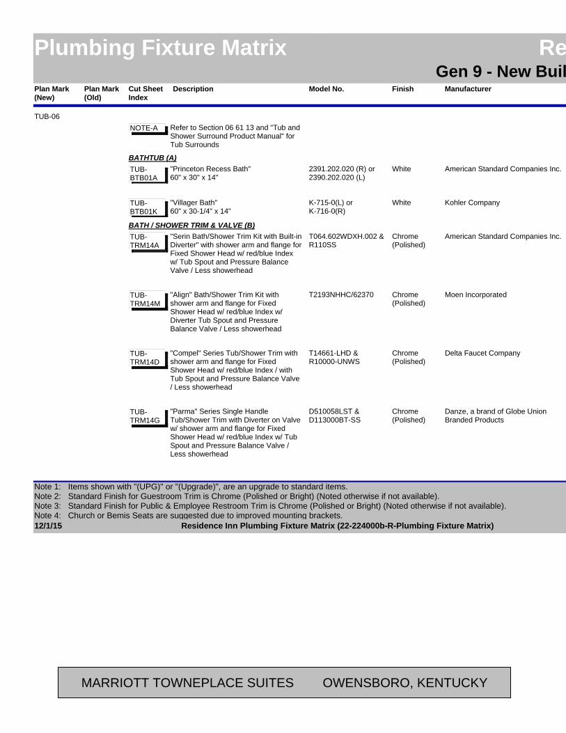
Plan Mark (Old)
ManufacturerModel No. LocationAreaFinishPlan Mark (New)
Residence InnPlumbing Fixture Matrix Residence InnGen 9 - New Build - Possibilities
DescriptionCut Sheet Index
TUB-06Refer to Section 06 61 13 and "Tub and Shower Surround Product Manual" for Tub Surrounds
NOTE-A
American Standard Companies Inc.2391.202.020 (R) or 2390.202.020 (L)
BathroomGuestroomWhiteBATHTUB (A)
"Princeton Recess Bath"60" x 30" x 14"
TUB-BTB01A
Kohler CompanyK-715-0(L) or K-716-0(R)
BathroomGuestroomWhite"Villager Bath"60" x 30-1/4" x 14"
TUB-BTB01K
American Standard Companies Inc.T064.602WDXH.002 &R110SS
BathroomGuestroomChrome(Polished)
BATH / SHOWER TRIM & VALVE (B)"Serin Bath/Shower Trim Kit with Built-in Diverter" with shower arm and flange for Fixed Shower Head w/ red/blue Index w/ Tub Spout and Pressure Balance Valve / Less showerhead
TUB-TRM14A
Moen IncorporatedT2193NHHC/62370 BathroomGuestroomChrome(Polished)
"Align" Bath/Shower Trim Kit with shower arm and flange for Fixed Shower Head w/ red/blue Index w/ Diverter Tub Spout and Pressure Balance Valve / Less showerhead
TUB-TRM14M
Delta Faucet CompanyT14661-LHD &R10000-UNWS
BathroomGuestroomChrome(Polished)
"Compel" Series Tub/Shower Trim with shower arm and flange for Fixed Shower Head w/ red/blue Index / with Tub Spout and Pressure Balance Valve / Less showerhead
TUB-TRM14D
Danze, a brand of Globe Union Branded Products
D510058LST &D113000BT-SS
BathroomGuestroomChrome(Polished)
"Parma" Series Single Handle Tub/Shower Trim with Diverter on Valve w/ shower arm and flange for Fixed Shower Head w/ red/blue Index w/ Tub Spout and Pressure Balance Valve / Less showerhead
TUB-TRM14G
12/1/15 Page 1 of 42Residence Inn Plumbing Fixture Matrix (22-224000b-R-Plumbing Fixture Matrix)
Note 1: Items shown with "(UPG)" or "(Upgrade)", are an upgrade to standard items.Note 2: Standard Finish for Guestroom Trim is Chrome (Polished or Bright) (Noted otherwise if not available). Note 3: Standard Finish for Public & Employee Restroom Trim is Chrome (Polished or Bright) (Noted otherwise if not available).Note 4: Church or Bemis Seats are suggested due to improved mounting brackets.
MARRIOTT TOWNEPLACE SUITES OWENSBORO, KENTUCKY

Plan Mark (Old)
ManufacturerModel No. LocationAreaFinishPlan Mark (New)
Residence InnPlumbing Fixture Matrix Residence InnGen 9 - New Build - Possibilities
DescriptionCut Sheet Index
Symmons Industries Inc.CD0100-3502-CYL-L/HD-X & 86-2X-BODY
BathroomGuestroomChrome(Polished)
TUB-06 BATH / SHOWER TRIM & VALVE (B)"Dia" Round valve trim with shower arm and flange for Fixed Shower Head w/ red/blue Index w/ Diverter Tub Spout and "Temptrol" Pressure Balanced Mixing Valve / Less showerhead
TUB-TRM14SY
American Standard Companies Inc.1640.305.002 BathroomGuestroomChrome(Polished)
BATHTUB DRAIN (C)"Deep Soak" Bathtub Drain with Overflow
TUB-DR01A
Kohler Company7160-AF-CP BathroomGuestroomChrome(Polished)
"Clearflo" Bathtub Drain with OverflowTUB-DR01K
Moen Incorporated90410 BathroomGuestroomChrome(Polished)
Bathtub Drain with OverflowTUB-DR01M
McGuire Mfg. Co., Inc.1221LAT BathroomGuestroomChrome(Polished)
"Lift & Turn Bath Waste with Overflow"TUB-DR02Mc
Gerber Plumbing Fixtures, a brand of Globe Union Branded Products
41-852 BathroomGuestroomChrome(Polished)
"Lift & Turn Bath Drains"TUB-DR02G
BathroomGuestroomSHOWER HEADS - WALL MOUNT
THERE ARE THREE (3) FLOW RATE CATEGORIES OF SHOWER HEADS LISTED BELOW. SELECT ONLY ONE OF THE CATEGORIES AND DELETE THE CATEGORIES NOT USED FOR THE PROJECT.
NOTE-
BathroomGuestroom2.5 GPM SHOWER HEAD - WALL MOUNT (D1)
RECOMMENDED GPM FOR OPTIMUM GUEST SATISFACTION AND SHOWERING EXPERIENCE.
NOTE-
12/1/15 Page 2 of 42Residence Inn Plumbing Fixture Matrix (22-224000b-R-Plumbing Fixture Matrix)
Note 1: Items shown with "(UPG)" or "(Upgrade)", are an upgrade to standard items.Note 2: Standard Finish for Guestroom Trim is Chrome (Polished or Bright) (Noted otherwise if not available). Note 3: Standard Finish for Public & Employee Restroom Trim is Chrome (Polished or Bright) (Noted otherwise if not available).Note 4: Church or Bemis Seats are suggested due to improved mounting brackets.
MARRIOTT TOWNEPLACE SUITES OWENSBORO, KENTUCKY
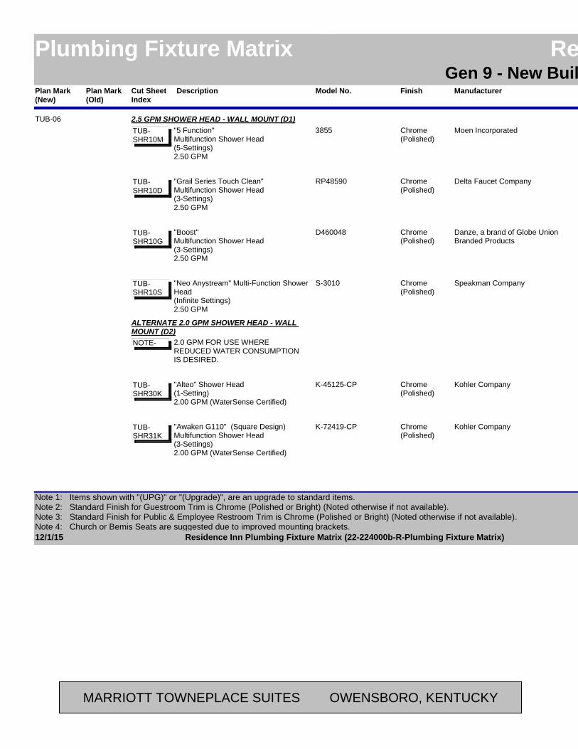
Plan Mark (Old)
ManufacturerModel No. LocationAreaFinishPlan Mark (New)
Residence InnPlumbing Fixture Matrix Residence InnGen 9 - New Build - Possibilities
DescriptionCut Sheet Index
Moen Incorporated3855 BathroomGuestroomChrome(Polished)
TUB-06 2.5 GPM SHOWER HEAD - WALL MOUNT (D1)"5 Function" Multifunction Shower Head(5-Settings)2.50 GPM
TUB-SHR10M
Delta Faucet CompanyRP48590 BathroomGuestroomChrome(Polished)
"Grail Series Touch Clean" Multifunction Shower Head(3-Settings)2.50 GPM
TUB-SHR10D
Danze, a brand of Globe Union Branded Products
D460048 BathroomGuestroomChrome(Polished)
"Boost" Multifunction Shower Head(3-Settings)2.50 GPM
TUB-SHR10G
Speakman CompanyS-3010 BathroomGuestroomChrome(Polished)
"Neo Anystream" Multi-Function Shower Head(Infinite Settings)2.50 GPM
TUB-SHR10S
BathroomGuestroom
ALTERNATE 2.0 GPM SHOWER HEAD - WALL MOUNT (D2)
2.0 GPM FOR USE WHERE REDUCED WATER CONSUMPTIONIS DESIRED.
NOTE-
Kohler CompanyK-45125-CP BathroomGuestroomChrome(Polished)
"Alteo" Shower Head(1-Setting)2.00 GPM (WaterSense Certified)
TUB-SHR30K
Kohler CompanyK-72419-CP BathroomGuestroomChrome(Polished)
"Awaken G110" (Square Design) Multifunction Shower Head(3-Settings)2.00 GPM (WaterSense Certified)
TUB-SHR31K
12/1/15 Page 3 of 42Residence Inn Plumbing Fixture Matrix (22-224000b-R-Plumbing Fixture Matrix)
Note 1: Items shown with "(UPG)" or "(Upgrade)", are an upgrade to standard items.Note 2: Standard Finish for Guestroom Trim is Chrome (Polished or Bright) (Noted otherwise if not available). Note 3: Standard Finish for Public & Employee Restroom Trim is Chrome (Polished or Bright) (Noted otherwise if not available).Note 4: Church or Bemis Seats are suggested due to improved mounting brackets.
MARRIOTT TOWNEPLACE SUITES OWENSBORO, KENTUCKY
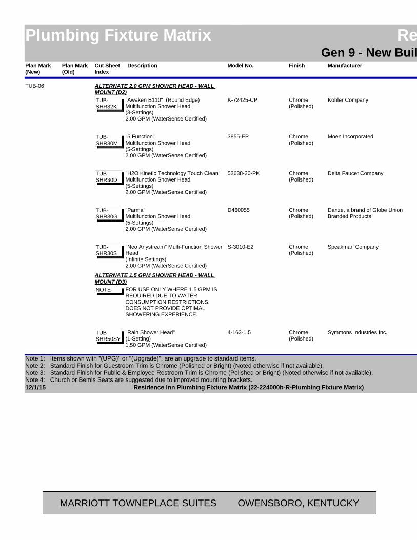
Plan Mark (Old)
ManufacturerModel No. LocationAreaFinishPlan Mark (New)
Residence InnPlumbing Fixture Matrix Residence InnGen 9 - New Build - Possibilities
DescriptionCut Sheet Index
Kohler CompanyK-72425-CP BathroomGuestroomChrome(Polished)
TUB-06 ALTERNATE 2.0 GPM SHOWER HEAD - WALL MOUNT (D2)
"Awaken B110" (Round Edge) Multifunction Shower Head(3-Settings)2.00 GPM (WaterSense Certified)
TUB-SHR32K
Moen Incorporated3855-EP BathroomGuestroomChrome(Polished)
"5 Function" Multifunction Shower Head(5-Settings)2.00 GPM (WaterSense Certified)
TUB-SHR30M
Delta Faucet Company52638-20-PK BathroomGuestroomChrome(Polished)
"H2O Kinetic Technology Touch Clean" Multifunction Shower Head(5-Settings)2.00 GPM (WaterSense Certified)
TUB-SHR30D
Danze, a brand of Globe Union Branded Products
D460055 BathroomGuestroomChrome(Polished)
"Parma" Multifunction Shower Head(5-Settings)2.00 GPM (WaterSense Certified)
TUB-SHR30G
Speakman CompanyS-3010-E2 BathroomGuestroomChrome(Polished)
"Neo Anystream" Multi-Function Shower Head(Infinite Settings)2.00 GPM (WaterSense Certified)
TUB-SHR30S
BathroomGuestroom
ALTERNATE 1.5 GPM SHOWER HEAD - WALL MOUNT (D3)
FOR USE ONLY WHERE 1.5 GPM IS REQUIRED DUE TO WATER CONSUMPTION RESTRICTIONS. DOES NOT PROVIDE OPTIMAL SHOWERING EXPERIENCE.
NOTE-
Symmons Industries Inc.4-163-1.5 BathroomGuestroomChrome(Polished)
"Rain Shower Head"(1-Setting)1.50 GPM (WaterSense Certified)
TUB-SHR50SY
12/1/15 Page 4 of 42Residence Inn Plumbing Fixture Matrix (22-224000b-R-Plumbing Fixture Matrix)
Note 1: Items shown with "(UPG)" or "(Upgrade)", are an upgrade to standard items.Note 2: Standard Finish for Guestroom Trim is Chrome (Polished or Bright) (Noted otherwise if not available). Note 3: Standard Finish for Public & Employee Restroom Trim is Chrome (Polished or Bright) (Noted otherwise if not available).Note 4: Church or Bemis Seats are suggested due to improved mounting brackets.
MARRIOTT TOWNEPLACE SUITES OWENSBORO, KENTUCKY

Plan Mark (Old)
ManufacturerModel No. LocationAreaFinishPlan Mark (New)
Residence InnPlumbing Fixture Matrix Residence InnGen 9 - New Build - Possibilities
DescriptionCut Sheet Index
TUB-07Refer to Section 06 61 13 and "Tub and Shower Surround Product Manual" for Tub Surrounds
NOTE-A
American Standard Companies Inc.2391.202.020 (R) or 2390.202.020 (L)
Accessible BathroomGuestroomWhiteBATHTUB (A)
"Princeton Recess Bath"60" x 30" x 14"
TUB-BTB01A
Kohler CompanyK-715-0(L) or K-716-0(R)
Accessible BathroomGuestroomWhite"Villager Bath"60" x 30-1/4" x 14"
TUB-BTB01K
American Standard Companies Inc.T064.602WDXH.002 &R110SS
Accessible BathroomGuestroomChrome(Polished)
BATH / SHOWER TRIM & VALVE (B)"Serin Bath/Shower Trim Kit with Built-in Diverter" with shower arm and flange for Fixed Shower Head w/ red/blue Index / with Tub Spout and Pressure Balance Valve / Less showerhead
TUB-TRM14A
Moen IncorporatedT2193NHHC/62370 Accessible BathroomGuestroomChrome(Polished)
"Align" Shower Trim Kit with shower arm and flange for Fixed Shower Head w/ red/blue Index / with diverter Tub Spout and Pressure Balance Valve / Less showerhead
TUB-TRM14M
Delta Faucet CompanyT14461-LHD &R10000-UNWS &50560
Accessible BathroomGuestroomChrome(Polished)
"Compel" Series Tub/Shower Trim with shower arm and flange for Fixed Shower Head w/ red/blue Index / with Tub Spout, supply elbow and Pressure Balance Valve / Less showerhead
TUB-TRM14D
Danze, a brand of Globe Union Branded Products
D510058LST &D113000BT-SS
Accessible BathroomGuestroomChrome(Polished)
"Parma" Series Single Handle Tub/Shower Trim with Diverter on Valve w/ shower arm and flange for Fixed Shower Head w/ red/blue Index w/ Tub Spout and Pressure Balance Valve / Less showerhead
TUB-TRM14G
12/1/15 Page 5 of 42Residence Inn Plumbing Fixture Matrix (22-224000b-R-Plumbing Fixture Matrix)
Note 1: Items shown with "(UPG)" or "(Upgrade)", are an upgrade to standard items.Note 2: Standard Finish for Guestroom Trim is Chrome (Polished or Bright) (Noted otherwise if not available). Note 3: Standard Finish for Public & Employee Restroom Trim is Chrome (Polished or Bright) (Noted otherwise if not available).Note 4: Church or Bemis Seats are suggested due to improved mounting brackets.
MARRIOTT TOWNEPLACE SUITES OWENSBORO, KENTUCKY
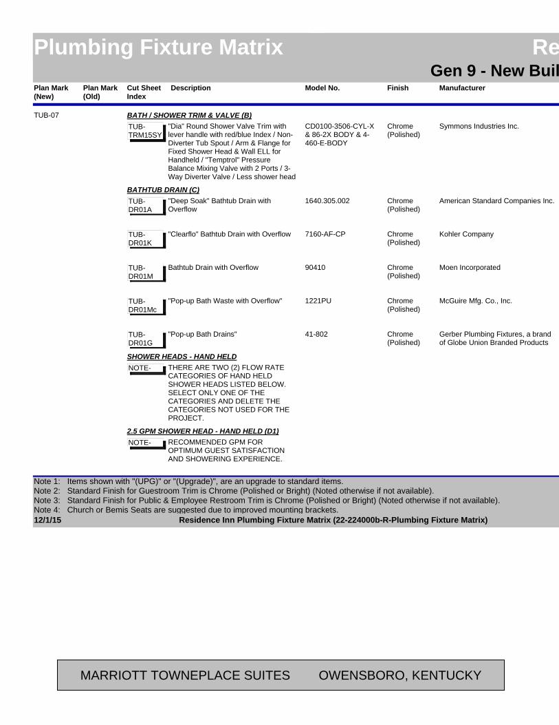
Plan Mark (Old)
ManufacturerModel No. LocationAreaFinishPlan Mark (New)
Residence InnPlumbing Fixture Matrix Residence InnGen 9 - New Build - Possibilities
DescriptionCut Sheet Index
Symmons Industries Inc.CD0100-3506-CYL-X & 86-2X BODY & 4-460-E-BODY
Accessible BathroomGuestroomChrome(Polished)
TUB-07 BATH / SHOWER TRIM & VALVE (B)"Dia" Round Shower Valve Trim with lever handle with red/blue Index / Non-Diverter Tub Spout / Arm & Flange for Fixed Shower Head & Wall ELL for Handheld / "Temptrol" Pressure Balance Mixing Valve with 2 Ports / 3-Way Diverter Valve / Less shower head
TUB-TRM15SY
American Standard Companies Inc.1640.305.002 Accessible BathroomGuestroomChrome(Polished)
BATHTUB DRAIN (C)"Deep Soak" Bathtub Drain with Overflow
TUB-DR01A
Kohler Company7160-AF-CP Accessible BathroomGuestroomChrome(Polished)
"Clearflo" Bathtub Drain with OverflowTUB-DR01K
Moen Incorporated90410 Accessible BathroomGuestroomChrome(Polished)
Bathtub Drain with OverflowTUB-DR01M
McGuire Mfg. Co., Inc.1221PU Accessible BathroomGuestroomChrome(Polished)
"Pop-up Bath Waste with Overflow"TUB-DR01Mc
Gerber Plumbing Fixtures, a brand of Globe Union Branded Products
41-802 Accessible BathroomGuestroomChrome(Polished)
"Pop-up Bath Drains"TUB-DR01G
SHOWER HEADS - HAND HELDTHERE ARE TWO (2) FLOW RATE CATEGORIES OF HAND HELD SHOWER HEADS LISTED BELOW. SELECT ONLY ONE OF THE CATEGORIES AND DELETE THE CATEGORIES NOT USED FOR THE PROJECT.
NOTE-
2.5 GPM SHOWER HEAD - HAND HELD (D1)RECOMMENDED GPM FOR OPTIMUM GUEST SATISFACTION AND SHOWERING EXPERIENCE.
NOTE-
12/1/15 Page 6 of 42Residence Inn Plumbing Fixture Matrix (22-224000b-R-Plumbing Fixture Matrix)
Note 1: Items shown with "(UPG)" or "(Upgrade)", are an upgrade to standard items.Note 2: Standard Finish for Guestroom Trim is Chrome (Polished or Bright) (Noted otherwise if not available). Note 3: Standard Finish for Public & Employee Restroom Trim is Chrome (Polished or Bright) (Noted otherwise if not available).Note 4: Church or Bemis Seats are suggested due to improved mounting brackets.
MARRIOTT TOWNEPLACE SUITES OWENSBORO, KENTUCKY
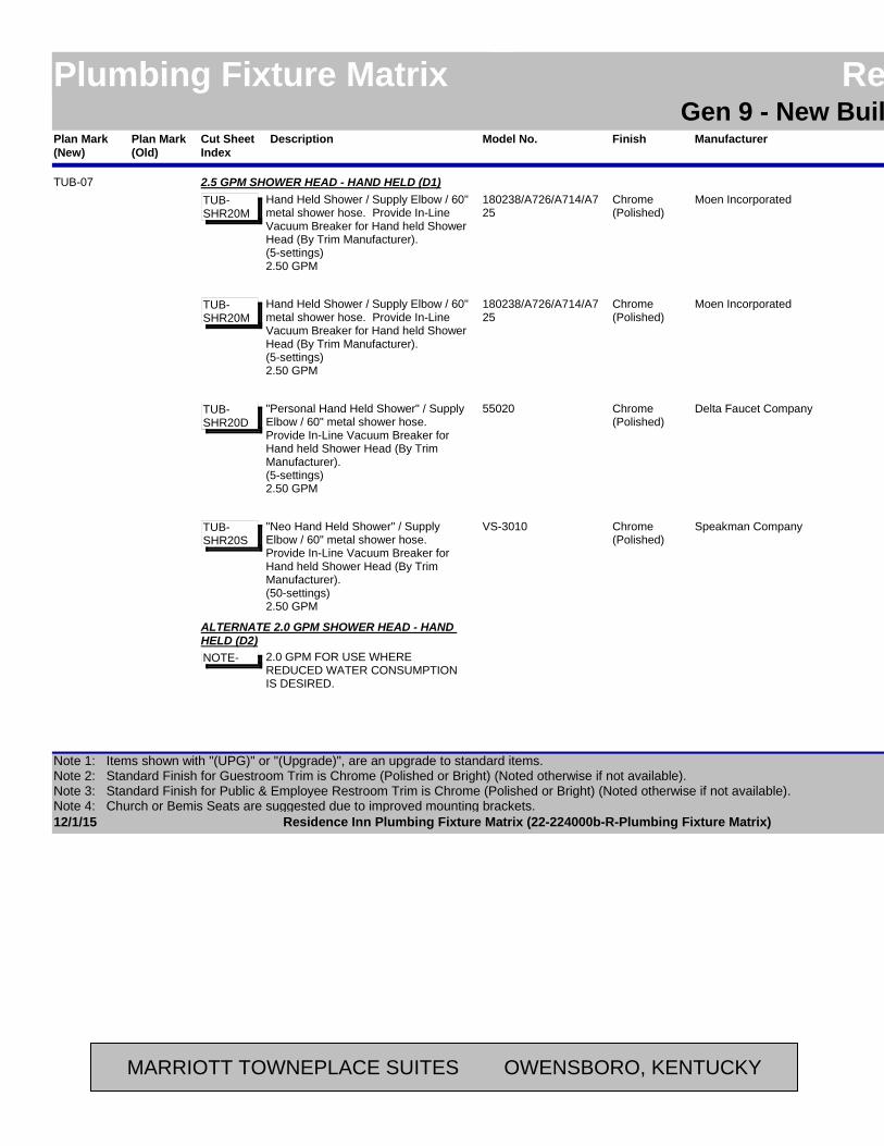
Plan Mark (Old)
ManufacturerModel No. LocationAreaFinishPlan Mark (New)
Residence InnPlumbing Fixture Matrix Residence InnGen 9 - New Build - Possibilities
DescriptionCut Sheet Index
Moen Incorporated180238/A726/A714/A725
Accessible BathroomGuestroomChrome(Polished)
TUB-07 2.5 GPM SHOWER HEAD - HAND HELD (D1)Hand Held Shower / Supply Elbow / 60" metal shower hose. Provide In-Line Vacuum Breaker for Hand held Shower Head (By Trim Manufacturer).(5-settings)2.50 GPM
TUB-SHR20M
Moen Incorporated180238/A726/A714/A725
Accessible BathroomGuestroomChrome(Polished)
Hand Held Shower / Supply Elbow / 60" metal shower hose. Provide In-Line Vacuum Breaker for Hand held Shower Head (By Trim Manufacturer).(5-settings)2.50 GPM
TUB-SHR20M
Delta Faucet Company55020 Accessible BathroomGuestroomChrome(Polished)
"Personal Hand Held Shower" / Supply Elbow / 60" metal shower hose. Provide In-Line Vacuum Breaker for Hand held Shower Head (By Trim Manufacturer).(5-settings)2.50 GPM
TUB-SHR20D
Speakman CompanyVS-3010 Accessible BathroomGuestroomChrome(Polished)
"Neo Hand Held Shower" / Supply Elbow / 60" metal shower hose. Provide In-Line Vacuum Breaker for Hand held Shower Head (By Trim Manufacturer).(50-settings)2.50 GPM
TUB-SHR20S
ALTERNATE 2.0 GPM SHOWER HEAD - HAND HELD (D2)
2.0 GPM FOR USE WHERE REDUCED WATER CONSUMPTIONIS DESIRED.
NOTE-
12/1/15 Page 7 of 42Residence Inn Plumbing Fixture Matrix (22-224000b-R-Plumbing Fixture Matrix)
Note 1: Items shown with "(UPG)" or "(Upgrade)", are an upgrade to standard items.Note 2: Standard Finish for Guestroom Trim is Chrome (Polished or Bright) (Noted otherwise if not available). Note 3: Standard Finish for Public & Employee Restroom Trim is Chrome (Polished or Bright) (Noted otherwise if not available).Note 4: Church or Bemis Seats are suggested due to improved mounting brackets.
MARRIOTT TOWNEPLACE SUITES OWENSBORO, KENTUCKY
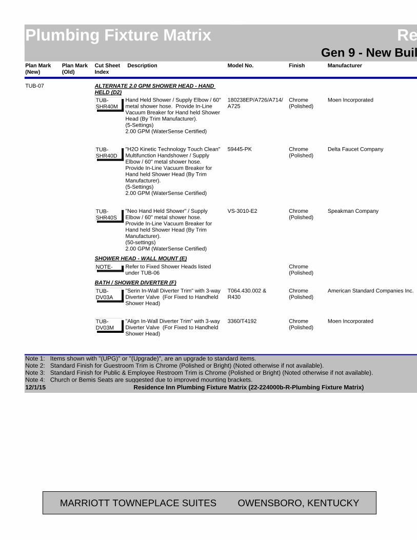
Plan Mark (Old)
ManufacturerModel No. LocationAreaFinishPlan Mark (New)
Residence InnPlumbing Fixture Matrix Residence InnGen 9 - New Build - Possibilities
DescriptionCut Sheet Index
Moen Incorporated180238EP/A726/A714/A725
Accessible BathroomGuestroomChrome(Polished)
TUB-07 ALTERNATE 2.0 GPM SHOWER HEAD - HAND HELD (D2)
Hand Held Shower / Supply Elbow / 60" metal shower hose. Provide In-Line Vacuum Breaker for Hand held Shower Head (By Trim Manufacturer).(5-Settings)2.00 GPM (WaterSense Certified)
TUB-SHR40M
Delta Faucet Company59445-PK Accessible BathroomGuestroomChrome(Polished)
"H2O Kinetic Technology Touch Clean" Multifunction Handshower / Supply Elbow / 60" metal shower hose. Provide In-Line Vacuum Breaker for Hand held Shower Head (By Trim Manufacturer).(5-Settings)2.00 GPM (WaterSense Certified)
TUB-SHR40D
Speakman CompanyVS-3010-E2 Accessible BathroomGuestroomChrome(Polished)
"Neo Hand Held Shower" / Supply Elbow / 60" metal shower hose. Provide In-Line Vacuum Breaker for Hand held Shower Head (By Trim Manufacturer).(50-settings)2.00 GPM (WaterSense Certified)
TUB-SHR40S
Accessible BathroomGuestroomChrome(Polished)
SHOWER HEAD - WALL MOUNT (E)Refer to Fixed Shower Heads listed under TUB-06
NOTE-
American Standard Companies Inc.T064.430.002 &R430
Accessible BathroomGuestroomChrome(Polished)
BATH / SHOWER DIVERTER (F)"Serin In-Wall Diverter Trim" with 3-way Diverter Valve (For Fixed to Handheld Shower Head)
TUB-DV03A
Moen Incorporated3360/T4192 Accessible BathroomGuestroomChrome(Polished)
"Align In-Wall Diverter Trim" with 3-way Diverter Valve (For Fixed to Handheld Shower Head)
TUB-DV03M
12/1/15 Page 8 of 42Residence Inn Plumbing Fixture Matrix (22-224000b-R-Plumbing Fixture Matrix)
Note 1: Items shown with "(UPG)" or "(Upgrade)", are an upgrade to standard items.Note 2: Standard Finish for Guestroom Trim is Chrome (Polished or Bright) (Noted otherwise if not available). Note 3: Standard Finish for Public & Employee Restroom Trim is Chrome (Polished or Bright) (Noted otherwise if not available).Note 4: Church or Bemis Seats are suggested due to improved mounting brackets.
MARRIOTT TOWNEPLACE SUITES OWENSBORO, KENTUCKY
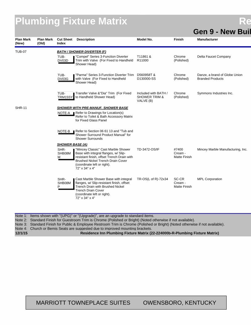
Plan Mark (Old)
ManufacturerModel No. LocationAreaFinishPlan Mark (New)
Residence InnPlumbing Fixture Matrix Residence InnGen 9 - New Build - Possibilities
DescriptionCut Sheet Index
Delta Faucet CompanyT11861 & R11000
Accessible BathroomGuestroomChrome(Polished)
TUB-07 BATH / SHOWER DIVERTER (F)"Compel" Series 3-Function Diverter Trim with Valve (For Fixed to Handheld Shower Head)
TUB-DV03D
Danze, a brand of Globe Union Branded Products
D560958T &D130000-SS
Accessible BathroomGuestroomChrome(Polished)
"Parma" Series 3-Function Diverter Trim with Valve (For Fixed to Handheld Shower Head)
TUB-DV03G
Symmons Industries Inc.Included with BATH / SHOWER TRIM & VALVE (B)
Accessible BathroomGuestroomChrome(Polished)
Transfer Valve &"Dia" Trim (For Fixed to Handheld Shower Head)
TUB-TRM15SY
SHR-11 SHOWER WITH PRE-MANUF. SHOWER BASERefer to Drawings for Location(s)Refer to Toilet & Bath Accessory Matrix for Fixed Glass Panel
NOTE-A
Refer to Section 06 61 13 and "Tub and Shower Surround Product Manual" for Shower Surrounds
NOTE-B
Mincey Marble Manufacturing, Inc.TD-3472-OS/IF BathroomGuestroom#7400 Cream - Matte Finish
SHOWER BASE (A)"Mincey Classic" Cast Marble Shower Base with integral flanges, w/ Slip-resistant finish, offset Trench Drain with Brushed Nickel Trench Drain Cover(coordinate left or right).72" x 34" x 4"
SHR-SHB08MM
MPL CorporationTR-OS(L of R)-72x34 BathroomGuestroomSC-CR Cream - Matte Finish
Cast Marble Shower Base with integral flanges, w/ Slip-resistant finish, offset Trench Drain with Brushed Nickel Trench Drain Cover(coordinate left or right).72" x 34" x 4"
SHR-SHB08MP
12/1/15 Page 9 of 42Residence Inn Plumbing Fixture Matrix (22-224000b-R-Plumbing Fixture Matrix)
Note 1: Items shown with "(UPG)" or "(Upgrade)", are an upgrade to standard items.Note 2: Standard Finish for Guestroom Trim is Chrome (Polished or Bright) (Noted otherwise if not available). Note 3: Standard Finish for Public & Employee Restroom Trim is Chrome (Polished or Bright) (Noted otherwise if not available).Note 4: Church or Bemis Seats are suggested due to improved mounting brackets.
MARRIOTT TOWNEPLACE SUITES OWENSBORO, KENTUCKY
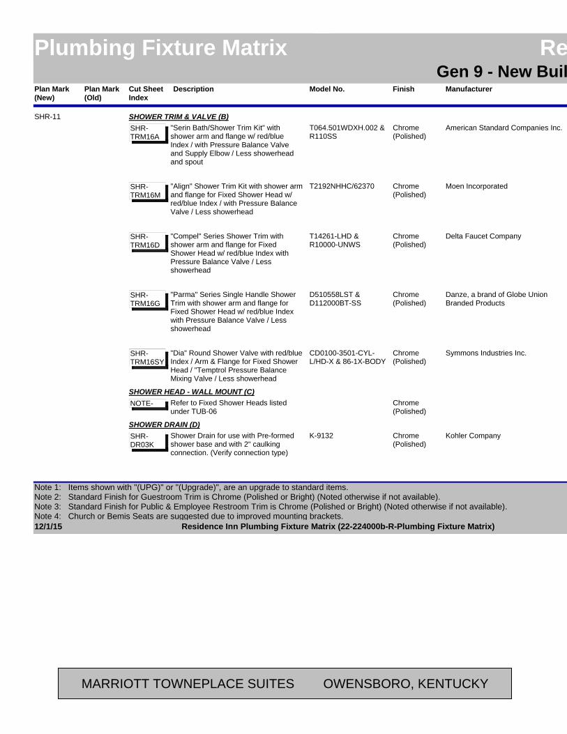
Plan Mark (Old)
ManufacturerModel No. LocationAreaFinishPlan Mark (New)
Residence InnPlumbing Fixture Matrix Residence InnGen 9 - New Build - Possibilities
DescriptionCut Sheet Index
American Standard Companies Inc.T064.501WDXH.002 &R110SS
BathroomGuestroomChrome(Polished)
SHR-11 SHOWER TRIM & VALVE (B)"Serin Bath/Shower Trim Kit" with shower arm and flange w/ red/blue Index / with Pressure Balance Valve and Supply Elbow / Less showerhead and spout
SHR-TRM16A
Moen IncorporatedT2192NHHC/62370 BathroomGuestroomChrome(Polished)
"Align" Shower Trim Kit with shower arm and flange for Fixed Shower Head w/ red/blue Index / with Pressure Balance Valve / Less showerhead
SHR-TRM16M
Delta Faucet CompanyT14261-LHD &R10000-UNWS
BathroomGuestroomChrome(Polished)
"Compel" Series Shower Trim with shower arm and flange for Fixed Shower Head w/ red/blue Index with Pressure Balance Valve / Less showerhead
SHR-TRM16D
Danze, a brand of Globe Union Branded Products
D510558LST &D112000BT-SS
BathroomGuestroomChrome(Polished)
"Parma" Series Single Handle Shower Trim with shower arm and flange for Fixed Shower Head w/ red/blue Index with Pressure Balance Valve / Less showerhead
SHR-TRM16G
Symmons Industries Inc.CD0100-3501-CYL-L/HD-X & 86-1X-BODY
BathroomGuestroomChrome(Polished)
"Dia" Round Shower Valve with red/blue Index / Arm & Flange for Fixed Shower Head / "Temptrol Pressure Balance Mixing Valve / Less showerhead
SHR-TRM16SY
BathroomGuestroomChrome(Polished)
SHOWER HEAD - WALL MOUNT (C)Refer to Fixed Shower Heads listed under TUB-06
NOTE-
Kohler CompanyK-9132 BathroomGuestroomChrome(Polished)
SHOWER DRAIN (D)Shower Drain for use with Pre-formed shower base and with 2" caulking connection. (Verify connection type)
SHR-DR03K
12/1/15 Page 10 of 42Residence Inn Plumbing Fixture Matrix (22-224000b-R-Plumbing Fixture Matrix)
Note 1: Items shown with "(UPG)" or "(Upgrade)", are an upgrade to standard items.Note 2: Standard Finish for Guestroom Trim is Chrome (Polished or Bright) (Noted otherwise if not available). Note 3: Standard Finish for Public & Employee Restroom Trim is Chrome (Polished or Bright) (Noted otherwise if not available).Note 4: Church or Bemis Seats are suggested due to improved mounting brackets.
MARRIOTT TOWNEPLACE SUITES OWENSBORO, KENTUCKY

Plan Mark (Old)
ManufacturerModel No. LocationAreaFinishPlan Mark (New)
Residence InnPlumbing Fixture Matrix Residence InnGen 9 - New Build - Possibilities
DescriptionCut Sheet Index
Oatey42150 BathroomGuestroomChrome(Polished)
SHR-11 SHOWER DRAIN (D)Shower Drain for use with Pre-formed shower base and with 2" caulking connection. (Verify connection type)
SHR-DR03O
SHR-12 SHOWER WITH PRE-MANUF. SHOWER BASERefer to Drawings for Location(s)Refer to Toilet & Bath Accessory Matrix for Fixed Glass Panel
NOTE-A
Refer to Section 06 61 13 and "Tub and Shower Surround Product Manual" for Shower Surrounds
NOTE-B
Mincey Marble Manufacturing, Inc.TD-3466-OS/IF BathroomGuestroom#7400 Cream - Matte Finish
SHOWER BASE (A)"Mincey Classic" Cast Marble Shower Base with integral flanges, w/ Slip-resistant finish, offset Trench Drain with Brushed Nickel Trench Drain Cover(coordinate left or right).66" x 34" x 4"
SHR-SHB09MM
MPL CorporationTR-OS(L of R)-66x34 BathroomGuestroomSC-CR Cream - Matte Finish
Cast Marble Shower Base with integral flanges, w/ Slip-resistant finish, offset Trench Drain with Brushed Nickel Trench Drain Cover(coordinate left or right).66" x 34" x 4"
SHR-SHB09MP
American Standard Companies Inc.T064.501WDXH.002 &R110SS
BathroomGuestroomChrome(Polished)
SHOWER TRIM & VALVE (B)"Serin Bath/Shower Trim Kit" with shower arm and flange w/ red/blue Index / with Pressure Balance Valve and Supply Elbow / Less showerhead and spout
SHR-TRM16A
Moen IncorporatedT2192NHHC/62370 BathroomGuestroomChrome(Polished)
"Align" Shower Trim Kit with shower arm and flange for Fixed Shower Head w/ red/blue Index / with Pressure Balance Valve / Less showerhead
SHR-TRM16M
12/1/15 Page 11 of 42Residence Inn Plumbing Fixture Matrix (22-224000b-R-Plumbing Fixture Matrix)
Note 1: Items shown with "(UPG)" or "(Upgrade)", are an upgrade to standard items.Note 2: Standard Finish for Guestroom Trim is Chrome (Polished or Bright) (Noted otherwise if not available). Note 3: Standard Finish for Public & Employee Restroom Trim is Chrome (Polished or Bright) (Noted otherwise if not available).Note 4: Church or Bemis Seats are suggested due to improved mounting brackets.
MARRIOTT TOWNEPLACE SUITES OWENSBORO, KENTUCKY
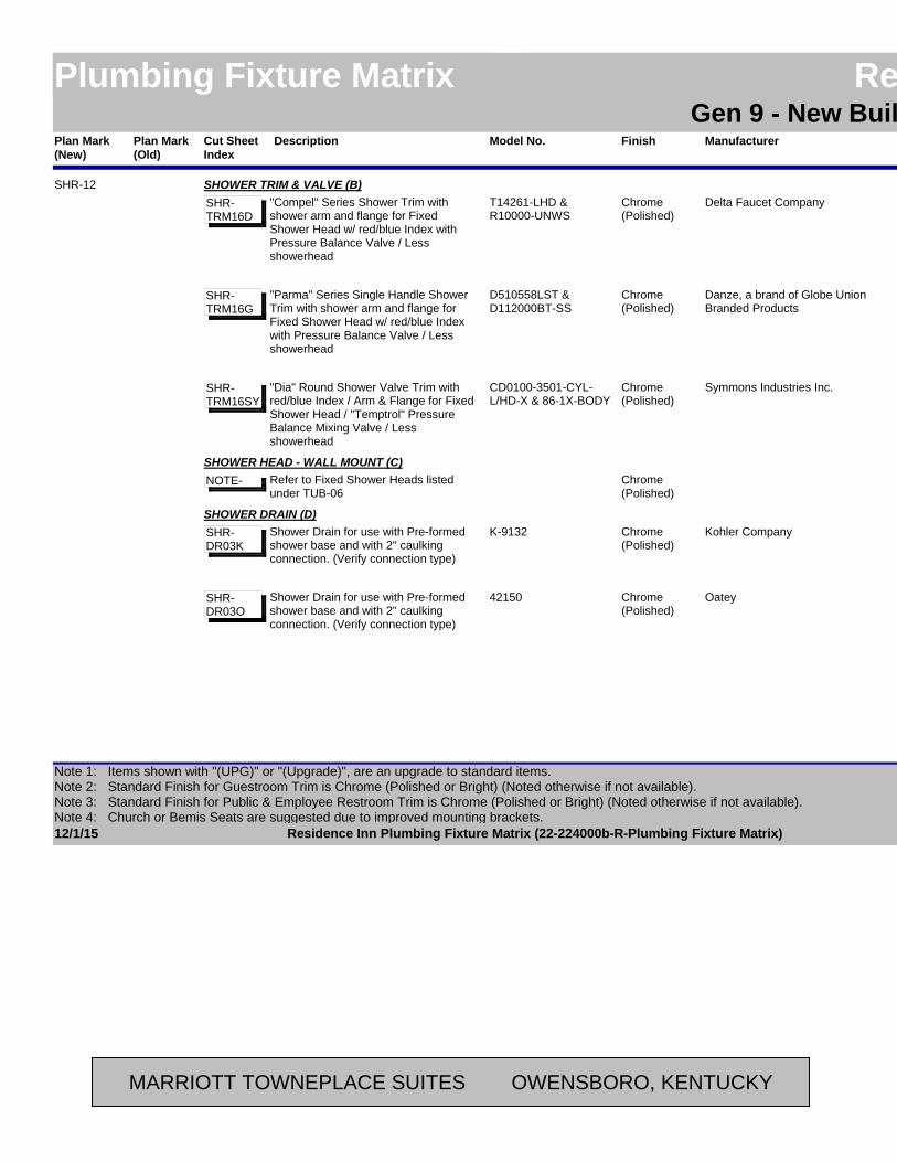
Plan Mark (Old)
ManufacturerModel No. LocationAreaFinishPlan Mark (New)
Residence InnPlumbing Fixture Matrix Residence InnGen 9 - New Build - Possibilities
DescriptionCut Sheet Index
Delta Faucet CompanyT14261-LHD &R10000-UNWS
BathroomGuestroomChrome(Polished)
SHR-12 SHOWER TRIM & VALVE (B)"Compel" Series Shower Trim with shower arm and flange for Fixed Shower Head w/ red/blue Index with Pressure Balance Valve / Less showerhead
SHR-TRM16D
Danze, a brand of Globe Union Branded Products
D510558LST &D112000BT-SS
BathroomGuestroomChrome(Polished)
"Parma" Series Single Handle Shower Trim with shower arm and flange for Fixed Shower Head w/ red/blue Index with Pressure Balance Valve / Less showerhead
SHR-TRM16G
Symmons Industries Inc.CD0100-3501-CYL-L/HD-X & 86-1X-BODY
BathroomGuestroomChrome(Polished)
"Dia" Round Shower Valve Trim with red/blue Index / Arm & Flange for Fixed Shower Head / "Temptrol" Pressure Balance Mixing Valve / Less showerhead
SHR-TRM16SY
BathroomGuestroomChrome(Polished)
SHOWER HEAD - WALL MOUNT (C)Refer to Fixed Shower Heads listed under TUB-06
NOTE-
Kohler CompanyK-9132 BathroomGuestroomChrome(Polished)
SHOWER DRAIN (D)Shower Drain for use with Pre-formed shower base and with 2" caulking connection. (Verify connection type)
SHR-DR03K
Oatey42150 BathroomGuestroomChrome(Polished)
Shower Drain for use with Pre-formed shower base and with 2" caulking connection. (Verify connection type)
SHR-DR03O
12/1/15 Page 12 of 42Residence Inn Plumbing Fixture Matrix (22-224000b-R-Plumbing Fixture Matrix)
Note 1: Items shown with "(UPG)" or "(Upgrade)", are an upgrade to standard items.Note 2: Standard Finish for Guestroom Trim is Chrome (Polished or Bright) (Noted otherwise if not available). Note 3: Standard Finish for Public & Employee Restroom Trim is Chrome (Polished or Bright) (Noted otherwise if not available).Note 4: Church or Bemis Seats are suggested due to improved mounting brackets.
MARRIOTT TOWNEPLACE SUITES OWENSBORO, KENTUCKY
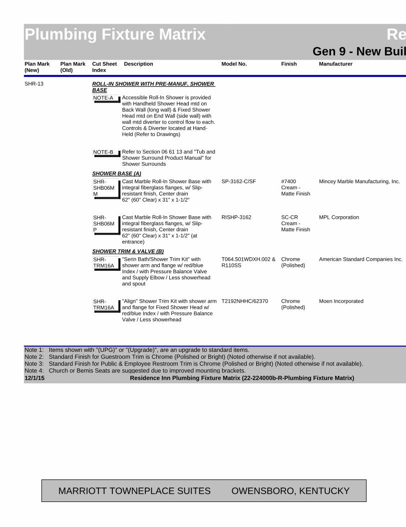
Plan Mark (Old)
ManufacturerModel No. LocationAreaFinishPlan Mark (New)
Residence InnPlumbing Fixture Matrix Residence InnGen 9 - New Build - Possibilities
DescriptionCut Sheet Index
SHR-13 ROLL-IN SHOWER WITH PRE-MANUF. SHOWER BASE
Accessible Roll-In Shower is provided with Handheld Shower Head mtd on Back Wall (long wall) & Fixed Shower Head mtd on End Wall (side wall) with wall mtd diverter to control flow to each. Controls & Diverter located at Hand-Held (Refer to Drawings)
NOTE-A
Refer to Section 06 61 13 and "Tub and Shower Surround Product Manual" for Shower Surrounds
NOTE-B
Mincey Marble Manufacturing, Inc.SP-3162-C/SF Accessible Roll-In Shower
Guestroom#7400 Cream - Matte Finish
SHOWER BASE (A)Cast Marble Roll-In Shower Base with integral fiberglass flanges, w/ Slip-resistant finish, Center drain62" (60" Clear) x 31" x 1-1/2"
SHR-SHB06MM
MPL CorporationRISHP-3162 Accessible Roll-In Shower
GuestroomSC-CR Cream - Matte Finish
Cast Marble Roll-In Shower Base with integral fiberglass flanges, w/ Slip-resistant finish, Center drain62" (60" Clear) x 31" x 1-1/2" (at entrance)
SHR-SHB06MP
American Standard Companies Inc.T064.501WDXH.002 &R110SS
Accessible Roll-In Shower
GuestroomChrome(Polished)
SHOWER TRIM & VALVE (B)"Serin Bath/Shower Trim Kit" with shower arm and flange w/ red/blue Index / with Pressure Balance Valve and Supply Elbow / Less showerhead and spout
SHR-TRM16A
Moen IncorporatedT2192NHHC/62370 Accessible Roll-In Shower
GuestroomChrome(Polished)
"Align" Shower Trim Kit with shower arm and flange for Fixed Shower Head w/ red/blue Index / with Pressure Balance Valve / Less showerhead
SHR-TRM16A
12/1/15 Page 13 of 42Residence Inn Plumbing Fixture Matrix (22-224000b-R-Plumbing Fixture Matrix)
Note 1: Items shown with "(UPG)" or "(Upgrade)", are an upgrade to standard items.Note 2: Standard Finish for Guestroom Trim is Chrome (Polished or Bright) (Noted otherwise if not available). Note 3: Standard Finish for Public & Employee Restroom Trim is Chrome (Polished or Bright) (Noted otherwise if not available).Note 4: Church or Bemis Seats are suggested due to improved mounting brackets.
MARRIOTT TOWNEPLACE SUITES OWENSBORO, KENTUCKY

Plan Mark (Old)
ManufacturerModel No. LocationAreaFinishPlan Mark (New)
Residence InnPlumbing Fixture Matrix Residence InnGen 9 - New Build - Possibilities
DescriptionCut Sheet Index
Delta Faucet CompanyT14261-LHD &R10000-UNWS
Accessible Roll-In Shower
GuestroomChrome(Polished)
SHR-13 SHOWER TRIM & VALVE (B)"Compel" Series Shower Trim with shower arm and flange for Fixed Shower Head w/ red/blue Index with Pressure Balance Valve / Less showerhead
SHR-TRM16D
Danze, a brand of Globe Union Branded Products
D510558LST &D112000BT-SS
Accessible Roll-In Shower
GuestroomChrome(Polished)
"Parma" Series Single Handle Shower Trim with shower arm and flange for Fixed Shower Head w/ red/blue Index with Pressure Balance Valve / Less showerhead
SHR-TRM16G
Symmons Industries Inc.CD0100-3505-CYL-X & 86-2X-BODY & 4-458-E BODY
Accessible Roll-In Shower
GuestroomChrome(Polished)
"Dia" Shower Valve Trim Only with red/blue Index / Arm & Flange for Fixed Shower Head / Less showerhead / "Temptrol Pressure Balance Mixing Valve & Diverter Valve / (Use w/ Speakman or Kohler Shower Head Unit below)
SHR-TRM17SY
American Standard Companies Inc.T064.430.002 &R430
Accessible Roll-In Shower
GuestroomChrome(Polished)
BATH / SHOWER DIVERTER (C)"Serin In-Wall Diverter Trim" with 3-way Diverter Valve (For Fixed to Handheld Shower Head)
SHR-DV03A
Moen Incorporated3360/T4192 Accessible Roll-In Shower
GuestroomChrome(Polished)
"Align" In-Wall Diverter Trim" with 3-way Diverter Valve (For Fixed to Handheld Shower Head)
SHR-DV03A
Delta Faucet CompanyT11861 & R11000
Accessible Roll-In Shower
GuestroomChrome(Polished)
"Compel" Series 3-Function Diverter Trim with Valve (For Fixed to Handheld Shower Head)
SHR-DV03D
Danze, a brand of Globe Union Branded Products
D560958T &D130000-SS
Accessible Roll-In Shower
GuestroomChrome(Polished)
"Parma" Series 3-Function Diverter Trim with Valve (For Fixed to Handheld Shower Head)
SHR-DV03G
12/1/15 Page 14 of 42Residence Inn Plumbing Fixture Matrix (22-224000b-R-Plumbing Fixture Matrix)
Note 1: Items shown with "(UPG)" or "(Upgrade)", are an upgrade to standard items.Note 2: Standard Finish for Guestroom Trim is Chrome (Polished or Bright) (Noted otherwise if not available). Note 3: Standard Finish for Public & Employee Restroom Trim is Chrome (Polished or Bright) (Noted otherwise if not available).Note 4: Church or Bemis Seats are suggested due to improved mounting brackets.
MARRIOTT TOWNEPLACE SUITES OWENSBORO, KENTUCKY

Plan Mark (Old)
ManufacturerModel No. LocationAreaFinishPlan Mark (New)
Residence InnPlumbing Fixture Matrix Residence InnGen 9 - New Build - Possibilities
DescriptionCut Sheet Index
Symmons Industries Inc.Included with SHOWER TRIM & VALVE (B)
Accessible Roll-In Shower
GuestroomChrome(Polished)
SHR-13 BATH / SHOWER DIVERTER (C)Transfer Valve & "Dia" Trim (For Fixed to Handheld Shower Head)
SHR-TRM17SY
Accessible Roll-In Shower
GuestroomChrome(Polished)
SHOWER HEAD - WALL MOUNT (D)Refer to Fixed Shower Heads listed under TUB-06
NOTE-
Accessible Roll-In Shower
GuestroomChrome(Polished)
SHOWER HEAD - HAND HELD (E)Refer to Hand Held Shower Heads listed under TUB-07. Provide matching In-Line Vacuum Breaker for Hand held Shower Head.
NOTE-
Kohler CompanyK-9132 Accessible Roll-In Shower
GuestroomChrome(Polished)
SHOWER DRAIN (F)Shower Drain for use with Pre-formed shower base and with 2" caulking connection. (Verify connection type)
SHR-DR03K
Oatey42150 Accessible Roll-In Shower
GuestroomChrome(Polished)
Shower Drain for use with Pre-formed shower base and with 2" caulking connection. (Verify connection type)
SHR-DR03O
American Standard Companies Inc.0355.012.020 Employee RestroomBack-of-House
WhiteSNK-03 SINK (A)
"Lucerne Wall-Mount Sink"20-1/2" x 18-1/4" (Basin: 15" x 10" x 6-1/2") / Wall Mount
SNK-BWL03A
Kohler CompanyK-1728-0 Employee RestroomBack-of-House
White"Chesapeake"19-14" x 17-1/4" (Basin: 14" x 11" x 4-7/8") / Wall Hung
SNK-BWL03K
American Standard Companies Inc.7385.008.002 Employee RestroomBack-of-House
Chrome(Polished)
FAUCET (B)"Reliant 3" w/ red/blue Index Handle1.50 GPM (WaterSense Certified)4-1/2" Spout
SNK-FCT01A
12/1/15 Page 15 of 42Residence Inn Plumbing Fixture Matrix (22-224000b-R-Plumbing Fixture Matrix)
Note 1: Items shown with "(UPG)" or "(Upgrade)", are an upgrade to standard items.Note 2: Standard Finish for Guestroom Trim is Chrome (Polished or Bright) (Noted otherwise if not available). Note 3: Standard Finish for Public & Employee Restroom Trim is Chrome (Polished or Bright) (Noted otherwise if not available).Note 4: Church or Bemis Seats are suggested due to improved mounting brackets.
MARRIOTT TOWNEPLACE SUITES OWENSBORO, KENTUCKY

Plan Mark (Old)
ManufacturerModel No. LocationAreaFinishPlan Mark (New)
Residence InnPlumbing Fixture Matrix Residence InnGen 9 - New Build - Possibilities
DescriptionCut Sheet Index
Kohler CompanyK-15198-F-CP Employee RestroomBack-of-House
Chrome(Polished)
SNK-03 FAUCET (B)"Coralais" Single Control with Red/Blue index and Grid Drain1.50 GPM (WaterSense Certified)4-5/8" Spout / 4" Centers
SNK-FCT03K
Moen IncorporatedL4601 &14750
Employee RestroomBack-of-House
Chrome(Polished)
"Chateau" Single-Handle Lavatory Faucet with red/blue index1.50 GPM (WaterSense Certified)4-3/8" Spout / 4" Centers
SNK-FCT01M
Delta Faucet Company523LF-HDF Employee RestroomBack-of-House
Chrome(Polished)
Single-Handle Lavatory Faucet with red/blue index and grid drain1.50 GPM5" Spout / 4" Centers
SNK-FCT03D
American Standard Companies Inc.0496.221.020 RestroomPublicWhiteSNK-04 SINK (A)
"Ovalyn Undercounter Sink"Bowl: 17" x 14" x 5-1/2" / Undermount (Granite)
SNK-BWL01A
Kohler CompanyK-2210-0 RestroomPublicWhite"Caxton Undercounter Lavatory"Bowl: 17" x 14" x 4" / Undermount (Granite)
SNK-BWL01K
American Standard Companies Inc.7385.003.002 RestroomPublicChrome(Polished)
FAUCET (B)"Reliant 3" w/ red/blue Index Handle and Grid Drain1.50 GPM (WaterSense Certified)4-1/2" Spout
SNK-FCT02A
Kohler CompanyK-15198-F-CP RestroomPublicChrome(Polished)
"Coralais" Single Control with Red/Blue index and Grid Drain1.50 GPM (WaterSense Certified)4-5/8" Spout / 4" Centers
SNK-FCT03K
12/1/15 Page 16 of 42Residence Inn Plumbing Fixture Matrix (22-224000b-R-Plumbing Fixture Matrix)
Note 1: Items shown with "(UPG)" or "(Upgrade)", are an upgrade to standard items.Note 2: Standard Finish for Guestroom Trim is Chrome (Polished or Bright) (Noted otherwise if not available). Note 3: Standard Finish for Public & Employee Restroom Trim is Chrome (Polished or Bright) (Noted otherwise if not available).Note 4: Church or Bemis Seats are suggested due to improved mounting brackets.
MARRIOTT TOWNEPLACE SUITES OWENSBORO, KENTUCKY
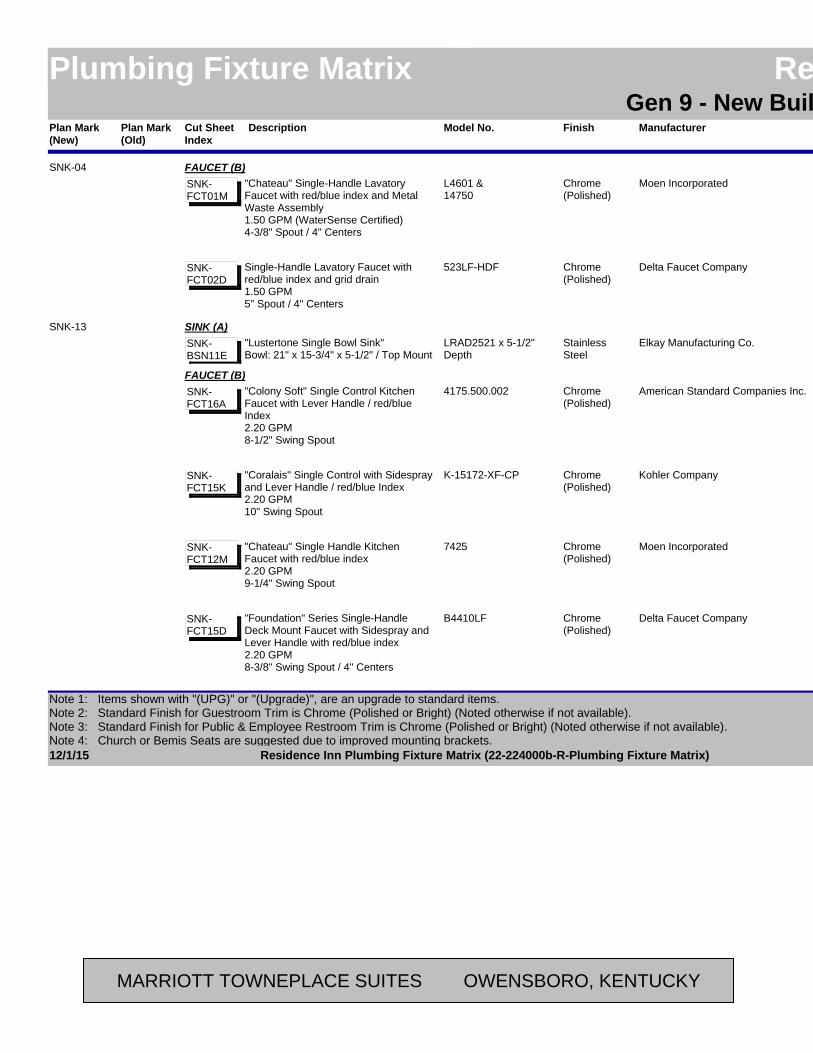
Plan Mark (Old)
ManufacturerModel No. LocationAreaFinishPlan Mark (New)
Residence InnPlumbing Fixture Matrix Residence InnGen 9 - New Build - Possibilities
DescriptionCut Sheet Index
Moen IncorporatedL4601 &14750
RestroomPublicChrome(Polished)
SNK-04 FAUCET (B)"Chateau" Single-Handle Lavatory Faucet with red/blue index and Metal Waste Assembly1.50 GPM (WaterSense Certified)4-3/8" Spout / 4" Centers
SNK-FCT01M
Delta Faucet Company523LF-HDF RestroomPublicChrome(Polished)
Single-Handle Lavatory Faucet with red/blue index and grid drain1.50 GPM5" Spout / 4" Centers
SNK-FCT02D
Elkay Manufacturing Co.LRAD2521 x 5-1/2" Depth
BreakroomEmployeeStainless Steel
SNK-13 SINK (A)"Lustertone Single Bowl Sink"Bowl: 21" x 15-3/4" x 5-1/2" / Top Mount
SNK-BSN11E
American Standard Companies Inc.4175.500.002 BreakroomEmployeeChrome(Polished)
FAUCET (B)"Colony Soft" Single Control Kitchen Faucet with Lever Handle / red/blue Index2.20 GPM8-1/2" Swing Spout
SNK-FCT16A
Kohler CompanyK-15172-XF-CP BreakroomEmployeeChrome(Polished)
"Coralais" Single Control with Sidespray and Lever Handle / red/blue Index2.20 GPM10" Swing Spout
SNK-FCT15K
Moen Incorporated7425 BreakroomEmployeeChrome(Polished)
"Chateau" Single Handle Kitchen Faucet with red/blue index2.20 GPM9-1/4" Swing Spout
SNK-FCT12M
Delta Faucet CompanyB4410LF BreakroomEmployeeChrome(Polished)
"Foundation" Series Single-Handle Deck Mount Faucet with Sidespray and Lever Handle with red/blue index2.20 GPM8-3/8" Swing Spout / 4" Centers
SNK-FCT15D
12/1/15 Page 17 of 42Residence Inn Plumbing Fixture Matrix (22-224000b-R-Plumbing Fixture Matrix)
Note 1: Items shown with "(UPG)" or "(Upgrade)", are an upgrade to standard items.Note 2: Standard Finish for Guestroom Trim is Chrome (Polished or Bright) (Noted otherwise if not available). Note 3: Standard Finish for Public & Employee Restroom Trim is Chrome (Polished or Bright) (Noted otherwise if not available).Note 4: Church or Bemis Seats are suggested due to improved mounting brackets.
MARRIOTT TOWNEPLACE SUITES OWENSBORO, KENTUCKY

Plan Mark (Old)
ManufacturerModel No. LocationAreaFinishPlan Mark (New)
Residence InnPlumbing Fixture Matrix Residence InnGen 9 - New Build - Possibilities
DescriptionCut Sheet Index
American Standard Companies Inc.4331.013.002 BreakroomEmployeeChrome(Polished)
SNK-13 SINK STRAINER (C)Sink StrainerSNK-
STR01A
Kohler CompanyK-6672-NA (2") orK-6673-NA (3")
BreakroomEmployeeChrome(Polished)
"Duostrainer"SNK-STR01K
Moen Incorporated22037 BreakroomEmployeeChrome(Polished)
Sink StrainerSNK-STR01M
Delta Faucet Company72010 BreakroomEmployeeChrome(Polished)
Sink StrainerSNK-STR01D
Kohler / Sterling Company442007-U Bathroom / Accessible Bathroom
GuestroomWhiteSNK-25 SINK (A)
"Stinson Undercounter Lavatory"Bowl: 18-3/16" x 12-3/16" x 5" / Undermount
SNK-BWL10K
American Standard Companies Inc.0614.000.020 Bathroom / Accessible Bathroom
GuestroomWhite"Studio Undercounter Sink"Bowl: 18-1/4" x 12-1/8" x 6" / Undermount
SNK-BWL10A
Kohler CompanyK-2214 Bathroom / Accessible Bathroom
GuestroomWhite(Upgrade Option)"Ladena Undercounter Lavatory"Bowl: 18-3/8" x 11-5/8" x 4-5/8" / Undermount
SNK-BWL11K
American Standard Companies Inc.2064.101.002 Bathroom / Accessible Bathroom
GuestroomChrome(Polished)
FAUCET (B)"Serin" Series Single Control Monobloc, deck mount w/ red/blue Index Handle.1.50 GPM6-3/8" High
SNK-FCT17A
Delta Faucet Company561LF-MPU Bathroom / Accessible Bathroom
GuestroomChrome(Polished)
"Compel" Series Single Handle deck mount w/ red/blue Index on handle.1.50 GPM7-1/2" High
SNK-FCT17D
12/1/15 Page 18 of 42Residence Inn Plumbing Fixture Matrix (22-224000b-R-Plumbing Fixture Matrix)
Note 1: Items shown with "(UPG)" or "(Upgrade)", are an upgrade to standard items.Note 2: Standard Finish for Guestroom Trim is Chrome (Polished or Bright) (Noted otherwise if not available). Note 3: Standard Finish for Public & Employee Restroom Trim is Chrome (Polished or Bright) (Noted otherwise if not available).Note 4: Church or Bemis Seats are suggested due to improved mounting brackets.
MARRIOTT TOWNEPLACE SUITES OWENSBORO, KENTUCKY
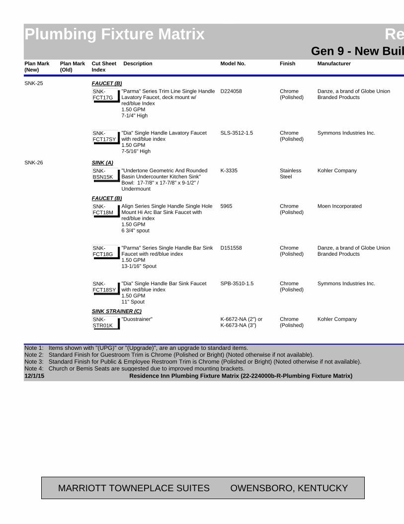
Plan Mark (Old)
ManufacturerModel No. LocationAreaFinishPlan Mark (New)
Residence InnPlumbing Fixture Matrix Residence InnGen 9 - New Build - Possibilities
DescriptionCut Sheet Index
Danze, a brand of Globe Union Branded Products
D224058 Bathroom / Accessible Bathroom
GuestroomChrome(Polished)
SNK-25 FAUCET (B)"Parma" Series Trim Line Single Handle Lavatory Faucet, deck mount w/ red/blue Index1.50 GPM7-1/4" High
SNK-FCT17G
Symmons Industries Inc.SLS-3512-1.5 Bathroom / Accessible Bathroom
GuestroomChrome(Polished)
"Dia" Single Handle Lavatory Faucet with red/blue index1.50 GPM7-5/16" High
SNK-FCT17SY
Kohler CompanyK-3335 KitchenGuestroomStainless Steel
SNK-26 SINK (A)"Undertone Geometric And Rounded Basin Undercounter Kitchen Sink"Bowl: 17-7/8" x 17-7/8" x 9-1/2" / Undermount
SNK-BSN15K
Moen Incorporated5965 KitchenGuestroomChrome(Polished)
FAUCET (B)Align Series Single Handle Single Hole Mount Hi Arc Bar Sink Faucet with red/blue index1.50 GPM6 3/4" spout
SNK-FCT18M
Danze, a brand of Globe Union Branded Products
D151558 KitchenGuestroomChrome(Polished)
"Parma" Series Single Handle Bar Sink Faucet with red/blue index1.50 GPM13-1/16" Spout
SNK-FCT18G
Symmons Industries Inc.SPB-3510-1.5 KitchenGuestroomChrome(Polished)
"Dia" Single Handle Bar Sink Faucet with red/blue index1.50 GPM11" Spout
SNK-FCT18SY
Kohler CompanyK-6672-NA (2") orK-6673-NA (3")
KitchenGuestroomChrome(Polished)
SINK STRAINER (C)"Duostrainer"SNK-
STR01K
12/1/15 Page 19 of 42Residence Inn Plumbing Fixture Matrix (22-224000b-R-Plumbing Fixture Matrix)
Note 1: Items shown with "(UPG)" or "(Upgrade)", are an upgrade to standard items.Note 2: Standard Finish for Guestroom Trim is Chrome (Polished or Bright) (Noted otherwise if not available). Note 3: Standard Finish for Public & Employee Restroom Trim is Chrome (Polished or Bright) (Noted otherwise if not available).Note 4: Church or Bemis Seats are suggested due to improved mounting brackets.
MARRIOTT TOWNEPLACE SUITES OWENSBORO, KENTUCKY
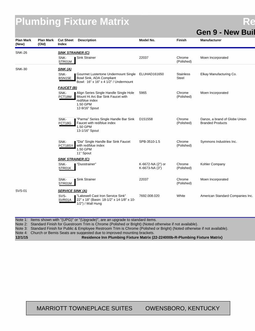
Plan Mark (Old)
ManufacturerModel No. LocationAreaFinishPlan Mark (New)
Residence InnPlumbing Fixture Matrix Residence InnGen 9 - New Build - Possibilities
DescriptionCut Sheet Index
Moen Incorporated22037 KitchenGuestroomChrome(Polished)
SNK-26 SINK STRAINER (C)Sink StrainerSNK-
STR01M
Elkay Manufacturing Co.ELUHAD161650 Accessible KitchenGuestroomStainless Steel
SNK-30 SINK (A)Gourmet Lustertone Undermount Single Bowl Sink, ADA CompliantBowl: 16" x 16" x 4 1/2" / Undermount
SNK-BSN15E
Moen Incorporated5965 Accessible KitchenGuestroomChrome(Polished)
FAUCET (B)Align Series Single Handle Single Hole Mount Hi Arc Bar Sink Faucet with red/blue index1.50 GPM12-9/16" Spout
SNK-FCT18M
Danze, a brand of Globe Union Branded Products
D151558 Accessible KitchenGuestroomChrome(Polished)
"Parma" Series Single Handle Bar Sink Faucet with red/blue index1.50 GPM13-1/16" Spout
SNK-FCT18G
Symmons Industries Inc.SPB-3510-1.5 Accessible KitchenGuestroomChrome(Polished)
"Dia" Single Handle Bar Sink Faucet with red/blue index1.50 GPM11" Spout
SNK-FCT18SY
Kohler CompanyK-6672-NA (2") orK-6673-NA (3")
Accessible KitchenGuestroomChrome(Polished)
SINK STRAINER (C)"Duostrainer"SNK-
STR01K
Moen Incorporated22037 Accessible KitchenGuestroomChrome(Polished)
Sink StrainerSNK-STR01M
American Standard Companies Inc.7692.008.020 (As Required - Option for Mop Sink MOP-01)
Back-of-House
WhiteSVS-01 SERVICE SINK (A)
"Lakewell Cast Iron Service Sink"22" x 18" (Basin: 18-1/2" x 14-1/8" x 10-1/2") / Wall Hung
SVS-SVR01A
12/1/15 Page 20 of 42Residence Inn Plumbing Fixture Matrix (22-224000b-R-Plumbing Fixture Matrix)
Note 1: Items shown with "(UPG)" or "(Upgrade)", are an upgrade to standard items.Note 2: Standard Finish for Guestroom Trim is Chrome (Polished or Bright) (Noted otherwise if not available). Note 3: Standard Finish for Public & Employee Restroom Trim is Chrome (Polished or Bright) (Noted otherwise if not available).Note 4: Church or Bemis Seats are suggested due to improved mounting brackets.
MARRIOTT TOWNEPLACE SUITES OWENSBORO, KENTUCKY
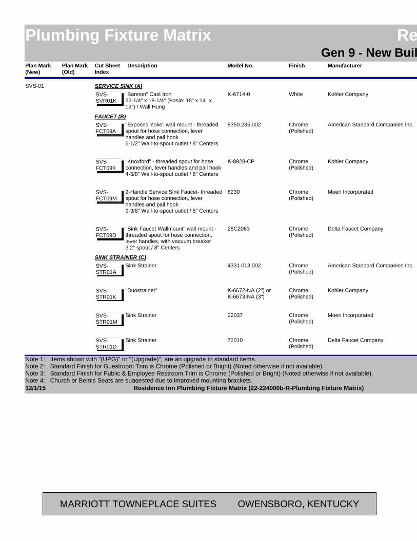
Plan Mark (Old)
ManufacturerModel No. LocationAreaFinishPlan Mark (New)
Residence InnPlumbing Fixture Matrix Residence InnGen 9 - New Build - Possibilities
DescriptionCut Sheet Index
Kohler CompanyK-6714-0 (As Required - Option for Mop Sink MOP-01)
Back-of-House
WhiteSVS-01 SERVICE SINK (A)
"Bannon" Cast Iron22-1/4" x 18-1/4" (Basin: 18" x 14" x 12") / Wall Hung
SVS-SVR01K
American Standard Companies Inc.8350.235.002 (As Required - Option for Mop Sink MOP-01)
Back-of-House
Chrome(Polished)
FAUCET (B)"Exposed Yoke" wall-mount - threaded spout for hose connection, lever handles and pail hook6-1/2" Wall-to-spout outlet / 8" Centers
SVS-FCT09A
Kohler CompanyK-8928-CP (As Required - Option for Mop Sink MOP-01)
Back-of-House
Chrome(Polished)
"Knoxford" - threaded spout for hose connection, lever handles and pail hook4-5/8" Wall-to-spout outlet / 8" Centers
SVS-FCT09K
Moen Incorporated8230 (As Required - Option for Mop Sink MOP-01)
Back-of-House
Chrome(Polished)
2-Handle Service Sink Faucet- threaded spout for hose connection, lever handles and pail hook9-3/8" Wall-to-spout outlet / 8" Centers
SVS-FCT09M
Delta Faucet Company28C2063 (As Required - Option for Mop Sink MOP-01)
Back-of-House
Chrome(Polished)
"Sink Faucet Wallmount" wall-mount - threaded spout for hose connection, lever handles, with vacuum breaker3.2" spout / 8" Centers
SVS-FCT09D
American Standard Companies Inc.4331.013.002 (As Required - Option for Mop Sink MOP-01)
Back-of-House
Chrome(Polished)
SINK STRAINER (C)Sink StrainerSVS-
STR01A
Kohler CompanyK-6672-NA (2") orK-6673-NA (3")
(As Required - Option for Mop Sink MOP-01)
Back-of-House
Chrome(Polished)
"Duostrainer"SVS-STR01K
Moen Incorporated22037 (As Required - Option for Mop Sink MOP-01)
Back-of-House
Chrome(Polished)
Sink StrainerSVS-STR01M
Delta Faucet Company72010 (As Required - Option for Mop Sink MOP-01)
Back-of-House
Chrome(Polished)
Sink StrainerSVS-STR01D
12/1/15 Page 21 of 42Residence Inn Plumbing Fixture Matrix (22-224000b-R-Plumbing Fixture Matrix)
Note 1: Items shown with "(UPG)" or "(Upgrade)", are an upgrade to standard items.Note 2: Standard Finish for Guestroom Trim is Chrome (Polished or Bright) (Noted otherwise if not available). Note 3: Standard Finish for Public & Employee Restroom Trim is Chrome (Polished or Bright) (Noted otherwise if not available).Note 4: Church or Bemis Seats are suggested due to improved mounting brackets.
MARRIOTT TOWNEPLACE SUITES OWENSBORO, KENTUCKY

Plan Mark (Old)
ManufacturerModel No. LocationAreaFinishPlan Mark (New)
Residence InnPlumbing Fixture Matrix Residence InnGen 9 - New Build - Possibilities
DescriptionCut Sheet Index
EL Mustee and Sons, Inc27F x 18.300F LaundryBack-of-House
WhiteSVS-02 LAUNDRY SINK (A)
Double Compartment - One-Piece Molded construction with complete drain assembly, twin drain waste coupling, 4 legs, levelers and stopper.40"W x 24"D x 34"H (Basin: 14-3/8"D) / Floor Mounted
SVS-BWL08MS
Fiat Products, A Crane Plumbing Company
FLTD II LaundryBack-of-House
White"Molded-Stone Floor Mouonted Serv-A-Sink" Twin Compartment - One-Piece Molded construction with complete drain assembly, twin drain waste coupling, 4 legs, levelers and stopper.40"W x 24"D x 33-3/4"H (Basin: 12-1/2"D) / Floor Mounted
SVS-BWL08F
EL Mustee and Sons, Inc93.600 LaundryBack-of-House
Chrome(Polished)
FAUCET (B)Faucet - Laundry Tub6" High Rise Swing Spout / 4" Centers
SVS-FCT10MS
Kohler CompanyK-15271-4-CP LaundryBack-of-House
Chrome(Polished)
Faucet - "Coralais" Laundry Tub2.20 GPM6" High Rise Swing Spout / 4" Centers
SVS-FCT11K
Fiat Products, A Crane Plumbing Company
A-1 LaundryBack-of-House
Chrome(Polished)
Faucet - Two-Handle Deck Faucet6-1/4" Swing Spout / 4" Centers
SVS-FCT10F
Moen Incorporated74998 LaundryBack-of-House
Chrome(Polished)
Two-Handle Laundry Faucet6-5/8" High Rise Swing Spout / 4" Centers
SVS-FCT10M
Delta Faucet Company2133 LaundryBack-of-House
Chrome(Polished)
Two-Handle Laundry Faucet8.0 GPM6-12" High Rise Swing Spout / 4" Centers
SVS-FCT10D
12/1/15 Page 22 of 42Residence Inn Plumbing Fixture Matrix (22-224000b-R-Plumbing Fixture Matrix)
Note 1: Items shown with "(UPG)" or "(Upgrade)", are an upgrade to standard items.Note 2: Standard Finish for Guestroom Trim is Chrome (Polished or Bright) (Noted otherwise if not available). Note 3: Standard Finish for Public & Employee Restroom Trim is Chrome (Polished or Bright) (Noted otherwise if not available).Note 4: Church or Bemis Seats are suggested due to improved mounting brackets.
MARRIOTT TOWNEPLACE SUITES OWENSBORO, KENTUCKY
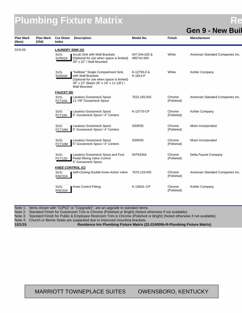
Plan Mark (Old)
ManufacturerModel No. LocationAreaFinishPlan Mark (New)
Residence InnPlumbing Fixture Matrix Residence InnGen 9 - New Build - Possibilities
DescriptionCut Sheet Index
American Standard Companies Inc.047.044.020 &485742.600
LaundryBack-of-House
WhiteSVS-03 LAUNDRY SINK (A)
Scrub Sink with Wall Brackets(Optional for use when space is limited)28" x 22" / Wall Mounted
SVS-SVR02A
Kohler CompanyK-12793-0 &K-1814-P
LaundryBack-of-House
White"Hollister" Single Compartment Sink with Wall Brackets(Optional for use when space is limited)28" x 22" (Basin 26" x 16" x 11-1/8") / Wall Mounted
SVS-SVR02K
American Standard Companies Inc.7522.155.002 LaundryBack-of-House
Chrome(Polished)
FAUCET (B)Lavatory Gooseneck Spout11-7/8" Gooseneck Spout
SVS-FCT10A
Kohler CompanyK-13770-CP LaundryBack-of-House
Chrome(Polished)
Lavatory Gooseneck Spout5" Gooseneck Spout / 4" Centers
SVS-FCT10K
Moen IncorporatedS00R30 LaundryBack-of-House
Chrome(Polished)
Lavatory Gooseneck Spout5" Gooseneck Spout / 4" Centers
SVS-FCT10M
Moen IncorporatedS00R30 LaundryBack-of-House
Chrome(Polished)
Lavatory Gooseneck Spout5" Gooseneck Spout / 4" Centers
SVS-FCT10M
Delta Faucet Company54T5434A LaundryBack-of-House
Chrome(Polished)
Lavatory Gooseneck Spout and Foot Pedal Mixing Valve Control5" Gooseneck Spout
SVS-FCT12D
American Standard Companies Inc.7676.129.002 LaundryBack-of-House
Chrome(Polished)
KNEE CONTROL (C)Self-Closing Double Knee-Action ValveSVS-
KNC01A
Kohler CompanyK-13816--CP LaundryBack-of-House
Chrome(Polished)
Knee Control FittingSVS-KNC01K
12/1/15 Page 23 of 42Residence Inn Plumbing Fixture Matrix (22-224000b-R-Plumbing Fixture Matrix)
Note 1: Items shown with "(UPG)" or "(Upgrade)", are an upgrade to standard items.Note 2: Standard Finish for Guestroom Trim is Chrome (Polished or Bright) (Noted otherwise if not available). Note 3: Standard Finish for Public & Employee Restroom Trim is Chrome (Polished or Bright) (Noted otherwise if not available).Note 4: Church or Bemis Seats are suggested due to improved mounting brackets.
MARRIOTT TOWNEPLACE SUITES OWENSBORO, KENTUCKY
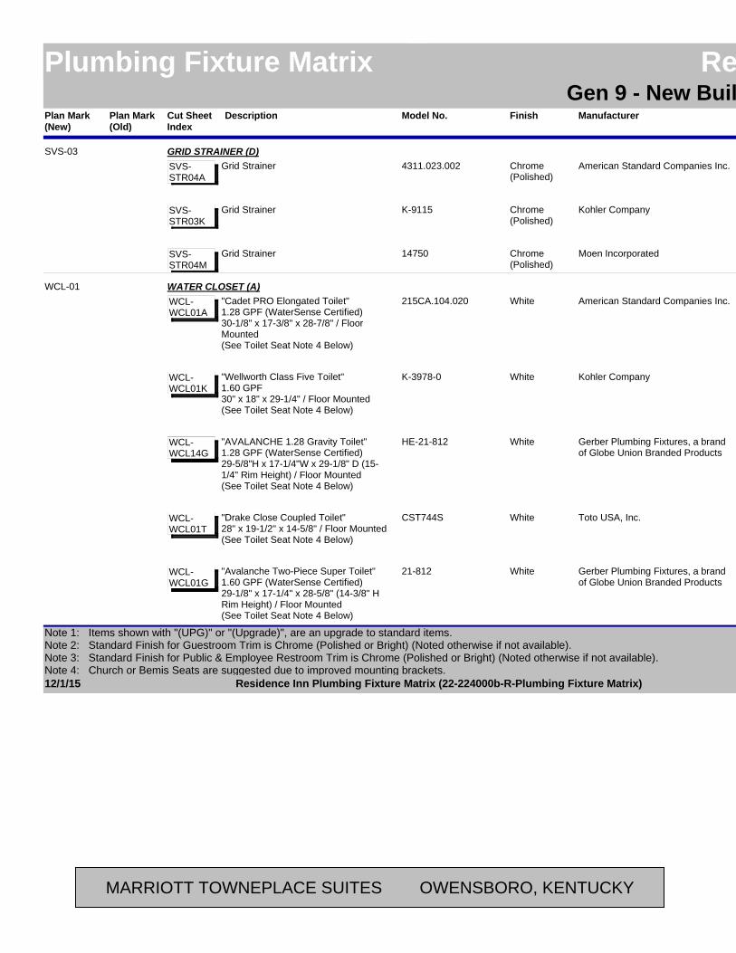
Plan Mark (Old)
ManufacturerModel No. LocationAreaFinishPlan Mark (New)
Residence InnPlumbing Fixture Matrix Residence InnGen 9 - New Build - Possibilities
DescriptionCut Sheet Index
American Standard Companies Inc.4311.023.002 LaundryBack-of-House
Chrome(Polished)
SVS-03 GRID STRAINER (D)Grid StrainerSVS-
STR04A
Kohler CompanyK-9115 LaundryBack-of-House
Chrome(Polished)
Grid StrainerSVS-STR03K
Moen Incorporated14750 LaundryBack-of-House
Chrome(Polished)
Grid StrainerSVS-STR04M
American Standard Companies Inc.215CA.104.020 BathroomGuestroomWhiteWCL-01 WATER CLOSET (A)
"Cadet PRO Elongated Toilet"1.28 GPF (WaterSense Certified)30-1/8" x 17-3/8" x 28-7/8" / Floor Mounted(See Toilet Seat Note 4 Below)
WCL-WCL01A
Kohler CompanyK-3978-0 BathroomGuestroomWhite"Wellworth Class Five Toilet" 1.60 GPF30" x 18" x 29-1/4" / Floor Mounted(See Toilet Seat Note 4 Below)
WCL-WCL01K
Gerber Plumbing Fixtures, a brand of Globe Union Branded Products
HE-21-812 BathroomGuestroomWhite"AVALANCHE 1.28 Gravity Toilet"1.28 GPF (WaterSense Certified)29-5/8"H x 17-1/4"W x 29-1/8" D (15-1/4" Rim Height) / Floor Mounted(See Toilet Seat Note 4 Below)
WCL-WCL14G
Toto USA, Inc.CST744S BathroomGuestroomWhite"Drake Close Coupled Toilet"28" x 19-1/2" x 14-5/8" / Floor Mounted(See Toilet Seat Note 4 Below)
WCL-WCL01T
Gerber Plumbing Fixtures, a brand of Globe Union Branded Products
21-812 BathroomGuestroomWhite"Avalanche Two-Piece Super Toilet"1.60 GPF (WaterSense Certified)29-1/8" x 17-1/4" x 28-5/8" (14-3/8" H Rim Height) / Floor Mounted(See Toilet Seat Note 4 Below)
WCL-WCL01G
12/1/15 Page 24 of 42Residence Inn Plumbing Fixture Matrix (22-224000b-R-Plumbing Fixture Matrix)
Note 1: Items shown with "(UPG)" or "(Upgrade)", are an upgrade to standard items.Note 2: Standard Finish for Guestroom Trim is Chrome (Polished or Bright) (Noted otherwise if not available). Note 3: Standard Finish for Public & Employee Restroom Trim is Chrome (Polished or Bright) (Noted otherwise if not available).Note 4: Church or Bemis Seats are suggested due to improved mounting brackets.
MARRIOTT TOWNEPLACE SUITES OWENSBORO, KENTUCKY

Plan Mark (Old)
ManufacturerModel No. LocationAreaFinishPlan Mark (New)
Residence InnPlumbing Fixture Matrix Residence InnGen 9 - New Build - Possibilities
DescriptionCut Sheet Index
Bemis Manufacturing Company7900TDGSL BathroomGuestroomWhiteWCL-01 TOILET SEAT (B)
Elongated Seat, Closed Front with Cover."Sta-Tite" Fastening System. - See Note 4
WCL-TS05CH
American Standard Companies Inc.5324.019.020 BathroomGuestroomWhite"Rise and Shine" Closed FrontWCL-TS03A
Kohler CompanyK-4774-0 BathroomGuestroomWhite"Brevia" Closed FrontWCL-TS03K
Toto USA, Inc.SS154 BathroomGuestroomWhite"Traditional Soft Close" Closed FrontWCL-TS02T
American Standard Companies Inc.211AA.104.020 BathroomGuestroomWhiteWCL-02 WATER CLOSET (A1) - UPGRADE FOR WCL-01
"Champion PRO Elongated Right Height Toilet"1.28 GPF (WaterSense Certified)30-1/4" x 19" x 30-7/8" (16-1/2" H Rim Height) / Floor Mounted(See Toilet Seat Note 4 Below)
WCL-WCL02A
Kohler CompanyK-3589-0 BathroomGuestroomWhite"Cimarron Class 6 Comfort Height Combination Elongated Toilet"1.60 GPF28-3/4" x 17-5/8" x 30-3/4" (16-1/2" H Rim Height) / Floor Mounted(See Toilet Seat Note 4 Below)
WCL-WCL02K
Toto USA, Inc.CST744S BathroomGuestroomWhite"Drake Close Coupled Toilet"1.60 GPF28" x 19-1/2" x 14-5/8" / Floor Mounted(See Toilet Seat Note 4 Below)
WCL-WCL01T
12/1/15 Page 25 of 42Residence Inn Plumbing Fixture Matrix (22-224000b-R-Plumbing Fixture Matrix)
Note 1: Items shown with "(UPG)" or "(Upgrade)", are an upgrade to standard items.Note 2: Standard Finish for Guestroom Trim is Chrome (Polished or Bright) (Noted otherwise if not available). Note 3: Standard Finish for Public & Employee Restroom Trim is Chrome (Polished or Bright) (Noted otherwise if not available).Note 4: Church or Bemis Seats are suggested due to improved mounting brackets.
MARRIOTT TOWNEPLACE SUITES OWENSBORO, KENTUCKY

Plan Mark (Old)
ManufacturerModel No. LocationAreaFinishPlan Mark (New)
Residence InnPlumbing Fixture Matrix Residence InnGen 9 - New Build - Possibilities
DescriptionCut Sheet Index
Danze, a brand of Globe Union Branded Products
DC013230WH-DC012223WH
BathroomGuestroomWhiteWCL-02 WATER CLOSET (A1) - UPGRADE FOR WCL-01
"Orrington 2 Piece Toilet"1.60 GPF (WaterSense Certified)29" x 18-3/4" x 31-1/2" (16-1/2" H Rim Height) / Floor Mounted(See Toilet Seat Note 4 Below)
WCL-WCL02G
Kohler CompanyK-3531-0 BathroomGuestroomWhite
WATER CLOSET (A2) - UPGRADE FOR WCL-01 - ALTERNATE FOR WATER CONSERVATION
"Wellworth Pressure-Lite 1.0 Elongated Toilet"1.00 GPF (WaterSense Certified)30-1/8" x 21-1/4" x 29-1/4" (15" H Rim Height) / Floor Mounted
WCL-WCL08K
Bemis Manufacturing Company7900TDGSL BathroomGuestroomWhiteTOILET SEAT (B)
Elongated Seat, Closed Front with Cover."Sta-Tite" Fastening System. - See Note 4
WCL-TS05CH
American Standard Companies Inc.5324.019.020 BathroomGuestroomWhite"Rise and Shine" Closed FrontWCL-TS03A
Kohler CompanyK-4636-0 BathroomGuestroomWhite"Cachet" Closed Front (Quiet Close)WCL-TS04K
Toto USA, Inc.SS154 BathroomGuestroomWhite"Traditional Soft Close" Closed FrontWCL-TS02T
American Standard Companies Inc.215AA.104.020 Accessible Bathroom /Employee Restroom
Guestroom/ Back-of-House
WhiteWCL-03 WATER CLOSET (ADA) (A1)
"Cadet PRO Right Height Elongated Toilet"1.28 GPF (WaterSense Certified)30-1/8" x 17-3/8" x 30-3/8" (16-1/2" H Rim Height) / Floor Mounted(See Toilet Seat Note 4 Below)
WCL-WCL03A
12/1/15 Page 26 of 42Residence Inn Plumbing Fixture Matrix (22-224000b-R-Plumbing Fixture Matrix)
Note 1: Items shown with "(UPG)" or "(Upgrade)", are an upgrade to standard items.Note 2: Standard Finish for Guestroom Trim is Chrome (Polished or Bright) (Noted otherwise if not available). Note 3: Standard Finish for Public & Employee Restroom Trim is Chrome (Polished or Bright) (Noted otherwise if not available).Note 4: Church or Bemis Seats are suggested due to improved mounting brackets.
MARRIOTT TOWNEPLACE SUITES OWENSBORO, KENTUCKY
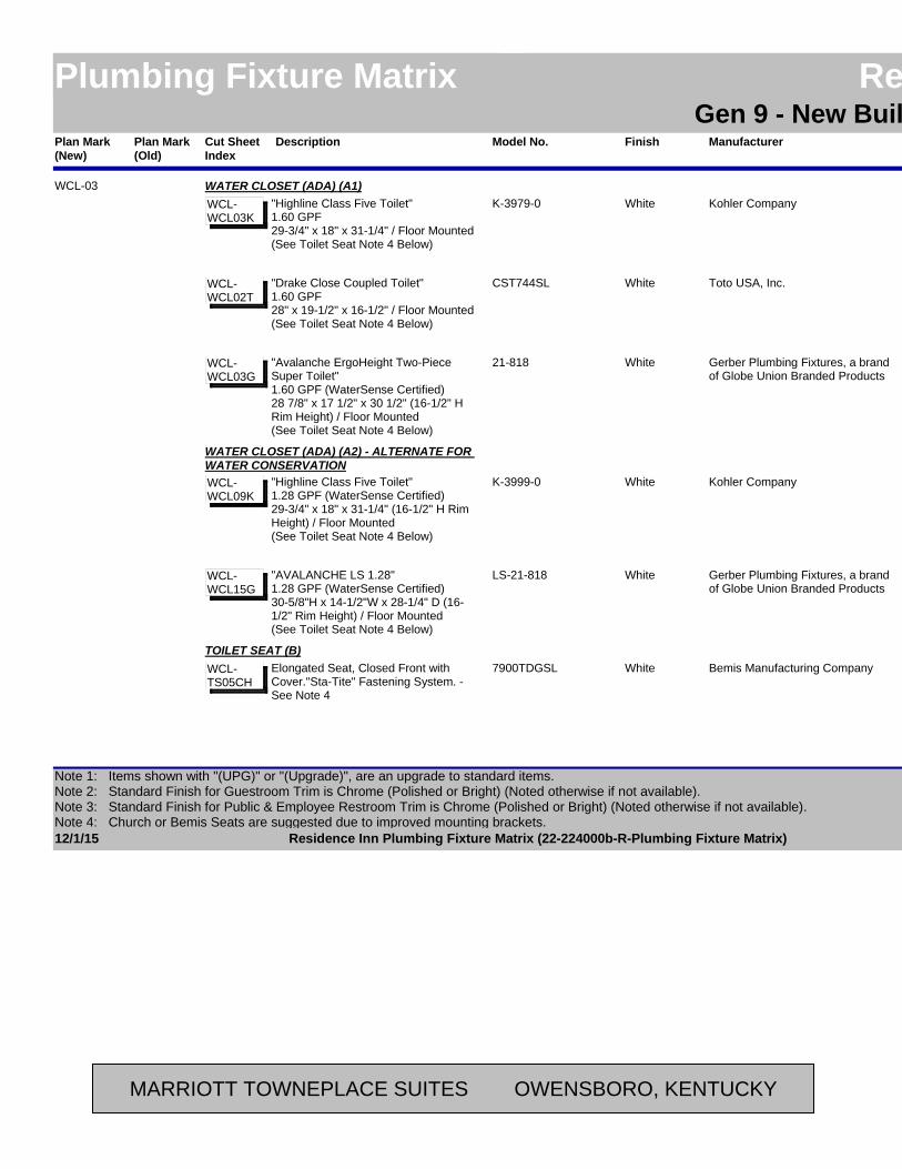
Plan Mark (Old)
ManufacturerModel No. LocationAreaFinishPlan Mark (New)
Residence InnPlumbing Fixture Matrix Residence InnGen 9 - New Build - Possibilities
DescriptionCut Sheet Index
Kohler CompanyK-3979-0 Accessible Bathroom /Employee Restroom
Guestroom/ Back-of-House
WhiteWCL-03 WATER CLOSET (ADA) (A1)
"Highline Class Five Toilet"1.60 GPF29-3/4" x 18" x 31-1/4" / Floor Mounted(See Toilet Seat Note 4 Below)
WCL-WCL03K
Toto USA, Inc.CST744SL Accessible Bathroom /Employee Restroom
Guestroom/ Back-of-House
White"Drake Close Coupled Toilet"1.60 GPF28" x 19-1/2" x 16-1/2" / Floor Mounted(See Toilet Seat Note 4 Below)
WCL-WCL02T
Gerber Plumbing Fixtures, a brand of Globe Union Branded Products
21-818 Accessible Bathroom /Employee Restroom
Guestroom/ Back-of-House
White"Avalanche ErgoHeight Two-Piece Super Toilet" 1.60 GPF (WaterSense Certified)28 7/8" x 17 1/2" x 30 1/2" (16-1/2" H Rim Height) / Floor Mounted(See Toilet Seat Note 4 Below)
WCL-WCL03G
Kohler CompanyK-3999-0 BathroomGuestroomWhite
WATER CLOSET (ADA) (A2) - ALTERNATE FOR WATER CONSERVATION
"Highline Class Five Toilet"1.28 GPF (WaterSense Certified)29-3/4" x 18" x 31-1/4" (16-1/2" H Rim Height) / Floor Mounted(See Toilet Seat Note 4 Below)
WCL-WCL09K
Gerber Plumbing Fixtures, a brand of Globe Union Branded Products
LS-21-818 BathroomGuestroomWhite"AVALANCHE LS 1.28"1.28 GPF (WaterSense Certified)30-5/8"H x 14-1/2"W x 28-1/4" D (16-1/2" Rim Height) / Floor Mounted(See Toilet Seat Note 4 Below)
WCL-WCL15G
Bemis Manufacturing Company7900TDGSL Accessible Bathroom /Employee Restroom
Guestroom/ Back-of-House
WhiteTOILET SEAT (B)
Elongated Seat, Closed Front with Cover."Sta-Tite" Fastening System. - See Note 4
WCL-TS05CH
12/1/15 Page 27 of 42Residence Inn Plumbing Fixture Matrix (22-224000b-R-Plumbing Fixture Matrix)
Note 1: Items shown with "(UPG)" or "(Upgrade)", are an upgrade to standard items.Note 2: Standard Finish for Guestroom Trim is Chrome (Polished or Bright) (Noted otherwise if not available). Note 3: Standard Finish for Public & Employee Restroom Trim is Chrome (Polished or Bright) (Noted otherwise if not available).Note 4: Church or Bemis Seats are suggested due to improved mounting brackets.
MARRIOTT TOWNEPLACE SUITES OWENSBORO, KENTUCKY
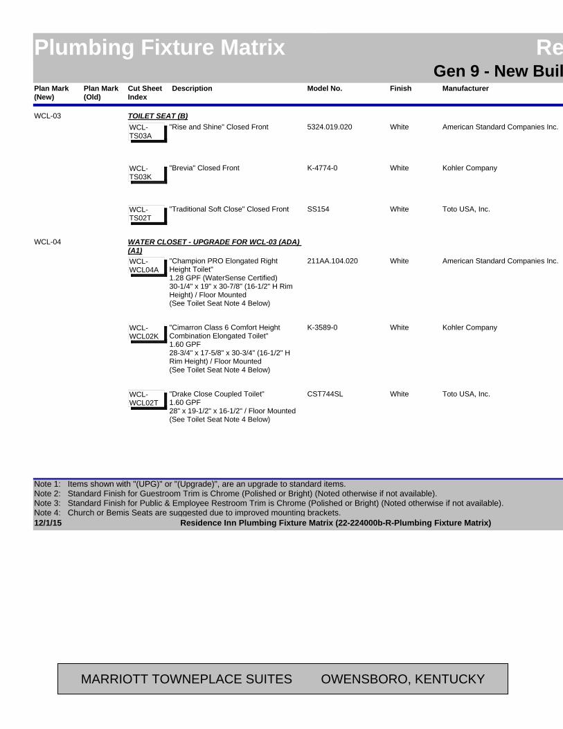
Plan Mark (Old)
ManufacturerModel No. LocationAreaFinishPlan Mark (New)
Residence InnPlumbing Fixture Matrix Residence InnGen 9 - New Build - Possibilities
DescriptionCut Sheet Index
American Standard Companies Inc.5324.019.020 Accessible Bathroom /Employee Restroom
Guestroom/ Back-of-House
WhiteWCL-03 TOILET SEAT (B)
"Rise and Shine" Closed FrontWCL-TS03A
Kohler CompanyK-4774-0 Accessible Bathroom /Employee Restroom
Guestroom/ Back-of-House
White"Brevia" Closed FrontWCL-TS03K
Toto USA, Inc.SS154 Accessible Bathroom /Employee Restroom
Guestroom/ Back-of-House
White"Traditional Soft Close" Closed FrontWCL-TS02T
American Standard Companies Inc.211AA.104.020 Accessible BathroomGuestroomWhite
WCL-04 WATER CLOSET - UPGRADE FOR WCL-03 (ADA) (A1)
"Champion PRO Elongated Right Height Toilet"1.28 GPF (WaterSense Certified)30-1/4" x 19" x 30-7/8" (16-1/2" H Rim Height) / Floor Mounted(See Toilet Seat Note 4 Below)
WCL-WCL04A
Kohler CompanyK-3589-0 Accessible BathroomGuestroomWhite"Cimarron Class 6 Comfort Height Combination Elongated Toilet"1.60 GPF28-3/4" x 17-5/8" x 30-3/4" (16-1/2" H Rim Height) / Floor Mounted(See Toilet Seat Note 4 Below)
WCL-WCL02K
Toto USA, Inc.CST744SL Accessible BathroomGuestroomWhite"Drake Close Coupled Toilet"1.60 GPF28" x 19-1/2" x 16-1/2" / Floor Mounted(See Toilet Seat Note 4 Below)
WCL-WCL02T
12/1/15 Page 28 of 42Residence Inn Plumbing Fixture Matrix (22-224000b-R-Plumbing Fixture Matrix)
Note 1: Items shown with "(UPG)" or "(Upgrade)", are an upgrade to standard items.Note 2: Standard Finish for Guestroom Trim is Chrome (Polished or Bright) (Noted otherwise if not available). Note 3: Standard Finish for Public & Employee Restroom Trim is Chrome (Polished or Bright) (Noted otherwise if not available).Note 4: Church or Bemis Seats are suggested due to improved mounting brackets.
MARRIOTT TOWNEPLACE SUITES OWENSBORO, KENTUCKY
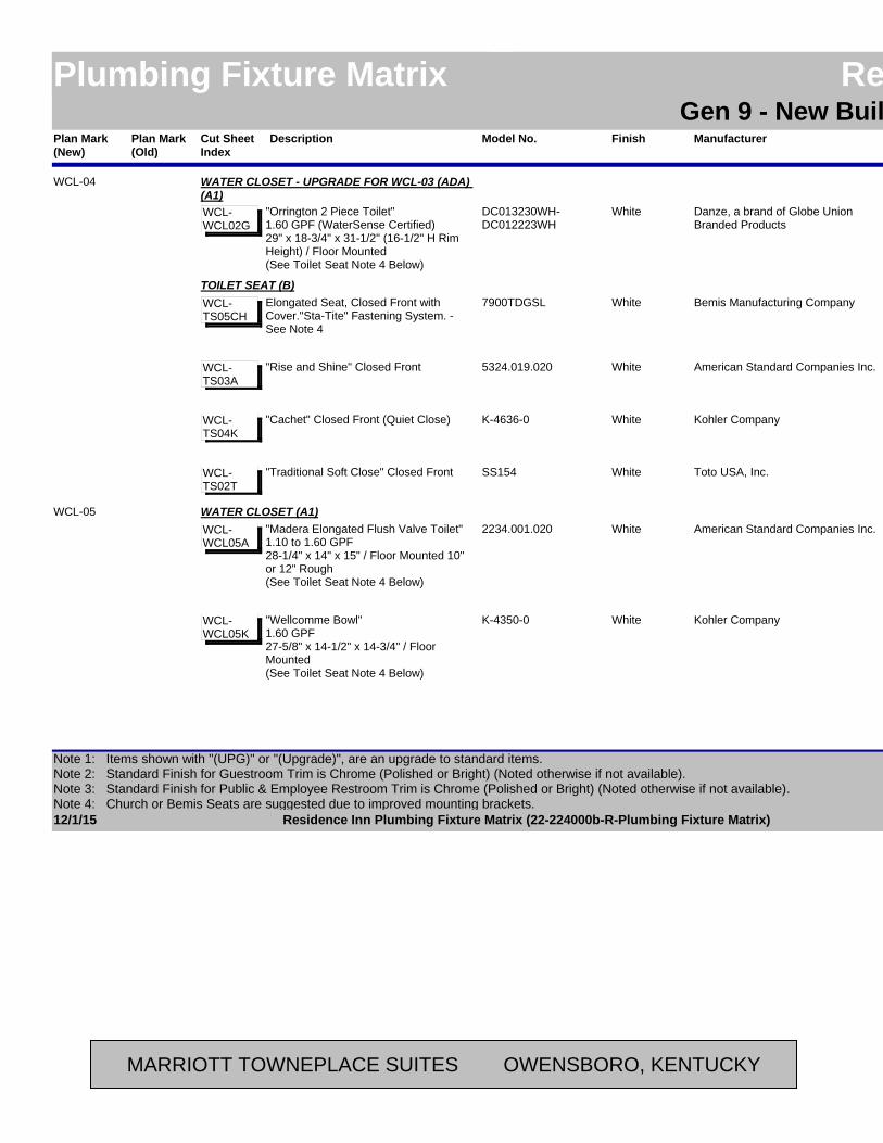
Plan Mark (Old)
ManufacturerModel No. LocationAreaFinishPlan Mark (New)
Residence InnPlumbing Fixture Matrix Residence InnGen 9 - New Build - Possibilities
DescriptionCut Sheet Index
Danze, a brand of Globe Union Branded Products
DC013230WH-DC012223WH
Accessible BathroomGuestroomWhite
WCL-04 WATER CLOSET - UPGRADE FOR WCL-03 (ADA) (A1)
"Orrington 2 Piece Toilet"1.60 GPF (WaterSense Certified)29" x 18-3/4" x 31-1/2" (16-1/2" H Rim Height) / Floor Mounted(See Toilet Seat Note 4 Below)
WCL-WCL02G
Bemis Manufacturing Company7900TDGSL Accessible BathroomGuestroomWhiteTOILET SEAT (B)
Elongated Seat, Closed Front with Cover."Sta-Tite" Fastening System. - See Note 4
WCL-TS05CH
American Standard Companies Inc.5324.019.020 Accessible BathroomGuestroomWhite"Rise and Shine" Closed FrontWCL-TS03A
Kohler CompanyK-4636-0 Accessible BathroomGuestroomWhite"Cachet" Closed Front (Quiet Close)WCL-TS04K
Toto USA, Inc.SS154 Accessible BathroomGuestroomWhite"Traditional Soft Close" Closed FrontWCL-TS02T
American Standard Companies Inc.2234.001.020 RestroomPublicWhiteWCL-05 WATER CLOSET (A1)
"Madera Elongated Flush Valve Toilet"1.10 to 1.60 GPF28-1/4" x 14" x 15" / Floor Mounted 10" or 12" Rough(See Toilet Seat Note 4 Below)
WCL-WCL05A
Kohler CompanyK-4350-0 RestroomPublicWhite"Wellcomme Bowl"1.60 GPF27-5/8" x 14-1/2" x 14-3/4" / Floor Mounted(See Toilet Seat Note 4 Below)
WCL-WCL05K
12/1/15 Page 29 of 42Residence Inn Plumbing Fixture Matrix (22-224000b-R-Plumbing Fixture Matrix)
Note 1: Items shown with "(UPG)" or "(Upgrade)", are an upgrade to standard items.Note 2: Standard Finish for Guestroom Trim is Chrome (Polished or Bright) (Noted otherwise if not available). Note 3: Standard Finish for Public & Employee Restroom Trim is Chrome (Polished or Bright) (Noted otherwise if not available).Note 4: Church or Bemis Seats are suggested due to improved mounting brackets.
MARRIOTT TOWNEPLACE SUITES OWENSBORO, KENTUCKY
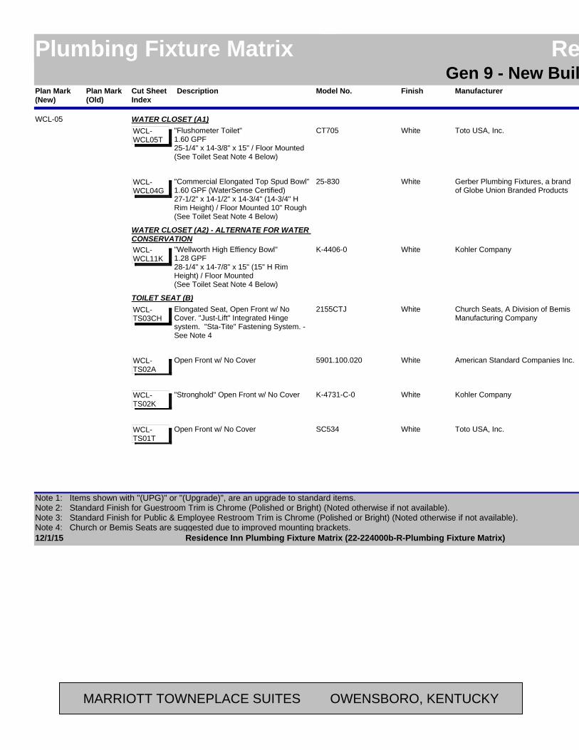
Plan Mark (Old)
ManufacturerModel No. LocationAreaFinishPlan Mark (New)
Residence InnPlumbing Fixture Matrix Residence InnGen 9 - New Build - Possibilities
DescriptionCut Sheet Index
Toto USA, Inc.CT705 RestroomPublicWhiteWCL-05 WATER CLOSET (A1)
"Flushometer Toilet"1.60 GPF25-1/4" x 14-3/8" x 15" / Floor Mounted(See Toilet Seat Note 4 Below)
WCL-WCL05T
Gerber Plumbing Fixtures, a brand of Globe Union Branded Products
25-830 RestroomPublicWhite"Commercial Elongated Top Spud Bowl"1.60 GPF (WaterSense Certified)27-1/2" x 14-1/2" x 14-3/4" (14-3/4" H Rim Height) / Floor Mounted 10" Rough(See Toilet Seat Note 4 Below)
WCL-WCL04G
Kohler CompanyK-4406-0 RestroomPublicWhite
WATER CLOSET (A2) - ALTERNATE FOR WATER CONSERVATION
"Wellworth High Effiency Bowl"1.28 GPF28-1/4" x 14-7/8" x 15" (15" H Rim Height) / Floor Mounted(See Toilet Seat Note 4 Below)
WCL-WCL11K
Church Seats, A Division of Bemis Manufacturing Company
2155CTJ RestroomPublicWhiteTOILET SEAT (B)
Elongated Seat, Open Front w/ No Cover. "Just-Lift" Integrated Hinge system. "Sta-Tite" Fastening System. - See Note 4
WCL-TS03CH
American Standard Companies Inc.5901.100.020 RestroomPublicWhiteOpen Front w/ No CoverWCL-TS02A
Kohler CompanyK-4731-C-0 RestroomPublicWhite"Stronghold" Open Front w/ No CoverWCL-TS02K
Toto USA, Inc.SC534 RestroomPublicWhiteOpen Front w/ No CoverWCL-TS01T
12/1/15 Page 30 of 42Residence Inn Plumbing Fixture Matrix (22-224000b-R-Plumbing Fixture Matrix)
Note 1: Items shown with "(UPG)" or "(Upgrade)", are an upgrade to standard items.Note 2: Standard Finish for Guestroom Trim is Chrome (Polished or Bright) (Noted otherwise if not available). Note 3: Standard Finish for Public & Employee Restroom Trim is Chrome (Polished or Bright) (Noted otherwise if not available).Note 4: Church or Bemis Seats are suggested due to improved mounting brackets.
MARRIOTT TOWNEPLACE SUITES OWENSBORO, KENTUCKY

Plan Mark (Old)
ManufacturerModel No. LocationAreaFinishPlan Mark (New)
Residence InnPlumbing Fixture Matrix Residence InnGen 9 - New Build - Possibilities
DescriptionCut Sheet Index
American Standard Companies Inc.6047.161.002 RestroomPublicChrome(Polished)
WCL-05 FLUSH VALVE (C1)Exposed Flush Valve - Manual OperationADA Compliant1.60 GPF / Wall Mounted
WCL-FLV01A
Kohler CompanyK-13516-CP RestroomPublicChrome(Polished)
Exposed Flush Valve - Manual OperationADA Compliant1.60 GPF / Wall Mounted
WCL-FLV01K
Delta Faucet Company81T201 RestroomPublicChrome(Polished)
Exposed Flush Valves - Manual OperationADA Compliant1.60 GPF / Wall Mounted
WCL-FLV01D
American Standard Companies Inc.6065.161.002 RestroomPublicChrome(Polished)
FLUSH VALVE (C2) - UPGRADE OPTIONSelectronic Sensor Operated, Concealed Flush ValveADA Compliant1.60 GPF / Wall Mounted
WCL-FLV03A
Kohler CompanyK-10674-SV-CP RestroomPublicChrome(Polished)
"Exposed Flush Valve" Touchless "Wave" Technology1.60 GPF / Wall Mounted
WCL-FLV03K
Delta Faucet Company81T201BTA RestroomPublicChrome(Polished)
Electronic Exposed TECK Flush ValvesADA Compliant1.60 GPF / Wall Mounted
WCL-FLV03D
12/1/15 Page 31 of 42Residence Inn Plumbing Fixture Matrix (22-224000b-R-Plumbing Fixture Matrix)
Note 1: Items shown with "(UPG)" or "(Upgrade)", are an upgrade to standard items.Note 2: Standard Finish for Guestroom Trim is Chrome (Polished or Bright) (Noted otherwise if not available). Note 3: Standard Finish for Public & Employee Restroom Trim is Chrome (Polished or Bright) (Noted otherwise if not available).Note 4: Church or Bemis Seats are suggested due to improved mounting brackets.
MARRIOTT TOWNEPLACE SUITES OWENSBORO, KENTUCKY
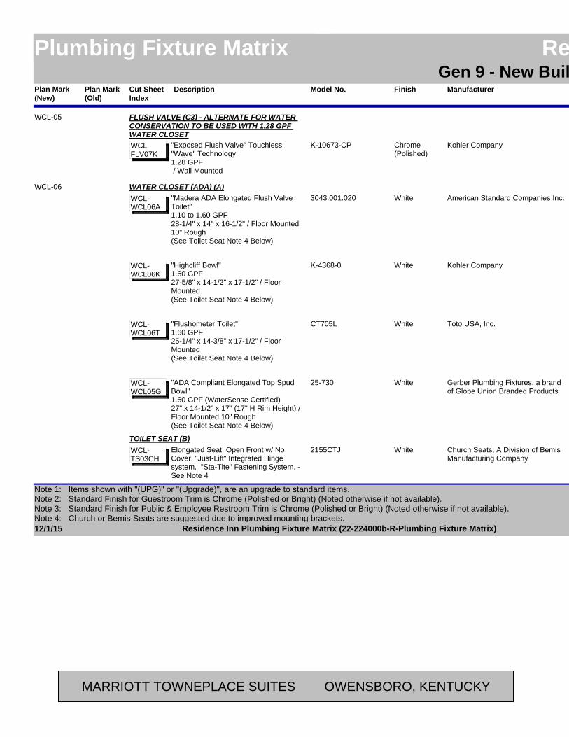
Plan Mark (Old)
ManufacturerModel No. LocationAreaFinishPlan Mark (New)
Residence InnPlumbing Fixture Matrix Residence InnGen 9 - New Build - Possibilities
DescriptionCut Sheet Index
Kohler CompanyK-10673-CP RestroomPublicChrome(Polished)
WCL-05 FLUSH VALVE (C3) - ALTERNATE FOR WATER CONSERVATION TO BE USED WITH 1.28 GPF WATER CLOSET
"Exposed Flush Valve" Touchless "Wave" Technology1.28 GPF / Wall Mounted
WCL-FLV07K
American Standard Companies Inc.3043.001.020 RestroomPublicWhiteWCL-06 WATER CLOSET (ADA) (A)
"Madera ADA Elongated Flush Valve Toilet"1.10 to 1.60 GPF28-1/4" x 14" x 16-1/2" / Floor Mounted 10" Rough(See Toilet Seat Note 4 Below)
WCL-WCL06A
Kohler CompanyK-4368-0 RestroomPublicWhite"Highcliff Bowl"1.60 GPF27-5/8" x 14-1/2" x 17-1/2" / Floor Mounted(See Toilet Seat Note 4 Below)
WCL-WCL06K
Toto USA, Inc.CT705L RestroomPublicWhite"Flushometer Toilet"1.60 GPF25-1/4" x 14-3/8" x 17-1/2" / Floor Mounted(See Toilet Seat Note 4 Below)
WCL-WCL06T
Gerber Plumbing Fixtures, a brand of Globe Union Branded Products
25-730 RestroomPublicWhite"ADA Compliant Elongated Top Spud Bowl"1.60 GPF (WaterSense Certified)27" x 14-1/2" x 17" (17" H Rim Height) / Floor Mounted 10" Rough(See Toilet Seat Note 4 Below)
WCL-WCL05G
Church Seats, A Division of Bemis Manufacturing Company
2155CTJ RestroomPublicWhiteTOILET SEAT (B)
Elongated Seat, Open Front w/ No Cover. "Just-Lift" Integrated Hinge system. "Sta-Tite" Fastening System. - See Note 4
WCL-TS03CH
12/1/15 Page 32 of 42Residence Inn Plumbing Fixture Matrix (22-224000b-R-Plumbing Fixture Matrix)
Note 1: Items shown with "(UPG)" or "(Upgrade)", are an upgrade to standard items.Note 2: Standard Finish for Guestroom Trim is Chrome (Polished or Bright) (Noted otherwise if not available). Note 3: Standard Finish for Public & Employee Restroom Trim is Chrome (Polished or Bright) (Noted otherwise if not available).Note 4: Church or Bemis Seats are suggested due to improved mounting brackets.
MARRIOTT TOWNEPLACE SUITES OWENSBORO, KENTUCKY

Plan Mark (Old)
ManufacturerModel No. LocationAreaFinishPlan Mark (New)
Residence InnPlumbing Fixture Matrix Residence InnGen 9 - New Build - Possibilities
DescriptionCut Sheet Index
American Standard Companies Inc.5901.100.020 RestroomPublicWhiteWCL-06 TOILET SEAT (B)
Open Front w/ No CoverWCL-TS02A
Kohler CompanyK-4731-C-0 RestroomPublicWhite"Stronghold" Open Front w/ No CoverWCL-TS02K
Toto USA, Inc.SC534 RestroomPublicWhiteOpen Front w/ No CoverWCL-TS01T
American Standard Companies Inc.6047.161.002 RestroomPublicChrome(Polished)
FLUSH VALVE (C1)Exposed Flush Valve - Manual OperationADA Compliant1.60 GPF / Wall Mounted
WCL-FLV01A
Kohler CompanyK-13516-CP RestroomPublicChrome(Polished)
Exposed Flush Valve - Manual OperationADA Compliant1.60 GPF / Wall Mounted
WCL-FLV01K
Delta Faucet Company81T201 RestroomPublicChrome(Polished)
Exposed Flush Valves - Manual OperationADA Compliant1.60 GPF / Wall Mounted
WCL-FLV01D
American Standard Companies Inc.6065.161.002 RestroomPublicChrome(Polished)
FLUSH VALVE (C2) - UPGRADE OPTIONSelectronic Sensor Operated, Concealed Flush ValveADA Compliant1.60 GPF / Wall Mounted
WCL-FLV03A
12/1/15 Page 33 of 42Residence Inn Plumbing Fixture Matrix (22-224000b-R-Plumbing Fixture Matrix)
Note 1: Items shown with "(UPG)" or "(Upgrade)", are an upgrade to standard items.Note 2: Standard Finish for Guestroom Trim is Chrome (Polished or Bright) (Noted otherwise if not available). Note 3: Standard Finish for Public & Employee Restroom Trim is Chrome (Polished or Bright) (Noted otherwise if not available).Note 4: Church or Bemis Seats are suggested due to improved mounting brackets.
MARRIOTT TOWNEPLACE SUITES OWENSBORO, KENTUCKY

Plan Mark (Old)
ManufacturerModel No. LocationAreaFinishPlan Mark (New)
Residence InnPlumbing Fixture Matrix Residence InnGen 9 - New Build - Possibilities
DescriptionCut Sheet Index
Kohler CompanyK-10674-SV-CP RestroomPublicChrome(Polished)
WCL-06 FLUSH VALVE (C2) - UPGRADE OPTION"Exposed Flush Valve" Touchless "Wave" Technology1.60 GPF / Wall Mounted
WCL-FLV03K
Delta Faucet Company81T201BTA RestroomPublicChrome(Polished)
Electronic Exposed TECK Flush ValvesADA Compliant1.60 GPF / Wall Mounted
WCL-FLV03D
American Standard Companies Inc.6065.121.002 RestroomPublicChrome(Polished)
FLUSH VALVE (C3) - ALTERNATE FOR WATER CONSERVATION TO BE USED WITH 1.28 GPF WATER CLOSET
Selectronic Sensor Operated, Concealed Flush ValveADA Compliant1.28 GPF / Wall Mounted
WCL-FLV07A
Kohler CompanyK-10673-CP RestroomPublicChrome(Polished)
"Exposed Flush Valve" Touchless "Wave" Technology1.28 GPF / Wall Mounted
WCL-FLV07K
Moen Incorporated8311 RestroomPublicChrome(Polished)
M-Power Sensor Operated, Concealed Flush ValveADA Compliant with manual override1.28 GPF / Wall Mounted
WCL-FLV07M
Delta Faucet Company81T201BTA-48 RestroomPublicChrome(Polished)
Electronic Exposed TECK Flush ValvesADA Compliant1.28 GPF / Wall Mounted
WCL-FLV07D
12/1/15 Page 34 of 42Residence Inn Plumbing Fixture Matrix (22-224000b-R-Plumbing Fixture Matrix)
Note 1: Items shown with "(UPG)" or "(Upgrade)", are an upgrade to standard items.Note 2: Standard Finish for Guestroom Trim is Chrome (Polished or Bright) (Noted otherwise if not available). Note 3: Standard Finish for Public & Employee Restroom Trim is Chrome (Polished or Bright) (Noted otherwise if not available).Note 4: Church or Bemis Seats are suggested due to improved mounting brackets.
MARRIOTT TOWNEPLACE SUITES OWENSBORO, KENTUCKY
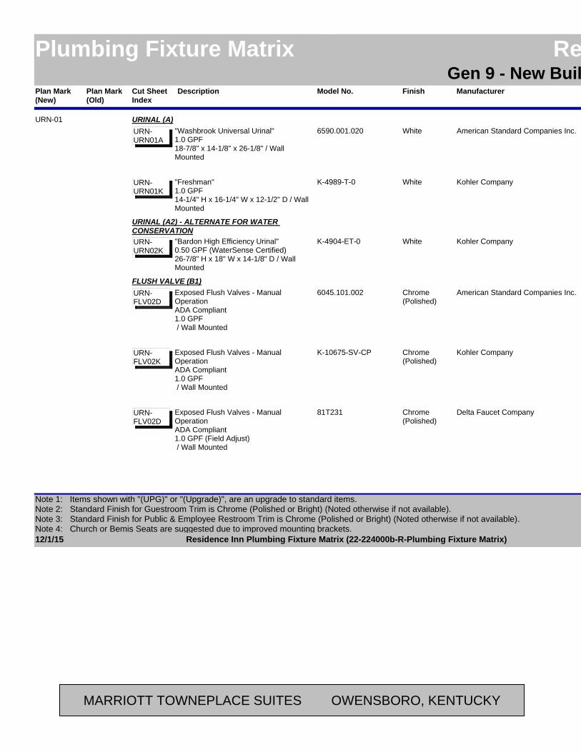
Plan Mark (Old)
ManufacturerModel No. LocationAreaFinishPlan Mark (New)
Residence InnPlumbing Fixture Matrix Residence InnGen 9 - New Build - Possibilities
DescriptionCut Sheet Index
American Standard Companies Inc.6590.001.020 RestroomPublicWhiteURN-01 URINAL (A)
"Washbrook Universal Urinal"1.0 GPF18-7/8" x 14-1/8" x 26-1/8" / Wall Mounted
URN-URN01A
Kohler CompanyK-4989-T-0 RestroomPublicWhite"Freshman"1.0 GPF14-1/4" H x 16-1/4" W x 12-1/2" D / Wall Mounted
URN-URN01K
Kohler CompanyK-4904-ET-0 RestroomPublicWhite
URINAL (A2) - ALTERNATE FOR WATER CONSERVATION
"Bardon High Efficiency Urinal"0.50 GPF (WaterSense Certified)26-7/8" H x 18" W x 14-1/8" D / Wall Mounted
URN-URN02K
American Standard Companies Inc.6045.101.002 RestroomPublicChrome(Polished)
FLUSH VALVE (B1)Exposed Flush Valves - Manual OperationADA Compliant1.0 GPF / Wall Mounted
URN-FLV02D
Kohler CompanyK-10675-SV-CP RestroomPublicChrome(Polished)
Exposed Flush Valves - Manual OperationADA Compliant1.0 GPF / Wall Mounted
URN-FLV02K
Delta Faucet Company81T231 RestroomPublicChrome(Polished)
Exposed Flush Valves - Manual OperationADA Compliant1.0 GPF (Field Adjust) / Wall Mounted
URN-FLV02D
12/1/15 Page 35 of 42Residence Inn Plumbing Fixture Matrix (22-224000b-R-Plumbing Fixture Matrix)
Note 1: Items shown with "(UPG)" or "(Upgrade)", are an upgrade to standard items.Note 2: Standard Finish for Guestroom Trim is Chrome (Polished or Bright) (Noted otherwise if not available). Note 3: Standard Finish for Public & Employee Restroom Trim is Chrome (Polished or Bright) (Noted otherwise if not available).Note 4: Church or Bemis Seats are suggested due to improved mounting brackets.
MARRIOTT TOWNEPLACE SUITES OWENSBORO, KENTUCKY

Plan Mark (Old)
ManufacturerModel No. LocationAreaFinishPlan Mark (New)
Residence InnPlumbing Fixture Matrix Residence InnGen 9 - New Build - Possibilities
DescriptionCut Sheet Index
American Standard Companies Inc.6063.101.002 RestroomPublicChrome(Polished)
URN-01 FLUSH VALVE (B2) - UPGRADE OPTIONSelectronic Sensor Operated Flush ValveADA Compliant1.0 GPF / Wall Mounted
URN-FLV04D
Kohler CompanyK-10676-SV-CP RestroomPublicChrome(Polished)
"Wshdwn Flushometer" Touchless "Wave" TechnologyADA Compliant1.0 GPF / Wall Mounted
URN-FLV04K
Delta Faucet Company81T231BTA-38 RestroomPublicChrome(Polished)
Electronic Exposed TECK Flush ValvesADA Compliant1.0 GPF / Wall Mounted
URN-FLV04D
American Standard Companies Inc.6063.051.002 RestroomPublicChrome(Polished)
FLUSH VALVE (B3) - ALTERNATE FOR WATER CONSERVATION TO BE USED WITH 0.50 GPF URINAL
Selectronic Sensor Operated Flush ValveADA Compliant0.50 GPF / Wall Mounted
URN-FLV08A
Kohler CompanyK-10675-SV-CP RestroomPublicChrome(Polished)
"Exposed Flush Valve" Touchless "Wave" Technology0.50 GPF / Wall Mounted
URN-FLV02K
Moen Incorporated8315 RestroomPublicChrome(Polished)
M-Power Sensor Operated Flush ValveADA Compliant with manual override0.50 GPF / Wall Mounted
URN-FLV08M
12/1/15 Page 36 of 42Residence Inn Plumbing Fixture Matrix (22-224000b-R-Plumbing Fixture Matrix)
Note 1: Items shown with "(UPG)" or "(Upgrade)", are an upgrade to standard items.Note 2: Standard Finish for Guestroom Trim is Chrome (Polished or Bright) (Noted otherwise if not available). Note 3: Standard Finish for Public & Employee Restroom Trim is Chrome (Polished or Bright) (Noted otherwise if not available).Note 4: Church or Bemis Seats are suggested due to improved mounting brackets.
MARRIOTT TOWNEPLACE SUITES OWENSBORO, KENTUCKY

Plan Mark (Old)
ManufacturerModel No. LocationAreaFinishPlan Mark (New)
Residence InnPlumbing Fixture Matrix Residence InnGen 9 - New Build - Possibilities
DescriptionCut Sheet Index
Delta Faucet Company81T231BTA-05 RestroomPublicChrome(Polished)
URN-01 FLUSH VALVE (B3) - ALTERNATE FOR WATER CONSERVATION TO BE USED WITH 0.50 GPF URINAL
Electronic Exposed TECK Flush ValvesADA Compliant0.50 GPF / Wall Mounted
URN-FLV08D
American Standard Companies Inc.6590.001.020 RestroomPublicWhiteURN-02 URINAL (ADA) (A1)
"Washbrook Universal Urinal"1.0 GPF18-7/8" x 14-1/8" x 26-1/8" / Wall Mounted
URN-URN01A
Kohler CompanyK-4989-T-0 RestroomPublicWhite"Freshman"1.0 GPF14-1/4" H x 16-1/4" W x 12-1/2" D / Wall Mounted
URN-URN01K
Kohler CompanyK-4904-ET-0 RestroomPublicWhite
URINAL (ADA) (A2) - ALTERNATE FOR WATER CONSERVATION
"Bardon High Efficiency Urinal"0.50 GPF (WaterSense Certified)26-7/8" H x 18" W x 14-1/8" D / Wall Mounted
URN-URN02K
American Standard Companies Inc.6045.101.002 RestroomPublicChrome(Polished)
FLUSH VALVE (B1)Exposed Flush Valves - Manual OperationADA Compliant1.0 GPF / Wall Mounted
URN-FLV02D
Kohler CompanyK-10675-SV-CP RestroomPublicChrome(Polished)
Exposed Flush Valves - Manual OperationADA Compliant1.0 GPF / Wall Mounted
URN-FLV02K
12/1/15 Page 37 of 42Residence Inn Plumbing Fixture Matrix (22-224000b-R-Plumbing Fixture Matrix)
Note 1: Items shown with "(UPG)" or "(Upgrade)", are an upgrade to standard items.Note 2: Standard Finish for Guestroom Trim is Chrome (Polished or Bright) (Noted otherwise if not available). Note 3: Standard Finish for Public & Employee Restroom Trim is Chrome (Polished or Bright) (Noted otherwise if not available).Note 4: Church or Bemis Seats are suggested due to improved mounting brackets.
MARRIOTT TOWNEPLACE SUITES OWENSBORO, KENTUCKY

Plan Mark (Old)
ManufacturerModel No. LocationAreaFinishPlan Mark (New)
Residence InnPlumbing Fixture Matrix Residence InnGen 9 - New Build - Possibilities
DescriptionCut Sheet Index
Delta Faucet Company81T231 RestroomPublicChrome(Polished)
URN-02 FLUSH VALVE (B1)Exposed Flush Valves - Manual OperationADA Compliant1.0 GPF (Field Adjust) / Wall Mounted
URN-FLV02D
American Standard Companies Inc.6063.101.002 RestroomPublicChrome(Polished)
FLUSH VALVE (B2) - UPGRADE OPTIONSelectronic Sensor Operated Flush ValveADA Compliant1.0 GPF / Wall Mounted
URN-FLV04D
Kohler CompanyK-10676-SV-CP RestroomPublicChrome(Polished)
"Wshdwn Flushometer" Touchless "Wave" TechnologyADA Compliant1.0 GPF / Wall Mounted
URN-FLV04K
Delta Faucet Company81T231BTA-38 RestroomPublicChrome(Polished)
Electronic Exposed TECK Flush ValvesADA Compliant1.0 GPF / Wall Mounted
URN-FLV04D
American Standard Companies Inc.6063.051.002 RestroomPublicChrome(Polished)
FLUSH VALVE (B3) - ALTERNATE FOR WATER CONSERVATION TO BE USED WITH 0.50 GPF URINAL
Selectronic Sensor Operated Flush ValveADA Compliant0.50 GPF / Wall Mounted
URN-FLV08A
Kohler CompanyK-10675-SV-CP RestroomPublicChrome(Polished)
"Exposed Flush Valve" Touchless "Wave" Technology0.50 GPF / Wall Mounted
URN-FLV02K
12/1/15 Page 38 of 42Residence Inn Plumbing Fixture Matrix (22-224000b-R-Plumbing Fixture Matrix)
Note 1: Items shown with "(UPG)" or "(Upgrade)", are an upgrade to standard items.Note 2: Standard Finish for Guestroom Trim is Chrome (Polished or Bright) (Noted otherwise if not available). Note 3: Standard Finish for Public & Employee Restroom Trim is Chrome (Polished or Bright) (Noted otherwise if not available).Note 4: Church or Bemis Seats are suggested due to improved mounting brackets.
MARRIOTT TOWNEPLACE SUITES OWENSBORO, KENTUCKY
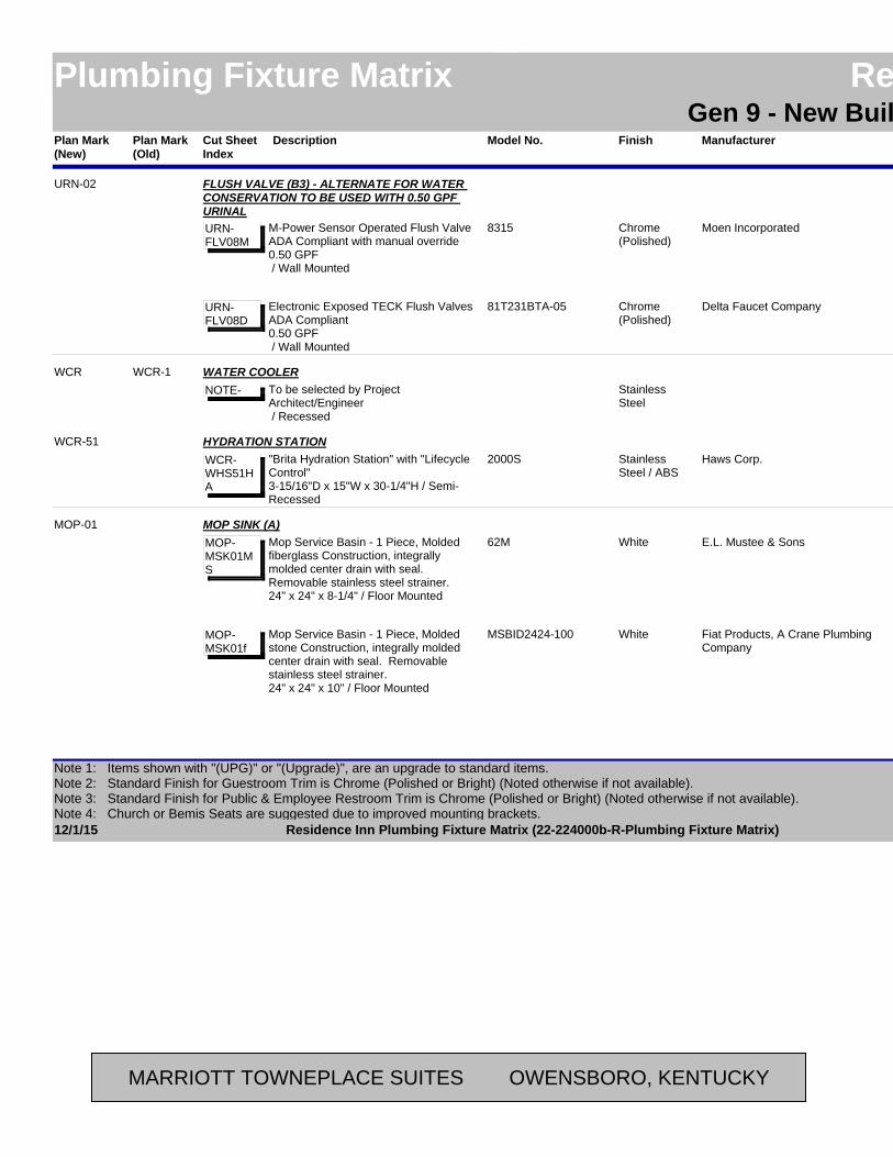
Plan Mark (Old)
ManufacturerModel No. LocationAreaFinishPlan Mark (New)
Residence InnPlumbing Fixture Matrix Residence InnGen 9 - New Build - Possibilities
DescriptionCut Sheet Index
Moen Incorporated8315 RestroomPublicChrome(Polished)
URN-02 FLUSH VALVE (B3) - ALTERNATE FOR WATER CONSERVATION TO BE USED WITH 0.50 GPF URINAL
M-Power Sensor Operated Flush ValveADA Compliant with manual override0.50 GPF / Wall Mounted
URN-FLV08M
Delta Faucet Company81T231BTA-05 RestroomPublicChrome(Polished)
Electronic Exposed TECK Flush ValvesADA Compliant0.50 GPF / Wall Mounted
URN-FLV08D
WCR-1(As Required)PublicStainless
Steel
WCR WATER COOLERTo be selected by Project Architect/Engineer / Recessed
NOTE-
Haws Corp.2000S (As Required)PublicStainless Steel / ABS
WCR-51 HYDRATION STATION"Brita Hydration Station" with "Lifecycle Control"3-15/16"D x 15"W x 30-1/4"H / Semi-Recessed
WCR-WHS51HA
E.L. Mustee & Sons62M (As Required)Back-of-House
WhiteMOP-01 MOP SINK (A)
Mop Service Basin - 1 Piece, Molded fiberglass Construction, integrally molded center drain with seal. Removable stainless steel strainer.24" x 24" x 8-1/4" / Floor Mounted
MOP-MSK01MS
Fiat Products, A Crane Plumbing Company
MSBID2424-100 (As Required)Back-of-House
WhiteMop Service Basin - 1 Piece, Molded stone Construction, integrally molded center drain with seal. Removable stainless steel strainer.24" x 24" x 10" / Floor Mounted
MOP-MSK01f
12/1/15 Page 39 of 42Residence Inn Plumbing Fixture Matrix (22-224000b-R-Plumbing Fixture Matrix)
Note 1: Items shown with "(UPG)" or "(Upgrade)", are an upgrade to standard items.Note 2: Standard Finish for Guestroom Trim is Chrome (Polished or Bright) (Noted otherwise if not available). Note 3: Standard Finish for Public & Employee Restroom Trim is Chrome (Polished or Bright) (Noted otherwise if not available).Note 4: Church or Bemis Seats are suggested due to improved mounting brackets.
MARRIOTT TOWNEPLACE SUITES OWENSBORO, KENTUCKY
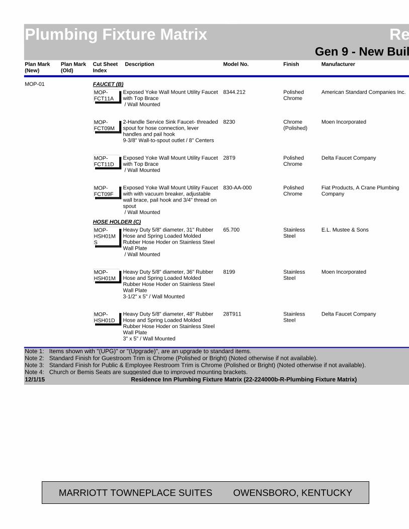
Plan Mark (Old)
ManufacturerModel No. LocationAreaFinishPlan Mark (New)
Residence InnPlumbing Fixture Matrix Residence InnGen 9 - New Build - Possibilities
DescriptionCut Sheet Index
American Standard Companies Inc.8344.212 (As Required)Back-of-House
Polished Chrome
MOP-01 FAUCET (B)Exposed Yoke Wall Mount Utility Faucet with Top Brace / Wall Mounted
MOP-FCT11A
Moen Incorporated8230 (As Required)Back-of-House
Chrome(Polished)
2-Handle Service Sink Faucet- threaded spout for hose connection, lever handles and pail hook9-3/8" Wall-to-spout outlet / 8" Centers
MOP-FCT09M
Delta Faucet Company28T9 (As Required)Back-of-House
Polished Chrome
Exposed Yoke Wall Mount Utility Faucet with Top Brace / Wall Mounted
MOP-FCT11D
Fiat Products, A Crane Plumbing Company
830-AA-000 (As Required)Back-of-House
Polished Chrome
Exposed Yoke Wall Mount Utility Faucet with with vacuum breaker, adjustable wall brace, pail hook and 3/4" thread on spout / Wall Mounted
MOP-FCT09F
E.L. Mustee & Sons65.700 (As Required)Back-of-House
Stainless Steel
HOSE HOLDER (C)Heavy Duty 5/8" diameter, 31" Rubber Hose and Spring Loaded Molded Rubber Hose Hoder on Stainless Steel Wall Plate / Wall Mounted
MOP-HSH01MS
Moen Incorporated8199 (As Required)Back-of-House
Stainless Steel
Heavy Duty 5/8" diameter, 36" Rubber Hose and Spring Loaded Molded Rubber Hose Hoder on Stainless Steel Wall Plate3-1/2" x 5" / Wall Mounted
MOP-HSH01M
Delta Faucet Company28T911 (As Required)Back-of-House
Stainless Steel
Heavy Duty 5/8" diameter, 48" Rubber Hose and Spring Loaded Molded Rubber Hose Hoder on Stainless Steel Wall Plate3" x 5" / Wall Mounted
MOP-HSH01D
12/1/15 Page 40 of 42Residence Inn Plumbing Fixture Matrix (22-224000b-R-Plumbing Fixture Matrix)
Note 1: Items shown with "(UPG)" or "(Upgrade)", are an upgrade to standard items.Note 2: Standard Finish for Guestroom Trim is Chrome (Polished or Bright) (Noted otherwise if not available). Note 3: Standard Finish for Public & Employee Restroom Trim is Chrome (Polished or Bright) (Noted otherwise if not available).Note 4: Church or Bemis Seats are suggested due to improved mounting brackets.
MARRIOTT TOWNEPLACE SUITES OWENSBORO, KENTUCKY

Plan Mark (Old)
ManufacturerModel No. LocationAreaFinishPlan Mark (New)
Residence InnPlumbing Fixture Matrix Residence InnGen 9 - New Build - Possibilities
DescriptionCut Sheet Index
Fiat Products, A Crane Plumbing Company
832-AA-000 (As Required)Back-of-House
Stainless Steel
MOP-01 HOSE HOLDER (C)Heavy Duty 5/8" diameter, 30" Rubber Hose and Spring Loaded Molded Rubber Hose Hoder on Stainless Steel Wall Plate / Wall Mounted
MOP-HSH01F
E.L. Mustee & Sons63.600 (As Required)Back-of-House
Stainless Steel
MOP HANGER (D)Three spring-loaded, molded rubber mop holders attached to stainless steel wall plate.3" x 24" / Wall Mounted
MOP-MPH01MS
Moen Incorporated8198 (As Required)Back-of-House
Stainless Steel
Three spring-loaded, molded rubber mop holders attached to stainless steel wall plate.3-1/2" x 26" / Wall Mounted
MOP-MPH01M
Delta Faucet Company28T910 (As Required)Back-of-House
Stainless Steel
Three spring-loaded, molded rubber mop holders attached to stainless steel wall plate.3" x 24" / Wall Mounted
MOP-MPH01D
Fiat Products, A Crane Plumbing Company
889-CC-000 (As Required)Back-of-House
Stainless Steel
Three spring-loaded, molded rubber mop holders attached to stainless steel wall plate.3" x 24" / Wall Mounted
MOP-MPH01F
E.L. Mustee & Sons67.2424 (As Required)Back-of-House
Stainless Steel
WALL GUARD (E)12" High, 20 Gauge, #304 Stainless Steel wall guard / Wall Mounted
MOP-WGD01MS
Fiat Products, A Crane Plumbing Company
MSG2424-000 (As Required)Back-of-House
Stainless Steel
Two (2), 12" High, 20 Gauge, #304 Stainless Steel wall guard plus corner bracket / Wall Mounted
MOP-WGD01F
12/1/15 Page 41 of 42Residence Inn Plumbing Fixture Matrix (22-224000b-R-Plumbing Fixture Matrix)
Note 1: Items shown with "(UPG)" or "(Upgrade)", are an upgrade to standard items.Note 2: Standard Finish for Guestroom Trim is Chrome (Polished or Bright) (Noted otherwise if not available). Note 3: Standard Finish for Public & Employee Restroom Trim is Chrome (Polished or Bright) (Noted otherwise if not available).Note 4: Church or Bemis Seats are suggested due to improved mounting brackets.
MARRIOTT TOWNEPLACE SUITES OWENSBORO, KENTUCKY

Plan Mark (Old)
ManufacturerModel No. LocationAreaFinishPlan Mark (New)
Residence InnPlumbing Fixture Matrix Residence InnGen 9 - New Build - Possibilities
DescriptionCut Sheet Index
CLO-01(As Required)Per Code
CLO CLEANOUTTo be selected by Project Architect/Engineer
NOTE-
EWS-1(As Required)Per Code
EWS EYE WASHTo be selected by Project Architect/Engineer
NOTE-
FLD-01Restroom /Employee Restroom
PublicFLD FLOOR DRAIN
To be selected by Project Architect/Engineer
NOTE-
FSK-01(As Required)Per Code
FSK FLOOR SINKTo be selected by Project Architect/Engineer
NOTE-
LIT-01LaundryBack-of-
House
LIT LINT INTERCEPTORTo be selected by Project Architect/Engineer
NOTE-
HYD-01(As Required)Exterior
HYD WALL HYDRANTTo be selected by Project Architect/Engineer
NOTE-
RDR-01RoofExterior
RDR ROOF DRAINTo be selected by Project Architect/Engineer
NOTE-
12/1/15 Page 42 of 42Residence Inn Plumbing Fixture Matrix (22-224000b-R-Plumbing Fixture Matrix)
Note 1: Items shown with "(UPG)" or "(Upgrade)", are an upgrade to standard items.Note 2: Standard Finish for Guestroom Trim is Chrome (Polished or Bright) (Noted otherwise if not available). Note 3: Standard Finish for Public & Employee Restroom Trim is Chrome (Polished or Bright) (Noted otherwise if not available).Note 4: Church or Bemis Seats are suggested due to improved mounting brackets.
MARRIOTT TOWNEPLACE SUITES OWENSBORO, KENTUCKY
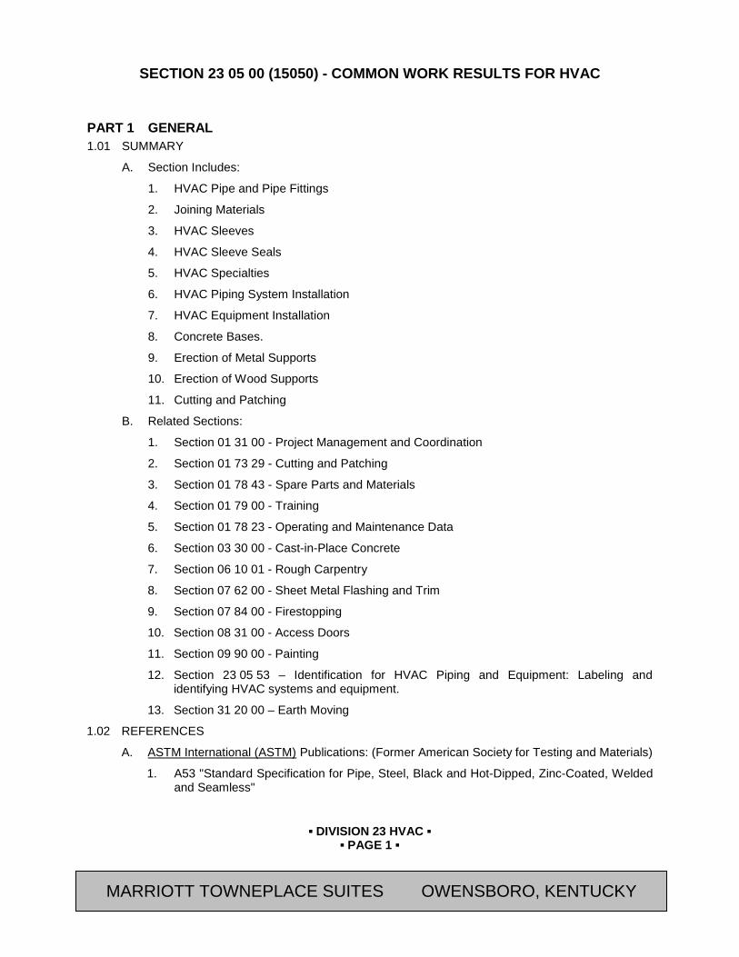
▪ DIVISION 23 HVAC ▪
▪ PAGE 1 ▪
RESIDENCE INN BY MARRIOTT - LITTLETON, COLORADO
SECTION 23 05 00 (15050) - COMMON WORK RESULTS FOR HVAC
PART 1 GENERAL 1.01 SUMMARY
A. Section Includes:
1. HVAC Pipe and Pipe Fittings
2. Joining Materials
3. HVAC Sleeves
4. HVAC Sleeve Seals
5. HVAC Specialties
6. HVAC Piping System Installation
7. HVAC Equipment Installation
8. Concrete Bases.
9. Erection of Metal Supports
10. Erection of Wood Supports
11. Cutting and Patching
B. Related Sections:
1. Section 01 31 00 - Project Management and Coordination
2. Section 01 73 29 - Cutting and Patching
3. Section 01 78 43 - Spare Parts and Materials
4. Section 01 79 00 - Training
5. Section 01 78 23 - Operating and Maintenance Data
6. Section 03 30 00 - Cast-in-Place Concrete
7. Section 06 10 01 - Rough Carpentry
8. Section 07 62 00 - Sheet Metal Flashing and Trim
9. Section 07 84 00 - Firestopping
10. Section 08 31 00 - Access Doors
11. Section 09 90 00 - Painting
12. Section 23 05 53 – Identification for HVAC Piping and Equipment: Labeling and identifying HVAC systems and equipment.
13. Section 31 20 00 – Earth Moving
1.02 REFERENCES
A. ASTM International (ASTM) Publications: (Former American Society for Testing and Materials)
1. A53 "Standard Specification for Pipe, Steel, Black and Hot-Dipped, Zinc-Coated, Welded and Seamless"
MARRIOTT TOWNEPLACE SUITES OWENSBORO, KENTUCKY
▪ DIVISION 23 HVAC ▪
▪ PAGE 2 ▪
RESIDENCE INN BY MARRIOTT - LITTLETON, COLORADO
2. B32 "Standard Specification for Solder Metal"
3. C1107 "Standard Specification for Packaged Dry, Hydraulic-Cement Grout (Nonshrink)"
B. American Welding Society (AWS) Publications:
1. BRH "Brazing Handbook"
2. A5.8 "Specification for Filler Metals For Brazing And Braze Welding"
3. D1.1 "Structural Welding Code - Steel"
4. D10.12 "Guide for Welding Mild Steel Pipe"
C. Copper Development Association (CDA) Publications:
1. "Copper Tube Handbook"
1.03 DEFINITIONS
A. Finished Spaces: Spaces other than mechanical and electrical equipment rooms, furred spaces, pipe and duct shafts, unheated spaces immediately below roof, spaces above ceilings, unexcavated spaces, crawl spaces, and tunnels.
B. Exposed, Interior Installations: Exposed to view indoors. Examples include finished occupied spaces and mechanical equipment rooms.
C. Exposed, Exterior Installations: Exposed to view outdoors, or subject to outdoor ambient temperatures and weather conditions. Examples include rooftop locations.
D. Concealed, Interior Installations: Concealed from view and protected from physical contact by building occupants. Examples include above ceilings and in duct shafts.
E. Concealed, Exterior Installations: Concealed from view and protected from weather conditions and physical contact by building occupants, but subject to outdoor ambient temperatures. Examples include installations within unheated shelters.
F. The following are industry abbreviations for plastic materials:
1. ABS: Acrylonitrile-butadiene-styrene plastic.
2. CPVC: Chlorinated polyvinyl chloride plastic.
3. PVC: Polyvinyl chloride plastic.
1.04 SUBMITTALS
A. General: Submit the following in accordance with Conditions of Contract and Division 01 Specification Sections.
B. Submit “Letter of Conformance” in accordance with Section 01 33 00 (01330) indicating specified items selected for use in project with the following supporting data.
1. Product Data: For dielectric fittings, flexible connectors, plumbing sleeve seals, and identification materials and devices.
2. Coordination Drawings: Detail major elements, components, and systems of plumbing equipment and materials in relationship with other systems, installations, and building components. Show space requirements for installation and access. Indicate if sequence and coordination of installations are important to efficient flow of the Work. Include the following:
a. Planned piping layout, including valve and specialty locations and valve-stem movement.
MARRIOTT TOWNEPLACE SUITES OWENSBORO, KENTUCKY

▪ DIVISION 23 HVAC ▪
▪ PAGE 3 ▪
RESIDENCE INN BY MARRIOTT - LITTLETON, COLORADO
b. Clearances for installing and maintaining insulation.
c. Clearances for servicing and maintaining equipment, accessories, and specialties, including space for disassembly required for periodic maintenance.
d. Equipment and accessory service connections and support details.
e. Exterior wall and foundation penetrations.
f. Fire-rated wall and floor penetrations.
g. Sizes and location of required concrete pads and bases.
h. Scheduling, sequencing, movement, and positioning of large equipment into building during construction.
i. Floor plans, elevations, and details to indicate penetrations in floors, walls, and ceilings and their relationship to other penetrations and installations.
1.05 QUALITY ASSURANCE
A. Equipment Selection: Equipment of higher electrical characteristics, physical dimensions, capacities, and ratings may be furnished provided such proposed equipment is approved in writing and connecting plumbing and electrical services, circuit breakers, conduit, motors, bases, and equipment spaces are increased. Additional costs shall be approved in advance by appropriate Contract Modification for these increases.
1. If minimum energy ratings or efficiencies of equipment are specified, equipment must meet design requirements. See drawings for equipment schedules and requirements.
1.06 DELIVERY, STORAGE, AND HANDLING
A. Deliver pipes and tubes with factory-applied end caps. Maintain end caps through shipping, storage, and handling to prevent pipe end damage and prevent entrance of dirt, debris, and moisture.
B. Protect stored pipes and tubes from moisture and dirt. Elevate above grade. Do not exceed structural capacity of floor, if stored inside.
C. Protect flanges, fittings, and piping specialties from moisture and dirt.
D. Store plastic pipes protected from direct sunlight. Support to prevent sagging and bending.
1.07 SEQUENCING AND SCHEDULING
A. Coordinate HVAC equipment installation with other building components.
B. Arrange for pipe spaces, chases, slots, and openings in building structure during progress of construction to allow for mechanical installations.
C. Coordinate installation of required supporting devices and set sleeves in poured-in-place concrete and other structural components, as they are constructed.
D. Sequence, coordinate, and integrate installations of mechanical materials and equipment for efficient flow of the Work. Coordinate installation of large equipment requiring positioning before closing in building.
E. Coordinate connection of HVAC systems with exterior underground and overhead utilities and services. Comply with requirements of governing regulations, franchised service companies, and controlling agencies.
F. Coordinate requirements for access panels and doors if mechanical items requiring access are concealed behind finished surfaces. Access panels and doors are specified in Section 08 31 00 - "Access Doors and Panels."
MARRIOTT TOWNEPLACE SUITES OWENSBORO, KENTUCKY
▪ DIVISION 23 HVAC ▪
▪ PAGE 4 ▪
RESIDENCE INN BY MARRIOTT - LITTLETON, COLORADO
G. Coordinate installation of identifying devices after completing covering and painting, if devices are applied to surfaces. Install identifying devices before installing acoustical ceilings and similar concealment.
1.08 Posted Operating Instructions
A. Provide and post operating instructions for all HVAC systems.
PART 2 PRODUCTS 2.01 MANUFACTURERS
A. Avendra, LLC Preferred Manufacturers:
1. HVAC Sleeve Seals:
a. None
B. Approved Manufacturers:
1. HVAC Sleeve Seals:
a. Metraflex Inc. (800-621-4347)
b. PSI-Thunderline/Link-Seal (800-423-2410)
2.02 JOINING MATERIALS
A. Solder Filler Metals: ASTM B32.
1. Alloy Sn95 or Alloy Sn94: Approximately 95 percent tin and 5 percent silver, with 0.10 percent lead content.
2. Alloy E: Approximately 95 percent tin and 5 percent copper, with 0.10 percent maximum lead content.
3. Alloy HA: Tin-antimony-silver-copper zinc, with 0.10 percent maximum lead content.
4. Alloy HB: Tin-antimony-silver-copper nickel, with 0.10 percent maximum lead content.
5. Alloy Sb5: 95 percent tin and 5 percent antimony, with 0.20 percent maximum lead content.
B. Brazing Filler Metals: AWS A5.8.
1. BCuP Series: Copper-phosphorus alloys.
2. BAg1: Silver alloy.
3. Welding Filler Metals: Comply with AWS D10.12 for welding materials appropriate for wall thickness and chemical analysis of steel pipe being welded.
2.03 HVAC SLEEVES
A. Sleeves: The following materials are for wall, floor, slab, and roof penetrations:
1. Steel Sheet Metal: 0.0239-inch minimum thickness, galvanized, round tube closed with welded longitudinal joint.
2. Steel Pipe: ASTM A53, Type E, Grade A, Schedule 40, galvanized, plain ends.
3. Cast Iron: Cast or fabricated "wall pipe" equivalent to ductile-iron pressure pipe, with plain ends and integral water stop, unless otherwise indicated.
4. Stack Sleeve Fittings: Manufactured, cast-iron sleeve with integral clamping flange. Include clamping ring and bolts and nuts for membrane flashing.
MARRIOTT TOWNEPLACE SUITES OWENSBORO, KENTUCKY
▪ DIVISION 23 HVAC ▪
▪ PAGE 5 ▪
RESIDENCE INN BY MARRIOTT - LITTLETON, COLORADO
a. Underdeck Clamp: Clamping ring with set screws.
2.04 HVAC SLEEVE SEALS
A. Description: Modular design, with interlocking rubber links shaped to continuously fill annular space between pipe and sleeve. Include connecting bolts and pressure plates.
2.05 HVAC SPECIALTIES
A. Grout:
1. Non-shrink, Nonmetallic Grout: ASTM C1107, Grade B.
a. Characteristics: Post-hardening, volume-adjusting, dry, hydraulic-cement grout, non-staining, non-corrosive, nongaseous, and recommended for interior and exterior applications.
b. Design Mix: 5000-psig, 28-day compressive strength.
c. Packaging: Premixed and factory packaged.
PART 3 EXECUTION 3.01 HVAC PIPING SYSTEMS - COMMON REQUIREMENTS
A. General: Install HVAC piping as described below, unless piping Sections specifies otherwise. Individual Division 23 Piping Sections specifies unique piping installation requirements.
B. General Locations and Arrangements: Drawing plans, schematics, and diagrams indicate general location and arrangement of piping systems. Install piping as indicated, unless deviations to layout are approved on Coordination Drawings as required by Division 01 Sections and as outlined in Part 1 of this section.
C. Install components with pressure rating equal to or greater than system operating pressure.
D. Install piping in concealed interior and exterior locations, except in equipment rooms and service areas.
E. Install piping free of sags and bends.
F. Install exposed interior and exterior piping at right angles or parallel to building walls. Diagonal runs are prohibited, unless otherwise indicated.
G. Install piping tight to slabs, beams, joists, columns, walls, and other building elements. Allow sufficient space above removable ceiling panels to allow for ceiling panel removal.
H. Install piping to allow application of insulation plus 1-inch clearance around insulation.
I. Install sleeves for pipes passing through concrete and masonry walls, and concrete floor and roof slabs.
1. Cut sleeves to length for mounting flush with both surfaces.
a. Exception: Extend sleeves installed in floors of mechanical equipment areas or other wet areas 2 inches above finished floor level. Extend cast-iron sleeve fittings below floor slab as required to secure clamping rings where required.
2. Build sleeves into walls and slabs as work progresses.
3. Install sleeves large enough to provide 1/4-inch annular clear space between sleeve and pipe or pipe insulation.
4. Use Type S, Grade NS, Class 25, Use O, neutral-curing silicone sealant.
MARRIOTT TOWNEPLACE SUITES OWENSBORO, KENTUCKY
▪ DIVISION 23 HVAC ▪
▪ PAGE 6 ▪
RESIDENCE INN BY MARRIOTT - LITTLETON, COLORADO
J. Aboveground, Exterior-Wall, Pipe Penetrations: Seal penetrations using sleeves and mechanical sleeve seals. Size sleeve for 1-inch annular clear space between pipe and sleeve for installing mechanical sleeve seals.
1. Install steel pipe for sleeves smaller than 6 inches in diameter.
2. Install cast-iron "wall pipes" for sleeves 6 inches in diameter and larger.
3. Assemble and install mechanical sleeve seals according to manufacturer's written instructions. Tighten bolts that cause rubber sealing elements to expand and make watertight seal.
K. Fire-Barrier Penetrations: Maintain indicated fire rating of walls, partitions, ceilings, and floors at pipe penetrations. Seal pipe penetrations with fire stopping materials. Refer to Section 07 84 00 - "Firestopping" for materials.
L. Refer to equipment specifications in other Sections of these Specifications for roughing-in requirements.
M. Piping Joint Construction: Join pipe and fittings as follows and as specifically required in individual piping specification Sections:
1. Ream ends of pipes and tubes and remove burrs. Bevel plain ends of steel pipe.
2. Remove scale, slag, dirt, and debris from inside and outside of pipe and fittings before assembly.
3. Soldered Joints: Construct joints according to CDA’s "Copper Tube Handbook."
4. Brazed Joints: Construct joints according to AWS’s "Brazing Handbook," Chapter "Pipe and Tube."
3.02 EQUIPMENT INSTALLATION - COMMON REQUIREMENTS
A. Install equipment to provide maximum possible headroom, if mounting heights is not indicated.
B. Install equipment according to approved submittal data. Portions of the Work are shown only in diagrammatic form. Refer conflicts to Owner’s Representative.
C. Install equipment level and plumb, parallel and perpendicular to other building systems and components in exposed interior spaces, unless otherwise indicated.
D. Install mechanical equipment to facilitate service, maintenance, and repair or replacement of components. Connect equipment for ease of disconnecting, with minimum interference to other installations. Extend grease fittings to accessible locations.
E. Clearance from Electrical Equipment: Piping and ductwork are prohibited in electric rooms and closets, elevator machine rooms and installation over transformers, switchboards and motor control centers.
3.03 ERECTION OF METAL SUPPORTS AND ANCHORAGE
A. Cut, fit, and place miscellaneous metal supports accurately in location, alignment, and elevation to support and anchor mechanical materials and equipment.
B. Field Welding: Comply with AWS D1.1, "Structural Welding Code--Steel."
C. Prime and paint all metal supports per Section 09 90 00 requirements similar to “Pipes and Mechanical Equipment”.
3.04 ERECTION OF WOOD SUPPORTS AND ANCHORAGE
A. Cut, fit, and place wood grounds, nailers, blocking, and anchorage to support and anchor HVAC materials and equipment.
MARRIOTT TOWNEPLACE SUITES OWENSBORO, KENTUCKY
▪ DIVISION 23 HVAC ▪
▪ PAGE 7 ▪
RESIDENCE INN BY MARRIOTT - LITTLETON, COLORADO
B. Select fastener sizes that will not penetrate members if opposite side will be exposed to view or will receive finish materials. Tighten connections between members. Install fasteners without splitting wood members.
C. Attach to substrates as required to support applied loads.
3.05 CUTTING AND PATCHING
A. Cut, channel, chase, and drill floors, walls, partitions, ceilings, and other surfaces necessary for mechanical installations. Perform cutting by skilled mechanics of trades involved.
B. Repair cut surfaces to match adjacent surfaces.
C. Refer to Division 01 Sections for additional requirements.
3.06 GROUTING
A. Install nonmetallic, non-shrink, grout for mechanical equipment base bearing surfaces, pump and other equipment base plates, and anchors. Mix grout according to manufacturer's written instructions.
B. Clean surfaces that will come into contact with grout.
C. Provide forms as required for placement of grout.
D. Avoid air entrapment during placing of grout.
E. Place grout, completely filling equipment bases.
F. Place grout on concrete bases to provide smooth bearing surface for equipment.
G. Place grout around anchors.
H. Cure placed grout according to manufacturer's written instructions.
END OF SECTION
Revision Log
MARRIOTT TOWNEPLACE SUITES OWENSBORO, KENTUCKY

▪ DIVISION 23 HVAC ▪
▪ PAGE 8 ▪
RESIDENCE INN BY MARRIOTT - LITTLETON, COLORADO
SECTION 23 05 13 (15090) - COMMON MOTOR REQUIREMENTS FOR HVAC EQUIPMENT
PART 4 GENERAL 4.01 SUMMARY
A. Section Includes:
1. Basic Motor Requirements
2. Polyphase Motors
3. Single Phase Motors
B. Related Sections:
1. Division 23 Sections for application of motors and reference to specific motor requirements for motor-driven equipment.
4.02 REFERENCES
A. Institute of Electrical and Electronics Engineers (IEEE) Publications:
1. 112 “Standard Test Procedure for Polyphase Induction Motors and Generators”
B. National Electrical Manufacturer’s Association (NEMA) Standards Publications:
1. MG 1 “Motors and Generators”
C. National Fire Protection Association (NFPA) Publications:
1. 70 "National Electric Code"
4.03 SUBMITTALS
A. General: Submit the following in accordance with Conditions of Contract and Division 01 Specification Sections.
B. Submit “Letter of Conformance” in accordance with Section 01 33 00 (01330) indicating specified items selected for use in project with the following supporting data.
1. Product Data: Show nameplate data and ratings; characteristics; mounting arrangements; size and location of winding termination lugs, conduit entry, and grounding lug; and coatings.
4.04 QUALITY ASSURANCE
A. Comply with NFPA 70.
B. Listing and Labeling: Provide motors specified in this Section that are listed and labeled.
1. Terms "Listed and Labeled": As defined in the National Electrical Code, Article 100.
PART 5 PRODUCTS 5.01 BASIC MOTOR REQUIREMENTS
A. Basic requirements apply to mechanical equipment motors, unless otherwise indicated.
B. Motors 1/2 HP and Larger: Polyphase.
C. Motors Smaller than 1/2 HP: Single phase.
MARRIOTT TOWNEPLACE SUITES OWENSBORO, KENTUCKY
▪ DIVISION 23 HVAC ▪
▪ PAGE 9 ▪
RESIDENCE INN BY MARRIOTT - LITTLETON, COLORADO
D. Frequency Rating: 60 Hz.
E. Voltage Rating: Determined by voltage of circuit to which motor is connected.
F. Service Factor: According to NEMA MG 1, general purpose continuous duty, design type “B.”
G. Capacity and Torque Characteristics: Rated for continuous duty and sufficient to start, accelerate, and operate connected loads at designated speeds, in indicated environment, with indicated operating sequence, and without exceeding nameplate ratings or considering service factor.
H. Enclosure: Open drip-proof, unless otherwise indicated.
I. Efficiency: Motors shall have a higher efficiency rating than industry standard average motor as delineated in IEEE Standard 112, Test Method 13.
5.02 POLYPHASE MOTORS
A. Description: NEMA MG 1, medium induction motor.
1. Design Characteristics: NEMA MG 1, Design B, unless otherwise indicated.
2. Energy-Efficient Design: Where indicated.
3. Stator: Copper windings, unless otherwise indicated. Multi-speed motors have separate winding for each speed.
4. Rotor: Squirrel cage, unless otherwise indicated.
5. Bearings: Double-shielded, pre-lubricated ball bearings suitable for radial and thrust loading.
6. Temperature Rise: Match insulation rating, unless otherwise indicated.
7. Insulation: Class F, unless otherwise indicated.
B. Motors Used with Reduced-Inrush Controllers: Match wiring connection requirements for indicated controller, with required motor leads brought to motor terminal box to suit control method.
C. Motors Used with Variable-Frequency Controllers: Ratings, characteristics, and features coordinated with and approved by controller manufacturer.
1. Critical vibration frequencies are not within operating range of controller output.
2. Temperature Rise: Match rating for Class B insulation.
3. Insulation: Class H
4. Thermal Protection: Where indicated, conform to NEMA MG 1 requirements for thermally protected motors.
D. Source Quality Control: Perform the following routine tests according to NEMA MG 1:
1. Measurement of winding resistance.
2. No-load readings of current and speed at rated voltage and frequency.
3. Locked rotor current at rated frequency.
4. High-potential test.
5. Alignment
MARRIOTT TOWNEPLACE SUITES OWENSBORO, KENTUCKY
▪ DIVISION 23 HVAC ▪
▪ PAGE 10 ▪
RESIDENCE INN BY MARRIOTT - LITTLETON, COLORADO
5.03 SINGLE-PHASE MOTORS
A. Type: As indicated or selected by manufacturer from one of the following, to suit starting torque and other requirements of specific motor application.
1. Permanent-split capacitor.
2. Split-phase start, capacitor run.
3. Capacitor start, capacitor run.
B. Shaded-Pole Motors: Do not use, unless motors are smaller than 1/20 hp.
C. Thermal Protection: Where indicated or required, internal protection automatically opens power supply circuit to motor when winding temperature exceeds a safe value calibrated to temperature rating of motor insulation. Thermal protection device automatically resets when motor temperature returns to normal range, unless otherwise indicated.
D. Bearings: Ball-bearing type for belt-connected motors and other motors with high radial forces on motor shaft. Sealed, pre-lubricated sleeve bearings for other single-phase motors.
PART 6 EXECUTION 6.01 ADJUSTING
A. Use adjustable motor mounting bases for belt-driven motors.
B. Align pulleys and install belts.
C. Tension according to manufacturer's written instructions.
END OF SECTION
Revision Log
MARRIOTT TOWNEPLACE SUITES OWENSBORO, KENTUCKY
▪ DIVISION 23 HVAC ▪
▪ PAGE 11 ▪
RESIDENCE INN BY MARRIOTT - LITTLETON, COLORADO
SECTION 23 05 19 (15900) - METERS AND GAGES FOR HVAC PIPING
PART 7 GENERAL 7.01 SUMMARY
A. Section Includes:
1. Meters and gages for HVAC systems.
B. Related Sections:
1. Section 01 81 13 - Sustainable Design Requirements
2. Division 23 - HVAC equipment Sections that specify meters and gages as part of factory-fabricated equipment.
7.02 REFERENCES
A. American Society of Heating, Refrigerating and Air-Conditioning Engineers (ASHRAE) Publications:
1. 62.1 “Ventilation for Acceptable Indoor Air Quality (ANSI Approved)”
2. 90.1 “Energy Code for Commercial and High-Rise Residential Buildings”
B. New Buildings Institute (NBI) Publications:
1. “Core Performance Guide”
C. ASTM International (ASTM) Publications: (Former American Society for Testing and Materials)
1. E1 “Standard Specification for ASTM Liquid-in-Glass Thermometers”
A. The American Society of Mechanical Engineers (ASME) Publications:
1. B40.1 “Pressure Gauges and Gauge Attachments”
2. B40.5 “Snubbers”
B. American Water Works Association (AWWA) Publications:
1. ANSI/AWWA C700 “AWWA Standard for Cold-Water Meters – Displacement Type, Bronze Main Case”
2. ANSI/AWWA C701 “AWWA Standard for Cold-Water Meters—Turbine Type, for Customer Service”
3. ANSI/AWWA C706 “AWWA Standard for Direct-Reading, Remote-Registration Systems for Cold-Water Meters”
7.03 SUBMITTALS
A. General: Submit the following in accordance with Conditions of Contract and Division 01 Specification Sections.
1. Product Data: Include scale range, ratings, and calibrated performance curves for each meter, gage, fitting, specialty, and accessory specified.
2. Shop Drawings: Include schedule indicating manufacturer's number, scale range, fittings, and location for each meter and gage.
3. Product Certificates: Signed by manufacturers of meters and gages certifying accuracies under specified operating conditions and compliance with specified requirements.
MARRIOTT TOWNEPLACE SUITES OWENSBORO, KENTUCKY
▪ DIVISION 23 HVAC ▪
▪ PAGE 12 ▪
RESIDENCE INN BY MARRIOTT - LITTLETON, COLORADO
4. Maintenance Data: For meters and gages to include in maintenance manuals. Include data for the following:
a. Flow-measuring systems.
b. Water meters.
PART 8 PRODUCTS 8.01 MANUFACTURERS
A. Avendra, LLC Preferred Manufacturers:
1. Liquid-in-Glass Thermometers:
a. None
2. Pressure Gages:
a. None
3. Test Plugs:
a. None
4. Venturi-Type Flow Elements:
a. None
5. Water Meters:
a. None
B. Approved Manufacturers:
1. Liquid-in-Glass Thermometers:
a. Ashcroft, Inc. (800-328-8258)
b. Miljoco Corp. (888-888-1496)
c. Trerice: H. O. Trerice Co. (888-873-7423)
2. Pressure Gages:
a. Ashcroft, Inc. (800-328-8258)
b. Miljoco Corp. (888-888-1496)
c. Trerice: H. O. Trerice Co. (888-873-7423)
3. Test Plugs:
a. Flow Design, Inc. (800-275-3568)
b. Peterson Equipment Co., Inc. (214-544-7584)
c. Trerice: H. O. Trerice Co. (888-873-7423)
4. Venturi-Type Flow Elements:
a. Flow Design, Inc. (800-275-3568)
b. Gerand Engineering Co. (952-374-1320)
c. Preso Meters Corp. (800-632-7337)
5. Water Meters:
MARRIOTT TOWNEPLACE SUITES OWENSBORO, KENTUCKY
▪ DIVISION 23 HVAC ▪
▪ PAGE 13 ▪
RESIDENCE INN BY MARRIOTT - LITTLETON, COLORADO
a. Hersey Measurement Co. (800-323-8584)
b. Master Meter, Inc. (800-765-6518)
c. Sensus Technologies, Inc. (800-638-3748)
8.02 THERMOMETERS, GENERAL
A. Scale Range: Temperature ranges for services listed are as follows:
1. Hot Water: 30 to 300 deg F, with 2-degree scale divisions.
2. Condenser Water: 0 to 160 deg F, with 2-degree scale divisions.
B. Accuracy: Plus or minus 1 percent of range span or plus or minus one scale division to maximum of 1.5 percent of range span.
8.03 LIQUID-IN-GLASS THERMOMETERS
A. Description: ASTM E1.
B. Case: Die cast and aluminum finished in baked-epoxy enamel, glass front, spring secured, 9 inches long.
C. Adjustable Joint: Finish to match case, 180-degree adjustment in vertical plane, 360-degree adjustment in horizontal plane, with locking device.
D. Tube: Red or blue reading, inorganic liquid-filled with magnifying lens.
E. Scale: Satin-faced nonreflective aluminum with permanently etched markings.
F. Stem: Copper-plated steel, aluminum, or brass for separable socket; of length to suit installation.
8.04 SEPARABLE SOCKETS
A. Description: Fitting with protective socket for installation in threaded pipe fitting to hold fixed thermometer stem.
1. Material: Brass, for use in copper piping.
2. Material: Stainless steel, for use in steel piping.
3. Extension-Neck Length: Nominal thickness of 2 inches, but not less than thickness of insulation. Omit extension neck for sockets for piping not insulated.
4. Insertion Length: To extend 2 inches into pipe.
5. Cap: Threaded, with chain permanently fastened to socket.
6. Heat-Transfer Fluid: Oil or graphite.
8.05 THERMOMETER WELLS
A. Description: Fitting with protective well for installation in threaded pipe fitting to hold test thermometer.
1. Material: Brass, for use in copper piping.
2. Material: Stainless steel, for use in steel piping.
3. Extension-Neck Length: Nominal thickness of 2 inches, but not less than thickness of insulation. Omit extension neck for wells for piping not insulated.
4. Insertion Length: To extend 2 inches into pipe.
5. Cap: Threaded, with chain permanently fastened to socket.
MARRIOTT TOWNEPLACE SUITES OWENSBORO, KENTUCKY

▪ DIVISION 23 HVAC ▪
▪ PAGE 14 ▪
RESIDENCE INN BY MARRIOTT - LITTLETON, COLORADO
6. Heat-Transfer Fluid: Oil or graphite.
8.06 PRESSURE GAGES
A. Description: ASME B40.1, phosphor-bronze bourdon-tube type with bottom connection; dry type, unless liquid-filled-case type is indicated.
B. Case: Drawn steel, brass, or aluminum with 4-1/2-inch-diameter, glass lens.
C. Connector: Brass, NPS 1/4.
D. Scale: White-coated aluminum with permanently etched markings.
E. Accuracy: Grade A, plus or minus 1 percent of middle 50 percent of scale.
F. Range: Comply with the following:
1. Fluids under Pressure: Two times the operating pressure.
2. Vacuum: 30 inches Hg of vacuum to two times the operating pressure.
8.07 PRESSURE-GAGE FITTINGS
A. Valves: NPS 1/4 brass or stainless-steel needle type.
B. Snubbers: ASME B40.5, NPS 1/4 brass bushing with corrosion-resistant porous-metal disc of material suitable for system fluid and working pressure.
8.08 TEST PLUGS
A. Description: Nickel-plated, brass-body test plug in NPS 1/2 fitting.
B. Body: Length as required to extend beyond insulation.
C. Pressure Rating: 500 psig minimum.
D. Core Inserts: Two self-sealing valves, suitable for inserting 1/8-inch OD probe from dial-type thermometer or pressure gage.
E. Core Material for Air, Water, Oil, and Gas: 20 to 200 deg F, chlorosulfonated polyethylene synthetic rubber.
F. Test-Plug Cap: Gasketed and threaded cap, with retention chain or strap.
G. Test Kit: Pressure gage and adapter with probe, two bimetal dial thermometers, and carrying case.
1. Pressure Gage and Thermometer Ranges: Approximately two times the system's operating conditions.
8.09 FLOW-MEASURING SYSTEMS
A. System includes calibrated flow element, separate meter, hoses or tubing, valves, fittings, and conversion chart compatible with flow element, meter, and system fluid.
1. Flow range of flow-measuring element and meter covers operating range of equipment or system where used.
2. Display: Visual instantaneous rate of flow, with register to indicate total volume in gallons (liters).
B. Portable Meters: Differential-pressure gage. Include two 12-foot hoses in carrying case with handle.
1. Scale: Inches of water, unless otherwise indicated.
2. Accuracy: Plus or minus 2 percent between 20 and 80 percent of range.
MARRIOTT TOWNEPLACE SUITES OWENSBORO, KENTUCKY
▪ DIVISION 23 HVAC ▪
▪ PAGE 15 ▪
RESIDENCE INN BY MARRIOTT - LITTLETON, COLORADO
C. Include complete operating instructions with each meter.
D. Venturi Flow Elements: Differential-pressure-design, flow-element fitting made for installation in piping.
1. Construction: Bronze, brass, or factory-primed steel; with brass fittings and attached tag with flow conversion data. Include ends threaded for NPS 2 and smaller elements and flanged or welded for NPS 2-1/2 and larger elements.
2. Pressure Rating: 125 and 250 psig as required by system operating pressures encountered.
3. Temperature Rating: 250 deg F.
8.10 WATER METERS
A. Displacement Type Water Meters (2-inches and Smaller): ANSI/AWWA C700, displacement type, bronze case, screwed end connections. Registers flow in gallons or cubic feet as required by utility.
B. Turbine-Type Water Meters (2-1/2-inches and Larger): ANSI/AWWA C701, totalization meter with 150-psig minimum working-pressure rating; with registration in gallons or cubic feet as required by utility; flanges end connections.
C. Remote Registration System: Utility's standard; complying with ANSI/AWWA C706; modified with signal transmitting assembly, low-voltage connecting wiring, and remote register assembly.
PART 9 EXECUTION 9.01 METER AND GAGE INSTALLATION, GENERAL
A. Install meters, gages, and accessories according to manufacturer's written instructions for applications where used.
9.02 THERMOMETER INSTALLATION
A. Install thermometers and adjust vertical and tilted positions.
B. Install in the following locations:
1. Inlet and outlet of each hydronic system boiler.
2. Elsewhere as indicated on the drawings.
C. Install separable sockets in vertical position in piping tees where fixed thermometers are indicated.
1. Install with socket extending a minimum of 2 inches into fluid.
2. Fill sockets with oil or graphite and secure caps.
D. Install thermometer wells in vertical position in piping tees where test thermometers are indicated.
1. Install with stem extending a minimum of 2 inches into fluid.
2. Fill wells with oil or graphite and secure caps.
9.03 PRESSURE-GAGE INSTALLATION
A. Install pressure gages in piping tees with pressure-gage valve located on pipe at most readable position.
MARRIOTT TOWNEPLACE SUITES OWENSBORO, KENTUCKY

▪ DIVISION 23 HVAC ▪
▪ PAGE 16 ▪
RESIDENCE INN BY MARRIOTT - LITTLETON, COLORADO
B. Install liquid-filled-type pressure gages at suction and discharge of each pump. Provide compound type liquid-filled gauges on the suction side of pumps.
C. Install pressure-gage needle valve and snubber in piping to pressure gages.
9.04 FLOW-MEASURING SYSTEM INSTALLATION
A. Install flowmeters in accessible and most readable positions in piping systems.
B. Install flow-measuring elements and meters at discharge of each pump, at inlet of each hydronic coil in built-up central systems, and elsewhere as indicated.
C. Install connection fittings for attachment to portable flowmeters in accessible locations.
9.05 WATER METER INSTALLATION
A. Install water meters at locations indicated on the drawings.
1. Install water meters with shutoff valve on water meter inlet. Install valve on water meter outlet and valved bypass around meter.
9.06 CONNECTIONS
A. Piping installation requirements are specified in other Division 23 Sections. Drawings indicate general arrangement of piping and specialties. The following are specific connection requirements:
1. Install meters and gages adjacent to machines and equipment to allow service and maintenance.
9.07 ADJUSTING AND CLEANING
A. Calibrate meters according to manufacturer's written instructions, after installation.
B. Adjust faces of meters and gages to proper angle for best visibility.
C. Clean windows of meters and gages and clean factory-finished surfaces. Replace cracked and broken windows, and repair scratched and marred surfaces with manufacturer's touchup paint.
END OF SECTION
Revision Log
MARRIOTT TOWNEPLACE SUITES OWENSBORO, KENTUCKY

▪ DIVISION 23 HVAC ▪
▪ PAGE 17 ▪
RESIDENCE INN BY MARRIOTT - LITTLETON, COLORADO
SECTION 23 05 23 (15110) - GENERAL-DUTY VALVES FOR HVAC PIPING
PART 10 GENERAL 10.01 SUMMARY
A. Section Includes:
1. General Duty Valves Common to Several Mechanical Piping Systems.
B. Related Sections:
1. Section 01 81 13 - Sustainable Design Requirements
2. Section 23 05 00 - Common Work Results for HVAC
3. Section 23 31 13.51 - Hydronic Piping - Metal
4. Section 23 31 13.52 - Hydronic Piping - Plastic
5. Division 23 piping Sections for specialty valves applicable to those Sections only.
6. Division 23 Section "Identification for HVAC Piping and Equipment" for valve tags and charts.
7. Division 23 Section "Instrumentation and Control for HVAC" for control valves and actuators.
10.02 REFERENCES
A. ASTM International (ASTM) Publications: (Former American Society for Testing and Materials)
1. A126 "Standard Specification for Gray Iron Castings for Valves, Flanges, and Pipe Fittings"
2. B32 "Standard Specification for Solder Metal"
3. B62 “Standard Specification for Composition Bronze or Ounce Metal Castings”
4. B584 “Standard Specification for Copper Alloy Sand Castings for General Applications”
5. B828 “Standard Practice for Making Capillary Joints by Soldering of Copper and Copper Alloy Tube and Fittings”
B. The American Society of Mechanical Engineers (ASME) Publications:
1. B1.20.1 "Pipe Threads, General Purpose, Inch"
2. B16.1 “Cast Iron Pipe Flanges and Flanged Fittings”
3. B16.5 “Pipe Flanges and Flanged Fittings”
4. B16.10 “Face-to-Face and End-to-End Dimensions of Valves”
5. B16.18 “Cast Copper Alloy Solder Joint Pressure Fittings”
6. B16.24 “Cast Copper Alloy Pipe Flanges and Flanged Fittings: Classes 150, 300, 400, 600, 900, 1500 and 2500”
7. B16.34 “Valves Flanged, Threaded and Welding End”
8. B31.1 “Power Piping”
9. B31.9 “Building Services Piping”
MARRIOTT TOWNEPLACE SUITES OWENSBORO, KENTUCKY
▪ DIVISION 23 HVAC ▪
▪ PAGE 18 ▪
RESIDENCE INN BY MARRIOTT - LITTLETON, COLORADO
10.03 DEFINITIONS
A. The following are standard abbreviations for valves:
1. CWP: Cold working pressure.
2. EPDM: Ethylene-propylene-diene terpolymer rubber.
3. PTFE: Polytetrafluoroethylene plastic.
4. TFE: Tetrafluoroethylene plastic.
10.04 SUBMITTALS
A. General: Submit the following in accordance with Conditions of Contract and Division 01 Specification Sections.
B. Product Data: For each type of valve indicated. Include body, seating, and trim materials; valve design; pressure and temperature classifications; end connections; arrangement; dimensions; and required clearances. Include list indicating valve and its application. Include rated capacities; shipping, installed, and operating weights; furnished specialties; and accessories.
C. Maintenance data for valves to include in the operation and maintenance manuals. Include detailed manufacturer's instructions on adjusting, servicing, disassembling, and repairing.
10.05 QUALITY ASSURANCE
A. ASME Compliance: Comply with ASME B31.9 for building services piping and ASME B31.1 for power piping.
B. ASME Compliance for Ferrous Valves: ASME B16.10 and ASME B16.34 for dimension and design criteria.
C. MSS Compliance: Comply with the various MSS Standard Practice documents referenced.
10.06 DELIVERY, STORAGE, AND HANDLING
A. Prepare valves for shipping as follows:
1. Protect internal parts against rust and corrosion.
2. Protect threads, flange faces, and weld ends.
3. Set ball valves open to minimize exposure of functional surfaces.
4. Set butterfly valves closed or slightly open.
5. Block check valves in either closed or open position.
B. Use the following precautions during storage:
1. Maintain valve end protection.
2. Store indoors and maintain valve temperature higher than ambient dew-point temperature. If outdoor storage is necessary, store valves off the ground in watertight enclosures.
C. Use a sling to handle large valves. Rig to avoid damage to exposed parts. Do not use handwheels and stems as lifting or rigging points.
PART 11 PRODUCTS 11.01 MANUFACTURERS
A. Avendra, LLC Preferred Manufacturers:
MARRIOTT TOWNEPLACE SUITES OWENSBORO, KENTUCKY
▪ DIVISION 23 HVAC ▪
▪ PAGE 19 ▪
RESIDENCE INN BY MARRIOTT - LITTLETON, COLORADO
1. Ball Valves:
a. None
2. Butterfly Valves:
a. None
3. Swing Check Valves:
a. None
B. Approved Manufacturers:
1. Ball Valves:
a. Conbraco Industries, Inc.; Apollo Division. (704-841-6000)
b. NIBCO Inc. (574-295-3000)
c. Milwaukee Valve Company, Inc. (262-432-2700)
d. Stockham Valves & Fittings, Inc. (800-786-2526)
2. Butterfly Valves:
a. Bray (888-390-8037)
b. General Signal; DeZurik Unit. (320-259-2000)
c. NIBCO Inc. (574-295-3000)
d. Milwaukee Valve Company, Inc. (262-432-2700)
e. Stockham Valves & Fittings, Inc. (800-786-2526)
3. Swing Check Valves:
a. Milwaukee Valve Company, Inc. (262-432-2700)
b. NIBCO Inc. (574-295-3000)
c. Stockham Valves & Fittings, Inc. (800-786-2526)
11.02 BASIC, COMMON FEATURES
A. Pressure and Temperature Ratings: As indicated in the "Application Schedule" of Part 3 of this Section and as required to suit system pressures and temperatures.
B. Sizes: Same size as upstream pipe, unless otherwise indicated.
C. Operators:
1. Lever Handles: For quarter-turn valves 4 inches and smaller.
2. Gear-Drive Operators: For quarter-turn valves 6 inches and larger.
D. Extended Stems: Where insulation is indicated or specified, provide extended stems arranged to receive insulation.
E. Bypass and Drain Connections: Comply with MSS SP-45 bypass and drain connections.
F. Threads: ASME B1.20.1.
G. Flanges: ASME B16.1 for cast iron, ASME B16.5 for steel, and ASME B16.24 for bronze valves.
H. Solder Joint: ASME B16.18.
MARRIOTT TOWNEPLACE SUITES OWENSBORO, KENTUCKY
▪ DIVISION 23 HVAC ▪
▪ PAGE 20 ▪
RESIDENCE INN BY MARRIOTT - LITTLETON, COLORADO
1. Caution: Where soldered end connections are used, use solder having a melting point below 840 deg F for check valves; below 421 deg F for ball valves.
11.03 BALL VALVES
A. Ball Valves, 2 Inches and Smaller: MSS SP-110, Class 150, 600-psi CWP, ASTM B584 bronze body and bonnet, 2-piece construction; chrome-plated brass ball; full port; blowout proof; bronze or brass stem; teflon seats and seals; threaded or soldered end connections:
1. Operator: Vinyl-covered steel lever handle.
2. Stem Extension: For valves installed in insulated piping.
11.04 BUTTERFLY VALVES
A. Resilient Seated Butterfly Valves, 2-1/2 inches and Larger: MSS SP-67, Class 150, 200-psi CWP dead-end service, bi-directional, ASTM A126 cast-iron body and bonnet, extended neck, stainless-steel stem, field-replaceable EPDM or Buna N sleeve and stem seals, lug style body with ANSI Class 150 tapped lugs and flange bolts. Bolts shall be installed at each side of the lugs to allow downstream piping to be disconnected:
1. Disc Type: Type 316 stainless steel.
2. Operator for Sizes 2-1/2 Inches to 4 Inches: Standard lever handle with memory stop.
3. Operator for Sizes 6 Inches and Larger: Gear operator with position indicator.
11.05 CHECK VALVES
A. Swing Check Valves, 2 Inches and Smaller: MSS SP-80; Class 150, 300-psi CWP; horizontal swing, Y-pattern, ASTM B62 cast-bronze body and cap, rotating bronze disc with rubber seat or composition seat, threaded or soldered end connections:
B. Swing Check Valves, 2-1/2 Inches and Larger: MSS SP-71, Class 125, 200-psi CWP, ASTM A126 cast-iron body and bolted cap, horizontal-swing bronze disc, flanged end connections.
PART 12 EXECUTION 12.01 EXAMINATION
A. Examine piping system for compliance with requirements for installation tolerances and other conditions affecting performance of valves. Do not proceed with installation until unsatisfactory conditions have been corrected.
B. Examine valve interior for cleanliness, freedom from foreign matter, and corrosion. Remove special packing materials, such as blocks, used to prevent disc movement during shipping and handling.
C. Operate valves from fully open to fully closed positions. Examine guides and seats made accessible by such operation.
D. Examine threads on valve and mating pipe for form and cleanliness.
E. Examine mating flange faces for conditions that might cause leakage. Check bolting for proper size, length, and material. Check gasket material for proper size, material composition suitable for service, and freedom from defects and damage.
F. Do not attempt to repair defective valves; replace with new valves.
12.02 INSTALLATION
A. Install valves as indicated, according to manufacturer's written instructions.
MARRIOTT TOWNEPLACE SUITES OWENSBORO, KENTUCKY
▪ DIVISION 23 HVAC ▪
▪ PAGE 21 ▪
RESIDENCE INN BY MARRIOTT - LITTLETON, COLORADO
B. Piping installation requirements are specified in other Division 23 Sections. Drawings indicate the general arrangement of piping, fittings, and specialties.
C. Install valves with unions or flanges at each piece of equipment arranged to allow servicing, maintenance, and equipment removal without system shutdown.
D. Locate valves for easy access and provide separate support where necessary.
E. Install valves in horizontal piping with stem at or above the center of the pipe.
F. Install valves in a position to allow full stem movement.
G. Installation of Check Valves: Install for proper direction of flow as follows:
1. Swing Check Valves: Horizontal position with hinge pin level.
12.03 SOLDERED CONNECTIONS
A. Cut tube square and to exact lengths.
B. Clean end of tube to depth of valve socket with steel wool, sand cloth, or a steel wire brush to a bright finish. Clean valve socket.
C. Apply proper soldering flux in an even coat to inside of valve socket and outside of tube.
D. Open gate and globe valves to fully open position.
E. Remove the cap and disc holder of swing check valves having composition discs.
F. Insert tube into valve socket, making sure the end rests against the shoulder inside valve. Rotate tube or valve slightly to ensure even distribution of the flux.
G. Apply heat evenly to outside of valve around joint until solder melts on contact. Feed solder until it completely fills the joint around tube. Avoid hot spots or overheating valve. Once the solder starts cooling, remove excess amounts around the joint with a cloth or brush.
12.04 THREADED CONNECTIONS
A. Note the internal length of threads in valve ends and proximity of valve internal seat or wall to determine how far pipe should be threaded into valve.
B. Align threads at point of assembly.
C. Apply appropriate tape or thread compound to the external pipe threads, except where dry seal threading is specified.
D. Assemble joint, wrench tight. Wrench on valve shall be on the valve end into which the pipe is being threaded.
12.05 FLANGED CONNECTIONS
A. Align flange surfaces parallel.
B. Assemble joints by sequencing bolt tightening to make initial contact of flanges and gaskets as flat and parallel as possible. Use suitable lubricants on bolt threads. Tighten bolts gradually and uniformly with a torque wrench.
C. For dead-end service, butterfly valves require flanges both upstream and downstream for proper shutoff and retention.
12.06 VALVE END SELECTION
A. Select valves with the following ends or types of pipe/tube connections:
1. Copper Tube Size, 2 Inches and Smaller: Solder ends.
MARRIOTT TOWNEPLACE SUITES OWENSBORO, KENTUCKY

▪ DIVISION 23 HVAC ▪
▪ PAGE 22 ▪
RESIDENCE INN BY MARRIOTT - LITTLETON, COLORADO
2. Steel Pipe Sizes, 2 Inches and Smaller: Threaded end.
3. Steel Pipe Sizes, 2-1/2 Inches and Larger: Flanged.
12.07 APPLICATION SCHEDULE
A. General Application: Use ball and butterfly valves for shutoff duty. Refer to piping system Specification Sections for specific valve applications and arrangements. Provide valves suitable for working pressures encountered in each system.
B. Make-Up Water Systems: Use the following valve types:
1. Ball Valves: Class 150, 600-psi CWP, with stem extension.
2. Check Valves: Class 125, swing type.
C. Heating Water Systems: Use the following valve types:
1. Ball Valves: Class 150, 600-psi CWP, with stem extension.
2. Resilient Seated Butterfly Valves: Class 150, stainless steel disc; EPDM or Buna N sleeve and stem seals.
3. Check Valves: Class 150, bronze body swing check with rubber seat or Class 125, cast-iron body swing check. Provide "spring-loaded globe type" check valves at pumps as specified in Section "Hydronic Piping".
D. Condenser Water Systems: Use the following valve types:
1. Ball Valves: Class 150, 600-psi CWP, with stem extension.
2. Resilient Seated Butterfly Valves: Class 150, stainless steel disc; EPDM or Buna N sleeve and stem seals.
3. Check Valves: Class 150, bronze body swing check with rubber seat or Class 125, cast-iron body swing check. Provide "spring-loaded globe type" check valves at pumps as specified in Section 23 31 13 "Hydronic Piping".
12.08 JOINT CONSTRUCTION
A. Refer to Section 23 05 00 "Common Work Results for HVAC" for basic piping joint construction.
B. Soldered Joints: Use ASTM B 813, water-flushable, lead-free flux; ASTM B32, lead-free-alloy solder; and ASTM B828 procedure, unless otherwise indicated.
12.09 ADJUSTING
A. Adjust or replace packing after piping systems have been tested and put into service, but before final adjusting and balancing. Replace valves if leak persists.
END OF SECTION
Revision Log
MARRIOTT TOWNEPLACE SUITES OWENSBORO, KENTUCKY
▪ DIVISION 23 HVAC ▪
▪ PAGE 23 ▪
RESIDENCE INN BY MARRIOTT - LITTLETON, COLORADO
SECTION 23 05 29 (15060) - HANGERS AND SUPPORTS FOR HVAC PIPING AND EQUIPMENT
PART 13 GENERAL 13.01 SUMMARY
A. Section Includes:
1. Hangers And Supports For HVAC System Piping And Equipment.
B. Related Sections:
1. Section 05 50 00 (05500) - Metal Fabrications
2. Section 09 90 00 (09900) - Painting
3. Section 23 05 48 (15070) – Vibration and Seismic Control for HVAC Piping and Equipment
13.02 REFERENCES
A. The American Society of Mechanical Engineers (ASME) Publications:
1. B31.9 “Building Services Piping”
B. American Welding Society (AWS) Publications:
1. D1.1 "Structural Welding Code - Steel"
C. ASTM International (ASTM) Publications: (Former American Society for Testing and Materials)
1. A36 “Standard Specification for Carbon Structural Steel”
2. A780 "Standard Practice for Repair of Damaged and Uncoated Areas of Hot-Dip Galvanized Coatings"
3. C552 “Standard Specification for Cellular Glass Thermal Insulation”
4. C1107 "Standard Specification for Packaged Dry, Hydraulic-Cement Grout (Nonshrink)"
D. Metal Framing Manufacturers Association (MFMA)
E. Manufacturers Standardization Society of the Valve and Fittings Industry. (MSS) Publications:
1. SP-6 “Standard Finishes for Contact Faces of Pipe Flanges and Connecting-End Flanges of Valves and Fittings”
2. SP-58 “Pipe Hangers and Supports - Materials, Design, and Manufacture”
3. SP-69 “ANSI/MSS Edition Pipe Hangers and Supports - Selection and Application”
4. SP-89 “Pipe Hangers and Supports -Fabrication and Installation Practices”
13.03 DEFINITIONS
A. MSS: Manufacturers Standardization Society for the Valve and Fittings Industry.
B. Terminology: As defined in MSS SP-90, "Guidelines on Terminology for Pipe Hangers and Supports.
13.04 SUBMITTALS
A. General: Submit the following in accordance with Conditions of Contract and Division 01 Specification Sections.
MARRIOTT TOWNEPLACE SUITES OWENSBORO, KENTUCKY
▪ DIVISION 23 HVAC ▪
▪ PAGE 24 ▪
RESIDENCE INN BY MARRIOTT - LITTLETON, COLORADO
B. Submit “Letter of Conformance” in accordance with Section 01 33 00 (01330) indicating specified items selected for use in project with the following supporting data.
1. Product Data:
a. For each type of pipe hanger, channel support system component, and thermal-hanger shield insert indicated.
13.05 QUALITY ASSURANCE
A. Engineering Responsibility: Where required by the local authority having jurisdiction design and preparation of Shop Drawings and calculations for each multiple pipe support, trapeze, and seismic restraint by a qualified professional engineer.
1. Professional Engineer Qualifications: A professional engineer who is legally qualified to practice in jurisdiction where Project is located and who is experienced in providing engineering services of the kind indicated. Engineering services are defined as those performed for installations of hangers and supports that are similar to those indicated for this Project in material, design, and extent.
PART 14 PRODUCTS 14.01 MANUFACTURERS
A. Avendra, LLC Preferred Manufacturers:
1. Pipe Hangers, Supports, and Components:
a. None
2. Channel Support Systems:
a. None
3. Thermal-Hanger Shield Inserts:
a. None
4. Powder-Actuated and Mechanical Anchor Fastener Systems:
a. None
B. Approved Manufacturers:
1. Pipe Hangers, Supports, and Components:
a. Cooper B-Line, Inc. (618-654-2184)
b. Grinnell Mechanical Products, A Tyco International Company (800-500-4768)
c. National Pipe Hanger Corporation (609-261-5353)
2. Channel Support Systems:
a. Cooper B-Line, Inc. (618-654-2184)
b. Grinnell Mechanical Products, A Tyco International Company (800-500-4768)
c. National Pipe Hanger Corporation (609-261-5353)
3. Thermal-Hanger Shield Inserts:
a. Carpenter & Patterson, Inc. (301.333.4631)
b. Erico (Michigan Hanger) (440-248-0100)
c. PHS Industries, Inc. (800-626-2336)
MARRIOTT TOWNEPLACE SUITES OWENSBORO, KENTUCKY
▪ DIVISION 23 HVAC ▪
▪ PAGE 25 ▪
RESIDENCE INN BY MARRIOTT - LITTLETON, COLORADO
4. Powder-Actuated and Mechanical Anchor Fastener Systems:
a. Gunnebo Fastening Corp. (800-336-1640)
b. Hilti, Inc.(800-879-8000)
c. ITW Ramset/Red Head (800-899-7890)
14.02 HANGERS AND SUPPORTS
A. Pipe Hangers, Supports, and Components:
1. MSS SP-58, factory-fabricated components. Refer to "Hanger and Support Applications" Article in Part 3 for where to use specific hanger and support types.
a. Galvanized, Metallic Coatings: For piping and equipment that will not have field-applied finish.
b. Nonmetallic Coatings: On attachments for electrolytic protection where attachments are in direct contact with copper tubing.
B. Channel Support Systems:
1. MFMA-2, Factory-fabricated components for field assembly.
2. Coatings: Manufacturer's standard finish.
3. Nonmetallic Coatings: On attachments for electrolytic protection where attachments are in direct contact with copper tubing.
C. Thermal-Hanger Shield Inserts:
1. 100-psi minimum compressive-strength insulation, encased in sheet metal shield.
2. Material for Cold Piping: ASTM C552, Type I cellular glass.
3. Material for Hot Piping: ASTM C552, Type I cellular glass.
4. For Trapeze or Clamped System: Insert and shield cover entire circumference of pipe.
5. For Clevis or Band Hanger: Insert and shield cover lower 180 degrees of pipe.
6. Insert Length: Extend 2 inches beyond sheet metal shield for piping operating below ambient air temperature.
14.03 MISCELLANEOUS MATERIALS
A. Powder-Actuated Drive-Pin Fasteners: Powder-actuated-type, drive-pin attachments with pull-out and shear capacities appropriate for supported loads and building materials where used.
B. Mechanical-Anchor Fasteners: Insert-type attachments with pull-out and shear capacities appropriate for supported loads and building materials where used.
C. Structural Steel: ASTM A36, steel plates, shapes, and bars, black and galvanized.
D. Grout: ASTM C1107, Grade B, factory-mixed and -packaged, non-shrink and nonmetallic, dry, hydraulic-cement grout.
1. Characteristics: Post hardening and volume adjusting; recommended for both interior and exterior applications.
2. Properties: Nonstaining, noncorrosive, and nongaseous.
3. Design Mix: 5000-psi, 28-day compressive strength.
MARRIOTT TOWNEPLACE SUITES OWENSBORO, KENTUCKY

▪ DIVISION 23 HVAC ▪
▪ PAGE 26 ▪
RESIDENCE INN BY MARRIOTT - LITTLETON, COLORADO
PART 15 EXECUTION 15.01 HANGER AND SUPPORT APPLICATIONS
A. General:
1. Specific hanger requirements are specified in Sections specifying equipment and systems.
2. Comply with MSS SP-69 for pipe hanger selections and applications that are not specified in piping system Specification Sections.
B. Horizontal-Piping Hangers and Supports: Unless otherwise indicated and except as specified in piping system Specification Sections, install the following types:
1. Adjustable Steel Clevis Hangers (MSS Type 1): For suspension of noninsulated or insulated stationary pipes, NPS 1/2 to NPS 30.
2. Steel Pipe Clamps (MSS Type 4): For suspension of cold and hot pipes, NPS 1/2 to NPS 24 if little or no insulation is required.
3. Pipe Hangers (MSS Type 5): For suspension of pipes, NPS 1/2 to NPS 4 to allow off-center closure for hanger installation before pipe erection.
4. Adjustable Steel Band Hangers (MSS Type 7): For suspension of noninsulated stationary pipes, NPS 1/2 to NPS 8.
5. Adjustable Band Hangers (MSS Type 9): For suspension of noninsulated stationary pipes, NPS 1/2 to NPS 8.
6. Adjustable Swivel-Ring Band Hangers (MSS Type 10): For suspension of noninsulated stationary pipes, NPS 1/2 to NPS 2.
7. Split Pipe-Ring with or without Turnbuckle-Adjustment Hangers (MSS ype 11): For suspension of noninsulated stationary pipes, NPS 3/8 to NPS 8.
8. Adjustable Pipe Saddle Supports (MSS Type 38): For stanchion-type support for pipes, NPS 2-1/2 to NPS 36 if vertical adjustment is required, with steel pipe base stanchion support and cast-iron floor flange.
C. Vertical-Piping Clamps: Unless otherwise indicated and except as specified in piping system Specification Sections, install the following types:
1. Extension Pipe or Riser Clamps (MSS Type 8): For support of pipe risers, NPS 3/4 to NPS 20 (DN20 to DN500).
D. Hanger-Rod Attachments: Unless otherwise indicated and except as specified in piping system Specification Sections, install the following types:
1. Steel Turnbuckles (MSS Type 13): For adjustment up to 6 inches for heavy loads.
E. Building Attachments: Unless otherwise indicated and except as specified in piping system Specification Sections, install the following types:
1. Top-Beam C-Clamps (MSS Type 19): For use under roof installations with bar-joist construction to attach to top flange of structural shape.
2. Side-Beam or Channel Clamps (MSS Type 20): For attaching to bottom flange of beams, channels, or angles.
3. Welded Beam Attachments (MSS Type 22): For attaching to bottom of beams if loads are considerable and rod sizes are large.
4. C-Clamps (MSS Type 23): For structural shapes.
MARRIOTT TOWNEPLACE SUITES OWENSBORO, KENTUCKY
▪ DIVISION 23 HVAC ▪
▪ PAGE 27 ▪
RESIDENCE INN BY MARRIOTT - LITTLETON, COLORADO
5. Welded-Steel Brackets: For support of pipes from below or for suspending from above by using clip and rod. Use one of the following for indicated loads:
a. Light (MSS Type 31): 750 lb.
b. Medium (MSS Type 32): 1500 lb.
F. Saddles and Shields: Unless otherwise indicated and except as specified in piping system Specification Sections, install the following types:
1. Steel Pipe-Covering Protection Saddles (MSS Type 39): To fill interior voids with insulation that matches adjoining insulation.
2. Protection Shields (MSS Type 40): Of length recommended by manufacturer to prevent crushing insulation.
15.02 HANGER AND SUPPORT INSTALLATION
A. Pipe Hanger and Support Installation: Comply with MSS SP-69 and MSS SP-89. Install hangers, supports, clamps, and attachments as required to properly support piping from building structure.
B. Channel Support System Installation: Arrange for grouping of parallel runs of piping and support together on field-assembled channel systems.
1. Field assemble and install according to manufacturer's written instructions.
C. Install building attachments to structural steel. Space attachments within maximum piping span length indicated in MSS SP-69. Install additional attachments at concentrated loads, including valves, flanges, guides, strainers, and expansion joints, and at changes in direction of piping.
D. Install powder-actuated drive-pin fasteners in concrete after concrete is placed and completely cured. Use operators that are licensed by powder-actuated tool manufacturer. Install fasteners according to powder-actuated tool manufacturer's operating manual.
E. Install mechanical-anchor fasteners in concrete after concrete is placed and completely cured. Install fasteners according to manufacturer's written instructions.
F. Install hangers and supports complete with necessary inserts, bolts, rods, nuts, washers, and other accessories.
G. Install hangers and supports to allow controlled thermal and seismic movement of piping systems, to permit freedom of movement between pipe anchors, and to facilitate action of expansion joints, expansion loops, expansion bends, and similar units.
H. Load Distribution: Install hangers and supports so that piping live and dead loads and stresses from movement will not be transmitted to connected equipment.
I. Pipe Slopes: Install hangers and supports to provide indicated pipe slopes and so maximum pipe deflections allowed by ASME B31.9, "Building Services Piping," is not exceeded.
J. Insulated Piping: Comply with the following:
1. Attach clamps and spacers to piping.
a. Piping Operating above Ambient Air Temperature: Clamp may project through insulation.
b. Piping Operating below Ambient Air Temperature: Use thermal-hanger shield insert with clamp sized to match OD of insert.
c. Do not exceed pipe stress limits according to ASME B31.9.
MARRIOTT TOWNEPLACE SUITES OWENSBORO, KENTUCKY
▪ DIVISION 23 HVAC ▪
▪ PAGE 28 ▪
RESIDENCE INN BY MARRIOTT - LITTLETON, COLORADO
2. Install MSS SP-58, Type 39 protection saddles, if insulation without vapor barrier is indicated. Fill interior voids with insulation that matches adjoining insulation.
3. Install MSS SP-58, Type 40 protective shields on cold piping with vapor barrier. Shields shall span arc of 180 degrees.
4. Shield Dimensions for Pipe: Not less than the following:
a. NPS 1/4 to NPS 3-1/2 (DN8 to DN90): 12 inches long and 0.048 inch thick.
b. NPS 4 (DN100): 12 inches long and 0.06 inch thick.
5. Insert Material: Length at least as long as protective shield.
15.03 EQUIPMENT SUPPORTS
A. Fabricate structural-steel stands to suspend equipment from structure above or to support equipment above floor.
B. Grouting: Place grout under supports for equipment and make smooth bearing surface.
C. Prime and Paint Equipment Supports as specified in Section 09 90 00 “Painting”.
15.04 METAL FABRICATION
A. Cut, drill, and fit miscellaneous metal fabrications for heavy-duty steel trapezes and equipment supports.
B. Fit exposed connections together to form hairline joints. Field-weld connections that cannot be shop-welded because of shipping size limitations.
C. Field Welding: Comply with AWS D1.1 procedures for shielded metal arc welding, appearance and quality of welds, and methods used in correcting welding work, and with the following:
1. Use materials and methods that minimize distortion and develop strength and corrosion resistance of base metals.
2. Obtain fusion without undercut or overlap.
3. Remove welding flux immediately.
4. Finish welds at exposed connections so no roughness shows after finishing and contours of welded surfaces match adjacent contours.
15.05 ADJUSTING
A. Hanger Adjustment: Adjust hangers to distribute loads equally on attachments to level equipment and to achieve indicated slope of pipe.
15.06 PAINTING
A. Touching Up: Cleaning and touchup painting of field welds, bolted connections, and abraded areas of shop paint on miscellaneous metal are specified in Section 09 90 00 “Painting”.
B. Galvanized Surfaces: Clean welds, bolted connections, and abraded areas and apply galvanizing-repair paint to comply with ASTM A780.
END OF SECTION
Revision Log
MARRIOTT TOWNEPLACE SUITES OWENSBORO, KENTUCKY
▪ DIVISION 23 HVAC ▪
▪ PAGE 29 ▪
RESIDENCE INN BY MARRIOTT - LITTLETON, COLORADO
SECTION 23 05 33 (15000) - HEAT TRACING FOR HVAC PIPING
PART 16 GENERAL 16.01 SUMMARY
A. Section Includes:
1. Heat Tracing
B. Related Sections:
1. Section 01 81 13 - Sustainable Design Requirements
2. Section 23 05 53 - Identification for HVAC Piping and Equipment
3. Section 23 07 00 - HVAC Insulation
4. Section 23 31 13.51 - Hydronic Piping - Metal
5. Section 23 31 13.52 - Hydronic Piping - Plastic
6. Section 23 81 46 – Water Source Heat Pumps
16.02 REFERENCES
A. Institute of Electrical and Electronics Engineers (IEEE) Publications:
1. 515.1 “IEEE Standard for the Testing, Design, Installation, and Maintenance of Electrical Resistance Heat Tracing for Commercial Applications”
B. National Fire Protection Association (NFPA) Publications:
1. 70 "National Electric Code"
C. Underwriter's Laboratories, Inc. (UL) Standards:
1. 486A “Standard For Wire Connectors and Soldering Lugs for Use With Copper Conductors”
2. 486B “Standard for Wire Connectors for Use With Aluminum Conductors”
16.03 SUBMITTALS
A. General: Submit the following in accordance with Conditions of Contract and Division 01 Specification Sections.
1. Product Data: For each type of product indicated.
2. Shop Drawings: Diagram power, signal, and control wiring and differentiate between manufacturer-installed and field-installed wiring.
3. Field Test Reports: Indicate and interpret test results for compliance with performance requirements.
4. Maintenance Data: For electric heating cables to include in maintenance manuals.
16.04 QUALITY ASSURANCE
A. Electrical Components, Devices, and Accessories: Listed and labeled as defined in NFPA 70 “National Electrical Code”, Article 100, by a testing agency acceptable to authorities having jurisdiction, and marked for intended use.
MARRIOTT TOWNEPLACE SUITES OWENSBORO, KENTUCKY
▪ DIVISION 23 HVAC ▪
▪ PAGE 30 ▪
RESIDENCE INN BY MARRIOTT - LITTLETON, COLORADO
16.05 COORDINATION
A. Coordinate layout and installation of electric heating cables and system components with other construction and with piping and insulation installations.
PART 17 PRODUCTS 17.01 MANUFACTURERS
A. Avendra, LLC Preferred Manufacturers:
1. Heat Tracing System:
a. None
B. Approved Manufacturers:
1. Heat Tracing System:
a. Chromalox; Wiegard Industrial Division; Emerson Electric Company (800-443-2640)
b. Delta-Therm Corporation (800-526-7887)
c. Nelson Heat Tracing Systems (918-627-5530)
d. Tyco Thermal Controls (800-545-6258)
17.02 HEAT TRACING SYSTEM
A. Provide electric heating tape system for piping located at the exterior of the building. Heating tape and accessories shall be installed by tradespersons skilled in this type of work. Methods of installation, electrical connections and similar requirements, shall be in strict accordance with the tape manufacturer's recommendations. Tape shall be neatly attached along the pipe length and under the pipe insulation. Heating tape shall be cut to desired length required.
B. Freeze-protection tracing shall be an electrical heating strip of self-limiting, flexible, parallel circuit construction, consisting of a continuous inner core of semi-conductive material between two (2) 16 AWG parallel tinned-copper bus wires and enclosed in a copper-tinned braided wire sheath and a modified polyolefin dielectric outer jacket. Cable shall be wrapped and overlapped on valves, according to manufacturer's recommendations. The cable shall be designed for self-controlling its wattage output in response to actual pipe temperature, without overheating. Cable shall be of type which cannot burn out where overlapped. Cable shall have a watts/ft. thermal rating at 50 degrees F. as recommended by the supplier for the diameter of piping being traced. Cable shall be UL listed.
C. Provide necessary lengths of heater strips, connector kits, end seal kits, glass tape, signs and an ambient sensing thermostat to deactivate the freeze-protection system during warmer weather. Locate signs on exterior surface of insulation at frequent intervals to indicate the presence of electrical tracing equipment to personnel.
D. Provide the junction boxes, connection kits and the installation of the ambient sensing thermostat. The entire installation shall conform with the requirements of the heating cable manufacturer's requirements and NFPA 70 “National Electrical Code”. Power wiring to the system will be provided under Division 26. System shall be suitable for operating at voltage indicated on the drawings.
17.03 ACCESSORIES
A. Cable Installation Accessories: Fiberglass tape, heat-conductive putty, cable ties, silicone end seals and splice kits, and installation clips all furnished by manufacturer, or as recommended in writing by manufacturer.
B. Warning Labels: Refer to Section 23 05 53 "Identification for HVAC Piping and Equipment."
MARRIOTT TOWNEPLACE SUITES OWENSBORO, KENTUCKY
▪ DIVISION 23 HVAC ▪
▪ PAGE 31 ▪
RESIDENCE INN BY MARRIOTT - LITTLETON, COLORADO
C. Warning Tape: Continuously printed "Electrical Tracing"; vinyl, at least 3 mils thick, and with pressure-sensitive, permanent, waterproof, self-adhesive back.
1. Width for Markers on Pipes with OD, Including Insulation:
a. Less Than 6 Inches: 3/4 inch minimum.
2. Width for Markers on Pipes with OD, Including Insulation:
a. 6 Inches or Larger: 1-1/2 inches minimum.
PART 18 EXECUTION 18.01 EXAMINATION
A. Examine areas and conditions for compliance with requirements for installation tolerances, other specific conditions, and other conditions affecting performance of water-source heat pumps. Do not proceed with installation until unsatisfactory conditions have been corrected.
B. Examine piping and electric rough installations for water-source heat pumps to verify actual locations of piping connections before installation.
18.02 INSTALLATION
A. Examine surfaces and substrates to receive heating cables for compliance with requirements for installation, tolerances, and other conditions affecting performance.
1. Ensure surfaces and pipes in contact with electric heating cables are free of burrs and sharp protrusions.
2. Ensure pipe testing is complete.
3. Ensure surfaces and substrates are level and plumb.
B. Test cables for electrical continuity before installing.
C. Test cables for insulation resistance before installing.
D. Proceed with installation only after unsatisfactory conditions have been corrected.
18.03 INSTALLATION
A. Cut cable to lengths required. Install cables and components in accordance with manufacturer's recommendations.
B. Install electric heating cable across expansion joints according to manufacturer's written recommendations using slack cable to allow movement without damage to cable.
C. Install electric heating cables after piping has been tested and before insulation is installed.
D. Install electric heating cables according to IEEE 515.1.
E. Install insulation over piping with electric cables according to Section 23 07 00 "HVAC Insulation."
F. Install warning tape on piping insulation where piping is equipped with electric heating cables.
G. Set field-adjustable switches and circuit-breaker trip ranges.
H. Protect installed heating cables, including non-heating leads, from damage.
18.04 CONNECTIONS
A. Electrical installation requirements are specified in Division 26 Sections. Drawings indicate general arrangement of wiring, conduit, and specialties.
MARRIOTT TOWNEPLACE SUITES OWENSBORO, KENTUCKY
▪ DIVISION 23 HVAC ▪
▪ PAGE 32 ▪
RESIDENCE INN BY MARRIOTT - LITTLETON, COLORADO
B. Connect heating cables and other components to wiring systems.
C. Ground equipment.
1. Tighten electrical connectors and terminals according to manufacturer's published torque-tightening values. If manufacturer's torque values are not indicated, use those specified in UL 486A and UL 486B.
18.05 FIELD QUALITY CONTROL
A. Testing: Perform tests after installation but before application of coverings, such as insulation, plaster, or concrete.
1. Test cables for electrical continuity before energizing.
2. Test cables for insulation resistance before energizing. Remove cables if measured resistance is less than 10 megohms to ground.
3. Test cables to verify rating and power input. Energize and measure voltage and current simultaneously.
B. Repeat tests for continuity, insulation resistance, and input power after applying thermal insulation.
C. Repair or replace malfunctioning units. Retest as specified above after repairs or replacements are made.
18.06 DEMONSTRATION
A. Engage a factory-authorized service representative to train Owner's maintenance personnel as specified below:
1. Train Owner's maintenance personnel on procedures and schedules related to startup and shutdown, troubleshooting, servicing, and preventive maintenance.
2. Review data in the maintenance manuals.
3. Schedule training with Owner, through [Architect][Owner’s Representative], with at least seven days' advance notice.
END OF SECTION
Revision Log
MARRIOTT TOWNEPLACE SUITES OWENSBORO, KENTUCKY
▪ DIVISION 23 HVAC ▪
▪ PAGE 33 ▪
RESIDENCE INN BY MARRIOTT - LITTLETON, COLORADO
SECTION 23 05 48 (15070) - VIBRATION AND SEISMIC CONTROL FOR HVAC PIPING AND EQUIPMENT
PART 19 GENERAL 19.01 SUMMARY
A. Section Includes:
1. Vibration Isolators.
2. Seismic Controls.
3. Vibration Isolation Bases.
B. Related Sections:
1. Section 03 30 00 (03300) - Cast-In-Place Concrete
2. Section 04 20 00 (04200) - Unit Masonry
3. Section 05 12 00 (05120) - Structural Steel
4. Section 06 10 01 (06100) - Rough Carpentry
5. Section 09 90 00 (09900) - Painting
6. Section 23 05 00 (15050) – Common Work Results for HVAC
7. Section 23 05 29 (15060) - Hangers and Supports for HVAC Piping and Equipment: for pipe hanger restraints.
8. Section 23 31 13 (15815) - Metal Ducts: for flexible duct connectors.
19.02 REFERENCES
A. ASTM International (ASTM) Publications: (Former American Society for Testing and Materials)
1. A36 “Standard Specification for Carbon Structural Steel”
19.03 SUBMITTALS
A. General: Submit the following in accordance with Conditions of Contract and Division 01 Specification Sections.
B. Submit “Letter of Conformance” in accordance with Section 01 33 00 (01330) indicating specified items selected for use in project with the following supporting data.
1. Product Data: Indicate types, styles, materials, and finishes for each type of isolator specified. Include load deflection curves.
2. Shop Drawings: Show designs and calculations, certified by a professional engineer, as required by the local authority, for the following:
a. Design Calculations: Calculations for selection of vibration isolators, design of vibration isolation bases, and selection of seismic restraints.
b. Vibration Isolation Base Details: Detail fabrication, including anchorages and attachments to the structure and to the supported equipment. Include auxiliary motor slides and rails, and base weights.
c. Seismic Restraint Details: Detail fabrication and attachment of restraints and snubbers.
MARRIOTT TOWNEPLACE SUITES OWENSBORO, KENTUCKY

▪ DIVISION 23 HVAC ▪
▪ PAGE 34 ▪
RESIDENCE INN BY MARRIOTT - LITTLETON, COLORADO
19.04 PROJECT CONDITIONS
A. Project seismic zone is 1 with a zone factor of 0.075.
B. Building Importance Factor: [1.5].
19.05 COORDINATION
A. Coordinate layout and installation of vibration isolation and seismic-restraint devices with other construction that penetrates ceilings or is supported by them, including light fixtures, HVAC equipment, fire-suppression-system components, and partition assemblies.
B. Coordinate size and location of concrete housekeeping and vibration isolation bases. Cast anchor-bolt inserts into base. Concrete, reinforcement, and formwork requirements are specified in Division 03 Sections.
C. Coordinate installation of roof curbs, equipment supports, and roof penetrations. These items are specified in Division 07 Sections.
PART 20 PRODUCTS 20.01 MANUFACTURERS
A. Avendra, LLC Preferred Manufacturers:
1. None
B. Approved Manufacturers:
1. Cooper B-Line Systems, Inc. (800-851-7415)
2. Kinetics Noise Control, Inc. (877-457-2695)
3. Mason Industries, Inc. (631-348-0282)
20.02 VIBRATION ISOLATORS
A. Isolator Pads: Oil and water resistant and factory cut to sizes that match requirements of the equipment supported.
1. Rubber Isolator Pads: Elastomer (neoprene or silicone) arranged in single or multiple layers and molded with a nonslip pattern and steel baseplates of sufficient stiffness to provide uniform loading over the pad area.
2. Load Range: From 10 to 50 psig and a deflection not less than 0.08 inch per 1 inch of thickness. Do not exceed a loading of 50 psig.
B. Rubber Isolator Mounts: Double-deflection type, with molded, oil-resistant rubber or neoprene isolator elements, with encapsulated top- and baseplates. Factory-drilled and tapped top plate for bolted equipment mounting. Factory-drilled baseplate for bolted connection to structure. Color-code to indicate capacity range.
C. Spring Isolators: Freestanding, laterally stable, open-spring-type isolators.
1. Outside Spring Diameter: Not less than 80 percent of the compressed height of the spring at rated load.
2. Minimum Additional Travel: 50 percent of the required deflection at rated load.
3. Lateral Stiffness: More than 1.2 times the rated vertical stiffness.
4. Overload Capacity: Support 200 percent of rated load, fully compressed, without deformation or failure.
MARRIOTT TOWNEPLACE SUITES OWENSBORO, KENTUCKY
▪ DIVISION 23 HVAC ▪
▪ PAGE 35 ▪
RESIDENCE INN BY MARRIOTT - LITTLETON, COLORADO
5. Baseplates: Factory drilled for bolting to structure and bonded to a 1/4-inch- thick, rubber isolator pad attached to the baseplate underside. Size baseplates to limit floor loading to 100 psig.
6. Top Plates: Provide threaded studs for fastening and leveling equipment.
7. Finishes: Manufacturer's standard corrosive-resistant finish.
D. Restrained Spring Isolators: Vertically restrained, freestanding, laterally stable, steel open-spring-type isolators.
1. Housing: Welded steel with resilient vertical limit stops to prevent spring extension due to wind loads or when weight is removed. Factory-drilled baseplate for bolting to structure and bonded to a 1/4-inch thick, rubber isolator pad attached to the baseplate underside. Provide adjustable equipment mounting and leveling bolt.
2. Outside Spring Diameter: Not less than 80 percent of the compressed height of the spring at rated load.
3. Minimum Additional Travel: 50 percent of the required deflection at rated load.
4. Lateral Stiffness: More than 0.8 times the rated vertical stiffness.
5. Overload Capacity: Support 200 percent of rated load, fully compressed, without deformation or failure.
6. Finishes: Baked enamel for metal components on isolators for interior use. Hot-dip galvanized for metal components on isolators for exterior use.
E. Rubber Hangers: Double-deflection type, with molded, oil-resistant rubber or neoprene isolator elements bonded to formed-steel housings with threaded connections for hanger rods. Color-code to indicate capacity range.
F. Spring Hangers: Combination spring and elastomeric hanger with coil spring and elastomeric insert in compression.
1. Frame: Formed steel, fabricated for connection to threaded rods and to allow for 30 degrees of angular hanger rod misalignment without binding or reducing isolation efficiency.
2. Outside Spring Diameter: Not less than 80 percent of the compressed height of the spring at rated load.
3. Minimum Additional Travel: 50 percent of the required deflection at rated load.
4. Elastomeric Element: Molded, oil-resistant rubber or neoprene.
5. Finishes: Baked enamel for metal components. Color-code to indicate capacity range.
20.03 SEISMIC CONTROLS
A. Thrust Restraints: Combination spring and elastomeric restraints with coil spring and elastomeric insert in compression. Factory set for thrust.
1. Frame: Formed steel, fabricated for connection to threaded rods and to allow for 30 degrees of angular hanger rod misalignment without binding or reducing isolation efficiency.
2. Outside Spring Diameter: Not less than 80 percent of the compressed height of the spring at rated load.
3. Minimum Additional Travel: 50 percent of the required deflection at rated load.
4. Elastomeric Element: Molded, oil-resistant rubber or neoprene.
MARRIOTT TOWNEPLACE SUITES OWENSBORO, KENTUCKY
▪ DIVISION 23 HVAC ▪
▪ PAGE 36 ▪
RESIDENCE INN BY MARRIOTT - LITTLETON, COLORADO
5. Finishes: Baked enamel for metal components. Color-code to indicate capacity range.
B. Manufactured Seismic Snubbers: All-directional, double-acting snubbers.
1. Construction: Interlocking steel members restrained by a 3/4-inch thick, replaceable, shock-absorbing neoprene insert. Maintain 1/8-inch clearance in all directions between rigid and resilient surfaces.
C. Fabricated Seismic Snubbers: Welded structural-steel shapes designed and fabricated to restrain equipment or vibration isolation bases from excessive movement during a seismic event. Design to resist gravity forces identified by authorities having jurisdiction.
1. Construction: Welded steel shapes conforming to ASTM A36.
2. Resilient Components: 3/4-inch thick, replaceable, shock-absorbing neoprene insert.
20.04 VIBRATION ISOLATION BASES
A. Fabricated Steel Bases: Structural-steel bases and rails designed and fabricated by the isolation equipment manufacturer. Include equipment static loadings, power transmission, component misalignment, and cantilever loadings.
1. Fabricate bases to shapes required, with welded structural-steel shapes, plates, and bars conforming to ASTM A36. Include support brackets to anchor base to isolation units. Include prelocated equipment anchor bolts and auxiliary motor slide bases or rails.
2. Design and fabricate bases to result in the lowest possible mounting height with not less than 1-inch clearance above the floor.
3. Weld steel angles on frame for outrigger isolation mountings, and provide for anchor bolts and equipment support.
4. Factory Finish: Manufacturer's standard corrosive-resistant finish.
PART 21 EXECUTION 21.01 INSTALLATION
A. Install and anchor vibration-, sound-, and seismic-control products according to manufacturer's written instructions and authorities having jurisdiction.
B. Anchor interior mounts, isolators, hangers, and snubbers to vibration isolation bases. Bolt isolator baseplates to structural floors as required by authorities having jurisdiction.
C. Anchor exterior mounts, isolators, hangers, and snubbers to vibration isolation bases. Bolt isolator baseplates to structural supports as required by authorities having jurisdiction.
D. Install pipe connectors at connections for equipment supported on vibration isolators.
21.02 SEISMIC CONTROL
A. Snubbers: Install the required number of seismic snubbers on each spring-mounted piece of equipment. Locate snubbers as close as possible to the vibration isolators and bolt to supporting structure.
21.03 ADJUSTING AND CLEANING
A. Adjust limit stops on restrained spring isolators to mount equipment at normal operating height. After equipment installation is complete, adjust limit stops so they are out of contact during normal operations.
B. Adjust thrust restraints for a maximum of 1/4 inch of movement at start and stop
MARRIOTT TOWNEPLACE SUITES OWENSBORO, KENTUCKY

▪ DIVISION 23 HVAC ▪
▪ PAGE 37 ▪
RESIDENCE INN BY MARRIOTT - LITTLETON, COLORADO
END OF SECTION
Revision Log
MARRIOTT TOWNEPLACE SUITES OWENSBORO, KENTUCKY
▪ DIVISION 23 HVAC ▪
▪ PAGE 38 ▪
RESIDENCE INN BY MARRIOTT - LITTLETON, COLORADO
SECTION 23 05 53 (15075) - IDENTIFICATION FOR HVAC PIPING AND EQUIPMENT
PART 22 GENERAL 22.01 SUMMARY
A. Section Includes:
1. Identifying Devices and Labels
B. Related Sections:
1. Section 23 05 00 (15050) – Common Work Results for HVAC
22.02 REFERENCES
A. ASTM International (ASTM) Publications: (Former American Society for Testing and Materials)
1. C1036 “Standard Specification for Flat Glass”
B. The American Society of Mechanical Engineers (ASME) Publications:
1. A13.1 “Scheme for the Identification of Piping Systems”
22.03 SUBMITTALS
A. General: Submit the following in accordance with Conditions of Contract and Division 01 Specification Sections.
B. Submit “Letter of Conformance” in accordance with Section 01 33 00 (01330) indicating specified items selected for use in project with the following supporting data.
1. Product Data: For identification materials and devices.
2. Samples: Of color, lettering style, and graphic representation required for each identification material and device.
22.04 QUALITY ASSURANCE
A. Comply with ASME A13.1, "Scheme for the Identification of Piping Systems" for lettering size, length of color field, colors, and viewing angles of identification devices.
22.05 SEQUENCING AND SCHEDULING
A. Coordinate installation of identifying devices with completion of covering and painting of surfaces where devices are to be applied.
B. Install identifying devices before installing acoustical ceilings and similar concealment.
PART 23 PRODUCTS 23.01 GENERAL
A. General: Products specified are for applications referenced in other Division 23 Sections. If more than single type is specified for listed applications, selection is Installer's option.
B. Pipes Including Insulation: Full-band pipe markers, extending 360 degrees around pipe at each location.
MARRIOTT TOWNEPLACE SUITES OWENSBORO, KENTUCKY
▪ DIVISION 23 HVAC ▪
▪ PAGE 39 ▪
RESIDENCE INN BY MARRIOTT - LITTLETON, COLORADO
23.02 IDENTIFYING DEVICES AND LABELS
A. Lettering: Manufacturer's standard preprinted captions as selected by Owner's Representative.
B. Lettering: Use piping system terms indicated and abbreviate only as necessary for each application length.
1. Arrows: Either integrally with piping system service lettering, to accommodate both directions, or as separate unit, on each pipe marker to indicate direction of flow.
C. Plastic Duct Markers: Manufacturer's standard laminated plastic, in the following color codes:
1. Green: Cold-air supply.
2. Yellow: Hot-air supply.
3. Blue: Exhaust, outside, return, and mixed air.
4. Terminology: Include direction of airflow; duct service such as supply, return, and exhaust; duct origin, duct destination, and design flow.
D. Plastic Tape: Manufacturer's standard color-coded, pressure-sensitive, self-adhesive, vinyl tape, at least 3 mils thick.
1. Width: 1-1/2 inches on pipes with OD, including insulation, less than 6 inches; 2-1/2 inches for larger pipes.
2. Color: Comply with ASME A13.1, unless otherwise indicated.
E. Valve Tags: Stamped or engraved with 1/4-inch letters for piping system abbreviation and 1/2-inch sequenced numbers. Include 5/32-inch hole for fastener.
1. Material: 0.032-inch thick, polished brass.
2. Size: 1-1/2-inches diameter, unless otherwise indicated.
F. Valve Tag Fasteners: Brass, wire-link chain and S-hooks.
G. Access Panel Markers: 1/16-inch thick, engraved plastic-laminate markers, with abbreviated terms and numbers corresponding to concealed valve. Provide 1/8-inch center hole for attachment.
H. Valve Schedule Frames: Glazed display frame for removable mounting on masonry walls for each page of valve schedule. Include screws.
1. Frame: Extruded aluminum.
2. Glazing: ASTM C1036, Type I, Class 1, Glazing quality B, 2.5-mm, single-thickness glass.
I. Lettering and Graphics: Coordinate names, abbreviations, and other designations used in mechanical identification with corresponding designations indicated. Use numbers, letters, and terms indicated for proper identification, operation, and maintenance of mechanical systems and equipment.
1. Multiple Systems: Identify individual system number and service if multiple systems of same name are indicated.
PART 24 EXECUTION 24.01 LABELING AND IDENTIFYING PIPING SYSTEMS
A. Install pipe markers on each system as indicated below. Include arrows showing normal direction of flow.
MARRIOTT TOWNEPLACE SUITES OWENSBORO, KENTUCKY
▪ DIVISION 23 HVAC ▪
▪ PAGE 40 ▪
RESIDENCE INN BY MARRIOTT - LITTLETON, COLORADO
1. Gas.
2. Condensate.
3. Vent.
4. Chilled Water Supply
5. Chilled Water Return
6. Heating Hot Water Supply
7. Heating Hot Water Return
8. Condenser Water Supply
9. Condenser Water Return
B. Marker Type: Plastic markers, with application systems. Install on pipe insulation segment where required for hot, noninsulated pipes.
C. Fasten markers on pipes and insulated pipes by one of following methods:
1. Snap-on application of pretensioned, semirigid plastic pipe marker.
D. Locate pipe markers where piping is exposed in machine rooms; accessible maintenance spaces such as shafts, tunnels, and plenums; and exterior nonconcealed locations according to the following:
1. Near each valve and control device.
2. Near each branch connection, excluding short takeoffs for fixtures and terminal units. Mark each pipe at branch, where flow pattern is not obvious.
3. Near penetrations through walls, floors, ceilings, or nonaccessible enclosures.
4. At access doors, manholes, and similar access points that permit view of concealed piping.
5. Near major equipment items and other points of origination and termination.
6. Spaced at a maximum of 50-foot intervals along each run. Reduce intervals to 25 feet in areas of congested piping and equipment.
7. On piping above removable acoustical ceilings, except omit intermediately spaced markers.
24.02 VALVE TAGS
A. Install on valves and control devices in piping systems, except check valves, valves within factory-fabricated equipment units, plumbing fixture supply stops, shutoff valves, faucets, convenience and lawn-watering hose connections, and HVAC terminal devices and similar roughing-in connections of end-use fixtures and units. List tagged valves in valve schedule.
B. Valve Tag Application Schedule: Tag valves according to size, shape, color scheme, and with captions similar to those indicated in the following:
1. Chilled Water
2. Heating Hot Water
3. Condenser Water
C. Tag Material: Brass.
D. Tag Size and Shape: According to the following:
MARRIOTT TOWNEPLACE SUITES OWENSBORO, KENTUCKY
▪ DIVISION 23 HVAC ▪
▪ PAGE 41 ▪
RESIDENCE INN BY MARRIOTT - LITTLETON, COLORADO
1. Cold Water: 1-1/2 inches round.
2. Hot Water: 1-1/2 inches round.
3. Gas: 1-1/2 inches round.
E. Install framed valve schedule in each major mechanical equipment room.
F. Valve schedule and tag locations shall be shown on record drawings.
24.03 LABELING AND IDENTIFYING DUCT SYSTEMS.
A. Duct Systems: Identify air supply, return, exhaust, intake, and relief ducts with duct markers; or provide stenciled signs and arrows showing service and direction of flow.
1. Location: Locate signs near points where ducts enter into concealed spaces and at maximum intervals of 50 feet in each space where ducts are exposed or concealed by removable ceiling system.
24.04 ADJUSTING AND CLEANING
A. Relocate HVAC identification materials and devices that have become visually blocked by work of this or other Divisions.
B. Clean faces of identification devices and glass frames of valve charts
END OF SECTION
Revision Log
MARRIOTT TOWNEPLACE SUITES OWENSBORO, KENTUCKY
▪ DIVISION 23 HVAC ▪
▪ PAGE 42 ▪
RESIDENCE INN BY MARRIOTT - LITTLETON, COLORADO
SECTION 23 05 93 (15950) - TESTING, ADJUSTING, AND BALANCING FOR HVAC
PART 25 GENERAL 25.01 SUMMARY
A. Section Includes:
1. Balancing airflow within distribution systems, including sub-mains, branches, and terminals, to indicated quantities according to specified tolerances.
2. Adjusting total HVAC systems to provide indicated quantities.
3. Measuring electrical performance of HVAC and plumbing equipment.
4. Setting quantitative performance of HVAC and plumbing equipment.
5. Verifying that automatic control devices are functioning properly.
6. Reporting results of the activities and procedures specified in this Section.
7. Adjustment of recirculating domestic hot water return system.
8. Verify performance of package terminal air conditioning units.
B. Related Sections:
1. Testing and adjusting requirements unique to particular systems and equipment are included in the Sections that specify those systems and equipment.
2. Field quality-control testing to verify that workmanship quality for system and equipment installation is specified in system and equipment Sections.
25.02 REFERENCES
A. Associated Air Balance Council (AABC): "National Standards for Testing, Adjusting and Balancing"
B. Air Movement & Control Association International, Inc. (AMCA): 201, "Fans and Systems
C. National Environmental Balancing Bureau (NEBB): “Procedural Standards for Testing, Adjusting and Balancing of Environmental Systems”
D. Sheet Metal and Air Conditioning Contractors' National Association (SMACNA): "HVAC Systems--Duct Design"
25.03 DEFINITIONS
A. Adjust: To regulate fluid flow rate and air patterns at the terminal equipment, such as to reduce fan speed or adjust a damper.
B. Balance: To proportion flows within the distribution system, including sub-mains, branches, and terminals, according to design quantities.
C. Draft: A current of air, when referring to localized effect caused by one or more factors of high air velocity, low ambient temperature, or direction of airflow, whereby more heat is withdrawn from a person's skin than is normally dissipated.
D. Procedure: An approach to and execution of a sequence of work operations to yield repeatable results.
E. Report Forms: Test data sheets for recording test data in logical order.
MARRIOTT TOWNEPLACE SUITES OWENSBORO, KENTUCKY
▪ DIVISION 23 HVAC ▪
▪ PAGE 43 ▪
RESIDENCE INN BY MARRIOTT - LITTLETON, COLORADO
F. Static Head: The pressure due to the weight of the fluid above the point of measurement. In a closed system, static head is equal on both sides of the pump.
G. Suction Head: The height of fluid surface above the centerline of the pump on the suction side.
H. System Effect: A phenomenon that can create undesired or unpredicted conditions that cause reduced capacities in all or part of a system.
I. System Effect Factors: Allowances used to calculate a reduction of the performance ratings of a fan when installed under conditions different from those presented when the fan was performance tested.
J. Terminal: A point where the controlled medium, such as fluid or energy, enters or leaves the distribution system.
K. Test: A procedure to determine quantitative performance of a system or equipment.
L. Testing, Adjusting, and Balancing Agent: The entity responsible for performing and reporting the testing, adjusting, and balancing procedures.
25.04 SUBMITTALS
A. General: Submit the following in accordance with Conditions of Contract and Division 01 Specification Sections.
B. Quality-Assurance Submittals: Within 30 days from the Contractor's Notice to Proceed, submit 2 copies of evidence that the testing, adjusting, and balancing Agent and this Project's testing, adjusting, and balancing team members meet the qualifications specified in the "Quality Assurance" Article below.
C. Contract Documents Examination Report: Within 45 days from the Contractor’s Notice to Proceed, submit 2 copies of the Contract Documents Review Report as specified in Part 3 of this Section.
D. Submittals Examination Report: Prior to the start of duct or piping fabrication, submit 2 copies of the Submitted Examination Report as specified in Part 3 of this Section.
E. Certified Testing, Adjusting, and Balancing Reports: Submit 2 copies of reports prepared, as specified in this Section, on approved forms certified by the testing, adjusting, and balancing Agent.
25.05 QUALITY ASSURANCE
A. Agent Qualifications: Engage a testing, adjusting, and balancing agent certified by either AABC or NEBB.
B. Certification of Testing, Adjusting, and Balancing Reports: Certify the testing, adjusting, and balancing field data reports. This certification includes the following:
1. Review field data reports to validate accuracy of data and to prepare certified testing, adjusting, and balancing reports.
2. Certify that the testing, adjusting, and balancing team complied with the approved testing, adjusting, and balancing plan and the procedures specified and referenced in this Specification.
C. Testing, Adjusting, and Balancing Reports: Use testing, adjusting, and balancing standard forms from AABC’s “National Standards for Testing, Adjusting and Balancing” or NEBB's “Procedural Standards for Testing, Adjusting and Balancing of Environmental Systems”.
MARRIOTT TOWNEPLACE SUITES OWENSBORO, KENTUCKY

▪ DIVISION 23 HVAC ▪
▪ PAGE 44 ▪
RESIDENCE INN BY MARRIOTT - LITTLETON, COLORADO
D. Instrumentation Calibration: Calibrate instruments at least every 6 months or more frequently if required by the instrument manufacturer.
E. Testing, Adjusting, and Balancing Conference: Meet with the Owner’s representatives on approval of the testing, adjusting, and balancing strategies and procedures plan to develop a mutual understanding of the details. Ensure the participation of testing, adjusting, and balancing team members, equipment manufacturers’ authorized service representatives, HVAC controls Installer, and other support personnel. Provide 7 days advance notice of scheduled meeting time and location. As a minimum include the following agenda items:
1. Submittal distribution requirements.
2. Contract Documents examination report.
3. Testing, adjusting, and balancing plan.
4. Work schedule and Project site access requirements.
5. Coordination and cooperation of trades and subcontractors.
25.06 COORDINATION
A. Coordinate the efforts of factory-authorized service representatives for systems and equipment, HVAC controls installers, and other mechanics to operate HVAC systems and equipment to support and assist testing, adjusting, and balancing activities.
B. Notice: Provide 7 days' advance notice for each test. Include scheduled test dates and times.
C. Perform testing, adjusting, and balancing after leakage and pressure tests on air and water distribution systems have been satisfactorily completed.
PART 26 PRODUCTS Not Used
PART 27 EXECUTION 27.01 EXAMINATION
A. Examine Contract Documents to discover conditions in systems' designs that may preclude proper testing, adjusting, and balancing of systems and equipment and submit “Contract Documents Examination Report”.
1. Contract Documents are defined in the General and Supplementary Conditions of the Contract.
2. Verify that balancing devices, such as test ports, gage cocks, thermometer wells, flow-control devices, balancing valves and fittings, and manual volume dampers, are required by the Contract Documents. Verify that quantities and locations of these balancing devices are accessible and appropriate for effective balancing and for efficient system and equipment operation.
3. Examine Engineer’s design data, including HVAC and Plumbing system descriptions, statements of design assumptions for environmental conditions and systems’ output, and statements of philosophies and assumptions about HVAC and Plumbing systems and equipment controls.
B. Examine approved submittal data of HVAC and Plumbing systems and equipment including sheet metal duct fabrication and plumbing piping shop drawings to ensure that the distribution system is reasonably complete and sufficiently designed to accurately balance the complete building. Submit “Submitting Examination Report”.
MARRIOTT TOWNEPLACE SUITES OWENSBORO, KENTUCKY

▪ DIVISION 23 HVAC ▪
▪ PAGE 45 ▪
RESIDENCE INN BY MARRIOTT - LITTLETON, COLORADO
1. Examine equipment performance data, including fan and pump curves. Relate performance data to project conditions and requirements, including system effects that can create undesired or unpredicted conditions that cause reduced capacities in all or part of a system. Calculate system effect factors to reduce the performance ratings of HVAC equipment when installed under conditions different from those presented when the equipment was performance tested at the factory. To calculate system effects for air systems, use tables and charts found in AMCA 201, "Fans and Systems," Sections 07 through 10; or in SMACNA's "HVAC Systems--Duct Design," Sections 05 and 06. Compare this data with the design data and installed conditions.
C. Examine system and equipment installations to verify that they are complete and that testing, cleaning, adjusting, and commissioning specified in individual Specification Sections have been performed.
1. Examine HVAC and Plumbing systems and equipment installations to verify that indicated balancing devices, such as test ports, gage cocks, thermometer wells, flow-control devices, balancing valves and fittings, and manual volume dampers, are properly installed, and their locations are accessible and appropriate for effective balancing and for efficient system and equipment operation.
2. Examine systems for functional deficiencies that cannot be corrected by adjusting and balancing.
3. Examine air-handling equipment to ensure clean filters have been installed, bearings are greased, belts are aligned and tight, and equipment with functioning controls is ready for operation.
4. Examine terminal units to verify that they are accessible and their controls are connected and functioning.
5. Examine plenum ceilings, utilized for return air, to verify that they are airtight. Verify that pipe penetrations and other holes are sealed.
6. Examine heat-transfer coils for clean and straight fins.
7. Examine equipment for installation and for properly operating safety interlocks and controls.
8. Examine automatic temperature system components to verify the following:
a. Dampers, and other controlled devices operate by the intended controller.
b. Dampers are in the position indicated by the controller.
c. Integrity dampers for free and full operation and for tightness of fully closed and fully open positions. This includes dampers in variable-air-volume terminals.
d. Thermostats are located to avoid adverse effects of sunlight, drafts, and cold walls.
e. Sensors are located to sense only the intended conditions.
f. Sequence of operation for control modes is according to the Contract Documents.
g. Controller set points are set at design values. Observe and record system reactions to changes in conditions. Record default set points if different from design values.
h. Interlocked systems are operating.
i. Changeover from heating to cooling mode occurs according to design values.
D. Examine project record documents described in Section 01 78 39 (01785) - “Project Record Documents”.
MARRIOTT TOWNEPLACE SUITES OWENSBORO, KENTUCKY
▪ DIVISION 23 HVAC ▪
▪ PAGE 46 ▪
RESIDENCE INN BY MARRIOTT - LITTLETON, COLORADO
E. Report deficiencies discovered before and during performance of testing, adjusting, and balancing procedures.
27.02 PREPARATION
A. Prepare a testing, adjusting, and balancing plan that includes strategies and step-by-step procedures.
B. Complete system readiness checks and prepare system readiness reports. Verify the following:
1. Permanent electrical power wiring is complete.
2. Automatic temperature-control systems are operational.
3. Equipment and duct access doors are properly located, sized, and securely closed.
4. Verify that smoke and fire dampers are open.
5. Isolating and balancing valves are open and control valves are operational.
6. Access to balancing devices is provided.
7. Windows and doors can be closed so design conditions for system operations can be met.
27.03 GENERAL TESTING AND BALANCING PROCEDURES
A. Perform testing and balancing procedures on each system according to the procedures contained in AABC national standards and this Section; or in NEBB's "Procedural Standards for Testing, Adjusting, and Balancing of Environmental Systems" and this Section.
B. Mark equipment settings with paint or other suitable, permanent identification material, including damper-control positions, balancing, valve indicators, fan-speed-control levers, and similar controls and devices, to show final settings.
C. Cut insulation, ducts, pipes, and equipment cabinets for installation of test probes to the minimum extent necessary to allow adequate performance of procedures. After testing and balancing, close probe holes and patch insulation with new materials identical to those removed. Restore vapor barrier and finish according to the insulation Specifications for this Project. Plastic plugs with retainers may be used to patch drilled holes in ductwork and housings.
27.04 FUNDAMENTAL AIR SYSTEMS' BALANCING PROCEDURES
A. Prepare test reports for both fans and outlets. Obtain manufacturer's outlet factors and recommended testing procedures. Crosscheck the summation of required outlet volumes with required fan volumes.
B. Prepare schematic single line diagrams of systems' "as-built" duct layouts and domestic hot water distribution.
C. Determine the best locations in main and branch ducts for accurate duct airflow measurements.
D. Check the airflow patterns from the outside-air louvers and dampers and the return- and exhaust-air dampers, through the supply-fan discharge and mixing dampers.
E. Locate start-stop and disconnect switches, electrical interlocks, and motor starters.
F. Verify that motor starters are equipped with properly sized thermal protection.
G. Check dampers for proper position to achieve desired airflow path.
MARRIOTT TOWNEPLACE SUITES OWENSBORO, KENTUCKY
▪ DIVISION 23 HVAC ▪
▪ PAGE 47 ▪
RESIDENCE INN BY MARRIOTT - LITTLETON, COLORADO
H. Check for airflow blockages.
I. Check condensate drains for proper connections and functioning.
J. Check for proper sealing of air-handling unit components.
27.05 CONSTANT-VOLUME AIR SYSTEMS' BALANCING PROCEDURES
A. The procedures in this Article apply to constant-volume supply-, return-, and exhaust-air systems.
B. Adjust fans to deliver total design airflows within the maximum allowable rpm listed by the fan manufacturer.
1. Measure fan static pressures to determine actual static pressure as follows:
a. Measure outlet static pressure as far downstream from the fan as practicable and upstream from restrictions in ducts such as elbows and transitions.
b. Measure static pressure directly at the fan outlet or through the flexible connection.
c. Measure inlet static pressure of single-inlet fans in the inlet duct as near the fan as possible, upstream from flexible connection and downstream from duct restrictions.
d. Measure inlet static pressure of double-inlet fans through the wall of the plenum that houses the fan.
2. Measure static pressure across each air-handling unit component.
a. Simulate dirty filter operation and record the point at which maintenance personnel must change filters.
3. Measure static pressures entering and leaving other devices such as sound traps, heat recovery equipment, and air washers under final balanced conditions.
4. Compare design data with installed conditions to determine variations in design static pressures versus actual static pressures. Compare actual system effect factors with calculated system effect factors to identify where variations occur. Recommend corrective action to align design and actual conditions.
5. Adjust fan speed higher or lower than design with the approval of the Owner’s Representative. Make required adjustments to pulley sizes, motor sizes, and electrical connections to accommodate fan-speed changes.
6. Do not make fan-speed adjustments that result in motor overload. Consult equipment manufacturers about fan-speed safety factors. Modulate dampers and measure fan-motor amperage to ensure no overload will occur. Measure amperage in full cooling, full heating, and economizer modes to determine the maximum required brake horsepower.
C. Adjust volume dampers for main duct, sub-main ducts, and major branch ducts to design airflows within specified tolerances.
1. Measure static pressure at a point downstream from the balancing damper and adjust volume dampers until the proper static pressure is achieved.
a. Where sufficient space in sub-mains and branch ducts is unavailable for Pilot-tube traverse measurements, measure airflow at terminal outlets and inlets and calculate the total airflow for that zone.
2. Re-measure each sub-main and branch duct after all have been adjusted. Continue to adjust sub-mains and branch ducts to design airflows within specified tolerances.
D. Measure terminal outlets and inlets without making adjustments.
MARRIOTT TOWNEPLACE SUITES OWENSBORO, KENTUCKY

▪ DIVISION 23 HVAC ▪
▪ PAGE 48 ▪
RESIDENCE INN BY MARRIOTT - LITTLETON, COLORADO
1. Measure terminal outlets using a direct-reading hood or the outlet manufacturer's written instructions and calculating factors.
E. Adjust terminal outlets and inlets for each space to design airflows within specified tolerances of design values. Make adjustments using volume dampers rather than extractors and the dampers at the air terminals.
1. Adjust each outlet in the same room or space to within specified tolerances of design quantities without generating noise levels above the limitations prescribed by the Contract Documents.
2. Adjust patterns of adjustable outlets for proper distribution without drafts.
27.06 MOTORS
A. Motors: Test at final balanced conditions and record the following data:
1. Manufacturer, model, and serial numbers.
2. Motor horsepower rating.
3. Motor RPM.
4. Efficiency rating if high-efficiency motor.
5. Nameplate and measured voltage, each phase.
6. Nameplate and measured amperage, each phase.
7. Starter thermal-protection-element rating.
27.07 CONDENSING UNITS
A. Verify proper rotation of fans and measure entering- and leaving-air temperatures. Record compressor data.
27.08 HEAT-TRANSFER COILS
A. Electric-Heating Coils: Measure the following data for each coil:
1. Nameplate data.
2. Airflow.
3. Entering- and leaving-air temperatures at full load.
4. Voltage and amperage input of each phase at full load and at each incremental stage.
5. Calculated kW at full load.
6. Fuse or circuit-breaker rating for overload protection.
27.09 TEMPERATURE TESTING
A. During testing, adjusting, and balancing, report need for adjustment in temperature regulation within the automatic temperature-control system.
B. Measure indoor and outdoor wet- and dry-bulb temperatures every other hour for a period of 2 successive 8-hour days, in each separately controlled zone, to prove correctness of final temperature settings. Measure when the building or zone is occupied.
27.10 TEMPERATURE-CONTROL VERIFICATION
A. Verify that controllers are calibrated and commissioned.
B. Check transmitter and controller locations and note conditions that would adversely affect control functions.
MARRIOTT TOWNEPLACE SUITES OWENSBORO, KENTUCKY

▪ DIVISION 23 HVAC ▪
▪ PAGE 49 ▪
RESIDENCE INN BY MARRIOTT - LITTLETON, COLORADO
C. Record controller settings and note variances between set points and actual measurements.
D. Verify operation of limiting controllers (i.e., high- and low-temperature controllers).
E. Verify free travel and proper operation of control devices such as damper and valve operators.
F. Confirm interaction of electrically operated switch transducers.
G. Confirm interaction of interlock and lockout systems.
H. Verify main control supply-air pressure and observe compressor and dryer operations.
I. Record voltages of power supply and controller output. Determine if the system operates on a grounded or non-grounded power supply.
J. Note operation of electric actuators using spring return for proper fail-safe operations.
27.11 TOLERANCES
A. Set HVAC system airflow rates within the following tolerances:
1. Supply, Return, and Exhaust Fans: Plus 5 to plus 10 percent.
2. Air Outlets and Inlets: 0 to minus 10 percent.
B. Set plumbing system water flow rates within the following tolerances:
1. Domestic Hot Water Recirculation Flow Rate: 0 to minus 10 percent.
27.12 FINAL REPORT
A. General: Typewritten, or computer printout in letter-quality font, on standard bond paper, in 3-ring binder, tabulated and divided into sections by tested and balanced systems.
B. Include a certification sheet in front of binder signed and sealed by the certified testing and balancing engineer.
1. Include a list of the instruments used for procedures, along with proof of calibration.
C. Final Report Contents: In addition to the certified field report data, include the following:
1. Pump curves.
2. Fan curves.
3. Manufacturers' test data.
4. Field test reports prepared by system and equipment installers.
5. Other information relative to equipment performance, but do not include approved Shop Drawings and Product Data.
D. General Report Data: In addition to the form titles and entries, include the following data in the final report, as applicable:
1. Title page.
2. Name and address of testing, adjusting, and balancing Agent.
3. Project name.
4. Project location.
5. Owner’s name and address.
6. Engineer's name and address.
7. Contractor's name and address.
MARRIOTT TOWNEPLACE SUITES OWENSBORO, KENTUCKY

▪ DIVISION 23 HVAC ▪
▪ PAGE 50 ▪
RESIDENCE INN BY MARRIOTT - LITTLETON, COLORADO
8. Report date.
9. Signature of testing, adjusting, and balancing Agent who certifies the report.
10. Summary of contents, including the following:
a. Design versus final performance.
b. Notable characteristics of systems.
c. Description of system operation sequence if it varies from the Contract Documents.
11. Nomenclature sheets for each item of equipment.
12. Data for terminal units, including manufacturer, type size, and fittings.
13. Notes to explain why certain final data in the body of reports vary from design values.
14. Test conditions for fans and pump performance forms, including the following:
a. Settings for outside-, return-, and exhaust-air dampers.
b. Conditions of filters.
c. Cooling coil, wet- and dry-bulb conditions.
d. Other system operating conditions that affect performance.
E. System Diagrams: Include schematic layouts of air distribution systems and domestic hot water distribution systems. Present with single-line diagrams and include the following:
1. Quantities of outside, supply, return, and exhaust airflows.
2. Duct, outlet, and inlet sizes.
3. Location of manual volume control dampers.
4. Water flow meter.
5. Balancing valve sizes/locations.
F. Fan Test Reports: For supply, return, and exhaust fans, include the following:
1. Fan Data: Include the following:
a. System identification.
b. Location.
c. Make and type.
d. Model number and size.
e. Manufacturer's serial number.
f. Arrangement and class.
g. Sheave make, size in inches and bore.
h. Sheave dimensions, center-to-center and amount of adjustments in inches.
2. Motor Data: Include the following:
a. Make and frame type and size.
b. Horsepower and rpm.
c. Volts, phase, and hertz.
MARRIOTT TOWNEPLACE SUITES OWENSBORO, KENTUCKY

▪ DIVISION 23 HVAC ▪
▪ PAGE 51 ▪
RESIDENCE INN BY MARRIOTT - LITTLETON, COLORADO
d. Full-load amperage and service factor.
e. Sheave make, size in inches and bore.
f. Sheave dimensions, center-to-center and amount of adjustments in inches (mm).
g. Number of belts, make, and size.
3. Test Data: Include design and actual values for the following:
a. Total airflow rate in cfm.
b. Total system static pressure in inches wg.
c. Fan rpm.
d. Discharge static pressure in inches wg.
e. Suction static pressure in inches wg
G. Air Handling Test Reports.
H. Gas-Fired Heat Apparatus Test Reports; i.e., unit heaters, duct furnaces, domestic water heaters.
I. Electric Coil Test Reports; i.e., electric baseboards, electric unit heaters, electric cabinet heaters.
J. Duct Traverse Reports.
K. Air Terminal Device Reports; i.e., diffusers/registers/grilles.
L. Pool Dehumidification Test Reports.
M. Package Terminal Air Conditioning Test Reports; including equipment leveling to ensure condensate is pitched to building exterior.
N. Plumbing Pump Test Reports including recirculating hot water and sump pumps.
O. Instrument Calibration Reports.
27.13 ADDITIONAL TESTS
A. Within 90 days of completing testing, adjusting, and balancing, perform additional testing and balancing to verify that balanced conditions are being maintained throughout and to correct unusual conditions.
B. Seasonal Periods: If initial testing, adjusting, and balancing procedures were not performed during near-peak summer and winter conditions, perform additional inspections, testing, and adjusting during near-peak summer and winter conditions.
END OF SECTION
Revision Log
MARRIOTT TOWNEPLACE SUITES OWENSBORO, KENTUCKY
▪ DIVISION 23 HVAC ▪
▪ PAGE 52 ▪
RESIDENCE INN BY MARRIOTT - LITTLETON, COLORADO
SECTION 23 07 00 (15081) - HVAC INSULATION
PART 28 GENERAL 28.01 SUMMARY
A. Section Includes:
1. Insulation Materials
2. Jackets
3. Accessories and Attachments
4. Vapor Retarders
B. Related Sections:
1. Section 07 84 00 (07840) - Firestopping: Firestopping materials and requirements for penetrations through fire and smoke barriers.
2. Section 22 07 00 (15083) - Plumbing Insulation
3. Section 23 31 13 (15815) - Metal Ducts: For duct liner.
28.02 REFERENCES
A. ASTM International (ASTM) Publications: (Former American Society for Testing and Materials)
1. A666 “Standard Specification for Annealed or Cold-Worked Austenitic Stainless Steel Sheet, Strip, Plate, and Flat Bar”
2. C533 “Standard Specification for Calcium Silicate Block and Pipe Thermal Insulation”
3. C534 “Standard Specification for Preformed Flexible Elastomeric Cellular Thermal Insulation in Sheet and Tubular Form”
4. C612 “Standard Specification for Mineral Fiber Block and Board Thermal Insulation”
5. C921 “Standard Practice for Determining the Properties of Jacketing Materials for Thermal Insulation”
6. C1126 “Standard Specification for Faced or Unfaced Rigid Cellular Phenolic Thermal Insulation”
7. E84 "Standard Test Method for Surface Burning Characteristics of Building Materials"
B. Military Specifications:
1. MIL-C-20079H “Cloth, Glass; Tape, Textile Glass and Thread, Glass and Wire-Reinforced Glass”
28.03 SUBMITTALS
A. General: Submit the following in accordance with Conditions of Contract and Division 01 Specification Sections.
B. Submit “Letter of Conformance” in accordance with Section 01 33 00 (01330) indicating specified items selected for use in project with the following supporting data.
1. Product Data:
a. Identify thermal conductivity, thickness, and jackets (both factory and field applied) for each type of product indicated.
MARRIOTT TOWNEPLACE SUITES OWENSBORO, KENTUCKY
▪ DIVISION 23 HVAC ▪
▪ PAGE 53 ▪
RESIDENCE INN BY MARRIOTT - LITTLETON, COLORADO
2. Shop Drawings:
a. Submit manufacturer’s data for each type of insulation used.
28.04 QUALITY ASSURANCE
A. Installer Qualifications: Skilled mechanics who have successfully completed an apprenticeship program or similar industry recognized craft training program.
B. Fire-Test-Response Characteristics: As determined by testing materials identical to those specified in this Section according to ASTM E84, by a testing and inspecting agency acceptable to authorities having jurisdiction. Factory label insulation and jacket materials and sealer and cement material containers with appropriate markings of applicable testing and inspecting agency.
1. Insulation Installed Indoors: Flame-spread rating of 25 or less, and smoke-developed rating of 50 or less.
28.05 DELIVERY, STORAGE, AND HANDLING
A. Packaging: Ship insulation materials in containers marked by manufacturer with appropriate ASTM specification designation, type and grade, and maximum use temperature.
28.06 COORDINATION
A. Coordinate clearance requirements with duct Installer for insulation application.
28.07 SCHEDULING
A. Schedule insulation application after testing duct systems. Insulation application may begin on segments of ducts that have satisfactory test results.
PART 29 PRODUCTS 29.01 MANUFACTURERS
A. Avendra, LLC Preferred Manufacturers:
1. Mineral-Fiber Insulation:
a. None
2. Mineral-Fiber Blanket Thermal Insulation:
a. None
3. Closed-Cell Phenolic-Foam Insulation:
a. None
4. Flexible Elastomeric Thermal Insulation:
a. None
B. Approved Manufacturers:
1. Mineral-Fiber Insulation:
a. CertainTeed Corp. (610-647-3011)
b. Knauf Insulation. (800-825-4434)
c. Owens-Corning Fiberglas Corp. (800-447-3759)
2. Mineral-Fiber Blanket Thermal Insulation:
a. CertainTeed Corp. (610-647-3011)
MARRIOTT TOWNEPLACE SUITES OWENSBORO, KENTUCKY
▪ DIVISION 23 HVAC ▪
▪ PAGE 54 ▪
RESIDENCE INN BY MARRIOTT - LITTLETON, COLORADO
b. Knauf Insulation. (800-825-4434)
c. Owens-Corning Fiberglas Corp. (800-447-3759)
3. Closed-Cell Phenolic-Foam Insulation:
a. "Kooltherm Pipe Insulation"; Kingspan Insulation Ltd. (904-486-0553).
4. Flexible Elastomeric Thermal Insulation:
a. Armstrong World Industries (800-448-1405)
b. Rubatex International LLC (800-782-2839)
29.02 INSULATION MATERIALS
A. Mineral-Fiber Board Thermal Insulation:
1. Glass fibers bonded with a thermosetting resin. Comply with ASTM C612, Type IB, without facing and with all-service jacket manufactured from kraft paper, reinforcing scrim, aluminum foil, and vinyl film.
B. Mineral-Fiber Blanket Thermal Insulation:
1. Glass fibers bonded with a thermosetting resin. Comply with ASTM C553, Type II, without facing and with all-service jacket manufactured from kraft paper, reinforcing scrim, aluminum foil, and vinyl film.
C. Closed-Cell Phenolic-Foam Insulation:
1. Block insulation of rigid, expanded, closed-cell structure. Comply with ASTM C1126, Type II, Grade 1.
D. Flexible Elastomeric Thermal Insulation:
1. Closed-cell, sponge or expanded-rubber materials.
2. Comply with ASTM C534, Type I for tubular materials and Type II for sheet materials
a. Adhesive: As recommended by insulation manufacturer.
b. Ultraviolet Protective Coating: As recommended by insulation manufacturer.
29.03 FIELD-APPLIED JACKETS
A. General: ASTM C921, Type 1, unless otherwise indicated.
B. Foil and Paper Jacket: Laminated, glass-fiber-reinforced, flame-retardant kraft paper and aluminum foil.
29.04 ACCESSORIES AND ATTACHMENTS
A. Glass Cloth and Tape: Comply with MIL-C-20079H, Type I for cloth and Type II for tape. Woven glass-fiber fabrics, plain weave, presized a minimum of 8 oz./sq. yd.
1. Tape Width: 4 inches.
B. Bands: 3/4 inch wide, in one of the following materials compatible with jacket:
1. Stainless Steel: ASTM A666, Type 304; 0.020 inch thick.
2. Galvanized Steel: 0.005 inch thick.
3. Aluminum: 0.007 inch thick.
4. Brass: 0.010 inch thick.
MARRIOTT TOWNEPLACE SUITES OWENSBORO, KENTUCKY

▪ DIVISION 23 HVAC ▪
▪ PAGE 55 ▪
RESIDENCE INN BY MARRIOTT - LITTLETON, COLORADO
5. Nickel-Copper Alloy: 0.005 inch thick.
C. Wire: 0.080-inch, nickel-copper alloy; 0.062-inch, soft-annealed, stainless steel; or 0.062-inch, soft-annealed, galvanized steel.
D. Weld-Attached Anchor Pins and Washers: Copper-coated steel pin for capacitor-discharge welding and galvanized speed washer. Pin length sufficient for insulation thickness indicated.
1. Welded Pin Holding Capacity: 100 lb for direct pull perpendicular to the attached surface.
E. Adhesive-Attached Anchor Pins and Speed Washers: Galvanized steel plate, pin, and washer manufactured for attachment to duct and plenum with adhesive. Pin length sufficient for insulation thickness indicated.
1. Adhesive: Recommended by the anchor pin manufacturer as appropriate for surface temperatures of ducts, plenums, and breechings; and to achieve a holding capacity of 100 lb for direct pull perpendicular to the adhered surface.
F. Self-Adhesive Anchor Pins and Speed Washers: Galvanized steel plate, pin, and washer manufactured for attachment to duct and plenum with adhesive. Pin length sufficient for insulation thickness indicated.
29.05 VAPOR RETARDERS
A. Mastics: Materials recommended by insulation material manufacturer that are compatible with insulation materials, jackets, and substrates.
PART 30 EXECUTION 30.01 EXAMINATION
A. Examine substrates and conditions for compliance with requirements for installation and other conditions affecting performance of insulation application.
B. Proceed with installation only after unsatisfactory conditions have been corrected.
30.02 PREPARATION
A. Surface Preparation: Clean and dry surfaces to receive insulation. Remove materials that will adversely affect insulation application.
30.03 GENERAL APPLICATION REQUIREMENTS
A. Apply insulation materials, accessories, and finishes according to the manufacturer's written instructions; with smooth, straight, and even surfaces; and free of voids throughout the length of ducts and fittings.
B. Refer to schedules at the end of this Section for materials, forms, jackets, and thicknesses required for each duct system.
C. Use accessories compatible with insulation materials and suitable for the service. Use accessories that do not corrode, soften, or otherwise attack insulation or jacket in either wet or dry state.
D. Apply multiple layers of insulation with longitudinal and end seams staggered.
E. Seal joints and seams with vapor-retarder mastic on insulation indicated to receive a vapor retarder.
F. Keep insulation materials dry during application and finishing.
G. Apply insulation with tight longitudinal seams and end joints. Bond seams and joints with adhesive recommended by the insulation material manufacturer.
MARRIOTT TOWNEPLACE SUITES OWENSBORO, KENTUCKY

▪ DIVISION 23 HVAC ▪
▪ PAGE 56 ▪
RESIDENCE INN BY MARRIOTT - LITTLETON, COLORADO
H. Apply insulation with the least number of joints practical.
I. Apply insulation over fittings and specialties, with continuous thermal and vapor-retarder integrity, unless otherwise indicated.
J. Hangers and Anchors: Where vapor retarder is indicated, seal penetrations in insulation at hangers, supports, anchors, and other projections with vapor-retarder mastic. Apply insulation continuously through hangers and around anchor attachments.
K. Insulation Terminations: For insulation application where vapor retarders are indicated, seal ends with a compound recommended by the insulation material manufacturer to maintain vapor retarder.
L. Apply insulation with integral jackets as follows:
1. Pull jacket tight and smooth.
2. Joints and Seams: Cover with tape and vapor retarder as recommended by insulation material manufacturer to maintain vapor seal.
3. Vapor-Retarder Mastics: Where vapor retarders are indicated, apply mastic on seams and joints and at ends adjacent to duct flanges and fittings.
M. Cut insulation according to manufacturer's written instructions to prevent compressing insulation to less than 75 percent of its nominal thickness.
N. Install vapor-retarder mastic on ducts and plenums scheduled to receive vapor retarders.
1. Ducts with Vapor Retarders: Overlap insulation facing at seams and seal with vapor-retarder mastic and pressure-sensitive tape having same facing as insulation. Repair punctures, tears, and penetrations with tape or mastic to maintain vapor-retarder seal.
2. Ducts without Vapor Retarders: Overlap insulation facing at seams and secure with outward clinching staples and pressure-sensitive tape having same facing as insulation.
O. Roof Penetrations: Apply insulation for interior applications to a point even with top of roof flashing.
1. Seal penetrations with vapor-retarder mastic.
2. Apply insulation for exterior applications tightly joined to interior insulation ends.
3. Seal insulation to roof flashing with vapor-retarder mastic.
P. Interior Wall and Partition Penetrations: Apply insulation continuously through walls and partitions, except fire-rated walls and partitions.
Q. Fire-Rated Wall and Partition Penetrations: Terminate insulation at fire/smoke damper sleeves for fire-rated wall and partition penetrations.
R. Floor Penetrations: Terminate insulation at underside of floor assembly and at floor support at top of floor.
1. For insulation indicated to have vapor retarders, taper termination and seal insulation ends with vapor-retarder mastic.
30.04 MINERAL-FIBER INSULATION APPLICATION
A. Blanket Applications for Ducts and Plenums: Secure blanket insulation with adhesive and anchor pins and speed washers.
1. Apply adhesives according to manufacturer's recommended coverage rates per square foot, for 100 percent coverage of duct and plenum surfaces.
MARRIOTT TOWNEPLACE SUITES OWENSBORO, KENTUCKY
▪ DIVISION 23 HVAC ▪
▪ PAGE 57 ▪
RESIDENCE INN BY MARRIOTT - LITTLETON, COLORADO
2. Apply adhesive to entire circumference of ducts and to all surfaces of fittings and transitions.
3. Install anchor pins and speed washers on sides and bottom of horizontal ducts and sides of vertical ducts as follows:
a. On duct sides with dimensions 18 inches and smaller, along longitudinal centerline of duct. Space 3 inches maximum from insulation end joints, and 16 inches o.c.
b. On duct sides with dimensions larger than 18 inches. Space 16 inches o.c. each way, and 3 inches maximum from insulation joints. Apply additional pins and clips to hold insulation tightly against surface at cross bracing.
c. Anchor pins may be omitted from top surface of horizontal, rectangular ducts and plenums.
d. Do not overcompress insulation during installation.
4. Impale insulation over anchors and attach speed washers.
5. Cut excess portion of pins extending beyond speed washers or bend parallel with insulation surface. Cover exposed pins and washers with tape matching insulation facing.
6. Create a facing lap for longitudinal seams and end joints with insulation by removing 2 inches from one edge and one end of insulation segment. Secure laps to adjacent insulation segment with 1/2-inch staples, 1 inch o.c., and cover with pressure-sensitive tape having same facing as insulation.
7. Overlap unfaced blankets a minimum of 2 inches on longitudinal seams and end joints. Secure with steel band at end joints and spaced a maximum of 18 inches o.c.
8. Apply insulation on rectangular duct elbows and transitions with a full insulation segment for each surface. Apply insulation on round and flat-oval duct elbows with individually mitered gores cut to fit the elbow.
9. Insulate duct stiffeners, hangers, and flanges that protrude beyond the insulation surface with 6-inch wide strips of the same material used to insulate duct. Secure on alternating sides of stiffener, hanger, and flange with anchor pins spaced 6 inches o.c.
10. Apply vapor-retarder mastic to open joints, breaks, and punctures for insulation indicated to receive vapor retarder.
B. Board Applications for Ducts and Plenums: Secure board insulation with adhesive and anchor pins and speed washers.
1. Apply adhesives according to manufacturer's recommended coverage rates per square foot, for 100 percent coverage of duct and plenum surfaces.
2. Apply adhesive to entire circumference of ducts and to all surfaces of fittings and transitions.
3. Space anchor pins as follows:
a. On duct sides with dimensions 18 inches and smaller, along longitudinal centerline of duct. Space 3 inches maximum from insulation end joints, and 16 inches o.c.
b. On duct sides with dimensions larger than 18 inches. Space 16 inches o.c. each way, and 3 inches maximum from insulation joints. Apply additional pins and clips to hold insulation tightly against surface at cross bracing.
MARRIOTT TOWNEPLACE SUITES OWENSBORO, KENTUCKY
▪ DIVISION 23 HVAC ▪
▪ PAGE 58 ▪
RESIDENCE INN BY MARRIOTT - LITTLETON, COLORADO
c. Anchor pins may be omitted from top surface of horizontal, rectangular ducts and plenums.
d. Do not overcompress insulation during installation.
4. Cut excess portion of pins extending beyond speed washers or bend parallel with insulation surface. Cover exposed pins and washers with tape matching insulation facing.
5. Create a facing lap for longitudinal seams and end joints with insulation by removing 2 inches from one edge and one end of insulation segment. Secure laps to adjacent insulation segment with 1/2-inch staples, 1 inch o.c., and cover with pressure-sensitive tape having same facing as insulation.
6. Apply insulation on rectangular duct elbows and transitions with a full insulation segment for each surface. Groove and score insulation to fit as closely as possible to outside and inside radius of elbows. Apply insulation on round and flat-oval duct elbows with individually mitered gores cut to fit the elbow.
7. Insulate duct stiffeners, hangers, and flanges that protrude beyond the insulation surface with 6-inch wide strips of the same material used to insulate duct. Secure on alternating sides of stiffener, hanger, and flange with anchor pins spaced 6 inches o.c.
8. Apply vapor-retarder mastic to open joints, breaks, and punctures for insulation indicated to receive vapor retarder.
30.05 CLOSED-CELL PHENOLIC-FOAM INSULATION APPLICATION
A. Apply insulation as follows:
1. Secure each layer of insulation to duct with stainless-steel bands at 12-inch intervals and tighten without deforming the insulation materials.
2. Apply two-layer insulation with joints tightly butted and staggered at least 3 inches. Secure inner layer with 0.062-inch, soft-annealed, stainless-steel wire spaced at 12-inch intervals. Secure outer layer with stainless-steel bands at 12-inch intervals.
3. On exposed applications, finish insulation with a skim coat of mineral-fiber, hydraulic-setting cement to surface of installed insulation. When dry, apply flood coat of lagging adhesive and press on one layer of glass cloth or tape. Overlap edges at least 1 inch. Apply finish coat of lagging adhesive over glass cloth or tape. Thin the finish coat to achieve smooth finish.
30.06 FLEXIBLE ELASTOMERIC THERMAL INSULATION APPLICATION
A. Apply insulation to straight pipes and tubes as follows:
1. Follow manufacturer’s written instructions for applying insulation.
2. Seal longitudinal seams and end joints with manufacturer’s recommended adhesive. Cement to avoid openings in insulation that will allow passage of air to the pipe surface.
B. Apply insulation to flanges as follows:
1. Apply pipe insulation to outer diameter of pipe flange.
2. Make width of insulation segment the same as overall width of the flange and bolts, plus twice the thickness of the pipe insulation.
3. Fill voids between inner circumference of flange insulation and outer circumference of adjacent straight pipe segments with cut sections of sheet insulation of the same thickness as pipe insulation.
MARRIOTT TOWNEPLACE SUITES OWENSBORO, KENTUCKY

▪ DIVISION 23 HVAC ▪
▪ PAGE 59 ▪
RESIDENCE INN BY MARRIOTT - LITTLETON, COLORADO
4. Secure insulation to flanges and seal seams with manufacturer’s recommended adhesive. Cement to avoid openings in insulation that will allow passage of air to the pipe surface.
C. Apply insulation to fittings and elbows as follows:
1. Apply mitered sections of pipe insulation.
2. Secure insulation to flanges and seal seams with manufacturer’s recommended adhesive. Cement to avoid openings in insulation that will allow passage of air to the pipe surface.
D. Apply insulation to valves and specialties as follows:
1. Apply preformed valve covers manufactured of the same material as pipe insulation and attached according to the manufacturer’s written instructions.
2. Apply cut segments of pipe and sheet insulation to valve body. Arrange insulation to permit access to packing and to allow valve operation without disturbing insulation. For check valves, fabricate removable sections of insulation arranged to allow access to strainer basket.
3. Apply insulation to flanges as specified for flange insulation application.
4. Secure insulation to valves and specialties and seal seams with manufacturer’s recommended adhesive. Cement to avoid openings in insulation that will allow passage of air to the pipe surface.
30.07 FIELD-APPLIED JACKET APPLICATION
A. Apply glass-cloth jacket, where indicated, directly over bare insulation or insulation with factory-applied jackets.
1. Apply jacket smooth and tight to surface with 2-inch overlap at seams and joints.
2. Embed glass cloth between two 0.062-inch thick coats of jacket manufacturer's recommended adhesive.
3. Completely encapsulate insulation with jacket, leaving no exposed raw insulation.
30.08 DUCT SYSTEM APPLICATIONS
A. Insulation materials and thicknesses are specified in schedules at the end of this Section.
B. Materials and thicknesses for systems listed below are specified in schedules at the end of this Section.
C. Insulate the following plenums and duct systems:
1. Indoor concealed supply-, return-, and outside-air ductwork.
D. Items Not Insulated: Unless otherwise indicated, do not apply insulation to the following systems, materials, and equipment:
1. Indoor exposed metal ducts, unless noted otherwise.
2. Metal ducts with duct liner, unless noted otherwise.
3. Factory-insulated flexible ducts.
4. Factory-insulated plenums, casings, terminal boxes, and filter boxes and sections, unless noted otherwise.
5. Flexible connectors.
MARRIOTT TOWNEPLACE SUITES OWENSBORO, KENTUCKY

▪ DIVISION 23 HVAC ▪
▪ PAGE 60 ▪
RESIDENCE INN BY MARRIOTT - LITTLETON, COLORADO
6. Vibration-control devices.
7. Testing agency labels and stamps.
8. Nameplates and data plates.
9. Access panels and doors in air-distribution systems.
30.09 INDOOR DUCT AND PLENUM APPLICATION SCHEDULE Service Material Thickness Number of
Layers R-Value
(Min. Installed)
Vapor Retarder Required
A. Round and rectangular, supply-air ducts, concealed
Mineral-fiber blanket
1-1/2” One 4.2 Yes
B. Round and rectangular, return-air ducts, concealed
Mineral-fiber blanket
1-1/2” One 4.2 Yes
C. Round and rectangular, outside-air ducts, concealed
Mineral-fiber blanket
2” One 4.2 Yes
D. Round and rectangular, supply-air ducts, exposed
None required, unless noted otherwise
Service Material Thickness Number of Layers
R-Value (Min.
Installed)
Vapor Retarder Required
E. Round and rectangular, return-air ducts, exposed
None required, unless noted otherwise
F. Round and rectangular, outside-air ducts, exposed
Mineral-fiber blanket
1-1/2” One 4.2 Yes
30.10 ATTIC DUCT AND PLENUM APPLICATION SCHEDULE Service Material Thickness Number of
Layers A. Round and
rectangular, supply-air, return-air, and outside-air ducts
Mineral fiber blanket
3” One
30.11 WATER HEATER BREECHING AND CONNECTOR APPLICATION SCHEDULE Service Material Thickness Number of
Layers Field Applied
Jacket A. Round, exposed Mineral-fiber
board 1” One Glass cloth
MARRIOTT TOWNEPLACE SUITES OWENSBORO, KENTUCKY
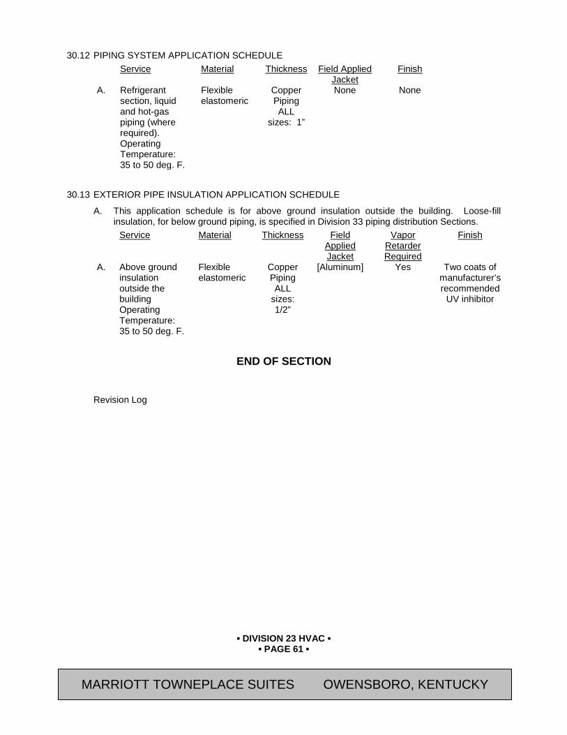
▪ DIVISION 23 HVAC ▪
▪ PAGE 61 ▪
RESIDENCE INN BY MARRIOTT - LITTLETON, COLORADO
30.12 PIPING SYSTEM APPLICATION SCHEDULE Service Material Thickness Field Applied
Jacket Finish
A. Refrigerant section, liquid and hot-gas piping (where required). Operating Temperature: 35 to 50 deg. F.
Flexible elastomeric
Copper Piping ALL
sizes: 1”
None None
30.13 EXTERIOR PIPE INSULATION APPLICATION SCHEDULE
A. This application schedule is for above ground insulation outside the building. Loose-fill insulation, for below ground piping, is specified in Division 33 piping distribution Sections.
Service Material Thickness Field Applied Jacket
Vapor Retarder Required
Finish
A. Above ground insulation outside the building Operating Temperature: 35 to 50 deg. F.
Flexible elastomeric
Copper Piping ALL
sizes: 1/2”
[Aluminum] Yes Two coats of manufacturer’s recommended
UV inhibitor
END OF SECTION
Revision Log
MARRIOTT TOWNEPLACE SUITES OWENSBORO, KENTUCKY
▪ DIVISION 23 HVAC ▪
▪ PAGE 62 ▪
RESIDENCE INN BY MARRIOTT - LITTLETON, COLORADO
SECTION 23 08 00 - COMMISSIONING OF HVAC
PART 31 GENERAL 31.01 SUMMARY
A. This Section includes the following:
1. The purpose of this section is to specify Division 23 responsibilities in the commissioning process.
a. The systems to be commissioned are listed in Section 01 91 13.
b. Commissioning requires the participation of Division 23 to ensure that all systems are operating in a manner consistent with the Contract Documents. The general commissioning requirements and coordination are detailed in Division 01. Division 23 shall be familiar with all parts of Division 01 and the commissioning plan issued by the CxA and shall execute all commissioning responsibilities assigned to them in the Contract Documents.
B. Related Sections:
1. Section 01 91 13 – General Commissioning Requirements
2. Section 23 08 00.01 – HVAC Testing Requirements
3. Section 23 08 00.02 – HVAC Prefunctional Checklists
4. Section 23 08 00.03 – HVAC Sample Functional Test Procedures
5. Section 23 09 00 – Instrumentation and Control of HVAC
6. Section 26 08 00 – Commissioning of Electrical Systems
7. Section 26 08 00.01 – Electrical Systems Testing Requirements
8. Section 26 08 00.02 – Electrical Systems Prefunctional Checklists
9. Section 26 08 00.03 – Electrical Systems Sample Functional Test Procedures
C. Related Work:
1. Refer to Section 01 91 13 for a listing of all Sections where commissioning requirements are found.
2. Refer to Section 01 91 13 for systems to be commissioned and Sections 23 08 00.01 through 23 08 00.03 for functional testing requirements.
31.02 REFERENCES
A. Associated Air Balance Council (AABC)
B. National Environmental Balancing Bureau (NEBB)
C. American Society of Heating, Refrigerating and Air-Conditioning Engineers (ASHRAE) Publications:
1. ANSI/ASHRAE 111 “Testing, Adjusting, and Balancing of Building HVAC Systems”
31.03 SUBMITTALS
A. General: Submit the following in accordance with Conditions of Contract and Division 01 Specification Sections.
MARRIOTT TOWNEPLACE SUITES OWENSBORO, KENTUCKY

▪ DIVISION 23 HVAC ▪
▪ PAGE 63 ▪
RESIDENCE INN BY MARRIOTT - LITTLETON, COLORADO
1. LEED Submittals:
a. Credit EAp1 [and EAc3]: Fundamental Commissioning [and Enhanced Commissioning]:
1) Division 23 shall provide submittal documentation relative to commissioning as required in this Section and Part 1, Section 01 91 13.
31.04 RESPONSIBILITIES
A. HVAC, Controls and TAB Contractors. The commissioning responsibilities applicable to each of the mechanical, controls and TAB contractors of Division 23 are as follows (all references apply to commissioned equipment only):
1. Construction and Acceptance Phases
a. Include and itemize the cost of commissioning in the contract price.
b. In each purchase order or subcontract written, include requirements for submittal data, commissioning documentation, O&M data and training.
c. Attend a commissioning scoping meeting and other meetings necessary to facilitate the Cx process.
d. Contractors shall provide the CxA with normal cut sheets and shop drawing submittals of commissioned equipment.
e. Provide additional requested documentation, prior to normal O&M manual submittals, to the CxA for development of start-up and functional testing procedures.
1) Typically this will include detailed manufacturer installation and start-up, operating, troubleshooting and maintenance procedures, full details of any owner-contracted tests, fan and pump curves, full factory testing reports, if any, and full warranty information, including all responsibilities of the Owner to keep the warranty in force clearly identified. In addition, the installation, start-up and checkout materials that are actually shipped inside the equipment and the actual field checkout sheet forms to be used by the factory or field technicians shall be submitted to the Commissioning Agent.
2) The Commissioning Agent may request further documentation necessary for the commissioning process.
3) This data request may be made prior to normal submittals.
f. Provide a copy of the O&M manuals and submittals of commissioned equipment, through normal channels, to the CxA for review and approval.
g. Contractors shall assist (along with the design engineers) in clarifying the operation and control of commissioned equipment in areas where the specifications, control drawings or equipment documentation is not sufficient for writing detailed testing procedures.
h. Provide limited assistance to the CxA in preparing the specific functional performance test procedures as specified in Section. Subs shall review test procedures to ensure feasibility, safety and equipment protection and provide necessary written alarm limits to be used during the tests.
i. Develop a full start-up and initial checkout plan using manufacturer’s start-up procedures and the prefunctional checklists from the CxA for all commissioned equipment. Submit to CxA for review and approval prior to startup. Refer to Section 01 91 13 for further details on start-up plan preparation.
MARRIOTT TOWNEPLACE SUITES OWENSBORO, KENTUCKY
▪ DIVISION 23 HVAC ▪
▪ PAGE 64 ▪
RESIDENCE INN BY MARRIOTT - LITTLETON, COLORADO
j. During the startup and initial checkout process, execute the mechanical-related portions of the prefunctional checklists for all commissioned equipment.
k. Perform and clearly document all completed startup and system operational checkout procedures, providing a copy to the CxA.
l. Address current A/E punch list items before functional testing. Air and water TAB shall be completed with discrepancies and problems remedied before functional testing of the respective air- or water-related systems.
m. Provide skilled technicians to execute starting of equipment and to execute the functional performance tests. Ensure that they are available and present during the agreed upon schedules and for sufficient duration to complete the necessary tests, adjustments and problem-solving.
n. Provide skilled technicians to perform functional performance testing under the direction of the CxA for specified equipment in Section 01 91 13 and 23 08 00.01 through 23 08 00.03. Assist the CxA in interpreting the monitoring data, as necessary.
o. Correct deficiencies (differences between specified and observed performance) as interpreted by the CxA, CM and A/E and retest the equipment.
p. Prepare O&M manuals according to the Contract Documents, including clarifying and updating the original sequences of operation to as-built conditions.
q. During construction, maintain as-built red-line drawings for all drawings and provide final CAD record drawings for owner and contractor-generated coordination drawings. Update after completion of commissioning (excluding deferred testing).
r. Provide training of the Owner’s operating staff using expert qualified personnel, as specified.
s. Coordinate with equipment manufacturers to determine specific requirements to maintain the validity of the warranty.
2. Warranty Period
a. Execute seasonal or deferred functional performance testing, witnessed by the CxA, according to the specifications.
b. Correct deficiencies and make necessary adjustments to O&M manuals and record drawings for applicable issues identified in any seasonal testing.
B. Mechanical Contractor. The responsibilities of the HVAC mechanical contractor, during construction and acceptance phases in addition to those listed in (A) are:
1. Provide startup for all HVAC equipment, except for the building automation control system.
2. Assist and cooperate with the TAB contractor and CxA by:
a. Putting all HVAC equipment and systems into operation and continuing the operation during each working day of TAB and commissioning, as required.
b. Including cost of sheaves and belts that may be required by TAB.
c. Providing test holes in ducts and plenums where directed by TAB to allow air measurements and air balancing. Providing an approved plug.
d. Providing temperature and pressure taps according to the Construction Documents for TAB and commissioning testing.
MARRIOTT TOWNEPLACE SUITES OWENSBORO, KENTUCKY

▪ DIVISION 23 HVAC ▪
▪ PAGE 65 ▪
RESIDENCE INN BY MARRIOTT - LITTLETON, COLORADO
3. Install a P/T plug at each water sensor which is an input point to the control system.
4. List and clearly identify on the as-built drawings the locations of all air-flow stations.
5. Prepare a preliminary schedule for Division 23 pipe and duct system testing, flushing and cleaning, equipment start-up and TAB start and completion for use by the CxA. Update the schedule as appropriate.
6. Notify the Owner, GC or CxA depending on protocol, when pipe and duct system testing, flushing, cleaning, startup of each piece of equipment and TAB will occur. Be responsible to notify the Owner, GC or CxA, ahead of time, when commissioning activities not yet performed or not yet scheduled will delay construction. Be proactive in seeing that commissioning processes are executed and that the CxA has the scheduling information needed to efficiently execute the commissioning process.
C. Controls Contractor (if Applicable). The commissioning responsibilities of the controls contractor, during construction and acceptance phases in addition to those listed in (A) are:
1. Sequences of Operation Submittals. The Controls Contractor’s submittals of control drawings shall include complete detailed sequences of operation for each piece of equipment, regardless of the completeness and clarity of the sequences in the specifications. They shall include:
a. An overview narrative of the system (1 or 2 paragraphs) generally describing its purpose, components and function.
b. All interactions and interlocks with other systems.
c. Detailed delineation of control between any packaged controls and the building automation system, listing what points the BAS monitors only and what BAS points are control points and are adjustable.
d. Written sequences of control for packaged controlled equipment. (Equipment manufacturers’ stock sequences may be included, but will generally require additional narrative).
e. Start-up sequences.
f. Warm-up mode sequences.
g. Normal operating mode sequences.
h. Unoccupied mode sequences.
i. Shutdown sequences.
j. Capacity control sequences and equipment staging.
k. Temperature and pressure control: setbacks, setups, resets, etc.
l. Detailed sequences for all control strategies, e.g., economizer control, optimum start/stop, staging, optimization, demand limiting, etc.
m. Effects of power or equipment failure with all standby component functions.
n. Sequences for all alarms and emergency shut downs.
o. Seasonal operational differences and recommendations.
p. Initial and recommended values for all adjustable settings, set points and parameters that are typically set or adjusted by operating staff; and any other control settings or fixed values, delays, etc. that will be useful during testing and operating the equipment.
MARRIOTT TOWNEPLACE SUITES OWENSBORO, KENTUCKY
▪ DIVISION 23 HVAC ▪
▪ PAGE 66 ▪
RESIDENCE INN BY MARRIOTT - LITTLETON, COLORADO
q. Schedules, if known.
r. To facilitate referencing in testing procedures, all sequences shall be written in small statements, each with a number for reference. For a given system, numbers will not repeat for different sequence sections, unless the sections are numbered.
2. Control Drawings Submittal
a. The control drawings shall have a key to all abbreviations.
b. The control drawings shall contain graphic schematic depictions of the systems and each component.
c. The schematics will include the system and component layout of any equipment that the control system monitors, enables or controls, even if the equipment is primarily controlled by packaged or integral controls.
d. Provide a full points list with at least the following included for each point:
e. Controlled system
1) Point abbreviation
2) Point description
3) Display unit
4) Control point or set point (Yes / No)
5) Monitoring point (Yes / No)
6) Intermediate point (Yes / No)
7) Calculated point (Yes / No) 1) Key:
Point Description: DB temp, airflow, etc.
Control or Set point: Point that controls equipment and can have its set point changed (OSA, SAT, etc.)
Intermediate Point: Point whose value is used to make a calculation which then controls equipment (space temperatures that are averaged to a virtual point to control reset).
Monitoring Point: Point that does not control or contribute to the control of equipment, but is used for operation, maintenance, or performance verification.
Calculated Point: “Virtual” point generated from calculations of other point values.
The Controls Contractor shall keep the CxA informed of all changes to this list during programming and setup.
3. An updated as-built version of the control drawings and sequences of operation shall be included in the final controls O&M manual submittal.
4. Assist and cooperate with the TAB contractor in the following manner:
a. Meet with the TAB contractor prior to beginning TAB and review the TAB plan to determine the capabilities of the control system toward completing TAB. Provide the TAB any needed unique instruments for setting terminal unit boxes and instruct TAB
MARRIOTT TOWNEPLACE SUITES OWENSBORO, KENTUCKY

▪ DIVISION 23 HVAC ▪
▪ PAGE 67 ▪
RESIDENCE INN BY MARRIOTT - LITTLETON, COLORADO
in their use (handheld control system interface for use around the building during TAB, etc.).
b. For a given area, have all required prefunctional checklists, calibrations, startup and selected functional tests of the system completed and approved by the CxA prior to TAB.
c. Provide a qualified technician to operate the controls to assist the TAB contractor in performing TAB, or provide sufficient training for TAB to operate the system without assistance.
5. Assist and cooperate with the CxA in the following manner:
a. Using a skilled technician who is familiar with this building, execute the functional testing of the controls system as specified for the controls contractor in Sections 23 08 00.01 through 23 08 00.03 and 26 08 00 through 26 08 00.03. Assist in the functional testing of all equipment specified in Sections 23 08 00.01 through 23 08 00.03 and 26 08 00 through 26 08 00.03. Provide two-way radios during the testing.
b. Execute all control system trend logs specified in Sections 23 08 00.01 through 23 08 00.03 and 26 08 00 through 26 08 00.03.
6. The controls contractor shall prepare a written plan indicating in a step-by-step manner, the procedures that will be followed to test, checkout and adjust the control system prior to functional performance testing, according to the process in Section 01 91 13. At minimum, the plan shall include for each type of equipment controlled by the automatic controls:
a. System name.
b. List of devices.
c. Step-by-step procedures for testing each controller after installation, including:
1) Process of verifying proper hardware and wiring installation.
2) Process of downloading programs to local controllers and verifying that they are addressed correctly.
3) Process of performing operational checks of each controlled component.
4) Plan and process for calibrating valve and damper actuators and all sensors.
5) A description of the expected field adjustments for transmitters, controllers and control actuators should control responses fall outside of expected values.
d. A copy of the log and field checkout sheets that will document the process. This log must include a place for initial and final read values during calibration of each point and clearly indicate when a sensor or controller has “passed” and is operating within the contract parameters.
e. A description of the instrumentation required for testing.
f. Indicate what tests on what systems should be completed prior to TAB using the control system for TAB work. Coordinate with the CxA and TAB contractor for this determination.
7. Provide a signed and dated certification to the CxA and GC upon completion of the checkout of each controlled device, equipment and system prior to functional testing for each piece of equipment or system, that all system programming is complete as to all respects of the Contract Documents, except functional testing requirements.
MARRIOTT TOWNEPLACE SUITES OWENSBORO, KENTUCKY

▪ DIVISION 23 HVAC ▪
▪ PAGE 68 ▪
RESIDENCE INN BY MARRIOTT - LITTLETON, COLORADO
8. Beyond the control points necessary to execute all documented control sequences, provide monitoring, control and virtual points as specified in Section 23 09 00.
9. List and clearly identify on the as-built duct and piping drawings the locations of all static and differential pressure sensors (air, water and building pressure).
D. TAB Contractor. The duties of the TAB contractor, in addition to those listed in (A) are:
1. Six weeks prior to starting TAB, submit to the GC the qualifications of the site technician for the project, including the name of the contractors and facility managers of recent projects the technician on which was lead. The Owner will approve the site technician’s qualifications for this project.
2. Submit the outline of the TAB plan and approach for each system and component to the Owner, CxA, GC and the controls contractor six weeks prior to starting the TAB. This plan will be developed after the TAB has some familiarity with the control system.
3. The submitted plan will include:
a. Certification that the TAB contractor has reviewed the construction documents and the systems with the design engineers and contractors to sufficiently understand the design intent for each system.
b. An explanation of the intended use of the building control system. The controls contractor will comment on feasibility of the plan.
c. All field checkout sheets and logs to be used that list each piece of equipment to be tested, adjusted and balanced with the data cells to be gathered for each.
d. Discussion of what notations and markings will be made on the duct and piping drawings during the process.
e. Final test report forms to be used.
f. Detailed step-by-step procedures for TAB work for each system and issue: terminal flow calibration (for each terminal type), diffuser proportioning, branch / submain proportioning, total flow calculations, rechecking, diversity issues, expected problems and solutions, etc. Criteria for using air flow straighteners or relocating flow stations and sensors will be discussed. Provide the analogous explanations for the water side.
g. List of all air flow, water flow, sound level, system capacity and efficiency measurements to be performed and a description of specific test procedures, parameters, formulas to be used.
h. Details of how total flow will be determined (Air: sum of terminal flows via BAS calibrated readings or via hood readings of all terminals, supply (SA) and return air (RA) pitot traverse, SA or RA flow stations. Water: pump curves, circuit setter, flow station, ultrasonic, etc.).
i. The identification and types of measurement instruments to be used and their most recent calibration date.
j. Specific procedures that will ensure that both air and water side are operating at the lowest possible pressures and provide methods to verify this.
k. Confirmation that TAB understands the outside air ventilation criteria under all conditions.
l. Details of whether and how minimum outside air cfm will be verified and set, and for what level (total building, zone, etc.).
MARRIOTT TOWNEPLACE SUITES OWENSBORO, KENTUCKY

▪ DIVISION 23 HVAC ▪
▪ PAGE 69 ▪
RESIDENCE INN BY MARRIOTT - LITTLETON, COLORADO
m. Details of how building static and exhaust fan / relief damper capacity will be checked.
n. Proposed selection points for sound measurements and sound measurement methods.
o. Details of methods for making any specified coil or other system plant capacity measurements.
p. Details of any TAB work to be done in phases (by floor, etc.), or of areas to be built out later.
q. Details regarding specified deferred or seasonal TAB work.
r. Details of any specified false loading of systems to complete TAB work.
s. Details of all exhaust fan balancing and capacity verifications, including any required room pressure differentials.
t. Details of any required interstitial cavity differential pressure measurements and calculations.
u. Plan for hand-written field technician logs of discrepancies, deficient or uncompleted work by others, contract interpretation requests and lists of completed tests (scope and frequency).
v. Plan for formal progress reports (scope and frequency).
w. Plan for formal deficiency reports (scope, frequency and distribution).
4. A running log of events and issues shall be kept by the TAB field technicians. Submit hand-written reports of discrepancies, deficient or uncompleted work by others, contract interpretation requests and lists of completed tests to the Owner, CxA and GC at least twice a week.
5. Communicate in writing to the controls contractor all set point and parameter changes made or problems and discrepancies identified during TAB which affect the control system setup and operation.
6. Provide a draft TAB report within two weeks of completion. A copy will be provided to the CxA. The report will contain a full explanation of the methodology, assumptions and the results in a clear format with designations of all uncommon abbreviations and column headings. The report should follow the latest and most rigorous reporting recommendations by the Associated Air Balance Council (AABC), the National Environmental Balancing Bureau (NEBB) or ASHRAE Standard 111 (as specified).
7. Provide the CxA with any requested data, gathered, but not shown on the draft reports.
8. Provide a final TAB report for the CxA with details, as in the draft.
9. Conduct functional performance tests and checks on the original TAB as specified for TAB in Sections 23 08 00.01 thru 23 08 00.03.
PART 32 PRODUCTS 32.01 TEST EQUIPMENT
A. Division 23 shall provide all test equipment necessary to fulfill the testing requirements of this Division.
B. Refer to Section 01 91 13 for additional Division 23 requirements.
MARRIOTT TOWNEPLACE SUITES OWENSBORO, KENTUCKY

▪ DIVISION 23 HVAC ▪
▪ PAGE 70 ▪
RESIDENCE INN BY MARRIOTT - LITTLETON, COLORADO
PART 33 EXECUTION 33.01 STARTUP
A. The HVAC mechanical and controls contractors shall follow the start-up and initial checkout procedures listed in the Responsibilities list in this Section and in 01 91 13. Division 23 has start-up responsibility and is required to complete systems and sub-systems so they are fully functional, meeting the design objectives of the Contract Documents. The commissioning procedures and functional testing do not relieve or lessen this responsibility or shift that responsibility partially to the commissioning agent or Owner.
B. Functional testing is intended to begin upon completion of a system. Functional testing may proceed prior to the completion of systems or sub-systems at the discretion of the CxA and GC. Beginning system testing before full completion does not relieve the Contractor from fully completing the system, including all prefunctional checklists as soon as possible.
33.02 TAB
A. Refer to the TAB responsibilities in Article 1.03 “Responsibilities” of this Section.
33.03 FUNCTIONAL PERFORMANCE TESTS
A. Refer to Section 01 91 13 for a list of systems to be commissioned and to Section 01 91 13, Article 3.06 “Documentation, Non-Conformance and Approval of Tests” for a description of the process and to Sections 23 08 00.01 through 23 08 00.03 for specific details on the required functional performance tests.
33.04 TESTING DOCUMENTATION, NON-CONFORMANCE AND APPROVALS
A. Refer to Section 01 91 13 for specific details on non-conformance issues relating to prefunctional checklists and tests.
B. Refer to Section 01 91 13 for issues relating to functional performance tests.
33.05 DEFERRED TESTING
A. Refer to Section 01 91 13 for requirements of deferred testing.
33.06 WRITTEN WORK PRODUCTS
A. Written work products of Contractors will consist of the start-up and initial checkout plan described in Section 01 91 13 and the filled out start-up, initial checkout and prefunctional checklists.
END OF SECTION
Revision Log
MARRIOTT TOWNEPLACE SUITES OWENSBORO, KENTUCKY
▪ DIVISION 23 HVAC ▪
▪ PAGE 71 ▪
RESIDENCE INN BY MARRIOTT - LITTLETON, COLORADO
SECTION 23 08 00.01 - HVAC TESTING REQUIREMENTS
PART 34 GENERAL 34.01 SUMMARY
A. This Section includes the following:
1. This Section specifies the functional testing requirements for Division 23 systems and equipment.
B. Related Sections:
1. Section 01 91 13 – General Commissioning Requirements.
2. Section 23 08 00 – Commissioning of HVAC
3. Section 23 08 00.02 – HVAC Prefunctional Checklists
4. Section 23 08 00.03 – HVAC Sample Functional Test Procedures
34.02 INCLUDED SYSTEMS AND EQUIPMENT
A. The following is a list of the equipment and system test requirements included in this section:
1. Instrumentation and Controls for HVAC
2. Exhaust Fans
3. Terminal Units
a. Fuel Fired Unit Heaters
b. Electric Baseboard
c. Electric Unit Heaters
4. Air Handling Units
a. Gas Fired Make-up Air Units
b. Packaged Outdoor Air Handling Units
c. Split System Air Conditioners
5. Water Source Heat Pump
a. Boilers
b. Heat Pumps
c. Cooling Towers
d. Pumps
e. Heat exchangers
6. Swimming Pool Dehumidifiers
7. Test and Balance Work (TAB)
MARRIOTT TOWNEPLACE SUITES OWENSBORO, KENTUCKY

▪ DIVISION 23 HVAC ▪
▪ PAGE 72 ▪
RESIDENCE INN BY MARRIOTT - LITTLETON, COLORADO
34.03 DESCRIPTION
A. This section specifies the functional testing requirements for Division 23 systems and equipment. From these requirements, the Commissioning Authority (CxA) shall develop step-by-step procedures to be executed by the subcontractors or the Commissioning Authority. The general functional testing process, requirements and test method definitions are described in Section 01 91 13. The test requirements for each piece of equipment or system contain the following:
1. The contractors responsible to execute the tests, under the direction of the CxA.
2. A list of the integral components being tested.
3. Prefunctional checklists associated with the components.
4. Functions and modes to be tested.
5. Required conditions of the test for each mode.
6. Special procedures.
7. Required methods of testing.
8. Required monitoring.
9. Acceptance criteria.
10. Sampling strategies allowed.
34.04 PREREQUISITES
A. The following applicable generic prerequisite checklist items are listed on each written functional test form and shall be completed and checked off by CxA prior to functional testing:
__ All related equipment has been started up and start-up reports and prefunctional checklists
submitted and approved ready for functional testing: __ All control system functions for this and all interlocking systems are programmed and operable
per contract documents, including final setpoints and schedules with debugging, loop tuning and sensor calibrations completed.
__ Piping system flushing complete and required report approved. __ Water treatment system complete and operational. __ Vibration control report approved (if required). __ Test and balance (TAB) complete and approved for the hydronic system. __ All A/E punchlist items for this equipment corrected. __ These functional test procedures reviewed and approved by installing contractor. __ Safeties and operating ranges reviewed by the CxA. __ Test requirements and sequences of operation attached. __ Schedules and setpoints attached. __ False loading equipment, system and procedures ready. __ Crankcase heaters have been on long enough for immediate startup. __ Sufficient clearance around equipment for servicing. __ Record of all values for pre-test setpoints changed to accommodate testing has been made and a
check box provided to verify return to original values (control parameters, limits, delays, lockouts, schedules, etc.).
MARRIOTT TOWNEPLACE SUITES OWENSBORO, KENTUCKY

▪ DIVISION 23 HVAC ▪
▪ PAGE 73 ▪
RESIDENCE INN BY MARRIOTT - LITTLETON, COLORADO
__ Other miscellaneous checks of the prefunctional checklist and start-up reports completed successfully.
34.05 MONITORING
A. Monitoring is a method of testing as a stand-alone method or to augment manual testing.
B. All points listed in the required monitoring section of the test requirements which are control system monitored points shall be trended by the controls contractor. At the option of the CxA, some control system monitoring may be replaced with datalogger monitoring. At the CxA’s request, the controls contractor shall trend up to 20% more points than listed herein at no extra charge.
C. Hard copies of monitored data must be in columnar format with time down the left column and at least 5 columns of point values on the same page.
D. Graphical output is desirable, and will be required for all output, if the system can produce it.
PART 35 PRODUCTS Not Used.
PART 36 EXECUTION 36.01 AIR HANDLER UNITS (AHU)
A. Parties Responsible to Execute Functional Test:
1. Controls contractor: operate the controls to activate the equipment as needed.
2. Mechanical contractor: Witnesses, document testing, assist in testing, and correct deficiencies.
3. CxA: to witness, direct and document testing.
4. Owners Representative: witness
B. Integral Components or Related Equipment Being Tested: Prefunctional Checklist AHU and components (fans, coils, valves, ducts, VFD): Air Handling Units Ductwork Energy Recovery Wheel
C. Prerequisites
1. The applicable prerequisite checklist items listed in Section 23 08 00.01 shall be listed on each functional test form and checked off prior to functional testing. The commissioning agent will also spot-check misc. items and calibrations on the prefunctional checklists previously completed by the installer, before the beginning of functional testing.
MARRIOTT TOWNEPLACE SUITES OWENSBORO, KENTUCKY

▪ DIVISION 23 HVAC ▪
▪ PAGE 74 ▪
RESIDENCE INN BY MARRIOTT - LITTLETON, COLORADO
D. Functions / Modes Required To Be Tested, Test Methods and Seasonal Test Requirements:
1. The following testing requirements are an addition to and do not replace any testing requirements elsewhere in this Division.
Function / Mode Test Method Manual,
Monitoring, Either or
Both3
Required Seasonal
Test1
General 1. Test each sequence in the sequence of operations, and other significant
modes and sequences not mentioned; including startup, shutdown, unnoccupied & manual modes and power failure. Test functionality of this piece of equipment or system in all control strategies or interlocks with which it is associated.
Manual
In addition to, or as part of (1) above, the following modes or tests are required: 2. Mixed & supply air, & reset temperature control functions. Both 3. Economizer functions. Both Cooling 4. SF, RF and exhaust fan interlocks. Either 5. Duct static pressure (SP) control. Both 6. Return or exhaust fan tracking and building SP. Monitoring 7. VFD (or inlet vanes) operation on SF and RF: modulation to
minimum, control system PID, proportional band of speed vs controlling parameter, constancy of static pressure, verification of program settings, alarms, etc.
Both 2
8. Damper interlocks and correct modulation in all modes, including smoke and fire dampers.
Manual
9. Temperature difference across HC & CC per specifications. Manual 10. Verification of minimum OSA control through varying VAV box
positions. Either 2
11. Branch duct control damper control. Manual 12. Night low limit, morning warmup cycle. Either 13. Heat recovery operation. Monitoring 14. Verify TAB reported SF cfm with control system reading. Manual 2 15. All alarms (low limits, high static, etc.). Manual 16. Heating and cooling coil capacity test, optional. Manual Design 17. Sensor and actuator calibration checks: on duct static pressure sensor
on SAT, MAT, OSAT, OSA & RA damper and valve positions, SF cfm reading with TAB, and other random checks (EMS readout against hand-held calibrated instrument or observation must be within specified tolerances)
Manual
18. Verify schedules and setpoints to be reasonable and appropriate 1Cooling season, Heating season or Both. “Design” means within 5°of season design (ASHRAE 2 1/2%), or 95% of loading design. A blank cell denotes no special seasonal test is required and that test can be executed during any season, if condition simulation is appropriate. 2Seasonal test not required if seasonal conditions can be adequately simulated. 3Refer to Special Procedures
E. Special Procedures:
1. Reduced Testing for Smaller Units. For standard application AHU’s less than 15 tons, the following modifications to the testing requirements apply: 1) either Manual or Monitoring will satisfy the verification requirement--where Both is listed, choose one. 2) Testing Modes 6, 8, 11, 13 and 16 is not required.
MARRIOTT TOWNEPLACE SUITES OWENSBORO, KENTUCKY
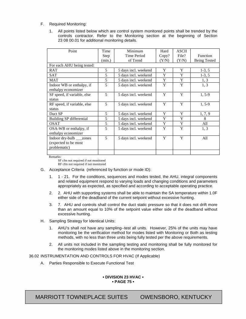
▪ DIVISION 23 HVAC ▪
▪ PAGE 75 ▪
RESIDENCE INN BY MARRIOTT - LITTLETON, COLORADO
F. Required Monitoring:
1. All points listed below which are control system monitored points shall be trended by the controls contractor. Refer to the Monitoring section at the beginning of Section 23 08 00.01 for additional monitoring details.
Point Time
Step (min.)
Minimum Time Period
of Trend
Hard Copy? (Y/N)
ASCII File? (Y/N)
Function
Being Tested For each AHU being tested: RAT 5 5 days incl. weekend Y Y 1-3, 5 SAT 5 5 days incl. weekend Y Y 1-3, 5 MAT 5 5 days incl. weekend Y Y 1, 3 Indoor WB or enthalpy, if enthalpy economizer
5 5 days incl. weekend Y Y 1, 3
SF speed, if variable, else status
5 5 days incl. weekend Y Y 1, 5-9
RF speed, if variable, else status
5 5 days incl. weekend Y Y 1, 5-9
Duct SP 5 5 days incl. weekend Y Y 1, 7, 9 Building SP differential 5 5 days incl. weekend Y Y 8 OSAT 5 5 days incl. weekend Y Y All OSA-WB or enthalpy, if enthalpy economizer
5 5 days incl. weekend Y Y 1, 3
Indoor dry-bulb ___zones (expected to be most problematic)
5 5 days incl. weekend Y Y All
Remarks: SF cfm not required if not monitored RF cfm not required if not monitored
G. Acceptance Criteria (referenced by function or mode ID):
1. 1 - 21. For the conditions, sequences and modes tested, the AHU, integral components and related equipment respond to varying loads and changing conditions and parameters appropriately as expected, as specified and according to acceptable operating practice.
2. 2. AHU with supporting systems shall be able to maintain the SA temperature within 1.0F either side of the deadband of the current setpoint without excessive hunting.
3. 7. AHU and controls shall control the duct static pressure so that it does not drift more than an amount equal to 10% of the setpoint value either side of the deadband without excessive hunting.
H. Sampling Strategy for Identical Units:
1. AHU’s shall not have any sampling--test all units. However, 25% of the units may have monitoring be the verification method for modes listed with Monitoring or Both as testing methods, with no less than three units being fully tested per the above requirements.
2. All units not included in the sampling testing and monitoring shall be fully monitored for the monitoring modes listed above in the monitoring section.
36.02 INSTRUMENTATION AND CONTROLS FOR HVAC (If Applicable)
A. Parties Responsible to Execute Functional Test
MARRIOTT TOWNEPLACE SUITES OWENSBORO, KENTUCKY

▪ DIVISION 23 HVAC ▪
▪ PAGE 76 ▪
RESIDENCE INN BY MARRIOTT - LITTLETON, COLORADO
1. Controls contractor: operate the controls to activate the equipment.
2. CxA: to witness, direct and document testing.
3. Owners Representative: witness
4. Integral Components or Related Equipment Being Tested: Prefunctional Checklist
1. Building Automation System BAS 2. All pre-functional checklists of controlled equipment ---
B. Prerequisites The applicable prerequisite checklist items listed in the beginning of Section 23 08 00.01 shall be listed on each functional test form and checked off prior to functional testing. The commissioning agent will also spot-check misc. items and calibrations on the prefunctional checklists previously completed by the installer, before the beginning of functional testing.
C. A significant part of the BAS functional testing requirements is the successful completion of the functional tests of equipment the BAS controls or interlocks with. Uncompleted equipment functional tests or outstanding deficiencies in those tests lend the required BAS functional testing incomplete.
D. Integral or stand-alone controls are functionally tested with the equipment they are attached to, including any interlocks with other equipment or systems and thus are not covered under the BAS testing requirements, except for any integrated functions or interlocks listed below.
E. In addition to the controlled equipment testing, the following tests are required for the BAS, where features have been specified. The following testing requirements are in addition to and do not replace any testing requirements elsewhere in the specifications.
Function / Mode
Test Method Manual (demonstration),
Monitoring, Either or Both MISC. FUNCTIONS
1. All specified functions and features are set up, debugged and fully operable
Verbal discussion of features
2. Power failure and battery backup and power-up restart functions Demonstration 3. Specified trending and graphing features demonstration See equipment trends 4. Global commands features Demonstration 5. Security and access codes Demonstration 6. Occupant over-rides (manual, telephone, key, keypad, etc.) Demonstration 7. O&M schedules and alarms Demonstration 8. Scheduling features fully functional and setup, including holidays Observation in terminal
screens or printouts 9. Date and time setting in central computer and verify field panels read
the same time Demonstration
10. Included features not specified to be setup are installed (list) Demonstration 11. Occupancy sensors and controls Demonstration 12. Demonstrate functionality of field panels using local operator keypads
and local ports (plug-ins) using portable computer/keypad Demonstration of 100% of
panels and 10% of ports 13. All graphic screens and value readouts completed Demonstration 14. Setpoint changing features and functions Done during equipment
testing 15. Communications to remote sites Demonstration
MARRIOTT TOWNEPLACE SUITES OWENSBORO, KENTUCKY
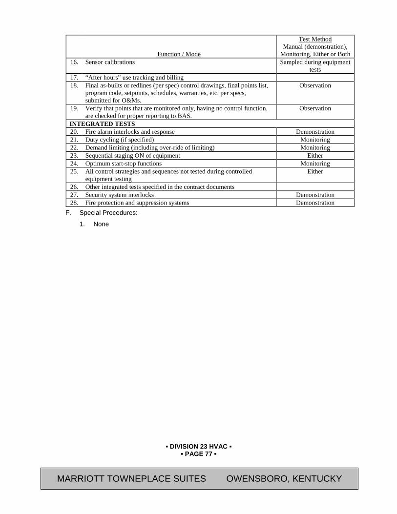
▪ DIVISION 23 HVAC ▪
▪ PAGE 77 ▪
RESIDENCE INN BY MARRIOTT - LITTLETON, COLORADO
Function / Mode
Test Method Manual (demonstration),
Monitoring, Either or Both 16. Sensor calibrations Sampled during equipment
tests 17. “After hours” use tracking and billing 18. Final as-builts or redlines (per spec) control drawings, final points list,
program code, setpoints, schedules, warranties, etc. per specs, submitted for O&Ms.
Observation
19. Verify that points that are monitored only, having no control function, are checked for proper reporting to BAS.
Observation
INTEGRATED TESTS 20. Fire alarm interlocks and response Demonstration 21. Duty cycling (if specified) Monitoring 22. Demand limiting (including over-ride of limiting) Monitoring 23. Sequential staging ON of equipment Either 24. Optimum start-stop functions Monitoring 25. All control strategies and sequences not tested during controlled
equipment testing Either
26. Other integrated tests specified in the contract documents 27. Security system interlocks Demonstration 28. Fire protection and suppression systems Demonstration
F. Special Procedures:
1. None
MARRIOTT TOWNEPLACE SUITES OWENSBORO, KENTUCKY
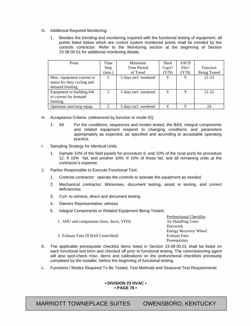
▪ DIVISION 23 HVAC ▪
▪ PAGE 78 ▪
RESIDENCE INN BY MARRIOTT - LITTLETON, COLORADO
G. Additional Required Monitoring:
1. Besides the trending and monitoring required with the functional testing of equipment, all points listed below which are control system monitored points shall be trended by the controls contractor. Refer to the Monitoring section at the beginning of Section 23 08 00.01 for additional monitoring details.
Point Time
Step (min.)
Minimum Time Period
of Trend
Hard Copy? (Y/N)
ASCII File? (Y/N)
Function
Being Tested Misc. equipment current or status for duty cycling and demand limiting
5 5 days incl. weekend Y Y 21-22
Equipment or building kW or current for demand limiting
5 5 days incl. weekend Y Y 21-22
Optimum start/stop equip. 5 5 days incl. weekend Y Y 24
H. Acceptance Criteria (referenced by function or mode ID):
1. All For the conditions, sequences and modes tested, the BAS, integral components and related equipment respond to changing conditions and parameters appropriately as expected, as specified and according to acceptable operating practice.
I. Sampling Strategy for Identical Units:
1. Sample 10% of the field panels for procedure 9, and 10% of the local ports for procedure 12. If 10% fail, test another 10%. If 10% of those fail, test all remaining units at the contractor’s expense.
J. Parties Responsible to Execute Functional Test:
1. Controls contractor: operate the controls to activate the equipment as needed.
2. Mechanical contractor: Witnesses, document testing, assist in testing, and correct deficiencies.
3. CxA: to witness, direct and document testing.
4. Owners Representative: witness
5. Integral Components or Related Equipment Being Tested: Prefunctional Checklist
1. AHU and components (fans, ducts, VFD): Air Handling Units Ductwork Energy Recovery Wheel
2. Exhaust Fans (If BAS Controlled) Exhaust Fans Prerequisites
K. The applicable prerequisite checklist items listed in Section 23 08 00.01 shall be listed on each functional test form and checked off prior to functional testing. The commissioning agent will also spot-check misc. items and calibrations on the prefunctional checklists previously completed by the installer, before the beginning of functional testing.
L. Functions / Modes Required To Be Tested, Test Methods and Seasonal Test Requirements
MARRIOTT TOWNEPLACE SUITES OWENSBORO, KENTUCKY
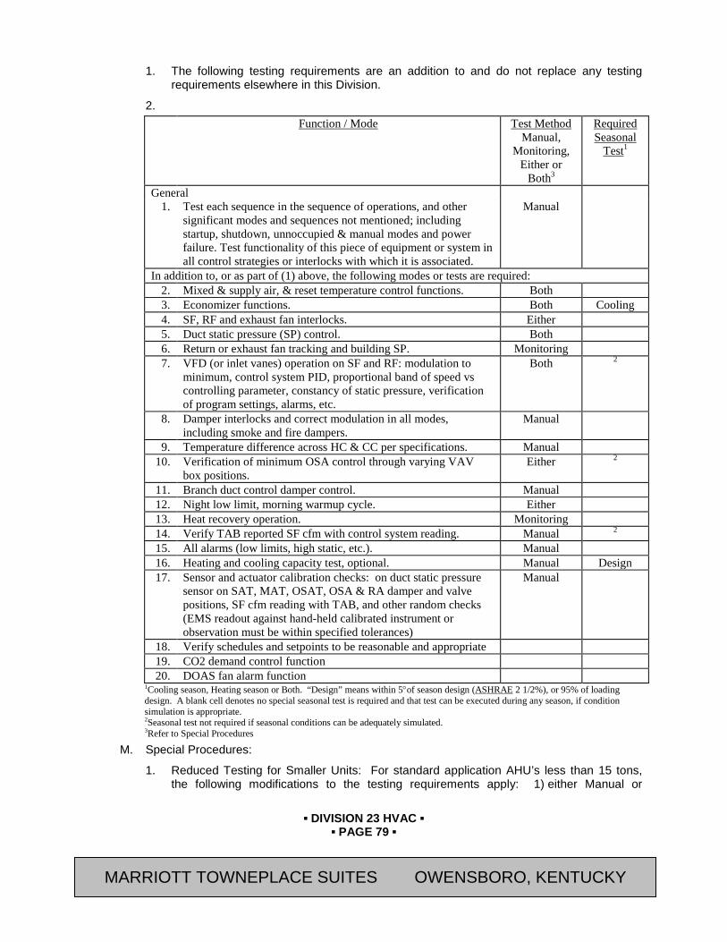
▪ DIVISION 23 HVAC ▪
▪ PAGE 79 ▪
RESIDENCE INN BY MARRIOTT - LITTLETON, COLORADO
1. The following testing requirements are an addition to and do not replace any testing requirements elsewhere in this Division.
2. Function / Mode Test Method
Manual, Monitoring,
Either or Both3
Required Seasonal
Test1
General 1. Test each sequence in the sequence of operations, and other
significant modes and sequences not mentioned; including startup, shutdown, unnoccupied & manual modes and power failure. Test functionality of this piece of equipment or system in all control strategies or interlocks with which it is associated.
Manual
In addition to, or as part of (1) above, the following modes or tests are required: 2. Mixed & supply air, & reset temperature control functions. Both 3. Economizer functions. Both Cooling 4. SF, RF and exhaust fan interlocks. Either 5. Duct static pressure (SP) control. Both 6. Return or exhaust fan tracking and building SP. Monitoring 7. VFD (or inlet vanes) operation on SF and RF: modulation to
minimum, control system PID, proportional band of speed vs controlling parameter, constancy of static pressure, verification of program settings, alarms, etc.
Both 2
8. Damper interlocks and correct modulation in all modes, including smoke and fire dampers.
Manual
9. Temperature difference across HC & CC per specifications. Manual 10. Verification of minimum OSA control through varying VAV
box positions. Either 2
11. Branch duct control damper control. Manual 12. Night low limit, morning warmup cycle. Either 13. Heat recovery operation. Monitoring 14. Verify TAB reported SF cfm with control system reading. Manual 2 15. All alarms (low limits, high static, etc.). Manual 16. Heating and cooling capacity test, optional. Manual Design 17. Sensor and actuator calibration checks: on duct static pressure
sensor on SAT, MAT, OSAT, OSA & RA damper and valve positions, SF cfm reading with TAB, and other random checks (EMS readout against hand-held calibrated instrument or observation must be within specified tolerances)
Manual
18. Verify schedules and setpoints to be reasonable and appropriate 19. CO2 demand control function 20. DOAS fan alarm function
1Cooling season, Heating season or Both. “Design” means within 5°of season design (ASHRAE 2 1/2%), or 95% of loading design. A blank cell denotes no special seasonal test is required and that test can be executed during any season, if condition simulation is appropriate. 2Seasonal test not required if seasonal conditions can be adequately simulated. 3Refer to Special Procedures
M. Special Procedures:
1. Reduced Testing for Smaller Units: For standard application AHU’s less than 15 tons, the following modifications to the testing requirements apply: 1) either Manual or
MARRIOTT TOWNEPLACE SUITES OWENSBORO, KENTUCKY

▪ DIVISION 23 HVAC ▪
▪ PAGE 80 ▪
RESIDENCE INN BY MARRIOTT - LITTLETON, COLORADO
Monitoring will satisfy the verification requirement--where Both is listed, choose one. 2) Testing Modes 6, 8, 11, 13 and 16 is not required.
N. Required Monitoring:
1. All points listed below which are control system monitored points shall be trended by the controls contractor. Refer to the Monitoring section at the beginning of Section 23 08 00.01 for additional monitoring details.
Point Time
Step (min.)
Minimum Time Period
of Trend
Hard Copy? (Y/N)
ASCII File? (Y/N)
Function
Being Tested For each AHU being tested: RAT 5 5 days incl. weekend Y Y 1-3, 5 SAT 5 5 days incl. weekend Y Y 1-3, 5 MAT 5 5 days incl. weekend Y Y 1, 3 Indoor WB or enthalpy, if enthalpy economizer
5 5 days incl. weekend Y Y 1, 3
SF speed, if variable, else status
5 5 days incl. weekend Y Y 1, 5-9
RF speed, if variable, else status
5 5 days incl. weekend Y Y 1, 5-9
Duct SP 5 5 days incl. weekend Y Y 1, 7, 9 Building SP differential 5 5 days incl. weekend Y Y 8 OSAT 5 5 days incl. weekend Y Y All OSA-WB or enthalpy, if enthalpy economizer
5 5 days incl. weekend Y Y 1, 3
Indoor dry-bulb ___zones (expected to be most problematic)
5 5 days incl. weekend Y Y All
Remarks: SF cfm not required if not monitored RF cfm not required if not monitored
O. Acceptance Criteria (referenced by function or mode ID):
1. 1 - 21. For the conditions, sequences and modes tested, the AHU, integral components and related equipment respond to varying loads and changing conditions and parameters appropriately as expected, as specified and according to acceptable operating practice.
2. 2. AHU with supporting systems shall be able to maintain the SA temperature within 1.0F either side of the deadband of the current setpoint without excessive hunting.
3. 7. AHU and controls shall control the duct static pressure so that it does not drift more than an amount equal to 10% of the setpoint value either side of the deadband without excessive hunting.
P. Sampling Strategy for Identical Units:
1. AHU’s shall not have any sampling--test all units. However, 25% of the units may have monitoring be the verification method for modes listed with Monitoring or Both as testing methods, with no less than three units being fully tested per the above requirements.
2. All units not included in the sampling testing and monitoring shall be fully monitored for the monitoring modes listed above in the monitoring section.
MARRIOTT TOWNEPLACE SUITES OWENSBORO, KENTUCKY
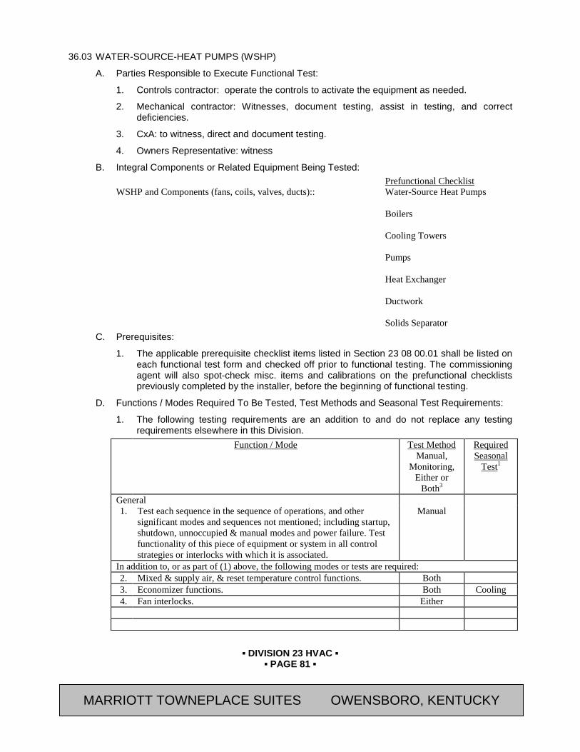
▪ DIVISION 23 HVAC ▪
▪ PAGE 81 ▪
RESIDENCE INN BY MARRIOTT - LITTLETON, COLORADO
36.03 WATER-SOURCE-HEAT PUMPS (WSHP)
A. Parties Responsible to Execute Functional Test:
1. Controls contractor: operate the controls to activate the equipment as needed.
2. Mechanical contractor: Witnesses, document testing, assist in testing, and correct deficiencies.
3. CxA: to witness, direct and document testing.
4. Owners Representative: witness
B. Integral Components or Related Equipment Being Tested: Prefunctional Checklist WSHP and Components (fans, coils, valves, ducts):: Water-Source Heat Pumps
Boilers Cooling Towers Pumps Heat Exchanger Ductwork Solids Separator
C. Prerequisites:
1. The applicable prerequisite checklist items listed in Section 23 08 00.01 shall be listed on each functional test form and checked off prior to functional testing. The commissioning agent will also spot-check misc. items and calibrations on the prefunctional checklists previously completed by the installer, before the beginning of functional testing.
D. Functions / Modes Required To Be Tested, Test Methods and Seasonal Test Requirements:
1. The following testing requirements are an addition to and do not replace any testing requirements elsewhere in this Division.
Function / Mode Test Method Manual,
Monitoring, Either or
Both3
Required Seasonal
Test1
General 1. Test each sequence in the sequence of operations, and other
significant modes and sequences not mentioned; including startup, shutdown, unnoccupied & manual modes and power failure. Test functionality of this piece of equipment or system in all control strategies or interlocks with which it is associated.
Manual
In addition to, or as part of (1) above, the following modes or tests are required: 2. Mixed & supply air, & reset temperature control functions. Both 3. Economizer functions. Both Cooling 4. Fan interlocks. Either
MARRIOTT TOWNEPLACE SUITES OWENSBORO, KENTUCKY

▪ DIVISION 23 HVAC ▪
▪ PAGE 82 ▪
RESIDENCE INN BY MARRIOTT - LITTLETON, COLORADO
Function / Mode Test Method Manual,
Monitoring, Either or
Both3
Required Seasonal
Test1
5. Duct static pressure (SP) control. Both 6. Damper interlocks and correct modulation in all modes, including
smoke and fire dampers. Both
7. Temperature difference across HC & CC per specifications. Manual 2 8. Branch duct control damper control. Manual 9. Verify TAB reported SF cfm with control system reading. Manual 2 10 All alarms (low limits, high static, etc.). Manual 11 Heating and cooling capacity test, optional. Manual Design
12
. Sensor and actuator calibration checks: on duct static pressure sensor on SAT, MAT, OSAT, OSA & RA damper and valve positions, SF cfm reading with TAB, and other random checks (EMS readout against hand-held calibrated instrument or observation must be within specified tolerances)
Manual Design
13.
Verify schedules and setpoints to be reasonable and appropriate
1Cooling season, Heating season or Both. “Design” means within 5°of season design (ASHRAE 2 1/2%), or 95% of loading design. A blank cell denotes no special seasonal test is required and that test can be executed during any season, if condition simulation is appropriate. 2Seasonal test not required if seasonal conditions can be adequately simulated. 3Refer to Special Procedures
E. Special Procedures:
1. Reduced Testing for Smaller Units. For standard application AHU’s less than 15 tons, the following modifications to the testing requirements apply:
a. Either Manual or Monitoring will satisfy the verification requirement--where Both are listed, choose one.
b. Testing Modes 6, 8, 11, 13 and 16 are not required.
F. Required Monitoring:
1. All points listed below which are control system monitored points shall be trended by the controls contractor. Refer to the Monitoring section at the beginning of Section 23 08 00.01 for additional monitoring details.
Point Time
Step (min.)
Minimum Time Period
of Trend
Hard Copy? (Y/N)
ASCII File? (Y/N)
Function
Being Tested For each WSHP being tested: RAT 5 5 days incl. weekend Y Y 1-3, 5 SAT 5 5 days incl. weekend Y Y 1-3, 5 MAT 5 5 days incl. weekend Y Y 1, 3 Duct SP 5 5 days incl. weekend Y Y 1, 7, 9 OSAT 5 5 days incl. weekend Y Y All OSA-WB or enthalpy, if enthalpy economizer
5 5 days incl. weekend Y Y 1, 3
MARRIOTT TOWNEPLACE SUITES OWENSBORO, KENTUCKY
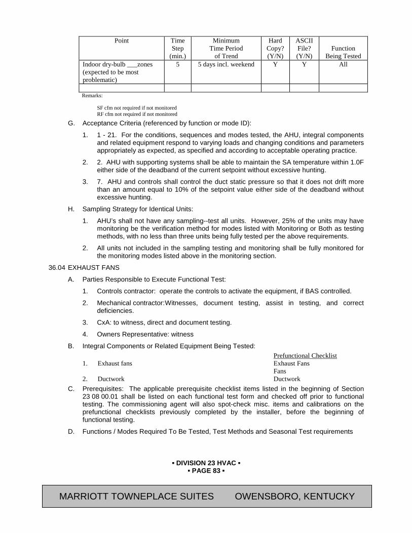
▪ DIVISION 23 HVAC ▪
▪ PAGE 83 ▪
RESIDENCE INN BY MARRIOTT - LITTLETON, COLORADO
Point Time Step
(min.)
Minimum Time Period
of Trend
Hard Copy? (Y/N)
ASCII File? (Y/N)
Function
Being Tested Indoor dry-bulb ___zones (expected to be most problematic)
5 5 days incl. weekend Y Y All
Remarks: SF cfm not required if not monitored RF cfm not required if not monitored
G. Acceptance Criteria (referenced by function or mode ID):
1. 1 - 21. For the conditions, sequences and modes tested, the AHU, integral components and related equipment respond to varying loads and changing conditions and parameters appropriately as expected, as specified and according to acceptable operating practice.
2. 2. AHU with supporting systems shall be able to maintain the SA temperature within 1.0F either side of the deadband of the current setpoint without excessive hunting.
3. 7. AHU and controls shall control the duct static pressure so that it does not drift more than an amount equal to 10% of the setpoint value either side of the deadband without excessive hunting.
H. Sampling Strategy for Identical Units:
1. AHU’s shall not have any sampling--test all units. However, 25% of the units may have monitoring be the verification method for modes listed with Monitoring or Both as testing methods, with no less than three units being fully tested per the above requirements.
2. All units not included in the sampling testing and monitoring shall be fully monitored for the monitoring modes listed above in the monitoring section.
36.04 EXHAUST FANS
A. Parties Responsible to Execute Functional Test:
1. Controls contractor: operate the controls to activate the equipment, if BAS controlled.
2. Mechanical contractor: Witnesses, document testing, assist in testing, and correct deficiencies.
3. CxA: to witness, direct and document testing.
4. Owners Representative: witness
B. Integral Components or Related Equipment Being Tested: Prefunctional Checklist 1. Exhaust fans Exhaust Fans
Fans 2. Ductwork Ductwork
C. Prerequisites: The applicable prerequisite checklist items listed in the beginning of Section 23 08 00.01 shall be listed on each functional test form and checked off prior to functional testing. The commissioning agent will also spot-check misc. items and calibrations on the prefunctional checklists previously completed by the installer, before the beginning of functional testing.
D. Functions / Modes Required To Be Tested, Test Methods and Seasonal Test requirements
MARRIOTT TOWNEPLACE SUITES OWENSBORO, KENTUCKY
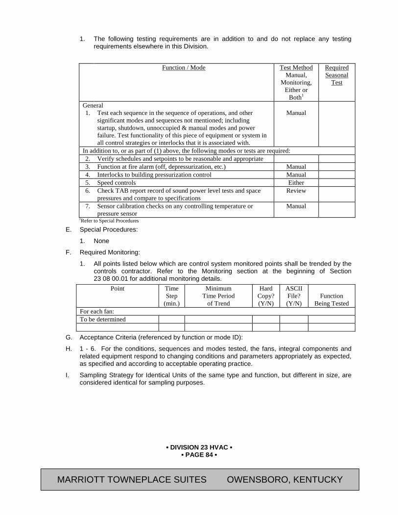
▪ DIVISION 23 HVAC ▪
▪ PAGE 84 ▪
RESIDENCE INN BY MARRIOTT - LITTLETON, COLORADO
1. The following testing requirements are in addition to and do not replace any testing requirements elsewhere in this Division.
Function / Mode Test Method
Manual, Monitoring,
Either or Both1
Required Seasonal
Test
General 1. Test each sequence in the sequence of operations, and other
significant modes and sequences not mentioned; including startup, shutdown, unnoccupied & manual modes and power failure. Test functionality of this piece of equipment or system in all control strategies or interlocks that it is associated with.
Manual
In addition to, or as part of (1) above, the following modes or tests are required: 2. Verify schedules and setpoints to be reasonable and appropriate 3. Function at fire alarm (off, depressurization, etc.) Manual 4. Interlocks to building pressurization control Manual 5. Speed controls Either 6. Check TAB report record of sound power level tests and space
pressures and compare to specifications Review
7. Sensor calibration checks on any controlling temperature or pressure sensor
Manual
1Refer to Special Procedures
E. Special Procedures:
1. None
F. Required Monitoring:
1. All points listed below which are control system monitored points shall be trended by the controls contractor. Refer to the Monitoring section at the beginning of Section 23 08 00.01 for additional monitoring details.
Point Time Step
(min.)
Minimum Time Period
of Trend
Hard Copy? (Y/N)
ASCII File? (Y/N)
Function
Being Tested For each fan: To be determined
G. Acceptance Criteria (referenced by function or mode ID):
H. 1 - 6. For the conditions, sequences and modes tested, the fans, integral components and related equipment respond to changing conditions and parameters appropriately as expected, as specified and according to acceptable operating practice.
I. Sampling Strategy for Identical Units of the same type and function, but different in size, are considered identical for sampling purposes.
MARRIOTT TOWNEPLACE SUITES OWENSBORO, KENTUCKY
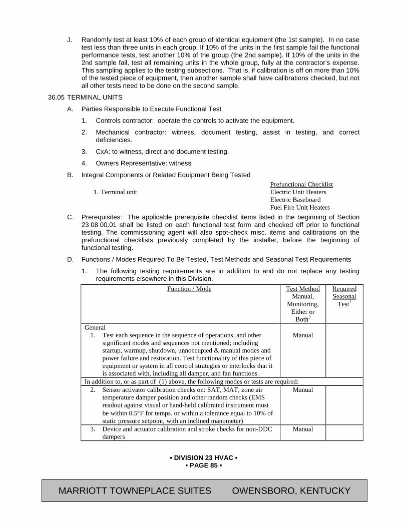
▪ DIVISION 23 HVAC ▪
▪ PAGE 85 ▪
RESIDENCE INN BY MARRIOTT - LITTLETON, COLORADO
J. Randomly test at least 10% of each group of identical equipment (the 1st sample). In no case test less than three units in each group. If 10% of the units in the first sample fail the functional performance tests, test another 10% of the group (the 2nd sample). If 10% of the units in the 2nd sample fail, test all remaining units in the whole group, fully at the contractor’s expense. This sampling applies to the testing subsections. That is, if calibration is off on more than 10% of the tested piece of equipment, then another sample shall have calibrations checked, but not all other tests need to be done on the second sample.
36.05 TERMINAL UNITS
A. Parties Responsible to Execute Functional Test
1. Controls contractor: operate the controls to activate the equipment.
2. Mechanical contractor: witness, document testing, assist in testing, and correct deficiencies.
3. CxA: to witness, direct and document testing.
4. Owners Representative: witness
B. Integral Components or Related Equipment Being Tested Prefunctional Checklist
1. Terminal unit Electric Unit Heaters Electric Baseboard Fuel Fire Unit Heaters
C. Prerequisites: The applicable prerequisite checklist items listed in the beginning of Section 23 08 00.01 shall be listed on each functional test form and checked off prior to functional testing. The commissioning agent will also spot-check misc. items and calibrations on the prefunctional checklists previously completed by the installer, before the beginning of functional testing.
D. Functions / Modes Required To Be Tested, Test Methods and Seasonal Test Requirements
1. The following testing requirements are in addition to and do not replace any testing requirements elsewhere in this Division. Function / Mode Test Method
Manual, Monitoring,
Either or Both3
Required Seasonal
Test1
General 1. Test each sequence in the sequence of operations, and other
significant modes and sequences not mentioned; including startup, warmup, shutdown, unnoccupied & manual modes and power failure and restoration. Test functionality of this piece of equipment or system in all control strategies or interlocks that it is associated with, including all damper, and fan functions.
Manual
In addition to, or as part of (1) above, the following modes or tests are required: 2. Sensor activator calibration checks on: SAT, MAT, zone air
temperature damper position and other random checks (EMS readout against visual or hand-held calibrated instrument must be within 0.5°F for temps. or within a tolerance equal to 10% of static pressure setpoint, with an inclined manometer)
Manual
3. Device and actuator calibration and stroke checks for non-DDC dampers
Manual
MARRIOTT TOWNEPLACE SUITES OWENSBORO, KENTUCKY
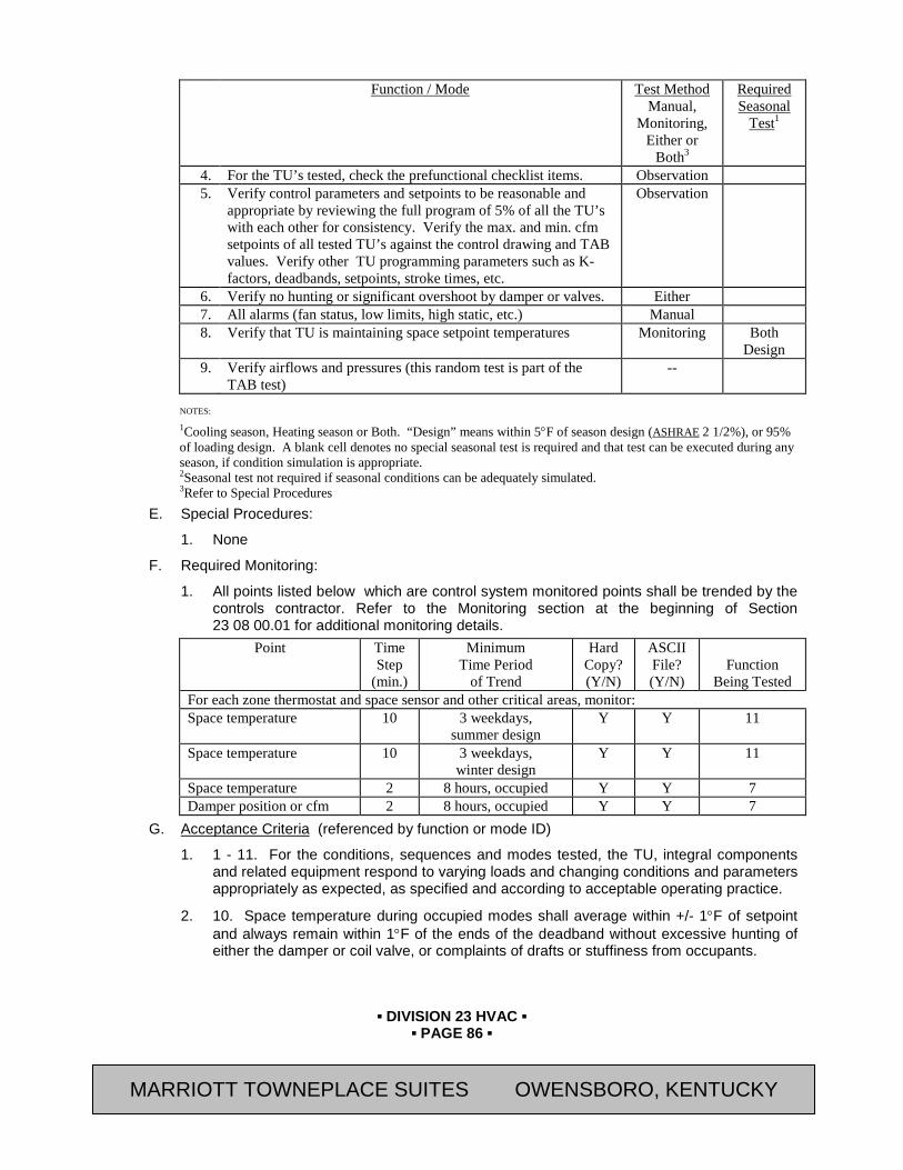
▪ DIVISION 23 HVAC ▪
▪ PAGE 86 ▪
RESIDENCE INN BY MARRIOTT - LITTLETON, COLORADO
Function / Mode Test Method Manual,
Monitoring, Either or
Both3
Required Seasonal
Test1
4. For the TU’s tested, check the prefunctional checklist items. Observation 5. Verify control parameters and setpoints to be reasonable and
appropriate by reviewing the full program of 5% of all the TU’s with each other for consistency. Verify the max. and min. cfm setpoints of all tested TU’s against the control drawing and TAB values. Verify other TU programming parameters such as K-factors, deadbands, setpoints, stroke times, etc.
Observation
6. Verify no hunting or significant overshoot by damper or valves. Either 7. All alarms (fan status, low limits, high static, etc.) Manual 8. Verify that TU is maintaining space setpoint temperatures Monitoring Both
Design 9. Verify airflows and pressures (this random test is part of the
TAB test) --
NOTES:
1Cooling season, Heating season or Both. “Design” means within 5°F of season design (ASHRAE 2 1/2%), or 95% of loading design. A blank cell denotes no special seasonal test is required and that test can be executed during any season, if condition simulation is appropriate. 2Seasonal test not required if seasonal conditions can be adequately simulated. 3Refer to Special Procedures
E. Special Procedures:
1. None
F. Required Monitoring:
1. All points listed below which are control system monitored points shall be trended by the controls contractor. Refer to the Monitoring section at the beginning of Section 23 08 00.01 for additional monitoring details.
Point Time Step
(min.)
Minimum Time Period
of Trend
Hard Copy? (Y/N)
ASCII File? (Y/N)
Function
Being Tested For each zone thermostat and space sensor and other critical areas, monitor: Space temperature 10 3 weekdays,
summer design Y Y 11
Space temperature 10 3 weekdays, winter design
Y Y 11
Space temperature 2 8 hours, occupied Y Y 7 Damper position or cfm 2 8 hours, occupied Y Y 7
G. Acceptance Criteria (referenced by function or mode ID)
1. 1 - 11. For the conditions, sequences and modes tested, the TU, integral components and related equipment respond to varying loads and changing conditions and parameters appropriately as expected, as specified and according to acceptable operating practice.
2. 10. Space temperature during occupied modes shall average within +/- 1°F of setpoint and always remain within 1°F of the ends of the deadband without excessive hunting of either the damper or coil valve, or complaints of drafts or stuffiness from occupants.
MARRIOTT TOWNEPLACE SUITES OWENSBORO, KENTUCKY
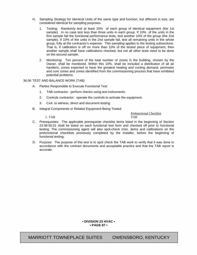
▪ DIVISION 23 HVAC ▪
▪ PAGE 87 ▪
RESIDENCE INN BY MARRIOTT - LITTLETON, COLORADO
H. Sampling Strategy for Identical Units of the same type and function, but different in size, are considered identical for sampling purposes.
1. Testing: Randomly test at least 10% of each group of identical equipment (the 1st sample). In no case test less than three units in each group. If 10% of the units in the first sample fail the functional performance tests, test another 10% of the group (the 2nd sample). If 10% of the units in the 2nd sample fail, test all remaining units in the whole group, fully at the contractor’s expense. This sampling applies to the testing subsections. That is, if calibration is off on more than 10% of the tested piece of equipment, then another sample shall have calibrations checked, but not all other tests need to be done on the second sample.
2. Monitoring: Ten percent of the total number of zones in the building, chosen by the Owner, shall be monitored. Within this 10%, shall be included a distribution of all air handlers, zones expected to have the greatest heating and cooling demand, perimeter and core zones and zones identified from the commissioning process that have exhibited potential problems.
36.06 TEST AND BALANCE WORK (TAB)
A. Parties Responsible to Execute Functional Test
1. TAB contractor: perform checks using test instruments.
2. Controls contractor: operate the controls to activate the equipment.
3. CxA: to witness, direct and document testing.
B. Integral Components or Related Equipment Being Tested Prefunctional Checklist
1. TAB TAB C. Prerequisites: The applicable prerequisite checklist items listed in the beginning of Section
23 08 00.01 shall be listed on each functional test form and checked off prior to functional testing. The commissioning agent will also spot-check misc. items and calibrations on the prefunctional checklists previously completed by the installer, before the beginning of functional testing.
D. Purpose: The purpose of this test is to spot check the TAB work to verify that it was done in accordance with the contract documents and acceptable practice and that the TAB report is accurate.
MARRIOTT TOWNEPLACE SUITES OWENSBORO, KENTUCKY
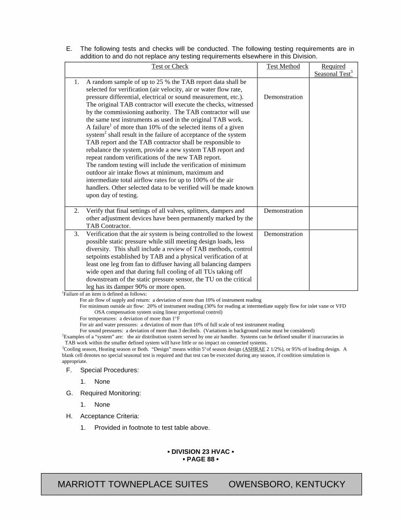
▪ DIVISION 23 HVAC ▪
▪ PAGE 88 ▪
RESIDENCE INN BY MARRIOTT - LITTLETON, COLORADO
E. The following tests and checks will be conducted. The following testing requirements are in
addition to and do not replace any testing requirements elsewhere in this Division. Test or Check Test Method Required
Seasonal Test3 1. A random sample of up to 25 % the TAB report data shall be
selected for verification (air velocity, air or water flow rate, pressure differential, electrical or sound measurement, etc.). The original TAB contractor will execute the checks, witnessed by the commissioning authority. The TAB contractor will use the same test instruments as used in the original TAB work. A failure1 of more than 10% of the selected items of a given system2 shall result in the failure of acceptance of the system TAB report and the TAB contractor shall be responsible to rebalance the system, provide a new system TAB report and repeat random verifications of the new TAB report. The random testing will include the verification of minimum outdoor air intake flows at minimum, maximum and intermediate total airflow rates for up to 100% of the air handlers. Other selected data to be verified will be made known upon day of testing.
Demonstration
2. Verify that final settings of all valves, splitters, dampers and other adjustment devices have been permanently marked by the TAB Contractor.
Demonstration
3. Verification that the air system is being controlled to the lowest possible static pressure while still meeting design loads, less diversity. This shall include a review of TAB methods, control setpoints established by TAB and a physical verification of at least one leg from fan to diffuser having all balancing dampers wide open and that during full cooling of all TUs taking off downstream of the static pressure sensor, the TU on the critical leg has its damper 90% or more open.
Demonstration
1Failure of an item is defined as follows: For air flow of supply and return: a deviation of more than 10% of instrument reading For minimum outside air flow: 20% of instrument reading (30% for reading at intermediate supply flow for inlet vane or VFD
OSA compensation system using linear proportional control) For temperatures: a deviation of more than 1°F For air and water pressures: a deviation of more than 10% of full scale of test instrument reading For sound pressures: a deviation of more than 3 decibels. (Variations in background noise must be considered)
2Examples of a “system” are: the air distribution system served by one air handler. Systems can be defined smaller if inaccuracies in TAB work within the smaller defined system will have little or no impact on connected systems.
3Cooling season, Heating season or Both. “Design” means within 5°of season design (ASHRAE 2 1/2%), or 95% of loading design. A blank cell denotes no special seasonal test is required and that test can be executed during any season, if condition simulation is appropriate.
F. Special Procedures:
1. None
G. Required Monitoring:
1. None
H. Acceptance Criteria:
1. Provided in footnote to test table above.
MARRIOTT TOWNEPLACE SUITES OWENSBORO, KENTUCKY

▪ DIVISION 23 HVAC ▪
▪ PAGE 89 ▪
RESIDENCE INN BY MARRIOTT - LITTLETON, COLORADO
I. Sampling Strategy for Identical Units:
1. Described in test table above.
END OF SECTION Revision Log
MARRIOTT TOWNEPLACE SUITES OWENSBORO, KENTUCKY

▪ DIVISION 23 HVAC ▪
▪ PAGE 90 ▪
RESIDENCE INN BY MARRIOTT - LITTLETON, COLORADO
SECTION 23 08 00.02 - HVAC PREFUNCTIONAL CHECKLISTS
PART 37 GENERAL 37.01 SUMMARY
A. This Section includes the following:
1. Prefunctional Checklists (PC) in a form format. The Prefunctional Checklists consist of Instructions Sheets and Record Sheets.
B. Related Sections:
1. Section 01 33 00 - Submittal and Substitution Procedures
2. Section 01 91 13 – General Commissioning Requirements.
3. Section 23 08 00 – Commissioning of HVAC
4. Section 23 08 00.01– HVAC Testing Requirements
5. Section 23 08 00.03– HVAC Sample Functional Test Procedures
37.02 DESCRIPTION
A. The PC procedures displayed in a form format here are intended to provide the Contractor with an example of the format and an indication of the rigor of the required prefunctional checklists (Instruction Sheets and Record Sheets) and documentation for various equipment types. Though they were not developed specifically for this project, they are generally applicable.
B. The checklists contain items for both Division 23 and 26 contractors to perform.
C. Those executing the checklists are only responsible to perform items that apply to the specific application at hand. These checklists do not take the place of the manufacturer’s recommended checkout and start-up procedures or report. Some checklist procedures may be redundant of some checkout procedures that will be documented on typical factory field checkout sheets. Double documenting is required in those cases.
D. Refer to Section 01 91 13 for additional requirements regarding prefunctional checklists, startup and initial checkout. Items that do not apply should be noted along with the reasons on the form. If supplied Prefunctional Checklist forms are not used for documenting, one of similar rigor and clarity shall be used. Contractors assigned responsibility for sections of the checklist shall be responsible to see that checklist items by their subcontractors are completed and checked off.
E. The following is a list of the equipment and systems which will require Prefunctional Checklists (Instruction Sheets and Record Sheets) to be completed by the Contractors.
1. Packaged Outdoor Air Handling Unit (Each Unit)
2. Boilers
3. Water-Source Heat Pumps
4. Cooling Towers
5. Pumps Heat Exchangers
6. Solids Separator
7. Instrumentation and Controls for HVAC (If Applicable)
MARRIOTT TOWNEPLACE SUITES OWENSBORO, KENTUCKY
▪ DIVISION 23 HVAC ▪
▪ PAGE 91 ▪
RESIDENCE INN BY MARRIOTT - LITTLETON, COLORADO
8. Fuel Fired Unit Heater (Each Unit)
9. Electric Unit Heater (Each Unit)
10. Ductwork (Each Air System)
11. Exhaust Fan (Each Unit)
12. Electric Baseboard (Each Space Served)
13. Swimming Pool Dehumidifiers
14. Fire and Smoke Dampers (Each Unit)
15. Gas Fired Make-up Air Unit (Each Unit)
16. Testing, Adjusting and Balancing
F. Refer to Section 01 33 00 - Submittal and Substitution Procedures for Prefunctional Checklists.
PART 38 PRODUCTS Not Used
PART 39 EXECUTION Not Used
END OF SECTION Revision Log
MARRIOTT TOWNEPLACE SUITES OWENSBORO, KENTUCKY
▪ DIVISION 23 HVAC ▪
▪ PAGE 92 ▪
RESIDENCE INN BY MARRIOTT - LITTLETON, COLORADO
SECTION 23 08 00.03 - HVAC SAMPLE FUNCTIONAL TEST PROCEDURES
PART 40 GENERAL 40.01 SUMMARY
A. This Section includes the following:
1. This Section contains the Functional Testing Procedures for Mechanical Systems
B. Related Sections:
1. Section 01 33 00 - Submittal and Substitution Procedures
2. Section 01 91 13 – General Commissioning Requirements.
3. Section 23 08 00 – Commissioning of HVAC
4. Section 23 08 00.01 – HVAC Testing Requirements
5. Section 23 08 00.02 – HVAC Prefunctional Checklists
40.02 DESCRIPTION
A. The CxA will use the functional testing requirements in Sections 23 08 00 thru 23 08 00.03 and the testing protocols specified in Section 01 91 13 for developing site-specific functional test procedures and forms for this project. For illustrative purposes, sequences of operation associated with a few pieces of the equipment for which tests are included are also provided.
B. The following is a list of the equipment and systems which will require Prefunctional Checklists (Instruction Sheets and Record Sheets) to be completed by the Contractors.
1. Dedicated Outdoor Air Unit (Each Unit)
2. Instrumentation and Controls for HVAC
3. Boilers
4. Water-Source Heat Pumps
5. Cooling Towers
6. Pumps Heat Exchangers
7. Solids Separator
8. Fuel Fired Unit Heater (Each Unit)
9. Electric Unit Heater (Each Unit)
10. Exhaust Fan (Each Unit)
11. Electric Baseboard (Each Space Served)
12. Swimming Pool Dehumidifiers
13. Gas Fired Make-up Air Unit (Each Unit)
C. Refer to Section 01 33 00 - Submittal and Substitution Procedures for Prefunctional Checklists.
PART 41 PRODUCTS Not Used
MARRIOTT TOWNEPLACE SUITES OWENSBORO, KENTUCKY

▪ DIVISION 23 HVAC ▪
▪ PAGE 93 ▪
RESIDENCE INN BY MARRIOTT - LITTLETON, COLORADO
PART 42 EXECUTION Not Used
END OF SECTION Revision Log
MARRIOTT TOWNEPLACE SUITES OWENSBORO, KENTUCKY
▪ DIVISION 23 HVAC ▪
▪ PAGE 94 ▪
RESIDENCE INN BY MARRIOTT - LITTLETON, COLORADO
SECTION 23 09 00 (15900) - INSTRUMENTATION AND CONTROL FOR HVAC
PART 43 GENERAL 43.01 SUMMARY
A. Section Includes:
1. Control Panels
2. Thermostats
3. Actuators
4. Dampers
5. Wiring
B. Related Sections:
1. Section 23 09 93 (15940) - Sequence of Operations for HVAC Controls
2. Section 23 73 40 (15731) – Gas Fired Makeup Air Units
3. Section 23 74 33 (15733) – Dedicated Outdoor Air Units
4. Section 23 81 13.13 (15735) – Packaged Terminal Air Conditioning Units
5. Section 23 81 13.15 (15738) – Vertical Packaged Terminal Air Conditioning Units
6. Section 23 81 26 (15738) – Split System Air Conditioners
7. Section 23 09 93 (15940) - Sequence of Operations for HVAC Controls
8. Section 25 51 10 – Integrated Automation Control of Guestroom Equipment
9. Section 26 05 19 (16120) – Low Voltage Electrical Power Conductors and Cables
43.02 REFERENCES
A. Air Movement & Control Association International, Inc. (AMCA) Publications:
1. 500D "Laboratory Methods of Testing Dampers for Rating"
B. National Electrical Manufacturer’s Association (NEMA) Standards Publications:
1. DC 3 “Residential Controls—Electrical Wall-Mounted Room Thermostats”
C. National Fire Protection Association (NFPA) Publications:
1. 70 "National Electric Code"
2. 90A “Standard for the Installation of Air Conditioning and Ventilating Systems”
D. Sheet Metal and Air Conditioning Contractors' National Association (SMACNA)
E. Underwriter's Laboratories, Inc. (UL) Standards:
1. 486A “Standard For Wire Connectors and Soldering Lugs for Use With Copper Conductors”
2. 486B “Standard for Wire Connectors for Use With Aluminum Conductors”
MARRIOTT TOWNEPLACE SUITES OWENSBORO, KENTUCKY
▪ DIVISION 23 HVAC ▪
▪ PAGE 95 ▪
RESIDENCE INN BY MARRIOTT - LITTLETON, COLORADO
43.03 SYSTEM DESCRIPTION
A. Electric/Digital Electronic system consists of sensors, indicators, actuators, final control elements, interface equipment, other apparatus, and accessories to control mechanical systems.
43.04 SUBMITTALS
A. General: Submit the following in accordance with Conditions of Contract and Division 01 Specification Sections.
B. Submit “Letter of Conformance” in accordance with Section 01 33 00 (01330) indicating specified items selected for use in project with the following supporting data.
1. Product Data:
a. Include manufacturer's technical literature for each control device. Indicate dimensions, capacities, performance characteristics, electrical characteristics, finishes for materials, and installation and startup instructions for each type of product indicated.
b. Each control device labeled with setting or adjustable range of control.
2. Shop Drawings: For each system to be controlled, prepare a drawing which includes a system flow diagram, control diagram, sequence of operation and schedule of components. Control diagrams shall be complete with end-to-end connections of wiring from component terminal.
3. Operation and Maintenance Data: Submit information for all products in accordance with the requirements of Specification " 01 78 23 (01830) – “Operating and Maintenance Data”.
a. .
43.05 QUALITY ASSURANCE
A. Installer Qualifications: An experienced installer who is an approved installer of the automatic control system manufacturer for both installation and maintenance of units required for this Project.
B. Manufacturer Qualifications: A firm experienced in manufacturing automatic temperature-control systems similar to those indicated for this Project and with a record of successful in-service performance.
C. Electrical Components, Devices, and Accessories: Listed and labeled as defined in NFPA 70, Article 100, by a testing agency acceptable to authorities having jurisdiction, and marked for intended use.
D. Comply with NFPA 90A, "Installation of Air Conditioning and Ventilation Systems."
E. The provision of 120 and 208 line voltage and 24 volt low voltage wiring, conduit, installed in accordance with National Fire Protection Association (NFPA) 70, “National Electric Code” and Division 26 of these specifications.
43.06 DELIVERY, STORAGE, AND HANDLING
A. Factory-Mounted Components: Where control devices specified in this Section are indicated to be factory mounted on equipment, arrange for shipping of control devices to unit manufacturer.
MARRIOTT TOWNEPLACE SUITES OWENSBORO, KENTUCKY
▪ DIVISION 23 HVAC ▪
▪ PAGE 96 ▪
RESIDENCE INN BY MARRIOTT - LITTLETON, COLORADO
43.07 COORDINATION
A. Coordinate location of thermostats, humidistats, and other exposed control sensors with plans and room details before installation.
43.08 TRAINING
A. Submit in accordance with the requirements of specification Section 01 79 00 (01820).
PART 44 PRODUCTS 44.01 CONTROL PANELS
A. MANUFACTURERS
1. Avendra, LLC Preferred Manufacturers:
a. None.
2. Approved Manufacturers:
a. Siemens USA (800-964-4114).
b. Invensys Controls (formally Siebe Environmental Controls) (630-260-3400)
c. Honeywell Inc., Automation and Control Solutions (800-345-6770)
d. Automated Logic Controls, a Unit of United Technologies Corp. (770-429-3000)
B. Local Control Panels: Unitized cabinet with suitable brackets for wall or floor mounting, located adjacent to each system under automatic control. Provide common keying for all panels.
1. Fabricate panels of 0.06-inch thick, furniture-quality steel, or extruded-aluminum alloy, totally enclosed, with hinged doors and keyed lock and with manufacturer's standard shop-painted finish.
2. Panel-Mounted Equipment: Mounted transformers, relays, and automatic switches; except safety devices. Mount devices with adjustments accessible through front of panel.
3. Door-Mounted Equipment: Flush-mount (on hinged door) manual switches, including damper-positioning switches, changeover switches, thermometers, and gages.
44.02 THERMOSTATS
A. Manufacturers:
1. Avendra, LLC Preferred Manufacturers:
a. PSG Controls, Inc. (215-257-3621)
1) “HotelStat Model 5-10506” (Cooling Units with Electric Heat)
2) “HotelStat Model 5-10505” (Heat Pump with backup Electric Heat)
3) “Model T5-10502” (First Company SPX Series VTAC Cooling Units with Electric Heat)
4) “Model T5-10501HP” (First Company SPX Series VTAC Heat Pump with backup Electric Heat)
2. Approved Manufacturers:
a. Carrier Corp.; Carrier Air Conditioning Division, United Technologies Corporation (800-827-7435 x 3496).
MARRIOTT TOWNEPLACE SUITES OWENSBORO, KENTUCKY
▪ DIVISION 23 HVAC ▪
▪ PAGE 97 ▪
RESIDENCE INN BY MARRIOTT - LITTLETON, COLORADO
1) “Debonair Model 33CSSN2-MH”
b. Trane, an Ingersoll Rand Brand (608-787-4810)
1) “Zone Controller (Thermostat)”
c. Refer to Section 25 51 10 – Integrated Automation Control of Guestroom Equipment for Smart Digital Thermostats to be used for Guestroom automation system.
B. Combination Thermostat and Fan Switches: Line-voltage or low voltage thermostat with two-, three-, or four-position, push-button or lever-operated fan switch.
1. Label switches "FAN ON-OFF," "FAN HIGH-LOW-OFF," "FAN HIGH-MED-LOW-OFF." Provide unit for mounting on two-gang switch box.
C. Electric solid-state, microcomputer-based room thermostat with remote sensor. (Where indicated on drawings.)
1. Automatic switching from heating to cooling.
2. Preferential rate control to minimize overshoot and deviation from set point.
3. Set up for four separate temperatures per day.
4. Instant override of set point for continuous or timed period from 1 hour to 31 days.
5. Short-cycle protection.
6. Programming based on every day of week.
7. Selection features include deg F display, 12- or 24-hour clock, keyboard disable, remote sensor, fan on-auto.
8. Battery replacement without program loss.
9. Thermostat backlit display features include the following:
a. Time of day.
b. Actual room temperature.
c. Programmed temperature.
d. Programmed time.
e. Duration of timed override.
f. Day of week.
g. System mode indications include "heating," "off," "fan auto," and "fan on."
D. Low-Voltage, On-Off Thermostats: NEMA DC 3, 24-V, bimetal-operated, mercury-switch type, with adjustable or fixed anticipation heater.
E. Line-Voltage, On-Off Thermostats: Bimetal-actuated, open contact or bellows-actuated, enclosed, snap-switch type, or equivalent solid-state type, with heat anticipator, integral manual on-off-auto selector switch.
1. Equip thermostats, which control electric heating loads directly, with off position on dial wired to break ungrounded conductors.
2. Dead Band: Maximum 2 deg F.
F. Room Thermostat Cover Construction: Manufacturer's standard locking covers.
G. Room thermostat accessories include the following:
MARRIOTT TOWNEPLACE SUITES OWENSBORO, KENTUCKY
▪ DIVISION 23 HVAC ▪
▪ PAGE 98 ▪
RESIDENCE INN BY MARRIOTT - LITTLETON, COLORADO
1. Insulating Bases: For thermostats located on exterior walls.
2. Thermostat Guards: Locking; heavy-duty, transparent plastic; mounted on separate base.
3. Adjusting Key: As required for calibration and cover screws.
4. Aspirating Boxes: For flush-mounted aspirating thermostats.
5. Set-Point Adjustment: 1/2-inch-diameter, adjustment knob.
44.03 ACTUATORS
A. Electric Motors: Spring-return type operators, sized to operate with sufficient reserve power to provide smooth modulating action or two-position action.
1. Permanent Split-Capacitor or Shaded-Pole Type: Gear trains completely oil immersed and sealed. Equip spring-return motors with integral spiral-spring mechanism in housings designed for easy removal for service or adjustment of limit switches, auxiliary switches, or feedback potentiometer.
2. Temperature Rating: Minus 22 to plus 122 deg F.
3. Damper Operator Mounting: Mount damper operators where accessible for maintenance.
a. If located outside the duct or casing, mount operators on a 14 gauge reinforced support plate arranged to allow insulation between the support plate and the face of the duct or casing.
b. Brace damper operators rigid to show no deflection or movement over the full range of the damper stroke.
44.04 DAMPERS
A. Dampers: Factory fabricated AMCA-rated opposed blade design of extruded aluminum, galvanized steel, with metallic antifriction nonferrous bearings.
1. Blades shall be secured to 1/2-inch diameter, zinc-plated axles using zinc-plated hardware, with nylon blade bearings, blade-linkage hardware of zinc-plated steel and brass, ends sealed against spring-stainless-steel blade bearings, and thrust bearings at each end of every blade.
2. Operating Temperature Range: From minus 40 to plus 200 deg F.
3. Pressure Rating: Rated for leakage at less than 10 cfm per sq. ft. of damper area, at differential pressure of 4 inches wg when damper is being held by torque of 50 in. x lbf when tested according to AMCA 500D.
4. Shafts and Bearings: Provide cadmium plated steel shafts in permanently lubricated bronze sleeve bearings or permanently lubricated ball bearings.
5. Blade: Reinforced or ribbed blades shall not exceed 8 inches in width nor 48 inches in length.
a. Blades shall be constructed of 16 gage (minimum) galvanized steel or extruded aluminum.
b. Flat or un-reinforced blades will not be acceptable.
c. Damper sections exceeding 4 feet in width or 4 feet height shall be constructed with multiple frames and linkages.
MARRIOTT TOWNEPLACE SUITES OWENSBORO, KENTUCKY

▪ DIVISION 23 HVAC ▪
▪ PAGE 99 ▪
RESIDENCE INN BY MARRIOTT - LITTLETON, COLORADO
6. Frames: Construct frames of factory welded 13 gage (minimum) galvanized steel hot dipped after construction or bolted extruded aluminum frames.
a. Dampers larger than 8 square feet in area shall have corner bracing gussets at each corner welded to the damper frame.
7. Linkages: Provide linkages to uniformly transmit damper operating forces to each damper blade.
a. Construct linkages of galvanized or cadmium plated steel or stainless steel.
b. Bearings and joints shall be ball and socket or sleeve bearings of brass, bronze or stainless steel, with plated bolts and locking nuts.
8. Seals: Provide mechanically attached elastomer or neoprene blade tip seal along the full length of each blade edge and flexible stainless steel seals along damper blade ends where the blades abut the frame. Adhesives or staples will not be acceptable.
9. Damper Mounting: Mount dampers to casings and ductwork in conformance with SMACNA standards. Provide welded or bolted galvanized steel structural supports for dampers larger than 20 square feet. Through bolt damper frames to structural supports.
10. Submit information showing leakage and flow characteristics, and schedule showing sizes, locations and actuators.
44.05 WIRING
A. General: Provide a complete system of electric wiring for temperature control apparatus including control power transformers and wiring to the transformer primary.
B. Insulation Level: Control circuit conductors which run in the same conduit as power circuit conductors shall have the same insulation level as adjacent power conductors.
C. NFPA 70: All wiring shall conform to the requirements of the NFPA 70.
D. Wiring: Wire for low voltage AC shall be minimum 300 volt insulated copper No. 18 AWG or larger conforming to NFPA 70, Type MTW, THHN or TFFN.
1. For low voltage DC and an electronic circuit carrying less than 0.5 amperes, cables of two or more conductors not smaller than No. 18 AWG solid copper or No. 18 AWG solid copper if not shielded may be used in lieu of individual wires.
2. Cables carrying analog signals shall be shielded.
3. Cables shall be terminated in solder or screw type terminal strips.
4. Cables shall not be tapped at any intermediate points.
5. All wire shall not be color coded or numbered for identification. Identify as indicated on shop drawings and “As-Built” drawings.
6. Wire terminating in screw type terminal strips shall have pressure connectors conforming to UL 486A, “Wire Connectors and Soldering Lugs for Use With Copper Conductors”, or UL 486B, “Wire Connectors for Use With Aluminum Conductors”.
7. Wire terminations without connectors or travelling pressure pads will not be accepted.
44.06 KITCHEN HOOD CONTROL
A. Manufacturers:
1. Avendra, LLC Preferred Manufacturers:
a. None.
MARRIOTT TOWNEPLACE SUITES OWENSBORO, KENTUCKY

▪ DIVISION 23 HVAC ▪
▪ PAGE 100 ▪
RESIDENCE INN BY MARRIOTT - LITTLETON, COLORADO
2. Approved Manufacturers:
a. Melink Corporation (513-965-7300)
B. Demand Ventilation Control: Unitized the Melink Intelli-Hood system.
PART 45 EXECUTION 45.01 EXAMINATION
A. Verify that duct-, pipe-, and equipment-mounted devices and wiring are installed before proceeding with installation.
45.02 INSTALLATION
A. Install equipment level and plumb.
B. Verify location of thermostats and other exposed control sensors with plans and room details before installation, unless otherwise indicated on the mechanical, electrical, or architectural drawings. Locate all wall mounted devices 60 inches above the floor.
C. Install guards on thermostats in the following locations:
1. Where indicated on drawings.
D. Install damper motors on duct exterior. Do not locate operators exposed to outdoor temperatures. Arrange actuators to “Fail Safe” in the event of power failure.
E. Install labels and nameplates to identify control components according to Section 23 05 53 (15075) - " Identification for HVAC Piping and Equipment."
45.03 ELECTRICAL WIRING AND CONNECTION INSTALLATION
A. Install raceways, boxes, and cabinets according to Division 26.
B. Install building wire and cable according to Section 26 05 19 (16120) - "Low Voltage Electrial Power Conductors and Cables."
C. Install signal and communication cable according to Division 26.
1. Conceal cable, except in mechanical rooms and areas where other conduit and piping are exposed.
2. Install exposed cable in raceway.
3. Bundle and harness multi-conductor instrument cable in place of single cables where several cables follow a common path.
4. Fasten flexible conductors, bridging cabinets and doors, along hinge side; protect against abrasion. Tie and support conductors.
5. Number-code or color-code conductors for future identification and service of control system, except local individual room control cables.
D. Connect manual-reset limit controls independent of manual-control switch positions. Automatic duct heater resets may be connected in interlock circuit of power controllers.
E. Connect hand-off-auto selector switches to override automatic interlock controls when switch is in hand position.
F. All wall-mounted space sensors such as thermostats shall be securely anchored to an electrical box. Do not mount devices directly to the wall surfaces.
G. Identification: Labor or color code each filed wire and conduit at each controller and controlled device.
MARRIOTT TOWNEPLACE SUITES OWENSBORO, KENTUCKY
▪ DIVISION 23 HVAC ▪
▪ PAGE 101 ▪
RESIDENCE INN BY MARRIOTT - LITTLETON, COLORADO
1. Identification shall be permanent and not subject to fading.
2. Permanently mark terminal blocks at wire termination points.
45.04 FIELD QUALITY CONTROL
A. Operational Test: After electrical circuitry has been energized, start units to confirm proper unit operation. Remove malfunctioning units, replace with new units, and retest.
B. Test and adjust controls and safeties. Replace damaged and malfunctioning controls and equipment, and retest.
C. Replace damaged or malfunctioning controls and equipment.
1. Start, test, and adjust control systems.
2. Demonstrate compliance with requirements, including calibration and testing, and control sequences.
3. Adjust, calibrate, and fine tune circuits and equipment to achieve sequence of operation specified.
45.05 DEMONSTRATION AND TRAINING
A. Demonstration: Include start-up, automatic and manual operation, and emergency modes of use in accordance with the prescribed sequence of operations. Should the HVAC system demonstration fail to operate properly, the system shall be repaired, recalibrated, and retested as necessary.
B. Train Owner's maintenance personnel to adjust, operate, and maintain control systems and components.
1. Train Owner's maintenance personnel on procedures and schedules for starting and stopping, troubleshooting, servicing, and maintaining equipment and schedules.
2. Conduct training as specified in Section 01 79 00 (01820) - "Training”.
45.06 POST OCCUPANCY ON-SITE ASSISTANCE
A. Occupancy Adjustments: Within one year of date of Substantial Completion, provide up to three 2-hour on-site Project visits, when requested by Owner, to adjust and calibrate components and to assist Owner's personnel in making program changes, adjust sensors and controls to suit actual conditions, and assist in the diagnostics of HVAC problems.
END OF SECTION
Revision Log
MARRIOTT TOWNEPLACE SUITES OWENSBORO, KENTUCKY
▪ DIVISION 23 HVAC ▪
▪ PAGE 102 ▪
RESIDENCE INN BY MARRIOTT - LITTLETON, COLORADO
SECTION 23 09 93 (15940) - SEQUENCE OF OPERATIONS FOR HVAC CONTROLS
PART 46 GENERAL 46.01 SUMMARY
A. Section Includes:
1. Control Sequences for HVAC Systems, Subsystems, and Equipment.
B. Related Sections:
1. Section 23 09 00 (15900) - Instrumentation and Control for HVAC.
46.02 SEQUENCES
A. (PTAC) Package Terminal Air Conditioning Units.
1. Service: As shown on the drawings.
2. Integral (remote) thermostat shall cycle fan, compressor and electric heat to maintain space set point temperature.
3. Remove temperature limiters.
B. (FCU) Split System Fan Coil Units
1. Service: As shown on the drawings.
2. Where required, duct mounted addressable Smoke Detector shall stop unit and notify building fire alarm system upon detection of smoke.
3. Provide complete with fan selector and sub-base with fan ON/OFF/AUTO switch.
4. With system switch in “AUTO” position, heating or cooling shall be provided as required via automatic changeover, fan shall run continuously.
5. With system switch in “COOL” position, cooling shall cycle on in stages when space temperature exceeds thermostat set point.
6. With system switch in “HEAT” position, heat shall cycle on in stages when space temperature is below thermostat set point.
7. In all occupied sequences, the outside air damper shall be set to the minimum position.
C. (EUH) Electric Unit Heaters.
1. Service: As shown on the drawings.
2. Integral thermostat shall cycle fan and resistance heat to maintain space set point temperature.
D. (ECH) Electric Cabinet Unit Heaters
1. Service: As shown on the drawings.
2. Integral thermostat shall cycle resistance heating, element to maintain space set point temperature.
E. (EWH) Electric Wall Heaters
1. Service: As shown on the drawings.
MARRIOTT TOWNEPLACE SUITES OWENSBORO, KENTUCKY
▪ DIVISION 23 HVAC ▪
▪ PAGE 103 ▪
RESIDENCE INN BY MARRIOTT - LITTLETON, COLORADO
2. Integral thermostat shall cycle resistance heating, element to maintain space set point temperature.
F. (EBB) Electric Baseboard Heaters
1. Service: As shown on the drawings. Various areas.
2. Integral thermostat shall cycle resistance heating, element to maintain space set point temperature.
G. Janitor’s Closet Exhaust.
1. The contractor shall interlock exhaust fan with light switch. When the lights are turned on, the exhaust fan shall start. When the lights are turned off, the fan shall stop.
H. Public Toilet Room Exhaust.
1. The exhaust fan shall run continuously, 24 hours per day.
I. Guest Room Bathroom Exhaust.
1. The contractor shall interlock exhaust fan with light switch. When the lights are turned on, the exhaust fan shall start. When the lights are turned off, the fan shall stop.
J. Meeting Room Exhaust
1. The exhaust fan shall be started and stopped by a wall mounted switch. The switch shall be equipped with a pilot light for visual operation reference.
K. Elevator Equipment Room, Mechanical Room and Electrical Room Exhaust.
1. Each space shall be controlled by a wall mounted thermostat. When the space temperature exceeds the set point, a signal shall be sent to open the outside air damper and start the exhaust fan [or start the split system]. Once the space is satisfied, a signal shall be sent to stop the exhaust fan and close the outside air damper.
L. Attic Ventilation.
1. The attic shall be controlled by a space mounted thermostat. When the space temperature exceeds the set point. A signal shall be sent to start the exhaust fan.
M. Kitchen Hood Exhaust
1. The contractor shall interlock the related supply and exhaust fans with the kitchen hood. When the kitchen hood is activated, a signal shall be sent to start the exhaust fan, open the outside air damper and start the supply fan [or makeup air unit].
2. When the kitchen hood is deactivated, a signal shall be sent to stop the supply fan, close the outside air damper and stop the exhaust fan.
3. The Melink "Intelli-hood" system shall be operated by pressing a light and fan switch prior to utilizing the cooking appliance. The resulting heat load causes the fan speeds to increase proportionally with the exhaust air temperature. Upon detection of smoke/vapors inside the hood, the fans ramp up to 100% speed to ensure proper capture performance, and compliance with national and local codes. If the automatic on/off feature is enabled, in the event the operator forgets to turn the fan switch on, the fan system shall automatically turn on as the duct temperature rises above 90F degrees. Similarly, the system shall automatically shut off as the temperature drops below 75F degrees. In the event of any problem, the operator can press the 100% switch and operate the fans at 100% speed. This sensor bypass feature shall include a programmable timer to ensure the energy saving mode is resumed after a period of time.
N. (PDU) Pool Dehumidification Unit
MARRIOTT TOWNEPLACE SUITES OWENSBORO, KENTUCKY

▪ DIVISION 23 HVAC ▪
▪ PAGE 104 ▪
RESIDENCE INN BY MARRIOTT - LITTLETON, COLORADO
1. Service: Pool area
2. The PDU shall operate as required by manufacturer’s specification and be controlled by a microprocessor supplied with PDU equipment; sequence heating, cooling and dehumidification as called for by space thermostat and humidistat and system microprocessor.
3. O.A. Damper with timeclock control for occupied and unoccupied.
4. Flow switch shall be interlocked with pool recirculating pumps.
5. Electric duct heaters shall operate in conjunction with the PDU Unit control sequence. Unit shall sequence heat on in multiple stages. Heater shall have overheat and airflow safety switches in addition to U.L., N.E.C. and Code requirements.
6. Interlock pool PDU with water heaters for staging.
7. Pool Exhaust fan runs continuous.
O. Combustion Air Louver Dampers
1. Interlock with gas fired equipment to open when equipment fires up. Not Used
PART 47 EXECUTION Not Used
END OF SECTION Revision Log
MARRIOTT TOWNEPLACE SUITES OWENSBORO, KENTUCKY
▪ DIVISION 23 HVAC ▪
▪ PAGE 105 ▪
RESIDENCE INN BY MARRIOTT - LITTLETON, COLORADO
SECTION 23 11 23 (15194) - FACILITY NATURAL-GAS PIPING
PART 48 GENERAL 48.01 SUMMARY
A. Section Includes:
1. Pipe, Fittings and Joining Materials.
2. Protective Coating.
3. Piping Specialties.
4. Valves.
B. Related Sections:
1. Section 09 90 00 (09900) - Painting
2. Section 22 34 00 (15486) – Fuel-Fired, Domestic Water Heaters
3. Section 23 05 00 (15050) – Common Work Results for HVAC
4. Section 23 05 29 (15060) - Hangers and Supports for HVAC Piping and Equipment: For pipe hanger restraints.
5. Section 33 00 00 (02500) - Utility Services: For natural gas service piping, specialties, and accessories outside the building.
48.02 REFERENCES
A. American National Standards Institute (ANSI) Publications:
1. Z21.15/CGA 9.1 “Manually Operated Gas Valves for Appliances, Appliance Connector Valves and Hose End Valves”
2. Z21.21 “Automatic Valves for Gas Appliances (same as CSA 6.5)”
3. Z21.24/CGA 6.10 “Connectors for Gas Appliances”
4. Z21.41/CSA 6.9 “Quick Disconnect Devices for Use with Gas Fuel Appliances”
5. Z21.70 “Earthquake Actuated Automatic Gas Shutoff Systems”
B. The American Society of Mechanical Engineers (ASME) Publications:
1. B1.20.1 "Pipe Threads, General Purpose, Inch"
2. B16.1 “Cast Iron Pipe Flanges and Flanged Fittings”
3. B16.3 “Malleable Iron Threaded Fittings”
4. B16.5 “Pipe Flanges and Flanged Fittings”
5. B16.9 “Factory-Made Wrought Buttwelding Fittings”
6. B16.11 “Forged Fittings, Socket-Welding and Threaded”
7. B16.24 “Cast Copper Alloy Pipe Flanges and Flanged Fittings: Classes 150, 300, 400, 600, 900, 1500 and 2500”
8. B16.33 “Manually Operated Metallic Gas Valves for Use in Gas Piping Systems up to 125 psi (Sizes NPS ½ through NPS 2)”
MARRIOTT TOWNEPLACE SUITES OWENSBORO, KENTUCKY

▪ DIVISION 23 HVAC ▪
▪ PAGE 106 ▪
RESIDENCE INN BY MARRIOTT - LITTLETON, COLORADO
9. B16.38 “Large Metallic Valves For Gas Distribution (Manually Operated NPS-2 1/2 To 12,125 PSIG Max)”
10. B16.39 “Malleable Iron Threaded Pipe Unions”
C. ASTM International (ASTM) Publications: (Former American Society for Testing and Materials)
1. A53 "Standard Specification for Pipe, Steel, Black and Hot-Dipped, Zinc-Coated, Welded and Seamless"
D. Manufacturers Standardization Society of the Valve and Fittings Industry. (MSS) Publications:
1. SP-70 “Gray Iron Gate Valves Flanged and Threaded Ends”
2. SP-78 “Socket Welding Reducer Inserts”
E. National Fire Protection Association (NFPA) Publications:
1. 54 “National Fuel Gas Code (ANSI Z223.1)”
F. The Society for Protective Coatings (SSPC) Publications:
1. Paint - Paint and Coating Standards and Specifications
a. Paint 16 “Brush-Off Blast Cleaning of Coated and Uncoated Galvanized Steel, Stainless Steels, and Non-Ferrous Metals”
G. Underwriter's Laboratories, Inc. (UL):
1. "Gas and Oil Equipment Directory"
48.03 SUBMITTALS
A. General: Submit the following in accordance with Conditions of Contract and Division 01 Specification Sections.
B. Submit “Letter of Conformance” in accordance with Section 01 33 00 (01330) indicating specified items selected for use in project with the following supporting data.
1. Product Data for the following:
a. Corrugated, stainless-steel tubing systems. Include associated components.
b. Specialty valves. Include pressure rating, capacity, settings, and electrical connection data of selected models.
c. Pressure regulators. Include pressure rating, capacity, and settings of selected models.
48.04 QUALITY ASSURANCE
A. ANSI Standard: Comply with ANSI Z223.1, "National Fuel Gas Code."
B. IAS Standard: Provide components listed in IAS's "Directory of A. G. A. and C. G. A Certified Appliances and Accessories" if specified to be IAS listed.
C. UL Standard: Provide components listed in UL's "Gas and Oil Equipment Directory" if specified to be UL listed.
48.05 PROJECT CONDITIONS
A. Gas System Pressure: As indicated on Drawings
B. Design values of fuel gas supplied for these systems are as follows:
1. Nominal Heating Value: As indicated on Drawings.
MARRIOTT TOWNEPLACE SUITES OWENSBORO, KENTUCKY

▪ DIVISION 23 HVAC ▪
▪ PAGE 107 ▪
RESIDENCE INN BY MARRIOTT - LITTLETON, COLORADO
2. Nominal Specific Gravity: As indicated on Drawings.
PART 49 PRODUCTS 49.01 MANUFACTURERS
A. Avendra, LLC Preferred Manufacturers:
1. Corrugated, Stainless-Steel Tubing Systems:
a. None.
2. Appliance Connector Valves:
a. None.
3. Gas Valves, NPS 2 (DN 50) and Smaller:
a. None.
4. Plug Valves, NPS 2-1/2 (DN 65) and Larger:
a. None.
5. Automatic Gas Valves:
a. None.
6. UL -Listed Earthquake Valves:
a. None.
7. Service Pressure Regulators:
a. None.
B. Approved Manufacturers:
1. Corrugated, Stainless-Steel Tubing Systems:
a. Omega Flex, Inc. (800-355-1039)
b. Titeflex Corporation (800-765-2525)
c. Tru-Flex Metal Hose Corp. (800-255-6291)
d. B&K Industries, Inc. (800-782-2385)
e. Cimberio Valve Co. (877-228-9246)
f. Conbraco Industries, Inc.; Apollo Div. (704-841-6000)
2. Gas Valves, NPS 2 (DN 50) and Smaller:
a. Crane Valves (800-323-3679)
b. Milwaukee Valve Co., Inc. (262-432-2700)
c. Mueller Co.; Mueller Gas Products Div. (217-423-4471)
3. Plug Valves, NPS 2-1/2 (DN 65) and Larger:
a. Milliken Valve Co., Inc. (610-861-8803)
b. Mueller Co.; Mueller Gas Products Div. (217-423-4471)
4. Automatic Gas Valves:
a. ASCO General Controls (800-524-1023)
MARRIOTT TOWNEPLACE SUITES OWENSBORO, KENTUCKY
▪ DIVISION 23 HVAC ▪
▪ PAGE 108 ▪
RESIDENCE INN BY MARRIOTT - LITTLETON, COLORADO
b. ASCO Power Technologies, LP; Division of Emerson (800-800-2726)
c. Honeywell, Inc. (800-328-5111)
5. UL -Listed Earthquake Valves:
a. Energy Pacific (800-638-2032)
b. Safe T Quake Corp. (800-833-5353)
c. Seismic Safety Products, Inc. (800-948-3782)
6. Service Pressure Regulators:
a. American Meter Co. (215-830-1800)
b. Invensys Metering Systems (800-375-8875)
c. Fisher Controls, Division of Emerson. (800-558-5853)
49.02 PIPING MATERIALS
A. Refer to Part 3 "Piping Applications" Article for applications of pipe, tube, fitting, and joining materials.
49.03 PIPES, TUBES, FITTINGS, AND JOINING MATERIALS
A. Steel Pipe: ASTM A53; Type E or S; Grade B; Schedule 40; black.
1. Malleable-Iron Threaded Fittings: ASME B16.3, Class 150, standard pattern, with threaded ends according to ASME B1.20.1.
2. Unions: ASME B16.39, Class 150, malleable iron with brass-to-iron seat, ground joint, and threaded ends according to ASME B1.20.1.
3. Cast-Iron Flanges and Flanged Fittings: ASME B16.1, Class 125.
4. Steel Welding Fittings: ASME B16.9, wrought steel or ASME B16.11, forged steel.
5. Steel Threaded Fittings: ASME B16.11, forged steel with threaded ends according to ASME B1.20.1.
6. Joint Compound and Tape: Suitable for natural gas.
7. Steel Flanges and Flanged Fittings: ASME B16.5.
8. Gasket Material: Thickness, material, and type suitable for natural gas.
B. Transition Fittings: Type, material, and end connections to match piping being joined.
C. Common Joining Materials: Refer to Section 23 05 00 - "Common Work Results for HVAC" for joining materials not in this Section.
49.04 PROTECTIVE COATING
A. Paint all exterior exposed gas piping with two coats of rust inhibitive paint.
49.05 PIPING SPECIALTIES
A. Flexible Connectors: ANSI Z21.24, copper alloy.
B. Quick-Disconnect Devices: ANSI Z21.41, convenience outlets and matching plug connector.
C. Valves, NPS 2 (DN 50) and Smaller: Threaded ends according to ASME B1.20.1 for pipe threads.
MARRIOTT TOWNEPLACE SUITES OWENSBORO, KENTUCKY
▪ DIVISION 23 HVAC ▪
▪ PAGE 109 ▪
RESIDENCE INN BY MARRIOTT - LITTLETON, COLORADO
D. Valves, NPS 2-1/2 (DN 65) and Larger: Flanged ends according to ASME B16.5 for steel flanges and according to ASME B16.24 for copper and copper-alloy flanges.
E. Appliance Connector Valves: ANSI Z21.15 and IAS listed.
F. Gas Stops: Bronze body with AGA stamp, plug type with bronze plug and flat or square head, ball type with chrome-plated brass ball and lever handle, or butterfly valve with stainless-steel disc and fluorocarbon elastomer seal and lever handle; 2-psig (13.8-kPa) minimum pressure rating.
G. Gas Valves, NPS 2 (DN 50) and Smaller: ASME B16.33 and IAS-listed bronze body and 125-psig pressure rating.
H. Plug Valves, NPS 2-1/2 (DN 65) and Larger: ASME B16.38 and MSS SP-78 cast-iron, lubricated plug valves, with 125-psig pressure rating.
I. General-Duty Valves, NPS 2-1/2 (DN 65) and Larger: ASME B16.38, cast-iron body, suitable for fuel gas service, with "WOG" indicated on valve body, and 125-psig pressure rating.
1. Gate Valves: MSS SP-70, OS&Y type with solid wedge.
J. Automatic Gas Valves: ANSI Z21.21, with electrical or mechanical operator for actuation by appliance automatic shutoff device.
K. Earthquake Valves: FM approved or listed in IAS Directory as complying with ANSI Z21.70 and UL listed. Include mechanical operator.
PART 50 EXECUTION 50.01 PREPARATION
A. Comply with NFPA 54 (ANSI Z223.1), "Prevention of Accidental Ignition" Paragraph.
50.02 SERVICE ENTRANCE PIPING
A. Extend fuel gas piping and connect to fuel gas distribution for service entrance to building.
1. Exterior fuel gas distribution system piping, service pressure regulator, and service meter will be provided by gas utility.
B. Install strainer upstream from each earthquake valve. Refer to Section 22 10 13 - "Plumbing Specialties" for strainers.
50.03 CONCRETE BASE INSTALLATION
A. Locate bases at service meters and service regulators.
B. Excavate earth and make level beds to support bases. Set bases level with top surface projecting approximately 3 inches above grade.
50.04 PIPING APPLICATIONS
A. Flanges, unions, transition, and special fittings with pressure ratings same as or higher than system pressure rating may be used in applications below, unless otherwise indicated.
B. Fuel Gas Piping, 0.5 psig or Less: Use the following:
1. NPS 3/4 (DN 20) steel pipe, malleable-iron threaded fittings, and threaded joints.
2. NPS 3/4 and NPS 1 (DN 20 and DN 25): Steel pipe, malleable-iron threaded fittings, and threaded joints.
a. Option: Soft copper tube, copper fittings, and brazed joints may be used for runouts at individual appliances.
MARRIOTT TOWNEPLACE SUITES OWENSBORO, KENTUCKY
▪ DIVISION 23 HVAC ▪
▪ PAGE 110 ▪
RESIDENCE INN BY MARRIOTT - LITTLETON, COLORADO
3. NPS 1-1/4 to NPS 2 (DN 32 to DN 50): Steel pipe, malleable-iron threaded fittings, and threaded joints.
4. NPS 2-1/2 to NPS 4 (DN 65 to DN 100): Steel pipe, steel welding fittings, and welded joints.
5. Larger Than NPS 4 (DN 100): Steel pipe, steel welding fittings, and welded joints.
50.05 VALVE APPLICATIONS Note: Select one or more of the following to suit Project.
A. Appliance Shutoff Valves for Pressure 0.5 psig or Less: Appliance connector valve or gas stop.
B. Appliance Shutoff Valves for Pressure 0.5 to 2 psig: Gas stop or gas valve.
C. Piping Line Valves, NPS 2 (DN 50) and Smaller: Gas valve.
D. Piping Line Valves, NPS 2-1/2 (DN 65) and Larger: Plug valve or general-duty valve.
E. Valves at Service Meter, NPS 2 (DN 50) and Smaller: Gas valve.
F. Valves at Service Meter, NPS 2-1/2 (DN 65) and Larger: Plug valve.
50.06 PIPING INSTALLATION
A. Refer to Section 23 05 00 - "Common Work Results for HVAC" for basic piping installation requirements.
B. Concealed Locations: Except as specified below, install concealed gas piping in airtight conduit constructed of Schedule 40, seamless, black steel pipe with welded joints. Vent conduit to outside and terminate with screened vent cap.
1. Above-Ceiling Locations: Gas piping may be installed in accessible spaces, subject to approval of authorities having jurisdiction, whether or not such spaces are used as plenums. Do not locate valves above ceilings.
2. In Floors: Gas piping with welded joints and protective wrapping specified in "Protective Coating" Article in Part 2 may be installed in floors, subject to approval of authorities having jurisdiction. Surround piping cast in concrete slabs with minimum of 1-1/2 inches of concrete. Piping may not be in physical contact with other metallic structures such as reinforcing rods or electrically neutral conductors. Do not embed piping in concrete slabs containing quick-set additives or cinder aggregate.
3. In Floor Channels: Gas piping may be installed in floor channels, subject to approval of authorities having jurisdiction. Channels must have cover and be open to space above cover for ventilation.
4. In Partitions: Do not install concealed piping in solid partitions. Protect tubing from physical damage when installed inside partitions or hollow walls.
a. Exception: Tubing passing through partitions or walls.
5. In Walls: Gas piping with welded joints and protective wrapping specified in "Protective Coating" Article in Part 2 may be installed in masonry walls, subject to approval of authorities having jurisdiction.
6. Prohibited Locations: Do not install gas piping in or through circulating air ducts, clothes or trash chutes, chimneys or gas vents (flues), ventilating ducts, or dumbwaiter or elevator shafts.
a. Exception: Accessible above-ceiling space specified above.
MARRIOTT TOWNEPLACE SUITES OWENSBORO, KENTUCKY

▪ DIVISION 23 HVAC ▪
▪ PAGE 111 ▪
RESIDENCE INN BY MARRIOTT - LITTLETON, COLORADO
C. Drips and Sediment Traps: Install drips at points where condensate may collect. Include outlets of service meters. Locate where readily accessible for cleaning and emptying. Do not install where condensate would be subject to freezing.
1. Construct drips and sediment traps using tee fitting with bottom outlet plugged or capped. Use minimum-length nipple of 3 pipe diameters, but not less than 3 inches (75 mm) long, and same size as connected pipe. Install with space between bottom of drip and floor for removal of plug or cap.
D. Conceal pipe installations in walls, pipe spaces, utility spaces, above ceilings, below grade or floors, and in floor channels, unless indicated to be exposed to view.
E. Install fuel gas piping at uniform grade of 0.1 percent slope upward toward risers.
F. Use eccentric reducer fittings to make reductions in pipe sizes. Install fittings with level side down.
G. Connect branch piping from top or side of horizontal piping.
H. Install unions in pipes NPS 2 (DN 50) and smaller, adjacent to each valve, at final connection to each piece of equipment, and elsewhere as indicated. Unions are not required on flanged devices.
I. Install corrugated, stainless-steel tubing system according to manufacturer's written instructions. Include striker plates to protect tubing from puncture where tubing is restrained and cannot move.
J. Install strainer on inlet of each line pressure regulator and automatic and electrically operated valve.
K. Install flanges on valves, specialties, and equipment having NPS 2-1/2 (DN 65) and larger connections.
L. Install vent piping for gas pressure regulators and gas trains, extend outside building, and vent to atmosphere. Terminate vents with turned-down, reducing-elbow fittings with corrosion-resistant insect screens in large end.
M. Install containment conduits for gas piping below slabs, within building, in gastight conduits extending minimum of 4 inches outside building, and vented to atmosphere. Terminate vents with turned-down, reducing-elbow fittings with corrosion-resistant insect screens in large end. Prepare and paint outside of conduits with coal-tar, epoxy-polyamide paint according to SSPC-Paint 16.
50.07 JOINT CONSTRUCTION
A. Refer to Section 23 05 00 "Common Work Results for HVAC" for basic piping joint construction.
B. Use materials suitable for fuel gas.
1. Brazed Joints: Make with brazing alloy with melting point greater than 1000 deg F. Brazing alloys containing phosphorus are prohibited.
50.08 HANGER AND SUPPORT INSTALLATION
A. Refer to Section 23 05 29 - "Hangers and Supports for HVAC Piping and Equipment" for pipe hanger and support devices.
B. Install hangers for horizontal steel piping with the following maximum spacing and minimum rod sizes:
1. NPS 1 (DN 25) and Smaller: Maximum span, 96 inches; minimum rod size, 3/8 inch.
MARRIOTT TOWNEPLACE SUITES OWENSBORO, KENTUCKY

▪ DIVISION 23 HVAC ▪
▪ PAGE 112 ▪
RESIDENCE INN BY MARRIOTT - LITTLETON, COLORADO
2. NPS 1-1/4 (DN 32): Maximum span, 108 inches; minimum rod size, 3/8 inch.
3. NPS 1-1/2 and NPS 2 (DN 40 and DN 50): Maximum span, 108 inches; minimum rod size, 3/8 inch.
4. NPS 2-1/2 to NPS 3-1/2 (DN 65 to DN 90): Maximum span, 10 feet; minimum rod size, 1/2 inch.
5. NPS 4 (DN 100) and Larger: Maximum span, 10 feet; minimum rod size, 5/8 inch.
50.09 CONNECTIONS
A. Drawings indicate general arrangement of fuel gas piping, fittings, and specialties.
B. Install piping adjacent to appliances to allow service and maintenance.
C. Connect piping to appliances using gas with shutoff valves and unions. Install valve upstream from and within 72 inches of each appliance. Install union downstream from valve.
D. Sediment Traps: Install tee fitting with capped nipple in bottom to form drip, as close as practical to inlet of each appliance using gas.
50.10 PAINTING
A. Use materials and procedures in Section 09 90 00 "Painting”
B. Paint exterior service meters, pressure regulators, specialty valves, and piping.
1. Color: Gray.
50.11 FIELD QUALITY CONTROL
A. Inspect, test, and purge piping according to NFPA 54 (ANSI Z223.1), Part 4 "Inspection, Testing, and Purging," and requirements of authorities having jurisdiction.
B. Repair leaks and defects with new materials and retest system until satisfactory results are obtained.
C. Report test results promptly and in writing to Owner’s Representative and authorities having jurisdiction.
D. Verify capacities and pressure ratings of service meters, pressure regulators, valves, and specialties.
E. Verify correct pressure settings for pressure regulators.
F. Verify that specified piping tests are complete.
50.12 ADJUSTING
A. Adjust controls and safety devices. Replace damaged and malfunctioning controls and safety devices.
END OF SECTION
Revision Log
MARRIOTT TOWNEPLACE SUITES OWENSBORO, KENTUCKY
▪ DIVISION 23 HVAC ▪
▪ PAGE 113 ▪
RESIDENCE INN BY MARRIOTT - LITTLETON, COLORADO
SECTION 23 21 13.51 (15180) - HYDRONIC PIPING - METAL
PART 51 GENERAL 51.01 SUMMARY
A. Section Includes:
1. Piping, special-duty valves, and hydronic specialties for hot-water heating and condenser water systems; makeup water for these systems; drain lines; and condensate drain piping.
B. Related Sections:
1. Section 01 81 13 - Sustainable Design Requirements
2. Section 23 05 00 - Common Work Results for HVAC: For general piping materials and installation requirements.
3. Section 23 05 29 - Hangers and Supports for HVAC Piping and Equipment: For pipe supports, product descriptions, and installation requirements. Hanger and support spacing is specified in this Section.
4. Section 23 05 23 - General-Duty Valves for HVAC Piping: For general-duty ball, butterfly, and check valves.
5. Section 23 05 19 - Meters and Gages for HVAC Piping: For thermometers, flow meters, and pressure gages.
6. Division 23 - HVAC equipment Sections that specify meters and gages as part of factory-fabricated equipment.
51.02 REFERENCES
A. ASTM International (ASTM) Publications: (Former American Society for Testing and Materials)
1. A53 "Standard Specification for Pipe, Steel, Black and Hot-Dipped, Zinc-Coated, Welded and Seamless"
2. A126 "Standard Specification for Gray Iron Castings for Valves, Flanges, and Pipe Fittings"
3. A234 “Standard Specification for Piping Fittings of Wrought Carbon Steel and Alloy Steel for Moderate and High Temperature Service”
4. A536 "Standard Specification for Ductile Iron Castings"
5. A733 ”Standard Specification for Welded and Seamless Carbon Steel and Austenitic Stainless Steel Pipe Nipples”
6. B32 "Standard Specification for Solder Metal"
B. The American Society of Mechanical Engineers (ASME) Publications:
1. “Boiler and Pressure Vessel Code”
2. B16.4 “Gray Iron Threaded Fittings: (Classes 125 and 250)”
3. B16.5 “Pipe Flanges and Flanged Fittings”
4. B16.22 “Wrought Copper and Copper Alloy Solder Joint Pressure Fittings”
5. B16.39 “Malleable Iron Threaded Pipe Unions”
MARRIOTT TOWNEPLACE SUITES OWENSBORO, KENTUCKY
▪ DIVISION 23 HVAC ▪
▪ PAGE 114 ▪
RESIDENCE INN BY MARRIOTT - LITTLETON, COLORADO
6. ANSI/ASME B31.1 “Power Piping”
7. B31.9 “Building Services Piping”
C. American Water Works Association (AWWA) Publications:
1. ANSI/AWWA C606 “AWWA Standard Grooved and Shouldered Joints”
D. Occupational Safety & Health Administration (OSHA) Regulations:
1. OSHA Regulation 29 CFR “Toxic and Hazardous Substances 1910-1200 Hazard Communication”
51.03 SUBMITTALS
A. General: Submit the following in accordance with Conditions of Contract and Division 01 Specification Sections.
1. Product Data: For each type of special-duty valve indicated. Include flow and pressure drop curves based on manufacturer's testing for flow-control valves.
a. Grooved joint couplings and fittings shall be shown on drawings and product submittals and shall be specifically identified with the applicable manufacturer's style or series designation.
2. Shop Drawings: Detail fabrication of pipe anchors, hangers, special pipe support assemblies, alignment guides, expansion joints and loops, and their attachment to the building structure. Detail location of anchors, alignment guides, and expansion joints and loops.
3. Welding Certificates: Copies of certificates for welding procedures and personnel.
4. Field Test Reports: Written reports of tests specified in Part 3 of this Section. Include the following:
a. Test procedures used.
b. Test results that comply with requirements.
c. Failed test results and corrective action taken to achieve requirements.
5. Maintenance Data: For hydronic specialties and special-duty valves to include in maintenance manuals.
6. Water Analysis: Submit a copy of the water analysis to illustrate water quality available at Project site.
51.04 QUALITY ASSURANCE
A. Welding: Qualify processes and operators according to the ASME Boiler and Pressure Vessel Code: Section IX, "Welding and Brazing Qualifications."
B. ASME Compliance: Comply with ASME B31.9, "Building Services Piping," for materials, products, and installation. Safety valves and pressure vessels shall bear the appropriate ASME label. Fabricate and stamp air separators and expansion tanks to comply with the ASME Boiler and Pressure Vessel Code, Section VIII, Division 1.
C. All grooved joint couplings and fittings shall be the products of a single manufacturer. Grooving tools shall be supplied by the mechanical grooved coupling manufacturer and shall form grooves that conform to ANSI/AWWA C-606 standards.
D. All mechanical grooved piping work including pipe grooving, shall be accomplished in accordance to the latest published grooved mechanical coupling manufacturer’s installation instructions.
MARRIOTT TOWNEPLACE SUITES OWENSBORO, KENTUCKY
▪ DIVISION 23 HVAC ▪
▪ PAGE 115 ▪
RESIDENCE INN BY MARRIOTT - LITTLETON, COLORADO
51.05 COORDINATION
A. Coordinate layout and installation of hydronic piping and suspension system components with other construction, including light fixtures, HVAC equipment, fire-suppression-system components, and partition assemblies.
B. Coordinate piping installation with roof curbs, equipment supports, and roof penetrations.
C. Coordinate pipe fitting pressure classes with products specified in related Sections.
D. Coordinate size and location of concrete bases. Cast anchor-bolt inserts into base. Concrete, reinforcement, and formwork requirements are specified in Division 03 Sections.
E. Coordinate installation of pipe sleeves for penetrations through walls and floor assemblies.
51.06 EXTRA MATERIALS
A. Water Treatment Chemicals: Furnish sufficient chemicals for initial system startup and for preventive maintenance for one year from date of Substantial Completion.
PART 52 PRODUCTS 52.01 MANUFACTURERS
A. Avendra, LLC Preferred Manufacturers:
1. Grooved Mechanical-Joint Fittings and Couplings:
a. None
2. Flow Control Valves:
a. None
3. Globe Type Check Valves at Pumps:
a. None
4. Safety Relief Valves:
a. None
5. Diaphragm-Type Expansion Tanks:
a. None
6. Air Separators:
a. None
7. Make-up Water Valves:
a. None
8. Chemical Water Treatment Products:
a. None
B. Approved Manufacturers:
1. Grooved Mechanical-Joint Fittings and Couplings:
a. Victaulic Company of America. (800-742-5842)
b. Tyco Grinnell Mechanical Products. (800-558-5236)
c. Approved Substitution.
MARRIOTT TOWNEPLACE SUITES OWENSBORO, KENTUCKY
▪ DIVISION 23 HVAC ▪
▪ PAGE 116 ▪
RESIDENCE INN BY MARRIOTT - LITTLETON, COLORADO
2. Flow Control Valves:
a. Hays Fluid Controls, Inc. (800-354-4297)
3. Globe Type Check Valves at Pumps:
a. Metraflex Company. (800-621-4347)
b. Mueller Valve Co. (800-423-1323)
c. O.C. Keckley Co. (800-532-5539)
4. Safety Relief Valves:
a. Armstrong Pumps, Inc. (716-693-8813)
b. ITT Fluid Technology Corp.; ITT Bell & Gossett. (847-966-3700)
c. O.C. Keckley Co. (800-532-5539)
5. Diaphragm-Type Expansion Tanks:
a. Armstrong Pumps, Inc. (716-693-8813)
b. ITT Fluid Technology Corp.; ITT Bell & Gossett. (847-966-3700)
c. Taco, Inc. (401-942-8000)
6. Air Separators:
a. Armstrong Pumps, Inc. (716-693-8813)
b. ITT Fluid Technology Corp.; ITT Bell & Gossett. (847-966-3700)
c. Taco, Inc. (401-942-8000)
7. Make-up Water Valves:
a. Hersey. (800-323-8584)
b. Conbraco. (704-841-6000)
c. Watts. (978-688-1811)
8. Chemical Water Treatment Products:
a. Barclay Chemical Co., Inc. (617-926-3400)
b. Inter-State Chemical Co. (814-456-7561)
c. Nalco Chemical Co. (630-305-1000)
52.02 PIPE AND TUBING MATERIALS
A. General: Refer to Part 3 "Pipe Applications" Article for identifying where the following materials are used.
B. Steel Pipe: ASTM A53, Type E or S, Grade A or B, Schedule 40, plain ends.
1. Steel Pipe Nipples: ASTM A733, made of ASTM A53, Schedule 40, carbon steel, seamless for 2-inch NPS and smaller and electric-resistance welded for 2-1/2-inch NPS and larger.
C. Drawn-Temper Copper Tubing: ASTM B 88, Type L.
52.03 FITTINGS
A. Wrought-Copper Fittings: ASME B16.22.
MARRIOTT TOWNEPLACE SUITES OWENSBORO, KENTUCKY
▪ DIVISION 23 HVAC ▪
▪ PAGE 117 ▪
RESIDENCE INN BY MARRIOTT - LITTLETON, COLORADO
B. Wrought-Copper Unions: ASME B16.22.
C. Cast-Iron Threaded Fittings: ASME B16.4; Class125.
D. Malleable-Iron Threaded Fittings: ASME B16.3, Class 150.
E. Malleable-Iron Unions: ASME B16.39; Class 150.
F. Wrought-Steel Fittings: ASTM A234, Standard Weight.
G. Wrought-Steel Flanges and Flanged Fittings: ASME B16.5, Class 150 including bolts, nuts, and gaskets of the following material group, end connections, and facings:
1. Material Group: 1.1.
2. End Connections: Butt welding.
3. Facings: Raised face.
H. Grooved Mechanical-Joint Fittings: ASTM A536, Grade 65-45-12 ductile iron; ASTM A53, Type E or S, Grade B factory fabricated steel; or ASTM A234, Grade WPB steel fittings with grooves or shoulders designed to accept grooved end couplings.
I. Grooved Mechanical-Joint Couplings: Consist of two ductile-iron housings, a synthetic rubber (EPDM) gasket of a central cavity pressure-responsive design; with nuts, bolts to secure grooved pipe and fittings.
1. 2-1/2 inches to 12 inches:
a. Rigid Type: Housings shall provide rigidity and system support and hanging in accordance with ASME B31.1 and B31.9.
1) Sizes through 8 inches: Installation-Ready, for direct stab installation without field disassembly, with grade EHP gasket rated to +250 deg F; Victaulic Style 107
2) Tyco Grinnell Style 772 rigid couplings, with grade E (EPDM) gasket rated to +230 deg. F. maybe used in lieu of the installation-ready type couplings.
b. Flexible Type: Use only in locations as needed or where vibration attenuation and stress relief are required.
1) Sizes through 8 inches: Installation-Ready, for direct stab installation without field disassembly, with grade EHP gasket rated to +250 deg F; Victaulic Style 177.
2) Tyco Grinnell Style 707 or 705 flexible couplings, with grade E (EPDM) gasket rated to +230 deg. F. maybe used in lieu of the installation-ready type couplings.
52.04 JOINING MATERIALS
A. Welding Materials: Comply with Section II, Part C of ASME Boiler and Pressure Vessel Code for welding materials appropriate for wall thickness and for chemical analysis of pipe being welded.
B. Gasket Material: Thickness, material, and type suitable for fluid to be handled; and design temperatures and pressures.
C. Solder Filler Metals: ASTM B32, 95-5 tin antimony.
D. Grooved Materials: Use grooving tools and lubricant for gaskets manufactured and supplied by the coupling manufacturer.
MARRIOTT TOWNEPLACE SUITES OWENSBORO, KENTUCKY
▪ DIVISION 23 HVAC ▪
▪ PAGE 118 ▪
RESIDENCE INN BY MARRIOTT - LITTLETON, COLORADO
52.05 VALVES
A. Check, ball and butterfly valves are specified in Section 23 05 23 “General-Duty Valves for HVAC Piping” for HVAC Piping."
B. Refer to Part 3 "Valve Applications" Article for specific uses and applications for each valve specified.
C. Flow Control Valves: 125-psig working pressure, 250 deg F maximum operating temperature, globe or ball valve with calibrated orifice. Provide with connections for portable differential pressure meter with integral check valves and seals. Valve shall have integral pointer and calibrated scale to register degree of valve opening and memory stop to retain set position. Valves 2-inch NPS and smaller shall have bronze body with threaded ends and 2-1/2-inch NPS and larger valves shall have cast iron body with flanged ends.
1. Portable Meters: Differential-pressure gage. Include two 12-foot hoses in carrying case with handle. Meter shall remain the property of the Owner.
a. Scale: Inches of water, unless otherwise indicated.
b. Accuracy: Plus or minus 2 percent between 20 and 80 percent of range.
D. Globe Type Check Valves at Pumps: To control surge pressures and resulting water hammer with spring-loaded bronze or alloy wafer style disc suitable for 150 psi CWP with Class 150 ANSI flanges. Valves shall be iron body, flanged, with bronze trim.
E. Safety Relief Valves: Brass or bronze body with brass and rubber, wetted, internal working parts; to suit system pressure and heat capacity; according to ASME Boiler and Pressure Vessel Code, Section IV.
F. Make-up Water Valves: Provide on cold water makeup piping to the hydronic systems, water pressure reducing valves to provide automatic filling of the systems. Pressure reducing valve shall be suitable for 125 psi CWP, with cast bronze body and bronze trim. Reducing valves shall be set to system fill pressure.
52.06 HYDRONIC SPECIALTIES
A. Manual Air Vent: Bronze body and nonferrous internal parts; 150-psig working pressure, 225 deg F operating temperature; manually operated with screwdriver or thumbscrew; with 1/8-inch NPS discharge connection and 1/2-inch NPS inlet connection.
B. Automatic Air Vent: Designed to vent automatically with float principle; bronze body and nonferrous internal parts; 150-psig working pressure, 240 deg F operating temperature; with 1/4-inch NPS discharge connection and 1/2-inch NPS inlet connection.
C. Diaphragm-Type Expansion Tanks: Welded carbon steel for 125-psig working pressure, 240 deg F maximum operating temperature. Separate air charge from system water to maintain design expansion capacity, by a flexible diaphragm securely sealed into tank. Provide taps for pressure gage and air-charging fitting, and drain fitting. Support vertical tanks with steel legs or base; support horizontal tanks with steel saddles. Fabricate and test tank with taps and supports, and label according to ASME Boiler and Pressure Vessel Code, Section VIII, Division 1.
D. Air Separators: Welded black steel; ASME constructed and labeled for 125-psig minimum working pressure and 240 deg F maximum operating temperature; perforated stainless-steel air collector tube designed to direct released air into expansion tank; tangential inlet and outlet connections; threaded connections for 2-inch NPS and smaller; flanged connections for 1-1/2-inch NPS and larger; threaded blow-down connection. Provide units in sizes for full-system flow capacity.
MARRIOTT TOWNEPLACE SUITES OWENSBORO, KENTUCKY
▪ DIVISION 23 HVAC ▪
▪ PAGE 119 ▪
RESIDENCE INN BY MARRIOTT - LITTLETON, COLORADO
E. Y-Pattern Strainers: 125-psig working pressure; cast-iron body (ASTM A126, Class B), flanged ends for 2-1/2-inch NPS and larger, threaded connections for 2-inch NPS and smaller, bolted cover, perforated Type 304 stainless-steel basket, and bottom drain connection.
F. Chemical Feeder: Bypass-type chemical feeders of 5-gallon capacity, welded steel construction; 125-psig working pressure; complete with fill funnel and inlet, outlet, and drain valves.
1. Chemicals: Specially formulated to prevent accumulation of scale and corrosion in piping system and connected equipment, and based on a water analysis of makeup water.
2. Chemical Piping: Construct of Schedule 40 PVC or stainless steel pipe as recommended by the chemical supplier.
PART 53 EXECUTION 53.01 PIPE APPLICATIONS
A. Hot Water and Condenser Water System, 2-Inch NPS and Smaller: Use Schedule 40 steel pipe with Class 125/150 threaded joints or Type L drawn-temper copper tubing with soldered joints.
B. Hot Water and Condenser Water System, 2-1/2-Inch NPS and Larger: Use Schedule 40 steel pipe with welded and flanged joints or grooved mechanical joints rated at Class 125/150.
C. Cold Water Make-Up Piping, All Sizes: Use Type L drawn-temper copper tubing with soldered joints.
D. Condensate Drain Piping, All Sizes: Use Type L drawn-temper copper tubing with soldered joints and Type DWV fittings.
53.02 VALVE APPLICATIONS
A. General-Duty Valve Applications: Unless otherwise indicated, use the following valve types:
1. Shutoff Duty: Use ball, and butterfly valves.
2. Throttling Duty: Use flow control valves.
B. Install shutoff-duty valves at each branch connection to supply and return mains, at supply and return connections to each piece of equipment, and elsewhere as indicated.
C. Install flow control valves and balancing cocks on the outlet of each coil, circulating pump and elsewhere as required to facilitate system balancing.
D. Install drain valves at low points in mains, risers, branch lines, and elsewhere as required for system drainage.
E. Install check valves on each pump discharge and elsewhere as required to control flow direction.
F. Install safety relief valves on heat exchangers and elsewhere as required by ASME Boiler and Pressure Vessel Code. Pipe discharge to floor without valves. Comply with ASME Boiler and Pressure Vessel Code, Section VIII, Division 1, for installation requirements.
G. Install make-up water valves on domestic cold water piping to the hydronic systems.
53.03 PIPING INSTALLATIONS
A. Install piping according to Section 23 05 00 “Common Work Results for HVAC".
B. Locate groups of pipes parallel to each other, spaced to permit applying insulation and servicing of valves.
MARRIOTT TOWNEPLACE SUITES OWENSBORO, KENTUCKY
▪ DIVISION 23 HVAC ▪
▪ PAGE 120 ▪
RESIDENCE INN BY MARRIOTT - LITTLETON, COLORADO
C. Install drains at low points in mains, risers, and branch lines consisting of a tee fitting, 3/4-inch NPS ball valve, and short 3/4-inch NPS threaded nipple and cap.
D. Install piping at a uniform grade of 0.2 percent upward in direction of flow.
E. Reduce pipe sizes using eccentric reducer fitting installed with level side up. Lap joint stub ends are not permitted.
F. Install branch connections to mains using tee fittings in main with takeoff out bottom of main, except for up-feed risers with takeoff out top of main line.
G. Install unions in pipes 2-inch NPS and smaller, adjacent to each valve, at final connections of each piece of equipment, and elsewhere as indicated.
H. Install flanges on valves, apparatus, and equipment having 2-1/2-inch NPS and larger connections.
I. Install flexible connectors at inlet and discharge connections to pumps (except in-line pumps) and other vibration-producing equipment.
1. Three flexible type grooved joint couplings may be used in lieu of a flexible connector at equipment connections for vibration attenuation and stress relief. Couplings shall be placed in close proximity to the source of the vibration.
J. Install strainers on supply side of each control valve, pump, and elsewhere as indicated. Install same size nipple and ball valve in blow-down connection of strainers.
K. Anchor piping to ensure proper direction of expansion and contraction.
53.04 HANGERS AND SUPPORTS
A. General: Hanger, support, and anchor devices are specified in Section 23 05 29 “Hangers and Supports for HVAC Piping and Equipment." Conform to requirements below for maximum spacing of supports.
B. Install the following pipe attachments:
1. Adjustable steel clevis hangers for individual horizontal piping less than 20 feet long.
2. Adjustable roller hangers and spring hangers for individual horizontal piping 20 feet or longer.
3. Pipe Roller: MSS SP-58, Type 44 for multiple horizontal piping 20 feet or longer, supported on a trapeze.
4. Spring hangers to support vertical runs.
5. Provide copper-clad hangers and supports for hangers and supports in direct contact with copper pipe.
6. On plastic pipe, install pads or cushions on bearing surfaces to prevent hanger from scratching pipe.
C. Install hangers for steel piping with the following minimum rod sizes and maximum spacing:
1. NPS 3/4: Maximum span, 7 feet; minimum rod size, 1/4 inch.
2. NPS 1: Maximum span, 7 feet; minimum rod size, 1/4 inch.
3. NPS 1-1/2: Maximum span, 9 feet; minimum rod size, 3/8 inch.
4. NPS 2: Maximum span, 10 feet; minimum rod size, 3/8 inch.
5. NPS 2-1/2: Maximum span, 11 feet; minimum rod size, 3/8 inch.
MARRIOTT TOWNEPLACE SUITES OWENSBORO, KENTUCKY
▪ DIVISION 23 HVAC ▪
▪ PAGE 121 ▪
RESIDENCE INN BY MARRIOTT - LITTLETON, COLORADO
6. NPS 3: Maximum span, 12 feet; minimum rod size, 3/8 inch.
7. NPS 4: Maximum span, 14 feet; minimum rod size, 1/2 inch.
8. NPS 6: Maximum span, 17 feet; minimum rod size, 1/2 inch.
9. NPS 8: Maximum span, 19 feet; minimum rod size, 5/8 inch.
10. NPS 10: Maximum span, 20 feet; minimum rod size, 3/4 inch.
11. NPS 12: Maximum span, 23 feet; minimum rod size, 7/8 inch.
D. Install hangers for drawn-temper copper piping with the following minimum rod sizes and maximum spacing:
1. NPS 3/4: Maximum span, 5 feet; minimum rod size, 1/4 inch.
2. NPS 1: Maximum span, 6 feet; minimum rod size, 1/4 inch.
3. NPS 1-1/2: Maximum span, 8 feet; minimum rod size, 3/8 inch.
4. NPS 2: Maximum span, 8 feet; minimum rod size, 3/8 inch.
E. Support vertical runs at roof, at each floor, and at 10-foot intervals between floors.
F. Provide additional hangers at each change of direction of piping and at concentrated equipment loads.
53.05 PIPE JOINT CONSTRUCTION
A. Refer to Section 23 05 00 “Common Work Results for HVAC" for joint construction requirements for soldered joints in copper tubing; threaded, welded, and flanged joints in steel piping.
B. Mechanical Joints: Assemble joints according to fitting manufacturer's written instructions. This option does not permit the substitution of valves, cocks, strainers, or other piping system specialties marketed by the mechanical joint manufacturer. Mechanical joints used on the project shall be the product of one manufacturer and shall be designed specifically for building hydronic heating and cooling systems.
1. Grooved joint couplings and fittings shall be installed in accordance with the manufacturer’s written installation instructions. Grooved ends shall be clean and free from indentations, projections, and roll marks in the area from pipe end to groove. Gaskets shall be verified as suitable for the intended service prior to installation. Gaskets shall be molded and produced by the coupling manufacturer. The Contractor’s field personnel shall be adequately trained by a factory-trained representative in the use of grooving tools, application of groove, and installation of grooved joint products prior to the start of the mechanical grooved piping installation.
2. The factory-trained representative shall submit correspondence to all parties through the submittal process once the job-site training has been completed.
3. Factory-trained representative shall periodically visit the jobsite to insure the proper field grooving and product installation procedures are being followed.
4. Contractor shall remove and replace any improperly installed grooved mechanical products and the factory-trained representative shall provide additional training to the contractor to mitigate any further improperly installed products.
53.06 HYDRONIC SPECIALTIES INSTALLATION
A. Install manual air vents at high points in system, at heat-transfer coils, and elsewhere as indicated or required for system air venting.
MARRIOTT TOWNEPLACE SUITES OWENSBORO, KENTUCKY
▪ DIVISION 23 HVAC ▪
▪ PAGE 122 ▪
RESIDENCE INN BY MARRIOTT - LITTLETON, COLORADO
B. Install automatic air vents at air separator, at inaccessible high points in the system, and elsewhere as indicated.
C. Install in-line air separators in pump suction lines. Run piping to expansion tank with a 2 percent upward slope toward tank. Install drain valve on units 2-inch NPS and larger.
D. Install diaphragm-type expansion tanks as indicated. Vent and purge air from hydronic system, and charge tank with proper air charge to suit system design requirements.
53.07 TERMINAL EQUIPMENT CONNECTIONS
A. Piping size for supply and return shall be same size as equipment connections.
B. Install control valves in accessible locations close to equipment.
53.08 FIELD QUALITY CONTROL
A. Testing Preparation: Prepare hydronic piping according to ASME B31.9 and as follows:
1. Leave joints, including welds, uninsulated and exposed for examination during test.
2. Flush system with clean water. Clean strainers.
3. Isolate equipment that is not subjected to test pressure from piping. If a valve is used to isolate equipment, its closure shall be capable of sealing against test pressure without damage to valve. Flanged joints where blinds are inserted to isolate equipment need not be tested.
4. Install relief valve set at a pressure no more than one-third higher than test pressure, to protect against damage by expanding liquid or other source of overpressure during test.
B. Testing: Test hydronic piping as follows:
1. Use ambient temperature water as testing medium, except where there is risk of damage due to freezing. Another liquid may be used if it is safe for workers and compatible with piping system components.
2. Use vents installed at the high points of system to release trapped air while filling system. Use drains installed at low points for complete removal of liquid.
3. Examine system to see that equipment and parts that cannot withstand test pressures are properly isolated. Examine test equipment to ensure that it is tight and that low-pressure filling lines are disconnected.
4. Subject piping system to hydrostatic test pressure that is not less than 1.5 times the design pressure. Test pressure shall not exceed maximum pressure for any vessel, pump, valve, or other component in system under test. Check to verify that stress due to pressure at bottom of vertical runs does not exceed either 90 percent of specified minimum yield strength or 1.7 times "SE" value in Appendix A of ASME B31.9, Code for Pressure Piping, "Building Services Piping."
5. After hydrostatic test pressure has been applied for at least 10 minutes, examine piping, joints, and connections for leakage. Eliminate leaks by tightening, repairing, or replacing components as appropriate, and repeat hydrostatic test until there are no leaks.
6. Prepare written report of testing.
C. Use of pressurized air for testing of hydronic piping systems is strictly prohibited.
MARRIOTT TOWNEPLACE SUITES OWENSBORO, KENTUCKY

▪ DIVISION 23 HVAC ▪
▪ PAGE 123 ▪
RESIDENCE INN BY MARRIOTT - LITTLETON, COLORADO
53.09 ADJUSTING AND CLEANING
A. After completing system installation, including outlet fittings and devices, inspect finish. Remove burrs, dirt, and construction debris, and repair damaged finishes including chips, scratches, and abrasions.
B. Mark calibrated nameplates of pump discharge valves after hydronic system balancing has been completed, to permanently indicate final balanced position.
C. Flushing: Flush new hydronic piping systems with clean water prior to connection to existing piping system. Remove, clean, and replace strainer screens.
D. Cleaning:
1. Hydronic system piping, circulating pumps, equipment and water passages shall be cleaned by circulating mixtures of trisodium phosphate, sodium carbonate or sodium hydroxide and water. Their preference is in the order named and should be used in the following proportions using a solution of only one type in the system:
a. Trisodium phosphate, 1 lb. for each 50 gallons in the system.
b. Sodium carbonate, 1 lb. for each 30 gallons in the system.
c. Sodium hydroxide, 1 lb. for each 50 gallons in the system.
2. Fill, vent and circulate system with the solution. Allow solution to reach design or operating temperatures if possible. After system has been circulated for four hours, system shall be drained completely and refilled with fresh water. The system shall be thoroughly vented of air.
3. After cleaning and flushing hydronic piping system, but before balancing, remove, clean and replace strainer screens.
E. Chemical Treatment: Provide a water analysis prepared by chemical treatment supplier to determine type and level of chemicals required to prevent scale and corrosion. Perform initial treatment after completing system testing. Water analysis shall be made after complete system has been cleaned. Two copies of each water analysis along with two copies of the treatment recommended, shall be furnished, one copy delivered to the Owner and one copy delivered to the [Architect][Owner’s Representative]. The analysis shall be made by the approved feeder supplier. Chemicals for the initial filling of the system shall be purchased by the Contractor. Chemical containers shall be marked with the chemical name and appropriate hazard warnings as required by OSHA 29, CFR 1910.1200.
53.10 COMMISSIONING
A. Fill system and perform initial chemical treatment.
B. Check expansion tanks to determine that they are not air bound and that system is completely full of water.
C. Perform these steps before operating the system:
1. Open valves to fully open position. Close coil bypass valves.
2. Check pump for proper direction of rotation.
3. Set automatic fill valves for required system pressure.
4. Check air vents at high points of systems and determine if all are installed and operating freely (automatic type) or bleed air completely (manual type).
5. Set temperature controls so all coils are calling for full flow.
MARRIOTT TOWNEPLACE SUITES OWENSBORO, KENTUCKY
▪ DIVISION 23 HVAC ▪
▪ PAGE 124 ▪
RESIDENCE INN BY MARRIOTT - LITTLETON, COLORADO
6. Check and set operating temperatures of heat exchangers to design requirements.
7. Lubricate motors and bearings.
END OF SECTION
MARRIOTT TOWNEPLACE SUITES OWENSBORO, KENTUCKY
▪ DIVISION 23 HVAC ▪
▪ PAGE 125 ▪
RESIDENCE INN BY MARRIOTT - LITTLETON, COLORADO
SECTION 23 21 13.52 (15180) - HYDRONIC PIPING - PLASTIC
PART 54 GENERAL 54.01 SUMMARY
A. Section Includes:
1. Polypropylene hydronic piping system, including associated fittings, and specialties within the building.
B. Related Sections:
1. Section 01 81 13 - Sustainable Design Requirements
2. Section 23 05 00 - Common Work Results for HVAC: For general piping materials and installation requirements.
3. Section 23 05 29 - Hangers and Supports for HVAC Piping and Equipment: For pipe supports, product descriptions, and installation requirements. Hanger and support spacing is specified in this Section.
4. Section 23 05 23 - General-Duty Valves for HVAC Piping: For general-duty ball, butterfly, and check valves.
5. Section 23 05 19 - Meters and Gages for HVAC Piping: For thermometers, flow meters, and pressure gages.
6. Division 23 - HVAC equipment Sections that specify meters and gages as part of factory-fabricated equipment.
54.02 REFERENCES
A. ASTM International (ASTM) Publications: (Former American Society for Testing and Materials)
1. E84 "Standard Test Method for Surface Burning Characteristics of Building Materials"
2. F2389 “Standard Specification for Pressure-rated Polypropylene (PP) Piping Systems”
B. Canadian Standards Association (CSA) Publications:
1. CSA B137.11 “Polypropylene (PP-R) Pipe and Fittings for Pressure Applications”
C. NSF Internatinal (NSF) Publications:
1. NSF/ANSI 14 “Plastics Piping System Components and Related Materials”
D. Underwriter's Laboratories, Inc. (UL) Standards:
1. CAN/ULC-S102.2-03 “Standard Method of Test for Surface Burning Characteristics of Flooring, Floor Coverings, and Miscellaneous Materials and Assemblies”
54.03 SUBMITTALS
A. General: Submit the following in accordance with Conditions of Contract and Division 01 Specification Sections.
1. Product Data: Material list naming each product to be used identified by manufacturer and product number.
2. Shop Drawings: Detail fabrication of pipe anchors, hangers, special pipe support assemblies, alignment guides, expansion joints and loops, and their attachment to the
MARRIOTT TOWNEPLACE SUITES OWENSBORO, KENTUCKY
▪ DIVISION 23 HVAC ▪
▪ PAGE 126 ▪
RESIDENCE INN BY MARRIOTT - LITTLETON, COLORADO
building structure. Detail location of anchors, alignment guides, and expansion joints and loops.
3. Field Test Reports: Written reports of tests specified in Part 3 of this Section. Include the following:
a. Test procedures used.
b. Test results that comply with requirements.
c. Failed test results and corrective action taken to achieve requirements.
4. Maintenance Data: For hydronic specialties and special-duty valves to include in maintenance manuals.
5. Water Analysis: Submit a copy of the water analysis to illustrate water quality available at Project site.
54.04 QUALITY ASSURANCE
A. Material shall be certified by NSF International as complying with NSF 14, and ASTM F2389 or CSA B137.11.
B. Material shall comply with manufacturers specifications.
C. Special Engineered products shall be certified by NSF International as complying with NSF 14.
54.05 COORDINATION
A. Coordinate layout and installation of hydronic piping and suspension system components with other construction, including light fixtures, HVAC equipment, fire-suppression-system components, and partition assemblies.
B. Coordinate piping installation with roof curbs, equipment supports, and roof penetrations.
C. Coordinate pipe fitting pressure classes with products specified in related Sections.
D. Coordinate size and location of concrete bases. Cast anchor-bolt inserts into base. Concrete, reinforcement, and formwork requirements are specified in Division 03 Sections.
E. Coordinate installation of pipe sleeves for penetrations through walls and floor assemblies.
54.06 WARRANTY
A. Manufacturer shall warrant pipe and fittings for 10 years to be free of defects in materials or workmanship.
B. Warranty shall cover labor and material costs of repairing and/or replacing defective materials and repairing any incidental damage caused by failure of the piping system due to defects in materials or workmanship.
54.07 EXTRA MATERIALS
A. Water Treatment Chemicals: Furnish sufficient chemicals for initial system startup and for preventive maintenance for one year from date of Substantial Completion.
PART 55 PRODUCTS 55.01 MANUFACTURERS
A. Avendra, LLC Preferred Manufacturers:
1. Polypropylene Piping and Accessories:
MARRIOTT TOWNEPLACE SUITES OWENSBORO, KENTUCKY
▪ DIVISION 23 HVAC ▪
▪ PAGE 127 ▪
RESIDENCE INN BY MARRIOTT - LITTLETON, COLORADO
a. None
B. Approved Manufacturers:
1. Polypropylene Piping and Accessories:
a. Aquatherm (801) 805 6657
b. Approved Substitution.
55.02 PIPE AND PIPING PRODUCTS
A. Pipe shall be manufactured from a PP-R resin meeting the short-term properties and long-term strength requirements of ASTM F2389 or CSA B137.11. The pipe shall contain no rework or recycled materials except that generated in the manufacturer's own plant from resin of the same specification from the same raw material. All pipe shall be made in a three layer extrusion process. Domestic hot water and heating piping shall contain a fiber layer (faser) to restrict thermal expansion. All pipe shall comply with the rated pressure requirements of ASTM F2389 or CSA B137.11. All pipe shall be certified by NSF International as complying with NSF 14, and ASTM F2389 or CSA B137.11.
55.03 FITTINGS
A. Fittings shall be manufactured from a PP-R resin meeting the short-term properties and long-term strength requirements of ASTM F2389. The fittings shall contain no rework or recycled materials except that generated in the manufacturer's own plant from resin of the same specification from the same raw material. All fittings shall be certified by NSF International as complying with NSF 14, and ASTM F2389 or CSA B137.11.
55.04 VALVES
A. Valves shall be manufactured in accordance with the manufacturers specifications and shall comply with the performance requirements of ASTM F2389 or CSA B137.11. The valves shall contain no rework or recycled thermoplastic materials except that generated in the manufacturer's own plant from resin of the same specification from the same raw material.
55.05 SMOKE AND FIRE RATINGS
A. Where indicated on the drawings that a Plenum-rated Piping System is needed, then the pipe shall be pre-insulated or field insulated, and when tested with standard un-insulated fittings per CAN/ULC-S102.2-03 or ASTM E84, the system consisting of wrapped pipe and bare fittings shall have a Flame Spread Classification of less than 25 and Smoke Development rating of less than 50.
55.06 UV PROTECTION
A. Where indicated on the drawings that the pipe will be exposed to direct UV light for more than 30 days, it shall be provided with a Factory applied, UV-resistant coating or alternative UV protection.
MARRIOTT TOWNEPLACE SUITES OWENSBORO, KENTUCKY

▪ DIVISION 23 HVAC ▪
▪ PAGE 128 ▪
RESIDENCE INN BY MARRIOTT - LITTLETON, COLORADO
55.07 INTEGRAL THERMAL AND VAPOR BARRIER
A. Where up to 1 inch of standard insulation is indicated on the drawings or in these specifications, a factory installed, thermal (radiant, conductive, and convective) and vapor barrier insulation shall be provided. Where more than 1 inch of standard insulation is indicated on the drawings or in these specifications, additional overlap of factory installed, thermal (radiant, conductive, and convective) and vapor barrier insulation shall be provided to ensure equivalent thermal resistance. The thick wall, self insulating fittings do not require an additional vapor barrier for the piping system to meet this performance level. The thermal barrier is UV resistant, CFC-free, non-porous, non-fibrous, and resist mold growth. The pipe with the integral thermal barrier with standard unprotected fittings shall meet the ASTM E84 and the CAN/ULC S102.2 requirements for a Flame Spread Rating of 25 and Smoke Development rating of 50.
PART 56 EXECUTION 56.01 PIPING APPLICATIONS
A. Install listed pipe materials and joining methods below in the following applications:
1. Hot Water and Condenser Water System, All Sizes: Use polypropylene (PP-R) piping in SDR 6, 7.4 or 11 based on the required minimum pressure rating and use temperature.
56.02 FUSION WELDING OF JOINTS
A. Install fittings and joints using socket-fusion, elecrofusion, or butt-fusion as applicable for the fitting or joint type. All fusion-weld joints shall be made in accordance with the pipe and fitting manufacturer’s specifications and product standards.
B. Fusion-weld tooling, welding machines, and electrofusion devices shall be as specified by the pipe and fittings manufacturer.
C. Prior to joining, the pipe and fittings shall be prepared in accordance with F 2389 and the manufacturer’s specifications.
D. Joint preparation, setting and alignment, fusion process, cooling times and working pressure shall be in accordance with the pipe and fitting manufacturer’s specifications.
56.03 VALVE APPLICATIONS
A. Install ball valves close to main on each branch and riser serving 2 or more equipment connections and where indicated.
B. Install ball valves on inlet to each equipment item and elsewhere as indicated.
C. Install drain valve at base of each riser, at low points of horizontal runs, and where required to drain hydronic piping system.
D. Install swing check valve on discharge side of each pump and elsewhere as indicated.
E. Install ball valves in each hot-water circulating loop and discharge side of each pump.
56.04 PIPING INSTALLATIONS
A. Install hangers and supports at intervals specified in the applicable Plumbing or Mechanical Code and as recommended by pipe manufacturer.
B. Support vertical piping at each floor and as specified in the applicable Plumbing or Mechanical Code.
MARRIOTT TOWNEPLACE SUITES OWENSBORO, KENTUCKY
▪ DIVISION 23 HVAC ▪
▪ PAGE 129 ▪
RESIDENCE INN BY MARRIOTT - LITTLETON, COLORADO
C. Fire stopping shall be provided to both be compatible with the Aquatherm Piping and meet the requirements of ASTM E814 or ULC S115 , “Fire Tests of Through-Penetration Firestops”. Pipe insulations or fire resistive coating shall be removed where the pipe passes through a fire stop and, if required by the firestop manufacturer, for 3 inches beyond the firestop outside of the fire barrier.
D. When installed in systems with pumps in excess of 7.5 HP, piping shall be protected from excessive heat generated by operating the pump at shut-off conditions. Where the possibility exists that the pump will operate with no flow, the protection method shall be a temperature relief valve or comparable level of protection, set to a maximum temperature of 185°F.
E. If heat tracing is specified for the piping, it should be installed on the pipe interior or exterior, and it must be suitable for use with plastic piping and self-regulating to ensure the surface temperature of the pipe and fittings will not exceed 70°C (158°F).
56.05 FIELD QUALITY CONTROL
A. Testing Preparation: Prepare hydronic piping according to ASME B31.9 and as follows:
1. Leave joints, including welds, uninsulated and exposed for examination during test.
2. Flush system with clean water. Clean strainers.
3. Isolate equipment that is not subjected to test pressure from piping. If a valve is used to isolate equipment, its closure shall be capable of sealing against test pressure without damage to valve. Flanged joints where blinds are inserted to isolate equipment need not be tested.
4. Install relief valve set at a pressure no more than one-third higher than test pressure, to protect against damage by expanding liquid or other source of overpressure during test.
B. Testing: Test hydronic piping as follows:
1. Use ambient temperature water as testing medium, except where there is risk of damage due to freezing. Another liquid may be used if it is safe for workers and compatible with piping system components.
2. Use vents installed at the high points of system to release trapped air while filling system. Use drains installed at low points for complete removal of liquid.
3. Examine system to see that equipment and parts that cannot withstand test pressures are properly isolated. Examine test equipment to ensure that it is tight and that low-pressure filling lines are disconnected.
4. Subject piping system to hydrostatic test pressure that is not less than 1.5 times the design pressure. Test pressure shall not exceed maximum pressure for any vessel, pump, valve, or other component in system under test. Check to verify that stress due to pressure at bottom of vertical runs does not exceed either 90 percent of specified minimum yield strength or 1.7 times "SE" value in Appendix A of ASME B31.9, Code for Pressure Piping, "Building Services Piping."
5. After hydrostatic test pressure has been applied for at least 10 minutes, examine piping, joints, and connections for leakage. Eliminate leaks by tightening, repairing, or replacing components as appropriate, and repeat hydrostatic test until there are no leaks.
6. Prepare written report of testing.
C. Use of pressurized air for testing of hydronic piping systems is strictly prohibited.
MARRIOTT TOWNEPLACE SUITES OWENSBORO, KENTUCKY

▪ DIVISION 23 HVAC ▪
▪ PAGE 130 ▪
RESIDENCE INN BY MARRIOTT - LITTLETON, COLORADO
56.06 ADJUSTING AND CLEANING
A. After completing system installation, including outlet fittings and devices, inspect finish. Remove burrs, dirt, and construction debris, and repair damaged finishes including chips, scratches, and abrasions.
B. Mark calibrated nameplates of pump discharge valves after hydronic system balancing has been completed, to permanently indicate final balanced position.
C. Flushing: Flush new hydronic piping systems with clean water prior to connection to existing piping system. Remove, clean, and replace strainer screens.
D. Cleaning:
1. Hydronic system piping, circulating pumps, equipment and water passages shall be cleaned by circulating mixtures of trisodium phosphate, sodium carbonate or sodium hydroxide and water. Their preference is in the order named and should be used in the following proportions using a solution of only one type in the system:
a. Trisodium phosphate, 1 lb. for each 50 gallons in the system.
b. Sodium carbonate, 1 lb. for each 30 gallons in the system.
c. Sodium hydroxide, 1 lb. for each 50 gallons in the system.
2. Fill, vent and circulate system with the solution. Allow solution to reach design or operating temperatures if possible. After system has been circulated for four hours, system shall be drained completely and refilled with fresh water. The system shall be thoroughly vented of air.
3. After cleaning and flushing hydronic piping system, but before balancing, remove, clean and replace strainer screens.
E. Chemical Treatment: Provide a water analysis prepared by chemical treatment supplier to determine type and level of chemicals required to prevent scale and corrosion. Perform initial treatment after completing system testing. Water analysis shall be made after complete system has been cleaned. Two copies of each water analysis along with two copies of the treatment recommended, shall be furnished, one copy delivered to the Owner and one copy delivered to the [Architect][Owner’s Representative]. The analysis shall be made by the approved feeder supplier. Chemicals for the initial filling of the system shall be purchased by the Contractor. Chemical containers shall be marked with the chemical name and appropriate hazard warnings as required by OSHA 29, CFR 1910.1200.
56.07 COMMISSIONING
A. Fill system and perform initial chemical treatment.
B. Check expansion tanks to determine that they are not air bound and that system is completely full of water.
END OF SECTION
Revision Log
MARRIOTT TOWNEPLACE SUITES OWENSBORO, KENTUCKY
▪ DIVISION 23 HVAC ▪
▪ PAGE 131 ▪
RESIDENCE INN BY MARRIOTT - LITTLETON, COLORADO
SECTION 23 21 23 (15180) - HYDRONIC PUMPS
PART 57 GENERAL 57.01 SUMMARY
A. Section Includes:
1. Vertical Inline Pumps.
2. End-Suction Pumps.
B. Related Sections:
1. Section 01 81 13 - Sustainable Design Requirements
2. Section 23 05 00 - Common Work Results for HVAC.
3. Section 23 05 13 - Common Motor Requirements for HVAC Equipment
4. Section 23 05 48 - Vibration and Seismic Controls for HVAC Piping and Equipment
5. Section 23 05 93 - Testing, Adjusting, and Balancing for HVAC
6. Section 23 31 13.51 - Hydronic Piping - Metal
7. Section 23 31 13.52 - Hydronic Piping - Plastic
57.02 REFERENCES
A. ASTM International (ASTM) Publications: (Former American Society for Testing and Materials)
1. A36 “Standard Specification for Carbon Structural Steel”
2. B584-09a “Standard Specification for Copper Alloy Sand Castings for General Applications”
B. Hydraulic Institute Publications:
1. ANSI/HI 1.1-1.2 "Centrifugal Pumps for Nomenclature and Definition"
C. National Fire Protection Association (NFPA) Publications:
1. 70 "National Electric Code"
D. Underwriter's Laboratories, Inc. (UL) Standards:
1. 486A “Standard For Wire Connectors and Soldering Lugs for Use With Copper Conductors”
2. 486B “Standard for Wire Connectors for Use With Aluminum Conductors”
3. 778 “Standard for Motor-Operated Water Pumps”
57.03 SUBMITTALS
A. General: Submit the following in accordance with Conditions of Contract and Division 01 Specification Sections.
1. Product Data: Include certified performance curves and rated capacities; shipping, installed, and operating weights; furnished specialties; final impeller dimensions; and accessories for each type of product indicated. Indicate pump's operating point on curves.
MARRIOTT TOWNEPLACE SUITES OWENSBORO, KENTUCKY

▪ DIVISION 23 HVAC ▪
▪ PAGE 132 ▪
RESIDENCE INN BY MARRIOTT - LITTLETON, COLORADO
2. Shop Drawings: Show pump layout and connections. Include Setting Drawings with templates for installing foundation and anchor bolts and other anchorages.
a. Wiring Diagrams: Detail wiring for power, signal, and control systems and differentiate between manufacturer-installed and field-installed wiring.
3. Maintenance Data: For pumps to include in maintenance manuals.
57.04 QUALITY ASSURANCE
A. Source Limitations: Obtain hydronic pumps through one source from a single manufacturer.
B. Electrical Components, Devices, and Accessories: Listed and labeled as defined in NFPA 70, Article 100, by a testing agency acceptable to authorities having jurisdiction, and marked for intended use.
C. UL Compliance: Comply with UL 778 for motor-operated water pumps.
57.05 DELIVERY, STORAGE, AND HANDLING
A. Manufacturer's Preparation for Shipping: Clean flanges and exposed machined metal surfaces and treat with anticorrosion compound after assembly and testing. Protect flanges, pipe openings, and nozzles with wooden flange covers or with screwed-in plugs.
B. Store pumps in dry location.
C. Retain protective covers for flanges and protective coatings during storage.
D. Protect bearings and couplings against damage from sand, grit, and other foreign matter.
E. Comply with pump manufacturer's written rigging instructions.
57.06 COORDINATION
A. Coordinate size and location of concrete bases. Cast anchor-bolt inserts into bases. Concrete, reinforcement, and formwork requirements are specified in Section 23 05 00 “Common Work Results for HVAC.”
57.07 EXTRA MATERIALS
A. Furnish extra materials described below that match products installed and that are packaged with protective covering for storage and identified with labels describing contents.
1. Mechanical Seals: One spare mechanical seal for each pump.
PART 58 PRODUCTS 58.01 MANUFACTURERS
A. Avendra, LLC Preferred Manufacturers:
1. Vertical In-Line Pumps:
a. None
2. End-Suction Pumps:
a. None
B. Approved Manufacturers:
1. Vertical In-Line Pumps:
a. "Series 4360"; Armstrong Pumps, Inc. (716-693-8813)
b. "Series 80"; Bell & Gossett ITT; Div. of ITT Fluid Technology Corp. (847-966-3700)
MARRIOTT TOWNEPLACE SUITES OWENSBORO, KENTUCKY

▪ DIVISION 23 HVAC ▪
▪ PAGE 133 ▪
RESIDENCE INN BY MARRIOTT - LITTLETON, COLORADO
c. "VL Series"; Taco; Fabricated Products Div. (401-942-8000)
2. End-Suction Pumps:
a. “Series 4030”; Armstrong Pumps, Inc. (716-693-8813)
b. “Series 1510” Bell & Gossett ITT; Div. of ITT Fluid Technology Corp. (847-966-3700)
c. “Series FM”; Taco; Fabricated Products Div. (401-942-8000)
58.02 GENERAL PUMP REQUIREMENTS
A. Pump Units: Factory assembled and tested.
B. Motors: Include built-in, thermal-overload protection and grease-lubricated ball bearings. Select each motor to be nonoverloading over full range of pump performance curve.
C. Energy Efficiency: Minimum efficiency complying with EPACT requirements.
58.03 VERTICAL INLINE PUMPS
A. Description: Vertical, in-line, centrifugal, flexible-coupled, single-stage, radially split case design. Include vertical-mounting, bronze-fitted design and mechanical seals rated for 125-psig minimum working pressure and a continuous water temperature of 225 deg F.
1. Casing: Cast iron, with threaded companion flanges for piping connections smaller than NPS 3, drain plug at low point of volute, and threaded gage tappings at inlet and outlet connections.
Impeller: ASTM B584, cast bronze, statically and dynamically balanced, closed, overhung, single suction, and keyed to shaft.
2. Wear Rings: Replaceable, bronze casing ring.
3. Shaft and Sleeve: Ground and polished stainless-steel shaft with bronze sleeve.
4. Shaft: Ground and polished stainless-steel shaft with axially split spacer coupling.
5. Seals: Mechanical, with carbon-steel rotating ring, stainless-steel spring, ceramic seat, and flexible bellows and gasket.
6. Pump Bearings: Oil-lubricated, bronze journal and thrust type.
7. Motor Bearings: Oil-lubricated, sleeve type.
8. Motor: Directly mounted to pump casing with lifting and supporting lugs in top of motor enclosure.
58.04 FLEXIBLE-COUPLED, END-SUCTION PUMPS
A. Description: Base-mounted, centrifugal, flexible-coupled, end-suction, single-stage, bronze-fitted, back-pull-out, radially split case design; rated for 150-psig minimum working pressure and a continuous water temperature of 225 deg F.
1. Casing: Cast iron, with flanged piping connections, drain plug at low point of volute, and threaded gage tappings at inlet and outlet connections.
2. Impeller: ASTM B584, cast bronze, statically and dynamically balanced, closed, overhung, single suction, keyed to shaft, and secured by locking cap screw.
3. Wear Rings: Replaceable, bronze casing ring.
4. Shaft and Sleeve: Stainless steel shaft with bronze sleeve.
5. Seals: Mechanical, with carbon-steel rotating ring, stainless-steel spring, ceramic seat, and flexible bellows and gasket.
MARRIOTT TOWNEPLACE SUITES OWENSBORO, KENTUCKY
▪ DIVISION 23 HVAC ▪
▪ PAGE 134 ▪
RESIDENCE INN BY MARRIOTT - LITTLETON, COLORADO
6. Pump Bearings: Grease-lubricated ball bearings contained in cast-iron housing with grease fittings.
7. Coupling: Flexible-spacer type, capable of absorbing torsional vibration and shaft misalignment; with flange and sleeve section that can be disassembled and removed without removing pump or motor.
8. Coupling Guard: Steel, removable, OSHA approved, and attached to mounting frame.
9. Mounting Frame: Welded-steel frame and cross members, factory fabricated from ASTM A36 channels and angles. Fabricate for mounting pump casing, coupling guard, and motor. Field-drill motor-mounting holes for field-installed motors.
10. Motor: Secured to mounting frame, with adjustable alignment.
58.05 PUMP SPECIALTY FITTINGS
A. Suction Diffuser: Angle or straight pattern, 150-psig pressure rating, cast-iron body and end cap, pump-inlet fitting; with bronze startup and bronze or stainless-steel permanent strainers; bronze or stainless-steel straightening vanes; drain plug; and factory- or field-fabricated support.
PART 59 EXECUTION 59.01 EXAMINATION
A. Examine equipment foundations and anchor-bolt locations for compliance with requirements for installation.
1. Examine roughing-in for piping systems to verify actual locations of piping connections before pump installation.
2. Examine foundations and bases for suitable conditions where pumps are to be installed.
B. Proceed with installation only after unsatisfactory conditions have been corrected.
59.02 PUMP INSTALLATION
A. Install pumps according to manufacturer's written instructions.
1. Install pumps according to HI 1.1-1.2, "Centrifugal Pumps for Nomenclature and Definitions."
B. Install pumps to provide access for periodic maintenance, including removing motors, impellers, couplings, and accessories.
C. Support pumps and piping separately so piping is not supported by pumps.
D. Set base-mounted pumps on concrete foundation. Disconnect coupling halves before setting. Do not reconnect couplings until alignment operations have been completed.
1. Support pump baseplate on rectangular metal blocks and shims, or on metal wedges with small taper, at points near foundation bolts to provide a gap of 3/4 to 1-1/2 inches between pump base and foundation for grouting.
2. Adjust metal supports or wedges until pump and driver shafts are level. Check coupling faces and suction and discharge flanges of pump to verify that they are level and plumb.
59.03 ALIGNMENT
A. Align pump and motor shafts and piping connections after setting them on foundations, after grout has been set and foundation bolts have been tightened, and after piping connections have been made.
MARRIOTT TOWNEPLACE SUITES OWENSBORO, KENTUCKY
▪ DIVISION 23 HVAC ▪
▪ PAGE 135 ▪
RESIDENCE INN BY MARRIOTT - LITTLETON, COLORADO
B. Comply with pump and coupling manufacturers' written instructions.
C. Adjust pump and motor shafts for angular and offset alignment by methods specified in HI 1.1-1.2, "Centrifugal Pumps for Nomenclature, and Definitions."
D. After alignment is correct, tighten foundation bolts evenly but not too firmly. Completely fill baseplate with nonshrink, nonmetallic grout while metal blocks and shims or wedges are in place. After grout has cured, fully tighten foundation bolts.
59.04 CONNECTIONS
A. Piping installation requirements are specified in other Division 23 Sections. Drawings indicate general arrangement of piping, fittings, and specialties.
B. Install piping adjacent to machine to allow service and maintenance.
C. Connect piping to pumps. Install suction and discharge pipe sizes equal to those shown on the drawings. Install valves and appurtances at the pumps that are the same size as system piping. If transitions are required, transition at the pump flanges.
D. Install balancing valve, check valve and shutoff valve on discharge side of pumps.
E. Install flexible connectors on suction and discharge sides of base-mounted pumps between pump casing and valves.
F. Install pressure gages on pump suction and discharge. Install at integral pressure-gage tappings where provided. Install compound type gauge on suction side.
G. Install electrical connections for power, controls, and devices.
H. Electrical power and control wiring and connections are specified in Division 26 Sections.
I. Ground equipment.
1. Tighten electrical connectors and terminals according to manufacturer's published torque-tightening values. If manufacturer's torque values are not indicated, use those specified in UL 486A and UL 486B.
59.05 FIELD QUALITY CONTROL
A. Verify that pumps are installed and connected according to the Contract Documents.
B. Verify that electrical wiring installation complies with manufacturer's written instructions and the Contract Documents.
C. Perform the following preventive maintenance operations and checks before starting:
1. Lubricate bearings.
2. Remove grease-lubricated bearing covers, flush bearings with kerosene, and clean thoroughly. Fill with new lubricant according to manufacturer's written instructions.
3. Disconnect coupling and check motor for proper rotation that matches direction marked on pump casing.
4. Verify that pumps are free to rotate by hand and that pumps for handling hot liquids are free to rotate with pumps hot and cold. Do not operate pumps if they are bound or drag, until cause of trouble is determined and corrected.
5. Check suction piping connections for tightness to avoid drawing air into pumps.
6. Clean strainers.
7. Verify that pump controls are correct for required application.
MARRIOTT TOWNEPLACE SUITES OWENSBORO, KENTUCKY
▪ DIVISION 23 HVAC ▪
▪ PAGE 136 ▪
RESIDENCE INN BY MARRIOTT - LITTLETON, COLORADO
D. Starting procedure for pumps with shutoff power not exceeding safe motor power is as follows:
1. Prime pumps by opening suction valves and closing drains, and prepare pumps for operation.
2. Open cooling water-supply valves in cooling water supply to bearings, where applicable.
3. Open sealing liquid-supply valves if pumps are so fitted.
4. Open warm-up valves of pumps handling hot liquids if pumps are not normally kept at operating temperature.
5. Open circulating line valves if pumps should not be operated against dead shutoff.
6. Start motors.
7. Open discharge valves slowly.
8. Check general mechanical operation of pumps and motors.
9. Close circulating line valves once there is sufficient flow through pumps to prevent overheating.
E. When pumps are to be started against closed check valves with discharge shutoff valves open, steps are the same, except open discharge valves before starting motors.
F. Refer to Section 23 05 93 "Testing, Adjusting, and Balancing for HVAC" for detailed requirements for testing, adjusting, and balancing hydronic systems.
59.06 DEMONSTRATION
A. Engage a factory-authorized service representative to train Owner's maintenance personnel to adjust, operate, and maintain hydronic pumps as specified below:
1. Train Owner's maintenance personnel on procedures and schedules for starting and stopping, troubleshooting, servicing, and maintaining pumps.
2. Review data in maintenance manuals.
3. Schedule training with Owner, through [Architect][Owner’s Representative], with at least seven days' advance notice.
END OF SECTION
Revision Log
MARRIOTT TOWNEPLACE SUITES OWENSBORO, KENTUCKY
▪ DIVISION 23 HVAC ▪
▪ PAGE 137 ▪
RESIDENCE INN BY MARRIOTT - LITTLETON, COLORADO
SECTION 23 23 00 (15530) - REFRIGERANT PIPING
PART 60 GENERAL 60.01 SUMMARY
A. Section Includes:
1. Tubes.
2. Fittings.
3. Joining Materials.
4. Specialties.
B. Related Sections:
1. Section 07 92 00 (07920) - Joint Sealants
2. Section 07 84 00 (07840) - Firestopping: Firestopping materials and requirements for penetrations through fire and smoke barriers.
3. Section 23 05 00 (15050) – Common Work Results for HVAC
4. Section 23 05 29 (15060) - Hangers and Supports for HVAC Piping and Equipment: for pipe hanger restraints.
5. Section 23 05 53 (15075) – Identification for HVAC Piping and Equipment
6. Section 23 07 00 (15083) - HVAC Insulation
60.02 REFERENCES
1. ASHRAE 15, "Safety Code for Mechanical Refrigeration."
B. The American Society of Mechanical Engineers (ASME) Publications:
1. “Boiler and Pressure Vessel Code”
2. B16.22 “Wrought Copper and Copper Alloy Solder Joint Pressure Fittings”
3. B31.5 “Refrigeration Piping and Heat Transfer Components”
C. ASTM International (ASTM) Publications: (Former American Society for Testing and Materials)
1. B88 “Standard Specification for Seamless Copper Water Tube”
2. B280 “Standard Specification for Seamless Copper Tube for Air Conditioning and Refrigeration Field Service”
D. American Welding Society (AWS) Publications:
1. A5.8 "Specification for Filler Metals For Brazing And Braze Welding"
E. Manufacturers Standardization Society of the Valve and Fittings Industry. (MSS) Publications:
1. SP-69 “ANSI/MSS Edition Pipe Hangers and Supports - Selection and Application”
F. Underwriter's Laboratories, Inc. (UL) Standards:
1. 207 “Standard for Refrigerant-Containing Components and Accessories, Nonelectrical”
2. 429 “Standard for Electrically Operated Valves”
MARRIOTT TOWNEPLACE SUITES OWENSBORO, KENTUCKY

▪ DIVISION 23 HVAC ▪
▪ PAGE 138 ▪
RESIDENCE INN BY MARRIOTT - LITTLETON, COLORADO
60.03 SUBMITTALS
A. General: Submit the following in accordance with Conditions of Contract and Division 01 Specification Sections.
B. Submit “Letter of Conformance” in accordance with Section 01 33 00 (01330) indicating specified items selected for use in project with the following supporting data.
1. Product Data for each valve type and refrigerant piping specialty specified.
2. Refrigerant piping indicated is schematic only. Contractor shall size and design the piping configuration and install the piping, including oil traps, double risers, specialties, and pipe and tube sizes, to ensure proper operation and conformance with warranties of connected equipment.
3. Qualification data for firms and persons specified in the "Quality Assurance" Article to demonstrate their capabilities and experience.
4. Maintenance data for refrigerant valves and piping specialties to include in the operation and maintenance manual specified in Division 01 Sections.
60.04 QUALITY ASSURANCE
A. ASME Compliance: Qualify brazing and welding processes and operators according to ASME Boiler and Pressure Vessel Code, Section IX, "Welding and Brazing Qualifications."
B. Regulatory Requirements: Comply with provisions of the following codes:
1. ASME B31.5, "Refrigeration Piping."
2. ASHRAE 15, "Safety Code for Mechanical Refrigeration."
C. UL Standard: Provide products complying with UL 207, "Refrigerant-Containing Components and Accessories, Non-electrical"; or UL 429, "Electrically Operated Valves."
D. Listing and Labeling: Provide products specified in this Section that are UL listed and labeled.
PART 61 PRODUCTS 61.01 MANUFACTURERS
A. Avendra, LLC Preferred Manufacturers:
1. Refrigerant Valves and Specialties:
a. None.
B. Approved Manufacturers:
1. Refrigerant Valves and Specialties:
a. Henry Pratt Company, Subsidiary of Mueller Water Products, Inc. (877-436-7966)
b. Parker-Hannifin Corporation; Refrigeration & Air Conditioning Division (800-272-7537)
c. Sporlan Valve Company (314-647-2775)
61.02 TUBES
A. Use pre-charged tubing where possible.
B. Soft Copper Tube: ASTM B280, Type ACR, annealed temper.
MARRIOTT TOWNEPLACE SUITES OWENSBORO, KENTUCKY

▪ DIVISION 23 HVAC ▪
▪ PAGE 139 ▪
RESIDENCE INN BY MARRIOTT - LITTLETON, COLORADO
61.03 TUBE FITTINGS
A. Copper Fittings: ASME B16.22, wrought-copper streamlined pattern.
61.04 JOINING MATERIALS
A. Brazing Filler Metals: AWS A5.8, Classification BAg-1 (Silver).
61.05 REFRIGERANT PIPING SPECIALTIES
A. Moisture/Liquid Indicators: 500-psig operating pressure, 200 deg F operating temperature; forged-brass body, with replaceable, polished, optical viewing window with color-coded moisture indicator, and solder-end connections.
B. Permanent Filter-Dryer: 350-psig maximum operating pressure, 225 deg F maximum operating temperature; steel shell, and wrought-copper fittings for solder-end connections; molded-felt core surrounded by desiccant.
PART 62 EXECUTION 62.01 EXAMINATION
A. Examine roughing-in for compliance with requirements for installation tolerances and other conditions affecting performance of refrigerant piping. Do not proceed with installation until unsatisfactory conditions have been corrected.
62.02 APPLICATIONS
A. Above ground, within Building: Type ACR drawn-copper tubing.
B. Below ground for 2-Inch NPS (DN50) and Smaller: Type L (Type B) annealed-copper tubing installed in schedule 40 PVC sleeve.
62.03 INSTALLATION
A. Install refrigerant piping according to ASHRAE 15.
B. Basic piping installation requirements are specified in Section 23 05 00 (15050) - "Common Work Results For HVAC."
C. Install piping in short and direct arrangement, with minimum number of joints, elbows, and fittings.
D. Arrange piping to allow normal inspection and service of compressor and other equipment. Install valves and specialties in accessible locations to allow for service and inspection.
E. Install piping with adequate clearance between pipe and adjacent walls and hangers, or between pipes for insulation installation. Use sleeves through floors, walls, or ceilings, sized to permit installation of full-thickness insulation. Maximum fill: 40%
F. Below ground, install copper tubing in schedule 40 PVC conduit. Vent conduit outdoors.
G. Insulate suction lines.
1. Do not install insulation until system testing has been completed and all leaks have been eliminated.
H. Install branch lines to parallel compressors of equal length, and pipe identically and symmetrically.
I. Install copper tubing in rigid or flexible conduit in locations where copper tubing will be exposed to mechanical injury.
J. Slope refrigerant piping as follows:
MARRIOTT TOWNEPLACE SUITES OWENSBORO, KENTUCKY

▪ DIVISION 23 HVAC ▪
▪ PAGE 140 ▪
RESIDENCE INN BY MARRIOTT - LITTLETON, COLORADO
1. Install horizontal suction lines with a uniform slope of 0.4 percent downward to compressor.
2. Install traps and double risers where indicated and where required to entrain oil in vertical runs.
3. Liquid lines may be installed level.
K. Use fittings for changes in direction and branch connections.
L. Install exposed piping at right angles or parallel to building walls. Diagonal runs are not permitted, unless expressly indicated.
M. Reduce pipe sizes using eccentric reducer fittings installed with level side down.
N. Provide bypass around moisture-liquid indicators in lines larger than 2-inch NPS (DN50).
O. Install unions to allow removal of solenoid valves, pressure-regulating valves, expansion valves, and at connections to compressors and evaporators.
P. Install refrigerant valves according to manufacturer's written instructions.
Q. When brazing, remove solenoid-valve coils; remove sight glasses; and remove stems, seats, and packing of valves, and accessible internal parts of refrigerant specialties. Do not apply heat near bulb of expansion valve.
R. Electrical wiring for solenoid valves is specified in Division 16 Sections. Coordinate electrical requirements and connections.
S. Charge and purge systems, after testing, dispose of refrigerant following ASHRAE 15 procedures.
62.04 HANGERS AND SUPPORTS
A. General: Hangers, supports, and anchors are specified in Section 23 05 29 - "Hangers and Supports for HVAC Piping and Equipment." Provide according to ASME B31.5 and MSS SP-69.
62.05 PIPE INSULATION
A. Piping insulation is specified in Section 23 07 00 “HVAC Insulation”.
62.06 SPECIALTIES APPLICATION AND INSTALLATION
A. Install permanent filter dryers in low-temperature systems using hermetic compressors, and before each solenoid valve.
62.07 PIPE JOINT CONSTRUCTION
A. Basic pipe and tube joint construction is specified in Section 23 05 00 - "Common Work Results for HVAC."
B. Fill pipe and fittings with an inert gas (nitrogen or carbon dioxide) during brazing to prevent formation of scale.
62.08 VALVE INSTALLATIONS
A. Install refrigerant valves according to manufacturer's written instructions.
62.09 CONNECTIONS
A. Electrical: Conform to applicable requirements of Division 26 Sections for electrical connections.
MARRIOTT TOWNEPLACE SUITES OWENSBORO, KENTUCKY

▪ DIVISION 23 HVAC ▪
▪ PAGE 141 ▪
RESIDENCE INN BY MARRIOTT - LITTLETON, COLORADO
62.10 FIELD QUALITY CONTROL
A. Inspect and test refrigerant piping according to ASME B31.5, Chapter VI.
1. Pressure test with nitrogen to 200 psig. Perform final tests at 27-psig vacuum and 200 psig using halide torch or electronic leak detector. Test to no leakage.
B. Test and adjust controls and safeties. Replace damaged or malfunctioning controls and equipment.
C. Repair leaks using new materials; retest.
62.11 ADJUSTING
A. Adjust thermostatic expansion valve to obtain proper evaporator superheat requirements.
62.12 CLEANING
A. Before installation of copper tubing other than Type ACR, clean tubing and fittings with trichloroethylene.
62.13 COMMISSIONING
A. Charge system using the following procedures:
1. Install core in filter dryer after leak test, but before evacuation.
2. Evacuate refrigerant system with vacuum pump until temperature of 35 deg is indicated on vacuum dehydration indicator.
3. During evacuation, apply heat to pockets, elbows, and low spots in piping.
4. Maintain vacuum on system for minimum of 5 hours after closing valve between vacuum pump and system.
5. Break vacuum with refrigerant gas, allowing pressure to build up to 2 psig.
6. Complete charging of system, using new filter-dryer core in charging line. Provide full-operating charge.
END OF SECTION
Revision Log
MARRIOTT TOWNEPLACE SUITES OWENSBORO, KENTUCKY
▪ DIVISION 23 HVAC ▪
▪ PAGE 142 ▪
RESIDENCE INN BY MARRIOTT - LITTLETON, COLORADO
SECTION 23 31 13 (15815) - METAL DUCTS
PART 63 GENERAL 63.01 SUMMARY
A. Section Includes:
1. Sheet Metal Materials.
2. Duct Liner.
3. Sealant Materials.
4. Hangers and Supports.
5. Duct Fabrication.
B. Related Sections:
1. Section 07 81 33 (07845) – Mineral-Fiber Fireproofing: For fire-resistant grease duct wrap assemblies.
2. Section 07 84 00 (07840) - Firestopping: For fire-resistant sealants for use around duct penetrations and fire-damper installations in fire-rated floors, partitions, and walls.
3. Section 08 31 00 (08310) - Access Doors: For wall- and ceiling-mounted access doors for access to concealed ducts.
4. Section 23 05 93 (15950) - Testing, Adjusting, and Balancing: For air balancing and final adjusting of manual-volume dampers.
5. Section 23 07 00 (15081) – HVAC Insulation: For duct insulation.
6. Section 23 33 00 (15820) – Air Duct Accessories: For dampers, sound-control devices, duct-mounted access doors and panels, turning vanes, and flexible ducts.
7. Section 23 37 00 (15850) - Air Outlets and Inlets
63.02 REFERENCES
A. ASTM International (ASTM) Publications: (Former American Society for Testing and Materials)
1. A36 “Standard Specification for Carbon Structural Steel”
2. A336 “Standard Specification for Alloy Steel Forgings for Pressure and High-Temperature Parts”
3. A480 “Standard Specification for General Requirements for Flat-Rolled Stainless and Heat-Resisting Steel Plate, Sheet, and Strip”
4. A653 "Standard Specification for Steel Sheet, Zinc-Coated (Galvanized) or Zinc-Iron Alloy-Coated (Galvannealed) by the Hot-Dip Process”
5. C168 “Standard Terminology Relating to Thermal Insulation”
6. C411 “Standard Test Method for Hot-Surface Performance of High-Temperature Thermal Insulation”
7. C916 “Standard Specification for Adhesives for Duct Thermal Insulation”
8. C920 “Standard Specification for Elastomeric Joint Sealants”
MARRIOTT TOWNEPLACE SUITES OWENSBORO, KENTUCKY
▪ DIVISION 23 HVAC ▪
▪ PAGE 143 ▪
RESIDENCE INN BY MARRIOTT - LITTLETON, COLORADO
9. C1071 “Standard Specification for Fibrous Glass Duct Lining Insulation (Thermal and Sound Absorbing Material)”
B. American Welding Society (AWS) Publications:
1. D1.1 "Structural Welding Code - Steel"
2. D1.2 "Structural Welding Code--Aluminum"
3. D9.1 “Sheet Metal Welding Code“
C. National Fire Protection Association (NFPA) Publications:
1. 90A “Standard for the Installation of Air Conditioning and Ventilating Systems”
2. 90B “Standard for the Installation of Warm Air Heating and Air-Conditioning Systems”
3. 96 “Standard for Ventilation Control and Fire Protection of Commercial Cooking Operations”
D. North American Insulation Manufacturers Association (NAIMA) Publications:
1. AH124 "Fibrous Glass Duct Liner Standard."
E. Sheet Metal and Air Conditioning Contractors' National Association (SMACNA) Publications:
1. “HVAC Air Duct Leakage Test Manual”
2. “HVAC Duct Construction Standards—Metal and Flexible”
63.03 DEFINITIONS
A. Thermal Conductivity and Apparent Thermal Conductivity (k-Value): As defined in ASTM C168.
63.04 SYSTEM DESCRIPTION
A. Duct system design, as indicated, has been used to select and size air-moving and -distribution equipment and other components of air system. Changes to layout or configuration of duct system must be specifically approved in writing by the Engineer of Record. Accompany requests for layout modifications with calculations showing that proposed layout will provide original design results without increasing system total pressure.
63.05 SUBMITTALS
A. General: Submit the following in accordance with Conditions of Contract and Division 01 Specification Sections.
B. Submit “Letter of Conformance” in accordance with Section 01 33 00 (01330) indicating specified items selected for use in project with the following supporting data.
1. Product Data:
a. For duct liner and sealing materials.
2. Welding Certificates: Copies of certificates indicating welding procedures and personnel comply with requirements in "Quality Assurance" Article.
3. Field Test Reports: Indicate and interpret test results for compliance with performance requirements.
4. Record Drawings: Indicate actual routing, fitting details, reinforcement, support, and installed accessories and devices.
MARRIOTT TOWNEPLACE SUITES OWENSBORO, KENTUCKY
▪ DIVISION 23 HVAC ▪
▪ PAGE 144 ▪
RESIDENCE INN BY MARRIOTT - LITTLETON, COLORADO
63.06 QUALITY ASSURANCE
A. Welding Standards: Qualify welding procedures and welding personnel to perform welding processes for this Project according to AWS D1.1, "Structural Welding Code--Steel" for hangers and supports; AWS D1.2, "Structural Welding Code--Aluminum," for aluminum supporting members; and AWS D9.1, "Sheet Metal Welding Code," for duct joint and seam welding.
B. Comply with NFPA 90A, "Installation of Air Conditioning and Ventilating Systems," unless otherwise indicated.
C. Comply with NFPA 90B, "Installation of Warm Air Heating and Air Conditioning Systems," unless otherwise indicated.
D. Comply with NFPA 96, "Ventilation Control and Fire Protection of Commercial Cooking Operations," Chapter 3, "Duct System," for range hood ducts, unless otherwise indicated.
63.07 DELIVERY, STORAGE, AND HANDLING
A. Deliver and store stainless-steel sheets with mill-applied adhesive protective paper maintained through fabrication and installation.
PART 64 PRODUCTS 64.01 SHEET METAL MATERIALS
A. Galvanized, Sheet Steel: Lock-forming quality; ASTM A653, G90 coating designation; mill-phosphatized finish for surfaces of ducts exposed to view.
B. Carbon-Steel Sheets: ASTM A366, cold-rolled sheets; commercial quality; with oiled, exposed matte finish.
C. Stainless Steel: ASTM A480, Type 316, sheet form with No. 4 finish for surfaces of ducts exposed to view; and Type 304, sheet form with No. 1 finish for concealed ducts.
D. Reinforcement Shapes and Plates: Galvanized steel reinforcement where installed on galvanized, sheet metal ducts; compatible materials for aluminum and stainless-steel ducts.
E. Tie Rods: Galvanized steel, 1/4-inch minimum diameter for 36-inch length or less; 3/8-inch minimum diameter for lengths longer than 36 inches.
64.02 DUCT LINER
A. General: Comply with NFPA 90A or NFPA 90B and NAIMA's "Fibrous Glass Duct Liner Standard."
B. Materials: ASTM C1071 with coated surface exposed to airstream to prevent erosion of glass fibers.
1. Thickness: 1 inch.
2. Thermal Conductivity (k-Value): 0.26 at 75 deg F mean temperature.
3. Fire-Hazard Classification: Maximum flame-spread rating of 25 and smoke-developed rating of 50, when tested according to ASTM C411.
4. Liner Adhesive: Comply with NFPA 90A or NFPA 90B and ASTM C916.
5. Mechanical Fasteners: Galvanized steel, suitable for adhesive attachment, mechanical attachment, or welding attachment to duct without damaging liner when applied as recommended by manufacturer and without causing leakage in duct.
a. Tensile Strength: Indefinitely sustain a 50-lb- tensile, dead-load test perpendicular to duct wall.
MARRIOTT TOWNEPLACE SUITES OWENSBORO, KENTUCKY

▪ DIVISION 23 HVAC ▪
▪ PAGE 145 ▪
RESIDENCE INN BY MARRIOTT - LITTLETON, COLORADO
b. Fastener Pin Length: As required for thickness of insulation and without projecting more than 1/8 inch into airstream.
c. Adhesive for Attaching Mechanical Fasteners: Comply with fire-hazard classification of duct liner system.
64.03 SEALANT MATERIALS
A. Joint and Seam Sealants, General: The term "sealant" is not limited to materials of adhesive or mastic nature but includes tapes and combinations of open-weave fabric strips and mastics.
1. Joint and Seam Tape: 2 inches wide; glass-fiber fabric reinforced.
2. Joint and Seam Sealant: One-part, nonsag, solvent-release-curing, polymerized butyl sealant, formulated with a minimum of 75 percent solids.
3. Flanged Joint Mastics: One-part, acid-curing, silicone, elastomeric joint sealants, complying with ASTM C920, Type S, Grade NS, Class 25, Use O.
64.04 HANGERS AND SUPPORTS
A. Building Attachments: Concrete inserts, powder-actuated fasteners, or structural-steel fasteners appropriate for building materials.
1. Use powder-actuated concrete fasteners for standard-weight aggregate concretes or for slabs more than 4 inches thick.
2. Exception: Do not use powder-actuated concrete fasteners for lightweight-aggregate concretes or for slabs less than 4 inches thick.
B. Hanger Materials: Galvanized, sheet steel or round, threaded steel rod.
1. Hangers Installed in Corrosive Atmospheres: Electrogalvanized, all-thread rod or galvanized rods with threads painted after installation.
2. Straps and Rod Sizes: Comply with SMACNA's "HVAC Duct Construction Standards--Metal and Flexible" for sheet steel width and thickness and for steel rod diameters.
C. Duct Attachments: Sheet metal screws, blind rivets, or self-tapping metal screws; compatible with duct materials.
D. Trapeze and Riser Supports: Steel shapes complying with ASTM A36/A36M.
1. Supports for Galvanized-Steel Ducts: Galvanized steel shapes and plates.
2. Supports for Stainless-Steel Ducts: Stainless-steel support materials.
64.05 FABRICATION - RECTANGULAR DUCT
A. General: Fabricate ducts, elbows, transitions, offsets, branch connections, and other construction with galvanized, sheet steel, according to SMACNA's "HVAC Duct Construction Standards--Metal and Flexible." Comply with requirements for metal thickness, reinforcing types and intervals, tie-rod applications, and joint types and intervals.
1. Lengths: Fabricate rectangular ducts in lengths appropriate to reinforcement and rigidity class required for pressure classification.
2. Materials: Free from visual imperfections such as pitting, seam marks, roller marks, stains, and discolorations.
B. Fabricate range hood exhaust ducts with 0.0598-inch-thick, carbon-steel sheet for concealed ducts and 0.0500-inch-thick stainless steel for exposed ducts. Weld and flange seams and joints. Comply with NFPA 96.
MARRIOTT TOWNEPLACE SUITES OWENSBORO, KENTUCKY

▪ DIVISION 23 HVAC ▪
▪ PAGE 146 ▪
RESIDENCE INN BY MARRIOTT - LITTLETON, COLORADO
1. For Fire-resistant Grease Duct Wrap Assemblies refer to Section 07 81 33 “Mineral-Fiber Fireproofing”
2. Acceptable Alternative:
a. Fire-rated Ductwork:
1) “Flamebar BW11”; Firespray USA (588-576-7600)
64.06 SHOP APPLICATION OF LINER IN RECTANGULAR DUCTS
A. Adhere a single layer of indicated thickness of duct liner with 90 percent coverage of adhesive at liner contact surface area. Multiple layers of insulation to achieve indicated thickness are prohibited.
B. Apply adhesive to liner facing in direction of airflow not receiving metal nosing.
C. Butt transverse joints without gaps and coat joint with adhesive.
D. Fold and compress liner in corners of rectangular ducts or cut and fit to ensure butted-edge overlapping.
E. Do not apply liners in rectangular ducts with longitudinal joints, except at corners of ducts, unless duct size and standard liner product dimensions make longitudinal joints necessary.
F. Secure liner with mechanical fasteners 4 inches from corners and at intervals not exceeding 12 inches transversely around perimeter; at 3 inches from transverse joints and at intervals not exceeding 18 inches longitudinally.
G. Secure transversely oriented liner edges facing the airstream with metal nosings that have either channel or "Z" profile or are integrally formed from duct wall. Fabricate edge facings at the following locations:
1. Fan discharge.
2. Intervals of lined duct preceding unlined duct.
H. Terminate liner with duct buildouts installed in ducts to attach dampers, turning vane assemblies, and other devices. Fabricated buildouts (metal hat sections) or other buildout means are optional; when used, secure buildouts to duct wall with bolts, screws, rivets, or welds. Terminate liner at fire dampers at connection to fire-damper sleeve.
64.07 FABRICATION - ROUND DUCT
A. Round Ducts: Fabricate supply ducts of galvanized steel according to SMACNA's "HVAC Duct Construction Standards--Metal and Flexible."
64.08 FABRICATION - ROUND SUPPLY AND EXHAUST FITTING
A. 90-Degree Tees and Laterals and Conical Tees: Fabricate to comply with SMACNA's "HVAC Duct Construction Standards--Metal and Flexible," with metal thicknesses specified for longitudinal seam straight duct.
B. Diverging-Flow Fittings: Fabricate with a reduced entrance to branch taps with no excess material projecting from body onto branch tap entrance.
C. Elbows: Fabricate in die-formed, gored, pleated, or mitered construction. Fabricate bend radius of die-formed, gored, and pleated elbows one and one-half times elbow diameter. Unless elbow construction type is indicated, fabricate elbows as follows:
1. Mitered-Elbow Radius and Number of Pieces: Welded construction complying with SMACNA's "HVAC Duct Construction Standards--Metal and Flexible," unless otherwise indicated.
MARRIOTT TOWNEPLACE SUITES OWENSBORO, KENTUCKY
▪ DIVISION 23 HVAC ▪
▪ PAGE 147 ▪
RESIDENCE INN BY MARRIOTT - LITTLETON, COLORADO
2. 90-Degree, Two-Piece, Mitered Elbows: Use only for supply systems, or exhaust systems for material-handling classes A and B; and only where space restrictions do not permit using 1.5 bend radius elbows. Fabricate with single-thickness turning vanes.
3. Round Elbows, 8 Inches and Smaller: Fabricate die-formed elbows for 45- and 90-degree elbows and pleated elbows for 30, 45, 60, and 90 degrees only. Fabricate nonstandard bend-angle configuration or nonstandard diameter elbows with gored construction.
4. Round Elbows, 9 through 14 Inches: Fabricate gored or pleated elbows for 30, 45, 60, and 90 degrees, unless space restrictions require a mitered elbow. Fabricate nonstandard bend-angle configuration or nonstandard diameter elbows with gored construction.
5. Round Elbows, Larger Than 14 Inches: Fabricate gored elbows, unless space restrictions require a mitered elbow.
6. Die-Formed Elbows for Sizes through 8 Inches and All Pressures: 0.040 inch thick with two-piece welded construction.
PART 65 EXECUTION 65.01 DUCT INSTALLATION - GENERAL
A. Duct installation requirements are specified in other Division 23 Sections. Drawings indicate general arrangement of ducts, fittings, and accessories.
B. Construct and install each duct system for the specific duct pressure classification indicated.
C. Install round ducts in lengths not less than 12 feet, unless interrupted by fittings.
D. Install ducts with fewest possible joints.
E. Install fabricated fittings for changes in directions, changes in size and shape, and connections.
F. Install couplings tight to duct wall surface with a minimum of projections into duct.
G. Install ducts, unless otherwise indicated, vertically and horizontally, parallel and perpendicular to building lines; avoid diagonal runs.
H. Install ducts close to walls, overhead construction, columns, and other structural and permanent enclosure elements of building.
I. Install ducts with a clearance of 1 inch, plus allowance for insulation thickness.
J. Conceal ducts from view in finished spaces. Do not encase horizontal runs in solid partitions, unless specifically indicated.
K. Coordinate layout with suspended ceiling, fire- and smoke-control dampers, lighting layouts, and similar finished work.
L. Electrical Equipment Spaces: Route ductwork to avoid passing through transformer vaults, electrical equipment spaces and enclosures, and through elevator equipment rooms.
M. Non-Fire-Rated Partition Penetrations: Where ducts pass through interior partitions and exterior walls, and are exposed to view, conceal space between construction opening and duct or duct insulation with sheet metal flanges of same metal thickness as duct. Overlap opening on four sides by at least 1-1/2 inches.
MARRIOTT TOWNEPLACE SUITES OWENSBORO, KENTUCKY
▪ DIVISION 23 HVAC ▪
▪ PAGE 148 ▪
RESIDENCE INN BY MARRIOTT - LITTLETON, COLORADO
N. Fire-Rated Partition Penetrations: Where ducts pass through interior partitions and exterior walls, install appropriately rated fire damper, sleeve, and firestopping sealant. Fire and smoke dampers are specified in Section 23 33 00 "Air Duct Accessories." Firestopping materials and installation methods are specified in Section 07 84 00 "Firestopping."
65.02 INSTALLATION - RANGE HOOD EXHAUST DUCT
A. Install ducts to allow for thermal expansion of ductwork through 2000 deg F temperature range.
B. Install ducts without dips or traps that may collect residues, unless traps have continuous or automatic residue removal.
C. Install access openings and doors at each change in direction and at 20-foot intervals; locate on sides of duct a minimum of 1-1/2 inches from bottom; and fit with grease-tight covers of same material as duct.
D. Do not penetrate fire-rated assemblies.
E. Provide cleanouts at the base of each riser and where required.
65.03 SEAM AND JOINT SEALING
A. General: Seal duct seams and joints according to the duct pressure class indicated and as described in SMACNA's "HVAC Duct Construction Standards--Metal and Flexible."
B. Pressure Classification Less Than 2-Inch wg: Transverse and longitudinal joints.
C. Seal externally insulated ducts before insulation installation.
D. Materials: 3M Brand No. 800.
65.04 HANGING AND SUPPORTING
A. Install rigid round, rectangular, and flat-oval metal duct with support systems indicated in SMACNA's "HVAC Duct Construction Standards--Metal and Flexible."
B. Support horizontal ducts within 24 inches of each elbow and within 48 inches of each branch intersection.
C. Support vertical ducts at a maximum interval of 16 feet and at each floor.
D. Install upper attachments to structures with an allowable load not exceeding one-fourth of failure (proof-test) load.
E. Install concrete inserts before placing concrete.
F. Install powder-actuated concrete fasteners after concrete is placed and completely cured.
65.05 CONNECTIONS
A. Connect equipment with flexible connectors according to Section 23 33 00 (15820) "Duct Accessories."
B. For branch, outlet and inlet, and terminal unit connections, comply with SMACNA's "HVAC Duct Construction Standards--Metal and Flexible."
C. Leakage Test: Perform tests according to SMACNA's "HVAC Air Duct Leakage Test Manual."
65.06 ADJUSTING
A. Refer to Section 23 05 93 "Testing, Adjusting, and Balancing for HVAC" for detailed procedures.
MARRIOTT TOWNEPLACE SUITES OWENSBORO, KENTUCKY
▪ DIVISION 23 HVAC ▪
▪ PAGE 149 ▪
RESIDENCE INN BY MARRIOTT - LITTLETON, COLORADO
65.07 CLEANING
A. After completing system installation, including outlet fittings and devices, inspect the system. Vacuum interior as well as exterior of ducts before final acceptance to remove dust and debris.
END OF SECTION
Revision Log
MARRIOTT TOWNEPLACE SUITES OWENSBORO, KENTUCKY

▪ DIVISION 23 HVAC ▪
▪ PAGE 150 ▪
RESIDENCE INN BY MARRIOTT - LITTLETON, COLORADO
SECTION 23 33 00 (15820) - AIR DUCT ACCESSORIES
PART 66 GENERAL 66.01 SUMMARY
A. Section includes:
1. Manual-Volume Dampers
2. Fire Dampers
3. Turning Vanes
4. Duct-Mounted Access Doors
5. Flexible Connectors
6. Flexible Ducts
7. Zone Control Exhaust Terminals
8. Accessories
B. Related Sections:
1. Section 08 31 00 (08310) - Access Doors and Panels: For wall- and ceiling-mounted access doors and panels.
2. Section 23 05 53 - Identification for HVAC Piping and Equipment.
3. Section 23 05 93 - Testing, Adjusting, and Balancing for HVAC.
4. Section 23 37 00 (15850) - Air Outlets and Inlets.
5. Section 25 51 00 – Integrated Automation Control of Guestroom Equipment
6. Section 28 31 00 (13850) - Fire Alarm and Detection Systems: For duct-mounted fire and smoke detectors.
66.02 REFERENCES
A. North American Insulation Manufacturers Association (NAIMA) Publications:
1. AH124 "Fibrous Glass Duct Liner Standard."
B. National Fire Protection Association (NFPA) Publications:
1. 90A “Standard for the Installation of Air Conditioning and Ventilating Systems”
2. 90B “Standard for the Installation of Warm Air Heating and Air-Conditioning Systems”
C. Sheet Metal and Air Conditioning Contractors' National Association (SMACNA) Publications:
1. “Fire Damper and Heat Stop Guide for Air Handling Systems”
2. “HVAC Duct Construction Standards—Metal and Flexible”
D. Underwriter's Laboratories, Inc. (UL) Standards:
1. 181 “Standard for Factory-Made Air Ducts and Air Connectors”
2. 181B “Closure Systems for Use With Flexible Air Ducts and Air Connectors”
3. 555 “Fire Dampers”
MARRIOTT TOWNEPLACE SUITES OWENSBORO, KENTUCKY

▪ DIVISION 23 HVAC ▪
▪ PAGE 151 ▪
RESIDENCE INN BY MARRIOTT - LITTLETON, COLORADO
4. 555C “Standard for Safety for Ceiling Dampers”
66.03 SUBMITTALS
A. General: Submit the following in accordance with Conditions of Contract and Division 01 Specification Sections.
B. Submit “Letter of Conformance” in accordance with Section 01 33 00 (01330) indicating specified items selected for use in project with the following supporting data.
1. Product Data: For the following:
a. Manual-volume dampers.
b. Fire dampers.
c. Duct-mounted access doors.
d. Flexible ducts.
e. Zone Control Exhaust Terminal
2. Shop Drawings: Detail equipment assemblies and indicate dimensions, weights, loadings, required clearances, method of field assembly, components, location, and size of each field connection. Detail the following:
a. Special fittings and manual- and automatic-volume-damper installations.
b. Fire damper installations, including sleeves and duct-mounted access doors and panels.
3. Product Certificates: Submit certified test data on dynamic insertion loss; self-noise power levels; and airflow performance data, static-pressure loss, dimensions, and weights.
66.04 QUALITY ASSURANCE
A. NFPA Compliance: Comply with the following NFPA standards:
1. NFPA 90A, "Installation of Air Conditioning and Ventilating Systems."
2. NFPA 90B, "Installation of Warm Air Heating and Air Conditioning Systems."
B. Sheet Metal and Air Conditioning Contractors National Association, Inc. manuals (SMACNA) except where details or notes on drawings indicate otherwise.
1. HVAC Duct Construction Standards—Metal and Flexible.
2. Fire Damper and Heat Stop Guide for Air Handling Systems.
C. Underwriters Laboratories (UL) Standard for Safety UL 181, UL 555.
66.05 EXTRA MATERIALS
A. Furnish extra materials described in Section 01 78 43 (01790) “Spare Parts and Materials” that match products installed, are packaged with protective covering for storage, and are identified with labels describing contents.
PART 67 PRODUCTS 67.01 MANUFACTURERS
A. Avendra, LLC Preferred Manufacturers:
1. Manual Volume Dampers
MARRIOTT TOWNEPLACE SUITES OWENSBORO, KENTUCKY
▪ DIVISION 23 HVAC ▪
▪ PAGE 152 ▪
RESIDENCE INN BY MARRIOTT - LITTLETON, COLORADO
a. None
2. Fire Dampers.
a. None
3. Ceiling Fire Dampers
a. None
4. Flexible Connectors
a. None
5. Flexible Ducts
a. None
6. Zone Control Exhaust Terminal
a. None
B. Approved Manufacturers:
1. Manual Volume Dampers.
a. Ruskin Company (816-761-7476)
b. Air Balance, Division of Mestek (419-865-5000)
c. Prefco (Perfect Air Control, Inc.) (800-437-6653)
2. Fire Dampers.
a. Ruskin Company (816-761-7476)
b. Air Balance, Division of Mestek (419-865-5000)
c. Prefco (Perfect Air Control, Inc.) (800-437-6653)
3. Ceiling Fire Dampers
a. Ruskin Company (816-761-7476)
b. Air Balance, Division of Mestek (419-865-5000)
c. Prefco (Perfect Air Control, Inc.) (800-437-6653)
4. Flexible Connectors.
a. Ventfabrics, Inc. (800-621-1207)
b. Ward Industries, Inc. (630-595-7320)
c. Vent Products Co. (800-368-8368)
5. Flexible Ducts
a. Clevaflex. Ltd. (216-941-6505)
b. Approved Substitution
6. Zone Control Exhaust Terminal
a. American Aldes (941-351-3441)
MARRIOTT TOWNEPLACE SUITES OWENSBORO, KENTUCKY

▪ DIVISION 23 HVAC ▪
▪ PAGE 153 ▪
RESIDENCE INN BY MARRIOTT - LITTLETON, COLORADO
67.02 MANUAL-VOLUME DAMPERS
A. General: Factory fabricated with required hardware and accessories. Stiffen damper blades for stability. Include locking device to hold single-blade dampers in a fixed position without vibration. Close duct penetrations for damper components to seal duct consistent with pressure class.
B. Standard Volume Dampers: Multiple- or single-blade, parallel- or opposed-blade design as indicated, standard leakage rating, with linkage outside airstream, and suitable for horizontal or vertical applications.
1. Steel Frames: Hat-shaped, galvanized, sheet steel channels, minimum of 0.064 inch thick, with mitered and welded corners; frames with flanges where indicated for attaching to walls; and flangeless frames where indicated for installing in ducts.
2. Roll-Formed Steel Blades: 0.064-inch- thick, galvanized, sheet steel.
3. Blade Axles: Nonferrous.
4. Tie Bars and Brackets: Galvanized steel.
C. Damper Hardware: Zinc-plated, die-cast core with dial and handle made of 3/32-inch thick zinc-plated steel, and a 3/4-inch hexagon locking nut. Include center hole to suit damper operating-rod size. Include elevated platform for insulated duct mounting.
67.03 FIRE DAMPERS
A. General: Labeled to UL 555.
B. Fire Rating: One and one-half hour unless noted otherwise.
C. Frame: SMACNA Type B with blades out of airstream; fabricated with roll-formed, 0.034-inch- thick galvanized steel; with mitered and interlocking corners.
D. Mounting Sleeve: Factory- or field-installed galvanized, sheet steel.
1. Minimum Thickness: 0.052 inch or 0.138 inch thick and length to suit application.
2. Exceptions: Omit sleeve where damper frame width permits direct attachment of perimeter mounting angles on each side of wall or floor, and thickness of damper frame complies with sleeve requirements.
E. Mounting Orientation: Vertical or horizontal as indicated.
F. Blades: Roll-formed, interlocking, 0.034 inch thick, galvanized, sheet steel. In place of interlocking blades, use full-length, 0.034 inch thick, galvanized steel blade connectors.
G. Horizontal Dampers: Include a blade lock and stainless-steel negator closure spring.
H. Fusible Link: Replaceable, 165 F rated as indicated.
I. Provide access door in duct adjacent to each fire damper.
67.04 CEILING FIRE DAMPERS
A. General: Labeled to UL 555C; comply with construction details for tested floor- and roof-ceiling assemblies as indicated in UL's "Fire Resistance Directory."
B. Frame: 0.040 inch thick, galvanized, sheet steel; round or rectangular; style to suit ceiling construction.
C. Blades: 0.034 inch thick, galvanized, sheet steel with nonasbestos refractory insulation.
D. Fusible Link: Replaceable, 165 deg F rated.
MARRIOTT TOWNEPLACE SUITES OWENSBORO, KENTUCKY
▪ DIVISION 23 HVAC ▪
▪ PAGE 154 ▪
RESIDENCE INN BY MARRIOTT - LITTLETON, COLORADO
67.05 TURNING VANES
A. Fabricate to comply with SMACNA's "HVAC Duct Construction Standards—Metal and Flexible."
B. Manufactured Turning Vanes: Fabricate of 1-1/2 inch wide, curved blades set 3/4 inch o.c.; support with bars perpendicular to blades set 2 inches o.c.; and set into side strips suitable for mounting in ducts.
67.06 DUCT-MOUNTED ACCESS DOORS
A. General: Fabricate doors airtight and suitable for duct pressure class.
B. Frame: Galvanized, sheet steel, with bend-over tabs and foam gaskets.
C. Door: Double-wall, galvanized, sheet metal construction with insulation fill and thickness, and number of hinges and locks as indicated for duct pressure class. Include vision panel where indicated. Include 1-by-1-inch butt or piano hinge and cam latches.
D. Seal around frame attachment to duct and door to frame with neoprene or foam rubber.
E. Insulation: 1-inch thick, fibrous-glass.
67.07 FLEXIBLE CONNECTORS
A. General: Flame-retarded or noncombustible fabrics, coatings, and adhesives complying with UL 181, Class 1.
B. Standard Metal-Edged Connectors: Factory fabricated with a strip of fabric 3-1/2 inches wide attached to two strips of 2-3/4 inch wide, 0.028 inch thick, galvanized, sheet steel. Select metal compatible with connected ducts.
C. Transverse Metal-Edged Connectors: Factory fabricated with a strip of fabric 3-1/2 inches wide attached to two strips of 4-3/8 inch wide, 0.028 inch thick, galvanized, sheet steel Select metal compatible with connected ducts.
D. Conventional, Indoor System Flexible Connector Fabric: Glass fabric double coated with polychloroprene.
1. Minimum Weight: 26 oz./sq. yd.
2. Tensile Strength: 480 lbf/inch in the warp, and 360 lbf/inch in the filling.
3. Minimum Movement: 2 inches.
E. Conventional, Outdoor System Flexible Connector Fabric: Glass fabric double coated with a synthetic-rubber, weatherproof coating resistant to the sun's ultraviolet rays and ozone environment.
1. Minimum Weight: 26 oz./sq. yd.
2. Tensile Strength: 530 lbf/inch in the warp, and 440 lbf/inch in the filling.
3. Minimum Movement: 2 inches.
F. High-Corrosive-Environment System Flexible Connectors: Glass fabric coated with a chemical-resistant coating (For use in pool area equipment room).
1. Minimum Weight: 14 oz./sq. yd.
2. Tensile Strength: 450 lbf/inch in the warp, and 340 lbf/inch in the filling.
3. Minimum Movement: 2 inches.
MARRIOTT TOWNEPLACE SUITES OWENSBORO, KENTUCKY
▪ DIVISION 23 HVAC ▪
▪ PAGE 155 ▪
RESIDENCE INN BY MARRIOTT - LITTLETON, COLORADO
67.08 FLEXIBLE DUCTS
A. General: Comply with UL 181, Class 1.
B. Flexible Ducts, Uninsulated: Corrugated aluminum. For use on dryer vents only.
C. Flexible Ducts, Insulated: Factory-fabricated, insulated, round duct, with an outer jacket enclosing 1-1/2-inch thick, glass-fiber insulation around a continuous inner liner.
1. Reinforcement: Steel-wire helix encapsulated in inner liner.
2. Outer Jacket: Glass-reinforced, silver Mylar with a continuous hanging tab, integral fibrous-glass tape, and nylon hanging cord.
3. Inner Liner: Polyethylene film.
D. Pressure Rating: 6-inch wg positive, 1/2-inch wg negative.
67.09 ZONE CONTROL EXHAUST TERMINALS
A. Zone exhaust terminals shall be of sizes and capacities scheduled on the Drawings.
B. Terminal casing shall be minimum 24-guage 690 galvanized steel with integral duct collar. Include all necessary mounting brackets and hardware.
C. All 120V terminals must be per UL standards.
D. Primary air volume mechanism shall be a single blade damper on solid through blade shaft with disconnecting drive motor and spring-return enclosure. A perimeter gasket shall seal to prevent noise and leakage in closed position.
67.10 ACCESSORIES
A. Louvers:
1. Provide blank off panels for unused portions of louvers. Panels shall be double wall construction with 0.032 inch aluminum, and 2 inch thick, internal glass fiber insulation in accordance with SMACNA “HVAC Duct Construction Standards—Metal and Flexible.”
B. Open ducts in suspended ceiling: No. 16 USSG, ¾ inch square mesh, screen over each opening; with 1 inch wide galvanized steel enclosing frame and flanged duct opening to receive frame. In lieu or screen and volume damper, provide register or grille plus opposed blade volume damper.
C. Duct sleeves: Minimum 20 gauge USSG galvanized sheet steel unless otherwise indicated.
1. Clearances:
a. Non-insulated duct: 1 inch between duct and sleeve on all sides.
b. Insulated duct: 1 inch between insulation and sleeve on all sides.
c. Grilles, registers and diffusers: Zero clearance.
2. Provide closure collars for exposed ducts on each side of wall or floor opening. Collars shall be galvanized sheet metal, minimum 4 inch wide, and fit tight against surface and around duct or insulation. Install with nails 6 inch on center.
3. Framed openings: Provide clearances and closure collars the same as for duct sleeves.
4. Duct-mounted automatic control devices: Mount on mechanical equipment all devices related to automatic controls such as automatic dampers.
MARRIOTT TOWNEPLACE SUITES OWENSBORO, KENTUCKY
▪ DIVISION 23 HVAC ▪
▪ PAGE 156 ▪
RESIDENCE INN BY MARRIOTT - LITTLETON, COLORADO
D. Cleanout Doors ( [Kitchen] [and] [Laundry Dryer] Exhaust): Horizontal ducts shall be mounted maximum 20 ft. apart and in change of direction. Cleanout doors on horizontal duct shall be mounted on side of duct. Bottom edge shall be not less than 2 inches above bottom of duct. Cleanout doors at veritical ducts shall be mounted at base. Door and frame shall be same gauge as duct. Hinges shall be Ventlock No. 260, extra heavy zinc plated. Latches shall be Ventlock No. 140, cast zinc. Gaskets shall be between door and frame. Gaskets shall be 1/8 inch double thickness rated 2,000 deg F for kitchen exhaust system. Cleanout door size shall be maximum 24 inch x 24 inch and minimum shall be 24 inch one side, and other side shall be 2 inch less than duct height.
PART 68 EXECUTION 68.01 INSTALLATION
A. Install duct accessories according to applicable details shown in SMACNA's "HVAC Duct Construction Standards—Metal and Flexible" for metal ducts and NAIMA's "Fibrous Glass Duct Construction Standards" for fibrous-glass ducts.
B. Install volume dampers in lined duct; avoid damage to and erosion of duct liner.
C. Provide test holes at fan inlet and outlet and elsewhere as indicated.
D. Install fire dampers according to manufacturer's UL-approved written instructions.
1. Install fusible links in fire dampers.
E. Install duct access panels for access to both sides of duct coils. Install duct access panels downstream from volume dampers, fire dampers, turning vanes, automatic dampers, smoke detectors, outside and exhaust air plenums equipment, and other locations as indicated.
1. Install duct access panels to allow access to interior of ducts for cleaning, inspecting, adjusting, and maintaining accessories and terminal units.
2. Install access panels on side of duct where adequate clearance is available.
F. Label access doors according to Section 23 05 53 "Identification for HVAC Piping and Equipment."
G. Provide flexible connections at fan and building joints.
H. Install automatic dampers supplied by the automatic temperature control system manufacturer. Notch end of rod and label duct/casing to indicate open and closed blade position.
I. Install zone control exhaust terminals and make required control and electrical connections.
J. Provide volume dampers at following locations:
1. In all duct splits and branch connections of supply, return, and exhaust systems.
2. Ducts connecting to common plenums.
3. Ducts serving single outlet.
4. At open return duct in hung ceiling.
5. Other locations as indicated on drawings.
K. Provide access doors in following locations and as indicated on the Drawings.
1. Automatic dampers: linkage side.
2. Main balancing dampers.
3. Fire dampers.
MARRIOTT TOWNEPLACE SUITES OWENSBORO, KENTUCKY
▪ DIVISION 23 HVAC ▪
▪ PAGE 157 ▪
RESIDENCE INN BY MARRIOTT - LITTLETON, COLORADO
4. Smoke detection heads.
5. On both sides of ducts where necessary to provide maintenance accessibility to equipment on the other side.
6. Outside air and exhaust air plenums.
L. Flexible Duct Installation:
1. Installation shall be in accordance with SMACNA and local building code standards.
2. Flexible duct runs shall be a maximum of 5 feet, straight lengths, no bends.
3. Connections to beaded sheet metal fittings shall be with 3 wraps of approved tape and stainless steel draw band for tight seal. Seal the outer jacket with 3 wraps of approved UL 181B tape.
4. A 1 ½” minimum strap shall be used to support the flexible duct at a distance not greater than 5’-0”. Maximum permissible sag is ½” per foot of duct length.
68.02 ADJUSTING
A. Adjust duct accessories for proper settings.
B. Adjust fire dampers for proper action.
C. Final positioning of manual-volume dampers is specified in Section 23 05 93 "Testing, Adjusting, and Balancing for HVAC”.
END OF SECTION
Revision Log
MARRIOTT TOWNEPLACE SUITES OWENSBORO, KENTUCKY
▪ DIVISION 23 HVAC ▪
▪ PAGE 158 ▪
RESIDENCE INN BY MARRIOTT - LITTLETON, COLORADO
SECTION 23 34 23 (15833) - HVAC POWER VENTILATORS
PART 69 GENERAL 69.01 SUMMARY
A. Section Includes:
1. Centrifugal Roof Ventilators.
2. Up-blast Roof Exhaust Fans (Kitchen Hood Exhaust).
3. Ceiling-Mounted Ventilators.
4. In-Line Centrifugal Fans.
5. Attic Ventilators
6. Motors
7. Factory Finishes
8. Quality Control
B. Related Sections:
1. Section 23 05 00 (15050) – Common Work Results for HVAC
2. Section 23 05 48 (15070) - Mechanical Sound, Vibration and Seismic Control.
3. Section 23 05 53 (15075) – Identification for HVAC Piping and Equipment
4. Section 23 05 13 (15090) – Common Motor Requirements for HVAC Equipment
5. Section 23 05 93 (15950) - Testing, Adjusting, and Balancing for HVAC
6. Section 23 09 00 (15900) – Instrumentation and Control for HVAC
7. Section 26 29 13 (16420) - Enclosed Controllers: For motor starters.
8. Section 26 51 00 (16510) – Interior Lighting: Light Fixture Matrix For Guestroom Toilet Ceiling Mounted Ventilators.
C. Products Supplied But Not Installed Under This Section:
1. Roof curbs for roof-mounted exhaust fans.
69.02 REFERENCES
A. Air Movement & Control Association International, Inc. (AMCA) Publications:
1. 99 "Standards Handbook" (Revised 2003)
2. 210 "Laboratory Methods of Testing Fans for Aerodynamic Performance Rating"
3. 300 "Reverberant Room Method for Sound Testing of Fans"
4. 301 "Methods for Calculating Fan Sound Ratings from Laboratory Test Data"
B. ASTM International (ASTM) Publications: (Former American Society for Testing and Materials)
1. B117 "Standard Practice for Operating Salt Spray (Fog) Apparatus"
C. National Electrical Manufacturer’s Association (NEMA) Standards Publications:
1. MG 1 “Motors and Generators”
MARRIOTT TOWNEPLACE SUITES OWENSBORO, KENTUCKY
▪ DIVISION 23 HVAC ▪
▪ PAGE 159 ▪
RESIDENCE INN BY MARRIOTT - LITTLETON, COLORADO
D. National Fire Protection Association (NFPA) Publications:
1. 70 "National Electric Code"
E. Underwriter's Laboratories, Inc. (UL) Publications:
1. 486A “Standard For Wire Connectors and Soldering Lugs for Use With Copper Conductors”
2. 486B “Standard for Wire Connectors for Use With Aluminum Conductors”
3. 705 “Standard for Power Ventilators”
69.03 PERFORMANCE REQUIREMENTS
A. Project Altitude: Base air ratings on actual site elevations.
B. Operating Limits: Classify according to AMCA 99.
C. Fan Schedule: The following information is described in an equipment schedule on the Drawings.
1. Fan performance data including capacities, outlet velocities, static pressures, sound power characteristics, motor requirements, and electrical characteristics.
2. Fan arrangement including wheel configuration, inlet and discharge configurations, and required accessories.
69.04 SUBMITTALS
A. General: Submit the following in accordance with Conditions of Contract and Division 01 Specification Sections.
B. Submit “Letter of Conformance” in accordance with Section 01 33 00 (01330) indicating specified items selected for use in project with the following supporting data.
1. Product Data including rated capacities of each unit, weights (shipping, installed, and operating), furnished specialties, accessories, and the following:
a. Certified fan performance curves with system operating conditions indicated.
b. Certified fan sound power ratings.
c. Motor ratings and electrical characteristics plus motor and electrical accessories.
d. Material gages and finishes, including color charts.
e. Dampers, including housings, linkages, and operators.
2. Shop Drawings from manufacturer detailing equipment assemblies and indicating dimensions, weights, loadings, required clearances, method of field assembly, components, and location and size of each field connection.
3. Wiring diagrams detailing wiring for power and control systems and differentiating clearly between manufacturer-installed and field-installed wiring.
4. Maintenance data for power ventilators to include in the operation and maintenance manual specified in Division 01 and in Section 23 05 00 "Common Work Results for HVAC."
69.05 QUALITY ASSURANCE
A. Electrical Component Standard: Provide components that comply with NFPA 70 and that are listed and labeled by UL where available.
MARRIOTT TOWNEPLACE SUITES OWENSBORO, KENTUCKY
▪ DIVISION 23 HVAC ▪
▪ PAGE 160 ▪
RESIDENCE INN BY MARRIOTT - LITTLETON, COLORADO
B. Listing and Labeling: Provide electrically operated fixtures specified in this Section that are listed and labeled.
1. The Terms "Listed" and "Labeled": As defined in the National Electrical Code, Article 100.
C. AMCA Compliance: Provide products that meet performance requirements and are licensed to use the AMCA Seal.
D. NEMA Compliance: Provide components required as part of fans that comply with applicable NEMA standards.
E. UL Standard: Provide power ventilators that comply with UL 705.
69.06 PROJECT CONDITIONS
A. Field Measurements: Verify dimensions by field measurements. Verify clearances.
B. Do not operate fans until ductwork is clean, filters are in place, bearings are lubricated, and fans have been commissioned.
69.07 COORDINATION AND SCHEDULING
A. Coordinate the size and location of structural steel support members.
B. Coordinate the installation of roof curbs, equipment supports, and roof penetrations. Roof specialties are specified in Division 07 Sections.
69.08 EXTRA MATERIALS
A. Furnish extra materials described in Section 01 78 43 (01790) “Spare Parts and Materials” that match products installed and that are packaged with protective covering for storage and identified with labels describing contents.
PART 70 PRODUCTS 70.01 MANUFACTURERS
A. Avendra, LLC Preferred Manufacturers:
1. Centrifugal Roof Ventilators:
a. None.
2. Up-blast Roof Exhaust Fans:
a. None.
3. Ceiling-Mounted Ventilators:
a. None.
4. In-Line Centrifugal Fans:
a. None.
5. Attic Ventilators:
a. None.
B. Approved Manufacturers:
1. Centrifugal Roof Ventilators:
a. Carnes Co. (608-845-6411)
b. Loren Cook Company (417-869-6474)
MARRIOTT TOWNEPLACE SUITES OWENSBORO, KENTUCKY
▪ DIVISION 23 HVAC ▪
▪ PAGE 161 ▪
RESIDENCE INN BY MARRIOTT - LITTLETON, COLORADO
c. Greenheck Fan Corporation(715-359-6171)
d. PennBarry (972-234-3202)
2. Up-blast Roof Exhaust Fans:
a. Carnes Co. (608-845-6411)
b. Loren Cook Company (417-869-6474)
c. Greenheck Fan Corporation(715-359-6171)
d. PennBarry (972-234-3202)
3. Ceiling-Mounted Ventilators:
a. Carnes Co. (608-845-6411)
b. Loren Cook Company (417-869-6474)
c. Greenheck Fan Corporation(715-359-6171)
d. PennBarry (972-234-3202)
e. Broan-NuTone LLC (888-336-6151)
f. Panasonic Corporation of North America (866-292-7292)
4. In-Line Centrifugal Fans:
a. Carnes Co. (608-845-6411)
b. Loren Cook Company (417-869-6474)
c. Greenheck Fan Corporation(715-359-6171)
d. PennBarry (972-234-3202)
5. Attic Ventilators:
a. Carnes Co. (608-845-6411)
b. Loren Cook Company (417-869-6474)
c. Greenheck Fan Corporation(715-359-6171)
d. PennBarry (972-234-3202)
70.02 CENTRIFUGAL ROOF VENTILATORS
A. Description: Belt-driven or direct-drive centrifugal fans, as indicated, consisting of housing, wheel, fan shaft, bearings, motor and disconnect switch, drive assembly, curb base, and accessories.
B. Housing: Removable, spun-aluminum, dome top and outlet baffle; square, one-piece, aluminum base with venturi inlet cone.
1. Polyester powder coating meeting ASTM B117 1,000+ hour salt spray test.
C. Fan Wheels: Aluminum hub and wheel with backward-inclined blades.
D. Belt-Driven Drive Assembly: Resiliently mounted to the housing, with the following features:
1. Fan Shaft: Turned, ground, and polished steel drive shaft keyed to wheel hub.
2. Shaft Bearings: Permanently lubricated, permanently sealed, self-aligning ball bearings.
3. Pulleys: Cast-iron, adjustable-pitch motor pulley.
MARRIOTT TOWNEPLACE SUITES OWENSBORO, KENTUCKY

▪ DIVISION 23 HVAC ▪
▪ PAGE 162 ▪
RESIDENCE INN BY MARRIOTT - LITTLETON, COLORADO
4. Fan and motor isolated from exhaust air stream.
E. Accessories: The following items are required as indicated:
1. Variable-Speed Controller: Solid-state control to reduce speed from 100 percent to less than 50 percent. (Direct drive fans only).
2. Disconnect Switch: Nonfusible type, with thermal-overload protection mounted inside fan housing, factory wired through an internal aluminum conduit.
3. Bird Screens: Removable 1/2-inch mesh, aluminum or brass wire.
4. Dampers: Counterbalanced, parallel-blade, backdraft dampers mounted in curb base; factory set to close when fan stops.
5. Roof Curbs: Galvanized steel; mitered and welded corners; 2-inch- thick, rigid, fiberglass insulation adhered to inside walls; and 2-inch wood nailer. Size as required to suit roof opening and fan base. Built-in cant and mounting flange.
a. Overall Height: 12 inches. Minimum.
70.03 UPBLAST ROOF EXHAUST
A. Description: Belt-driven or direct-driven centrifugal fans consisting of housing, wheel, fan shaft, bearings, motor and disconnect switch, drive assembly, curb base, and accessories.
B. Housing: Removable, spun-aluminum, square one-piece, aluminum base with venturi inlet cone.
1. Up-blast Units: Provide spun-aluminum discharge baffle to direct discharge air upward, with rain and snow drains and grease collector.
C. Fan Wheels: Aluminum hub and wheel with backward-inclined blades.
D. Belt-Driven Drive Assembly: Resiliently mounted to housing, with the following features:
1. Fan Shaft: Turned, ground, and polished steel; keyed to wheel hub.
2. Shaft Bearings: Permanently lubricated, permanently sealed, self-aligning ball bearings.
3. Pulleys: Cast-iron, adjustable-pitch motor pulley.
4. Fan and motor isolated from exhaust airstream.
E. Accessories:
1. Disconnect Switch: Non-fusible type, with thermal-overload protection mounted inside fan housing, factory wired through an internal aluminum conduit.
2. Bird Screens: Removable, ½ inch(13-mm) mesh, aluminum or brass wire.
3. Motorized Dampers: Parallel-blade dampers mounted in curb base with electric actuator; wired to close when fan stops.
F. Roof Curbs: Galvanized steel; mitered and welded corners; 1-1/2 inch thick, rigid, fiberglass insulation adhered to inside walls with galvanized steel metal liner; and 1-1/2 inch wood nailer. Size as required to suit roof opening and fan base.
G. Coordinate control of kitchen hood exhaust fans with [Melink “Intelli-Hood”system] [CaptiveAire “EMS”system].
70.04 CEILING-MOUNTED VENTILATORS
A. Description: Centrifugal fans designed for installing in ceiling or wall, or for concealed in-line applications.
MARRIOTT TOWNEPLACE SUITES OWENSBORO, KENTUCKY
▪ DIVISION 23 HVAC ▪
▪ PAGE 163 ▪
RESIDENCE INN BY MARRIOTT - LITTLETON, COLORADO
B. Housing: Galvanized steel lined with acoustical insulation.
C. Fan Wheel: Centrifugal wheels directly mounted on motor shaft. Fan shrouds, motor, and fan wheel shall be removable for service.
D. Grille: Aluminum, louvered grille or egg-crate with flange on intake and thumbscrew attachment to fan housing.
E. Electrical Requirements: Junction box for electrical connection on housing and receptacle for motor plug-in.
F. Variable-Speed Controller Mounted on Fan Housing: Solid-state control to reduce speed from 100 percent to less than 50 percent.
G. Sound Level: Guestroom Toilets shall have a maximum of 0.3 Sones per HVI 915 Procedure for Loudness Rating of Residential Fan Products – Refer to Light Fixture Matrix for approved manufacturers and models.
H. Accessories: Manufacturer's standard roof jack or wall cap, and transition fittings.
70.05 IN-LINE CENTRIFUGAL FANS
A. Description: In-line, belt-driven, or direct-drive centrifugal fans consisting of housing, wheel, outlet guide vanes, fan shaft, bearings, drive assembly, motor and disconnect switch, mounting brackets, and accessories.
B. Housing: Split, spun-aluminum housing, with aluminum straightening vanes; inlet and outlet flanges; and support bracket adaptable to floor, side wall, or ceiling mounting.
C. Direct-Drive Units: Motor encased in housing out of air stream, factory wired to disconnect located on outside of fan housing.
D. Belt-Driven Units: Motor mounted on adjustable base, with adjustable sheaves, enclosure around belts within fan housing, and lubricating tubes from fan bearings extended to outside of fan housing.
E. Fan Wheels: Aluminum, airfoil blades welded to aluminum hub.
F. Accessories: The following accessories are required as indicated:
1. Volume-Control Damper: Manually operated with quadrant lock, located in fan outlet.
2. Companion Flanges: For inlet and outlet duct connections.
3. Fan Guards: Expanded metal in removable frame. Provide fan guards for units not connected to ductwork.
70.06 ATTIC VENTILATORS
A. Description: Roof mounted, direct drive, propeller fan consisting of housing, wheel, motor drive, thermostat.
B. Housing: Heavy gauge aluminum dome with insect screen, splash guard, heavy gauge aluminum flashing.
C. Motor Drive: Thermally protected, permanently protected motor.
D. Wheel: Aluminum propeller and hub construction.
E. Thermostat: Single stage line voltage thermostat with 55° to 130° F. range, bimetal actuated.
70.07 MOTORS
A. Refer to Section 23 05 13 - "Common Motor Requirements for HVAC Equipment" for general requirements for factory-installed motors.
MARRIOTT TOWNEPLACE SUITES OWENSBORO, KENTUCKY
▪ DIVISION 23 HVAC ▪
▪ PAGE 164 ▪
RESIDENCE INN BY MARRIOTT - LITTLETON, COLORADO
B. Motor Construction: NEMA MG 1, general purpose, continuous duty, Design B.
C. Enclosure Type: The following features are required as indicated:
1. Open dripproof motors where satisfactorily housed or remotely located during operation.
70.08 FACTORY FINISHES
A. Sheet Metal Parts: Prime coat before final assembly.
B. Exterior Surfaces: Baked-enamel finish coat after assembly.
C. Aluminum Parts: No finish required.
70.09 SOURCE QUALITY CONTROL
A. Testing Requirements: The following factory tests are required as indicated:
1. Sound Power Level Ratings: Comply with AMCA 301, "Methods for Calculating Fan Sound Ratings From Laboratory Test Data." Test fans according to AMCA 300, "Reverberant Room Method for Sound Testing of Fans." Label fans with the AMCA Seal.
2. Fan Performance Ratings: Establish flow rate, pressure, power, air density, speed of rotation, and efficiency by factory tests and ratings according to AMCA 210, "Laboratory Methods of Testing Fans for Rating."
PART 71 EXECUTION 71.01 EXAMINATION
A. Examine areas and conditions for compliance with requirements of installation tolerances and other conditions affecting performance of the power ventilators. Do not proceed with installation until unsatisfactory conditions have been corrected.
71.02 INSTALLATION
A. Install power ventilators according to manufacturer's written instructions.
B. Support units using the vibration-control devices indicated. Vibration-control devices are specified in Section 23 05 48 - "Vibration, and Seismic Control for HVAC Piping and Equipment."
1. Secure roof-mounted fans to roof curbs with cadmium-plated hardware.
a. Installation of roof curbs is specified in Division 07 Sections.
2. Suspend units from structural steel support frame using threaded steel rods and vibration isolation springs.
3. Ceiling Units: Suspend units from structure using steel wire or metal straps.
C. Install units with clearances for service and maintenance.
D. Label units according to requirements specified in Section 23 05 53 "Identification for HVAC Piping and Equipment."
71.03 CONNECTIONS
A. Duct installation and connection requirements are specified in other Division 15 Sections. Drawings indicate the general arrangement of ducts and duct accessories. Make final duct connections with flexible connectors.
B. Electrical: Conform to applicable requirements in Division 26 Sections.
MARRIOTT TOWNEPLACE SUITES OWENSBORO, KENTUCKY

▪ DIVISION 23 HVAC ▪
▪ PAGE 165 ▪
RESIDENCE INN BY MARRIOTT - LITTLETON, COLORADO
C. Grounding: Ground equipment. Tighten electrical connectors and terminals, including grounding connections, according to manufacturer's published torque-tightening values. Where manufacturer's torque values are not indicated, use those specified in UL 486A and UL 486B.
D. Controls: [CaptiveAire “EMS”] System for kitchen hood exhaust fans.
71.04 FIELD QUALITY CONTROL
A. Manufacturer's Field Service: Provide services of a factory-authorized service representative to supervise the field assembly of components and installation of fans, including duct and electrical connections, and to report results in writing.
71.05 ADJUSTING
A. Adjust damper linkages for proper damper operation.
B. Adjust belt tension.
C. Lubricate bearings.
71.06 CLEANING
A. After completing installation, inspect exposed finish. Remove burrs, dirt, and construction debris, and repair damaged finishes including chips, scratches, and abrasions.
B. Clean fan interiors to remove foreign material and construction debris. Vacuum clean fan wheel and cabinet.
71.07 COMMISSIONING
A. Final Checks before Startup: Perform the following operations and checks before startup:
1. Verify that shipping, blocking, and bracing are removed.
2. Verify that unit is secure on mountings and supporting devices and that connections for piping, ducts, and electrical components are complete. Verify that proper thermal-overload protection is installed in motors, starters, and disconnects.
3. Perform cleaning and adjusting specified in this Section.
4. Disconnect fan drive from motor, verify proper motor rotation direction, and verify fan wheel free rotation and smooth bearing operation. Reconnect fan drive system, align and adjust belts, and install belt guards.
5. Lubricate bearings, pulleys, belts, and other moving parts with factory-recommended lubricants.
6. Verify that manual and automatic volume control and fire and smoke dampers in connected ductwork systems are in the fully open position.
7. Disable automatic temperature-control operators.
B. Starting procedures for fans are as follows:
1. Energize motor; verify proper operation of motor, drive system, and fan wheel. Adjust fan to indicated RPM.
2. Measure and record motor voltage and amperage.
3. Test control integration of [CaptiveAire “EMS Plus”] System for kitchen hood exhaust fans.
C. Shut unit down and reconnect automatic temperature-control operators.
MARRIOTT TOWNEPLACE SUITES OWENSBORO, KENTUCKY
▪ DIVISION 23 HVAC ▪
▪ PAGE 166 ▪
RESIDENCE INN BY MARRIOTT - LITTLETON, COLORADO
D. Refer to Section 23 05 93 "Testing, Adjusting, and Balancing for HVAC" for procedures for air-handling-system testing, adjusting, and balancing.
E. Replace fan and motor pulleys as required to achieve design conditions.
71.08 DEMONSTRATION
A. Engage a factory-authorized service representative to train Owner's maintenance personnel to adjust, operate, and maintain units.
1. Conduct training as specified in Section 01 79 00 (01820) "Training”.
2. Train Owner's maintenance personnel on procedures and schedules related to startup and shutdown, troubleshooting, servicing, and preventive.
END OF SECTION
Revision Log
MARRIOTT TOWNEPLACE SUITES OWENSBORO, KENTUCKY
▪ DIVISION 26 ELECTRICAL ▪
▪ PAGE 1 ▪
RESIDENCE INN BY MARRIOTT - LITTLETON, COLORADO
SECTION 26 05 00 (16050) - COMMON WORK RESULTS FOR ELECTRICAL
PART 1 GENERAL 1.01 SUMMARY
A. Section Includes: 1. Supporting Devices For Electrical Components. 2. Electricity-Metering Components. 3. Concrete Equipment Bases. 4. Electrical Demolition. 5. Cutting And Patching For Electrical Construction. 6. Touchup Painting.
B. Related Sections: 1. Section 03 30 00 (03300) - Cast-In-Place Concrete. 2. Section 07 84 00 (07840) - Firestopping. 3. Section 09 90 00 (09900) - Painting.
1.02 REFERENCES A. American Welding Society (AWS) Publications:
1. D1.1 "Structural Welding Code - Steel" B. ASTM International (ASTM) Publications: (Former American Society for Testing and Materials)
1. A53 "Standard Specification for Pipe, Steel, Black and Hot-Dipped, Zinc-Coated, Welded and Seamless"
C. National Fire Protection Association (NFPA) Publications: 1. 70 "National Electric Code"
D. National Electrical Manufacturer’s Association (NEMA) Standards Publications: 1. 250 “Enclosures for Electrical Equipment (1000 Volts Maximum)”
1.03 SUBMITTALS A. General: Submit the following in accordance with Conditions of Contract and Division 01
Specification Sections. B. Submit “Letter of Conformance” in accordance with Section 01 33 00 (01330) indicating
specified items selected for use in project with the following supporting data. 1. Product Data: For electricity-metering equipment. 2. Shop Drawings: Dimensioned plans and sections or elevation layouts of electricity-
metering equipment. 3. Field Test Reports: Indicate and interpret test results for compliance with performance
requirements. 1.04 QUALITY ASSURANCE
A. Electrical Components, Devices, and Accessories: Listed and labeled as defined in NFPA 70, Article 100, by a testing agency acceptable to authorities having jurisdiction, and marked for intended use.
B. Comply with NFPA 70. C. All work to be in accordance with latest requirements of the N.E.C. and all other applicable
codes and regulations of authorities having jurisdiction over the work.
MARRIOTT TOWNEPLACE SUITES OWENSBORO, KENTUCKY
▪ DIVISION 26 ELECTRICAL ▪
▪ PAGE 2 ▪
RESIDENCE INN BY MARRIOTT - LITTLETON, COLORADO
1.05 COORDINATION A. Coordinate chases, slots, inserts, sleeves, and openings with general construction work and
arrange in building structure during progress of construction to facilitate the electrical installations that follow. 1. Set inserts and sleeves in poured-in-place concrete, masonry work, and other structural
components as they are constructed. B. Sequence, coordinate, and integrate installing electrical materials and equipment for efficient
flow of the Work. Coordinate installing large equipment requiring positioning before closing in the building.
C. Coordinate electrical service connections to components furnished by utility companies. 1. Coordinate installation and connection of exterior underground and overhead utilities and
services, including provision for electricity-metering components. 2. Comply with requirements of authorities having jurisdiction and of utility company
providing electrical power and other services. D. Coordinate location of access panels and doors for electrical items that are concealed by
finished surfaces. Access doors and panels are specified in Division 08 Section 08 31 00 (08310) - "Access Doors."
E. Coordinate all work with Division 26. Electrical Contractor shall provide all wiring and final connection to all line voltage thermostats. Thermostat provided and installed by Division 15.
F. All electrical drawings are to be read in conjunction with the project specifications and all other related contract drawings.
G. The contractor shall examine the site and observe the conditions under which the work will be done or other circumstances which will affect the contemplated work. No allowance will be made subsequently in the connection for any error or negligence on the contractor’s part.
H. The contractor shall verify exact location, size and extent of all existing utilities, obstructions and/or other conditions which may affect the proposed work under the project. The contractor shall take every precaution to prevent damage to existing work and shall repair any damage as a result of this work.
I. The contractor shall verify all door swings in the field and mount switches on knob side of doors or as approved by the engineer.
J. The contractor shall carefully examine all contract drawings/specifications and be responsible for the proper fittings of materials and equipment at each location as indicated without substantial alteration. The drawings are generally diagrammatic and because of the small scale of the drawings, it is not possible to indicate all offsets, fittings and accessories which may be required. Furnishing such fittings that are required to meet such conditions shall be furnished and installed at no cost.
PART 2 PRODUCTS 2.01 SUPPORTING DEVICES
A. Material: Cold-formed steel, with corrosion-resistant coating acceptable to authorities having jurisdiction.
B. Metal Items for Use Outdoors or in Damp Locations: Hot-dip galvanized steel. C. Slotted-Steel Channel Supports: Flange edges turned toward web, and 9/16-inch diameter
slotted holes at a maximum of 2 inches o.c., in webs. 1. Channel Thickness: Selected to suit structural loading. 2. Fittings and Accessories: Products of the same manufacturer as channel supports.
D. Raceway and Cable Supports: Manufactured clevis hangers, riser clamps, straps, threaded C-clamps with retainers, ceiling trapeze hangers, wall brackets, and spring-steel clamps or click-type hangers.
MARRIOTT TOWNEPLACE SUITES OWENSBORO, KENTUCKY
▪ DIVISION 26 ELECTRICAL ▪
▪ PAGE 3 ▪
RESIDENCE INN BY MARRIOTT - LITTLETON, COLORADO
E. Pipe Sleeves: ASTM A53, Type E, Grade A, Schedule 40, galvanized steel, plain ends. F. Cable Supports for Vertical Conduit: Factory-fabricated assembly consisting of threaded body
and insulating wedging plug for non-armored electrical cables in riser conduits. Plugs have number and size of conductor gripping holes as required to suit individual risers. Body constructed of malleable-iron casting with hot-dip galvanized finish.
G. Expansion Anchors: Carbon-steel wedge or sleeve type. H. Toggle Bolts: All-steel springhead type.
2.02 EQUIPMENT FOR UTILITY COMPANY'S ELECTRICITY METERING A. Current-Transformer Cabinets: Comply with requirements of electrical power utility company. B. Meter Sockets: Comply with requirements of electrical power utility company. C. Modular Meter Centers: Factory-coordinated assembly of a main meter center circuit-breaker
unit with wireways, tenant meter socket modules, and tenant branch circuit breakers arranged in adjacent vertical sections, complete with interconnecting buses.
2.03 CONCRETE BASES A. Concrete Forms and Reinforcement Materials: As specified in Section 03 30 00 (03300) -
"Cast-in-Place Concrete." 2.04 TOUCHUP PAINT
A. For Equipment: Equipment manufacturer's paint selected to match installed equipment finish. B. Galvanized Surfaces: Zinc-rich paint recommended by item manufacturer.
PART 3 EXECUTION 3.01 ELECTRICAL EQUIPMENT INSTALLATION
A. Headroom Maintenance: If mounting heights or other location criteria are not indicated, arrange and install components and equipment to provide the maximum possible headroom.
B. Materials and Components: Install level, plumb, and parallel and perpendicular to other building systems and components, unless otherwise indicated.
C. Equipment: Install to facilitate service, maintenance, and repair or replacement of components. Connect for ease of disconnecting, with minimum interference with other installations.
D. Right of Way: Give to raceways and piping systems installed at a required slope. E. Coordinate work with other trades and install conduit and boxes to clear embedded ducts,
openings, etc. and all structural features. F. Unless otherwise noted, mounting heights, as shown, are from finished floor to top of
panelboard and to centerline of other equipment. Coordinate all mounting heights with contract drawings, local code requirements, and all ADA. requirements. 1. Toggle (snap) switch: 4’-0”. 2. Enclosed circuit breaker: 5’-0” 3. Disconnect (safety) switch: 5’-0”. 4. Motor starter: 5’-0”. 5. Panelboard: 6’-6”.
3.02 ELECTRICAL SUPPORTING DEVICE APPLICATION A. Damp Locations, [Pool Equipment Rooms], Storage Rooms and Outdoors: Hot-dip
galvanized materials or nonmetallic, U-channel system components. B. Dry Locations: Steel materials. C. Support Clamps for PVC Raceways: Click-type clamp system. D. Selection of Supports: Comply with manufacturer's written instructions.
MARRIOTT TOWNEPLACE SUITES OWENSBORO, KENTUCKY
▪ DIVISION 26 ELECTRICAL ▪
▪ PAGE 4 ▪
RESIDENCE INN BY MARRIOTT - LITTLETON, COLORADO
E. Strength of Supports: Adequate to carry present and future loads, times a safety factor of at least four; minimum of 200-lb design load.
3.03 SUPPORT INSTALLATION A. Install support devices to securely and permanently fasten and support electrical components. B. Install individual and multiple raceway hangers and riser clamps to support raceways. Provide
U-bolts, clamps, attachments, and other hardware necessary for hanger assemblies and for securing hanger rods and conduits.
C. Support parallel runs of horizontal raceways together on trapeze- or bracket-type hangers. D. Size supports for multiple raceway installations so capacity can be increased by a 25 percent
minimum in the future. E. Support individual horizontal raceways with separate, malleable-iron pipe hangers or clamps. F. Install 1/4-inch- diameter or larger threaded steel hanger rods, unless otherwise indicated. G. Spring-steel fasteners specifically designed for supporting single conduits or tubing may be
used instead of malleable-iron hangers for 1-1/2-inch and smaller raceways serving lighting and receptacle branch circuits above suspended ceilings and for fastening raceways to slotted channel and angle supports.
H. Arrange supports in vertical runs so the weight of raceways and enclosed conductors is carried entirely by raceway supports, with no weight load on raceway terminals.
I. Simultaneously install vertical conductor supports with conductors. J. Separately support cast boxes that are threaded to raceways and used for fixture support.
Support sheet-metal boxes directly from the building structure or by bar hangers. If bar hangers are used, attach bar to raceways on opposite sides of the box and support the raceway with an approved fastener not more than 24 inches from the box.
K. Install metal channel racks for mounting cabinets, panelboards, disconnect switches, control enclosures, pull and junction boxes, transformers, and other devices unless components are mounted directly to structural elements of adequate strength.
L. Install sleeves for cable and raceway penetrations of concrete slabs and walls unless core-drilled holes are used. Install sleeves for cable and raceway penetrations of masonry and fire-rated gypsum walls and of all other fire-rated floor and wall assemblies. Install sleeves during erection of concrete and masonry walls.
M. Securely fasten electrical items and their supports to the building structure, unless otherwise indicated. Perform fastening according to the following unless other fastening methods are indicated: 1. Wood: Fasten with wood screws or screw-type nails. 2. Masonry: Toggle bolts on hollow masonry units and expansion bolts on solid masonry
units. 3. New Concrete: Concrete inserts with machine screws and bolts. 4. Existing Concrete: Expansion bolts. 5. Steel: Welded threaded studs or spring-tension clamps on steel.
a. Field Welding: Comply with AWS D1.1. 6. Welding to steel structure may be used only for threaded studs, not for conduits, pipe
straps, or other items. 7. Light Steel: Sheet-metal screws. 8. Fasteners: Select so the load applied to each fastener does not exceed 25 percent of its
proof-test load. 3.04 UTILITY COMPANY ELECTRICITY-METERING EQUIPMENT
A. Install equipment according to utility company's written requirements. Provide grounding and empty conduits as required by utility company.
MARRIOTT TOWNEPLACE SUITES OWENSBORO, KENTUCKY

▪ DIVISION 26 ELECTRICAL ▪
▪ PAGE 5 ▪
RESIDENCE INN BY MARRIOTT - LITTLETON, COLORADO
3.05 FIRESTOPPING A. Apply firestopping to cable and raceway penetrations of fire-rated floor and wall assemblies to
achieve fire-resistance rating of the assembly. Firestopping materials and installation requirements are specified in Section 07 84 00 (07840) “Firestopping."
3.06 CONCRETE BASES A. Construct concrete bases of dimensions indicated, but not less than 4 inches larger, in both
directions, than supported unit. Follow supported equipment manufacturer's anchorage recommendations and setting templates for anchor-bolt and tie locations, unless otherwise indicated. Use 3000-psi 28-day compressive-strength concrete and reinforcement as specified in Section 03 30 00 (03300) "Cast-in-Place Concrete."
3.07 DEMOLITION A. Protect existing electrical equipment and installations indicated to remain. If damaged or
disturbed in the course of the Work, remove damaged portions and install new products of equal capacity, quality, and functionality.
B. Accessible Work: Remove exposed electrical equipment and installations, indicated to be demolished, in their entirety.
C. Abandoned Work: Cut and remove buried raceway and wiring, indicated to be abandoned in place, 2 inches below the surface of adjacent construction. Cap raceways and patch surface to match existing finish.
D. Remove demolished material from Project site. E. Remove, store, clean, reinstall, reconnect, and make operational components indicated for
relocation. 3.08 CUTTING AND PATCHING
A. Cut, channel, chase, and drill floors, walls, partitions, ceilings, and other surfaces required to permit electrical installations. Perform cutting by skilled mechanics of trades involved.
B. Repair and refinish disturbed finish materials and other surfaces to match adjacent undisturbed surfaces. Install new fireproofing where existing firestopping has been disturbed. Repair and refinish materials and other surfaces by skilled mechanics of trades involved.
3.09 FIELD QUALITY CONTROL A. Inspect installed components for damage and faulty work, including the following:
1. Supporting devices for electrical components. 2. Electricity-metering components. 3. Concrete bases. 4. Electrical demolition. 5. Cutting and patching for electrical construction. 6. Touchup painting.
3.10 REFINISHING AND TOUCHUP PAINTING A. Refinish and touch up paint. Paint materials and application requirements are specified in
Section 09 90 00 (09900) - "Painting." 3.11 CLEANING AND PROTECTION
A. On completion of installation, including outlets, fittings, and devices, inspect exposed finish. Remove burrs, dirt, paint spots, and construction debris.
B. Protect equipment and installations and maintain conditions to ensure that coatings, finishes, and cabinets are without damage or deterioration at time of Substantial Completion.
END OF SECTION
MARRIOTT TOWNEPLACE SUITES OWENSBORO, KENTUCKY
▪ DIVISION 26 ELECTRICAL ▪
▪ PAGE 6 ▪
RESIDENCE INN BY MARRIOTT - LITTLETON, COLORADO
Revision Log
MARRIOTT TOWNEPLACE SUITES OWENSBORO, KENTUCKY
▪ DIVISION 26 ELECTRICAL ▪
▪ PAGE 7 ▪
RESIDENCE INN BY MARRIOTT - LITTLETON, COLORADO
SECTION 26 05 19 (16120) - LOW-VOLTAGE ELECTRICAL POWER CONDUCTORS AND CABLES
PART 4 GENERAL 4.01 SUMMARY
A. This Section includes building wires and cables and associated connectors, splices, and terminations for wiring systems rated 600 V and less.
B. Related Documents: 1. Drawings and general provisions of the Contract, including General and Supplementary
Conditions and Division 01 Specification Sections, apply to this Section. C. Related Sections:
1. Section 07 84 00 (07840) - Firestopping 2. Section 26 05 00 (16050) – Common Work Results for Electrical 3. Section 26 05 53 (16075) – Identification for the Electrical Systems
4.02 REFERENCES A. National Electrical Contractors Association (NECA) Publications. B. National Electrical Manufacturer’s Association (NEMA) Standards Publications:
1. WC 26 “Binational Wire and Cable Packaging Standard” 2. WC 70 “Power Cables Rated 2,000 V or Less for the Distribution of Electrical Energy”
C. InteNational Electrical Testing Association (NETA) Publications: 1. ATS “Standard for Acceptance Testing Specifications”
D. National Fire Protection Association (NFPA) Publications: 1. 70 "National Electric Code"
E. Occupational Safety & Health Administration (OSHA) Regulations: 1. 1910.7 “Definition And Requirements For A Nationally Recognized Testing Laboratory”
F. Underwriter's Laboratories, Inc. (UL) Standards: 1. 486A “Standard For Wire Connectors and Soldering Lugs for Use with Copper
Conductors” 2. 486B “Standard for Wire Connectors for Use with Aluminum Conductors”
4.03 SUBMITTALS A. Submit “Letter of Conformance” in accordance with Section 01 33 00 (01330) indicating
specified items selected for use in Project with the following supporting data: 1. Field Test Reports: Indicate and interpret test results for compliance with performance
requirements. 4.04 QUALITY ASSURANCE
A. Listing and Labeling: Provide wires and cables specified in this Section that are listed and labeled. 1. The Terms "Listed" and "Labeled": As defined in NFPA 70, Article 100. 2. Listing and Labeling Agency Qualifications: A "Nationally Recognized Testing
Laboratory" as defined in OSHA Regulation 1910.7. B. Comply with NFPA 70.
4.05 DELIVERY, STORAGE, AND HANDLING A. Deliver wires and cables according to NEMA WC 26.
4.06 COORDINATION A. Coordinate layout and installation of cables with other installations.
MARRIOTT TOWNEPLACE SUITES OWENSBORO, KENTUCKY
▪ DIVISION 26 ELECTRICAL ▪
▪ PAGE 8 ▪
RESIDENCE INN BY MARRIOTT - LITTLETON, COLORADO
B. Revise locations and elevations from those indicated, as required to suit field conditions and as approved by Owner representative.
PART 5 PRODUCTS 5.01 MANUFACTURERS
A. Avendra, LLC Preferred Manufacturers: 1. Wires and Cables:
a. None. 2. Connectors for Wires and Cables:
a. None. B. Approved Manufacturers:
1. Wires and Cables: a. American Insulated Wire Corp.; Leviton Manufacturing Co. (800-366-2492) b. General Cable. (859-572-8000) c. Southwire Company (800-444-1700) d. Alcan Cable Division of Alcan Aluminum Corporation (770-392-2368)
2. Connectors for Wires and Cables: a. AMP Incorporated (800-522-6752) b. O-Z/Gedney Unit (847) 268-6200 c. Square D Co.; a Division of Groupe Schneider (888-778-2733) d. Alcan Cable Division of Alcan Aluminum Corporation (770-392-2368)
5.02 BUILDING WIRES AND CABLES A. UL-listed building wires and cables with conductor material, insulation type, cable
construction, and rating as specified in Part 3 "Wire and Insulation Applications" Article. B. Rubber Insulation Material: Comply with NEMA WC 70. C. Thermoplastic Insulation Material: Comply with NEMA WC 70. D. Cross-Linked Polyethylene Insulation Material: Comply with NEMA WC 70. E. Ethylene Propylene Rubber Insulation Material: Comply with NEMA WC 70. F. Conductor Material: Copper
1. Feeders 1/0 ampere or greater may be aluminum "Alcan Stabiloy #8000", or approved substitution by listed manufacturers.
G. Stranding: Solid conductor for No. 10 AWG and smaller; stranded conductor for larger than No. 10 AWG.
H. Multiconductor Cable: Metal-clad cable, Type MCI. 5.03 CONNECTORS AND SPLICES
A. UL-listed, factory-fabricated wiring connectors of size, ampacity rating, material, type, and class for application and service indicated. Comply with Project's installation requirements and as specified in Part 3 "Wire and Insulation Applications" Article.
PART 6 EXECUTION 6.01 EXAMINATION
A. Examine raceways and building finishes to receive wires and cables for compliance with requirements for installation tolerances and other conditions affecting performance of wires and cables. Do not proceed with installation until unsatisfactory conditions have been corrected.
MARRIOTT TOWNEPLACE SUITES OWENSBORO, KENTUCKY
▪ DIVISION 26 ELECTRICAL ▪
▪ PAGE 9 ▪
RESIDENCE INN BY MARRIOTT - LITTLETON, COLORADO
6.02 WIRE AND INSULATION APPLICATIONS A. Service Entrance: Type RHW or THWN, in raceway. B. Horizontal Feeders: Type THHN/THWN, in raceway. C. Vertical Feeders: Type THHN/THWW in raceway or type MC cable. D. Fire-Pump Feeder: Type MI, 3-conductor. E. Horizontal Branch Circuits: Type THHN/THWN, in raceway. F. Vertical Branch Circuits: Type THNN/THWW in raceway or Type MC Cable G. Fire Alarm Circuits: Type THHN/THWN, in raceway. H. Class 1 Control Circuits: Type THHN/THWN, in raceway. I. Class 2 Control Circuits: Power-limited cable, concealed in building finishes. J. Class 2 Control Circuits: Type THHN/THWN, in raceway.
6.03 INSTALLATION A. Install wires and cables as indicated, according to manufacturer's written instructions and
NECA‘s appropriate "Standard of Installation." B. Pull Conductors: Use manufacturer-approved pulling compound or lubricant where
necessary; compound used must not deteriorate conductor or insulation. Do not exceed manufacturer's recommended maximum pulling tensions and sidewall pressure values.
C. Use pulling means, including fish tape, cable, rope, and basket-weave wire/cable grips, that will not damage cables or raceway.
D. Install exposed cables, parallel and perpendicular to surfaces of exposed structural members, and follow surface contours where possible.
E. Support cables according to Section 26 05 00 - "Common Work Results for Electrical." F. Seal around cables penetrating fire-rated elements according to Section 07 84 00 (07840)
"Firestopping." G. Identify wires and cables according to Section 26 05 53 "Identification for Electrical Systems."
6.04 CONNECTIONS A. Conductor Splices: Keep to minimum. B. Install splices and tapes that possess equivalent or better mechanical strength and insulation
ratings than conductors being spliced. C. Use splice and tap connectors compatible with conductor material. D. Use oxide inhibitor in each splice and tap connector for aluminum conductors. E. Wiring at Outlets: Install conductor at each outlet, with at least 12 inches of slack. F. Connect outlets and components to wiring and to ground as indicated and instructed by
manufacturer. G. Tighten electrical connectors and terminals according to manufacturer's published torque-
tightening values. If manufacturer's torque values are not indicated, use those specified in UL 486A and UL 486B.
6.05 FIELD QUALITY CONTROL A. Testing: On installation of wires and cables and before electrical circuitry has been energized,
demonstrate product capability and compliance with requirements. 1. Procedures: Perform each visual and mechanical inspection and electrical test stated in
NETA ATS, Section 7.3.1. Certify compliance with test parameters. B. Correct malfunctioning conductors and cables at Project site, where possible, and retest to
demonstrate compliance; otherwise, remove and replace with new units and retest.
MARRIOTT TOWNEPLACE SUITES OWENSBORO, KENTUCKY
▪ DIVISION 26 ELECTRICAL ▪
▪ PAGE 10 ▪
RESIDENCE INN BY MARRIOTT - LITTLETON, COLORADO
END OF SECTION
Revision Log
MARRIOTT TOWNEPLACE SUITES OWENSBORO, KENTUCKY

▪ DIVISION 26 ELECTRICAL ▪
▪ PAGE 11 ▪
RESIDENCE INN BY MARRIOTT - LITTLETON, COLORADO
SECTION 26 05 26 (16060) - GROUNDING AND BONDING FOR ELECTRICAL SYSTEMS
PART 7 GENERAL 7.01 SUMMARY
A. Section Includes: 1. Grounding of Electrical Systems and Equipment.
a. Grounding requirements specified in this Section may be supplemented by special requirements of systems described in other Sections.
B. Related Sections: 1. Section 26 05 19 (16120) – Low Voltage Electrical Power Conductors and Cables. 2. Section 26 41 13 (13100) - Lightning Protection for Structures: For additional grounding
and bonding materials. 3. Section 32 90 00 (02900) - Planting.
7.02 REFERENCES A. ASTM International (ASTM) Publications: (Former American Society for Testing and Materials)
1. B3 “Standard Specification for Soft or Annealed Copper Wire” 2. B8 “Standard Specification for Concentric-Lay-Stranded Copper Conductors, Hard,
Medium-Hard, or Soft” 3. B33 “Standard Specification for Tinned Soft or Annealed Copper Wire for Electrical
Purposes” B. Institute of Electrical and Electronics Engineers (IEEE) Publications:
1. C2 “ASC C2 Eighth Interim Collection of the National Electrical Safety Code” 2. 81 “IEEE Guide for Measuring Earth Resistivity, Ground Impedance, and Earth Surface
Potentials of a Ground System Part 1: Normal Measurements “ 3. 837 “IEEE Standard for Qualifying Permanent Connections Used in Substation
Grounding” C. National Fire Protection Association (NFPA) Publications:
1. 70 "National Electric Code" 2. 780 “Standard for the Installation of Lightning Protection Systems”
D. Underwriter's Laboratories, Inc. (UL) Standards: 1. 486A “Standard For Wire Connectors and Soldering Lugs for Use with Copper
Conductors” 2. 96 “Standard for Safety for Lightning Protection Components” 3. 467 “Grounding and Bonding Equipment”
7.03 SUBMITTALS A. Submit “Letter of Conformance” in accordance with Section 01 33 00 (01330) indicating
specified items selected for use in Project with the following supporting data: 1. Product Data: For the following:
a. Ground rods. 7.04 QUALITY ASSURANCE
A. Electrical Components, Devices, and Accessories: Listed and labeled as defined in NFPA 70, Article 100, by a testing agency acceptable to authorities having jurisdiction, and marked for intended use. 1. Comply with UL 467.
MARRIOTT TOWNEPLACE SUITES OWENSBORO, KENTUCKY

▪ DIVISION 26 ELECTRICAL ▪
▪ PAGE 12 ▪
RESIDENCE INN BY MARRIOTT - LITTLETON, COLORADO
B. Comply with NFPA 70; for overhead-line construction and medium-voltage underground construction, comply with IEEE C2.
C. Comply with NFPA 780 and UL 96 when interconnecting with lightning protection system.
PART 8 PRODUCTS 8.01 MANUFACTURERS
A. Avendra, LLC Preferred Manufacturers: 1. None.
B. Approved Manufacturers: 1. Grounding Conductors, Cables, Connectors, and Rods:
a. Chance/Hubbell (573-682-5521) b. Copperweld Corp. (931-433-7177) c. Thomas & Betts, Electrical (800-816-7809)
8.02 GROUNDING CONDUCTORS A. For insulated conductors, comply with Section 26 05 19 - "Low-Voltage Electrical Power
Conductors and Cables." B. Material: Aluminum, copper-clad aluminum, and copper. C. Equipment Grounding Conductors: Insulated with green-colored insulation. D. Isolated Ground Conductors: Insulated with green-colored insulation with yellow stripe. On
feeders with isolated ground, use colored tape, alternating bands of green and yellow tape to provide a minimum of three bands of green and two bands of yellow.
E. Grounding Electrode Conductors: Stranded cable. F. Underground Conductors: Bare, tinned, stranded, unless otherwise indicated. G. Bare Copper Conductors: Comply with the following:
1. Solid Conductors: ASTM B3. 2. Assembly of Stranded Conductors: ASTM B8. 3. Tinned Conductors: ASTM B33.
H. Copper Bonding Conductors: As follows: 1. Bonding Cable: 28 kcmil, 14 strands of No. 17 AWG copper conductor, 1/4 inch in
diameter. 2. Bonding Conductor: No. 4 or No. 6 AWG, stranded copper conductor. 3. Bonding Jumper: Bare copper tape, braided bare copper conductors, terminated with
copper ferrules; 1-5/8 inches wide and 1/16 inch thick. 4. Tinned Bonding Jumper: Tinned-copper tape, braided copper conductors, terminated
with copper ferrules; 1-5/8 inches wide and 1/16 inch thick. I. Ground Conductor and Conductor Protector for Wood Poles: As follows:
1. No. 4 AWG minimum, soft-drawn copper conductor. 2. Conductor Protector: Half-round PVC or wood molding. If wood, use pressure-treated
fir, or cypress or cedar. J. Grounding Bus: Bare, annealed copper bars of rectangular cross section, with insulators. K. Equipment Ground Conductor (Green) shall be included with all circuit conductors. In
addition, provide a neutral conductor where applicable. 8.03 CONNECTOR PRODUCTS
A. Comply with IEEE 837 and UL 467; listed for use for specific types, sizes, and combinations of conductors and connected items.
B. Bolted Connectors: Bolted-pressure-type connectors, or compression type.
MARRIOTT TOWNEPLACE SUITES OWENSBORO, KENTUCKY

▪ DIVISION 26 ELECTRICAL ▪
▪ PAGE 13 ▪
RESIDENCE INN BY MARRIOTT - LITTLETON, COLORADO
C. Welded Connectors: Exothermic-welded type, in kit form, and selected per manufacturer's written instructions.
8.04 GROUNDING ELECTRODES A. Ground Rods: copper-clad steel.
1. Size: 120” long by 3/4” in diameter.
PART 9 EXECUTION 9.01 APPLICATION
A. Use only copper conductors for both insulated and bare grounding conductors in direct contact with earth, concrete, masonry, crushed stone, and similar materials.
B. In raceways, use insulated equipment grounding conductors. C. Exothermic-Welded Connections: Use for connections to structural steel and for underground
connections, except those at test wells. D. Equipment Grounding Conductor Terminations: Use bolted pressure clamps. E. Ground Rod Clamps at Test Wells: Use bolted pressure clamps with at least two bolts. F. Grounding Bus: Install in electrical and telephone equipment rooms, in rooms housing service
equipment, and elsewhere as indicated. 1. Use insulated spacer; space 1 inch from wall and support from wall 6 inches above
finished floor, unless otherwise indicated. 2. At doors, route the bus up to the top of the door frame, across the top of the doorway,
and down to the specified height above the floor. 9.02 EQUIPMENT GROUNDING CONDUCTORS
A. Comply with NFPA 70, Article 250, for types, sizes, and quantities of equipment grounding conductors, unless specific types, larger sizes, or more conductors than required by NFPA 70 are indicated.
B. Install equipment grounding conductors in all feeders and circuits. C. Computer Outlet Circuits: Install insulated equipment grounding conductor in branch-circuit
runs from computer-area power panels or power-distribution units. D. Isolated Grounding Receptacle Circuits: Install an insulated equipment grounding conductor
connected to the receptacle grounding terminal. Isolate grounding conductor from raceway and from panelboard grounding terminals. Terminate at equipment grounding conductor terminal of the applicable derived system or service, unless otherwise indicated.
E. Isolated Equipment Enclosure Circuits: For designated equipment supplied by a branch circuit or feeder, isolate equipment enclosure from supply raceway with a nonmetallic raceway fitting listed for the purpose. Install fitting where raceway enters enclosure, and install a separate equipment grounding conductor. Isolate equipment grounding conductor from raceway and from panelboard grounding terminals. Terminate at equipment grounding conductor terminal of the applicable derived system or service, unless otherwise indicated.
F. Nonmetallic Raceways: Install an equipment grounding conductor in nonmetallic raceways unless they are designated for telephone or data cables.
G. Air-Duct Equipment Circuits: Install an equipment grounding conductor to duct-mounted electrical devices operating at 120 V and more, including air cleaners and heaters. Bond conductor to each unit and to air duct.
H. Signal and Communication Systems: For telephone, alarm, voice and data, and other communication systems, provide No. 4 AWG minimum insulated grounding conductor in raceway from grounding electrode system to each service location, terminal cabinet, wiring closet, and central equipment location. 1. Service and Central Equipment Locations and Wiring Closets: Terminate grounding
conductor on a 1/4-by-2-by-12-inch grounding bus.
MARRIOTT TOWNEPLACE SUITES OWENSBORO, KENTUCKY
▪ DIVISION 26 ELECTRICAL ▪
▪ PAGE 14 ▪
RESIDENCE INN BY MARRIOTT - LITTLETON, COLORADO
2. Terminal Cabinets: Terminate grounding conductor on cabinet grounding terminal. I. Metal Poles Supporting Outdoor Lighting Fixtures: Provide a grounding electrode in addition
to installing a separate equipment grounding conductor with supply branch-circuit conductors. J. Common Ground Bonding with Lightning Protection System: Bond electrical power system
ground directly to lightning protection system grounding conductor at closest point to electrical service grounding electrode. Use bonding conductor sized same as system grounding electrode conductor, and install in conduit.
9.03 INSTALLATION A. Ground Rods: Install at least three rods spaced at least one-rod length from each other and
located at least the same distance from other grounding electrodes. 1. Drive ground rods until tops are 2 inches below finished floor or final grade, unless
otherwise indicated. 2. Interconnect ground rods with grounding electrode conductors. Use exothermic welds,
except at test wells and as otherwise indicated. Make connections without exposing steel or damaging copper coating.
B. Grounding Conductors: Route along shortest and straightest paths possible, unless otherwise indicated. Avoid obstructing access or placing conductors where they may be subjected to strain, impact, or damage.
C. Bonding Straps and Jumpers: Install so vibration by equipment mounted on vibration isolation hangers and supports is not transmitted to rigidly mounted equipment. Use exothermic-welded connectors for outdoor locations, unless a disconnect-type connection is required; then, use a bolted clamp. Bond straps directly to the basic structure taking care not to penetrate any adjacent parts. Install straps only in locations accessible for maintenance.
D. Metal Water Service Pipe: Provide insulated copper grounding conductors, in conduit, from building's main service equipment, or grounding bus, to main metal water service entrances to building. Connect grounding conductors to main metal water service pipes by grounding clamp connectors. Where a dielectric main water fitting is installed, connect grounding conductor to street side of fitting. Bond metal grounding conductor conduit or sleeve to conductor at each end.
E. Water Meter Piping: Use braided-type bonding jumpers to electrically bypass water meters. Connect to pipe with grounding clamp connectors.
F. Bond each aboveground portion of gas piping system upstream from equipment shutoff valve. G. Install one test well for each service at the ground rod electrically closest to the service
entrance. Set top of well flush with finished grade or floor. 9.04 CONNECTIONS
A. General: Make connections so galvanic action or electrolysis possibility is minimized. Select connectors, connection hardware, conductors, and connection methods so metals in direct contact will be galvanically compatible. 1. Use electroplated or hot-tin-coated materials to ensure high conductivity and to make
contact points closer to order of galvanic series. 2. Make connections with clean, bare metal at points of contact. 3. Coat and seal connections having dissimilar metals with inert material to prevent future
penetration of moisture to contact surfaces. B. Exothermic-Welded Connections: Comply with manufacturer's written instructions. Welds
that are puffed up or that show convex surfaces indicating improper cleaning are not acceptable.
C. Equipment Grounding Conductor Terminations: For No. 8 AWG and larger, use pressure-type grounding lugs. No. 10 AWG and smaller grounding conductors may be terminated with winged pressure-type connectors.
MARRIOTT TOWNEPLACE SUITES OWENSBORO, KENTUCKY
▪ DIVISION 26 ELECTRICAL ▪
▪ PAGE 15 ▪
RESIDENCE INN BY MARRIOTT - LITTLETON, COLORADO
D. Non-contact Metal Raceway Terminations: If metallic raceways terminate at metal housings without mechanical and electrical connection to housing, terminate each conduit with a grounding bushing. Connect grounding bushings with a bare grounding conductor to grounding bus or terminal in housing. Bond electrically non-continuous conduits at entrances and exits with grounding bushings and bare grounding conductors, unless otherwise indicated.
E. Connections at Test Wells: Use compression-type connectors on conductors and make bolted- and clamped-type connections between conductors and ground rods.
F. Tighten screws and bolts for grounding and bonding connectors and terminals according to manufacturer's published torque-tightening values. If manufacturer's torque values are not indicated, use those specified in UL 486A .
G. Compression-Type Connections: Use hydraulic compression tools to provide correct circumferential pressure for compression connectors. Use tools and dies recommended by connector manufacturer. Provide embossing die code or other standard method to make a visible indication that a connector has been adequately compressed on grounding conductor.
H. Moisture Protection: If insulated grounding conductors are connected to ground rods or grounding buses, insulate entire area of connection and seal against moisture penetration of insulation and cable.
9.05 OVERHEAD-LINE GROUNDING A. Comply with IEEE C2 requirements. Use 2 or more parallel ground rods if a single ground rod
electrode resistance to ground exceeds 25 ohms. B. Drive ground rods to a depth of 12 inches below finished grade in undisturbed earth. C. Ground Rod Connections: Use clamp-type connectors listed for the purpose for underground
connections and connections to rods. D. Lightning Arresters: Separate arrester grounds from other grounding conductors. E. Secondary Neutral and Tank of Transformer: Interconnect and connect to grounding
conductor. F. Protect grounding conductors running on surface of wood poles with molding extended from
grade level up to and through communication service and transformer spaces. 9.06 UNDERGROUND DISTRIBUTION SYSTEM GROUNDING
A. Manholes and Handholes: Install a driven ground rod close to wall and set rod depth so 4 inches will extend above finished floor. If necessary, install ground rod before manhole is placed and provide a No. 1/0 AWG bare, tinned-copper conductor from ground rod into manhole through a waterproof sleeve in manhole wall. Protect ground rods passing through concrete floor with a double wrapping of pressure-sensitive tape or heat-shrunk insulating sleeve from 2 inches above to 6 inches below concrete. Seal floor opening with waterproof, nonshrink grout.
B. Connections to Manhole Components: Connect exposed-metal parts, such as inserts, cable racks, pulling irons, ladders, and cable shields within each manhole or handhole, to ground rod or grounding conductor. Make connections with No. 4 AWG minimum, stranded, hard-drawn copper conductor. Train conductors level or plumb around corners and fasten to manhole walls. Connect to cable armor and cable shields as recommended by manufacturer of splicing and termination kits.
C. Pad-Mounted Transformers and Switches: Install two ground rods and counterpoise circling pad. Ground pad-mounted equipment and non-current-carrying metal items associated with substations by connecting them to underground cable and grounding electrodes. Use tinned-copper conductor not less than No. 2 AWG for counterpoise and for taps to equipment ground pad. Bury counterpoise not less than 18 inches below grade and 6 inches from the foundation.
9.07 FIELD QUALITY CONTROL A. Testing: Perform the following field quality-control testing:
MARRIOTT TOWNEPLACE SUITES OWENSBORO, KENTUCKY
▪ DIVISION 26 ELECTRICAL ▪
▪ PAGE 16 ▪
RESIDENCE INN BY MARRIOTT - LITTLETON, COLORADO
1. After installing grounding system but before permanent electrical circuitry has been energized, test for compliance with requirements.
2. Test completed grounding system at each location where a maximum ground-resistance level is specified, at service disconnect enclosure grounding terminal, and at ground test wells. Measure ground resistance not less than two full days after the last trace of precipitation, and without the soil being moistened by any means other than natural drainage or seepage and without chemical treatment or other artificial means of reducing natural ground resistance. Perform tests, by the fall-of-potential method according to IEEE 81.
3. Provide drawings locating each ground rod and ground rod assembly and other grounding electrodes, identify each by letter in alphabetical order, and key to the record of tests and observations. Include the number of rods driven and their depth at each location and include observations of weather and other phenomena that may affect test results. Describe measures taken to improve test results. a. Equipment Rated 500 kVA and Less: 10 ohms. b. Equipment Rated 500 to 1000 kVA: 5 ohms. c. Equipment Rated More Than 1000 kVA: 3 ohms. d. Substations and Pad-Mounted Switching Equipment: 5 ohms. e. Manhole Grounds: 10 ohms.
4. Excessive Ground Resistance: If resistance to ground exceeds specified values, notify Owner representative promptly and include recommendations to reduce ground resistance.
9.08 GRADING AND PLANTING A. Restore surface features, including vegetation, at areas disturbed by Work of this Section.
Reestablish original grades, unless otherwise indicated. If sod has been removed, replace it as soon as possible after backfilling is completed. Restore areas disturbed by trenching, storing of dirt, cable laying, and other activities to their original condition. Include application of topsoil, fertilizer, lime, seed, sod, sprig, and mulch. Comply with Section 32 90 00 (02900) - "Planting." Maintain restored surfaces. Restore disturbed paving as indicated.
END OF SECTION
Revision Log
MARRIOTT TOWNEPLACE SUITES OWENSBORO, KENTUCKY
▪ DIVISION 26 ELECTRICAL ▪
▪ PAGE 17 ▪
RESIDENCE INN BY MARRIOTT - LITTLETON, COLORADO
SECTION 26 05 33 (16130) - RACEWAYS AND BOXES FOR ELECTRICAL SYSTEMS
PART 10 GENERAL 10.01 SUMMARY Note: Edit list below to suit Project.
A. Section Includes: 1. Raceways include the following:
a. RMC. b. PVC, Schedule 40 or 80. c. EMT. d. FMC. e. LFMC. f. LFNC. g. RNC. h. Wireways.
Note: Delete surface raceway if not required. i. Surface raceways.
2. Boxes, enclosures, and cabinets include the following: a. Device boxes. b. Floor boxes. c. Outlet boxes. d. Pull and junction boxes. e. Cabinets and hinged-cover enclosures.
B. Related Sections: 1. Section 07 84 00 (07840) - Firestopping. 2. Section 26 05 00 (16050) – Common Work Results for Electrical: For raceways and box
supports. 3. Section 26 27 26 (16140) - Wiring Devices: For devices installed in boxes and for floor-
box service fittings. 10.02 REFERENCES
A. American National Standards Institute (ANSI) Publications: 1. C80.1 “Electrical Rigid Steel Conduit (ERSC)” 2. C80.3 “Steel Electrical Metallic Tubing (EMT)”
B. National Electrical Manufacturer’s Association (NEMA) Standards Publications: 1. ANSI/NEMA FB 1 “Fittings, Cast Metal Boxes, and Conduit Bodies for Conduit, Electrical
Metallic Tubing, and Cable” 2. ANSI/NEMA OS 1 “Sheet-Steel Outlet Boxes, Device Boxes, Covers, and Box Supports” 3. 250 “Enclosures for Electrical Equipment (1000 Volts Maximum)” 4. RN 1 “Polyvinyl Chloride (PVC) Externally Coated Galvanized Rigid Steel Conduit and
Intermediate Metal Conduit” 5. TC 2 “Electrical Polyvinyl Chloride (PVC) Tubing and Conduit” 6. TC 3 “Polyvinyl Chloride (PVC) Fittings for Use with Rigid PVC Conduit and Tubing”
MARRIOTT TOWNEPLACE SUITES OWENSBORO, KENTUCKY

▪ DIVISION 26 ELECTRICAL ▪
▪ PAGE 18 ▪
RESIDENCE INN BY MARRIOTT - LITTLETON, COLORADO
C. National Fire Protection Association (NFPA) Publications: 1. 70 "National Electric Code"
D. Occupational Safety & Health Administration (OSHA) Regulations: 1. 1910.7 “Definition and Requirements for a Nationally Recognized Testing Laboratory”
E. National Electrical Contractors Association (NECA) Publications: 1. 111 “Standard for Installing Nonmetallic Raceways (RNC, ENT, LFNC) (ANSI)”
F. Underwriter's Laboratories, Inc. (UL) Standards: 1. 1660 “Liquid-Tight Flexible Nonmetallic Conduit”
10.03 DEFINITIONS A. EMT: Electrical metallic tubing. B. FMC: Flexible metal conduit. C. IMC: Intermediate metal conduit. D. LFMC: Liquidtight flexible metal conduit. E. LFNC: Liquidtight flexible nonmetallic conduit. F. RMC: Rigid metal conduit. G. RNC: Rigid nonmetallic conduit.
10.04 SUBMITTALS A. General: Submit the following in accordance with Conditions of Contract and Division 01
Specification Sections. B. Submit “Letter of Conformance” in accordance with Section 01 33 00 (01330) indicating
specified items selected for use in project with the following supporting data. 1. Product Data: For surface raceways, wireways and fittings, floor boxes, hinged-cover
enclosures, and cabinets. 10.05 QUALITY ASSURANCE
A. Comply with NFPA 70 "National Electric Code". B. Listing and Labeling: Provide raceways and boxes specified in this Section that are listed and
labeled. 1. The Terms "Listed" and "Labeled": As defined in NFPA 70 "National Electric Code"
Article 100. 2. Listing and Labeling Agency Qualifications: A "Nationally Recognized Testing
Laboratory" as defined in OSHA Regulation 1910.7. 3. Comply with NECA 111 “Standard for Installing Nonmetallic Raceways (RNC, ENT,
LFNC) (ANSI)” 10.06 COORDINATION
A. Coordinate layout and installation of raceways and boxes with other construction elements to ensure adequate headroom, working clearance, and access.
PART 11 PRODUCTS 11.01 MANUFACTURERS
A. Avendra, LLC Preferred Manufacturers: 1. Metal Conduit and Tubing:
a. None. 2. Flexible Conduit:
a. None. 3. Nonmetallic Conduit and Tubing:
MARRIOTT TOWNEPLACE SUITES OWENSBORO, KENTUCKY
▪ DIVISION 26 ELECTRICAL ▪
▪ PAGE 19 ▪
RESIDENCE INN BY MARRIOTT - LITTLETON, COLORADO
a. None. 4. Conduit Bodies and Fittings:
a. None. 5. Metal Wireways:
a. None. 6. Nonmetallic Wireways:
a. None. 7. Surface Metal Raceways:
a. None. 8. Surface Nonmetallic Raceways:
a. None. 9. Boxes, Enclosures, and Cabinets:
a. None. B. Approved Manufacturers:
1. Metal Conduit and Tubing: a. Anixter Brothers, Inc. (800-323-8166) b. Carol Cable Co., Inc. (401-728-7000) c. Wheatland Tube Co. (800-257-8128)
2. Flexible Conduit: a. Carol Cable Co., Inc. (401-728-7000) b. Electri-Flex Co. (800-323-6174)
3. Nonmetallic Conduit and Tubing: a. Hubbell, Inc.; Raco, Inc. (800-722-6437) b. Lamson & Sessions; Carlon Electrical Products (800-322-7566) c. Thomas & Betts Corp. (800-816-7809)
4. Conduit Bodies and Fittings: a. Emerson Electric Co.; Appleton Electric Co. (800-727-5102) b. Hubbell, Inc.; Killark Electric Manufacturing Co. (314-531-0460) c. Lamson & Sessions; Carlon Electrical Products (800-322-7566)
5. Metal Wireways: a. Hoffman Engineering Co. (203-425-8900) b. Keystone/Rees, Inc. (219-495-9811) c. Square D Co.; a Division of Groupe Schneider (888-778-2733)
6. Nonmetallic Wireways: a. Hoffman Engineering Co. (203-425-8900) b. Lamson & Sessions; Carlon Electrical Products (800-322-7566)
7. Surface Metal Raceways: a. Airey-Thompson Co., Inc.; A-T Power Systems (800-421-6196) b. Butler Manufacturing Co.; Walker Division (304-485-1611) c. Wiremold Co. (The); Electrical Sales Division (800-621-0049)
8. Surface Nonmetallic Raceways: a. Hubbell, Inc.; Wiring Device Division (203-882-4900) b. Panduit Corp. (800-777-3300)
MARRIOTT TOWNEPLACE SUITES OWENSBORO, KENTUCKY
▪ DIVISION 26 ELECTRICAL ▪
▪ PAGE 20 ▪
RESIDENCE INN BY MARRIOTT - LITTLETON, COLORADO
c. Wiremold Co. (The); Electrical Sales Division (800-621-0049) 9. Boxes, Enclosures, and Cabinets:
a. Hoffman Engineering Co.; Federal-Hoffman, Inc. (203-425-8900) b. Hubbell Inc.; Killark Electric Manufacturing Co. (314-531-0460) c. Thomas & Betts Corp. (800-816-7809)
11.02 METAL CONDUIT AND TUBING A. Rigid Steel Conduit: ANSI C80.1. B. Plastic-Coated Steel Conduit and Fittings: NEMA RN 1. C. EMT and Fittings: ANSI C80.3.
1. Fittings: Set-screw or compression type. D. FMC: Zinc-coated steel. E. LFMC: Flexible steel conduit with PVC jacket. F. Fittings: NEMA FB 1; compatible with conduit/tubing materials.
11.03 NONMETALLIC CONDUIT AND TUBING A. RNC: NEMA TC 2, Schedule 40 or 80 PVC. B. RNC Fittings: NEMA TC 3; match to conduit or conduit/tubing type and material. C. LFNC: UL 1660.
11.04 METAL WIREWAYS A. Material: Sheet metal sized and shaped as indicated. B. Fittings and Accessories: Include couplings, offsets, elbows, expansion joints, adapters, hold-
down straps, end caps, and other fittings to match and mate with wireways as required for complete system.
C. Select features, unless otherwise indicated, as required to complete wiring system and to comply with NFPA 70.
D. Wireway Covers: As indicated E. Finish: Manufacturer's standard enamel finish.
11.05 NONMETALLIC WIREWAYS A. Description: PVC plastic, extruded and fabricated to size and shape indicated, with snap-on
cover and mechanically coupled connections using plastic fasteners. B. Fittings and Accessories: Include couplings, offsets, elbows, expansion joints, adapters, hold-
down straps, end caps, and other fittings to match and mate with wireways as required for complete system.
C. Select features, unless otherwise indicated, as required to complete wiring system and to comply with NFPA 70.
11.06 SURFACE RACEWAYS A. Surface Metal Raceways: Galvanized steel with snap-on covers. Finish with manufacturer's
standard prime coating. B. Surface Nonmetallic Raceways: 2-piece construction, manufactured of rigid PVC compound
with matte texture and manufacturer's standard color. C. Types, sizes, and channels as indicated and required for each application, with fittings that
match and mate with raceways. 11.07 OUTLET AND DEVICE BOXES
A. Sheet Metal Boxes: NEMA OS 1. 11.08 FLOOR BOXES
A. Floor Boxes: Cast metal, fully adjustable, rectangular.
MARRIOTT TOWNEPLACE SUITES OWENSBORO, KENTUCKY

▪ DIVISION 26 ELECTRICAL ▪
▪ PAGE 21 ▪
RESIDENCE INN BY MARRIOTT - LITTLETON, COLORADO
11.09 PULL AND JUNCTION BOXES A. Small Sheet Metal Boxes: NEMA OS 1. B. Cast-Metal Boxes: NEMA FB 1, cast aluminum with gasketed cover.
11.10 ENCLOSURES AND CABINETS A. Hinged-Cover Enclosures: NEMA 250, Type 1, with continuous hinge cover and flush latch.
1. Metal Enclosures: Steel, finished inside and out with manufacturer's standard enamel. 2. Nonmetallic Enclosures: Plastic, finished inside with radio-frequency-resistant paint.
B. Cabinets: NEMA 250, Type 1, galvanized steel box with removable interior panel and removable front, finished inside and out with manufacturer's standard enamel. Hinged door in front cover with flush latch and concealed hinge. Key latch to match panelboards. Include metal barriers to separate wiring of different systems and voltage, and include accessory feet where required for freestanding equipment.
PART 12 EXECUTION 12.01 EXAMINATION
A. Examine surfaces to receive raceways, boxes, enclosures, and cabinets for compliance with installation tolerances and other conditions affecting performance of raceway installation. Do not proceed with installation until unsatisfactory conditions have been corrected.
12.02 WIRING METHODS A. Outdoors: Use the following wiring methods:
1. Exposed: Rigid steel. 2. Concealed: Rigid steel. 3. Underground, Single Run: RNC. 4. Underground, Grouped: RNC. 5. Connection to Vibrating Equipment (Including Transformers and Hydraulic, Pneumatic,
Electric Solenoid, or Motor-Driven Equipment): LFMC. 6. Boxes and Enclosures: NEMA 250, Type 3R or Type 4.
B. Indoors: Use the following wiring methods: 1. Exposed on ceilings and wall in Mechanical Equipment Rooms galvanized rigid steel
conduit. 2. Concealed in spaces above hung ceiling and wall: Electrical Metallic Tubing (EMT). 3. Connection to Vibrating Equipment (Including Transformers and Hydraulic, Pneumatic,
Electric Solenoid, or Motor-Driven Equipment): FMC; except in wet or damp locations, use LFMC.
4. Damp or Wet Locations: Rigid steel conduit. 5. Boxes and Enclosures: NEMA 250, Type 1, except as follows:
a. Damp or Wet Locations: NEMA 250, Type 4, stainless steel. C. Underground or concrete encased:
1. Schedule 40 PVC. 12.03 INSTALLATION - GENERAL
A. Install raceways, boxes, enclosures, and cabinets as indicated, according to manufacturer's written instructions.
B. Do not install aluminum conduits embedded in or in contact with concrete. C. Set floor boxes level and adjust to finished floor surface. D. Install hinged-cover enclosures and cabinets plumb. Support at each corner.
MARRIOTT TOWNEPLACE SUITES OWENSBORO, KENTUCKY

▪ DIVISION 26 ELECTRICAL ▪
▪ PAGE 22 ▪
RESIDENCE INN BY MARRIOTT - LITTLETON, COLORADO
E. Size all conduits supplying motors and associated control equipment to include equipment grounding conductor sized per NFPA 70 whether or not shown on the drawings or specified.
F. Unless otherwise noted, terminate all conduits stubbing up inside rooms or roof as follows: 1. Conduits for AC power: Stub up 6” above finished floor and provide concrete sill to
protect stub-ups. 2. On PVC conduit for AC power and control cable, provide PVC to galvanized steel rigid
conduit adaptor. 3. Plug or cap all conduits during construction or until permanent conductors are installed.
Taped ends will not be allowed. G. In exposed conduit runs longer than 300 feet, expansion fittings shall be installed. Where
embedded conduit crosses a structural expansion joint, expansion and deflection fitting shall be installed.
H. Tighten set screws of threadless fittings with suitable tools. I. Complete raceway installation before starting conductor installation.
12.04 INSTALLATION - RACEWAYS A. Minimum Raceway Size: 3/4-inch trade size (DN21). B. Conceal conduit and EMT, unless otherwise indicated, within finished walls, ceilings, and
floors. C. Keep raceways at least 6 inches away from parallel runs of flues and steam or hot-water
pipes. Install horizontal raceway runs above water and steam piping. D. Install raceways level and square and at proper elevations. Provide adequate headroom. E. Support raceways as specified in Section 26 05 00 (16050) - "Basic Electrical Materials and
Methods." F. Use temporary closures to prevent foreign matter from entering raceways. G. Protect stub-ups from damage where conduits rise through floor slabs. Arrange so curved
portion of bends is not visible above the finished slab. H. Make bends and offsets so ID is not reduced. Keep legs of bends in the same plane and
straight legs of offsets parallel, unless otherwise indicated. I. Use raceway fittings compatible with raceways and suitable for use and location. For
intermediate steel conduit, use threaded rigid steel conduit fittings, unless otherwise indicated. J. Run concealed raceways, with a minimum of bends, in the shortest practical distance
considering the type of building construction and obstructions, unless otherwise indicated. K. Raceways Embedded in Slabs: Install in middle third of slab thickness where practical, and
leave at least 1-inch concrete cover. 1. Secure raceways to reinforcing rods to prevent sagging or shifting during concrete
placement. 2. Space raceways laterally to prevent voids in concrete. 3. Run conduit larger than 1-inch trade size (DN27) parallel to or at right angles to main
reinforcement. Where at right angles to reinforcement, place conduit close to slab support.
4. Transition from nonmetallic tubing to Schedule 80 nonmetallic conduit or rigid steel conduit, before rising above floor.
L. Install exposed raceways parallel to or at right angles to nearby surfaces or structural members, and follow the surface contours as much as practical. 1. Run parallel or banked raceways together, on common supports where practical.
MARRIOTT TOWNEPLACE SUITES OWENSBORO, KENTUCKY
▪ DIVISION 26 ELECTRICAL ▪
▪ PAGE 23 ▪
RESIDENCE INN BY MARRIOTT - LITTLETON, COLORADO
2. Make bends in parallel or banked runs from same centerline to make bends parallel. Use factory elbows only where elbows can be installed parallel; otherwise, provide field bends for parallel raceways.
M. Join raceways with fittings designed and approved for the purpose and make joints tight. 1. Make raceway terminations tight. Use bonding bushings or wedges at connections
subject to vibration. Use bonding jumpers where joints cannot be made tight. 2. Use insulating bushings to protect conductors.
N. Terminations: Where raceways are terminated with locknuts and bushings, align raceways to enter squarely and install locknuts with dished part against the box. Where terminations are not secure with 1 locknut, use 2 locknuts: 1 inside and 1 outside the box.
O. Where raceways are terminated with threaded hubs, screw raceways or fittings tightly into the hub so the end bears against the wire protection shoulder. Where chase nipples are used, align raceways so the coupling is square to the box and tighten the chase nipple so no threads are exposed.
P. Install pull wires in empty raceways. Use No. 14 AWG zinc-coated steel or monofilament plastic line with not less than 200-lb tensile strength. Leave at least 12 inches of slack at each end of the pull wire.
Q. Telephone and Signal System Raceways, 2-Inch Trade Size (DN53) and Smaller: In addition to the above requirements, install raceways in maximum lengths of 150 feet and with a maximum of two 90-degree bends or equivalent. Separate lengths with pull or junction boxes where necessary to comply with these requirements.
12.05 SURFACE RACEWAYS A. Surface Raceways: Install a separate, green, ground conductor in raceways from junction box
supplying the raceways to receptacle or fixture ground terminals. 1. Select each surface raceway outlet box, to which a lighting fixture is attached, of
sufficient diameter to provide a seat for the fixture canopy. 2. Where a surface raceway is used to supply a fluorescent lighting fixture having central-
stem suspension with a backplate and a canopy (with or without extension ring), no separate outlet box is required.
3. Provide surface metal raceway outlet box, and the backplate and canopy, at the feed-in location of each fluorescent lighting fixture having end-stem suspension.
4. Where a surface metal raceway extension is made from an existing outlet box on which a lighting fixture is installed, no additional surface-mounted outlet box is required. Provide a backplate slightly smaller than the fixture canopy.
12.06 INSTALLATION - ACCESSORIES A. Install raceway sealing fittings according to manufacturer's written instructions. Locate fittings
at suitable, approved, and accessible locations and fill them with UL-listed sealing compound. For concealed raceways, install each fitting in a flush steel box with a blank cover plate having a finish similar to that of adjacent plates or surfaces. Install raceway sealing fittings at the following points: 1. Where conduits pass from warm to cold locations, such as the boundaries of refrigerated
spaces. 2. Where otherwise required by NFPA 70.
B. Stub-up Connections: Extend conduits through concrete floor for connection to freestanding equipment. Install with an adjustable top or coupling threaded inside for plugs set flush with the finished floor. Extend conductors to equipment with rigid steel conduit; FMC may be used 6 inches above the floor. Install screwdriver-operated, threaded flush plugs flush with floor for future equipment connections.
MARRIOTT TOWNEPLACE SUITES OWENSBORO, KENTUCKY
▪ DIVISION 26 ELECTRICAL ▪
▪ PAGE 24 ▪
RESIDENCE INN BY MARRIOTT - LITTLETON, COLORADO
C. Flexible Connections: Use maximum of 6 feet of flexible conduit for recessed and semirecessed lighting fixtures; for equipment subject to vibration, noise transmission, or movement; and for all motors. Use liquidtight flexible conduit in wet or damp locations. Install separate ground conductor across flexible connections.
D. PVC Externally Coated, Rigid Steel Conduits: Use only fittings approved for use with that material. Patch all nicks and scrapes in PVC coating after installing conduits.
12.07 PROTECTION A. Provide final protection and maintain conditions, in a manner acceptable to manufacturer and
Installer, that ensure coatings, finishes, and cabinets are without damage or deterioration at the time of Substantial Completion. 1. Repair damage to galvanized finishes with zinc-rich paint recommended by
manufacturer. 2. Repair damage to PVC or paint finishes with matching touchup coating recommended by
manufacturer. 12.08 CLEANING
A. On completion of installation, including outlet fittings and devices, inspect exposed finish. Remove burrs, dirt, and construction debris and repair damaged finish, including chips, scratches, and abrasions.
END OF SECTION
Revision Log
MARRIOTT TOWNEPLACE SUITES OWENSBORO, KENTUCKY
▪ DIVISION 26 ELECTRICAL ▪
▪ PAGE 25 ▪
RESIDENCE INN BY MARRIOTT - LITTLETON, COLORADO
SECTION 26 05 36 (16139) - CABLE TRAYS FOR ELECTRICAL SYSTEMS PART 13 GENERAL 13.01 SUMMARY
A. Section Includes: 1. Cable Trays and Accessories.
B. Related Sections: 1. Section 07 84 00 (07840) - Firestopping: For firestopping materials and installation
requirements. 2. Section 26 05 00 (16050) – Common Work Results for Electrical 3. Section 26 05 53 (16075) – Identification for the Electrical Systems
13.02 REFERENCES A. ASTM International (ASTM) Publications: (Former American Society for Testing and Materials)
1. A123 “Standard Specification for Zinc (Hot-Dip Galvanized) Coatings on Iron and Steel Products’
2. B633 "Standard Specification for Electrodeposited Coatings of Zinc on Iron and Steel" 3. B766 “Standard Specification for Electrodeposited Coatings of Cadmium”
B. National Electrical Manufacturer’s Association (NEMA) Standards Publications: 1. VE 1 ”Metal Cable Tray Systems”
C. National Fire Protection Association (NFPA) Publications: 1. 70 "National Electric Code"
D. Underwriter's Laboratories, Inc. (UL) Standards: 1. 486A “Standard For Wire Connectors and Soldering Lugs for Use with Copper
Conductors” 2. 486B “Standard for Wire Connectors for Use with Aluminum Conductors”
13.03 SUBMITTALS A. Submit “Letter of Conformance” in accordance with Section 01 33 00 (01330) indicating
specified items selected for use in Project with the following supporting data: 1. Shop Drawings: Detail fabrication and installation of cable tray, including plans,
elevations, and sections of components and attachments to other construction elements. Designate components and accessories, including clamps, brackets, hanger rods, splice-plate connectors, expansion-joint assemblies, straight lengths, and fittings.
2. Design Calculations: Verify loading capacities for supports. 3. Coordination Drawings: Include floor plans and sections drawn to scale. Include scaled
cable tray layout and relationships between components and adjacent structural and mechanical elements.
4. Factory-certified test reports of specified products, complying with NEMA VE 1. 5. Field Test Reports: Indicate and interpret test results for compliance with performance
requirements specified in "Field Quality Control" Article. 6. Maintenance Data: For cable trays to include in the maintenance manuals specified in
Section 01 78 23 (01830) “Operating and Maintenance Data.” 13.04 QUALITY ASSURANCE
A. Source Limitations: Obtain cable tray components through one source from a single manufacturer.
B. Listing and Labeling: Provide cable trays and accessories specified in this Section that are listed and labeled.
MARRIOTT TOWNEPLACE SUITES OWENSBORO, KENTUCKY
▪ DIVISION 26 ELECTRICAL ▪
▪ PAGE 26 ▪
RESIDENCE INN BY MARRIOTT - LITTLETON, COLORADO
1. The Terms "Listed" and "Labeled": As defined in NFPA 70, Article 100. 2. Listing and Labeling Agency Qualifications: A "Nationally Recognized Testing
Laboratory" as defined in OSHA Regulation 1910.7. C. Comply with NEMA VE 1, "Metal Cable Tray Systems," for materials, sizes, and
configurations. D. Comply with NFPA 70.
13.05 COORDINATION A. Coordinate layout and installation of cable tray with other installations.
1. Revise locations and elevations from those indicated as required to suit field conditions and as approved by Owner representative.
PART 14 PRODUCTS 14.01 MANUFACTURERS
A. Avendra, LLC Preferred Manufacturers: 1. None.
B. Approved Manufacturers: 1. B-Line Systems, Inc. (800-851-7415) 2. Chalfant Cable Trays (330-273-3510) 3. Husky: MP Husky Corp. (864-234-4800)
14.02 MATERIALS AND FINISHES A. Cable Trays, Fittings, and Accessories: Steel, hot-dip galvanized after fabrication, complying
with ASTM A123, Class B2. B. Cable Trays, Fittings, and Accessories: Aluminum, complying with Aluminum Association's
alloy 6063-T6 for rails, rungs, and cable trays, and alloy 5052-H32 or 6061-T6 for fabricated parts.
C. Protect steel hardware against corrosion by galvanizing according to ASTM B633 or cadmium plating according to ASTM B766.
D. Fabricate cable tray products with rounded edges and smooth surfaces. E. Sizes and Configurations: Refer to Cable Tray Schedule at the end of the Section for specific
requirements for types, materials, sizes, and configurations. 14.03 CABLE TRAY ACCESSORIES
A. Fittings: Tees, crosses, risers, elbows, and other fittings as indicated, of same materials and finishes as cable tray.
B. Barrier Strips: Same materials and finishes as cable tray. C. Cable tray supports and connectors, including bonding jumpers, as recommended by cable
tray manufacturer. 14.04 WARNING SIGNS
A. Lettering: 1-1/2-inch- high, black letters on yellow background with legend: "WARNING! NOT TO BE USED AS WALKWAY, LADDER, OR SUPPORT FOR LADDERS OR PERSONNEL."
B. Materials and fastening are specified in Section 26 05 53 (16075) - "Identification for the Electrical Systems."
14.05 SOURCE QUALITY CONTROL A. Perform design and production tests according to NEMA VE 1.
MARRIOTT TOWNEPLACE SUITES OWENSBORO, KENTUCKY

▪ DIVISION 26 ELECTRICAL ▪
▪ PAGE 27 ▪
RESIDENCE INN BY MARRIOTT - LITTLETON, COLORADO
PART 15 EXECUTION 15.01 EXAMINATION
A. Examine substrates for compliance with requirements for installation tolerances and other conditions affecting performance of cable trays. Do not proceed with installation until unsatisfactory conditions have been corrected.
15.02 INSTALLATION A. Cable tray shall be installed in Phone Switch Room only. B. Install cable tray level and plumb according to manufacturer's written instructions,
Coordination Drawings, original design, and referenced standards. C. Remove burrs and sharp edges from cable trays. D. Fasten cable tray supports securely to building structure as specified in Section 26 05 00
(16050) - "Common Work Results for Electrical" unless otherwise indicated. 1. Locate and install supports according to NEMA VE 1. 2. Design supports, including fastenings to the structure, to carry the greater of the
calculated load multiplied by a safety factor of 4 or the calculated load plus 200 lb. E. Install expansion connectors where cable tray crosses a building expansion joint and in cable
tray runs that exceed 90 feet. Space connectors and set gaps according to NEMA VE 1. F. Make changes in direction and elevation using standard fittings. G. Make cable tray connections using standard fittings. H. Locate cable tray above piping, unless accessibility to cable tray is required or unless
otherwise indicated. I. Seal penetrations through fire and smoke barriers according to Section 07 84 00 (07840)
"Firestopping." J. Sleeves for Future Cables: Install capped sleeves for future cables through firestopping-
sealed cable tray penetrations of fire and smoke barriers. K. Workspace: Install cable trays with sufficient space to permit access for installing cables. L. Install barriers to separate cables of different systems, such as power, communications, and
data processing; or of different insulation levels, such as 600, 5000, and 15,000 V. 15.03 CONNECTIONS
A. Ground cable trays according to manufacturer's instructions. 1. Tighten electrical connectors and terminals according to manufacturer's published
torque-tightening values. Where manufacturer's torque values are not indicated, use those specified in UL 486A and UL 486B.
15.04 WARNING SIGNS A. After installation of cable trays is completed, install warning signs in visible locations on or
near cable trays. 15.05 FIELD QUALITY CONTROL
A. Grounding: Test cable trays to ensure electrical continuity of bonding and grounding connections.
B. Replace malfunctioning units. 15.06 CLEANING
A. On completion of cable tray installation, including fittings, inspect exposed finish. Remove burrs, dirt, and construction debris and repair damaged finishes, including chips, scratches, and abrasions.
MARRIOTT TOWNEPLACE SUITES OWENSBORO, KENTUCKY
▪ DIVISION 26 ELECTRICAL ▪
▪ PAGE 28 ▪
RESIDENCE INN BY MARRIOTT - LITTLETON, COLORADO
15.07 PROTECTION A. Provide final protection and maintain conditions, in a manner acceptable to manufacturer and
Installer, that ensure cable tray is without damage or deterioration at the time of Substantial Completion. 1. Repair damage to galvanized finishes with zinc-rich paint recommended by cable tray
manufacturer. 2. Repair damage to PVC or paint finishes with matching touchup coating recommended by
cable tray manufacturer. 3.
END OF SECTION
Revision Log
MARRIOTT TOWNEPLACE SUITES OWENSBORO, KENTUCKY
▪ DIVISION 26 ELECTRICAL ▪
▪ PAGE 29 ▪
RESIDENCE INN BY MARRIOTT - LITTLETON, COLORADO
SECTION 26 05 48 (16071) - VIBRATION AND SEISMIC CONTROLS FOR ELECTRICAL SYSTEMS
PART 16 GENERAL 16.01 SUMMARY
A. This Section includes seismic restraints and other earthquake-damage-reduction measures for electrical components. It complements optional seismic construction requirements in the various electrical component Sections.
B. Related Sections: 1. Section 03 30 00 (03300) - Cast-In-Place Concrete 2. Section 04 20 00 (04200) - Unit Masonry 3. Section 05 12 00 (05120) - Structural Steel 4. Section 06 10 00 (06100) - Rough Carpentry 5. Section 26 05 00 (15050) – Common Work Results for Electrical
16.02 REFERENCES A. ASTM International (ASTM) Publications: (Former American Society for Testing and Materials)
1. A36 “Standard Specification for Carbon Structural Steel” 2. A325 "Standard Specification for Structural Bolts, Steel, Heat Treated, 120/105 ksi
Minimum Tensile Strength" 3. A575 - 96 “Standard Specification for Steel Bars, Carbon, Merchant Quality, M Grades” 4. A576 - 90b “Standard Specification for Steel Bars, Carbon, Hot-Wrought, Special Quality” 5. A603 "Standard Specification for Zinc-Coated Steel Structural Wire Rope" 6. A1011 "Standard Specification for Steel Sheet and Strip, Hot-Rolled, Carbon, Structural,
High-Strength Low-Alloy and High-Strength Low-Alloy with Improved Formability" B. Manufacturers Standardization Society of the Valve and Fittings Industry. (MSS) Publications:
1. SP-69 “ANSI/MSS Edition Pipe Hangers and Supports - Selection and Application” 16.03 DEFINITIONS
A. IBC: International Building Code B. Seismic Restraint: A fixed device (a seismic brace, an anchor bolt or stud, or a fastening
assembly) used to prevent vertical or horizontal movement, or both vertical and horizontal movement, of an electrical system component during an earthquake.
C. Mobile Structural Element: A part of the building structure such as a slab, floor structure, roof structure, or wall that may move independent of other mobile structural elements during an earthquake.
16.04 SUBMITTALS A. Submit “Letter of Conformance” in accordance with Section 01 33 00 (01330) indicating
specified items selected for use in Project with the following supporting data: 1. Product Data:
a. Illustrate and indicate types, styles, materials, strength, fastening provisions, and finish for each type and size of seismic restraint component used.
b. Anchor Bolts and Studs: Tabulate types and sizes, complete with report numbers and rated strength in tension and shear as evaluated by an agency approved by authorities having jurisdiction.
2. Shop Drawings: For anchorage and bracing not defined by details and charts on Drawings. Indicate materials, and show designs and calculations signed and sealed by a professional engineer.
MARRIOTT TOWNEPLACE SUITES OWENSBORO, KENTUCKY
▪ DIVISION 26 ELECTRICAL ▪
▪ PAGE 30 ▪
RESIDENCE INN BY MARRIOTT - LITTLETON, COLORADO
a. Design Analysis: To support selection and arrangement of seismic restraints. Include calculations of combined tensile and shear loads.
b. Details: Detail fabrication and arrangement. Detail attachment of restraints to both structural and restrained items. Show attachment locations, methods, and spacings, identifying components and listing their strengths. Indicate direction and value of forces transmitted to the structure during seismic events.
3. Coordination Drawings: Plans and sections drawn to scale and coordinating seismic bracing for electrical components with other systems and equipment, including other seismic restraints, in the vicinity.
4. Product Certificates: Signed by manufacturers of seismic restraints certifying that products furnished comply with requirements.
5. Qualification Data: For firms and persons specified in "Quality Assurance" Article. 6. Material Test Reports: From a qualified testing agency indicating and interpreting test
results of seismic control devices for compliance with requirements indicated. 16.05 QUALITY ASSURANCE
A. Comply with seismic restraint requirements in IBC unless requirements in this Section are more stringent.
B. Professional Engineer Qualifications: A professional engineer who is legally qualified to practice in jurisdiction where Project is located and who is experienced in providing seismic engineering services, including the design of seismic restraints, that are similar to those indicated for this Project.
C. Testing Agency Qualifications: An independent testing agency, acceptable to authorities having jurisdiction, with the experience and capability to conduct the testing indicated.
16.06 PROJECT CONDITIONS 16.07 COORDINATION
A. Coordinate layout and installation of seismic bracing with building structural system and architectural features, and with mechanical, fire-protection, electrical, and other building features in the vicinity.
B. Coordinate concrete bases with building structural system.
PART 17 PRODUCTS 17.01 MANUFACTURERS
A. Avendra, LLC Preferred Manufacturers: 1. None.
B. Approved Manufacturers: 1. B-Line Systems, Inc (800-851-7415) 2. Thomas & Betts Corp (800-816-7809) 3. Unistrut Corporation (800-521-7730)
17.02 MATERIALS A. Use the following materials for restraints:
1. Indoor Dry Locations: Steel, zinc plated. 2. Outdoors and Damp Locations: Galvanized steel.
17.03 ANCHORAGE AND STRUCTURAL ATTACHMENT COMPONENTS A. Strength: Defined in reports by ICBO Evaluation Service or another agency acceptable to
authorities having jurisdiction. 1. Structural Safety Factor: Strength in tension and shear of components used shall be at
least two times the maximum seismic forces to which they will be subjected.
MARRIOTT TOWNEPLACE SUITES OWENSBORO, KENTUCKY
▪ DIVISION 26 ELECTRICAL ▪
▪ PAGE 31 ▪
RESIDENCE INN BY MARRIOTT - LITTLETON, COLORADO
B. Concrete and Masonry Anchor Bolts and Studs: Steel-expansion wedge type. C. Concrete Inserts: Steel-channel type. D. Through Bolts: Structural type, hex head, high strength. Comply with ASTM A325. E. Welding Lugs: Comply with MSS SP-69, Type 57. F. Beam Clamps for Steel Beams and Joists: Double sided. Single-sided type is not acceptable. G. Bushings for Floor-Mounted Equipment Anchors: Neoprene units designed for seismically
rated rigid equipment mountings, and matched to the type and size of anchor bolts and studs used.
H. Bushing Assemblies for Wall-Mounted Equipment Anchorage: Assemblies of neoprene elements and steel sleeves designed for seismically rated rigid equipment mountings, and matched to the type and size of attachment devices used.
17.04 SEISMIC BRACING COMPONENTS A. Slotted Steel Channel: 1-5/8-by-1-5/8-inch cross section, formed from 0.1046-inch thick steel,
with 9/16-by-7/8-inch slots at a maximum of 2 inches o.c. in webs, and flange edges turned toward web. 1. Materials for Channel: ASTM A1011, GR 33. 2. Materials for Fittings and Accessories: ASTM A575, ASTM A576, or ASTM A36. 3. Fittings and Accessories: Products of the same manufacturer as channels and designed
for use with that product. 4. Finish: Baked, rust-inhibiting, acrylic-enamel paint applied after cleaning and phosphate
treatment, unless otherwise indicated. B. Channel-Type Bracing Assemblies: Slotted steel channel, with adjustable hinged steel
brackets and bolts. C. Cable-Type Bracing Assemblies: Zinc-coated, high-strength steel wire rope cable attached to
steel thimbles, brackets, and bolts designed for cable service. 1. Arrange units for attachment to the braced component at one end and to the structure at
the other end. 2. Wire Rope Cable: Comply with ASTM A603. Use 49- or 133-strand cable with a
minimum strength of 2 times the calculated maximum seismic force to be resisted. D. Hanger Rod Stiffeners: Slotted steel channels with internally bolted connections to hanger
rod.
PART 18 EXECUTION 18.01 INSTALLATION
A. Install seismic restraints according to applicable codes and regulations and as approved by authorities having jurisdiction, unless more stringent requirements are indicated.
18.02 STRUCTURAL ATTACHMENTS A. Use bolted connections with steel brackets, slotted channel, and slotted-channel fittings to
spread structural loads and reduce stresses. B. Attachments to New Concrete: Bolt to channel-type concrete inserts or use expansion
anchors. C. Attachments to Existing Concrete: Use expansion anchors. D. Holes for Expansion Anchors in Concrete: Drill at locations and to depths that avoid
reinforcing bars. E. Attachments to Solid Concrete Masonry Unit Walls: Use expansion anchors. F. Attachments to Hollow Walls: Bolt to slotted steel channels fastened to wall with expansion
anchors.
MARRIOTT TOWNEPLACE SUITES OWENSBORO, KENTUCKY
▪ DIVISION 26 ELECTRICAL ▪
▪ PAGE 32 ▪
RESIDENCE INN BY MARRIOTT - LITTLETON, COLORADO
G. Attachments to Wood Structural Members: Install bolts through members. 18.03 ELECTRICAL EQUIPMENT ANCHORAGE
A. Anchor rigidly to a single mobile structural element or to a concrete base that is structurally tied to a single mobile structural element.
B. Anchor panelboards, motor-control centers, motor controls, switchboards, switchgear, transformers, unit substations, fused power-circuit devices, transfer switches, busways, battery racks, static uninterruptible power units, power conditioners, capacitor units, communication system components, and electronic signal processing, control, and distribution units as follows: 1. Size concrete bases so expansion anchors will be a minimum of 10 bolt diameters from
the edge of the concrete base. 2. Concrete Bases for Floor-Mounted Equipment: Use female expansion anchors and
install studs and nuts after equipment is positioned. 3. Bushings for Floor-Mounted Equipment Anchors: Install to allow for resilient media
between anchor bolt or stud and mounting hole in concrete. 4. Anchor Bolt Bushing Assemblies for Wall-Mounted Equipment: Install to allow for
resilient media where equipment or equipment-mounting channels are attached to wall. 5. Torque bolts and nuts on studs to values recommended by equipment manufacturer.
18.04 SEISMIC BRACING INSTALLATION A. Install bracing according to spacings and strengths indicated by approved analysis. B. Expansion and Contraction: Install to allow for thermal movement of braced components. C. Cable Braces: Install with maximum cable slack recommended by manufacturer. D. Attachment to Structure: If specific attachment is not indicated, anchor bracing to the
structure at flanges of beams, upper truss chords of bar joists, or at concrete members. 18.05 ACCOMMODATION OF DIFFERENTIAL SEISMIC MOTION
A. Make flexible connections in raceways, cables, wireways, cable trays, and busways where they cross expansion and seismic control joints, where adjacent sections or branches are supported by different structural elements, and where they terminate at electrical equipment anchored to a different mobile structural element from the one supporting them.
18.06 FIELD QUALITY CONTROL A. Testing Agency: ]{Contractor shall] engage a qualified testing agency[ as approved by Owner]
to perform the following field quality-control testing: 1. Testing: Test pull-out resistance of seismic anchorage devices.
a. Provide necessary test equipment required for reliable testing. b. Provide evidence of recent calibration of test equipment by a testing agency
acceptable to authorities having jurisdiction. c. Schedule test with Owner, through Owner representative, before connecting
anchorage device to restrained component (unless post-connection testing has been approved), and with at least seven days' advance notice.
d. Obtain Owner’s representative approval before transmitting test loads to the structure. Provide temporary load-spreading members.
e. Test at least four of each type and size of installed anchors and fasteners selected by Owner representative.
f. Test to 90 percent of rated proof load of device. g. If a device fails the test, modify all installations of same type and retest until
satisfactory results are achieved. h. Record test results.
MARRIOTT TOWNEPLACE SUITES OWENSBORO, KENTUCKY
▪ DIVISION 26 ELECTRICAL ▪
▪ PAGE 33 ▪
RESIDENCE INN BY MARRIOTT - LITTLETON, COLORADO
END OF SECTION
Revision Log
MARRIOTT TOWNEPLACE SUITES OWENSBORO, KENTUCKY
▪ DIVISION 26 ELECTRICAL ▪
▪ PAGE 34 ▪
RESIDENCE INN BY MARRIOTT - LITTLETON, COLORADO
SECTION 26 05 53 (16075) - IDENTIFICATION FOR ELECTRICAL SYSTEMS PART 19 GENERAL 19.01 SUMMARY
A. Section Includes: 1. Electrical identification materials and devices required to comply with ANSI C2, NFPA 70,
OSHA standards, and authorities having jurisdiction. B. Related Sections:
1. Section 26 05 19 (16120) – Low Voltage Electrical Power Conductors and Cables 2. Section 26 05 33 (16130) - Raceways and Boxes for Electrical Systems 3. Section 26 24 00 (16440) – Switchboards and Panel Boards 4. Section 26 27 26 (16140) - Wiring Devices 5. Section 26 28 16 (16410) - Enclosed Switches and Circuit Breakers
19.02 REFERENCES A. American National Standards Institute (ANSI) Publications:
1. ANSI/ASME A13.1 “Scheme for the Identification of Piping Systems” B. Institute of Electrical and Electronics Engineers (IEEE) Publications:
1. C2 “ASC C2 Eighth Interim Collection of the National Electrical Safety Code” C. National Fire Protection Association (NFPA) Publications:
1. 70 "National Electric Code" 19.03 SUBMITTALS
A. Submit “Letter of Conformance” in accordance with Section 01 33 00 (01330) indicating specified items selected for use in Project with the following supporting data: 1. Product Data: For each electrical identification product indicated.
19.04 QUALITY ASSURANCE A. Comply with IEEE C2. B. Comply with NFPA 70 "National Electric Code” C. Comply with ANSI A13.1 and NFPA 70 for color-coding.
PART 20 PRODUCTS 20.01 MANUFACTURERS
A. Avendra, LLC Preferred Manufacturers: 1. None.
B. Approved Manufacturers: 1. Brady USA, Inc. (800-541-1686) 2. Panduit corp. (800-777-3300) 3. Seton Identification Products (800-571-2596)
20.02 RACEWAY AND CABLE LABELS A. Comply with ANSI A13.1, Table 3, for minimum size of letters for legend and for minimum
length of color field for each raceway and cable size. 1. Color: Black letters on orange field. 2. Legend: Indicates voltage
B. Pre-tensioned, Wraparound Plastic Sleeves: Flexible, preprinted, color-coded, acrylic band sized to suit the diameter of the line it identifies and arranged to stay in place by pretensioned gripping action when placed in position.
MARRIOTT TOWNEPLACE SUITES OWENSBORO, KENTUCKY

▪ DIVISION 26 ELECTRICAL ▪
▪ PAGE 35 ▪
RESIDENCE INN BY MARRIOTT - LITTLETON, COLORADO
C. Colored Adhesive Tape: Self-adhesive vinyl tape not less than 3 mils thick by 1 to 2 inches wide.
D. Underground-Line Warning Tape: Permanent, bright-colored, continuous-printed, vinyl tape. 1. Not less than 6 inches wide by 4 mils thick. 2. Compounded for permanent direct-burial service. 3. Embedded continuous metallic strip or core. 4. Printed legend indicating type of underground line.
E. Tape Markers: Vinyl or vinyl-cloth, self-adhesive, wraparound type with preprinted numbers and letters.
F. Aluminum, Wraparound Marker Bands: Bands cut from 0.014-inch thick aluminum sheet, with stamped or embossed legend, and fitted with slots or ears for permanently securing around wire or cable jacket or around groups of conductors.
G. Plasticized Card-Stock Tags: Vinyl cloth with preprinted and field-printed legends. Orange background, unless otherwise indicated, with eyelet for fastener.
H. Aluminum-Faced, Card-Stock Tags: Weather-resistant, 18-point minimum card stock faced on both sides with embossable aluminum sheet, 0.002 inch thick, laminated with moisture-resistant acrylic adhesive, punched for fasteners, and preprinted with legends to suit each application.
20.03 NAMEPLATES AND SIGNS A. Safety Signs: Comply with 29 CFR, Chapter XVII, Part 1910.145. B. Engraved Plastic Nameplates and Signs: Engraving stock, melamine plastic laminate,
minimum 1/16 inch thick for signs up to 20 sq. in. and 1/8 inch thick for larger sizes. 1. Engraved legend with black letters on white face. 2. Punched or drilled for mechanical fasteners.
C. Baked-Enamel Signs for Interior Use: Preprinted aluminum signs, punched or drilled for fasteners, with colors, legend, and size required for the application. 1/4-inch grommets in corners for mounting.
D. Exterior, Metal-Backed, Butyrate Signs: Weather-resistant, nonfading, preprinted, cellulose-acetate butyrate signs with 0.0396-inch galvanized-steel backing; and with colors, legend, and size required for the application. 1/4-inch grommets in corners for mounting.
E. Fasteners for Nameplates and Signs: Self-tapping, stainless-steel screws or No. 10/32, stainless-steel machine screws with nuts and flat and lock washers.
20.04 MISCELLANEOUS IDENTIFICATION PRODUCTS A. Cable Ties: Fungus-inert, self-extinguishing, one-piece, self-locking, Type 6/6 nylon cable
ties. 1. Minimum Width: 3/16 inch. 2. Tensile Strength: 50 lb minimum. 3. Temperature Range: Minus 40 to plus 185 deg F. 4. Color: According to color-coding.
PART 21 EXECUTION 21.01 INSTALLATION
A. Identification Materials and Devices: Install at locations for most convenient viewing without interference with operation and maintenance of equipment.
B. Lettering, Colors, and Graphics: Coordinate names, abbreviations, colors, and other designations with corresponding designations in the Contract Documents or with those required by codes and standards. Use consistent designations throughout Project.
MARRIOTT TOWNEPLACE SUITES OWENSBORO, KENTUCKY
▪ DIVISION 26 ELECTRICAL ▪
▪ PAGE 36 ▪
RESIDENCE INN BY MARRIOTT - LITTLETON, COLORADO
C. Sequence of Work: If identification is applied to surfaces that require finish, install identification after completing finish work.
D. Self-Adhesive Identification Products: Clean surfaces before applying. E. Circuits with More Than 600 V: Identify raceway and cable with "DANGER--HIGH VOLTAGE"
in black letters 2 inches high, stenciled with paint at 10-foot intervals over a continuous, painted orange background. Identify the following: 1. Entire floor area directly above conduits running beneath and within 12 inches of a
basement or ground floor that is in contact with earth or is framed above unexcavated space.
2. Wall surfaces directly external to conduits concealed within wall. 3. All accessible surfaces of concrete envelope around conduits in vertical shafts, exposed
in the building, or concealed above suspended ceilings. 4. Entire surface of exposed conduits.
F. Color Banding Raceways and Exposed Cables: Band exposed and accessible raceways of the systems listed below: 1. Bands: Pre-tensioned, wraparound plastic sleeves; colored adhesive tape; or a
combination of both. Make each color band 2 inches wide, completely encircling conduit, and place adjacent bands of two-color markings in contact, side by side.
2. Band Locations: At changes in direction, at penetrations of walls and floors, at 50-foot maximum intervals in straight runs, and at 25-foot maximum intervals in congested areas.
3. Apply the following colors to the systems listed below: a. Fire Alarm System: Red. b. Fire-Suppression Supervisory and Control System: Red and yellow. c. Combined Fire Alarm and Security System: Red and blue. d. Security System: Blue and yellow. e. Mechanical and Electrical Supervisory System: Green and blue. f. Telecommunication System: Green and yellow.
G. Caution Labels for Indoor Boxes and Enclosures for Power and Lighting: Install pressure-sensitive, self-adhesive labels identifying system voltage with black letters on orange background. Install on exterior of door or cover.
H. Circuit Identification Labels on Boxes: Install labels externally. 1. Exposed Boxes: Pressure-sensitive, self-adhesive plastic label on cover. 2. Concealed Boxes: Plasticized card-stock tags. 3. Labeling Legend: Permanent, waterproof listing of panel and circuit number or
equivalent. I. Paths of Underground Electrical Lines: During trench backfilling, for exterior underground
power, control, signal, and communication lines, install continuous underground plastic line marker located directly above line at 6 to 8 inches below finished grade. Where width of multiple lines installed in a common trench or concrete envelope does not exceed 16 inches overall, use a single line marker. Install line marker for underground wiring, both direct-buried cables and cables in raceway.
J. Secondary Service, Feeder, and Branch-Circuit Conductors: Color-code throughout the secondary electrical system. 1. Color-code 208/120-V system as follows:
a. Phase A: Black. b. Phase B: Red. c. Phase C: Blue.
MARRIOTT TOWNEPLACE SUITES OWENSBORO, KENTUCKY
▪ DIVISION 26 ELECTRICAL ▪
▪ PAGE 37 ▪
RESIDENCE INN BY MARRIOTT - LITTLETON, COLORADO
d. Neutral: White. e. Ground: Green.
2. Color-code 480/277-V system as follows: a. Phase A: Yellow. b. Phase B: Brown. c. Phase C: Orange. d. Neutral: White with a colored stripe or gray. e. Ground: Green.
3. Factory apply color the entire length of conductors, except the following field-applied, color-coding methods may be used instead of factory-coded wire for sizes larger than No. 10 AWG: a. Colored, pressure-sensitive plastic tape in half-lapped turns for a distance of 6
inches from terminal points and in boxes where splices or taps are made. Apply last two turns of tape with no tension to prevent possible unwinding. Use 1-inch wide tape in colors specified. Adjust tape bands to avoid obscuring cable identification markings.
b. Colored cable ties applied in groups of three ties of specified color to each wire at each terminal or splice point starting 3 inches from the terminal and spaced 3 inches apart. Apply with a special tool or pliers, tighten to a snug fit, and cut off excess length.
K. Power-Circuit Identification: Metal tags or aluminum, wraparound marker bands for cables, feeders, and power circuits in vaults, pull and junction boxes, manholes, and switchboard rooms. 1. Legend: 1/4-inch steel letter and number stamping or embossing with legend
corresponding to indicated circuit designations. 2. Tag Fasteners: Nylon cable ties. 3. Band Fasteners: Integral ears.
L. Apply identification to conductors as follows: 1. Conductors to Be Extended in the Future: Indicate source and circuit numbers. 2. Multiple Power or Lighting Circuits in the Same Enclosure: Identify each conductor with
source, voltage, circuit number, and phase. Use color-coding to identify circuits' voltage and phase.
3. Multiple Control and Communication Circuits in the Same Enclosure: Identify each conductor by its system and circuit designation. Use a consistent system of tags, color-coding, or cable marking tape.
M. Apply warning, caution, and instruction signs as follows: 1. Warnings, Cautions, and Instructions: Install to ensure safe operation and maintenance
of electrical systems and of items to which they connect. Install engraved plastic-laminated instruction signs with approved legend where instructions are needed for system or equipment operation. Install metal-backed butyrate signs for outdoor items.
2. Emergency Operation: Install engraved laminated signs with white legend on red background with minimum 3/8-inch high lettering for emergency instructions on power transfer, load shedding, and other emergency operations.
MARRIOTT TOWNEPLACE SUITES OWENSBORO, KENTUCKY
▪ DIVISION 26 ELECTRICAL ▪
▪ PAGE 38 ▪
RESIDENCE INN BY MARRIOTT - LITTLETON, COLORADO
N. Equipment Identification Labels: Engraved plastic laminate. Install on each unit of equipment, including central or master unit of each system. This includes power, lighting, communication, signal, and alarm systems, unless units are specified with their own self-explanatory identification. Unless otherwise indicated, provide a single line of text with 1/2-inch high lettering on 1-1/2-inch high label; where two lines of text are required, use labels 2 inches high. Use white lettering on black field. Apply labels for each unit of the following categories of equipment using mechanical fasteners: 1. Panelboards, electrical cabinets, and enclosures. 2. Access doors and panels for concealed electrical items. 3. Electrical switchgear and switchboards. 4. Emergency system boxes and enclosures. 5. Disconnect switches. 6. Enclosed circuit breakers. 7. Motor starters. 8. Push-button stations. 9. Power transfer equipment. 10. Contactors. 11. Remote-controlled switches. 12. Dimmers. 13. Control devices. 14. Transformers. 15. Telephone switching equipment. 16. Fire alarm master station or control panel. 17. Security-monitoring master station or control panel.
END OF SECTION
Revision Log
MARRIOTT TOWNEPLACE SUITES OWENSBORO, KENTUCKY
▪ DIVISION 26 ELECTRICAL ▪
▪ PAGE 39 ▪
RESIDENCE INN BY MARRIOTT - LITTLETON, COLORADO
SECTION 26 08 00 - COMMISSIONING OF ELECTRICAL SYSTEMS
PART 22 GENERAL 22.01 SUMMARY
A. This Section includes the following: 1. The purpose of this section is to specify Division 26 responsibilities in the commissioning
process. a. The systems to be commissioned are listed in Section 01 91 13. b. Commissioning requires the participation of Division 26 to ensure that all systems
are operating in a manner consistent with the Contract Documents. The general commissioning requirements and coordination are detailed in Division 01. Division 26 shall be familiar with all parts of Division 01 and the commissioning plan issued by the CxA and shall execute all commissioning responsibilities assigned to them in the Contract Documents.
B. Related Sections: 1. Section 01 91 13 – General Commissioning Requirements. 2. Section 26 08 00.01 – Electrical System Testing Requirements 3. Section 26 08 00.02 – Electrical System Prefunctional Checklists 4. Section 26 08 00.03 – Electrical System Sample Functional Test Procedures
C. Related Work: 1. Refer to Section 01 91 13 for a listing of all Sections where commissioning requirements
are found. 2. Refer to Section 01 91 13 for systems to be commissioned and Sections 26 08 00
through 26 08 00.03 for functional testing requirements. 22.02 RESPONSIBILITIES
A. Electrical Contractors. The commissioning responsibilities applicable to the electrical contractor are as follows (all references apply to commissioned equipment only): 1. Construction and Acceptance Phases
a. Include the cost of commissioning in the contract price, if not yet let. b. In each purchase order or subcontract written, include requirements for submittal
data, O&M data and training. c. Attend a commissioning scoping meeting and other necessary meetings scheduled
by the CxA to facilitate the Cx process. d. Contractors shall provide cut sheets and shop drawing submittals to the CxA of
commissioned equipment. e. Provide additional requested documentation, prior to normal O&M manual
submittals, to the CxA for development of start-up and functional testing procedures. 1) Typically this will include detailed manufacturer installation and start-up,
operating, troubleshooting and maintenance procedures, full details of any owner-contracted tests, fan and pump curves, full factory testing reports, if any, and full warranty information, including all responsibilities of the Owner to keep the warranty in force clearly identified. In addition, the installation and checkout materials that are actually shipped inside the equipment and the actual field checkout sheet forms to be used by the factory or field technicians shall be submitted to the Commissioning Agent.
MARRIOTT TOWNEPLACE SUITES OWENSBORO, KENTUCKY
▪ DIVISION 26 ELECTRICAL ▪
▪ PAGE 40 ▪
RESIDENCE INN BY MARRIOTT - LITTLETON, COLORADO
2) The Commissioning Agent may request further documentation necessary for the commissioning process.
3) This data request may be made prior to normal submittals. f. Contractors shall assist (along with the design engineers) in clarifying the operation
and control of commissioned equipment in areas where the specifications, control drawings or equipment documentation is not sufficient for writing detailed testing procedures.
g. Provide limited assistance to the CxA in preparation of the specific functional performance test procedures specified in Section 26 08 00 through 26 08 00.03. Subcontractors shall review test procedures to ensure feasibility, safety and equipment protection and provide necessary written alarm limits to be used during the tests.
h. Develop a full start-up and initial checkout plan using manufacturer’s start-up procedures and the prefunctional checklists from the CxA. Submit manufacturer’s detailed start-up procedures and the full start-up plan and procedures and other requested equipment documentation to CxA for review.
i. During the startup and initial checkout process, execute and document the electrical-related portions of the prefunctional checklists provided by the CxA for all commissioned equipment.
j. Perform and clearly document all completed startup and system operational checkout procedures, providing a copy to the CxA.
k. Address current A/E punch list items before functional testing. l. Provide skilled technicians to execute starting of equipment and to execute the
functional performance tests. Ensure that they are available and present during the agreed upon schedules and for sufficient duration to complete the necessary tests, adjustments and problem-solving.
m. Perform functional performance testing under the direction of the CxA for specified equipment in Section 26 08 00 through 26 08 00.03 and 01 91 13. Assist the CxA in interpreting the monitoring data, as necessary.
n. Correct deficiencies (differences between specified and observed performance) as interpreted by the CxA, GC and A/E and retest the equipment.
o. Provide training of the Owner’s operating personnel as specified. p. Coordinate with equipment manufacturers to determine specific requirements to
maintain the validity of the warranty. 2. Warranty Period
a. Execute seasonal or deferred functional performance testing, witnessed by the CxA, according to the specifications.
b. Correct deficiencies and make necessary adjustments to O&M manuals and record drawings for applicable issues identified in any seasonal testing.
PART 23 PRODUCTS 23.01 TEST EQUIPMENT
A. Division 26 shall provide all test equipment necessary to fulfill the testing requirements of this Division.
B. Refer to Section 01 91 13 for additional Division 26 requirements.
MARRIOTT TOWNEPLACE SUITES OWENSBORO, KENTUCKY

▪ DIVISION 26 ELECTRICAL ▪
▪ PAGE 41 ▪
RESIDENCE INN BY MARRIOTT - LITTLETON, COLORADO
PART 24 EXECUTION 24.01 STARTUP
A. The electrical contractors shall follow the start-up and initial checkout procedures listed in the Responsibilities list in this section and in 01 91 13. Division 26 has start-up responsibility and is required to complete systems and sub-systems so they are fully functional, meeting the design objectives of the Contract Documents. The commissioning procedures and functional testing do not relieve or lessen this responsibility or shift that responsibility partially to the commissioning agent or Owner.
B. Functional testing is intended to begin upon completion of a system. Functional testing may proceed prior to the completion of systems, or sub-systems at the discretion of the CxA and CM. Beginning system testing before full completion does not relieve the Contractor from fully completing the system, including all prefunctional checklists as soon as possible.
24.02 FUNCTIONAL PERFORMANCE TESTS A. Refer to Section 01 91 13 for a list of systems to be commissioned and to Section 01 91 13,
Article 3.06 “Documentation, Non-Conformance and Approval of Tests” for a description of the process and to Sections 23 08 00 through 23 08 00.03 for specific details on the required functional performance tests.
24.03 TESTING DOCUMENTATION, NON-CONFORMANCE AND APPROVALS A. Refer to Section 01 91 13 for specific details on non-conformance issues relating to
prefunctional checklists and tests. B. Refer to Section 01 91 13 for issues relating to functional performance tests.
24.04 DEFERRED TESTING A. Refer to Section 01 91 13 for requirements of deferred testing.
24.05 WRITTEN WORK PRODUCTS A. Written work products of Contractors will consist of the start-up and initial checkout plan
described in Section 01 91 13 and the filled out start-up, initial checkout and prefunctional checklists.
END OF SECTION
Revision Log
MARRIOTT TOWNEPLACE SUITES OWENSBORO, KENTUCKY

▪ DIVISION 26 ELECTRICAL ▪
▪ PAGE 42 ▪
RESIDENCE INN BY MARRIOTT - LITTLETON, COLORADO
SECTION 26 08 00.01 - ELECTRICAL SYSTEMS TESTING REQUIREMENTS
PART 25 GENERAL 25.01 SUMMARY
A. This Section includes the following: 1. This Section specifies the functional testing requirements for Division 22 systems and
equipment. B. Related Sections:
1. Section 01 91 13 – General Commissioning Requirements. 2. Section 26 08 00 – Commissioning of Electrical Systems 3. Section 26 08 00.02 – Electrical Systems Prefunctional Checklists 4. Section 26 08 00.03 – Electrical Systems Sample Functional Test Procedures
25.02 INCLUDED SYSTEMS AND EQUIPMENT A. The following is a list of the equipment and system test requirements included in this section:
1. Lighting Controls 25.03 DESCRIPTION
A. This section specifies the functional testing requirements for Division 26 systems and equipment. From these requirements, the Commissioning Authority (CxA) shall develop step-by-step procedures to be executed by the subcontractors or the Commissioning Authority. The general functional testing process, requirements and test method definitions are described in Section 01 91 13. The test requirements for each piece of equipment or system contain the following: 1. The contractors responsible to execute the tests, under the direction of the CxA. 2. A list of the integral components being tested. 3. Prefunctional checklists associated with the components. 4. Functions and modes to be tested. 5. Required conditions of the test for each mode. 6. Special procedures. 7. Required methods of testing. 8. Required monitoring. 9. Acceptance criteria. 10. Sampling strategies allowed.
25.04 PREREQUISITES A. The following applicable generic prerequisite checklist items are listed on each written
functional test form and shall be completed and checked off by CxA prior to functional testing:
__ All related equipment has been started up and start-up reports and prefunctional checklists submitted and approved ready for functional testing:
__ All control system functions for this and all interlocking systems are programmed and operable per contract documents, including final setpoints and schedules with debugging, loop tuning and sensor calibrations completed.
__ All A/E punchlist items for this equipment corrected. __ These functional test procedures reviewed and approved by installing contractor. __ Safeties and operating ranges reviewed by the CxA.
MARRIOTT TOWNEPLACE SUITES OWENSBORO, KENTUCKY
▪ DIVISION 26 ELECTRICAL ▪
▪ PAGE 43 ▪
RESIDENCE INN BY MARRIOTT - LITTLETON, COLORADO
__ Test requirements and sequences of operation attached. __ Schedules and setpoints attached. __ Sufficient clearance around equipment for servicing. __ Record of all values for pre-test setpoints changed to accommodate testing has been
made and a check box provided to verify return to original values (control parameters, limits, delays, lockouts, schedules, etc.).
__ Other miscellaneous checks of the prefunctional checklist and start-up reports completed successfully.
25.05 MONITORING A. Monitoring is a method of testing as a stand-alone method or to augment manual testing. B. All points listed in the required monitoring section of the test requirements which are control
system monitored points shall be trended by the controls contractor. At the option of the CxA, some control system monitoring may be replaced with datalogger monitoring. At the CxA’s request, the controls contractor shall trend up to 20% more points than listed at no extra charge.
C. Hard copies of monitored data must be in columnar format with time down the left column and at least 5 columns of point values on the same page.
D. Graphical output is desirable, and will be required for all output, if the system can produce it.
PART 26 PRODUCTS Not Used.
PART 27 EXECUTION 27.01 LIGHTING CONTROLS
A. Parties Responsible to Execute Functional Test 1. Electrical contractor: assist in testing sequences 2. CxA: to witness, direct and document testing.
B. Integral Components or Related Equipment Being Tested 1. Lighting Control Prefunctional Checklist 2. Building Automation Prefunctional Checklist (if Applicable)
C. Prerequisites: The applicable prerequisite checklist items listed in the beginning of Section 26 08 00.01 shall be listed on each functional test form and checked off prior to functional testing.
D. Functions / Modes Required To Be Tested and Test Methods 1. The following testing requirements are an addition to and do not replace any testing
requirements elsewhere in this Division.
Function / Mode
Test Method Manual (demonstration),
Monitoring, Either or Both
MISCELLANEOUS FUNCTIONS 1. All specified functions and features are set up, debugged
and fully operable. Verbal discussion of
features 2. Power failure and battery backup and power-up restart
functions. Demonstration
3. Occupant over-ride functions and duration setting. Demonstration 4. Scheduling features fully functional and setup, including
holidays. Observation in terminal
screens or printouts 5. Date and time setting in central computer. Demonstration
MARRIOTT TOWNEPLACE SUITES OWENSBORO, KENTUCKY
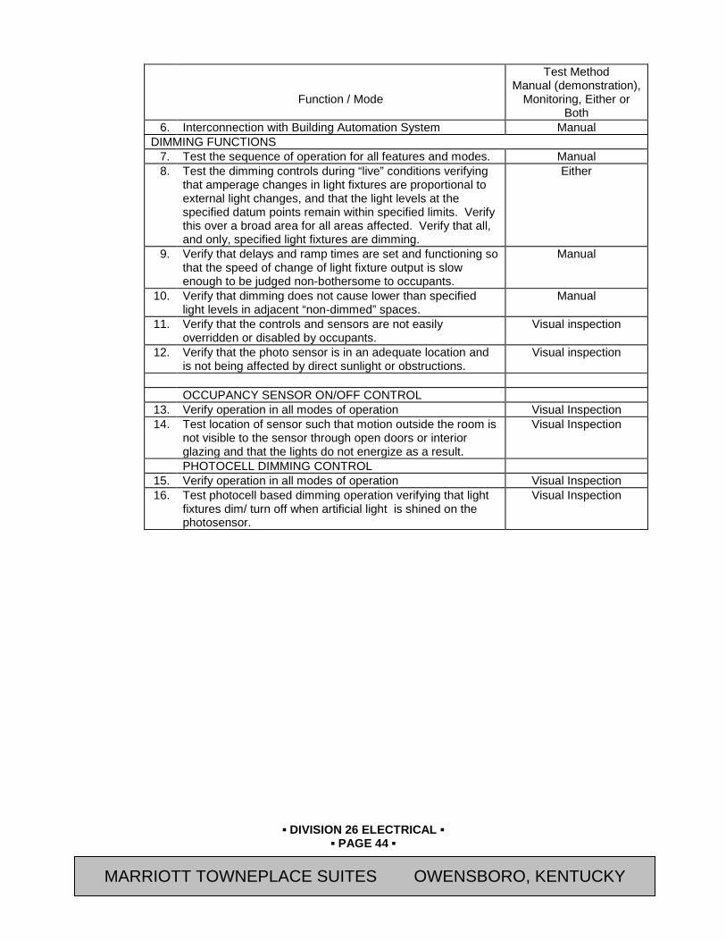
▪ DIVISION 26 ELECTRICAL ▪
▪ PAGE 44 ▪
RESIDENCE INN BY MARRIOTT - LITTLETON, COLORADO
Function / Mode
Test Method Manual (demonstration),
Monitoring, Either or Both
6. Interconnection with Building Automation System Manual DIMMING FUNCTIONS
7. Test the sequence of operation for all features and modes. Manual 8. Test the dimming controls during “live” conditions verifying
that amperage changes in light fixtures are proportional to external light changes, and that the light levels at the specified datum points remain within specified limits. Verify this over a broad area for all areas affected. Verify that all, and only, specified light fixtures are dimming.
Either
9. Verify that delays and ramp times are set and functioning so that the speed of change of light fixture output is slow enough to be judged non-bothersome to occupants.
Manual
10. Verify that dimming does not cause lower than specified light levels in adjacent “non-dimmed” spaces.
Manual
11. Verify that the controls and sensors are not easily overridden or disabled by occupants.
Visual inspection
12. Verify that the photo sensor is in an adequate location and is not being affected by direct sunlight or obstructions.
Visual inspection
OCCUPANCY SENSOR ON/OFF CONTROL
13. Verify operation in all modes of operation Visual Inspection 14. Test location of sensor such that motion outside the room is
not visible to the sensor through open doors or interior glazing and that the lights do not energize as a result.
Visual Inspection
PHOTOCELL DIMMING CONTROL 15. Verify operation in all modes of operation Visual Inspection 16. Test photocell based dimming operation verifying that light
fixtures dim/ turn off when artificial light is shined on the photosensor.
Visual Inspection
MARRIOTT TOWNEPLACE SUITES OWENSBORO, KENTUCKY

▪ DIVISION 26 ELECTRICAL ▪
▪ PAGE 45 ▪
RESIDENCE INN BY MARRIOTT - LITTLETON, COLORADO
E. Acceptance Criteria (referenced by function or mode ID) 1. 1 - 11 For the conditions, sequences and modes tested, the dimming controls, integral
components and related equipment respond to changing conditions and parameters appropriately as expected, as specified and according to acceptable operating practice.
F. Sampling Strategy for Identical Units 1. Each photosensor and its controlled zone must be tested (no sampling).
END OF SECTION
Revision Log
MARRIOTT TOWNEPLACE SUITES OWENSBORO, KENTUCKY

▪ DIVISION 26 ELECTRICAL ▪
▪ PAGE 46 ▪
RESIDENCE INN BY MARRIOTT - LITTLETON, COLORADO
SECTION 26 08 00.02 - ELECTRICAL SYSTEMS PREFUNCTIONAL CHECKLISTS
PART 28 GENERAL 28.01 SUMMARY
A. This Section includes the following: 1. Prefunctional Checklists (PC) in a form format. The Prefunctional Checklists consist of
Instructions Sheets and Record Sheets. B. Related Sections:
1. Section 01 33 00 - Submittal and Substitution Procedures 2. Section 01 91 13 – General Commissioning Requirements. 3. Section 26 08 00 – Commissioning of Electrical Systems 4. Section 26 08 00.01 – Electrical Systems Testing Requirements 5. Section 26 08 00.03 – Electrical Systems Sample Functional Test Procedures
28.02 DESCRIPTION A. The PC procedures displayed in a form format here are intended to provide the Contractor
with an example of the format and an indication of the rigor of the required prefunctional checklists (Instruction Sheets and Record Sheets) and documentation for various equipment types. Though they were not developed specifically for this project, they are generally applicable.
B. The checklists contain items for Division 26 contractors to perform. Division 26 contractor has additional responsibilities to complete Division 22 and 23 checklists.
C. Those executing the checklists are only responsible to perform items that apply to the specific application at hand. These checklists do not take the place of the manufacturer’s recommended checkout and start-up procedures or report. Some checklist procedures may be redundant of some checkout procedures that will be documented on typical factory field checkout sheets. Double documenting is required in those cases.
D. Refer to Section 01 91 13 for additional requirements regarding prefunctional checklists, startup and initial checkout. Items that do not apply should be noted along with the reasons on the form. If supplied Prefunctional Checklist forms are not used for documenting, one of similar rigor and clarity shall be used. Contractors assigned responsibility for sections of the checklist shall be responsible to see that checklist items by their subcontractors are completed and checked off.
E. The following is a list of the equipment and systems which will require Prefunctional Checklists (Instruction Sheets and Record Sheets) to be completed by the Contractors. 1. Lighting Controls (Each Space Served) 2. Divisions 22 and 23 – Refer to 22 08 00.02 and 23 08 00.02
F. Refer to Section 01 33 00 - Submittal and Substitution Procedures for Prefunctional Checklists.
PART 29 PRODUCTS Not Used
PART 30 EXECUTION Not Used
END OF SECTION Revision Log
MARRIOTT TOWNEPLACE SUITES OWENSBORO, KENTUCKY

▪ DIVISION 26 ELECTRICAL ▪
▪ PAGE 47 ▪
RESIDENCE INN BY MARRIOTT - LITTLETON, COLORADO
SECTION 26 08 00.03 - ELECTRICAL SYSTEMS SAMPLE FUNCTIONAL TEST PROCEDURES
PART 31 GENERAL 31.01 SUMMARY
A. This Section includes the following: 1. This Section contains the Functional Testing Procedures for Mechanical Systems
B. Related Sections: 1. Section 01 33 00 - Submittal and Substitution Procedures 2. Section 01 91 13 – General Commissioning Requirements. 3. Section 26 08 00 – Commissioning of Electrical Systems 4. Section 26 08 00.01 – Electrical Systems Testing Requirements 5. Section 26 08 00.02 – Electrical Systems Prefunctional Checklists
31.02 DESCRIPTION A. The CxA will use the functional testing requirements in Sections 26 08 00.01 and the testing
protocols specified in Section 01 91 13 for developing site-specific functional test procedures and forms for this project. For illustrative purposes, sequences of operation associated with a few pieces of the equipment for which tests are included are also provided.
B. The following is a list of the equipment and systems which will require Prefunctional Checklists (Instruction Sheets and Record Sheets) to be completed by the Contractors. 1. Lighting Controls (Each Space Served)
C. Refer to Section 01 33 00 - Submittal and Substitution Procedures for Prefunctional Checklists.
PART 32 PRODUCTS Not Used
MARRIOTT TOWNEPLACE SUITES OWENSBORO, KENTUCKY

▪ DIVISION 26 ELECTRICAL ▪
▪ PAGE 48 ▪
RESIDENCE INN BY MARRIOTT - LITTLETON, COLORADO
PART 33 EXECUTION Not Used
END OF SECTION
Revision Log
MARRIOTT TOWNEPLACE SUITES OWENSBORO, KENTUCKY

▪ DIVISION 26 ELECTRICAL ▪
▪ PAGE 49 ▪
RESIDENCE INN BY MARRIOTT - LITTLETON, COLORADO
SECTION 26 22 00 (16460) - LOW-VOLTAGE TRANSFORMERS PART 34 GENERAL 34.01 SUMMARY
A. Section Includes: 1. Dry-Type Distribution And Specialty Transformers Rated 1000 V And Less.
a. General-Purpose Distribution and Power Transformers b. Buck-Boost Transformers c. Control and Signal Transformers
B. Related Sections: 1. Section 26 05 26 (16060) - Grounding and Bonding for Electrical Systems. 2. Section 26 05 53 (16075) – Identification for Electrical Systems.
34.02 REFERENCES A. Institute of Electrical and Electronics Engineers (IEEE) Publications:
1. C2 “ASC C2 Eighth Interim Collection of the National Electrical Safety Code” 2. C57.12.28 “IEEE Standard for Pad-Mounted Equipment-Enclosure Integrity” 3. C57.12.91 “IEEE Standard Test Code for Dry-Type Distribution and Power Transformers”
B. InterNational Electrical Testing Association C. National Electrical Manufacturer’s Association (NEMA) Standards Publications:
1. 250 “Enclosures for Electrical Equipment (1000 Volts Maximum)” 2. ST 1 “Specialty Transformers (Except General Purpose Type)” 3. ST 20 “Dry Type Transformers for General Applications” 4. TP2 “Standard Test Method for Measuring the Energy Consumption of Distribution
Transformers” D. National Fire Protection Association (NFPA) Publications:
1. 70 "National Electric Code" E. National Institute for Certification in Engineering Technologies F. Occupational Safety & Health Administration (OSHA) Regulations:
1. 1910.7 “Definition and Requirements for a Nationally Recognized Testing Laboratory” G. Underwriter's Laboratories, Inc. (UL) Standards:
1. 486A “Standard For Wire Connectors and Soldering Lugs for Use with Copper Conductors”
2. 486B “Standard for Wire Connectors for Use with Aluminum Conductors” 3. 506 “Standard for Specialty Transformers 4. 1561 “Standard for Dry-Type General Purpose and Power Transformers”
34.03 SUBMITTALS A. General: Submit the following in accordance with Conditions of Contract and Division 01
Specification Sections. B. Submit “Letter of Conformance” in accordance with Section 01 33 00 (01330) indicating
specified items selected for use in project with the following supporting data. 1. Product Data:
a. Include data on features, components, ratings, and performance for each type of transformer specified. Include dimensioned plans, sections, and elevation views. Show minimum clearances and installed devices and features.
MARRIOTT TOWNEPLACE SUITES OWENSBORO, KENTUCKY

▪ DIVISION 26 ELECTRICAL ▪
▪ PAGE 50 ▪
RESIDENCE INN BY MARRIOTT - LITTLETON, COLORADO
2. Wiring Diagrams: Detail wiring and identify terminals for tap changing and connecting field-installed wiring.
3. Product Certificates: Signed by manufacturers of transformers certifying that the products furnished comply with requirements.
4. Qualification Data: For firms and persons specified in "Quality Assurance" Article. 5. Field Test Reports: Indicate and interpret test results for tests specified in Part 3. 6. Maintenance Data: For transformers to include in the maintenance manuals specified in
Division 01. 34.04 QUALITY ASSURANCE
A. Testing Agency Qualifications: In addition to requirements specified in Section 01 45 00 "Quality Control," an independent testing agency shall meet OSHA criteria for accreditation of testing laboratories, Title 29, Part 1907; or shall be a full-member company of the InterNational Electrical Testing Association. 1. Testing Agency's Field Supervisor: Person currently certified by the InterNational
Electrical Testing Association or the National Institute for Certification in Engineering Technologies, to supervise on-site testing specified in Part 3.
B. Listing and Labeling: Provide transformers specified in this Section that are listed and labeled. 1. The Terms "Listed" and "Labeled": As defined in NFPA 70, Article 100. 2. Listing and Labeling Agency Qualifications: A "Nationally Recognized Testing
Laboratory" as defined in OSHA Regulation 1910.7. C. Comply with IEEE C2. D. Comply with NFPA 70.
34.05 DELIVERY, STORAGE, AND HANDLING A. Temporary Heating: Apply temporary heat according to manufacturer's written instructions
within the enclosure of each ventilated-type unit throughout periods during which equipment is not energized and is not in a space that is continuously under normal control of temperature and humidity.
PART 35 PRODUCTS 35.01 MANUFACTURERS
A. Avendra, LLC Preferred Manufacturers: 1. None.
B. Approved Manufacturers: 1. Acme Electric Corp.; Transformer Division (800-334-5214) 2. Cutler-Hammer/Eaton Corp. (800-498-2678) 3. GE Electrical Distribution & Control (800-431-7867) 4. Siemens Energy & Automation, Inc. (800-964-4114) 5. Square D; a Division of Groupe Schneider (888-778-2733)
35.02 TRANSFORMERS, GENERAL A. Description: Factory-assembled and -tested, air-cooled units of types specified, designed for
60-Hz service. B. Cores: Grain-oriented, non-aging silicon steel. C. Coils: Continuous windings without splices, except for taps. D. Internal Coil Connections: Brazed or pressure type. E. Enclosure: Class complies with NEMA 250 for the environment in which installed.
MARRIOTT TOWNEPLACE SUITES OWENSBORO, KENTUCKY
▪ DIVISION 26 ELECTRICAL ▪
▪ PAGE 51 ▪
RESIDENCE INN BY MARRIOTT - LITTLETON, COLORADO
35.03 GENERAL-PURPOSE DISTRIBUTION AND POWER TRANSFORMERS A. Comply with NEMA ST 20 and list and label as complying with UL 1561. B. Energy Efficiency for Transformers Rated 15 KVA and Larger:
1. Comply with NEMA TP1, Class 1 efficiencies. 2. Tested according to NEMA TP2.
C. Cores: One leg per phase. D. Windings: One coil per phase in primary and secondary. E. Enclosure: Indoor, ventilated. F. Insulation Class: 185 or 220 deg C class for transformers 15 kVA or smaller; 220 deg C class
for transformers larger than 15 kVA. 1. Rated Temperature Rise: 115 deg C maximum rise above 40 deg C.
G. Taps: For transformers 3 kVA and larger, full-capacity taps in high-voltage windings are as follows: 1. Taps, 3 through 10 kVA: Two 5-percent taps below rated high voltage. 2. Taps, 15 through 500 kVA: Six 2.5-percent taps, 2 above and 4 below rated high
voltage. 3. Taps, 750 kVA and Above: Four 2.5-percent taps, 2 above and 2 below rated high
voltage. H. K-Factor Rating: Transformers indicated to be K-factor rated are listed to comply with
UL 1561 requirements for non-sinusoidal load current handling capability to the degree defined by the designated K-factor. 1. Transformer design prevents overheating when carrying full load with harmonic content
corresponding to the designated K-factor. 2. Nameplate states the designated K-factor of the transformer.
I. Wall-Mounting Brackets: Manufacturer's standard brackets for transformers up to 45 kVA. 35.04 BUCK-BOOST TRANSFORMERS
A. Units comply with NEMA ST 1 and are listed and labeled as complying with UL 506 or UL 1561.
B. Description: Self-cooled dry type, rated for continuous duty, and connected as autotransformers to provide the percentage of buck or boost indicated.
35.05 CONTROL AND SIGNAL TRANSFORMERS A. Units comply with NEMA ST 1 and are listed and labeled as complying with UL 506. B. Ratings: Continuous duty. If rating is not indicated, provide capacity exceeding peak load by
50 percent minimum. C. Description: Self-cooled, 2 windings.
35.06 FINISHES A. Indoor Units: Manufacturer's standard paint over corrosion-resistant pretreatment and primer. B. Outdoor Units: Comply with IEEE C57.12.28.
35.07 SOURCE QUALITY CONTROL A. Factory Tests: Design and routine tests comply with referenced standards.
PART 36 EXECUTION 36.01 INSTALLATION
A. Comply with safety requirements of IEEE C2. B. Arrange equipment to provide adequate spacing for access and for circulation of cooling air.
MARRIOTT TOWNEPLACE SUITES OWENSBORO, KENTUCKY
▪ DIVISION 26 ELECTRICAL ▪
▪ PAGE 52 ▪
RESIDENCE INN BY MARRIOTT - LITTLETON, COLORADO
C. Identify transformers and install warning signs according to Section 26 05 53 - "Identification for Electrical Systems."
D. Tighten electrical connectors and terminals according to manufacturer's published torque-tightening values. If manufacturer's torque values are not indicated, use those specified in UL 486A and UL 486B.
36.02 GROUNDING A. Separately Derived Systems: Comply with NFPA 70 requirements for connecting to grounding
electrodes and for bonding to metallic piping near the transformer. B. Comply with Section 26 05 26 - "Grounding and Bonding for Electrical Systems” for materials
and installation requirements. 36.03 FIELD QUALITY CONTROL
A. Test Objectives: To ensure transformer is operational within industry and manufacturer's tolerances, is installed according to the Contract Documents, and is suitable for energizing.
B. Test Labeling: On satisfactory completion of tests for each transformer, attach a dated and signed "Satisfactory Test" label to tested component.
C. Schedule tests and provide notification at least 7 days in advance of test commencement. D. Report: Submit a written report of observations and tests. Report defective materials and
installation. E. Tests: Include the following minimum inspections and tests according to manufacturer's
written instructions. Comply with IEEE C57.12.91 for test methods and data correction factors. 1. Inspect accessible components for cleanliness, mechanical and electrical integrity, and
damage or deterioration. Verify that temporary shipping bracing has been removed. Include internal inspection through access panels and covers.
2. Inspect bolted electrical connections for tightness according to manufacturer's published torque values or, if not available, those specified in UL 486A and UL 486B.
3. Insulation Resistance: Perform megohmmeter tests of primary and secondary winding to winding and winding to ground. a. Minimum Test Voltage: 1000 V, dc. b. Minimum Insulation Resistance: 500 megohms. c. Duration of Each Test: 10 minutes. d. Temperature Correction: Correct results for test temperature deviation from 20
deg C standard. F. Test Failures: Compare test results with specified performance or manufacturer's data.
Correct deficiencies identified by tests and retest. Verify that transformers meet specified requirements.
36.04 CLEANING A. On completion of installation, inspect components. Remove paint splatters and other spots,
dirt, and debris. Repair scratches and mars on finish to match original finish. Clean components internally using methods and materials recommended by manufacturer.
36.05 ADJUSTING A. After installing and cleaning, touch up scratches and mars on finish to match original finish. B. Adjust transformer taps to provide optimum voltage conditions at utilization equipment
throughout normal operating cycle of facility. Record primary and secondary voltages and tap settings and submit with test results.
C. Adjust buck-boost transformer connections to provide optimum voltage conditions at utilization equipment throughout normal operating cycle of facility.
MARRIOTT TOWNEPLACE SUITES OWENSBORO, KENTUCKY
▪ DIVISION 26 ELECTRICAL ▪
▪ PAGE 53 ▪
RESIDENCE INN BY MARRIOTT - LITTLETON, COLORADO
D. Occupancy Adjustments: When requested within 12 months of date of Substantial Completion, provide on-site assistance in readjusting transformer tap settings to suit actual occupied conditions. Provide up to 2 visits to Project site for this purpose without additional cost. 1. Voltage Recordings: Contractor performed. Provide up to 48 hours of recording on the
low-voltage system of each medium-voltage transformer. 2. Point of Measurement: Make voltage recordings at load outlets selected by Owner’s
Representative. END OF SECTION
Revision Log
MARRIOTT TOWNEPLACE SUITES OWENSBORO, KENTUCKY

▪ DIVISION 26 ELECTRICAL ▪
▪ PAGE 54 ▪
RESIDENCE INN BY MARRIOTT - LITTLETON, COLORADO
SECTION 26 24 00 (16440) - SWITCHBOARDS AND PANELBOARDS PART 37 GENERAL 37.01 SUMMARY
A. Section Includes: 1. Service and Distribution Switchboards Rated 600 V and Less. 2. Load Centers and Panelboards, Overcurrent Protective Devices, And Associated
Auxiliary Equipment Rated 600 V and Less For The Following Types: a. Lighting and Appliance Branch-Circuit Panelboards. b. Distribution Panelboards.
B. Related Sections: 1. Section 03 30 00 (03300) - Cast-In-Place Concrete. 2. Section 26 05 19 (16490) - Low-Voltage Electrical Power Conductors and Cables. 3. Section 26 05 48 (16071) – Vibration and Seismic Controls for Electrical Work. 4. Section 26 05 53 (16075) – Identification for Electrical Systems.
37.02 REFERENCES A. American National Standards Institute (ANSI) Publications:
1. C39.1 “Requirements For Electrical Analog Indicating Instruments B. Institute of Electrical and Electronics Engineers (IEEE) Publications:
1. C57.13 “IEEE “Standard Requirements for Instrument Transformers” C. InterNational Electrical Testing Association (NICET) D. National Electrical Manufacturer’s Association (NEMA) Standards Publications:
1. 250 “Enclosures for Electrical Equipment (1000 Volts Maximum)” 2. AB 1 “Molded-Case Circuit Breakers, Molded Case Switches, and Circuit-Breaker
Enclosures” 3. EI 21.1, “Instrument Transformers for Revenue Metering (110 kV BIL and less)” 4. FU 1 “Low Voltage Cartridge Fuses” 5. PB 1 “Panelboards” 6. PB 1.1 “General Instructions for Proper Installation, Operation, and Maintenance of
Panelboards Rated 600 Volts or Less” 7. PB 2 “Deadfront Distribution Switchboards” 8. PB 2.1 “General Instructions for Proper Handling, Installation, Operation, and
Maintenance of Deadfront Distribution Switchboards Rated 600 Volts or Less” E. National Institute for Certification in Engineering Technologies (NETA)
1. ATS “Standard for Acceptance Testing Specifications for Electrical Power Equipment and Systems”
F. National Fire Protection Association (NFPA) Publications: 1. 70 "National Electric Code"
G. Underwriter's Laboratories, Inc. (UL) Standards: 1. 486A “Standard For Wire Connectors and Soldering Lugs for Use with Copper
Conductors” 2. 486B “Standard for Wire Connectors for Use with Aluminum Conductors”
37.03 DEFINITIONS A. EMI: Electromagnetic interference. B. GFCI: Ground-fault circuit interrupter.
MARRIOTT TOWNEPLACE SUITES OWENSBORO, KENTUCKY

▪ DIVISION 26 ELECTRICAL ▪
▪ PAGE 55 ▪
RESIDENCE INN BY MARRIOTT - LITTLETON, COLORADO
C. RFI: Radio-frequency interference. D. RMS: Root mean square. E. SPDT: Single pole, double throw. F. TVSS: Transient voltage surge suppressor.
37.04 SUBMITTALS A. Submit “Letter of Conformance” in accordance with Section 01 33 00 (01330) indicating
specified items selected for Project with the following supporting data: 1. Product Data:
a. For each type of switchboard, panelboard, overcurrent protective device, TVSS device, ground-fault protector, accessory, and component indicated. Include dimensions and manufacturers' technical data on features, performance, electrical characteristics, ratings, and finishes.
2. Shop Drawings: For each switchboard, panelboard and related equipment. a. Dimensioned plans, elevations, sections, and details, including required clearances
and service space around equipment. Show tabulations of installed devices, equipment features, and ratings. Include the following: 1) Enclosure types and details for types other than NEMA 250, Type 1. 2) Bus configuration, current, and voltage ratings. 3) Short-circuit current rating of switchboards and overcurrent protective devices. 4) Descriptive documentation of optional barriers specified for electrical insulation
and isolation. 5) Utility company's metering provisions with indication of approval by utility
company. 6) UL listing for series rating of installed devices. 7) Features, characteristics, ratings, and factory settings of individual overcurrent
protective devices and auxiliary components. b. Wiring Diagrams: Diagram power, signal, and control wiring and differentiate
between manufacturer-installed and field-installed wiring. 3. Manufacturer Seismic Qualification Certification: Submit certification that switchboards,
overcurrent protective devices, accessories, and components will withstand seismic forces defined in Section 26 05 48 (16071) "Vibration and Seismic Controls for Electrical Work." Include the following: a. Basis of Certification: Indicate whether withstand certification is based on actual test
of assembled components or on calculation. b. The term "withstand" means "the unit will remain in place without separation of
internal and external parts during a seismic event and the unit will be fully operational after the event."
c. Dimensioned Outline Drawings of Equipment Unit: Identify center of gravity and locate and describe mounting and anchorage provisions.
d. Detailed description of equipment anchorage devices on which the certification is based and their installation requirements.
4. Qualification Data: Submit data for testing agencies indicating that they comply with qualifications specified in "Quality Assurance" Article.
5. Field Test Reports: Submit written test reports and include the following: a. Test procedures used. b. Test results that comply with requirements.
MARRIOTT TOWNEPLACE SUITES OWENSBORO, KENTUCKY

▪ DIVISION 26 ELECTRICAL ▪
▪ PAGE 56 ▪
RESIDENCE INN BY MARRIOTT - LITTLETON, COLORADO
c. Results of failed tests and corrective action taken to achieve test results that comply with requirements.
6. Manufacturer's field service report. 7. Updated mimic-bus diagram for switchboard reflecting field changes after final
switchboard load connections have been made, for record. 8. Maintenance Data: For Switchboards, Panelboards and components to include in
maintenance manuals specified in Division 01. In addition to requirements specified in Division 01 Section "Contract Closeout," include the following: a. Routine maintenance requirements for switchboards and all installed components. b. Manufacturer's written instructions for testing and adjusting overcurrent protective
devices. c. Time-current curves, including selectable ranges for each type of overcurrent
protective device. 9. Panelboard Schedules: For installation in panelboards. Submit final versions after load
balancing. 37.05 QUALITY ASSURANCE
A. Testing Agency Qualifications: Testing agency that is a member company of the InterNational Electrical Testing Association and that is acceptable to authorities having jurisdiction. 1. Testing Agency's Field Supervisor: Person currently certified by the the InterNational
Electrical Testing Association or National Institute for Certification in Engineering Technologies to supervise on-site testing specified in Part 3.
B. Electrical Components, Devices, and Accessories: Listed and labeled as defined in NFPA 70, Article 100, by a testing agency acceptable to authorities having jurisdiction, and marked for intended use.
C. Comply with NEMA PB 2 for switchboards. D. Comply with NEMA PB1 for panelboards. E. Comply with NFPA 70. F. Product Selection for Restricted Space: Drawings indicate maximum dimensions for
switchboards, including clearances between switchboards, and adjacent surfaces and other items. Comply with indicated maximum dimensions.
37.06 DELIVERY, STORAGE, AND HANDLING A. Deliver in sections of lengths that can be moved past obstructions in delivery path. B. Store indoors in clean dry space with uniform temperature to prevent condensation. Protect
from exposure to dirt, fumes, water, corrosive substances, and physical damage. C. Handle switchboards according to NEMA PB 2.1.
37.07 PROJECT CONDITIONS A. Installation Pathway: Remove and replace access fencing, doors, lift-out panels, and
structures to provide pathway for moving switchboards into place. B. Environmental Limitations: Rate equipment for continuous operation under the following,
unless otherwise indicated: 1. Ambient Temperature: Not exceeding 104 deg F. 2. Altitude: Not exceeding 6600 feet.
37.08 COORDINATION A. Coordinate layout and installation of switchboards, panelboards, and components with other
construction, including conduit, piping, equipment, and adjacent surfaces. Maintain required workspace clearances and required clearances for equipment access doors and panels.
MARRIOTT TOWNEPLACE SUITES OWENSBORO, KENTUCKY
▪ DIVISION 26 ELECTRICAL ▪
▪ PAGE 57 ▪
RESIDENCE INN BY MARRIOTT - LITTLETON, COLORADO
B. Coordinate size and location of concrete bases. Cast anchor-bolt inserts into bases. Concrete, reinforcement, and formwork requirements are specified in Section 03 30 00 (03300) "Cast-in-Place Concrete."
PART 38 PRODUCT 38.01 MANUFACTURERS
A. Avendra, LLC Preferred Manufacturers: 1. Switchboards:
a. None. 2. Panelboards, Overcurrent Protective Devices, Controllers, Contactors, and Accessories:
a. None. B. Approved Manufacturers:
1. Switchboards: a. Eaton Corp.; Cutler-Hamer Products (800-498-2678) b. General Electric Co.; Electrical Distribution & Control Div. (800-431-7867) c. Siemens Energy & Automation, Inc. (800-964-4114) d. Square D Co.; a Division of Groupe Schneider (888-778-2733)
2. Panelboards, Overcurrent Protective Devices, Controllers, Contactors, and Accessories: a. Eaton Corp.; Cutler-Hammer Products (800-498-2678) b. General Electric Co.; Electrical Distribution & Control Div. (800-431-7867) c. Siemens Energy & Automation, Inc. (800-864-4114) d. Square D Co.; a Division of Groupe Schneider (888-778-2733)
38.02 SWITCHBOARDS - MANUFACTURED UNITS A. Front-Connected, Front-Accessible Switchboard Fixed, individually mounted main device,
panel-mounted branches, and sections rear aligned. 38.03 SWITCHBOARDS - FABRICATION AND FEATURES
A. Enclosure Finish for Indoor Units: Factory-applied finish in manufacturer's standard gray finish over a rust-inhibiting primer on treated metal surface.
B. Barriers: Between adjacent switchboard sections. C. Utility Metering Compartment: Fabricated compartment and section complying with utility
company's requirements. If separate vertical section is required for utility metering, match and align with basic switchboard.
D. Bus Transition and Incoming Pull Sections: Matched and aligned with basic switchboard. E. Hinged Front Panels: Allow access to circuit-breaker, metering, accessory, and blank
compartments. F. Buses and Connections: Three phase, four wire, unless otherwise indicated. Include the
following features: 1. Phase- and Neutral-Bus Material: Hard-drawn copper of 98 percent conductivity or tin-
plated, high-strength, electrical-grade aluminum alloy. a. If bus is aluminum, use copper or tin-plated aluminum for circuit-breaker line
connections. b. If bus is copper, use copper for feeder circuit-breaker line connections.
2. Ground Bus: 1/4-by-2-inch minimum size, drawn-temper copper of 98 percent conductivity, equipped with pressure connectors for feeder and branch-circuit ground conductors. For busway feeders, extend insulated equipment grounding cable to busway ground connection and support cable at intervals in vertical run.
MARRIOTT TOWNEPLACE SUITES OWENSBORO, KENTUCKY

▪ DIVISION 26 ELECTRICAL ▪
▪ PAGE 58 ▪
RESIDENCE INN BY MARRIOTT - LITTLETON, COLORADO
3. Contact Surfaces of Buses: Silver plated for copper to copper and copper to aluminum connections, silver or tin plating for aluminum to aluminum connections.
4. Main Phase Buses, Neutral Buses, and Equipment Ground Buses: Uniform capacity for entire length of switchboard's main and distribution sections. Provide for future extensions from both ends.
5. Isolation Barrier Access Provisions: Permit checking of bus-bolt tightness. 6. Neutral Buses: 100 percent of the ampacity of the phase buses, unless otherwise
indicated, equipped with pressure connectors for outgoing circuit neutral cables. Bus extensions for busway feeder neutral bus is braced.
G. Future Devices: Equip compartments with mounting brackets, supports, bus connections, and appurtenances at full rating of circuit-breaker compartment.
38.04 SWITCHBOARDS - INSTRUMENTATION A. Instrument Transformers: NEMA EI 21.1, IEEE C57.13, and the following:
1. Potential Transformers: Secondary voltage rating of 120 V and NEMA accuracy class of 0.3 with burdens of W, X, and Y.
2. Current Transformers: Ratios shall be as indicated with accuracy class and burden suitable for connected relays, meters, and instruments.
3. Control-Power Transformers: Dry type, mounted in separate compartments for units larger than 3 kV.
B. Ammeters, Voltmeters, and Power-Factor Meters: ANSI C39.1. 1. Meters: 4-inch diameter or 6 inches square, flush or semi-flush, with anti-parallax 250-
degree scales and external zero adjustment. 2. Voltmeters: Cover an expanded-scale range of nominal voltage plus 10 percent.
C. Instrument Switches: Rotary type with off position. 1. Voltmeter Switches: Permit reading of all phase-to-phase voltages and, where a neutral
is indicated, phase-to-neutral voltages. 2. Ammeter Switches: Permit reading of current in each phase and maintain current-
transformer secondaries in a closed-circuit condition at all times. D. Feeder Ammeters: 2-1/2-inch minimum size with 90- or 120-degree scale. Meter and transfer
device with an off position, located on overcurrent device door for indicated feeder circuits only.
38.05 SWITCHBOARDS - CONTROL POWER A. Control Circuits: 120 V, supplied through secondary disconnecting devices from control-
power transformer. B. Control-Power Fuses: Primary and secondary fuses for current-limiting and overload
protection of transformer and fuses for protection of control circuits. C. Control Wiring: Factory installed, with bundling, lacing, and protection included. Provide
flexible conductors for No. 8 AWG and smaller, for conductors across hinges, and for conductors for interconnections between shipping units.
38.06 PANELBOARDS - FABRICATION AND FEATURES A. Enclosures: Flush- and/or surface-mounted cabinets as indicated on drawings. NEMA PB 1,
Type 1, to meet environmental conditions at installed location. 1. Outdoor Locations: NEMA 250, Type 3R. 2. Kitchen Areas: NEMA 250, Type 4X, stainless steel. 3. Other Wet or Damp Indoor Locations: NEMA 250, Type 4.
B. Front: Secured to box with concealed trim clamps. For surface-mounted fronts, match box dimensions; for flush-mounted fronts, overlap box.
MARRIOTT TOWNEPLACE SUITES OWENSBORO, KENTUCKY
▪ DIVISION 26 ELECTRICAL ▪
▪ PAGE 59 ▪
RESIDENCE INN BY MARRIOTT - LITTLETON, COLORADO
C. Hinged Front Cover: Entire front trim hinged to box and with standard door within hinged trim cover.
D. Finish: Manufacturer's standard enamel finish over corrosion-resistant treatment or primer coat.
E. Directory Card: With transparent protective cover, mounted inside metal frame, inside panelboard door.
F. Bus: Hard-drawn copper, 98 percent conductivity or tin-plated aluminum. G. Main and Neutral Lugs: Mechanical type suitable for use with conductor material. H. Equipment Ground Bus: Adequate for feeder and branch-circuit equipment ground
conductors; bonded to box. I. Future Devices: Mounting brackets, bus connections, and necessary appurtenances required
for future installation of devices. J. Isolated Equipment Ground Bus: Adequate for branch-circuit equipment ground conductors;
insulated from box. K. Extra-Capacity Neutral Bus: Neutral bus rated 200 percent of phase bus and UL listed as
suitable for nonlinear loads. L. Gutter Barrier: Arrange to isolate individual panel sections. M. Feed-through Lugs: Mechanical type suitable for use with conductor material. Locate at
opposite end of bus from incoming lugs or main device. 38.07 PANELBOARDS - SHORT-CIRCUIT RATING
A. UL label indicating series-connected rating with integral or remote upstream devices. Include size and type of upstream device allowable, branch devices allowable, and UL series-connected short-circuit rating.
B. Fully rated to interrupt symmetrical short-circuit current available at terminals. 38.08 PANELBOARDS - LIGHTING AND APPLIANCE BRANCH-CIRCUITS
A. Branch Overcurrent Protective Devices: Plug-in circuit breakers, replaceable without disturbing adjacent units.
B. Doors: Front mounted with concealed hinges; secured with flush latch with tumbler lock; keyed alike.
38.09 PANELBOARDS - DISTRIBUTION A. Doors: Front mounted, except omit in fused-switch panelboards; secured with vault-type latch
with tumbler lock; keyed alike. B. Main Overcurrent Protective Devices: Circuit breaker. C. Branch overcurrent protective devices shall be one of the following:
1. For Circuit-Breaker Frame Sizes 125 A and Smaller: Plug-in circuit breakers. 2. For Circuit-Breaker Frame Sizes Larger Than 125 A: Bolt-on circuit breakers; plug-in
circuit breakers where individual positive-locking device requires mechanical release for removal.
38.10 LOAD CENTERS A. Overcurrent Protective Devices: Plug-in, full-module circuit breaker. B. Conductor Connectors: Mechanical type for main, neutral, and ground lugs and buses.
38.11 SWITCHBOARD AND PANELBOARDS - OVERCURRENT PROTECTIVE DEVICES A. Molded-Case Circuit Breaker: NEMA AB 1, with interrupting capacity to meet available fault
currents. 1. Thermal-Magnetic Circuit Breakers: Inverse time-current element for low-level overloads,
and instantaneous magnetic trip element for short circuits. Adjustable magnetic trip setting for circuit-breaker frame sizes 250 A and larger.
MARRIOTT TOWNEPLACE SUITES OWENSBORO, KENTUCKY
▪ DIVISION 26 ELECTRICAL ▪
▪ PAGE 60 ▪
RESIDENCE INN BY MARRIOTT - LITTLETON, COLORADO
2. Adjustable Instantaneous-Trip Circuit Breakers: Magnetic trip element with front-mounted, field-adjustable trip setting.
3. Electronic Trip Unit Circuit Breakers: RMS sensing; field-replaceable rating plug; with the following field-adjustable settings: a. Instantaneous trip. b. Long- and short-time pickup levels. c. Long- and short-time time adjustments. d. Ground-fault pickup level, time delay, and I2t response.
4. Current-Limiting Circuit Breakers: Frame sizes 400 A and smaller; let-through ratings less than NEMA FU 1, RK-5.
5. Integrally Fused Circuit Breakers: Thermal-magnetic trip element with integral limiter-style fuse listed for use with circuit breaker; trip activation on fuse opening or on opening of fuse compartment door.
6. GFCI Circuit Breakers: Single- and two-pole configurations with [5] [30]-mA trip sensitivity.
B. Molded-Case Circuit-Breaker Features and Accessories: Standard frame sizes, trip ratings, and number of poles. 1. Lugs: Mechanical style, suitable for number, size, trip ratings, and material of
conductors. 2. Application Listing: Appropriate for application; Type SWD for switching fluorescent
lighting loads; Type HACR for heating, air-conditioning, and refrigerating equipment. 3. Ground-Fault Protection: Integrally mounted relay and trip unit with adjustable pickup
and time-delay settings, push-to-test feature, and ground-fault indicator. 4. Shunt Trip: 120-V trip coil energized from separate circuit, set to trip at 75 percent of
rated voltage. 5. Undervoltage Trip: Set to operate at 35 to 75 percent of rated voltage with field-
adjustable 0.1- to 0.6-second time delay. 38.12 ACCESSORY COMPONENTS AND FEATURES
A. Spare-Fuse Cabinet: Suitably identified, wall-mounted, lockable, compartmented steel box or cabinet. Arrange for wall mounting.
38.13 IDENTIFICATION A. Mimic Bus for Switchboard: Continuously integrated mimic bus factory applied to front of
switchboard. Arrange in single-line diagram format, using symbols and letter designations consistent with final mimic-bus diagram. Coordinate mimic-bus segments with devices in switchboard sections to which applied. Produce a concise visual presentation of principal switchboard components and connections.
B. Presentation Media: Painted graphics in color contrasting with equipment factory-finished background to represent bus and components, complete with lettered designations.
PART 39 EXECUTION 39.01 PROTECTION
A. Temporary Heating: Apply temporary heat to maintain temperature according to manufacturer's written instructions.
39.02 EXAMINATION A. Examine elements and surfaces to receive switchboards for compliance with installation
tolerances and other conditions affecting performance. 1. Proceed with installation only after unsatisfactory conditions have been corrected.
MARRIOTT TOWNEPLACE SUITES OWENSBORO, KENTUCKY

▪ DIVISION 26 ELECTRICAL ▪
▪ PAGE 61 ▪
RESIDENCE INN BY MARRIOTT - LITTLETON, COLORADO
39.03 INSTALLATION A. Install switchboards and accessories according to NEMA PB 2.1. B. Install panelboards and accessories according to NEMA PB 1.1 C. Support switchboards on concrete bases, 4-inch nominal thickness. D. Comply with mounting and anchoring requirements specified in Section 26 05 48 (16071)
"Seismic Controls for Electrical Work." E. Temporary Lifting Provisions: Remove temporary lifting eyes, channels, and brackets and
temporary blocking of moving parts from switchboard units and components. F. Operating Instructions: Frame and mount the printed basic operating instructions for
switchboards, including control and key interlocking sequences and emergency procedures. Fabricate frame of finished wood or metal and cover instructions with clear acrylic plastic. Mount on front of switchboards.
G. Mounting of Panelboards: Plumb and rigid without distortion of box. Mount recessed panelboards with fronts uniformly flush with wall finish.
H. Circuit Directory: Create a directory to indicate installed circuit loads after balancing panelboard loads. Obtain approval before installing. Use a computer or typewriter to create directory; handwritten directories are not acceptable.
I. Install filler plates in unused spaces. J. Provision for Future Circuits at Flush Panelboards: Stub four 1-inch (27-GRC) empty conduits
from panelboard into accessible ceiling space or space designated to be ceiling space in the future. Stub four 1-inch (27-GRC) empty conduits into raised floor space or below slab not on grade.
K. Wiring in Panelboard Gutters: Arrange conductors into groups and bundle and wrap with wire ties after completing load balancing.
39.04 IDENTIFICATION A. Identify field-installed conductors, interconnecting wiring, and components; provide warning
signs as specified in Section 26 05 53 (16075) "Identification for Electrical Systems". B. Switchboard Nameplates: Label each switchboard compartment with engraved metal or
laminated-plastic nameplate mounted with corrosion-resistant screws. C. Panelboard Nameplates: Label each panelboard with engraved metal or laminated-plastic
nameplate mounted with corrosion-resistant screws. 39.05 CONNECTIONS
A. Install equipment grounding connections for switchboards with ground continuity to main electrical ground bus.
B. Tighten electrical connectors and terminals according to manufacturer's published torque-tightening values. If manufacturer's torque values are not indicated, use those specified in UL 486A and UL 486B.
39.06 FIELD QUALITY CONTROL A. Prepare for acceptance tests as follows:
1. Test insulation resistance for each switchboard bus, component, connecting supply, feeder, and control circuit.
2. Test continuity of each circuit. B. Testing: After installing switchboards and after electrical circuitry has been energized,
demonstrate product capability and compliance with requirements. 1. Procedures: Perform each visual and mechanical inspection and electrical test indicated
in NETA ATS, Sections 7.1, 7.5, 7.6, 7.9, 7.10, 7.11, and 7.14 as appropriate. Certify compliance with test parameters.
MARRIOTT TOWNEPLACE SUITES OWENSBORO, KENTUCKY

▪ DIVISION 26 ELECTRICAL ▪
▪ PAGE 62 ▪
RESIDENCE INN BY MARRIOTT - LITTLETON, COLORADO
2. Correct malfunctioning units on-site, where possible, and retest to demonstrate compliance; otherwise, replace with new units and retest.
C. Infrared Scanning: Switchboard only. After Substantial Completion, but not more than 60 days after Final Acceptance, perform an infrared scan of each switchboard. Remove front panel so joints and connections are accessible to portable scanner. 1. Follow-up Infrared Scanning: Perform an additional follow-up infrared scan of each
switchboard 11 months after date of Substantial Completion. 2. Instrument: Use an infrared scanning device designed to measure temperature or to
detect significant deviations from normal values. Provide calibration record for device. 3. Record of Infrared Scanning: Prepare a certified report that identifies switchboards
checked and that describes scanning results. Include notation of deficiencies detected, remedial action taken, and observations after remedial action.
D. Balancing Loads: After Substantial Completion, but not more than 60 days after Final Acceptance, measure load balancing and make circuit changes as follows: 1. Measure as directed during period of normal system loading. 2. Perform load-balancing circuit changes outside normal occupancy/working schedule of
the facility and at time directed. Avoid disrupting critical 24-hour services such as fax machines and on-line data-processing, computing, transmitting, and receiving equipment.
3. After circuit changes, recheck loads during normal load period. Record all load readings before and after changes and submit test records.
4. Tolerance: Difference exceeding 20 percent between phase loads, within a panelboard, is not acceptable. Rebalance and recheck as necessary to meet this minimum requirement.
39.07 ADJUSTING A. Set field-adjustable switches and circuit-breaker trip ranges.
39.08 CLEANING A. On completion of installation, inspect interior and exterior of switchboards. Remove paint
splatters and other spots. Vacuum dirt and debris; do not use compressed air to assist in cleaning. Repair exposed surfaces to match original finish.
END OF SECTION
Revision Log
MARRIOTT TOWNEPLACE SUITES OWENSBORO, KENTUCKY
▪ DIVISION 26 ELECTRICAL ▪
▪ PAGE 63 ▪
RESIDENCE INN BY MARRIOTT - LITTLETON, COLORADO
SECTION 26 27 26 (16140) - WIRING DEVICES
PART 40 GENERAL 40.01 SUMMARY
A. Section Includes: 1. Receptacles, Connectors, Switches, and Finish Plates.
B. Related Sections: 1. Section 00 31 13.43 (00370) - Interior Finish Index 2. Section 25 51 10 – Integrated Automation Control of Guestroom Equipment 3. Section 26 05 53 (16075) – Identification for Electrical Systems.
40.02 REFERENCES A. National Electrical Manufacturer’s Association (NEMA) Standards Publications:
1. WD 1 “General Color Requirements for Wiring Devices” 2. WD 6 “Wiring Devices—Dimensional Requirements”
B. National Fire Protection Association (NFPA) Publications: 1. 70 "National Electric Code"
C. Underwriter's Laboratories, Inc. (UL) Publications: 1. 486A “Standard For Wire Connectors and Soldering Lugs for Use with Copper
Conductors” 2. 486B “Standard for Wire Connectors for Use with Aluminum Conductors” 3. 498 “Attachment Plugs and Receptacles” 4. 1310 “Standard for Class 2 Power Units”
40.03 DEFINITIONS A. GFCI: Ground-fault circuit interrupter.
40.04 SUBMITTALS A. General: Submit the following in accordance with Conditions of Contract and Division 01
Specification Sections. B. Submit “Letter of Conformance” in accordance with Section 01 33 00 (01330) indicating
specified items selected for use in project with the following supporting data. 1. Maintenance Data: For materials and products to include in maintenance manuals
specified in Division 01. 40.05 QUALITY ASSURANCE
A. Electrical Components, Devices, and Accessories: Listed and labeled as defined in NFPA 70, Article 100, by a testing agency acceptable to authorities having jurisdiction.
B. Comply with NEMA WD 1. C. Comply with NFPA 70.
40.06 COORDINATION A. Receptacles for Owner-Furnished Equipment: Match plug configurations.
1. Cord and Plug Sets: Match equipment requirements. 40.07 EXTRA MATERIALS
A. Furnish extra materials described in Section 01 78 43 (01790) “Spare Parts and Materials” that match products installed and that are packaged with protective covering for storage and identified with labels describing contents. Deliver extra materials to Owner.
MARRIOTT TOWNEPLACE SUITES OWENSBORO, KENTUCKY
▪ DIVISION 26 ELECTRICAL ▪
▪ PAGE 64 ▪
RESIDENCE INN BY MARRIOTT - LITTLETON, COLORADO
PART 41 PRODUCTS 41.01 MANUFACTURERS
A. Avendra, LLC Preferred Manufacturers: 1. Receptacles, Switches and Wall Plates
a. None. 2. Wiring Devices:
a. None. 3. Illuminated Night Light with Sensor
a. None. 4. Pendant Cord and Connector Devices
a. None. 5. Cord and Plug Sets
a. None. 6. Multioutlet Assemblies:
a. None. 7. Poke-through, Floor Service Outlets and Telephone/Power Poles:
a. None. B. Approved Manufacturers:
1. Receptacles, Switches and Wall Plates a. Legrand (877-295-3472) b. Leviton Manufacturing Co., Inc. (800-736-6682). c. Lutron Electronics Company, Inc (888-LUTRON1) d. Cooper Wiring Devices by Eaton (866-853-4293)
2. Wiring Devices: a. GE Company; GE Wiring Devices (401-886-6200) b. Hubbell, Inc.; Wiring Devices Div. (203-882-4900) c. Killark Electric Manufacturing Co. (314-531-0460) d. Legrand (877-295-3472) e. Leviton Manufacturing Co., Inc. (800-736-6682).
3. Illuminated Night Light with Sensor a. Legrand (877-295-3472)
4. Pendant Cord and Connector Devices a. GE Company; GE Wiring Devices (401-886-6200) b. Hubbell, Inc.; Wiring Devices Div. (203-882-4900) c. Killark Electric Manufacturing Co. (314-531-0460) d. Legrand (877-295-3472) e. Leviton Manufacturing Co., Inc. (800-736-6682).
5. Cord and Plug Sets a. GE Company; GE Wiring Devices (401-886-6200) b. Hubbell, Inc.; Wiring Devices Div. (203-882-4900) c. Killark Electric Manufacturing Co. (314-531-0460) d. Legrand (877-295-3472) e. Leviton Manufacturing Co., Inc. (800-736-6682).
MARRIOTT TOWNEPLACE SUITES OWENSBORO, KENTUCKY
▪ DIVISION 26 ELECTRICAL ▪
▪ PAGE 65 ▪
RESIDENCE INN BY MARRIOTT - LITTLETON, COLORADO
6. Multioutlet Assemblies: a. Airey-Thompson Co. (800-421-61969) b. Wiremold (800-621-0049)
7. Poke-through, Floor Service Outlets and Telephone/Power Poles: a. Hubbell, Inc.; Wiring Devices Div. (203-882-4900) b. Legrand (877-295-3472) c. Square D Co.; a Division of Groupe Schneider (888-778-2733) d. Wiremold. (800-621-0049)
41.02 RECEPTACLES A. Straight Blade and Locking Type Receptacles: General duty grade, NEMA 5-20R duplex type. B. GFCI Receptacles: Feed-through type, with integral NEMA WD 6, Configuration 5-20R duplex
receptacle arranged to protect connected downstream receptacles on same circuit. Design units for installation in a 2-3/4-inch- deep outlet box without an adapter.
C. Isolated-Ground Receptacles: Equipment grounding contacts connected only to the green grounding screw terminal of the device with inherent electrical isolation from mounting strap. 1. Devices: Listed and labeled as isolated-ground receptacles. 2. Isolation Method: Integral to receptacle construction and not dependent on removable
parts. D. Combination USB Charger Receptacles:
1. Standard AC Duplex receptacle with two USB charging ports rated at 2.1 A, UL listed to UL 498 and UL 1310. a. Device shall have one AC outlet and two USB charging ports (2.1 A @ 5 V DC). b. USB ports shall be work with USB 2.0 and 3.0 compatible devices. c. Device shall have auto grounding feature. d. Where shown on Drawings as ground-fault protected, device shall be wired from
load-side of a GFCI receptacle. e. Device shall be compatible with standard wall plates.
41.03 SWITCHES A. Toggle Switches:
1. Snap Switches: General-duty, quiet type. 2. Combination Switch and Receptacle: Both devices in a single gang unit with plaster ears
and removable tab connector that permit separate or common feed connection. a. Switch: 20 A, 120/277-VAC. b. Receptacle: NEMA WD 6, Configuration 5-15R.
3. Where more than one switch occurs at the same location, they shall be ganged under one plate. Where space does not permit horizontal ganging, interchangeable type switches may be used, only with approval of the Owner’s Representative.
4. Locations: a. Refer to Drawings. b. All locations. c. Guestrooms. d. All Public Space locations [except Lobby]. e. All Back-of-House locations.
B. Rocker Switches and matching Receptacles:
MARRIOTT TOWNEPLACE SUITES OWENSBORO, KENTUCKY
▪ DIVISION 26 ELECTRICAL ▪
▪ PAGE 66 ▪
RESIDENCE INN BY MARRIOTT - LITTLETON, COLORADO
1. Switches shall be 15 AMP; 120/277 VAC, side-wired with grounding screw similar to “Decora Devices” as manufactured by Leviton Manufacturing Co., Inc., or approved substitution by listed manufacturers.
2. Switch and matching cover plate that hides the screws. 3. Where more than one switch occurs at the same location, they shall be ganged under
one plate. Where space does not permit horizontal ganging, interchangeable type switches may be used, only with approval of the Owner’s Representative.
4. Locations: a. Refer to Drawings.
C. Dimmer Switches: Modular, full-wave, solid-state units with integral, quiet on/off switches and audible and electromagnetic noise filters. 1. Control: Continuously adjustable slide. Single-pole or three-way switch to suit
connections. 2. Incandescent Lamp Dimmers: Modular, 120 V, 60 Hz with continuously adjustable slide;
single pole with soft tap or other quiet switch; electromagnetic filter to eliminate noise, RF, and TV interference; and 5-inch wire connecting leads.
3. Fluorescent Lamp Dimmers: Modular; compatible with dimmer ballasts; trim potentiometer to adjust low-end dimming; dimmer-ballast combination capable of consistent dimming to a maximum of 1 percent of full brightness, with filters to reduce audible noise, RF and TV interference.
D. Fireplace Timer Switch: Remote wall switch with 30-minute timer. 1. Timer to be “Model 6260M”; Leviton Manufacturing Co., Inc. Provide all required relays
to coordinate gas log set valve (250 millivolts) with 120 voltage supplied to timer switch. E. Illuminated Night Light with Sensor:
1. Decorator light with light sensor: “Model TMHWL-CC (Clear)”; Legrand. 2. Impact-resistant face and back body. Energy-efficient LED light source with GE Lexan
high impact-resistant lens. External screw-pressure-plate back and side wired. Accepts #12 and #14 AWG. Sensor automatically turns light ON.
41.04 WALL PLATES A. Single and combination types match corresponding wiring devices.
1. Plate-Securing Screws: Metal with head color to match plate finish. 2. Provide plates for all devices and outlets with opening configuration suitable for devices
to be covered. 3. Plates shall be smooth urea plastic secured in place with screws finished to match the
plates. Back of the house areas, such as equipment spaces, shall have steel plates. Stainless steel plates shall be used in kitchens. Weatherproof plates shall be used where exposed to the weather or in pool area.
4. Color:
Device Location Type Wall Finish (Int. Finish Index #)
Color
a. Guestroom Headboard wall areas:
Toggle 344A White
b. Guestroom Headboard wall areas:
Toggle 344B White
MARRIOTT TOWNEPLACE SUITES OWENSBORO, KENTUCKY
▪ DIVISION 26 ELECTRICAL ▪
▪ PAGE 67 ▪
RESIDENCE INN BY MARRIOTT - LITTLETON, COLORADO
c. Guestroom Headboard wall areas:
Toggle 344C White
d. Guestroom Headboard wall areas:
Toggle 344D White
e. Guestroom Kitchen walls: Toggle 302 White
f. All other Guestroom locations: Toggle Varies White
g. Public Spaces: Toggle Varies White
h. Back-of-House Toggle Varies White
i. All other locations: Toggle Varies White
j. Color of devices shall match cover plates, unless noted otherwise.
41.05 PENDANT CORD/CONNECTOR DEVICES A. Description: Matching, locking type, plug and receptacle body connector, NEMA WD 6,
Configurations L5-20P and L5-20R, Heavy-Duty grade. 1. Body: Nylon with screw-open cable-gripping jaws and provision for attaching external
cable grip. 2. External Cable Grip: Woven wire-mesh type made of high-strength galvanized-steel wire
strand, matched to cable diameter, and with attachment provision designed for corresponding connector.
41.06 CORD AND PLUG SETS A. Description: Match voltage and current ratings and number of conductors to requirements of
equipment being connected. 1. Cord: Rubber-insulated, stranded-copper conductors, with type SOW-A jacket. Green-
insulated grounding conductor, and equipment-rating ampacity plus a minimum of 30 percent.
2. Plug: Nylon body and integral cable-clamping jaws. Match cord and receptacle type for connection.
41.07 FLOOR SERVICE FITTINGS A. Type: Modular, flush-type, dual-service units suitable for wiring method used. B. Compartmentation: Barrier separates power and signal compartments. C. Housing Material: Die-cast aluminum, satin finished. D. Power Receptacle: NEMA WD 6, Configuration 5-20R, gray finish, unless otherwise
indicated. E. Signal Outlet: Blank cover with bushed cable opening, unless otherwise indicated.
41.08 POKE-THROUGH ASSEMBLIES A. Description: Factory-fabricated and -wired assembly of below-floor junction box unit with
multi-channeled, through-floor raceway/firestop unit and detachable matching floor service-outlet assembly. 1. Size: Selected to fit nominal 3-inch cored holes in floor and matched to floor thickness. 2. Fire Rating: Unit is listed and labeled for fire rating of floor-ceiling assembly. 3. Closure Plug: Arranged to close unused 3-inch cored openings and reestablish fire rating
of floor. 4. Wiring: Three No. 12 AWG power and ground conductors; one 75-ohm coaxial
telephone/data cable; and one four-pair, 75-ohm telephone/data cable.
MARRIOTT TOWNEPLACE SUITES OWENSBORO, KENTUCKY
▪ DIVISION 26 ELECTRICAL ▪
▪ PAGE 68 ▪
RESIDENCE INN BY MARRIOTT - LITTLETON, COLORADO
41.09 MULTIOUTLET ASSEMBLIES A. Components of Assemblies: Products from a single manufacturer designed for use as a
complete, matching assembly of raceways and receptacles. B. Raceway Material: Metal, with manufacturer's standard finish. C. Wire: No. 12 AWG.
PART 42 EXECUTION 42.01 INSTALLATION
A. Install devices and assemblies plumb and secure. B. Protect devices and assemblies during painting. Install wall plates when painting is complete. C. Install wall dimmers to achieve indicated rating after derating for ganging as instructed by
manufacturer. D. Do not share neutral conductor on load side of dimmers. E. Arrangement of Devices: Unless otherwise indicated, mount flush, with long dimension
vertical, and grounding terminal of receptacles on top. Group adjacent switches under single, multi-gang wall plates.
F. Adjust locations at which floor service outlets and telephone/power service poles are installed to suit arrangement of partitions and furnishings.
42.02 IDENTIFICATION A. Comply with Section 26 05 53 (16075) "Identification for Electrical Systems."
1. Switches: Where three or more switches are ganged, and elsewhere as indicated, identify each switch with approved legend engraved on wall plate.
2. Receptacles: Identify panelboard and circuit number from which served. Use machine-printed, pressure-sensitive, abrasion-resistant label tape on face of plate and durable wire markers or tags within outlet boxes.
42.03 CONNECTIONS A. Connect wiring device grounding terminal to branch-circuit equipment grounding conductor. B. Isolated-Ground Receptacles: Connect to isolated-ground conductor routed to designated
isolated equipment ground terminal of electrical system. C. Tighten electrical connectors and terminals according to manufacturers published torque-
tightening values. If manufacturers torque values are not indicated, use those specified in UL 486A and UL 486B.
42.04 FIELD QUALITY CONTROL A. Test wiring devices for proper polarity and ground continuity. Operate each device at least six
times. B. Check TVSS receptacle indicating lights for normal indication. C. Test GFCI operation with both local and remote fault simulations according to manufacturer's
written instructions. D. Replace damaged or defective components.
42.05 CLEANING A. Internally clean devices, device outlet boxes, and enclosures. Replace stained or improperly
painted wall plates or devices.
END OF SECTION Revision Log
MARRIOTT TOWNEPLACE SUITES OWENSBORO, KENTUCKY
▪ DIVISION 26 ELECTRICAL ▪
▪ PAGE 69 ▪
RESIDENCE INN BY MARRIOTT - LITTLETON, COLORADO
SECTION 26 28 16 (16410) - ENCLOSED SWITCHES AND CIRCUIT BREAKERS PART 43 GENERAL 43.01 SUMMARY
A. Section Includes: 1. Individually Mounted Switches and Circuit Breakers Used for the following:
a. Service Disconnect Switches. b. Feeder And Equipment Disconnect Switches. c. Feeder Branch-Circuit Protection. d. Motor Disconnect Switches.
B. Related Sections: 1. Section 26 05 19 (16490) - Low-Voltage Electrical Power Conductors and Cables: For
fuses in fusible disconnect switches. 2. Section 26 05 53 (16075) - Identification for Electrical Systems. 3. Section 26 24 00 (16440) - Switchboards and Panelboards: For individually enclosed,
fused power-circuit devices used as feeder disconnect switches. 4. Section 26 27 26 (16140) - Wiring Devices: For attachment plugs and receptacles, and
snap switches used for disconnect switches. 43.02 REFERENCES
A. InterNational Electrical Testing Association (NICET) B. National Electrical Manufacturer’s Association (NEMA) Standards Publications:
1. AB 1 “Molded-Case Circuit Breakers, Molded Case Switches, and Circuit-Breaker Enclosures”
2. FU 1 “Low Voltage Cartridge Fuses” 3. KS 1 “Enclosed and Miscellaneous Distribution Equipment Switches (600 Volts
Maximum)” C. National Fire Protection Association (NFPA) Publications:
1. 70 "National Electric Code" D. National Institute for Certification in Engineering Technologies (NETA)
1. ATS “Standard for Acceptance Testing Specifications for Electrical Power Equipment and Systems”
E. Occupational Safety & Health Administration (OSHA) Regulations: 1. OSHA criteria for accreditation of testing laboratories, Title 29, Part 1907 2. 1910.7 “Definition and Requirements for a Nationally Recognized Testing Laboratory”
F. Underwriter's Laboratories, Inc. (UL) Standards: 1. 486A “Standard For Wire Connectors and Soldering Lugs for Use with Copper
Conductors” 2. 486B “Standard for Wire Connectors for Use with Aluminum Conductors”
43.03 SUBMITTALS A. Submit “Letter of Conformance” in accordance with Section 01 33 00 (01330) indicating
specified items selected for use in Project with the following supporting data: 1. Product Data:
a. Descriptive data and time-current curves. b. Let-through current curves for circuit breakers with current-limiting characteristics. c. Coordination charts and tables and related data.
MARRIOTT TOWNEPLACE SUITES OWENSBORO, KENTUCKY
▪ DIVISION 26 ELECTRICAL ▪
▪ PAGE 70 ▪
RESIDENCE INN BY MARRIOTT - LITTLETON, COLORADO
2. Wiring diagrams detailing wiring for power and control systems and differentiating between manufacturer-installed and field-installed wiring.
3. Qualification data for firms and persons specified in the "Quality Assurance" Article to demonstrate their capabilities and experience. Include lists of completed projects with project names and addresses, names and addresses of owners representative and owners, and other information specified.
4. Field test reports indicating and interpreting test results. 5. Maintenance data for tripping devices to include in the operation and maintenance
manual specified in Division 01. 43.04 QUALITY ASSURANCE
A. Testing Agency Qualifications: In addition to the requirements specified in Section 01 45 00 - "Quality Control," an independent testing agency shall meet OSHA criteria for accreditation of testing laboratories, Title 29, Part 1907, or shall be a full member company of the InterNational Electrical Testing Association (NICET) 1. Testing Agency's Field Supervisor: Person currently certified by NETA or InterNational
Electrical Testing Association (NICET), to supervise on-site testing specified in Part 3 of this Specification Section.
B. Source Limitations: Obtain disconnect switches and circuit breakers from one source and by a single manufacturer.
C. Comply with NFPA 70 for components and installation. D. Listing and Labeling: Provide disconnect switches and circuit breakers specified in this
Section that are listed and labeled. 1. The Terms "Listed" and "Labeled": As defined in the National Electrical Code,
Article 100. 2. Listing and Labeling Agency Qualifications: A "Nationally Recognized Testing
Laboratory" (NRTL) as defined in OSHA Regulation 1910.7.
PART 44 PRODUCTS 44.01 MANUFACTURERS
A. Avendra, LLC Preferred Manufacturers: 1. Disconnect Switches:
a. None 2. Fusible Switches:
a. None 3. Molded-Case Circuit Breakers:
a. None 4. Combination Circuit Breaker and Ground Fault Trip:
a. None 5. Molded-Case, Current-Limiting Circuit Breakers:
a. None B. Approved Manufacturers:
1. Disconnect Switches: a. General Electric Co.; Electrical Distribution and Control Division (800-431-7867) b. Siemens Energy & Automation, Inc. (800-964-4114) c. Square D Co.; a Division of Groupe Schneider (888-778-2733) d. Eaton Corp. Cutler-Hammer Products (800-498-2678)
2. Fusible Switches:
MARRIOTT TOWNEPLACE SUITES OWENSBORO, KENTUCKY
▪ DIVISION 26 ELECTRICAL ▪
▪ PAGE 71 ▪
RESIDENCE INN BY MARRIOTT - LITTLETON, COLORADO
a. General Electric Co.; Electrical Distribution and Control Division (800-431-7867) b. Siemens Energy & Automation, Inc. (800-964-4114) c. Square D Co.; a Division of Groupe Schneider (888-778-2733) d. Eaton Corp. Cutler-Hammer Products (800-498-2678)
3. Molded-Case Circuit Breakers: a. General Electric Co.; Electrical Distribution and Control Division (800-431-7867) b. Siemens Energy & Automation, Inc. (800-964-4114) c. Square D Co.; a Division of Groupe Schneider (888-778-2733) d. Eaton Corp. Cutler-Hammer Products (800-498-2678)
4. Combination Circuit Breaker and Ground Fault Trip: a. General Electric Co.; Electrical Distribution and Control Division (800-431-7867) b. Siemens Energy & Automation, Inc. (800-964-4114) c. Square D Co.; a Division of Groupe Schneider (888-778-2733) d. Eaton Corp. Cutler-Hammer Products (800-498-2678)
5. Molded-Case, Current-Limiting Circuit Breakers: a. General Electric Co.; Electrical Distribution and Control Division (800-431-7867) b. Siemens Energy & Automation, Inc. (800-964-4114) c. Square D Co.; a Division of Groupe Schneider (888-778-2733) d. Eaton Corp. Cutler-Hammer Products (800-498-2678)
44.02 DISCONNECT SWITCHES A. Enclosed, Non-fusible Switch: NEMA KS 1, Type HD, with lockable handle. B. Enclosed, Fusible Switch, 800 A and Smaller: NEMA KS 1, Type HD, clips to accommodate
specified fuses, enclosure consistent with environment where located, handle lockable with 2 padlocks, and interlocked with cover in CLOSED position.
C. Enclosure: NEMA KS 1, Type 1, unless otherwise specified or required to meet environmental conditions of installed location. 1. Outdoor Locations: Type 3R. 2. Kitchen Areas: Type 4X, stainless steel. 3. Other Wet or Damp Indoor Locations: Type 4.
44.03 ENCLOSED CIRCUIT BREAKERS A. Enclosed, Molded-Case Circuit Breaker: NEMA AB 1, with lockable handle. B. Characteristics: Frame size, trip rating, number of poles, and auxiliary devices as indicated
and interrupting rating to meet available fault current. C. Application Listing: Appropriate for application, including switching fluorescent lighting loads
or heating, air-conditioning, and refrigerating equipment. D. Circuit Breakers, 200 A and Larger: Trip units interchangeable within frame size. E. Circuit Breakers, 400 A and Larger: Field-adjustable, short-time and continuous-current
settings. F. Current-Limiting Trips: Where indicated, let-through ratings less than NEMA FU 1, Class RK-
5. G. Current Limiters: Where indicated, integral fuse listed for circuit breaker. H. Lugs: Mechanical lugs and power-distribution connectors for number, size, and material of
conductors indicated. I. Shunt Trip: Where indicated. J. Accessories: On drawings.
MARRIOTT TOWNEPLACE SUITES OWENSBORO, KENTUCKY

▪ DIVISION 26 ELECTRICAL ▪
▪ PAGE 72 ▪
RESIDENCE INN BY MARRIOTT - LITTLETON, COLORADO
K. Enclosure: NEMA AB 1, Type 1, unless otherwise specified or required to meet environmental conditions of installed location. 1. Outdoor Locations: Type 3R. 2. Kitchen Areas: Type 4X, stainless steel. 3. Other Wet or Damp Indoor Locations: Type 4.
PART 45 EXECUTION 45.01 INSTALLATION
A. Install disconnect switches and circuit breakers in locations as indicated, according to manufacturer's written instructions.
B. Install disconnect switches and circuit breakers level and plumb. C. Install wiring between disconnect switches, circuit breakers, control, and indication devices. D. Connect disconnect switches and circuit breakers and components to wiring system and to
ground as indicated and instructed by manufacturer. 1. Tighten electrical connectors and terminals according to manufacturer's published
torque-tightening values. Where manufacturer's torque values are not indicated, use those specified in UL 486A and UL 486B.
E. Identify each disconnect switch and circuit breaker according to requirements specified in Section 26 05 53 (16075) - "Electrical Identification."
45.02 FIELD QUALITY CONTROL A. Testing: After installing disconnect switches and circuit breakers and after electrical circuitry
has been energized, demonstrate product capability and compliance with requirements. 1. Procedures: Perform each visual and mechanical inspection and electrical test stated in
NETA ATS, Section 7.5 for disconnect switches and Section 7.6 for molded-case circuit breakers. Certify compliance with test parameters.
B. Correct malfunctioning units on-site, where possible, and retest to demonstrate compliance; otherwise, remove and replace with new units and retest.
45.03 ADJUSTING A. Set field-adjustable disconnect switches and circuit-breaker trip ranges as indicated or as
directed in coordination study report. 45.04 CLEANING
A. After completing system installation, including outlet fittings and devices, inspect exposed finish. Remove burrs, dirt, and construction debris and repair damaged finish including chips, scratches, and abrasions.
END OF SECTION
Revision Log
MARRIOTT TOWNEPLACE SUITES OWENSBORO, KENTUCKY

▪ DIVISION 26 ELECTRICAL ▪
▪ PAGE 73 ▪
RESIDENCE INN BY MARRIOTT - LITTLETON, COLORADO
SECTION 26 29 13 (16420) - ENCLOSED CONTROLLERS ENCLOSED CONTROLLERS
PART 46 GENERAL 46.01 SUMMARY
A. Section Includes: 1. AC Motor-Control Devices Rated 600 V and Less that are Supplied as Enclosed Units.
a. Manual Motor Controllers b. Magnetic Motor Controllers c. Variable-Frequency Controllers d. Enclosed Timer Switches e. Enclosures
B. Related Sections include the following: 1. Section 03 30 00 (03300) - Cast-In-Place Concrete. 2. Section 26 05 00 (16050) – Common Work Results for Electrical. 3. Section 26 05 19 (16120) - Low-Voltage Electrical Power Conductors and Cables. 4. Section 26 05 53 (16075) – Identification for Electrical Systems.
46.02 REFERENCES A. National Electrical Manufacturer’s Association (NEMA) Standards Publications:
1. 250 “Enclosures for Electrical Equipment (1000 Volts Maximum)” 2. AB 1 “Molded-Case Circuit Breakers, Molded Case Switches, and Circuit-Breaker
Enclosures” 3. ICS 2 “Industrial Control and Systems Controllers, Contactors and Overload Relays
Rated 6000 Volts” 4. KS 1 “Enclosed and Miscellaneous Distribution Equipment Switches (600 Volts
Maximum)” 5. MG 1 “Motors and Generators”
B. National Institute for Certification in Engineering Technologies (NETA): 1. ATS “Standard for Acceptance Testing Specifications for Electrical Power Equipment and
Systems” C. National Fire Protection Association (NFPA) Publications:
1. 70 "National Electric Code" D. Occupational Safety & Health Administration (OSHA) Regulations:
1. 1910.7 “Definition and Requirements for a Nationally Recognized Testing Laboratory” E. Underwriter's Laboratories, Inc. (UL) Standards:
1. 486A “Standard For Wire Connectors and Soldering Lugs for Use with Copper Conductors”
2. 486B “Standard for Wire Connectors for Use with Aluminum Conductors” 46.03 SUBMITTALS
A. Submit “Letter of Conformance” in accordance with Section 01 33 00 (01330) indicating specified items selected for use in project with the following supporting data: 1. Field Test Reports: Indicate and interpret test results for compliance with performance
requirements. 2. Maintenance Data: For products to include in the maintenance manuals specified in
Division 01.
MARRIOTT TOWNEPLACE SUITES OWENSBORO, KENTUCKY

▪ DIVISION 26 ELECTRICAL ▪
▪ PAGE 74 ▪
RESIDENCE INN BY MARRIOTT - LITTLETON, COLORADO
3. Load-Current and Overload-Relay Heater List: Compile after motors have been installed and arrange to demonstrate that selection of heaters suits actual motor nameplate full-load currents.
4. Qualification Data for Field Testing Agency: Certificates, signed by Contractor, certifying that agency complies with requirements specified in "Quality Assurance" Article below.
46.04 QUALITY ASSURANCE A. Source Limitations: Obtain similar motor-control devices through one source from a single
manufacturer. B. Comply with NFPA 70. C. Listing and Labeling: Provide motor controllers specified in this Section that are listed and
labeled. 1. The Terms "Listed" and "Labeled": As defined in the National Electrical Code,
Article 100. 2. Listing and Labeling Agency Qualifications: A "Nationally Recognized Testing
Laboratory" as defined in OSHA Regulation 1910.7. 46.05 COORDINATION
A. Coordinate features of controllers and accessory devices with pilot devices and control circuits to which they connect.
B. Coordinate features, accessories, and functions of each motor controller with the ratings and characteristics of the supply circuit, the motor, the required control sequence, and the duty cycle of the motor and load.
46.06 EXTRA MATERIALS A. Furnish extra materials described in Section 01 78 43 (01790) “Spare Parts and Material” that
match products installed, are packaged with protective covering for storage, and are identified with labels describing contents. Deliver extra materials to Owner.
PART 47 PRODUCTS 47.01 MANUFACTURERS
A. Avendra, LLC Preferred Manufacturers: 1. None.
B. Approved Manufacturers: 1. ABB Power Distribution, Inc.; ABB Control, Inc. Subsidiary (888-385-1221) 2. Allen-Bradley Co.; Industrial Control Group (414-382-2000) 3. Crouse-Hinds ECM.; Cooper Industries, Inc. Div. (315-477-5531) 4. Eaton Corp.; Westinghouse & Cutler-Hammer Products (800-386-1911) 5. General Electric Co.; Electrical Distribution & Control Div. (800-431-7867) 6. Siemens Energy & Automation, Inc. (800-964-4114) 7. Square D Co.; a Division of Groupe Schneider (888-778-2733)
47.02 MANUAL MOTOR CONTROLLERS A. Description: NEMA ICS 2, general purpose, Class A with toggle action and overload element.
47.03 MAGNETIC MOTOR CONTROLLERS A. Description: NEMA ICS 2, Class A, full voltage, non-reversing, across the line, unless
otherwise indicated. B. Control Circuit: 120 V; obtained from integral control power transformer, unless otherwise
indicated. Include a control power transformer with adequate capacity to operate connected pilot, indicating and control devices, plus 100 percent spare capacity.
MARRIOTT TOWNEPLACE SUITES OWENSBORO, KENTUCKY

▪ DIVISION 26 ELECTRICAL ▪
▪ PAGE 75 ▪
RESIDENCE INN BY MARRIOTT - LITTLETON, COLORADO
C. Combination Controller: Factory-assembled combination controller and disconnect switch with or without overcurrent protection as indicated. 1. Fusible Disconnecting Means: NEMA KS 1, heavy-duty, fusible switch with rejection-type
fuse clips rated for fuses indicated. Select and size fuses to provide Type 2 protection according to IEC 947-4-1, as certified by a Nationally Recognized Testing Laboratory.
2. Non-fusible Disconnect: NEMA KS 1, heavy-duty, non-fusible switch. 3. Circuit-Breaker Disconnect: NEMA AB 1, motor-circuit protector with field-adjustable
short-circuit trip coordinated with motor locked-rotor amperes. D. Overload Relay: Ambient-compensated type with inverse-time-current characteristic. Provide
with heaters or sensors in each phase matched to nameplate full-load current of specific motor to which they connect, and with appropriate adjustment for duty cycle.
47.04 VARIABLE-FREQUENCY CONTROLLERS A. Description: NEMA ICS 2, variable-frequency controller, listed and labeled as a complete unit
and arranged to provide variable speed of a standard NEMA MG 1, Design B, 3-phase, induction motor by adjusting output voltage and frequency.
B. Design and Rating: Match load type such as fans, blowers, and pumps; and type of connection used between motor and load such as direct or through a power-transmission connection.
C. Isolation Transformer: Match transformer voltage ratings and capacity to system and motor voltages; and controller, motor, drive, and load characteristics.
D. Starting Torque: 100 percent of rated torque or as indicated. E. Speed Regulation: Plus or minus one percent. F. Ambient Temperature: 0 to 40 deg C. G. Efficiency: 95 percent minimum at full load and 60 Hz. H. Internal Adjustability: Include the following internal adjustment capabilities:
1. Minimum Speed: 5 to 25 percent of maximum rpm. 2. Maximum Speed: 80 to 100 percent of maximum rpm. 3. Acceleration: 2 to 22 seconds. 4. Deceleration: 2 to 22 seconds. 5. Current Limit: 50 to 110 percent of maximum rating.
I. Multiple-Motor Capability: Controller suitable for service to multiple motors and furnished with a separate overload relay and protection for each controlled motor. Shut off the controller and motors served by it when an overload relay is tripped.
J. Self-protection and reliability features include the following: 1. Input transient protection by means of surge suppressors. 2. Snubber networks to protect against malfunction due to system voltage transients. 3. Motor Overload Relay: Adjustable and capable of NEMA 250, Class 10 performance. 4. Notch filter to prevent operation of the controller-motor-load combination at a natural
frequency of the combination. 5. Instantaneous overcurrent trip. 6. Loss of phase protection. 7. Reverse phase protection. 8. Under- and overvoltage trips. 9. Overtemperature trip. 10. Short-circuit protection.
MARRIOTT TOWNEPLACE SUITES OWENSBORO, KENTUCKY
▪ DIVISION 26 ELECTRICAL ▪
▪ PAGE 76 ▪
RESIDENCE INN BY MARRIOTT - LITTLETON, COLORADO
K. Automatic Reset/Restart: Attempt 3 restarts after controller fault or on return of power after an interruption and before shutting down for manual reset or fault correction. Restarting during deceleration will not damage controller, motor, or load.
L. Status Lights: Door-mounted LED indicators to indicate the following conditions: 1. Power on. 2. Run. 3. Overvoltage. 4. Line fault. 5. Overcurrent. 6. External fault.
M. Panel-Mounted Operator Station: Start-stop and auto-manual selector switches with manual speed control potentiometer and elapsed time meter.
N. Indicating Devices: Meters or digital readout devices and selector switch, mounted flush in controller door and connected to indicate controller output current, voltage, and frequency.
O. Manual Bypass: Magnetic contactor arranged to safely transfer motor between controller output and bypass controller circuit when motor is at zero speed. Controller-off-bypass selector switch indicator lights set and indicate mode selection.
P. Integral disconnect. Q. Bypass Controller: NEMA ICS 2, full-voltage, non-reversing motor controller, provides across-
the-line starting capability in manual-bypass mode. Provide motor overload protection under both modes of operation with control logic that allows common start-stop capability in either mode.
R. Isolating Switch: Non-load-break switch arranged to isolate variable-frequency controller and permit safe troubleshooting and testing, both energized and de-energized, while motor is operating in bypass mode.
47.05 ENCLOSED TIMER SWITCHES A. Timer switch for spa: Spring wound 0 to 30 minutes, by Tork or Intermatic. B. Timer switch for fireplaces: Inteliswitch TS-300, by Watt Stopper, digital electronic timer 10
minutes to 2 hours. Provide additional relay at fireplaces for fireplace control circuit, timer operates relay. Timer requires 120 volts to operate.
47.06 ENCLOSURES A. Description: Flush or surface-mounted cabinets as indicated. NEMA 250, Type 1, unless
otherwise indicated to meet environmental conditions at installed location. 1. Outdoor Locations: NEMA 250, Type 3R. 2. Kitchen Areas: NEMA 250, Type 4X, stainless steel. 3. Other Wet or Damp Indoor Locations: NEMA 250, Type 4.
47.07 ACCESSORIES A. Devices are factory installed in controller enclosure, unless otherwise indicated. B. Push-Button Stations, Pilot Lights, and Selector Switches: NEMA ICS 2, heavy-duty type. C. Stop and Lockout Push-Button Station: Momentary-break push-button station with a factory-
applied hasp arranged so a padlock can be used to lock push button in depressed position with control circuit open.
D. Control Relays: Auxiliary and adjustable time-delay relays. E. Elapsed Time Meters: Heavy duty with digital readout in hours. F. Phase-Failure and Undervoltage Relays: Solid-state sensing circuit with isolated output
contacts for hard-wired connection. Provide adjustable undervoltage setting.
MARRIOTT TOWNEPLACE SUITES OWENSBORO, KENTUCKY
▪ DIVISION 26 ELECTRICAL ▪
▪ PAGE 77 ▪
RESIDENCE INN BY MARRIOTT - LITTLETON, COLORADO
G. Impulse sparkover voltage coordinated with system circuit voltage. H. Factory mounted with Nationally Recognized Testing Laboratory listed and labeled mounting
device.
PART 48 EXECUTION 48.01 GENERAL
A. Select features of each motor controller to coordinate with ratings and characteristics of supply circuit and motor; required control sequence; duty cycle of motor, drive, and load; and configuration of pilot device and control circuit affecting controller functions.
B. Select horsepower rating of controllers to suit motor controlled. C. Use fractional-horsepower manual controllers for single-phase motors, unless otherwise
indicated. D. Use manual controllers for 3-phase motors up to 7-1/2 hp not requiring automatic or remote
control. E. Push-Button Stations: In covers of magnetic controllers for manually started motors where
indicated, start contact connected in parallel with sealing auxiliary contact for low-voltage protection.
F. Hand-Off-Automatic Selector Switches: In covers of manual and magnetic controllers of motors started and stopped by automatic controls or interlocks with other equipment.
48.02 INSTALLATION A. Install independently mounted motor-control devices according to manufacturer's written
instructions. B. Manufacturer's Field Services: Provide services of a factory-authorized service representative
to supervise the field assembly and connection of components, including the pretesting and adjustment of solid-state controllers.
C. Location: Locate controllers within sight of motors controlled. D. For control equipment at walls, bolt units to wall or mount on lightweight structural-steel
channels bolted to wall. For controllers not at walls, provide freestanding racks conforming to Section 26 05 00 - "Common Work Results for Electrical."
E. Install freestanding equipment on concrete housekeeping bases conforming to Section 03 30 00 - "Cast-in-Place Concrete."
F. Motor-Controller Fuses: Install indicated fuses in each fusible switch. 48.03 IDENTIFICATION
A. Identify motor-control components and control wiring according to Section 26 05 53 "Electrical Identification."
48.04 CONTROL WIRING INSTALLATION A. Install wiring between motor-control devices according to Section 26 05 19 “Low-Voltage
Electrical Power Conductors and Cables." B. Bundle, train, and support wiring in enclosures. C. Connect hand-off-automatic switch and other automatic control devices where available.
1. Connect selector switches to bypass only the manual and automatic control devices that have no safety functions when switch is in the hand position.
2. Connect selector switches with motor-control circuit in both hand and automatic positions for safety-type control devices such as low- and high-pressure cutouts, high-temperature cutouts, and motor overload protectors.
MARRIOTT TOWNEPLACE SUITES OWENSBORO, KENTUCKY
▪ DIVISION 26 ELECTRICAL ▪
▪ PAGE 78 ▪
RESIDENCE INN BY MARRIOTT - LITTLETON, COLORADO
48.05 CONNECTIONS A. Tighten connectors, terminals, bus joints, and mountings. Tighten field-connected connectors
and terminals, including screws and bolts, according to manufacturer's published torque-tightening values. Where manufacturer's torque values are not indicated, use those specified in UL 486A and UL 486B.
48.06 FIELD QUALITY CONTROL A. Testing: After installing motor controllers and after electrical circuitry has been energized,
demonstrate product capability and compliance with requirements. 1. Procedures: Perform each visual and mechanical inspection and electrical test stated in
NETA ATS, Sections 7.5, 7.6, and 7.16. Certify compliance with test parameters. 2. Remove and replace malfunctioning units with new units, and retest.
48.07 CLEANING A. Remove paint splatters and other spots, dirt, and debris. Touch up scratches and mars of
finish to match original finish. Clean devices internally, using methods and materials recommended by manufacturer.
48.08 DEMONSTRATION A. Training: Engage a factory-authorized service representative to demonstrate solid-state and
variable- speed controllers and train Owner's maintenance personnel. 1. Conduct training as specified in Section 01 79 00 (01820) - "Training”. 2. Include training relating to equipment operation and maintenance procedures.
END OF SECTION
Revision Log
MARRIOTT TOWNEPLACE SUITES OWENSBORO, KENTUCKY
▪ DIVISION 26 ELECTRICAL ▪
▪ PAGE 79 ▪
RESIDENCE INN BY MARRIOTT - LITTLETON, COLORADO
SECTION 26 41 13 (13100) - LIGHTNING PROTECTION FOR STRUCTURES PART 49 GENERAL 49.01 SUMMARY
A. Section Includes: 1. Lightning Protection System for Buildings and Associated Structures
B. Related Sections: 1. Section 07 61 00 (07610) - Sheet Metal Roofing 2. Section 26 05 00 (16050) – Common Work Results for Electrical 3. Section 26 05 26 (16060) - Grounding and Bonding for Electrical Systems
49.02 REFERENCES A. Lightning Protection Institute (LPI) Publications:
1. 175 “Standard Practice for the Design – Installation – Inspection of Lightning Protection Systems”
2. 177 “Inspection Guide for Certified Systems” B. Occupational Safety & Health Administration (OSHA) Regulations:
1. 1910.7 “Definition and Requirements for a Nationally Recognized Testing Laboratory” C. Underwriter's Laboratories, Inc. (UL) Standards:
1. 96A “Standard for Installation Requirements for Lightning Protection Systems” 49.03 SYSTEM DESCRIPTION
A. Lightning Protection System to protect entire building. 49.04 SUBMITTALS
A. Submit “Letter of Conformance” in accordance with Section 01 33 00 (01330) indicating specified items selected for use in project with the following supporting data: 1. Product Data for each component specified. Include the following: 2. Shop Drawings detailing lightning protection system. Include air terminal locations,
conductor routing and connections, and bonding and grounding provisions. Include indications for use of raceway and data on how concealment requirements will be met.
3. Qualification data for firms and persons specified in "Quality Assurance" Article to demonstrate their capabilities and experience. Include data on listing or certification by nationally recognized testing laboratory (NRTL) or trade association. Include lists of completed projects with project names and addresses, names and addresses of owner's representative and owners, and other information specified.
4. Certification, signed by Contractor, that roof adhesive for air terminals is approved by manufacturers of both the terminal assembly and the single-ply membrane roofing material.
5. Field inspection reports indicating compliance with specified requirements. 49.05 QUALITY ASSURANCE
A. Installer Qualifications: Engage an experienced installer who is NRTL listed or who is certified by the Lightning Protection Institute as a Master Installer/Designer.
B. Listing and Labeling: Provide products specified in this Section that are listed and labeled. 1. The Terms "Listed" and "Labeled": As defined in the National Electrical Code, Article 100. 2. Listing and Labeling Agency Qualifications: A "Nationally Recognized Testing Laboratory"
(NRTL) as defined in OSHA Regulation 1910.7. C. Provide UL Master Label.
MARRIOTT TOWNEPLACE SUITES OWENSBORO, KENTUCKY

▪ DIVISION 26 ELECTRICAL ▪
▪ PAGE 80 ▪
RESIDENCE INN BY MARRIOTT - LITTLETON, COLORADO
49.06 SEQUENCING AND SCHEDULING A. Coordinate installation of lightning protection with installation of other building systems and
components, including electrical wiring, supporting structures and building materials, metal bodies requiring bonding to lightning protection components, and building finishes.
PART 50 PRODUCTS 50.01 MANUFACTURERS
A. Avendra, LLC Preferred Manufacturers: 1. None.
B. Approved Manufacturers: 1. Approved Lightning Protection Co., Inc. (631-643-6327) 2. Harger Lightning Protection, Inc. (800-842-7437) 3. Heary Bros. Lightning Protection Co. (800-421-6141) 4. Independent Protection Co., Inc. (800-860-8388) 5. Robbins Lightning, Inc. (800-426-3792) 6. Thompson Lightning Protection Co. (651-455-7661)
50.02 LIGHTNING PROTECTION SYSTEM COMPONENTS A. Comply with UL 96. B. System Materials: Copper, with solid air terminals, except as otherwise indicated. C. Air Terminals for Single-Ply Membrane Roof Mounting: Units with bases especially designed
for single-ply membrane roof materials. D. Air Terminal Decorations: Decorative ball, direction vane, and compass set where indicated. E. Air Terminals for Main Stack: Stainless steel. F. Ground Rods: Copper-clad steel with a minimum of 27 percent of rod weight in copper
cladding. 1. Diameter: 3/4 inch 2. Length: 10 feet
PART 51 EXECUTION 51.01 EXAMINATION
A. Examine surfaces, areas, and conditions, with Installer present, for compliance with installation tolerances and other conditions affecting performance of lightning protection. Do not proceed with installation until unsatisfactory conditions have been corrected.
51.02 INSTALLATION A. Install lightning protection as indicated, according to manufacturer's written instructions. B. Comply with UL 96A and LPI-175. C. Conform to the most stringent requirements when more than one standard is specified. D. Install conductors with direct paths from air terminals to ground connections. Avoid sharp
bends and narrow loops. Where indicated, run conductors in nonmetallic raceway, Schedule 40, minimum.
E. Conceal system conductors. F. Conceal down conductors. G. Conceal interior conductors. H. Conceal conductors from normal view from exterior locations at grade within 200 feet of
building.
MARRIOTT TOWNEPLACE SUITES OWENSBORO, KENTUCKY

▪ DIVISION 26 ELECTRICAL ▪
▪ PAGE 81 ▪
RESIDENCE INN BY MARRIOTT - LITTLETON, COLORADO
I. Provide notification to Owner's Representative a minimum of 48 hours prior to concealing lightning protection components.
J. Cable Connections: Use approved exothermic-welded connections for all conductor splices and connections between conductors and other components except those above single-ply membrane roofing.
K. Air Terminals on Single-Ply Membrane Roofing: Comply with adhesive manufacturer's installation instructions.
L. Bond extremities of vertical metal bodies exceeding 60 feet in length to lightning protection components.
M. Bond ground terminals to counterpoise conductor. N. Bond grounded metal bodies on building within 12 feet of ground to counterpoise conductor. O. Bond grounded metal bodies on building within 12 feet of roof to counterpoise conductor. P. Bond lightning protection components to grounded metal bodies on building at every 60 feet
with intermediate-level interconnection loop conductors. 51.03 CORROSION PROTECTION
A. Do not combine materials that can form an electrolytic couple that will accelerate corrosion in the presence of moisture, unless moisture is permanently excluded from the junction of such materials.
B. Use conductors with protective coatings where conditions would cause deterioration or corrosion of conductors.
51.04 FIELD QUALITY CONTROL A. Periodic Inspections: Provide the services of a qualified inspector to perform periodic
inspections during construction and at its completion, according to LPI-177. B. UL Inspection: Apply for inspection by UL as required for UL master labeling of system.
END OF SECTION
Revision Log
MARRIOTT TOWNEPLACE SUITES OWENSBORO, KENTUCKY
▪ DIVISION 26 ELECTRICAL ▪
▪ PAGE 82 ▪
RESIDENCE INN BY MARRIOTT - LITTLETON, COLORADO
SECTION 26 43 13 (16289) - SURGE PROTECTION FOR LOW VOLTAGE ELECTRICAL POWER CIRCUITS
PART 52 GENERAL 52.01 SUMMARY
A. Section Includes: 1. Transient Voltage Surge Suppressors for Low-Voltage Power, Control, and
Communication Equipment. a. Service Entrance Suppressors b. Plug-In Surge Suppressors c. Control And Data Terminals d. Enclosures
B. Related Sections: 1. Section 26 24 00 (16440) – Switchboards and Panelboards 2. Section 26 24 26 (16140) - Wiring Devices
52.02 REFERENCES A. Institute of Electrical and Electronics Engineers (IEEE) Publications:
1. C62.41 “Surge Voltages In Low-Voltage AC Power Circuits” 2. C62.45, "IEEE Recommended Practice on Surge Testing for Equipment Connected to
Low-Voltage (1000 V and less) AC Power Circuits” B. InterNational Electrical Testing Association (NICET) C. National Electrical Manufacturer’s Association (NEMA) Standards Publications:
1. 250 “Enclosures for Electrical Equipment (1000 Volts Maximum)” 2. WD 6 “Wiring Devices—Dimensional Requirements”
D. National Institute for Certification in Engineering Technologies (NETA) 1. ATS “Standard for Acceptance Testing Specifications for Electrical Power Equipment and
Systems” E. National Fire Protection Association (NFPA) Publications:
1. 70 "National Electric Code" F. Underwriter's Laboratories, Inc. (UL) Publications:
1. 486A “Standard For Wire Connectors and Soldering Lugs for Use with Copper Conductors”
2. 486B “Standard for Wire Connectors for Use with Aluminum Conductors” 3. 1283 “Electromagnetic Interference Filters” 4. 1449 “Transient Voltage Surge Suppressors”
52.03 SUBMITTALS A. Submit “Letter of Conformance” in accordance with Section 01 33 00 (01330) indicating
specified items selected for use in Project and with the following supporting data: 1. Product Certificates: Signed by manufacturers of transient voltage suppression devices,
certifying that products furnished comply with the following testing and labeling requirements: a. UL 1283 certification. b. UL 1449 listing and classification.
2. Field Test Reports: Written reports of tests specified in Part 3 of this Section. Include the following:
MARRIOTT TOWNEPLACE SUITES OWENSBORO, KENTUCKY
▪ DIVISION 26 ELECTRICAL ▪
▪ PAGE 83 ▪
RESIDENCE INN BY MARRIOTT - LITTLETON, COLORADO
a. Test procedures used. b. Test results that comply with requirements. c. Failed test results and corrective action taken to achieve requirements.
3. Maintenance Data: For transient voltage suppression devices to include in maintenance manuals specified in Division 01.
4. Warranties: Special warranties specified in this Section. 52.04 QUALITY ASSURANCE
A. Testing Agency Qualifications: Testing agency as defined by OSHA in 29 CFR 1910.7 and that is acceptable to authorities having jurisdiction. 1. Testing Agency's Field Supervisor: Person currently certified by the InterNational
Electrical Testing Association or the National Institute for Certification in Engineering Technologies, to supervise on-site testing specified in Part 3.
B. Source Limitations: Obtain suppression devices and accessories through one source from a single manufacturer.
C. Product Options: Drawings indicate size, dimensional requirements, and electrical performance of suppressors and are based on the specific system indicated.
D. Electrical Components, Devices, and Accessories: Listed and labeled as defined in NFPA 70, Article 100, by a testing agency acceptable to authorities having jurisdiction, and marked for intended use.
E. IEEE Compliance: Comply with IEEE C62.41, "IEEE Guide for Surge Voltages in Low Voltage AC Power Circuits," and test devices according to IEEE C62.45, "IEEE Guide for Surge Suppressor Testing."
F. UL Compliance: Comply with UL 1283, "Electromagnetic Interference Filters," and UL 1449, third edition, "Transient Voltage Surge Suppressors."
52.05 PROJECT CONDITIONS A. Placing into Service: Do not energize or connect service entrance equipment to their sources
until the surge protective devices are installed and connected. B. Existing Utilities: Do not interrupt utilities serving facilities occupied by Owner or others unless
permitted under the following conditions and then only after arranging to provide temporary utility services according to requirements indicated: 1. Notify Owner representative not less than two days in advance of proposed utility
interruptions. 2. Do not proceed with utility interruptions without Owner’s representative written
permission. C. Service Conditions: Rate surge protective devices for continuous operation under the
following conditions, unless otherwise indicated: 1. Maximum Continuous Operating Voltage: Not less than 115 percent of nominal system
operating voltage. 2. Operating Temperature: 30 to 120 deg F. 3. Humidity: 0 to 85 percent, non-condensing. 4. Altitude: Less than 20,000 feet above sea level.
52.06 COORDINATION A. Coordinate location of field-mounted surge suppressors to allow adequate clearances for
maintenance.
MARRIOTT TOWNEPLACE SUITES OWENSBORO, KENTUCKY
▪ DIVISION 26 ELECTRICAL ▪
▪ PAGE 84 ▪
RESIDENCE INN BY MARRIOTT - LITTLETON, COLORADO
52.07 WARRANTY A. General Warranty: Special warranties specified in this Article shall not deprive Owner of other
rights Owner may have under other provisions of the Contract Documents and shall be in addition to, and run concurrent with, other warranties made by Contractor under requirements of the Contract Documents.
B. Special Warranty: Written warranty, executed by manufacturer agreeing to repair or replace components of surge suppressors that fail in materials or workmanship within Five (5) years from date of Substantial Completion.
PART 53 PRODUCTS 53.01 MANUFACTURERS
A. Avendra, LLC Preferred Manufacturers: 1. Broad Line of Suppressors:
a. None 2. Category A and Telephone/Data Line Suppressors:
a. None B. Approved Manufacturers:
1. Broad Line of Suppressors: a. Current Technology, Inc. (800-238-5000) b. Liebert Corp. (614-888-0246) c. Square D Co.; a Division of Group Schneider (888-778-2733)
2. Category A and Telephone/Data Line Suppressors: a. MCG Electronics, Inc. (800-851-1508) b. NTE Electronics, Inc. (973-748-5089) c. Telebyte Technology, Inc. (800-835-3298)
53.02 SERVICE ENTRANCE SUPPRESSORS A. Surge Protective Device Description: Modular design with field-replaceable modules and the
following features and accessories: 1. Fuses, rated at 200-kA interrupting capacity. 2. Fabrication using bolted compression lugs for internal wiring. 3. Integral disconnect switch. 4. Redundant suppression circuits. 5. Redundant replaceable modules. 6. Arrangement with wire connections to phase buses, neutral bus, and ground bus. 7. Red and green LED indicator lights for power and protection status. 8. Audible alarm, with silencing switch, to indicate when protection has failed. 9. One set of dry contacts rated at 5 a and 250-V ac, for remote monitoring of protection
status. Coordinate with building power monitoring and control system. 10. Surge-event operations counter.
B. . C. Connection Means: Permanently wired.
53.03 PLUG-IN SURGE SUPPRESSORS A. Description: Non-modular, plug-in suppressors with at least four 15-A, 120-V ac,
NEMA WD 6, Configuration 15-15R receptacles, suitable to plug into a NEMA WD 6, Configuration 15-15R receptacle; with the following features and accessories: 1. LED indicator lights for power and protection status.
MARRIOTT TOWNEPLACE SUITES OWENSBORO, KENTUCKY
▪ DIVISION 26 ELECTRICAL ▪
▪ PAGE 85 ▪
RESIDENCE INN BY MARRIOTT - LITTLETON, COLORADO
2. LED indicator lights for reverse polarity and open outlet ground. 3. Circuit breaker and thermal fusing. Unit continues to supply power if protection is lost. 4. Close-coupled direct plug-in. 5. Rocker-type on-off switch, illuminated when in the on position. 6. One RJ11/12C telephone line protector, suitable for modem connection. Maximum
clamping voltage 220 peak on pins No. 3 and 4. B. Protection modes and UL 1449 clamping voltage shall be as follows:
1. Line to Neutral: 475 V. 2. Line to Ground: 475 V. 3. Neutral to Ground: 475 V.
53.04 CONTROL AND DATA TERMINALS A. Protectors for copper control, data, antenna and telephone conductors entering the building
from the outside shall be as recommended by the manufacturer for the type of line being protected.
53.05 ENCLOSURES A. NEMA 250, with type matching the enclosure of panel or device being protected.
PART 54 EXECUTION 54.01 INSTALLATION OF SURGE PROTECTIVE DEVICES
A. Install devices at service entrance on load side, with ground lead bonded to service entrance ground.
B. Install devices for panelboard and auxiliary panels with conductors between suppressor and points of attachment as short and straight as possible. Do not exceed manufacturer's recommended lead length. Do not bond neutral and ground. 1. Provide multi-pole, 15-A circuit breaker as a dedicated disconnect for the suppressor,
unless otherwise indicated. 54.02 CONNECTIONS
A. Tighten electrical connectors and terminals according to manufacturer's published torque-tightening values. If manufacturer's torque values are not indicated, use those specified in UL 486A and UL 486B.
54.03 FIELD QUALITY CONTROL A. Testing: Perform the following field quality-control testing:
1. After installing surge protective devices, but before electrical circuitry has been energized, test for compliance with requirements.
2. Complete startup checks according to manufacturer's written instructions. 3. Perform each visual and mechanical inspection and electrical test stated in NETA ATS,
Section 07.19. Certify compliance with test parameters. B. Repair or replace malfunctioning units. Retest after repairs or replacements are made.
54.04 DEMONSTRATION A. Engage a factory-authorized service representative to train Owner's maintenance personnel to
adjust, operate, and maintain surge protective devices. 1. Train Owner's maintenance personnel on procedures and schedules for maintaining
suppressors. 2. Review data in maintenance manuals. Refer to Section 01 78 23 (01830) - "Operation
and Maintenance Data." 3. Schedule training with Owner, through Owner representative, with at least seven days'
advance notice.
MARRIOTT TOWNEPLACE SUITES OWENSBORO, KENTUCKY

▪ DIVISION 26 ELECTRICAL ▪
▪ PAGE 86 ▪
RESIDENCE INN BY MARRIOTT - LITTLETON, COLORADO
END OF SECTION
Revision Log
MARRIOTT TOWNEPLACE SUITES OWENSBORO, KENTUCKY
▪ DIVISION 26 ELECTRICAL ▪
▪ PAGE 87 ▪
RESIDENCE INN BY MARRIOTT - LITTLETON, COLORADO
SECTION 26 51 00 (16510) - INTERIOR LIGHTING
PART 55 GENERAL 55.01 SUMMARY
A. Section Includes: 1. Interior Lighting Fixtures 2. Lamps 3. Ballasts 4. Exit Signs 5. Emergency Lighting Units 6. Accessories
B. Related Sections: 1. Section 09 51 23 (09512) - Acoustical Tile Ceilings 2. Section 26 05 00 (16050) - Common Work Results For Electrical. 3. Section 26 56 00 (16520) - Exterior Lighting 4. Section 26 60 00 (16580) - Lighting Accessories: For programmable lighting control
systems, time switches, additional photoelectric relays, power relays, and contactors. 55.02 REFERENCES
A. American National Standards Institute (ANSI) Publications: 1. C82.4 “Ballasts for High – Intensity – Discharge and Low Pressure Sodium Lamps
(Multiple-Supply Type)” B. Institute of Electrical and Electronics Engineers, Inc. (IEEE) Publications:
1. C62.41 “Surge Voltages in Low-Voltage AC Power Circuits” C. Illuminating Engineering Society (IES) Publications:
1. LM-79 “Approved Method: Electrical and Photometric Measurements of Solid-State Lighting Products”
2. LM-80 “Approved Method: Measuring Lumen Maintenance of LED Light Sources” D. National Fire Protection Association (NFPA) Publications:
1. NFPA 70 "National Electric Code" 2. NFPA 101 “Life Safety Code®”
E. Underwriter's Laboratories, Inc. (UL) Publications: 1. 486A “Standard For Wire Connectors and Soldering Lugs for Use with Copper
Conductors” 2. 486B “Standard for Wire Connectors for Use with Aluminum Conductors” 3. 924 “Emergency Lighting and Power Equipment”
55.03 SUBMITTALS A. General: Submit the following in accordance with Conditions of Contract and Division 01
Specification Sections. B. Submit “Letter of Conformance” in accordance with Section 01 33 00 (01330) indicating
specified items selected for use in project with the following supporting data. 1. For each type of lighting fixture indicated, arranged in order of fixture designation.
Include data on features, accessories, and the following: a. Dimensions of fixtures.
MARRIOTT TOWNEPLACE SUITES OWENSBORO, KENTUCKY

▪ DIVISION 26 ELECTRICAL ▪
▪ PAGE 88 ▪
RESIDENCE INN BY MARRIOTT - LITTLETON, COLORADO
b. Certified results of laboratory tests for fixtures and lamps for photometric performance.
c. Emergency lighting unit battery and charger. d. Fluorescent and high-intensity-discharge ballasts. e. Types of lamps. f. Photometric data.
2. Dimming Ballast Compatibility Certificates: Signed by manufacturer of ballast certifying that ballasts are compatible with dimming systems and equipment with which they are used.
3. Field Test Reports: Indicate and interpret test results for compliance with performance requirements.
4. Maintenance Data: For lighting fixtures to include in maintenance manuals specified in Division 01.
55.04 QUALITY ASSURANCE A. Fixtures, Emergency Lighting Units, and Accessories: Listed and labeled as defined in
NFPA 70, Article 100, by a testing agency acceptable to authorities having jurisdiction. B. Comply with NFPA 70. C. NFPA 101 Compliance: Comply with visibility and luminance requirements for exit signs.
55.05 COORDINATION A. Fixtures, Mounting Hardware, and Trim: Coordinate layout and installation of lighting fixtures
with ceiling system and other construction. 55.06 EXTRA MATERIALS
A. Furnish extra materials described in Section 01 78 43 (01790) “Spare Parts and Materials” that match products installed and that are packaged with protective covering for storage and identified with labels describing contents.
PART 56 PRODUCTS 56.01 MANUFACTURERS
A. Avendra, LLC Preferred Manufacturers: 1. Subject to compliance with requirements, provide the products indicated for each
designation in the Light Fixture Matrix attached at the end of this Section. a. None.
B. Approved Manufacturers: 1. Subject to compliance with requirements, provide the products indicated for each
designation in the Light Fixture Matrix attached at the end of this Section. 2. 2nd Avenue Design (800-843-1602)
a. Contact: Jan Zanger (800-544-4879) 3. 3Form, Inc. (800-726-0126)
a. Contact: Janice Eldredge (801-649-2599) 4. Acclaim Lighting (706-868-5451) 5. Ashley Lighting Inc. (870-483-6184)
a. Contact: Laurie Foster (870-483-6181) 6. B-K Lighting
a. Contact: Kahn Wright (301-470-3282) 7. Broan-NuTone LLC (513-936-4200)
a. Contact: Ron Greene (301-599-0101)
MARRIOTT TOWNEPLACE SUITES OWENSBORO, KENTUCKY
▪ DIVISION 26 ELECTRICAL ▪
▪ PAGE 89 ▪
RESIDENCE INN BY MARRIOTT - LITTLETON, COLORADO
8. Challenger Lighting Company (847-717-4700) a. Contact: Peggy Hart (301-260-2161 x 13)
9. Continental Group (614-679-1201) a. Contact: Sean Snyder (614-679-1201)
10. Cree LED Lighting Solutionsm (919-287-7700) a. Contact: Mark Wanless (708-505-4227) b. To obtain special volume pricing and accuracy for Marriott projects, contact:
1) Wiedenbach-Brown Co., Inc. Attn: Buck Buchanan (917-566-4848) or Christine Sturm (800-243-0043 x 353)
11. D’Style, Inc. (619-662-0560) a. Contact: Jacob Shor (619-662-0560 x 118)
12. Eaton Cooper Lighting Business a. Contact: Kathleen Kenny (678-447-5208)
13. Electric Mirror LLC (425-776-4946) a. Contact: Doug Finefrock (425-776-4946)
14. ExceLine, a Philips Group Brand (800-334-2212) a. Contact: Rachel Roper (443-422-9363)
15. Forecast, a Philips Group Brand (847-622-0416) a. Contact: Rachel Roper (443-422-9363)
16. Hadco, a Philips Group Brand (800-331-4185) a. Contact: Rachel Roper (443-422-9363)
17. InLight, a Unilight International Co, (800-361-0472) a. Contact: Patrice Adore (301-873-5234)
18. Insight Lighting Inc. (262.524.2010) a. Contact: Heather Reed (301-338-1116)
19. io LED Cooper Lighting (713-209-8400) 20. Kichler Lighting (216-573-1005)
a. Contact: Peggy Hart (301-260-2161 x 13) 21. LBL Lighting, a Generation Brands Company (847-626-6304)
a. Contact: Joe Krause (301-537-5808) 22. Lightolier, a Philips Group Brand (508-679-8131)
a. Contact: Rachel Roper (443-422-9363) 23. Lithonia Lighting, Accuity Brands, Inc. (770-992-9000) 24. Lumark Lighting, Division of Cooper Industries Company (770-486-4800)
a. Contact: Mike Larkin (301-953-2020 x 239) 25. Lukas Lighting (800-841-4011)
a. Contact: Craig Corona (718-706-0595) 26. LUMAPRO 27. Lumiere, Division of Cooper Industries Company (770-486-4800) 28. iWORKS (LUDO Lamp) (323-278-8363)
a. Contact: Michele Chan (323-278-8363) 29. Ledra, by Bruck Lighting Systems, Inc. (714-259-9959) 30. Lyte Poles Incorporated (586-774-5650)
MARRIOTT TOWNEPLACE SUITES OWENSBORO, KENTUCKY
▪ DIVISION 26 ELECTRICAL ▪
▪ PAGE 90 ▪
RESIDENCE INN BY MARRIOTT - LITTLETON, COLORADO
a. Contact: Rachel Roper (443-422-9363) 31. MaxLite (800-555-5629)
a. Contact: Bill Masi (908-672-1665) 32. National Specialty Lighting, Inc. (800-527-2923) 33. Pacific Coast Lighting (800-709-9004)
a. Contact: Christopher Bryan (800-905-7225) 34. Panasonic (866-292-7292)
a. Contact: Angy Steiner (262-670-9822) 35. Lithonia Lighting, Accuity Brands, Inc. (510-845-2760) 36. Philips Color Kinetics
a. Contact: Rachel Roper (443-422-9363) 37. Philips Lighting Company (800.555.0050)
a. Contact: Rachel Roper (443-422-9363) 38. Progress Lighting (864.599.6000)
a. Contact: Rob Anderson (757-547-8050) 39. Project Light (877-688-9005)
a. Contact: Sam Avny (561-847-0322) 40. Quoizel Lighting (631-273-2700)
a. Contact: Hope Steen (843-574-3457) 41. Renaissance Lighting, Gotham Lighting, Accuity Brands, Inc. (800-315-4982)
a. Contact: Troy Cook (540-342-1548) 42. Resolute, (206-343-9323)
a. Contact: Holly Finn (206-452-1468) 43. RSA, a Cooper Lighting Brand (713-209-8400) 44. Scott Lamp Company (707-864-2066)
a. Contact: Leanne Weber-Kreis (301-440-6740) 45. Stonco Lighting, a Philips Group Brand (800-334-2212)
a. Contact: Rachel Roper (443-422-9363) 46. TCP, Inc. (800-324-1496)
a. Contact: Scott Carroll (216-372-2736) 47. Tech Lighting, a Generation Brands Company (847-410-4400)
a. Contact: To obtain special volume pricing and accuracy for Marriott projects, contact: 1) Valley Lighting, Linthicum, MD (800-932-6012)
48. Translite Sonoma, a Philips Group Brand (707-996-6906) a. Contact: Rachel Roper (443-422-9363)
49. Trend Lighting, a McFadden Lighting Company (314 773-1340) a. Contact: Rob Bruck (626-480-8880)
50. Trinity Lighting, Inc. (870-972-1177) a. Contact: Angie Allison (870-972-1177)
51. Van Teal, Inc. (305-751-6767) a. Contact: Joey Rogers (336-549-1274)
52. Wide-Lite, a Philips Group Brand (512.392.5821)
MARRIOTT TOWNEPLACE SUITES OWENSBORO, KENTUCKY
▪ DIVISION 26 ELECTRICAL ▪
▪ PAGE 91 ▪
RESIDENCE INN BY MARRIOTT - LITTLETON, COLORADO
a. Contact: Rachel Roper (443-422-9363) 53. Approved Substitution.
56.02 FIXTURES AND FIXTURE COMPONENTS, GENERAL A. Metal Parts: Free from burrs, sharp corners, and edges. B. Sheet Metal Components: Steel, unless otherwise indicated. Form and support to prevent
warping and sagging. C. Doors, Frames, and Other Internal Access: Smooth operating, free from light leakage under
operating conditions, and arranged to permit re-lamping without use of tools. Arrange doors, frames, lenses, diffusers, and other pieces to prevent accidental falling during re-lamping and when secured in operating position.
D. Reflecting Surfaces: Minimum reflectance as follows, unless otherwise indicated: 1. White Surfaces: 85 percent. 2. Specular Surfaces: 83 percent. 3. Diffusing Specular Surfaces: 75 percent. 4. Laminated Silver Metallized Film: 90 percent.
E. Lenses, Diffusers, Covers, and Globes: 100 percent virgin acrylic plastic or annealed crystal glass, unless otherwise indicated. 1. Plastic: High resistance to yellowing and other changes due to aging, exposure to heat,
and ultraviolet radiation. 2. Lens Thickness: 0.125 inch minimum, unless greater thickness is indicated.
56.03 FLUORESCENT LAMP BALLASTS A. General Requirements: Unless otherwise indicated, features include the following:
1. Designed for type and quantity of lamps indicated at full light output. 2. Total Harmonic Distortion Rating: Less than 20 percent. 3. Sound Rating: A.
B. Electronic Ballasts for Linear Lamps: Unless otherwise indicated, features include the following, besides those in "General Requirements" Paragraph above: 1. Certified Ballast Manufacturer Certification: Indicated by label. 2. Encapsulation: Without voids in potting compound. 3. Parallel Lamp Circuits: Multiple lamp ballasts connected to maintain full light output on
surviving lamps if one or more lamps fail. C. Ballasts for Compact Lamps in Recessed Fixtures: Unless otherwise indicated, additional
features include the following: 1. Type: Electronic fully encapsulated in potting compound. 2. Power Factor: 90 percent, minimum. 3. Operating Frequency: 20 kHz or higher. 4. Flicker: Less than 5 percent. 5. Lamp Current Crest Factor: Less than 1.7. 6. Transient Protection: Comply with IEEE C62.41 for Category A1 locations.
D. Ballasts for Dimmer-Controlled Fixtures: Comply with general and fixture-related requirements above for electronic ballasts. 1. Compatibility: Certified by manufacturer for use with specific dimming system indicated
for use with each dimming ballast. E. Ballasts for Low-Temperature Environments: As follows:
MARRIOTT TOWNEPLACE SUITES OWENSBORO, KENTUCKY
▪ DIVISION 26 ELECTRICAL ▪
▪ PAGE 92 ▪
RESIDENCE INN BY MARRIOTT - LITTLETON, COLORADO
1. Temperatures 0 Deg F Above: Electronic or electromagnetic type rated for 0 deg F starting temperature.
2. Temperatures Minus 20 Deg F and Above: Electromagnetic type designed for use with high-output lamps.
56.04 HIGH-INTENSITY-DISCHARGE LAMP BALLASTS A. General: Comply with ANSI C82.4. Unless otherwise indicated, features include the
following: 1. Type: Constant wattage autotransformer or regulating high-power-factor type, unless
otherwise indicated. 2. Operating Voltage: Match system voltage. 3. Minimum Starting Temperature: Minus 22 deg F for single lamp ballasts. 4. Normal Ambient Operating Temperature: 104 deg F 5. Open-circuit operation that will not reduce average life. 6. Auxiliary, Instant-on, Quartz System: Automatically switches quartz lamp on when fixture
is initially energized and when momentary power outages occur. Automatically turns quartz lamp off when high-intensity-discharge lamp reaches approximately 60 percent light output.
56.05 EXIT SIGNS A. General Requirements: Comply with UL 924 and the following:
1. Sign Colors and Lettering Size: Comply with authorities having jurisdiction. B. Internally Lighted Signs: As follows:
1. Lamps for AC Operation: Light-emitting diodes, 70,000 hours minimum rated lamp life. C. Self-Powered Exit Signs (Battery Type): Integral automatic charger in a self-contained power
pack. 1. Battery: Sealed, maintenance-free, nickel-cadmium type with special warranty. 2. Charger: Fully automatic, solid-state type with sealed transfer relay. 3. Operation: Relay automatically energizes lamp from unit when circuit voltage drops to 80
percent of nominal or below. When normal voltage is restored, relay disconnects lamps, and battery is automatically recharged and floated on charger.
56.06 EMERGENCY LIGHTING UNITS A. General Requirements: Self-contained units. Comply with UL 924. Units include the
following features: 1. Battery: Sealed, maintenance-free, lead-acid type with minimum 10-year nominal life and
special warranty. 2. Charger: Fully automatic, solid-state type with sealed transfer relay. 3. Operation: Relay automatically turns lamp on when supply circuit voltage drops to 80
percent of nominal voltage or below. Lamp automatically disconnects from battery when voltage approaches deep-discharge level. When normal voltage is restored, relay disconnects lamps, and battery is automatically recharged and floated on charger.
4. Integral Time-Delay Relay: Arranged to hold unit on for fixed interval after restoring power after an outage. Provides adequate time delay to permit high-intensity-discharge lamps to restrike and develop adequate output.
56.07 LED FIXTURES A. Fixtures shall be UL or Intertek (ETL) Listed. B. Drivers shall be capable of accepting the voltage indicated on the [schedule] [drawings] and
capable of dimming if required. The driver shall meet the following requirements: 1. Class A Sound Rating
MARRIOTT TOWNEPLACE SUITES OWENSBORO, KENTUCKY
▪ DIVISION 26 ELECTRICAL ▪
▪ PAGE 93 ▪
RESIDENCE INN BY MARRIOTT - LITTLETON, COLORADO
2. Total Harmonic Distortion of less than 20 percent. 3. Operating temperature between -40 degree Celsius and 40 degrees Celsius. 4. Driver shall not contain any Polychlorinated Biphenyl (PCB).
C. All LED fixtures shall be tested to IES LM-79 and IES LM-80 and meet the following: 1. Fixture Efficacy (Lumens per watt): 60 or greater. 2. Color Accuracy: Color Rendering Index (CRI): 70 or greater. 3. Light Color: As indicated on lighting fixture schedule. 4. Outdoor fixtures shall be IP65 Rated. 5. LEDs, driver and all components shall have a system lifetime of 50,000 hours or more at
25 degrees Celsius. 6. Fixture shall have a minimum of a five year warranty on all components and finishes.
56.08 LAMPS A. Fluorescent Color Temperature and Minimum Color-Rendering Index: 3500 K and 85 CRI,
unless otherwise indicated. B. Non-compact Fluorescent Lamp Life: Rated average is 20,000 hours at 3 hours per start
when used on rapid-start circuits. C. Metal-Halide Color Temperature and Minimum Color-Rendering Index: 3600 K and 70 CRI,
unless otherwise indicated. 56.09 FIXTURE SUPPORT COMPONENTS
A. Comply with Section 26/27 05 00 (16050) "Basic Electrical Materials and Methods," for channel- and angle-iron supports and nonmetallic channel and angle supports.
B. Single-Stem Hangers: 1/2-inch steel tubing with swivel ball fitting and ceiling canopy. Finish same as fixture.
C. Twin-Stem Hangers: Two, 1/2-inch steel tubes with single canopy arranged to mount a single fixture. Finish same as fixture.
D. Rod Hangers: 3/16-inch- minimum diameter, cadmium-plated, threaded steel rod. E. Hook Hangers: Integrated assembly matched to fixture and line voltage and equipped with
threaded attachment, cord, and locking-type plug. F. Aircraft Cable Support: Use cable, anchorages, and intermediate supports recommended by
fixture manufacturer. 56.10 FINISHES
A. Fixtures: Manufacturer's standard, unless otherwise indicated. 1. Paint Finish: Applied over corrosion-resistant treatment or primer, free of defects. 2. Metallic Finish: Corrosion resistant. 3. Colors as indicated in Light Fixture Matrix.
PART 57 EXECUTION 57.01 INSTALLATION
A. Fixtures: Set level, plumb, and square with ceiling and walls, and secure according to manufacturer's written instructions and approved submittal materials. Install lamps in each fixture.
B. Support for Fixtures in or on Grid-Type Suspended Ceilings: 1. Recessed lighting fixtures shall be supported independently from the suspended ceiling
system. Number 8 gauge galvanized steel wire or approved type hangers from the overhead building structures shall be provided for fixture support.
C. Suspended Fixture Support: As follows:
MARRIOTT TOWNEPLACE SUITES OWENSBORO, KENTUCKY
▪ DIVISION 26 ELECTRICAL ▪
▪ PAGE 94 ▪
RESIDENCE INN BY MARRIOTT - LITTLETON, COLORADO
1. Pendants and Rods: Where longer than 48 inches brace to limit swinging. 2. Stem-Mounted, Single-Unit Fixtures: Suspend with twin-stem hangers. 3. Continuous Rows: Suspend from cable installed according to fixture manufacturer's
written instructions and details on Drawings. 57.02 CONNECTIONS
A. Ground Equipment. 1. Tighten electrical connectors and terminals according to manufacturer's published
torque-tightening values. If manufacturer's torque values are not indicated, use those specified in UL 486A and UL 486B.
57.03 FIELD QUALITY CONTROL A. Inspect each installed fixture for damage. Replace damaged fixtures and components. B. Advance Notice: Give dates and times for field tests. C. Provide instruments to make and record test results. D. Tests: As follows:
1. Verify normal operation of each fixture after installation. 2. Emergency Lighting: Interrupt electrical supply to demonstrate proper operation. 3. Verify normal transfer to battery source and retransfer to normal. 4. Report results in writing.
E. Malfunctioning Fixtures and Components: Replace or repair, then retest. Repeat procedure until units operate properly.
F. Corrosive Fixtures: Replace during warranty period. 57.04 CLEANING AND ADJUSTING
A. Clean fixtures internally and externally after installation. Use methods and materials recommended by manufacturer.
B. Adjust aimable fixtures to provide required light intensities.
END OF SECTION Revision Log
MARRIOTT TOWNEPLACE SUITES OWENSBORO, KENTUCKY
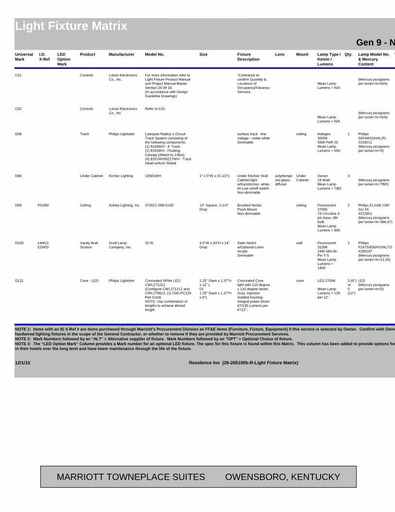
Universal Mark
Manufacturer Model No. Fixture Description
Lens Lamp Type / Kelvin / Lumens
Lamp Model No. & Mercury Content
VoltsMount Qty. Fixture Watts (Max)
LocationAreaSizeProductI.D. X-Ref
Residence InnLight Fixture Matrix Residence InnGen 9 - New Build - Possibilities
LED Option Mark
C01 Lutron Electronics Co., Inc.
For more information refer to Light Fixture Product Manual and Project Manual Master Section 26 09 33.(In accordance with Design Guideline Drawings)
*Contractor to confirm Quantity & Locations of Occupancy/Vacancy Sensors.
Mean Lamp Lumens = N/A
(Mercury picograms per lumen-hr=N/A)
General Lighing - Controls
Controls Public
C02 Lutron Electronics Co., Inc.
Refer to C01
Mean Lamp Lumens = N/A
(Mercury picograms per lumen-hr=N/A)
General Lighing - Controls
Controls Public
D08 Philips Lightolier Lytespan Radius 1-Circuit Track System consisting of the following components:(1) 9104WH - 4' Track(1) 9163WH - Floating Canopy (Attach to J-Box)(4) 8201WH/8227WH - Track Head w/Arch Shield
surface track - line voltage - matte whiteDimmable
Halogen 3000K50W PAR 20Mean Lamp Lumens = 550
Philips 50PAR20/HAL/FL#229211(Mercury picograms per lumen-hr=0)
120ceiling 1 50 MarketTrack Public
D66 Kichler Lighting 10581WH Under Kitchen Wall Cabinet light w/transformer, white, Hi-Low on/off switchNon-dimmable
poly/tempered glass-diffuser
Xenon18 WattMean Lamp Lumens = TBD
(Mercury picograms per lumen-hr=TBD)
120Under Cabinet
3 54 Kitchen - Under CabinetsOPTIONAL
1" x 5"W x 21-1/2"LUnder Cabinet Guestroom
D68 Ashley Lighting, Inc. 073021-098-014D Brushed Nickel, Flush MountNon-dimmable
Fluorescent 2700KT6 Circuline 4-pin base, dbl bulbMean Lamp Lumens = 900
Philips EL/mdt 13W GU 24 #222851(Mercury picograms per lumen-hr=366.67)
120ceiling 2 26 Corridors14" Square, 3-1/4" Drop
CeilingPG400 Public
D100 Scott Lamp Company, Inc.
3176 Satin Nickel w/Optional Linen AcrylicDimmable
Fluorescent 3100K24W Mini Bi-Pin T-5Mean Lamp Lumens = 1900
Philips F24T5/830/HO/ALTO #290197(Mercury picograms per lumen-hr=21.05)
120wall 1 24 Restroom /Employee Restroom
4.5"W x 24"H x 14" Drop
Vanity Wall Sconce
LM412, ED403
Public /Back-of-House
D121 Philips Lightolier Concealed White LED CWL271212 (Configure CWL271212 and CWL270612, (1) CWLPC120 Pwr Cord)NOTE: Use combination of lengths to achieve disired length.
Concealed Cove light with 110 degree x 110 degree beam. Gray injection molded housing. Integral power driver. 67/135 Lumens per 6"/12".
LED 2700K
Mean Lamp Lumens = 135 per 12"
LED(Mercury picograms per lumen-hr=0)
120cove 3 (6")or5 (12")
1.5 (6")or3 (12")
Exercise Rm Cove / Feature Wall at Front Desk / Elevator Lobby @ Main Floor Accent Wall
1.25" Diam x 1.37"H x 12" LOr1.25" Diam x 1.37"H x 6"L
Cove - LED Public
12/1/15 Page 1 of 11Residence Inn (26-265100b-R-Light Fixture Matrix)
NOTE 1: Items with an ID X-Ref # are items purchased through Marriott’s Procurement Division as FF&E items (Furniture, Fixture, Equipment) if this service is selected by Owner. Confirm with Owner whether to include these “decorative” but hardwired lighting fixtures in the scope of the General Contractor, or whether to remove if they are provided by Marriott Procurement Services.NOTE 2: Mark Numbers followed by an "ALT" = Alternative supplier of fixture. Mark Numbers followed by an "OPT" = Optional Choice of fixture.NOTE 3: The “LED Option Mark” Column provides a Mark number for an optional LED fixture. The spec for this fixture is found within this Matrix. This column has been added to provide options for those that want to obtain increased energy savingsin their hotels over the long term and have lower maintenance through the life of the fixture.
MARRIOTT TOWNEPLACE SUITES OWENSBORO, KENTUCKY
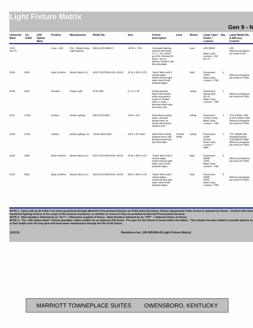
Universal Mark
Manufacturer Model No. Fixture Description
Lens Lamp Type / Kelvin / Lumens
Lamp Model No. & Mercury Content
VoltsMount Qty. Fixture Watts (Max)
LocationAreaSizeProductI.D. X-Ref
Residence InnLight Fixture Matrix Residence InnGen 9 - New Build - Possibilities
LED Option Mark
D121(ALT1)
RSL - Roberts Step-Light Systems
RW12-LED-2850-FL Concealed lighiting channel with lamps 1" o.c. 23 Lumens per LED. Remote DC driver. Not on dimmer. 50,000 hr lifeNon-dimmable
LED 2850K
Mean Lamp Lumens = 230 per 12"
LED(Mercury picograms per lumen-hr=0)
120cove 13 per FT
Exercise Rm Cove / Feature Wall at Front Desk / Elevator Lobby @ Main Floor Accent Wall
.46"W x .75"HCove - LED Public
D144 Electric Mirror LLC NOV-CUSTOM-41.00 x 36.00 "Nuria" Mirror with 2 vertical edges frosted left and right sides, back lit with polished edges.
FluorescentT5HOMean Lamp Lumens = TBD
(Mercury picograms per lumen-hr=TBD)
120Wall 4 117 Bathroom41"W x 36"H x 3"DBack Lit MirrorX505 Guestroom
D146 Project Light PL217498 Ceiling pendant fixture with frosted white encasement (upper 9" frosted, lower 3" clear)Brushed nickel base and silver cord
Fluorescent Spring lampGU-24Mean Lamp Lumens = TBD
(Mercury picograms per lumen-hr=TBD)
120ceiling 1 26 Kitchen above counter
5" x 5" x 33"PendantX402 Guestroom
D147 Kichler Lighting MS131762-IN4C Flush Mount ceiling fixture, off white painted linen on acrylic with bushed stainless trim
FluorescentCircline G10QMean Lamp Lumens = TBD
TCP #32032 32W& TCP #32022 22W(Mercury picograms per lumen-hr=TBD)
120ceiling 2 54 Kitchen16"W x 4"HSurfaceX-403 Guestroom
D149 Ashley Lighting, Inc. 73145-OW3-010D Semi-Flush Ceiling pendant fixture with bushed nickel body.Non-dimmable
Frosted White
Fluorescent 3100KCirclineMean Lamp Lumens = 2800
TCP #32040 with threaded Bracket #12818BCRTOEM(Mercury picograms per lumen-hr=TBD)
120ceiling 1 40 Dressing Area6.5"H x 15" DiamSurfaceX-405 Guestroom
D155 Electric Mirror LLC NOV-CUSTOM-34.00 x 36.00 "Nuria" Mirror with 2 vertical edges frosted left and right sides, back lit with polished edges.
Fluorescent3000KT5HOMean Lamp Lumens = TBD
(Mercury picograms per lumen-hr=TBD)
120Wall 4 117 Bathroom34"W x 36"H x 3"DBack Lit MirrorX506 Guestroom
D187 Electric Mirror LLC NOV-CUSTOM-50.00 x 36.00 "Nuria" Mirror with 2 vertical edges frosted left and right sides, back lit with polished edges.
Fluorescent3000KT5HOMean Lamp Lumens = TBD
(Mercury picograms per lumen-hr=TBD)
120Wall 4 117 Bathroom - 1 Bdrm End Unit
50"W x 36"H x 3"DBack Lit MirrorX504 Guestroom
12/1/15 Page 2 of 11Residence Inn (26-265100b-R-Light Fixture Matrix)
NOTE 1: Items with an ID X-Ref # are items purchased through Marriott’s Procurement Division as FF&E items (Furniture, Fixture, Equipment) if this service is selected by Owner. Confirm with Owner whether to include these “decorative” but hardwired lighting fixtures in the scope of the General Contractor, or whether to remove if they are provided by Marriott Procurement Services.NOTE 2: Mark Numbers followed by an "ALT" = Alternative supplier of fixture. Mark Numbers followed by an "OPT" = Optional Choice of fixture.NOTE 3: The “LED Option Mark” Column provides a Mark number for an optional LED fixture. The spec for this fixture is found within this Matrix. This column has been added to provide options for those that want to obtain increased energy savingsin their hotels over the long term and have lower maintenance through the life of the fixture.
MARRIOTT TOWNEPLACE SUITES OWENSBORO, KENTUCKY

Universal Mark
Manufacturer Model No. Fixture Description
Lens Lamp Type / Kelvin / Lumens
Lamp Model No. & Mercury Content
VoltsMount Qty. Fixture Watts (Max)
LocationAreaSizeProductI.D. X-Ref
Residence InnLight Fixture Matrix Residence InnGen 9 - New Build - Possibilities
LED Option Mark
D193 Trend Lighting Basics by Trend " Harmony" BP9709
INTERIM FIXTURE UNTIL DESIGN COMPLETE
Pendant with crsytal beaded silver sheen shade with metalic silver finish.
incandescent or CFL equivalent3000Kmed base sockets, Type A or CFL equivalentMean Lamp Lumens = TBD
TCP #4892330K23 watt CFL(Mercury picograms per lumen-hr=TBD)
120ceiling 3 180 Social Zone19"dia x 9" H X 60" Max Drop w/ 5" x 5" x 1" H escutcheon plate.
PendantLM-416INT Public
D208 Kichler Lighting MS139959NI Wall sconce with steel brushed nickel faceplate and rectangle linen hardback shade with gray square pattern on rigth hand side of shade which wraps around side of shade self fold.Non-dimmable
white acrylic diffuser top and bottom
CFL (Lamp not included)GU24 QuadMean Lamp Lumens = TBD
TCP #33113Q30K(Mercury picograms per lumen-hr=TBD)
120Wall 2 13 Elevator Lobby11.5" W x 4" D x 11" H
SconcePG-401 Public
F05 Philips Daybrite 2LP3GA3CF40R-33AL-UNV-1/3-EB-2WC
White (Accommodates Standard & Tegular Grid Ceiling)Non-dimmable
parabolic Fluorescent 3000K40W T5Mean Lamp Lumens = 2970
Philips PL-L 40W/830/4P/RS/IS#300426(Mercury picograms per lumen-hr=23.57)
120recessed 3 99 Meeting Room / Guest Laundry
24" x 24"Box Public /Back-of-House
L29
F07 Philips Daybrite SJ232-UNV-1/2-EB whiteNon-dimmable
parabolic Fluorescent 3000KF032T8Mean Lamp Lumens = 2800
Philips F32T8/TL830/ALTO#281519(Mercury picograms per lumen-hr=25.30)
120Recessed 3 70 Electrical / Storage / Video / Linen / Mechanical / Elev. Equip. / Pool Stor / Pool Equip
24" x 48"Strip Back of HouseL31
F09 Philips Daybrite 2DPG432-FS01-UNV-1/4-EB WhiteNon-dimmable
acrylic Fluorescent 3000KF032T8Mean Lamp Lumens = 2800
Philips F32T8/TL830/ALTO#281519(Mercury picograms per lumen-hr=25.30)
120Recessed 4 70 Employee Lounge / Vending /Laundry / Work Rm / Sales Offices / Food Prep / Fire Rm / Storage Rm / Linen Rm / Pool Storage / Pool Equip
2'W x 4'LLensed Box Public / Back of House
L33
12/1/15 Page 3 of 11Residence Inn (26-265100b-R-Light Fixture Matrix)
NOTE 1: Items with an ID X-Ref # are items purchased through Marriott’s Procurement Division as FF&E items (Furniture, Fixture, Equipment) if this service is selected by Owner. Confirm with Owner whether to include these “decorative” but hardwired lighting fixtures in the scope of the General Contractor, or whether to remove if they are provided by Marriott Procurement Services.NOTE 2: Mark Numbers followed by an "ALT" = Alternative supplier of fixture. Mark Numbers followed by an "OPT" = Optional Choice of fixture.NOTE 3: The “LED Option Mark” Column provides a Mark number for an optional LED fixture. The spec for this fixture is found within this Matrix. This column has been added to provide options for those that want to obtain increased energy savingsin their hotels over the long term and have lower maintenance through the life of the fixture.
MARRIOTT TOWNEPLACE SUITES OWENSBORO, KENTUCKY
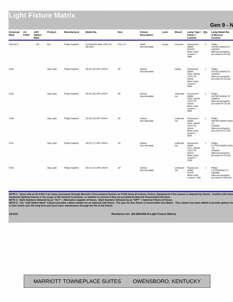
Universal Mark
Manufacturer Model No. Fixture Description
Lens Lamp Type / Kelvin / Lumens
Lamp Model No. & Mercury Content
VoltsMount Qty. Fixture Watts (Max)
LocationAreaSizeProductI.D. X-Ref
Residence InnLight Fixture Matrix Residence InnGen 9 - New Build - Possibilities
LED Option Mark
F09 (ALT) Philips Daybrite 2LP3GA332-36AL-UNV-1/3-EB-2WC
WhiteNon-dimmable
acrylic Fluorescent 3000KF032T8Mean Lamp Lumens = 2800
Philips F32T8/TL830/ALTO#281519(Mercury picograms per lumen-hr=25.30)
120recessed 3 70 Employee Lounge / Vending /Laundry / Work Rm / Sales Offices / Food Prep / Fire Rm / Storage Rm / Linen Rm / Pool Storage / Pool Equip
2'W x 4'LBox Public / Back of House
L30
F24a Philips Daybrite SN 4S 132 HPF UNVHI IndirectNon-dimmable
Fluorescent 3000KF032 / 830XP / ECO T8 OctronMean Lamp Lumens = 2800
Philips F32T8/TL830/ALTO#246678(Mercury picograms per lumen-hr=25.30)
120ceiling 1 34 Attic Catwalks (Provide Switch at access points)
48"Strip Light Back of House
F24a Philips Daybrite SN 4S 132 HPF UNVHI IndirectNon-dimmable
Fluorescent 3000KF032 / 830XP / ECO T8 OctronMean Lamp Lumens = 2800
Philips F32T8/TL830/ALTO#246678(Mercury picograms per lumen-hr=25.30)
120undercabinet
1 34 Breakfast Area48"Strip Light Public
F24b Philips Daybrite SN 3S 125 HPF UNVHI IndirectNon-dimmable
Fluorescent 3000KF025 / 830XP / ECO T8 OctronMean Lamp Lumens = 2050
Philips F25T8/TL830/PLUS/ALTO#145565(Mercury picograms per lumen-hr=27.64)
120undercabinet
1 28 Breakfast Area36"Strip Light Public
F24c Philips Daybrite SN 2S 117 HPF UNVHI IndirectNon-dimmable
Fluorescent 3000KF017 / 830XP / ECO T8 OctronMean Lamp Lumens = 1300
Philips F17T8/TL830/PLUS/ALTO#145524(Mercury picograms per lumen-hr=43.59)
120undercabinet
1 21 Breakfast Area24"Strip Light Public
F24d Philips Daybrite SN 1S 115 HPF UNVHI IndirectNon-dimmable
Fluorescent 3000KF15T8Mean Lamp Lumens = 660
Philips F15T8/WW/ALTO #382986(Mercury picograms per lumen-hr=383.84)
120undercabinet
1 15 Breakfast Area18"Strip Light Public
12/1/15 Page 4 of 11Residence Inn (26-265100b-R-Light Fixture Matrix)
NOTE 1: Items with an ID X-Ref # are items purchased through Marriott’s Procurement Division as FF&E items (Furniture, Fixture, Equipment) if this service is selected by Owner. Confirm with Owner whether to include these “decorative” but hardwired lighting fixtures in the scope of the General Contractor, or whether to remove if they are provided by Marriott Procurement Services.NOTE 2: Mark Numbers followed by an "ALT" = Alternative supplier of fixture. Mark Numbers followed by an "OPT" = Optional Choice of fixture.NOTE 3: The “LED Option Mark” Column provides a Mark number for an optional LED fixture. The spec for this fixture is found within this Matrix. This column has been added to provide options for those that want to obtain increased energy savingsin their hotels over the long term and have lower maintenance through the life of the fixture.
MARRIOTT TOWNEPLACE SUITES OWENSBORO, KENTUCKY

Universal Mark
Manufacturer Model No. Fixture Description
Lens Lamp Type / Kelvin / Lumens
Lamp Model No. & Mercury Content
VoltsMount Qty. Fixture Watts (Max)
LocationAreaSizeProductI.D. X-Ref
Residence InnLight Fixture Matrix Residence InnGen 9 - New Build - Possibilities
LED Option Mark
L10 Philips Daybrite 2DLG49L835-4-D-UNV-OCC-SDIM
Recessed LED with switched dimming ballast and integrated occupancy sensor 3500K. Dim from 100% to 40% when unoccupied.Dimmable
DR Acrylic LED 3500KIntegrated LEDMean Lamp Lumens = TBD
LED(Mercury picograms per lumen-hr=0)
120Ceiling (Suitable for Grid and Slot Ceiling types)
55 Location indicated when this Mark# is under "LED Option Mark"
2'-0" x 4'-0"LED Box PublicN/A
L12 Philips Color (1) 523000027-50 EW Profile Powercore(1) 120000065-00 Permanent Wiring Compartment and Terminator(1) 108000035-00 6"jumper
39.25" LED Undercabinet light, 3000K, ultra low profile white, 120 vt hard wired, aluminumDimmable
Polycarbonate
LED 3000K
Mean Lamp Lumens = 1042
LED(Mercury picograms per lumen-hr=0)
120Surface 20 2 Bedroom Option above TV
41.375" L x .88" H x 1.77" W (incl terminator and jumper connection)
Undercabinet GuestroomN/A
L22 Philips Lightolier 1004ICLED-1013CDL30K 5" Downlight with Clear Annodized ReflectorDmmable
LED 3000KIntegrated LEDMean Lamp Lumens = 742
LED(Mercury picograms per lumen-hr=0)
120recessed 1 13 LED Option: Corridor Above Guest Entry Door
5" diameterDown PublicN/A
L29 Philips Daybrite 2CLG36L835-2-D-UNV White (Accommodates Standard & Tegular Grid Ceiling)Non-dimmable
parabolic LED 3500K
Mean Lamp Lumens = 3668
LED(Mercury picograms per lumen-hr=0)
120 / 277
Recessed 42.3 LED Option: Meeting Room / Guest Laundry
24" x 24"Box Public /Back-of-House
N/A
L30 Philips Daybrite 2CLG54L835-4-D-UNV whiteNon-dimmable
Lensed LED 3500K
Mean Lamp Lumens = 5448
LED(Mercury picograms per lumen-hr=0)
120/277Recessed 56.3 Employee Lounge / VendingLaundry / Work Rm / Sales Offices / Food Prep / Fire Rm / Storage Rm / Linen Rm
24" x 48"Box Public / Back of House
N/A
L31 Philips Daybrite DWAE43L835-4-UNV Wrap Around LensNon-dimmable
acrylic LED 3500K
Mean Lamp Lumens = 4293
LED(Mercury picograms per lumen-hr=0)
120/277surface 40 LED Option: Electrical / Storage / Video / Linen Rm / Mechanical / Elev. Equip./ Pool Stor / Pool Equip. / Fire Rm
7"W x 5 3/16"H x 50"L
Strip Back of HouseN/A
L33 Philips Daybrite 2CLG74L835-4-D-UNIV WhiteNon-dimmable
acrylic LED
Mean Lamp Lumens = 7400
LED(Mercury picograms per lumen-hr=0)
120Recessed LED Option: Lounge / Vending /Laundry / Work Rm / Sales Offices / Food Prep
2'W x 4'LLensed Box Public / Back of House
N/A
12/1/15 Page 5 of 11Residence Inn (26-265100b-R-Light Fixture Matrix)
NOTE 1: Items with an ID X-Ref # are items purchased through Marriott’s Procurement Division as FF&E items (Furniture, Fixture, Equipment) if this service is selected by Owner. Confirm with Owner whether to include these “decorative” but hardwired lighting fixtures in the scope of the General Contractor, or whether to remove if they are provided by Marriott Procurement Services.NOTE 2: Mark Numbers followed by an "ALT" = Alternative supplier of fixture. Mark Numbers followed by an "OPT" = Optional Choice of fixture.NOTE 3: The “LED Option Mark” Column provides a Mark number for an optional LED fixture. The spec for this fixture is found within this Matrix. This column has been added to provide options for those that want to obtain increased energy savingsin their hotels over the long term and have lower maintenance through the life of the fixture.
MARRIOTT TOWNEPLACE SUITES OWENSBORO, KENTUCKY

Universal Mark
Manufacturer Model No. Fixture Description
Lens Lamp Type / Kelvin / Lumens
Lamp Model No. & Mercury Content
VoltsMount Qty. Fixture Watts (Max)
LocationAreaSizeProductI.D. X-Ref
Residence InnLight Fixture Matrix Residence InnGen 9 - New Build - Possibilities
LED Option Mark
L33(ALT)
Philips Daybrite WhiteNon-dimmable
acrylic LED
Mean Lamp Lumens = TBD
LED(Mercury picograms per lumen-hr=0)
120recessed LED Option: Employee Lounge / VendingLaundry / Work Rm / Sales Offices / Food Prep / Fire Rm / Storage Rm / Linen Rm
2'W x 4'LBox Public / Back of House
N/A
L34D Philips Controls SR1200ZTUNV 0-10V Dimmer (To be used with Fixture L34) Mean Lamp
Lumens = N/A
(Mercury picograms per lumen-hr=N/A)
120 N/A LED Option: Mtg Room
Dimmer PublicN/A
L38 Philips Lightolier C2L04DL30K25RUZ10V-C2LDLCCDP
LED Dowmlight, ClearDimmable
Phospor LED 3000K
Mean Lamp Lumens = 400
LED(Mercury picograms per lumen-hr=0)
120recessed 1 11 Social Zone, Communal Table
1.75" diameterRecessed Downlight - LED
Public
L43 Philips Lightolier 1004ICLED-1013CDL30K-16FR2X16
UL Fire Rated Enclosure, Clear Reflector, White FlangeDimmable
LED 3000KIntegrated LEDMean Lamp Lumens = 742
LED(Mercury picograms per lumen-hr=0)
120recessed 1 13 LED Option: Elevator Lobby
5" Diam ApertureDownlight PublicN/A
L46 Philips Lightolier 1101LED15N27D1-1113 LED Recessed Downlight, Wet Location, Clear Reflector, White FlangeDimmable
LED 2700K1500 Lumen Integrated LEDMean Lamp Lumens = 1500
LED(Mercury picograms per lumen-hr=0)
120recessed 1 30 Top Floor Roof Soffit outside guestroom
6" diameterRecessed Downlight - LED
Exterior SoffitN/A
L47 Philips Lightolier 1050LRN06D1 - 1050LRN0627 - 1050RNDLWB
Shallow Frame In Kit IC Rated, Wet Location, Solite Lens, White Baffle, White FlangeDimmable
Solite Lens LED 2700K600 Lumen Integrated LEDMean Lamp Lumens = 600
LED(Mercury picograms per lumen-hr=0)
120recessed 1 16 Shower5" DiameterRecessed Downlight - LED
GuestroomN/A
L51 Philips Lightolier 1101LED15N27D1-1113 LED Recessed Downlight, Clear Reflector, White FlangeDimmable
LED 2700K1500 Lumen Integrated LEDMean Lamp Lumens = 1764
LED(Mercury picograms per lumen-hr=0)
120Recessed 1 30 LED Option:Meeting Rm / Breakfast Room
6.75" diameterRecessed Public
L57 Philips Lightolier 1101LED09N27D1-1146 Specular Clear AlzakDimmable
LED 2700K900 Lumen Integrated LEDMean Lamp Lumens = 995
LED(Mercury picograms per lumen-hr=0)
120recessed 1 20.6 LED Option: Lobby / Front Desk / Luggage Carts / Serving / Market / Restrooms / Stairwell
6.75" diameterDown PublicN/A
12/1/15 Page 6 of 11Residence Inn (26-265100b-R-Light Fixture Matrix)
NOTE 1: Items with an ID X-Ref # are items purchased through Marriott’s Procurement Division as FF&E items (Furniture, Fixture, Equipment) if this service is selected by Owner. Confirm with Owner whether to include these “decorative” but hardwired lighting fixtures in the scope of the General Contractor, or whether to remove if they are provided by Marriott Procurement Services.NOTE 2: Mark Numbers followed by an "ALT" = Alternative supplier of fixture. Mark Numbers followed by an "OPT" = Optional Choice of fixture.NOTE 3: The “LED Option Mark” Column provides a Mark number for an optional LED fixture. The spec for this fixture is found within this Matrix. This column has been added to provide options for those that want to obtain increased energy savingsin their hotels over the long term and have lower maintenance through the life of the fixture.
MARRIOTT TOWNEPLACE SUITES OWENSBORO, KENTUCKY

Universal Mark
Manufacturer Model No. Fixture Description
Lens Lamp Type / Kelvin / Lumens
Lamp Model No. & Mercury Content
VoltsMount Qty. Fixture Watts (Max)
LocationAreaSizeProductI.D. X-Ref
Residence InnLight Fixture Matrix Residence InnGen 9 - New Build - Possibilities
LED Option Mark
L74 Eaton Halo SLD405930WHJB LED Round Aperature Surface Mount Light (intall into compatible Jbox)(Suitable for Grid and Slot Ceiling types)Dimmable
Edgelit Frosted
LED LED 3000K1500 Lumen Integrated LEDMean Lamp Lumens = 1764
LED(Mercury picograms per lumen-hr=0)
120Ceiling 1 30 LED Option:Meeting Rm / Breakfast Room
4" DiamterCeiling Surface Publicn/a
L80 Insight Lighting DFLED/120/35K/WM/INT-X/W Wet listed, natatorium rated. Cold rolled steed, powder-coated finish.Non-dimmable
clear lighting grade acrylic
LED3500KIntegrated LEDMean Lamp Lumens = 7193
LED(Mercury picograms per lumen-hr=TBD)
120wall 1 120 Pool - Indoor3- 5/8" H x 31- 1/8" W x 10- 5/8" D
Deco LED PublicN/A
L200 Trend Lighting Basics by Trend "Luminary" BP6009(INTERIM FIXTURE UNTIL DESIGN COMPLETE)
Hand woven aluminum wire metallic Silver Sphere. Clear silver 44" adjustable cord
incandescent or CFL equivalentmed base sockets, Type A or CFL equivalentMean Lamp Lumens = N/A
11 Watt LED med base, GE #68015(Mercury picograms per lumen-hr=TBD)
120ceiling 1 100 Communal Table15" diam x 60" max drop with 5"x 5" x 1" H escutcheon plate
PendantLM404 INT PublicN/A
L201 D'Style DSTY-I-CH-RI408A Metal tube cirular chandelier with LED bulbs on stainless steel wires, hung by 10' black power cord with 10' SS airplane support wire.
LEDCandleabra base screw inMean Lamp Lumens = N/A
Grainger #6XWK7, GE #61545-LED2CAC/ES/TP(Mercury picograms per lumen-hr=0)
120ceiling 8 480 Lobby38" Diam x 42" H with 6" Diam escutcheon plate
PendantLM408 PublicN/A
L202 Ashley Lighting, Inc. 72108-XUT8 Double Wall Sconce
Mean Lamp Lumens = TBD
(Mercury picograms per lumen-hr=TBD)
120Wall Queen Queen - Bed Headboard
16" W x 6" H x 5" DSconceX408 GuestroomN/A
L504 Philips Gardco ECF-1-4-215LA-641A-NW-UNV-NP
Low profile LED luminaire, Aluminum FinishNon-dimmable
Type IV LED 4000KIntegrated LEDMean Lamp Lumens = 19991
LED(Mercury picograms per lumen-hr=0)
120On Pole L505
1 211 Parking24.2" x 13" x 1.3"Site SiteN/A
L505 Philips Wide-Lite SSS-25-5-11-D1-NP Pole, Aluminum Finish
Mean Lamp Lumens = N/A
(Mercury picograms per lumen-hr=N/A)
N/AConc. Pad N/A Parking5" Square x 25' PolePole SiteN/A
12/1/15 Page 7 of 11Residence Inn (26-265100b-R-Light Fixture Matrix)
NOTE 1: Items with an ID X-Ref # are items purchased through Marriott’s Procurement Division as FF&E items (Furniture, Fixture, Equipment) if this service is selected by Owner. Confirm with Owner whether to include these “decorative” but hardwired lighting fixtures in the scope of the General Contractor, or whether to remove if they are provided by Marriott Procurement Services.NOTE 2: Mark Numbers followed by an "ALT" = Alternative supplier of fixture. Mark Numbers followed by an "OPT" = Optional Choice of fixture.NOTE 3: The “LED Option Mark” Column provides a Mark number for an optional LED fixture. The spec for this fixture is found within this Matrix. This column has been added to provide options for those that want to obtain increased energy savingsin their hotels over the long term and have lower maintenance through the life of the fixture.
MARRIOTT TOWNEPLACE SUITES OWENSBORO, KENTUCKY
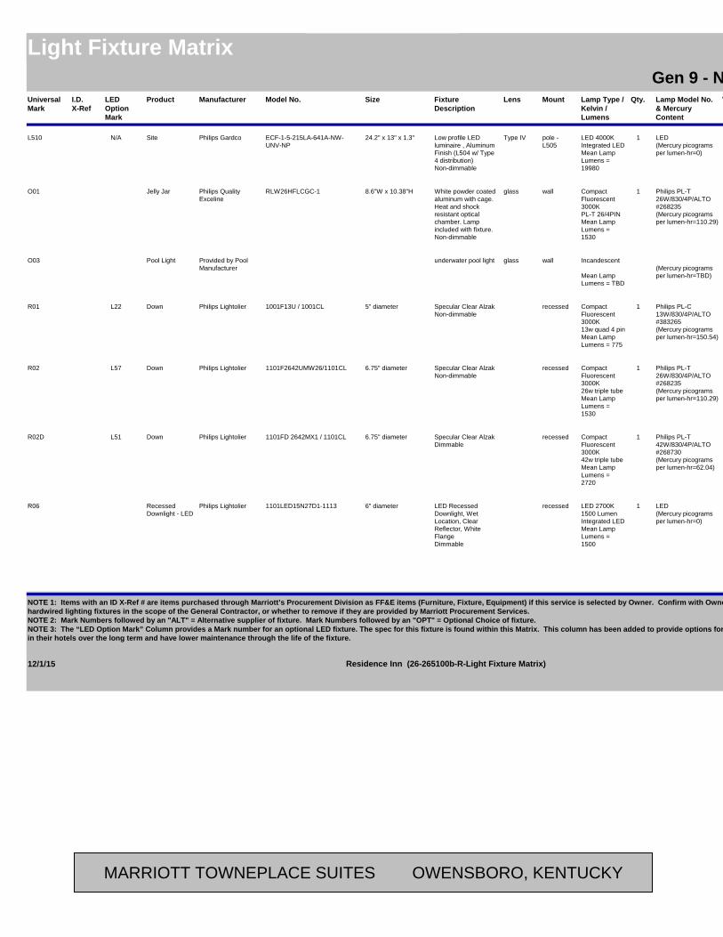
Universal Mark
Manufacturer Model No. Fixture Description
Lens Lamp Type / Kelvin / Lumens
Lamp Model No. & Mercury Content
VoltsMount Qty. Fixture Watts (Max)
LocationAreaSizeProductI.D. X-Ref
Residence InnLight Fixture Matrix Residence InnGen 9 - New Build - Possibilities
LED Option Mark
L510 Philips Gardco ECF-1-5-215LA-641A-NW-UNV-NP
Low profile LED luminaire , Aluminum Finish (L504 w/ Type 4 distribution)Non-dimmable
Type IV LED 4000KIntegrated LEDMean Lamp Lumens = 19980
LED(Mercury picograms per lumen-hr=0)
120pole - L505
1 211 Parking24.2" x 13" x 1.3"Site SiteN/A
O01 Philips Quality Exceline
RLW26HFLCGC-1 White powder coated aluminum with cage. Heat and shock resistant optical chamber. Lamp included with fixture.Non-dimmable
glass Compact Fluorescent 3000KPL-T 26/4PINMean Lamp Lumens = 1530
Philips PL-T 26W/830/4P/ALTO#268235(Mercury picograms per lumen-hr=110.29)
120wall 1 28 Elevator Pit8.6"W x 10.38"HJelly Jar Back of House
O03 Provided by Pool Manufacturer
underwater pool light glass Incandescent
Mean Lamp Lumens = TBD
(Mercury picograms per lumen-hr=TBD)
120wall Pool (underwater)Pool Light Public
R01 Philips Lightolier 1001F13U / 1001CL Specular Clear AlzakNon-dimmable
Compact Fluorescent 3000K13w quad 4 pinMean Lamp Lumens = 775
Philips PL-C 13W/830/4P/ALTO#383265(Mercury picograms per lumen-hr=150.54)
120 / 277
recessed 1 16 Corridor Above Guest Entry Door
5" diameterDown PublicL22
R02 Philips Lightolier 1101F2642UMW26/1101CL Specular Clear AlzakNon-dimmable
Compact Fluorescent 3000K26w triple tubeMean Lamp Lumens = 1530
Philips PL-T 26W/830/4P/ALTO#268235(Mercury picograms per lumen-hr=110.29)
120 / 277
recessed 1 29 Lobby / Front Desk / Vestibule / Serving / Social Zone / Market / Restrooms / Stairwell
6.75" diameterDown PublicL57
R02D Philips Lightolier 1101FD 2642MX1 / 1101CL Specular Clear AlzakDimmable
Compact Fluorescent 3000K42w triple tubeMean Lamp Lumens = 2720
Philips PL-T 42W/830/4P/ALTO#268730(Mercury picograms per lumen-hr=62.04)
120 / 277
recessed 1 42 Breakfast / Meeting Rm
6.75" diameterDown PublicL51
R06 Philips Lightolier 1101LED15N27D1-1113 LED Recessed Downlight, Wet Location, Clear Reflector, White FlangeDimmable
LED 2700K1500 Lumen Integrated LEDMean Lamp Lumens = 1500
LED(Mercury picograms per lumen-hr=0)
120recessed 1 30 Exterior Soffit Outside of Guestroom Upper Level
6" diameterRecessed Downlight - LED
Guest Bldg
12/1/15 Page 8 of 11Residence Inn (26-265100b-R-Light Fixture Matrix)
NOTE 1: Items with an ID X-Ref # are items purchased through Marriott’s Procurement Division as FF&E items (Furniture, Fixture, Equipment) if this service is selected by Owner. Confirm with Owner whether to include these “decorative” but hardwired lighting fixtures in the scope of the General Contractor, or whether to remove if they are provided by Marriott Procurement Services.NOTE 2: Mark Numbers followed by an "ALT" = Alternative supplier of fixture. Mark Numbers followed by an "OPT" = Optional Choice of fixture.NOTE 3: The “LED Option Mark” Column provides a Mark number for an optional LED fixture. The spec for this fixture is found within this Matrix. This column has been added to provide options for those that want to obtain increased energy savingsin their hotels over the long term and have lower maintenance through the life of the fixture.
MARRIOTT TOWNEPLACE SUITES OWENSBORO, KENTUCKY
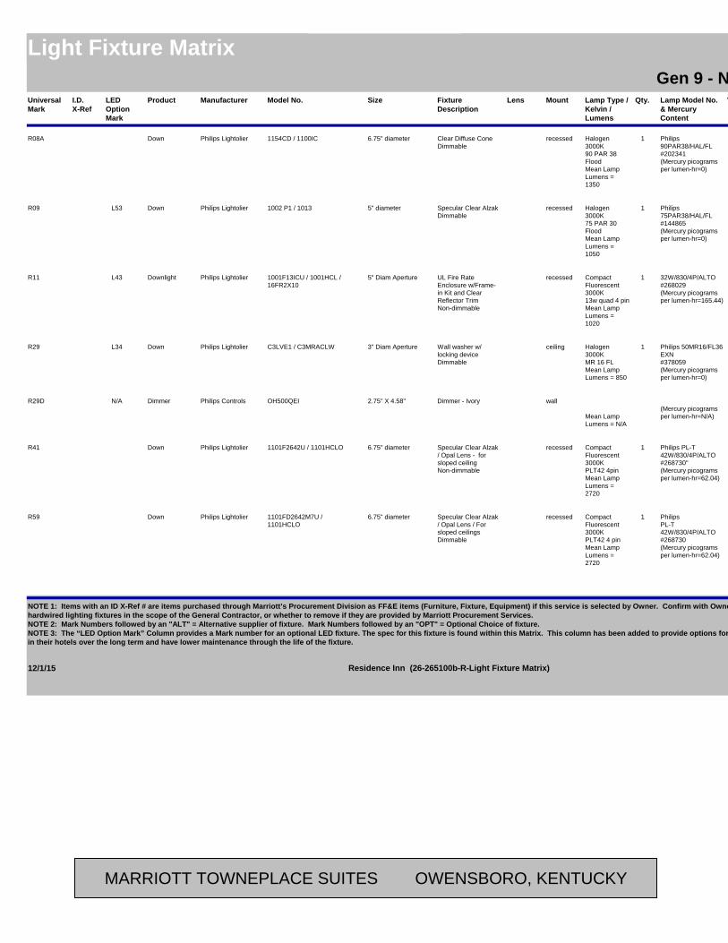
Universal Mark
Manufacturer Model No. Fixture Description
Lens Lamp Type / Kelvin / Lumens
Lamp Model No. & Mercury Content
VoltsMount Qty. Fixture Watts (Max)
LocationAreaSizeProductI.D. X-Ref
Residence InnLight Fixture Matrix Residence InnGen 9 - New Build - Possibilities
LED Option Mark
R08A Philips Lightolier 1154CD / 1100IC Clear Diffuse ConeDimmable
Halogen 3000K90 PAR 38 FloodMean Lamp Lumens = 1350
Philips 90PAR38/HAL/FL#202341(Mercury picograms per lumen-hr=0)
120recessed 1 90 Sloped Alcove Soffit6.75" diameterDown Exterior
R09 Philips Lightolier 1002 P1 / 1013 Specular Clear AlzakDimmable
Halogen 3000K75 PAR 30 FloodMean Lamp Lumens = 1050
Philips 75PAR38/HAL/FL#144865(Mercury picograms per lumen-hr=0)
120recessed 1 75 Porch5" diameterDown ExteriorL53
R11 Philips Lightolier 1001F13ICU / 1001HCL / 16FR2X10
UL Fire Rate Enclosure w/Frame-in Kit and Clear Reflector TrimNon-dimmable
Compact Fluorescent 3000K13w quad 4 pinMean Lamp Lumens = 1020
32W/830/4P/ALTO#268029(Mercury picograms per lumen-hr=165.44)
120 / 277
recessed 1 13 Elevator Lobby5" Diam ApertureDownlight PublicL43
R29 Philips Lightolier C3LVE1 / C3MRACLW Wall washer w/ locking deviceDimmable
Halogen 3000KMR 16 FLMean Lamp Lumens = 850
Philips 50MR16/FL36 EXN#378059(Mercury picograms per lumen-hr=0)
120ceiling 1 50 Meeting Room along back wall / Breakfast Buffet
3" Diam ApertureDown PublicL34
R29D Philips Controls OH500QEI Dimmer - Ivory
Mean Lamp Lumens = N/A
(Mercury picograms per lumen-hr=N/A)
120wall Meeting Room for Fixture R29
2.75" X 4.58"Dimmer PublicN/A
R41 Philips Lightolier 1101F2642U / 1101HCLO Specular Clear Alzak / Opal Lens - for sloped ceilingNon-dimmable
Compact Fluorescent 3000KPLT42 4pinMean Lamp Lumens = 2720
Philips PL-T 42W/830/4P/ALTO#268730"(Mercury picograms per lumen-hr=62.04)
120 / 277
recessed 1 42 Lobby / Vestibule / Study Area Corridor
6.75" diameterDown Public
R59 Philips Lightolier 1101FD2642M7U / 1101HCLO
Specular Clear Alzak / Opal Lens / For sloped ceilingsDimmable
Compact Fluorescent 3000KPLT42 4 pinMean Lamp Lumens = 2720
Philips PL-T 42W/830/4P/ALTO#268730(Mercury picograms per lumen-hr=62.04)
120 / 277
recessed 1 42 Lobby6.75" diameterDown Public
12/1/15 Page 9 of 11Residence Inn (26-265100b-R-Light Fixture Matrix)
NOTE 1: Items with an ID X-Ref # are items purchased through Marriott’s Procurement Division as FF&E items (Furniture, Fixture, Equipment) if this service is selected by Owner. Confirm with Owner whether to include these “decorative” but hardwired lighting fixtures in the scope of the General Contractor, or whether to remove if they are provided by Marriott Procurement Services.NOTE 2: Mark Numbers followed by an "ALT" = Alternative supplier of fixture. Mark Numbers followed by an "OPT" = Optional Choice of fixture.NOTE 3: The “LED Option Mark” Column provides a Mark number for an optional LED fixture. The spec for this fixture is found within this Matrix. This column has been added to provide options for those that want to obtain increased energy savingsin their hotels over the long term and have lower maintenance through the life of the fixture.
MARRIOTT TOWNEPLACE SUITES OWENSBORO, KENTUCKY
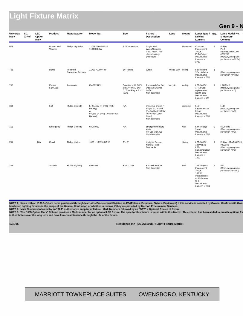
Universal Mark
Manufacturer Model No. Fixture Description
Lens Lamp Type / Kelvin / Lumens
Lamp Model No. & Mercury Content
VoltsMount Qty. Fixture Watts (Max)
LocationAreaSizeProductI.D. X-Ref
Residence InnLight Fixture Matrix Residence InnGen 9 - New Build - Possibilities
LED Option Mark
R68 Philips Lightolier 1101FD2642M7U / 1101HCLSW
Single Wall Wash/Specular Clear Alzak / For sloped ceilingsDimmable
Compact Fluorescent 3000KPLT42 4 pinMean Lamp Lumens = 2720
Philips PL-T 42W/830/4P/ALTO#268730(Mercury picograms per lumen-hr=62.04)
120 / 277
Recessed 1 42 Lobby seating at fireplace for accent
6.75" AperatureDown - Wall Washer
Public
T05 Technical Consumer Products
11730 / 32WH-HP White White Swirl Fluorescent32w circlelineMean Lamp Lumens = TBD
(Mercury picograms per lumen-hr=TBD)
120ceiling 1 26 Bathroom (To be used w/continuous ventilation only)
14" RoundDome Guestroom
T06 Panasonic FV-08VRE1 Recessed Can fan with light w/white baffleNon-dimmable
Acrylic LED 3000K1 - 14 watt replaceable GU24 baseMean Lamp Lumens = 575
LPHT14D(Mercury picograms per lumen-hr=0)
120ceiling 1 20.5 BathroomCan size is 12 3/4" L x 8 1/4" W x 7 1/2" D, Trim Ring is 6 1/2" round
Exhast Fan/Light
Guestroom
X01 Philips Chloride ER55L3W (R or G) (with Battery)or55L3W (R or G) - W (with out Battery)
Universal arrows / Single or 2-Sided(R=Red Letter Color / G=Green Letter Color)Non-dimmable
LEDLED comes w/ fixtureMean Lamp Lumens = TBD
LED(Mercury picograms per lumen-hr=0)
120universal 2 ExitN/AExit Public
X03 Philips Chloride 6M25WJ2 emergency battery - whiteFor use with X01Non-dimmable
Low Voltage9 wattMean Lamp Lumens = TBD
6V, 9 watt(Mercury picograms per lumen-hr=0)
120wall 2 18 ExitN/AEmergency Public
Z01 Philips Hadco 1020 H LED18 NF W Uplight - BronzeNarrow FloodDimmable
LED 3000K18 PAR 38 LED(lamp included)Mean Lamp Lumens = 1200
Philips 18PAR38/END #202341(Mercury picograms per lumen-hr=0)
120Stake 1 90 Flag Pole7" x 6"Flood ExteriorN/A
Z05 Kichler Lighting 49271RZ Rubbed BronzeNon-dimmable
???Compact Fluorescent 3000K100 W incandescent or 23-30 watt CFLMean Lamp Lumens = TBD
A21(Mercury picograms per lumen-hr=TBD)
120wall 1 18 Side Entrance8"W x 14"HSconce Site
12/1/15 Page 10 of 11Residence Inn (26-265100b-R-Light Fixture Matrix)
NOTE 1: Items with an ID X-Ref # are items purchased through Marriott’s Procurement Division as FF&E items (Furniture, Fixture, Equipment) if this service is selected by Owner. Confirm with Owner whether to include these “decorative” but hardwired lighting fixtures in the scope of the General Contractor, or whether to remove if they are provided by Marriott Procurement Services.NOTE 2: Mark Numbers followed by an "ALT" = Alternative supplier of fixture. Mark Numbers followed by an "OPT" = Optional Choice of fixture.NOTE 3: The “LED Option Mark” Column provides a Mark number for an optional LED fixture. The spec for this fixture is found within this Matrix. This column has been added to provide options for those that want to obtain increased energy savingsin their hotels over the long term and have lower maintenance through the life of the fixture.
MARRIOTT TOWNEPLACE SUITES OWENSBORO, KENTUCKY

Universal Mark
Manufacturer Model No. Fixture Description
Lens Lamp Type / Kelvin / Lumens
Lamp Model No. & Mercury Content
VoltsMount Qty. Fixture Watts (Max)
LocationAreaSizeProductI.D. X-Ref
Residence InnLight Fixture Matrix Residence InnGen 9 - New Build - Possibilities
LED Option Mark
Z07 Kichler Lighting 49275RZ Lantern Fixture, Rubbed BronzeNon-dimmable
???incandescent Metal Halidetbd 150 MHMean Lamp Lumens = 10500
tbd PhilipsMHC250/U/M/3K/ALTO(Mercury picograms per lumen-hr=TBD)
120v 1 150 Courtyard26" x 12"Decorative Site
Z08 Philips Hadco SP - 5894 - N N/AN/AMean Lamp Lumens = N/A
(Mercury picograms per lumen-hr=N/A)
N/AConc. Pad N/A Parking10' PoleDecorative Pole for Z07
Site
Z24 Connor Sport Court International, Inc.
Lighting System Provided by Section 11 68 23 (Included in Game Court Package) Mean Lamp
Lumens = TBD
(Mercury picograms per lumen-hr=TBD)
Sport CourtPole & Light Site
Z28 Philips Lightolier 1101F2642UEM / 1101HCLF Exterior appropriate for wet location.Non-dimmable
Spun Aluminum, fresnel lens
Fluorescent 3000KPL-T32/4PinMean Lamp Lumens = 2040
Philips PL-T 32W/830/4P/ALTO#268326(Mercury picograms per lumen-hr=82.72)
120Recessed 1 32 Side Entrances6-3/4" x 7-3/4"Emergency Exterior
Z42 Lukas Lighting CL914 Exterior Pendant - 3 FT Body Custom Pendant Clear Frosted Acrylic Outer Cylinder / White Acrylic Inner Cylinder Finish Powder CoatedNon-dimmable
Acrylic FluorescentVerticalMean Lamp Lumens = 1405
Philips F25T8 Adv835, ALTO, 17w, linear T8(Mercury picograms per lumen-hr=33.6)
120Stem Mtd, Jbox, Wind tie Safety cable
3 51 Main Entryway5'-2" x 1'-10" DiamExterior Pendant
Exterior
Z43 Lukas Lighting CLK913 Exterior Pendant - 4 FT Body Custom Pendant Clear Frosted Acrylic Outer Cylinder / White Acrylic Inner Cylinder Finish Powder CoatedNon-dimmable
Acrylic FluorescentVerticalMean Lamp Lumens = 2185
Philips F25T8 Adv835, ALTO, 17w, linear T8(Mercury picograms per lumen-hr=21.6)
120Stem Mtd, Jbox, Wind tie Safety cable
3 75 Above Entryway by Elevator Lobby
7'-4" x 2'-2" DiamExterior Pendant
Exterior
12/1/15 Page 11 of 11Residence Inn (26-265100b-R-Light Fixture Matrix)
NOTE 1: Items with an ID X-Ref # are items purchased through Marriott’s Procurement Division as FF&E items (Furniture, Fixture, Equipment) if this service is selected by Owner. Confirm with Owner whether to include these “decorative” but hardwired lighting fixtures in the scope of the General Contractor, or whether to remove if they are provided by Marriott Procurement Services.NOTE 2: Mark Numbers followed by an "ALT" = Alternative supplier of fixture. Mark Numbers followed by an "OPT" = Optional Choice of fixture.NOTE 3: The “LED Option Mark” Column provides a Mark number for an optional LED fixture. The spec for this fixture is found within this Matrix. This column has been added to provide options for those that want to obtain increased energy savingsin their hotels over the long term and have lower maintenance through the life of the fixture.
MARRIOTT TOWNEPLACE SUITES OWENSBORO, KENTUCKY
▪ DIVISION 26 ELECTRICAL ▪
▪ PAGE 95 ▪
RESIDENCE INN BY MARRIOTT - LITTLETON, COLORADO
SECTION 26 56 00 (16520) - EXTERIOR LIGHTING PART 58 GENERAL 58.01 SUMMARY
A. Section Includes: 1. Exterior Lighting Units with Luminaires 2. Ballasts 3. Lamps 4. Luminaire Support Components 5. Accessories
B. Related Sections: 1. Section 03 30 00 (03300) - Cast-in-Place Concrete. 2. Section 26 05 26 (16060) - Grounding and Bonding for Electrical Systems. 3. Section 26 51 00 (16510) - Interior Lighting 4. Section 26 60 00 (16580) - Lighting Accessories: For programmable lighting control
systems, time switches, additional photoelectric relays, power relays, and contactors. 58.02 REFERENCES
A. American National Standards Institute (ANSI) Publications: 1. C2 “National Electrical Safety Code” 2. C78 “Standard Test Method for Flexural Strength of Concrete (Using Simple Beam with
Third-Point Loading)” 3. C82.4 “Ballasts for High – Intensity – Discharge and Low Pressure Sodium Lamps
(Multiple-Supply Type)” B. American Association of State Highway and Transportation Officials (AASHTO) Publications:
1. LTS-3 “Standard Specifications for Structural Supports for Highway Signs, Luminaires and Traffic Signals”
C. ASTM International (ASTM) Publications: (Former American Society for Testing and Materials) 1. A123 “Standard Specification for Zinc (Hot-Dip Galvanized) Coatings on Iron and Steel
Products’ 2. A500 "Standard Specification for Cold-Formed Welded and Seamless Carbon Steel
Structural Tubing in Rounds and Shapes" 3. B660 “Standard Practices for Packaging/Packing of Aluminum and Magnesium Products”
D. Illuminating Engineering Society (IES) Publications: 1. RP-8 “Roadway Lighting”
E. National Fire Protection Association (NFPA) Publications: 1. NFPA 70 "National Electric Code"
F. National Association of Architectural Metal Manufacturers (NAAMM) Publications: 1. "Metal Finishes Manual for Architectural and Metal Products"
G. Underwriter's Laboratories, Inc. (UL) Publications: 1. 486A “Standard For Wire Connectors and Soldering Lugs for Use with Copper
Conductors” 2. 486B “Standard for Wire Connectors for Use with Aluminum Conductors”
58.03 DEFINITIONS A. Lighting Unit: A luminaire or an assembly of luminaires complete with a common support,
including pole, post, or other structure, and mounting and support accessories.
MARRIOTT TOWNEPLACE SUITES OWENSBORO, KENTUCKY
▪ DIVISION 26 ELECTRICAL ▪
▪ PAGE 96 ▪
RESIDENCE INN BY MARRIOTT - LITTLETON, COLORADO
B. Luminaire (Light Fixture): A complete lighting device consisting of lamp(s) and ballast(s), when applicable, together with parts designed to distribute light, to position and protect lamps, and to connect lamps to power supply.
58.04 SUBMITTALS A. Submit “Letter of Conformance” in accordance with Section 01 33 00 (01330) indicating
specified items selected for use in Project with the following supporting data: 1. For each type of lighting unit indicated, arranged in order of lighting unit designation.
Include data on features, accessories, finishes, and the following: a. Materials and dimensions of luminaires and poles. b. Certified results of laboratory tests for fixtures and lamps for photometric
performance. c. High-intensity-discharge luminaire ballasts. d. Photometric data.
2. Shop Drawings: Anchor-bolt templates keyed to specific poles and certified by manufacturer.
3. Maintenance Data: For lighting units to include in maintenance manuals specified in Division 01.
58.05 QUALITY ASSURANCE A. Luminaires and Accessories: Listed and labeled as defined in NFPA 70, Article 100, for their
indicated use, location, and installation conditions by a testing agency acceptable to authorities having jurisdiction
B. Comply with ANSI C2. C. Comply with NFPA 70.
58.06 DELIVERY, STORAGE, AND HANDLING OF POLES A. Package aluminum poles for shipping according to ASTM B660. B. Store poles on decay-resistant treated skids at least 12 inches above grade and vegetation.
Support poles to prevent distortion and arrange to provide free air circulation. C. Handle wood poles so they will not be damaged. Do not use pointed tools that can indent
surface more than 1/4 inch deep. Do not apply tools to section of poles below ground-line. D. Retain factory-applied pole wrappings on fiberglass poles until just before pole installation.
Handle poles with web fabric straps. E. Retain factory-applied pole wrappings on metal poles until just before pole installation. For
poles with nonmetallic finishes, handle with web fabric straps. 58.07 EXTRA MATERIALS
A. Furnish extra materials described in section 01 78 43 (01790) “Spare Parts and Materials” that match products installed and that are packaged with protective covering for storage and identified with labels describing contents. Deliver extra materials to Owner.
PART 59 PRODUCTS 59.01 MANUFACTURERS
A. Avendra, LLC Preferred Manufacturers: 1. Refer to Section 26 51 00 for list of approved manufacturers.
B. Approved Manufacturers: 1. Subject to compliance with requirements, provide the products indicated for each
designation in the Light Fixture Matrix attached at the end of this Section. 2. Refer to Section 26 51 00 for list of approved manufacturers.
MARRIOTT TOWNEPLACE SUITES OWENSBORO, KENTUCKY

▪ DIVISION 26 ELECTRICAL ▪
▪ PAGE 97 ▪
RESIDENCE INN BY MARRIOTT - LITTLETON, COLORADO
59.02 LUMINAIRES A. Comply with IES RP-8 for parameters of lateral light distribution patterns indicated for
luminaires. B. Metal Parts: Free from burrs, sharp corners, and edges. C. Sheet Metal Components: Corrosion-resistant aluminum, unless otherwise indicated. Form
and support to prevent warping and sagging. D. Housings: Rigidly formed, weather- and light-tight enclosures that will not warp, sag, or
deform in use. Provide filter/breather for enclosed luminaires. E. Doors, Frames, and Other Internal Access: Smooth operating, free from light leakage under
operating conditions, and arranged to permit re-lamping without use of tools. Arrange doors, frames, lenses, diffusers, and other pieces to prevent accidental falling during re-lamping and when secured in operating position. Provide for door removal for cleaning or replacing lens. Arrange to disconnect ballast when door opens.
F. Exposed Hardware Material: Stainless steel. G. Plastic Parts: High resistance to yellowing and other changes due to aging, exposure to heat,
and ultraviolet radiation. H. Reflecting Surfaces: Minimum reflectance as follows, unless otherwise indicated:
1. White Surfaces: 85 percent. 2. Specular Surfaces: 83 percent. 3. Diffusing Specular Surfaces: 75 percent.
I. Lenses and Refractors: Materials as indicated. Use heat- and aging-resistant, resilient gaskets to seal and cushion lens and refractor in luminaire doors.
J. Photoelectric Relays: As follows: 1. Contact Relays: Single throw, arranged to fail in the on position and factory set to turn
light unit on at 1.5 to 3 fc and off at 4.5 to 10 fc with 15-second minimum time delay. 2. Relay Mounting: In luminaire housing.
K. High-Intensity-Discharge Ballasts: Comply with ANSI C82.4. Constant wattage autotransformer or regulating high-power-factor type, unless otherwise indicated. 1. Ballast Fuses: One in each ungrounded supply conductor. Voltage and current ratings
as recommended by ballast manufacturer. 2. Single-Lamp Ballasts: Minimum starting temperature of minus 40 deg C. 3. Open-circuit operation will not reduce average life. 4. Noise: Uniformly quiet operation, with a noise rating of B or better.
L. Lamps: Comply with the standard of the ANSI C78 series that is applicable to each type of lamp. Provide luminaires with indicated lamps of designated type, characteristics, and wattage. Where a lamp is not indicated for a luminaire, provide medium wattage lamp recommended by manufacturer for luminaire. 1. Metal-Halide Color Temperature and Minimum Color-Rendering Index: 3600 K and
70 CRI, unless otherwise indicated. 59.03 LUMINAIRE SUPPORT COMPONENTS
A. Description: Comply with AASHTO LTS-3 for pole or other support structures, brackets, arms, appurtenances, base, and anchorage and foundation.
B. Wind-Load Strength of Total Support Assembly: Adequate to carry support assembly plus luminaires at indicated heights above grade without failure, permanent deflection, or whipping in steady winds of 100 mph (160 km/h) with a gust factor of 1.3. Support assembly includes pole or other support structures, brackets, arms, appurtenances, base, and anchorage and foundation.
MARRIOTT TOWNEPLACE SUITES OWENSBORO, KENTUCKY
▪ DIVISION 26 ELECTRICAL ▪
▪ PAGE 98 ▪
RESIDENCE INN BY MARRIOTT - LITTLETON, COLORADO
1. Strength Analysis: For each pole type and luminaire combination, multiply the actual equivalent projected area of luminaires and brackets by a factor of 1.1 to obtain the equivalent projected area to be used in pole selection strength analysis.
C. Finish: Match finish of pole/support structure for arm, bracket, and tenon mount materials. D. Mountings, Fasteners, and Appurtenances: Corrosion-resistant items compatible with support
components. 1. Materials: Will not cause galvanic action at contact points. 2. Mountings: Correctly position luminaire to provide indicated light distribution. 3. Anchor Bolts, Nuts, and Washers: Hot-dip galvanized after fabrication unless stainless-
steel items are indicated. 4. Anchor-Bolt Template: Plywood or steel.
E. Pole/Support Structure Bases: Anchor type with hold-down or anchor bolts, leveling nuts, and bolt covers.
F. Steel Poles: Tubing complying with ASTM A500, Grade B, carbon steel with a minimum yield of 46,000 psig (317 MPa); one-piece construction up to 40 feet in length with access handhole in pole wall. 1. Grounding Provisions for Metal Pole/Support Structure: Welded 1/2-inch threaded lug,
accessible through handhole and listed for copper conductor connection. 2. Shafts: Square, straight.
G. Metal Pole Brackets: Match pole metal. Provide cantilever brackets without underbrace, in sizes and styles indicated, with straight tubular end section to accommodate luminaire.
H. Pole-Top Tenons: Fabricated to support luminaire or luminaires and brackets indicated, and securely fastened to pole top.
I. Concrete for Pole Foundations: Comply with Section 03 30 00 (03300) "Cast-in-Place Concrete." 1. Design Strength: 3000-psig, 28-day compressive strength.
59.04 FINISHES A. Comply with NAAMM's "Metal Finishes Manual for Architectural and Metal Products" for
recommendations for applying and designating finishes. B. Steel: Grind welds and polish surfaces to a smooth, even finish.
1. Galvanized Finish: Hot-dip galvanize after fabrication to comply with ASTM A123. 2. Surface Preparation: Clean surfaces to comply with SSPC-SP 1, "Solvent Cleaning," to
remove dirt, oil, grease, and other contaminants that could impair paint bond. Remove mill scale and rust, if present, from uncoated steel, complying with SSPC-SP 5/NACE No. 1, "White Metal Blast Cleaning," or SSPC-SP 8, "Pickling."
3. Interior: Apply one coat of bituminous paint on interior of pole, or otherwise treat to prevent corrosion.
4. Polyurethane Enamel: Manufacturer's standard finish consisting of one or more coats of primer and two finish coats of high-gloss, high-build polyurethane enamel. a. Color: Refer to Light Fixture Matrix.
PART 60 EXECUTION 60.01 INSTALLATION
A. Concrete Foundations: Construct according to Section 03 30 00 (03300) "Cast-in-Place Concrete." 1. Comply with details for reinforcement and for anchor bolts, nuts, and washers. Verify
anchor-bolt templates by comparing with actual pole bases furnished.
MARRIOTT TOWNEPLACE SUITES OWENSBORO, KENTUCKY
▪ DIVISION 26 ELECTRICAL ▪
▪ PAGE 99 ▪
RESIDENCE INN BY MARRIOTT - LITTLETON, COLORADO
2. Finish for Parts Exposed to View: Trowel and rub smooth. Comply with Section 03 30 00 (03300) - "Cast-in-Place Concrete" for exposed finish.
B. Embedded Poles: Set poles to indicated depth, but not less than one-sixth of pole length below finish grade. Dig holes large enough to permit use of tampers the full depth of hole. Backfill in 6-inch layers and thoroughly tamp each layer so compaction of backfill is equal to or greater than that of undisturbed earth.
C. Install poles as follows: 1. Use web fabric slings (not chain or cable) to raise and set poles. 2. Mount pole to foundation with leveling nuts, and tighten top nuts to torque level
recommended by pole manufacturer. 3. Secure poles level, plumb, and square. 4. Grout void between pole base and foundation. Use non-shrinking or expanding concrete
grout firmly packed in entire void space. 5. Use a short piece of 1/2-inch diameter pipe to make a drain hole through grout. Arrange
to drain condensation from interior of pole. D. Luminaire Attachment: Fasten to indicated structural supports. E. Luminaire Attachment with Adjustable Features or Aiming: Attach luminaires and supports to
allow aiming for indicated light distribution. F. Lamp luminaires with indicated lamps according to manufacturer's written instructions.
Replace malfunctioning lamps. 60.02 CONNECTIONS
A. Ground equipment. 1. Tighten electrical connectors and terminals according to manufacturer's published
torque-tightening values. If manufacturer's torque values are not indicated, use those specified in UL 486A and UL 486B.
B. Ground metal poles/support structures according to Section 26 05 26 (16060) - "Grounding and Bonding for Electrical Systems." 1. Nonmetallic Poles: Ground metallic components of lighting units and foundations.
Connect luminaires to grounding system with No. 6 AWG conductor. 60.03 FIELD QUALITY CONTROL
A. Inspect each installed unit for damage. Replace damaged units. B. Advance Notice: Give dates and times for field tests. C. Provide instruments to make and record test results. D. Tests and Observations: Verify normal operation of lighting units after installing luminaires
and energizing circuits with normal power source, and as follows: 1. Measure light intensities at night if specific illumination performance is indicated. Use
photometers with calibration referenced to NIST standards. 2. Check intensity and uniformity of illumination. 3. Check excessively noisy ballasts.
E. Prepare a written report of tests, inspections, observations and verifications indicating and interpreting results.
F. Malfunctioning Fixtures and Components: Replace or repair, then retest. Repeat procedure until units operate properly.
60.04 CLEANING AND ADJUSTING A. Clean units after installation. Use methods and materials recommended by manufacturer. B. Adjust amiable luminaires and luminaires with adjustable lamp position to provide required
light distributions and intensities.
MARRIOTT TOWNEPLACE SUITES OWENSBORO, KENTUCKY
▪ DIVISION 26 ELECTRICAL ▪
▪ PAGE 100 ▪
RESIDENCE INN BY MARRIOTT - LITTLETON, COLORADO
END OF SECTION
Revision Log
REFER TO 26 51 00 FOR LIGHT FIXTURE MATRIX
MARRIOTT TOWNEPLACE SUITES OWENSBORO, KENTUCKY

▪ DIVISION 26 ELECTRICAL ▪
▪ PAGE 101 ▪
RESIDENCE INN BY MARRIOTT - LITTLETON, COLORADO
SECTION 26 60 00 (16580) - LIGHTING ACCESSORIES
PART 61 GENERAL 61.01 SUMMARY
A. Section Includes: 1. Time Switches 2. Photoelectric Relays 3. Multi-pole Lighting Relays and Contactors. 4. Hearing Impaired Door Annunciator
B. Related Sections: 1. Section 10 14 00 (10400) - Signage 2. Section 26 05 00 (16050) - Common Work Results For Electrical. 3. Section 26 05 19 (16120) - Low-Voltage Electrical Power Conductors and Cables. 4. Section 26 05 33 (16130) - Raceways and Boxes For Electrical Systems. 5. Section 26 05 53 (16075) - Identification for Electrical Systems. 6. Section 26 24 00 (16440) - Switchboards and Panelboards 7. Section 26 27 26 (16140) - Wiring Devices: For wall-box dimmers and manual light
switches. 61.02 REFERENCES
A. American National Standards Institute (ANSI) Publications: 1. C62.41 “IEEE Recommended Practice for Surge Voltages in Low-Voltage AC Power
Circuits” B. National Electrical Manufacturer’s Association (NEMA) Standards Publications:
1. ICS 2 “Industrial Control and Systems Controllers, Contactors and Overload Relays Rated 6000 Volts”
C. National Fire Protection Association (NFPA) Publications: 1. NFPA 70 "National Electric Code"
D. Underwriter's Laboratories, Inc. (UL) Publications:
1. 486A “Standard For Wire Connectors and Soldering Lugs for Use with Copper Conductors”
2. 508 “Standard for Industrial Control Equipment” 3. 773A “Nonindustrial Photoelectric Switches for Lighting Control” 4. 917 “Standard for Safety for clock-Operated Switches” 5. 1449 “Transient Voltage Surge Suppressors”
61.03 SUBMITTALS A. General: Submit the following in accordance with Conditions of Contract and Division 01
Specification Sections. B. Submit “Letter of Conformance” in accordance with Section 01 33 00 (01330) indicating
specified items selected for use in project with the following supporting data. 1. Product Data:
a. Include dimensions and data on features, components, and ratings for lighting control devices.
MARRIOTT TOWNEPLACE SUITES OWENSBORO, KENTUCKY
▪ DIVISION 26 ELECTRICAL ▪
▪ PAGE 102 ▪
RESIDENCE INN BY MARRIOTT - LITTLETON, COLORADO
61.04 QUALITY ASSURANCE A. Electrical Components, Devices, and Accessories: Listed and labeled as defined in NFPA 70,
Article 100, for their indicated use and installation conditions by a testing agency acceptable to authorities having jurisdiction.
B. Comply with NFPA 70. 61.05 COORDINATION
A. Coordinate features of devices specified in this Section with systems and components specified in other Sections to form an integrated system of compatible components. Match components and interconnections for optimum performance of specified functions. Include coordination with the following: 1. Section 26 24 00 (16440) - "Switchboards and Panelboards."
PART 62 PRODUCTS 62.01 MANUFACTURERS
A. Avendra, LLC Preferred Manufacturers: 1. Contactors and Relays:
a. None 2. Time Switches:
a. None 3. Photoelectric Relays:
a. None 4. Occupancy Sensors:
a. None 5. Hearing Impaired Door Annunciator:
a. None B. Approved Manufacturers:
1. Contactors and Relays: a. Challenger Electrical Equipment Corp. (412-920-2400) b. Cutler-Hammer Products; Eaton Corporation (800-498-2678) c. GE Lighting Controls (888-437-3765) d. Hubbell Lighting, Inc. (864-599-6000) e. Siemens Energy and Automation, Inc. (800-964-4114) f. Square D Co.; a Division of Groupe Schneider, Power Management Organization
(888-778-2733) 2. Time Switches:
a. Diversified Electronics, Inc. (800-874-0619) b. Intermatic, Inc. (815-675-7000) c. Tork, Inc. (914-664-3542) d. Leviton Manufacturing Co., Inc. (718-229-4040).
3. Photoelectric Relays: a. Allen-Bradley/Rockwell Automation (414-382-2000) b. Intermatic, Inc. (815-675-7000) c. Rhodes: M H Rhodes, Inc. (800-548-3647) d. Tork, Inc. (914-664-3542)
4. Occupancy Sensors:
MARRIOTT TOWNEPLACE SUITES OWENSBORO, KENTUCKY

▪ DIVISION 26 ELECTRICAL ▪
▪ PAGE 103 ▪
RESIDENCE INN BY MARRIOTT - LITTLETON, COLORADO
a. Honeywell, Inc.; Home and Building Controls (800-328-5111) b. Hubbell Lighting, Inc. (864-599-6000) c. Leviton Manufacturing Co., Inc. (718-229-4040). d. Lutron Electronics Co., Inc. (800-523-9466) e. Philips Lighting Company (800.555.0050) f. Watt Stopper, Inc. (The) (800-879-8585)
5. Hearing Impaired Door Annunciator: a. Edwards Signaling, UTC Fire & Security (800-336-4206)
62.02 GENERAL LIGHTING CONTROL DEVICE REQUIREMENTS A. Line-Voltage Surge Protection: Include in all 120- and 277-V solid-state equipment. Comply
with UL 1449 and with ANSI C62.41 for Category A locations. 62.03 HEARING IMPAIRED DOOR ANNUNCIATOR.
A. Guestroom Door Annunciator Kit: Visual signaling device with strobe, hall push button station, and transformer. Minimum high intensity 150 candela visual signal.
B. Approved Manufacturer: 1. Edwards Signaling
C. The kit shall consist of the following components: 1. Push Button: No. 20 2. Cover Plate: No. 147-10 3. Strobe in location shown on Drawings: No. 89STR (B)–AQ 4. Auxiliary Strobe in bathroom: No. 89STR (B)-AQ 5. Below strobes provide a small plaque in off-white plastic with black letters that reads
“DOOR BUTTON SIGNALER” as well as Braille equivalent. Secure to wall with clear sanitary sealant. a. Plaque: By Section 10 14 00 (10400) (Interior Signage Package).
6. Transformer: No. 598 D. A disconnect switch from the door button power transformer shall be located on the wall in
location shown on Drawings with an applied label on the cover plate reading “DOOR SIGNAL OVERRIDE”. 1. Plaque: By Section 10 14 00 (10400) (Interior Signage Package).
E. Mount the push button at 48” above the floor on the corridor side next to the lock strike of the door.
F. Mount the strobe on the wall in location shown on Drawings at 80” above the floor. G. Mount the auxiliary strobe on the bathroom wall in location shown on Drawings at 80” above
the floor. H. Screw components to walls using plastic plugs.
62.04 HEARING IMPAIRED DOOR ANNUNCIATOR. A. Guestroom Door Annunciator Kit: Audible/visual signaling device with horn/strobe, hall push
button station, and transformer. Minimum 82 dB sound pressure at 10 feet and a high intensity 110 candela visual signal. 1. "Model 7005-G5 Hotel Room Annunciator Kit"; Edwards Signaling
a. Kit consisting of the following components: 1) Model 6536-G5 Horn Strobe 2) Model 592 Transformer 3) Model 620 Push Button
MARRIOTT TOWNEPLACE SUITES OWENSBORO, KENTUCKY
▪ DIVISION 26 ELECTRICAL ▪
▪ PAGE 104 ▪
RESIDENCE INN BY MARRIOTT - LITTLETON, COLORADO
4) (Do not use 147-10 Face Plate) b. Model 147-1 Face Plate (No text on plate).
2. Locations as shown on Drawings. Plaque: By Section 10 14 00 (10400) (Interior Signage Package).
B. Doorbell Disable Switch: 1. Single Pole Toggle Switch: Refer to Section 26 27 26 (16140). 2. Cover Plate: Refer to Section 26 27 26 (16140). 3. Plaque: By Section 10 14 00 (10400) (Interior Signage Package). 4. Location as shown on Drawings.
62.05 TIME SWITCHES A. Description: Solid-state programmable units with alphanumeric display complying with
UL 917. 1. Astronomic dial. 2. Two contacts, rated 30 A at 277-V ac, unless otherwise indicated. 3. Two pilot-duty contacts, rated 2 A at 240-V ac, unless otherwise indicated. 4. Eight-day program uniquely programmable for each weekday and holidays. 5. Skip-day mode.
62.06 PHOTOELECTRIC RELAYS A. Description: Solid state, with single-pole, double-throw dry contacts rated to operate
connected relay or contactor coils or microprocessor input, and complying with UL 773A. B. Light-Level Monitoring Range: 0 to 3500 fc with an adjustment for turn-on/turn-off levels. C. Time Delay: Prevents false operation. D. Outdoor Sealed Units: Weathertight housing, resistant to high temperatures and equipped
with sun-glare shield and ice preventer. 62.07 MULTI-POLE CONTACTORS AND RELAYS
A. Description: Electrically operated and mechanically held, and complying with UL 508 and NEMA ICS 2. 1. Current Rating for Switching: UL listing or rating consistent with type of load served,
including tungsten filament, inductive, and high-inrush ballast (ballasts with 15 percent or less total harmonic distortion of normal load current).
2. Control Coil Voltage: Match control power source.
PART 63 EXECUTION 63.01 INSTALLATION
A. Install equipment level and plumb and according to manufacturer's written instructions. B. Mount lighting control devices according to manufacturer's written instructions and
requirements in Section 26 05 00 - "Common Work Results for Electrical". C. Mounting heights indicated are to bottom of unit for suspended devices and to center of unit
for wall-mounting devices. 63.02 CONTROL WIRING INSTALLATION
A. Install wiring between sensing and control devices according to manufacturer's written instructions and as specified in Section 26 05 19 - "Low-Voltage Electrical Power Conductors and Cables" for low-voltage connections.
B. Wiring Method: Install all wiring in raceway as specified in Section 26 05 33 "Raceways and Boxes for Electrical Systems."
C. Bundle, train, and support wiring in enclosures.
MARRIOTT TOWNEPLACE SUITES OWENSBORO, KENTUCKY
▪ DIVISION 26 ELECTRICAL ▪
▪ PAGE 105 ▪
RESIDENCE INN BY MARRIOTT - LITTLETON, COLORADO
D. Ground equipment. E. Connections: Tighten electrical connectors and terminals according to manufacturer's
published torque-tightening values. If manufacturer's torque values are not indicated, use those specified in UL 486A.
63.03 IDENTIFICATION A. Identify components and power and control wiring according to Section 26 05 53 -
"Identification for Electrical Systems." 63.04 FIELD QUALITY CONTROL
A. Schedule visual and mechanical inspections and electrical tests with at least seven days' advance notice.
B. Inspect control components for defects and physical damage, testing laboratory labeling, and nameplate compliance with the Contract Documents.
C. Check tightness of electrical connections with torque wrench calibrated within previous six months. Use manufacturer's recommended torque values.
D. Verify settings of photoelectric devices with photometer calibrated within previous six months. E. Electrical Tests: Use particular caution when testing devices containing solid-state
components. Perform the following according to manufacturer's written instructions: 1. Continuity tests of circuits. 2. Operational Tests: Set and operate devices to demonstrate their functions and
capabilities in a methodical sequence that cues and reproduces actual operating functions. a. Include testing of devices under conditions that simulate actual operational
conditions. Record control settings, operations, cues, and functional observations. F. Correct deficiencies, make necessary adjustments, and retest. Verify that specified
requirements are met. G. Test Labeling: After satisfactory completion of tests and inspections, apply a label to tested
components indicating test results, date, and responsible agency and representative. H. Reports: Written reports of tests and observations. Record defective materials and
workmanship and unsatisfactory test results. Record repairs and adjustments. 63.05 CLEANING
A. Cleaning: Clean equipment and devices internally and externally using methods and materials recommended by manufacturers, and repair damaged finishes.
63.06 ON-SITE ASSISTANCE A. Occupancy Adjustments: Within one year of date of Substantial Completion, provide up to
three Project site visits, when requested, to adjust light levels, make program changes, and adjust sensors and controls to suit actual conditions.
END OF SECTION
MARRIOTT TOWNEPLACE SUITES OWENSBORO, KENTUCKY

▪ DIVISION 27 COMMUNICATIONS ▪
▪ PAGE 1 ▪
RESIDENCE INN BY MARRIOTT - LITTLETON, COLORADO
SECTION 27 05 00 (16050) - COMMON WORK RESULTS FOR COMMUNICATIONS
PART 1 GENERAL 1.01 SUMMARY
A. Section Includes:
1. Supporting Devices for Communication Components.
2. Concrete Equipment Bases.
3. Cutting and Patching For Communication Construction.
4. Touchup Painting.
B. Related Sections:
1. Section 03 30 00 (03300) - Cast-In-Place Concrete.
2. Section 07 84 00 (07840) - Firestopping.
3. Section 09 90 00 (09900) - Painting.
4. Division 26 and 28 Sections
1.02 REFERENCES
A. ASTM International (ASTM) Publications: (Former American Society for Testing and Materials)
1. A53 "Standard Specification for Pipe, Steel, Black and Hot-Dipped, Zinc-Coated, Welded and Seamless"
B. American Welding Society (AWS) Publications:
1. D1.1 "Structural Welding Code - Steel"
C. National Fire Protection Association (NFPA) Publications:
1. 70 "National Electric Code"
D. U.S. Architectural & Transportation Barriers Compliance Board:
1. Americans with Disabilities Act (ADA)
1.03 SUBMITTALS
A. Submit “Letter of Conformance” in accordance with Section 01 33 00 (01330) indicating specified items selected for use in Project with the following supporting data:
1. Product Data: For electricity-metering equipment.
2. Shop Drawings: Dimensioned plans and sections or elevation layouts of electricity-metering equipment.
3. Field Test Reports: Indicate and interpret test results for compliance with performance requirements.
1.04 QUALITY ASSURANCE
A. Electrical Components, Devices, and Accessories: Listed and labeled as defined in NFPA 70, Article 100, by a testing agency acceptable to authorities having jurisdiction, and marked for intended use.
B. Comply with NFPA 70.
C. All work to be in accordance with latest requirements of NFPA 70 and all other applicable codes and regulations of authorities having jurisdiction over the work.
MARRIOTT TOWNEPLACE SUITES OWENSBORO, KENTUCKY

▪ DIVISION 27 COMMUNICATIONS ▪
▪ PAGE 2 ▪
RESIDENCE INN BY MARRIOTT - LITTLETON, COLORADO
1.05 COORDINATION
A. Coordinate chases, slots, inserts, sleeves, and openings with general construction work and arrange in building structure during progress of construction to facilitate the communication installations that follow.
1. Set inserts and sleeves in poured-in-place concrete, masonry work, and other structural components as they are constructed.
B. Sequence, coordinate, and integrate installing communication materials and equipment for efficient flow of the Work. Coordinate installing large equipment requiring positioning before closing in the building.
C. Coordinate communication service connections to components furnished by utility companies.
1. Comply with requirements of authorities having jurisdiction and of utility company providing electrical power and other services.
D. Coordinate location of access panels and doors for communication items that are concealed by finished surfaces. Access doors and panels are specified in Section 08 31 00 (08310) - "Access Doors."
E. Coordinate all work with Division 26.
F. All communication drawings are to be read in conjunction with the Project specifications and all other related drawings.
G. The contractor shall examine the site and observe the conditions under which the work will be done or other circumstances which will affect the contemplated work. No allowance will be made subsequently in the connection for any error or negligence on the contractor’s part.
H. The contractor shall verify exact location, size and extent of all existing utilities, obstructions and/or other conditions which may affect the proposed work under the project. The contractor shall take every precaution to prevent damage to existing work and shall repair any damage as a result of this Work.
I. The contractor shall verify all door swings in the field and mount switches on knob side of doors or as approved by the [Owner’s Representative].
J. The contractor shall carefully examine all contract drawings/specifications and be responsible for the proper fittings of materials and equipment at each location as indicated without substantial alteration. The drawings are generally diagrammatic and because of the small scale of the drawings, it is not possible to indicate all offsets, fittings and accessories which may be required. Furnishing such fittings that are required to meet such conditions shall be furnished and installed at no cost.
PART 2 PRODUCTS 2.01 SUPPORTING DEVICES
A. Material: Cold-formed steel, with corrosion-resistant coating acceptable to authorities having jurisdiction.
B. Metal Items for Use Outdoors or in Damp Locations: Hot-dip galvanized steel.
C. Slotted-Steel Channel Supports: Flange edges turned toward web, and 9/16-inch diameter slotted holes at a maximum of 2 inches o.c., in webs.
1. Channel Thickness: Selected to suit structural loading.
2. Fittings and Accessories: Products of the same manufacturer as channel supports.
MARRIOTT TOWNEPLACE SUITES OWENSBORO, KENTUCKY
▪ DIVISION 27 COMMUNICATIONS ▪
▪ PAGE 3 ▪
RESIDENCE INN BY MARRIOTT - LITTLETON, COLORADO
D. Raceway and Cable Supports: Manufactured clevis hangers, riser clamps, straps, threaded C-clamps with retainers, ceiling trapeze hangers, wall brackets, and spring-steel clamps or click-type hangers.
E. Pipe Sleeves: ASTM A53, Type E, Grade A, Schedule 40, galvanized steel, plain ends.
F. Cable Supports for Vertical Conduit: Factory-fabricated assembly consisting of threaded body and insulating wedging plug for non-armored electrical cables in riser conduits. Plugs have number and size of conductor gripping holes as required to suit individual risers. Body constructed of malleable-iron casting with hot-dip galvanized finish.
G. Expansion Anchors: Carbon-steel wedge or sleeve type.
H. Toggle Bolts: All-steel springhead type.
2.02 CONCRETE BASES
A. Concrete Forms and Reinforcement Materials: As specified in Section 03 30 00 (03300) - "Cast-in-Place Concrete."
2.03 TOUCHUP PAINT
A. For Equipment: Equipment manufacturer's paint selected to match installed equipment finish.
B. Galvanized Surfaces: Zinc-rich paint recommended by item manufacturer.
PART 3 EXECUTION 3.01 ELECTRICAL EQUIPMENT INSTALLATION
A. Headroom Maintenance: If mounting heights or other location criteria are not indicated, arrange and install components and equipment to provide the maximum possible headroom.
B. Materials and Components: Install level, plumb, and parallel and perpendicular to other building systems and components, unless otherwise indicated.
C. Equipment: Install to facilitate service, maintenance, and repair or replacement of components. Connect for ease of disconnecting, with minimum interference with other installations.
D. Right of Way: Give to raceways and piping systems installed at a required slope.
E. Coordinate work with other trades and install conduit and boxes to clear embedded ducts, openings, etc. and all structural features.
F. Unless otherwise noted, mounting heights, as shown, are from finished floor to top of panelboard and to centerline of other equipment. Coordinate all mounting heights with contract drawings, local code requirements, and all ADA.requirements.
1. Toggle (snap) switch: 4’-0”.
2. Enclosed circuit breaker: 5’-0”
3. Disconnect (safety) switch: 5’-0”.
4. Motor starter: 5’-0”.
5. Panelboard: 6’-6”.
3.02 COMMUNICATION SUPPORTING DEVICE APPLICATION
A. Damp Locations, [Pool Equipment Rooms], Storage Rooms and Outdoors: Hot-dip galvanized materials or nonmetallic, U-channel system components.
B. Dry Locations: Steel materials.
MARRIOTT TOWNEPLACE SUITES OWENSBORO, KENTUCKY
▪ DIVISION 27 COMMUNICATIONS ▪
▪ PAGE 4 ▪
RESIDENCE INN BY MARRIOTT - LITTLETON, COLORADO
C. Support Clamps for PVC Raceways: Click-type clamp system.
D. Selection of Supports: Comply with manufacturer's written instructions.
E. Strength of Supports: Adequate to carry present and future loads, times a safety factor of at least four; minimum of 200-lb design load.
3.03 SUPPORT INSTALLATION
A. Install support devices to securely and permanently fasten and support communication components.
B. Install individual and multiple raceway hangers and riser clamps to support raceways. Provide U-bolts, clamps, attachments, and other hardware necessary for hanger assemblies and for securing hanger rods and conduits.
C. Support parallel runs of horizontal raceways together on trapeze- or bracket-type hangers.
D. Size supports for multiple raceway installations so capacity can be increased by a 25 percent minimum in the future.
E. Support individual horizontal raceways with separate, malleable-iron pipe hangers or clamps.
F. Install 1/4-inch- diameter or larger threaded steel hanger rods, unless otherwise indicated.
G. Spring-steel fasteners specifically designed for supporting single conduits or tubing may be used instead of malleable-iron hangers for 1-1/2-inch and smaller raceways serving lighting and receptacle branch circuits above suspended ceilings and for fastening raceways to slotted channel and angle supports.
H. Arrange supports in vertical runs so the weight of raceways and enclosed conductors is carried entirely by raceway supports, with no weight load on raceway terminals.
I. Simultaneously install vertical conductor supports with conductors.
J. Separately support cast boxes that are threaded to raceways and used for fixture support. Support sheet-metal boxes directly from the building structure or by bar hangers. If bar hangers are used, attach bar to raceways on opposite sides of the box and support the raceway with an approved fastener not more than 24 inches from the box.
K. Install metal channel racks for mounting cabinets, panelboards, disconnect switches, control enclosures, pull and junction boxes, transformers, and other devices unless components are mounted directly to structural elements of adequate strength.
L. Install sleeves for cable and raceway penetrations of concrete slabs and walls unless core-drilled holes are used. Install sleeves for cable and raceway penetrations of masonry and fire-rated gypsum walls and of all other fire-rated floor and wall assemblies. Install sleeves during erection of concrete and masonry walls.
M. Securely fasten communication items and their supports to the building structure, unless otherwise indicated. Perform fastening according to the following unless other fastening methods are indicated:
1. Wood: Fasten with wood screws or screw-type nails.
2. Masonry: Toggle bolts on hollow masonry units and expansion bolts on solid masonry units.
3. New Concrete: Concrete inserts with machine screws and bolts.
4. Existing Concrete: Expansion bolts.
5. Steel: Welded threaded studs or spring-tension clamps on steel.
a. Field Welding: Comply with AWS D1.1.
MARRIOTT TOWNEPLACE SUITES OWENSBORO, KENTUCKY
▪ DIVISION 27 COMMUNICATIONS ▪
▪ PAGE 5 ▪
RESIDENCE INN BY MARRIOTT - LITTLETON, COLORADO
6. Welding to steel structure may be used only for threaded studs, not for conduits, pipe straps, or other items.
7. Light Steel: Sheet-metal screws.
8. Fasteners: Select so the load applied to each fastener does not exceed 25 percent of its proof-test load.
3.04 FIRESTOPPING
A. Apply firestopping to cable and raceway penetrations of fire-rated floor and wall assemblies to achieve fire-resistance rating of the assembly. Firestopping materials and installation requirements are specified in Section 07 84 00 (07840) “Firestopping."
3.05 CONCRETE BASES
A. Construct concrete bases of dimensions indicated, but not less than 4 inches larger, in both directions, than supported unit. Follow supported equipment manufacturer's anchorage recommendations and setting templates for anchor-bolt and tie locations, unless otherwise indicated. Use 3000-psi 28-day compressive-strength concrete and reinforcement as specified in Section 03 30 00 (03300) "Cast-in-Place Concrete."
3.06 CUTTING AND PATCHING
A. Cut, channel, chase, and drill floors, walls, partitions, ceilings, and other surfaces required to permit electrical installations. Perform cutting by skilled mechanics of trades involved.
B. Repair and refinish disturbed finish materials and other surfaces to match adjacent undisturbed surfaces. Install new fireproofing where existing firestopping has been disturbed. Repair and refinish materials and other surfaces by skilled mechanics of trades involved.
3.07 FIELD QUALITY CONTROL
A. Inspect installed components for damage and faulty work, including the following:
1. Supporting devices for communication components.
2. Concrete bases.
3. Cutting and patching for communication construction.
4. Touch up painting.
3.08 REFINISHING AND TOUCHUP PAINTING
A. Refinish and touch up paint. Paint materials and application requirements are specified in Section 09 90 00 (09900) - "Painting."
3.09 CLEANING AND PROTECTION
A. On completion of installation, including outlets, fittings, and devices, inspect exposed finish. Remove burrs, dirt, paint spots, and construction debris.
B. Protect equipment and installations and maintain conditions to ensure that coatings, finishes, and cabinets are without damage or deterioration at time of Substantial Completion.
END OF SECTION
Revision Log
MARRIOTT TOWNEPLACE SUITES OWENSBORO, KENTUCKY

▪ DIVISION 27 COMMUNICATIONS ▪
▪ PAGE 6 ▪
RESIDENCE INN BY MARRIOTT - LITTLETON, COLORADO
SECTION 27 10 00 (16710) - STRUCTURED CABLING
PART 4 GENERAL 4.01 SUMMARY
A. Section Includes:
1. Premises Wiring For Telephone Distribution, Including Installations For Service By Local Telephone Exchange Carrier.
B. Related Sections:
1. Section 26 05 26 (16060) - Grounding and Bonding for Electrical Systems.
2. Section 26 05 33 (16130) - Raceways and Boxes for Electrical Systems.
3. Section 26 05 53 (16075) – Identification for Electrical Systems.
4. Section 27 20 00 (16740) - Communication and Data Processing Equipment.
4.02 REFERENCES
A. American National Standards Institute / Insulated Cable Engineers Association, Inc. (ANSI/ICEA) Publications:
1. ANSI/ICEA S-80-576 ”Category 1 & 2 Individually Unshielded Twisted Pair Indoor Cables for Use in Communications Wiring Systems”
B. National Fire Protection Association (NFPA) Publications:
1. 70 "National Electric Code"
C. Telecomunications Industry Association" (TIA) Publications:
1. 569-B “Commercial Building Standard for Telecommunication Pathways and Spaces”
2. 570-B “Residential Telecommunications -- Infrastructure Standard”
D. Underwriter's Laboratories, Inc. (UL) Standards:
1. 486A “Standard For Wire Connectors and Soldering Lugs for Use with Copper Conductors”
2. 486B “Standard for Wire Connectors for Use with Aluminum Conductors”
4.03 DEFINITIONS
A. Local Exchange Carrier: Telephone utility or other entity that provides an access line from a local exchange into the premises.
B. Exchange Access Line: Circuit carrying telephone service into the premises.
C. Distribution Circuit: Circuit from the network interface device to a distribution device, such as a terminal block or junction box.
D. Station Circuit: Circuit from a distribution device to a telecommunications outlet.
E. Telecommunications Outlet: Telephone jack for connecting equipment to communication circuits.
4.04 SUBMITTALS
A. Submit “Letter of Conformance” in accordance with Section 01 33 00 (01330) indicating specified items selected for use in Project.
MARRIOTT TOWNEPLACE SUITES OWENSBORO, KENTUCKY
▪ DIVISION 27 COMMUNICATIONS ▪
▪ PAGE 7 ▪
RESIDENCE INN BY MARRIOTT - LITTLETON, COLORADO
4.05 QUALITY ASSURANCE
A. Electrical Components, Devices, and Accessories: Listed and labeled as defined in NFPA 70, Article 100, by a testing agency acceptable to authorities having jurisdiction.
B. Comply with TIA 570-B.
C. Comply with NFPA 70.
4.06 PROJECT CONDITIONS
4.07 COORDINATION
A. Coordinate premises wiring with requirements of local telephone exchange carrier.
B. Coordinate premises wiring with requirements of telephone equipment supplier.
PART 5 PRODUCTS 5.01 COMPONENTS
A. Comply with TIA 570-B.
B. Telecommunications and Auxiliary Disconnect Outlets: Four-position modular, latching, plug-type, jack-in, flush-mounting wall plate, unless otherwise indicated.
C. Wall Plates: Designed for telephone service. Match those indicated for power receptacle outlets in same spaces for materials and finish. For wall telephone units, include provision for support of unit.
D. Distribution and Station Cable: Category [5e][6], Four-pair, No. 24 AWG, solid-copper, unshielded, twisted-pair construction in PVC sheath. Verify with MEP drawings
1. Comply with ANSI/ICEA S-80-576.
2. Plenum cable is listed for use in plenums.
E. Cabinets: Comply with Section 26 05 33 "Raceways and Boxes for Electrical Systems." Furnish cabinets with backboard.
F. Backboard: 3/4-inch fireproofed interior grade plywood. Where installed in wire closet, height and width shall cover entire wall up to 96 inches above floor, unless otherwise indicated.
PART 6 EXECUTION 6.01 INSTALLATION
A. Telephone Service: Comply with local telephone exchange carrier's requirements for details of telephone service.
B. Install outlet boxes and telecommunications outlets.
C. Install cable without damaging conductors and jacket.
1. Do not bend cable to a smaller radius than minimum recommended by manufacturer.
D. Install premises wiring in raceways, where raceway is in an accessible location, otherwise premises wiring shall be plenum rated and installed per manufacturer’s instructions.
1. Install cables in walls unless walls are solid or filled with insulation. In solid walls, install in raceway and terminate raceway with a bushing in ceiling space above outlet.
2. Install cables without raceway where concealed in accessible ceiling space, unless otherwise indicated.
MARRIOTT TOWNEPLACE SUITES OWENSBORO, KENTUCKY

▪ DIVISION 27 COMMUNICATIONS ▪
▪ PAGE 8 ▪
RESIDENCE INN BY MARRIOTT - LITTLETON, COLORADO
3. Use pulling methods that will not damage cable or raceway, including fish tape, cable, rope, and wire-cable grips. Do not exceed manufacturer's recommended pulling tensions.
4. Pull cables simultaneously where more than one is being installed in the same raceway or at the same location.
5. Conceal raceway, except in unfinished spaces and as indicated.
E. Install exposed cable parallel or perpendicular to surfaces or exposed structural members and follow surface contours where possible.
F. Secure cable to independent supports at intervals as required to prevent sagging between supports.
G. Separation of Wires: Comply with TIA 569-B rules for separating unshielded copper communication and data-processing equipment cables from potential EMI sources, including electrical power lines and equipment.
6.02 CONNECTIONS
A. Ground equipment.
1. Install ground terminal at local exchange carrier service location and connect according to Section 26 05 26 "Grounding and Bonding for Electrical Systems."
2. Tighten electrical connectors and terminals according to manufacturers published torque-tightening values. If manufacturers torque values are not indicated, use those specified in UL 486A and UL 486B.
6.03 IDENTIFICATION
A. Identify components and circuits according to Section 26 05 53 - "Identification for Electrical Systems."
B. Identify telephone system backboards and cabinets with the legend "Telephone."
C. Identify terminals at terminal strips, telecommunications outlets, and pull-and-junction boxes with approved designations.
6.04 FIELD QUALITY CONTROL
A. Testing: Perform the following field quality-control testing:
1. Test continuity of each circuit pair loop.
END OF SECTION
Revision Log
MARRIOTT TOWNEPLACE SUITES OWENSBORO, KENTUCKY
▪ DIVISION 27 COMMUNICATIONS ▪
▪ PAGE 9 ▪
RESIDENCE INN BY MARRIOTT - LITTLETON, COLORADO
SECTION 27 20 00 (16740) - COMMUNICATION AND DATA-PROCESSING EQUIPMENT
PART 7 GENERAL 7.01 SUMMARY
A. Section Includes:
1. Wire, Cable, Connecting Devices, Installation, And Testing For Wiring Systems To Be Used As Signal Pathways For Voice And High-Speed Data Transmission.
a. Mounting Elements
b. Twisted-Pair Cables, Connectors, and Terminal Equipment
c. Fiber-Optic Cables, Connectors, and Terminal Equipment
B. Related Sections include the following:
1. Section 26 05 26 (16060) - Grounding and Bonding for Electrical Systems.
2. Section 26 05 33 (16130) - Raceways and Boxes for Electrical Systems.
3. Section 26 05 53 (16075) – Identification for Electrical Systems.
4. Section 26 05 36 (16139) - Cable Trays for Electrical Systems.
5. Section 27 10 00 (16710) – Structured Cabling.
7.02 REFERENCES
A. InteNational Electrical Testing Association (NETA) Publications:
1. ATS “Standard for Acceptance Testing Specifications”
B. National Fire Protection Association (NFPA) Publications:
1. 70 "National Electric Code"
C. Telecomunications Industry Association" (TIA) Publications:
1. 568-A “Commercial Building Wiring Standard”
2. 568-B “Commercial Building Telecommunications Cabling Standards - Parts 1, 2, 3 Complete”
3. 569-B “Commercial Building Standard for Telecommunication Pathways and Spaces”
4. TSB-67 “Transmission Performance Specifications for Field Testing of Unshielded Twisted-Pair Cabling Systems”
7.03 DEFINITIONS
A. EMI: Electromagnetic interference.
B. IDC: Insulation displacement connector.
C. LAN: Local area network.
D. PVC: Polyvinyl chloride.
E. STP: Shielded twisted pair.
F. UTP: Unshielded twisted pair.
MARRIOTT TOWNEPLACE SUITES OWENSBORO, KENTUCKY
▪ DIVISION 27 COMMUNICATIONS ▪
▪ PAGE 10 ▪
RESIDENCE INN BY MARRIOTT - LITTLETON, COLORADO
7.04 SUBMITTALS
A. Submit “Letter of Conformance” in accordance with Section 01 33 00 (01330) indicating specified items selected for Project with the following supporting data:
1. Shop Drawings: Include dimensioned plan and elevation views of components. Show access and workspace requirements.
a. System labeling schedules, including electronic copy of labeling schedules, as specified in Part 3, in software and format selected by Owner.
2. Product Certificates: Signed by manufacturers of cables, connectors, and terminal equipment certifying that products furnished comply with requirements.
3. Qualification Data: For firms and persons specified in "Quality Assurance" Article. Provide evidence of applicable registration or certification.
4. Field Test Reports: Indicate and interpret test results for compliance with performance requirements.
5. Maintenance Data: For products to include in maintenance manuals specified in Division 01.
7.05 QUALITY ASSURANCE
A. Installer Qualifications: An experienced installer who is a registered communication distribution designer certified by the Building Industry Consulting Service International.
B. Comply with NFPA 70.
C. Electrical Components, Devices, and Accessories: Listed and labeled as defined in NFPA 70, Article 100, by a testing agency acceptable to authorities having jurisdiction, and marked for intended use.
7.06 COORDINATION
A. Coordinate Work of this Section with Owner's telephone switch, telephone instrument, workstation, and LAN equipment suppliers. Coordinate service entrance arrangement with local exchange carrier.
1. Meet jointly with representatives of above organizations and Owner's representatives to exchange information and agree on details of equipment arrangements and installation interfaces.
2. Record agreements reached in meetings and distribute record to other participants.
3. Adjust arrangements and locations of distribution frames, patch panels, and cross connects in equipment rooms and wiring closets to accommodate and optimize arrangement and space requirements of telephone switch and LAN equipment.
PART 8 PRODUCTS 8.01 MANUFACTURERS
A. Avendra, LLC Preferred Manufacturers:
1. Cable:
a. None.
2. Terminal and Connector Components, and Distribution Racks:
a. Leviton Mfg. Co., Inc. (800-323-8920)
B. Approved Manufacturers:
MARRIOTT TOWNEPLACE SUITES OWENSBORO, KENTUCKY

▪ DIVISION 27 COMMUNICATIONS ▪
▪ PAGE 11 ▪
RESIDENCE INN BY MARRIOTT - LITTLETON, COLORADO
1. Cable:
a. Belden, Inc. (800-235-3361)
b. Draka Communications (800-879-9862)
c. Superior Essex Inc.; (800-551-8948)
d. Alcatel-Lucent; (908-508-8080)
e. Mohawk, a Division of Belden Networking, Inc. (978-537-9961)
f. Panduit Corp. (800-777-3300)
2. Terminal and Connector Components, and Distribution Racks:
a. Hubbell, Inc. (800-288-6000)
b. Alcatel-Lucent; (908-508-8080)
c. Panduit Corp. (800-777-3300)
d. Thomas & Betts Corp. (800-816-7809)
8.02 SYSTEM REQUIREMENTS
A. General: Coordinate the features of materials and equipment so they form an integrated system. Match components and interconnections for optimum future performance.
B. Expansion Capability: Unless otherwise indicated, provide spare fibers and conductor pairs in cables, positions in patch panels, cross connects, and terminal strips, and space in backbone cable trays and wireways to accommodate 50 percent future increase in active station pairs.
8.03 MOUNTING ELEMENTS
A. Cable Trays: Comply with Section 26 05 36 "Cable Trays for Electrical Systems."
B. Raceways and Boxes: Comply with Section 26 05 33 "Raceways and Boxes for Electrical Systems."
C. Backboards: 3/4-inch interior-grade, fire-resistive-treated plywood.
D. Distribution Racks: Freestanding and wall-mounting, modular-steel units designed for telecommunications terminal support and coordinated with dimensions of units to be supported.
1. Approximate Module Dimensions: 84 inches high by 22 inches wide.
2. Finish: Baked-polyester powder coat.
8.04 TWISTED-PAIR CABLES, CONNECTORS, AND TERMINAL EQUIPMENT
A. Listed as complying with [Category 6] of TIA 568-A. Telephone branch cable shall be Category [Category 6]. Data branch cable shall be [Category 6].
1. Insulation Color: Blue
B. Conductors: Solid copper.
C. UTP Cable: Comply with TIA 568-A. Four thermoplastic-insulated, individually twisted pairs of conductors; No. 24 AWG, color-coded; enclosed in PVC jacket.
1. Jacket Color:
a. Telephone: White
b. Cata Cable: Blue
MARRIOTT TOWNEPLACE SUITES OWENSBORO, KENTUCKY
▪ DIVISION 27 COMMUNICATIONS ▪
▪ PAGE 12 ▪
RESIDENCE INN BY MARRIOTT - LITTLETON, COLORADO
D. STP Workstation Cable: Comply with TIA 568-B. Two thermoplastic-insulated, individually twisted pairs of conductors; No. 22 AWG, color-coded, overall aluminum and polyester shield and No. 22 AWG tinned-copper drain wire; enclosed in PVC jacket.
E. UTP Plenum Cable: Listed for use in air-handling spaces. Features are as specified above, except materials are modified as required for listing.
F. UTP Cable Connecting Hardware: Comply with TIA 568-A. IDC type, using modules designed for punch-down caps or tools.
1. IDC Terminal Block Modules: Integral with connector bodies, including plugs and jacks where indicated.
2. IDC Connecting Hardware: Consistent throughout Project.
G. STP Cable Connecting Hardware: Comply with TIA 568-A for connectors, plugs, and jack assemblies.
H. Cross-Connect Panel: Modular array of IDC terminal blocks arranged to terminate building cables and permit interconnection between cables.
1. Number of Terminals per Field: One for each conductor in assigned cables.
2. Mounting: Backboard or rack as indicated.
I. Patch Panel: Modular panels housing multiple, numbered jack units with IDC-type connectors at each jack for permanent termination of pair groups of installed cables.
J. Jacks and Jack Assemblies for data circuit UTP Cable: Modular, color-coded, RJ-45 receptacle units with integral IDC-type terminals.
K. Jacks and Jack Assemblies for telephone circuit UTP Cable: Modular, color-coded, RJ-11/RJ-45 receptacle units with integral IDC-type terminals. Color coded: white/blue, white/orange, white/green, white/brown.
L. UTP Patch Cords: Four-pair cables in 48-inch lengths, terminated with RJ-11 plug at each end.
M. STP Patch Cords: Two-pair cables in 48-inch lengths, terminated with STP plug connectors at both ends. Match plug connectors with patch-panel connectors.
N. Workstation Outlets: Dual jack-connector assemblies mounted in single or multigang faceplate.
1. Faceplate: High-impact plastic; color as selected by Owner representative.
2. Mounting: Flush, unless otherwise indicated.
3. Legend: Factory label top jack, "Voice" and bottom jack, "Data"; by silk-screening or engraving.
8.05 FIBER-OPTIC CABLES, CONNECTORS, AND TERMINAL EQUIPMENT
A. Cables: Factory fabricated, jacketed, low loss, glass type, fiber optic, multimode, graded index, operating at 850 and 1300 nm.
1. Backbone, Strands per Cable: 12, unless otherwise indicated.
2. Dimensions: 62.5-micrometer core diameter, 125-micrometer cladding diameter.
3. Maximum Attenuation: Minus 3.75 dB/km at 850 nm; minus 1.5 dB/km at 1300 nm.
4. Minimum Modal Bandwidth: 160 MHz/km at 850 nm; 500 MHz/km at 1300 nm.
5. Operating Temperature Range: Minus 20 to plus 70 deg C.
MARRIOTT TOWNEPLACE SUITES OWENSBORO, KENTUCKY
▪ DIVISION 27 COMMUNICATIONS ▪
▪ PAGE 13 ▪
RESIDENCE INN BY MARRIOTT - LITTLETON, COLORADO
B. Plenum Cable: Listed for use in plenums.
C. Cable Connectors: Quick-connect, simplex- and duplex-type SC couplers with self-centering, axial alignment mechanisms. Insertion loss not more than 0.7 dB.
D. Patch Panel: Modular panels housing multiple-numbered duplex cable connectors.
1. Permanent Connection: Permanently connect one end of each connector module to installed cable fiber.
2. Number of Connectors per Field: One for each fiber of cable or cables assigned to field, plus spares and blank positions adequate to satisfy specified expansion criteria.
E. Patch Cords: Dual fiber cables in 36-inch lengths.
1. Terminations: Two duplex connectors arranged to mate with patch-panel connectors, one at each end of each fiber in cord.
8.06 IDENTIFICATION PRODUCTS
A. Comply with Section 26 05 53 - Identification for Electrical Systems" and the following:
1. Cable Labels: Self-adhesive vinyl or vinyl-cloth wraparound tape markers, machine printed with alphanumeric cable designations.
PART 9 EXECUTION 9.01 EXAMINATION
A. Examine pathway elements intended for cable. Check raceways, cable trays, and other elements for compliance with space allocations, installation tolerances, hazards to cable installation, and other conditions affecting installation. Proceed with installation only after unsatisfactory conditions have been corrected.
9.02 APPLICATION OF MEDIA. Verify with General Contractorr
A. Backbone Cable for Data Service: Use UTP cable complying with [Category 5e] [Category 6] of TIA 568-A, fiber-optic cable for runs between equipment rooms and wiring closets and for runs between wiring closets if over 100 meters.
B. Backbone Cables for Voice Service: Use UTP cable complying with [Category 5e] [Category 6] of TIA 568-A for runs between equipment rooms and wiring closets and for runs between wiring closets.
C. Horizontal Cables for Data Service: Use UTP cable complying with [Category 5e] [Category 6] of TIA 568-A for runs between wiring closets and workstation outlets.
D. Horizontal Cables for Voice Service: Use UTP cable complying with [Category 5e] [Category 6] of TIA 568-A for runs between wiring closets and workstation outlets.
9.03 INSTALLATION
A. Wiring Method: Install wiring in raceway where raceway is in an accessible location and cable tray except within consoles, cabinets, desks counters and above accessible ceilings where plenum wiring method may be used. Conceal raceway and wiring except in unfinished spaces.
B. Install cable using techniques, practices, and methods that are consistent with Category 5e rating of components and that ensure Category 5e performance of completed and linked signal paths, end to end.
C. Install cable without damaging conductors, shield, or jacket.
MARRIOTT TOWNEPLACE SUITES OWENSBORO, KENTUCKY
▪ DIVISION 27 COMMUNICATIONS ▪
▪ PAGE 14 ▪
RESIDENCE INN BY MARRIOTT - LITTLETON, COLORADO
D. Do not bend cable in handling or in installing to smaller radii than minimums recommended by manufacturer.
E. Pull cables without exceeding cable manufacturer's recommended pulling tensions.
1. Pull cables simultaneously if more than one is being installed in the same raceway.
2. Use pulling compound or lubricant if necessary. Use compounds that will not damage conductor or insulation.
3. Use pulling means, including fish tape, cable, rope, and basket-weave wire/cable grips, that will not damage media or raceway.
F. Secure and support cable at intervals not exceeding 30 inches and not more than 6 inches from cabinets, boxes, fittings, outlets, racks, frames, and terminals.
G. Wiring within Wiring Closets and Enclosures: Provide adequate length of conductors. Train conductors to terminal points with no excess. Use lacing bars to restrain cables, to prevent straining connections, and to prevent bending cables to smaller radii than minimums recommended by manufacturer.
H. Separation of Wires: Comply with TIA 569 rules for separating unshielded copper communication and data-processing equipment cables from potential EMI sources, including electrical power lines and equipment.
I. Make splices, taps, and terminations only at indicated outlets, terminals, and cross-connect and patch panels.
J. Use splice and tap connectors compatible with media types.
K. Install a pull wire in each and every empty conduit.
L. For each guest room that contains more than one telephone location, all telephones are to be served by one cable that is daisy-chained or looped from the first outlet to the second and third, etc. all guest rooms must be provided with a discrete cable for that room, no common wiring between guest rooms.
M. Each cable shall be terminated and labeled with the room number for the purpose of identification.
N. Each administrative telephone location is to be served by one discrete four pair cable.
O. Connections of all telephone jacks should follow the USOC wiring standard.
9.04 GROUNDING
A. Comply with Section 26 05 26 (16060) “Grounding and Bonding for Electrical Systems.”
B. Ground cable shields, drain conductors, and equipment to eliminate shock hazard and to minimize ground loops, common-mode returns, noise pickup, cross talk, and other impairments.
C. Bond shields and drain conductors to ground at only one point in each circuit.
D. Signal Ground Terminal: Locate in each equipment room and wiring closet. Isolate from power system and equipment grounding.
E. Signal Ground Bus: Mount on wall of main equipment room with standoff insulators.
F. Signal Ground Backbone Cable: Extend from signal ground bus to signal ground terminal in each wiring closet and equipment room.
9.05 INSTALLATION IN EQUIPMENT ROOMS AND WIRING CLOSETS
A. Line walls with plywood backboards, floor to ceiling.
MARRIOTT TOWNEPLACE SUITES OWENSBORO, KENTUCKY
▪ DIVISION 27 COMMUNICATIONS ▪
▪ PAGE 15 ▪
RESIDENCE INN BY MARRIOTT - LITTLETON, COLORADO
B. Mount patch panels, terminal strips, and other connecting hardware on backboards, unless otherwise indicated.
C. Group connecting hardware for cables into separate logical fields.
D. Use patch panels to terminate cables entering the space, unless otherwise indicated.
9.06 IDENTIFICATION
A. Identify system components complying with applicable requirements in Section 26 05 53 (16075) “Identification for Electrical Systems” and the following Specifications.
B. System: Use a unique, three-syllable alphanumeric designation for each cable, and label cable and jacks, connectors, and terminals to which it connects with the same designation. Use logical and systematic designations for facility's architectural arrangement.
1. First syllable identifies and locates wiring closet or equipment room where cable originates.
2. Second syllable identifies and locates cross-connect or patch-panel field in which cable terminates.
3. Third syllable designates type of media (copper or fiber) and position occupied by cable pairs or fibers in the field.
C. Workstation: Label cables within outlet boxes.
D. Distribution Racks and Frames: Label each unit and field within that unit.
E. Within Connector Fields, in Wiring Closets and Equipment Rooms: Label each connector and each discrete unit of cable-terminating and connecting hardware. Where similar jacks and plugs are used for both communication and data-processing equipment, use a different color for jacks and plugs of each service.
F. Cables, General: Label each cable within 4 inches of each termination and tap, where it is accessible in a cabinet or junction or outlet box, and elsewhere as indicated.
G. Exposed Cables and Cables in Cable Trays and Wire Troughs: Label each cable at intervals not exceeding 15 feet.
H. Cable Schedule: Post in prominent location in each wiring closet and equipment room. List incoming and outgoing cables and their designations, origins, and destinations. Protect with rigid frame and clear plastic cover. Provide electronic copy of final comprehensive schedules for Project, in software and format selected by Owner.
9.07 FIELD QUALITY CONTROL
A. Testing: On installation of cable and connectors, demonstrate product capability and compliance with requirements. Test each signal path for end-to-end performance from each end of all pairs installed. Remove temporary connections when tests have been satisfactorily completed.
1. Copper Cable Procedures: Inspect for physical damage and test each conductor signal path for continuity and shorts. Use Class 2 bidirectional Category 5e tester. Test for faulty connectors, splices, and terminations. Test according to TIA TSB 67, "Transmission Performance Specifications for Field Testing of Unshielded Twisted-Pair Cabling Systems." Link performance for UTP cables must meet minimum criteria of TIA 568-A.
2. Fiber-Optic Cable Procedures: Perform each visual and mechanical inspection and electrical test, including optional procedures, stated in NETA ATS, Section 7.25. Certify compliance with test parameters and manufacturer's written recommendations. Test
MARRIOTT TOWNEPLACE SUITES OWENSBORO, KENTUCKY
▪ DIVISION 27 COMMUNICATIONS ▪
▪ PAGE 16 ▪
RESIDENCE INN BY MARRIOTT - LITTLETON, COLORADO
optical performance with optical power meter capable of generating light at all appropriate wavelengths.
B. Correct malfunctioning units at Project site, where possible, and retest to demonstrate compliance; otherwise, remove and replace with new units and retest.
9.08 CLEANING
A. After completing system installation, including outlet fittings and devices, inspect exposed finish. Remove burrs, dirt, and construction debris and repair damaged finish, including chips, scratches, and abrasions.
9.09 DEMONSTRATION
A. Engage a factory-authorized service representative to train Owner's maintenance personnel to adjust, operate, and maintain systems.
1. Conduct training as specified in Section 01 79 00 (01820) "Training”.
2. Train Owner's maintenance personnel on procedures and schedules for starting and stopping, troubleshooting, servicing, and maintaining equipment and schedules.
3. Train designated personnel in cable-plant management operations, including changing signal pathways for different workstations, rerouting signals in failed cables, and extending wiring to establish new workstation outlets.
END OF SECTION
Revision Log
MARRIOTT TOWNEPLACE SUITES OWENSBORO, KENTUCKY
▪ DIVISION 27 COMMUNICATIONS ▪
▪ PAGE 17 ▪
RESIDENCE INN BY MARRIOTT - LITTLETON, COLORADO
SECTION 27 41 16 (16850) - TELEVISION EQUIPMENT
PART 10 GENERAL 10.01 SUMMARY
A. Section Includes:
1. Master Antenna Television Systems Using [An Internal Antenna System, and a Satellite Earth-Station System of the Receive-Only Type] As the Signal Source.
B. Related Sections:
1. Section 03 30 00 (03300) - Cast-in-Place Concrete.
2. Section 05 12 00 (05120) - Structural Steel.
3. Section 07 31 13 (07311) – Asphalt Shingles
4. Section 07 53 23 (07530) - Ethylene-Propylene-Diene-Monomer (EPDM) Roofing.
5. Section 07 61 00 (07610) - Sheet Metal Roofing
6. Section 26 05 53 (16075) – Identification for Electrical Systems.
7. Section 26 35 33 (16280) - Power Factor Correction Equipment
10.02 DEFINITIONS
A. CATV: Community antenna television.
B. MATV: Master antenna television.
C. NTSC: National television system committee.
D. RF: Radio frequency.
10.03 SUBMITTALS
A. Product Data: Include detailed manufacturer's specifications for each component specified. Include data on features, ratings, and performance.
B. Shop Drawings: For television equipment. Include plans, elevations, sections, details, and attachments to other Work.
1. Design Calculations: Calculate requirements and perform structural analysis for installed products including selection of seismic restraints, signed and sealed by the qualified professional engineer responsible for their preparation.
2. Include dimensioned plan and elevation views of components and enclosures, and details of control panels. Show access and workspace requirements.
3. Wiring Diagrams: Power, signal, and control wiring. Differentiate between manufacturer-installed and field-installed wiring.
C. Product Certificates: Signed by manufacturers of television equipment and components certifying that products furnished comply with requirements.
D. Installer Certificates: Signed by manufacturer certifying that installers comply with requirements.
E. Field Test Reports: Indicate and interpret test results for compliance with performance requirements of installed systems.
MARRIOTT TOWNEPLACE SUITES OWENSBORO, KENTUCKY
▪ DIVISION 27 COMMUNICATIONS ▪
▪ PAGE 18 ▪
RESIDENCE INN BY MARRIOTT - LITTLETON, COLORADO
F. Maintenance Data: For television equipment and components to include in maintenance manuals specified in Section 01 78 23 “Operating and Maintenance Data”. In addition to requirements specified in Section 01 77 00 "Contract Closeout," include the following:
1. Detailed operating instructions covering operation under both normal and abnormal conditions.
2. Routine maintenance requirements for system components.
3. Lists of spare parts and replacement components recommended to be stored at the site for ready access.
G. Warranties: Special warranties specified in this Section.
10.04 QUALITY ASSURANCE
A. Installer Qualifications: An experienced installer who is an authorized representative of the television equipment manufacturer, for both installation and maintenance of units required for this Project, to supervise installation of the system.
B. Professional Engineer Qualifications: A professional engineer who is legally qualified to practice in jurisdiction where Project is located and who is experienced in providing engineering services of the kind indicated. Engineering services are defined as those performed for installations of seismic controls for electrical and electronic equipment that are similar to those indicated for this Project in material, design, and extent.
C. Testing Agency Qualifications: Testing agency that is a member company of the InterNational Electrical Testing Association and that is acceptable to authorities having jurisdiction.
1. Testing Agency's Field Supervisor: Person currently certified by the InterNational Electrical Testing Association or the National Institute for Certification in Engineering Technologies, to supervise on-site testing specified in Part 3.
D. Product Options: Drawings indicate size, profiles, and dimensional requirements of television equipment and are based on the specific system indicated.
E. Electrical Components, Devices, and Accessories: Listed and labeled as defined in NFPA 70, Article 100, by a testing agency acceptable to authorities having jurisdiction, and marked for intended use.
F. Comply with NFPA 70.
G. Comply with 47 CFR 15, 17, and 76.
10.05 PROJECT CONDITIONS
A. Environmental Limitations: System components are equipped and rated for the environments where installed.
1. Service Conditions for Outdoor Equipment: Rate equipment for continuous operation under the following environmental conditions, unless otherwise indicated:
a. Temperature: Minus 22 deg F to plus 122 deg F
b. Relative Humidity: 5 to 100 percent.
c. Weather: Enclosure housings to prevent entry of moisture due to melting ice build-up or driven rain or snow.
MARRIOTT TOWNEPLACE SUITES OWENSBORO, KENTUCKY

▪ DIVISION 27 COMMUNICATIONS ▪
▪ PAGE 19 ▪
RESIDENCE INN BY MARRIOTT - LITTLETON, COLORADO
2. Service Conditions for Indoor Equipment: Rate equipment for continuous operation under the following environmental conditions, unless otherwise indicated:
a. Temperature: 32 deg F to 122 deg F
b. Relative Humidity: 0 to 95 percent.
10.06 COORDINATION
A. Coordinate layout and installation of television equipment and suspension system components with other construction that penetrates ceilings or is supported by them, including light fixtures, HVAC equipment, fire-suppression-system components, and partition assemblies.
B. Coordinate size and location of concrete bases. Cast anchor-bolt inserts into bases. Concrete, reinforcement, and form work requirements are specified in Section 03 30 00 "Cast-in-Place Concrete."
C. Coordinate installation of roof curbs, equipment supports, and roof penetrations.
D. Coordinate work with antenna system supplier and provide the following:
1. PVC conduit with pull rope:
a. Satellite antenna to head end conduit.
b. Building to building conduit.
c. Local antenna to head end conduit.
2. Building attic access.
3. Suite electrical (TV) boxes.
4. Empty conduit
10.07 WARRANTY
A. Special warranty specified in this Article shall not deprive Owner of other rights Owner may have under other provisions of the Contract Documents and shall be in addition to, and run concurrent with, other warranties made by Contractor under requirements of the Contract Documents.
1. Special Warranty for Television System and Components: Written warranty, signed by manufacturer and Installer agreeing to correct system deficiencies and replace components that fail in materials or workmanship within specified warranty period when installed and used according to manufacturer's written instructions. This warranty shall be in addition to, and not limiting, other rights Owner may have under other provisions of the Contract Documents.
PART 11 PRODUCTS 11.01 MANUFACTURERS
A. Avendra, LLC Preferred Manufacturers:
1. MATV System Components:
a. None
MARRIOTT TOWNEPLACE SUITES OWENSBORO, KENTUCKY

▪ DIVISION 27 COMMUNICATIONS ▪
▪ PAGE 20 ▪
RESIDENCE INN BY MARRIOTT - LITTLETON, COLORADO
B. Approved Manufacturers:
1. MATV System Components:
a. On Command Video (720-873-3200)
b. Substitution as approved by Marriott.
11.02 TELEVISION SYSTEMS
A. Components: Modular plug-in, heavy-duty, industrial- or commercial-grade units.
B. Equipment: Silicon-based, solid-state, integrated circuit devices.
C. Power Supply Characteristics: Devices shall be within specified parameters for ac supply voltages within the range of 105 to 130 V.
D. Protect signal cables and connected components against transient-voltage surges by suppressors and absorbers designed specifically for the purpose.
E. RF and Video Impedance Matching: Signal-handling components, including connecting cable, shall have end-to-end impedance-matched signal paths. Match and balance devices used at connections where it is impossible to avoid impedance mismatch or mismatch of balanced circuits to unbalanced circuits.
11.03 MATV EQUIPMENT
A. Description: Signal-source components, signal-processing and amplifying equipment, distribution components, and interconnecting wiring. System shall receive signals from sources, amplify and process them, and distribute them to outlets for receiving sets. UHF channels indicated to be received are translated to VHF channels before distribution to outlets.
B. MATV System Functional Description: System shall receive signals from sources, amplify and process them, and distribute them to outlets for receiving sets. UHF channels indicated to be received are translated to VHF channels before distribution to outlets.
11.04 MATV ANTENNAS
A. Satellite Earth-Station Antennas: Variable-alignment, receive-only, prime-focus, paraboloidal type.
1. Materials: Corrosion resistance, suitable for marine and moderate industrial environments.
2. Mount Configuration and Finish: Integral type with epoxy-powder coating finish.
3. Operating Frequency: 3.7 to 12.2 GHz.
4. Survival Wind Velocity: 100 mph, minimum.
5. Feed Horn: Dual C and K(u) bands, dual-polarization type.
B. Steerable-Satellite Earth-Station Antenna: Programmable motorized variable alignment throughout entire satellite coverage range.
C. Low-Noise Block Converter, K(u) Band: Weatherproof, with integral protection from surge voltages and an input frequency range to suit signals specified to be received.
MARRIOTT TOWNEPLACE SUITES OWENSBORO, KENTUCKY

▪ DIVISION 27 COMMUNICATIONS ▪
▪ PAGE 21 ▪
RESIDENCE INN BY MARRIOTT - LITTLETON, COLORADO
D. Antenna-Support Structures: Prefabricated, hot-dip galvanized steel units.
1. Strength of Structure and Attachments: Adequate to withstand 100-mph winds while supporting installed antennas.
2. Comply with TIA 222 and 47 CFR 17.
3. Comply with FAA AC 70/7460-1.
11.05 MATV COMPONENTS
A. Satellite Receivers for Use with Steerable-Satellite Earth-Station Antennas: Include the following features:
1. C and K(u) band ready.
2. Automatic, programmable antenna positioning control and receiver tuning for a minimum of 40 channels, with manual override/fine tuning.
3. Intermediate frequency bandwidth individually adjustable per channel in increments from 17 to 36 MHz.
4. Stereo audio reception.
5. Manual and automatic, programmable channel selection.
6. Programmable timer for unattended system operation.
7. Digital indication of antenna position, channel selection, and signal strength.
8. Baseband video and stereo audio signal outputs.
9. Suitable for 19-inch electronic equipment rack mounting.
B. Signal-Path Adaptation Components: Units consistent with specified levels of overall system performance. Include the following where necessary for indicated functional requirements whether shown in system diagrams or not:
1. Modulators.
2. Demodulators.
3. Processors.
4. Descramblers.
5. Decoders.
6. Converters.
C. Preamplifiers: Coaxial-down-lead-broadband or single-channel type, inherently protected against lightning and voltage surges and enclosed in weatherproof housings. Use antenna cable for power supply from external source.
D. Head-End Equipment: Include filters, processors, broadband and single-channel amplifiers combining networks, power supplies, and other equipment as required to provide specified performance. House units in standard 19-inch electronic equipment cabinet.
E. Signal Power Splitters and Isolation Taps: Metal-enclosed directional couplers with brass connector parts. Where installed in signal circuits used to supply cable-powered amplifiers, power throughput capacity shall exceed load by 25 percent minimum.
F. Signal Traps: Packaged filters tuned to interference frequencies encountered in Project.
G. Attenuators: Fixed to balance signal levels.
H. Terminating Resistors: Enclosed units rated 0.5 W and matched for coaxial impedance.
MARRIOTT TOWNEPLACE SUITES OWENSBORO, KENTUCKY
▪ DIVISION 27 COMMUNICATIONS ▪
▪ PAGE 22 ▪
RESIDENCE INN BY MARRIOTT - LITTLETON, COLORADO
I. Outlets: Flush, female type with metallic parts of anodized brass, beryllium copper, or phosphor bronze.
1. Wall Plates: Match materials and finish of power outlets in the same space.
2. Attenuation: Less than 0.1 dB.
3. Voltage Standing Wave Ratio: Less than 1.15 to 1.
11.06 SIGNAL TRANSMISSION COMPONENTS
A. Cable: Coaxial cable elements have 75-ohms nominal impedance and are 100 percent factory-sweep tested to meet or exceed requirements of NFPA 70, Articles 725, 800, and 820. Cables run in environmental air spaces are listed for use in plenums.
1. Satellite Antenna Cable: (2) two RG-11/U; cellular-polyethylene dielectric, tinned-copper braid shield with 100 percent shielding factor, No. 18 AWG solid copper conductor; and PVC jacket. From Head-end to satellite dish.
2. MATV Indoor Trunk Cable: RG-11/U; cellular-polyethylene dielectric, tinned-copper braid shield with 100 percent shielding factor, No. 18 AWG solid copper conductor; and PVC jacket. From Head-end room to the roof top, as directed by system manufacturer.
3. MATV Public area Indoor Branch Cable: (1) one RG-6/U; cellular-polyethylene dielectric, bare-copper braid shield with 95 percent minimum shielding factor, No. 18 AWG solid copper-clad-steel conductor; and PVC jacket run to designated TV Outlet in “Public Area”, and “Hearth Room”.
4. Guest Room MATV Indoor Branch Cable: (1) One RG-6/U; cellular-polyethylene dielectric, bare-copper braid shield with 95 percent minimum shielding factor, No. 18 AWG solid copper-clad-steel conductor; and PVC jacket, plenum rated, to Guest Room TV Outlet.
B. MATV Coaxial Cable Connectors: Type F, 75 ohms.
PART 12 EXECUTION 12.01 EXAMINATION
A. Examine pathway elements intended for cable. Check raceways, cables trays, and other elements for compliance with space allocations, installation tolerances, hazards to cable installation, and other conditions affecting installation.
B. Examine roughing-in for antenna to verify actual locations of cable connections before antenna installation.
C. Examine walls, floors, roofs, equipment bases, and roof supports for suitable conditions where television equipment is to be installed.
D. Proceed with installation only after unsatisfactory conditions have been corrected.
12.02 INSTALLATION
A. Outdoor Installation: Comply with ANSI C2, "National Electrical Safety Code."
B. Install surge suppressors where ac-power-operated devices are not protected against voltage transients by integral surge suppressors specified in UL 1449. Install surge suppressors at the devices' power-line terminals. Comply with Section (26 35 33) 16280 “Power Filters And Conditioners”.
C. Support and anchor antenna towers, masts, and mountings.
1. Concrete Foundations: Reinforced concrete complying with Section (03 30 00) 03300 "Cast-in-Place Concrete."
MARRIOTT TOWNEPLACE SUITES OWENSBORO, KENTUCKY

▪ DIVISION 27 COMMUNICATIONS ▪
▪ PAGE 23 ▪
RESIDENCE INN BY MARRIOTT - LITTLETON, COLORADO
2. Steel Anchorage Components: Galvanized-steel shapes and plates complying with Section (05 12 00) 05120 "Structural Steel."
D. All entry conduits shall have a 200 lb. Pull rope provided with a 24” length extending at both ends of conduit terminations.
E. Complete trim-out of system to include fitting cutting, installation of directional couplers, antennas and wall plates. Tag cable routing.
F. Satellite dish location, must be approved by Architect prior to installation.
G. Wiring Method: Install cables in raceways, except in accessible indoor ceiling spaces and attics, in hollow gypsum board partitions, and as otherwise indicated. Conceal raceways and wiring except in unfinished spaces.
H. Wiring within Enclosures: Bundle, lace, and train conductors to terminal points with no excess and without exceeding manufacturer's limitations on bending radii. Provide and use lacing bars and distribution spools.
I. Pulling Cable: Do not exceed manufacturer's recommended pulling tensions. Do not install bruised, kinked, scored, deformed, or abraded cable. Do not splice cable between termination, tap, or junction points. Remove and discard cable if damaged during installation and replace it with new cable.
J. Exposed Cable: Install parallel to building lines, follow surface contours, and support the cable according to manufacturer's written instructions. Do not run adjacent and parallel to power or data cables.
K. Equalizing Video Signals: Where system performance may be degraded in certain operating modes, revise component connections and install video distribution amplifiers and attenuators as required to provide a balanced signal across the system.
L. Splices, Taps, and Terminations: For power and control wiring, use numbered terminal strips in junction, pull, and outlet boxes; terminal cabinets; and equipment enclosures. Tighten electrical connectors and terminals according to manufacturer's published torque-tightening values. If manufacturer's torque values are not indicated, use those specified in UL 486A and UL 486B.
M. Grounding: Provide independent signal circuit grounding recommended by manufacturer.
12.03 CABLING
A. Coaxial cables should have approximately 3 feet of slack in the ceiling fur-down areas and 6” to 1’ slack in the guest room wall junction boxes.
B. Cables shall be tested for continuity prior to and after sheet-rocking of the walls and ceiling areas.
C. Recommended conduit sizes and junction boxes will be provided by and installed by the subcontractor and must meet or exceed N.E.C. and Local City codes.
D. Cabling will be provided by On Command Video.
E. Cabling shall be ringed-out and labeled accordingly.
F. Cabling should not have a bend in routing of less than 90 degrees. It should also be free of cuts, scraps, splices and barreling techniques.
G. Guest corridor/trunk cabling, i.e. RG-11 Plenum, shall be anchored every 6 feet between J-boxes via zip ties or clamps.
H. Fireproof caulking material must be used when cutting any holes into sheet rocked walls when routing cables from the guest corridors into the first floor guest room wall junction boxes.
MARRIOTT TOWNEPLACE SUITES OWENSBORO, KENTUCKY

▪ DIVISION 27 COMMUNICATIONS ▪
▪ PAGE 24 ▪
RESIDENCE INN BY MARRIOTT - LITTLETON, COLORADO
I. Cabling entering the MATV Equipment Room should have a minimum of 10 feet slack and all centrally located in that room on the west wall.
J. Cable installation methods must meet or exceed N.E.C. and Local City Codes.
12.04 MATV INSTALLATION
A. Head-End Equipment: Mount in electronic equipment the types of cabinets recommended by manufacturer. Group related items in methodical sequence.
B. Satellite Receivers: Mount in head-end equipment racks.
C. Arrange equipment to facilitate access for maintenance and to preserve headroom and passage space.
D. MATV Antennas: Align antenna elements to achieve maximum signal level and quality.
E. MATV Antenna-Supporting Structure: Increase antenna height as required to obtain signal strength needed for specified system performance.
1. Attachment to Building: Use 0.375-inch- minimum expansion anchors for masonry and place anchors clear of grout or mortar joints.
2. Attachment to Building: Use 0.375-inch- minimum lag bolts for attachment to wood.
3. Grounding: Comply with NFPA 780, "Installation of Lightning Protection Systems," unless more stringent requirements are indicated.
F. Antenna Cable Entrance: Use entrance fittings and seal and waterproof penetrations of the building envelope.
12.05 IDENTIFICATION
A. Identify system components, wiring, cabling, and terminals according to Section 26 05 53 " Identification for Electrical Systems."
12.06 FIELD QUALITY CONTROL
A. Manufacturer's Field Service: Engage a factory-authorized service representative to inspect field-assembled components and equipment installation and supervise pre-testing, testing, and adjusting of television equipment.
B. Inspection: Verify that units and controls are properly installed, connected, and labeled and that interconnecting wires and terminals are identified.
C. Pre-testing: Align and adjust system and pretest components, wiring, and functions to verify that they comply with specified requirements. Replace malfunctioning or damaged items. Retest until satisfactory performance and conditions are achieved. Prepare television equipment for acceptance and operational testing as follows:
1. Off-Air, Mast-Mounted Antenna Sources: Connect the receiver to the down lead of a 10-element, single-channel antenna, tuned and oriented to optimize reception for the channel and placed at the system antenna's location. Alternatively, connect the receiver to a single-channel video amplifier connected to the down lead of the above single-channel antenna.
2. CATV Sources: Connect the receiver to an agile demodulator or CATV set-top converter at the CATV service entrance to the facility.
3. Satellite Earth-Station System Sources: Adapt the receiver to the output of the satellite-TV receiver.
MARRIOTT TOWNEPLACE SUITES OWENSBORO, KENTUCKY
▪ DIVISION 27 COMMUNICATIONS ▪
▪ PAGE 25 ▪
RESIDENCE INN BY MARRIOTT - LITTLETON, COLORADO
D. Test Schedule: Schedule tests after pre-testing has successfully been completed and system has been in normal functional operation for at least 14 days. Provide a minimum of 10 days' notice of test schedule.
E. Operational Tests: Perform operational system tests to verify that system complies with Specifications. Include all modes of system operation. Test equipment for proper operation in all functional modes.
F. MATV System Acceptance Tests: Include the following, performed according to NCTA-02:
1. Instrumentation: Use a field-strength meter rated for minus 40-dB mV measuring sensitivity and a frequency range of 54 to 812 MHz, minimum. Provide documentation of recent calibration against recognized standards.
2. Signal Level: Use a field-strength meter to measure signal levels at MATV system outlets. Readings on each of the channels designated to be received must be within specified limits.
3. Signal-to-Noise-Ratio Test: Use a field-strength meter to make a sequence of measurements at the output of the last distribution amplifier or of another agreed-upon location in system. With system operating at normal levels, tune meter to the picture carrier frequency of each of the designated channels in turn and record the level. With signal removed and input to corresponding head-end amplifier terminated at 75 ohms, measure the level of noise at the same tuning settings. With meter correction factor added to last readings, differences from first set must not be less than 45 dB.
4. Picture-Quality Test: Connect a standard TV receiver to each system outlet and observe picture quality on designated channels. No evidence of cross-channel inter-modulation, ghost images, or beat interference should appear.
G. Qualitative and Quantitative Performance Tests: Demonstrate reception quality of color-television program transmissions at each system outlet from each designated channel and source. Quality shall be equal to or superior than that obtained with performance checks specified below, using a standard, commercial, cable-ready, color-television receiver. Level and quality of signal at each outlet and from each designated channel and source shall comply with the following Specifications when tested according to NCTA-02 or 47 CFR 76:
1. RF Video Carrier Level: Between 3 and 12 dB mV.
2. Relative Video Carrier Level: Within 3 dB to adjacent channel.
3. Carrier Level Stability, Short Term: Level does not change more than 0.5 dB during a 60-minute period.
4. Carrier Level Stability, Long Term: Level does not change more than 2 dB during a 24-hour period.
5. Broadband Frequency Response: More than the 54- to 220-MHz frequency range, signal amplitude is plus or minus 3 dB, maximum.
6. Channel Frequency Response: Across any 6-MHz channel in the 54- to 220-MHz frequency range, referenced to video carrier, signal amplitude is plus or minus 1 dB, maximum, unless otherwise indicated.
7. Carrier-to-Noise Ratio: 45 dB or more, unless otherwise indicated.
8. RF Visual Signal-to-Noise Ratio: 43 dB or more.
9. RF FM Carrier Level: 13 to 17 dB below video carrier level.
10. FM Frequency Response: More than the 88- to 108-MHz frequency range, signal amplitude is plus or minus 0.75 dB, maximum.
MARRIOTT TOWNEPLACE SUITES OWENSBORO, KENTUCKY
▪ DIVISION 27 COMMUNICATIONS ▪
▪ PAGE 26 ▪
RESIDENCE INN BY MARRIOTT - LITTLETON, COLORADO
11. FM Carrier-to-Noise Ratio: More than 24 dB.
MARRIOTT TOWNEPLACE SUITES OWENSBORO, KENTUCKY
▪ DIVISION 27 COMMUNICATIONS ▪
▪ PAGE 27 ▪
RESIDENCE INN BY MARRIOTT - LITTLETON, COLORADO
H. Record test results.
I. Retest: Correct deficiencies identified by tests and observations and retest until specified requirements are met.
12.07 CLEANING
A. Clean installed items using methods and materials recommended by manufacturer.
B. Clean MATV system components, including antennas and supports, head-end equipment, distribution components, and outlets.
12.08 DEMONSTRATION
A. Engage a factory-authorized service representative to train Owner's maintenance personnel to adjust, operate, and maintain television equipment.
1. Conduct training as specified in Section 01 79 00 "Training”.
2. Train Owner's maintenance personnel on procedures and schedules for troubleshooting, servicing, and maintaining equipment.
3. Demonstrate methods of determining optimum alignment and adjustment of components and settings for system controls.
4. Demonstrate programming and tuning of satellite receivers.
12.09 ON-SITE ASSISTANCE
A. Occupancy Adjustments: When requested by Owner within one year of date of Substantial Completion, provide on-site assistance in tuning and adjusting the system to suit actual occupied conditions and to optimize performance. Provide up to two adjustments at Project site for this purpose, without additional cost.
END OF SECTION
Revision Log
MARRIOTT TOWNEPLACE SUITES OWENSBORO, KENTUCKY

▪ DIVISION 27 COMMUNICATIONS ▪
▪ PAGE 28 ▪
RESIDENCE INN BY MARRIOTT - LITTLETON, COLORADO
SECTION 27 51 00 (16810) - DISTRIBUTED AUDIO-VIDEO COMMUNICATIONS SYSTEM
PART 13 GENERAL 13.01 SUMMARY
A. Section Includes
1. Equipment for Amplifying, Distributing, and Reproducing Sound Signals.
B. Related Sections:
1. Section 26 05 26 (16060) - Grounding and Bonding for Electrical Systems.
2. Section 26 05 33 (16130) - Raceways and Boxes for Electrical Systems.
3. Section 26 05 53 (16075) – Identification for Electrical Systems.
4. Section 27 20 00 (16740) - Communication and Data Processing Equipment.
13.02 DEFINITIONS
A. Channels: Separate parallel signal paths, from sources to loudspeakers or loudspeaker zones, with separate amplification and switching that permit selection between paths for speaker alternative program signals.
B. Zone: A separate group of loudspeakers and associated supply wiring that may be arranged for selective switching between different channels.
C. VU: Volume unit.
13.03 PERFORMANCE REQUIREMENTS
A. System Functions: Include the following:
1. Selectively connecting separate zones to different signal channels.
2. Selectively amplifying sound among various microphone outlets and other inputs.
3. Communicating simultaneously to all zones regardless of zone or channel switch settings.
4. Reproducing high-quality sound that is free from noise and distortion at all loudspeakers at all times during equipment operation, including standby mode with inputs off; and output free from non-uniform coverage of amplified sound.
13.04 SUBMITTALS
A. Submit “Letter of Conformance” in accordance with Section 01 33 00 (01330) indication items indicating specified items selected for use in Project with the following supporting data:
1. Shop Drawings: Detail equipment assemblies and indicate dimensions, weights, required clearances, method of field assembly, components, and location of each field connection.
a. Console layouts.
b. Control panels.
c. Rack arrangements.
2. Maintenance Data: For equipment to include in maintenance manuals specified in Section 01 83 00 (01830) “Operating and Maintenance Data”.
MARRIOTT TOWNEPLACE SUITES OWENSBORO, KENTUCKY
▪ DIVISION 27 COMMUNICATIONS ▪
▪ PAGE 29 ▪
RESIDENCE INN BY MARRIOTT - LITTLETON, COLORADO
13.05 QUALITY ASSURANCE
A. Installer Qualifications: An experienced installer who is an authorized representative of equipment manufacturer for both installation and maintenance of equipment required for this Section.
B. Electrical Components, Devices, and Accessories: Listed and labeled as defined in NFPA 70, Article 100, by a testing agency acceptable to authorities having jurisdiction.
C. Comply with NFPA 70.
D. Comply with UL 50.
PART 14 PRODUCTS 14.01 MANUFACTURERS
A. Avendra, LLC Preferred Manufacturers:
1. None.
B. Approved Manufacturers:
1. DMX, Inc. (800-345-5000)
2. Muzak (800-331-3340)
14.02 EQUIPMENT
A. Coordinate features to form an integrated system. Match components and interconnections for optimum performance of specified functions.
B. Equipment: Modular type, using solid-state components, fully rated for continuous duty, unless otherwise indicated. Select equipment for normal operation on input power usually supplied at 110 to 130 V, 60 Hz.
C. Waterproof Equipment: Listed and labeled for duty outdoors or in damp locations (pool).
D. Products: Provide the following products subject to conformance with the requirements specified.
1. AEI Propac cassette deck.
2. TOA P-912 MK2 amplifier and University 1701 MOH amplifier.
3. Volume Control, one for pool/spa room and one for meeting/breakfast room.
4. Speakers as required per layout.
14.03 PREAMPLIFIERS
A. Comply with EIA SE-101-A; either separately mounted or as an integral part of power amplifier.
B. Output Power: Plus 4 dB above 1 mW at matched power-amplifier load.
C. Total Harmonic Distortion: Less than 1 percent.
D. Frequency Response: Within plus or minus 2 dB from 20 to 20,000 Hz.
E. Input Jacks: Minimum of two. One matched for low-impedance microphone; the other matchable to cassette deck, CD player, or radio tuner signals without external adapters.
F. Minimum Noise Level: Minus 55 dB below rated output.
G. Controls: On/off, input levels, and master gain.
MARRIOTT TOWNEPLACE SUITES OWENSBORO, KENTUCKY

▪ DIVISION 27 COMMUNICATIONS ▪
▪ PAGE 30 ▪
RESIDENCE INN BY MARRIOTT - LITTLETON, COLORADO
14.04 POWER AMPLIFIERS
A. Comply with EIA SE-101-A.
B. Mounting: As required to meet field conditions and as directed by Owner.
C. Output Power: 70-W balanced line.
D. Frequency Response: Within plus or minus 2 dB from 50 to 12,000 Hz.
E. Minimum Signal-to-Noise Ratio: 60 dB, at rated output.
F. Total Harmonic Distortion: Less than 3 percent at rated power output from 50 to 12,000 Hz.
G. Output Regulation: Less than 2 dB from full to no load.
H. Controls: On/off, input levels, and low-cut filter.
I. Input Sensitivity: Matched to preamplifier and providing full-rated output with a sound-pressure level of less than 10 dynes/sq. cm impinging on a speaker microphone or handset transmitter.
14.05 COMPONENTS
A. Microphone: Comply with EIA SE-105.
1. Type: Dynamic, with cardioid polar or omni-directional characteristic.
2. Impedance: 150 ohms.
3. Frequency Response: Uniform, 60 to 12,000 Hz.
4. Output Level: Minus 58 dB minimum.
5. Finish: Satin chrome.
6. Mounting: Desk stand with integral-locking, press-to-talk switch.
7. Quantity of Microphones: Four, including one spare.
8. Quantity of Desk Stands: Three.
B. Telephone Paging Adapter: Arranged to accept voice signals from telephone extension dialing access and to automatically provide amplifier input and program override for pre-selected zones.
1. Minimum Frequency Response: Flat, 200 to 2500 Hz.
2. Impedance Matching: Adapter matches telephone line to public address equipment input.
C. Cone-Type Loudspeakers: Comply with EIA SE-103.
1. Minimum Axial Sensitivity: EIA pressure rating of 45 dB.
2. Frequency Response: Within plus or minus 3 dB from 50 to 15,000 Hz.
3. Size: 8 inches with 1-inch voice coil and minimum 5-oz. ceramic magnet.
4. Minimum Dispersion Angle: 100 degrees.
5. Rated Output Level: 10 W.
6. Matching Transformer: Comply with EIA-160. Full-power rated with four EIA standard taps. Maximum insertion loss of 0.5 dB.
MARRIOTT TOWNEPLACE SUITES OWENSBORO, KENTUCKY
▪ DIVISION 27 COMMUNICATIONS ▪
▪ PAGE 31 ▪
RESIDENCE INN BY MARRIOTT - LITTLETON, COLORADO
7. Surface-Mounting Units: Ceiling, wall, or pendant mounting, as indicated, in steel back boxes, acoustically dampened. Front face of at least 0.0478-inch steel and whole assembly rust proofed and shop primed for field painting.
8. Flush-Ceiling Mounting Units: In steel back boxes, acoustically dampened. Metal ceiling grille with baked, white-enamel finish.
D. Horn-Type Loudspeakers: Comply with EIA SE-103.
1. Type: Single-horn units, double-reentrant design, with minimum full-range power rating of 15 W.
2. Matching Transformer: Comply with EIA-160. Full-power rated with four EIA standard taps. Maximum insertion loss of 0.5 dB.
3. Frequency Response: Within plus or minus 3 dB from 250 to 12,000 Hz.
4. Dispersion Angle: 130 by 110 degrees.
5. Mounting: Integral bracket.
6. Units in Hazardous (Classified) Locations: Listed and labeled for the environment in which they are located.
E. Volume Attenuator Stations: Wall-plate-mounted autotransformer type with paging priority feature.
1. Wattage Rating: 10 W, unless otherwise indicated.
2. Attenuation per Step: 3 dB, with positive off position.
3. Insertion Loss: 0.4 dB maximum.
4. Label: "PA Volume."
F. Microphone Outlets: Three-pole, polarized, locking-type, microphone receptacles in single-gang boxes. Equip wall outlets with a brushed stainless-steel device plate. Equip floor outlets with gray tapered rubber or plastic cable nozzles and fixed outlet covers.
G. Cable and Conductors: Cable shall be jacketed, twisted-pair 300 V power limited 2 conductor 18AWG. Use 20AWG for telephone interface.
1. Insulation for Wire in Conduit: Thermoplastic, not less than 1/32 inch thick.
2. Plenum Cable: Listed and labeled for plenum installation.
PART 15 EXECUTION 15.01 INSTALLATION
A. Install equipment to comply with manufacturer's written instructions.
B. Wiring Method: Install wiring in raceway except within consoles, desks, and counters. Conceal cable and raceway except in unfinished spaces.
C. Wiring Method: Install wiring in raceway where raceway is in an accessible location except within consoles, cabinets, desks, and counters and except in accessible ceiling spaces and in gypsum-board partitions where cable wiring method may be used. Use plenum cable in environmental air spaces, including plenum ceilings. Conceal cable and raceway except in unfinished spaces.
D. Install exposed cables parallel and perpendicular to surfaces or exposed structural members, and follow surface contours. Secure and support cables by straps, staples, or similar fittings so designed and installed to avoid damage to cables. Secure cable at intervals not exceeding 30 inches (760 mm) and not more than 6 inches from cabinets, boxes, or fittings.
MARRIOTT TOWNEPLACE SUITES OWENSBORO, KENTUCKY
▪ DIVISION 27 COMMUNICATIONS ▪
▪ PAGE 32 ▪
RESIDENCE INN BY MARRIOTT - LITTLETON, COLORADO
E. Wiring within Enclosures: Bundle, lace, and train conductors to terminal points with no excess. Use lacing bars in cabinets.
F. Control-Circuit Wiring: Install number and size of conductors as recommended by system manufacturer for control functions indicated.
G. Separation of Wires: Separate speaker-microphone, line-level, speaker-level, and power wiring runs. Install in separate raceways or, where exposed or in same enclosure, separate conductors at least 12 inches for speaker microphones and adjacent parallel power and telephone wiring. Separate other intercommunication equipment conductors as recommended by equipment manufacturer.
H. Splices, Taps, and Terminations: Make splices, taps, and terminations on numbered terminal strips in junction, pull, and outlet boxes; terminal cabinets; and equipment enclosures.
I. Match input and output impedances and signal levels at signal interfaces. Provide matching networks where required.
J. Identification of Conductors and Cables: Color-code conductors and apply wire and cable marking tape to designate wires and cables to identify media in coordination with system wiring diagrams.
K. Wall-Mounting Outlets: Flush mounted.
L. Floor-Mounting Outlets: Conceal in floor and install cable nozzles through outlet covers. Secure outlet covers in place. Trim with carpet in carpeted areas.
M. Conductor Sizing: Unless otherwise indicated, size conductors not smaller than No. 18 AWG.
N. Weatherproof Equipment: Install units that are mounted outdoors, in damp locations, or where exposed to weather consistent with requirements of weatherproof rating.
O. Line Matching Transformer Connections: Make initial connections using tap settings indicated on Drawings.
15.02 GROUNDING
A. Ground cable shields and equipment to eliminate shock hazard and to minimize ground loops, common-mode returns, noise pickup, cross talk, and other impairments.
B. Signal Ground Terminal: Locate at main equipment cabinet. Isolate from power system and equipment grounding.
C. Install grounding electrodes as specified in Section 26 05 26 (16060) "Grounding and Bonding."
15.03 FIELD QUALITY CONTROL
A. Manufacturer's Field Service: Engage a factory-authorized service representative to inspect field-assembled components and equipment installations, including connections. Report results in writing.
B. Operational Test: Perform tests that include originating program and page material at microphone outlets, preamplifier program inputs, and other inputs. Verify proper routing and volume levels and freedom from noise and distortion.
C. Signal-to-Noise Ratio Test: Measure the ratio of signal to noise of complete system at normal gain settings, using the following procedure:
1. Disconnect a microphone at the connector or jack closest to it and replace it in the circuit with a signal generator using a 1000-Hz signal. Replace all other microphones at corresponding connectors with dummy loads, each equal in impedance to microphone it replaces. Measure the ratio of signal to noise.
MARRIOTT TOWNEPLACE SUITES OWENSBORO, KENTUCKY
▪ DIVISION 27 COMMUNICATIONS ▪
▪ PAGE 33 ▪
RESIDENCE INN BY MARRIOTT - LITTLETON, COLORADO
2. Repeat test for each separately controlled zone of loudspeakers.
3. Minimum acceptance ratio is 50 dB.
D. Distortion Test: Measure distortion at normal gain settings and rated power. Feed signals at frequencies of 50, 200, 400, 1000, 3000, 8000, and 12,000 Hz into each preamplifier channel. For each frequency, measure the distortion in the paging and all-call amplifier outputs. Maximum acceptable distortion at any frequency is 3 percent total harmonics.
E. Acoustic Coverage Test: Feed pink noise into system using octaves centered at 500 and 4000 Hz. Use a sound-level meter with octave-band filters to measure level at five locations in each zone. For spaces with seated audiences, maximum permissible variation in level is plus or minus 2 dB. In addition, the levels between locations in the same zone and between locations in adjacent zones must not vary more than plus or minus 3 dB.
F. Power Output Test: Measure electrical power output of each power amplifier at normal gain setting at 50, 1000, and 12,000 Hz. Maximum variation in power output at these frequencies must not exceed plus or minus 1 dB.
G. Signal Ground Test: Measure and report ground resistance at pubic address equipment signal ground. Comply with testing requirements specified in Division 16 Section 26 05 26 (16060) "Grounding and Bonding."
H. Retesting: Correct deficiencies, revising tap settings of speaker-line matching transformers where necessary to optimize volume and uniformity of sound levels, and retest. Prepare written record tests.
I. Inspection: Verify that units and controls are properly labeled and interconnecting wires and terminals are identified. Prepare a list of final tap settings of paging speaker-line matching transformers.
J. Schedule tests with at least seven days' advance notice of test performance.
15.04 DEMONSTRATION
A. Engage a factory-authorized service representative to train Owner's maintenance personnel to adjust, operate, and maintain equipment as specified below:
1. Conduct training as specified in Section 01 79 00 (01820) "Training”.
2. Train Owners maintenance personnel on programming equipment for starting up and shutting down, troubleshooting, servicing, and maintaining equipment.
END OF SECTION
Revision Log
MARRIOTT TOWNEPLACE SUITES OWENSBORO, KENTUCKY
▪ DIVISION 28 ELECTRONIC SAFETY AND SECURITY ▪
▪ PAGE 1 ▪
RESIDENCE INN BY MARRIOTT - LITTLETON, COLORADO
SECTION 28 16 00 (13730) - INTRUSION DETECTION
PART 1 GENERAL 1.01 SUMMARY
A. Section Includes:
1. Intrusion Detection Sensors
2. Signal Equipment
3. System Controls
4. Alarm Displays
5. Alarm Indicating Devices
B. Related Sections:
1. Section 26 05 00 (16050) - Common Work Results for Electrical
2. Section 26 05 53 (16075) - Identification for Electrical Systems
3. Section 26 35 33 (16280) - Power Factor Correction Equipment
4. Section 27 05 00 (16050) - Common Work Results for Communications
5. Section 28 23 00 (13740) - Video Surveillance
6. Section 28 31 00 (13850) - Fire Alarm and Detection Systems
1.02 REFERENCES
A. FM Global (FMG): Standards
B. Institute of Electrical and Electronics Engineers (IEEE) Publications:
1. C62.41 “Surge Voltages In Low-Voltage AC Power Circuits”
C. National Burglar and Fire Alarm Association (NBFAA)
D. National Fire Protection Association (NFPA) Publications:
1. 70 "National Electric Code"
2. 72 “National Fire Alarm Code”
E. Underwriter's Laboratories, Inc. (UL) Standards:
1. 681 “Installation and Classification of Burglar and Holdup Alarm Systems”
2. 1076 “Proprietary Burglar Alarm Units and Systems”
3. 1449 “Transient Voltage Surge Suppressors”
4. 1610 “Central-Station Burglar-Alarm Units”
5. 1641 “Installation and Classification of Residential Burglar Alarm Systems”
1.03 DEFINITIONS
A. Hard-Wired System: Alarm, supervisory, and detection devices that are directly connected, through individual dedicated conductors, to central-control unit.
B. Zone: A space or area for which an intrusion must be detected and uniquely identified, the sensor or group of sensors assigned to perform the detection, and any interface equipment between the sensors and the communication link to central-control unit.
MARRIOTT TOWNEPLACE SUITES OWENSBORO, KENTUCKY
▪ DIVISION 28 ELECTRONIC SAFETY AND SECURITY ▪
▪ PAGE 2 ▪
RESIDENCE INN BY MARRIOTT - LITTLETON, COLORADO
C. LCD: Liquid-crystal display.
D. LED: Light-emitting diode.
1.04 SYSTEM DESCRIPTION
A. Microprocessor-based central controls, remote intrusion sensors and detection devices, and a communication link to perform monitoring, alarm, and control functions. System is physically and electronically modular with provision for future expansion. System is self-monitoring and self-diagnostic.
1. Communication Link: Hard wired, using separate individual circuits for each zone of alarm initiation, alarm device operation, and control.
1.05 SYSTEM FUNCTIONAL PERFORMANCE
A. Central-Control Units: Continuously, electronically supervised system components for normal, alarm, and trouble conditions. Central-control unit indicates deviations from normal conditions at any location in system. Indication includes identification of device or circuit in which deviation has occurred and whether deviation is an alarm or malfunction.
B. System Control: Central-control unit directly monitors intrusion detection devices and circuits.
C. Alarm Indication: Audible signal sounds and a plain-language identification of zone originating the alarm appears on an LED or LCD at central-control unit. Annunciator panel displays a common alarm light and an audible tone.
D. Printed Record of Events: Print a record of alarm, supervisory, and trouble events on system printer. Sort and report by zone, device, and function. When central-control system receives a signal, print a report of alarm, supervisory, or trouble condition. Report type of signal (alarm, supervisory, or trouble), zone description, date, and time of occurrence. Differentiate alarm signals from other indications. When system is reset, report reset event with the same information concerning device, location, date, and time. Commands initiate the reporting of a list of current alarm, supervisory, and trouble conditions in system or a log of past events.
E. Maximum Permissible Signal Time Elapse: Two seconds between actuation of any alarm or detection and its indication at central-control unit.
F. Circuit Supervision: Central-control unit indicates circuit faults with both zone and trouble signals and makes a distinctive audible tone and illuminates an LED indicating light. Maximum permissible elapsed time between occurrence of a trouble condition and indication at central-control unit is 20 seconds.
G. Programmed Secure-Access Control: A system programmed to change status of various combinations of zones automatically between "secure" and "access" at scheduled times. Changeable schedules for status changes preset, repetitive, daily and weekly operation and special scheduled operations up to a year in advance. Manual secure-access control stations override programmed settings.
H. Manual Secure-Access Control: Coded entries at manual stations change status of associated zone between "secure" and "access."
1.06 SUBMITTALS
A. Submit “Letter of Conformance” in accordance with Section 01 33 00 indicating specified items selected for use in project.
B. Shop Drawings: Include data on custom-fabricated components. Show plans, elevations, and sections detailing installed features and devices.
1. System Wiring Diagrams: One reproducible and four prints include system diagram unique to Project. Show connections for all devices, components, and auxiliary
MARRIOTT TOWNEPLACE SUITES OWENSBORO, KENTUCKY
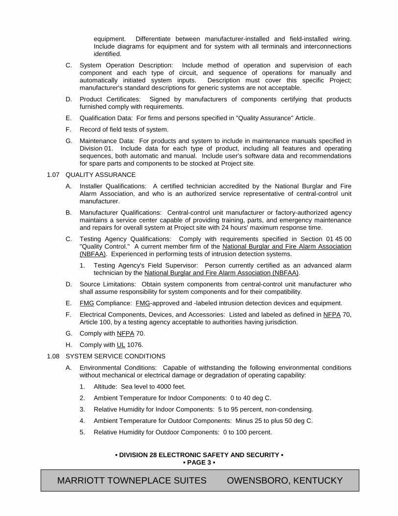
▪ DIVISION 28 ELECTRONIC SAFETY AND SECURITY ▪
▪ PAGE 3 ▪
RESIDENCE INN BY MARRIOTT - LITTLETON, COLORADO
equipment. Differentiate between manufacturer-installed and field-installed wiring. Include diagrams for equipment and for system with all terminals and interconnections identified.
C. System Operation Description: Include method of operation and supervision of each component and each type of circuit, and sequence of operations for manually and automatically initiated system inputs. Description must cover this specific Project; manufacturer's standard descriptions for generic systems are not acceptable.
D. Product Certificates: Signed by manufacturers of components certifying that products furnished comply with requirements.
E. Qualification Data: For firms and persons specified in "Quality Assurance" Article.
F. Record of field tests of system.
G. Maintenance Data: For products and system to include in maintenance manuals specified in Division 01. Include data for each type of product, including all features and operating sequences, both automatic and manual. Include user's software data and recommendations for spare parts and components to be stocked at Project site.
1.07 QUALITY ASSURANCE
A. Installer Qualifications: A certified technician accredited by the National Burglar and Fire Alarm Association, and who is an authorized service representative of central-control unit manufacturer.
B. Manufacturer Qualifications: Central-control unit manufacturer or factory-authorized agency maintains a service center capable of providing training, parts, and emergency maintenance and repairs for overall system at Project site with 24 hours' maximum response time.
C. Testing Agency Qualifications: Comply with requirements specified in Section 01 45 00 "Quality Control." A current member firm of the National Burglar and Fire Alarm Association (NBFAA). Experienced in performing tests of intrusion detection systems.
1. Testing Agency's Field Supervisor: Person currently certified as an advanced alarm technician by the National Burglar and Fire Alarm Association (NBFAA).
D. Source Limitations: Obtain system components from central-control unit manufacturer who shall assume responsibility for system components and for their compatibility.
E. FMG Compliance: FMG-approved and -labeled intrusion detection devices and equipment.
F. Electrical Components, Devices, and Accessories: Listed and labeled as defined in NFPA 70, Article 100, by a testing agency acceptable to authorities having jurisdiction.
G. Comply with NFPA 70.
H. Comply with UL 1076.
1.08 SYSTEM SERVICE CONDITIONS
A. Environmental Conditions: Capable of withstanding the following environmental conditions without mechanical or electrical damage or degradation of operating capability:
1. Altitude: Sea level to 4000 feet.
2. Ambient Temperature for Indoor Components: 0 to 40 deg C.
3. Relative Humidity for Indoor Components: 5 to 95 percent, non-condensing.
4. Ambient Temperature for Outdoor Components: Minus 25 to plus 50 deg C.
5. Relative Humidity for Outdoor Components: 0 to 100 percent.
MARRIOTT TOWNEPLACE SUITES OWENSBORO, KENTUCKY

▪ DIVISION 28 ELECTRONIC SAFETY AND SECURITY ▪
▪ PAGE 4 ▪
RESIDENCE INN BY MARRIOTT - LITTLETON, COLORADO
1.09 WARRANTY
A. General Warranty: Special warranty specified in this Article shall not deprive Owner of other rights Owner may have under other provisions of the Contract Documents and shall be in addition to, and run concurrent with, other warranties made by Contractor under requirements of the Contract Documents.
PART 2 PRODUCTS 2.01 MANUFACTURERS
A. Avendra, LLC Preferred Manufacturers:
1. ADT Security Services, Inc. , a Tyco International Business (800-238-8988).
B. Approved Manufacturer:
1. No substitutions accepted.
2.02 EQUIPMENT
A. Protection from Power Line Surges: Use integral surge suppressors listed in UL 1449 and complying with IEEE C62.41, Category B. Include the following features:
1. Suppression Level: 300 V.
2. Maximum Response Time: 5 nanoseconds.
3. Circuit: Multistage, using inductors and silicon-avalanche zener diodes or equivalent.
4. Indicator Lamp: Labeled neon or LED located on control unit and arranged to extinguish on failure of protection.
5. Fuses: Externally accessible.
B. System- and Equipment-Interference Resistance: Not affected by radiated-radio-frequency interference and electrical induction of 15 V/m over a frequency range of 10 to 10,000 MHZ and conducted interference signals up to 0.25-V RMS injected into power supply lines at 10 to 10,000 MHZ.
C. Tamper Protection: Tamper switches on detection devices, control units, annunciators, pull boxes, junction boxes, cabinets, and other system components indicated to provide an alarm signal when unit is opened or partially disassembled. Central-control unit identifies tamper alarms and indicates location in alarm display.
D. Products: Provide the following products subject to conformance with the requirements specified. Note: Connections shall be made to the relays (NO/NC) to provided fire alarm control panel for fire alarm and fire alarm trouble.
1. “Focus 200 Control Dual Line Control Communicator with F-200 Interactive Keypad and Standby Batteries”; ADT Security Systems, Inc.
a. Location: Telephone room.
b. Quantity: 1
2. “F-200 Interactive Keypad”; ADT Security Services, Inc.
a. Location: Administrative Office vestibule area.
b. Quantity: 1
3. Each: “Hold Up Button, ADT 270SN-ADT with Reset Tool”; ADT Security Services, Inc.
a. Location: Located at each check-in podium (if this is a traditional front desk then at each end of the Front Desk) and on the work counter located in the Workroom.
MARRIOTT TOWNEPLACE SUITES OWENSBORO, KENTUCKY

▪ DIVISION 28 ELECTRONIC SAFETY AND SECURITY ▪
▪ PAGE 5 ▪
RESIDENCE INN BY MARRIOTT - LITTLETON, COLORADO
b. Quantity: 3
2.03 ELECTRICAL POWER
A. Normal System Power Supply: 120 V, 60 Hz, through a locked disconnect device. System control unit supplies power to components.
B. Power Continuity: Batteries in power supplies of control units and individual system components maintain continuous system operation during outages of both normal and backup ac system supply.
1. Batteries: Rechargeable, valve-regulated, recombinant, sealed lead-acid type with nominal 10-year life expectancy. Capacity adequate to operate portion of system served, including audible trouble signal devices for up to four hours and audible and visual alarm devices under alarm conditions for an additional 10 minutes.
2. Battery Charger: Solid-state, fully automatic, variable-charging-rate type. Charger recharges fully discharged battery within 24 hours.
C. Annunciation: Central-control unit indicates, as a change in system condition, switching of system or component to backup power.
2.04 INTRUSION DETECTION DEVICES
A. Comply with UL 639.
B. Configuration: Single or multiple components to perform indicated functions. Single-component devices may not be used where multiple-component devices are indicated.
C. Power Source: One or more dedicated power supply circuits from control unit.
D. Detection Indicator: LED in unit housing, latch type where indicated.
1. Sensitivity: Detect presence of an intruder within their zone patterns, but not outside their zone patterns.
E. Acoustical Devices: Detect intrusion by monitoring pattern of a steady-state sonic field produced by an ultrasonic transmitter. Changes in pattern are analyzed and those matching the profile of an intrusion initiate an alarm.
F. Glass-Break Devices, Acoustic Type: Detect unique airborne acoustic energy spectrum caused by breaking glass.
G. Dual-Technology, Glass-Break and Vibration Devices: Require both methods to result in an alarm signal.
2.05 CONTROL UNITS
A. Comply with UL 1076.
B. Cabinet: Lockable steel enclosure, arranged so operations required for testing, normal operation, and maintenance are performed from front of enclosure. If more than a single cabinet is required to form a complete control unit, provide exactly matching modular enclosures. Accommodate all components and allow ample gutter space for interconnecting cabinets and field wiring. Identify each enclosure by an engraved, laminated, phenolic-resin nameplate. Lettering on enclosure nameplate shall not be less than 1 inch (25 mm) high. Identify individual components and modules within cabinets with permanent labels.
C. Systems: Separate and independent alarm and supervisory systems in control units. Alarm-initiating zone boards consist of plug-in cards. Arrangements requiring removal of field wiring for module replacement are not acceptable.
D. Timing Unit: Solid state, programmable, 365 day. Features include the following:
MARRIOTT TOWNEPLACE SUITES OWENSBORO, KENTUCKY

▪ DIVISION 28 ELECTRONIC SAFETY AND SECURITY ▪
▪ PAGE 6 ▪
RESIDENCE INN BY MARRIOTT - LITTLETON, COLORADO
1. Astronomic Control: For automatic adjustment of light switching at dawn and dusk.
2. Confirmation: Relays, contactors, and other control devices have auxiliary contacts connected to provide confirmation signals to the system of on or off status of the equipment controlled. Software interprets such signals, displays equipment status, and initiates failure signals.
3. Override Capability: Programmed shutdown of lighting and other items can be overridden by using override push buttons or by entering a command over a telephone data link.
E. Control Modules: Types and capacities as required to perform unit functions. Visible and audible signals in central-control unit indicate alarm, supervisory, and trouble conditions for each zone. Each type of audible alarm has a distinct sound.
F. Zones: Quantity of alarm and supervisory zones as indicated with capacity for expanding number of zones by a minimum of 25 percent.
G. Power Supply Circuits: Units provide power for remote power-consuming detection devices. Circuit capacity is adequate for at least a 25 percent increase in load.
H. Indicating Lights: Individual LED devices designate each zone. An LED test switch for each control unit section illuminates all LED devices on that section of the unit. Manual toggle test-switches or push test-buttons do not require a key to operate. Alarm and supervisory signals light a red LED for the associated zone. Trouble signals light an amber LED for the associated zone.
I. Resetting: Controls permit silencing audible signals for individual zones but prevent resetting of alarm, supervisory, or trouble signals while the condition still exists.
J. Alphanumeric Display and System Controls: Arrange for basic interface between human operator at central-control unit and system components, including annunciation, supervision, and control. A display with a minimum of 80 characters displays alarm, supervisory, and component status messages and indicates control commands to be entered into system. Arrange keypad to enter and execute control commands.
2.06 SECURE-ACCESS CONTROL STATIONS
A. Keypad: Arranged for entering and executing commands for system-status changes.
B. Key-Operated Switch: Changes zone between "secure" and "access" modes.
2.07 SYSTEM PRINTER
A. Description: Listed in UL 1610 and labeled as an integral part of intrusion detection system.
2.08 CONDUCTORS AND CABLES
A. Cable for fire panel connection shall be power limited fire alarm plenum cable 2 conductor 16AWG Red (FPLP).
B. Cable for hold-up button connections shall be power limited fire alarm plenum cable 4 conductor 22 AWG (FPLP).
PART 3 EXECUTION 3.01 INSTALLATION
A. Install system according to NFPA 70, NFPA 72, applicable codes, and manufacturer's written instructions.
B. Comply with UL 681 and/or 1641.
MARRIOTT TOWNEPLACE SUITES OWENSBORO, KENTUCKY
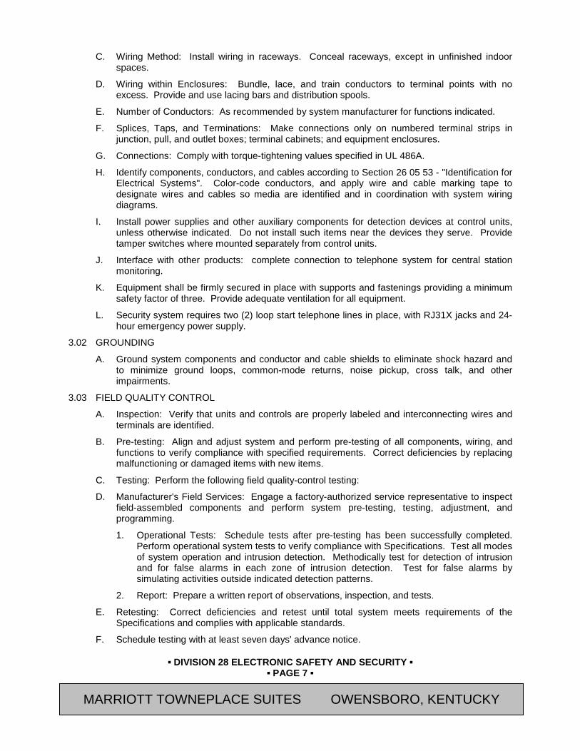
▪ DIVISION 28 ELECTRONIC SAFETY AND SECURITY ▪
▪ PAGE 7 ▪
RESIDENCE INN BY MARRIOTT - LITTLETON, COLORADO
C. Wiring Method: Install wiring in raceways. Conceal raceways, except in unfinished indoor spaces.
D. Wiring within Enclosures: Bundle, lace, and train conductors to terminal points with no excess. Provide and use lacing bars and distribution spools.
E. Number of Conductors: As recommended by system manufacturer for functions indicated.
F. Splices, Taps, and Terminations: Make connections only on numbered terminal strips in junction, pull, and outlet boxes; terminal cabinets; and equipment enclosures.
G. Connections: Comply with torque-tightening values specified in UL 486A.
H. Identify components, conductors, and cables according to Section 26 05 53 - "Identification for Electrical Systems". Color-code conductors, and apply wire and cable marking tape to designate wires and cables so media are identified and in coordination with system wiring diagrams.
I. Install power supplies and other auxiliary components for detection devices at control units, unless otherwise indicated. Do not install such items near the devices they serve. Provide tamper switches where mounted separately from control units.
J. Interface with other products: complete connection to telephone system for central station monitoring.
K. Equipment shall be firmly secured in place with supports and fastenings providing a minimum safety factor of three. Provide adequate ventilation for all equipment.
L. Security system requires two (2) loop start telephone lines in place, with RJ31X jacks and 24-hour emergency power supply.
3.02 GROUNDING
A. Ground system components and conductor and cable shields to eliminate shock hazard and to minimize ground loops, common-mode returns, noise pickup, cross talk, and other impairments.
3.03 FIELD QUALITY CONTROL
A. Inspection: Verify that units and controls are properly labeled and interconnecting wires and terminals are identified.
B. Pre-testing: Align and adjust system and perform pre-testing of all components, wiring, and functions to verify compliance with specified requirements. Correct deficiencies by replacing malfunctioning or damaged items with new items.
C. Testing: Perform the following field quality-control testing:
D. Manufacturer's Field Services: Engage a factory-authorized service representative to inspect field-assembled components and perform system pre-testing, testing, adjustment, and programming.
1. Operational Tests: Schedule tests after pre-testing has been successfully completed. Perform operational system tests to verify compliance with Specifications. Test all modes of system operation and intrusion detection. Methodically test for detection of intrusion and for false alarms in each zone of intrusion detection. Test for false alarms by simulating activities outside indicated detection patterns.
2. Report: Prepare a written report of observations, inspection, and tests.
E. Retesting: Correct deficiencies and retest until total system meets requirements of the Specifications and complies with applicable standards.
F. Schedule testing with at least seven days' advance notice.
MARRIOTT TOWNEPLACE SUITES OWENSBORO, KENTUCKY

▪ DIVISION 28 ELECTRONIC SAFETY AND SECURITY ▪
▪ PAGE 8 ▪
RESIDENCE INN BY MARRIOTT - LITTLETON, COLORADO
3.04 ADJUSTING
A. Occupancy Adjustment: When requested within 12 months of date of Substantial Completion, provide on-site assistance in adjusting and reprogramming to suit actual occupied conditions. Provide up to two visits to Project for this purpose without additional cost.
3.05 DEMONSTRATION
A. Engage a factory-authorized service representative to explain programming and operation of system and to train Owner's maintenance personnel on procedures and schedules for maintaining, programming, operating, adjusting, troubleshooting, and servicing system.
1. Refer to Section 01 79 00 “Demonstration and Training” for additional requirements.
END OF SECTION
Revision Log
MARRIOTT TOWNEPLACE SUITES OWENSBORO, KENTUCKY
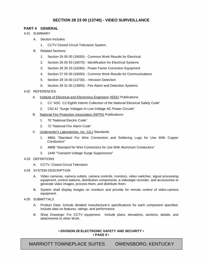
▪ DIVISION 28 ELECTRONIC SAFETY AND SECURITY ▪
▪ PAGE 9 ▪
RESIDENCE INN BY MARRIOTT - LITTLETON, COLORADO
SECTION 28 23 00 (13740) - VIDEO SURVEILLANCE
PART 4 GENERAL 4.01 SUMMARY
A. Section Includes:
1. CCTV Closed Circuit Television System.
B. Related Sections:
1. Section 26 05 00 (16050) - Common Work Results for Electrical
2. Section 26 05 53 (16075) - Identification for Electrical Systems
3. Section 26 35 33 (16280) - Power Factor Correction Equipment
4. Section 27 05 00 (16050) - Common Work Results for Communications
5. Section 28 16 00 (13730) – Intrusion Detection
6. Section 28 31 00 (13850) - Fire Alarm and Detection Systems
4.02 REFERENCES
A. Institute of Electrical and Electronics Engineers (IEEE) Publications:
1. C2 “ASC C2 Eighth Interim Collection of the National Electrical Safety Code”
2. C62.41 “Surge Voltages In Low-Voltage AC Power Circuits”
B. National Fire Protection Association (NFPA) Publications:
1. 70 "National Electric Code"
2. 72 “National Fire Alarm Code”
C. Underwriter's Laboratories, Inc. (UL) Standards:
1. 486A “Standard For Wire Connectors and Soldering Lugs for Use With Copper Conductors”
2. 486B “Standard for Wire Connectors for Use With Aluminum Conductors”
3. 1449 “Transient Voltage Surge Suppressors”
4.03 DEFINITIONS
A. CCTV: Closed Circuit Television.
4.04 SYSTEM DESCRIPTION
A. Video cameras, camera outlets, camera controls, monitors, video switches, signal processing equipment, control stations, distribution components, a videotape recorder, and accessories to generate video images, process them, and distribute them.
B. System shall display images on monitors and provide for remote control of video-camera equipment.
4.05 SUBMITTALS
A. Product Data: Include detailed manufacturer's specifications for each component specified. Include data on features, ratings, and performance.
B. Shop Drawings: For CCTV equipment. Include plans, elevations, sections, details, and attachments to other Work.
MARRIOTT TOWNEPLACE SUITES OWENSBORO, KENTUCKY

▪ DIVISION 28 ELECTRONIC SAFETY AND SECURITY ▪
▪ PAGE 10 ▪
RESIDENCE INN BY MARRIOTT - LITTLETON, COLORADO
1. Wiring Diagrams: Power, signal, and control wiring. Differentiate between manufacturer-installed and field-installed wiring.
C. Product Certificates: Signed by manufacturers of CCTV equipment and components certifying that products furnished comply with requirements.
D. Installer Certificates: Signed by manufacturer certifying that installers comply with requirements.
E. Field Test Reports: Indicate and interpret test results for compliance with performance requirements of installed systems.
F. Maintenance Data: For CCTV equipment and components to include in maintenance manuals refer to Section 01 78 23 - “Operating and Maintenance Data” and Section 01 77 00 - "Closeout Procedures”. In addition to those requirements, include the following:
1. Detailed operating instructions covering operation under both normal and abnormal conditions.
2. Routine maintenance requirements for system components.
3. Lists of spare parts and replacement components recommended being stored at the site for ready access.
G. Warranties: Special warranties specified in this Section.
4.06 QUALITY ASSURANCE
A. Installer Qualifications: An experienced installer who is an authorized representative of the CCTV equipment manufacturer, for both installation and maintenance of units required for this Project, to supervise installation of the system.
B. Product Options: Drawings indicate size, profiles, and dimensional requirements of CCTV equipment and are based on the specific system indicated.
C. Comply with NFPA 70.
D. Comply with 47 CFR 15, 17, and 76.
4.07 PROJECT CONDITIONS
A. Environmental Limitations: System components are equipped and rated for the environments where installed.
1. Service Conditions for Indoor Equipment: Rate equipment for continuous operation under the following environmental conditions, unless otherwise indicated:
a. Temperature: 32 deg F to 106 deg F.
b. Relative Humidity: 0 to 90 percent (non-condensing).
4.08 SEQUENCING
A. Coordinate work of this section with requirements of CCTV equipment provider.
B. Coordinate layout and installation of CCTV equipment and suspension system components with other construction that penetrates ceilings or is supported by them, including light fixtures, HVAC equipment, fire-suppression-system components, and partition assemblies.
4.09 WARRANTY
A. Special warranty specified in this Article shall not deprive Owner of other rights Owner may have under other provisions of the Contract Documents and shall be in addition to, and run concurrent with, other warranties made by Contractor under requirements of the Contract Documents.
MARRIOTT TOWNEPLACE SUITES OWENSBORO, KENTUCKY

▪ DIVISION 28 ELECTRONIC SAFETY AND SECURITY ▪
▪ PAGE 11 ▪
RESIDENCE INN BY MARRIOTT - LITTLETON, COLORADO
PART 5 PRODUCTS 5.01 MANUFACTURERS
A. Avendra, LLC Preferred Manufacturers:
1. ADT Security Services, Inc. , a Tyco International Business (800-238-8988).
B. Approved Manufacturers:
1. No substitutions accepted
5.02 CCTV COMPONENTS
A. Dome Camera: 540 TVL, True Day/Night; 2.8 – 12mm; UNI; UTP.
1. Acceptable Products:
a. "Model CD5D2812UWCU "; ADT Security Services, Inc.
2. Features:
a. 540TVL or 580TVL High Resolution CCD
b. 2.8 – 12mm Day/Night AI Varifocal Lens
c. Composite & UTP Video Outputs
d. Low-Lux Operation
e. Digital and TRUE Day/Night Models
f. Wide Dynamic Range (TRUE D/N models)
g. Wide Auto White Balance mode (TRUE D/N models)
h. Digital Noise Reduction Function
i. 4-Point Privacy Zone Masking
j. Sense Up (2X – 32X) for extreme low light image capture
k. Video Motion Detection (VMD)
l. RS485 for remote operation
m. 12VDC / 24VAC
n. 12VDC / 24VAC
o. Test Monitor Output
p. Interior Vandal or Exterior Vandal Housing
q. 3-Axis Gimbal, Optional Wall, Pendent and Back-shell only Mounts
r. Exterior Housing with Built-in Heater
MARRIOTT TOWNEPLACE SUITES OWENSBORO, KENTUCKY

▪ DIVISION 28 ELECTRONIC SAFETY AND SECURITY ▪
▪ PAGE 12 ▪
RESIDENCE INN BY MARRIOTT - LITTLETON, COLORADO
B. Power Supply: CCTV DC Wall Mount Power Supply, Four (4) Fused Outputs, 6-15 VDC @ 2.5cULus Listed, Gray Enclosure.
a. "Model ALTV615DC4UL"; ADT Security Services, Inc.
C. Monitors: Color, metal cabinet units designed for continuous operation. 17-inch active TFT LCD color, multimode monitor with minimum 50 pound rated rack mount as required.
1. Acceptable Product:
a. Monitor: “Part Number M170CP2 Color LCD Monitor”; ADT Security Services, Inc.
b. Wall Mount: “Part Number A-CS777”; ADT Security Services, Inc.
2. Quantity: 1
3. Screen Size (Diagonal Dimension): 17”
4. LCD Panel Pixel Array: 1280 X 1024.
5. Minimum Front Panel Devices and Controls: Power switch, power-on indicator, and brightness.
D. Digital Recorder: Professional Digital Recorder, 4-Channel, H.246 120/120/120, VGA, No Audio, 2-USB (1-mouse only), Looping, Mouse, IR, 500GB.
1. Acceptable Products:
a. "Model A-ADT4HS-500; ADT Security Services, Inc.
1) Quantity: 1 each.
b. "Model LB1000"; ADT Security Services, Inc.
1) Quantity: 1 each.
2. Features:
a. Video:
1) Signal Format: NTSC or PAL (auto detect).
2) Video Input: Composite: 4 looping inputs.
3) Monitor Outputs: Composite: One (BNC), 1 Vp-p, 75 Ohms / Analog RGB: One VGA.
4) Display Resolution: 720x480 (NTSC)
5) Record Resolution: Standard: 336x224 (NTSC) / High: 672x224 (NTSC) / Very High: 672x448 (NTSC).
MARRIOTT TOWNEPLACE SUITES OWENSBORO, KENTUCKY
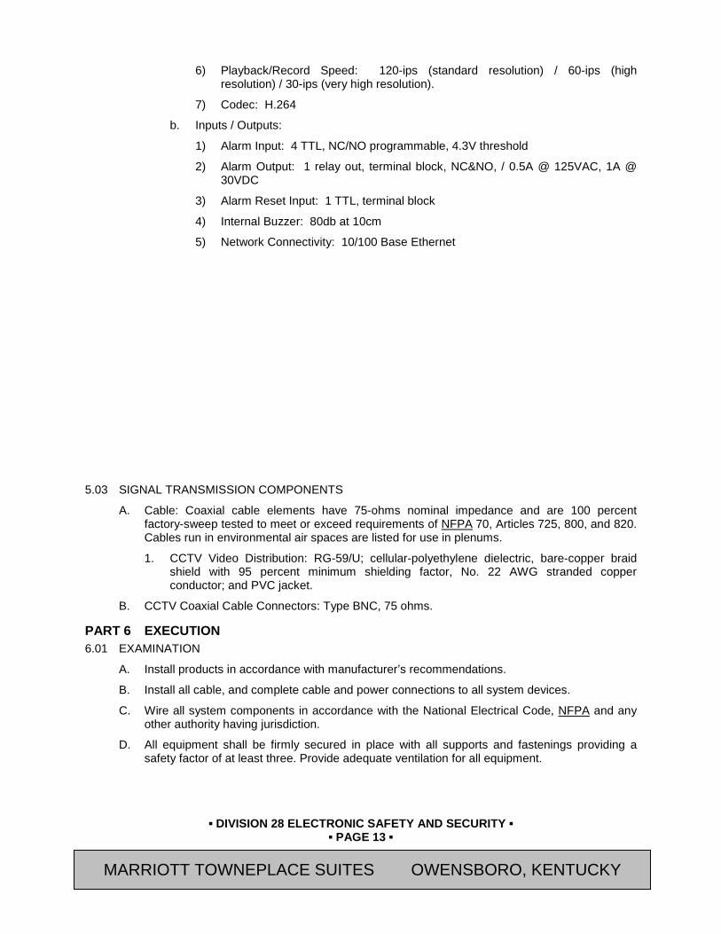
▪ DIVISION 28 ELECTRONIC SAFETY AND SECURITY ▪
▪ PAGE 13 ▪
RESIDENCE INN BY MARRIOTT - LITTLETON, COLORADO
6) Playback/Record Speed: 120-ips (standard resolution) / 60-ips (high resolution) / 30-ips (very high resolution).
7) Codec: H.264
b. Inputs / Outputs:
1) Alarm Input: 4 TTL, NC/NO programmable, 4.3V threshold
2) Alarm Output: 1 relay out, terminal block, NC&NO, / 0.5A @ 125VAC, 1A @ 30VDC
3) Alarm Reset Input: 1 TTL, terminal block
4) Internal Buzzer: 80db at 10cm
5) Network Connectivity: 10/100 Base Ethernet
5.03 SIGNAL TRANSMISSION COMPONENTS
A. Cable: Coaxial cable elements have 75-ohms nominal impedance and are 100 percent factory-sweep tested to meet or exceed requirements of NFPA 70, Articles 725, 800, and 820. Cables run in environmental air spaces are listed for use in plenums.
1. CCTV Video Distribution: RG-59/U; cellular-polyethylene dielectric, bare-copper braid shield with 95 percent minimum shielding factor, No. 22 AWG stranded copper conductor; and PVC jacket.
B. CCTV Coaxial Cable Connectors: Type BNC, 75 ohms.
PART 6 EXECUTION 6.01 EXAMINATION
A. Install products in accordance with manufacturer’s recommendations.
B. Install all cable, and complete cable and power connections to all system devices.
C. Wire all system components in accordance with the National Electrical Code, NFPA and any other authority having jurisdiction.
D. All equipment shall be firmly secured in place with all supports and fastenings providing a safety factor of at least three. Provide adequate ventilation for all equipment.
MARRIOTT TOWNEPLACE SUITES OWENSBORO, KENTUCKY
▪ DIVISION 28 ELECTRONIC SAFETY AND SECURITY ▪
▪ PAGE 14 ▪
RESIDENCE INN BY MARRIOTT - LITTLETON, COLORADO
6.02 INSTALLATION
A. Outdoor Installation: Comply with IEEE C2, "National Electrical Safety Code."
B. Install surge suppressors where ac-power-operated devices are not protected against voltage transients by integral surge suppressors specified in UL 1449. Install surge suppressors at the devices' power-line terminals. Comply with Section 26 35 33 - “Power Factor Correction Equipment”.
C. Wiring Method: Install cables in raceways.
D. Wiring within Enclosures: Bundle, lace, and train conductors to terminal points with no excess and without exceeding manufacturer's limitations on bending radii. Provide and use lacing bars and distribution spools.
E. Pulling Cable: Do not exceed manufacturer's recommended pulling tensions. Do not install bruised, kinked, scored, deformed, or abraded cable. Do not splice cable between termination, tap, or junction points. Remove and discard cable if damaged during installation and replace it with new cable.
F. Equalizing Video Signals: Where system performance may be degraded in certain operating modes, revise component connections and install video distribution amplifiers and attenuates as required to provide a balanced signal across the system.
G. Splices, Taps, and Terminations: For power and control wiring, use numbered terminal strips in junction, pull, and outlet boxes; terminal cabinets; and equipment enclosures. Tighten electrical connectors and terminals according to manufacturer's published torque-tightening values. If manufacturer's torque values are not indicated, use those specified in UL 486A and UL 486B.
H. Grounding: Provide independent signal circuit grounding recommended by manufacturer.
6.03 CCTV SYSTEM INSTALLATION
A. Install cameras at final locations defined by camera location tests. Install cameras with 84-inch minimum clear space below cameras and their mountings. Change type of mounting to achieve required clearance.
B. Set pan unit and pan-and-tilt unit stops to suit final camera position and to obtain the field of view required for camera.
C. Install power supplies and other auxiliary components at control stations. Do not install such items near the devices they serve, unless otherwise indicated.
D. Placement:
1. CCTV Camera Placement: Mount camera to the ceiling tile in the corner behind the Front Desk that is opposite the main entrance. The purpose of the camera is to identify armed assailants standing in front of the desk. (Note: All attempts should be made to also position the camera to view persons standing near the intercom in the lobby vestibule.
2. Mount and Monitor Placement:
a. Monitor mount provided shall be installed directly under the CCTV Camera fixed with appropriate fasteners to support a minimum 14” color flat screen monitor. (Note: All attempts should be made to make the monitor conspicuously visible from the front entrance and cable/wire system correctly to always display time date stamp from the DVR .
b. CCTV # 2 Camera Placement: Mount camera within the “computer room” (room where the computer/Micros server is located that contains credit card information). The camera must identify persons accessing the Micros server. If the camera is not
MARRIOTT TOWNEPLACE SUITES OWENSBORO, KENTUCKY

▪ DIVISION 28 ELECTRONIC SAFETY AND SECURITY ▪
▪ PAGE 15 ▪
RESIDENCE INN BY MARRIOTT - LITTLETON, COLORADO
able to properly fit in the room to identify persons, then place the camera on the exterior of the room to identify persons who are exiting the room.
c. CCTV # 3 Camera Placement: Mount camera within the work room to identify persons who opens the drop safe within the room.
3. DVR Placement: The DVR shall be housed in the lock box provided and powered from the AC outlet inside the lock box. The DVR, lock box, and monitor shall be placed in the telephone equipment room. If the telephone equipment room is not within close proximity to the front desk then the DVR, lock box, and monitor shall be placed in a secured office behind the front desk. The keys shall be surrendered to the General Manager and secured according to Owner procedures.
E. DVR Programming: Set the current time and date and position display so as to not interfere with the camera field of view. The DVR should be programmed torecord minimum 14 days, high resolution with minimum 4 frames per second per camera. .
F. Camera Adjustments: The camera provided shall be factory set and white balanced. A manual iris, variable focus lens shall be provided. The lens should be adjusted so as to capture as much of the desk area as possible while maintaining the ability to identify a person at the counter. Adjust the iris to achieve optimal lighting with consideration given to the main entrance diffusing sunlight toward the camera.
6.04 IDENTIFICATION
A. Identify system components, wiring, cabling, and terminals according to Section 26 05 53 - "Identification for Electrical Systems”.
6.05 FIELD QUALITY CONTROL
A. Testing: Engage a qualified testing agency to perform field quality control testing.
B. Manufacturer's Field Service: Engage a factory-authorized service representative to inspect field-assembled components and equipment installation and supervise pre-testing, testing, and adjusting of CCTV equipment.
C. Inspection: Verify that units and controls are properly installed, connected, and labeled and that interconnecting wires and terminals are identified.
D. Pre-testing: Align and adjust system and pretest components, wiring, and functions to verify that they comply with specified requirements. Replace malfunctioning or damaged items. Retest until satisfactory performance and conditions are achieved. Prepare CCTV equipment for acceptance and operational testing as follows:
1. CCTV Sources: Connect the receiver to the output of each CCTV signal source or the distribution amplifier associated with it.
E. Test Schedule: Schedule tests after pre-testing has successfully been completed and system has been in normal functional operation for at least 14 days. Provide a minimum of 10 days notice of test schedule to Owner's Representative.
F. Operational Tests: Perform operational system tests to verify that system complies with Specifications. Include all modes of system operation. Test equipment for proper operation in all functional modes.
G. CCTV Camera Location Test: Temporarily support each camera at the indicated location and connect to monitor. Adjust camera location and mounting and substitute fixed lenses to provide required performance at monitor. Adjust locations within 15 feet of those indicated.
H. Record test results.
MARRIOTT TOWNEPLACE SUITES OWENSBORO, KENTUCKY
▪ DIVISION 28 ELECTRONIC SAFETY AND SECURITY ▪
▪ PAGE 16 ▪
RESIDENCE INN BY MARRIOTT - LITTLETON, COLORADO
I. Retest: Correct deficiencies identified by tests and observations and retest until specified requirements are met.
6.06 CLEANING
A. Clean installed items using methods and materials recommended by manufacturer.
B. Clean CCTV system components, camera housing windows, lenses, and monitor screens.
6.07 DEMONSTRATION
A. Engage a factory-authorized service representative to train Owner's maintenance personnel to adjust, operate, and maintain CCTV equipment.
1. Train Owner's maintenance personnel on procedures and schedules for troubleshooting, servicing, and maintaining equipment.
2. Demonstrate methods of determining optimum alignment and adjustment of components and settings for system controls.
3. Demonstrate programming and tuning of satellite receivers.
4. Conduct training as specified in Section 01 79 00 - "Demonstration and Training”.
6.08 ON-SITE ASSISTANCE
A. Occupancy Adjustments: When requested by Owner within one year of date of Substantial Completion, provide on-site assistance in tuning and adjusting the system to suit actual occupied conditions and to optimize performance. Provide up to two adjustments at Project site for this purpose, without additional cost.
END OF SECTION
Revision Log
MARRIOTT TOWNEPLACE SUITES OWENSBORO, KENTUCKY
▪ DIVISION 28 ELECTRONIC SAFETY AND SECURITY ▪
▪ PAGE 17 ▪
RESIDENCE INN BY MARRIOTT - LITTLETON, COLORADO
SECTION 28 31 00 (13850) - FIRE ALARM AND DETECTION SYSTEMS
PART 7 GENERAL 7.01 SUMMARY
A. Section Includes:
1. Automatic and Manual Fire Alarm System, complete per Marriott’s Fire Protection and Life Safety Design Standards (Module 14), and applicable local, state and national codes
B. Related Documents:
1. Marriott’s Fire Protection and Life Safety Design Standards (Module 14):
a. Marriott’s Fire Protection and Life Safety Design Standards include Design Standards, performance criteria, reference standards and life safety process verification that define a comprehensive fire protection program.
C. Related Sections:
1. Section 14 24 23 (14240) – Elevators.
2. Section 21 10 00 (13900) - Fire Protection.
3. Section 27 05 00 (16050) – Common Work Results for Electrical
7.02 QUALITY ASSURANCE
A. Equipment shall be manufactured by a firm who has been actively manufacturing fire alarm systems of the type required and shall have supplied similar equipment to comparable installations and rendered satisfactory service for a minimum of 10 years. All components of the fire alarm system shall be manufactured by the vendor supplying the equipment, and standard products of a single manufacturer.
B. Material and equipment shall be new and UL listed.
PART 8 PRODUCTS 8.01 MANUFACTURERS
A. Avendra, LLC Preferred Manufacturers:
1. None.
B. Approved Manufacturers:
1. Tyco Integrated Fire and Security
a. Contact: William Glover (443-259-3352)
b. Email: [email protected]
a. Approved Models:
1) “EST/ADT 3000 Life Safety Control Panel Platform”
2) “EST Quickstart Series Intelligent Life Safety Control Panels”
3) “EST io 500 Intelligent Life Safety System”
4) “CP-3500” (replaces CP-3000, CP300D and CP300DA)
5) CP-3500D (replaces CP-3000, CP300D and CP300DA)
2. SimplexGrinnell –Tyco Fire & Security
a. Contact: John Morgan (978-731-7352)
MARRIOTT TOWNEPLACE SUITES OWENSBORO, KENTUCKY
▪ DIVISION 28 ELECTRONIC SAFETY AND SECURITY ▪
▪ PAGE 18 ▪
RESIDENCE INN BY MARRIOTT - LITTLETON, COLORADO
1) Email: [email protected]
b. Approved Models:
1) “Simplex 4020” (no longer manufactured but supported)
2) “Simplex 4100 Classic” (no longer manufactured but supported)
3) “Simplex 4100 Plus” (no longer manufactured but supported)
4) “Simplex 4010” (only when supplied with a graphic annunciator)
5) “Simplex 4100U”
6) “Simplex 4100ES”
3. Siemens (Cerbeus, Pyrotronics Faraday) – Siemens Fire Safety (201-266-4516)
a. Contact: Matt Watson (240-401-0373)
1) Email: [email protected]
b. Approved Models:
1) “Siemens MXL System”
2) “Siemens XLS System”
3) “Siemens Desigo System”
4) “Siemens Cerberus Pro System”
5) “Siemens FS-250”
6) “Faraday MPC System”
4. Honeywell Fore Safety Americas (Engineered Systems Distributors), Notifier (NESCO); Gamewell, FCI, Silent Knight IFP-2000, Honeywel)
a. Contact: John Brady (203-581-1235)
1) Email: [email protected]
b. Approved Models:
1) “Silent Knight IFP-2000”
2) “Gamewell/FCI E3”
3) “Gamewell/FCI S3”
4) “Notifier Onyx Series”
5) “Notifier NFS 320”
6) “Notifier NFS 2-640”
7) “Notifier NFS 2-3030”
8) “Honeywell XLS 140” (peripherals must be Honeywell)
9) “Honeywell XLS 3000” (peripherals must be Honeywell)
5. Edwards/UTC Fire and Security (860-284-3000) (Edwards Technology; Vigilant Fire & Life Safety)
a. Contact: Timm Weber (772-978-9296)
1) Email: [email protected]
MARRIOTT TOWNEPLACE SUITES OWENSBORO, KENTUCKY
▪ DIVISION 28 ELECTRONIC SAFETY AND SECURITY ▪
▪ PAGE 19 ▪
RESIDENCE INN BY MARRIOTT - LITTLETON, COLORADO
b. Approved Models:
1) “EST 3X"
2) “EST 3”
3) “io 500”
4) “Vigilant VM” (same as EST3X)
5) “Vigilant VS” (same as io-500)
6. Mircom (816-628-5348)
a. Contact: Todd Gustafson (816-914-8880)
1) Email: [email protected]
b. Approved Models:
1) “FX-2000 Series”: “FX-2003-6” “FX-2003-12” “FX-2003S-12” “FX-2003-6N” “FX-2003-12N” “FX-2009-12” “FX-2009S-12” “FX-2009-12N” “FX-2017-12A” “FX-2017-12N”
7. VES (Formely Viking Electronic Services) (800-270-3066)
a. Contact: Bo Woods (714-522-2246)
1) Email: [email protected]
b. Approved Models:
1) “eLAN Series”
2) “eLAN RS Series”
3) “Elite Series”
4) “Elite RS Series”
8. Hochiki America Corporation (281-826-0165)
a. Contact: Bo Woods (714-522-2246)
1) Email: [email protected]
b. Approved Models:
1) FN-4127”
2) “FN-2127
3) “FN 1127””
9. Commercial Wireless Systems International (CWSI) (954-318-6005)
a. Contact: Scott Barrett (866-937-2537)
1) Email: [email protected]
MARRIOTT TOWNEPLACE SUITES OWENSBORO, KENTUCKY
▪ DIVISION 28 ELECTRONIC SAFETY AND SECURITY ▪
▪ PAGE 20 ▪
RESIDENCE INN BY MARRIOTT - LITTLETON, COLORADO
b. Approved Models:
1) “CP3000”
2) “CP3000A”
3) “CP3000D”
4) “CP3000DA
10. Fike Facilities Protection Group
a. Contact: Tom Boyle (816-655-45113)
1) Email: [email protected]
b. Approved Models:
1) “CyberCat 50”
2) “CyberCat 254”
3) “CyberCat 1016”
11. Potter Electric Signal Company
a. Contact: Mark Sandler (800-325-3936)
1) Email: [email protected]
b. Approved Models:
1) “P200
2) “P300
3) “P400
4) “P400R
PART 9 EXECUTION 9.01 INSTALLATION
A. Install system in accordance with Marriott’s Fire Protection and Life Safety Design Standards (Module 14), all national, state and local codes, UL standards, and the manufacturer's published instructions.
END OF SECTION
Revision Log
MARRIOTT TOWNEPLACE SUITES OWENSBORO, KENTUCKY
▪ DIVISION 31 EARTHWORK▪
▪ PAGE 1 ▪
RESIDENCE INN BY MARRIOTT - LITTLETON, COLORADO
SECTION 31 10 00 (02200) - SITE CLEARING
PART 1 GENERAL 1.01 SUMMARY
A. Section Includes:
1. Erosion and Sedimentation Control.
2. Site Demolition:
a. Selective Site Demolition:
1) Demolition of retaining walls, foundations, pavements, curbs and gutters, drainage structures, and utilities, and backfilling voids resulting from removals or demolition.
b. Building Demolition: Demolition of Structures.
3. Site Clearing:
a. Protection of Existing Trees
b. Removal of Trees and Other Vegetation
c. Topsoil Stripping and Stockpiling
d. Clearing and Grubbing
e. Removing Above-Grade Improvements, As Indicated On Drawings
B. Related Sections:
1. Section 01 50 00 (01500) - Construction Facilities and Temporary Controls
2. Section 31 20 00 (02300) – Earth Moving
1.02 QUALITY ASSURANCE
A. Regulatory Requirements:
1. Conform to applicable local code for demolition of structures, safety of adjacent structures, dust control and runoff control.
2. Obtain required permits and licenses from authorities. Pay associated fees including disposal charges.
3. Notify affected utility companies before starting work and comply with their requirements.
4. Do not close or obstruct roadways, sidewalks or hydrants without permits.
5. Conform to applicable regulatory procedures when discovering hazardous or contaminated materials.
6. Test soils around buried tanks for contamination.
B. Contractor shall provide methods to ensure pollution control during the demolition period.
C. In addition to complying with all pertinent codes, the Contractor will also comply with the requirements of those insurance carriers providing coverage for existing structures and this work.
1. Comply with governing EPA notification regulations before starting selective demolition. Comply with hauling disposal regulations of authorities having jurisdiction.
MARRIOTT TOWNEPLACE SUITES OWENSBORO, KENTUCKY

▪ DIVISION 31 EARTHWORK▪
▪ PAGE 2 ▪
RESIDENCE INN BY MARRIOTT - LITTLETON, COLORADO
D. Arborist Qualifications: An arborist certified by the International Society of Arboriculture or licensed in the jurisdiction where Project is located.
E. Tree Pruning Standards: Comply with ANSI A300, "Trees, Shrubs , and Other Woody Plant Maintenance - Standard Practices," unless more stringent requirements are indicated.
1.03 PROJECT CONDITIONS
A. Existing Conditions:
1. Conditions existing at time of inspection for bidding purposes will be maintained by Owner in so far as practicable. Variations within structures may occur by Owner's removal and salvage operations prior to start of demolition work.
a. Start of work is acceptance of conditions.
2. Notify Owner of variations to conditions or discrepancies in actual site conditions prior to start of site preparation Work.
3. Structures to be demolished will be discontinued in use and vacated prior to start of work.
4. Owner assumes no responsibility for condition of structures to be demolished.
B. Traffic: Conduct site clearing operations to ensure minimum interference with roads, streets, walks, and other adjacent occupied or used facilities. Do not close or obstruct streets, walks, or other occupied or used facilities without permission from authorities having jurisdiction.
C. Existing Services:
1. General: Indicated locations are approximate; determine exact locations before commencing Work.
2. Arrange and pay for disconnecting, removing, capping, and plugging utility se5rvies. Notify affected utility companies in advance and obtain before starting this Work.
3. Place markers to indicated location of disconnected services. Identify service lines and capping locations on Project Record Documents.
D. Protection of Existing Improvements: Provide protections necessary to prevent damage to existing improvements indicated to remain in place.
1. Restore damaged improvements to their original condition, as acceptable to property Owners.
2. Provide protection for safe passage of persons around area of site preparation. Take precautions and conduct operations to prevent injury to adjacent buildings, structures, other facilities, and persons.
3. Provide interior and exterior shoring, bracing, or support to prevent movement, settlement or collapse of structures to be demolished and adjacent facilities to remain.
E. Protection of Existing Trees and Vegetation: Protect tops, trunks, and roots of existing trees and other vegetation to remain in place against unnecessary cutting, breaking or skinning of roots, skinning or bruising of bark, smothering of trees by stockpiling construction materials or excavated materials within drip line, excess foot or vehicular traffic, or parking of vehicles within drip line. Provide temporary guards to protect trees and vegetation to be left standing.
1. Install Temporary fencing located as indicated or outside the drip line of trees to protect remaining vegetation from construction damage. Utilize plastic snow fence materials as approved by Owner's Representative.
2. Water trees and other vegetation to remain within limits of contract work as required to maintain their health during course of construction operations.
MARRIOTT TOWNEPLACE SUITES OWENSBORO, KENTUCKY
▪ DIVISION 31 EARTHWORK▪
▪ PAGE 3 ▪
RESIDENCE INN BY MARRIOTT - LITTLETON, COLORADO
3. Provide protection for roots over 1-1/2 inch diameter that are cut during construction operations. Coat cut faces with an emulsified asphalt, or other acceptable coating, formulated for use on damaged plant tissues. Temporarily cover exposed roots with wet burlap to prevent roots from drying out. Cover with earth as soon as possible.
4. Repair or replace trees and vegetation to remain, which are damaged by construction operations, in a manner acceptable to Owner’s Representative. Employ a licensed Arborist to repair damages to trees and shrubs.
F. Improvements on Adjoining Property: Authority for performing removal and alteration work on property adjoining Owner's property will be obtained by Owner prior to award of Contract.
G. Salvageable Improvements: Carefully remove items indicated to be salvaged and store on Owner's premises where indicated or directed.
PART 2 PRODUCTS 2.01 FILL MATERIALS
A. Specified in Section 31 20 00 (02300) – Earth Moving
PART 3 EXECUTION 3.01 PREPARATION
A. Provide, erect, and maintain erosion control devices, temporary barriers and security devices at locations indicated as specified in Section 01 50 00 (01500) and as shown on Drawings.
B. Protect existing landscaping materials, appurtenances and structures and other features indicated to remain.
C. Prevent movement or settlement of adjacent structures: Provide bracing and shoring.
D. Mark location of utilities. Protect and maintain in safe and operable condition the utilities to remain. Prevent interruption of existing utility service to occupied or used facilities, except when authorized in writing by authorities having jurisdiction. Provide temporary services during interruptions to existing utilities as acceptable to governing authorities and the Owner.
3.02 SITE DEMOLITION
A. General:
1. Document existing conditions of adjacent areas prior to start of demolition.
2. Conduct demolition to minimize interference with adjacent structures or pavements.
3. Cease operations immediately if adjacent structures appear to be in danger. Notify authority having jurisdiction. Do not resume operations until directed.
4. Conduct operations with minimum interference to public or private access. Maintain access and egress at all times.
5. Obtain written permission from adjacent property owners when demolition equipment will traverse, infringe upon or limit access to their property.
6. Sprinkle Work with water to minimize dust. Provide hoses and water connections for this purpose.
7. Comply with governing regulations pertaining to environmental protection.
8. Clean adjacent structures and improvements of dust, dirt, and debris caused by demolition operations. Return adjacent areas to condition existing prior to start of work.
B. Pollution Controls:
MARRIOTT TOWNEPLACE SUITES OWENSBORO, KENTUCKY
▪ DIVISION 31 EARTHWORK▪
▪ PAGE 4 ▪
RESIDENCE INN BY MARRIOTT - LITTLETON, COLORADO
1. Furnish and install temporary control measures for erosion and sedimentation in accordance with authorities having jurisdiction.
2. Use water mist, temporary enclosures, and other suitable methods to limit the spread of dust and dirt. Comply with governing environmental protection regulations.
a. Do not use water when it may damage existing construction or create hazardous or objectionable conditions, such as ice, flooding, and pollution.
3. Remove and transport debris in a manner that will prevent spillage on adjacent surfaces and areas.
a. Clean adjacent structures and improvements of dust, dirt, and debris caused by selective demolition operations. Return adjacent areas to condition existing before start of selective demolition.
C. Salvage Materials:
1. All demolished material shall be offered to the Owner. If not desired by the Owner, materials shall become property to be removed from site and disposed of by the Contractor at his expense unless noted otherwise on the Drawings.
2. Historic artifacts, including cornerstones and their contents, commemorative plaques and tablets, antiques, and other articles of historic significance remain to the Owner. Notify the Owner's representative if items are encountered and obtain acceptance regarding method of removal and salvage for the Owner.
3.03 SITE CLEARING AND GRUBBING
A. General: Remove trees, shrubs, grass and other vegetation, improvements, or obstructions as required to permit installation of new construction. Remove similar items elsewhere on site or premises as specifically indicated. "Removal" includes digging out and off-site disposing of stumps and roots.
1. Cut minor roots and branches of trees indicated to remain in a clean and careful manner, where such roots and branches obstruct installation of new construction.
2. Completely remove stumps, roots, and other debris protruding through ground surface.
3. Use only hand methods for grubbing inside drip line of trees indicated to remain.
4. All roots 3 inches and greater in diameter shall be removed within 5'-0" of all existing or new site improvements.
3.04 STRIPPING AND STOCKPILING OF TOPSOIL
A. Topsoil: Topsoil is defined as friable clay loam surface soil found in a depth of not less than 4 inches. Satisfactory topsoil is reasonably free of subsoil, clay lumps, stones, and other objects over 2 inches in diameter, or over 3’ in length, and without weeds, roots, and other objectionable material.
1. Strip topsoil to whatever depths encountered in a manner to prevent intermingling with underlying subsoil or other objectionable material.
a. Remove heavy growths of grass from areas before stripping.
b. Where existing trees are indicated to remain, leave existing topsoil in place within drip lines to prevent damage to root system.
2. Stockpile topsoil where indicated on Drawings or directed by Owner's Representative. Construct stockpile areas to positively drain surface water. Cover stockpile areas as required to prevent windblown dust. Dispose of unsuitable topsoil off-site as specified
MARRIOTT TOWNEPLACE SUITES OWENSBORO, KENTUCKY
▪ DIVISION 31 EARTHWORK▪
▪ PAGE 5 ▪
RESIDENCE INN BY MARRIOTT - LITTLETON, COLORADO
clearing, unless directed otherwise by Owner's Representative. Dispose of excess topsoil off-site as specified for clearing, unless directed otherwise by Owner's Representative.
a. Stockpile to be a maximum of 10’ in height.
b. Install silt fence around perimeter of the stockpile area.
3.05 BACKFILLING
A. Completely fill below grade areas and voids resulting from demolition or removal of structures (including underground fuel storage tanks, wells, cisterns, etc.) using approved select fill materials consisting of stone, gravel, and sand free from debris, trash, frozen materials, roots, and other organic matter.
1. Fill depressions caused by clearing and grubbing operations with acceptable fill material to subgrade elevation.
2. Ensure that areas to be filled are free of standing water, frost, frozen, or unsuitable material, trash, and debris prior to fill placement.
3. Place fill materials in horizontal layers and compact each layer at optimum moisture content of fill material to proposed density as specified in Section 02300 (31 20 00) - Earthwork.
4. Grade surface to match adjacent grades and to provide flow of surface drainage after fill placement and compaction.
3.06 EXCAVATION AROUND EXISTING TREES
A. Excavation Around Trees to Remain:
1. Where trenching for utilities is required within drip line, hand dig under or around roots. Do not cut lateral roots or tap roots. Cut smaller roots interfering with new construction.
2. Where excavating for new construction is required within drip line of trees, hand excavate to minimize damage to root systems and provide sheeting at excavations if required. Use narrow tine spading forks and comb soil to expose roots. Relocate roots in backfill areas. If large, main lateral roots are encountered, exposed beyond excavation limits, bend and relocate without breaking. If encountered immediately adjacent to location of new construction and relocation is not practical, cut roots approximately 3 inches back from new construction.
3. Allow no exposed roots to dry out before permanent backfill is placed; provide temporary earth cover, or pack with peat moss and wrap with burlap. Water and maintain in moist condition and temporarily support and protect from damage until permanently relocated and covered with backfill.
4. Prune branches in accordance with standard horticultural practice to balance loss to root system caused by damage or cutting of root system. Engage qualified arborist to prune branches.
B. Grading and Filling Around Trees Near Clearing Limits:
1. Existing Grades: Maintain existing grading within drip line of trees, unless otherwise indicated on the Drawings.
2. Lowering Grades: Where existing grade is above new finish grade shown around trees, carefully hand excavate within drip line to new finish grade. Cut roots exposed by excavation or provide permanent protection as recommended by arborist.
3. Raising Grades:
MARRIOTT TOWNEPLACE SUITES OWENSBORO, KENTUCKY

▪ DIVISION 31 EARTHWORK▪
▪ PAGE 6 ▪
RESIDENCE INN BY MARRIOTT - LITTLETON, COLORADO
a. Minor Fill: Where existing grade is 6 inches or less below elevation of finish grade shown, use a topsoil fill mixture. Place a single layer and do not compact; hand grade to required finish elevations.
b. Moderate Fills: Where existing grade is more than 6 inches but less than 12 inches below finish grade elevation, place layer of drainage fill on existing grade elevation prior to placing topsoil. Carefully place against trunk of tree approximately 2 inches above finish grade elevation and extend not less than 18 inches from tree trunk on all sides. For balance of area within drip line perimeter, place drainage fill to an elevation of 6 inches below grade and complete fill with a layer of topsoil to finish grade elevation. Do not compact stone or gravel or topsoil layers, and grade to required elevations.
C. Repair for Damaged Trees:
1. Engage a qualified arborist to perform tree repair work.
2. Make repairs promptly after damage occurs to prevent progressive deterioration.
3. Remove dead and damaged trees which are determined by arborist to be incapable of restoration to normal growth pattern.
3.07 REMOVAL
A. Remove debris, rock, extracted plant life, paving, curbs, and other structures indicated on Drawings and as specified.
B. Disposal of Demolished Materials:
1. Remove from site debris, rubbish, and other materials resulting from demolition operations.
2. No burning of any material, debris, cleared material, or trash on-site or off-site will be allowed, except when allowed by the appropriate governing authority and the Owner. If allowed as stated above, burning shall be performed in manner prescribed by governing authority. Attend burning materials until fires have burned out or have been extinguished.
3. Transport cleared and demolished materials with appropriate vehicles and dispose off-site to areas which are approved for disposal by governing authorities and appropriate property owners.
C. Remove grass, trees, plant life, stumps and all other construction debris from site to a dump site that is suitable for handling such material according to state laws and regulations.
D. Remove erosion control materials.
END OF SECTION
Revision Log
MARRIOTT TOWNEPLACE SUITES OWENSBORO, KENTUCKY
▪ DIVISION 31 EARTHWORK▪
▪ PAGE 7 ▪
RESIDENCE INN BY MARRIOTT - LITTLETON, COLORADO
SECTION 31 20 00 (02300) - EARTH MOVING
PART 4 GENERAL 4.01 SUMMARY
A. Section Includes:
1. Excavation and Grading To Levels and Elevations Indicated on the Drawings.
2. Preparation of Subgrade For Building Slabs, Walks, and Pavements.
3. Drainage Course for Slabs-On-Grade.
4. Excavation and Backfilling Trenches Within Building Lines.
5. On Site and Imported Fill to Bring Areas To Elevations Indicated On Drawings.
B. Related Sections:
1. Section 00 31 32 (00320) - Geotechnical Data
2. Section 01 50 00 (01500) - Construction Facilities and Temporary Controls
3. Section 03 30 00 (03300) - Cast-In-Place Concrete
4. Section 31 20 00 (02200) - Site Clearing
5. Section 31 12 16 (02740) – Asphalt Paving
6. Section 31 13 13 (02751) - Concrete Paving
7. Section 32 90 00 (02900) – Planting: Final grading, together with placement and preparation of topsoil for lawns and planting.
8. Excavating and Backfilling or Fire Suppression, Plumbing, HVAC , Electrical and Communications Work: Refer to Drawings and Divisions 21, 22, 23, 26, & 27 Sections for excavation and backfill required in conjunction with underground utilities and buried plumbing, HVAC, electrical and communication appurtenances.
4.02 DEFINITIONS
A. Excavation: Removal of material encountered above subgrade elevations.
1. Additional Excavation: Excavation below subgrade elevations as directed by Architect. Additional excavation and replacement material will be paid for according to Contract provisions for changes in the Work.
2. Bulk Excavation: Excavations more than 10 feet in width and pits more than 30 feet in either length or width.
B. Unauthorized excavation consists of removal of materials beyond indicated subgrade elevations or dimensions without specific direction of [Owner’s Representative]. Unauthorized excavation, as well as remedial work directed by [Owner’s Representative] shall be at Contractor's expense.
1. Under footings, foundation bases, or retaining walls, fill unauthorized excavation by extending indicated bottom elevation of footing or base to excavation bottom, without altering required top elevation with engineered fill. Lean concrete fill may be used to bring elevations to proper position, when acceptable to Owner’s Representative.
2. In locations other than those above, backfill and compact unauthorized excavations as specified for authorized excavations of same classifications, unless otherwise directed by Owner’s Representative.
MARRIOTT TOWNEPLACE SUITES OWENSBORO, KENTUCKY
▪ DIVISION 31 EARTHWORK▪
▪ PAGE 8 ▪
RESIDENCE INN BY MARRIOTT - LITTLETON, COLORADO
C. Subbase Course: Layer placed between the subgrade and base course for asphalt paving, or layer placed between the subgrade and a concrete pavement or walk.
D. Subgrade: Surface or elevation remaining after completing excavation, or top surface of a fill or backfill immediately below subbase, drainage fill, or topsoil materials.
E. Rock: Rock material in beds, ledges, unstratified masses, and conglomerate deposits and boulders of rock material 3/4 C.Y. or more in volume than when tested by an independent geotechnical testing agency, according to ASTM D1586, exceeds a standard penetration resistance of 100 blows/2 inches.
F. Structures: Buildings, foundations, slabs, tanks, curbs, or other man-made stationary features occurring above or below ground surface.
G. Utilities include on-site underground pipes, conduits, ducts, and cables, as well as underground services within buildings.
H. Additional Excavation: If unsatisfactory soil materials are encountered at design elevations, continue elevation as directed by Owner’s Representative. If conditions are not a result of Contractor's negligence, additional excavation will be measured per Cubic Yard as directed by Owner’s Representative.
1. Additional excavation and replacement material will be paid for according to Contract provisions for changes in the Work.
4.03 SUBMITTALS
A. Product Data: Submit "Letter of Conformance" in accordance with Section 01 33 00 and with the following supporting data:
1. Manufacturer's Installation Instructions: Indicate special procedures required to install products specified.
4.04 QUALITY ASSURANCE
A. Codes and Standards: Perform excavation work in compliance with applicable requirements of governing authorities having jurisdiction.
B. Survey: This Contractor, under the direct supervision of a Registered Professional Engineer or Professional Surveyor provided by the Contractor, as approved by theOwner’s Representative, shall be responsible for verifying the property lines, restrictions, bench marks, location surveys and setting of grade control as required to complete the site work.
C. Soil Tests: Soils testing, if required, shall be by the [Owner], and shall be coordinated by Contractor.
4.05 EXISTING UTILITIES: Locate existing underground utilities in areas of work. If utilities are to remain in place, provide adequate means of support and protection during earthwork operations.
A. Should uncharted, or incorrectly charted, piping or other utilities be encountered during excavation, consult utility owner immediately for directions. Cooperate with Owner and utility companies in keeping respective services and facilities in operation. Repair damaged utilities to satisfaction of utility owner.
1. Existing sub-surface structures, including old sewers, abandoned drains, etc., which may appear within the limits of excavation, shall be removed if required by the governing authority, but such removals will not be paid for separately, being included in the price paid for excavation or other items including such excavation.
2. In case the uncovering or interference of sub-surface structures necessitates a change in the alignment or grade of the proposed work, the Contractor shall give written notice of such condition, and shall cease work at such points until ordered to proceed.
MARRIOTT TOWNEPLACE SUITES OWENSBORO, KENTUCKY
▪ DIVISION 31 EARTHWORK▪
▪ PAGE 9 ▪
RESIDENCE INN BY MARRIOTT - LITTLETON, COLORADO
3. In case any change of grade or alignment shall serve to delay the work, the time allowed for completion of the contract will be extended by the same length of time to which the delay shall have operated, the decisions of the [Owner’s Representative], being final.
B. Do not interrupt existing utilities serving facilities occupied and used by Owner or others, during occupied hours, except when permitted in writing by [Owner’s Representative] and then only after acceptable temporary utility services have been provided.
1. Provide minimum of 48-hour notice to Owner and Public Service Corporations who may be affected, and receive written notice to proceed before interrupting any utility.
C. Demolish and completely remove from site existing underground utilities indicated to be removed. Coordinate with utility companies for shut-off of services if lines are active.
4.06 USE OF EXPLOSIVES
A. The use of explosives is not permitted.
4.07 PROTECTION OF PERSONS AND PROPERTY
A. Barricade open excavations occurring as part of this work and post with warning lights.
B. Operate warning lights as recommended by authorities having jurisdiction.
C. Protect structures, utilities, sidewalks, pavements, and other facilities from damage caused by settlement, lateral movement, undermining, washout, and other hazards created by earthwork operations.
D. Perform excavation by hand within dripline of large trees to remain. Protect root systems from damage or dryout to the greatest extent possible. Maintain moist condition for root system and cover exposed roots with moistened burlap.
E. Protect trees, shrubs, lawns, and other features remaining as portions of final landscape.
F. Use all means necessary to protect the building, neighboring property, and materials that are to be salvaged. This protection shall be given to public walks, streets and utilities. Any damage to same shall be repaired by Contractor at his expense.
PART 5 PRODUCTS 5.01 SOIL MATERIALS
A. Satisfactory soil materials are defined as those complying with ASTM D2487 soil classification groups GW, GP, GM, SM, SW, and SP.
B. Unsatisfactory soil materials are defined as those complying with ASTM D2487 soil classification groups GC, SC, ML, MH, CL, CH, OL, OH, and PT, or a combination of these symbols.
5.02 FILL MATERIALS
A. The Contractor shall include the cost of all required fill in their proposal.
B. All fill material, unless noted otherwise herein, shall be a clean fill material free of debris and organic matter and shall have a plasticity index of less than 20. Material shall be free of rock, stone, or broken concrete larger than 4 inches in the largest dimension.
5.03 GRANULAR FILL MATERIAL
A. Granular fill materials shall be bank run gravel or sand, or processed stone which meets the gradation criteria of the Unit Soil Classification System for Well Graded Gravel (GW) or sand (SW or SP). Maximum particle size shall pass a 2-inch sieve.
MARRIOTT TOWNEPLACE SUITES OWENSBORO, KENTUCKY
▪ DIVISION 31 EARTHWORK▪
▪ PAGE 10 ▪
RESIDENCE INN BY MARRIOTT - LITTLETON, COLORADO
B. The material shall contain less that 15 percent silt passing the No. 200 sieve and shall be a maximum plasticity index of six (6). All granular fill material is subject to the continuing inspection and acceptance of the Owner and Architect.
5.04 DRAINAGE FILL:
A. Washed, evenly graded mixture of crushed stone, or uncrushed or crushed gravel; ASTM D448; with 100 percent passing a 1-1/2" sieve and not more than 5 percent passing a No. 4. sieve.
5.05 BACKFILL AND SUBBASE FILL MATERIAL
A. Material for backfilling foundation excavations, walls, pipes, conduit trenches, and any other excavations shall be imported granular material as specified in Article 2.04.
5.06 TOPSOIL
A. Topsoil shall be natural fertile friable loamy soil from a well-drained site, free of coarse sand, weeds, roots, and any sticks, stones or other extraneous matter over 1 inch in size. Architect shall approve topsoil in advance.
5.07 ACCESSORIES
A. Warning Tape: Acid- and alkali-resistant polyethylene film warning tape manufactured for marking and identifying underground utilities, 6” wide and 4 mils thick, continuously inscribed with a description of the utility; colored as follows:
1. Red: Electric
2. Yellow: Gas, oil, steam, and dangerous materials
3. Orange: Telephone and other communications
4. Blue: Water systems
5. Green: Sewer systems
B. Drainage Fabric: Nonwoven geotextile, specifically manufactured as a drainage geotextile; made from polyolefins, polyesters, or polyamides; and with the following minimum properties determined according to ASTM D4759 and referenced standard test methods:
1. Grab Tensile Strength: 110 lbf; ASTM D4632
2. Tear Strength: 40 lbf; ASTM D4533
3. Puncture Resistance: 50 lbf; ASTM D4833
4. Water Flow Rate: 150 gpm per sf.; ASTM D4491
5. Apparent Opening Size: No. 50; ASTM D4751
PART 6 EXECUTION 6.01 PREPARATION
A. Prior to construction, all existing sod, topsoil, and vegetation along with any soft/loose deposits that become obvious thereafter shall be completely removed from within the proposed building and pavement limits, and areas to be cut or receive fill.
B. Refer to Section 31 20 00 (02200) for protection, excavation, filling and grading around existing trees.
MARRIOTT TOWNEPLACE SUITES OWENSBORO, KENTUCKY
▪ DIVISION 31 EARTHWORK▪
▪ PAGE 11 ▪
RESIDENCE INN BY MARRIOTT - LITTLETON, COLORADO
C. Areas at grade or requiring fill should be leveled, compacted, and proof-rolled with a fully loaded dump truck making at least two (2) forward and back passes in each of two (2) perpendicular directions. This proofroll will serve to detect any near surface zones of loose, soft, or otherwise unstable material which may then be corrected per the recommendations of the qualified Soils Engineer who should witness the proofroll.
D. Following the proofroll and any remedial work that may be required, the building pad can be cut and filled to grade as required. Proper moisture conditioned site soil that is free of organic matter and rock larger than 6" in any dimension will be adequate for fill. If any has to be imported, it is recommended that only granular soil be specified.
E. All surfaces cut to subgrade elevation or subgrades to receive compacted fill shall be proof-rolled under the direction of an on-site geotechnical engineer. Any soft, very loose, yielding, or obviously contaminated zones shall be undercut as directed by the geotechnical engineer. The undercut areas are to be backfilled with approved, compacted material.
F. Any fill or backfill required within building and pavement limits shall be select material as approved by a qualified Soils Engineer. For all filling operations, the following should be observed:
1. Prior to use, the approved fill material shall be tested as outlined in ASTM D698 to determine the maximum dry density and optimum moisture content for silty or cohesive soils, or ASTM D4253 and D4254 for clean granular soils. For each change in borrow material, additional tests will be required.
2. All filling operations requiring compaction shall be observed by a qualified soils technician with field density tests made, to assure compaction to Specification.
G. Cut site soils, excepting topsoil, may be used as compacted fill borrow. However, moisture control of soils is critical in attaining the required compaction.
6.02 EXCAVATION:
A. Remove and dispose of material encountered to obtain required subgrade elevations, including pavement, obstructions visible on ground surface, underground structures, and utilities indicated to be removed.
B. All slab-on-grade structures shall be completely removed, including concrete and asphalt slabs, floor slabs, and foundations. Included in this category are garages, outbuildings, driveways, etc.
C. All basements and other miscellaneous buried structural units, including concrete slabs, walls, foundations, and abandoned utilities shall be completely removed to a depth of 3.0 feet below planned subgrade elevation.
D. All buried structural units located under, and within the building area to a lateral distance of four feet from the outer edge of new structural footings, shall be completely removed.
E. All slabs encountered, but which are located below the above cited minimum depths, shall be sufficiently broken throughout the slab thickness to permit any water traveling downward to pass through the slab and into the underlying soils.
F. All resulting debris should be wasted from the site.
G. Excavate for structure to elevations and dimensions shown, within a tolerance of plus or minus 0.10 foot, and extending excavation a sufficient distance to permit placing and removal of other work and for inspection. Trim bottom to required lines and grades to provide solid base to receive concrete.
H. Cut ground under pavements to comply with cross-sections, elevations, and grades indicated.
MARRIOTT TOWNEPLACE SUITES OWENSBORO, KENTUCKY
▪ DIVISION 31 EARTHWORK▪
▪ PAGE 12 ▪
RESIDENCE INN BY MARRIOTT - LITTLETON, COLORADO
I. If on-site, materials are permitted, stockpile excavated materials where directed, until required for backfill and fill.
6.03 ROCK EXCAVATION:
A. Rock excavation in open excavations includes removal and disposal of solid rock, boulders over 1/2 cu. yd., ledge rock, rock-hard cementitious deposits, and other materials or obstructions which cannot be dislodged and excavated with modern, heavy-duty, track-mounted excavating equipment defined as follows:
B. For trenches less than 10 feet in width or for pits less than 30 feet in either length or width: Caterpillar Model 215C-LC or equivalent hydraulic excavator.
C. For open excavation (all excavations other than above): Caterpillar Model No. 973 or equivalent loader.
6.04 ROCK EXCAVATION CLASSIFICATION
A. Do not perform rock excavation work, if encountered, until material to be excavated has been classified by the Owner’s Representative. Such excavation will be paid for in accordance with contract conditions relative to changes in work and the following:
B. Rock pavement lines are limited to the following:
1. Two feet outside of concrete work for which forms are required, except footings.
2. One foot outside perimeter of footings.
3. In pipe trenches, 6 inches below invert elevation of pipe and 2 feet wider than inside diameter of pipe, but not less than 3 feet minimum trench width.
4. Actual outside dimensions of concrete work where no forms are required.
5. Under slabs on grade, 6 inches below bottom of concrete slab.
6.05 STABILITY OF EXCAVATION
A. General: Comply with local codes, ordinances, and requirements of agencies having jurisdiction.
B. Slope sides of excavations to comply with local codes, ordinances, and requirements of agencies having jurisdiction. Shore and brace where sloping is not possible because of space restrictions or stability of material excavated. Maintain sides and slopes of excavations in safe condition until completion of backfilling.
C. Shoring and Bracing: Provide materials for shoring and bracing, such as sheet piling, uprights, stringers, and cross braces, in good serviceable condition. Maintain shoring and bracing in excavations regardless of time period excavations will be open. Extend shoring and bracing as excavation progresses.
1. Provide permanent steel sheet piling or pressure-creosoted timber sheet piling wherever subsequent removal of sheet piling might permit lateral movement of soil under adjacent structures. Cut off tops a minimum of 2'-6" below final grade and leave permanently in place.
6.06 DEWATERING
A. Prevent surface water and subsurface or ground water from entering into excavations, from ponding on prepared subgrades, and from flooding project site and surrounding area.
1. Do not allow water to accumulate in excavations. Remove water to prevent softening of foundation bottoms, undercutting footings, and soil changes detrimental to stability of subgrades and foundations. Provide and maintain pumps, well points, sumps, suction,
MARRIOTT TOWNEPLACE SUITES OWENSBORO, KENTUCKY
▪ DIVISION 31 EARTHWORK▪
▪ PAGE 13 ▪
RESIDENCE INN BY MARRIOTT - LITTLETON, COLORADO
and discharge lines, and other dewatering system components necessary to convey water away from excavations.
2. Establish and maintain temporary drainage ditches and other diversions outside excavation limits to convey rain water and water removed from excavations to collecting or runoff areas. Do not use trench excavations as temporary drainage ditches.
6.07 COLD WEATHER PROTECTION:
A. Protect excavation bottoms against freezing when atmospheric temperature is less than 35 degrees F.
6.08 BACKFILL AND FILL:
A. Place and compact acceptable soil material in layers to required elevations. Use soil material free of clay, rock or gravel larger than 2 inches in any dimension, debris, vegetable matter, waste, and frozen materials. Use subbase material where indicated under piping or conduit; shape to fit bottom 90 degrees of cylinder.
B. Backfill trenches with concrete where trench excavations pass within 18 inches of column or wall footings and that are carried below bottom of such footings or that pass under wall footings. Place concrete to level of bottom of adjacent footing.
1. Do not backfill trenches until tests and inspections have been made and backfilling is authorized by [Owner’s Representative]. Use care in backfilling to avoid damage or displacement of pipe systems.
C. Backfill excavations as promptly as work permits, but not until completion of the following:
1. Acceptance of construction below finish grade including, where applicable, dampproofing, waterproofing, and perimeter insulation.
2. Inspection, testing, approval, and recording locations of underground utilities have been performed and recorded.
3. Removal of concrete formwork.
4. Removal of shoring and bracing, and backfilling of voids with satisfactory materials. Cut off temporary sheet piling driven below bottom of structures and remove in manner to prevent settlement of the structure or utilities, or leave in place if required.
5. Removal of trash and debris from excavation.
6. Permanent or temporary horizontal bracing is in place on horizontally supported walls.
6.09 PLACEMENT AND COMPACTION
A. Ground Surface Preparation: Remove vegetation, debris, unsatisfactory soil materials, obstructions, and deleterious materials from ground surface prior to placement of fills. Plow strip or break-up sloped surfaces steeper than 1 vertical to 4 horizontal so that fill material will bond with existing surface.
1. When existing ground surface has a density less than that specified under "Compaction" for particular area classification, break up ground surface, pulverize, moisture-condition to optimum moisture content, and compact to required depth and percentage of maximum density.
B. Place backfill and fill materials in layers not more than 8 inches in loose depth for material compacted by heavy compaction equipment, and not more than 4 inches in loose depth for material compacted by hand-operated tampers.
MARRIOTT TOWNEPLACE SUITES OWENSBORO, KENTUCKY
▪ DIVISION 31 EARTHWORK▪
▪ PAGE 14 ▪
RESIDENCE INN BY MARRIOTT - LITTLETON, COLORADO
C. Before compaction, moisten or aerate each layer as necessary to provide optimum moisture content. Compact each layer to required percentage of maximum dry density or relative dry density for each area classification. Do not place backfill or fill material on surfaces that are muddy, frozen, or contain frost or ice.
D. Place backfill and fill materials evenly adjacent to structures, piping, or conduit to required elevations. Prevent wedging action of backfill against structures or displacement of piping or conduit by carrying material uniformly around structure, piping, or conduit to approximately same elevation in each lift.
E. Control soil and fill compaction, providing minimum percentage of density specified for each area classification indicated. Correct improperly compacted areas or lifts as directed by [Owner’s Representative] if soil density tests indicate inadequate compaction.
1. Moisture Control: Where subgrade or layer of soil material must be moisture conditioned before compaction, uniformly apply water to surface of subgrade or layer of soil material. Apply water in minimum quantity as necessary to prevent free water from appearing on surface during or subsequent to compaction operations.
a. Remove and replace, or scarify and air dry, soil material that is too wet to permit compaction to specified density.
b. Stockpile or spread soil material that has been removed because it is too wet to permit compaction. Assist drying by discing, harrowing, or pulverizing until moisture content is reduced to a satisfactory value.
6.10 GRADING
A. General: Uniformly grade areas within limits of grading under this section, including adjacent transition areas. Smooth finished surface within specified tolerances, compact with uniform levels or slopes between points where elevations are indicated or between such points and existing grades.
B. Grading Outside Building Lines: Grade areas adjacent to building lines to drain away from structures and to prevent ponding. Finish surfaces free from irregular surface changes and as follows:
1. Lawn or Unpaved Areas: Finish areas to receive topsoil to within not more than 0.10 foot above or below required subgrade elevations.
2. Walks: Shape surface of areas under walks to line, grade, and cross-section, with finish surface not more than 1/2 inch above or below required subgrade elevation.
3. Pavements: Shape surface of areas under pavement to line, grade, and cross-section, with finish surface not more than 1/2 inch above or below required subgrade elevation.
C. Grading Surface of Fill under Building Slabs: Grade smooth and even, free of voids, compacted as specified, and to required elevation. Provide final grades within a tolerance of 1/2 inch when tested with a 10-foot straightedge.
D. Compaction: After grading, compact subgrade surfaces to the depth and indicated percentage of maximum or relative density for each area classification.
6.11 PAVEMENT SUBBASE COURSE
A. General: Subbase course consists of placing subbase material, in layers of specified thickness, over subgrade surface to support a pavement base course.
B. Grade Control: During construction, maintain lines and grades including crown and cross-slope of subbase course.
MARRIOTT TOWNEPLACE SUITES OWENSBORO, KENTUCKY
▪ DIVISION 31 EARTHWORK▪
▪ PAGE 15 ▪
RESIDENCE INN BY MARRIOTT - LITTLETON, COLORADO
C. Placing: Place subbase course material on prepared subgrade in layers of uniform thickness, conforming to indicated cross-section and thickness. Maintain optimum moisture content for compacting subbase material during placement operations.
1. When a compacted subbase course is indicated to be 6 inches thick or less, place material in a single layer. When indicated to be more than 6 inches thick, place material in equal layers, except no single layer more than 6 inches or less than 3 inches in thickness when compacted.
6.12 BUILDING SLAB DRAINAGE COURSE
A. General: Drainage course consists of placement of drainage fill material, in layers of indicated thickness, over subgrade surface to support concrete building slabs.
B. Placing: Place drainage fill material on prepared subgrade in layers of uniform thickness, conforming to indicated cross-section and thickness. Maintain optimum moisture content for compacting material during placement operations.
6.13 MAINTENANCE
A. Protect newly-graded areas from traffic and erosion. Keep free of trash and debris.
B. Repair and re-establish grades in settled, eroded, rutted, or otherwise damaged areas. In damaged compacted areas, scarify surface, reshape, and compact to required density prior to further construction.
6.14 DISPOSAL:
A. Remove waste materials, excess excavated material, unacceptable excavated material, trash, and debris from site, off Owner's property.
END OF SECTION
Revision Log
MARRIOTT TOWNEPLACE SUITES OWENSBORO, KENTUCKY

▪ DIVISION 31 EARTHWORK▪
▪ PAGE 16 ▪
RESIDENCE INN BY MARRIOTT - LITTLETON, COLORADO
SECTION 31 31 00 (02360) - SOIL TREATMENT
PART 7 GENERAL 7.01 SUMMARY
A. Section Includes:
1. Soil treatment below slabs-on-grade for subterranean insects, within limits of foundation system.
2. Soil treatment at interior and exterior foundation perimeter, for subterranean insects.
7.02 DEFINITIONS
A. EPA - Federal Insecticide, Fungicide, and Rodenticide Act.
B. PCO - Pest Control Operator
7.03 SUBMITTALS
A. Submit product data under provision that indicate toxicants to be used, composition by percentage, dilution schedule, and intended application rate.
B. Certification that products comply with U.S. Environmental Protective Agency (EPA) regulations for termiticides.
1. Include the EPA-Registered Label for termiticide and borate products.
7.04 QUALITY ASSURANCE
A. Applicator: Professional Pest Control Operator licensed according to regulations of authorities having jurisdiction to apply soil treatment system in jurisdiction where Project is located and who is an experienced installed who employs workers trained and approved by manufacturer to install manufactured products.
B. Materials: Provide certification that toxicants conform to requirements of the EPA and the authority having jurisdiction.
C. Material Packaging: Manufacturer's labels and seals identifying content. Label with a Federal Registration Number, to comply with EPA regulations and authorities having jurisdiction.
D. Regulatory Requirements:
1. Conform to U.S. Government and State requirements for application licensing and authority to use toxicant chemicals.
7.05 PROJECT RECORD DOCUMENTS
A. Accurately record moisture content of soil before treatment, date, and rate of application, areas of application, diary of meter readings and corresponding soil coverage.
7.06 PROJECT CONDITIONS
A. Restrictions: Do not apply soil treatment solution until excavating, filling, and grading operations are completed, except as otherwise required in construction operations.
B. Environmental Limitations: To ensure penetration, do not treat soil that is water saturated or frozen. Do not treat soil while penetration is occurring. Comply with EPA-Registered Label requirements and requirements of authorities having jurisdiction.
MARRIOTT TOWNEPLACE SUITES OWENSBORO, KENTUCKY
▪ DIVISION 31 EARTHWORK▪
▪ PAGE 17 ▪
RESIDENCE INN BY MARRIOTT - LITTLETON, COLORADO
7.07 COORDINATION
A. Coordinate soil treatment application with excavating, filling, and grading and concreting operations. Treat soil under footings, grade beams, and ground-supported slabs, before construction.
7.08 WARRANTY
A. General Warranty: Special warranty specified in this Article shall not deprive Owner of other rights Owner may have under other provisions of the Contract Documents and shall be in addition to, and run concurrent with, other warranties made by Contractor under requirements of the Contract Documents.
B. Special Warranty: Written warranty, signed by applicator and Contractor certifying that termite control work, consisting of applied soil termiticide treatment, will prevent infestation of subterranean termites. If subterranean termite activity or damage is discovered during warranty period, re-treat soil and repair or replace damage caused by termite infestation.
C. Warranty Period: Five years from date of Substantial Completion
7.09 MAINTENANCE SERVICE
A. Continuing Service: Provide a proposal for continuing service, including monitoring, inspection, and retreatment of occurrences of insect activity, from applicator to Owner, in the form of a standard yearly (or other period) continuing service agreement, starting on the date of Substantial Completion. State services, obligations, conditions, and terms for agreement period and for future options.
PART 8 PRODUCTS 8.01 SOIL TREATMENT
A. Termiticide: Provide an EPA-registered termiticide complying with requirements of authorities having jurisdiction, in a soluble or emulsible, concentrated formulation that dilutes with water or foaming agent, and formulated to prevent termite infestation. Use only soil treatment solutions that are not harmful to plants. Provide quantity required for application at the label volume and rate for the maximum termiticide concentration allowed for each specific use, according to the product's EPA-Registered Label.
PART 9 EXECUTION 9.01 EXAMINATION
A. Examine substrates, areas, and conditions, with Applicator present, for compliance with requirements for moisture content of the soil, interfaces with earthwork, slab and foundation work, landscaping, and other conditions affecting performance of termite control. Proceed with application only after unsatisfactory conditions have been corrected.
9.02 PREPARATION
A. General: Comply with the most stringent requirements of authorities having jurisdiction and with manufacturer's written instructions for preparing substrate. Remove all extraneous sources of wood cellulose and other edible materials such as wood debris, tree stumps and roots, stakes, formwork, and construction waste wood from soil and around foundations.
B. Soil Treatment Preparation: Remove foreign matter and impermeable soil materials that could decrease treatment effectiveness on areas to be treated. Loosen, rake, and level soil to be treated, except previously compacted areas under slabs and footings. Termiticides may be applied before placing compacted fill under slabs if recommended by termiticide manufacturer.
C. Fit filling hose connected to water source at the site with a backflow preventer, complying with requirements of authorities having jurisdiction.
MARRIOTT TOWNEPLACE SUITES OWENSBORO, KENTUCKY
▪ DIVISION 31 EARTHWORK▪
▪ PAGE 18 ▪
RESIDENCE INN BY MARRIOTT - LITTLETON, COLORADO
9.03 APPLICATION
A. General: Comply with the most stringent requirements of authorities having jurisdiction and with manufacturer's EPA-Registered Label for products.
9.04 APPLYING SOIL TREATMENT
A. Application: Mix soil treatment termiticide solution to a uniform consistency. Provide quantity required for application at the label volume and rate for the maximum specified concentration of termiticide, according to manufacturer's EPA-Registered Label, to the following so that a continuous horizontal and vertical termiticidal barrier or treated zone is established around and under building construction. Distribute the treatment evenly.
1. Slabs-on-Grade and Basement Slabs: Under ground-supported slab construction, including footings, building slabs, and attached slabs as an overall treatment. Treat soil materials before concrete footings and slabs are placed.
2. Foundations: Adjacent soil including soil along entire inside perimeter of foundation walls, along both sides of interior partition walls, around plumbing pipes and electric conduit penetrating slab, and around interior column footers, piers, and chimney bases; and along entire outside perimeter, from grade to bottom of footing. Avoid soil washout around footings.
3. Crawlspaces: Soil under and adjacent to foundations as previously indicated. Treat adjacent areas including around entrance platform, porches, and equipment bases. Apply overall treatment only where attached concrete platform and porches are on fill or ground.
4. Masonry: Treat voids.
5. Penetrations: At expansion joints, control joints, and areas where slabs will be penetrated.
B. Avoid disturbance of treated soil after application. Keep off treated areas until completely dry.
C. Protect termiticide solution, dispersed in treated soils and fills, from being diluted until ground-supported slabs are installed. Use waterproof barrier according to EPA-Registered Label instructions.
D. Post warning signs in areas of application.
E. Reapply soil treatment solution to areas disturbed by subsequent excavation, grading, landscaping, or other construction activities following application.
9.05 RETREATMENT:
A. If inspection identifies the presence of termites, retreat soil and retest.
B. Use same toxicant as for original treatment.
END OF SECTION
Revision Log
MARRIOTT TOWNEPLACE SUITES OWENSBORO, KENTUCKY

▪ DIVISION 31 EARTHWORK▪
▪ PAGE 19 ▪
RESIDENCE INN BY MARRIOTT - LITTLETON, COLORADO
SECTION 31 60 00 (02450) - SPECIAL FOUNDATIONS AND LOAD-BEARING ELEMENTS
PART 10 GENERAL 10.01 SUMMARY
A. Section Includes:
1. Bored Piles:
a. Drilled Concrete Piers and Shafts
B. Related Sections:
1. Section 00 31 32 (00320) - Geotechnical Data
2. Section 01 45 00 (01450) - Quality Control: Procedures for Testing and Inspection.
3. Section 03 30 00 (03300) - Cast-in-Place Concrete: Concrete and concrete reinforcement.
10.02 REFERENCES
A. ASTM International (ASTM) Publications:
1. A252 “Welded and Seamless Steel Pipe Piles”.
10.03 DESIGN REQUIREMENTS
A. Load Carrying Capacities: Indicated on Structural Drawings.
10.04 SUBMITTALS
A. General: Submit the following in accordance with Conditions of Contract and Division 01 Specification Sections.
B. Submit “Letter of Conformance” in accordance with Section 01 33 00 (01330) indicating specified items selected for use in project with the following supporting data.
1. Product Data
2. Reports; Drilled Piers: Submit the following reports:
a. Concrete materials test reports as proposed for use in concrete mixes.
b. Preliminary pier report of actual allowable bearing capacity at bottom of each shaft, issued as soon as possible after testing each excavation.
c. Certified pier report for each pier, recording actual elevation at bottom and top, final centerline location at top, variation of shaft from plumb, result of all tests performed, levelness of bottom seepage of water and top of any casing left in place, any unusual conditions, corrective measures and construction changes, variation of dimensions from excavation, completion of excavation, inspection, testing, and placement of concrete, delays in concreting, and location of construction joints in shaft, and any other data as may be required.
10.05 QUALITY ASSURANCE
A. Installer Qualifications: Company specializing in performing Work of this Section with minimum 10 years documented experience.
B. Pre-lnstallation Meeting:
1. Convene a pre-installation meeting at site, one week prior to commencing Work . Require attendance of parties directly affecting Work of this Section, including, but not limited to,
MARRIOTT TOWNEPLACE SUITES OWENSBORO, KENTUCKY
▪ DIVISION 31 EARTHWORK▪
▪ PAGE 20 ▪
RESIDENCE INN BY MARRIOTT - LITTLETON, COLORADO
Owner’s Representative, Contractor, Pier Installer, Testing Laboratory Representative, and Owner's Geotechnical Consultant.
2. Contact [Owner’s Representative] two weeks prior to pre-installation meeting to confirm schedule.
3. Review preparation and installation procedures and coordinate scheduling required with related Work.
4. Record discussions of conference and decisions and agreements (or disagreements) reached, and furnish copy of record to each party attending. Review foreseeable methods and procedures related to pier Work, including:
a. Tour, inspect and discuss condition of soil substrate, pier locations and other preparatory work performed by other trades.
b. Review structural loading requirements.
c. Review pier system requirements (drawings, specifications and other contract documents.
d. Review pier drilling methods and equipment.
e. Review and finalize construction schedule related to pier work and verify availability of materials, installer's personnel, equipment and facilities needed to make progress and avoid delays.
f. Review required inspections, testing and certifying procedures.
g. Review weather and forecasted weather conditions, and procedures for coping with unfavorable conditions.
PART 11 PRODUCTS 11.01 MATERIALS
A. Casing: ASTM A252, Grade 1, Grade 2, and Grade 3 single length steel pipe.
1. Wall: Plain,1/4 inch minimum thickness
2. 2. Ends: Plain.
3. 3 Diameter: Outside diameter not less than indicated shaft sizes.
B. Concrete: Specified in Section 03 30 00 (03300) using Type I or II cement, 3/4 inch aggregate size, 3,000 psi 28 day strength, 5-7 inch slump.
C. Reinforcement: Specified in Section 03 30 00 (03300).
D. Reinforcing Cage Support and Alignment System
1. Avendra, LLC Preferred Manufacturers:
a. None
2. Approved Manufacturers:
a. “Centraligner Pier Sleds and Hijacker Pier Bolsters”; Pieresearch (800-656-0417)
b. Approved substitution
3. Products:
a. Pier Bolster: Unit consisting of a fabricated concrete support with minimum compressive strength of 8,500 psi with integral tie wires.
MARRIOTT TOWNEPLACE SUITES OWENSBORO, KENTUCKY

▪ DIVISION 31 EARTHWORK▪
▪ PAGE 21 ▪
RESIDENCE INN BY MARRIOTT - LITTLETON, COLORADO
1) Nominal 4-inch diameter, nominal 3-inch high with two 9 gauge wires for attachment to bottom of reinforcing cage to support bottom of cage free of earth.
2) Use minimum two bolsters cage spaced to support steel free of earth
b. Centering Device: Patented unit consisting of fabricated concrete support with minimum compressive strength of 8,500 psi with integral tie wires.
1) Nominal 8 x 3 x 1 -1/4 inch with eight 16 gauge wires for attachments to vertical and horizontal reinforcing bars of cage to align cage in shaft free of earth.
2) Provide minimum sleds per cage in accordance with the following table spaced uniformly to properly align cage in shaft.
Shaft Depth Diameter Feet Under 30 Inch 30 inch and over 10-14 6 8 15-24 9 12 25-34 12 15 35-44 15 20
PART 12 EXECUTION 12.01 EXAMINATION
A. Verify that existing site conditions are ready for Work. Do not proceed with Work until unsatisfactory conditions have been corrected.
B. Verify site conditions will support drilling equipment for performance of pier drilling operations.
C. Verify field measurements and survey benchmarks are as indicated on Drawings.
D. Starting Work indicates acceptance of existing conditions.
E. Examine the areas and conditions under which piers are to be installed. Notify the [Owner’s Representative] in writing of conditions detrimental to the proper and timely completion of the work. Do not proceed with the work until unsatisfactory conditions have been corrected in a manner acceptable to the Drilled Pier Installer.
F. The Owner's Geotechnical Engineer will inspect each drilled pier excavation. Concrete shall not be placed until the excavation has been approved by the [Owner’s Representative]. The Contractor shall furnish the] [Owner’s Representative] all necessary equipment and support personnel required for proper inspection of pier excavations.
12.02 EXCAVATION:
A. General:
1. Drill vertical concentric pier shafts to diameters and depths indicated on Structural Drawings. Excavate holes for piers to the required bearing strata or elevation as shown on the Drawings.
2. Pier design dimensions shown are minimums. The design of the piers is based on the assumed strata bearing capacity. If the bearing strata is not capable of maintaining the bearing capacity assumed, the foundation system will be revised as directed by the [Engineer]. Revisions will be paid for in accordance with the Contract Conditions relative to changes in the work.
3. If required, install casings as excavation proceeds so that earth wails are maintained without spelling into the shaft.
MARRIOTT TOWNEPLACE SUITES OWENSBORO, KENTUCKY

▪ DIVISION 31 EARTHWORK▪
▪ PAGE 22 ▪
RESIDENCE INN BY MARRIOTT - LITTLETON, COLORADO
B. Temporary Shaft Protections: When required, provide full length watertight steel casings of sufficient thickness to withstand compressive, displacement and withdrawal stresses and to maintain the shaft walls. Progressively raise shaft liner during concrete placement. Do not permit top of pier to deform to a mushroom shape due to premature removal of liner. Temporary casings may be left in place or may be withdrawn as the concrete is placed, at the Contractor's option.
C. Excavation Equipment: Provide adequate equipment so work is expedited to the fullest extent possible. Use equipment fully capable of excavating shafts to depths, diameters, and sizes indicated, and within the specified tolerances. Maintain equipment in satisfactory operating condition and provide sufficient quantity of equipment to maintain the project schedule of the work.
D. Dewatering: Provide and maintain pumping equipment to keep the excavations free of water before placing concrete. If excessive water is encountered and during operations shall be halted. Consult with the [Engineer] before using alternate methods of construction.
E. Depth of Bearing Strata: If the indicated depth of shaft excavation is reached without developing the required strata bearing capacity, immediately suspend excavation operations and inform the [Engineer]. The [Engineer] will determine the procedures to be followed in each instance.
F. Where changes in the 'indicated depth or dimensions are required, or additional soil borings are required, proceed with such work only when directed in writing by the Architect.
G. Over Excavation: No additional payment will be made for the extra length, when pier shafts are excavated to a greater depth than required or authorized by the Architect, due to overdriving by the Contractor. Complete the pier and fill the extra depth with concrete, if all other conditions are satisfactory.
H. Excavated Materials: Remove excavated material and dispose of off the site.
1. Clean shaft bottom of loose material. Maintain shafts free of water. The maximum permissible depth of water will be 2 inches at the beginning of the concrete placement.
12.03 INSTALLATION
A. Reinforcing Steel and Dowel Placement:
1. Fabricate and erect reinforcing cages in shafts as one continuous unit. Place reinforcement accurately and symmetrically about axis of hole and hold securely in position during concrete placement.
2. Use templates to set anchor bolts, leveling plates and other accessories furnished under work of other Sections. Provide blocking and holding devices to maintain required position during concrete placement. Install dowels at top of pier as indicated on Structural Drawings for connection to grade beams.
3. Protect exposed ends of dowels and anchor bolts from mechanical damage and exposure to the weather.
4. Position steel using sleds and bolsters. Provide number of sleds and bolsters as recommend by manufacturer. Install in accordance with published instructions.
B. Concrete Placement:
1. Fill piers with concrete immediately after inspection and approval by the Geotechnical Engineer. Place concrete within maximum 8 hours after drilling shaft. Use protection sheets (cut out to receive concrete) over excavation openings, extending at least 12" beyond edge in all directions.
MARRIOTT TOWNEPLACE SUITES OWENSBORO, KENTUCKY
▪ DIVISION 31 EARTHWORK▪
▪ PAGE 23 ▪
RESIDENCE INN BY MARRIOTT - LITTLETON, COLORADO
2. Place continuously without interruption and in a smooth flow without segregating the mixed materials. Provide mechanical vibration for consolidation of a least the top 25' of each shaft.
3. Should it become necessary to interrupt placing concrete in any pier, bring concrete to a true level surface inside the shaft and form a full width cross key and install dowels. Prior to placing additional concrete, clean joint surfaces of laitance and slush grout using one-to-one Portland cement(s) and mixture.
4. Place concrete by means of a bottom discharge bucket, or flexible drop chute, elephant trunk hopper, or tremie. Provide runways and other means for conveying concrete to placement locations. Use chutes or tremies for placing concrete where a drop of more than 25' is required, or pump concrete into place.
5. Place concrete in-the-dry. In the event that water occurs, and it is impractical to dewater the excavation, and all reasonable attempts to seal off the flow of water have failed, allow the water to level to attain its normal level and place concrete by the tremie method. Control placement operations to ensure that the tremie is not broken during continuous placing from bottom to top. Other methods of depositing concrete underwater may be used if acceptable to the Owner’s Representative.
6. Take care to maintain a sufficient head of concrete to prevent reduction in diameter of the pier shaft by earth pressure and to prevent extraneous material from mixing with the fresh concrete. Coordinate the withdrawal of temporary casings with concrete placement operations to maintain a head of concrete approximately 5' above the casing bottom.
7. Stop the concrete placement at the cut-off elevation shown. Where cut-off elevation is above ground elevation, form the top section above grade and extend the shaft to the required elevation.
C. Provide protection for open pier holes. Do not leave pier holes open overnight.
12.04 SITE TOLERANCES
A. Maximum Variation From Vertical For Plumb Piers: 1 in 48.
B. Minimum Variation From Required Angle for Batter Piers: 1 in 24 or 5% of length from specified inclination.
C. Maximum Variation From Top of Pier Elevation: plus or minus 2 inches.
D. Maximum Out-of Position for pier top: 4 inches from centerline location.
12.05 FIELD QUALITY CONTROL
A. Inspect pier installations, locations, and elevation
B. Quality Control Testing During Construction:
1. Concrete shall be sampled and tested in accordance with Section 03 30 00 (03300) - Cast In Place Concrete
2. Slump: One test for each concrete load at point of discharge; and one for each set of compressive strength test specimens.
3. Compression Test Specimens: One set of four standard cylinders for each compressive strength test, unless otherwise directed. Mold and store cylinders for laboratory cured test specimens except when field-cure test specimens are required.
4. Concrete Temperature: Test hourly when air temperature is 40 degrees F. and below, and when 800 degrees F. and above; and each time a set of compression test specimens is made.
MARRIOTT TOWNEPLACE SUITES OWENSBORO, KENTUCKY

▪ DIVISION 31 EARTHWORK▪
▪ PAGE 24 ▪
RESIDENCE INN BY MARRIOTT - LITTLETON, COLORADO
5. Compressive Strength Test. One set for each 100 cu. yds. or fraction thereof of concrete placed in any one day.
6. Have one specimen tested at seven days, two specimens tested at 28 days, and one specimen remained in reserve for later testing if required.
7. When the strength of field-cured cylinders is less than 85% of companion laboratory cured cylinders, evaluate current operations and provide corrective procedures for protecting and curing the in-place concrete.
C. Additional Concrete Tests: The testing service may take core samples of in-place concrete when test results are such that there is reasonable doubt that the specified concrete strengths and other characteristics have been attained.
D. The testing service shall conduct tests to determine the strength and other characteristics of the in-place concrete by compression tests on cored cylinders complying with ASTM C42, or by load testing as outlined in ACI 318, or others as directed. The Contractor shall pay for such tests conducted and any other additional testing as may be required.
E. Complete continuous coring of piers may be required, at the Contractor's expense, where time for removal of temporary casings exceeded the specified limits or where observations of placement operations indicated cause for suspicion of the quality of the concrete, presence of voids, segregation or other possible defects.
F. Inspection and Tests for Piers: The soil testing facility shall perform and report all specified tests, and additional tests which may be required. Conduct tests, and additional tests which may be required. Conduct tests and provide reports as soon as possible so as to not delay concreting operations for acceptable excavations.
G. The bottom elevations and bearing capacities and lengths of piers as shown on the drawings are estimated from available soil data.- the actual elevations, pier lengths, and bearing capacities will be determined by the soil testing facility from conditions found in excavations. Final evaluations and acceptance of data will be determined by the Architect.
H. The soil testing facility shall inspect each drilled pier to confirm it is bottomed in the proper strata, that no soft material has been left in the excavation and that no water is present.
END OF SECTION
Revision Log
MARRIOTT TOWNEPLACE SUITES OWENSBORO, KENTUCKY
▪ DIVISION 32 EXTERIOR IMPROVEMENTS ▪
▪ PAGE 1 ▪
RESIDENCE INN BY MARRIOTT - LITTLETON, COLORADO
SECTION 32 12 16 (02740) - ASPHALT PAVING
PART 1 GENERAL 1.01 SUMMARY
A. Section Includes:
1. Hot-Mix Asphalt Paving
2. Pavement markings, including temporary markings before sealer coat and final markings after sealer coat.
B. Related Sections:
1. Section 31 10 00 (02200) – Site Clearing
2. Section 31 20 00 (02300) – Earth Moving
3. Section 32 13 13 (02751) - Concrete Paving
1.02 SUBMITTALS
A. Submit “Letter of Conformance” in accordance with Section 01 33 00 (01330) and with the following supporting data:
1. Product Data: For each product specified include technical data and tested physical performance properties.
2. Job Mix Designs: For each job mix proposed for the work.
3. Material Certificates: Provide copies of materials certificates signed by material producer and Contractor certifying that each material item complies with, or exceeds, specified requirements, including job mix design.
1.03 QUALITY ASSURANCE
A. Provide hot-mix asphalt pavement according to the materials, workmanship, and other applicable requirements of the standard specifications of the State Department of Transportation (DOT), or of authorities having jurisdiction.
B. Use locally available materials and gradations which meet standard state highway specifications and exhibit satisfactory records of previous installations.
1.04 DELIVERY, STORAGE, AND HANDLING
A. Deliver pavement-marking materials to Project site in original packages with seals unbroken and bearing manufacturer’s labels containing brand name and type of material, date of manufacturer, and directions for storage.
B. Store pavement-marking materials in a clean, dry, protected location and within temperature range required by manufacturer. Protect stored materials from direct sunlight.
1.05 PROJECT CONDITIONS
A. Weather Limitations: Apply prime and tack coats when ambient temperature is above 50 deg. F., and when temperature has not been below 35 deg. F. for 12 hours immediately prior to application. Do not apply when base is wet or contains an excess of moisture.
B. Construct asphalt concrete surface course when atmospheric temperature is above 40 deg. F., and when base is dry. Base course may be placed when air temperature is above 30 deg. F. and rising.
MARRIOTT TOWNEPLACE SUITES OWENSBORO, KENTUCKY
▪ DIVISION 32 EXTERIOR IMPROVEMENTS ▪
▪ PAGE 2 ▪
RESIDENCE INN BY MARRIOTT - LITTLETON, COLORADO
C. Pavement-Marking Paint: Proceed with pavement marking only on clean, dry surfaces and at a minimum ambient or surface temperature of 40 degrees F for oil-based materials, 50 degrees F for water-based materials, and not exceeding 95 degrees F.
PART 2 PRODUCTS 2.01 AGGREGATES
A. General: Use materials and gradations that have performed satisfactorily in previous installations.
B. Coarse Aggregate: Sound; angular crushed stone; crushed gravel; or properly cured, crushed blast-furnace slag; complying with ASTM D692.
C. Fine Aggregate: Sharp-edged natural sand or sand prepared from stone; gravel, properly cured blast-furnace slag, or combinations thereof; complying with ASTM D1073.
1. For hot-mix asphalt, limit natural sand to a maximum of 20 percent by weight of the total aggregate mass.
D. Mineral Filler: Rock or slag dust, hydraulic cement, or other inert material complying with ASTM D242, if recommended by applicable DOT standards.
2.02 ASPHALT MATERIALS
A. Asphalt Cement: Comply with ASTM D3381; Table 2 AC-10, AC-20, or AC-30, viscosity grade, depending on local mean annual air temperature as indicated below:
Temperature Condition Asphalt Grades Cold, mean annual air temperature AC-10 at 45 degrees F or lower 85/100 pen.
Warm, mean annual air temperature AC-20 between 45 degrees F and 60/70 pen.
75 degrees F
Hot, mean annual air temperature AC-30 at 75 degrees F or higher
B. Prime Coat: A medium curing cut-back asphalt or an asphalt penetrating prime coat consisting of either ASTM D2397 or ASTM D2399, MC-30 or SS-1 h.
C. Tack Coat: Emulsified asphalt; ASTM D2397 or ASTM D2399, SS-1 h, CSS-1, or CSS-1 h, diluted with one part water to one part emulsified asphalt.
D. Asphalt-Aggregate Mixture: Unless otherwise indicated on Drawings, the Design Mix shall have a minimum stability based on a 50-blow Marshall complying with ASTM D1559 of 1000 pounds with a flow between 8 and 16. The Design Mix shall be within sieve analysis and bitumen ranges below:
MARRIOTT TOWNEPLACE SUITES OWENSBORO, KENTUCKY
▪ DIVISION 32 EXTERIOR IMPROVEMENTS ▪
▪ PAGE 3 ▪
RESIDENCE INN BY MARRIOTT - LITTLETON, COLORADO
SIEVE ANALYSIS OF MIX: Square Sieve Total Percent Passing Percent Tolerance 3/4 inch 100 7 1/2 inch 80 - 100 5
3/8 inch 65 - 93 4 No. 8 40 - 55 4 No. 50 12 - 27 2 No. 200 0 - 10 0
Percent Bitumen by Weight of Total Mix: 5.0 - 8.5. Percent Air Voids: 3-6. Percent Aggregate Voids Filled with Asphalt Cement: 70 - 82. Allowable Variance of Percent Bitumen by Weight of Total Mix: 0.4.
2.03 AUXILIARY MATERIALS
A. Water: Potable
B. Herbicide: Commercial chemical for weed control, registered by Environmental Protection Agency (EPA). Provide granular, liquid, or wetable powder form.
C. Sand: ASTM D1073, Grade No’s. 2 or 3.
D. Paving Geotextile: Nonwoven polypropylene, specifically designed for paving applications, resistant to chemical attack, rot, and mildew.
E. Joint Fillers:
1. Bituminous Fiber Joint Filler: Preformed strips of asphalt saturated fiberboard, complying with ASTM D1751.
F. Pavement-Marking Paint: Alkyd-resin type, ready-mixed, complying with FS TT-P-115, Type I, or AASHTO M-248, Type N.
1. Avendra, LLC Preferred Manufacturers:
a. “Setfast Vinyl Acrylic Waterborne Traffic Marking Paint”; Sherwin-Williams Co. (800-321-8194)
2. Approved Manufacturers:
a. “Traffic-Line Interior-Exterior Water Based Traffic Marking Paint”, No. 41611; ICI Paints Devoe Coatings (800-984-5444, Option 4)
b. “Ultra Hide Waterbased Traffic Paint”; ICI Dulux Paint Centers (216-227-1080)
c. Approved substitution
3. Colors:
a. All striping shall meet the MUTCD (Manual for Uniform Traffic Control Devices).
b. Recommended Colors, as approved by local authorities having jurisdiction:
1) Parking Spaces, stop bars, lane or chevron striping for traffic moving in the same direction shall be White.
2) Lane or chevron striping for opposing traffic shall be Yellow.
3) Accessible parking spaces shall be blue.
MARRIOTT TOWNEPLACE SUITES OWENSBORO, KENTUCKY
▪ DIVISION 32 EXTERIOR IMPROVEMENTS ▪
▪ PAGE 4 ▪
RESIDENCE INN BY MARRIOTT - LITTLETON, COLORADO
2.04 MIXES
A. Hot-Mix Asphalt: Provide dense, hot-laid, hot-mix asphalt plant mixes approved by authorities having jurisdiction; designed according to procedures in AI’s “Mix Design Methods for Asphalt Concrete and other Hot-Mix Types”; and complying with the following requirements:
1. Provide mixes with a history of satisfactory performance in geographical area where Project is located.
2. Base Course: As indicated.
3. Surface Course: As indicated.
PART 3 EXECUTION 3.01 EXAMINATION
A. Verify that subgrade is dry and in suitable condition to support paving and imposed loads.
B. Notify General Contractor in writing of any unsatisfactory conditions. Do not begin paving installation until these conditions have been satisfactorily corrected.
3.02 SURFACE PREPARATION
A. General: Immediately before placing asphalt minerals, remove loose and deleterious material from substrate surfaces. Ensure that prepared subgrade is ready to receive paving.
1. Sweep loose granular particles from surface of unbound-aggregate base course. Do not dislodge or disturb aggregate embedded in compacted surface of base course.
B. Herbicide Treatment: Apply herbicide according to manufacturer's recommended rates and written application instructions. Apply to dry, prepared subgrade or surface of compacted-aggregate base before applying paving materials.
1. Mix herbicide with prime coat when formulated by manufacturer for that purpose.
C. Prime Coat: Apply uniformly over surface of compacted-aggregate base at a rate of 0.15 to 0.50 gal./sq. yd. Apply enough material to penetrate and seal, but not flood, surface. Allow prime coat to cure for 72 hours minimum.
1. If prime coat is not entirely absorbed within 24 hours after application, spread sand over surface to blot excess asphalt. Use just enough sand to prevent pickup under traffic. Remove loose sand by sweeping before pavement is placed and after volatiles have evaporated.
2. Protect primed substrate from damage until ready to receive paving.
D. Base Coat: Apply over compacted subgrade. Apply material to penetrate and seal, but not flood surface. Cure and dry as long as necessary to attain penetration and evaporation of volatile.
E. Tack Coat: Apply to contact surfaces of previously constructed asphalt or Portland cement concrete and surfaces abutting or projecting into asphalt concrete pavement.
F. Allow to dry until at proper condition to receive paving.
G. Exercise care in applying bituminous materials to avoid smearing of adjoining concrete surfacing. Remove and clean damaged surfaces.
MARRIOTT TOWNEPLACE SUITES OWENSBORO, KENTUCKY
▪ DIVISION 32 EXTERIOR IMPROVEMENTS ▪
▪ PAGE 5 ▪
RESIDENCE INN BY MARRIOTT - LITTLETON, COLORADO
3.03 GEOTEXTILE INSTALLATION
A. Apply bond coat, consisting of asphalt cement, uniformly to existing surfaces at a rate of 0.20 to 0.30 gal./sq. yd.
B. Place paving geotextile promptly according to manufacturer's written instructions. Broom or rod geotextile smooth and free of wrinkles and folds. Overlap longitudinal joints 4 inches and transverse joints 6 inches.
1. Protect paving geotextile from traffic and other damage and place overlay paving the same day.
3.04 HOT-MIX ASPHALT PLACING
A. General: Place asphalt concrete mixture on prepared surface, spread and strike-off. Spread mixture at minimum temperature of 225 deg. F. Place inaccessible and small areas by hand. Place each course to required grade, cross-section, and compacted thickness.
B. Placing Asphalt Paving: Place in strips not less than 10’ wide, unless otherwise acceptable to Architect. After first strip has been placed and rolled, place succeeding strips and extend rolling to overlap previous strips. Complete base course for a section before placing surface course.
C. Joints: Make joints between old and new pavements, or between successive days' work, to ensure continuous bond between adjoining work. Construct joints to have same texture, density and smoothness as other sections of asphalt concrete course. Clean contact surfaces and apply tack coat.
D. Final course of asphalt paving shall be installed at completion of Project, at scheduled time as approved by [Owner’s Representative].
3.05 ROLLING AND COMPACTION
A. General: Begin rolling when mixture will bear roller weight without excessive displacement.
B. Compact mixture with hot hand tampers or vibrating plate compactors in areas inaccessible to rollers.
C. Breakdown Rolling: Accomplish breakdown or initial rolling immediately following rolling of joints and outside edge. Check surface after breakdown rolling and repair displaced areas by loosening and filling, if required, with hot material.
D. Second Rolling: Follow breakdown rolling as soon as possible, while mixture is hot. Continue second rolling until mixture has been thoroughly compacted.
E. Finish Rolling: Perform finish rolling while mixture is still warm enough for removal of roller marks. Continue rolling until roller marks are eliminated and course has attained maximum density.
F. Patching: Remove and replace paving areas mixed with foreign materials and defective areas. Cut-out such areas and fill with fresh, hot asphalt concrete. Compact by rolling to maximum surface density and smoothness.
G. Protection: After final rolling, do not permit vehicular traffic on pavement until it has cooled and hardened, and in no case sooner than six hours.
H. Erect barricades to protect paving from traffic until mixture has cooled enough not to become marked.
3.06 PAVEMENT MARKING
A. General: The extent of pavement marking is shown on the Drawings.
MARRIOTT TOWNEPLACE SUITES OWENSBORO, KENTUCKY
▪ DIVISION 32 EXTERIOR IMPROVEMENTS ▪
▪ PAGE 6 ▪
RESIDENCE INN BY MARRIOTT - LITTLETON, COLORADO
B. Allow paving to cure for a minimum of 30 days before starting markings.
C. Preparation: Sweep surface with power broom supplemented by hand brooms to eliminate loose material and dust.
D. Installation - General
1. Control points for locating stall lines shall be verified with the Owner’s representative prior to any chalking and painting operation.
2. Lines and arrows shall be accurately measured and chalklines as to location, direction, and length before being painted.
3. Lines shall be painted with a mechanical striper capable of providing continuous painted lines 4" in width with uniform straight edges. Parking lot stall marking lines shall be continuous and located as shown on the plans.
4. Handicap stall dimensional markings and symbols shall be in accordance with [ANSI A117.1] [ADAAG], except as modified on the Drawings.
5. Directional arrows, stop bars and handicap symbols shall be painted as shown on the Drawings using the applicable templates.
E. Apply paint products in accordance with manufacturer's published instructions using application procedures approved for the particular application and substrate to the specified Minimum Dry Film Thickness (MDF). Apply each coat to uniform finish.
F. Apply paint markings on surfaces that are dry and rain is not expected within 24 hours.
G. Apply 2 coats at 7 mils for each coat or the manufacturer recommended rate without addition of thinner, with maximum 100 square feet per gallon coverage. Apply with mechanical equipment to produce uniform straight edges. At sidewalk curbs and crosswalks, use straightedge to provide uniform, clean, and straight stripe.
H. Clean-Up: Upon completion of the work, Contractor shall perform clean-up as necessary, eliminating any incorrectly painted lines or spills by paint remover or painting over with blending color, and leaving the area in a neat and finished condition.
3.07 SEALER COAT
A. Sealer coat will be applied by Owner.
3.08 FIELD QUALITY CONTROL
A. General: Provide results of reports to test in-place asphalt concrete courses for compliance with requirements for thickness and surface smoothness. Repair or remove and replace unacceptable paving as directed by [Owner’s Representative].
B. Thickness: In-place compacted thickness will not be acceptable if exceeding ASTM D3549 and the following allowable variation from required thickness:
1. Base Coat: Plus or minus ½”
2. Surface Course: Plus or minus ¼”
C. Surface Smoothness: Test finished surface of each asphalt concrete course for smoothness using 10' straightedge applied parallel with, and at right angles to, centerline of paved area. Surfaces will not be acceptable if exceeding the following tolerances for smoothness.
1. Wearing Course Surface: 3/16"
D. Compaction: Field density test for in place materials shall be performed by examination of field cores in accordance with one of the following standards:
MARRIOTT TOWNEPLACE SUITES OWENSBORO, KENTUCKY
▪ DIVISION 32 EXTERIOR IMPROVEMENTS ▪
▪ PAGE 7 ▪
RESIDENCE INN BY MARRIOTT - LITTLETON, COLORADO
1. Bulk Specific Gravity of Paraffin-Coated Specimens: ASTM D1188, minimum one core per 20,000 square feet.
a. Standard Duty Areas: Minimum 3 cores.
b. Heavy Duty Areas: Minimum 3 cores.
2. Bulk Specific Gravity Using Saturated Surface-Dry Specimens: ASTM D2726, minimum one core per 20,000 square feet.
a. Standard Duty Areas: Minimum 3 cores.
b. Heavy Duty Areas: Minimum 3 cores.
E. Check surface areas at intervals as directed by Owner’s Representative.
3.09 CLEAN-UP
A. Upon completion of the work, Contractor is to clean-up the site and leave it in a finished condition acceptable to the Owner.
B. All overspray of Tack or Prime Coats shall be removed from adjacent surfaces. END OF SECTION
Revision Log
MARRIOTT TOWNEPLACE SUITES OWENSBORO, KENTUCKY

▪ DIVISION 32 EXTERIOR IMPROVEMENTS ▪
▪ PAGE 8 ▪
RESIDENCE INN BY MARRIOTT - LITTLETON, COLORADO
SECTION 32 13 13 (02751) - CONCRETE PAVING
PART 4 GENERAL 4.01 SUMMARY
A. Section Includes:
1. Extent of portland cement concrete paving is shown on Drawings, including curbs, walkways, approaches, pavement, and exterior stairs.
2. Colored, imprinted, and textured concrete paving.
3. Pavement-Marking Paint
4. Paving Joint Sealers
B. Related Sections:
1. Section 03 30 00 (03300) – Cast-In-Place Concrete
2. Section 31 10 00 (02200) – Site Clearing
3. Section 31 10 00 (02200) – Earth Moving
4. Section 32 12 16 (02740) - Asphalt Paving
4.02 REFERENCE STANDARDS
A. American Association of State Highway and Transportation Officials (AASHTO) Publications:
1. M248 “Ready-Mixed White and Yellow Traffic Paints”
B. American Concrete Institute (ACI) Publications:
1. 117 "Standard Specifications for Tolerances for Concrete Construction and Materials"
2. 301 "Standard Specification for Structural Concrete"
C. American National Standards Institute (ANSI) Publications:
1. A117.1 “Standard on Accessible and Usable Buildings and Facilities”
D. ASTM International (ASTM) Publications:
1. A82 “Standard Specification for Steel Wire, Plain, for Concrete Reinforcement”
2. A185 “Standard Specification for Steel Welded Wire Reinforcement, Plain, for Concrete”
3. A307 "Standard Specification for Carbon Steel Bolts and Studs, 60 000 PSI Tensile Strength"
4. C309 “Standard Specification for Liquid Membrane-Forming Compounds for Curing Concrete”
5. A615 "Standard Specification for Deformed and Plain Billet-Steel Bars for Concrete Reinforcement"
6. A775 “Standard Specification for Epoxy-Coated Steel Reinforcing Bars”
7. C94 “Standard Specification for Ready-Mixed Concrete”
8. C260 “Standard Specification for Mortar for Unit Masonry”
9. C881 “Standard Specification for Epoxy-Resin-Base Bonding Systems for Concrete”
10. C920 “Standard Specification for Elastomeric Joint Sealants”
MARRIOTT TOWNEPLACE SUITES OWENSBORO, KENTUCKY

▪ DIVISION 32 EXTERIOR IMPROVEMENTS ▪
▪ PAGE 9 ▪
RESIDENCE INN BY MARRIOTT - LITTLETON, COLORADO
11. D1751 “Standard Specification for Preformed Expansion Joint Filler for Concrete Paving and Structural Construction (Nonextruding and Resilient Bituminous Types)”
12. D1752 “Standard Specification for Preformed Sponge Rubber Cork and Recycled PVC Expansion Joint Fillers for Concrete Paving and Structural Construction”
E. US Department of Transporation Publications
1. (MUTCD) “Manual on Uniform Traffic Control Devices”
F. US General Services Administration Federal Specifications (FS) Publications:
1. TT-P-115 “Paint, Traffic Highway, White and Yellow”
4.03 SUBMITTALS
A. General: Submit the following in accordance with Conditions of Contract and Division 01 Specification Sections.
1. Provide samples, manufacturer's product data, test reports, and materials' certifications as required in referenced Section 03 30 00 (03300) for concrete, joint fillers and sealers.
2. Provide product data and installation instructions on imprinting tools, color additives and other accessories required for imprinted concrete.
3. Construct 4' x 4' sample of imprinted concrete according to Specifications to illustrate finished appearance of imprinted concrete. Locate where directed on site. Cure sample seven (7) days prior to inspection. Approved sample may remain as part of the finished work.
4. Submit written certification from manufacturer of imprinted concrete that installer is trained and licensed to install specified work.
4.04 QUALITY ASSURANCE
A. Codes and Standards: Comply with local governing regulations if more stringent than herein specified.
B. Installer Qualifications: An experienced installed who has completed pavement work similar in material, design, and extent to that indicated for this Project and whose work has resulted in construction with a record of successful in-service performance.
C. Manufacturer Qualifications: Manufacturer of ready-mixed concrete products complying with ASTM C94 requirements for production facilities and equipment.
D. ACI Publications: Comply with ACI 301, "Specification for Structural Concrete," unless modified by the requirements of the Contract Documents.
E. Obtain Joint Sealant Materials from a single manufacturer for each different product specified.
F. Imprinted concrete shall be installed by Company specializing in decorative concrete work, licensed and trained by imprinted concrete manufacturer.
4.05 PROJECT CONDITIONS
A. Traffic Control: Maintain access for vehicular and pedestrian traffic as required for other construction activities.
MARRIOTT TOWNEPLACE SUITES OWENSBORO, KENTUCKY
▪ DIVISION 32 EXTERIOR IMPROVEMENTS ▪
▪ PAGE 10 ▪
RESIDENCE INN BY MARRIOTT - LITTLETON, COLORADO
PART 5 PRODUCTS 5.01 MATERIALS
A. Forms: Plywood, metal, metal-framed plywood, or other approved panel-type material of size and strength to resist movement during concrete placement and to retain horizontal and vertical alignment until removal. Use straight forms, free of distortion and defects. Provide full-depth, continuous, straight, smooth exposed surfaces.
1. Use flexible spring steel forms or laminated boards to form radius bends for curves of a 100-foot or less radius and as required.
B. Form Release Agent: Coat forms with a nonstaining form release agent that will not discolor or deface surface of concrete. Provide commercial formulation with a maximum of 350 g/L volatile organic compounds (VOC's).
C. Plain-Steel Welded Wire Mesh: Fabricated from as-drawn steel wire into flat sheets, ASTM A185.
D. Reinforcing Bars and Tie Bars: Deformed steel bars, ASTM A615, Grade 60.
E. Plain, Cold-drawn Steel Wire: ASTM A82.
F. Joint Dowel Bars: Plain steel bars, ASTM A615, Grade 60. Cut bars true to length with ends square and free of burrs.
G. Epoxy-Coated Joint Dowel Bars: ASTM A775 with ASTM A615, Grade 60 Plain Steel Bars.
H. Hook Bolts: ASTM A-307, Grade A bolts, internally and externally threaded. Design hook bolt joint assembly to hold coupling against pavement form and in position during concreting operations, and to permit removal without damage to concrete or hook bolt.
I. Bar Supports: Bolsters, chairs, spacers, and other devices for spacing, supporting, and fastening reinforcement bars, welded wire fabric, and dowels in place. Manufacture bar supports according to CRSI's "Manual of Standard Practice" from steel wire, plastic, or precast concrete or fiber-reinforced concrete of greater compressive strength than concrete.
J. Concrete Materials: Comply with requirements of applicable Division 03 Sections for concrete materials, admixtures, bonding materials, curing materials, and others as required.
K. Expansion Joint Materials: Comply with requirements of applicable Division 07 Sections for preformed expansion joint fillers and sealers.
1. Bituminous Fiber Joint Filler: Pre-formed strips of asphalt saturated fiberboard, complying with ASTM D1751.
L. Clear Liquid-Membrane Forming and Sealing Curing Compound: Comply with ASTM C309, Type I, Class A unless other type acceptable to Owner’s Representative. Moisture loss no more than 0.055 gr./sq. cm. when applied at 200 sq. ft./gal.
M. Bonding Compound
1. Epoxy Adhesive: ASTM C881, 2-component material suitable for use on dry or damp surfaces. Provide material "Type", "Grade", and "Class" to suit project requirements.
a. Avendra, LLC Preferred Manufacturers:
1) None
b. Approved Manufacturers:
1) "Sikadur Hi-Mod", Sika Corporation (800-933-7452)
2) "Eucopoxy 452 or 620", Euclid Chemical Co; (800-321-7628)
MARRIOTT TOWNEPLACE SUITES OWENSBORO, KENTUCKY
▪ DIVISION 32 EXTERIOR IMPROVEMENTS ▪
▪ PAGE 11 ▪
RESIDENCE INN BY MARRIOTT - LITTLETON, COLORADO
N. Pavement-Marking Paint: Alkyd-resin type; ready mixed; complying with FS TT-P-115, Type I, or AASHTO M 248, Type N, or latex, water-base emulsion, ready mixed, complying with FS TT-P-1952.
1. Colors:
a. All striping shall meet the MUTCD (Manual for Uniform Traffic Control Devices).
b. Recommended Colors, as approved by local authorities having jurisdiction:
1) Parking Spaces, stop bars, lane or chevron striping for traffic moving in the same direction shall be White.
2) Lane or chevron striping for opposing traffic shall be Yellow.
5.02 JOINT MATERIALS
A. Sealed expansion and contraction joints: Filler of nonbituminous rubber or cork conforming to ASTM D1752.
B. Non-sealed joints:
1. Avendra, LLC Preferred Manufacturers:
a. None
2. Approved Manufacturers:
a. "Flexcell"; Knight-Celotex Corp. (800.596.9699)
b. "Seal Tight Fiber Expansion Joint"; W.R. Meadows Inc. (800-342-5976)
1) Filler premolded bituminous type conforming to ASTM D1751.
C. Noncompressive Filler:
1. Avendra, LLC Preferred Manufacturers:
a. None
2. Approved Manufacturers:
a. "Styrofoam SM"; Dow Chemical Co. (800-441-4369)
D. Compressive Filler:
1. Avendra, LLC Preferred Manufacturers:
a. None
2. Approved Manufacturers:
a. "Ethafoam"; Dow Chemical Co. (800-441-4369)
1) 1" or 2" thick sheets, compression modulus within the range of 15 to 25 pounds per square inch per inch.
E. Filler Adhesive for Noncompressive Filler and Compressive Filler:
1. Avendra, LLC Preferred Manufacturers:
a. None
2. Approved Manufacturers:
a. "General Purpose Mastic No. 11"; Dow Chemical Co. (800-441-4369)
MARRIOTT TOWNEPLACE SUITES OWENSBORO, KENTUCKY
▪ DIVISION 32 EXTERIOR IMPROVEMENTS ▪
▪ PAGE 12 ▪
RESIDENCE INN BY MARRIOTT - LITTLETON, COLORADO
3. Slab-on-grade Construction Joints: Provide a full slab depth 24 gauge metal preshaped key approximate depth of key to be 1/4 slab thickness and a key width of about 1/10 slab thickness.
F. Joint Sealants: ASTM C920. Non-priming, pourable, self-leveling polyurethane.
1. Avendra, LLC Preferred Manufacturers:
a. None
2. Approved Manufacturers:
a. "SL2"; Sonneborn Building Products Division, ChemRex Inc. (800-243.6739)
b. "Sonomeric 1 Sealant"; Sonneborn Building Products Division, ChemRex Inc (800-243-6739).
c. "Sonomeric 2 Sealant"; Sonneborn Building Products Division, ChemRex Inc (800-243-6739).
d. "Vulkem 45"; Tremco, Inc. (800-562-2728)
e. "THC-900"; Tremco, Inc. (800-562-2728)
5.03 MIXES
A. Concrete Mixes: Comply with requirements of applicable Division 03 Sections for concrete mix design, sampling and testing, quality control, and as herein specified.
B. Design mix to produce normal-weight concrete consisting of portland cement, aggregate, water-reducing or high-range water-reducing admixture (superplasticizer), air-entraining admixture, and water to produce the following properties:
1. Compressive Strength: 4000 psi minimum at 28 days, unless otherwise indicated.
2. Slump Limits: 4 inches
3. Air Content: 6 percent 5.04 MATERIALS - IMPRINTED CONCRETE
A. All materials listed below shall be utilized for imprinted concrete in lieu of other similar materials specified herein and in Division 03 Sections.
1. Contractor shall verify all concrete mixes with imprinted concrete manufacturer and shall obtain approval of Owner's representative before installation.
B. Avendra, LLC Preferred Manufacturers:
1. None
C. Approved Manufacturers:
1. Bomanite Corporation (800-854-2094)
2. lncrete Systems (800-752-4626)
3. Approved Substitution
D. Admixtures:
1. Contractor to verify with manufacturer that color admixtures utilized are compatible with all other admixtures.
2. Admixtures containing calcium chloride are not permitted.
MARRIOTT TOWNEPLACE SUITES OWENSBORO, KENTUCKY
▪ DIVISION 32 EXTERIOR IMPROVEMENTS ▪
▪ PAGE 13 ▪
RESIDENCE INN BY MARRIOTT - LITTLETON, COLORADO
3. Air Entraining Admixture: Comply with ASTM C260.
4. Color Hardener: Standard duty grade, type as recommended by manufacturer.
E. Color to be as shown on Exterior Finish Index, or approved substitution by other listed manufacturers.
1. Release Agent: Dry-shake powder to facilitate release of imprinting tool, to match colored hardener.
2. Sealer: Sealed in accordance with manufacturers recommendations. Concrete to be sealed before installation of grout in joints.
F. Pattern: as shown on Exterior Finish Index, or approved substitution by other listed manufacturers.
PART 6 EXECUTION 6.01 SURFACE PREPARATION
A. Proof-roll prepared subbase surface to check for unstable areas and need for additional compaction. Do not begin paving work until such conditions have been corrected and subgrade is ready to receive paving.
B. Remove loose material from compacted subbase surface immediately before placing concrete.
6.02 EDGE FORMS AND SCREED CONSTRUCTION
A. Set, brace, and secure edge forms, bulkheads, and intermediate screed guides for pavement to required lines, grades, and elevations. Install forms to allow continuous progress of work and so forms can remain in place at least 24 hours after concrete placement
B. Check completed formwork for grade and alignment to following tolerances:
1. Top of forms not more than 1/4 inch in 10 feet.
2. Vertical face on longitudinal axis not more than 1/4 inch in 10 feet.
C. Clean forms after each use and coat with form release agent as required to ensure separation from concrete without damage.
D. Slope step treads at 1/4 inch per foot to drain.
6.03 STEEL REINFORCEMENT
A. General: Comply with CRSI's "Manual of Standard Practice" for fabricating reinforcement, with recommendations in CRSI's "Placing Reinforcing Bars" and as specified in Division 03 Sections, for placing and supporting reinforcement.
B. Install fabricated bar mats in lengths as long as practicable. Handle units to keep them flat and free of distortions. Straighten bends, kinks, and other irregularities, or replace units as required before placement. Set mats for a minimum 2" overlap to adjust mats.
6.04 JOINTS
A. General: Construct expansion, weakened-plane (contraction), and construction joints true to line with face perpendicular to surface of concrete. Construct transverse joints at right angles to the centerline, unless otherwise indicated.
1. When joining existing structures, place transverse joints to align with previously placed joints, unless otherwise indicated.
2. Use a bonding agent at locations where fresh concrete is placed against hardened or partially hardened concrete surfaces.
MARRIOTT TOWNEPLACE SUITES OWENSBORO, KENTUCKY
▪ DIVISION 32 EXTERIOR IMPROVEMENTS ▪
▪ PAGE 14 ▪
RESIDENCE INN BY MARRIOTT - LITTLETON, COLORADO
B. Weakened-Plane (Contraction) Joints: Form weakened-plane (contraction) joints, sectioning concrete into areas as shown on Drawings. Construct weakened-plane joints for a depth equal to at least 1/4 concrete thickness, with one of the following methods:
1. Sawed Joints; Form weakened-plane joints with powered saws equipped with shatterproof abrasive or diamond-rimmed blades. Cut 1/8" wide joints into hardened concrete as soon as surface will not be torn, abated, or otherwise damaged by cutting action.
2. Grooved Joints: Form contraction joints after initial floating by grooving and finishing each edge of joint with groover tool to the following radius. Repeat grooving of contraction joints after applying surface finishes. Eliminate groover marks on concrete surfaces. Provide 1/4" radius.
C. Construction Joints: Set construction joints at side and at end terminations of pavement and at locations where placement operations are stopped for more than 1/2 hour, unless pavement terminates at isolation joints.
1. Construct joints as shown or, if not shown, use standard galvanized steel or plastic keyway-section forms, or bulkhead forms with keys. Embed keys at least 1-1/2" into concrete.
2. Continue reinforcement across construction joints, unless otherwise indicated. Do not continue reinforcement through sides of pavement strips, unless otherwise indicated.
3. Provide tie bars at sides of pavement strips where indicated.
D. Isolation Joints: Provide premolded joint filler for isolation joints abutting concrete curbs, catch basins, manholes, inlets, structures, walks, other fixed objects, and where indicated.
1. Locate expansion joints at intervals of 50' for each pavement lane unless otherwise indicated.
2. Extend joint fillers full width and depth of joint. Terminate joint filler less than 1/2" or more than 1" below finished surface if joint sealant is indicated. Place top of joint filler flush with finished concrete surface if joint sealant is not indicated.
3. Furnish joint fillers in one-piece lengths. Where more than one length is required, lace or clip joint-filler sections together.
4. Protect top edge of joint filler during concrete placement with metal, plastic, or other temporary preformed cap. Remove protective cap after concrete has been placed on both sides of joint.
E. Install dowel bars and support assemblies at joints where indicated. Lubricate or asphalt-coat one-half of dowel length to prevent concrete bonding to one side of joint.
F. Edging: Tool edges of pavement, gutters, curbs, and joints in concrete after initial floating with an edging tool to the following radius. Repeat tooling of edges after applying surface finishes. Eliminate tool marks on concrete surfaces. Provide 1/4" radius, unless noted otherwise.
6.05 CONCRETE PLACEMENT
A. General: Comply with requirements of Division 03 Sections for mixing and placing concrete, and as herein specified.
B. Inspection: Before placing concrete, inspect and complete formwork installation, reinforcement steel, and items to be embedded or cast in. Notify other trades to permit installation of their work.
C. Remove snow, ice, or frost from subbase surface and reinforcement before placing concrete. Do not place concrete on frozen surfaces.
MARRIOTT TOWNEPLACE SUITES OWENSBORO, KENTUCKY
▪ DIVISION 32 EXTERIOR IMPROVEMENTS ▪
▪ PAGE 15 ▪
RESIDENCE INN BY MARRIOTT - LITTLETON, COLORADO
D. Do not place concrete until subbase and forms have been checked for line and grade. Moisten subbase if required to provide a uniform dampened condition at time concrete is placed. Do not place concrete around manholes or other structures until they are at required finish elevation and alignment.
E. Place concrete by methods that prevent segregation of mix. Consolidate concrete along face of forms and adjacent to transverse joints with internal vibrator. Keep vibrator away from joint assemblies, reinforcement, or side forms. Use only square-faced shovels for hand-spreading and consolidation. Consolidate with care to prevent dislocation of reinforcing, dowels, and joint devices.
F. Use bonding agent at locations where fresh concrete is placed against hardened or partially hardened concrete surfaces.
G. Deposit and spread concrete in a continuous operation between transverse joints as far as possible. If interrupted for more than 1/2 hour, place a construction joint. Do not push or drag concrete into place or use vibrators to move concrete into place.
H. Curbs: Automatic slip-form machine may be used for placement at Contractor's option. If machine placement is to be used, submit revised mix design and laboratory test results that meet or exceed minimums specified. Machine placement must produce curbs and gutters to required cross-section, lines, grades, finish, and jointing as specified for formed concrete. If results are not acceptable, remove and replace with formed concrete as specified.
1. Compact subbase and prepare subgrade of sufficient width to prevent displacement of paver machine during operations.
6.06 CONCRETE FINISHING
A. After striking-off and consolidating concrete, smooth surface by screeding and floating.
1. Wetting of concrete surfaces during screeding, initial floating, or finishing operations is prohibited.
2. Float Finish: Begin the second floating operation when bleed-water sheen has disappeared and the concrete surface has stiffened sufficiently to permit operations. Float surface with power-driven floats, or by hand floating if area is small or inaccessible to power units. Finish surfaces to true planes. Cut down high spots, and fill low spots. Refloat surface immediately to uniform granular texture.
B. After floating, test surface for trueness. Distribute concrete as required to remove surface irregularities, and refloat repaired areas to provide a continuous smooth finish. Comply with tolerances of ACI 117 and as follows:
1. Elevation: 1/4"
2. Thickness: Plus 3/8", minus 1/4"
3. Surface: Gap below 10' long, unleveled straightedge not to exceed 1/4"
4. Lateral Alignment and Spacing of Tie Bars and Dowels: 1"
5. Vertical Alignment of Tie Bars and Dowels: 1/4"
6. Alignment of Tie-Bar End Relative to Line Perpendicular to Pavement Edge: 1/2"
7. Alignment of Dowel-Bar End Relative to Line Perpendicular to Pavement Edge: Length of dowel 1/4" per 12".
8. Joint Spacing: 3"
9. Contraction Joint Depth: Plus 1/4", no minus.
10. Joint Width: Plus 1/8", no minus.
MARRIOTT TOWNEPLACE SUITES OWENSBORO, KENTUCKY
▪ DIVISION 32 EXTERIOR IMPROVEMENTS ▪
▪ PAGE 16 ▪
RESIDENCE INN BY MARRIOTT - LITTLETON, COLORADO
C. Work edges of slabs, gutters, back top edge of curb, and formed joints with an edging tool, and round to 1/2 inch radius, unless otherwise indicated. Eliminate tool marks on concrete surface.
D. After completion of floating and when excess moisture or surface sheen has disappeared, complete troweling and finish surface as follows:
1. Broom finish by drawing a fine-hair broom across concrete surface perpendicular to line of traffic. Repeat operation if required to provide a fine line texture acceptable to Owner’s Representative.
a. On inclined slab surfaces, provide a coarse, non-slip finish by scoring surface with a stiff-bristled broom, perpendicular to line of traffic.
E. Exposed vertical surfaces shall be finished as follows:
1. Smooth form finish with grout-cleaned finish.
2. Refer to Section 03300 (03 30 00) for finish description.
F. Do not remove forms for 24 hours after concrete has been placed. After form removal, clean ends of joints and point-up any minor honeycombed areas. Remove and replace areas or sections with major defects, as directed by Owner’s Representative.
6.07 IMPRINTED CONCRETE
A. Verify substrate is prepared according to specifications and is unfrozen and free of frost or standing water. Beginning of installation means acceptance of existing conditions.
B. Layout formwork and joints taking into consideration the pattern and construction sequence. Layout long lines of patterns to run across the normal line of size, all as approved by Owners representative.
C. Apply colored hardener and release agent in strict accordance with manufacturers recommendations for commercial applications.
D. Imprint pattern in compliance with manufacturers specifications. Layout to proper alignment and imprint to a consistent depth. Hand tool in areas where imprinting tools are not practical. Coordinate joint locations with layout of imprinted pattern. Saw cut joints to 1/3 of the depth of slab, in patterns indicated.
E. Remove marks left by imprinting tools.
F. Seal slab as recommended by manufacturer after initial curing period.
6.08 CURING
A. Protect and cure finished concrete paving in compliance with applicable requirements of Division 03 Sections. Use membrane-forming curing and sealing compound or approved moist-curing methods.
6.09 PAVEMENT MARKING
A. Do not apply pavement-marking paint until layout, colors, and placement have been verified with Owner’s Representative.
B. Allow concrete pavement to cure for 28 days and be dry before starting pavement marking.
C. Sweep and clean surface to eliminate loose material and dust.
D. Apply paint with mechanical equipment to produce pavement markings of dimensions indicated with uniform, straight edges. Apply at manufacturer's rates to provide a minimum wet film thickness of 15 mils.
MARRIOTT TOWNEPLACE SUITES OWENSBORO, KENTUCKY

▪ DIVISION 32 EXTERIOR IMPROVEMENTS ▪
▪ PAGE 17 ▪
RESIDENCE INN BY MARRIOTT - LITTLETON, COLORADO
6.10 REPAIRS AND PROTECTIONS
A. Repair or replace broken, damaged, defective concrete, or does not meet requirements of this Section, as directed by Owner’s Representative.
B. Drill test cores where directed by Owner’s Representative when necessary to determine magnitude of cracks or defective areas. Fill drilled core holes in satisfactory pavement areas with portland cement concrete bonded to pavement with epoxy adhesive.
C. Protect concrete from damage until acceptance of work. Exclude traffic from pavement for at least 14 days after placement. When construction traffic is permitted, maintain pavement as clean as possible by removing surface stains and spillage of materials as they occur.
D. Maintain concrete pavement free of stains, discoloration, dirt and other foreign material. Sweep concrete pavement not more than two days before date scheduled for Substantial Completion inspections.
END OF SECTION
Revision Log
MARRIOTT TOWNEPLACE SUITES OWENSBORO, KENTUCKY
▪ DIVISION 32 EXTERIOR IMPROVEMENTS ▪
▪ PAGE 18 ▪
RESIDENCE INN BY MARRIOTT - LITTLETON, COLORADO
SECTION 32 31 29 (02825) - WOOD FENCES AND GATES
PART 7 GENERAL 7.01 SUMMARY
A. Section Includes:
1. Wood Fences and Gates
B. Related Sections:
1. Section 05 73 00 (05720) - Ornamental Handrails and Railings
2. Section 09 90 00 (09900) - Painting: Painting steel gates
3. Section 31 20 00 (02300) – Earth Moving
4. Section 32 31 13 (02821) - Chain Link Fences and Gates
7.02 REFERENCES
A. American Society of Testing Materials (ASTM):
1. ASTM A36 “Standard Specification for Carbon Structural Steel”
2. ASTM A123 “Standard Specification for Zinc (Hot-Dip Galvanized) Coatings on Iron and Steel Products’
3. ASTM A153 "Standard Specification for Zinc Coating (Hot-Dip) on Iron and Steel Hardware"
4. ASTM A500 "Standard Specification for Cold-Formed Welded and Seamless Carbon Steel Structural Tubing in Rounds and Shapes"
B. American Welding Society (AWS)
1. AWS D1.1 "Structural Welding Code - Steel"
7.03 SUBMITTALS
A. Submit “Letter of Conformance” in accordance with Section 01 33 00 (01330) and with the following supporting data:
1. Product Data and manufacturer’s written instructions for care, installation and maintenance.
B. Shop Drawings:
1. Show Dimensions, fencing layout, finish, weight and size of members, methods of fastening, and installation details of fence and gates. Provide coordination drawings where inserts or sleeves are required.
PART 8 PRODUCTS 8.01 WOOD FENCES AND GATES
A. Wood Materials: Western Red Cedar; WRCLA.
1. Fence (Slats) Boards and Trim: Surfaced One Side, Two Edges (S1S2E); Standard Grade and Better; size and location as indicated on Drawings.
MARRIOTT TOWNEPLACE SUITES OWENSBORO, KENTUCKY

▪ DIVISION 32 EXTERIOR IMPROVEMENTS ▪
▪ PAGE 19 ▪
RESIDENCE INN BY MARRIOTT - LITTLETON, COLORADO
2. Horizontal Supports: Rough Sawn; Custom Knotty Grade; size and location as indicated on Drawings.
3. Posts: Rough Sawn; No. 2 Grade and Better; size and location as indicated on Drawings.
4. Finish: As shown on Exterior Finish Index.
B. Steel Framed Gate Materials:
1. Steel tubes: ASTM A500
2. Angles: ASTM A36
3. Plates: ASTM A36
4. Bolts, Nuts, Screws, Clips and Washers: AISI 300 series stainless steel. Exposed screws shall be Phillip's flat head, countersunk unless noted otherwise.
5. Bolts for Field Connections Only: Provide washers under heads and nuts bearing on wood. Draw nuts tight and nick threads of permanent connections. Use beveled washers where bearing is on sloped surfaces.
6. Welding: As permitted by AWS Code D1.1.
7. Steel Finish: Paint as specified in Section 09 90 00 (09900). Color to match adjacent enclosure.
C. Fasteners:
1. Nails:
a. Flat head aluminum with ring or spiral-threaded shank and blunt point.
b. Length sufficient to penetrate into support framing a minimum of 1-1/2 inch.
2. Bolts and Washers: Hot-dip galvanized in accordance with ASTM A153, unless noted otherwise.
3. Concrete Anchors:
a. Avendra, LLC Preferred Manufacturers:
1) None
b. Approved Manufacturers:
1) "Red-Head"; ITW Ramset/Redhead (800-899-7890)
2) "Wej-It"; United Inds. Metals Group (800-952-5063)
3) Approved substitution
c. Galvanized machine screws or bolts with standard expansion shield.
4. Adjustable (Wood) Post Base:
a. Avendra, LLC Preferred Manufacturers:
1) None
b. Approved Manufacturers:
1) "AB Series”; Simpson Strong-Tie Company, Inc. (800-999-5099)
2) Approved substitution
c. Galvanized steel slotted plate and spacer
MARRIOTT TOWNEPLACE SUITES OWENSBORO, KENTUCKY
▪ DIVISION 32 EXTERIOR IMPROVEMENTS ▪
▪ PAGE 20 ▪
RESIDENCE INN BY MARRIOTT - LITTLETON, COLORADO
D. Gate Hardware:
1. Avendra, LLC Preferred Manufacturers:
a. None
2. Approved Manufacturers:
a. Stanley Hardware (800-337-4393)
3. Steel Framed Gates:
a. Hinges: Ball bearing, galvanized, 1-1/2 pair per leaf.
b. Latch: Industrial double drive latch assembly with locking device.
c. Cane Bolt: #CD1009, 1 per leaf.
PART 9 EXECUTION 9.01 INSTALLATION
A. Construct plumb, square, level and anchored securely with smooth miters and field cuts after joining. Provide adequate support for anchoring.
B. Install gates plumb, level, and secure for full opening without interference. Adjust hardware for smooth operation.
C. Set posts in concrete footings as shown on Drawings.
D. Expansion Bolts:
1. Install in snug fittings, smoothly drilled holes in accordance with the manufacturer's written instructions.
2. Place bolts so load acts in shear.
END OF SECTION
Revision Log
MARRIOTT TOWNEPLACE SUITES OWENSBORO, KENTUCKY
▪ DIVISION 32 EXTERIOR IMPROVEMENTS ▪
▪ PAGE 21 ▪
RESIDENCE INN BY MARRIOTT - LITTLETON, COLORADO
SECTION 32 84 00 (02810) - PLANTING IRRIGATION
PART 10 GENERAL 10.01 SUMMARY
A. Section Includes:
1. Irrigation System: Lawn sprinkler system
B. Related Sections:
1. Section 31 20 00 (02300) – Earth Moving
2. Section 32 90 00 (02900) - Planting
3. Section 33 00 00 (02500) - Utilities
10.02 REFERENCES
A. American Society of Testing Materials (ASTM):
1. ASTM D1784 “Rigid Poly(Vinyl Chloride) (PVC) Compounds and Chlorinated Poly(Vinyl Chloride) (CPVC) Compounds”
2. ASTM D2241 “Poly (Vinyl Chloride) (PVC) Pressure-Rated Pipe (SDR Series)”
3. D2466 “Poly (Vinyl Chloride) (PVC) Plastic Pipe Fittings, Schedule 40”
B. American Welding Society (AWS)
1. D1.1 "Structural Welding Code - Steel"
10.03 DEFINITIONS
A. Circuit Piping: Downstream from control valves to sprinklers, specialties, and drain valves. Piping is under pressure during flow.
B. Drain Piping: Downstream from circuit-piping drain valves. Piping is not under pressure.
C. Pressure Piping: Downstream from point of connection to water distribution piping to and including control valves. Piping is under water distribution system pressure.
D. The following are industry abbreviations for plastic materials:
1. PVC: Polyvinyl chloride plastic
10.04 SYSTEM DESCRIPTION
A. All irrigation systems to be furnished and installed as a subcontract to Section 32 90 00 (02900) - Planting.
B. Design Requirements for Lawn Sprinkler System:
1. Provide 100% coverage as described in Design Guideline Standards, unless otherwise specified herein. Layout portions of irrigation system not indicated on Drawings to meet specified coverage in compliance with local codes and regulations.
2. Provide complete irrigation system including trenching and backfilling for all pipes, values and drain pits, providing mains, laterals, risers, fittings, sprinkler heads, values, controllers, electric wiring, and necessary specialties and accessories.
3. Provide sleeves beneath parking areas, walkways, roads, and driveways where required.
MARRIOTT TOWNEPLACE SUITES OWENSBORO, KENTUCKY
▪ DIVISION 32 EXTERIOR IMPROVEMENTS ▪
▪ PAGE 22 ▪
RESIDENCE INN BY MARRIOTT - LITTLETON, COLORADO
4. Regulate and adjust sprinkler heads, timed sequence control devices, sectional valves and rain overrider.
5. Each zone shall be comprised of approximately equal water demand. Pressure shall be such that velocity will not exceed 6 feet per second.
6. All sprinkler heads within a single zone shall have the same precipitation rate.
7. Provide 100 percent coverage by locating heads as recommended by the manufacturer. Proper overlap shall prevent "scalloping". Avoid throw over walks, drives or buildings.
8. Turf and unlike plant materials shall be zoned separately based on water needs.
9. Locate heads discretely using risers only in shrub beds.
10. Heads adjacent to pavement shall be installed on swing joints.
11. Consider all plant heights and grade changes in design and installation of the irrigation system.
10.05 SUBMITTALS
A. Submit “Letter of Conformance” in accordance with Section 01 33 00 and the following supporting information:
1. Product Data: Submit manufacturer's product data with installation and storage instructions for each product specified.
2. Shop Drawings:
a. Irrigation System:
1) Indicate location of irrigation heads to match specified water coverage. Indicate valves, piping and accessories, show design pressure, valve size, pipe size, GPM requirements, drains valves, and sleeves.
2) Show location and size of city/county main, size of tap to be made, water meter location, and backflow prevention size and location.
3. Closeout Submittals - Irrigation System: Section 01 70 00 - Contract Closeout.
a. Operating and Maintenance Instructions: Provide two copies instructions for operation and maintenance of system and controls, seasonal activation and shutdown, and manufacturer's parts catalog.
1) Include winterization procedures.
2) Indicate length of time each valve is to be open to produce a given amount of water delivery.
b. Record Drawings:
1) Indicate locations, sizes and kinds of equipment installed.
2) Dimension from 2 permanent points of reference (building corners, sidewalk, or road intersections, etc.) the location of the following items: a. Connection to water lines. b. Connection to electrical power. c. Gate valves. d. Routing of sprinkler pressure lines (dimension max. 100' along routing). e. Significant changes in routing of lateral lines from those indicated on
Drawings. f. Sprinkler control valves g. Routing of control wiring
MARRIOTT TOWNEPLACE SUITES OWENSBORO, KENTUCKY
▪ DIVISION 32 EXTERIOR IMPROVEMENTS ▪
▪ PAGE 23 ▪
RESIDENCE INN BY MARRIOTT - LITTLETON, COLORADO
h. Yard hydrants and quick coupling valves c. Controller Charts:
1) Record Drawings shall be approved by the Owner before controller charts are prepared.
2) Submit 1 controller chart for each controller.
3) Show the area controlled by the automatic controller. It shall be the maximum size which the controller enclosure door will allow.
4) The chart shall be a reduced drawing of the actual as-built system. If controller sequence is not legible when the drawing is reduced, enlarged size that will be readable when reduced.
5) Use a different color to indicate the area of coverage for each station.
6) When approved, hermetically seal chart between 2 pieces of plastic and securely mount to controller enclosure door.
10.06 QUALITY ASSURANCE
A. Electrical Components, Devices, and Accessories: Listed and labeled as defined in NFPA 70, Article 100, by a testing agency acceptable to authorities having jurisdiction.
B. Comply with requirements of utility supplying water and authorities having jurisdiction for preventing backflow and back siphonage.
C. Comply with ASTM F645, “Guide for Selection, Design, and Installation of Thermoplastic Water Pressure Piping Systems”
D. Comply with NFPA 70, “National Electrical Code”, for electrical connections between wiring and electrically operated devices.
10.07 PROJECT CONDITIONS
A. Existing Utilities:
1. Be responsible for locating and identifying existing utilities. Notify Owner of any conflicts which affect the approved irrigation layout.
B. Obstructions Below Grade:
1. If obstructions such as rock or underground construction work are encountered in any irrigation excavation work, alternate locations will be selected. Where locations cannot be changed, remove obstruction. The obstruction shall be removed to a depth of not less than 3 feet below grade.
C. Damage by Leaks:
1. Be responsible for damages to the grounds, plants, walks, roads, building piping system, electrical systems, and their equipment and contents caused by leaks in piping systems being installed or having been installed.
D. Staking:
1. Be responsible for location staking. Irrigation head locations shall be determined by calculating dimensions from approved shop drawings. Adjustments may be necessary to avoid interference with underground obstructions.
10.08 SEQUENCING AND SCHEDULING
A. Coordinate lawn sprinkler piping with work specified in Division 02 Section “Landscaping”.
B. Coordinate lawn sprinkler piping with utility work.
MARRIOTT TOWNEPLACE SUITES OWENSBORO, KENTUCKY
▪ DIVISION 32 EXTERIOR IMPROVEMENTS ▪
▪ PAGE 24 ▪
RESIDENCE INN BY MARRIOTT - LITTLETON, COLORADO
10.09 WARRANTY
A. Materials and equipment shall be warranted by the respective manufacturers.
B. Repair any settling of backfield trenches which may occur during the warranty period.
C. Restore damaged plantings, paving, or improvements resulting from faulty irrigation system within the warranty period.
10.10 EXTRA MATERIALS
A. Furnish extra materials described below that match products installed and that are packaged with protective covering for storage with labels describing contents. Deliver extra materials to the Owner.
1. Refer to Section 01 78 43 (01790).
10.11 MAINTENANCE TOOLS
A. Refer to Section 01 78 43 (01790).
PART 11 PRODUCTS 11.01 MANUFACTURERS
A. Unless Noted Otherwise, provide products by the following:
1. Avendra, LLC Preferred Manufacturers:
a. None
2. Approved Manufacturers:
a. Rain Bird Corporation (520-741-6100)
b. Approved Substitution
11.02 PIPE AND PIPE FITTINGS
A. Irrigation Mains:
1. Pipe: ASTM D1784, PVC Class-200, SDR-21, 260 psi maximum.
2. Joint: ASTM D2241 bell end type.
3. Fittings: Schedule 40, ASTM D2466 solvent cement type.
B. Zone Lateral Lines:
1. Pipe: ASTM D1784, PVC Class-200, SDR-21.
2. Joints: ASTM D2241 bell end.
3. Fittings: ASTM D2466 Sockettype.
C. Pipe shall be marked continuously and permanently with the following information: Manufacturer's name, nominal pipe size, class or schedule, and NSF approval, and type of pipe.
11.03 VALVES
A. Gate Valves:
1. 3 Inch and Larger: Iron body, non-rising stem, threaded ends.
2. 2 1/2 Inch and Smaller: Type 1, class 150 psi, threaded ends.
B. Station Control Valves:
MARRIOTT TOWNEPLACE SUITES OWENSBORO, KENTUCKY

▪ DIVISION 32 EXTERIOR IMPROVEMENTS ▪
▪ PAGE 25 ▪
RESIDENCE INN BY MARRIOTT - LITTLETON, COLORADO
1. Valve Type: Remote control valves.
a. "PEB Series"; Rain Bird Corporation (520-741-6100)
11.04 SPRINKLER HEADS
A. Small Area Heads (for use in small lawn/shrub areas):
1. Each head shall have an interchangeable nozzle (available in different patterns and distances of throw).
2. Each head shall have a basket screen.
3. Provide pressure compensating screens (P.C.S.) as indicated on Drawings.
a. Small Area Heads: Plastic "1800 Series"; Rain Bird Corporation (520-741-6100)
B. Large Area Heads (for use in large lawn areas):
1. Large Area Heads: “R-50/R-50-SAM"; Rain Bird Corporation (520-741-6100)
2. Use adjustable arc (ADJ) unless Drawings show full circle (360).
3. If water pressure is excessively high, provide pressure reducing feature on zone valves.
11.05 AUTOMATIC CONTROLLERS
A. Product: “RC-Series"; Rain Bird Corporation (520-741-6100)
B. Stations: Control stations as shown on shop drawings.
C. Station Timing: Independent for each station with each infinitely adjustable from 0 to 60 minutes.
D. Day Programming: programming dials encompassing 14 day cycle.
E. Operation: Capable of automatic, semi-automatic or manual function as selected by operator.
F. Power Requirements:
1. Input: 115 volt AC.
2. Output to Valves: 24 Volts AC.
G. Provide reset circuit breaker for overcurrent protection.
H. Provide master manual on-off switch.
11.06 RAIN SENSOR
A. Avendra, LLC Preferred Manufacturers:
1. None
B. Approved Manufacturers:
1. “RSD Series”; Rain Bird Corporation (520-741-6100)
2. "Mini-Clik II"; Hunter Industries, Inc. (800-476-0260)
3. Approved Substitution
11.07 VALVE BOXES
A. Avendra, LLC Preferred Manufacturers:
1. None
B. Approved Manufacturers:
MARRIOTT TOWNEPLACE SUITES OWENSBORO, KENTUCKY

▪ DIVISION 32 EXTERIOR IMPROVEMENTS ▪
▪ PAGE 26 ▪
RESIDENCE INN BY MARRIOTT - LITTLETON, COLORADO
1. Armorcast Products Company (818-982-3600)
2. Carson Industries LLC (800-735-5566).
3. Nationwide Plastics, Inc. (800-782-1836)
4. Oldcastle, Inc. (800-899-8455)
5. USFilter/Plymouth Products, Inc. (800-348-7558)
C. Description: Box and cover, with open bottom and openings for piping; designed for installing flush with grade.
1. Size: As required for valves and service.
2. Shape: Square.
3. Sidewall Material: PE, ABS, or FRP.
4. Cover Material: PE, ABS, or FRP.
5. Lettering: "IRRIGATION”
6. Paint box covers matte black with paint specified in Section 09 90 00 (09900) - Painting.
11.08 SWING JOINTS
A. Schedule 40 pipe with insert to male thread combination elbows. The swing joint shall allow far precise adjustments of each head to grade as well as protecting both the head and the pipe from damage if struck by unusual force.
11.09 CONTROL WIRE
A. #14 AWG solid copper, single conductor rated "U.F." with "U.L." listing, with 600 volt PVC insulation. Make splices with wire nuts and totally encased in DBY direct burial splice kits.
11.10 QUICK COUPLING VALVES
A. Mount quick coupling valves on 3/4 inch galvanized triple swing joints. Swing joints shall be assembled using two to three wraps of Teflon tape. Furnish three quick coupling keys and three 3/4 inch hose swivels.
B. Avendra, LLC Preferred Manufacturers:
1. None
C. Approved Manufacturers:
1. “Model 3RC”; Rain Bird Corporation (520-741-6100)
2. Approved Substitution
11.11 BACKFLOW PREVENTER
A. Backflow preventer shall meet or exceed local codes or requirements, size according to shop drawings.
B. Avendra, LLC Preferred Manufacturers:
1. None
C. Approved Manufacturers:
1. "Model 007 Series Double Check Valve Assemblies”; Watts Regulator, Inc. (978-688-1811)
2. Approved Substitution
MARRIOTT TOWNEPLACE SUITES OWENSBORO, KENTUCKY

▪ DIVISION 32 EXTERIOR IMPROVEMENTS ▪
▪ PAGE 27 ▪
RESIDENCE INN BY MARRIOTT - LITTLETON, COLORADO
PART 12 EXECUTION 12.01 INSTALLATION
A. Preparation:
1. Layout and stake locations of system components.
2. Review layout requirements with other affected work. Coordinate locations of sleeves under paving to accommodate system.
B. Sequencing:
1. Install sleeves under roads & pavement prior to commencement of paving.
2. Install sprinkler system after completion of site grading.
C. Minimum Cover Below Finished Grade:
1. Zone Lateral Pipe: Not less than 12 inches.
2. Mains: Not less than 24 inches.
D. Clearance Horizontally Between Lines:
1. Pipe 2 inches and smaller: 4 inches.
2. Pipe 2 1/2 inches and larger: 12 inches.
3. Other services: 12 inches.
E. Maintain a minimum 1 inch vertical clearance between lines crossing at an angle greater than 45 degrees.
F. Trench Width: Not less than 6 inches.
G. Install underground piping so that it is not in contact with concrete, existing piping or other hard objects. Provide a minimum clearance of 2 inches between piping and hard object.
H. Thrust Blocks: Concrete thrust blocks shall be provided on the thrust side of mains.
I. Backfill: Section 31 20 00 (02300) – Earth Moving.
1. Material shall not contain brick, rock, lumber or organic materials subject to decomposing.
2. Trenches, after backfilling, shall be water filled and settled to prevent aftersettling.
3. Level with finished grade.
4. After backfilling and water settling, soil, around pop-up heads shall be tamped and heads left level with grade and plumb.
J. Piping Installation:
1. Install plastic pipe in a manner to provide for expansion and contraction.
2. Cut plastic pipe with a hand saw. Ensure a square cut. Remove burrs at cut ends prior to installation.
3. Plastic to plastic joints shall be solvent-welded. Solvent compatible with pipe and able to withstand specified pressure requirements.
4. Solvent Welded Joints:
a. Thoroughly clean pipe and fitting with all purpose primer/cleaner and clean dry cloth.
b. Apply a uniform coat of solvent to the outside of the pipe.
MARRIOTT TOWNEPLACE SUITES OWENSBORO, KENTUCKY
▪ DIVISION 32 EXTERIOR IMPROVEMENTS ▪
▪ PAGE 28 ▪
RESIDENCE INN BY MARRIOTT - LITTLETON, COLORADO
c. Apply solvent to the fitting.
d. Re-apply a light coat of solvent to the pipe and quickly insert into the fitting.
e. Give the pipe or fitting a quarter turn to ensure even distribution of the solvent and make sure the pipe is inserted to the full depth of the fitting socket.
f. Hold in position for 15 seconds.
g. Wipe off excess solvent that appears at the outer shoulder of the fitting.
h. Allow joints to set at least 24 hours before pressure is applied to the system.
K. Valves:
1. Manual Valves: Install manual valves in a valve box extending from grade to valve body, with minimum of 4 inch cover measured from grade to top of valve stem.
2. Automatic Valves:
a. Install automatic valves plumb to within 1/16 inch, in a valve box extending from grade to valve body, with minimum of 4 inch cover measured from grade to top of valve stem.
b. Automatic valves installed under sprinkler heads may be installed without valve box.
c. Automatic drains valves: Locate downstream of each control valve at the low point.
L. Sprinklers and Quick Coupler:
1. Install plumb to within 1/16 inch.
2. Heads at Walks and Curbs: Set flush to within 1/8 inch.
3. Lower sprinkler heads to finished grade after lawn has become established and has settled.
M. Control Wire:
1. Bury wires taped to side of pipe in same trench.
2. Bundle multiple wires and tape together maximum 10 feet on center.
3. Provide a 10 inch loop in wire at each valve where controls are connected.
4. Provide 10 inch loop in wires at not over 100 foot intervals.
5. Make electrical splices waterproof.
N. Automatic controller: Mount on rear of Landscape Maintenance Building in accordance with manufacturer's recommendations.
O. Interface with Other Work:
1. Locate and coordinate irrigated system work with underground utilities.
2. Coordinate irrigation system work with landscaping work.
3. Coordinate irrigation system sleeve installation with curbing and pavement work.
12.02 FIELD QUALITY CONTROL
A. Inspection
1. Do not close or cover any work until it has been observed, tested and accepted by the Owner.
2. Inspection Schedule:
MARRIOTT TOWNEPLACE SUITES OWENSBORO, KENTUCKY

▪ DIVISION 32 EXTERIOR IMPROVEMENTS ▪
▪ PAGE 29 ▪
RESIDENCE INN BY MARRIOTT - LITTLETON, COLORADO
a. Notify Owner 48 hours in advance for:
1) Pre-job conference.
2) Trenching.
3) Pressure supply line installation and testing.
4) Lateral line and electrical valves.
5) Coverage tests.
6) Pre-maintenance and final inspection.
b. Do not backfill until inspections and testing have been completed and approved by the Owner.
c. Provide Record Drawings before final inspection.
B. Testing and Flushing:
1. Flushing:
a. After all piping, risers, and valves are in place and connected, but prior to installation of sprinkler heads, yard hydrant assemblies, and hose valves, thoroughly flush piping system under a full head of water.
b. Maintain flushing for 3 minutes though furthermost valve.
c. After flushing, cap all risers.
2. Adjusting:
a. Flush and adjust all sprinkler heads for optimum performance and to prevent over-spray onto walks, roadways, and buildings.
b. If it is determined that adjustments in the irrigation equipment will provide proper and more adequate coverage, make such adjustments prior to planting. Adjustments may include changes in nozzle sizes and degrees of arc as required.
c. Lower raised sprinkler heads within 10 days after notification by Owner.
3. Testing:
a. Test pressure lines under hydrostatic pressure of 150 pounds per square inch. Prove water tightness.
b. Testing of pressure main lines shall occur prior to installation of electric control valves.
c. Sustain pressure in lines for not less than 2 hours. If leaks develop, replace joints and repeat test until entire system has been accepted.
d. Furnish force pump and accessory test equipment.
e. When the irrigation system is completed, perform a coverage test in the presence of the Owner to determine if the water coverage for planting areas is complete and adequate. Correct inadequacies of coverage due to deviations from Drawings. Complete test before planting is started.
12.03 DEMONSTRATION
A. Operation:
1. Operate the completed system for the Owner's punchlist inspection for substantial completion at which time each sprinkler head shall be visually checked for coverage,
MARRIOTT TOWNEPLACE SUITES OWENSBORO, KENTUCKY

▪ DIVISION 32 EXTERIOR IMPROVEMENTS ▪
▪ PAGE 30 ▪
RESIDENCE INN BY MARRIOTT - LITTLETON, COLORADO
adjustment, installation and performance. Valves shall be inspected for adjustment installation, and proper automatic or manual control. Record documents shall be checked for accuracy. Cleanup of site shall be performed. General items such as manual drain valves, controller and quick couple valves shall be inspected for the maintenance period.
B. Instruction:
1. Instruct Owner's personnel or designated representative in complete operation and maintenance of the irrigation system including but not limited toh the controller operation, maintenance of the system's filters, adjustment of heads, and winterization of system.
C. Maintenance:
1. After substantial completion of the installation of landscape-related materials, maintain system for 60 days.
END OF SECTION Revision Log
MARRIOTT TOWNEPLACE SUITES OWENSBORO, KENTUCKY
▪ DIVISION 33 UTILITIES ▪
▪ PAGE 1 ▪
RESIDENCE INN BY MARRIOTT - LITTLETON, COLORADO
SECTION 33 00 00 (02500) - UTILITIES
PART 1 GENERAL 1.01 SUMMARY
A. Section Includes:
1. Water Distribution:
a. Site Domestic and Fire Protection Waterlines and Appurtenances
2. Sanitary Sewerage:
a. Sanitary Sewage Systems, Manholes, and Cleanouts
B. Related Sections:
1. Section 03 30 00 (03300) - Cast-in-Place Concrete: Concrete for thrust blocks and manholes.
2. Section 31 20 00 (02300) - Earth Moving: Trenching and backfilling for utilities.
3. Section 33 46 00 (02620) - Subdrainage: Storm sewers and subdrainage systems.
1.02 REFERENCES
A. The American Society of Mechanical Engineers (ASME) Publications:
1. B16.18 “Cast Copper Alloy Solder Joint Pressure Fittings”.
2. B16.22 “Wrought Copper and Copper Alloy Solder Joint Pressure Fittings”.
B. ASTM International (ASTM) Publications: (Former American Society for Testing and Materials)
1. A48 "Standard Specification for Gray Iron Castings"
2. A746 “Specification for Ductile Iron Gravity Sewer Pipe”
3. B88 “Standard Specification for Seamless Copper Water Tube”
4. C12 “Practice for Installing Vitrified Clay Pipe Lines”
5. C14 “Specification for Concrete Sewer, Storm Drain, and Culvert Pipe”
6. C55 “Specification for Concrete Building Brick”
7. C76 “Specification for Reinforced Concrete Culvert, Storm Drain, and Sewer Pipe”
8. C425 “Specification for Compression Joints for Vitrified Clay Pipe and Fittings”
9. C443 “Specification for Joints for Circular Concrete Sewer and Culvert Pipe, Using Rubber Gaskets”
10. C478 “Specification for Precast Reinforced Concrete Manhole Sections”
11. C700 “Standard Specification for Vitrified Clay Pipe, Extra Strength, Standard Strength, and Perforated”
12. C923 “Specification for Resilient Connectors Between Reinforced Concrete Manhole Structures and Pipes”
13. D1785 “Standard Specification for Poly(Vinyl Chloride) (PVC) Plastic Pipe, Schedules 40, 80, and 120”
14. D2241 “Specification for Polyvinyl Chloride (PVC) Pressure Rated Pipe (SDR Series).6”
15. D3034 “Specification for Type PSM Polyvinyl Chloride (PVC) Sewer Pipe and Fittings”
MARRIOTT TOWNEPLACE SUITES OWENSBORO, KENTUCKY
▪ DIVISION 33 UTILITIES ▪
▪ PAGE 2 ▪
RESIDENCE INN BY MARRIOTT - LITTLETON, COLORADO
16. D3139 “Specification for Joints for Plastic Pressure Pipes using Flexible Elastomeric Seals”
17. F477 "Standard Specification for Elastomeric Seals (Gaskets) for Joining Plastic Pipe"
C. American Water Works Association (AWWA) Publications:
1. C110/ANSI A21.10 " Standard for Ductile-Iron and Gray-Iron Fittings, 3 In.-48 In. (76 mm-1,219 mm), for Water "
2. C111/ANSI A21.11 "Standard for Rubber-Gasket Joints for Ductile-Iron Pressure Pipe and Fittings"
3. ANSI/AWWA C151/A21.51 “AWWA Standard for Ductile-Iron Pipe, Centrifugally Cast”
4. ANSI/AWWA C504 “Rubber Seated Butterfly Valves, 3 IN (75mm) Through 72 IN. (1,800mm)”
5. C509 “Resilient Seated Gate Valves for Water Supply Service”
6. C600 “Installation of Ductile-Iron Water Mains and Their Appurtenances”
7. C900 “PVC Pressure Pipe & Fab. Fitting”
D. American Association of State Highway and Transportation Officials (AASHTO) Publications:
1. AASHTO M252 – Specification for Corrugated Polyethylene Drainage Tubing.
E. American National Standards Institute (ANSI) Publications:
1. A21.14 “Ductile Iron Fittings, 3-inch through 24-inch, for Gas”
F. International Masonry Industry All-Weather Council (IMIAC):
1. “Recommended Practices and Guide Specification for Cold Weather Masonry Construction”
1.03 SUBMITTALS
A. Submit "Letter of Conformance" in accordance with Section 01 33 00 (01330) - and with the following supporting data:
1. Submit separate "Letter of Conformance" for each specified item.
a. Submit supporting catalog materials indicating pipe, pipe accessories, and fittings.
b. Provide supporting data for manhole covers, manhole steps, component construction, features, configuration, and dimensions.
2. Manufacturer's Installation Instructions.
a. Indicate special procedures required to install products specified.
3. Project Record Documents: Accurately record the following.
a. Locations of piping mains, valves, connections, and top of pipe elevations.
b. Actual locations of pipe runs, connections, manholes, cleanouts, piping with sizes, locations and elevations of penetrations, and invert elevations.
c. Identify and describe unexpected variations to subsoil conditions and location of uncharted utilities.
1.04 QUALITY ASSURANCE
A. Regulatory Requirements:
MARRIOTT TOWNEPLACE SUITES OWENSBORO, KENTUCKY

▪ DIVISION 33 UTILITIES ▪
▪ PAGE 3 ▪
RESIDENCE INN BY MARRIOTT - LITTLETON, COLORADO
1. Conform to local Public Works Standard Specification and State Department of Health codes for materials and installation of the work of this Section.
2. Perform work in accordance with utility company and/or municipality requirements.
3. Valves: Manufacturer's name and pressure rating shall be marked on valve body.
B. Environmental Requirements:
1. Cold Weather Requirements: IMIAC - Recommended Practices and Specifications for Cold Weather Masonry Construction
PART 2 PRODUCTS 2.01 WATER PIPE
A. Pipe sizes less than 3 inch that are installed below grade and outside building shall comply with one or combination of following:
1. Seamless Copper Tubing: Type "K" soft copper to comply with ASTM B88 latest edition and installed with wrought copper (95-5 Tin Antimony solder joint) fittings in accordance with ASME B16.22.
2. Polyvinyl Chloride (PVC) Water Pipe: Pipe shall conform to ASTM D2241 with an SDR 21 rating and shall be continually marked with manufacturer's name, pipe size, cell classification, SDR rating, and ASTM D1785 classification. Pipe joints shall be integrally molded bell ends in accordance with ASTM D3139 with factory supplied elastomeric gaskets and lubricant.
B. Pipe sizes 3 inch and larger that are installed below grade and outside building shall comply with one of the following:
1. Ductile Iron Water Pipe: In accordance with ANSI/AWWA C151, Fittings shall be either mechanical joint or push-on joint complying with ANSI/AWWA C110 or ANSI/AWWA C111 (CLASS So).
2. Polyvinyl Chloride (PVC) Water Pipe: Pipe shall meet the requirements of AWWA C900 and comply with ASTM D2241, rated SDR 21 (Class 150). Pipe shall be continually marked as for smaller pipes. Pipe joints shall be integrally molded bell ends in accordance with ASTM D3034, Table 2, with factory supplied elastomeric gaskets and lubricant.
2.02 SEWER PIPE
A. Polyvinyl Chloride (PVC) Pipe:
1. ASTM D3034, Rated SDR 35 unless otherwise required by local utility having jurisdiction. Continuously mark pipe with manufacturer's name, pipe size, cell classification, SDR rating, and ASTM D3034 classification.
2. ASTM D3034, Table 2; pipe joints with integrally molded bell ends and factory supplied elastomeric gaskets and lubricant.
B. ABS or PVC Composite Pipe:
1. Avendra, LLC Preferred Manufacturers:
a. None
2. Approved Manufacturers:
a. Truss Pipe"; Contech Engineered Solutions (800-338-1122)
3. ASTM D2680 for composite pipe and fittings.
MARRIOTT TOWNEPLACE SUITES OWENSBORO, KENTUCKY
▪ DIVISION 33 UTILITIES ▪
▪ PAGE 4 ▪
RESIDENCE INN BY MARRIOTT - LITTLETON, COLORADO
C. Ductile Iron Pipe:
1. Pipe: ASTM A746; Extra Heavy type, inside nominal diameter as indicated on Drawings with bell and spigot end.
2. Pipe Joint: ANSI A21.14, rubber gasket joint devices.
D. GATE VALVES – 2” and Larger
1. AWWA C509, Iron body' bronze mounted double disc, parallel seat type, non-rising stem with square nut, single wedge, resilient seat, flanged or mechanical joint ends, control rod, post indicator where indicated on Drawings, extension box and valve key.
2. Avendra, LLC Preferred Manufacturers:
a. None
3. Approved Manufacturers:
a. “Resilient Wedge”; Mueller Company (800-423-1323)
b. Approved substitution
2.03 BALL VALVES - 2 Inches and Smaller
A. Brass body, teflon coated brass ball, rubber seats and stem seals, Tee stem pre-drilled for control rod, AWWA compression inlet end, compression outlet with electrical ground connector, with control rod, extension box and valve key.
1. Avendra, LLC Preferred Manufacturers:
a. None
2. Approved Manufacturers:
a. “Oriseal”; Mueller Company (800-423-1323)
b. Approved substitution
2.04 BUTTERFLY VALVES - 2 inches to 24 inches
A. ANSI/AWWA C504, iron body, bronze disc, resilient replaceable seat, water or lug ends, infinite position lever handle.
2.05 CHECK VALVES, POST INDICATOR VALVES, AND BACKFLOW PREVENTORS
A. Specified in Division 21 Section for Fire Protection.
2.06 HYDRANTS
A. Hydrant: Type as required by utility company and as shown on Drawings.
B. Hydrant Extensions: Install in multiples of 6 inches with rod and coupling to increase barrel length.
C. Hose and Stream Connection: Match sizes with utility company, two hose nozzles, one pumper nozzle.
D. Finish: Primer and two coats of enamel or special coating to color as required by utility company.
2.07 ACCESSORIES
A. Concrete for Thrust Blocks: Concrete shall be 2,500 psi concrete as specified in Section 03 00 00 “Cast-ln-Place Concrete”. Place thrust blocking to provide sufficient bearing area to transmit unbalanced thrust from bends, tees, caps, or plugs to undisturbed soil without loading undisturbed soil in excess of 2,500 Ibs/sq ft. when water main pressure is 100 psi.
MARRIOTT TOWNEPLACE SUITES OWENSBORO, KENTUCKY

▪ DIVISION 33 UTILITIES ▪
▪ PAGE 5 ▪
RESIDENCE INN BY MARRIOTT - LITTLETON, COLORADO
MINIMUM THRUST BLOCKING BEARING AREAS
Pipe Diameter
Tees Sq. Ft.
90° Bend Sq. Ft.
45° Bend Sq. Ft.
22° Bend Sq. Ft.
11° Bend Sq. Ft.
3" 1.0 1.0 1.0 1.0 1.0 4” 1.0 1.0 1.0 1.0 1.0 6” 1.5 2.0 1.0 1.0 1.0 8” 2.5 3.5 1.8 1.0 1.0 10” 4.0 5.5 2.8 1.5 1.0 12” 6.0 8.0 4.0 2.0 1.5 14” 8.0 11.0 5.5 3.0 2.0 16” 10.0 14.2 7.0 4.0 3.0 18” 21.0 21.0 12.0 6.0 4.0
B. Locked Mechanical Joint fittings shall be installed where pressure line vertical changes in
direction are required and, if approved by the Owner and governing authority, may be installed in lieu of the above thrust blocking requirements.
C. Trace Wire: Magnetic detectable conductor, clear brightly colored plastic covered, imprinted with "DOMESTIC WATER SERVICE" or "SEWER SERVICE" in large letters.
D. Pipe Joints: Mechanical clamp ring type, stainless steel expanding and contracting sleeve, neoprene ribbed gasket for positive seal.
E. Fittings: Same material as pipe molded or formed to suit pipe size and end design, in required tee, bends, elbows, cleanouts, reducers, traps and other configurations required.
2.08 MANHOLES
A. Precast Concrete: Reinforced precast concrete in accordance with ASTM C890 with gaskets in accordance with ASTM C923. Construct manholes as shown on the Drawings but not less than 4 foot 0 inch inside diameter.
B. Cast-ln-Place Concrete: Non-reinforced cast-in-place concrete shall be constructed of 3500 psi concrete specified in Section 03 30 00.
C. Concrete Brick Masonry Units: ASTM C55, Grade N Type I- Moisture Controlled normal weight of same Grade, Type and weight as block units, nominal modular size of 3 5/8” x 5/8” x 2 1/4”.
D. Mortar and Grout: Mortar for finishing and sealing shall be Class "C". Honeycombing less than 2 inches deep shall be repaired using Class "D" mortar.
E. Brick Transition Reinforcement: Formed steel 8 gage wire with galvanized finish.
F. Lid and Frame: ASTM A48, Class 30B Heavy Duty Cast iron construction, machined flat bearing surface, removable lid, closed or open as indicated on Drawings; with sealing gasket.
1. Avendra, LLC Preferred Manufacturers:
a. None
2. Approved Manufacturers:
a. Neenah Foundry Company (920-725-7000)
G. Manhole Steps:
1. Avendra, LLC Preferred Manufacturers:
a. None
MARRIOTT TOWNEPLACE SUITES OWENSBORO, KENTUCKY
▪ DIVISION 33 UTILITIES ▪
▪ PAGE 6 ▪
RESIDENCE INN BY MARRIOTT - LITTLETON, COLORADO
2. Approved Manufacturers:
a. Precast: “No. R- 1 982-F”; Neenah Foundry Company (920-725-7000)
b. Brick/Cast-in-place: “No. R- 1 982-F”; Neenah Foundry Company (920-725-7000)
3. Base Pad: Cast-in-place concrete as specified in Section 03 30 00 “Cast-ln-Place Concrete”.
4. Configuration:
a. Manhole Section Construction: Concentric with eccentric cone top section.
b. Shape: Cylindrical.
c. Clear Inside Dimensions: 48 inch diameter or as indicated on Drawings.
d. Design Depth: As indicated on Drawings.
e. Clear Lid Opening: 24 inches minimum.
f. Pipe Entry: Provide openings as indicated on Drawings.
g. Main and Lateral Pipes: Neatly cut off main and lateral pipes flush with inside of manhole or inlet where they enter structure walls, and point up irregularities and rough edges with nonshrinking grout.
h. Inverts: Shape inverts for smooth flow across structure floor as shown on Drawings. Use concrete and mortar to obtain proper grade and contour and finish surface with fine textured wood float.
2.09 CLEANOUTS
A. Shaft Construction: Cast Iron shaft of internal diameter as indicated on Drawings with 2500 psi concrete collar for cleanouts.
PART 3 EXECUTION 3.01 PREPARATION
A. Hand trim excavations to required elevations. Correct over excavation with fine aggregate.
B. Remove large stones or other hard matter which could damage pipe or impede consistent backfilling or compaction.
C. Cut pipe ends square, ream pipe and tube ends and remove burrs.
D. Remove scale and dirt, on inside and outside, before assembly.
E. Prepare pipe for connections to equipment with flanges or unions.
F. Remove large stones or other hard matter which could damage pipe or impede consistent backfilling or compaction.
G. Coordinate placement of inlet and outlet pipe or pipe sleeves as indicated on Drawings.
3.02 BEDDING
A. Excavate pipe trench and place bedding material in accordance with Section 31 20 00 “Earth Moving for work of this Section. Provide trench wall shoring as required.
B. Place bedding material at trench bottom, level fill materials in one continuous layer not exceeding 6 inches compacted depth, each layer. Place compacted bedding material to elevation of paving subgrade as indicated on Drawings.
C. Maintain optimum moisture content of bedding material to attain required compaction density.
MARRIOTT TOWNEPLACE SUITES OWENSBORO, KENTUCKY
▪ DIVISION 33 UTILITIES ▪
▪ PAGE 7 ▪
RESIDENCE INN BY MARRIOTT - LITTLETON, COLORADO
D. Remove excess backfill and excavated material from site.
3.03 WATER PIPE AND FITTINGS
A. Maintain separation of water main from sanitary and storm sewer piping in accordance with state or local code.
B. Install pipe and fittings in accordance with AWWA C600.
C. Install pipe to allow for expansion and contraction without stressing pipe or joints or as specified by pipe manufacturer.
D. Install access fittings in accordance with local codes to permit disaffection of water system performed under this Section.
E. Connections with Existing Pipelines: Where connections are made between new work and existing piping, make connection using suitable fittings for conditions encountered. Make each connection with existing pipe at time and under conditions which least interfere with operation of existing pipeline and in compliance with the local utility company.
F. Form and place concrete for pipe thrust restraints at any change of pipe direction and at fittings as indicated on Drawings. Place concrete to permit full access to pipe and pipe accessories. Provide thrust restraint bearing on subsoil per schedule on Drawings.
G. Establish elevations of buried piping in accordance with Section 31 20 00 “Earth Moving” for work in this Section.
H. Backfill trench in accordance with Section 31 20 00 “Earth Moving”.
I. Install trace wire continuous buried 6-10 inches below finish grade, above pipe line. Trace wire shall be in accordance with local utilities standards.
3.04 SEWER PIPE AND FITTINGS
A. Install pipe, fittings, and accessories in accordance with ASTM C12, ASTM C14, manufacturer's published instructions and state or local requirements. Seal joints watertight.
B. Install pipe on minimum 4 inch bedding as specified in Section 31 20 00 “Earth Moving”.
C. Lay pipe to slope gradients indicated on Drawings.
D. Refer to Section 31 20 00 “Earth Moving”for trenching requirements. Do not displace or damage pipe when compacting.
E. Connect to building sanitary sewer outlet and municipal sewer system as indicated on Drawings.
F. Install trace wire continuous over top of pipe buried 6-10 inches below finish grade, above pipe line.
G. Interface with Other Work: Coordinate the Work with termination of sanitary sewer connection outside building including connection to municipal sanitary sewer system.
H. Maintain drainage and sewerage lines clean and free of debris with inflatable plugs at open ends of pipe systems until subsequent connections are made to complete each system.
3.05 VALVES AND HYDRANTS
A. Install gate valves as indicated on Drawings and supported on concrete pads with valve stem vertical and plumb. Install valve boxes in a manner that will not transmit loads, stress, or shock to valve body. Center valve box over operating nut of valve vertical and plumb. Securely fit valve box together leaving cover flush with finished surface.
MARRIOTT TOWNEPLACE SUITES OWENSBORO, KENTUCKY
▪ DIVISION 33 UTILITIES ▪
▪ PAGE 8 ▪
RESIDENCE INN BY MARRIOTT - LITTLETON, COLORADO
B. Install fire hydrant assemblies as indicated on Drawings in vertical and plum position with stream/pumper nozzle pointed perpendicular to traffic where hydrant is adjacent to a street, roadway or parking lot drive or toward the protected building unless otherwise directed by local authorities. Support hydrant assembly on concrete pad and firmly braced on side opposite inlet pipe against undisturbed soil and concrete blocking. Place minimum of 6 cu. ft. of crushed stone or gravel around hydrant base and barrel after thrust blocking has cured at least 24 hours. Exercise care when backfilling and compacting so proper vertical position will not be altered.
C. Provide a drainage pit 36 inches square by 24 inches deep filled with 2 inch washed gravel. Encase elbow of hydrant in gravel to 6 inches above drain opening. Do not connect drain opening to sewer.
D. Paint hydrants in accordance with local utility company requirements.
3.06 CLEANOUTS
A. Form bottom of excavation clean and smooth to elevation indicated on Drawings.
B. Form and place cast-in-place concrete base pad, with provision for sanitary sewer pipe to be placed at required elevations.
C. Mount lid and frame level in grout, secured to top section at elevation indicated.
3.07 PRE-CAST CONCRETE MANHOLES
A. Place base pad to proper elevation and location and trowel top surface level for placement of manhole section.
B. Place manhole section plumb and level to correct elevations and anchor to base pad.
1. After completion of slab foundation the first joint of manhole section shall be lowered into position, grooved end first, and set level and plumb on concrete base. Align and adjust to proper grade prior to placing and forming invert which shall be poured immediately after setting of first section of manhole section.
2. Prior to setting subsequent manhole sections, apply primer to tongue and groove ends and allow to set in accordance with manufacturer recommendations. Place "Ram-nek", or equivalent, plastic rope on tongue end. Lower next section into position, and remove excess material from interior of structure. Add additional material on exterior of joint, if necessary, for completely watertight joint.
3.08 CAST-IN-PLACE CONCRETE MANHOLES
A. Place base pad to proper elevation and location and trowel top surface level for placement of manhole section.
B. Forms shall be made of steel sheets accurately shaped and fabricated of sufficient strength to form dense watertight walls to true dimensions.
C. Concrete shall be deposited in evenly distributed layers of about 18 inches, with each layer vibrated to bond it to the preceding layer.
3.09 CONCRETE BRICK MASONRY MANHOLES
A. Maintain masonry courses to uniform dimension. Form vertical and horizontal joints of uniform thickness.
B. Lay masonry units in running bond. Course 3 brick units and 3 mortar joints to equal 8 inches.
C. Form flush mortar joints.
D. Lay masonry units in full bed of mortar, with full head joints, uniformly jointed with other work.
MARRIOTT TOWNEPLACE SUITES OWENSBORO, KENTUCKY
▪ DIVISION 33 UTILITIES ▪
▪ PAGE 9 ▪
RESIDENCE INN BY MARRIOTT - LITTLETON, COLORADO
E. Install joint reinforcement 16 inches on center
F. Place joint reinforcement in first and second horizontal joints above base pad and below lid frame opening.
G. As work progresses, build-in fabricated metal items.
H. Cut and fit masonry for pipes as specified herein.
I. Set cover frames and covers level without tipping, to correct elevations.
J. Grout base of shaft section to achieve slope to exit piping. Trowel smooth. Contour as required.
K. Coordinate with other sections of Work to provide correct size, shape and location.
3.10 DISINFECTION OF DOMESTIC WATER PIPING SYSTEM
A. Disinfect distribution system with chlorine before acceptance for domestic operation. Amount of chlorine shall be such as to provide dosage of not less than 50 parts/million. Thoroughly flush lines before introduction of chlorinating materials and after contact period of not less than 24 hours, system shall be flushed with clean water until residual chlorine content is not greater than 1.0 part/million. Open and close valves in lines being disinfected several times during contact period. After disinfection, take water sample and bacteriologically test in accordance with AWWA specifications. Do not place water system in service until approval is obtained from applicable governing authorities.
3.11 SERVICE CONNECTIONS
A. Provide water service connection in compliance with utility company requirements including reduced pressure backflow presenter if required and water meter with by-pass valves and sand strainer.
3.12 FIELD QUALITY CONTROL
A. Waterline Tests:
1. Trench:
a. Perform inspections prior to and immediately after placing bedding.
b. Perform tests on backfill as specified in Section 31 20 00 “Earth Moving”.
2. Piping: Water distribution system pipe installed below grade and outside building shall be tested in accordance with following procedures:
a. Perform the testing of pipe materials, joints, and/or other materials incorporated into the construction of water mains and force mains to determine leakage and watertightness. All pressure pipeline shall be tested in accordance with Section 4 of AWWA C600 latest edition. In the event any state or local code requires a more stringent test, the more stringent shall apply.
b. Pressure Test: After the pipe has been laid, all newly laid pipe or any valved section thereof shall be subjected to a hydrostatic pressure of at least 1.5 times the working pressure at the point of testing and not less than 1.25 times the working pressure at the highest point along the test section.
c. Leakage Test: The leakage test shall be conducted concurrently with the pressure test. Leakage is defined as the quantity of water that must be supplied into the newly laid pipeline, or any valved section thereof, to maintain pressure within 5 psi of the specified test pressure after the air in the pipeline has been expelled and the pipeline has been filled with water. Leakage shall not be measured by a drop in
MARRIOTT TOWNEPLACE SUITES OWENSBORO, KENTUCKY
▪ DIVISION 33 UTILITIES ▪
▪ PAGE 10 ▪
RESIDENCE INN BY MARRIOTT - LITTLETON, COLORADO
pressure in a test section over a period of time. No pipeline installation will be accepted if the leakage is greater than that determined by the following formula:
SD P L = 133200 L = allowable leakage, (gallons per hour) S = length of pipe tested, (feet) D = nominal diameter of pipe, (inches) P = average test pressure during test, (psig)
B. Visible Leakage: All visible leaks shall be repaired regardless of the amount of leakage.
C. Acceptance of Installation: If any test of pipe laid in place discloses leakage greater than that specified, the Contractor shall, at his own expense, locate the leak and make repairs as necessary until the leakage is within the specified allowance. Contractor shall supply all water for testing at no expense to the Owner.
D. Provide one copy of results of meter test and hydrostatic pressure test to the Owner and utility company upon completion of water distribution backfilling operations.
E. Sewerline Tests:
1. Alignment and Deflection Tests:
F. Ball Test: Prior to other tests all sewer lines should be cleaned and tested for major defects by flushing with an appropriately sized sewer cleaning ball. Precleaning by high velocity jet or other method may be necessary.
G. Visual Test: All sewer lines shall be inspected visually by the Contractor to verify accuracy of alignment and freedom from debris and obstructions. The full diameter of the pipe should be visible when viewed between consecutive manholes. The method of test may be photography, closed circuit television or visually ramping with mirrors and lights.
H. Deflection Testing: The maximum allowable pipe deflection is 7.5%. The Contractor may, at his option, use a deflectometer, calibrated television or photography.
1. Pressure and Infiltration Tests:
a. Perform pressure and infiltration tests in accordance with applicable local Public Works Department Standard Specifications and requirements.
END OF SECTION
Revision Log
MARRIOTT TOWNEPLACE SUITES OWENSBORO, KENTUCKY

▪ DIVISION 33 UTILITIES ▪
▪ PAGE 11 ▪
RESIDENCE INN BY MARRIOTT - LITTLETON, COLORADO
SECTION 33 46 00 (02620) - SUBDRAINAGE
PART 4 GENERAL 4.01 SUMMARY
A. Section Includes:
1. Subdrainage: Subsurface Drainage Board
2. Storm Drainage: Storm Drainage Pipe and Fittings
B. Related Sections:
1. Section 31 20 00 (02300) – Earth Moving: Trenching and backfilling for utilities.
2. Section 33 00 00 (02500) - Utilities: Manholes and appurtenances
4.02 REFERENCES
A. American Society for Testing and Materials (ASTM):
1. ASTM A760 - Specification for Pipe, Corrugated Steel, Zinc Coated, (Galvanized).
2. ASTM C12 - Practice for Installing Vitrified Clay Pipe Lines.
3. ASTM C76 - Specification for Reinforced Concrete Culvert, Storm Drain, and Sewer Pipe.
4. ASTM C443 - Specification for Joints for Circular Concrete Sewer and Culvert Pipe, Using Rubber Gaskets.
5. ASTM D2321 - Recommended Practice for Underground Installation of Flexible Thermoplastic Sewer Pipe.
6. ASTM D3034 - Specification for Type PSM Polyvinyl Chloride (PVC) Sewer Pipe and Fittings.
4.03 DEFINITIONS
A. Bedding: Fill placed under, beside and directly over pipe, prior to start of backfill operations.
4.04 SUBMITTALS
A. Submit "Letter of Conformance" in accordance with Section 01 33 00 (01330) and with the following supporting data:
1. Product Data: Indicating pipe, pipe accessories, and fittings.
2. Manufacturer's Installation Instructions: Indicate special procedures required to install products specified.
B. Project Record Documents: Accurately record the following.
1. Actual locations of pipe runs, connections, manholes, catch basins, cleanouts, and invert elevations.
2. Identify and describe unexpected variations to subsoil conditions and location of uncharted utilities.
4.05 QUALITY ASSURANCE
A. Regulatory Requirements: Conform to local Public Works Standard Specifications for materials and installation of the work of this Section.
MARRIOTT TOWNEPLACE SUITES OWENSBORO, KENTUCKY
▪ DIVISION 33 UTILITIES ▪
▪ PAGE 12 ▪
RESIDENCE INN BY MARRIOTT - LITTLETON, COLORADO
PART 5 PRODUCTS 5.01 PIPE MATERIALS
A. Reinforced Concrete Pipe:
1. Pipe: ASTM C76, Class In unless indicated otherwise on Drawings.
2. Gaskets: ASTM C443; rubber compression gaskets installed in accordance with manufacturer's published instructions.
B. Corrugated Steel Pipe:
1. Pipe: ASTM A760; galvanized, aluminized or bituminous coated round pipe, arch pipe, or slotted drain pipe as indicated on Drawings, 16 gage unless otherwise indicated. a. Provide slotted drain pipe with 1.75 inch wide drain guide waterway openings and 6 inch minimum height drain guide.
2. Fittings:
a. Matching band connectors.
b. Sleeve gaskets in accordance with manufacturer's recommendations.
C. Spiral Rib Metal Pipe:
1. Pipe: ASTM A760, Type 1 R; Galvanized, aluminized or bituminous coated as indicated on Drawings.
2. Fittings: Provide re- corrugated pipe ends with semi-corrugated Hugger-type bands and "O" ring gaskets in accordance with manufacturers’ recommendations.
D. Polyvinyl Chloride (PVC) Pipe:
1. Pipe: ASTM D3034, SDR 35 Rated.
a. Continuously mark pipe with manufacturer's name, pipe size, cell classification, SDR rating, and ASTM D3034 classification.
2. Joints: ASTM D3034, Table 2; integrally molded bell ends with factory supplied elastomeric gaskets and lubricant.
E. Subsurface Drainage Board:
1. Avendra, LLC Preferred Manufacturers:
a. None
2. Approved Manufacturers:
a. "Amerdrain 480"; American Wick Drain Corp. (800-242-9425)
b. "Enkadrain 9120"; Colbond, Inc. (800-365-7391)
c. "Battle Drain”; Linq Industrial Fabrics, Inc.
d. "J-Drain 100"; JDR Enterprises, Inc. (800-843-7569)
3. Drainage core shall be standard three dimensional non-biodegradable, plastic material designed to effectively conduct water to foundation drainage system under maximum soil pressure with filter fabric of standard geotextile fabric of propylene or polyester fibers or a combination thereof.
5.02 MANHOLES
A. Manholes and appurtenances are specified in Section 33 00 00 (02500) - Utilities and shown on the Drawings.
MARRIOTT TOWNEPLACE SUITES OWENSBORO, KENTUCKY
▪ DIVISION 33 UTILITIES ▪
▪ PAGE 13 ▪
RESIDENCE INN BY MARRIOTT - LITTLETON, COLORADO
5.03 INLETS, CATCH BASINS AND JUNCTION BOXES
A. Lid and Frame: Cast iron as indicated on Drawings.
B. Structure: As indicated on Drawings.
C. Concrete: Specified in Section 03 30 00 (03300).
PART 6 EXECUTION 6.01 PREPARATION
A. Hand trim excavations to required elevations. Correct over excavation with fine aggregate.
B. Remove large stones or other hard matter which could damage piping or impede consistent backfilling or compaction.
6.02 BEDDING
A. Excavate pipe trench as specified in Section 31 20 00 (02300) – Earth Moving. Hand trim excavation for accurate placement of pipe to elevations indicated.
B. Place bedding material at trench bottom, level materials in continuous layers not exceeding 6 inches compacted depth, each layer. Place compacted bedding material to elevation of paving subgrade as indicated on Drawings.
C. Maintain optimum moisture content of bedding material to attain required compaction density.
D. Remove excess backfill and excavated material from site.
6.03 INSTALLATION - PIPE
A. Install pipe, fittings, and accessories in accordance with ASTM C12, ASTM D2321 or manufacturer's published instructions and state or local requirements. Seal joints watertight.
B. Install pipe on minimum 4 inch bedding as specified in Section 31 20 00 (02300).
C. Lay pipe to slope gradients indicated on Drawings.
D. Install aggregate at sides and over top of pipe. Provide top cover to minimum compacted thickness equal to paving subgrade indicated on Drawings.
E. Refer to Section 31 20 00 (02300) for trenching requirements. Do not displace or damage pipe when compacting.
F. Refer to Section 33 00 00 (02500) - Utility Systems for manhole requirements.
G. Connect to municipal storm sewer systems, manholes, and inlets as indicated on Drawings.
6.04 INSTALLATION - CATCH BASINS, INLETS, AND JUNCTION BOXES
A. Form bottom of excavation clean and smooth to elevation indicated on Drawings.
B. Form and place cast-in-place concrete base pad, with provision for storm sewer pipe to be placed at required elevations.
C. Form and place cast-in-place concrete walls, sleeved at required elevation, to receive storm sewer pipe as indicated on Drawings.
D. Form and place cast-in-place top of structure as indicated on Drawings.
E. Mount grate and frame level, in grout, secured to top section at elevation indicated.
6.05 CONSTRUCTION
A. Interface with Other work: Coordinate the Work with termination of storm sewer connection outside building including connection to municipal storm sewer system.
MARRIOTT TOWNEPLACE SUITES OWENSBORO, KENTUCKY

▪ DIVISION 33 UTILITIES ▪
▪ PAGE 14 ▪
RESIDENCE INN BY MARRIOTT - LITTLETON, COLORADO
B. Maintain drainage and sewerage lines clean and free of debris with inflatable plugs at open ends of pipe systems until subsequent connections are made to complete each system.
6.06 FIELD QUALITY CONTROL
A. Site Tests:
1. Perform inspections prior to and immediately after placing bedding.
2. Perform the following tests in accordance with applicable local Public Works Department Standard Specifications and requirements.
a. Pressure Test
b. Infiltration Test
c. Deflection Test
END OF SECTION
Revision Log
MARRIOTT TOWNEPLACE SUITES OWENSBORO, KENTUCKY