Apartment Design Guide - WordPress.com
182
Apartment Design Guide Tools for improving the design of residential apartment development
-
Upload
khangminh22 -
Category
Documents
-
view
0 -
download
0
Transcript of Apartment Design Guide - WordPress.com

Apartment Design GuideTools for improving the design of residential apartment development

To view an electronic version in PDF format, visit www.planning.nsw.gov.au
ISBN 978-0-7313-3676-0
© Crown Copyright 2015
NSW Department of Planning and Environment July 2015
Disclaimer
While every reasonable effort has been made to ensure that this document is correct at the time of printing, the State of New South Wales, its agents and employees, disclaim any and all liability to any person in respect of anything or the consequences of anything done or omitted to be done in reliance or upon the whole or any part of this document.
Copyright Notice
In keeping with Planning and Environment’s commitment to encourage the availability of information, you are welcome to reproduce the material that appears in this document for personal, in-house or non-commercial use without formal permission or charge. All other rights are reserved. If you wish to reproduce, alter, store or transmit material appearing in this document for any other purpose, a request for formal permission should be directed to:
NSW Department of Planning and Environment GPO Box 39Sydney NSW 2001
You are required to acknowledge that the material is provided by the Department or the owner of the copyright as indicated in this document and to include this copyright notice and disclaimer in any copy. You are also required to acknowledge the author (Planning and Environment) of the material as indicated in this document.
Apartment Design GuideTools for improving the design of residential apartment development

4 Apartment Design Guide
Con
tent
s
Contents
Introduction
Minister's foreword 7
About this guide 8
How to use this guide 10
Part 1 Identifying the context
1A Apartment building types 16
1B Local character and context 20
1C Precincts and individual sites 24
Part 2 Developing the controls
2A Primary controls 28
2B Building envelopes 29
2C Building height 30
2D Floor space ratio 32
2E Building depth 34
2F Building separation 36
2G Street setbacks 38
2H Side and rear setbacks 40
Part 3 Siting the development
3A Site analysis 44
3B Orientation 48
3C Public domain interface 50
3D Communal and public open space 54
3E Deep soil zones 60
3F Visual privacy 62
3G Pedestrian access and entries 66
3H Vehicle access 68
3J Bicycle and car parking 70
5Apartment Design Guide
Con
tent
s
Part 4 Designing the building
Amenity
4A Solar and daylight access 78
4B Natural ventilation 82
4C Ceiling heights 86
4D Apartment size and layout 88
4E Private open space and balconies 92
4F Common circulation and spaces 96
4G Storage 100
4H Acoustic privacy 102
4J Noise and pollution 104
Configuration
4K Apartment mix 106
4L Groundfloorapartments 108
4M Facades 110
4N Roof design 112
4O Landscape design 114
4P Planting on structures 116
4Q Universal design 118
4R Adaptive reuse 120
4S Mixed use 122
4T Awnings and signage 124
Performance
4U Energyefficiency 126
4V Water management and conservation 128
4W Waste management 130
4X Building maintenance 132
Part 5 Design review panels
5A Function of design review panels 137
5B Membership and establishment 138
5C Roles and responsibilities 140
5D Meeting procedures 142
5E Templates 144
Appendices
Appx 1 Site analysis checklist 150
Appx 2 Pre-development application checklist 152
Appx 3 DA documentation checklist 154
Appx 4 Apartment building example schemes 158
Appx 5 Sunlight access analysis tool 177
Glossary 178

6 Apartment Design Guide
Intro
duct
ion

7Apartment Design Guide
Intro
duct
ion
Apartments are an increasingly popular housing choice in New SouthWalesandSydneymoresignificantly.Inthedecadeupto 2011, the proportion of Sydney households living in a house fell from 68% to 60% while the share living in apartments rose to almost 30% in that same period. Although a house with a backyard will remain the preference for many, the number of people living in apartments will continue to increase across Sydney and in our regional centres. In fact, the City of Sydney is expecting around 80 per cent of residents to be living in apartments by 2030. With this demand for apartment living growing, the design of this popular housing choice and its potential to improve liveability is more crucial than ever.
ThefirstmajorpolicyinitiativeinNewSouthWalestoliftthequality of apartment design was the introduction of State Environmental Planning Policy No. 65 – Design Quality of Residential Flat Development (SEPP 65) and the Residential Flat Design Code back in 2002.
There have been a number of achievements since the introduction of this policy thirteen years ago. We have seen a shift to well designed, high quality apartment buildings withimprovedinternalamenityandwehaveseensignificantimprovements to how apartment developments relate to their neighbourhood. This has also meant the growth of new, well designed apartment based communities surrounded by public transport, shops and services, as well as open spaces that encourage more active lifestyles.
There is no doubt that good apartment design helps to create healthy, safe and liveable communities. Apartments also provide housing choice for those with a range of incomes and lifestyle preferences. We need more and different types of homes as our State’s needs change over time.
With this in mind, the New South Wales Government embarked on a review of SEPP 65. Throughout the review one thing was clear – our stakeholders, including councils, industry, practitioners and the community all commended the policy for the positive effect it has had on apartment design in the State.
Minister's foreword
The review has resulted in amendments to both SEPP 65 and the Residential Flat Design Code, now called the Apartment Design Guide. The name of SEPP 65 has also been amended to update terminology throughout the SEPP and align it with the updated Apartment Design Guide. These amendments have updated the policy based on extensive feedback from our stakeholders and ensure that design quality of apartments is maintained, while promoting housing supply and affordability. Thechangesintroducegreaterflexibilityintothedesignprocess to encourage more innovation, and provide clarity and consistency in the way design issues are dealt with for apartments.
In preparing the Apartment Design Guide, expert advice has been widely sought. I thank our councils, industry partners, organisations and the community who have all contributed to the review.
My vision is to see New South Wales delivering the best apartments in the country. We’ve been setting the benchmark since SEPP 65 was introduced, with architects striving for innovation in apartment design and contributing to diverse communities. In future, councils and industry partners will continue to work together to create these places, and more great neighbourhoods. Good apartment design is a key factor in delivering quality homes for communities that are light, well ventilatedandflexibletosuitthemanyneedsofourmodernlifestyle. Most importantly, I envisage diverse neighbourhoods and great places for communities to live. Working together, I have no doubt that we can achieve this vision and continue to be the leaders, setting the benchmark for apartment design in Australia.
The Hon. Rob Stokes MP Minister for Planning

8 Apartment Design Guide
Intro
duct
ion
What is the Apartment Design Guide
This Apartment Design Guide is a resource to improve the planning and design of residential apartment development in NSW. It updates and replaces the Residential Flat Design Code introduced in 2002.
TheApartmentDesignGuideistobeusedinconjunctionwith State Environmental Planning Policy No 65 – Design Quality of Residential Apartment Development (SEPP 65) which sets out the NSW Government's policy direction for residential apartment development in NSW.
Aims of the Guide
This Apartment Design Guide will help to achieve better design and planning for residential apartment development, by providing benchmarks for designing and assessing these developments.
It is designed to:
• deliver better quality design for buildings that respond appropriately to the character of the area, landscape setting and surrounding built form
• improve liveability through enhanced internal and external apartment amenity, including better layout, apartment depth and ceiling heights, solar access, natural ventilation and visual privacy
• deliverimprovedsustainabilitythroughbettertrafficand transport solutions, greater building adaptability androbustness,improvedenergyefficiencyandwatersensitive urban design
• improve the relationship of apartments to the public domain including streets, lanes and parks
• deliver design guidance and assist in the provision of more diverse housing mix and choice
• support councils in developing planning controls and master plans through improved guidance.
The Guide has responded to challenges, advances and innovations across a range of social, economic, environmentalandsustainabledevelopmentfieldsaswellas aesthetic and technical changes and opportunities.
About this guide
9Apartment Design Guide
Intro
duct
ion
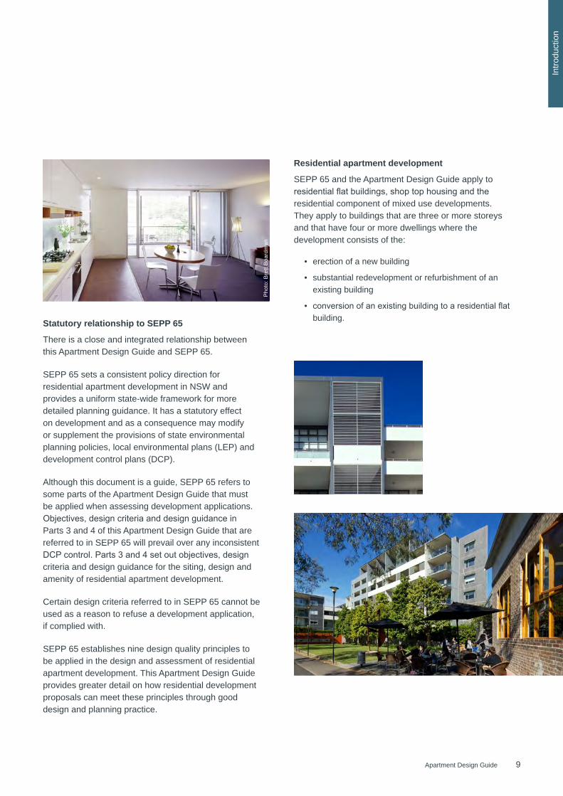
Statutory relationship to SEPP 65
There is a close and integrated relationship between this Apartment Design Guide and SEPP 65.
SEPP 65 sets a consistent policy direction for residential apartment development in NSW and provides a uniform state-wide framework for more detailed planning guidance. It has a statutory effect on development and as a consequence may modify or supplement the provisions of state environmental planning policies, local environmental plans (LEP) and development control plans (DCP).
Although this document is a guide, SEPP 65 refers to some parts of the Apartment Design Guide that must be applied when assessing development applications. Objectives,designcriteriaanddesignguidanceinParts 3 and 4 of this Apartment Design Guide that are referred to in SEPP 65 will prevail over any inconsistent DCPcontrol.Parts3and4setoutobjectives,designcriteria and design guidance for the siting, design and amenity of residential apartment development.
Certain design criteria referred to in SEPP 65 cannot be used as a reason to refuse a development application, if complied with.
SEPP 65 establishes nine design quality principles to be applied in the design and assessment of residential apartment development. This Apartment Design Guide provides greater detail on how residential development proposals can meet these principles through good design and planning practice.
Residential apartment development
SEPP 65 and the Apartment Design Guide apply to residentialflatbuildings,shoptophousingandtheresidential component of mixed use developments. They apply to buildings that are three or more storeys and that have four or more dwellings where the development consists of the:
• erection of a new building
• substantial redevelopment or refurbishment of an existing building
• conversionofanexistingbuildingtoaresidentialflatbuilding.
Pho
to: B
rett
Boa
rdm
an

10 Apartment Design Guide
Intro
duct
ion
How to use this guide
Who is this Apartment Design Guide for?
The Apartment Design Guide provides consistent planning and design standards for residential apartments across NSW. It has been prepared to:
• be a tool for developers, planners, urban designers, architects, landscape architects, builders and other professionals when designing apartments and preparing a development application
• assist planning professionals in local and state government with strategic planning and in the preparation of local controls, design guidelines and the assessment of development proposals.
The Guide will also help to inform the community on what is required to achieve good design and planning practice for residential apartments.
Structure of the Apartment Design Guide
The Apartment Design Guide addresses the design of residential apartment development at the site and individual building scale. It includes the following parts:
Part 1 - Identifying the context
This part introduces generic apartment building types to inform appropriate site, block and building design responses at a strategic level. It outlines the importance of understanding the context, setting, local character, size andconfigurationofadevelopmentsite.Itistobeusedprimarily during the design stage of a development and during the strategic planning process when preparing planning controls.
Part 2 - Developing the controls
This part explains the application of building envelopes andprimarycontrolsincludingbuildingheight,floorspaceratio, building depth, separation and setbacks. It provides tools to support the strategic planning process when preparing planning controls.
Part 3 - Siting the development
This part provides guidance on the design and configurationofapartmentdevelopmentatasitescale.Itoutlines how to relate to the immediate context, consider the interface to neighbours and the public domain, achieve quality open spaces and maximise residential amenity. It is to be used during the design process and in the preparation and assessment of development applications.
Part 4 - Designing the building
This part addresses the design of apartment buildings in more detail. It focuses on building form, layout, functionality, landscape design, environmental performance and residential amenity. It is to be used during the design process and in the preparation and assessment of development applications.
Part 5 – Design review panels
This part explains the role of design review panels in the development assessment process, outlines administrative procedures and provides templates for the successful operation of a panel. It is to be used by councils to administer design review panels at all relevant stages of the development process.
11Apartment Design Guide
Intro
duct
ion
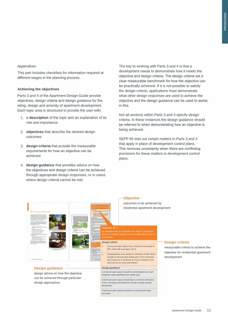
Appendices
This part includes checklists for information required at different stages in the planning process.
Achieving the objectives
Parts 3 and 4 of the Apartment Design Guide provide objectives,designcriteriaanddesignguidanceforthesiting, design and amenity of apartment development. Each topic area is structured to provide the user with:
The key to working with Parts 3 and 4 is that a development needs to demonstrate how it meets the objectiveanddesigncriteria.Thedesigncriteriasetaclearmeasurablebenchmarkforhowtheobjectivecanbe practically achieved. If it is not possible to satisfy the design criteria, applications must demonstrate what other design responses are used to achieve the objectiveandthedesignguidancecanbeusedtoassist.in this.
Not all sections within Parts 3 and 4 specify design criteria. In these instances the design guidance should bereferredtowhendemonstratinghowanobjectiveisbeing achieved.
SEPP 65 sets out certain matters in Parts 3 and 4 that apply in place of development control plans. Thisremovesuncertaintywhenthereareconflictingprovisions for these matters in development control plans.
Objectiveoutcomes to be achieved by residential apartment development
Design criteriameasurable criteria to achieve the objectiveforresidential apartment development
Design guidance designadviceonhowtheobjective can be achieved through particular design approaches
Objective 3D-1An adequate area of communal open space is provided to enhance residential amenity and to provide opportunities for landscaping
Design criteria
1. Communal open space has a minimum area equal to 25%ofthesite(seefigure3D.3)
2. Developments must achieve a minimum of 50% direct sunlight to the principal usable part of the communal open space for a minimum of 2 hours between 9 am and 3 pm on 21 June (mid winter)
Design guidance
Communal open space should be consolidated into a well designed,easilyidentifiedandusablearea
Communal open space should have a minimum dimension of 3m, and larger developments should consider greater dimensions
Communal open space should be co-located with deep soil areas
1.
2.
3.
4.
a description of the topic and an explanation of its role and importance
objectives that describe the desired design outcomes
design criteria that provide the measurable requirementsforhowanobjectivecanbeachieved.
design guidance that provides advice on how theobjectivesanddesigncriteriacanbeachievedthrough appropriate design responses, or in cases where design criteria cannot be met.
12 Apartment Design Guide
Intro
duct
ion
How to use this guide
Principle 1: Context and Neighbourhood Character
Good design responds and contributes to its context. Context is the key natural and built features of an area, their relationship and the character they create when combined. It also includes social, economic, health and environmental conditions.
Responding to context involves identifying the desirable elements of an area’s existing or future character. Well designed buildings respond to and enhance the qualities and identity of the area includingtheadjacentsites,streetscapeandneighbourhood. Consideration of local context is important for all sites, including sites in established areas,thoseundergoingchangeoridentifiedforchange.
Principle 2: Built Form and Scale
Good design achieves a scale, bulk and height appropriate to the existing or desired future character of the street and surrounding buildings.
Good design also achieves an appropriate built form for a site and the building’s purpose in terms of building alignments, proportions, building type, articulation and the manipulation of building elements.Appropriatebuiltformdefinesthepublicdomain, contributes to the character of streetscapes and parks, including their views and vistas, and provides internal amenity and outlook.
Principle 3: Density
Good design achieves a high level of amenity for residents and each apartment, resulting in a density appropriate to the site and its context.
Appropriate densities are consistent with the area’sexistingorprojectedpopulation.Appropriatedensities can be sustained by existing or proposed infrastructure,publictransport,accesstojobs,community facilities and the environment.
Design Quality Principles (SEPP 65)
Development application and assessment process
The Apartment Design Guide provides a resource for pre-development application (pre-DA) discussions between applicants and consent authorities. The guide advocates meetings early on in the design and planning process to focus on how to ensure the best builtformconfiguration,sitinganddesignoutcomes.
Appendix 2 of this guide provides recommendations and a list of suggested documents for pre-DA discussions.
Development application submission requirements for residential apartment developments are set within the Environmental Planning and Assessment Regulation 2000. Residential apartment developments also need to meet the requirements set out in SEPP 65, which includes a suite of nine design quality principles.
The checklist in Appendix 3 of this guide elaborates on the required information for development application submissions and explains the purpose of each item in more detail.
The SEPP 65 design quality principles act as an important link between the provisions of SEPP 65 and the more detailed design guidance contained in this Apartment Design Guide.
Application of the design quality principles
The SEPP 65 design quality principles must be considered by design professionals when designing residential apartment development, by design review panels when giving advice on proposals and by consent authorities.
13Apartment Design Guide
Intro
duct
ion
Principle 4: Sustainability
Good design combines positive environmental, social and economic outcomes. Good sustainable design includes use of natural cross ventilation and sunlight for the amenity and liveability of residents and passive thermal design for ventilation, heating and cooling reducing reliance on technology and operation costs. Other elements include recycling and reuse of materials and waste, use of sustainable materials, and deep soil zones for groundwater recharge and vegetation.
Principle 5: Landscape
Good design recognises that together landscape and buildings operate as an integrated and sustainable system, resulting in attractive developments with good amenity.Apositiveimageandcontextualfitofwelldesigned developments is achieved by contributing to the landscape character of the streetscape and neighbourhood.
Good landscape design enhances the development’s environmental performance by retaining positive natural features which contribute to the local context, co-ordinating water and soil management, solar access, micro-climate, tree canopy, habitat values, and preserving green networks. Good landscape design optimises usability, privacy and opportunities for social interaction, equitable access, respect for neighbours’ amenity, provides for practical establishment and long term management.
Principle 6: Amenity
Gooddesignpositivelyinfluencesinternalandexternalamenity for residents and neighbours. Achieving good amenity contributes to positive living environments and resident well being.
Good amenity combines appropriate room dimensions and shapes, access to sunlight, natural ventilation, outlook, visual and acoustic privacy, storage, indoor andoutdoorspace,efficientlayoutsandserviceareas,and ease of access for all age groups and degrees of mobility.
Principle 7: Safety
Good design optimises safety and security, within the development and the public domain. It provides for quality public and private spaces that are clearlydefinedandfitfortheintendedpurpose.Opportunities to maximise passive surveillance of public and communal areas promote safety.
A positive relationship between public and private spacesisachievedthroughclearlydefinedsecureaccess points and well lit and visible areas that are easily maintained and appropriate to the location and purpose.
Principle 8: Housing Diversity and Social Interaction
Good design achieves a mix of apartment sizes, providing housing choice for different demographics, living needs and household budgets.
Well designed apartment developments respond to social context by providing housing and facilities to suit the existing and future social mix. Good design involvespracticalandflexiblefeatures,includingdifferent types of communal spaces for a broad range of people, providing opportunities for social interaction amongst residents.
Principle 9: Aesthetics
Good design achieves a built form that has good proportions and a balanced composition ofelements,reflectingtheinternallayoutandstructure. Good design uses a variety of materials, colours and textures.
The visual appearance of well designed apartment development responds to the existing or future local context, particularly desirable elements and repetitions of the streetscape.

14 Apartment Design Guide
15Apartment Design Guide
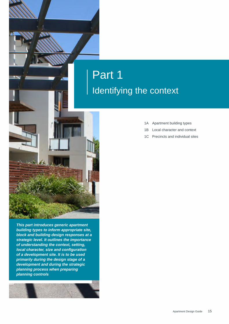
Part 1Identifying the context
This part introduces generic apartment building types to inform appropriate site, block and building design responses at a strategic level. It outlines the importance of understanding the context, setting, local character, size and configuration of a development site. It is to be used primarily during the design stage of a development and during the strategic planning process when preparing planning controls
1A Apartment building types 18
1B Local character and context 22
1C Precincts and individual sites 26
16 Apartment Design Guide
01 I
Con
text
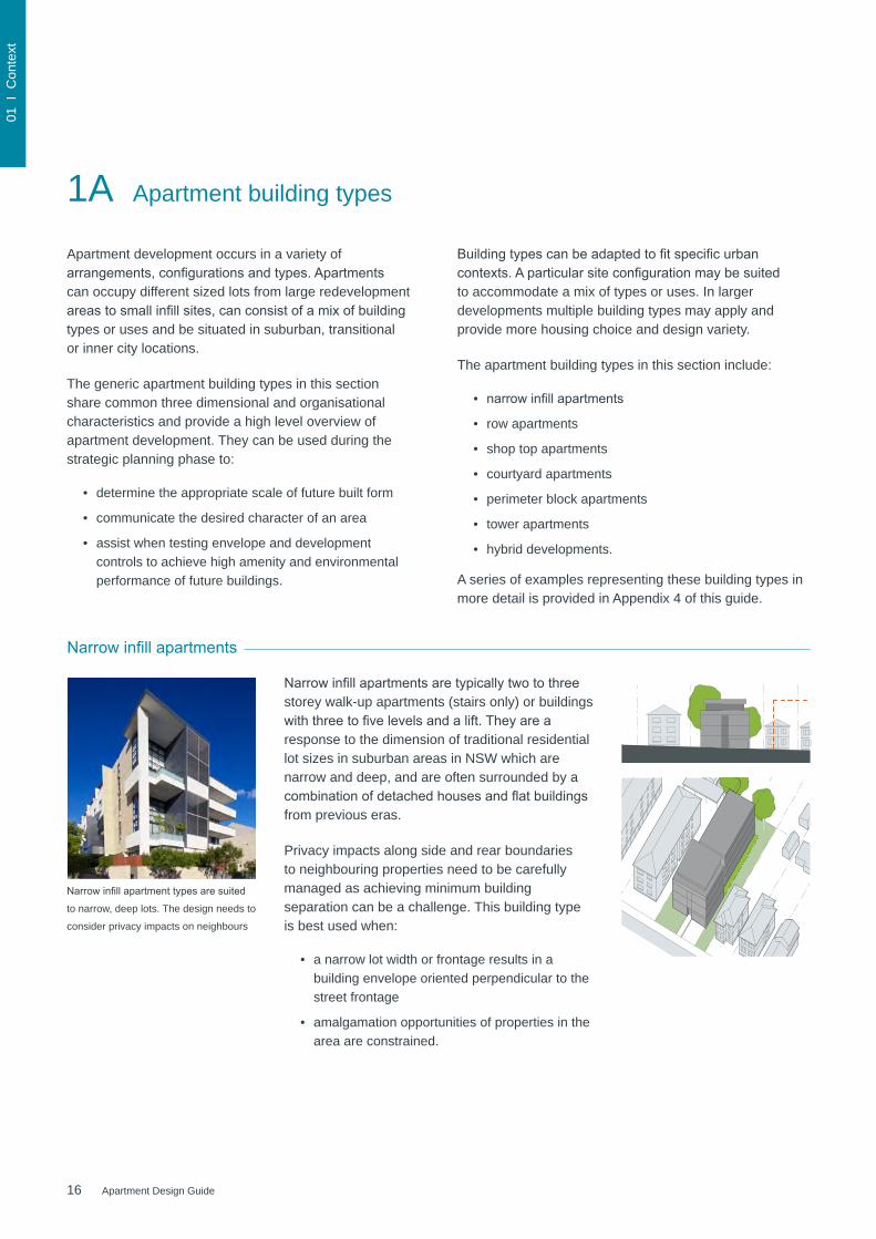
Apartment development occurs in a variety of arrangements,configurationsandtypes.Apartmentscan occupy different sized lots from large redevelopment areastosmallinfillsites,canconsistofamixofbuildingtypes or uses and be situated in suburban, transitional or inner city locations.
The generic apartment building types in this section share common three dimensional and organisational characteristics and provide a high level overview of apartment development. They can be used during the strategic planning phase to:
• determine the appropriate scale of future built form
• communicate the desired character of an area
• assist when testing envelope and development controls to achieve high amenity and environmental performance of future buildings.
1A Apartment building types
Narrowinfillapartments
plan
N
elevation
section
50m0
Narrowinfillapartmentsaretypicallytwotothreestorey walk-up apartments (stairs only) or buildings withthreetofivelevelsandalift.Theyarearesponse to the dimension of traditional residential lot sizes in suburban areas in NSW which are narrow and deep, and are often surrounded by a combinationofdetachedhousesandflatbuildingsfrom previous eras.
Privacy impacts along side and rear boundaries to neighbouring properties need to be carefully managed as achieving minimum building separation can be a challenge. This building type is best used when:
• a narrow lot width or frontage results in a building envelope oriented perpendicular to the street frontage
• amalgamation opportunities of properties in the area are constrained.
Narrowinfillapartmenttypesaresuited
to narrow, deep lots. The design needs to
consider privacy impacts on neighbours
Buildingtypescanbeadaptedtofitspecificurbancontexts.Aparticularsiteconfigurationmaybesuitedto accommodate a mix of types or uses. In larger developments multiple building types may apply and provide more housing choice and design variety.
The apartment building types in this section include:
• narrowinfillapartments
• row apartments
• shop top apartments
• courtyard apartments
• perimeter block apartments
• tower apartments
• hybrid developments.
A series of examples representing these building types in more detail is provided in Appendix 4 of this guide.
17Apartment Design Guide
01 I
Con
text
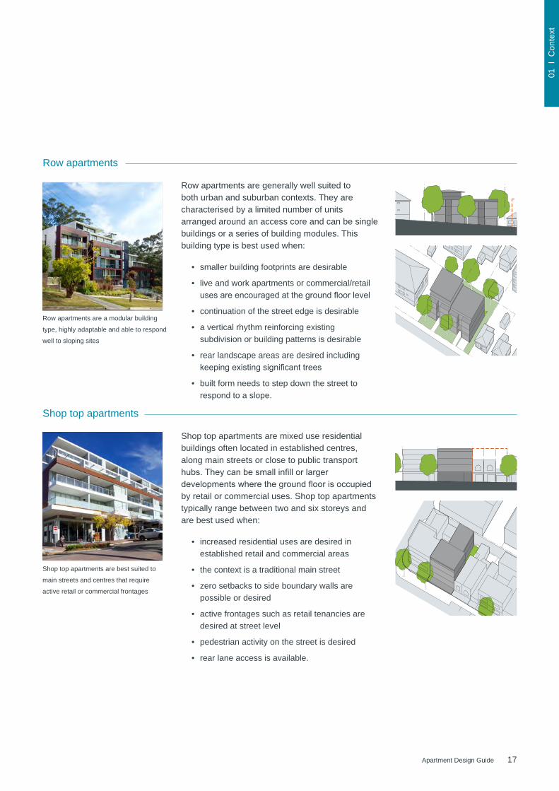
Shop top apartments
Shop top apartments are best suited to
main streets and centres that require
active retail or commercial frontages
Shop top apartments are mixed use residential buildings often located in established centres, along main streets or close to public transport hubs.Theycanbesmallinfillorlargerdevelopmentswherethegroundfloorisoccupiedby retail or commercial uses. Shop top apartments typically range between two and six storeys and are best used when:
• increased residential uses are desired in established retail and commercial areas
• the context is a traditional main street
• zero setbacks to side boundary walls are possible or desired
• active frontages such as retail tenancies are desired at street level
• pedestrian activity on the street is desired
• rear lane access is available.
Row apartments
Row apartments are a modular building
type, highly adaptable and able to respond
well to sloping sites
Row apartments are generally well suited to both urban and suburban contexts. They are characterised by a limited number of units arranged around an access core and can be single buildings or a series of building modules. This building type is best used when:
• smaller building footprints are desirable
• live and work apartments or commercial/retail usesareencouragedatthegroundfloorlevel
• continuation of the street edge is desirable
• a vertical rhythm reinforcing existing subdivision or building patterns is desirable
• rear landscape areas are desired including keepingexistingsignificanttrees
• built form needs to step down the street to respond to a slope.
N
elevation
section
50m0
plan
50m0N
elevation
section
plan
18 Apartment Design Guide
01 I
Con
text
1A Apartment building types
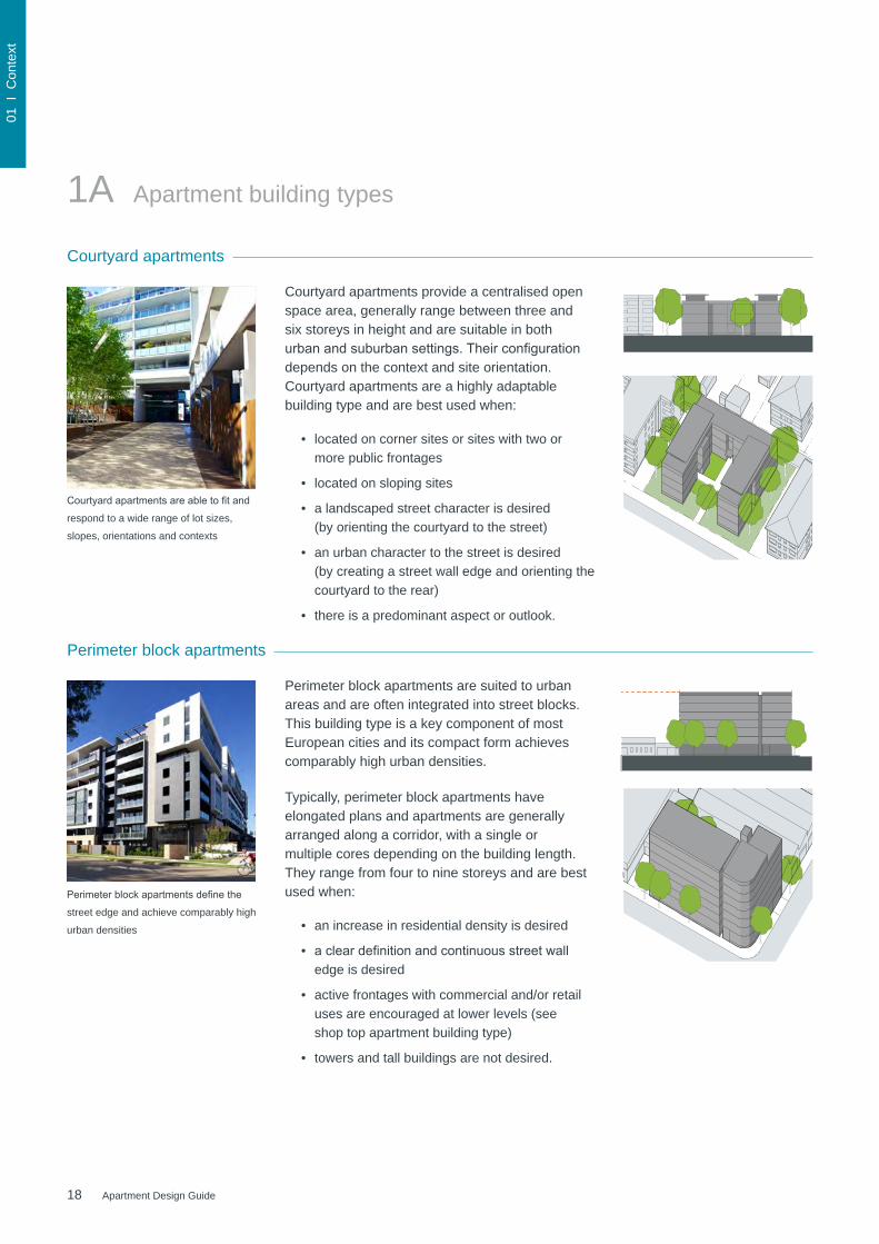
Courtyard apartments
Courtyard apartments provide a centralised open space area, generally range between three and six storeys in height and are suitable in both urbanandsuburbansettings.Theirconfigurationdepends on the context and site orientation. Courtyard apartments are a highly adaptable building type and are best used when:
• located on corner sites or sites with two or more public frontages
• located on sloping sites
• a landscaped street character is desired (by orienting the courtyard to the street)
• an urban character to the street is desired (by creating a street wall edge and orienting the courtyard to the rear)
• there is a predominant aspect or outlook.
Perimeter block apartments are suited to urban areas and are often integrated into street blocks. This building type is a key component of most European cities and its compact form achieves comparably high urban densities.
Typically, perimeter block apartments have elongated plans and apartments are generally arranged along a corridor, with a single or multiple cores depending on the building length. They range from four to nine storeys and are best used when:
• an increase in residential density is desired
• acleardefinitionandcontinuousstreetwalledge is desired
• active frontages with commercial and/or retail uses are encouraged at lower levels (see shop top apartment building type)
• towers and tall buildings are not desired.
N
elevation
section
50m0
plan
Courtyardapartmentsareabletofitand
respond to a wide range of lot sizes,
slopes, orientations and contexts
Perimeterblockapartmentsdefinethe
street edge and achieve comparably high
urban densities
Perimeter block apartments
elevation
section
plan
N 50m0

19Apartment Design Guide
01 I
Con
text
75m0N
plan
elevation
sectionTower apartments
Hybrid developments
Towers are suited to central business districts, majorcentresandurbanrenewalareas.Thisbuilding type can be freestanding or combined with block developments (podiums). The location andsitingneedstoreflectenvironmentalconsiderations such as wind, overshadowing and visual impacts on surrounding properties and the public domain. Tower apartments are typically more than nine storeys and best used when:
• located in dense urban areas
• other towers exist in the surrounding context
• an area requires greater density than can be delivered by perimeter block buildings
• a strong vertical form or landmark is desired.
Hybrid developments combine different uses or building types in one development. They can incorporate community facilities and larger commercialorretailcomponents,suchasofficesor a supermarket.
Hybrid developments are particularly relevant for larger sites that need to respond to a change inbuildingformandscalewithintheadjacentcontext. This approach is best used when:
• located on large and/or irregular shaped sites
• a combination of uses is desired to support active urban areas or centres
• greater diversity of apartment types is desired
• a development needs to address two or more streets with different scales and/or characters.
In commercial centres, tower apartment
types are often combined with a podium
of four to eight storeys
Hybrid development types can respond
to varying site conditions and achieve
interface and future character outcomes
20 Apartment Design Guide
01 I
Con
text
1B Local character and context
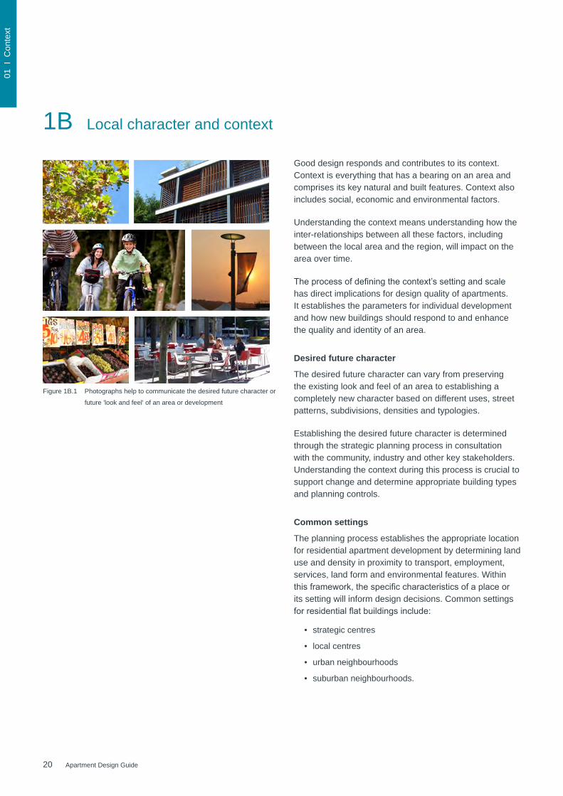
Good design responds and contributes to its context. Context is everything that has a bearing on an area and comprises its key natural and built features. Context also includes social, economic and environmental factors.
Understanding the context means understanding how the inter-relationships between all these factors, including between the local area and the region, will impact on the area over time.
Theprocessofdefiningthecontext’ssettingandscalehas direct implications for design quality of apartments. It establishes the parameters for individual development and how new buildings should respond to and enhance the quality and identity of an area.
Desired future character
The desired future character can vary from preserving the existing look and feel of an area to establishing a completely new character based on different uses, street patterns, subdivisions, densities and typologies.
Establishing the desired future character is determined through the strategic planning process in consultation with the community, industry and other key stakeholders. Understanding the context during this process is crucial to support change and determine appropriate building types and planning controls.
Common settings
The planning process establishes the appropriate location for residential apartment development by determining land use and density in proximity to transport, employment, services, land form and environmental features. Within thisframework,thespecificcharacteristicsofaplaceorits setting will inform design decisions. Common settings forresidentialflatbuildingsinclude:
• strategic centres
• local centres
• urban neighbourhoods
• suburban neighbourhoods.
Figure 1B.1 Photographs help to communicate the desired future character or
future 'look and feel' of an area or development
21Apartment Design Guide
01 I
Con
text
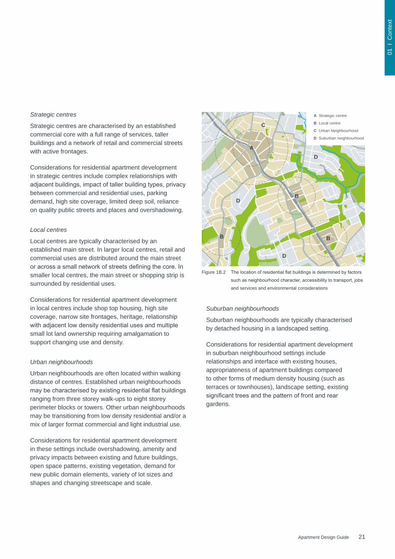
Strategic centres
Strategic centres are characterised by an established commercial core with a full range of services, taller buildings and a network of retail and commercial streets with active frontages.
Considerations for residential apartment development in strategic centres include complex relationships with adjacentbuildings,impactoftallerbuildingtypes,privacybetween commercial and residential uses, parking demand, high site coverage, limited deep soil, reliance on quality public streets and places and overshadowing.
Local centres
Local centres are typically characterised by an established main street. In larger local centres, retail and commercial uses are distributed around the main street oracrossasmallnetworkofstreetsdefiningthecore.Insmaller local centres, the main street or shopping strip is surrounded by residential uses.
Considerations for residential apartment development in local centres include shop top housing, high site coverage, narrow site frontages, heritage, relationship withadjacentlowdensityresidentialusesandmultiplesmall lot land ownership requiring amalgamation to support changing use and density.
Urban neighbourhoods
Urban neighbourhoods are often located within walking distance of centres. Established urban neighbourhoods maybecharacterisedbyexistingresidentialflatbuildingsranging from three storey walk-ups to eight storey perimeter blocks or towers. Other urban neighbourhoods may be transitioning from low density residential and/or a mix of larger format commercial and light industrial use.
Considerations for residential apartment development in these settings include overshadowing, amenity and privacy impacts between existing and future buildings, open space patterns, existing vegetation, demand for new public domain elements, variety of lot sizes and shapes and changing streetscape and scale.
A Strategic centre
B Local centre
C Urban Neighbourhood
D Suburban neighbourhood
A
B
B
B
C
D
D
D
A Strategic centre
B Local centre
C Urban Neighbourhood
D Suburban neighbourhood
A
B
B
B
C
D
D
DFigure 1B.2 Thelocationofresidentialflatbuildingsisdeterminedbyfactors
suchasneighbourhoodcharacter,accessibilitytotransport,jobs
and services and environmental considerations
Suburban neighbourhoods
Suburban neighbourhoods are typically characterised by detached housing in a landscaped setting.
Considerations for residential apartment development in suburban neighbourhood settings include relationships and interface with existing houses, appropriateness of apartment buildings compared to other forms of medium density housing (such as terraces or townhouses), landscape setting, existing significanttreesandthepatternoffrontandreargardens.
22 Apartment Design Guide
01 I
Con
text
1B Local character and context
The range of scales
Apartment development needs to consider a range of scales during the planning and design phase.
Wider scale: The wider scale includes the urban structure, landscape setting and broader land use patterns of thewidercontextandidentifiesthedevelopmentsite’sproximitytocentres,transportandmajorpublicopenspaces. It should also illustrate the future density and proposed change of the area (if known or applicable) and highlightimportantinfrastructuresuchasmajorhospitals,schools and education facilities. Addressing this scale is important for larger precincts and redevelopment sites in particular. As a guide, a radius of 1 to 5 kilometres around the development site should be considered.
Neighbourhood scale: The neighbourhood scale outlines the urban structure including streets and open spaces. It should also include topography contours, drainage and vegetation patterns, services and future infrastructure requirements (if known), land use zones, cadastre boundariesandidentificationofheritageitemsandotherlocal landmarks. It is appropriate to address this scale when planning for individual or small groups of apartment building sites. A radius of 400 metres to 1 kilometre should be considered.
Streetscape scale: The streetscape scale deals with the character of the street(s) that the proposed development addresses, and shows its spatial enclosure by buildings or landscape elements. It should outline surrounding building uses and heights, front setbacks, pedestrian access, awnings, vehicle driveways and public domain elements including street trees, verges and footpaths. It is appropriate that all proposals for apartment buildings address this scale.
Site scale: The site scale involves detailed consideration of the individual development site relative to neighbouring properties, buildings across the street and the public domain. It addresses surrounding and proposed deep soil zones and open spaces, existing vegetation and trees, fences, retaining walls, overshadowing impacts and privacy considerations. This scale should also highlight anyothersitespecificfactorssuchasorientation,slope, geology, infrastructure or access easements and stormwater management.
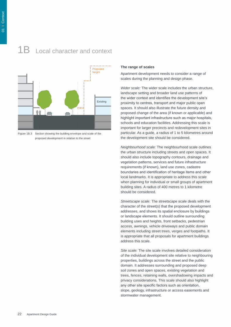
Figure 1B.3 Section showing the building envelope and scale of the
proposed development in relation to the street
Proposed height
Existing

23Apartment Design Guide
01 I
Con
text
400m
wal
king
radi
us
Railway station
Sports fields and reserve
Main street
Local shops
Local shops
Local shops
Hospital
High school
Major road
Major road
Site
Reserve
Grammar school
2km radius
1km radius
Main street
Local street
Local street
Local street
Local street
Local shops
Local shops
Local shops
Local sports reserve
Reserve
Legend
Site boundary
Future planned built form
Existing buildings to change
Existing buildings to remain (1 - 2 stories)
Existing buildings to remain (3 - 6 stories)
Heritage listed buildings
Existing cycle lane
Public open space
Existing trees
Private open space (planned)
Local street
50m
45m
Figure 1B.4 The wider scale should analyse the urban structure and
broader landscape setting and identify the site’s proximity to
centres,transportandmajorpublicopenspaces.Proposals
for larger precincts and redevelopment sites should address
this scale
Figure 1B.5 The neighbourhood scale outlines the urban grid and block
structureincludingstreetsandopenspaces,significant
topography, heritage and civic and community uses. Proposals
for individual or small groups of apartment building sites
should address this scale
Figure 1B.6 The streetscape scale helps understand the impact of
proposed development on streetscape quality and should
show heights, setbacks, driveways and existing street trees. All
proposals should address this scale
Figure 1B.7 The site scale is a detailed analysis of the development's
immediate context and should include the site itself, the street
it addresses and surrounding properties. All proposals should
address this scale
N
N
N
N
24 Apartment Design Guide
01 I
Con
text
1C Precincts and individual sites
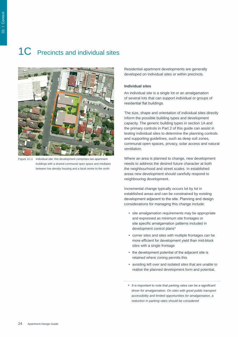
Figure 1C.1 Individual site: this development comprises two apartment
buildings with a shared communal open space and mediates
between low density housing and a local centre to the north
Residential apartment developments are generally developed on individual sites or within precincts.
Individual sites
An individual site is a single lot or an amalgamation of several lots that can support individual or groups of residentialflatbuildings.
The size, shape and orientation of individual sites directly inform the possible building types and development capacity. The generic building types in section 1A and the primary controls in Part 2 of this guide can assist in testing individual sites to determine the planning controls and supporting guidelines, such as deep soil zones, communal open spaces, privacy, solar access and natural ventilation.
Where an area is planned to change, new development needs to address the desired future character at both the neighbourhood and street scales. In established areas new development should carefully respond to neighbouring development.
Incremental change typically occurs lot by lot in established areas and can be constrained by existing developmentadjacenttothesite.Planninganddesignconsiderations for managing this change include:
• site amalgamation requirements may be appropriate and expressed as minimum site frontages or sitespecificamalgamationpatternsincludedindevelopment control plans*
• corner sites and sites with multiple frontages can be moreefficientfordevelopmentyieldthanmid-blocksites with a single frontage
• thedevelopmentpotentialoftheadjacentsiteisretained where zoning permits this
• avoiding left over and isolated sites that are unable to realise the planned development form and potential.
It is important to note that parking rates can be a significant driver for amalgamation. On sites with good public transport accessibility and limited opportunities for amalgamation, a reduction in parking rates should be considered
*

25Apartment Design Guide
01 I
Con
text
Figure 1C.2 Precinct: this precinct plan for the redevelopment provides
a clear structure of new streets, public parklands, adaptive
re-use of former tram sheds and mid block shared communal
open spaces
Precincts
Precincts are characterised by large land parcels or a group of larger sites undergoing extensive change. These sites often need to be restructured to support a change of land use mix, building height and density.
Precinct plans typically incorporate new streets and infrastructure, through-site links and public open spaces that relate in scale, location and character to the local context. The subdivision of large land parcels into smaller onesassistsincreatingafinerurbangrainandachievinggreater diversity in building design. It can also assist with the staging of redevelopment.
Precinct plans provide a number of opportunities including:
• reconnecting parts of the city or town that have previously been isolated
• improving the public domain network and providing more public open space
• incorporating a mix of uses to support more vibrant renewal areas
• integrating heritage and important views within the site or surrounding context
• providing greater housing diversity
• providing space for new community facilities such as recreational centres, libraries and childcare centres
• leveragingefficienciesofscaletodelivermoreeffective environmental measures such as on site energy production, integrated stormwater management and waste water recycling
• supportinggreaterflexibilityinsitelayouttoprovidegreater amenity to individual apartments and open spaces.
Precinct plans establish building envelopes and inform the controls within a local environmental plan and development control plan, against which future development applications are assessed. Indicative plans at both ground and upper levels can assist to describe the expectations of future development types within the envelope providing more certainty for local government, applicants and the community.
Whendeterminingthefloorspaceofaprecinctplan,thenetfloorspaceisbasedonthewholesitearea including streets and open spaces. This will be significantlylowerthanthenetfloorspaceofindividualparcels within the precinct plan (see also section 2D Floor space ratio).
Through the precinct plan design process and the testing of proposed building envelopes against the site constraints, alternative solutions to some of the design criteria in this guide may be appropriate.
Some design criteria may be best applied to the entire precinct area or to stages within the site, for example deep soil and communal open space may be consolidated and accessed by a number of buildings.
Other design criteria associated with the amenity of individual apartments, such as visual privacy, sunlight access and ventilation, are typically applied to each building within the precinct plan.

26 Apartment Design Guide
27Apartment Design Guide
Part 2 Developing the controls
This part explains the application of building envelopes and primary controls including building height, floor space ratio, building depth, separation and setbacks. It provides tools to support the strategic planning process when preparing planning controls
2A Primary controls 30
2B Building envelopes 31
2C Building height 32
2D Floor space ratio 34
2E Building depth 36
2F Building separation 38
2G Street setbacks 40
2H Side and rear setbacks 42

28 Apartment Design Guide
02 I
Con
trols
2A Primary controls
Primary development controls are the key planning tool used to manage the scale of development so that it relates to the context and desired future character of an area and manages impacts on surrounding development.
Primary development controls include building height,floorspaceratio,buildingdepth,building separation and setbacks (refer to in sections 2C-2H). When applied together, the primary development controls create a building envelope, which forms the three dimensional volume where development should occur.
Setting and testing the controls
Primary controls should be developed taking into account sunlight and daylight access, orientation and overshadowing, natural ventilation, visual and acoustic privacy, ceiling heights, communal open space, deep soil zones, public domain interface, noise and pollution.
The controls must be carefully tested to ensure they are co-ordinated and that the desired built form outcome is achievable. They should ensure the desired density and massing can be accommodated within the building height and setback controls.
The rationale for setting primary controls needs to be explained to the community, applicants and practitioners.
Figure 2A.1 Key considerations when testing development controls and establishing a
three-dimensional building envelope
1. Retention of trees
3. Deep soil zones and basement levels
5. Building performance and orientation
2. Minimum setbacks
4. Building separation and depth
6. Three-dimensional building envelope
29Apartment Design Guide
02 I
Con
trols
2B Building envelopes
Stre
et
Foot
path
Site
bou
ndar
y
Building envelope
Site
bou
ndar
y
Building envelope
Building envelope
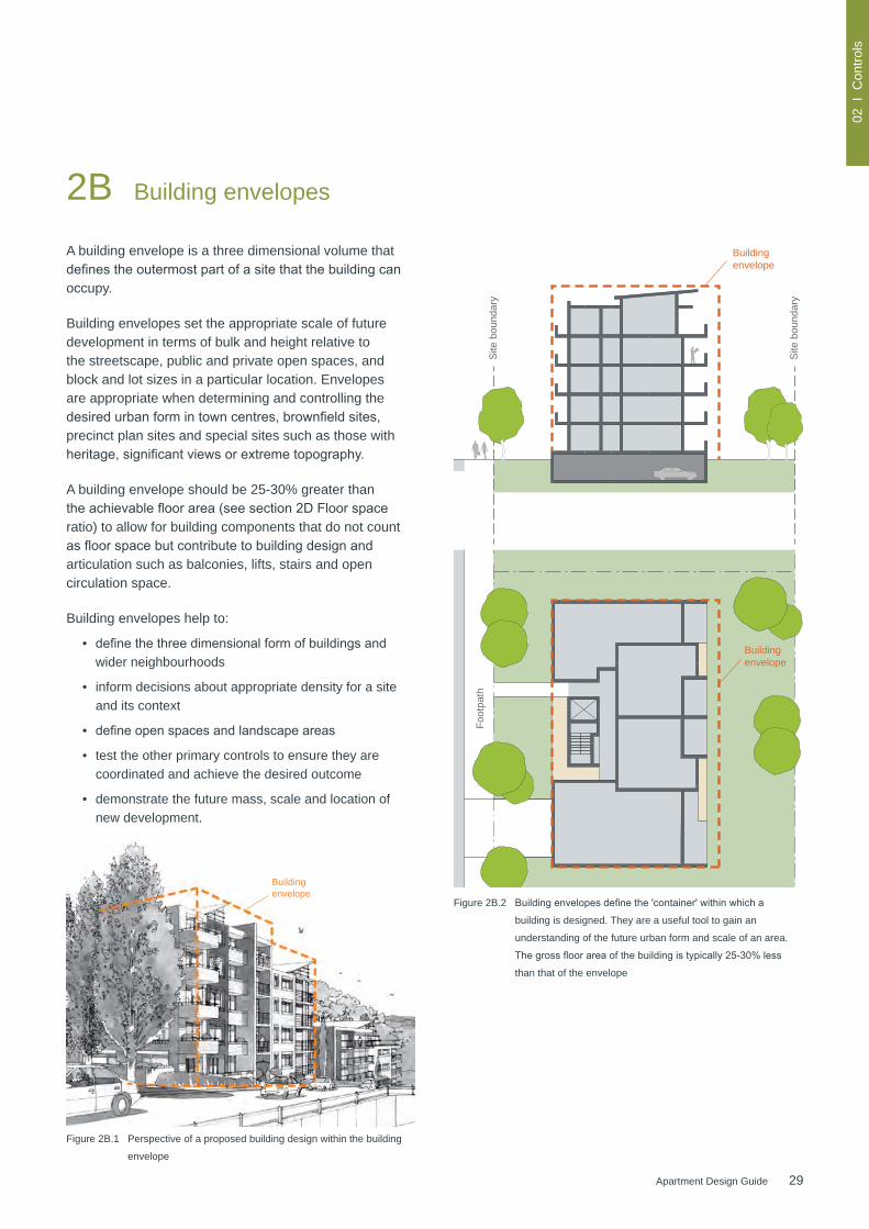
Figure 2B.1 Perspective of a proposed building design within the building
envelope
Figure 2B.2 Buildingenvelopesdefinethe'container'withinwhicha
building is designed. They are a useful tool to gain an
understanding of the future urban form and scale of an area.
Thegrossfloorareaofthebuildingistypically25-30%less
than that of the envelope
A building envelope is a three dimensional volume that definestheoutermostpartofasitethatthebuildingcanoccupy.
Building envelopes set the appropriate scale of future development in terms of bulk and height relative to the streetscape, public and private open spaces, and block and lot sizes in a particular location. Envelopes are appropriate when determining and controlling the desiredurbanformintowncentres,brownfieldsites,precinct plan sites and special sites such as those with heritage,significantviewsorextremetopography.
A building envelope should be 25-30% greater than theachievablefloorarea(seesection2DFloorspaceratio) to allow for building components that do not count asfloorspacebutcontributetobuildingdesignandarticulation such as balconies, lifts, stairs and open circulation space.
Building envelopes help to:
• definethethreedimensionalformofbuildingsandwider neighbourhoods
• inform decisions about appropriate density for a site and its context
• defineopenspacesandlandscapeareas
• test the other primary controls to ensure they are coordinated and achieve the desired outcome
• demonstrate the future mass, scale and location of new development.
30 Apartment Design Guide
02 I
Con
trols
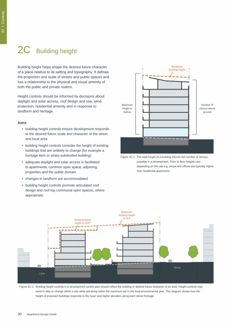
Building height helps shape the desired future character ofaplacerelativetoitssettingandtopography.Itdefinesthe proportion and scale of streets and public spaces and has a relationship to the physical and visual amenity of both the public and private realms.
Height controls should be informed by decisions about daylight and solar access, roof design and use, wind protection, residential amenity and in response to landform and heritage.
Aims• building height controls ensure development responds
to the desired future scale and character of the street and local area
• building height controls consider the height of existing buildings that are unlikely to change (for example a heritage item or strata subdivided building)
• adequate daylight and solar access is facilitated toapartments,commonopenspace,adjoiningproperties and the public domain
• changes in landform are accommodated
• building height controls promote articulated roof design and roof top communal open spaces, where appropriate.
2C Building height
Number of storeys above
ground
Figure 2C.1 The total height of a building informs the number of storeys
possibleinadevelopment.Floortofloorheightsvary
dependingontheusee.g.shopsandofficesaretypicallyhigher
than residential apartments
Maximum height in metres
Maximum building height
Figure 2C.2 Buildingheightcontrolsinadevelopmentcontrolplanshouldreflecttheexistingordesiredfuturecharacterofanarea.Heightcontrolsmay
need to step or change within a site while still being within the maximum set in the local environmental plan. This diagram shows how the
height of proposed buildings responds to the lower and higher densities along each street frontage
Street
Lane
Maximum building height
in LEPVaried building height in DCP
31Apartment Design Guide
02 I
Con
trols
Site
12-18m
Varied building height in DCP
Maximum building height
in LEP
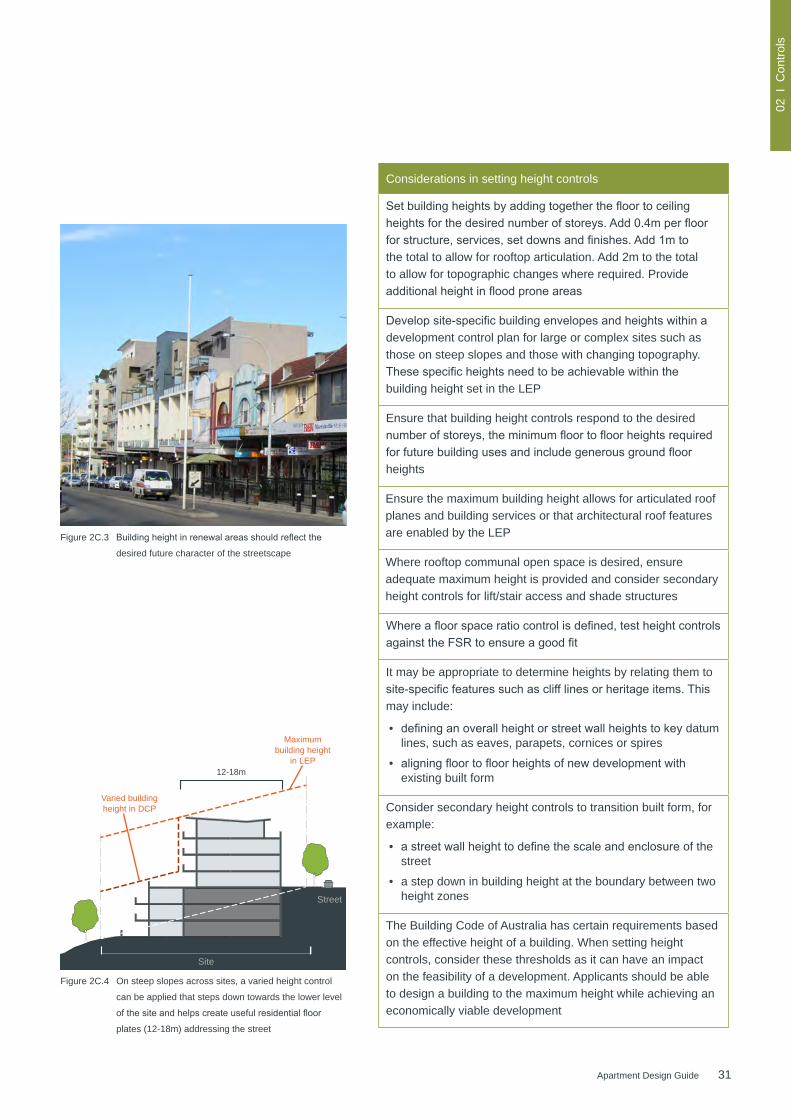
Figure 2C.3 Buildingheightinrenewalareasshouldreflectthe
desired future character of the streetscape
Considerations in setting height controls
Setbuildingheightsbyaddingtogetherthefloortoceilingheightsforthedesirednumberofstoreys.Add0.4mperfloorforstructure,services,setdownsandfinishes.Add1mtothe total to allow for rooftop articulation. Add 2m to the total to allow for topographic changes where required. Provide additionalheightinfloodproneareas
Developsite-specificbuildingenvelopesandheightswithinadevelopment control plan for large or complex sites such as those on steep slopes and those with changing topography. Thesespecificheightsneedtobeachievablewithinthebuilding height set in the LEP
Ensure that building height controls respond to the desired numberofstoreys,theminimumfloortofloorheightsrequiredforfuturebuildingusesandincludegenerousgroundfloorheights
Ensure the maximum building height allows for articulated roof planes and building services or that architectural roof features are enabled by the LEP
Where rooftop communal open space is desired, ensure adequate maximum height is provided and consider secondary height controls for lift/stair access and shade structures
Whereafloorspaceratiocontrolisdefined,testheightcontrolsagainsttheFSRtoensureagoodfit
It may be appropriate to determine heights by relating them to site-specificfeaturessuchasclifflinesorheritageitems.Thismay include:
• defininganoverallheightorstreetwallheightstokeydatum lines, such as eaves, parapets, cornices or spires
• aligningfloortofloorheightsofnewdevelopmentwithexisting built form
Consider secondary height controls to transition built form, for example:
• astreetwallheighttodefinethescaleandenclosureof the street
• a step down in building height at the boundary between two height zones
The Building Code of Australia has certain requirements based on the effective height of a building. When setting height controls, consider these thresholds as it can have an impact on the feasibility of a development. Applicants should be able to design a building to the maximum height while achieving an economically viable development
Figure 2C.4 On steep slopes across sites, a varied height control
can be applied that steps down towards the lower level
ofthesiteandhelpscreateusefulresidentialfloor
plates (12-18m) addressing the street
Street

32 Apartment Design Guide
02 I
Con
trols
2D Floor space ratio
Floor space ratio (FSR) is the relationship of the total grossfloorarea(GFA)ofabuildingrelativetothetotal site area it is built on. It indicates the intended density. FSR is a widely used method for estimating the development potential of a site.
However, it is important to note that FSR controls set the theoretical maximum capacity. It may not always bepossibletoreachthemaximumallowablefloorspace due to other development controls or constraints specifictothesitesuchaslotsizeorshape,existinglandscape features, neighbouring properties or heritage considerations.
FSR is not a measure of the maximum capacity of the building envelope. The envelope provides an overall parameter for the design of the development. The allowablegrossfloorareashouldonly‘fill’approximately70% of the building envelope (see section 2B Building envelopes). In new urban areas or where an existing neighbourhood is undergoing change, building envelopes should be tested prior to setting FSR controls.
Aims• ensure that development aligns with the optimum
capacity of the site and the desired density of the local area
• provide opportunities for building articulation and creativity within a building envelope by carefully settingtheallowablefloorspace.
Figure 2D.1 Indicativebuiltformmassingforresidentialflatbuildingswith
differentfloorspaceratios
Approx. 1:1 FSR
3 storeys
Approx. 2:1 FSR
6-7 storeys
Approx. 3:1 FSR
9-12 storeys
33Apartment Design Guide
02 I
Con
trols
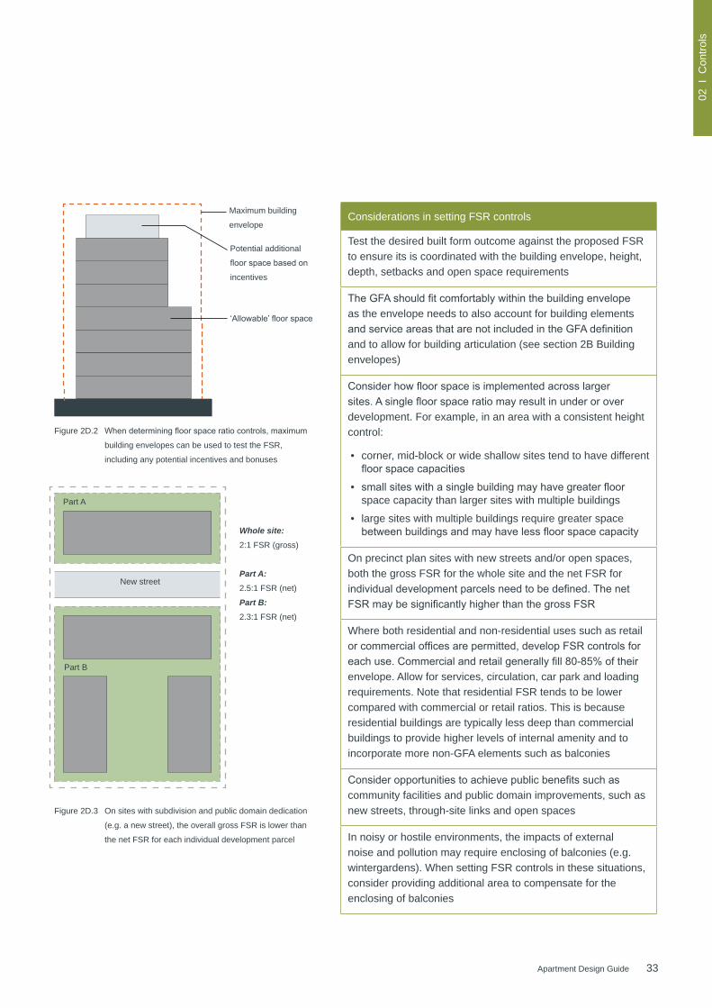
Figure 2D.2 Whendeterminingfloorspaceratiocontrols,maximum
building envelopes can be used to test the FSR,
including any potential incentives and bonuses
Whole site:2:1 FSR (gross)
Part A: 2.5:1 FSR (net)
Part B:2.3:1 FSR (net)
New street
Part A
Maximum building
envelope
Potential additional
floorspacebasedon
incentives
‘Allowable’floorspace
Figure 2D.3 On sites with subdivision and public domain dedication
(e.g. a new street), the overall gross FSR is lower than
the net FSR for each individual development parcel
Considerations in setting FSR controls
Test the desired built form outcome against the proposed FSR to ensure its is coordinated with the building envelope, height, depth, setbacks and open space requirements
TheGFAshouldfitcomfortablywithinthebuildingenvelopeas the envelope needs to also account for building elements andserviceareasthatarenotincludedintheGFAdefinitionand to allow for building articulation (see section 2B Building envelopes)
Considerhowfloorspaceisimplementedacrosslargersites.Asinglefloorspaceratiomayresultinunderoroverdevelopment. For example, in an area with a consistent height control:
• corner, mid-block or wide shallow sites tend to have different floorspacecapacities
• smallsiteswithasinglebuildingmayhavegreaterfloorspace capacity than larger sites with multiple buildings
• large sites with multiple buildings require greater space betweenbuildingsandmayhavelessfloorspacecapacity
On precinct plan sites with new streets and/or open spaces, both the gross FSR for the whole site and the net FSR for individualdevelopmentparcelsneedtobedefined.ThenetFSRmaybesignificantlyhigherthanthegrossFSR
Where both residential and non-residential uses such as retail orcommercialofficesarepermitted,developFSRcontrolsforeachuse.Commercialandretailgenerallyfill80-85%oftheirenvelope. Allow for services, circulation, car park and loading requirements. Note that residential FSR tends to be lower compared with commercial or retail ratios. This is because residential buildings are typically less deep than commercial buildings to provide higher levels of internal amenity and to incorporate more non-GFA elements such as balconies
Consideropportunitiestoachievepublicbenefitssuchascommunity facilities and public domain improvements, such as new streets, through-site links and open spaces
In noisy or hostile environments, the impacts of external noise and pollution may require enclosing of balconies (e.g. wintergardens). When setting FSR controls in these situations, consider providing additional area to compensate for the enclosing of balconies
Part B

34 Apartment Design Guide
02 I
Con
trols
2E Building depth
Building depth is an important tool for determining the development capacity of a site. It is the overall cross section dimension of a building envelope. Building depth dimensionstypicallyincludearticulationsuchasprojectingbalconies, gallery access, eaves, overhangs, sun hoods, blades and other architectural features.
Buildingdepthinfluencesbuildingcirculationandconfigurationandhasadirectrelationshiptointernalresidential amenity by determining room depths, which inturninfluencesaccesstolightandair.Forresidentialdevelopment in general, narrower building depths have a greater potential to achieve optimal natural ventilation and daylightaccessthandeeperfloorplates.Depthsofmixeduse buildings transition from deeper commercial and retail uses at the lower levels to narrower building depths for the residential uses at upper levels.
Aims• ensure that the bulk of the development relates to the
scale of the desired future context
• ensure building depths support apartment layouts thatmeettheobjectives,designcriteriaanddesignguidance within the Apartment Design Guide.
Figure 2E.1 A mixed used building showing the transition of building depth:
deeperfloorsonlowerlevelsdedicatedtoretail/commercialuses
and narrower residential apartments on upper levels
Overall building depth
Residential component building depth
Residential
Commercial
Car parking Retail

35Apartment Design Guide
02 I
Con
trols
Considerations in setting building depth controls
Use a range of appropriate maximum apartment depths of 12-18m from glass line to glass line when precinct planning and testing development controls. This will ensure that apartments receive adequate daylight and natural ventilation and optimise natural cross ventilation
Testbuildingdepthsagainstindicativefloorplateandapartment layouts to ensure they can meet natural ventilation and sunlight requirements
Site constraints may require varied building depths to achieve good levels of residential amenity for residents and neighbours
Consider varying building depth relative to orientation. For example, buildings facing east-west capture sun from both aspects and may have apartments of up to 18m wide (if dual aspect), while buildings facing north-south should be narrower to reduce the number of south facing apartments that have limited or no direct sunlight access (consider relationship with section 4A Solar and daylight access)
Where greater depths are proposed, demonstrate that indicative layouts can achieve acceptable amenity with room andapartmentdepths.Thismayrequiresignificantbuildingarticulation and increased perimeter wall length
Coordinate building height and building depth:
• buildings that have smaller depths over a greater height deliver better residential amenity than those with greater depth and a lower height
• greater building depths may be possible where higher ceiling heights are provided, for example adaptive reuse of an existing building (see 4D Apartment size and layout)
For mixed use buildings, align building depth to the likely future uses. For example, transition deeper commercial or retail podium levels to a narrower residential tower above. For precinct planning, if the intended building use changes, the building depth needs to change accordingly
Set the depth control in metres. The building depth includes theinternalfloorplate,externalwalls,balconies,externalcirculation and articulation such as recesses and steps in plan and section
Building depth
Building depth
Building depth
Figure 2E.3 Building depth dimensions should include articulation
suchasprojectingbalconies,galleryaccess,overhangs,
blades and other architectural features
Figure 2E.2 These examples show how to measure building depth
for different apartment building shapes

36 Apartment Design Guide
02 I
Con
trols
2F Building separation
Building separation is the distance measured between building envelopes or buildings. Separation between buildings contributes to the urban form of an area and the amenity within apartments and open space areas.
Amenity is improved through establishing minimum distances between apartments within the site, between apartments and non-residential uses and with boundaries to neighbours. Building separation ensures communal and private open spaces can have useable space with landscaping, deep soil and adequate sunlight and privacy. Within apartments, building separation assists with visual and acoustic privacy, outlook, natural ventilation and daylight access.
Buildingseparationcontrolsshouldbesetinconjunctionwith height controls and controls for private/communal open space and visual and acoustic privacy.
Aims• ensure that new development is scaled to support the
desired future character with appropriate massing and spaces between buildings
• assist in providing residential amenity including visual and acoustic privacy, natural ventilation, sunlight and daylight access and outlook
• provide suitable areas for communal open spaces, deep soil zones and landscaping.
Req
uire
d si
de s
etba
ck
Req
uire
d si
de s
etba
ck (i
f red
evel
oped
)
Building separation
Figure 2F.1 Building separation is measured from the outer face of
building envelopes which includes balconies
Figure 2F.2 In areas undergoing transition from low density to higher
densities, minimum building separation distances may not
be achieved until the area completes its transition
37Apartment Design Guide
02 I
Con
trols
Considerations in setting building separation controls
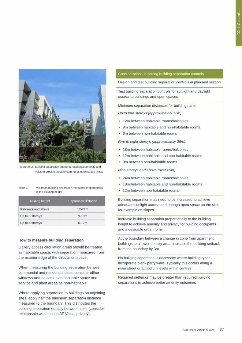
Design and test building separation controls in plan and section
Test building separation controls for sunlight and daylight access to buildings and open spaces
Minimum separation distances for buildings are:
Up to four storeys (approximately 12m):
• 12m between habitable rooms/balconies
• 9m between habitable and non-habitable rooms
• 6m between non-habitable rooms
Five to eight storeys (approximately 25m):
• 18m between habitable rooms/balconies
• 12m between habitable and non-habitable rooms
• 9m between non-habitable rooms
Nine storeys and above (over 25m):
• 24m between habitable rooms/balconies
• 18m between habitable and non-habitable rooms
• 12m between non-habitable rooms
Building separation may need to be increased to achieve adequate sunlight access and enough open space on the site, for example on slopes
Increase building separation proportionally to the building height to achieve amenity and privacy for building occupants and a desirable urban form
At the boundary between a change in zone from apartment buildings to a lower density area, increase the building setback from the boundary by 3m
No building separation is necessary where building types incorporate blank party walls. Typically this occurs along a main street or at podium levels within centres
Required setbacks may be greater than required building separations to achieve better amenity outcomes
How to measure building separation
Gallery access circulation areas should be treated as habitable space, with separation measured from the exterior edge of the circulation space.
When measuring the building separation between commercialandresidentialuses,considerofficewindows and balconies as habitable space and service and plant areas as non-habitable.
Whereapplyingseparationtobuildingsonadjoiningsites, apply half the minimum separation distance measured to the boundary. This distributes the building separation equally between sites (consider relationship with section 3F Visual privacy).
Figure 2F.3 Building separation supports residential amenity and
helps to provide suitable communal open space areas
Table 1 Minimum building separation increases proportionally to the building height
Building height Separation distance
9 storeys and above 12-24m
Up to 8 storeys 9-18m
Up to 4 storeys 6-12m
38 Apartment Design Guide
02 I
Con
trols
2G Street setbacks
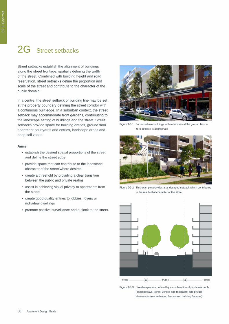
Street setbacks establish the alignment of buildings alongthestreetfrontage,spatiallydefiningthewidthof the street. Combined with building height and road reservation,streetsetbacksdefinetheproportionandscale of the street and contribute to the character of the public domain.
In a centre, the street setback or building line may be set atthepropertyboundarydefiningthestreetcorridorwitha continuous built edge. In a suburban context, the street setback may accommodate front gardens, contributing to the landscape setting of buildings and the street. Street setbacksprovidespaceforbuildingentries,groundfloorapartment courtyards and entries, landscape areas and deep soil zones.
Aims• establish the desired spatial proportions of the street anddefinethestreetedge
• provide space that can contribute to the landscape character of the street where desired
• create a threshold by providing a clear transition between the public and private realms
• assist in achieving visual privacy to apartments from the street
• create good quality entries to lobbies, foyers or individual dwellings
• promote passive surveillance and outlook to the street.
Figure 2G.1 Formixedusebuildingswithretailusesatthegroundfloora
zero setback is appropriate
Figure 2G.2 This example provides a landscaped setback which contributes
to the residential character of the street
Private PrivatePublic
Figure 2G.3 Streetscapesaredefinedbyacombinationofpublicelements
(carriageways, kerbs, verges and footpaths) and private
elements (street setbacks, fences and building facades)

39Apartment Design Guide
02 I
Con
trols
2. Variation for angled subdivision
3. Setback range
4. Building line
Figure 2G.4 Street setbacks should be consistent with existing
setback patterns in the street or setbacks that achieve
the desired future character of the area
1. Predominant setbackConsiderations in setting street setback controls
Determine street setback controls relative to the desired streetscape and building forms, for example:
• defineafuturestreetscapewiththefrontbuildingline
• match existing development
• step back from special buildings
• retainsignificanttrees
• in centres the street setback may need to be consistent to reinforce the street edge
• consider articulation zones accommodating balconies, landscaping etc. within the street setback
• use a setback range where the desired character is for variation within overall consistency, or where subdivision is at an angle to the street
• manage corner sites and secondary road frontages
Align street setbacks with building use. For example in mixed use buildings a zero street setback is appropriate
Consider nominating a maximum percentage of development that may be built to the front build-to line, where one is set, to ensure modulated frontages along the length of buildings
Identify the quality, type and use of open spaces and landscaped areas facing the street so setbacks can accommodate landscaping and private open space
Inconjunctionwithheightcontrols,considersecondaryupperlevel setbacks to:
• reinforce the desired scale of buildings at the street frontage
• minimise overshadowing of the street and other buildings
To improve passive surveillance, promote setbacks which ensure a person on a balcony or at a window can easily see the street
Consider increased setbacks where street or footpath widening is desired
40 Apartment Design Guide
02 I
Con
trols
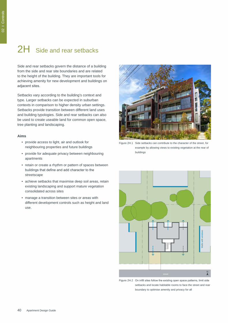
2H Side and rear setbacks
Side and rear setbacks govern the distance of a building from the side and rear site boundaries and are related to the height of the building. They are important tools for achieving amenity for new development and buildings on adjacentsites.
Setbacks vary according to the building’s context and type. Larger setbacks can be expected in suburban contexts in comparison to higher density urban settings. Setbacks provide transition between different land uses and building typologies. Side and rear setbacks can also be used to create useable land for common open space, tree planting and landscaping.
Aims• provide access to light, air and outlook for
neighbouring properties and future buildings
• provide for adequate privacy between neighbouring apartments
• retain or create a rhythm or pattern of spaces between buildingsthatdefineandaddcharactertothestreetscape
• achieve setbacks that maximise deep soil areas, retain existing landscaping and support mature vegetation consolidated across sites
• manage a transition between sites or areas with different development controls such as height and land use.
Building separation
Rear setback
Side setback
Wal
ls w
ith w
indo
ws
Wal
ls w
ith w
indo
ws
Wal
ls w
ith w
indo
ws
street
street
Figure 2H.1 Side setbacks can contribute to the character of the street, for
example by allowing views to existing vegetation at the rear of
buildings
N
Figure 2H.2 Oninfillsitesfollowtheexistingopenspacepatterns,limitside
setbacks and locate habitable rooms to face the street and rear
boundary to optimise amenity and privacy for all
41Apartment Design Guide
02 I
Con
trols
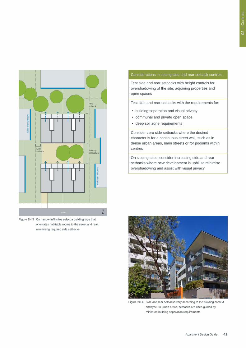
Figure 2H.3 Onnarrowinfillsitesselectabuildingtypethat
orientates habitable rooms to the street and rear,
minimising required side setbacks
Building separation
Rear setback
Side setback
Wal
ls w
ith w
indo
ws
Wal
ls w
ith w
indo
ws
Wal
ls w
ith w
indo
ws
street
street
Figure 2H.4 Side and rear setbacks vary according to the building context
and type. In urban areas, setbacks are often guided by
minimum building separation requirements
Considerations in setting side and rear setback controls
Test side and rear setbacks with height controls for overshadowingofthesite,adjoiningpropertiesandopen spaces
Test side and rear setbacks with the requirements for:
• building separation and visual privacy
• communal and private open space
• deep soil zone requirements
Consider zero side setbacks where the desired character is for a continuous street wall, such as in dense urban areas, main streets or for podiums within centres
On sloping sites, consider increasing side and rear setbacks where new development is uphill to minimise overshadowing and assist with visual privacy
N

42 Apartment Design Guide
43Apartment Design Guide
Part 3 Siting the development
This part provides guidance on the design and configuration of apartment development at a site scale. Objectives, design criteria and design guidance outline how to relate to the immediate context, consider the interface to neighbours and the public domain, achieve quality open spaces and maximise residential amenity. It is to be used during the design process and in the preparation and assessment of development applications
3A Site analysis 46
3B Orientation 50
3C Public domain interface 52
3D Communal and public open space 56
3E Deep soil zones 62
3F Visual privacy 64
3G Pedestrian access and entries 68
3H Vehicle access 70
3J Bicycle and car parking 72

44 Apartment Design Guide
03 I
Siti
ng
3A Site analysis
3. Local context plan
Plan drawing(s) of the existing features of the local context including relevant sections and elevations should also be provided, especially for sloping sites. Information may include but is not limited to:
• landuse,heightandtypologyofadjacentandoppositebuildings in the street
• views to and from the site
• circulation patterns and access for pedestrians, vehicles and servicing
• location of heritage items and areas of environmental significance
• patterns of buildings, open spaces and vegetation
• significantnoisesourcesonandnearthesite,particularlyroads, rail, aircraft and industrial noise
• building envelopes and setbacks for future development
• a written statement of key issues.
4. Site context and survey plan
Plan and section drawings of existing site features including propertiesthatareadjoiningandontheothersideofthestreet, together with appropriate written material. Information may include but is not limited to:
• site dimensions, site areas and north point
• topography showing spot levels and contours at 0.5m intervals, any unique natural features such as rock outcropsorwatercoursesandclearlyidentifyadjoiningstreetsandlandadjoiningthesite
• locationofmajortreesonsiteandadjacentpropertiesincludingidentificationofcanopysizeandspecies
• location and use of any existing buildings or built features on the site
• locationandimportantcharacteristicsofadjacentpublic,communal and private open spaces
• location and height of existing windows, balconies, walls andfencesonadjacentproperties,aswellasparapetandridge lines
• pedestrian and vehicular access points
• location of utility services including electricity poles, substation kiosks, stormwater drainage, natural drainage, kerb crossings and easements.
Wider context
Local context
Site context
Site
Site analysis is an important part of the design process andshouldbeundertakenattheoutsetofaprojecttoinform the design principles. Development proposals need to illustrate that design decisions are based on careful analysis of the site conditions and relationship to the surrounding context.
By describing the physical elements of the locality and the conditions impacting on the site, opportunities and constraints for future apartment development can beidentifiedandaddressedinthedesign.Itmaybebeneficialtoundertakeasiteanalysisincollaborationwith technical consultants, depending on the nature of the site and scale of development.
The key elements of a site analysis include:
1. Site location plan
Aplanshowingthewidercontextthatidentifiesthesitein relation to retail and commercial areas, community facilities and transport.
2. Aerial photograph
A colour aerial photograph of the development site and surrounding context.
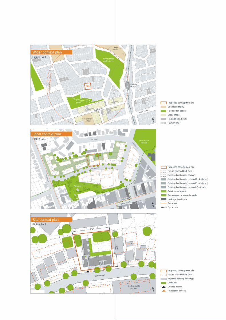
45Apartment Design Guide
03 I
Siti
ng
45Apartment Design Guide
Main street
Local street
Local street
Local street
Local street
Local shops
Local shops
Local shops
Local sports reserve
Reserve
400m
wal
king
radi
us
Railway station
Sports fields and reserve
Main street
Local shops
Local shops
Local shops
Hospital
High school
Major road
Major road
Site
Reserve
Grammar school
Legend
Site boundary
Future planned built form
Existing buildings to change
Existing buildings to remain (1 - 2 stories)
Existing buildings to remain (3 - 6 stories)
Heritage listed buildings
Existing cycle lane
Public open space
Existing trees
Private open space (planned)
Wider context plan
Local context plan
Site context plan
Proposed development site
Future planned built form
Adjacentexistingbuildings
Deep soil
Vehicle access
Pedestrian access
Proposed development site
Future planned built form
Existing buildings to change
Existing buildings to remain (1 - 2 stories)
Existing buildings to remain (3 - 4 stories)
Existing buildings to remain (+5 stories)
Public open space
Private open space (planned)
Heritage listed item
Bus route
Cycle lane
Existing public car park
Local street
50m
N
N
N
Figure 3A.1
Figure 3A.2
Figure 3A.3
45m
Proposed development site
Education facility
Public open space
Local shops
Heritage listed item
Railway line

46 Apartment Design Guide
03 I
Siti
ng
5. Streetscape elevations and sections
Photographs and drawings of nearby existing buildings help explain the existing scale of the area, the spacing of development and the local architectural character. Information may include but is not limited to:
• streetscape showing both sides of any street that the development fronts including the patterns of building frontages, street and side setbacks
• adjacentbuildingsshowingoverallheight(inmetresand storeys) and important parapet and datum lines, awnings, colonnades and other building elements
• planned heights or building envelopes
• a written statement of key issues.
6. Analysis
These plans and sections synthesise and interpret the context, streetscape and site documentation into opportunities and constraints that generate design parameters. Analysis information may include:
• overshadowingofthesiteandadjoiningpropertiesbyneighbouring structures. The winter sun path should be shown from 9 am to 3 pm on 21 June
• direction of prevailing wind
• geotechnical characteristics of the site including topography, and how this relates to the proposed development
• public domain interface and street setback
• relationshiptoandinterfacewithadjacentproperties,including side and rear setbacks
• orientation including solar access and ventilation
• building footprint location
• retained trees and tree protection zones
• proposed trees and deep soil zones
• communal open space location
• building entries
• car park footprint and depth.
3A Site analysis
Winter sun path
Local street
Afternoonsun
Morningsun
Prevailing wind (summer)
Solar and wind access
Figure 3A.4 Analysis of solar and wind access
Proposed development site
Proposed built form
AdjacentexistingbuildingsN

47Apartment Design Guide
03 I
Siti
ng
47Apartment Design Guide
Figure 3A.5 Cross section
Figure 3A.6 Streetscape elevation
A written statement explaining how the design of the proposed development has responded to the site analysis must accompany the development application. Where relevant, this should include technical advice from landscape architects, contamination specialists, geotechnical engineers and arborists.
See Appendix 1 Site Analysis Checklist, Appendix 2 Pre-development application design proposal check sheet and Appendix 3 Development Application Recommended Documentation Checklist.
Objective 3A-1 Site analysis illustrates that design decisions have been based on opportunities and constraints of the site conditions and their relationship to the surrounding context
Design guidance
Each element in the Site Analysis Checklist should be addressed (see Appendix 1)
Future development
Future development
Future development
Future building separation in m
AHD in m
6m
3m
Local street
North
East
West
South
Proposed development
Car parking
Car parking
Deep soil
Retail
Residential
AHD in m
AHD in m
AHD in m
AHD in m
AHD in m
AHD in m
AHD in m
AHD in m
AHD in m
AHD in m
AHD in m
Rea
r bou
ndar
y
Sid
e bo
unda
ry
Sid
e bo
unda
ry
Proposed development
AHD in mAHD in m
Future development
Future development
Future development
Future building separation in m
AHD in m
6m
3m
Local street
North
East
West
South
Proposed development
Car parking
Deep soil
Retail
Residential
AHD in m
AHD in m
AHD in m
AHD in m
AHD in m
AHD in m
AHD in m
AHD in m
AHD in m
AHD in m
AHD in m
Rea
r bou
ndar
y
Sid
e bo
unda
ry
Sid
e bo
unda
ry
Proposed development
AHD in mAHD in m

48 Apartment Design Guide
03 I
Siti
ng
Figure 3B.1 Proposed buildings are sited to clearly address the street while maximising solar access to apartments
NN
Stre
et
NN
Stre
et
Figure 3B.2 Buildingorientationandheightinfluencessolaraccesstoapartmentsandcommonopenspaces.Onsouthfacingslopes,orienttherearwingofthe building(s) east to west to maximise solar access, on north facing slopes, step building(s) with the slope
Orientation is the position of a building and its internal spaces in relation to its site, the street, the subdivision and neighbouring buildings. Building orientation influencestheurbanformofthestreetandbuildingaddress. Building orientation directly affects residential amenityincludingsolaraccessandinfluencesothermatters including visual and acoustic privacy to both the development and neighbouring sites.
Designing the site layout to maximise northern orientation is an important consideration, but it must be balanced with:
• responding to desired streetscape character
• promoting amenity for both the proposed development and neighbouring properties
• providingfortheenjoymentofsignificantviews
• retaining trees and locating open spaces
• responding to the topography and contextual constraints such as overshadowing and noise.
3B Orientation
South facing slope North facing slope
N
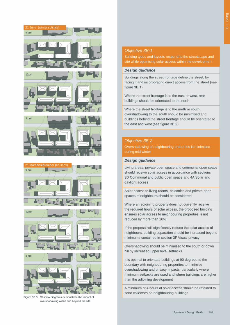
49Apartment Design Guide
03 I
Siti
ng
49Apartment Design Guide
Figure 3B.3 Shadow diagrams demonstrate the impact of overshadowing within and beyond the site
21 June (winter solstice)
21 March/September (equinox)
Objective 3B-1 Building types and layouts respond to the streetscape and site while optimising solar access within the development
Design guidance
Buildingsalongthestreetfrontagedefinethestreet,byfacing it and incorporating direct access from the street (see figure3B.1)
Where the street frontage is to the east or west, rear buildings should be orientated to the north
Where the street frontage is to the north or south, overshadowing to the south should be minimised and buildings behind the street frontage should be orientated to theeastandwest(seefigure3B.2)
Objective 3B-2Overshadowing of neighbouring properties is minimised during mid winter
Design guidance
Living areas, private open space and communal open space should receive solar access in accordance with sections 3D Communal and public open space and 4A Solar and daylight access
Solar access to living rooms, balconies and private open spaces of neighbours should be considered
Whereanadjoiningpropertydoesnotcurrentlyreceivethe required hours of solar access, the proposed building ensures solar access to neighbouring properties is not reduced by more than 20%
Iftheproposalwillsignificantlyreducethesolaraccessofneighbours, building separation should be increased beyond minimums contained in section 3F Visual privacy
Overshadowing should be minimised to the south or down hill by increased upper level setbacks
It is optimal to orientate buildings at 90 degrees to the boundary with neighbouring properties to minimise overshadowing and privacy impacts, particularly where minimum setbacks are used and where buildings are higher thantheadjoiningdevelopment
A minimum of 4 hours of solar access should be retained to solar collectors on neighbouring buildings
9 am
9 am
12pm
12pm
3 pm
3 pm

50 Apartment Design Guide
03 I
Siti
ng
Figure 3C.1 Diagrams illustrating various public domain interface scenarios
StreetFront setback
A change in level from the
footpathtoagroundfloor
apartment by up to 1m enhances
privacy while allowing surveillance
of the public domain
Groundfloorterracesatstreet
level can help promote activity
along a street and contribute to
the safety of the public domain
Wheregroundfloorapartments
are elevated above the footpath,
landscaping should be considered
to soften the building edge and
improve the relationship with the
public domain
Street
Street
Level change max. 1m
Level change max. 1m
StreetSetback
The public domain interface is the transition area between the apartment building, its private or communal space at the street edge and the public domain.
The interface of the development contributes to the quality and character of the street. Subtle variations through planting and fencing can create an attractive and active public domain with a pedestrian scale. Long, high blank walls or fences can detract from the appearance of the public domain and impact on the safety of pedestrians and residents. Direct access from the street to ground floorapartmentsandwindowsoverlookingthestreetcanimprove safety and social interaction.
Key components to consider when designing the interface include entries, private terraces or balconies, fences and walls, changes in level, services locations and planting. Thedesignoftheseelementscaninfluencetherealorperceived safety and security of residents, opportunities for social interaction and the identity of the development when viewed from the public domain.
See also sections 3G Pedestrian access and entries, 3H Vehicle access and 4S Mixed use.
Gardens with a variety
of plantings including
trees and shrubs can
enhance the quality
of the public domain,
while providing privacy
andamenitybenefits
to apartment residents
3C Public domain interface
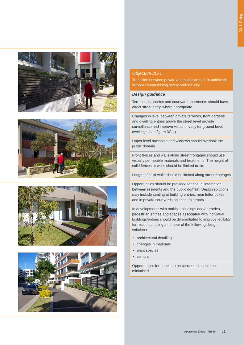
51Apartment Design Guide
03 I
Siti
ng
51Apartment Design Guide
Figure 3C.1 Diagrams illustrating various public domain interface scenarios
Objective 3C-1Transition between private and public domain is achieved without compromising safety and security
Design guidance
Terraces, balconies and courtyard apartments should have direct street entry, where appropriate
Changes in level between private terraces, front gardens and dwelling entries above the street level provide surveillance and improve visual privacy for ground level dwellings(seefigure3C.1)
Upper level balconies and windows should overlook the public domain
Front fences and walls along street frontages should use visually permeable materials and treatments. The height of solid fences or walls should be limited to 1m
Length of solid walls should be limited along street frontages
Opportunities should be provided for casual interaction between residents and the public domain. Design solutions may include seating at building entries, near letter boxes andinprivatecourtyardsadjacenttostreets
In developments with multiple buildings and/or entries, pedestrian entries and spaces associated with individual buildings/entries should be differentiated to improve legibility for residents, using a number of the following design solutions:
• architectural detailing
• changes in materials
• plant species
• colours
Opportunities for people to be concealed should be minimised

52 Apartment Design Guide
03 I
Siti
ng
Figure 3C.2 Thiscourtyarddesignlocatestreeplantingalongthepedestrianpathway,allowingfornaturalventilationanddaylightaccesstotheadjacentunderground car parking below, and visual screening of the car park
Figure 3C.3 Planting can be used to soften the edges of raised terraces to the street
Figure 3C.4 Front fences along public street frontages should use visually permeable materials and treatments such as timber slats
3C Public domain interface
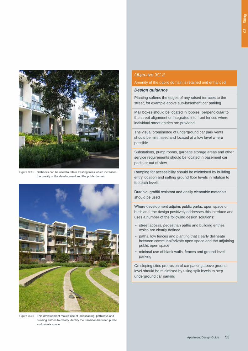
53Apartment Design Guide
03 I
Siti
ng
53Apartment Design Guide
Figure 3C.5 Setbacks can be used to retain existing trees which increases the quality of the development and the public domain
Figure 3C.6 This development makes use of landscaping, pathways and building entries to clearly identify the transition between public and private space
Objective 3C-2Amenity of the public domain is retained and enhanced
Design guidance
Planting softens the edges of any raised terraces to the street, for example above sub-basement car parking
Mail boxes should be located in lobbies, perpendicular to the street alignment or integrated into front fences where individual street entries are provided
The visual prominence of underground car park vents should be minimised and located at a low level where possible
Substations, pump rooms, garbage storage areas and other service requirements should be located in basement car parks or out of view
Ramping for accessibility should be minimised by building entrylocationandsettinggroundfloorlevelsinrelationtofootpath levels
Durable,graffitiresistantandeasilycleanablematerialsshould be used
Wheredevelopmentadjoinspublicparks,openspaceorbushland, the design positively addresses this interface and uses a number of the following design solutions:
• street access, pedestrian paths and building entries whichareclearlydefined
• paths, low fences and planting that clearly delineate betweencommunal/privateopenspaceandtheadjoiningpublic open space
• minimal use of blank walls, fences and ground level parking
On sloping sites protrusion of car parking above ground level should be minimised by using split levels to step underground car parking

54 Apartment Design Guide
03 I
Siti
ng
Figure 3D.1 Quality landscape design of communal spaces and pathways is particularly important for high density developments
Communal open space is an important environmental resource that provides outdoor recreation opportunities for residents, connection to the natural environment and valuable‘breathingspace’betweenapartmentbuildings.It also contributes to the appeal of a development and the wellbeing of residents. Some communal open space is accessible and usable by the general public.
The size, location and design of communal or public open space will vary depending on the site context and the scale of development. The function of open space is to provide amenity in the form of:
• landscape character and design
• opportunities for group and individual recreation and activities
• opportunities for social interaction
• environmental and water cycle management
• opportunities to modify microclimate
• amenity and outlook for residents.
The useable part of the communal open space area may be supplemented by:
• additional landscape area, circulation space and areas for passive use and outlook
• public land used for open space and vested in or under the control of a public authority.
High quality open space is particularly important and beneficialinhigherdensitydevelopments(forprivateopen space requirements see section 4E Private open space and balconies).
3D Communal and public open space
Figure 3D.2 Communal open spaces can be located on the podium or roofs and should offer gathering areas to provide opportunity for social interaction amongst residents
Pho
to: A
SP
EC
T S
tudi
osP
hoto
: AS
PE
CT
Stu
dios
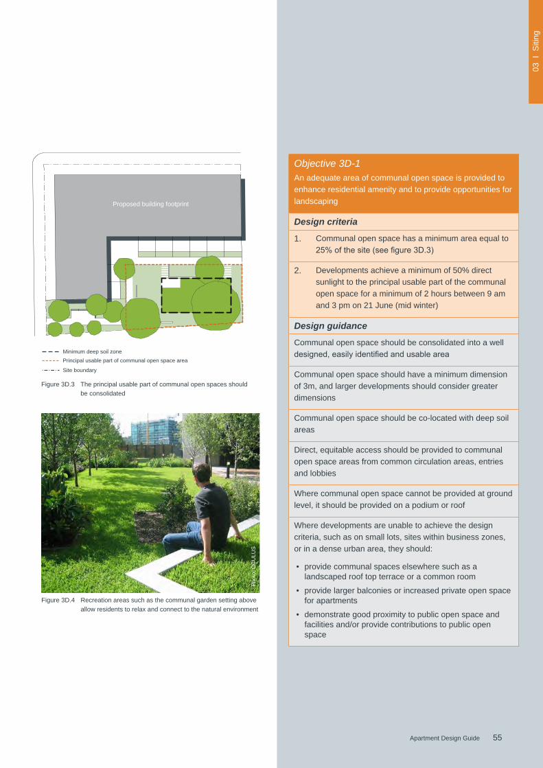
55Apartment Design Guide
03 I
Siti
ng
55Apartment Design Guide
Figure 3D.3 The principal usable part of communal open spaces should be consolidated
Figure 3D.4 Recreation areas such as the communal garden setting above allow residents to relax and connect to the natural environment
Proposed building footprint
Objective 3D-1An adequate area of communal open space is provided to enhance residential amenity and to provide opportunities for landscaping
Design criteria
1. Communal open space has a minimum area equal to 25%ofthesite(seefigure3D.3)
2. Developments achieve a minimum of 50% direct sunlight to the principal usable part of the communal open space for a minimum of 2 hours between 9 am and 3 pm on 21 June (mid winter)
Design guidance
Communal open space should be consolidated into a well designed,easilyidentifiedandusablearea
Communal open space should have a minimum dimension of 3m, and larger developments should consider greater dimensions
Communal open space should be co-located with deep soil areas
Direct, equitable access should be provided to communal open space areas from common circulation areas, entries and lobbies
Where communal open space cannot be provided at ground level, it should be provided on a podium or roof
Where developments are unable to achieve the design criteria, such as on small lots, sites within business zones, or in a dense urban area, they should:
• provide communal spaces elsewhere such as a landscaped roof top terrace or a common room
• provide larger balconies or increased private open space for apartments
• demonstrate good proximity to public open space and facilities and/or provide contributions to public open space
Pho
to: O
CU
LUS
Minimum deep soil zonePrincipal usable part of communal open space area
Site boundary
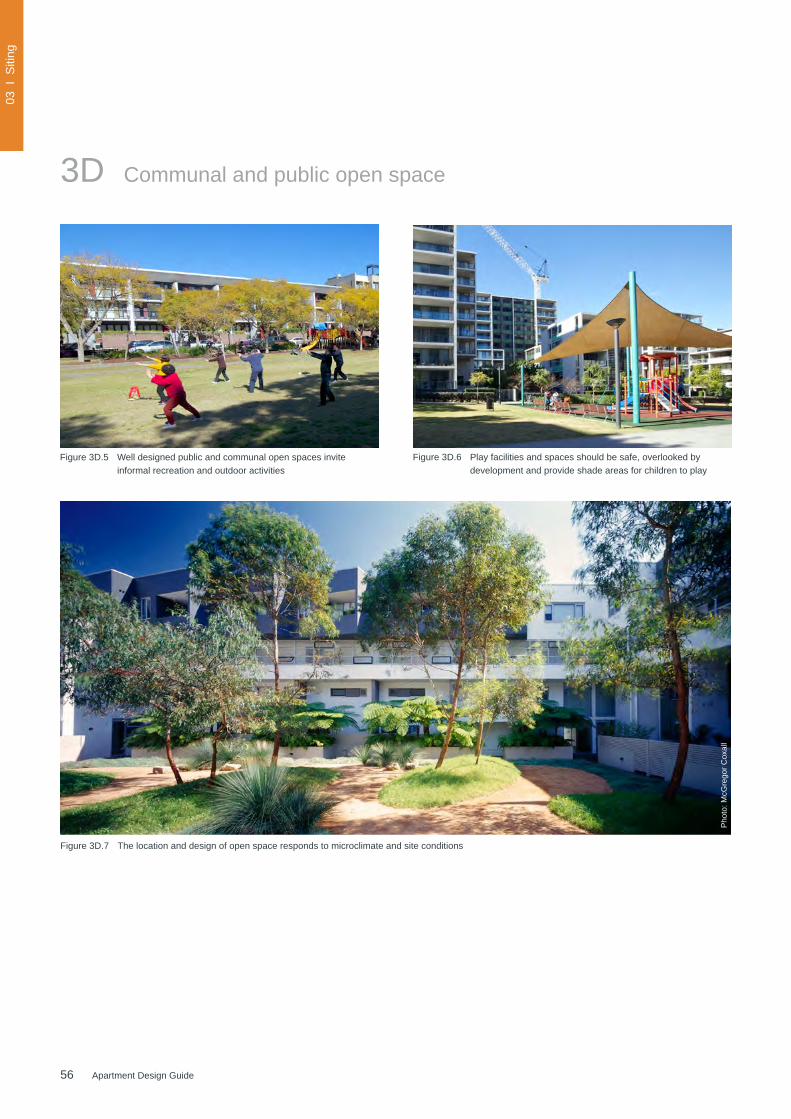
56 Apartment Design Guide
03 I
Siti
ng
Figure 3D.5 Well designed public and communal open spaces invite informal recreation and outdoor activities
Figure 3D.6 Play facilities and spaces should be safe, overlooked by development and provide shade areas for children to play
3D Communal and public open space
Figure 3D.7 The location and design of open space responds to microclimate and site conditions
Pho
to: M
cGre
gor C
oxal
l
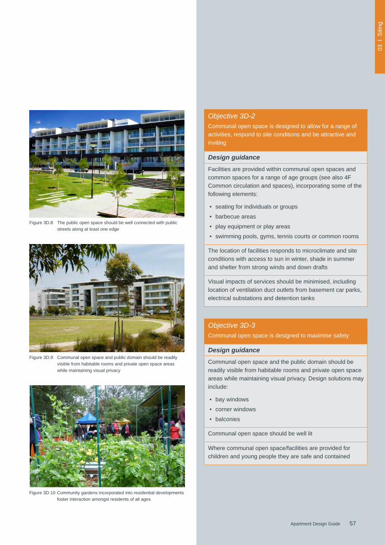
57Apartment Design Guide
03 I
Siti
ng
57Apartment Design Guide
Figure 3D.8 The public open space should be well connected with public streets along at least one edge
Figure 3D.9 Communal open space and public domain should be readily visible from habitable rooms and private open space areas while maintaining visual privacy
Figure 3D.10 Community gardens incorporated into residential developments foster interaction amongst residents of all ages
Objective 3D-3Communal open space is designed to maximise safety
Design guidance
Communal open space and the public domain should be readily visible from habitable rooms and private open space areas while maintaining visual privacy. Design solutions may include:
• bay windows
• corner windows
• balconies
Communal open space should be well lit
Where communal open space/facilities are provided for children and young people they are safe and contained
Objective 3D-2Communal open space is designed to allow for a range of activities, respond to site conditions and be attractive and inviting
Design guidance
Facilities are provided within communal open spaces and common spaces for a range of age groups (see also 4F Common circulation and spaces), incorporating some of the following elements:
• seating for individuals or groups
• barbecue areas
• play equipment or play areas
• swimming pools, gyms, tennis courts or common rooms
The location of facilities responds to microclimate and site conditions with access to sun in winter, shade in summer and shelter from strong winds and down drafts
Visual impacts of services should be minimised, including location of ventilation duct outlets from basement car parks, electrical substations and detention tanks
Photo:A
shfieldCouncil
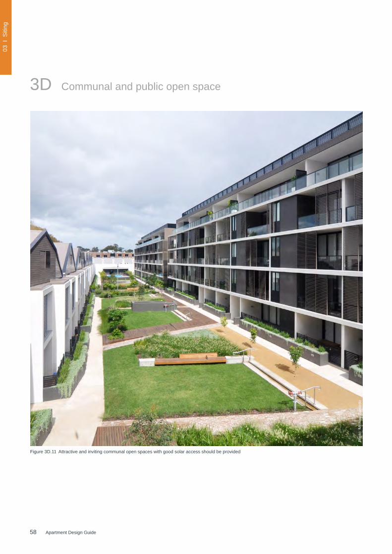
58 Apartment Design Guide
03 I
Siti
ng
Figure 3D.11 Attractive and inviting communal open spaces with good solar access should be provided
3D Communal and public open space
Pho
to: M
icha
el Z
anar
do

59Apartment Design Guide
03 I
Siti
ng
59Apartment Design Guide
Figure 3D.12 This communal courtyard provides gathering spaces, seating facilities, pergolas and barbecue facilities for residents
Figure 3D.13 This semi-public courtyard connects to the surrounding inner-city neighbourhood and offers a central water feature, seating and convenient pedestrian through-site links
Objective 3D-4
Public open space, where provided, is responsive to the existing pattern and uses of the neighbourhood
Design guidance
The public open space should be well connected with public streets along at least one edge
The public open space should be connected with nearby parks and other landscape elements
Public open space should be linked through view lines, pedestrian desire paths, termination points and the wider street grid
Solar access should be provided year round along with protection from strong winds
Opportunities for a range of recreational activities should be provided for people of all ages
A positive address and active frontages should be provided adjacenttopublicopenspace
Boundariesshouldbeclearlydefinedbetweenpublicopenspace and private areas

60 Apartment Design Guide
03 I
Siti
ng
Deep soil zone Deep soil zoneStreet
Figure 3E.1 Opportunities for deep soil zones are increased when parking levels are contained within the building footprint
Parking
Parking
Deep soil zones are areas of soil not covered by buildings or structures within a development. They exclude basement car parks, services, swimming pools, tennis courts and impervious surfaces including car parks, driveways and roof areas.
Deepsoilzoneshaveimportantenvironmentalbenefits,suchasallowinginfiltrationofrainwatertothewatertableand reducing stormwater runoff, promoting healthy growth of large trees with large canopies and protecting existing mature trees which assist with temperature reduction in urban environments. Deep soil zones may be constrained by the size of the lot or the location of a proposed development. To provide shade and amenity for residents they can be co-located with communal open space.
Services Min. 6m wide
Deep soil zone
Building zone
3E Deep soil zones
Figure 3E.2 Diagram showing the minimum dimension of deep soil zones for sites greater than 1,500m2
Table 2 Suggested soil volumes on sites with sand, clay, alluvial, transition and disturbed soils
Tree size Height Spread Soil volume
Large trees 13-18m 16m 80m3
Medium tree 9-12m 8m 35m3
Small tree 6-8m 4m 15m3
Note: On sandy sites with reduced soil volumes, the number of trees planted is proportional to the available soil volume
services greater than
300mm diameter
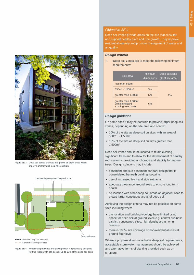
61Apartment Design Guide
03 I
Siti
ng
61Apartment Design Guide
Objective 3E-1 Deep soil zones provide areas on the site that allow for and support healthy plant and tree growth. They improve residential amenity and promote management of water and air quality
Design criteria
1. Deep soil zones are to meet the following minimum requirements:
Site areaMinimum
dimensionsDeep soil zone (% of site area)
less than 650m2 -
7%
650m2 - 1,500m2 3m
greater than 1,500m2 6m
greater than 1,500m2
withsignificantexisting tree cover
6m
Design guidance
On some sites it may be possible to provide larger deep soil zones, depending on the site area and context:
• 10% of the site as deep soil on sites with an area of 650m2 - 1,500m2
• 15% of the site as deep soil on sites greater than 1,500m2
Deep soil zones should be located to retain existing significanttreesandtoallowforthedevelopmentofhealthyroot systems, providing anchorage and stability for mature trees. Design solutions may include:
• basement and sub basement car park design that is consolidated beneath building footprints
• use of increased front and side setbacks
• adequate clearance around trees to ensure long term health
• co-locationwithotherdeepsoilareasonadjacentsitestocreate larger contiguous areas of deep soil
Achieving the design criteria may not be possible on some sites including where:
• the location and building typology have limited or no space for deep soil at ground level (e.g. central business district, constrained sites, high density areas, or in centres)
• there is 100% site coverage or non-residential uses at groundfloorlevel
Where a proposal does not achieve deep soil requirements, acceptable stormwater management should be achieved and alternative forms of planting provided such as on structure
Deep soil zone
Figure 3E.3 Deep soil zones promote the growth of larger trees which improve amenity and local microclimate
Figure 3E.4 Pedestrianpathwaysandpavingwhichisspecificallydesignedfor tree root growth can occupy up to 10% of the deep soil zone
Minimum deep soil zone areaCommunal open space area
permeable paving over deep soil zone
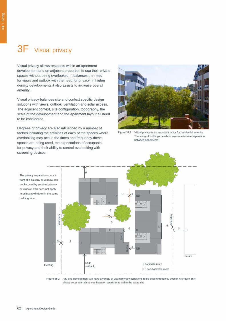
62 Apartment Design Guide
03 I
Siti
ng
Figure 3F.1 Visual privacy is an important factor for residential amenity. The siting of buildings needs to ensure adequate separation between apartments
Visual privacy allows residents within an apartment developmentandonadjacentpropertiestousetheirprivatespaces without being overlooked. It balances the need for views and outlook with the need for privacy. In higher density developments it also assists to increase overall amenity.
Visualprivacybalancessiteandcontextspecificdesignsolutions with views, outlook, ventilation and solar access. Theadjacentcontext,siteconfiguration,topography,thescale of the development and the apartment layout all need to be considered.
Degreesofprivacyarealsoinfluencedbyanumberoffactors including the activities of each of the spaces where overlooking may occur, the times and frequency these spaces are being used, the expectations of occupants for privacy and their ability to control overlooking with screening devices.
3F Visual privacy
The privacy separation space in
front of a balcony or window can
not be used by another balcony
or window. This does not apply
toadjacentwindowsinthesame
building face
Figure 3F.2 Any one development will have a variety of visual privacy conditions to be accommodated. Section A (Figure 3F.4)shows separation distances between apartments within the same site
6
Boun
dary
H
Future
Existing
H
6
HH 93
DCP Setback
6
6
H
H
Blan
k
Blan
k 3
6 H
NH
Boun
dary
3 NH6H
Street
6H
ExistingDCP setback
Future
H: habitable room
NH: non-habitable room
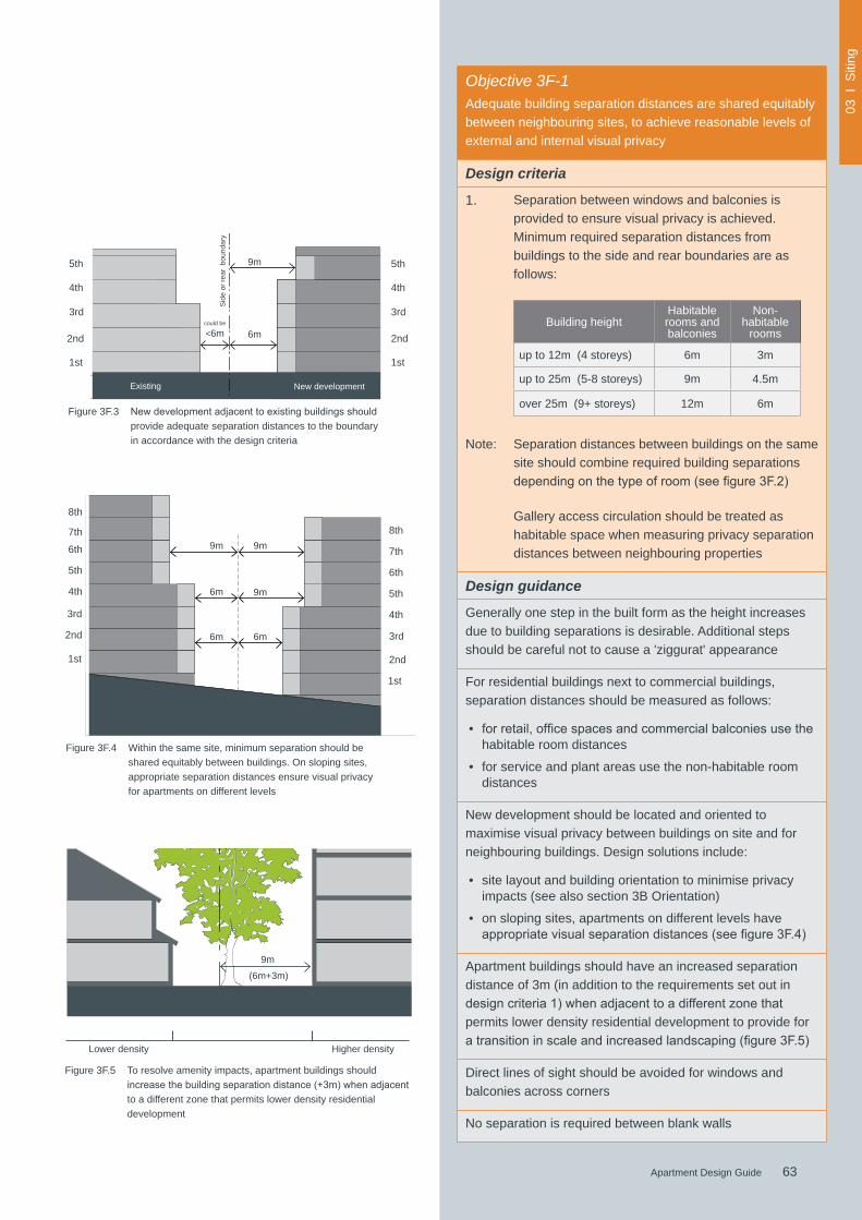
63Apartment Design Guide
03 I
Siti
ng
63Apartment Design Guide
Objective 3F-1Adequate building separation distances are shared equitably between neighbouring sites, to achieve reasonable levels of external and internal visual privacy
Design criteria
1. Separation between windows and balconies is provided to ensure visual privacy is achieved. Minimum required separation distances from buildings to the side and rear boundaries are as follows:
Building heightHabitable rooms and balconies
Non-habitable
rooms
up to 12m (4 storeys) 6m 3m
up to 25m (5-8 storeys) 9m 4.5m
over 25m (9+ storeys) 12m 6m
Note: Separation distances between buildings on the same site should combine required building separations dependingonthetypeofroom(seefigure3F.2)
Gallery access circulation should be treated as habitable space when measuring privacy separation distances between neighbouring properties
Design guidance
Generally one step in the built form as the height increases due to building separations is desirable. Additional steps should be careful not to cause a 'ziggurat' appearance
For residential buildings next to commercial buildings, separation distances should be measured as follows:
• forretail,officespacesandcommercialbalconiesusethehabitable room distances
• for service and plant areas use the non-habitable room distances
New development should be located and oriented to maximise visual privacy between buildings on site and for neighbouring buildings. Design solutions include:
• site layout and building orientation to minimise privacy impacts (see also section 3B Orientation)
• on sloping sites, apartments on different levels have appropriatevisualseparationdistances(seefigure3F.4)
Apartment buildings should have an increased separation distance of 3m (in addition to the requirements set out in designcriteria1)whenadjacenttoadifferentzonethatpermits lower density residential development to provide for atransitioninscaleandincreasedlandscaping(figure3F.5)
Direct lines of sight should be avoided for windows and balconies across corners
No separation is required between blank walls
6mcould be
<6m
Sid
e or
rear
bou
ndar
y
Existing New development
5th
4th4th
3rd3rd
2nd2nd
1st1st
Figure 3F.3 Newdevelopmentadjacenttoexistingbuildingsshouldprovide adequate separation distances to the boundary in accordance with the design criteria
9m
5th
5th
6th
7th
8th
4th
4th3rd
3rd6m
9m
9m
2nd 6m
6m
9m
2nd1st
1st
6th
Figure 3F.4 Within the same site, minimum separation should be shared equitably between buildings. On sloping sites, appropriate separation distances ensure visual privacy for apartments on different levels
7th
8th
5th
Higher density Lower density
9m
Figure 3F.5 To resolve amenity impacts, apartment buildings should increasethebuildingseparationdistance(+3m)whenadjacentto a different zone that permits lower density residential development
(6m+3m)

64 Apartment Design Guide
03 I
Siti
ng
Figure 3F.6 Diagrams showing different privacy interface conditions
Figure 3F.7 Solid walls with non-habitable room windows are used for end elevations to manage privacy impacts between buildings. Solid balconies at lower levels provide better privacy from the street
Figure 3F.8 Well designed fences and balconies provide privacy to apartmentswhenviewedfromthepublicdomainoradjacentapartment buildings
Blank wall conditionsBoundary conditionsConditions within a development
6m
6m
45˚
45˚
6m
boun
dary
futu
re b
uilt
form
6m
45˚45˚6m
45˚
6m
45˚ 3m45˚
boun
dary
<6m 6m45˚45˚
3m
45˚
Habitable to habitable rooms Habitable to habitable rooms To habitable rooms
Habitable to non-habitable rooms Habitable to non-compliant existing To non-habitable rooms
3F Visual privacy

65Apartment Design Guide
03 I
Siti
ng
65Apartment Design Guide
Building layout and design features such as off set windows can contribute to increased privacy between apartments
Privacy to apartments can be improved by locating circulation cores at the internal corners of a building
Figure 3F.9 Fencingofgroundfloorapartmentsshouldnotbesolidtoallowfor surveillance of common open space and the public domain
Objective 3F-2
Site and building design elements increase privacy without compromising access to light and air and balance outlook and views from habitable rooms and private open space
Design guidance
Communal open space, common areas and access paths should be separated from private open space and windows to apartments, particularly habitable room windows. Design solutions may include:
• setbacks
• solid or partially solid balustrades to balconies at lower levels
• fencing and/or trees and vegetation to separate spaces
• screening devices
• bay windows or pop out windows to provide privacy in one direction and outlook in another
• raising apartments/private open space above the public domain or communal open space
• planter boxes incorporated into walls and balustrades to increase visual separation
• pergolas or shading devices to limit overlooking of lower apartments or private open space
• on constrained sites where it can be demonstrated that buildinglayoutopportunitiesarelimited,fixedlouvresorscreen panels to windows and/or balconies
Bedrooms, living spaces and other habitable rooms should be separated from gallery access and other open circulation space by the apartment’s service areas
Balconies and private terraces should be located in front of living rooms to increase internal privacy
Windowsshouldbeoffsetfromthewindowsofadjacentbuildings
Recessedbalconiesand/orverticalfinsshouldbeusedbetweenadjacentbalconies
Figure 3F.10 Examples of solutions to increase privacy Note: building separations are shown for up to 12m (4 storeys)
3m3m
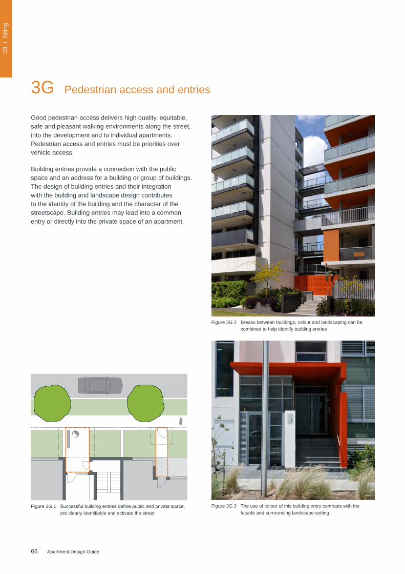
66 Apartment Design Guide
03 I
Siti
ng
Figure 3G.1 Successfulbuildingentriesdefinepublicandprivatespace,areclearlyidentifiableandactivatethestreet
Figure 3G.2 Breaks between buildings, colour and landscaping can be combined to help identify building entries
Figure 3G.3 The use of colour of this building entry contrasts with the facade and surrounding landscape setting
3G Pedestrian access and entries
Good pedestrian access delivers high quality, equitable, safe and pleasant walking environments along the street, into the development and to individual apartments. Pedestrian access and entries must be priorities over vehicle access.
Building entries provide a connection with the public space and an address for a building or group of buildings. The design of building entries and their integration with the building and landscape design contributes to the identity of the building and the character of the streetscape. Building entries may lead into a common entry or directly into the private space of an apartment.
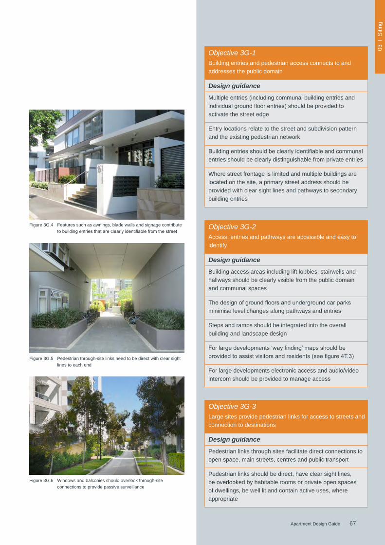
67Apartment Design Guide
03 I
Siti
ng
67Apartment Design Guide
Figure 3G.4 Features such as awnings, blade walls and signage contribute tobuildingentriesthatareclearlyidentifiablefromthestreet
Figure 3G.5 Pedestrian through-site links need to be direct with clear sight lines to each end
Objective 3G-1Building entries and pedestrian access connects to and addresses the public domain
Design guidance
Multiple entries (including communal building entries and individualgroundfloorentries)shouldbeprovidedtoactivate the street edge
Entry locations relate to the street and subdivision pattern and the existing pedestrian network
Buildingentriesshouldbeclearlyidentifiableandcommunalentries should be clearly distinguishable from private entries
Where street frontage is limited and multiple buildings are located on the site, a primary street address should be provided with clear sight lines and pathways to secondary building entries
Objective 3G-3Large sites provide pedestrian links for access to streets and connection to destinations
Design guidance
Pedestrian links through sites facilitate direct connections to open space, main streets, centres and public transport
Pedestrian links should be direct, have clear sight lines, be overlooked by habitable rooms or private open spaces of dwellings, be well lit and contain active uses, where appropriate
Objective 3G-2Access, entries and pathways are accessible and easy to identify
Design guidance
Building access areas including lift lobbies, stairwells and hallways should be clearly visible from the public domain and communal spaces
Thedesignofgroundfloorsandundergroundcarparksminimise level changes along pathways and entries
Steps and ramps should be integrated into the overall building and landscape design
Forlargedevelopments‘wayfinding’mapsshouldbeprovidedtoassistvisitorsandresidents(seefigure4T.3)
For large developments electronic access and audio/video intercom should be provided to manage access
Figure 3G.6 Windows and balconies should overlook through-site connections to provide passive surveillance
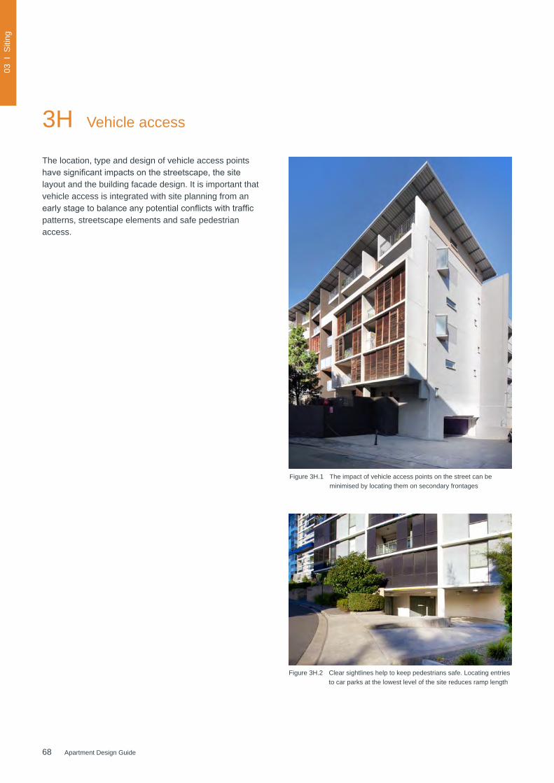
68 Apartment Design Guide
03 I
Siti
ng
Figure 3H.1 The impact of vehicle access points on the street can be minimised by locating them on secondary frontages
The location, type and design of vehicle access points havesignificantimpactsonthestreetscape,thesitelayout and the building facade design. It is important that vehicle access is integrated with site planning from an earlystagetobalanceanypotentialconflictswithtrafficpatterns, streetscape elements and safe pedestrian access.
3H Vehicle access
Figure 3H.2 Clear sightlines help to keep pedestrians safe. Locating entries to car parks at the lowest level of the site reduces ramp length
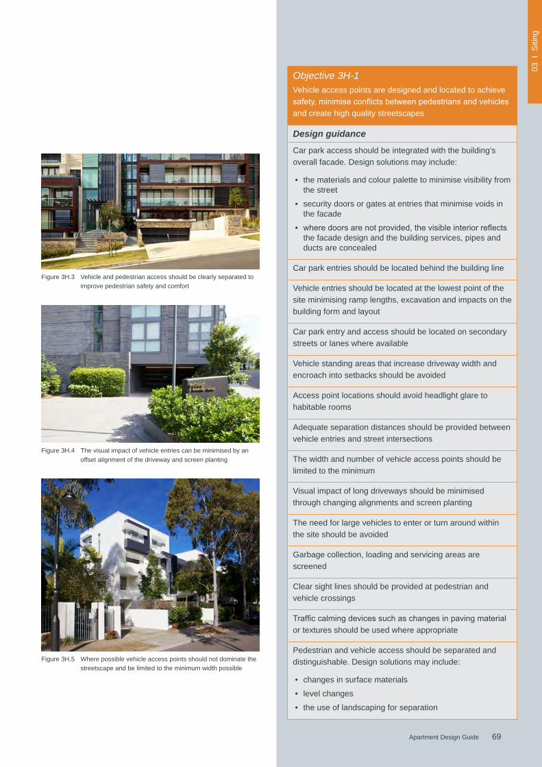
69Apartment Design Guide
03 I
Siti
ng
69Apartment Design Guide
Objective 3H-1Vehicle access points are designed and located to achieve safety,minimiseconflictsbetweenpedestriansandvehiclesand create high quality streetscapes
Design guidance
Car park access should be integrated with the building’s overall facade. Design solutions may include:
• the materials and colour palette to minimise visibility from the street
• security doors or gates at entries that minimise voids in the facade
• wheredoorsarenotprovided,thevisibleinteriorreflectsthe facade design and the building services, pipes and ducts are concealed
Car park entries should be located behind the building line
Vehicle entries should be located at the lowest point of the site minimising ramp lengths, excavation and impacts on the building form and layout
Car park entry and access should be located on secondary streets or lanes where available
Vehicle standing areas that increase driveway width and encroach into setbacks should be avoided
Access point locations should avoid headlight glare to habitable rooms
Adequate separation distances should be provided between vehicle entries and street intersections
The width and number of vehicle access points should be limited to the minimum
Visual impact of long driveways should be minimised through changing alignments and screen planting
The need for large vehicles to enter or turn around within the site should be avoided
Garbage collection, loading and servicing areas are screened
Clear sight lines should be provided at pedestrian and vehicle crossings
Trafficcalmingdevicessuchaschangesinpavingmaterialor textures should be used where appropriate
Pedestrian and vehicle access should be separated and distinguishable. Design solutions may include:
• changes in surface materials
• level changes
• the use of landscaping for separation
Figure 3H.3 Vehicle and pedestrian access should be clearly separated to improve pedestrian safety and comfort
Figure 3H.4 The visual impact of vehicle entries can be minimised by an offset alignment of the driveway and screen planting
Figure 3H.5 Where possible vehicle access points should not dominate the streetscape and be limited to the minimum width possible

70 Apartment Design Guide
03 I
Siti
ng
3J Bicycle and car parking
Integrating car parking within apartment buildings has a significantimpactonsiteplanning,landscapeandbuildingdesign. On site parking can be located underground, above ground within a structure or at grade.
The location, form and organisation of parking is usually a balance of development feasibility, site constraints, local context, apartment types and regulatory car parking requirements. Deep soil zones, stormwater management and the retention of trees can also affect the size and shape of a car park footprint.
Parking requirements should be determined in relation to the availability, frequency and convenience of public transport or proximity to a centre in regional areas. Reduced requirements promote a reduction in car dependency and encourage walking, cycling and use of public transport. Provision of parking for alternative forms of transport such as car share vehicles, motorcycles and bicycles should also be considered. Where less car parking is provided, councils should not provide on street resident parking permits.
Figure 3J.1 This development provides green open space on top of the car park structure (top photo). The ground level facing the street is 'wrapped' with retail and commercial uses (bottom photo)
Nominated regional centres
Albury, Ballina, Batemans Bay, Bathurst, Bega, Bowral, Cessnock, Charlestown, Coffs Harbour, Dapto, Dubbo, Glendale–Cardiff, Gosford, Goulburn, Grafton, Lismore, Maitland, Morisset, Newcastle, Nowra, Orange, Port Macquarie, Queanbeyan, Raymond Terrace, Shellharbour, Tamworth, Taree, Tuggerah–Wyong, Tweed Heads, Wagga Wagga, Warrawong and Wollongong
Table 3 Nominated regional centres for design criteria 1
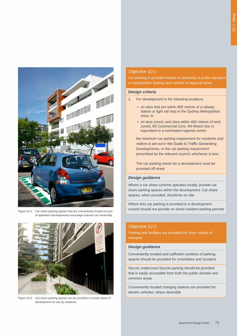
71Apartment Design Guide
03 I
Siti
ng
71Apartment Design Guide
Figure 3J.2 Car share parking spaces that are conveniently located as part of apartment developments encourage reduced car ownership
Figure 3J.3 Car share parking spaces can be provided in private areas of development for use by residents
Objective 3J-1Car parking is provided based on proximity to public transport in metropolitan Sydney and centres in regional areas
Design criteria
1. For development in the following locations:
• on sites that are within 800 metres of a railway station or light rail stop in the Sydney Metropolitan Area; or
• on land zoned, and sites within 400 metres of land zoned, B3 Commercial Core, B4 Mixed Use or equivalent in a nominated regional centre
the minimum car parking requirement for residents and visitorsissetoutintheGuidetoTrafficGeneratingDevelopments, or the car parking requirement prescribed by the relevant council, whichever is less
The car parking needs for a development must be provided off street
Design guidance
Where a car share scheme operates locally, provide car share parking spaces within the development. Car share spaces, when provided, should be on site
Where less car parking is provided in a development, council should not provide on street resident parking permits
Objective 3J-2Parking and facilities are provided for other modes of transport
Design guidance
Convenientlylocatedandsufficientnumbersofparkingspaces should be provided for motorbikes and scooters
Secure undercover bicycle parking should be provided that is easily accessible from both the public domain and common areas
Conveniently located charging stations are provided for electric vehicles, where desirable
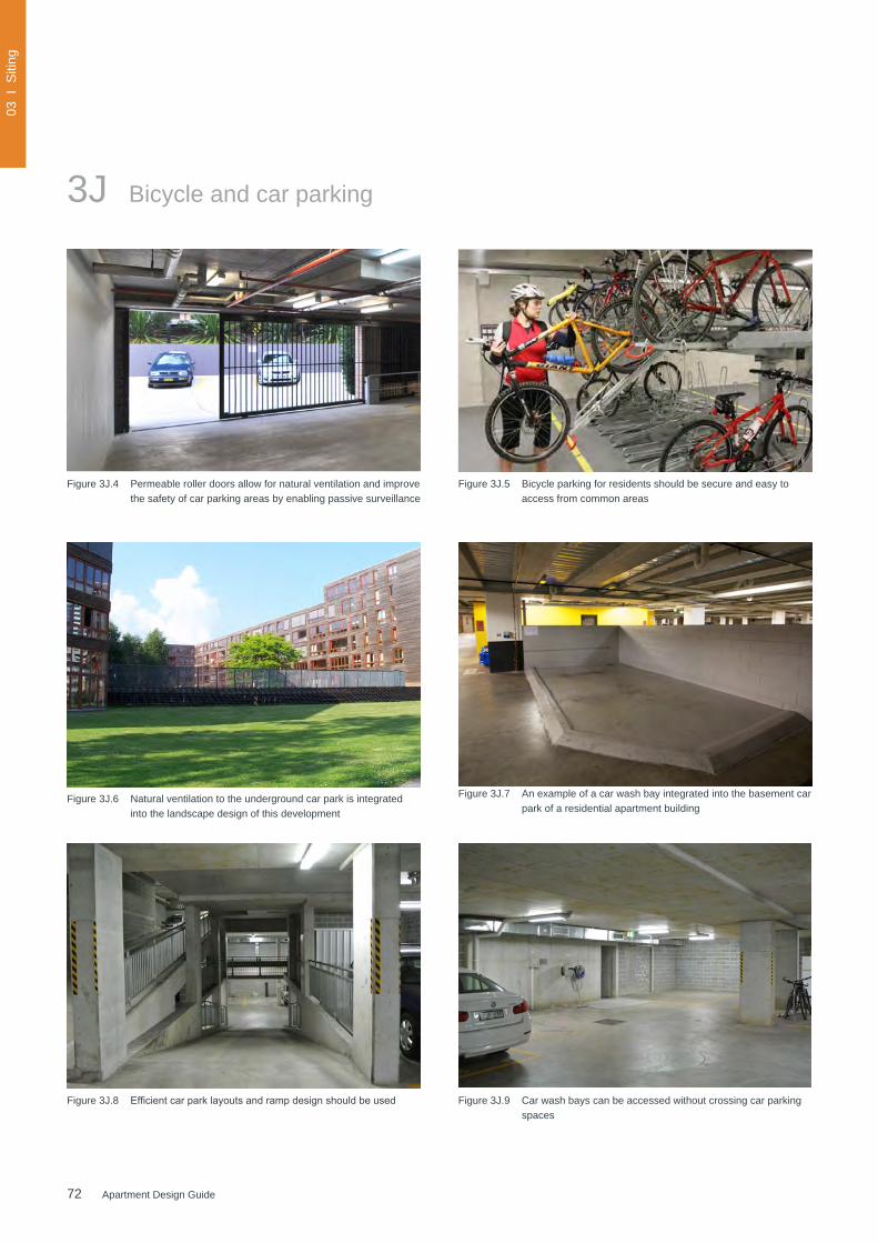
72 Apartment Design Guide
03 I
Siti
ng
Figure 3J.5 Bicycle parking for residents should be secure and easy to access from common areas
3J Bicycle and car parking
Figure 3J.4 Permeable roller doors allow for natural ventilation and improve the safety of car parking areas by enabling passive surveillance
Figure 3J.8 Efficientcarparklayoutsandrampdesignshouldbeused Figure 3J.9 Car wash bays can be accessed without crossing car parking spaces
Figure 3J.6 Natural ventilation to the underground car park is integrated into the landscape design of this development
Figure 3J.7 An example of a car wash bay integrated into the basement car park of a residential apartment building
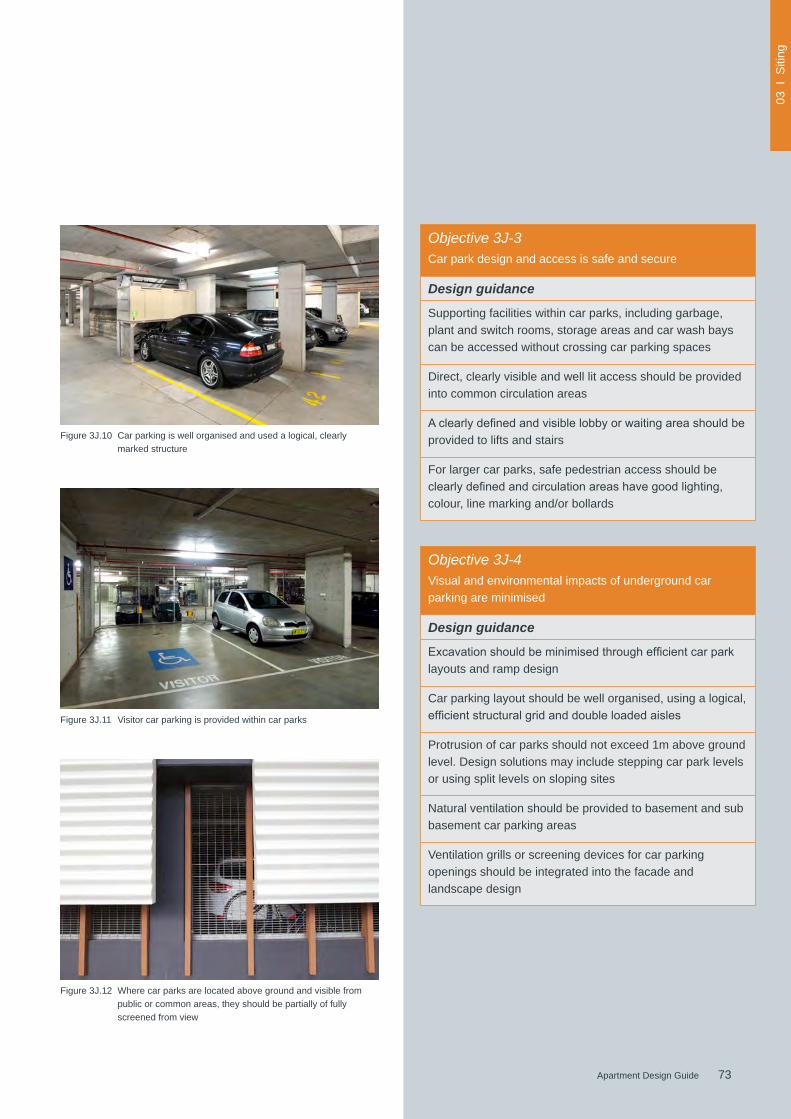
73Apartment Design Guide
03 I
Siti
ng
73Apartment Design Guide
Figure 3J.10 Car parking is well organised and used a logical, clearly marked structure
Figure 3J.11 Visitor car parking is provided within car parks
Figure 3J.12 Where car parks are located above ground and visible from public or common areas, they should be partially of fully screened from view
Objective 3J-3Car park design and access is safe and secure
Design guidance
Supporting facilities within car parks, including garbage, plant and switch rooms, storage areas and car wash bays can be accessed without crossing car parking spaces
Direct, clearly visible and well lit access should be provided into common circulation areas
Aclearlydefinedandvisiblelobbyorwaitingareashouldbeprovided to lifts and stairs
For larger car parks, safe pedestrian access should be clearlydefinedandcirculationareashavegoodlighting,colour, line marking and/or bollards
Objective 3J-4Visual and environmental impacts of underground car parking are minimised
Design guidance
Excavationshouldbeminimisedthroughefficientcarparklayouts and ramp design
Car parking layout should be well organised, using a logical, efficientstructuralgridanddoubleloadedaisles
Protrusion of car parks should not exceed 1m above ground level. Design solutions may include stepping car park levels or using split levels on sloping sites
Natural ventilation should be provided to basement and sub basement car parking areas
Ventilation grills or screening devices for car parking openings should be integrated into the facade and landscape design

74 Apartment Design Guide
03 I
Siti
ng
3J Bicycle and car parking
Figure 3J.13 Landscaped on-street parking can enhance streetscape character
Figure 3J.14 Landscaping of on-street parking reduces visual impact while providingamenityandenvironmentalbenefitssuchasshade,reduced surface temperatures and water management
Figure 3J.15 The impact of car parking and vehicular access points on the streetscape should be minimised
Figure 3J.16 Screening can be used to integrate above ground car parking with the facade
Pho
to: M
icha
el Z
anar
do
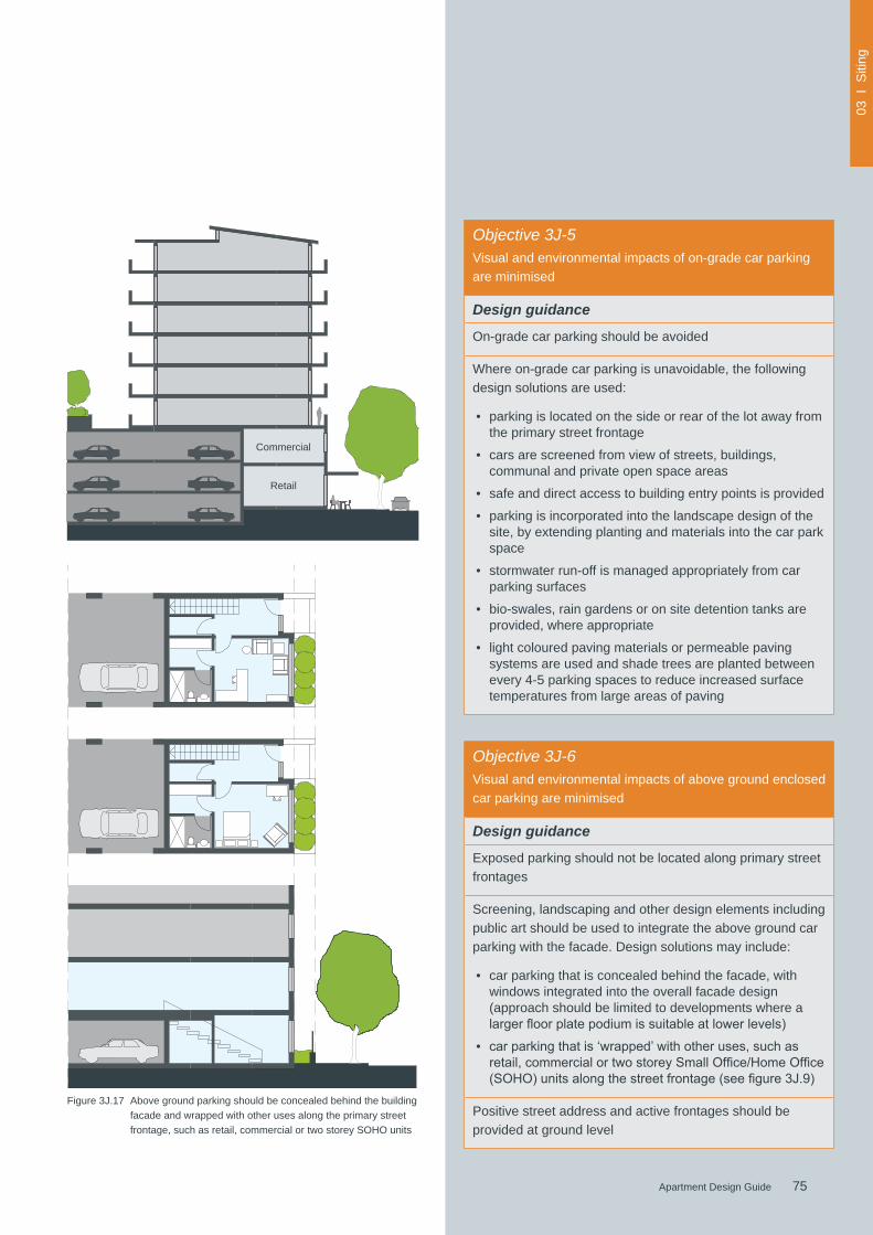
75Apartment Design Guide
03 I
Siti
ng
75Apartment Design Guide
Figure 3J.17 Above ground parking should be concealed behind the building facade and wrapped with other uses along the primary street frontage, such as retail, commercial or two storey SOHO units
Retail
Commercial
Objective 3J-6Visual and environmental impacts of above ground enclosed car parking are minimised
Design guidance
Exposed parking should not be located along primary street frontages
Screening, landscaping and other design elements including public art should be used to integrate the above ground car parking with the facade. Design solutions may include:
• car parking that is concealed behind the facade, with windows integrated into the overall facade design (approach should be limited to developments where a largerfloorplatepodiumissuitableatlowerlevels)
• carparkingthatis‘wrapped’withotheruses,suchasretail,commercialortwostoreySmallOffice/HomeOffice(SOHO)unitsalongthestreetfrontage(seefigure3J.9)
Positive street address and active frontages should be provided at ground level
Objective 3J-5Visual and environmental impacts of on-grade car parking are minimised
Design guidance
On-grade car parking should be avoided
Where on-grade car parking is unavoidable, the following design solutions are used:
• parking is located on the side or rear of the lot away from the primary street frontage
• cars are screened from view of streets, buildings, communal and private open space areas
• safe and direct access to building entry points is provided
• parking is incorporated into the landscape design of the site, by extending planting and materials into the car park space
• stormwater run-off is managed appropriately from car parking surfaces
• bio-swales, rain gardens or on site detention tanks are provided, where appropriate
• light coloured paving materials or permeable paving systems are used and shade trees are planted between every 4-5 parking spaces to reduce increased surface temperatures from large areas of paving

76 Apartment Design Guide

77Apartment Design Guide
Part 4 Designing the building
This part addresses the design of apartment buildings in more detail. It focuses on building form, layout, functionality, landscape design, environmental performance and residential amenity. It is to be used during the design process and in the preparation and assessment of development applications
Amenity
4A Solar and daylight access 80
4B Natural ventilation 84
4C Ceiling heights 88
4D Apartment size and layout 90
4E Private open space and balconies 94
4F Common circulation and spaces 98
4G Storage 102
4H Acoustic privacy 104
4J Noise and pollution 106
Configuration
4K Apartment mix 108
4L Groundfloorapartments 110
4M Facades 112
4N Roof design 114
4O Landscape design 116
4P Planting on structures 118
4Q Universal design 120
4R Adaptive reuse 122
4S Mixed use 124
4T Awnings and signage 126
Performance
4UEnergyefficiency 128
4V Water management and conservation 130
4W Waste management 132
4X Building maintenance 134

78 Apartment Design Guide
04 I
Bui
ldin
g
7.8m
5.8m 2m
2.2m 2m
4.2m
Sun angle@ 9 am
mid winter
sun altitude ratio 2.9:1
Sun angle@ 12 noon mid winter
sun altitude ratio 1.55:1
2.7m
2.7m
Summer 79o (Sydney)
Winter 33o
(Sydney)
4A Solar and daylight access
Solar and daylight access are important for apartment buildings,reducingtherelianceonartificiallightingandheating,improvingenergyefficiencyandresidentialamenity through pleasant conditions to live and work.
Solar access is the ability of a building to receive direct sunlight without the obstruction from other buildings or impediments, not including trees. Sunlight is direct beam
north
east
Afternoonsun
Morningsun
west
6 hours
3 hours <2 hours <2
hou
rs
3 ho
urs
very good
goodgood
OK OK2020
radiation from the sun. Daylight consists of sunlight and diffuse light from the sky. Daylight changes with the time of day, season and weather conditions.
Access to sunlight for habitable rooms and private open space is measured at mid winter (21 June) as this is when the sun is lowest in the sky, representing the 'worst case' scenario for solar access.
Figure 4A.1 The hours of sunlight that can be expected in mid winter are directly related to the orientation of the facade. This diagram shows the optimal orientation for habitable rooms and balconies Note: An additional design and assessment tool is provided at Appendix 5 to assist in confirming the level of sunlight access to apartments
Figure 4A.2 Shading devices on balconies should shade summer sun and allow winter sun access to living areas
2.7m

79Apartment Design Guide
04 I
Bui
ldin
g
79Apartment Design Guide
Figure 4A.3 Horizontal louvres are most effective on north facing elevations and achieve summer shade and winter sun access
Figure 4A.4 Theseoperablescreenscanbeadjustedbyresidentsaccording to the season, weather conditions and time of day
Objective 4A-1To optimise the number of apartments receiving sunlight to habitable rooms, primary windows and private open space
Design criteria
1. Living rooms and private open spaces of at least 70% of apartments in a building receive a minimum of 2 hours direct sunlight between 9 am and 3 pm at mid winter in the Sydney Metropolitan Area and in the Newcastle and Wollongong local government areas
2. In all other areas, living rooms and private open spaces of at least 70% of apartments in a building receive a minimum of 3 hours direct sunlight between 9 am and 3 pm at mid winter
3. A maximum of 15% of apartments in a building receive no direct sunlight between 9 am and 3 pm at mid winter
Design guidance
The design maximises north aspect and the number of single aspect south facing apartments is minimised
Single aspect, single storey apartments should have a northerly or easterly aspect
Living areas are best located to the north and service areas to the south and west of apartments
To optimise the direct sunlight to habitable rooms and balconies a number of the following design features are used:
• dual aspect apartments
• shallow apartment layouts
• two storey and mezzanine level apartments
• bay windows
Tomaximisethebenefittoresidentsofdirectsunlightwithinliving rooms and private open spaces, a minimum of 1m2 ofdirectsunlight,measuredat1mabovefloorlevel,isachieved for at least 15 minutes
Achieving the design criteria may not be possible on some sites. This includes:
• where greater residential amenity can be achieved along a busy road or rail line by orientating the living rooms away from the noise source
• on south facing sloping sites
• wheresignificantviewsareorientedawayfromthedesired aspect for direct sunlight
Design drawings need to demonstrate how site constraints and orientation preclude meeting the design criteria and howthedevelopmentmeetstheobjective
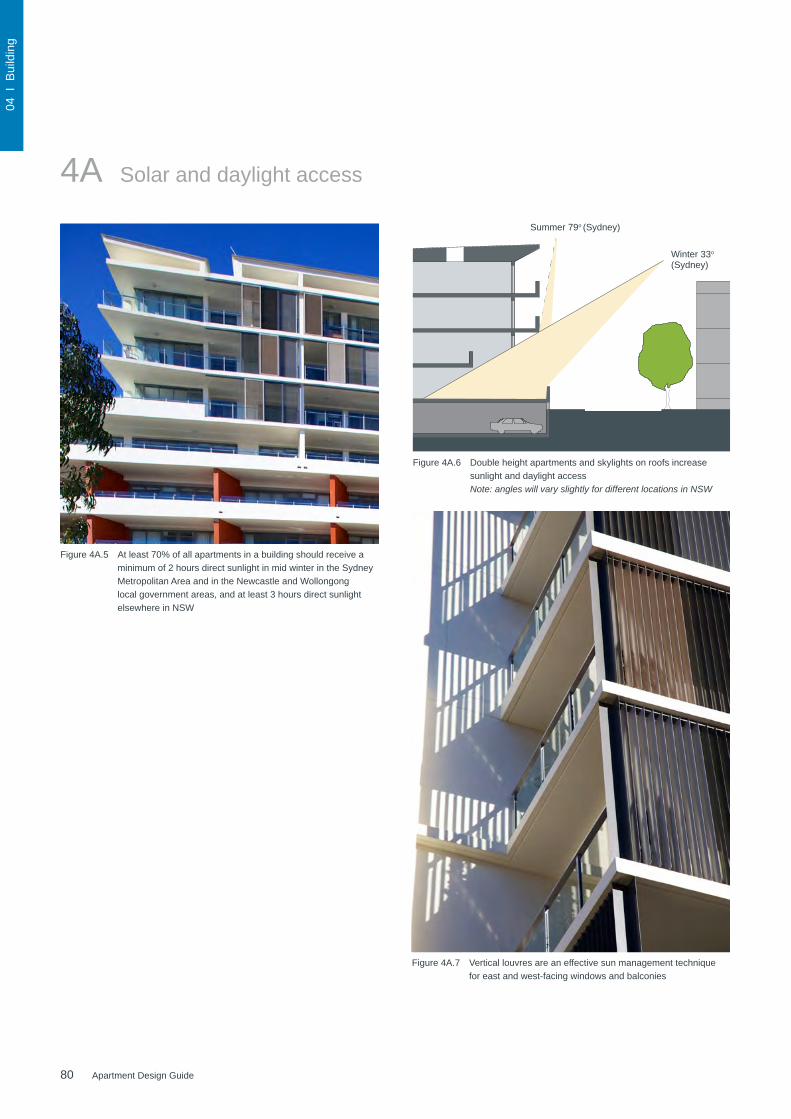
80 Apartment Design Guide
04 I
Bui
ldin
g
Figure 4A.5 At least 70% of all apartments in a building should receive a minimum of 2 hours direct sunlight in mid winter in the Sydney Metropolitan Area and in the Newcastle and Wollongong local government areas, and at least 3 hours direct sunlight elsewhere in NSW
Figure 4A.6 Double height apartments and skylights on roofs increase sunlight and daylight access Note: angles will vary slightly for different locations in NSW
Summer 79o (Sydney)
Winter 33o
(Sydney)
4A Solar and daylight access
Figure 4A.7 Vertical louvres are an effective sun management technique for east and west-facing windows and balconies
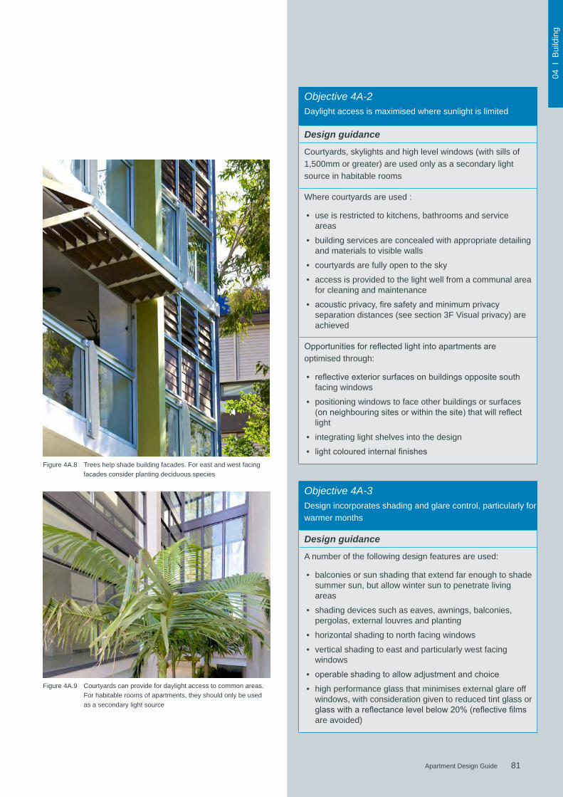
81Apartment Design Guide
04 I
Bui
ldin
g
81Apartment Design Guide
Figure 4A.9 Courtyards can provide for daylight access to common areas. For habitable rooms of apartments, they should only be used as a secondary light source
Figure 4A.8 Trees help shade building facades. For east and west facing facades consider planting deciduous species
Objective 4A-3Design incorporates shading and glare control, particularly for warmer months
Design guidance
A number of the following design features are used:
• balconies or sun shading that extend far enough to shade summer sun, but allow winter sun to penetrate living areas
• shading devices such as eaves, awnings, balconies, pergolas, external louvres and planting
• horizontal shading to north facing windows
• vertical shading to east and particularly west facing windows
• operableshadingtoallowadjustmentandchoice
• high performance glass that minimises external glare off windows, with consideration given to reduced tint glass or glasswithareflectancelevelbelow20%(reflectivefilmsare avoided)
Objective 4A-2Daylight access is maximised where sunlight is limited
Design guidance
Courtyards, skylights and high level windows (with sills of 1,500mm or greater) are used only as a secondary light source in habitable rooms
Where courtyards are used :
• use is restricted to kitchens, bathrooms and service areas
• building services are concealed with appropriate detailing and materials to visible walls
• courtyards are fully open to the sky
• access is provided to the light well from a communal area for cleaning and maintenance
• acousticprivacy,firesafetyandminimumprivacyseparation distances (see section 3F Visual privacy) are achieved
Opportunitiesforreflectedlightintoapartmentsareoptimised through:
• reflectiveexteriorsurfacesonbuildingsoppositesouthfacing windows
• positioning windows to face other buildings or surfaces (onneighbouringsitesorwithinthesite)thatwillreflectlight
• integrating light shelves into the design
• lightcolouredinternalfinishes
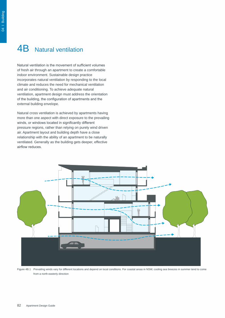
82 Apartment Design Guide
04 I
Bui
ldin
g
4B Natural ventilation
Naturalventilationisthemovementofsufficientvolumesof fresh air through an apartment to create a comfortable indoor environment. Sustainable design practice incorporates natural ventilation by responding to the local climate and reduces the need for mechanical ventilation and air conditioning. To achieve adequate natural ventilation, apartment design must address the orientation ofthebuilding,theconfigurationofapartmentsandtheexternal building envelope.
Natural cross ventilation is achieved by apartments having more than one aspect with direct exposure to the prevailing winds,orwindowslocatedinsignificantlydifferentpressure regions, rather than relying on purely wind driven air. Apartment layout and building depth have a close relationship with the ability of an apartment to be naturally ventilated. Generally as the building gets deeper, effective airflowreduces.
Figure 4B.1 Prevailing winds vary for different locations and depend on local conditions. For coastal areas in NSW, cooling sea breezes in summer tend to come
from a north-easterly direction

83Apartment Design Guide
04 I
Bui
ldin
g
83Apartment Design Guide
Figure 4B.2 Operable balcony screens allow occupants to customise their environment and regulate access of natural light and ventilation
Objective 4B-1All habitable rooms are naturally ventilated
Design guidance
The building's orientation maximises capture and use of prevailing breezes for natural ventilation in habitable rooms
Depths of habitable rooms support natural ventilation
The area of unobstructed window openings should be equal toatleast5%ofthefloorareaserved
Light wells are not the primary air source for habitable rooms
Doors and openable windows maximise natural ventilation opportunities by using the following design solutions:
• adjustablewindowswithlargeeffectiveopenableareas
• a variety of window types that provide safety and flexibilitysuchasawningsandlouvres
• windowswhichtheoccupantscanreconfiguretofunnelbreezes into the apartment such as vertical louvres, casement windows and externally opening doors
Objective 4B-2The layout and design of single aspect apartments maximises natural ventilation
Design guidance
Apartment depths are limited to maximise ventilation and airflow(seealsofigure4D.3)
Natural ventilation to single aspect apartments is achieved with the following design solutions:
• primary windows are augmented with plenums and light wells (generally not suitable for cross ventilation)
• stack effect ventilation / solar chimneys or similar to naturally ventilate internal building areas or rooms such as bathrooms and laundries
• courtyards or building indentations have a width to depth ratio of 2:1 or 3:1 to ensure effective air circulation and avoid trapped smells

84 Apartment Design Guide
04 I
Bui
ldin
g
Figure 4B.4 Responding to the local climate reduces the need for mechanical ventilation and air conditioning
Figure 4B.5 Natural cross ventilation is facilitated by limited apartment depths and use of dual aspect apartments
Figure 4B.6 Natural ventilation is further enhanced by using generous window and door openings
Figure 4B.7 Operable louvres allow residents to regulate natural ventilation
4B Natural ventilation
Inlet
(m2)
Outlet
(m2)
Figure 4B.3 Effective cross ventilation is achieved when the inlet and outlet have approximately the same area, allowing air to be drawn through the apartment using opposite air pressures on each side of the building

85Apartment Design Guide
04 I
Bui
ldin
g
85Apartment Design Guide
Figure 4B.8 Thefloorplanabovedemonstratesoneapproachforhowfiveof a total of eight apartments achieve natural cross ventilation
Objective 4B-3The number of apartments with natural cross ventilation is maximised to create a comfortable indoor environment for residents
Design criteria
1. At least 60% of apartments are naturally cross ventilatedinthefirstninestoreysofthebuilding.Apartments at ten storeys or greater are deemed to be cross ventilated only if any enclosure of the balconies at these levels allows adequate natural ventilation and cannot be fully enclosed
2. Overall depth of a cross-over or cross-through apartment does not exceed 18m, measured glass line to glass line
Design guidance
The building should include dual aspect apartments, cross through apartments and corner apartments and limit apartment depths
In cross-through apartments external window and door opening sizes/areas on one side of an apartment (inlet side) are approximately equal to the external window and door opening sizes/areas on the other side of the apartment (outletside)(seefigure4B.4)
Apartments are designed to minimise the number of corners,doorsandroomsthatmightobstructairflow
Apartment depths, combined with appropriate ceiling heights,maximisecrossventilationandairflow
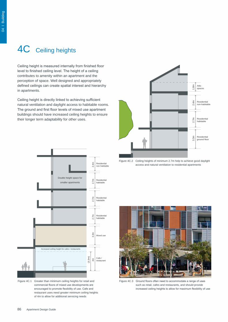
86 Apartment Design Guide
04 I
Bui
ldin
g
Attic spaces 1.
8m
Residential non-habitable 2.
4m
Residential habitable
Residential ground floor
2.7m
3.3m
Residential non-habitable 2.
4m
Residential habitable
Mixed use
2.7m
Residential habitable 2.
7m
Residential habitable 2.
7m3.
3m
(3.3
m)
Cafe / restaurant 4
m
4C Ceiling heights
Ceilingheightismeasuredinternallyfromfinishedfloorleveltofinishedceilinglevel.Theheightofaceilingcontributes to amenity within an apartment and the perception of space. Well designed and appropriately definedceilingscancreatespatialinterestandhierarchyin apartments.
Ceilingheightisdirectlylinkedtoachievingsufficientnatural ventilation and daylight access to habitable rooms. Thegroundandfirstfloorlevelsofmixeduseapartmentbuildings should have increased ceiling heights to ensure their longer term adaptability for other uses.
Increased ceiling height for cafes / restaurants
Figure 4C.1 Greater than minimum ceiling heights for retail and commercialfloorsofmixedusedevelopmentsareencouragedtopromoteflexibilityofuse.Cafeandrestaurant uses need greater minimum ceiling heights of 4m to allow for additional servicing needs
Figure 4C.2 Ceiling heights of minimum 2.7m help to achieve good daylight access and natural ventilation to residential apartments
Figure 4C.3 Groundfloorsoftenneedtoaccommodatearangeofusessuch as retail, cafes and restaurants, and should provide increasedceilingheightstoallowformaximumflexibilityofuse
Double height space for
smaller apartments

87Apartment Design Guide
04 I
Bui
ldin
g
87Apartment Design Guide
Service bulkhead
Non-habitable (e.g. bathroom) 2
.7m
3.1m
2.4m
Figure 4C.4 Differing ceiling heights are an opportunity to provide visual interest in the building facade
Objective 4C-2Ceiling height increases the sense of space in apartments and provides for well proportioned rooms
Design guidance
A number of the following design solutions can be used:
• thehierarchyofroomsinanapartmentisdefinedusingchanges in ceiling heights and alternatives such as raked or curved ceilings, or double height spaces
• well proportioned rooms are provided, for example, smaller rooms feel larger and more spacious with higher ceilings
• ceiling heights are maximised in habitable rooms by ensuring that bulkheads do not intrude. The stacking ofserviceroomsfromfloortofloorandcoordinationofbulkhead location above non-habitable areas, such as robes or storage, can assist
Objective 4C-3Ceilingheightscontributetotheflexibilityofbuildinguseoverthe life of the building
Design guidance
Ceiling heights of lower level apartments in centres should be greater than the minimum required by the design criteria allowingflexibilityandconversiontonon-residentialuses(seefigure4C.1)
Figure 4C.5 Service bulkheads are wholly contained within non-habitable rooms and do not intrude into habitable spaces
Objective 4C-1Ceilingheightachievessufficientnaturalventilationanddaylight access
Design criteria
1. Measuredfromfinishedfloorleveltofinishedceilinglevel, minimum ceiling heights are:
Minimum ceiling height for apartment and mixed use buildings
Habitable rooms 2.7m
Non-habitable 2.4m
For 2 storey apartments
2.7mformainlivingareafloor
2.4mforsecondfloor,whereitsarea does not exceed 50% of the apartment area
Attic spaces 1.8m at edge of room with a 30 degree minimum ceiling slope
If located in mixed used areas
3.3mforgroundandfirstfloortopromotefutureflexibilityofuse
These minimums do not preclude higher ceilings if desired
Design guidance
Ceiling height can accommodate use of ceiling fans for cooling and heat distribution
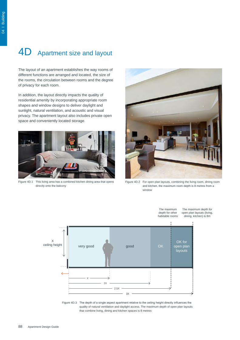
88 Apartment Design Guide
04 I
Bui
ldin
g
4D Apartment size and layout
The layout of an apartment establishes the way rooms of different functions are arranged and located, the size of the rooms, the circulation between rooms and the degree of privacy for each room.
In addition, the layout directly impacts the quality of residential amenity by incorporating appropriate room shapes and window designs to deliver daylight and sunlight, natural ventilation, and acoustic and visual privacy. The apartment layout also includes private open space and conveniently located storage.
Figure 4D.1 This living area has a combined kitchen dining area that opens directly onto the balcony
Figure 4D.2 For open plan layouts, combining the living room, dining room and kitchen, the maximum room depth is 8 metres from a window
Figure 4D.3 Thedepthofasingleaspectapartmentrelativetotheceilingheightdirectlyinfluencesthequality of natural ventilation and daylight access. The maximum depth of open plan layouts that combine living, dining and kitchen spaces is 8 metres
very good
X
X ceiling height good OK
OK for open plan
layouts
2X
2.5X
3X
The maximum depth for open plan layouts (living,
dining, kitchen) is 8m
The maximum depth for other
habitable rooms
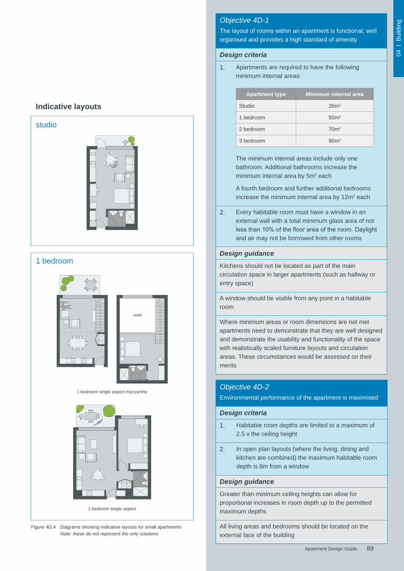
89Apartment Design Guide
04 I
Bui
ldin
g
89Apartment Design Guide
Objective 4D-1The layout of rooms within an apartment is functional, well organised and provides a high standard of amenity
Design criteria
1. Apartments are required to have the following minimum internal areas:
Apartment type Minimum internal area
Studio 35m2
1 bedroom 50m2
2 bedroom 70m2
3 bedroom 90m2
The minimum internal areas include only one bathroom. Additional bathrooms increase the minimum internal area by 5m2 each
A fourth bedroom and further additional bedrooms increase the minimum internal area by 12m2 each
2. Every habitable room must have a window in an external wall with a total minimum glass area of not lessthan10%ofthefloorareaoftheroom.Daylightand air may not be borrowed from other rooms
Design guidance
Kitchens should not be located as part of the main circulation space in larger apartments (such as hallway or entry space)
A window should be visible from any point in a habitable room
Where minimum areas or room dimensions are not met apartments need to demonstrate that they are well designed and demonstrate the usability and functionality of the space with realistically scaled furniture layouts and circulation areas. These circumstances would be assessed on their merits
Objective 4D-2Environmental performance of the apartment is maximised
Design criteria
1. Habitable room depths are limited to a maximum of 2.5 x the ceiling height
2. In open plan layouts (where the living, dining and kitchen are combined) the maximum habitable room depth is 8m from a window
Design guidance
Greater than minimum ceiling heights can allow for proportional increases in room depth up to the permitted maximum depths
All living areas and bedrooms should be located on the external face of the building
1 bedroom single aspect mezzanine
void
1 bedroom single aspect
1 bedroom
studio
Indicative layouts
Figure 4D.4 Diagrams showing indicative layouts for small apartments Note: these do not represent the only solutions

90 Apartment Design Guide
04 I
Bui
ldin
g
Figure 4D.5 Diagrams showing indicative layouts for 2 bedroom apartments Note: these do not represent the only solutions
2 bedroom “L” dual aspect apartment
2bedroommid-floorplate2storeygalleryaccess
2bedroommid-floorplatecross-over
2 bedroom corner apartment
2 bedroom
Indicative layouts
4D Apartment size and layout
2bedroommid-floorplatesingleaspect

91Apartment Design Guide
04 I
Bui
ldin
g
91Apartment Design Guide
Figure 4D.6 Diagrams showing indicative layouts for 3 bedroom apartments Note: these do not represent the only solutions
3 bedroom corner apartment
3bedroommid-floorplatecross-throughapartment
3 bedroom
Indicative layouts
Objective 4D-3Apartment layouts are designed to accommodate a variety of household activities and needs
Design criteria
1. Master bedrooms have a minimum area of 10m2 and other bedrooms 9m2 (excluding wardrobe space)
2. Bedrooms have a minimum dimension of 3m (excluding wardrobe space)
3. Living rooms or combined living/dining rooms have a minimum width of:• 3.6m for studio and 1 bedroom apartments
• 4m for 2 and 3 bedroom apartments
4. The width of cross-over or cross-through apartments are at least 4m internally to avoid deep narrow apartment layouts
Design guidance
Access to bedrooms, bathrooms and laundries is separated from living areas minimising direct openings between living and service areas
All bedrooms allow a minimum length of 1.5m for robes
The main bedroom of an apartment or a studio apartment should be provided with a wardrobe of a minimum 1.8m long, 0.6m deep and 2.1m high
Apartmentlayoutsallowflexibilityovertime,designsolutions may include:
• dimensions that facilitate a variety of furniture arrangements and removal
• spaces for a range of activities and privacy levels between different spaces within the apartment
• dual master apartments
• dual key apartments Note: dual key apartments which are separate but on the same title are regarded as two sole occupancy units for the purposes of the Building Code of Australia and for calculating the mix of apartments
• room sizes and proportions or open plans (rectangular spaces (2:3) are more easily furnished than square spaces (1:1))
• efficientplanningofcirculationbystairs,corridorsandthroughroomstomaximisetheamountofusablefloorspace in rooms
Where possible:
• bathrooms and laundries should have an external openable window
• main living spaces should be oriented toward the primary outlook and aspect and away from noise sources

92 Apartment Design Guide
04 I
Bui
ldin
g
Figure 4E.1 Balconies, courtyards and terraces enhance the amenity and indoor/outdoor lifestyle of residents
Groundfloorapartmentsand podium levels should provide private terraces
A balcony with a minimum depth of 2 metres is appropriate for 1 and 2 bedroom apartmentsandfitsatable and 2-4 chairs
A balcony for a three bedroom apartment has a minimum depth of 2.4 metres fitsatableand4-6chairs
Noisy locations may necessitate different solutions such as enclosed wintergardens, balconies with operable walls,baywindowsorjulietbalconies
2.4m min.2m min.
Figure 4E.2 Diagrams illustrating minimum balcony depth and options for noise treatment
4E Private open space and balconies
Private open spaces are outdoor spaces of the apartment, including balconies, courtyards and terraces, which enhance the amenity and indoor/outdoor lifestyle of residents. They capitalise on New South Wales' temperate climate, providing an area for external activities and an extension of living spaces.
Balconies that are safe and appropriately designed can provide space for children to play outdoors, and the opportunity for pet ownership.
Private open spaces are also important architectural elements on the outside of an apartment building, contributing to the form and articulation of the building with fences, balustrades and screens.

93Apartment Design Guide
04 I
Bui
ldin
g
93Apartment Design Guide
Figure 4E.3 Minimum balcony depths ensure that the balcony area is useable and can be easily accessed
Figure 4E.4 Building layout should maximise balcony use by allowing access from the main living area and a bedroom (where possible). Secondary balconies provide further amenity to apartment living and are best accessed off kitchens and laundries
Figure 4E.5 Primary balconies provide outdoor living, articulate the building facade and contribute to the safety of the public domain through increased surveillance opportunities
Objective 4E-2Primary private open space and balconies are appropriately located to enhance liveability for residents
Design guidance
Primary open space and balconies should be located adjacenttothelivingroom,diningroomorkitchentoextendthe living space
Private open spaces and balconies predominantly face north, east or west
Primary open space and balconies should be orientated with the longer side facing outwards or be open to the sky to optimisedaylightaccessintoadjacentrooms
Objective 4E-1Apartments provide appropriately sized private open space and balconies to enhance residential amenity
Design criteria
1. All apartments are required to have primary balconies as follows:
Dwelling type
Minimum area
Minimum depth
Studio apartments 4m2 -
1 bedroom apartments 8m2 2m
2 bedroom apartments 10m2 2m
3+ bedroom apartments 12m2 2.4m
The minimum balcony depth to be counted as contributing to the balcony area is 1m
2. For apartments at ground level or on a podium or similar structure, a private open space is provided instead of a balcony. It must have a minimum area of 15m2 and a minimum depth of 3m
Design guidance
Increased communal open space should be provided where the number or size of balconies are reduced
Storage areas on balconies is additional to the minimum balcony size
Balcony use may be limited in some proposals by:
• consistently high wind speeds at 10 storeys and above
• close proximity to road, rail or other noise sources
• exposuretosignificantlevelsofaircraftnoise
• heritage and adaptive reuse of existing buildings
Inthesesituations,julietbalconies,operablewalls,enclosedwintergardens or bay windows may be appropriate, and otheramenitybenefitsforoccupantsshouldalsobeprovided in the apartments or in the development or both. Natural ventilation also needs to be demonstrated
2.4m min.

94 Apartment Design Guide
04 I
Bui
ldin
g
4E Private open space and balconies
Figure 4E.6 For one and two bedroom apartments, balconies should be at least 2m deep to allow enough space for a small table
Figure 4E.7 Balconies should be designed to be safe outdoor spaces for children
Figure 4E.8 Partially solid fences and balustrades allow views and passive surveillance of the street while maintaining visual privacy to ground level apartments
Figure 4E.9 A combination of solid and transparent materials balances the need for privacy with surveillance of the public domain
Figure 4E.10 Viewed from the inside, screening increases privacy and allows for storage and external clothes drying

95Apartment Design Guide
04 I
Bui
ldin
g
95Apartment Design Guide
Figure 4E.11 Setting the balustrade back from the building edge allows for landscaping towards the street for increased privacy
Figure 4E.12 Soffitsandundersidesofbalconiesshouldbewelldetailedasthey are visible from the street
Objective 4E-3Private open space and balcony design is integrated into and contributes to the overall architectural form and detail of the building
Design guidance
Solid, partially solid or transparent fences and balustrades are selected to respond to the location. They are designed to allow views and passive surveillance of the street while maintaining visual privacy and allowing for a range of uses on the balcony. Solid and partially solid balustrades are preferred
Full width full height glass balustrades alone are generally not desirable
Projectingbalconiesshouldbeintegratedintothebuildingdesignandthedesignofsoffitsconsidered
Operable screens, shutters, hoods and pergolas are used to control sunlight and wind
Balustrades are set back from the building or balcony edge where overlooking or safety is an issue
Downpipes and balcony drainage are integrated with the overall facade and building design
Air-conditioning units should be located on roofs, in basements, or fully integrated into the building design
Where clothes drying, storage or air conditioning units are located on balconies, they should be screened and integrated in the building design
Ceilings of apartments below terraces should be insulated to avoid heat loss
Water and gas outlets should be provided for primary balconies and private open space
Objective 4E-4Private open space and balcony design maximises safety
Design guidance
Changes in ground levels or landscaping are minimised
Design and detailing of balconies avoids opportunities for climbing and falls
Pho
to: M
icha
el Z
anar
do
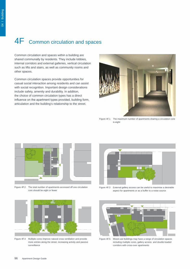
96 Apartment Design Guide
04 I
Bui
ldin
g
4F Common circulation and spaces
Common circulation and spaces within a building are shared communally by residents. They include lobbies, internal corridors and external galleries, vertical circulation such as lifts and stairs, as well as community rooms and other spaces.
Common circulation spaces provide opportunities for casual social interaction among residents and can assist with social recognition. Important design considerations include safety, amenity and durability. In addition, the choice of common circulation types has a direct influenceontheapartmenttypesprovided,buildingform,articulation and the building’s relationship to the street.
N
elevation
section
50m0
LINEAR COURTYARD APARTMENT
CONTEXTLinear courtyard apartments are suited to sites with a secondary street address. They are typically situated in suburban contexts thatbenefit from a street hierarchy that includes a laneway structure.
EXISTING SITEThe case study shows the amalgamation of four mid-block detached house lots for two residential flat buildings over a joint car park. Other characteristics include:* northeast frontage to lane and southwest frontage to street* fall from street to lane with deep soil zone established along the street* neighbouring apartment buildings with different site layout approaches
PROPOSED BUILDING TYPETwo buildings step down the slope with 12m building separation between them. The larger 4 storey building fronts the wider street whilst the smaller 3 storey building fronts the narrower lane. The lower building allows sunlight access over it to the building behind. The primary address is to main street however the circulation runs through to the rear building. A secondary address is possible from the lane. The taller building has lift access whilst the shorter building is walk-up. The communal open space is located between the buildings immediately accessible from the building circulation. Deep soil is located in the centre of the site and in the front setback both of which sustain large tree plantings. Vehicular access is from the lane to a split level car park which is located predominantly below the building footprint. Side walls are predominantly blank with small windows to non-habitable rooms.
DATASite dimensions 40 x 45mSite area 1800m2FSR 1.3:1Height 3 - 4 storeysBuilding depth 7.8 - 16.2mFront setback 6mSide setback 3mRear setback 3mDeep soil 21%Trees 5 x LargeThis example contains: 22 x 2 Bed
30 x Car spaces
plan
Site BoundaryPrevious SubdivisionPrevious Building FootprintFuture HeightParty WallsWall With WindowsPotential Vehicle AccessPotential Pedestrian AccessNoiseAdjoining Open Space
75m0N
TOWER APARTMENT
CONTEXTTower developments are suited to dense urban areas such as regional cities and major centres. They are often comprise mixed uses at lower levels and may be in central business districts. Building separation is important.
EXISTING SITEThe case study shows a single inner city corner site with a previous low rise building being redeveloped for a residential tower over a mixed use podium. Other characteristics include:* southwest and southeast street frontages* relatively flat site* a variety of commercial building neighbours with party wall conditions
PROPOSED BUILDING TYPEThe ground floor is retail in use, has full site coverage, and addresses the street with an awning. Three levels of commercial floor space are located over, forming a strong street wall that has punched window openings and responds to the parapet height of the neighbouring buildings. Planting on structure is provided on the podium. The residential tower component sits above this, defines the corner, and is more open and vertically proportioned. It has a typical floorplate, but visually collects floors together with varied facade treatments to reduce repetitiveness. The tower is lifted off the podium with a recessed floor and has a distinctive treatment for the top floors. Each floor has eight units around the core and windows are provided to the ends of circulation hallways. The building is separated from its neighbours, units face towards north for solar access and corner apartments benefit from cross ventilation. Higher balconies are enclosed because of consistent high wind speeds.
DATASite dimensions 45.6 x 38.4m Site area 1748m2FSR 8.4:1 (including 2.8:1 retail/commercial)Height 4 - 25 storeysBuilding depth 18m (21.6m commercial)Front setback 0m (2.4m at upper)Side setback 0m (0 - 4.5m at upper)Rear setback 0m (24m at upper)Deep soil 0% (planting on structure 6%)Trees 3 x MediumThis example contains: Retail 1400m2 (80% of ground floor)
Commercial 3500m236 x Studio64 x 1 Bed40 x 2 Bed10 x 3 Bed192 x Car spaces
plan
elevation
section
Site BoundaryPrevious SubdivisionPrevious Building FootprintFuture HeightParty WallsWall With WindowsPotential Vehicle AccessPotential Pedestrian AccessNoiseAdjoining Open Space
Figure 4F.1 The maximum number of apartments sharing a circulation core is eight
Figure 4F.2 The total number of apartments accessed off one circulation core should be eight or fewer
elevation
section
plan
N 50m0
SLAB APARTMENT
CONTEXTSlab apartments are suited to denser urban areas with larger sites, or may be a component of a perimeter block form. They are typically elongated plans with a controlled depth. Units are arranged along a corridor, may be single or double loaded, and can cross-over for improved solar access and ventilation.
EXISTING SITEThe case study shows a single corner lot in a transitional industrial area being redeveloped for a mixed use perimeter block slab building. Other characteristics include:* northwest and southwest frontage to busy streets* flood prone topography requiring the ground floor to be raised above the street* a variety of neighbours from factories to recent apartment buildings
PROPOSED BUILDING TYPEThe building is built hard to both street frontages and defines curved corner. Separation is provided from the rear boundaries for privacy and deep soil. The ground floor is a colonnade with setback retail/commercial and has steps and ramps to make a level change up from the footpath. Residential is set above the hostile street level. Two storey units are arranged along an open gallery to maximise northern solar access, whilst single storey units are stacked on the corner adjacent to the lift core. Communal open space is provided to the rear of the site with deep soil and trees and also at roof level where solar access is available. Vehicular access is from the quieter of the two streets. Side setbacks respond to existing neighbours and anticipate future neighbours of a similar scale.
DATASite dimensions 40.8 x 23.4mSite area 950m2FSR 3.3:1Height 6-7 storeysBuilding depth 9.6 - 13.5mFront setback 0mSide setback 0mRear setback 10.2mDeep soil 15%Trees 1 x Medium 1 x LargeThis example contains: 400m2 Retail/Commercial
18 x 2 Bed11 x 3 Bed48 x Car spaces
Site BoundaryPrevious SubdivisionPrevious Building FootprintFuture HeightParty WallsWall With WindowsPotential Vehicle AccessPotential Pedestrian AccessNoiseAdjoining Open Space
75m0N
plan
elevation
section
Site BoundaryPrevious SubdivisionPrevious Building FootprintFuture HeightParty WallsWall With WindowsPotential Vehicle AccessPotential Pedestrian AccessNoiseAdjoining Open Space
MIXED USE APARTMENT
CONTEXTMixed use developments are suited to larger metropolitan and regional centres. Care must be taken to ensure a contextual fit with finer grain neighbours.
EXISTING SITEThe case study shows the amalgamation of four commercial lots on the corner of two streets for a large single storey retail premises with residential flat buildings on the podium over. Other characteristics include:* northwest and southern street frontages with sharp corner* gradual fall along the length of the site* attached commercial and detached residential flat building neighbours
PROPOSED BUILDING TYPEThe ground floor is commercial and has full site coverage. The acute street corner is positively defined and both streets are addressed with open commercial frontages and an awning which turns the corner. Lift cores to the 4 and 6 storey residential buildings above are located at the street edge to provide strong address and to avoid hindering the retail floorspace. Single storey units are stacked vertically on the corner and accessed from an open gallery whilst crossover apartments are used to either side to maximise northern sunlight access. Communal open space is provided on the podium with substantial planting on structure, large trees and 12m building separation. Vehicular access and loading dock is accessed from the side street with two levels of basement parking. Side setbacks anticipate future neighbours.
DATASite dimensions 80 x 45m (irregular)Site area 2840m2FSR 2.8:1 (including 0.8:1 retail)Height 5 - 7 storeysBuilding depth 10.2 - 17.1mFront setback 0m (0 - 2.4m at upper)Side setback 0m (0 - 3m at upper)Rear setback 0m (9m at upper)Deep soil 0% (planting on structure 12%)Trees 3 x LargeThis example contains: Retail 2272m2 (80% of ground floor)
16 x 1 Bed42 x 2 Bed6 x 3 Bed210 x Car spaces
Figure 4F.3 External gallery access can be useful to maximise a desirable aspect for apartments or as a buffer to a noise source
Figure 4F.4 Multiple cores improve natural cross ventilation and provide more entries along the street, increasing activity and passive surveillance
Figure 4F.5 Mixed use buildings may have a range of circulation spaces including multiple cores, gallery access and double-loaded corridors with cross-over apartments

97Apartment Design Guide
04 I
Bui
ldin
g
97Apartment Design Guide
Figure 4F.6 Common areas should be provided in larger developments
Objective 4F-1Common circulation spaces achieve good amenity and properly service the number of apartments
Design criteria
1. The maximum number of apartments off a circulation core on a single level is eight
2. For buildings of 10 storeys and over, the maximum number of apartments sharing a single lift is 40
Design guidance
Greater than minimum requirements for corridor widths and/or ceiling heights allow comfortable movement and access particularly in entry lobbies, outside lifts and at apartment entry doors
Daylight and natural ventilation should be provided to all common circulation spaces that are above ground
Windows should be provided in common circulation spaces andshouldbeadjacenttothestairorliftcoreorattheendsof corridors
Longer corridors greater than 12m in length from the lift core should be articulated. Design solutions may include:
• a series of foyer areas with windows and spaces for seating
• wider areas at apartment entry doors and varied ceiling heights
Design common circulation spaces to maximise opportunities for dual aspect apartments, including multiple core apartment buildings and cross over apartments
Achieving the design criteria for the number of apartments off a circulation core may not be possible. Where a development is unable to achieve the design criteria, a high level of amenity for common lobbies, corridors and apartments should be demonstrated, including:
• sunlight and natural cross ventilation in apartments
• access to ample daylight and natural ventilation in common circulation spaces
• common areas for seating and gathering
• generous corridors with greater than minimum ceiling heights
• other innovative design solutions that provide high levels of amenity
Where design criteria 1 is not achieved, no more than 12 apartments should be provided off a circulation core on a single level
Primary living room or bedroom windows should not open directly onto common circulation spaces, whether open or enclosed. Visual and acoustic privacy from common circulation spaces to any other rooms should be carefully controlled
Window
Figure 4F.7 Windows provide daylight and natural ventilation to common circulation spaces
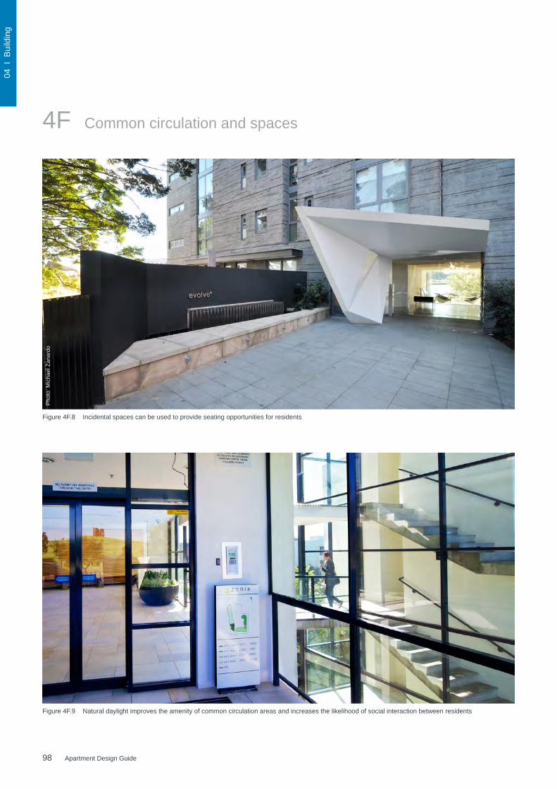
98 Apartment Design Guide
04 I
Bui
ldin
g
4F Common circulation and spaces
Figure 4F.8 Incidental spaces can be used to provide seating opportunities for residents
Figure 4F.9 Natural daylight improves the amenity of common circulation areas and increases the likelihood of social interaction between residents
Pho
to: M
icha
el Z
anar
do

99Apartment Design Guide
04 I
Bui
ldin
g
99Apartment Design Guide
Figure 4F.10 Common circulation spaces should provide short sight lines and be well lit at night
Figure 4F.11 Space for seating in common circulation spaces promotes opportunities for social interaction
Objective 4F-2Common circulation spaces promote safety and provide for social interaction between residents
Design guidance
Direct and legible access should be provided between vertical circulation points and apartment entries by minimising corridor or gallery length to give short, straight, clear sight lines
Tight corners and spaces are avoided
Circulation spaces should be well lit at night
Legible signage should be provided for apartment numbers, commonareasandgeneralwayfinding
Incidental spaces, for example space for seating in a corridor, at a stair landing, or near a window are provided
In larger developments, community rooms for activities such as owners corporation meetings or resident use should be provided and are ideally co-located with communal open space
Where external galleries are provided, they are more open than closed above the balustrade along their length
Pho
to: M
icha
el Z
anar
do

100 Apartment Design Guide
04 I
Bui
ldin
g
Figure 4G.1 Areas in car parks provide an opportunity to incorporate secure and convenient storage facilities for residents
4G Storage
Adequate storage is an important component of apartment design. It is calculated by volume as opposed tofloorareaandshouldbeprovidedproportionallytothesize of the apartment.
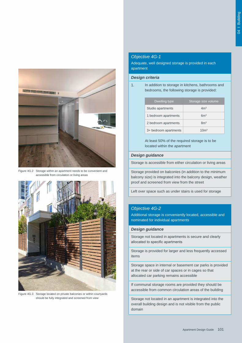
101Apartment Design Guide
04 I
Bui
ldin
g
101Apartment Design Guide
Figure 4G.2 Storage within an apartment needs to be convenient and accessible from circulation or living areas
Figure 4G.3 Storage located on private balconies or within courtyards should be fully integrated and screened from view
Objective 4G-1
Adequate, well designed storage is provided in each apartment
Design criteria
1. In addition to storage in kitchens, bathrooms and bedrooms, the following storage is provided:
Dwelling type Storage size volume
Studio apartments 4m3
1 bedroom apartments 6m3
2 bedroom apartments 8m3
3+ bedroom apartments 10m3
At least 50% of the required storage is to be located within the apartment
Design guidance
Storage is accessible from either circulation or living areas
Storage provided on balconies (in addition to the minimum balcony size) is integrated into the balcony design, weather proof and screened from view from the street
Left over space such as under stairs is used for storage
Objective 4G-2
Additional storage is conveniently located, accessible and nominated for individual apartments
Design guidance
Storage not located in apartments is secure and clearly allocatedtospecificapartments
Storage is provided for larger and less frequently accessed items
Storage space in internal or basement car parks is provided at the rear or side of car spaces or in cages so that allocated car parking remains accessible
If communal storage rooms are provided they should be accessible from common circulation areas of the building
Storage not located in an apartment is integrated into the overall building design and is not visible from the public domain
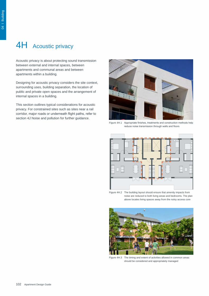
102 Apartment Design Guide
04 I
Bui
ldin
g
4H Acoustic privacy
Acoustic privacy is about protecting sound transmission between external and internal spaces, between apartments and communal areas and between apartments within a building.
Designing for acoustic privacy considers the site context, surrounding uses, building separation, the location of public and private open spaces and the arrangement of internal spaces in a building.
This section outlines typical considerations for acoustic privacy. For constrained sites such as sites near a rail corridor,majorroadsorunderneathflightpaths,refertosection 4J Noise and pollution for further guidance.
Figure 4H.1 Appropriatefinishes,treatmentsandconstructionmethodshelpreducenoisetransmissionthroughwallsandfloors
Figure 4H.2 The building layout should ensure that amenity impacts from noise are reduced to both living areas and bedrooms. The plan above locates living spaces away from the noisy access core
Figure 4H.3 The timing and extent of activities allowed in common areas should be considered and appropriately managed

103Apartment Design Guide
04 I
Bui
ldin
g
103Apartment Design Guide
Objective 4H-1Noise transfer is minimised through the siting of buildings and building layout
Design guidance
Adequate building separation is provided within the developmentandfromneighbouringbuildings/adjacentuses(see also section 2F Building separation and section 3F Visual privacy)
Window and door openings are generally orientated away from noise sources
Noisy areas within buildings including building entries and corridors should be located next to or above each other and quieter areas next to or above quieter areas
Storage, circulation areas and non-habitable rooms should be located to buffer noise from external sources
The number of party walls (walls shared with other apartments) are limited and are appropriately insulated
Noise sources such as garage doors, driveways, service areas, plant rooms, building services, mechanical equipment, active communal open spaces and circulation areas should be located at least 3m away from bedrooms
Objective 4H-2Noise impacts are mitigated within apartments through layout and acoustic treatments
Design guidance
Internal apartment layout separates noisy spaces from quiet spaces, using a number of the following design solutions:
• rooms with similar noise requirements are grouped together
• doors separate different use zones
• wardrobes in bedrooms are co-located to act as sound buffers
Where physical separation cannot be achieved noise conflictsareresolvedusingthefollowingdesignsolutions:
• double or acoustic glazing
• acoustic seals
• use of materials with low noise penetration properties
• continuous walls to ground level courtyards where theydonotconflictwithstreetscapeorotheramenityrequirements
Figure 4H.4 Bedrooms should be located at least 3m away from noise sources such as driveways and garage doors
Figure 4H.5 In addition to mindful siting and orientation of the building, acoustic seals and double or triple glazing are effective methods to further reduce noise transmission
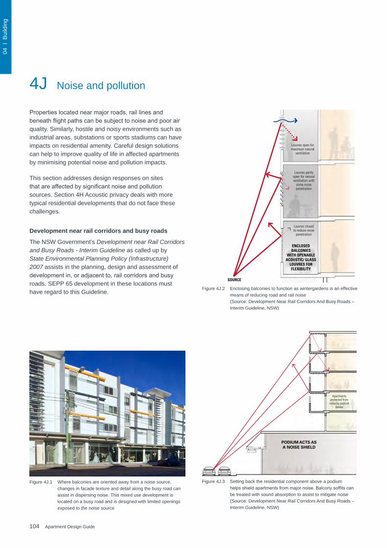
104 Apartment Design Guide
04 I
Bui
ldin
g
Propertieslocatednearmajorroads,raillinesandbeneathflightpathscanbesubjecttonoiseandpoorairquality. Similarly, hostile and noisy environments such as industrial areas, substations or sports stadiums can have impacts on residential amenity. Careful design solutions can help to improve quality of life in affected apartments by minimising potential noise and pollution impacts.
This section addresses design responses on sites thatareaffectedbysignificantnoiseandpollutionsources. Section 4H Acoustic privacy deals with more typical residential developments that do not face these challenges.
Development near rail corridors and busy roads
The NSW Government's Development near Rail Corridors and Busy Roads - Interim Guideline as called up by State Environmental Planning Policy (Infrastructure) 2007 assists in the planning, design and assessment of developmentin,oradjacentto,railcorridorsandbusyroads. SEPP 65 development in these locations must have regard to this Guideline.
4J Noise and pollution
Figure 4J.1 Where balconies are oriented away from a noise source, changes in facade texture and detail along the busy road can assist in dispersing noise. This mixed use development is located on a busy road and is designed with limited openings exposed to the noise source
December 2008 25 Development near Rail Corridors and Busy Roads – Interim Guideline Part C: Noise and Vibration
balconies
When considering balconies in building design it is important to note that the standard jutting balcony may act to reflect noise directly into the interior of the building as illustrated in the figure 3.�5.
Where balconies are required, solid balustrades with sound absorption material added to the underside of balconies above is a good means of reducing noise entering the building.
Providing enclosed balconies (or winter gardens) is another means of reducing the noise entering a building. Where enclosed balconies are used ventilation may need to be considered. By installing acoustic louvres ventilation requirements and reduced noise can be addressed. These approaches are shown in figure 3.�6.
3.8.� podiums, balconies and courtyards
podiums
Traffic noise can be substantially reduced by building residential apartments on top of a podium or commercial building space. If the residential tower is set back the podium acts to provide increased distance from the road thus shielding noise from the road to the lower apartments (see figures 3.�3 and 3.��).
pODium Acts As A nOise shielD
Apartments protected from
noise by podium below
figure 3.�3: Podiums acting as partial noise shields for residential apartments
figure 3.��: Example of commercial podium with residential apartments above
As below + higher solid balustrade
Closed solid balustrade with sound adsorption
to balcony soffit
Closed solid balustrade
Thick solid wall with fewer penetrations
Standard openBalustrade
figure 3.�5: Balcony treatments which reduce traffic noise intrusion
It should be noted that although balconies should be located away from a road, where this occurs on the southern side of a development it may result in space that is not used and that is of low amenity.
SOURCE
ENCLOSED BALCONIES
WITH OPENABLE ACOUSTIC/ GLASS
LOUVRES FOR FLEXIBILITY
Louvres open for maximum natural
ventilation
Louvres partly open for natural ventilation with
some noise penetration
Louvres closed to reduce noise
penetration
figure 3.�6: Enclosable balconies facing the road
Figure 4J.2 Enclosing balconies to function as wintergardens is an effective means of reducing road and rail noise (Source: Development Near Rail Corridors And Busy Roads – Interim Guideline, NSW)
December 2008 25 Development near Rail Corridors and Busy Roads – Interim Guideline Part C: Noise and Vibration
balconies
When considering balconies in building design it is important to note that the standard jutting balcony may act to reflect noise directly into the interior of the building as illustrated in the figure 3.�5.
Where balconies are required, solid balustrades with sound absorption material added to the underside of balconies above is a good means of reducing noise entering the building.
Providing enclosed balconies (or winter gardens) is another means of reducing the noise entering a building. Where enclosed balconies are used ventilation may need to be considered. By installing acoustic louvres ventilation requirements and reduced noise can be addressed. These approaches are shown in figure 3.�6.
3.8.� podiums, balconies and courtyards
podiums
Traffic noise can be substantially reduced by building residential apartments on top of a podium or commercial building space. If the residential tower is set back the podium acts to provide increased distance from the road thus shielding noise from the road to the lower apartments (see figures 3.�3 and 3.��).
pODium Acts As A nOise shielD
Apartments protected from
noise by podium below
figure 3.�3: Podiums acting as partial noise shields for residential apartments
figure 3.��: Example of commercial podium with residential apartments above
As below + higher solid balustrade
Closed solid balustrade with sound adsorption
to balcony soffit
Closed solid balustrade
Thick solid wall with fewer penetrations
Standard openBalustrade
figure 3.�5: Balcony treatments which reduce traffic noise intrusion
It should be noted that although balconies should be located away from a road, where this occurs on the southern side of a development it may result in space that is not used and that is of low amenity.
SOURCE
ENCLOSED BALCONIES
WITH OPENABLE ACOUSTIC/ GLASS
LOUVRES FOR FLEXIBILITY
Louvres open for maximum natural
ventilation
Louvres partly open for natural ventilation with
some noise penetration
Louvres closed to reduce noise
penetration
figure 3.�6: Enclosable balconies facing the road
Figure 4J.3 Setting back the residential component above a podium helpsshieldapartmentsfrommajornoise.Balconysoffitscanbe treated with sound absorption to assist to mitigate noise (Source: Development Near Rail Corridors And Busy Roads – Interim Guideline, NSW)
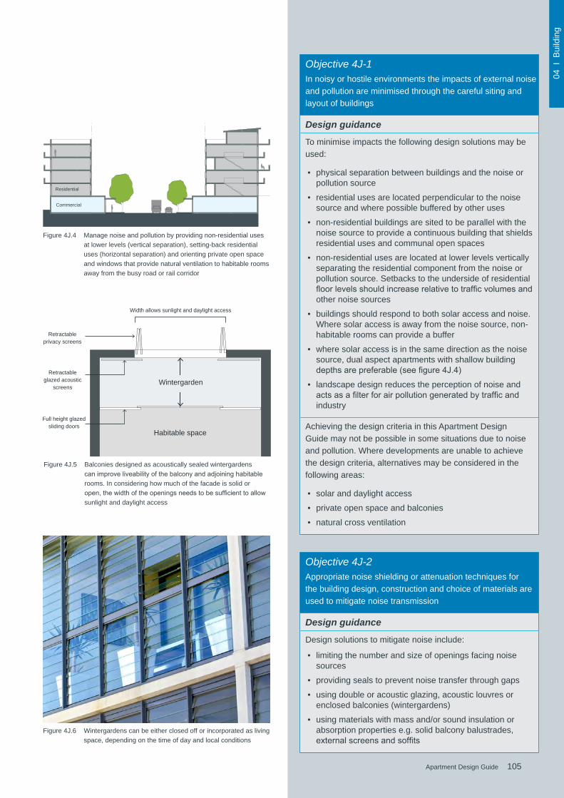
105Apartment Design Guide
04 I
Bui
ldin
g
105Apartment Design Guide
Objective 4J-1In noisy or hostile environments the impacts of external noise and pollution are minimised through the careful siting and layout of buildings
Design guidance
To minimise impacts the following design solutions may be used:
• physical separation between buildings and the noise or pollution source
• residential uses are located perpendicular to the noise source and where possible buffered by other uses
• non-residential buildings are sited to be parallel with the noise source to provide a continuous building that shields residential uses and communal open spaces
• non-residential uses are located at lower levels vertically separating the residential component from the noise or pollution source. Setbacks to the underside of residential floorlevelsshouldincreaserelativetotrafficvolumesandother noise sources
• buildings should respond to both solar access and noise. Where solar access is away from the noise source, non-habitable rooms can provide a buffer
• where solar access is in the same direction as the noise source, dual aspect apartments with shallow building depthsarepreferable(seefigure4J.4)
• landscape design reduces the perception of noise and actsasafilterforairpollutiongeneratedbytrafficandindustry
Achieving the design criteria in this Apartment Design Guide may not be possible in some situations due to noise and pollution. Where developments are unable to achieve the design criteria, alternatives may be considered in the following areas:
• solar and daylight access
• private open space and balconies
• natural cross ventilation
Objective 4J-2Appropriate noise shielding or attenuation techniques for the building design, construction and choice of materials are used to mitigate noise transmission
Design guidance
Design solutions to mitigate noise include:
• limiting the number and size of openings facing noise sources
• providing seals to prevent noise transfer through gaps
• using double or acoustic glazing, acoustic louvres or enclosed balconies (wintergardens)
• using materials with mass and/or sound insulation or absorption properties e.g. solid balcony balustrades, externalscreensandsoffits
Commercial
Residential
Figure 4J.4 Manage noise and pollution by providing non-residential uses at lower levels (vertical separation), setting-back residential uses (horizontal separation) and orienting private open space and windows that provide natural ventilation to habitable rooms away from the busy road or rail corridor
Habitable space
Retractable privacy screens
Retractable glazed acoustic
screens
Full height glazed sliding doors
Width allows sunlight and daylight access
Wintergarden
Figure 4J.5 Balconies designed as acoustically sealed wintergardens canimproveliveabilityofthebalconyandadjoininghabitablerooms. In considering how much of the facade is solid or open,thewidthoftheopeningsneedstobesufficienttoallowsunlight and daylight access
Figure 4J.6 Wintergardens can be either closed off or incorporated as living space, depending on the time of day and local conditions
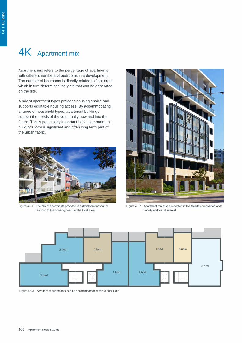
106 Apartment Design Guide
04 I
Bui
ldin
g
1 bed 1 bed studio
3 bed
2 bed2 bed2 bed
2 bed
4K Apartment mix
Apartment mix refers to the percentage of apartments with different numbers of bedrooms in a development. Thenumberofbedroomsisdirectlyrelatedtofloorareawhich in turn determines the yield that can be generated on the site.
A mix of apartment types provides housing choice and supports equitable housing access. By accommodating a range of household types, apartment buildings support the needs of the community now and into the future. This is particularly important because apartment buildingsformasignificantandoftenlongtermpartofthe urban fabric.
Figure 4K.1 The mix of apartments provided in a development should respond to the housing needs of the local area
Figure 4K.2 Apartmentmixthatisreflectedinthefacadecompositionaddsvariety and visual interest
Figure 4K.3 Avarietyofapartmentscanbeaccommodatedwithinafloorplate

107Apartment Design Guide
04 I
Bui
ldin
g
107Apartment Design Guide
Figure 4K.4 Large apartments are often located on the ground or roof level due to opportunities for increased private open space. Internal common circulation (e.g. corridors) can be reduced by adding 'up and over' apartments to the mix
3 bed
3+ bed
2 bed'up & over'
Studio
1 bed
Objective 4K-1A range of apartment types and sizes is provided to cater for different household types now and into the future
Design guidance
A variety of apartment types is provided
The apartment mix is appropriate, taking into consideration:
• the distance to public transport, employment and education centres
• thecurrentmarketdemandsandprojectedfuturedemographic trends
• the demand for social and affordable housing
• different cultural and socioeconomic groups
Flexibleapartmentconfigurationsareprovidedtosupportdiverse household types and stages of life including single person households, families, multi-generational families and group households
Objective 4K-2The apartment mix is distributed to suitable locations within the building
Design guidance
Different apartment types are located to achieve successful facadecompositionandtooptimisesolaraccess(seefigure4K.3)
Larger apartment types are located on the ground or roof level where there is potential for more open space and on corners where more building frontage is available
Figure 4K.5 Flexibleapartmentconfigurationsshouldbeprovidedtosupport diverse household types and stages of life
2 bed'up & over'

108 Apartment Design Guide
04 I
Bui
ldin
g
4L GroundfloorapartmentsGroundfloorapartmentsofferthepotentialforat-gradelandscaped private open spaces and direct access from the street. They also provide opportunities for the apartment building and its landscape to respond to the human scale of the streetscape. On steep sites they may belocatedoverdifferentfloorsofthebuildingsteppingdown the site.
Groundfloorapartmentscanbeofparticularbenefitto the elderly and disabled as they are generally more accessible. They also suit families with small children and extend the lifestyle choices available in apartment buildings by facilitating activities such as home business, gardening, outdoor play and pet ownership.
Alternativegroundfloorlayout-residential
Groundfloorplan-homeoffice
Figure 4L.1 Groundfloorapartmentsshouldaddressthepublicdomainand be accessed directly from the street
Figure 4L.2 Thegroundfloorcomponentofthisdoublestoreyapartmentisflexibleandcanbeusedasahomeoffice
Figure 4L.3 Plan and section of a double storey apartment which is directly accessible from the street
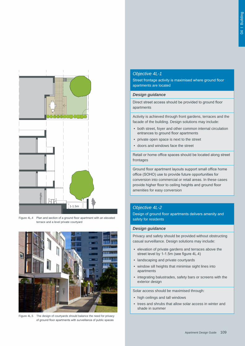
109Apartment Design Guide
04 I
Bui
ldin
g
109Apartment Design Guide
Figure 4L.5 The design of courtyards should balance the need for privacy ofgroundfloorapartmentswithsurveillanceofpublicspaces
Figure 4L.4 Planandsectionofagroundfloorapartmentwithanelevatedterrace and a level private courtyard
1-1.5m
Objective 4L-1
Streetfrontageactivityismaximisedwheregroundfloorapartments are located
Design guidance
Directstreetaccessshouldbeprovidedtogroundfloorapartments
Activity is achieved through front gardens, terraces and the facade of the building. Design solutions may include:
• both street, foyer and other common internal circulation entrancestogroundfloorapartments
• private open space is next to the street
• doors and windows face the street
Retailorhomeofficespacesshouldbelocatedalongstreetfrontages
Groundfloorapartmentlayoutssupportsmallofficehomeoffice(SOHO)usetoprovidefutureopportunitiesforconversion into commercial or retail areas. In these cases providehigherfloortoceilingheightsandgroundflooramenities for easy conversion
Objective 4L-2Designofgroundfloorapartmentsdeliversamenityandsafety for residents
Design guidance
Privacy and safety should be provided without obstructing casual surveillance. Design solutions may include:
• elevation of private gardens and terraces above the streetlevelby1-1.5m(seefigure4L.4)
• landscaping and private courtyards
• window sill heights that minimise sight lines into apartments
• integrating balustrades, safety bars or screens with the exterior design
Solar access should be maximised through:
• high ceilings and tall windows
• trees and shrubs that allow solar access in winter and shade in summer

110 Apartment Design Guide
04 I
Bui
ldin
g
Figure 4M.1 Thoughtful modulation of the facade reduces the perceived depth and bulk of a building
Figure 4M.2 Building facades should have an appropriate scale, rhythm and proportion relative to the streetscape
4M Facades
The design of facades contributes greatly to the visual interest of the building and the character of the local area. Facades that face the street have an impact on the public domain,whilesideandrearfacadesofteninfluencetheamenity of neighbouring buildings and communal and private open spaces.
High quality facades are a balanced composition of building elements, textures, materials and colour selections.Welldesignedfacadesalsoreflecttheuse,internal layout and structure of an apartment building.
The composition and detailing of a facade is not only important to the appearance of the building, it also influencesitsperceivedscale.Thepatternandrepetitionsof the facade, the proportions and articulation of external walls and the detailed design of facade elements are all important considerations.
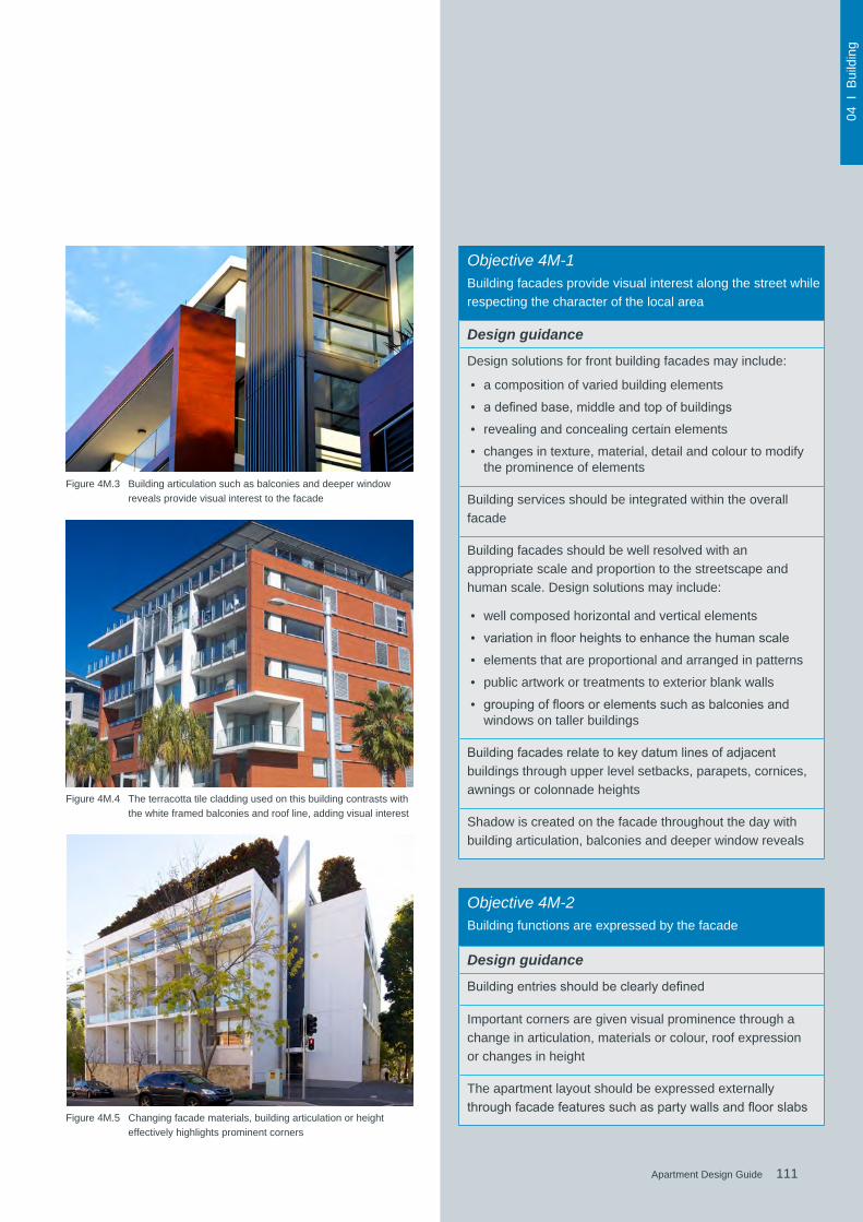
111Apartment Design Guide
04 I
Bui
ldin
g
111Apartment Design Guide
Objective 4M-1Building facades provide visual interest along the street while respecting the character of the local area
Design guidance
Design solutions for front building facades may include:
• a composition of varied building elements
• adefinedbase,middleandtopofbuildings
• revealing and concealing certain elements
• changes in texture, material, detail and colour to modify the prominence of elements
Building services should be integrated within the overall facade
Building facades should be well resolved with an appropriate scale and proportion to the streetscape and human scale. Design solutions may include:
• well composed horizontal and vertical elements
• variationinfloorheightstoenhancethehumanscale
• elements that are proportional and arranged in patterns
• public artwork or treatments to exterior blank walls
• groupingoffloorsorelementssuchasbalconiesandwindows on taller buildings
Buildingfacadesrelatetokeydatumlinesofadjacentbuildings through upper level setbacks, parapets, cornices, awnings or colonnade heights
Shadow is created on the facade throughout the day with building articulation, balconies and deeper window reveals
Objective 4M-2Building functions are expressed by the facade
Design guidance
Buildingentriesshouldbeclearlydefined
Important corners are given visual prominence through a change in articulation, materials or colour, roof expression or changes in height
The apartment layout should be expressed externally throughfacadefeaturessuchaspartywallsandfloorslabs
Figure 4M.3 Building articulation such as balconies and deeper window reveals provide visual interest to the facade
Figure 4M.4 The terracotta tile cladding used on this building contrasts with the white framed balconies and roof line, adding visual interest
Figure 4M.5 Changing facade materials, building articulation or height effectively highlights prominent corners

112 Apartment Design Guide
04 I
Bui
ldin
g
The roof is an important element in the overall composition and design of a building. Quality roof design provides a positive addition to the character of an area and can form an important part of the skyline. Roofs also provide opportunities for open space where appropriate and can add to the sustainability performance of a building.
The Standard Instrument (Local Environmental Plans) Order 2006 allows for architectural roof features that can exceed the maximum building height. This is an important tool for achieving high quality roof design and articulation.
4N Roof design
Figure 4N.1 Special roof features need to be proportionate to the overall building size, scale and form
Figure 4N.2 Architectural roof features and articulation are generally allowed to exceed the maximum statutory building height
Figure 4N.3 Solar access to apartments can be maximised by tilting roof elements towards the north
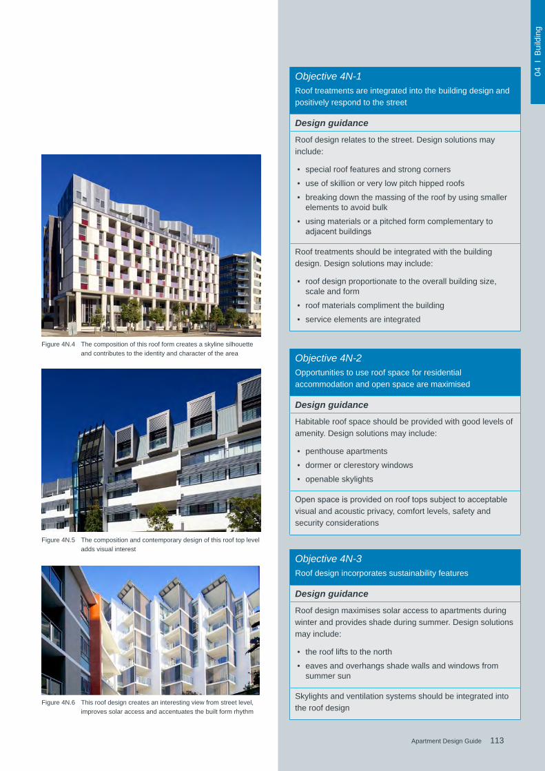
113Apartment Design Guide
04 I
Bui
ldin
g
113Apartment Design Guide
Objective 4N-1Roof treatments are integrated into the building design and positively respond to the street
Design guidance
Roof design relates to the street. Design solutions may include:
• special roof features and strong corners
• use of skillion or very low pitch hipped roofs
• breaking down the massing of the roof by using smaller elements to avoid bulk
• using materials or a pitched form complementary to adjacentbuildings
Roof treatments should be integrated with the building design. Design solutions may include:
• roof design proportionate to the overall building size, scale and form
• roof materials compliment the building
• service elements are integrated
Objective 4N-2Opportunities to use roof space for residential accommodation and open space are maximised
Design guidance
Habitable roof space should be provided with good levels of amenity. Design solutions may include:
• penthouse apartments
• dormer or clerestory windows
• openable skylights
Openspaceisprovidedonrooftopssubjecttoacceptablevisual and acoustic privacy, comfort levels, safety and security considerations
Objective 4N-3Roof design incorporates sustainability features
Design guidance
Roof design maximises solar access to apartments during winter and provides shade during summer. Design solutions may include:
• the roof lifts to the north
• eaves and overhangs shade walls and windows from summer sun
Skylights and ventilation systems should be integrated into the roof design
Figure 4N.4 The composition of this roof form creates a skyline silhouette and contributes to the identity and character of the area
Figure 4N.5 The composition and contemporary design of this roof top level adds visual interest
Figure 4N.6 This roof design creates an interesting view from street level, improves solar access and accentuates the built form rhythm

114 Apartment Design Guide
04 I
Bui
ldin
g
Figure 4O.1 Existinglandscapefeaturessuchassignificanttreescontributeto the overall quality of residential developments
Successful landscape design complements the existing natural and cultural features of a site and contributes to the building’s setting. Landscape design includes the planning, design, construction and maintenance of all external spaces.
Incorporating landscape design early in the design process provides optimal outcomes for residential apartments. It needs to be coordinated with other disciplines to ensure the building design and service locations complement the landscape and public domain.
4O Landscape design
Figure 4O.2 Landscape design should include plants endemic to the region, enhancing biodiversity and providing habitat for native wildlife
Figure 4O.3 Landscape design should respond to the local context by using complementary materials and planting schemes

115Apartment Design Guide
04 I
Bui
ldin
g
115Apartment Design Guide
Objective 4O-1Landscape design is viable and sustainable
Design guidance
Landscape design should be environmentally sustainable and can enhance environmental performance by incorporating:
• diverse and appropriate planting
• bio-filtrationgardens
• appropriately planted shading trees
• areas for residents to plant vegetables and herbs
• composting
• green roofs or walls
Ongoing maintenance plans should be prepared
Microclimate is enhanced by:
• appropriately scaled trees near the eastern and western elevations for shade
• a balance of evergreen and deciduous trees to provide shading in summer and sunlight access in winter
• shade structures such as pergolas for balconies and courtyards
Tree and shrub selection considers size at maturity and the potential for roots to compete (see Table 4)
Objective 4O-2Landscape design contributes to the streetscape and amenity
Design guidance
Landscape design responds to the existing site conditions including:
• changes of levels
• views
• significantlandscapefeaturesincludingtreesandrockoutcrops
Significantlandscapefeaturesshouldbeprotectedby:
• treeprotectionzones(seefigure4O.5)
• appropriate signage and fencing during construction
Plantsselectedshouldbeendemictotheregionandreflectthe local ecology
Figure 4O.4 Shading trees improve the microclimate and are particularly effective along the eastern and western elevations of buildings
Figure 4O.5 Where trees are retained, tree protection zones need to be established during construction to protect the canopy and roots
tree protection zone
construction zone
Table 4 Recommended tree planting in deep soil zones
Site area Recommended tree planting
Up to 850m2 1 medium tree per 50m2 of deep soil zone
Between 850 - 1,500m2 1 large tree or 2 medium trees per 90m2 of deep soil zone
Greater than 1,500m2 1 large tree or 2 medium trees per 80m2 of deep soil zone
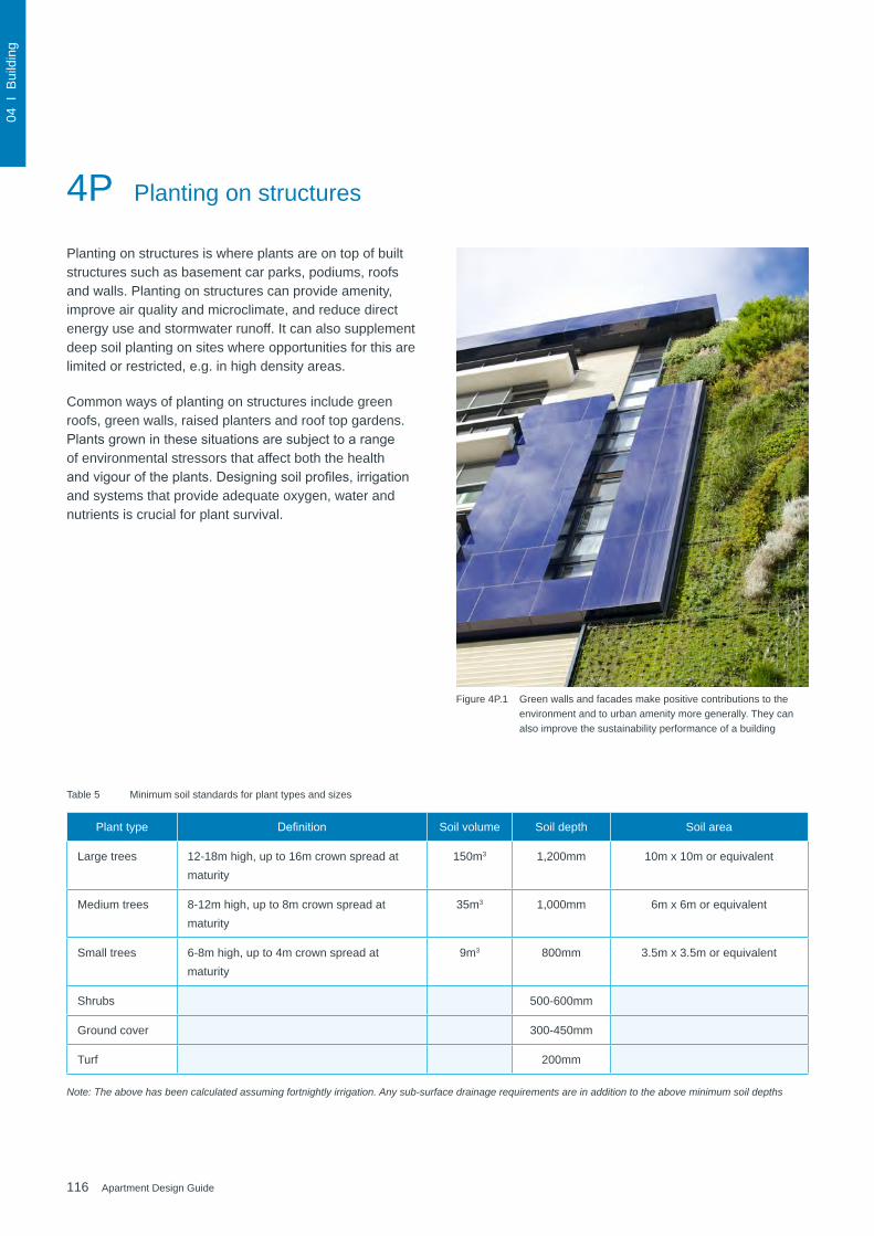
116 Apartment Design Guide
04 I
Bui
ldin
g
Figure 4P.1 Green walls and facades make positive contributions to the environment and to urban amenity more generally. They can also improve the sustainability performance of a building
Planting on structures is where plants are on top of built structures such as basement car parks, podiums, roofs and walls. Planting on structures can provide amenity, improve air quality and microclimate, and reduce direct energy use and stormwater runoff. It can also supplement deep soil planting on sites where opportunities for this are limited or restricted, e.g. in high density areas.
Common ways of planting on structures include green roofs, green walls, raised planters and roof top gardens. Plantsgrowninthesesituationsaresubjecttoarangeof environmental stressors that affect both the health andvigouroftheplants.Designingsoilprofiles,irrigationand systems that provide adequate oxygen, water and nutrients is crucial for plant survival.
4P Planting on structures
Table 5 Minimum soil standards for plant types and sizes
Plant type Definition Soil volume Soil depth Soil area
Large trees 12-18m high, up to 16m crown spread at maturity
150m3 1,200mm 10m x 10m or equivalent
Medium trees 8-12m high, up to 8m crown spread at maturity
35m3 1,000mm 6m x 6m or equivalent
Small trees 6-8m high, up to 4m crown spread at maturity
9m3 800mm 3.5m x 3.5m or equivalent
Shrubs 500-600mm
Ground cover 300-450mm
Turf 200mm
Note: The above has been calculated assuming fortnightly irrigation. Any sub-surface drainage requirements are in addition to the above minimum soil depths
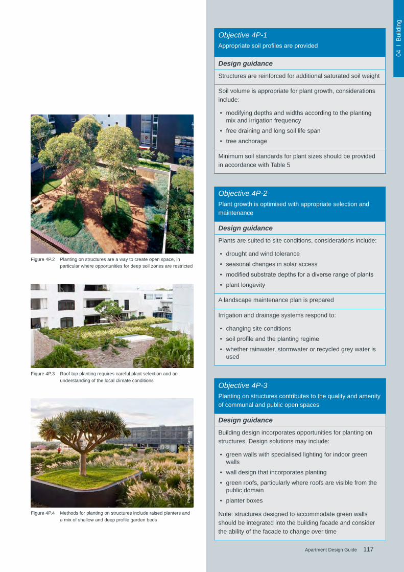
117Apartment Design Guide
04 I
Bui
ldin
g
117Apartment Design Guide
Figure 4P.2 Planting on structures are a way to create open space, in particular where opportunities for deep soil zones are restricted
Figure 4P.3 Roof top planting requires careful plant selection and an understanding of the local climate conditions
Figure 4P.4 Methods for planting on structures include raised planters and amixofshallowanddeepprofilegardenbeds
Objective 4P-3Planting on structures contributes to the quality and amenity of communal and public open spaces
Design guidance
Building design incorporates opportunities for planting on structures. Design solutions may include:
• green walls with specialised lighting for indoor green walls
• wall design that incorporates planting
• green roofs, particularly where roofs are visible from the public domain
• planter boxes
Note: structures designed to accommodate green walls should be integrated into the building facade and consider the ability of the facade to change over time
Objective 4P-2Plant growth is optimised with appropriate selection and maintenance
Design guidance
Plants are suited to site conditions, considerations include:
• drought and wind tolerance
• seasonal changes in solar access
• modifiedsubstratedepthsforadiverserangeofplants
• plant longevity
A landscape maintenance plan is prepared
Irrigation and drainage systems respond to:
• changing site conditions
• soilprofileandtheplantingregime
• whether rainwater, stormwater or recycled grey water is used
Objective 4P-1Appropriatesoilprofilesareprovided
Design guidance
Structures are reinforced for additional saturated soil weight
Soil volume is appropriate for plant growth, considerations include:
• modifying depths and widths according to the planting mix and irrigation frequency
• free draining and long soil life span
• tree anchorage
Minimum soil standards for plant sizes should be provided in accordance with Table 5
Pho
to: M
cGre
gor C
oxal
lP
hoto
: Bre
tt B
oard
man
Pho
to: 3
60 D
egre
es L
ands
cape
Arc
hite
cts

118 Apartment Design Guide
04 I
Bui
ldin
g
Figure 4Q.1 A universally designed apartment provides design features such as wider circulation spaces, reinforced bathroom walls andeasytoreachandoperatefixtures
Universal design is an international design philosophy that enables people to continue living in the same home by ensuring that apartments are able to change with the needs of the occupants. Universally designed apartments are safer and easier to enter, move around and live in. Theybenefitallmembersofthecommunity,fromyoungfamilies to older people, their visitors, as well as those with permanent or temporary disabilities.
Incorporating universal design principles in apartment designisasteptowardsproducingarobust,flexiblehousing stock. It ensures that simple and practical design features are incorporated into new buildings that would be difficultandcostlytoretrofitatalaterdate.
Universal design is different to adaptable housing which is governed by Australian Standard AS 4299-1995 Adaptable Housingandisspecificallydesignedtoallowfor the future adaptation of a dwelling to accommodate the occupant’s needs.
Inadditionflexibleapartmentdesignisalsodesirableto allow buildings to accommodate a diverse range of lifestyle needs such as different household structures, live/work housing arrangements and future changes in use.
4Q Universal design
Figure 4Q.2 Wide and barrier free entries and common circulation spaces help accessibility
Figure 4Q.3 Level threshold transitions eliminate trip hazards
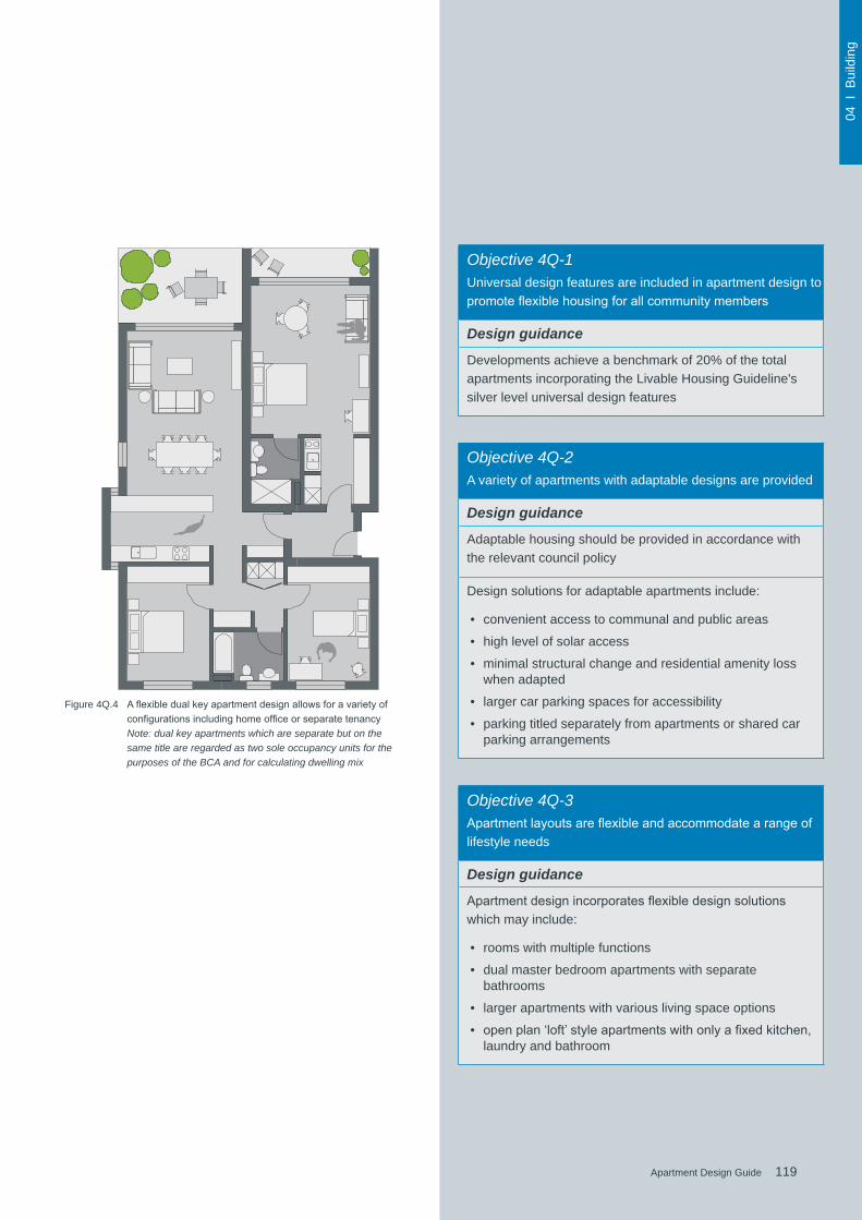
119Apartment Design Guide
04 I
Bui
ldin
g
119Apartment Design Guide
Objective 4Q-1Universal design features are included in apartment design to promoteflexiblehousingforallcommunitymembers
Design guidance
Developments achieve a benchmark of 20% of the total apartments incorporating the Livable Housing Guideline's silver level universal design features
Objective 4Q-2A variety of apartments with adaptable designs are provided
Design guidance
Adaptable housing should be provided in accordance with the relevant council policy
Design solutions for adaptable apartments include:
• convenient access to communal and public areas
• high level of solar access
• minimal structural change and residential amenity loss when adapted
• larger car parking spaces for accessibility
• parking titled separately from apartments or shared car parking arrangements
Objective 4Q-3Apartmentlayoutsareflexibleandaccommodatearangeoflifestyle needs
Design guidance
Apartmentdesignincorporatesflexibledesignsolutionswhich may include:
• rooms with multiple functions
• dual master bedroom apartments with separate bathrooms
• larger apartments with various living space options
• openplan‘loft’styleapartmentswithonlyafixedkitchen,laundry and bathroom
Figure 4Q.4 AflexibledualkeyapartmentdesignallowsforavarietyofconfigurationsincludinghomeofficeorseparatetenancyNote: dual key apartments which are separate but on the same title are regarded as two sole occupancy units for the purposes of the BCA and for calculating dwelling mix

120 Apartment Design Guide
04 I
Bui
ldin
g
Buildings adapted for reuse as apartments can range from large houses, redundant industrial buildings, majorinstitutionalbuildingsandgroupsofbuildingstocommercialofficetowers.
Therearemanybenefitsofretainingexistingbuildingsincluding sustainability, aesthetics, character and valuing theirsocialandculturalsignificance.Adaptationofanexisting building for a new residential use provides for its repurposing and should be approached in a way that acknowledges the past and respects its sense of place.Thesignificanceofheritageitemsorbuildingsinconservationareasneedstoberespected.Modificationsshould ensure the building’s continued relevance in the future.Residentialadaptivereuseprojectsshouldbesensitively designed, to respect existing elements and character.
Non-residential buildings often have dimensions, layouts and orientations that are not designed for residential use. Abalancemustbeachievedbetweenthebenefitsofretaining existing buildings versus the quality of residential amenity that can be achieved.
4R Adaptive reuse
Figure 4R.1 Modern materials can be used if their proportions and details suit the building and context, and allow for interpretation of old and new building elements
Figure 4R.2 Residential conversion of these silos successfully acknowledges the industrial past of this local landmark
Figure 4R.3 New building elements should be distinguishable from the original structure
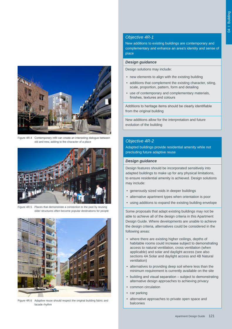
121Apartment Design Guide
04 I
Bui
ldin
g
121Apartment Design Guide
Figure 4R.4 Contemporaryinfillcancreateaninterestingdialoguebetweenold and new, adding to the character of a place
Figure 4R.5 Places that demonstrate a connection to the past by reusing older structures often become popular destinations for people
Objective 4R-1New additions to existing buildings are contemporary and complementary and enhance an area's identity and sense of place
Design guidance
Design solutions may include:
• new elements to align with the existing building
• additions that complement the existing character, siting, scale, proportion, pattern, form and detailing
• use of contemporary and complementary materials, finishes,texturesandcolours
Additionstoheritageitemsshouldbeclearlyidentifiablefrom the original building
New additions allow for the interpretation and future evolution of the building
Figure 4R.6 Adaptive reuse should respect the original building fabric and facade rhythm
Objective 4R-2Adapted buildings provide residential amenity while not precluding future adaptive reuse
Design guidance
Design features should be incorporated sensitively into adapted buildings to make up for any physical limitations, to ensure residential amenity is achieved. Design solutions may include:
• generously sized voids in deeper buildings
• alternative apartment types when orientation is poor
• using additions to expand the existing building envelope
Some proposals that adapt existing buildings may not be able to achieve all of the design criteria in this Apartment Design Guide. Where developments are unable to achieve the design criteria, alternatives could be considered in the following areas:
• where there are existing higher ceilings, depths of habitableroomscouldincreasesubjecttodemonstratingaccess to natural ventilation, cross ventilation (when applicable) and solar and daylight access (see also sections 4A Solar and daylight access and 4B Natural ventilation)
• alternatives to providing deep soil where less than the minimum requirement is currently available on the site
• buildingandvisualseparation–subjecttodemonstratingalternative design approaches to achieving privacy
• common circulation
• car parking
• alternative approaches to private open space and balconies
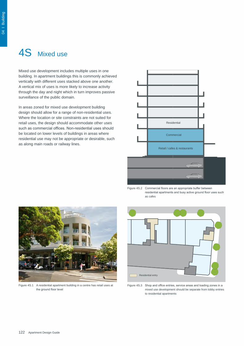
122 Apartment Design Guide
04 I
Bui
ldin
g
Residential entry
Figure 4S.1 A residential apartment building in a centre has retail uses at thegroundfloorlevel
Figure 4S.2 Commercialfloorsareanappropriatebufferbetweenresidentialapartmentsandbusyactivegroundfloorusessuchas cafes
Figure 4S.3 Shopandofficeentries,serviceareasandloadingzonesinamixed use development should be separate from lobby entries to residential apartments
Retail / cafes & restaurants
Residential
Commercial
4S Mixed use
Mixed use development includes multiple uses in one building. In apartment buildings this is commonly achieved vertically with different uses stacked above one another. A vertical mix of uses is more likely to increase activity through the day and night which in turn improves passive surveillance of the public domain.
In areas zoned for mixed use development building design should allow for a range of non-residential uses. Where the location or site constraints are not suited for retail uses, the design should accommodate other uses suchascommercialoffices.Non-residentialusesshouldbe located on lower levels of buildings in areas where residential use may not be appropriate or desirable, such as along main roads or railway lines.

123Apartment Design Guide
04 I
Bui
ldin
g
123Apartment Design Guide
Figure 4S.4 A compact and varied mix of uses improves access to services and promotes walking, social interaction and safety
Objective 4S-1Mixed use developments are provided in appropriate locations and provide active street frontages that encourage pedestrian movement
Design guidance
Mixed use development should be concentrated around public transport and centres
Mixed use developments positively contribute to the public domain. Design solutions may include:
• development addresses the street
• active frontages are provided
• diverse activities and uses
• avoiding blank walls at the ground level
• live/workapartmentsonthegroundfloorlevel,ratherthan commercial
Objective 4S-2Residential levels of the building are integrated within the development, and safety and amenity is maximised for residents
Design guidance
Residentialcirculationareasshouldbeclearlydefined.Design solutions may include:
• residential entries are separated from commercial entries and directly accessible from the street
• commercial service areas are separated from residential components
• residential car parking and communal facilities are separated or secured
• security at entries and safe pedestrian routes are provided
• concealment opportunities are avoided
Landscaped communal open space should be provided at podium or roof levelsFigure 4S.5 Mixed use development should maximise retail and commercial
activity at ground level
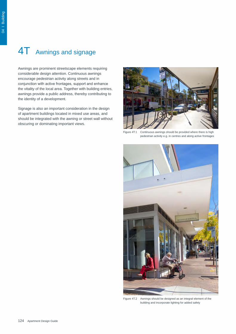
124 Apartment Design Guide
04 I
Bui
ldin
g
Awnings are prominent streetscape elements requiring considerable design attention. Continuous awnings encourage pedestrian activity along streets and in conjunctionwithactivefrontages,supportandenhancethe vitality of the local area. Together with building entries, awnings provide a public address, thereby contributing to the identity of a development.
Signage is also an important consideration in the design of apartment buildings located in mixed use areas, and should be integrated with the awning or street wall without obscuring or dominating important views.
4T Awnings and signage
Figure 4T.1 Continuous awnings should be provided where there is high pedestrian activity e.g. in centres and along active frontages
Figure 4T.2 Awnings should be designed as an integral element of the building and incorporate lighting for added safety

125Apartment Design Guide
04 I
Bui
ldin
g
125Apartment Design Guide
Objective 4T-1Awnings are well located and complement and integrate with the building design
Design guidance
Awnings should be located along streets with high pedestrian activity and active frontages
A number of the following design solutions are used:
• continuous awnings are maintained and provided in areas with an existing pattern
• height, depth, material and form complements the existing street character
• protection from the sun and rain is provided
• awnings are wrapped around the secondary frontages of corner sites
• awnings are retractable in areas without an established pattern
Awnings should be located over building entries for building address and public domain amenity
Awnings relate to residential windows, balconies, street tree planting, power poles and street infrastructure
Gutters and down pipes should be integrated and concealed
Lighting under awnings should be provided for pedestrian safety
Objective 4T-2Signage responds to the context and desired streetscape character
Design guidance
Signage should be integrated into the building design and respond to the scale, proportion and detailing of the development
Legibleanddiscretewayfindingshouldbeprovidedforlarger developments
Signage is limited to being on and below awnings and a single facade sign on the primary street frontage
Figure 4T.5 Signage should respond to the scale, proportion and detailing of the development and its surrounds
Figure 4T.3 Clearway-findingsignageisimportanttobothresidentsandvisitors, in particular in larger residential developments
Figure 4T.4 Building address signage can be integrated as a feature of the facade design
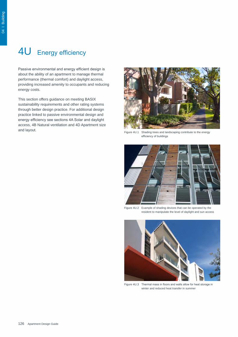
126 Apartment Design Guide
04 I
Bui
ldin
g
4U EnergyefficiencyPassiveenvironmentalandenergyefficientdesignisabout the ability of an apartment to manage thermal performance (thermal comfort) and daylight access, providing increased amenity to occupants and reducing energy costs.
This section offers guidance on meeting BASIX sustainability requirements and other rating systems through better design practice. For additional design practice linked to passive environmental design and energyefficiencyseesections4ASolaranddaylightaccess, 4B Natural ventilation and 4D Apartment size and layout.
Figure 4U.2 Example of shading devices that can be operated by the resident to manipulate the level of daylight and sun access
Figure 4U.3 Thermalmassinfloorsandwallsallowforheatstorageinwinter and reduced heat transfer in summer
Figure 4U.1 Shading trees and landscaping contribute to the energy efficiencyofbuildings

127Apartment Design Guide
04 I
Bui
ldin
g
127Apartment Design Guide
Figure 4U.5 Environmental technology, integrated into the overall design, adds to the sustainable performance of buildings
Figure 4U.4 Grouping rooms with similar uses together creates different zones in an apartment, helping to optimise energy use
Objective 4U-1Development incorporates passive environmental design
Design guidance
Adequate natural light is provided to habitable rooms (see 4A Solar and daylight access)
Well located, screened outdoor areas should be provided for clothes drying
Objective 4U-2Development incorporates passive solar design to optimise heat storage in winter and reduce heat transfer in summer
Design guidance
A number of the following design solutions are used:
• the use of smart glass or other technologies on north and west elevations
• thermalmassinthefloorsandwallsofnorthfacingrooms is maximised
• polishedconcretefloors,tilesortimberratherthancarpet
• insulatedroofs,wallsandfloorsandsealsonwindowanddoor openings
• overhangs and shading devices such as awnings, blinds and screens
Provision of consolidated heating and cooling infrastructure should be located in a centralised location (e.g. the basement)
Objective 4U-3Adequate natural ventilation minimises the need for mechanical ventilation
Design guidance
A number of the following design solutions are used:
• rooms with similar usage are grouped together
• natural cross ventilation for apartments is optimised
• natural ventilation is provided to all habitable rooms and as many non-habitable rooms, common areas and circulation spaces as possible

128 Apartment Design Guide
04 I
Bui
ldin
g
Figure 4V.1 Streets and parks of larger developments should be designed totreatstormwaterrunoffandaccommodatefloodingevents
Figure 4V.2 Stormwater quantities can be reduced and water quality increased by circulating rainwater through a connected water feature and wetland system
1. Firstflushdiversionvalve
2. Diversion to water feature spout
3. Overflowfromwaterfeature
4. Retention tank
5. Detention tank
6. Pumpandfilter
7. Overflowfromcourtyarddetention
8. Water feature supply
9. Pavement runoff
10. Firstflushroofwater(15mm)
11. Infiltrationtowatertable
12. Biosink/wetlandfiltersystem
13. Irrigation
14. Water feature
15. Municipal stormwater system
16. Basement parking
17. Water table
Clean water
Contaminated water
3
6
4515 7
17
10
142 9
16
11
13
12
1
Bio-filtrationswales
Constructed wetland
Water feature using recycled water
Open space
Parks with detention capacity
Water sensitive urban design is the integrated management of water in urban areas. It takes into account all of the elements of the urban water cycle including potable (drinking quality) water, rainwater, wastewater, stormwater and groundwater.
Best practice water management considers water measuresatallstagesoftheproject.Thisrangesfrominitial site planning measures that maximise deep soil areasforwaterinfiltrationtodetailedbuildingdesignthatcaptures and recycles stormwater and wastewater for building services.
The Building Sustainability Index (BASIX) ensures that all new dwellings are designed to minimise potable water use and reduce greenhouse gas emissions. To support the requirements of BASIX there are a number of planning and design considerations that are relevant to apartment developments.
4V Water management and conservation
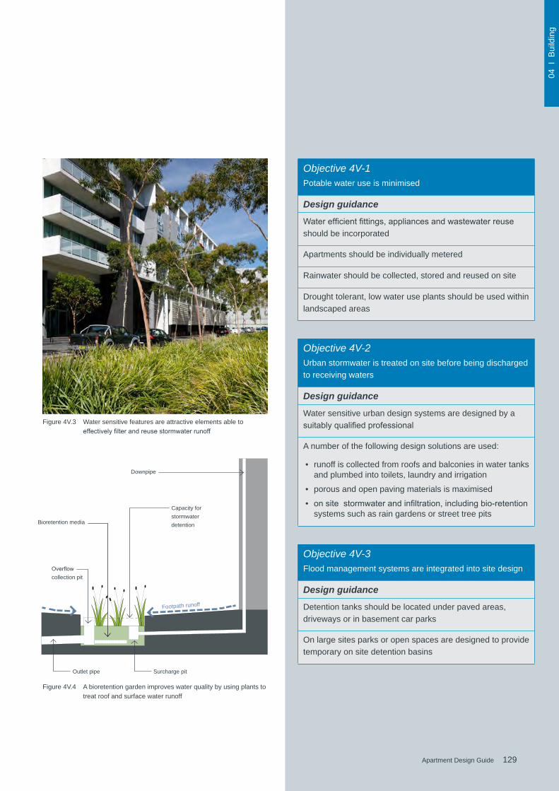
129Apartment Design Guide
04 I
Bui
ldin
g
129Apartment Design Guide
Downpipe
Capacity for stormwater detentionBioretention media
Overflowcollection pit
Footpath runoff
Outlet pipe Surcharge pit
Figure 4V.4 A bioretention garden improves water quality by using plants to treat roof and surface water runoff
Figure 4V.3 Water sensitive features are attractive elements able to effectivelyfilterandreusestormwaterrunoff
Objective 4V-1Potable water use is minimised
Design guidance
Waterefficientfittings,appliancesandwastewaterreuseshould be incorporated
Apartments should be individually metered
Rainwater should be collected, stored and reused on site
Drought tolerant, low water use plants should be used within landscaped areas
Objective 4V-2Urban stormwater is treated on site before being discharged to receiving waters
Design guidance
Water sensitive urban design systems are designed by a suitablyqualifiedprofessional
A number of the following design solutions are used:
• runoff is collected from roofs and balconies in water tanks and plumbed into toilets, laundry and irrigation
• porous and open paving materials is maximised
• onsitestormwaterandinfiltration,includingbio-retentionsystems such as rain gardens or street tree pits
Objective 4V-3Flood management systems are integrated into site design
Design guidance
Detention tanks should be located under paved areas, driveways or in basement car parks
On large sites parks or open spaces are designed to provide temporary on site detention basins
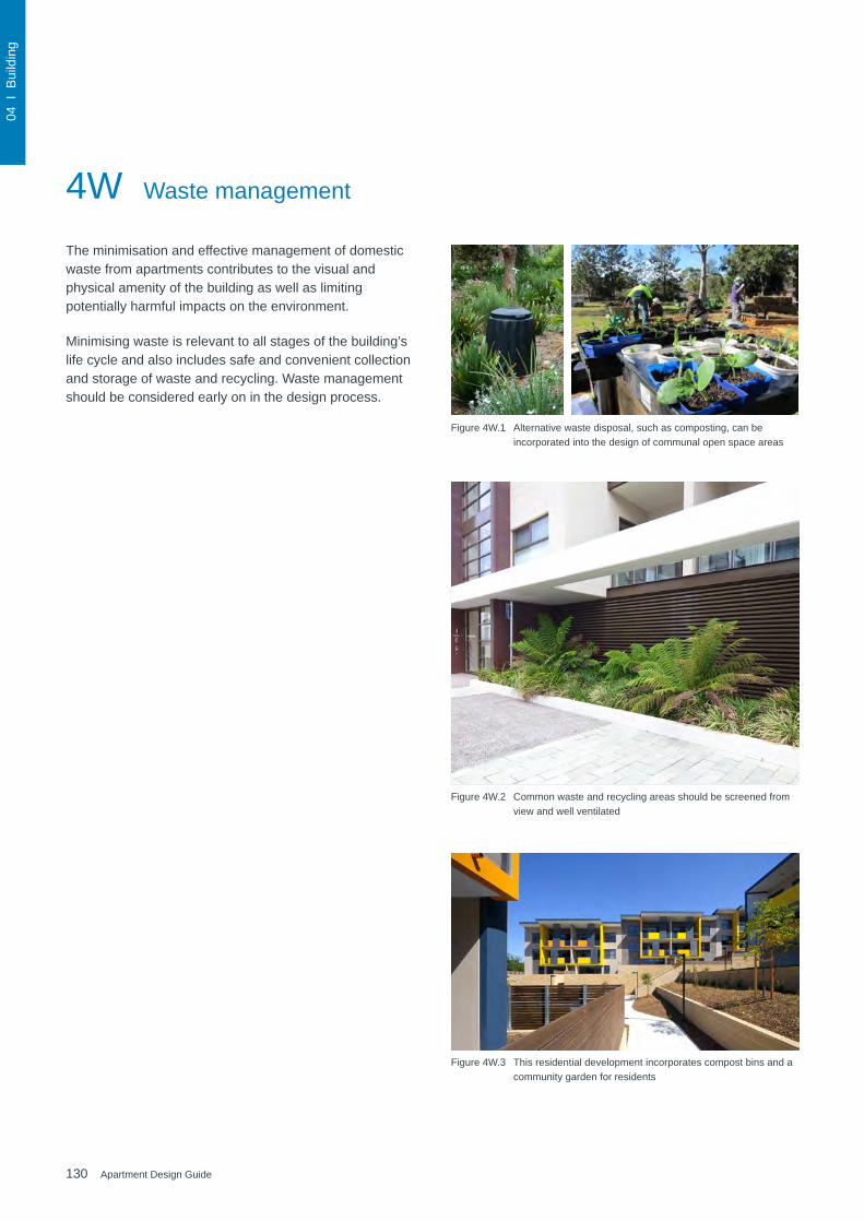
130 Apartment Design Guide
04 I
Bui
ldin
g
The minimisation and effective management of domestic waste from apartments contributes to the visual and physical amenity of the building as well as limiting potentially harmful impacts on the environment.
Minimising waste is relevant to all stages of the building’s life cycle and also includes safe and convenient collection and storage of waste and recycling. Waste management should be considered early on in the design process.
4W Waste management
Figure 4W.2 Common waste and recycling areas should be screened from view and well ventilated
Figure 4W.1 Alternative waste disposal, such as composting, can be incorporated into the design of communal open space areas
Figure 4W.3 This residential development incorporates compost bins and a community garden for residents

131Apartment Design Guide
04 I
Bui
ldin
g
131Apartment Design Guide
Figure 4W.4 Well designed, easily accessible and clean waste and recycling rooms improve the collection and management of household waste
Figure 4W.5 Wasteandrecyclingareasshouldallowforsufficientspacetomanoeuvre bins and sort waste for recycling
Figure 4W.6 For taller developments, garbage chutes can be located on floorstoallowforconvenientdisposalofwasteandrecycling
Objective 4W-2Domestic waste is minimised by providing safe and convenient source separation and recycling
Design guidance
All dwellings should have a waste and recycling cupboard ortemporarystorageareaofsufficientsizetoholdtwodaysworth of waste and recycling
Communal waste and recycling rooms are in convenient and accessible locations related to each vertical core
For mixed use developments, residential waste and recycling storage areas and access should be separate and secure from other uses
Alternative waste disposal methods such as composting should be provided
Objective 4W-1Waste storage facilities are designed to minimise impacts on the streetscape, building entry and amenity of residents
Design guidance
Adequately sized storage areas for rubbish bins should be located discreetly away from the front of the development or in the basement car park
Waste and recycling storage areas should be well ventilated
Circulation design allows bins to be easily manoeuvred between storage and collection points
Temporary storage should be provided for large bulk items such as mattresses
A waste management plan should be prepared
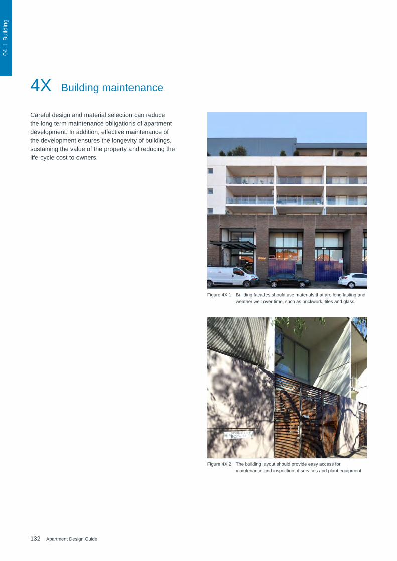
132 Apartment Design Guide
04 I
Bui
ldin
g
Figure 4X.1 Building facades should use materials that are long lasting and weather well over time, such as brickwork, tiles and glass
Figure 4X.2 The building layout should provide easy access for maintenance and inspection of services and plant equipment
Careful design and material selection can reduce the long term maintenance obligations of apartment development. In addition, effective maintenance of the development ensures the longevity of buildings, sustaining the value of the property and reducing the life-cycle cost to owners.
4X Building maintenance
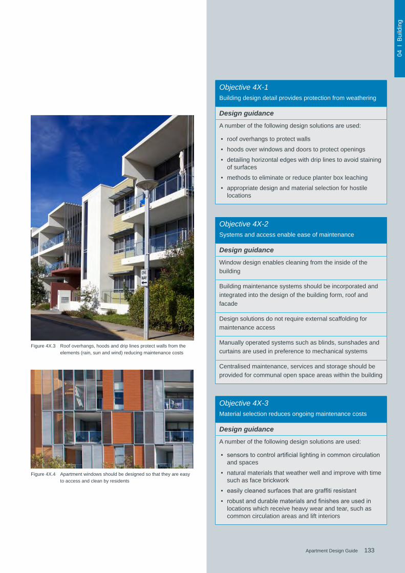
133Apartment Design Guide
04 I
Bui
ldin
g
133Apartment Design Guide
Figure 4X.3 Roof overhangs, hoods and drip lines protect walls from the elements (rain, sun and wind) reducing maintenance costs
Objective 4X-1Building design detail provides protection from weathering
Design guidance
A number of the following design solutions are used:
• roof overhangs to protect walls
• hoods over windows and doors to protect openings
• detailing horizontal edges with drip lines to avoid staining of surfaces
• methods to eliminate or reduce planter box leaching
• appropriate design and material selection for hostile locations
Objective 4X-2Systems and access enable ease of maintenance
Design guidance
Window design enables cleaning from the inside of the building
Building maintenance systems should be incorporated and integrated into the design of the building form, roof and facade
Design solutions do not require external scaffolding for maintenance access
Manually operated systems such as blinds, sunshades and curtains are used in preference to mechanical systems
Centralised maintenance, services and storage should be provided for communal open space areas within the building
Objective 4X-3Material selection reduces ongoing maintenance costs
Design guidance
A number of the following design solutions are used:
• sensorstocontrolartificiallightingincommoncirculationand spaces
• natural materials that weather well and improve with time such as face brickwork
• easilycleanedsurfacesthataregraffitiresistant
• robustanddurablematerialsandfinishesareusedinlocations which receive heavy wear and tear, such as common circulation areas and lift interiors
Figure 4X.4 Apartment windows should be designed so that they are easy to access and clean by residents

134 Apartment Design Guide
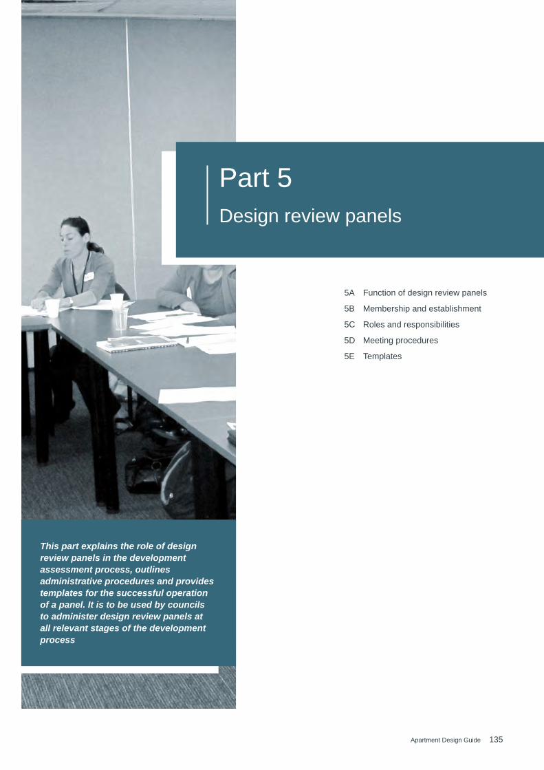
135Apartment Design Guide
Part 5 Design review panels
This part explains the role of design review panels in the development assessment process, outlines administrative procedures and provides templates for the successful operation of a panel. It is to be used by councils to administer design review panels at all relevant stages of the development process
5A Function of design review panels 139
5B Membership and establishment 140
5C Roles and responsibilities 142
5D Meeting procedures 144
5E Templates 146

136 Apartment Design Guide
05 I
Rev
iew
Pan
els
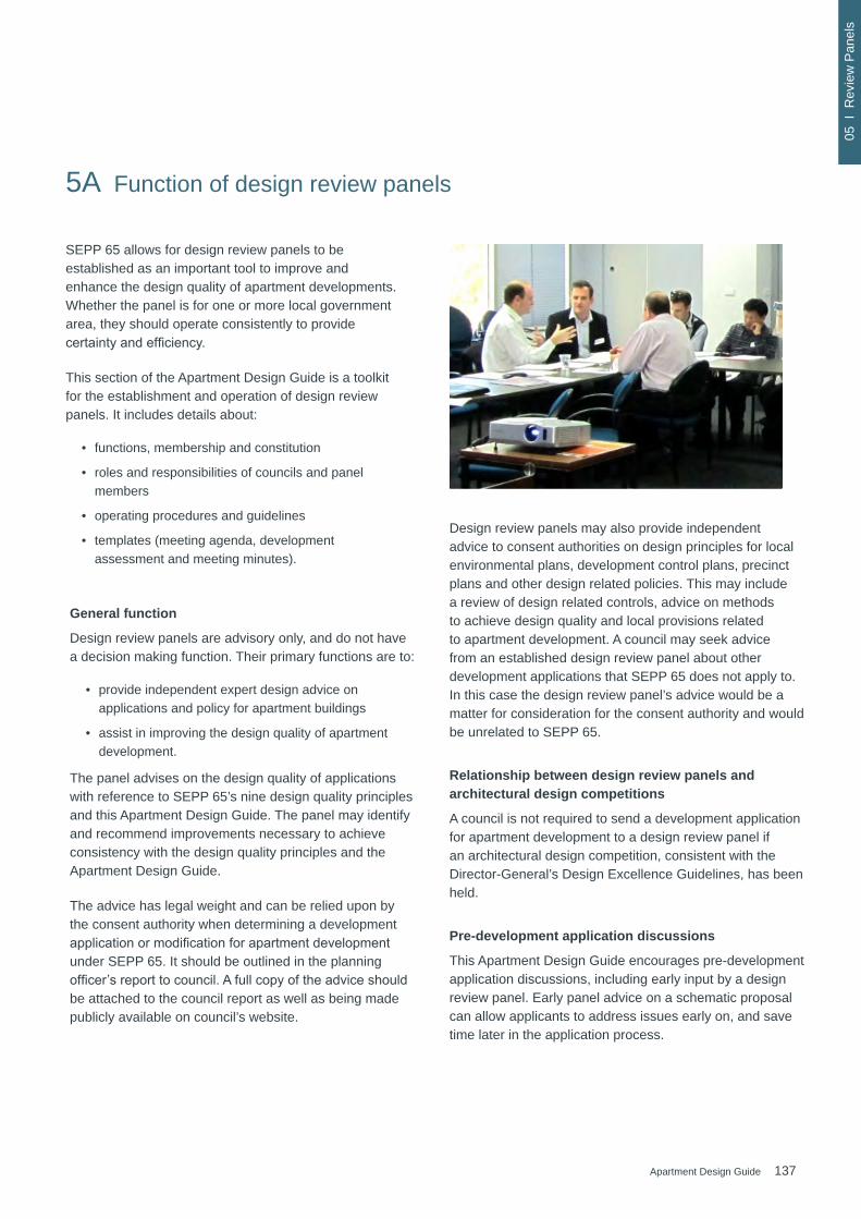
137Apartment Design Guide
05 I
Rev
iew
Pan
els
5A Function of design review panels
General function
Design review panels are advisory only, and do not have a decision making function. Their primary functions are to:
• provide independent expert design advice on applications and policy for apartment buildings
• assist in improving the design quality of apartment development.
The panel advises on the design quality of applications with reference to SEPP 65’s nine design quality principles and this Apartment Design Guide. The panel may identify and recommend improvements necessary to achieve consistency with the design quality principles and the Apartment Design Guide.
The advice has legal weight and can be relied upon by the consent authority when determining a development applicationormodificationforapartmentdevelopmentunder SEPP 65. It should be outlined in the planning officer’sreporttocouncil.Afullcopyoftheadviceshouldbe attached to the council report as well as being made publicly available on council’s website.
Design review panels may also provide independent advice to consent authorities on design principles for local environmental plans, development control plans, precinct plans and other design related policies. This may include a review of design related controls, advice on methods to achieve design quality and local provisions related to apartment development. A council may seek advice from an established design review panel about other development applications that SEPP 65 does not apply to. In this case the design review panel’s advice would be a matter for consideration for the consent authority and would be unrelated to SEPP 65.
Relationship between design review panels and architectural design competitions
A council is not required to send a development application for apartment development to a design review panel if an architectural design competition, consistent with the Director-General’s Design Excellence Guidelines, has been held.
Pre-development application discussions
This Apartment Design Guide encourages pre-development application discussions, including early input by a design review panel. Early panel advice on a schematic proposal can allow applicants to address issues early on, and save time later in the application process.
SEPP 65 allows for design review panels to be established as an important tool to improve and enhance the design quality of apartment developments. Whether the panel is for one or more local government area, they should operate consistently to provide certaintyandefficiency.
This section of the Apartment Design Guide is a toolkit for the establishment and operation of design review panels. It includes details about:
• functions, membership and constitution
• roles and responsibilities of councils and panel members
• operating procedures and guidelines
• templates (meeting agenda, development assessment and meeting minutes).
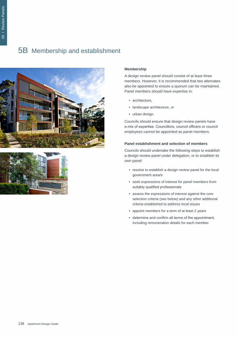
138 Apartment Design Guide
05 I
Rev
iew
Pan
els
Membership
A design review panel should consist of at least three members. However, it is recommended that two alternates also be appointed to ensure a quorum can be maintained. Panel members should have expertise in:
• architecture,
• landscape architecture, or
• urban design.
Councils should ensure that design review panels have amixofexpertise.Councillors,councilofficersorcouncilemployees cannot be appointed as panel members.
Panel establishment and selection of members
Councils should undertake the following steps to establish a design review panel under delegation, or to establish its own panel:
• resolve to establish a design review panel for the local government area/s
• seek expressions of interest for panel members from suitablyqualifiedprofessionals
• assess the expressions of interest against the core selection criteria (see below) and any other additional criteria established to address local issues
• appoint members for a term of at least 2 years
• determineandconfirmalltermsoftheappointment,including remuneration details for each member.
5B Membership and establishment
139Apartment Design Guide
05 I
Rev
iew
Pan
els
Core selection criteria for panel members
Expressions of Interest for design review panel members shouldincludeabriefprofessionalprofileaddressingtheselection criteria below:
Selection criteria
1. Appropriatequalificationanddemonstratedexperience in the design of apartment developments in relation to architecture, landscape architecture or urban design
2. Demonstrated highly developed skills and experience in urban analysis of local planning strategies and policies (e.g. local environmental plans, development control plans, precinct plans and town centre revitalisation) that contain provisions for apartment development
3. Knowledge or understanding of local council policies and development controls
4. Knowledge of the design issues of the local area
5. Ability to analyse, evaluate and report on complex design quality issues for development applications and strategic planning
6. Ability to develop design options and/or recommendations to ensure appropriate application of SEPP 65 design quality principles and the Apartment Design Guide
7. Ability to work in a multi-disciplinary team
8. Ability to liaise/negotiate with local government as well as the private sector
9. Good written and verbal communication skills including the ability to translate technical information into plain English
10. Knowledge, commitment and ability to implement council policies and standards, including those that relate to integrity, ethics, safety, anti-discrimination and equity
Funding and remuneration
Design review panel members are entitled to remuneration and the payment of expenses. The Environmental Planning and Assessment Regulation 2000 allows councils with a design review panel to charge a maximum fee for the design review panel as part of development application fees. Councils are therefore responsible for the funding and remuneration of design review panels.
The following should be considered when determining funding and remuneration arrangements with design review panel members:
• where more than one council is involved in the operation of a design review panel, councils should fund the panel’s operation on an equitable basis, for example, based on the number of development applications referred to the panel by each council
• the Environmental Planning and Assessment Regulation 2000 allows a maximum additional development application fee to be charged for residential apartment development applications that will be referred to a design review panel. This allows councils to determine within their own fee policy how much they will charge up to the maximum amount. Thismaybeinfluencedbytheaveragedesignreviewpanel costs per application and the estimated number of times an application will be referred to a design review panel
• councils are to remunerate each panel member commensurate with their professional role and meeting input. Remuneration should be fair and equitable taking into consideration the time taken to participate in design review panel processes.

140 Apartment Design Guide
05 I
Rev
iew
Pan
els
Panel coordinator
Councils are responsible for coordinating the operation ofthedesignreviewpanel.Itissuggestedthataspecificcouncilofficerbethenominatedcoordinatorortherolemaybesharedamongstseveralofficers.Inthecaseofdesignreview panels formed for more than one local government area, the role could be shared on a rotational basis.
Whichever approach is taken, arrangements about how tasks will be undertaken need to be established, particularly where more than one coordinator or council is involved.
The nominated coordinator will need to:
• determine the annual meeting schedule and make it publicly available
• be the central point of contact between the design review panel members and other council staff or stakeholders
• arrange meeting venues which have appropriate display space and room for applicants and other observers
• prepare and distribute meeting invites, application informationandagendas,ensuringsufficientnoticeisprovided to all parties
• arrange site inspections
• ensure in advance of each meeting that there will be a quorum
• arrange for relevant council staff members to attend meetings
• arrange minute taking and panel member endorsement of minutes
• distribute minutes to relevant parties and make them publicly available on council’s website within 14 days of the panel meeting
• administer fee and member remuneration payments
• arrange for a summary of council decisions on applications considered by the panel to be given to panel members, providing feedback on consideration of applications and awareness of any other relevant matters
• provide information about the design review panel and its operation to any interested party, including new panel members.
5C Roles and responsibilities

141Apartment Design Guide
05 I
Rev
iew
Pan
els
Pecuniary interests
Under SEPP 65 design review panel members must disclose any pecuniary interests. Where a pecuniary interest exists, the member must:
• disclose the interest to the chair as soon as practicable, and preferably before the meeting to ensure there is a quorum for all items
• not take part in the consideration or discussion of the matter
• not vote on any advice or recommendations relating to the matter.
Pecuniary interests should be recorded in panel meeting minutes.
Agenda
The agenda is to be prepared and distributed, taking account of the following:
• applications should be referred to the design review panel as soon as possible after lodgement. This will ensurethatdesignmodificationscanbeidentifiedearly, together with any additional information being requested by council
• the agenda for each meeting should be circulated to all panel members and meeting attendees at least one week prior to the meeting. A meeting agenda template is included in section 5E Templates
• the priority of agenda items for each meeting should be determined by each council ensuring the timing has regard for their statutory timeframes
• each item should be allocated an equitable time slot on theagendaadjustedforcomplexitywhereappropriate,to allow fair and reasonable consideration of the application and time for a brief presentation by the applicant or their representative, as well as questions of them by the panel
• each agenda item should be accompanied by a brief development assessment overview prepared by council’s assessment staff, giving a summary of the development's compliance with the key SEPP 65 requirements and council development standards.
Panel chairperson
The panel chair is responsible for:
• running design review meetings
• ensuring that the meeting agenda is followed and that allocated timeframes are adhered to
• ensuring that discussion remains focused on the application or matter being considered and that advice relates to matters covered by SEPP 65 and the Apartment Design Guide
• ensuring the advice and recommendations developed for each application is voted on by the panel. In the case of a tied vote, the chairperson has the casting vote
• ensuring the panel endorses the minutes
• liaising with council staff about the operation of the panel, where required
• attending meetings to brief councillors on panel advice, where required
• ensuring new members have been inducted and are briefed about panel operation.
Panel members
Panel members are required to:
• treat all discussions and information about applications withsensitivityandconfidentiality
• provide independent, fair and reasonable professional advice relative to the design quality principles of SEPP 65 and this Apartment Design Guide
• respond to and comment on material presented, providing constructive feedback to make amendments as required.

142 Apartment Design Guide
05 I
Rev
iew
Pan
els
The following design review panel meeting procedures have been developed to ensure consistency in the process and to make expectations clear for all parties. A council may choose to include additional operating procedures to address local circumstances. If a council chooses to include additional operating procedures the panel chair should make recommendations to the council for their endorsement.
It is recommended that an inception meeting be held when new design review panels are established to confirmgeneraloperatingandmeetingprocedures.The inception meeting should be hosted by the council sothatmemberscanbebriefedonspecificoperationalmatters. Meeting procedures can also be discussed and confirmed.
Suggested topics to be covered in the inception meeting are outlined below. Where individual new members are appointed to a panel at a later time, it is recommended thattheybebriefedjointlybythepanelcoordinatorandchair on this information.
Suggested inception meeting topics:
• introduce panel coordinator, members, relevant council staff and provide contact details
• provide background on local planning and design issues and copies of relevant policies including the LEP and DCP
• adviseofannualmeetingschedule,confirmmemberresponsibilities and reporting timeframes
• advise of responsibilities for preparing the agenda, circulationofprojectinformationandminutes
• confirmcontactdetailsforremunerationmatters,andfrequency of invoicing
• advise of council’s media protocols
• determine a protocol for the panel responding to any media enquiries (e.g. only through the chair, or only through council’s media unit)
• appoint a chairperson (which may be revolving)
• confirmstandardmeetingproceduresandanyadditional local procedures
• arrange to advise the Minister for Planning and council of the agreed procedures and publicise on council's website.
Meeting preparation and site inspection
Panel members should familiarise themselves with the agenda and documents prior to the meeting.
Panel members should visit each site on the agenda prior to the meeting. Joint inspections are arranged by the panel coordinator, and can be part of the overall agendafortheday.Specificarrangementsforthiscanbedetermined by each panel.
Quorum and attendance
Each meeting is to maintain a quorum. A quorum consists of three appointed or alternate design review panel members. If less than three members are present there is no quorum and the meeting cannot proceed. Panel members should attend at least 75% of design review panel meetings. The Minister or council/s may replace panel members who are regularly unavailable for meetings during a 12 month period.
5D Meeting procedures
143Apartment Design Guide
05 I
Rev
iew
Pan
els
Meeting format
The chairperson should run the meeting in accordance with the agenda. A suggested format for individual items includes:
• site inspections
• panel pre-discussion and application overview by council planning staff including site history, background, surrounding proposed/approved developments, compliance with planning controls, internal referral comments (e.g. heritage, stormwater, traffic/parking)andsubmissions/objections.Relevantstate government agency comments should also be provided. Depending on the issue, a representative of the referral agency may also be invited to attend the meeting
• proponent presentation – short presentation explaining theprojectwithinthelocalcontext,backgroundandhow it addresses key design quality principles of SEPP 65 and the Apartment Design Guide
• panelquestions/clarificationsoftheproponent–asrequired
• panel discussion – debate and drafting of advice and recommendations
• confirmagreedadviceandrecommendations–thechair convenes a vote by panel members on the advice and recommendations.
Where an application has been considered previously a site inspection may not be necessary and the council planningstaffbriefingwillupdatethedesignreviewpanelabout the compliance of the amended scheme.
Providing advice and voting on recommendations
Panel members should be aware of the following points whenprovidingadviceandfinalisingrecommendations:
• advice should be in plain English that is readily understood by the consent authority, the development proponent and the community
• advice should be consistent between scheme iterations.Ifsignificantchangesarerecommendedthat depart from previously issued advice they must be supportedbyfullwrittenjustification
• when preparing advice, the panel should be aware that State Environmental Planning Policy (Building Sustainability Index: BASIX) 2004 overrides SEPP 65 provisions on thermal performance, greenhouse emission reduction and water reduction
• either the design review panel or the council may require that additional expert assistance be sought in the assessment of a particular proposal or other matter
• panel members should vote on the recommendations for each proposal being considered. In the case of a tied vote, the chairperson has the casting vote.
Minutes and reporting
Panel members should be aware of the following points when minutes are being drafted:
• minutes should be recorded directly into the template andpreferablywall-projectedinthemeetingroomtoenablerecommendationstobefinalisedatthemeeting. A meeting minutes template is provided in section 5E Templates
• the panel meeting minutes should include an accurate record of the key discussion points and panel recommendations
• the minutes are to be endorsed by the design review panel and returned to council within 14 days of the meeting. Ideally the minutes should be completed on the day of the meeting to streamline timeframes
• report recommendations should assist council's decision making, including suggested amendments, draft conditions of approval and if relevant, options for consideration.
SEPP 65 requires that the panel’s advice be made publicly available and accessible. It should therefore be published on the council's website within seven days of receipt from the panel.
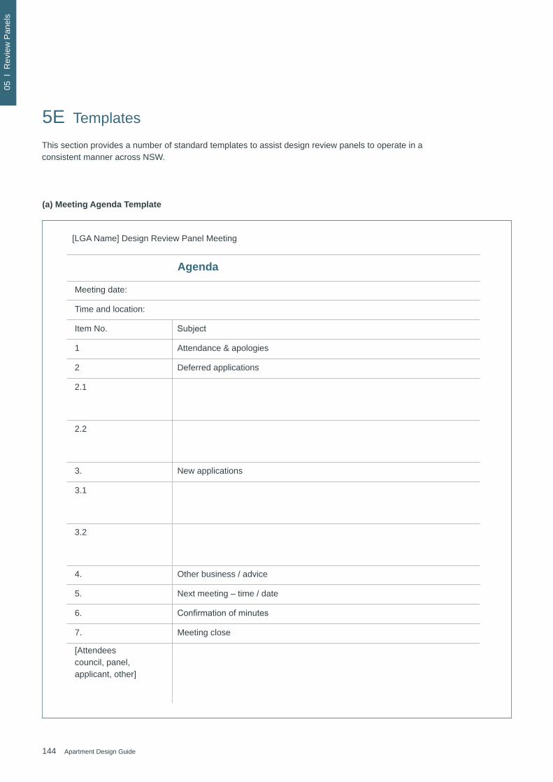
144 Apartment Design Guide
05 I
Rev
iew
Pan
els
(a) Meeting Agenda Template
[LGA Name] Design Review Panel Meeting
Agenda
Meeting date:
Time and location:
Item No. Subject
1 Attendance & apologies
2 Deferred applications
2.1
2.2
3. New applications
3.1
3.2
4. Other business / advice
5. Next meeting – time / date
6. Confirmationofminutes
7. Meeting close
[Attendees council, panel, applicant, other]
5E Templates
This section provides a number of standard templates to assist design review panels to operate in a consistent manner across NSW.
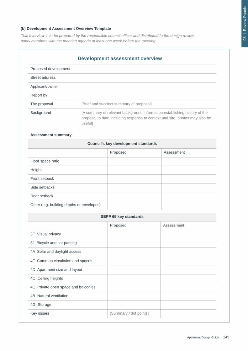
145Apartment Design Guide
05 I
Rev
iew
Pan
els
Development assessment overview
Proposed development
Street address
Applicant/owner
Report by
The proposal [Brief and succinct summary of proposal]
Background [A summary of relevant background information establishing history of the proposal to date including response to context and site; photos may also be useful]
(b) Development Assessment Overview Template
This overview is to be prepared by the responsible council officer and distributed to the design review panel members with the meeting agenda at least one week before the meeting.
Assessment summary
Council's key development standards
Proposed Assessment
Floor space ratio
Height
Front setback
Side setbacks
Rear setback
Other (e.g. building depths or envelopes)
SEPP 65 key standards
Proposed Assessment
3F Visual privacy
3J Bicycle and car parking
4A Solar and daylight access
4F Common circulation and spaces
4D Apartment size and layout
4C Ceiling heights
4E Private open space and balconies
4B Natural ventilation
4G Storage
Key issues [Summary / dot points]

146 Apartment Design Guide
05 I
Rev
iew
Pan
els
Meeting minutes and recommendations
Time & date
Meeting location
Panel members (Chair)
(Member)
(Member)
(Member)
Apologies
Council staff
Guests
Declarations of interest
Business item and meeting minutes
Item number
DA number
Property address
Proposal [Succinct summary of proposal]
Applicant or applicant’s representative address to the design review panel
[Note if applicant addressed the design review panel. Include name and position]
Background The site was inspected by the panel [DATE]
Key issues and recommendation
[Summary of key issues discussed]
A development application was previously before the panel at its meeting of [DATE]. At this time the panel made the following recommendation:
[Insert recommendation]
(c) Meeting Minutes Template
The Report of the design review panel is taken to also be the minutes of the review meeting. The report accurately records the discussion and recommendations reached at the review meeting. In endorsing the design review panel report, the design review panel has ensured the meeting discussion and the drafting of the report contain consistent conclusions and recommendations.
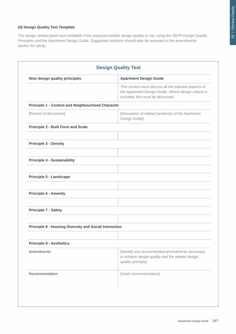
147Apartment Design Guide
05 I
Rev
iew
Pan
els
Design Quality Test
Nine design quality principles Apartment Design Guide
This section must discuss all the relevant aspects of the Apartment Design Guide. Where design criteria is included, this must be discussed
Principle 1 - Context and Neighbourhood Character
[Record of discussion] [Discussion of related section(s) of the Apartment Design Guide]
Principle 2 - Built Form and Scale
Principle 3 - Density
Principle 4 - Sustainability
Principle 5 - Landscape
Principle 6 - Amenity
Principle 7 - Safety
Principle 8 - Housing Diversity and Social Interaction
Principle 9 - Aesthetics
Amendments [Identify any recommended amendments necessary to achieve design quality and the related design quality principle]
Recommendation [Insert recommendation]
(d) Design Quality Test Template
The design review panel must establish if the proposal exhibits design quality or not, using the SEPP Design Quality Principles and the Apartment Design Guide. Suggested solutions should also be recorded in the amendments section for clarity.

148 Apartment Design Guide
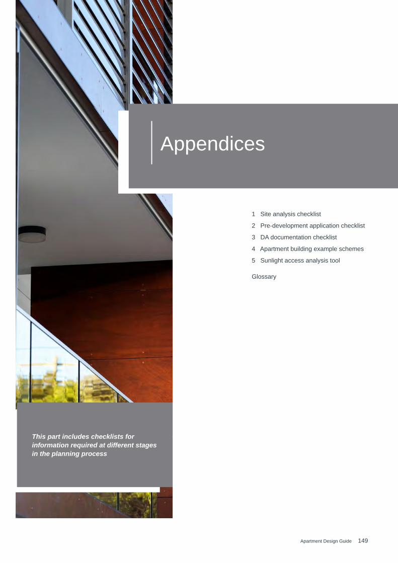
149Apartment Design Guide
Appendices
This part includes checklists for information required at different stages in the planning process
1 Site analysis checklist 152
2 Pre-development application checklist 154
3 DA documentation checklist 156
4 Apartment building example schemes 160
5 Sunlight access analysis tool 179
Glossary 180

150 Apartment Design Guide
App
endi
ces
Documentation Required information Provided
Yes () No (x)
Site location Broad map or aerial photo showing site location in relation to surrounding centres, shops, civic/community facilities and transport
Aerial photograph Colour aerial photographs of site in its context
Local context plan Plan(s) of the existing features of the wider context including adjoiningpropertiesandtheothersideofthestreet,thatshow:
• pattern of buildings, proposed building envelopes, setbacks and subdivision pattern
• landuseandbuildingtypologiesofadjacentandoppositebuildingsin the street
• movement and access for vehicles, servicing, pedestrians and cyclists
• topography, landscape, open spaces and vegetation
• significantviewstoandfromthesite
• significantnoisesourcesinthevicinityofthesite,particularlyvehiculartraffic,train,aircraftandindustrialnoise
Site context and survey plan
Plan(s) of the existing site based on a survey drawing showing the features of the immediate site including:
• boundaries, site dimensions, site area, north point
• topography, showing relative levels and contours at 0.5 metre intervals for the site and across site boundaries where level changes exist, any unique natural features such as rock outcrops, watercourses,existingcutorfill,adjacentstreetsandsites
• locationandsizeofmajortreesonsiteandrelativelevelswhererelevant,onadjacentpropertiesandstreettrees
• location and use of existing buildings or built features on the site
• locationandimportantcharacteristicsofadjacentpublic,communal and private open spaces
• location and height of existing windows, balconies, walls and fencesonadjacentpropertiesfacingthesite,aswellasparapetand ridge lines
• pedestrian and vehicular access points, driveways and features suchasservicepoles,busstops,firehydrantsetc.
• location of utility services, including easements and drainage
• location of any other relevant features
APPENDIX 1 Site analysis checklist

151Apartment Design Guide
App
endi
ces
Documentation Required information Provided
Yes () No (x)
Streetscape elevations and sections
Photographs or drawings of the site in relation to the streetscape and along both sides of any street that the development fronts, that show:
• overall height (storeys, metres) and important parapet/datum lines ofadjacentbuildings
• patterns of building frontage, street setbacks and side setbacks
• planned heights
Analysis Plan that synthesises and interprets the context, streetscape and site documentation into opportunities and constraints that generate design parameters, including the following information:
• orientationandanyovershadowingofthesiteandadjoiningproperties by neighbouring structures (excludes vegetation). The winter sun path should also be shown between 9 am and 3 pm on 21 June
• identificationofprevailingwind
• the geotechnical characteristics of the site and suitability of the proposed development
• the public domain interface and street setback
• relationshiptoandinterfacewithadjacentproperties,includingsideand rear setbacks
• ventilationforthesubjectsiteandimmediateneighbours
• proposed building footprint location
• retainedandproposedsignificanttreesanddeepsoilzones
• proposed communal open space
• proposed car park footprint and depth
• proposed building entries
• supporting written material - this should include technical advice from specialists involved in the development process including landscape architects, arborists, geotechnical engineers and/or contamination specialists where applicable
152 Apartment Design Guide
App
endi
ces
This Apartment Design Guide encourages pre-development application(pre-DA)discussions.Toensuremaximumbenefitof pre-DA discussions, consent authorities should appoint an urban designer or architect to provide specialist design advice. This may be a member of the Design Review Panel. Early input about the design may help to resolve issues prior to a development application being submitted.
Where a council requests panel members to attend a pre-DA discussion, it should be held at a regular time, and before the scheduled Design Review Panel meeting.
Pre-DA discussions are a critical component of the development process. Meeting early in the process allows for discussion and agreement of the overall design approach. Thisprovidesgreaterefficiencyatthedevelopmentassessment stage and also saves time and costs associated withrevisionsormajormodifications.Minutesfrompre-DAdiscussions should be issued by the consent authority within one week of the meeting or as soon as available.
Theadjacenttableshowsthebasicinformationthatshouldbe provided by the applicant before the pre-DA discussion. The emphasis should be on having enough information to communicate the proposal rather than having fully resolved drawingsofeveryaspectoftheproject.
Pre-development application design proposal checklistAPPENDIX 2

153Apartment Design Guide
App
endi
ces
Documentation Required information Provided
Yes () No (x)
Development details
A summary of the proposal that establishes the:
• Floor space ratio
• Building height in metres and storeys
• Number and mix of apartments
• Number of car parking spaces
• Indicative percentage of apartments receiving the minimum level of cross ventilation and daylight access
Design quality statement
Adraftstatementofkeypointsthatestablisheshowtheproposalsatisfiesthedesign quality principles of State Environmental Planning Policy No. 65
Precedents Images of precedents relevant to the proposal such as:
• streetscape concept
• landscape design
• communal open spaces use
• building elements such as entries, balconies, materials
Site analysis Prepared consistent with Appendix 1 of the Apartment Design Guide
Site plan A drawing to scale showing:
• any proposed site amalgamation or subdivision
• the indicative footprint of the proposal
• setbacks and building separation dimensions
• site entry points
• areas of communal open space and private open space
• indicative locations of planting and deep soil zones including retained or proposessignificanttrees
• interface with public domain
Floor plans Drawings to scale showing:
• theinternalbuildinglayoutandunittypedistributionforthegroundfloor,representative middle floor,andthetopfloor
• typical car park layout
• sample unit plans with furniture layouts, key room depth dimensions and balcony sizes
Building mass elevations
Drawing to scale showing the basic massing of the proposal in the context of the adjacentthreeproperties,orfor50mineachdirection,oneachelevation.Thisdrawing should show, in diagrammatic form:
• the composition of the elevations including ground level, roof form, and articulation of massing of the overall building
• pattern of buildings and spaces between buildings along the street
• theprofileofanyexistingbuildings
Sections A drawing to scale showing:
• theproposalandadjacentbuildings
• the relationship of the proposal to the ground plane, streets, open spaces and deep soil zones

154 Apartment Design Guide
App
endi
ces
Documentation Required information Provided
Yes () No (x)
Development details A summary document that provides the key details of the development proposal. It contains information such as the:
• floorspaceratioofthedevelopment
• number, mix, size and accessibility of apartments
• number of car parking spaces for use (residential, retail, accessible, visitor etc.)
• percentage of cross ventilation and daylight compliance
Statement of Environmental Effects
In addition to the consent authorities requirements:
• An explanation of the design in terms of the design quality principles set out in Schedule 1 of State Environmental Planning Policy No 65 - Design Quality of Residential Apartment Development
• If the proposed development is within an area where the built form and density is changing, statements about how the proposed development responds to the existing context and contributes to desired future character of the area
• Description of how the proposed development achieves therelevantobjectivesanddesigncriteriaoftheApartmentDesign Guide
Site analysis Prepared consistent with Appendix 1 of the Apartment Design Guide
Information required in a development application is established in Schedule 1 of the Environmental Planning and Assessment Regulation 2000. For residential apartment development, SEPP 65 provides additional recommendations for development application requirements.
The following table elaborates on the SEPP recommendations and is a guide that suggests more detailed and well resolved drawings to assist with demonstrating better design practice. The consent authority may also identify additional information that is required for the assessment of a residential apartment development. All plans, elevations and sections should be drawn to scale and include a graphic scale bar and true north point. A cover page with drawing list and BASIX commitments should be included.
Development application – recommended documentation checklist APPENDIX 3
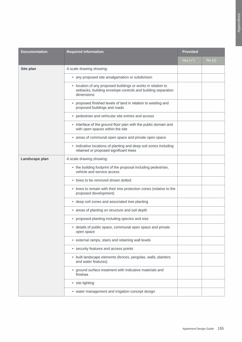
155Apartment Design Guide
App
endi
ces
Documentation Required information Provided
Yes () No (x)
Site plan A scale drawing showing:
• any proposed site amalgamation or subdivision
• location of any proposed buildings or works in relation to setbacks, building envelope controls and building separation dimensions
• proposedfinishedlevelsoflandinrelationtoexistingandproposed buildings and roads
• pedestrian and vehicular site entries and access
• interfaceofthegroundfloorplanwiththepublicdomainandwith open spaces within the site
• areas of communal open space and private open space
• indicative locations of planting and deep soil zones including retainedorproposedsignificanttrees
Landscape plan A scale drawing showing:
• the building footprint of the proposal including pedestrian, vehicle and service access
• trees to be removed shown dotted
• trees to remain with their tree protection zones (relative to the proposed development)
• deep soil zones and associated tree planting
• areas of planting on structure and soil depth
• proposed planting including species and size
• details of public space, communal open space and private open space
• external ramps, stairs and retaining wall levels
• security features and access points
• built landscape elements (fences, pergolas, walls, planters and water features)
• ground surface treatment with indicative materials and finishes
• site lighting
• water management and irrigation concept design
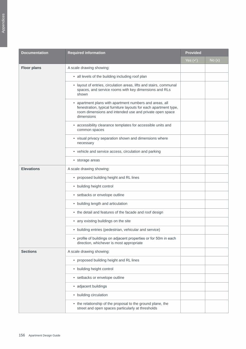
156 Apartment Design Guide
App
endi
ces
Documentation Required information Provided
Yes () No (x)
Floor plans A scale drawing showing:
• all levels of the building including roof plan
• layout of entries, circulation areas, lifts and stairs, communal spaces, and service rooms with key dimensions and RLs shown
• apartment plans with apartment numbers and areas, all fenestration, typical furniture layouts for each apartment type, room dimensions and intended use and private open space dimensions
• accessibility clearance templates for accessible units and common spaces
• visual privacy separation shown and dimensions where necessary
• vehicle and service access, circulation and parking
• storage areas
Elevations A scale drawing showing:
• proposed building height and RL lines
• building height control
• setbacks or envelope outline
• building length and articulation
• the detail and features of the facade and roof design
• any existing buildings on the site
• building entries (pedestrian, vehicular and service)
• profileofbuildingsonadjacentpropertiesorfor50mineachdirection, whichever is most appropriate
Sections A scale drawing showing:
• proposed building height and RL lines
• building height control
• setbacks or envelope outline
• adjacentbuildings
• building circulation
• the relationship of the proposal to the ground plane, the street and open spaces particularly at thresholds
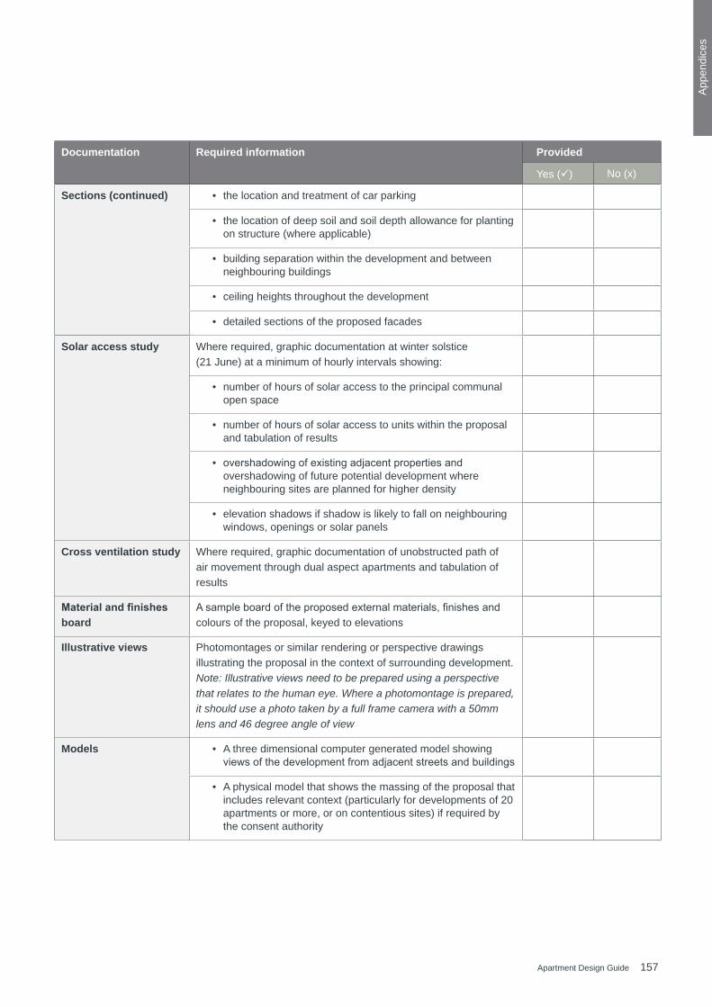
157Apartment Design Guide
App
endi
ces
Documentation Required information Provided
Yes () No (x)
Sections (continued) • the location and treatment of car parking
• the location of deep soil and soil depth allowance for planting on structure (where applicable)
• building separation within the development and between neighbouring buildings
• ceiling heights throughout the development
• detailed sections of the proposed facades
Solar access study Where required, graphic documentation at winter solstice (21 June) at a minimum of hourly intervals showing:
• number of hours of solar access to the principal communal open space
• number of hours of solar access to units within the proposal and tabulation of results
• overshadowingofexistingadjacentpropertiesandovershadowing of future potential development where neighbouring sites are planned for higher density
• elevation shadows if shadow is likely to fall on neighbouring windows, openings or solar panels
Cross ventilation study Where required, graphic documentation of unobstructed path of air movement through dual aspect apartments and tabulation of results
Material and finishes board
Asampleboardoftheproposedexternalmaterials,finishesandcolours of the proposal, keyed to elevations
Illustrative views Photomontages or similar rendering or perspective drawings illustrating the proposal in the context of surrounding development. Note: Illustrative views need to be prepared using a perspective that relates to the human eye. Where a photomontage is prepared, it should use a photo taken by a full frame camera with a 50mm lens and 46 degree angle of view
Models • A three dimensional computer generated model showing viewsofthedevelopmentfromadjacentstreetsandbuildings
• A physical model that shows the massing of the proposal that includes relevant context (particularly for developments of 20 apartments or more, or on contentious sites) if required by the consent authority
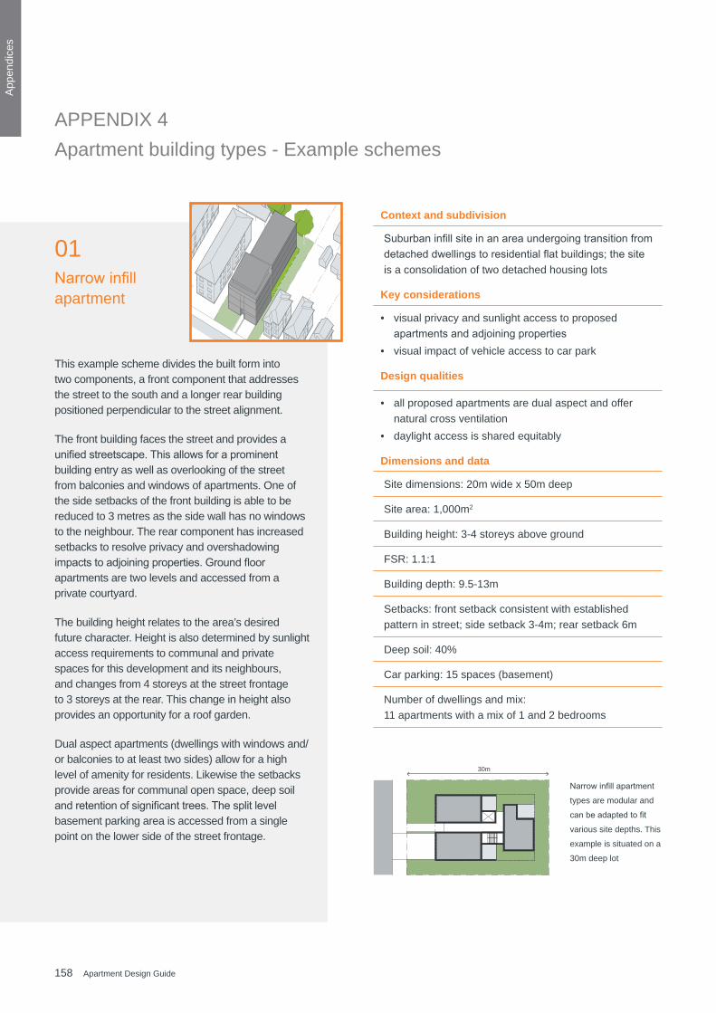
158 Apartment Design Guide
App
endi
ces
Narrowinfillapartment
types are modular and
canbeadaptedtofit
various site depths. This
example is situated on a
30m deep lot
30m
Context and subdivision
Suburbaninfillsiteinanareaundergoingtransitionfromdetacheddwellingstoresidentialflatbuildings;thesiteis a consolidation of two detached housing lots
Key considerations
• visual privacy and sunlight access to proposed apartmentsandadjoiningproperties
• visual impact of vehicle access to car park
Design qualities
• all proposed apartments are dual aspect and offer natural cross ventilation
• daylight access is shared equitably
Dimensions and data
Site dimensions: 20m wide x 50m deep
Site area: 1,000m2
Building height: 3-4 storeys above ground
FSR: 1.1:1
Building depth: 9.5-13m
Setbacks: front setback consistent with established pattern in street; side setback 3-4m; rear setback 6m
Deep soil: 40%
Car parking: 15 spaces (basement)
Number of dwellings and mix: 11 apartments with a mix of 1 and 2 bedrooms
This example scheme divides the built form into two components, a front component that addresses the street to the south and a longer rear building positioned perpendicular to the street alignment.
The front building faces the street and provides a unifiedstreetscape.Thisallowsforaprominentbuilding entry as well as overlooking of the street from balconies and windows of apartments. One of the side setbacks of the front building is able to be reduced to 3 metres as the side wall has no windows to the neighbour. The rear component has increased setbacks to resolve privacy and overshadowing impactstoadjoiningproperties.Groundfloorapartments are two levels and accessed from a private courtyard.
The building height relates to the area’s desired future character. Height is also determined by sunlight access requirements to communal and private spaces for this development and its neighbours, and changes from 4 storeys at the street frontage to 3 storeys at the rear. This change in height also provides an opportunity for a roof garden.
Dual aspect apartments (dwellings with windows and/or balconies to at least two sides) allow for a high level of amenity for residents. Likewise the setbacks provide areas for communal open space, deep soil andretentionofsignificanttrees.Thesplitlevelbasement parking area is accessed from a single point on the lower side of the street frontage.
01Narrowinfillapartment
Apartment building types - Example schemes APPENDIX 4

159Apartment Design Guide
App
endi
ces
N N
A
A
7m3m 4m
6m
4m3m
7m
6m
Primary street Primary street
Street Front Rear
Street frontage
Future development
Futu
re d
evel
opm
ent
Apartment building types - Example schemes Narrow frontage
50m0
N N
A
A
7m3m 4m
6m
4m3m
7m
6m
Primary street Primary street
Street Front Rear
Street frontage
Future development
Futu
re d
evel
opm
ent
Apartment building types - Example schemes Narrow frontage
50m0
N N
A
A
7m3m 4m
6m
4m3m
7m
6m
Primary street Primary street
Street Front Rear
Street frontage
Future development
Futu
re d
evel
opm
ent
Apartment building types - Example schemes Narrow frontage
50m0
N N
A
A
7m3m 4m
6m
4m3m
7m
6m
Primary street Primary street
Street Front Rear
Street frontage
Future development
Futu
re d
evel
opm
ent
Apartment building types - Example schemes Narrow frontage
50m0
N N
Existing site and proposed development footprint Proposed development - Typical ground level plan
Proposed development - Section A Proposed development - Street elevation
A
A
3m
3m
10m
6m
3m3m10m 6m
Street Street frontage
Front
Primary streetPrimary street
Rear
Futuredevelopment
Future development
50m0
Site boundary
Proposed development footprint
Pedestrian access
Vehicular access
Deep soil zone
Significant tree to be retained
Walls with balconies or windows to habitable rooms
N N
Apartment building types - Example schemes Row Apartments
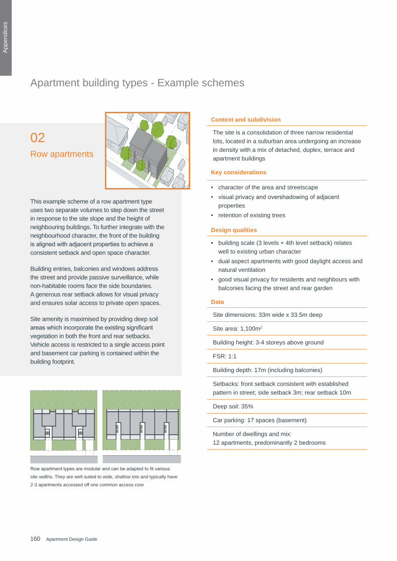
160 Apartment Design Guide
App
endi
ces
This example scheme of a row apartment type uses two separate volumes to step down the street in response to the site slope and the height of neighbouring buildings. To further integrate with the neighbourhood character, the front of the building isalignedwithadjacentpropertiestoachieveaconsistent setback and open space character.
Building entries, balconies and windows address the street and provide passive surveillance, while non-habitable rooms face the side boundaries. A generous rear setback allows for visual privacy and ensures solar access to private open spaces.
Site amenity is maximised by providing deep soil areaswhichincorporatetheexistingsignificantvegetation in both the front and rear setbacks. Vehicle access is restricted to a single access point and basement car parking is contained within the building footprint.
Rowapartmenttypesaremodularandcanbeadaptedtofitvarious
site widths. They are well suited to wide, shallow lots and typically have
2-3 apartments accessed off one common access core
Context and subdivision
The site is a consolidation of three narrow residential lots, located in a suburban area undergoing an increase in density with a mix of detached, duplex, terrace and apartment buildings
Key considerations
• character of the area and streetscape • visualprivacyandovershadowingofadjacent
properties • retention of existing trees
Design qualities
• building scale (3 levels + 4th level setback) relates well to existing urban character
• dual aspect apartments with good daylight access and natural ventilation
• good visual privacy for residents and neighbours with balconies facing the street and rear garden
Data
Site dimensions: 33m wide x 33.5m deep
Site area: 1,100m2
Building height: 3-4 storeys above ground
FSR: 1:1
Building depth: 17m (including balconies)
Setbacks: front setback consistent with established pattern in street; side setback 3m; rear setback 10m
Deep soil: 35%
Car parking: 17 spaces (basement)
Number of dwellings and mix: 12 apartments, predominantly 2 bedrooms
Apartment building types - Example schemes
02Row apartments
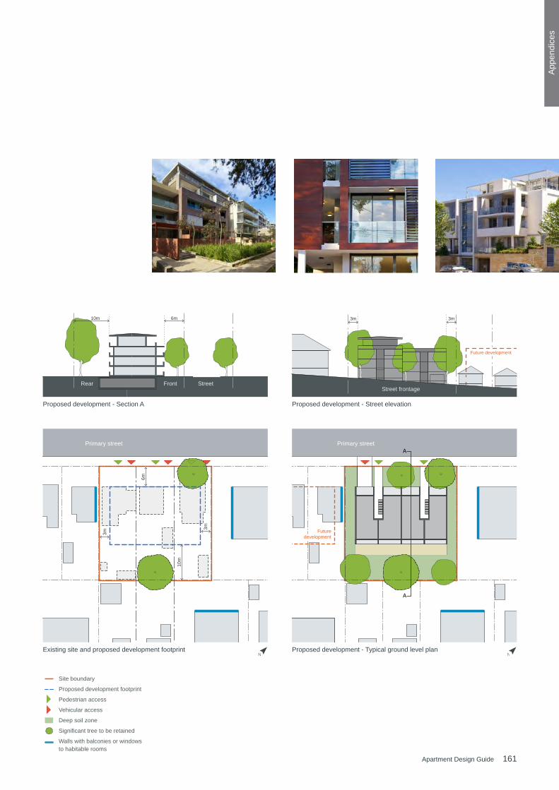
161Apartment Design Guide
App
endi
ces
A
A
3m
3m
10m
6m
3m3m10m 6m
Street Street frontage
Front
Primary streetPrimary street
Rear
Futuredevelopment
Future development
50m0
Site boundary
Proposed development footprint
Pedestrian access
Vehicular access
Deep soil zone
Significant tree to be retained
Walls with balconies or windows to habitable rooms
N N
Apartment building types - Example schemes Row Apartments
A
A
3m
3m
10m
6m
3m3m10m 6m
Street Street frontage
Front
Primary streetPrimary street
Rear
Futuredevelopment
Future development
50m0
Site boundary
Proposed development footprint
Pedestrian access
Vehicular access
Deep soil zone
Significant tree to be retained
Walls with balconies or windows to habitable rooms
N N
Apartment building types - Example schemes Row Apartments
Existing site and proposed development footprint Proposed development - Typical ground level plan
A
A
3m
3m
10m
6m
3m3m10m 6m
Street Street frontage
Front
Primary streetPrimary street
Rear
Futuredevelopment
Future development
50m0
Site boundary
Proposed development footprint
Pedestrian access
Vehicular access
Deep soil zone
Significant tree to be retained
Walls with balconies or windows to habitable rooms
N N
Apartment building types - Example schemes Row Apartments
A
A
3m
3m
10m
6m
3m3m10m 6m
Street Street frontage
Front
Primary streetPrimary street
Rear
Futuredevelopment
Future development
50m0
Site boundary
Proposed development footprint
Pedestrian access
Vehicular access
Deep soil zone
Significant tree to be retained
Walls with balconies or windows to habitable rooms
N N
Apartment building types - Example schemes Row Apartments
Proposed development - Section A Proposed development - Street elevation
N N
A
A
3m
3m
10m
6m
3m3m10m 6m
Street Street frontage
Front
Primary streetPrimary street
Rear
Futuredevelopment
Future development
50m0
Site boundary
Proposed development footprint
Pedestrian access
Vehicular access
Deep soil zone
Significant tree to be retained
Walls with balconies or windows to habitable rooms
N N
Apartment building types - Example schemes Row Apartments
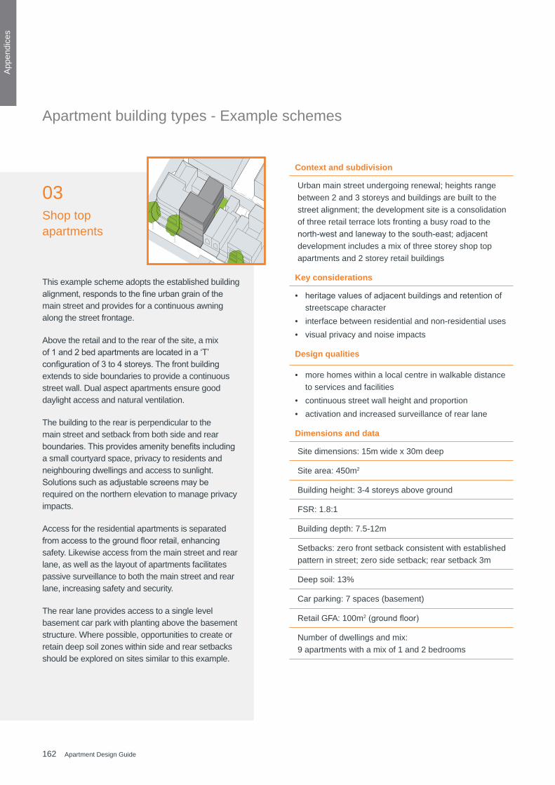
162 Apartment Design Guide
App
endi
ces
Context and subdivision
Urban main street undergoing renewal; heights range between 2 and 3 storeys and buildings are built to the street alignment; the development site is a consolidation of three retail terrace lots fronting a busy road to the north-westandlanewaytothesouth-east;adjacentdevelopment includes a mix of three storey shop top apartments and 2 storey retail buildings
Key considerations
• heritagevaluesofadjacentbuildingsandretentionofstreetscape character
• interface between residential and non-residential uses• visual privacy and noise impacts
Design qualities
• more homes within a local centre in walkable distance to services and facilities
• continuous street wall height and proportion • activation and increased surveillance of rear lane
Dimensions and data
Site dimensions: 15m wide x 30m deep
Site area: 450m2
Building height: 3-4 storeys above ground
FSR: 1.8:1
Building depth: 7.5-12m
Setbacks: zero front setback consistent with established pattern in street; zero side setback; rear setback 3m
Deep soil: 13%
Car parking: 7 spaces (basement)
Retail GFA: 100m2(groundfloor)
Number of dwellings and mix: 9 apartments with a mix of 1 and 2 bedrooms
This example scheme adopts the established building alignment,respondstothefineurbangrainofthemain street and provides for a continuous awning along the street frontage.
Above the retail and to the rear of the site, a mix of1and2bedapartmentsarelocatedina‘T’configurationof3to4storeys.Thefrontbuildingextends to side boundaries to provide a continuous street wall. Dual aspect apartments ensure good daylight access and natural ventilation.
The building to the rear is perpendicular to the main street and setback from both side and rear boundaries.Thisprovidesamenitybenefitsincludinga small courtyard space, privacy to residents and neighbouring dwellings and access to sunlight. Solutionssuchasadjustablescreensmayberequired on the northern elevation to manage privacy impacts.
Access for the residential apartments is separated fromaccesstothegroundfloorretail,enhancingsafety. Likewise access from the main street and rear lane, as well as the layout of apartments facilitates passive surveillance to both the main street and rear lane, increasing safety and security.
The rear lane provides access to a single level basement car park with planting above the basement structure. Where possible, opportunities to create or retain deep soil zones within side and rear setbacks should be explored on sites similar to this example.
03Shop top apartments
Apartment building types - Example schemes
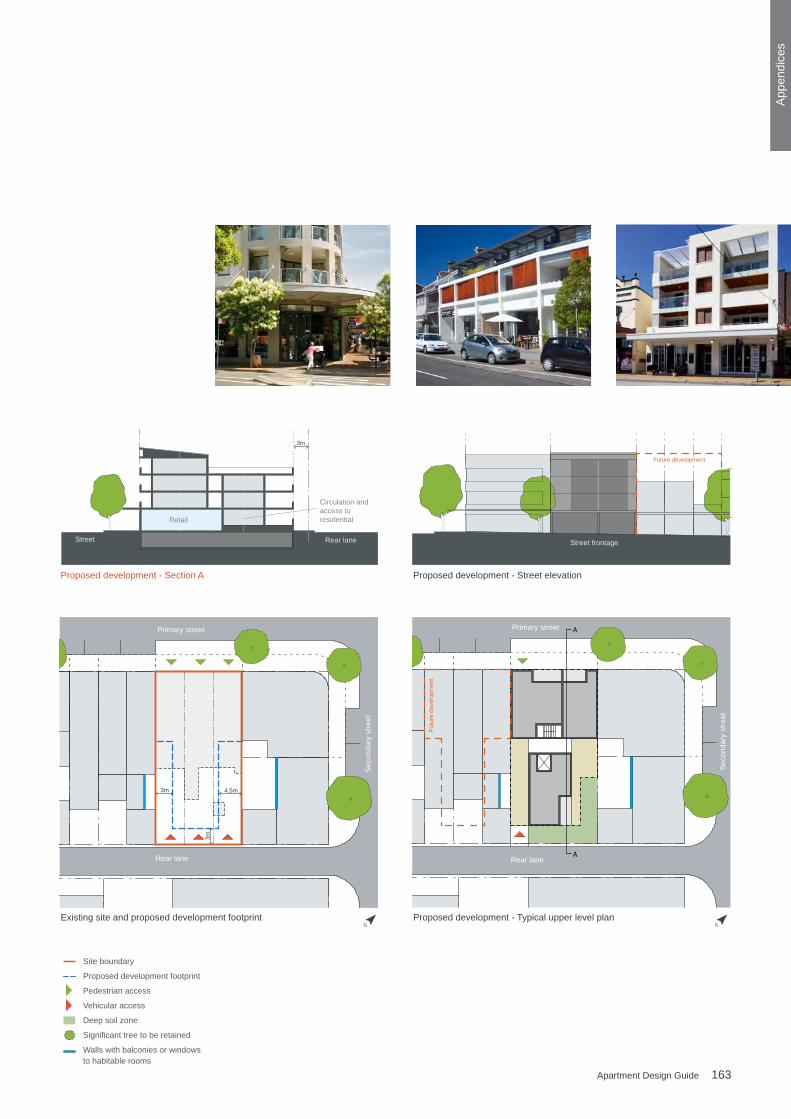
163Apartment Design Guide
App
endi
ces
50m0
Futu
re d
evel
opm
ent
A
A
3m
4.5m3m
3m
Street Rear lane
Retail
Circulation and access to residential
Primary street
Rear lane
Primary street
Rear lane
Sec
onda
ry s
treet
Sec
onda
ry s
treet
Street frontage
Future development
N N
Apartment building types - Example schemes Shop top
50m0
Futu
re d
evel
opm
ent
A
A
3m
4.5m3m
3m
Street Rear lane
Retail
Circulation and access to residential
Primary street
Rear lane
Primary street
Rear lane
Sec
onda
ry s
treet
Sec
onda
ry s
treet
Street frontage
Future development
N N
Apartment building types - Example schemes Shop top
50m0
Futu
re d
evel
opm
ent
A
A
3m
4.5m3m
3m
Street Rear lane
Retail
Circulation and access to residential
Primary street
Rear lane
Primary street
Rear lane
Sec
onda
ry s
treet
Sec
onda
ry s
treet
Street frontage
Future development
N N
Apartment building types - Example schemes Shop top
50m0
Futu
re d
evel
opm
ent
A
A
3m
4.5m3m
3m
Street Rear lane
Retail
Circulation and access to residential
Primary street
Rear lane
Primary street
Rear lane
Sec
onda
ry s
treet
Sec
onda
ry s
treet
Street frontage
Future development
N N
Apartment building types - Example schemes Shop top
N NExisting site and proposed development footprint Proposed development - Typical upper level plan
Proposed development - Section A Proposed development - Street elevation
A
A
3m
3m
10m
6m
3m3m10m 6m
Street Street frontage
Front
Primary streetPrimary street
Rear
Futuredevelopment
Future development
50m0
Site boundary
Proposed development footprint
Pedestrian access
Vehicular access
Deep soil zone
Significant tree to be retained
Walls with balconies or windows to habitable rooms
N N
Apartment building types - Example schemes Row Apartments
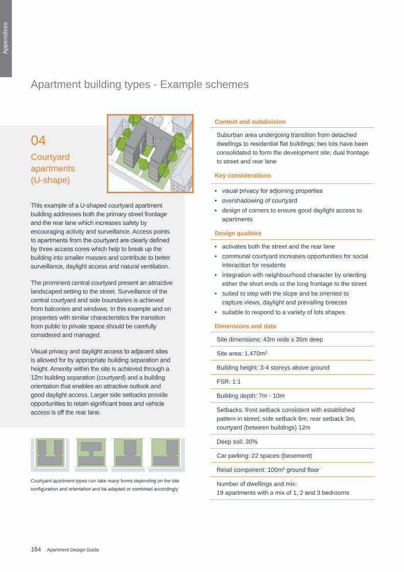
164 Apartment Design Guide
App
endi
ces
Context and subdivision
Suburban area undergoing transition from detached dwellingstoresidentialflatbuildings;twolotshavebeenconsolidated to form the development site; dual frontage to street and rear lane
Key considerations
• visualprivacyforadjoiningproperties• overshadowing of courtyard• design of corners to ensure good daylight access to
apartments
Design qualities
• activates both the street and the rear lane • communal courtyard increases opportunities for social
interaction for residents• integration with neighbourhood character by orienting
either the short ends or the long frontage to the street• suited to step with the slope and be oriented to
capture views, daylight and prevailing breezes • suitable to respond to a variety of lots shapes
Dimensions and data
Site dimensions: 43m wide x 35m deep
Site area: 1,470m2
Building height: 3-4 storeys above ground
FSR: 1:1
Building depth: 7m - 10m
Setbacks: front setback consistent with established pattern in street; side setback 6m; rear setback 3m, courtyard (between buildings) 12m
Deep soil: 30%
Car parking: 22 spaces (basement)
Retail component: 100m2groundfloor
Number of dwellings and mix: 19 apartments with a mix of 1, 2 and 3 bedrooms
This example of a U-shaped courtyard apartment building addresses both the primary street frontage and the rear lane which increases safety by encouraging activity and surveillance. Access points toapartmentsfromthecourtyardareclearlydefinedby three access cores which help to break up the building into smaller masses and contribute to better surveillance, daylight access and natural ventilation.
The prominent central courtyard present an attractive landscaped setting to the street. Surveillance of the central courtyard and side boundaries is achieved from balconies and windows. In this example and on properties with similar characteristics the transition from public to private space should be carefully considered and managed.
Visualprivacyanddaylightaccesstoadjacentsitesis allowed for by appropriate building separation and height. Amenity within the site is achieved through a 12m building separation (courtyard) and a building orientation that enables an attractive outlook and good daylight access. Larger side setbacks provide opportunitiestoretainsignificanttreesandvehicleaccess is off the rear lane.
04Courtyard apartments (U-shape)
Courtyard apartment types can take many forms depending on the site
configurationandorientationandbeadaptedorcombinedaccordingly
Apartment building types - Example schemes

165Apartment Design Guide
App
endi
ces
A
A
3m3m 6m 6m
6m
6m
3m
3m
Primary street Primary street
Rear lane Rear lane
Street Lane Street frontage
50m0
Apartment building types - Example schemes Courtyard (U-shape)
A
A
3m3m 6m 6m
6m
6m
3m
3m
Primary street Primary street
Rear lane Rear lane
Street Lane Street frontage
50m0
Apartment building types - Example schemes Courtyard (U-shape)
A
A
3m3m 6m 6m
6m
6m
3m
3m
Primary street Primary street
Rear lane Rear lane
Street Lane Street frontage
50m0
Apartment building types - Example schemes Courtyard (U-shape)
A
A
3m3m 6m 6m
6m
6m
3m
3m
Primary street Primary street
Rear lane Rear lane
Street Lane Street frontage
50m0
Apartment building types - Example schemes Courtyard (U-shape)
NN
Existing site and proposed development footprint Proposed development - Typical ground level plan
Proposed development - Section A Proposed development - Street elevation
A
A
3m
3m
10m
6m
3m3m10m 6m
Street Street frontage
Front
Primary streetPrimary street
Rear
Futuredevelopment
Future development
50m0
Site boundary
Proposed development footprint
Pedestrian access
Vehicular access
Deep soil zone
Significant tree to be retained
Walls with balconies or windows to habitable rooms
N N
Apartment building types - Example schemes Row Apartments

166 Apartment Design Guide
App
endi
ces
Context and subdivision
Suburban area in transition to increased density with a mix of apartment buildings and detached dwellings; the development site is an amalgamation of four traditional detached housing lots with street and rear lane frontage
Key considerations
• visualprivacyforadjoiningproperties• adequate building separation to ensure good solar
access and ventilation
Design qualities
• multiple building entries achieve activation of the street and rear lane
• front building forms part of an intended street wall • can be adapted for narrow sites and include SOHO
units (live/work) or small commercial tenancies• suitable for sloping sites
Dimensions and data
Site dimensions: 45m wide x 40m deep
Site area: 1,800m2
Building height: 3-4 storeys above ground
FSR: 1.3:1
Building depth: 7.8m - 16.2m
Setbacks: front setback consistent with established pattern in street; side setback 3m
Deep soil: 20%
Car parking: 25 spaces (basement)
Number of dwellings and mix: 22 apartments with a mix of 1, 2 and 3 bedrooms
This example uses a centralised courtyard between two linear buildings to optimise development of the site while ensuring good amenity. By using this typology it is possible to provide consistent setbacks to the street and lane, a sense of address and good surveillance of the public domain.
Buildingheightshouldrelatetotheadjacentdevelopment, street width and the direction of solar access. In this example, the larger 4 storey building fronts the wider street while the 3 storey building is oriented to the north and fronts the narrower lane. This lower building height allows for sunlight to access to the courtyard behind.
Amenity to neighbouring properties is improved by providing greater visual privacy and improved daylight and sunlight access than would otherwise be possible with a building perpendicular to the street alignment. Walls facing the side boundary are mostly blank with windows only to common entry corridors and non-habitable rooms. This improves the privacy toadjacentpropertiesthathavehabitablewindowsand balconies facing the side boundary.
A centralised courtyard provides separation between facades and a pleasant open space for passive recreation. The courtyard also provides opportunities toretainanysignificantvegetationandoverlapdeepsoil with communal open space. In addition, planting on top of the car park increases the attractiveness and usability of this area. Vehicle access is from the lane to a split level car park which is located predominantly below the building footprint.
05Courtyard apartments (linear)
Apartment building types - Example schemes

167Apartment Design Guide
App
endi
ces
50m0
A
A
3m
3m3m
3m
6m
6m
3m 3m3m
Street Rear lane Street frontage
Primary street Primary street
Rear lane Rear lane
N N
Apartment building types - Example schemes Courtyard (lnear)
50m0
A
A
3m
3m3m
3m
6m
6m
3m 3m3m
Street Rear lane Street frontage
Primary street Primary street
Rear lane Rear lane
N N
Apartment building types - Example schemes Courtyard (lnear)
50m0
A
A
3m
3m3m
3m
6m
6m
3m 3m3m
Street Rear lane Street frontage
Primary street Primary street
Rear lane Rear lane
N N
Apartment building types - Example schemes Courtyard (lnear)
50m0
A
A
3m
3m3m
3m
6m
6m
3m 3m3m
Street Rear lane Street frontage
Primary street Primary street
Rear lane Rear lane
N N
Apartment building types - Example schemes Courtyard (lnear)
NNExisting site and proposed development footprint Proposed development - Typical ground level plan
Proposed development - Section A Proposed development - Street elevation
A
A
3m
3m
10m
6m
3m3m10m 6m
Street Street frontage
Front
Primary streetPrimary street
Rear
Futuredevelopment
Future development
50m0
Site boundary
Proposed development footprint
Pedestrian access
Vehicular access
Deep soil zone
Significant tree to be retained
Walls with balconies or windows to habitable rooms
N N
Apartment building types - Example schemes Row Apartments
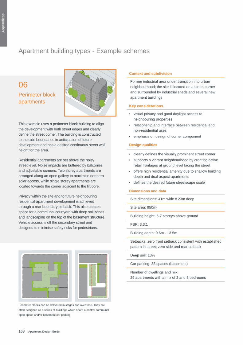
168 Apartment Design Guide
App
endi
ces
Context and subdivision
Former industrial area under transition into urban neighbourhood; the site is located on a street corner and surrounded by industrial sheds and several new apartment buildings
Key considerations
• visual privacy and good daylight access to neighbouring properties
• relationship and interface between residential and non-residential uses
• emphasis on design of corner component
Design qualities
• clearlydefinesthevisuallyprominentstreetcorner• supports a vibrant neighbourhood by creating active
retail frontages at ground level facing the street • offers high residential amenity due to shallow building
depth and dual aspect apartments • definesthedesiredfuturestreetscapescale
Dimensions and data
Site dimensions: 41m wide x 23m deep
Site area: 950m2
Building height: 6-7 storeys above ground
FSR: 3.3:1
Building depth: 9.6m - 13.5m
Setbacks: zero front setback consistent with established pattern in street; zero side and rear setback
Deep soil: 13%
Car parking: 38 spaces (basement)
Number of dwellings and mix: 29 apartments with a mix of 2 and 3 bedrooms
This example uses a perimeter block building to align the development with both street edges and clearly definethestreetcorner.Thebuildingisconstructedto the side boundaries in anticipation of future development and has a desired continuous street wall height for the area.
Residential apartments are set above the noisy street level. Noise impacts are buffered by balconies andadjustablescreens.Twostoreyapartmentsarearranged along an open gallery to maximise northern solar access, while single storey apartments are locatedtowardsthecorneradjacenttotheliftcore.
Privacy within the site and to future neighbouring residential apartment development is achieved through a rear boundary setback. This also creates space for a communal courtyard with deep soil zones and landscaping on the top of the basement structure. Vehicle access is off the secondary street and designed to minimise safety risks for pedestrians.
06Perimeter block apartments
Perimeter blocks can be delivered in stages and over time. They are
often designed as a series of buildings which share a central communal
open space and/or basement car parking
Apartment building types - Example schemes
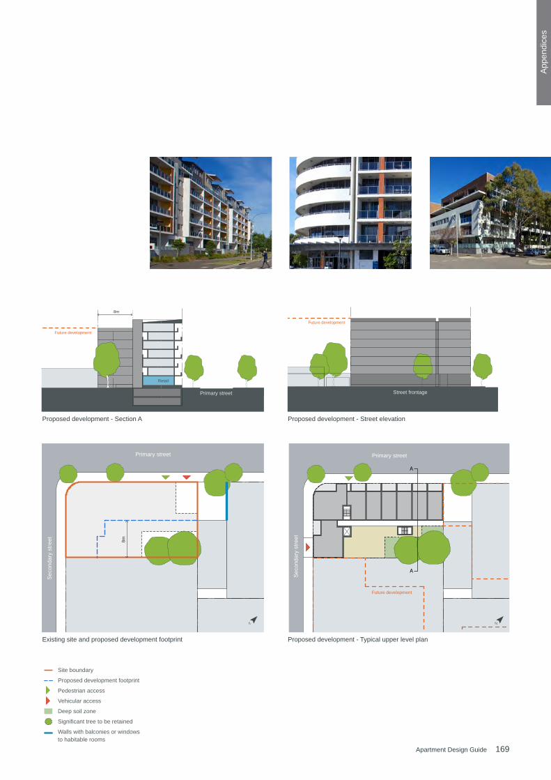
169Apartment Design Guide
App
endi
ces
A
A
8m
8m
Primary street Primary street
Sec
onda
ry s
treet
Sec
onda
ry s
treet
Street frontage Primary street
N
50m0
Future development
Future development
Future development
Retail
Apartment building types - Example schemes Perimeter block apartments
A
A
8m
8m
Primary street Primary street
Sec
onda
ry s
treet
Sec
onda
ry s
treet
Street frontage Primary street
N
50m0
Future development
Future development
Future development
Retail
Apartment building types - Example schemes Perimeter block apartments
A
A
8m
8m
Primary street Primary street
Sec
onda
ry s
treet
Sec
onda
ry s
treet
Street frontage Primary street
N
50m0
Future development
Future development
Future development
Retail
Apartment building types - Example schemes Perimeter block apartments
A
A
8m
8m
Primary street Primary street
Sec
onda
ry s
treet
Sec
onda
ry s
treet
Street frontage Primary street
N
50m0
Future development
Future development
Future development
Retail
Apartment building types - Example schemes Perimeter block apartments
N N
Existing site and proposed development footprint Proposed development - Typical upper level plan
Proposed development - Section A Proposed development - Street elevation
A
A
3m
3m
10m
6m
3m3m10m 6m
Street Street frontage
Front
Primary streetPrimary street
Rear
Futuredevelopment
Future development
50m0
Site boundary
Proposed development footprint
Pedestrian access
Vehicular access
Deep soil zone
Significant tree to be retained
Walls with balconies or windows to habitable rooms
N N
Apartment building types - Example schemes Row Apartments
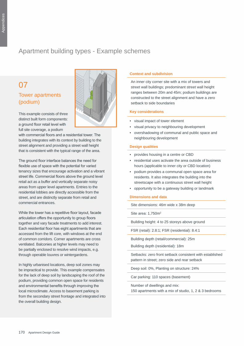
170 Apartment Design Guide
App
endi
ces
Context and subdivision
An inner city corner site with a mix of towers and street wall buildings; predominant street wall height ranges between 20m and 45m; podium buildings are constructed to the street alignment and have a zero setback to side boundaries
Key considerations
• visual impact of tower element • visual privacy to neighbouring development • overshadowing of communal and public space and
neighbouring development
Design qualities
• provides housing in a centre or CBD• residential uses activate the area outside of business
hours (applicable to inner city or CBD location) • podium provides a communal open space area for
residents. It also integrates the building into the streetscape with a continuous street wall height
• opportunity to be a gateway building or landmark
Dimensions and data
Site dimensions: 46m wide x 38m deep
Site area: 1,750m2
Building height: 4 to 25 storeys above ground
FSR (retail): 2.8:1; FSR (residential): 8.4:1
Building depth (retail/commercial): 25m
Building depth (residential): 18m
Setbacks: zero front setback consistent with established pattern in street; zero side and rear setback
Deep soil: 0%, Planting on structure: 24%
Car parking: 110 spaces (basement)
Number of dwellings and mix: 150 apartments with a mix of studio, 1, 2 & 3 bedrooms
This example consists of three distinct built form components: agroundfloorretaillevelwithfull site coverage, a podium withcommercialfloorsandaresidentialtower.Thebuilding integrates with its context by building to the street alignment and providing a street wall height that is consistent with the typical range of the area.
Thegroundfloorinterfacebalancestheneedforflexibleuseofspacewiththepotentialforvariedtenancy sizes that encourage activation and a vibrant streetlife.Commercialfloorsabovethegroundlevelretail act as a buffer and vertically separate noisy areas from upper level apartments. Entries to the residential lobbies are directly accessible from the street, and are distinctly separate from retail and commercial entrances.
Whilethetowerhasarepetitivefloorlayout,facadearticulationofferstheopportunitytogroupfloorstogether and vary facade treatments to add interest. Eachresidentialfloorhaseightapartmentsthatareaccessed from the lift core, with windows at the end of common corridors. Corner apartments are cross ventilated. Balconies at higher levels may need to be partially enclosed to resolve wind impacts, e.g. through operable louvres or wintergardens.
In highly urbanised locations, deep soil zones may be impractical to provide. This example compensates for the lack of deep soil by landscaping the roof of the podium, providing common open space for residents andenvironmentalbenefitsthroughimprovingthelocal microclimate. Access to basement parking is from the secondary street frontage and integrated into the overall building design.
07Tower apartments (podium)
Apartment building types - Example schemes

171Apartment Design Guide
App
endi
ces
75m0
Futu
re d
evel
opm
ent
A
A
Secondary setback (tower)
Pod
ium
Secondary street
Prim
ary
stre
et
Secondary street
Prim
ary
stre
et
Future development
Retail
Commercial
Street frontage Secondary street
Secondary street
Podiumroof
Car parkroof
Apartment building types - Example schemes Tower apartments (podium)
N N
App
endi
ces
Existing site and proposed development footprint Proposed development - Typical upper level plan
Proposed development - Section A Proposed development - Street elevation
A
A
3m
3m
10m
6m
3m3m10m 6m
Street Street frontage
Front
Primary streetPrimary street
Rear
Futuredevelopment
Future development
50m0
Site boundary
Proposed development footprint
Pedestrian access
Vehicular access
Deep soil zone
Significant tree to be retained
Walls with balconies or windows to habitable rooms
N N
Apartment building types - Example schemes Row Apartments

172 Apartment Design Guide
App
endi
ces
Context and subdivision
The site is located within a predominantly residential contextattheedgeofatowncentre,adjacenttoa(noisy)railwaylinetotheeastanddefinedbystreetsonthree sides and a public park to the north
Key considerations
• visual impact of tower element • visual privacy to neighbouring development • overshadowing of communal and public space and
neighbouring development • relationship with streetscape
Design qualities
• small footprint minimises hard surface areas and reduces urban heat island effect
• excellent views, daylight access and natural ventilation for residents
• separation from noise sources (e.g. busy road/rail) • opportunity to be a gateway building or landmark
Dimensions and data
Site dimensions: 95m wide x 62m deep
Site area: 5,890m2
Building height: 25 storeys above ground
FSR: 4.4:1
Building depth: 15.5m - 21.5m
Setbacks: landscaped setback, consistent with surrounding context
Deep soil: 14%
Car parking: 340 spaces (basement)
Number of dwellings and mix: 314 apartments with a mix of 1, 2 and 3 bedrooms
08Tower apartments (freestanding)
This development integrates with its context by aligning withthesetbackofadjacentbuildings and providing an address to surrounding streets. The location of the tower minimises overshadowing of communal and public open space and neighbouring development. The orientation of the building along the north-south axis maximises views and enables good solar access to all apartments.
Communal open space for residents is provided in the centre of the site facing the public park. The basement car park has a U-shaped footprint over two levels and wraps around a deep soil zone under the communal courtyard. Vehicle access is located on the secondary street to the south.
Pedestrian entries to lobbies are located along all street frontages. Additional access is provided from the public park to the north and off the communal courtyard. At ground level, apartments have direct access from the street or the communal courtyard and the design allows for live-work apartments and retail space facing the street.
The tower has a central core with eight apartments perfloor.Allcirculationcorridorshaveaccesstonatural light and ventilation.
Apartment building types - Example schemes
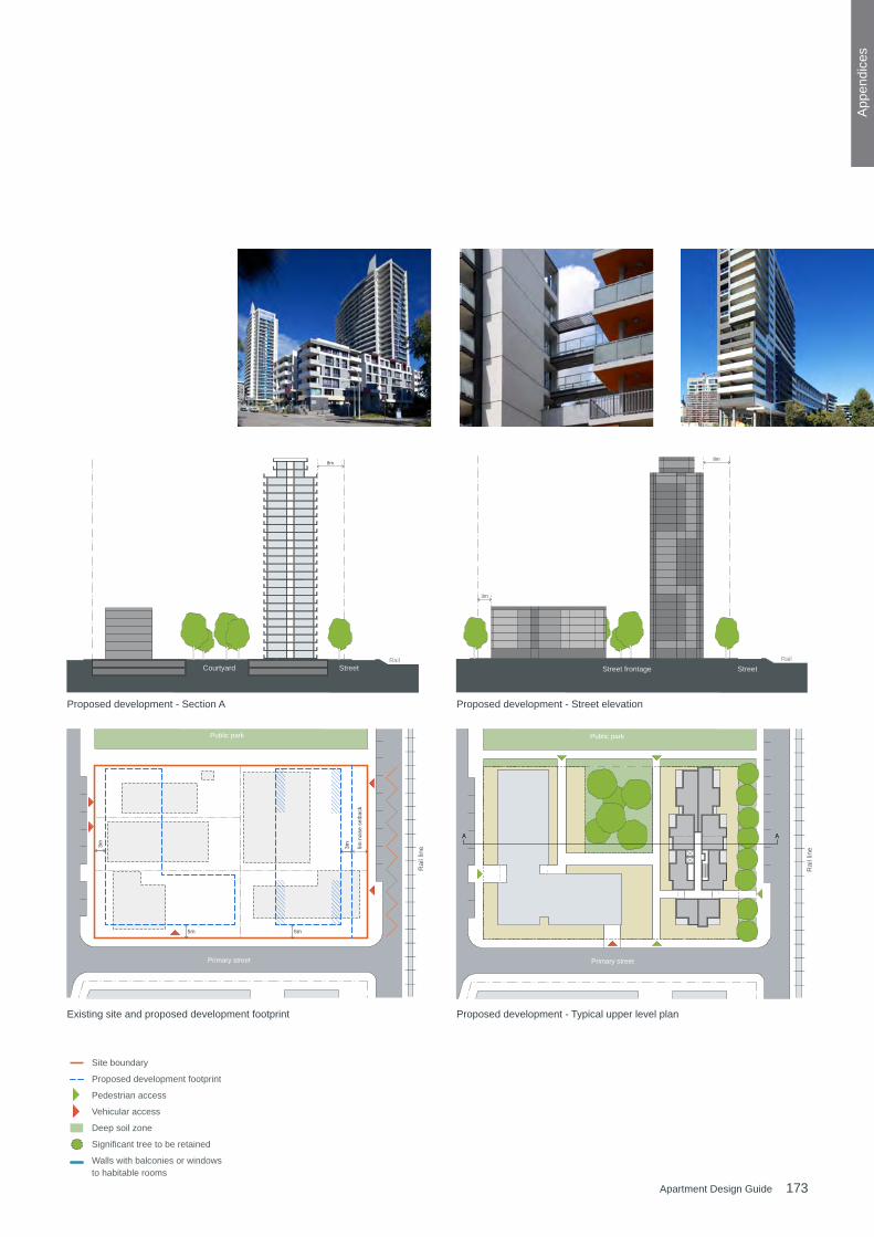
173Apartment Design Guide
App
endi
ces
100m0
N
AA
8m8m
3m
5m
3m
5m
5m n
oise
set
back
3m
Primary street Primary street
Public park Public park
Rai
l lin
e
Rai
l lin
e
Street frontage Street RailRail
Street Courtyard
Apartment building types - Example schemes Tower apartments (freestanding)
100m0
N
AA
8m8m
3m
5m
3m
5m
5m n
oise
set
back
3m
Primary street Primary street
Public park Public park
Rai
l lin
e
Rai
l lin
e
Street frontage Street RailRail
Street Courtyard
Apartment building types - Example schemes Tower apartments (freestanding)
100m0
N
AA
8m8m
3m
5m
3m
5m
5m n
oise
set
back
3m
Primary street Primary street
Public park Public park
Rai
l lin
e
Rai
l lin
e
Street frontage Street RailRail
Street Courtyard
Apartment building types - Example schemes Tower apartments (freestanding)
100m0
N
AA
8m8m
3m
5m
3m
5m
5m n
oise
set
back
3m
Primary street Primary street
Public park Public park
Rai
l lin
e
Rai
l lin
e
Street frontage Street RailRail
Street Courtyard
Apartment building types - Example schemes Tower apartments (freestanding)
Existing site and proposed development footprint Proposed development - Typical upper level plan
Proposed development - Section A Proposed development - Street elevation
A
A
3m
3m
10m
6m
3m3m10m 6m
Street Street frontage
Front
Primary streetPrimary street
Rear
Futuredevelopment
Future development
50m0
Site boundary
Proposed development footprint
Pedestrian access
Vehicular access
Deep soil zone
Significant tree to be retained
Walls with balconies or windows to habitable rooms
N N
Apartment building types - Example schemes Row Apartments

174 Apartment Design Guide
App
endi
ces
This example scheme of a mixed use development is an amalgamation of four lots and is located on a prominent street corner. It consists of a single level retail podium with full site coverage and residential apartments on the upper levels.
Thesharpstreetcornerisdefinedandbothstreetsare addressed through the use of commercial frontages (windows and entries) and a continuous awning that turns the corner. Lift cores to residential floorsabovearelocatedatthestreetedge.Singlestorey units are stacked vertically on the corner and accessed from an open gallery while crossover apartments to either side of the building maximise northern sunlight access.
Communal open space is provided on the podium with substantial planting on structure (roof garden). Large trees and adequate building separation further enhance residential amenity. Vehicle access to the basement car park and the retail loading dock are located off the secondary street to the north.
Integrating residential apartments with large format commercial uses requires detailed consideration to resolvepotentialconflictsbetweenuses.Thelocationof retail and residential entries, the arrangement of loading docks and basement car parking and the impact and mitigation of noise generated by the commercial component are some examples.
Hybrid (mixed) development
Context and subdivision
A prominent corner site that addresses two streets with different streetscape character; surrounding buildings are anticipated to redevelop into similar density and height; desired future character of the area includes active street frontages, continuous awnings, zero building alignments and street frontage heights of 17 to 24m
Key considerations
• relationship and activation of surrounding streets • relationship and interface between residential and
non-residential uses and mitigation of potential conflictsbetweenthem
• emphasis on design of prominent corner component
Design qualities
• clear street address with active frontages • podium roof gardens add to residential amenity • selection of robust facade materials • integration of photo voltaics (PV) on roofs and
awnings
Dimensions and data
Site dimensions: 80 x 45m (irregular)
Site area: 2,840m2
Building height: 5-7 storeys above ground
FSR: 2.8:1 residential and 0.8:1 retail
Building depth (residential): 10.2 - 17m
Setbacks: nil front setback, 2.4m front setback upper levels, nil side setback, 3m upper levels, nil rear setback, 9m upper levels
Deep soil zone: 0%, Planting on structure: 10%
Car parking: 210 spaces (basement) including parking for both residential and non-residential uses
Retail GFA: 2,270m2(groundfloor)
Number of dwellings and mix: 64 apartments with a mix of 1, 2 and 3 bedrooms
09
Apartment building types - Example schemes

175Apartment Design Guide
App
endi
ces
A
A
A
A
3m
3m
Primary street
Primary street
Primary street
Street frontage Street
Site boundary
Proposed upper level footprint
Pedestrian access
Vehicular access
Planting on structure
Significant tree to be retained
Walls with balconies or windows to habitable rooms
Apartment building types - Example schemes Hybrid (mixed) developments
A
A
A
A
3m
3m
Primary street
Primary street
Primary street
Street frontage Street
Site boundary
Proposed upper level footprint
Pedestrian access
Vehicular access
Planting on structure
Significant tree to be retained
Walls with balconies or windows to habitable rooms
Apartment building types - Example schemes Hybrid (mixed) developments
Existing site and proposed development footprint Proposed development - Typical upper level plan
Proposed development - Ground level plan
Proposed development - Section A Proposed development - Street elevation A
A
3m
3m
10m
6m
3m3m10m 6m
Street Street frontage
Front
Primary streetPrimary street
Rear
Futuredevelopment
Future development
50m0
Site boundary
Proposed development footprint
Pedestrian access
Vehicular access
Deep soil zone
Significant tree to be retained
Walls with balconies or windows to habitable rooms
N N
Apartment building types - Example schemes Row Apartments

176 Apartment Design Guide
App
endi
ces

177Apartment Design Guide
App
endi
ces
Sunlight access analysis toolAPPENDIX 5
Afternoonsun
Morningsun
Sun Altitude Ratios
Based on Sydney coordinates33° South 151.20° East +10 GMT for winter solstice at 21 June
(angles and ratios shown roundedfor convenient design and assessment)
12 noon(1.55:1)1pm
(1.65:1)2pm(2:1)
3pm(2.9:1)
11am(1.65:1)
10am(2:1)
9am(2.9:1)
EastWest45°
15° 15°15° 15°15° 15°
45°
north
2.9:12.7m
7.8m
2:12.7m
5.4m
2.7m
4.5m
1.65:1
2.7m1.55:1
4.2m
To achieve 2 hours of direct sunlight in midwinter, a good test is to check whether the sun can ‘see’ the living room window and private open space between 11am and 1pm in plan
If it can, a second test is to check whether the sun altitude ratio will allow sunlight to reach the living room window
All deminstrations of solar access should be verified with ‘a view from the sun’ analysis at quarter hour intervals
Sun altitude ratios
Afternoonsun
Morningsun
Sun Altitude Ratios
Based on Sydney coordinates33° South 151.20° East +10 GMT for winter solstice at 21 June
(angles and ratios shown roundedfor convenient design and assessment)
12 noon(1.55:1)1pm
(1.65:1)2pm(2:1)
3pm(2.9:1)
11am(1.65:1)
10am(2:1)
9am(2.9:1)
EastWest45°
15° 15°15° 15°15° 15°
45°
north
2.9:12.7m
7.8m
2:12.7m
5.4m
2.7m
4.5m
1.65:1
2.7m1.55:1
4.2m
To achieve 2 hours of direct sunlight in midwinter, a good test is to check whether the sun can ‘see’ the living room window and private open space between 11am and 1pm in plan
If it can, a second test is to check whether the sun altitude ratio will allow sunlight to reach the living room window
All deminstrations of solar access should be verified with ‘a view from the sun’ analysis at quarter hour intervals
Based on Sydney coordinates33o South 151.20o East +10 GMT for winter solstice at 21 June
ceiling heightsun altitu
de ratio
sunlight extent
To achieve 2 hours of direct sunlight in mid winter, a good test is to check whether the sun can 'see' the living room window and private open space between 11 am and 1 pm in plan view
The ratios below can be used to determine how far sunlight extends into apartments at a given time of day, according to the ratios indicated on the sunlight access tool above
Sunlight access tool

178 Apartment Design Guide
Glo
ssar
y
Acoustic privacy a measure of sound insulation between apartments, between apartments and communal areas, and between external and internal spaces
Adaptable housinghousing that is designed and built to accommodate future changes to suit occupants with mobility impairment or life cycle needs
Adaptive reusethe conversion of an existing building or structure from one usetoanother,orfromoneconfigurationtoanother
Amenity the‘liveability’,comfortorqualityofaplacewhichmakesit pleasant and agreeable to be in for individuals and the community. Amenity is important in the public, communal andprivatedomainsandincludestheenjoymentofsunlight,views, privacy and quiet. It also includes protection from pollution and odours
Aircraft noiseaircraftnoiseisidentifiedascontoursontheAustralianNoise Exposure Forecast (ANEF) Map. The higher the ANEF contour value, the greater the exposure to aircraft noise
Articulation zonean area in front of the building line that may contain porticos, balconies, bay windows, decks, patios, pergolas, terraces, verandahs, window box treatments, window bays, awnings and sun shading features
Attached dwellingasdefinedintheStandard Instrument - Principal Local Environmental Plan
Bay windowwindowelementwhichprojectsashortwaypastthefaceof the building. It can have windows on the return walls and sometimes incorporates a seat
BCA Building Code of Australia
Building line the predominant line formed by the main external face of the building.Balconiesorbaywindowprojectionsmayormaynot be included depending on desired streetscape
Building heightasdefinedintheStandard Instrument - Principal Local Environmental Plan
Building depthis the overall cross section dimension of a building envelope. Itincludestheinternalfloorplate,externalwalls,balconies,external circulation and articulation such as recesses and steps in plan and section
Business zoneslandidentifiedonaLandZoningMapwithinalocalenvironmental plan as a B1 Neighbourhood Centre, B2 Local Centre, B3 Commercial Core, B4 Mixed Use, B5 Business Development, B6 Enterprise Corridor, B7 Business Park or B8 Metropolitan Centre zone
Note: residential apartment development may not be permissible or appropriate in all Business zones
Busy road or rail lineasdefinedinState Environmental Planning Policy (Infrastructure) 2007 and Development Near Rail Corridors and Busy Roads – Interim Guideline
Cadastre the current subdivisional pattern of a locality on the ground e.g.boundaries,roads,waterways,parcelidentifiersandnames
Clerestoryhigh level windows that can be part of a wall above a lower roof
Communal open space outdoor space located within the site at ground level or on a structure that is within common ownership and for the recreational use of residents of the development. Communal open space may be accessible to residents only, or to the public
Core vertical circulation (lift and/or stairs) within a building. A singlecoremayincludemultipleliftsservingthesamefloorarea
Corner apartmentcross ventilating apartments on one level with aspects at least 90 degrees apart. Corner apartments are commonly located on the outermost corners of buildings
Glossary

179Apartment Design Guide
App
endi
ces
Glo
ssar
y
Cornice decorative horizontal moulding at the top of a building which ‘crowns’orfinishestheexternalfacade
Courtyard communal space at ground level or on a structure (podium or roof) that is open to the sky, formed by the building and enclosed on 3 or more sides
Cross-over apartment cross ventilating apartment with two opposite aspects and with a change in level between one side of the building and the other
Cross-through apartmentcross ventilating apartment on one level with two opposite aspects
Datum point or datum line asignificantpointorlineinspaceestablishedbytheexistingordesiredcontext,oftendefinedasanAustralianHeightDatum.Forexample,thetopofsignificanttreesorthecornice of a heritage building
Daylightconsists of both skylight (diffuse light from the sky) and sunlight (direct beam radiation from the sun). Daylight changes with the time of day, season and weather conditions
Deep soil zonearea of soil within a development that are unimpeded by buildings or structures above and below ground and have a minimum dimension of 6m. Deep soil zones exclude basement car parks, services, swimming pools, tennis courts and impervious surfaces including car parks, driveways and roof areas
Dense urban areaanareawherethepermittedfloorspaceratiofordevelopment under a local environmental plan is 2.5:1 or greater
Director-General's Design Excellence Guidelinesthe Design Excellence Guidelines issued by the Director-General in October 2010
Dual aspect apartment crossventilatingapartmentswhichhaveatleasttwomajorexternal walls facing in different directions, including corner, cross-over and cross-through apartments
Dual key apartment an apartment with a common internal corridor and lockable doors to sections within the apartment so that it is able to be separated into 2 independent units. Under the BCA, dual key apartments are regarded as two sole occupancy units. They are also considered as two units when calculating apartment mix
Effective Openable Area (EOA)the minimum area of clear opening of a window that can take part in providing natural ventilation. The effective openable area of a sliding or hung sash window can be measured in elevation. Hinged windows such as casement, awning and hopper windows may measure the diagonal planefromthesashtothejambandaddthetrianglesat either end up to a total area of the window opening in the wall. Obstructions within 2m of a window reduce the effective openable area as measured in elevation. Fly screens and security screens will reduce the effective openable area by half
Facade the external face of a building, generally the principal face, facing a public street or space
Floor Space RatioasdefinedintheStandard Instrument - Principal Local Environmental Plan
Gallery accessan external corridor, generally single loaded, which provides access to individual apartments along its length
Glass line inside face of windows on the external walls of a building
Guide to Traffic Generating DevelopmentsGuidetoTrafficGeneratingDevelopments,publishedbyRoads and Maritime Services (formerly RTA) and available on its' website
Green roof a roof surface that supports the growth of vegetation,comprisedofawaterproofingmembrane,drainage layer, organic growing medium (soil) and vegetation.Greenroofscanbeclassifiedaseitherextensiveor intensive, depending on the depth of substrate used and the level of maintenance required. Intensive green roofs are generally greater than 300mm deep and are designed as accessible landscape spaces with pathways and other features. Extensive green roofs are generally less than 300mmdeepandaregenerallynottrafficable

180 Apartment Design Guide
Glo
ssar
y
Green wall awallwithfixturestofacilitateclimbingplants.Itcanalsobea cladding structure with growing medium to facilitate plant growth
Habitable rooma room used for normal domestic activities, and includes a bedroom, living room, lounge room, music room, television room, kitchen, dining room, sewing room, study, playroom, family room and sunroom; but excludes a bathroom, laundry, water closet, pantry, walk-in wardrobe, corridor, hallway, lobby, photographic darkroom, clothes-drying room, and other spaces of a specialised nature occupied neither frequentlynorforextendedperiods,asdefinedbytheBCA
Juliet balcony asmallprojectingbalcony,generallyornamentaloronlylarge enough for one person standing
Livable Housing Design Guidelines Livable Housing Design Guidelines, published by Livable Housing Australia and available on its' website
Master bedroomthe main bedroom within an apartment, often the largest with an ensuite bathroom
Mid winter is 21 June (winter solstice) when the sun is lowest in the sky
Mixed use developmentasdefinedintheStandard Instrument - Principal Local Environmental Plan
Multi dwelling housingasdefinedintheStandard Instrument - Principal Local Environmental Plan
Natural cross ventilationnaturalventilationwhichallowsairtoflowbetweenpositive pressure on the windward side of the building to the negative pressure on the leeward side of the building providing a greater degree of comfort and amenity for occupants. The connection between these windows must provideaclear,unobstructedairflowpath.Foranapartmenttobeconsideredcrossventilated,themajorityoftheprimaryliving space and n-1 bedrooms (where n is the number of bedrooms) should be on a ventilation path
Non-habitable rooma space of a specialised nature not occupied frequently or for extended periods, including a bathroom, laundry, water closet, pantry, walk-in wardrobe, corridor, hallway, lobby, photographicdarkroomorclothes-dryingroom,asdefinedby the BCA
On-gradeon ground level
Open planapartment layouts where spaces are not divided into discrete rooms,butareopenandconnectedtoallowflexibilityofuse(typically living, dining, kitchen and study areas)
Operable screening devicesliding, folding or retractable elements on a building designed to provide shade, privacy, and protection from natural elements
Operable wallswalls which can be moved, for example by sliding, folding, orpivoting,toallowfordifferentroomconfigurationsorabalcony
Parapeta horizontal low wall or barrier at the edge of a balcony or roof. Often taken to refer to the decorative element which establishes the street wall height of heritage buildings (see cornice)
Perimeter blockdevelopmentwherebuildingsgenerallydefinethestreetedge and enclose or partially enclose an area in the middle of the block
Plenuma duct or chamber, usually with grilles, that air passes through. Plenums of small cross section tend to limit the passage of air and are not equivalent in performance to standard windows
Podiumthe base of a building upon which taller (tower) elements are positioned
Potable waterwater which conforms to Australian Standards for drinking quality
181Apartment Design Guide
App
endi
ces
Glo
ssar
y
Primary private open spacethe principal area of private open space, usually the largest consolidated area
Private open spaceoutdoor space located at ground level or on a structure that is within private ownership and provided for the recreational use of residents of the associated apartment
Primary windowswindows to habitable rooms located on the external wall of a buildings; primary windows may be supplemented by windows in courtyards, skylights, notches and along galleries
Principal usable part of communal open spacea consolidated part of the communal open space that is designed as the primary focus of recreational activity and social interaction
Public open spacepublic land for the purpose of open space and vested in or under the control of a public authority
Residential flat buildingasdefinedintheStandard Instrument - Principal Local Environmental Plan
Shop top housingasdefinedintheStandard Instrument - Principal Local Environmental Plan
Silhouette a building outline viewed against the sky
Sloping sitea site with a slope of 15% or greater
Small lotssites with an area of less than 650 square metres
Soffittheundersurfaceofabalconyorotherprojectingbuildingelement
Solar accessis the ability of a building to continue to receive direct sunlight without obstruction from other buildings or impediments, not including trees
Stack effect ventilation / solar chimneyair convection resulting from hot air being pushed up and out by colder denser air which is drawn in at a lower level
Street setbackthe space along the street frontage between the property boundary and the building. Refer to building line or setback asdefinedintheStandard Instrument - Principal Local Environmental Plan
Studio apartmentan apartment consisting of one habitable room that combines kitchen, living and sleeping space
Sunlight direct beam radiation from the sun
Sydney Metropolitan Areathe41LocalGovernmentAreasofAshfield,Auburn,Bankstown, Blacktown, Blue Mountains, Botany, Burwood, CanadaBay,Camden,Campbelltown,Canterbury,Fairfield,Hawkesbury, Holroyd, Hornsby, Hunters Hill, Hurstville, Kogarah, Ku–Ring–Gai, Lane Cove, Leichhardt, Liverpool, Manly, Marrickville, Mosman, North Sydney, Parramatta, Penrith,Pittwater,Randwick,Rockdale,Ryde,Strathfield,Sutherland, Sydney, The Hills, Warringah, Waverley, Willoughby, Wollondilly and Woollahra
Terrace an outdoor area, usually paved and unroofed, that is connected to an apartment and accessible from at least one room. May be on-grade or on a structure (podium or roof)
Universal design international design philosophy that enables people to carry on living in the same home by ensuring apartments are able to change with the needs of the occupant
Wintergardenan enclosed balcony, typically glazed and can be used to minimise noise impacts along busy roads, railway lines and from aircraft noise
Ziggurathaving the form of a terraced structure with successive receding storeys