Architect and Engineer DESIGN GUIDE
210
Architect and Engineer DESIGN GUIDE December 2021
-
Upload
khangminh22 -
Category
Documents
-
view
0 -
download
0
Transcript of Architect and Engineer DESIGN GUIDE

Architect and Engineer
DESIGN GUIDE
December 2021

Table of Contents
ARCHITECTURAL
1. GENERAL ................................................................................................................................... 1 2. NOT USED .................................................................................................................................. 1
3. CONCRETE ................................................................................................................................ 2 4. MASONRY.................................................................................................................................. 2 5. METALS...................................................................................................................................... 2 6. WOODS, PLASTICS AND COMPOSITES ............................................................................... 3 7. THERMAL AND MOISTURE PROTECTION ......................................................................... 4
8. OPENINGS .................................................................................................................................. 6 9. FINISHES .................................................................................................................................. 10 10. SPECIALTIES ........................................................................................................................... 13 11. EQUIPMENT ............................................................................................................................ 15 12. FURNISHINGS ......................................................................................................................... 15
13. SPECIAL CONSTRUCTION ................................................................................................... 16
14. CONVEYING EQUIPMENT .................................................................................................... 17
FIRE PROTECTION
21. FIRE PROTECTION ................................................................................................................. 18
PLUMBING
22.1 GENERAL ................................................................................................................................. 19
22.2 PLUMBING VALVES .............................................................................................................. 19 22.3 PLUMBING FIXTURES .......................................................................................................... 19 22.4 WATER SUPPLY ..................................................................................................................... 20
22.5 HOT WATER ............................................................................................................................ 20 22.6 COLD WATER ......................................................................................................................... 20
22.7 DOMESTIC WATER PIPING .................................................................................................. 20
22.8 IRRIGATION SYSTEMS ......................................................................................................... 21
22.9 PLUMBING SUPPORTS AND ANCHORS ............................................................................ 21 22.10 NA .............................................................................................................................................. 21
22.11 NA .............................................................................................................................................. 21 22.12 SEWAGE DISPOSAL ............................................................................................................... 21
22.13 KITCHEN PLUMBING ............................................................................................................ 22 22.14 DRAINAGE, WASTE AND VENT SYSTEMS....................................................................... 23 22.15 FLOOR DRAINS....................................................................................................................... 23 22.16 H CLEANOUTS ........................................................................................................................ 23 22.17 ACID WASTE LINES ............................................................................................................... 23
22.18 VENTS and VENT PIPING ...................................................................................................... 24 22.19 ROOF DRAINS – Move ............................................................................................................ 24
22.20 FITTINGS .................................................................................................................................. 24 22.21 NATURAL GAS SYSTEMS .................................................................................................... 24 22.22 COMMISSIONING ................................................................................................................... 24
MECHANICAL
23.1 GENERAL ................................................................................................................................. 25 23.2 OBJECTIVES ............................................................................................................................ 25 23.3 DESIGN REQUIREMENTS ..................................................................................................... 25
23.4 PRODUCTS ............................................................................................................................... 26 23.5 INSTALLATION STANDARDS ............................................................................................. 31

23.6 START UP ................................................................................................................................. 32 23.7 TESTING AND BALANCING ................................................................................................. 32
23.8 COMMISSIONING ................................................................................................................... 32 23.9 OPERATION/MAINTENANCE MANUALS AND TRAINING ............................................ 33
23.10 DEMOLITION STANDARDS ................................................................................................. 33
ELECTRICAL
26.1 CODES AND STANDARDS .................................................................................................... 34 26.2 ELECTRICAL SERVICE ......................................................................................................... 35
26.3 UTILITY METER ..................................................................................................................... 35 26.4 CONDUCTORS FOR SERVICE, FEEDERS AND BRANCH CIRCUITS ............................ 36 26.5 COMMUNICATIONS AND LOW VOLTAGE SYSTEMS CABLING ................................. 37 26.6 PANELBOARDS AND SWITCHBOARDS ............................................................................ 37 26.7 TRANSFORMERS .................................................................................................................... 37
26.8 CIRCUIT BREAKERS .............................................................................................................. 37
26.9 DISCONNECT SWITCHES ..................................................................................................... 38
26.10 ACCEPTABLE EQUIPMENT MANUFACTURERS ............................................................. 38
26.11 WIRING DEVICES – CONVENIENCE OUTLETS................................................................ 38 26.12 WIRING DEVICES – LIGHT SWITCHES .............................................................................. 38 26.13 WIRING DEVICES – MISCELLANEOUS ............................................................................. 38
26.14 STANDBY ENGINE-GENERATOR SET ............................................................................... 39 26.15 RACEWAY SYSTEMS ............................................................................................................ 40
26.16 PENETRATIONS, SLEEVES AND FIRESTOPPING ............................................................ 41 26.17 LIGHTNING AND SURGE PROTECTION ............................................................................ 41 26.18 LIGHTING – GENERAL INFORMATION ............................................................................. 41
26.20 SPECIAL AREAS ..................................................................................................................... 44 26.21 MISCELLANEOUS .................................................................................................................. 46
26.22 COMMISSIONING ................................................................................................................... 46
COMMUNICATIONS
27.1 DESIGN REQUIREMENTS ..................................................................................................... 47
27.2 AUDIO ....................................................................................................................................... 50 27.3 ASSISTED LISTENING SYSTEM .......................................................................................... 50
ELECTRONIC SAFETY AND SECURITY
28.1 SECURITY SYSTEMS ............................................................................................................. 58 28.2 FIRE ALARM SYSTEM ........................................................................................................... 58 28.3 VIDEO SURVEILLANCE SYSTEM (VSS) STANDARD ..................................................... 58
CIVIL
31. EARTHWORK .......................................................................................................................... 59 32. EXTERIOR IMPROVEMENTS ............................................................................................... 60
UTILITIES
33. UTILITIES ................................................................................................................................. 65
APPENDICIES

ARCHITECTURAL
AE Design Guide Page | 1 December 2021
INTRODUCTION The Charlotte-Mecklenburg Schools (CMS) Architects and Engineers Design Guide has been developed to assist in the planning and
design of new, expanded, or renovated facilities and has been organized to mirror CSIs format. It is not intended to place limits on the
Designers’ creativity and resourcefulness. Rather, it reflects past experience with similar projects and/or systems, products, or
components. The CMS A/E Guide is to be applied by the Designer as necessary to accomplish a solution to the project utilizing sound
architectural and engineering judgment and practices.
The CMS System consists of 175+ schools, over 500 buildings, more than 22 million square feet and 5,000 +/- acres. Its building
program is expanding at a steady pace to meet the needs of Mecklenburg County. The need to develop building standards is a natural
process that follows in an expansive building program. CMS’s AE Guide is a collection of these building standards to guide the
architect with basic design requirements. The primary intent of these guidelines will be to make CMS’s facilities equitable, easier to
build and maintain.
The designer should receive from CMS the current version of the following documents at the beginning of each project: AE
Guideline, Master Specifications and Facility Program for that particular facility.
Should the project design vary from the CMS A/E Guide, or if the Guidelines do not align with the problem as understood by the
designer, then it must be identified with the owner for clarification or direction. The designer is required to identify any deviations to
the CMS A/E Guide immediately, and resolve them before proceeding with the next phase of the project.
Technical specifications should be prepared in conformance with the most recent edition of the CMS Master Specification. The
architect/engineer should bring variations and additions between the proposed project specification and the Master Specification to the
attention of CMS as early as possible. Pre-bid substitution requests which pertain to specific sections of the A/E Guide and which are
proposed to be accepted by the architect/engineer, should be submitted to CMS for written approval prior to the A/E’s formal
approval. All post-bid substitution which varies in character from the approved specification should be brought to CMS’s attention.
There are many products and specifications included in a project that are not addressed in the CMS Master Specification. CMS
approval or disapproval for any item covered or not covered in the CMS Master Specification is not required if, in the
architect/engineer’s judgment, the request for substitution should be denied.
The designer is reminded to refer to NC General Statute 133-3 for current regulations regarding specifications to carry competitive
materials. It is the designer’s responsibility to evaluate different products or proposed substitutions, and request the owner’s
concurrence before bidding the project.
It is the intent of CMS to update and improve the A/E Design Guide periodically. Comments and recommendations from designers
will be considered for future revisions.
1. GENERAL
2. NOT USED
1.1 Refer to CMS Facility Programs for all attributes of spaces. In all cases, where high ceilings occur,
particular attention must be given to maintenance of space, including light fixture lamping, window
cleaning, etc.
1.2 Refer to sheet name and numbering standards. See Appendix 1.2
1.3 All major entrances are to be covered.
1.4 Main entrance ramps shall be of such width and appearance that they are the main and preferred route
of travel for all.

ARCHITECTURAL
AE Design Guide Page | 2 December 2021
3. CONCRETE
4. MASONRY
4.1 Refer to the National Concrete Masonry Association and the Brick Institute of America for detailing of
masonry walls.
4.1.1 Particular attention should be paid to details and joints to minimize contraction cracks. Clearly indicate
on the drawings where control joints are necessary. Provide control joint covers at control joints in
circulation areas.
4.1.2 Use non-corrosive ties to prevent spalling of brick veneer.
4.1.3 Do not use a water repellent coating unless approved by the Owner.
4.1.4 Indicate precast concrete cap at exterior masonry screen walls (no rowlock terminations).
4.1.5 Do not use colored mortar unless approved by the Owner.
4.1.6 Interior CMU walls: Provide special shape, bull-nose corner masonry units in traffic areas. Base and
ceiling CMU unit shall remain square for cove base and ceiling grid installation.
4.1.7 When expansion joint metal covers are used inside or exterior, they shall be vandal resistant.
4.1.8 At new construction, field masonry to be standard wire cut, running bond. No glossy finishes. Rowlock
and soldier course accents may be used at limited locations. Brick colors to be limited to red, brown, or
neutral light brown/beige. Concrete masonry units (for example, split-face units) may be used as an
exterior accent material. Do not use light colors at base of building.
4.1.9 Minimize exterior brick extrusions to a ½” maximum.
4.1.10 CMS prefers a beige tone mortar color when using a tan or red brick; Grey tone masonry units should
use a gray tone mortar mixture. At existing building conditions where a new addition abuts, match the
existing mortar color, as best as possible, without using a colored mortar when using red, beige or white
sand.
4.2 PROCESS OF MASONRY SELECTION
4.2.1 Submit unit masonry samples for each type brick unit required (full range of exposed color and texture).
4.2.2 The contractor shall erect sample panels of exterior materials proposed from above selection. The
initial, selected samples must be on site when mock-up panel is reviewed. The CM shall provide and
maintain a safe walking path to get to the mock up panel utilizing mulch, stone, etc. and the mock up
panel be located in an area where it will receive direct sunlight and be located within reasonable distance
of the work.
4.2.3 The architect should recommended samples to be approved by the owner.
4.2.4 At the same time all other exterior samples are proposed and recommended for approval.
4.2.5 Sample panels that are approved are marked and maintained until the building is completed. CMS
approval will not be given if approved samples are not available on site.
4.2.6 The sample panels are also used as a quality standard to judge the masonry of the actual construction.
5. METALS
5.1 METAL FABRICATIONS
5.1.1 Ladders, ships ladders and railings
5.1.1.1 Under no circumstance will any roof access be provided that may be used by students.
5.1.1.2 Where ladders are used, they should be provided in storage rooms or other spaces that can be secured.
5.1.1.3 Interior ladders, where provided for roof or mechanical mezzanine access, shall be limited to ships
ladders.
3.1 FLOOR SLABS (unless otherwise recommended by Soils and/or Structural Engineer):
3.1.1 Slabs not to bear on grade beams, walls or piers.
3.1.2 The following surfaces, as well as other exterior concrete surfaces that may become wet shall receive a
non-slip, broom finish: ramps, walks, loading docks ground surface loading area, aprons, or as required
by ADA for accessibility.
3.1.3 At slab edge of walls utilize 15 mill vapor barrier or black tar paper as the bond breaker in lieu of ½”
expansion joint material. Consult with structural engineer for recommended method.
3.1.4 At thick set tile locations (kitchen, toilets, etc.) slab shall be depressed 3”.
3.1.5 The foundation type and allowable soil bearing pressure shall be determined with the assistance of a
qualified geotechnical engineer.

ARCHITECTURAL
AE Design Guide Page | 3 December 2021
5.1.1.4 Where space and economy allow, stairs are preferred to ladders.
5.1.1.5 Handrails are to be provided on each side of ships ladders. The ships ladder assembly is to be an
aluminum ladder including handrails designed to be permanently attached at the top and bottom.
Ships ladders are not to extend beyond a twenty (20) feet in height. The ships ladder is to have a
60% slope and is to be used to service roofs via a roof hatch.
5.1.1.6 External ladders from grade for access to roof are not permitted for security and safety reasons.
Exterior ladders used to access one roof level from another roof level are permitted if no other means
of accessing that roof level can be provided.
5.1.1.7 Where vertical ladders are used, extended handrails should be provided where applicable. A cage is
required for all heights above twenty (20) feet. Ships ladders are to have deeply serrated treads for
non-slip safety.
5.1.1.8 Finishes are to be mill finish on all aluminum components.
5.1.1.9 Hasps are to be provided for roof scuttles.
5.1.1.10 Acceptable exterior railing finishes shall be hot dipped galvanized steel, aluminum or stainless steel.
Acceptable interior railing finishes shall be painted ferrous metal or aluminum.
5.1.1.11 If roof top HVAC units are used, provide an over-sized roof hatch to allow heavy equipment access
to the roof, using a pedestal-mounted (on roof) hoist system. Verify with CMS design manager for
location and applicability.
5.2 ROOF STRUCTURE
5.2.1 Structural frame for roofs shall be sloped to drain.
5.2.2 Minimize the use of tapered insulation.
5.2.3 Do not cover exterior expansion joints with downspouts.
5.2.4 Preference to not have internal roof drains, utilize scuppers and downspouts.
6. WOODS, PLASTICS AND COMPOSITES
6.1 GENERAL
6.1.1 Countertops shall be a plastic laminate material with post-chamfer hardwood edge banding or solid
phenolic. Finish options to be selected by the Architect and approved by the Owner.
6.1.2 Select construction and finish materials for durability. Only cabinet plywood, not particleboard shall
be used. Indicate solid 3/8” minimum wood edge banding on wood-faced shelves, doors and drawers.
6.1.3 Use five knuckle butt hinges. Do not use Euro-style cabinet hinges.
6.1.4 Design cabinet door width to prevent warping.
6.1.5 Provide 3/8” +/- gaps between doors and/or drawers to improve the durability of the product.
6.1.6 In new construction use birch or oak veneer throughout, except in the media center. The Media Center
circulation desk shall coordinate with the bookcases.
6.1.7 Provide mailroom casework. See Appendix 6.1.7
6.1.8 Provide work table, see appendices. See Appendix 6.1.8
6.2 ELEMENTARY AND K8 SCHOOLS
6.2.1 Casework shall be constructed with birch or oak veneer plywood with clear finish with 3/8” min.
matching wood edge banding on shelves, doors and drawers. Use heavy-duty butt hinges or heavy-
duty wrap around hinges.
6.2.2 Reception desk shall be constructed utilizing plastic laminate(s).
6.2.3 Provide casework in each elementary classroom. All classroom casework locks shall be keyed the
same. See Appendix 6.2.3.
6.2.4 Provide storage cubbies in each elementary classroom, see appendices. See Appendix 6.2.4
6.2.5 Provide locks on wardrobes in classrooms which are to be keyed alike.
6.2.6 Provide anti-tipping shelf clips for adjustable shelving.
6.2.7 In science prep rooms provide a chemical storage cabinet with anti-tip shelving, a metal corrosive
storage cabinet and a separate metal flammable storage cabinet.
6.3 MIDDLE AND HIGH SCHOOLS
6.3.1 Casework in all areas (except Science Classrooms) shall be plastic laminate covered MDF with solid
3mm thick PVC edging and heavy-duty butt hinges.
6.3.2 Casework in Science Classrooms shall be veneer plywood with solid wood facing. Countertops to be

ARCHITECTURAL
AE Design Guide Page | 4 December 2021
acid/alkali resistant.
6.3.3 Casework in parent centers, workrooms, lounges and reception areas shall be plastic laminate covered
MDF with solid 3mm thick PVC edging and with heavy-duty five knuckle hinges.
6.3.4 Provide locks on wardrobes in classrooms which are to be keyed alike.
6.3.5 Provide anti-tipping shelf clips for adjustable shelving.
6.3.6 In science prep rooms provide a chemical storage cabinet with anti-tip shelving, a metal corrosive
storage cabinet and a separate metal flammable storage cabinet. In K-8 science prep rooms these two
metal cabinets can be smaller, stackable type with safety warning.
6.4 BLOCKING
6.4.1 Blocking shall be provided in the wall where required to mount grab bars, handrails, casework, tack
and marker boards, monitors, flag holder, wall stops and etc. Use fire retardant wood where required.
7. THERMAL AND MOISTURE PROTECTION
7.1 INSULATION AND FIREPROOFING
7.1.1 The Architect shall specify appropriate insulation and fireproofing to provide a safe, energy efficient,
and quiet school environment that meets or exceeds code requirements. Insulation values shall be at
least equal to those listed in the Energy Code. When possible, and at a reasonable cost, minimum
requirements should be exceeded. Copies of the energy requirements shall be provided to the Owner
during the Design Development phase.
7.1.2 Specify fireproofing (when required) that is approved for safe application in plenum spaces. Do not
design roof systems that require the metal deck to be fireproofed.
7.2 SOFFITS
7.2.1 First choice: Commercial quality steel or aluminum soffit panel.
7.2.2 Second choice: Exterior cement board with cementitious finish.
7.2.3 Do not use exterior gypsum products or wood.
7.2.4 Soffit finish must withstand a low pressure wash.
7.3 BUILT-UP ROOFS
7.3.1 General
7.3.1.1 Roofs shall be four-ply built-up; or three-ply built-up with white modified bitumen cap sheet; or 60
mill single-ply PVC fully adhered system.
7.3.1.2 No interior rain leaders.
7.3.1.3 Consult latest edition of National Roofing Contractors Association (www.NRCA.net) roofing
materials guide for low slope membrane and insulation board products for design, product,
manufacturer and warranty information.
7.3.1.4 Review access to the roof with the Owner. There shall be no access to the roof that would allow
students to access the roof. Do not place ladders on the outside of the building from the ground level.
Ladders shall be provided from one roof level to another.
7.3.1.5 Number of roof penetrations should be minimized. Locate penetrations in a vertical outside wall
whenever possible.
7.3.1.6 Locate outside air intakes away from exhaust fans.
7.3.1.7 All roofing materials and components comprising the total roof system shall be compatible with each
other.
7.3.1.8 Roof areas must be sloped sufficiently to produce good and complete drainage to the outlets. Roof
slope shall be attained by sloping structure/deck, not insulation.
7.3.1.9 A single subcontractor shall be responsible for the entire roof system.
7.3.1.10 All roof areas to be inspected by Owner’s Roofing Specialist for defects prior to installation of cap
sheet.
7.3.1.11 When provided, sloped roofs and canopies to have a maximum slope of 6:12.
7.3.2 Substrate
7.3.2.1 The structural substrate shall provide a minimum slope of ¼ inch per foot.
7.3.3 Insulation
7.3.3.1 The roof insulation shall comply with the North Carolina Energy Conservation Manual.
7.3.3.2 Tapered insulation shall be minimized.

ARCHITECTURAL
AE Design Guide Page | 5 December 2021
7.3.4 Membrane
7.3.4.1 Currently preferred systems include but are not necessarily limited to, the followings systems:
7.3.4.1.1 First choice is 4-ply with type VI fiberglass felts with modified cap sheet.
7.3.4.1.2 Second choice is fully adhered 60ml fleece backed PVC over a cover board.
7.3.5 Detailing
7.3.5.1 Consult National Roofing
7.3.5.2 Contractors Association (NRCA) Manual (latest edition) for roofing design and detail
recommendations.
7.3.5.3 Refer to SMACNA for sheet metal designs and details.
7.3.5.4 Detail flashing against parapets under copings, gravel stops, over shelf angles, windows, doors,
horizontal relief joints, penetrations, and at changes from horizontal to vertical plane. See Appendix
7.3.5.3
7.3.6 Project Conditions
7.3.6.1 For additions and renovation projects, provide alternate for fume recovery system if students and
staff are on site.
7.3.7 Roof Walk-Pads
7.3.7.1 Show walk pads on architectural roof plan in configuration to meet roof manufacturer’s warranty
requirements. As a minimum, provide from the point of roof access and to all equipment requiring
service. Pads to be 10” – 12” apart.
7.4 METAL ROOFS
7.4.1 Manufacturer is required to inspect the installation prior to final acceptance.
7.4.2 Provide snow/ice guards. (T-Bar type that clamps to standing seams.)
7.4.3 Provide continuous 1 piece metal panels.
7.4.4 Avoid steep pitches and low slopes (3:12 min. slope). When provided, sloped roofs and canopies to
have a maximum slope of 6:12.
7.4.5 Provide 2 piece clips in standing seams for thermal movement.
7.4.6 Provide standing seam, 2” minimum height, 2 ½” maximum height, and factory-made panels.
7.4.7 All flashing and roof accessories shall match roof material and color.
7.4.8 Metal roofs are acceptable for use on entrance canopies, athletic buildings, i.e., concessions, ticket
booths, etc.
7.5 SEALANT/FIRE STOPPING
7.5.1 Require contractor to submit details on each proposed assembly identifying intended products and
applicable UL system number or UL classified device.
7.5.2 Require contractor to verify with local building official when inspection of rated penetrations is
required.
7.5.3 Specify manufacturers that are listed in the UL Fire Resistance Directory for the UL system used.
7.5.4 At painted drywall that terminates at brick, split-face block, or some other porous material that is
not to be painted, provide a drywall edge and a thin bead of clear silicone caulk at that termination
point and paint (cut) to that point.
7.6 EXPANSION JOINT COVER
7.6.1 Provide metal expansion joint covers at all expansion joints as per SMACNA requirements.
7.7 GUTTER AND DOWNSPOUT
7.7.1 Provide over-sized units – exceed code minimums. Tie downspouts into storm drainage system;
provide aluminum or cast iron (preferred) boots 18” high above grade.
7.8 SHINGLE ROOFS
7.8.1 Shingle roofs are acceptable for dugouts, storage buildings, etc.
7.8.2 Provide 20-year 3-tab asphalt shingles with underlayment and metal drip edge. Installation and
ventilation systems per manufacturer’s warranty requirements.
7.9 BUILDING ENVELOPE AND AIR BARRIER REQUIREMENTS
7.9.1 The project shall be designed to conform to an air infiltration rate of no greater than 0.15 cfm per
square foot of exterior envelope at 0.3 inches of water gauge (75 Pa) pressure difference when
tested by a qualified testing agent.

ARCHITECTURAL
AE Design Guide Page | 6 December 2021
7.9.2 Upon completion of the new buildings and/or additions CMS in coordination with the Designer
and CM/GC will have an Air Barrier System Envelope Test performed to specifically measure
the air leakage through the opaque and fenestration portions of the building envelope excluding
HVAC related penetrations. Prior to initiating the test the following steps will be taken:
7.9.2.1 Windows and doors will be closed and latched with the exception of those that contain test fans,
which will be secured in the open position.
7.9.2.2 All exhaust and make up air fans will be turned off, motorized dampers will be cycled to the
closed position, and gravity dampers will be left in the closed position or blocked so they do not
open from the pressures induced during the test.
7.9.2.3 All other HVAC related openings will be temporarily sealed.
7.9.3 Building designs resulting in actual air infiltration of less than or equal to .20 cfm when tested
will be considered acceptable.
7.9.4 If after the CM/GC corrects the deficiencies and/or non-compliances the building does not
conform to the acceptable leakage rate; at the discretion of the Owner; the Designer shall be
responsible to correct the errors/omissions as required to bring the building into compliance
including the cost of an additional retest.
8. OPENINGS
8.1 ENTRANCE SYSTEMS
8.1.1 Aluminum storefront systems with clear anodized finishes will be used at all prominent exterior
entrances. Utilitarian spaces shall have hollow metal frames and doors.
8.1.2 Whenever possible, exterior doors should be recessed or have some means of overhead protection.
Primary entrance doors must be covered. Secondary doors without overhead protection must have
rain drips.
8.1.3 Recessed doors shall have a vision panel for security and monitoring.
8.1.4 Avoid use of automatic door operators.
8.1.5 CMS prefers to not have glass in the lower half of the doors.
8.1.6 Provide security hardening at new schools and renovations to front entrances. Front door entry
glazing and doors have security glass and a transaction window within a hardened vestibule shall be
designed as a base bid feature. Classroom wing and entries will have security glass and be bid as an
add alternate. A 2-bay design is acceptable providing a secured staff entrance in a different location
from the teacher’s parking lot. See Appendix 8.1.6
8.2 EXTERIOR DOORS AND FRAMES
8.2.1 Aluminum store front doors shall have wide stiles. The hardware supplier (not the door
manufacturer) shall provide the hardware. Lite or narrow style doors are unacceptable; 5” nominal
width, minimum.
8.2.2 Exterior doors should be designed to swing open 105 degrees minimum to reduce abuse to the door
frame and hardware.
8.2.3 Exterior wood doors are not acceptable.
8.2.4 Fabricate aluminum doors with mechanically fastened corners with reinforcing brackets or fillet
welded or incorporate concealed tie rods.
8.2.5 Provide stops for every exterior door, in the following order of preference:
8.2.5.1 Wall stop
8.2.5.2 Floor stop (if not creating a trip hazard)
8.2.5.3 Extra Duty (EDA) closer arm with concealed HD overhead stop
8.2.5.4 Spring stop arm on the door closer (SCUSH)
8.2.6 When there is panic hardware specified for an aluminum storefront door, coordinate the glazed
opening with the panic hardware.
8.2.7 Provide stainless steel ball bearing hinges at exterior doors with non-removable pins. Continuous
hinges are unacceptable.
8.2.8 Exterior Kitchen door shall typically be 42 inches wide with a fly fan, electrified exit device (QEL),
card reader, viewer, armor plate, doorbell, and night latch (NL) trim.
8.2.9 In locations where multiple exterior doors are used, provide only one lock on the outside.
8.2.10 Exterior pairs shall have rim exit devices with removable mullion.

ARCHITECTURAL
AE Design Guide Page | 7 December 2021
8.2.11 Non-main entrance doors:
8.2.11.1 Typical: Exit only (EO) unless noted for access.
8.2.11.2 If keyed access, provide night latch (NL) function less dogging (LD).
8.2.11.3 If card access, provide electric latch retraction (QEL) with NL trim.
8.2.11.4 High School stadium pressbox lock and keyway will coordinate with the Field House building
keyway.
8.2.12 Provide access from the bus parking lot into the multipurpose room or cafeteria or through to an
adjoining corridor. These openings will provide a pathway through double doors with a removable
mullion for the purpose of distributing or removing palletized materials, A 5’ wide sidewalk
providing access from the parking lot to this opening is required. The exterior doors supporting this
opening will have hold open closers and a locking cylinder.
8.2.13 At bus parking lot entry/exit doors provide QEL door access control to support school staff and
students during physical education period.
8.2.14 At non-door access control leaf(s) add “dogging” feature to doors supporting the bus lot for peak
periods of student arrival or exiting.
8.3 INTERIOR DOORS AND FRAMES
8.3.1 Generally, most interior doors shall be 3’-0’ wide and 7’-0” high and solid core wood, 1 ¾” thick.
8.3.2 Do not specify gypsum core fire doors; use hollow metal.
8.3.3 Wood finish shall be birch or oak veneer, custom grade with a clear finish. Make sure that the tops
and bottoms of the wood doors are sealed.
8.3.4 In renovation projects the new doors shall match the existing doors.
8.3.5 Flush wood doors shall be obtained through one source from a single manufacturer.
8.3.6 Avoid entrance doors to restrooms with multiple toilet compartments. Design entrances to toilet
rooms with adequate screening that does not depend on doors.
8.3.7 Provide glass lites in all public access doors, or doors requiring visual access to spaces. Glass lites
shall be ¼” clear, tempered glass.
8.3.8 Inside gyms, take care to locate doors away from the end of the courts where students can easily run
into the lever set or glass. If doors must be located in these potentially hazardous situations, they
will need recessed hardware and possibly pad protection.
8.3.9 Where double egress fire doors are required, the following conditions are preferred:
8.3.9.1 In a corridor area, design double egress single doors with an intermediate wall section and each door
is held open with electromagnetic hold open devices.
8.3.9.2 Minimum 3’-6” opening.
8.3.9.3 Security Design (2) single doors with rim devices.
8.3.9.4 No center mullion.
8.3.9.5 No vertical concealed rod with top and bottom latches.
8.3.9.6 Removable Mullions shall be standard type, with no keyed cylinders for removal.
8.3.9.7 Provide standard dogging at non-rated exit devices. (No cylinder dogging)
8.3.9.8 Vertical surface-mounted rod with top-only latch is acceptable under certain conditions – verify
with CMS.
8.3.9.9 At areas of double egress (near gym or multi-purpose), provide alarm device at exit doors for
segregated use after school hours. These doors shall be equipped with battery type alarm device.
8.3.10 In general, interior doors that functionally are to be held-open most of the time but have closers,
shall have magnetic hold-open devices. For example: doors in circulation paths through firewalls,
doors to stairwells that are used for regular circulation, and any other that are likely to be held open.
8.3.11 Inside Kitchens, specify HM door frames and HM doors with A60 galvaneal coating.
8.3.12 Provide door identification tag on hinge side. See Appendix 8.3.12
8.3.13 At hinge stiles, provide manufacturer’s standard laminated-edge construction with improved screw-
holding capability and split resistance and with outer stile matching face veneer.
8.3.14 Provide fire-rated doors with fire-retardant stiles matching face veneer that are labeled and listed
without the need for formed-steel edges and astragals.
8.3.15 At 20-minute, fire-rated, wood-core doors, provide wood beads and metal glazing clips approved for
such use.

ARCHITECTURAL
AE Design Guide Page | 8 December 2021
8.3.16 Door Size for all Band Rooms: Provide a minimum door width of 40 inches.
8.3.17 Classroom/Office/Workroom-type corridor doors:
8.3.17.1 Provide with glass vision panel. No sidelight windows.
8.3.17.2 Door width to accommodate floor buffer.
8.3.18 Typical hardware functions:
8.3.19 Standard classrooms shall have classroom function locks.
8.3.20 Single exterior Classroom doors shall have panic hardware with NL function for Visual Arts and K-1;
less dogging; exit only (EO) for others.
8.3.21 Interior Kitchen doors to serving area shall have push/pull trim with recessed pulls, no closers, and
wall-mounted hold-open (WS40).
8.3.22 Offices in Administration area shall have office function locksets except at reception area.
8.3.23 Conference Rooms in Administration Area shall have classroom function locksets.
8.3.24 Typical doors off a corridor shall have classroom function locksets.
8.3.25 Records Room, and Electrical Rooms shall have storeroom function locksets.
8.3.26 Electrical rooms requiring panic hardware shall have NL function and hold-open function.
8.3.27 Custodial closets shall have storeroom function locksets with no closer.
8.3.28 IDF/MDF Rooms shall have card reader access with storeroom function lockset and electric strike.
8.3.29 All K-1 classrooms shall have “No Key Cylinders” at toilet rooms. Toilet rooms inside of classrooms
shall have privacy function locksets with occupancy indicator.
8.3.30 Modified Restrooms (with one or two door(s) to Classroom and one door to Corridor) shall have
privacy function on the door to the Classroom, and staff bathroom function on the door to the
Corridor.
8.3.31 Provide staff toilets and family restrooms with storeroom function with deadbolt and occupancy
indicator. (Basis of design, Schlage L9480)
8.3.32 Collaboration Rooms shall have classroom function lockset.
8.3.33 Stairwell doors shall be non-locking lever trim, surface vertical rods with less bottom rods (LBR) and
held open.
8.3.34 Resource Rooms shall have classroom function lockset with no closer.
8.3.35 Planning Rooms (teacher space) shall have classroom function lockset with closer.
8.3.36 For typical larger classrooms requiring minimum 2 exits and panic hardware, provide one door with
EO trim, and one door with key access with a pull (typically NL). For exterior exit doors from
classrooms, provide NL function.
8.3.37 Storerooms within classrooms shall have classroom function locksets.
8.3.38 Kiln rooms shall have storeroom function locksets.
8.3.39 Pairs of doors at assembly spaces shall have rim panic devices with removable mullion (NL x DT). If
rated, provide lever trim (L-F).
8.3.40 Door from Visitor Vestibule into Reception shall have an electric strike with storeroom function
lockset.
8.3.41 Door from Reception into the school shall have an electric strike with special function lockset
(storeroom function on inside x classroom function on outside).
8.3.42 Door from Reception into Office Suite shall have an office function lockset, to be approved by CMS.
8.3.43 Door from Office Suite to the Corridor shall have a storeroom function lockset.
8.3.44 Where possible provide manual flush bolts in lieu of automatic or self-latching type.
8.3.45 Do not provide levers or offset pulls on exterior doors. EO, NL or DT (dummy trim) only
8.3.46 Include Molex connectors at all electrified door hardware.
8.3.47 Provide sound gasket at Music, and Band room locations.
8.3.48 Double-acting, door-edge profiles shall have round vertical edges with 2-1/8” (54-mm) radius.
8.3.49 Kick and mop plates shall be used at utilitarian spaces and custodial doors.
8.3.50 Provide panic hardware devices on play area gates for emergency egress away from the play area.
8.3.51 Provide stops for doors in the following order of preference
8.3.51.1 Wall stop

ARCHITECTURAL
AE Design Guide Page | 9 December 2021
8.3.51.2 Floor stop (if not creating a trip hazard) will be Rockwood Model 466.
8.3.51.3 Spring stop armon the door closer (SCUSH)
8.3.52 Door handles shall b 99NL or 99DT straight pull handles
8.3.53 All staff restrooms and wellness rooms shall have occupancy indicator feature.
8.4 STEEL DOORS AND FRAMES
8.4.1 Knock-down frames are not permitted.
8.4.2 Concealed fastenings shall be used.
8.4.3 At exterior locations, provide doors fabricated with thermal-insulating door and frame assemblies
(thermal break).
8.4.4 Countersunk flat or oval heads shall be used for exposed screws and bolts.
8.4.5 Frame stop/mullion shall be dimensioned to receive door closure for proper installation.
8.5 WINDOWS
8.5.1 Provide fixed windows unless required by code.
8.5.2 Do not provide low windows that may be compromised with lawn maintenance; breakage is an issue.
8.5.3 Operable windows are to be provided only when required by Code.
8.5.3.1 Do not provide operable windows that could project into a walkway path of travel.
8.5.3.2 When required by Code, horizontal slider operable windows are preferred.
8.5.3.3 Do not provide double hung windows without approval.
8.5.3.4 For operable windows on upper levels, provide a window sill height and window opening restrictor
that complies with exit code requirements as well as safety (OSHA) requirements - minimum 42”.
8.5.3.5 Specify institutional grade heavy-duty hardware that will withstand heavy use and abuse.
8.5.4 Glazing shall be clear insulated low-e glass, typically avoid low iron glass due to cost constraints.
Recommend glazing in the low to medium range for solar gain.
8.5.5 Architect must consider how windows will be maintained while designing the project, cleaning access
to all interior and exterior glass surfaces.
8.5.6 Finish shall be clear anodized.
8.5.7 Separate aluminum and other corrodible surfaces from sources of corrosion or electrolytic action at
points of contact with other materials.
8.5.8 Utilize day-lighting when designing fenestration in all teaching spaces.
8.5.9 1” mini-blinds to match window framing system, use at exterior and interior windows.
8.5.10 Insect screens not required.
8.6 KEYING
8.6.1 Submittal Sequence: Submit the final Door Hardware Schedule at earliest possible date, particularly
where approval of the Door Hardware Schedule must precede fabrication of other work that is critical
in the Project construction schedule. Include Product Data, Samples, Shop Drawings of other work
affected by door hardware, and other information essential to the coordinated review of the Door
Hardware Schedule.
8.6.2 Keying Schedule: Prepared by or under the supervision of supplier, detailing Owner’s final keying
instructions for locks. Include schematic keying diagram and index each key set to unique door
designations. Including a bitting schedule at conclusion of project to CMS locksmith department.
8.6.3 Keying Conference: Conduct conference at Project site to comply with requirements in Division 1
Section Project Meetings. Incorporate keying conference decisions into final keying schedule after
reviewing door hardware keying system. A copy of the items CMS will bring up is available upon
written request to the CMS locksmith Department.
8.6.4 All cylinders shall be factory master keyed and grand-master keyed as required by the Owner. All
locks shall be construction keyed during the construction period.
8.6.5 Construction control and operating keys shall not be part of the Owner’s permanent keying system or
furnished on the same keyway as the Owners permanent keying system.
8.6.6 Locks will be supplied in manufacturers 6 pin standard key section with the exception of: the school is
under an existing factory master key, cylinders will be supplied and keyed to the existing system.
8.6.7 Dry food storage at Kitchen Cafeteria shall be single, keyed different (SKD).
Provide CMS preferred pin coded padlocks at all gates, fencing, roof hatches or other access ways
requiring security (new ES – 12 padlocks; new MS/K8 – 25 padlocks; new HS – 35 padlocks).
ARCHITECTURAL
AE Design Guide Page | 10 December 2021
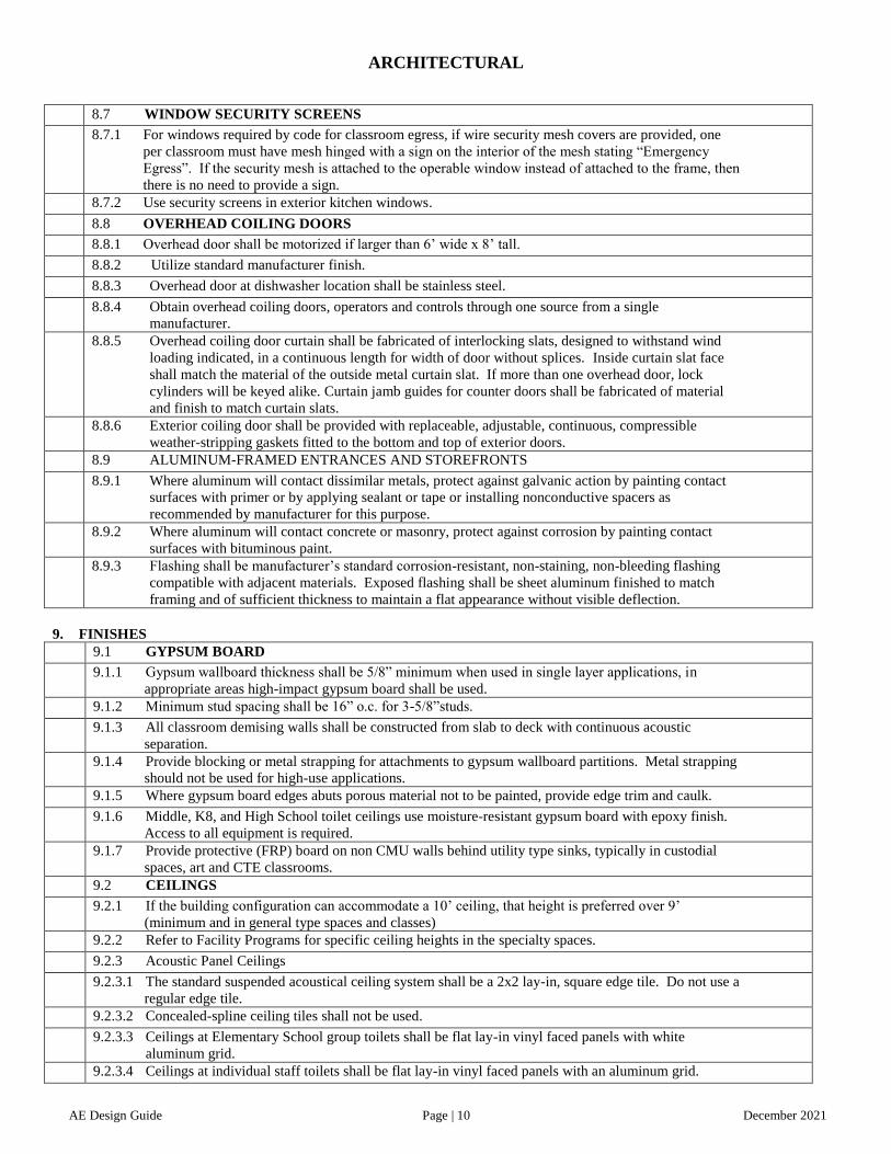
8.7 WINDOW SECURITY SCREENS
8.7.1 For windows required by code for classroom egress, if wire security mesh covers are provided, one
per classroom must have mesh hinged with a sign on the interior of the mesh stating “Emergency
Egress”. If the security mesh is attached to the operable window instead of attached to the frame, then
there is no need to provide a sign.
8.7.2 Use security screens in exterior kitchen windows.
8.8 OVERHEAD COILING DOORS
8.8.1 Overhead door shall be motorized if larger than 6’ wide x 8’ tall.
8.8.2 Utilize standard manufacturer finish.
8.8.3 Overhead door at dishwasher location shall be stainless steel.
8.8.4 Obtain overhead coiling doors, operators and controls through one source from a single
manufacturer.
8.8.5 Overhead coiling door curtain shall be fabricated of interlocking slats, designed to withstand wind
loading indicated, in a continuous length for width of door without splices. Inside curtain slat face
shall match the material of the outside metal curtain slat. If more than one overhead door, lock
cylinders will be keyed alike. Curtain jamb guides for counter doors shall be fabricated of material
and finish to match curtain slats.
8.8.6 Exterior coiling door shall be provided with replaceable, adjustable, continuous, compressible
weather-stripping gaskets fitted to the bottom and top of exterior doors.
8.9 ALUMINUM-FRAMED ENTRANCES AND STOREFRONTS
8.9.1 Where aluminum will contact dissimilar metals, protect against galvanic action by painting contact
surfaces with primer or by applying sealant or tape or installing nonconductive spacers as
recommended by manufacturer for this purpose.
8.9.2 Where aluminum will contact concrete or masonry, protect against corrosion by painting contact
surfaces with bituminous paint.
8.9.3 Flashing shall be manufacturer’s standard corrosion-resistant, non-staining, non-bleeding flashing
compatible with adjacent materials. Exposed flashing shall be sheet aluminum finished to match
framing and of sufficient thickness to maintain a flat appearance without visible deflection.
9. FINISHES
9.1 GYPSUM BOARD
9.1.1 Gypsum wallboard thickness shall be 5/8” minimum when used in single layer applications, in
appropriate areas high-impact gypsum board shall be used.
9.1.2 Minimum stud spacing shall be 16” o.c. for 3-5/8”studs.
9.1.3 All classroom demising walls shall be constructed from slab to deck with continuous acoustic
separation.
9.1.4 Provide blocking or metal strapping for attachments to gypsum wallboard partitions. Metal strapping
should not be used for high-use applications.
9.1.5 Where gypsum board edges abuts porous material not to be painted, provide edge trim and caulk.
9.1.6 Middle, K8, and High School toilet ceilings use moisture-resistant gypsum board with epoxy finish.
Access to all equipment is required.
9.1.7 Provide protective (FRP) board on non CMU walls behind utility type sinks, typically in custodial
spaces, art and CTE classrooms.
9.2 CEILINGS
9.2.1 If the building configuration can accommodate a 10’ ceiling, that height is preferred over 9’
(minimum and in general type spaces and classes)
9.2.2 Refer to Facility Programs for specific ceiling heights in the specialty spaces.
9.2.3 Acoustic Panel Ceilings
9.2.3.1 The standard suspended acoustical ceiling system shall be a 2x2 lay-in, square edge tile. Do not use a
regular edge tile.
9.2.3.2 Concealed-spline ceiling tiles shall not be used.
9.2.3.3 Ceilings at Elementary School group toilets shall be flat lay-in vinyl faced panels with white
aluminum grid.
9.2.3.4 Ceilings at individual staff toilets shall be flat lay-in vinyl faced panels with an aluminum grid.

ARCHITECTURAL
AE Design Guide Page | 11 December 2021
9.2.3.5 Kitchen and serving area ceilings shall be flat lay-in tile. Finish should be vinyl covered meeting
Health Department standards. Size to be 2’x2’. Grid to be aluminum finished white.
9.2.3.6 Corridors and main lobby shall use lay-in acoustical panels. Gypsum wallboard may be used as an
accent. Consider exposed painted structure on a case by case basis.
9.2.3.7 Provide panels with a minimum NRC of .70 in classrooms.
9.2.3.8 Provide panels with a minimum NRC of .90 in music and band rooms.
9.2.3.9 Provide panels with a minimum NRC of .90 in cafeteria dining area and multipurpose rooms.
9.2.3.10 For any circular or non-linear penetrations of ceiling, provide edge moldings fabricated to diameter
required to fit penetration exactly.
9.3 RESILIENT FLOOR AND BASE
9.3.1 Vinyl composition tile (VCT) shall be the predominant floor covering material in the school. Review
a preliminary floor finish plan with the Owner prior to developing the construction documents.
9.3.2 Refer to the appendices for the ES and K8 Multipurpose Room play striping. See Appendix 9.3.2
9.3.3 Avoid use of rubber risers and treads on stairs, concrete filled pan stairs preferred.
9.3.4 Refer to Appendix 9.3.3 for HS gym striping.
9.3.5 Color of base to be selected by AE using standard color selections.
9.4 CARPET
9.4.1 Carpet tiles (preferred) shall be used in the administration area, media center, remote office locations,
SRO office, with the exception of Maker space.
9.5 TERRAZZO
9.5.1 High School lobby and corridors: Terrazzo floors with terrazzo base (include as an Alternate to the
Base Bid).
9.5.2 Review a preliminary floor finish plan with the Owner prior to developing the construction
documents.
9.6 CERAMIC TILE
9.6.1 Use ceramic tile that is impervious to soil and stains to reduce the amount of grout and to facilitate
easy cleaning.
9.6.2 Toilets and Locker Rooms
9.6.2.1 Toilet and locker room floors shall be non-slip porcelain tile with epoxy or cementitious grout.
(White or light colored grouts are not to be used.) 1”x 1” or 2”x 2” mosaic tile will not be accepted.
9.6.2.2 Toilet and locker room walls: Ceramic tile with epoxy or cementitious grout on CMU block is first
choice. Epoxy painted CMU is second choice. Base to be tile.
9.6.2.3 Contractor to plug floor drain during construction to prevent grout from setting in P-trap.
9.6.2.4 Tile backing isolation membrane over cracks with concrete substrate and over areas susceptible to
cracking.
9.6.2.5 Set tile on thickset mortar bed in all group restrooms (including elevated slabs) to provide proper
slope to drains.
9.6.2.6 Use different colors of wall tile in male/female group restrooms for wayfinding.
9.6.2.7 Preferred: 5 foot high tile wainscot in group toilets on wet and end walls, and in Health room toilet
room. Provide tile finish on wet walls and below and around the hand dryer to protect wall finish.
9.6.3 Kitchen
9.6.3.1 Use non-slip quarry tile on thickset mortar bed with epoxy grout as a flooring material in all kitchen
areas.
9.6.3.2 Quarry tile floors shall have epoxy grout and positive slope to drains to insure water will not stand.
9.6.3.3 Walk-in cooler and freezer floor to be quarry tile with epoxy grout.
9.6.3.4 Walls and Base: Epoxy painted CMU meeting Health Department requirements.
9.6.3.5 Review a preliminary floor finish plan showing floor slope and floor drain locations with the Owner
prior to developing the construction documents.
9.7 PAINTING
9.7.1 Standard field paint color to be Sherwin Williams CMS UPDATED JAN 17 2020 OYSTER WHITE
Oyster White (basis of color is ICI 1416).
9.7.1.1 Semi-gloss latex paint for gypsum board walls, CMU walls and hollow metal frames unless specified
otherwise.

ARCHITECTURAL
AE Design Guide Page | 12 December 2021
9.7.1.2 Preference for accent colors in higher locations. Door frame and HM door color to coordinate with
rubber base color.
9.7.1.3 Custodial, toilet, kitchen areas and anywhere food will be served to receive semi-gloss epoxy paint
over a higher grade of block fill.
9.7.2 Painting includes field painting of interior exposed bare and covered pipes and ducts (including color
coding), hangers, exposed steel and iron supports and surfaces of mechanical and electrical equipment
that do not have a factory-applied final finish.
9.7.3 Do not paint prefinished items, concealed surfaces, finished metal surfaces, operating parts and labels.
Prefinished items may include the following factory-finished components:
9.7.3.1 Architectural woodwork
9.7.3.2 Overhead coiling doors
9.7.3.3 Door hardware
9.7.3.4 Acoustical wall panels
9.7.3.5 Metal toilet enclosures
9.7.3.6 Metal lockers
9.7.3.7 Finished mechanical and electrical equipment
9.7.3.8 Light fixtures
9.7.4 Concealed surfaces include walls or ceilings in the following generally inaccessible spaces:
9.7.4.1 Furred areas
9.7.4.2 Ceiling plenums
9.7.4.3 Utility tunnels
9.7.4.4 Pipe spaces
9.7.4.5 Duct shafts
9.7.5 Finished metal surfaces may include the following:
9.7.5.1 Anodized aluminum
9.7.5.2 Galvanized metal
9.7.5.3 Stainless steel
9.7.6 Operating parts include moving parts of operating equipment and the following:
9.7.6.1 Valve and damper operators
9.7.6.2 Linkages
9.7.6.3 Sensing devices
9.7.6.4 Motor and fan shafts
9.7.7 Mechanical and Electrical Work: Painting of mechanical and electrical work is limited to items
exposed in occupied spaces. Exposed mechanical items to be painted include, but are not limited to,
the following:
9.7.7.1 Pipe hangers and supports
9.7.7.2 Heat exchangers
9.7.7.3 Tanks that do not have factory-applied final finishes
9.7.7.4 Ductwork
9.7.7.5 Insulation
9.7.7.6 Motors and mechanical equipment
9.7.7.6.1 Accessory items
9.7.7.7 Exposed electrical items to be painted include, but are not limited to, the following:
9.7.7.7.1 Conduit and fittings
9.7.7.7.2 Switchgear (Not already pre-finished)
9.7.7.7.3 Panelboards (Not already pre-finished)
9.7.8 At the TV Studio in Media Centers coordinate the painting of the appropriate wall(s) to receive the
“Green Wall” paint with CMS ISS and Design Manager.
9.8 WALL COVERING
9.8.1 Not allowed on CMS projects without written permission from CMS (on Letterhead).

ARCHITECTURAL
AE Design Guide Page | 13 December 2021
9.9 WOOD FLOOR
9.9.1 Provide a wood gym floor in all MS, K8 and HS and not a sports or rubber floor. See Appendix 9.9.1
9.9.2 K8, Middle School and High School dance floors: Provide sprung wood floor system.
9.9.3 Provide wood floor on platform (stage) on a sleeper system that allows for replacement of damaged
panels or areas.
10. SPECIALTIES
10.1 MARKER BOARDS
10.1.1 Locate in consideration of the teaching station, teacher’s desk, glare and view-ability for all students
from all locations in the classroom.
10.1.2 See Appendices for standard teaching wall layout.
10.2 TACK BOARDS and STRIPS
10.2.1 Locate in consideration of the teaching station, teacher’s desk and view-ability for all students from
all locations in the classroom.
10.2.2 Provide a minimum of one 4’ x 8’ tack board outside each elementary and K8 school classroom.
10.2.3 Provide a minimum of one 4’ x 4’ tack board outside each middle and high school classroom.
10.2.4 Provide tack strips outside of classrooms on corridor walls, confirm with CMS on extent.
10.3 FIRE EXTINGUISHERS/CABINETS
10.3.1 Do not use plastic bubble type door or breakable glazing.
10.4 TOILET PARTITIONS
10.4.1 Toilet and urinal partitions to be floor mounted, overhead-braced, solid plastic, or solid phenolic core.
10.4.2 Minimum 3’ wide stalls.
10.4.3 Provide a wall mounted bumper for the accessible stall door.
10.4.4 Preference for textured finish and color in the charcoal gray range. Panel thickness to be ¾” thick.
10.5 TOILET ACCESSORIES
10.5.1 Provide sanitary napkin disposal receptacles in all female group and staff toilet rooms in K8, Middle
Schools and High Schools. Also provide in Elementary School women’s staff toilets and the
women’s group toilet in public areas, such as adjacent to the assembly areas. Coordinate locations
with CMS.
10.5.2 CMS standard toilet tissue dispensers to be installed at all locations and above grab bars in accessible
stalls. See Appendix 10.5.2
10.5.3 Electric hand dryers to be located in close proximity to the sinks to minimize water on the floor.
10.6 LOCKERS
10.6.1 At middle and high schools, limited student corridor lockers are to be provided under the general
contract. Verify quantity with CMS.
10.6.2 When lockers are provided in High Schools and Middle Schools, provide combination pad locks for
hall lockers and provide CMS with master key(s).
10.6.3 Locate ADA lockers at the end of a row, NOT all grouped together. Hooks and shelves inside this
locker are to be at accessible heights plus an extra shelf at 16” above locker floor. When 2-tier lockers
are used, the ADA locker will be the lower one.
10.6.4 CMS prefers that lockers are installed on only one side of the corridor whenever possible.
10.6.5 All lockers shall be vented.
10.6.6 Corridor and PE lockers shall be 12” x 12” single or double tier.
10.6.7 Kitchen lockers shall be 12” x 12” x 72”
10.6.8 Athletic lockers shall be 18” x 18” x 72”.
10.6.9 Locks for the corridor lockers need to be provided as part of the construction contract: High security
combination padlock with key for supervisory access.
10.6.10 Verify Accessibility Code and ADA requirements.
10.7 OPERABLE PARTITIONS
10.7.1 Partitions to be supported independently off the roof structure or joists of the floor above (do not use
floor-supported partitions). Verify structural requirements to ensure that the mid-span deflection will
not impede movement of the operable partition or affect the performance of acoustic seals. Include
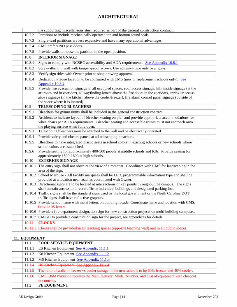
ARCHITECTURAL
AE Design Guide Page | 14 December 2021
the supporting miscellaneous steel required as part of the general construction contract.
10.7.2 Partitions to include mechanically operated top and bottom sound seals.
10.7.3 Single-lead partitions are less expensive and have many operational advantages.
10.7.4 CMS prefers NO pass doors.
10.7.5 Provide walls to house the partition in the open position.
10.8 INTERIOR SIGNAGE
10.8.1 Signs to comply with NCSBC accessibility and ADA requirements. See Appendix 10.8.1
10.8.2 Screw-attach to wall with tamper-proof screws. Use adhesive tape only over glass.
10.8.3 Verify sign titles with Owner prior to shop drawing approval.
10.8.4 Dedication Plaque location to be confirmed with CMS (new or replacement schools only). See
Appendix 10.8.4
10.8.5 Provide fire evacuation signage in all occupied spaces, roof access signage, kiln inside signage (at the
art room and in corridor), 4” wayfinding letters above the fire doors in the corridors, sprinkler access
above signage (in the kitchen above the cooler/freezer), fire alarm control panel signage (outside of
the space where it is located).
10.9 TELESCOPING BLEACHERS
10.9.1 Bleachers for gymnasiums shall be included in the general construction contract.
10.9.2 Architect to indicate layout of bleacher seating on plan and provide appropriate accommodations for
wheelchairs per ADA requirements. Bleacher seating and accessible routes must not encroach onto
the playing surface when fully open.
10.9.3 Telescoping bleachers must be attached to the wall and be electrically operated.
10.9.4 Provide safety end closure panels at all telescoping bleachers.
10.9.5 Bleachers to have integrated plastic seats in school colors in existing schools or new schools where
school colors are established.
10.9.6 Provide seating for approximately 400-500 people at middle schools and K8s. Provide seating for
approximately 1500-1600 at high schools.
10.10 EXTERIOR SIGNAGE
10.10.1 The entry sign shall not obstruct the view of a motorist. Coordinate with CMS for landscaping in the
area of the sign.
10.10.2 School Marquee - All facility marquees shall be LED, programmable information type and shall be
provided at a location near road, as coordinated with Owner.
10.10.3 Directional signs are to be located at intersections or key points throughout the campus. The signs
shall contain arrows to direct traffic to individual buildings and designated parking lots.
10.10.4 Traffic signs shall be the standard signs used by the local government or the North Carolina DOT,
traffic signs shall have reflective graphics.
10.10.5 Provide school name with metal letters on building façade. Coordinate name and location with CMS.
Provide 35 letters.
10.10.6 Provide a fire department designation sign for new construction projects on multi building campuses.
10.10.7 CM/GC to provide a construction sign for the project, see appendices for details.
10.11 CLOCKS
10.11.1 Clocks shall be provided in all teaching spaces (opposite teaching wall) and in all public spaces.
11. EQUIPMENT
11.1 FOOD SERVICE EQUIPMENT
11.1.1 ES Kitchen Equipment See Appendix 11.1.1
11.1.2 K8 Kitchen Equipment See Appendix 11.1.2
11.1.3 MS Kitchen Equipment See Appendix 11.1.3
11.1.4 HS Kitchen Equipment See Appendix 11.1.4
11.1.5 The ratio of walk-in freezer vs cooler storage in the new schools to be 60% freezer and 40% cooler.
11.1.6 CMS Child Nutrition requires the Manufacturer, Model Number, and cost of equipment with closeout
documents,
11.2 PE EQUIPMENT

ARCHITECTURAL
AE Design Guide Page | 15 December 2021
11.2.1 Designer to allow for owner provided and installed (vendor) climbing wall in Elementary and K8
schools’ multi-purpose rooms, coordinate with CMS.
11.2.2 Designer to coordinate with CMS on locations and attachment of owner provided and contractor
installed TRX system for all MS and K8 facility types only. Provide 14 snap on training stations at 5’-
6” OC and at 6” and 96” AFF. Provide 10 snap on training stations at 5’-6” OC at 96” AFF, on a
separate (perpendicular) wall.
12. FURNISHINGS
12.1 SOLID WOOD MEDIA CENTER CASEWORK
12.1.1 Capacity - Refer to CMS Media Services book collection worksheet.
12.1.1.1 Generally a new 45 classroom elementary school, 54/63/66 classroom, K8 or 54 classroom middle
school utilize perimeter shelving with mobile shelving to house a maximum 10,000 volumes. Refer
to CMS Media Services book collection worksheet. For Language Immersion schools or other
magnet/specialty programs consult CMS Media Services regarding quantities of collection.
12.1.1.2 Generally a new 125 100 classroom high school utilize perimeter shelving with mobile shelving to
house a maximum 10,000 volumes.
12.1.2 Perimeter Shelving
12.1.2.1 Elementary School/K8: 5’ high x 12” deep with 3 adjustable shelves (divider type).
12.1.2.2 Middle School: 6’ high x 12” deep with 4 adjustable shelves
12.1.2.3 High School: 7’ high x 12” deep with 5 adjustable shelves
12.1.2.4 Top of shelving unit shall have a valance and bottom should have a toe plate/kick.
12.1.3 Double-faced mobile divider wood shelving:
12.1.3.1 Elementary School/K8: Centrally located shelving shall be 3’ high x 24” deep (double sided) with
one adjustable shelf on each side (divider type). Provide 3-foot long sections to supplement
perimeter shelving to meet book collection requirements.
12.1.3.2 Middle and High School: Centrally located shelving shall be 3’-9” high x 24” deep (double sided)
with one adjustable shelf on each side, with no dividers. Provide 3-foot long sections to supplement
perimeter shelving to meet book collection requirements.
12.1.3.3 Each section must be capable of carrying 1,000 pounds.
12.1.4 Media Center - All Shelving
12.1.4.1 12” minimum clear spacing between all shelves.
12.1.4.2 All units to be solid oak. No particleboard allowed.
12.1.4.3 All units shall have a 1/4” plywood back panel of plain sliced oak veneer.
12.1.4.4 Adjustable shelves to be set at ½” increments.
12.1.4.5 All shelving units to utilize individual sectional tops to allow maximum flexibility in reorganizing
shelving ranges. Continuous tops are not acceptable.
12.1.4.6 All shelving units are to be assembled using a minimum of four (4), 5/16” hex bolts with washers
and nuts per section face to provide maximum strength, stability and easy disassembly and re-
assembly. The use of screws into the wood panel stock is not an acceptable method of assembly.
12.1.4.7 Divider shelves are required at elementary school main rooms only. Shelves shall be solid oak with
a 2 ½” high back and three 3/4” solid oak dividers that are glued and screwed in place. Dividers are
to be 6” high and equally spaced along shelf width.
12.1.4.8 Shelf pins are to be double-pin, anti-tipping shelf locks capable of supporting 300 pounds.
12.1.5 Media Center Magazine Shelving
12.1.5.1 Built-in units with sloped solid oak shelves.
12.1.5.2 Sloped shelves are 14” high with a solid oak lip and able to be located in any standard 12” deep unit
regardless of height or location in room. This makes a special depth magazine unit unnecessary and
provides maximum layout flexibility.
12.1.5.3 Sloped top shelf is also the top of the magazine shelving unit. There is no countertop.
12.1.5.4 Elementary school/K8: Provide three 5’ high x 3’ wide perimeter sections of magazine shelving.
12.1.5.5 Middle School: Provide five 6’ high x 3’ wide perimeter sections of magazine shelving.
12.1.5.6 High School: Provide five 7’ high x 3’ wide perimeter sections of magazine shelving.

ARCHITECTURAL
AE Design Guide Page | 16 December 2021
12.1.6 Casters: 2” diameter casters shall be provided in the island shelving units and concealed within the
base of the shelving unit. Caster supports to be designed so that the shelving range height is not
increased more than 5/8” and will support minimum 250 pounds each. Provide (4) casters for each
3-foot long shelf section. Color to be black.
12.1.7 Book Drop: Coordinate height of the book drop cart with the modular circulation desk slot.
12.2 LAMINATE CLAD CASEWORK
12.2.1 Refer to the appendices for casework elevations and details.
12.2.2 Casework in all Middle, K8 and High School areas (except Science Classrooms) shall be plastic
laminate covered MDF with solid 3mm thick PVC edging or solid wood chamfered banding and
with heavy-duty five knuckle hinges.
12.3 DISPLAY CASEWORK
12.3.1 Provide built in display casework at all schools. Quantity and location to be determined by CMS
staff.
12.4 SCIENCE CASEWORK
12.4.1 Science casework (manufactured) shall be hardwood (with a preference for red oak) cabinets and
drawers with acid proof tops with integral sink bowls and sink filler panels.
12.4.2 Science lab sinks and casework to be around the perimeter of the classroom in Middle Schools, K8,
and general science classrooms at high schools. Provide protruding peninsulas in High School
Biology and Chemistry.
12.5 CAFETERIA SEATING (Not in Contract)
12.5.1 Cafeteria seating to utilize folding, 12 seat table configuration.
12.5.2 At the cafeteria serving line at the menu screens, CMS's Child Nutrition’s vendor is providing the
TV brackets and monitors for the digital menu boards. The designer of record only needs to design
the pathway, blocking and infrastructure to support this equipment provided by others.
12.6 HORIZONTAL BLINDS
12.6.1 Generally all exterior windows shall receive blinds (which should match window framing system)
where practical for light control and/or security.
12.6.2 No blinds on doors.
12.7 ATHLETIC INTERIOR
12.7.1 MS/K8/HS Scoreboard should be visible by the coaches and players.
13. SPECIAL CONSTRUCTION
13.1 BLEACHERS
13.1.1 High school football stadiums - Provide permanent aluminum bleachers for 2,500 home and 1,500
away spectators. Provide accessible route and companion seating per ADA requirements. Provide
covered scoring platform on press box roof accessed only through the press box. Provide scoring
covered platform on visitor side.
13.1.2 High School baseball - Provide an accessible route, slab and aluminum bleacher seating for 250
spectators.
13.1.3 High School softball - Provide an accessible route, slab and aluminum bleacher seating for 200
spectators.
13.1.4 Middle School football fields - Provide an accessible route and slab.
13.1.5 K8 soccer fields - Provide an accessible route and slab.
14. CONVEYING EQUIPMENT
14.1 Elevator shall have a side entry single acting door (no center bi-parting doors) and adequate
platform space to allow EMS use with an ambulance stretcher and multiple wheelchairs.
14.2 Hydraulic lines (if used) shall be accessible, not buried underground.
14.3 A grate shall be provided over the sump pit. A/E to coordinate with Specification 221429 to select
correct sump pump.
14.4 Elevators shall be programmed to automatically go to the first floor in the event of a power outage.
The Designer shall resolve code requirements and provide an area of refuge.
14.5 Request that the elevator floor finish be provided by the general contractor and it should be the same
finis

ARCHITECTURAL
AE Design Guide Page | 17 December 2021
14.6 h as the corridor.
14.7 Keying features shall not affect emergency firefighters’ service.
14.7.1 Provide knox box to accommodate key/tool for emergency opening of elevator door – placement of
box per Fire Marshal’s direction.

FIRE PROTECTION
AE Design Guide Page | 18 December 2021
INTRODUCTION Division 21 is the fire protection portion of this Standard. It is intended to assist a qualified Plumbing Engineer in the preparation of
drawings and specifications for the fire protection system to be included in school construction. It is not intended to serve as a code
book or a construction specification. It also does not relieve the Plumbing Engineer of his responsibility for adequate design and
coordination, and for compliance with the criteria provided by Charlotte-Mecklenburg Schools for a specific project.
Division 21 is compiled primarily to describe the fire protection system for new schools. In schools undergoing expansion and/or
renovation, extent and condition of existing facilities and budget restraints may limit the scope of the fire protection renovation. In
such cases, where feasible, the design shall facilitate the future implementation of the “New School” criteria.
The A&E and construction manager/general contractor shall obtain from the CMS the latest version of the Charlotte-Mecklenburg
Schools Architect and Engineer Design Guide.
21. FIRE PROTECTION
21.1 Underground water service; 2 ½ in. and less – type “K” copper with silver solder joints; 3 in. and
above; cement lined ductile iron ASTM C151 with mechanical joints except straight sections may be
push-on joints.
21.2 Backflow Preventer for fire line service, use double check type.
21.3 Backflow preventer for fire loop shall be located in an insulated cover. See 5.07.
21.4 Appropriate local authorities shall approve fire hydrants and valves.
21.5 Provide profile of water distribution lines to site from nearest source of municipal water with all
interferences.
21.6 Provide hydrant protection with pilings.
21.7 Fire loop around building shall be sized appropriately with fire hydrants spaced per authority having
jurisdiction.
21.8 Fire Protection: The Mechanical Engineer is responsible for obtaining flow test data on the fire main
and building protection requirements to make a preliminary assessment of the need for a booster pump
for the fire line before construction documents are issued for review.
21.8.1 On new projects plan for a space in each footprint of a new building to accommodate a fire pump.
21.8.2 At existing facilities make certain the nearest hydrant serving the property is tested properly to fulfill
the needs of the design. The test cannot be older than one year.
21.8.3 Pressure tests of public hydrants will occur at schematic and 50% construction document phase.
21.9 Provide concrete bunker around control valve boxes, meters, etc.
21.10 Ductile iron class 50 with push on type joints – ASTM C-150 (for 8 inch and larger).
21.11 Valve covers for fire line will use a lockable cover that is painted red.

PLUMBING
AE Design Guide Page | 19 December 2021
INTRODUCTION Division 22 is the plumbing portion of this Standard. It is intended to assist a qualified Plumbing Engineer in the preparation of
drawings and specifications for the plumbing system to be included in school construction. It is not intended to serve as a code book or
a construction specification. It also does not relieve the Plumbing Engineer of his responsibility for adequate design and coordination,
and for compliance with the criteria provided by Charlotte-Mecklenburg Schools for a specific project.
Division 22 is compiled primarily to describe the plumbing system for new schools. In schools undergoing expansion and/or
renovation, extent and condition of existing facilities and budget restraints may limit the scope of plumbing renovation. In such cases,
where feasible, the design shall facilitate the future implementation of the “New School” criteria.
The A&E and construction manager/general contractor shall obtain from the CMS the latest version of the Charlotte-Mecklenburg
Schools Architect and Engineer Design Guide.
22. PLUMBING
22.1 GENERAL
22.1.1 All provisions to the “General Plumbing & HVAC Requirements” in above shall apply to this
section.
22.1.2 All water consuming devices shall be of the water saving type.
22.1.3 Provide positive freeze protection on all water lines fixtures subject to freezing conditions.
22.1.4 Provide outside freeze proof hose bibs at 100 feet intervals around the building.
22.1.5 Provide a ball valve in branch piping to all exterior hose bibs. Where suitable locate hose bibs
adjacent to exterior mechanical rooms, dropping branch piping exposed in mechanical room and
locating ball valve a maximum of 6’ above finish floor. Provide 18” clearance under all hose bibs.
22.1.6 Contractor shall be required to completely rod and flush out all sanitary waste lines both new and
existing after a building is completed. A diagnostic video of all sanitary waste lines will be
performed. One video will be done after the slab is poured and another at the completion of the
project. The design engineer and CMS engineer should be informed prior to making this video.
22.1.7 Provide isolation valves in cold water and hot water piping so that water can be shut off to each
classroom wing, administration area, each individual group toilet (separate shut-off for boys and
girls) and science classrooms.
22.1.8 Provide chrome escutcheon rings at all exposed ceiling and wall penetrations.
22.1.9 Engineer shall specify plaster solids interceptor for all art room sinks.
22.1.10 Provide all floor drains with SureSeal, deep seal P-trap. Provide hose bib at all deep P-trap
locations.
22.1.11 Install all V.T.R. (vent through roof) a minimum of 15 ft. from fresh air intake.
22.2 PLUMBING VALVES
22.2.1 Gate valves are not allowed.
22.3 PLUMBING FIXTURES
22.3.1 Provide floor mounted type water closet, vitreous china.
22.3.2 Elongated bowls on water closets and open front seats, without covers, with stainless steel or solid brass
closet, bolts and nuts and black seats.
22.3.3 Utilize acid-resistant, cast-iron (no ceramic) lavatories with through wall carriers.
22.3.4 Grid type strainers are specified in lavatory drains in public toilets and restrooms.
22.3.5 Provide tamper proof aerators and faucets.
22.3.6 Only single purpose fixtures shall be specified.
22.3.7 Waste fittings to be cast iron type with 17 gauge traps.
22.3.8 Provide wall hung type urinals with removable strainers.
22.3.9 Provide water coolers with a bottle filler (50% of units).
22.3.10 Provide a mop sink within the kitchen in a separate room.
22.3.11 Provide plumber key operated, chrome plated, box type, hose bib/vacuum breaker mounted flush with wall for
group toilets.
22.3.12 All water closets and urinals shall have automatic flush valves

PLUMBING
AE Design Guide Page | 20 December 2021
22.3.13 Local AHU requires a CMS Letter of Deviation for modified restrooms See Appendix 22.3.13. The modified
restroom fixtures cannot be used in calculations for overall fixture counts. This document is to be inserted next
to the plumbing fixture schedule for all projects which have a modified restroom.
22.4 WATER SUPPLY
22.4.1 Main domestic water supply line shall have a pulse meter located in, or close to the boiler room interconnected
to Energy Management System, and a reduced pressure backflow preventer installed downstream of the
CMUD meter on the school property.
22.4.2 Provide shock absorbers on supplies to all fixtures/appliances that have quick closing valves.
22.5 HOT WATER
22.5.1 New School
22.5.1.1 Maintain 85-110 deg F hot water to lavatories. Discuss with CMS Engineers.
22.5.1.2 Maintain 140 deg F hot water to kitchen prep sinks and dishwasher. Dishwasher will have a booster heater for
final rinse temperature of 180 deg F minimum.
22.5.1.3 Install gas fired tankless water heaters to provide domestic hot water.
22.5.1.4 Provide one set of tankless heaters to serve only the 140 deg F kitchen hot water loop and separate set of
tankless heaters to serve the 110 deg F building loop.
22.5.1.5 Provide an installed spare tankless water heater for each system to allow for uninterrupted maintenance.
22.5.1.6 Preference is to not to use master mixing valves. The new 2018 code requires point of use ASSE 1070 mixing
valves at each public lavatory. Preference is to circulate building hot water loop at 110 deg F with a separate
140 degree loop for the kitchen area. Where applicable provide mixing valves to reduce the temperature of the
hot water to 110 ° F. Do not use heat tape as a means of maintaining water temperature on hot water lines.
22.5.1.7 In renovation projects, discuss hot water requirements with CMS.
22.5.1.8 In renovation projects, consider the location of programs/functions requiring warm water temperature of 110˚
including, but not limited to children’s lavatories within proximity of Cafeteria, modified restrooms, Health
Room, accessible shower/Health Room, Pre-K, After-School Enrichment Program (ASEP), staff-use
lavatories, and as required by code and/or the Health Department.
22.5.1.9 Any shower in the school, including the accessible bathrooms and health room shall have an anti-scald mixing
valve.
22.5.1.10 Safety showers will be tempered to 85 degrees F or as required by code.
22.5.1.11 Provide a hot water system in a loop configuration.
22.5.1.12 If hot water is required at locations that require very long runs of piping and/or circulation pumps, special
consideration should be given to an alternate source. An electric instantaneous hot water system sized to meet
the demand is an economical source for continuous hot water. An energy efficient water heater would be the
last consideration due to size and cost of operation over the years.
22.5.1.13 If tempering valves are used, locate these at point of use.
22.5.1.14 NSF approval required for 180-degree F water-heaters.
22.5.1.15 Circulators for domestic hot water shall be bronze.
22.5.1.16 Provide shock absorbers in supply line between hot water heater and dishwasher machine.
22.5.1.17 Install tees, valves and male pipe nipple with cap on the hot and cold water lines close to the water heater for
emergency purposes.
22.5.1.18 Provide “tepid” water for emergency eye wash units.
22.6 COLD WATER
22.6.1 Provide appropriate protective boxes for shut-off valves, etc. on CMS property.
22.7 DOMESTIC WATER PIPING
22.7.1 Provide hot and cold water to all lavatories.
22.7.2 Underground piping
22.7.2.1 Domestic water piping shall not be below slab-on-grade construction, except at riser room. Provide Type “K”
copper with silver brazed joints for domestic water piping underground at riser room.
22.7.2.2 PVC piping can be used starting five feet outside of the building.

PLUMBING
AE Design Guide Page | 21 December 2021
22.7.3 Above ground piping
22.7.3.1 Type “L” copper with lead free soldered joints (95/5 solder).
22.7.4 Backflow Preventer Applications:
22.7.4.1 Domestic water service, use reduced pressure type backflow preventer.
22.7.4.2 Fire Line service, use reduced pressure backflow preventer.
22.7.4.3 Irrigation service, use reduced pressure backflow preventer.
22.7.4.4 Provide pressure gauges on entering and leaving sides of backflow preventer assembly.
22.7.4.5 Applications for all backflow prevention assembly installations must be submitted to and approved by
Charlotte Water.
22.7.4.6 Provide heated, insulated enclosure (hot box) for backflow prevention assemblies installed outside and above
ground. Coordinate with electrical design engineer for adequate power supply.
22.7.4.7 All underground non-metallic pipes must be marked and identified with tracer wire tape.
22.7.4.8 Pressure reducing valves shall be installed in domestic water service and irrigation service when the water
pressure exceeds 65 psi.
22.8 IRRIGATION SYSTEMS
22.8.1 Provide irrigation system for athletic fields at Middle Schools, K8s and High Schools. Discuss each project
with CMS Engineers.
22.8.2 Install backflow preventer for irrigation service, use double check type.
22.8.3 Install metal identification tapes (or 14 gauge or larger tracer wire) over PVC lines.
22.8.4 Minimum 24” cover to top of irrigation piping.
22.8.5 Meter the irrigation water supply so the amount of water can be subtracted from main meter to save sewage
charges.
22.8.6 Use triple elbow swing joints at all heads.
22.8.7 Provide head protection from aeration.
22.8.8 Configure underground solenoids to minimize distance of underground wiring from head-end. Drive at least
one ground rod at head-end.
22.8.9 Provide concrete bunker around control valve boxes, meters, etc.
22.9 PLUMBING SUPPORTS AND ANCHORS
22.9.1 One hanger manufacturer used throughout the job is preferable.
22.9.2 Horizontal piping hangers – insulated piping shall have hanger around insulation with rigid insulation above
shield. Adjustable steel clevis hangers are recommended.
22.9.3 Vertical piping clamps – size to fit bare pipe, copper plated for copper piping.
22.9.4 Building attachments – use beam clamp with retaining strap or concrete inserts.
22.9.5 Use trapeze hangers where possible to rack piping together.
22.9.6 Do not support piping from bar joist bridging and/or roof deck.
22.9.7 Support all piping so as to prevent excessive movement.
22.10 NA
22.11 NA
22.12 SEWAGE DISPOSAL
22.12.1 Public Sanitary Sewer Lines
22.12.2 All plumbing 5’ beyond all buildings on property shall be installed under DIVISION 2.
22.12.3 Manholes shall be spaced no more than 300’ apart.
22.12.4 Provide manhole to make tie-in to 6” and larger sewer.
22.12.5 Use 4’ diameter pre-cast eccentric manholes with steps 15” on center.
22.12.6 Minimum cover in non-traffic areas will be 3’.
22.12.7 Minimum cover in traffic area shall be 3’ for ductile iron on Class 1 bedding.
22.12.8 See Section 5.02 for sewer material.
22.12.9 Provide profiles of sanitary sewer lines between manholes.
22.12.10 Use laser instrument to install all exterior sanitary sewer lines

PLUMBING
AE Design Guide Page | 22 December 2021
22.12.11 Use drop manhole if elevation of sewer line exceeds 24” above manhole invert.
22.12.12 Minimum slope of sewer lines:
22.12.12.1 Minimum of ¼” per foot slope inside and under the building until the first manhole connection.
22.12.12.2 Minimum flow velocity – 2fps
22.12.12.3 Sewer lines shall be located outside of building. Design sanitary sewer lines to exit the building as soon as
possible.
22.12.12.4 Sewer lines shall be straight with uniform slope between manholes.
22.12.12.5 Maximum slope is 10%.
22.12.12.6 Show new and existing grade contours on plan.
22.12.12.7 Exterior area cleanouts shall have pre-cast concrete donuts installed to protect cleanouts, valve boxes,
meters, shut-off valves, etc. Donuts are to be no higher than 2” above grade.
22.12.12.8 Install stub-outs for future mobile classrooms per CMS Engineers. Mechanical and Civil engineer
coordinate.
22.12.12.9 Engineer shall require contractor to dimension actual location of all sewer lines on as-constructed drawings.
A minimum of two (2) dimensions from building reference points shall be provided and a bury depth
indicated at a minimum spacing of 100’.
22.12.12.10 Provide a minimum of a 6” sewer waste line from all group toilet restrooms.
22.12.12.11 If applicable, sewage ejectors and lift stations shall be installed with a cellular (preferred) phone line for the
alarm package. These systems are not preferred.
22.13 KITCHEN PLUMBING
22.13.1 Maintain 140 deg. F. water to dishwasher, prep and pot sinks, can wash, and mop receptor.
22.13.2 Maintain 110 deg. F. water to hand sink. Discuss alternate designs with CMS Engineers.
22.13.3 Maintain 140 deg. F. and 110 deg. F. water loops by means of a recirculation system. Verify recirculation
pump head and flow rate.
22.13.4 Provide hand sinks with sensor type operation at all locations.
22.13.5 Provide stainless steel or enameled cast iron floor sink for indirect waste from prep and pot sinks and
steamer.
22.13.6 Provide 7” round recessed strainer floor drain for indirect waste from ice machine, serving line equipment
and cooler/freezer.
22.13.7 Provide stainless steel floor troughs for wastes from cutter mixer, tilting skillet and area in front of steamer
and steam kettle. Use stainless steel strainers built-in as a component of trough. PLEASE NOTE: Drain for
tilting skillet installed parallel to skillet, not perpendicular to the skillet. Place ½ of floor drains (each floor
drain) in front of equipment for cleanout purposes.
22.13.8 Provide cleaning faucet as required– American Standard or similar and mount under hand sink. 18” above
finish floor.
22.13.9 Provide floor drain under cleaning faucet.
22.13.10 Provide an adequate number of general area floor drains to kitchen so entire floor can be easily hosed down
(drains shall be sloped at ½” below finished floor, and floor shall be sloped to drains)
22.13.11 Provide hose reels for cleaning purposes, one reel close to the rear door entrance and another reel in the
dishwasher area.
22.13.12 Provide a utility distribution system to serve equipment under hood. Use flexible hoses under hood. Adjust
hose lengths to prevent hoses from lying on floor.
22.13.13 Kitchen equipment shall utilize natural gas where available. Do not use LP gas.
22.13.14 Hood manufacturer shall furnish solenoid gas shut off valve to Plumbing Contractor for installation.
22.13.15 Provide American Standard freeze proof mixing faucet with a vacuum breaker for can wash. Provide shut-
off valves in a protected location on hot and cold water supply lines to faucet.
22.13.16 Provide non-clog floor drain for can wash.
22.13.17 Provide manual hose reel in dishwashing area for wash down.
22.13.18 Provide minimum 1,000-gallon capacity outdoor grease interceptor (use Charlotte Water outdoor sizing
requirements). Provide minimum 500 gallon capacity outdoor solids interceptor.
22.13.19 Connect disposals to solids interceptor prior to the grease interceptor.
22.13.20 Provide fill faucet for cutter mixer.
22.13.21 Use copper pipe for prep and pot sink for continuous waste.
22.13.22 Provide shock absorbers for all solenoid operated equipment.

PLUMBING
AE Design Guide Page | 23 December 2021
22.13.23 Provide water filter at kitchen icemaker connection.
22.13.24 Provide hot and cold water supply for steamer.
22.13.25 Plumbing Contractor shall do all final connections to kitchen equipment except items connected to the
utility distribution system.
22.13.26 All floor drains shall be accessible.
22.13.27 Check all kitchen equipment to be sure we pick up all faucets.
22.14 DRAINAGE, WASTE AND VENT SYSTEMS
22.14.1 This section includes sanitary, acid and storm drainage and vent piping systems inside building to a point 5
feet outside building. Roof drains are to be furnished and installed by General Contractor. Plumbing
Contractor connects to roof drain outlet.
22.14.2 All cast iron piping and fittings shall meet the latest standards and specifications of the Cast Iron Soil Pipe
Institute (CISPI) and of the American Society for Testing and Materials (ASTM).
22.14.3 Sanitary lines and drainage under slab shall be videotaped twice by a third party:
22.14.3.1 Following the pouring of the slab.
22.14.3.2 When all underground sanitation and the pouring of the slab is complete. Third party to issue report of test
identifying any deficiencies, and marking on drawings where applicable. Videoing to be performed in the
presence of CMS Plumbing department representative.
22.15 FLOOR DRAINS
22.15.1 Provide floor drains in all toilet rooms with more than one water closet and in the staff restroom in the
kitchen area.
22.15.2 Provide floor drains at all water heater locations.
22.15.3 Provide all floor drains with SureSeal, deep seal P-trap. Provide hose bib at all deep P-trap locations.
22.15.4 Minimum drain size shall be 3”.
22.15.5 Floor drains shall be located in all boiler rooms and in all mechanical equipment rooms (including laundry
rooms) containing any equipment utilizing steam or water or that produces condensation. Drain shall be
located ½” below finished floor. Slope floor toward drain.
22.15.6 At toilets, locate floor drains away from high traffic areas, and not under toilet partitions.
22.15.7 Kitchen can wash areas: Provide floor drain and non-freeze faucet with permanent vacuum breaker.
22.15.8 Provide in rooms with washer and dryers.
22.15.9 Provide in all kitchens, group toilets, mechanical rooms and modified restrooms. Locate so that the drain is
aligned under the most central partition but not under a partition floor support.
22.15.10 Science classrooms with emergency shower.
22.16 CLEANOUTS
22.16.1 Do not design clean outs in a space with carpet or wood flooring.
22.16.2 Floor cleanouts:
22.16.2.1 Exposed rim type, install flush with floor finish.
22.16.2.2 Exposed flush type, standard non-slip scored or abrasive finish.
22.16.2.3 Design clean outs to be flush with floor finish material.
22.16.3 Wall cleanouts:
22.16.3.1 Utilize cast iron body with cast-bronze clean-out plug, stainless steel cover.
22.16.3.2 Exterior cleanouts at finish grade: Cast brass plug with recessed slot in fitting or in caulked cast iron ferrule.
Exterior area cleanouts shall have pre-cast concrete donuts installed to protect cleanouts, valve boxes,
meters, shut-off valves, etc. Donuts are to be no higher than 2” above grade.
22.16.3.3 Pipe sleeves – schedule 40 black steel.
22.17 ACID WASTE LINES
22.17.1 Acid resisting waste lines are required for all science labs in High Schools and Middle schools, per DPI
requirements.
22.17.2 Route acid waste piping from science classrooms to acid neutralization tank before tie in to sanitary sewer.
Preference for one large tank outside of the building in lieu of point of use system(s).
22.17.3 Provide access to sensor probes in acid waste discharge line.
22.17.4 Alarm panel for neutralization tank should be mounted inside science lab/classroom.
22.17.5 High water alarm and flasher mounted outside building.

PLUMBING
AE Design Guide Page | 24 December 2021
22.17.6 Corrosion resistant traps required in all fixtures in chemistry classrooms.
22.17.7 P-traps to wall are preferred in lieu of S-traps to floor.
22.17.8 Plaster and/or interceptor traps are required for work sinks in areas such as art classrooms, and shall be
accessible for cleaning.
22.17.9 Underground and above ground acid waste and vent piping shall conform to the following:
22.17.9.1 Polypropylene piping is to be used below grade and outside of return air plenum spaces. PVDF piping
within provided in return air spaces.
22.17.9.2 Electrical fusion or heat fusion joints are acceptable above grade but are typically specified for under slab
pipig conditions. No Hub mechanical joints are allowed above grade.
22.17.9.3 Provide No Hub under slabs. Acid waste piping shall not use no Hub piping..
22.18 VENTS and VENT PIPING
22.18.1 Two-piece vent-pipe flashing at the roof is preferred, of which one should be a cap over pipe overlapping
the base flashing. Use copper or lead. Roofing contracting to perform roof flashing.
22.18.2 Use 3” minimum vent size at point of roof penetration.
22.19 ROOF DRAINS
22.19.1 Designed in accordance with the North Carolina State Building Code - Plumbing. CMS prefers to utilize
gutters and downspouts.
22.19.2 Roof drain installation to be by the general contractor/roofing contractor. Flashing to be done by general
contractor/roofing contractor.
22.19.3 Piping to roof drains by plumbing contractor.
22.19.4 See Thermal and Moisture Protection in “General Design Guidelines” for boots.
22.20 FITTINGS
22.20.1 Provide all lavatories with individual water supply cutoff valves. Provide separate supply cut off valves to
each bank of urinals and water closets in the group toilets.
22.20.2 All exterior hose bibs to be freeze-proof type and key operated.
22.20.3 Lavatory waste fittings to be cast-type not tube construction.
22.20.4 All group toilet rooms have isolation valves that are clearly located and marked and accessible.
22.20.5 Provide and install isolation valves at for each group toilet, wing/area, gym/locker rooms and kitchen that
will facilitate easy access, maintenance, and repair of fixtures and equipment of total plumbing and
mechanical systems.
22.21 NATURAL GAS SYSTEMS
22.21.1 Engineer and Contractor shall coordinate with Gas Company and have high-pressure gas line routed to gas
meter. Plumbing contractor shall connect to load side of meter and extend inside building. Gas meter shall
have pulse attachment for EMS interface.
22.21.2 Provide main gas valve above ground prior to entrance to building.
22.21.3 Provide adequate air for combustion and proper ventilation when locating gas-fired water heaters.
22.21.4 Preference to route gas piping outside of the building, however gas piping may be installed above accessible
(lay-in) ceiling if outside the building preference is not feasible. Do not locate gas piping under floor slab
and inside solid partitions including CMU. Provide accessible chases for concealed gas piping, for example
a floor trench. Route gas piping exposed where possible. Gas line not allowed in return air plenum.
22.21.5 Provide gas shut off valves at each piece of equipment.
22.21.6 Final connections to equipment shall be made with flexible connectors.
22.22 COMMISSIONING
22.22.1 CMS has incorporated a Commissioning Program for all of its Capital Improvement Program schools. CMS
shall hire an independent Commissioning Agent, however this shall not relieve the contractor or the
engineer from their prime responsibilities. The Architect shall incorporate into each project specifications
defining the commissioning plan provided by the Commissioning Agent. It will be the responsibility of the
Plumbing contractor to provide all required labor and/or material to comply with the commissioning plan.

MECHANICAL
AE Design Guide Page | 25 December 2021
INTRODUCTION Division 23 represents the mechanical portions of this Standard. It is intended to assist a qualified Mechanical Engineer in their
preparation of drawings and specifications of the complete system. This information is not intended to serve as a code book or a
construction specification. It also does not relieve the Mechanical Engineer of their responsibility for adequate design and
coordination, and for compliance with the criteria provided by Charlotte-Mecklenburg Schools for a specific project.
Division 23 is compiled primarily to describe the mechanical system for new schools. In schools undergoing expansion and/or
renovation, extent and condition of existing facilities and budget restraints may limit the scope of the mechanical system renovations.
In such cases, where feasible, the design shall facilitate the future implementation of the “New School” criteria.
The A&E and construction manager/general contractor shall obtain from the CMS the latest version of the Charlotte-Mecklenburg
Schools Architect and Engineer Design Guide.
23. MECHANICAL
23.1 GENERAL
23.1.1 Design conditions will follow North Carolina Mechanical and Plumbing and Energy Codes for Charlotte,
NC.
23.1.2 New schools, additions, and renovations to existing facilities shall be air-conditioned and all areas shall
have the means for CO2 and dehumidification control except in the kitchen. The heating and air
conditioning systems, i.e., type of system must be discussed with the Charlotte-Mecklenburg Schools
(CMS) representative(s) before the design work begins. Dehumidification and CO2 control are not
normally provided on the kitchen RTU. In a gas/dx arrangement, you would need to either add hot gas
reheat or an electric duct heater to be able to dehumidify with that unit. And from a kitchen pressure
standpoint, DCV is not recommended in kitchens.
23.1.3 In accordance with Chapter 4, Section 403.3 of the NC State Mechanical Code, 2018 Edition, outside air
intake components shall be sized per Table 403.3, but school classroom’s ventilation may be reduced to a
minimum of 7.5 CFM per person as noted. The 2018 NCMC now simply shows 7.5 cfm/person and 0
cfm/sf for classrooms, no more footnotes or verbiage about systems designed to handle additional OA under
special circumstances. The only time you should run into 10 cfm/sf and 0.12 cfm/sf would be on LEED
projects.
23.1.4 Additional ventilation and/or exhaust systems shall be provided as required for conditions that generate
unusual odors or sensory irritating contaminants. Test and Balance for outside air shall be for 7.5 CFM per
person. Once the determination of the system has been agreed upon, load calculations, including existing
buildings when adding to these buildings, shall be submitted to CMS Design Team for review and
comments prior to the final selection of equipment.
23.1.5 It shall be the responsibility of the designer or engineer to determine in consultation with CMS the type of
HVAC system to be designed, and installed, taking into consideration the conditions and the location of the
project. The total building cooling load shall cater for the diversity such that full cooling load of all
classrooms wings/floors, Media Center, Auditorium and administrative zones is included. For the
Gymnasium and Café/Multipurpose room, at least 50% of the cooling load shall be catered in the total
building cooling load.
23.2 OBJECTIVES
23.2.1 The following factors must be carefully considered in determining the most suitable type of system:
23.2.1.1 Simplicity of operation and maintenance
23.2.1.2 Operating costs, total energy analysis for normal operation
23.2.1.3 Equipment noise criteria (NC) level
23.2.1.4 Durability
23.2.1.5 Cost
23.2.1.6 Reliability of maintaining room comfort
23.2.1.7 For renovations, the best system for the existing building layout and envelope
23.3 DESIGN REQUIREMENTS
23.3.1 NEW SCHOOL
23.3.1.1 New schools shall be operating on a Direct Digital Control (DDC) system. All AHUs will have VFDs.
23.3.2 EXISTING SCHOOLS
23.3.2.1 Additions to existing schools shall be operating on a Direct Digital Control (DDC) system. If the existing

MECHANICAL
AE Design Guide Page | 26 December 2021
system is pneumatic then it shall be upgraded to DDC. If there is a DDC system then the additions will have
the same DDC system as the existing one. All AHUs will have VFDs.
23.3.3 SCIENCE LABS
23.3.3.1 Meet NCDPI standards for Science Classrooms.
23.3.4 GYMNASIUMS
23.3.4.1 Gymnasiums in K8s and Middle Schools shall be air-conditioned. The normal design load shall be for 60
people (equivalent of two classes). Gymnasiums shall have 2 AHUs; one shall cater for the normal design
load, whereas the other will cater for the additional heat loads during events. However, second AHU cooling
load shall not be catered in the chiller tonnage. Duct sox will be used in the Gymnasiums.
23.3.4.2 Gymnasiums in High Schools shall be air-conditioned. The normal design load shall be for 100 people
(equivalent of two classes). Gymnasiums shall have 2 AHUs; one shall cater for the normal design load,
whereas the other will cater for the additional heat loads during events. However, second AHU cooling load
shall not be catered in the chiller tonnage. Duct sox will be used in the Gymnasiums.
23.3.4.3 VAV Boxes shall not be used in gymnasiums.
23.3.4.4 Ventilate gym storage rooms to prevent odors.
23.3.5 LOCKER ROOMS
23.3.5.1 The use of Energy Conservation applications is encouraged. Energy recovery ventilation units shall be
included for locker rooms at middle, K8 and high schools. Locker room ventilation is not recirculated i.e.
100% OA capability.
23.3.5.2 Swimming Pools shall have their own dedicated Natatorium units. They shall also have their own dedicated
cast iron boiler for hot water system. If the Gymnasium and swimming pool are housed in same building
then they shall share the same boiler.
23.3.6 COMPUTER CLASSROOMS
23.3.6.1 Computer classrooms shall be designed at 1.5 times the normal classroom load.
23.3.7 TELECOMMUNICATION & NETWORK CLOSETS
23.3.7.1 All MDF & IDF shall operate on a cooling only VAV. In addition, a DX ductless mini-split unit (cooling
only) with hard wired controller shall be installed in each room. This system shall have sufficient airflow to
keep the room below 75 degrees Fahrenheit. A nominal 2.5 ton unit is required for the MDF room, but the
small IDF closets are 1 ton loads. IDF closets require 1.5 ton unit, MDF closets require 2.5 ton unit.
23.3.8 KITCHEN
23.3.8.1 The kitchen area shall have negative pressure to the surrounding areas.
23.3.8.2 The kitchen shall be served by a dedicated Roof Top Unit.
23.3.8.3 Kitchen hood ventilation shall meet applicable codes and minimize net exhaust air.
23.3.9 MAIN MECHANICAL ROOM
23.3.9.1 Main mechanical equipment room shall be mechanically ventilated.
23.3.10 CLASSROOM
23.3.10.1 All classrooms shall have a minimum of four (4) diffusers.
23.3.11 NOISE CRITERIA
23.3.11.1 Design noise criteria for the classrooms shall be 35 NC with HVAC equipment running.
23.3.11.2 Design noise criteria for the property lines shall be 55 NC with HVAC equipment running.
23.3.12 K-1 Toilet HVAC
23.3.12.1 When a design places single fixture toilet rooms on an exterior wall, provide ducted supply air to the space.
23.4 PRODUCTS
23.4.1 CHILLERS
23.4.1.1 Air cooled chillers for all new schools and additions. Above 300 Tons of building cooling load, use 2 air
cooled chillers. Above 130 Tons use only screw compressor machines (minimum 2 compressors each).
Scroll compressor chillers to be used only for less than 130 Tons building cooling loads. The chillers shall
be selected catering to 110% of total building cooling load.

MECHANICAL
AE Design Guide Page | 27 December 2021
23.4.1.2 Compressors shall have manufacturer’s extended 4-year warranty in addition to the normal 1-year
warranty. The condenser coils shall have extended 9 years warranty in addition to the normal one year
warranty. The warranties shall cover material, labor and refrigerant. Provide 10-year complete chiller
warranty covering materials, parts, labor and refrigerant.
23.4.1.3 Maintenance Service: Furnish repair services and first year manufacturers recommended equipment service
of complete assembly for one (1) year from date of substantial completion.
23.4.1.4 All chillers shall include automatic reset/restart after voltage sag/interruption.
23.4.1.5 All chillers shall be set up with 30% current phase imbalance threshold.
23.4.1.6 Chilled water piping must be well insulated and must have a heat trace to protect piping from freezing on
exterior installations.
23.4.1.7 All direct expansion (DX) Systems, package and split systems, must have low-pressure refrigerant control,
manual reset high-pressure control, a low ambient pressure control, and a crankcase heater.
23.4.1.8 Piping shall be installed with a tee connection, and isolation valve on the supply and the return chilled water
piping, and isolation valves shall also be installed on the main chilled water supply and return piping to
isolate a failed chiller. This will allow connecting to a portable chiller.
23.4.1.9 Arrange piping for easy access to disconnect, maintain or replace the compressor, and any chiller
accessories.
23.4.1.10 Condenser control panel (outside air cooled chiller), extend concrete pad a minimum of 36” beyond the
control panel to allow for a maintenance technician’s safety.
23.4.1.11 Utilize neoprene isolators beneath chillers, minimum 2.5” thickness.
23.4.1.12 A minimum of six (6) foot high chain link fence surrounding the high efficiency low noise air-cooled
chiller(s) and other equipment in the chiller yard with a minimum four feet clearance around the equipment
shall be installed to protect this equipment from vandalism.
23.4.1.13 Contractor shall spread gravel (coordinate with CMS on extents) around the chiller, heavy duty plastic cover
shall be placed under the gravel, also gravel shall be placed between the chiller and the fence to prevent
grass and weeds growing too close to the chiller which will result in difficulty of the air flow to pass
through the chiller coils. Storm water drains shall be installed to prevent the accumulation of water in the
gravel area.
23.4.1.14 Sound attenuation packages, if necessary, shall be designed to meet local zoning ordinances.
23.4.1.15 Fin tube type coils and micro-channel coils are both acceptable.
23.4.1.16 Chiller shall be furnished with architectural, full length coil guards for complete coverage of air cooled
condenser and to provide coverage to prevent access inside of chiller frame.
23.4.1.17 Chiller condenser coils shall have louvers, baffles or hoods to protect against hail damage.
23.4.1.18 The following areas shall be part of the central chiller and heating plant – dining room, auditorium, media
center, administration spaces, and all other classrooms. Deviation from this preference shall be approved by
CMS Sr. Mechanical Engineer.
23.4.2 BOILERS
23.4.2.1 In new schools and additions, a minimum of two cast iron sectional boilers shall be installed (each sized at
the full building designed heating load). Each boiler shall be sized at 110% of full calculated heat load.
23.4.2.2 It shall be the responsibility of the designer to select a boiler to accommodate the heating capacity needed to
maintain a comfortable atmosphere in the building. Depending on the application and the availability of
energy, the selected boiler shall be efficient and equipped with all necessary accessories.
23.4.2.3 Boilers shall have port to read gas pressure.
23.4.2.4 Burners shall be UL/FM/IRI approved for use.
23.4.3 PUMPS
23.4.3.1 Related documentation (Section: 23.4.13) HVAC Identification & Pipe Markers.
23.4.3.2 Pumps shall be equipped with high efficiency motors. Any motor that is controlled by a VFD shall have an
Inverter Duty Motor. All motors shall be totally enclosed fan cooled (TEFC).
23.4.3.3 Secondary (building) pumping systems shall be equipped with VFDs, and parallel wired. Pumps shall be
sized at 100% load for redundant operation at full load, two pumps minimum.
23.4.3.4 Primary (chiller) pumping systems shall be equipped with parallel standby pumps sized at 100% capacity
each. The primary (chiller) pumps shall be controlled by the chillers to maintain warranty. Provide two full
size pumps for each chiller.
23.4.3.5 Packaged factory assembled pumping systems shall be evaluated on projects. Packaged pumping system

MECHANICAL
AE Design Guide Page | 28 December 2021
shall be controlled by the Building Automation System (BAS). VFD’s shall be per acceptable manufacturer
listings mentioned in CMS specifications.
23.4.3.6 Packaged factory assembled pumping systems shall have a minimum of three (3) feet clearance around the
equipment for service.
23.4.3.7 On a primary-secondary pumping arrangement, to avoid confusion, the primary hot water and chilled water
pumps shall be labeled HWP and CWP. The secondary hot water and chilled water pumps for the building
shall be labeled BHWP and BCWP.
23.4.3.8 Provide positive freeze protection for all water systems subject to freezing conditions such as air cooled
chillers, outdoor piping (above ground) etc.
23.4.4 AIR HANDLING UNITS
23.4.4.1 Variable air volume AHUs shall be equipped with a VFD control on the motor, and shall be direct digital
control (DDC) compatible.
23.4.4.2 Single zone and Single Zone VAV AHUs with 4-pipe system should have a heating coil mounted on the
discharge side of the cooling coil for possible dehumidification control. Dehumidification control is
required for all air handlers.
23.4.4.3 AHU’s shall be equipped with economizer control. The control shall be “Enthalpy Differential” type.
23.4.4.4 All central station AHU’s shall have a minimum of six-row cooling coil.
23.4.4.5 Provide hinged doors between coils to enable repair/maintenance; minimum distance shall be 14”.
23.4.4.6 Preheat coils shall be utilized for all air handlers.
23.4.4.7 All AHU fans shall be direct driven plenum fans (no belts). ’s shall be supplied with adjustable sheaves for
capacity adjustment if the unit is belt driven. No more than 10 hp fan motors to be used (servicibiltiby
concerns)
23.4.4.8 AHU’s shall be equipped with cog belts. Intentionally left blank
23.4.4.9 AHU’s shall be constructed of double wall, and shall be equipped with metal grid frames for media filter
material.
23.4.4.10 All AHU’s shall have metal handles with door hinges as CMS standard.
23.4.4.11 Contractor shall clean the unit from the inside and the unit shall be free of dirt and debris before turning the
project to the owner.
23.4.4.12 Access doors to filters shall open fully in order to enable the maintenance staff to reach, and change the air
filters.
23.4.4.13 Mechanical Contractor shall provide any changes in the pulleys, belts, dampers, sheave or the addition of
dampers, required to achieve design requirement without motor overload at no additional cost to the owner
as part of the system T&B.
23.4.4.14 Air handling units consist of plenum return, airside economizer section with relief fan, filter section with
metal filter racks with MERV-10 replaceable, blow-through variable speed supply fan, hot water preheat
coil (where required), chilled water coil, and hot water reheat coil (where required).
Air handling units shall be set up in a draw-thru configuration. Air handling uits consist of airside
economizer section with variable speed relief fan, filter section with MERV-10 filters, bipolar ionizers, hot
water preheat coil for freeze protection, chilled water coil, hot water reheat coil (for single zone and single
zone VAV units) and variable speed supply fan.
23.4.5 VARIABLE AIR VOLUME (VAV)
23.4.5.1 Variable air volume (VAV) system shall be adopted in all new schools and building additions system
design.
23.4.5.2 In existing schools’ renovations / additions, Variable Air Volume (VAV) system is preferred, if the ceiling
space allows. If there is not enough room above the dropped ceiling, then the designer shall consider another
means of heating and cooling. VAV system may be applied in auditorium and cafeteria or multi-purpose
areas for the purpose of energy savings. Any departure from VAV system for renovations / additions will
need prior approval of CMS during SD phase of projects.
23.4.5.3 During school renovations, the existing HVAC Multi-zone or VAV system shall be upgraded to the current
state of the art system and as required by the state code and guideline.
23.4.5.4 VAV throttling valves shall be of the sliding positive shut off type.
23.4.5.5 VAV applications, non-powered series units are preferred and shall be a pressure independent VAV Box.
23.4.5.6 Fan powered VAV units shall only be applied after approval of CMS engineers. When applied, they shall be
of the parallel flow type.
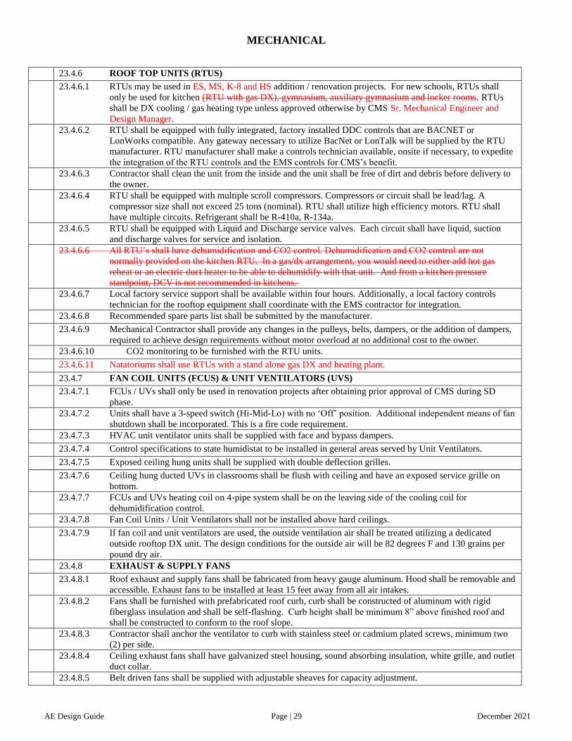
MECHANICAL
AE Design Guide Page | 29 December 2021
23.4.6 ROOF TOP UNITS (RTUS)
23.4.6.1 RTUs may be used in ES, MS, K-8 and HS addition / renovation projects. For new schools, RTUs shall
only be used for kitchen (RTU with gas DX), gymnasium, auxiliary gymnasium and locker rooms. RTUs
shall be DX cooling / gas heating type unless approved otherwise by CMS Sr. Mechanical Engineer and
Design Manager.
23.4.6.2 RTU shall be equipped with fully integrated, factory installed DDC controls that are BACNET or
LonWorks compatible. Any gateway necessary to utilize BacNet or LonTalk will be supplied by the RTU
manufacturer. RTU manufacturer shall make a controls technician available, onsite if necessary, to expedite
the integration of the RTU controls and the EMS controls for CMS’s benefit.
23.4.6.3 Contractor shall clean the unit from the inside and the unit shall be free of dirt and debris before delivery to
the owner.
23.4.6.4 RTU shall be equipped with multiple scroll compressors. Compressors or circuit shall be lead/lag. A
compressor size shall not exceed 25 tons (nominal). RTU shall utilize high efficiency motors. RTU shall
have multiple circuits. Refrigerant shall be R-410a, R-134a.
23.4.6.5 RTU shall be equipped with Liquid and Discharge service valves. Each circuit shall have liquid, suction
and discharge valves for service and isolation.
23.4.6.6 All RTU’s shall have dehumidification and CO2 control. Dehumidification and CO2 control are not
normally provided on the kitchen RTU. In a gas/dx arrangement, you would need to either add hot gas
reheat or an electric duct heater to be able to dehumidify with that unit. And from a kitchen pressure
standpoint, DCV is not recommended in kitchens.
23.4.6.7 Local factory service support shall be available within four hours. Additionally, a local factory controls
technician for the rooftop equipment shall coordinate with the EMS contractor for integration.
23.4.6.8 Recommended spare parts list shall be submitted by the manufacturer.
23.4.6.9 Mechanical Contractor shall provide any changes in the pulleys, belts, dampers, or the addition of dampers,
required to achieve design requirements without motor overload at no additional cost to the owner.
23.4.6.10 CO2 monitoring to be furnished with the RTU units.
23.4.6.11 Natatoriums shall use RTUs with a stand alone gas DX and heating plant.
23.4.7 FAN COIL UNITS (FCUS) & UNIT VENTILATORS (UVS)
23.4.7.1 FCUs / UVs shall only be used in renovation projects after obtaining prior approval of CMS during SD
phase.
23.4.7.2 Units shall have a 3-speed switch (Hi-Mid-Lo) with no ‘Off’ position. Additional independent means of fan
shutdown shall be incorporated. This is a fire code requirement.
23.4.7.3 HVAC unit ventilator units shall be supplied with face and bypass dampers.
23.4.7.4 Control specifications to state humidistat to be installed in general areas served by Unit Ventilators.
23.4.7.5 Exposed ceiling hung units shall be supplied with double deflection grilles.
23.4.7.6 Ceiling hung ducted UVs in classrooms shall be flush with ceiling and have an exposed service grille on
bottom.
23.4.7.7 FCUs and UVs heating coil on 4-pipe system shall be on the leaving side of the cooling coil for
dehumidification control.
23.4.7.8 Fan Coil Units / Unit Ventilators shall not be installed above hard ceilings.
23.4.7.9 If fan coil and unit ventilators are used, the outside ventilation air shall be treated utilizing a dedicated
outside rooftop DX unit. The design conditions for the outside air will be 82 degrees F and 130 grains per
pound dry air.
23.4.8 EXHAUST & SUPPLY FANS
23.4.8.1 Roof exhaust and supply fans shall be fabricated from heavy gauge aluminum. Hood shall be removable and
accessible. Exhaust fans to be installed at least 15 feet away from all air intakes.
23.4.8.2 Fans shall be furnished with prefabricated roof curb, curb shall be constructed of aluminum with rigid
fiberglass insulation and shall be self-flashing. Curb height shall be minimum 8” above finished roof and
shall be constructed to conform to the roof slope.
23.4.8.3 Contractor shall anchor the ventilator to curb with stainless steel or cadmium plated screws, minimum two
(2) per side.
23.4.8.4 Ceiling exhaust fans shall have galvanized steel housing, sound absorbing insulation, white grille, and outlet
duct collar.
23.4.8.5 Belt driven fans shall be supplied with adjustable sheaves for capacity adjustment.

MECHANICAL
AE Design Guide Page | 30 December 2021
23.4.9 GRILLES & REGISTERS
23.4.9.1 Grilles and registers shall be fabricated from steel or aluminum with horizontal steel louvers, spaced ¾” on
centers and fixed 35 degrees deflection.
23.4.9.2 Grilles and registers faces shall have baked enamel factory painted finish.
23.4.10 DIFFUSERS
23.4.10.1 Diffusers shall be square, adjustable pattern, multicore type to discharge air in 360 degrees pattern.
23.4.10.2 Linear slot diffusers shall only be used in special applications, only with CMS approval.
23.4.10.3 Diffuser shall be fabricated of steel aluminum and shall have off-white baked enamel factory painted finish.
23.4.10.4 Provide diffusers with inverted T-bar type frame. In gypsum board ceilings, provide ceiling frame.
23.4.10.5 All d Diffusers in the kitchen, toilets and locker room area shall be perforated, and aluminum type to
prevent corrosion.
23.4.11 KITCHEN HOOD
23.4.11.1 For new construction, CMS requires under the hood to have kitchen utility distribution system. In
renovation projects utility distribution system should be used, with prior approval from CMS. The
Mechanical Contractor shall install the hood and the Utility Distribution System which would be supplied
by the Food Service contractor. The UDS allows for one point of connection for all the utilities. The
Mechanical Engineer shall coordinate electrical power and control wiring with the Electrical Engineer. All
electrical outlet faceplates will have a vertical plane presentation on the UDS in the direction of the
equipment being served. Switches for the fans and lights will need to be field wired to the prewire package
by the electrical contractor. Kitchen exhaust and make-up hood design shall comply with all the
requirements of sections 507 and 508 of the North Carolina Mechanical Code. CMS has determined that
makeup air will be tempered to 55 degrees if the incoming air is less than that temperature.
23.4.11.2 Kitchen hood shall be eyebrow type. Provide a UL listed canopy type exhaust hood, sized per drawings to
overhang equipment. Hood shall feature exposed surface 304 stainless steel, stainless steel UL baffle filters,
integral insulated supply air plenum with combination UL listed fire/volume dampers, vapor proof UL listed
light fixtures, stainless steel closure panels between hood and ceiling, integral grease gutters sloped to drain
to grease receptacles, and a properly sized fire protection system to be provided to the hood supplier for
installation, which shall meet UL 300 standards. Include a solenoid activated mechanical gas valve shutoff
and micro switch for shutdown of electric equipment. Micro switch shall be double pole and double throw.
There shall be an On/Off switch for the kitchen hood for manual operation by remaining within the
scheduled occupied hours.
23.4.12 AIR FILTERS
23.4.12.1 General: The mechanical contractor shall provide “PERMANENT AIR FILTER FRAMES” with “throw
away MERV-108 media” to fit the standard filter sizes required by the manufactures of the HVAC
equipment utilized on the project. The Contractor shall provide four (4) complete media changes, as regular
filter changes are required during construction and a final filter media change at the date of acceptance by
the Owner.
23.4.12.2 Tuck-In Metal Frame. The “permanent frames” shall be of 26 gage. Galvanized metal design. Frame will
consist of a rigid channel no rivet construction as manufactured by United Air Filter Company using a
spring-tensioned media-retaining grid incorporating a 16 gage. (1.0" x 1.0") galvanized wire, which
provides a compression-type seal. Filter shall be sized accurately to meet the filter rack dimensions.
Permanent frames shall be 1/2", 1.0" and 2.0" of thickness of the HVAC equipment to which they are
applied.
23.4.12.3 Filter Media shall consist of, or be equal to Bruce Air Filter BF-090 polyester filter. Filter media shall be
100% virgin polyester fiber manufactured by the Rando-Webber air layered process or an approved equal
air-laid process. Filter media shall be a multi-denier, gradient density with a minimum loft of 7/8" and
weigh 11.25 ounces per square yard, plus or minus 10%. Media shall have a non-migrating, heavy dry
tackifier on the downstream side. It shall have a MERV of 10 8 @ 300 fpm (30% efficiency) with a
maximum initial resistance of 0.25" w.g. as tested in accordance with ASHRAE Standard 52.2. Media shall
have a minimum average arrestance of 90%. Media shall be classified UL-900 Class II. Filter Media shall consist of or be equal to United Air Filter 810A polyester filter. Filter Media shall be
84% polyester fiber, 16% Bicomponent fiber. Filter Media will be a distinct Dual Layered Garnetted
product characterized by a large fiber denier air entering side and a smaller fiber denier air leaving side. Air
leaving side shall also be Needled with a dry non-migrating lackiliar applied to the media. Filter Media
must be treated with an Anti-Microbial agent consisting of or equal to POMOFRESH during the
manufacturing process. Filter Media will have a loft of 1.25” and have a weight of 1 oz. per square foot of

MECHANICAL
AE Design Guide Page | 31 December 2021
media. Media shall have a MERV rating of 10 @ 300 fpm with a maximum initial resistance of .30” w.g. as
tested in accordance of ASHRARE Standard 52.2. Media will be required to have an average efficiency
greater than 50% on particle sizes 1.0 to 3.0 um and an average efficiency greater than 80% on particle sizes
3.0 to 10.0 um. Media is classified UL-900
23.4.13 HVAC IDENTIFICATION & PIPE MARKERS
23.4.13.1 In all existing schools renovations, engineers shall check the existing equipment numbers and start the new
equipment numbers as a continuous sequence, for example in a school if the last air handling unit number
finished with AHU-5 the new number shall carry from their AHU-6, and that shall be similar for fans,
pumps, boilers, chillers, fan coil units, unit ventilators and other equipment.
23.4.13.2 In all new schools equipment shall be identified as air cooled chiller (ACCH), boiler (B), pump (P) in the
pumps case the engineer shall specify on the schedule whether the pump is a condenser pump, primary or
secondary pump, air handling unit (AHU), rooftop unit (RTU), unit ventilators (UV), fan coil unit (FCU),
exhaust fan (EF), supply fan (SF), condensing unit (CU), variable frequency drive (VFD), variable air
volume (VAV), energy recovery ventilation unit (ERV), and kitchen hood supply fan (KSH), and kitchen
hood exhaust fan (KEH).
23.4.13.3 If the school contains multiple wings identified as A, B, C, D wings the units shall be identified as AHU-A-
1, AHU-B-1, etc. and that shall be the same for all equipment in each unit.
23.4.14 ISOLATION VALVES
23.4.14.1 Provide and install mechanical system isolation valves for each wing / floor/ area facilitating easy access,
maintenance, and repair of equipment. Isolation valves shall be reachable from a 10-foot step-ladder. A
phenolic tag (3 in x 2 in) shall visually identify isolation valve location with the valve number engraved on
it and permanently attached by screws to the ceiling grid directly under the valve(s). Hot water tags shall be
red. Chilled water tags shall be blue. Domestic water tags shall be green.
23.4.15 HYDRONIC PIPING
23.4.17.1 All underground piping shall be insulated and jacketed, and shall be Ricwil system or approved equal. No
PVC piping for underground will be used.
23.4.17.2 All pressure relief piping shall be directed to the floor unless Code requires otherwise.
23.4.17.3 Exposed piping shall be protected from freezing by insulation and heat tracing when necessary.
23.4.17.4 All temperature and pressure gauges, and sensors installed on equipment and piping shall be no higher than
6’ above finish floor for access and reading. Temperature and pressure gauges above 6’ shall have remote
read out located in the mechanical room at a central location. The remote read-outs shall be clearly marked
with the appropriate reference to the temperature or pressure gauges from which they are receiving the
information. Standing on the equipment or high ladder for a read out is not acceptable.
23.4.16 DUCTWORK SYSTEMS
23.4.16.1 Plenum return air shall be used. Create sound traps between spaces.
23.4.16.2 Maximum length of flexible ductwork shall be five (5’) feet.
23.4.16.3 On multi-zone units, manual-balancing dampers shall be installed on each zone ductwork near the AHU.
23.4.16.4 Exposed supply and return air ductwork shall be spiral, and shall be installed at highest point possible.
23.4.16.5 Fabric duct shall be used for K8, Middle and High School gyms and other areas where applicable. It will
also be used for Elementary School multi-purpose rooms and other areas.
23.4.16.6 On renovation projects, ductwork to remain shall have the open ends sealed and taped as soon as possible.
Remaining ductwork shall be cleaned by vacuuming the bottom and sides.
23.4.17 BIPOLAR IONIZATION
23.4.17.1 Provide bipolar ionization air cleaning systems with all AHU systems, mounted on the entering side of the
cooling coil. Ionizers shall be self cleaning and UL 2998 listed, equal to Global Plasma Solutions model
FC-48.14
23.5 INSTALLATION STANDARDS
23.5.1 Refer to manufacturer’s installation specification for complete installation procedure.
23.5.2 In order to reduce field labor and related construction impacts, AHUs, UVs, and FCUs, controls shall be
specified to be factory mounted and tested, readily accessible for service.
23.5.3 AHUs, UVs, FCUs, Pumps, Boilers, Air cooled Chillers, and all other system components requiring service
or replacement shall be specified to be installed with isolation valves, flanged or union connections, and
pressure and temperature gauges.
23.5.4 Whenever dissimilar metals are connected a dielectric union shall be installed.
23.5.5 All system components exceeding 50 pounds shall be installed in accordance with seismic requirements.

MECHANICAL
AE Design Guide Page | 32 December 2021
23.5.6 All materials installed on roofs or canopies, i.e. piping or duct, shall have a minimum of 12” clear for
roofing maintenance.
23.5.7 There shall be a maximum of 24” and a minimum of 12” between the supply and return piping at the chilled
water or hot water decoupling loop.
23.5.8 The VFD’s shall be in same room as motor and not greater than 25’ away.
23.5.9 No combustible material shall be used above ceilings.
23.5.10 Condensate drain lines shall be copper. Copper is allowed for drain lines not at floor or ground level. Drain
lines shall run to floor drains. Drains lines shall maintain proper pitch ¼” per 100’ to allow the proper flow
of condensate to the drain. Condensate pumps are allowed only if there isn’t enough room for a condensate
line pitch. Water spills on the floor shall not be acceptable.
23.5.11 A humidity sensor shall be installed in the return air duct of all AHUs for humidity control.
23.5.12 VAV boxes should be mounted within 18” of the drop ceiling for maintenance purposes.
23.5.13 Where possible, install VAV boxes on or near walkways or decks above hallways for ease of maintenance.
23.5.14 Automatic valves shall have a visual indication of valve position relative to the pipe flow that can be seen
from floor level.
23.5.15 All valves on water systems installed for service to equipment or to isolated areas shall be installed within
18” of the drop ceiling and no higher than 12’ from the floor with no ceiling.
23.5.16 Air handling units mounted 16 feet or higher above finished floor shall have maintenance platforms for
convenience and safety. Provide permanent access to platforms.
23.5.17 Pump layout and installation shall have maintenance clearance of 36” minimum all directions around as a
first consideration for future maintenance.
23.6 START UP
23.6.1 Fully trained service technicians employed or recommended by the manufacturer’s representative(s)
providing the main mechanical room equipment such as boiler(s), chiller(s), pump(s), etc. shall perform
start up (Chillers only by manufacturer technicians). After start up, technicians shall complete start up form
and mail three (3) copies to CMS/Building Services, Warranty Dept., 3301 Stafford Drive, Charlotte, NC
28208 for file verification (and included in the closeout manuals). A second start up shall be done at a
mutually agreed upon time when a more consistent load will be available. A second set of three (3) start up
reports shall be sent to the CMS/Building Services, Warranty Dept., 3301 Stafford Drive, Charlotte, NC
28208 for file verification. This start up shall note any deficiencies and corrections to the initial startup.
Manufacturers’ representative shall warrant all equipment to be free from defect.
23.6.2 Per Building Standards, there shall be an automatic means of controlling the HVAC equipment during
construction for unoccupied periods. Therefore, the control system shall provide this control or temporary
time clocks shall be installed to cycle the equipment off during unoccupied hours.
23.7 TESTING AND BALANCING
23.7.1 Note: Work in this section will be contracted directly by the General Contractor or CMAR and NOT by the
Mechanical Contractor. The Mechanical Contractor shall coordinate work with the Testing and Balancing
Agency.
23.7.2 Testing and balancing shall be performed by a fully Certified, Independent, Test and Balancing Agency.
Certification shall be from AABC or NEBB.
23.7.3 Mechanical Contractor shall provide any changes in the pulleys, belts, dampers, sheaves or the addition of
dampers, required to achieve design requirements without motor overload at no additional cost to the owner.
23.7.4 All punch lists from the Test and Balance agency shall be submitted to the CMAR / GC and copies shall be
sent to the Mechanical Contractor, CMS, Commissioning Agent and the A/E for information purposes.
23.7.5 The General Contractor or CMAR will NOT be able to achieve substantial completion until the Test and
Balance final report is completed, submitted, and verified by the Commissioning Agent and the Engineer of
Record.
23.7.6 Commissioning Engineer, at his discretion, may request a recheck or resetting of any outlet, supply or return
air fan, or exhaust fan, or any hydraulic flow as listed in test report. Provide technicians to assist the
Commissioning Engineer in making any tests required during this period of time. This recheck shall also
include a spot check of the actual field balance with the Commissioning Engineer. Allow for spot-checking
25% of documented flow rates.
23.8 COMMISSIONING
23.8.1 CMS has incorporated a Commissioning Program for all of its Capital Improvement Program schools. CMS
shall hire an independent Commissioning Agent, however this shall not relieve the contractor or the
engineer from their responsibilities. The Architect shall incorporate into each project specifications defining

MECHANICAL
AE Design Guide Page | 33 December 2021
the commissioning plan provided by the Commissioning Agent. It will be the responsibility of the HVAC
contractor to provide all required labor and/or material to comply with the commissioning plan.
23.8.2 For details of commissioning requirements, refer to relevant specification.
23.9 OPERATION/MAINTENANCE MANUALS AND TRAINING
23.9.1 When the project is 50% complete, it shall be the contractor’s responsibility to provide and submit two (2)
copies of the operation and maintenance manuals to the engineer for review. Once the review by the
engineer is completed, one (1) manual shall be delivered to the CMS for their record, and one (1) manual
the engineer will keep.
23.9.2 Operation and maintenance manuals shall be organized in 3 ring binders, in the index order of the project
manual. Each Spec section shall be separated with a numbered divider tab matching the project manual
index and shall include approved copies of all product data, shop drawings, cut-sheets and operating and
maintenance instructions for all equipment and materials (including sizes) that were installed in the project. 23.9.3 Startup sheets for all HVAC equipment chillers, boilers, VFD’s, etc., shall be included in operation and
maintenance (O & M) manuals and the warranty/closeout manual. All approved equipment suppliers shall
maintain technical service manuals.
23.9.4 The Mechanical Contractor will provide on-site operator/maintainer training to CMS HVAC technicians
through respective OEMs. All training shall be videoed by contractor or CMAR and 2 copies submitted to
CMS.
23.9.5 Following the installation of any HVAC system the contractor shall provide at the main mechanical
equipment room valve chart(s), sequence of operation, piping schematic(s), and control diagram(s). These
items shall be reduced copies, 11”x17” in size and shall be in a laminated cover.
23.9.6 The mechanical contractor shall install a drawing holder in a convenient location in the main mechanical
room. The drawing holder shall consist of a 4” PVC pipe of sufficient length to hold the mechanical
drawings. The drawing holder shall have PVC pipe plug screwed into each end. The mechanical contractor
shall place “Construction Record” drawings in the drawing holder when available. Contract drawings shall
be in the drawing holder until replaced by “Construction Record” drawings. NCDOL Boiler Inspection
Certificates shall be framed and mounted in the boiler room.
23.9.7 A – The following information / documents shall be required to be submitted separately to CMS HVAC;
this is additional to the Maintenance Manuals:
23.9.7.1 Safety instructions.
23.9.7.2 Detailed spare parts lists (e-copies in MS Excel format) of each equipment.
23.9.7.3 Tabular list of warranties of each equipment (e-copy).
23.9.7.4 PM inspection procedures.
23.10 DEMOLITION STANDARDS
23.10.1 The owner reserves the right to reclaim refrigerant and oil prior to demolition. If the owner does not want
refrigerant to be reclaimed, the Contractor shall be responsible for reclaiming refrigerant and refrigerant oil
in conformance with all applicable laws and regulations. Contractor shall recycle or dispose of refrigerant
and refrigerant oil in a lawful manner, completing all documentation regarding refrigerant. One copy of all
documentation regarding refrigerant and refrigerant oil shall be forwarded to Owner for record keeping.
23.10.2 This shall apply to all units containing refrigerant and refrigerant oil including, but not limited to: chillers,
freezers, coolers, water coolers, air dryers, window units, heat pumps, split units, and ice machines.
23.10.3 Owner has the right of first refusal on all HVAC / mechanical equipment unless specifically stated in the
project documents.
23.10.4 Chillers shall have the piping seal welded shut with a ¼” Swagelock fitting for gas blanket. DX equipment
shall have the refrigerant piping sealed.
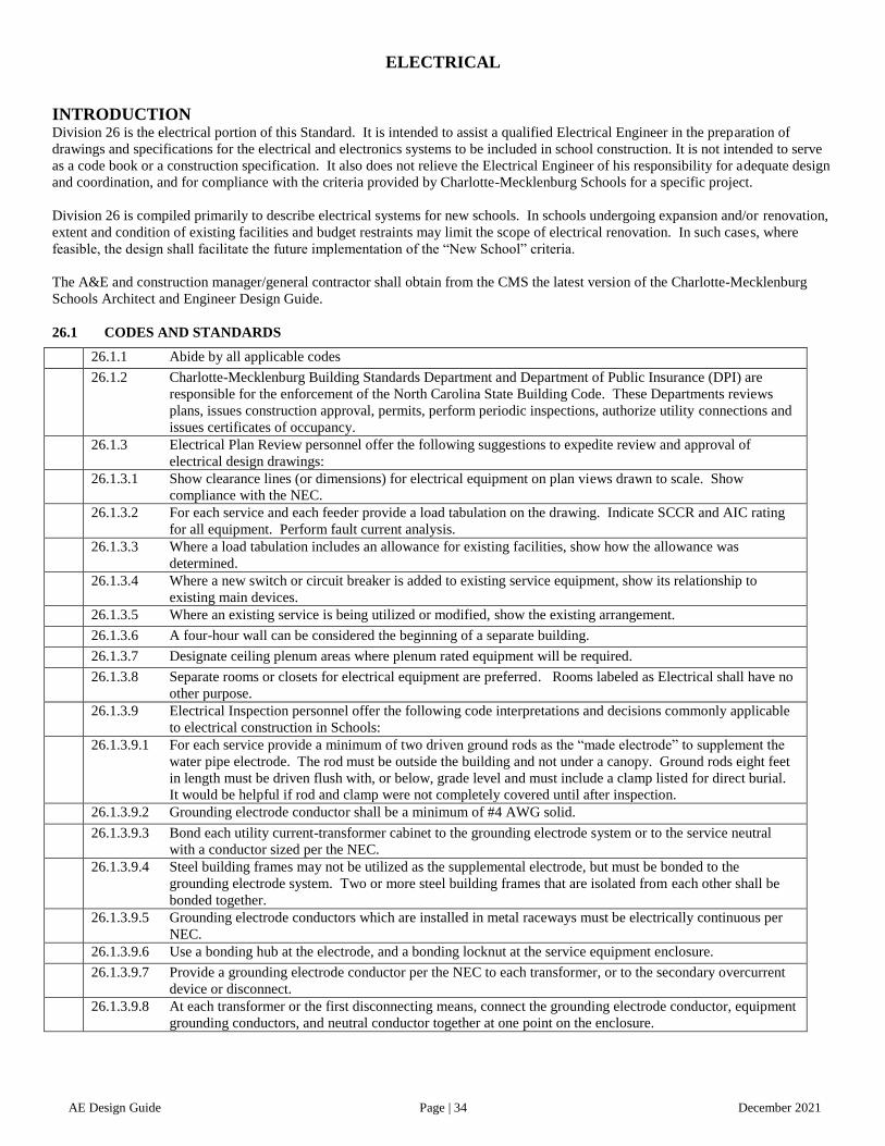
ELECTRICAL
AE Design Guide Page | 34 December 2021
INTRODUCTION Division 26 is the electrical portion of this Standard. It is intended to assist a qualified Electrical Engineer in the preparation of
drawings and specifications for the electrical and electronics systems to be included in school construction. It is not intended to serve
as a code book or a construction specification. It also does not relieve the Electrical Engineer of his responsibility for adequate design
and coordination, and for compliance with the criteria provided by Charlotte-Mecklenburg Schools for a specific project.
Division 26 is compiled primarily to describe electrical systems for new schools. In schools undergoing expansion and/or renovation,
extent and condition of existing facilities and budget restraints may limit the scope of electrical renovation. In such cases, where
feasible, the design shall facilitate the future implementation of the “New School” criteria.
The A&E and construction manager/general contractor shall obtain from the CMS the latest version of the Charlotte-Mecklenburg
Schools Architect and Engineer Design Guide.
26.1 CODES AND STANDARDS
26.1.1 Abide by all applicable codes
26.1.2 Charlotte-Mecklenburg Building Standards Department and Department of Public Insurance (DPI) are
responsible for the enforcement of the North Carolina State Building Code. These Departments reviews
plans, issues construction approval, permits, perform periodic inspections, authorize utility connections and
issues certificates of occupancy.
26.1.3 Electrical Plan Review personnel offer the following suggestions to expedite review and approval of
electrical design drawings:
26.1.3.1 Show clearance lines (or dimensions) for electrical equipment on plan views drawn to scale. Show
compliance with the NEC.
26.1.3.2 For each service and each feeder provide a load tabulation on the drawing. Indicate SCCR and AIC rating
for all equipment. Perform fault current analysis.
26.1.3.3 Where a load tabulation includes an allowance for existing facilities, show how the allowance was
determined.
26.1.3.4 Where a new switch or circuit breaker is added to existing service equipment, show its relationship to
existing main devices.
26.1.3.5 Where an existing service is being utilized or modified, show the existing arrangement.
26.1.3.6 A four-hour wall can be considered the beginning of a separate building.
26.1.3.7 Designate ceiling plenum areas where plenum rated equipment will be required.
26.1.3.8 Separate rooms or closets for electrical equipment are preferred. Rooms labeled as Electrical shall have no
other purpose.
26.1.3.9 Electrical Inspection personnel offer the following code interpretations and decisions commonly applicable
to electrical construction in Schools:
26.1.3.9.1 For each service provide a minimum of two driven ground rods as the “made electrode” to supplement the
water pipe electrode. The rod must be outside the building and not under a canopy. Ground rods eight feet
in length must be driven flush with, or below, grade level and must include a clamp listed for direct burial.
It would be helpful if rod and clamp were not completely covered until after inspection.
26.1.3.9.2 Grounding electrode conductor shall be a minimum of #4 AWG solid.
26.1.3.9.3 Bond each utility current-transformer cabinet to the grounding electrode system or to the service neutral
with a conductor sized per the NEC.
26.1.3.9.4 Steel building frames may not be utilized as the supplemental electrode, but must be bonded to the
grounding electrode system. Two or more steel building frames that are isolated from each other shall be
bonded together.
26.1.3.9.5 Grounding electrode conductors which are installed in metal raceways must be electrically continuous per
NEC.
26.1.3.9.6 Use a bonding hub at the electrode, and a bonding locknut at the service equipment enclosure.
26.1.3.9.7 Provide a grounding electrode conductor per the NEC to each transformer, or to the secondary overcurrent
device or disconnect.
26.1.3.9.8 At each transformer or the first disconnecting means, connect the grounding electrode conductor, equipment
grounding conductors, and neutral conductor together at one point on the enclosure.

ELECTRICAL
AE Design Guide Page | 35 December 2021
26.1.3.9.9 Service equipment shall be labeled as suitable for use as service equipment.
26.1.3.9.10 In order to apply 75 degrees C insulated conductors at their 75 degrees C rating, the equipment terminals at
both ends must be rated 60/75 degrees C or 75 degrees C. If the terminal is rated 60 degrees C only, the
conductor must also be sized as if it had a 60 degrees C rating.
26.1.3.9.11 Bundling of wires in panel boards in excess of 24” in length will cause them to be subject to the de-rating
requirements of the NEC. Receptacles are not required in group Restrooms, but if provided they must be
protected by ground fault circuit interrupters. Student Restrooms are better off without receptacles, locate in
the adjacent corridor when possible.
26.1.3.9.12 Weatherproof GFCI type receptacles should be provided on roofs within 25 feet of Heating, Air
Conditioning and Refrigeration Equipment. They are not required for ventilation and exhaust fans and the
intake and exhaust for a Kitchen Hood.
26.1.3.9.13 Panel directories shall reference room names and numbers actually assigned on door tag and signage, not
the room numbers used on Construction Floor Plans.
26.1.3.9.14 Lay-in Lighting Fixtures shall be supported from the overhead structure. One wire per corner minimum.
26.1.3.9.15 Panels fed from a utility transformer must be service rated.
26.1.3.9.16 Panels fed from an existing panel in a different building must be service rated or no continuous metallic
pathway between the two buildings with a separately provided ground rod provided.
26.1.3.9.17 Circuit breakers for Fire Alarm System circuit must be red and must be dedicated.
26.1.3.9.18 Energy efficiency should be considered per the latest edition of the NCECC standards. Also, while LEED
designation is not being pursued, LEED-NC and EB design criteria should be considered.
26.1.3.9.19 Provide an Arc Flash Analysis per NFPA 70E and OSHA 29 CFR 1910 and label all panels accordingly
with the specific hazard level. Provide overcurrent protective device coordination study for the entire power
distribution system, with emphasis on all life safety generator backed up systems.
26.2 ELECTRICAL SERVICE
26.2.1 As the predominant electrical utility in Mecklenburg County, Duke Power Company’s procedures and
standards are described herein. Projects in and near the Towns of Cornelius, Huntersville, and Pineville
may be served by their respective Towns; and Union Electric Membership Corp. serves a portion of
Mecklenburg County adjacent to Union County.
26.2.2 The initial Duke Power Company contact should be the Marketing Account Executive for Charlotte-
Mecklenburg Schools. They will be the overall coordinator for Duke Power Company and will advise the
Duke Power engineering office to be contacted. For existing schools, they can also provide information on
the electrical KW demands.
26.2.3 Preferred Service Arrangement:
26.2.3.1 For new schools, one service is preferred. However, consideration should be given for a second service for
out-buildings and outdoor air-conditioning chillers.
26.2.3.2 Pad mount transformer delivering 480/277 volt, 3 phase, 4 wire service, or 208Y/120 volt, 3 phase, 4 wire
service, depending on the size of the building.
26.2.3.3 Standard concrete pad details shall be obtained from the utility company.
26.2.3.4 Duke Power Engineer will determine whether or not a “pit box” will be required.
26.2.3.5 Locate transformer within the fenced-in utility area that includes the chiller(s). Provide weatherproof GFI
receptacle in enclosure and photocell controlled outdoor luminaire for the utility area.
26.2.3.6 Duke Power personnel will provide their standard padlock for the chain that secures the gate for the fenced
utility area. The Duke Power padlock and the Charlotte- Mecklenburg Schools padlock will be installed in
tandem so either lock can be used for access to the utility area.
26.3 UTILITY METER
26.3.1 Locate within the same fenced-in utility area as the transformer, wall mounted if possible.
26.3.2 Provide 1 ¼” conduit from meter box to secondary side of pad mount transformer.
26.3.3 Charlotte-Mecklenburg Schools requires that new meters be the pulse type. This requirement should be
indicated on the electrical drawings with the statement that the electrical contractor request the installation
of the pulse meter when coordinating with Duke Power Company.

ELECTRICAL
AE Design Guide Page | 36 December 2021
26.3.4 The pulse meter installation will include a small relay box nippled to the meter box. Provide #18 AWG
stranded pair cable in conduit from the relay box to the Energy Management System Controls. The
necessary wiring connection of the pulse relays to the Energy Management System is the responsibility of
the HVAC Controls Subcontractor under Division 23. Only the main meter shall be monitored. Coordinate
with the CMS project manager if there are multiple “mains” provided and which need to be specifically
metered.
26.3.5 Provide a breakdown of the connected load for each service to the Duke Power Engineer, including largest
motor, winter load, summer load, lighting, kitchen equipment, HVAC, receptacles, and miscellaneous
power.
26.3.6 Service shall include provisions for load growth of 25% in the form of excess conductor capacity, or with
spare conduits for future parallel service conductors. Spare conduits for future paralleling should be tagged
with actual conductor lengths for each phase and neutral. Switchboard busses shall be sized for 25% future
growth. In sizing the feeders, consider NEC Article 220.86 with respect to applying demand factors
applicable to schools.
26.3.7 Electrical service shall be underground in concrete encased PVC from power company transformer to main
service equipment. Minimum depth of 36”.
26.3.8 Electrical service requirements for mobile units shall be coordinated with the owner.
26.3.9 Existing schools with multiple services and/or multiple meters:
26.3.9.1 Show all meter locations on the Electrical Site Plan. At the conclusion of the project, add the utility’s meter
numbers to the Site Plan record drawing.
26.3.9.2 Analyze new and existing services for combination of metering where economically feasible.
26.3.9.3 Arrange for a site visit with the Charlotte-Mecklenburg Schools Electrical Engineer and the Duke Power
Engineer to observe the existing and proposed new service and metering arrangements. This shall be done
during the design development phase of project.
26.4 CONDUCTORS FOR SERVICE, FEEDERS AND BRANCH CIRCUITS
26.4.1 Branch circuit conductors shall be copper. Although copper feeder conductors are preferred, aluminum
conductors shall be considered as an acceptable alternate to copper and the cost of both materials quoted
subject to the requirements in specification 260519.
26.4.2 Insulation for copper conductors THWN/THHN.
26.4.3 Type AC, NM and NMC cables shall not be used.
26.4.4 Limited use of MC cable is allowed for above ground interior lighting and receptacle branch circuits. Work
shall be per the NEC with the additional restrictions listed in specification 260519.
26.4.5 Feeders shall be sized for load growth of 25%. All panelboard busses served by feeders with future growth
shall be sized accordingly.
26.4.6 Branch power circuits shall be a minimum of #12 AWG.
26.4.7 Use stranded conductors for all power wiring.
26.4.8 Run a separate neutral for each 120V circuit.
26.4.9 Each branch or feeder circuit shall have a green equipment-grounding conductor sized in compliance with
the NEC.
26.4.10 Backstabbed (quick wired) outlets and switches shall not be used.
26.4.11 When doing demolition, remove unused circuits (wiring and conduit) back to source. Conduit in slabs
should be cut off flush with surface. Repair concrete with grout.
26.4.12 All underground wiring shall have marker tape buried 6” below finished grade and directly above
underground wiring conduits.
26.4.13 All wiring shall be color coded. For 120/208V – phase A black, phase B red, phase C blue, neutral white.
For 277/480V – phase A brown, phase B orange, phase C yellow, neutral gray. Ground conductor on all
systems shall be green. Insulation for #6 AWG and smaller conductors shall be suitably colored in
manufacturing. #4 AWG conductors and larger may be identified with bands of proper color plastic tape
near each termination and in each junction box. Low voltage color coding shall be as follows:
26.4.13.1 Fire Alarm – Red
26.4.13.2 Intercom - Off White
26.4.13.3 Security - see specifications for color coding required.
26.4.13.4 Cable TV- Black
26.4.13.5 DDC - Purple/Yellow

ELECTRICAL
AE Design Guide Page | 37 December 2021
26.4.14 Show location of all exterior underground power circuit wiring on as-built drawings including hand hole
locations.
26.5 COMMUNICATIONS AND LOW VOLTAGE SYSTEMS CABLING
26.5.1 All Communications and Low Voltage Systems Cabling shall be plenum rated unless noted otherwise.
Non-plenum is acceptable for Fire Alarm Cabling installed entirely in conduit.
26.5.2 All Communications and Low Voltage Systems Cabling shall be routed in cable trays where provided above
suspended ceilings unless noted otherwise.
26.5.3 All Communications and Low Voltage Systems Cabling not concealed above a suspended ceiling shall be
routed in raceways.
26.5.4 Do not run low voltage cabling underground unless given specific direction to do so from CMS. This
includes but is not limited to fire alarm, intercom, data and security cabling.
26.6 PANELBOARDS AND SWITCHBOARDS
26.6.1 Panelboards shall be dead-front type with copper bussing. Hinged fronts (trims) are preferred.
26.6.2 Panelboards shall have main circuit breaker unless it is fed from another panel in the same room and labeled
as such.
26.6.3 Panelboards shall be located in equipment rooms or kitchens. Avoid installations in corridors, classrooms
and other finished areas. Panelboards in equipment rooms shall be surface mounted. Panelboards in
kitchens shall be flush mounted. Mount panels so top is at 6’-6” A.F.F. A minimum of 36” unobstructed
access shall be provided at the front of the panelboard.
26.6.4 All flush mounted panelboards shall have a minimum of five empty ¾” conduits stubbed out into the ceiling
space above the panel for future use. Seal ends of conduit with caps.
26.6.5 Busses in panelboards and switchboards shall be considered “A”, “B” and “C” from left to right, top to
bottom, or front to back when facing equipment.
26.6.6 Load centers shall not be installed without approval of CMS Electrical Engineer.
26.6.7 Lighting panelboards shall contain only lighting circuits. All other loads such as receptacles and
mechanical equipment shall be served from separate panelboards.
26.6.8 Switchboards shall have group mounted branch circuit breakers.
26.6.9 Switchboards shall have copper bussing.
26.6.10 A housekeeping pad shall be provided for switchboards. Minimum of 4” high.
26.6.11 Unobstructed access shall be provided to switchboards per NEC.
26.6.12 Panel board and Switchboard Directory cards shall be neatly typed. Space typing on card so all is visible
when inserted into frame. Panelboard and Switchboard directories must be updated with each project. Do
not use “white-out” or scratch out existing information. Do not use pencil to update. Retype entire
schedule if necessary. Directories will list specific device and location. e.g. “Receptacles Rm 123” not
generic “Receptacles”.
26.6.13 New panels shall be designed with a minimum of 15% spare 20A single pole breakers and 15% blank
spaces unless otherwise approved by CMS Electrical Engineer.
26.6.14 New panels shall be 42 pole minimum unless otherwise approved by CMS Electrical Engineer. An
exception would be emergency panels and similar locations where very few breakers are needed and
minimal growth is expected.
26.6.15 The main service entrance switchboard shall have a main breaker and a digital display for voltage and
amperage.
26.7 TRANSFORMERS
26.7.1 Dry Type Distribution
26.7.1.1 Housekeeping pad shall be provided. Minimum of 4” high.
26.7.1.2 See specification 262200 for requirements.
26.7.2 For new construction or renovations that require a building to be sprinkled, by the building code, the main
electrical room and emergency ATS room need not be sprinkled if it has a minimum of a 2 hour rated wall.
This is the preferred arrangement. All other electrical rooms shall be sprinkled.
26.8 CIRCUIT BREAKERS
26.8.1 Interrupting capacity for circuit breakers shall be determined by the coordination study.

ELECTRICAL
AE Design Guide Page | 38 December 2021
26.8.2 Panel boards shall utilize bolt-on type breakers.
26.9 DISCONNECT SWITCHES
26.9.1 Switches shall be heavy duty.
26.9.2 Switches enclosures shall be NEMA 3R for outdoor use.
26.9.3 Switches enclosures shall be NEMA 4 for kitchen equipment.
26.10 ACCEPTABLE EQUIPMENT MANUFACTURERS (others need to be approved by CMS Electrical
Engineer):
26.10.1 Square D Company
26.10.2 Eaton/Cutler Hammer
26.10.3 Siemens ITE
26.10.4 General Electric
26.11 WIRING DEVICES – CONVENIENCE OUTLETS
26.11.1 Receptacles shall be specification grade NEMA 5-20R, side wired with high impact thermoplastic face.
Color shall be gray unless installed in ivory wire mold, then color shall be ivory. Ground fault interrupter
receptacles shall be used outdoors and adjacent to sinks indoors.
26.11.2 Device plates shall be standard size 302 stainless steel. Use midi size plates.
26.11.3 Receptacles shall be recessed in wall on new school construction projects.
26.11.4 Locate convenience outlets in all occupied spaces other than Student’s Restrooms, Locker Rooms,
Swimming Pools, Time Out Rooms, small Closets and small Storage Rooms.
26.11.5 Mounting height for devices shall comply with current ADA requirements.
26.11.6 In Offices, Workrooms, and Conference Rooms provide widely-spaced convenience outlets to result in
approximately one outlet for each 50 square feet of floor area, with minimum of two.
26.11.7 Provide a duplex outlet at each end of large fixed tables in workrooms. Provide a blanked data wiring box
at one end only. Architectural plans shall provide a wiring chase for the electrical and data cabling.
26.11.8 Provide one duplex receptacle within 25’ of each piece of mechanical and plumbing equipment. Also
provide one or more duplex convenience receptacle in each boiler room depending on the size of the room.
26.11.9 Provide an outlet at least every 50’ in corridors, and open wall locations, i.e., large spaces such as media
center, gymnasiums, dining area, etc.
26.11.10 Provide a weatherproof GFI outside outlet near every main outside door and near any outside mechanical
equipment. As a school’s design dictates provide additional outside outlets. Provide inside outlets within
10’ of any outside doors.
26.11.11 In addition to the dedicated 120VAC, 20A duplex and quad receptacles required in data rooms, provide
120VAC, 30A dedicated circuit with an L5-30R receptacle.
26.11.12 MDF: (2) L5-30R, 80” aff, (4) quad receptacles 80” aff, (4) quad receptacles 18” aff, (2) duplex receptacles
48” aff.
26.11.13 IDF: (1) L5-30R, 80” aff, (2) quad receptacles 80” aff, (4) quad receptacles 18” aff, (1) duplex receptacle
26.11.14 Grounding pin of receptacles shall be in the “down” orientation.
26.12 WIRING DEVICES – LIGHT SWITCHES
26.12.1 Toggle switches shall be specification grade 120/277V, side wired with high impact thermoplastic handle.
Color shall be gray.
26.12.2 Device plates shall be standard size 302 stainless steel.
26.12.3 Switches shall be recessed in wall on new school construction projects.
26.12.4 Locate switches for Corridors and group restrooms in an Office, a Workroom, or a similar area not subject
to student’s tampering. Key operated switches may be appropriate in Corridors of Building Additions.
26.13 WIRING DEVICES – MISCELLANEOUS
26.13.1 Clock receptacles need no longer be provided. Battery operated clocks shall be provided by CM/GC
supplied by Charlotte-Mecklenburg Schools.
26.13.2 Provide a door bell and chime as standard at the kitchen back door. Devices will be commercial grade.
26.13.3 Provide pathways and cabling for the owner provided HELIOS system at the front entry door. Coordinate
with Design Manager regarding the Owner’s Helios System provided by other Contractors.

ELECTRICAL
AE Design Guide Page | 39 December 2021
26.13.4 Occupancy Sensors
26.13.4.1 Provide energy study to CMS for Review.
26.13.4.2 As a normal practice, provide vacancy sensor or off delay timer switches for irregularly occupied spaces as
is appropriate and required by the energy codes. This may include data, server, conference and storage
rooms, restrooms (except elementary school group toilets) and offices. The arrangement should include
manual over-ride capabilities. Sensors with dual sensing technology are preferred and off delay should be
set to 30 minutes. Do not use occupancy sensors in electrical or mechanical rooms where they may create a
hazard.
26.13.4.3 Upon request by CMS, occupancy sensors are to be included as an alternate for other regularly occupied
spaces where they may be desirable, but are not required by the energy codes.
26.13.4.4 Provide pathways (3/4”) and double gang box with single gang reducer mounted at 48” AFF to center of
outlet located in the kitchen area and the admin area. Kitchen area location shall be near the cafeteria
manager’s office, away from possible damage from delivery carts and excessive heat/moisture.
26.14 STANDBY ENGINE-GENERATOR SET
26.14.1 An on-site Standby Engine-Generator Set shall be provided for each new school in compliance with NEC
Article 700.
26.14.2 Generators will include an automatic transfer switch (ATS) for life safety functions only. An
equipment/auxiliary transfer switch should only be considered where loss of power could cause
considerable damage to the building as with certain sump pumps or sewage lift stations.
26.14.3 If the ATS is located in a separate room, the building code requires this room to be sprinkled which is not
desirable. It is preferred that this ATS be located in the main electrical which requires its’ clearances to be
doubled. The main electrical room should not be sprinkled, but requires a minimum of a 2 hour rated wall.
26.14.4 CMS will determine if a Generator should be provided when doing an alteration or addition to existing
schools.
26.14.5 Design Engineer to submit Generator sizing calculations to CMS for review. The generator shall have a
minimum of 25% excess capacity and be no smaller than 20KW.
26.14.6 Locate the Engine-Generator Set in a weather-protective enclosure, outdoors on a concrete pad enclosed by
a chain-link fence. The same fenced-in area as the pad mount transformer and chillers is preferred.
26.14.7 Generator fuel system is natural gas where available. Consider diesel or liquid propane where natural gas is
not available.
26.14.8 Generator shall include the following features:
26.14.8.1 Generator to be brushless, three-phase; either 208Y/120 or 480Y/277 volts.
26.14.8.2 Indoor wall-mounted contactor-type Automatic Transfer Switch complete with time-delays for engine start,
transfer, retransfer, and cool-down; and an automatic exerciser clock. ATS shall have programmable timer.
ATS shall be 4-pole, no smaller then 30A and must match the ampacity of the generator per code.
26.14.8.3 Automatic battery charger capable of recharging a completely discharged battery in 8 hours or less.
26.14.8.4 Critical exhaust silencer on top of the weather-protective enclosure.
26.14.8.5 Block heater and anti-freeze if engine is water-cooled.
26.14.8.6 Set to be assembled, tested, and warranted by the prime manufacturer of either the engine or the generator.
26.14.8.7 A generator remote annunciator panel shall be installed in the main office area preferably near the fire alarm
panel.
26.14.9 Connect the following equipment/systems for operation from the Generator including emergency lighting in
the rooms noted:
26.14.9.1 Exit signs, egress lighting, assembly areas and all spaces, devices and systems as explicitly required by the
building codes.
26.14.9.2 Fire Alarm Systems and fire pump if one exists.
26.14.9.3 The Intercom Console
26.14.9.4 Area of Rescue Assistance/Two way elevator communication (if provided) enabling complete operation.
26.14.9.5 Group restrooms
26.14.9.6 Locker rooms
26.14.9.7 Health room

ELECTRICAL
AE Design Guide Page | 40 December 2021
26.14.9.8 Teacher workroom/lounge
26.14.9.9 Main electrical room
26.14.9.10 Boiler room
26.14.9.11 Kitchen
26.14.9.12 Reception area
26.14.9.13 Classrooms where area of glazing/floor area < 8%
26.14.10 The number and arrangement of 480/277V panels, dry type transformers and 208/120V panels should be
held to the minimum that practicality dictates.
26.15 RACEWAY SYSTEMS
26.15.1 Rigid Metal Conduit (RMC) or Intermediate Metal Conduit (IMC) shall be used indoors for all exposed
feeders in normally occupied areas and outdoors for all feeders, above ground branch circuits and above
ground low voltage/communications wiring.
26.15.2 Schedule 40 conduit Rigid Nonmetallic Conduit (RNMC) shall be used for outdoor underground branch
circuits and outdoor low voltage wiring unless noted otherwise. Electrical service from the utility
transformer to the main service equipment shall be concrete encased RNMC.
26.15.3 Flexible Metal Conduit shall be used for connections to mechanical equipment, transformers and light
fixture whips. MC cable may be used for lighting whips. Use Liquid tight Flexible Metal Conduit for
connections outdoors, in the kitchen and in other wet locations complete with Liquid tight connectors.
Connectors shall be the insulated throat type, of steel or malleable iron.
26.15.4 Electrical Metallic Tubing (EMT) may be used indoors above grade only. It may be used in normally
unoccupied spaces such as electrical rooms, mechanical rooms and similar areas.
26.15.4.1 EMT connectors and couplings to be the compression type, of zinc coated steel or malleable iron.
26.15.4.2 Provide EMT connectors with insulated throats.
26.15.5 RNMC may be used in a concrete slab on grade and under a concrete slab.
26.15.6 RNMC runs that are required to stub up exposed shall utilize Rigid Metal Conduit elbows vertically.
26.15.7 RNMC runs that stub up in pad mounted equipment such as switchboards or transformers may utilize
RNMC elbows vertically. Install termination fitting with a plastic bushing.
26.15.8 RNMC runs that turn up inside walls shall transition to EMT no greater than 60” above the slab or first
junction box, whichever comes first.
26.15.9 Size raceways for signal and communication cables based on 40% fill. Use 3/4” as the minimum size
conduit for Telephone, Data and CATV. Use 1” as the minimum size conduit for all conduit ran under slab.
26.15.10 Run raceways concealed in finished areas.
26.15.11 All exposed or concealed raceways to be run perpendicular or parallel to building walls and ceilings. All
exposed raceway to be painted to match color of surrounding surfaces.
26.15.12 Nonmetallic surface mounted wire ways shall not be used in any installation.
26.15.13 The minimum size conduit shall be ¾” for homeruns, and ½” for all other power circuit installations.
26.15.14 The minimum size junction box shall be 4” x 2 1/8” square. There shall be no more than one box extension.
26.15.15 Over- the- floor pancake raceways shall not be used. Run power to the center of the room in the floor or use
power poles. Use Wire mold 25DTP-4 series tele-power poles (ivory) or equivalent. Make an effort to lay
out furniture, computer workstations, etc. so that power and communication raceway can be run down walls
and columns instead of having to use floor boxes and/or power poles.
26.15.16 Use surface metal raceways for new exposed work on existing surfaces in finished areas that would
otherwise be free of exposed conduits and piping. Use Wire mold 4000 or V2400BD or equivalent.
26.15.17 Cable trays shall be provided in corridors. Use trays ONLY for distribution of low voltage signal and
communication cabling. Cable tray and cable tray supports shall not be used for the support of any other
raceways or MC cable (including no fire alarm MC cable.) At no time shall a cable tray go through a rated
wall. Cable trays above suspended ceilings shall be the ladder type with 4” rails and 12” maximum rung
spacing. Cables trays exposed in corridors shall be solid bottom type. All cable trays shall utilize “sweeping
90s”. Notify the Charlotte-Mecklenburg Schools Telecommunications Department when the cable tray
system is complete for their review prior to the ceiling installation. Cable tray minimum width of 12” for
elementary and middle schools and 18” for high schools. One divider will be provided in the trays that will
separate the 12” trays into 8” for data/voice/catv and 4” for other trades and for 18” trays the division will
be 12” and 6”. See specification 260536 for further requirements.

ELECTRICAL
AE Design Guide Page | 41 December 2021
26.15.18 Raceways shall not be installed under canopies that are less than 12’ high. Raceways installed above
canopies shall be installed a minimum of 8’ above the finished surface. Do not penetrate the finished
surface of canopies.
26.16 PENETRATIONS, SLEEVES AND FIRESTOPPING
26.16.1 Provide wall sleeves and appropriate fire-stopping at passage of conduits and cables through rated walls.
Provide and seal similar sleeves for passage of signal and communications cables through unrated walls
unless other openings exist that can be utilized.
26.16.2 All penetrations, sleeves and fire stopping shall be fully described or detailed for each condition. Refer to
the appropriate Through-Penetration Firestop Systems by their UL System numbers, and provide details on
the drawings for each condition.
26.17 LIGHTNING AND SURGE PROTECTION
26.17.1 Surge/Lightning Protection shall be provided at the main service entrance equipment. A secondary level of
protection shall be provided on all 120/208V power panels serving computer receptacles and/or convenience
receptacles and low voltage systems. In rooms where multiple panels exist fed from the same source in that
room, only one TVSS (SPD) is required connected to the distribution panel or the first section of a multiple
section arrangement unless the subpanel has a substantial amount of computer or low voltage loads. A third
level of protection shall be provided for power and data lines entering Fire Alarm Panels, Intercom
Consoles, Telephone Head end Equipment, Security Camera Equipment and Media Retrieval Equipment.
Provide surge protection on any lighting panel that feeds exterior lighting. Per NEC requirements, provide
surge protection on all emergency panels. All protection shall be coordinated. Care must be taken to wire
TVSS devices per the manufacture’s recommendations with regards to keeping wires as short as possible,
no sharp bends etc. See specification 264313 “surge protection for low-voltage electrical power circuits”.
26.17.2 See “Charlotte-Mecklenburg Schools Lightning Protection Standard” for structural lightning protection
requirements. Check requirements with CMS.
26.17.3 All existing lightning protection systems shall be maintained during building renovations and extended to
any additions to the building.
26.18 LIGHTING – GENERAL INFORMATION
26.18.1 Lighting systems for new schools should be designed in accordance with Illuminating Engineering Society
(IES) recommendations. This is 50fc for classrooms. The maintained target lighting level for all gyms
should be 50fc and high school gyms should be 70-80fc for competition. Include consideration for possible
sound attenuation baffles in the design. High schools should have dual level controls to provide 50fc for
normal activities and secured controls to turn on additional lights for competition. Coordinate with CMS on
location of the secured controls.
26.18.2 Lighting design shall incorporate the latest requirements of the NCECC energy code.
26.18.3 CMS prefers that general lighting in most areas be implemented with 2’x 4’ LED (light emitting diode) light
fixtures. Lens should be of flat clear KSH12 type acrylic of 0.125” minimum, straight sided cones, 9.6
ounces per square foot, in rigid hinged steel or extruded aluminum door frames finished in baked white
enamel and secured with inconspicuous spring-loaded or rotary cam type steel latches. Lenses shall be
maintained in a flat position with invisible clips and shall be removable from the door frames using a
screwdriver without damaging the lens or the frame. Diodes shall have a CCT of 4000K, Provide LED
driver quick connect disconnecting means.
26.18.4 See specification 265119 “LED interior lighting” and 265619 “LED exterior lighting” for requirements.
26.18.5 All new area lighting shall be 277 volt where available.
26.18.6 Lighting shall be installed such that it can be easily maintained. 2’x 4’ fixtures should be able to be
completely removed. Pay specific attention to stairwells where access may be difficult. Do not locate light
fixtures over stairwells. Use wall mounted light fixtures in stairwells. Lights to be located above landings,
not over stair steps.
26.18.7 Classrooms, tutor rooms and offices shall have double switching; bi-level drivers or dimming capability.
Classroom lighting shall be controlled by (2) single pole switches at the room entry (bi-level control of all
fixtures) and a single pole double throw switch at the teaching wall location to control the teaching wall
fixtures on/off.
26.18.8 Lighting and outlets shall not be on the same circuit. Wiring for lighting and outlets shall be run in separate
raceways.

ELECTRICAL
AE Design Guide Page | 42 December 2021
26.18.9 Exterior building mounted lighting shall be LED and shall be controlled by photocell enable and
astronomical time clock (ON/OFF). Light pollution is a common issue. Use cutoff type light fixtures unless
specific requirements dictate otherwise. Do not direct light out and up for decorative purposes. The time
clock will be the electronic type and retain its’ programming during loss of power. See specification
260923. Exterior lighting shall be installed at building entrances, exterior mechanical/electrical/storage
room doors, loading docks ground surface loading area, over the emergency generator, under canopies and
around the building perimeter (wall-packs). Coordinate building mounted fixtures with parking lot and
driveway lights so as to not duplicate lighting. Building mounted fixtures shall be vandal resistant. Normal
setup should be on at dusk from photocell, off at 10:00 PM by timer, on at 5:00 AM by timer and off at
dawn by photocell. Beginning and ending time setting should be wide enough to cover the change in
seasons.
26.18.10 Parking lot lighting shall be part of the construction contract. LED basis of design. See specifications
265619 and 265613 for further information. Light pollution is an issue and a photometric study should be
provided. Existing schools may have leased lighting as part of their original design; for those instances see
the below items:
26.18.10.1 Verify with the CMS if the added site lighting shall be leased or provided as part of the contract documents.
26.18.10.2 Where verified to be leased, parking lot lighting shall be leased from the existing local electric utility. Poles
shall match the existing design. The engineer shall be responsible for coordinating and obtaining the design
from the respective utility. The Electrical Contractor shall provide all necessary sleeving under the parking
lot to accommodate the underground wiring. Note that the respective utility may have specific requirements
for this. The General Contractor shall be responsible for coordinating installation by the utility. The cost of
the parking lot lighting materials and installation will be paid in one lump sum to Duke Power.
26.18.11 Energy Management Controlled Lighting
26.18.11.1 Provide lighting panel load side contactors tied to the Energy Management System (EMS) controlling all
interior building lights except night lights or those controlled by occupancy sensors or those where a hazard
would be created by turning them off. Normally these contactors would be scheduled On/Off by the EMS
and would enable normal lighting control by the typical wall mounted light switches. These contactors
should be the mechanically held type such that a normally open contact that was closed would retain its’
state even with an EMS system failure. These contactors require a signal to close and a separate signal to
open. An auxiliary contact from each of the lighting contactors would be monitored by the EMS to assure
that the contactors were actually in the state expected by the EMS.
26.18.11.2 In the front office area, adjacent to the security system keypad there will be “Lighting Controls Over-ride”
pushbutton(s) and pre-setable timer(s) that will keep the lighting contactors closed for a period not to exceed
2 hours. The quantity of such over-rides will be a function of building layout. A layout drawing should be
posted adjacent to the overrides indicating individual areas of control. When over-ridden, this will cause the
contactors to be closed regardless of the state of the EMS. When the timer times out, the contactors will
revert to control by the EMS schedule. Associated with this button will be an “Over-ride Off” function
which will cancel the timer and immediately revert control to the EMS. Adjacent to these control device(s)
will be an engraved label explaining the function of the device in detail in laymen’s terms.
26.18.11.3 It is desired to minimize “Hand/Off/Auto” type functionality that would make it convenient to permanently
bypass the automation system. Such functions should not be readily accessible and the state of this switch
should be monitored by the EMS so that it can be annunciated that the system is bypassed.
26.18.11.4 Provide an interface from the building security system to the EMS such that when the security system is
armed, the building would be assumed to be unoccupied and the lighting contactors would be opened
regardless of the EMS schedule. When the security system is disarmed, control of the lighting contactors
would revert to the EMS schedule. The “Over-ride” feature (2 above) would still take precedence over this.
The intent is to satisfy the energy codes, actually save energy, provide fail-safe functionality in the event of
EMS issues and allow easy extension of the availability of the building lights to support evening events like
PTA meetings.
26.18.12 All control cabinets shall be located in electrical rooms. In no case should cabinets be mounted above
ceiling.
26.18.13 Use LED high bay fixtures for gyms, multipurpose rooms, lobbies, or similar spaces. Fixtures in gyms
shall have safety cables and guards to protect LED boards. The safety cables should be affixed to both the
fixture and the wire guard.
26.18.13.1 Use of high bay fixtures in the gymnasiums or multi-purpose environments shall be installed so the fixture
does not extend beyond the bottom of the roof joist.

ELECTRICAL
AE Design Guide Page | 43 December 2021
26.18.14 High bay lighting shall be cord and plug connected.
26.18.15 Incandescent lamps shall not be used.
26.18.16 Use standard light fixtures when Standby Engine-Generator is available.
26.18.17 Provide emergency lighting in large rooms (classrooms, conference rooms, etc.) without windows. Provide
emergency relays in classrooms to permit control of emergency lighting.
26.18.18 Battery type emergency lighting must be provided for paths to exit in facilities not provided with emergency
lighting supplied through a Standby Engine-Generator. Use adjustable dual lamp-head equipment with
maintenance-free batteries and built-in self-diagnostic features with audible battery alarms. In middle and
high schools, those accessible to students should be of impact and tamper resistant design. Do not use
emergency battery powered ballasts of any kind.
26.18.19 Use LED type exit signs with white plastic housing and red letters. Wall mount (flat) whenever possible.
Provide battery back-up type exit signs with maintenance-free batteries and self-diagnostic features with
audible battery alarms wherever the exit sign circuit is not supplied through a standby emergency generator.
26.18.20 Exit signs and emergency lights shall be high abuse, vandal resistant types.
26.18.21 Lighting, exit signs, clocks, etc., in gymnasiums shall be protected by wire guards or protective lens.
26.18.22 Provide control relay in all gymnasiums and multipurpose rooms for emergency lights so that if the coil
becomes de-energized during a power failure closing contacts in parallel with localized light switching for
emergency circuit fixtures causing the fixtures to illuminate. This is particularly true for multipurpose
rooms where always on emergency fixtures interfere with theatrical productions.
26.18.23 Lighting for each corridor shall be controlled from switches located in the office area or keyed switches
located in the corridor.
26.18.24 Submit lighting calculations to CMS for review.
26.18.25 Do not locate drivers under ground or on the ground, i.e. bollards.
26.18.26 Do not use air-handling lay-in light fixtures.
26.18.27 Power to all AHU (air-handler unit) work lights must be included in work scope.
26.18.28 Athletic stadium field lighting shall utilize 1500W MH lamps. Stadium poles shall include maintenance
cages and climbing pegs. Design football stadiums as IES class II venues. For football stadiums only,
wiring from the top to the bottom of pole shall be hard wired, un-spliced and not contain “quick-wiring” or
Molex type connectors. Assure that down cables from the lamps at the top of the pole to the control box are
well supported so that there is no strain on the connections. Use terminal block connections at the top of
these cables as pin type connections tend to pull loose. Verify with the project manager for the evaluation
of general LED lighting. Provide emergency lighting on poles for stadium seating (high school football.)
Where emergency lighting is required, lamping shall be LED tied back to the stadium generator. See
specification 265668 “exterior athletic lighting” for more information.
26.18.29 See specifications 265561.01 (elementary) and 26561.02 (middle and K8).
26.18.30 At ES, K8 and MS facilities the cafeteria lighting shall be independent from the theatrical lighting system.
26.19 LABELING
26.19.1 Label all receptacles, light switches and disconnect switches with feeder panel name and branch circuit
number. Use dyno-type labeling. Black background with white letters for normal power. Red background
with white letters for emergency power. Labels to be installed on the exterior front cover of disconnect
switches and under cover plates of receptacles and switches.
26.19.2 Label all motor control centers, transformers, power, lighting and distribution panels with name, voltage, #
phases, # wires and feeder information. Labels to be engraved laminated phenolic nameplates. Black
background with white letters for normal power. Red background with white letters for emergency power.
26.19.2.1 For example: PP103A 120/208V, 3 Phase 4W, Fed from DP201C
26.19.2.2 In addition, each major piece of mechanical equipment and low voltage system will be labeled with the
device name and source of power.
26.19.3 Use the following naming convention for electrical equipment:
26.19.3.1 PPXXXY for Power Panels
26.19.3.2 LPXXXY for Lighting Panels
26.19.3.3 DPXXXY for Distribution Panels

ELECTRICAL
AE Design Guide Page | 44 December 2021
26.19.3.4 MDPXXXY for Main Distribution Panels
26.19.3.5 TXXXY for Transformers
26.19.3.6 TGHXXXY for Troughs
26.19.3.7 Where XXX = the architectural room/corridor designation number where the equipment is located or the
nearest identifiable room number. If no architectural room/corridor designation number is available, use
KIT, ELEC, MECH for equipment located in kitchens, electrical and mechanical rooms respectively. Y =
A,B,C designation if multiple panels are located in the same room. For example, if one power panel was
located in room 207, it would be designated PP207A. If two power panels were located in room 207, they
would be designated PP207A and PP207B. If the equipment is fed from emergency power the above
names should be preceded by an “E”.
26.19.4 A reduced size (17” X 22” minimum), but clearly readable, copy of the as-built riser diagram will be
mounted to the wall adjacent to the main distribution panel (MDP) at the service entrance. It shall be
laminated and rigidly mounted under Plexiglas or other means that protects it from damage or easy removal.
26.20 SPECIAL AREAS
26.20.1 FOOD SERVICE
26.20.1.1 The Food Service Area includes the Kitchen, Dishwashing, Food Storage, Serving, Dining and Satellite
Serving Areas. The Child Nutrition Director for CMS is the primary contact person. Review all
requirements with the CMS.
26.20.1.2 Provide suitable branch circuits, wiring, grounding, receptacles and connections for all Food Service
equipment.
26.20.1.3 Whenever possible, locate receptacles in flush outlet boxes on walls.
26.20.1.4 Where exposed floor stub-ups are unavoidable, use vertical factory fabricated elbows consisting of
galvanized heavy-wall rigid steel conduit with 40 MIL PVC coating. Do not use field bent elbows. Do not
use flush floor boxes. Stub-ups to be of minimum height, to a waterproof cast box. Two conduits are
required to each cast box; one for wiring the other for support.
26.20.1.5 Twist lock receptacles, flush in the ceiling, may be utilized for tall, freestanding appliances such as reach-in
refrigerators and freezers, and proof cabinets.
26.20.1.6 The use of Satellite Serving Areas will require receptacles for food carts in the remote Serving Area, and
also in the Kitchen.
26.20.1.7 Serving lines in the Serving Areas adjacent to the Kitchen are also mobile, requiring receptacles, cords and
plugs.
26.20.1.8 Connect Fly Fans at exterior doors for automatic operation using door switches and relays or magnetic
starters as required by the rating of the fan and door switch.
26.20.1.9 Use standard power for kitchen equipment. Do not connect circuits for Walk-in and Reach-in Refrigerators
and Freezers to the Standby Engine-Generator System.
26.20.1.10 Provide panel board space and capacity for a future additional Walk-In freezer.
26.20.1.11 For outdoor condensing units, locate the disconnect switches within the fenced enclosures to avoid
unauthorized shut-off.
26.20.1.12 Provide convenience outlets on each wall of Kitchen, Serving and Dining Areas for portable appliances and
general purpose use.
26.20.1.13 Electrical outlet for the computer in the Cafeteria Manager’s Office shall be on a dedicated circuit.
26.20.1.14 Electrical outlet for the computer in each Cafeteria cash line (Point Of Sale/POS terminal) shall be on a
dedicated circuit. Menu board outlet conduit shall be routed back to the cafeteria manager’s office (above
ceiling).
26.20.1.15 Ansul systems will be provided for all cooking hoods (not dishwashing). Using control contacts furnished,
provide the following operations upon actuation of the system.
26.20.1.16 Shunt trip all circuits connected to outlets or equipment under the hood.
26.20.1.17 All 120V 15 or 20A receptacles under the hood shall be protected by GFCI rated breakers. Do not supply
with GFCI outlets.
26.20.1.18 Close the gas solenoid valve.
26.20.1.19 Actuate a separate zone on the Fire Alarm System, which in turn, will initiate fan shutdown sequences
through the Energy Management System.

ELECTRICAL
AE Design Guide Page | 45 December 2021
26.20.1.20 In Dry Storage Room, provide occupancy sensor.
26.20.1.21 Serving line equipment will include lighting built-in.
26.20.1.22 Food Service personnel will normally enter and leave via the Loading Dock ground surface loading area and
the exterior door to the Kitchen. Arrange light switches as follows:
26.20.1.22.1 Photo control for Loading Dock ground surface loading area.
26.20.1.22.2 Light switches for Kitchen at exterior door to Kitchen.
26.20.1.22.3 Light switches for Serving Area in Kitchen adjacent to Serving Area.
26.20.1.22.4 Three-way light switches for Dining Room in Dining Room adjacent to Kitchen, and in Dining Room
adjacent to Student’s entrance from Corridor.
26.20.1.23 Provide a doorbell in the Kitchen controlled by a push-button on the Loading Dock ground surface
loading area adjacent to the Kitchen door. Doorbell and push-button must be commercial grade.
26.20.1.24 Provide an Administrative Data outlet at each Cash Register. Provide 1” conduit with pull-cord from the
Cash Register outlets to the Combination Tel/Data outlet in the Kitchen Office.
26.20.1.25 Provide hard wired CO detector with digital display in the kitchen area. See specification 283111 “digital,
addressable fire-alarm system”.
26.20.1.26 Provide wall mounted oscillating fans at dish room.
26.20.1.27 Provide oversizesd door and peep hole to loading area.
26.20.2 MEDIA CENTER
26.20.2.1 Obtain Media Center requirements from CMS. Provide a duplex receptacle at both ends of the workroom
table and a data drop at one end of the table. A wiring chase shall be provided by the architectural plans for
data and power cabling.
26.20.2.2 Coordinate outlets with media center shelving to maintain 75’ maximum distance between each outlet.
26.20.3 KILN ROOM
26.20.3.1 Provide a 120V receptacle next to the kiln no more than 4 feet away from the kiln exhaust hood. Receptacle
to be controlled by a 12 hour wind-up timer (without hold feature) and be used for kiln exhaust fan. Provide
a heat detector in kiln room tied to fire alarm panel. Also provide power for thermostatically controlled kiln
room exhaust fan (by mech. contractor). Provide a third outlet for the Skutt Kiln down draft exhaust system.
Coordinate with Skutt manufacturer’s design criteria.
26.20.3.2 Kiln based on Skutt KM-1027 or equal. Breaker basis is 40A/3P at 208V 3 phase, service disconnect when
required with a NEMA 15-50R receptacle. For renovation projects review existing electrical service
limitations with CMS.
26.20.4 SHOP AREAS
26.20.4.1 Power panels for shop areas to be have main breaker with shunt trip. Shunt trip to be activated by
momentary Emergency Power Off buttons. E.P.O. buttons to be located at each room exit door. All shop
power (except lights and teaching wall circuitry) shall be disconnected when E.P.O. is activated.
26.20.4.2 Verify the use of enclosed bus assemblies for shop areas with CMS.
26.20.5 ATHLETIC VENUES – SCOREBOARDS AND POWER
26.20.5.1 Provide scoreboards in all K8, Middle and High School Gymnasiums. All scoreboards shall be the LED and
wireless type. K8 and Middle Schools shall have one scoreboard facing bleachers. High Schools shall have
two scoreboards, one at either end of gymnasium on the end walls. Provide power for each scoreboard
location with a keyed on/off switch directly below. Provide power for scorer’s location on the sideline of
the court in a floor box.
26.20.5.2 Provide scoreboards for all Middle and High School football fields, baseball fields and softball fields.
Provide power (w/disconnect) at each scoreboard location. Coordinate scoreboard location with the owner.
In general, the scoreboards for baseball and softball shall be located behind left field. Scoreboards for
football shall be located behind one end-zone opposite the main entrance to the field. Control wiring in
conduit shall be provided to the scorer’s location. The scorer’s location shall be in the home-team dugout
for baseball and softball. The scorer’s location for football shall be on the home-team sideline at the 50 yard
line for Middle Schools and inside the press box for High Schools. All scorer’s locations shall be provided
with suitable power to operate the scorer’s box. Coordinate scorer’s locations with the owner. Also provide
power in the home-team dugout on High School baseball fields for a portable public address system.
Provide power at K8 and HS soccer fields for portable scoreboard, locate at center of sideline on the home
side.
26.20.5.3 Football Scoreboards HS: Electro-Mech Model #3260
26.20.5.4 Football Scoreboards MS: Electro-Mech Model #6650

ELECTRICAL
AE Design Guide Page | 46 December 2021
26.20.5.5 Gymnasium HS: Electro-Mech Model #2665 (Master); Electro-Mech Model # (Slave)
26.20.5.6 Gymnasium MS: Electro-Mech Model #2350
26.20.5.7 Baseball/Softball HS: Electro-Mech Model #1530
26.20.5.8 Baseball/Softball MS: Electro-Mech #1060
26.21 MISCELLANEOUS
26.21.1 Typical Recommendation for Power and Communication Additions to Existing Schools.
26.21.1.1 365 EMT to panel
26.21.1.2 Data cables for power circuits for power circuits to cable tray
26.21.1.3 Data cables to cable tray 18” AFF or 6”
26.21.1.4 Data outlet above counter
26.21.1.5 Finished floor
26.21.1.6 Data outlet top backsplash.
26.21.1.7 Provide power for surface mounted electric hand driers.
26.21.1.8 Notes: 1) In the rooms with no lay-in ceiling extend the Wiremold to approximately 9’ above finished floor.
Extend data cable conduit from this point to nearest accessible lay-in ceiling or data junction box where data
cables can be pulled in. 2) No more than 6 duplex receps. per 20 A circuit. 3) Try to locate vertical portion
of 4000 wire mold near corner of room. 4) If 18” height of 4000 Wire mold conflicts with existing room
outlets, locate 6” above desks/benches.
26.21.2 Lamp Schedule
26.21.2.1 For reuse of existing fixtures coordinate re-lamping and ballasting with CMS.
26.21.3 School Sign
26.21.3.1 Provide power for school sign at front of school. Provide (2) 120V 20A circuits with a protective disconnect
for LED sign. No telecom conduit required, sign uses cellular communication.
26.21.4 Backflow Preventer
26.21.4.1 Provide power for heater in backflow preventer. Verify each backflow (domestic, fire, irrigation, etc.)
Provide tamper switches for the fire backflow as required in a separate conduit.
26.21.5 Student Group Restrooms
26.21.5.1 Provide power for hand dryers, dedicated circuit each with a lockable disconnecting means to perform
service.
26.21.6 Provide 3/4” conduit with #18 AWG stranded pair wire from electric and gas company meter to EMS
control cabinet. EC to coordinate final hook-up with Electric and Gas Company. See specification 262713
Electricity Metering.
26.22 COMMISSIONING
26.22.1 The commissioning process of CMS capital projects starts at design and continues through project close-out.
The designer shall incorporate the following list of commissioning items within the specifications as
applicable. It is intended for one or two days at each school to be dedicated to accomplishing/verifying the
list below. A knowledgeable representative from the electrical and low voltage contractor must be present
to verify. It shall be the contractor’s responsibility to set-up such a meeting prior to TCO.

COMMUNICATIONS
AE Design Guide Page | 47 December 2021
INTRODUCTION Division 27 is the low voltage portion of this Standard. It is intended to assist the communications designer in the preparation of
drawings and specifications for the low voltage (data, voice, wireless and catv) systems to be included in school construction. It is not
intended to serve as a code book or a construction specification. It also does not relieve the communications distribution designer of
their responsibility for adequate design and coordination, and for compliance with the criteria provided by Charlotte-Mecklenburg
Schools for a specific project.
The designer shall have no less than three to five years of experience designing facilities of similar size and scope. The designer shall
hold a current BICSI RCDD (Registered Communications Distribution Designer) certification. The certificate shall be produced
upon request.
Division 27 is compiled primarily to describe low voltage systems for new schools. In schools undergoing expansion and/or
renovation, extent and condition of existing facilities and budget restraints may limit the scope of electrical renovation. In such cases,
where feasible, the design shall facilitate the future implementation of the “New School” criteria.
The A&E shall obtain from CMS the latest version of the Charlotte-Mecklenburg Schools Architects and Engineers Design Guide.
The construction manager/general contractor can be provided the Charlotte-Mecklenburg Schools Architects and Engineers Design
Guide as a reference only document.
REGULATORY REQUIREMENTS The following latest editions of the industry standards are the basis for the structured cabling system described in this document. The
standard listed shall be adhered to in the same manner as if they were the codes:
TIA/EIA
Article 492A , 526, 568, 569, 606, 607, 1152-A, 4966, TSB 162, 184-A, 190
BISCI
Telecommunications Distribution Methods Manual
Cabling Installation Manual
Customer-Owned Outside Plant Design Manual
NFPA
NFPA 70 National Electric Code (NEC)
27.1 DESIGN REQUIREMENTS
27.1.1 SCHEMATIC DESIGN
27.1.1.1 Designer to work with Architect for location of telecommunications rooms.
27.1.1.2 All rooms must be located where no cable length, when installed, exceeds 295’. Designer to do calculations
including horizontal AND vertical distances and required slack to determine whether locations of telecom
rooms are correct to ensure all cables will be within standard requirements and testing requirements of the
Category cabling to be installed.
27.1.1.3 Room sizes - Coordinate with Owner to ensure that the telecommunications rooms are sized correctly, and
that all rooms will have room for one future telecom rack. (All telecommunications rooms will have a
minimum of 2 floor mounted racks.
27.1.1.3.1 MC/MDF (main telecommunications room) typically will have a minimum of 4 floor mounted racks and
one 4 post rack, Designers to size the rooms with required racks and required clearances on all sides of the
racks and rack row. If additional racks are needed due to the quantity of horizontal cables feeding into the
room, the architect is to size the room accordingly. Also, to be included in design is space for a future 7’
floor mounted rack. Refer to 27.1.5 for required clearances around the racks. A typical size shall be 19’x12’.
If the security head-end is not located in this telecom room, the width of the room can be reduced to 10’.
27.1.1.3.2 TR/IDF (intermediate telecommunications room) typically will have a minimum of 2-3 floor mounted
racks. Designers to size the rooms with required racks and required clearances on all sides of the racks and
rack row. Also, to be included is space for future 7’ floor mounted rack. Refer to 27.1.5 for required
clearances around the racks. A typical IDF size is 13’-9”x10’. If the security headend is to be located in an
IDF, the 10’ width must be changed to 12’ to accommodate the four post rack.

COMMUNICATIONS
AE Design Guide Page | 48 December 2021
27.1.1.4 Room shapes are to be maximum 4 walls in rectangular shapes. Minimize any other architectural or
structural obstructions so that the interior space of the telecommunications room can be dedicated
completely to telecommunications equipment.
27.1.2 DESIGN DEVELOPMENT
27.1.2.1 Meet with Owner’s IT representative(s) prior to beginning design.
27.1.2.2 Design floor plans incorporating all the Owner’s standards and requirements.
27.1.2.3 Include the following on the Communications floor plans:
27.1.1.3.1 Data, voice, CATV, AV (audio visual) outlets with appropriate cable count designation, if necessary, and
heights that differ from the symbol schedule(s). Communications outlets are to be provided by the electrical
contractor and the cabling, terminations and faceplates are provided by the telecommunications contractor
(T.C.)
27.1.1.3.2 Wireless access point locations
27.1.1.3.3 Power receptacles to be provided by the electrical contractor. Power receptacles are to be shown for
reference only.
27.1.1.3.4 Sleeves, cable tray and conduits to be provided by the electrical contractor
27.1.1.3.5 Legend sheet
27.1.1.3.6 Riser diagram with data racks and/or enclosures being installed in each TR (Telecommunications Room).
27.1.1.3.7 Enlarged TRs showing racks/enclosures, power receptacles, sleeves, conduit and ladder racking. Also show
ground bus bars that will be provided by the E.C. (electrical contractor).
27.1.2.4 Coordinate with Architect, Electrical and Mechanical Engineers to ensure all spaces designed by other
disciplines are coordinated with the Communications drawings.
27.1.2.5 Review completed Design Development submittal with the Owner’s IT representative(s).
27.1.3 CONSTRUCTION DOCUMENTS
27.1.3.1 Complete floor plan designs incorporating all Owner’s comments, updated architectural and electrical
backgrounds.
27.1.3.2 Complete the riser diagram.
27.1.3.2.1 Show all rack mounted equipment provided by the T.C. (Patch panels amounts shown on the drawings shall
match the actual drop counts per TRs.)
27.1.3.2.2 Backbone cables and their types running between the TRs.
27.1.3.2.3 Lightning protection if applicable.
27.1.3.3 Enlarged drawing for ladder racking to be installed in the TRs.
27.1.3.4 Enlarged drawing for telecommunication room equipment placement.
27.1.3.5 Prepare specifications documents.
27.1.3.5.1 Designer will obtain the Owner’s master specifications. The Designer is responsible for altering these
specifications for job-specific purposes.
27.1.3.6 Review drawings and specifications with Owner’s IT representative(s) prior to Construction Document
submittal. Incorporate Owner’s comments from previous phase into this submittal.
27.1.4 CONSTRUCTION ADMINISTRATION REQUIREMENTS
27.1.4.1 Review and comment on submitted bids by T.C.s.
27.1.4.2 Review and comment on submittals.
27.1.4.3 Perform site visits at regular intervals during construction to ensure the project is being built according to
the Construction Documents.
27.1.5 DESIGN STANDARDS
27.1.5.1 Telecommunications Rooms
27.1.5.2 The MC/MDF contains the telephone switch, CATV distribution headend and network electronics.
27.1.5.3 The security head-end may also be in the MC.
27.1.5.4 This will be the entrance facility for the service providers.
27.1.5.5 The Intermediate Communications Cross-Connect Rooms (TRs) are telecommunication rooms fed from the
MC. They will house cross-connect equipment as well as network electronics.
27.1.5.6 TR/MC sizes:

COMMUNICATIONS
AE Design Guide Page | 49 December 2021
27.1.5.6.1 Size of room shall include required clearances behind, front and side of racks. Required clearances behind
racks is a minimum of 42”, and a clearance of 36” shall be designed in for the front and side of the racks.
27.1.5.6.2 Designer to determine if additional racks are necessary and the room size shall be adjusted accordingly.
27.1.5.6.3 MC (Main Telecommunications Room) will be designed to house a minimum of three to four floor mounted
racks and if security head end is located in the MC a four post floor mounted rack will be added to this
room. Design future space for a future 7’ floor mounted rack minimum.
27.1.5.6.4 TRs (Intermediate Telcom Rooms) will be designed to house a minimum of two to three floor mounted
racks. Design the room for a future rack, minimum.
27.1.5.6.5 TRs shall be centrally located on each floor to serve as a junction point for communications cabling.
27.1.5.6.6 The MC shall be centrally located on grade level.
27.1.5.6.7 All cabling shall be served from a telecommunications room from the same floor.
27.1.5.6.8 In multistory structures, the telecommunications rooms shall be in line vertically, located directly above and
below one another.
27.1.5.6.9 TRs must be located to ensure that the length of the Category cables will not exceed the maximum length of
an individual Category 6 data cable of 295 feet. This includes vertical distance going up and down the walls
and service slack.
27.1.5.6.10 All Telecommunications rooms shall not have lay-in ceilings and shall be conditioned (no heat).
27.1.5.6.10.1 Conditioning shall take into consideration the heat emissions from installed equipment in each room.
27.1.5.6.11 Entranceways to telecommunications rooms shall be a minimum of 36 inches wide and 80 inches high
without a doorsill and shall be fitted with a lock.
27.1.5.6.12 The lock shall be keyed where all TR and MC rooms are the same/or had card readers, with card readers
being preferred. Coordinate with Owner during design.
27.1.5.6.13 It is preferred that the door swing out.
27.1.5.6.14 Lighting shall be provided in all telecommunications rooms to illuminate to 50-foot candles at 3 feet above
finished floor.
27.1.5.6.15 Portable fire extinguishers shall be provided in each telecommunications room per applicable codes.
27.1.5.6.16 If the building is sprinkled, the sprinkler heads in each telecommunications room shall be provided with
wire cages to prevent accidental operation.
27.1.5.6.17 The wall finish in telecommunications rooms shall be light in color to enhance room lighting. Painted walls
shall not have hues or shades of gray.
27.1.5.6.18 Rooms that contain power distribution equipment (power panels, transformers, etc.) or running water (sinks,
showers, etc.) shall not be considered for telecommunications rooms.
27.1.5.6.19 Rooms that may be subject to water damage in general shall not be considered for Telecommunications
Rooms.
27.1.5.6.20 Water piping shall not be run above or through the MC or any TR.
27.1.5.6.21 Electrical conduit, electrical feeders or branch circuits shall not run above or through the MC or any TR.
27.1.5.6.22 Mechanical Ductwork or piping shall not run above or through the MC or any TR.
27.1.6 WALL SLEEVES FOR TELCOM ROOMS
27.1.6.1 In the MC/MDF provide a (8) 4” conduit sleeves in wall for cabling pathway and support into the room. The
sleeves sizes and number shall be calculated allowing a 40% fill ratio. A spare conduit shall be left in every
room.
27.1.6.2 For the IDF/TRs provide (5) 4” conduit sleeves in wall for cabling pathway and support into the room. The
designer to calculate the cables entering the rooms and determine whether more or less sleeves will be
necessary. One spare sleeve shall be left unused.
27.1.6.3 Add (1) 4” sleeve if the main security system headend is in the TR.
27.1.6.4 Provide (4) 4” conduit sleeves between floors to provide pathways feeding different levels.
27.1.6.5 Designer to perform conduit sleeve calculations to determine if more sleeves are necessary. One sleeve in
each room shall be for future use.
27.1.7 POWER REQUIREMENTS FOR TELCOM ROOMS
27.1.7.1 MC/MDF
27.1.7.2 Provide one (1) dedicated quad receptacle at 80” AFF for each data rack installed.
27.1.7.3 Provide quad receptacles at 18” on each wall.

COMMUNICATIONS
AE Design Guide Page | 50 December 2021
27.1.7.4 Provide 24” ground bus bar at 80” near the service entrance conduits.
27.1.8 IDF/TR
27.1.8.1 Rooms shall be provided with one (1) dedicated quad receptacle at 80” AFF for each data rack installed.
Mount be each rack.
27.1.8.2 Provide quad receptacles at 18” on each wall.
27.1.8.3 Provide 12” ground bus bar at 80” on the wall behind the racks.
27.1.9 LADDER RACKS
27.1.9.1 Racks and accessories shall be provided and installed by the Telecommunications Contractor in each
TR/MC. Racks and accessories shall be assembled in accordance with the manufacturer’s instructions.
27.1.9.2 Ladder racking shall be installed at 8’-6” AFF (above finished floor) wall mounted to route cables from the
point where they enter the rooms to the rear of the racks.
27.1.9.3 A second level of ladder racking will be installed at 7’-6” AFF from each rack and route to the wall behind
the racks. Also, a ladder rack shall be installed routing across the rack row.
27.1.9.4 Wide sweeping turns are required for all ladder racks and cable trays. Backbone cables, voice cables and
data cables shall be neatly grouped in separate bundles before they enter the room then neatly routed to the
rack. Use Velcro straps to bundle cabling.
27.1.9.5 Provide a 12 to 18” ladder rack vertically where cables route between floors.
27.1.10 SERVICE PROVIDERS ENTRANCE REQUIREMENTS IN MC/MDF
27.1.10.1 Provide two (2) 4” conduits and one (1) 2” conduit from the property line to the MC/MDF.
27.1.10.2 Coordinate with Service Providers for the exact location of the conduit end-points at the property line.
27.1.10.3 Conduits shall be rigid metal or rigid non-metallic, installed in accordance with Articles 345, 346 or 347,
respectively, of the NEC, and ANSI/TIA/EIA-569-B.
27.1.10.4 Use rigid metal conduit elbows when turning up inside the building and when turning up at the service
pedestal or poles located at the property line.
27.1.10.5 Turn up a minimum of 3’ at the property line.
27.1.10.6 Conduits entering the MC/MDF shall be located at the left side of the backboard, extending 12” to 18” AFF
and placed tightly against the wall.
27.1.10.7 Conduits shall be buried to a minimum depth of 36” below final grade (EIA/TIA 569-B).
27.1.10.8 Warning tape (detectable) shall be placed at a minimum of 18” above the underground conduit.
27.1.10.9 Provide 30” x 48” x 24” with open bottom pull box at the pole location for conduits transitioning from
pole/pedestal to underground routing.
27.1.10.10 Provide additional pull boxes at 150’ on center, then provide additional hand holes as required by the
service providers.
27.1.10.11 Conduits shall have no more than the equivalent of 180 degrees of conduit bends or contain a reverse bend
(U shape). If there is a reverse bend, install pull box for a pull point.
27.1.10.12 All conduit bends shall have a minimum radius of ten times the inside diameter of the conduit. LBs are not
permitted.
27.1.10.13 A nylon pull line, rated 200 pounds, shall be installed in each of the entrance conduits.
27.1.10.14 Cap the conduit ends at the property line to prevent debris, water, and gases from entering the conduits and
building before cable installation.
27.1.10.15 Use a rubber cap with stainless steel clamps.
27.1.10.16 The responsibility to seal entrance conduits to protect against water damage is left entirely with the
Telecommunications Contractor.
27.1.10.17 Sealing compound and plugs to withstand at least 15-psig hydrostatic pressure.
27.1.10.18 Stake the end of the conduits with an orange marker to aid in location by the local telephone and cable TV
companies.
27.1.10.19 Indicate location on drawings.
27.1.10.20 All fire rated structures, walls, floors, ceilings, that are penetrated during conduit placement must be fire-
stopped to re-establish the integrity of fire-rated architectural structures and assemblies to appropriate
building codes.
27.1.10.21 In order to assure timely service to new construction sites, coordinate a site meeting with the service
providers, E.C and T.C. to review the service provider’s requirements early in construction.

COMMUNICATIONS
AE Design Guide Page | 51 December 2021
27.1.11 TELECOMMUNICATIONS ROOM EQUIPMENT
27.1.11.1 7’H x 19”W floor mounted racks shall be installed in the telecom rooms.
27.1.11.2 When the security head end is in the TR, add (1) 7’H 4 post rack to house the security equipment. 4 post
rack is by the T.C. The security cabling and equipment is by the security contractor.
27.1.11.3 Keep a 42” clearance from back of rack to the wall behind the racks.
27.1.11.4 Leave 36” clearance to one side of the row of racks as well as 36” clearance to the front of the racks.
27.1.11.5 Provide a dual layer of ladder racking.
27.1.11.5.1 18” ladder rack shall be installed at 8’-6” in the telecom rooms.
27.1.11.5.2 12” ladder rack shall be installed at 7’-6” in the telecom rooms.
27.1.11.5 Network equipment provided by Owner will be installed in the floor mounted racks.
27.1.11.6 Contractor provided patch panels, wire management, grounding equipment and surged power strips are
required.
27.1.11.7 Install A/C ¾” fire-rated plywood on walls. After installation of A/C ¾” fire rated playwood on walls do
NOT paint.
27.1.11.7.1 MC/MDF and TR/IDF will receive plywood on all walls. MC/MDF will house the security alarm panel.
27.1.11.8 A data outlet will be provided at this location.
27.1.11.9 MC/MDF will house the Helios front door controls.
27.1.11.10 A data outlet will be provided at this location.
27.1.11.11 Occasionally the Intercom Contractor will install pop-it cans in the telecom rooms.
27.1.11.12 All other discipline’s equipment must be installed on the wall opposite the wall the racks back up to.
27.1.11.13 Owner provided network electronics will be installed in the racks by Owner in the telecom rooms.
27.1.11.14 Owner provided UPS equipment will be installed in the racks by Owner in the telecom rooms.
27.1.11.15 Security head-end equipment will typically be installed in the MC/MDF, and at times a TR/IDF.
27.1.11.16 This equipment is to be installed in the 7’H 4 post rack.
27.1.11.17 Security patch panels for IP security devices are installed in the telecom rooms, TR and MC.
27.1.11.18 In the TRs these patch panels are to be installed at the bottom of the data rack to keep a separation between
the contractors.
27.1.11.19 The T.C. provides one modular patch panel in each telecom room for the Security Contractor’s use.
27.1.11.20 The Security Contractor shall provide any additional needed patch panels needed for IP Security.
27.1.11.21 Wire management, both vertical and horizontal are to be installed in each telecom rack.
27.1.11.22 For MC/MDFsee Appendix 27.1.11.22
27.1.11.23 For TR/IDFsee Appendix 27.1.11.23
27.1.12 TELECOMMUNICATION OUTLET REQUIREMENTS
27.1.12.1 A telecommunication outlet is defined as a 3/4” conduit terminating in a 4” square, extra deep outlet box,
with a single gang mud ring.
27.1.12.2 The electrical contractor shall provide all outlets.
27.1.12.3 Each telcom outlet may be used for data cabling, voice cabling, catv cabling or a combination of each.
27.1.12.4 Each telcom outlet shall be located next to an associated electrical quad power receptacle.
27.1.12.5 Telcom contractor to provide faceplates and labeling.
27.1.13 CABLING REQUIREMENTS
27.1.13.1 Horizontal Data, Voice and Wireless Cabling
27.1.13.2 Voice and data cable shall be blue jacket, Category 6 four pair, UTP (Unshielded Twisted Pair) cable.
27.1.13.3 Wireless cable shall be yellow jacket, Category 6 four pair, UTP cable.
27.1.14.1 Horizontal data/voice cabling is installed in a star topology (homerun) method.
27.1.14.2 Bridged taps and splices are not permitted as part of the copper horizontal cabling.
27.1.14.3 All cabling will be installed adhering to the latest BICSI and TIA guidelines as well as manufacturer’s best
recommendations
27.1.14.4 All cabling will be installed adhering to the NEC and to the satisfaction of the Authority Having
Jurisdiction.

COMMUNICATIONS
AE Design Guide Page | 52 December 2021
27.1.14.5 Terminations will be to the T568B standard.
27.1.14.6 Terminations shall be on RJ45 jacks.
27.1.14.7 Jack color coding requirements are blue for data, green for voice, yellow for wireless, white for security IP.
27.1.14.8 All cabling in the ceiling cavities shall be plenum rated.
27.1.14.9 Cabling routing under slab or underground or on top or under canopies between buildings shall be rated as
Outside Plant.
27.1.14.10 Suspended cable runs shall be supported every 5 feet or less and have a minimum 3-inch vertical clearance
from the ceiling grid and tile.
27.1.14.11 Under no circumstances shall cable of any type, including fiber optic and inner duct, be laid on the ceiling
grid or be supported from ceiling or light fixture hanger wires. (NEC 300-11, BICSI Standards-latest
editions).
27.1.14.12 Cables shall not lie directly on light fixtures, electrical machinery, or air return ducts in the hung ceiling.
Cables shall be installed at a minimum of 12 inches away from EMI inducing equipment.
27.1.14.13 Horizontal cables shall terminate to the closest TR/IDF or MC/MDF on the same floor. Copper cabling
shall not terminate on different floors other than Coaxial Cables.
27.1.14.14 Horizontal cable links shall not exceed 295’.
27.1.14.15 All copper and fiber optic cable bend radii shall be maintained per manufacturer and industry standards.
27.1.14.16 Do not exceed the cable pulling force and minimum cable bending radius.
27.1.14.17 Cable slack required
27.1.14.18.1 Data Room
27.1.14.18.1.1 20 feet minimum for UTP
27.1.14.18.1.2 20 feet minimum for Fiber, not including the 15 feet of workable fiber wound inside fiber cabinet.
27.1.14.18.2 Work area outlets
27.1.14.18.2.1 12 inch minimum for UTP
27.1.14.18.3 Access point locations
27.1.14.18.3.1 20 feet minimum for UTP
27.1.14.18.4 Ceiling terminated outlets for UTP
27.1.14.18.4.1 40 feet minimum for UTP
27.1.15 CATV CABLING
27.1.15.1 CATV cabling shall be accomplished with series 6 or series 11 coaxial cables.
27.1.15.2 Coaxial cabling head-end distribution area will be the Main Telcom Room (MC) and extend to the outlets
via Series 6 or Series 11 coaxial cabling utilizing Contractor provided Amplifiers, Directional Couplers,
Equalizers and Attenuators.
27.1.15.3 Adhere to industry standard cabling methods. Refer to Horizontal and Backbone Cabling Sections.
27.1.16 BACKBONE CABLING
27.1.16.1 All cabling shall originate at the MC/MDF and route to TR/IDFs feeding different areas of the campus.
27.1.16.2 Data circuit
27.1.16.3 Single-mode fiber, twelve strands shall be provided to each TR and terminate with LC connectors within
fiber enclosures.
27.1.16.4 Voice circuit
27.1.16.5 Voice backbone shall be Category 3 twenty-five pair routing from the MC to each TR. It will terminate on
modular patch panels with RJ 45 jacks. Terminate 2 pairs per port, and port and roll back the 25th pair.
27.1.16.6 Cabling will be installed in adherence to the requirements of the latest BICSI and TIA standards as well as
to the current NEC and acceptable to the Authority Having Jurisdiction.
27.1.16.7 Video circuit
27.1.16.8 Video signal backbone cabling will be typically Series 11 coaxial cable. However, it can at times be
accomplished with Series 6 coaxial cabling. The Designer shall do attenuation calculations to determine the
proper coaxial cable to be used for backbone cabling.
27.1.16.9 Where backbone cables and distribution cables are installed in a cable tray or wire way, backbone cables
shall be bundled separately from the horizontal distribution cables.

COMMUNICATIONS
AE Design Guide Page | 53 December 2021
27.1.16.10 All backbone cables shall be securely fastened to the sidewall of the Telecommunications Rooms on each
floor with metallic D-Rings on the fire-rated plywood behind the data racks.
27.1.16.11 Backbone cables spanning more than three floors shall be securely attached at the top of the cable run with a
wire mesh grip and on alternating floors or as required by local codes.
27.1.16.12 Vertical runs of cable shall be supported to messenger strand, cable ladder, or other method to provide
proper support for the weight of the cable.
27.1.16.13 Large bundles of cables and/or heavy cables shall be attached using metal clamps and/or metal banding to
support the cables.
27.1.16.14 All backbone cabling will be installed per the latest editions of industry standards, BICSI and TIA
(Telecommunication Industries Association) also in a method acceptable to the Authority Having
Jurisdiction and per the NEC.
27.1.16.15 Proper supports to structure are required.
27.1.17 PATHWAYS
27.1.17.1 Cable trays
27.1.17.2 In corridors and other designated locations, open cable tray is to be installed as raceway for low voltage
cabling above accessible ceilings. In the case of hard or open ceiling areas, a closed-top cable tray is to be
provided.
27.1.17.3 Cable tray to be sized as follows:
27.1.17.4 18-inch ladder type cable tray supported either wall mounted, or trapeze supports via Unistrut.
27.1.17.5 Provide one divider in the tray; 12” section for data, voice, video and 6” section for intercom, IP security,
intrusion.
27.1.17.6 Cable tray clearance requirements
27.1.17.7 12” of clearance above the tray, and 36” clearance from one side of the tray to protect access to the trays.
27.1.17.8 This requirement will not be required where there are no joints in branch piping less than 2” in diameter that
do not have any joints in the pipes 2’ from the top of the cable tray dimensioning from each side of the tray.
27.1.17.9 Electrical conductors are not allowed to be routed in the tray or supported by the tray, nor be routed parallel
within 12” of the tray to protect the cables from EMI.
27.1.17.10 Mechanical controls cables shall not be installed in the cable tray, nor be supported by the cable tray or the
cable tray supports.
27.1.17.11 Duct work and mechanical piping shall not obstruct the tray and must leave the tray accessible through out
its routing.
27.1.17.12 Cable tray shall be provided at telecom rooms to provide a continuous pathway to the sleeves entering
telecom rooms.
27.1.17.13 Conduit pathways
27.1.17.14 The size of conduit required will depend on the number of cables to be routed through the conduit. A
maximum 40% fill ratio is required for all conduit.
27.1.17.15 Minimum size conduit is 1”. (Minimum size for a conduit stub up for an outlet is ¾”.)
27.1.17.16 Flexible conduit for data/voice cabling is only permitted at power pole locations and in some cases in
casework.
27.1.17.17 Conduit for low voltage cabling shall be run overhead and not under slab whenever possible.
27.1.17.18 When running under slab, the conduits shall be extended to the nearest data closet.
27.1.17.19 All conduits shall have no continuous sections longer than 100 feet without a j-box.
27.1.17.20 All conduits shall not have two 90 degrees or a reverse bend (U shape) between pull points without a pull
box.
27.1.17.21 Pull boxes shall be labeled on the exposed exterior side, per TIA-606A. Labeling shall be easily visible.
27.1.17.22 Conduit sleeves
27.1.17.23 Designer to review with the Architect areas and space where the walls rise to the deck of the floor or roof
above.
27.1.17.24 Sleeves shall be EMT; quantity and sizing below:
27.1.17.25 Instructional Classrooms (3) 2” Conduit Sleeves
27.1.17.26 Resource Classrooms (3) 2” Conduit Sleeves
27.1.17.27 Flex Classrooms (3) 2” Conduit Sleeves

COMMUNICATIONS
AE Design Guide Page | 54 December 2021
27.1.17.28 CTE Computer Lab Classrooms (2) 3” Conduit Sleeves
27.1.17.29 Tutor Rooms (2) 1” Conduit Sleeves
27.1.17.30 One/Two Person Offices (2) 1” Conduit Sleeves
27.1.17.31 Conference Rooms (2) 1” Conduit Sleeves
27.1.17.32 Prep Rooms (2) 1” Conduit Sleeves
27.1.17.33 Science Classrooms (3) 2” Conduit Sleeves
27.1.17.34 Maker Space (size and quantity to be determined on project by project basis)
27.1.17.35 Media Center (size and quantity to be determined on project by project basis)
27.1.17.36 Cable Tray Breaks (4) 4” Conduit Sleeves
27.1.17.37 Telecom Rooms to be determined per individual room
27.1.17.38 Aerial cabling
27.1.17.39 When aerial cable is being considered as an option the following must be addressed:
27.1.17.40 The minimum height/clearances
27.1.17.41 Loading
27.1.17.42 Distance between support structures
27.1.17.43 Distance from power conductors
27.1.17.44 Grounding of messenger/suspension strand and guy wires
27.1.17.45 Non-continuous hangers and supports
27.1.17.46 Provide non-continuous hangers and supports for cabling not supported by cable tray or conduits.
27.1.17.47 Cabling will be supported by hangers and supports within 6” of exiting conduits.
27.1.17.48 Hangers and supports installed above accessible ceilings shall be plenum-rated.
27.1.17.49 Installation of hangers and supports shall abide by current industry standards and manufacturer
recommendations.
27.1.17.50 Maximum fill ratio shall not exceed 40% and shall not exceed manufacturer’s allowable fill capacity for
each hanger or support.
27.1.17.51 All hangers and supports shall be secured to structure and must be also be secured at the bottom.
27.1.17.52 If tying to existing ceiling grid, these support wires must be tagged or painted and must be easily
distinguishable from the ceiling grid support wires.
27.1.17.53 Provide cabling supports 4’-5’ on center but stagger the lengths between the required 4’-5’ requirement.
27.1.17.54 Install supports where cabling routes parallel and perpendicular to building lines.
27.1.17.55 Groom cables within supports with tie-wraps or other acceptable methods.
27.1.17.56 Cable sag is limited to 12” between supports.
27.1.17.57 A 3” minimum clearance is required between the cable support system and the ceiling tie support grid.
27.1.17.58 For Category 6 UTP four pair cables, no more than 40 cables shall be bundled together or supported with a
single hanger.
27.1.18 LIGHTNING PROTECTION
27.1.18.1 Provide over voltage protection on both ends of cabling exposed to lightning or accidental contact with
power conductors.
27.1.18.2 For UTP cable, solid state modules are required.
27.1.18.3 For coaxial cabling, provide lightning blocks at the service provider entrance and all other areas that could
be exposed to lightning damage.
27.1.18.4 Typically lightning protection will be installed in the telecom rooms.
27.1.18.5 At times it may need to be installed in ceiling cavities for transition purposes as well. In these situations,
install in a NEMA (National Electrical Manufacturers Association) and NEC approved junction box and
ground according to best practices and per NEC requirements.
27.1.19 GROUNDING
27.1.19.1 In telecom rooms the E.C. will provide grounding bus bars.
27.1.19.2 Bus bar sizes
27.1.19.3 MC/MDF-24” pre-drilled bus bars

COMMUNICATIONS
AE Design Guide Page | 55 December 2021
27.1.19.4 TR/IDF-12” pre-drilled bus bars
27.1.19.5 All bus bars are to be installed with insulation standoff brackets
27.1.19.6 Bus bars to be bonded to building ground by the Electrical Contractor.
27.1.19.7 Two bonding conductors are required for each bus bar.
27.1.19.8 One bonding conductor will be installed to building steel.
27.1.19.9 One bonding conductor will be installed and terminated at the nearest power panel.
27.1.19.10 Provide two-hole long barrel irreversible grounding lugs with ¼” bolt holes spaced on 5/8” centers.
27.1.19.11 Straps shall be a minimum 11” in length.
27.1.19.12 Each data rack or cabinet will have a horizontal ground bus bar installed at the top of the rack.
27.1.19.13 Provide one (1) 6 AWG bonding conductor to the telecom room ground bus bar to bond each rack.
27.1.19.14 Each section of ladder rack must be bonded, as well as each sheath of shielded or armored cable. Metallic
housings, messenger cables and metallic raceways will also be bonded to ground.
27.1.19.15 Size bonding conductors to NEC requirements.
27.1.20 FIRESTOPPING
27.1.20.1 All penetrations through fire-rated building structures (partitions and floors) shall be sealed with an
appropriate firestop system.
27.1.20.2 This requirement applies to through penetrations (complete penetration) and membrane penetrations
(through one side of a hollow fire rated structure).
27.1.20.3 Any penetrating item i.e., riser slots and sleeves, cables, conduit, cable tray, and raceways that are
specifically designated for the data/voice/catv infrastructure shall be properly fire stopped.
27.1.20.4 The contracting discipline installing the sleeve or slot shall be responsible for sealing the area on the
exterior of the sleeve or slot.
27.1.20.5 The T.C. is responsible for fire stopping the interior annular area.
27.1.20.6 Firestop systems utilized shall be dictated by this project’s Professional Electrical Engineer’s selected UL
(Underwriters Laboratory) design.
27.1.20.7 If a Professional Engineer’s selected UL design is not available, the T.C. shall provide appropriate UL
design for penetrations through rated walls and properly firestop penetrations. These documents shall be
submitted to the Designer.
27.1.21 WORK AREA OUTLETS
27.1.21.1 Telcom outlets will be provided by E.C.
27.1.21.2 Cabling provided by T.C.
27.1.21.3 Refer to Appendix 27.1.21.3 for cabling required in various spaces.
27.1.21.4 Refer to Appendices 27.1.21.4 for example designs of classrooms, offices, media centers, etc.
27.1.21.5 Provide horizontal cabling to outlets from zoned telcom rooms.
27.1.21.6 Terminate cables according to this document.
27.1.21.7 The cable jacket shall be maintained as close as possible to the termination point.
27.1.21.8 Pair untwist at the termination shall not exceed ½”.
27.1.21.9 Observe and follow industry standard bend radius requirements.
27.1.21.10 Provide single-gang faceplates in the vertical position.
27.1.21.11 Provide blank modules on unused positions within the faceplate.
27.1.21.12 Adhere to color codes and color of equipment as stated in Sections 270200, 270510.
27.1.21.13 E.C. shall provide stainless steel blank cover plates for all unused telcom outlets.
27.1.22 WIRELESS ACCESS POINTS
27.1.22.1 Each wireless access point will receive one (1) yellow jacketed 4 pair Category 6 UTP cable.
27.1.22.2 Termination will be accomplished by terminating the cable in the ceiling cavity with a RJ45 jack or plug.
27.1.22.3 20’ of slack at the wireless access point location is required.
27.1.22.4 Coil and secure slack to building structure.
27.1.22.5 Label the ceiling grid below the termination per Section 270200.
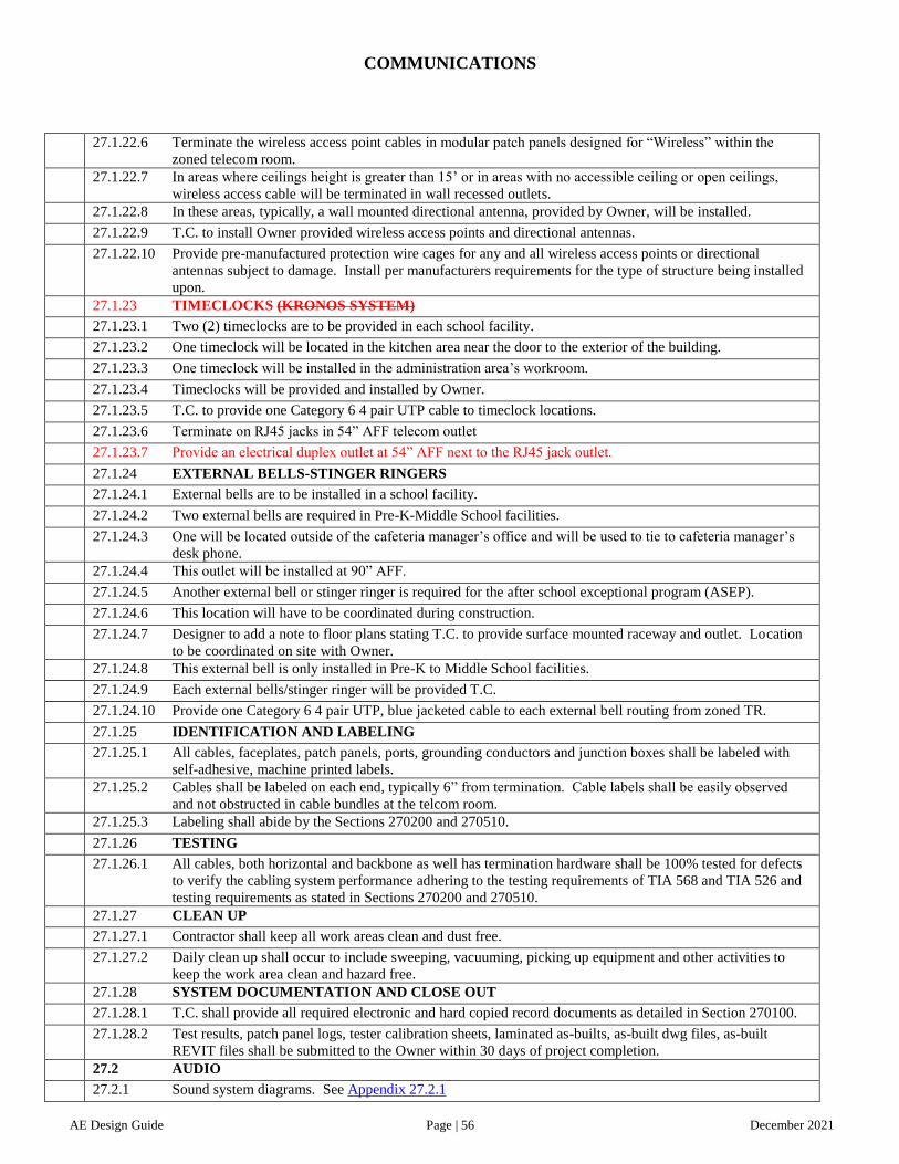
COMMUNICATIONS
AE Design Guide Page | 56 December 2021
27.1.22.6 Terminate the wireless access point cables in modular patch panels designed for “Wireless” within the
zoned telecom room.
27.1.22.7 In areas where ceilings height is greater than 15’ or in areas with no accessible ceiling or open ceilings,
wireless access cable will be terminated in wall recessed outlets.
27.1.22.8 In these areas, typically, a wall mounted directional antenna, provided by Owner, will be installed.
27.1.22.9 T.C. to install Owner provided wireless access points and directional antennas.
27.1.22.10 Provide pre-manufactured protection wire cages for any and all wireless access points or directional
antennas subject to damage. Install per manufacturers requirements for the type of structure being installed
upon.
27.1.23 TIMECLOCKS (KRONOS SYSTEM)
27.1.23.1 Two (2) timeclocks are to be provided in each school facility.
27.1.23.2 One timeclock will be located in the kitchen area near the door to the exterior of the building.
27.1.23.3 One timeclock will be installed in the administration area’s workroom.
27.1.23.4 Timeclocks will be provided and installed by Owner.
27.1.23.5 T.C. to provide one Category 6 4 pair UTP cable to timeclock locations.
27.1.23.6 Terminate on RJ45 jacks in 54” AFF telecom outlet
27.1.23.7 Provide an electrical duplex outlet at 54” AFF next to the RJ45 jack outlet.
27.1.24 EXTERNAL BELLS-STINGER RINGERS
27.1.24.1 External bells are to be installed in a school facility.
27.1.24.2 Two external bells are required in Pre-K-Middle School facilities.
27.1.24.3 One will be located outside of the cafeteria manager’s office and will be used to tie to cafeteria manager’s
desk phone.
27.1.24.4 This outlet will be installed at 90” AFF.
27.1.24.5 Another external bell or stinger ringer is required for the after school exceptional program (ASEP).
27.1.24.6 This location will have to be coordinated during construction.
27.1.24.7 Designer to add a note to floor plans stating T.C. to provide surface mounted raceway and outlet. Location
to be coordinated on site with Owner.
27.1.24.8 This external bell is only installed in Pre-K to Middle School facilities.
27.1.24.9 Each external bells/stinger ringer will be provided T.C.
27.1.24.10 Provide one Category 6 4 pair UTP, blue jacketed cable to each external bell routing from zoned TR.
27.1.25 IDENTIFICATION AND LABELING
27.1.25.1 All cables, faceplates, patch panels, ports, grounding conductors and junction boxes shall be labeled with
self-adhesive, machine printed labels.
27.1.25.2 Cables shall be labeled on each end, typically 6” from termination. Cable labels shall be easily observed
and not obstructed in cable bundles at the telcom room.
27.1.25.3 Labeling shall abide by the Sections 270200 and 270510.
27.1.26 TESTING
27.1.26.1 All cables, both horizontal and backbone as well has termination hardware shall be 100% tested for defects
to verify the cabling system performance adhering to the testing requirements of TIA 568 and TIA 526 and
testing requirements as stated in Sections 270200 and 270510.
27.1.27 CLEAN UP
27.1.27.1 Contractor shall keep all work areas clean and dust free.
27.1.27.2 Daily clean up shall occur to include sweeping, vacuuming, picking up equipment and other activities to
keep the work area clean and hazard free.
27.1.28 SYSTEM DOCUMENTATION AND CLOSE OUT
27.1.28.1 T.C. shall provide all required electronic and hard copied record documents as detailed in Section 270100.
27.1.28.2 Test results, patch panel logs, tester calibration sheets, laminated as-builts, as-built dwg files, as-built
REVIT files shall be submitted to the Owner within 30 days of project completion.
27.2 AUDIO
27.2.1 Sound system diagrams. See Appendix 27.2.1

COMMUNICATIONS
AE Design Guide Page | 57 December 2021
27.3 ASSISTED LISTENING SYSTEM
27.3.1 Assisted listening systems are only required at fixed seating assembly spaces in K-8, middle and high school
gymnasiums and auditoriums.
27.3.2 High school stadiums should be designed with the appropriate infrastructure to support assisted listening
hearing devices.
27.3.3 Replacement school projects shall review the condition of the existing receivers to determine if these
devices can be reused and the new design would only provide the assisted listening system infrastructure.

ELECTRONIC SAFETY AND SECURITY
AE Design Guide Page | 58 December 2021
INTRODUCTION Division 28 represents security systems and the fire alarm of this Standard. It is intended to assist a qualified Electrical Engineer,
Architect and Civil Engineer in their preparation of drawings and specifications for the security system. The Electrical Engineer has
the primary responsibility of designing the systems through collaboration with the Architect, Civil Engineer, and Owner. The
incorporation of CPTED – crime prevention through environmental design principals is a requirement of the overall design outcome.
This information is not intended to serve as a code book or a construction specification. It also does not relieve the Engineers and
Architect of their responsibility for adequate design and coordination, and for compliance with the criteria provided by Charlotte-
Mecklenburg Schools for a specific project.
Division 28 is compiled primarily to describe the security systems for new schools. In schools undergoing expansion and/or
renovation, extent and condition of existing facilities and budget restraints may limit the scope of security system renovations. In such
cases, where feasible, the design shall facilitate the future implementation of the “New School” criteria.
The A&E and construction manager/general contractor shall obtain from the CMS the latest version of the Charlotte-Mecklenburg
Schools Architect and Engineer Design Guide.
28.1 SECURITY SYSTEMS
.
28.1.1 Contact CMS for system requirements, scope and equipment.
28.1.2 All Charlotte-Mecklenburg School facilities are protected by an electronic Burglar Alarm System during
periods of non-occupancy. Each construction project is required to include the equipment, devices and
wiring necessary for the system. See specification 281600 – Intrusion Detection.
28.1.3 CCTV surveillance will be implemented at Charlotte-Mecklenburg High Schools. Contact Project Manager
for complete scope of work concerning CCTV. Camera locations shall be determined on a school by school
basis. In general, cameras shall be provided at main gathering areas on the interior (hallways, cafeterias,
doors of entry, auditoriums, gymnasiums, etc.) and exterior (parking lots, etc.). See “Charlotte-
Mecklenburg Schools Video Surveillance System (VSS) Standard” specification 282300 – IP based video
surveillance system.
28.1.4 Helios system - Provide pathway and back box to support owner provided system at front entry.
28.1.5 Door Access Control See Appendix 28.1.5
28.2 FIRE ALARM SYSTEM
28.2.1 Contact CMS for complete Fire Alarm System scope of work on renovation or addition projects.
28.2.2 Provide heat detectors in custodial spaces greater than 100 sq. ft., in laundry rooms in proximity to the
dryer, kiln and main mechanical rooms.
28.2.3 All fire alarm wiring must be in conduit or utilize MC fire alarm/control cable.
28.2.4 Only provide fire alarm in exterior buildings (remote from the main school building) required by code (such
as field houses). If not required in these exterior buildings, do not provide fire alarm annunciation.
Coordinate with the fire marshal for required fire alarm activation as it relates to zoning with the main
building and how that alerts each zone.
28.2.5 Provide an allowance for first responder Bi Directional amplifier (800 MHz) if directed by CMS.
Determination of installation of system shall be evaluated at the end of the project when tested with first
responder radio systems. Allowance based on $70,000.00.
28.2.6 Provide carbon monoxide detector that is a hard wired type device, connected to the fire alarm system with
supervisory status only.
28.3 VIDEO SURVEILLANCE SYSTEM (VSS) STANDARD
28.3.1 See specification 282300 - IP based video surveillance system, and 282310 - Video surveillance cabling.
Designer shall provide a full camera schedule matrix including cabling, mounting, height, cabling zone and
type on the plans for CMS to review.
28.3.2 PTZ cameras shall not be used for new projects. They shall be evaluated by CMS in existing schools
where they are managed. Fisheye type cameras shall not be used

CIVIL
AE Design Guide Page | 59 December 2021
INTRODUCTION Division 31 and 32 represents the earthwork, exterior improvements, physical education and exterior athletic competition features of
this Standard. It is intended to assist a qualified Civil Engineer and or Landscape Architect in their preparation of drawings and
specifications. The designer of record is to have a thorough knowledge of how K-12 environments operate on a day to day and annual
perspective. Experience in land development design practices are essential of civil engineer and landscape architect. This information
is not intended to serve as a code book or a construction specification. It also does not relieve the Civil Engineer of their
responsibility for adequate design and coordination, and for compliance with the criteria provided by Charlotte-Mecklenburg Schools
for a specific project.
Division 31 and 32 is compiled primarily to describe the earthwork, exterior improvements, physical education and exterior athletic
competition features for new schools. In schools undergoing expansion and/or renovation, extent and condition of existing facilities
and budget restraints may limit the scope of renovations. In such cases, where feasible, the design shall facilitate the future
implementation of the “New School” criteria.
The A&E and construction manager/general contractor shall obtain from the CMS the latest version of the Charlotte-Mecklenburg
Schools Architect and Engineer Design Guide. 31. EARTHWORK
31.1 EXISTING CONDITIONS
31.1.1 Preserve existing landscape and natural vegetation whenever possible, especially trees larger than 6” trunk
diameter measured at 4’ above grade. New projects shall include trees located and identified on the survey
that are 12” diameter or greater, where practical.
31.1.2 Include in the construction documents the removal of trees and underbrush that is poisonous or otherwise
harmful to children or staff.
31.1.3 Identify wetland areas requiring preservation or previous Corp of Engineers determination.
31.1.4 Identify and review with CMS, flood plain and tree save areas during schematic design phase.
31.2 GRADING
31.2.1 The Designer shall develop a cost effective grading plan that provides a balanced site. Topsoil shall be
stockpiled and properly reused as required. The grading plan should consider areas required for future
expansion.
31.2.2 Top of finish grade next to exterior wall shall be a minimum of 8” below finish floor except at building
entrances.
31.2.3 Take care to design and construct appropriate ground slopes in order to eliminate temporary ponding during
heavy rain and prevent runoff from entering the building. Prevent conflicts with storm water requirements.
31.2.4 Avoid steep slope designs (steeper than 3:1) unless approved in advance by the Owner. Provide a low
maintenance non-invasive ground cover for long slope conditions.
31.2.5 The side slopes of ditches or swales shall be no steeper than 3:1. Provide a stabilized mesh at the bottom of
all ditches and swales.
31.2.6 Grassed areas (except for retention/detention pond/banks) shall have a minimum slope of 1% and a
maximum slope of 3:1.
31.3 STORM WATER CONTROL & DRAINAGE
31.3.1 CMS prefers the following methods in this order: wet retention pond, dry detention basin, swales, sand
filter, underground detention basins, rain garden/bio-retention and wet lands. Designer to coordinate with
AHJ. CMS prefers slope at bottom of dry detention for complete drainage.
31.3.2 CMS prefers reinforced concrete pipe for site drainage.
31.3.3 Playground drainage. See Appendix 31.3.3
31.3.4 Use Super Silt Fence when silt fence is the last structural BMP to protect an existing waterway or other
sensitive environmental condition against a sedimentation release.

CIVIL
AE Design Guide Page | 60 December 2021
32. EXTERIOR IMPROVEMENTS
Facility Type
(Classroom #) Bus Spaces
Car Spaces
Staff
Car Spaces
Visitors
Bus Lot Over
Stripe* Student Car Queue Length
ES (45) 18 100 25 100-125 0 1,380 linear feet
Use Current MSTA Calculator to determine length
MS/K8 (54/63) 24 125 25 125-150 0 2,003 linear feet
Use Current MSTA Calculator to determine length
32.1 PARKING AND VEHICULAR CIRCULATION
32.1.1 Refer to the current zoning ordinance for regulations regarding vehicular access to the site.
32.1.2 The safety of students shall be the primary consideration in designing vehicular circulation of the school
site. Vehicle entrances and exits at the school site shall be located such that they facilitate safe access to and
from the school. They should be designed without severe grade changes, blind curves and hills.
32.1.3 Provide striping for 5 lane walking track on bus lot for ES and K8 facilities. Provide indicator for distance
on track.
32.1.4 Provide separate exit/entrance drives for bus parking and drop-off and visitors (cars) loading and drop-off.
Entrance and exit driveways should be located to maximize visibility and with consideration for traffic flow
during school hours.
32.1.5 Visitor parking spaces to be near the main entrance (administration) of the building and closer to the
building than the staff parking.
32.1.6 Parking lots are to be located such that administration suite staff can monitor movement during the day.
32.1.7 Automobile parking is preferred to be 90 degree.
32.1.8 Traffic and pedestrian routes must have safe, logical, and adequate circulation.
32.1.9 Sidewalks should be provided adjacent to all parking lots with curb cuts at each intersection.
32.1.10 Access and parking not open to public view should be provided for cafeteria deliveries and for other service
vehicles.
32.1.11 All parking spaces and drives should be properly lined and have arrows indicating exits and entrances with
stop bars.
32.1.12 Provide maneuvering for large delivery trucks to loading area even when bus parking and visitor/staff
parking areas are occupied. Generally most trucks that frequent the loading area are: Cube truck: 18’-0”
long x 6’-0” wide x 10’-6” high. Warehouse truck: 24’ – 0” long x 7’- 0” wide x 13’ - 0” high.
32.1.13 Driveway turns should be laid out so the turning radius of each will adequately accommodate maximum-
length wheel base buses and fire trucks.
32.1.14 Maximum parking lot slope shall be 5%.
32.1.15 Provide accessible parking spaces near the main entrance and near the main staff entrance in accordance
with the ADA requirements.
32.1.16 Verify with CMS if speed bumps are to be included in the project.
32.1.17 Total closure gates are to be installed at bus lots for hard surface activities and lock down procedures. Gate
post should be spaced more than 32’ apart to allow for mobile classroom installations. See Appendix
32.1.17
32.1.18 Asphalt paving shall be provided for all parking and driveways. Provide heavy duty pavement design for
heavy use areas such as bus loading, and delivery trucks. Loading area and dumpster apron shall be
reinforced concrete. Provide a minimum of 40’ reinforced concrete pavement in front of the dumpster
enclosure. Paving at car parking areas and fire access shall be light duty pavement.
32.1.19 Curbs and accessible ramps shall be concrete. The car drop-off area and bus drop-off area need a
continuous rolled concrete curb; however, note that code compliant curb cuts must also be located. Bollards
and/or structures must be provided to prevent vehicles from driving up on the sidewalk. Roll-edge curbs are
preferred.
32.1.20 Provide wheel stops when there are no curbs and gutter, and when needed to block vehicular traffic.
32.1.21 Provisions are to be made for the installation of basketball goals and court striping at the perimeter of the
bus parking lot. Goals should be in a visible location. Provide at ES, K8 and MS facilities.
32.1.22 Parking/Queue (Stacking) Requirements: Confirm parking and queue totals with CMS staff, quantities are a
minimum goal. Provide car stacking for peak flow during drop-off and pick-up of students per NCDOT.

CIVIL
AE Design Guide Page | 61 December 2021
HS (100125) 40 200 25 250-300
Per zoning
(1 per 5 students)
2,700 linear feet
Use Current MSTA Calculator to determine length
*Provide for planning purposes on the design development and 95% construction documents but do not include on the building permit
submittal.
32.1.23 At student drop-off (or pick-up) from buses, and drop-off (or pick-up) from cars, students shall not cross
parking areas or drives. Avoid students having to cross parking lots or streets to get to the play fields,
which should be as close as possible to the building.
32.1.24 Provide minimum 12’ x 50’ canopy at bus lot per ADA code at elementary schools. Provide minimum 12’
x 50’ canopy at middle and high school bus lots if project budget allows.
32.1.25 An accessible space should be provided parallel to the path of vehicular travel, beyond the front door for
van loading/unloading.
32.1.26 Provide control signage at parking lots.
32.1.27 The parking area should be of sufficient size to accommodate all buses serving the school. Additional
undeveloped space should be considered for future growth.
32.1.28 The bus parking area should be so planned that the movement of buses on the school site will be kept to a
minimum. Bus parking should be established so that backing-up of buses is avoided.
32.1.29 The bus parking area should be located adjacent to playground areas and should be separate from all other
vehicle parking areas.
32.1.30 Preference for one single row of bus parking. If site conditions do not allow, it is acceptable for bus parking
to be stacked nose to tail.
32.1.31 Pupils unloading from the bus door will walk away from the bus toward the school entrance.
32.1.32 Pupils shall not cross any driveway on which other vehicles may be moving, and buses arriving on the lot
will not cut through the line of pupils walking to the school entrance.
32.1.33 Bus Circulation Requirements:
32.1.33.1 Accommodate the 84-passenger capacity buses.
32.1.33.2 Minimum turning radius is 26’ inside; 45’ outside.
32.1.33.3 Bus lot to be minimum 110’ wide, preference for 120’ wide for turn radius and to accommodate overflow
parking.
32.1.33.4 Bus parking space: min. 12’ wide; max. 14’ wide x 35’ long.
32.1.33.5 Maximum parking slope is 2% (the fueling procedure dictates this slope).
32.1.33.6 Maximum driveway slope is 8 degrees.
32.1.33.7 Lot to be well-drained and paved for a vehicle carrying 27,000 pounds.
32.1.33.8 Note on construction documents for existing paving to be re-cycled for on-site re-use.
32.1.33.9 Pavement sealants shall not include coal tar based sealants.

CIVIL
AE Design Guide Page | 62 December 2021
32.2 SIDEWALKS AND PLAZAS
32.2.1 Review safety surveillance during the design of plazas, and parking with CMS. Special attention to be
given to provide adequate visual control to the bus loading/unloading, staff, student parking, and visitor
parking area to prevent potential concealed spaces near these and other drives.
32.2.2 Surfaces to be slip resistant under wet and dry conditions and to slope to drain away from building.
32.2.3 Pedestrian areas at major entrances shall have a minimum pavement width of 15’.
32.2.4 The width of walkways at minor entrances shall be 3’wider than the entrance door(s).
32.2.5 The designated crosswalk zone shall be provided at all pedestrian walks crossing drives and shall meet
ADA requirements.
32.2.6 Sidewalks shall be concrete and 5’ – 6’ wide minimum (widths shall be determined by pedestrian usage).
Maximum sidewalk slope 5%.
32.2.7 Provide appropriate control joints (6’ o.c. max) and expansion joints in sidewalks and plazas to control
cracking. Sidewalks (or concrete pavement) where service vehicles are anticipated should be designed and
reinforced appropriately.
32.2.8 Locate sidewalks where pedestrians are most likely to walk in direct routes. Provide triangular infill at
intersections.
32.2.9 All outside exits must have concrete sidewalk and extend to a public way where required by code.
32.2.10 At walks and paths, provide a minimum cross slope of ¼” per foot, not to exceed ADA requirements.
32.2.11 Plazas shall have a maximum slope of 2% with a uniform surface that prevents puddling/ponding.
32.2.12 Provide accessible route to Flagpole.
32.2.13 When site stairs are required, provide ramp access in the same location.
32.2.14 All trench drain grate slots in court yards, pathways and means of egress shall be 3/8” wide maximum.
32.3 LANDSCAPING
32.3.1 General
32.3.1.1 Provide minimum buffers to comply with local ordinance.
32.3.1.2 Landscape design should preserve and enhance existing resources, improve overall environmental quality,
minimize maintenance requirements and improve the visual quality of the site.
32.3.2 Trees and Shrubs:
32.3.2.1 Select trees from the local municipalities approved list.
32.3.2.2 Landscape plants should be selected to require a minimum of maintenance. Use of native and non-invasive
species is preferred.
32.3.2.3 Do not use invasive plants and do not use poisonous plants or plants with sharp thorns or foliage near
student’s path of travel.
32.3.2.4 Landscaping must be specified to be planted in the fall.
32.3.2.5 Do not specify or locate planting material that will cause security problems, i.e., create hiding places. For
example; shrubs no taller than 3’ and trees limbed below 7’.
32.3.2.6 Do not plant trees or shrubs in locations that will interfere with overhead, underground utilities, site lighting,
or security cameras.
32.3.2.7 Trees and shrubs to be readily available, locally if possible. Trees and shrubs to be native or hardy to the
site area.
32.3.2.8 The mature height and spread of all trees and shrubs to be considered during the design process. Trees and
shrubs are not to be too close together or close to buildings. Avoid the overgrown look when plantings are
mature.
32.3.3 Grass and Ground Cover:
32.3.3.1 Existing stockpiled topsoil or new topsoil must be spread and fine graded prior to installation of grass and
ground cover.
32.3.3.2 Non-mowable and long slopes to be covered with appropriate vegetative ground cover with non-eroding
mesh.
32.3.4 Soil
32.3.4.1 Topsoil shall be free of subsoil, roots, clods, stones, brush, weeds, or other debris and shall not contain any
material toxic to plant growth.
32.3.4.2 New fill dirt and topsoil shall be tested for hazardous material prior to being moved onto site.
32.3.4.3 Areas next to the building and particularly courtyards get compacted by construction activity. These areas
must be ripped and tilled after construction prior to installation of topsoil, landscaping or grassing.

CIVIL
AE Design Guide Page | 63 December 2021
32.3.4.4 Pre-installation of grassing/landscaping: Review soil conditions for (1) amount of rock and stone, and (2)
depth of topsoil and condition of soil. Landscaping shall not void termite warranty.
32.4 FENCING
32.4.1 Fencing around storm water detention basins to be 5’-0” high, with (1) 12’-0” wide access gate for
maintenance.
32.4.2 Fencing around track/football field to be 4’-0’ high and with 10’ wide access gates for emergency vehicles.
The track/football field fence should have (2) remote, 4’-0” gates on each side, for band and cheerleaders,
and (1) 12’-0” gate for equipment access.
32.4.3 Fencing around baseball and softball fields to be 5’-0” high and (2) 4’- 0” with (1) 12’-0” equipment access
gate.
32.4.4 Fencing around tennis courts to be 10’- 0” high with vision screening mesh.
32.4.5 Fencing at discus throw to be 8’- 0” high.
32.4.6 Provide Athletic playfield backstop at softball and baseball fields.
32.4.7 Exterior fencing around HVAC and electrical equipment, i.e., generator, transformer and chiller, etc., to be
enclosed with code and service clearances and gates for service and maintenance.
32.4.8 Fencing used to reduce buffer widths shall meet the requirements of the local zoning department.
32.4.9 Provide steel lockable gates with duckbill latch at each post at bus and staff parking lots, see appendices.
32.4.10 Provide knox padlock and CMS padlock at each vehicle gate.
32.4.11 All gates used as egress routes must have a sign attached stating “THIS GATE MUST BE UNLOCKED
DURING ALL OCCUPIED HOURS”.
32.4.12 Provide decorative fencing outside of PK – 1 classroom egress doors to create a play area and that has a 4’-
0” wide egress gate.
32.5 FLAGPOLE
32.5.1 At Elementary, Middle, K8 and High Schools provide one aluminum flagpole with a maximum height of
30’ at a prominent location near the primary building entrance.
32.5.2 At Middle, K8 and High Schools provide one aluminum flagpole with a maximum height of 30’ at main
athletic field.
32.5.3 Provide solar powered LED lighting device that clamps to the pole at all flag pole locations.
32.6 SPIRIT BOULDER
32.6.1 If a large boulder is found during construction of any facility type, it should be moved to a location
identified near the front entrance for student painting. If no is boulder present, identify location for future
boulder.
32.7 SITE EQUIPMENT
32.7.1 When requested, provide accessible benches and route near the main entrance of the building. Seating is
required in the pedestrian area of the main staff entrance and student courtyards. Bench design should be
compatible with the building design. Benches shall be freestanding and anchored to be immovable.
32.7.2 Provide bike racks per ordinance.
32.7.3 Provide separate Knox Boxes for Fire and Police Departments at main entry and at fire riser (Fire only).
32.7.4 Provide Knox Locks at site access gates.
32.7.5 Provide Knox Cap at FDC.
32.7.6 Playground equipment for replacement schools should match school colors to the extent possible using
standard color options from the playground equipment manufacturer.
32.7.7 Provide concrete pad (12’ x 21’) for each CMS provided Conex storage unit (8’ x 20’) with accessible walk.
Provide fencing, gates, etc., or incorporate units within service yard as directed by CMS. Elementary
schools receive one unit, Middle Schools and K8 receive two units, and High Schools receive three units.
32.7.8 Coordinate mailbox location with CMS and local postmaster serving that facility. Do not mount mailbox on
the building.

CIVIL
AE Design Guide Page | 64 December 2021
32.8 SERVICE AREA – DUMPSTERS
32.8.1 Solid waste is to be collected in dumpsters located in the service area. Provide space for two garbage
dumpsters and one two cardboard recycling dumpsters. Comply with zoning requirements for recycling at
facilities that require more than two dumpsters. Dumpsters are approximately 6’ x 6’ and require
approximately 4’ – 5’ between them.
32.8.2 Provide bollards, see appendices for locations and details.
32.8.3 Dumpster enclosure to be constructed of masonry to match building. See Appendix 32.8.3
32.8.4 Provide exterior access to the loading area in the vicinity of the kitchen, to comply with Health Department
restrictions for trash not being transported through kitchen.
32.8.5 Refer to the Charlotte zoning ordinance for screening requirements and Fencing Guide below. Dumpsters
are to have a lockable gate, or gates, on a rubber roller wheel. Gate construction shall be galvanized or
aluminum with composite decking when required to comply with zoning ordinances. Refer to appendices.
32.8.6 All dumpsters are to be located on reinforced concrete slab. Provide striping on the pavement that reads
“No Parking”.
32.8.7 Provide heavy-duty concrete paving in all truck turn around areas.
32.9 ATHLETIC FIELDS
32.9.1 High School Softball/Baseball Field Standards: Dugouts for softball recommend that distance from foul line
to nearest obstruction shall be 25’ minimum to 30’ maximum. Dugouts for Baseball recommend that the
distance from foul line to nearest obstruction shall be 60’. See Appendix 32.9.1
32.9.2 Provide ADA access to all bleacher seating.
32.9.3 Provide synthetic turf football fields at high schools with cannon type irrigation, all areas within the track to
be synthetic turf other than field event areas outside of the field (“D” zone) to match track material. Size
field area for football and soccer.
32.9.4 All middle school football fields to be natural grass fields with irrigation. All baseball, softball and soccer
fields to be natural grass fields with irrigation.
32.9.5 Athletic field preparation
32.9.6 Softball field/football field/Soccer field/Baseball field preparation and Warning Track mixture
32.9.7 Fertilizer – commercial grade 17 17 17. Apply at 300 lbs/acre or as required by soils analysis
32.9.8 Lime – Dolomite limestone containing not less than 85% total carbonates and shall be ground to such
fineness that 50% will pass through a 100 mesh sieve and 90% will pass through a 20 mesh sieve. Apply at
1.5 tons/acre or as required by soils analysis.
32.9.9 Sand – C-10 sand shall comply with USGA specifications for compaction and percolation. Sand shall be
weed, disease, and insect free. Apply at 300 tons/acre (1.5 inch depth).
32.9.10 Infield and Outfield GRASSING, fertilizing and sub soil PREPARATION.
32.9.11 Obtain soils test in three locations per field from a qualified soil laboratory.
32.9.12 Remove any temporary grassing with herbicide.
32.9.13 Remove all rocks ½ inch diameter and larger and any other debris in top 3 inches of soil by making two
passes over the initial grade in opposite directions with a rock hound or similar machine.
32.9.14 Add soil amendments and lime per soil test.
32.9.15 Apply organic poultry compost at 80 cubic yards/acre.

UTILITIES
AE Design Guide Page | 65 December 2021
INTRODUCTION Division 33 represents coordination of the design with the water, natural gas, electrical power, and future mobile classrooms of this
Standard. It is intended to assist a qualified Civil Engineer in their preparation of drawings and specifications for the overall utility
systems and future mobile classroom coordination. The Civil Engineer has the primary responsibility of designing the systems
through collaboration with the Architect, Owner and various utility companies serving Mecklenburg County. This information is not
intended to serve as a code book or a construction specification. It also does not relieve the Civil Engineer of their responsibility for
adequate design, coordination, and for compliance with the criteria provided by Charlotte-Mecklenburg Schools for a specific project.
Division 33 is compiled primarily to describe the utility systems for new schools. In schools undergoing expansion and/or renovation,
extent and condition of existing facilities and budget restraints may limit the scope of the utility renovations. In such cases, where
feasible, the design shall facilitate the future implementation of the “New School” criteria.
The A&E and construction manager/general contractor shall obtain from the CMS the latest version of the Charlotte-Mecklenburg
Schools Architect and Engineer Design Guide.
33. UTILITIES
33.1 GENERAL
33.1.1 Designer should review site for available utilities and the requirements for each utility prior to the schematic
design submittal.
33.1.2 Separate water tap, meter, back flow preventer per code for domestic water, irrigation, fire protection.
33.1.3 If lift station is required provide a hoist at lift station with a capacity for lifting the pump.
33.1.4 lf plumbing clean out and underground valves in grassy areas shall be installed with white, donut precast
concrete fittings.
33.1.5 All underground piping shall be installed with metallic marking tape above the utility.
33.1.6 Contractor to coordinate with gas utility to provide pulse meter attachment to gas meter. The cost of the
pulse meter is the responsibility of the contractor and coordination with the utility is required. Size of the
pulse meter to be determined by utility based on load information provided by mechanical engineer.
33.1.7 Contractor to coordinate with electric utility to provide pulse meter attachment to electrical transformer.
33.2 SITE LIGHTING: Refer to Electrical
33.3 MOBILE CLASSROOMS
33.3.1 Future mobile classroom locations shall be established and approved during schematic design by CMS. See
mechanical, electrical and plumbing sections for additional requirements.
33.3.2 Provide stub connections in a heavy duty underground vault for a 2” water line, 4” sewer line and two 3”
conduits for fire alarm, intercom and telecommunications.
33.3.3 Architect and Civil Engineer to include on all appropriate site plans, proposed locations of future mobile
classroom units and all associated site utilities required at each unit. Construction documents to be designed
and drawn to account for all coordination required during construction to accommodate the safe, three-
dimensional installation of utilities needed for the permanent school buildings in conjunction with all
temporary buildings on site or proposed to be on site. See Appendix 33.3.3
33.3.4 The typical arrangement is: High Schools one, 10 Classroom Modular Unit or 10 single mobile units and
associated restroom unit; Middle Schools and K8s one, 10 Classroom Modular Unit or 10 Single mobile
units and associated restroom unit and Elementary Schools, 6 Single mobile units and associated restroom
unit.

APPENDICES
1.2 SHEET NAME AND NUMBERING STANDARD ...........................................................................................
6.1.7 MAILROOM CASEWORK .............................................................................................................................
6.1.8 WORKROOM CASEWORK ...........................................................................................................................
6.2.3 ES CLASSROOM CASEWORK .....................................................................................................................
6.2.4 ES CLASSROOM CUBBIES...........................................................................................................................
7.3.5.3 HI-LO ROOF DETAIL..................................................................................................................................
8.1.6 ENTRANCE SYSTEMS ..................................................................................................................................
8.3.12 DOOR ID TAG ...............................................................................................................................................
9.3.2 ES/K8 MULTIPURPOSE ROOM STRIPING .................................................................................................
9.3.3 HS GYM STRIPING ........................................................................................................................................
9.9.1 MS/K8/HS GYM FLOOR ................................................................................................................................
9.9.1 VOLLEYBALL SLEEVE ................................................................................................................................
10.5.2 RESTROOM MOUNTING ............................................................................................................................
10.8.1 SIGNAGE .......................................................................................................................................................
10.8.4 DEDICATION PLAQUE ...............................................................................................................................
11.1.1 ES KITCHEN EQUIPMENT .........................................................................................................................
11.1.2 K8 KITCHEN EQUIPMENT .........................................................................................................................
11.1.3 MS KITCHEN EQUIPMENT ........................................................................................................................
11.1.4 HS KITCHEN EQUIPMENT .........................................................................................................................
22.3.13 LETTER OF DEVIATION...........................................................................................................................

APPENDICES
27.1.11.22 T-001 MDF EQUIPMENT DETAIL.......................................................................................................
27.1.11.22 T-002 MDF LADDER RACK DETAIL ................................................................................................
27.1.11.22 T-011 MDF DATA RACKS ELEVATION ............................................................................................
27.1.11.23 T-003 IDF EQUIPMENT DETAIL .........................................................................................................
27.1.11.23 T-004 IDF LADDER RACK DETAIL....................................................................................................
27.1.11.23 T-012 IDF RACK ELEVATION.............................................................................................................
27.1.21.3 CABLING DESIGN STANDARDS .........................................................................................................
27.1.21.4 T-100 ELEMENTARY CLASSROOM ....................................................................................................
27.1.21.4 T-101 INSTRUCTIONAL COMPUTER LAB .........................................................................................
27.1.21.4 T-101A CTE COMPUTER LAB...............................................................................................................
27.1.21.4 T-102 SCIENCE AND PREP ROOMS .....................................................................................................
27.1.21.4 T-103 OFFICES .........................................................................................................................................
27.1.21.4 T-104A MEDIA CENTER SPACES.........................................................................................................
27.1.21.4 T-104B MEDIA CENTER SPACES .........................................................................................................
27.1.21.4 T-105 ELEMENTARY AND K8 RECEPTION AREAS .........................................................................
27.1.21.4 T-106 KITCHEN DETAIL ........................................................................................................................
27.1.21.4 T-107 MULTIPURPOSE DETAIL ...........................................................................................................
27.1.21.4 MIDDLE AND HIGH SCHOOL CLASSROOM .....................................................................................
28.1.5 DOOR ACCESS CONTROL .........................................................................................................................
31.3.3 PLAYGROUND DRAINAGE .......................................................................................................................

APPENDICES
32.1.17 VEHICLE GATE ..........................................................................................................................................
32.8.3 DUMPSTER ENCLOSURE ...........................................................................................................................
32.9.1 SKINNED INFIELD ......................................................................................................................................
33.3.3 SITE PLUMBING FOR MOBILES ...............................................................................................................

Discipline Sheet Title
Cover Sheet CS
Life Safety LS100 Appendix B
LS200 Egress Plans
LS300 UL Assemblies / Details
Phasing PF100 Phasing/fencing plans and notes
Site Survey SS100 Site Survey
Civil C000 Site Demolition
C100 Erosion Control
C200 Grading
C300 Utility
C400 Details
C500 Road Improvements
Landscaping L000 Landscape Demolition
L100 Landscape Plans
L200 Landscape Schedules
L300 Landscape Details
L400 Irrigation Plans
Architectural A0000 Demolition
A0100 Reference Plan
A0200 Floor Plans
A0300 Reflected Ceiling Plans
A0400 Roof Plan and Details
A0500 Exterior Elevations
A0600 Building Sections
A0700 Vertical Circulation
A0800 Wall Sections
A0900 Details
A1000 Enlarged Plans and Details
A1100 Interior Elevations, Casework and Library Shelving
A1200 Door Schedule and Details
A1300 Finish Schedule
A1400 Finish Plans and Details
A1500 Signage
Food Service FS100 Floor Plan
FS200 Schedules
FS300 Details
Structural S000 Structural Demolition
S100 Legend, Schedule, Notes
S200 Plans
S300 Details
Fire Protection FP100 Floor Plans
FP200 Schedules, Details, Notes
Plumbing P000 Plumbing Demolition
P100 Legend, Schedule, Notes
P200 Site Plan
P300 Floor Plans
P400 Details
Mechanical M000 Mechanical Demolition
M100 Legend, Schedule, Notes
M200 Site Plan
M300 HVAC Plans
M400 Piping Plans
M500 Details
Electrical E000 Electrical Demolition
E100 Legend, Schedule, Notes
E200 Site Plan
E300 Power Plans
E400 Lighting Plans
E500 Special Systems Intercom
E600 Special Systems Fire Alarm
E700 Special Systems Security
E800 Details
Telecommunications T100 Legend, Schedule, Notes
T200 Floor Plans
T300 Details
1.2 Sheet Name and Numbering Standard 6/28/2018
mende.smith
Text Box
1.2 Sheet Name and Numbering Standard

TOILET PAPER
DISPENSERS (NON-
TYPICAL)
RE
F:
MA
NU
F.
DA
TA
19
" M
IN
GENERAL NOTE:
VERIFY DIMENSIONS OF
DISPENSER UNITS FROM
MANUFACTURER DATA
1'-0" 42" MIN
33
" -
35
"250 FT./LB.
MIN.
FORCE IN
ANY
DIRECTION
36" MIN
1' - 0" MIN
33
" -
35
"
GRAB BAR (SIDE) GRAB BAR (REAR)GRAB BAR (VERTICAL)
3'-
4"
1'-
6"
39"-41"
250 FT./LB. MIN.
FORCE IN ANY
DIRECTION
250 FT./LB. MIN.
FORCE IN ANY
DIRECTION
SANITARY NAPKIN
DISPOSAL (WOMENS
AND UNISEX ONLY)
OF
UN
IT
2'-
6"
TO
TO
P
SEAT COVER
DISPENSER
RE
F:
MA
NU
FA
CT
UR
ER
DA
TA
3'-
4"
TO
TO
P O
F D
ISP
EN
SE
R
CMS JUMBO TOILET ROLL
DISPENSER (TYPICAL)1
2"
MIN
48
" M
AX
36" MAX
24" MIN
17
"-1
9"
17
"-1
9"
17
"-1
9"
CMS JUMBO ROLL
MOUNTING (NON-
ACCESSIBLE)
22
"-2
6"
36" MAX
24" MIN.
MAX
1'-0" 42" MIN
19
" -
26
"
250 FT./LB. MIN.
FORCE IN ANY
DIRECTION
36" MIN
1' - 0" MIN
19
" -
26
"
GRAB BAR
(CHILDRENS' SIDE)
GRAB BAR
(CHILDRENS' REAR)
GRAB BAR (CHILDRENS'
VERTICAL)
21
" -
30
"1
'-6
"
34" - 36"
250 FT./LB. MIN.
FORCE IN ANY
DIRECTION
250 FT./LB. MIN.
FORCE IN ANY
DIRECTION
CHILD-HEIGHT TOILET ROLL
(ACCESSIBLE)
14
" M
IN
24" MIN
11
"-1
7"
11
"-1
7"
19
" M
AX
42" MAX
1.5
" M
IN
11
"-1
7"
19
"-2
2"
42" MAX
24" MIN.
CMS JUMBO ROLL
MOUNTING (NON-
ACCESSIBLE, CHILD-HEIGHT)
HIGH SCHOOL/MIDDLE SCHOOL
ELEMENTARY SCHOOL NON-COMPLIANT
SECONDARY DISPENSER SHOWN
IN ADDITION TO REQUIRED UNIT
(DIMENSIONS AS ABOVE).
12
" M
IN
4"MIN
03/11/2021
MOUNTING EXHIBITCHARLOTTE-MECKLENBURG SCHOOLS
mende.smith
Text Box
10.5.2Restroom Mounting

ABCDEFGH
5/8"
1"
1/4"
1"
1/4"
1/2"
1/4"
5/8"
3/8"
5/8"
1/2"
6"
6"
Primary copy
Secondary copy
Braille
First clear acrylicwindow with insertslot (if required)
Second clear acrylicwindow with insertslot (if required)
Door inventorynumber
Typical screwmounting placement
3/8
" 3/8"
3/4"
mende.smith
Text Box
10.8.1Signage

CHARLOTTEMECKLENBURG BOARD OF EDUCATION
"NAME OF CHAIRPERSON" CHAIRPERSON
"NAME OF VICE CHAIRPERSON" VICE CHAIRPERSON
"NAME OF SCHOOL"
"NAME OF SUPERINTENDENT" SUPERINTENDENT
"NAME OF BOARD MEMBER" At Large
"NAME OF BOARD MEMBER" District 1
"NAME OF BOARD MEMBER" District 3
"NAME OF BOARD MEMBER" District 5
"NAME OF BOARD MEMBER" District 2
"NAME OF BOARD MEMBER" District 4
"NAME OF BOARD MEMBER" District 6
20??
"NAME OF ARCHITECTURE FIRM" ARCHITECT
"NAME OF CONSTRUCTION MANAGER" CONSTRUCTION MANAGER
18
"
24"
Cast bronze plaque with 1/4" raisedTimes Roman lettering, dark bronzeleatherette background, single lineborder edge, and concealed studmounting
Use the names of board membersactive at the time of constructioncost approval.
Square edge trim
Concealedmounting hardware
Face of wall
mende.smith
Text Box
10.8.4Dedication Plaque

CHARLOTTE-MECKLENBURG SCHOOLS
CHILD NUTRITION SERVICES
ELEMENTARY SCHOOL KITCHEN EQUIPMENT SPECIFICATIONS
AS OF AUGUST, 2019
ALL FOODSERVICE EQUIPMENT TO BE NSF AND/OR UL
APPROVED WHENEVER APPLICABLE
IF DISCREPANCY EXISTS BETWEEN THE WRITTEN
DESCRIPTION AND MODEL NUMBERS, THE WRITTEN
DESCRIPTION WILL TAKE PRECEDENCE.
ITEM 1 - NOT USED
ITEM 2 SPECIALTY DISPLAY CASE - QUANTITY AS SCHEDULED
A. Low profile, two tier, self-service display case
B. Solid Rear Sliding Access Doors
C. Stainless steel interior, including Shelves
D. Black exterior with flush ends: NO VELCRO
E. Two tiered shelves
F. Air temperature maintained at constant 35- 40 degrees F
G. On-demand PTC condensate evaporator provided for a totally self-contained system.
H. Clearly visible thermometer to indicate air temperature
I. (4) Exposed, lockable 4” casters
J. Provide optional lockable night cover
K. Light below shelves
L. Provide optional LED lighting
M. Electrical: 120V / 15 Amp / 1 Phase
N. Minimum length – 48”, maximum overall height of 46”
Approved Manufacturer: Federal Refrigerated Self-Serve Low Profile Specialty Merchandiser,
LPRSS-4. or pre-approved equal.
Revised 10-29-07, Revised 11-21-08, Revised 5-15-15, Revised 7-25-17, Revised 8-12-19
ITEMS 3-4 - NOT USED

ITEM 5 BOOSTER HEATER – (1) DELETE: with integrated booster provided with
dish machine-8-15-19
Provide compact booster heater having the following features:
A. Castone, glass lined, or silicone bronze tank, 6 gallon capacity.
B. Low-water cut-off, temperature/pressure relief valve, pressure reducing valve,
temperature/pressure gauge, and shock absorber.
C. Standard finish body and base.
D. Electrical characteristics as scheduled.
E. Under-counter mounting kit.
Approved Manufacturer: Hatco Corporation, Model C36, or pre-approved equal.
ITEM 6 NOT USED
ITEM 7 BRAISING PAN GAS – (1) (FUTURE)
Provide hood space and all utilities for future installation
Approved Manufacturer: Cleveland SGL-30T
ITEM 8 NOT USED
ITEM 9 CART, TRAY - QUANTITY AS SCHEDULED
Provide tray and silver cart with the following features to match Items 12,15,17,31,100.
A. Stainless steel construction.
B. One bottom shelf.
C. Tubular frame.
D 5” casters.
E. Modify height to 36" overall for elementary school use.
F. Include optional napkin holders for folded 3 1/2” wide X 5” high napkins
Approved Manufacturers: Colorpoint Model CPM-MTS-MOD, Delfield UTS-1-MOD, Randell
to above specifications.
Revised 8-15-19
ITEM 10: CART, UTILITY, THREE TIER (4)
A. Frame-16 gauge, 1” square tubing
B. 16 gauge reinforced, 18” X 32” stainless steel shelves
C. All stainless steel construction
D. Leg and handle bumpers protect walls and furniture
E. 500 lb. capacity per shelf
F. 5” all swivel casters
G. NSF
Approved manufacturer: Choice Equipment UC20-3321-3, Lakeside 544, Win-Holt SSUC-3-
2133SS.
Revised 07-15-10, Revised 7-25-17

ITEM 11: CASH REGISTER –QUANTITY AS SCHEDULED
PROVIDED BY OWNER
ITEM 12: CASHIER STAND - QUANTITY AS SCHEDULED
Provide modular counter of size and content as shown on plan and detail drawings, having the
following features to match Items 9, 15, 17, 31, 100
A. 36" high basic counter section with seamless molded fiberglass body, flame retardant per
ASTM E162 and flame spread of 25 or less.
B. 14 gauge stainless steel plain top with highlighted finish, turndown on all sides and corners
fully welded, ground, and polished.
C. Solid 10" wide, 14- gauge stainless steel, “V" type tray slide for both sides mounted at 28".
D. 1" diameter 18-gauge stainless steel foot rest shall be secured to the interior walls.
E. 4" diameter ball bearing swivel type casters to be non-marking and with brakes on all
wheels.
F. Provide a 2" diameter ferrule hole with rubber grommet in center top for elec. cords.
G. 18-gauge stainless steel liner
H. Line-up locks on opposing corners.
I. One convenience outlet mounted inside the counter with 115v/15a outlet with 10 amp
breaker.
J. Stainless steel drawer, lockable.
K. A 10" wide fold-down stainless steel shelf is to be mounted at 28” to back of cashiers
stand to hold keypad provided by others. Delete shelf if cashier stand is not free-standing.
L. Provide a 2" diameter ferrule hole with rubber grommet in back of stand with conduit to
feed electrical cords from keypad to convenience outlet located inside of stand.
M. Color: Black
Approved Manufacturers: Colorpoint, Model 36-CSE-F, Delfield KCS-36, or Randell modified
to above specifications, or pre-approved equal.
Revised 8-15-19
ITEMS 13 CART, UTILITY, TWO TIER (4)
A. Frame-16-gauge, 1” square tubing
B. 16 gauge reinforced, 21” X 33” stainless steel shelves
C. All stainless steel construction
D. Leg and handle bumpers
E. 500 lb. Capacity per shelf
F. Two shelves.
G. 5” all swivel casters
Approved manufacturer: Choice Equipment UC20-3321-2, Lakeside 543, Win-Holt UC-2-
2133SS
Revised 10-15-07, Revised 07-15-10
ITEM 14 NOT USED

ITEM 15 COUNTER, PLAIN TOP QUANTITY AS SCHEDULED
Provide modular serving counter of size and content as shown on plan drawings, having the
following features to match Items 9, 12,17, 30, 31, and 100
A. 36" high basic counter section with seamless molded fiberglass body, flame retardant per
ASTM E162 and flame spread of 25 or less.
B. Body lined with 18-gauge stainless steel.
C. Open base in rear of cabinet.
D. 30" wide 14-gauge stainless steel top with highlighted finish.
E. Solid 10" wide, 14- gauge stainless steel, "V" type tray slide, mounted 28" AFF.
F. Fold down cutting board on server side, to facilitate restocking
G. 4" ball bearing swivel type casters to be non-marking, with brakes on all wheels. Casters to
be mounted with interior and exterior bracing for maximum stress relief.
H. Line-up locks to be barrel bolt and key slot design with cam locking action placed on opposing
corners.
I. Install in banked line-up as shown on drawings.
J. Color: Black.
Approved Manufacturers: Colorpoint Model 60-ST-F, Delfield KC-60-NU, or Randell modified
to above specifications, or pre-approved equal.
Revised 8-15-19
ITEM 16 NOT USED
ITEM 17 COUNTER, HOT SERVING - QUANTITY AS SCHEDULED
Provide modular serving counter of size and content as shown on plan drawings, having the
following Features to match items 9, 12, 15, 31, 100
A. 36" high basic counter section with seamless molded fiberglass body, flame retardant per
ASTM E162 and flame spread of 25 or less.
B. Body lined with 18-gauge stainless steel.
C. Base to have under-storage with shelf and fiberglass door panels with locks.
D. 30" wide 14-gauge stainless steel top with square turndown on all sides and corners fully
welded, ground and polished.
E. Recessed top accept 18" X 26" sheet pans.
F. Five individually controlled dry/moist wells, with solid state digital controls wired to circuit
breaker for current overload protection.
G. Control panel to be hinged for service access.
H. Hot food drains for each food well shall be plumbed to common manifold and extended to
shut off valve under holding wells. Provide 4’ flexible hose to drain.
I. Solid 10" wide, 14-gauge stainless steel, "V" type tray slide, mounted at 34”.
J. 5" ball bearing swivel type casters to be non-marking, with brakes on all wheels. Casters to
be mounted with interior and exterior bracing for maximum stress relief.
K. 10” shelf on server side, fold down, and 14-gauge stainless steel.

L. Single tier tempered glass over shelf with front tempered glass shield that is adjustable to
allow attendant or self-service. Full sloped front protector to prevent customers from
touching food. Ends top, and front to be 3/8" tempered glass. Versa-Gard VG 6S,
Flexishield or approved equal.
M. Line-up locks to be barrel bolt and key slot design with cam locking action placed on
opposing corners.
N. Replacement Panels (5 ea.)
O. All equipment to be built in accordance with Underwriters Laboratories, Inc. and bear the
UL complete Unit listing label, no component parts listed equipment will be accepted, and
shall also bear the UL listing seal for safety and certification label for sanitation.
P. ELECTRICAL: 208 Volt / 1 phase /Max 2500 Watts
Plug to be 120V-250V / 50 AMP / Twist Lock/ 4 wire/ Male.
Q. Curved Infrared heat strip with LED lights built into the heat strip housing and wired to
separate infinite control with on/off switch, and fused as required. Hatco Glo-Ray Model
GR5AL- or preapproved equal. Black in color.
R. Color: Black
Approved Manufacturers: Colorpoint, Model EF5-CPA-F, Delfield KH-5-NU, or Randell
modified to above specifications, or pre-approved equal
Revised 6-1-06, Revised 11-25-08, 7-25-17, 12/19/18, Revised 8-15-19
ITEM 18 COUNTER, SOLID TOP, FROST TOP – NOT USED
Revised 10-29-07
ITEM 19 TRASH COUNTER- NOT USED
Revised 7-15-06
ITEM 20 - NOT USED
ITEM 21 CUTTER, FOOD, NOT USED
Revised 10-29-07
ITEM 22 NOT USED
ITEM 23 TRAY DOLLY – QUANTITY (6)
A. 16 gauge, 304 stainless steel construction
B. 800 pound rolling capacity
C. Holds 2 stacks of 12” X 16” cafeteria trays
D. 1 ¼” lip to securely hold trays
E. 5” all swivel casters
F. Lifetime guarantee against rust or corrosion
Approved Manufacturers: Choice Equipment UC200-1625, Lakeside, Win-Holt D1625/SS,
Revised 10-29-07, 07-15-10, 10-05-15, 7-25-17

ITEM 24 TROUGH, FLOOR, STAINLESS STEEL - QUANTITY AS SCHEDULED
Provide floor trough with removable grate having the following features:
Grate:
A. All Stainless steel welded construction.
B. 3/16" x 1" flat bars set on edge, with 13/16" clearance between bars.
C. Two 1/2" diameter rods wedged through bars full length, and weld to each bar.
D. Size to suit trough with removable sections not to exceed 20" long.
Trough:
E. 14 gauge 304 18-8 stainless steel, all welded with coved corners and anchor straps, full
perimeter flange for installation under grout.
F. Pitch to waste and provide stainless steel cup with removable perforated stainless
steel basket.
G. Overall trough size is to be approximately l'-6" wide ~x 2'-0" long.
H. See plan for clarification. Coordinate with General Contractor and Plumbing
Contractor to assure proper installation.
Approved Manufacturers: IMC/Teddy Food Service Corp. Model FT-SG, Serv-o-Lift, Eastern,
or pre-approved equal.
ITEM 25 NOT USED
ITEM 26 DISH MACHINE
Provide gas powered machine with following features:
A. 44” machine
B. Convertible for low temperature or hot water final rinse
C. #16-gauge stainless steel tank and chamber. Provide oversized wash chamber option
to accommodate sheet pans in upright position
D. 2 HP machine power wash motor with stainless steel pump and impeller
E. Self-draining pumps
F. 15 KW electric immersion heater, inter-wired at factory. Heater is to have solid state
thermostat with positive low water protection.
G. Top mounted dial thermometers mounted in stainless steel enclosure.
Motor controls wired to common electrical point in stainless steel control center
mounted on top of machine. Motors to have built-in thermister overload protection
with manual reset.
H. Dual side pawl conveyor driven by 1/6 HP motor.
I. Minimum capacity of 203 racks per hour
J. Ball detent clutch system to prevent damage to conveyor and drive motor if rack
should be obstructed.

K. Stainless steel upper and lower wash arms with anti-clog nozzles. Both wash arms to
be removable for cleaning without use of tools.
L. Final rinse automatically activated by racks in passing. Rinse agent dispenser injector
and electrical interface points. Final rinse rate to be 5.0GPM.
M. Automatic fill with tank water level automatically maintained. Fill to be interrupted
if door is opened. Drain handle to be located inside tank chamber and to be closed
automatically upon lowering of inspection door.
N. Stainless steel front panel, frame, feet and legs.
O. Energy saver auto timer
P. Removable self-flushing stainless steel strainer pans and large deep stainless steel
basket removable from front of machine.
Q. Door safety interlocks on all doors
R. Pump intake screen assembly
S. Built in integral wiring channel
T. Vent fan control
U. Stainless steel splash shields
V. Plastic strip curtains throughout
W. Conveyor dwell switch
X. Table limit switch
Y. 2 vent cowls with locking dampers
Z. 4 peg, 2 combinations and 2 bun pan dish racks included
AA. Machine to have integrated booster heater with 70° temperature rise
BB. Machine to have as standard a full two-year warranty against manufacturer’s defects
on parts, labor, and mileage. Extended 3-year warranty is to be provided making 5 years
total coverage
CC. Energy Star Certified
Approved Manufacturers: Hobart Model CL44E, Champion 44 PRO, Insinger Admiral 44
Revised 5-10-04, Revised 10-29-07, Revised 11-25-08, Revised 07-15-10, 7-25-17, Revised
8-15-19
ITEM 27 NOT USED
ITEM 28 DISPENSER, ICE (1)
Provide ice dispenser with following features:
A. Stainless steel exterior cabinet with merchandiser and “Ice” sign.
B. Push lever ice-dispense.
C. 45 pound ice storage capacity.
D. Electrical 120V/ 60HZ/ 2.5FLA.
E. Two ¾” PVC drain fittings, one from drain pan and one from bin.
F. Dispenses any size cube ice up to one- inch square.
G. Motor, drain and electrical connections are front-serviceable.
Approved Manufacturers: SerVend Model M45, or pre-approved equal.

ITEM 29 QUANTITY (2)
A. Horizontal ice cream freezer with glass angled lid
B. Internal LED lighting
C Lid lock with keys
D. 1 ½” dual swivel casters
E. Power indicator light
G. Slide-out, easy access condensing unit
H. Maintain Temperature -18 to +10 degrees
J. Three baskets with dividers
K. External mounted thermometer
L. 115V/60/1 with 9’cord and plug attached
Approved Manufacturer: NorLake CTB-43-9, Masterbilt MSC-31N or pre-approved equal
Revised 6-1-06, Revised 10-29-07, Revised 07-15-10, 77-25-17, Revised 8-15-19
ITEM 30 DISPENSER, MILK (MUST BE OPEN FRONT) ELEMENTARY
SCHOOLS - QUANTITY AS SCHEDULED
Provide mobile carton milk cabinet having the following features:
A. Stainless steel interior and exterior
B. Top mounted Removable refrigeration system
C. Forced air refrigeration system
D. Sliding lift up and down door(s)
E. Reinforced cabinet interior bottom. Capacity to hold (12) standard milk cases.
F. Floor drain with plug
G. 6” casters
H. 3 year parts and labor warranty, 5-year compressor parts warranty
I. Magnetic snap-in EZ clean door gaskets
Approved Manufacture: Traulsen RMC49DR, or pre-approved equal
ITEM 31 - COUNTER, SOLID TOP, FOR CONDIMENTS AND ACCESSORIES (1)
Provide modular serving counter to match items 9, 12, 15, 17, and 100, with the following
features:
A. 30” high basic counter section with seamless molded fiberglass body, flame retardant
per ASTM E162 and flame spread of 25 or less. (total counter height to be 30”)
B. Total length of unit to be 60”
C. Body lined with 18-gauge stainless steel.
D. Base to have under-storage with shelf and fiberglass door panels with locks
E. 30’wide, 14-gauge stainless steel top with highlighted finish
F. Solid 10” wide, 14-gauge stainless steel, “V” type tray slides on both sides, mounted
28” AFF.
G. 6” diameter ball bearing swivel type casters to be non-marking and with brakes on all
wheels. Casters to be mounted with interior and exterior bracing for maximum stress
relief.
H. Color: Black
Approved Manufacturer: Colorpoint or Delfield, Randell modified to meet specifications.

ITEM 32 DISPOSAL, FOOD PREP & POTSINK AREA
Delete from specifications: Revised 07-15-10
ITEM 33 DUNNAGE RACK - QUANTITY AS SCHEDULED
Provide single deck dunnage platform unit with the following features:
A. One-piece rust and corrosion proof polymer construction.
B. Slotted deck.
C. Racks join together end to end or back to back with bow tie feature
D. Heavy duty construction – each rack holds up to 1500 pounds
E. Arrange as shown on Plan drawings, using quantities and sizes as specified.
Approved Manufacturers: Cambro, Metro, Eagle, Amco
Revised 07-15-10
ITEM 34 DISPOSAL, DISHWASH AREA (1)
A. Voltage characteristics as scheduled.
B. 18" diameter stainless steel cone for welding to drain-board.
C. Auto-reversing control center including, magnetic starter(s) and start/stop buttons, in
stainless steel NEMA 4 enclosure, or better, with disconnect switch.
D. Thermal overload protection either built into motor or in control center with manual reset.
E. Solenoid and vacuum breaker.
F. Control center to be mounted out of splash zone, under drainboard on stainless steel
mounting bracket as shown on details.
G. Short neck as necessary to provide clearance under disposal.
H. Coordinate installation of pre-rinse unit (item #65)
I. Low water pressure cutoff, with time delay for water after cut off occurs
J. Permanently lubricated ball bearings
K. Tubular stainless steel legs with bullet feet adjustable to 3 inches in either direction
L. Rubber isolating ring at cone mounting to reduce vibration and noise
M. Air cooled motor.
Approved Manufacturers: Bus Boy Model 3000, Hobart, Insinkerator
Revised 7-20-06, Revised 10-12-07
ITEM 35-36 NOT USED
ITEM 37 EXHAUST HOOD - (1)
Refer to the most current version of the Division 15 Mechanical & Plumbing Design Guidelines,
sections 4.01, A, B, and C.

ITEM 38 FAN, AIR CURTAIN- (1)
Provide air curtain fan having the following features:
A. #304 stainless steel exterior with adjustable deflectors and adjustable air
intake.
B. Electrical characteristics as scheduled.
C. Micro-switch for automatic door-actuated on-off control.
D. 5-year parts warranty.
Approved Manufacturers: Berner model ASR1036A-SS, Mars Door Company, Model48CH,
Universal Jet Industries
Revised 07-15-10
ITEM 39 EQUIPMENT STAND (for item 87, if required)
Approved Manufacturer: Hobart Model, 205025, or pre-approved equal
ITEM 40 FIRE SUPPRESSION SYSTEM – (1)
Provide automatic wet chemical fire control system as required to protect exhaust hood, Item
37, and the cooking equipment located under this hood, and having the following features:
A. All tanks, control heads, piping, relays, cable, fusible links, nozzles, elbows, etc., as
required for complete system.
B. Brass nozzles and chrome plated or sleeved exposed piping.
C. Manual strike mechanism in accessible location.
D. Installation in accord with N.F.P.A. 17A code requirements and coordinate with
exhaust hood construction and installation.
E. Four contacts for use by E.C., one contact for alarm, one for supply fan shut-Off, one
for shunt trip actuation, and one spare.
F. Provide mechanical gas solenoid valve loose for installation by plumber.
Approved Manufacturers: Ansul Model R-102, Range Guard, Pyro-chem.
ITEMS 41-45 - NOT USED
ITEM 46 HOSE REEL - QUANTITY AS SCHEDULED (2)
Provide open type retractable all-in-one hose reel system having the following features:
A. B-1434 reel, open, stainless steel.
B. Continuous pressure type vacuum breaker, B-963.
C. Shut off control, ORK3.
D. MV-0522 spray gun.
E. B-1 31 base faucet.
F. 50 feet of heavy duty hose.
G. All chrome interconnecting piping.
H. Mount on wall at location shown on drawings.

Approved Manufacturers: T&S, or pre-approved equal.
ITEM 47, 48 NOT USED
ITEM 49 ICE MACHINE – (1)
Provide cube ice maker and bin having the following features:
ICE MAKER:ARI certified ice production based on 70º F incoming water and 90º F air
A. ARI Harvest rate minimum of 350 pounds
B. Self-contained, air cooled.
C. Electrical characteristics as scheduled.
D. IFQ-1filtration system to include pressure gauge, mounting brackets and water cut off, or
like capacity to meet manufacturer’s specification. Must meet all accessories.
E Manufacturer's standard finishes.
F. Arrange to make dice cube ice.
BIN:
G. Bin to have minimum 270 pound storage capacity
H. Manufacturer's standard finishes.
I. 6" stainless steel legs.
J. ARI certified and rated in accordance with ARI Standard 820-88
K. NSF listed, UL approved
L. ENERGY STAR CERTIFIED
Mount icemaker on bin and install at location shown on drawings.
Approved Manufacturers: Hoshizaki KML 350MAH, Ice-o-Matic ICE-0400, Manitowoc,
Revised 1-02-07, Revised 11-05-08, Revised 5-15-15, Revised 8-16-19
ITEM 50- INGREDIENT BIN DELETE FROM SPECS 5-15-15
ITEMS 51-54 NOT USED
ITEM 55 MIXER, 20 QUART- NOT USED
Revised 10-29-07
ITEM 56-A MIXER, 30 QUART (1)
MIXER AND ACCESSORIES:
1. # 12 attachment hub
2. Removable s/s bowl guard
3. Direct gear driven transmission. ¾ HP motor by manufacturer.
4. Three fixed speeds plus stir speed.
5. Ability to shift gears while machine is operating. Automated soft transition into higher speed
to avoid product splashing out of bowl
6. 15-minute timer
7. Automatic time recall remembers last time set for each speed
8. Ergonomic swing out bowl
9. 115/60/1 voltage, with 6-foot cord and plug.
10. 2 year parts, labor and mileage warranty against manufacturer’s defects.

11. NSF and UL approved
12. Factory trained service technicians available for service.
13. Powder coat paint
14. Rubber foot pads
15. The motor shall have grease packed ball bearings, ventilation, and splash proof enclosure .
16. Manufacturer provided accessories (no replacement brands): s/s bowl, bowl truck-wire
whip, flat beater, dough hook and ingredient chute.
Approved Manufacturer: Hobart HL-300, Globe SP-30, or pre-approved equal
Revised 10-12-07, Revised 11-20-08, Revised 5-15-15, Revised 8-16-19
ITEM 56-B MIXER, 30 QUART DELETE FROM SPECS- 5-15-15
ITEMS 57-63 - NOT USED
ITEM 64 OVEN, CONVECTION, DOUBLE, GAS – (2 SETS)
OVEN, CONVECTION, DOUBLE, NATURAL GAS
Provide with following features:
2 sections, standard depth
_ Stainless steel front, top, and sides. Full metal rear cover
_ Solid stainless steel doors
_ Single porcelain door handle with simultaneous door operation
_ Triple-mounted pressure lock door design with turnbuckle assembly
_ Modular slide out front control panel for easy access & cleaning
_ Fully insulated at top, back, sides and bottom
_ Porcelain baking compartment liner (14 gauge)
_ Five chrome-plated racks, eleven rack positions
_ Two commercial bake oven lamps per compartment
_ Dual Flow Gas system
_ Electronic spark ignition
_ Pressure regulator
_ Manual gas service cut-off switch located on the front of the control panel
_ Air mixers with adjustable air shutters
_ Gas manifold for stacking
_ 48” gas hose with quick disconnect
_ Solid state thermostat with infinite temperature control range of 200°F to 500°F
_ Two speed fan motor
_ 1/3 horsepower blower motor with automatic thermal overload protection
_ Cook/Cool mode selector
_ Control area cooling fan
_ Solid state manual control with separate dials to control thermostat and timer
_ 60-minute timer
_ 6" adjustable stainless steel legs
_ Wired 120 volt with plug and cord attached
_ Two-year oven parts and one-year labor warranty
_ Five-year oven door warranty

_ Replacement parts guaranteed available for 12 years from purchase date
_ NSF, UL or ETL approved
-- ENERGY STAR CERTIFIED.
Approved Manufacturers: Blodgett DFG-100-ES, Hobart HGC5 Series, Vulcan SG44 Series
Revised 07-15-10, Revised 12-1-11, Revised 5-15-15, 7-25-17, Revised 8-15-19
ITEM 65 PRE-RINSE UNIT –DECK MOUNTED- (1) INSTALL OVER DISHROOM
DISPOSAL
Provide deck mounted pre-rinse unit having the following features:
A. Flexible stainless steel hose.
B. Self-closing spray nozzle.
C. Wall support bracket.
D. Mixing valve with integral check valves.
E. Sink to have Stainless Steel guard over sink to allow ease of sliding dish racks into dish
machine
Approved Manufacturers: T&S Brass and Bronze Works Model B-113, Chicago Faucet, or
pre-approved equal.
ITEM 66 PRE-RINSE UNIT - INSTALL OVER PREP SINKS AND POTWASHING
DISPOSALS
Delete from specs- Revised 07-15-10
ITEMS 67-68 NOT USED
ITEM 69 RACK, MOBILE POT AND PAN (2)
Provide four-tier polymer shelving unit complete with tubular uprights and having the following
features:
A. Uprights shall be nominal 74" high, numbered at one inch intervals.
B. Shelf connectors to be wedge lock type with corner collar.
C. Each unit to be free standing.
D. Shelf frames shall be made of steel with electroplated substrate and epoxy finish. Shelf mats
to be injection molded polypropylene.
E. Arrange using quantities and sizes as shown on plan drawings.
F. 800 pound per shelf capacity, minimum.
Approved Manufacturer: Metro Max Q Series Q556EG2, Eagle to match specifications, or pre-
approved equal.
Revised 10-12-07, Revised 8-15-19
ITEM 70 RACK, BUN PANS (6)
Provide all-welded aluminum pan rack having the following features:
A. End loading.
B. Designed for 18” X 26” sheet pans and trays
C. 3” Spacing between shelves

B. 350 lb capacity
C. 5 " diameter swivel casters, with brakes.
E. Lifetime guarantee against rust
Preferred Manufacturer: Choice Equipment PRIO-A-1820, Lakeside 8900, Win-Holt AL-
1820/HD
Revised 10-12-07, Revised 7-15-10, Revised 7-25-17
ITEM 71 NOT USED
ITEM 72 WALK-IN REFRIGERATOR/FREEZER – (1)
Provide pre-fabricated cold storage room assembly of size and shape shown on plan and detail
drawings. Exact overall size to be field verified prior to fabrication.
A. Insulation: Panels shall be insulated with 4" thick injected urethane, expanded with R1416,
no CFC's used. Foam shall be 2.25 lb. density, 95% closed cell. Panels shall meet
ASTME-84 (UL-723) and be listed by Underwriters laboratories and by Factory Mutual as
a Class I building material.
B. Coved corners: Assembly shall be constructed so that all interior wall, floor and ceiling
intersections shall comply with N.S.F. requirements.
C. Cam lock fasteners: All panel intersections and wall, floor and ceiling intersections shall
be secured by cam lock fasteners.
D. Ceiling panels to be one piece, self-supporting and span full width of assembly.
E. Finishes: Aluminum exterior and interior finishes shall be as shown on drawings.
F. Doors: Door size and finish shall be as shown on drawings, and shall be furnished complete
with sill wiper gasket, lift type hinges.
G. Hinges, latches and hardware shall be chrome plated. Minimum (3) hinges.
H. Exterior door to be equipped with automatic door closer.
I. Freezer door to be equipped with perimeter heat.
J. Exterior door(s) to be equipped with cylinder lock having inside safety release feature and
also configured to allow use of padlock to secure door.
K. Aluminum kick plate to be provided on door.
L. Thermometers: Each compartment to be provided with exterior flush mounted dial
thermometer mounted at eye level to each door.
M. Lights: Each compartment to be furnished complete with manufacturer's standard light
fixture, having protective cover, mounted and pre-wired to switch with pilot light in door
section. Extra lights as needed to provide 30 foot candles 30" above floor.
N. Floor: Quarry Tile
O. The floor and ceiling shall have maximum length panels to span full length of box if
possible, otherwise stagger joints so there are no common "four corner" intersections and
no joints occurring in doorways.
P. Refrigeration System: Shall be furnished by manufacturer as part of cold storage room
assembly, provide each compartment with complete refrigeration system sized to maintain
appropriate temperature.
Q. Condensing units to be semi-hermetic, or scroll type, air-cooled, remote. Units to have
performance and wiring characteristics as scheduled on drawings. Units shall have pre-
wired disconnects. Refrigeration systems to be designed for use with R404A or R507
refrigerant only.

R. Condensing units to be provided with painted galvanized steel all-weather housing,
controls, and crankcase heaters, all suitable for outdoor conditions, and located as shown
on drawings.
S. Unit coolers to be low-silhouette type, mounted at locations shown on drawings.
Performance and wiring characteristics to be as scheduled on drawings. Freezer system to
be provided with timed electric defrost.
T. Evaporator drain lines to be provided by this section and extended to floor receptors outside
assembly.
U. Freezer drain lines to be wrapped with heater cable.
V. Refrigerant piping to be ACR copper tubing, hard temper, with wrought fittings and silver
solder joints. Insulate suction lines with 3/4" pre-molded foamed plastic insulation.
W. Ensure bracing of refrigeration line every 7 feet.
X. If bracing is overhead, 12”saddles are required at support
Y. All insulated portions of refrigerant line to be equal or greater than R-7.1
Z. Refrigeration systems to be provided with all required refrigerant piping, insulation,
vibration eliminator, solenoid(s), dryer, suction line filter, expansion valve(s),
thermostat(s), heat exchangers, and defrost timers, etc. as necessary for complete
installation. Provide pump down control circuit consisting of thermostat and solenoid
valve. All components including piping and insulation to be installed using accepted
industry standards, manufacturer’s instructions and first class workmanship.
AA. Miscellaneous: Provide 1/8" diamond tread wainscot along exposed front exterior of
assembly mounted from floor to 48" A.F.F.
BB. Provide trim strips, closure panels, etc., as necessary to trim assembly to adjacent
building surfaces.
CC Provide removable top closure panels with “C” channel rails. Lift-out panel sections
to have turndown edges for strength and are not to exceed 4’-0” in length.
DD Provide plastic strip curtains at door locations, transparent vinyl overlapping strips,
aluminum Bar hanging rod and bracket, suitable for low temperature applications, as
manufactured by Curtron Flexstrip Products, Inc. or equal.
EE Provide heated pressure relief port in freezer.
FF Provide sleeves properly located for utility entrance, drain lines, and refrigeration
lines, and after lines are installed, fill sleeves with spray foam compound, suitable for
use in refrigerated spaces. Seal all penetrations with fire foam, as required by
Mecklenburg County Code Enforcement, and fire caulk over fire foam
GG. Cold storage room shall be erected by factory trained and certified installers or shall
be supervised by factory personnel. Refrigeration systems shall be furnished by cold
storage room manufacturer and installed by factory authorized personnel.
ENERGY STAR CERTIFIED
Lights:
Each compartment to be furnished complete with Kason model 1806 LED light fixture, having
protective cover, mounted and pre-wired to switch with pilot light in door section.
a. Unbreakable lexan jar.
b. Rated 50,000 hr. life.
c. Exceeds Federal Energy Act requirement at 85 lumens/watt.
d. Lamps to be cULus listed, NSF listed and RoHS compliant.

e. Reach full light immediately at lowest temperatures.
f. 5-yr. limited warranty on fixture.
g. 3-yr. limited warranty on lamps.
h. Extra Kason model 1810 4-ft. LED lights as needed to provide 30 foot
candles 30" above floor.
i. Unbreakable IP-65 polycarbonate enclosure.
j. Exceeds Federal Energy Act requirement at 67 lumens/watt.
k. Rated 50,000 hr. life.
l. 5-yr. limited warranty on fixture.
m. 3-yr. limited warranty on lamps.
n. Reach full light immediately at lowest temperatures.
o. Lamps to be cULus listed, NSF listed and RoHS compliant.
This specification does not constitute a complete description of cold storage assembly, also see
plan and detail drawings.
Approved Manufacturers: Bally, Kolpak, Norlake, ThermoKool
Revised 10-29-07, Revised 12-1-11, 7-25-17, 12-18-18, Revised 8-15-19
ITEMS 73-75 - NOT USED
ITEM 76 REFRIGERATOR, REACH-IN – (1)
Provide two-section reach-in refrigerator with top mounted air-cooled condensing unit, exterior
thermometer, cylinder door locks and top mounted condensate evaporator, having the following
features:
NOTE: Items 76, 77 and 103 must be provided by same manufacturer.
A. Full length stainless steel doors, hinged as shown on drawings.
B. Stainless steel exterior
C. Stainless steel or aluminum door liners
D. Stainless steel or aluminum interior. NO PLASTIC
E. 6 stainless steel shelves in each compartment
F. Set of 5” swivel type locking casters.
G. Wired for 120/1 operation, cord and plug set.
H. ENERGY STAR CERTIFIED
Approved Manufacturers: Traulsen RHT132WUT, Victory RS/RSA-2D-S1-HS/HG, Delfield to
above specs.
Revised 11-20-08, Revised 07-15-10, Revised 5-15-15, Revised 7-25-17, 8-15-19
ITEM 77 REFRIGERATOR, PASS-THRU – (1)
Provide two-section pass-thru refrigerator with top mounted air-cooled condensing unit, exterior
dial thermometer, cylinder door locks and top mounted condensate evaporator, having the
following features.
NOTE: Items 76, 77 and 103 must be provided by the same manufacturer.
A. Full length stainless steel doors, hinged as shown on drawings.
B. Stainless steel exterior

C. Stainless steel or aluminum door liners
D. Stainless steel or aluminum interior-NO PLASTIC
E. Removable, universal type stainless steel pan slides, both sections. Enough for 20 sheet
pans total
F. Set of adjustable stainless steel legs
G. Stainless steel banking strip.
H. Stainless steel trim strip to seal cabinet to all adjacent building surfaces.
I. Wired for 120/1 operation.
J. Install cabinet so that controls face kitchen area.
K. Energy Star Certified
Approved Manufacturers: Traulsen RHT232WPUT, Victory RS/RSA-2D-S1-PT-HS, Delfield
GARPTP-2,
Revised 11-20-08, Revised 07-15-10, Revised 5-15-15, Revised 7-25-17, Revised 8-15-19
ITEMS 78 NOT USED
ITEM 79 SHELVING, REFRIGERATION - QUANTITY AS SCHEDULED
Provide four-tier polymer shelving unit complete with tubular uprights and having the following
features:
A. Uprights shall be nominal 74" high, numbered at one inch intervals.
B. Shelf connectors to be wedge lock type with corner collar.
C. Each unit to be free standing.
D. Shelf frames shall be made of steel with electroplated substrate and epoxy finish. Shelf
mats to be injection molded polypropylene.
E. Arrange using quantities and sizes as shown on plan drawings.
F. 800 pound per shelf capacity, minimum.
Approved Manufacturers: Metro-Max Q Series, Eagle Lifstor, Amco Plastic Plus
ITEM 80 SHELVING, DRY STORAGE - QUANTITY AS SCHEDULED
Provide five-tier bright zinc plated wire shelving unit complete with tubular uprights and having
the following features:
A. Electro-zinc plated with chromate bath and clear protective coating.
B. Uprights shall be nominal 86" high.
C. Adjustable stainless steel feet.
D. Each unit to be free standing.
E. Arrange using quantities and sizes as shown on Plan Drawings.
Approved Manufacturers: Metro, Eagle, Amco
Revised 8-15-19
ITEM 81 NOT USED
This item to be custom fabricated in accord with General Requirements of specifications and
with plan and detail drawings.
Approved Manufacturers: Select Stainless, Universal, Low Temp Industries

ITEMS 82, 83 NOT USED
ITEM 84 SINK, POTWASHING SINK – (1)
This item to be custom fabricated in accord with General Requirements of specifications and
with plan and detail drawings.
Approved Manufacturers: Select Stainless, Universal, Low Temp Industries
Revised 07-15-10
ITEM 85 NOT USED
ITEM 86 SINK, VEGETABLE, TWO-COMPARTMENT - (1)
This item to be custom fabricated in accord with General Requirements of specifications and
with plan and detail drawings.
Approved Manufacturers: Select Stainless, Universal, Low Temp Industries
Revised 07-15-10
ITEM 87 SLICER
Slicer, 12” automatic.
Features to be included:
1. ½ HP motor wired for 120/1 operation, with cord and plug set
2. Adjustable capacity: 12” wide or 7” diameter
3. Adjustable gauge plate up to 1” thickness
4. Stainless steel knife
5. Two speed automatic carriage drive
6. Top mounted removable sharpener with mineral stone
7. All metal finish
8. Lift lever for easy cleaning
9. MICROBAN antimicrobial protection
Approved Manufacturer: Hobart Model HS7, Globe 3850, or pre-approved equal.
Revised 8-15-19
ITEM 88 UTENSIL RACK
Provide utensil rack with the following features:
A. 18 gauge stainless steel shelf.
B. Stainless steel bar under shelf, mounted to brackets.
C. Double stainless steel pot hooks approximately 8"o.c.
D. See detail drawings.
Approved Manufacturers: LowTemp Model SWS-9, or pre-approved equal.
ITEM 89 - NOT USED

ITEM 90 - NOT USED
ITEM 91 STEAMER, CONVECTION - QUANTITY (2)
A. Two compartment pressure-less floor model steamer
B. Solid one- piece body for both compartments with heavy duty 14-gauge stainless steel
construction for compartment door, interior and exterior walls.
C. Totally independent cooking compartments with separate gas valve, ignition and water
level controls. No shared components between compartments.
D. Front access generator controls allowing complete service from front of unit
E. Manual on/off switch which activates automatic fill/drainage via manual ball valve.
Electric solenoid switch is not acceptable.
F. Automatic water fill on start-up
G. Exterior de-liming port
H. Generator de-liming light to alert operator when it’s time to de-scale
I. Twin high efficiency power burner forced air generators rated at minimum of 72,000
BTU’s per compartment
J. Capacity for ten (10) 12” X 20” X 2 ½” pans.
K. Electronic spark ignition
L. Fan-less high velocity steam distribution system with brass steam jets.
M. Manual 60 minute electro-mechanical timers with load compensating feature and bypass
switch for constant steaming.
N. Reversible door gaskets
O. Water filtration system
P. Three-year warranty for parts, labor and mileage.
Q. ENERGY STAR CERTIFIED
R. Approved Manufacturers: Cleveland, Model 24-CGA10.2ES, or pre-approved equal.
NOTE: ITEMS # 91, #92 MUST BE PROVIDED BY THE SAME MANUFACTURER
Revised 6-1-06, Revised 11-20-08, Revised 07-15-10
ITEM 92 TRUNNION KETTLES, (1) SINGLE GAS POWERED KETTLE
ITEMS # 92, #91 MUST BE PROVIDED BY THE SAME MANUFACTURER
Provide kettle with following features:
A. One 6-gallon kettle on self-contained modular base.
B. Kettle steam jackets permanently filled with treated distilled water. Venting and/or
filling not required.
C. Kettle to be 2/3 steam jacketed, type 304 stainless steel kettle and supports.
D. D.Manual tilting, balanced design with mounting lugs on both sides, centered pouring lip.
E. 50 PSI steam jacket ration, provided with safety and control valves.
F. Nickel guard coating that resists scale and corrosion.
G. Stainless steel enclosure base with backsplash.
H. Console mounted controls, pressure gauge, illuminated “Start/Reset” control switches.
I. Solid State water level steam generator controls.
J. Electronic spark ignition.
K. Automatic water fill on start-up

L. Automatic generator blow-down.
M. Provide kettle lift-off cover and double pantry faucet.
N. Provide with Secondary Low Water Cut-off per ASME-CSD-1 codes.
O. Five-year boiler warranty
Approved Manufacturers: Cleveland Model KGT6, or pre-approved equal.
Revised 5-15-15
ITEM 93 TABLE, WORK, (WITH SINK) - QUANTITY AS SCHEDULED
This item to be custom fabricated in accord with General Requirements of specifications and
with plan and detail drawings, and is to be constructed with 14-gauge stainless steel. Table is to
include under-shelf and drawer. SINK MUST BE LOCATED AT END OF WORKTABLE.
Approved Manufacturers: Select Stainless, Universal, Low Temp Industries
Revised 8-15-19
ITEM 94 TABLE, SOILED DISH - (1)
This item to be custom fabricated in accord with General Requirements of specifications and
with plan and detail drawings, and is to be constructed with 14-gauge stainless steel.
Sink to have Stainless Steel guard over sink to allow ease of sliding dish racks into dish machine
Approved Manufacturers: Select Stainless, Universal, Low Temp Industries
Revised 8-15-19
ITEM 95 TABLE, CLEAN DISH – (1)
This item to be custom fabricated in accord with General Requirements of specifications and
with plan and detail drawings, and is to be constructed with 14-gauge stainless steel.
Approved Manufacturers: Select Stainless, Universal, Low Temp Industries
ITEM 96 TABLE, MOBILE - QUANTITY AS SCHEDULED
This item to be custom fabricated in accord with General Requirements of specifications and
with plan and detail drawings, and is to be constructed with 14-gauge stainless steel. Provide
drawer, under-shelf and locking wheels. Table is to be 60” or 72” long per drawings.
Approved Manufacturers: Select Stainless, Universal, Low Temp Industries
ITEM 97 COOK’S, (W/POT RACK AND SINK) – (1)
This item to be custom fabricated in accord with General Requirements of specifications and
with plan and detail drawings, and is to be constructed with 14-gauge stainless steel. Table is to
include under-shelf and drawer.
Approved Manufacturers: Select Stainless, Universal, Low Temp Industries
ITEM 98 TABLE, WORK - QUANTITY AS SCHEDULED
This item to be custom fabricated in accord with General Requirements of specifications and
with plan and detail drawings, and is to be constructed with 14-gauge stainless steel. Table is to
include under-shelf and drawer.
Approved Manufacturers: Select Stainless, Universal, Low Temp Industries

ITEM 99 TABLE, BAKER - (1)
This item is to be custom fabricated in accord with General Requirements of specifications and
with plan and detail drawings.
A. 14 gauge 304 stainless one piece, seamless stainless steel top, with 6” high integral riser
on back and ends with coved corners. Overall size 30” X 84” long
B. Stainless steel over-shelf, 16-gauge 304 stainless steel, with rear and ends flare up 2”.
Height of shelf AFF is 54”
C. Stainless steel legs fitted at top with fully enclosed stainless steel gussets welded to
underbracing and at bottom, with adjustable stainless steel bullet feet. Front rail omitted
on open base section to allow for ingredient bins.
D. Provide three (3) roller bearing drawers mounted on right side, 20” X 20” X 5”, 18-gauge
stainless steel coved corned body, set in stainless steel channel frame and having stainless
steel roller slides.
E. All joints ground and polished to match adjoining surfaces. Sound deaden underside of
top.
F. NSF approved.
Approved Manufactures: Select Stainless, Universal Stainless, Low Temp Industries.
Revised 10-29-07, Revised 07-15-10
ITEM 100 TABLE, BEVERAGE (FOR FACULTY) – (1) Provide modular counter of size and content as shown on plan and detail drawings, having the
following features to match Items 9, 12, 15, 17, 31.
A. 36" high basic counter section with seamless molded fiberglass body, flame retardant
per ASTM E162 and flame spread of 25 or less.
B. 14-gauge stainless steel top with highlighted finish, turndown on all sides and corners
fully welded, grounded, and polished.
C. Solid 10" wide, 14-gauge stainless steel, "V" type tray slide on one side mounted at
34" AFF.
D. 4" diameter ball bearing swivel type casters to be non-marking and with brakes on all
wheels. Casters to be mounted with interior and exterior bracing for maximum stress
relief.
E. Unit to contain drain trough of 14-gauge stainless steel welded in top and fitted with a
removable stainless steel anti-splash grid. Trough to slope to 1" open brass drain and
extend to shut off valve located below base. Provide drain pipe to floor drain.
F. Base to have under-storage with shelf and fiberglass door panels with locks.
G. Color: Black.
Approved Manufacturers: Colorpoint Model 60-BT-F, Delfield KCU-60-NU, Randell, or pre-
approved equal.
Note: Model number given is for 60" long unit.
ITEM 101 VENT DUCT SET
To be custom fabricated in accord with General Requirements of specifications and with plan
and detail drawings.
Approved Manufactures: Select Stainless, Universal Stainless, Low Temp Industries.

ITEM 102 WALL SHELF - QUANTITY AS SCHEDULED-MINIMUM ONE OVER
WASHER/DRYER
This item to be custom fabricated in accord with General Requirements of specifications and
with plan
Approved Manufactures: Select Stainless, Universal Stainless, Low Temp Industries.
Revised 11-25-08
ITEM 103 PASS-THRU HOT CABINET - (2)
Provide one-section pass-through hot cabinet, having the following features.
NOTE: Items 76, 77 and 103 must be provided by the same manufacturer.
A. Half-height doors hinged as shown on drawings.
B. Stainless steel exterior.
C. Stainless steel or aluminum interior.
D. Removable, universal stainless steel pan slides, each half-door section. Enough for 10
18x26 sheet pans total.
E. Voltage characteristics as scheduled.
F. Set of adjustable stainless steel legs
G. Stainless steel trim strip to seal cabinet to all adjacent building surfaces.
H. Install cabinet so controls face kitchen.
I. Top housing to match refrigerator cabinet.
J. Energy Star Certified
Approved Manufacturers: Traulsen RHF132WP, Victory HS/HSA-2D-S1-PT-HS, Delfield
GAHPT1- S
Revised 11-20-08, Revised 5-15-15, 7-25-17, Revised 8-15-19
ITEM 104 MOBILE HOLDING CABINET/PROOFER – (1)
A. All stainless steel construction, fully insulated cabinet
B. 20 Amp plug with 8' wire.
C. Maximum 2000 watts, 16 amps
D. Removable universal tray slides to hold 14 bun pans or 28 steam table pans
E. Maintains temperatures from 90º F to 180º F
F. Circulating fan to maintain even temperature throughout cabinet, as well as speed initial
warm-up and recovery times
G. External thermometer
H. Dutch doors removable for cleaning, magnetic door latches
I. Bottom mounted water pan with 2 gallon capacity. No exposed heating elements.
J. 5" locking casters
K. UL and NSF approved
L. 5” lockable casters
M. Energy Star Certified
Approved Manufacturers: Cres Cor H-137-WSUA-12D-15A, Metro C599-SDS-U, Winston
HL4522-5
Revised 11-20-08, Revised 7-25-17, Revised 8-15-19
ITEMS 105-117 NOT USED

ITEM 118 STAINLESS STEEL UTILITY CHASE – (1)
Provide island utility chase to serve items under exhaust hood, having the following features:
A. Stainless steel construction.
B. UL label.
C. Designed to include electrical wire way.
D. Water tight electrical receptacles to match equipment.
E. 1 1/2" gas manifold with tees and shut-off valves.
F. 1/2" hot water and cold water manifold with tees and shut-off valves.
G. Gas and water quick disconnects and appropriate cord and plug sets as required by
equipment for installation under Division 15 and 16.
H. Manual gas shut-off valve for installation under Division 15.
I. Length as shown on drawings, with utilities coming from above.
J. Mount switches for pre-starter and hood lights in end riser, approximately 48" above the
floor.
K. Designed by Foodservice Contractor
L. Outlets to be easily accessible, not under utility chase
Approved Manufacturers: Captive-Aire, Avtec, or pre-approved equal.
Revised 12/18/19, Revised 8-15-19
ITEM 122 PREP TABLE, MOBILE (2)
This item to be fabricated in accord with General Requirements of specifications and with plan
and detail drawings, and is to be constructed with 14-gauge stainless steel. Provide drawer,
under-shelf and locking wheels. Table is to be 48” long.
Approved Manufacturers: Select Stainless, Universal, Low Temp Industries
ITEM 123 PAPER TOWEL DISPENSER - QUANTITY AS SCHEDULED
Locate directly above the hand sinks in cafeteria areas:
A. Self-locking.
B. Holds 2-packages of single-fold towels.
C. Stainless steel finish.
Approved manufacturers: A&J Washroom accessories, Model U190, or pre-approved equal
UPON TAKING OCCUPANCY OF CAFETERIA SCHOOL NUTRITION
SERVICES IS TO RECEIVE TWO COPIES OF A COMPLETE LIST OF
ALL KITCHEN EQUIPMENT, INDICATING THE MANUFACTURER,
MODEL AND SERIAL NUMBERS FOR EVERY ITEM.
THIS CONCLUDES ELEMENTARY SCHOOL
CAFETERIA EQUIPMENT SPECIFICATIONS


56
CHARLOTTE-MECKLENBURG SCHOOLS
CHILD NUTRITION SERVICES
K-8 SCHOOL KITCHEN EQUIPMENT SPECIFICATIONS
AS OF DECEMBER, 2018
ALL FOODSERVICE EQUIPMENT TO BE NSF AND/OR UL APPROVED WHENEVER
APPLICABLE
IF DISCREPANCY EXISTS BETWEEN THE WRITTEN DESCRIPTION AND MODEL
NUMBERS, THE WRITTEN DESCRIPTION WILL TAKE PRECEDENCE.
ITEM 1 BEVERAGE MERCHANDISER, QUANTITY (3)
Provide merchandiser with the following features:
-Horizontal bottle cooler with single sliding door
-Forced air cabinet to chill and hold product between 32-38 degrees F
-Maximum dimensions: 36" length, 26 1/2 depth, 34" overall height
-Electrical 115/60/1 pre-wired with 8' cord and plug
-Provide optional stainless steel interior
-Provide optional stainless steel exterior
-Provide optional locking device
-Provide optional swivel casters
-NSF and UL Approved Manufacturer: Beverage Air Model SF-34 or pre-approved equal.
Revised 6-1-06, Revised 11-20-08, Revised 03-01-12
ITEM 2 SPECIALTY DISPLAY CASE - QUANTITY (3)
A. Merchandiser-Air Curtain
B. Solid Rear Sliding Access Doors
C. Stainless steel interior, including Shelves
D. Two tiered shelves
E. Air temperature maintained at constant 35- 40 degrees F
F. On-demand PTC condensate evaporator provided for a totally self-contained system.
A condensate pump is required on the LPRSS5 and LPRSS6.
G. Clearly visible thermometer to indicate air temperature
H. Provide optional casters
I. Provide optional lockable night cover
J. Light below shelves
K. Provide optional LED lighting
L. Unit pre-wired 115 / 60 / 1 for 15 amp dedicated outlet

57
Approved Manufacturer: Federal Refrigerated Self-Serve Low Profile Specialty Merchandiser, or
pre-approved equal.
Revised 10-29-07, Revised 11-21-08, Revised 5-15-15, Revised 7-25-17
Length-48 inches if schedule provides one display case per line
Length- 60 inches if two lines are sharing one display case
ITEM 3 NOT USED
ITEM 4 COUNTER, CORNER, PLAIN TOP - QUANTITY AS SCHEDULED
Provide modular serving counter of size and content as shown on plan drawings, having the following
features to match Items 9, 12, 14, 15, 17, 27
A. 36" high basic counter section with seamless molded fiberglass body, flame retardant per
ASTM E162 and flame spread of 25 or less.
B. Body lined with 18 gauge stainless steel.
C. Base to have under-storage with shelf and fiberglass door panels with locks.
D. 30" wide 14 gauge stainless steel top with highlighted finish.
E. Solid 12" wide, 14 gauge stainless steel, "V" type tray slide, mounted at 30" AFF.
F. 6" ball bearing swivel type casters to be non-marking, with brakes on all wheels. Casters to
be mounted with interior and exterior bracing for maximum stress relief.
G. Line-up locks to be barrel bolt and key slot design with cam locking action placed on opposing
corners.
H. Install in banked line-up as shown on drawings.
I. Color: black.
Approved Manufacturers: Colorpoint Model 36 ST-F, Delfield modified to above specifications, or
pre-approved equal. Revised 9-20-18
ITEM 5 BOOSTER HEATER - QUANTITY (1)
Provide compact booster heater having the following features:
A. Castone, glass lined, or silicone bronze tank, 6 gallon capacity.
B. Low-water cut-off, temperature/pressure relief valve, pressure reducing valve,
temperature/pressure gauge, and shock absorber.
C. Standard finish body and base.
D. Electrical characteristics as scheduled.
E. Under-counter mounting kit.
Approved Manufacturers: Hatco Corporation Model C36, or pre-approved equal.
ITEM 6 NOT USED
ITEM 7 BRAISING PAN GAS - FUTURE
-Provide hood space and utilities for future Installation.
Approved Manufacturer: Cleveland SGL-30T1
ITEM 8 PIZZA CART -NOT USED
Revised 10-29-07
ITEM 9 CART, TRAY WITH SILVERWARE & NAPKIN DISPENSERS – QUANTITY (3)
Provide tray and silver cart with the following features to match Items 4, 12, 14, 15, 17, 27

58
A. Stainless steel construction.
B. One bottom shelf.
C. Tubular frame.
D. 4” non-marking ball bearing swivel type casters with brakes on all wheels.
E. Silverware container will be molded fiberglass and secured to tray dispenser frame by 1” 16
gauge stainless steel tubing.
F. Napkin holders to be mounted to each side. Dispenser to hold a folded napkin that is 3 ½”
wide X 5” high.
G. Standard height for secondary schools.
H. NSF listed
Approved Manufacturers: Colorpoint Model CPM-MTS-MOD, Delfield modified to above
specifications, or pre-approved equal.
ITEM 10 - CART, UTILITY, THREE TIER (6)
A. Frame-16 gauge, 1” square tubing
B. 16 gauge reinforced, 18” X 32” stainless steel shelves
C. All stainless steel construction
D. Leg and handle bumpers protect walls and furniture
E. 500 lb. capacity per shelf
F. 5” all swivel casters
Approved manufacturer: Choice Equipment UC20-3321-3, Win-Holt UC-3-2133SS, Lakeside 544
Revised 7-19-10, 7-25-17
ITEM 11 CASH REGISTERS & COMPUTER /NIC PROVIDED BY OWNER
ITEM 12 CASHIER STAND - QUANTITY (3)
Provide modular counter of size and content as shown on plan and detail drawings, having the following
features to match Items 4, 9, 14, 15, 17, 27
36" high basic counter section with seamless molded fiberglass body, flame retardant per ASTM E162
and flame spread of 25 or less.
A. 14 gauge stainless steel plain top with highlighted finish, turndown on all sides and corners
fully welded, ground, and polished.
B. Solid 12" wide, 14 gauge stainless steel "V" type tray slide for both sides, mounted at 30".
C. 1" diameter 18-gauge stainless steel foot rest shall be secured to the interior walls.
D. 6" diameter ball bearing swivel type casters to be non-marking and with brakes on all wheels.
E. Provide a 2" diameter ferrule hole with rubber grommet in center top for electrical cords.
F. 18 gauge stainless steel liner
G. Line-up locks on opposing corners.
H. One convenience outlet mounted inside the counter with 115v/15a outlet with 10a breaker.
I. Stainless steel drawer, lockable.
J. A 10" wide fold-down stainless steel shelf is to be mounted at 30” to back of cashiers stand
to hold keypad provided by others.
K. Provide a 2" diameter ferrule hole with rubber grommet in back of stand with conduit to feed
electrical cords from keypad to convenience outlet located inside of stand.
L. Color: Black
Approved Manufacturers: Colorpoint Model 36-CSE-F, Delfield KCS-36 modified to above
specifications, or pre-approved equal.

59
ITEMS 13 CART, UTILITY, TWO TIER (4)
A. Frame-16 gauge , 1” square tubing
B. 16 gauge reinforced, 21” X 33” stainless steel shelves
C. All stainless steel construction
D. Leg and handle bumpers
E. 500 lb. Capacity per shelf
F. Two shelves.
G. 5” all swivel casters
Approved manufacturer: Choice Equipment UC20-3321-2, Win-Holt UC-2-2133SS, Lakeside 543,
or pre-approved equal
Revised 10-15-07, Revised 7-19-10, 7-25-17
ITEM 14 COUNTER, BEVERAGE - (1)
Provide modular counter of size and content as shown on plan and detail drawings, having the following
features to match Items 4, 9, 12, 15, 17, 27
A. 36" high basic counter section with seamless molded fiberglass body, flame retardant per
ASTM E162 and flame spread of 25 or less.
B. 14-gauge stainless steel top with highlighted finish, turndown on all sides and corners fully
welded, grounded, and polished.
C. Solid 12" wide, 14- gauge stainless steel, "V" type tray slide on one side mounted at 30" AFF.
D. 6" diameter ball bearing swivel type casters to be non-marking and with brakes on all wheels.
Casters to be mounted with interior and exterior bracing for maximum stress relief.
E. Unit to contain drain trough of 14-gauge stainless steel welded in top and fitted with a
removable stainless steel anti-splash grid. Trough to slope to 1" open brass drain and extend
to shut off valve located below base.
F. Provide drain pipe to floor drain.
G. Base to have under-storage with shelf and fiberglass door panels with locks.
H. Color: Black.
Note: Model number given is for 74" long unit. Unit is also available in 36", 50", 60", and 96"
lengths. Length desired is indicated on plan drawings.
Approved Manufacturers: Colorpoint Model 74-BT-F, Delfield KCU-74-NU modified to above
specifications, or pre-approved equal.
Revised 6-1-06, 7-25-17

60
ITEM 15 COUNTER, PLAIN TOP QUANTITY (3)
Provide modular serving counter of size and content as shown on plan drawings, having the following
features to match Items 4, 9, 12, 14, 17, and 27
A. 36" high basic counter section with seamless molded fiberglass body, flame retardant per
ASTM E162 and flame spread of 25 or less.
B. Body lined with 18 gauge stainless steel.
C. Open base in rear of cabinet.
D. 30" wide 14 gauge stainless steel top with highlighted finish.
E. Solid 12" wide, 14- gauge stainless steel, "V" type tray slide, mounted 30" AFF.
F. Fold down cutting board on server side, to facilitate restocking
G. 6" ball bearing swivel type casters to be non-marking, with brakes on all wheels. Casters to
be mounted with interior and exterior bracing for maximum stress relief.
H. Line-up locks to be barrel bolt and key slot design with cam locking action placed on opposing
corners.
I. Install in banked line-up as shown on drawings.
J. Color: Black.
Approved Manufacturers: Colorpoint Model 60-ST-F, Delfield KC-60-NU modified to above
specifications, or pre-approved equal.
Revised 10-29-07, Revised 11-25-08, 7-25-17, 9-20-18
ITEM 16 NOT USED
ITEM 17 COUNTER, HOT SERVING - QUANTITY (3)
Provide modular serving counter of size and content as shown on plan drawings, having the following
features to match Items 4, 9, 12, 14, 15, 27
A. 36" high basic counter section with seamless molded fiberglass body, flame retardant per ASTM
E162 and flame spread of 25 or less.
B. Body lined with 18-gauge stainless steel.
C. Base to have under-storage with shelf and fiberglass door panels with locks.
D. 30" wide 14-gauge stainless steel top with square turndown on all sides and corners fully welded,
ground and polished.
E. Recessed top accept 18" X 26" sheet pans.
F. Five individually controlled dry/moist wells, with solid state digital controls wired to circuit
breaker for current overload protection.
G. Control panel to be hinged for service access.
H. Hot food drains for each food well shall be plumbed to common manifold and extended to shut
off valve under holding wells. Provide 4’ flexible hose to drain.
I. Solid 10" wide, 14-gauge stainless steel, "V" type tray slide, mounted at 30”.
J. 6" ball bearing swivel type casters to be non-marking, with brakes on all wheels. Casters to be
mounted with interior and exterior bracing for maximum stress relief.
K. 10” shelf on server side, fold down, and 14-gauge stainless steel.
L. Single tier tempered glass over shelf with front tempered glass shield that is adjustable to allow
attendant or self-service. Full sloped front protector to prevent customers from touching food.
Ends top, and front to be 3/8" tempered glass.

61
M. Line-up locks to be barrel bolt and key slot design with cam locking action placed on opposing
corners.
N. Replacement Panels (5 ea.)
O. All equipment to be built in accordance with Underwriters Laboratories, Inc. and bear the UL
complete Unit listing label, no component parts listed equipment will be accepted, and shall also
bear the UL listing seal for safety and certification label for sanitation.
P. ELECTRICAL: 208 Volt / 1 phase /Max 2500 Watts
Plug to be 120V-250V / 50 AMP / Twist Lock/ 4 wire/ Male.
Q. Hatco Glo-Ray Curved Infrared heat strip with LED lights built into the heat strip housing and
wired to separate infinite control with on/off switch, and fused as required. Model GR5AL-
Black in color.
R. Color: Black
Approved Manufacturers: Colorpoint, Model EF5-CPA-F, Delfield KH-5-NU
Revised 6-1-06, Revised 11-25-08, 7-25-17
ITEM 18 COUNTER, SOLID TOP, FROST TOP - NOT USED
Revised 10-29-07
ITEM 19, 20 NOT USED
ITEM 21 CUTTER, FOOD NOT USED
ITEM 22 DISH CART - QUANTITY (4) PROVIDED BY OWNER
ITEM 23 TRAY DOLLY – QUANTITY (6)
A. 16 gauge, 304 stainless steel construction
B. 800 pound rolling capacity
C. Holds 2 stacks of 12” X 16” cafeteria trays
D. 1 ¼” lip to securely hold trays
E. 5” all swivel casters
F. Lifetime guarantee against rust or corrosion
Approved Manufacturers: Choice Equipment Model UC200-1625, Win-Holt D1625/SS, Lakeside,
or pre-approved equal.
Revised 10-05-15
ITEM 24 TROUGH, FLOOR, STAINLESS STEEL - QUANTITY AS SCHEDULED
Provide floor trough with removable grate having the following features:
Grate:
A. All Stainless steel welded construction.
B. 3/16" x 1" flat bars set on edge, with 13/16" clearance between bars.
C. Two 1/2" diameter rods wedged through bars full length, and weld to each bar.
D. Size to suit trough with removable sections not to exceed 20" long.
Trough
A. 14 gauge 304 18-8 stainless steel, all welded with coved corners and anchor straps, full
perimeter flange for installation under grout.
B. Pitch to waste and provide stainless steel cup with removable perforated stainless steel basket.
C. Overall trough size to be approximately l'-6" wide ~X 2'-O" long.

62
D. See plan for clarification. Coordinate with General Contractor and Plumbing Contractor to
assure proper installation.
Approved Manufacturers: IMC/Teddy Food Service Corporation Model FT-SG, Serv-o-
LifuEastern, or pre-approved equal.
ITEM 25 NOT USED
ITEM 26 DISHMACHINE (1)
Provide gas powered machine with following features:
A. 44” unit
B. Convertible for low temperature or hot water final rinse
C. #16 gauge stainless steel tank and chamber. Provide oversized wash chamber option to
accommodate sheet pans in upright position
D. 2 HP machine power wash motor with stainless steel pump and impeller
E. Self-draining pumps
F. 15 KW electric immersion heater, inter-wired at factory. Heater is to have solid state
thermostat with positive low water protection.
G. Top mounted dial thermometers mounted in stainless steel enclosure
H. Motor controls wired to common electrical point in stainless steel control center mounted
on top of machine. Motors to have built-in thermister overload protection with manual
reset.
I. Dual side pawl conveyor driven by 1/6 HP motor.
J. Minimum capacity of 203 racks per hour
K. Ball detent clutch system to prevent damage to conveyor and drive motor if rack should be
obstructed.
L. Stainless steel upper and lower wash arms with anti-clog nozzles. Both wash arms to be
removable for cleaning without use of tools.
M. Final rinse automatically activated by racks in passing. Rinse agent dispenser injector and
electrical interface points. Final rinse rate to be 5.0GPM.
N. Automatic fill with tank water level automatically maintained. Fill to be interrupted if door
is opened. Drain handle to be located inside tank chamber and to be closed automatically
upon lowering of inspection door.
O. Stainless steel front panel, frame, feet and legs.
P. Energy saver auto timer
Q. Removable self-flushing stainless steel strainer pans and large deep stainless steel basket
removable from front of machine.
R. Door safety interlocks on all doors
S. Pump intake screen assembly
T. Built in integral wiring channel
U. Vent fan control
V. Stainless steel splash shields
W. Plastic strip curtains throughout
X. Conveyor dwell switch
Y. Table limit switch
Z. 2 vent cowls with locking dampers
AA. 4 peg, 2 combinations and 2 bun pan dish racks included

63
BB. Machine to have as standard a full two year warranty against manufacturer’s defects on
parts, labor, and mileage. Extended 3 year warranty is to be provided making 5 years total
coverage.
CC. Energy Star Certified
Approved Manufacturers: Hobart Model CL44E, Champion 44-PRO VHR, Stero
Revised 5-10-04, Revised 10-29-07, Revised 7-19-10, Revised 7-25-17
ITEM 27 DISPENSER, MILK (MUST BE OPEN FRONT) - QUANTITY (3)
Provide mobile carton milk cabinet having the following features:
A. Stainless steel interior and exterior
B. Top mounted Removable refrigeration system
C. Forced air refrigeration system
D. Sliding lift up and down door(s)
E. Reinforced cabinet interior bottom. Capacity to hold (12) standard milk cases.
F. Floor drain with plug
G. 6” casters
H. 3 year parts and labor warranty, 5 year compressor parts warranty
I. Magnetic snap-in EZ clean door gaskets
Approved Manufacture: Traulsen RMC49DR, or pre-approved equal
Revised 6-1-06, 7-25-17
ITEM 28 NOT USED
Revised 10-29-07
ITEM 29 QUANTITY (3)
A. Horizontal ice cream freezer with glass angled lid
B. Internal LED lighting
C Lid lock with keys
D. 1 ½” dual swivel casters
E. Power indicator light
G. Slide-out, easy access condensing unit
H. Maintain Temperature -18 to +10 degrees
J. Three baskets with dividers
K. External mounted thermometer
L. 115V/60/1 with 9’cord and plug attached
Approved Manufacturer: NorLake CTB-43-9 or pre-approved equal
Revised 6-1-06, Revised 10-29-07, Revised 07-15-10, 7-25-17
ITEMS 30, 31 NOT USED
ITEM 32 DISPOSAL, FOOD PREP & POTSINK AREA
Delete From Specs
Revised 7-19-10

64
ITEM 33 DUNNAGE RACK - QUANTITY AS SCHEDULED
Provide single deck dunnage platform unit with the following features to match Item 79 or 80.
A. One piece polymer construction.
B. Slotted deck.
C. Arrange as shown on Plan drawings, using quantities and sizes as specified.
Approved Manufacturers: Cambro, Metro, Eagle
ITEM 34 DISPOSAL, DISHWASH AREA (1)
A. Voltage characteristics as scheduled.
B. 18" diameter stainless steel cone for welding to drain-board.
C. Auto-reversing control center including, magnetic starter(s) and start/stop buttons, in stainless
steel NEMA 4 enclosure, or better, with disconnect switch.
D. Thermal overload protection either built into motor or in control center with manual reset.
E. Solenoid and vacuum breaker.
F. Control center to be mounted out of splash zone, under drain board on stainless steel mounting
bracket as shown on details.
G. Short neck as necessary to provide clearance under disposal.
H. Coordinate installation of pre-rinse unit (item #65)
I. Low water pressure cutoff, with time delay for water after cut off occurs
J. Permanently lubricated ball bearings
K. Tubular stainless steel legs with bullet feet adjustable to 3 inches in either direction
L. Rubber isolating ring at cone mounting to reduce vibration and noise
M. Air cooled motor.
Approved Manufacturers: Bus Boy Model 3000, Hobart, Insinkerator
Revised 7-20-06, Revised 10-12-07
ITEM 35 DISPLAY CASE, REFRIGERATED, DROP-IN NOT USED
Revised 10-29-07
ITEM 36 NOT USED
ITEM 37 EXHAUST HOOD - QUANTITY (1)
Refer to the most current version of the Division 15 Mechanical & Plumbing Design Guidelines,
sections 4.01, A, B & C.
ITEM 38 FAN, AIR CURTAIN - QUANTITY (1)
Provide air curtain fan having the following features:
A. #304 stainless steel exterior with adjustable deflectors and adjustable air intake.
B. Electrical characteristics as scheduled.
C. Micro-switch for automatic door-actuated on-off control.
D. 5-year warranty.
Approved Manufacturers: Berner ASR1036A-SS, Mars Door Company Model48CH, Universal Jet
Industries,
Revised 6-1-06.

65
ITEM 39 EQUIPMENT STAND - FOR ITEM 87 QUANTITY (1)
Approved Manufacturer: HOBART Model 205025, or pre-approved equal
Revised 10-29-07
ITEM 40 FIRE SUPPRESSION SYSTEM - QUANTITY (1)
Provide automatic wet chemical fire control system as required to protect exhaust hood, Item 37, and
the cooking equipment located under this hood, and having the following features:
A. All tanks, control heads, piping, relays, cable, fusible links, nozzles, elbows, etc., as required
for complete system.
B. Brass nozzles and chrome plated or sleeved exposed piping.
C. Manual strike mechanism in accessible location.
D. Installation in accord with N.F.P.A. 17A code requirements and coordinate with exhaust hood
construction and installation.
E. Four contacts for use by E.C., one contact for alarm, one for supply fan shut-Off, one for
shunt trip actuation, and one spare.
F. Provide mechanical gas solenoid valve loose for installation by plumber.
Approved Manufacturers: Ansul Model R-1 02, Range Guard, Pyro-chem
ITEM 41 NOT USED
ITEM 42 FREEZER, REACH-IN, TWO-DOORS - NOT USED
Revised 10-29-07
ITEM 43 NOT USED
ITEM 44 GUIDE RAILINGS - QUANTITY AND LENGTH PER DRAWINGS
Provide guide railings with the following features:
A. Double horizontal type rail
B. 14 gauge stainless steel-all welded construction
C. 2” tubing
D. 6” radius on end uprights
E. Die formed flanges with three 3/8” holes for fastening rail to floor
F. All welds ground and polished to match commercial finish on railing
Approved Manufacturers: United Show Case Company, Inc., or pre-approved equal
ITEM 45 FRYERS NOT USED
Revised 6-01-06
ITEM 46 HOSE REEL - QUANTITY AS SCHEDULED
Provide open type retractable all-in-one hose reel system having the following features:
A. B-1434 reel, open, stainless steel.
B. Continuous pressure type vacuum breaker, B-963.
C. Shut off control, ORK3.
D. MV-0522 spray gun.

66
E. B-1 31 base faucet.
F. 50 feet of heavy duty hose.
G. All chrome interconnecting piping.
H. Mount on wall at location shown on drawings.
Approved Manufacturers: T&S, or pre-approved equal.
ITEMS47, 48 NOT USED
ITEM 49 ICE MACHINE – (1)
Provide cube ice maker and bin having the following features:
ICE MAKER: ARI certified ice production based on 70º F incoming water and 90º F air
A. ARI Harvest rate minimum of 350 pounds
B. Self-contained, air cooled.
C. Electrical characteristics as scheduled.
D. Water filtration system
E Manufacturer's standard finishes.
F. Arrange to make dice cube ice.
BIN:
G. Bin to have minimum 270 pound storage capacity
H. Manufacturer's standard finishes.
I. 6" stainless steel legs.
J. ARI certified and rated in accordance with ARI Standard 820-88
K. NSF listed, UL approved
L. ENERGY STAR CERTIFIED
Mount icemaker on bin and install at location shown on drawings.
Approved Manufacturers: Hoshizaki KML 350MAH, Ice-o-Matic ICE-0400, Manitowoc
Revised 1-02-07, Revised 11-05-08, Revised 7-19-10
ITEM 50- INGREDIENT BIN -DELETE FROM SPECS 5-15-15
ITEMS 51-54 NOT USED
ITEM 55 MIXER, 20 QUART NOT USED
Revised 10-29-07
ITEM 56-A MIXER, 30 QUART (1)
MIXER AND ACCESSORIES:
1. # 12 attachment hub
2. Removable s/s bowl guard
3. Direct gear driven transmission. ¾ HP motor by manufacturer.
4. Three fixed speeds plus stir speed.
5. Ability to shift gears while machine is operating. Automated soft transition into higher speed to
avoid product splashing out of bowl
6. 15 minute timer
7. Automatic time recall remembers last time set for each speed
8. Ergonomic swing out bowl

67
9. 115/60/1 voltage, with 6-foot cord and plug.
10. 2 year parts, labor and mileage warranty against manufacturer’s defects.
11. NSF and UL approved
12. Factory trained service technicians available for service.
13. Powder coat paint
14. Rubber foot pads
15. The motor shall have grease packed ball bearings, ventilation, and splash proof enclosure .
16. Manufacturer provided accessories (no replacement brands): s/s bowl, bowl truck-wire whip,
flat beater, dough hook and ingredient chute.
Approved Manufacturer: Hobart HL-300, or pre-approved equal
Revised 10-12-07, Revised 11-20-08, Revised 5-15-15
ITEM 56-B MIXER, 30 QUART- DELETE FROM SPECS 5-15-15
ITEMS 57-63 NOT USED
ITEM 64 OVEN, CONVECTION, DOUBLE, GAS – (3 SETS)
OVEN, CONVECTION, DOUBLE, NATURAL GAS
Provide with following features:
2 sections, standard depth
_ Stainless steel front, top, and sides. Full metal rear cover
_ Solid stainless steel doors
_ Single porcelain door handle with simultaneous door operation
_ Triple-mounted pressure lock door design with turnbuckle assembly
_ Modular slide out front control panel for easy access & cleaning
_ Fully insulated at top, back, sides and bottom
_ Porcelain baking compartment liner (14 gauge)
_ Five chrome-plated racks, eleven rack positions
_ Two commercial bake oven lamps per compartment
_ Dual Flow Gas system
_ Electronic spark ignition
_ Pressure regulator
_ Manual gas service cut-off switch located on the front of the control panel
_ Air mixers with adjustable air shutters
_ Gas manifold for stacking
_ 48” gas hose with quick disconnect
_ Solid state thermostat with infinite temperature control range of 200°F to 500°F
_ Two speed fan motor
_ 1/3 horsepower blower motor with automatic thermal overload protection
_ Cook/Cool mode selector
_ Control area cooling fan
_ Solid state manual control with separate dials to control thermostat and timer
_ 60 minute timer
_ 6" adjustable stainless steel legs
_ Wired 120 volt with plug and cord attached
_ Two year oven parts and one year labor warranty

68
_ Five year oven door warranty
_ Replacement parts guaranteed available for 12 years from purchase date
_ NSF, UL or ETL approved
-- ENERGY STAR CERTIFIED.
Approved Manufacturers: Blodgett DFG-100, Hobart, or pre-approved equal
Revised 07-15-10, Revised 12-01-11, Revised 5-15-15, 7-25-17
ITEM 65 PRE-RINSE UNIT - QUANTITY (1) - INSTALL OVER DISHROOM DISPOSAL
Provide deck mounted pre-rinse unit having the following features:
A. Flexible stainless steel hose.
B. Self-closing spray nozzle.
C. Wall support bracket.
D. Mixing valve with integral check valves.
Approved Manufacturers: T&S Model B-113, or pre-approved equal.
ITEM 66 PRE-RINSE UNIT
Delete from specs.
Revised 7-19-10
ITEMS 67-68 NOT USED
ITEM 69 RACK, MOBILE POT AND PAN (3)
Provide four-tier polymer shelving unit complete with tubular uprights and having the following
features:
A. Uprights shall be nominal 74" high, numbered at one inch intervals.
B. Shelf connectors to be wedge lock type with corner collar.
C. Each unit to be free standing.
D. Shelf frames shall be made of steel with electroplated substrate and epoxy finish. Shelf mats to
be injection molded polypropylene.
E. Arrange using quantities and sizes as shown on plan drawings.
F. 800 pound per shelf capacity, minimum.
Preferred Manufacturer: Metro Max Q Series Q556EG2, Eagle Lifestor, Amco Plastic Plus
Revised 10-12-07
ITEM 70 RACK, BUN PANS (6)
Provide all-welded aluminum pan rack having the following features:
A. End loading.
B. Designed for 18” X 26” pans and trays.
3” spacing between shelves
C. 350 lb capacity
D. 5" diameter swivel casters, with brakes.
E. Lifetime guarantee against rust
Preferred Manufacturer: Choice Equipment PRIO-A-1820, Lakeside 8900, Win-Holt AL-1820/HD
Revised 10-12-07, Revised 7-19-10, 7-25-17

69
ITEM 71 NOT USED
ITEM 72 WALK-IN REFRIGERATOR/FREEZER
Provide pre-fabricated cold storage room assembly of size and shape shown on plan and detail
drawings. Exact overall size to be field verified prior to fabrication.
A. Insulation: Panels shall be insulated with 4" thick injected urethane, expanded with R1416, no
CFC's used. Foam shall be 2.25 lb. density, 95% closed cell. Panels shall meet ASTME-84
(UL-723) and be listed by Underwriters laboratories and by Factory Mutual as a Class I building
material.
B. Coved corners: Assembly shall be constructed so that all interior wall, floor and ceiling
intersections shall comply with N.S.F. requirements.
C. Cam lock fasteners: All panel intersections and wall, floor and ceiling intersections shall be
secured by cam lock fasteners.
D. Ceiling panels to be one piece, self-supporting and span full width of assembly.
E. Finishes: Aluminum exterior and interior finishes shall be as shown on drawings.
F. Doors: Door size and finish shall be as shown on drawings, and shall be furnished complete
with sill wiper gasket, lift type hinges.
G. Hinges, latches and hardware shall be chrome plated. Minimum (3) hinges.
H. Exterior door to be equipped with automatic door closer.
I. Freezer door to be equipped with perimeter heat.
J. Exterior door(s) to be equipped with cylinder lock having inside safety release feature and also
configured to allow use of padlock to secure door.
K. Aluminum kick plate to be provided on door.
L. Thermometers: Each compartment to be provided with exterior flush mounted dial thermometer
mounted at eye level to each door.
M. Lights: Each compartment to be furnished complete with manufacturer's standard light fixture,
having protective cover, mounted and pre-wired to switch with pilot light in door section. Extra
lights as needed to provide 30 foot candles 30" above floor.
N. Floor: Quarry Tile
O. The floor and ceiling shall have maximum length panels to span full length of box if possible,
otherwise stagger joints so there are no common "four corner" intersections and no joints
occurring in doorways.
P. Refrigeration System: Shall be furnished by manufacturer as part of cold storage room
assembly, provide each compartment with complete refrigeration system sized to maintain
appropriate temperature.
Q. Condensing units to be semi-hermetic, or scroll type, air-cooled, remote. Units to have
performance and wiring characteristics as scheduled on drawings. Units shall have pre-wired
disconnects. Refrigeration systems to be designed for use with R404A or R507 refrigerant only.
R. Condensing units to be provided with painted galvanized steel all-weather housing, controls,
and crankcase heaters, all suitable for outdoor conditions, and located as shown on drawings.
S. Unit coolers to be low-silhouette type, mounted at locations shown on drawings. Performance
and wiring characteristics to be as scheduled on drawings. Freezer system to be provided with
timed electric defrost.
T. Evaporator drain lines to be provided by this section and extended to floor receptors outside
assembly.
U. Freezer drain lines to be wrapped with heater cable.

70
V. Refrigerant piping to be ACR copper tubing, hard temper, with wrought fittings and silver
solder joints. Insulate suction lines with 3/4" pre-molded foamed plastic insulation.
W. Ensure bracing of refrigeration line every 7 feet.
X. If bracing is overhead, 12”saddles are required at support
Y. All insulated portions of refrigerant line to be equal or greater than R-7.1
Z. Refrigeration systems to be provided with all required refrigerant piping, insulation, vibration
eliminator, solenoid(s), dryer, suction line filter, expansion valve(s), thermostat(s), heat
exchangers, and defrost timers, etc. as necessary for complete installation. Provide pump down
control circuit consisting of thermostat and solenoid valve. All components including piping
and insulation to be installed using accepted industry standards, manufacturer’s instructions and
first class workmanship.
AA. Miscellaneous: Provide 1/8" diamond tread wainscot along exposed front exterior of
assembly mounted from floor to 48" A.F.F.
BB. Provide trim strips, closure panels, etc., as necessary to trim assembly to adjacent
building surfaces.
CC Provide removable top closure panels with “C” channel rails. Lift-out panel sections
to have turndown edges for strength and are not to exceed 4’-0” in length.
DD Provide plastic strip curtains at door locations, transparent vinyl overlapping strips,
aluminum Bar hanging rod and bracket, suitable for low temperature applications, as
manufactured by Curtron Flexstrip Products, Inc. or equal.
EE Provide heated pressure relief port in freezer.
FF Provide sleeves properly located for utility entrance, drain lines, and refrigeration
lines, and after lines are installed, fill sleeves with spray foam compound, suitable for
use in refrigerated spaces.
GG. Cold storage room shall be erected by factory trained and certified installers or shall
be supervised by factory personnel. Refrigeration systems shall be furnished by cold
storage room manufacturer and installed by factory authorized personnel.
ENERGY STAR CERTIFIED
Lights:
Each compartment to be furnished complete with Kason model 1806 LED light fixture, having
protective cover, mounted and pre-wired to switch with pilot light in door section.
a. Unbreakable lexan jar.
b. Rated 50,000 hr. life.
c. Exceeds Federal Energy Act requirement at 85 lumens/watt.
d. Lamps to be cULus listed, NSF listed and RoHS compliant.
e. Reach full light immediately at lowest temperatures.
f. 5-yr. limited warranty on fixture.
g. 3-yr. limited warranty on lamps.
h. Extra Kason model 1810 4-ft. LED lights as needed to provide 30 foot candles
30" above floor.
i. Unbreakable IP-65 polycarbonate enclosure.
j. Exceeds Federal Energy Act requirement at 67 lumens/watt.
k. Rated 50,000 hr. life.
l. 5-yr. limited warranty on fixture.
m. 3-yr. limited warranty on lamps.
n. Reach full light immediately at lowest temperatures.
o. Lamps to be cULus listed, NSF listed and RoHS compliant.

71
Revised 6-1-06., Revised 07-15-10, Revised 12-1-11, 7-25-17, 5-3-18
ITEMS 73-75 NOT USED
ITEM 76 REFRIGERATOR, REACH-IN - QUANTITY (1)
Provide two-section reach-in refrigerator with top mounted air-cooled condensing unit, exterior
thermometer, cylinder door locks and top mounted condensate evaporator, having the following
features:
A. Full length stainless steel doors, hinged as shown on drawings.
B. Stainless steel exterior and interior.
C. 6 stainless steel shelves in each compartment
D. Set of 5” swivel- type locking casters.
E. Wired for 120/1 operation, cord and plug set.
F. Energy Star Certified
Preferred Manufacturer: Traulsen RHT232WUT, Victory RS/RSA-2D-S1-HS/HG, Delfield SSR-
2-S,
Note: 76, 77 and 103 must be provided by same manufacturer.
Revised 6-1-06, Revised 11-20-08, Revised 7-15-10, Revised 5-15-15, Revised 7-25-17
ITEM 77 REFRIGERATOR, PASS-THRU - QUANTITY AS SCHEDULED
Provide two-section pass-thru refrigerator with top mounted air-cooled condensing unit, exterior dial
thermometer, cylinder door locks and top mounted condensate evaporator, having the following
features.
A. Full length stainless steel doors, hinged as shown on drawings.
B. Stainless steel exterior and interior.
C. Removable, universal type stainless steel pan slides, both sections.
D. Set of adjustable stainless steel legs
E. Stainless steel banking strip.
F. Customized stainless steel trim strip to seal cabinet to adjacent interior and exterior building
surfaces.
G. Wired for 120/1 operation.
H. Install cabinet so that controls face kitchen area.
I. Energy Star Certified
Approved Manufacturers: Traulsen RHT232WPUT, Victory RS/RSA-2D-S1-PT-HS, Delfield
SSR-PT-2
Note: items 76, 77 and 103 must be provided by the same manufacturer.
Revised 6-1-06, Revised 11-20-08, Revised 07-15-10, Revised 5-15-15, 7-25-17
ITEM 78 NOT USED
ITEM 79 SHELVING, REFRIGERATION - QUANTITY AS SCHEDULED
Provide four-tier polymer shelving unit complete with tubular uprights and having the following
features:
Uprights shall be nominal 74" high, numbered at one inch intervals.
A. Shelf connectors to be wedge lock type with corner collar.
B. Each unit to be free standing.

72
C. Shelf frames shall be made of steel with electroplated substrate and epoxy finish. Shelf mats
to be injection molded polypropylene.
D. Arrange using quantities and sizes as shown on plan drawings.
E. 800 pound per shelf capacity, minimum.
Approved Manufacturers: Metro-Max Q Series, Eagle Lifstor, Amco Plastic Plus.
ITEM 80 SHELVING, DRY STORAGE - QUANTITY AS SCHEDULED
Provide five-tier bright zinc plated wire shelving unit complete with tubular uprights and having the
following features:
A. Electro-zinc plated with chromate bath and clear protective coating.
B. Uprights shall be nominal 86" high.
C. Adjustable feet.
D. Arrange using quantities and sizes as shown on Plan Drawings.
Approved Manufacturers: Metro, Eagle, Amco
ITEM 81 SILVERWARE CHUTE – NOT USED
Revised 10-29-07
ITEMS 82, 83 NOT USED
ITEM 84 SINK, POTWASHING - QUANTITY AS SCHEDULED
This item to be custom- fabricated in accord with General Requirements of specifications and with plan
and detail drawings. Include disposal (#32) and pre-rinse (#66).
Approved Manufacturers: Select Stainless, Universal Stainless, Low Temp Industries
ITEM 85 SINK, SILVER SOAK -NOT USED
Revised 10-29-07
ITEM 86 SINK, VEGETABLE, TWO-COMPARTMENT - QUANTITY (1)
This item to be custom- fabricated in accord with General Requirements of specifications and with plan
and detail drawings. Include disposal (#32) and pre-rinse unit (#66).
Approved Manufacturers: Select Stainless, Universal Stainless, Low Temp Industries
ITEM 87 SLICER
Slicer, 12” automatic.
Features to be included:
1. ½ HP motor wired for 120/1 operation, with cord and plug set
2. Adjustable capacity: 12” wide or 7” diameter
3. Adjustable gauge plate up to 1” thickness
4. Stainless steel knife
5. Two speed automatic carriage drive
6. Top mounted removable sharpener with mineral stone
7. All metal finish
8. Lift lever for easy cleaning
9. MICROBAN antimicrobial protection
Approved Manufacturer: Hobart Model HS7, or pre-approved equal

73
Updated 7-25-17
ITEM 88 UTENSIL RACK
Provide utensil rack with the following features:
A. 18 gauge stainless steel shelf.
B. Stainless steel bar under shelf, mounted to brackets.
C. Double stainless steel pot hooks approximately 8"o.c.
D. See detail drawings.
Approved Manufacturers: Select Stainless, LowTemp Model SWS-9, Universal Stainless
ITEM 89 NOT USED
ITEM 90 COMBI OVENS NOT USED
Revised 6-01-06
ITEM 91 STEAMER, CONVECTION - QUANTITY (2)
A. Two compartment pressure-less floor model steamer
B. Solid one- piece body for both compartments with heavy duty 14 gauge stainless steel
construction for compartment door, interior and exterior walls.
C. Totally independent cooking compartments with separate gas valve, ignition and water level
controls. No shared components between compartments.
D. Front access generator controls allowing complete service from front of unit
E. Manual on/off switch which activates automatic fill/drainage via manual ball valve. Electric
solenoid switch is not acceptable.
F. Automatic water fill on start-up
G. Exterior de-liming port
H. Generator de-liming light to alert operator when it is time to de-scale
I. Twin high efficiency power burner forced air generators rated at minimum of 72,000 BTU’s
per compartment
J. Capacity for ten (10) 12” X 20” X 2 ½” pans.
K. Electronic spark ignition
L. Fan-less high velocity steam distribution system with brass steam jets.
M. Manual 60 minute electro-mechanical timers with load compensating feature and bypass
switch for constant steaming.
N. Reversible door gaskets
O. Water filtration system
P. Three year warranty for parts, labor and mileage.
Q. Approved Manufacturers: Cleveland, Model 24-CGA10.2ES, or pre-approved equal.
NOTE: ITEMS # 91, #92 MUST BE PROVIDED BY THE SAME MANUFACTURER
Revised 6-1-06, Revised 11-20-08
ITEM 92 TRUNNION KETTLE, SINGLE, GAS - QUANTITY – (1)
Provide kettles with following features:
A. One 6-gallon kettle on self-contained modular base with drain trough.

74
B. Kettle steam jacket permanently filled with treated distilled water. Venting and/or refilling
not required.
C. Kettle to be 2/3 steam jacketed, type 304 stainless steel kettle and supports.
D. Manual tilting, balanced design with mounting lugs on both sides, centered pouring lip.
E. 50 PSI steam jacket ration, provided with safety and control valves.
F. Nickel-guard coating that resists scale and corrosion.
G. Stainless steel enclosure base with backsplash.
H. Console mounted controls, pressure gauge, illuminated “Start/Reset” control switches.
I. Solid State water level steam generator controls.
J. Electronic spark ignition.
K. Automatic water fill on start-up
L. Automatic generator blow-down.
M. Provide kettle lift-off cover and double pantry faucet.
N. Provide with Secondary Low Water Cut-off per ASME-CSD-1 codes.
O. 5-year boiler warranty
Approved Manufacturers: Cleveland Model KGT-6, or pre-approved equal.
ITEMS # 92, #91 MUST BE PROVIDED BY SAME MANUFACTURER
Revised 6-1-06, Revised 5-15-15
ITEM 93 TABLE, WORK (WITH SINK) - QUANTITY (1) - BAKING AREA
This item to be custom fabricated in accord with General Requirements of specifications and with plan
and detail drawings, and is to be constructed with 14-gauge stainless steel. Table is to include under-
shelf and drawer. SINK MUST BE LOCATED AT END OF TABLE.
Approved Manufacturers: Select Stainless, Universal Stainless, Low Temp Industries
ITEM 94 TABLE, SOILED DISH - QUANTITY (1)
This item to be custom fabricated in accord with General Requirements of specifications and with
plan and detail drawings, and is to be constructed with 14-gauge stainless steel.
Approved Manufacturers: Select Stainless, Universal Stainless, Low Temp Industries
ITEM 95 TABLE, CLEAN DISH - QUANTITY (1)
This item to be custom fabricated in accord with General Requirements of specifications and with
plan and detail drawings, and is to be constructed with 14-gauge stainless steel.
Approved Manufacturers: Select Stainless, Universal Stainless, Low Temp Industries
ITEM 96 TABLE, PORTABLE - QUANTITY AS SCHEDULED
This item to be custom fabricated in accord with General Requirements of specifications and with
plan and detail drawings, and is to be constructed with 14-gauge stainless steel. Provide drawer,
under-shelf and locking wheels. Table is to be 60” or 72” long, per drawings.
Approved Manufacturers: Select Stainless, Universal Stainless, Low Temp Industries
ITEM 97 TABLE, COOK’S (W/POT RACK AND SINK) - QUANTITY (1)

75
This item to be custom fabricated in accord with General Requirements of specifications and with
plan and detail drawings, and is to be constructed with 14-gauge stainless steel. Provide drawer and
under-shelf.
Approved Manufacturers: Select Stainless, Universal Stainless, Low Temp Industries
ITEM 98 TABLE, WORK - QUANTITY AS SCHEDULED
This item to be custom fabricated in accord with General Requirements of specifications and with
plan and detail drawings, and is to be constructed with 14-gauge stainless steel. Provide drawer and
under-shelf.
Approved Manufacturers: Select Stainless, Universal Stainless, Low Temp Industries
ITEM 99 TABLE, BAKER - QUANTITY (1)
This item to be custom fabricated in accord with General Requirements of specs and with plan and
detail drawings.
A. 14 gauge 304 stainless one piece, seamless stainless steel top, with 6” high integral riser on
back and ends with coved corners. Overall size 30” X 84” long.
B. Stainless steel over-shelf, 16-gauge 304 stainless steel, with rear and ends flare up 2”. Height
of shelf AFF is 74”.
C. Stainless steel legs fitted at top with fully enclosed stainless steel gussets welded to
underbracing and at bottom, with adjustable stainless steel bullet feet. Front rail omitted on
open base section to allow for ingredient bins.
D. Provide three (3) roller bearing drawers mounted on right side, 20” X 20” X 5”, 18-gauge
stainless steel coved corned body, set in stainless steel channel frame and having stainless
steel roller sides.
E. All joints ground and polished to match adjoining surfaces. Sound deaden underside of top.
F. NSF approved.
Approved Manufacturers: Select Stainless, Universal Stainless, Low Temp Industries
Revised 6-01-06, Revised 10-29-07, Revised 07-15-10
ITEM 100 NOT USED
ITEM 101 VENT DUCT SET - QUANTITY (1)
To be custom fabricated in accord with General Requirements of specifications and with plan and
detail drawings.
Approved Manufacturers: Select Stainless, Universal Stainless, Low Temp Industries
ITEM 102 WALL SHELF - QUANTITY AS SCHEDULED-MINIMUM (1) OVER WASHER
AND DRYER
This item to be custom fabricated in accord with General Requirements of specifications and with plan
Approved Manufacturers: Select Stainless, Universal Stainless, Low Temp Industries
Revised 11-28-08
ITEM 103 WARMING CABINET, PASS THRU - QUANTITY AS SCHEDULED
Provide one-section pass-through hot cabinet, having the following features. Note: items 76, 77, and
103 must be provided by the same manufacturer.
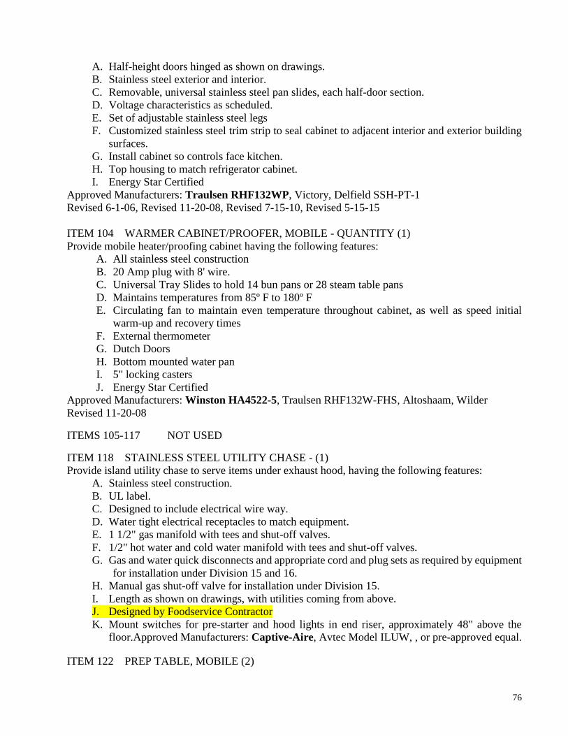
76
A. Half-height doors hinged as shown on drawings.
B. Stainless steel exterior and interior.
C. Removable, universal stainless steel pan slides, each half-door section.
D. Voltage characteristics as scheduled.
E. Set of adjustable stainless steel legs
F. Customized stainless steel trim strip to seal cabinet to adjacent interior and exterior building
surfaces.
G. Install cabinet so controls face kitchen.
H. Top housing to match refrigerator cabinet.
I. Energy Star Certified
Approved Manufacturers: Traulsen RHF132WP, Victory, Delfield SSH-PT-1
Revised 6-1-06, Revised 11-20-08, Revised 7-15-10, Revised 5-15-15
ITEM 104 WARMER CABINET/PROOFER, MOBILE - QUANTITY (1)
Provide mobile heater/proofing cabinet having the following features:
A. All stainless steel construction
B. 20 Amp plug with 8' wire.
C. Universal Tray Slides to hold 14 bun pans or 28 steam table pans
D. Maintains temperatures from 85º F to 180º F
E. Circulating fan to maintain even temperature throughout cabinet, as well as speed initial
warm-up and recovery times
F. External thermometer
G. Dutch Doors
H. Bottom mounted water pan
I. 5" locking casters
J. Energy Star Certified
Approved Manufacturers: Winston HA4522-5, Traulsen RHF132W-FHS, Altoshaam, Wilder
Revised 11-20-08
ITEMS 105-117 NOT USED
ITEM 118 STAINLESS STEEL UTILITY CHASE - (1)
Provide island utility chase to serve items under exhaust hood, having the following features:
A. Stainless steel construction.
B. UL label.
C. Designed to include electrical wire way.
D. Water tight electrical receptacles to match equipment.
E. 1 1/2" gas manifold with tees and shut-off valves.
F. 1/2" hot water and cold water manifold with tees and shut-off valves.
G. Gas and water quick disconnects and appropriate cord and plug sets as required by equipment
for installation under Division 15 and 16.
H. Manual gas shut-off valve for installation under Division 15.
I. Length as shown on drawings, with utilities coming from above.
J. Designed by Foodservice Contractor
K. Mount switches for pre-starter and hood lights in end riser, approximately 48" above the
floor.Approved Manufacturers: Captive-Aire, Avtec Model ILUW, , or pre-approved equal.
ITEM 122 PREP TABLE, MOBILE (2)

77
This item to be custom fabricated in accord with General Requirements of specifications and with plan
and detail drawings, and is to be constructed with 14-gauge stainless steel. Provide drawer, under-shelf
and locking wheels. Table is to be 48” long.
Approved Manufacturers: Select Stainless, Universal Stainless, Low Temp Industries
Revised 10-29-07
ITEM 123 PAPER TOWEL DISPENSER - QUANTITY AS SCHEDULED
Locate directly above the hand sinks in cafeteria areas:
A. Self-locking.
B. Holds 2-packages of single-fold towels.
C. Stainless steel finish.
Approved manufacturers: A&J Washroom Accesories Model # U190, or pre-approved equal
Revised 6-1-06.
UPON TAKING OCCUPANCY OF CAFETERIA CHILD NUTRITION SERVICES IS TO
RECEIVE TWO COPIES OF A COMPLETE LIST OF ALL KITCHEN EQUIPMENT,
INDICATING THE MANUFACTURER, MODEL AND SERIAL NUMBERS FOR EVERY
ITEM.
THIS CONCLUDES MIDDLE SCHOOL CAFETERIA EQUIPMENT
SPECIFICATIONS
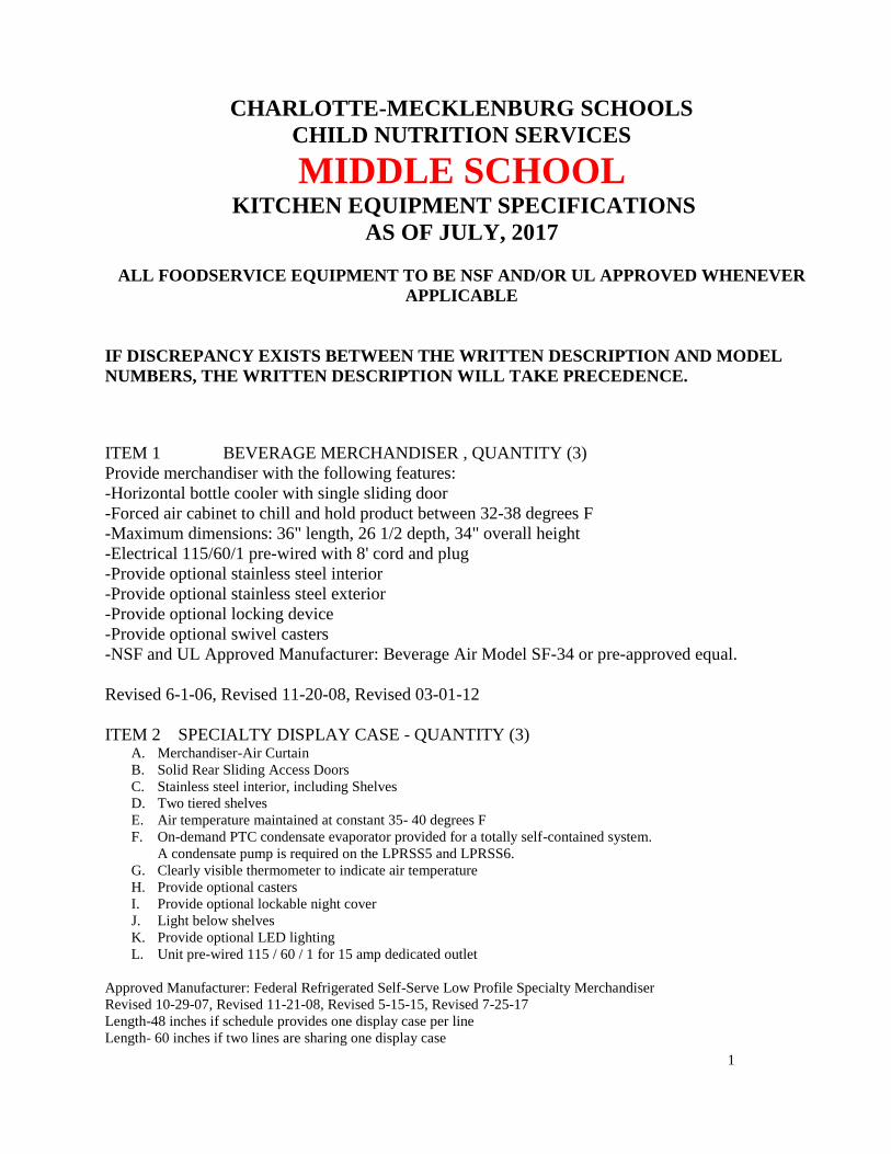
1
CHARLOTTE-MECKLENBURG SCHOOLS
CHILD NUTRITION SERVICES
MIDDLE SCHOOL KITCHEN EQUIPMENT SPECIFICATIONS
AS OF JULY, 2017
ALL FOODSERVICE EQUIPMENT TO BE NSF AND/OR UL APPROVED WHENEVER
APPLICABLE
IF DISCREPANCY EXISTS BETWEEN THE WRITTEN DESCRIPTION AND MODEL
NUMBERS, THE WRITTEN DESCRIPTION WILL TAKE PRECEDENCE.
ITEM 1 BEVERAGE MERCHANDISER , QUANTITY (3)
Provide merchandiser with the following features:
-Horizontal bottle cooler with single sliding door
-Forced air cabinet to chill and hold product between 32-38 degrees F
-Maximum dimensions: 36" length, 26 1/2 depth, 34" overall height
-Electrical 115/60/1 pre-wired with 8' cord and plug
-Provide optional stainless steel interior
-Provide optional stainless steel exterior
-Provide optional locking device
-Provide optional swivel casters
-NSF and UL Approved Manufacturer: Beverage Air Model SF-34 or pre-approved equal.
Revised 6-1-06, Revised 11-20-08, Revised 03-01-12
ITEM 2 SPECIALTY DISPLAY CASE - QUANTITY (3) A. Merchandiser-Air Curtain
B. Solid Rear Sliding Access Doors
C. Stainless steel interior, including Shelves
D. Two tiered shelves
E. Air temperature maintained at constant 35- 40 degrees F
F. On-demand PTC condensate evaporator provided for a totally self-contained system.
A condensate pump is required on the LPRSS5 and LPRSS6.
G. Clearly visible thermometer to indicate air temperature
H. Provide optional casters
I. Provide optional lockable night cover
J. Light below shelves
K. Provide optional LED lighting
L. Unit pre-wired 115 / 60 / 1 for 15 amp dedicated outlet
Approved Manufacturer: Federal Refrigerated Self-Serve Low Profile Specialty Merchandiser
Revised 10-29-07, Revised 11-21-08, Revised 5-15-15, Revised 7-25-17
Length-48 inches if schedule provides one display case per line
Length- 60 inches if two lines are sharing one display case
mende.smith
Text Box
11.1.3 MS Kitchen Equipment

2
ITEM 3 NOT USED
ITEM 4 COUNTER, CORNER, PLAIN TOP - QUANTITY AS SCHEDULED
Provide modular serving counter of size and content as shown on plan drawings, having the following
features to match Items 9, 12, 14, 15, 17, 27
A. 36" high basic counter section with seamless molded fiberglass body, flame retardant per
ASTM E162 and flame spread of 25 or less.
B. Body lined with 18 gauge stainless steel.
C. Base to have under-storage with shelf and fiberglass door panels with locks.
D. 30" wide 14 gauge stainless steel top with highlighted finish.
E. Solid 12" wide, 14 gauge stainless steel, "V" type tray slide, mounted at 34" AFF.
F. 4" ball bearing swivel type casters to be non-marking, with brakes on all wheels. Casters to
be mounted with interior and exterior bracing for maximum stress relief.
G. Line-up locks to be barrel bolt and key slot design with cam locking action placed on opposing
corners.
H. Install in banked line-up as shown on drawings.
I. Color: black.
Approved Manufacturers: Colorpoint Model 36 ST-F, Delfield modified to above specifications, or
pre-approved equal.
ITEM 5 BOOSTER HEATER - QUANTITY (1)
Provide compact booster heater having the following features:
A. Castone, glass lined, or silicone bronze tank, 6 gallon capacity.
B. Low-water cut-off, temperature/pressure relief valve, pressure reducing valve,
temperature/pressure gauge, and shock absorber.
C. Standard finish body and base.
D. Electrical characteristics as scheduled.
E. Under-counter mounting kit.
Approved Manufacturers: Hatco Corporation Model C36, or pre-approved equal.
ITEM 6 NOT USED
ITEM 7 BRAISING PAN GAS - FUTURE
-Provide hood space and utilities for future Installation.
Approved Manufacturer: Cleveland SGL-30T1
ITEM 8 PIZZA CART -NOT USED
Revised 10-29-07
ITEM 9 CART, TRAY WITH SILVERWARE & NAPKIN DISPENSERS – QUANTITY (6)
Provide tray and silver cart with the following features to match Items 4, 12, 14, 15, 17, 27
A. Stainless steel construction.
B. One bottom shelf.
C. Tubular frame.
D. 4” non-marking ball bearing swivel type casters with brakes on all wheels.
E. Silverware container will be molded fiberglass and secured to tray dispenser frame by 1” 16
gauge stainless steel tubing.
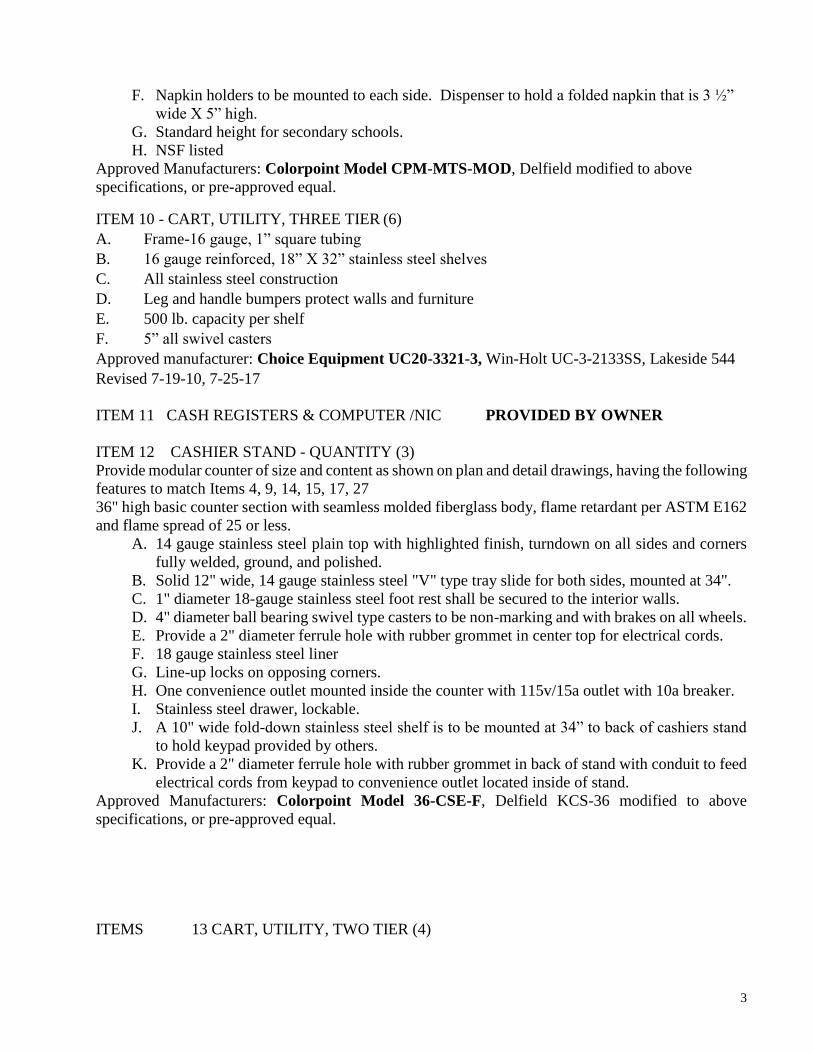
3
F. Napkin holders to be mounted to each side. Dispenser to hold a folded napkin that is 3 ½”
wide X 5” high.
G. Standard height for secondary schools.
H. NSF listed
Approved Manufacturers: Colorpoint Model CPM-MTS-MOD, Delfield modified to above
specifications, or pre-approved equal.
ITEM 10 - CART, UTILITY, THREE TIER (6)
A. Frame-16 gauge, 1” square tubing
B. 16 gauge reinforced, 18” X 32” stainless steel shelves
C. All stainless steel construction
D. Leg and handle bumpers protect walls and furniture
E. 500 lb. capacity per shelf
F. 5” all swivel casters
Approved manufacturer: Choice Equipment UC20-3321-3, Win-Holt UC-3-2133SS, Lakeside 544
Revised 7-19-10, 7-25-17
ITEM 11 CASH REGISTERS & COMPUTER /NIC PROVIDED BY OWNER
ITEM 12 CASHIER STAND - QUANTITY (3)
Provide modular counter of size and content as shown on plan and detail drawings, having the following
features to match Items 4, 9, 14, 15, 17, 27
36" high basic counter section with seamless molded fiberglass body, flame retardant per ASTM E162
and flame spread of 25 or less.
A. 14 gauge stainless steel plain top with highlighted finish, turndown on all sides and corners
fully welded, ground, and polished.
B. Solid 12" wide, 14 gauge stainless steel "V" type tray slide for both sides, mounted at 34".
C. 1" diameter 18-gauge stainless steel foot rest shall be secured to the interior walls.
D. 4" diameter ball bearing swivel type casters to be non-marking and with brakes on all wheels.
E. Provide a 2" diameter ferrule hole with rubber grommet in center top for electrical cords.
F. 18 gauge stainless steel liner
G. Line-up locks on opposing corners.
H. One convenience outlet mounted inside the counter with 115v/15a outlet with 10a breaker.
I. Stainless steel drawer, lockable.
J. A 10" wide fold-down stainless steel shelf is to be mounted at 34” to back of cashiers stand
to hold keypad provided by others.
K. Provide a 2" diameter ferrule hole with rubber grommet in back of stand with conduit to feed
electrical cords from keypad to convenience outlet located inside of stand.
Approved Manufacturers: Colorpoint Model 36-CSE-F, Delfield KCS-36 modified to above
specifications, or pre-approved equal.
ITEMS 13 CART, UTILITY, TWO TIER (4)

4
A. Frame-16 gauge , 1” square tubing
B. 16 gauge reinforced, 21” X 33” stainless steel shelves
C. All stainless steel construction
D. Leg and handle bumpers
E. 500 lb. Capacity per shelf
F. Two shelves.
G. 5” all swivel casters
Approved manufacturer: Choice Equipment UC20-3321-2, Win-Holt UC-2-2133SS, Lakeside 543,
or pre-approved equal
Revised 10-15-07, Revised 7-19-10, 7-25-17
ITEM 14 COUNTER, BEVERAGE - (1)
Provide modular counter of size and content as shown on plan and detail drawings, having the following
features to match Items 4, 9, 12, 15, 17, 27
A. 36" high basic counter section with seamless molded fiberglass body, flame retardant per
ASTM E162 and flame spread of 25 or less.
B. 14-gauge stainless steel top with highlighted finish, turndown on all sides and corners fully
welded, grounded, and polished.
C. Solid 12" wide, 14- gauge stainless steel, "V" type tray slide on one side mounted at 34" AFF.
D. 4" diameter ball bearing swivel type casters to be non-marking and with brakes on all wheels.
Casters to be mounted with interior and exterior bracing for maximum stress relief.
E. Unit to contain drain trough of 14-gauge stainless steel welded in top and fitted with a
removable stainless steel anti-splash grid. Trough to slope to 1" open brass drain and extend
to shut off valve located below base.
F. Provide drain pipe to floor drain.
G. Base to have under-storage with shelf and fiberglass door panels with locks.
H. Color: Black.
Note: Model number given is for 74" long unit. Unit is also available in 36", 50", 60", and 96"
lengths. Length desired is indicated on plan drawings.
Approved Manufacturers: Colorpoint Model 74-BT-F, Delfield KCU-74-NU modified to above
specifications, or pre-approved equal.
Revised 6-1-06, 7-25-17
ITEM 15 COUNTER, PLAIN TOP QUANTITY (3)
Provide modular serving counter of size and content as shown on plan drawings, having the following
features to match Items 4, 9, 12, 14, 17, and 27
A. 36" high basic counter section with seamless molded fiberglass body, flame retardant per
ASTM E162 and flame spread of 25 or less.
B. Body lined with 18 gauge stainless steel.
C. Open base in rear of cabinet.
D. 30" wide 14 gauge stainless steel top with highlighted finish.
E. Two tier display stand 48” X 28” shall have uprights constructed of 1¼" square stainless steel
tubing with stainless cap and base. Shelves to be ¼" polished glass resting on a horizontal
stainless steel framework welded to the uprights. The display stand is to be enclosed on ends

5
with ¼" polished glass. Front sneeze guard to be 1/4" polished glass mounted on adjustable
stainless steel brackets. Glass to be bound in 1/4" stainless steel channel to prevent chipping
and breaking. Total height of unit shall not exceed 60”
F. Solid 12" wide, 14- gauge stainless steel, "V" type tray slide, mounted 34" AFF.
G. Fold down cutting board on server side, to facilitate restocking
H. 4" ball bearing swivel type casters to be non-marking, with brakes on all wheels. Casters to
be mounted with interior and exterior bracing for maximum stress relief.
I. Line-up locks to be barrel bolt and key slot design with cam locking action placed on opposing
corners.
J. Install in banked line-up as shown on drawings.
K. Color: Black.
Approved Manufacturers: Colorpoint Model 60-ST-F, Delfield KC-60-NU modified to above
specifications, or pre-approved equal.
Revised 10-29-07, Revised 11-25-08, 7-25-17
ITEM 16 NOT USED
ITEM 17 COUNTER, HOT SERVING - QUANTITY (3)
Provide modular serving counter of size and content as shown on plan drawings, having the following
features to match Items 4, 9, 12, 14, 15, 27
A. 36" high basic counter section with seamless molded fiberglass body, flame retardant per ASTM
E162 and flame spread of 25 or less.
B. Body lined with 18-gauge stainless steel.
C. Base to have under-storage with shelf and fiberglass door panels with locks.
D. 30" wide 14-gauge stainless steel top with square turndown on all sides and corners fully welded,
ground and polished.
E. Recessed top accept 18" X 26" sheet pans.
F. Five individually controlled dry/moist wells, with solid state digital controls wired to circuit
breaker for current overload protection.
G. Control panel to be hinged for service access.
H. Hot food drains for each food well shall be plumbed to common manifold and extended to shut
off valve under holding wells. Provide 4’ flexible hose to drain.
I. Solid 10" wide, 14-gauge stainless steel, "V" type tray slide, mounted at 34”.
J. 5" ball bearing swivel type casters to be non-marking, with brakes on all wheels. Casters to be
mounted with interior and exterior bracing for maximum stress relief.
K. 10” shelf on server side, fold down, and 14-gauge stainless steel.
L. Single tier tempered glass over shelf with front tempered glass shield that is adjustable to allow
attendant or self-service. Full sloped front protector to prevent customers from touching food.
Ends top, and front to be 3/8" tempered glass.
M. Line-up locks to be barrel bolt and key slot design with cam locking action placed on opposing
corners.
N. Replacement Panels (5 ea.)

6
O. All equipment to be built in accordance with Underwriters Laboratories, Inc. and bear the UL
complete Unit listing label, no component parts listed equipment will be accepted, and shall also
bear the UL listing seal for safety and certification label for sanitation.
P. ELECTRICAL: 208 Volt / 1 phase /Max 2500 Watts
Plug to be 120V-250V / 50 AMP / Twist Lock/ 4 wire/ Male.
Q. Hatco Glo-Ray Curved Infrared heat strip with LED lights built into the heat strip housing and
wired to separate infinite control with on/off switch, and fused as required. Model GR5AL-
Black in color.
R. Color: Black
Approved Manufacturers: Colorpoint, Model EF5-CPA-F, Delfield KH-5-NU
Revised 6-1-06, Revised 11-25-08, 7-25-17
ITEM 18 COUNTER, SOLID TOP, FROST TOP - NOT USED
Revised 10-29-07
ITEM 19, 20 NOT USED
ITEM 21 CUTTER, FOOD NOT USED
ITEM 22 DISH CART - QUANTITY (4) PROVIDED BY OWNER
ITEM 23 TRAY DOLLY – QUANTITY (6)
A. 16 gauge, 304 stainless steel construction
B. 800 pound rolling capacity
C. Holds 2 stacks of 12” X 16” cafeteria trays
D. 1 ¼” lip to securely hold trays
E. 5” all swivel casters
F. Lifetime guarantee against rust or corrosion
Approved Manufacturers: Choice Equipment Model UC200-1625, Win-Holt D1625/SS, Lakeside,
or pre-approved equal.
Revised 10-05-15
ITEM 24 TROUGH, FLOOR, STAINLESS STEEL - QUANTITY AS SCHEDULED
Provide floor trough with removable grate having the following features:
Grate:
A. All Stainless steel welded construction.
B. 3/16" x 1" flat bars set on edge, with 13/16" clearance between bars.
C. Two 1/2" diameter rods wedged through bars full length, and weld to each bar.
D. Size to suit trough with removable sections not to exceed 20" long.
Trough
A. 14 gauge 304 18-8 stainless steel, all welded with coved corners and anchor straps, full
perimeter flange for installation under grout.
B. Pitch to waste and provide stainless steel cup with removable perforated stainless steel basket.
C. Overall trough size to be approximately l'-6" wide ~X 2'-O" long.
D. See plan for clarification. Coordinate with General Contractor and Plumbing Contractor to
assure proper installation.
Approved Manufacturers: IMC/Teddy Food Service Corporation Model FT-SG, Serv-o-
LifuEastern, or pre-approved equal.
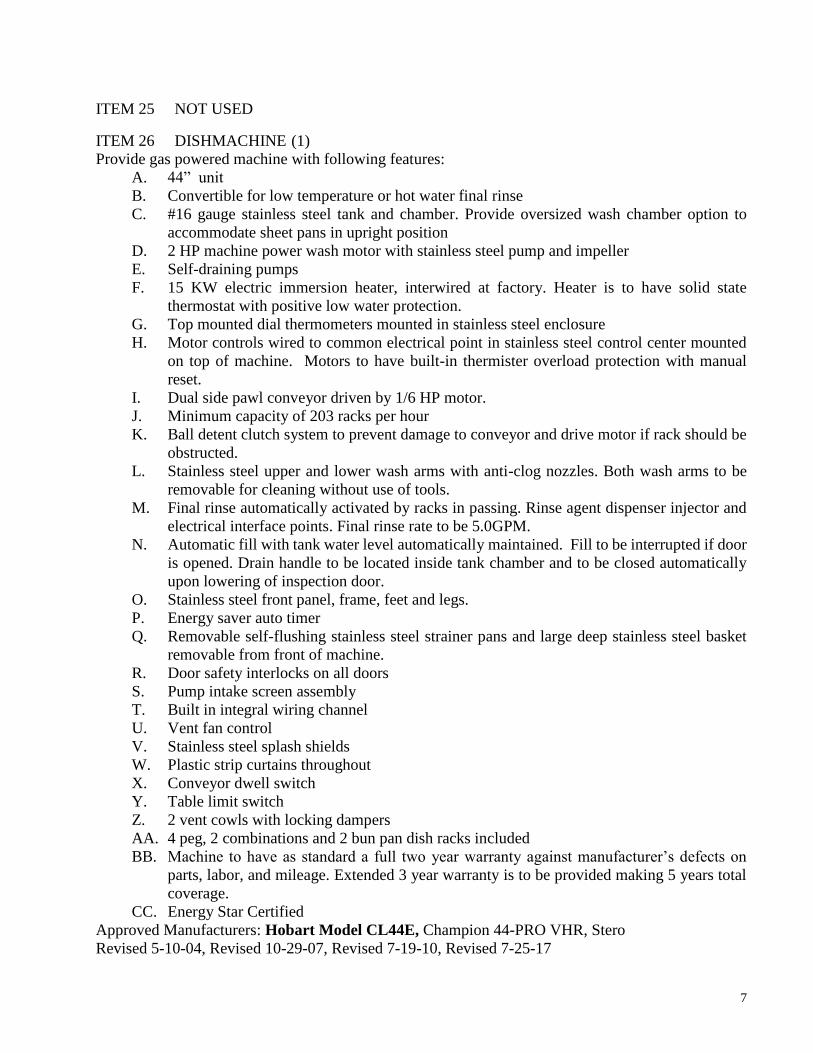
7
ITEM 25 NOT USED
ITEM 26 DISHMACHINE (1)
Provide gas powered machine with following features:
A. 44” unit
B. Convertible for low temperature or hot water final rinse
C. #16 gauge stainless steel tank and chamber. Provide oversized wash chamber option to
accommodate sheet pans in upright position
D. 2 HP machine power wash motor with stainless steel pump and impeller
E. Self-draining pumps
F. 15 KW electric immersion heater, interwired at factory. Heater is to have solid state
thermostat with positive low water protection.
G. Top mounted dial thermometers mounted in stainless steel enclosure
H. Motor controls wired to common electrical point in stainless steel control center mounted
on top of machine. Motors to have built-in thermister overload protection with manual
reset.
I. Dual side pawl conveyor driven by 1/6 HP motor.
J. Minimum capacity of 203 racks per hour
K. Ball detent clutch system to prevent damage to conveyor and drive motor if rack should be
obstructed.
L. Stainless steel upper and lower wash arms with anti-clog nozzles. Both wash arms to be
removable for cleaning without use of tools.
M. Final rinse automatically activated by racks in passing. Rinse agent dispenser injector and
electrical interface points. Final rinse rate to be 5.0GPM.
N. Automatic fill with tank water level automatically maintained. Fill to be interrupted if door
is opened. Drain handle to be located inside tank chamber and to be closed automatically
upon lowering of inspection door.
O. Stainless steel front panel, frame, feet and legs.
P. Energy saver auto timer
Q. Removable self-flushing stainless steel strainer pans and large deep stainless steel basket
removable from front of machine.
R. Door safety interlocks on all doors
S. Pump intake screen assembly
T. Built in integral wiring channel
U. Vent fan control
V. Stainless steel splash shields
W. Plastic strip curtains throughout
X. Conveyor dwell switch
Y. Table limit switch
Z. 2 vent cowls with locking dampers
AA. 4 peg, 2 combinations and 2 bun pan dish racks included
BB. Machine to have as standard a full two year warranty against manufacturer’s defects on
parts, labor, and mileage. Extended 3 year warranty is to be provided making 5 years total
coverage.
CC. Energy Star Certified
Approved Manufacturers: Hobart Model CL44E, Champion 44-PRO VHR, Stero
Revised 5-10-04, Revised 10-29-07, Revised 7-19-10, Revised 7-25-17

8
ITEM 27 DISPENSER, MILK (MUST BE OPEN FRONT) - QUANTITY (3)
Provide mobile carton milk cabinet having the following features:
A. Stainless steel interior and exterior
B. Top mounted Removable refrigeration system
C. Forced air refrigeration system
D. Sliding lift up and down door(s)
E. Reinforced cabinet interior bottom. Capacity to hold (12) standard milk cases.
F. Floor drain with plug
G. 6” casters
H. 3 year parts and labor warranty, 5 year compressor parts warranty
I. Magnetic snap-in EZ clean door gaskets
Approved Manufacture: Traulsen RMC49DR, or pre-approved equal
Revised 6-1-06, 7-25-17
ITEM 28 NOT USED
Revised 10-29-07
ITEM 29 QUANTITY (3)
A. Horizontal ice cream freezer with glass angled lid
B. Internal LED lighting
C Lid lock with keys
D. 1 ½” dual swivel casters
E. Power indicator light
G. Slide-out, easy access condensing unit
H. Maintain Temperature -18 to +10 degrees
J. Three baskets with dividers
K. External mounted thermometer
L. 115V/60/1 with 9’cord and plug attached
Approved Manufacturer: NorLake CTB-43-9 or pre-approved equal
Revised 6-1-06, Revised 10-29-07, Revised 07-15-10, 7-25-17
ITEMS 30, 31 NOT USED
ITEM 32 DISPOSAL, FOOD PREP & POTSINK AREA
Delete From Specs
Revised 7-19-10
ITEM 33 DUNNAGE RACK - QUANTITY AS SCHEDULED
Provide single deck dunnage platform unit with the following features to match Item 79 or 80.
A. One piece polymer construction.
B. Slotted deck.
C. Arrange as shown on Plan drawings, using quantities and sizes as specified.
Approved Manufacturers: Cambro, Metro, Eagle, Amco
ITEM 34 DISPOSAL, DISHWASH AREA (1)
A. Voltage characteristics as scheduled.

9
B. 18" diameter stainless steel cone for welding to drain-board.
C. Auto-reversing control center including, magnetic starter(s) and start/stop buttons, in stainless
steel NEMA 4 enclosure, or better, with disconnect switch.
D. Thermal overload protection either built into motor or in control center with manual reset.
E. Solenoid and vacuum breaker.
F. Control center to be mounted out of splash zone, under drain board on stainless steel mounting
bracket as shown on details.
G. Short neck as necessary to provide clearance under disposal.
H. Coordinate installation of pre-rinse unit (item #65)
I. Low water pressure cutoff, with time delay for water after cut off occurs
J. Permanently lubricated ball bearings
K. Tubular stainless steel legs with bullet feet adjustable to 3 inches in either direction
L. Rubber isolating ring at cone mounting to reduce vibration and noise
M. Air cooled motor.
Approved Manufacturers: Bus Boy Model 3000, Hobart, Insinkerator
Revised 7-20-06, Revised 10-12-07
ITEM 35 DISPLAY CASE, REFRIGERATED, DROP-IN NOT USED
Revised 10-29-07
ITEM 36 NOT USED
ITEM 37 EXHAUST HOOD - QUANTITY (1)
Refer to the most current version of the Division 15 Mechanical & Plumbing Design Guidelines,
sections 4.01, A, B & C.
ITEM 38 FAN, AIR CURTAIN - QUANTITY (1)
Provide air curtain fan having the following features:
A. #304 stainless steel exterior with adjustable deflectors and adjustable air intake.
B. Electrical characteristics as scheduled.
C. Micro-switch for automatic door-actuated on-off control.
D. 5-year warranty.
Approved Manufacturers: Berner ASR1036A-SS, Mars Door Company Model48CH, Universal Jet
Industries,
Revised 6-1-06.
ITEM 39 EQUIPMENT STAND - FOR ITEM 87 QUANTITY (1)
Approved Manufacturer: HOBART Model 205025, or pre-approved equal
Revised 10-29-07
ITEM 40 FIRE SUPPRESSION SYSTEM - QUANTITY (1)
Provide automatic wet chemical fire control system as required to protect exhaust hood, Item 37, and
the cooking equipment located under this hood, and having the following features:
A. All tanks, control heads, piping, relays, cable, fusible links, nozzles, elbows, etc., as required
for complete system.

10
B. Brass nozzles and chrome plated or sleeved exposed piping.
C. Manual strike mechanism in accessible location.
D. Installation in accord with N.F.P.A. 17A code requirements and coordinate with exhaust hood
construction and installation.
E. Four contacts for use by E.C., one contact for alarm, one for supply fan shut-Off, one for
shunt trip actuation, and one spare.
F. Provide mechanical gas solenoid valve loose for installation by plumber.
Approved Manufacturers: Ansul Model R-1 02, Range Guard, Pyro-chem
ITEM 41 NOT USED
ITEM 42 FREEZER, REACH-IN, TWO-DOORS - NOT USED
Revised 10-29-07
ITEM 43 NOT USED
ITEM 44 GUIDE RAILINGS - QUANTITY AND LENGTH PER DRAWINGS
Provide guide railings with the following features:
A. Double horizontal type rail
B. 14 gauge stainless steel-all welded construction
C. 2” tubing
D. 6” radius on end uprights
E. Die formed flanges with three 3/8” holes for fastening rail to floor
F. All welds ground and polished to match commercial finish on railing
Approved Manufacturers: United Show Case Company, Inc., or pre-approved equal
ITEM 45 FRYERS NOT USED
Revised 6-01-06
ITEM 46 HOSE REEL - QUANTITY AS SCHEDULED
Provide open type retractable all-in-one hose reel system having the following features:
A. B-1434 reel, open, stainless steel.
B. Continuous pressure type vacuum breaker, B-963.
C. Shut off control, ORK3.
D. MV-0522 spray gun.
E. B-1 31 base faucet.
F. 50 feet of heavy duty hose.
G. All chrome interconnecting piping.
H. Mount on wall at location shown on drawings.
Approved Manufacturers: T&S, or pre-approved equal.
ITEMS47, 48 NOT USED
ITEM 49 ICE MACHINE – (1)
Provide cube ice maker and bin having the following features:

11
ICE MAKER: ARI certified ice production based on 70º F incoming water and 90º F air
A. ARI Harvest rate minimum of 350 pounds
B. Self-contained, air cooled.
C. Electrical characteristics as scheduled.
D. Water filtration system
E Manufacturer's standard finishes.
F. Arrange to make dice cube ice.
BIN:
G. Bin to have minimum 270 pound storage capacity
H. Manufacturer's standard finishes.
I. 6" stainless steel legs.
J. ARI certified and rated in accordance with ARI Standard 820-88
K. NSF listed, UL approved
L. ENERGY STAR CERTIFIED
Mount icemaker on bin and install at location shown on drawings.
Approved Manufacturers: Hoshizaki KML 350MAH, Ice-o-Matic ICE-0400, Manitowoc
Revised 1-02-07, Revised 11-05-08, Revised 7-19-10
ITEM 50- INGREDIENT BIN -DELETE FROM SPECS 5-15-15
ITEMS 51-54 NOT USED
ITEM 55 MIXER, 20 QUART NOT USED
Revised 10-29-07
ITEM 56-A MIXER, 30 QUART (1)
MIXER AND ACCESSORIES:
1. # 12 attachment hub
2. Removable s/s bowl guard
3. Direct gear driven transmission. ¾ HP motor by manufacturer.
4. Three fixed speeds plus stir speed.
5. Ability to shift gears while machine is operating. Automated soft transition into higher speed to
avoid product splashing out of bowl
6. 15 minute timer
7. Automatic time recall remembers last time set for each speed
8. Ergonomic swing out bowl
9. 115/60/1 voltage, with 6-foot cord and plug.
10. 2 year parts, labor and mileage warranty against manufacturer’s defects.
11. NSF and UL approved
12. Factory trained service technicians available for service.
13. Powder coat paint
14. Rubber foot pads
15. The motor shall have grease packed ball bearings, ventilation, and splash proof enclosure .
16. Manufacturer provided accessories (no replacement brands): s/s bowl, bowl truck-wire whip,
flat beater, dough hook and ingredient chute.

12
Approved Manufacturer: Hobart HL-300, or pre-approved equal
Revised 10-12-07, Revised 11-20-08, Revised 5-15-15
ITEM 56-B MIXER, 30 QUART- DELETE FROM SPECS 5-15-15
ITEMS 57-63 NOT USED
ITEM 64 OVEN, CONVECTION, DOUBLE, GAS – (3 SETS)
OVEN, CONVECTION, DOUBLE, NATURAL GAS
Provide with following features:
2 sections, standard depth
_ Stainless steel front, top, and sides. Full metal rear cover
_ Solid stainless steel doors
_ Single porcelain door handle with simultaneous door operation
_ Triple-mounted pressure lock door design with turnbuckle assembly
_ Modular slide out front control panel for easy access & cleaning
_ Fully insulated at top, back, sides and bottom
_ Porcelain baking compartment liner (14 gauge)
_ Five chrome-plated racks, eleven rack positions
_ Two commercial bake oven lamps per compartment
_ Dual Flow Gas system
_ Electronic spark ignition
_ Pressure regulator
_ Manual gas service cut-off switch located on the front of the control panel
_ Air mixers with adjustable air shutters
_ Gas manifold for stacking
_ 48” gas hose with quick disconnect
_ Solid state thermostat with infinite temperature control range of 200°F to 500°F
_ Two speed fan motor
_ 1/3 horsepower blower motor with automatic thermal overload protection
_ Cook/Cool mode selector
_ Control area cooling fan
_ Solid state manual control with separate dials to control thermostat and timer
_ 60 minute timer
_ 6" adjustable stainless steel legs
_ Wired 120 volt with plug and cord attached
_ Two year oven parts and one year labor warranty
_ Five year oven door warranty
_ Replacement parts guaranteed available for 12 years from purchase date
_ NSF, UL or ETL approved
-- ENERGY STAR CERTIFIED.
Approved Manufacturers: Blodgett DFG-100, Hobart, Garland MCO-GS-10-ESS
Revised 07-15-10, Revised 12-01-11, Revised 5-15-15, 7-25-17
ITEM 65 PRE-RINSE UNIT - QUANTITY (1) - INSTALL OVER DISHROOM DISPOSAL
Provide deck mounted pre-rinse unit having the following features:
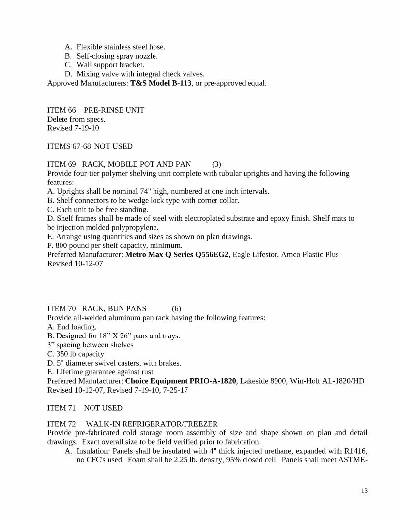
13
A. Flexible stainless steel hose.
B. Self-closing spray nozzle.
C. Wall support bracket.
D. Mixing valve with integral check valves.
Approved Manufacturers: T&S Model B-113, or pre-approved equal.
ITEM 66 PRE-RINSE UNIT
Delete from specs.
Revised 7-19-10
ITEMS 67-68 NOT USED
ITEM 69 RACK, MOBILE POT AND PAN (3)
Provide four-tier polymer shelving unit complete with tubular uprights and having the following
features:
A. Uprights shall be nominal 74" high, numbered at one inch intervals.
B. Shelf connectors to be wedge lock type with corner collar.
C. Each unit to be free standing.
D. Shelf frames shall be made of steel with electroplated substrate and epoxy finish. Shelf mats to
be injection molded polypropylene.
E. Arrange using quantities and sizes as shown on plan drawings.
F. 800 pound per shelf capacity, minimum.
Preferred Manufacturer: Metro Max Q Series Q556EG2, Eagle Lifestor, Amco Plastic Plus
Revised 10-12-07
ITEM 70 RACK, BUN PANS (6)
Provide all-welded aluminum pan rack having the following features:
A. End loading.
B. Designed for 18” X 26” pans and trays.
3” spacing between shelves
C. 350 lb capacity
D. 5" diameter swivel casters, with brakes.
E. Lifetime guarantee against rust
Preferred Manufacturer: Choice Equipment PRIO-A-1820, Lakeside 8900, Win-Holt AL-1820/HD
Revised 10-12-07, Revised 7-19-10, 7-25-17
ITEM 71 NOT USED
ITEM 72 WALK-IN REFRIGERATOR/FREEZER
Provide pre-fabricated cold storage room assembly of size and shape shown on plan and detail
drawings. Exact overall size to be field verified prior to fabrication.
A. Insulation: Panels shall be insulated with 4" thick injected urethane, expanded with R1416,
no CFC's used. Foam shall be 2.25 lb. density, 95% closed cell. Panels shall meet ASTME-

14
84 (UL-723) and be listed by Underwriters laboratories and by Factory Mutual as a Class I
building material.
B. Coved corners: Assembly shall be constructed so that all interior wall, floor and ceiling
intersections shall comply with N.S.F. requirements.
C. Cam lock fasteners: All panel intersections and wall, floor and ceiling intersections shall be
secured by cam lock fasteners.
D. Ceiling panels to be one piece, self-supporting and span full width of assembly.
E. Finishes: Aluminum exterior and interior finishes shall be as shown on drawings.
F. Doors: Door size and finish shall be as shown on drawings, and shall be furnished complete
with sill wiper gasket, lift type hinges.
G. Hinges, latches and hardware shall be chrome plated. Minimum (3) hinges.
H. Exterior door to be equipped with automatic door closer.
I. Freezer door to be equipped with perimeter heat.
J. Exterior door(s) to be equipped with cylinder lock having inside safety release feature and
also configured to allow use of padlock to secure door.
K. Aluminum kick plate to be provided on door.
L. Thermometers: Each compartment to be provided with exterior flush mounted dial
thermometer mounted at eye level to each door.
M. Lights: Each compartment to be furnished complete with manufacturer's standard light
fixture, having protective cover, mounted and pre-wired to switch with pilot light in door
section. Extra lights as needed to provide 30 foot candles 30" above floor.
N. Floor: Quarry Tile
O. The floor and ceiling shall have maximum length panels to span full length of box if possible,
otherwise stagger joints so there are no common "four corner" intersections and no joints
occurring in doorways.
P. Refrigeration System: Shall be furnished by manufacturer as part of cold storage room
assembly, provide each compartment with complete refrigeration system sized to maintain
appropriate temperature.
Q. Condensing units to be semi-hermetic, or scroll type, air-cooled, remote. Units to have
performance and wiring characteristics as scheduled on drawings. Units shall have pre-wired
disconnects. Refrigeration systems to be designed for use with R404A or R507 refrigerant
only.
R. Condensing units to be provided with painted galvanized steel all-weather housing, controls,
and crankcase heaters, all suitable for outdoor conditions, and located as shown on drawings.
S. Unit coolers to be low-silhouette type, mounted at locations shown on drawings. Performance
and wiring characteristics to be as scheduled on drawings. Freezer system to be provided
with timed electric defrost.
T. Evaporator drain lines to be provided by this section and extended to floor receptors outside
assembly.
U. Freezer drain lines to be wrapped with heater cable.
V. Refrigerant piping to be ACR copper tubing, hard temper, with wrought fittings and silver
solder joints. Insulate suction lines with 1/2" pre-molded foamed plastic insulation.
W. Refrigeration systems to be provided with all required refrigerant piping, insulation, vibration
eliminator, solenoid(s), dryer, suction line filter, expansion valve(s), thermostat(s), heat
exchangers, and defrost timers, etc. as necessary for complete installation. Provide pump
down control circuit consisting of thermostat and solenoid valve. All components including

15
piping and insulation to be installed using accepted industry standards, manufacturer’s
instructions and first class workmanship.
X. Miscellaneous: Provide 1/8" diamond tread wainscot along exposed front exterior of
assembly mounted from floor to 48" A.F.F.
Y. Provide trim strips, closure panels, etc., as necessary to trim assembly to adjacent building
surfaces.
Z. Provide removable top closure panels with "C" channel rails. Lift-out panel sections to have
turndown edges for strength and are not to exceed 4'-O" in length.
AA. Provide plastic strip curtains at door locations, transparent vinyl overlapping strips,
aluminum bar hanging rod and bracket, suitable for low temperature application, as
manufactured by Curtron, Flexstrip Products, Inc., or equal.
BB. Provide heated pressure relief port in freezer.
CC. Provide sleeves properly located for utility entrance, drain lines, and refrigeration lines,
and after lines are installed, fill sleeves with spray foam compound, suitable for use in
refrigerated spaces.
DD. Cold storage room shall be erected by factory trained and certified installers or shall be
supervised by factory personnel. Refrigeration systems shall be furnished by cold storage
room manufacturer and installed by factory authorized personnel.
EE. ENERGY STAR CERTIFIED
This specification does not constitute a complete description of cold storage assembly, also see plan
and detail drawings.
Approved Manufacturers: Bally, Kolpak, , American Panel, Norlake, Masterbilt, Thermokool
Revised 6-1-06., Revised 07-15-10, Revised 12-1-11, 7-25-17
ITEMS 73-75 NOT USED
ITEM 76 REFRIGERATOR, REACH-IN - QUANTITY (1)
Provide two-section reach-in refrigerator with top mounted air-cooled condensing unit, exterior
thermometer, cylinder door locks and top mounted condensate evaporator, having the following
features:
A. Full length stainless steel doors, hinged as shown on drawings.
B. Stainless steel exterior and interior.
C. 6 stainless steel shelves in each compartment
D. Set of 5” swivel- type locking casters.
E. Wired for 120/1 operation, cord and plug set.
F. Energy Star Certified
Preferred Manufacturer: Traulsen RHT132WUT, Victory RS/RSA-2D-S1-HS/HG, Delfield SSR-
2-S,
Note: 76, 77 and 103 must be provided by same manufacturer.
Revised 6-1-06, Revised 11-20-08, Revised 7-15-10, Revised 5-15-15, Revised 7-25-17
ITEM 77 REFRIGERATOR, PASS-THRU - QUANTITY AS SCHEDULED
Provide two-section pass-thru refrigerator with top mounted air-cooled condensing unit, exterior dial
thermometer, cylinder door locks and top mounted condensate evaporator, having the following
features.
A. Full length stainless steel doors, hinged as shown on drawings.
B. Stainless steel exterior and interior.

16
C. Removable, universal type stainless steel pan slides, both sections.
D. Set of adjustable stainless steel legs
E. Stainless steel banking strip.
F. Customized stainless steel trim strip to seal cabinet to adjacent interior and exterior building
surfaces.
G. Wired for 120/1 operation.
H. Install cabinet so that controls face kitchen area.
I. Energy Star Certified
Approved Manufacturers: Traulsen RHT232WPUT, Victory RS/RSA-2D-S1-PT-HS, Delfield
SSR-PT-2
Note: items 76, 77 and 103 must be provided by the same manufacturer.
Revised 6-1-06, Revised 11-20-08, Revised 07-15-10, Revised 5-15-15, 7-25-17
ITEM 78 NOT USED
ITEM 79 SHELVING, REFRIGERATION - QUANTITY AS SCHEDULED
Provide four-tier polymer shelving unit complete with tubular uprights and having the following
features:
Uprights shall be nominal 74" high, numbered at one inch intervals.
A. Shelf connectors to be wedge lock type with corner collar.
B. Each unit to be free standing.
C. Shelf frames shall be made of steel with electroplated substrate and epoxy finish. Shelf mats
to be injection molded polypropylene.
D. Arrange using quantities and sizes as shown on plan drawings.
E. 800 pound per shelf capacity, minimum.
Approved Manufacturers: Metro-Max Q Series, Eagle Lifstor, Amco Plastic Plus.
ITEM 80 SHELVING, DRY STORAGE - QUANTITY AS SCHEDULED
Provide five-tier bright zinc plated wire shelving unit complete with tubular uprights and having the
following features:
A. Electro-zinc plated with chromate bath and clear protective coating.
B. Uprights shall be nominal 86" high.
C. Adjustable feet.
D. Arrange using quantities and sizes as shown on Plan Drawings.
Approved Manufacturers: Metro, Eagle, Amco
ITEM 81 SILVERWARE CHUTE – NOT USED
Revised 10-29-07
ITEMS 82, 83 NOT USED
ITEM 84 SINK, POTWASHING - QUANTITY AS SCHEDULED
This item to be custom- fabricated in accord with General Requirements of specifications and with plan
and detail drawings. Include disposal (#32) and pre-rinse (#66).
Approved Manufacturers: Select Stainless, Universal Stainless, Low Temp Industries
ITEM 85 SINK, SILVER SOAK -NOT USED

17
Revised 10-29-07
ITEM 86 SINK, VEGETABLE, TWO-COMPARTMENT - QUANTITY (1)
This item to be custom- fabricated in accord with General Requirements of specifications and with plan
and detail drawings. Include disposal (#32) and pre-rinse unit (#66).
Approved Manufacturers: Select Stainless, Universal Stainless, Low Temp Industries
ITEM 87 SLICER
Slicer, 12” automatic.
Features to be included:
1. ½ HP motor wired for 120/1 operation, with cord and plug set
2. Adjustable capacity: 12” wide or 7” diameter
3. Adjustable gauge plate up to 1” thickness
4. Stainless steel knife
5. Two speed automatic carriage drive
6. Top mounted removable sharpener with mineral stone
7. All metal finish
8. Lift lever for easy cleaning
9. MICROBAN antimicrobial protection
Approved Manufacturer: Hobart Model HS7, or pre-approved equal
Updated 7-25-17
ITEM 88 UTENSIL RACK
Provide utensil rack with the following features:
A. 18 gauge stainless steel shelf.
B. Stainless steel bar under shelf, mounted to brackets.
C. Double stainless steel pot hooks approximately 8"o.c.
D. See detail drawings.
Approved Manufacturers: Select Stainless, LowTemp Model SWS-9, Universal Stainless
ITEM 89 NOT USED
ITEM 90 COMBI OVENS NOT USED
Revised 6-01-06
ITEM 91 STEAMER, CONVECTION - QUANTITY (2)
A. Two compartment pressure-less floor model steamer
B. Solid one- piece body for both compartments with heavy duty 14 gauge stainless steel
construction for compartment door, interior and exterior walls.
C. Totally independent cooking compartments with separate gas valve, ignition and water level
controls. No shared components between compartments.
D. Front access generator controls allowing complete service from front of unit
E. Manual on/off switch which activates automatic fill/drainage via manual ball valve. Electric
solenoid switch is not acceptable.
F. Automatic water fill on start-up
G. Exterior de-liming port
H. Generator de-liming light to alert operator when it is time to de-scale
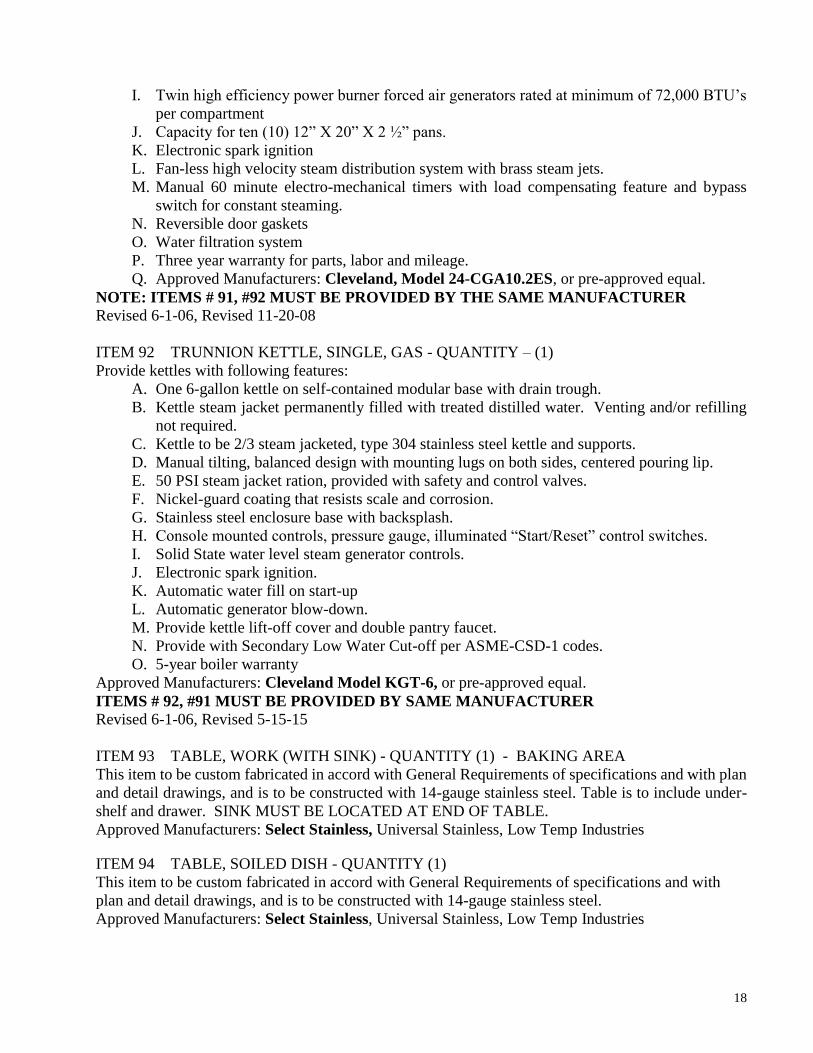
18
I. Twin high efficiency power burner forced air generators rated at minimum of 72,000 BTU’s
per compartment
J. Capacity for ten (10) 12” X 20” X 2 ½” pans.
K. Electronic spark ignition
L. Fan-less high velocity steam distribution system with brass steam jets.
M. Manual 60 minute electro-mechanical timers with load compensating feature and bypass
switch for constant steaming.
N. Reversible door gaskets
O. Water filtration system
P. Three year warranty for parts, labor and mileage.
Q. Approved Manufacturers: Cleveland, Model 24-CGA10.2ES, or pre-approved equal.
NOTE: ITEMS # 91, #92 MUST BE PROVIDED BY THE SAME MANUFACTURER
Revised 6-1-06, Revised 11-20-08
ITEM 92 TRUNNION KETTLE, SINGLE, GAS - QUANTITY – (1)
Provide kettles with following features:
A. One 6-gallon kettle on self-contained modular base with drain trough.
B. Kettle steam jacket permanently filled with treated distilled water. Venting and/or refilling
not required.
C. Kettle to be 2/3 steam jacketed, type 304 stainless steel kettle and supports.
D. Manual tilting, balanced design with mounting lugs on both sides, centered pouring lip.
E. 50 PSI steam jacket ration, provided with safety and control valves.
F. Nickel-guard coating that resists scale and corrosion.
G. Stainless steel enclosure base with backsplash.
H. Console mounted controls, pressure gauge, illuminated “Start/Reset” control switches.
I. Solid State water level steam generator controls.
J. Electronic spark ignition.
K. Automatic water fill on start-up
L. Automatic generator blow-down.
M. Provide kettle lift-off cover and double pantry faucet.
N. Provide with Secondary Low Water Cut-off per ASME-CSD-1 codes.
O. 5-year boiler warranty
Approved Manufacturers: Cleveland Model KGT-6, or pre-approved equal.
ITEMS # 92, #91 MUST BE PROVIDED BY SAME MANUFACTURER
Revised 6-1-06, Revised 5-15-15
ITEM 93 TABLE, WORK (WITH SINK) - QUANTITY (1) - BAKING AREA
This item to be custom fabricated in accord with General Requirements of specifications and with plan
and detail drawings, and is to be constructed with 14-gauge stainless steel. Table is to include under-
shelf and drawer. SINK MUST BE LOCATED AT END OF TABLE.
Approved Manufacturers: Select Stainless, Universal Stainless, Low Temp Industries
ITEM 94 TABLE, SOILED DISH - QUANTITY (1)
This item to be custom fabricated in accord with General Requirements of specifications and with
plan and detail drawings, and is to be constructed with 14-gauge stainless steel.
Approved Manufacturers: Select Stainless, Universal Stainless, Low Temp Industries
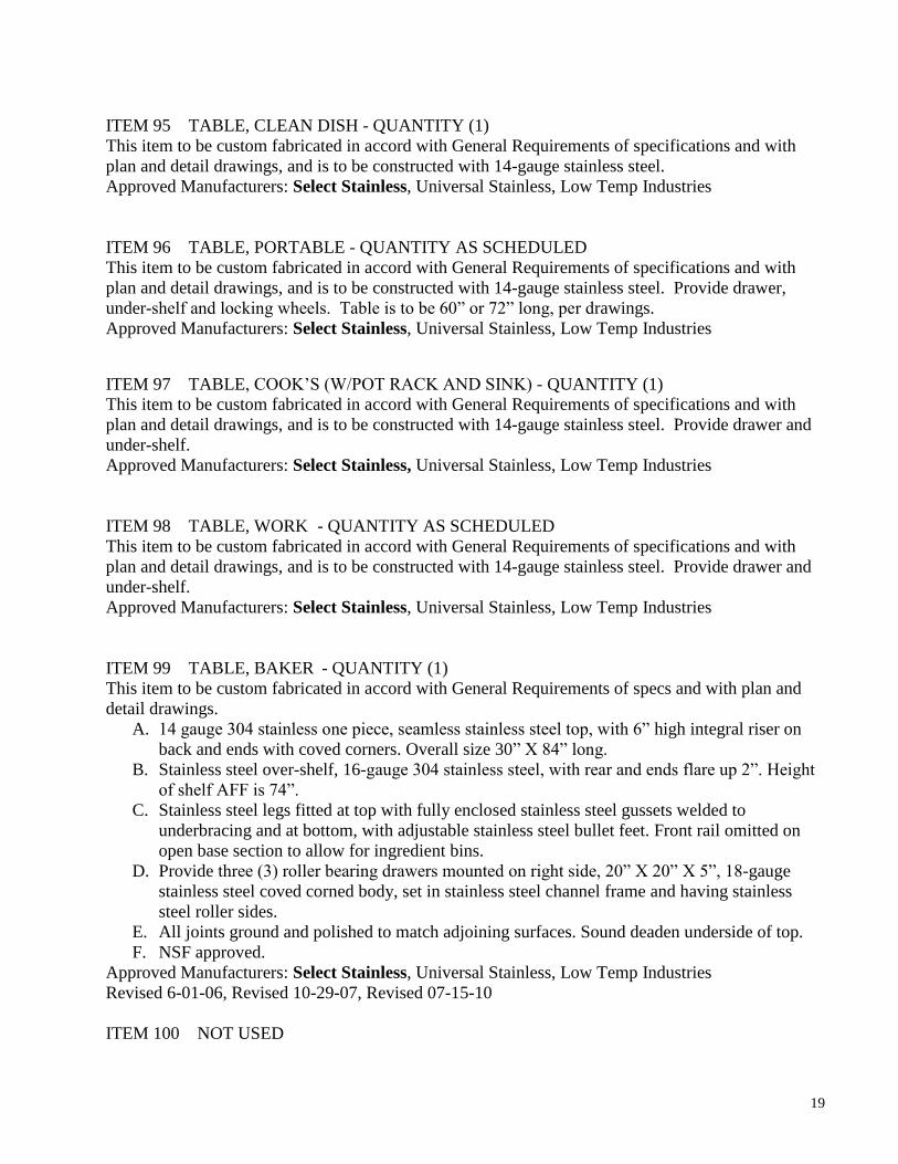
19
ITEM 95 TABLE, CLEAN DISH - QUANTITY (1)
This item to be custom fabricated in accord with General Requirements of specifications and with
plan and detail drawings, and is to be constructed with 14-gauge stainless steel.
Approved Manufacturers: Select Stainless, Universal Stainless, Low Temp Industries
ITEM 96 TABLE, PORTABLE - QUANTITY AS SCHEDULED
This item to be custom fabricated in accord with General Requirements of specifications and with
plan and detail drawings, and is to be constructed with 14-gauge stainless steel. Provide drawer,
under-shelf and locking wheels. Table is to be 60” or 72” long, per drawings.
Approved Manufacturers: Select Stainless, Universal Stainless, Low Temp Industries
ITEM 97 TABLE, COOK’S (W/POT RACK AND SINK) - QUANTITY (1)
This item to be custom fabricated in accord with General Requirements of specifications and with
plan and detail drawings, and is to be constructed with 14-gauge stainless steel. Provide drawer and
under-shelf.
Approved Manufacturers: Select Stainless, Universal Stainless, Low Temp Industries
ITEM 98 TABLE, WORK - QUANTITY AS SCHEDULED
This item to be custom fabricated in accord with General Requirements of specifications and with
plan and detail drawings, and is to be constructed with 14-gauge stainless steel. Provide drawer and
under-shelf.
Approved Manufacturers: Select Stainless, Universal Stainless, Low Temp Industries
ITEM 99 TABLE, BAKER - QUANTITY (1)
This item to be custom fabricated in accord with General Requirements of specs and with plan and
detail drawings.
A. 14 gauge 304 stainless one piece, seamless stainless steel top, with 6” high integral riser on
back and ends with coved corners. Overall size 30” X 84” long.
B. Stainless steel over-shelf, 16-gauge 304 stainless steel, with rear and ends flare up 2”. Height
of shelf AFF is 74”.
C. Stainless steel legs fitted at top with fully enclosed stainless steel gussets welded to
underbracing and at bottom, with adjustable stainless steel bullet feet. Front rail omitted on
open base section to allow for ingredient bins.
D. Provide three (3) roller bearing drawers mounted on right side, 20” X 20” X 5”, 18-gauge
stainless steel coved corned body, set in stainless steel channel frame and having stainless
steel roller sides.
E. All joints ground and polished to match adjoining surfaces. Sound deaden underside of top.
F. NSF approved.
Approved Manufacturers: Select Stainless, Universal Stainless, Low Temp Industries
Revised 6-01-06, Revised 10-29-07, Revised 07-15-10
ITEM 100 NOT USED

20
ITEM 101 VENT DUCT SET - QUANTITY (1)
To be custom fabricated in accord with General Requirements of specifications and with plan and
detail drawings.
Approved Manufacturers: Select Stainless, Universal Stainless, Low Temp Industries
ITEM 102 WALL SHELF - QUANTITY AS SCHEDULED-MINIMUM (1) OVER WASHER
AND DRYER
This item to be custom fabricated in accord with General Requirements of specifications and with plan
Approved Manufacturers: Select Stainless, Universal Stainless, Low Temp Industries
Revised 11-28-08
ITEM 103 WARMING CABINET, PASS THRU - QUANTITY AS SCHEDULED
Provide one-section pass-through hot cabinet, having the following features. Note: items 76, 77, and
103 must be provided by the same manufacturer. A. Half-height doors hinged as shown on drawings.
B. Stainless steel exterior and interior.
C. Removable, universal stainless steel pan slides, each half-door section.
D. Voltage characteristics as scheduled.
E. Set of adjustable stainless steel legs
F. Customized stainless steel trim strip to seal cabinet to adjacent interior and exterior building
surfaces.
G. Install cabinet so controls face kitchen.
H. Top housing to match refrigerator cabinet.
I. Energy Star Certified
Approved Manufacturers: Traulsen RHF132WP, Victory, Delfield SSH-PT-1
Revised 6-1-06, Revised 11-20-08, Revised 7-15-10, Revised 5-15-15
ITEM 104 WARMER CABINET/PROOFER, MOBILE - QUANTITY (1)
Provide mobile heater/proofing cabinet having the following features:
A. All stainless steel construction
B. 20 Amp plug with 8' wire.
C. Universal Tray Slides to hold 14 bun pans or 28 steam table pans
D. Maintains temperatures from 85º F to 180º F
E. Circulating fan to maintain even temperature throughout cabinet, as well as speed initial
warm-up and recovery times
F. External thermometer
G. Dutch Doors
H. Bottom mounted water pan
I. 5" locking casters
J. Energy Star Certified
Approved Manufacturers: Winston HA4522-5, Traulsen RHF132W-FHS, Altoshaam, Wilder
Revised 11-20-08
ITEMS 105-117 NOT USED
ITEM 118 STAINLESS STEEL UTILITY CHASE - (1)
Provide island utility chase to serve items under exhaust hood, having the following features:

21
A. Stainless steel construction.
B. UL label.
C. Designed to include electrical wire way.
D. Water tight electrical receptacles to match equipment.
E. 1 1/2" gas manifold with tees and shut-off valves.
F. 1/2" hot water and cold water manifold with tees and shut-off valves.
G. Gas and water quick disconnects and appropriate cord and plug sets as required by equipment
for installation under Division 15 and 16.
H. Manual gas shut-off valve for installation under Division 15.
I. Length as shown on drawings, with utilities coming from above.
J. Mount switches for pre-starter and hood lights in end riser, approximately 48" above the
floor.Approved Manufacturers: Captive-Aire, Avtec Model ILUW, , or pre-approved equal.
ITEM 122 PREP TABLE, MOBILE (2)
This item to be custom fabricated in accord with General Requirements of specifications and with plan
and detail drawings, and is to be constructed with 14-gauge stainless steel. Provide drawer, under-shelf
and locking wheels. Table is to be 48” long.
Approved Manufacturers: Select Stainless, Universal Stainless, Low Temp Industries
Revised 10-29-07
ITEM 123 PAPER TOWEL DISPENSER - QUANTITY AS SCHEDULED
Locate directly above the hand sinks in cafeteria areas:
A. Self-locking.
B. Holds 2-packages of single-fold towels.
C. Stainless steel finish.
Approved manufacturers: A&J Washroom Accesories Model # U190, or pre-approved equal
Revised 6-1-06.
UPON TAKING OCCUPANCY OF CAFETERIA CHILD NUTRITION SERVICES IS TO
RECEIVE TWO COPIES OF A COMPLETE LIST OF ALL KITCHEN EQUIPMENT,
INDICATING THE MANUFACTURER, MODEL AND SERIAL NUMBERS FOR EVERY
ITEM.
THIS CONCLUDES MIDDLE SCHOOL CAFETERIA EQUIPMENT
SPECIFICATIONS

CHARLOTTE-MECKLENBURG SCHOOLS
CHILD NUTRITION SERVICES
HIGH SCHOOL KITCHEN EQUIPMENT SPECIFICATIONS
AS OF MARCH, 2019
ALL FOODSERVICE EQUIPMENT TO BE NSF AND/OR UL APPROVED
WHENEVER APPLICABLE
IF DISCREPANCY EXISTS BETWEEN THE WRITTEN DESCRIPTION AND
MODEL NUMBERS, THE WRITTEN DESCRIPTION WILL TAKE PRECEDENCE.
ITEM 1 BEVERAGE MERCHANDISER , QUANTITY AS SCHEDULED
A. Merchandiser-Air Curtain
B. Solid Rear Sliding Access Doors
C. Stainless steel interior, including Shelves
D. Flush ends
E. Two tiered shelves
F. Air temperature maintained at constant 35- 40 degrees F
G. On-demand PTC condensate evaporator provided for a totally self-contained system.
A condensate pump is required on the LPRSS5 and LPRSS6.
H. Clearly visible thermometer to indicate air temperature
I. Provide optional casters
J. Provide optional lockable night cover
K. Light below shelves
L. Provide optional LED lighting
M. Unit pre-wired 115 / 60 / 1 for 15 amp dedicated outlet
N. Color: Black exterior
Approved Manufacturer: Federal Refrigerated Self-Serve Low Profile Specialty Merchandiser
LPRSSR4, or pre approved equal.
Revised 6-1-06, Revised 11-20-08, Revised 03-01-12, Revised 3-12-2018
ITEM 2 SPECIALTY DISPLAY CASE - QUANTITY AS SCHEDULED
A. Merchandiser-Air Curtain
B. Solid Rear Sliding Access Doors
C. Stainless steel interior, including Shelves
D. Flush ends
E. Two tiered shelves
F. Air temperature maintained at constant 35- 40 degrees F
G. On-demand PTC condensate evaporator provided for a totally self-contained system.
A condensate pump is required on the LPRSS5 and LPRSS6.
H. Clearly visible thermometer to indicate air temperature
I. Provide optional casters
J. Provide optional lockable night cover
K. Light below shelves
L. Provide optional LED lighting
M. Unit pre-wired 115 / 60 / 1 for 15 amp dedicated outlet
N. Color: Black exterior
Approved Manufacturer: Federal Refrigerated Self-Serve Low Profile Specialty Merchandiser
or pre-approved equal, LPRSS4

Revised 10-29-07, Revised 11-21-08, Revised 5-15-15, Revised 7-25-17, 4-22-18, 3-11-19
Length-48 inches if schedule provides one display case per line
ITEMS 3 NOT USED
ITEM 4 NOT USED
Revised 10-12-07
ITEM 5 BOOSTER HEATER (DISHMACHINE) DELETE (1)
Provide compact booster heater having the following features:
A. Castone, glass lined, or silicone bronze tank, 6 gallon capacity.
B. Low-water cut-off, temperature/pressure relief valve, pressure reducing valve,
temperature/pressure gauge, and shock absorber.
C. Standard finish body and base.
D. Electrical characteristics as scheduled.
E. Under-counter mounting kit.
Approved Manufacturers: Hatco Corporation Model C36, or pre-approved equal.
ITEM 6 NOT USED
ITEM 7 BRAISING PAN-GAS (FUTURE) Provide hood space all utilities for future installation
Revised 10-12-07
Approved Manufacturer: Cleveland SGL-T1 or pre-approved equal
ITEM 8 NOT USED
Revised 10-12-07
ITEM 9 CART, TRAY WITH SILVERWARE & NAPKIN DISPENSERS (6) Provide tray and silver cart with the following features to match Items 12, 15, 16, 17, 18
A. Stainless steel construction.
B. One bottom shelf.
C. Tubular frame.
D. 4” non-marking ball bearing swivel type casters with brakes on all wheels.
E. Silverware container will be molded fiberglass and secured to tray dispenser frame by
1” 16 gauge stainless steel tubing.
F. Napkin holders to be mounted to each side. Dispenser to hold a folded napkin that is 3
½” wide X 5” high.
G. Standard height for secondary schools.
H. NSF listed
I. Color: Black
Approved Manufacturers: Colorpoint Model CPM-MTS, Delfield modified to above
specifications, or pre-approved equal.
Revised 10-15-07, 3/13/18
ITEM 10 CART, UTILITY, THREE TIER (8)
A. Frame-16 gauge, 1” square tubing
B. 16 gauge reinforced, 18” X 32” stainless steel shelves
C. All stainless steel construction
D. Leg and handle bumpers protect walls and furniture
E. 500 lb. capacity per shelf
F. 5” all swivel casters
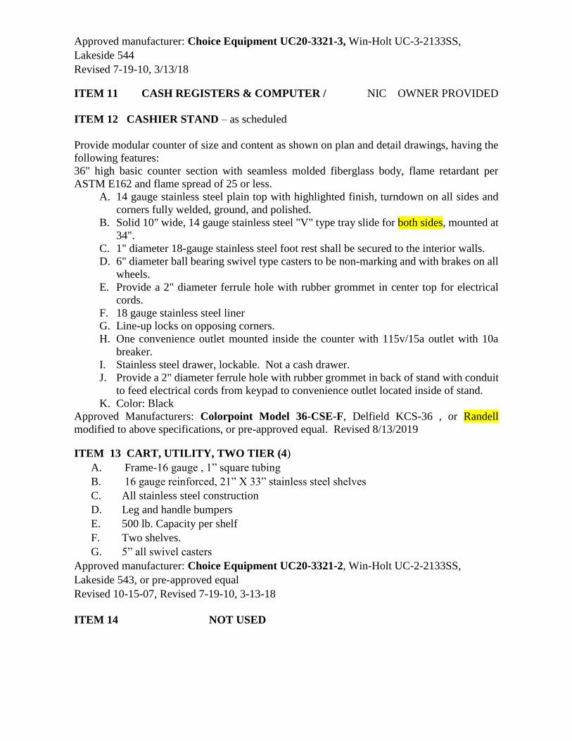
Approved manufacturer: Choice Equipment UC20-3321-3, Win-Holt UC-3-2133SS,
Lakeside 544
Revised 7-19-10, 3/13/18
ITEM 11 CASH REGISTERS & COMPUTER / NIC OWNER PROVIDED
ITEM 12 CASHIER STAND – as scheduled
Provide modular counter of size and content as shown on plan and detail drawings, having the
following features:
36" high basic counter section with seamless molded fiberglass body, flame retardant per
ASTM E162 and flame spread of 25 or less.
A. 14 gauge stainless steel plain top with highlighted finish, turndown on all sides and
corners fully welded, ground, and polished.
B. Solid 10" wide, 14 gauge stainless steel "V" type tray slide for both sides, mounted at
34".
C. 1" diameter 18-gauge stainless steel foot rest shall be secured to the interior walls.
D. 6" diameter ball bearing swivel type casters to be non-marking and with brakes on all
wheels.
E. Provide a 2" diameter ferrule hole with rubber grommet in center top for electrical
cords.
F. 18 gauge stainless steel liner
G. Line-up locks on opposing corners.
H. One convenience outlet mounted inside the counter with 115v/15a outlet with 10a
breaker.
I. Stainless steel drawer, lockable. Not a cash drawer.
J. Provide a 2" diameter ferrule hole with rubber grommet in back of stand with conduit
to feed electrical cords from keypad to convenience outlet located inside of stand.
K. Color: Black
Approved Manufacturers: Colorpoint Model 36-CSE-F, Delfield KCS-36 , or Randell
modified to above specifications, or pre-approved equal. Revised 8/13/2019
ITEM 13 CART, UTILITY, TWO TIER (4)
A. Frame-16 gauge , 1” square tubing
B. 16 gauge reinforced, 21” X 33” stainless steel shelves
C. All stainless steel construction
D. Leg and handle bumpers
E. 500 lb. Capacity per shelf
F. Two shelves.
G. 5” all swivel casters
Approved manufacturer: Choice Equipment UC20-3321-2, Win-Holt UC-2-2133SS,
Lakeside 543, or pre-approved equal
Revised 10-15-07, Revised 7-19-10, 3-13-18
ITEM 14 NOT USED

ITEM 15 DISPLAY COUNTER, PLAIN TOP QUANTITY AS SCHEDULED
Provide modular serving counter of size and content as shown on plan drawings, having the
following features to match Items 9, 12, 16, 17, 18
A. 36" high basic counter section with seamless molded fiberglass body, flame
retardant per ASTM E162 and flame spread of 25 or less.
B. Body lined with 18 gauge stainless steel., or
C. Open base in rear of cabinet.
D. 30" wide 14 gauge stainless steel top with highlighted finish.
E. Single tier tempered glass over shelf display stand to match food shield on hot
counter.
F. Solid 10" wide, 14- gauge stainless steel, "V" type tray slide, mounted 34" AFF.
G. Fold down cutting board on server side, to facilitate restocking
H. 5" ball bearing swivel type casters to be non-marking, with brakes on all wheels.
Casters to be mounted with interior and exterior bracing for maximum stress relief.
I. Line-up locks to be barrel bolt and key slot design with cam locking action placed
on opposing corners.
J. Install in banked line-up as shown on drawings.
K. Color: Black
Revised 10-12-07, Revised 8-25-15, Revised 5/21/18
ITEM 16 COUNTER, SOLID TOP, FOR CONDIMENTS AND ACCESSORIES (2)
Provide modular serving counter with the following features to match items 9, 12, 15. 17, 18
A. 36" high basic counter section with seamless molded fiberglass body, flame retardant
per ASTM E162 and flame spread of 25 or less.
B. Total length of unit to be 60”
C. Body lined with 18-gauge stainless steel.
D. Base to have under-storage with shelf and fiberglass door panels with locks
E. 30" wide, 14-gauge stainless steel top with highlighted finish
F. Solid 12” wide, 14 gauge stainless steel, "V" type tray slide on both sides, mounted
at 34” AFF.
G. 5" diameter ball bearing swivel type casters to be non-marking and with brakes on all
wheels. Casters to be mounted with interior and exterior bracing for maximum stress
relief.
H. Color: Black
Approved Manufacturer: Colorpoint Model 60 ST , Delfield modified to above
specifications, or pre- approved equal.
Revised 10-12-07, 5/21/18
ITEM 17 COUNTER, HOT SERVING – AS SCHEDULED
Provide modular serving counter of size and content as shown on plan drawings, having the
following features to match items 9, 12, 15, 16, 18
A. 36" high basic counter section with seamless molded fiberglass body, flame retardant per
ASTM E162 and flame spread of 25 or less.
B. Body lined with 18-gauge stainless steel.
C. Base to have under-storage with shelf and fiberglass door panels with locks.
D. 30" wide 14-gauge stainless steel top with square turndown on all sides and corners fully
welded, ground and polished.
E. Recessed top accept 18" X 26" sheet pans.
F. Five individually controlled dry/moist wells, with solid state digital controls wired to
circuit breaker for current overload protection.

G. Control panel to be hinged for service access.
H. Hot food drains for each food well shall be plumbed to common manifold and extended
to shut off valve under holding wells. Provide 4’ flexible hose to drain.
I. Solid 12" wide, 14-gauge stainless steel, "V" type tray slide, mounted at 34”.
J. 5" ball bearing swivel type casters to be non-marking, with brakes on all wheels. Casters
to be mounted with interior and exterior bracing for maximum stress relief.
K. 10” shelf on server side, fold down, and 14-gauge stainless steel.
L. Single tier tempered glass over shelf with front tempered glass shield that is adjustable to
allow attendant or self-service. Full sloped front protector to prevent customers from
touching food. Ends top, and front to be 3/8" tempered glass. Versa-Gard VG 6S,
Flexishield or approved equal.
M. Line-up locks to be barrel bolt and key slot design with cam locking action placed on
opposing corners.
N. Replacement Panels (5 ea.)
O. All equipment to be built in accordance with Underwriters Laboratories, Inc. and bear the
UL complete Unit listing label, no component parts listed equipment will be accepted,
and shall also bear the UL listing seal for safety and certification label for sanitation.
P. ELECTRICAL: 208 Volt / 1 phase /Max 2500 Watts
Plug to be 120V-250V / 50 AMP / Twist Lock/ 4 wire/ Male.
Q. Curved Infrared heat strip with LED lights built into the heat strip housing and wired to
separate infinite control with on/off switch, and fused as required. Hatco Glo-Ray Model
GR5AL- or preapproved equal. Black in color.
R. Color: Black
Approved Manufacturers: Colorpoint, Model EF5-CPA-F, Delfield KH-5-NU- modified to
above specifications, or pre-approved equal
Revised 6-1-06, Revised 11-25-08, 7-25-17, 5/20/18
ITEM 18 REFRIGERATED COLD FOOD TABLE-IN PLACE OF FROST TOP-
QUANTITY AS SCHEDULED to match 9, 12, 15, 16, and 17
A. 36” high basic counter with body to e seamless molded fiber glass with smooth
exterior surfaces and rounded corners. Fiberglass to be flame retardant per
specification ASTM E 162 having flame spread of 25 or less.
B. Rear of body to have lockable storage made from 18 gauge stainless steel.
C. Cold pans t be 18 gauge stainless steel fully welded construction with ¼” coved
corners
D. Cold pan shall be pitched to a 1” drain, which is extended to a valve below the base.
E. All cold pans shall be furnished with urethane insulation on bottom and all four sides
of pan.
F. Pan shall be fully separated from the counter top by a full perimeter breaker strip.
G. Cold pans are to allow for a full steam table pan 6”deep.
H. Temperature is maintained by a static air system utilizing1/2” copper coils attached to
the bottom liner and sides to a level 1” above the food pans.
I. Food pans to be supported by full length removable brackets located 3” below the top.
J. Single tier tempered glass over shelf with front tempered glass shield. Straight
tempered glass food protector, Versa-Gard, Flexishield, or approved equal.
K. 5” diameter, ball bearing, swivel type casters to be non-marking and with brakes on all
wheels.
L. Color: Black
Approved manufacturers: Colorpoint 50-CFMX-F, Delfield KCSC-B modified to
above specifications, or pre-approved equal. Revised 5/20/18

ITEM 19, 20 NOT USED
ITEM 21 FOOD CUTTER DELETE FROM SPECS 5-15-15
ITEM 22 NOT USED
ITEM 23 TRAY DOLLY – QUANTITY (6)
A. 16 gauge, 304 stainless steel construction
B. 800 pound rolling capacity
C. Holds 2 stacks of 12” X 16” cafeteria trays
D. 1 ¼” lip to securely hold trays
E. 5” all swivel casters
F. Lifetime guarantee against rust or corrosion
Approved Manufacturers: CHOICE Model UC200-1625, Win-Holt D1625/SS, Lakeside, or
pre-approved equal. Revised 10-29-07. 10-05-15
ITEM 24 TROUGH, FLOOR- STAINLESS STEEL QUANTITY AS SCHEDULED
Provide floor trough with removable grate having the following features:
Grate:
A. All Stainless steel welded construction.
B. 3/16" x 1" flat bars set on edge, with 13/16" clearance between bars.
C. Two 1/2" diameter rods wedged through bars full length, and weld to each bar.
D. Size to suit trough with removable sections not to exceed 20" long.
Trough:
E. 14 gauge 304 18-8 stainless steel, all welded with coved corners and anchor straps, full
perimeter flange for installation under grout.
F. Pitch to waste and provide stainless steel cup with removable perforated stainless steel
basket.
G. Overall trough size to be approximately l'-6" wide ~x 2'-0" long.
H. See plan for clarification. Coordinate with General Contractor and Plumbing Contractor
to assure proper installation.
Approved Manufacturers: IMC/Teddy Food Service Corporation Model FT-SG, Serv-o-LifT,
Eastern, or pre-approved equal.
ITEM 25 NOT USED
ITEM 26 DISHMACHINE
Provide gas or electric powered machine with following features:
A. 44” machine
B. Convertible for low temperature or hot water final rinse
C. #16 gauge stainless steel tank and chamber.
D. Oversized wash chamber option to accommodate sheet pans in upright position
D. 2 HP machine power wash motor with stainless steel pump and impeller
E. Self draining pumps
F. 15 KW electric immersion heater, inter-wired at factory. Heater is to have solid state
thermostat with positive low water protection.
G. Top mounted dial thermometers mounted in stainless steel enclosure

Motor controls wired to common electrical point in stainless steel control center
mounted on top of machine. Motors to have built-in thermister overload protection
with manual reset.
H. Dual side pawl conveyor driven by 1/6 HP motor.
I. Minimum capacity of 203 racks per hour
J. Ball detent clutch system to prevent damage to conveyor and drive motor if rack
should be obstructed.
K. Stainless steel upper and lower wash arms with anti-clog nozzles. Both wash arms to
be removable for cleaning without use of tools.
L. Final rinse automatically activated by racks in passing. Rinse agent dispenser injector
and electrical interface points. Final rinse rate to be 5.0GPM.
M. Automatic fill with tank water level automatically maintained. Fill to be interrupted if
door is opened. Drain handle to be located inside tank chamber and to be closed
automatically upon lowering of inspection door.
N. Stainless steel front panel, frame, feet and legs.
O. Energy saver auto timer
P. Removable self-flushing stainless steel strainer pans and large deep stainless steel
basket removable from front of machine.
Q. Door safety interlocks on all doors
R. Pump intake screen assembly
S. Built in integral wiring channel
T. Vent fan control
U. Stainless steel splash shields
V. Plastic strip curtains throughout
W. Conveyor dwell switch
X. Table limit switch
Y. 2 vent cowls with locking dampers
Z. 4 peg, 2 combinations and 2 bun pan dish racks included
AA. Machine to have integrated booster heater with 70° temperature rise
AB. Machine to have as standard a full two year warranty against manufacturer’s defects
on parts, labor, and mileage. Approved Manufacturers: Hobart Model CL44eN,
Champion 44-PRO, Insinger Admiral 44-
Revised 10-12-07, Revised 12-1-11, 3/13/18, 3-11-19
ITEM 27 DISPENSER, MILK (MUST BE OPEN FRONT - QUANTITY AS
SCHEDULED
Provide mobile carton milk cabinet having the following features:
A. Stainless steel interior and exterior
B. Top mounted Removable refrigeration system
A. Forced air refrigeration system
B. Sliding lift up and down door(s)
E. Reinforced cabinet interior bottom. Capacity to hold (12) standard milk cases.
F. Floor drain with plug
G. 6” casters
H. Heavy Duty Dunnage Racks
I. 3 year parts and labor warranty, 5 year compressor parts warranty
J. Magnetic snap-in EZ clean door gaskets
Approved Manufacture: Traulsen RMC49D6, or pre-approved equal
Revised 6-1-06, 7-25-17

ITEM 28 DISPENSER, ICE (2)
Provide ice dispenser with following features:
A. Stainless steel exterior cabinet with merchandiser and “Ice” sign
B. Push lever ice-dispense.
C. 90 pound ice storage capacity.
D. Electrical 120V/60HZ/2.5 FLA.
E. Two ¾” PVC drain fittings, one from drain pan and one from bin.
F. Dispenses any size cube up to one-inch square.
G. Motor, drain and electrical connections are front-serviceable.
H. Provide drain hose to floor trough
I. Provide and install 4” stainless steel legs.
Approved manufacturers: SerVend Model M90, or pre-approved equal.
ITEM 29 DISPENSER, ICE CREAM (1)
Horizontal ice cream freezer with glass angled lid
B. Internal LED lighting
C Lid lock with keys
D. 1 ½” dual swivel casters
E. Power indicator light
G. Slide-out, easy access condensing unit
H. Maintain Temperature -18 to +10 degrees
J. Three baskets with dividers
K. External mounted thermometer
L. 115V/60/1 with 9’cord and plug attached
Approved Manufacturer: NorLake CTB-31-6, Masterbilt MSC-31N, or pre-approved equal
Revised 6-1-06, Revised 10-29-07, Revised 07-15-10, 7-25-17, 3-11-19
ITEMS 30, 31 NOT USED
ITEM 32 DISPOSAL, FOOD PREP & POTSINK AREA
Delete from Specifications
Revised 7-20-06, Revised 10-12-07, Revised
ITEM 33 DUNNAGE RACK QUANTITY AS SCHEDULED
Provide single deck dunnage platform unit with the following features to match Item 79 or 80.
A. One piece polymer construction.
B. Slotted deck.
C. Arrange as shown on Plan drawings, using quantities and sizes as specified.
Approved Manufacturers: Metro Model HP2236PD, Cambro, Eagle
ITEM 34 DISPOSAL, DISHWASH AREA (1)
A. Voltage characteristics as scheduled.
B. 18" diameter stainless steel cone for welding to drain-board.
C. Auto-reversing control center including, magnetic starter(s) and start/stop buttons, in
stainless steel NEMA 4 enclosure, or better, with disconnect switch.
D. Thermal overload protection either built into motor or in control center with manual reset.
E. Solenoid and vacuum breaker.
F. Control center to be mounted out of splash zone, under drainboard on stainless steel
mounting bracket as shown on details.
G. Short neck as necessary to provide clearance under disposal.
H. Coordinate installation of pre-rinse unit (item #65)

I. Low water pressure cutoff, with time delay for water after cut off occurs
J. Permanently lubricated ball bearings
K. Tubular stainless steel legs with bullet feet adjustable to 3 inches in either direction
L. Rubber isolating ring at cone mounting to reduce vibration and noise
M. Air cooled motor.
Approved Manufacturers: Bus Boy Model 3000, Hobart, Insinkerator
Revised 7-20-06, Revised 10-12-07
ITEM 35 DISPLAY CASE, REFRIGERATED, COUNTERTOP – (2) DELETE
Provide unit with following features:
1. Condensing component mounted on rear
2. Optional LED lighting
3. Rear has (2) adjustable and removable doors
4. Removable back display deck
5. Locks for all doors
6. External dimensions of 48”W x 29 “D x 28”H
7. Adjustable shelves
8. Cord and plug-NEMA 5-15P
9. If GFCI circuit is required, GFCI breaker must be used instead of GFCI receptacle
Approved Manufacturer: Federal CRB4828, or pre-approved equal.
Revised 5/23/18
ITEM 36 NOT USED
ITEM 37 EXHAUST HOOD (1)
Refer to most current version of division 15 Mechanical & Plumbing Design Guidelines,
Sections 4.01, A, B, and C.
ITEM 38 FAN, AIR CURTAIN (1)
Provide air curtain fan having the following features:
A. #304 stainless steel exterior with adjustable deflectors and adjustable air intake.
B. Electrical characteristics as scheduled.
C. Micro-switch for automatic door-actuated on-off control.
D. 5-year warranty.
Approved Manufacturers: Berner ASR1036A-SS, Mars Door Company Model48CH,
Universal Jet Industries,
Revised 6-1-06.
ITEM 39 EQUIPMENT STAND (for item 21) DELETE
ITEM 40 FIRE SUPPRESSION SYSTEM (1)
Provide automatic wet chemical fire control system as required to protect exhaust hood, Item
37, and the cooking equipment located under this hood, and having the following features:
A. All tanks, control heads, piping, relays, cable, fusible links, nozzles, elbows, etc., as
required for complete system.
B. Brass nozzles and chrome plated or sleeved exposed piping.
C. Manual strike mechanism in accessible location.
D. Installation in accord with N.F.P.A. 17A code requirements and coordinate with
exhaust hood construction and installation.
E. Four contacts for use by E.C., one contact for alarm, one for supply fan shut-Off, one
for shunt trip actuation, and one spare.
F. Provide mechanical gas solenoid valve loose for installation by plumber.

Approved Manufacturers: Ansul Model R-1 02, Range Guard, Pyro-chem
ITEM 41 NOT USED
ITEM 42 FREEZER, REACH-IN, TWO DOORS (Future)
Provide electrical service for future installation Add to floor plan?
ITEM 43 NOT USED
ITEM 44 GUIDE RAILINGS QUANTITY AND LENGTH PER DRAWINGS-
Provide guide railings with the following features:
1. Double horizontal type rail
2. 14 gauge stainless steel-all welded construction
3. 2” tubing
4. 6” radius on end uprights
5. Die formed flanges with three 3/8” holes for fastening rail to floor
6. All welds ground and polished to match commercial finish on railing
Approved Manufacturers: United Show Case Company, Inc., or pre-approved equal
ITEM 45 NO LONGER USED
ITEM 46 HOSE REEL QUANTITY AS SCHEDULED
Provide open type retractable all-in-one hose reel system having the following features:
A. B-1434 reel, open, stainless steel.
B. Continuous pressure type vacuum breaker, B-963.
C. Shut off control, ORK3.
D. MV-0522 spray gun.
E. B-1 31 base faucet.
F. 50 feet of heavy duty hose.
G. All chrome interconnecting piping.
H. Mount on wall at location shown on drawings.
Approved Manufacturers: T&S, or pre-approved equal.
ITEM 47, 48 NOT USED
ITEM 49 ICE MACHINE (1)
Provide elevated bin and gravity loading cart system with the following features:
ICE MACHINE
A. Up to 630 lbs. of ice produced per 24 hours
B. Produces crescent shaped ice cubes
C. Stainless steel exterior
D. Ambient temperature range 45-100°
E. Water temperature range 45-90°
F. Self-contained, air cooled
G. Water filtration system
H. Three years warranty parts and labor on entire machine
I. Five years warranty parts and labor on evaporator
BIN:

J. Bin to have minimum 500 lb. storage capacity
K. 6” stainless legs
L. NSF listed, UL approved
Approved manufacturers: Hoshizaki KM-650MAJ, Ice-O-Matic to above specs, pre-
approved equal, or pre-approved equal
ITEM 50 INGREDIENT BIN –DELETE FROM SPECS 5-15-15
ITEMS 51-54 NOT USED
ITEM 55 MIXER, 20 QUART DELETE FROM SPECS 5-15-15
ITEM 56 MIXER, 30 QUART (1)
MIXER AND ACCESSORIES:
1. # 12 attachment hub
2. Removable s/s bowl guard
3. Direct gear driven transmission. ¾ HP motor by manufacturer.
4.115/60/1 voltage, with 6-foot cord and plug.
5. 2 year parts, labor and mileage warranty against manufacturer’s defects.
6. NSF and UL approved
7. Factory trained service technicians available for service.
8. Powder coat paint
9. The motor shall have grease packed ball bearings, ventilation, splash proof enclosure and
certified by the Baking Industry Sanitation Standard Committee.
10. Manufacturer provided accessories (no replacement brands): s/s bowl, bowl truck,wire
whip, flat beater, dough hook and ingredient chute.
Approved Manufacturer: Hobart D-300, Globe SP-30 or pre-approved equal
Revised 10-12-07, Revised 5-15-15, Revised 5-21-18, Revised 3-11-19
ITEMS 57-63 NOT USED
ITEM 64 OVEN, CONVECTION, DOUBLE, GAS (3)
Provide gas-fired convection oven having the following features:
2 sections, standard depth
_ Stainless steel front, top, and sides. Full metal rear cover
_ Dual pane thermal glass windows encased in stainless steel door frame
_ Single porcelain door handle with simultaneous door operation
_ Triple-mounted pressure lock door design with turnbuckle assembly
_ Modular slide out front control panel for easy access & cleaning
_ Fully insulated at top, back, sides and bottom
_ Porcelain baking compartment liner (14 gauge)
_ Five chrome-plated racks, eleven rack positions
_ Two commercial bake oven lamps per compartment
_ Dual Flow Gas system
_ Electronic spark ignition
_ Pressure regulator
_ Manual gas service cut-off switch located on the front of the control panel
_ Air mixers with adjustable air shutters
_ Gas manifold for stacking
_ 48” gas hose with quick disconnect
_ Solid state thermostat with infinite temperature control range of 200°F to 500°F
_ Two speed fan motor

_ 1/3 horsepower blower motor with automatic thermal overload protection
_ Cook/Cool mode selector
_ Control area cooling fan
_ Solid state manual control with separate dials to control thermostat and timer
_ 60 minute timer
_ 6" adjustable stainless steel legs
_ Wired 120 volt with plug and cord attached
_ Two year oven parts and one year labor warranty
_ Five year oven door warranty
_ Replacement parts guaranteed available for 12 years from purchase date
_ NSF, UL or ETL approved
-- ENERGY STAR CERTIFIED.
Approved Manufacturers: Blodgett DFG-100, Hobart HGC5 Series, Vulcan SG44 Series
Revised 07-15-10, Revised 12-01-11, Revised 5-15-15, 7-25-17, 3-11-19
ITEM 65 PRE-RINSE UNIT (1) INSTALL OVER DISHROOM DISPOSAL
Provide deck mounted pre-rinse unit having the following features:
A. Flexible stainless steel hose.
B. Self-closing spray nozzle.
C. Wall support bracket.
A. Mixing valve with integral check valves.
Approved Manufacturers: T&S Model B-1 13, Chicago Faucet, or pre-approved equal.
ITEM 66 PRE-RINSE UNIT– GENERAL KITCHEN USE
Delete from Specifications.
Revised
ITEMS 67-68 NOT USED
ITEM 69 RACK, MOBILE POT AND PAN QUANTITY AS SCHEDULED (3
MINIMUM)
Provide four-tier polymer shelving unit complete with tubular uprights and having the
following features:
A. Uprights shall be nominal 74" high, numbered at one inch intervals.
B. Shelf connectors to be wedge lock type with corner collar.
C. Each unit to be free standing.
D. Shelf frames shall be made of steel with electroplated substrate and epoxy finish. Shelf
mats to be injection molded polypropylene.
E. Arrange using quantities and sizes as shown on plan drawings.
F. 800 pound per shelf capacity, minimum.
Preferred Manufacturer: Metro, Metro-Max Q Series Q556EG2, Eagle Lifestor, Amco Plastic
Plus
Revised 10-12-07
ITEM 70 RACK, BUN PANS (6)
Provide all-welded aluminum pan rack having the following features:
A. End loading.
B. Designed for 18” X 26” pans and trays.
3” spacing between shelves
C. 350 lb capacity
D. 5" diameter swivel casters, with brakes.
E. Lifetime guarantee against rust

Preferred Manufacturer: Choice Equipment PRIO-A-1820, Lakeside 8900, Win-Holt AL-
1820/HD
Revised 10-12-07, Revised 7-19-10, 7-25-17
ITEM 71 NOT USED
ITEM 72 WALK-IN REFRIGERATOR/FREEZER (1)
Provide pre-fabricated cold storage room assembly of size and shape shown on plan and detail
drawings. Exact overall size to be field verified prior to fabrication.
A. Insulation: Panels shall be insulated with 4" thick injected urethane, expanded with
R1416, no CFC's used. Foam shall be 2.25 lb. density, 95% closed cell. Panels shall
meet ASTME-84 (UL-723) and be listed by Underwriters laboratories and by Factory
Mutual as a Class I building material.
B. Coved corners: Assembly shall be constructed so that all interior wall, floor and ceiling
intersections shall comply with N.S.F. requirements.
C. Cam lock fasteners: All panel intersections and wall, floor and ceiling intersections
shall be secured by cam lock fasteners.
D. Ceiling panels to be one piece, self-supporting and span full width of assembly.
E. Finishes: Aluminum exterior and interior finishes shall be as shown on drawings.
F. Doors: Door size and finish shall be as shown on drawings, and shall be furnished
complete with sill wiper gasket, lift type hinges.
G. Hinges, latches and hardware shall be chrome plated. Minimum (3) hinges.
H. Exterior door to be equipped with automatic door closer.
I. Freezer door to be equipped with perimeter heat.
J. Exterior door(s) to be equipped with cylinder lock having inside safety release feature
and also configured to allow use of padlock to secure door.
K. Aluminum kick plate to be provided on door.
L. Thermometers: Each compartment to be provided with exterior flush mounted dial
thermometer mounted at eye level to each door.
M. Lights: Each compartment to be furnished complete with manufacturer's standard light
fixture, having protective cover, mounted and pre-wired to switch with pilot light in
door section. Extra lights as needed to provide 30 foot candles 30" above floor.
N. Floor: Quarry Tile
O. The floor and ceiling shall have maximum length panels to span full length of box if
possible, otherwise stagger joints so there are no common "four corner" intersections
and no joints occurring in doorways.
P. Refrigeration System: Shall be furnished by manufacturer as part of cold storage room
assembly, provide each compartment with complete refrigeration system sized to
maintain appropriate temperature.
Q. Condensing units to be semi-hermetic, or scroll type, air-cooled, remote. Units to have
performance and wiring characteristics as scheduled on drawings. Units shall have pre-
wired disconnects. Refrigeration systems to be designed for use with R404A or R507
refrigerant only.
R. Condensing units to be provided with painted galvanized steel all-weather housing,
controls, and crankcase heaters, all suitable for outdoor conditions, and located as shown
on drawings.
S. Unit coolers to be low-silhouette type, mounted at locations shown on drawings.
Performance and wiring characteristics to be as scheduled on drawings. Freezer system
to be provided with timed electric defrost.
T. Evaporator drain lines to be provided by this section and extended to floor receptors
outside assembly.
U. Freezer drain lines to be wrapped with heater cable.

V. Refrigerant piping to be ACR copper tubing, hard temper, with wrought fittings and
silver solder joints. Insulate suction lines with 3/4" pre-molded foamed plastic
insulation.
W. Ensure bracing of refrigeration line every 7 feet.
X. If bracing is overhead, 12”saddles are required at support
Y. All insulated portions of refrigerant line to be equal or greater than R-7.1
Z. Refrigeration systems to be provided with all required refrigerant piping, insulation,
vibration eliminator, solenoid(s), dryer, suction line filter, expansion valve(s),
thermostat(s), heat exchangers, and defrost timers, etc. as necessary for complete
installation. Provide pump down control circuit consisting of thermostat and solenoid
valve. All components including piping and insulation to be installed using accepted
industry standards, manufacturer’s instructions and first class workmanship.
AA. Miscellaneous: Provide 1/8" diamond tread wainscot along exposed front exterior of
assembly mounted from floor to 48" A.F.F.
BB. Provide trim strips, closure panels, etc., as necessary to trim assembly to adjacent
building surfaces.
CC Provide removable top closure panels with “C” channel rails. Lift-out panel sections
to have turndown edges for strength and are not to exceed 4’-0” in length.
DD Provide plastic strip curtains at door locations, transparent vinyl overlapping strips,
aluminum Bar hanging rod and bracket, suitable for low temperature applications, as
manufactured by Curtron Flexstrip Products, Inc. or equal.
EE Provide heated pressure relief port in freezer.
FF Provide sleeves properly located for utility entrance, drain lines, and refrigeration
lines, and after lines are installed, fill sleeves with spray foam compound, suitable for
use in refrigerated spaces. Seal all penetrations with fire foam, as required by
Mecklenburg County Code Enforcement, and fire caulk over fire foam.
GG. Cold storage room shall be erected by factory trained and certified installers or shall
be supervised by factory personnel. Refrigeration systems shall be furnished by cold
storage room manufacturer and installed by factory authorized personnel.
ENERGY STAR CERTIFIED
Lights:
Each compartment to be furnished complete with Kason model 1806 LED light fixture,
having protective cover, mounted and pre-wired to switch with pilot light in door section.
a. Unbreakable lexan jar.
b. Rated 50,000 hr. life.
c. Exceeds Federal Energy Act requirement at 85 lumens/watt.
d. Lamps to be cULus listed, NSF listed and RoHS compliant.
e. Reach full light immediately at lowest temperatures.
f. 5-yr. limited warranty on fixture.
g. 3-yr. limited warranty on lamps.
h. Extra Kason model 1810 4-ft. LED lights as needed to provide 30 foot
candles 30" above floor.
i. Unbreakable IP-65 polycarbonate enclosure.
j. Exceeds Federal Energy Act requirement at 67 lumens/watt.
k. Rated 50,000 hr. life.
l. 5-yr. limited warranty on fixture.
m. 3-yr. limited warranty on lamps.
n. Reach full light immediately at lowest temperatures.
o. Lamps to be cULus listed, NSF listed and RoHS compliant.
Revised 12-20-11, Revised 5-15-15

This specification does not constitute a complete description of cold storage assembly, also see
plan and detail drawings.
Approved Manufacturers: Bally, Thermokool, Norlake, Kolpak
Revised 6-1-06., Revised 07-15-10, Revised 12-1-11, 7-25-17, 5-3-18
ITEMS 73-75 NOT USED
ITEM 76 REFRIGERATOR, REACH-IN (1)
Provide one-section reach-in refrigerator with top mounted air-cooled condensing unit,
exterior thermometer, cylinder door locks and top mounted condensate evaporator, having the
following features:
Items 76, 77 and 103 must be provided by same manufacturer.
A. Full length stainless steel doors, hinged as shown on drawings.
B. Stainless steel exterior and interior.
C. S/S universal pan slides to accommodate 14 18 x 26 sheet pans
D. Set of 5” swivel- type locking casters.
E. Wired for 120/1 operation, cord and plug set.
Approved manufacturer: Traulsen RHT132WUT, Victory RS/RSA-1D-S1-EW,
Continental 1R-SS
Revised 7-20-06, Revised 3-01-12, Revised 5-15-15, Revised 5/21/18
ITEM 77 REFRIGERATOR, PASS-THRU QUANTITY AS SCHEDULED
Provide two-section pass-thru refrigerator with top mounted air-cooled condensing unit,
exterior dial thermometer, cylinder door locks and top mounted condensate evaporator,
having the following features. Items 76, 77 and 103 must be provided by the same
manufacturer.
A. Full length stainless steel doors, hinged as shown on drawings.
B. Stainless steel exterior and interior.
C. Removable, universal type pan slides, both sections.
D. Set of adjustable stainless steel leg.
E. Stainless steel banking strip.
F. Customized stainless steel trim strip to seal cabinet to adjacent interior and exterior
building surfaces.
G. Wired for 120/1 operation.
A. External thermometer
B. Install cabinet so that controls face kitchen area.
Approved Manufacturers: Traulsen RHT232WPUT, Victory, or Continental 2R-SS-PT-HD
Revised: 7-20-06, Revised 10-12-07, 3-01-12, Revised 5-15-15
ITEM 78 NOT USED
ITEM 79 SHELVING, REFRIGERATION QUANTITY AS SCHEDULED
Provide four-tier polymer shelving unit complete with tubular uprights and having the
following features:
A. Uprights shall be nominal 74" high, numbered at one inch intervals.
B. Shelf connectors to be wedge lock type with corner collar.
C. Each unit to be free standing.
D. Shelf frames shall be made of steel with electroplated substrate and epoxy finish. Shelf
mats to be injection molded polypropylene.
E. Arrange using quantities and sizes as shown on plan drawings.
F. 800 pound per shelf capacity, minimum.

Approved Manufacturers: Metro-Max Q Series, Eagle Lifstore, Amco Plastic Plus
ITEM 80 SHELVING, DRY STORAGE QUANTITY AS SCHEDULED
Provide five-tier bright zinc plated wire shelving unit complete with tubular uprights and
having the following features:
A. Electro-zinc plated with chromate bath and clear protective coating.
B. Uprights shall be nominal 86" high.
C. Adjustable feet.
D. Stainless steel feet
E. Each unit to be free standing.
F. Arrange using quantities and sizes as shown on Plan Drawings.
Approved Manufacturers: Metro, Eagle, Amco
ITEM 82 HAND SINK, DROP-IN (1)
Provide stainless steel lavatory having the following features:
A. 14 gauge stainless steel, 10” x 14” x 10” D.
B. Chrome plated goose-neck faucet.
C. Strainer type waste outlet.
D. Built into Beverage Counter, Item 128.
Sink to be as manufactured by Select Stainless, Universal, or Low Temp.
ITEM 83 NOT USED
ITEM 84 SINK, POTWASHING (1)
This item to be custom- fabricated in accord with General Requirements of specifications and
with plan and detail drawings. Include disposal (#32) and pre-rinse (#66).
Approved Manufacturers: Select Stainless, Universal, and Low Temp.
ITEM 85 NOT USED
ITEM 86 SINK, VEGETABLE, and TWO-COMPARTMENT (1)
This item to be custom- fabricated in accord with General Requirements of specifications and
with plan and detail drawings. Include disposal (#32) and pre-rinse (#66).
Approved Manufacturers: Select Stainless, Universal, and Low Temp.
ITEM 87 SLICER
Slicer, 12” automatic.
Features to be included:
1. ½ HP motor wired for 120/1 operation, with cord and plug set
2. Adjustable capacity: 12” wide or 7” diameter
3. Adjustable gauge plate up to 1” thickness
4. Stainless steel knife
5. Two speed automatic carriage drive
6. Top mounted removable sharpener with mineral stone
7. All metal finish
8. Lift lever for easy cleaning
9. MICROBAN antimicrobial protection
Approved Manufacturer:Hobart Model HS7, Globe Model 3850, or pre-approved equal
ITEM 88 UTENSIL RACK, TABLE MOUNTED QUANTITY AS SCHEDULED

Provide utensil rack with the following features:
A. Double rail constructed of 3/16” x 2” flat bar 304 stainless steel.
B. 1 5/8” stainless steel tubing legs, mounted and secured to table.
Provide utensil rack with the following features:
A. 18 gauge stainless steel shelf.
B. Stainless steel bar under shelf, mounted to brackets.
C. Double stainless steel pot hooks approximately 8"o.c.
D. See detail drawings.
Approved Manufacturers: LowTemp Model SWS-9, or pre-approved equal.
ITEM 89 NOT USED
ITEM 90 STEAMER, COMBI/OVEN, DOUBLE STACK, GAS (1)
Provide product with following features:
1. Gas powered unit with 210,000 BTU power rating
2. Two full sized compartments
3. Glass doors
4. Five stainless steel wire shelves per compartment
5. Easy to operate mechanical controls
6. Automatic fast cool down control
7. Two speed fan (high/low) control switch
8. Humidity release control switch
9. Generator drain control
10. Core temperature probe with digital read-out which automatically turns off unit
when desired temperature is reached
11. Condensate drip tray which automatically empties into floor drain
12. NSF approved 6” stainless steel adjustable legs
13. Spray head and flexible hose for cleaning
14. Water filtration system
15. Three year warranty for parts, labor and mileage
Approved Manufacturers: Cleveland Convotherm, Altoshaam, UNOX
ITEM 91 STEAMER, CONVECTION (2) NOTE: ITEMS # 91, #92 MUST BE
PROVIDED BY THE SAME MANUFACTURER
1. Two compartment pressure-less floor model steamer.
2. Solid one- piece body for both compartments with heavy duty 14 gauge stainless
steel construction for compartment door, interior and exterior walls.
3. Totally independent cooking compartments with separate gas valve, ignition and
water level controls. No shared components between compartments.
4. Front access generator controls allowing complete service from front of unit
5. Manual on/off switch which activates automatic fill/drainage via manual ball
valve. Electric solenoid switch is not acceptable.
6. Exterior de-liming port
7. Generator de-liming light to alert operator when it is time to de-scale
8. Twin high efficiency power burner forced air generators rated at minimum of
72,000 BTU’s per compartment
9. Capacity for ten (10) 12” X 20” X 2 ½” pans.
10. Electronic spark ignition
11. Fan-less high velocity steam distribution system with brass steam jets.
12. Manual 60 minute electro-mechanical timers with load compensating feature and
bypass switch for constant steaming.
13. Water filtration system
14. Three year warranty for parts, labor and mileage.
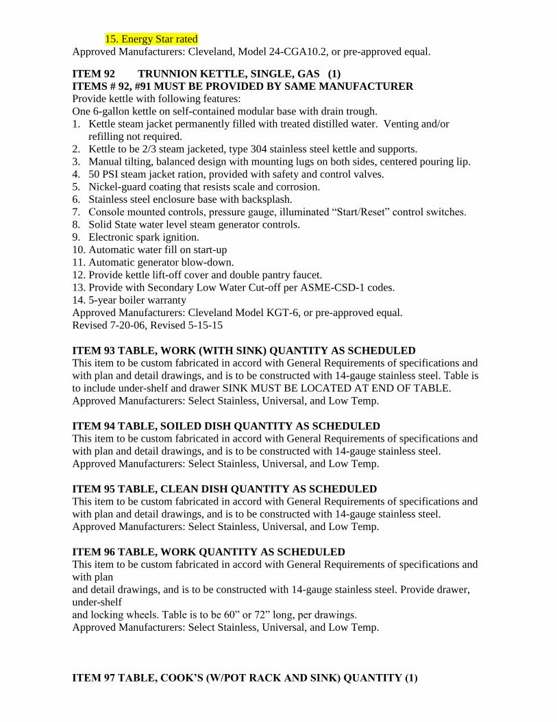
15. Energy Star rated
Approved Manufacturers: Cleveland, Model 24-CGA10.2, or pre-approved equal.
ITEM 92 TRUNNION KETTLE, SINGLE, GAS (1)
ITEMS # 92, #91 MUST BE PROVIDED BY SAME MANUFACTURER
Provide kettle with following features:
One 6-gallon kettle on self-contained modular base with drain trough.
1. Kettle steam jacket permanently filled with treated distilled water. Venting and/or
refilling not required.
2. Kettle to be 2/3 steam jacketed, type 304 stainless steel kettle and supports.
3. Manual tilting, balanced design with mounting lugs on both sides, centered pouring lip.
4. 50 PSI steam jacket ration, provided with safety and control valves.
5. Nickel-guard coating that resists scale and corrosion.
6. Stainless steel enclosure base with backsplash.
7. Console mounted controls, pressure gauge, illuminated “Start/Reset” control switches.
8. Solid State water level steam generator controls.
9. Electronic spark ignition.
10. Automatic water fill on start-up
11. Automatic generator blow-down.
12. Provide kettle lift-off cover and double pantry faucet.
13. Provide with Secondary Low Water Cut-off per ASME-CSD-1 codes.
14. 5-year boiler warranty
Approved Manufacturers: Cleveland Model KGT-6, or pre-approved equal.
Revised 7-20-06, Revised 5-15-15
ITEM 93 TABLE, WORK (WITH SINK) QUANTITY AS SCHEDULED
This item to be custom fabricated in accord with General Requirements of specifications and
with plan and detail drawings, and is to be constructed with 14-gauge stainless steel. Table is
to include under-shelf and drawer SINK MUST BE LOCATED AT END OF TABLE.
Approved Manufacturers: Select Stainless, Universal, and Low Temp.
ITEM 94 TABLE, SOILED DISH QUANTITY AS SCHEDULED
This item to be custom fabricated in accord with General Requirements of specifications and
with plan and detail drawings, and is to be constructed with 14-gauge stainless steel.
Approved Manufacturers: Select Stainless, Universal, and Low Temp.
ITEM 95 TABLE, CLEAN DISH QUANTITY AS SCHEDULED
This item to be custom fabricated in accord with General Requirements of specifications and
with plan and detail drawings, and is to be constructed with 14-gauge stainless steel.
Approved Manufacturers: Select Stainless, Universal, and Low Temp.
ITEM 96 TABLE, WORK QUANTITY AS SCHEDULED
This item to be custom fabricated in accord with General Requirements of specifications and
with plan
and detail drawings, and is to be constructed with 14-gauge stainless steel. Provide drawer,
under-shelf
and locking wheels. Table is to be 60” or 72” long, per drawings.
Approved Manufacturers: Select Stainless, Universal, and Low Temp.
ITEM 97 TABLE, COOK’S (W/POT RACK AND SINK) QUANTITY (1)

This item to be custom fabricated in accord with General Requirements of specifications and
with plan and detail drawings, and is to be constructed with 14-gauge stainless steel. Provide
drawer and under shelf. Approved Manufacturers: Select Stainless, Universal, and Low Temp.
ITEM 98 TABLE, WORK QUANTITY AS SCHEDULED
This item to be custom fabricated in accord with General Requirements of specifications and
with plan and detail drawings, and is to be constructed with 14-gauge stainless steel. Provide
drawer and under shelf. Approved Manufacturers: Select Stainless, Universal, and Low
Temp.
ITEM 99 TABLE, BAKER QUANTITY AS SCHEDULED
This item to be custom fabricated in accord with General Requirements of specifications and
with plan and detail drawings, and is to be constructed with 14-gauge stainless steel.
A. 14 gauge 304 stainless one piece, seamless stainless steel top, with 6”high integral riser on
back and ends with coved corners. Overall size 30” X 72” long
B. Stainless steel over-shelf, 16-gauge 304 stainless steel, with rear and ends flared up 2”.
Height of shelf AFF is 54”.
C. Stainless steel legs fitted at top with fully enclosed stainless steel gussets welded to
underbracing and at bottom, with adjustable stainless steel bullet feet. Front rail omitted on
open base section to allow for ingredient bins.
D. Provide three (3) roller bearing drawers mounted on right side, 20” X 20” X 5”, 18–gauge
stainless steel coved corned body, set in stainless steel channel frame and having stainless
steel roller slides.
E. All joints ground and polished to match adjoining surfaces. Sound deaden underside of
top.
F. NSF approved.
Approved Manufacturers: Universal Stainless, Select Stainless, Low Temp Industries
ITEM 100 NOT USED
ITEM 101 VENT DUCT SET
To be custom fabricated in accord with General Requirements of specifications and with plan
and detail drawings.
Approved Manufacturers: Universal Stainless, Select Stainless, Low Temp Industries
ITEM 102 WALL SHELF QUANTITY AS SCHEDULED
This item to be custom fabricated in accord with General Requirements of specifications and
with plan
Approved Manufacturers: Universal Stainless, Select Stainless, Low Temp Industries
ITEM 103 WARMING CABINET, PASS THRU QUANTITY AS SCHEDULED
Provide one-section pass-through hot cabinet, having the following features. Items 76, 77,
and 103 must be provided by the same manufacturer. A. Half-height doors hinged as shown on drawings.
B. Stainless steel exterior and interior.
C. Removable, universal pan slides, each half-door section.
D. Voltage characteristics as scheduled.
E. Set of adjustable stainless steel legs
F. Customized stainless steel trim strip to seal cabinet to adjacent building surfaces.
G. Install cabinet so controls face kitchen.
H. External thermometer

I. Top housing to match refrigerator cabinet.
Approved Manufacturers: Traulsen RHF132WP-FHS, Delfield SLH-PT-29SS, Victory
Revised 03-1-12, Revised 5-15-15
ITEM 104 WARMER CABINET/PROOFER, MOBILE (3)
Provide mobile heater/proofing cabinet having the following features:
A. All stainless steel construction
B. 20 Amp plug with 8' wire.
C. Universal Tray Slides to hold 14 bun pans or 28 steam table pans
D. Maintains temperatures from 85º F to 180º F
E. Circulating fan to maintain even temperature throughout cabinet, as well as speed
initial warm-up and recovery times
F. External thermometer
G. Dutch Doors
H. Bottom mounted water pan with minimum 2-gallon capacity. No exposed heating
elements
I. 5" locking casters
J. Full perimeter bumper
Approved Manufacturers: CresCor H-137-WSUA-12D-15A, Metro C-5 9 Series, Winston
ITEM 105 WARMER, 2-DRAWER (2)-
Provide 2-drawer warmer having the following features:
A. All stainless steel construction.
B. Cord and plug.
C. Drawers to accept two full steam table pans.
D. Electronic differential controls.
E. Controlled vapor technology.
F. External thermometer.
G. Full perimeter insulators.
H. Bottom mounted water pan.
I. Built into Beverage Counter, Item 20, see detail drawings.
J. Electrical characteristics as scheduled.
Approved Manufacturers: Winston HBB0D2, or pre-approved equal.
ITEMS 106-117 NOT USED
ITEM 118 STAINLESS STEEL UTILITY CHASE (1)
Provide island utility chase to serve items under exhaust hood, having the following features:
A. Stainless steel construction.
B. UL label.
C. Designed to include electrical wire way.
D. Water tight electrical receptacles to match equipment.
E. 1 1/2" gas manifold with tees and shut-off valves.
F. 1/2" hot water and cold water manifold with tees and shut-off valves.
G. Gas and water quick disconnects and appropriate cord and plug sets as required by
equipment for installation under Division 15 and 16.
H. Manual gas shut-off valve for installation under Division 15.
I. Length as shown on drawings, with utilities coming from above.
J. Mount switches for pre-starter and hood lights in end riser, approximately 48" above
the floor.
Approved Manufacturers: Avtec Model ILUW, Captive-Aire, or pre-approved equal.
ITEM 122 PREP TABLE, MOBILE
This item to be custom fabricated in accord with General Requirements of specifications and
with plan and detail drawings, and is to be constructed with 14-gauge stainless steel. Provide
drawer, under-shelf and locking wheels. Table is to be 48” long.
Approved Manufacturers: Universal Stainless, Select Stainless, Low Temp Industries
ITEM 123 PAPER TOWEL DISPENSER - QUANTITY AS SCHEDULED
Locate directly above all hand sinks in cafeteria areas:
A. Self-locking.
B. Holds 2-packages of single-fold towels.
C. Stainless steel finish.
Approved manufacturer: Atlantic Corporation Model U-190, or pre-approved equal
ITEM 126 SECURITY STORAGE CABINET QUANTITY AS SCHEDULED
(MINIMUM 3)
A. Chrome wire construction.
B. Heavy duty platform bottom with bumper around frame.
C. Double door front with full height latch bar suitable for padlock.
D. Three intermediate shelves, adjustable.
E. Corner posts.
F. Enclosed top.
G. Plate casters.
H. Overall size: 28" x 63" x 68" high.
Truck to be as manufactured by Metro, Model SEC56C, or pre-approved equal.
ITEM 128 BEVERAGE COUNTER ( 1 ) Delete
A. Fabricate and provide a counter to be size and shape as shown on plan. Top to be of 14
gauge stainless steel, one piece construction with all sides turned down 2" on 90º, tight
against the body. Top to be cut out to receive the equipment detailed and made with a
minimum of field joints. Provide grommets as necessary for counter top electrical
cords. Counter to have top cut out to receive ice cream cabinet.
B. Framework to be 1-1/2" x 1-1/2” x 1/8" galvanized angles, electrically welded, welds
ground smooth and coated with a rust inhibiting finish. There are to be die formed
heavy galvanized steel channel member where required to support counter top
equipment. Channel members located to accommodate legs.
C. Body enclosed with 20 gauge stainless steel panels secured to the angle frame. Front
aprons, panels and trims to be 18 gauge stainless steel. High-pressure laminate to be
applied to front panels. Color to be selected by Architect.
D. Front legs to be 6" polished stainless steel with stainless steel adjustable feet. Legs
shall be bolted to the framework. There is to be a removable toe kick, faced with a
black high pressure plastic laminate. Rear legs to be stainless steel with adjustable
flanged feet for securing to the floor.
E. Counter top to have stainless steel swinging gate for access as shown on fabrication
drawings.
F. See fabrication drawings for details.
Approved manufacturer: Universal Stainless, Select Stainless Steel, Low Temp Industries

ITEM 129 Slant/Horizontal Merchandising Display Warmer
A. Top shelf overheat heat designed to hold fries and sandwiches
B. Thermostatically-controlled heated base with a temperature range of 185° - 200°
C. Include a slant and horizontal shelf for merchandising a variety of products.
D. Offers the convenience of self-serve
Approved manufacturer: Hatco GRSDS/H-30D, or pre-approved equal
THIS CONCLUDES HIGH SCHOOL
EQUIPMENT SPECIFICATIONS

mende.smith
Text Box
22.3.13 Letter of Deviation

mende.smith
Text Box
27.2.1 Sound System Diagrams


VIA SYSTEM AND SECURITY PLAN - ELECTRICAL AND SECURITY COORDINATION
NO SCALE
S1
VIA (VIDEO INTERCOM ACCESS) SYSTEM:
• ELECTRICAL CONTRACTOR TO PROVIDE BACKBOX WITH 3/4"C. CMS VENDOR TO PROVIDE VIA SYSTEM DEVICE. CMS VENDOR TO MAKE FINAL
TERMINATION TO VIA SYSTEM HARDWARE/DEVICES.
• ACCESS CONTROL CONTRACTOR TO PROVIDE (1) PUSH BUTTONS SURFACE MOUNTED ON DESK FOR ACTIVATION OF VIA SYSTEM RELAY DOOR
RELEASE. PROVIDE PHENOLIC LABEL NEXT TO BUTTON, "INTERIOR DOOR RELEASE OF VISITOR VESTIBULE". CM-4020 DPST MOMENTARY N/O &
N/C PUSHBUTTON OR EQUAL. GREEN BUTTON.
• DOOR HARDWARE CONTRACTOR (SEE ARCHITECTURAL PLANS) SHALL PROVIDE THE RIM ELECTRIC EXIT DEVICE WITH ELECTRIC POWER TRANSFER
DEVICE. SEE SPECIFICATION 087100 SERIES FOR ADDITIONAL INFORMATION.
• E.C. TO PROVIDE 3/4"C FROM DOOR FRAME JUNCTION BOX DOOR HARDWARE PROVIDED POWER SUPPLY. DOOR HARDWARE CONTRACTOR TO
PROVIDE RIM EXIT WIRE HARNESS TO JUNCTION BOX ABOVE CEILING. ACCESS CONTROL CONTRACTOR SHALL EXTEND RIM EXIT WIRE HARNESS
WITH 18/4 CABLE TO DOOR HARDWARE POWER SUPPLY AS REQUIRED.
• E.C. TO PROVIDE 3/4'C TO MDP FROM POWER SUPPLY TO ACCESSIBLE CEILING. ACCESS CONTROL CONTRACTOR TO PROVIDE 18/4 CABLE FROM
DOOR HARDWARE POWER SUPPLY TO VIA SYSTEM RELAY (OWNER'S VENDOR).
• E.C. TO PROVIDE A MIN. OF 4X4 JUNCTION BOX FOR RIM EQUIPMENT CABLE CONNECTION TO LOCAL DOOR HARDWARE POWER SUPPLY.
• VISITOR ENTRY EXTERIOR DOOR OPERATED BY SIP PHONE, AS PART OF THE VIA SYSTEM. PROVIDE PHENOLIC LABEL NEXT TO PHONE, "EXTERIOR
DOOR RELEASE OF VISITOR VESTIBULE".
• DOOR HARDWARE POWER SUPPLY, PROVIDED BY DOOR HARDWARE CONTRACTOR.
• VIA SYSTEM RELAY. SEE VIA SYSTEM DOOR DETAIL.
• ACCESS CONTROL CONTRACTOR TO PROVIDE THE CAT 6 CABLE FOR THE VIA SYSTEM DEVICE. ROUTE CAT 6 CABLE BACK TO THE MDF SECURITY
PATCH PANEL VIA 3/4"C. SEE VIA SYSTEM DETAIL.
• VIA SYSTEM CABLING TO POWER SUPPLY BY THE ACCESS CONTROL CONTRACTOR. SEE VIA SYSTEM DETAIL.
STUDENT
VESTIBULE
RECEPTION DESK
SRO MDFRECEPTION
VISITOR
VESTIBULE
STAFF
VESTIBULE
S2
S3
S4
S5
S6
ACCESS CONTROL SYSTEM:
• E.C. TO PROVIDE 120V POWER ABOVE CEILING FOR DOOR HARDWARE CONTRACTOR PROVIDED POWER SUPPLY. E.C. TO ROUTE 120V TO EACH DOOR
POWER SUPPLY AS DETAILED ON THE FLOOR PLANS.
• DCONTROLLER ABOVE THE CEILING BY ACCESS CONTROL CONTRACTOR. ACCESS CONTROL CONTRACTOR TO PROVIDE 1-CAT 6 CABLE FROM MDF OR
NEAREST IDF TO DCONTROLLER. ROUTE IN DEDICATED CONDUIT TO NEAREST ACCESSIBLE CEILING OR CABLETRAY.
• CARD READER BY ACCESS CONTROL CONTRACTOR. E.C. TO PROVIDE DOUBLE GANG BACKBOX AND SINGLE GANG OPENING WITH 3/4"C. ACCESS
CONTROL CONTRACTOR TO PROVIDE CABLE TO RESPECTIVE CONTROLLER ABOVE THE CEILING. SEE CONTROLLER DETAILS.
• E.C. TO PROVIDE 3/4'C TO DCONTROLLER. DOOR HARDWARE CONTRACTOR TO PROVIDE RIM SIGNAL CABLE FROM RIM EQUIPMENT HARDWARE TO THE
LOCAL ACCESSIBLE CEILING. COIL 2' OF WIRE AT ACCESSIBLE CEILING JUNCTION BOX. JUNCTION BOX PROVIDED BY ELECTRICAL CONTRACTOR.
• DOOR HARDWARE CONTRACTOR (SEE ARCHITECTURAL PLANS AND SPECIFICATIONS) SHALL PROVIDE ELECTRIC RIM EXIT DEVICE AND ELECTRIC POWER
TRANSFER DEVICE.
• ALTERNATE LOCATION FOR DCONTROLLER AND POWER SUPPLY IF VESTIBULE CEILING IS NOT ACCESSIBLE, OR HIGHER THAN 10'. LOCATE ABOVE
ACCESSIBLE LAY-IN CEILING.
• ACCESS CONTROL CONTRACTOR IS TO PROVIDE CAT 6 CABLE FOR THE DCONTROLLER SYSTEM. DCONTROLLER IS PoE POWERED. THIS DOES NOT FALL
UNDER THE T.C. SCOPE OF WORK. ROUTE CAT 6 CABLE BACK TO NEAREST MDF/IDF ROOM. UTILIZE JHOOKS OR CABLETRAY. E.C. TO PROVIDE 3/4"C TO
ACCESSIBLE CORRIDOR CEILING.
• BOTH DOOR ELECTRIFIED HARDWARE SETS IN THIS VESTIBULE IS CONTROLLED BY SINGLE DCONTROLLER. EXTERIOR DOOR IS IMMEDIATE RESPONSE.
CABLING FROM DOOR HARDWARE TO POWER SUPPLY AND POWER SUPPLY CONTROLLED BY DCONTROLLER. INTERIOR DOOR HARDWARE IS
CONTROLLED BY SINGLE DCONTROLLER, WITH A PROGRAMMED TIMER OF 5 SECOND DELAY BEFORE ENTRY. PROVIDE CABLING FROM DOOR
HARDWARE TO POWER SUPPLY AND FROM POWER SUPPLY TO DCONTROLLER.
• NSC-200 MODULE ABOVE THE DOOR BY ACCESS CONTROL CONTRACTOR. ACCESS CONTROL CONTRACTOR TO PROVIDE 1-CAT 6 CABLE FROM MDF OR
NEAREST IDF TO NSC-200. SEE DATA ROOM CARD READER DETAIL. DOOR STRIKE PROVIDED BY HARDWARE CONTRACTOR.
AC5
AC4
AC3
AC2
AC1
TELECOM SYSTEM:
• E.C. IS TO PROVIDE A 3/4"C AND STANDARD DOUBLE GANG BACKBOX AND SINGLE GANG
OPENING FROM FRONT DESK TO ABOVE ACCESSIBLE CEILING FOR TELECOM USE. TELECOM
CONTRACTOR TO PROVIDE (2) CAT6 DATA DROP FROM FRONT DESK TO MDF TELECOM
PATCH PANEL AS WELL, PROVIDE A 7' PATCH CABLE (FOR OWNER'S CROSS CONNECT
ACTIVITIES). THIS CABLE IS FOR VIA SYSTEM SIP PHONE USE.
• T.C. TO PROVIDE (1) DATA DROP AND (1) VOICE DROP FOR INTRUSION DETECTION PANEL.T2
T1
VIDEO SURVEILLANCE SYSTEM:
• E.C. IS TO PROVIDE 3/4"C WITH BACKBOX FOR WALL MOUNTED CAMERA. VIDEO SURVEILLANCE
CONTRACTOR TO PROVIDE CAMERA AIMED AT THE FRONT ENTRANCE DOORS. SEE CMS SECURITY
SPECIFICATIONS FOR ADDITIONAL INFORMATION. SEE FLOOR PLANS FOR TYPE.
• VIDEO SURVEILLANCE CONTRACTOR IS TO PROVIDE A FIXED CAMERA AIMED AT THE FRONT ENTRANCE
DOORS. SEE CMS SECURITY SPECIFICATIONS FOR ADDITIONAL INFORMATION. SEE FLOOR PLANS FOR TYPE.
• VIDEO SURVEILLANCE CONTRACTOR IS TO PROVIDE A FIXED CAMERA AIMED AT THE VISITORS DESK. SEE CMS
SECURITY SPECIFICATIONS FOR ADDITIONAL INFORMATION. MINIMUM 2MP. SEE FLOOR PLANS FOR TYPE.
V3
V2
V1
INTRUSION DETECTION SYSTEM:
• E.C. IS TO PROVIDE A 3/4"C AND FLUSH MOUNT BACKBOX AT TO ABOVE CEILING. INTRUSION DETECTION CONTRACTOR TO PROVIDE
INTRUSTION ALARM KEYPAD WITH HINGED CLEAR COVER. SEE SPECIFICATION 281600.
• MOTION DETECTOR (PIR SENSOR). SEE SPECIFICATION 281600. CEILING MOUNTED FOR 10' OR LESS CEILING HEIGHTS. WALL MOUNTED FOR
HEIGHTS GREATER THAN 10'. SEE SPECIFICATION 281600.
• GLASS BREAK DETECTOR. CEILING MOUNTED FOR 10' OR LESS CEILING HEIGHTS. WALL MOUNTED FOR HEIGHTS GREATER THAN 10'. SEE
SPECIFICATION 281600.
• PUSH BUTTON PANIC ALARM. SEE SPECIFICATIONS FOR CABLING,DEVICES AND EQUIPMENT. LOCATE 6" FROM EDGE OF DESK COUNTER, UNDER
THE COUNTER. E.C. TO PROVIDE 3/4"C FROM PANIC BUTTON TO ACCESSIBLE CORRIDOR CEILING.
• INTRUSION DETECTION SYSTEM MAIN PANEL AND POPIT CAN LOCATION.
I1
FIRE ALARM SYSTEM:
• E.C. IS TO PROVIDE A RECESSED FIRE ALARM ADDRESSABLE ANNUCIATOR PANEL AT 48" AFF. PROVIDE BACKBOX
(CUSTOM SIZE) WITH A 3/4"C TO ABOVE ACCESSIBLE CEILING . SEE CMS FIRE ALARM SPECIFICATIONS FOR ADDITIONAL
INFORMATION.
F1
A2
A1
ARCHITECTURAL SYSTEM:
• SEMI-RECESSED LOCKABLE KNOX BOX FOR CMS PROVIDED KEYS. SEE ARCHITECTURAL PLANS.
• SEMI-RECESSED LOCKABLE KNOX BOX TO HOUSE CMS PROVIDED KEYS. SEE ARCHITECTURAL PLANS.
• TRANSACTION WINDOW. SEE ARCHITECTURAL SPECIFICATIONS AND FLOOR PLANS.
• CMS PROVIDED LOBBY GUARD (ID STATION). QUAD OUTLET AND ONE DATA (TWO DROPS) OUTLET TO BE PROVIDED.
SEE ELECTRICAL AND TELECOM PLANS FOR EXACT LOCATIONS AND REQUIREMENTS.
T2
S10
V2
V1
V2
V2
V2
V3
T1
KP
I1
CR
KB
KB
A1
A2
SEQUENCE OF OPERATIONS:
STAFF VESTIBULE
• FULL-TIME FREE EGRESS FOR INTERIOR AND EXTERIOR DOORS.
• EXTERIOR DOOR: CARD READER ACCESS CONTROLLED.
• INTERIOR DOOR: DELAYED ACCESS (INITAL FIVE SECONDS.) TIMER STARTS ON EXTERIOR CARD READER USE.
• PIR MOTION SENSOR AND GLASS BREAK REQUIRED.
• CAMERA TO COVER EXTERIOR ENTRY.
STUDENT VESTIBULE
• FULL-TIME FREE EGRESS FOR INTERIOR AND EXTERIOR DOORS.
• NON-ELECTRIFED HARDWARE (MANUAL)
• PIR MOTION SENSOR AND GLASS BREAK REQUIRED.
• CAMERA TO COVER EXTERIOR ENTRY.
VISITOR VESTIBULE
• FULL-TIME FREE EGRESS AT INTERIOR AND EXTERIOR DOORS.
• EXTERIOR DOOR: ACCESS THROUGH SECURE VESTIBULE BY SIP PHONE AT RECEPTION.
• INTERIOR DOOR: ACCESS THROUGH SECURE VESTIBULE BY BUTTON RELEASE AT RECEPTION.
• CAMERA TO COVER ID STATIONS/TRANSACTION WINDOW AND ALL DOORS INTO VISITOR VESTIBULE.
• ACCESS THROUGH SCHOOL IS ONLY THROUGH THE RECEPTION AREA.
• PIR MOTION SENSOR AND GLASS BREAK REQUIRED.
A3
S1
J
J
AC1
J
J
EH
S3
EH
EH
AC5
EH
AC5
DPSDPS
A3
VIA
RA F1
S7
S7
S2
S7
A4
A4
SP
I4
P
AC6
AC3
AC4
AC4
GENERAL NOTES:
1. FLOOR PLAN IS DIAGRAMMATIC. SEE FLOOR PLANS FOR EXACT LOCATIONS AND
QUANTITY OF DEVICES.
2. ELECTRICAL CONTRACTOR SHALL PROVIDE PATHWAYS AND BOXES REQUIRED FOR
SYSTEMS.
3. COORDINATE WITH CMS DESIGN MANAGER AND CMS POLICE DEPARTMENT FOR
ADDITIONAL INTRUSION DETECTION KEY PAD LOCATIONS.
MD
GB
I2
I3
I4
S4
AC6
NSC
CR
AC1
AC1
J
AC7
AC8
AC3
AC9
AC8
I5
I5
DPS MSE
RA
F1
I3
GB I3
GB I3
S3
S6
MD
S4
S6
S8
S8
S8
S5
S5
I2
I2
MD I2
DA
AC2
AC7
MD
I2
A4
GB I3
KP
I1
KP
I1
MULTIPURPOSE/CAFETERIA
S2
S9
AC9
S9
S10
S11
S11
ACCESS CONTROL/VIA SYSTEM/VIDEO
SURVEILLANCE PATCH PANEL, PROVIDED
BY TELECOM CONTRACTOR
ROUTE CAT 6 IN ACCESSIBLE
CEILING VIA J-HOOKS OR
CABLETRAY TO MDF/IDF PATCH
PANEL
3/4"C WITH 1-CAT 6
PROVIDED BY ACCESS
CONTROL CONTRACTOR)
TO ABOVE ACCESSIBLE
CEILING
3/4"C WITH 18/4 AWG (18/4
PROVIDED BY ACCESS CONTROL
CONTRACTOR) TO POWER
SUPPLY PROVIDED BY DOOR
HARDWARE CONTRACTOR
DOOR HARDWARE POWER SUPPLY
WITH RELAYS, BY DOOR
HARDWARE CONTRACTOR
JUNCTION BOX FOR RIM SIGNAL CABLE, EXTEND
TO POWER SUPPLY WITH 18/4 CABLE AS
REQUIRED BY ACCESS CONTROL CONTRACTOR
CAT6 BY TELECOM
CONTRACTOR IN
3/4"C TO ACCESSIBLE
CEILING.
PATCH PANEL BY TELECOM
CONTRACTOR
CAT6 BY TELECOM
CONTRACTOR IN
3/4"C TO CABLE
TRAY.
VIA
SYSTEM
DEVICE48"MIN.FOR
DOOR
SWING
CLEARANCE
ELECTRIC RIM
EXIT DEVICE
BY DOOR
HARDWARE
CONTRACTOR
ELECTRIC POWER
TRANSFER DEVICE
BY DOOR
HARDWARE
CONTRACTOR42"
FRONT OFFICE RECEPTION SIP
PHONE (PROVIDED BY CMS) TO
UNLOCK VIA SYSTEM
CONROLLED DOORS.
VIA
SYSTEM
RELAY
MIN. 7' PATCH CORD BY RESPECTIVE SECURITY CONTRACTOR.
CONTRACTOR TO LABEL CABLING PER CMS REQUIREMENTS.
CROSS CONNECT ACTIVITIES BY OWNER.
VIA SYSTEM DOOR DETAIL - VISITOR VESTIBULE
GENERAL NOTES:
1. ELECTRICAL CONTRACTOR SHALL PROVIDE PATHWAYS AND BOXES REQUIRED FOR SYSTEMS.
2. FLUSH BRICK MOUNT 2N-HELIOS #9151001 BACKBOX IS THE BASIS OF DESIGN TO BE PROVIDED FOR THE VIA DEVICE.
3. E.C. TO PULL AND TERMINATE ALL LOW VOLTAGE WIRE AND MAKE CONNECTIONS TO EPT HINGE AND COORDINATE ALL POWER SUPPLY CONNECTIONS WITH
CARD READERS FOR THE VIA SYSTEM HARDWARE/DEVICES.
4. VIA SYSTEM RELAY PROVIDED BY CMS VENDOR.
CEILING
VISITOR
EXTERIOR DOOR
ELECTRIC RIM
EXIT DEVICE
BY DOOR
HARDWARE
CONTRACTOR
P.S.
VISITOR
INTERIOR DOOR
MDF ROOMRECEPTION
120V
P.S.
120V
VISITOR VESTIBULEBUILDING EXTERIOR
RIM SIGNAL CABLE
BY HARDWARE
CONTRACTOR TO
RIM EXIT DEVICE
LOW VOLTAGE PUSH BUTTON BY ACCESS
CONTROL CONTRACTOR FOR EACH VISITOR
DOOR, 3/4" CONDUIT TO EACH POWER SUPPLY
WITH 18/4 AWG
2#12, #12G., 3/4"C TO INDICATED CIRCUIT
OR TO THE NEAREST RECEPTACLE CIRCUIT IF
NOT SHOWN
CAT 6 CABLE BY
ACCESS CONTROL
CONTRACTOR TO
VIA SYSTEM
RELAY
FLOOR
CEILING
NO SCALE
CARD READER D-CONTROLLER - EXTERIOR
42"
3/4"C
POWER SUPPLY,
DH.*
2#12, #12G., 3/4"C TO
INDICATED CIRCUIT OR TO THE
NEAREST RECEPTACLE CIRCUIT
IF NOT SHOWN
ELECTRIC CRASHBAR
PROVIDED BY DOOR
HARDWARE CONTRACTOR
CARD READER, PROVIDE
WHERE SHOWN, DOUBLE
GANG WP J-BOX WITH
SINGLE GANG MUDRING
(EXTERIOR)
JDA
DCONTROLLER
TO DATA ROOM
ELECTRIC POWER TRANSFER BY
HARDWARE CONTRACTOR
CR
DOOR POSITION SWITCH
EH
CR
NOTES:
1. SEE SPECIFICATIONS FOR ALL CABLING AND DEVICE REQUIREMENTS.
2. ACC* - INDICATES BY ACCESS CONTROL SECURITY CONTRACTOR. E.C.* - INDICATES BY ELECTRICAL CONTRACTOR.
DH* INDICATES BY DOOR HARDWARE CONTRACTOR.
3. E.C. SHALL PROVIDE ALL PATHWAYS FOR SYSTEM. E.C. SHALL PROVIDE ALL JUNCTION BOXES FOR SYSTEM
UNLESS OTHERWISE NOTED.
ACC*
DPS ACC*
ACC*
E.C. *
CAT 6 CABLE IN 3/4"C OR CABLE TRAYACC*
JUNCTION BOX FOR WIRE HARNESS
ELECTRIC EXIT RIM
DEVICE WIRE
HARNESS *DH
18/4 HARDWARE, 22/2 DPS, (ACC*) IN 3/4"C
MTB15
(STANDARD)
MTB11
(MULLION)
22/6
FLOOR
CEILING
NO SCALE
CARD READER NSC-200 - DATA(MDF/IDF) ROOMS
42"
3/4"C
POWER SUPPLY,
DH*
2#12, #12G., 3/4"C TO INDICATED
CIRCUIT OR TO THE NEAREST
RECEPTACLE CIRCUIT IF NOT
SHOWN
ELECTRIC STRIKE
MORTISED INTO FRAME
EXTERNAL TO ROOM CARD
READER, PROVIDE WHERE
SHOWN, DOUBLE GANG J-
BOX WITH SINGLE GANG
MUDRING
J
NSC
NSC-200
VIEWED FROM INSIDE
TO DATA ROOM
NON-ELECTRIC HARDWARE
MORTISE SET BY
HARDWARE CONTRACTOR
DOOR MOTION SENSOR ON
INTERIOR SIDE FRAME
CR
CAT 6 CABLE IN 3/4"C
NOTES:
1. SEE SPECIFICATIONS FOR ALL CABLING AND DEVICE REQUIREMENTS.
2. ACC* - INDICATES BY ACCESS CONTROL SECURITY CONTRACTOR. E.C.* - INDICATES BY ELECTRICAL CONTRACTOR.
DH* - INDICATES BY DOOR HARDWARE CONTRACTOR.
3. E.C. SHALL PROVIDE PATHWAYS FOR SYSTEM. E.C. SHALL PROVIDE JUNCTION BOXES FOR SYSTEM UNLESS
OTHERWISE NOTED.
ES
CR
ACC*
ACC*
E.C.*
DH*
MSE ACC*
ACC*
DOOR POSITION SWITCH DPS ACC*
18/4 HARDWARE, 22/4 MSE, 22/2 DPS, (ACC*) IN 3/4"C
JUNCTION BOX FOR WIRE HARNESS
ELECTRIC EXIT RIM DEVICE WIRE HARNESS *DH
MTB15
(STANDARD)
MTB11
(MULLION)
22/6
1
42 3NO SCALE
CARD ACCESS SCHEDULE
DEVICE ID CABLING ZONE CAMERA TYPE
DEVICE
MOUNT
DEVICE ID, CABLING ZONE, READER TYPE, CABLING TYPE, DETAIL, DOOR TAG
DETAILS LAST EDITED: 9.23.2021

2' �
6"
0' � 6"
MIN
1' �
0"
1' � 0"
Engineered Wood Fiber
Grade Level
1" Radius, Typ.
Concrete curb.
#57 Stone
4" Perforated PVC pipingconnected to storm drainage
Compacted Subgrade
0' �
4"
MIN
2% Slope MIN
General Notes
1. Contraction joints shall be spaced at 10' intervals. Contraction jointsmay be installed by the use of templates or formed by other approvedmethods. Minimum of 1" depth. Fill contraction joints with joint sealer
2. Expansion Joints shall be spaced at 90' intervals and adjacent to allrigid objects.
3. Concrete shall be at least 4000 PSI.
mende.smith
Text Box
33.xPlayground Drainage
mende.smith
Text Box
3000
mende.smith
Cross-Out
mende.smith
Text Box
1% Slope Max

Varies � See Site Plan 6" Varies � See Site Plan
48" OC Max
6"
48"
36"
12"
18"
2" Nominal Schedule 40 Steel Pipe
See Latch Detail Below
Attach ReflectiveTape EvenlySpaced as Shown
Steel Ball Cap
6" Schedule 40Steel Post
Box Hinge Steelwith 180° Adapter
12"
12"
135.00°
Notes
1. Gates shall include duckbill keeper latch tosecure access. Keeper posts shall be 2"Schedule 40 steel post welded to main post at90° from closed position. Provide adjustableduckbill gate keeper at each gate post.
2. All metal surface to be galvanized (G�90) andnot painted
3. Contractor shall install a Knox Padlock andCMS Lock at all vehicle access gates on site.
4. Contractor shall provide shop drawings forreview
Concrete Footing@ 3600 PSI
Left Right
Latch Detail
Knox Padlock
Welded Pipe
CMS Padlock
3/8" Chain
3/8" Galvanized Steel RodLoop Welded to End
Duck BillLatch
Plan View of Post
8"
Minimum 30' Clear
mende.smith
Text Box
32.1.17 Vehicle Gate

38' � 0"
4' � 2" 4' � 0" 7' � 10" 4' � 0" 7' � 10" 4' � 0" 4' � 2"
11' �
4"
11' � 4" clear
1' �
4"
Provide three bays atES, K8, and MS.Provide five bays at HS.
8' tall welded steelframe gate with chainlink and privacy slats.
8' tall masonry screenwall with brick veneer.Cap of wall to matchbuilding parapet cap
6" steel bollard to 3'�6" tall.Fill bollards with concreteand round off cap, typ
mende.smith
Text Box
32.8.3Dumpster Enclosure

Finish Grade
Soil mixture shall be60% clay and 40%sand with surfaceconditioner.
6"
Compacted Subgrade
mende.smith
Text Box
32.9.1Skinned Infield

Copper LineTo Meter
BackflowPreventer
School
Copper LineTo Main Bldg
2" PVC to MobileRestroom Vault
Copper Tee
mende.smith
Text Box
33.3.3Site Plumbing for Mobiles

10' � 8"
EQ EQ EQ EQ EQ
EQ EQ EQ EQ EQ EQ EQ EQ EQ EQ
EQ
EQ
EQ
EQ
2' �
10
"4
' � 2
"
7' �
0"
0' �
4"
Forty 12" Deep Mail Cubes at ES, K8 and MS,Forty Eight Mail Cubes at HS
Adjustable shelving
Rout slots at one thirdpoints horizontal andvertical for changeable1/4" hardboard divider slats
24" Deep Base Cabinet
Additional Bay at HS
mende.smith
Text Box
6.1.7Mailroom Casework

1" EQ
1"
1' � 4"
1"
3' � 11"
1"
1' � 4"
1"
EQ 1"
12' � 0"
4"
2' �
4 1
/2"
1 1
/2"
2' �
10"
OPEN OPEN
ADJUSTABLE SHELVES
2' �
10"
1 1
/2"
2' �
4 1
/2"
4"
ADJUSTABLE SHELVES
OPEN
1" EQ 1" EQ 1" 4' � 0" 1" EQ 1" EQ 1"
12' � 0"
1' � 5" 9" 1' � 10"
4' � 0"
4"
2' �
4 1
/2"
1 1
/2"
2' �
10"
ELEC / DATAOUTLET @ BOTHENDS. SEE ELEC.
OP
EN
FR
ON
T
RE
AR
SIDE ELEVATION
REAR ELEVATION
FRONT ELEVATION
mende.smith
Text Box
6.1.8Workroom Casework

7' �
4"
5' �
0"
2' �
4"
18' � 0"
3' � 0"3' � 0"2' � 9"3' � 0"2' � 9"3' � 6"
4" Toe Kick
Lockable teacherwardrobe
24" Cabinets withadjustable shelving
Open shelving, typ
Flat shelving
24" Deep basecabinets, typ
3' �
6"
Pe
r G
rade
Leve
l
Sink unit with hotand cold water
Note:Counter top height to be 2'�2" AFF at K�1 gradesCounter top height to be 2'�6" AFF at 2�5 grades
mende.smith
Text Box
6.2.3ES Classroom Casework

0' �
4"
2' �
0"
2' �
8"
5' �
0"
15' � 0"
15 Equal Spaces
Two coat hooks eachside spaced 12" apart
Cubbies
4" Toe Kick
24" Deep Cabinets
mende.smith
Text Box
6.2.4ES Classroom Cubbies
mende.smith
Line
mende.smith
Line
mende.smith
Text Box
Per AE Guideline Change 023 reduce ES cubbies from 30 to 26.

j.dougherty
Text Box
Reglet to be made of Stainless Steel
mende.smith
Text Box
7.3.5.3 Hi Lo Roof Details

j.dougherty
Text Box
Reglet to be made of Stainless Steel

E1A0601
PARENT
CENTER
126SRO OFFICE
125
CUSTODIAL
212
SERVICE YARD
312 Seats
SERVING
202
FOOD SERVICE
OFFICE
205
STAFF TOILET
UNISEX
204
STAFF LOCKER
203
MECHANICAL 01
211
ELECTRICAL EM
209
FREEZER/COOLERDRY STORAGE
DISHWASH
MOVABLE PARTITION
DINING
201
KITCHEN
206
SRO OFFICE
125
STORAGE
VOLUNTEER
124
45
' -
4"
EM ELEC
210
A0501
D1
A0501
G1
A1001
A5
VESTIBULE
NORTH
V004
VESTIBULE
STAFF
V003
3' - 4" 6' - 0" 10' - 0" 4' - 0" 3' - 4" 4' - 0" 10' - 0" 6' - 0" 3' - 4"
VESTIBULE
VISITOR
V001
6' -
8"
1' -
4"
11
' - 1
1 5
/8"
1' -
4"
6' -
0"
27' - 11" 13' - 10" 5' - 9" 15' - 6" 5' - 8" 13' - 0"
24' - 10" 10' - 8" 23' - 0" 23' - 2"
20' - 2" 11' - 4" 11' - 4" 14' - 6" 11' - 6 3/8" 14' - 1 5/8"
17
' - 1
0"
12
' -
8"
12
' -
2"
16
' -
0"
19
' -
4"
1' -
4"
9' -
0"
15
' -
7"
19
' - 1
0"
12
' -
5"
6' -
2"
14
' -
4"
1' -
4"
9' - 8"
VESTIBULE
STUDENT
V002
LARGE
CONFERENCE
102
FINANCE SEC
107
RECEPTION
101
CORRIDOR A
C000
COUNSELOR
OFFICE
109
COUNSELOR
OFFICE
110
FACULTY
WORKROOM
120
FACULTY
BREAKROOM
119
ITINERANT
OFFICE
114
HEALTH RM
116
STORAGE
ADMIN
115
STUDENT
RECORDS
121
LOBBY
100
STUDENT
SERVICES
111
MECHANICAL A
118
COUNSELOR
CONFERENCE
108
HEALTH TOILET
117
STAFF TOILET
M
112STAFF TOILET F
113
PRINCIPAL
OFFICE
106
ASST.
PRINCIPALOFFICE
103
SMALL
CONFERENCE
105
ASST.
PRINCIPALOFFICE
104
DRY STORAGE
207
COOLER-FREEZER
208STORAGE
1116
MDF-IDF
122
MAIN
CORRIDOR
C001
EXT3
EXT3
M80.0
M80.0
EXT3
M80.0
M80.0
M80.0
M80.0
EXT3
EXT3
EXT3
EXT3
M80_2
M80_2
M80.0M80.0
EXT3
M80.0 M80.0
M80.0
M80_2
M80.0
M80_2
M80_2
M80_2
M80_2
EXT3
17M.0
17M.0
17M.0
17M.0
17M.0
17M.0
17M.0
17M.0
M80.0
6G.0
6G.0
6G.0
6G.0
9G.0
G32.1
M120
EXT-1
6G.06G.0
6G.0
4G.0
6G.0
4G.04G.0 4G.04G.0
G32.1
4G.0
6G.0
6G.09G.0
6G.0
6G.0
4G.0
EXT-1
4G.0
4G.0
4G.0
6G.0
EXT-1
6G.0
6G.06G.0
9G.0
G31.0
G31.0
EXT2
EXT-1M80.0
6G.0
6G.0
6G.0
M120
M80_2
M80_2
M80.0
4G.0
6G.0
2' -
0"
2' - 0"
4' - 2 3/4" 3' - 4" 6' - 0" 3' - 4" 6' - 0" 3' - 4" 6' - 0" 3' - 4" 9' - 4" 10' - 8" 9' - 4" 3' - 4" 5' - 5 1/4" 3' - 4" 6' - 0"
SFSF
J
H
K
L
X1 X2 X3 X4 X5
X6
X7 X8 X9X10 X11 X12 X13 X14 X15 X16
4' - 0 3/4"
AREA A
AREA B
AREA A
AREA B
SHEET NUMBER
SHEET TITLE
THESE DRAWINGS AND THE PROJECT MANUAL ARE INSTRUMENTS OF SERVICE AND REMAIN PROPERTY OF THE FWA GROUP ARCHITECTS. UNAUTHORIZED DUPLICATION OR REUSE WITHOUT WRITTEN CONSENT IS PROHIBITED.
APPROVED BY:
CHECKED BY:
PROJECT NO:
500 EAST BOULEVARDCHARLOTTE, NC 28203704 | 332-7004
10 PALMETTO BUSINESS PARKHILTON HEAD ISLAND, SC 29928843 | 785-2199
NOT FOR CONSTRUCTION
G
J
E
C
A
1
DRAWN BY:
H
F
D
B
2 3 4 5 6 7 8 9 10 11 12
I
REVISIONS
KEY PLAN
AREA A
AREA B
AREA C AREA D
AREA E AREA F
BLDG 1
BLDG 2
A0201
FIRST FLOOR PLAN -AREA A
Approver
Checker
2574
NEW ELEMENTARYSCHOOL NATIONSFORD, STERLING,STEELE CREEKRELIEF (17)2541 SANDY PORTER ROADCHARLOTTE, NC
Author
Design Development 50%
NO. DATE DESCRIPTION
1/8" = 1'-0"A1
01 - FIRST FLOOR - A
mende.smith
Text Box
8.1.6 Entrance Systems

Provide a brass ID tag to be recessmounted on the hinge edge of everywood door equal distance above thetop hinge and the top of the door.Provide two identical tags at paireddoors. Tags identify door numbersbased on architectural planssubmitted to the fire marshal.
1 1/8"2
3/4
" B000A
Low profile pan headhardware at wood doors,rivits at metal doors
1/2" high engraved buildingwing/area designation
1/4" high engraved architecturalplan door designation
EQ EQ
Edge of door beyond
1/16" thick brass tag
mende.smith
Text Box
8.3.12 Door I.D. Tag
mende.smith
Cross-Out
mende.smith
Cross-Out
mende.smith
Cross-Out
mende.smith
Text Box
mortised
mende.smith
Cross-Out
mende.smith
Text Box
Brass brad hardware fasteners in wood doors, rivets at metal doors.
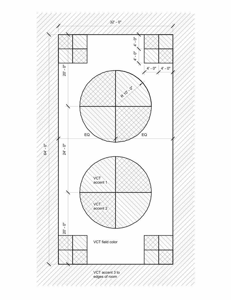
32' � 0"
64' �
0"
R 1
0' � 0
"
VCT field color
VCTaccent 1
VCTaccent 2
VCT accent 3 toedges of room
20' �
0"
24' �
0"
20' �
0"
4' �
0"
4' �
0"
4' � 0" 4' � 0"
EQ EQ
mende.smith
Text Box
9.3.2Multi-purpose Room Striping

84' �
0"
For
All
Gym
nasiu
ms
50' � 0"
30' � 0"
60' �
0"
Basketball striping to be blackVolleyball striping to be whitePE/Sidecourt striping to be grey
Center the volleyball courton the basketball court
Provide a schoollogo at center court
Provide school name at one end of thecourt and school mascot name at the other
R 1
9' �
9"
R 6
' � 0
"
Side courts with dashedfree throw lane
40' �
0"
78' � 0"
R 6' � 0"
Line Crossing Hierarchy1. Basketball Striping2. Volleyball Striping3. PE/Sidecourt Striping
Align PE/Sidecourt stripingwith volleyball endline
mende.smith
Text Box
9..3.3Gym Striping

84' �
0"
For
All
Gym
nasiu
ms
50' � 0"
30' � 0"
60' �
0"
Basketball striping to be blackVolleyball striping to be whitePE/Sidecourt striping to be grey
Center the volleyball courton the basketball court
Provide a schoollogo at center court
Provide school name at one end of thecourt and school mascot name at the other
R 1
9' �
9"
R 6
' � 0
"
Side courts with dashedfree throw lane
40' �
0"
78' � 0"
R 6' � 0"
Line Crossing Hierarchy1. Basketball Striping2. Volleyball Striping3. PE/Sidecourt Striping
Align PE/Sidecourt stripingwith volleyball endline
mende.smith
Text Box
9.9.1Gym Striping

Wood gym floor system
Volleyball sleeve insert
Thickened concrete slabaround insert
mende.smith
Text Box
9.9.1Volleyball Sleeve

RA
CK
RA
CK
RA
CK
RA
CK
(8) 4"C BY E.C.
ADD ADDITIONAL
SLEEVES AS
NECESSARY
MC
D2
3
4
" FIRE-RATED
PLYWOOD
84"X19" FLOOR
MTD DATA RACK
4 POST 7'H
SECURITY RACK
80" AFF
80" AFF
(1) 2" CONDUIT, (2) 4" CONDUIT
TO PROPERTY LINE FOR
SERVICE PROVIDERS
ENTRANCES
(2) 3" CONDUIT STUBBED OUT 5' FROM BUILDING
ENVELOPE INTO HANDHOLE FOR FUTURE MOBILE UNITS.
PROVIDE 3 CELL FLEX FABRIC INNERDUCT IN EACH
CONDUIT
D2
HELIOS
24" PRE-DRILLED
GROUND BUS BAR
AT 80" AFF
SECURITY ALARM
PANEL. PROVIDE
RJ21X JACK.
COORDINATE
WITH SECURITY
CONTRACTOR
VOICE SERVICE PROVIDER
DEMARCATION LOCATION
CATV
EQUIPMENT
3
4
" FIRE-RATED
PLYWOOD
3
4
" FIRE-RATED
PLYWOOD
3
4
" FIRE-RATED
PLYWOOD
80" AFF
80" AFF
80" AFF
TELECOM ROOMS TO BE SIZED PER PROJECT. DESIGNER SHALL ADD OR REDUCE RACKS,
THUS REDUCING THE ROOM SIZE OR INCREASING AS THE PARTICULAR PROJECT
DICTATES. THE DESIGNER SHALL DESIGN THE ROOM TO INCLUDE SPACE FOR ONE
FUTURE RACK.
THE 12' WIDTH OF THE ROOM SHALL BE ENFORCED WHEN THE SECURITY HEAD END IS
LOCATED IN THAT ROOM. OTHERWISE, 10' MINIMUM WIDTH OF A ROOM IS REQUIRED.
Information Systems & Support1230 Alleghany StreetCharlotte, NC 28208
980-344-0100
DATE:
ISSUE DATE:
CHECKED BY:
DRAWN BY:
7/2017
WP
WP
7/2017
MDFEQUIPMENTDETAILT-001
REVISIONS
02/19/2020 RACK CONFIGURATIONS
APPENDIX 1
6/24/20ADDED DIMENSION
AutoCAD SHX Text
MDF
AutoCAD SHX Text
###
AutoCAD SHX Text
48"
AutoCAD SHX Text
48"
AutoCAD SHX Text
6"
AutoCAD SHX Text
5
AutoCAD SHX Text
5

D2
D1
(3) 2"C;
BY E.C.
(2) 1"C;
BY E.C.
INSTRUCTOR
ISLAND IS
OFF-SET
INSTRUCTIONAL
WALL
TEACHER
1"C TO NEAREST
TELCOM ROOM BY
E.C.. IF ON FIRST
FLOOR PROVIDE
OSP CABLE
67"
D1
67"
APD1
1
IN WALL OUTLET
48"
D1
WALL
PHONE
SHEET NOTES:
FOR TV OR INTERACTIVE TV OUTLET PROVIDE TYPICAL
TELCOM OUTLET, BUT PROVIDE ONE OF TWO OPTIONS:
1) THE OTHER CATEGORY 6 RJ45 AND ROTATE 45 DEGREES
WITHIN THE FACEPLATE.
2) PROVIDE ANGLED FACEPLATE
1 Information Systems & Support1230 Alleghany StreetCharlotte, NC 28208
980-344-0100
DATE:
ISSUE DATE:
CHECKED BY:
DRAWN BY:
7/2017
WP
WP
7/2017
SCIENCEPREP ROOMTYPICALST-102
DATE DESCRIPTION
3/8/19 DROP COUNT CHANGES
REVISIONS
APPENDIX 10
3/25/19INSTRUCTIONAL WALL
2/24/20 DROP COUNT CHANGES
6/24/20TV AND INTERACTIVE BOARD
OUTLET CHANGE
4/2021 DATA FOR STUDENTS
AutoCAD SHX Text
SCIENCE
AutoCAD SHX Text
CLASSROOM
AutoCAD SHX Text
###
AutoCAD SHX Text
PREP
AutoCAD SHX Text
ROOM
AutoCAD SHX Text
###
AutoCAD SHX Text
1A
AutoCAD SHX Text
1
AutoCAD SHX Text
3
AutoCAD SHX Text
3
AutoCAD SHX Text
3
AutoCAD SHX Text
3
AutoCAD SHX Text
3
AutoCAD SHX Text
3
AutoCAD SHX Text
3
AutoCAD SHX Text
3
AutoCAD SHX Text
6
AutoCAD SHX Text
5
AutoCAD SHX Text
1A
AutoCAD SHX Text
3
AutoCAD SHX Text
5
AutoCAD SHX Text
6

D2
D2
D1
D2
D1
D1
D2D2
D1
Information Systems & Support1230 Alleghany StreetCharlotte, NC 28208
980-344-0100
DATE:
ISSUE DATE:
CHECKED BY:
DRAWN BY:
7/2017
WP
WP
7/2017
OFFICESTYPICAL
T-103
ONE PERSON OFFICE PRINCIPAL OFFICE FINANCE OFFICE
ITINERANT STAFF
2/24/20 DROP COUNT CHANGESDATE DESCRIPTIONREVISIONS
AutoCAD SHX Text
(2) 1"C; BY E.C.
AutoCAD SHX Text
OFFICE
AutoCAD SHX Text
###
AutoCAD SHX Text
PRINCIPAL
AutoCAD SHX Text
OFFICE
AutoCAD SHX Text
###
AutoCAD SHX Text
(2) 1"C; BY E.C.
AutoCAD SHX Text
3
AutoCAD SHX Text
FINANCE
AutoCAD SHX Text
OFFICE
AutoCAD SHX Text
###
AutoCAD SHX Text
(2) 1"C; BY E.C.
AutoCAD SHX Text
ITINERANT
AutoCAD SHX Text
STAFF
AutoCAD SHX Text
###
AutoCAD SHX Text
(2) 1"C; BY E.C.
AutoCAD SHX Text
3
wendyg.parker
Text Box
APPENDIX 11

DN
AP
D2
D1
D1
D2 AP
D1MEDIACENTER
1300
D2 D2
D2
LEISUREREADINGAREA
1301
STORYAREA
1302
GROUPCOLLABORATION
1303
67"D1
67"
D1
D1
Information Systems & Support1230 Alleghany StreetCharlotte, NC 28208
980-344-0100
DATE:
ISSUE DATE:
CHECKED BY:
DRAWN BY:
9/2017
WP
WP
9/2017
MEDIA CENTERSPACES
T-104-AMEDIA CENTER SPACES
CONTINUED ON T-104-A
DATE DESCRIPTION3/8/19 DROP COUNT CHANGES
REVISIONS
APPENDIX 12
2/24/20 DROP COUNT CHANGES
AutoCAD SHX Text
AVOID BOOK DROP
AutoCAD SHX Text
CARD CATALOG ACCESS
AutoCAD SHX Text
1
AutoCAD SHX Text
1
AutoCAD SHX Text
IN WALL OUTLET
AutoCAD SHX Text
3
AutoCAD SHX Text
3
AutoCAD SHX Text
3
AutoCAD SHX Text
SHEET NOTES: PROVIDE RECESSED WALL OUTLET (MOUNTED IN WALL) AND FACEPLATE.
AutoCAD SHX Text
1
AutoCAD SHX Text
1
AutoCAD SHX Text
3

D2
D2
D2
AP
AP
D2
D2
D2
EQUIP.
STOR.
1307
TV STUDIO
1309
MEDIA
CENTER
1300
STUDENT
MAKERSPACE
1310
OFFICE
1306
VIDEO
CLASSROOM
1305
INSTRUCTIONAL
AREA
1304
D2
D1
D2
D2
80"
D2
GREEN WALL
(3) 2"C
(2) 1"C
(2) 1"C
(3) 2"C
(2) 3"C
ROUTE (1) RG-6 FROM CATV
HEADEND DISTRIBUTION TO THIS
LOCATION
LAPTOP CHARGING
STATION
67"
D1
67"
67"
D1
67"
APD1
D1
D2
67"
D1
67"
1
D1
D1
1
1
SHEET NOTES:
FOR TV OR INTERACTIVE TV OUTLET PROVIDE TYPICAL
TELCOM OUTLET, BUT PROVIDE ONE OF TWO OPTIONS:
1) THE OTHER CATEGORY 6 RJ45 AND ROTATE 45 DEGREES
WITHIN THE FACEPLATE.
2) PROVIDE ANGLED FACEPLATE
1
Information Systems & Support1230 Alleghany StreetCharlotte, NC 28208
980-344-0100
DATE:
ISSUE DATE:
CHECKED BY:
DRAWN BY:
9/2017
WP
WP
9/2017
MEDIA CENTERSPACES
T-104-BMEDIA CENTER SPACES
CONTINUED ON T-104-A
DATE DESCRIPTION
3/8/19 DROP COUNT CHANGES
REVISIONS
APPENDIX 13
2/24/20DROP COUNT CHANGES
6/24/20TV AND INTERACTIVE BOARD
OUTLET CHANGE
4/2021 REMOVING COAX DROPS
AutoCAD SHX Text
1
AutoCAD SHX Text
1
AutoCAD SHX Text
1
AutoCAD SHX Text
1
AutoCAD SHX Text
3
AutoCAD SHX Text
3
AutoCAD SHX Text
3
AutoCAD SHX Text
3
AutoCAD SHX Text
5
AutoCAD SHX Text
5
AutoCAD SHX Text
6
AutoCAD SHX Text
6
AutoCAD SHX Text
5
AutoCAD SHX Text
1
AutoCAD SHX Text
3
AutoCAD SHX Text
5
AutoCAD SHX Text
6

GE
N.
D1
D2
D1
D2D2 D1
D2
D1
WAITING
1400A
RECEPTION
1400
AP
80"
80"
INTERCOM
CONSOLE
RED FAIL
POWER
JACK
SECURITY
MONITOR
(2) 1"C
D1
D1
D2
TWO WAY
COMMUNICATION
SYSTEM
HELIOS
1
D1
SHEET NOTES:
FOR TV OR INTERACTIVE TV OUTLET PROVIDE TYPICAL
TELCOM OUTLET, BUT PROVIDE ONE OF TWO OPTIONS:
1) THE OTHER CATEGORY 6 RJ45 AND ROTATE 45 DEGREES
WITHIN THE FACEPLATE.
2) PROVIDE ANGLED FACEPLATE
1
Information Systems & Support1230 Alleghany StreetCharlotte, NC 28208
980-344-0100
DATE:
ISSUE DATE:
CHECKED BY:
DRAWN BY:
9/2017
WP
WP
9/2017
ELEMENTARY& K8 RECEPTIONEXAMPLE
T-105ELEMENTARY AND K8 SCHOOLS-RECEPTION EXAMPLE
DATE DESCRIPTION
3/8/19 DROP COUNT CHANGES
REVISIONS
APPENDIX 14
2/24/20DROP COUNT CHANGES
6/24/20TV AND INTERACTIVE BOARD
OUTLET CHANGE
4/2021 REMOVING COAX DROPS
AutoCAD SHX Text
1
AutoCAD SHX Text
2
AutoCAD SHX Text
2
AutoCAD SHX Text
5
AutoCAD SHX Text
5
AutoCAD SHX Text
6
AutoCAD SHX Text
6
AutoCAD SHX Text
5
AutoCAD SHX Text
1
AutoCAD SHX Text
3
AutoCAD SHX Text
5
AutoCAD SHX Text
6

Information Systems & Support1230 Alleghany StreetCharlotte, NC 28208
980-344-0100
DATE:
ISSUE DATE:
CHECKED BY:
DRAWN BY:
9/2018
WP
WP
9/2018
KITCHENDETAIL
T-106
DATEDESCRIPTION
3/25/19 FACP REMOVE DROPS
REVISIONS
2/24/20 DROP COUNT CHANGES
4/2021 ADDING D1 TO APs
AutoCAD SHX Text
D1
AutoCAD SHX Text
D2
AutoCAD SHX Text
90"
AutoCAD SHX Text
54"
AutoCAD SHX Text
D2
AutoCAD SHX Text
FACP
AutoCAD SHX Text
D1
AutoCAD SHX Text
D1
AutoCAD SHX Text
AP
AutoCAD SHX Text
D1
AutoCAD SHX Text
D1
AutoCAD SHX Text
10'
AutoCAD SHX Text
D1
AutoCAD SHX Text
POS
AutoCAD SHX Text
D1
AutoCAD SHX Text
D2
AutoCAD SHX Text
D1
AutoCAD SHX Text
D1
AutoCAD SHX Text
MECH/BOILER
AutoCAD SHX Text
###
AutoCAD SHX Text
FIRE
AutoCAD SHX Text
###
AutoCAD SHX Text
EMERG
AutoCAD SHX Text
###
AutoCAD SHX Text
ELEC
AutoCAD SHX Text
###
AutoCAD SHX Text
KITCH
AutoCAD SHX Text
###
AutoCAD SHX Text
SERVING
AutoCAD SHX Text
###
AutoCAD SHX Text
DISH
AutoCAD SHX Text
###
AutoCAD SHX Text
FREEZER
AutoCAD SHX Text
###
AutoCAD SHX Text
DRY STOR
AutoCAD SHX Text
###
AutoCAD SHX Text
OFFICE
AutoCAD SHX Text
###
AutoCAD SHX Text
LAUND
AutoCAD SHX Text
###
AutoCAD SHX Text
TLT
AutoCAD SHX Text
###
AutoCAD SHX Text
DINING
AutoCAD SHX Text
###
AutoCAD SHX Text
12'
AutoCAD SHX Text
12'
AutoCAD SHX Text
10'
AutoCAD SHX Text
SHEET NOTES:
AutoCAD SHX Text
WIRELESS ACCESS POINT IN WALL MOUNTED TELCOM OUTLET. CABLES ROUTE TO NEAREST TELCOM ROOM. INSTALL OWNER PROVIDED DIRECTIONAL ANTENNA. PROVIDE AND INSTALL CONTRACTOR PROVIDED WIRE CAGES. MENU BOARDS. ROUTE CABLES TO CAFE MGRS OFFICE. POS. ROUTE CABLES TO CAFE MGRS. OFFICE IN THE POS OUTLET. COORDINATE TERMINATION WITH KITCHEN STAFF. NOT USED. BAS CONTROL PANEL. ROUTE CABLES TO ZONED TELCOM ROOM. LOUD BELL FOR CAFE MGRS TELEPHONE. KRONOS (TIMECLOCK). ROUTE CABLES TO ZONED TELCOM ROOM. POS OUTLETS IN KITCHEN. ONE FOR POS CASH REGISTERS CABLES AND ONE FOR MENU BOARD CABLES.
AutoCAD SHX Text
1
AutoCAD SHX Text
2
AutoCAD SHX Text
3
AutoCAD SHX Text
4
AutoCAD SHX Text
5
AutoCAD SHX Text
6
AutoCAD SHX Text
7
AutoCAD SHX Text
1
AutoCAD SHX Text
1
AutoCAD SHX Text
2
AutoCAD SHX Text
2
AutoCAD SHX Text
3
AutoCAD SHX Text
3
AutoCAD SHX Text
3
AutoCAD SHX Text
POS
AutoCAD SHX Text
POS
AutoCAD SHX Text
POS
AutoCAD SHX Text
5
AutoCAD SHX Text
BAS
AutoCAD SHX Text
7
AutoCAD SHX Text
LOUD BELL
AutoCAD SHX Text
6
AutoCAD SHX Text
8
AutoCAD SHX Text
8
AutoCAD SHX Text
(2) 1"C
AutoCAD SHX Text
(2) 2"C
AutoCAD SHX Text
(2) 2"C
AutoCAD SHX Text
(2) 2"C
AutoCAD SHX Text
(2) 2"C
AutoCAD SHX Text
1
AutoCAD SHX Text
3
AutoCAD SHX Text
3
AutoCAD SHX Text
D1
AutoCAD SHX Text
6
AutoCAD SHX Text
AP
AutoCAD SHX Text
6
AutoCAD SHX Text
AP
AutoCAD SHX Text
6
AutoCAD SHX Text
D1
AutoCAD SHX Text
1
AutoCAD SHX Text
3
AutoCAD SHX Text
6

DN
Information Systems & Support1230 Alleghany StreetCharlotte, NC 28208
980-344-0100
DATE:
ISSUE DATE:
CHECKED BY:
DRAWN BY:
9/2018
WP
WP
9/2018
MULTIPURPOSEDETAIL
T-107
2/24/20 DROP COUNT CHANGES
4/2021 ADDING D1 TO APs
AutoCAD SHX Text
AP
AutoCAD SHX Text
D2
AutoCAD SHX Text
D1
AutoCAD SHX Text
D2
AutoCAD SHX Text
TELECOMMUNICATIONS CABLING IN AREAS OF CEILING HEIGHTS GREATER THAN 14' OR OPEN CEILINGS TO BE ROUTED UNDER SLAB TO THE NEAREST TR.
AutoCAD SHX Text
AP
AutoCAD SHX Text
D2
AutoCAD SHX Text
MULTI-PURP
AutoCAD SHX Text
###
AutoCAD SHX Text
CHAIR STOR
AutoCAD SHX Text
###
AutoCAD SHX Text
RAMP
AutoCAD SHX Text
###
AutoCAD SHX Text
M.P.
AutoCAD SHX Text
STAGE
AutoCAD SHX Text
###
AutoCAD SHX Text
STOR
AutoCAD SHX Text
###
AutoCAD SHX Text
12'
AutoCAD SHX Text
12'
AutoCAD SHX Text
12'
AutoCAD SHX Text
1
AutoCAD SHX Text
1
AutoCAD SHX Text
1
AutoCAD SHX Text
SHEET NOTES:
AutoCAD SHX Text
WIRELESS ACCESS POINT IN WALL MOUNTED TELCOM OUTLET. CABLES ROUTE TO NEAREST TELCOM ROOM. INSTALL OWNER PROVIDED DIRECTIONAL ANTENNA. PROVIDE AND INSTALL CONTRACTOR PROVIDED WIRE CAGES. MENU BOARDS. ROUTE CABLES TO CAFE MGRS OFFICE. POS. ROUTE CABLES TO CAFE MGRS. OFFICE IN THE POS OUTLET. COORDINATE TERMINATION WITH KITCHEN STAFF. NOT USED. BAS CONTROL PANEL. ROUTE CABLES TO ZONED TELCOM ROOM. LOUD BELL FOR CAFE MGRS TELEPHONE. KRONOS (TIMECLOCK). ROUTE CABLES TO ZONED TELCOM ROOM. POS OUTLETS IN KITCHEN. ONE FOR POS CASH REGISTERS CABLES AND ONE FOR MENU BOARD CABLES.
AutoCAD SHX Text
1
AutoCAD SHX Text
2
AutoCAD SHX Text
3
AutoCAD SHX Text
4
AutoCAD SHX Text
5
AutoCAD SHX Text
6
AutoCAD SHX Text
7
AutoCAD SHX Text
8
AutoCAD SHX Text
3
AutoCAD SHX Text
3
AutoCAD SHX Text
3
AutoCAD SHX Text
3
AutoCAD SHX Text
3
AutoCAD SHX Text
D1
AutoCAD SHX Text
D1
AutoCAD SHX Text
6
AutoCAD SHX Text
AP
AutoCAD SHX Text
D1
AutoCAD SHX Text
6
AutoCAD SHX Text
AP
AutoCAD SHX Text
D1
AutoCAD SHX Text
12'
AutoCAD SHX Text
1
AutoCAD SHX Text
6
AutoCAD SHX Text
3
AutoCAD SHX Text
6


Information Systems & Support1230 Alleghany StreetCharlotte, NC 28208
980-344-0100
DATE:
ISSUE DATE:
CHECKED BY:
DRAWN BY:
7/2017
WP
WP
7/2017
MDFLADDER RACKDETAILT-002
REVISIONS
02/19/2020RACKCONFIGURATIONS
AutoCAD SHX Text
18" LADDER RACK AT 8'-6" AFF. PROVIDE WIDE SWEEPING TURNS. PROVIDE AND UTILIZE WATERFALL DEVICES TO TRANSITION FROM THE LADDER RACK ABOVE TO THE LADDER RACKS BELOW.
AutoCAD SHX Text
12" LADDER RACK MOUNTED AT 7'-6" AFF. MOUNT FLUSH TO TOP OF DATA RACKS UTILIZING 6" RUNWAY ELEVATION KITS.
AutoCAD SHX Text
MC
AutoCAD SHX Text
MDF
AutoCAD SHX Text
###
AutoCAD SHX Text
(4) 4"C TO IDF ON FLOOR ABOVE. PROVIDE 12" VERTICAL LADDER RACKING AS A SUPPORT FOR THE CABLES BETWEEN THE CONDUITS
wendyg.parker
Text Box
APPENDIX 2
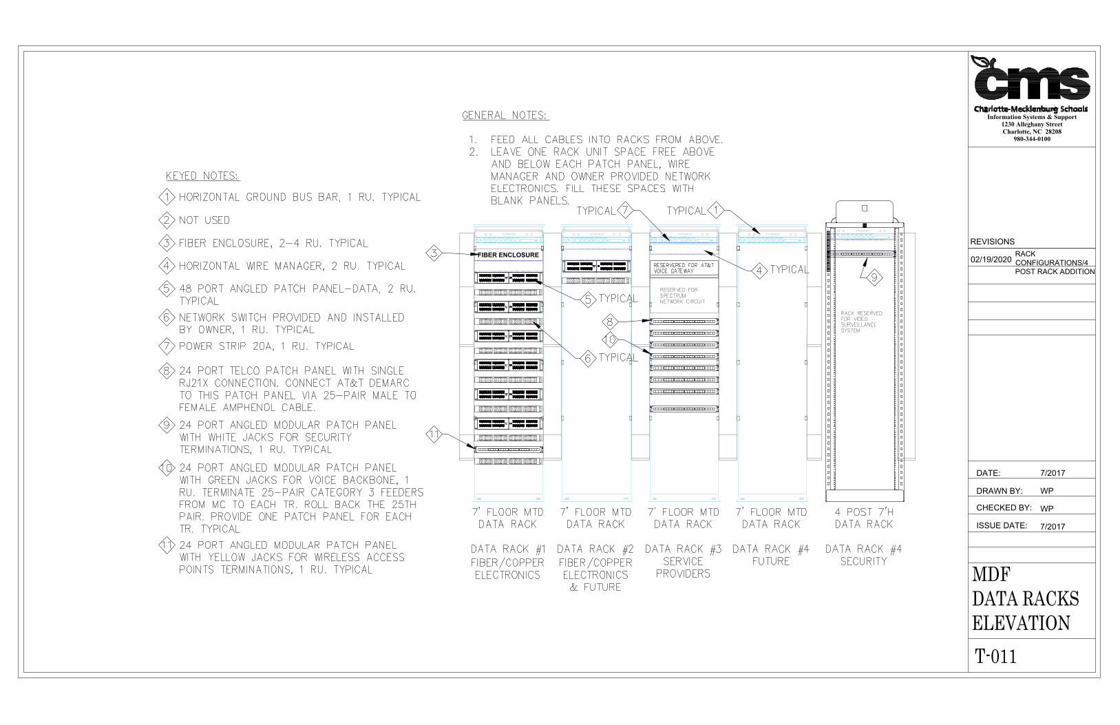
FIBER ENCLOSURE
Information Systems & Support1230 Alleghany StreetCharlotte, NC 28208
980-344-0100
DATE:
ISSUE DATE:
CHECKED BY:
DRAWN BY:
7/2017
WP
WP
7/2017
MDFDATA RACKSELEVATIONT-011
REVISIONS
02/19/2020RACKCONFIGURATIONS/4POST RACK ADDITION
AutoCAD SHX Text
RESERVED FOR SPECTRUM NETWORK CIRCUIT
AutoCAD SHX Text
RESERVERED FOR AT&T VOICE GATEWAY
AutoCAD SHX Text
RACK RESERVED FOR VIDEO SURVEILLANCE SYSTEM
AutoCAD SHX Text
7' FLOOR MTD DATA RACK
AutoCAD SHX Text
DATA RACK #1 FIBER/COPPER ELECTRONICS
AutoCAD SHX Text
7' FLOOR MTD DATA RACK
AutoCAD SHX Text
DATA RACK #2 FIBER/COPPER ELECTRONICS & FUTURE
AutoCAD SHX Text
7' FLOOR MTD DATA RACK
AutoCAD SHX Text
DATA RACK #3 SERVICE PROVIDERS
AutoCAD SHX Text
7' FLOOR MTD DATA RACK
AutoCAD SHX Text
DATA RACK #4 FUTURE
AutoCAD SHX Text
KEYED NOTES:
AutoCAD SHX Text
1
AutoCAD SHX Text
HORIZONTAL GROUND BUS BAR, 1 RU. TYPICAL
AutoCAD SHX Text
2
AutoCAD SHX Text
NOT USED
AutoCAD SHX Text
3
AutoCAD SHX Text
FIBER ENCLOSURE, 2-4 RU. TYPICAL
AutoCAD SHX Text
4
AutoCAD SHX Text
HORIZONTAL WIRE MANAGER, 2 RU. TYPICAL
AutoCAD SHX Text
1
AutoCAD SHX Text
3
AutoCAD SHX Text
5
AutoCAD SHX Text
48 PORT ANGLED PATCH PANEL-DATA, 2 RU. TYPICAL
AutoCAD SHX Text
5
AutoCAD SHX Text
6
AutoCAD SHX Text
NETWORK SWITCH PROVIDED AND INSTALLED BY OWNER, 1 RU. TYPICAL
AutoCAD SHX Text
7
AutoCAD SHX Text
POWER STRIP 20A, 1 RU. TYPICAL
AutoCAD SHX Text
8
AutoCAD SHX Text
24 PORT TELCO PATCH PANEL WITH SINGLE RJ21X CONNECTION. CONNECT AT&T DEMARC TO THIS PATCH PANEL VIA 25-PAIR MALE TO FEMALE AMPHENOL CABLE.
AutoCAD SHX Text
8
AutoCAD SHX Text
10
AutoCAD SHX Text
9
AutoCAD SHX Text
24 PORT ANGLED MODULAR PATCH PANEL WITH WHITE JACKS FOR SECURITY TERMINATIONS, 1 RU. TYPICAL
AutoCAD SHX Text
10
AutoCAD SHX Text
24 PORT ANGLED MODULAR PATCH PANEL WITH GREEN JACKS FOR VOICE BACKBONE, 1 RU. TERMINATE 25-PAIR CATEGORY 3 FEEDERS FROM MC TO EACH TR. ROLL BACK THE 25TH PAIR. PROVIDE ONE PATCH PANEL FOR EACH TR. TYPICAL
AutoCAD SHX Text
11
AutoCAD SHX Text
24 PORT ANGLED MODULAR PATCH PANEL WITH YELLOW JACKS FOR WIRELESS ACCESS POINTS TERMINATIONS, 1 RU. TYPICAL
AutoCAD SHX Text
11
AutoCAD SHX Text
GENERAL NOTES: 1. FEED ALL CABLES INTO RACKS FROM ABOVE. FEED ALL CABLES INTO RACKS FROM ABOVE. 2. LEAVE ONE RACK UNIT SPACE FREE ABOVE LEAVE ONE RACK UNIT SPACE FREE ABOVE AND BELOW EACH PATCH PANEL, WIRE MANAGER AND OWNER PROVIDED NETWORK ELECTRONICS. FILL THESE SPACES WITH BLANK PANELS.
AutoCAD SHX Text
4 POST 7'H DATA RACK
AutoCAD SHX Text
DATA RACK #4 SECURITY
AutoCAD SHX Text
9
AutoCAD SHX Text
TYPICAL
AutoCAD SHX Text
6
AutoCAD SHX Text
TYPICAL
AutoCAD SHX Text
TYPICAL
AutoCAD SHX Text
7
AutoCAD SHX Text
TYPICAL
AutoCAD SHX Text
4
AutoCAD SHX Text
TYPICAL
wendyg.parker
Text Box
APPENDIX 3

(5) 4"C BY E.C.
ADD ADDITIONAL
SLEEVES AS
NECESSARY
(4) 4"C TO ABOVE
CEILING FLOOR
ABOVE/BELOW
3
4
" FIRE-RATED
PLYWOOD
12" PRE-DRILLED
GROUND BUS BAR
AT 80" AFF
CATV
EQUIPMENT
3
4
" FIRE-RATED
PLYWOOD
3
4
" FIRE-RATED
PLYWOOD
TR-#
RA
CK
RA
CK
RA
CK
80" AFF
80" AFF
80" AFF
84"X19" FLOOR
MTD DATA RACK
TELECOM ROOMS TO BE SIZED PER PROJECT. DESIGNER
SHALL ADD OR REDUCE RACKS, THUS REDUCING THE ROOM
SIZE OR INCREASING AS THE PARTICULAR PROJECT DICTATES.
THE DESIGNER SHALL DESIGN THE ROOM TO INCLUDE SPACE
FOR ONE FUTURE RACK.
THE 12' WIDTH OF THE ROOM SHALL BE ENFORCED WHEN THE
SECURITY HEAD END IS LOCATED IN THAT ROOM. OTHERWISE,
10' MINIMUM WIDTH OF A ROOM IS REQUIRED.
RA
CK
84"X19" FLOOR
MTD DATA RACK
FUTURE RACK
Information Systems & Support1230 Alleghany StreetCharlotte, NC 28208
980-344-0100
DATE:
ISSUE DATE:
CHECKED BY:
DRAWN BY:
7/2017
WP
WP
7/2017
IDFEQUIPMENTDETAILT-003
REVISIONS
2/19/20RACK CONFIGURATIONS
APPENDIX 4
6/24/20ROOM SIZE CHANGE
AutoCAD SHX Text
IDF
AutoCAD SHX Text
###
AutoCAD SHX Text
5
AutoCAD SHX Text
5
AutoCAD SHX Text
5

12" LADDER RACK . MOUNT
FLUSH TO TOP OF DATA
RACKS UTILIZING 6"
RUNWAY ELEVATION KITS.
18" LADDER RACK AT 8'-6" AFF.
PROVIDE WIDE SWEEPING
TURNS. PROVIDE AND UTILIZE
WATERFALL DEVICES TO
TRANSITION FROM THE LADDER
RACK ABOVE TO THE LADDER
RACKS BELOW.
TR-#
(4) 4"C TO IDF ON FLOOR
ABOVE. PROVIDE 12"
VERTICAL LADDER RACKING
AS A SUPPORT FOR THE
CABLES BETWEEN THE
CONDUITS
(5) 4"C BY E.C.
ADD ADDITIONAL
SLEEVES AS
NECESSARY
Information Systems & Support1230 Alleghany StreetCharlotte, NC 28208
980-344-0100
DATE:
ISSUE DATE:
CHECKED BY:
DRAWN BY:
7/2017
WP
WP
7/2017
IDFLADDER RACKDETAILT-004
REVISIONS
2/19/20RACK CONFIGURATIONS
6/24/20ROOM SIZE CHANGE ADDED
LADDER RACK
APPENDIX 5
AutoCAD SHX Text
IDF
AutoCAD SHX Text
###
AutoCAD SHX Text
5
AutoCAD SHX Text
5

KEYED NOTES:
1 HORIZONTAL GROUND BUS BAR, 1 RU. TYPICAL
2 NOT USED
3 FIBER ENCLOSURE, 1 RU.
4 HORIZONTAL WIRE MANAGER, 2 RU. TYPICAL
5 48 PORT ANGLED PATCH PANEL-DATA, 2 RU. TYPICAL
6 NETWORK SWITCH PROVIDED AND INSTALLED BY
OWNER, 1 RU. TYPICAL
7 POWER STRIP 20A, 1 RU. TYPICAL
8 24 PORT ANGLED MODULAR PATCH PANEL WITH
GREEN JACKS FOR VOICE BACKBONE, 1 RU.
TERMINATE 25-PAIR CATEGORY 3 FEEDERS FROM
MC TO EACH TR. ROLL BACK THE 25TH PAIR.
PROVIDE ONE PATCH PANEL FOR EACH TR. TYPICAL
9 24 PORT ANGLED MODULAR PATCH PANEL WITH
YELLOW JACKS FOR WIRELESS ACCESS POINTS
TERMINATIONS, 1 RU. TYPICAL
10 24 PORT ANGLED MODULAR PATCH PANEL WITH
WHITE JACKS FOR SECURITY TERMINATIONS, 1 RU.
TYPICAL
FIBER ENCLOSURE
7' FLOOR MTD
DATA RACK
DATA RACK #1
FIBER/COPPER
ELECTRONICS
7' FLOOR MTD
DATA RACK
DATA RACK #2
VOICE
SECURITY
1
3
4
5
6
9
10
8
7
GENERAL NOTES:
1. FEED ALL CABLES INTO RACKS FROM ABOVE.
2. LEAVE ONE RACK UNIT SPACE FREE ABOVE AND
BELOW EACH PATCH PANEL, WIRE MANAGER AND
OWNER PROVIDED NETWORK ELECTRONICS. FILL
THESE SPACES WITH BLANK PANELS.
TYPICAL
TYPICAL
TYPICAL
TYPICAL
7' FLOOR MTD
DATA RACK
DATA RACK #2
VOICE
SECURITY
OR FUTURE
Information Systems & Support1230 Alleghany StreetCharlotte, NC 28208
980-344-0100
DATE:
ISSUE DATE:
CHECKED BY:
DRAWN BY:
7/2017
WP
WP
7/2017
IDFDATA RACKSELEVATIONT-012
REVISIONS
2/19/20 RACK CONFIGURATIONS
6/24/20ADDED RACK
APPENDIX 6
AutoCAD SHX Text
5
AutoCAD SHX Text
5

CMS IS DROP COUNT STANDARDS
04/2021 REV 5
(RED HIGHLIGHTING OF CELLS INDICATE CHANGED ITEMS)
APPENDIX 7
Notes Comments
Room Designation Voice Data Wireless
CEILING
MTD TV Voice Data Wireless
CEILING
MTD TV
Classrooms:
A typical Classroom 3 1 1 3 1 1 Promethean board on instructional wall
ISS Classroom 3 1 1 3 1 1 Promethean board on instructional wall
EC Classroom 3 1 1 3 1 1 Promethean board on instructional wall
Flex Classroom 5 1 1 5 1 1 Promethean board on instructional wall D2 for copier
Health Education Classroom 3 1 1 3 1 1 Promethean board on instructional wall
Music Classroom 3 1 1 3 1 1 Promethean board on instructional wall
Band Classroom N/A N/A N/A N/A N/A 3 1 1 Promethean board on instructional wall
Choral Classroom N/A N/A N/A N/A N/A 3 1 1 Promethean board on instructional wall
Dance Classroom N/A N/A N/A N/A N/A 3 1 1 Promethean board on instructional wall
Art Classroom 3 1 1 3 1 1 Promethean board on instructional wall
Large Music Room N/A N/A N/A N/A 3 1 1 Promethean board on instructional wall
Resource Room 3 1 1 3 1 1 Promethean board on instructional wall
Tutor Room 2 2
Math Classrooms 3 1 1 3 1 1 Promethean board on instructional wall
Career & Technical Education (CTE)
Business Management N/A N/A N/A N/A 6 2 2 Promethean board on instructional wall
30 Students. Laps tops used. Build as regular classroom, but add d1
on all other walls-centered at 18" for cart mtd monitors.
Interior Design N/A N/A N/A N/A 35 2 2 Promethean board on instructional wall
4 students per workstation (will have distinictive desks). Plotter and
printer.
Marketing N/A N/A N/A N/A 6 2 2 Promethean board on instructional wall
30 Students. Laps tops used. Build as regular classroom, but add d1 on
all other walls-centered at 18" for cart mtd monitors.
Software Development N/A N/A N/A N/A 35 2 2 Promethean board on instructional wall
30 Students. Dual monitors per workstation. Using REVIT. Dual
Monitors. Drops for students on perimeter.
APP Development & Web Design N/A N/A N/A N/A 35 2 2 Promethean board on instructional wall
30 Students. Dual monitors per workstation. Using REVIT. Dual
Monitors. Drops for students on perimeter.
Graphic & Digital Design N/A N/A N/A N/A 35 2 2 Promethean board on instructional wall
Dual monitors per workstation. Furniture hi top desks. Printer. Wants
tv/monitors in corridor adjacent to door
Environmental Sustainability N/A N/A N/A N/A 6 2 2 Promethean board on instructional wall Cable like a regular classroom
Architecture & Engineering N/A N/A N/A N/A 30 2 2 Promethean board on instructional wall
24 Students. Hard cabled. Special furniture. Plotter, lazer cutter, 3D
printer & tabloid size printer.
Urban Planning N/A N/A N/A N/A 35 2 2 Promethean board on instructional wall 30 Students. Laptops. Add one data on all non teaching walls, centered.
Advanced Manufacturing & Engineering N/A N/A N/A N/A 6 2 2 Promethean board on instructional wall
Will be heavy machinery. Some will be networked. Review cut sheets.
Coordinate with CTE for other requirements.
Cosmotology Advanced Dept Lab N/A N/A N/A N/A 2 2 AP coverage only
Cosmotology Beginner Classroom N/A N/A N/A N/A 6 2 2 Promethean board on instructional wall
Regular Classroom lay-out but add one data on each non instructional
wall.
Cosmotology Reception Area N/A N/A N/A N/A 1 1 Desk phone for appointments Wireless covereage by neighboring Aps
Culinary Arts Classroom N/A N/A N/A N/A 6 2 2 Promethean board on instructional wall Regular Classroom lay-out
Culinary Lab N/A N/A N/A N/A 2 2 2
Regular Classroom lay-out but add one data on each non instructional
wall.
Automotive Classroom N/A N/A N/A N/A 6 2 2 Promethean board on instructional wall
Elementary Secondary
1 of 4 MARCH 2019/revised March 2020

CMS IS DROP COUNT STANDARDS
04/2021 REV 5
(RED HIGHLIGHTING OF CELLS INDICATE CHANGED ITEMS)
APPENDIX 7
Notes Comments
Room Designation Voice Data Wireless
CEILING
MTD TV Voice Data Wireless
CEILING
MTD TV
Elementary Secondary
Automotive Lab N/A N/A N/A N/A 2 2 2 2 Lay out per each room for equipment 30 Students. May have inspection station that will need data & voice.
Carpentry Classroom N/A N/A N/A N/A 6 2 2 Promethean board on instructional wall
Regular Classroom lay-out but add one data on each non instructional
wall.
Carpentry Lab N/A N/A N/A N/A 2 2 Add data for any device that may be networked.
Public Safety N/A N/A N/A N/A 6 2 2 Promethean board on instructional wall 30 Students. Laptops. Add one data on all non teaching walls, centered.
Career Management N/A N/A N/A N/A 6 2 2 Promethean board on instructional wall 31 Students. Laptops. Add one data on all non teaching walls, centered.
Health Sciences N/A N/A N/A N/A 6 2 2 Promethean board on instructional wall 31 Students. Laptops. Add one data on all non teaching walls, centered.
Other Spaces N/A N/A N/A N/A Coordinate with CTE
ROTC
ROTC Classroom N/A N/A N/A N/A 3 1 1 Promethean board on instructional wall Coordinate with ROTC
Science Classrooms/Labs
Science Classrooms N/A N/A N/A N/A N/A 3 1 1 Promethean board on instructional wall
Science Labs N/A N/A N/A N/A N/A 4 1 1 Promethean board on instructional wall 1 data on instructor island.
Prep Rooms N/A N/A N/A N/A N/A 1 For desk phone. Put on top of a counter
Administrative Spaces:
Itinerant Rooms 6 1 1 8 1 1 D2 for copier
Team Rooms 5 1 1 5 1 1 Promethean board on instructional wall Design like a classroom plus D2 for copier.
Teacher Planning 5 1 1 5 1 1 Promethean board on instructional wall Design like a classroom plus D2 for copier.
Principal Office 3 3 Split drops to one D2 and one D1
Finance Office 3 3 Split drops to one D2 and one D1
Assistant Principal 2 2
Waiting Area in Reception 5 2 6 2 (2) TV Brackets
D1 for visitor drop, D1 for security monitor at 67", D2 for lobby guard,
D1 for IP TV at 67"
Reception/Secretary 3 12 1 1 3 14 1 1
Depends on lay-out; power fail phone outlet at 48", 2 data for two
communication panel, 2 voice intercom. Also 2 cables for two way
communications panel.
Health/Nurse Area 2 2
Conference Rooms 4 1 4 or 5 1 TV Bracket
Split drops to one D1 and one D2. TV is fed with one data cable at 67".
If large room, add D1 in floor box
Counselor or Guidance Office 2 2
Student Services N/A N/A N/A N/A 5 1 TV Bracket D2 for staff member, TV at 67" fed with 1 data cable. D2 for copier.
Career Center N/A N/A N/A N/A 10 1 1
Parent Center 4 4
Flex Office 2 2
Records Room 2 2
Mail Room N/A N/A N/A N/A 2
Lounge 2 2
Teacher Workroom 4 4 Large fax copier may be located in this space. No outlet on island.
Janitor Office 1 1
2 of 4 MARCH 2019/revised March 2020

CMS IS DROP COUNT STANDARDS
04/2021 REV 5
(RED HIGHLIGHTING OF CELLS INDICATE CHANGED ITEMS)
APPENDIX 7
Notes Comments
Room Designation Voice Data Wireless
CEILING
MTD TV Voice Data Wireless
CEILING
MTD TV
Elementary Secondary
Security Resource Officer (SRO) N/A N/A N/A N/A 4 Their monitors are direct connected not IP.
Box Office N/A N/A N/A N/A 2
Athletics
Coaches Office 2 7
Student Store 2 2
Gymnasium N/A N/A N/A N/A 3 4 4
Gymnasium, Auxilliary N/A N/A N/A N/A 3 3 3
Training Room N/A N/A N/A N/A 2
Field House-Office N/A N/A N/A N/A 4 1 1
Field House-Officials Office N/A N/A N/A N/A 2
Weight Room N/A N/A N/A N/A 3 1 1 Promethean board on instructional wall Build out for future classroom
Press Box N/A N/A N/A N/A 2 Also provide 6 strand single-mode fiber for future broadcasts
Concession Stands N/A N/A N/A N/A Provide conduit to field house for future
Media Center
Media Center 8 3 3 8 3 to 4 3 to 4 (2-3) Promethean Boards
3 data in floor box for circulation desk. Data at each entrance for card
catalog access. 2 or 3 instructional walls. 4-5 conveneince outlets.
Media Center Office 3 to 4 3 to 4
Media Center Workroom 4 4
TV Studio 3 3 2 Outlets on non green walls.
Video Conference Classroom 3 1 1 3 1 1 Promethean board on instructional wall ADD TV WITH COAX AT 80" TO SIDE OF MARKERBOARD.
Maker Space 3 1 1 3 1 1 Promethean board on instructional wall Design like a classroom
Miscellaneous Spaces
Multipurpose Room 2 2 2 2
Stage 3 1 1 3 1 1 D1 on stage riser-the second riser from the bottom, then D2 on side of stage behind curtain
Storage Room 1 1
ASEP Loud Bell 1 1
Coordinate location with school personnel. TYPICALLY MULTI-
PURPOSE MOUNTED HIGH.
Cafeteria
Cafeteria/Dining 5 3 3 6 4 4
Also add: one D1 for each POS and one
D1 for each menu board. These cables
route directly back to the POS outlet in
café mgrs office
Café Mgrs Office 2 1 1 2 1 1
Also add POS outlets for POS and menu
board cables routing back to this space. Add D1 outside of office at 90" AFF for loud bell for café mgrs phone.
3 of 4 MARCH 2019/revised March 2020

CMS IS DROP COUNT STANDARDS
04/2021 REV 5
(RED HIGHLIGHTING OF CELLS INDICATE CHANGED ITEMS)
APPENDIX 7
Notes Comments
Room Designation Voice Data Wireless
CEILING
MTD TV Voice Data Wireless
CEILING
MTD TV
Elementary Secondary
Building Support
Boiler Room 2 2 For BAS panel
Mechanical Rooms 1 1
Elevator Control Room 1 1 Connected directly to elevator equipment
Main Telcom Room 3 3 D2 Security Alarm Panel (add RJ31x jack), D1 Helios
Intermediate Telcom Rooms only as needed for panels
Main Electrical Room 2 2 For Fire Alarm Control panel ONLY RENOVATIONS. USING CELLULAR NOW. PROVIDE A BLANK OUTLET.
NOTES:
Wireless is terminated with 20' of slack coiled and secured to structure.
Future Ceiling Mount terminated with 20' of slack coiled and secured to structure.
4 of 4 MARCH 2019/revised March 2020

D2
AP 67"D167"
D1
Information Systems & Support1230 Alleghany StreetCharlotte, NC 28208
980-344-0100
DATE:
ISSUE DATE:
CHECKED BY:
DRAWN BY:
7/2017
WP
WP
7/2017
ELEMENTARYCLASSROOMTYPICALT-100
DATE DESCRIPTION3/8/19 DROP COUNT CHANGES
REVISIONS
APPENDIX 8
6/10/19 POWER REDUCTIONS
2/24/20 DROP COUNT CHANGES
AutoCAD SHX Text
(3) 2"C; BY E.C.
AutoCAD SHX Text
INSTRUCTIONAL WALL
AutoCAD SHX Text
TEACHER
AutoCAD SHX Text
ELEMENTARY
AutoCAD SHX Text
CLASSROOM
AutoCAD SHX Text
###
AutoCAD SHX Text
FUTURE
AutoCAD SHX Text
1
AutoCAD SHX Text
1
AutoCAD SHX Text
IN WALL OUTLET
AutoCAD SHX Text
2
AutoCAD SHX Text
2
AutoCAD SHX Text
2
AutoCAD SHX Text
2
AutoCAD SHX Text
3
AutoCAD SHX Text
SHEET NOTES: PROVIDE RECESSED WALL OUTLET (MOUNTED IN WALL) AND FACEPLATE.
AutoCAD SHX Text
1
AutoCAD SHX Text
1
AutoCAD SHX Text
2
AutoCAD SHX Text
3
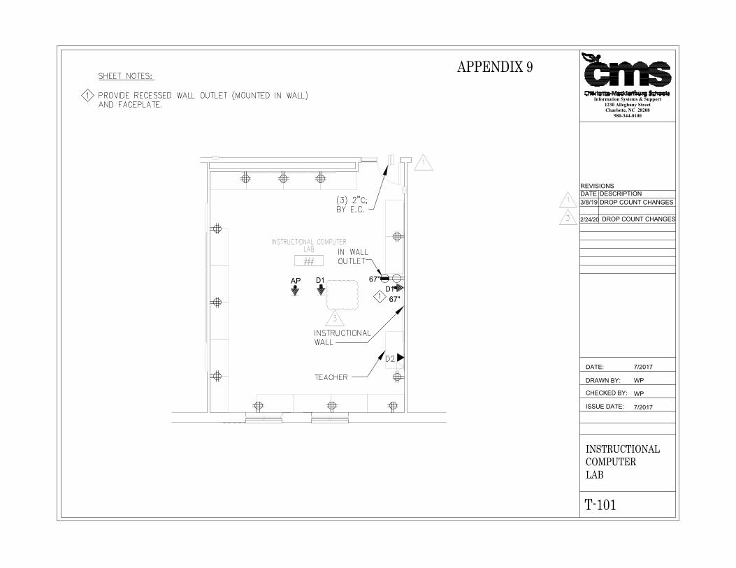
67"D167"
AP D1
Information Systems & Support1230 Alleghany StreetCharlotte, NC 28208
980-344-0100
DATE:
ISSUE DATE:
CHECKED BY:
DRAWN BY:
7/2017
WP
WP
7/2017
INSTRUCTIONALCOMPUTERLAB
T-101
DATE DESCRIPTION3/8/19 DROP COUNT CHANGES
REVISIONS
APPENDIX 9
2/24/20 DROP COUNT CHANGES
AutoCAD SHX Text
D2
AutoCAD SHX Text
(3) 2"C; BY E.C.
AutoCAD SHX Text
INSTRUCTIONAL WALL
AutoCAD SHX Text
TEACHER
AutoCAD SHX Text
INSTRUCTIONAL COMPUTER
AutoCAD SHX Text
LAB
AutoCAD SHX Text
###
AutoCAD SHX Text
1
AutoCAD SHX Text
1
AutoCAD SHX Text
IN WALL OUTLET
AutoCAD SHX Text
3
AutoCAD SHX Text
SHEET NOTES: PROVIDE RECESSED WALL OUTLET (MOUNTED IN WALL) AND FACEPLATE.
AutoCAD SHX Text
1
AutoCAD SHX Text
1
AutoCAD SHX Text
3

67"D167"
AP D1
Information Systems & Support1230 Alleghany StreetCharlotte, NC 28208
980-344-0100
DATE:
ISSUE DATE:
CHECKED BY:
DRAWN BY:
7/2017
WP
WP
7/2017
CTECOMPUTERLAB
T-101-A
DATE DESCRIPTION3/8/19 ADDING DETAIL
REVISIONS
APPENDIX 9A
2/24/20 DROP COUNT CHANGES
AutoCAD SHX Text
D2
AutoCAD SHX Text
(3) 2"C; BY E.C.
AutoCAD SHX Text
INSTRUCTIONAL WALL
AutoCAD SHX Text
TEACHER
AutoCAD SHX Text
CTE COMPUTER
AutoCAD SHX Text
LAB
AutoCAD SHX Text
###
AutoCAD SHX Text
D3
AutoCAD SHX Text
D2
AutoCAD SHX Text
D2
AutoCAD SHX Text
D2
AutoCAD SHX Text
D3
AutoCAD SHX Text
D2
AutoCAD SHX Text
D2
AutoCAD SHX Text
D2
AutoCAD SHX Text
D2
AutoCAD SHX Text
D2
AutoCAD SHX Text
D2
AutoCAD SHX Text
D2
AutoCAD SHX Text
D2
AutoCAD SHX Text
D2
AutoCAD SHX Text
D2
AutoCAD SHX Text
FUTURE
AutoCAD SHX Text
1
AutoCAD SHX Text
1
AutoCAD SHX Text
IN WALL OUTLET
AutoCAD SHX Text
3
AutoCAD SHX Text
SHEET NOTES: PROVIDE RECESSED WALL OUTLET (MOUNTED IN WALL) AND FACEPLATE.
AutoCAD SHX Text
1
AutoCAD SHX Text
1
AutoCAD SHX Text
3