Interact Pro Design Guide
8
Design Guide Release 1.0 Find out more about Interact www.Interact-lighting.com Works with Connected lighting Pro
-
Upload
khangminh22 -
Category
Documents
-
view
0 -
download
0
Transcript of Interact Pro Design Guide

Design GuideRelease 1.0
Find out more about Interactwww.Interact-lighting.com
Works with
Connected lighting
Pro
System architecture It is useful to understand the high-level system architecture as depicted in Figure 2.
The combination of several hardware components and system specific firm- and software makes the Interact Pro system. The system consists of:
• Wireless Gateway (gateway): the basis of the lighting system connects the system to the cloud via the IT network of the customer and the internet. The wireless gateway connects with the light points by means of ZigBee.
• Light points: lamps or luminaires equipped with electronics to receive and send ZigBee signals.
• Sensor: device that senses presence of people in an area and triggers the switching of the lighting in the area by means of ZigBee. Daylight dependent regulation is possible with a multi-sensor that supports light sensing and occupancy detection.
• Switch: device that enables the possibility to control the lighting in an area manually, switch on or off, or dim up or down.
• Portal: a cloud-based webpage, where access rights of the users determine the field of operation of the portal, for example for design, installation, commissioning, operation, or management.
• App: a small piece of software installed on a smart device (for example a smart phone) that is used for commissioning and operation.
All key components are future proof, as they receive regular firm- and software updates that are pushed over the air (OTA). This process makes sure the stable and secure operation of the system, meanwhile adding new features and functionality without the customer requiring installing new hardware.
Router/Switch
Cus
tom
erIn
stal
ler
IP backbone
Up to 200ligth points
Wirelessgateway
Zigbee 3.0/distributed
Light points
Sensor
UI
Philips Portal andInstaller dashboard
On-site commissioningapplications
Philips Portal and Customer dashboard
Customer applications
Philips userapplications
Figure 2 High level system architecture of the Interact Pro system
Interact Pro08System Guide
Interact Pro
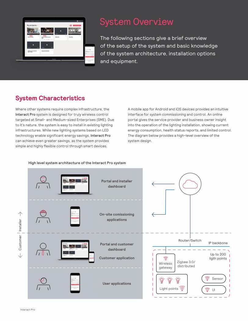
System OverviewThe following sections give a brief overview of the setup of the system and basic knowledge of the system architecture, installation options and equipment.
System CharacteristicsWhere other systems require complex infrastructure, the Interact Pro system is designed for truly wireless control targeted at Small- and Medium-sized Enterprises (SME). Due to it's nature, the system is easy to install in existing lighting infrastructures. While new lighting systems based on LED technology enable significant energy savings, Interact Pro can achieve even greater savings, as the system provides simple and highly flexible control through smart devices.
A mobile app for Android and iOS devices provides an intuitive interface for system commissioning and control. An online portal gives the service provider and business owner insight into the operation of the lighting installation, showing current energy consumption, health status reports, and limited control. The diagram below provides a high-level overview of the system design.
High level system architecture of the Interact Pro system
Portal and installer dashboard
On-site comissioning applications
Portal and customer dashboard
Customer application
User applications
1
Application AreasThe system is designed to create a connected lighting system in single buildings of the following types:
• Tenant fit out offices • Retail banks
• Small to medium retail stores • Schools
• Municipal buildings • Micro hospitals
• Small industry (for example a small workshop or warehouse)
Interact Pro is optimized for the application spaces above and can connect up to 200 light points per wireless gateway to the cloud. Multiple gateways can be used in one project when the number of light points exceeds 200, or in cases where the wireless signal cannot propagate due to building materials such as steel reinforced concrete.
Each gateway would be used to control a logical area such as a floor or discrete part of the building. Typically, one wireless gateway can cover an area of up to 11,000ft² (1,000m²) or larger. In buildings with lower lighting requirements, warehousing for example, up to 110,000ft² (10,000m²) may be connected.
Currently supported maximum system size To be able to design the lighting system correctly, it is important to know its possibilities and limitations.
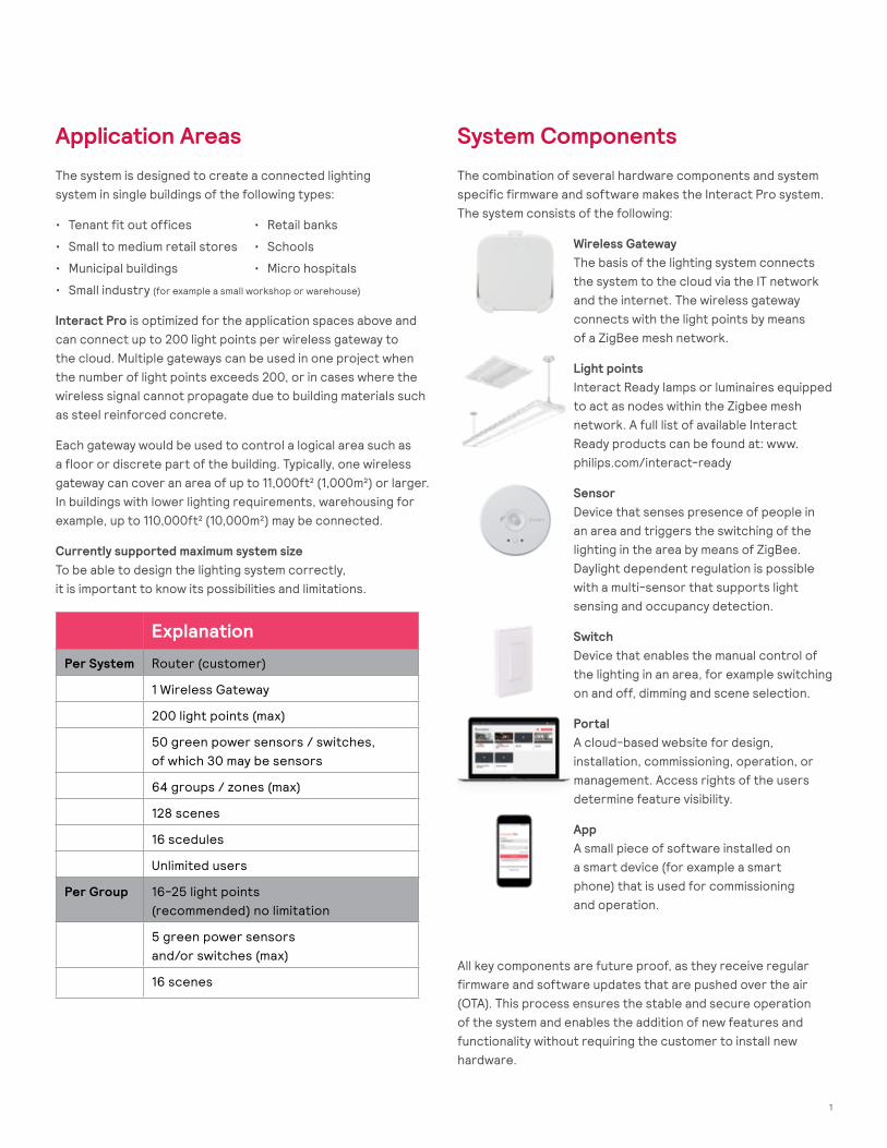
System ComponentsThe combination of several hardware components and system specific firmware and software makes the Interact Pro system. The system consists of the following:
Wireless Gateway The basis of the lighting system connects the system to the cloud via the IT network and the internet. The wireless gateway connects with the light points by means of a ZigBee mesh network.
Light points Interact Ready lamps or luminaires equipped to act as nodes within the Zigbee mesh network. A full list of available Interact Ready products can be found at: www.philips.com/interact-ready
Sensor Device that senses presence of people in an area and triggers the switching of the lighting in the area by means of ZigBee. Daylight dependent regulation is possible with a multi-sensor that supports light sensing and occupancy detection.
Switch Device that enables the manual control of the lighting in an area, for example switching on and off, dimming and scene selection.
Portal A cloud-based website for design, installation, commissioning, operation, or management. Access rights of the users determine feature visibility.
App A small piece of software installed on a smart device (for example a smart phone) that is used for commissioning and operation.
All key components are future proof, as they receive regular firmware and software updates that are pushed over the air (OTA). This process ensures the stable and secure operation of the system and enables the addition of new features and functionality without requiring the customer to install new hardware.
Explanation
Per System Router (customer)
1 Wireless Gateway
200 light points (max)
50 green power sensors / switches, of which 30 may be sensors
64 groups / zones (max)
128 scenes
16 scedules
Unlimited users
Per Group 16-25 light points (recommended) no limitation
5 green power sensors and/or switches (max)
16 scenes
Design Guide 04 Interact Pro
Multiple gateways can be used in one project when the number of light points exceeds 200, or in cases where the wireless signal cannot propagate due to building materials such as steel reinforced concrete. Each gateway would be used to control a logical area such as a floor or discrete part of the building.
Currently supported maximum system size To be able to design the lighting system correctly, it is important to know its possibilities and limitations.
1.3 System Components
The combination of several hardware components and system specific firmware and software makes the Interact Pro system. The system consists of:
Wireless Gateway: the basis of the lighting system connects the system to the cloud via the IT network of the customer and the internet. The wireless gateway connects with the light points by means of a ZigBee mesh network.
Light points: Interact Ready lamps or luminaires equipped to act as nodes within the Zigbee mesh network. A full list of available light points can be found at http://www.lighting.philips.com/main/products/interact-ready
Sensor: device that senses presence of people in an area and triggers the switching of the lighting in the area by means of ZigBee. Daylight dependent regulation is possible with a multi-sensor that supports light sensing and occupancy detection.
Switch: device that enables the manual control of the lighting in an area, for example switching on and off, dimming and scene selection.
Portal: a cloud-based website for design, installation, commissioning, operation, or management. Access rights of the users determine feature visibility.
App: a small piece of software installed on a smart device (for example a smart phone) that is used for commissioning and operation.
All key components are future proof, as they receive regular firmware and software updates that are pushed over the air (OTA). This process ensures the stable and secure operation of the system and enables the addition of new features and functionality without requiring the customer to install new hardware.

2 Interact Pro
Designing SpacesThe entire portfolio of Interact Ready luminaires, smart lamps, and retrofit kits is available at:www.philips.com/interact-ready
Prepare a Lighting LayoutUsing the building layout, select the appropriate type and quantity of light points for your project.
Establish ProjectsUsing the Lighting Layout and the maximum system sizes listed above, determine the number and location of the projects for this installation. When the total number of light points is less than 200 and there are no obstructions to the wireless signal, only one wireless gateway is required. More wireless gateways may be required in the following situations::
1. Challenging building layouts and obstructions When the layout of a space does not allow for two light points to be within 33ft (10m) of each other, or other environmental factors such as steel reinforced walls in the layout do not allow for adequate propagation of the wireless ZigBee signal.
2. Larger spaces requiring more than 200 light points Each Interact Pro wireless gateway supports up to 200 light points.
Considerations when using multiple wireless gateways When using more than one wireless gateway in a space, each gateway will appear in the web-based portal or the mobile app as a separate project, therefore it is advisable to divide the building up into separate, logical areas of 200 light points or less and to only assign the light points in one logical area to a single gateway. For example, a small elementary school may be separated by an East and West wing each with < 200 Light points. In this case, two wireless gateways may be installed (one in each wing) and the light points in each wing can then be assigned to the wireless gateway that has been installed in that area.
Note: When commissioning a space with multiple Wireless Gateways, it is strongly advised to only apply power to one gateway and its associated light points at a time during the discovery phase to ensure that the gateway that is being commissioned only discovers the intended light points.
Wireless Gateway Requirements • Within reach of at least two light points within 33 ft (10 m)• A non-switched power outlet• A location where the QR code is accessible
for scanning during commissioning• Unsecured Ethernet connection with DHCP and NTP
(TCP port 443 must be open)
Interact Pro Portal as a Service Provider
3
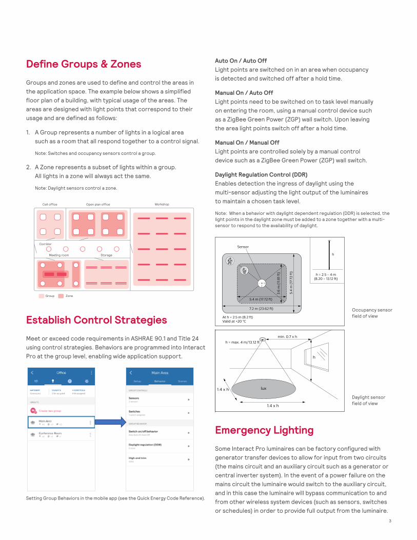
Define Groups & ZonesGroups and zones are used to define and control the areas in the application space. The example below shows a simplified floor plan of a building, with typical usage of the areas. The areas are designed with light points that correspond to their usage and are defined as follows:
1. A Group represents a number of lights in a logical area such as a room that all respond together to a control signal.
Note: Switches and occupancy sensors control a group.
2. A Zone represents a subset of lights within a group. All lights in a zone will always act the same.
Note: Daylight sensors control a zone.
Auto On / Auto Off Light points are switched on in an area when occupancy is detected and switched off after a hold time.
Manual On / Auto Off Light points need to be switched on to task level manually on entering the room, using a manual control device such as a ZigBee Green Power (ZGP) wall switch. Upon leaving the area light points switch off after a hold time.
Manual On / Manual Off Light points are controlled solely by a manual control device such as a ZigBee Green Power (ZGP) wall switch.
Daylight Regulation Control (DDR) Enables detection the ingress of daylight using the multi-sensor adjusting the light output of the luminaires to maintain a chosen task level.
Note: When a behavior with daylight dependent regulation (DDR) is selected, the light points in the daylight zone must be added to a zone together with a multi-sensor to respond to the availability of daylight.
Emergency LightingSome Interact Pro luminaires can be factory configured with generator transfer devices to allow for input from two circuits (the mains circuit and an auxiliary circuit such as a generator or central inverter system). In the event of a power failure on the mains circuit the luminaire would switch to the auxiliary circuit, and in this case the luminaire will bypass communication to and from other wireless system devices (such as sensors, switches or schedules) in order to provide full output from the luminaire.
Design lighting network architectureThe design of the lighting network must comply with the following requirements:• Determine the amount and position of the light points,
sensors and, if applicable, switches• Use the input from the customer (for example floorplans)
to define groups and zones• Define the scenes and lighting behavior for the groups and
zones• Define the location of the gateway
The example shows a simplified floor plan of a building, with typical usage of the areas. The areas are designed with light points that correspond to their usage and have groups and zones defined.
Design of the power gridThe number per circuit is limited by the circuit breaker and the inrush current of the wireless driver. Make sure to create sufficient circuits as per the following table:
The gateway requires a power outlet, available close to the location of the device. Note that the gateway is placed at high altitude against a wall or dropped ceiling.
Cell office Open plan office Workshop
Corridor
Meeting room Storage
Group Zone
Driver type (application) Circuit Breaker: 16 A, type B
Independent driver (for example: panel, downlight)
Max 24 luminaires
Built-in driver(for example: waterproof, troffer)
Max 22 luminaires
Interact Pro18System Guide
Establish Control StrategiesMeet or exceed code requirements in ASHRAE 90.1 and Title 24 using control strategies. Behaviors are programmed into Interact Pro at the group level, enabling wide application support.
Design Guide 06 Interact Pro
2.3 Define Groups & Zones
Groups and zones are used to define and control the areas in the application space. The example below shows a simplified floor plan of a building, with typical usage of the areas. The areas are designed with light points that correspond to their usage and are defined as follows:
i. A Group represents a number of lights in a logical area such as a room that all respond together to a control signal Note: switches and occupancy sensors control a group
ii. A Zone represents a subset of lights within a group. All lights in a zone will always act the same. Note: daylight sensors control a zone
2.4 Establish Control Strategies
Meet or exceed code requirements in ASHRAE 90.1 and Title 24 using control strategies. Behaviors are programmed into Interact Pro at the group level, enabling wide application support.
2.4.1 Auto On / Auto Off
Light points are switched on in an area when occupancy is detected and switched off after a hold time.
2.4.2 Manual On / Auto Off
Light points need to be switched on to task level manually on entering the room, using a manual control device such as a ZigBee Green Power (ZGP) wall switch. Upon leaving the area light points switch off after a hold time.
2.4.3 Manual On / Manual Off
Light points are controlled solely by a manual control device such as a ZigBee Green Power (ZGP) wall switch.
2.4.4 Daylight Regulation Control (DDR)
Enables detection the ingress of daylight using the multi-sensor adjusting the light output of the luminaires to maintain a chosen task level. Note: When a behavior with daylight dependent regulation (DDR) is selected, the light points close to a window must be added to a zone together with a multi sensor to respond on the ingress of daylight.
Figure 4 Occupancy sensor field of view
Figure 5 Daylight sensor field of view
Figure 3 Setting Group Behaviors in the app Setting Group Behaviors in the mobile app (see the Quick Energy Code Reference).
Occupancy sensor field of view
Daylight sensor field of view
3
• Field-of-view (FOV) for motion detection is determined at typical height (h=2.5m) for major and
minor motion with NEMA tests, respectively. Daylight FOV is for multi sensor only.
• Motion FOV can be reduced using the plastic shield around the lens.
Field-of-View
Motion FOV
Daylight FOV
7.2 m (23.62 ft)
5.4 m (17.72 ft)
At h = 2.5 m (8.2 ft)Valid at +20 °C
5.4
m (
17.7
2 f
t)
3.6
m (
11.8
1 ft
)h = 2.5 - 4 m
(8.20 - 13.12 ft)
h
Sensor
min. 0.7 x h
1.4 x h
1.4 x h
h = max. 4 m/13.12 ft
h
lux
3
• Field-of-view (FOV) for motion detection is determined at typical height (h=2.5m) for major and
minor motion with NEMA tests, respectively. Daylight FOV is for multi sensor only.
• Motion FOV can be reduced using the plastic shield around the lens.
Field-of-View
Motion FOV
Daylight FOV
7.2 m (23.62 ft)
5.4 m (17.72 ft)
At h = 2.5 m (8.2 ft)Valid at +20 °C
5.4
m (
17.7
2 f
t)
3.6
m (
11.8
1 ft
)
h = 2.5 - 4 m(8.20 - 13.12 ft)
h
Sensor
min. 0.7 x h
1.4 x h
1.4 x h
h = max. 4 m/13.12 ft
h
lux
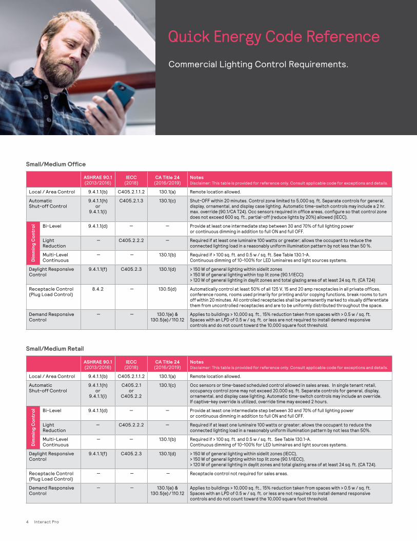
Quick Energy Code ReferenceCommercial Lighting Control Requirements.
ASHRAE 90.1 (2013/2016)
IECC (2018)
CA Title 24 (2016/2019)
Notes Disclaimer: This table is provided for reference only. Consult applicable code for exceptions and details.
Local / Area Control 9.4.1.1(b) C405.2.1.1.2 130.1(a) Remote location allowed.
Automatic Shut-off Control
9.4.1.1(h) or
9.4.1.1(i)
C405.2.1.3 130.1(c) Shut-OFF within 20 minutes. Control zone limited to 5,000 sq. ft. Separate controls for general, display, ornamental, and display case lighting. Automatic time-switch controls may include a 2 hr. max. override (90.1/CA T24). Occ sensors required in office areas, configure so that control zone does not exceed 600 sq. ft., partial-off (reduce lights by 20%) allowed (IECC).
Dim
min
g C
ontr
ol Bi-Level 9.4.1.1(d) — — Provide at least one intermediate step between 30 and 70% of full lighting power or continuous dimming in addition to full ON and full OFF.
Light Reduction
— C405.2.2.2 — Required if at least one luminaire 100 watts or greater; allows the occupant to reduce the connected lighting load in a reasonably uniform illumination pattern by not less than 50 %.
Multi-Level Continuous
— — 130.1(b) Required if > 100 sq. ft. and 0.5 w / sq. ft. See Table 130.1-A. Continuous dimming of 10-100% for LED luminaires and light sources systems.
Daylight Responsive Control
9.4.1.1(f) C405.2.3 130.1(d) > 150 W of general lighting within sidelit zones> 150 W of general lighting within top lit zone (90.1/IECC) > 120 W of general lighting in daylit zones and total glazing area of at least 24 sq. ft. (CA T24)
Receptacle Control (Plug Load Control)
8.4.2 — 130.5(d) Automatically control at least 50% of all 125 V, 15 and 20 amp receptacles in all private offices, conference rooms, rooms used primarily for printing and/or copying functions, break rooms to turn off within 20 minutes. All controlled receptacles shall be permanently marked to visually differentiate them from uncontrolled receptacles and are to be uniformly distributed throughout the space.
Demand Responsive Control
— — 130.1(e) & 130.5(e) / 110.12
Applies to buildings > 10,000 sq. ft., 15% reduction taken from spaces with > 0.5 w / sq. ft. Spaces with an LPD of 0.5 w / sq. ft. or less are not required to install demand responsive controls and do not count toward the 10,000 square foot threshold.
ASHRAE 90.1 (2013/2016)
IECC (2018)
CA Title 24 (2016/2019)
Notes Disclaimer: This table is provided for reference only. Consult applicable code for exceptions and details.
Local / Area Control 9.4.1.1(b) C405.2.1.1.2 130.1(a) Remote location allowed.
Automatic Shut-off Control
9.4.1.1(h) or
9.4.1.1(i)
C405.2.1 or
C405.2.2
130.1(c) Occ sensors or time-based scheduled control allowed in sales areas. In single tenant retail, occupancy control zone may not exceed 20,000 sq. ft. Separate controls for general, display, ornamental, and display case lighting. Automatic time-switch controls may include an override. If captive-key override is utilized, override time may exceed 2 hours.
Dim
min
g C
ontr
ol Bi-Level 9.4.1.1(d) — — Provide at least one intermediate step between 30 and 70% of full lighting power or continuous dimming in addition to full ON and full OFF.
Light Reduction
— C405.2.2.2 — Required if at least one luminaire 100 watts or greater; allows the occupant to reduce the connected lighting load in a reasonably uniform illumination pattern by not less than 50%.
Multi-Level Continuous
— — 130.1(b) Required if > 100 sq. ft. and 0.5 w / sq. ft. See Table 130.1-A. Continuous dimming of 10-100% for LED luminaires and light sources systems.
Daylight Responsive Control
9.4.1.1(f) C405.2.3 130.1(d) > 150 W of general lighting within sidelit zones (IECC), > 150 W of general lighting within top lit zone (90.1/IECC), > 120 W of general lighting in daylit zones and total glazing area of at least 24 sq. ft. (CA T24).
Receptacle Control (Plug Load Control)
— — — Receptacle control not required for sales areas.
Demand Responsive Control
— — 130.1(e) & 130.5(e) / 110.12
Applies to buildings > 10,000 sq. ft., 15% reduction taken from spaces with > 0.5 w / sq. ft. Spaces with an LPD of 0.5 w / sq. ft. or less are not required to install demand responsive controls and do not count toward the 10,000 square foot threshold.
Small/Medium Office
Small/Medium Retail
4 Interact Pro

5
© 2019 Signify Holding. All rights reserved. The information provided herein is subject to change, without notice. Signify does not give any representation or warranty as to the accuracy or completeness of the information included herein and shall not be liable for any action in reliance thereon. The information presented in this document is not intended as any commercial offer and does not form part of any quotation or contract, unless otherwise agreed by Signify. All trademarks are owned by Signify Holding or their respective owners.
INt-1818DG 05/19 www.Interact-lighting.com
Signify North America Corporation 200 Franklin Square Drive, Somerset, NJ 08873 Telephone 855-486-2216
Signify Canada Ltd. 281 Hillmount Road, Markham, ON, Canada L6C 2S3 Telephone 800-668-9008