VB-860 PA-44-180 Pilots Operating Handbook (POH)
370
SEMINOLE PILOT’S OPERATING HANDBOOK AND FAA APPROVED AIRPLANE FLIGHT MANUAL AIRPLANE AIRPLANE SERIAL NO. ____________________ REGIST. NO. _________________ PA-44-180 REPORT: VB-860 FAA APPROVED BY: ____________________________ WARD EVANS D.O.A. NO. SO-1 DATE OF APPROVAL: PIPER AIRCRAFT CORPORATION MARCH 23, 1978 VERO BEACH, FLORIDA THIS HANDBOOK INCLUDES THE MATERIAL REQUIRED TO BE FURNISHED TO THE PILOT BY THE FEDERAL AVIATION REGULATIONS AND ADDITIONAL INFORMATION PROVIDED BY THE MANUFACTURER AND CONSTITUTES THE FAA APPROVED AIRPLANE FLIGHT MANUAL. THIS HANDBOOK MUST BE CARRIED IN THE AIRPLANE AT ALL TIMES. C t f
-
Upload
khangminh22 -
Category
Documents
-
view
2 -
download
0
Transcript of VB-860 PA-44-180 Pilots Operating Handbook (POH)

seminolepilot’s
operatinghandbook
and
faa approvedairplane flight manual
airplane airplaneserial no. ____________________ regist. no. _________________
pa-44-180report: vb-860 faa approved by: ____________________________ Ward evans d.o.a. no. so-1date of approval: piper airCraft CorporationmarCh 23, 1978 vero beaCh, florida
This handbook includes The maTerial required To be furnished To The piloT by The federal aviaTion regulaTions and addiTional informaTion provided by The manufacTurer and consTiTuTes The faa approved airplane flighT manual. This handbook musT be carried in The airplane aT all Times.
C t f
zeke
N-A for Flight-POH

PIPER AIRCRAFT CORPORATION PA-44-180, SEMINOLE
REPORT: VB-860 ISSUED: MARCh 23, 1978ii REVISED: OCTOBER 11, 2011
wARNINgExtrEmE carE must bE ExErcisEd to limit thE usE of this handbook to applicablE aircraft. this hand-book is valid for usE with thE airplanE idEntifiEd on thE facE of thE titlE pagE. subsEquEnt rEvisions suppliEd by pipEr aircraft corporation must bE propErly insErtEd.
published bypublications dEpartmEnt
issued: march 23, 1978piper aircraft corporation
© 1978-1983,1989,2004,2011piper aircraft corporation
all rights reserved.


APPLICABILITY
Application of this handbook is limited to the specific Piper P A-44-180 model airplane designated by serial number and registration number on the face of the title page of this handbook.
This handbook cannot be used for operational purposes unless kept in a current status.
REVISIONS
The information compiled in the Pilot's Operating Handbook will be kept current by revisions distributed to the airplane owners.
Revision material will consist of information necessary to update the text of the present handbook and/ or to add information to cover added airplane equipment.
I. Revisions
Revisions will be distributed whenever necessary as complete page replacements or additions and shall be inserted into the handbook in accordance with the instructions given below:
I. Revision pages will replace only pages with the same page number. 2. Insert all additional pages in proper numerical order within each
section. 3. Page numbers followed by a small letter shall be inserted in direct
sequence with the same common numbered page.
II. Identification of Revised Material
Revised text and illustrations shall be indicated by a black vertical line along the outside margin of the page, opposite revised, added or deleted material. A line along the outside margin of the page opposite the page number will indicate that an entire page w:1s added.
REPORT: VB-860 iii

Black lines will indicate only current rev1S1ons with .changes and additions to or deletions of existing text and illustrations. Changes in capitalization, spelling, punctuation or the physical location of material on a page will not be identified.
OHJGINAL PAGES ISSUED
The original pa6es issued for this handbook prior to revision are given below:
Title, ii through vii, 1-1 through 1-21, 2-1 through 2-10, 3-1 through 3-21, 4-1 through 4-27, 5-1 through 5-33, 6-1 through6-50, 7-1 through 7-34, 8-l through 8-17, 9-1 through 9-22, and 10-1 through 10-3.
REPORT: VB-860 iv

PILOT'S OPERATING HANDBOOK LOG OF REVISIONS
Current Revisions to the PA-44-180 Seminole Pilot's Operating Handbook, REPORT: VB-860 issued March 23, 1978.
Revision Number and Revised
Code Pages
Rev. I 1-3 761 662
(PR781215) 1-4
1-5 1-8 1-18 2-3 2-4 2-6 3-i 3-2 3-3
3-4
3-5
3-6
3-7
3-8
3-9
3-10 3-11 3-12
Description of Revision
Revised para. 1.5; relocated info. to pg. 1-4. Added info. from pg. 1-3; relocated info. to pg. 1-5. Added info. from pg. 1-4. Revised para. 1.19. Revised para. 1.21 Revised para. 2.7. Revised para. 2. 7. Revised para. 2.23. Revised para. 3.7. Revised para. 3.3. Revised para. 3.3; added Warning from pg. 3-4. Revised para. 3.3; relocated Warning to pg. 3-3; added info. from pg. 3-5. Relocated info. to pg. 3-4; added info. from pg. 3-6. Relocated info. to pg. 3-5; added info. from pg. 3-7. Relocated info. to pg. 3-6; added info. from pg. 3-8. Relocated info. to pg. 3-7; added info. from pg. 3-9. Relocated info. to pg. 3-8; added info. from pg. 3-10. Relocated info. to pg. 3-9. Revised para. 3. 7. Revised para. 3. 7; relocated info. to pg. 3-13.
FAA Approval Signature and
Date
REPORT: VB-860 V

PILOT'S OPERATING HANDBOOK LOG OF REVISIONS (cont)
Revision Number and Revised
Code Pages
Rev. I (cont) 3-13
3-14
3-15 4-i
4-1
4-2
4-6
4-7
4-8
4-9
4-10
4-11
4-12
4-!2a
i 4-11b
4-13
REPORT: VB-860 vi
FAA Approval Description of Revision Signature and
Date
Added info. from pg. 3-12; revised para. 3. 7; added info. from pg. 3-14. Relocated info. to pg. 3-13; revised para. 3. 7; relocated info. to pg. 3-15. Added info. from pg. 3-14. Added para. 4.16; revised pg. nos. Revised para. 4.1; relocated info. to pg. 4-2. Added info. from pg. 4-1; revised para. 4.3. Added info. to para. 4.5; relocated info. to pg. 4-7. Added info. from pg. 4-6; relocated info. to pg. 4-8. Added info. from pg. 4-7; relocated info. to pg. 4-9. Added info. from pg. 4-8; relocated info. to pg. 4-10. Added info. from pg. 4-9; relocated info. to pg. 4-1 I. Added info. from pg. 4-10; relocated info. to pg. 4-12. Added info. from pg. 4-11; relocated info. to pg. 4-12a. Added pg. (added info. from pg. 4-12). Added pg. (added info. from pg. 4-13). Relocated info. to pg. 4-12b; added info. from pg. 4-14.
PILOT'S OPERATING HANDBOOK LOG OF REVISIONS (cont)
Revision Number and Revised
Code Pages
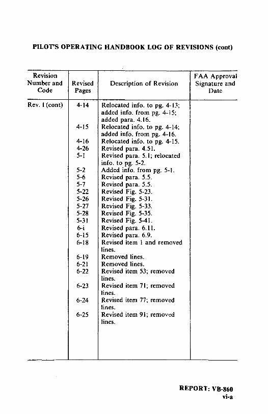
Rev. l (cont) 4-14
4-15
4-16 4-26 5-1
5-2 5-6 5-7 5-22 5-26 5-27 5-28 5-31 6-i 6-15 6-18
6-19 6-21 6-22
6-23
6-24
6-25
FAA Approval Description of Revision Signature and
Date
Relocated info. to pg. 4-13; added info. from pg. 4- i 5; added para. 4.16. Relocated info. to pg. 4- I 4; added info. from pg. 4- I 6. Relocated info. to pg. 4-15. Revised para. 4.51. Revised para. 5.1; relocated info. to pg. 5-2. Added info. from pg. 5-1. Revised para. 5.5. Revised para. 5.5. Revised Fig. 5-23. Revised Fig. 5-31. Revised Fig. 5-33. Revised Fig. 5-35. Revised Fig. 5-41. Revised para. 6.11. Revised para. 6.9. Revised item I and removed lines. Removed lines. Removed lines. Revised item 53; removed lines. Revised item 71; removed lines. Revised item 77; removed lines. Revised item 91; removed lines.
REPORT: VB-860 vi-a

PILOTS OPERATING HANDBOOK LOG OF REVISIONS (cont)
Revision Number and Revised
Code Pages
Rev. I (cont) 6-26
6-27
6-31 6-33 6-34
6-35
6-37
6-38
6-39 6-45 6-46
6-47
6-48
7-i 7-10 7-14 7-35 8-10
REPORT: VB-860 vi-b
FAA Approval Description of Revision Signature and
Date
' Added para. 6.11 (g) from pg. 6-27; added new item 113. Revised para. 6.11 (h) to 6.11 (g) and relocated to pg. 6-26; revised para. 6.11 (g) to 6.11 (h); renumbered existing items 113 and 115 to 121 and 123; added new items I 15 and ll7. Revised item 165. Revised items 173 and 175. Added item 176; relocated item 187 to pg. 6-35. Added item 187 from pg. 6-34. Added new item 212; re-located item 219 to pg. 6-38. Added item 219 from pg. 6-37. Revised item 231. Revised item 281. Added new item 282; re-located item 289 to pg. 6-47. Added item 289 from pg. 6-46. Deleted item 353; revised items 355 and 361. Added para. 7.39. Revised Fig. 7-7.
W°"cl. Revised para. 7.15. Added pg. (added para. 7.39). Ward Evans Revised para. 8.17. Dec. 15, 1978

PILOTS OPERATING HANDBOOK LOG OF REVISIONS (cont)
Revision Number and Revised
Code Pages
Rev. 2 6-46 761 662
(PR790413) 6-47
7-i
7-33 7-34
7-35
7-36
Rev. 3 1-9 761 662 2-2
(PR790914) 2-7, 2-8, 2-9, 2-10
3-6 3-7
3-8 3-13 3-18 4-6 4-11 4-12 5-2
5-3, 5-5, 5-6, 5-7
5-9 5-15
FAA Approval Description of Revision Signature and
Date
Revised item 283; added item 284; relocated item 287 to pg. 6-47. Added item 287 from pg. 6-46. Revised para. 7.37 & 7.39 pg. nos. Revised para. 7.35. Revised para. 7.35; relocated para. 7.37 to pg. 7-36. Added para. 7.35 info.; re-located para. 7.39 to pg. 7-36. WOAJ. Added pg. (added para. 7.37 from pg. 7-34 & para. 7.39 Ward Evans from pg. 7-35). April 13, 1979
Added Demo. X-Wind. Revised para. 2.3. Revised para. 2.27.
Added info. Replaced abbreviations with words. Added word to title. Revised procedure. Revised para. 3. 15. Revised Caution. Added info. from pg. 4-12. Relocated info. to pg. 4-1 l. Added Warning. Revised para. 5.5 (a), (c), (d), (e), (t) and (g). Revised List of Figures. Revised Fig. 5-9.
REPORT: VB-860 vi-c

PILOT'S OPERATING HANDBOOK LOG OF REVISIONS (cont)
Revision Number and Revised
Code Pages
Rev. 3 (cont) 5-24 thru 5-3!
6-i, 6-2 6-3
6-4
6-5 6-18 6-24 6-26 6-27 6-30
6-31
6-32 6-34 6-35 6-36
6-37
6-38
6-39
REPORT: VB-860 vi-d
FAA Approval Description of Revision Signature and
Date
Revised Figs. 5-27 thru ; 5-41.
Revised para. 6.1. Added Caution. Moved info. to pg. 6-4. Relocated info. from pg. 6-3. Moved info. to pg. 6-5. Relocated info. from pg. 6-4. Revised items 1, 3 and 5. Revised item 77. Revised item 113. Revised items I I 5 and 121. Relocated item 159 from pg. 6-31. Relocated item 159 to pg. 6-30; added item 167 from pg. 6-32. Added item 170. Added item 178. Revised items 191 and 193. Added item 206; revised item 207; relocated item 209. Revised, relocated item 209 from pg. 6-36; changed item 213 to 214; added new 213; relocated items 215 and 217 to pg. 6-38. Changed item 215 to 216, relocated from pg. 6-37; added new 216; relocated item 217 from pg. 6-37; relocated items 221 and 223 to pg. 6-39. Relocated items 221 and 223 from pg. 6-38; added item 224; relocated items 225 thru 235 to pg. 6-40.

PILOT'S OPERATING HANDBOOK LOG OF REVISIONS (cont)
Revision N umber and Revised
Code Pages
R ev. 3(cont) 6-40
6-41
6-4la
6-4Ib 6-47 6-48 7-9 7-11 7-2S 7-26 7-28
10-2
1-2 Rev. 4 1-4
761 662 2-3 (PR800301) 2-4
2-5 2-6 2-10 3-ii 3-21 3-22
5-23 S-24 S-32 6-9
FAA Approval Description of Revision Signature and
Date
Relocated items 22S thru 23S from pg. 6-39; added items 230 and 234; relocated items 237 thru 243 to pg. 6-41. Relocated items 237 thru 243 from pg. 6-40; added item 242; relocated items 245 thru 251 to pg. 6-4la. New page; relocated items 24S thru 251 from pg. 6-41. New page. Revised item 291. Revised item 35S. Revised para. 7.9. Revised Figure 7-9. Revised para. 7 .23. Wc,J. Revised Figure 7-25. Revised Figure 7-27. Ward Evans Revised para. 10.3 (h). Sept. 14, 1979
Revised Figure 1-1. Revised para. I. 7, 1.9 and I.I I. Revised para. 2. 7 Revised para. 2.11. Revised para. 2.13. Revised para. 2.23. Added serial number effectivity Added para. 3.37. Added para. 3.37. New page, contin. para. 3.37. Revised Figure S-2S. Revised Figure 5-27. Revised Figure S-43. Moved revised Figure 6-9 to pg. 6-10.
REPORT: VB-860 vi-e

PILOT'S OPERATING HANDBOOK LOG OF REVISIONS (cont)
Revision Number and Revised
Code Pages
Rev. 4(cont) I 6-IO ! i
! i I
6-lOa I
6-IOb 6-12 6-15 6-28 6-41
6-4la
6-4lb
7-i 7-3 7-4 7-26 7-27 7-37 8-11
8-1 la
8-llb
9-i 9-23
I thru 9-26 9-27 thru 9-30
REPORT: VB-860 vi-f
!
FAA Approval Description of Revision Signature and
Date
Added revised Figure 6-9; moved revised Figure 6-11 to pg. 6-I0a. New page; added revised Figure 6-11. New page. Revised Figure 6-15. Revised sample problem. Added item 125. Added items 238 & 240; moved items 241, 242 and 243 to pg. 6-41a. Relocated items 241, 242, 243; moved items 249 and 251 to pg. 6-41b. Relocated items 249 and 251. Added para. 7.41. Revised Figure 7-1. Revised Figure 7-3. Revised Figure 7-25. Revised para 7.23 New page; added para. 7.41. Revised para. 8.19, and para. 8-21. New page; cont. revised para. 8.21. New page; cont. revised para. 8.21 Added Supplements 4 and 5. Added pages (Supplement 4).
Added pages (Supplement 5). u)~.l ~ Ward Evans
March I, 1980

PILOT'S OPERA TING HANDBOOK LOG OF REVISIONS (cont)
Revision Number and Revised
Code Pages '
Rev. 5 Title 761 662 Publ.
(PR800926) 2-9
2-10 4-9
4-11 4-18 4-23 5-5 5-7 5-23 6-1 6-4 6-6 6-22 6-26
6-26a
6-26b 6-27
6-28 6-28a 6-28b
6-2C,
FAA Approval Description of Revision Signature and
Date
Revised title pg. Revised Warning. Revised Takeoff and Landing checklists: relocated placard to pg. 2-10. Added placard from pg. 2-9. Revised Before Takeoff checklist. Revised Approach and Landing Revised para. 4.27. Revised para. 4.37. Revised item 5.5 (c). Revised items 5.5 (e), (f) and (g) Revised Figure 5-25. Revised pg. nos. Revised Figure 6-3. Revised Figure 6-5. Added items 59 and 61. Added item 104: relocated item to pg. 6-26a. Added pg. (added items from pgs. 6-26 and 6-27). Added pg. Relocated items to pg. 6-26a; added item from pg. 6-28. Relocated item to pg. 6-27. Added pg. Added pg. (added items from pg. 6-29: added item 138: re-vised item no.). Relocated items to pg. 6-28b; revised item no.: added items 142, 143 and 144.
REPORT: VB-860 vi-g

PILOT'S OPERATING HANDBOOK LOG OF REVISIONS (cont)
Revision Number and Revised
Code Pages
Rev. 5 (cont) 6-35 6-36
6-36a, 6-36b, 6-36c 6-36d
6-37, 6-38, 6-39 6-40
6-41
6-41a
6-4lb
6-42 6-44 6-45
6-48 6-49
6-50
REPORT: VB-860 vi-h
FAA Approval Description of Revision Signature and
Date
Revised item no. Relocated items to pg. 6-36d; added items 193 and 194. Added pgs. (added items 200 thru 212).
Added pg. (added renumbered items from pg. 6-36). Renumbered items.
Renumbered items; added item! 229 and 230; relocated items to pg. 6-41. Added items from pg. 6-40; re-numbered items; relocated item to pg. 6-4Ia. Added item from pg. 6-41; renumbered items; added items 243 and 245; relocated items to pg. 6-41b. Added items from pg. 6-41a; renumbered item; relocated item to pg. 6-42. Added item from pg. 6-41b. Added item 277 from pg. 6-45. Relocated item to pg. 6-44; re-numbered item; added item 281. Added item 353. Renumbered and relocated item to pg. 6-50; added new item 375. Renumbered items; relocated info. to pg. 6-51; added item from pg. 6-49; added new items 377 and 379.

PILOT'S OPERATING HANDBOOK LOG OF REVISIONS (cont)
Revision Number and Revised
Code Pages
Rev. 5 (cont) 6-51
7-18 7-20 7-26 7-30, 7-31 8-9 9-i 9-31 thru 9-36 9-37 thru 9-40 9-41 thru 9-52 9-53, 9-54 9-55 thru 9-60 9-61 thru 9-66 9-67 thru 9-72 9-73 thru 9-76
Rev. 6 2-3 761 662 2-4
(PR801 I 19) 2-5 6-24
-
FAA Approval Description of Revision Signature and
Date
Added pg. (added info. from pg. 6-50). Revised Figure 7-17. Revised Figure 7-19. Revised Figure 7-25. Revised para. 7.27.
Revised Figure 8-9. Added Supplements 6 thru 13. Added Supplement 6 (Air Conditioning).
Added Supplement 7 (Century 21 Autopilot).
Added Supplement 8 (Century 41 Autopilot).
Added Supplement 9 (Control Wheel Clock). Added Supplement IO (WeatherScout II Radar).
Added Supplement 11 (RDR-160 Radar).
Added Supplement 12 (RDR-160/ IN-2026A Radar).
Added Supplement 13 weal\! (Color WeatherScout II Radar). Ward Evans
Sept. 26. 1980
Revised para. 2.7. Revised para. 2.9: moved wcwt para. 2.11 to pg. 2-5. Relocated para. 2.11 from pg. 2-4 W;ird Evans Deleted items 79 and 81 Nov. 19. 1980
REPORT: VB-860 vi-i

PILOT'S OPERATING HANDBOOK LOG OF REVISIONS (cont)
Revision Number and Revised
Codes Pages
Rev. 7 2-4 761 662 3-i. ~ii
(PR8l0I05) i 3-5
3-7 3-8
3-9
3-10 3-lOa
3-IOb
3-13 ,
3-15
3-16
3-17
3-19 3-20
3-21
3-22
3-23
REPORT: VB-860 vi-j
FAA Approval Description of Revision Signature and
Date
Revised 2.9 (c). I Changed page numbers. , Revised Air Start
(Unfeathering Procedure). Revised Electrical Failures. Moved info. to pg. 3- IOa; cont. Electrical Failure. Moved info. to pg. 3-l0b; cont. Electrical Failure. Cont. Electrical Failure. New page; relocated info. from pg. 3-8. New page; relocated info. from pg. 3-9. Revised engine failure during takeoff (75 KIAS and above). Revised Air Start (Unfeathering Procedure). Moved para. 3.11 to pg. 3-17; cont. Air Start. Relocated para. 3.11 from pg. 3-16. Revised para. 3.23. Moved para. 3.25 and para. 3.27 to pg. 3-22; cont. para. 3.23 revision. Moved para. 3.29, 3.31, 3.33 and 3.35 to pg. 3-23 and para. 3.35 and 3.37 to pg. 3-24; cont. para. 3.23 revision. Relocated para. 3.25 from pg. 3-20; moved part of para. 3.37 to pg. 3-24. New page; relocated para. 3.29, 3.31 and 3.35 from pg. 3-21.

PILOT'S OPERATING HANDBOOK LOG OF REVISIONS (cont)
Revision Number and Revised
Codes Pages
Rev. 7 (cont) 3-24
6-34
6-35
6-36
7-16 7-17 7-19 7-21 9-77
Rev. 8 3-3 761 662 3-13
(PR810410) 4-i
4-18
4-19
5-23 6-25 6-26 6-34 6-39 thru 6-42
6-49
FAA Approval Description of Revision Signature and
Date
New page; relocated para. 3.37 from pg. 3-21 and 3-22. Added item 180; moved item 185 to pg. 6-35. Relocated item 185 from rg. 6-35; moved items 191 and 192 to pg. 6-36. Relocated items 191 and 192 from pg. 6-36. Revised para. 7 .17. Revised Figure 7-15. lJJ_C_ ~ Cont. para. 7 .17 revision. Deleted info. Ward Evans Added info. Jan. 5, 1981
Revised Warning. Added Warning. Changed pg. no. for para. 4.27. Revised para. 4.27; moved para. 4.29 to pg. 4-19. Relocated para. 4.29 from pg. 4-18. Revised fig. 5-25. Revised items 99 and IO I . Revised items 103 and 104. Revised item 178. Added new item 228; moved and renumbered items 228 thru 252; revised new item 244. Revised item 375.
REPORT: VB-860 vi-k

PILOT'S OPERATING HANDBOOK LOG OF REVISIONS (cont)
Revision Number and Revised
Codes Pages
Rev. 8(cont) 6-50
i 7-i)
' 7-20 9-25 9-41
Rev. 9 1-5 761 662 2-9
(PR8I0724) 3-2 3-12 4-4 4-5
4-9 4-11 4-12b 4-13
4-14
4-15 4-17 4-18
4-19
4-20 4-23
4-24
4-25
REPORT: VB-860 vi-I
FAA Approval Description of Revision Signature and
Date
Revised items 377 and 379. Revised fig. 7-15. lJo,•~l 5..-n,. Revised fig. 7 - I 9. Revised Sec. 4 (b) (8) a and b. Ward Evans Revised Sec. 2 (c). April IO, 1981
Revised para. I .I 3. Revised check list. Revised procedure. Revised procedure. Relocated info. from pg. 4-5. Moved info. to pg. 4-4; revised procedure. Revised procedure. Revised procedure. Revised Caution. Added Note; moved para. 4.15 to pg. 4-14. Relocated para. 4.15; moved info. to pg. 4-15. Relocated info. from pg. 4-14. Relocated info. from pg. 4-18. Moved info. to pg. 4-17; added Note; moved info. to pg. 4-19. Relocated info. from pg. 4-18; moved info. to pg. 4-20. Relocated info. from pg. 4-19. Revised para. 4.37; moved info. to 4-24. Relocated info. from pg. 4-23; moved info. to pg. 4-25. Relocated info. from pg. 4-24; moved para. 4.47 to pg. 4-26.
PILOT'S OPERATING HANDBOOK LOG OF REVISIONS (cont)
Revision Number and Revised
Codes Pages
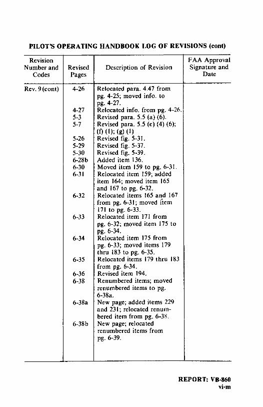
Rev. 9(cont) 4-26
4-27 5-3 5-7
5-26 5-29 5-30 6-28b 6-30 6-31
6-32
6-33
6-34
6-35
6-36 6-38
6-38a
6-38b
FAA Approval Description of Revision Signature and
Date
Relocated para. 4.47 from pg. 4-25; moved info. to pg. 4-27. Relocated info. from pg. 4-26. Revised para. 5.5 (a) (6). Revised para. 5.5 (e) (4) (6); (f) (I); (g) (I) Revised fig. 5-3 I. Revised fig. 5-37. Revised fig. 5-39. Added item 136. Moved item 159 to pg. 6-31. Relocated item 159; added item 164; moved item 165 and 167 to pg. 6-32. Relocated items 165 and 167 from pg. 6-31; moved item 171 to pg. 6-33. Relocated item 171 from pg. 6-32; moved item 175 to pg. 6-34. Relocated item 175 from pg. 6-33; moved items 179 thru 183 to pg. 6-35. Relocated items 179 thru 183 from pg. 6-34. Revised item 194. Renumbered items; moved renumbered items to pg. 6-38a. New page; added items 229 and 23 I; relocated renum-bered item from pg. 6-3/i. New page; relocated renumbered items from pg. 6-39.
REPORT: VB-860 vi-m

PILOT'S OPERATING HANDBOOK LOG OF REVISIONS (cont)
Revision Number and Revised
Codes Pages
Rev. 9(cont) 6-39
6-40
6-41
6-4la
6-4lb
6-42 thru 6-47 6-51
7-19
7-21
Rev. 10 1-i 761 662 2-4
(PR820122) 2-5
2-6
'l ... ,.-,
2-8
2-9 3-10
REPORT: VB-860 vi-n
FAA Approval Description of Revision Signature and
Date
Moved renumbered items to pg. 6-38b; relocated renum-bered items from pg. 6-40; added item 247.
· Moved renumbered items to pg. 6-39; relocated renum-bered items from pg. 6-41. Moved renumbered items to pg. 6-40; renumbered items. Revised item 273; renum-bered items; relocated renumbered item from pg. 6-4lb. Moved renumbered item to pg. 6-41a; renumbered items. Renumbered items.
Added item 389; removed info. cJarJI Revised para. 7.17; moved info. to pg. 7-21. Ward Evans Relocated info. from pg. 7-19. July 24, 1981
Correct page numbers. Revised para. 2.9; move info. to pg. 2-5. Relocated info. from pg. 2-4; moved info. to pg. 2-6. Relocated info. from pg. 2-5; moved info. to pg. 2-7. Relocated info. from pg. 2-6; moved info. to pg. 2-8. Relocated info. from pg. 2-7; moved info. to pg. 2-9. Relocated info. from pg. 2-8. Revised procedure.

PILOT'S OPERATING HANDBOOK LOG OF REVISIONS (cont)
Revision Number and Revised
Code Pages
Rev. 10 3-12 (cont) 4-23
4-24
4-25 5-3 thru 5-7 6-6 6-17 6-24 6-40 6-45 7-30
7-31
7-32 9-21 9-25
Rev. II Title 761 662 1-1
(PR830314) 1-9 2-i 3-i
3-ii 4-i 4-ii 4-13 4-18 4-23
FAA Approval Description of Revision Signature and
Date
Revised para. 4.37. Revised para. 4.37; moved info. to pg. 4-24. Relocated info. from pg. 4-23; revised para. 4.37; moved info. to pg. 4-25. Relocated info. from pg. 4-24. Revised para. 5.5.
Revised fig. 6-5. Revised para. 6.11. Added items 79 and 81. Revised item 255. Added item 324. Revised para. 7.27; moved info. to pg. 7-31. Relocated info. from pg. 7-30; moved info. to pg. 7-32. WOAJ~ Relocated info. from pg. 7-31. Revised section 3(a). Ward Evans Revised section 4(b), {8)c. Jan. 22. 1982
Revised bottom para. Revised para. I. I. Deleted MEA. Revised index. Added info to 3.3; relocated items to pg. 3-ii. Added items from pg. 3 i. Added info. to 4.5. Added items from pg. 4-i. Revised 1st para. and l\ote. Revised Note. Revised Note.
REPORT: VB-860 vi-o

PILOT'S OPERATING HANDBOOK LOG OF REVISIONS (cont) KevtSIOII
Number and Revised Code Pages
Rev.11 5-27 (cont) thru
5<!0 6-28 6-36 7-6 7-21 7-32 8-2 8-3
8-4 9-i
9-79 thru 9-82
Rev.12 1-i 761662 1-12
(PR890304) 1-13 thru 1-21 3-1 3-17 4-5
4-8
4-11
4-13 4-17 4-24 8-1 thru 8-3 8-10 thru 8-11
REPORT: VB-860 vi-p
FAA Approval Description of Revisions Signature
and Date
Revised fig. 6-33 thru 5-39.
Revised item 127. Revised items 191 and 192. Revised 2nd para. Added Caution. Revised para. 7.29 and 7 .33. Revised para. 8.3. Revised 1st para. and para. 8.5. MovedtexL Added Supplement No. 14 to index. W-4&, Added Supplement No. 14.
Ward Evans March 14, 1983
Revised index. Para. 1.21 deleted. Para. 1.21 deleted, pages removed.
Revised para. 3.1. Revised para. 3.11. Revised Before Starting Engines. Revised Before Takeoff-Ground Check. Revised Approach and Landing. Revised para. 4.13. Revised para. 4.27. Revised para. 4-37. Revised para. 8-1 and 8.3.
~It~ ~w D.H. Trompler
Revised para. 8.19. Ju1:r6, 1282
Date

ISSUED: maRch 23, 1978 REPORT: VB-860 vi-qREVISED: OcTOBER 11, 2011
PIPER aIRcRaFT cORPORaTIONPa-44-180, SEmINOlE
PIlOT’S OPERaTINg haNDBOOk lOg OF REVISIONS (cont)
Revision FAA Approved Number and Revised Description of Revisions Signature Code Pages and Date
Rev. 13 vi-q Added page & Rev. 13 (PR040823) to L of R. vi-r Added page. 4-10 Revised para. 4.5. 4-20 Revised para. 4.31. 4-21 Revised para. 4.33. 7-9 Revised para. 7.9. Linda J. Dicken August 23, 2004
Rev. 14 ii Updated copyright.(PR111011) vi-q Added Rev. 14 to L of R. 4-7 Revised para. 4.5. 4-8 Revised para. 4.5. 4-17 Revised para.’s 4.23 and 4.25. 4-26 Added Note to para. 4.51. 6-i Revised T of C. 6-ii Revised T of C. 6-13 Removed para. 6.9. 6-14 Removed Sample Problem in para. 6.9. 6-15 Removed fi gure for Sample Problem. 7-16 Revised Note in para. 7.15. Albert J. Mill 10-3 Revised para. 10.3. October 11, 2011 7-16 Revised Note in para. 7.15. Albert J. Mill
--
I I I -
- -
,ft/~
0 /t, JP ,,,-. -,\ 1 L/__.._ T 1'.~ '. 11-
I I I - -

REPORT: VB-860 ISSUED: maRch 23, 1978vi-r REVISED: aUgUST 23, 2004
PIPER aIRcRaFT cORPORaTION Pa-44-180, SEmINOlE
PIlOT’S OPERaTINg haNDBOOk lOg OF REVISIONS (cont)
Revision FAA Approved Number and Revised Description of Revisions Signature Code Pages and Date

TABLE OF CONTENTS
SECTION 1 GENERAL
SECTION 2 LIMITATIONS
SECTION 3 EMERGENCY PROCEDURES
SECTION 4 NORMAL PROCEDURES
SECTION 5 PERFORMANCE
SECTION 6 WEIGHT AND BALANCE
SECTION 7 DESCRIPTION AND OPERATION OF THE AIRPLANE AND ITS SYSTEMS
SECTION 8 AIRPLANE HANDLING, SERVICING AND MAINTENANCE
SECTION 9 SUPPLEMENTS
SECTION 10 SAFETY TIPS
REPORT: VB-860 vii


TABLE OF CONTENTS
SECTION l
GENERAL
Paragraph No.
I.I 1.3 1.5 1.7 1.9 I.I I I.I 3 1.15 1.17 1.19
Introduction ..................................... . Engine .......................................... . Propeller ........................................ . Fuel ............................................ . Oil ................................... _ ........... . Maximum Weights ............................... . Standard Airplane Weights ........................ . Baggage Space ................................... . Specific Loadings ................................. . Symbols, Abbreviations and Terminology ............ .
Page No.
1-1 1-3 1-3 1-4 1-4 1-4 1-5 1-5 1-5 1-6
REPORT: VB-860 1-i


PIPER AIRCRAFT CORPORATION PA-44-180, SEMINOLE
1.1 INTRODUCTION
SECTION 1
GENERAL
SECTION I GENERAL
This Pilot's Operating Handbook is designed for maximum utilization as an operating guide for the pilot. It includes the material required to be furnished to the pilot by the Federal Aviation Regulations and additional information provided by the manufacturer and constitutes the FAA Approved Airplane Flight Manual.
This handbook is not designed as a substitute for adequate and competent flight instruction, knowledge of current airworthiness directives, applicable federal air regulations or advisory circulars. It is not intended to be a guide for basic flight instruction or a training manual and should not be used for operational purposes unless kept in a current status.
Assurance that the airplane is in an airworthy condition is the responsibility of the owner. The pilot in command is responsible for determining that the airplane is safe for flight. The pilot is also responsible for remaining within the operating limitations as outlined by instrument markings, placards. and this handbook.
Although the arrangement of this handbook is intended to increase its in-flight capabilities, it should not be used solely as an occasional operating reference. The pilot should study the entire handbook to become familiar with the limitations, performance, procedures and operational _handling characteristics of the airplane before flight.
The handbook has been divided into numbered (arabic) sections, each provided with a "finger-tip" tab divider for 4uick reference. The limitations and emergency procedures have been placed ahead of the normal procedures, performance -and other sections to provide easier access to information that may be required in flight. The "Emergency Procedures" Section has been furnished with a red tab divider to present an instant reference to the section. Provisions for expansion of the handbook have been made by the deliberate omission of certain paragraph numbers, figure numbers, item numbers and pages noted as being intentionally left blank.
ISSUED: MARCH 23, 1978 REVISED: MARCH 14, 1983
REPORT: VB-860 1-1

SECTION 1 GENERAL
REPORT: VB-860 1-2
PIPER AIRCRAFT CORPORATION PA-44-180, SEMINOLE
Wing Area (sq. ft.) 183.8 Min. Turning Radius (ft.) 33.0 (from pivot point to wingtip)
THREE VIEW Figure 1-1
ISSUED: MARCH 23, 1978

PIPER AIRCRAFT CORPORATION PA-44-180, SEMINOLE
1.3 ENGINE
(a) Number of Engines (b) Engine Manufacturer (c) Engine Model Number
Left Right
(d) Rated Horsepower (e) Rated Speed (rpm) (f) Bore (in.) (g) Stroke (in.) (h) Displacement (cu. in.) (i) Compression Ratio (i) Engine Type
1.S PROPELLER
STANDARD (a) Number of Propellers (b) Propeller Manufacturer (c) Model
Left
Right
(d) Number of Blades (e) Propeller Diameter (in.)
(I) Maximum (2) Minimum
(f) Propeller Type
OPTIONAL (a) Number of Propellers (b) Propeller Manufacturer (c) Model
Left
Right
ISSUED: MARCH 23, 1978 REVISED: DECEMBER 15, 1978
SECTION 1 GENERAL
2 Lycoming
O-360-ElA6D LO-360-EIA6D
180 2700
5.125 4.375
361 9.00:1
Four Cylinder, Direct Drive, Horizontally
Opposed, Air Cooled
2 Hartzell
HC-C2Y(K,R)-2CEUF / FC7666A-2R
HC-C2Y(K,R)-2CLEUF / FJC7666A-2R
2
74 72
Constant Speed, Hydraulically Actuated,
Full Feathering
2 Hartzell
HC-C3YR-2EUF / FC-7663-5R
HC-C3YR-2LEUF/ FJC-7663-5R
REPORT: VB-860 1-3
SECTION 1 GENERAL
PIPER AIRCRAFT CORPORATION PA-44-180, SEMINOLE
(d) Number of Blades (e) Propeller Diameter (in.)
(I) Maximum (2) Minimum
(f) Propeller Tvpe
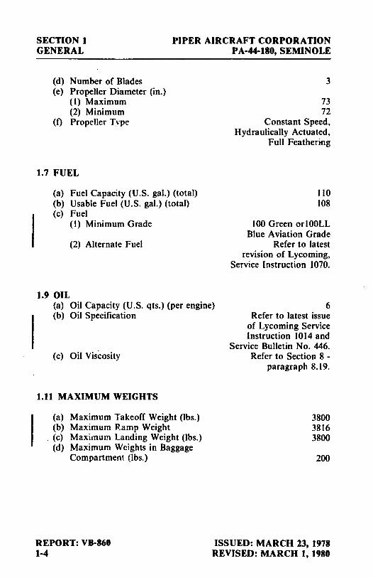
1.7 FUEL
(a) Fuel Capacity (U.S. gal.) (total) (b) Usable Fuel (U.S. gal.) (total) (c) Fuel
(I) Minimum Grade
(2) Alternate Fuel
1.9 OIL
3
73 72
Constant Speed, Hydraulically Actuated,
Full Feathering
110 108
100 Green orlO0LL Blue A via ti on Grade
Refer to latest revision of Lycoming,
Service Instruction 1070.
(a) Oil Capacity (U.S. qts.) (per engine) (b) Oil Specification
6 Refer to latest issue
of Lycoming Service Instruction 1014 and
Service Bulletin No. 446. (c) Oil Viscosity
I.II MAXIMUM WEIGHTS
(a) Maximum Takeoff Weight (lbs.) (b) Maximum Ramp Weight
. (c) Maximum Landing Weight (lbs.) (d) Maximum Weights in Baggage
Compartment (lbs.)
REPORT: VB-860 1-4
Refer to Section 8 -paragraph 8.19.
3800 3816 3800
200
ISSUED: MARCH 23, 1978 REVISED: MARCH 1, 1980

PIPER AIRCRAFT CORPORATION PA-4C-IIO, SEMINOLE
1.13 STANDARD AIRPLANE WEIGHTS
SECTION I GENERAL
Refer to Figure 6-S for the Standard Empty Weight and the Useful Load.
1.15 BAGGAGE SPACE
(a) Compartment Volume (cu. ft.) {b) Entry Width (in.) (c) Entry Height(in.)
1.17 SPECIFIC LOADINGS
(a) Wing Loading (lbs. per sq. ft.) (b) Power Loading (lbs. per hp)
ISSUED: MARCH 23, 1978 REVISED: JULY 14, 1981
24 22 20
21.1 10.SS
REPORT: VB•860 1•5

SECTION 1 GENERAL
PIPER AIRCRAFT CORPORATION PA-44-180, SEMINOLE
1.19 SYMBOLS, ABBREVIATIONS AND TERMINOLOGY
The following definitions are of symbols, abbreviations and terminology used throughout the handbook and those which may be of added operational significanct' to the pilot.
(a) Generai Airspeed Terminology and Symbols
CAS
KCAS
GS
IAS
KIAS
M
TAS
REPORT: VB-860 1-6
Calibrated Airspeed means the indicated speed of an aircraft, corrected for position and instrument error. Calibrated airspeed is equal to true airspeed in standard atmosphere at sea level.
Calibrated Airspeed expressed in "Knots."
Ground Speed is the speed of an airplane relative to the ground.
Indicated Airspeed is the speed of an aircraft as shown on the airspeed indicator when corrected for instrument error. IAS values published in this handbook assume zero instrument error.
Indicated Airspeed expressed in "Knots."
Mach Number is the ratio of true airspeed to the speed of sound.
True Airspeed is the airspeed of an airplane relative to undisturbed air which is the CAS corrected for altitude, temperature and compressibility.
Maneuvering Speed is the maximum speed at which application of full available aerodynamic control will not overstress the airplane.
Maximum Flap Extended Speed is the highest speed permissible with wing flaps in a prescribed extended position.
ISSUED: MARCH 23, 1978

PIPER AIRCRAFT CORPORATION PA-44-180, SEMINOLE
SECTION l GENERAL
VLE Maximum Landing Gear Extended Speed is the maximum speed at which an aircraft can be safely flown with the landing gear extended.
VLO Maximum Landing Gear Operating Speed is the maximum speed at which the landing gear can be safely txtended or retracted.
YMCA Air Minimum Control Speed is the minimum flight speed at which the airplane is directionally controllable as determined in accordance with Federal Aviation Regulations. Airplane certification conditions include one engine becoming inoperative and windmilling, not more than a 5° bank towards the operative engine, takeoff power on operative engine, landing gear up, flaps in takeoff position, and most rearward C.G.
VNE/MNE Never Exceed Speed or Mach Number is the speed limit that may not be exceeded at any time.
VNO Maximum Structural Cruising Speed is the speed that should not be exceeded except in smooth air and then only with caution.
VS Stalling Speed or the minimum steady flight speed at which the airplane is controllable.
VSO Stalling Speed or the mm1mum steady flight speed at which the airplane is controllable in the landing configuration.
VSSE Intentional One Engine Inoperative Speed is a minimum speed selected by the manufacturer for intentionally rendering one engine inoperative in flight for pilot training.
ISSUED: MARCH 23, 1978 REPORT: VB-860 1-7

SECTION l GENERAL
vx
VY
PIPER AIRCRAFT CORPORATION PA-44-180, SEMINOLE
Best Angle-of-Climb Speed·is the airspeed which delivers the greatest gain of altitude in the shortest possible horizontal distance.
Best Rate-of-Climb Speed is the airspeed which delivers the greatest gain in altitude in the shortest possible time.
(b) Meteorological Terminology
ISA
OAT
Indicated Pressure Altitude
Pressure Altitude
Station Pressure
REPORT: VB-860 1-8
International Standard Atmosphere in which the air is a dry perfect gas, the temperature at sea level is 15° Celsius (59° Fahrenheit), the pressure at sea level is 29.92 inches Hg (1013 mb), and the temperature gradient from sea level to the altitude at which the temperature is -56.5°C (-69.7°F) is -0.00198°C (-0.003566°F) per foot and zero above that altitude.
Outside Air Temperature is the free air static temperature obtained either from inflight temperature indications or ground meteorological sources, adjusted for instrument error and compressibility effects.
The number actually read from an altimeter when the barometric subscale has been set to 29.92 inches of mercury (l013 millibars).
Altitude measured from standard sea-level pressure (29.92 in. Hg) by a pressure or barometric altimeter. It is the indicated pressure altitude corrected for position and instrument error. In this handbook, altimeter instrument errors are assumed to be zero.
Actual atmospheric pressure at field elevation.
ISSUED: MARCH 23, 1978 REVISED: DECEMBER 15, 1978

PIPER AIRCRAFT CORPORATION PA-44-180, SEMINOLE
SECTION I GENERAL
Wind
(c) Power Terminology
Takeoff Power
Maximum Continuous Power
Maximum Climb Power
Maximum Cruise Power
(d) Engine Instruments
EGT Gauge
The wind velocities recorded as variables on the charts of this handbook are to be understood as the headwind or tailwind components of the reported winds.
Maximum power permissible for takeoff.
Maximum power permissible continuously during flight.
Maximum power permissible during climb.·
Maximum power permissible during cruise.
Exhaust Gas Temperature Gauge
(e) Airplane Performance and Flight Planning Terminology
Climb Gradient
Demonstrated Crosswind Velocity (DEMO. X-WIND)
Accelerate-Stop Distance
ISSUED: MARCH 23, 1978 REVISED: MARCH 14, 1983
The demonstrated ratio of the change in height during a portion of a climb, to the horizontal distance traversed in the same time interval.
The demonstrated crosswind velocity is the velocity of the crosswind component for which adequate control of the airplane during takeoff and landing was actually demonstrated during certification tests.
The distance required to accelerate an airplane to a specified ~peed and, assuming failure of an engine at the instant that speed is attained, to bring the airplane to a stop.
REPORT: VB-860 1-9

SECTION 1 GENERAL
Route Segment
PIPER AIRCRAFT CORPORATION PA-44-180, SEMINOLE
A part of a route. Each end of that part is identified by ( 1) a geographical location or (2) a point at which a definite radio fix can be established.
(0 Weight and ~ahnce Terminology
Reference Datum
Station
Arm
Moment
Center of Gravity (C.G.)
C.G. Arm
C.G. Limits
Usable Fuel
Unusable Fuel
REPORT: VB-860 1-10
An imaginary vertical plane from which all horizontal distances are measured for balance purposes.
A location along the airplane fuselage usually given in terms of distance in inches from the reference datum.
The horizontal distance from the reference datum to the center of gravity (C.G.) of an item.
The product of the weight of an item multiplied by its arm. (Moment divided by a constant is used to simplify balance calculations by reducing the number of digits.)
The point at which an airplane would balance if suspended. Its distance from the reference datum is found by dividing the total moment by the total weight of the airplane.
The arm obtained by adding the airplane's individual moments and dividing the sum by the total weight.
The extreme center of gravity locations within which the airplane must be operated at a given weight.
Fuel available for flight planning.
Fuel remaining after a runout test has been completed in accordance with governmental regulations.
ISSUED: MARCH 23, 1978

PIPER AIRCRAFf CORPORATION PA-44-180, SEMINOLE
SECTION I GENERAL
Standard Empty Weight
Basic Empty Weight
Payload
Useful Load
Maximum Ramp Weight
Maximum Takeoff Weight
Maximum Landing Weight
Maximum Zero Fuel Weight
ISSUED: MARCH 23, 1978
Weight of a standard airplane including unusable fuel. full operating fluids and full oil.
Standard empty weight plus optional equipment
Weight of occupants, cargo and baggage.
Difference between takeoff weight, or ramp weight if applicable, and basic empty weight
Maximum weight approved for ground maneuver. (It includes weight of start, taxi and run-up fuel).
Maximum weight approved for the start of the takeoff run.
Maximum weight approved for the landing touchdown.
Maximum weight exclusive of usable fuel.
REPORT: VB-860 1-11
SECTION! GENERAL
PIPER AIRCRAFf CORPORATION PA-44-180, SEMINOLE
THIS PAGE INTENTIONALLY LEFf BLANK
I REPORT: VB-860 1-12
ISSUED: MARCH 23, 1978 REVISED: MARCH 4, 1989

TABLE OF CONTENTS
SECTION 2
LIMITATIONS
Paragraph No.
2.1 2.3 2.5 2.7 2.9 2.11 2.13 2.15 2.17 2.19 2.21 2.23 2.25 2.27
General ......................................... . Airspeed Limitations .............................. . Airspeed Indicator Markings ....................... . Power Plant Limitations ........................... . Power Plant Instrument Markings .................. . Weight Limits .................................... . Center of Gravity Limits ........................... . Maneuver Limits ................................. . Flight Maneuvering Load Factors .................. . Types of Operation ............................... . Fuel Limitations .................................. . Noise Level ...................................... . Gyro Suction Limits .............................. . Placards ......................................... .
Page No.
2-1 2-1 2-2 2-3 2-4 2-5 2-5 2-5 2-6 2-6 2-6 2-6 2-7 2-7
REPORT: VB-860 2-i


PIPER AIRCRAFT CORPORATION PA-44-180, SEMINOLE
SECTION 2 LIMITATIONS
2.1 GENERAL
SECTION 2
LIMITATIONS
This section provides the .. FAA Approved" operating limitations, instrument markings, color coding and basic placards necessary for the safe operation of the airplane and its systems.
This airplane must be operated as a normal category airplane in compliance with the operating limitations stated in the form of placards and markings and those given in this section and handbook.
Limitations associated with those optional systems and equipment which require handbook supplements can be found in Section 9 (Supplements).
2.3 AIRSPEED LIMITATIONS
SPEED
Design Maneuvering Speed (VA) - Do not make full or abrupt control movements above this speed.
3800 lbs. 2700 lbs.
CAUTION
KIAS
135 112
Maneuvering speed decreases at lighter weight as the effects of aerodynamic forces become more pronounced. Linear interpolation may be used for intermediate gross weights. Maneuvering speed should not be exceeded while operating in rough air.
KCAS
133 I 12
ISSUED: MARCH 23, 1978 REPORT: VB-860 2-1

SECTION 2 LIMITATIONS
PIPER AIRCRAFT CORPORATION PA-44-180, SEMINOLE
SPEED
Never Exceed Speed (VNE) - Do not exceed this speed in any operation.
Maximum Structural Cruising Speed (VNO) - Dn not exi:eed this speed except in smooth air and then only with caution.
Maximum Flaps Extended Speed (VFE) -Do not exceed this speed with the flaps extended.
Maximum Gear Extended Speed (VLE) -Do not exceed this speed with landing gear extended.
Maximum Landing Gear Extending Speed (VLO) - Do not extend landing gear above this speed.
Maximum Landing Gear Retracting Speed (VLO) - Do not retract landing gear above this speed.
Air Minimum Control Speed (VMCA) -Lowest airspeed at which airplane is controllable with one engine operating and no flaps. Note: This is a stalled condition.
One Engine Inoperative Best Rate of Climb Speed.
2.5 AIRSPEED INDICATOR MARKINGS
MARKING
Red Radial Line (Never Exceed)
Red Radial Line (One Engine Inoperative Air Minimum Control Speed)
KIAS KCAS
202 194
169 165
111 109
140 138
140 138
109 109
56 63
88 90
IAS
202 KTS
56 KTS
REPORT: VB-860 2-2
ISSUED: MARCH 23, 1978 REVISED: SEPTEMBER 14, 1979

PIPER AIRCRAFT CORPORATION PA-44-180, SEMINOLE
MARKING
Blue Radial Line (One Engine Inoperative Best Rate of Climb Speed)
Yellow Arc (Caution Range - Smooth Air Only)
Green Arc (Normal Operating Range)
White Arc (Flap Down)
2.7 POW.ER PLANT LIMITATIONS
(a) Number of Engines (b) Engine Manufacturer (c) Engine Model No.
Left Right
( d) Engine Operating Limits (I) Maximum Horsepower (2) Maximum Rotation Speed (RPM) (3) Maximum Manifold Pressure
SECTION 2 LIMITATIONS
IAS
88 KTS
169 KTS to 202 KTS
57 KTS to 169 KTS
55 KTS to 111 KTS
2 Lycoming
O-360-E IA6D LO-360-EIA6D
180 2700
(4) Maximum Cylinder Head Temperature (5) Maximum Oil Temperature
Full Throttle 500°F 245°F
(e) Oil Pressure Minimum Maximum
(f) Fuel Pressure Normal Operating Range (green arc) Minimum (red line) Maximum (red line)
(g) Fuel (minimum grade)
(h) Number of Propellers · ti) Propeller Manufacturer (j) Propeller Hub and Blade Models
(I) Standard (Two Blade) Left
Right
ISSUED: MARCH 23, 1978 REVISED: NOVEMBER 19, 1980
15 PSI 115 PSI
.5 PSI to 8 PSI .5 PSI 8 PSI
l00 or IO0LL Aviation Grade
2 Hartzell
HC-C2Y(K,R)-2CEUF / FC'7666A-2R
HC-C2Y(K,R)-2CLEU F / FJC7666A-2R
REPORT: VB-860 2-3

SECTION 2 LIMITATIONS
PIPER AIRCRAFT CORPORATION PA-44-180, SEMINOLE
(2) Optional (Three Blade) Left
Right
(k) Propeller Diameter (I) Standard (Two Blade)
~faximum Minimum
(2) Optional (Three Blade) Maximum Minimum
2.9 POWER PLANT INSTRUMENT MARKINGS
(a) Tachometer Green Arc (Normal Operating Range) Red Linc (Maximum)
(b) Oil Temperature Green Arc (Normal Operating Range) Red Line (Maximum)
(c) Oil Pressure Green Arc (Normal Operating Range) ·Yellow Arc (Caution Range) (Idle) Yellow Arc (Warm Up, Taxi & T.O.) Red Line (Minimum) Red Line (Maximum)
or Green Arc (Normal Operating Range) Yellow Arc (Caution Range) (Idle) Yellow Arc (Warm Up, Taxi & T.O.) Red Line (Minimum) Red Line (Maximum)
or Green Arc (Normal Operating Range) Yellow Arc (Caution Range) (Idle) Yellow Arc ( Warm Up, Taxi & T.O.) Red Line (Minimum) Red Line (Maximum)
(d) Fuel Pressure Green Arc (Normal Operating Range) Red Line (Minimum) Red Line (Maximum)
HC-C3YR-2EUF / FC-7663-5R
HC-C3YR-2LEUF / FJC-7663-5R
74 IN. 72 IN.
73 IN. 72 IN.
500 to 2700 RPM 2700 RPM
75° to 245°F 245°F
60 PSI to 90 PSI 25 PSI to 60 PSI
90 PSI to 100 PSI 25 PSI
100 PSI
60 PSI to 90 PSI 15 PSI to 60 PSI
90 PSI to I 15 PSI 15 PSI
ll5 PSI
55 PSI to 90 PSI 15 PSI to 55 PSI
90 PSI to l 15 PSI 15 PSI
115 PSI
.5 PSI to 8 PSI .5 PSI 8 PSI
REPORT: VB-860 2-4
ISSUED: MARCH 23, 1978 REVISED: JANUARY 22, 1982

PIPER AIRCRAFT CORPORATION PA-44-180, SEMINOLE
(e) Cylinder Head Temperature Green Arc (Normal Range) Red Line (Maximum)
2.11 WEIGHT LIMITS
(a) Maximum Takeoff Weight (b) Maximum Ramp Weight (c) Maximum Landing Weight (d) Maximum Weight in Baggage
Compartment
2.13 CENTER OF GRAVITY LIMITS
Weight Pounds
2800 3400 3800
Forward Limit Inches Aft of Datum
84.0 85.0 89.0
NOTES
SECTION 2 LIMITATIONS
200° to 435° F 500°F
3800 lbs. 3816 lbs. 3800 lbs.
200 lbs.
Rearward Limit Inches Aft of Datum
93.0 93.0 93.0
Straight line variation between points given.
The datum used is 78.4 inches ahead of the wing leading edge at wing station 106.
It is the responsibility of the airplane owner and the pilot to insure that the airplane is properly loaded. See Section 6 (Weight and Balance) for proper loading instructions.
2.15 MANEUVER LIMITS
All intentional acrobatic maneuvers (including spins) are prohibited. Avoid abrupt maneuvers.
ISSUED: MARCH 23, 1978 REVISED: JANUARY 22, 1982
REPORT: VB-860 2-5

SECTION 2 LIMITATIONS
PIPER AIRCRAFT CORPORATION PA-44-180, SEMINOLE
. 2.17 FLIGHT MANEUVERING LOAD FACTORS
(a) Positive Load Factor (Maximum) (I) Flaps Up (2) Flaps Down
(b) Nega,we Lond Factor (Maximum)
2.19 TYPES OF OPERATION
3.8 G 2.0 G
No inverted maneuvers approved.
The airplane is approved for the following operations when equipped in accordance with FAR 91 or FAR 135.
(a) Day V.F.R. (b) Night V.F.R. (c) Day I.F.R. (d) Night 1.F.R. (e) Non Icing
2.21 FUEL LIMITATIONS
(a) Total Capacity (b) Unusable Fuel
The unusable fuel for this airplane has been determined as 1.0 gallon in each nacelle in critical flight attitudes.
(c) Usable Fuel The usable fuel in this airplane has been determined as 54 gallons in each nacelle or a total of 108 gallons.
2.23 NOISE LEVEL
110 U.S. GAL. 2 U.S. GAL.
108 U.S. GAL.
The corrected noise level of this aircraft is 74. 7 d B(A) with the two blade propeller and 75.6 d B(A) with the three blade propeller.
No determination has been made by the Federal Aviation Administration that the noise levels of this airplane are or should be acceptable or unacceptable for operation at, into, or out of, any airport.
REPORT: VB-860 2-6
ISSUED: MARCH 23, 1978 REVISED: JANUARY 22, 1982

PIPER AIRCRAFT CORPORATION PA-44-180, SEMINOLE
SECTION 2 LIMITATIONS
The above statement notwithstanding, the noise level stated above has been verified by and approved by the Federal Aviation Administration in noise level test flights conducted in accordance with FAR 36, Noise Standards - Aircraft Type and Airworthiness Certification. This aircraft model is in compliance with all FAR 36 noise standards applicable to this type.
2.25 GYRO SUCTION LIMITS
The operating limits for the suction system are 4.5 to 5.2 inches of mercury for all operations as indicated by the gyro suction gauge.
2.27 PLACARDS
In full view of the pilot:
The markings and placards installed in this airplane contain operating limitations which must be complied with when operating this airplane in the normal category. Other operating limitations which must be complied with when operating this airplane in this category are contained in the airplane flight manual. No acrobatic maneuvers, including spins, approved.
This aircraft approved for V.F.R., I.F.R., day and night non-icing flight when equipped in accordance with FAR 91 or FAR 135.
On instrument panel in full view of the pilot:
DEMONSTRATED CROSSWIND COMPONENT 17 KTS OR
DEMO. X-WIND 17 KTS
In full view of the pilot:
ONE ENGINE INOPERATIVE AIR MINIMUM CONTROL SPEED 56 KIAS
ISSUED: MARCH 23, 1978 REVISED: JANUARY 22, 1982
REPORT: VB-860 2-7

SECTION 2 LIMITATIONS
In full view of the pilot:
PIPER AIRCRAFT CORPORATION PA-44-180, SEMINOLE
WARNING - TURN OFF STROBE LIGHTS WHEN IN CLOSE PROXIMITY TO GROUND, OR DURING FLIGHT THROUGH CLOUD, FOG OR HAZE.
On instrument panel in full view of the pilot:
MANEUVERING SPEED 135 KIAS AT 3800 LBS. (SEE AFM)
OR VA 135 AT 3800 LBS
(SEE P.O.H.)
GEAR DOWN GEAR UP EXTENDED
OR
140 KIAS (MAX.) 109 KIAS (MAX.) 140 KIAS (MAX.)
Vw 140 ON, 109 UP VLE 140 MAX.
Near emergency gear release:
EMERGENCY GEAR EXTENSION PULL TO RELEASE. SEE AFM
BEFORE RE-ENGAGEMENT
Near gear selector switch:
GEAR UP DOWN
Adjacent to upper door latch:
109 KIAS MAX. 140 KIAS MAX.
ENGAGE LATCH BEFORE FLIGHT
REPORT: VB-860 2-8
ISSUED: MARCH 23, 1978 REVISED: JANUARY 22, 1982

PIPER AIRCRAFT CORPORATION PA-44-180, SEMINOLE
SECTION 2 LIMITATIONS
On inside of baggage compartment door:
BAGGAGE MAXIMUM 200 LBS
On storm window:
DO NOT OPEN ABOVE 129 KIAS
In full view of the pilot:
TAK EOFF CHECK LIST
Fuel Selectors On Electric Fuel Pumps On Alternators On Engine Gauges Checked Mixtures Set Primers Locked Propellers Set Carb Heat Off
Cowl Flaps Set Seat Backs Erect Flaps Set Trim Set (Stab. & Rudder) Fasten Belts/ Harness Controls Free - Full Travel Doors Latched Air Conditioner Off
LANDING CHECK LIST
Seat Backs Erect Fasten Belts/ Harness Fuel Selectors On Cowl Flaps Set Electric Fuel Pumps On
OR
Mixtures Rich Propellers Set Gear Down - 140 KIAS Max. Flaps Set - 111 KIAS Max. Air Conditioner Off
LANDING CHECK LIST
Seat Backs Erect Fasten Belts/ Harness Fuel Selectors On Cowl Flaps Set
Electric Fuel Pumps On Mixtures Rich Propellers Set Gear Down (Green Arc) Flaps Set - (White Arc) Air Conditioner Off
The "AIR CONDITIONER OFF" item in the above takeoff and landing check lists is mandatory for air conditioned aircraft only.
ISSUED: MARCH 23, 1978 REVISED: JANUARY 22, 1982
REPORT: VB-860 2-9

SECTION 2 LIMITATIONS
PIPER AIRCRAFT CORPORATION PA-44-180, SEMINOLE
In full view of the pilot:
ONE ENGINE INOPERATIVE ST ALLS NOT RECOMMENDED. CAN CAUSE 300 FT. LOSS OF ALTITUDE AND 30° PITCH ANGLF.
In full view of the pilot when the oil cooler winterization kit is installed:
OIL COOLER WINTERIZATION PLATE TO BE REMOVED WHEN AMBIENT TEMPERATURE EXCEEDS 50°F.
On the vertical window post between the first and second left side windows and close to the Emergency Exit release handle:
EMERGENCY EXIT PULL HANDLE FORWARD
PUSH WINDOW OUT
Adjacent to fuel tank filler caps (Prior to Serial Number 44-7995002):
FUEL ONLY 100/ 130 AVIATION GRADE MIN. - USABLE CAPACITY 54 GAL
OR
Adjacent to fuel tank filler caps (Serial Number 44-7995002 and up):
FUEL 100 OR IO0LL AVIATION GRADE
REPORT: VB-860 2-10
ISSUED: MARCH 23, 1978 REVISED: SEPTEMBER 26, 1980

TABLE OF CONTENTS
SECTION 3
EMERGENCY PROCEDURES
Paragraph No.
3.1 3.3
3.5 3.7 3.9 3.11
3.13 3.15 3.17 3.19 3.21 3.23
General ......................................... . Emergency Procedures Checklist .................... .
Airspeeds For Safe Operations ................... . Engine Inoperative Procedures ................... . Fire ........................................... . Fuel Management During One Engine Inoperative Operation .................................... .
Engine Driven Fuel Pump Failure ................ . Landing Gear Unsafe Warnings .................. . Manual Extension of Landing Gear ............... . Gyro Suction Failures ........................... . Electrical Failures .............................. . Electrical Overload (Alternators Over 30 Amps Above Known Electrical Load) .................. .
Spin Recovery (Intentional Spins Prohibited) ....... . Open Door (Entry Door Only) ................... . Propeller Overspeed ............................. . Emergency Exit ................................ .
Amplified Emergency Procedures (General) .......... . Engine Inoperative Procedures ..................... . Fire ...................... ••••••••••··•••········· Fuel Management During One Engine Inoperative Operation ....................................... . Engine-Driven Fuel Pump Failure .................. . Landing Gear Unsafe Warnings .................... . Manual Extension Of The Landing Gear ............ . Gear-Up Emergency Landing ....................... . Gyro Suction Failures ............................. . Electrical Failures ................................ .
Page No.
3-1 3-2 3-2 3-2 3-5
3-6 3-6 3-6 3-7 3-7 3-7
3-10 3-IOa 3-IOb 3-IOb 3-IOb 3-11 3-11 3-16
3-17 3-17 3-18 3-18 3-18 3-19 3-19
REPORT: VB-860 3-i

Paragraph No.
TABLE OF CONTENTS (cont)
SECTION 3 (cont)
Page No.
3.25 Spins . . . . . . . . . . . . . . . . . . . . . . . . . . . . . . . . . . . . . . . . . . . . 3-22 3.27 Open Door . . . . . . . . . . . . . . . . . . . . . . . . . . . . . . . . . . . . . . . 3-22 3.29 Propeller Overspeed.. . . . . . . . . . . . . . . . . . . . . . . . . . . . . . . 3-23 3.31 Combustion Heater Overheat . . . . . . . . . . . . . . . . . . . . . . . 3-23 3.33 Emergency Descent . . . . . . . . . . . . . . . . . . . . . . . . . . . . . . . . 3-23 3.35 Emergency Exit . . . . . . . . . . . . . . . . . . . . . . . . . . . . . . . . . . . 3-23 3.37 Carburetor Icing................................... 3-24
REPORT: VB-860 3~ii

PIPER AIRCRAFT CORPORATION SECTION 3 PA-44-180, SEMINOLE EMERGENCY PROCEDURES
3.l GENERAL
SECTION 3
EMERGENCY PROCEDURES
This section provides the recommended procedures for coping with various emergency or critical situations. All of the emergency procedures required by the FAA as well as those necessary for operation of the airplane, as determined by the operating and design features of the airplane, are presented.
Emergency procedures associated with optional systems and equipment which require handbook supplements are provided by Section 9, Supplements.
This section is divided into two basic parts. The first part contains the emergency procedures checklists. These checklists supply an immediate action sequence to be followed during critical situations with little emphasis on the operation of the systems.
The second part of the section provides amplified emergency procedures corresponding to the emergency procedures checklist items. These amplified emergency procedures contain additional information to provide the pilot with a more complete description of the procedures so they may be more easily understood.
Pilots must familiarize themselves with the procedures given in this section and must be prepared to take the appropriate action should an emergency situation arise. The procedures are offered as a course of action for coping with the particular situation or condition described. They are not a substitute for sound judgment and common sense.
Most basic emergency procedures are a normal part of pilot training. The information presented in this section is not intended to replace this training. This information is intended to provide a source of reference for the procedures which are applicable to this airplane. The pilot should review standard emergency procedures periodically to remain proficient in them.
ISSUED: MARCH 23, 1978 REVISED: MARCH 4, 1989
REPORT: VB-860 3-1

SECTION 3 PIPER AIRCRAFT CORPORATION EMERGENCY PROCEDURES PA-44-180, SEMINOLE
3.3 EMERGENCY PROCEDURES CHECK LIST
AIRSPEEDS FOR SAFE OPERATIONS
One engine inoperative air minimum control ......••..•.•••• 56 KIAS One engine inoperative best rate of climb ••....•.••••..••••• 88 KIAS One engine inoperative best angle of climb ••..•..•.......•.. 82 KIAS Maneuvering .................••.•.••.•.•..•.•.••..•.••. l 35 KIAS Never exceed .•.....•.....•.•••.••••.•.•...••.........•• 202 KIAS
ENGINE INOPERATIVE PROCEDURES
DETECTING DEAD ENGINE
Loss of thrust. Nose of aircraft will yaw in direction of dead engine (with coordinated controls).
ENGINE SECURING PROCEDURE (FEATHERING PROCEDURE)
Minimum control speed ••.••••••••••••••••••••••••..•.••• 56 KIAS One engine inoperative best rate of climb •••••••••••••••.•.• 88 KIAS Maintain direction and airspeed above 82 KIAS. Mixture controls •....•.•.••.•.•....•.•.•.••.••.••.••••••• forward Propeller controls •...•..••.••.•••••••••••.•.••..•...•••••• forward Throttle controls •..••.•.••••••••••...•••••••..•.••••••.•• forward Flaps ••••.•.•.••..••••••.•••..••••••••..••.•.••••••••.••• retract Gear ..••....•.•...•••.•......•..........••....••••••••••• retract Identify inoperative engine. Throttle of inop. engine • • . • . • • • • • • • • • • • • . . . . . . • . . • . retard to verify
To attempt to restore power prior to feathering: Mixtures .••••...•.•...•.••••..••••.••..•....••.•••• as requir.ed Fuel selector • . . . . • • . • . • . . • • • • • • . . . . • . • . . • . . • • • • • • . . . . . • • • • ON Primers •.....•....••••.•••.•••......•.••••..•••••••...• locked Magnetos ..•.......•••••.••••.•.•.•.....••••••• left or right only Electric fuel pump ...••....•.•••.•.•.•..•.•.....•••.•• check ON Carburetor heat . . • . • • . . • • • . . . . . . . . • . . • . • • • . • • • . . • • . • • • • • • • ON
Prop control of inop. engine .....••..•.•.•••...• feather before RPM drops below 950
Mixture of inop. engine ...••••................•••••.••• idle cut-off
REPORT: VB-860 3-2
ISSUED: MARCH 23, 1978 REVISED: JULY 24, 1981

PIPER AIRCRAFT CORPORATION SECTION 3 PA-44-180, SEMINOLE EMERGENCY PROCEDURES
Trim . . . . . . . . . . . . . . . . . . . . . . . . . . as required (3° to 5° of bank toward operative engine - ball ½ to ¾ out)
Electric fuel pump of inop. engine ......•..................... OFF Magnetos of inop. engine .................................... OFF Cowl flaps ................................... close on inop. engine,
as required on operative engine Alternator of inop. engine . . . . . . . • . . . . . . . . . . . . . . . . . . . . . . . . . . . OFF Electrical load ............................................. reduce Fuel selector ................................... OFF inop. engine,
consider crossfeed Electric fuel pump operative engine ........................... OFF
ENGINE FAILURE DURING TAKEOFF (Below 75 KIAS)
If engine (ailure occurs during takeoff and 75 KIAS has not been attained: Throttles ................................ CLOSE both immediately Stop straight ahead.
If inadequate runway remains to stop: Throttles .......................•...................... CLOSED Brakes .............•......................... apply max. braking Master switch ....•......................................... OFF Fuel selectors .............................................. OFF Continue straight ahead, turning to avoid obstacles.
ENGINE FAILURE DURING TAKEOFF (75 KIAS or above)
H engine failure occurs during takeoff ground roll or after lift-off with gear still down and 75 KIAS has been attained: H adequate runway remains CLOSE both throttles immediately, land if airborne and stop straight ahead. If runway remaining is inadequate for stopping, decide whether to abort or continue. If decision is made to continue, maintain heading and when climb is established retract landing gear, accelerate to 88 KIAS, and feather inoperative engine prop (see Engine Securing Procedure).
WARNING
In certain combinations of aircraft weight, configuration, ambient conditions and speed, negative climb performance may result. Refer to One Engine Inoperative Climb Performance chart, Figure 5-25.
ISSUED: MARCH 23, 1978 REVISED: APRIL 10, 1981
REPORT: VB-860 3-3

SECTION 3 PIPER AIRCRAFT CORPORATION EMERGENCY PROCEDURES PA-44-180, SEMINOLE
ENGINE FAILURE DURING FLIGHT (below 56 KIAS)'
Rudder ...•.........•................ apply toward operative engine Throttles (both) . . . . . . . . . . • . . . . . . • . . . . . . . . . . . . . • • retard to stop tum Pitch attitude . • . . . . . . • . . . . . . . lower nose to accelerate above 56 KIAS Operative engine . . . . . . . . . . . . . . . . . . . . . . . . . increase power as airspeed
increases above 56 KIAS
If altitude permits, a restart may be attempted. If restart fails or if altitude does not permit restart, see Engine Securing Procedure.
ONE ENGINE INOPERATIVE LANDING
lnop. engine prop ...............................•.......... feather When certain of making field: Landing gear .....................................•....•... extend Wing flaps ...................•...........................•. lower Maintain additional altitude and speed during approach. Final approach speed ..................................... 90 KIAS Wing flaps ..••.•....•........•............................... 25°
ONE ENGINE INOPERATIVE GO-AROUND (SHOULD BE AVOIDED IF AT ALL POSSIBLE)
Mixture· .•..............................•................ forward Propeller .....................•.................•.•....... forward Throttle . . . . . . . . . . . . . . . . . . • . • . . . . . . • . . . . . . . . . . . . . . • • . open slowly Flaps ......................••..•...................•.•.... retract Landing gear .....................•.................•..•... retract Airspeed ........................••...•...........••..... 88 KIAS Trim ........................................................ set Cowl flap operating engine ............•................. as required
REPORT: VB-860 3-4
ISSUED: MARCH 23, 1978 REVISED: DECEMBER IS, 1978

PIPER AIRCRAFT CORPORATION SECTION 3 PA-44-180, SEMINOLE EMERGENCY PROCEDURES
AIR START (UNFEATHERING PROCEDURE)
Fuel selector inop. engine . . . . . . . . . . . . • . . . . . . . . . . . . . . . . . . . . . . . . ON Electric fuel pump inop. engine . . . . . . . . . . . . . . . . . . . . . . . . . . . • . . . . ON Prop control .•.................................•• forward to cruise
RPM position Mixture .................................................• RICH Throttle .......•.............................. two full strokes and
then open 1 / 4 inch Magneto switches ............................................ ON Starter . . . . . . . . . . . . . . . . • . . . . . . . . . . . . . . . engage until prop windmills Throttle . . . . . . . . . . . . . . . . . . . . . . . . . reduce power until engine is warm If engine does not start, prime as required. Alternator . . . . . . . . . . . . . . . . . . . . . . . . . . . . . . . . . . . . . . . . . . . . . . . . . . ON
FIRE
ENGINE FIRE ON GROUND
If engine has not started: Mixture .•.•.•........................................ idle cut-off Throttle . . . . . . . . . . . . . . . . . . . . . . . . . . . . . • . . . . . . . . . . . . . . . . . . . . . open Starter . . . . . . . . . . . . . . . . . . . . . . . . . • . . . . . . . . . . . . . . . . . . . crank engine
If engine has already started and is running, continue operating to try pulling the fire into the engine. If fire continues, extinguish with best available means. If external fire extinguishing is to be applied: Fuel selector valves ................................•........ OFF Mixture .....••......................•................ idle cut-off
ENGINE FIRE IN FLIGHT
Affected engine: Fuel selector ..........•....•..........................•.... OFF Thi;ottle . . . . . . . . . . . . . . . . . . . . . . . . . . . . . . . . . . . . . . . . . . . . . . . . . . . close Propeller ..•..........•................................... feather Mixture ........••....•..........................•.... idle cut-off Cowl flap ................................................. OPEN If terrain permits land immediately.
ISSUED: MARCH 23, 1978 REVISED: JANUARY 5, 1981
REPORT: VB-860 3-5

SECTION 3 PIPER AIRCRAFT CORPORATION EMERGENCY PROCEDURES PA-44-180, SEMINOLE
FUEL MANAGEMENT DURING ONE ENGINE INOPERATlVE OPERATION
CRUISING
When using fuel fr01,~ t,:nk on the same side as the operating engine: Fuel selector operating engine ................................. ON Fuel selector mop. engine ...................... ; . . . . . . . . . . . . . OFF Electric fuel pumps .......................................... OFF
(except in case of engine driven pump failure, electric fuel pump on operating
engine side must be used)
When using fuel from tank on the side opposite the operating engine: Fuel selector operating engine ........................ CROSS FEED Fuel selector inop. engine . . . . . . . . . . . . . . . . . . . . . . . . . . . . . . . . . . . . OFF Electric fuel pumps .......................................•.. OFF
(except in case of engine driven pump failure, electric fuel pump· on operating
engine side must be used)
NOTE
Use crossfeed in level cruise flight only.
LANDING
Fuel selector operating engine . . . . . . . . . . . . . . . . . . . . . . . . . . . . . . . . . ON Fuel selector inop. engine .................................... OFF
ENGINE DRIVEN FUEL PUMP FAILURE
Electric fuel pump ........................................... ON
LANDING GEAR UNSAFE WARNINGS
Red light indicates gear intransit. Recycle gear if indication continues. Light will illuminate and gear horn sounds when the gear is not down and locked if throttles are at low settings or wing flaps are in second or third notch position.
REPORT: VB-860 3-6
ISSUED: MARCH 23, 1978 REVISED: SEPTEMBER 14, 1971J

PIPER AIRCRAFT CORPORATION SECTION 3 PA-44-180, SEMINOLE EMERGENCY PROCEDURES
MANUAL EXTENSION OF LANDING GEAR
Check following before extending gear manually: Circuit breakers ..•.......................••.............•.. check Master switch . . • • • . . . . . . . . . . • . . . . . . . . . . . . . . . . . . . . . . . . . . . . . . . ON Alternators ...•••.....•..................................•. check Navigation lights ........................................... OFF
(daytime)
To extend, proceed as follows: Airspeed •................................. reduce (100 KIAS max.) Gear selector ...•...•......................•....... GEAR DOWN
LOCKED position Emerg. gear extend knob •..•.••........•...•.•..•............ pull Indicator lights . . . . . . . . . . . . . . . . . . . . . • . . . . . . . . . . . . . . . . . . . . . 3 green Leave emergency gear extension knob out.
GYRO SUCTION FAILURES
Suction below 4.5 in. Hg. RPM ............................................ increase to 2700 Altitude .............••...................•... descend to maintain
4.5 in. Hg. Use electric turn indicator to monitor Directional Indicator and Attitude Indicator performance.
ELECTRICAL FAILURES
ALT annunciator light illuminated Ammeters ............•.....•........•..••...•. check to determine
inoperative alternator
If one ammeter shows zero loop. ALT switch ....................•.••................... OFF
Reduce electrical loads to minimum ALT circuit breaker ................................ Check and reset
as required lnop. ALT switch. . . . . . . . . . . . . . . . . . . . . . . . . . . . . . . . . . . . . • . . . . . . ON
ISSUED: MARCH 23, 1978 REVISED: JANUARY 5, 1981
REPORT: VB-860 3-7

SECTION 3 PIPER AIRCRAFT CORPORATION EMERGENCY PROCEDURES PA-44-180, SEMINOLE
If power is not restored loop. ALT switch. . . • • • • • • • • • . • • • • • • • . . . . . . • • . • • • . • . • • • • • • • • OFF Electrical loads ..................................... Re-establish to
60 amps max.
If both ammeters show zero ALT switches .........•.••••.••.••....•••.....•.•.•.•. Both OFF
Reduce electrical loads to minimum ALT circuit breakers .......................... Check both and reset
as required ALT switches ................................... ON one at a time
- Determine ALT showing LEAST (but not zero) amps ALT switches ................•.....•••.••••....•.•. Least load ON
other OFF Electrical loads ..................................... Re-establish to
60 amps. max.
FOR AIRPLANES WITH INTERLOCKED MASTER AND ALT SWITCH OPERATION
If alternator outputs are NOT restored Alt switches ...........•.................•..•.•.•.•..•.••••• OFF Electrical loads ................................ Reduce to minimum
Land as soon as practical. The battery is the only remaining source of electrical power. Anticipate complete electrical failure.
WARNING
Compass error may exceed IO degrees with both alternators inoperative.
NOTE
If the battery is depleted, the landing gear must be lowered using the emergency gear extension procedure. The gear position lights will be inoperative.
REPORT: VB-860 3-8
ISSUED: MARCH 23, 1978 REVISED: JANUARY 5, 1981

PIPER AIRCRAFT CORPORATION SECTION 3 PA-44-180, SEMINOLE EMERGENCY PROCEDURES
FOR AIRPLANES WITH SEPARATE BAT AND ALT SWITCH OPERATION
If alternator outputs are NOT restored BAT switch ............................................••.. OFF ALT switches . . . . . . . . . . . . . . . . . . . . . • . . . . . . . . . . . . . ON one at a time
If one or both alternator outputs are restored Electrical loads .........•.....•................ Reduce to minimum
Land as soon as practical. The alternator(s) is the only remaining source of electrical power.
NOTE
Due to increased system voltage and radio frequency noise, operation with ALT switch ON and BAT switch OFF should be made only when required by an electrical system failure.
If alternator outputs are NOT restored ALT switches ...••.•...•..................•................ OFF Electrical loads .•.............................. Reduce to minimum
Land as soon as practical. The battery is the only remaining source of electrical power. Anticipate complete electrical system failure.
WARNING
Compass error may exceed IO degrees with both alternators inoperative.
NOTE
If the battery is depleted, the landing gear must be lowered using the emergency gear extension procedure. The gear position lights will be inoperative.
ISSUED: MARCH 13, 1971 REVISED: JANUARY 5, 1918
REPORT: VB-160 3-9

SECTION 3 PIPER AIRCRAFT CORPORATION EMERGENCY PROCEDURES PA-44-180, SEMINOLE
ELECTRICAL OVERLOAD (ALTERNATORS OVER 30 AMPS ABOVE KNOWN ELECTRICAL LOAD)
FOR AIRPLANES WITH INTERLOCKED MASTER AND ALT SWITCH OPERATION
Electrical load . . . . . . . . . . . . . . • • . . . • • . • • . • • . . • . . . . . . . . . . . • . . Reduce
If alternator loads are NOT reduced ALT switches .•.........•••••...•.•..............••••••.... OFF
Land as soon as possible. The battery is the only remaining source of electrical power. Anticipate complete electrical failure.
FOR AIRPLANES WITH A SEPARATE BAT AND ALT SWITCH OPERATION
ALT switches • • • • . • . . . • • . . . . • • • . . . • • • . • • . . • • . . . . • . • • • . • . • . . • ON BAT switch •....•.. , ...•••••.•••.....•.••••.•••••••......•• OFF
If alternator loads are reduced, this indicates a malfunction of the battery and/ or battery wiring. Electrical loads ••..•....•....••.••••....•••.••••.• Reduce to Min.
Land as soon as practical. The alternator(s) is the only remaining source of electrical power.
NOTE
Due to increased system voltage and radio frequency noise, operation with ALT switches ON and BAT switch OFF should be made only when required by an electrical failure.
If alternator loads are NOT reduced ALT switches .•.•.......•.....•...••.....•...............•• OFF BAT switch . . . . . • . . . . . . . • . • . . • . • . . . . • . . • • . . . . . . • • . . • • As required Electrical loads •.•...........•.......•...•..... Reduce to minimum
Land as soon as practical. The battery is the only remaining source of electrical power. Anticipate complete electrical failure.
REPORT: VB-860 3-10
ISSUED: MARCH 23, 1978 REVISED: JANUARY 22, 1982

PIPER AIRCRAFT CORPORATION SECTION 3 PA-44-180, SEMINOLE EMERGENCY PROCEDURES
WARNING
Compass error may exceed 10 degrees with both alternators inoperative.
NOTE
If the battery is depleted, the landing gear mu5t be lowered using the emergency gear •~xtcnsion procedure. The gear position lights will be inoperative.
SPIN RECOVERY (INTENTIONAL SPINS PROHIBITED)
Throttles ............................................ retard to idle Rudder ........................................... full opposite to
direction of spin Control wheel ................................ release back pressure Control wheel ...................................... full forward if
nose does not drop Ailerons . . . . . . . . . . . . . . . . . . . . . . . . . . . . . . . . . . . . . . . . . . . . . . . . . neutral Rudder ........................................... neutralize when
rotation stops Control wheel ................................ smooth back pressure
to recover from dive
NOTE
Federal Aviation Administration Regulations do not require spin demonstration of multi-engine airplanes; therefore, spin tests have not been conducted. The recovery technique presented is based on the best available information.
ISSUED: JANUARY 5, 1981 REPORT: VB-860 I 3-IOa

SECTION 3 PIPER AIRCRAFT CORPORATION EMERGENCY PROCEDURES PA-44-180, SEMINOLE
OPEN DOOR (ENTRY DOOR ONLY)
If both upper and side latches are open, the door will trail slightly open and airspeeds will be reduced slightly.
To close the dnor in flight: Slow airplane to 82 KI :\S. Cabin vents . . . . . . . . . . . . . . . . . . . . . . . . . . . . . . . . . . . . . . . . . . . . . . . . close Storm window .............................................. open
If upper latch is open. . . . . . . . . . . . . . . . . . . . . . . . . . . . . . . . . . . . . . . . latch If side latch is open ........................... pull on armrest while
moving latch handle to latched position
If both latches are open. . . . . . . . . . . . . . . . . . . . . . . . . . . . . latch side latch then top latch
PROPELLER OVERSPEED
Throttle . . . . . . . . . . . . . . . . . . . . . . . . . . . . . . . . . . . . . . . . . . . . . . . . . . retard Oil pressure ................................................ check Prop control ................................ full DECREASE rpm,
then set if any control available
Airspeed .................................................. reduce Throttle ..................................... as required to remain
EMERGENCY EXIT
Remove thermoplastic cover. Pull handle forward. Push window out.
REPORT: VB-860 3-tob
below 2700 rpm
ISSUED: JANUARY 5, 1981

PIPER AIRCRAFT CORPORATION SECTION 3 PA-44-180, SEMINOLE EMERGENCY PROCEDURES
3.S AMPLIFIED EMERGENCY PROCEDURES (GENERAL)
The following paragraphs are presented to supply additional information for the purpose of providing the pilot with a more complete understanding of the recommended course of action and probable cause of an emergency situation.
3.7 ENGINE INOPERATIVE PROCEDURES
DETECTING A DEAD ENGINE
A loss of thrust will be noted and with coordinated controls, the nose of the aircraft will yaw in the direction of the dead engine.
ENGINE SECURING PROCEDURE (FEATHERING PROCEDURE)
Keep in mind that the one engine inoperative air minimum control speed is 56 KIAS and the one engine inoperative best rate of climb speed is 88 KIAS when beginning the feathering procedure.
To feather a propeller, maintain direction and an airspeed above 82 KIAS. Move the mixture and propeller controls forward. The throttle controls should be moved forward to maintain a safe airspeed. Retract the flaps and landing gear and identify the inoperative engine. The airplane will yaw in the direction of the dead engine. Retard the throttle of the inoperative engine to verify loss of power.
NOTE
If circumstances permit, in the event of an actual engine failure, the pilot may elect to attempt to restore power prior to feathering.
If circumstances permit an attempt to restore power prior to feathering, adjust the mixture control as required, move the fuel selector control to ON, cht:ck primers locked and select either L (left) or R (right) magneto. Move the carburetor heat control to ON and the electric fuel pump to the ON position. If power is not immediately restored turn off the electric fuel pump.
ISSUED: MARCH 23, 1978 REVISED: DECEMBER IS, 1978
REPORT: VB-860 3-11
SECTION 3 PIPER AIRCRAFT CORPORATION EMERGENCY PROCEDURES PA-44-180, SEMINOLE
The propellers can be feathered only while the engine is rotating above 950 RPM. Loss of centrifugal force due to slowing RPM will actuate a stop pin that keeps the propeller from feathering each time the engine is stopped on the ground. One engine inoperative performance will decrease if the
. propeller of the inoperative engine is not feathered.
The propdie, control of the inoperative engine should be moved to the feather position. a1,d ihe mixture control of the inoperative engine should be moved to idle cut-otf.
Trim the aircraft as required and maintain a 3° to 5° bank toward the operating engine. The ball will be½ to¾ out for minimum drag. The electric fuel pumps should be bff except in the case of an engine-driven fuel pump failure. Turn OFF the magnetos and close the cowl flaps on the inoperative engine. Cowl flaps should be used as necessary on the operative engine. The alternator of the inoperative engine should be turned OFF and the electrical load reduced to prevent depletion of the battery. Move the fuel selector control for the inoperative engine to the OFF position. If necessary, consider the use of crossfeed (refer to Fuel Management During One Engine Inoperative Operation, paragraph 3.11 ). Turn OFF the operative engine's electric fuel pump.
NOTE
When an engine is feathered, the alternator, gyro air, and oil annunciator warning lights will remain illuminated.
ENGINE FAILURE DURING TAKEOFF (Below 75 KIAS)
The one engine inoperative air minimum control speed for this airplane is 56 KIAS under standard conditions.
REPORT: VB-860 3-12
NOTE
This is a stalled condition.
ISSUED: MARCH 23, 1978 REVISED: JANUARY 22, 1982

PIPER AIRCRAFT CORPORATION SECTION 3 PA-:44-180, SEMINOLE EMERGENCY PROCEDURES
If engine failure occurs during takeoff ground roll and 75 KIAS has not been attained, CLOSE both throttles immediately and stop straight ahead. If inadequate runway remains to stop, close the throttles and apply maximum braking. The master switch and fuel selectors should be turned OFF. Continue path straight ahead turning to a void obstacles as necessary.
ENGINE FAILURE DURING TAKEOFF (75 KIAS or above)
If engine failure occurs during takeoff ground roll or after lift-off with the gear still down and 75 KIAS has been attained the course of action to be taken will depend on the runway remaining. If adequate runway remains, CLOSE both throttles immediately, land if airborne and stop straight ahead. If the runway remaining is inadequate for stopping, the pilot must decide whether to abort the takeoff or to continue. The decision must be based on the pilot's judgment considering loading, density altitude, obstructions, the weather, and the pilot's competence. If the decision is made to continue the takeoff, maintain heading and airspeed, RETRACT the landing gear, accelerate to 88 KIAS and FEATHER the inoperative engine (refer to Engine Securing Procedure).
WARNING
In certain combinations of aircraft weight, configuration, ambient conditions and speed, negative climb performance may result. Refer to One Engine Inoperative Climb Performance chart, Figure 5-25.
ENGINE FAILURE DURING FLIGHT (Below 56 KIAS)
Should an engine fail during flight at an airspeed below 56 KIAS, apply rudder towards the operative engine to maintain directional control. The throttles should be retarded to stop the yaw force produced by the inoperative engine. Lower the nose of the aircraft to accelerate above 56 KIAS and increase the power on the operative engine as the airspeed exceeds 56 KIAS.
After an airspeed above 56 KIAS has been established, an engine restart attempt may be made if altitude permits. If the restart has failed, or if altitude does not permit, the engine should be secured, see Engine Securing Procedure.
ISSUED: MARCH 23, 1978 REVISED: APRIL 10, 1981
REPORT: VB-860 3-13

SECTION 3 PIPER AIRCRAFT CORPORATION EMERGENCY PROCEDURES PA-44-180, SEMINOLE
THIS PAGE INTENTIONALLY LEFT BLANK
REPORT: VB-860 3-14
ISSUED: MARCH 23, 1978 REVISED: DECEMBER 1S, 1978

PIPER AIRCRAFT CORPORATION SECTION 3 PA-44-180, SEMINOLE EMERGENCY PROCEDURES
ONE ENGINE INOPERATIVE LANDING
Complete the Engine Securing Procedure. The landing gear should not be extended and the wing flaps should not be lowered until certain of making the field.
Maintain additional altitude and speed during approach, keeping in mind that landing should be made right the first time and that a go-around should be avoided if at all possible.
A final approach speed of 90 KIAS and the use of 25° rather than full wing flaps will place the airplane in the best configuration for a go-around should this be necessary.
WARNING
Under some conditions of loading and density altitude a go-around may be impossible, and in any event the sudden application of power during one engine inoperative operation makes control of the airplane more difficult.
ONE ENGINE INOPERATIVE GO-AROUND
NOTE
A one engine inoperative go-around should be avoided if at all possible.
To execute a one engine inoperative go-around, advance the mixture and propeller levers forward. The throttle should be advanced slowly to the full forward position. Retract the flaps and landing gear. Maintain airspeed at the one engine inoperative best rate of climb speed of 88 KIAS. Set the trim and cowl flaps as required.
AIR START (UNFEATHERING PROCEDURE)
Move the fuel selector for the inoperative engine to the ON position and check to make sure the electric fuel pump for that engine is ON. Push the propeller control forward to the cruise RPM position and the mixture should be set RICH. Push in full throttle twice and then open it I/ 4 inch.
ISSUED: MARCH 23, 1978 REVISED: JANUARY 5, 1981
REPORT: VB-860 3-15

SECTION 3 PIPER AIRCRAFT CORPORATION EMERGENCY PROCEDURES PA-44-180, SEMINOLE
Turn ON the magneto switches and engage the starter un(il the propeller windmills. The throttle should be set at reduced power until the engine is warm. If the engine does not start, prime as necessary. The alternator switch should then be turned ON.
3.9 FIRE
ENGINE FIRE ON THE GROUND
The first attempt to extinguish the fire is to try to draw the fire back into the engine. If the engine has not started, move the mixture control to idle cut-off and open the throttle. Begin to crank the engine with the starter in an attempt to pull the fire into the engine.
If the engine has already started and is running, continue operating to try to pull the fire into the engine.
In either case (above), if the fire continues longer than a few seconds the fire should be extinguished by the best available external means.
If an external fire extinguishing method is to be applied move the fuel selector valves to OFF and the mixture to idle cut-off.
ENGINE FIRE IN FLIGHT
The possibility of an engine fire in flight is extremely remote. The procedure given below is general and pilot judgment should be the deciding factor for action in such an emergency.
If an engine fire occurs in flight, place the fuel selector of the affected engine in the OFF position and close its throttle. Feather the propeller on the faulty engine. Move the mixture control to idle cut-off. The cowl flap should be open. A landing should be made if terrain permits.
REPORT: VB-860 3-16
ISSUED: MARCH 23, 1978 REVISED: JANUARY 5, 1981

PIPER AIRCRAFT CORPORATION SECTION 3 PA-44-180, SEMINOLE EMERGENCY PROCEDURES
3.11 FUEL MANAGEMENT DURING ONE ENGINE INOPERATIVE OPERATION
A crossfeed is provided to increase range during one engine inoperative operation. Use crossfeed in level flight only.
CRUISING
When using fuel from the fuel tank on the same side as the operating engine, the fuel selector of the operating engine should be ON and the fuel selector for the inoperative engine should be OFF. The electric fuel pumps should be OFF except in the case ofan engine-driven fuel pump failure. Ifan engine-driven fuel pump has failed, the electric fuel pump on the operating engine side must be ON.
Increased range is available by using fuel from the tank on the opposite side of the operating engine. For this configuration the fuel selector of the operating engine must be on X-FEED (crossfeed) and the fuel selector of the inoperative engine must be OFF. The electric fuel pumps should be OFF. Crossfeed is approved for level cruise flight only.
LANDING
During the landing sequence, the fuel selector of the operating engine must be ON and the fuel selector of the inoperative engine OFF. The electric fuel pump of the operating engine should be ON.
3.13 ENGINE-DRIVEN FUEL PUMP FAILURE
Loss of fuel pressure and engine power can be an indication of failure of the engine-driven fuel pump. Should these occur and engine-driven fuel pump failure is suspected, turn ON the electric fuel pump.
CAUTION
If normal engine operation and fuel !low is not immediately re-established, the electric fuel pump should be turned off. The lack of a fuel flow indication while on the electric fuel pump could indicate a leak in the fuel system, or fuel exhaustion.
ISSUED: MARCH 23, 1978 REVISED: MARCH 4, 1989
REPORT: VB-860 3-17

SECTION 3 PIPER AIRCRAFT CORPORATION EMERGENCY PROCEDURES PA-44-IU, SEMINOLE
3.15 LANDING GEAR UNSAFE WARNINGS
The red landing gear light will illuminate when the landing gear is in transition between the full up position and the down and locked position. The pilot should recycle the landing gear if continued illumination of the light occurs. AdditionaHy, the light will illuminate when the gear warning horn sounds. The gear warning horn will sound at low throttle settings if t-he gear is not down and locked, and when wing flaps are in the second or third notch position and the gear is not down and locked.
3.17 MANUAL EXTENSION OF THE LANDING GEAR
Several items should be checked prior to extending the landing gear manually. Check for popped circuit breakers and ensure the master switch is ON. Then check the alternators. If it is daytime, turn OFF the navigation lights.
To execute a manual extension of the landing gear, power should be reduced to maintain airspeed below 100 KIAS. Place the landing gear selector switch in the GEAR DOWN position and pull the emergency gear extension.,knob. Check for 3 green indicator lights.
WARNING
If the emergency gear extension knob has been pulled out to lower the gear due to a gear system malfunction, leave the control in its extended position until the airplane has been put on jacks to check the proper function of the landing gears hydraulic and electrical systems.
3.19 GEAR-UP EMERGENCY LANDING
An approach should be made with power at a normal airspeed with the flaps up. The flaps are left up to reduce wing and flap damage. Close the throttles just before touchdown. Turn OFF the master and ignition switches and move the fuel selector valve controls to OFF. Contact to the surface should be made at a minimum airspeed.
REPORT: VB-860 3-18
ISSUED: MARCH 13, 1978 REVISED: SEPTEMBER 14, 1979
PIPER AIRCRAFT CORPORATION SECTION 3 PA-44-180, SEMINOLE EMERGENCY PROCEDURES
3.21 GYRO SUCTION FAILURES
A malfunction of the instrument suction system will be indicated by a reduction of the suction reading on the gauge. A red button annunciator will show in case of a feathered engine or vacuum pump failure.
In the event of a suction system malfunction, (suction lower than 4.5 inches of mercury) increase engine RPM to 2700. Descend to an altitude at which 4.5 inches of mercury suction can be maintained, if possible. The electric turn indicator should be used to monitor the performance of the directional and attitude indicators.
3.23 ELECTRICAL FAILURES
If one ammeter shows zero output, turn its switch OFF, reduce electrical loads to a minimum and check its circuit breaker. Reset if required. Turn ALT switch ON. If the alternator remains inoperative, repeat the above procedure one more time. If the alternator still remains inoperative, turn ALT switch OFF, maintain an electrical load of 60 amps maximum on the operating alternator and exercise judgment regarding continued flight.
If both ammeters show zero output, turn both ALT switches OFF and reduce electrical loads to a minimum. Check both alternator circuit breakers and reset if required. Turn ALT switches ON one at a time while observing the ammeters. The alternator showing the LEAST (but not zero) output, should be turned ON and the other alternator should be left OFF. Electrical loads may be re-established as required to a maximum of 60 amps.
FOR AIRPLANES WITH INTERLOCKED MASTER AND ALT SWITCH OPERATION
If neither alternator output can be restored, both alternator switches should be left OFF. Reduce electrical load to essential systems and land as soon as practical. The battery is the only remaining source of electrical power.
WARNING
Compass error may exceed IO degrees with both alternators inoperative.
ISSUED: MARCH 23, 1978 REVISED: JANUARY S, 1981
REPORT: VB-860 3-19

SECTION 3 PIPER AIRCRAFT CORPORATION EMERGENCY PROCEDURES PA-44-180, SEMINOLE
NOTE
If the battery is depleted, the landing gear must be lowered using the emergency gear extension procedure. The gear position lights will be inorerntive.
FOR AIRPLANES WITH SEPARATE BAT AND ALT SWITCH OPERATION
If alternator outputs are not restored, turn BAT switch OFF, ALT switches OFF, then ON one at a time. If one or both alternator outputs are restored, leave the BAT switch OFF and land as soon as practical. This condition is an indication of a battery and/ or battery wiring malfunction.
NOTE
Operation with the ALT switches ON and the BAT switch OFF should be made only when required by an electrical failure, due to increased system voltage and radio frequency n01se.
If neither alternator output can be restored, turn both ALT switches OFF and turn the BAT switch ON as required. Maintain a minimum electrical load and land as soon as practical. The battery is the only remaining source of electrical power.
WARNING
Compass error may exceed IO degrees with both alternators inoperative.
NOTE
If the battery is depleted, the landing gear must be lowered using the emergency extension procedure. The green position lights will be inoperative.
REPORT: VB-860 3-20
ISSUED: MARCH 23, 1978 REVISED: JANUARY 5, 1981

PIPER AIRCRAFT CORPORATION SECTION 3 PA-44-180, SEMINOLE EMERGENCY PROCEDURES
ELECTRICAL OVERLOAD (ALTERNATORS OVER 30 AMPS ABOVE KNOWN ELECTRICAL LOAD)
If abnormally high alternator outputs are observed and persist (more than 30 amps above known electrical load for the operating conditions), they may be caused by a low battery, a battery fault or other abnormal electrical load. If the cause is a low battery, the indication should begin to decrease toward normal within 5 minutes. If the overload condition persists proceed as follows:
For airplanes with interlocked MASTER and ALT switches, reduce electrical loads by turning off non-essential electrical equipment. If the loads cannot be reduced, turn the ALT switches OFF, maintain minimum electrical load and land as soon as practical. The battery is the only remaining source of electrical power. Also anticipate complete electrical failure.
WARNING
Compass error may exceed IO degrees with both alternators inoperative.
NOTE
If the battery is depleted, the landing gear must be lowered using the emergency extension procedure. The green position lights will be inoperative.
For airplanes with separate BAT and ALT switch operation, turn the BAT switch OFF and the ammeter indication should decrease. Turn the BAT switch 0)'1 and continue to monitor the ammeter. Should the alternator outputs not decrease within 5 minutes, turn the BAT switch OFF and land as soon as practical. All electrical loads are being supplied by the alternators.
NOTE
Operation with the ALT switches 0:'11 and the BAT switch OFF should be made only when required by an electrical failure, due to increased system voltage and radio frequency noise.
ISSUED: MARCH 23, 1978 REVISED: JANUARY 5, 1981
REPORT: VB-860 3-21

SECTION 3 PIPER AIRCRAFT CORPORATION EMERGENCY PROCEDURES PA-44-180, SEMINOLE
3.25 SPINS
Intentional spins are prohibited in this airplane. In the event a spin is encountered unintentionally, immediate recovery actions must be taken.
To recove~ from an unintentional spin, immediately retard the throttles to the idle position. Apply full rudder opposite the direction of the spin rotation. Let up all back pressure on the control wheel. If the nose does not drop, immediately push the control wheel full forward. Keep the ailerons neutral. Maintain the controls in these positions until spin rotation stops, then neutralize the rudder. Recovery from the resultant dive should be with smooth back pressure on the control wheel. No abrupt control movement should be used during recovery from the dive, as the positive limit maneuvering load factor may be exceeded.
NOTE
Federal Aviation Administration Regulations do not require spin demonstration of multiengine airplanes; therefore, spin tests have not been conducted. The recovery technique presented is based on the best available information.
3.27 OPEN DOOR (ENTRY DOOR ONLY)
The cabin door is double latched, so the chances of its springing open in flight at both the top and side are remote. However, should you forget the upper latch, or not fully engage the side latch, the door may spring partially open. This will usually happen at takeoff or soon afterward. A partially open door will not affect normal flight characteristics, and a normal landing can be made with the door open.
If both upper and side latches are open, the door will trail slightly open, and airspeed will be reduced slightly.
To close the door in flight, slow the airplane to 82 KIAS, close the cabin vents and open the storm window. If the top latch is open, latch it. If the side latch is open, pull on the armrest while moving the latch handle to the latched position. If both latches are open, close the side latch then the top latch.
REPORT: VB-860 3-22
ISSUED: MARCH 23, 1978 REVISED: JANUARY 5, 1981

PIPER AIRCRAFT CORPORATION SECTION 3 PA-44-180, SEMINOLE EMERGENCY PROCEDURES
3.29 PROPELLER OVERSPEED
Propeller overspeed is usually caused by a malfunction in the propeller governor which allows the propeller blades to rotate to full low pitch.
If propeller overspeed should occur, retard the throttle. The propeller control should be moved to full "DECREASE rpm" and then set if any control is available. Airspeed should be reduced and the throttle should be used to maintain 2700 RPM.
3.31 COMBUSTION HEATER OVERHEAT
In the event of an overheat condition, the fuel, air and ignition to the heater is automatically cut off. Do not attempt to restart the heater until it has been inspected and the cause of the malfunction has been determined and corrected.
3.33 EMERGENCY DESCENT
In the event an emergency descent becomes necessary, CLOSE the throttles and move the propeller controls full FORWARD. Adjust the mixture control as necessary to attain smooth operation. Extend the landing gear at 140 KIAS and maintain this airspeed.
3.35 EMERGENCY EXIT
The pilot's left side window is an emergency exit. This is to be used when emergency egress becomes necessary on the ground only. The emergency exit release handle is located beneath the thermoplastic cover on the vertical post between the 1st and 2nd left side windows. To exit the aircraft, remove the thermoplastic cover, push the release handle forward and then push the window out. The window then will fall free from the fuselage.
ISSUED: JANUARY 5, 1981 REPORT: VB-860 3-23

SECTION 3 PIPER AIRCRAFT CORPORATION EMERGENCY PROCEDURES PA-44-180, SEMINOLE
3.37 CARBURETOR ICING
Under certain moist atmospheric conditions at temperatures of -5°C to 20°C, it is possible for ice to form in the induction system, even in summer weather. This is due to the high air velocity through the carburetor venturi and the absorption of heat from this air by vaporization of the fuel.
To avoid this, carburetor preheat is provided to replace the heat lost by vaporization. Carburetor heat should be full on when carburetor ice is encountered. Adjust mixture for maximum smoothness.
REPORT: VB-860 3-24
ISSUED: JANUARY 5, 1981

TABLE OF CONTENTS
SECTION 4
NORMAL PROCEDURES
Paragraph No.
4.1 4.3 4.5
4.7 4.9 4.11 4.13 4.15
General ......................................... . Airspeeds For Safe Operations ..................... . Normal Procedures Checklist. ...................... .
Preparation .................................... . Preflight Check ................................. . Before Starting Engines ......................... . Starting Engines ................................ . Starting Engines In Cold Weather (Below 10°F) .... . Starting Engines When Hot ...................... . Starting Engines When Flooded .................. . Starting Engines With External Power ............ . Warm-Up ..................................... . Taxiing ........................................ . Before Takeoff - Ground Check .................. . Takeoff ....................................... . Takeoff Climb ................................. . Cruise Climb ................................... . Cruising ....................................... . Descent ....................................... . Approach and Landing .......................... . Go-Around .................................... . After Landing .................................. . Shutdown ..................................... . Parking ....................................... .
Amplified Normal Procedures (General) ............. . Preparation ...................................... . Preflight Check ................................... . Before Starting Engines ........................... . Starting Engines .................................. .
Page No.
4-1 4-2 4-3 4-3 4-3 4-5 4-5 4-6 4-6 4-7 4-7 4-7 4-8 4-8 4-9 4-10 4-10 4-10 4-11 4-11 4-11 4-11 4-12 4-12 4-12a 4-12a 4-12a 4-13 4-14
REPORT: VB-860 4-i

TABLE OF CONTENTS (cont)
SECTION 4 (cont)
Paragraph No.
4.16 4.17 4.19 4.21 4.23 4.25 4.27 4.29 4.31 4.33 4.35 4.37 4.39 4.41 4.43 4.45 4.47 4.49 4.51 4.53
Starting Engines In Cold Weather (Below 10° F) ...... . Starting Engines When Hot •........................ Starting Engines When Flooded .................... . Starting Engines With External Power .............. . Warm-Up ....................................... . Taxiing .......................................... . Before Takeoff - Ground Check .................... . Takeoff ......................................... . Climb ........................................... . Cruising ......................................... . Descent ......................................... . Approach and Landing ...................•......... .Go-Around ...................................... . After Landing .....•............................... Shutdown ...............................•........ Parking .....................•.................... Turbulent Air Operation .......•...•. _- ............. . VssE - Intentional One Engine Inoperative Speed ..... . YMCA - Air Minimum Control Speed ................ . Stalls ........................................... .
REPORT: VB-860 4-ii
Page No.
4-14 4-15 4-15 4-15 4-17 4-17 4-17 4-19 4-20 4-21 4-22 4-23 4-25 4-25 4-25 4-25 4-26 4-26 4-26 4-27

PIPER AIRCRAFT CORPORATION PA-44-180, SEMINOLE
SECTION 4 NORMAL PROCEDURES
SECTION 4
NORMAL PROCEDURES
4.1 GENERAL
This section describes the recommended procedures for the conduct of normal operations for the Seminole. All of the required (FAA regulations) procedures and those necessary for the safe operation of the airplane as determined by the operating and design features of the airplane are presented.
Normal procedures associated with those optional systems and equipment which require handbook supplements are provided by Section 9 (Supplements).
These procedures are provided to present a source of reference and review and to supply information on procedures which are not the same for all aircraft. Pilots should familiarize themselves with the procedures given in this section in order to become proficient in the normal operations of the airplane.
The first portion of this section consists of a short form check list which supplies an action sequence for normal operations with little emphasis on the operation of the systems.
The remainder of the section is devoted to amplified normal procedures which provide detailed information and explanations of the procedures and how to perform them. This portion of the section is not intended for use as an in-flight reference due to the lengthly explanations. The short form check list should be used for this purpose.
All data given is for both two and three blade propellers unless otherwise noted.
ISSUED: MARCH 23, 1978 REVISED: DECEMBER 15, 1978
REPORT: VB-860 4-1

SECTION 4 NORMAL PROCEDURES
PIPER AIRCRAFT CORPORATION PA-44-180, SEMINOLE
4.3 AIRSPEEDS FOR SAFE OPERATIONS
The following airspeeds are those which are significant to the safe operation of the airplane. These figures are for standard airplanes flown at gross weight under standard conditions at sea level.
Performance for a ~pecific airpiane may vary from published figures depending upon the equipment installed; the condition of the engine, airplane and equipment; atmospheric conditions; and piloting technique.
(a) Best Rate of Climb Speed (b) Best Angle of Climb Speed ( c) Turbulent Air Operating Speed (See
Subsection 2.3) (d) Maximum Flap Speed (e) Landing Final Approach Speed (Flaps 40°)
Short Field Effort , (f) Intentional One Engine Inoperative Speed (g) Maximum Demonstrated Crosswind Velocity
88 KIAS 82 KIAS
135 KIAS 111 KIAS
75 KIAS 82 KIAS
17 KTS
REPORT: VB-860 4-2
ISSUED: MARCH 23, 1978 REVISED: DECEMBER 15, 1978

PIPER AIRCRAFT CORPORATION PA-44-180, SEMINOLE
SECTION 4 NORMAL PROCEDURES
i·······•··i :···••-♦ ······················..l .
·············· . . . . . . ♦
··············♦••············ t
1 ............................................... : ♦ -----==ti--1==~ .. ··•·······················+:
't f
.............. t t
= ........... -..• -.. -... -.... - .. -•. -... -•.. -" .••.. :
WALK-AROUND Figure 4-1
4.5 NORMAL PROCEDURES CHECK LIST
PREPARATION
Airplane status ...................•..•... airworthy, papers on board Weather ..............................................•.. suitable Baggage ..................................... weighed, stowed, tied Weight and C.G ....................................... within limits Navigation ..••........................................... planned Charts and navigation equipment .......................... on board Performance and range ........... ; .............. computed and safe
PREFLIGHT CHECK
INSIDE CABIN
Landing gear control .............................. DOWN position Avionics ................................................... OFF
ISSUED: MARCH 23, 1978 REPORT: VB-860 4-3

SECTION 4 NORMAL PROCEDURES
PIPER AIRCRAFT CORPORATION PA-44-180, SEMINOLE
Master switch . . . . . . . . . . . . . . . . . . . . . . . . . . . . . . . . . . . . . . . . . . . . . • . ON Landing gear lights ...................................... 3 GREEN Fuel quantity ................................. adequate plus reserve Cowl flaps ................................................ OPEN Master switch .............•................................ OFF Ignition switches ........................................... OFF Mixture contro!s ....................................••. idle cut-off Trim indicators ........................................... neutral Flaps ............................................. check operation Controls . . . . . . . . . . . . . . . . . . . . . . . . . . . . . . . . . . . . . . . . . . . . . . . . . . . . free Pitot and static systems ...................................... drain Empty seats ........................................... fasten belts Emergency exit .................................. closed and locked
OUTSIDE CABIN
Fuel sump drains ........................................... drain Right wing, aileron and flap . . . . . . . . . . . . . . . . • . . . . . . . . . . check, no ice Right main gear ...... ~ . . . . . . . . . . . . . . . . . . . . . . . . . . . . . . . . . . no leaks Strut ................................•............ proper inflation Tire ..........................•............................ check Right wing tip .............................................. check Right leading edge . . . . . . . . . . . . . . . . . . . • . . . . . . • . . . . . . . . check, no ice Fuel cap . . . . . . . . . . . . . . . . . . . . . . • . . . . . . . . . . open, check quantity and
color, secure Right engine nacelle ...................................••. check oil Right propeller ............................................. check Cowl flaps ...................................... OPEN and secure Fuel drains ................................................. drain Nose section ........................•...•................... check Nose gear ....................•..••.•.....••............. no leaks Strut ............................................. proper inflation Tire ....................................................... check Tow bar ...................................... removed and stowed Landing light .......................•....................... check Windshield ........ , ..........••............................ clean Left wing, engine nacelle and landing gear. . . . . . . . . . . . . . . . . . . check as
on right side Stall warning vanes ......................................... check Pitot/static mast .................................... clear, checked Dorsal fin air scoop . . . . . . . . . . . . . . . . . . . . . . . . . . . . . . . . . . . . . . . . . clear Empennage . . . . . . . . . . . . . . . . . . . . . . . . . . . . . . . . . . . . . . . . . check, no ice Stabilator ................................................... free
REPORT: VB-860 4-4
ISSUED: MARCH 23, 1978 REVISED: JULY 24, 1981

PIPER AIRCRAFT CORPORATION PA-44-180, SEMINOLE
SECTION 4 NORMAL PROCEDURES
Antennas .................................................. check Navigation and landing lights ................................. check Baggage door .................................... secure and locked
BEFORE STARTING ENGINES
Seats ................................................... adjusted Seat belts and harness ................................ fasten/adjust
check inertia reel Parking brake ................................................ set Circuit breakers ................................................ in Radios .................................................... OFF Cowl flaps ................................................ OPEN Carburetor heat ............................................. OFF Alternators . . . . . . . . . . . . . . . . . . . . . . . . . . . . . . . . . . . . . . . . . . . . . . . . . . ON Prop sync ............................................. MANUAL
STARTING ENGINES
Fuel selector . . . . . . . . . . . . . . . . . . . . . . . . . . . . . . . . . . . . . . . . . . . . . . . . ON Mixture .................................................. RICH Throttle . . . . . . . . . . . . . . . . . . . . . . . . . . . . . . . . . . . . . . . . . . . l / 4 inch open Propeller ............................................ FORWARD Master switch . . . . . . . . . . . . . . . . . . . . . . . . . . . . . . . . . . . . . . . . . . . . . . . ON Electric fuel pump . . . . . . . . . . . . . . . . . . . . . . . . . . . . . . . . . . . . . . . . . . . ON Ignition switches . . . . . . . . . . . . . . . . . . . . . . . . . . . . . . . . . . . . . . . . . . . . . ON Propeller. . . . . . . . . . . . . . . . . . . . . . . . . . . . . . . . . . . . . . . . . . . . . . . . . . . clear Primer ................................................ as required Starter .................................................... engage Throttle .................................. adjust when engine starts Oil pressure ................................................ check Repeat for opposite engine. Alternators ................................................. check Gyro suction ............................................... check
NOTE
When starting at ambient temperatures + 20° F and below, operate first engine started with alternator ON (at max charging rate not to exceed 1500 RPM) for 5 minutes minimum before initiating start on second engine.
ISSUED: MARCH 23, 1978 REVISED: MARCH 4, 1989
REPORT: VB-860 4-5

SECTION 4 NORMAL PROCEDURES
PIPER AIRCRAFT CORPORATION PA-44-180, SEMINOLE
STARTING ENGINES IN COLD WEATHER (BELOW.I0°F)
If available. preheat should be considered. Rotate each propeller through 10 blades manually during preflight inspection.
CAUTION
Insure magneto and master switches are OFF and mixture controls are in idle cut-off before turning propeller manually.
Master switch ......••....................•....•..•...••.... OFF External power ....•......................•••...•..• connected (See
Starting Engines With External Power)
Magnetos .................................................. OFF Electric fuel pump . . . . . . . . . . . . . . . . . . . . . . . . . • . . . . . • . . . . . . . . . . . ON Mixture ............................................... full RICH Propeller ............................................. full forward Throttle . . . . . . . . . . . . . . . . . . . . . . . . . . . . . . . . . . . . . . . . . . . I / 4 inch open Primer .........••.•.................................. 5-10 strokes Magnetos . . . . . . . . . . . . . . . . . . . . . . . . . . . . . . . . . . . . . . . . . . . . . . . . . . . ON Starter .......................•............. , .............. engage Oil pressure ....................•..........•................ check If engine does not start, add prime and repeat above. When engine fires, pump primer as required until engine is running smoothly. External power . . . . . . . • . . . . . . . . . . • • . . . . . . . . . . . . . . . . . . disconnected Master swi_tch ......................•...•.•.............. ·. . . . ON
STARTING ENGINES WHEN HOT
Throttle ..................................•... ; .... I /2 inch open Master switch . . . . . . . . . . . . . . . . . . . . . . . . . . . . . . . . . . . . . . . . . . . . . . . ON Electric fuel pump . . . . . . . . . . . . . . . . . . . . . . . . . . . . . . . . . . . . . . . . . . . ON Mixture ... , ........................................... full RICH Starter ........ : ........................................... engage Throttle .................................................. adjust Oil pressure .............................................. , . check
REPORT: VB-860 4-6
ISSUED: MARCH 23, 1978 REVISED: SEPTEMBER 14, 1979

PIPER AIRCRAFT CORPORATION SECTION 4PA-44-180, SEMINOLE NORMAL PROCEDURES
ISSUED: MARCh 23, 1978 REPORT: VB-860 4-7REVISED: OCTOBER 11, 2011
STARTING ENGINES WhEN FLOODED
Mixture ................................................................................................ idle cut-oflThrottle ................................................................................................... open fullPropeller .............................................................................................full forwardMaster switch ..................................................................................................ONIgnition switch ................................................................................................ONElectric fuel pump ......................................................................................... OFFStarter ........................................................................................................ engageThrottle ........................................................................................................ retardMixture .....................................................................................................advanceOil pressure ................................................................................................. check
STARTING ENGINES WITh EXTERNAL POWER
Master switch ................................................................................................ OFFAll electrical equipment ................................................................................ OFFTerminals ................................................................................................. connectExternal power plug .................................................................. insert in fuselageProceed with normal start.Throttles ..............................................................................lowest possible RPM
WARNING
Shutdown the right engine when it is warmed prior to disconnecting the external power plug.
External power plug ......................................................disconnect from fuselageMaster switch ...................................................................... ON - check ammeterOil pressure ................................................................................................. checkRight engine ................................................................................................restart
WARM-UP
Throttles ................................................................................. 1000 to 1200 RPMFuel Selectors .............................................. ON, BOTH X-FEED (30 SEC), ON

SECTION 4 PIPER AIRCRAFT CORPORATIONNORMAL PROCEDURES PA-44-180, SEMINOLE
REPORT: VB-860 ISSUED: MARCh 23, 19784-8 REVISED:OCTOBER 11, 2011
TAXIING
Chocks .....................................................................................................removedTaxi area ........................................................................................................ clearThrottle ............................................................................................. apply slowlyBrakes ......................................................................................................... checkSteering ....................................................................................................... checkInstruments .................................................................................................. checkHeater and defroster .................................................................................... check
BEFORE TAKEOFF - GROUND ChECK
Parking brake ..................................................................................................ONMixture controls ................................................................................FORWARDProp controls .....................................................................................FORWARDProp sync ............................................................................................. MANUALThrottle control ................................................................................... 1500 RPMProp controls ............................................................................. check feathering, 500 RPM max. dropThrottle controls .................................................................................. 2000 RPMProp controls ................................................................................ check governorProp controls .............................................................................. full FORWARDCarburetor heat ............................................................................................ checkMagnetos ................................................................................... check, max. drop 175 RPM, max. diff. drop SO RPMAlternator output ......................................................................................... checkGyro suction gauge ....................................................................4.8 to 5.2 in. Hg.Throttles .......................................................................................800-1000 RPMFuel selectors ..................................................................................................ONElectric fuel pumps .........................................................................................ONAlternators .......................................................................................................ONEngine gauges ....................................................................................in the greenAnnunciator panel ............................................................................. press-to-testAltimeter .......................................................................................................... setAttitude indicator ............................................................................................. setD.G .................................................................................................................. setClock ..............................................................................................wound and setMixtures ........................................................................................................... setPrimers ....................................................................................................... lockedPropellers ..........................................................................set in forward position

PIPER AIRCRAFT CORPORATION SECTION 4PA-44-180, SEMINOLE NORMAL PROCEDURES
ISSUED: MARCh 23, 1978 REPORT: VB-860 4-9REVISED: jULy 24, 1981
Quadrant friction ..................................................................................... adjustedCarburetor heat .............................................................................................. OFFCowl naps ......................................................................................................... setWing flaps ........................................................................................................ setTrim .................................................................................................................. setSeat backs ...................................................................................................... erectSeat belts and harness ............................................................... fastened/adjustedEmpty seats ..............................................................................seat belts fastenedControls ........................................................................................free, full travelDoors ......................................................................................................... latchedAir conditioner .............................................................................................. OFFPitot heat ............................................................................................. as required
TAKEOFF
CAUTION
Fast taxi turns immediately prior to takeoff run should be avoided.
Adjust mixture prior to takeoff from high elevations. Do not over heat. Adjust mixture only enough to obtain smooth engine operation.
NORMAL TAKEOFF (FLAPS uP)
Flaps .................................................................................................................uPAccelerate to 75 KIAS.Control wheel .......................................................................... ease back to rotate to climb attitudeAfter breaking ground, accelerate to best rate of climb speed of 88 KIAS.Gear ..................................................................................................................uP
SHORT FIELD TAKEOFF (FLAPS uP)
Flaps .................................................................................................................uPStabilator trim ..................................................................................takeoff rangeBrakes .............................................................................................................. setFull power before brake release.Accelerate to 70 KIAS.Control wheel ......................................................................rotate firmly to attain 75 KIAS through 50 ft.

SECTION 4 PIPER AIRCRAFT CORPORATIONNORMAL PROCEDURES PA-44-180, SEMINOLE
REPORT: VB-860 ISSUED: MARCh 23, 19784-10 REVISED: AUGUST 23, 2004
Accelerate to best angle of climb speed of 82 KIAS for obstacle clearance orbest rate of climb speed of 88 KIAS, no obstacle.Gear ..................................................................................................................uP
SHORT FIELD TAKEOFF (25° Flaps)
Flaps ....................................................................................... 25° (second notch)Stabilator trim .................................................................................................. setBrakes .............................................................................................................. setFull power before brake release.Accelerate to 63 KIAS.Control wheel ......................................................................rotate firmly to attain 67 KIAS through 50 ft.Gear ..................................................................................................................uP
TAKEOFF CLIMB
Best rate (flaps up) ................................................................................. 88 KIASBest angle (flaps up) .............................................................................. 82 KIASEnroute ................................................................................................. 105 KIASCowl flaps .................................................................................................. OPENElectric fuel pumps .........................................................................................ON
CRUISE CLIMB
Mixture ..................................................................................................full RICHPower ............................................................................................................ 75%Climb speed ......................................................................................... 105 KIASCowl flaps ........................................................................................... as requiredElectric Fuel Pumps ........................................................................................ON
CRUISING
Reference performance charts and Avco-Lycoming Operator’s Manual.Power ..................................................................................... set per power tableElectric Fuel Pumps ...................................................................................... OFFMixture controls .......................................................................................... adjustCowl flaps ........................................................................................... as required

PIPER AIRCRAFT CORPORATION P"\-44-180, SEMINOLE
DESCENT
SECTION 4 NORMAL PROCEDURES
Mixtures ....................................... adjust with descent Throttles . . . . . . . . . . . . . . . . . . . . . . . . . . . . . . . . . . . . . . . . . . . . . . . . . . . . . set Cowl flaps ............................................. CLOSED
APPROACH AND LANDING
Gear warning horn .......................................... check Seat backs ................................................. erect Seat belts and harness ................................ fasten/ adjust Fuel selectors. . . . . . . . . . . . . . . . . . . . . . . . . . . . . . . . . . . . . . . . . . . . . . . . ON Cowl flaps ............................................ as required Electric fuel pumps. . . . . . . . . . . . . . . . . . . . . . . . . . . . . . . . . . . . . . . . . . . ON Mixture controls . . . . . . . . . . . . . . . . . . . . . . . . . . . . . . . . . . . . . . . . . . . . . rich Prop sync ............................................. MANUAL Prop controls ..................................... full FORWARD Landing gear .............................. DOWN, 140 KIAS max. Flaps ......................................... set, 111 KIAS max. Approach speed ................................ 75 KIAS or above Air conditioner ............................................. OFF
GO-AROUND
Full takeoff power, both engines. Establish positive climb. Flaps ..................................................... retract Gear ........................................................ UP Cowl flaps ................................................ adjust
AFTER LANDING
Clear of runway. Flaps ..................................................... retract Cowl flaps ........................................... fully OPEN Carburetor heat ............................................. OFF Electric fuel pump .......................................... OFF
ISSUED: MARCH 23, 1978 REVISED: MARCH 4, 1989
REPORT: VB-860 4-11

SECTION 4 NORMAL PROCEDURES
SHUTDOWN
PIPER AIRCRAFT CORPORATION PA-44-180, SEMINOLE
Radios .................................................... OFF Throttle .................................................. full aft Mixture .... , ........ _ ................................ idle cut-off Magnetos ......... , , ....................................... OFF Master switch ...... , ....................................... OFF
PARKING
Parking brake ................................................ set Control wheel ................................... secured with belts Flaps ..................................................... full up Wheel chocks ............................................. in place Tie downs . . . . . . . . . . . . . . . . . . . . . . . . . . . . . . . . . . . . . . . . . . . . . . . . . secure
REPORT: VB-860 4-12
ISSUED: MARCH 23, 1978 REVISED: SEPTEMBER 14, 1979

PIPER AIRCRAFT CORPORATION PA-44-180, SEMINOLE
SECTION 4 NORMAL PROCEDURES
4.7 AMPLIFIED NORMAL PROCEDURES (GENERAL)
The following paragraphs are provided to supply detailed information and explanations of the normal procedures necessary for the safe operation of the airplane.
4.9 PREPARATION
The airplane should be given a thorough preflight and walk-around check. The preflight should include a determination of the airplane's operational status, a check that necessary papers and charts are on board and in order, and a computation of weight and C.G. limits, takeoff distance and in-flight performance. Baggage should be weighed, stowed and tied down. Passengers should be briefed on the use of seat belts and shoulder harnesses, oxygen, and ventilation controls, advised when smoking is prohibited, and cautioned against handling or interfering with controls, equipment, door handles, etc. A weather briefing for the intended flight path should be obtained, and any other factors relating to a safe flight should be checked before takeoff.
4.11 PREFLIGHT CHECK
CAUTION
The flap position should be noted before boarding the airplane. The flaps must be placed in the "UP" position before they will lock and support weight on the step.
Upon entering the cockpit, check that the landing gear selector is in the DOWN position, turn OFF all avionics equipment (to save power and prevent wear on the units), and turn the master switch ON. Check the landing gear indicator lights to insure that the three green lights have illuminated and the red light has not illuminated. Check the fuel supply. Adequate fuel should be indicated for the flight plus reserve. The cowl flaps should be OPEN to facilitate inspection and ensure cooling after engine start. Return the master switch to OFF to save the battery.
ISSUED: DECEMBER 15, 1978 REPORT: VB-860 4-12a

SECTION 4 NORMAL PROCEDURES
PIPER AIRCRAFT CORPORATION PA-44-180, SEMINOLE
Check that the ignition switches are OFF and move the mixture controls to idle cut-off to prevent an inadvertent start while checking the propellers. Move the trim controls to neutral so that the tabs can be checked for alignment. Extend and retract the flaps to check for proper operation. This check is performed prior to engine start so that you can hear any noise that might indicate binding. ThP. controls should be free and move properly. Drain the pitot and static f:ystem lir.es through the drains located on the side panel next to the pilot's seat. Fasten the seat belts on the empty seats. Before leaving the cockpit, check the emergency exit for security, verifying that the emergency exit latch is locked and all components are in place.
CAUTION
If the emergency exit is unlatched in flight it may separate and damage the exterior of the airplane.
The first item to check during the walk-around is the fuel sumps. Drain and check for foreign matter. Check the right wing, aileron and flap hinges and surfaces for damage and ice. Make a close check of the right landing gear for leaks, proper piston exposure under a static load (2.6 inches) and that the tires are properly inflated and not excessively worn. The right wing tip and leading edge should be free from ice and damage.
Open the fuel cap to check the quantity and color of the fuel. Check fuel quantity with the calibrated dipstick provided for that purpose. For an accurate reading, the airplane should be on level ground. The cap vent should be free of obstructions. Secure the fuel cap properly. Check the oil quantity (four-to six quarts). Six quarts are required for maximum range. Secure the inspection door. Check the right propeller for nicks or leaks. The spinner should be secure and undamaged (check closely for cracks). The cowl flaps should be open and secure.
Check the nose section for damage and the nose landing gear for leaks and proper strut inflation. Under a normal static load, 2. 7 inches of strut should be exposed - Check the tire for wear and proper inflation. If the tow bar was used, remove and stow. Check the condition of the landing light.
At the front of the airplane, the windshield should be clean, secure and free from cracks or distortion. Moving around to the left wing, check the wing, engine nacelle and landing gear as described for the right side. Don't forget to check the fuel and oil.
REPORT: VB-860 4-12b
ISSUED: DECEMBER 15, 1978 REVISED: JULY 24, 1981

PIPER AIRCRAFT CORPORATION PA-44-180, SEMINOLE
SECTION 4 NORMAL PROCEDURES
If a pitot cover was installed, it should be removed before flight and the holes checked for obstructions. With the heated pitot switch on, check the heated pitot head for proper heating. Check the stall warning vanes for freedom of movement and for damage. A squat switch in the stall warning system does not allow the units to be activated on the ground.
CAUTION
Care should be taken when an operational check of the heated pitot head is being performed. The unit becomes very hot. Ground operation should be limited to 3 minutes maximum to avoid damaging the heating elements.
Check the dorsal fin air scoop for obstructions. The empennage should be free of ice and damage and all hinges should be secure. Check the stabilator for freedom of movement. Antennas should be secure and undamaged. After turning on the master switch and light switches in the cockpit, check the navigation and landing lights. Check to make sure the baggage door is secured and locked.
4.13 BEFORE STARTING ENGINES
Before starting the engines, adjust the seats and fasten the seat belts and shoulder harnesses.
NOTES
If the fixed shoulder harness (non-inertia reel type) is installed, it must be connected to the seat belt and adjusted to allow proper accessibility to all controls, including fuel selectors, flaps, trim, etc, while maintaining adequate restraint for the occupant.
If the inertia reel type shoulder ha mess is installed, a pull test of its locking restraint feature should be performed.
Set the parking brake and check to make sure all the circuit breakers are in and the radios are OFF. Cowl flaps should be OPEN and carburetor heat OFF. The alternators should now be switched ON. Ensure prop sync is in the MANUAL position.
ISSUED: MARCH 23, 1978 REVISED: MARCH 4, 1989
REPORT: VB-860 4.13

SECTION 4 NORMAL PROCEDURES
PIPER AIRCRAFT CORPORATION PA-44-180, SEMINOLE
4.lS STARTING ENGINES
The first step in starting is to move the fuel selector to the ON position. Advance the mixture control to full RICH, open the throttle I /4 inch and move the propeller control full FORWARD. Turn the master switch, electric fuel pump and i~nition switches ON. After ensuring that the propellers are clear, prime t!1e engine if required and engage the starter. Wfien the engine stai t.s, adjust the throttle and monitor the oil pressure gauge. If no oil pressure is indicated within 30 seconds, shut down the engine and have it checked. In cold weather it may take somewhat longer for an oil pressure indication. Repeat the above procedure for the opposite engine. After the engines have started, check the alternators for sufficient output and the gyro suction gauge for a reading between 4.8 and 5.2 in. Hg.
NOTES
To prevent starter damage, limit starter cranking to 30-second periods. If the engine does not start within that time, allow a cooling period of several minutes before engaging starter again. Do not engage the starter immediately after releasing it. This practice may damage the starter mechanism.
When starting at ambient temperatures +20°F and below, operate first engine started with alternator ON (at max charging rate not to exceed 1500 RPM) for 5 minutes minimum before initiating start on second engine.
4.16 STARTING ENGINES IN COLD WEATHER (BELOW 10°F)
If available, preheat should be considered. After checking that the master and magneto switches are OFF, manually rotate each engine through to propeller blades during the preflight inspection. Read Section 4.21 before starting with external power.
REPORT: VB-860 4-14
ISSUED: MARCH 23, 1978 REVISED: JULY 24, 1981

PIPER AIRCRAFT CORPORATION PA-44-180, SEMINOLE
SECTION 4 NORMAL PROCEDURES
Turn the master switch OFF and connect the external power. Turn the magneto switches OFF, electric fuel pump ON, move the propeller control full forward and open the throttle I/ 4 inch. Next, prime several strokes then turn the magnetos ON and engage the starter. It may be necessary to disengage the starter and prime again if the engine does not start. When the engine fires, pump the primer as required until the engine is running smoothly. Follow the instructions in Section 4.21 for removing the external power.
4.17 STARTING ENGINES WHEN HOT
If the engines are hot, open the throttle I/ 2 inch. Turn ON the master switch and the electric fuel pump. Advance the mixture control to full RICH and engage the starter. When the engine starts, adjust the throttle and monitor the oil pressure gauge.
4.19 STARTING ENGINES WHEN FLOODED
If an engine is flooded, move the mixture control to idle cut-off and advance the throttle and propeller controls full forward. Turn ON the master switch and ignition switches. The electric fuel pump should be OFF. After ensuring that the propeller is ~tear, engage the starter. When the engine fires, retard the throttle, advance the mixture slowly and check the oil pressure.
4.21 STARTING ENGINES WITH EXTERNAL POWER
An optional feature called the Piper External Power (PEP) allows the operator to use an external battery to crank the engines without having to gain access to the airplane's battery.
Turn the master switch OFF and turn all electrical equipment OFF. Connect the RED lead of the PEP kit jumper cable to the POSITIVE(+) terminal of an external 12-volt battery and the BLACK lead to the NEGATIVE(-) terminal. Insert the plug of the jumper cable into the socket located on the fuselage. Note that when the plug is inserted, the electrical system is ON. Proceed with the normal starting technique.
ISSUED: MARCH 23, 1978 REVISED: JULY 24, 1981
REPORT: VB-860 4-15

SECTION 4 NORMAL PROCEDURES
PIPER AIRCRAFT CORPORATION PA-44-188, SEMINOLE
. After the engines have started, reduce power on the left engine to the lowest possible RPM to reduce sparking, and shut down the right engine. Disconnect the jumper cable from the aircraft. Turn the master switch ON and check the alternator ammeter for an indication of output. DO NOT ATTEMPT FLIGHT IF THERE IS NO INDICATION OF ALTERNATOR OUTPUT Check the oil pressure. Restart the right engine after the external power plug nas been removed.
NOTE
For all normal operations using the PEP jumper cables, the master switch should be OFF, but it is possible to use the ship's battery in parallel by turning the master switch ON. This will give longer cranking capabilities, but will not increase the amperage.
CAUTION
Care should be exercised because if the ship's battery has been depleted, the external power supply can be reduced to the level of the ship's battery. This can be tested by turning the master switch ON momentarily while the starter is engaged. If cranking speed increases, the ship's battery is at a higher level than the external power supply. If the battery has been depleted by excessive cranking, it must be recharged before the second engine is started. All the alternator current will go to the low battery until it receives sufficient charge, and it may not start the other engine immediately.
REPORT: VB-860 4-16
ISSUED: MARCH 23, 1978 REVISED: DECEMBER 15, 1978

PIPER AIRCRAFT CORPORATION SECTION 4PA-44-180, SEMINOLE NORMAL PROCEDURES
ISSUED: MARCh 23, 1978 REPORT: VB-860 4-17REVISED: OCTOBER 11, 2011
4.23 WARM-UP
Warm-up the engines at 1000 to 1200 RPM. Avoid prolonged idling at low RPM, as this practice may result in fouled spark plugs. Move both fuel selectors from ON to X-FEED (crossfeed). Leave them in X-FEED for a minimum of 30-seconds to minimize the possibility of fuel contamination in the crossfeed fuel lines, then return both fuel selectors to the ON position.
Takeoff may be made as soon as the ground check is completed, provided that the throttles may be opened fully without backfiring or skipping and without a reduction in engine oil pressure.
Do not operate the engines at high RPM when running up or taxiing over ground containing loose stones, gravel or any loose material that may cause damage to the propeller blades.
4.25 TAXIING
Remove chocks from the wheels and check to make sure the taxi area is clear. Always apply the throttles slowly.
Before taxiing, the brakes should be checked by moving forward a few feet, throttling back and applying pressure on the toe pedals. As much as possible, turns during taxiing should be made using rudder pedal motion and differential power (more power on the engine on the outside of the turn, less on the inside engine) rather than brakes.
During the taxi, check the instruments (turn indicator, directional gyro, coordination ball, compass) and the heater and defroster.
4.27 BEFORE TAKEOFF - GROUND ChECK
A thorough check should be made before takeoff, using a check list. Before advancing the throttle to check the magnetos and the propeller action, be sure that the engine oil temperature is 75ºF or above.
During engine run-up, head the airplane into the wind if possible and set the parking brake. Ensure prop sync is in the MANUAL position. Advance the mixture and propeller controls forward and the throttle controls to 1500 RPM. Check the feather position of the propellers by bringing the controls fully aft and then full forward. Do not allow more than a 500 RPM drop during the feathering check. Move the throttles

SECTION 4 PIPER AIRCRAFT CORPORATIONNORMAL PROCEDURES PA-44-180, SEMINOLE
REPORT: VB-860 ISSUED: MARCh 23, 19784-18 REVISED:MARCh 14, 1983
to 2000 RPM and exercise the propeller controls to check the function of the governor. Retard control until a 200 to 300 drop in RPM is indicated. This should be done three times on the first flight of the day. The governor can be checked by retarding the propeller control until a drop of 100 RPM to 200 RPM appears. then advancing the throttle to get a slight increase in manifold pressure. The propeller speed should stay the same when the throttle is advanced, thus indicating proper function of the governor.
Return the propeller controls to full forward and move the carburetor heat controls to ON then OFF. Check the magnetos at 2000 RPM. The normal drop on each magneto is 100 RPM and the maximum drop should not exceed 175 RPM. The maximum differential drop should not exceed 50 RPM. If the RPM drop or engine roughness is excessive, the engines may be leaned to peak RPM for a short period. After approximately 10 seconds, the mixture should be returned to the full rich position and another mag check performed. The alternator output should be approximately equal for both alternators. A 4.8 to 5.2 in. Hg. indication on the gyro suction gauge signifies proper operation of the gyro suction system.
Set the throttles between 800 and 1000 RPM, check that the fuel selectors and alternator switches are ON and that all the engine gauges are within their normal operating ranges (green arc). Press-to-test the annunciator light to make sure they all illuminate. Set the altimeter, attitude indicator and directional gyro. Wind and set the clock. Set the mixtures, check primers locked and advance the propeller controls in the forward position. The friction lock should be adjusted. Check to make sure the carburetor heat is OFF. Adjust the cowl flaps and set the wing flaps and trim (stabilator and rudder) tabs as required. The seat backs should be erect and seat belts and harnesses fastened. Fasten the seat belts on the empty seats.
NOTES
If the fixed shoulder harness (non-inertia reel type) is installed, it must be connected to the seat belt and adjusted to allow proper accessibility to all controls, including fuel selectors, flaps. trim, etc., while maintaining adequate restraint for the occupant.
If the inertia reel type shoulder harness is installed, a pull test of its locking restraint feature should be performed.

PIPER AIRCRAFT CORPORATION SECTION 4PA-44-180, SEMINOLE NORMAL PROCEDURES
ISSUED: MARCh 23, 1978 REPORT: VB-860 4-19REVISED:jULy 24, 1981
All controls should be free with full travel, and all doors should be securely latched. Ensure that the electric fuel pumps are ON. Pitot heat should be used as required. Turn OFF the air conditioner to insure maximum power.
4.29 TAKEOFF
The normally recommended procedure for sea level takeoff is to advance the throttles full forward. During pretakeoff check at a high elevation, lean the mixture to obtain smooth operation. Leave the mixture in this position for takeoff. Do not overheat the engine when operating with mixture leaned. If overheating occurs, enrich the mixture enough that temperature returns to normal..
Takeoff should not be attempted with ice or frost on the wings. Takeoff distances and 50-foot obstacle clearance distances are shown on charts in the Performance Section of this Handbook. The performance shown on charts will be reduced by uphill gradient, tailwind component, or soft, wet, rough or grassy surface, or poor pilot technique.
Avoid fast turns onto the runway followed by immediate takeoff, especially with a low fuel supply. As power is applied at the start of the takeoff roll, look at the engine instruments to see that the engines are operating properly and putting out normal power and at the airspeed indicator to see that it is functioning. Apply throttle smoothly.
The flap setting for normal takeoff is 0º. In certain short field takeoff efforts when the shortest possible ground roll and the greatest clearance distance over a 50 ft. obstacle is desired, a flap setting of 25º is recommended.
When obstacle clearance is no problem, a normal flaps up (0º) takeoff may be used. Accelerate to 75 KIAS and ease back on the wheel enough to let the airplane lift off. After lift-off, accelerate to the best rate of climb speed, 88 KIAS, or higher if desired, retracting the landing gear when a gear-down landing is no longer possible on the runway.
When a short field effort is required but the situation presents a wide margin on obstacle clearance, the safest short field technique to use is with the flaps up (0º). In the event of an engine failure, the airplane is in the best flight configuration to sustain altitude immediately after the gear is raised. Set the stabilator trim indicator in the takeoff range. Set the brakes and bring the engines to full power before release. Accelerate to 70 KIAS and

SECTION 4 PIPER AIRCRAFT CORPORATIONNORMAL PROCEDURES PA-44-180, SEMINOLE
REPORT: VB-860 ISSUED: MARCh 23, 19784-20 REVISED: AUgUST 23, 2004
rotate the airplane firmly so that the airspeed is approximately 75 KIAS when passing through the 50-foot height. The airplane should then be allowed to accelerate to the best angle of climb speed (82 KIAS at sea level) if obstacle clearance is necessary, or best rate of climb speed (88 KIAS) if obstacles are not a problem. The landing gear should be retracted when a gear-down landing is no longer possible on the runway.
When the shortest possible ground roll and the greatest clearance distance over a 50-foot obstacle is desired, use a 25-degree flap setting (second notch). Set the stabilator trim indicator slightly nose up from the takeoff range. Set the brakes and bring the engines to full power before release. Accelerate to 63 KIAS and rotate firmly so that when passing through the 50-foot height the airspeed is approximately 67 KIAS. Retract the gear when a gear-down landing is no longer possible on the runway. It should also be noted that when a 25-degree flap setting is used on the takeoff roll, an effort to hold the airplane on the runway too long may result in a “wheelbarrowing” tendency. This should be avoided.
The distances required using these takeoff procedures are given on charts in the Performance Section of this Handbook.
4.31 CLIMBOn climb-out after takeoff, it is recommended that the best rate of climb
speed (88 KIAS) be maintained with full power on the engines until adequate terrain clearance is obtained. If obstacle clearance is a consideration, maintain best angle of climb speed (82 KIAS) until clear of all obstacles, then accelerate to best rate of climb speed (88 KIAS). The cowl flaps should be OPEN and electric fuel pumps should be ON until level off is accomplished at desired cruise altitude. At this point, engine power should be reduced to approximately 75% power for cruise climb. A cruise climb speed of 105 KIAS or higher is also recommended. This combination of reduced power and increased climb speed provides better engine cooling, less engine wear, reduced fuel consumption, lower cabin noise level, and better forward visibility.
When reducing engine power, the throttles should be retarded first, followed by the propeller controls. The mixture controls should remain at full rich during the climb. Cowl flaps should be adjusted to maintain cylinder head and oil temperatures within the normal ranges specified for the engine. The electric fuel pumps should be ON until level off is accomplished at desired cruise altitude.
Consistent operational use of cruise climb power settings is strongly recommended since this practice will make a substantial contribution to fuel economy and increased engine life, and will reduce the incidence of premature engine overhauls.

4.33 CRUISING
When leveling off at cruise altitude, the pilot may reduce to a cruise powersetting in accordance with the Power Setting Table in this Handbook.
For maximum service life, cylinder head temperature should bemaintained below 435°F during high performance cruise operation and below400°F during economy cruise operation. If cylinder head temperatures becometoo high during flight, reduce them by enriching the mixture, by opening cowlflaps, by reducing power, or by use of any combination of these methods.
Following level-off for cruise, the electric fuel pumps may be turned off,the cowl flaps should be closed or adjusted as necessary to maintain propercylinder head temperatures, and the airplane should be trimmed to fly handsoff.
The pilot should monitor weather conditions while flying and should bealert to conditions which might lead to icing. If induction system icing isexpected, place the carburetor heat control in the ON position.
WARNING
Flight in icing conditions is prohibited. If icing isencountered, immediate action should be takento fly out of icing conditions. Icing is hazardousdue to greatly reduced performance, loss offorward visibility, possible longitudinal controldifficulties due to increased control sensitivity,and impaired power plant and fuel systemoperation.
The ammeters for the electrical system should be monitored duringflight, especially during night or instrument flight, so that correctivemeasures can be taken in case of malfunction. The procedures for dealingwith electrical failures are contained in the Emergency Procedure Sectionof this Handbook. The sooner a problem is recognized and corrective actiontaken, the greater is the chance of avoiding total electrical failure. Both al-ternator switches should be ON for normal operation. The two ammeterscontinuously indicate the alternator outputs. Certain regulator failures can
PIPER AIRCRAFT CORPORATION SECTION 4PA-44-180, SEMINOLE NORMAL PROCEDURES
ISSUED: MARCH 23, 1978 REPORT: VB-860REVISED: AUGUST 23, 2004 4-21

cause the alternator output voltage to increase uncontrollably. To preventdamage, overvoltage relays are installed to automatically shut off the al-ternator(s). The alternator light on the annunciator panel will illuminate towarn of the tripped condition. Alternator outputs will vary with the electricalequipment in use and the state of charge of the battery. Alternator outputsshould not exceed 60 amperes.
It is not recommended to takeoff into IFR operation with a single al-ternator. During flight, electrical loads should be limited to 50 amperes foreach alternator. Although the alternators are capable of 60 amperes output,limiting loads to 50 amperes will assure battery charging current.
Since the Seminole has one fuel tank per engine, it is advisable to feedthe engines symmetrically during cruise so that approximately the sameamount of fuel will be left in each side for the landing. A crossfeed is pro-vided and can be used to even up the fuel, if necessary.
During flight, keep account of time and fuel used in connection withpower settings to determine how the fuel flow and fuel quantity gaugingsystems are operating.
There are no mechanical uplocks in the landing gear system. In the eventof a hydraulic system malfunction, the landing gear will free-fall to the geardown position. The true airspeed with gear down is approximately 75% ofthe gear retracted airspeed for any given power setting. Allowances for thereduction in airspeed and range should be made when planning extendedflight between remote airfields or flight over water.
4.35 DESCENT
When power is reduced for descent, the mixtures should be enriched asaltitude decreases. The propellers may be left at cruise setting; however ifthe propeller speed is reduced, it should be done after the throttles have beenretarded. Cowl flaps should normally be closed to keep the engines at theproper operating temperature.
SECTION 4 PIPER AIRCRAFT CORPORATIONNORMAL PROCEDURES PA-44-180, SEMINOLE
REPORT: VB-860 ISSUED: MARCH 23, 19784-22

PIPER AIRCRAFT CORPORATION PA-44-180, SEMINOLE
4.37 APPROACH AND LANDING
SECTION4 NORMAL PROCEDURES
Sometime during the approach for a landing, the throttle controls should be retarded to check the gear warning horn. Flying the airplane with the horn inoperative is not advisable. Doing so can lead to a gear up landing as it is easy to forget the landing gear, especially when approaching for a one engine inoperative landing, or when other equipment is inoperative, or when attention is drawn to events outside the cabin. The red landing gear unsafe light will illuminate when the landing gear is in transition between the full up position and the down and locked position. Additionally, the light will illuminate when the gear warning horn sounds. The gear warning horn will sound at low throttle settings if the gear is not down and locked and when landing flaps are selected and the gear is not down and locked.
. The light is off when the landing gear is in either the full down and locked or full up positions.
Prior to entering the traffic pattern, the aircraft should be slowed to approximately 100 KIAS, and this speed should be maintained on the downwind leg. The landing check should be made on the downwind leg. The seat backs should be erect, and the seat belts and shoulder harnesses should be fastened.
N01ES
If the fixed shoulder harness (non-inertia reel type) is installed, it must be connected to the seat belt and adjusted to allow proper accessibility to all controls, including fuel selectors, flaps, trim, etc., while maintaining adequate restraint for the occupant
If the inertia reel type shoulder harness is installed, a pull test of its locking restraint feature should be perfonned.
Both fuel selectors should normally be ON, and the cowl flaps should be set as required. The electric fuel pumps should be ON. Set the mixture controls. Select landing gear OOWN and check for three green lights on the panel and look for the nose wheel in the nose wheel mirror. The landing gear should be lowered at speeds below 140 KIAS and the flaps at speeds below 111 KIAS.
ISSUED: MARCH 23, 1978 REVISED: MARCH 14, 1983
REPORT: VB-860 4-23

SECTION 4 NORMAL PROCEDURES
PIPER AIRCRAFT CORPORATION PA-44-180, SEMINOLE
Maintain a traffic pattern speed of I 00 KIAS and a final approach speed of90 KIAS. If the aircraft is lightly loaded, the final approach speed maybe reduced to 80 KIAS.
When the power is reduced on close final approach, the prop sync should be in the MAr-rtrAL position and the propeller controls should be advanced to the full forward position to provide maximum power in the event of a go-around. The air conditioner should also be turned OFF to ensure maximum power.
The landing gear position should be checked on the downwind leg and again on final approach by checking the three green indicator lights on the instrument panel and looking at the external mirror to check that the nose gear is extended. Remember that when the navigation lights are on, the gear position lights are dimmed and are difficult to see in the daytime.
Flap position for landing will depend on runway length and surface wind. Full flaps will reduce stall speed during final approach and will permit contact with the runway at a slower speed. Good pattern management includes a smooth, gradual reduction of power on final approach with the power fully off before the wheels touch the runway. This gives the gear warning horn a chance to blow if the gear is not locked down. If electric trim is available, it can be used to assist a smooth back pressure during flare-out.
Maximum braking after touchdown is achieved by retracting the flaps, applying back pressure to the wheel and applying pressure on the brakes. However, unless extra braking is needed or unless a strong crosswind or gusty air condition exists, it is best to wait until turning off the runway to retract the flaps. This will permit full attention to be given to the landing and landing roll and will also.prevent the pilot from accidentally reaching for the gear handle instead of the flap handle.
For a normal landing, approach with full flaps (40°) and partial power until shortly before touchdown. Hold the nose up as long as possible before
. and after contacting the ground with the main wheels.
Approach with full flaps at 75 KIAS for a short field landing. Immediately after touchdown, raise the flaps, apply back pressure to the wheel and apply brakes.
If a crosswind or high-wind landing is necessary, approach with higher than normal speed and with zero to 25 degrees of flaps. Immediately after touchdown, raise the flaps. During a crosswind approach hold a crab angle into the wind until ready to flare out for the landing. Then lower the wing that is into the wind to eliminate the crab angle without drifting, and use the
REPORT: VB-860 4-24
ISSUED: MARCH 23, 1978 REVISED: MARCH 4, 1989

PIPER AIRCRAFT CORPORATION SECTION 4PA-44-180, SEMINOLE NORMAL PROCEDURES
ISSUED: MARCh 23, 1978 REPORT: VB-860 4-25REVISED: jANUARy 22, 1982
rudder to keep the wheels aligned with the runway. Avoid prolonged side slips with a low fuel indication.
The maximum demonstrated crosswind component for landing is 17 KTS.
4.39 GO-AROUND
If a go-around from a normal approach with the airplane in the landing configuration becomes necessary, apply takeoff power to both engines. Establish a positive climb attitude, retract the flaps and landing gear and adjust the cowl flap for adequate engine cooling.
4.41 AFTER LANDING
After leaving the runway, retract the flaps and open the cowl flaps. Test the toe brakes, a spongy pedal is often an indication that the brake fluid needs replenishing. The carburetor heat control should be OFF.
4.43 ShUTDOWN
Turn the electric fuel pumps and all radio and electrical equipment OFF. Move the throttle controls full aft and the mixture controls to idle cut-off. Turn OFF the magneto and master switches.
NOTE
The flaps must be placed in the “UP” position for the flap step to support weight. Passengers should be cautioned accordingly.
4.45 PARKING
The airplane can be moved on the ground with the aid of the optional nose wheel tow bar. Set the parking brake. The ailerons and stabilator should be secured by looping the seat belt through the control wheel and pulling it snug. The rudder need not be secured under normal conditions, as its connection to the nose wheel holds it in position. The flaps are locked when in the fully retracted position. Tie-down ropes may be attached to mooring rings under each wing and to the tail skid.

SECTION 4 PIPER AIRCRAFT CORPORATIONNORMAL PROCEDURES PA-44-180, SEMINOLE
REPORT: VB-860 ISSUED: MARCh 23, 19784-26 REVISED: OCTOBER 11, 2011
4.47 TURBULENT AIR OPERATION
In keeping with good operating practice used in all aircraft, it is recommended that when turbulent air is encountered or expected, the airspeed be reduced to maneuvering speed to reduce the structural loads caused by gusts and to allow for inadvertent speed build-ups, which may occur as a result of the turbulence or of distractions caused by the conditions. (See Subsection 2.3)
4.49 VSSE - INTENTIONAL ONE ENGINE INOPERATIVE SPEED
VSSE is a speed selected by the aircraft manufacturer as a training aid for pilots in the handling of multi-engine aircraft. It is the minimum speed for intentionally rendering one engine inoperative in flight. This minimum speed provides the margin the manufacturer recommends for use when intentionally performing engine inoperative maneuvers during training in the particular airplane.
The intentional one engine inoperative speed, VSSE, for the PA-44-180 is 82 KIAS.
4.51 VMCA - AIR MINIMUM CONTROL SPEED
VMCA is the minimum flight speed at which a twin-engine airplane is directionally controllable as determined in accordance with Federal Aviation Regulations. Airplane certification conditions include one engine becoming inoperative and windmilling; not more than a 5º bank toward the operative engine; landing gear up; flaps in takeoff position; and most rearward center of gravity.
VMCA for the PA-44-180 has been determined to be 56 KIAS and is a stalled condition.
The VMCA demonstration, which may be required for the FAA flight test for the multi-engine rating, approaches an uncontrolled flight condition with power reduced on one engine. The demonstration and all intentional one engine operations should not be performed at an altitude of less than 4000 feet above the ground. The recommended procedure for VMCA demonstration is to reduce the power to idle on the simulated inoperative engine at or above the intentional one engine inoperative speed, VSSE, and slow down approximately one knot per second until the FAA Required Demonstration Speed, VMCA, or stall warning is obtained.
NOTEA rapid reduction in power (full throttle to idle in less than 2 seconds) may be harmful to the engine.

PIPER AIRCRAFT CORPORATION PA-44-180, SEMINOLE
SECTION 4 NORMAL PROCEDURES
YSSE is a minimum speed selected by the manufacturer for intentionally rendering one engine inoperative in flight for pilot training.
YSSE for the PA-44-180 is 82 KIAS.
YMCA DEMONSTRATION
(a) (b) (c) (d) (e) (f) (g)
Landing Gear Flaps Airspeed Propeller Controls
UP UP
at or above 82 KIAS (YSSE)
Throttle (Simulated Inoperative Engine) HIGH RPM
IDLE MAX ALLOWABLE Throttle (Other Engine)
Airspeed Reduce approximately I knot per second until either YMCA or
ST ALL WARNING is obtained
CAUTIONS
Use rudder to maintain directional control (heading) and ailerons to maintain 5° bank towards the operative engine (lateral attitude). At the first sign of either YMCA or stall warning (which may bl! evidenced by: Inability to maintain heading or lateral attitude, aerodynamic stall buffet, or stall warning horn) immediately initiate recovery; reduce power to idle on the operative engine, and immediately lower the nose to regain YSSE.
One engine inoperative stalls are not recommended.
Under no circumstances should an attempt be made to fly at a speed below YMCA with only one engine operating.
4.53 STALLS
The loss of altitude during a power off stall with the gear and flaps retracted may be as much as 300 feet.
The stall warning system is inoperative with the master switch OFF.
ISSUED: MARCH 23, 1978 REVISED: J.ULY 24, 1981
REPORT: VB-860 4-27


TABLE OF CONTENTS
SECTION 5
PERFORMANCE
Paragraph No.
5.1 5.3 5.5 5.7
General ......................................... . Introduction - Performance and Flight Planning ...... . Flight Planning Example .......................... . Performance Graphs .............................. .
List of Figures ................................. .
Page No.
5-1 5-1 5-3 5-9 5-9
REPORT: VB-860 5-i


PIPER AIRCRAFT CORPORATION PA-44-180, SEMINOLE
5.1 GENERAL
SECTION 5
PERFORMANCE
SECTION 5 PERFORMANCE
All of the required (FAA regulations) and complementary performance information applicable to this aircraft is provided by this section.
Performance information associated with those optional systems and equipment which require handbook supplements is provided by Section 9 (Supplements).
All data given is for both two and three blade propellers unless otherwise noted.
5.3 INTRODUCTION - PERFORMANCE AND FLIGHT PLANNING
The performance information presented in this section is based on measured Flight Test Data corrected to I.C.A.O. standard day conditions and analytically expanded for the various parameters of weight, altitude, temperature, etc.
The performance charts are unfactored and do not make any allowance for varying degrees of pilot proficiency or mechanical deterioration of the aircraft. This performance, however, can be duplicated by following the stated procedures in a properly maintained airplane.
Effects of conditions not considered on the charts must be evaluated by the pilot, such as the effect of soft or grass runway surface on takeoff and landing performance, or the effect of winds aloft on cruise and range performance. Endurance can be grossly affected by improper leaning procedures, and inflight fuel flow and quantity checks are recommended.
REMEMBER! To get chart performance, follow the chart procedures.
ISSUED: MARCH 23, 1978 REVISED: DECEMBER 15, 1978
REPORT: VB-860 S-1

SECTIONS PERFORMANCE
PIPER AIRCRAFT CORPORATION PA-44-180, SEMINOLE
The information provided by paragraph 5.5 (Flight Planhing Example) outlines a detailed flight plan using the performance charts in this section. Each chart includes its own example to show how it is used.
WARNING
Performance information derived by extrapolation beyond the limits shown on the charts should not be used for flight planning purposes.
REPORT: VB-860 S-2
ISSUED: MARCH 23, 1978 REVISED: SEPTEMBER 14, 1979

PIPER AIRCRAFT CORPORATION PA-44-180, SEMINOLE
5.5 FLIGHT PLANNING EXAMPLE
(a) Aircraft Loading
SECTION 5 PERFORMANCE
The first step in planning a flight is to calculate the airplane weight and center of gravity by utilizing the information provided by Section 6 (Weight and Balance) of this handbook.
The basic empty weight for the airplane as delivered from the factory has been centered in Figure 6-5. If any alterations to the airplane have been made affecting weight and balance, reference-to the aircraft logbook and Weight and Balance Record (Figure 6-7) should be made to determine the current basic empty weight of the airplane.
Make use of the Weight and Balance Loading Form (Figure 6-11) and the C.G. Range and Weight graph (Figure 6-15) to determine the total weight of the airplane and the center of gravity position.
After proper utilization of the information provided, the following weights have been found for consideration in the flight planning example.
The landing weight cannot be determined until the weight of the fuel to be used has been established [ refer to item (g)( I)].
(I) Basic Empty Weight 2583 lbs. (2) Occupants (2 x 170 lbs.) 340 lbs. (3) Baggage and Cargo 27 lbs. (4) Fuel (6 lb./ gal. x 80) 480 lbs. (5) Takeoff Weight (3800 lb. max. allowable) 3430 lbs. (6) Landing Weight
(a)(5) minus (g)(l), (3430 lbs. minus 311.4 lbs.) 3119 lbs.
Takeoff and landing weights are below the maximums, and the weight and balance calculations have determined the C.G. position within the approved limits.
(b) Takeoff and Landing
Now that the aircraft loading has been determined, all aspects of the takeoff and landing must be considered.
ISSUED: MARCH 23, 1978 REVISED: JANUARY 22, 1982
REPORT: VB-860 5-3

SECTION 5 PERFORMANCE
PIPER AIRCRAFT CORPORATION PA-44-180, SEMINOLE
All of the existing conditions at the departure and destination airport must be acquired, evaluated and maintained throughout the flight.
Apply the departure airport conditions and takeoff weight to the appropriate Takeoff Performance and Accelerate and Stop Distance graphs (Figures 5-5 thru 5-19) to determine the length of runway necessary for the takeoff and/or the barrier distance.
The landing distance calculations are performed in the same manner using the existing conditions at the destination airport and, when established, the landing weight.
The conditions and calculations for the example flight are listed below. The takeoff and landing distances required for the example flight have fallen w·en below the available runway lengths.
Departure Airport
(I) Pressure Altitude 680 ft. (2) Temperature 8°C (3) Wind Component 5 KTS
(Headwind) (4) Runway Length Available 7400 ft. (5) Runway Required (Normal
Procedure, Std. Brakes) Takeoff 1750 ft.* Accelerate and Stop 2050 ft.** Landing
NOTE
The remainder of the performance charts used in this flight plan example assume a no wind condition. The effect of winds aloft must be considered by the pilot when computing climb, cruise and descent performance.
*reference Figure 5-1 I **reference Figure 5-5
***reference Figure 5-45
Destination Airport
680 ft. 8°C
6 KTS (Headwind)
9000 ft.
1200***
REPORT: VB-860 5-4
ISSUED: MARCH 23, 1978 REVISED: JANUARY 22, 1982

PIPER AIRCRAFT CORPORATION PA-44-180, SEMINOLE
(c) Climb
SECTION 5 PERFORMANCE
The next step in the flight plan is to determine the necessary climb segment components.
The desired cruise pressure altitude and corresponding cruise outside air temperature values are the first variables to be considered in determining the climb components from the Fuel, Time and Distance to Climb graph (Figure 5-27). After the fuel, time and distance for the cruise pressure altitude and outside air temperature values have been established, apply the existing conditions at the departure field to graph (Figure 5-27). Now, subtract the values obtained from the graph for the field of departure conditions from those for the cruise pressure altitude.
The remaining values are the true fuel, time and distance components for the climb segment of the flight plan corrected for field pressure altitude and temperature.
The following values were determined from the above instructions in the flight planning example.
(I) Cruise Pressure Altitude 5500 ft. (2) Cruise OAT (3) Time to Climb (4.5 min. minus 1.2 min.)
-2°C 3.3 min.*
(4) Distance to Climb (7 naut. miles minus 1.4 naut. miles)
(5) Fuel to Climb (2.5 gal. minus 1.0 gal.) 5.6 naut. miles*
1.5 gal.*
(d) Descent
The descent data will be determined prior to the cruise data to provide the descent distance for establishing the total cruise distance.
Utilizing the cruise pressure altitude and OAT determine the basic fuel, time and distance for descent (Figure 5-41). These figures must be adjusted for the field pressure altitude and temperature at the destination airport. To find the nece~sary adjustment values, use the existing pressure altitude and temperature conditions at the destination airport as variables to find the fuel, time and distance
*reference Figure 5-27'
ISSUED: MARCH 23, 1978 REVISED: JANUARY 22, 1982
REPORT: VB-860 5-5

SECTION 5 PERFORMANCE
PIPER AIRCRAFT CORPORATION PA-44-180, SEMINOLE
values from the graph (Figure 5-41). Now, subtract the values obtained from the field conditions from the values obtained from the cruise conditions to find the true fuel, time and distance values needed for the flight plan.
The values obtained by proper utilization of the graphs for the descent segment of the example are shown below.
(I) Time to Descend (9 min. minus 2 min.) 7 min.*
(2) Distance to Descend (30 naut. miles minus 4 naut. miles) 26 naut. miles*
(3) Fuel to Descend (3 gal. minus l gal.) 2 gal.*
(e) Cruise
Using the total distance to be traveled during the flight, subtract the previously calculated distance to climb and distance to descend to establish the total cruise distance. Refer to the appropriate Lycoming Operator's Manual and the Power Setting Tables when selecting the cruise power setting. The established pressure altitude and temperature values and the selected cruise power should now be utilized to determine the true airspeed from the Speed Power graph (Figure 5-31).
Calculate the cruise fuel for the cruise power setting from the information provided on Figure 5-31.
The cruise time is found by dividing the cruise distance by the cruise speed and the cruise fuel is found by multiplying the cruise fuel flow by the cruise time.
The cruise calculations established for the cruise segment of the flight planning example are as follows:
(I) Totai Distance 394 miles (2) Cruise Distance
(e)(l) minus (c)(4) minus (d)(2), (394 naut. miles minus 5.6 naut. miles minus 26 naut. miles) 362.4 naut. miles
*reference Figure 5-41
REPORT: VB-860 5-6
ISSUED: MARCH 23, 1978 REVISED: JANUARY 22, 1982

PIPER AIRCRAFT CORPORATION PA-44-180, SEMINOLE
(3) Cruise Power (Best Power Mixture)
(4) Cruise Speed (5) Cruise Fuel Consumption (6) Cruise Time
(e)(2) divided by (e)(4), (362.4 naut. miles divided by 138 KTS)
(7) Cruise Fuel (e)(5) multiplied by (e)(6), (18.6 GPH multiplied by 2.6 hrs.)
(f) Total Flight Time
SECTION 5 PERFORMANCE
55% rated power 138 KTS TAS•
18.6 GPH*
2.6 hrs.
48.4 gal.
The total flight time is determined by adding the time to climb, the time to descend and the cruise time. Remember! The time values taken from the climb and descent graphs are in minutes and must be converted to hours before adding them to the cruise time.
The following flight time is required for the flight planning example.
(1) Total Flight Time (c)(3) plus (d)(I) plus (e)(6), (0.06 hrs. plus .12 hrs. plus 2.6 hrs.) 2.78 hrs.
(g) Total Fuel Required
Determine the total fuel required by adding the fuel to climb, the fuel to descend and the cruise fuel. When the total fuel (in gallons) is determined, multiply this value by 61 b. / gal. to determine the total fuel weight used for the flight.
The total fuel calculations for the example flight plan are shown below.
(1) Total Fuel Required (c)(5) plus (d)(3) plus (e)(7), (1.5 gal. plus 2.0 gal. plus 48.4 gal.) 51.9 gal. (51.9 gal. multiplied by 6 lb./gal.) 311.4 lbs.
•reference Figure 5-31
ISSUED: MARCH 23, 1978 REVISED: JANUARY 22, 1982
REPORT: VB-860 5-7

SECTION 5 PERFORMANCE
PIPER AIRCRAFT CORPORATION PA-44-118, SEMINOLE
THIS PAGE INTENTIONALLY LEFf BLANK
REPORT: VB-860 S-8
ISSUED: MARCH 23, 1978

PIPER AIRCRAFT CORPORATION PA-44-180, SEMINOLE
SECTIONS PERFORMANCE
S.7 PERFORMANCE GRAPHS
Figure No.
LIST OF FIGURES
Page No.
5- l Airspeed Calibration . . . . . . . . . . . . . . . . . . . . . . . . . . . . . . . 5- l l 5-3 Stall Speed Vs. Angle of Bank .. . . . . . .. . . .. .. .. .. .. . 5-12 5-5 Normal Procedure - Accelerate and Stop Distance . . . . . 5-13 5-7 Short Field Accelerate and Stop Distance............. 5-14 5-9 Normal Procedure Takeoff Ground Roll C0° Flaps) . . . . 5-15 5-ll Normal Procedure Takeoff Distance Over 50 Ft .
. Barrier C0° Flaps)................................ 5-16 5-13 Short Field Effort Takeoff Ground Roll C0° Flaps)..... 5-17 5-15 Short Field Effort Takeoff Distance Over 50 Ft.
Barrier(0° Flaps)................................ 5-18 5-17 Short Field Effort Takeoff Ground Roll (25° Flaps).... 5-19 5-19 Short Field Effort Takeoff Distance Over 50 Ft.
Barrier (25° Flaps).. . . . . . . . . . . . . . . . . . . . . . . . . . . . . . 5-20 5-21 Climb Performance - Both Engines Operating - Gear
Down.......................................... 5-21 5-23 Climb Performance - Both Engines Operating -
Gear Up........................................ 5-22 5-25 Climb Performance - One Engine Operating -
Gear Up........................................ 5-23 5-27 Fuel, Time and Distance to Climb . . . . . . . . . . . . . . . . . . . 5-24 5-29 Power Setting Table . . . . . . . . . . . . . . . . . . . . . . . . . . . . . . . 5-25 5-31 Speed Power...................................... 5-26 5-33 Standard Temperature Performance Cruise Range . . . . . 5-27 5-35 Standard Temperature Economy Cruise Range . . . . . . . . 5-28 5-37 Performance Cruise Endurance . . . . . . . . . . . . . . . . . . . . . . 5-29 5-39 Economy Cruise Endurance.. . . . . . . . . . . . . . . . . . . . . . . . 5-30 5-41 Fuel, Time and Distance to Descend . . . . . . . . . . . . . . . . . 5-31 5-43 Landing Ground Roll . . . . . . . . . . . . . . . . . . . . . . . . . . . . . . 5-32 5-45 Landing Distance Over 50 Ft. Barrier . . . . . . . . . . . . . . . . 5-33
ISSUED: MARCH 23, 1978 REVISED: SEPTEMBER 14, 1979
REPORT: VB-860 5-9

SECTIONS PERFORMANCE
PIPER AIRCRAFT CORPORATION PA-44-180, SEMINOLE
THIS PAGE INTENTIONALLY LEFT BLANK
REPORT: VB-860 S-10
ISSUED: MARCJ:I 23, 1978

PIPER AIRCRAFT CORPOllATION PA-44-180, SEMINOLE
PA-44-180
SECTION 5 PERFORMANCE
AIRSPEED CALIBRATION 3800POUNDS
200
I
I I
f j -tL I ,,
' . 1 j
-·
BO r1 1 I'!: r ii ~ 'j,t i
~ ' ·1 L .
60 t
40 60 BO 100 120 140
I
I
1 l + f l, fr +l
t _, t
(l
160
-+
t r l
it\ t
rn '~
rt - it
rl
180
i : i l
LJ j
t 200
INDICATED AIRSPEED - KNOTS
Example: Indicated airspeed: 124 knots Flaps up Calibrated airspeed: 123 knots
AIRSPEED CALIBRATION Figure 5-1
ISSUED: MARCH 23, 1978 REPORT: VB-860 5-11

SECTIONS PERFORMANCE
0 00 ...
I
~ ~
I
<( a.
:w: C z w c( w m a. (1)(1) u.. ..1>0 ..I w c( ..I r c, (I) z
c(
: l" 4-
._ .... .J_
t.;f ,-, .!
~1
I i i b· c-,,! IO
... 2 Q,ai C ::,'° .!~ &l
I O ·· • 1 ii .1:;:: Am:ri ,Ec3:~-~<( Ill w
i l.j.T1
i
PIPER AIRCR,AFT CORPORATION PA-44-180, SEMINOLE
:1 II
SYl)I - 03:ldS TIYJ.S
Iii
·:1:1
Iii a, w w a: C, w *0 I :iii: z ~
2 u. 0
~ C, z
0 "'
STALL SPEED VS. ANGLE OF BANK Figure 5-3
REPORT: VB-860 5-12
ISSUED: MARCH 23, 1978

-r:ri r:ri ~ ~.
~ 3: > ,, ("J
:: N .;'" .. -= ~
,, ~ "C:I 0 ,, :, < = {.II I
I CIC .. cil ~=
z 0 ,, 3: > r"' "C:I ,, 0 ("J ~ 0 ~ ,, ~
I
'Tl> -· ("J (IQ ("J E; ~ 0 r"' VI~ ~,,
> -3 ~
> z 0 r:ri -3 0 "C:I
0 -r:ri -3 > z ("J ~
PA-44-180 NORMAL PROCEDURE -ACCELERATE
*NOTE REDUCE ACCEL. & STOP DIST. BY 10% IF HEAVY DUTY BRAKES ARE INSTALLED.
_l
~-/.
AND STOP DISTANCE *STAN DAR S
I r ' I LI I I : I ' l rr-·r '
~ ! "' z ::I
"' u ifi
BOTH ENGINES 2700 RPM ·AND FULL THROTTLE MIXTURE FULL RICH
WING FLAPS 0° MAX. BRAKING
COWL FLAPS OPEN PAVED LEVEL DRY RUNWAY
ABORT SPEED. 76 KIAS
·)lffl~t," ~
"' IC
~-:+-,~
Example: ~..-
"' ~ "' u z "' IC
j; !tt'..f.·~ r.~j '4..,.,
~J~1- t
~ ..
-1-!-~
Airport pressure altitude: 680 ft. Outside air temperature: 8°C Weight: 3430 lbs. ~ -I~. 1-'·tt' !::~ ::::::p I I 1111 Wind component: 5 kt. headwind Acee!. & stop dist.: 2050 ft.
I I I r I I I II 1 11 1 ll 1 1 I I I II I II I I I I I I! I I I II II I II
6000
4000
tu w LI,
3000 I
~
! 2000 !!
0
1GOO
-40 -30 -20 -10 0 10 20 30 40 3600 3000 2600 0 6 10 16
TEMPERATURE - °C WEIGHT - POUNDS WIND COMPONENT - KNOTS
"C:l"C:I >J. "C:I ""~ I ,, .. oa> =-~ ,, r:ri (") ~ ,, 3:> -'Tl z -3 0 r"' ("J ~0
"C:I ~ ,,
,, "C:I 0 ,, > -3 0 z
'Tl coo ,,~ 3: ("J
> :::2 zO ("JZ ~{.II

UI ::ii, .:.. l:'l!l ~-=
0 rJ:J " ::c :; 0 < " = ..,
I
~ QO c,, -= l:'l!l
t:'"' 0 > n n l:'l!l
'Tl t:'"' --1:'l!l
(IQ " = > ri .., VI l:'l!l
I -.J> z - 0 rJ:J rJ:J rJ:J
~ .., l:'l!l 0 0 -=
0 ::: -rJ:J > .., " > n z ::c n N l:'l!l l...i . -'° .... QO
Example: Airport press. Outside air te Weight: 3430 Wind compon, Accelerate &
PA-44-180 SHORT FIELD ACCELERATE AND
alt.: 680 ft. STOP DISTANCE ,,p.: e·c lbs. tti*STANDARD BRAKES ant 5 kts. headwind + BOTH ENGINES 2700 RPM & FULL THROTTLE stop distance: 1750 ft. + MIXTURE FULL RICH f-tt.' +-( '
WING FLAPS 0° • ABORT SPEED 70 KIAS OR 'NOTE WING FLAPS 215° • ABORT SPEED 63 KIAS Reduce ■ccel.& 1topdlat.by10%
~-~ duty brak~• ,•re lnatalled. ~. COWL FLAPS OPEN PAVED LEVEL DRY RUNWAY ·•· MAXIMUM BRAKINC
,, . ,:, ..... ~ ~ ~ ..,.
t) ~ >-§ e
STD.T P. ,Ill .. ~ "' IJ z "' a: "' ... "' a:
~~
-40 --:ao -20 .,o o ~,o 20 30 40
TEMPERATURE - °C
31500 3000 21500
WEIGHT - POUNDS
·~ --r ~~ ,.,. ,._
f".ii
"' z :I
"' IJ z "' a: "' ... "' a:
150001ii
It!
w 4000U ; 3000 a.
I:? en Q z
2000"' w !c ~
1000~
Si
0 &----..0~-,15
WIND COMPONENT - KNOTS
-= rJ:J l:'l!l l:'l!l :,i:,n '!1 .., o,,o ~z > UI
z n l:'l!l
-= -"'Cl l:'l!l
" > ;; n
"'Cl" >> I '!1 t.., .:..n 000 _s=" 00 "'Cl l:'l!lO
~" -► z .., ot:'"' 0 l:'l!lZ

PIPER AIRCRAFT CORPORATION PA-44-180, SEMINOLE
SECTION 5 PERFORMANCE
.133:1- 3::>NV.LSIO 1101:1 ON00l:l9
8 8 8 8 ID O ID 0 N N .- -
J-j
I '
-,..,i ".(. T 1 t 1 t l
IONIM 01:1:1z1 :1Nn ·:1:111 _,. t; L i , ! 11, i .• b l, j T ir
i "' en .. l-
o oZ .. :.ii:
I "'0 z
i 0
NORMAL PROCEDURE TAKEOFF GROUND ROLL (0° FLAPS) Figure 5-9
ISSUED: MARCH 23, 1978 REVISED: SEPTEMBER 14, 1979
REPORT: VB-860 5-15

SECTION 5 PERFORMANCE
PIPER AIRCRAFT CORPORATION PA-44-180, SEMINOLE
0 co ~
I
q'
~ <( CL
.13:1::i - Y:IIYYY8 'l:I 09 Y:11\0 :l:>NY lSIO ::i:10:l)IY 1
g .. +t+-H Q H-l +H > ._,:J ➔
+ m-· 11, ~ -1-r!ll : jt:t ~ 0 .
rtB:1±~·- ~~ ~ --1-c .• 1. -g:·' ~ ., ~ ... lJ j r . a: ,ti·~ ,..
~ Y!~r IONINI 01131ZI 31Nn ':13111 ~
a: ti:t:1 a:w .... i"' ~ <(In .50 -~ C( C: .!!
UI~ z!:.:!ji ~
-~ !:?c .. i.• ~
W t::w :!; : :.!!~l ~ a: lit -~ :s ., .!! = I C( -~· • .,, ,-
::::> Oa: i..1 J 'e::E -I -caom ~ :t'iill:
Wa:~. ~-, -U w2°a: 0 win>:Er.t! • >m~a:
1• 1., 1·sa1oon:l:11Nn·:1,nt .i: a:o~ ... c-t' 0
D.. wl=ciii U)· ..... ..J (,)~!:Gi . -'O i.:
c:a: zi!:3~ C ·E-:E <(:I ~ I
Ill ~= a: 1-i : • ~
.r. .i: ou,. ~ ~ 0
ZQ::E · ~'I- U) U)
r.\1 ~-~ .,J • ~
LL== 15! ... ;! ~ u.8 iii:~ ...... , co ..
IC •• ,.._,... 8. (') g o~ :r ~ E~ :I w • i('" 8 ~=s ~ ... ,
~¼:
~ .5!- CD~
<( IL jj! .. 0 0 0 •~•N ~ ~ ... ~
I- li:111 ........ -111 ,))~ .i: -...... • ?di oc.r
!c~ 8§§8 ~" a, 0 -C0 a,_ ..
!2Z"' • .::: ci w5 MM!"H'<i Ill E 3! A. ... .. "'-"' ~-
ID fl) ..... 0
oZ .. lit
I ..,c z
oi
8m ID 0 "'z
:::, 0 a. o,
g 1-% c:, iii
gJ ii:
NORMAL PROCEDURE TAKEOFF DISTANCE OVER 50 FT.
REPORT: VB-860 5-16
BARRIER (0° FLAPS) Figure 5-11
ISSUED: MARCH 23, 1978

PIPER AIRCRAFT CORPORATION PA-44-180, SEMINOLE
SECTION 5 PERFORMANCE
!33:j -1101:1 ONOOYO ;j;j03>1'1.1
0 ... ~ w .. a:
0::::, NI-
"' a: w
~ II)
~ ~ ~ u."' u.- ·O o:.i: OIONm ~ t: la ,-..fDfOIO
~ -w ..J11,,
~ . 1, II)
1-11> ~ ~ .. :cc gggg ti~ " f c,z -::::, .,..,0.,
0, -~ t ..j., .~ WO (II') cw, cw, N ~\ 3: II. :H"fj~:H :'
II. :e
ow I-a: ci: w
oE! ':'~
::::, 0
0 "t
SHORT FIELD EFFORT TAKEOFF GROUND ROLL (0° FLAPS) Figure 5-13
ISSUED: MARCH 23, 1978 REPORT: VB-860 5-17

SECTION 5 PERFORMANCE
•tTt ......_.~~..J.1.-nT_
a: w -a: a: <( m
PIPER AIRCRAFT CORPORATION PA-44-180, SEMINOLE
SHORT FIELD EFFORT TAKEOFF DISTANCE OVER 50 FT.
REPORT: VB-860 5-18
BARRIER (0° FLAPS) Figure 5-1~
ISSUED: MARCH 23, 1978

PIPER AIRCRAFT CORPORATION PA-44-180, SEMINOLE
SECTIONS PERFORMANCE
J.33:t - TIOl:t ONnOl:tE> :t:t03>1Y.L
0 00 ....
I
~ ~
I
<t Q.
w (I) cc w
..J""Z WW I- ..J IICQ. a:O~O oa:a§~ 1.1.cw11.3: I.I. zac""~ W ::::,f3:ac
wO ► Com"a:: ..J w 0 . w a:~.,.., U:: C,oNi
1,1.a::I_, le 1,1.i!:f51 o@g~~ ::c l&."Q.
u,~•z c(~-1-:/ 0 0 .... N (I) ,, 1&.CI: .,, 11.-
C 0~
I t::fil • -w .. _, Q. ~ Cl) .i::
0 CD CD
p~ .i:: g i-cn :co CD CD CD CZ
ti.Eli=- -:::, WO E 11- o: 3: Q. !! cg~~
ill!~ii!i~ ~o l ()
Q ~ ~~-,; ~
~ .. ; ~" (ONINI 0113ZI ;iNn ·:1;i11 t -;-
1·sa1 008£1 ;iNn ·:1;i11
~ ~~ ~,,\ 1,t.'1-~· ~'®.-; 51.0·
~ '<tt
l'IOGN ,IJ<>. IDIDIDID
~ ~ ~~
'?,11
Iii! ~~-\it ~
'
ID II) ..... 0
~ ~ I
ID Q z
oi
ow NIIC
:::,
!c 15
0~ w ... IIC
c ow ':'0
~ 0
~
SHORT FIELD EFFORT TAKEOFF GROUND ROLL (25° FLAPS) Figure 5-17
ISSUED: MARCH 23, 1978 REPORT: VB-860 S-19

SECTIONS PERFORMANCE
PIPER AIRCRAFT CORPORATION PA-44-180, SEMINOLE
133:1 - 1:1311:11:1V8 ·.u 09 1:131\0 3:>NVJ.S1O :1~O3}1VJ.
~ g ~ N N ,-
IONIM 0113Zl 3NO ":1311
21 w IC ::,
~ 015
D. :IE w ... IC
2-i ·w
0
i!! ::, ~o
SHORT FIELD EFFORT TAKEOFF DISTANCE OVER SO FT.
REPORT: VB-860 S-20
BARRIER (2S° FLAPS) Figure 5-19
ISSUED: MARCH 23, 1978

PIPER AIRCRAFT CORPORATION PA-44-180, SEMINOLE
p.
SECTION 5 PERFORMANCE
g N
q gw
fl.f.'l..9S· :!! !;
z ~f>~~- i
' "e· 8 Iii \;
NW .- IL
~ "M· ~eS· ID
o:E id
IL 0 w ~:
0
oU ~ .., 0
I
+
~
CLIMB PERFORMANCE - BOTH ENGINES OPERATING -GEAR DOWN
Figure 5-21
ISSUED: MARCH 23, 1978 REPORT: VB-860 5-21

SECTIONS PERFORMANCE
0 CX) I"""
I
~ ~
I
<( 0..
f-' 1 ··1:t Q. a olt1111 ::::, IO.#! a:
~- a:~ ;~~ CJ
~ <( I= u.~i W o,1 CJOa:tl CJ a: rzrow-'- t :z: -c~ .
~Cl) .,_ I~ :I: II: ~
~w I ::11 · 2fi~-::::>u,ifiic ... o-~
to~ CJ u.wa._.u,11.:it.1
ILCJ tll~o..1111,.eCD' z =iiCJu,~IDIOCD a:z - a.Za..,t11r-
~II.I t- 1Clllja:a:~ <( gi!:u.::::>;g
m:r:: a: r-0~~0111
:it-W NIDO:EILID Q. - _u _o
..JUI 0 CJ
"
~-~ ~
ct.
C: ·e ' u -= co 0
-= ii .,; :;; ~ oeJ:1-
' :g ?~t ~ .. -~ ~ ·-... a:11 (W) u
ii ~ -3 £ 0 ~
• -- Q
e!~~! ., Q. a: ~
~ in '!.II H'!s
Ji+.' b !1" ~i-
~H ;" '}!l-+ >tA '.(. ;>;..'ts ,~ :,;.;.
-+ ~
PIPER AIRCRAFT CORPORATION PA-44-180, SEMINOLE
if;_\.~ ~e·
:%'~· i><!"'""'
~\.~ ~\.~-
~\.e· ... _, ... Q Ill z
" Ill ... 111..,: a: . ::, C!
·tc"' -->I: :E ~ a: IL ...... 31:o 0:z: "-u lniii: Ill CD
~
. ~
.
~- ;, ~ o.,
'Ji
d~ .3
\;
~
:i:: u ii: -:I ::, ...
~
I 8 .. .. 8 ... .. 8 CD
8 ,t
0
~
0
~~ ..,
"' 0 ... ~ . 0
~,'IJ ~ ~,OJ..!(; 0 "'•~ ~ rtr..:.i O ~ ..,
-lff 0
~ :::)
z i ' Iii Ill u. I
ID
== :::; u u. 0 Ill
~ IC
Ill a: :::)
~ a: Ill Q.
== Ill ... a: :c Ill 0
i! :::) 0
CLIMB PERFORMANCE - BOTH ENGINES OPERATING -GEAR UP
REPORT: VB-860 S-22
Figure 5-23
ISSUED: MARCH 23, 1978 REVISED: DECEMBER 1S, 1978

PIPER AIRCRAFT CORPORATION PA-44-180, SEMINOLE
0 m ...
I
~ ~
I
c( a.
SECTION 5 PERFORMANCE
§
§~ ::, z i g,
Nlii w ... ID
0 :I :; CJ ... 0
gw ~~'
a::
$
iP I
ow Na::
'~~ a:: ~ w
oi 0~
' .. a:
~~~ ·:c 2 Ill •0
~i ~
CLIMB PERFORMANCE - ONE ENGINE OPERA TING - GEAR UP Figure 5-25
ISSUED: MARCH 23, 1978 REVISED: APRIL 10, 1981
REPORT: VB-860 S-23

er"' W(II! ....
= :5
~ ~
~ E
C'I) -e~ •• C: C'I) (Ill flllc, ~ .. (II! I: i: ► .,, (Ill t")
•= -w ,.~ -.... ~~
I'!!
~ r d ! ►
:n~ ~ C, ii -V, C'I)
~~ ~ (II!
~ t")
i
PA-44--180 FUEL, TIME AND DISTANCE TO CLIMB
BOttf i!'NGINES 2700 RPM & FULL THROTTLE WINO FLAPS 0° - COWL FLAPS OPEN LANPI.NO OEAR.REll'llcfWi~DcuMB SPEED 88 KIAS
►~" -~t)
a.@O'
.o~ 'i: "
.40 -20 0 20 40
OUTSIDE AIR TEMPERATURE - °C
a1 ::, , ...
~ .~: - ~·
rl •I$
Example: Airport pren. alt.: 880 ft. Alrpon outside air temp.: 8°C Crulee pre■■• ah.: 6600 ft. Crui■e outllde air temp.: -2°C Fuel to climb: 2.6 mlnu1 1.0 = 1.6 gal. Time to climb: 4.6 mlnu1 1.2 = 3.3 min. Dietance to climb: 7 minu1 1.4 = 6.8 NM
o to 20 30 40
TIME DISTANCE AND FUEL TO CLIMB
tl[Q ,an l'f!d ii ~UI
~
:! ti "' ► ~ ·~ ;~
.n Ji = .. !! zd ~i

,,_ tt,rll <rll -~ rJ'l tll tll·O O·· .. a: rll ► ~:a, -i ("") tll = a: M =~ tll ~ :a,; ... ;it
~Ila. ... '° ~
:a, tll "l:l 0 :a, ~ <
'-f' f MO\ Ulc:I,
"l:l 0 ~ ;
:!! rJ'l ~ tll ... -i 0 -i ...,,• Z ~C"l
~ = ~ tll
Fl!EL AND POWER CHART - LYCOMING (L) 0-360-E SERIES (PER ENGINE)
Press. Std. Alt. 99 BHP - 55% Rated Power 117 BHP• 65% Rated Power 135 BHP• 75% Rated Power Press. Alt. Temp. Approx. Fuel Flow-9.3 Gal/ Hr.• Approx. Fuel Flow-10.3 Gal/ Hr.• Approx. Fuel Flow-I 1.2 Gal/ Hr.• Alt. Feet oc RPM AND MAN. PRESS. RPM AND MAN. PRESS. RPM AND MAN. PRESS. Feet
2100 2200 2300 2400 2100 2200 2300 2400 2200 2300 2400
SL 15 22.2 21.7 21.2 20.7 24.5 24.0 23.4 22.9 26.4 25.8 25.2 SL 1000 13 21.9 21.4 21.0 20.4 24.2 23.7 23.1 22.6 26.1 25.5 24.9 1000 2000 11 21.6 21.1 20.7 20.2 23.9 23.4 22.9 22.3 25.8 25.2 24.6 2000 3000 9 21.3 20.8 20.4 19.9 23.6 23.1 22.6 22.1 25.4 24.9 24.4 3000
4000 7 21.0 20.6 20.1 19.7 23.2 22.7 22.3 21.8 FT 24.7 24.1 4000 5000 5 20.8 20.3 19.9 19.4 22.9 22.4 22.0 21.5 - FT 23.8 5000 6000 3 20.5 20.2 19.6 19.2 22.6 22.1 21.7 21.3 - - FT 6000 7000 I 20.2 19.7 19.3 18.9 FT 21.8 21.5 21.0 7000
8000 -1 19.9 19.5 19.1 18.6 FT 21.2 20.7 8000 9000 -3 19.6 19.2 18.8 18.4 - - FT 20.5 9000
10,000 -5 19.3 18.9 18.5 18.1 - - - FT 10,000 11,000 -7 FT 18.6 18.3 17.9 11,000
12,000 -9 - FT 18.0 17.6 12,000 13,000 -11 - - FT 17.4 13,000 14,000 -13 - - - FT 14,000
NOTE: To maintain constant power, add approximately 1% manifold pressure for each 6°C above standard, subtract approximately 1% for each 6°C below standard.
•Best Power
"l:l "l:l ►-' "l:l Ila.~ t- :a, -OIi ► ,i=;; rJ'l ("") ~,, a: ► -~ Z-i 0 ~("") ~=
"l:l t"l :a, ~
:a, "l:l 0 :a, ► -i -0 z
0 rJ'l ,,~ a: ("") ► ::! zO ("")Z ~UI

SECTIONS PERFORMANCE
0 00 ....
I
~ ~
I
c( 0.
REPORT: VB-860 S-26
PIPER AIRCRAFT CORPORATION PA-44-180, SEMINOLE
SPEED POWER Figure 5-31
ISSUED: MARCH 23, 1978 REVISED: JULY 24, 1981

PIPER AIRCRAFT CORPORATION PA-44-180, SEMINOLE
0 0 0 0 0 0 0 0 0 .., N I 0
} T I 1 I I I I I I
"' ".' ~ -f~ ~8 0
0 o-
1i ID
!L tt i\ I
':- "' ,...
:>, - 3110.LYll3dW3.L OIIYONY.LS
SECTION 5 PERFORMANCE
STANDARD TEMPERATURE PERFORMANCE CRUISE RANGE
Figure 5-33
ISSUED: MARCH 23, 1978 REVISED: MARCH 14, 1983
REPORT: VB-860 5-27

SECTIONS PERFORMANCE
0 CIO ~
I q' q'
I
<( 0.
t -.1
PIPER AIRCRAFT CORPORATION PA•44-180, SEMINOLE
-ID ....
g OI
8 m
!Jru -
i - --.u 300.Ll.11Y 3110SS311d 0 0 0 .. t
g
t I 1 I .., I I I I I I I I I .., I .... I I
'7
REPORT: VB-860 S.28
:>. • 3110.LVll3dW3.L OIIVONV.LS
STANDARD TEMPERATURE ECONOMY CRUISE RANGE
Figure 5-35
..
ISSUED: MARCH 23, 1978 REVISED: MARCH 14, 1983

PIPER AIRCRAFT CORPORATION PA-44-180, SEMINOLE
0 0
~ -0 0 0 N -
0 0 0 0 -
0 0 0
"'
"'
0 0 0
"'
0 0 0 .,
·u - 3on.111111 311nsS311d
SECTION 5 PERFORMANCE
0 0 0 N
0
w :ii: j:: 1-cnz
ICW ::,u ocn :i:;W ,0 we oz Z< <m IC :ii: ::,_ 0-' zU wen
w C ::, ..I u ~
PERFORMANCE CRUISE ENDURANCE Figure 5-37
ISSUED: MARCH 23, 1978 REVISED: MARCH 14, 1983
REPORT: VB-860 5-29

SECTIONS PERFORMANCE
w 0 z ct a: :::>
Co CX>z ~w •w
q".~ q" :::>
I a: <t 0 CL>
:E 0 z 0 0 w
1
I
J.
• LI l!hht ti~ Lillll ;rt
8 0 N ~
i'
"' "' ' I. ! i
·'I"' CD
i'
"' ....
~'I"' ....
8 m
PIPER AIRCRAFT CORPORATION PA-44-180, SEMINOLE
0 0
i
j
H
0 0 0 N
i if +
....
ID
"'
ID
"'
.. 0
"li - 300J.l.l1Y 3110SS311d
ECONOMY CRUISE ENDURANCE Figure 5-39
REPORT: VB-860 5-30
ISSUED: MARCH 23, 1978 REVISED: MARCH 14, 1983
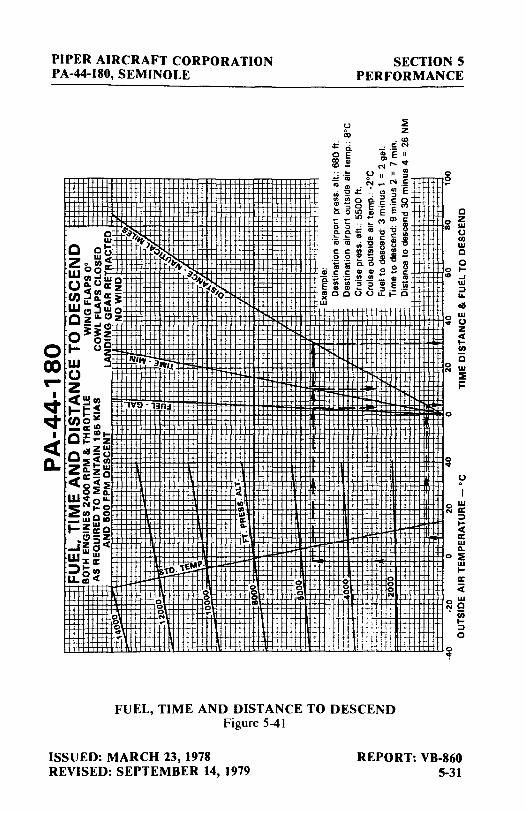
PIPER AIRCRAFT CORPORATION PA-44-180, SEMINOLE
0 00 ....
I
~ ~
I
<( 0.
~ ,$'~);
i't C oi-- ,~.,
wO- ~,,,,,, Zo u,C ~-ooa:: Wu,...1liio ~.,4' 011. 0 a::z "'l (l)~~a::3:
. .s-,0 l&.jC We, wo
Cz1&.C1z - ...ICJ
03::3::z o-t- oi w ~ !!ftv. 3,vu_
0 z <(~u, ·1vo-1:1n:1 t-1= :! (l)o~ -a:'° c:z:"'1-..... z coll~~
:IE Cu, Z 1-w D.z <(a::-0
oC:!E o:!:11.
w..i-o ... ~""1-0 _:3o~ t-~~o
~CJ5Z ...12 c,C WWW
:z: IC to-1~~~: :::, I- II)
LL~C . s
0 0 g 0 ... '6 ..
II~ fl J ...
':, 4 ,ii
"' ... s: ... t:
0 0 0 CD
0 0 0
"'
SECTION 5 PERFORMANCE
~ z
. co . C N
1·e II N,-....,
(J II II ~ ~ ·ca o NC m CD CD • ~ - en·- . .; -g.::: ·: " :::, E 1 I; g ~ .S .5 ~ !ioltla,EE-., __ in- enc Q Q ·: -~ M •• CD Q.Q..!::CV-i:j"'C~
-~-~::2;~.g 551!!~-5s· -- - ~ :::, -8 21 .. 1a1vc.0 0
CD .E .E:: B - i e;; ~ ·:; ·5 a;~;;-·::~~UU~.=o .w
+
0 0 0 0 0 0 . I': ~.• l ·t tt+Hl : r+ u, t ! i" i j; : , . •+, '{F , /tf i :J t.1+1 - , , !, i I: :Ji.fl
C 0 z ., ~
II) w C 0
0 I-"' ...I w
::, ... oll
0 w ., 0
z i! II)
c ~ w
:IE i=
0
0 .,
0 .,
0
FUEL, TIME AND DISTANCE TO DESCEND Figure 5-41
ISSUED: MARCH 23, 1978 REVISED: SEPTEMBER 14, 1979
REPORT: VB-860 5-31
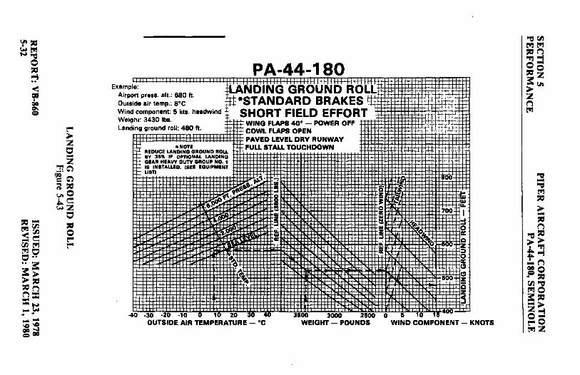
'-f''= ~~ N-r:,
0 = ~ < = I QO c,, =
I!"" > z c::, -"Tlz (iQ"~ = ~ nl = u.O .l,.~ ,...z
c::, =-~r.n = <r.n -~ 0 r.n ~ I!""
~o I!""
O·· •• 3:: 3:: > >= '=n n= =N :- !M --'°'° QO..., =QO
E"amp Airpo Outs Win Wei Lan
PA-44-180 !: ·LA'NDING GROUND ROLL rt press. alt.: 680 ft.
ft*STANDARD BRAKES ~e air temp.: e•c component: 5 kta. headwind SHORT FIELD EFFORT 11'. 3430 lbs.
i WING FLAPS 40° - POWER OFF ng ground roll: 480 ft. COWL FLAPS OPEN
PAVED LEVEL DRY RUNWAY *NOTE FULL STALL TOUCHDOWN
REDUCE LANDING GROUND ROU SY 311" IF OPTIONAL LANDING GEAII HEAVY DUTY GIIOUP NO. 1 18 INITAWD. (IEE EQUIPMENT LISTI
~~ ..,. ..._t.••·~ ~ -~- I r.~ w z . :I ..: . w IIC
~ • >,
~ :0
~~~-St'±t ;.t . ' I-':j.:L
i1= f::t;] -:--: :- J.-+.~1-t .. t:U(J±
ii 00
0 ..., ti I Ill 0 u. a:: 700 I Ill
::I !! :t ~~ Ill
~~ 0 z a: :I C ,.; ~ 00 z Ill
IIC ::, 0 a: c:,
1500 c:, z i5
~ .40 .30 -20 ·10 0 10 20 30 40
OUTSIDE AIR TEMPERATURE - °C 31500 3~ 21500 0 & 10 f5
400 ._....
WEIGHT - POUNDS WIND COMPONENT - KNOTS
"-r::I r.n ~~ =n 'Tl ""I o,,o 3:: z >I.II z n ~
"-r::I -"-r::I ~ = > -= n
"-r::I = >> I 'Tl t""I .:..n :o ~ = r.n "-r::I ~o 3:: = -> z""I o-1!""0 ~z

-~ c:: t"l ~ :: > ,::, (""'}
= N ~ -~ --.I 00
,::, t"l -= 0 ,::, :-, < = fJI I
I 00
~g
~ > 2 C z ~
C -,;,:i ~ >
'"1"!2 -·n ~ t"l ~ 0 VI,< ~t"l VI,::,
!JI = "!'.I :-i = > ,:::, ,:::, -t"l ,:::,
PA-44-180 Example: -,:;,LANDING ~ISTANCE OVER 50 FT. BARRIER
Air~rt pr~ss. alt.: 680ft. I I!!, 111; I •: ! STANDARD BRAKES Outside air temp.: s•c ___,_....._....._ SHORT FIELD EFFORT Wind component: 6 kts. headwind i WING FLAPS 40° - POWER OFF - COWL FLAPS OPEN Weight: 3107 lbs. PAVED LEVEL DRY RUNWAY Approach speed: 68 KIAS . FULL STALL TOUCHDOWN Total landing distance: 1200 ft. APPROACH SPEED AS SCHEDULED
n --'-"NOTE
Reduce total landing diltance b 111%1foptlon■ll■ndlngga■rhea duty Group No. 1 l■ inatalled. ( Equipment Listi
~= i.
h~
f-+.:.;-•'
APPROACH SPEED • KIAS
: ... -W -w u.
a: w
[J .. ,+'ii: 1600-:-+~
ID
Ii:
... ~u, -0 -c, -z --0
. ~ =r::r:!:
-40 ·30 -20 -10 0 10 20 30 40 3600 3000 2600 0 6 10 16
OUTSIDE AIR TEMPERATURE - °C WEIGHT - POUNDS WIND COMPONENT - KNOTS
-=-= ►-' -= ~t"l t-,::, -oo> =-~ ,::, ,;,:i (""'} t"l,:::, :: > -"!'.I 2~ 0 ~(""'} t":!O
-= t"l ,:::, "!'.I
,::, -= 0 ,:::, > ~
0 2
0 ,;,:i ,::, t"l 3:n > ::! 2 0 (""'}2 t"l !JI


PIPER AIRCRAFT CORPORATION SECTION 6PA-44-180, SEMINOLE WEIGHT AND BALANCE
ISSUED: MARCH 23, 1978 REPORT: VB-8606-iREVISED: OCTOBER 11, 2011
TABLE OF CONTENTS
SECTION 6
WEIGHT AND BALANCE
Paragraph PageNo. No.
6.1 General .................................................................................... 6-16.3 Airplane Weighing Procedure ................................................. 6-26.5 Weight and Balance Data and Record ..................................... 6-56.7 Weight and Balance Determination for Flight ........................ 6-9 6.11 Equipment List ........................................................................ 6-17 (a) Propeller and Propeller Accessories.......................... 6-18 (b) Engine and Engine Accessories ................................ 6-19 (c) Landing Gear and Brakes .......................................... 6-20 (d) Electrical Equipment ................................................. 6-22 (e) Instruments ................................................................ 6-23 (f) Miscellaneous ............................................................ 6-25 (g) Propeller and Propeller Accessories (Optional Equipment) ........................................... 6-26a (h) Engine and Engine Accessories (Optional Equipment) ........................................................... 6-27 (i) Landing Gear and Brakes (Optional Equipment) ........................................................... 6-28 (j) Electrical Equipment (Optional Equipment) ............. 6-28b (k) Instruments (Optional Equipment) ............................ 6-31 (l) Autopilots (Optional Equipment) .............................. 6-36 (m) Radio Equipment (Optional Equipment) .................. 6-36a (n) Miscellaneous (Optional Equipment) ....................... 6-48

SECTION 6 PIPER AIRCRAFT CORPORATION WEIGHT AND BALANCE PA-44-180, SEMINOLE
REPORT: VB-860 ISSUED: MARCH 23, 19786-ii REVISED: OCTOBER 11, 2011
TABLE OF CONTENTS
SECTION 6
WEIGHT AND BALANCE
Paragraph PageNo. No.
THIS SPACE INTENTIONALLY LEFT BLANK

PIPER AIRCRAFT CORPORATION PA-44-180, SEMINOLE
SECTION 6 WEIGHT AND BALANCE
SECTION 6
WEIGHT AND BALANCE
6.1 GENERAL
In order to achieve the performance and flying characteristics which are designed into the airplane, it must be flown with the weight and center of gravity (C.G.) position within the approved operating range (envelope). Although the airplane offers flexibility of loading, it cannot be flown with the maximum number of adult passengers, full fuel tanks and maximum baggage. With the flexibility comes responsibility. The pilot must insure that the airplane is loaded within the loading envelope before he makes a takeoff.
Misloading carries consequences for any aircraft. An overloaded airplane will not take off, climb or cruise as well as a properly loaded one. The heavier the airplane is loaded, the less climb performance it will have.
Center of gravity is a determining factor in flight characteristics. If the C.G. is too far forward in any airplane, it may be difficult to rotate for takeoff or landing. If the C.G. is too far aft, the airplane may rotate prematurely on takeoff or tend to pitch up during climb. Longitudinal stability will be reduced. This can lead to inadvertent stalls and even spins; and spin recovery becomes more difficult as the center of gravity moves aft of the approved limit.
A properly loaded airplane, however, will perform as intended. This airplane is designed to provide performance within the flight envelope. l Before the airplane is delivered, it is weighed, and a basic empty weight and C.G. location is computed (basic empty weight consists of the standard empty weight of the airplane plus the optional equipment). Using the basic empty weight and C.G. location, the pilot can determine the weight and C.G. position for the loaded airplane by computing the total weight and moment and then determining whether they are within the approved envelope.
ISSUED: MARCH 23, 1978 REVISED: SEPTEMBER 14, 1979
REPORT: VB-860 6-1

SECTION 6 WEIGHT AND BALANCE
PIPER AIRCRAFT CORPORATION PA-44-180, SEMINOLE
The basic empty weight and C.G. location are recorded in the Weight and Balance Data Form (Figure 6-5) and the Weight and Balance Record (Figure 6-7). The current values should always be used. Whenever new equipment is added or any modification work is done, the mechanic responsible for the work is required to compute a new basic empty weight and C.G. position and to write these in the Aircraft Log Book and the Weight and Balance Record. The owner should make sure that it is done.
A weight and balance calculation is necessary in determining how much fuel or baggage can be boarded so as to keep within allowable limits. Check calculations prior to adding fuel to insure against o~erloading.
The following pages are forms used in weighing an airplane in production and in computing basic empty weight, C.G. position, and useful load. Note that the useful load includes usable fuel, baggage, cargo and passengers. Following this is the method for computing takeoff weight and C.G.
6.3 AIRPLANE WEIGHING PROCEDURE
At the time of delivery, Piper Aircraft Corporation provides each airplane with the basic empty weight and center of gravity location. This data is supplied by Figure 6-5.
The removal or addition of equipment or airplane modifications can affect the basic empty weight and center of gravity. The following is a weighing procedure to determine this basic empty weight and center of gravity location:
(a) Preparation
(I) Be certain that all items checked in the airplane equipment list are installed in the proper location in the airplane.
(2) Remove excessive dirt, grease, moisture, and foreign items such as rags and tools, from the airplane before weighing.
(3) Defuel airplane. Then open all fuel drains until all remaining fuel is drained. Operate each engine until all undrainable fuel is used and engine stops. Then add the unusable fuel (2.0 gallons total, 1.0 gallons each wing).
REPORT: VB-860 6-2
ISSUED: MARCH 23, 1978 REVISED: SEPTEMBER 14, 1979

PIPER AIRCRAFT CORPORATION PA-44-180, SEMINOLE
CAUTION
SECTION 6 WEIGHT AND BALANCE
Whenever the fuel system is completely drained and fuel is replenished it will be necessary to run the engines for a minimum of 3 minutes at 1000 RPM on each tank to insure no air exists in the fuel supply lines.
(4) Fill with oil to full capacity.
(5) Place pilot and copilot seats in fourth (4th) notch, aft of forward position. Put flaps in the fully retracted position and all control surfaces in the neutral position. Tow bar should be in the proper location and entrance and baggage door closed.
(6) Weigh the airplane inside a closed building to prevent errors in scale readings due to wind.
(b) Leveling
( l) With airplane on scales, block main gear oleo pistons in the fully extended position.
(2) Level airplane (refer to Figure 6-3) deflating nose wheel tire, to center bubble on level.
(c) Weighing - Airplane Basic Empty Weight
( l) With the airplane level and brakes released, record the weight shown on each scale. Deduct the tare, if any, from each reading.
ISSUED: MARCH 23, 1978 REVISED: SEPTEMBER 14, 1979
REPORT: VB-860 6-3

SECTION 6 WEIGHT AND BALANCE
PIPER AIRCRAFT CORPORATION PA-44-180, SEMINOLE
Scale Net Scale Position and Symbol Reading Tare Weight
N ose Wheel (N)
-R ight Main Wheel (R)
ft Main Wheel (L) Le
Ba sic Empty Weight, as Weighed (T)
WEIGHING FORM Figure 6-1
(d) Basic Empty Weight Center of Gravity
A = 8.7 B = 109.7
( l) The following geometry applies to the P A-44-180 airplane when it is level. Refer to Leveling paragraph 6.3 (b).
Top View
Wing Leading Edge
The datum is 78.4 inches ahead of the wing leading edge at Wing Station I06.
LEVELING DIAGRAM Figure 6-3
REPORT: VB-860 6-4
ISSUED: MARCH 23, 1978 REVISED: SEPTEMBER 26, 1980
PIPER AIRCRAFT CORPORATION PA-4.-180, SEMINOLE
SECTION 6 WEIGHT AND BALANCE
(2) The basic empty weight center of gravity (as weighed including optional equipment, full oil and unusable fuel) can be determined by the following formula:
C.G. Arm = N (A) + (R + L) (B)
T
Where: T = N + R + L
inches
6.5 WEIGHT AND BALANCE DATA AND RECORD
The Basic Empty Weight, Center of Gravity Location and Useful Load listed in Figure 6-5 are for the airplane as delivered from the factory. These figures apply only to the specific airplane serial number and registration number shown.
The basic empty weight of the airplane as delivered from the factory has been entered in the Weight and Balance Record (Figure 6-7). This form is provided to present the current status of the airplane basic empty weight and a complete history of previous modifications. Any change to the permanently installed equipment or modification which affects weight or moment must be entered in the Weight and Balance Record.
ISSUED: MARCH 23, 1978 REVISED: SEPTEMBER 14, 1979
REPORT: VB-860 6-5

SECTION 6 WEIGHT AND BALANCE
PIPER AIRCRAFT CORPORATION PA-44-180, SEMINOLE
MODEL PA-44-180, SEMINOLE
Airplane Serial Number ________ _
Regist1'.ltion Number _________ _
Date ______________ _
AIRPLANE BASIC EMPTY WEIGHT
Item
Actual Standard Empty Weight* Computed
Optional Equipment
Basic Empty Weight
C.G. Arm Weight x (Inches Aft= Moment (Lbs) of Datum) (In-Lbs)
*The standard empty weight includes full oil capacity and 2.0 gallons of unusable fuel.
AIRPLANE USEFUL LOAD - NORMAL CATEGORY OPERATION
(Gross Weight) - (Basic Empty Weight) = Useful Load
(3800 lbs.) - ( lbs.) = lbs.
l THIS BASIC EMPTY WEIGHT, C.G. AND USEFUL LOAD ARE I FOR THE AIRPLANE AS LICENSED AT THE FACTORY. REFER
TO APPROPRIATE AIRCRAFT RECORD WHEN ALTERATIONS HA VE BEEN MADE.
WEIGHT AND BALANCE DATA FORM Figure 6-5
REPORT: VB-860 6-6
ISSUED: MARCH 23, 1978 REVISED: JANUARY 22, 1982

PIPER AIRCRAFT CORPORATION PA-44-180, SEMINOLE
u -c <U 0 --..c:: EO "' IOI) ....
o:s __
0 ·-cc <U <U IOI)~ ~ J:l
E ·= >, ::, c-z C Q. -<U ::, E ..; ..0
IOI) ~Ul ~..J o:I -0.. ~
-C <U 0 eo 0 --
<U ~ IOI) ... C <U J:l o:I
E ..c:: ::, u E '"c
z .E .._ C ,<:::,
C IOI)
.2 ·v ~ ~ -... ..; ..c -"' ~..J "6i) <U -~
L___ (-) pdA0Wd1f
(+) pdppy
<U
] C ... .!= < ~ '- u ... 0 ..;:: <U
J:l C :-a E .2 0
-0 ::, C. ~ <U z ... ·;:: ... <U
;; u 0 ~ "' ·;:: <U <U <U Cl Cl rJJ
'--- "' < 0 00 "ON Wdlf -I ..,. ..,.
<U < ... 0.. o:I
Cl
SECTION 6 WEIGHT AND BALANCE
WEiGHT AND BALANCE RECORD · Figure 6-7
ISSUED: MARCH 23, 1978 REPORT: VB-860 6-7

SECTION 6 WEIGHT AND BALANCE
-u- C uo ·-.c E:= "'t,I) .. "'·- o.___ a:l u u
t,I)~ 2 .r, e .5 >. ::,
C -z C Q. --~
::, e ~..t:i 0::LLI ~...J tsS -0.. - -C uo e~ 0 ----
~ 2 .. C u .r, tsS
e .c ::, u e--=-z .c .., C
<:::, C Oil
.9 ·a:; - ~ tsS --... ~..t:i -"' ~~ "6b u
°' c--- (-) p;>AOW;>lf (+) p;1ppy
u ~ C -... .9 < -._ tsS
u .. 0 t:: u .r, C ~ E .9 0 ::, C. 2 z ·.: ... ~
u 0 "' ·.: u
u Cl ti) -0 00 "ON W;)lJ -I '-:t ...,.
u < -0.. tsS Cl
PIPER AIRCRAFT CORPORATION PA-44-180, SEMINOLE
WEIGHT AND BALANCE RECO.i:.D (cont) Figure 6-7 (cont)
REPORT: VB-860 6-8
ISSUED: MARCH 23, 1978

PIPER AIRCRAFT CORPORATION PA-44-180, SEMINOLE
SECTION 6 WEIGHT AND BALANCE
6.7 WEIGHT AND BALANCE DETERMINATION FOR FLIGHT
(a) Add the weight of all items to be loaded to the basic empty weight. (b) Use the Loading Graph (Figure 6-13) to determine the moment of
all items to be carried in the airplane. (c) Add the moment of all items to be loaded to the basic empty weight
moment. (d) Divide the total moment by the total weight to determine the C.G.
location. (e) By using the figures of item (a) and item (d) (above), locate a point
on the C.G. range and weight graph (Figure 6-15). If the point falls within the C.G. envelope, the loading meets the weight and balance requirements.
ISSUED: MARCH 23, 1978 REVISED: MARCH I, 1980
REPORT: VB-860 6-9

SECTION 6 WEIGHT AND BALANCE
PIPER AIRCRAFT CORPORATION PA-44-180, SEMINOLE
Arm Aft Weight Datum Moment (Lbs) (Inches) (In-Lbs)
Basic Empty Weight
Pilot and _Front Passenger 340.0 80.5 27370
Passengers (Rear Seats) 340.0 118.1 40154
Fuel (108 Gallon Maximum Usable) 95.0
Baggage (200 Lb. Limit) 142.8
Ramp Weight (3816 Lbs. Max.)
Fuel Allowance for Engine .
Start, Taxi & Runup -16.0 95.0 -1520 T~ke-off Weight (3800 Lbs. Max.)
The center of gravity (C.G.) for the take-off weight of this sample loading problem is at inches aft of the datum line. Locate this point ( ) on the C.G. range and weight graph. Since this point falls within the weight -C.G. envelope, this loading meets the weight and balance requirements.
Take-off Weight
Minus Estimated Fuel Burn-off (climb & cruise) @ 6.0 Lbs/Gal. 95.0
Landing Weight
Locate the cehter of gravity of the landing weight on the C.G. range and weight graph. Since this point falls within the weight - C.G. envelope, the loading may be assumed acceptable for landing.
IT IS THE RESPONSIBILITY OF THE PILOT AND AIRCRAFT OWNER TO INSURE THAT THE AIRPLANE IS LOADED PROPERLY AT ALL TIMES.
REPORT: VB-860 6-10
SAMPLE LOADING PROBLEM Figure 6-9
ISSUED: MARCH 23, 1978 REVISED: MARCH I, 1980

PIPER AIRCRAFT CORPORATION PA-44-180, SEMINOLE
Basic Empty Weight
Pilot and Front Passenger
Passengers (Rear Seats)
Fuel ( 108 Gallon Maximum Usable)
Baggage (200 Lb. Limit)
Ramp Weight (3816 Lbs. Max.)
Fuel Allowance for Engine Start, Taxi & Runup
Take-off Weight (3800 Lbs. Max.)
SECTION 6 WEIGHT AND BALANCE
Arm Aft Weight Datum Moment (Lbs) (Inches) (In-Lbs)
80.5 118.1
95.0
142.8
-16.0 95.0 -1520
The center of gravity (C.G.) for the take-off weight of this loading problem is at inches aft of the datum line. Locate this point ( ) on the C.G. range and weight graph. If this point falls within the weight -C.G. envelope, this loading meets the weight and balance requirements.
Take-off Weight
Minus Estimated Fuel Burn-off (climb & cruise)@ 6.0 Lbs/Gal. 95.0
Landing Weight
Locate the center of gravity of the landing weight on the C.G. range and weight graph. If this point falls within the weight - C.G. envelope, the. loading may be assumed acceptable for landing.
IT IS THE RESPONSIBILITY OF THE PILOT AND AIRCRAFT OWNER TO INSURE THAT THE AIRPLANE IS LOADED PROPERLY AT ALL TIMES.
WEIGHT AND BALANCE LOADING FORM Figure 6-11
ISSUED: MARCH 1, 1980 REPORT: VB-860 I 6-toa

SECTION 6 WEIGHT AND BALANCE
PIPER AIRCRAFT CORPORATION PA-44-180, SEMINOLE
THIS PAGE INTENTIONALLY LEFT BLANK
REPORT: VB-860 6-lOb
ISSUED: MARCH 1, 1980

PIPER AIRCRAFT CORPORATION PA-44-180, SEMINOLE
SECTION 6 WEIGHT AND BALANCE
160
100
60
0 0 6 10 16
+· • \ '1 .j I 1 ' ,j ''!'· ·-t! +tJtJ• ·t , i=l + H1j , 4 j,) ' h
t 1 ·tH t • + • I+ 4 + Ht+·ll it LHj; li _. rtt-H ·it .. -, '
~ U ~ ~ ~ U ~ H ~ H
MOMENT/1000 (POUNDS-INCHES)
LOADING GRAPH Figure 6-13
ISSUED: MARCH 23, 1978 REPORT: VB-860 6-11

SECTION 6 WEIGHT AND BALANCE
PIPER AIRCRAFT CORPORATION PA-44-180, SEMINOLE
3800 MAX. T.O. AND
LANDING WEIGHT 89 90 91 92 93
3700-------8~
8----------+-----,..--
85 3400-u;+---l--+----f-----if----t--+--+---f
m 3300- -t++---4--+--t-----if---+---+---+--➔
1-. ::c
3200 ~-----+--+----1----+-----w
3100 -~.-....---+--I---+--+---+--+---+-➔
3000 :-------------------u 2900-~------------------+----t--+-
2800-84---1---1----1-----------
11
2&00-~-------------t--+--0
2500--i----+---'I---+--+---,..---+--~
2400--~~+---+---t-+---+--+---t-+-➔ ~
2300 ---84 85 86 87 88 89 90 91 92 93
C.G. LOCATION (INCHES AFT DATUM)
REPORT: VB-860 6-12
C.G. RANGE AND WEIGHT Figure 6-15
ISSUED: MARCH 23, 1978 REVISED: MARCH 1, 1980

PIPER AIRCRAFT CORPORATION SECTION 6PA-44-180, SEMINOLE WEIGHT AND BALANCE
ISSUED: MARCH 23, 1978 REPORT: VB-8606-13REVISED: OCTOBER 11, 2011
THIS PAGE INTENTIONALLy LEFT BLANk

SECTION 6 PIPER AIRCRAFT CORPORATION WEIGHT AND BALANCE PA-44-180, SEMINOLE
REPORT: VB-860 ISSUED: MARCH 23, 19786-14 REVISED: OCTOBER 11, 2011
THIS PAGE INTENTIONALLy LEFT BLANk

PIPER AIRCRAFT CORPORATION SECTION 6PA-44-180, SEMINOLE WEIGHT AND BALANCE
ISSUED: MARCH 23, 1978 REPORT: VB-8606-15REVISED: OCTOBER 11, 2011
THIS PAGE INTENTIONALLy LEFT BLANk

SECTION 6 PIPER AIRCRAFT CORPORATION WEIGHT AND BALANCE PA-44-180, SEMINOLE
REPORT: VB-860 ISSUED: MARCH 23, 19786-16
THIS PAGE INTENTIONALLy LEFT BLANk
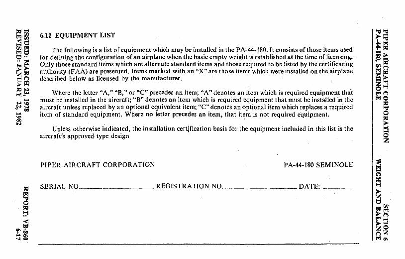
::a-1:!!:1"(/'J -< rJ'J .... c rntll!'.! tll1 t:, t:, •• .. ~ c..,> ~~ en >::C: :;ti N ~~ NN\0 ~ ~
- 00 \0 00 N
~
~ 0 ::a ~ -< t:1:1
«r'do -0'1 ~=
6.11 EQUIPMENT LIST
The following is a list of equipment which may be installed in the PA-44-180. It consists of those items used for defining the configuration of an airplane when the basic empty weight is established at the time of licensing. Only those standard items which are alternate standard items and those required to be listed by the certificating authority (FAA) are presented. Items marked with an "X" are those items which were installed on the airplane described below as licensed by the manufacturer.
Where the letter "A," "B," or "C" precedes an item; ''A" denotes an item which is required equipment that must be installed in the aircraft; "8" denotes an item which is required equipment that must be installed in the aircraft unless replaced by an optional equivalent item; "C" denotes an optional item which replaces a required item of standard equipment. Where no letter precedes an item, that it~m is not required equipment.
Unless otherwise indicated, the installation certjfication basis for the equipment included in this list is the aircraft's approved type design
PIPER AIRCRAFT CORPORATION PA-44-180 SEMINOLE
SERIAL NQ, ________ REGISTRATION NO, ________ DATE: __ _
"'Cl~ ~"'Cl ""'tll1 ~~
= ► ~;; oon l:!!:I~ a: > -~ z~ 0 t-4 ("') 1:!!:10
~ £ ~
~ t:,
~ 0
~ ~ -0 z
t:1:1 rn >~ l""'~
►-zO nZ tll1 0'I

,-=a, ~rn (a) Propeller and Propeller Accessories t_!!lt'J!j .... t'J!j ,...n
00~ c;".1 i-il 0 Item Mark if Weight Arm (In.) Moment =-= ..,;ii i-ij No. Item Instl. (Pounds) Aft Datum (Lb-In.) ..
► O\ < z = I B Two Propellers e, I QC 0\ Cert. Basis - TC P920 = = ► Left Engine r--
Hartzell Model HC-C2Y (K,R)-2CEUF / ► FC7666A-2R 65.0 31.4 2041 z
n Right Engine t'J!j
Hartzell Model HC-C2Y(K,R)-2CLEUF / FJC7666A-2R 65.0 31.4· 2041
~ -3 A Two Hydraulic Governors ~
= t'J!j
t'J!j Cert. Basis - TC P920 = :s Hartzell ·Governor > -~- Model E-3-2 (Left Engine) 3.9 41.2 161 ~
0~ Hartzell Governor n .. ~ Model E-3-2L (Right Engine) 3.9 41.2 161 ~~ rn [!l!j ►► t'J!j 0 .~ ~ ..
5 Two Spinners & Attachment Plates ;: i-ij
i-ij == .... n t_!!l ► Hartzell Model C2285-3 (Left Prop) 3.8 29.6 112 ooo s= Hartzell Model C2285-3L (Rt. Prop) 3.8 29.6 112 !=~
rn~ [!l!j n t'J!j0 == ==,, .,..N -► ~~ Z..,;i ........ o-\C \C ~o ~~ t.!!lZ "° QC

,:, ,... (b) Engine and Engine Accessories ~~
~~ >,... .~
Item Mark if Weight Arm (In.) Moment ~; fl) l'"'.I ~> l'"'.I t:::I No . Item Inst!. (Pounds) Aft Datum (Lb-In.) t:::I •• e,... .. ::: .. ,:, r,:i n t:I > I I A Two Engines t_!!J,:,
l'"'.I ,:, Cert. Basis -TC E286 a::> n n -~ t_!!J = Lycoming Model: z...,
a:: w O-360-E1A6D (Left Wing) 290.0 50.7 14703 0 = !.H ~n l'"'.I .. LO-360-EIA6D (Right Wing) 290.0 50.7 14703 t_!!JO ,:, - ~ \C - ...:a .. u. 00 13 A Engine Driven Fuel Pumps (2) 0 - Cert .. Basis -TC E286 ,:, 'Cl > ...:a P/N LW-15399 (Included in engine weight) ..., 00 ,-;
0 15 A Electric Fuel Pumps (2) I z
Bendix P / N 480543 5.0 78.0 390
17 A Fuel Valves (2)· ~ ~ Scott Aviation Corp. Ci)
23640-5 Rev. K 1.0 110.0 I 10 = ..., ,:, 19 A Oil Coolers (2) > t_!!J z lood Piper Dwg. 16599-0 13.(> 63.1 858 t:::, 0 =00 ,:,
21 A Air Filters (2) >t_!!J ~ ~("'}
< Fram P/N CA-l44PL 1.5 69.8 105 > ::j = zO
~clo 23 A Alternator (2) 25.4 23.4 594 nZ -°' l'"'.ICI'\ \C =

",, (c) Landing Gear and Brakes ~00 Nl'l!J l'l!J l'l!J 0 "'d -~
0 Item Mark if Weight Arm (In.) Moment C:,1-3
==-,, No. Item Instl. (Pounds) Aft Datum (Lb-In.) 1-3~ ~
< >=--Two Main Wheel Assemblies z = 31 B 34.4 109.8 3777 0 I
CIC a. Cleveland Aircraft Products g = Wheel Assy. #40-90 > Brake Assy. #30-65 ~
> Cert. Basis - TSO C26a z
b. 6.00-6 Type III 8 Ply Rating ~ l'l!J
Tires with Reg. Tubes Cert. Basis - TSO C62
"'d Nose Wheel Assembly -33 B "'d a. Cleveland Aircraft Products l'l!J ,,
Wheel Assy. #40-77 > Cert. Basis - TSO C26a 2.6 8.6 22 -- ~
00 b. McCauley Industrial Corp. ~ t'/.l "'d,, ~ Wheel Assy. #D-30500
l'l!J Cert. Basis - TSO C26b 3.6 8.6 31 >> ~
.~ c. 5.00-5 Type III 6 Ply Rating t: -3
a: Tire with Reg. Tube ~~ CIOQ > Cert. Basis - TSO C62 6.1 8.6 52 .? ,, ,,
~ OO"'d l'l!JO = 35 A Toe Brake Cylinders (4) a: ,,
N a. Cleveland Aircraft Products -> jH Z-i .... . No. 10-27 0.7 53.0 37 o-l,C
b. Gar-Kenyon Instruments 17000 0.4 53.0 21 ~o
-I l'l!JZ QO

~- (c) Landing ·Gear and Brakes (cont) ""d~
~rn >1-1 ~~
,"'Cl ,&:,.t"J
~n~ Item Mark if Weight Arm (In.) Moment t- :;a:.,
t::1 •• No, Item Instl. {Pounds) Aft Datum (Lb-In.) :i:> tj~
~-Cl.I :;a:.,
Landing Gear Hydraulic Pump ~("")
l:'J 10 37 A ~,::J ("") ("") Piper Dwg. 96671-2 ""4> l:'J = z'T:I
1~ (Prestolite HYC-5005) 9.0 160.4 1444 oi-J t"" ("")
,::J .... 39 A Main Gear Hydraulic Cylinders (2) l:'10
IQ ::c, --- Piper Dwg. 96860-0 1-tj ,!JI QO - (Synco Devices SFA 232-3) 2.2 108.0 238 0
'° ,::J
-- > QO 41 A Nose Gear Hydraulic Cylinder t-l -Piper Dwg. 35797-2 0
(Gar-Kenyon 94951) 2.0 31.4 63 z
43 A Parking Brake Valve 060-0031 I~ Cleveland Aircraft Products 0.6 45.6 27 a'l = t-l
,::J l:'J ~ ""d 0 t::I ,::J =~ ~ >n < t.""4~
= ►-,'t' ~ zO NO\ nZ -= t:"-1,:,._

Cl'lil' (d) Electrical Equipment ~ r:ll Wl":I l":I l":I w"T:1 -~ 0 Item Mark if Weight Arm (In.) Moment
C".l~ Iii' =-~ No. Item I nstl. (Pounds) Aft Datum (Lb-In.) ~i < > Cl\
= 51 A Voltage Regulator (2) z I t:l 00 c,., Piper Dwg. 86368-2 1.0 27.3 27 = = >
53 Battery 12V 35 A.H. t-t >
Rebat R35 28.4 9.1 258 z n 55 A Starter Relay (2)
. l":I
Piper Dwg. 99130-2 1.0 9.7 10 (RBM Controls P/N 111-111) 1.0 12.3 12 ~ -~ :,:,
57 A Overvoltage Relay (2) l":I l":I Iii' < Piper PS50034- I > -Cll - (Prestolite. Wico Div .. -~("/l :,:, t:l ("/l P/N Xl6799) 1.0 32.3 32 ~ .. ~ ~== r:ll l":I
59 A Stall Warning Devices >> ~ t:l .~ ~ ..
Piper Dwg. 86355-2-3. t~ ~3: ,!..e;, ~> (Safe Flight P/N 148-7) 0.4 85.9 34 000 ; Iii' .. = Iii' :a 61 A Stall Warning Horn Cll "T:1
l":10 NN Piper Dwg. 86355-2-3 ~:,:, J"JM (Safe Flight P/N 35214) 0.2 55.0 11 -> z~ -- 00 \C \C QC~ ~z c=oo
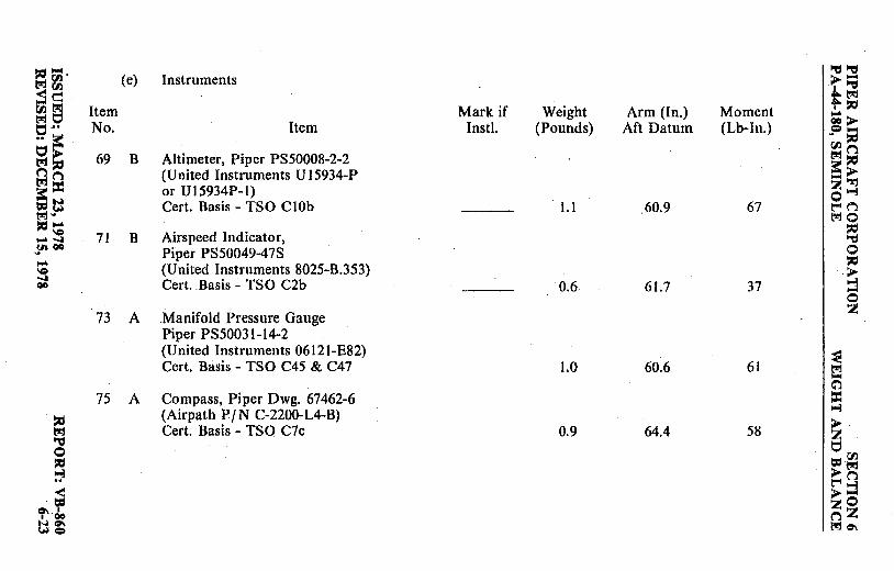
i,:,;, ~~ (e) Instruments ►-~~ I '"0
.. trJ
~a Item Mark if Weight Arm (In.) Moment t- i,:,
;:> t:i·" No. Item Inst!. (Pounds) Aft Datum (Lb-In.) ,P ;;
t:,~ r,i n 69 B Altimeter, Piper PS50008-2-2 ~17:1 ~17:1 a::> nn (United Instruments U 15934-P ~= ~~
or U15934P-I) z'"".! a::w 0 =~ Cert. Basis - TSO C !Ob I.I 60.9 67 t"'C":l I:!!:!"' l'!t'JO 17:1 .... 17:1 \C 71 B Airspeed Indicator, ..,.-.,1 ~ !" 00 Piper PS50049-47S 0 .... i,:, \C (United Instruments 8025-B.353) > -.,I
Cert. Basis - TSO C2b 0.6 61.7 37 I-'.! 00 ~
0
73 A Manifold Pressure Gauge I 2!
Piper PS50031-14-2 (United Instruments 0612I-E82) ,~ Cert. Basis - TSO C45 & C47 1.0 60.6 61
""4
a'l 75 A Compass, Piper Dwg, 67462-6 =
(Airpath P/N C-2200-L4-B) I-'.! 17:1 > I:!!:! Cert. Basis - TSO C7c 0.9 64.4 58 z "'O t:, 0 i,:, =r.n ~ >~ t""ln ~ >::l = zO
C:,,.. I nZ I 00 NC:,,. t.'!t'Jc:,,. ~=

~== (e) Instruments (cont) ~ r/.l N~ l:!!:I~ ,.. ~ ,_.("')
0 Item Mark if Weight Arm (In.) Moment ~~
== =-::3 No. Item Instl. (Pounds) Aft Datum (Lb-In.) ~~ < ► c,..
= 77 B Tachometer (2), z
I 0 00 c,,. Piper Dwg. 62177-3 = = Stewart Wartier 551-WE(N) 1.4 60.7 85 >
~ >
79 Left Engine Cluster I~ Piper Dwg. 86552-6 or -11 0.8 62.4 50
81 Right Engine Cluster Piper (?wg. 86552-6 or -11 0.8 62.4 50 I ~ -~
~
== ,cl
l:!!:I > <_ --r/.l ::it,
r/.l r/.l ("')
ae -= ::it, •• l:!!:I > ► c.. t:, ,"!j
> .. ,..~ za:: tn e> oco ~ ==
.P::it,
~g r/.l '"C:I ~o NN
a:: ::it,
~~ -► ........ z ::3 \Q \Q 00 OC 00 ~z N =

~ ;- (f) Miscellaneous ~~ tt'J~ ►~ .l:.,t-rj ~~- Item Mark if Weight Arm (In.) Moment t- ~ rl.l~ No. Item lnstl. (Pounds) Aft Datum (Lb-In.) ~> tt'Jt:, t:, •• =-~ ~ •• a=
91 B Left Front Seat rl.lr, >> ~~ ~~ Piper Dwg. 79337-19 15.5 88.2 1367 e:?n -► z 'Tj t"I= 93 Right Front Seat oi-J -~ t-tt""l .? ~~ Piper Dwg. 79337-20 15.5 88.2 1367 trJ 0 -- ~ \Cl,C
~ 00 .... 95 Left Rear Seat - QO 0
Piper Dwg. 79479-2 14.5 124.2 1801 ~ >
I I-]
97 Right Rear Seat -0 Piper Dwg. 79479-3 14.5 124.2 1801 z
99 A Front Seat Belts (2)'· Piper PS50039-4-2A ~ (American Safety Eqpt. Corp. 500576) ~ (Davis Acft. Prod. Inc. ~
= FDC-5900-120-5) (Black) I-]
~ Cert. Basis - TSO C22f 1.8 86.9 156 ~ trJ ~
101 A Aft Seat Belts (2) t:, 0 t,:100 ~ Piper PS50039-4-4A >t-rj ~ t-t n <
(American Safety Eqpt. Corp. 449968) >~ = (Davis Acft. Prod. Inc. zO °'' FDC-5900-120-2) (Black) n Z I 00
~°' WO\ Cert. Basis - TSO C22f 1.6 122.0 195 U\C:::,
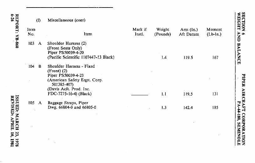
'r' ::0 ~Cl) !)lj!)lj
N!)lj (f) Miscellaneous (cont) _r.i Q'l""d c;')-3
0 =-,, Item Mark if Weight Arm (ln.) Moment ...,~
~ No. Item Inst!. (Pounds) Aft Datum (Lb-In.) >Q'I
< z = 0 I QC 103 A Shoulder Harness (2) = O'I = (Front Seats Only) >
~ Piper PS50039-4-20 > (Pacific Scientific I 107447-13 Black) 1.4 119.5 167 z
(".l !)lj
l04 B Shoulder Harness - Fixed (Front) (2) Piper PS50039-4-23 ""d -(American Safety Eqpt. Corp. ""d
!)lj 501385-407) ,,
(Davis Acft. Prod. Inc. > FDC-7275-16-4) (Black) I. I 119.5 131 -,, ..... ~
!)lj~ (".l
105 A Baggage Straps, Piper ""d,, <e >> -!)lj Dwg. 66804-0 and 66805-0 1.3 142.4 185 ~o ·~ t..., i:::,··
,:.. (".l .. :: oco >> ~= ::0 ""d~ ,, (".l (/l "=
t"'lO E=::i:: a= ::0 ,_.N -> e,W z..., ~ ~ ......... o-\C \C ~o QC -I tse:!Z ..... QC

.. ~:g fl) (g) Propeller and Propeller Accessories fl) .~ ~ (Optional Equipment) +; ~ Item Mark if Weight Arm (In.) Moment = ► r:n No. Item Instl. (Pounds) ·Aft Datum (Lb-In.) ~=s l.'J1 r:nn "Ct I" ~ 113 C Two Propellers t ; Cert. Basis - TC P25EA 0~ l.'J1 Left Engine t:""41'i
" Hartzell Model HC-C3YR-2EUF/ l'J!:10 t.J FC7663-5R *19.0 31.4 597 ~ !1' Right Engine 0 .....
" ',Q · Hartzell Model HC-C3YR-2LEUF/ > QO 0 FJC7663-5R *19.0 31.4 597 ~ -0 z
115 Two Spinners & Attachment Plates Hartzell Model C-4558 • 1.8 29.6 53
~ 1.17 Synchrophaser ,~
Piper Dwg. 36889-2 5.1 63.3 323 £ ~
" > ~ z 0 t;j
" =~ ~ >n ~~
t""4 ::i •weight and momen~ difference between standard and optional equipment.
~o woo n:Z c,,,c:,-. 1111 Q l'J!:I c,,.

SECTION 6 WEIGHT AND BALANCE
PIPER AIRCRAFT CORPORATION PA-44-180, SEMINOLE
THIS PAGE INTENTIONALLY LEFT BLANK
I REPORT: VB-860 6-l6b
ISSUED: SEPTEMBER 26, 1980

:ii:, ~ (h) Engine and Engine Ac~essories lo'd~ t,,:I 00 ►-<tl'J (Optional Equipment) ~~ '"'"d t-~ OO·t,,:I e;, Item Mark if ·Weight Arm (In.) Moment = ► .. ~ No. Item Instl. (Pounds) Aft Datum (Lb-In.) J=I ;;
r:J) ► ti.In t,,:I~ 121 Vacuum Pump, ;~ ~g ,...►
a. Piper Dwg. 79399-0 and -2 · z~ ~~ (Airborne P /N 211cc & 212cw) 7.2 64.0 461 0~ b:j .. b. Piper Dwg. 36535-2
~(")
tr,-t,l!:IO
:c ',O (Edo-Aire P/N lUl28A) 4.4 64.0 282 :c N--.1 lo'd 9' 00 0 - 123 Exhaust Gas Temperature Gauge :c l,C Installation, Piper Dwg. 86415-2, ► 00 ~ c:> Alcor Indicator
,... 0
P/N 202A-7A or z P/N 202B-7A Probe (2)
I~ Lead Assembly 90.00 0.7 60.4 42 ,...
125 Carburetor Ice Detector c;"l = Piper Dwg. 39684-4 0.7 61.9 43 ~
~ ► z 0 ~ ~
b:j I'll
:, >t,l!j ~n
b3 ►~ 0\ I
zO ' 00 nZ NO\ t,l!:tc,-. --.JO

~~ 0
.~ ~ QC g
" ~-~ < r:I)
~c:-:: ~-~ ~ '!;'
~-~ " ~ gg -w
~,Iii,. :H --IC '-C QC ..J ~ QC>·
Item No.
(i) Landing Gear and Brakes (Optional Equipment)
Item
127 C Heavy Duty Group No. 1 a. Cleveland Aircraft Products
40-120C Wheel Assy. (2), 30-83 Brake Assy. (2), Cert. Basis - TSO C26a Goodrich 6.00 x 6 Ribbed Type ]II 8 Ply Rating Tire with Tube (2) Cert. Basis - TSO C62
b. Goodrich 5.00 x 5 Ribbed Type 111 6 Ply Rating Tire with Tube Cert. Basis - TSO C62
Mark if Weight Inst!. (Pounds)
*2.9
Arm (In.) Aft Datum
109.8
Moment (Lb-In.)
318
(Same as Standard Equipment)
*Weight and moment difference between standard and optional equipment.
::E r:I) t,.jt,.j ,..n c:':I ::! =o ~z ►~ z 0
: ~ ~ ~ t,.j
::g ~
= ~ ~ ("l
~~ t i:; ;~ -n ooo ~ 1:1:1 r:I)~ ;~ •> z ::! ~o t,.:1Z

PIPER AIRCRAFT CORPORATION PA-44-180, SEMINOLE
SECTION 6 WEIGHT AND BALANCE
THIS PAGE INTENTIONALLY LEFT BLANK
ISSUED: SEPTEMBER 26, 1980 REPORT: VB-860 6-28a

Cl'::O ~--
~(/) Nt!tj (j) Electrical Equipment t!tjt!tj QC~ (Optional Equipment) ... n c:r 0 C') "'"1
::ii, =-:7 Item Mark if Weight Arm (In.) Moment ""'li < No. Item Inst!. (Pounds) Aft Datum (Lb-In.) ► c:,, = z
I 0 go
=-- 135 Instrument Panel Lights Inst!. ci:, = Piper Dwg. 86355-3 0.3 62.8 19 > t:"'4 >
136 Instrument Light z Grimes 15-0083-7 or n
t!tj
Whelen A-300-W-14 0.1 99.0 IO
137 Landing Light Piper PS I 0008-4509 --= -(G.E. Model 4509) 0.5 -16.4 -8 --= t!tj
r';j i:i:, (/) 138 Landing Light Instl. > d Piper Dwg. 86925-2 3.7 0.4 I -
i:i:,~ i:i:, n
t!tj •• 139 Navigation Lights (Wing) (2) --= i:i:, <Cl.l > ► -t!tj (Red & Green) (Whelen P /N I "!'j
Cl) --= ;"'"1 I'.!!:! >-l A429-PG-D-14 and A429-PR-D-14) 0.4 106.6 43 ~I'.!!:! .... n c.., a:: ooo
140 Navigation Light (Rear) Pi:i:, dt:1:1 Cl.l--= t:"'4 t!tj Grimes Model A2064 (White) 0.2 302.5 61 t!tj0 <1:10 ~i:i:, NN
.!'-?' -► Z--i -- o-\CIC l:"'40 ~I l'.!!:!Z

:,:,- 0) Electrical Equipment . "'d "'d Moo ►-<Cl) (Optional Equipment) (cont) I "'d _c:: ~; ~t1 Item Mark if Weight Arm (In.) Moment = ► C, •• =-.. ~ No. Item Instl. (Pounds) Aft Datum (Lb-In.) "' :,:, Cl)> oon ~= trj :,.:,
,-i n 141 Navigation Light (Rear) eS> M::i:= Grimes Model A2064 (White) 0.2 273.1 55 z~ ~N 0 i-l =~ ~n M ... 142 Navigation Lights (Wing) (2) MO :,:, \0
Red/White and Green/White :,.:, N --..I "'d f" QO Whelen Model A675 0.5 106.6 53 0 .... :,.:, \0 > 00 143 Navigation Lights (Wing) (2) ~ e, -Red/White and Green/White 0
with White Strobe z Whelen Model A600 6.4 186.5 1194
144 Navigation Lights (Wing) (2) ~ trj
Red/White and Green/White -~ with Red Strobe ::c Whelen Model A600 6.4 186.5 1194 ~ :,.:, > M z "'d 145 Anti-Collision Lights 0 C,
:,.:, (Wing Tip) (Whelen) =rJl :-:l ► M Piper Dwg. 86355-3 ~n < Cert. Basis - STC SA615EA 6.3 186.5 1175 > ::j = zO 0\ I
I 00 nZ NO\ \Q e, M0\

er,,, (j) Electrical Equipment ~fl.l ~M (Optional Equipment) (cont)
t,!jt,!j ="Cl -n
0 C:"P•-l ,, =---:i Item Mark if Weight Arm (In.) Moment ~~ .. No. Item Instl. (Pounds) Aft Datum (Lb-In.) ► O\ < = z
I
147 Heated Pitot Installation ~ 00
°' Piper Dwg. 96392-4 = e 0.4 100.4 40 ► t"" 149 Piper Pitch Trim ► z
Piper Dwg. 67496-4 4.3 159.7 687 ~ M
151 Auxiliary Power Receptacle Piper Dwg. 86680 2.7 14.6 39 I "Cl -"Cl
153 External Power Cable M Piper Dwg. 62355-2 4.6 142.8 657
,, ► -- 155 Lighter ,,
,, r/} ("'l M fl.l Casco P/N 200462 0.2 62.4 12 "t1,, <<::::
►► -M fl.l~ -~ M .. t~ ~~ ,!.. ("'l
er.. ► ooo <::::,, .!'= ,, t""~ fl.l "t1 <= MO
S:ll' tN -► ~ ~ z~ -- o-\C \C t""0 00 ....... MZ - QO

'~ 00 '"= "'d t-r1 en (k) Instruments <~ ►-(Optional Equipment) ' "'d in t!!j ;tM
t-r1 t:; .~ t:; ••
Item Mark if Weight Arm (In.) Moment ;> .. ~ =-I:., > No. Item lnstl. (Pounds) Aft Datum (Lb-In.) .. ~
~ ~ r.,J (i
t-4(i t-rj~ ~= 159 Attitude Gyro, Piper Dwg. 99002-3 ~>
- "l:j ~N (Edo-Aire P /N 5000B-9) z.., .. w (Aeritalia S.P.A. P/N 36101 P)
0 ...... t-4 (i \0 .... 00 IC Cert. Basis - TSO C4c 1.9 59.4 113 t-r10 ........ ::,:;
00 "'d 161 Directional Gyro 0
a. Piper Dwg. 99003-3 ~ >
(Edo-Aire P /N 40008-9) 2.6 59.7 155 .., -b. Piper Dwg. 99003-4 (Aviation 0
Inst. Mfg. Corp. P /N 200-5) 2.8 59.7 167 z Cert. Basis - TSO C5c
c. Piper Dwg. 99003-7 I~ (Aeritalia S.P.A. P/N 31101-P) 1.8 59.7 107 -
Horizontal Situation Indicator Cl
163 = ~ Mitchell P /N NSD 360A ..,
t-r1 > '"= Cert. Basis - TSO C6c, C9c, C52a 4.9 58.9 289 0 z ~ -~
~ 164 Horizontal Situation Indicator =("J) >t-rj < Mitchell P /N NSD 360A - Slaved t-4 ("')
= Cert. Basis - TSO C6c, C9c, C52a 8.2 136.0 I 116 > ::j '1'clo zO WO\ (i z '""= t-r1 0\

er,,:, (k) Instruments =eoo <Mtr.l (Optional Equipment) (cont) tr.I tr.I W"l:j -n
0 C') ~
~ Item Mark if Weight Arm (In.) Moment =-~ ~i .. No . Item Instl. (Pounds) Aft Datum (Lb-In.) < >er.. = 2! I t:,
Oil 165 C Tru-Speed Indicator .,._ = c:> Piper PS50049-47T > (United Instruments P/N 8125-B.354) t'"4
> Cert. Basis - TSO C2b (Same as Standard Equipment) z
n tr.I
167 C Altimeter, Piper PS50008-3-2 (United Instruments P /N U 15934-PM or P/N U15934PM-l) I "Cl -Cert. Basis - TSO C IOb (Same as Standard Equipment) "l:j
tr.I ,, 169 C Encoding Altimeter, Piper PS50008-6-2 > - (United Instruments P / N UI5035P-P23) -
:;:cCl.l :::0
or Piper PS50008-7-2 (United n tr.I Cl) "l:j,, <~ Instruments P /N UI5035PM-P24 _tr.1 > ► oot:i Cert. Basis - TSO C IOb and C88 *0.7 60.3 42 -~ tr.I" ;~ p=: 170 Altitude Digitizer
.... n ~►
oco Cl,:, (United Instruments P/N 5125-P3) .;:> :ic t"'lr'l Cert. Basis - TSO C88 LO 51.5 52 Cll "l:j
>< ::c: tr.IQ
WW == ,, ~!;M -► 2!~ -- 0-~\Cl t"4 0 00-...1 *Weight and moment difference between standard and optional equip'ment. -oc tr.I 2!

::ici- (k) Instruments :::J tr.I Cf.I -< Cf.I (Optional Equipment) (cont) .~ ~<:: ~~ fl) tr:t tr:t t::i Item Mark if Weight Arm (In.) Moment = ► t::i •• =-.. a: No. Item lnstl. (Pounds) Aft Datum (Lb-In.) "' ::ic c..> OO·C"'l <::::ici
171 Rate of Climb tr.I ::ic
t"'4n == ► ::!= a. Piper Dwg. 99010-3 -"!j Z...i
.f'-fj (Standard Precision Co. 0 '""w P/N SP-1403(1)-PIP) 0.5 61.9 31
t-4 C"'l IQ'""
tr.10 00 IQ b. Piper Dwg. 99010-5 ::ic '"" ..... ~
00 (United Instruments P/N Ul-7000) 0.7 60.9 43 0 Cert. Basis - TSO C8b ::ic
> ...i
173 Turn and Slip Indicator I -0 a. Piper PS50030-2-2 z b. Piper PS50030-2-3_
Electric Gyro Corp. ~ P/N 1234TI00-5(p)
c. Piper PS50030-2-4 l:l Electric Gyro Corp.
(;')
= P/N l234TIO0-(TY) I. I 61.0 67 ...i ::ic Cert. Basis - TSO C3b ► tr.I ~ z 0 ~ ::ic ~00
~ ► tr.I t-4(1 -< >::! ~ zO to,\ I
I QO nZ ~t tr.IQ\

'?',C, (k) Instruments ~ r:J'J
~~ (Optional Equipment) (cont) l_!ljl_!lj ... n
0 c.:, ~ ,cl =-~ Item Mark if Weight Arm (In.) Moment ~~ .. No. Item lnsti. (Pounds) Aft Datum (Lb-In.) > Cl\ < = z I 175 Turn Coordinator t::,
00 Cl'\
a. Piper PS50030-3-2 = = > b. Piper PS50030-3-3 i:-c Electric Gyro Corp. > z l394TI00-3(5Y) ("")
c. Piper PS50030-3-5 l_!lj
Electric Gyro Corp. I 394TI00-3(5PE) I.I 61.0 67 "'tj
d. Piper PS50030-3-4 -'"C:1 Brittain (AIM) t'!'j
P / N 600-009-900 2.1 61.0 128 ,cl
Cert. Basis - TSO C3b > -- ,cl ,cl r:J'J
MKJOX Radar Altimeter. ("")
l":IC'll 176 '"C:1 ::ti <c:: Piper Dwg. 37693-IO 5.4 156.3 844 >> - t'!'j C'll t::, I ".rj .... 1-j t'!'j ••
Dual Tachometer, Consolidated ;t("") ~== 177 C c...> Instruments P /N 57-5 AW *0.3 60.7 18 ooo c:: ,cl ,P ~
i:-cn C/l '"C:1 <= 178 Engine Hour Meter l":10 a: l:1:1 NN Piper Dwg. 86651-2 0.3 61.2 18 -► :"~ z~ ........ o-~~- *Weight and moment difference between standard and optional equipment.
i:-cO .... 00 t!l!lZ

~- (k) Instruments ",:l",:l trl U'J (Optional Equipment) (cont) ►-< U'J I ",:j _e ttr1 ~a .~
Item Mark if Weight Arm (In.) Moment ... o·· 0CI >
No. Item lnstL (Pounds) Aft Datum (Lb-in.) c-.. ~ ~ ~
~> Clock; Piper Dwg. 86367-3
r:nn e~ 179 trl::i:, t""n Borg; Instrument CA 7613 0.3 62.0 19 ~> :;~ '""''1:j z >-i :"~ 180 Control Whee~ Digital Clock
0 -~ t"" n \C ... Piper Dwg. 86666-3 0.3 71.9 22 trio OO-.c ~ ... -a
00 ",:I
181 Outside Air Temperature Gauge 0
Piper Dwg. 99479-2 ~ >
(Dresser Industries P/N NHM-70) 0.2 71.4 14 >-i -0
183 Gyro Suction Gauge I z Piper Dwg. 99480~0 (Airborne -P /N I G 10-1) or
I~ (AN Std. P /N AN577-l 1) 0.5 61.9 31 -C")
185 Vacuum Regulators (2) ~
~ Airborne P /N 2H3-27 1.2 73.0 88 >-i
trl > ",:I
187 Vacuum Filter z
0 0 ~ Piper .Dwg. 66673-0 ={J) :, (Airborne P /N IJ7-1) 0.3 73.3 22 > trl
re n < > :j = 0\ I zO
I 00 nZ !HO\ *Weight and moment difference between standard and optional equipment. !AC:, trl 0\

~i,:, ~I'll ~n~ ( I) Autopilots ~ ~
(Optional Equipment) .... n
0 C:'l~ ,::, =o ~ Item Mark if Weight Arm (In.) Moment "'i 2!
~ No. Item I nstl. ( Pounds) Aft Datum (Lb-In.) > 0\ 2!
I = QO
g 191 AutoControl Ill B 7.4 88.5 655 • a. Directional Gyro 52D54 2.9 60.0 174 >
' t"'! b. Omni Coupler IC-388 1.0 60.3 60 >
Cert. Basis - STC SA\.3276 SW-D 2 n l,t!j
192 AitiMatic IIIC 22.8 127.5 2907 a. Directional Gyro 52D54 2.9 60.0 174 b. Omni Coupler IC-388 1.0 60.3 60 ~ -c. G/ S Coupler IC-493 t.5· 46.6 70 ~
~ Cert. Basis - STC SA-3277 SW-D i,:,
,::, > (!!j- 193 Century 21 Autopilot
.... <00 ,::, _c,, Cert. Basis STC SA-3376 SW-D 12.0 69.0 828 n {/j c:: ~" (!!j~ >> ~~ 194 Century 41 Autopilot 23.0 122.0 2806 •'2'
~::: a. Horizon Ind. 52D267 2.8 59.3 166 ~"'i .... n
>> b. Steering Horizon 52Dl77 3.3 59.1 195 ooo ,::,,::,
c. Steering Horizon 52C77 3.7 58.8 218 P,::,
n n fl) ~ == d. Directional Gyro 52D254 3.3 59.4 196 ~o -w Cert. Basis - STC SA-3375 SW-D e5:= ... t.,.I .. ,• :;z:> -.... 0~ ~~ 00 ... t"' 0 t.,.I QO ~2!

:ici- (m) Radio Equipment ""d ""d l:'"100 ►-<rJJ (Optional Equipment) ·~ -~ ~,c, rJJ t'"1 l:'"10 Item Mark if Weight Arm (In.) Moment. ~> 0 ..
,? ;a .. > No. Item Inst!. (Pounds) Aft Datum (Lb-ln.) rJJ ~ oon r,l'l~ t'"1 ::a ""d ~ 200 Bendix - AS-2015A-7 or -9 Audio Panel 1.0 66.4 66 ~> "'-irJJ -~ !'11"'-i z--i ::: N 201 Bendix - CN20l3-I, COM/NAV 0 =\Q l:"'(("'l t-rl" Cert. Basis - TSO C34c, C35d, C36c, l:'"10 ,c, ....
C37b, C38b, C40a 7.5 61.4 461 ,c, \Q ""d N 00
jt', = 0 - 202 Bendix - CN20l3-2, COM/NAV ::a \C) > 00 w/GS Receiver · "'-i = -Cert. Basis - TSO C34c, C35d, C36c, 0
C37b, C38b, C40a 8.2 61.4 504 :z
203 Bendix - CN20l3-4, COM/NAV
I~ w / GS Receiver and Marker Beacon Receiver 8.5 61.4 522
= 204 Bendix - ADF 2070 "'-i ,c, Cert. Basis - TSO C41c, C2a 6.0.* l05 630 > t'"1 :z ""d
0 t;; ,c, = rJJ !':i > t'"1
I:"'( ("'l
Cl\~ >::3 f I :zO woo
*Weight includes antenna and cable. n:Z i'~ ~Cl\ --

i" ,cl ~00 1M ~ {m) Radio Equipment ~~ ©"'d (Optional Equipment) (cont)
_n 0 ~~ ,c, =-~ Item Mark if Weight Arm (In.) Moment ~~ < No. Item lnstl. (Pounds) Aft Datum (Lb-In.) ► o-. Ir' z 00
t:,
°' = Q 205 Bendix - TR2060 Transponder >
Cert. Basis - TSO C74c 2.8* 63.6 175 t"I > z
206 Bendix - CN201 I Dual COM/NAV IQ Cert. Basis - TSO C34c, C35d, C36c, C37b, C40a 16.8 66.8 1122
"'d 207 Bendix - IN 2014B Indicator -"'d
- a. Single 1.9 63.4 121 ~
r:Jl b. Dual 3.8 63.4 241 ,cl
r:Jl > e Cert, Basis - TSO C36c, C40a, C66c -~ ::i:;
~ n r:Jl 208 Bendix - DME 2030 "'d ,cl
~ Cert. Basis - TSO C66a 10.3* 185 1906 > ► "'d
•"rl "-i ;:~ t'"l -n ? 000
= .? ,c, t'"l 00 "'d ,cl ~o N
:: ,cl
9' -► - z~ \C *Weight includes antenna and cable. 00 00 ~z =

.... "-:1"-:t (ll (m) Radio Equipment ;i;..-(ll ,"'Cl e (Optional Equipment) (cont) -"'.M s t-~
Item Mark if Weight Arm (In.) Moment :;> c::, ....
(I) No. Item I nstl. (Pounds) Aft Datum (Lb-In.) ~ ~
M {/) (") "-:I M~ ..,
? > M 209 Bendix Radar RDR-160 (Monochrome) '""'>-:r:! ? z ..,
= Piper Dwg. 39697-4 0 M I:'"'(") ,:, Cert. Basis - TSO C63b 19.5 16.6 324 MO N ~
"-:I SS' 210 Bendix Radar RDR-160 (Color) 0 - Piper Dwg. 39697-5 ~ \Q 00 > c::, Cert. Basis - TSO C63b. 23.5 26.1 613 .., ....
0 211 RCA Weather Scout II I z
Radar (Monochrome) Piper Dwg. 39697-2
1~ Cert. Basis - TSO C63b 15.2 16.6 253 M .... 212 RCA Weather Scout II ~
:I: Radar (Color) ..,
~ Piper Dwg. 39697-3 > M z "'Cl Cert. Basis - TSO C63b 24.4 26.1 637 0 0 ~ = {/) ::l >M
t'"'(") < > ::! e-.= zO I I (") z ~ 00
°' °' Mc,., no

i" ::ti (m) Radio Equipment ~Cll trltrl
~trl (Optional Equipment) (cont) -n g:i,:i c:, ~ 0 =-::ti Item Mark if Weight Arm (In.) Moment ~~ ~ .. No. Item Intl. (Pounds) Aft Datum (Lb-In.) >o-. < z = t:::, I
213 Collins VHF-250 or VHF-251 00 = 0\ = Comm Transceiver > a. Single 4.0 56.9 228 t:'""
> b. Dual 8.1 56.9 461 z Cert. Basis - TSO C37b, C38b
("'.I M
214 Collins VIR-350 or VIR-351 Nav Receiver '"1:1 -a. Single 3.9 57.4 224 '"1:1
- b. Dual 7.9 57.4 453 M trJ
::ti Cl.I Cert. Basis - TSO C40a. C36c > ~ -trl
Collins ANS 351 R-Nav ::ti
t::I 215 ~ .. Cert. Basis - TSO C36c 3.8 58.2 221 '"1:1 ::ti
rJl >> trl .~ '"1:1 216 Collins IND-350( )VOR/LOC
,I:,.~
'-l !n trl Indicator ~
ooo = a. Single 1.0 60.2 60 .;= ::ti trl b. Dual 2.0 60.2 120 Cll '"1:1
~ MO
N Cert. Basis - TSO C40a. C36c ;::ti 9' z> .... o:::! '° t:'""0 00 = MZ

,,- 1-dl-d trj !'I.I (m) Radio Equipment ►-< !'I.I
I l"C:j _c (Optional Equipment) (cont) ~~ ~tJ :ii: ► t::, •• Item Mark if Weight Ann (In.) Moment =-.. :: ~ ,,
!'I.I ► No. Item Instl. (Pounds) Aft Datum (Lb-In.) !'I.I(") trj ,,
t_,ij,, 1-d (") == ► ~= 217 Collins IND-351( )VOR/LOC/ -"rj z~ a: N GS Indicator 0 =~ Cert. Basis - TSO C40a, C36c 1.3 60.2 78 ~n trj ... ~o ,,\0 ,, N~ 218 Collins GLS-350 Glide Slope 1-d !" 0 ..... Receiver ,, \0 Cert. Basis - TSO C34c 2.0 181.8 364 ► 00 ~ = -
219 Collins DCE 400 Distance 0 z
Computing Equipment Cert. Basis - TSO C40a 2.1 58.9 124
~ 220 Collins DME-451
trj -W/lnd, 451/450 ~ = Cert Basis - TSO C66a 8,0 174.9 1399 ~ ,, ► trj
1-d 221 Collins RCR-650 ADF Receiver z 0 and Antenna and IND-650
0 ,, t= Cll
~ Indicator >trj
< Cert Basis - TSO C4 lc 7.7 104.8 807 l:'"'n > :;j = zO
~~ (")Z WO\ -.IC> l:"jc,,.

<i':::C, (m) Radio Equipment ~Cl) Wt,rj t,rj t,rj 00 ~ (Optional Equipment) (cont) ... n
0 ~.., :::c, = ... ::1 Item Mark if Weight Arm (In.) Moment .., ~ < No. Item Instl. (Pounds) Aft Datum (Lb-In.) ► =-= z I t:,
00 Cl\
223 Collins RCR-650A ADF = c::> ► Receiver and Antenna and ~
IND-650A Indicator ► z Cert. Basis - TSO C4lc 8.4 100.9 848 n
t_,cj
225 Collins AMR-350 Audio/ Marker Panel
I ~ Cert. Basis - TSO C35d, C50b *3.3 110.0 363 ...
~ t,rj
227 Collins TDR-950 Transponder :::c,
Cert. Basis - TSO C74c *2.8 63.2 177 ► ..... - :::c, :i= Cl.) n t_,cj t:l.l ~~ < c:: ►► - t_,cj Cll t:, I "%j t_,cj •• ~.., t:, 3: ,..n .. ► ooo c..~ .? ~ c::!n t:l.l~ ~= t,rjQ
3: :i= NN -► ~w .... z.., -.... o-
\C'C *Weight includes marker antenna and cable. ~o 00 ...:I ~z -oo
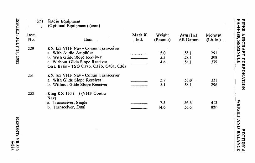
.... (m) Radio Equipment "Cl "Cl Cl)
Cl) >'""' ~ (Optional Equipment) (cont) ' "Cl tl.'!'l t-rj .~ ~ Item Mark if Weight Arm(ln.) Moment ~> c:.., = .... c:: No. Item Intl. (Pounds) Aft Datum (Lb-In.) ~ ~
oon ~ t-r:l.~ ~ 229 KX 155 VHF Nav - Comm Transceiver ::> N
a. With Audio Amplifier '""'lo!'.! ~"'" 5.0 58.1 291 zi-j I-' b. With Glide Slope Receiver 5.3 58.1 308 0 \0 ~n QCI c. Without Glide Slope Receiver 4.8 58.1 279 t-r:lO loM
Cert. Basis - TSO C37b, C38b, C40a, C36a :;i::I "Cl 0
231 KX 165 VHF Nav - Comm Transceiver ~
a. With Glide Slope Receiver 5.7 58.0 331 > i-j
b. Without Glide Slope Receiver 5.1 58.1 296 .... 0 z
233 · King KX 170 ( ) (VHF Comm Nav) ,~ a. Transceiver, Single 7.3 56.6 413 b. Transceiver, Dual 14.6 56.6 826
C".l = ~
i-j
t-rj > "Cl z 0 0 ~ = u, ~ >t-rj
~n °'~ >~ ' ' zO ~00 nZ 000'\ IQ = M°'
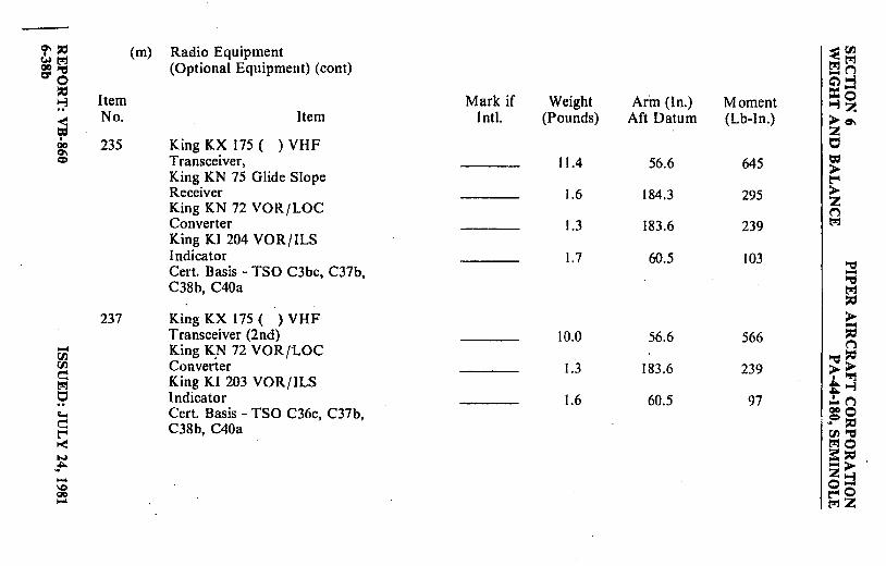
°':;i::I (m) Radio Equipment ~C/.l ~('l!j ('l!j t!l'J QO"'CI (Optional Equipment) (cont) -n a' 0 C'l~
:;i::, =-~ Item Mark if Weight Ar·m (In.) Moment ~~ ~
No. Item Intl. (Pounds) Aft Datum (Lb-In.) ► ct. z I
235 King KX 175 ( )VHF 0 00 0\ = = Transceiver, 11.4 56.6 645
► King KN 75 Glide Slope t:"'I Receiver 1.6 184.3 295 ► z King KN 72 VOR/LOC n Converter 1.3 183.6 239 ('l!j
King KI 204 VOR/ILS Indicator 1.7 60.5 103
I ~ Cert. Basis - TSO C3bc, C37b, -"Cl C38b, C40a t!l'J ~
237 King KX 175 ( ) VHF ► -Transceiver (2nd) 10.0 56.6 566 ~ n - King K,N 72 VOR/LOC "Cl~ rn
C/.l Converter 1.3 183.6 239 ►► e King KI 203 VOR/ILS .~ ('l!j t~ ~ Indicator 1.6 60.5 97 ,!. n ;_, Cert. Basis - TSO C36c, C37b, aoo e C38b, C40a
.. = :;i::, t:"'I rn~ t-< t!l'JO w ::: :;i::, --~ -► z~ ... o-\C t:"'10 00 ... t!l'JZ

lit! ,... (m) Radio Equipment
.,, "'d ~-~ ► ....
(Optional Equipment) (cont) I .,, ~s ;~
Item Mark if Weight Arm (In.) Moment = ► 0 .. 0 .... .. == No. Item -Instl. (Pounds) Aft Datum (Lb-In,) .. ::,:l
~► ti} ("'l 239 King KY l96E with ~II' '""::,:) RB 125 Power Booster a= ► -< ("'l
~ ::r: a. Single · 5.7 · 77.0 439 i"-1 ... ~ b. Dual 11.4 77.0 878 oi-i .. ~ t-1n ......
Cert. Basis - TSO C37b, C38b l'-1 0 \C) -QO \C) ·i:a ,.,. ....
"'d 00 241 King KY-197 Transceiver 0
a. Single 4.2 58.7 247 II' ► b. Dual 8.4 58.7 493 1-j
Cert. Basis - TSO C37b, C38b · .... 0 z
243 King KN 53 NAV /REC with GS Receiver a. Single 3.1 63.8 198
I~ b. Dual 6.2 63.8 396 Cert. Basis • TSO C40a, C34c, C36c
= II' 245 King KN 53 NAV/REC 1-j
l'li Cert. Basis - TSO C40a, C34c, C36c 2.8 63.8 179 ► .,, z 0
King Kl 202 VOR/LOC Indicator C
II' 247 1.3 60.9 79 ti; r.ll :, Cert. Basis - TSO C40a, C36c · ► tr.I t'"' ("'l ~- ► ::j :t~ zO
nZ \00 ~0\

,",0 (m) Radio Equipment ~Cll ~~ ~~ =~ (Optional Equipment) (cont) -n 0 ~>-i
,0 =-:, Item Mark if Weight Arm (In.) Moment >-i ~ < No. Item Inst!. (Pounds) Aft Datum (Lb-In.) ► c,, = :z I 249 King Kl 208 VOR / LOC Indicator -~ 00
er.. a. Single 1.0 59.6 60 = = b. Dual 2.0 59.6 119 >
~ Cert. Basis - TSO C34c. C36c, C40a > z
251 King Kl 209 VOR/LOC;GS Indicator 1Q Cert. Basis - TSO C34c. C36c, C40a 1.2 59.9 72
253 King KN 74 R-Nav 4.7 56.6 266 I -~ -~ ,0 255 King KNS 80 R-Nav 7.0
~ 56.6 396 ,0
~ a. Blower 14 VDC King KA 20 0.9 53.9 49 > < .... --oo ,0 rncn 257 King Kl 206 R-Nav Indicator ("'} ~c ~:::i::, ~~ Cert. Basis - TSO C34c, C36c, C40a 1.3 56.6 74 >> ~1::1 •"%1
~i · 259 King KN 61 DME 12.5 179.0 2238 t >-i .:.. ("'} c> ooo
>::C 261 King KN 62A DME 3.3 58.3 193 ~'° ,0("'} Cll ~ -< ::r:: . ~o NN 263 King KN 65A DME :: ,0 ~~ Cert. Basis - TSO C66a 13.0 174.9 2274 -► -- :z >-i
'°'° o-00 -I t-40 NOO ~z
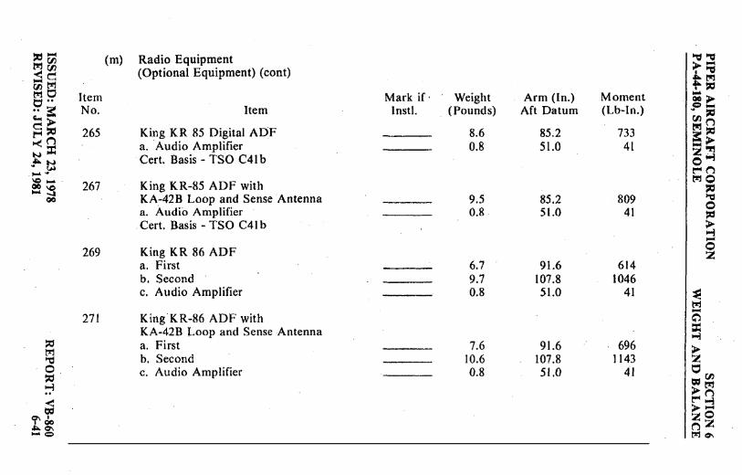
:r:,- (m) Radio Equipment "d "d tr.I Cl) ►-< 00 (Optional Equipment) (cont) • "d _e .... tr.I ootrJ ,t-,::, trJ 0 Item Mark if· Weight Arm (In.) Moment -c::I •• oc> .. ~ No. Item Inst!. ( Pounds) Aft Datum (Lb-In.) .? ;; Go., > Cll ("') C:::.:, 265 King KR 85 Digital AOF 8.6 85.2 733 tr.I ::ti !"'In ~> "< ::r: a. Audio Amplifier 0.8 51.0 41 - '°!'I N Cert. Basis - TSO C41 b z i-J ""N 0 . ~ r"" n ..... \C .....
267 King KR-85 ADF with tr.I 0
0C \C ::ti .... -I KA.-42B Loop and Sense Antenna 9.5 85.2 809 "d 00
0 a. Audio Amplifier 0.8 51.0 41 ,::, . Cert. Basis - TSO C41 b >
...j -269 King KR 86 ADF I 0 z a. First 6.7 91.6 614 b. Second 9.7 107.8 1046 c. Audio Amplifier 0.8 51.0 41 ,~
trJ -271 King KR-86 ADF with ~ KA-42B Loop and Sense Antenna ::c
...j :;i::, a. First 7.6 91.6 · 696 > trJ '"d b. Second 10.6 107.8 1143 z 0. c. Audio Amplifier 0.8 51.0 41 t:::I ::ti =r.J') ...j >trJ < r"" n = >::j
C7\ I zO I 00 nZ ,S>.O'\ .... ,:, trJc,.,

,. = (m) Radio Equipment ~C'l.l
~~ (Optional Equipment) (cont) l":ll":I -n 11110 Item Mark if Weight Arm (In.) Moment c:"l"°!J
= No. Item Intl. (Pounds) Aft Datum (Lb-ln.) =-:; 273 King KR 87ADF
~i ~
> °' a. Receiver and Indicator z QO Single 4.0 59.0 236 t:,
°' = Dual 7.4 58.6 434 = > b. KA 44 Antenna ~
Single 2.8 147.4 413 > z Dual 5.8 161.4 936 n
c. KA 448 Antenna t!l!'j
Single 3.6 150.6 542. Dual· 7.4 188.9 680 '"Cl
d. Audio Amplifier 0.8 51.0 41 -'"Cl Cert. Basis -TSO C41c t!l!'j - = rn 275 King KMA 20 ( ) Audio C'I.I >
~ Panel -l":I Cert. Basis - TSO C35c, C50b *3.7 70.8 262 = = t:, n l":I ••
277 King KMA-24 Audio Control '"Cl ::ic, < Cl) >> - l":I Panel -~ C'l.l '"Cl :t~ a~ Cert. Basis - TSO C35d, C50b 1.7 65.3 111 .!. ("".) .. a: 279 King KRA l O Radio ooo """ = .P ::ic, 0 l":I Altimeter 4.3 162.6 699 fl.I ""Cl
~= 281 King KT 76 ( )/78 ( ) l":10
=== ~:;: Transponder -► .. .. z~ -- Cert. Basis - TSO C74~ *3.1 58.1 180 o-\C IO l:'"'0 QD ......
*Weight includes antenna and cable. l":IZ a- IO

=- (m) Radio Equipment ""d ""d ('l'j!JJ ►:::: <r.n (Optional Equipment) (cont) I -, _c::: Arr! ~e Item Mark if Weight Arm (In.) Moment f- ::0
No. Item Inst!, (Pounds) Aft Datum ( Lb-In.) ~► o·· o-•• 00 283 Narco Comm 111 VHF ~ ::0 0:... ('l'j ',-.. c~ Transceiver r"l::t;i
~ ..., ::: ><('l'j a. Single 4.0 57.4 230 -► --...:: z or:
""'= b. Dual 8.0 57.4 459 0 --l ~ ('l'j Cert. Basis - TSO C37b, C38b
_,..., ~= ~o Ql0 - 285 Narco Comm 111 B VHF ::0 .... !--
Transceiver ""d 0 - a. Single 4.2 57.4 241 ::0 \Q .....
b. Dual 8.4 57.4 482 ► \¢ --l
Cert. Basis - TSO C37b, C38b 0 287 Narco Comm 120 VHF 2
Transceiver a. Single 4.8 56.9 273
~ b. Dual 8.6 57.4 494 [Tl
Cert. Basis - TSO C37b, C38b 2S 289 Narco Nav 111 :c:
..; ::0 Cert. Basis - TSO C36c, C40a,
► "'1 C66a 2.5 58.6 147 z ·"tl 0 0 ::0 291 Narco Nav 121 VHF Receiver = 'J.
'.-:i a. Single 3.1 58.4 181 ►~ !""' -i < b. Dual 6.2 58.4 362 ►-O-.tl:f
Cert. Basis - TSO C36c. C40c, zO I I
""-00 ,,..,z - °' i::ro C66a r:i °'

i" ::0 (m) Radio Equipment ~en ~t'J!l (Optional Equipment) (cont)
t'J!ll:"1 N>,: -(")
0 C")..,
::0 Item Mark if Weight Arm (In.) Moment =o· .., .., 2 .. No . Item I nstl. (Pounds) Aft Datum (Lb-In.) >~ -< = 2 I
Narco Nav 122 VHF Receiver 0
00 293 Cl'\ = = a. Single *5.1 99.4 507 > b-. Dual *8.6 82.9 713 -► Cert. Basis - TSO C35d, C36c. 2 C40c, C66a (")
l:"1
295 Narco Nav 122A VHF Receiver a. Single *5.2 98.5 512 -= b. Dual *8.8 82.2 723 --= Cert. Basis - TSO C34c, C35d, t'J!l
::0 C36c, C40c, C66a >
::0 00 297 Narco Nav 124A VHF Receiver ;; I"")
t'J!l C/'J a. Single *6.2 92.3 572 -= ::0 <e - t'J!l b. Dual *10.9 77.2 841 >> ti.I 0 I 'T'j tetj •• Cert. Basis - TSO C35d, C36c. t.., 9 3: C40a, C66a .:.. I"")
c:.., > 000
e ::o ~ ::0 t'."" (") 299 Narco Nav 124R VHF Receiver rJJ·-c
~ ::z:: Cert. Basis - TSO C36c, C40a, ~o 3:,:,
N N C66a 4.4 57.5 253 -> ~ ~ 2.., - - o-\I:> \I:> -o 00 --.I *Weight includes marker antenna and cable. r.r, 2! - 00

,,_ (mJ Radio Equipment 1-d ~ tr.! r/) >-< r/) (Optional Equipment) (cont) I 1-d
- c:: ""tr.! r/) t-,1 f-~
· MO Item Mark if Weight Arm (In.) Moment ... t;t •• QC >
No. Item I nstl. (Pounds) Aft Datum (Lb-In.) =-•• r( .• ~ '°'> r/) ("') c::,, 301 Narco ID 124 VOR/LOC/GS tr.!~ t"'I ("')
Indicator ~> ~·:r: - "rj
a. Single 1.2 60.5 73 Z..,i . ~ t! 0 ..... b. Dual 2.4 60.5 145 t"'I ("')
\0 .... Cert. Basis - TSO C34c, C35d, to::10 00 IC ,:, ... -4
C36c, C40c "'l;I 00 0 ,,
303 Narco UGR-2A Glide Slope. > a. Single 4.2 154.0 647 ,-i -b. Dual 8.4 220.0 1848 0
Cert. Basis - TSO C34b z
305 Narco CP-135 Audio Selector Panel Cert. Basis - TSO C50b 2.2 55.0 121 I~
!_,rj -307 Narco CP-135M Audio Selector Panel a"l = Cert. Basis - TSO C50b. C35d --- *3.7 114.3 423 ..,i ,, > M
"'l;I 309 Narco CLC-60A R-Nav 9.6 140.1 1345 z 0 a. Narco SA-I I Adapter 0.7 174.0 122
t::! ,, = r/) ~· >tr.!
I:""("'.) < >~ = zO Ch I
*Weight includes marker antenna and cable. I QO ("'.)2 °"'Ch W,:;, t,:'l 0\

'r' :::r::, (m) Radio Equipment ~en 1:-tj~
t~ (Optional Equipment) (cont) -(":) G"l..., 0 :r: -:::r::,
Item Mark if Weight Arm (In.) Moment ...,~ ..., .. No. Item I nstl. (Pounds) Aft Datum (Lb-In.) >=-< :z = i:::, I
311 Narco DME-190 TSO 00 = 0\ 0 Cert. Basis - TSO C66a **5.9 65.9 389 >
r"'
313 Narco DME-195 Receiver and Indicator > :z
Cert. Basis - TSO C66a **13.2 154.5 2039 (":) 1:-tj
315 Narco ADF-141 a. Single **8.9 91.2 812
I --=
b. Dual *** 17.9 80.4 1439 ---= Cert. Basis - TSO C4 lc 1:-tj
:::r::,
> 317 Narco ATl50 Transponder -
:::r::,~ :::r::,
Cert. Basis - TSO C74c *3.0 57.3 172 (":)
1:-tj c:: a. Narco AR-500 Altitude --= :::r::, <!ttj Encoder > ► tii t=i
,',:j
1:-tj .. Cert. Basis - TSO C88 1.0 51.5 52 t..., t:, ~ ,!. (":)
ooo .. > .? :::r::, c.., :::r::, c(":) Cll --= ~= ~o
~:::r::, NN *Weight includes marker antenna and cable. -► .a. tu :z ..., ~ .. -- **Weight includes antenna and cable. o-IC \C
***Weight includes dual antenna and cable. r-O
00 -.I ~z - 00

,:, ..., t"'.I 00 <" (/} -~ (/} 1:'11 t"'.I t:, t:, •• .. ~ c.. > > ~ ~g
. ~ 1-J ,<J..i w-~~ .... 00 so 00 N
lid t"'.I
~ ~ ~ < ~
0\ • • 00 ~0\ UIO
Item No.
321
323
324
325
(m) Radio Equipment (Optional Equipment) (cont)
Item
Antenna and Cable a. Nav Receiving b. #I VHF Comm· c. #2 VHF Comm d. Glide Slope (Single) e. Glide Slope (Dual)· f. Single ADF Sense
Marker Antenna · Piper PS50040- I 5
· Mark if Weight Inst!. (Pounds)
1.4 0.7 0.8 0,7 0.9 0.4
Arm (In.) Moment Aft Datum (Lb~ln.)
195.7 274 125.7 88 147.5 118 53.0 37 53.0 48
147.S 59
King KA-23 or Narco VMA-15 or Comant CJ-102 Included as part of the marker beacon installation.
Marker Beacon Antenna with Cable. Piper Dwg. 39737-2 (Comant Cl-l02) ·
Anti-Static Antenna and Cable a. # I VHF Comm b. # 2 VHF Comm c. Single ADF.Scnse
*Includes antenna coaxial. wire and marker beacon receiver.
*1.2
1.5 l.o O.o
192.0
125.7 147.5 · 147.5
230
189 236 89
i'\:11'\:l >=a :t~ I i= .... >. =-.. 1:11, fl) """' ~ .\ ,. i= -> z "rj 0 1-3 t""( n t'!'10
~ ~ (;")
~ ~
,:, ~ 0 ,, ; 0 z
0 (n
=!.'!I >n ,t""(j
>o Zz QQ\

9' ,:i (m) Radio Equipment ~('/)
"'"t'"l (Optional Equip~ent) (cont) t'Z:t t'"l =--~ -n
0 ~~
,:i Item Mark if Weight Arm (In.) Moment =-~ -3~ .. No. Item Inst!. (Pounds) Aft Datum (Lb-In.) < ► =--= z
I r:, QC 327 Emergency Locator Transmitter °' = = (C.C.C. Model CIR-I 1-2) 1.7 254.0 432 >
a. Antenna and Coax 0.2 240.0 48 ~
b. Shelf and Access Hole 0.5 253.5 127 ► z Cert. Basis - TSO C9 I ("'}
l."t'j
329 Emergency Locator Transmitter (Narco Model ELT-10). 3.5 254.0 889 ~
a. Antenna and Coax 0.3 240.0 72 :; b. Shelf and Access Hole 0.5 253.5 127 t'Z:t
,:i Cert. Basis - TSO C9 I
► --,:i 00 331 Headphone ,:i
t'"l 00 ("'}
<(j Wm. J. Murdock PN P-23 ~ ::d _r:,,,:, 300 Ohms with MCl62A ►► 00 r:, ,l'!'j
l."t'j •• Cushions or Telex Comm. ::.:~ r:, ~ PN 61650-03 0.5 60.0 30 .!..n .. ► CIOO c... ,:i ~ ,:i c r.,
~= ('/)~ l."t'j0
NN :::: ,:i
~A,.J'-l -► -- Z-3 SC SC
o-00 -I
~o - 00
l."t'jz

!:IC! - (m) Radio Equipment "d "d t"l 00 >-< 00 (Optional Equipment) (cont) ti -~ 00 l'I1 1'!10 ... C .. Item Mark if Weight Arm (In.) Moment oo> =·-.. a: No. Item lnstl. · (Pounds) Aft Datum (Lb-In.) .. := c... > oo n ~~ t"l:= I:"'("') ~> ~= .333 -Microphone 2:"Tl J'-~ a. Telex Acoustics PN
0>-l l:"'n ......
60837-17 (Model 66C) 0.3 64.9 19 l'"'JO :I ... -~ b. Narco PN M700B 0.6 69.9 42 := "d 00
c. Telex Acoustics PN 0 62800-04 (Model IO0T NH)· 0.3 64.9 19 ::i:,
> >-l
I ....
335 Boom Microphone - Headset 0 a. Single, Piper Dwg. 37921-7 0.3 80.5 24 z b. Dual, Piper Dwg. 86402-10 0.6 80.5 48 (Telex 5 x 5 Mark II
I~ PN 62629-00) -337 Cabin Speaker, Installation
G"'l = Piper Dwg. 99746--0 I.I 99.0 109 >-l ~ > t"l "d z
·o 0 := = 00 ~ >t,:J r-tn < >:j t,:, zO ~' I QC ("')Z ""'~ -..:tc:, t"lo--

~:.ti Miscellaneous
~Cl) .,._M (n) MM QO"tl
(Optional Equipment) -n 0 c:") >-l :.ti =-:, Item Mark if Weight Arm (In.) Moment >-l ~ < No. Item Instl. (Pounds) Aft Datum (Lb-In.) >c:r-= z I 0 0CI 0\ 351 Zinc Chromate 5.0 158.0 790 = = > r-
353 Air Conditioner > Piper Dwg. 39702 54.7 105.4 5765 z n
M 355 Ground Ventilating Blower
Piper Dwg. 76304-22 or 36983-8 8.5 181.8 1545 I "'d -
,::, 357 Assist Step "ti M
M Piper Dwg. 65384-0 1.8 156.0 281 :.ti < - ► ui_
359 Super Cabin Soundproofing ~ M 00 Ooo Piper Dwg. 79601-9 18.1 86.8 1571 ("') .. c:: "ti,::, Uli:,,j Mi:,
361 C Adjustable Front Seat (Left) > ►
"ti .. I "rl t: >-l
~~ Piper Dwg. 79592-2 *6.6 80.3 530 .:..n ~> ooo =,::, 363 Adjustable Front Seat (Right)
~,::, Mn Cll"'tl ,::, = Piper Dwg. 79592-3 *6.6 79.6 525 MO NN ~,::, .?'~ *Weight and moment difference between standard and optional equipment.
-> -- Z..,i ,,e,\Q o-0CI ..... t'"l0 c;, 0CI MZ

~- (nJ Miscellaneous '-= "1:1 trJ 00 ►~ ~~ (Optional Equipment) (cont) .C,.trJ fl)trJ ,.~ e s, Item Mark if Weight Arm (In.) Moment = ►-
No. Item Inst I. (Pounds) Aft Datum (Lb.-ln.) =-.. ::: .. ~ ►► fl) ("') .,, Ila 365 Headrests (2) Front trJ,,
~g Piper Dwg. 79337-18 2.2 94.5 208 !i ► zlT.I ; fj 367 Headrests (2) Rear
oi-l .. . t"" ("} i- i- Piper Dwg. 79337-18 2.2 · 132. l 291 tr.10 1 -c :a:, i- ail "ti
369 Oversize Headrests (2) 0 ~
Front 3.2 94.5 302 > ..;i -Oversize Headrests (2) 371 0
- Rear 3.2 132. I 423 z
373 Inertia Safety Belts (Rear) (2) ~ Piper PS50039-4-14 ~
(Pacific Scientific -(.') P/N 1107.319-01 Black) or =
::,:, (American Safety Equipment Co., 1--!
tr.I P /N 500853-401) 1.6 122.0 195 ► "ti z 0 0 ::,:, 375 C Shoulder Harness - Inertia = fl) ~ ► M (Front) (2) t""' <'"l < Piper PS50039-4-20 ►~ = zo ,"(» (Pacific Scientific .,.,°' nZ
\CIC> 1107447-13) (Black) 1.3 119.5 1S5 t,ije..

'i" :::cl (n) Miscellaneous ~00 lll l:'!j l:'!jl:'!j ='"d (Optional Equipment) (cont) .... n
0 C'} ..,
:::cl ::i::-~ Item Mark if Weight Arm (In.) Moment ..,~ < No. Item Inst!. (Pounds) Aft Datum (Lb.-ln.) >a-Cd 377 Shoulder Harness - Fixed z I 0 QC 0\ (Rear) (2) = = P1per PS50039-4-22 >
(American Safety Eqpt. Corp. t"" >
501385-403) z (Davis Acft. Prod. Inc. n
~ FDC-7275-16-2) (Black) 1.1 140.3 154
379 Shoulder Harness - Inertia (Rear) (2) "" -Piper PS50039-4- I 9 '"d
M (Pacific Scientific l:1:::1
1107447-01) (Black) 1.3 140.3 182 > ~r;: 381 Assist Straps ;a l:'!j U) P}per Dwg. 79455-0 0.3 109.5 33 n <e '"d :::cl -~ >> 00 0 383 Curtain & Rod Installation •'Tl a .. Piper Dwg. 79721-3 1.2 129.2 155
t.., .. 3: .!. n >> 385 Luxurious Interior 000 "":::cl Piper Dwg. 86690 17.0 101.9 1732
.= :::cl :::tln 00 '"d
t=: = ~o ... N 387 Fire Extinguisher 3: :::cl =lH -> . . Piper Dwg. 37872-9 z.., ... - o-\C \C (Graviner P/N HA1014-0I) 5.6 57.9 324 t"""0 QC -J ~z ... QC

PIPER AIRCRAFT CORPORATION PA-44-180, SEMINOLE
- "' .c -0 bJ)C: ·- :J .., 0
~ 0..
0
E ..,
ISSUED: SEPTEMBER 26, 1980 REVISED: JULY 24, 1981
1-z 1,.1.J
~ 0..
::i 0 1,.1.J
..J < z 0 IQ.,
0 ..J < 1-G I-
SECTION 6 WEIGHT AND BALANCE
..; i:::
·"" E 0. ;::l O"
·"" ce C:
-~ c.. 0
-0 C: ce -0 ,_ ce -0 C: ce -ell
i::: .., .., a=: -.., .0 .., u C: <1) ,_ ~-
c <1)
E 0 E -0 C: ce
REPORT: VB-860 6-51


Paragraph No.
TABLE OF CONTENTS
SECTION 7
DESCRIPTION AND OPERATION OF THE AIRPLANE AND ITS SYSTEMS
Page No.
7. I The Airplane . . . . . . . . . . . . . . . . . . . . . . . . . . . . . . . . . . . . . 7-1 7.3 Airframe . . . . . . . . . . . . . . . . . . . . . . . . . . . . . . . . . . . . . . . . 7-1 7.5 Engines ...................................... ·.... 7-2 7. 7 Propellers . . . . . . . . . . . . . . . . . . . . . . . . . . . . . . . . . . . . . . . . 7-5 7.9 Landing Gear . . . . . . . . . . . . . . . . . . . . . . . . . . . . . . . . . . . . . 7-6 7.11 Brake System . . . . . . . . . . . . . . . . . . . . . . . . . . . . . . . . . . . . . 7-12 7.13 Flight Control System.............................. 7-12 7.15 Fuel System . . . . . . . . . . . . . . . . . . . . . . . . . . . . . . . . . . . . . . 7-14 7.17 Electrical System . . . . . . . . . . . . . . . . . . . . . . . . . . . . . . . . . . 7-16 7.19 Vacuum System . . . . . . . . . . . . . . . . . . . . . . . . . . . . . . . . . . . 7-21 7.21 "Pitot Static System . . . . . . . . . . . . . . . . . . . . . . . . . . . . . . . . 7-23 7.23 Instrument Panel . . . . . . . . . . . . . . . . . . . . . . . . . . . . . . . . . . 7-25 7.25 Heating, Ventilating and Defrosting System........... 7-27 7.27 Cabin Features . . . . . . . . . . . . . . . . . . . . . . . . . . . . . . . . . . . . 7-30 7.29 Stall Warning . . . . . . . . . . . . . . . . . . . . . . . . . . . . . . . . . . . . . 7-32 7.31 Baggage Area . . . . . . . . . . . . . . . . . . . . . . . . . . . . . . . . . . . . . 7-32 7.33 Finish............................................ 7-32 7.35 Emergency Locator Transmitter . . . . . . . . . . . . . . . . . . . . . 7-33 7.37 Piper External Power . . . . . . . . . . . . . . . . . . . . . . . . . . . . . . 7-36 7.39 Propeller Synchrophaser............................ 7-36 7.41 Carburetor Ice Detection System . . . . . . . . . . . . . . . . . . . . . 7-3,
REPORT: VB-860 7-i

THIS PAGE INTENTIONALLY BLANK

PIPER AIRCRAFT CORPORATION SECTION 7 PA-44-180, SEMINOLE DESCRIPTION & OPERATION
SECTION 7
DESCRIPTION AND OPERATION OF THE AIRPLANE AND ITS SYSTEMS
7.1 THE AIRPLANE
The Seminole is a twin-engine, all metal, retractable landing gear, airplane. It has seating for up to four occupants and has a two hundred pound capacity luggage compartment.
7 .3 AIRFRAME
With the exception of the steel engine mounts and landing gear, the fiberglass nose cone, cowling nose bowls and tips of wings, and the ABS thermoplastic extremities (tail fin, rudder and stabilator), the basic airframe is of aluminum alloy. Aerobatics are prohibited in this airplane since the structure is not designed for aerobatic loads.
The fuselage is a semi-monocoque structure with a passenger door on the forward right side, a cargo door on the aft right side with an emergency egress door on the forward left side.
The wing is of a semi-tapered design and employs a laminar flow NACA 65 -415 airfoil section. The main spar is located at approximately 40% of the chord. The wings are attached to the fuselage by the insertion of the butt ends of the spar into a spar box carry-through, which is an integral part of the fuselage structure. The bolting of the spar ends into the spar box carry-through structure, which is located under the rear seats, provides in effect a continuous main spar. The wings are also attached fore and aft of the main spar by an auxiliary front spar and a rear spar. The rear spar, in addition to taking torque and drag loads, provides a mount for flaps and ailerons. The four-position wing flaps are mechanically controlled by a handle located between the front seats. When fully retracted, the r:ght flap locks into place to provide a step for cabin entry. Each nacelle contains one fuel tank.
ISSUED: MARCH 23, 1978 REPORT: VB-860 7-1

TABLE OF CONTENTS
SECTION 6
WEIGHT AND BALANCE
Paragraph PageNo. No.
6.1 General ..................................................................................... 6-16.3 Airplane Weighing Procedure .................................................. 6-26.5 Weight and Balance Data and Record...................................... 6-56.7 Weight and Balance Determination for Flight ......................... 6-96.9 Instructions for Using the Weight and Balance Plotter ............ 6-136.11 Equipment List ......................................................................... 6-17
(a) Propeller and Propeller Accessories........................... 6-18(b) Engine and Engine Accessories ................................. 6-19(c) Landing Gear and Brakes........................................... 6-20(d) Electrical Equipment.................................................. 6-22(e) Instruments................................................................. 6-23(f) Miscellaneous ............................................................ 6-25(g) Propeller and Propeller Accessories
(Optional Equipment) ........................................... 6-26a(h) Engine and Engine Accessories (Optional
Equipment)............................................................ 6-27(i) Landing Gear and Brakes (Optional
Equipment)............................................................ 6-28(j) Electrical Equipment (Optional Equipment) ............. 6-28b(k) Instruments (Optional Equipment) ............................ 6-31(l) Autopilots (Optional Equipment) .............................. 6-36(m) Radio Equipment (Optional Equipment) ................... 6-36a(n) Miscellaneous (Optional Equipment) ........................ 6-48
PIPER AIRCRAFT CORPORATION SECTION 6 PA-44-180, SEMINOLE WEIGHT AND BALANCE
REPORT: VB-8606-i
A vertical stabilizer, an all-movable horizontal stabilator, and a ruddermake up the empennage. The stabilator, which is mounted on top of the finincorporates an anti-servo tab which provides longitudinal stability and trim.This tab moves in the same direction as the stabilator, but with increased travel.Rudder effectiveness is increased by an anti-servo tab on the rudder.
7.5 ENGINES
The aircraft is powered by two Lycoming four-cylinder engines, each ratedat 180 horsepower at 2700 RPM at sea level. The engines are air cooled and areequipped with oil coolers with low temperature bypass systems and engine-mounted oil filters. A winterization plate is provided to restrict air duringwinter operation. (See Winterization in Section 8.) Asymmetric thrust duringtakeoff and climb is eliminated by the counter-rotation of the engines, the leftengine rotating in a clockwise direction when viewed from the cockpit, and theright engine rotating counterclockwise.
The engines are accessible through removable cowls. The upper cowl halfis attached with quarter-turn fasteners and is removable. Engine mounts areconstructed of steel tubing, and dynafocal engine mounts are provided toreduce vibration.
The induction air box incorporates a manually operated two-way valvewhich allows the carburetor to receive either induction air which passesthrough the air filter or heated air which bypasses the filter. Carburetor heatselection provides heated air to the carburetor in the event of carburetor icing,and also allows selection of an alternate source of air in the event the inductionair source or the air filter becomes blocked with ice, snow, freezing rain, etc.Carburetor heat selection provides air which is unfiltered; therefore, it shouldnot be used during ground operation when dust or other contaminants mightenter the system. The primary (through the filter) induction source shouldalways be used for takeoffs.
Engine controls consist of a throttle, a propeller control and a mixturecontrol lever for each engine. These controls are located on the controlquadrant on the lower center of the instrument panel where they are accessibleto both the pilot and the copilot (Figure 7-1). The controls utilize teflon-linedcontrol cables to reduce friction and binding.
SECTION 7 PIPER AIRCRAFT CORPORATIONDESCRIPTION & OPERATION PA-44-180, SEMINOLE
REPORT: VB-860 ISSUED: MARCH 23, 19787-2

PIPER AIRCRAFT CORPORATION SECTION 7 PA-44-180, SEMINOLE DESCRIPTION & OPERATION
CONTROL PEDESTAL Figure 7-1
ISSUED: MARCH 23, 1978 REVISED: MARCH 1, 1980
REPORT: VB-86e 7-3

SECTION 7 PIPER AIRCRAFT CORPORATION DESCRIPTION & OPERATION PA-44-180, SEMINOLE
PIA.L-a.oSE PULL-CI.OSE
L ~~ R L ~~ R PUSH-OPEN PUSH-OPEN
CURRENT MODEL EARLY MODEL
COWL FLAP CONTROL Figure 7-3
The throttle levers are used to adjust the manifold pressure. They incorporate a gear up warning horn switch which is activated during the last portion of travel of the throttle levers to the low power position. If the landing gear is not locked down, the horn will sound until the gear is down and locked or until the power setting is increased. This is a feature to warn the pilot of an inadvertent gear up landing.
The propeller control levers are used to adjqst the propeller speed from high RPM to feather.
The mixture control levers are used to adjust the air to fuel ratio. An engine is shut down by the placing of the mixture control lever in the full lean (idle cut-off) position.
The friction adjustment lever on the right side of the control quadrant may be adjusted to increase or decrease the friction holding the throttle, propeller, and mixture controls or to lock the controls in a selected position.
REPORT: VB-860 7-4
ISSUED: MARCH 23, 1978 REVISED: MARCH I, 1980

PIPER AIRCRAFT CORPORATION SECTION 7 PA-44-188, SEMINOLE DESCRIPTION & OPERATION
The carburetor heat controls are located on the control quadrant just below the engine control levers. When a carburetor heat lever is in the up, or off, position the engine is operating on filtered air; when the lever is in the down, or on, position the engine is operating on unfiltered, heated air.
The cowl flap control levers (Figure 7-3), located below the control quadrant, are used to regulate cooling air for the engines. The levers have three positions: full open, full closed, and intermediate. A lock incorporated in each control lever locks the cowl flap in the select"Cd position. To operate the cowl flaps, depress the lock and move the lever toward the desired setting. Release the lock after initial movement and continue movement of the lever. The control will stop and lock into place at the next setting. The lock must be depressed for each selection of a new cowl flap setting.
All throttle operations should be made with a smooth, not too rapid · movement to prevent unnecessary engine wear or damage to the engines.
7.7 PROPELLERS
Counter-rotation of the propellers provides balanced thrust during takeoff and climb and eliminates the "critical engine" factor in single-engine flight.
Constant speed, controllable pitch and feathering Hartzell propellers are installed as standard equipment. The propellers mount directly to the engine crankshafts. Pitch is ~ontrolled by oil and nitrogen pressure. Oil pressure sends a propeller toward the high RPM or unfeather position; nitrogen pressure and a large spring sends a propeller toward the low RPM or feather position and also prevents propeller overspeeding. Governors, one on each engine, supply engine oil at various pressures through the propeller shafts to maintain constant RPM settings. A governor controls engine speed by varying the pitch of the propeller to match load torque to engine torque in response to changing flight conditions. The recommended nitrogen pressure to be used when charging the unit is listed on placards on the propeller domes and inside the spinners. This pressure varies with ambient temperature at the time of charging. Although dry nitrogen gas is recommended, compressed air may be used provided it contains no moisture. For more detailed instructions, see "Propeller Service" in Section 8 of this Handbook.
ISSUED: MARCH 23, 1978 REPORT: VB-860 7-5
SECTION 7 PIPER AIRCRAFT CORPORATION DESCRIPTION & OPERATION PA-44-180, SEMINOLE
Each propeller is controlled by the propeller control levers located in the center of the power control quadrant. Feathering of a propeller is accomplished by moving the control fully aft through the low RPM detent, into the FEATHER position. Feathering takes place in approximately six seconds. Unfeathering is accomplished by moving the propeller control forward and engaging the starter until the propeller is windmilling.
A feathering lock, operated by centrifugal force, prevents feathering during engine shut down by making it impossible to feather any time the engine speed falls below 950 RPM. For this reason, when airborne, and the pilot wishes to feather a propeller to save an engine, he must be sure to move the propeller control into the FEATHER position before the engine speed drops below 950 RPM.
7.9 LANDING GEAR
The aircraft is equipped with hydraulically operated, fully retractable, tricycle landing gear.
Hydraulic pressure for gear operation is furnished by an electrically powered, reversible hydraulic pump ( refer to Figures 7-7 and 7-9). The pump is activated by a two-position gear selector switch located to the left of the control quadrant on the instrument panel (Figure 7-5). The gear selector switch, which has a wheel-shaped knob, must be pulled out before it is moved to the UP or DOWN position. When hydraulic pressure is exerted in one direction, the gear is retracted; when it is exerted in the other direction, the gear is extended. Gear extension or retraction normally takes six to seven seconds.
CAUTION
If the landing gear is in transit, and the hydraulic pump is running, it is NOT advisable to move the gear selector switch to the opposite position before the gear has reached its full travel limit, because a sudden reversal may damage the electric pump.
REPORT: VB-860 7-6
ISSUED: MARCH 23, 1978 REVISED: MARCH 14, 1983

PIP~R AIRCRAFT CORPORATION SECTION 7 PA-44-180, SEMINOLE DESCRIPTION & OPERATION
The landing gear is designed to extend even in the event of hydraulic failure. Since the gear is held in the retracted position by hydraulic pressure, should the hydraulic system fail for any reason, gravity will allow the gear to extend. When the landing gear is retracted, the main wheels retract inboard into the wings and the nose wheel retracts aft into the nose section. Springs assist in gear extension and in locking the gear in the down position. After the gears are down and the downlock hooks engage, springs maintain force on each hook to keep it locked until it is released by hydraulic pressure.
To extend and lock the gears in the event of hydraulic failure, it is necessary only to relieve the hydraulic pressure. An emergency gear extension knob, located directly beneath the gear selector switch is provided for this purpose. Pulling this knob releases the hydraulic pressure holding the gear in the up position and allows the gear to fall free. Before pulling the emergency gear extension knob, place the landing gear selector switch in the DOWN position to prevent the pump from trying to raise the gear. If the emergency gear knob has been pulled out to lower the gear by gravity, due to a gear system malfunction, leave the control in its extended position until the airplane has been put on jacks to check the proper function of the landing gear hydraulic and electrical systems. See the Service Manual for proper landing gear system check out procedures. If the airplane is being used for training purposes or a pilot check out mission, and the emergency gear extension knob has been pulled out, it may be pushed in again when desired if there has not been any apparent malfunction of the landing gear system.
When the gear is fully extended or fully retracted and the gear selector is in the corresponding position, electrical limit switches stop the flow of current to the motor of the hydraulic pump. The three green lights directly above the landing gear selector switch illuminate to indicate that each of the three landing gears is down and locked. A convex mirror on the left engine nacelle both serves as a taxiing aid and allows the pilot to visually confirm the condition of the nose gear. If the gear is in neither the full up nor the full down position, a red warning light on the instrument panel illuminates. Should the throttle be placed in a low setting - as for a landing approach -while the gear is retracted, a warning horn sounds to alert the pilot that the gear is retracted. The gear warning horn emits a 90 cycles per minute beeping sound.
ISSUED: MARCH 23, 1978 REPORT: VB-860 7-7

SECTION 7 PIPER AIRCRAFT CORPORATION DESCRIPTION & OPERATION PA-44-180, SEMINOLE
REPORT: VB-860 7-8
LANDING GEAR SELECTOR Figure 7-5
ISSUED: MARCH 23, 1978

The green gear lights are dimmed automatically when the navigation lightsare turned on. For this reason, if the navigation lights are turned on in thedaytime, it is difficult to see the landing gear lights. If the green lights are notobserved after the landing gear selector switch is placed in the DOWNposition, the first thing to check is the position of the navigation lights switch.
If one or two of the three green lights do not illuminate when the gearDOWN position has been selected, any of the following conditions could existfor each light that is out:
(a) The gear is not locked down.(b) A bulb is burned out.(c) There is a malfunction in the indicating system.In order to check the bulbs, the square indicator lights can be pulled outand interchanged.
A micro switch incorporated in the switching network activates the gearwarning horn under the following conditions:
(a) The gear is not locked down and the manifold pressure has fallenbelow 14 inches on either one or both engines.
(b) The gear selector switch is in the UP position when the airplane is onthe ground.
(c) The gear selector switch is in the UP position and wing flaps areextended to the second or third notch position.
To prevent inadvertent gear retraction should the gear selector be placed inthe UP position when the airplane is on the ground, a squat switch located onthe left main gear will prevent the hydraulic pump from actuating if the masterswitch is turned on. On takeoff, when the landing gear oleo strut drops to itsfull extension, the safety switch closes to complete the circuit which allows thehydraulic pump to be activated to raise the landing gear when the gear selectoris moved to the UP position. During the preflight check, be sure the landinggear selector is in the DOWN position and that the three green gear indicatorlights are illuminated. On takeoff, the gear should be retracted before anairspeed of 109 KIAS is exceeded. The landing gear may be lowered at anyspeed up to 140 KIAS.
The hydraulic reservoir for landing gear operation is an integral part of thegear hydraulic pump. Access to the combination pump and reservoir is througha panel in the baggage compartment. For filling instructions, see the ServiceManual.
PIPER AIRCRAFT CORPORATION SECTION 7PA-44-180, SEMINOLE DESCRIPTION & OPERATION
ISSUED: MARCH 23, 1978 REPORT: VB-860REVISED: AUGUST 23, 2004 7-9

LANDING GEAR ELECTRICAL SYSTEM SCHEMATICFigure 7-7
SECTION 7 PIPER AIRCRAFT CORPORATIONDESCRIPTION & OPERATION PA-44-180, SEMINOLE
REPORT: VB-860 ISSUED: MARCH 23, 19787-10 REVISED: DECEMBER 15, 1978
SECTION 7 PIPER AIRCRAFT CORPORATIONDESCRIPTION & OPERATION PA-44-180, SEMINOLE
REPORT: VB-860 ISSUED: MARCH 23, 19787-10 REVISED: DECEMBER 15, 1978
LANDING GEAR ELECTRICAL SYSTEM SCHEMATICFigure 7-7
-.. ..... ..... ...
,UOHT
NO
NYDIIIAULIC PRESSURE: SWITCH
SQUAT .... ..... NC POS.
UP SW.
NC
T£RM. •
LUT .... _JND ND
TERMINAL 3
.. .. SELECT SWITCH
-=-
UP SW.
DOWN LOCK sw.
NC
Gf.AII HORN FLASHIII
UP SW.
0
ND ND
• 7>------,
IE:U UNSAF't
IIIIHT ..,.. ND
r-----: ' ' ...
TO ••• LIGHTS
NC

PIPER AIRCRAFT CORPORATION SECTION 7 PA-44-180, SEMINOLE DESCRIPTION & OPERATION
RIGHT MAIN GEAR HYDRAULIC CYLINDER
UP
DOWN
NOSE GEAR HYDRAULIC CYLINDER
UP
LEFT MA1N GEAR HYDRAULIC CYLINDER
UP
DOWN
PRESSURE PRESSURE SWITCH SWITCH OFF AT 1800 • 100 PSI
ON AT 200 -•00 PSI IIELOW OFF
-------~
DELIVERED PRESS. 400-800 PSI
LOW PRESSURE CONTROL
650±150 PSI
FREE FALL CONTROL
LANDING GEAR HYDRAULIC SYSTEM SCHEMATIC Figure 7-9
ISSUED: MARCH 23. 1978 REVISED: SEPTEMBER 14, 1979
REPORT: VB-860 7-11

SECTION 7 PIPER AIRCRAFT CORPORATION DESCRIPTION & OPERATION PA-44-180, SEMINOLE
The nose gear is steerable through a 30 degree arc either side of center by use of a combination of full rudder pedal travel and brakes. A . gear centering spring, incorporated in the nose gear steering system, prevents shimmy tendencies. A bungee assembly reduces ground steering effort and dampens shocks and bumps during taxiing. When the gear is retracted, the nose wheel centers as it enters the wheel well: and the steering linkage disengages to reduce pedal loads in flight. ·
The main landing gear carries 6.00 x 6, 8-ply tires. The nose wheel has a 5.00 x 5, 6-ply tire. For information on servicing the tires, see "Tire Inflation" in Section 8 of this Handbook.
Struts for the landing gear are air-oil assemblies. Strut exposure should be checked during each preflight inspection. If a need for service or adjustment is indicated, refer to the instructions printed on the units. Should more detailed landing gear service information be required, refer to the Service Manual.
7.11 BRAKE SYSTEM
The brake system is designed to meet all normal braking needs. Two single-disc, double puck brake assemblies, one on each main gear, are actuated .bY toe brake pedals mounted on both the pilot's and copilot's rudder pedals. A brake system hydraulic reservoir, independent of the landing gear hydraulic reservoir, is located in the rear top of the nose compartment. Brake fluid should be maintained at the level marked on the reservoir. For further information see "Brake Service" in Section 8 of this Handbook.
The parking brake is engaged by depressing the toe brake pedals and pulling out the parking brake knob located on the lower instrument panel adjacent to the throttle quadrant. The parking brake is released by depressing the toe brake pedals and pushing in the parking brake knob.
7.13 FLIGHT CONTROL SYSTEM
Dual flight controls are installed as standard equipment. The controls actuate the control surfaces through a cable system. The horizontal tail surface (stabilator) is of the all movable slab type with an anti-servo tab mounted on the trailing edge. This tab, actuated by a control mounted on the console between the front seats, also acts as a longitudinal trim tab (refer to Figure 7-11).
REPORT: VB-860 7-12
ISSUED: MARCH 23, 1978

PIPER AIRCRAFT CORPORATION SECTION 7 PA-44-180, SEMINOLE DESCRIPTION & OPERATION
ISSUED: MARCH 23, 1978
CONSOLE Figure 7-11
REPORT: VB-860 7-13

SECTION 7 PIPER AIRCRAFT CORPORATION DESCRIPTION & OPERATION PA-44-180, SEMINOLE
The vertical tail is fitted with a rudder which incorporates a combination rudder trim and anti-servo tab. The rudder trim control is located on the control console between the front seats.
The flaps are manually operated and spring loaded to return to the retracted position. A four-position flap control lever (Figure 7-11) between the front seats adjusts the flaps for reduced landing speeds and glide path control. The flaps have three extended positions - 10, 25 and 40 degrees- as well as the fully retracted position. A button on the end of the lever must be depressed before the control can be moved. A past center lock incorporated in the actuating linkage holds the flap when it is in the retracted position so that it may be used as a step on the right side. Since the flap will not support a step load except in the fully retracted position, the flaps should be retracted when people are entering or leaving the airplane.
7.15 FUEL SYSTEM
Fuel is stored in two 55 gallon fuel tanks, one in each nacelle (Figure 7-13). One gallon of fuel in each nacelle is unusable, giving a total of 108 usable gallons. The minimum fuel grade is 100/ 130 octane. The fuel tank vents, one installed under each wing, feature an anti-icing design to prevent ice formation from blocking the fuel tank vent lines.
Normally, fuel is supplied to the engines through engine-driven fuel pumps. Auxiliary electric fuel pumps serve as a back-up feature. The electric fuel pumps are controlled by rocker switches on the switch panel to the left of the pilot. The electric fuel pumps should be ON during takeoffs and landings.
Fuel quantities and pressures are indicated on gauges on the instrument panel. There is a separate fuel quantity gauge for each tank. A calibrated fuel dipstick is provided with the airplane. To visually check the quantity of fuel in a tank, insert the dipstick to the bottom of the tank, close off the protruding end with a finger, withdraw the dipstick, and read the fuel level. The most accurate" reading will be obtained with the airplane on level ground.
Fuel management controls are located on the console between the front seats ( Figure 7-11 ). There is a control lever for each of the engines, and each is placarded "ON" - "OFF' - "X FEED." During normal operation, the levers are in the ON position, and each engine draws fuel from the tanks on the same side as the engine. When the X FEED position is selected, the engine will draw fuel from the tank on the opposite side in order to extend range and keep fuel weight balanced during single-engine operation. The
REPORT: VB-860 7-14
ISSUED: MARCH 23, 1978 REVISED: DECEMBER 15, 1978

PIPER AIRCRAFT CORPORATION SECTION 7PA-44-180, SEMINOLE DESCRIPTION & OPERATION
ISSUED: MARCH 23, 1978 REPORT: VB-8607-15
FUEL SySTEM SCHEMATICFigure 7-13
======-- TO HEATER
COMBUSTION HEATER 't' FUEL PUMP
ENGINE DRIVEN FUEL PUMP
ELECTRIC FUEL PUMP
@ FILLER CAP
L. FUEL CELL
I I !SCUPPER DRAIN l..= FUEL VENT
(L) (R)
FUEL PRIMER
• L. FUEL R. FUEL PRESS. PRESS . GAUGE GAUGE
FUEL SELECTOR CONTROLS L. ENGINE R. ENGINE
ON ON OFF OFF
X-FEED X-FEED
ENGINE DRIVEN FUEL PUMP
ELECTRIC FUEL PUMP
FILLER CAP© r,;;:;:;-;;:::::;==::it,~.;;;;:=j
R. FUEL CELL
SCUPPER DRAINJ I FUEL VENT:_J

SECTION 7 PIPER AIRCRAFT CORPORATIONDESCRIPTION & OPERATION PA-44-180, SEMINOLE
REPORT: VB-860 ISSUED: MARCH 23, 19787-16 REVISED: OCTOBER 11, 2011
OFF position shuts off the fuel now to that engine.
NOTE
When one engine is inoperative and the fuel selector for the operating engine is on X FEED the selector for the inoperative engine must be in the OFF position. Do not operate with both fuel selectors on X FEED except as required in the WARM-UP checklist. Do not take off or land with a selector on X FEED.
Before each night, fuel must be drained from the low points in the fuel system to ensure that any accumulation of moisture or sediment is removed from the system. A fuel drain is provided for each half of the fuel system. The fuel drains are located on the right side of the fuselage just forward of the entrance step. (Refer to fuel draining procedure in paragraph 8.21, Fuel System.)
7.17 ELECTRICAL SySTEM
The electrical system is capable of supplying sufficient current for complete night IFR equipment. Electrical power is supplied by two 60 ampere alternators (Figure 7-15), one mounted on each engine. A 35 ampere-hour, 12-volt battery provides current for starting, for use of electrical equipment when the engines are not running, and for a source of stored electrical power to back up the alternator output. The battery, which is located in the nose section is normally kept charged by the alternators. If it becomes necessary to charge the battery, it should be removed from the airplane.
Two solid state voltage regulators maintain effective load sharing while regulating electrical system bus voltage to 14-volts. An overvoltage relay in each alternator circuit prevents damage to electrical and avionics equipment by taking an alternator off the line if its output exceeds 17-volts. If this should occur, the alternator light on the annunciator panel will illuminate. Voltage regulators and overvoltage relays are located in the nose section.

PIPER AIRCRAFT CORPORATION SECTION 7 PA-44-118, SEMINOLE DESCRIPTION & OPERATION
; _J-'<n----------0>-----~ : : '
' I g
ALTERNATOR AND STARTER SCHEMA TIC Figure 7-1S
ISSUED: MARCH 23, 1978 REVISED: APRIL 10, 1981
REPORT: VB-860 7-17

SECTION 7 PIPER AIRCRAFT CORPORATION DESCRIPTION & OPERATION PA-44-180, SEMINOLE
---/
TYPICAL CIRCUIT BREAKER PANEL Figure 7-17
REPORT: VB-160 7-18
ISSUED: MARCH 23, 1978 REVISED: SEPTEMBER 26, 1980

PIPER AIRCRAFT CORPORATION SECTION 7 PA-44-180, SEMINOLE DESCRIPTION & OPERATION
The electrical system and equipment are protected by circuit breakers located on a circuit breaker panel on the lower right side of the instrument panel (Figure 7-17). The circuit breaker panel is provided with enough hlank spaces to accommodate additional circuit breakers if extra electrical equipment is installed. In the event of equipment malfunctions or a sudden surge of current, a circuit breaker can trip automatically. The pilot can reset the breaker by pressing it in (preferably after a few minutes cooling period). The circuit breakers can be pulled out manually.
Most of the electrical switches, including the master switch and switches for magnetos, fuel pumps, starters, alternators, lights and pitot heat, are conveniently located on the switch panel (Figure 7-19) to the left of the pilot.
An optional light, mounted in the overhead panel, provides instrument and cockpit lighting for night flying. The lig~t is controlled by a rheostat switch located adjacent to the light. A map light window in the lens is actuated by an adjacent switch.
WARNING
Anti-collision lights should not be operating when flying through cloud, fog or haze, since the reflected light can produce spatial disorientation. Strobe lights should not be used in close proximity to the ground, such as during taxiing, takeoff or landing.
Approximately 2000 RPM or more is required to obtain full alternator output of 60 amperes. It is normal to have zero output at idle RPM. This is due to the reduced drive ratio from the engine. Dual ammeters and the ALT annunciator light provide a means of monitoring the electrical system operation. The two ammeters (load meters) indicate the output of the alternators. Should an ammeter indicate a load much higher than the known consumption of the electrical equipment in use, it should be suspected of a malfunction and turned off. In this event, the remaining alternator's ammeter should show a normal indication after approximately one minute. If both ammeters indicate a load much higher than the known consumption for more than approximately five minutes, an electrical defect other than the alternator system should be suspected because a discharged battery will reduce the alternator load as it approaches the charged conditions. A zero ammeter reading indicates an alternator is not producing current and should be accompanied by illumination of the ALT annunciator light. A single
ISSUED: MARCH 23, 1978 REVISED: JULY 24, 1981
REPORT: VB-860 7-19

SECTION 7 PIPER AIRCRAFT CORPORATION DESCRIPTION & OPERATION PA-44-180, SEMINOLE
---------
REPORT: VB-860 7-20
D
TYPICAL SWITCH PANEL Figure 7-19
ISSUED: MARCH 23, 1978 REVISED: APRIL 10, 1981

PIPER AIRCRAFT CORPORATION SECTION 7 PA-44-180, SEMINOLE DESCRIPTION & OPERATION
alternator is capable of supporting a continued flight in case of alternator or engine failure in most conditions; however, with deicing equipment and other high loads, care must be exercised to prevent the loads from exceeding the 60 ampere rating and subsequent depletion of the battery. For abnormal and/ or emergency operations and procedures, refer to Section 3 - Emergency Procedures.
An optional starting installation known as Piper External Power(PEP) is accessible through a receptacle located on the lower left side of the nose section. An external battery can be connected to the socket, thus allowing the operator to crank the engine without having to gain access to ·the airplane's battery.
Do not use cigar lighter receptacles as power sources for any devices other than the cigar lighters supplied with the airplane. Any other device plugged into these receptacles may be damaged.
7.19 VACUUM SYSTEM
The vacuum system operates the air-driven gyro instruments. The vacuum system (Figure 7-21) consists of a vacuum pump on each engine. plus plumbing and regulating equipment.
The vacuum pumps are dry-type pumps, which eliminates the need for an air/ oil separator and its plumbing. A shear drive protects the engine from damage. If the drive shears, the gyros will become inoperative.
The vacuum gauge, mounted on the right instrument panel to the right of the radios (refer to Figure 7-25), provides valuable information to the pilot about the operation of the vacuum system. A decrease in pressure in a s:istem that has remained constant over an extended period may indicate a dirty filter, dirty screens, possibly a sticking vacuum regulator or leak in system (a· low vacuum indicator light is provided in the annunciator panel). Zero pressure would indicate a sheared pump drive, defective pump. possibly a defective gauge or collapsed line. In the event of any gauge variation from the norm, the pilot should have a mechanic check the system to prevent possible damage to the system components or eventual failure of the system.
ISSUED: MARCH 23, 1978 REVISED: MARCH 14, 1983
REPORT: VB-860 7-21

SECTION 7 PIPER AIRCRAFT CORPORATION DESCRIPTION & OPERATION PA-44-180, SEMINOLE
I
1. PUMP 2. REGULATOR 3. VACUUM GAUGE 4. ATTITUDE GYRO 5. DIRECTIONAL GYRO 6. CHECK VALVE 7. FILTER
REPORT: VB-860 7,-22
VACUUM SYSTEM Figure 7-21
/
ISSUED: MARCH 23, 1978

PIPER AIRCRAFT CORPORATION SECTION 7 PA-44-180, SEMINOLE DESCRIPTION & OPERATION
A vacuum regulator is provided in the system to protect the gyros. The valve is set so the normal vacuum reads 4.8 to 5.2 inches of mercury, a setting which provides sufficient vacuum to operate all the gyros at their rated RPM. Higher settings will damage the gyros and with a low setting the gyros will be unreliable. The regulator is located behind the instrument panel.
7.21 PITOT STATIC SYSTEM
The pitot static system (Figure 7-23) supplies both pitot and static pressure for the airspeed indicator and static pressure for the altimeter and vertical speed indicator (when installed). Pitot and static pressure are picked up by the pitot head on the bottom of the left wing.
The control valve for an alternate static source is located below the left side of the instrument panel. When the valve is set in the alternate position, the altimeter, vertical speed indicator and airspeed indicator will be using cabin air for static pressure. The storm window and cabin vents must be closed and the cabin heater and defroster must be on during alternate static source operation. The altimeter error is less than 50 feet unless otherwise placarded.
To prevent bugs and water from entering the pitot and static pressure holes when the airplane is parked, a cover should be placed over the pitot head. A partially or completely blocked pitot head will give erratic or zero readings on the instruments.
NOTE
During preflight, check to make sure the pitot cover is removed.
An optional heated pitot head installation, which alleviates problems with icing or heavy rain, is available. The switch for pitot heat is located on the switch panel to the pilot's left. The pitot heat system has a separate circuit breaker located in the circuit breaker panel and labeled '"Pitot Heat." The operational status of the pitot heat system should be included in the preflight check. ·
ISSUED: MARCH 23, 1978 REPORT: VB-860 7-23

SECTION 7 PIPER AIRCRAFT CORPORATION DESCRIPTION & OPERATION PA-44-180, SEMINOLE
REPORT: VB-860 7-24
\
PITOT STATIC SYSTEM Figure 7-23
/ I
ISSUED: MARCH 23, 1978

PIPER AIRCRAFT CORPORATION SECTION 7 PA-44-180, SEMINOLE DESCRIPTION & OPERATION
CAUTION
Care should be exercised when checking the operation of the heated pitot head. The unit becomes very hot. Ground operation of pitot heat should be limited to 3 minutes maximum to avoid damaging the heating units.
7.23 INSTRUMENT PANEL
Flight instruments are grouped in the upper instrument panel (Figure 7-25); engine and electrical system monitoring instruments, the autopilot, and the circuit breaker panel are in the lower instrument panel. Left and right engine instruments are separated by the left control wheel shaft.
Radios are mounted in the center of the upper instrument panel. An optional radio master switch is located near the top of the instrument panel between the radio stacks. It controls the power to all radios through the aircraft master switch. An emergency bus switch is also provided to insure auxiliary power to the avionics bus in the event of a radio master switch circuit failure. The emergency bus switch is located behind the lower right shin guard left of the circuit breaker panel. The control quadrant - throttles and propeller and mixture controls - is in the center of the lower instrument panel. To the left of the control quadrant is the landing gear selector.
Various warning lights are located with the pilot's flight instruments on the left upper instrument panel. The gear unsafe warning light is to the left of the annunciator panel.
The annunciator panel, with oil pressure, gyro vacuum and alternator lights, and incorporating a press-to-test feature, is located to the upper left of the radios. The illumination of these lights in flight is an indication of a possible system malfunction. The pilot should closely monitor instrument panel gauges to check the condition of a system whose corresponding light on the annunciator panel illuminates. During preflight, the operational status of the annunciator panel should be tested by use of the press-to-test button. When the button is depressed, all annunciator panel lights should illuminate.
NOTE
When an engine is feathered, the alternator, gyro air and engine oil pressure annunciator lights will remain illuminated.
ISSUED: MARCH 23, 1978 REVISED: SEPTEMBER 14, 1979
REPORT: VB-860 7-25

7' ::c N 1!°l Cl\ '"Cl
::c ~ <: -
0 ::c :, <: = I QC
g
'JJ -~ 'JJ 0 'JJ .. ,... 'JJ -l!'l 9 '"Cl ..
;; :: :: > = ::c ~ I'") ::c :i: NN :" ';H ---t:;-1:; QC ..... = QC
..., ~ '"Cl i==; > ~
.,, z rio. 'JJ C: ...,
,ti ::c -..J~ N:: Vl~
2 ..., '"Cl > 2 ::'fl ~
6 7 8 9 10 11 12
18 19 20 21 22 23 24 2526 27282930
1. ADF 2. CLOCK 3. TURN COORDINATOR 4. AIRSPEED INDICATOR 5 DIRECTIONAL GYRO 6. GEAR UNSAFE WARNING LIGHT 7. ATTITUDE GYRO 8. VERTICAL SPEED INDICATOR 9. ALTIMETER
10. ANNUNCIATOR TEST SWITCH
11. ANNUNCIATOR DISPLAY 12 RADAR ALTIMETER 13. NAV 2 14. AVIONICS 15. HOURMETER 16. VACUUM GAUGE 17. CIGAR LIGHTER 18. LEFT ENGINE GAUGES 19. MIKE/PHONE JACKS 20. AUTOPILOT CONTROLS
13 14
31 32 3·3 34
21. NAV SELECTOR 22. COUPLER 23. ELECTRIC PITCH 24. DUAL MANIFOLD PRESSURE GAUGE 25. DUAL TACHOMETER 26. PARKING BRAKE KNOB 27. EMERGENCY GEAR EXTENDER 28. LANDING GEAR SELECTOR .!9. RIGHT ENGINE GAUGES 30. CARBURETOR HEAT CONTROLS
15 16 17
I)
3'8 3'9
31. CONTROL LEVERS 32. AMMETERS 33. CONTROL FRICTION LOCK 34. LIGHT DIMMER SWITCHES 35. DUAL E.GT GAUGE 36. EMERGENCY BUS SWITCH 37. RADIO MASTER SWITCH 38. CIRCUIT BREAKER PANEL 39. CLIMATE CONTROL PANEL
0::/l ~~ 'JJ I'") l'")-l ::c -_o "'Cl2 ::! ..... 0 2 Re 0 '"Cl ~ ::c > ..., 0 ZJ
'"Cl ~ ::c > ;; I'")
'"Cl ::c ;...> •"!1 ~..., ! I'") QCQ
.? ::c 'JJ '"Cl ~o :: ::c -> z..., o~o ~z
PIPER AIRCRAFT CORPORATION SECTION 7 PA-44-180, SEMINOLE DESCRIPTION & OPERATION
Instrument panel lighting can be dimmed or brightened by rheostat switches to the right of the control quadrant. Back-lights and a red flood light are optional equipment. When instrument panel iights are turned on, annunciator lights are dimmed. However, they will not show dim when the press-to-test swich is depressed.
7.25 HEATING, VENTILATING AND DEFROSTING SYSTEM
Heated air for cabin heat and windshield defrosting is provided by a Janitrol combustion heater located in the forward fuselage (refer to Figure 7-27). Air from the heater is distributed by a manifold to the ducts along the cabin floor to outlets at each seat and to the defroster outlets.
Operation of the combustion heater is controlled by a three-position switch located on the instrument panel (Figure 7-29) and labeled FAN, OFF and HEATER. Airflow and temperature are regulated by the three levers on the instrument panel. The upper lever regulates air intake and the center lever regulates cabin temperature. Cabin comfort can be maintained as desired through various combinations of lever positions. Passengers have secondary control over heat output by individually adjustable outlets at each seat location. The third lever on the instrument panel controls the windshield defrosters.
For cabin heat, the air intake lever on the instrument panel must be partially or fully open and the three-position switch set to the HEATER position. This simultaneously starts fuel flow and ignites the heater; and, during ground operation, it also activates the ventilation blower which is an integral part of the combustion heater. With instant starting and no need for priming, heat should be felt within a few seconds. When cabin air reaches the temperature selected on the cabin temperature lever, ignition of the heater cycles automatically to maintain the selected temperature. Two safety switches activated by the intake valve and located aft of the heater unit prevent both fan and heater operation when the air intake lever is in the closed position. A micro switch, which actuates when the landing gear is retracted, turns off the ventilation blower so that in flight the cabin air is circulated by ram air pressure only.
When the three-position switch is in the FAN position during ground operation, the ventilation fan blows fresh air through the heater duct work for cabin ventilation and windshield defogging when heat is not desired.
ISSUED: MARCH 23, 1978 REVISED: MARCH 1, 1980
REPORT: VB-860 7-27

SECTION 7 PIPER AIRCRAFT CORPORATION DESCRIPTION & OPERATION PA-44-180, SEMINOLE
a: <
a: w - u <( a: w ::, u 0 a:"' ::, a: 0 O "' ... ffi :::i ~ rz w w :c >
CABIN HEATING, VENTILATING AND DEFROSTING SYSTEM Figure 7-27
REPORT: VB-860 7-28
ISSUED: MARCH 23, 1978 REVISED: SEPTEMBER 14, 1979

PIPER AIRCRAFT CORPORATION SECTION 7 PA-44-180, SEMINOLE DESCRIPTION & OPERATION
HEATING, VENTILATING & DEFROSTING CONTROL CONSOLE
ISSUED: MARCH 23, 1978
Figure 7-29 ·
REPORT: VB-860 7-29

SECTION 7 PIPER AIRCRAFT CORPORATION DESCRIPTION & OPERATION PA-44-180, SEMINOLE
To introduce fresh, unheated air into the cabin during flight, the air intake should be open and the heater off. Ram air enters the system and can be individually regulated at each floor outlet. Overhead outlets also supply fresh air for cabin ventilation. The occupant of each seat can manually adjust an outlet in the ceiling to regulate the flow of fresh air to that seat area. An optional fresh air blower may be installed in the overhead ventilation system to provide additional fresh air flow during ground operation.
An overheat switch located in the heater unit acts as a safety device to render the heater inoperative if a malfunction should occur. Should the switch deactivate the heater, the OVERHEAT light on the instrument panel will illuminate. The overheat switch is located on the aft inboard end of the heater vent jacket. The red reset button is located on the heater shroud in the nose cone compartment.
To prevent activation of the overheat switch upon normal heater shutdown during ground operation, turn the three-position switch to FAN for two minutes with the air intake lever in the open position before turning the switch to OFF. During flight, ·1eave the air intake lever open for a minimum of fifteen seconds after turning the switch to OFF.
The combustion heater uses fuel from the airplane fuel system. An electric fuel pump draws fuel from the left tank at a rate of approximately one-half gallon per hour. Fuel used for heater operation should be considered when planning for a flight.
7.27 CABIN FEATURES
The front seats are adjustable fore and aft. Each seat reclines and is provided with an armrest. The rear seats are easily removed to provide additional cargo space.
NOTE
To remove the rear seats, depress the plunger behind each front leg and slide seat to rear.
Seat belts are standard on all seats, and the front seats are equipped with adjustable shoulder harnesses. These shoulder harnesses are optionally available for the two rear seats. The shoulder harness is routed over the shoulder adjacent to the window and attached to the seat belt in the general area of the occupant's inboard hip. Adjust this fixed strap so that all controls are accessible while maintaining adequate restraint for the occupant.
REPORT: VB-860 7-30
ISSUED: MARCH 23, 1978 REVISED: JANUARY 22, i982

PIPER AIRCRAFT CORPORATION SECTION 7 PA-44-180, SEMINOLE DESCRIPTION & OPERATION
EMERGENCY EXIT Figure 7-31
Shoulder harnesses with inertial reels are available for all four seats. A check of the inertial reel mechanism is made by pulling sharply on the strap. The reel should lock in place and prevent the strap from extending. For normal body movements, the strap will extend or retract as required. Other seat options include headrests and push-button, vertically adjustable pilot and copilot seats. The seat belt should be snugly fastened over each unoccupied seat.
Standard cabin features include a pilot's storm window, ashtrays, map pockets, sun visors, and pockets on the front seat backs. Among the options which may be added to suit individual needs are headrests, a fire extinp1isher, and a special cabin sound-proofing package.
The pilot's left side window is an emergency exit. The emergency exit rdease handle is located beneath the thermoplastic cover on the vertical post between the first and second left side windows (Figure 7-31).
ISSUED: MARCH 23, 1978 REVISED: JANUARY 22, 1982
REPORT: VB-860 7-31

SECTION 7 PIPER AIRCRAFT CORPORATION DESCRIPTION & OPERATION PA-44-180, SEMINOLE
CAUTION
The emergency exit is for ground use only. When released, the window will fall free from the fuselage.
7.29 STALL WARNING
An approaching stall is indicated by a stall warning horn which is activated between five and ten knots above stall speed. Mild airframe buffeting and gentle pitching may also precede the stall. Stall speeds are shown on a graph in the Performance Charts Section. The stall warning indication consists of a continuous sounding horn located behind the instrument panel. The stall warning horn has a different sound from that of the gear warning horn which has a 90 cycles per minute beeping sound. The stall warning horn is activated by two lift detectors on the leading edge of the left wing, outboard of the engine nacelle. The inboard detector activates the horn when the flaps are in the 25 and 40 degree positions, the outboard when the flaps are in other positions. A squat switch in the stall warning sy!,,tem does not allow the units to be activated on the ground.
7.31 BAGGAGE AREA
The 24 cubic foot baggage compartment, located aft of the seats, has a weight capacity of 200 pounds. This compartment is loaded and unloaded through a separate 22 x 20 inch baggage door, and it is accessible during flight. Tie-down straps are provided and they should be used at all times. The baggage compartment and passenger doors use the same key.
7.33 FINISH
NOTE
It is the pilot's responsibility to be sure when baggage is loaded that the airplane C.G. falls within the allowable C.G. range. (See Weight and Balance Section.)
The standard exterior finish is painted with acrylic lacquer. An optional polyurethane finish is also available. To keep the finish attractive. economy size spray cans of touch-up paint are available from Piper Dealers.
REPORT: VB-860 7-32
ISSUED: MARCH 23, 1978 REVISED: MARCH 14, 1983

PIPER AIRCRAFT CORPORATION SECTION 7 PA-44-180, SEMINOLE DESCRIPTION & OPERATION
7.35 EMERGENCY LOCATOR TRANSMITTER*
The Emergency Locator Transmitter (EL T) meets the requirements of FAR 91.52. It operates on self-contained batteries and is located in the aft fuselage section. It is accessible through a rectangular cover on the right hand side. A number 2 Phillips screwdriver is required to remove the cover.
A battery replacement date is marked on the transmitter. To comply with FAA regulations, the battery must be replaced on or before this date. rhe battery must also be replaced if the transmitter has been used in an emergency situation or if the accumulated test time exceeds one hour. or if the unit has been inadvertently activated for an undetermined time period.
NOTE
If for any reason a test transm1ss10n is necessary, the test transmission should be conducted only in the first five minutes of any hour and limited to three audio sweeps. If tests must be made at any other time, the tests should be coordinated with the nearest FAA tower or flight service station.
NARCO ELT 10 OPERATION
On the ELT unit itself is a three position switch placarded "ON, '"'OFF" and "ARM." The ARM position sets the EL Tso that it will transmit after impact and will continue to transmit until its battery is drained. The ARM position is selected when the EL T is installed in the airplane and it should remain in that position.
To use the EL T as a portable unit in an emergency, remove the cover and unlatch the unit from its mounting base. The antenna cable is disconnected by a left quarter-turn of the knurled nut and a pull. A sharp tug on the two small wires will break them loose. Deploy the self-contained antenna by pulling the plastic tab marked "PULL FULLY TO EXTEND ANTENNA." Move the switch to ON to activate the transmitter.
*Optional equipment
ISSUED: MARCH 23, 1978 REVISED: APRIL 13, 1979
REPORT: VB-860 7-33

SECTION 7 PIPER AIRCRAFT CORPORATION DESCRIPTION & OPERATION PA-44-180, SEMINOLE
In the event the transmitter is activated by an impact, it can only be turned off by moving the switch on the ELT unit to OFF. Normal operation can then be restored by pressing the small clear plastic reset button located on the top of the front face of the EL T and then moving the switch to ARM.
A pilot's remote switch located on the left side panel is provided to allow the transmitter to be turned on from inside the cabin. The pilot's remote switch is placarded "ON" and "ARMED." The switch is normally in the ARMED position. Moving the switch to ON will activate the transmitter. Moving the switch back to the ARMED position will turn off the transmitter only if the impact switch has not been activated.
The ELT should be checked to make certain the unit has not been activated during the ground check. Check by selecting 121.50 MHz on an operating receiver. If there is an oscillating chirping sound, the ELT may have been activated and should be turned off immediately. This requires removal of the access cover and moving the switch to OFF, then press the reset button and return the switch to ARM. Recheck with the receiver to ascertain the transmitter is silent.
CCC CIR 11-2 OPERATION
On the unit itself is a three position selector switch placarded "OFF," "ARM" and "ON." The ARM position is provided to set the unit to the automatic position so that it will transmit only after impact and will continue to transmit until the battery is drained to depletion or until the switch is manually moved to the OFF position. The ARM position is selected when the transmitter is installed at the factory and the switch should remain in that position whenever the unit is installed in the airplane. The ON position is provided so the unit can be used as a portable transmitter or in the event the automatic feature was not triggered by impact or to periodically test the function of the transmitter.
Select the OFF position when changing the battery, when rearming the unit if it has been activated for any reason, or to discontinue transmission.
NOTE
If the switch has been placed in the ON position for any reason, the OFF position has to be selected before selecting ARM. If ARM is selected directly from the ON position, the unit will continue to transmit in the ARM position.
REPORT: VB-860 7-34
ISSUED: MARCH 23, .1978 REVISED: APRIL 13, 1979

PIPER AIRCRAFT CORPORATION SECTION 7 PA-44-180, SEMINOLE DESCRIPTION & OPERATION
A pilot's remote switch, located on the left side panel, is provided to allow the transmitter to be controlled from inside the cabin. The pilot's remote switch is placarded "ON,""AUTO/ ARM"and OFF/ RESET."The switch is normally left in the AUTO/ ARM position. To turn the transmitter off, move the switch momentarily to the OFF/ RESET position. The aircraft master switch must be ON to turn the transmitter OFF. To actuate the transmitter for tests or other reasons, move the switch upward to the ON position and leave it in that position as long as transmission is desired.
The unit is equipped with a portable antenna to allow the locator to be removed from the aircraft in case of an emergency and used as a portable signal transmitter.
The locator should be checked during the ground check to make certain the unit has not been accidentally activated. Check by tuning a radio receiver to 121.50 MHz. If there is an oscillating sound, the locator may have been activated and should be turned off immediately. Reset to the ARM position and check again to insure against outside interference.
ISSUED: DECEMBER 15, 1978 REVISED: APRIL 13, 1979
REPORT: VB-860 7-35

SECTION 7 PIPER AIRCRAFT CORPORATION DESCRIPTION & OPERATION PA-44-180, SEMINOLE.
7.37 PIPER EXTERNAL POWER*
An optional starting installation known as Piper External Power (PEP) allows the airplane engine to be started from an external battery without the necessity of gaining access to the airplane battery. The cable from the external battery can be attached to a receptacle under the right side of the nose section of the fuselage. Instructions on a placard located on the cover of the receptacle should be followed when starting with external power. For instructions on the use of the PEP, refer to Starting Engines - Section 4.
7.39 PROPELLER SYNCHROPHASER*
A propeller synchrophaser installation is available as optional equipment. Its function is to maintain both propellers at the same RPM and at a preselected phase angle. This eliminates the propeller "beat" effect and minimizes vibration. When the synchrophaser is installed, the left engine is established as the master engine, and the right engine is equipped with a slave governor which automatically maintains its RPM with the left engine RPM. When the propeller synchrophaser is installed, a two-position switch is located on the throttle quadrant below the propeller controls. It is labeled "MANUAL'~ for manual control or standby and "AUTO SYNC" for propeller synchrophaser.
During taxi, takeoff, landing or single engine operations the propeller synchrophaser switch should be in the MANUAL position. During cruise, propellers should be synchronized manually to within approximately 10 RPM and the switch placed in the AUTO SYNC position. Normally, propeller synchrophasing will take place within a few seconds, but occasionally it may take up to a full minute. When the power setting is to be changed, the synchrophaser switch should be set to MANUAL for 30 seconds before the power setting is adjusted; then the synchrophaser switch may be returned to the AUTO SYNC position. If the propeller RPM differential exceeds 50 RPM, the switch should be placed on MANUAL for 30 to 40 seconds; then the propellers can be synchronized again and the synchrophaser switch returned to AUTO SYNC. Pulling the circuit breakers completely deactivates the propeller synchrophaser system. If the master switch is turned OFF or if there is an electrical system failure, the slave engine will return to the controlled, selected RPM plus appr9ximately 25 RP M's "out of synchronization" regardless of the position of the synchrophaser switch.
*Optional equipment
REPORT: VB-860 7-36
ISSUED: APRIL 13, 1979

PIPER AIRCRAFT CORPORATION SECTION 7 PA-44-180, SEMINOLE DESCRIPTION & OPERATION
7.41 CARBURETOR ICE DETECTION SYSTEM
A carburetor ice detection system is available as an option on this airplane.
The system consists of a control box mounted on the instrument panel, a probe sensor mounted in the carburetor and a red warning light to indicate the presence of ice in the carburetor.
If ice is present, apply full carburetor heat. Refer to 3.37, Carburetor Icing, in the emergency procedures.
To adjust the system for critical ice detection. first turn on the airplane's master switch and then turn on the ice detection unit. Turn the sensitivity knob fully counterclockwise causing the carb ice light to come on. Now_ rotate the sensitivity knob back (clockwise) until the ice light just goes out. This establishes the critical setting.
WARNING
This instrument is approved as optional equipment only and Flight Operations should not be predicated on its use.
ISSUED: MARCH 1, 1980 REPORT: VB-860 7-37


TABLE OF CONTENTS
SECTION 8
AIRPLANE HANDLING, SERVICING AND MAINTENANCE
Paragraph No.
8.1 8.3 8.5 8.7 8.9 8.11 8.13 8.15 8.17 8.19 8.21 8.23 8.25 8.27 8.29 8.31 8.33
General ......................................... . Airplane Inspection Periods ........................ . Preventive Maintenance ........................... . Airplane Alterations ............................ · .. . Ground Handling ................................. . Engine Induction Air Filters ....................... . Brake Service .................................... . Landing Gear Service ............................. . Propeller Service ................................. . Oil Requirements ................................. . Fuel System ..................................... . Tire Inflation .................................... . Battery Service ................................... . Serial Number Plates .............................. . Lubrication ...................................... . Cleaning ......................................... . Winterization .................................... .
Page No.
8-1 8-2 8-3 8-4 8-5 8-7 8-8 8-8 8-10 8-10 8-11 8-13 8-13 8-14 8-14 8-14 8-17
REPORT: VB-860 8-i


PIPER AIRCRAFT CORPORATION PA-44-180, SEMINOLE
SECTION 8 HANDLING, SERV & MAINT
SECTION 8
AIRPI.ANE HANDLING, SERVICING, AND MAINTENANCE
8.1 GENERAL
This section provides guidelines relating to the handling, servicing, and maintenance of the Seminole. For complete maintenance instructions. refer to the PA-44-180 Maintenance Manual.
Every owner should stay in close contact with an authorized Piper Service Center or Piper's Customer Service Department to obt~in the latest information pertaining to their airplane, and to avail himself of Piper Aircraft's support systems.
Piper Aircraft Corporation takes a continuing interest in having the owner get the most efficient use from his airplane and keeping it in the best mechanical condition. Consequently, Piper Aircraft. from time to time. issues service releases including Service Bulletins, Service Letters. Service Spares Letters, and others relating to the aircraft.
Service Bulletins are of special importance and Piper considers compliance mandatory. These are sent directly to the latest FAA-registered owners in the United States (U.S.) and Piper Service Centers worldwide. Depending on the nature of the release, material and labor allowances rriay apply. This information is provided to all authorized Service Centers.
Service Letters deal with product improvements and servicing techniques pertaining to the airplane. They are sent to Piper Service Centers and. if necessary, to the latest FAA-registered owners in the U.S. Owners should give careful attention to Service Letter information.
Service Spares Letters offer improved parts. kits. and optional equipment which were not available originally and which may be of interest to the owner.
ISSUED: MARCH 23, 1978 REVISED: MARCH 4, 1989
REPORT: VB-860 8-1

SECTION 8 HANDLING, SERV & MAINT
PIPER AIRCRAFT CORPORATION PA-44-180, SEMINOLE
Piper Aircraft Corporation offers a subscription service for the Service Bulletins, Service Letters, and Service Spares Letters. This service is available to interested persons, such as owners, pilots, and mechanics at a nominal fee, -and may be obtained through an authorized Piper Service Center or Piper's Customer Services Department.
Maintenance manuals, parts catalogs, and revisions to both, are available from Piper Service Centers or Piper's Customer Services Department.
Any correspondence regarding the airplane should include the airplane model and serial number to ensure proper response.
8.3 AIRPLANE INSPECTION PERIODS
Piper Aircraft Corporation has developed inspection items and required inspection intervals (i.e.: 50, I 00, 500, and l000 hours) for the specific model aircraft. Appropriate forms are contained in the applicable Piper Service/ Maintenance Manual, and should be complied with by a properly trained, knowledgeable, and qualified mechanic at a Piper Authorized Service Center or a reputable repair shop. Piper Aircraft Corporation cannot accept responsibility for the continued airworthiness of any aircraft not maintained to these standards, and/ or not brought into compliance with applicable Service Bulletins issued by Piper Aircraft Corporation, instructions issued by the engine, propeller, or accessory manufacturers, or Airworthiness Directives issued by the FAA.
A programmed inspection, approved by the Federal Aviation Administration (FAA), is also available to the owner. This involves routine and detailed inspections to allow maximum utilization of the airplane. Maintenance inspection costs are reduced, and the maximum standard of continued airworthiness is maintained. Complete details are available from Piper Aircraft Corporation.
In addition, but in conjunction with the above, the FAA requires periodic inspections on all aircraft to keep the Airworthiness Certificate in effect. The owner is responsible for assuring compliance with these inspection requirements and for maintaining proper documentation in logbooks and/ or maintenance records.
REPORT: VB-860 8-2
ISSUED: MARCH 23, 1978 REVISED: MARCH 4, 1989

PIPER AIRCRAFT CORPORATION SECTION 8 PA-44-180, SEMINOLE HANDLING, SERV & MAINT
A spectographic analysis of the engine oil is available from several sources. This inspection, if performed properly, provides a good check of the internal condition of the engine. To be accurate, induction air filters must be cleaned or changed regularly, and oil samples must be taken and sent in at regular intervals.
8.5 PREVENTIVE MAINTENANCE
The holder of a Pilot Certificate issued under FAR Part 61 may perform certain preventive maintenance described in FAR Part 43. This maintenance may be performed only on an aircraft which the pilot owns or operates and which is not used to carry persons or property for hire. Although such maintenance is allowed by law, each individual should make a self-analysis as to whether he has the ability to perform the work.
All other maintenance required on the airplane should be accomplished by appropriately licensed personnel.
If maintenance is accomplished, an entry must be made in the appropriate logbook. The entry should contain:
(a) The date the work was accomplished. (b) Description of the work. (c) Number of hours on the aircraft. (d) The certificate number of pilot performing the work. (e) Signature of the individual doing the work.
ISSUED: MARCH 23, 1978 REVISED: MARCH 4, 1989
REPORT: VB-860 8-3

SECTION 8 PIPER AIRCRAFT CORPORATION HANDLING, SERV & MAINT PA-44-180, SEMINOLE
·8.7 AIRPLANE ALTEgATIONS
If the owner desires to have his aircraft modified, he must obtain FAA approval for the alteration. Major alterations accomplished in accordance with Advisory Circular 43.13-2, when performed by an A & P mechanic, may be approved by the local FAA office. Major alterations to the basic airframe or systems not covered by AC 43.13-2 require a Supplemental Type Certificate.
The owner or pilot is required to ascertain that the following Aircraft Papers are in order and in the aircraft.
(a) To be displayed in the aircraft at all times: (I) Aircraft Airworthiness Certificate Form FAA-8100-2. (2) Aircraft ·Registration Certificate Form F AA-8050-3. (3) Aircraft Radio Station License if transmitters are installed.
(b) To be carried in the aircraft at all times: (I) Pilot's Operating Handbook. (2) Weight and Balanc·e data plus a copy of the latest Repair
and Alteration Form FAA-337. if applicable. (3) Aircraft equipment list.
Although the aircraft and engine logbooks are not required to be in the aircraft. they should be made available upon request. Logbooks should be complete and up to date. Good records will reduce maintenance cost by giving the mechanic information about what has or has not been accomplished.
REPORT: VB-860 8-4
ISSUED: MARCH 23, 1978 REVISED: MARCH 14, 1983

PIPER AIRCRAFT CORPORATION SECTION 8 PA-44-180, SEMINOLE HANDLING, SERV & MAINT
8.9 GROUND HANDLING
(a) Towing
The airplane may be moved on the ground by the use of the nose wheel steering bar that is stowed in the baggage compartment or by power equipment that will not damage or excessively strain the nose gear steering assembly.
CAUTIONS
When towing with power equipment, do not tum the nose gear beyond its steering radius in either direction, as this will result in damage to the nose gear and steering mechanism.
Do not tow the airplane when the controls are secured.
In the event towing lines are necessary, ropes should be attached to both main gear struts as high up on the tubes as possible. Lines should be long enough to clear the nose and/ or tail by not less than fifteen feet, and a qualified person should ride in the pilot's seat to maintain control by use of the brakes.
(b) Taxiing
Before attempting to taxi the airplane, ground personnel should be instructed and approved by a qualified person authorized by the owner. Engine starting and shut-down procedures as well as taxi techniques should be covered. When it is ascertained that the propeller back blast and taxi areas are clear, power should be applied to start the taxi roll, and the following checks should be performed:
(1) Taxi a few feet forward and apply the brakes to determine their effectiveness.
(2) Taxi with the propeller set in low pitch, high RPM setting. (3) While taxiing, make slight turns to ascertain the effective
ness of the steering. (4) Observe wing clearance when taxiing near ·buildings or
other stationary objects. If possible, station .an observer outside the airplane.
(5) When taxiing over uneven ground, avoid. holes and ruts.
ISSUED: MARCH 23, 1978 REPORT: VB-860 8-5

SECTION 8 PIPER AIRCRAFT CORPORATION HANDLING, SERV & MAINT PA-44-180, SEMINOLE
(6) Do not operate the engine at high RPM when running up or taxiing over ground containing loose stones, gravel, or any loose material that may cause damage to the propeller blades.
(c) Parking
When parking the airplane, be sure that it is sufficiently protected from adverse weather conditions and that it presents no danger to other aircraft. When parking the airplane for 1µ1y length of time or overnight, it is suggested that it be moored securely.
(I) To park the airplane, bead it into the wind if possible. (2) Set the parking brake by depressing the toe brakes and
· pulling out the parking brake control. To release the parking brake, depress the toe brakes and push in the parking brake control, then release the toe brakes.
CAUTION
Care should be taken when setting brakes that are overheated or during cold weather when accumulated moisture may freeze a brake.
(3) Aileron and stabilator controls should be secured with the front seat belt and chocks used to properly block the wheels.
(d) Mooring
The airplane should be moored for immovability, security and and protection. The following procedures should be used for the proper mooring of the airplane:
(I) Head the airplane into the wind if possible. (2) Retract the flaps. (3) Immobilize the ailerons and stabilator by looping the seat
belt through the control wheel and pulling it snug. ( 4) Block the wheels. (5) · Secure tie-down ropes to the wing tie-down rings and to the
tail skid at approximately 45 degree angles to the ground. When using rope of non-synthetic material, leave sufficient slack to avoid damage to the airplane should the ropes contract.
REPORT: VB-860 8-6
ISSUED: MARCH 23, 1978

PIPER AIRCRAFT CORPORATION SECTION 8 PA-44-180, SEMINOLE HANDLING, SERV & MAINT
CAUTION
Use bowline knots, square knots or locked slip knots. Do not use plain slip knots.
NOTE
Additional preparations for high winds include using tie-down ropes from the landing gear forks and securing the rudder.
( 6) Install a pitot head cover if available. Be sure to remove the pitot head cover before flight.
(7) Cabin and baggage doors should be locked when the airplane is unattended.
8.11 ENGINE INDUCTION AIR FILTERS
(a) Removing Induction Air Filter
(I) Remove the upper cowling to gain access to the air filter box.
(2) Tum the three studs and remove the air filter box cover. (3) Lift the air filter from the filter box.
(b) Cleaning Induction Air Filters
The induction air filters must be cleaned at least once every 50 hours, and more often, even daily, when operating in dusty conditions. Extra filters are inexpensive, and a spare should be kept on hand for use as a rapid replacement.
To clean the filter: (1) Tap filter gently to remove dirt particles. Do not use
compressed air or cleaning solvents. (2) Inspect filter. If paper element is tom or ruptured or gasket
is damaged, the filter should be replaced. The usable life of the filter should be restricted to one year or 500 hours, whichever comes first.
ISSUED: MARCH 23, 1978 REPORT: VB-860 8-7

SECTION I PIPER AIRCRAFT CORPORATION HANDLING, SERV & MAINT PA-44-110, SEMINOLE
(c) Installation of Induction Air Filters
After cleaning, place filter in air box and install cover. Secure cover by turning studs. Replace cowl.
1.13 BRAKE SERVICE
The brake system is filled with MIL-H-5606 (petroleum base) hydrau!ic brake fluid. This should be checked periodically or at every SO-hour inspection and replenished when necessary. The brake reservoir is located in the forward maintenance area. Remove the four screws and rotate the fiberglass nose cone forward and down. The reservoir is located at the top rear of the compartment. Keep the fluid level at the level marked on the reservoir.
No adjustment of brake clearance is necessary. Refer to the Service Manual for brake lining replacement instructions.
I.IS LANDING GEAR SERVICE
Two jack points are provided for jacking the aircraft for servicing. One is located outboard of each main landing gear. Before jacking, attach a tail support to the tail skid. Approximately 500 pounds of ballast should be placed on the tail support.
CAUTION
Be sure to apply sufficient support ballast; otherwise the airplane may tip forward, and the nose section could be damaged.
Landing gear oleos should be serviced according to instruction on the units. Under normal static load (empty weight of airplane plus full fuel and oil), main oleo struts should be exposed 2.60 inches and the nose oleo strut should be exposed 2. 70 inches. Refer to the Service Manual for complete information on servicing oleo struts.
REPORT: VB-860 8-8
ISSUED: MARCH 23. 1978

PIPER AIRCRAFT CORPORATION SECTION 8 PA-44-180, SEMINOLE HANDLING, SERV & MAINT
BRAKE SYSTEM Figure 8-1
ISSUED: MARCH 23, 1978 REVISED: SEPTEMBER 26, 1980
REPORT: VB-860 8-9

SECTION 8 HANDLING, SERV & MAINT
PIPER AIRCRAFT CORPORATION PA-44-180, SEMINOLE
8.17 PROPELLER SERVICE
The gas charge in the propeller cylinder should be kept at the pressure specified on the placard located in the spinner cap. The pressure in the cylinder will increase about one-third psi for every degree Fahrenheit increase in temperature. This effect should be considered when checking pressure. The charge maintained must be accurate and free of excessive moisture since moisture may freeze the piston during cold weather. Dry nitrogen gas is recommended.
CHAMBER PRESSURE REQUIREMENTS WITH TEMPERATURE FOR COUNTERWEIGHT TYPE PROPELLERS
Temp. °F
70 to JOO 40 to 70
0 to 40 -30 to 0
Pressure (PSI)
FOR PROPELLER HUBS: HC-C2Y(K,R)-2CEUF, HC-C2Y(K,R)-2CLEUF,
HC-C3YK-2EUF AND HC-C3YK-2LEUF
41 +/- I 38 +/- I 36 +/- I 33 + /- I
NOTE: Do not check pressure or charge with propeller in feather position.
The spinner and backing plate should be cleaned and inspected for cracks frequently. Before each flight the propeller should be inspected for nicks, scratches, or corrosion. If found, they should be repaired as soon as possible by a rated mechanic, since a nick or scratch causes an area of increased stress which can lead to serious cracks or the loss of a propeller tip. The back face of the blades should be painted when necessary with flat black paint to retard glare. To prevent corrosion, all surfaces should be cleaned and waxed periodically.
8.19 OIL REQUIREMENTS
The oil capacity of the Lycoming engines is 6 quarts per engine with a minimum safe quantity of 2 quarts per engine. It is necessary that oil be maintained at full for maximum endurance flights. It is recommended that engine oil be drained and renewed every 50 hours, or sooner under
REPORT: VB-860 8-10
ISSUED: MARCH 23, 1978 REVISED: MARCH 4, 1989

PIPER AIRCRAFT CORPORATION PA-44-180, SEMINOLE
SECTION 8 HANDLING, SERV & MAINT
unfavorable conditions. Full flow cartridge type oil filters should be replaced each 50 hours of operation. The interval between oil and oil filter change is not to exceed four (4) months. Lycoming Service Bulletin No. 446should be complied with each 50 hours, also. The following grades are required for temperatures:
Average Ambient Temperature
All Temperatures Above 80" F Above 60°F 30°F to 90°F 0° F to 70" F
Below 10°F
MIL-L-60828 SAE Grade
60 50 40 30 20
MIL-L-22851 Ashless Dispersant
SAE Grades
15W-50 or 20W-50 60
40 or 50 40
30, 40 or 20W-40 30 or 20W-30
When operating temperatures overlap indicated ranges, use the lighter grade oil.
NOTE
Refer to the latest issue of Lycoming Service Instruction 1014 (Lubricating Oil Recommendations) for further information.
8.21 FUEL SYSTEM
(a) Servicing Fuel System
The fuel screens in the strainers require cleaning at 50 hour or 90 day intervals, whichever occurs first. The fuel gascolator strainers are located in the fuselage under the rear seats. The fuel selector valves and the auxiliary pumps are in the wings adjacent to the nacelles.
(b) Fuel Requirements
The minimum aviation grade fuel for the PA-44-180 is 100. Since the use of lower grades can cause serious engine damage in a short period of time, the engine warranty is invalidated by the use of lower octanes.
Whenever l00 or IO0LL grade fuel is not available, commercial grade 100/ l30should be used. (See Fuel Grade Comparison Chart.) Refer to the latest issued of Lycoming Service Instruction No. l070 for additional information.
ISSUED: MARCH 23, 1978 REVISED: MARCH 4, 1989
REPORT: VB-860 8-11

SECTION 8 PIPER AIRCRAFT CORPORATION PA-44-180, SEMINOLE HANDLING, SERV & MAINT
A summary of current grades as well as the previous fuel designations is shown in the following chart:
FUEL GRADE COMPARISON CHART
Current Military Previous Commercial Current Commercial Fuel Grades (MIL:-G-5572El
Fuel Grades (ASTM-D9IO) Fuel Grades (ASTM-D910-75) Amendment No. 3
G rade
8 9
0/87 1/98
100/ 130 115/ 145
Color
red blue green purple
Max. TEL ml/U.S. gal. Grade Color
0.5 80 red 2.0 •IO0LL blue 3.0 100 green 4.6 none none
Max. TEL Max. TEI. ml/U.S. gal. Grade Color ml/U.S. gal.
0.5 80/87 red 0.5 2.0 none none none
.. 3.0 100/130 green ••3.0 none 115/ 145 purple 4.6
• - Grade I OOLL fuel in some overseas countries is currently colored green and designated as·· IO0L." ••- Commercial fuel grade 100 and grade 100/ 130 (both of which are colored green) having TEL
content of up to 4 ml/ U.S. gallon are approved for use in all engines certificated for use with grade 100/ 130 fuel.
The operation of the aircraft is approved with an anti-icing additive in the fuel. When an anti-icing additive is used it must meet the specification MIL-1-27686, must be uniformly blended with the fuel while refueling, must not exceed .15% by volume of the refueled quantity, and to ensure its effectiveness should be blended at not less than . I 0% by volume. One and one half liquid ozs. per ten gallon of fuel would fall within this range. A blender supplied by the additive manufacturer-should be used. Except for the information contained in this section, the manufacturer's mixing or blending instructions should be carefully followed.
CAUTION
Assure that the additive is directed into the flowing fuel stream. The additive flow should start after and stop before the fuel flow. Do not permit the concentrated additive to come in contact with the aircraft painted surfaces orthe interior surfaces of the fuel tanks.
REPORT: VB-860 8-lla
ISSUED: MARCH 1, 1980

PIPER AIRCRAFT CORPORATION SECTION 8 PA-44-180, SEMINOLE HANDLING, SERV, & MAINT
CAUTIONS
Some fuels have anti-icing additives preblended in the fuel at the refinery, so no further blending should be performed.
Fuel additive can not be used as a substitute for preflight draining of the fuel system.
(c) Filling Fuel Tanks
Observe all safety precautions required when handling gasoline. Fill the fuel tanks through the fillers located inside the access cover aft of the engine cowling on the outboard side of the nacelles. Each nacelle tank holds a maximum of55 U.S. gallons. When using less than the standard 110 gallon capacity, fuel should be distributed equally between each side.
ISSUED: MARCH 1, 1980 REPORT: VB-860 8-llb

SECTION 8 PIPER AIRCRAFT CORPORATION HANDLING, SERV & MAINT PA-44-180, SEMINOLE
FUEL DRAINS Figure 8-2
(d) Draining Fuel Strainers, Sumps and Lines
The aircraft is equipped with single point drains which should be drained before the first flight of the day and after refueling, to check for fuel contamination. If contamination is found, fuel should be drained until the contamination stops. If contamination persists after draining fuel for a minute, contact a mechanic to check the fuel system.
Each half of the fuel system can be drained from a single point which is located just forward of the entrance step. Fuel selectors should be in the ON position during draining. The fuel drained should be collected in a transparent container and examined for contamination.
CAUTION
When draining fuel, be sure that no fire hazard exists before starting the engines.
REPORT: VB-860 8-12
ISSUED: MARCH 23, 1978

PIPER AIRCRAFT CORPORATION SECTION 8 PA-44-180, SEMINOLE HANDLING, SERV & MAINT
(e) Draining Fuel System
The fuel may be drained by opening the valves at the right hand side of the fuselage just forward of the entrance step or by siphoning. The remaining fuel in the lines may be drained through the gascolators.
8.23 TIRE INFLATION
For maximum service from the tires, keep them inflated to the proper pressures. The main gear tires should be inflated to 55 psi and the nose gear should be inflated to 50 psi.
Interchange the tires on the main wheels, if necessary. to produce even wear. All wheels and tires are balanced before original installation, and the relationship of the tire, tube, and wheel should be maintained if at all possible. Unbalanced wheels can cause extreme vibration on takeoff. In the installation of new components, it may be necessary to rebalance the wheel with the tire mounted.
When checking the pressure, examine the tires for wear, cuts, bruises and slippage.
8.25 BATTERY SERVICE
Access to the 12-volt 35 ampere hour battery is gained through the fiberglass nose cone. The battery container has a plastic drain tube which is normally closed off. This tube should be opened occasionally to drain off any accumulation of liquid.
The battery fluid level must not be brought above the baffle plates. It should be checked every 30 days to determine that the fluid level is proper and the connections are tight and free of corrosion. DO NOT fill the battery ;,bove the baffle plates. DO NOT fill the battery with acid -use distilled water only. A hydrometer check will determine the percent of charge in the battery.
If the battery is not properly charged, recharge it starting with a rate of 4 amperes and finishing with a rate of 2 amperes-. Quick charges are not recommended.
ISSUED: MARCH 23, 1978 REPORT: VB-860 8-13

SECTION 8 PIPER AIRCRAFT CORPORATION HANDLING, SERV & MAINT PA-44-180, SEMINOLE
The external power receptacle, if installed, is located on the left side of the nose section. Be sure the master switch is off while inserting or removing a plug at this receptacle.
Refer to the Service Manual for detailed procedures for cleaning and servicing the battery.
8.27 SERIAL NUMBER PLATES
The serial number plate is located on the bottom of the fuselage nearthe aft end of the tail cone. The serial number should always be used when referring to the airplane on service or warranty matters.
8.29 LUBRICATION
Lubrication at regular intervals is an essential part of the maintenance of an airplane. For lubrication instructions and a chart showing lubrication points, types of lubricants to be used, lubrication methods and recommended frequencies, refer to the Service Manual.
8.31 CLEANING
(a) Cleaning Engine Compartment
Before cleaning the engine compartment, place a strip of tape on the magneto vents to prevent any solvent from entering these units.
(I) Place a large pan under the engine to catch waste. (2) With the engine cowling removed, spray or brush the
engine with solvent or a mixture of solvent and degreaser. In order to remove especially heavy dirt and grease deposits, it may be necessary to brush areas that were sprayed.
CAUTION
Do not spray solvent into the alternator, vaccuum pump, starter, air intakes, or alternate air inlets.
REPORT: VB-860 8-14
ISSUED: MARCH 23, 1978

PIPER AIRCRAFT CORPORATION SECTION 8 PA-44-180, SEMINOLE HANDLING, SERV & MAINT
(3) Allow the solvent to remain on the engine from five to ten minutes. Then rinse the engine clean with additional solvent and allow it to dry.
CAUTION
Do not operate the engine until excess solvent has evaporated or otherwise been removed.
(4) Remove the protective tape from the magnetos. (5) Lubricate the controls, bearing surfaces, etc., in
accordance with the Lubrication Chart in the Service Manual.
(b) Cleaning Landing Gear
Before cleaning the landing gear, place a plastic cover or similar material over the wheel and brake assembly.
(I) Place a pan under the gear to catch waste. (2) Spray or brush the gear area with solvent or a mixture of
solvent and degreaser, as desired. Where heavy grease and dirt deposits have collected, it may be necessary to brush areas that were sprayed, in order to clean them.
(3) Allow the solvent to remain on the gear from five to ten minutes. Then rinse the gear with additional solvent and allow to dry.
(4) Remove the cover from the wheel and remove the catch pan.
(5) Lubricate the gear in accordance with the Lubrication Chart in the Service Manual.
(6) Caution: Do not brush the micro switches.
(c) Cleaning Exterior Surfaces
The airplane should be washed with a mild soap and water. Harsh abrasives or alkaline soaps or detergents could make scratches on painted or plastic surfaces or could cause corrosion of metal. Cover areas where cleaning solution could cause damage. To wash the airplane, use the following procedure:
(1) Flush away loose dirt with water. (2) Apply cleaning solution with a soft cloth, a sponge or a
soft bristle brush. (3) To remove exhaust stains, allow the solution to remain on
the surface longer.
ISSUED: MARCH 23, 1978 REPORT: VB-86e 8-15

SECTION 8 PIPER AIRCRAFT CORPORATION HANDLING, SE~V & MAINT PA-44-180, SEMINOLE
(4) To remove stubborn oil and grease, use a cloth dampened with naphtha.
(5) Rinse all surfaces thoroughly. (6) Any good automotive wax may be used to preserve painted
surfaces. Soft cleaning cloths or a chamois should be used to prevent scratches when cleaning or polishing. A heavier coating of wax on the leading surfaces will reduce the abrasion problems in these areas.
( d) Cleaning Windshield and Windows
( l) Remove dirt, mud and other loose particles from exterior surfaces with clean water.
(2) Wash with mild soap and warm water or with aircraft plastic cleaner. Use a soft cloth or sponge in a straight back and forth motion. Do not rub harshly.
(3) Remove oil and grease with a cloth moistened with kerosene.
CAUTION
Do not use gasoline, alcohol, benzene, carbon tetrachoride, thinner, acetone, or window cleaning sprays .
. (4) After cleaning plastic surfaces, apply a thin coat of hard polishing wax. Rub lightly with a soft cloth. Do not use a circular motion.
(5) A severe scratch or mar in plastic can be removed by rubbing out the scratch with jeweler's rouge. Smooth both sides and apply wax.
(e) Cleaning Headliner, Side Panels and Seats
(I) Clean headliner, side panels, and seats with a stiff brush, and vacuum where necessary.
(2) Soiled upholstery, except leather, may be cleaned with a good upholstery cleaner suitable for the material. Carefully follow the manufacturer's instructions. Avoid soaking or harsh rubbing.
REPORT: VB-860 8-J6
ISSUED: MARCH 23, 1978

PIPER AIRCRAFT CORPORATION SECTION 8 PA-44-180, SEMINOLE HANDLING, SERV & MAINT
CAUTION
Solvent cleaners require adequate ventilation.
(3) Leather should be cleaned with saddle soap or a mild hand soap and water.
( f) Cleaning Carpets
To clean carpets, first remove loose dirt with a whisk broom or vacuum. For soiled spots and stubborn stains use a noninflammable dry cleaning fluid. Floor carpets may be removed and cleaned like any household carpet.
8.33 WINTERIZATION
For winter operation a winterization kit is installed on the inlet opening of the oil cooler outboard chamber of the plenum chamber. This kit should be installed whenever the ambient temperature is 50° F or less. When the kit is not being used it can be stowed in the nose cone compartment.
ISSUED: MARCH 23, 1978 REPORT: VB-860 8-17


TABLE OF CONTENTS
SECTION 9
SUPPLEMENTS
Paragraph/ Supplement No.
Page No.
9.1
1 2 3 4 5 6 7 8 9
10 11 12 13 14
General ...........•..............................
AutoControl IIIB Autopilot Installation ............. . AltiMatic IIIC Autopilot Installation ......••......... Piper Electric Pitch Trim ......................... .. KNS 80 Navigation System ........•................ ANS 351 Area Navigation Computer •....•........... Air Conditioning Installation .......•................ Century 21 Autopilot Installation ..•......•.......... Century 41 Autopilot Installation ••.................. Piper Control Wheel Clock Installation ..•.•...•...... RCA WeatherScout II Weather Radar System ....... . RDR-160 Weather Radar System .............••..... RDR-160/IN-2026A Weather Radar System ......•... RCA Color WeatherScout II Weather Radar System .•. Electrical Distribution Bus Modification ............•.
9-1
9-3 9-9 9-21. 9-23 9-27 9-31 9-37 9-41 9-53 9-55 9-61 9-67 9-73 9-79
REPORT: VB-860 9-i


PIPER AIRCRAFT CORPORATION PA-44-188, SEMINOLE
9.1 GENERAL
SECTION 9
SUPPLEMENTS
SECTION 9 SUPPLEMENTS
This section provides information in the form of supplements which are necessary for efficient operation of the airplane when it is equipped with one or more of the various optional systems and equipment not approved with the standard airplane.
All of the supplements provided in this section are "FAA Approved" and consecutively numbered as a permanent part of this handbook. The information contained in each supplement applies only when the related equipment is installed in the airplane.
ISSUED: MARCH 23, 1978 REPORT: VB-860 9-1

SECTION 9 SUPPLEMENTS
PIPER AIRCRAFT CORPORATION PA-44-180, SEMINOLE
THIS PAGE INTENTIONALLY LEFT BLANK
REPORT: VB-860 9-2
ISSUED: MARCH 23, 1978
PIPER AIRCRAFT CORPORATION PA-44-180, SEMINOLE
SUPPLEMENT 1
SECTION 9 SUPPLEMENTS
AUTOCONTROL 111B AUTOPILOT INSTALLATION
SECTION 1 - GENERAL
This supplement supplies information necessary for the operation of the airplane when the optional Piper AutoControl IIIB Autopilot is installed. The information contained within this supplement is to be used in conjunction with the complete handbook.
This supplement has been "FAA Approved,. as a permanent part of this handbook based on EDO-AIRE Mitchell STC SA3276SW-D and must remain in this handbook at all times when the optional Piper AutoControl IIIB Autopilot is installed.
SECTION 2 - LIMITATIONS
(a) Autopilot operation prohibited above 185 K.IAS. (Autopilot Vmo) (b) Autopilot must be "OFF" for takeoff and landing.
SECTION 3 - EMERGENCY PROCEDURES
(a) In an emergency the AutoControl IIIB can be disconnected by pushing the AP ON-OFF switch "OFF."
(b) The autopilot can be overpowered at either control wheel. (c) An autopilot runaway, with a 3 second delay in the initiation of re
covery while operating in climb, cruise or descending flight, could result in a 58° bank and 190 foot altitude loss. Maximum altitude loss measured at 185 KIAS in descent.
(d) An autopilot runaway, with a I second delay in the initiation of recovery during an approach operation, single or multi-engine, coupled or uncoupled, could result in a 12° bank and 20 foot altitude loss.
ISSUED: MARCH 23, 1978 REPORT: VB-860 9-3

SECTION 9 SUPPLEMENTS
PIPER AIRCRAFT CORPORATION PA-44-180, SEMINOLE
(e) Emergency operation with optional NSO 360A (HSI) - Slaved and/ or Non-Slaved:
NSO 360A (1) Appearance of HOG Flag:
a. Check air supply gauge (vac or pressure) for adequate air supply (4 in. Hg. min.). ·
b. Check compass circuit breaker. c. Observe display for proper operation.
(2) To disable heading card -pull circuit breaker and use magnetic compass for directional data.
NOTE
If heading card is not operational, autopilot should not be used.
(3) With card disabled, VOR/ Localizer and Glide Slope displays are still functional; use card set to rotate card to aircraft heading for correct picture.
(4) Slaving Failure - (i.e. failure to self-correct for gyro drift): a. Check gyro slaving switch is set to No. I position. b. Check for HOG Flag. c. Check compass circuit breaker. d. Reset heading card while observing slaving meter.
NOTE
Dead slaving meter needle or needle displaced fully one direction indicates a slaving system failure.
e. Selecfslaving amplifier No. 2 (gyro slaving switch is set to No. 2 position).
f. Reset heading card while checking slaving meter. g. Switch to free gyro mode and periodically set card as
unslaved gyro.
NOTE
In the localizer mode the .. TO-FROM" arrows may remain out of view, depending upon the design of the NA V converter used in the installation.
REPORT: VB-860 9-4
ISSUED: MARCH 23, 1978

PIPER AIRCRAFT CORPORATION PA-44-180, SEMINOLE
SECTION 4 - NORMAL PROCEDURES
PREFLIGHT
(a) AUTOPILOT
SECTION 9 SUPPLEMENTS
(1) Place radio coupler in HDG mode (if installed) and place the AP "ON-OFF" switch to the "ON" position to engage roil section. Rotate roll command knob left and right and observe that control wheel describes a corresponding left and right tum, then center knob.
(2) Set proper D.G. heading on D.G. and tum HDG bug to aircraft heading. Engage HDG mode rocker switch and rotate HDG bug right and left. Aircraft control wheel should turn same direction as bug. Grasp control wheel and manually override servo, both directions.
(b) RADIO COUPLER - (OPTIONAL) ( 1) Tune and identify VOR or VOT station. Position radio coupler
to OMNI mode. Place autopilot and HDG switches to the ON position. Set HDG bug to aircraft heading and rotate OBS to cause OMNI indicator needle to swing left and right slowly. Observe that control wheel rotates in direction of needle movement.
(2) Disengage AP "ON-OFF" switch. Reset radio coupler control to HDG.
IN-FLIGHT
(a) Trim airplane (ball centered).
(b) Check air pressure or vacuum to ascertain that the directional gyro and attitude gyro are receiving sufficient air.
ISSUED: MARCH 23, 1978 REPORT: VB-860 9-5

SECTION 9 SUPPLEMENTS
PIPER AIRCRAFT CORPORATION PA-44-180, SEMINOLE
(c) Roll Section
(d)
(I) To engage, center ROLL COMMAND knob, push AP "ONOFF" switch to "ON" position. To tum, rotate ROLL COMMAND knob in desired direction. (Maximum angle of bank should not exceed 30° .)
(2) For heading mode, set directional gyro with magnetic <:om pass. Push directional gyro HDG knob in, rotate bug to aircraft heading. Push console heading rocker (HDG) switch to "ON" position. To select a new aircraft heading, push D.G. heading knob "IN" and rotate, in desired direction of tum, to the desired heading.
Radio Coupling VOR-ILS with H.S.I. (Horizontal Situation Indicator) Type Instrument Display. (Optional) (l) VOR Navigation
a. Tune and identify VOR station. Select desired course by rotating CRS knob of H.S.I.
b. Select OMNI mode on radio coupler. c. Select HDG mode on autopilot console to engage coupler.
Aircraft will tum to a 45° intercept angle to intercept the selected VOR course. Intercept angle magnitude depends on radio needle off course magnitude, 100% needle deflection will result in 45° intercept with the intercept angle diminishing as the needle offset diminishes.
d. NAV mode -NAVmodeprovidesreduced VORseusitivity for tracking weak, or noisy VOR signals. NA V mode should be selected after the aircraft is established on course.
(2) ILS-LOC Front Course a. Set inbound, front, localizer course with H.S.I. course
knob. b. Select LOC-Normal on radio coupler to intercept and
track inbound on the localizer. Select LOC-REV to intercept and track the localizer course outbound to the procedure tum area.
c. Select HDG mode on autopilot console tp engage coupler.
REPORT: VB-860 9-6
ISSUED: MARCH 23, 1978

PIPER AIRCRAFT CORPORATION PA-44-180, SEMINOLE
(3) ILS - Back Course
SECTION 9 SUPPLEMENTS
a. Set inbound, front localizer course with H.S.I. course knob.
b. Select LOC-REV on radio coupler to intercept and track inbound on the back localizer course. Select LOC-NORM to intercept and track outbound on the back course to the procedure tum area.
c. Select HDG mode on autopilot console to engage coupler.
(e) Radio Coupling - VOR/ILS with standard directional gyro. (Optional) Radio coupler operation in conjunction with a standard directional gyro and VOR/ LOC display differs from operation with an integrated display (H.S.I.) only in one respect. The HDG bug is used as the radio course datum and therefore must be set to match the desired VOR course as selected on the OBS. (1) For VOR intercepts and tracking:
Select the desired VO R course and set the HDG bug to the same heading. Select OMNI mode on the coupler and HDG mode on the autopilot console.
(2) For ILS Front Course intercepts and tracking: Tune the localizer frequency and place the HDG bug on the inbound, front course heading. Select LOC-NORM mode on the coupler and HDG mode on the autopilot console.
(3) For LOC Back Course intercepts and tracking: Tune the localizer frequency and place the HDG bug on the inbound course heading to the airport. Select LOC-REV mode with coupler and HDG mode on the autopilot console.
SECTION 5 - PERFORMANCE
No changes to the basic performance provided by Section 5 afthe Pilot's Operating Handbook are necessary for this supplement.
ISSUED: MARCH 23, 1978 REPORT: VB-860 9-7

SECTION 9 SUPPLEMENTS
PIPER AIRCRAFT CORPORATION PA-44-180, SEMINOLE
THIS PAGE INTENTIONALLY LEFT BLANK
REPORT: VB-860 9-8
ISSUED: MARCH 23, 1978

PIPER AIRCRAFT CORPORATION PA-44-180, SEMINOLE
SUPPLEMENT l
SECTION 9 SUPPLEMENTS
ALTIMATIC IIIC AUTOPILOT INSTALLATION
SECTION 1 - GENERAL
This supplement supplies information necessary for the operation of the airplane when the optional AltiMatic IIIC Autopilot is installed. The information contained within this supplement is to be used in conjunction with the complete handbook.
This supplement has been "FAA Approved., as a permanent part of this handbook based on EDO-AIRE Mitchell STC SA3277SW-D and must remain in this handbook at all times when the optional AltiMatic IIIC Autopilot is installed.
SECTION l - LIMITATIONS
(a) Autopilot operation prohibited above 185 KIAS. (Autopilot Vmo) (b) Autopilot must be "OFF .. during takeoff and landing. (c) Required placard P/N 13A660 "Conduct Trim Check prior to
flight (see AFM)" to be installed in clear view of pilot. (d) During autopilot operation, the pilot must be in his seat with the
safety belt fastened.
ISSUED: MARCH 23, 1978 REPORT: VB-860 9-9

SECTION 9 SUPPLEMENTS
PIPER AIRCRAFT CORPORATION PA-44-180, SEMINOLE
SECTION 3 - EMERGENCY PROCEDURES
This aircraft is equipped with a Master Disconnect/ Interrupt Switch on the pilot's control wheel. When the switch button is depressed it will disconnect the autopilot. When depressed and held it will interrupt all Electric Elevator Trim Operations. Trim operations will be restored when the switch is released. If an autopilot or trim emergency is encountered, do not attempt to determine which system is at fault. Immediately depress and hold the Master Disconnect/ Interrupt button. Tum off autopilot and trim master switch and retrim aircraft, then release the interrupt switch.
NOTE
During examination of this supplement, the pilot is advised to locate and identify the autopilot controls, the trim master switch and circuit breaker for both systems.
(a) In the event of an autopilot malfunction the autopilot can be: (I) Overpowered at either control wheel.
CAUTION
Do not overpower autopilot pitch axis for periods longer than 3 seconds because the autotrim system will operate in a direction to oppose the pilot and will, thereby, cause an increase in the pitch overpower forces.
(2) Disconnected by depressing the Master Disconnect/ Interrupt Switch.
(3) Disconnected by depressing the Trim Switch "AP OFF" bar. (4) Disconnected by pushing the roll rocker switch "OFF."
REPORT: VB-860 9-10
ISSUED: MARCH 23, 1978

PIPER AIRCRAFT CORPORATION PA-44-180, SEMINOLE
(b) In the event of a trim malfunction:
SECTION 9 SUPPLEMENTS
(I) Depress and hold the Master Trim Interrupt Switch. (2) Trim Master Switch - .. OFF." Retrim aircraft as necessary
using manual trim system. (3) Release Master Interrupt Switch - be alert for possible trim
action. (4) Trim Circuit Breaker- Pull. Do not operate trim until problem
is corrected. (5) If the trim system operates only in one direction, pull the circuit
breaker and do not operate the trim system until corrective action is taken. Monitor autopilot operation closely when operating without trim follow-up.
(c) If a trim runaway occurs with the autopilot operating, the above procedure will disconnect the autopilot which will immediately result in higher control wheel forces. Be prepared to manually retrim, as necessary to eliminate undesirable forces.
(d) Altitude Loss During Malfunction: (I) An autopilot malfunction during climb, cruise or descent with
a 3 second delay in recovery initiation could result in as much as 58° of bank and 300' of altitude loss. Maximum altitude loss measured in a descent at Vmo.
(2) An autopilot malfunction during an approach with a I second delay in recovery initiation could result in as much as 12° of bank and 60' altitude loss. Maximum altitude loss measured in approach configuration gear down and operating either coupled or uncoupled, single or multi-engine.
(e) Emergency Operation With Optional NSD 360A (HSI) - Slaved and/or Non-Slaved:
NSD 360A (I) Appearance of HDG Flag:
a. Check air supply gauge (vac or pressure) for adequate air supply (4 in. Hg. min.).
b. Check compass circuit breaker. c. Observe display for proper operation.
ISSUED: MARCH 23, 1978 REPORT: VB-860 9-11

SECTION 9 SUPPLEMENTS
PIPER AIRCRAFT CORPORATION PA-44-180, SEMINOLE
(2) To disable heading card - pull circuit breaker and use magnetic compass for directional data.
NOTE
If heading card is not operational, autopilot should not be used.
(3) With card disabled, VOR/ Localizer and Glide Slope displays are still functional; use card set to rotate card to aircraft heading for correct picture.
(4) Slaving Failure - (i.e. failure to self-correct for gyro drift): a. Check gyro slaving switch is set to No. 1 position. b. Check for HDG Flag. c. Check compass circuit breaker. d. Reset heading card while observing slaving meter.
NOTE
Dead slaving meter needle or a needle displaced fully one direction indicates a slaving system failure.
e. Select slaving amplifier No. 2 (gyro slaving switch is set to No. 2 position).
f. Reset heading card while checking slaving meter. g. Switch to free gyro and periodically set card as unslaved
gyro.
NOTE
In the localizer mode the "TO-FROM"arrows may remain out of view, depending upon the design of the NA V converter used in the installation.
REPORT: VB-860 9-12
ISSUED: MARCH 23, 1978
PIPER AIRCRAFT CORPORATION PA-44-180, SEMINOLE
(f) Single Engine Operations:
SECTION 9 SUPPLEMENTS
(I) Engine failure during an autopilot approach operation: Disengage autopilot; conduct remainder of approach manually.
(2) Engine failure during go-around: Disengage autopilot, retrim aircraft, perform normal aircraft engine out procedures; then re-engage autopilot.
(3) Engine failure during normal climb, cruise, descent: Retrim aircraft, perform normal aircraft engine out procedures.
(4) Maintain aircraft yaw trim throughout all single engine operations.
SECTION 4 - NORMAL PROCEDURES
PREFLIGHT INSPECTION -AUTOPILOT
(a) Roll Section (I) Place Radio Coupler in "Heading" mode and place roll rocker
switch "ON,. to engage roll section. Rotate roll command knob left and right and observe that control wheel describes a corresponding left and right turn, then center knob.
(2) Set proper D.G. Heading on D.G. and turn Heading Bug to aircraft heading. Engage "Heading" mode rocker switch and rotate heading bug right and left. Aircraft control wheel should turn same direction as bug. Grasp control wheel and manually override servo, both directions.
(3) Disengage autopilot by depressing trim switch. Check aileron operation is free and autopilot is disconnected from controls.
(b) Pitch Section (l) Engage "Roll" rocker switch. (2) Center pitch command disc and engage "Pitch,. rocker switch. (3) Rotate pitch command disc full UP and foll DOWN and check
that control wheel moves same direction. Check to see that servo can be overriden by hand at control wheel.
NOTE
Autopilot might not be able to raise elevators, on ground, without assistance from pilot.
ISSUED: MARCH 23, 1978 REPORT: VB-860 9-13

SECTION 9 SUPPLEMENTS
PIPER AIRCRAFT CORPORATION PA-44-180, SEMINOLE
( 4) Hold control wheel and disengage autopilot by pressing Master Autopilot Disconnect/Trim Interrupt Switch button. Check Roll and Pitch controls to assure autopilot has disconnected.
TRIM SYSTEM
General ,. This aircraft is equipped with a Command Trim System designed to withstand any type of single malfunction, either mechanical or electrical, without uncontrolled operation resulting. The preflight check procedure is designed to uncover hidden failures that might otherwise go undetected. Proper operation of the electric trim system is predicated on conducting the following preflight check before each flight. If the trim system fails any portion of the procedure, pull the trim circuit breaker out until trim system is repaired. Substitution of any trim system component for another model is not authorized. For emergency interrupt information, refer to Section 3 of this Suoplement.
Command Electric Trim Switch The Command Electric Trim Switch on the left hand portion of the pilot's control wheel has two functions: (l) When the top bar (AP OFF) is pressed, it disconnects the
Autopilot. (2) When the top bar is pressed AND the rocker is moved forward,
nose down trim will occur, when moved aft, nose up trim will occur.
(a) Preflight: Command Trim - Before Each Flight ( l) Check trim circuit breaker - IN. (2) Trim Master Switch - ON. (3) AP OFF -Check normal trim operation - UP. Grasp trim wheel
and check override capability. Check nose down operation. Recheck override.
(4) With trim operating - depress interrupt switch - trim should stop - release interrupt switch - trim should operate.
(5) Activate center bar only. Push rocker fore and aft only. Trim should not operate with either separate action.
REPORT: VB-860 9-14
ISSUED: MARCH 23, 1978

PIPER AIRCRAFT CORPORATION PA-44-180, SEMINOLE
(b) Autotrim - Before Each Flight
SECTION 9 SUPPLEMENTS
(I) AP ON -(Roll and Pitch Sections) Check automatic operation by activating autopilot pitch command UP then ON. Observe trim operation follows pitch command direction.
NOTE
In autopilot mode, there will be approximately a 3 second delay between operation of pitch command and operation of trim.
(2) Press center bar (AP OFF) - release - check autopilot disengagement.
(3) Rotate trim wheel to check manual trim operation. Reset to takeoff position prior to takeoff.
AUTOPILOT IN-FLIGHT PROCEDURE
(a) Trim airplane (ball centered).
(b) Check air pressure or vacuum to ascertain that the directional gyro and attitude gyro are receiving sufficient air.
(c) Roll Section (I) To engage - Center ROLL COMMAND knob, push ROLL
rocker to "ON" position. To turn, rotate console ROLL knob in desired direction.
(2) For heading mode, set directional gyro with magnetic compass. Push directional gyro HOG knob in, rotate to select desired heading. Push console heading rocker (HOG) to "ON" position. (Maximum angle to bank will be 20" with heading lock engaged.) ·
(d) Pitch Section (Roll section must be engaged prior to pitch section engagement). (I) Center pitch trim indicator with the pitch command disc. (2) Engage pitch rocker switch. To change attitude, rotate pitch
command disc in the desired direction.
ISSUED: MARCH 23, 1978 REPORT: VB-860 9-15

SECTION 9 SUPPLEMENTS
(e) Altitude Hold
PIPER AIRCRAFT CORPORATION PA-44-180, SEMINOLE
Upon reaching desired or cruising altitude, engage altitude hold mode rocker switch. As long as Altitude Hold mode rocker is engaged, aircraft will maintain selected altitude. For maximum passenger comfort, rate of climb or descent should be reduced to approximately 500 FPM prior to altitude hold engagement. For accurate Altitude Holding below 90 KIAS lower flaps orie or two notches.
NOTE
Prior to disengaging Altitude Hold mode, rotate Pitch Command Disc to center.
(f) Radio Coupling VOR-ILS with H.S.I. type instrument display. (Optional) (1) VOR Navigation
a. Tune and identify VOR Station. Select desired course by rotating CRS knob of H.S.I.
b. Select OMNI mode on Radio Coupler. c. Select HDG mode on autopilot console to engage coupler.
Aircraft will tum to a 45° intercept angle to intercept the selected VOR course. Intercept angle magnitude depends on radio needle off - course magnitude, 100% needle deflection will result in 45° intercept angle, diminishing as the needle off-set diminishes.
d. NA V mode - NA V mode provides reduced VOR sensitivity for tracking weak, or noisy, VOR signals. NAV mode should be selected after the aircraft is established on course.
(2) ILS-LOC Front Course a. Set inbound, front, localizer course with H.S.I. course
knob. b. Select LOC-Normal on Radio Coupler to intercept and
track inbound on the localizer. Select LOC-REV to intercept and track the localizer course outbound to procedure tum area.
c. Select HDG mode on autopilot console to engage coupler.
REPORT: VB-860 9-16
ISSUED: MARCH 23, 1978

PIPER AIRCRAFT CORPORATION PA-44-180, SEMINOLE
(3) ILS - Back Course
SECTION 9 SUPPLEMENTS
a. Set inbound, front, localizer course with H.S.I. course knob.
b. Select LOC-REV, on radio coupler to intercept and track inbound on the back localizer course. Select LOC-NORM to intercept and track outbound on the back course to the procedure tum area.
c. Engage HOG mode on autopilot console to engage coupler.
(g) Radio Coupling - VOR/ ILS with standard directional gyro. (Optional) Radio Coupler operation in conjunction with a standard directional gyro and VOR/ LOC display differs from operation with an integrated display (H.S.I.) only in one respect. The HOG bug is used as the radio course datum and therefore must be set to match the desired VOR/ ILS course as selected on the O.B.S. (I) For VOR Intercepts and Tracking:
Select the desired VOR Course and set the HOG bug to the same heading. Select OMNI mode on the coupler and engage HOG mode on the autopilot console.
(2) For ILS Front Course Intercepts and Tracking: Tune the localizer frequency and place the HOG bug on the inbound, front course heading. Select LOC-NORM mode on the coupler and engage HOG mode on the autopilot console.
(3) For LOC Back Course Intercepts and Tracking: Tune the localizer frequency and place the HOG bug on the inbound course heading to the airport. Select LOC-REV mode on the coupler and engage HOG mode on the autopilot console.
(h) Coupled Approach Operations (I) VOR or LOC
a. After arrival at the VOR Station, track outbound to the procedure tum area as described in Section 4 (f) or (g) as appropriate. Slow to I IO K.IAS and lower one notch of flaps.
b. Use HOG mode and Pitch or Altitude Hold modes as appropriate during procedure tum.
ISSUED: MARCH 23, 1978 REPORT: VB-860 9-17

SECTION 9 SUPPLEMENTS
PIPER AIRCRAFT CORPORATION PA-44-180, SEMINOLE
c. At the F.A.F. inbound, return to pitch mode for control of descent and lower landing gear.
d. At the M.D.A. select altitude hold mode and add power for level flight. Monitor altimeter to assure accurate altitude control is being provided by the autopilot.
e. Go Around - For missed approach select desired pitch attitude with pitch command disc and disengage altitude hold mode. This will initiate the pitch up attitude change. Immediately add takeoff power and monitor Altimeter and rate of climb for positive climb indication. After climb is established, retract flaps and gear. Adjust attitude as necessary for desired airspeed and select HOG mode for turn from the VOR final approach course.
(2) ILS - Front Course Approach With Glide Slope Capture. (Optional) a. Track inbound to LOM as described in Section 4 (f) or (g)
above and in Altitude Hold mode. b. Inbound to LOM slow to 100 to l lO KIAS and lowerflaps
one notch. c. Automatic Glide Slope capture will occur at Glide Slope
intercept if the following conditions are met: I. Coupler in LOC-Normal mode. 2. Altitude Hold mode engaged (Altitude Rocker on
Console). 3. Under Glide Slope for more than 20 seconds. 4. Localizer radio frequency selected on NAV Receiver.
d. At Glide Slope Intercept immediately lower landing gear and reduce power to maintain approximately 90-100 KIAS on final approach. Glide Slope capture is indicated by lighting of the green Glide Slope engage Annunciator Lamp and by a slight pitch down of the aircraft.
e. Monitor localizer and Glide Slope raw data throughout approach. Adjust power as necessary to maintain correct final approach airspeed. All power changes should be of small magnitude and smoothly applied for best tracking performance. Do not change aircraft configuration duri1Jg approach while autopilot is engaged.
REPORT: VB-860 9-18
ISSUED: MARCH 23, 1978

PIPER AIRCRAFT CORPORATION PA-44-180, SEMINOLE
SECTION 9 SUPPLEMENTS
f. Conduct missed approach maneuver as described in (h)(I) e. above.
NOTE
Glide Slope Coupler will not automatically decouple from Glide Slope. Decoupling may be accomplished by any of the following means:
I. Disengage Altitude Mode. 2. Switch Radio Coupler to HDG Mode. 3. Disengage Autopilot.
SECTION 5 - PERFORMANCE
No changes to the basic performance provided by Section 5 of the Pilot's Operating Handbook are necessary for this supplement.
ISSUED: MARCH 23, 1978 REPORT: VB-860 9-19

SECTION 9 SUPPLEMENTS
PIPER AIRCRAFT CORPORATION PA-44-180, SEMINOLE
THIS PAGE INTENTIONALLY LEFT BLANK
REPORT: VB-860 9-20
ISSUED: MARCH 23, 1978

PIPER AIRCRAFT CORPORATION PA-44-180, SEMINOLE
SUPPLEMENT 3
PIPER ELECTRIC PITCH TRIM
SECTION 1 - GENERAL
SECTION 9 SUPPLEMENTS
This supplement supplies information necessary for the operation of the airplane when the optional Piper Electric Pitch Trim is installed. The information contained within this supplement is to be used "asdescribed"in conjunction with the complete handbook.
This supplement has been "FAA Approved" as a permanent part of this handbook and must remain in this handbook at all times when the optional Piper Electric Pitch Trim is installed.
SECTION 2 - LIMITATIONS
No changes of the basic limitations provided by Section 2 of this Pilot's Operating Handbook are necessary for this supplement.
SECTION 3 - EMERGENCY PROCEDURES
(a) In case of malfunction, ACTIVATE disconnect switch located on the instrument panel below the left control wheel to OFF position.
(b) In case of malfunction, overpower the electric trim at either control wheel.
(c) Maximum altitude change with a 4 second delay in recovery initiation is 600 feet and occurs in the cruise configuration. Maximum altitude change in the approach configuration with a 2 second recovery delay is 250 feet.
ISSUED: MARCH 23, 1978 REVISED: JANUARY 22, 1982
REPORT: VB-860 9-21

SECTION 9 SUPPLEMENTS
PIPER AIRCRAFT CORPORATION PA-44-180, SEMINOLE
SECTION 4- NORMAL PROCEDURES
The electric trim system may be turned ON or OFF by a switch located on the instrument panel below the left control wheel. The pitch trim may be changed when the electric trim system is turned on either by moving the manual pitch trim control wheel or by operating the trim control switch on the pilot's control yoke. To prevent excessive speed increase in the event of an electric trim run-a way malfunction, the system incorporates an automatic disconnect feature which renders the system inoperative above approximately 169 KIAS. The disconnected condition does not affect the manual trim system.
SECTION 5 - PERFORMANCE
No changes to the basic performance provided by Section 5 of this Pilot's Operating Handbook are necessary for this supplement.
I REPORT: VB-860 9-22
ISSUED: MARCH 23, 1978

PIPER AIRCRAFT CORPORATION PA-44-180, SEMINOLE
SUPPLEMENT 4
KNS 80 NAVIGATION SYSTEM
SECTION 1 - GENERAL
SECTION 9 SUPPLEMENTS
This supplement supplies information necessary for the operation of the airplane when the optional KNS 80 Navigation System is installed. The information contained within this supplement is to be used in conjunction with the complete handbook.
This supplement has been .. FAA Approved .. as a permanent part of this handbook and must remain in this handbook at all times when the optional KNS 80 Navigation System is installed.
SECTION 2 - LIMITATIONS
No changes to the basic limitations provided by Section 2 of this Pilot's Operating Handbook are necessary for this supplement.
SECTION 3 - EMERGENCY PROCEDURES
No changes to basic Emergency Procedures provided by Section 3 of this Pilot's Operating Handbook are necessary for this supplement.
ISSUED: MARCH 1, 1980 REPORT: VB-860 9-23

SECTION 9 SUPPLEMENTS
PIPER AIRCRAFT CORPORATION PA-44-180, SEMINOLE
SECTION 4 - NORMAL PROCEDURES
(a) KNS 80 OPERATION The KNS 80 can be operated in any one of 3 basic modes: (a) VOR, (b) RNAV, or (c) ILS. To change from one mode to another, the appropriate pushbutton switch is pressed, except that the ILS mode is entered automatically whenever an ILS frequency is channeled in the USE waypoint. The display will annunciate the mode by lighting a message above the pushbutton. In addition to the standard VOR and RN AV enroute (RNV ENR) modes, the KNS 80 has a constant course width or parallel VOR mode (VOR PAR) and an RNA V approach mode (RNV APR). To place the unit in either of these secondary modes the VOR pushbutton or the RNA V pushbutton, as the case may be, is pushed a second time. Repetitive pushing of the VOR button will cause the system to alternate between the VOR and VOR PAR modes, while repetitive pushing of the RNA V button causes the system to alternate between RNV ENR and RNV APR modes.
(b) CONTROLS (I) VOR BUTTON
Momentary pushbutton. When pushed while system is in either RNV mode causes system to go to VOR mode. Otherwise the button causes system to toggle between VOR and VOR PAR modes.
(2) RNAV BUTTON Momentary pushbutton. When pushed while system is in either VOR mode causes system to go to RNV ENR mode. Otherwise the button causes system to toggle between RNV ENR and RNV APR modes.
(3) HOLD BUTTON Two position pushbutton. When in depressed position, inhibits DME from channeling to a new station when the VO R frequency is changed. Pushing the button again releases the button and channels the DME to the station paired with the VOR station.
(4) USE BUTTON Momentary pushbutton. Causes active waypoint to take on same value as displayed waypoint and data display to go to FRQ mode.
I REPORT: VB-860 9-24
ISSUED: MARCH 1, 1980

PIPER AIRCRAFT CORPORATION PA..W-180, SEMINOLE
(5) DSP BUTTON Momentary pushbutton.
SECTION 9 SUPPLEMENTS
Causes displayed waypoint to increment by I and data display to go to frequency mode.
(6) DAT A BUTTON Momentary pushbutton. Causes waypoint data display to change from FRQ to RAD to DST and back to FRQ.
(7) OFF/PULL ID CONTROL a. Rotate counterclockwise to switch off power to the
KNS 80. b. Rotate clockwise to increase audio level. c. Pull switch out to hear VOR Ident.
(8) DAT A INPUT CONTROL Dual concentric knobs. Center knob has "in" and "out" positions. a. Frequency Data
Outer knob varies 1 MHz digit. A carryover occurs from the units to tens position. Rollover occurs from 117 to l08, or vice versa. Center knob varies frequency in .05 MHz steps regardless of whether the switch is in its "in" or "out" position.
b. Radial Data Outer knob varies 10 degree digit. A carryover occurs from tens to hundreds position. A rollover to zero occurs at 360 degrees. Center knob "in" position varies I degree digit. Center knob "out" position varies 0.1 degree digit.
c. Distance Data Outer knob varies 10 NM digit. A carryover occurs from the tens to hundreds place. A rollover to zero occurs at 200 NM. Center knob "in .. position varies 1 NM digit. Center knob "out" position varies 0.1 NM digit.
(9) COURSE SELECT KNOB Located in CDI unit. Selects desired course through the VOR ground station or waypoint.
ISSUED: MARCH 1, 1980 REVISED: JANUARY 22, 1982
REPORT: VB-860 9-25

SECTION 9 SUPPLEMENTS
SECTIONS - PERFORMANCE
PIPER AIRCRAFT CORPORATION PA-44-180, SEMINOLE
No changes to the basic performance provided by Section 5 of this Pilot's Operating Handbook are necessary for this supplement.
I REPORT: VB-860 9-26
ISSUED: MARCH 1, 1980

PIPER AIRCRAFT CORPORATION PA-44-180, SEMINOLE
SUPPLEMENT 5
SECTION 9 SUPPLEMENTS
ANS 351 AREA NAVIGATION COMPUTER
SECTION 1 - GENERAL
This supplement supplies information necessary for the operation of the airplane when the optional ANS 351 Area Navigation Computer is installed. The information contained within this supplement is to be used in conjunction with the complete handbook.
This supplement has been "FAA Approved., as a permanent part of this handbook and must remain in this handbook at all times when the optional ANS 351 Area Navigation Computer is installed.
SECTION 2 - LIMITATIONS
No changes to the basic limitations provided by Section 2 of this Pilot's Operating Handbook are necessary for this supplement.
SECTION 3 - EMERGENCY PROCEDURES
No changes to basic Emergency Procedures provided by Section 3 of this Pilot's Operating Handbook are necessary for this supplement.
ISSUED: MARCH 1, 1980 REPORT: VB-860 9-27

SECTION 9 SUPPLEMENTS
PIPER AIRCRAFT CORPORATION PA-44-110, SEMINOLE
SECTION 4 - NORMAL PROCEDURES
AMBIENT LIGHT SENSOR DISTANCE
ENR/APPA
WAYPOINT SELECTOR
WAYPOINT NUMBER
USE BUTTON
RADIAL
CHECK BUTTON
ANS 351 AREA NAVIGATION COMPUTER, CONTROLS AND INDICATORS
(a) CONTROLS
CONTROL OR FUNCTION INDICATOR
Mode Control Selects ENR (enroute) or APPR (approach) modes of operation. In the enroute mode, CDI deviation is I mile/ dot, S miles full scale. In approach, CDI deflection is I/ 4 mile/ dot, 1-1 / 4 miles full scale.
Waypoint Selector Sequences display waypoints from I through 8. Winking waypoint number indicates inactive waypoints; steadily-on-waypoint number indicates active waypoint.
Return Button Depressing RTN (return) button returns the display to the active waypoint when an inactive waypoint is currently being displayed.
REPORT: VB-860 ISSUED: MARCH 1, 1980 9-28

PIPER AIRCRAFT CORPORATION PA-44-188, SEMINOLE
SECTION 9 SUPPLEMENTS
CONTROL OR INDICATOR
Use Button
Radial Selector
Distance Selector
Check Button
Ambient Light Sensor
FUNCTION
Depressing the USE button converts the waypoint being displayed into the active waypoint.
Two concentric knobs set radial information into the display. Knobs control information as follows:
Large knob: Changes display in IO-degree increments.
Small knob pushed in: Changes display Idegree increments.
Small knob pulled out: Changes display in 0.1-degree increments.
Two concentric knobs set distance information in nautical miles into the display. Knobs control information as follows:
Large knob: Changes display in IO-mile increments.
Small knob pushed in: Changes display I-mile increments.
Small knob pulled out: Changes display in 0.1-mile divisions from 00.0 through 100 miles. Beyond 100 nmi, changes display in I-mile increments.
Depressing CHK (check) button causes DME and bearing indicators to display raw distance and bearing information. RNA V computation, CDI deviation, to/from display, and autopilot tracking of RNAV path remain unaffected. The check button is spring-loaded to prevent permanent actuation ..
Automatically adjusts display lighting intensity as a function of cockpit ambient light.
ISSUED: MARCH 1, 1980 REPORT: VB-860 9-29

SECTION 9 SUPPLEMENTS
PIPER AIRCRAFT CORPORATION PA-44-180, SEMINOLE
(b) AREA .NAVIGATION WAYPOINT PROGRAMMING (I) Presentation Of Waypoint On Ground
Waypoints are entered after engine start, since the waypoint information will probably be lost during the low-voltage condition occurring during engine cranking. Waypoint data should always be written in flight planning form to facilitate checking later in flight. When power is first applied to the ANS 351 and the system is in the RNAV mode, waypoint number I will be active, (waypoint number not blinking) and waypoint bearing and distance preset to zero will appear. a. Waypoint number I coordinates are set into the ANS 351
using concentric knobs under bearing and distance display fields.
b. The waypoint selection knob is then rotated to select waypoint number 2. Note that the waypoint number is blinking, indicating that the waypoint is at this point inactive. Waypoint number 2 bearing and distance definitions are then set into the ANS 351.
c. Set up the rest of the desired wa ypoints as described above. d. Press the RTN (return) pushbutton to display the active
waypoint.
(2) Changing Waypoints In Hight To change a waypoint in flight, rotate the waypoint selector until the desired waypoint number and coordinates are displayed on the ANS 351. a. Verify that the waypoint definition is correct by comparing
the display with the flight plan. b. Uncouple the autopilot if tracking RNAV deviation. c. Select the desired reference facility frequency on the
associated NAV receiver. d. Depress the USE pushbutton and note that the waypoint
identification number stops winking. e. Select the desired course on OBS. f. Recouple the autopilot after deviation and distance-to
waypoint idications have stabilized.
SECTION S - PERFORMANCE
No changes to the basic performance provided by Section 5 of this Pilot's Operating Handbook are necessary for this supplement.
I REPORT: VB-860 9-30
ISSUED: MARCH 1, 1980

PIPER AIRCRAFT CORPORATION PA-44-180, SEMINOLE
SUPPLEMENT 6
SECTION 9 SUPPLEMENTS
AIR CONDITIONING INSTALLATION
SECTION 1 - GENERAL
This supplement supplies information necessary for the efficient operation of the airplane when the optional air conditioning system is installed. The information contained within this supplement is to be used .. as described., in conjunction with the complete handbook.
This supplement has been "FAA Approved., as a permanent part of this handbook and must remain in this handbook at all times when the optional air conditioning system is installed.
The air conditioning system is a recirculating air system. The major components include an evaporator, a condenser, a compressor, a blower, switches and temperature controls.
The evaporator is located behind the rear baggage compartment. Air from the baggage area is drawn through the evaporator by the blower and is distributed through an overhead duct to individual outlets located adjacent to each occupant.
The condenser is mounted aft of the evaporator on the bottom tailcone skin. A continuously operating cooling fan ducts outside air through the condenser and dumps it overboard, on the ground or in flight, when the air conditioning is turned on.
The compressor is mounted on the front side of the left engine. It has an electric clutch which automatically engages or disengages the compressor to its belt drive system.
ISSUED: SEPTEMBER 26, 1980 REPORT: VB-8601 9-31

SECTION 9 SUPPLEMENTS
PIPER AIRCRAFT CORPORATION PA-44-180, SEMINOLE
CLIMATE CONTROL CENTER Figure 1-1
The switches and temperature control are located on the lower right side of the instrument panel. The temperature control regulates the temperature of the cabin. Turning the control clockwise increases cooling; counterclockwise decreases cooling.
The fan-speed switch and the air conditioner ON - OFF switch are inboard of the temperature control. The fan can be operated independently of the air conditioning. However, the fan must be on for air conditioner operation. Turning either switch off will disengage the compressor clutch and switch off the condenser cooling fan. Cooling air should be felt within two minutes after the air conditioner is turned on.
NOTE
If the system is not operating within 2 minutes, turn the system OFF until the fault is corrected.
I REPORT: VB-860 9-32
ISSUED: SEPTEMBER 26, 1980

PIPER AIRCRAFT CORPORATION PA-44-180, SEMINOLE
SECTION 9 SUPPLEMENTS
The fan switch allows operation of the fan with the air conditioner turned OFF to aid in cabin air circulation. "LOW" or "HIGH" can be selected to direct a flow of air through the air conditioner outlets in the overhead duct. These outlets can be adjusted or turned off individually.
Two circuit breakers on the circuit breaker panel protect the air ce>nditioning electrical system.
SECTION 2 - LIMIT A TIO NS
(a) To insure maximum climb performance the air conditioner must be turned "OFF" manually prior to takeoff to disengage the compressor and tum off the condenser cooling fan. Also the air conditioner must be turned "OFF" manually before the landing approach in preparation for a possible go-around.
(b) Placards
In full view of the pilot, in the area of the air conditioner controls when the air conditioner is installed:
"WARNING: AIR CONDITIONER MUST BE OFF TO INSURE NORMAL TAKEOFF CLIMB PERFORMANCE.,.
SECTION 3 - EMERGENCY PROCEDURES
The air conditioner must be off during all one-engine inoperative operations.
No other changes to the basic Emergency Procedures provided by Section 3 of this Pilot's Operating Handbook are necessary for this supplement.
ISSUED: SEPTEMBER 26, 1980 REPORT: VB-860 9-33

SECTION 9 SUPPLEMENTS
PIPER AIRCRAFT CORPORATION PA-44-180, SEMINOLE
SECTION 4 - NORMAL PROCEDURES
Prior to takeoff, the air conditioner should be checked for proper operation as follows:
(a) Check aircraft master switch "ON . ., (b) Turn the air conditioner control switch to "ON" and the fan switch
to one of the operating positions. A slight decrease in left-engine RPM, and an ammeter increase of about 15 amps each, indicates proper equipment operation. Cool air should be felt from the overhead outlets within 2 minutes.
(c) Turn the air conditioner control switch to .. OFF." Left-engine RPM should increase and the ammeter indication should drop.
(d) If the system does not respond as specified above, a malfunction is indicated and further investigation should be conducted prior to flight.
The above operational check may be performed during flight if an in-flight failure is suspected. ·
SECTION 5. - PERFORMANCE
I~stallation of the air conditioner does not effect the basic cruise performance information presented in Section 5 of this handbook. The climb performance in Section 5 is not effected when the air conditioner is in the off position.
NOTE
To insure maximum climb performance the air conditioner must be turned off manually before takeoff to disengage the compressor. Also the air conditioner must be turned off manually before the landing approach in preparation for a possible go-around. The air conditioner must be off for all one-engine-inoperative operations.
I REPORT: VB-860 9-34
ISSUED: SEPTEMBER 26, 1980

PIPER AIRCRAFT CORPORATION PA-44-180, SEMINOLE
SECTION 9 SUPPLEMENTS
Additionally. the air conditioning system is designed so that the compressor will declutch when the throttle is advanced to the full throttle position to provide maximum performance should the air conditioner be in the on position inadvertently.
ISSUED: SEPTEMBER 26, 1980 REPORT: VB-860 9-35

SECTION 9 SUPPLEMENTS
PIPER AIRCRAFT CORPORATION PA-44-180, SEMINOLE
THIS PAGE INTENTIONALLY LEFT BLANK
I REPORT: VB-860 9-36
ISSUED: SEPTEMBER 26, 1980

PIPER AIRCRAFT CORPORATION PA-44-180, SEMINOLE
SUPPLEMENT 7
SECTION 9 SUPPLEMENTS
CENTURY 21 AUTOPILOT INSTALLATION
SECTION 1 - GENERAL
This supplement supplies information necessary for the operation of the airplane when the optional Century 21 Autopilot is installed in accordance with STC SA3376SW-D. The information contained within this supplement is to be used in conjunction with the complete handbook.
This supplement has been .. FAA Approved" as a permanent part of this handbook and must remain in this handbook at all times when the optional Century 21 Autopilot is installed.
SECTION 2 - LIMITATIONS
(a) Maximum airspeed for autopilot operation is 185 KIAS. (b) Autopilot OFF during takeoff and landing.
SECTION 3 - EMERGENCY PROCEDURES
(a) AUTOPILOT In the event of an autopilot malfunction, or anytime the autopilot is not performing as commanded, do not attempt to identify the problem. Regain control of the aircraft by overpowering and immediately disconnecting the autopilot by depressing the AP ON-OFF switch on the programmer OFF.
Do not operate until the system failure has been identified and corrected.
ISSUED: SEPTEMBER 26, 1980 REPORT: VB-860 9-37

SECTION 9 SUPPLEMENTS
PIPER AIRCRAFT CORPORATION PA-44-180, SEMINOLE
(I) Altitude Loss During Malfunction: a. An autopilot malfunction during climb, cruise or descent
with a 3 second delay in recovery initiation could result in as much as 59" of bank and 350' altitude loss. Maximum altitude loss was recorded at 185 KIAS during descent.
b. An autopilot malfunction during an approach _with a I second delay in recovery initiation could result in as much as 18° bank and 40' altitude loss. Maximum altitude loss measured in approach configuration, and operating either coupled or uncoupled, single or multi-engine.
(b) COMPASS SYSTEM (I) Emergency Operation With Optional NSD 360A (HSI) Slaved
and/or Non-Slaved:
NSD 360A a. Appearance of HDG Flag:
I. Check air supply gauge (vac or pressure) for adequate air supply (4 in. Hg. min.).
2. Check compass circuit breaker. 3. Observe display for proper operation.
b. To disable heading card - pull circuit breaker and use magnetic compass for directional data.
NOTE
If heading card is not operational, autopilot should not be used.
c. With card disabled VOR/ Localizer and Glide Slope displays are still functional; use card set to rotate card to aircraft heading for correct picture.
d. Slaving Failure - (i.e. failure to self correct for gyro drift): I. Check gyro slaving switch is set to No. l position (if
equipped with Slave No. 1 - No. 2 switch) or .. Slaved" position when equipped with Slaved and Free Gyro Mode Switch.
2. Check for HDG Flag. 3. Check compass circuit breaker. 4. Reset heading card while observing slaving meter.
REPORT: VB-860 9-38
ISSUED: SEPTEMBER 26, 1980

PIPER AIRCRAFT CORPORATION PA-44-180, SEMINOLE
NOTE
SECTION 9 SUPPLEMENTS
Dead slaving meter needle or a needle displaced fully one direction indicates a slaving system failure.
5. Select slaving amplifier No. 2, if equipped. 6. Reset heading card while checking slaving meter. If
proper slaving indication is not obtained, switch to free gyro mode and periodically set card as an unslaved gyro.
NOTE
In the localizer mode, the "TO-FROM"arrows may remain out of view, depending upon the design of the NA V converter used in the installation.
SECTION 4 - NORMAL PROCEDURES
Refer to Edo-Aire Mitchell Century 21 Autopilot Operator's Manual, PiN 68S80S, dated 1-79 for Autopilot Description and Normal Operating Procedures.
(a) PREFLIGHT PROCEDURES
NOTE
During system functional check the system must be provided adequate D.C. voltage (12.0 VDC min.) and instrument air (4.2 in. Hg. min.). It is recommended that one engine (minimum) be operated to provide the necessary power and that the aircraft be positioned in a level attitude, during the functional check.
ISSUED: SEPTEMBER 26, 1980 REPORT: VB-860 9-39

SECTION 9 SUPPLEMENTS
PIPER AIRCRAFT CORPORATION PA-44-180, SEMINOLE
(b) AUTOPILOT WITH STANDARD D.G. (I) Engage autopilot. (2) Control wheel movement should correspond to HDG
command input. (3) Grasp control wheel and override roll servo actuator to assure
override capability. ( 4) With H DG bug centered select NA V or APPR mode ·and note
control wheel movement toward VOR needle offset. (5) Select REV mode and note control wheel movement opposite
VOR needle offset. (6) Disengage autopilot. (7) Check aileron controls through full travel to assure complete
autopilot disengagement.
(c) AUTOPILOT WITH COMPASS SYSTEM (NSD 360A) (For other compass systems, refer to appropriate manufacturer's instructions) (I) Check slaving switch in slave or slave I or 2 position, as appro
priate. (Slaving systems with R.M.I. output provide only slave and free gyro positions.)
(2) Rotate card to center slaving meter - check HOG displayed with magnetic compass HOG.
(3) Perform standard VOR receiver check. (4) Perform Steps (l) - (7) in Section 4 item (b) except in Steps (4)
and (5) substitute course arrow for HDG bug when checking control wheel movement in relation to L/ R needle. HDG bug ·is inoperative with NAV, APPR, or REV mode selected.
(d) IN-FLIGHT PROCEDURE (I) Trim aircraft for existing flight condition (all axes). (2) Rotate heading bug to desired heading. Engage autopilot. (3) During maneuvering flight - control aircraft through use of the
HOG bug. (HDG mode) (4) For navigation operations select modes as required by the
operation being conducted and in accordance with the mode description provided in the Century 21 Operator's Manual.
SECTION S - PERFORMANCE
No changes to the basic performance provided by Section 5 of this Pilot's Operating Handbook are necessary for this supplement.
I REPORT: VB-860 9-40
ISSUED: SEPTEMBER 26, 1980

PIPER AIRCRAFT CORPORATION PA-44-180, SEMINOLE
SUPPLEMENT 8
SECTION 9 SUPPLEMENTS
CENTURY 41 AUTOPILOT INSTALLATION
SECTION 1 - GENERAL
This supplement supplies information necessary for the operation of the airplane when the optional Century 41 Autopilot Model AK.873 or Century 41 Flight Director Autopilot Mode AK.873FD is installed in accordance with STC SA3375SW-D. The information contained within this supplement is to be used in conjunction with the complete handbook.
This supplement has been "FAA Approved" as a permanent part of this handbook and must remain in this handbook at all times when the optional Century 41 Autopilot or the Century 41 Flight Director Autopilot is installed.
SECTION 2 - LIMITATIONS
(a) Autopilot use prohibited above 185 K.IAS. (b) Autopilot OFF during takeoff and landing. (c) Required Placard, P / N I 3A990 stating "Conduct trim check prior
to first flight of day- (See A.F.M.)" to be installed in clear view of pilot.
(d) Autopilot coupled Go-Around maneuvers prohibited [See Section 4 item (iX3)].
(e) Category I operations only.
ISSUED: SEPTEMBER 26, 1980 REVISED: APRIL 10, 1981
REPORT: VB-860 9-41

SECTION 9 SUPPLEMENTS
PIPER AIRCRAFT CORPORATION PA-44-180, SEMINOLE
SECTION 3 - EMERGENCY PROCEDURES
(a) AUTOPILOT In the event of an autopilot malfunction, or anytime the autopilot is not performing as commanded, do not attempt to identify the problem system. Regain control by overpowering and immediately disconnecting the autopilot. This will disable both the ·autotrim system and the autopilot system. If the malfunction was in the autotrim system there may be residual control wheel force after the system is OFF. Be prepared for any residual trim force and retrim, as necessary, using the aircraft's primary trim control system.
NOTE
Do not overpower autopilot in pitch for more than approximately 3 seconds as the autotrim system will cause an increase in pitch overpower forces.
(1) Autopilot may be disconnected by: a. Depressing" AP OFF" bar on pilot's trim switch. b. Depressing the AP ON-OFF switch on the programmer. c. Depressing master disconnect switch on pilot's control
wheel. (2) Autotrim may be disconnected by:
a. Depressing the autopilot ON-OFF switch - OFF. b. Placing the autotrim master switch - OFF. c. Depressing master disconnect switch on pilot's control
wheel. After failed system has been identified, pull system circuit breaker and do not operate until the system has been corrected.
(3) Single Engine Operations: a. Engine failure during an autopilot approach operation:
Disengage autopilot, conduct remainder of approach manually.
b. Engine failure during normal climb, cruise, descent: Retrim aircraft, perform normal aircraft engine out procedures.
REPORT: VB-860 9-42
ISSUED: SEPTEMBER 26, 1980

PIPER AIRCRAFT CORPORATION PA-44-180, SEMINOLE
SECTION 9 SUPPLEMENTS
c. Maintain aircraft yaw trim throughout all single engine operations.
NOTE
Single engine operations below Single Engine Best Rate of Oimb Airspeed may require manual rudder application to maintain directional trim depending upon aircraft configuration and power applied.
(4) Altitude Loss During Malfunction: a. An autopilot malfunction during climb or cruise with a 3
second delay in recovery initiation could result in as much as 59° bank and 700' altitude loss. Maximum altitude lost measured at 185 KIAS during descent.
b. An autopilot malfunction during an approach with a l second delay in recovery initiation could result in as much as 200 bank and 80' altitude loss. Maximum altitude loss measured in approach configuration, gear down, and operating either coupled or uncoupled, single or multiengine.
(b) COMPASS SYSTEM (I) Emergency Operation With Optional NSD 360A (HSI) Slaved
and/ or Non-Slaved:
NSD 360A a. Appearance of HOG Flag:
I. Check air supply gauge (vac or pressure) for adequate air supply (4 in. Hg. min.).
2. Check compass circuit breaker. 3. Observe display for proper operation.
b. To disable heading card - pull circuit breaker and use magnetic compass for directional data.
NOTE
If heading card is not operational, autopilot should not be used.
ISSUED: SEPTEMBER 26, 1980 REVISED: APRIL 10, 1981
REPORT: VB-860 9-43

SECTION 9 SUPPLEMENTS
PIPER AIRCRAFT CORPORATION PA-44-180, SEMINOLE
c. · With card disabled VOR/ Localizer and Glide Slope displays are still functional; use card set to rotate card to aircraft heading for correct picture.
d. Slaving Failure - (i.e. failure to self correct for gyro drift): 1. Check gyro slaving switch is set to No. I position (if
equipped with Slave No. I - No. 2 switch) or "Slaved" position when equipped with Slaved and Free Gyro Mode Switch.
2. Check for HDG Flag. 3. Check compass circuit breaker. 4. Reset heading card while observing slaving meter.
NOTE
Dead slaving meter needle or a needle displaced fully one direction indicates a slaving system failure.
5. Select slaving· amplifier No. 2, if equipped. If not equipped, proceed with No. 7.
6. Reset heading card while checking slaving meter. If proper slaving indication is not obtained,
7. Switch to free gyro mode and periodically set card as an unslaved gyro.
NOTE
In the localizer mode, the"TO-FROM"arrows may remain out of view, depending upon the design of the NAY converter used in the installation.
REPORT: VB-860 9-44
ISSUED: SEPTEMBER 26, 1980

PIPER AIRCRAFT CORPORATION PA-44-180, SEMINOLE
SECTION 4 - NORMAL PROCEDURES
(a) NORMAL OPERATING PROCEDURES
NOTE
SECTION 9 SUPPLEMENTS
This autopilot is equipped with an A/ P "OFF" warning horn that will sound for approximately 4 seconds anytime the autopilot is disengaged. This will be accompanied by an "A/ P., message flash on the autopilot remote annunciator for approximately 5 seconds.
The horn may be silenced before the 4 second time limit is up by: (l) Pressing "T., bar atop command trim switch. (2) Or by re-engaging the autopilot.
NOTE
If this autopilot is equipped with a Aight Director steering horizon the F / D must be switched on before the autopilot may be engaged. Any autopilot mode may be preselected and will be retained upon autopilot engagement.
CAUTION
Aight Director Autopilot versions only are equipped with a remote go-around switch. When G/ A mode is selected the AUTOPILOT WILL DISCONNECT and warning horn will sound. Pilot may use Aight Director steering for missed approach guidance and after aircraft is stabilii.ed in a proper climb with gear and flaps up autopilot may be re-engaged and will retain G/ A mode. Autopilot only versions (no Aight Director) do not have a G/ A switch.
ISSUED: SEPTEMBER 26, 1980 REPORT: VB-860 9-4S

SECTION 9 SUPPLEMENTS
PIPER AIRCRAFT CORPORATION PA-44-180, SEMINOLE
CAUTIONS
To avoid inadvertent or false glideslope captures while operating on the localizer use NA V mode instead of APR mode.
Refer to Edo-Aire Mitchell Century 41 Operator's Manual, P/N 68S803, dated 1-79 for additional System Description and Normal Operating Procedures.
(b) PREFLIGHT PROCEDURES
NOTE
During system functional check, the system must be provided adequate D.C. voltage (12.0 VDC min.) and instrument air (4.2 in. Hg. min.). It is recommended that one engine be operated (minimum) to provide the necessary power and that the aircraft be positioned in a
. level attitude, during the functional check.
(I) AUTOPILOT (F/D Switch ON if F/D Equipped) a. Engage autopilot by pushing programmer OFF - ON
switch ON. b. Rotate D.G. HOG bug left then right and verify that
control wheel movement corresponds to HOG command input.
c. Press pitch modifier button first up then down and note that pitch control follows pitch command input. Autotrim should follow pitch command input after approximately three second delay.
d. Grasp control wheel and override roll and pitch servo actuators to assure override capability.
e. Hold control yoke and disengage autopilot by activating the control wheel trim switch.
f. Check controls through full travel in roll and pitch to assure complete autopilot disengagement.
g. Retrim aircraft for takeoff.
REPORT: VB-860 9-46
ISSUED: SEPTEMBER 26, 1980

PIPER AIRCRAFT CORPORATION PA-44-18iJ, SEMINOLE
(c) TRIM SYSTEM
SECTION 9 SUPPLEMENTS
The autopilot is provided with an electric elevator trim system having two modes of operation. When the autopilot is engaged and the trim master switch is ON, automatic electric trim (autotrim) is provided. When the autopilot is disengaged, command electric elevator trim is available by use of the control wheel switch provided or by use of the primary trim control wheel. The electric elevator trim system has been designed to withstand any type of single failure, either mechanical or electrical, without uncontrolled operation resulting. The automated system self test circuit provided, in conjunction with a functional check, described below, will uncover internal failures that otherwise could remain undetected and thus compromise the fail-safe properties of the system. Proper operation of the system is, therefore, predicated on conducting the following preflight check before first flight of each day. If the trim system fails any portion of this test, tum the autotrim master switch OFF and pull the autotrim circuit breaker, until the system is corrected.
The command electric trim switch on the left portion of the pilot's control wheel has two functions: ( I) When the top bar (AP OFF) is pressed, it disconnects the auto
pilot. (2) When the top bar is pressed and the rocker is moved forward,
nose down trim will occur; when moved aft, nose up trim will occur.
Command Trim - Before the First Flight of Each Day (I) Trim master switch - ON. (2) Verify normal trim UP and DOWN operation with control
wheel switch. (3) Press - center bar only - then release center bar. (4) Push rocker fore and aft - only. Trim should not operate with
either separate action.
ISSUED: SEPTEMBER 26. 1980 REPORT: VB-860 9-47

SECTION 9 SUPPLEMENTS
PIPER AIRCRAFT CORPORATION PA-44-180, SEMINOLE
Any failure of the preceding operations indicates that a failure exists in the system and the Command Trim shall not be operated until the failure has been identified and corrected.
Autotrim - Before the First Flight of Each Day (1) Check trim master switch ON, autopilot OFF. (2) Press and hold TEST pushbutton on Mode Annunciator.
Verify the following sequence. (Each sequence will last approximately two seconds.): a. All annunciations light with FAIL and AP flashing. b. Autotrim flashes, goes steady, then flashes. c. All lights go steady. d. After three to five seconds, AUTOTRIM and FAIL flash
continually. (3) With TEST button on the Mode Annunciator still depressed,
verify Trim will not operate in either direction with the Control Wheel Switch.
(4) Release TEST pushbutton. All lights except HOG and ATT shall extinguish.
Any deviation from the above sequence indicates that a failure exists in either the primary system or in the monitor circuits. The autopilot and trim system shall not be operated until the failure has been identified and corrected.
CAUTION
Recheck trim position prior to initiating takeoff.
(d) FLIGHT DIRECTOR (l) Check circuit breaker - IN. (2) Flight director switch on steering horizon - ON. (Adjacent to
instrument on single cue horizon.) (3) Pitch modifier ON - UP - check pitch steering indicator moves
appropriately. (4) HOG bug RT - LT - check roll steering indicator moves
appropriately.
REPORT: VB-860 9-48
ISSUED: SEPTEMBER 26, 1980

PIPER AIRCRAFT CORPORATION PA-44-180, SEMINOLE
(e) COMPASS SYSTEM (NSD 360A)
SECTION 9 SUPPLEMENTS
For other compass systems, refer to appropriate manufacturer's instructions. (I) Check slaving switch in slave or slave 1 or 2 position, as appro
priate. (Slaving systems with R.M.I. output provide only slave and free gyro positions.)
(2) Rotate card to center slaving meter - check HOG displayed with magnetic compass HOG.
(3) Perform standard VOR receiver check. (4) NA V - APPR - Engage NA V or APPR mode switch and
observe steering bar indicates turn toward the VOR needle.
NOTE
If the Omni Bearing Selector is more than 45° from the aircraft heading, the flight director steering bar will only indicate a turn toward the omni bearing.
(0 IN-FLIGHT PROCEDURE - FLIGHT DIRECTOR (I) Century 41 circuit breaker - IN. Flight director switch - ON. (2) Adjust HOG bug to aircraft heading and select desired pitch
attitude by activation of the CWS (Pitch Synch) switch or the modifier switch.
(3) Maneuver aircraft manually to satisfy the commands presented. Select other modes as desired; refer to Century 41 Operator's Manual for mode description.
(g) IN-FLIGHT PROCEDURE - AUTOPILOT/FLIGHT DIRECTOR AUTOPILOT (I) Flight director switch - ON, if F / D equipped. Rotate heading
bug to desired heading. (2) Trim aircraft for existing flight condition (all axes). Engage
autopilot. (3) During maneuvering flight - control aircraft through use of the
HOG bug and the pitch modifier. (HOG-A TT modes) (For use of pitch synch switch see Operator's Manual.)
(4) For navigation operations select modes as required by the operation being conducted and in accordance with the mode description provided in Operator's Manual. For specific instructions relating to coupled instrument approach operations, refer to Special Operations and Information Section 4, item (i).
ISSUED: SEPTEMBER 26, 1980 REPORT: VB-860 9-49

SECTION 9 SUPPLEMENTS
PIPER AIRCRAFT CORPORATION PA-44-180, SEMINOLE
(h) IN-FLIGHT PROCEDURE - COMMAND/ AUTOTRIM SYSTEM (I) Trim master switch - ON. (2) When the autopilot is engaged, pitch trim is accomplished and
maintained automatically. (3) With the autopilot OFF, command trim is obtained by pressing
and rocking the combination TRIM-AP disconnect bar on the pilot's control wheel trim switch.
(i) SPECIAL OPERA TIO NS AND INFORMATION (1) Altitude Hold Operation:
For best results, reduce rate of climb or descent to 1000 FPM before engaging altitude hold mode.
(2) Instrument Approach Operations: Initial and/or intermediate approach segments should be conducted between 95-110 KIAS with the flaps extended as desired. Upon intercepting the glide path or when passing the final approach fix (F AF) immediately lower the landing gear and reduce the power for approximately 80-95 KIAS on the final approach segment. Adjust power as necessary during remainder of approach to maintain correct airspeed. Monitor course guidance information (raw data) throughout the approach. All power changes should be of small magnitude and smoothly applied for best tracking performance. Do not change aircraft configuration during approach while autopilot is engaged. For approaches without glide path coupling, adjust pitch attitude in conjunction with power to maintain desired airspeed and descent rate.
NOTE
Flight director or autopilot will not decouple from the GS or localizer in the event of radio failure, however, warnings will flash in the mode appropriate to the failure. Monitor course guidance raw data during the approach to assure signal quality.
REPORT: VB-860 9-50
ISSUED: SEPTEMBER 26, 1980

PIPER AIRCRAFT CORPORATION PA-44-180, SEMINOLE
SECTION 9 SUPPLEMENTS
(3) Instrument Approach Go-Around Maneuver (Flight Director Version Only): a. Select GA mode at the remote GA switch. Autopilot will
disconnect and warning horn will sound. b. Add takeoff power, or power as desired. c. Check the correct attitude and that a positive rate of climb
is indicated, then raise gear and flaps. d. Pilot may hand fly aircraft with reference to flight director
steering information. e. After aircraft is established in climb, gear and flaps up,
autopilot may be re-engaged by pushing "ON" button on console if flight director steering is switched on.
f. Set desired HDG and select HDG mode for lateral maneuvering.
SECTION 5
No changes to the basic performance provided by Section 5 of this Pilot's Operating Handbook are necessary for this supplement.
ISSUED: SEPTEMBER 16, 1980 REPORT: VB-860 9-51

SECTION 9 SUPPLEMENTS
PIPER AIRCRAFT CORPORATION PA-44-180, SEMINOLE
THIS PAGE INTENTIONALLY LEFT BLANK
I REPORT: VB-860 9-52
ISSUED: SEPTEMBER 26, 1980

PIPER AIRCRAFT CORPORATION PA-44-180, SEMINOLE
SUPPLEMENT 9
SECTION 9 SUPPLEMENTS
PIPER CONTROL WHEEL CLOCK INSTALLATION
SECTION 1 - GENERAL
This supplement supplies information necessary for the operation of the airplane when the optional Piper Control Wheel Clock is installed. The information contained within this supplement is to be used in conjunction with the complete handbook.
This supplement has been "FAA Approved" as a permanent part of this handbook and must remain in this handbook at all times when the optional Piper Control Wheel Clock is installed.
SECTION 2 - LIMITATIONS
No changes to the basic limitations provided by Section 2 of this Pilot's Operating Handbook are necessary for this supplement.
SECTION 3 - EMERGENCY PROCEDURES
No changes to the basic Emergency Procedures provided by Section 3 of this Pilot's Operating Handbook are necessary for this supplement.
SECTION 4 - NORMAL PROCEDURES
(a) SETTING While in the CLOCK mode, the time and the date can be set by the operation of the RST button.
ISSUED: SEPTEMBER 26, 1980 REPORT: VB-860 9-53

SECTION 9 SUPPLEMENTS
(b) DATE SETTING
PIPER AIRCRAFT CORPORATION PA-44-180, SEMINOLE
Pressing the RST button once will cause the date to appear with the month flashing. Pressing the ST-SP button will advance the month at one per second, or at one per push, until the right month appears.
Pressing the RST button once again will cause the date to flash, and it can be set in a similar manner.
(c) TIME SETTING The RST button must now be pressed two times to cause the hours digi_ts to flash. The correct hour can be set in as described above.
Pressing the RST button once again will now cause the minutes digits to flash. The minutes should be set to the next minute to come up at the zero seconds time mark. The RST button is pressed once more to hold the time displayed. At the time mark, the ST-SP button is pressed momentarily to begin the time counting at the exact second.
If the minutes are not advanced when they are flashing in the set mode, pressing the RST button will return the clock to the normal timekeeping mode without altering the minutes timing. This feature is useful when changing time zones, when only the hours are to be changed.
(d) AUTOMATIC DATE ADVANCE The calendar function will automatically advance the date correctly according to the four year perpetual calendar. One day must be added manually on Feb. 29 on leap year. The date advances correctly at midnight each day.
(e) DISPLAY TEST Pressing both the RST and ST-SP buttons at the same time will result in a display test function.
SECTION 5 - PERFORMANCE
No changes to the basic performance provided by Section 5 of this Pilot's Operating Handbook are necessary for this supplement.
I REPORT: VB-860 9-54
ISSUED: SEPTEMBER 26, 1980

PIPER AIRCRAFT CORPORATION PA-44-180, SEMINOLE
SUPPLEMENT 10
SECTION 9 SUPPLEMENTS
RCA WEATHERSCOUT II WEATHER RADAR SYSTEM
SECTION l - GENERAL
This supplement supplies information necessary for the operation of the airplane when the optional RCA WeatherScout II Weather Radar System is installed. The information contained within this supplement is to be used in conjunction with the complete handbook.
This supplement has been "FAA Approved" as a permanent part of this handbook and must remain in this handbook at all times when the optional RCA WeatherScout II Weather Radar System is installed.
SECTION 2 - LIMITATIONS
No changes to the basic limitations provided by Section 2 of this Pilot's Operating Handbook are necessary for this supplement.
SECTION 3 - EMERGENCY PROCEDURES
No changes to the basic Emergency Procedures by Section 3 of this Pilot's Operating Handbook are necessary for this supplement.
ISSUED: SEPTEMBER 26, 1980 REPORT: VB-860 9-55

SECTION 9 SUPPLEMENTS
PIPER AIRCRAFT CORPORATION PA-44-180, SEMINOLE
SECTION 4 - NORMAL PROCEDURES
(a) SYSTEM CONTROLS All controls used to operate the radar system are located on the front panel. These controls and the display features are indexed and identified in Figure 4-1 and described in Table 4--3.
INDICATOR CONTROLS AND DISPLAY FEATURES Figure 4-1
REPORT: VB-860 9-56
ISSUED: SEPTEMBER 26, 1980

PIPER AIRCRAFT CORPORATION PA-44-180, SEMINOLE
SECTION 9 SUPPLEMENTS
(1) OFF
(2) INT
(3) TILT
(4) RANGE 12/30/60/90
or 12/30/60/120
(5) CYC
(6) Range Field
(7) Test Field
(8) Range Mark Identifier
(9) Mode Field
On/ Off function: full CCW rotation of INTensity control places system in OFF condition.
Rotary control used to regulate brightness (INTensity) of display.
Rotary control used to adjust antenna elevation position. Control indexes increments of tilt from O to 12 degrees up or down.
Rotary switch used to select one of four ranges.
Pushbutton switch used to select cyclical contour mode. Data is presented alternately as normal for 0.5 seconds, then contoured for 0.5 seconds. Pressing switch a second time restores normal or WX mode.
Maximum selected range is displayed. Maximum range is always displayed when indicator is in on-condition.
Test block displays three illumination levels.
Individual label displayed for each range mark.
Operating mode is displayed as WX or CYC.
When system is first turned on, WAIT is displayed until system times out (30-40 seconds).
INDICATOR CONTROLS AND DISPLAY FEATURES Table 4-3
ISSUED: SEPTEMBER 26, 1980 REPORT: VB-860 9-57

SECTION 9 SUPPLEMENTS
PIPER AIRCRAFT CORPORATION PA-44-180, SEMINOLE
(b) PRELIMINARY CONTROL SETTINGS Place the Indicator controls in the following positions before applying power from the aircraft electrjcal system:
INTensity control ............. Fully counterclockwise, in OFF TILT control. .•.............................. Fully upward RANGE switch ............................ 12 nauti"cal miles
(c) OPERATIONAL CONTROL SETTINGS (I) Rotate INTensity control clockwise to bring system into ON
condition. (2) Note that WAIT is displayed during warm-up period of
30-40 seconds. (3) When WX is displayed, rotate INTensity control clockwise
until display brightness is at desired level. (4) Set RANGE switch to desired range. (5) Adjust TILT control for desired forward scan area.
(d) PRECAUTIONS If the radar is to be operated while the aircraft is on the ground: (I) Direct nose of aircraft such that antenna scan sector is free of
large metallic objects (hangars, other aircraft) for a distance of 100 yards (90 meters), and tilt antenna fully upward.
WARNING
Do not operate the radar during refueling operations or in the vicinity of trucks or containers accommodating flammables or explosives; do not allow personnel within 15 feet of area being scanned by antenna when system is transmitting.
(2) Flash bulbs can be exploded by radar energy. (3) Since storm patterns are never stationary, the display is
constantly changing, and continued observation is always advisable where areas of turbulence prevail.
I REPORT: VB-860 9-58
ISSUED: SEPTEMBER 26, 1980

PIPER AIRCRAFT CORPORATION PA-44-110, SEMINOLE
SECTION 5 - PERFORMANCE
SECTION9 SUPPLEMENTS
No changes to the basic performance provided by Section 5 of the Pilot•s Operating Handbook are necessary for this supplement.
ISSUED: SEPTEMBER 26, 1980 REPORT: VB-860 9-59

SECTION 9 SUPPLEMENTS
PIPER AIRCRAFT CORPORATION PA-44-180, SEMINOLE
THIS PAGE INTENTIONALLY LEFT BLANK
I REPORT: VB-860 9-60
ISSUED: SEPTEMBER 26, 1980

PIPER AIRCRAFT CORPORATION PA-44-188, SEMINOLE
SUPPLEMENT 11
SECTION 9 SUPPLEMENTS
RDR-160 WEATHER RADAR SYSTEM
SECTION 1 - GENERAL
This supplement supplies information necessary for the operation of the airplane when the optional RDR-160 w_eather Radar System is installed. The information contained within this supplement is to be used in conjunction with the complete handbook.
This supplement has been "FAA Approved,. as a permanent part of this handbook and must remain in this handbook at all times when the optional RDR-160 Weather Radar System is installed.
SECTION 2 - LIMITATIONS
No changes to the basic limitations provided by Section 2 of this Pilot's Operating Handbook are necessary for this supplement.
SECTION 3- EMERGENCY PROCEDURES
No changes to basic Emergency Procedures by Section 3 of this Pilot's Operating Handbook are necessary for this supplement.
SECTION 4 - NORMAL PROCEDURES
(a) SYSTEM CONTROLS Table 4-3 lists and describes the system controls, all of which are mounted on the panel of the radar indicator. Figure 4-1 illustrates the location of these controls. Table 4-5 lists the alphanumeric readouts of range - range marks and mode selection as a function of switch position.
ISSUED: SEPTEMBER 26, 1980 REPORT: VB-860 9-61

SECTION 9 SUPPLEMENTS
HOI.D PUSHIUffON
BRIGHTNESS CONTROi.
CONTROL/ FUNCTION
PIPER AIRCRAFT CORPORATION PA-44-180, SEMINOLE
laecnDMODI
MlltANUll8IIC ON-ICllll!N IIIADOUI'
IIAN&alllAllll IPACINCIN.M.
8ELECTED IIANGEN.M.
LOCATION OF CONTROLS Figure 4-1
OPERATIONAL USE
IIANGE SELECTOII
OFF/STBY/TEST I. Controls primary power to radar system.
Range Selector 2. Places system in .. standby" condition during warmup period and when system is not in use.
3. Places system in .. test" mode to determine operability of system. No transmission in "test" mode.
4. Selects operating range. Enables transmitter.
CONTROL FUNCTIONS AND OPERATION Table 4-3
REPORT: VB-860 9-62
ISSUED: SEPTEMBER 26, 1980

PIPER AIRCRAFT CORPORATION PA-44-180, SEMINOLE
SECTION 9 SUPPLEMENTS
CONTROL/ FUNCTION
Wx/GAIN/Wx A
Gain Control and Mode Selector
HOLD Pushbutton
Video Hold/ Scan
TILT
Antenna Tilt Control
BRT ·
Brightness Control
OPERATIONAL USE
I. In Wx position, weather image gain is at preadjusted level. Contour operation is automatic and constant.
2. In GAIN position, 6 levels from MAP (maximum gain) to MIN may be selected for ground mapping operations. Contour operation is disabled. ·
3. In Wx A position, the radar indicator display alternately cycles between the Wx position and the GAIN MAP position. This will verify if a contour storm cell area is a storm cell and not a lake or some other terrain feature.
When the HOLD pushbutton initially depressed, weather or ground mapping image last presented is retained (frozen) on indicator display in order to evaluate the significance of storm cell movement. Depressing for a second time reveals direction and distance of target movement during hold period. During HOLD mode, the antenna continues to scan and the display will continue to be presented as long as power is supplied to the system. The word HOLD will be flashing.
Electrically adjusts the antenna to move the radar beam to 15 degrees up or down from horizontal ("O" position).
Control CRT picture intensity.
CONTROL FUNCTIONS AND OPERATION (cont) Table 4-3 (cont)
ISSUED: SEPTEMBER 26, 1980 REPORT: VB-860 9-63

SECTION 9 SUPPLEMENTS
PIPER AIRCRAFT CORPORATION PA-44-180, SEMINOLE
RADAR-160 WEATHER RADAR SYSTEM
Range Switch Position
**TEST 5,
IO 20 40 80
160
Wx-MAP-Wx A Switch Position
Wx MAP WxA
Range-Range Mark Readout
40-IO 5-1
10-2 20-4 40-IO 80-20
160-40
Mode Readout*
Wx MAP WxA
*When the HOLD pushbutton is initially depressed, the MODE READOUT displays flashing HOLD.
**The MODE READOUT displays TEST.
ALPHANUMERIC READOUT Table 4-5
(b) GENERAL OPERATING PRECAUTIONS
WARNING
Do not operate the radar during refueling operations or in the vicinity of trucks or containers accommodating flammables or explosives; do not allow personnel within 15 feet of area being scanned by antenna when system is transmitting.
I REPORT: VB-860 9-64
ISSUED: SEPTEMBER 26, 1980

PIPER AIRCRAFT CORPORATION PA-44-180, SEMINOLE
SECTION 9 SUPPLEMENTS
(1) Flash bulbs can be exploded by radar energy. (2) Since storm patterns are never stationary, the display is con
stantly changing, and continued observation is always advisable where areas of turbulence prevail.
NOTE
See RDR-160 pilot manual for detailed operating information and analysis of targets.
SECTION 5 - PERFORMANCE
No changes to the basic performance provided by Section 5 of the Pilot's Operating Handbook are necessary for this supplement.
ISSUED: SEPTEMBER 26, 1980 REPORT: VB-860 9-65

SECTION 9 SUPPLEMENTS
PIPER AIRCRAFT CORPORATION PA-44-180, SEMINOLE
THIS PAGE INTENTIONALLY LEFT BLANK
REPORT: VB-860 9-66
ISSUED: SEPTEMBER 26, 1980

PIPER AIRCRAFT CORPORATION PA-44-lN, SEMINOLE
SECTION 9 SUPPLEMENTS
SUPPLEMENT 12
RDR-160/IN-2126A WEATHER RADAR SYSTEM
SECTION 1 - GENERAL
This supplement supplies information necessary for the operation of the airplane when the optional RDR-160/IN-2026A Weather Radar System is installed. The information contained within this supplement is to be used in conjunction with the complete handbook.
This supplement has been '"FAA Approved" as a permanent part of this handbook and must remain in this handbook at all times when .the optional RDR-160/IN-2026A Weather Radar System is installed.
SECTION 2 - LIMITATIONS
No changes to the basic limitations provided by Section 2 of this Pilot•s Operating Handbook are necessary for this supplement.
SECTION 3 - EMERGENCY PROCEDURES
No changes to the basic Emergency Procedures by Section 3 of this Pilot•s Operating Handbook are necessary for this supplement.
ISSUED: SEPTEMBER 26, 1910 REPORT: VB-860 9-67

SECTION 9 SUPPLEMENTS
SCMEN llllr.HTNESS CONTIIOL
USEDONl.Y WITH OPTIONAL ECIUIPMENf {NAVPI.US· WEAll<EAI
MESS TO OIITAIN UST OR CHANGE MODES
IN09CAT£S MAV BUTTON f'RESSED BUT NAV OPTION NOT CONNECTED
FUNCTION SWITCH
FI.ASHESIN HOLD-
LOCIONG PRESS TI> PAWL RET-
D■PI.AY
PIPER AIRCRAFT CORPORATION PA-44-180, SEMINOLE
INDICATES INDICATES _,. RlNC110N SELECTED SWITCH • MOD£ RANGE SB.ECTa> SET 'JO '11ST
I.UT RIGHT ----f'RESSTOMOIIE TRACK CURSOII
RANGE-130MUI
f'RESSTO DECREASEIIAHGE
ANTENNA TILT
C0NTIIOL
IN-2026A CONTROLS AND DISPLAYS Figure 4-1
(a) EQUIPMENT OPERATION AND CONTROLS (1) RDR-160/IN-2026A CONTROLS AND DISPLAYS
Controls and displays for the RDR-160/IN-2026A Weather Radar System are listed in table 4-3, with a functional description. Location of the controls and displays is shown in figure 4-1. All operating controls and displays are located on the indicator.
REPORT: VB-860 9-68
ISSUED: SEPTEMBER 26, 1980

PIPER AIRCRAFT CORPORATION PA-44-180, SEMINOLE
SECTION 9 SUPPLEMENTS
CONTROL/ DISPLAY
Function selector
[ t] RANGE button
TILT control
TRACK(.-] button
FUNCTION
1. OFF position removes primary power from the system.
2. STBY position places system in the standby condition during warm-up period and when the system is not in use. No display.
3. TEST position selects test function to determine operability of the system. A test pattern is displayed. NO transmission exists in the TEST condition.
4. ON position selects the condition for normal operation. Radar transmission exists in the ON position.
Clears the display and places the indicator in the next lower range each time the button is pressed (eg: 40 to 20), until minimum range is reached.
Electrically adjusts the antenna to move the radar beam up to + 15 degrees above the horizontal, or to a maximum of -15 degrees below the horizontal position. The horizontal position is indicated as zero degrees on the control.
When pressed, a yellow track cursor line appears and moves to the right (in one degree steps) while the button is held depressed. The track cursor stops when the button is released, and remains for about 10 to I 5 seconds, then disappears unless the button is pressed again. The differential heading will be indicated in yellow numerals in the upper left corner of the display, and disappears simultaneously with the track cursor.
CONTROL/DISPLAY FUNCTIONS Table 4-3
ISSUED: SEPTEMBER 26, 1980 REPORT: VB-860 I 9-69

SECTION 9 SUPPLEMENTS
CONTROL/ DISPLAY
TRACK(-] button
GAIN control
BRT control
[♦ ]MODE button
[ t] MODE button
PIPER AIRCRAFT CORPORATION PA-44-180, SEMINOLE
FUNCTION
When pressed, the yellow track cursor appears and moves to the left while held depressed. Operation is as explained above. ·
Varies the radar receiver gain when in the MAP mode. Gain and the STC are preset in TEST function and in the WX and WXA modes.
Adjusts brightness of the display for varying cockpit light conditions.
Pressing momentarily produces an "information list" on the display. Pressing again, while information display is still present, advances the indicator display to the next higher mode shown on the list. The list disappears after a few seconds and the mode does not change if the button is not pressed again. The following standard modes are available in the order shown.
NA V FLT LOG - Functions available with optional IU-2023A. MAP - Ground mapping WXA - Weather mapping )Vith alert. The red area flashes. WX - Weather mapping
NOTE: When the top mode is reached, the button will not change the mode.
Moves the indicator display to the next lower mode each time the button is pressed while the list is present. The sequence is as listed above.
NOTE: When the bottom mode (WX) is reached, this button will not change the mode.
CONTROL/DISPLAY FUNCTIONS (cont) Table 4-3 (cont)
REPORT: VB-860 9-70
ISSUED: SEPTEMBER 26, 1980

PIPER AIRCRAFT CORPORATION PA-44-180, SEMINOLE
SECTION 9 SUPPLEMENTS
CONTROL/ DISPLAY
NAY button (push-on/ push-off)
[ ♦] RANGE button
HOLD pushbutton (push-on/ push-off)
FUNCTION
Operational only when optional IU-2023A Remote Computer Unit is connected. When actuated, provides NAY information superimposed over the MODE selected (WX, WXA, or MAP). If interface is not connected, the words NO NAY will be displayed in the lower left corner.
Gears the display and advances the indicator to the next higher range each time the button is pressed (eg: 20 to 40, 40 to 80, etc.), until 160 mile range is reached. The range selected is displayed in the upper right comer (on the last range mark), and the distance to each of the other range marks circles is displayed along the right edge of the circles (arcs).
Retains the display (NAY and weather) when button is actuated (push-on). The word HOLD flashes in the upper left comer of the display. The weather or ground mapping image last presented is retained (frozen) on indicator display in order to evaluate the significance of storm cell movement. Switching back to normal operation (pressing HOLD pushbutton a second time) reveals direction and distance of target movement during HOLD period. In HOLD, the antenna continues to scan and a nonupdated display will continue to be presented as long as power is supplied to the system. A change in range selection with indicator in HOLD results in a blank screen.
CONTROL/DISPLAY FUNCTIONS (cont) Table 4-3 (cont)
ISSUED: SEPTEMBER 26, 1980 REPORT: VB-860 9-71

SECTION 9 SUPPLEMENTS
PIPER AIRCRAFT CORPORATION PA-44-180, SEMINOLE
(b) OPERATING PRECAUTIONS
WARNING
Do not operate the radar during refueling operations or in the vicinity of trucks or containers accommodating flammables or explosives. Do not allow personnel within 15 feet of area being scanned by antenna when system is transmitting.
(I) Aash bulbs can be exploded by radar energy. (2) Since storm patterns are never stationary, the display is con
stantly changing. Continued observation is always advisable in stormy areas.
SECTION 5 - PERFORMANCE
No changes to the basic performance provided by Section 5 of the Pilot's Operating Handbook are necessary for this supplement.
I REPORT: VB-860 9-72
ISSUED: SEPTEMBER 26, 1980

PIPER AIRCRAFT CORPORATION PA-44-180, SEMINOLE
SUPPLEMENT 13
SECTION 9 SUPPLEMENTS
RCA COLOR WEATHERSCOUT II WEATHER RADAR SYSTEM
SECTION I • GENERAL
This supplement supplies information necessary for the operation of the airplane when the optional RCA Color WeatherScout II Weather Radar System is installed. The information contained within this supplement is to be used in conjunction with the complete handbook.
This supplement has been "FAA Approved,. as a permanent part of this handbook and must remain in this handbook at all times when the optional RCA Color WeatherScout II Weather Radar System is installed.
SECTION 2 · LIMITATIONS
No changes to the basic limitations provided by Section 2 of this Pilot's Operating Handbook are necessary for this supplement.
SECTION 3 · EMERGENCY PROCEDURES
No changes to the basic Emergency Procedures by Section 3 of this Pilot's Operating Handbook are necessary for this supplement.
ISSUED: SEPTEMBER 26, 1980 REPORT: VB-860 I 9-73

SECTION 9 SUPPLEMENTS
PIPER AIRCRAFT CORPORATION PA-44-180, SEMINOLE
SECTION 4 - NORMAL PROCEDURES
(a) SYSTEM CONTROLS All controls used to operate the radar system are located on the indicator front panel. These controls and the display features are indexed and identified in Figure 4-l and described in Table 4-3.
INDICATOR CONTROLS AND DISPLAY FEATURES Figure 4-l
(b) OPERATION Preliminary Control Settings Place the Indicator controls in the following positions before applying power from the aircraft electrical system:
INTensity control ............. Fully counterclockwise, in OFF TILT control ................................. Fully upward RANGE switch ............................ IO nautical miles
REPORT: VB-860 9-74
ISSUED: SEPTEMBER 26, 1980

PIPER AIRCRAFT CORPORATION PA-44-180, SEMINOLE
SECTION 9 SUPPLEMENTS
(I) Display Area See item A, B, and C for explanation of alphanumeric display.
(A) Mode Field Selected mode is displayed as wx. CYC. MAP, or TEST. STBY is displayed if R-T is warming up and no mode is seiected after tum-on. WAIT is displayed if a mode is selected prior to end of warm up or when Indicator and Antenna are syn-chronizing.
(B) Auxiliary FRZ is displayed as a blinking word if Field radar is in freeze mode (to remind pilot
that radar display is not being updated for incoming target returns).
I 2 3 and color bar legend is displayed in WX/C, TEST and MAP modes. In weather mode color bar is green, yellow. and red. In map mode, color bar is cyan. yellow, and magenta.
(C) Range Mark Five labeled range marks are displayed Identifiers on each range. Label of furthest mark is
same as range selected. Range and azi-moth marks are displayed in cyan for WX/C and TEST, green for MAP.
(2) INT/OFF Rotary control used to regulate bright-ness (intensity) of display.
On/ Off function: Full CCW rotation of intensity control places system in OFF condition. CW rotation from OFF setting turns system on. STBY is displayed until WX/C. MAP, or TEST is selected.
INDICATOR CONTROLS AND DISPLAY FEATURES Table 4-3
ISSUED: SEPTEMBER 26, 1980 REPORT: VB-860 9-75

SECTION 9 SUPPLEMENTS
(3) WX/C
(4) MAP
PIPER AIRCRAFT CORPORATION PA-44-180, SEMINOLE
NOTE: WeatherScout systems using RT A-1001 (wing-mounted}, employs a time~elay circuit that inhibits transmitter and antenna operation for 4.5 minutes from the time the aircraft engine is turned on. ·
H WX/ C or MAP is selected initially or prior to the end of the warm-up period, WAIT will be displayed until RT warms up (approximately 30 seconds).
H TEST is selected immediately, WAIT will be displayed until Antenna is synchronized (less than 4 seconds) and then test pattern will appear.
Alternate-action pushbutton switch used to select weather mode or cyclic contour mode.
If selected at turn-on, system will come up in weather mode; second depression of switch will select cyclic contour mode.
H selected when system is already operating in another mode, system will return to weather mode; second switch depression will select cyclic contour mode.
In cyclic contour mode, 3-Ievel (red) display will flash on and off at 1/2-second intervals.
Pushbutton switch used to select ground mapping mode.
INDICATOR CONTROLS AND DISPLAY FEATURES (cont) Table 4-3 (cont)
REPORT: VB-860 9-76
ISSUED: SEPTEMBER 26, 1980

PIPER AIRCRAFT CORPORATION PA-44-180, SEMINOLE
SECTION 9 SUPPLEMENTS
(5) TEST
(6) FRZ
(7) AZ MK
(8) TILT
(9) 10/25/50/100/ 200 (DI-1005)
Pushbutton switch used to select test mode. Special test pattern is displayed. In test, transmitter does not transmit and range is automatically 100 nm.
Pushbutton switch used to select freeze mode. Radar display is not updated with incoming target return data. As a warning to the pilot, FRZ level will flash on and off at 1 / 2-second intervals.
Slide switch used to display threeazimuth markers at 30-degree intervals.
Rotary control that enables pilot to select angles of antenna beam tilt with relation to airframe. Rotating control CW tilts beam upward; CCW rotation tilts beam downward.
Push button switches used to select desired range. Five range marks are displayed for each range.
INDICATOR CONTROLS AND DISPLAY FEATURES (cont) Table 4-3 (cont)
SECTION 5 - PERFORMANCE
No changes to the basic performance provided by Section 5 of the Pilot's Operating Handbook are necessary for this supplement.
ISSUED: SEPTEMBER 26, 1980 REVISED: JANUARY 5, 1981
REPORT: VB-860 9-77

SECTION 9 SUPPLEMENTS
PIPER AIRCRAFT CORPORATION PA-44-180, SEMINOLE
THIS PAGE INTENTIONALLY LEFT BLANK
REPORT: VB-860 9-78
ISSUED: SEPTEMBER 26, 1980

PIPER AIRCRAFT CORPORATION PA-44-180, SEMINOLE
SECTION 9 SUPPLEMENTS
PILOT'S OPERATING HANDBOOK AND
FAA APPROVED AIRPLANE FLIGHT MANUAL
SUPPLEMENT NO. 14 FOR
ELECTRICAL DISTRIBUTION BUS MODIFICATION
This supplement must be attached to the Pilot's Operating Handbook and -FAA Approved Airplane Flight Manual when the Electrical Distribution Bus Modification is installed in accordance with Piper Kit No. 764 937V.
The information contained herein supplements or supersedes the information in the basic Pilot's Operating Handbook and FAA Approved Airplane Flight Manual only in those areas listed herein. For limitations, procedures and performance information not contained in this supplement, consult basic Pilot's Operating Handbook and FAA Approved Airplane Flight Manual.
FAA APPROVED w~ ~ WARD EVANS D.O.A. NO. SO-I PIPER AIRCRAFT CORPORATION VERO BEACH, FLORIDA
DATE OF APPROVAL ____________ _
ISSUED: MARCH 14, 1983 REPORT: VB-860 I 9-79

SECTION 9 SUPPLEMENTS
PIPER AIRCRAFT CORPORATION PA-44-180, SEMINOLE
SECTION 1 - GENERAL
This supplement supplies information necessary fort he operation of the airplane when the Electrical Distribution Bus Modification is installed in accordance with "FAA Approved" Piper data.
SECTION 2 - LIMITATIONS
No change.
SECTION 3 - EMERGENCY PROCEDURES
ELECTRICAL POWER LOSS
ALT annunciator light illuminated: Ammeters ............................ check to determine inop. ALT
If one ammeter shows zero: lnop. ALT switch ........................................... OFF
Reduce electrical loads to minimum: ALT circuit breaker (5A) & (60A) .................... check and reset
as required
Inop. ALT switch ............................................ ON
If power is not restored: lnop. ALT switch ........................................... OFF Electrical loads ........................ re-establish to 60 amps max.
If both ammeters show zero: ALT switches ........................................... both OFF
Reduce electrical loads to minimum: ALT circuit breakers (5A) & (60A) ............... check both and res:>t
as required
ALT switches .................................... ON one at a time
REPORT: VB-860 9-80
If either or both AL TS are restored leave its associated switch ON. Turn inop. ALT switch OFF.
ISSUED: MARCH 14, 1983

PIPER AIRCRAFT CORPORATION PA-44-180, SEMINOLE
SECTION 9 SUPPLEMENTS
Electrical loads . . . . . . . . . . . . . . . • . . . . . . . . re-establish to 60 amps max.
If alternator outputs NOT restored: ALT switches ............................................... OFF Electrical loads . . . . . . . . . . . . . . . . . . . . . . . . . . . . . . . . reduce to minimum
Land as soon as possible. The battery is the only remaining source of electrical power.
If both alternators cannot be restored and the battery circuit breaker is tripped, a main bus failure is indicated. Tum the emergency avionics switch to ON. Reduce avionics loads to minimum. Land as soon as practical.
WARNING
Compass error may exceed IO degrees with both alternators inoperative.
NOTE
If the battery is depleted, the landing gear must be lowered using the emergency gear extension procedure. The gear position light will be inoperative.
SECTION 4 - NORMAL PROCEDURES
No change.
SECTION S - PERFORMANCE
No change.
SECTION 6 - WEIGHT AND BALANCE
No change.
ISSUED: MARCH 14, 1983 REPORT: VB-860 9-81

SECTION 9 SUPPLEMENTS
SECTION 7 - DESCRIPTION
PIPER AIRCRAFT CORPORATION PA-44-180, SEMINOLE
Modification of the electrical distribution system per Piper Kit 764 937V provides for additional isolation of main power distribution wires and electrical busses.
Three 60 amp circuit breakers were added for the output liries of the battery, right alternator and left alternator respectively. A 30 amp breaker was added to power the separate avionics bus. These four new breakers are located just below the existing circuit breaker panel on the right instrument panel and are placarded for their function. The existing emergency avionics master switch is also relocated to this panel for better pilot access. An 80 amp current limiter has also been added at the junction of the battery feed line and the starter contactor.
No change in normal operation of the aircraft electrical system is required by the addition of this supplement. Emergency procedures are covered in Section 3.
REPORT: VB-860 9-82
ISSUED: MARCH 14, 1983

Paragraph No.
TABLE OF CONTENTS
SECTION 10
SAFETY TIPS
Page No.
10.1 General . . • . . . . . . . . . . . . . . . . . . . . . . . . . . . . . . . . . . . . . . • 10-1 10.3 Safety Tips . . . . . . . . . . . . . . . . . . . . . . . . . . . . . . . . . . . . . . . 10-1
REPORT: VB-860 10-i


PIPER AIRCRAFT CORPORATION PA-44-180, SEMINOLE
10.l GENERAL
SECTION 10
SAFETY TIPS
SECTION JO SAFETY TIPS
This section provides safety tips of particular value in the operation of the Piper Seminole.
10.3 SAFETY TIPS
(a) Learn to trim for takeoff so that only a very light back pressure on the wheel is required to lift the airplane off the ground.
(b) On takeoff, do not retract the gear prematurely. The airplane may settle and make contact with the ground because of lack of flying speed, atmospheric conditions, or rolling terrain.
(c) Flaps may be lowered at airspeeds up to 111 KIAS. To reduce flap operating loads, it is desirable to have the airplane at a slower speed before extending the flaps. The flap step will not support weignt if the flaps are in any extended position. The flaps must be placed in the "UP" position before they will lock and support weight on the step.
(d) Before attempting to reset any circuit breaker, allow a two to five minute cooling off period.
(e) Always determine position of landing gear by checking the gear position lights.
(t) The shape ofthe nacelle fuel tanks is such that in certain maneuvers and with low fuel levels, the fuel may move away from the tank outlet. If the outlet is uncovered, the fuel flow will be interrupted and a temporary loss of power may result. Pilots can prevent inadvertent uncovering of the outlet by avoiding maneuvers which could result in uncovering the outlet.
ISSUED: MARCH 23, 1978 REPORT: VB-860 10-1
SECTION JO SAFETY TIPS
PIPER AIRCRAFT CORPORATION PA-44-180, SEMINOLE
Extreme running turning takeoffs should be avoided.
Prolonged slips and skids which result in excess of 2000 feet of altitude loss, or other radical or extreme maneuvers which could cause uncovering of the fuel outlet must be avoided as fuel flow interruption may occur when the tank being used is not full.
(g) The rudder pedals are suspended from a torque tube which extends across the fuselage . The pilot should become familiar with the proper positioning of his feet on the rudder pedals so as to avoid intc_rference with the torque tube when moving the rudder pedals or operating the toe brakes.
(h) Anti-collision lights should not be operating when flying through clouds, fog, or haze, since reflected light can produce spacial disorientation. Strobe lights should not be used in close proximity to the ground such as during taxiing, takeoff or landing.
(i) In an effort to avoid accidents, pilots should obtain and study the safety related information made available in FAA publications such as regulations, advisory circulars, Aviation News, AIM and safety aids.
(j) Pilots who fly above 10,000 feet should be aware of the need for special physiological training." Appropriate training is available at approximately twenty-three Air Force Bases throughout the United States for a small fee. The training is free at the NASA Center in Houston and at the FAA Aeronautical Center in Oklahoma.
Forms to be completed (Physiological Training Application and Agreement) for application for the training course may be obtained by writing to the following address:
Chief of Physiological Training, AAC-143 FAA Aeronautical Center P. 0 . Box 25082 Oklahoma City, Oklahoma 73125
It is recommended that all pilots who plan to fly above l0,000 feet take this training before flying this high and then take refresher training every two or three years.
REPORT: VB-860 10-2
ISSUED: MARCH 23, 1978 REVISED: SEPTEMBER 14, 1979

PIPER AIRCRAFT CORPORATION SECTION 10PA-44-180, SEMINOLE SAFETY TIPS
ISSUED: MARCH 23, 1978 REPORT: VB-86010-3REVISED: OCTOBER 11, 2011
(k) Sluggish RPM control and propeller overspeed with poor RPM recovery after rapid throttle application are indications that nitrogen pressure in the propeller dome is low.
(l) Experience has shown that the training advantage gained by pulling a mixture control or turning off the fuel to simulate engine failure at low altitude is not worth the risk assumed, therefore it is recommended that instead of using either of these procedures to simulate loss of power at low altitude, the throttle be retarded slowly to idle position. A rapid reduction in power (full throttle to idle power in less than 2 seconds) may be harmful to the engine. A power setting of 2000 RPM and 11.5 in. Hg MAP is recommended for simulated one engine operation.
(m) Before starting either engine, check that all radio switches, light switches and the pitot heat switch are in the OFF position so as not to create an overloaded condition when the starter is engaged.
(n) The airplane should not be flown in severe turbulence as damage to the airframe structure could result.
(o) The best speed for takeoff is about 75 KIAS under normal conditions. Trying to pull the airplane off the ground at too low an airspeed decreases the controllability of the airplane in the event of an engine failure.

SECTION 10 PIPER AIRCRAFT CORPORATION SAFETY TIPS PA-44-180, SEMINOLE
REPORT: VB-860 ISSUED: MARCH 23, 197810-4
THIS PAGE INTENTIONALLY LEFT BLANK