Effect of geotextile and cement on the performance of sabkha subgrade

Oct. 2013, Volume 7, No. 10 (Serial No. 71), pp. 1253-1259 Journal of Civil Engineering and Architecture, ISSN 1934-7359, USA
Performance of a Nonwoven Geotextile Reinforced Wall
with Unsaturated Fine Backfill Soil
Fernando Henrique Martins Portelinha1, Benedito de Souza Bueno2 and Jorge Gabriel Zornberg3
1. Department of Civil Engineering, Federal University of Sao Carlos, Sao Carlos/SP 13564-350, Brazil
2. Sao Carlos Engineering School, University of Sao Paulo, Sao Carlos/SP 13566-536, Brazil
3. Civil Engineering Department, University of Texas at Austin, Austin/TX 78712-0280, USA
Abstract: The use of marginal backfills in GSE (geosynthetic stabilized earth) walls has not been recommended by different standards specifications. Restrictions are motivated by the poor hydraulic conductivity of fine soils that are capable of developing of water pressures. However, the use of granular materials can expend the cost of the construction. As a result, local soils, granular or not, have been increasingly used. Unsaturated conditions of fine soils may result in convenient performance even using extensible reinforcements. This paper evaluates the performance of a full scale model of a nonwoven geotextile reinforced wall constructed with fine grained soil backfill. The unsaturated condition was maintained and matric suctions, displacements and reinforcement strains were monitored during the test. Results have shown that the unsaturated condition of the backfill allowed maximum reinforcement peak strain of 0.4 %. For the case of a wrap faced wall on a firm foundation the performance and good agreement between measured strains and factors of safety from limit equilibrium analyses have shown the maintenance of unsaturated conditions as an economical alternative to the use of high quality fill.
Key words: Reinforced soil wall, nonwoven geotextile, fine soil, unsaturated soil.
1. Introduction
Since the reinforced soil technique began to be used
in retaining walls, embankments and slopes, standard
organizations have been concerned about the
hydraulic behavior of poorly draining backfill soils
[1, 2]. The major problems are the development of
positive water pressures inside the reinforced zone and
reinforcement interaction in the presence of water.
In fact, the low draining capacity of fine soils can
affect the reinforced soil walls performance under
rainfall infiltration as reported by Yoo and Jung [3]
and Fowze et al. [4]. On the other hand, an excellent
performance can be expected from these structures
under unsaturated conditions due to the positive effect
of matric suction on soil and interface behavior.
Khoury et al. [5] report that pullout strength of
Corresponding author: Fernando Henrique Martins Portelinha, Ph.D., research fields: development of concepts, methodologies and tools focused at the geosynthetic technologies applied to geotechnical engineering. E-mail: [email protected].
geotextiles embedded in unsaturated soils are so
influenced by matric suction as shear strength of soils.
Additionally, some real cases reported in the literature
could confirm the strong influence of unsaturated
conditions of backfill on the performance of
geosynthetic reinforced soil walls [6, 7]. The
maintenance of unsaturated conditions of backfill soils
is a difficult task regarding field conditions. Koerner
and Soong [8] recommend avoiding any possible
water in the front, behind and beneath the reinforced
zone collecting, transmitting and discharging the
water. Furthermore, the top of the zone should be
waterproofed, e.g., by a geomembrane or a
geosynthetic clay liner, to prevent water from entering
the backfill zone from the surface. However, Wayne
and Wilcosky [9] reported that use of nonwoven
geotextiles assisted in maintaining fine grained soils
in an unsaturated condition in the reconstruction of
failed slope, since the hydraulic properties of
nonwoven geotextile reinforcements can be useful to
DAVID PUBLISHING
D
Performance of a Nonwoven Geotextile Reinforced Wall with Unsaturated Fine Backfill Soil
1254
dissipate pore water pressures and, consequently,
enhance the internal stability of the structure
[10, 11].
Matric suction can improve the walls performance
in two aspects: increasing the soil stiffness and
improving the interface shear strength behavior.
Therefore, two design implications can be drawn from
these aspects: a stiffer soil favors the selection of
lower stiffness reinforcements, resulting in reductions
of costs; and, convenient interface behavior provides a
good transmission and mobilization of forces by the
reinforcement.
This paper describes the performance of an
instrumented full scale model of a nonwoven
geotextile reinforced soil wall under unsaturated
backfill conditions.
2. Experimental Program
2.1 Materials
Full scale models were constructed using clayey
sand with a hydraulic conductivity of 5 × 10⁻⁶ cm/s,
with 40% passing the No. 200 sieve, and low
plasticity (PI = 18%). Compaction parameters from
standard Proctor tests are maximum dry unit weight of
17.8 kN/m3 and optimum water content of 14.6%.
With the relative low hydraulic conductivity and
significant percentages of fine particles, this material
would be restricted from use by AASHTO [2] and
FHWA [1], being classified as a poorly draining soil.
Triaxial tests in unsaturated soil samples indicated
cohesion of 0 kPa and friction angle of 38o for CD
(consolidated drained) tests and, cohesion of 60 kPa
and friction angle of 25o for CU (consolidated
undrained) tests, in terms of total stresses.
The reinforcement consisted of a polyester
needle-punched nonwoven geotextile made of
polyester with a mass per unit area of 293 g/m2,
thickness of 2.69 mm, tensile strength of 10 kN/m and
strain at failure of 83% (testing was performed in
accordance with ASTM D4595). A relatively weak
and extensible geotextile was specifically selected to
generate detectable strain levels.
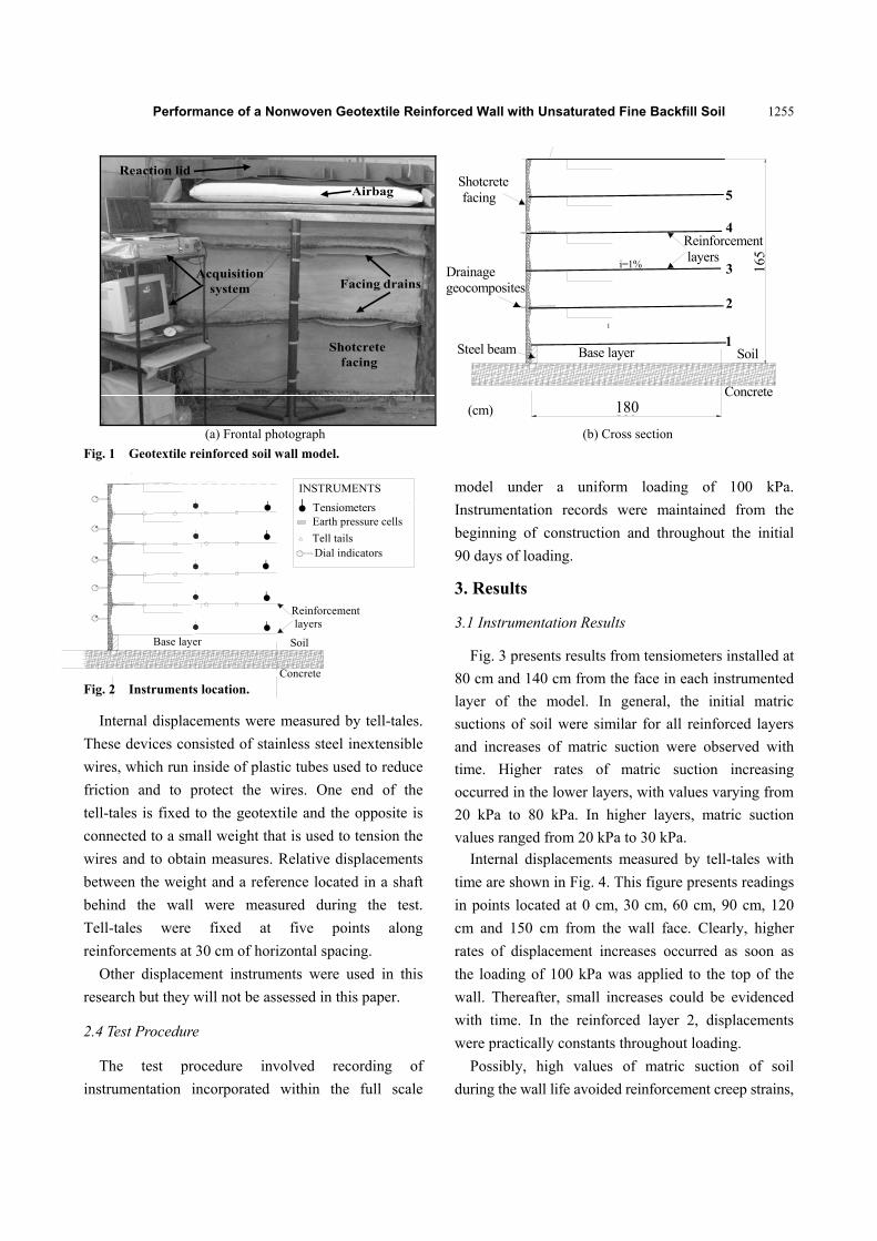
2.2 Full Scale Model Construction
Full scale walls have been constructed in the
Laboratory of Geosynthetics located within the Sao
Carlos School of Engineering at the University of Sao
Paulo. A metallic box allows reinforced soil wall
structures to be constructed with 1.8 m height by 1.55
m width, with backfill soil extending to a distance of
1.8 m from the front edge of the metallic box. The soil
was compacted at 98% of relative density and the
maximum dry unit weight and optimum water content
from standard Proctor tests. In order to assure the
required relative density, compaction was performed
manually in layers of 5 cm height. Compaction
control was assured by the drive-cylinder method
(ASTM D2937), spiked every compacted layer
reaching 30 cm height. The backfill soil was seated on
a rigid concrete foundation.
Geotextile reinforcements were placed at 30 cm
vertical spacing with declivity of 1% to the face. Each
layer of reinforcement had a total length of 1.80 m
measured from the face. The wall was constructed
with no facing batter and using the wrapped-around
technique. Protective shotcrete coating varying from 5
cm to 8 cm was used. Drainage geocomposites were
used as face drainage elements into the second and
forth reinforced layers located at 30 cm from the face
forward into the wall. Fig. 1 presents the cross section
view of the model.
2.3 Instrumentation
Instrumentation was deployed to record pore water
pressures including negatives values (soil suction),
internal horizontal displacements, reinforcement
strains and horizontal face displacements. Instruments
locations are presented in Fig. 2.
Matric suction was monitored by tensiometers
(range of -100 kPa to 100 kPa) located in the middle
of each reinforced layer at 5 cm above the
reinforcements at a distance of 80 cm and 140 cm
from the face.
Performance of a Nonwoven Geotextile Reinforced Wall with Unsaturated Fine Backfill Soil
1255
Shotcretefacing
Facing drains
Airbag
Reaction lid
Acquisitionsystem
Base layer
1
Steel beam
165
160
Drainagegeocomposites
Reinforcement layers
Concrete
Soil
Shotcrete facing
i=1%
1
2
3
4
5
(cm) 180
(a) Frontal photograph (b) Cross section
Fig. 1 Geotextile reinforced soil wall model.
Base layer
Reinforcement layers
Concrete
Soil
Tensiometer
Water content sensor
Tell tailsDial indicators
Earth pressure cellsTensiometers
INSTRUMENTS
Fig. 2 Instruments location.
Internal displacements were measured by tell-tales.
These devices consisted of stainless steel inextensible
wires, which run inside of plastic tubes used to reduce
friction and to protect the wires. One end of the
tell-tales is fixed to the geotextile and the opposite is
connected to a small weight that is used to tension the
wires and to obtain measures. Relative displacements
between the weight and a reference located in a shaft
behind the wall were measured during the test.
Tell-tales were fixed at five points along
reinforcements at 30 cm of horizontal spacing.
Other displacement instruments were used in this
research but they will not be assessed in this paper.
2.4 Test Procedure
The test procedure involved recording of
instrumentation incorporated within the full scale
model under a uniform loading of 100 kPa.
Instrumentation records were maintained from the
beginning of construction and throughout the initial
90 days of loading.
3. Results
3.1 Instrumentation Results
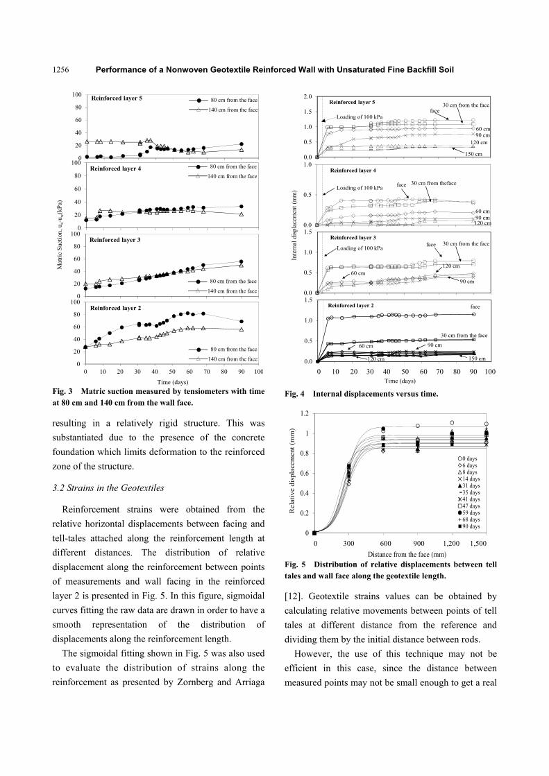
Fig. 3 presents results from tensiometers installed at
80 cm and 140 cm from the face in each instrumented
layer of the model. In general, the initial matric
suctions of soil were similar for all reinforced layers
and increases of matric suction were observed with
time. Higher rates of matric suction increasing
occurred in the lower layers, with values varying from
20 kPa to 80 kPa. In higher layers, matric suction
values ranged from 20 kPa to 30 kPa.
Internal displacements measured by tell-tales with
time are shown in Fig. 4. This figure presents readings
in points located at 0 cm, 30 cm, 60 cm, 90 cm, 120
cm and 150 cm from the wall face. Clearly, higher
rates of displacement increases occurred as soon as
the loading of 100 kPa was applied to the top of the
wall. Thereafter, small increases could be evidenced
with time. In the reinforced layer 2, displacements
were practically constants throughout loading.
Possibly, high values of matric suction of soil
during the wall life avoided reinforcement creep strains,
Performance of a Nonwoven Geotextile Reinforced Wall with Unsaturated Fine Backfill Soil
1256M
atri
c S
ucti
on, u
a-u w
(kP
a)
0
20
40
60
80
100
0 10 20 30 40 50 60 70 80 90 100
Reinforced layer 2
0
20
40
60
80
100Reinforced layer 3
Reinforced layer 4
0
20
40
60
80
1000
20
40
60
80
10080 cm from the face
140 cm from the face
Reinforced layer 5
Time (days)
80 cm from the face
140 cm from the face
80 cm from the face
140 cm from the face
80 cm from the face
140 cm from the face
Fig. 3 Matric suction measured by tensiometers with time at 80 cm and 140 cm from the wall face.
resulting in a relatively rigid structure. This was
substantiated due to the presence of the concrete
foundation which limits deformation to the reinforced
zone of the structure.
3.2 Strains in the Geotextiles
Reinforcement strains were obtained from the
relative horizontal displacements between facing and
tell-tales attached along the reinforcement length at
different distances. The distribution of relative
displacement along the reinforcement between points
of measurements and wall facing in the reinforced
layer 2 is presented in Fig. 5. In this figure, sigmoidal
curves fitting the raw data are drawn in order to have a
smooth representation of the distribution of
displacements along the reinforcement length.
The sigmoidal fitting shown in Fig. 5 was also used
to evaluate the distribution of strains along the
reinforcement as presented by Zornberg and Arriaga
0.0
0.5
1.0
1.5
2.0
Loading of 100 kPa
Reinforced layer 5
face30 cm from the face
60 cm90 cm
120 cm
150 cm
0.0
0.5
1.0
Loading of 100 kPa face 30 cm from theface
60 cm90 cm120 cm
Reinforced layer 4
0.0
0.5
1.0
1.5
Loading of 100 kPa
Reinforced layer 3face 30 cm from the face
60 cm
90 cm
120 cm
0.0
0.5
1.0
1.5
0 10 20 30 40 50 60 70 80 90 100
Time (days)
Reinforced layer 2 face
30 cm from the face
60 cm 90 cm
120 cm 150 cm
Inte
rnal
dis
plac
emen
t (m
m)
Fig. 4 Internal displacements versus time.
0
0.2
0.4
0.6
0.8
1
1.2
0 300 600 900 1200 1500
Rel
ativ
e d
ispl
acem
ent
(mm
)
Distance from the face (mm)
0 days6 days8 days14 days31 days35 days41 days47 days59 days68 days90 days
Fig. 5 Distribution of relative displacements between tell tales and wall face along the geotextile length.
[12]. Geotextile strains values can be obtained by
calculating relative movements between points of tell
tales at different distance from the reference and
dividing them by the initial distance between rods.
However, the use of this technique may not be
efficient in this case, since the distance between
measured points may not be small enough to get a real
0 300 600 900 1,200 1,500
0 10 20 30 40 50 60 70 80 90 100

Performance of a Nonwoven Geotextile Reinforced Wall with Unsaturated Fine Backfill Soil
1257
strain between points. For this reason, the raw data
from tell tales was initially smoothed by fitting the
data to a sigmoidal curve. Thus, the distribution of
strains along the geotextile length could be obtained
by deriving the displacement function as:
dxcxbea
d /1
(1)
where, d is the tell-tale displacement, x is the distance
from the wall face to the measured point, and a, b and
c are parameters defined by the fitting of sigmoidal
curves to the raw data using the minimum squares
technique. This technique was used in a GSE field
case by Zornberg et al. [13].
The distribution of strains in each instrumented
layer is shown in Fig. 6. The strain levels were very
small with a maximum value of 0.43% in the
reinforced layer 2 and minimum value of 0.15% in the
reinforced layer 4. Additionally, no relaxation or
retraction of reinforcements could be observed.
A consistent distribution of strains was obtained by
the derivation of a sigmoidal fitting curve and a
Rankine failure surface seems to properly fit it,
assuming a friction angle from C-U triaxial tests on
unsaturated samples.
The effect of matric suction on the stiffness of soil
can be a good explanation for very small strains and
displacements even using extensible reinforcements as
nonwoven geotextiles. Additionally, interface shear
behavior is absolutely improved under unsaturated
conditions [5]. Other aspects requiring further
consideration is the tensile and creep behavior of
nonwoven geotextiles under confined conditions [14].
These influences are not discussed as part of this
paper as they are covered in detail elsewhere [1].
3.3 Limit Equilibrium Analysis
Factors of safety were calculated by limit
equilibrium analyses in order to compare design
parameters and measured values. Limit equilibrium
analyses were conducted using the technical software
UTEXAS3 from the University of Texas, by Wright
[15]. This software allows for analysis of slopes and
walls considering the reinforcement contribution and
interpolating negative pore water pressures (matric
suction) in the soil.
The effect of matric suction on the factor of safety
and reinforcement peak strains can be better
understood through examination of Fig. 7, where the
factor of safety and reinforcement peak strains are
plotted as function of the average of matric suction
measured by all the tensiometers installed in the
model. From this plot, the factors of safety increased
linearly with matric suction and a better stability could
be noted with the time.
No significant changes in measured values of peak
strains with matric suction could be evidenced, and
significantly small levels of strains were noticed.
Therefore, small forces were mobilized by
reinforcement, and, possibly, this structure would be
0
0,2
0,4
0 300 600 900 1200 1500
Distance from the face (mm)
Rankine failure surface
0
0,1
0,20
0,1
0,20
0,1
0,2
0
0 days6 days
8 days14 days31 days35 days41 days47 days59 days
Days after construction:
Geo
text
ile
stra
ins
(%)
Fig. 6 Distribution of strains.
0
0.2
0.4
0.6
0.8
1
1
1.5
2
2.5
3
-10 0 10 20 30 40 50 60 70 80
Peak
str
ains
(%)
Fact
or o
f sa
fety
Average of matric suction (kPa)
Factor of safety x Average of matric suction
Peak strains x Average of matric suction
Saturated condition (suction zero)
Fig. 7 Limit equilibrium analyses: effect of matric suction on factors of safety and reinforcement peak strains.
0.2
0.10
0.20.10
0.20.1
00.40.2
0300 600 900 1,200 1,500
Performance of a Nonwoven Geotextile Reinforced Wall with Unsaturated Fine Backfill Soil
1258
0
30
60
90
120
150
0 300 600 900 1200 1500
H (
cm)
Distance from the face (mm)
14 dias
41 dias
68 dias
90 dias
14 dias
41 dias
68 dias
90 dias
14 days
41 days
68 days
90 days
14 days
41 days
68 days
90 days
Days after construction:
Predicted
Measured
Fig 8 Slip surfaces from equilibrium limit analyses in different times.
stable even without reinforcements. In this case,
reinforcements perform purely the constructability
function.
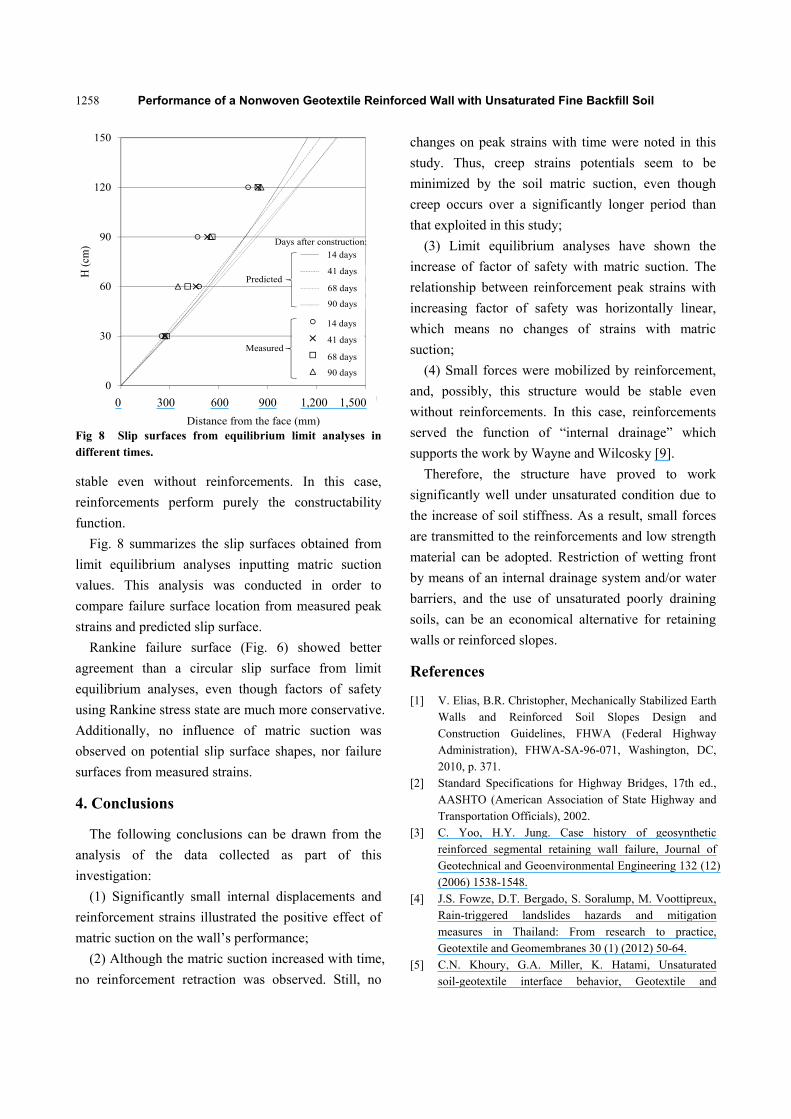
Fig. 8 summarizes the slip surfaces obtained from
limit equilibrium analyses inputting matric suction
values. This analysis was conducted in order to
compare failure surface location from measured peak
strains and predicted slip surface.
Rankine failure surface (Fig. 6) showed better
agreement than a circular slip surface from limit
equilibrium analyses, even though factors of safety
using Rankine stress state are much more conservative.
Additionally, no influence of matric suction was
observed on potential slip surface shapes, nor failure
surfaces from measured strains.
4. Conclusions
The following conclusions can be drawn from the
analysis of the data collected as part of this
investigation:
(1) Significantly small internal displacements and
reinforcement strains illustrated the positive effect of
matric suction on the wall’s performance;
(2) Although the matric suction increased with time,
no reinforcement retraction was observed. Still, no
changes on peak strains with time were noted in this
study. Thus, creep strains potentials seem to be
minimized by the soil matric suction, even though
creep occurs over a significantly longer period than
that exploited in this study;
(3) Limit equilibrium analyses have shown the
increase of factor of safety with matric suction. The
relationship between reinforcement peak strains with
increasing factor of safety was horizontally linear,
which means no changes of strains with matric
suction;
(4) Small forces were mobilized by reinforcement,
and, possibly, this structure would be stable even
without reinforcements. In this case, reinforcements
served the function of “internal drainage” which
supports the work by Wayne and Wilcosky [9].
Therefore, the structure have proved to work
significantly well under unsaturated condition due to
the increase of soil stiffness. As a result, small forces
are transmitted to the reinforcements and low strength
material can be adopted. Restriction of wetting front
by means of an internal drainage system and/or water
barriers, and the use of unsaturated poorly draining
soils, can be an economical alternative for retaining
walls or reinforced slopes.
References
[1] V. Elias, B.R. Christopher, Mechanically Stabilized Earth Walls and Reinforced Soil Slopes Design and Construction Guidelines, FHWA (Federal Highway Administration), FHWA-SA-96-071, Washington, DC, 2010, p. 371.
[2] Standard Specifications for Highway Bridges, 17th ed., AASHTO (American Association of State Highway and Transportation Officials), 2002.
[3] C. Yoo, H.Y. Jung. Case history of geosynthetic reinforced segmental retaining wall failure, Journal of Geotechnical and Geoenvironmental Engineering 132 (12) (2006) 1538-1548.
[4] J.S. Fowze, D.T. Bergado, S. Soralump, M. Voottipreux, Rain-triggered landslides hazards and mitigation measures in Thailand: From research to practice, Geotextile and Geomembranes 30 (1) (2012) 50-64.
[5] C.N. Khoury, G.A. Miller, K. Hatami, Unsaturated soil-geotextile interface behavior, Geotextile and
0 300 600 900 1,200 1,500
Performance of a Nonwoven Geotextile Reinforced Wall with Unsaturated Fine Backfill Soil
1259
Geomembranes 29 (2010) 17-28. [6] M. Ehrlich, D. Vidal., P.A. Carvalho, Performance of two
geotextile reinforced soil slopes, in: Proceedings of International Symposium on Recent Developments in Soil and Pavement Mechanics, 1997, pp. 415-420.
[7] F.H.M. Portelinha, B.S. Bueno, J.G. Zornberg, Performance of nonwoven geotextiles reinforced soil walls under wetting conditions: Laboratory and field investigation, Geosynthetics International 20 (2) 90-104.
[8] R.M. Koerner, T.Y. Soong, Geosynthetic reinforced segmental retaining walls, Geotextiles and Geomembranes 19 (6) (2001) 359-386.
[9] M.H. Wayne, E. Wilcosky, An innovative use of a nonwoven geotextile in the repair of Pennsylvania State Route 54, Geotechnical Fabrics Report 14 (7) (1996) 26-29.
[10] D.V. Raisinghani, B.V.S. Viswanadham, Evaluation of permeability characteristics of a geosynthetic-reinforced soil through laboratory tests, Geotextile and Geomembranes 28 (6) (2010) 579-588.
[11] D.V. Raisinghani, B.V.S. Viswanadham, Centrifuge model study on low permeable slope reinforced by hybrid geosynthetics, Geotextile and Geomembranes 28 (6) (2011) 579-588.
[12] J.G. Zornberg, F. Arriaga, Strain distribution within geosynthetic-reinforced slopes, Journal of Geotechnical and Geoenvironmental Engineering 129 (1) (2003) 32-34.
[13] J.G. Zornberg, B.R. Christopher, J.K. Mitchell, Performance of a geotextile reinforced slope using decomposed granite as backfill material, in: Proceedings of Second Brazilan Simposium on Geosynthetics Applications, São Paulo, 1995, pp. 19-29.
[14] A. McGown., K.Z. Andrawes, M.H. Kabir, Load-extension testing of geotextiles confined in-soil, in: Proceedings of International Conference on Geotextiles, USA, 1982, pp. 793-798.
[15] S.G. Wright, UTEXAS3: A Computer Program for Slope Stability Analyses Calculation, Shinoak Software, Austin, Texas, 1990.
Copyright © 2022 FDOKUMEN