PelcoNet™ Multimedia Transmission Via Networks
82
PelcoNet ™ Multimedia Transmission Via Networks C2904M-B (2/05) ® INSTALLATION/OPERATION NET4001A
-
Upload
khangminh22 -
Category
Documents
-
view
0 -
download
0
Transcript of PelcoNet™ Multimedia Transmission Via Networks

PelcoNet™
Multimedia TransmissionVia Networks
C2904M-B (2/05)
®
I N S T A L L A T I O N / O P E R A T I O N
NET4001A


C2904M-B (2/05) 3
CONTENTS
Section Page
IMPORTANT SAFEGUARDS AND WARNINGS .................................................................................................................................................................. 7REGULATORY NOTICES ............................................................................................................................................................................................. 8UNPACKING INSTRUCTIONS .................................................................................................................................................................................... 8
WHAT IS THE PELCONET NET4001A TRANSMISSION SYSTEM? .................................................................................................................................... 9HOW DO LANS AND WANS WORK? ........................................................................................................................................................................ 9WHO SHOULD INSTALL THE PELCONET NET4001A TRANSMISSION SYSTEM? ................................................................................................... 9
INSTRUCTIONS FOR THE NETWORK ADMINISTRATOR .................................................................................................................................................. 10THE TRANSMITTER-RECEIVER ................................................................................................................................................................................. 10THE BROWSER ......................................................................................................................................................................................................... 10MINIMUM REQUIREMENTS .................................................................................................................................................................................... 10MPEG ACTIVEX® PLATFORM REQUIREMENTS ...................................................................................................................................................... 10
OVERVIEW ......................................................................................................................................................................................................................... 11DESCRIPTION ........................................................................................................................................................................................................... 11SOFTWARE VERSION ............................................................................................................................................................................................... 11PACKAGE CONTENTS ............................................................................................................................................................................................... 11FRONT PANEL LEDS ................................................................................................................................................................................................. 12REAR PANEL CONNECTORS ..................................................................................................................................................................................... 12PIN ASSIGNMENTS ................................................................................................................................................................................................. 13
TYPICAL APPLICATIONS .................................................................................................................................................................................................... 14DISPLAYING REMOTE VIDEO ON A WEB BROWSER .............................................................................................................................................. 14DISPLAYING VIDEO VIA A TRANSMITTER-TO-RECEIVER CONNECTION ................................................................................................................ 15DIAGRAMS OF TYP21
HARDWARE INSTALLATION .............................................................................................................................................................................................. 22RACK MOUNTING .................................................................................................................................................................................................... 22
MOUNTING A SINGLE UNIT ........................................................................................................................................................................... 22MOUNTING TWO UNITS ................................................................................................................................................................................. 23
CONNECTING VIDEO SOURCES OR DISPLAYS ........................................................................................................................................................ 24CONNECTING A MONITOR ...................................................................................................................................................................................... 24CONNECTING AUDIO EQUIPMENT .......................................................................................................................................................................... 24CONNECTING DATA TERMINALS ............................................................................................................................................................................ 25
USE AS CONTROL TERMINAL PORT ............................................................................................................................................................... 25USE AS TRANSPARENT DATA PORT ............................................................................................................................................................... 25
CONTROLLING PERIPHERAL DEVICES ..................................................................................................................................................................... 26CONNECTING EXTERNAL SENSORS ....................................................................................................................................................................... 26
CONFIGURATION ............................................................................................................................................................................................................... 28CONFIGURATION USING A TERMINAL PROGRAM ................................................................................................................................................. 28
TYPICAL SESSION ........................................................................................................................................................................................... 28TERMINAL PROGRAM MENU STRUCTURE .................................................................................................................................................... 29
CONFIGURATION USING A WEB BROWSER ........................................................................................................................................................... 31WEB SERVER CONCEPT .................................................................................................................................................................................. 31ONLINE HELP ................................................................................................................................................................................................... 31QUICK GUIDE TO THE MENU STRUCTURE ..................................................................................................................................................... 32PELCONET NET4001A HOME PAGE ................................................................................................................................................................ 33CONFIGURATION PAGE FOR GENERAL SETTINGS ......................................................................................................................................... 34CONFIGURATION PAGE FOR VIDEO DECODER SETTINGS .............................................................................................................................. 39CONFIGURATION PAGE FOR ALARM SETTINGS ............................................................................................................................................ 40CONFIGURATION PAGE FOR RELAY SETTINGS .............................................................................................................................................. 43CONFIGURATION PAGE FOR COM 1 INTERFACE SETTINGS .......................................................................................................................... 44CONFIGURATION PAGE FOR COM 2 INTERFACE SETTINGS .......................................................................................................................... 45CONFIGURATION PAGE FOR NETWORK SETTINGS ....................................................................................................................................... 46
LIVE VIDEO PAGE INDICATORS ......................................................................................................................................................................................... 48
LIVE VIDEO AND SERVER PUSH VIDEO PAGES ................................................................................................................................................................ 49CONTROLLING THE DISPLAY ................................................................................................................................................................................... 50

4 C2904M-B (2/05)
WEB BROWSER CONTROL PAGES .................................................................................................................................................................................... 50ACCESSING THESE PAGES ...................................................................................................................................................................................... 50MATRIX CONTROL LIVE VIDEO/SERVER PUSH PAGE CONTENTS .......................................................................................................................... 51
GENEX LIVE VIDEO/SERVER PUSH PAGE CONTENTS ...................................................................................................................................................... 52SPECTRA LIVE VIDEO/SERVER PUSH PAGE CONTENTS ......................................................................................................................................... 53ESPRIT LIVE VIDEO/SERVER PUSH PAGE CONTENTS ............................................................................................................................................. 54
ADVANCED FEATURES ...................................................................................................................................................................................................... 55AUTOMATIC CONNECTION FEATURE ...................................................................................................................................................................... 55VIDEO MOTION DETECTION FEATURE ..................................................................................................................................................................... 55RECORDING AND PLAYING BACK THE DISPLAY ON A PC ...................................................................................................................................... 55
CHOOSING WHERE TO STORE THE FILE ......................................................................................................................................................... 55RECORDING A SNAPSHOT .............................................................................................................................................................................. 55VIEWING A SNAPSHOT .................................................................................................................................................................................. 56RECORDING THE VIDEO DISPLAY ................................................................................................................................................................... 56VIEWING THE VIDEO DISPLAY ........................................................................................................................................................................ 56
FIRMWARE UPLOAD ................................................................................................................................................................................................ 57CONFIGURATION DOWNLOAD ................................................................................................................................................................................ 57CONFIGURATION UPLOAD ....................................................................................................................................................................................... 57
TROUBLESHOOTING .......................................................................................................................................................................................................... 58LEDS ......................................................................................................................................................................................................................... 58TERMINAL PROGRAM .............................................................................................................................................................................................. 58TROUBLESHOOTING A TCP/IP NETWORK USING A PING UTILITY ......................................................................................................................... 58TROUBLESHOOTING CONNECTION PROBLEMS ..................................................................................................................................................... 59TROUBLESHOOTING THE VIDEO CONNECTION ...................................................................................................................................................... 59TESTING THE AUDIO CONNECTION ........................................................................................................................................................................ 59
TEST BETWEEN TWO NET4001A UNITS ........................................................................................................................................................ 59TEST BETWEEN NET4001A AND PC ............................................................................................................................................................... 59
GENERAL REMEDIES TABLE .................................................................................................................................................................................... 60
SPECIFICATIONS ................................................................................................................................................................................................................ 61NETWORK PROTOCOL AND STANDARDS COMPATIBILITY ........................................................................................................................... 61INTERFACE ....................................................................................................................................................................................................... 61VIDEO ............................................................................................................................................................................................................... 61POWER ............................................................................................................................................................................................................ 61MISCELLANEOUS ............................................................................................................................................................................................ 61ENVIRONMENTAL ........................................................................................................................................................................................... 61GENERAL ......................................................................................................................................................................................................... 61CERTIFICATIONS .............................................................................................................................................................................................. 61
GLOSSARY ......................................................................................................................................................................................................................... 62
APPENDIX A – CONNECTING PELCONET NET4001A TO VARIOUS COMPONENTS ........................................................................................................ 64CONNECTING PELCONET TO VARIOUS COMPONENTS WITH ASSORTED KEYBOARDS ...................................................................................... 65
CONNECTION SCENARIO 1 – USING A KBD300A IN DIRECT MODE ............................................................................................................ 65CONNECTION SCENARIO 2 – USING A KBD4000 FOR MULTIPLEXER CONTROL .......................................................................................... 66CONNECTION SCENARIO 3 – USING A CM9760-KBD ................................................................................................................................... 67
CONNECTING PELCONET TO THE COM IN RS-422 PORT ON A GENEX MULTIPLEXER ......................................................................................... 68CONNECTING A PELCONET RECEIVER TO A SYSTEM CM9502 ............................................................................................................................. 68CONNECTING PELCONET TO A CM9502 ASCII SERIAL PORT ................................................................................................................................. 69CONNECTING PELCONET TO A CM6700 AND KBD200A FOR REMOTE ASCII CONTROL ...................................................................................... 70CONNECTING PELCONET TO A CM6700 ASCII PORT ............................................................................................................................................. 71CONNECTING PELCONET TO A CM9760-DT FOR REMOTE BROWSER CONTROL ................................................................................................. 72CONNECTING PELCONET TO CM9760 EQUIPMENT FOR REMOTE COMMUNICATION ......................................................................................... 73
CONNECTING A PELCONET TRANSMITTER TO THE CM6800 ASCII PORT ..................................................................................................................... 74CONNECTING PELCONET TO A CM6800 AND KBD200A FOR REMOTE ASCII CONTROL ...................................................................................... 76
APPENDIX B – FREQUENTLY ASKED QUESTIONS (FAQS) ................................................................................................................................................ 77

C2904M-B (2/05) 5
LIST OF ILLUSTRATIONS
Figure Page
1 Front Panel LEDs .............................................................................................................................................................................................. 122 Rear Panel Connectors .................................................................................................................................................................................... 123 PelcoNet NET4001A Home Page .................................................................................................................................................................... 144 Configuration for Box-To-Box Connections ..................................................................................................................................................... 155 LAN Box-To-Box Connection (Transmitter, Receiver, Fixed Camera) ............................................................................................................... 166 LAN Box-To-Box Connection (Transmitter, Receiver, Spectra) ........................................................................................................................ 167 LAN Browser-To-Box Connection (Transmitter, Browser, Fixed Camera) ........................................................................................................ 178 LAN Browser-To-Box Connection (Transmitter, Browser, Spectra) ................................................................................................................. 179 LAN Browser-To-Box Connection (Transmitter, Browser, Spectra, Genex) ..................................................................................................... 1810 WAN Box-To-Box Connection (Transmitter, Receiver, Fixed Camera) ............................................................................................................. 1811 WAN Box-To-Box Connection (Transmitter, Receiver, Spectra) ...................................................................................................................... 1912 WAN Box-To-Box Connection (Transmitter, Receiver, Spectra, Genex) .......................................................................................................... 1913 WAN Browser-To-Box Connection (Transmitter, Browser, Fixed Camera) ...................................................................................................... 2014 WAN Browser-To-Box Connection (Transmitter, Browser, Spectra) ................................................................................................................ 2015 WAN Browser-To-Box Connection (Transmitter, Browser, Spectra, Genex) ................................................................................................... 2116 Mounting One Unit .......................................................................................................................................................................................... 2217 Mounting Two Units ........................................................................................................................................................................................ 2318 Connecting Camera or Monitor ....................................................................................................................................................................... 2419 Control Terminal Port Pin Assignments in RS-232 Mode ................................................................................................................................ 2520 Data Port Pin Assignments in RS-232 Mode .................................................................................................................................................. 2521 Connecting External Sensors and Peripheral Devices .................................................................................................................................... 2622 Connecting to the LAN Port ............................................................................................................................................................................. 2723 PelcoNet NET4001A Menu Tree ...................................................................................................................................................................... 3224 PelcoNet Home Page ....................................................................................................................................................................................... 3325 PelcoNet NET4001A Transmission System Setup Page ................................................................................................................................. 3326 Configuration Page for General Settings ........................................................................................................................................................ 3427 Configuration Page for MPEG 1/-2 Video Encoder Settings ........................................................................................................................... 3728 Configuration Page for MPEG-4 Video Encoder Settings ................................................................................................................................ 3829 Configuration Page for Video Decoder Settings ............................................................................................................................................. 3930 Configuration Page for Alarm Settings ........................................................................................................................................................... 4031 Motion Detection Screen ................................................................................................................................................................................ 4032 Motion Detection Grid Screen ........................................................................................................................................................................ 4133 Configuration Page for Relay Settings ............................................................................................................................................................ 4334 Configuration Page for COM 1 Interface Settings .......................................................................................................................................... 4435 Configuration Page for COM 2 Interface Settings .......................................................................................................................................... 4536 Configuration Page for Network Settings ....................................................................................................................................................... 4637 Live Video Page ............................................................................................................................................................................................... 4938 Device Controls Page ...................................................................................................................................................................................... 5039 Matrix Control Page ........................................................................................................................................................................................ 5140 Genex Control Page ......................................................................................................................................................................................... 5241 Spectra Control Page ....................................................................................................................................................................................... 5342 Esprit Control Page .......................................................................................................................................................................................... 5443 Viewer Screen ................................................................................................................................................................................................. 5644 DB9 Cable Wire Splicing ................................................................................................................................................................................. 6445 KBD300A (Direct Mode) Connected to a Receiver or Spectra Dome System ................................................................................................ 6546 KBD4000 Connected to a Multiplexer ............................................................................................................................................................. 6647 CM9760KBD Connected to a CM9760-CC1 Controller ................................................................................................................................... 6748 Connecting PelcoNet to Genex Using the COM IN RS-422 Port ..................................................................................................................... 6849 Using PelcoNet with CM9505 to Provide Remote Control ............................................................................................................................. 6850 Using PelcoNet with CM9502 to Provide Remote Control ............................................................................................................................. 6951 Using PelcoNet with CM6700 and KBD200A to Provide Remote Control ...................................................................................................... 7052 Using PelcoNet with CM6700 to Provide Remote Control ............................................................................................................................. 7153 Using PelcoNet with CM9760-DT to Provide Remote Control of a 9760 Monitor Output ............................................................................. 7254 Using PelcoNet to Transmit Data and Video Between 9760 Nodes ............................................................................................................... 7355 Using PelcoNet to Receive Data and Video Between 9760 Nodes ................................................................................................................ 7356 Using PelcoNet with CM6800 to Provide Remote Control ............................................................................................................................. 7457 Manager Screen .............................................................................................................................................................................................. 7558 Menu Screen ................................................................................................................................................................................................... 7559 Using PelcoNet with CM6800 and KBD200A to Provide Remote Control ...................................................................................................... 76
6 C2904M-B (2/05)
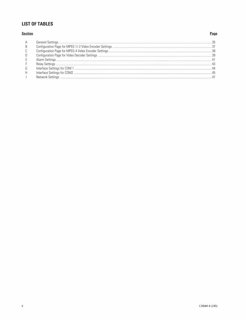
LIST OF TABLES
Section Page
A General Settings .............................................................................................................................................................................................. 35B Configuration Page for MPEG 1/-2 Video Encoder Settings ........................................................................................................................... 37C Configuration Page for MPEG-4 Video Encoder Settings ................................................................................................................................ 38D Configuration Page for Video Decoder Settings ............................................................................................................................................. 39E Alarm Settings ................................................................................................................................................................................................. 41F Relay Settings ................................................................................................................................................................................................. 43G Interface Settings for COM 1 .......................................................................................................................................................................... 44H Interface Settings for COM2 ........................................................................................................................................................................... 45I Network Settings ............................................................................................................................................................................................ 47

C2904M-B (2/05) 7
IMPORTANT SAFEGUARDS AND WARNINGS
Observe the following WARNINGS before installing and using this product.
1. Read these instructions.
2. Keep these instructions.
3. Heed all warnings.
4. Follow all instructions.
5. Do not use this apparatus near water.
6. Clean only with dry cloth.
7. Do not block any ventilation openings. Install in accordance with the manufacturer’s instructions.
8. Do not install near any heat sources such as radiators, heat registers, stoves, or other apparatus (including amplifiers) that produceheat.
9. Do not defeat the safety purpose of the polarized or grounding-type plug. A polarized plug has two blades with one wider than theother. A grounding plug has two blades and a third grounding prong. The wide blade or the third prong is provided for your safety. Ifthe provided plug does not fit into your outlet, consult your electrician for replacement of the obsolete outlet.
10. Protect the power cord from being walked on or pinched, particularly at the plug, convenience receptacle, and the point where itexits from the apparatus.
11. Only use attachments/accessories specified by the manufacturer.
12. Use only with the cart, stand, tripod, bracket, or table specified by the manufacturer, or sold with the apparatus. When a cart is used,use caution when moving the cart/apparatus combination to avoid injury from tip-over.
13. Refer all servicing to qualified service personnel. Servicing is required when the apparatus has been damaged in any way, such aswhen the power supply cord or plug is damaged, liquid has been spilled or objects have fallen into the apparatus, the apparatus hasbeen exposed to rain or moisture, the apparatus does not operate normally, or the apparatus has been dropped.
14. Apparatus shall not be exposed to dripping or splashing, and no objects filled with liquids, such as vases, shall be placed on theapparatus.
15. Warning: To reduce the risk of fire or electric shock, do not expose this apparatus to rain or moisture.
16. To reduce the risk of shock, do not perform any servicing other than that contained in the operating instructions unless you arequalified to do so.
17. Installation should be done only by qualified personnel and conform to all local codes.
18. If the unit requires 120/230 VAC and does not have an on/off switch, the input power circuit must have a circuit breaker.
19. The installation method and materials should be capable of supporting four times the weight of the unit.
The product and/or manual may bear the following marks:
This symbol indicates that dangerous voltageconstituting a risk of electric shock is presentwithin this unit.
This symbol indicates that there are importantoperating and maintenance instructions in theliterature accompanying this unit.
C A U T I O N :
R I S K O F E L E C T R I C S H O C K .D O N O T O P E N .
Thoroughly familiarize yourself with the information in this manual prior to installation and operation.

8 C2904M-B (2/05)
REGULATORY NOTICES
This equipment has been tested and found to comply with the limits of a Class B digital device, pursuant to part 15 of the FCC rules. Theselimits are designed to provide reasonable protection against harmful interference in a residential installation. This equipment generates,uses, and can radiate radio frequency energy and, if not installed and used in accordance with the instructions, may cause harmfulinterference to radio communications. However there is no guarantee that the interference will not occur in a particular installation. If thisequipment does cause harmful interference to radio or television reception, which can be determined by turning the equipment off and on,the user is encouraged to try to correct the interference by one or more of the following measures:
• Reorient or relocate the receiving antenna.
• Increase the separation between the equipment and the receiver.
• Connect the equipment into an outlet on a circuit different from that to which the receiver is connected.
• Consult the dealer or an experienced radio/TV technician for help.
UNPACKING INSTRUCTIONS
Unpack and inspect all parts carefully. Save the shipping carton, boxes, and inserts. They are the safest manner in which to make futureshipments.
If an item needs to be returned to the factory for repair, consult the Warranty and Return Information section of this manual forinstructions.

C2904M-B (2/05) 9
WHAT IS THE PELCONET NET4001A TRANSMISSION SYSTEM?
The PelcoNet NET4001A transmission system is technology that lets you view video in real time across a LAN (local area network) andeven WANs (wide area networks). This technology is based on the TCP/IP protocol suite and Ethernet technology, providing compatibilitywith today’s networking standards.
The following devices can be controlled from your computer through Internet Explorer with the PelcoNet NET4001 Transmission System:Spectra®, Esprit®, Genex® multiplexer, CM9760 (requires CM9760 data translator), CM9740 (requires CM9760 data translator), CM9502(through integrated ASCII port), CM8500 (requires latest CM8500 data translator), CM6700 (through integrated ASCII port, COM 2), andthe CM6800 matrix.
(See the Glossary section for definitions of terms used in this manual.)
HOW DO LANS AND WANS WORK?
• A LAN consists of multiple computers connected together, sharing information. This information could be files, e-mail, printers, or—with the PelcoNet NET4001A transmission system—even live video and audio.
• A WAN consists of multiple LANs connected over a great distance (for example, the Internet).
• In any network environment, each computer needs an address so other computers on the network know how to reach it.
It is similar to a city with street addresses. For the post office to deliver mail to your house, you need a unique street address for themail carrier to find you. A network is like a city. Like a street address, the IP address on your computer is your address on thenetwork. The IP address is how other computers can find you on the network.
Remember that the IP address must be unique on the network.
• When there are multiple networks and you are using the TCP/IP protocol, there must be a way to communicate between the twonetworks. A physical device called a router is required. The router’s IP address is referred to as the default gateway IP address.
• A cable that connects one computer to another is like a city street you can use to get from one house to another. The cable lets youcommunicate with each other on the network. This cable is Category 5 cable with RJ-45 connectors at each end. (It looks like aphone cord, only slightly larger.)
WHO SHOULD INSTALL THE PELCONET NET4001A TRANSMISSION SYSTEM?
NOTE: Unless you are very familiar with how computers work, consult your network administrator for help.
Installation is a matter of configuring an IP address using a standard terminal program or any Internet browser and connecting thePelcoNet NET4001A transmission system to the Ethernet network. You should have the following background and experience to configureand install these units:
• Working knowledge of basic network management concepts and terminology• Working knowledge of tools and procedures for installing and operating sensitive electronic equipment

10 C2904M-B (2/05)
INSTRUCTIONS FOR THE NETWORK ADMINISTRATOR
The PelcoNet™ NET4001A multimedia transmission system allows live video transmission to be viewed over TCP/IP-based networks. Thissection is intended to help the network administrator know what is involved with installing this product and how it will affect the network.The person installing the product will need the following information about the network to make the product function properly.
THE TRANSMITTER-RECEIVER
• A valid IP address* for each PelcoNet NET4001A transmission system unit• Subnet mask*• Default gateway (if applicable)• E-mail server’s IP address (if applicable)• Dedicated maximum allowable amount of bandwidth for live video**
*Required for the PelcoNet NET4001A transmission system to function properly.
**The PelcoNet NET4001A Transmission System requires a continuous amount of bandwidth to display true live video. Pelco recommends using switches with the product so the amount of bandwidth available to each unit is constant and reliable.
THE BROWSER
If you plan to use a web browser to view live video across the network, there are procedures to complete before you can use the browser.If you installed Internet Explorer® 6.0 from the CD that came with the PelcoNet NET4001A transmission system, you can skip thefollowing. Otherwise, complete the following before trying to use the browser.
1. Internet Explorer 5.5 or higher must be installed before continuing.
2. Set the computer’s display settings to use 16- or 32-bit color. (This is required for the live video feature to function properly.)
3. Click the Start menu in Windows®.
4. Click Run.
5. In the Open box, type D:\ACTIVEX\SETUP.EXE (where D:\ = your CD ROM drive letter).
6. Click OK.
7. Follow the on-screen setup instructions to finish installing the plug-in.
MINIMUM REQUIREMENTS
• PC (Pentium® 4 microprocessor, 1.6 GHz) with Windows 98/2000/XP or higher
• Gateway to the network
• Microsoft® Internet Explorer 5.5 (or higher) or free serial interface and terminal program or PelcoNet NET4001A (acting as receiver)and video monitor
• Screen resolution of 800 x 600 pixels or higher, 16- or 32-bit pixel color resolution
MPEG ACTIVEX® PLATFORM REQUIREMENTS
RAM: 256 MbyteGraphic Card: ATI RADEON™ 7500 or 8500, Matrox G 550 or Parhelia™, or NVIDIA® GeForce 3 or 4 with direct show compatible MPEG-2
playback capability (DVD player)Ethernet Card: 100 MbitISDN Card: Not requiredSound Card: RecommendedSoftware: DirectX® 8.1 or 9.0 application programming interface

C2904M-B (2/05) 11
OVERVIEW
NOTE: This manual refers to the PelcoNet NET4001A transmission system when discussing features, functions, or specifications thatapply to the transmitter/receiver. “Receiver,” as used in this manual, refers to the PelcoNet NET4001A unless otherwise noted.
DESCRIPTION
The PelcoNet NET4001A Transmission System is a network video server whose primary purpose is to encode and decode live video, audio,and control data for transmission over existing Ethernet computer networks (either intranet or Internet) using the TCP/IP protocol. You canview the pictures on a CCTV or PC monitor.
The NET4001A functions as a transmitter/receiver and is the only unit required to use the PelcoNet NET4001A transmission system. TheNET4001A connects any NTSC or PAL video sources (cameras, for example) to the computer network.
Depending on how you want to display the video, you can use a NET4001A as a transmitter with a PC or a NET4001A as a receiver. Thereare two ways to display remote video:
• Web browser using any PC on the network to display the video• A NET4001A (as a receiver) with attached standard NTSC or PAL monitor
Two NET4001A units (as transmitter and receiver) can form a standalone system for data transfer without a PC.
Transmitters and receivers are identified by IP addresses, just like any other equipment connected to a computer network.
There is a bi-directional serial interface for remote control of peripherals like PTZ cameras. This interface can also transmit transparentdata. The NET4001A transmits full-duplex audio.
In appropriately configured networks, the multicast function permits simultaneous video transmission in real time to several receivers. Forthis to work, the UDP and IGMP multicasting protocols must be implemented in the network.
The NET4001A incorporates dual processors. It operates with the MPEG-1, MPEG-2, and MPEG-4 video compression standards. MPEG-2encoding allows the data bit rate to remain low even with high image quality. Also, it can be matched into the local environment withinwide limits. In this process, simultaneous encoding of the video signal according to MPEG-4 is supported so concurrent transmission usinglow bandwidth (for example, for Internet streaming) is possible. This flexibility lets you view a camera in one compression standard, forexample, while recording in another compression standard if you wish.
SOFTWARE VERSION
This manual documents PelcoNet NET4001A software version 2.00.
PACKAGE CONTENTS
The following are supplied:
Qty Description1 PelcoNet NET4001A2 Power cables (USA and European)1 RS-232 null modem cable1 Patch cable1 Software CD1 Rack mount kit
Keep the carton, including the original packaging material, to repack the equipment if you need to return it for repair.

12 C2904M-B (2/05)
FRONT PANEL LEDS
Video In Video Out
Audio In
10/100 Base-T 100-250VAC50/60Hz 100mA
COM2: RS232
� � � ��
�
EthernetAudio Out
Power
�
COM1: RS232/485
�
Key:1 = IR (infrared) diode for future development.2 = HDD LED. Not currently used.3 = VIDEO LED lights green if a video signal is present on the input.4 = IN LED lights red to indicate an active alarm or green to indicate a ready alarm.5 = OUT LED lights green to indicate a switched relay.6 = COM LED flashes orange during active data transmissions on the serial interface ports.7 = ETHERNET green LED lights with a physical network connection while the red LED flashes when data packets are being transmitted.8 = POWER LED flashes green to indicate the unit is operationally ready.
Figure 1. Front Panel LEDs
REAR PANEL CONNECTORS
Key:
1 = Video In BNC socket for video source.2 = Video Out BNC socket for an analog video monitor.3 = Audio Out and Audio In 3.5 mm stereo jack sockets to connect an amplified microphone and loudspeaker.4 = Output and Input connectors for switches for external equipment (for example, lights or audible alarms) or external sensors.5 = Serial interface port COM 1 RS232/485 9-pin sub-D socket for control data transmissions (RS-232, RS-422, RS-485 protocols) and for
configuration using terminal software.6 = Serial interface port COM 2 RS232 9-pin sub-D socket for configuration using terminal software.7 = Ethernet port accepts Cat5 cable with RJ-45 connectors for connecting to the network.8 = Power socket for connecting the unit’s power cord.
Figure 2. Rear Panel Connectors
NOTE: Use only the supplied power plug. If the cable or connector show any sign of damage, do not use the plug. Send it in for repair orreplacement. Never try to use any power plug except the supplied one.
IR HDD VIDEO IN OUT COM ETHERNET POWER
MPEG 2/4 Network Video CodecNET4001A
��
��
�� � �

C2904M-B (2/05) 13
PIN ASSIGNMENTS
PinCOM1 COM2
RS-232 RS-232/485 RS-2321 DCD – –
(data carrier detect)2 RxD RxD+ RxD
(receive data) (receive data plus) (receive data)3 TxD TxD- TxD
(transmit data) (transmit data minus) (transmit data)4 DTR – –
(data terminal ready)
5 GND (ground) GND (ground) GND (ground)6 DSR – –
(data set ready)7 RTS TxD+ –
(ready to send) (transmit data plus)8 CTS RxD- –
(clear to send) (receiver data minus)9 – – –
1 2 3 4 5
6 7 8 9
14 C2904M-B (2/05)
TYPICAL APPLICATIONS
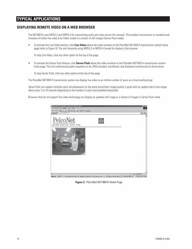
DISPLAYING REMOTE VIDEO ON A WEB BROWSER
The NET4001A uses MPEG-2 and MPEG-4 for transmitting audio and video across the network. This enables transmission to standard webbrowsers of either live video (Live Video mode) or a stream of still images (Server Push mode).
• To activate the Live Video feature, click Live Video above the video window on the PelcoNet NET4001A transmission system homepage (refer to Figure 3). The unit transmits using MPEG-2 or MPEG-4 format for display in the browser.
To stop Live Video, click any other option at the top of the page.
• To activate the Server Push feature, click Server Push above the video window on the PelcoNet NET4001A transmission systemhome page. The unit continuously grabs snapshots to be JPEG encoded, transferred, and displayed continuously by the browser.
To stop Server Push, click any other option at the top of the page.
The PelcoNet NET4001A transmission system can display live video to an infinite number of users at a time (multicasting).
Server Push can support multiple users simultaneously on the same transmitter. Image quality is good with an update rate of one imageabout every 2 to 10 seconds depending on the number of users and available bandwidth.
Browsers that do not support live video technology can display an updated still image or a stream of images in Server Push mode.
Figure 3. PelcoNet NET4001A Home Page

C2904M-B (2/05) 15
Video In Video Out
Audio Out
Audio In
COM1: RS232/485 10/100 Base-T
Ethernet
Power
100-250VAC50/60Hz 100mA
COM2: RS232
Video In Video Out
Audio Out
Audio In
COM1: RS232/485 10/100 Base-T
Ethernet
Power
100-250VAC50/60Hz 100mA
COM2: RS232
TRANSMITTER
RECEIVER
LAN/WAN TCP/IP INTRANET/INTERNET
CAMERA
MONITOR
DISPLAYING VIDEO VIA A TRANSMITTER-TO-RECEIVER CONNECTION
Figure 4. Configuration for Box-To-Box Connections
There are two ways to make a high performance multimedia transmission system for computer networks:
• One way is to use just the NET4001A as a transmitter and connect it through the computer network to a PC with a web browser atthe receiving end.
• Another way is to connect a NET4001A as a transmitter through the computer network to another NET4001A as a receiver. This isoften called a box-to-box connection because it uses two PelcoNet units.
In either case, routing dedicated cables from a camera to a monitor is not required because you can use an existing computer network forthat purpose.
The following explains a box-to-box connection.
1. First, the NET4001A transmitter and receiver need to be configured appropriately. If the units are supposed to be operated indifferent subnets, a gateway IP address must be configured. Use the Live video receiver IP address field to address the destination.Enter the settings using either a terminal program or a web browser.
2. Once all addresses are configured, under the terminal program menu, go into the “Rcp+” menu and press 1 to make the connection.Or program the live video receive IP address and enable the live auto connect setting through the web browser. Make sure the unitthat will initiate the connection has an alarm IP address that points to the destination unit. After a few seconds, video transmissionbegins and the camera scene appears on the monitor attached to the receiver.
Instead of using a terminal program or web browser for establishing a connection, you can attach a contact to the alarm input. Makesure the alarm input is enabled.
You can use a web browser to connect to either of the two units, even during an active box-to-box connection. This way you can makechanges to the configuration and immediately see the result of the setting (for example, when changing video quality). (This is not true forpasswords, however.) If you are connected to the transmitter, the camera pictures are sent to the receiver and web browser simulta-neously. There will be a short break in the video display on the receiver monitor whenever the web browser requests a new frame. This isespecially noticeable with the Server Push feature.
Full-duplex audio can be transmitted in parallel with the video transmission. To do so, you need to use the web browser to enable audioon the Video Encoder Settings MPEG-1/-2 page.
Transparent data is always transmitted automatically between the two units as soon as the connection becomes active. Data bytesentering the interface are transported to the other end transparently. There is no flow control mechanism for the data channel. Overflow-ing the serial interface will cause data loss.
To sever the connection from either end, in the “Rcp+” menu press 3 (or disable the alarm).

16 C2904M-B (2/05)
DIAGRAMS OF TYPICAL APPLICATIONS
Video In Video Out
Audio Out
Audio In
COM1: RS232/485 10/100 Base-T
Ethernet
Power
100-250VAC50/60Hz 100mA
COM2: RS232
Video In Video Out
Audio Out
Audio In
COM1: RS232/485 10/100 Base-T
Ethernet
Power
100-250VAC50/60Hz 100mA
COM2: RS232
AUDIO
TRANSMITTER
SERVER
HUB
DATA
AUDIO (PRE-AMP)
DATAMONITOR CAMERA
RECEIVER
Figure 5. LAN Box-To-Box Connection (Transmitter, Receiver, Fixed Camera)
Video In Video Out
Audio Out
Audio In
COM1: RS232/485 10/100 Base-T
Ethernet
Power
100-250VAC50/60Hz 100mA
COM2: RS232
Video In Video Out
Audio Out
Audio In
COM1: RS232/485 10/100 Base-T
Ethernet
Power
100-250VAC50/60Hz 100mA
COM2: RS232
AUDIO
TRANSMITTER
SERVER
HUB
DATA
AUDIO (PRE-AMP)
DATA
MONITOR
SPECTRAKEYBOARD
VIDEO
RECEIVER
Figure 6. LAN Box-To-Box Connection (Transmitter, Receiver, Spectra)

C2904M-B (2/05) 17
Figure 7. LAN Browser-To-Box Connection (Transmitter, Browser, Fixed Camera)
Video In Video Out
Audio Out
Audio In
COM1: RS232/485 10/100 Base-T
Ethernet
Power
100-250VAC50/60Hz 100mA
COM2: RS232
TRANSMITTER
SERVER
HUB
BROWSER CAMERA
Figure 8. LAN Browser-To-Box Connection (Transmitter, Browser, Spectra)
Video In Video Out
Audio Out
Audio In
COM1: RS232/485 10/100 Base-T
Ethernet
Power
100-250VAC50/60Hz 100mA
COM2: RS232
TRANSMITTER
SERVER
HUB
BROWSER
SPECTRA
VIDEO
DATA

18 C2904M-B (2/05)
Video In Video Out
Audio Out
Audio In
COM1: RS232/485 10/100 Base-T
Ethernet
Power
100-250VAC50/60Hz 100mA
COM2: RS232
TRANSMITTER
SERVER
HUB
BROWSER
SPECTRA
VIDEO
DATA
GENEX
Video In Video Out
Audio Out
Audio In
COM1: RS232/485 10/100 Base-T
Ethernet
Power
100-250VAC50/60Hz 100mA
COM2: RS232
Video In Video Out
Audio Out
Audio In
COM1: RS232/485 10/100 Base-T
Ethernet
Power
100-250VAC50/60Hz 100mA
COM2: RS232
AUDIO
TRANSMITTER
CLOVISSERVER
HUB
AUDIO (PRE-AMP)
MONITORCAMERA
ROUTER
1 OR MORE PCsNEW YORK
SERVER
HUB
ROUTER
1 OR MORE PCs
VIDEO VIDEO
RECEIVER
. . . . . . . . . . . . . . . . . . . . . . .
Figure 10. WAN Box-To-Box Connection (Transmitter, Receiver, Fixed Camera)
Figure 9. LAN Browser-To-Box Connection (Transmitter, Browser, Spectra, Genex)

C2904M-B (2/05) 19
Figure 11. WAN Box-To-Box Connection (Transmitter, Receiver, Spectra)
Video In Video Out
Audio Out
Audio In
COM1: RS232/485 10/100 Base-T
Ethernet
Power
100-250VAC50/60Hz 100mA
COM2: RS232
Video In Video Out
Audio Out
Audio In
COM1: RS232/485 10/100 Base-T
Ethernet
Power
100-250VAC50/60Hz 100mA
COM2: RS232
TRANSMITTER
AUDIO
DATA
AUDIO (PRE-AMP)
DATA
MONITOR
SPECTRAKEYBOARD
VIDEO
VIDEO
CLOVISSERVER
HUB
ROUTER
1 OR MORE PCsNEW YORK
SERVER
HUB
ROUTER
1 OR MORE PCs
RECEIVER
. . . . . . . . . . . . . . . . . . . . . . .
Figure 12. WAN Box-To-Box Connection (Transmitter, Receiver, Spectra, Genex)
Video In Video Out
Audio Out
Audio In
COM1: RS232/485 10/100 Base-T
Ethernet
Power
100-250VAC50/60Hz 100mA
COM2: RS232
Video In Video Out
Audio Out
Audio In
COM1: RS232/485 10/100 Base-T
Ethernet
Power
100-250VAC50/60Hz 100mA
COM2: RS232
TRANSMITTER
MONITORKEYBOARD
SPECTRA
VIDEO
DATA
GENEX
VIDEO
DATA
CLOVISSERVER
HUB
ROUTER
1 OR MORE PCsNEW YORK
SERVER
HUB
ROUTER
1 OR MORE PCs
RECEIVER
. . . . . . . . . . . . . . . . . . . . . . .

20 C2904M-B (2/05)
Figure 13. WAN Browser-To-Box Connection (Transmitter, Browser, Fixed Camera)
Video In Video Out
Audio Out
Audio In
COM1: RS232/485 10/100 Base-T
Ethernet
Power
100-250VAC50/60Hz 100mA
COM2: RS232
TRANSMITTER
BROWSER CAMERA
VIDEO
VIDEO
CLOVISSERVER
HUB
ROUTER
1 OR MORE PCsNEW YORK
SERVER
HUB
ROUTER
1 OR MORE PCs
. . . . . . . . . . . . . . . . . . . . . . .
Figure 14. WAN Browser-To-Box Connection (Transmitter, Browser, Spectra)
Video In Video Out
Audio Out
Audio In
COM1: RS232/485 10/100 Base-T
Ethernet
Power
100-250VAC50/60Hz 100mA
COM2: RS232
TRANSMITTER
BROWSER
SPECTRA
VIDEO
DATA
CLOVISSERVER
HUB
ROUTER
1 OR MORE PCsNEW YORK
SERVER
HUB
ROUTER
1 OR MORE PCs
RECEIVER
. . . . . . . . . . . . . . . . . . . . . . .

C2904M-B (2/05) 21
Figure 15. WAN Browser-To-Box Connection (Transmitter, Browser, Spectra, Genex)
Video In Video Out
Audio Out
Audio In
COM1: RS232/485 10/100 Base-T
Ethernet
Power
100-250VAC50/60Hz 100mA
COM2: RS232
TRANSMITTER
CLOVISSERVER
HUB
ROUTER
1 OR MORE PCsNEW YORK
SERVER
HUB
ROUTER
1 OR MORE PCs
BROWSER
SPECTRA
VIDEO
DATA
GENEX
. . . . . . . . . . . . . . . . . . . . . . .

22 C2904M-B (2/05)
HARDWARE INSTALLATION
Refer to Appendix A – Connecting PelcoNet NET4001A To Different Components for diagrams that show various connections.
RACK MOUNTING
If desired, rack mount one or two NET4001A units on a single shelf of a standard 19-inch equipment rack using the supplied rack mount kit.
MOUNTING A SINGLE UNIT
Figure 16. Mounting One Unit
Refer to Figure 16. Use one short and one long angle bracket from the mounting kit. Do the following:
1. Screw the two brackets to the sides of the unit housing using the supplied small black screws in the bag that comes with the rackmount kit.
2. If necessary, remove the rubber feet from the unit’s base if other equipment will be mounted directly underneath.
3. Mount the unit in the rack and secure the angle brackets using four screws. (Leave cooling space of two inches [5 cm] on each sideand 4 inches [10 cm] at the rear.)
4. Plug the supplied power cable into the Power socket on the rear of the unit.

C2904M-B (2/05) 23
MOUNTING TWO UNITS
Figure 17. Mounting Two Units
Refer to Figure 17. Use the two short angle brackets and two rails from the mounting kit. The two units must first be bolted together. Dothe following:
1. Turn the two units upside down. Lay them alongside each other and secure the two rails to the units using four supplied chromescrews for each unit. Turn them right side up.
2. Screw the two short angle brackets to the outside of the two units using the four supplied small black screws.
3. If necessary, remove the rubber feet from the unit’s base if other equipment will be mounted directly underneath.
4. Mount the units in the rack and secure the angle brackets using four screws. (Leave cooling space of two inches [5 cm] on left andright sides and 4 inches [10 cm] at the rear.)
5. Plug the supplied power cables into the Power sockets on the rear of the units.
24 C2904M-B (2/05)
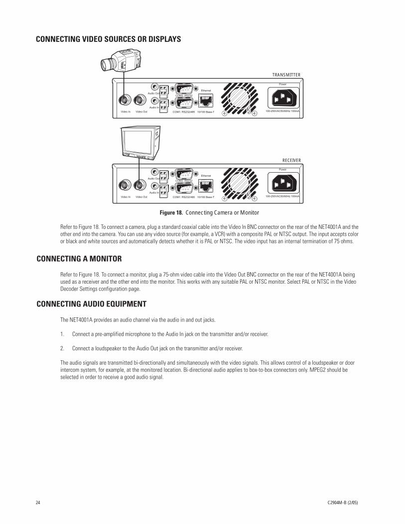
CONNECTING VIDEO SOURCES OR DISPLAYS
Figure 18. Connecting Camera or Monitor
Refer to Figure 18. To connect a camera, plug a standard coaxial cable into the Video In BNC connector on the rear of the NET4001A and theother end into the camera. You can use any video source (for example, a VCR) with a composite PAL or NTSC output. The input accepts coloror black and white sources and automatically detects whether it is PAL or NTSC. The video input has an internal termination of 75 ohms.
CONNECTING A MONITOR
Refer to Figure 18. To connect a monitor, plug a 75-ohm video cable into the Video Out BNC connector on the rear of the NET4001A beingused as a receiver and the other end into the monitor. This works with any suitable PAL or NTSC monitor. Select PAL or NTSC in the VideoDecoder Settings configuration page.
CONNECTING AUDIO EQUIPMENT
The NET4001A provides an audio channel via the audio in and out jacks.
1. Connect a pre-amplified microphone to the Audio In jack on the transmitter and/or receiver.
2. Connect a loudspeaker to the Audio Out jack on the transmitter and/or receiver.
The audio signals are transmitted bi-directionally and simultaneously with the video signals. This allows control of a loudspeaker or doorintercom system, for example, at the monitored location. Bi-directional audio applies to box-to-box connectors only. MPEG2 should beselected in order to receive a good audio signal.
Video In Video Out
Audio Out
Audio In
COM1: RS232/485 10/100 Base-T
Ethernet
Power
100-250VAC50/60Hz 100mA
COM2: RS232
Video In Video Out
Audio Out
Audio In
COM1: RS232/485 10/100 Base-T
Ethernet
Power
100-250VAC50/60Hz 100mA
COM2: RS232
TRANSMITTER
RECEIVER

C2904M-B (2/05) 25
CONNECTING DATA TERMINALS
The bi-directional data interface ports can be used as control ports for equipment connected to the NET4001A (for example, a domecamera with motorized lens).
USE AS CONTROL TERMINAL PORTFor local control and configuration of the unit, you can connect the COM port of a data terminal (for example, a PC running a standardterminal program) to COM 1 on the NET4001A.
You can use a standard terminal program to communicate with the unit. The default parameters are set to 19200 baud, 8 bits of data, 1stop bit, and no parity (8N1).
For more information on the command set, see the Configuration section. This mode allows the control port to be used to send serial datathat requires flow control.
You can configure the RS-232 half-duplex mode in the web browser. The RTS and CTS signals are enabled for flow control.
If this RS-232 mode is chosen, the camera control data is transferred to this port. Certain cameras with fixed data length require thebuffered RS-232 mode. (This half-duplex mode is not required for interfacing to any Pelco product.)
Figure 19. Control Terminal Port Pin Assignments in RS-232 Mode
1 2 3 4 5
6 7 8 9
VIEWED FROM SOLDERINGSIDE OF PLUG
Pin Name Direction Description
1 DCD Input Data Carrier Detect2 RXD Input Receive Data3 TXD Output Transmit Data4 DTR Output Data Terminal Ready5 GND Ground6 DSR Input Data Set Ready7 RTS Output Ready To Send8 CTS Input Clear To Send9 – – –
USE AS TRANSPARENT DATA PORTThe COM 2 serial interface offers a transparent serial data channel between the receiver and the transmitter. A typical application fortransparent data is remote control of peripheral equipment (for example, a dome system with PTZ functions). You also can use thesechannels to control remotely any external device with a serial interface. The serial data is transferred in parallel to the video and audiodata.
Transmission of transparent data is enabled only after a video connection has been established. Also, the RS-232 interface for thetransparent data port does not support hardware flow control.
For proper operation, you must configure the following: baud rate, parity of the interface of the PelcoNet NET4001A transmission systemunit, and number of data and stop bits. Use a web browser to configure these parameters at the unit.
The transparent data interface is used to control PTZ cameras remotely, to transmit data transparently between the two units, or tocontrol equipment connected to a PC COM port. Transmission of transparent data is possible only when the units are connected. Only thedata transmit and receive signals are provided at this port.
1 2 3 4 5
6 7 8 9
VIEWED FROM SOLDERINGSIDE OF PLUG
Pin Name Direction Description
1 – N.C.2 RXD Input Receive Data3 TXD Output Transmit Data4 – N.C.5 GND Ground6 – N.C.7 – N.C.8 – N.C.9 – N.C.
Figure 20. Data Port Pin Assignments in RS-232 Mode

26 C2904M-B (2/05)
CONNECTING EXTERNAL SENSORS
Figure 21. Connecting External Sensors and Peripheral Devices
The unit has an alarm input that lets you connect an external signaling device, like a door contact or motion detector. If configuredaccordingly, an alarm trigger can, for example, set up an automatic connection between NET4001A and the remote station. You canconnect switches or contacts directly without a separate power supply.
Do the following to connect an external sensor. Refer to Figure 21.
1. Pull the Input (bottom) terminal block from its plug-in base.
2. Attach the conductor to the alarm input terminal. Either terminal will work. A ground conductor can be attached to the remainingterminal if needed. (Insert a small screwdriver tip in the top square hole and push hard enough to open the lower hole. Insert thewire in the lower hole.)
3. Push the terminal block back on to the plug-in base.
CONTROLLING PERIPHERAL DEVICES
The NET4001A has an output for switching an external device (for example, a light or siren). The relay can be operated interactively,during an active connection, or automatically to coincide with certain events. Settings for the relay must be configured (refer to theConfiguration section).
Typical applications of the relay output are activating door openers or switching of lights and other electrical devices. Do not exceed themaximum rating of 40V and 0.8A.
Do the following to connect a peripheral device. Refer to Figure 21.
1. Pull the Output (top) terminal block from its plug-in base.
2. Attach the conductor to the output terminal. Either terminal will work. A ground conductor can be attached to the remaining terminalif needed. (Insert a small screwdriver tip in the top square hole and push hard enough to open the lower hole. Insert the wire in thelower hole.)
3. Push the terminal block back on to the plug-in base.

C2904M-B (2/05) 27
Figure 22. Connecting to the LAN Port
Refer to Figure 22. To connect a 10/100 BASE-T network, plug a standard UTP/Cat5 cable with RJ-45 connectors into the receptaclelabeled Ethernet on the NET4001A. You can connect directly to the Ethernet network. The green ETHERNET LED on the front of the unit(refer to Figure 1) lights as soon as the connection to the network is correct physically and synchronized with the LAN. Check the cable orrefer to the Troubleshooting section if the LED does not light.
The second ETHERNET LED flashes red when data is transmitted.
Video In Video Out
Audio Out
Audio In
COM1: RS232/485 10/100 Base-T
Ethernet
Power
100-250VAC50/60Hz 100mA
COM2: RS232

28 C2904M-B (2/05)
CONFIGURATION
There are three ways to configure your system:
• The most basic configuration is accomplished by connecting a terminal to the RS-232 terminal port. You then type in commands andparameters. Refer to the Configuration Using a Terminal Program section.
• Another way is to use the Telnet command and IP address from your PC to access the same interface as the terminal program. (Clickthe Start button at the bottom of your PC screen, click Run, type command, type telnet and the IP address.) You can then followthe instructions in the Configuration Using a Terminal Program section.
• A more convenient, complete configuration and display of video is through the built-in HTTP server, which connects to any standardweb browser (for example, Internet Explorer). You then configure using screens and menus. This is the recommended method. Referto the Configuration Using a Web Browser section.
CONFIGURATION USING A TERMINAL PROGRAM
Using a terminal program (for example, the Windows application HyperTerminal) connected to the RS-232 terminal port on the unit’s rearpanel provides limited configuration and control capabilities (null modem cable required). Ensure that the PC’s COM port is set up properly(default properties are 19200 baud, 8N1) and that the local terminal echo is disabled.
Do the following:
1. Connect the COM 1 on the NET4001A to an unused serial port on the PC.
2. After the connection is made, you will be prompted for the case-sensitive username (service).
3. All commands consist of single characters you type inside the terminal window. Enter only one command at a time and do notterminate this input by pressing the Enter key. After entering a value (for example, an IP address), check the entered characters againand only then press Enter to transmit the values to the NET4001A.
The following section shows a typical session.
TYPICAL SESSIONThe terminal program menu appears as follows in the terminal window. Refer to the Terminal Program Menu Structure section for moreinformation.
VJ1000 (172.16.0.80)
‘0’ Main Menu‘1’ IP‘2’ MPEG-2 encoder‘3’ MPEG-4 encoder‘4’ Misc‘5’ Rcp+‘6’ logout
NOTE: You cannot use backspace during a terminal session—if you mistype a character, end your entry by pressing Enter and try again. Ifyou see duplicate characters on any entry, the “local echo” feature of your PC’s terminal program is not disabled.
If you are using the terminal to set up the unit’s IP address, just type 1 and then type 1 again. You are prompted to enter a new IP address:
local IP (*) 192.168.01�192.168.0.2 [Enter]
If you want to establish a live video connection to a remote unit, you have to specify the remote IP address by typing 5 and then enteringthe remote IP address in the same manner as the unit IP address as shown in the example above.
To establish a connection, go to the menu, and then press 5, and then 1. To disconnect, press 3 in the same menu.

C2904M-B (2/05) 29
TERMINAL PROGRAM MENU STRUCTUREThe following describes the terminal program menu structure.
Main Menu ‘0’ Main Menu‘1’ IP‘2’ MPEG-2 encoder‘3’ MPEG-4 encoder‘4’ Misc‘5’ Rcp+‘6’ logout
1 – IP MenuThe selections and format are shown below. Enter the appropriate information where indicated by the quotation marks, but do not enterthe quotation marks. An asterisk (*) means a reset after a change is necessary.
NOTE: When you change the IP address, subnet mask, or gateway IP address either through HyperTerminal or the browser, the systemneeds to be rebooted by cycling the power.
‘0’ Exit menu IP‘1’ local IP (*) 172.160.0.80 -> ‘new IP address’ [Enter]‘2’ local subnet mask (*) 255.255.0.0 -> ‘new subnet mask’ [Enter]‘3’ local gateway (*) 0.0.0.0 -> ‘new gateway IP address’ [Enter]‘4’ tx multicast group 224.1.2.37 -> ‘new transmit multicast group address’ [Enter]‘5’ remote IP 172.16.0.17 -> ‘new remote IP address’ [Enter]‘6’ ntp server 0.0.0.0 -> ‘new ntp server IP address’ [Enter]‘7’ alarm IP (access the Alarm IP Address menu)
7 – Alarm IP Address Submenu‘0’ Exit menu alarm IP‘1’ alarm IP [1] = 172.16.0.17‘2’ alarm IP [2] = 0.0.0.0‘3’ alarm IP [3] = 0.0.0.0‘4’ alarm IP [4] = 0.0.0.0‘5’ alarm IP [5] = 0.0.0.0‘6’ alarm IP [6] = 0.0.0.0‘7’ alarm IP [7] = 0.0.0.0‘8’ alarm IP [8] = 0.0.0.0‘9’ alarm IP [9] = 0.0.0.0‘a’ alarm IP [10] = 0.0.0.0
2 – MPEG-2 Encoder Menu (advanced MPEG-2 encoder settings)‘0’ Exit MPEG-2 configuration‘1’ current par 6 [1,2…8]‘2’ name 5 MBPS high quality‘3’ set defaults‘4’ bitrate 5000 [KBps]‘5’ GOP Structure 4 [1=I, 2=IP, 3=IPB, 4=IPBB]‘6’ GOP Length 15 [n]‘7’ streamtype 1 [1=VES, 3=PRG]‘8’ skip ratio 1 [n]‘9’ resolution 3 [0=QCIF, 1=CIF, 2=2CIF, 3=4CIF]‘a’ MPEG-1 0 [1=MPEG-1, 0=MPEG-2]
3 – MPEG-4 Encoder Menu (advanced MPEG-4 encoder settings)‘0’ Exit MPEG-4 configuration‘1’ current par 1 [1,2…8]‘2’ name high quality (CIF)‘3’ set defaults‘4’ bitrate 1000 [KBps]‘5’ I-frm dist 0 [n]‘6’ skip ratio 1 [n]‘7’ resolution 1 [0=QCIF, 1=CIF]

30 C2904M-B (2/05)
4 – Misc Menu‘0’ Exit Misc configuration‘1’ mac address (lists PelcoNet unit’s MAC address)‘2’ video out 2 [1=PAL, 2=NTSC] -> ‘set the video out’ [Enter]‘3’ change username login, enter username -> ‘new username’ [Enter]‘4’ passwords (access password menu)‘5’ test (access test menu)‘6’ timezone [sec] 28800 -> ‘new timezone’ [Enter]
4 – Password Submenu
‘0’ Exit password settings‘1’ live live -> ‘new live password’ [Enter]‘2’ user user -> ‘new user password’ [Enter]‘3’ service service -> ‘new service password’ [Enter]
5 – Test Submenu (allows full testing of the unit)
‘0’ Exit Test‘1’ boot history‘2’ video‘3’ audio‘4’ COM 1 232‘5’ COM 1 485‘6’ RTC‘7’ LED‘8’ ALARM‘9’ PHY‘a’ format HDD‘b’ FLASH‘c’ self test
5 – Rcp+ Menu‘0’ Exit menu rcp+‘1’ connect to remote host 172.16.0.17 (connects to remote host)‘2’ coding standard MPEG-4 (toggles MPEG-2/MPEG- 4)‘3’ disconnect all local connections (disconnects all live connections to the unit)‘4’ display connection list (displays all connections to the unit)‘5’ autoconnect OFF (toggles autoconnect ON/OFF)‘6’ direction outgoing (toggles outgoing/incoming/bi-directional)‘7’ protocol UDP (toggles TCP/UDP)

C2904M-B (2/05) 31
CONFIGURATION USING A WEB BROWSER
In addition to the aforementioned configuration using a terminal program, which only covers the most basic settings, a web browser is thetool of choice for a more complete configuration. To accomplish this, the system features a complete HTTP server.
Microsoft Internet Explorer 5.5 or higher is the recommended browser.
WEB SERVER CONCEPT1. Start your web browser.
2. Connect to the URL http://IP-Address, where IP-Address is the IP address of the unit you want to configure. Use the standard dot-separated format (x.x.x.x) to enter the address. The home page is displayed along with the video from the camera.
The HTTP server provides nine separate pages for configuration.
You can return to the home page from any other page by clicking the PelcoNet log. Clicking the Pelco® logo while on the home pageimmediately transfers you to the Pelco Internet home page, provided the network allows for Internet access.
In order for live video images to be decoded, the special ActiveX control file must be installed on your PC. The latest version of ActiveXcomes on the PelcoNet CD.
ONLINE HELPTo access the online help files, click Help on this page?

32 C2904M-B (2/05)
VIDEO ENCODER MPEG2CAMERAPRESET PARAMETER MPEG-2 ENCODINGVIDEO ON LIVE PAGE
GENERALUNIT NAMEUNIT IDPASSWORD LEVELPASSWORDPASSWORD CONFIRMDATE FORMATUNIT DATEUNIT TIMETIME ZONETIME SERVER IP ADDRESSHARDWARE VERSIONSOFTWARE VERSIONSOFTWARE UPLOADUPLOAD PROGRESSCONFIGURATION DOWNLOADCONFIGURATION UPLOAD
VIDEO DECODERVIDEO MONITOR NAMEVIDEO OUTPUT STANDARDVIDEO INPUT TERMINATION
ALARMVIDEO MOTION ALARMVIDEO LOSS ALARMALARM INPUTCONNECT ON ALARMCONNECTION TYPENUMBER OF VIDEO RECEIVER ADDRESSLIVE VIDEO RECEIVER IP ADDRESSREMOTE RECEIVER PASSWORDLIVE VIDEO AUTO-CONNECTDIRECTION OF ALARM CONNECTIONMOTION DETECTORSELECT SENSOR FIELDMOTION TRACKINGTRACKER LOCAL SENSITIVITYAVERAGE N [frames]OBJECT MIN SIZE [n*n blocks]ALARM INDICATOR
RELAYIDLE STATEOPERATING MODERELAY FOLLOWSRELAY NAMETRIGGER RELAY
UNIT IP ADDRESSSUBNET MASKGATEWAY IP ADDRESSVIDEO/AUDIO TRANSMISSIONMULTICAST STREAMINGMULTICAST GROUP IP ADDRESSMULTICAST PORT MPEG-2MULTICAST PORT MPEG-4MULTICAST PACKET TTL
NETWORK
SERIAL PORT FUNCTIONBAUD RATEDATA BITSSTOP BITSPARITY CHECKINTERFACE MODEHALF-DUPLEX MODE
INTERFACE COM1
INTERFACE COM2SERIAL PORT FUNCTIONBAUD RATEDATA BITSSTOP BITSPARITY CHECK
ESPRITWITH MJPEG
SERVER PUSH
ESPRITWITH
LIVE VIDEO
S
SPECTRA DOMESYSTEM WITH MJPEG
SERVER PUSH
SPECTRA DOME SYSTEM
WITH LIVE VIDEO
S
GENEX MUX WITHMJPEG SERVER PUSH
GENEX MUXWITH LIVE VIDEO
MATRIX CONTROLWITH MJPEG
SERVER PUSH
MATRIXCONTROL WITH
LIVE VIDEO
SERVER PUSH
LIVE VIDEO
CONTROL
SETUP
HOME
VIDEO ENCODER MPEG4CAMERA PRESET PARAMETER MPEG-4 ENCODINGVIDEO ON LIVE PAGE
QUICK GUIDE TO THE MENU STRUCTURE
Figure 23. PelcoNet NET4001A Menu Tree

C2904M-B (2/05) 33
PELCONET NET4001A HOME PAGE
Figure 24. PelcoNet Home Page
The home page is the starting point for any configuration.
The window in the left of the screen is the display area for decoded video.
• Clicking the Pelco logo on any page connects you to the Pelco Internet home page (provided the LAN supports Internet access).
• Click Live Video to choose a live display or Server Push for periodically updated stills.
• Click Control to access an options screen with links to pages where you can see and control the displayed view. (Refer to the WebBrowser Control Pages section.)
• Click Setup to access an options screen with links to configuration pages. Click any icon on the side or the text itself to transfer tothe desired page.
Figure 25. PelcoNet NET4001A Transmission System Setup Page

34 C2904M-B (2/05)
CONFIGURATION PAGE FOR GENERAL SETTINGSThe unit identification, password, date and time, timer server, and software update settings, as well as version information, comprise theGeneral Settings configuration page.
All units have a real-time clock set during manufacture. However, time and date can be changed any time; for example, when the units areoperated in different time zones.
Version numbers for the hardware and firmware are for information only. Whenever you need technical support, have these numbers ready.
Figure 26. Configuration Page for General Settings
NOTE: When changing any configuration item in one of the following pages, make sure to change a single item at a time. Then click therespective Set button. If more than one item needs to be changed, execute the procedure repeatedly. If more than one item is changedwithout clicking the Set button in between, only the entry associated with the clicked button is actually changed. All other entries returnto their previous settings.
All configuration items are stored in non-volatile memory so they are kept when the unit is powered down.
Some configurations apply only to transmitters (for example, camera settings) while others apply to receivers. All settings not expresslyrestricted to certain models apply to all.

C2904M-B (2/05) 35
Table A. General Settings
Configuration Default DescriptionItem Setting
Unit Name None The Unit name and Unit ID identify the device; for example, in the event of an alarm call. (For future development.)Unit ID None The ID serves as a machine-readable name. (For future development.)Password level None Select the password level from the pull-down menu.
Access to a NET4001A generally is protected with a password to prevent unauthorized use of the unit. The threelevels are:
• Service: This is the administrative, and highest level. This level grants access to all configuration parametersafter the current password is entered.
• User: This is the second highest level. This level lets the user view live video and access the control pages.
• Live: This is the lowest level. This level does not grant access to configuration pages but allows the unit to beoperated (for example, viewing video).
If any password level is set, you will be always be required to log on to the NET4001A.
For example, if a “live” level password is set and you view that unit through the browser, the unit will ask for a username and password to access any configuration page. If you then try to access the setup page, the unit will againprompt for a user name and password.
IMPORTANT: “Service” is an administrative account. If you do not set up a “service” password, then there is nopoint in setting up “user” or “live” passwords because a user can login to the unit as “service” and then eliminatethe “user” and “live” passwords.
Some scenarios that can occur are as follows:
• If a password is set for the service level, then the only way to access the setup page is by logging on using the“service” user name and the “service” level password.
• If no password is set for the service level, then you can log on with the “service” user name and no password oryou can log on with the “live” user name and the “live” password you have selected.
WARNING: Setting a “user” level password on a transmitter can cause complications on the receiver side in abox-to-box configuration. To avoid this, on the receiver’s Alarm Settings configuration page enter the transmitter’sIP address and user password in the appropriate fields (live video IP address and remote receiver password). If no“user” level password is set on a transmitter, then the receiver needs no setup.
Password None You can enter or change a password if the unit is accessed in the Service authorization level or if the unit is notprotected by a password. Passwords can be changed one at a time only (that is, either Service, User, or Live).Maximum entry is 19 alphanumeric characters. All entered characters will be saved when you click Set; however,only eight asterisks will be displayed when you access the screen next time.
Password None Re-enter the new password again to guard against typing errors. If the deviceconfirm is not protected by a password, the “No password set” message will be displayed.Date format Europe Use the pull-down menu to select the format for the date: USA, Europe, or Japan.Unit date N/A Enter the current date in MM/DD/YYYY format for the USA; DD.MM.YYYY for Europe; and YYYY/MM/DD for
Japan. This is the system date, driven by the internal real-time clock. The day of the week (first entry box) need notbe entered and will be automatically adjusted based on the given date.
Unit time N/A Enter the current time or click the Synchr. PC button to synchronize the NET4001A with your computer’s systemtime. The system time is driven by the internal real-time clock.
Time zone (UTC + 1.00) Use the pull-down menu to select the time zone for the NET4001A. This and the Timer Server IP Address settingsare important if the internal clock should be synchronized with the time received from a timer server on the Internet.
Time server 0.0.0.0 Enter the IP address of an NTP server. The time and date are automatically synchronized every two hours.IP addressHardware N/A Read-only hardware version number. This contains unique serial number, type of hardware, and revision.versionSoftware N/A Read-only firmware version number. This is important information should you need technical support.versionSoftware N/A Units have flash EPROMs for firmware upgrades in the field. These upgrades can be done directly from the webupload browser.
Enter the name of the file containing the upgrade, or locate it using the Browse button. Then click the Uploadbutton.

36 C2904M-B (2/05)
Table A. General Settings (Continued)
Configuration Default DescriptionItem Setting
Upload 0% This field shows the percentage of the upload that has been completed.progressConfiguration N/A Clicking the Download button saves the current configuration of the PelcoNet NET4001 transmission systemdownload to a PC file.Configuration N/A This copies a file from a PC to the NET4001A. Enter the name of the file containing the configuration, or locate itupload using the Browse button. Then click the Upload button to overwrite the configuration with the configuration
stored in the named file.

C2904M-B (2/05) 37
CONFIGURATION PAGE FOR MPEG 1/-2 VIDEO ENCODER SETTINGS
Figure 27. Configuration Page for MPEG 1/-2 Video Encoder Settings
MPEG-2 encoder and live page settings make up the configuration page for MPEG 1/-2 video encoder settings. The following tabledescribes the configuration items.
Table B. Configuration Page for MPEG 1/-2 Video Encoder Settings
Configuration Default DescriptionItem Setting
Camera Camera 1 Enter a camera name (30 alphanumeric characters maximum). (This name is not displayed except on this configura-tion page. For future development.)
Preset 2MBPS MPEG-2 data transmissions can be configured to suit the local operating environment (for example, networkparameter low delay architecture, bandwidth, data structures). To help with this, several pre-programmed profiles with different featuresMPEG-2 are provided. Select from the pull-down menu.encoding
• 2 MBPS low delay/3,5 MBPS low delay/5 MBPS low delay2 or 3.5 or 5 Mbps transmission rate with minimum delay on image refresh
• 2 MBPS high quality/3,5 MBPS high quality/5 MBPS high quality2 or 3.5 or 5 Mbps transmission rate with highest picture quality
• 2 MBPS with audio/3,5 MBPS with audio2 or 3.5 Mbps transmission rate with associated audio transmission
Video on live MPEG2 Select MPEG2 from the pull-down menu.page

38 C2904M-B (2/05)
CONFIGURATION PAGE FOR MPEG-4 VIDEO ENCODER SETTINGS
Figure 28. Configuration Page for MPEG-4 Video Encoder Settings
MPEG-4 encoder and live page settings make up the configuration page for MPEG-4 video encoder settings. The following table describesthe configuration items.
Table C. Configuration Page for MPEG-4 Video Encoder Settings
Configuration Default DescriptionItem Setting
Camera Camera 1 Enter a camera name (30 alphanumeric characters maximum). (This name is not displayed except on this configura-tion page. For future development.)
Preset high quality MPEG-4 data transmissions can be configured to suit the local operating environment (for example, networkparameter (CIF) architecture, bandwidth, data structures). To help with this, several pre-programmed profiles with different featuresMPEG-4 are provided. Select from the pull-down menu.encoding
• high quality (CIF)1 Mbps transmission rate for connections with high bandwidth
• high resolution (2CIF)1 Mbps transmission rate of high resolution for connections with high bandwidth
• small resolution (QCIF)9.6 Kbps transmission rate of low resolution for connections with high bandwidth
• DSL768 Kbps transmission rate for DSL connections
• ISDN (2B)128 Kbps transmission rate for ISDN connections over two B channels
• ISDN (1B)64 Kbps transmission rate for ISDN connections over one B channel
• MODEM33.6 Kbps transmission rate for analog modem connections
• GSM9.6 Kbps transmission rate for mobile communications (global standard)
Video on live MPEG2 Select MPEG4 from the pull-down menu.page

C2904M-B (2/05) 39
CONFIGURATION PAGE FOR VIDEO DECODER SETTINGS
Figure 29. Configuration Page for Video Decoder Settings
Video monitor name, output standard, and input termination make up this page. The following table describes the configuration items.
Table D. Configuration Page for Video Decoder Settings
Configuration Default DescriptionItem Setting
Video monitor Monitor 1 Enter an identifier for the monitor. (This name is not displayed except on this configuration page. For futurename development.)Video output PAL For devices that also function as a receiver, select the video standard from the pull-down menu: PAL or NTSC.standardVideo input On Select On from the pull-down menu to terminate video input if the video signal will not be looped through (fortermination example, with a T-connector).

40 C2904M-B (2/05)
CONFIGURATION PAGE FOR ALARM SETTINGSThe PelcoNet NET4001 transmission system is not only a multimedia gateway but also a security device and, therefore, has many featuresrelated to security applications. The configuration page for alarm settings lets you configure your unit for surveillance applications. Inmost surveillance-related applications, the receiver is located in a secure alarm center-type environment while the transmitter is mountedinside or at the location to be monitored.
Figure 30. Configuration Page for Alarm Settings
Figure 31. Motion Detection Screen

C2904M-B (2/05) 41
Figure 32. Motion Detection Grid Screen
The set of alarm features is explained below.
Table E. Alarm Settings
Configuration Default DescriptionItem Setting
Video motion N/A The system has a video motion detection feature. The video scene is monitored constantly for relevant motion.alarm
NOTE: Use of the motion detection feature is recommended only indoors and under controlled lighting conditions;it is not recommended in dim lighting.
To set motion detection, do the following:
1. Click the Motion detection button to access the Motion Detection screen. (Refer to Figure 31.) Press Defaultto get the default settings for motion detection. If you want to customize the settings, continue to step 2.
2. Select On from the Motion detector pull-down menu to trigger an alarm in the event of movement.
3. Click the Select area button to display a window with a grid superimposed on it (refer to Figure 32). Select thecells in the image you want the system to monitor for motion. You can use the Select all and Clear all buttons.The default is all cells selected (red).
To set an individual cell, click it with the left mouse button (it will turn red). Click with the right button todeselect a cell (which will turn white). Select or deselect multiple cells by holding down the left or right mousebutton and dragging. Release when finished.
Click the Set button.
4. Use the Motion tracking pull-down menu to turn on/off tracking. (Note that motion tracking overrides motiondetection.)
5. The Tracker box indicates and controls the direction of motion detection. You can set motion detection tooperate in one direction only by removing the check mark in the opposite direction.
6. Use the Local sensitivity slide bar to set detection sensitivity. You need to adapt sensitivity to the respectiveenvironment and the acceptable false alarm rate: for a lower false alarm rate select a lower sensitivity and viceversa. Experiment to find the best setting.
7. Use the Average n [frames] slide bar to define for how long or over how many pictures motion in the scenemust be detected before an alarm will be released. If the value is low, even movement over a small periodtriggers an alarm. If the value is high, movement over a longer period is required to trigger an alarm.
(Continued on next page)

42 C2904M-B (2/05)
Table E. Alarm Settings (Continued)
Configuration Default DescriptionItem Setting
8. Use the Object min size [nxn blocks] slide bar to designate the minimum number of cells in the frame amoving object must fill to trigger an alarm. You can set the value between 1*1 and 6*6 (2*2 is recommended).If the size of the object in the picture exceeds the value you set, motion detection triggers an alarm.
9. The Alarm indicator box lets you set a threshold so an alarm is triggered only if the sensitivity of the videosensor is exceeded. Thus, something such as background noise caused by the camera can be filtered to avoidunwanted alarms.
The blue line indicates the alarm threshold. Any value exceeding this produces an alarm signal. Components ofthe motion signal generating the alarm are indicated in red.
Pull up or down on the blue line to observe the motion detector. Set it straight above the basic deviation of thered curve.
10. Click Back to Alarm page! when finished.
The following conditions must be met for motion detection to function:
• Motion detection must be activated.• At least one cell must be activated.• Sensitivity must be set higher than zero.
Video loss Off If you select On, the signal from the video source (the camera in most cases) is monitored constantly for interrup-alarm tion. If no signal is received, the NET4001A triggers the alarm.Alarm input Off/High/ 1. Select On from the pull-down menu if you want to activate an alarm through an external alarm sensor. If not,
Input 1 select Off.
2. Select High or Low for the voltage level to activate the alarm.
3. Enter a name for the alarm input to be displayed on the screen if an alarm is activated.Connect on Off The alarm functions would have little effect without automatically triggering corresponding actions. Select On foralarm automatic connection to the video receiver’s IP address. The idea is to provide a remote monitoring station with live
video in case of an alarm.
This feature can be useful even for many applications not related to alarm conditions. One example is a video-equipped door entry system: when the doorbell is pressed, a contact closes and the connected transmitterautomatically connects to a receiver. Full-duplex audio can provide verbal communication, while the relay outputcan open the door remotely.
Connection MPEG-2 Select the transmission standard for the alarm connection to the receiver’s IP address.typeNumber of 1 The NET4001A can store up to 10 different alarm IP addresses. When an alarm occurs, a connection will bevideo receiver established to the first address. Up to 10 separate addresses can be added should the first address not accept theaddress call.
Use the pull-down menu to select how many additional addresses to contact, if necessary. (Add them in the nextfield.)
Live video 0.0.0.0 Enter the IP address of the receiver to be notified in the event of an alarm.receiver IPaddressRemote N/A Enter the password for the remote unit if it is protected by a user or live password.receiverpasswordLive video Off Select On if at each restart an active connection should be set up automatically to the receiver’s IP address.auto-connect Otherwise, select Off.
The auto connect feature guarantees an active connection to the receiver’s alarm IP address even after connectionbreakdown or network failures. As soon as the network communications are restored, the connection is reinstated.On a receiver, this feature is enabled to establish a connection to a transmitter automatically.
Direction of Outgoing Use the pull-down menu to select either Incoming, Outgoing, or Bidirectional depending on whether you wantalarm to receive (incoming), send (outgoing), or receive and send (bidirectional) video.connection

C2904M-B (2/05) 43
CONFIGURATION PAGE FOR RELAY SETTINGSYou can use the configuration page for relay settings to specify parameters such as normally open or normally closed switching andbistable or monostable operation of the output.
Figure 33. Configuration Page for Relay Settings
The relay settings are described in the following table.
Table F. Relay Settings
Configuration Default DescriptionItem Setting
Idle state Open Select Open (N.O. at zero current) if the relay will operate as a normally open contact or Closed (N.C. at zerocurrent) if it will operate as a normally closed contact.
Operating mode Bistable Select the relay’s operating mode.
• When you select the default Bistable mode, the relay will stay in the idle or active state for an indefinite period.(For example, select Bistable if a floodlight activated by an alarm is to remain switched on at the end of thealarm.)
• When you select monostable mode, the relay automatically falls back to the idle state after a predefined periodexpires. (For example, select 10 s if a siren triggered by an alarm is to sound for 10 seconds.)
The choices on the pull-down menu are: Bistable, 0.5 s, 1 s, 2 s, 5 s, 10 s, and 60 s.Relay follows Off Select from the pull-down menu an event that will activate the relay. A typical application is having the relay
following the status of the alarm input; for example, to power peripheral equipment or even the camera itself.Select from the following:
• Off: Relay does not operate.• Connection: Relay operates whenever you open live video and will turn off once you exit live video.• Video alarm: Relay operates when there is loss of the video signal.• Motion alarm: Relay operates when there is motion alarm.• Local input: Relay is operated by an external alarm sensor.• Remote input: Relay is operated by a switching contact from a remote location.
Relay name Relay 1 Enter a name for the relay that will appear on the Live page.
Trigger relay N/A Click the Relay button to manually switch the relay (for example, as a test or to operate a door opener).

44 C2904M-B (2/05)
CONFIGURATION PAGE FOR COM 1 INTERFACE SETTINGSYou can use this configuration page to set the parameters of the COM1 RS-232/RS-485 serial interface port.
Figure 34. Configuration Page for COM 1 Interface Settings
Table G. Interface Settings for COM 1
Configuration Default DescriptionItem Setting
Serial port Terminal Select a controllable device from the pull-down menu: Terminal, Transparent, or Pelco Prot. (protocol).function
If the port must transmit data transparently, select Transparent.Baud rate 19200 Select any transmission rate from 300 to 57600 baud.Data bits 8 Select the number of data bits (7 or 8) per character.Stop bits 1 Select the number of stop bits (1 or 2) per character.Parity check None Select the type of parity check (None, Even, or Odd).Interface mode RS232 Select the required protocol for the port (RS232 or RS422/485).Half-duplex Off If you choose this RS-232 mode, camera control data is transferred automatically to the control port, which is amode serial interface on the unit’s rear panel to which you can connect a PC. This mode supports flow control.
NOTE: In On or Buffered mode, transparent data is rerouted to the control terminal port; terminal functions areprovided on the transparent data port.

C2904M-B (2/05) 45
CONFIGURATION PAGE FOR COM 2 INTERFACE SETTINGSYou can use this configuration page to set the parameters of the COM2 RS-232/RS-485 serial interface port.
Table H. Interface Settings for COM2
Configuration Default DescriptionItem Setting
Serial port Transparent Select the function for serial port 2 from the pull-down menu: Terminal, Transparent, or Pelco Prot. (protocol).function
If the unit will be operated from a terminal, select Terminal. If the port must transmit data transparently, selectTransparent.
Baud rate 19200 Select any transmission rate from 300 to 57600 baud.Data bits 8 Select the number of data bits (7 or 8) per character.Stop bits 1 Select the number of stop bits (1 or 2) per character.Parity check None Select the type of parity check (None, Even, or Odd).
Figure 35. Configuration Page for COM 2 Interface Settings

46 C2904M-B (2/05)
CONFIGURATION PAGE FOR NETWORK SETTINGS
Figure 36. Configuration Page for Network Settings
Network and routing information make up the configuration page for network settings. These settings are used to integrate the NET4001Ainto an existing network. The following table describes the configuration items.
NOTE: When you change the IP address, subnet mask, or gateway IP address either through HyperTerminal or the browser, the systemneeds to be rebooted by cycling the power.

C2904M-B (2/05) 47
Table I. Network Settings
Configuration Default DescriptionItem Setting
Unit IP address 192.168.0.1 Enter a unique IP address that is valid for your network. The pre-configured default IP address allows for easyconfiguration in closed environments. You can use a crossed cable to connect directly to a PC.
NOTE: Changing the IP address also affects the current browser connection. You will have to enter the new URL toregain connectivity to the unit.
Subnet mask 255.255.255.0 Enter a valid subnet mask for your network.Gateway 0.0.0.0 Enter the IP address of the router if the unit is to establish a connection outside of the local network. This isIP address typically used in a WAN environment. This field can otherwise remain empty (0.0.0.0).Video/Audio UDP Use the pull-down menu to select the means of transmission. Select TCP (Port 80) to send data through a firewall.transmission Select UDP for communication between local networks.Multicast Off Use the pull-down menu to select multicast streaming mode.streaming
Besides a one-to-one connection between a transmitter and a receiver (unicast), the NET4001A lets you connect anumber of receivers to receive the video signal simultaneously. This is achieved by distribution of a single datastream on the network itself to a number of receivers in a defined group (multicast).
Choose one of the options. With one of the MPEG options selected and a valid multicast group address selected inthe Multicast Group IP Address field, the NET4001A operates in multicast mode (data stream duplicated over thenetwork).
When multicast streaming is turned off, operation resorts to unicast mode.Multicast group 0.0.0.0 This is the Multicast IP address. (Network hardware—such as switches, hubs, routers, etc.—must support theIP address multicasting protocol, ICMP.) This field sets PelcoNet to use the multicasting protocol, which allows more efficient
use of bandwidth. The IP range is 224.0.1.0 through 238.255.255.255.
Some IP addresses may be reserved for system resources. Contact your network administrator for more information.Multicast port 50000 Enter the port address for the MPEG-2 data stream.MPEG-2Multicast port 60000 Enter the port address for the MPEG-4 data stream.MPEG-4Multicast 1 Enter the number of seconds for the packet to live.packet TTL
TTL stands for time to live. This setting defines the lifetime of multicast packages in the network. If multicasttraffic is to be transmitted over routers and switches this setting is important in adjusting the lifetime of thepackage to the network topology (shape).

48 C2904M-B (2/05)
LIVE VIDEO PAGE INDICATORS
These five indicators are located at the top of the Live Video and live video Control pages.
Indicator DescriptionMPEG-2/MPEG-4 Indicates whether live viewing is in MPEG-2 or MPEG-4 format. You can assign this on the Video Encoder Settings page.M (motion detector) When motion alarm is triggered, this indicator turns red while the alarm is activated.V (video alarm) When the video loss alarm is triggered, this indicator turns red until the video returns.I (input activation) When triggered, this indicator turns red. The name assigned to this trigger and its duration and how it reacts can be
assigned on the Alarm page.R (relay activation) When triggered, this indicator turns red. The name assigned to this trigger and how it reacts can be assigned on the
Relay page.

C2904M-B (2/05) 49
LIVE VIDEO AND SERVER PUSH VIDEO PAGES
Figure 37. Live Video Page
The Live Video page shows a real-time picture of a camera view with update rates and image quality similar to a box-to-box configuration.It can be configured for bandwidth use and for various image quality settings. The Server Push page shows still pictures that are updatedperiodically, and image quality is fixed.
1. To access the PelcoNet NET4001 transmission system home page, you must first connect to the Internet/intranet network and openInternet Explorer (the browser).
2. Then, enter the default address 192.168.0.1 in the address box. If this address has been changed, enter the application address. Thehome page appears.
3. Click either Live Video or Server Push on the home page.
To exit either page, click an option at the top of the page.
The program displays dialog boxes when you try to view live video under any of the following conditions:
• With a browser other than Internet Explorer
• Without first installing ActiveX
• When your computer display is not set for 16- or 32-bit color
To change: right-click the desktop, and then click Properties, the Settings tab, and select High Color [16 bit] or True Color [32bit]. For NT, select 65536 Colors.
NOTE: Do not change the video properties while viewing live video. You may get a gray background if you do.
• When Microsoft Virtual Machine is not enabled
To enable: on the Tools menu select Internet Options, select the Advanced tab, locate Microsoft VM, checkmark Java ConsoleEnabled and JIT compiler for virtual machine enabled. Reboot your PC.
With any of these conditions, you can only view the video as a series of still images.

50 C2904M-B (2/05)
WEB BROWSER CONTROL PAGES
ACCESSING THESE PAGES
1. To access the PelcoNet NET4001 transmission system home page, you must first connect to the Internet/intranet network and openInternet Explorer (the browser).
2. Then, enter the default address 192.168.0.1 in the address box. If this address has been changed, enter the application address. Thehome page appears.
3. Click Control to access the Device Controls page.
4. The Device Controls page has underlined links to the control pages. To access, click one.
Figure 38. Device Controls Page
CONTROLLING THE DISPLAY
The live video control pages include representations of keys that let you control various functions (in addition to showing the cameradisplay). Use the mouse pointer and click the left mouse button to enable options and operate controls on the screen. Click outside theoptions to disable a radio button or selection button.
Live video pages let you choose the size of the video viewing area. Click either 352x288 (small) or 704x576 (large) in the Resize Videofield.
Live video pages also let you record and play back camera views on a PC’s hard drive. Refer to the Record and Play Back the Display on aPC section for details.
On the Spectra and Esprit live video control pages, you can control the following:
• Presets –To program a preset: position the camera, click the Set check box, and then click a preset number button.
To activate a preset: click a preset number button.
• Patterns – You can program only one pattern through PelcoNet. To program a pattern: click the Set check box, then click Start, andthen use the arrow buttons to position the camera. Click Stop to halt pattern programming.
To operate a pattern: click Start to begin the pattern and Stop to halt.
• Programming Menus – To access the programming menus: click the Set check box, and then click the 95 button. Use the open irisicon to open menus and set options. Use the open iris icon in conjunction with the Exit option to move backward through menulayers and to exit programming mode.

C2904M-B (2/05) 51
MATRIX CONTROL LIVE VIDEO/SERVER PUSH PAGE CONTENTS
Figure 39. Matrix Control Page
The Matrix Control pages contain the following:• Ten numbered buttons• CLR (clear) button• CAM (camera) button• MON (monitor) button• PRST (preset) button• PATT (pattern) button• MAC (macro) button• STOP button• BWD (backward) button• FWD (forward) button• AUX ON button• AUX OFF button
The following are arrayed under “Lens ”:• Iris open and close buttons• Focus far and near buttons• Zoom out and zoom in buttons
The following are arrayed under “Pan/Tilt ”:• Eight direction arrow buttons• Home button in the center
Recording control buttons are beneath the picture.

52 C2904M-B (2/05)
GENEX LIVE VIDEO/SERVER PUSH PAGE CONTENTS
Figure 40. Genex Control Page
The Genex pages contain the following across the top of the page:• Main and Spot monitor selection radio buttons• A LIVE/VCR button• A Sequence button• A View button• A zoom button• A picture-in-picture button• Buttons for 4-, 9-, and 16-screen display
The following are arrayed down the right side of the page:• Radio buttons for 16 cameras• Iris open and close buttons• Focus far and near buttons• Zoom out and in buttons• Eight direction arrow buttons with a home button in the center• Ten numbered buttons to use with the Pattern button (enter preset number and click Pattern)• A Pattern button
Recording control buttons are beneath the picture.
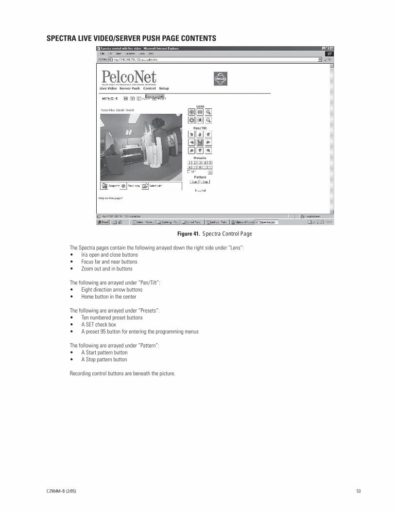
C2904M-B (2/05) 53
SPECTRA LIVE VIDEO/SERVER PUSH PAGE CONTENTS
Figure 41. Spectra Control Page
The Spectra pages contain the following arrayed down the right side under “Lens”:• Iris open and close buttons• Focus far and near buttons• Zoom out and in buttons
The following are arrayed under “Pan/Tilt”:• Eight direction arrow buttons• Home button in the center
The following are arrayed under “Presets”:• Ten numbered preset buttons• A SET check box• A preset 95 button for entering the programming menus
The following are arrayed under “Pattern”:• A Start pattern button• A Stop pattern button
Recording control buttons are beneath the picture.

54 C2904M-B (2/05)
Figure 42. Esprit Control Page
The Esprit pages contain the following arrayed down the right side under “Lens”:• Iris open and close buttons• Focus far and near buttons• Zoom out and in buttons
The following are arrayed under “Pan/Tilt”:• Eight direction arrow buttons• Home button in the center
The following are arrayed under “Presets”:• Ten numbered preset buttons• A SET check box• A preset 95 button for entering the programming menus
The following are arrayed under “Pattern”:• A Start pattern button• A Stop pattern button• A Wiper button
Recording control buttons are beneath the picture.
ESPRIT LIVE VIDEO/SERVER PUSH PAGE CONTENTS

C2904M-B (2/05) 55
ADVANCED FEATURES
AUTOMATIC CONNECTION FEATURE
The advantage of conventional dedicated cabling lies in guaranteed performance and availability. The PelcoNet transmission system’sauto-connect feature is designed to provide the same level of guaranteed connectivity expected from analog coaxial video cables.
IT networks commonly experience short breakdowns and congestion. Protocols used for computer communication (for example, TCP/IP)are designed to cope with missing data and interruptions. With the PelcoNet NET4001A transmission system, once a video connection isestablished, the video stream normally terminates gracefully when a network connector is pulled or the network is otherwise disrupted.
The system can be configured to reconnect automatically to guarantee connectivity. To activate this feature, use the Connect on alarmpull-down menu to select On (on the Alarm Settings configuration page) and confirm this choice by clicking the Set button. Now the unitwill try to connect to the specified alarm IP address every time. The receiving station (alarm IP address) can be another receiver.
VIDEO MOTION DETECTION FEATURE
The transmitter can check video input automatically for significant motion in the scene and trigger an alarm if the motion exceeds a presetthreshold. Activate motion detection by clicking the Motion detection button on the Alarm Settings configuration page, and then use theMotion detector pull-down menu on the Motion Detection screen to select On.
Use the Local sensitivity sliding scale to select sensitivity for motion detection. You need to tailor this parameter to the particularapplication. Experiment to find the best setting. For example, higher sensitivity may lead to erroneous detection and increase false alarms.
You can restrict motion detection to certain areas in the scene. Click the Select area button. Select the cells you want the system tomonitor for motion. To set an individual cell, click it with the left mouse button (which will turn red). Click with the right mouse button todeselect a cell (which will turn white).Select or deselect multiple cells by holding down the left or right mouse button and dragging.Release when finished, and then click the Set button.
RECORDING AND PLAYING BACK THE DISPLAY ON A PC
CHOOSING WHERE TO STORE THE FILEThe program automatically saves the snapshot (still picture) and video recording files at C:\ on the hard drive of the PC on which you areviewing the picture unless you tell it otherwise. If you want to store files in a different location on the PC, you need to first specify thatlocation. To do so:
1. On the Home page, click either Control (and then click one of the underlined links to a live video control page) or Live Video.
2. Click the Select path icon (open folder) beneath the picture. (Click the icon just once. Double-clicking may cause display problemswith the select path window.)
3. The program opens the “Path for saving MPEG/JPEG files” screen. Do not specify a file name (leave blank), just navigate to thelocation where you want the file stored and then click the Save button.
The file of any snapshot or video you record will be saved to that location.
RECORDING A SNAPSHOTYou can record a snapshot from the Live Video page or live video Matrix, Genex, Spectra, and Esprit control pages. The file is recorded onthe PC on which you are viewing the picture. To do so:
1. On the Home page, click either Control (and then click one of the underlined links to a live video control page) or Live Video.
2. Position the camera as desired (if it has PTZ capability).
3. Click the Snapshot icon (camera) to record a still picture. The snapshot is saved on the PC’s hard drive with a .jpg extension.

56 C2904M-B (2/05)
VIEWING A SNAPSHOTYou can view a snapshot by double-clicking on the desired file (.jpg extension) in Windows Explorer.
RECORDING THE VIDEO DISPLAYYou can record the camera display from the Live Video or live video Matrix, Genex, Spectra, and Esprit control pages. The file is recordedon the PC on which you are viewing the picture. To do so:
1. On the Home page, click either Control (and then click one of the underlined links to a live video control page) or Live Video.
2. Position the camera as desired (if it has PTZ capability).
3. Click the MPEG Recording icon (red dot button) to begin recording. The button flashes while recording is happening.
4. Click the MPEG Recording button again to stop recording. The recording is saved on the PC’s hard drive with an .mp4 or .mp2extension.
NOTE: When video files are saved, an extra file (.ind extension) is created that allows you to see the video in Pelco’s MPEG Viewer. If youdelete this file, you cannot view the saved .mp4 file although .mp2 files can still be viewed using the Windows Media Player.
VIEWING THE VIDEO DISPLAYThe video file is identified by date and time. MPEG-2 and MPEG-4 files are viewed differently.
• MPEG-2 Files
View MPEG-2 files using the Windows Media Player. In Windows Explorer, double-click the file (.mp2 extension) you want to view.The player will load and play the file automatically.
• MPEG-4 Files
View MPEG-4 files using the MPEGViewer program included on the PelcoNet Resource CD. Do the following:
1. Locate the MPEGViewer.exe file (either on the resource CD or the PC) or MPEG Viewer shortcut on the desktop if you used theinstallation program on the CD. Double-click the file. The viewer opens.
Figure 43. Viewer Screen
2. Click the Open button. A browse dialog box opens. Navigate to the recorded file (.mp4 extension) you want to view. Click the file tohighlight it, and then click Open.
3. Click Play on the viewer to begin playback.
The start and end locations are shown below the slide control. A counter marks your location in the file.
4. Use the Pause button to temporarily halt playback. You can change your location in the file by moving the pointer on the slidecontrol. Click Play to resume playback.
5. Click Stop to halt playback.

C2904M-B (2/05) 57
FIRMWARE UPLOADUnits have flash EPROMs for firmware upgrades in the field. These upgrades can be done directly from the web browser.
Do the following to upload firmware using the web browser.
1. Obtain the latest PelcoNet NET4001A transmission system firmware from Pelco (http://www.pelco.com).
2. Use the browser to select the General Settings configuration page of your unit.
3. Use the Browse button in the Software upload field to select the correct new firmware file.
4. Click the Upload button. The Upload progress field shows how the upload is proceeding.
5. After about 30 seconds you should get a feedback message from the connected unit.
6. The message “upload complete – WAIT” confirms the correct upload of the new firmware, which is now being installed.
WARNING: Do not disconnect power to the unit for any reason while firmware is being installed. Disrupting the cycle will damagethe flash EPROM. If this occurs, you will have to return the unit for repair.
The unit automatically restarts when a successful upload is completed.
However, if the LED IN flashes on conclusion, the upload has been unsuccessful and must be restarted. To do so: in the browser’saddress field behind the unit’s IP address, enter /main.htm. For example, 192.168.0.12/main.htm. Restart the upload process.
7. If you try to upload an invalid firmware file, you will get the message “Upload Failed.”
8. If you revisit the General Settings configuration page after the firmware is uploaded successfully, you will see the message “NewFirmware Installed.”
CONFIGURATION DOWNLOADThis feature, located on the General Settings configuration page, lets you save the current configuration of the PelcoNet NET4001Atransmission system to a PC file.
Do the following:
1. Use the browser to select the General Settings configuration page of your unit.
2. Click the Download button in the Configuration download field.
3. Save the file to the local hard drive. Use the default name and click the Save button. (Do not rename the configuration file when yousave it; the NET4001A will not be able to upload the file later.)
4. Click the Close button.
You now have a configuration file to upload into a different PelcoNet unit.
CONFIGURATION UPLOADThis feature copies a configuration file from a PC to the NET4001A.
Do the following:
1. Use the browser to select the General Settings configuration page of your unit.
2. Enter the name of the file containing the configuration, or locate it using the Browse button in the Configuration upload field.
3. Click the Upload button to overwrite the configuration with the configuration stored in the named file.
4. Wait for the General Settings page to refresh on its own. The configuration now matches that of the file created in the ConfigurationDownload section.

58 C2904M-B (2/05)
TROUBLESHOOTING
If the following instructions fail to solve your problem, contact Pelco Technical Support at 1-800-289-9100 for help. You should have theserial number from the bottom of the unit and the firmware version ready in case they are needed.
Do not try to repair a unit yourself. Opening it immediately voids any warranty. Leave maintenance and repairs to qualified technicalpersonnel. Swap a defective unit with a replacement unit and return the defective one for repair.
LEDS
The NET4001A has several LEDs that show the operating status and indicate possible faults:
LED Indication MeaningVIDEO Lit green A video signal is present at the input.IN Flashing slowly No valid firmware is installed; firmware upload is necessary.
Lit green Alarm input activated.Lit red Alarm triggered.Not lit Alarm input inactive.
OUT Lit green Relay activated.Not lit Relay not activated.
COM Flashing orange Data transmission via serial interface.ETHERNET Lit green Physical connection to the network is established.
Flashing orange Data transmission via the network.POWER Lit green The unit is switched on but no connection.
Flashing green 600 ms (50:50) = 1 active connection.300 ms (50:50) = 2 active connection.150 ms (50:50) = 3 or more connections.
Flashing green (50:650) = Streaming mode is active.Flashing green 70 ms (50:50) = External prompt.Not lit The unit is switched off.
TERMINAL PROGRAM
• Is the right COM port interface on the PC selected for the terminal program, and are the settings correct? Is the cable connected toCOM 1 and not COM 2 on the PelcoNet unit? Program default settings are 19200 kb/s, 8 data bits, no parity, 1 stop bit (8N1) for theterminal program.
• If the data exchange between the terminal program and the system still does not work, check the serial cable. Does the systemanswer when you press the Enter key?
• Disable the local echo if you see duplicate characters on your screen.
TROUBLESHOOTING A TCP/IP NETWORK USING A PING UTILITY
(Enter the appropriate information where indicated by the quotation marks below. Do not enter the quotation marks.)
To see if a unit in your network can be reached, try to ping your unit by typing the following command in a DOS window:
c:\ping ‘unit IP address’
If it is reached, there will be a response like the following:
Reply from <IP address>: bytes=32 time=NN ms TTL=xxx
If the LAN path is malfunctioning, the ping command will time out. If so, you could have one of the following problems:
• Wrong physical connections. Make sure the green Ethernet LED is on.
• Wrong network connection. Verify the IP address is entered correctly and that subnet mask and gateway address are set properly.
Otherwise, ask your network administrator.

C2904M-B (2/05) 59
TROUBLESHOOTING CONNECTION PROBLEMS
If you fail to connect to a system from a hardware receiver, make sure network connectivity is available (for example, by using the pingcommand).
TROUBLESHOOTING THE VIDEO CONNECTION
If no video or a distorted video image is displayed at the receiver during a connection to a transmitter:
• Make sure the camera is switched on and the coaxial cable is connected to the NET4001A transmitter.
• Check the camera cable and connect a video monitor to the camera and check that the camera is functioning correctly.
• At the receiving system, make sure the monitor is switched on and the coaxial cable is connected to the NET4001A receiver.
• Check the monitor cable and the selection of the monitor channel, if the monitor features more than one video channel.
• If the monitor can display only a single video standard (PAL or NTSC), check the setting of the video output format on the VideoSettings configuration page.
TESTING THE AUDIO CONNECTION
TEST BETWEEN TWO NET4001A UNITS1. Connect a microphone (via a preamplifier) to the Audio In jack and a loudspeaker to the Audio Out jack on each NET4001A.
2. After establishing the Ethernet connection, audio should be transmitted both ways.
3. If you cannot hear any audio, check the microphone and loudspeaker together with other audio equipment, and make sure themicrophone is switched on if it has a power switch.
TEST BETWEEN NET4001A AND PC1. Connect a microphone (via a preamplifier) to the Audio In jack on the PelcoNet unit.
2. Connect a loudspeaker to the PC’s sound card. After establishing the Ethernet connection, audio should be transmitted from thePelcoNet unit to the PC.
3. If you cannot hear any audio, check the microphone and loudspeaker together with other audio equipment, and make sure themicrophone is switched on if it has a power switch.

60 C2904M-B (2/05)
GENERAL REMEDIES TABLE
Problem Possible Causes Suggested RemedyNo connection between unit and terminal Faulty cable connections. Check all leads, plugs, contacts, and connections.program. The computer’s serial interface is not Check other serial interfaces.
connected.Interface parameters do not match. If necessary, select a different COM port, make sure the
computer’s interface parameters match with those of theunit. Possibly select the following standard parameters:19200 baud, 8 data bits, no parity, 1 stop bit. Then turn offpower to the unit and turn on again after a few seconds.
No picture transmission to remote station. Defective camera. Connect local monitor and check camera function.Faulty cable connection. Check all leads, plugs, contacts, and connections.
No connection established, no picture Configuration of the unit. Check all configuration parameters.transmission. Faulty installation. Check all leads, plugs, contacts, and connections.
Wrong IP address. Check IP address (terminal program).Faulty data transmission within LAN. Check data transmission with the ping command.The maximum number of receivers is Wait until a new connection is possible and dial again.connected.
No audio transmission to receiver. Defective hardware. Check perfect functioning of all audio devices connected.Faulty cable connection. Check all leads, plugs, contacts, and connections.Audio voice connection is occupied by Wait until the connection is free and dial again.another receiver.
Cannot control PTZ cameras or other Cable connection between the RS-232 Check all cable connections and ensure all plugs aredevices. interfaces and the connected device is properly plugged in.
incorrect.The interface parameters conflict with Make sure the settings of the devices involved agree withthe other connected devices. each other.
The unit is not ready for operation after Voltage failure while the update file is Replace the device and have it checked by Pelco.firmware upload. being programmed.

C2904M-B (2/05) 61
SPECIFICATIONS
NETWORK PROTOCOL AND STANDARDS COMPATIBILITYInternet Configuration: RTP, RTCP, UDP, TCP, IP, HTTP, SNMP, IGMP, ICMP, ARP, DHCPVideo Coding: MPEG-1, MPEG-2, MPEG-4, (M-JPEG in Server Push mode only)Video Frame Rate: Up to 30 images/second
INTERFACEVideo Input: 1 BNC, PAL/NTSC, 75 ohms, 1 Vp-pVideo Output: 1 BNC, PAL/NTSC, 75 ohms, 1 Vp-pAudio Input: 3.5 mm stereo jack, 3 Vp-p, approximately 50 kohmsAudio Output: 3.5 mm stereo jack, 2.5 Vp-p, 60 mW, minimum 8 ohmsLAN Interface: UTP (Ethernet 10/100BASE-T auto-sensing), RJ-45LAN Data Rate
MPEG-2: 1 Mbps to 6 MbpsMPEG-4: 9.6 Kbps to 1.5 Mbps
Data Interface: 1 RS-232/RS-422/RS-485, bi-directional (9-pin, D-sub)Alarm Input: 1 terminal for direct connection of control, maximum 40V, 0.8AAlarm Output: 1 terminal for relay
VIDEOVideo Standards: PAL, NTSCVideo Image Size
PAL: 704 x 576 pixels (high resolution)352 x 288 pixels (CIF)
NTSC: 704 x 480 pixels (high resolution)352 x 240pixels (CIF)
POWERCable Type: 1 USA standard and 1 European standardOperating voltage: 90-250 VAC, 50/60 Hz
MISCELLANEOUSLED Displays: 9 LEDs (video, in, out, Ethernet, IR, HDD, COM, power)
ENVIRONMENTALOperating Temperature: 32° to 122°F (0° to 50°C)Operating Humidity: 80% maximum relative humidity, non-condensingStorage Temperature: -4° to 140°F (-20° to 60°C)Storage Humidity: 95% maximum relative humidity, non-condensing
GENERALDimensions: 8.1 (W) x 1.7 (H) x 11.9 (D) inches (20.5 x 4.4 x 30.1 cm)Unit Weight: Approx. 4.4 lb (2.0 kg)Shipping Weight: Approx. 7.3 lb (3.3 kg)
CERTIFICATIONS• CE, Class B• cTUVus• FCC, Class B

62 C2904M-B (2/05)
GLOSSARY
10BASE-T IEEE 802.3 specification for 10 or 100 Mbs Ethernet
ARP Address Resolution Protocol
Baud rate Data transmission rate
bps Bits per second, the actual data rate
Cat5 Cable Type of cable used on a LAN to connect computers, printers, and transmitters and receivers to a hub onthe network
CIF Common Intermediate Format; video format with 352 x 288 pixels
Default Gateway The router’s IP address (for example, 192.168.0.1)
DHCP Dynamic Host Configuration Protocol
DNS Domain Name Service
FTP File Transfer Protocol
Full duplex Simultaneous data transmission in both directions
G.711, G.728 Standard audio coding algorithms defined by ITU-T
H.224 Standard protocol for data communication and remote control
H.261 Standard motion video coding algorithm defined by ITU-T
H.323 Standard for M-JPEG video and audio compression defined by ITU-T
HTTP Hypertext Transfer Protocol
HTML Hypertext Markup Language
Hub A device on the network that connects multiple computers together to form a LAN
ICMP Internet Control Message Protocol
ID Identification: machine-readable number or name
IGMP Internet Group Management Protocol
IEEE Institute of Electrical and Electronics Engineers
Internet Protocol The main protocol used on the Internet. Forms—in conjunction with the Transfer Control Protocol(TCP)—the TCP/IP protocol suite
IP See Internet Protocol
IP Address A unique four-byte number that identifies each unit on the Internet or network. Usually written in dotteddecimal notation with periods separating the bytes. This address is required to communicate on thenetwork (for example, 192.168.0.100).
ISDN Integrated Services Digital Network
ISP Internet Service Provider
JPEG Joint Photographic Expert Group (procedure to encode still images)
Kbps Kilobits per second; the actual data rate
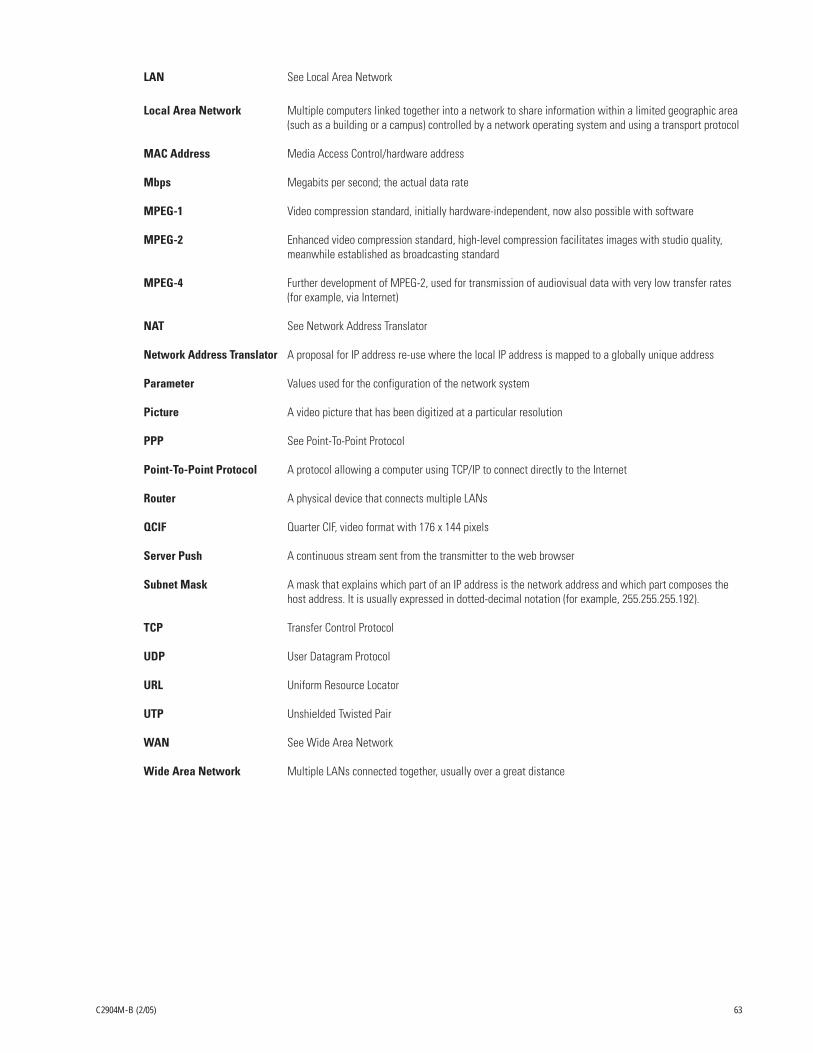
C2904M-B (2/05) 63
LAN See Local Area Network
Local Area Network Multiple computers linked together into a network to share information within a limited geographic area(such as a building or a campus) controlled by a network operating system and using a transport protocol
MAC Address Media Access Control/hardware address
Mbps Megabits per second; the actual data rate
MPEG-1 Video compression standard, initially hardware-independent, now also possible with software
MPEG-2 Enhanced video compression standard, high-level compression facilitates images with studio quality,meanwhile established as broadcasting standard
MPEG-4 Further development of MPEG-2, used for transmission of audiovisual data with very low transfer rates(for example, via Internet)
NAT See Network Address Translator
Network Address Translator A proposal for IP address re-use where the local IP address is mapped to a globally unique address
Parameter Values used for the configuration of the network system
Picture A video picture that has been digitized at a particular resolution
PPP See Point-To-Point Protocol
Point-To-Point Protocol A protocol allowing a computer using TCP/IP to connect directly to the Internet
Router A physical device that connects multiple LANs
QCIF Quarter CIF, video format with 176 x 144 pixels
Server Push A continuous stream sent from the transmitter to the web browser
Subnet Mask A mask that explains which part of an IP address is the network address and which part composes thehost address. It is usually expressed in dotted-decimal notation (for example, 255.255.255.192).
TCP Transfer Control Protocol
UDP User Datagram Protocol
URL Uniform Resource Locator
UTP Unshielded Twisted Pair
WAN See Wide Area Network
Wide Area Network Multiple LANs connected together, usually over a great distance

64 C2904M-B (2/05)
APPENDIX A – CONNECTING PELCONET NET4001A TO VARIOUS COMPONENTS
Some of the connection examples that follow require the customer to supply a DB9 cable. Refer to the following figure when one isneeded.
Figure 44. DB9 Cable Wire Splicing
123456789
PIN
DCD (DATA CARRIER DETECT)RXD (RECEIVE DATA)TXD (TRANSMIT DATA)DTR (DATA TERMINAL READY)GND (GROUND)DSR (DATA SET READY)RTS (READY TO SEND)CTS (CLEAR TO SEND)
RXD- (RECEIVE DATA MINUS)TXD- (TRANSMIT DATA MINUS)
GND
TXD+ (TRANSMIT DATA PLUS)RXD+ (RECEIVE DATA PLUS)
RS-232 RS-422/RS-485
1 2 3 4 5
6 7 8 9
TX+ RX+
TX- RX-
RX+ TX+
RX- TX-
ESPRIT
SPECTRA
TO RECEIVER
DB9

C2904M-B (2/05) 65
Figure 45. KBD300A (Direct Mode) Connected to a Receiver or Spectra Dome System
TX-TX+
P PROTOCOL ONLY
RECEIVER ORSPECTRA
RX+ RX-Video In Video Out
Audio Out
Audio In
COM1: RS232/485 10/100 Base-T
Ethernet
Power
100-250VAC50/60Hz 100mA
COM2: RS232
PELCONET TRANSMITTER
4800, 8, NONE, 1
CONNECTING PELCONET TO VARIOUS COMPONENTS WITH ASSORTED KEYBOARDS
CONNECTION SCENARIO 1 – USING A KBD300A IN DIRECT MODERefer to Figure 45 and the instructions that follow.
1. Connect a PV130 converter to the COM1 port on the back of the NET4001A receiver unit. (In Interface Mode select RS232.) The dataformat should be 4800 baud, 8 data bits, no parity, and 1 stop bit.
2. Connect the black and white striped wire from the power supply that comes with the converter to the converter’s +12 VDC terminaland the solid black wire to the GND terminal.
3. Connect RD(A) on the converter to terminal 2 on the wall block. Connect RD(B) on the converter to terminal 1 on the wall block.
4. Connect a 12 VAC power supply to terminals 3 and 4 on the wall block.
5. Set DIP switch 6 on the KBD300A to ON to enable turbo pan operation or OFF to disable that feature. The KBD300A will recognizeDirect Mode automatically.
6. Connect the wall block to the KBD300A with an RJ-45 straight cable.
7. Connect the monitor.
8. Refer to Figure 44 and Figure 45. Splice the customer-supplied DB9 cable into the Spectra/Esprit or receiver cable. Use P protocol only.
9. Plug the DB9 cable into the COM1 port on the transmitter. (For Interface Mode select RS422/485.) The data format should be 4800,8, no parity, 1.
10. Connect the camera’s video to the transmitter.
PV130 TD
(A)
TD
(B)
RD
(A)
RD
(B)
GN
D+
12 VD
C
1
2
3
4
8
7
6
5
12 VDCRD(A)RD(B)
12 VAC KBD300A
4800, 8, NONE, 1
STRAIGHT CABLE
DIRECT MODE
Video In Video Out
Audio Out
Audio In
COM1: RS232/485 10/100 Base-T
Ethernet
Power
100-250VAC50/60Hz 100mA
COM2: RS232
PELCONET RECEIVER

66 C2904M-B (2/05)
CONNECTION SCENARIO 2 – USING A KBD4000 FOR MULTIPLEXER CONTROLRefer to Figure 46 and the instructions that follow.
NOTE: If you set all your cameras to Standard Coaxitron for better control on the browser, you will lose most of the KBD4000 keyboardcontrol functions. If you set your cameras to Extended Coaxitron, you will have all the keyboard functions but the PTZ functions on theNET4001A will be very slow.
Figure 46. KBD4000 Connected to a Multiplexer
Video In Video Out
Audio Out
Audio In
COM1: RS232/485 10/100 Base-T
Ethernet
Power
100-250VAC50/60Hz 100mA
COM2: RS232
Video In Video Out
Audio Out
Audio In
COM1: RS232/485 10/100 Base-T
Ethernet
Power
100-250VAC50/60Hz 100mA
COM2: RS232
PELCONET RECEIVER
PELCONET TRANSMITTER
9600, 8, ODD, 1
PV130 TD
(A)
TD
(B)
RD
(A)
RD
(B)
GN
D+
12 VD
C
1
2
3
4
8
7
6
5
12 VDCRD(A)RD(B)
12 VAC
KBD4000
9600, 8, ODD, 1
STRAIGHT CABLE
VIDEOON
OFF
2
3
4 5
6
7
1 8
STRAIGHT CABLE
COM IN MULTIPLEXER
TX(-) TX(+) RX(-) RX(+)
TD(A)TD(B)
1. Connect a PV130 converter to the COM1 port on the back of the NET4001A receiver unit. (For Interface Mode select RS232.) Thedata format must be 9600 baud, 8 data bits, odd parity, and 1 stop bit.
2. Connect the black and white striped wire from the power supply that comes with the converter to the converter’s +12 VDC terminaland the solid black wire to the GND terminal.
3. Connect TD(A) on the converter to terminal 7 on the wall block. Connect TD(B) on the converter to terminal 8 on the wall block.Connect RD(A) on the converter to terminal 2 on the wall block. Connect RD(B) on the converter to terminal 1 on the wall block.
4. Connect a 12 VAC power supply to terminals 3 and 4 on the wall block.
5. Connect the wall block to the KBD4000 with an RJ-45 straight cable.
6. Connect the monitor.
7. Refer to Figure 44 and Figure 46. Splice the customer-supplied DB9 cable into the multiplexer wall block. Connect TX- from theNET4001A to terminal 2 on the wall block, TX+ to terminal 1, RX- to terminal 7, and RX+ to terminal 8.
8. Plug the DB9 cable into the COM1 port on the transmitter. (For Interface Mode select RS422/485.) The data format must be 9600, 8, odd, 1.
9. Connect the wall block to COM IN on the multiplexer with an RJ-45 straight cable.
10. Connect MAIN video output from the multiplexer to the transmitter.

C2904M-B (2/05) 67
CONNECTION SCENARIO 3 – USING A CM9760-KBDRefer to Figure 47 and the instructions that follow.
Figure 47. CM9760KBD Connected to a CM9760-CC1 Controller
1. Connect a PV130 converter to the COM1 port on the back of the NET4001A receiver unit. (For Interface Mode select RS232.) Thedata format must be 4800 baud, 8 data bits, even parity, and 1 stop bit.
2. Connect the black and white striped wire from the power supply that comes with the converter to the converter’s +12 VDC terminaland the solid black wire to the GND terminal.
3. Connect TD(A) on the converter to terminal 7 on the wall block. Connect TD(B) on the converter to terminal 8 on the wall block.Connect RD(A) on the converter to terminal 2 on the wall block. Connect RD(B) on the converter to terminal 1 on the wall block.
4. Connect an RJ-45 straight cable from the wall block to the power pack.
5. Connect an RJ-45 straight cable from the keyboard input connector on the power pack to COM 1 on the keyboard.
6. Connect the monitor.
7. Refer to Figure 44 and Figure 47. Splice the customer-supplied DB9 cable into the CM9760-CC1 wall block. Connect TX- from theNET4001A to terminal 2 on the wall block, TX+ to terminal 1, RX- to terminal 7, and RX+ to terminal 8.
8. Plug the DB9 cable into the COM1 port on the transmitter unit. (For Interface Mode select RS232.) The data format must be 4800, 8,even, 1.
9. Connect an RJ-45 flipped cable from the wall block to Sercom port 5 on the CC1’s rear panel.
10. Connect one of the three monitor outputs on the rear of the controller to the transmitter unit.
Video In Video Out
Audio Out
Audio In
COM1: RS232/485 10/100 Base-T
Ethernet
Power
100-250VAC50/60Hz 100mA
COM2: RS232
Video In Video Out
Audio Out
Audio In
COM1: RS232/485 10/100 Base-T
Ethernet
Power
100-250VAC50/60Hz 100mA
COM2: RS232
PELCONET RECEIVER
PELCONET TRANSMITTER
PV130 TD
(A)
TD
(B)
RD
(A)
RD
(B)
GN
D+
12 VD
C
1
2
3
4
8
7
6
5
12 VDCRD(A)RD(B)
CM9760KBD
4800, 8, EVEN, 1
STRAIGHT CABLE
12VDC
PV130 TD
(A)
TD
(B)
RD
(A)
RD
(B)
GN
D+
12 VD
C
2
3
4 5
6
7
1 8
FLIPPED CABLE
TD(A) TD(B) RD(A) RD(B)
COM IN
STRAIGHT CABLE
TD(A)TD(B)
CARD CAGEKEYBOARD
4800,8, EVEN, 1
SERCOM PORTPROGRAMMEDFOR KBD
CM9760-CC1
CM9750-UPS

68 C2904M-B (2/05)
CONNECTING PELCONET TO THE COM IN RS-422 PORT ON A GENEX MULTIPLEXER
Refer to Figure 48 and the instructions to follow.
Figure 48. Connecting PelcoNet to Genex Using the COM IN RS-422 Port
1. Verify that the multiplexer has Version 4.1 firmware. (The version number flashes on the monitor when power is applied to themultiplexer.)
2. Set the NET4001A COM1 data port to Transparent, 9600 baud, 8 data bits, odd (for parity), 1 stop bit, and off if it is not so setalready. (For Interface Mode select RS232.)
3. Create a cable using the diagram in Figure 44.
4. Attach the cable’s DB9 connector end to PelcoNet’s COM 1 port. Connect the cable’s RJ-45 connector end to COM IN on the back ofthe multiplexer.
5. Connect the MAIN video output from the multiplexer to the NET4001A transmitter.
6. Connect PelcoNet’s Ethernet port to the network using a Cat5 Ethernet patch cable.
CONNECTING A PELCONET RECEIVER TO A SYSTEM CM9502
Refer to Figure 49. This configuration lets an operator view and control cameras with a CM9505 keyboard.
Video In Video Out
Audio Out
Audio In
COM1: RS232/485 10/100 Base-T
Ethernet
Power
100-250VAC50/60Hz 100mA
COM2: RS232
PELCONET TRANSMITTER 9600, 8, ODD, 1
PELCONET DB9CONNECTOR
GENEX COM OUTRJ-45 CONNECTOR
PIN 2PIN 3PIN 5
RXTXGND
PIN 6PIN 4PIN 5
TXRXGND
18GENEX COM
IN OUT
TO NETWORK
18
Figure 49. Using PelcoNet with CM9505 to Provide Remote Control
Video In Video Out
Audio Out
Audio In
COM1: RS232/485 10/100 Base-T
Ethernet
Power
100-250VAC50/60Hz 100mA
COM2: RS232
PELCONET RECEIVER
PV130
TD
(A)
TD
(B)
RD
(A)
RD
(B)
GN
D+
12 VD
C
1
2
3
4
8
7
6
5
12 VDCRD(A)RD(B)
STRAIGHTCABLE
KBDCARDCAGE
TD(A)TD(B)
CM9505UPS
1200 BAUD, 8 BIT, 1 STOP BIT,NO PARITY
CM9502-KBD
TRANSPARENT DATA

C2904M-B (2/05) 69
CONNECTING PELCONET TO A CM9502 ASCII SERIAL PORT
Refer to Figure 44 and Figure 50. This configuration lets an operator view and control cameras from a PC using a web browser. (Theoperator’s PC is not shown on the diagram.)
Figure 50. Using PelcoNet with CM9502 to Provide Remote Control
Video In Video Out
Audio Out
Audio In
COM1: RS232/485 10/100 Base-T
Ethernet
Power
100-250VAC50/60Hz 100mA
COM2: RS232
PELCONET TRANSMITTER
2 3 4 5 6 7
1 8
TX- TX+
RX- RX+
TRANSPARENT DATA PORT
VIDEO
USING INTERNET EXPLORERSET TRANSPORT SETTINGS:BAUD RATEDATA BITSPARITYSTOP BITS
96008ODD1
LOOPEDSERIALPORTS
MON 1
CM9502-KBD
CM9502
RJ-45 WALLBLOCK &STRAIGHTCABLESUPPLIED
PELCONET CM9502 ASCII SERIAL PORT SETUP
TO NETWORK (LAN/WAN)

70 C2904M-B (2/05)
CONNECTING PELCONET TO A CM6700 AND KBD200A FOR REMOTE ASCII CONTROL
Refer to Figure 51. This configuration lets an operator view and control cameras with a remote KBD200A keyboard.
Figure 51. Using PelcoNet with CM6700 and KBD200A to Provide Remote Control
Video In Video Out
Audio Out
Audio In
COM1: RS232/485
Ethernet
Power
100-250VAC50/60Hz 100mA
COM2: RS232
10/100 Base-T
Video In Video Out
Audio Out
Audio In
COM1: RS232/485 10/100 Base-T
Ethernet
Power
100-250VAC50/60Hz 100mA
COM2: RS232
PELCONET RECEIVER
PELCONET TRANSMITTER
PELCONET REMOTE KBD200A ASCII MODE SETUP
GND
PV130
TD
(A)
TD
(B)
RD
(A)
RD
(B)
GN
D+
12 VD
C
2 3 4 5 6 7
1 8
RD(A) RD(B)
TD(A) TD(B)
12V
PV130 ORDEREDSEPARATELY
2-RX3-TX5-GND
TRANSPARENTDATA PORT
NOTE: FIRMWARE VER 4.0 OR LATER REQUIRED. SET KEYBOARD DIP SWITCHES - SWITCH 6 ON, SWITCHES 5 AND 8 OFF, SWITCHES 1 - 4 FOR ADDRESS ACCORDING TO THE TABLE IN THE KBD200A MANUAL.
KBD200A
RJ-45 WALL BLOCK AND STRAIGHTCABLE SUPPLIED
TRANSPARENT DATA PORTUSING INTERNET EXPLORER, SETTRANSPARENT DATA SETTINGSON BOTH PELCONET RECEIVERAND TRANSMITTER:
BAUD RATEDATA BITSPARITYSTOP BITS
96008ODD1
TO NETWORK(LAN/WAN)
1 2 3 4 5 6 7 8
ON
1 2 3 4 5 6 7 8
ONRS-422/485
ON OFF
KEY
RS-232
SW5 DIP SWITCH SETTINGS
1 3 5 7 9
2 4 6 8 10
11
12 14
13 15
16
1
2
VIDEO INPUTS VIDEO OUTPUTS
ALARMS(1-9)
ALARMS(10-18)
COM 1 (1-6)COM 2 (7-12)
CONTROLOUTPUTS
REMOTE KEYBOARD(S)
LOCALKEYBOARD
1 2 3 4 5 6 7 8 9
10 11 1213 14 15 16 1718
1 2 3 4 5 6 7 8 9 10 11 12
0 1 2 3 F2
F3
NO
NC
COM
T T R R+ +
CM6700-MXB
SET DIP SWITCH (SW5) ON CM6700-MXB TO RS-232 MODE
PELCONETTRANSPARENT
DATA PORT2 RX......................3 TX.....................5 GND.....................
CM6700-MXBCOM 2 (7-12)
7 TX12 RX 9 GND
CM6700 MATRIX COM 2PORT SETTINGS:
SPECTRA COAXITRONPROTOCOL
BAUD RATEDATA BITSPARITYSTOP BITS
96008ODD1
CONNECT PELCONET TO6700 VIA RS-232 PORT
2-RX3-TX5-GND
TO NETWORK(LAN/WAN)
12VAC

C2904M-B (2/05) 71
CONNECTING PELCONET TO A CM6700 ASCII PORT
Refer to Figure 52. This configuration lets an operator view and control cameras from a PC using a web browser. (The operator’s PC is notshown on the diagram.)
Figure 52. Using PelcoNet with CM6700 to Provide Remote Control
Video In Video Out
Audio Out
Audio In
COM1: RS232/485 10/100 Base-T
Ethernet
Power
100-250VAC50/60Hz 100mA
COM2: RS232
PELCONET TRANSMITTER
TRANSPARENTDATA PORT
TRANSPARENT DATA PORT
USING INTERNET EXPLORER, SETTRANSPARENT DATA SETTINGSON BOTH PELCONET RECEIVERAND TRANSMITTER:BAUD RATEDATA BITSPARITYSTOP BITS
96008ODD1
1 2 3 4 5 6 7 8
ON
1 2 3 4 5 6 7 8
ONRS-422/485
ON OFF
KEY
RS-232
SW5 DIP SWITCH SETTINGS
1 3 5 7 9
2 4 6 8 10
11
12 14
13 15
16
1
2
VIDEO INPUTS VIDEO OUTPUTS
ALARMS(1-9)
ALARMS(10-18)
COM 1 (1-6)COM 2 (7-12)
CONTROLOUTPUTS
REMOTE KEYBOARD(S)
LOCALKEYBOARD
1 2 3 4 5 6 7 8 9
10 11 1213 14 15 16 1718
1 2 3 4 5 6 7 8 9 10 11 12
0 1 2 3 F2
F3
NO
NC
COM
T T R R+ +
CM6700-MXB
SET DIP SWITCH (SW5) ON CM6700-MXB TO RS-232 MODE
CM6700 MATRIX COM 2PORT SETTINGS:
BAUD RATEDATA BITSPARITYSTOP BITS
96008ODD1
2-RX3-TX5-GND
TO NETWORK(LAN/WAN)
PELCONET CM6700 ASCII SETUP SPECTRA COAXITRON PROTOCOL
PELCONETTRANSPARENT
DATA PORT2 RX.......................3 RX.....................5 GND.....................
CM6700-MXBCOM 2 (7-12)
7 TX12 RX 9 GND

72 C2904M-B (2/05)
CONNECTING PELCONET TO A CM9760-DT FOR REMOTE BROWSER CONTROL
Refer to Figure 53. This configuration lets an operator view and control cameras on a PC using a web browser. (Theoperator’s PC is not shown on the diagram.)
Figure 53. Using PelcoNet with CM9760-DT to Provide Remote Control of a 9760 Monitor Output
Video In Video Out
Audio Out
Audio In
COM1: RS232/485 10/100 Base-T
Ethernet
Power
100-250VAC50/60Hz 100mA
COM2: RS232
TRANSPARENT DATA PORT
CM9760-MXB
USING INTERNET EXPLORERSET TRANSPORT SETTINGS:BAUD RATEDATA BITSPARITYSTOP BITS
VIDEO
SPECTRA “P”PROTOCOL
CM9760-CC1
CM9760-KBD CM9505-UPS
PELCONET CM9760-DT SETUP
2-RX3-TX5-GND
CM9760-DT1
12VAC
1 ON 2 OFFCOM A
COM B
2-RX3-TX5-GND
NULL MODEMCABLE NOTSUPPLIED
SUPPLIEDCABLE
DIP SWITCH
COM 1 COM 2COM 2 PROGRAMMED FOR 9760-DT
CAT 5 TO NETWORK(LAN/WAN)
4800 OR 96008EVEN OR ODD1
PELCONET TRANSMITTER
NOTE: 4800 BAUD AND EVEN PARITY APPLIES TO CM9760-DT VERSION 2.07,WHILE 9600 BAUD AND ODD PARITY APPLIES TO VERSION 3.0

C2904M-B (2/05) 73
CONNECTING PELCONET TO CM9760 EQUIPMENT FOR REMOTE COMMUNICATION
Refer to Figure 44 and Figure 54 and Figure 55. These configurations let an operator remotely view and control cameras connected to theCM9760.
Figure 54. Using PelcoNet to Transmit Data and Video Between 9760 Nodes
Video In Video Out
Audio Out
Audio In
COM1: RS232/485 10/100 Base-T
Ethernet
Power
100-250VAC50/60Hz 100mA
COM2: RS232
TRANSPARENT DATA PORT
CM9760-MXB
USING INTERNET EXPLORER SETTRANSPARENT DATA PORT SETTINGS:BAUD RATEDATA BITSPARITYSTOP BITS
VIDEO
SPECTRA “P”PROTOCOL
CM9760-CC1
CM9760-KBD CM9505-UPS
REMOTE NODE: TRANSMITTING DATA AND VIDEO
SERCOM PORT PROGRAMMEDFOR NETWORK COMMUNICATION
96008EVEN1
PELCONET TRANSMITTER
2 3 4 5 6 7
1 8
TX- TX+
RX- RX+
FLIPPED CABLE
MON OUTPUT TIE LINE
RJ-45 WALL BLOCKNOT SUPPLIED
MON 1
TO NETWORK(LAN/WAN)
Figure 55. Using PelcoNet to Receive Data and Video Between 9760 Nodes
Video In Video Out
Audio Out
Audio In
COM1: RS232/485 10/100 Base-T
Ethernet
Power
100-250VAC50/60Hz 100mA
COM2: RS232
TRANSPARENT DATA PORTUSING INTERNET EXPLORER SETTRANSPARENT DATA SETTINGS:BAUD RATEDATA BITSPARITYSTOP BITS
96008EVEN1
GND
PV130
TD
(A)
TD
(B)
RD
(A)
RD
(B)
GN
D+
12 VD
C
2 3 4 5 6 7
1 8
TD(A) TD(B)
RD(A) RD(B)
12V
CM9760-MXB
2-3-5-
RXTXGND
RJ-45 WALLBLOCK NOTSUPPLIED
MON 1
VIDEO
SPECTRA “P”PROTOCOL
SERCOM PORTPROGRAMMEDFOR NETWORKCOMMUNICATION
CM9760-CC1
CM9760-KBD CM9505-UPS
FLIPPED CABLE
CAM INPUT TIE LINE
LOCAL NODE: RECEIVING DATA AND VIDEO
PELCONET RECEIVER
TO NETWORK(LAN/WAN)

74 C2904M-B (2/05)
CONNECTING A PELCONET TRANSMITTER TO THE CM6800 ASCII PORT
Refer to Figure 56. This configuration lets an operator view and control cameras with a PC using a web browser. (The operator’s PC is notshown on the diagram.) All settings are done in the CM6800 manager program or through a CM6800 menu. Note the following:
• Port 2 defaults to ASCII and RS-232.
• Ports 7 and 8 can be set to ASCII and RS-232 by using the CM6800 manager program (refer to Figure 57) or by using a CM6800menu (refer to Figure 58).
• Pelco recommends using Port 2.
Figure 56. Using PelcoNet with CM6800 to Provide Remote Control
Video In Video Out
Audio Out
Audio In
COM1: RS232/485 10/100 Base-T
Ethernet
Power
100-250VAC50/60Hz 100mA
COM2: RS232
TRANSPARENT DATA PORTUSING INTERNET EXPLORER SETTRANSPARENT DATA SETTINGS: BAUD RATEDATA BITSPARITYSTOP BITS
96008ODD1
2-3-5-
RXTXGND
SPECTRA COAXITRONPROTOCOL
PELCONET CM6800 ASCII SETUP
COM 1
1
2
3
4
5
6
7
8
16151413121110987654321
8765484746454039383736353433
32313029282726252423222120191817
41 42 43 44 4321
ALTERNATE SOURCE INPUTS VIDEO OUTPUTS120/230~50/60 HZ
25 WATTS
COM
ALARM1 2 3 4 5 6 7 8
CONTROL
PTZ
OUT
A T+
T-
R+
R-
T+
T-
R+
R-
B
1 2
F3
HZ
75
PELCONET TRANSPARENTDATA PORT
2 RX..............................3 TX..............................5 GND............................
CM6800-48X8COM 28 TX1 RX5 GND
6800 MATRIX COM 2PORT SETTINGS:
BAUD RATEDATA BITSPARITYSTOP BITS
96008ODD1CONNECT PELCONET TO 6800 VIA RS-232 PORT
PELCONET TRANSMITTER
TO NETWORK (LAN/WAN)
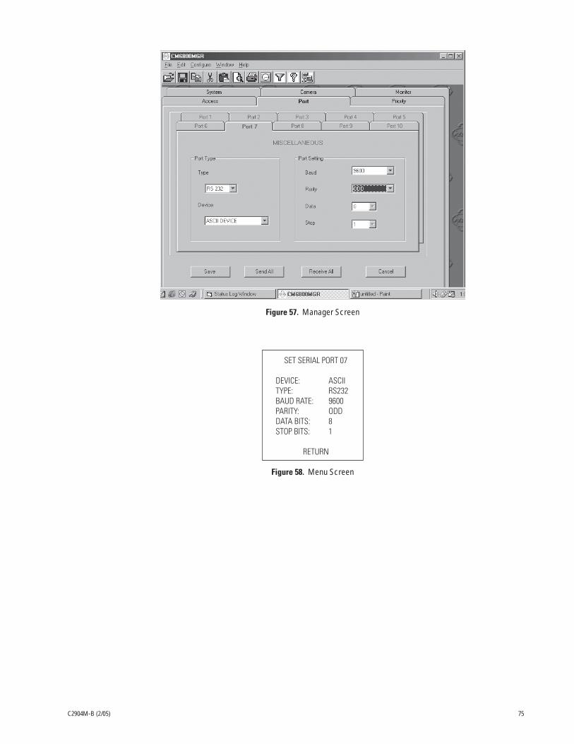
C2904M-B (2/05) 75
Figure 57. Manager Screen
SET SERIAL PORT 07
DEVICE: ASCIITYPE: RS232BAUD RATE: 9600PARITY: ODDDATA BITS: 8STOP BITS: 1
RETURN
Figure 58. Menu Screen

76 C2904M-B (2/05)
CONNECTING PELCONET TO A CM6800 AND KBD200A FOR REMOTE ASCII CONTROL
Refer to Figure 59. This configuration lets an operator view and control cameras with a remote KBD200A keyboard. All settings are donein the CM6800 manager program or through a CM6800 menu. Note the following:
• Port 2 defaults to ASCII and RS-232.
• Ports 7 and 8 can be set to ASCII and RS-232 by using the CM6800 manager program (refer to Figure 57) or by using a CM6800menu (refer to Figure 58).
• Pelco recommends using Port 2.
Figure 59. Using PelcoNet with CM6800 and KBD200A to Provide Remote Control
Video In Video Out
Audio Out
Audio In
COM1: RS232/485 10/100 Base-T
Ethernet
Power
100-250VAC50/60Hz 100mA
COM2: RS232
TRANSPARENT DATA PORTUSING INTERNET EXPLORERSET TRANSPORT SETTINGS:BAUD RATEDATA BITSPARITYSTOP BITS
96008ODD1
2-3-5-
RXTXGND
SPECTRA COAXITRONPROTOCOL
PELCONET CM6800 ASCII SETUP
COM 1
1
2
3
4
5
6
7
8
16151413121110987654321
8765484746454039383736353433
32313029282726252423222120191817
41 42 43 44 4321
ALTERNATE SOURCE INPUTS VIDEO OUTPUTS120/230~50/60 HZ
25 WATTS
COM
ALARM1 2 3 4 5 6 7 8
CONTROL
PTZ
OUT
A T+
T-
R+
R-
T+
T-
R+
R-
B
1 2
F3
HZ
75
PELCONET TRANSPARENTDATA PORT
2 RX..............................3 TX..............................5 GND............................
CM6800-48X8COM 28 TX1 RX5 GND
6800 MATRIX COM 2PORT SETTINGS:
BAUD RATEDATA BITSPARITYSTOP BITS
96008ODD1CONNECT PELCONET TO 6800 VIA RS-232 PORT
PELCONET TRANSMITTER
TO NETWORK (LAN/WAN)
Video In Video Out
Audio Out
Audio In
COM1: RS232/485 10/100 Base-T
Ethernet
Power
100-250VAC50/60Hz 100mA
COM2: RS232
PELCONET RECEIVER
PELCONET REMOTE KBD200A ASCII MODE SETUP
GND
PV130
TD
(A)
TD
(B)
RD
(A)
RD
(B)
GN
D+
12 VD
C
2 3 4 5 6 7
1 8
RD(A) RD(B)
TD(A) TD(B)
12V
PV130 ORDEREDSEPARATELY
2-RX3-TX5-GND
NOTE: FIRMWARE VER 4.0 OR LATER REQUIRED. SET KEYBOARD DIP SWITCHES - SWITCH 6 ON, SWITCHES 5 AND 8 OFF, SWITCHES 1 - 4 FOR ADDRESS ACCORDING TO THE TABLE IN THE KBD200A MANUAL.
KBD200A
RJ-45 WALL BLOCK AND STRAIGHTCABLE SUPPLIED
TRANSPARENT DATA PORTUSING INTERNET EXPLORER, SETTRANSPARENT DATA SETTINGSON BOTH PELCONET RECEIVERAND TRANSMITTER:
BAUD RATEDATA BITSPARITYSTOP BITS
96008ODD1
CAT 5 TO NETWORK(LAN/WAN)
12VAC

C2904M-B (2/05) 77
APPENDIX B – FREQUENTLY ASKED QUESTIONS (FAQS)
1. What Pelco devices can I control from my computer with the PelcoNet NET4001 transmission system?
PelcoNet can control the following from Internet Explorer:• Spectra and Esprit• Genex multiplexer• CM9760 (requires CM9760 data translator)• CM9740 (requires CM9760 data translator)• CM9502 (through integrated ASCII port)• CM8500 (requires latest CM8500 data translator)• CM6700 (through integrated ASCII port, COM 2)• CM6800 matrix
2. What TCP/IP ports does PelcoNet use?
PelcoNet lets you select which base port to use. You can select either 80 or 1756. This means PelcoNet will use UDP ports for some video andcontrol data. The ports must be open for PelcoNet to function properly.
3. Can I view PelcoNet over the Internet?
Yes. You will need a static IP address and enough bandwidth to view live video. Pelco recommends a minimum of 250 Kbps for medium imagequality. Also check with your ISP to verify the correct TCP and UDP ports are open through any routers or firewalls through which you willconnect.
4. How many connections does PelcoNet support? Can more than one receiver connect to a transmitter at the same time?
Yes. PelcoNet can support an unlimited number of receivers. To do so, all hubs, switches, and routers must support multicasting (IGMP), andPelcoNet must be configured to use multicasting. If the network hardware does not support this, then the maximum number of simultaneousconnections is five.
5. Can I enlarge the picture size in the browser?
Yes. You can select from two different image sizes in PelcoNet with the browser: 352 x 288 or 704 x 576.
6. What software does PelcoNet require?
PelcoNet works with Internet Explorer 5.5 or higher. An ActiveX plug-in is also required for Internet Explorer to get live video. All software isincluded.
7. Can I control other manufacturers’ equipment from the browser?
Not at this time.
8. Can I record video with PelcoNet NET4001A?
Yes. PelcoNet can record video to the hard drive of the viewing PC (you can select the location). The video is recorded in either mp2 or mp4format.
9. Everything is wired correctly but I do not have any control from the browser. What else could be wrong?
The transparent data port settings must be set to match the equipment to which PelcoNet is connected.
Also, in Internet Explorer, the Microsoft Virtual Machine must be enabled. To do so: on the Tools menu, select Internet Options. Then select theAdvanced tab. Locate the option Microsoft VM. Place a check mark next to Java Console Enabled and JIT compiler for virtual machine enabled.Reboot your computer.
These options are required for the Java applets in PelcoNet to function properly.
10. Can I control the Genex multiplexer server?
Not at this time.
11. Can I use DHCP (dynamically assigned IP address) with PelcoNet?
No.

78 C2904M-B (2/05)
12. What type of compression does PelcoNet use?
PelcoNet uses the MPEG-2 and MPEG-4 industry standards for video teleconferencing over the Internet. They provide the most effective use ofbandwidth with excellent video quality.
13. I do not get live video in the browser but server push is working. What could be wrong?
Verify that the ActiveX plug-in is installed and that your video is set to 16-bit or 32-bit color. Also check with your network administrator toverify that the TCP/IP ports PelcoNet uses are not being filtered and that you have enough bandwidth.
14. How do I program PelcoNet with Hyperterminal?
Using a null modem cable, connect a COM port on your PC to either COM port on NET4001A. Open Hyperterminal and set the port to use to19200, 8, N, 1, and No Flow Control. Type service (lower case), and follow the help menu.
When accessing the unit through HyperTerminal, each time after the unit boots up the program prompts for the username (enter service). Ifthere has not been a reboot since you last accessed the unit, you can access it by entering ? for the username.
15. How much bandwidth does PelcoNet use?
PelcoNet’s bandwidth is adjustable. You can set it from 2 to 5 Mbps. Pelco recommends a minimum of 250 Kbps for live video at medium imagequality. Check with your network administrator for how much bandwidth to use.
16. Can I use PelcoNet with a DSL or cable connection?
Yes. You will need a static IP address from your provider. Also verify what kind of bandwidth you will get since it varies by location. Verify thatyour provider is not filtering the TCP/IP ports that PelcoNet uses.

C2904M-B (2/05) 79
INDEX
A
alarm input 26Alarm indicator 42Alarm input 42Automatic connection 55Average n [frames] 41
B
Baud rate 44, 45Box-to-box connection 15
C
Camera (name) 37, 38Configuration download 36, 57Configuration upload 36, 57Configuration with terminal program 28Configuration with web browser 31Connect on alarm 55Connection on alarm 42Connection type 42
D
Data bits 44, 45Date format 35Direction of alarm connection 42
F
Firmware upload 57
G
Gateway IP address 47
H
Half-duplex mode 44Hardware version 35Help files 31
I
Idle state 43Interface mode 44IP address 9
L
Live video 14Live video auto-connect 42Live video page 49Live video page indicators 48Live video receiver IP address 42Local sensitivity 41
M
Menu tree 32Motion detection 41, 55Motion tracking 41MPEG-2/MPEG-4 11Multicast group IP address 47Multicast packet TTL 47Multicast port MPEG-2 47Multicast port MPEG-4 47Multicast streaming 47
N
Network administrator instructions 10Number of video receiver address 42
O
Object min size [nxn blocks] 42Operating mode 43
P
Parity check 44, 45Password 35Password confirm 35Password level 35Peripherals (connecting) 26Pin assignments 13Preset parameter MPEG-2 encoding 37Preset parameter MPEG-4 encoding 38PTZ cameras 11
R
Recording the video display 56Relay follows 43Relay name 43Remote receiver password 42
S
Select area 41Select path for storage 55Serial interfaces 25Serial port function 44, 45Server push 14Server push page 49Snapshot (recording) 55Snapshot (viewing) 56Software upload 35, 57Software version 11, 35Stop bits 44, 45Subnet mask 47

80 C2904M-B (2/05)
T
Terminal program commands 29Time server IP address 35Time zone 35Tracker 41Transparent data 25Trigger relay 43
U
Unit date 35Unit ID 35Unit IP address 47Unit name 35Unit time 35Upload progress 36
V
Video input termination 39Video loss alarm 42Video monitor name 39Video motion alarm 41Video on live page 37, 38Video output standard 39Viewing the video display 56
W
Web browser 10

C2904M-B (2/05) 81
PRODUCT WARRANTY AND RETURN INFORMATION
WARRANTY
Pelco will repair or replace, without charge, any merchandise proved defective in material or work-manship for a period of one year after the date of shipment.
Exceptions to this warranty are as noted below:
• Five years on FT/FR8000 Series fiber optic products and the following fixed camera models:CC3701H-2, CC3701H-2X, CC3751H-2, CC3651H-2X, MC3651H-2, and CC3651H-2X.
• Three years on all other fixed camera models (including Camclosure® Integrated CameraSystems) and Genex® Series (multiplexers, server, and keyboard).
• Two years on all standard motorized or fixed focal length lenses.
• Two years on Legacy®, CM6700/CM6800/CM8500/CM9500/CM9700 Series Matrix, DF5 andDF8 Series Fixed Dome products.
• Two years on Spectra®, Esprit®, and PS20 Scanners, including when used in continuous motionapplications.
• Two years on Esprit® and WW5700 Series window wiper (excluding wiper blades).
• Eighteen months on DX Series digital video recorders and NVR300 Series network videorecorders.months on DX Series digital video recorders, NVR300 Series network video record-ers, and all Endura™ Series distributed network-based video products.
• One year (except video heads) on video cassette recorders (VCRs). Video heads will be coveredfor a period of six months.
• Six months on all pan and tilts, scanners or preset lenses used in continuous motion applica-tions (that is, preset scan, tour and auto scan modes).
Pelco will warrant all replacement parts and repairs for 90 days from the date of Pelco shipment.All goods requiring warranty repair shall be sent freight prepaid to Pelco, Clovis, California. Repairsmade necessary by reason of misuse, alteration, normal wear, or accident are not covered underthis warranty.
Pelco assumes no risk and shall be subject to no liability for damages or loss resulting from thespecific use or application made of the Products. Pelco’s liability for any claim, whether based onbreach of contract, negligence, infringement of any rights of any party or product liability, relatingto the Products shall not exceed the price paid by the Dealer to Pelco for such Products. In no eventwill Pelco be liable for any special, incidental or consequential damages (including loss of use, lossof profit and claims of third parties) however caused, whether by the negligence of Pelco or other-wise.
The above warranty provides the Dealer with specific legal rights. The Dealer may also have addi-tional rights, which are subject to variation from state to state.
REVISION HISTORY
Manual # Date CommentsC2904M 4/03 Original version.C2904M-A 7/03 Added additional safeguards and warnings. Added note that unit needs to be rebooted after changing the IP address, subnet mask, or gateway IP address. Revised
specifications to reflect stereo jacks rather than RCA phone jacks for audio.C2904M-B 2/05 Changed pages 22 and 23 to instruct the installer to use the four supplied small screws from the rack mount kit to attach the brackets to the unit(s).
Pelco, the Pelco logo, Spectra, Genex, Esprit, Camclosure, Legacy, Coaxitron, and System 9760 are registered trademarks of Pelco.Windows is a registered trademark of Microsoft Corporation.PelcoNet and System 9740 are trademarks of Pelco.Windows, DirectX, and ActiveX are registered trademarks of Microsoft Corporation in the United States and/or other countries.Pentium 4 is a registered trademark of Intel Corporation.NVIDIA is a registered trademark of NVIDIA Corporation.ATI RADEON is a trademark of ATI Technologies Inc. © Copyright 2005, Pelco.Parhelia is a trademark of Matrox Technologies Inc. All rights reserved.
If a warranty repair is required, the Dealer must contact Pelco at (800) 289-9100 or (559) 292-1981 toobtain a Repair Authorization number (RA), and provide the following information:
1. Model and serial number
2. Date of shipment, P.O. number, Sales Order number, or Pelco invoice number
3. Details of the defect or problem
If there is a dispute regarding the warranty of a product which does not fall under the warrantyconditions stated above, please include a written explanation with the product when returned.
Method of return shipment shall be the same or equal to the method by which the item wasreceived by Pelco.
RETURNS
In order to expedite parts returned to the factory for repair or credit, please call the factory at (800)289-9100 or (559) 292-1981 to obtain an authorization number (CA number if returned for credit,and RA number if returned for repair).
All merchandise returned for credit may be subject to a 20% restocking and refurbishing charge.
Goods returned for repair or credit should be clearly identified with the assigned CA or RA numberand freight should be prepaid. Ship to the appropriate address below.
If you are located within the continental U.S., Alaska, Hawaii or Puerto Rico, send goods to:
Service DepartmentPelco3500 Pelco WayClovis, CA 93612-5699
If you are located outside the continental U.S., Alaska, Hawaii or Puerto Rico and are instructed toreturn goods to the USA, you may do one of the following:
If the goods are to be sent by a COURIER SERVICE, send the goods to:
Pelco3500 Pelco WayClovis, CA 93612-5699 USA
If the goods are to be sent by a FREIGHT FORWARDER, send the goods to:
Pelco c/o Expeditors473 Eccles AvenueSouth San Francisco, CA 94080 USAPhone: 650-737-1700Fax: 650-737-0933

World Headquarters3500 Pelco Way
Clovis, California 93612 USA
USA & CanadaTel: 800/289-9100Fax: 800/289-9150
InternationalTel: 1-559/292-1981Fax: 1-559/348-1120
www.pelco.com
ISO9001
Orangeburg, New York Las Vegas, Nevada Eindhoven, The Netherlands Wokingham, United Kingdom Montreal, Canada
®