Surface smoothing effect of an amorphous thin film deposited ...
Po
SC
a
ARRAA
KBPAP
1
mtebbintPa
vpsacih
tBic
0d
Applied Surface Science 257 (2011) 7864–7870
Contents lists available at ScienceDirect
Applied Surface Science
journa l homepage: www.e lsev ier .com/ locate /apsusc
arametric study of Al and Al2O3 ceramic coatings deposited by air plasma spraynto polymer substrate
un Guanhong, He Xiaodong ∗, Jiang Jiuxing, Sun Yueenter for Composite Materials and Structures, Harbin Institute of Technology, Harbin 150080, PR China
r t i c l e i n f o
rticle history:eceived 26 December 2010eceived in revised form 8 April 2011ccepted 11 April 2011
a b s t r a c t
Aluminum and ceramic (Al2O3) coatings were deposited onto the polymer substrate by air plasma spray(APS) to improve the mechanical properties of the polymer surface. The effect of spray parameters(current and spray distance in this paper) on the phase composition, microstructure and mechanicalproperties was investigated. Shear adhesion strength between the coatings and the substrates was also
vailable online 21 April 2011
eywords:ond coatolymer matrix composite
examined. The results indicate that the deposition parameters have a significant effect on the phase com-position, microstructure and mechanical properties of as-spayed coatings. The maximum shear adhesionstrength of the bond coats was 5.21 MPa with the current of 180 A and 190 mm spray distance.
© 2011 Elsevier B.V. All rights reserved.
luminalasma spray coatings
. Introduction
Polymer matrix composites (PMCs) are relatively competitiveaterials for many applications, because of their high strength
o weight ratio compared to metals. To increase the propulsionfficiency of the turbine engine, more and more metal parts areeing replaced by PMCs all over the world. However, a high relia-ility is a fundamental requirement for applications, which makes
t somewhat difficult for making more use of PMCs. Strength, stiff-ess, fatigue strength and corrosion resistance of PMCs can meethe requirement of turbine engine, and the key factor that restrictMCs from being more widely used are their low heat resistancend erosion resistance [1,2].
The plasma spraying is an economical and effective method forarious machine parts to reduce the surface degradation [3]. Duringlasma spraying process, a layer is formed on a substrate surface bypraying melted or partially melted powders at a high speed usinghigh-temperature plasma heat source. Plasma-sprayed ceramic
oatings have been widely used for many applications in order tomprove resistances to wear, corrosion, oxidization, erosion, andeat [3–6].
Coatings of metal [7] and cermet have been proven to be effec-ive to improve the erosion resistance of polyimide composites.
ecause of the high thermal resistant, ceramic and cermet coat-ngs can be used to raise the service temperature of polyimideomposites.
∗ Corresponding author. Tel.: +86 45186412513; fax: +86 45186402333.E-mail address: [email protected] (H. Xiaodong).
169-4332/$ – see front matter © 2011 Elsevier B.V. All rights reserved.oi:10.1016/j.apsusc.2011.04.057
In recent years, in terms of coatings fabricated by plasmaspraying, effects of processing parameters on coatings propertieswere extensively reported [8–14]. However, most of these papersconcentrated on alloy coatings sprayed on metallic or ceramic sub-strates [15–17]. In this work, Al and Al2O3 coatings were fabricatedon the PMCs (carbon fiber reinforced unsaturated polyester in thiswork) by plasma spray technique. During the plasma spraying,powders are melted and accelerated in the plasma flame, whichupon impinging the substrate, rapidly solidify to form splats. Thecoating develops by successive build-up of these splats. The state ofthe particle upon impinging will affect the property of the coating.The sprayed particles with high energy can cause degradation of themechanical properties of the PMC, or even damage, and particleswith low energy can hardly form splats and coating and result lowadhesion strength with substrate. This paper aimed at obtainingcoating with strong adhesion strength by optimizing the parame-ters of plasma spray. In this work, Al coating is the bond coating toprotect the substrate between the top coating and substrate, Al2O3ceramic coating is the top coating to improve the surface property.We aimed to spray the Al2O3 ceramic coating onto the PMC sub-strate, but the melting point of the Al2O3 is too high for the PMC,spraying alumina directly onto the substrate will destroy the sub-strate, so we added the Al bond coating between the PMC and theAl2O3 top coating to protect the PMC substrate.
2. Experimental details
Self-designed air plasma spray system was used to spray thepowders to produce the coating. Substrates were placed on an alu-minum plate in 1.5 m diameter, which can rotate clockwise and

S. Guanhong et al. / Applied Surface Science 257 (2011) 7864–7870 7865
Table 1Plasma spray parameters for Al bond coatings.
Bond Coating Current/A Voltage/V Spray distance/mm Plasma gas flow rate l/h Pressure of carrier gas/MPa
Ar H2
B1 150 65 150 1000 100 0.02B2 150 65 170 1000 100 0.02B3 180 65 170 1000 100 0.02
c4gipwpT
1swaftp
uRwS
w(dc9
sGolcC0lPwsigT
TP
B4 150 65 190B5 180 65 190
ounterclockwise, then the plate was set to rotate in a speed ofs/r for spraying. For both bond coating and top coating, the sprayun scanned the substrates four times to fabricate the coating, last-ng about 16 s. In order to optimize the plasma spray processingarameters (focused on spray current and spray distance in thisork), five groups of parameters (B1–B5, Table 1) were used torepare the bond coatings and nine groups of parameters (T1–T9,able 2) were used to produce the top coatings.
The PMC substrates with the dimensions of21 mm × 86 mm × 3 mm were prepared for aluminum depo-ition according to the following steps: (1) chemical cleaningith acetone to remove grease, and (2) grit blasting with 60 �m
lumina powders at 40–60 psi for approximately 10 s in a glassactory in order to create an anchor tooth profile at the surface ofhe substrates, and then (3) cleaning again with acetone beforelasma spraying.
The aluminum powders with the average diameter of 20–40 �msed in the plasma spray process were provided by Beijing Generalesearch Institute of Mining & Metallurgy, and the Al2O3 powdersith the size of 20–40 �m were manufactured by Beijing Langqiao
urface Technology.The cross-sectional and surface microstructure of the coatings
as analyzed using FEI Sirion 200 scanning electron microscopeSEM) equipped with energy-dispersive spectroscopy (EDS). X-rayiffraction (XRD) was used to assess the phase composition of theoatings using Cu K� radiation at a scan rate of 4◦/min from 20◦ to0◦.
Shear adhesion strength between the coatings and the sub-trates was tested according to Chinese national standardB/T7124-1986 [18]. As-coated samples were cut into the diameterf 100 mm × 25 mm and then were glued to the steel sheet, and theength of the adhesion area was 12.5 mm. Then the samples werelamped onto the Css-88100 tester (Changchun Center of Testers,hangchun, China). The samples were pulled with the speed of.5 mm/min till it failed. The shear adhesion strength was calcu-
ated according to � = P/A where � was the shear adhesion strength,was the maximum load applied before the sample failed, and Aas the area of the coating glued to the uncoated side. When the
ample failed at the substrate/coating interface or within the coat-ng, the data were valid. If the sample failed at the coating/glue orlue/steel plate interface, glue with higher strength must be used.hree samples were tested for each data point [19].
able 2lasma spray parameters for alumina top coatings.
Top Coating Bond coating Current/A Voltage/V Spra
T1 B1 270 50 170T2 B2 270 50 170T3 B3 270 50 170T4 B4 270 50 170T5 B5 270 50 170T6 B5 300 50 170T7 B5 330 50 170T8 B5 360 50 170
1000 100 0.021000 100 0.02
Nanoindentation tests were carried out using a HysitronTriboindenter with a diamond Berkovich indenter tip. Thenanohardness can be obtained by analyzing the loading and unload-ing curves.
The nanohardness can be calculated as followed:
H = P
A= 4ˇ2
�
P
S2E2
r (1)
where A is the projected contact area, ˇ is a constant that dependson the geometry of the indenter, S is the contact stiffness and Er isthe reduced modulus. If do not concern the effect of the substrate,Er can be expressed in terms of the elastic properties of the indenter(i) and film (f) as
1Er
= (1 − v2i )
Ei+ (1 − v2)
E(2)
The test results were calculated with the Er, which is not con-cerned about the substrate, if we consider the substrate’s affection,Er can be expressed as
1Er
= 1 − v2i
Ei+ 1 − v2
fEf
(1 − e−˛t/a) + 1 − v2s
Es(e−˛t/a) (3)
where Ei, Ef, Es are Young’s modulus of the indenter, film and sub-strate, respectively. �i, �f and �s are Poisson’s ratio of the indenter,film and substrate, respectively. ˛ is a constant related with theindenter geometry. t is the film thickness, and a =
√A [20]. We used
Eq. (3) to modify the test results.
3. Results and discussion
3.1. Morphology and phase composition
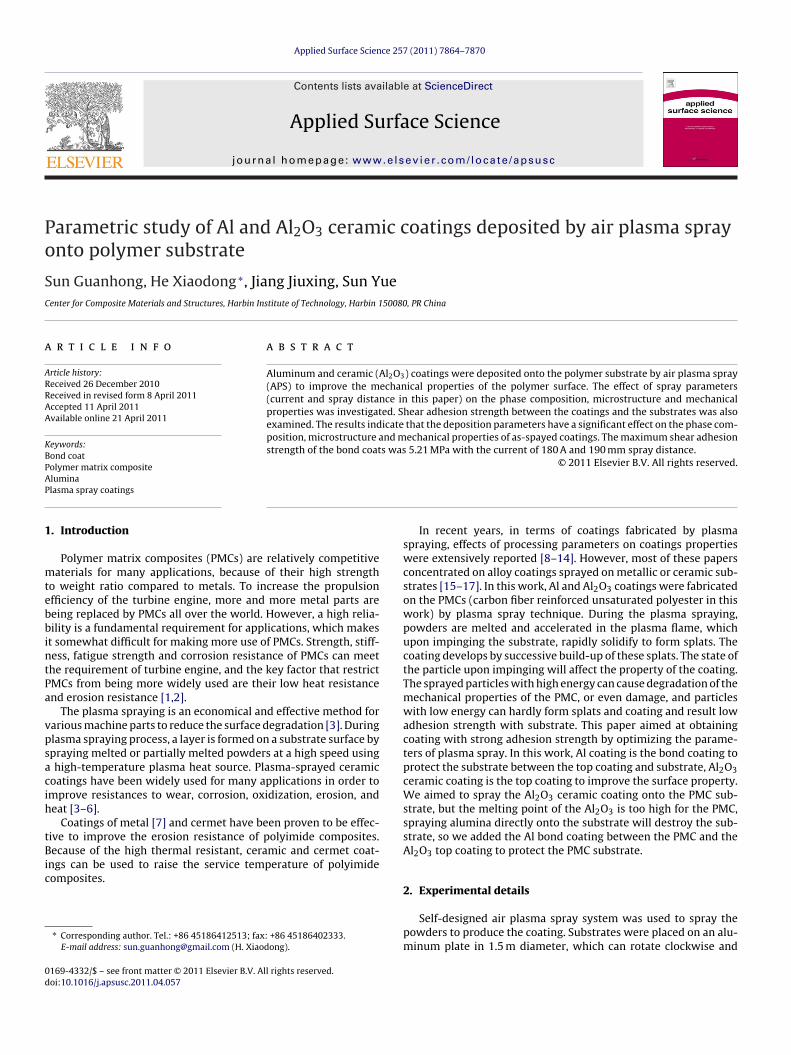
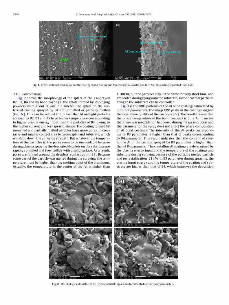
To obtain the alumina top ceramic coating, Al bond coatings wasfirstly sprayed onto the PMC substrate to protect the substrate andmake good adhesion between the top ceramic coating and the PMCsubstrate. Fig. 1 shows the cross-sectional image of the coating,
the sprayed coating is about 60 �m thick involving approximately40 �m thick bond coating and 20 �m thick top coating. There isno obvious defect found between the substrate and the coating inFig. 1a.y distance/mm Plasma gas flow rate l/h Pressure of carrier gas/MPa
Ar H2
800 150 0.02800 150 0.02800 150 0.02800 150 0.02800 150 0.02800 150 0.02800 150 0.02800 150 0.02
7866 S. Guanhong et al. / Applied Surface Science 257 (2011) 7864–7870
d top
3
Bpf(stturwtdrpspA
Fig. 1. Cross-sectional SEM images of the coating (bond coating an
.1.1. Bond coatingFig. 2 shows the morphology of the splats of the as-sprayed
2, B3, B4 and B5 bond coatings. The splats formed by impingingowders were about 30 �m in diameter. The splats on the sur-ace of coating sprayed by B4 are unmelted or partially meltedFig. 2c). This can be related to the fact that Al in-flight particlesprayed by B2, B3 and B5 have higher temperature correspondingo higher plasma energy input than the particles of B4, owing tohe higher current and less spray distance. The coating formed bynmelted and partially melted particles have more pores, microc-acks and smaller contact area between splat and substrate, whichill drop down the adhesion strength. But whatever the tempera-
ure of the particles is, the pores seem to be unavoidable becauseuring plasma spraying the deposited droplets on the substrate areapidly solidified and they collide with a solid surface. As a result,
ores are formed around the droplets’ contact point [21]. Becauseome part of the particle was melted during the spraying, the tem-erature must be higher than the melting point of the aluminum.ctually, the temperature in the center of the jet is higher thanFig. 2. Morphologies of (a) B2, (b) B3, (c) B4 and (d) B5
coating), (a) coating on the PMC, (b) coating separated from PMC.
10,000 K, but the particles stay in the flame for very short time, andare cooled during flying onto the substrate, so the heat that particlesbring to the substrate can be controlled.
Fig. 3 is the XRD patterns of the Al bond coatings fabricated bydifferent parameters. The sharp XRD peaks in the coatings suggestthe crystalline quality of the coatings [22]. The results reveal thatthe phase composition of the bond coatings is pure Al. It meansthat there was no oxidation happened during the spray process andthe parameter of the spray does not affect the phase compositionof Al bond coatings. The intensity of the Al peaks correspond-ing to B3 parameter is higher than that of peaks correspondingto B4 parameter. This result indicates that the content of crys-talline Al in the coating sprayed by B3 parameter is higher thanthat of B4 parameter. The crystalline Al coatings are determined bythe plasma energy input and the temperature of the coatings and
substrate during spraying because of the partially melted particleand recrystallization [21]. With B3 parameter during spraying, theplasma input energy and the temperature of the coating and sub-strate are higher than that of B4, which improves the depositionsplats produced with different spray parameters.

S. Guanhong et al. / Applied Surface Science 257 (2011) 7864–7870 7867
esents
oc
dicdiotrop
3
awlkc
Fig. 3. XRD patterns of the B3 and B4 coating, (b) pr
f the melted particles and recrystallization of Al, resulting higherontent of crystalline.
In Fig. 3b there is a difference between the positions of theiffraction peaks of the two coating which means that the shift-
ng of the peaks happened. As is well known, in plasma sprayedoating, the relatively low substrate temperature compared to theroplet temperature brings about rapid solidification of the coat-
ng [23], which lead to the residual stress in the coating. The shiftf the peak is caused by the residual stress of the Al coat, because ofhe different thermal expansion between Al and polymer [24]. Theesidual stress in the coating will weaken the mechanical propertyf the coating, although it cannot be avoided in the plasma sprayrocessing.
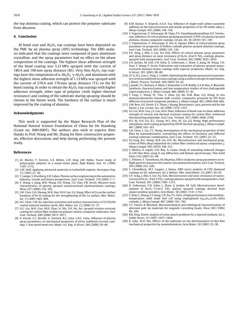
.1.2. Al2O3 top coatingsFig. 4a is the surface morphology of the Al2O3 ceramic coatings at
low magnification, showing the plasma sprayed alumina coating
ith layered splats, along with other features such as interlamel-ar pores, cracks and partially molten particles [11]. There are twoinds of structures distributing irregularly over the surface of theoating: (i) coarse and coral-like splats with pores and (ii) smooth
the different of the peak positions of two coatings.
and relatively flat splats. EDX surface analysis indicates that thetwo kinds of splats have the similar element content, which meansthey are both alumina. It can be concluded that the Al2O3 ceramiccoating can be produced on the polymer substrate by air plasmaspray technology. The two kinds of splats are formed by particleswith different melting state.
Fig. 5 shows the morphology of the Al2O3 top coatings fabricatedtwo spray currents: (a) T6, 300 A and (b) T8, 360 A. There are lesscoral-like splats in the coating sprayed by higher current. The parti-cles had more energy when came out of the plasma flame with theparameter of T8, and more particles were totally melted than theparticles sprayed by T6. The higher current results in the decreaseof pores and �-Al2O3 and the increase of �-Al2O3with increasingthe possibility of full melting [12,25,26].
The cross-section of theAl2O3 top coatings on the PMC substratesprayed with different parameters is showed in Fig. 6. It can beseen that there are cracks in the substrate as showed in Fig. 6a.
As showed in Fig. 6b that the coating is apart from the substrate,which indicates the poor adhesion between the coating and sub-strate. The current for the top coatings was higher than that of thebond coatings. As is well known, plasma jet velocity and heat energy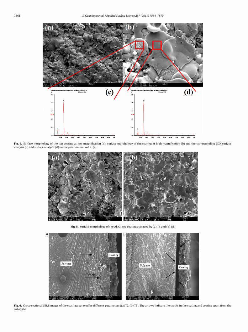
7868 S. Guanhong et al. / Applied Surface Science 257 (2011) 7864–7870
Fig. 4. Surface morphology of the top coating at low magnification (a); surface morphology of the coating at high magnification (b) and the corresponding EDX surfaceanalysis (c) and surface analysis (d) on the position marked in (c).
Fig. 5. Surface morphology of the Al2O3 top coatings sprayed by (a) T6 and (b) T8.
Fig. 6. Cross-sectional SEM images of the coatings sprayed by different parameters ((a) T2, (b) T5). The arrows indicate the cracks in the coating and coating apart from thesubstrate.

S. Guanhong et al. / Applied Surface Science 257 (2011) 7864–7870 7869
ittthdat
sam[Aaatdc
3
Ti5
Fig. 7. XRD patterns of the APS Al2O3 top coatings.
ncrease with increasing current, which causes an elevation in par-icle velocity and temperature, respectively. With higher current,he in-flight particles’ temperature firstly increases up to 500 A andhen decreases [23]. The Al2O3 particles sprayed by high currentad higher temperature than the Al particles, which cause thermalamage to the polymer substrate as showed in Fig. 6. These cracksnd delamination will certainly decrease the adhesion strength ofhe coatings.
Fig. 7 shows the XRD patterns of the Al2O3 top coating, whichuggested that the coating is composed of �-Al2O3, �-Al2O3 andluminum. As it is well established, �-Al2O3 is one of the inter-ediate phases formed when alumina is melted in the plasma jet
27]. Upon cooling from the melting temperature of alumina, �-l2O3 nucleates firstly over �-Al2O3; therefore, �-Al2O3 typicallyppears in the plasma-sprayed alumina coatings. The presence ofluminum is due to lacking covering of the top coat. To prevent thehermal damage to the polymer, relative low current, long sprayistance and short spray time were used to produce the Al2O3 topoat, and the aluminum appeared in the XRD result.
.2. Shear adhesion strength
Fig. 8 shows the adhesion strength of different bonding coatings.
he parameters of the bond coatings listed in the figure are shownn Table 1. The B5 bond coat has the highest adhesion strength,.21 MPa, while B4 has the lowest value, 1.72 MPa. As shown inFig. 8. Shear adhesion strength of bond coatings.
Fig. 9. Shear adhesion strength of top coatings.
Fig. 2, the splats of the B4 are different from the others, it was obvi-ously partially molten, which might be related to B4s low shearadhesion strength. We chose B5 as the bond coat to examine theeffect of the different current.
Fig. 9 shows the shear adhesion strength of top coatings. Withthe same reason mentioned above for B1, T1s result is not listedhere. T7 and T8 have too weak adhesion strength that cannot betested. It can be found that the shear adhesion strength is the high-est for T3, 1.13 MPa, and lowest for T5, 0.21 MPa, respectively. Theshear adhesion strength of the top coatings has dropped under1.2 MPa, because of the thermal damage during the spray process.
Nanoindentation was tested on the surface of the specimensof T5, T6, T7, B5 and PMC substrate. The results are showed inFig. 10. Firstly, the nanohardness of the Al2O3 top coating is muchhigher than the nanohardness of the Al bond coating and PMCsubstrate, which suggesting that we can use the plasma spraytechnology to elevate the surface’s hardness. But the result wegot is much lower than the nanohardness of the alumina coat-ing [28], is only 0.458 GPa on average. The reason of the reductionof the coating’s nanohardness is we did the nanoindentation on ahard coating/soft substrate system. The very soft substrate (about1.685 Gpa of Young’s modulus) can strongly affect the result of thenanoindentation test [20,29,30].
We used Eq. (3) to modify Er, and recalculated the hardness,which is showed in Fig. 10. The modified results were obtained by
considering the effect the soft substrate. The average of the mod-ified results is 13.308 GPa, which is much closer to the reportedresults. The hardness of the surface was significantly improved byFig. 10. Nanohardness of the Al2O3 top coating sprayed by different current, Al bondcoating and PMC substrate and modified results.
7 rface S
tf
4
tscco1ittbarci
A
N(tas
R
[
[
[
[
[
[
[
[
[
[
[
[
[
[
[
[
[
[
[
870 S. Guanhong et al. / Applied Su
he top alumina coating, which can protect the polymer substraterom abrasion.
. Conclusion
Al bond coat and Al2O3 top coatings have been deposited onhe PMC by air plasma spray (APS) technology. The XRD analy-is indicated that the coatings were composed of pure aluminumrystalline, and the spray parameters had no effect on the phaseomposition of the coatings. The highest shear adhesion strengthf the bond coating was 5.21 MPa sprayed with the current of80 A and 190 mm spray distance (B5). Very thin Al2O3 top coat-
ngs have the composition of �-Al2O3, �-Al2O3 and aluminum withhe highest shear adhesion strength of 1.13 MPa was sprayed withhe current of 270 A and 170 mm spray distance (T3) on the B3ond coating. In order to obtain the Al2O3 top coatings with higherdhesion strength, other type of polymer (with higher thermalesistance) and cooling of the substrate during spraying should behosen in the future work. The hardness of the surface is muchmproved by the coating of alumina.
cknowledgments
This work is supported by the Major Research Plan of theational Natural Science Foundation of China for He Xiaodong
Grant no. 90816005). The authors also wish to express theirhanks to Prof. Wang and Mr. Zhang for their constructive propos-ls, effective discussions and help during performing the presenttudy.
eferences
[1] J.E. Martin, T. Stevens, G.E. Bellen, L.W. King, J.M. Hylko, Tracer study ofpolyacrylate polymer in a waste-water plant, Appl Radiat. Isot. 41 (1990)1165–1172.
[2] S.M. Hoff, Applying advanced materials to turboshaft engines, Aerospace Eng.15 (1995) 27–30.
[3] T. Lampe, S. Eisenberg, E.R. Cabeo, Plasma surface engineering in the automotiveindustry—trends and future prospectives, Surf. Coat. Technol. 174 (2003) 1–7.
[4] Y. Wang, S. Jiang, M.D. Wang, S.H. Wang, T.D. Xiao, P.R. Strutt, Abrasive wearcharacteristics of plasma sprayed nanostructured alumina/titania coatings,Wear 237 (2000) 176–185.
[5] J.W. Choi, G.H. Hwang, W.K. Han, W.H. Lee, S.G. Kang, Effect of Cu on the surfacehardness of Ni–B coating for the strengthening of the Cu surface, Met. Mater.Int. 13 (2007) 403–409.
[6] H.C. Choe, Y.M. Ko, Interface activation and surface characteristics of Ti/TiN/HAcoated sintered stainless steels, Met. Mater. Int. 12 (2006) 31–37.
[7] A.G. Liu, M.H. Guo, M.H. Zhao, H. Ma, S.H. Hu, Arc sprayed erosion-resistant
coating for carbon fiber reinforced polymer matrix composite substrates, Surf.Coat. Technol. 200 (2006) 3073–3077.[8] A. Kucuk, C.C. Berndt, U. Senturk, R.S. Lima, C.R.C. Lima, Influence of plasmaspray parameters on mechanical properties of yttria stabilized zirconia coat-ings. I: four point bend test, Mater. Sci. Eng. A-Struct. 284 (2000) 29–40.
[
[
cience 257 (2011) 7864–7870
[9] K.M. Kumar, V. Kripesh, A.A.O. Tay, Influence of single-wall carbon nanotubeaddition on the microstructural and tensile properties of Sn–Pb solder alloy, J.Alloys Compd. 455 (2008) 148–158.
10] S. Yugeswaran, V. Selvarajan, M. Vijay, P.V. Ananthapadmanabhan, K.P. Sreeku-mar, Influence of critical plasma spraying parameter (CPSP) on plasma sprayedalumina–titania composite coatings, Ceram. Int. 36 (2010) 141–149.
11] S. Yugeswaran, V. Selvarajan, D. Seo, K. Ogawa, Effect of critical plasma sprayparameter on properties of hollow cathode plasma sprayed alumina coatings,Surf. Coat. Technol. 203 (2008) 129–136.
12] E.P. Song, J. Ahn, S. Lee, N.J. Kim, Effects of critical plasma spray parameterand spray distance on wear resistance of Al2O3–8 wt.% TiO2 coatings plasma-sprayed with nanopowders, Surf. Coat. Technol. 202 (2008) 3625–3632.
13] E.H. Jordan, M. Gell, Y.H. Sohn, D. Goberman, L. Shaw, S. Jiang, M. Wang, T.D.Xiao, Y. Wang, P. Strutt, Fabrication and evaluation of plasma sprayed nanos-tructured alumina-titania coatings with superior properties, Mater. Sci. Eng.A-Struct. 301 (2001) 80–89.
14] J.F. Li, H.L. Liao, C. Ding, C. Coddet, Optimizing the plasma spray process parame-ters of yttria stabilized zirconia coatings using a uniform design of experiments,J. Mater. Process. Technol. 160 (2005) 34–42.
15] J. Janaki, T.G. Kumary, A. Mani, S. Kalavathi, G.V.R. Reddy, G.V.N. Rao, A. Bharathi,Synthesis, characterization and low temperature studies of iron chalcogenidesuperconductors, J. Alloys Compd. 486 (2009) 37–41.
16] Y Yang, Y. Wang, W. Tian, Y. Zhao, J.Q. He, H.M. Bian, Z.Q. Wang, In situalumina/aluminum titanate bulk ceramic composites prepared by SPS fromdifferent structured composite powders, J. Alloys Compd. 481 (2009) 858–862.
17] S.M. Best, A.E. Porter, E.S. Thian, J. Huang, Bioceramics: past, present and for thefuture, J. Eur. Ceram. Soc. 28 (2008) 1319–1327.
18] A.G Liu, M.H. Guo, J.S. Gao, M.H. Zhao, Influence of bond coat on shear adhesionstrength of erosion and thermal resistant coating for carbon fiber reinforcedthermosetting polyimide, Surf. Coat. Technol. 201 (2006) 2696–2700.
19] H.S. Ni, X.H. Liu, X.C. Chang, W.L. Hou, W. Liu, J.Q. Wang, High performanceamorphous steel coating prepared by HVOF thermal spraying, J. Alloys Compd.467 (2009) 163–167.
20] S.H. Chen, L. Liu, T.C. Wang, Investigation of the mechanical properties of thinfilms by nanoindentation, considering the effects of thickness and differentcoating-substrate combinations, Surf. Coat. Technol. 191 (2005) 25–32.
21] D.J Song, R.G. Wang, W.B. Liu, X.D. He, Microstructure and mechanical prop-erties of PbSn alloys deposited on carbon fiber reinforced epoxy composites, J.Alloys Compd. 505 (2010) 348–351.
22] S. Mishra, A. Ingale, U.N. Roy, A. Gupta, Study of annealing-induced changesin CdS thin films using X-ray diffraction and Raman spectroscopy, Thin SolidFilms 516 (2007) 91–98.
23] C. Tekmen, Y. Tsunekawa, M. Okumiya, Effect of plasma spray parameters on in-flight particle characteristics and in-situ alumina formation, Surf. Coat. Technol.203 (2008) 223–228.
24] S. Chowdhury, M.T. Laugier, J. Henry, XRD stress analysis of CVD diamondcoatings on SiC substrates, Int. J. Refract. Met. Hard Mater. 25 (2007) 39–45.
25] E.P. Song, J. Ahn, S. Lee, N.J. Kim, Microstructure and wear resistance of nanos-tructured Al2O3–8 wt.% TiO2 coatings plasma-sprayed with nanopowders, Surf.Coat. Technol. 201 (2006) 1309–1315.
26] D. Goberman, Y.H. Sohn, L. Shaw, E. Jordan, M. Gell, Microstructure devel-opment of Al2O3–13 wt.% TiO2 plasma sprayed coatings derived fromnanocrystalline powders, Acta Mater. 50 (2002) 1141–1152.
27] F. Zhao, L. Zhang, Z.Y. Jiang, C.R. Xia, F.L. Chen, A high performance intermediate-temperature solid oxide fuel cell using impregnated La0.6Sr0.4CoO3-deltacathode, J. Alloys Compd. 487 (2009) 781–785.
28] S.T. Patton, B. Bhushan, Micromechanical and tribological characterization ofalternate pole tip materials for magnetic recording heads, Wear 202 (1996)
99–109.29] R.B. King, Elastic analysis of some punch problems for a layered medium, Int. J.Solids Struct. 23 (1987) 1657–1664.
30] R. Saha, W.D. Nix, Effects of the substrate on the determination of thin filmmechanical properties by nanoindentation, Acta Mater. 50 (2002) 23–38.
Copyright © 2022 FDOKUMEN