P3 OU 160002 >m
385
CO P3 OU 160002 >m
-
Upload
khangminh22 -
Category
Documents
-
view
0 -
download
0
Transcript of P3 OU 160002 >m

CO
P3 OU 160002 >m


THE PENNSYLVANIA STATE COLLEGEINDUSTRIAL SERIES
PRACTICAL PHYSICS
The quality of the materials used in
the manufacture cf this book is gov-
erned by continuedpostwar shortages.

THE
PENNSYLVANIA STATE COLLEGE
INDUSTRIAL SERIES
BRENEMAN Mathematics, 2d ed.
BRENEMAN Mechanics
BRENEMAN Strength cf Materials
SCHAEFER Job Instruction
SCHAEFEU Safety Supervision
SCHAEFER AND WlSSLER Industrial
SupervisionOrganization
SCHAEFER AND WISSLER Industrial
Supervision Controls
THAYER Blue Print Heading and
Sketching
THAYER Industrial Drawing
WALTON Do You Want to Be aForeman?
WALTON The Fundamentals cf Indus-
trial Psychology
WHITE (Editor) Practical Physics

INDUSTRIAL SERIES
PRACTICAL PHYSICS
BY
MARSH W. WHITE, PH.D., Editor
Professor of Physics
KENNETH V. MANNING, PH.D.Assistarit Supervisor of Physics Exte7isio?i
ROBERT L. WEBER, PH.D.Assistant, Professor of Physics
R. ORIN CORNETT, PH.D.Lecturer in Electronics, Harvard University
Formerly Assistant Supervisor of Physics Extension
arid, others on
THE PHYSICS EXTENSION STAFFThe Pennsylvania State College
FIRST EDITION
EIGHTH IMPRESSION
PREPARED UNDER THE DIRECTION OF
THE DIVISION OF ARTS AND SCIENCE EXTENSIONTHE PENNSYLVANIA STATE COLLEGE
McGRAW-HILL BOOK COMPANY, INC.
NEW YORK AND LONDON1943

PRACTICAL PHYSICS
COPYRIGHT, 1943, BY
THE PENNSYLVANIA STATE COLLEGE
PRINTED IN THE UNITED STATES OF AMERICA
All rights reserved. This book, or
parts thereofj may not be reproduced
in any form without permission of
the publishers.
THE MAPI ffi 1'BESS COMPANY, YORK, PA.

FOREWORD
In the field of adult education the needs of the students are so varied
and their educational backgrounds are so diverse that conventional
textbooks are often not satisfactory. To be most valuable for these
groups the textbooks must be simple and practical, readily understand-
able by all and yet able to supplement experience at many levels. The
Pennsylvania State College Industrial Series was originated in 1941 in
an attempt to provide books having these desirable characteristics.
The earlier volumes of the series were prepared by members of the staff
of the School of Engineering. This volume is the first contribution from
the staff of the School of Chemistry and Physics. Other books are
expected from the School of the Liberal Arts.
The increased need for technically trained personnel has emphasizedthe shortage of persons with basic training in physics. To provide
trainees with the minimum technical skill and knowledge of physical
principles necessary for effective participation in war industries and in
the armed services, short courses have been set up, covering only the
principles of most immediate use. For example, in extension classes of
the Engineering, Science and Management War Training Program, The
Pennsylvania State College has given training in a course of basic mathe-
matics and physics to more than 8,000 students in the period from 1941
to 1943. It was realized early that a new concise physics text was needed
for this purpose. Consequently the present volume was prepared."Practical Physics
"is designed to present in streamlined form the
major concepts of general physics so that the book can be used in acceler-
ated programs of resident college study, in the ESMWT Program, in
classes for special service groups, and in extension and vocational training.
It seems probable that such training will continue for a considerable period.
The Editor of this book, Dr. Marsh W. White, Professor of Physicsat The Pennsylvania State College, is key supervisor of physics in exten-
sion in addition to his campus duties. In the ESMWT Program, he
and the other authors, Drs. Robert L. Weber, Kenneth V. Manning, and
R. Orin Cornett, have been responsible, with others, for the supervision
of the physics instruction given in the 150 extension centers operated byThe Pennsylvania State College. The material of the book includes,
therefore, the results of wide experience in the field of college physics and
its practical applications in industry.
DAVID B. PUQH,
THE PENNSYLVANIA STATE COLLEGE, Director of Aria and
1943. Science Extension.


PREFACE
This book was prepared in response to a wartime need for a concise
textbook in general physics at the introductory level. The emergencyconditions brought streamlined courses with shortened hours and special
service group and adult training programs, all demanding practical and
condensed physics courses. Hence in this book emphasis is placed on
those parts of physics that are basic to practical use in engineering, war
industry, technical work, and the armed services.
The simplest algebra and the trigonometric functions of a right
triangle (the latter contained in this book) constitute the extent of the
mathematics used. A distinctive part of the plan of the book is its
design to utilize in a logically progressive manner the simple mathematical
material that is needed. This enables the students to study and review
the mathematics concurrently with the physics. To achieve this inte-
gration of mathematics and physics the order of topics in the book is
somewhat unusual, with heat and fluid physics preceding the mechanics
of solidg.
Another feature of this book is the inclusion at the end of each chapter
of one or more experiments that have been planned to illustrate the topics
considered in the chapter. These experiments are designed to utilize
simple and readily available apparatus. The experiments may be per-
formed either as conventional demonstrations or, preferably, as coopera-
tive group exercises. Large-scale apparatus is particularly desirable.
Emphasis has been given throughout the book to the proper use of
significant figures. Each topic is illustrated by one or more solved
problems. The summary given at the end of each chapter enables the
instructor and students to make a quick and systematic review of the
material covered. The questions and problems in each chapter are
graded in order of increasing difficulty, with answers given to alternate
problems. The British system of units is stressed wherever possible,
the metric system being employed only as a basis for those units com-
monly met in science.
The text material has been tried out in lithoprinted form in more than
100 classes, and constructive criticisms have been made by many of the
200 instructors who have used the preliminary editions. This groupincludes college instructors, high-school teachers, and professional
engineers temporarily doing extra-time teaching. Grateful acknowledg-ment is made to them for these suggestions.
vii

Vlii PREFACE
A considerable number of people have been involved in the prepara-
tion of the material of this book. Much of the first draft was written
by Dr. Robert F. Paton, Associate Professor of Physics at the University
of Illinois, and Dr. J. J. Gibbons, Assistant Professor of Physics at The
Pennsylvania State College. Dr. Harold K. Schilling, Associate Pro-
fessor of Physics at The Pennsylvania State College, was largely respon-
sible for many of the group experiments; some of the earlier work on them
was done by Dr. C. R. Fountain, formerly of the George Peabody
College. Others who have made valuable contributions, especially to
the review material and illustrations, are Dr. Ira M. Freeman, of Central
College, Dr. Paul E. Martin, formerly Professor of Physics and Mathe-
matics at Muskingum College, and Dr. Harry L. Van Velzer and Dr.
Wayne Webb, Assistant Professors of Physics at The Pennsylvania State
College.
It is a pleasure to acknowledge the courtesy of the instrument com-
panies and others who have freely granted permission for the use of their
illustrations. The following have been particularly helpful: Central
Scientific Company, General Electric Company, The National Bureau
of Standards, Stromberg-Carlson Telephone Manufacturing Company,C. J. Tagliabue Manufacturing Company, Weston Electrical Instrument
Company, Westinghouse Electric and Manufacturing Company, and
the U.S. Army Signal Corps.
The Editor expresses his appreciation to his colleagues, Drs. Robert
L. Weber, Kenneth V. Manning, and R. Orin Cornett, whose sustained
efforts have made possible the completion of this book. The present
edition is due almost solely to the work of Dr. Manning and Dr. Weber.
MARSH W. WHITE,Editor.
THE PENNSYLVANIA STATE COLLEGE,
May, 1943.

CONTENTS
MAP OF PHYSICS FrontispiecePAGE
FOREWORD. ... v
PREFACE. ... . . . . . . ^ vii
INTRODUCTORY: The fields and uses of physics 3< 'HAPTEB
1. FUNDAMENTAL UNITS; ACCUBACY AND SIGNIFICANT FIGURES 7
Experiment: Volume Measurements 16
2. LINEAR MEASUREMENT; ERRORS 19
Experiment: Length Measurements 26
3. TEMPERATURE MEASUREMENT; THERMAL EXPANSION 28
Experiment : Linear Expansion of Rods 37
4. HEAT QUANTITIES 40
Experiment: Specific Heats of Metals 48
5. HEAT TRANSFER 49
Experiment: Heat Transfer. . . 55
6. PROPERTIES OF SOLIDS ... ... 57
Experiment: Elasticity. 64
7. PROPERTIES OF LIQUIDS. . . 66
Experiment: Liquid Pressure, Archimedes' Principle 74
8. GASES AND THE GAS LAWS . . . 76
Experiment: Expansion of Air 82
9. METEOROLOGY .... 86
Experiment : Dew Point and Relative Humidity 95
LO. TYPES OF MOTION .... 98
Experiment: Uniformly Accelerated Motion. ... 105
11. FORCE AND MOTION 109
Experiment: Newton's Second Law of Motion 114
12. FRICTION; WORK AND ENERGY . ... 117
Experiment: Friction . . 123
13. SIMPLE MACHINES . 125
Experiment: Mechanical Advantage, Efficiency ... . 132
14. POWER ; . . 134
Experiment: Manpower ... 138
15. CONCURRENT FORCES; VECTORS . 140
Experiment: Concurrent Forces; Vectors 150
16. NONCONCURRENT FORCES; TORQUE 152
Experiment: Nonconcurrent Forces; Torque 159
17. PROJECTILE MOTION; MOMENTUM 162
Experiment: Speed of a Rifle Bullet 169
ix

X CONTENTSCHAPTER PAQ18. UNIFORM CIRCULAR MOTION 171
^^^ Experiment: Centripetal and Centrifugal Forces 177
19.yRoTARY MOTION; TORQUE; MOMENT OP INERTIA 180
Experiment: Torque; Moment of Inertia 187
20. VIBRATORY MOTION; RESONANCE 189
Experiment: Simple Harmonic Motion; Resonance 194
21. SOURCES AND EFFECTS OF ELECTRIC CURRENT 196
Experiment: Sources and Effects of Electric Current 205
22. OHM'S LAW; RESISTANCE; SERIES AND PARALLEL CIRCUITS 207
Experiment: Ohm's Law; Resistance Combinations 216
23. ELECTRICAL MEASURING INSTRUMENTS 219
ExperimentGalvanometers, Multipliers, and Shunts (Part I) 229
24. HEATING EFFECT OF AN ELECTRIC CURRENT 234
ExperimentGalvanometers, Multipliers, and Shunts (Part II) 240
25. CHEMICAL EFFECTS OF AN ELECTRIC CURRENT 242
Experiment: Emf and Internal Resistance 251
23. ELECTROMAGNETIC INDUCTION 253
Experiment: Electromagnetism, Induced Currents, St. Louis Motor . . . 262
27. ALTERNATING CURRENT 266
Experiment: Resistance, Reactance, and Impedance . . 276
28. COMMUNICATION SYSTEMS; ELECTRONICS .... 277
^x. Experiment: Characteristics of Electron Tubes ... 284
29.)SouND WAVES . .... 286s--^ Experiment: Demonstrations of Sound Waves .... 296
30. ACOUSTICS 298
Experiment: Demonstrations of Vibration, Interference, and Resonance . 308
31. LIGHT; ILLUMINATION AND REFLECTION 309
--^ Experiment: Illumination and Photometry 320
32./REFRACTION OF LIGHT; LENSES; OPTICAL INSTRUMENTS 322* '
Experiment: Lenses and Optical Instruments 337
Appendix
I. FUNDAMENTALS OF TRIGONOMETRY 339
II. GRAPHS 341
III. SYMBOLS USED IN EQUATIONS 344
TABLE
1. PROPERTIES OF SOLIDS AND LIQUIDS 347
2. SATURATED WATER VAPOR 348
3. ELECTROCHEMICAL DATA 349
4. RESISTIVITIES AND TEMPERATURE COEFFICIENTS 349
5. DIMENSIONS AND RESISTANCE OF COPPER WIRE 349
6. NATURAL SINES AND COSINES 350
7. NATURAL TANGENTS AND COTANGENTS 353
S. LOGARITHMS 354
INDEX 357

PRACTICAL PHYSICS


THE FIELDS AND USES OF PHYSICS
The story of man's advancing civilization is the story of his study of
nature and his attempt to apply the knowledge so gained to improve his
environment. Primitive man was born, lived, and died with little changein his manner of living from generation to generation. Occasional dis-
coveries led to slow advances but no systematic attempt was made to studythe laws of nature. The existence of such laws was hardly suspected.
The use of tools, first of stone and later of metal, the domestication of
animals, the development of writing and counting, all progressed slowly
since rapid advance was not possible until systematic gathering of data
and experimental verification of theories were introduced.
Much of our science has its roots in the speculations of the Greeks but
their failure to check conclusions by experiment prevented the rise of a
true science. Not until a little over three centuries ago did man adoptthe scientific method of studying his environment Great progress was
made, and in the succeeding centuries the development of civilization has
become increasingly more rapid.
The rise of all the natural sciences has been almost simultaneous; in
fact, many of the prominent scientists have excelled in more than one field.
We shall confine our attention to the one field of physics. Probably morethan any other science, physics has modified the circumstances under
man lives and exemplifies the scientific method. Physics deals not

4 PRACTICAL PHVSICS
with man himself, but with the things he sees and feels and hears.
Physics is usually defined as the science of matter and energy. This science
deals with the laws of mechanics, heat, sound, electricity, and light which
have been applied in numerous combinations to build our machine age.
Mechanics is the oldest and most basic branch of physics. This divi-
sion of the subject deals with such ideas as inertia, motion, force, and
energy. Their interrelationships of especial interest are the laws dealing
with the effects of forces upon the form and motion of objects, since these
principles apply to all devices and structures such as machines, buildings,
and bridges. Mechanics includes the properties and laws of both solids
and liquids.
The subject of heat includes the principles of temperature measure-
ment, the effect of temperature on the properties of materials, heat flo\\,
and thermodynamics the transformation of heat into work. These
studies are of importance in foundries, welding plants, pattern and
machine shops, where expansion and shrinkage and heat treating air
important. In furnaces1 and steel mills, temperature measurement and
control and the flow of heat are essential matters for the engineer to
understand.
The study of sound is of importance not only in music and speech but
also in war and industry. The acoustical and communications engineer
is concerned with the generation, transmission, and absorption of sound.
An understanding of scientific principles in sound is of importance to the
radio engineer. The safety engineer is greatly concerned with the effects
of sound in producing fatigue in production personnel
Electricity and magnetism are fields of physics having innumerable
everyday applications, many of which are of peculiar importance in war
industries and the armed services. An understanding of the principles
involving the sources, effects, measurements, and uses of electricity and
magnetism is valuable to the worker in that it enables him to use more
effectively the manifold electrical devices now so vital to our efficiency
and comfort.
Optics is a division of physics that includes the study of the nature and
propagation of light, the laws of reflection from plane and curved mirrors,
and the bending or refraction that occurs in the transmission of light
through prisms and lenses. Of importance also are the separation of
white light into its constituent colors, the nature and types of spectra,
interference, diffraction, and polarization phenomena. Photometryinvolves the measurement of luminous intensities of light sources and
of the illumination of surfaces, so useful in industry and in everyday life.
The war applications of optical devices are numerous and important, as
illustrated by such essential achievements of the optical engineer as gunand bomb sights, range finders, binoculars, and searchlights.

THE FIELDS AND USES OF PHYSICS 5
A fascinating portion of physics is that known as "modern physics,"which includes electronics, atomic and subatomic phenomena, photo-
electricity, x-rays, radioactivity, the transmutations of matter and
energy, relativity, and the phenomena associated with electron tubes andthe electric wraves of modern radio. Many of the devices that are almost
commonplace today are applications of one or more of these branches of
modern physics. Radio, long-distance telephony, sound amplification,and television are a few of the many developments made possible by the
use of electron tubes. Photoelectricity makes possible television, trans-
mission of pictures by wire or radio, talking moving pictures, and manydevices for the control of machinery. Examination of welds and castings
by x-rays to locate hidden flaws is standard procedure in many war and
peacetime industries. The practical application of the developments of
physics continues at an ever increasing rate."Practical physics
"is, therefore, no idle term, for the laws of physics
are applied in every movement we make, in every attempt at communica-
tion, in the warmth and light we receive from the sun, in every machinethat does our bidding for construction or destruction.
Not only during the war but certainly after actual fighting is over will
there be increasing demand for men and women trained in basic physics.It is expected that postwar industrial developments will involve unpre-cedented applications of physics in industry and will utilize the services
of men and women with knowledge of this science to a degree never before
visualized. These needs will involve many grades of workers, from high-school graduates to doctors of philosophy, from junior technical aids to
the professional engineer. One thing all must have in common knowl-
edge of the fundamental laws of physics on which so much industrial
development and research are based.
The war has placed physics in a peculiarly important position amongthe sciences. Its present and potential contributions are expected to havea profound effect on the course and outcome of the war. So widely usedand so significant are the devices of the physicist that this war is beingcalled a " war of physics." Much of the research that has produced these
applications is secret and many of the most important tools of war
developed by the physicist cannot even be mentioned. The fact that
several hundred physicists are working on war problems in a single
research center is startling evidence of the way in which new tools of
war are being fashioned by those who are applying the laws of physicalscience to the war effort.
Practical applications of physics are not all made by those labeled as
physicists for the majority of those who apply the principles of physics are
called "engineers." In fact most of the branches of engineering are
closely allied with one or more sections of physics: civil engineering applies

6 PRACTICAL PHYSICS
the principles of mechanics; mechanical engineering utilizes the laws of
mechanics and heat; electrical engineering is based on the fundamentals
of electricity; acoustical engineering and optical engineering are the indus-
trial applications of the physics of sound and light. The alliance be t ween
engineering and physics is so close that a thorough knowledge and under-
standing of physical principles is essential for progress in engineering.
One of the tools common to physics and engineering is mathematics.
Principles are expressed quantitatively and most usefully in the languageof mathematics. In development and application, careful measurement
is essential. If we are to make effective use of the principles and measure-
ments of physical science, we must have a workable knowledge of mathe-
matics. Physics and mathematics are thus the basic "foundations of
engineering."

CHAPTER 1
FUNDAMENTAL UNITS/ ACCURACY ANDSIGNIFICANT FIGURES
Engineering design, manufacture, and commerce today no longer rest
on guesswork. Cut-and-try methods have given way to measurement, so
that the stone cut in the quarry slips neatly into its prepared place in a
building under construction hundreds of miles away. A new spark plugor a piston ring can be purchased in Philadelphia to fit a car made in
Detroit. Cooperative planning and the manufacture of interchangeable
parts became possible only when people quit guessing and learned to
measure.
The Measuring Process. Measuring anything means comparing it with
some standard to see how many times as big it is. The process is simpli-
fied by using as few standards as possible. These few must be carefully
devised and kept. The standard with which other things are comparedis called a unit. So also are its multiples and submultiples, which maybe of more convenient size. The numerical ratio of the thing measured
to the unit with which it is compared is called the numerical measure, or
magnitude, of the thing measured.
Some measurements are direct, that is, they are made by comparingthe quantity to be measured directly with the unit of that kind, as when
7

8 PRACTICAL PHYSICS
we find the length of a table by placing a yard or meter scale beside it.
But most measurements are indirect. For example, to measure the speed
of a plane we measure the distance it travels and the time required, and,
by calculation, we find the number of units that represents its speed.
Fundamental Units. Surprising as it may seem, the only kinds of units
that are essential in mechanics are those of length, mass, and time.
These are arbitrarily chosen, because of their convenience and, hence, are
called fundamental units. Many other units are based on these three.
For example, a unit of length multiplied by itself serves as a unit of area.
A unit area multiplied by unit length becomes a unit
of volume. A unit of length divided by a unit of
time represents a unit of speed. A unit that is
formed by multiplying or dividing fundamental units
is called a derived unit.
Length. To specify a distance we must use some
unit of length. The unit commonly employed for
scientific use and accepted as an international
standard is the meter. The meter is defined as the
distance between two lines on a certain bar of plati-
num-iridium-when the temperature of the bar is that
of melting ice (0C). The prototype meter is kept
of theTstandard^eter at ^he International Bureau of Weights and Meas-bar showing the mark- Ures at Sevres, France. In order that it could beings a one en .
reproduced if destroyed, it was intended by the
designers that this length should be one ten-millionth of the distance from
a pole of the earth to the equator, measured along a great circle, but this
ideal was not quite realized.
One one-hundredth of the meter is called the centimeter (0.01 m), a
unit of length that we shall often employ. Other decimal fractions of the
meter are the decimeter (0.1 m) and the millimeter (0.001 m). For large
distances the kilometer (1,000 m) is employed.Units of length popularly used in English-speaking countries are the
yard and its multiples and submultiples. The British or Imperial yardhas its legal definition as the distance between two lines on a bronze bar,
kept at the office of the Exchequer in London, when its temperature is
62F. Other common units of length are the mile (1,760 yd), the foot
(1A yd), and the inch (^6 yd).
In the United States the yard is legally defined in terms of the meter:
1 yd = 3,6QO/3,937m. This leads to the simple approximate relation
1 in. = 2.54 cm. From this simplified relation it is possible to shift from
British to metric units on a screw-cutting lathe by the introduction of a
gear ratio of 127 to 50 teeth.

FUNDAMENTAL UNITS/ SIGNIFICANT FIGURES
Mass. The mass of an object is a measure of the amount of material
in it as evidenced by its inertia. (Inertia is the measure of resistance to
change of motion.)
The unit of mass chiefly employed in physics is the gram, which is
defined as one one-thousandth of the mass of the kilogram prototype
a block made of the same platinum-indium alloy as the meter prototype
and also kept at S&vres. Fractions and multiples of the gram in commonuse are named as follows: milligram (0.001 gin), centigram (0.01 gm),
decigram (0.1 gm), kilogram (1,000
gm) and the metric ton (1,000 kg or
1,000,000 gm).In the United States the pound,
a unit of mass, is legally defined in
terms of the kilogram: 1 kg =2.2046 Ib, so that 1 Ib equals ap-
proximately 454 gm.
Weight. Sir Isaac Newton(1642-1726) pointed out that be-
sides having inertia all material ob-
jects have the ability to attract all
other objects. As a result of this
universal gravitation everything on
or near the surface of the earth is
attracted toward the earth with a
force we call weight.
The force with which the earth
pulls on a mass of 1 Ib under stand-
ard conditions (g= 32.16 ft/sec
2)
is called the weight of 1 Ib or the
pound of force. This force is one of
the basic units in common usage.
Time. The fundamental unit of time is the mean solar second. This
is defined as 1/86,400 (NOTE: 86,400 = 24 X 60 X 60) of the mean solar
day, which is the average, throughout a year, of the time between succes-
sive transits of the sun across the meridian at any place. Thus, the time
it takes for the earth to turn once on its axis, with respect to the sun,
serves as the basis for the unit of time. A properly regulated watch or
clock, a pendulum of suitable length, or an oscillating quartz crystal is
the working standard for measuring time.
Metric and British Systems. The metric system of measure is based on
the units: the meter, the kilogram, and the second. It is the one systemcommon to all nations that is used by physicists, chemists, and manyengineers. It was legalized for use in the United States by the Metric
Fio. 2. The national standard of mass.
Kilogram No. 20, a cylinder 39 mm in diam-eter and 39 mm high, v ith slightly rounded
edges, made of an alloy containing 90 percent platinum and 10 per cent iridium. It
was furnished by the International Bureauof Weights and Measures in pursuance of the
metric treaty of 1875.
10 PRACTICAL PHYSICS
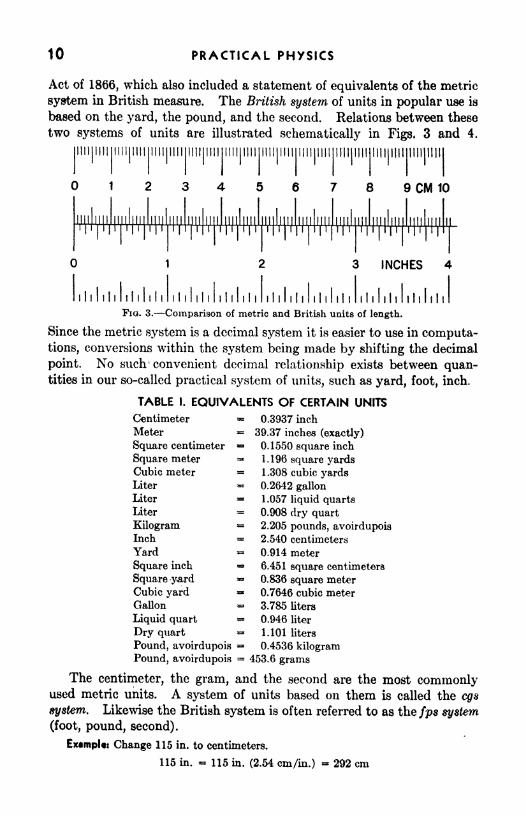
Act of 1866, which also included a statement of equivalents of the metric
system in British measure. The British system of units in popular use is
based on the yard, the pound, and the second. Relations between these
two systems of units are illustrated schematically in Figs. 3 and 4.
Hill Mill
8 9 CM 10
2 3 INCHES
lihhlilili ihlih ililih ihlih ihiili ihlililihliliFIQ. 3. Comparison of metric and British units of length.
Since the metric system is a decimal system it is easier to use in computa-tions, conversions within the system being made by shifting the decimal
point. No such 1 convenient decimal relationship exists between quan-tities in our so-called practical system of units, such as yard, foot, inch.
TABLE I. EQUIVALENTS OF CERTAIN UNITS
Centimeter
Meter
Square centimeter
Square meter
Cubic meter
Liter
Liter
Liter
KilogramInch
Yard
Square inch
Square yardCubic yardGallon
Liquid quart
Dry quart
Pound, avoirdupois
Pound, avoirdupois
0.3937 inch
39.37 inches (exactly)
0.1550 square inch
1.196 square yards1.308 cubic yards0.2642 gallon
1.057 liquid quarts0.908 dry quart2.205 pounds, avoirdupois2.540 centimeters
0.914 meter
6.451 square centimeters
0.836 square meter
0.7646 cubic meter
3.785 liters
0.946 liter
1.101 liters
0.4536 kilogram453.6 grams
The centimeter, the gram, and the second are the most commonlyused metric units. A system of units based on them is called the cgs
system. Likewise the British system is often referred to as the/ps system
(foot, pound, second).
Examples Change 115 in. to centimeters.
115 in. = 115 in. (2.54 cm/in.) - 292 cm

FUNDAMENTAL UNITS/ SIGNIFICANT FIGURES 11
If all units are inserted into an equation, they can be handled as
algebraic quantities and, when they are handled in this manner, the
correct final unit is obtained. This method has an added advantage in
that it frequently calls attention to a factor that has
been forgotten.
Example: Convert 165 Ib to kilograms.
165 Ib165 Ib 74.8 kg2.205 IbAg
Example: Express 50 mi/hr in feet per second.
50 mi/hr(50 mi/hr) (5,280 ft/mi)
3,600 sec/hr73 ft/sec
Fio. 4. Comparison of
units of volume.
Accuracy of Measurements. Measurements of
mass, length, and time have been perfected by re-
search to an accuracy that may seem almost fan-
tastic. The length of a meter or the thickness of a
transparently thin film can be measured by optical
methods with an uncertainty of only 1 part in
1,000,000. Electric oscillators provide standards
of time that measure intervals to 1 part in
10,000,000. The range of measurements possible,
as well as their accuracy, is important. Masseshave been determined, for example, for objects as large as the earth *
13, 100,000,000,000,000,000,000,000 Ib
and as small as the electron
0.000,000,000,000,000,000,000,000,000,001,98 Ib.
These long numbers can be expressed much more satisfactorily byusing a number multiplied by some power of ten. Thus the mass of the
earth is expressed as
1.31 X 1026 Ib
and that of the electron as
1.98 X 10-* Ib.
This notation is used frequently in technical work.
The accuracy to which a certain measurement should be taken and the
number of figures that should be expressed in its numerical measure are
practical questions. Their answers, which depend upon the particular
problem, are often more difficult to determine than anything else
about the problem. A farmer buying a 160-acre farm need not worry

12 PRACTICAL PHYSICS
about the boundaries to within a foot or so. But the architect and
surveyor who plan a building on Wall Street have to establish boundaries
with a precision involving fractions of an inch. The bearings for the
crank-shaft of an engine must be more nearly identical in size than the
bricks a mason uses in building a house.
Uncertainty in Measurements. The word accuracy has various shades
of meaning depending on the circumstances under which it is used. It is
commonly used to denote the reliability of the indications of a measuringinstrument.
As applied to the final result of a measurement, the accuracy is
expressed by stating the uncertainty of the numerical result, that is, the
estimated maximum amount by which the result may differ from the
"true" or accepted value.
A few facts should be noted in deciding the accuracy possible and
needed in any set of measurements. First, it should be remembered that
no measurement of a physical magnitude, such as length, mass, or time, is
ever absolutely correct. It is just as impossible to measure the exact
volume of the cylinder of an automobile or the space in a building as it is
to measure the exact volume of the ocean. It is important also to
recognize that all measurements should be taken so that the uncertainty
in the final result will not be larger than that which can be tolerated in the
completed job.
Significant Figures. The accuracy of a physical measurement is prop-
erjy indicated by the number of figures used in expressing the numerical
measure. Conventionally, only those figures which are reasonably
trustworthy are retained. These are called significant figures.
Assume that the amount of brass in a sheet of the metal is to be deter-
mined. Suppose that the length is measured with a tape measure and
found to be (20.2 0.1) ft. The number 20.2 ft has three significant
figures and the 0.1 ft is the way of writing the fact that the length
measurement showed that the sheet was not longer than 20.3 nor shorter
than 20.1 ft. The width of the sheet measured with the same tape at
various places along the sheet gives an average value of (2.90 0.04) ft.
Again there are three significant figures and the 0.04 means that the
width is not known closer than to within a range of 0.04 ft, on either side
of the value given. The width lies somewhere between 2.86 ft and
2.94 ft.
To measure the thickness of the brass sheet the tape is no longer
useful. A vernier caliper or a micrometer gauge is convenient for
this purpose. Suppose the average of several readings of the thick-
ness taken at different places on the sheet is (0.0042 0.0001) ft, or
(0.050 0.001) in. There are only two significant figures in this
result.

FUNDAMENTAL UNITS; SIGNIFICANT FIGURES 13
The volume is then given by the product of these measurements.
If the multiplication is carried out in the customary longhand manner,
7 -'(20.2 ft) (2.90 ft) (0.0042 ft)=* 0.246036 ft
3.
However the precision implied in writing six digits far exceeds the pre-
cision of the original measurements. In order to avoid this situation rules
have been set up for deciding the proper number of figures to retain.
Rules for Computation with Experimental Data. There is always a pro-nounced and persistent tendency on the part of beginners to retain too
many figures in a computation. This not only involves too much arith-
metic labor but, worse still, leads to a fictitiously precise result as just
illustrated.
The following are safe rules to follow and will save much time that
would otherwise be spent in calculation; furthermore, their careful use
will result in properly indicated accuracies.
RULE I. In recording the result of a measurement or a calculation,
one and one only doubtful digit is retained.
RULE II. In addition and subtraction, do not carry the operations
beyond the first column that contains a doubtful figure.
RULE III. In multiplication and division, carry the result to the
same number of significant figures that there are in that quantity enteringinto the calculation which has the least number of significant figures.
RULE IV. In dropping figures that are not significant, the last figure
retained should be unchanged if the first figure dropped is less than 5.
It should be increased by 1 if the first figure dropped is greater than 5.
If the first figure dropped is 5, the preceding digit should be unchanged if
it is an even number but increased by 1 if it is an odd number. Examples :
3.455 becomes 3.46; 3.485 becomes 3.48; 6.7901 becomes 6.790.
Rules III and IV apply directly to the computation above. The
quantity entering into the calculation that has the least number of
significant figures is (0.0042), which has only two. Therefore only two
significant figures should b~. retained in the result. The first figure to be
dropped is 6 and, since this is greater than 5, we must increase by one thp
last digit retained. Hance
V = 0.25 ft 3
Example, Illustrating Rule II: Add the following:

14 PRACTICAL PHVSICS
The data indicate that both the first and last quantities have no significant
figures after the first decimal place. Hence, the sum can have no significant figure
beyond the first decimal place. Note that, even if we had used all the figures in the
data, the sum would have been 3,416.2598, a number that does not appreciablydiffer from the given sum.
In recording certain numbers the location of the decimal point requires
zeros to be added to the significant figures. When this requirementleaves doubt as to which figures are significant, we shall overscore the last
significant figure. This overscored figure is the first digit whose value is
doubtful.
Examples:
Length of a page = 22.7 cm (3 significant figures)Thickness of the page 0_.011 cm (2 significant figures)
Distance to the sun -93,000,000 mi (2 significant figures)
Speed of light 299,780 km/sec (5 significant figures)
If each of these numbers is expressed in terms of powers of 10, there is no doubtas to the number of significant figures for only the significant figures are then retained.
Thus
Length of the page = 22.7 X 10 l cmThickness of the page 1.1 X 10~2 cm
Distance to the sun = 9.3 X 10⁷ mi
Speed of light 2.9978 X 10* km/sec
There are some numbers which, by their definition, may be taken to
have an unlimited number of significant figures. For example, the factors
2 and v in the relation,
Circumference = 2ir (radius)
In calculations there is frequently need to use data that have been
recorded without a clear indication of the number of significant figures.
For example, a textbook problem may refer to a "2-lb weight/' or in a
cooperative experiment a student may announce that he has measured a
certain distance as "5 ft." In such cases the values with the appropriate
number of significant figures should be written from what is known or
assumed about the way in which the measurements were made. If the
distance referred to were measured with an ordinary tape measure, it
might appropriately be written as 5.0 ft. If it were carefully measured
with a steel scale to the nearest tenth of an inch, the distance might be
recorded as 5.00 ft. In academic problem work a good rule to follow is to
retain three figures unless there is reason to decide otherwise.
A systematic use of the rules given above relating to significant figures
results in two advantages: (1) Time is saved by carrying out calculations
only to that number of figures which the data justify, and (2) intelligent
recording of data is encouraged by noting always the least accurate of a
number of measurements needed for a given determination. Attention
can then be concentrated on improving the least,accurate measurement or,

FUNDAMENTAL UNITS, SIGNIFICANT FIGURES 15
if this is not possible, other measurements need be taken only to an
accuracy commensurate with it.
SUMMARY
Engineering is an applied science, which is founded on and utilizes
physical measurements.
Measurement means numerical comparison with a standard.
The mass of an object is the amount of material in it as evidenced byits inertia. Its weight is the force with which it is attracted by the earth.
In scientific work of all countries a metric system of units is used.
Units in this system are based upon the centimeter, gram, and second.
In the British system the foot, pound, and second are the bases of
engineering measurements.
Convenient approximate relations for ordinary comparisons are
1 m = 40 in.; 1 in. = 2.54 cm; 1 liter = 1 liquid quart; 1 kg = 2.2 Ib;
30 gm = 1 avoirdupois ounce.
The accuracy of a numerical measure (65.459 cm) means its reli-
ability. It is expressed by indicating the uncertainty in the measurement
(65.459 0.02 cm), by writing only those figures which are significant
(65.46 cm), or by overscoring the first doubtful figure (65.459).
Only significant figures are retained in recording data. The last
significant figure is the first doubtful digit.
In making calculations there are certain rules to follow, which indicate
the number of figures to be retained in the result.
QUESTIONS AND PROBLEMS
L Define measurement. Give examples of things that can be measuredand some that cannot.
2. Convert 1 Ib to grams; 2.94 m to feet and inches; 1 day to seconds.
3. Express your height in meters and your weight in kilograms.4. A shaft is to be turned to a diameter of % in. Express this in decimal
form in inches and in centimeters. Ans. 0.625 in.; 1.59 cm.5. In short-distance running the 440-yd dash is used. How many meters
is this?
6. If an industrial process uses 500 tons of iron ore each hour, how manypounds are used per day? per minute? Ans. 24,500,000 Ib/day ; 16,700 Ib/min.
7. A thin circular sheet of iron has a diameter of 14 cm. Find its area. If
the material weight is 0.3 kg/m2,find the weight of the sheet.
8. Why is it necessary to specify the temperature at which comparisonswith the standard meter bar are to be made?
9. Suggest several ways in which primary standards of length and mass
might be defined in order that, if destroyed, they could be reproduced withoutloss of accuracy.
10. What is meant by significant figures?
11. Distinguish between mass and .weight.

16 PRACTICAL PHYSICS
12. Express properly to three significant figures the volume in cubic meters
of 1 Ib of water. Am. 0.000454 m3.
13. Express the following quantities with the proper number of signifi-
cant figures: 3.456 0.2; 746,000 20; 0.002654 0.00008; 6,523.587 0.3;
716.4 0.2; 12.671 good to 5 parts in 1,000. Assume that the errors are
correctly stated.
14. Assuming that the following numbers are written with the correct number
of significant figures, make the indicated computations, carrying the answers
to the correct number of significant figures: (a) add 372.6587, 25.61, and 0.43798;
(6) multiply 24.01 X 11.2 X 3.1416; (c) 3,887.6 X 3.1416/25.4.
Ans. 398.71; 846; 482.
EXPERIMENT
Volume Measurements
Apparatus: Meter stick; yardstick; small metric rulers; large table.
To illustrate the principles discussed earlier in this chapter, let us now
carry out some actual measurements. It has been emphasized that if
measurement is to be " accurate" it must involve rather critical thinking
concerning the reliability of the methods employed, the characteristics
of the measuring instruments, and the significance of figures appearing as
data. To facilitate such thinking it will be advisable to confine our
experimentation to very simple cases.
Our general problem is how to measure anything as accurately as
possible with the measuring instruments or devices that may be available.
What do we mean by "as accurately as possible "? Just how much can
we do, or how far can we go, with any given instrument? At what
juncture should we be especially careful and when would being verycareful be a waste of time?
In particular, how well can we measure the dimensions and volume of
a large table top, first with a meter stick and then with a yardstick?The measurement of a large table top presents distinctly different
measurement problems, because the table is longer, the width usually
slightly shorter, and the thickness very much shorter than the measuringstick.
m
25 26 2728 I 29'30
FIQ. 6. In reading a scale, fractions of the smallest division should be estimated.
Suppose we now make a preliminary measurement of each of these
dimensions (disregarding bevels at edges, etc.). In doing so it should be
remembered that one can usually (with a bit of practice) estimate the posi-
tion of a mark with respect to a standard scale down to a fraction of the

FUNDAMENTAL UNITS/ SIGNIFICANT FIGURES 17
smallest scale division. Thus arrow m in Fig. 5 is known definitely to
be between 26.5 and 26.6, and estimated to be at 26.54. The first three
digits are certain, the fourth is uncertain. All four are significant. It
would not be correct to report 26.540 or 26.54000 for the position of m.
To achieve a result that could legitimately be reported by 26.54000
would require very expensive measuring devices, a great deal of skill
and knowledge of techniques, and a vast amount of time.
With all this in mind your results for the preliminary measurements
may conceivably look like the figures in the first line of the following
table :
Suppose we now repeat these measurements several times and record
them as in the table. These figures illustrate an important fact, namely,that when one pushes the use of a measuring device to the limit, that is, if
one desires results including an estimated significant figure, repeatedmeasurements yield slightly different results. Under such circumstances,
therefore, one should always repeat like measurements and then calculate
average values, which presumably are much more likely to representthe true values, even though those true values ftre always unknown
experimentally.
Each student should measure the thickness of the table top inde-
pendently and record his values. After all measurements have been
completed, each should be reported. Note the random distribution of
the errors.
If the results do indeed resemble those given in the accompanyingtable, we should raise an important question that has been neglectedthus far. Is the figure 207.16 for the length really legitimate? The
repeated results show that only the first three digits are certain. Further-
more, an analysis of the actual procedure (in laying the meter stick end
for end, etc.) makes it very evident that, even though the position of the
end of the table can indeed be estimated down to tenths of a millimeter,
the length of the table, that is, the distance between the ends, cannot so be
estimated. Results should therefore have been reported no better than
207.2, 207.0, 207.3, 207.3 cm.
From these results let us calculate the volume V = TTFL, where T is
the thickness, W the width, and L the length of the table top. Multi-

18 PRACTICAL PHYSICS
plying the average values, we obtain a figure with seven digits. Howmany of these are significant? If we remember that the multiplication of
an uncertain digit by either an uncertain or a certain one yields an
uncertain product, we shall find that only three digits are significant for
the volume the number of significant digits in the thickness, which is the
dimension having the least number of significant digits.
We are now ready to consider another important question concerning
the efficiency of our measuring technique. Was there any use in esti-
mating the width to the fourth significant figure, as far as the volume
determination is concerned? How about the length? Since the weakest
link in our chain is the thickness, with only three significant digits, wecould have saved time by measuring the width to millimeters and the
length merely to centimeters. Our results, as far as the volume deter-
mination is concerned, would have been just as reliable had we recorded:
Thickness 2.54 cmWidth 83.5 cmLength 207. cm
The use of the British system of units introduces difficulties in meas-
urement and computation, because of the nondecimal character of the
fractions involved. If time permits, these difficulties may be observed
by repeating the measurements and computations, using the British
system of units.

CHAPTER 2
LINEAR MEASUREMENT/ ERRORS
Measurement, the comparison of a thing with a standard, usually
requires reading a numerical value on an appropriately graduated scale.
For the sake of accuracy, that is, to permit the reading of more significant
figures, the eye is often aided by some auxiliary device. A simple
magnifying glass is frequently useful.
Vernier Principle. Pierre Vernier (1580-1637) introduced a device,
4ow used on many types of instrument. It is an auxiliary scale made to
slide along the divisions of a graduated instrument for indicating parts
of a division. The vernier is so graduated that a certain convenient
number of divisions n on it are equivalent to n 1 divisions on the main
scale.
In Fig. 1, 10 divisions on vernier B correspond to 9 divisions on the
.scale A. This means that the vernier divisions are shorter than the
scale divisions by one-tenth of the length of a scale unit. Parts of a
division are determined by observing which line on the vernier coincides
with a line (any line) on the instrument scale. In Fig. 2, "6" on the
vernier coincides with a line on scale A. The reading is therefore
19

20 PRACTICAL PHYSICS
0.3 + 0.06 = 0.36. The essential principle of all verniers is the sameand the student who masters the fundamental idea of the vernier can
easily understand any special type that he may meet. In brief, the
B10
1.0
FIQ. 1. A vernier scale.
general principle is that a certain number of vernier divisions will be equalin length to a different number (practically always one less) of scale
divisions. Writing this in equation form,
nV (n-
1)5 (1)
where n is the number of divisions on the vernier scale, V is the length of
FIG. 2. Vernier reading 0.36.
one vernier division, and S is the length of the smallest main-scale
division.
The term "least count" is applied to the smallest value that can be
read directly from a vernier scale. It is equal to the difference in length
between a scale division and a
vernier division. The definition
can be put into the form of a sim-
ple equation by rearranging Eq.M(1), thus,
| i l l
i i
'l
1
i )2 (
FIG. 3. A model vernier caliper.
Least count = S - V - S (2)n
When one has occasion to use a
vernier with a new type of scale,
the first thing that should be done is to determine the least count of the
instrument. To obtain a reading, read first the number that appearson the main scale just in front of the zero of the vernier scale; then note
which vernier division coincides with a scale division. Multiplying this
latter number by the least count gives the desired fractional part of the
least scale division; adding this to the reading first made gives the com-
plete measurement.

LINEAR MEASUREMENT; ERRORS 21
Example: What is the least count of the vernier shown in Fig. 3? What is the
reading of the caliper measuring the length of P in Fig. 3A?Five divisions of the vernier correspond to four divisions on the main scale*
Each division of the scale is 0.5 unit. From Eq. (2)
S 0.5 unitLeast count = = *= 0.1 unit
n 5
In Fig. 3-4 the zero of the vernier is beyond the fifth mark. The third markbeyond the zero on the vernier coincides with a line on the main scale. The lengthof P is therefore
I - 5 (0.5 unit) 4-3(0.1 unit)* 2.5 units 4- 0.3 unit 2.8 units
/ernier Caliper. In design, a vernier caliper is an ordinary rule fitted
with two jaws, one rigidly fixed to the rule, the other attached to a vernier
scale which slides along the rule. A commercial type of vernier is shown
1 n
i I
FIG. 4. A common form of vernier caliper.
in Fig. 4. This instrument has both British and metric scales and is
provided with devices to measure internal depths and also diameters of
cavities. The jaws c and d are arranged to measure an outside diameter,
jaws e and /to measure an inside diameter, and the blade g to measure an
internal depth. The knurled wheel W is used for convenient adjustmentof the movable jaw and the latch L to lock it in position.
Main Scale
i i i I i i i I i i i i I ii I
VernierFro. 5. A British-scale vernier.
When the jaws of the instrument are together, the zero on the vernier
should, of course, coincide with the zero on the scale. On a particular
instrument it may not. In that case, whatever reading is indicated
when the jaws are in contact, the zero reading (which may be either
positive or negative) must be subtracted from readings obtained in
subsequent use.

22 PRACTICAL PHYSICS
Example: Find the reading indicated by the position of the vernier hi Fig. 5.
The smallest scale division is M 6 in., and eight vernier divisions equal seven main-scale divisions. Hence the least count is one-eighth of He in., or Has in. Since
the second vernier division coincides with a main-scale division, the reading of thescale is
3 in. -f Ke in. + (2)(H2s) in. - 34%28 in.
Micrometer Caliper. A micrometer caliper employs an accuratelythreaded screw to determine small distances to a high precision. The
instrument, Fig. 6, has a C-shaped frame, one arm of which is drilled and
tiffitS ;/$*'''' ^"'V;t,'r ;^r . o^^f\
FIG. 6.-A micrometer Caliper, cutaway view.
tapped, the other provided with an anvil. A threaded spindle can be
advanced through one arm to bear against the anvil attached to the
other. The object whose thickness is to be measured is placed between
the anvil and the spindle and the screw is rotated until the surfaces are in
contact. A reading is taken on the graduated head of the screw. Care
should be taken that the contact is not made so tight that the surfaces
are dented or the jaws of the instrument sprung. To obtain the zero
reading, the object is removed and the screw turned until the micrometer
jaws meet. Each revolution of the graduated head advances the spindle
by an amount equal to the distance between adjacent threads (the pitch
of the screw).
Fractions of this distance are read by means of the graduations on the
head. For instance, a British micrometer may have a screw whose pitchis Ko in. and a graduated head on the circumference of which 25 equaldivisions are marked. This makes it possible to read distances of 0.001
in. directly.
Errors. Physical measurements are always subject to some uncer-
tainty, technically called error. There are two classes of error: sys-
tematic and erratic. If a distance is repeatedly measured by a scale
that is imperfectly calibrated (a yardstick that has shrunk, for example)-
9

LINEAR MEASUREMENT/ ERRORS 23
the errors in the measured distance will always be similar. This is an
example of a systematic error.
If one attempted to measure accurately the distance between two fine
lines, estimating each time the fraction of the smallest division on the
scale, one would probably get slightly different values for each measure-
ment, and these differences would be erratic. These are called random
or erratic errors.
One of the most common sources of error in experimental data is that
due to the uncertainty of estimating fractional parts of scale divisions.
In spite of this error, such estimations are exceedingly valuable and
should always be made, unless there is a good reason to the contrary.
For example, if one wishes accurately to note the
position of the pointer in Fig. 7, he may record it ?1 4 ? T
as 8.4. If he wishes further to record the un-' ' ' ' ' ' ' T ' ' ' ' ' '
certainty of his estimation of a fraction of the '
smallest division, he probably may observe that theFlG * 7 '
pointer is nearly halfway between divisions, but not quite so. Further-
more, he can probably note the difference between a reading of 8.4 and
8.6, but not between 8.4 and 8.5. Hence he concludes that the uncer-
tainty of his estimation is about 0.2 of a division, and his reading is
recorded 8.4 0.1.
Percentage Error. By percentage error is meant the number of parts
out of each 100 parts that a number is in error. For example, if a
110-yd race track is too long by 0.5 yd, the numerical error is 0.5 yd, the
relative error is 0.5 yd in 110 yd and the percentage error is therefore
approximately 0.5 per cent. Suppose the same numerical error hadexisted in a 220-yd track: 0.5 yd in 220 yd is 0.25 yd in 110 yd, or
approximately ^ per cent. This method of determining the approxi-
mate percentage error is very desirable, and the habit of making such
calculations by a rapid mental process should be cultivated by the
student. A more formal statement of the calculation of the percentageerror in this case is:
220.5 yd -220.0 yd-220yd- X % 0< %
or in general
Percentage error - X 100% (3)
Percentage errors are usually wanted to only one or two significant
figures, so that the method of mental approximation or a rough slide-rule
computation is quite sufficient for most practical purposes.
It frequently happens that the percentage difference between two
quantities is desired when neither of the quantities may be taken as the

24 PRACTICAL PHYSICS
"standard value." In such cases their average may well be used as
the standard value.
Percentage Uncertainty. The relative uncertainty or fractional uncer-
tainty of a measurement is the quotient of the uncertainty of measurement
divided by the magnitude of the quantity measured. The percentage
uncertainty is this quantity expressed as a per cent:
T> x _* x uncertainty ^, .,~Percentage uncertainty =
* y X 100%measured value
(4)
The relative uncertainty of a measurement is cf greater significance
than the uncertainty itself. An uncertainty of an inch in the measure-
ment of a mile race track is of no importance, but an uncertainty of an
inch in the diameter of an 8-in. gun barrel is intolerable. The amount of
uncertainty is the same, but the relative uncertainty is far greater for the
gun barrel than for the race track.
Uncertainty in Computed Results. The uncertainty of a computedresult is always greater than that of the roughest measurement used in the
calculation. Rules have been set up for determining the uncertainty of
the result.
RULE V. The numerical uncertainty of the sum or difference of anytwo measurements is equal to the sum of the individual uncertainties.
RULE VI. The percentage uncertainty of the product or quotient of
several numbers is equal to the sum of the percentage uncertainties of the
several quantities entering into the calculation.
By the use of these rules, we may find the numerical and percentage
uncertainties in any computed result if we know the uncertainty of each
individual quantity.
Example: From the data recorded in the following table, find the sura and productand determine the numerical and percentage uncertainty of each.
From Rule V the sum is (32.8 0.4) ft, and the percentage uncertainty is
0.4ftXlCO% ,
The product is
32.8ft-
(20.2 ft) (2.9 ft) (9.7 ft) 560 ft 3
From Rule VI the percentage uncertainty is 5.9 per cent. To find the numerical
uncertainty we use Eq. (4).

LINEAR MEASUREMENT/ ERRORS 25
_ . uncertaintyPercentage uncertainty = : : X 100 %& J measured value
/Q
uncertainty5 -9% ~
seoft*X100%
Uncertainty-560
?' 'I'** - ft.1UU To
The product, therefore, may be expressed, as (560 30) ft 3.
SUMMARY
When n divisions on a vernier scale correspond to n-1 divisions on the
main scale, the instrument may be read to (l/n)th of a division on the
main scale.
Physical measurements are always subject to erratic errors, detectable
by repeating the measurements; and systematic errors, detectable only byperforming the measurement with different instruments or by a different
method.
The rules given in the text are to be followed in making calculations
with data from physical measurements.
QUESTIONS AND PROBLEMS
1. Classify the following as to whether they are systematic or erratic errors:
(a) incorrect calibration of scale; (6) personal bias or prejudice; (c) expansionof scale due to temperature changes; (d) estimating fractional parts of scale divi-
sions; (e) displaced zero of scale; (/) pointer friction; (g) lack of exact uniformityin object repeatedly measured.
2. Determine to one significant figure the approximate percentage error in
the following data:
Observed Value Standard Value
108. 105.
262. 252.
46.2 49.5
339. 336.
460. 450.
0.000011120 0.000011180
Ans. 3 per cent; 4 per cent; 7 per cent; 1 per cent; 2 per cent; 0.5 percent.3. The masses of three objects, together with their respective uncertainties,
were recorded as mi = 3,147.226 0.3 gm; M 2= 8.23246 gm 0.10 per cent;
MS ~ 604.279 gm, error 2 parts in 5,000. Assuming that the errors are correctly
given, (a) indicate any superfluous figures in the measurements; (6) compare the
precisions of the three quantities; (c) find their sum; (d) record their product
properly.
4. A certain vernier has 20 vernier divisions corresponding to 19 main-scale
divisions. If each main-scale division is 1 mm find the least count of the vernier
A ns. 0.05 mm.

26 PRACTICAL PHYSICS
6. a. For a vernier and main-scale combination, 10 vernier divisions equal
9 main-scale divisions. What is the least count if the main-scale division equals
1 mm?6. For a vernier and main-scale combination, 30 vernier divisions equal
28 main-scale divisions. What is the least count in minutes of angle if the
main-scale division equals J of angle?
6. a. You are given a rule whose smallest divisions are >g in. and are asked
to measure a given length accurately to 3^2 in. How many divisions will be
necessary on the vernier? Make a rough outline schematic sketch to show the
vernier set to measure a length of 153>f 2 in.
b. The pitch of a certain micrometer caliper screw is ^2 *& If there are
64 divisions on the graduated drum, to what fraction of an inch can readings
be determined? Ans. 9; 1/2,000 in.
7. Two measurements, 10.20 0.04 and 3.61 0.03, are made. What is
the error in the result when these data are added? when divided?
8. The masses of two bodies were recorded as m\. = (3,147.278 0.3) gmand w 2
= 1.3246 gm 0.1 per cent. Assuming that the errors are properly
stated, (a) write the numbers properly, omitting any superfluous figures; (6) find
the sum; (c) find the product (each to the proper number of significant figures);
(d) calculate the uncertainty of the sum and of the product.
Ans. 3,147.3 + 0.3 gin; 1.325 gm 0.1 per cent; 3,148.6 gm; 4,] 70 gm;0.3 gm; 0.11 per cent.
9. Could a practical vernier be made in which n divisions on the vernier scale
corresponded to n + 1 divisions on the main scale? Explain.
EXPERIMENT
Length Measurements
Apparatus: Vernier caliper; micrometer caliper; cylindrical cup; thin
disk or plate.
In this experiment we shall learn to use vernier and micrometer
calipers. With each we should go through the following steps:
1. Examine the instrument carefully with reference to the discussion
earlier in this chapter. Just how is it constructed? What can be
measured with it?
2. Discover what special care should be taken in using the instrument.
In closing the caliper jaws upon an object to be measured, how may goodcontact be assured without making it too tight or too loose?
3. Evaluate its constants. If it has a vernier scale, what are the
values of n, V, and S of Eq. (1)?
4. What is the "zero reading"? How is the final observation to be
corrected for this zero reading?
Now let us use the vernier caliper to measure the dimensions of a
cylindrical cup and compute its inside volume. Specifically we wish to
measure the length, outside diameter, inside diameter, and inside depth.

LINEAR MEASUREMENT/ ERRORS 27
Each measurement should be repeated for various positions on the object.
One reason for doing this has already been discussed, namely, that it is
difficult for anyone exactly to duplicate a given measurement. Another
reason is that a given object is not exactly uniform with respect to its
dimensions. Since it is likely that the cup is longer at some places than
at others, an average value should be obtained.
To obtain some estimate of the reproducibility of results, we can
compute also the deviation of each individual measurement from the
average, that is, the difference between a given measurement andthe average. The average of these deviations is a good indication of
the reliability of our results, that is, if the average deviation is large, weshould not feel so confident of our result as we would were the averagedeviation small.
The method of obtaining the average deviation of a set of data is
illustrated in the following table:
The length may, therefore, be written (8.73 0.01) cm. Since in this
case there is no accepted or standard value and hence there is no "error"
in the usual sense of that word, we shall call the average deviation the
uncertainty. What is the percentage uncertainty?
Compute the value of the inside volume of the cup, remembering to
observe the rules for significant figures. Also compute the uncertaintyand the percentage uncertainty for the volume.
Using the micrometer caliper, make several measurements of the
thickness of a thin disk or plate. Determine the average, the uncertainty,
and the percentage uncertainty.

The original pyrometer.
CHAPTER 3
TEMPERATURE MEASUREMENT;
THERMAL EXPANSION
In many industrial operations it is necessary to heat the material that
enters into a process. In such cases a major factor in the success of the
procedure is a knowledge of when to stop. In the early stages of the
development of heat treatment skilled workers learned to estimate
the final stage by visual observation. Such approximate methods yield
crude results and hence are not suitable when a uniform product is
required. It became necessary to measure accurately the factor involved.
This concept is known as temperature. Many modern industrial processes
require precise measurement and control of temperature during the opera-
tion. For example, in the metallurgical industries the characteristics of
the metal being treated are vitally affected by their temperature history.
The most common type of temperature-measuring device, the thermome-
ter, is based upon the expansive properties of certain materials.
Temperature Sensation. To measure temperature it is necessary to set
up a new standard procedure, for a unit of temperature cannot be defined
28
TEMPERATURE MEASUREMENT; THERMAL EXPANSION 29
in terms of the units of mass, length, and time, or even in a manner
strictly similar to that which we have used in defining those units. Wecan tell something about the temperature of an object by feeling it. If
it is very hot, we can sense this even without touching it. But under
some conditions our temperature sense is a very unreliable guide. For
example, if the hand has been in hot water, tepid water will feel cold;
whereas, if the hand has been in cold water, the same tepid water will feel
warm. If we go outdoors on a cold day and pick up a piece of wood, it
will feel cold. Under the same conditions a piece of steel will feel even
colder.
Both of these examples suggest that our sensation of hot or cold
depends on the transfer of heat to or away from the hand. The steel feels
colder than the wood because it is a better conductor of heat and takes
heat from the hand much more rapidly than does the wood.
Temperature Level. The sense we possess for judging whether a thing
is hot or cold cannot be used to measure temperature, but it does tell us
what temperature is. The temperature of an object is that propertywhich determines the direction of flow of heat between it and its sur-
roundings. If heat flows away from an object, we say that its tempera-ture is above that of the surroundings. If the reverse is true, then its
temperature is lower. To answer the question of how much higher or
lower requires a standard of measure and some kind of instalment
calibrated to read temperature difference in terms of that standard.
Such an instrument is called a thermometer.
Thermometers. There are many possible kinds of thermometers, since
almost all the properties of material objects (except mass) change as the
temperature changes. The amount of any such change may be used to
measure temperature. To be useful, the amount of the change must
correspond in some known manner to the temperature change that
induces it. The simplest case is the one in which equal changes in the
property correspond to equal changes in the temperature. This is prac-
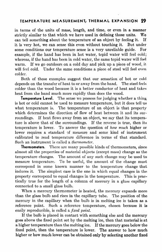
tically true for the length of a column of mercury in a glass capillary
connected to a small glass bulb.
When a mercury thermometer is heated, the mercury expands morethan the glass bulb and rises in the capillary tube. The position of the
mercury in the capillary when the bulb is in melting ice is taken as a
reference point. Such a reference temperature, chosen because it is
easily reproducible, is called a fixed point.
If the bulb is placed in contact with something else and the mercurygoes above the fixed point set by the melting ice, then that material is at
a higher temperature than the melting ice. If the mercury goes below the
fixed point, then the temperature is lower. The answer to how much
higher or how much lower can be obtained only by selecting another fixed

30 PRACTICAL PHYSICS
too 212 373 -BOILING POINTOF WATER
3Z 273
OF WATER
point so that the interval between the two can be divided into a conven-
ient number of units in terms of which temperature changes can be
compared or, as we say, measured.
The other fixed point chosen is the boiling point of water. This is the
temperature of the water vapor above pure water which is boiling under
a pressure of one standard atmosphere. Since the temperature at which
water boils depends upon the pressure, it is necessary to define this fixed
point in terms of a standard pressure.
Many other easily reproducible
temperatures may be used as fixed
points. For example, the boiling point
of oxygen, a very low temperature, and
the melting point of platinum, a very
high temperature, are sometimes used.
The temperatures of such fixed points
are based on the primary temperatureinterval between the freezing point of
water and the (standard) boiling pointFREEZ/NG POINT of water.
Common Thermometer Scales. Twothermometer scales are in common use :
one, the centigrade scale, which divides
the standard interval into 100 equal
parts called degrees centigrade; and the
other, the Fahrenheit scale, which di-
vides the standard interval into 180 equal parts called degrees
Fahrenheit (Fig. 1). A reading on the centigrade scale indicates
directly the interval between the associated temperature and the lower
fixed point, since the latter is marked zero. The Fahrenheit scale is more
cumbersome, not only because the standard interval is divided into 180
parts instead of 100, but also because the base temperature, that of
melting ice, is marked 32. The Fahrenheit scale is used in manyEnglish-speaking countries, while nearly all others use the centigrade
scale. Having the two temperature scales is something of a nuisance, but
it is comparatively easy to convert temperatures from one scale to the
other.
In science the centigrade scale is used almost exclusively. The
centigrade degree is one one-hundredth of the temperature interval
between the freezing and boiling points of water at standard pressure.
The Fahrenheit degree is one one-hundred-eightieth of the same interval.
Therefore, the centigrade degree represents a larger temperature interval
than a Fahrenheit degree. One Fahrenheit degree is equal to five-ninths
of a centigrade degree.
FAHRENHEITCENTIGRADE ABSOLUTE
FIG. 1. Fixed points on
temperature scales.
TEMPERATURE MEASUREMENT; THERMAL EXPANSION 31
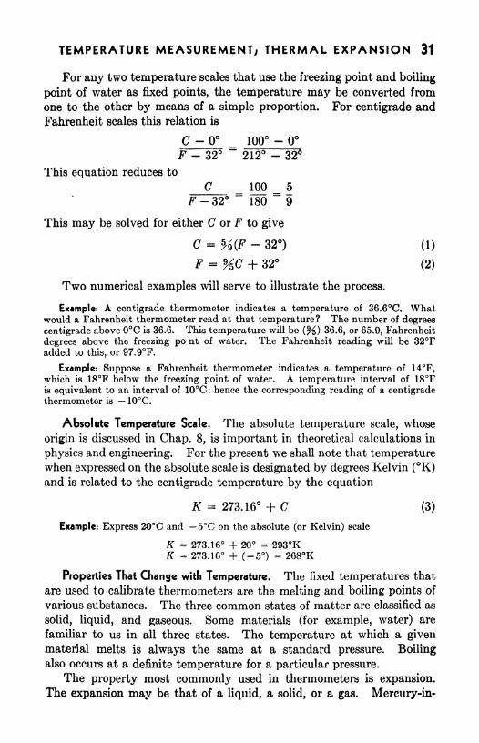
For any two temperature scales that use the freezing point and boiling
point of water as fixed points, the temperature may be converted from
one to the other by means of a simple proportion. For centigrade and
Fahrenheit scales this relation is
C - 100 -F - 32
d212 - 32
This equation reduces to
C 100 5
F-32 180 9
This may be solved for either C or F to give
C = H(F - 32) (1)
F = HC + 32 (2)
Two numerical examples will serve to illustrate the process.
Example: A centigrade thermometer indicates a temperature of 36.6C. Whatwould a Fahrenheit thermometer read at that temperature? The number of degrees
centigrade above 0C is 36.6. This temperature will be (%} 36.6, or 65.9, Fahrenheit
degrees above the freezing po nt of water. The Fahrenheit reading will be 32Fadded to this, or 97.9F.
Example: Suppose a Fahrenheit thermometer indicates a temperature of 14F,which is 18F below the freezing point of water. A temperature interval of 18Fis equivalent to an interval of 10C; hence the corresponding reading of a centigradethermometer is 10C.
Absolute Temperature Scale. The absolute temperature scale, whose
origin is discussed in Chap. 8, is important in theoretical calculations in
physics and engineering. For the present we shall note that temperaturewhen expressed on the absolute scale is designated by degrees Kelvin (K)and is related to the centigrade temperature by the equation
K = 273.16 + C (3)
Example: Express 20C and 5C on the absolute (or Kelvin) scale
K 273.16 -f 20 293KK = 273.16 -f (-5) * 268K
Properties That Change with Temperature. The fixed temperatures that
are used to calibrate thermometers are the melting and boiling points of
various substances. The three common states of matter are classified as
solid, liquid, and gaseous. Some materials (for example, water) are
familiar to us in all three states. The temperature at which a givenmaterial melts is always the same at a standard pressure. Boiling
also occurs at a definite temperature for a particular pressure.
The property most commonly used in thermometers is expansion.
The expansion may be that of a liquid, a solid, or a gas. Mercury-in-
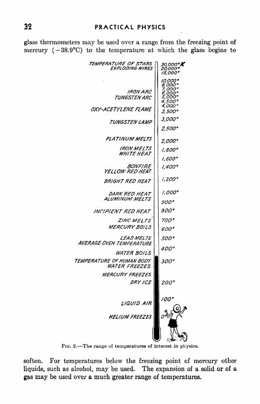
32 PRACTICAL PHYSICS
glass thermometers may be used over a range from the freezing point of
mercury ( 38.9C) to the temperature at which the glass begins to
TEMPERATURE OP STARSEXPLOD/NG W/RES
/ROMARCTUNGSTENARC
OXY-ACETYLENE FLAME
TUMGSTEMLAMP
PLAT/NUM MELTS
/RONMELTSWH/TEHEAT
BOUF/REYELLOWRED HEAT
BR/GHTRED HEAT
DARKRED HEATALUM/MSMMELTS
MC/P/NTRED HEA TZ/NC MELTS
MERCURY BOiLS
LEADMELTSAVERAGE OVEN TEMPERA TURE
WATER BOILS
TEMPERATURE OFHUMANBODYWATER FREEZES
MERCURY FREEZESDRY /CE
LIQU/D AIR
HEL/UM FREEZES
30,000/C2O,OOO/5,000
/O,OOO*8.OOO7,0006,000S.OOO 9
4,500*4.0OO3,500
3,000
2,500
2,000
/,800
/,600
ff400 9
f,OOO
900
800
7OO
600
400
3OO
200
too
OFIQ. 2. The range of temperatures of interest in physics.
soften. For temperatures below the freezing point of mercury other
liquids, such as alcohol, may be used. The expansion of a solid or of a
gas may be used over a much greater range of temperatures.

TEMPERATURE MEASUREMENT; THERMAL EXPANSION 33
The variation of electrical resistance with temperature is often used
as a thermometric property. The variation in electric current producedin a circuit having junctions of two different metals (thermocouple) is
also used.
At very high temperatures special thermometers, called pyrometers,
are used. One kind employs the brightness of the hot object (inside of a
/O 04/0 20 3O 40 50TEMPERATURE IN DEG. C.
FIG. 3. The expansion of water.
60
furnace, for example) to measure the temperature. The color of an
object also changes with temperature. As the temperature rises the
object first becomes a dull red, at a higher temperature a bright red, and
finally, at very high temperatures, white. These changes in color may be
used to measure temperature.Linear Coefficient of Expansion. Nearly all materials expand with an
increase in temperature. Water is an exception in that it contracts with
rising temperature in the interval between and 4C. Gases and
liquids, having no shape of their own, exhibit only volume expansion.Solids have expansion properties, which, in the case of crystals, maydiffer along the various axes.
The fractional amount a material will expand for a 1 rise in tempera-ture is called its coefficient of expansion. For example, the coefficient of
expansion of iron is approximately 0.00001/C. This means that a bar
of iron will increase its length by the 0.00001 fractional part of its original
length for each degree centigrade that its temperature increases. Aniron rod 50 ft long, when its temperature is changed from to 100C,increases in length by an amount
(0.00001/C)(100C)(50 ft) 0.05 ft = 0.6 in.

34 PRACTICAL PHYSICS
The coefficient of linear expansion of a material is the change in length
per unit length per degree change in temperature. In symbols
LQL t
(4)
where a is the coefficient of linear expansion, Lt is the length at tempera-ture t, and L Q is the length at 0C (32F). Measurements of the changein length and the total length are always expressed in the same unit of
length, so that the value of the coefficient will be independent of the
length unit used but will depend on the temperature unit used. Hencethe value of the coefficient of expansion must be specified as "per degree
centigrade" or "per degree Fahrenheit" as the case may be. If we let
AL represent the change in length of a bar (AL is the final length minus the
initial length), a the coefficient of expansion, and At the corresponding
change in temperature, then
AL = oL At (5)
LO being the original length of the rod. The final length of the rod Lt will
be
L t= I/o + AL = Lo + oL A = L (l + a A) (6)
Example: A copper bar is 8.0 ft long at 68F and has a coefficient of expansion of
0.0000094/F. What is its increase in length when heated to 110F?
AL LoaA* =(8.0 ft)(0.0000094/F)fllOF - 68F) = 0.0032 ft
Example: A steel plug has a diameter of 10.000 cm at 30.0C. At what temperaturewill the diameter be 9.997 cm?
AL = LOOT AJ
M _ 10.000 cm - 9.997 cm _~(10.000 cm)(0.000013/C)
~
Hence the required temperature
t = 30.0C - 23.1C = 6.90
Volume Coefficient of Expansion. The volume coefficient of expansionfor a material is the change in volume per unit volume per degree changein temperature. In symbols
where ft is the volume coefficient of expansion, Vt is the volume at tem-
perature t, and Fo is the volume at 0C. The volume coefficient of
expansion is very nearly three times the linear expansion coefficient far
the same material. By comparing volume coefficients calculated roughlyfrom Table I with those given in Table II, it will be seen that, in general,
liquids expand more than solids, but this is not universally true. Thecoefficients of expansion of all gases are approximately the same. More-

TEMPERATURE MEASUREMENT; THERMAL EXPANSION 35
over, this value is much greater than the coefficients of expansion of
liquids and solids.
The facts that different solids have different expansion coefficients, and
that the coefficient of expansion for a given material may vary somewhat
with temperature, lead to many industrial problems. If a structure, for
example, a furnace, can be made of materials that expand equally over
TABLE I. COEFFICIENTS OF LINEAR EXPANSION (AVERAGE)
TABLE II. COEFFICIENTS OF VOLUME EXPANSION OF LIQUIDS
wide ranges in temperature, the structure will hold together much better
than if such materials cannot be found. When it is impossible to find
suitable materials with approximately equal coefficients, allowance must
be made for the large forces that arise, owing to the fact that different
parts of the structure expand at different rates. Some materials that go
together well at one temperature may be quite unsatisfactory at others
because their coefficients may change considerably as the temperature
changes. The coefficient of expansion for each material is determined for
an appropriate range of temperature.
Finding types of glass that have suitable coefficients of expansion and
elastic properties has made it possible to enamel metals with glass. This
product has wide uses, for enameled ware is much more resistant to
corrosion than most of the cheaper metals and alloys. Enameled tanks,
retorts, and cooking utensils are familiar examples. If correctly designed,
they seldom fail except from mechanical blows or improper use. An

36 PRACTICAL PHYSICS
enameled dish put over a hot burner will crack to pieces if it boils dry,
for the coefficients of expansion of the metal and the glass enamel do not
match closely enough, so that at temperatures considerably above the
boiling point of water, the stresses that arise are too great to be withstood.
Tungsten is a metal that expands in a manner similar to that of manyglasses. Tungsten, platinum, and Dumet (an alloy) are metals often
used to seal electrodes through the glass of electric light bulbs, x-ray
tubes, and the like.
SUMMARYThe temperature of an object is that property which determines the
direction of flow of heat between it and its surroundings.
A thermometer scale is established by choosing as fixed points two
easily reproducible temperatures (ice point and steam point), dividing
this interval into a number of equal subintervals, and assigning an
arbitrary zero.
Conversions between centigrade and Fahrenheit scale readings are
made by the relations
F = %C + 32
C = %(F - 32)
The fractional change due to change in temperature is the change in
size (length, area, or volume) divided by the original size at some specified
temperature.The coefficient of expansion is the fractional change per degree change
in temperature. The units, per C or per F, must be expressed.
The linear expansion of a material is equal to the product of the
coefficient of linear expansion, the original length, and the temperature*
change. Symbolically
AL = oL A/
QUESTIONS AND PROBLEMS
1. Express a change in temperature of 20 C in terms of the Fahrenheit scale.
2. Convert -14C, 20C, 40 C, and 60C to Fahrenheit readings. Convert
98F, -13F, and 536F to centigrade readings.
Ans. 6.8F; 68F; 104F; 140F; 37C; -25C; 280C,
3. What is the approximate temperature of a healthy person in C?4. Liquid oxygen freezes at 218.4C and boils at 183.0C. Express
these temperatures on the Fahrenheit scale. Ans. 361.1F; 297.4F,
6. At what temperature are the readings of a Fahrenheit and a centigrade
thermometer the same?
6. From Eq. (5), show that the coefficient of area expansion is approximatelytwice that of linear expansion and that the coefficient of volume expansion is
approximately three times that of linear expansion.

TEMPERATURE MEASUREMENT; THERMAL EXPANSION 37
7. Table III gives the coefficient of linear expansion for iron at different
temperatures. Explain the meaning and usefulness of such a table.
TABLE III
t, C a
0-100 . 10.5 X 10~VC100-200 , . 11.5
200-300 13
300-400... . . 15
400-500 14
500-000. . . 16
600-700. . , .16Above 900. 29
8. The coefficient of volume expansion of air at atmospheric pressure is
0.0037/C. What volume would 10 cm 3 of air at 0C occupy at 100C? at
-100C? at -2003C? Ans. 13.7 cm 3;6.3 cm 3
;2.6 cm 3
.
9. If 40-ft steel rails are laid when the temperature is 35F, what should
be the separation between successive rails to allow for expansion up to 120F?10. A steel tape correct at 0C is used to measure land ^\hen the temperature
is 25C. What percantage error will result in length measureirents due to the
expansion of the tapo? Ans. 0.03 per cent.
11. A steel wa^on tire is 16 ft in circumference at 220C \\hen it is put onto
the wheel. How much will the circuirference shrink in cooling to 20C?12. A pyrex glass flask of volume 1,000 cm 3
is full of mercury at 20C. Howmany cubic centimeters will overflow when the temperature is raised to 50C?
Ans. 5.1 cm 3.
EXPERIMENT
Linear Expansion of Rods
Apparatus: Linear expansion apparatus; boiler; tripod; to 110Cthermometer; rubber tubing; pinchcock; beaker; Bunsen burner; two rods
of different materials.
From the illustration already cited it is evident that the proper design-
ing of many types of machines, utensils, instruments, and buildings
depends upon accurate knowledge of the coefficients of expansion of the
various parts of each and of the materials binding the various parts
together.
Since the coefficient of linear expansion of a material is its change in
length per unit length per degree change in temperature, its determina-
tion requires the measuring of its original length at some definite tem-
perature and its change in length for a given change in temperature.
One type of expansion apparatus commonly available is illustrated by
Fig. 4. If the apparatus has been in the laboratory for several hours, it
may be assumed that the rod enclosed in the jacket is at room tempera-

38 PRACTICAL PHYSICS
ture. Record this temperature Q and the position P of the pointer onthe scale, first making sure that the rod is in contact with the adjustable
stop and that the pointer is near the bottom of the scale. Next, allow
steam from the boiler to flow slowly through the jacket. When the
pointer ceases to rise, it may be assumed that the rod has reached the
temperature of the steam. This temperature t is determined by means of
FIG. 4. Linear-expansion apparatus, mechanical-lever type,
a thermometer inserted in the jacket. The difference between the new
position Pi of the pointer on the scale and its original position is the
magnified change in the length of the rod. The actual change in length
AL of the rod is equal to the magnified change, Pt Po, divided by the
magnifying power of the lever system, which is the length h of the longlever arm divided by the length Z2 of the short lever arm.
AT (P*~h
Compute the coefficient of expansion of the rod by using Eq. (5), and
compare the value thus obtained with that listed in Table I.
FIG. 5. Linear-expansion apparatus, micrometer-screw type.
The apparatus shown in Fig. 5 is equipped with a micrometer screw
for direct measurement of the expansion of the rod. An electric contact
detector is used to adjust the micrometer screw until it is barely in contact
with the rod. One connects a dry cell in series with a current-indicating
device, such as a telephone receiver or a galvanometer (with a protective
resistance), to the two binding posts on the expansion apparatus. Thescrew is then turned slowly toward the rod until contact is barely made.Several observations of this position are made and recorded. Before

TEMPERATURE MEASUREMENT; THERMAL EXPANSION 39
allowing the steam to enter the jacket, one must turn the screw back until
there is no danger that the expanding rod will again make contact. After
steam has been issuing from the end of the jacket for at least 1 min, bring
the micrometer screw into contact with the rod and make several observa-
tions of its position. Compute the change in length AZ/, then determine
the coefficient of expansion, using Eq. (5).

CHAPTER 4
HEAT QUANTITIES
After the concept of temperature became understood there were manycenturies of scientific development before the real nature of heat was
established. Even today there are many people who do not carefully
observe the distinction between these important technical terms. It
was early recognized that a temperature difference between two objects
resulted in a flow of heat when they were placed in thermal contact.
The real nature of the "thing" that flows under such circumstances
has only recently been clearly identified. This development again wasdue to the measurement of heat phenomena.
Meaning of Heat. To raise the temperature of an object, it is neces-
sary either to add heat to it from some source at a higher temperature or
to do work on it. It is possible to warm your hands by rubbing them
together. The work done against friction is transformed into heat andraises their temperatures. When a wire is broken by bending it back
and forth rapidly, some of the work is transformed into heat and the wire
gets hot. When a nail is pulled out of a board, work is needed because
of the friction between the wood and the nail. The work produces heat,
which warms the wood and the nail. Pumping up an automobile tire
with a hand pump takes work. Some of this work produces heat which
warms the pump, tire, and air. Heat is a form of energy, which the mole-
cules of matter possess because of their motion. It must not be confused
with temperature, which determines the direction of transfer of heat.
40

HEAT QUANTITIES 41
Suppose we dip a pail of water from the ocean. Its temperature is
the same as that of the ocean, but the amount of heat (energy) in the
pail of water is almost inconceivably smaller than the amount in the
ocean. Temperature must be measured in terms of an independentlyestablished standard. Heat may be measured in terms of any unit that
can be used to measure energy. It is more convenient, however, to
measure heat in terms of a unit appropriate to the experiments that
involve heat.
Units of Heat. One effect of the addition of heat to water, or any other
substance, is a rise of temperature. The amount of heat necessary to
raise the temperature of a certain amount of water one degree Fahrenheit
is nearly constant throughout the interval between 32 and 212F. This
fact suggests a convenient unit to use in measuring heat. It is called the
British thermal unit (Btu) and is the amount of heat needed to raise the
temperature of one pound of water one degree Fahrenheit. Since
the amount is not quite constant throughout the temperature range, it is
more precisely defined as the amount of heat needed to change the
temperature of a pound of water from 38.7 to 39.7F.
In the metric system the corresponding unit of heat is called a calorie.
The calorie is the heat necessary to raise the temperature of one gram of
water one degree centigrade (more precisely, from 3.5 to 4.5C). OneBtu is equivalent to approximately 252 calorics.
TABLE I. SPECIFIC HEATS OF SOLIDS AND LIQUIDS
cal/gm C or
Substance Etu/lb FAluminum 0.212
Brass 0.090
Carbon (graphite) . 160
Copper 0.092
Glass (soda) 0.016
Gold 0.0316
Ice 0.51
Iron 0.117
Lead 0.030
Silver . 056
Zinc. . 0.093
Alcohol. ... 0.60
Mercury . 033
Water (by definition) . . 1 00
Specific Heat. The heat needed to change the temperature of one
pound of a substance one degree Fahrenheit is a characteristic of the
substance. The number of Btu's necessary to raise the temperatureof one pound of a material one degree Fahrenheit is called the specific heat 1
1 Some authors call this quantity thermal capacity and define specific heat as tho
ratio of the thermal capacity of the substance to that of water.
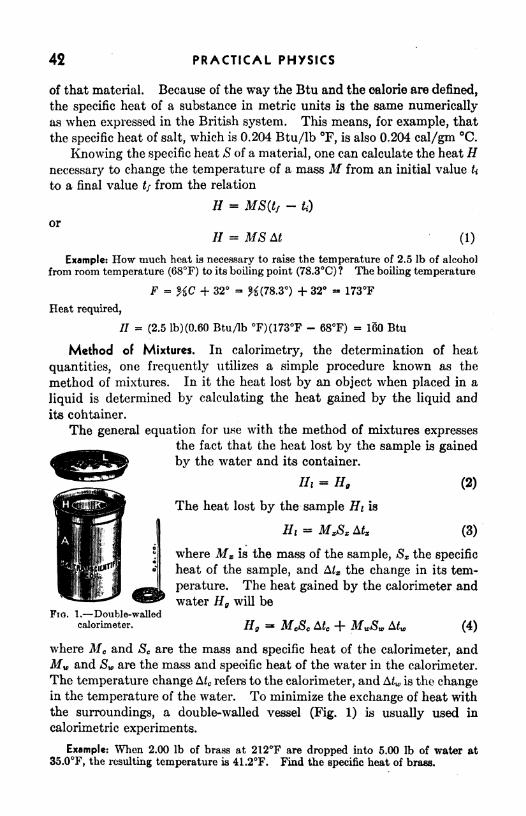
42 PRACTICAL PHYSICS
of that material. Because of the way the Btu and the calorie are defined,
the specific heat of a substance in metric units is the same numerically
as when expressed in the British system. This means, for example, that
the specific heat of salt, which is 0.204 Btu/lb F, is also 0.204 cal/gm C.
Knowing the specific heat S of a material, one can calculate the heat Hnecessary to change the temperature of a mass M from an initial value U
to a final value tf from the relation
H MS(tf-
fc)
or
// = MS M (1)
Example: How much heat is necessary to raise the temperature of 2.5 Ib of alcohol
from room temperature (68F) to its boiling point (78.3C) ? The boiling temperature
F - HC + 32 - K(78.3) + 32 - 173F
Heat required,
// = (2.5 lb)(0.60 Btu/lb F)(173F - 68F) - 180 Btu
Method of Mixtures. In calorimetry, the determination of heat
quantities, one frequently utilizes a simple procedure known as the
method of mixtures. In it the heat lost by an object when placed in a
liquid is determined by calculating the heat gained by the liquid and
its container.
The general equation for use with the method of mixtures expressesthe fact that the heat lost by the sample is gained
by the water and its container.
Hi = H. (2)
The heat lost by the sample Hi is
Hi =(3)
Fio. 1. Double-walledcalorimeter.
where M is the mass of the sample, Sx the specific
heat of the sample, and Alx the change in its tem-
perature. The heat gained by the calorimeter andwater Hg will be
Eg = McSc Afe + MJSW (4)
where Mc and Sc are the mass and specific heat of the calorimeter, andMw and Sw are the mass and specific heat of the water in the calorimeter.
The temperature change A c refers to the calorimeter, and A^, is the changein the temperature of the water. To minimize the exchange of heat with
the surroundings, a double-walled vessel (Fig. 1) is usually used in
calorimetric experiments.
Example: When 2.00 Ib of brass at 212F are dropped into 5.00 Ib of water at
35.0F, the resulting temperature is 41.2F. Find the specific heat of brass.

HEAT QUANTITIES 43
Hi -H,
(2.00 lb)S*(212F - 41.2F) - (5.00 lb)(l Btu/lb F)(41.2P - 35.0F)
(5.00 lb)(l Btu/lb F)(4I.2F - 35.0F)B ~
(2.00 lb)(212F - 41.2F)- 0.091 Btu/lb F
Example: Eighty grams of iron shot at 100.0C are dropped into 200 gm of water
at 20.0C contained in an iron vessel weighing 50 gm. Find the resulting tempera-ture t.
Heat lost by shot = MXSX A/x = (80 gm)(0.12 cal/gm C)(100.0C -Heat gained by water = MWSW A^ (200 gm)(l cal/gm C)(t
- 20.0C)Heat gained by vessel MCSC Afc
= (50 gm)(0.12 cal/gm C)(*- 20.0C)
Heat lost = heat gained
(80 gm)(0.12 cal/gm C)(100.0C - t)- (200 gm)(l cal/gm C)(t - 20.0C)
+ (50 gm)(0.12 cal/gm C)(* - 20.0C)t - 23.6C
Change of State. Not all the heat that an object receives necessarily
raises its temperature. Surprisingly large amounts of energy are needed
to do the work of separating the molecules when solids change to liquids
and liquids change to gases. Water will serve as a familiar example.In the solid phase water is called ice. Ice has a specific heat of about
0.5 cal/gm C. Water has a specific heat of 1 cal/gm C. Water
changes from solid to liquid at 0C (at atmospheric pressure). Large
changes in pressure change this melting point appreciably, a fact that is
demonstrated when we make a snowball freeze together by squeezingand then releasing the snow.
If a liquid is cooled without being disturbed and without the presenceof any of the solid, it is possible to reduce its temperature below the
normal freezing point without solidification. The liquid is said to be
supercooled. If the supercooled liquid is disturbed, it immediatelyfreezes. Water droplets in the air are frequently much below the normal
freezing temperature. Clouds of water droplets are more frequentabove 10C; below that temperature ice clouds are more numerous.
Water droplets have been observed at temperatures as low as 40C.Severe icing may result if the supercooled droplets strike an airplane.
Heat of Fusion. To raise the temperature of 1 gm of ice from 1 to
0C requires J cal of heat energy. To raise the temperature of 1 gmof water in the liquid phase from to 1C requires 1 cal. To melt a
gram of ice requires 80 oal, although the temperature does not changewhile this large amount of heat is being added. The heat needed to
change unit mass of a substance from the sclid to the liquid state at its
melting temperature is called the heat of fusion. It is measured in Btu
per pound or in calories per gram. The heat of fusion of ice is about
144 Btu/lb, or 80 cal/gm. (NOTE : Whereas specific heats are numerically

44 PRACTICAL PHYSICS
the same in British and metric units, heats of fusion differ numerically in
the two systems of units.)
Heat of Vaporization. Once a gram of ice is melted, 100 cal is
required to raise its temperature from the melting point to the boiling
point. Though water evaporates at all temperatures, boiling occurs
when its vapor pressure becomes as large as atmospheric pressure and
bubbles of vapor begin forming under the surface of the liquid. As wecontinue to add heat at the boiling point, the temperature remains the
same until the liquid is changed entirely to vapor. The steps by which a
gram of ice is heated through fusion and vaporization are shown to scale
in Fig. 2. The amount of heat necessary to change a unit mass of a
liquid from the liquid to the vapor phase without changing the tempera-
//o/oo
o
MPOWZAT/ON \MPOR
I I
100 200 300 400 S00 60O 7OO 80OHEA T CHANGE /N CALOWES
FIG. 2. Heat required to change 1 gm of ice at 10C to steam at 110C.
ture is called the heat of vaporization. For water it is approximately540 cal/gm, or 970 Btu/lb, over five times as much energy as is needed
to heat water from the melting to the boiling point. Where this energy
goes is partly understood if we think of the liquid as made up of a myriadof molecules packed closely but rather irregularly, compared to the neat
arrangement in the crystals that make up the solid. One gram of water
occupies 1 cm 3 of space as a liquid. The same amount of water (and
therefore the same number of molecules) in the vapor state at 1 atm
of pressure and a temperature of 100C fills 1,671 crn 3 instead of one. The
work to vaporize the water has been done in separating the molecules to
much larger distances than in the liquid state.
Example: How much heat is required to change 50 Ib of ice at 15F to steam at
212F?
Heat to raise temperature of ice to its melting point Mt& (32F 15F)(50 lb)(0.51 Btu/lb F)(32F - 15F) = 430 Btu
Heat to melt ice = (50 lb)(144 Btu/lb) 7200 BtuHeat to warm water to its boiling point = MWSW (212F - 32F)
- (50 lb)(l Btu/lb F)(212F - 32F) 9000 Btu
Heat to vaporize water (50 lb)(970 Btu/lb) * 4,000 Btu

HEAT QUANTITIES 45
Total heat required: 430 Btu
7,500. 9,000
48,000
64,000 Btu
Note that in this summation the 430"is negligible and may be disregarded, since there
is a doubtful figure in the thousands place in 48,000.
Measurement of Meet of Fusion. Heats of fusion and vaporization, like
specific heats, are determined by calorimeter experiments. The only
change needed in Eqs. (3) and (4) is the addition of a term giving the
amount of heat required to change the state. If a mass M of ice is
added to a calorimeter containing enough warm water so that the ice all
melts, the ice will gain heat and the calorimeter and water will lose an
equal amount. The heat gained by the ice will be the heat to melt it,
assuming that it is at 0C when put into the calorimeter, plus the heat to
warm it to the final temperature once it is all melted. This is,
//.= JlfvL, + MJ3w (tf
-0) (5)
where II represents heat gained by the mass Aft of melting ice whose heat
cf fusion L t is to be measured, Sw is the specific heat of the water which
was ice before it melted, and t/ is the final temperature. The heat lost
by the calorimeter and the water in it will be
Hi = MJSc Afc + MJSV At (6)
where the symbols have meanings analogous to those in Eq. (4). Theinitial temperature should be about as far above room temperature as
the latter is above the final temperature. In this case, the heat that is
lost to the surroundings while the calorimeter is above room temperatureis compensated by that gained while it is below room temperature.
Because of the relatively large amount of heat required to melt the ice,
the quantity of ice used should be chosen appropriately smaller than the
quantity of water. The value of the heat of fusion L t is determined by
equating IIg and Hi from Eqs. (5) and (6), and solving the resulting
equation for L t .
Example: When 150 gm of ice at 0C is mixed with 300 gm of water at 50C the
resulting temperature is 6.7C. Calculate the heat of fusion of ice.
Heat lost by water = (300 gm)(l cal/gm C)(50C - 6.7C) = 13,000 cal
Heat to melt ice = (150 gm)LiHeat to raise temperature of ice water to final temperature
= (150 gm)(l cal/gm C)(6.7C - 0C) - 1,000 cal
_ Heat lost = heat gained_13,000 cal = (150 gm)L< + 1,000 cal
Li - 80 cal/gm
Phaser of Matter. Among the common materials are many that do
not have definite melting points; for example, glass and butter. In a

46 PRACTICAL PHYSICS
furnace, glass will gradually soften until it flows freely even thoughat ordinary temperatures it is quite solid. When it is solid it may be
thought of as a supercooled liquid; it flows, but very slowly. Since it
does not have a definite melting point, it does not have a heat of fusion.
The specific heat of glass changes as the temperature rises. Such
changes indicate transitions in the arrangement of the molecules.
Specific heat measurements may be used by the ceramic engineer in
studying the changes in these products as the temperature is varied.
Many materials decompose at high temperatures and therefore do
not exist in liquid and gaseous states. Some may exist in the liquid
state but decompose before reaching the gaseous state.
Since the chemical elements cannot be decomposed by heating, theyare all capable of existing in the solid, liquid, and gaseous states. Manyof them have more than one solid state, as in the case of phosphorus,which is known in three solid phases: black, formed at very high pressures,
and the more familiar red and yellow forms. Powdered sulphur results
from a direct transition of sulphur vapor to the solid state. If this powderis melted and then cooled, it solidifies normally. By lowering the pres-
sure on water with a vacuum pump, one can cause it to boil and freeze
at the same time. Ice, solid carbon dioxide, and many other solid
substances evaporate. The odor of solid camphor is evidence of its
evaporation.
SUMMARY
Heat is a form of energy.
The most commonly used units of heat are the calorie and the British
thermal unit.
The calorie is the amount of heat required to change the temperatureof 1 gm of water 1C.
The British thermal unit is the amount of heat required to change the
temperature of 1 Ib of water 1F.The specific heat of a substance is the amount of heat required to
change the temperature of unit mass of the substance one degree (Units:
cal/gm C or Btu/lb F).
The specific heat of water varies so slightly with temperature that
for most purposes it can be assumed constant (1 cal/gm C) between
and 100C.The heat lost or gained by a body when the temperature changes is
given by the equation
H MSMIn a calorimeter the heat lost by the hot bodies is equal to the heat
gained by the cold bodies (Hi Hg). To reduce the effect of the sur-

HEAT QUANTITIES 47
roundings, the final temperature of the calorimeter should be as muchbelow (or above) room temperature as it was originally above (or below)room temperature.
The heat of fusion of ice is approximately 80 cal/gm, or 144 Btu/lb.
The heat of vaporization of water is approximately 540 cal/gm, or
970 Btu/lb. It depends on the temperature at which vaporization takes
place.
QUESTIONS AND PROBLEMS
L How many Btu are required to raise the temperature of 0.50 Ib of alumi-
num from 48 to 212F?2. How much heat is required to raise the temperature of 1.5 Ib of water
in an 8-oz aluminum vessel from 48F to the boiling point, assuming no loss of
heat to the surroundings? Ans. 260 Btu.
3. Wliat is the specific heat of 500 gm of dry soil if it requires the addition
of 2,000 cal to increase its temperature 20C?4. From the following data, taken in a calorimeter experiment, what value
is obtained for the specific heat of iron?
Mass of iron 320 gmMass of calorimeter 55 gmSpecific heat of brass calorimeter 0.090 cal/gm CMass of cold water 350 gmTemperature of iron, before mixing 95.0CTemperature of water, before mixing 15 .0CTemperature of water and iron after mixing 22 . 6C
.4ns. 0.1 16 cal/gm C.
6. By referring to the definitions, show that 1 Btu is equal to 252 cal.
6. Which produces the more severe burn, boiling water or steam? Why?7. One frequently places a tub of water in a fruit storage room to keep the
temperature above 30F during a cold night. Explain.
8. How much heat is required to change the temperature of a 10.0-lb block
of copper from 50 to 250F? If the block (at 250F) is placed in 50 Ib of water
at 40F, what will be the resulting temperature? Ans. 184 Btu; 43.8F.
9. A 100-lb casting was cooled from 1300 (red hot) to 200F by placing it
in water whose initial temperature was 50F. How much water was used? The
specific heat of iron is approximately 0.12 Btu/lb F for this temperature range.
10. Water is heated in a boiler from 100 to 284F where, under a pressure of
52.4 lb/in.2
,it boils. The heat of vaporization for water at 284F is 51 1.5 cal/gm,
or 920.7 Btu/lb. How much heat is required to raise the temperature and to
evaporate 500 gal of water? Ans. 4,610,000 Btu.
11. How much energy must be removed by the refrigerator coils from a K-lbaluminum tray containing 3 Ib of water at 70F to freeze all the water, and then
to cool the ice to 10F? Plot the amount of heat extracted against temperature.
12. Calculate the amount of energy required to heat the air in a house 30 by50 by 40 ft from 10 to 70F. The density of air is about 0.08 lb/ft
8 and its

48 PRACTICAL PHYSICS
specific heat at constant pressure is approximately 0.24 Btu/lb F. Discuss the
assumptions made in your calculations. Ans. 69,000 Btu.
EXPERIMENT
Specific Heats of Metals
Apparatus: Double-walled calorimeter; steam generator outfit;
Bunsen burner; two thermometers (0 to 110C and to 50C); 100 gmeach of two different kinds of metal shot; trip scales.
FIG. 3. Steam generator.
While the water in the boiler is being heated, 100 gm of metal shot
Mx is weighed out, poured into the dipper, and placed in the steam
generator (Fig. 3) so that the shot can be heated without coming into
contact with the hot water or steam. The dipper should be covered
during the heating to ensure that the shot will be heated uniformly.
While the shot is being heated, weigh the inner calorimeter cup Mc \then
pour into it about 100 gm of water Mw whose temperature is 3 or 4 below
room temperature, and place it in the outer calorimeter to minimize the
gain of heat from the surroundings.
After the shot has reached a temperature above 95C, record its exact
temperature and that of the cold water in the calorimeter. Pour the
shot quickly into the water and stir the mixture. Record the highest
temperature reached by the water above the shot.
Substitute the data in Eqs. (3) and (4), assume HI = H,and solve
for the specific heat of the metal shot. (The specific heat of the calorim-
eter may be obtained from Table I.) Compare the experimentalvalue of the specific heat with the value given in the table. What is
the percentage error? .

CHAPTER 5
HEAT TRANSFER
Heat is the most common form of energy. The engineer is concerned
with it continually. Sometimes he wants to get it from one place to
another, sometimes he wants to"bottle it up" for storage. In the first
problem, he is confronted with the fact that there are no perfect con-
ductors of heat. The problem of heat storage is complicated by the
fact that there are no perfect insulators of heat, so that one cannot
confine it.
Heat Flow. Heat is always being transferred in one way or another,
wherever there is any difference in temperature. Just as water will
run down hill, always flowing to the lowest possible level, so heat, if left
to itself, flows down the temperature hill, always warming the cold
objects at the expense of the warmer ones. The rate at which heat flows
depends on the steepness of the temperature hill as well as on the proper-
ties of the materials through which it has to flow. The difference of
temperature per unit distance is called the temperature gradient in analogyto the idea of steepness of grade, which determines the rate of flow of
water.
Types of Heat Transfer. There are three ways in which heat is
transferred. Since heat itself is the energy of 'molecular activity, the
49

50 PRACTICAL PHYSICS
H
simplest mode of transfer of heat, called conduction, is the direct com-
munication of molecular disturbance through a substance by means of the
collisions of neighboring molecules. Convection is the transfer of heat
from one place to another by actual motion of the hot material. Heattransfer is accomplished also by a combination of radiation and absorption.
In the former, heat energy is transformed into electromagnetic energy.
While in this form, the energy may travel a tremendous distance before
being absorbed or changed back into heat. For example, energy radiated
from the surface of the sun is converted into heat at the surface of the
earth only eight minutes later.
Conduction. Conduction of heat is important in getting the heat from
the fire through the firebox and into the air or water beyond. Goodheat conductors, such as iron, are used for such jobs. To keep heat in,
poor conductors, or insulators, are used, the amountof flow being reduced to the smallest level that is
consistent with other necessary properties of the
material, such as strength and elasticity. Theamount of heat that flows through any body de-
pends upon the time of flow, the area throughwhich it flows, the temperature gradient, andthe kind of material. Stated as an equation
(i)
where K is called the thermal conductivity of the
material, A is the area measured at right anglesFIO i.-Heat conduction to the direction of the flow of heat, t is the time thethrough a thin plate. .
'
flow continues, and AT/L is the temperaturegradient. The symbol AT1
represents the difference in temperaturebetween two parallel surfaces distant L apart (Fig. 1).
In the British system these quantities are usually measured in the
following units: // in Btu, A in square feet, t in hours, AT in F, andLin inches. The conductivity K is then expressed in Btu/ (ft
2 hr F/in.).
The corresponding unit of K in the metric system is cal/(cm2 sec C/cm).
Example: A copper kettle, the circular bottom of which is 6.0 in. in diameter and0.062 in. thick, is placed over a gas flame. Assuming that the average temperatureof the outer surface of the copper is 300 F and that the water in the kettle is at its
normal boiling point, how much heat is conducted through the bottom in 5.0 sec?The coefficient of thermal conductivity may be taken as 2,40 Btu/(ft
2 hr F/in.).
The area A of the bottom is
A -T(Trft) -0.20ft*

HEAT TRANSFER 51
t 5.0 sec5.0
3,600
300F - 212F
hr
0.062 in.
11 -(2,480 ft2h/in
= 1400 F/in.
-) (0.20 ft*) (1400 <F/in.) . 960 Btu
There are large differences in the conductivities of various materials.
Gases have very low conductivities. Liquids also are, in general, quite
poor conductors. The conductivities of solids vary over a wide range,
from the very low values for asbestos fiber or brick to the relatively high
values for most metals. Fibrous materials such as hair felt or asbestos
are very poor conductors (or good insulators) when dry; if they become
wet, they conduct heat rather well.
One of the difficult problems in us-
ing such materials for insulation is to
keep them dry.
Under certain conditions goodconductors fail to transfer heat read-
ily. This may be caused by an insu-
lating layer of air that sticks to the
surface, a layer that can be removed
to some extent by vigorous stirring or
ventilation. The familiar difficulty
we have of keeping warm in a cold
wind as compared with cold, still air
is an illustration of this. A thinFm' 2-~Heating
layer of air is one of the most effective of all heat insulators. Surface
layers of oxide or other foreign material also impede the flow of heat.
Iron, which is a rather good conductor in itself, fails to transfer heat
readily when covered by a layer of rust.
Convection. The heating of buildings is accomplished largely throughconvection. Air heated by contact with a stove (conduction) expandsand floats upward through the denser cold air around it. This causes
more cold air to come in contact with the stove setting up a circulation,
which distributes warm air throughout the room. When these convec-
tion currents are enclosed in pipes, one for the ascending hot air andanother for the descending cold air, heat from a single furnace can bedistributed throughout a large building (Fig. 2). In order to providea supply of fresh air, the cold-air return pipe is often supplemented or
even replaced by a connection to the outside of the building.In water, as in air, the principal method of heat transfer is convection.
If heat is supplied at the bottom of a container filled with water, con-
vection currents will be set up and the whole body of water will be
convection.

52 PRACTICAL PHYSICS
wanned. If, however, the heat is supplied at the top of the container,
the water at the bottom will be warmed very slowly.
For example, if the top of a test tube filled with water is placed in a
flame, the water in the top of the tube can be made to boil vigorously
before the bottom of the tube begins to feel warm to the hand. This is
possible only when the test tube is of sufficiently small diameter to
prevent the formation of effective convection currents. Convection
currents are utilized in hot-water heating systems, in which the hot water
rises through the pipes, circulates through the radiators, and sinks again
when cooled, forcing up more hot water.
Since convection is a very effective method of heat transfer, it must be
considered in designing a system of insulation. If large air spaces are
left within the walls of a house, convection currents are set up readily
and much heat is lost. If, however, the air spaces are broken up into
small, isolated regions, no major convection currents are possible and
little heat is lost by this method. For this reason the insulating material
used in a refrigerator or in the walls of a house is a porous material
cork, rock wool, or other materials of like nature. They arc not only
poor conductors in themselves but they leave many small air spaces,
which are very poor conductors and at the same time are so small that no
effective convection currents can be set up.
Radiation. The transfer of heat by radiation does not require a
material medium for the process. Energy traverses the space between
the sun and the earth and, when it is absorbed, it becomes heat energy.
Energy emitted by the heated filament of an electric lamp traverses the
space between the filament and the glass even though there is no gas in
the bulb. Energy of this nature is emitted by all bodies. If the tempera-ture of the radiating body is high enough, we can actually see the radia-
tion, for our eyes are sensitive to this type of energy. The fact that
objects radiate energy that does not affect the eye is shown by the warmthwe get from a stove long before it becomes "red hot."
The rate at which energy is radiated from an object depends upon the
temperature of the object, the area of the surface, and upon the condition
of the surface. The rate of radiation increases very rapidly as the
temperature rises. A piece of ice radiates energy less rapidly than one's
hand held near it and thus seems cold, while a heated iron radiates energyfaster than the hand and thus seems warm.
Objects whose surfaces are in such condition that they are goodabsorbers of radiation are also good radiators. A blackened surface will
absorb more readily than a polished surface. The blackened surface
will also radiate faster than the polished surface if the two are at the
same temperature. One can decrease the radiation from a surface bypolishing it, or increase the radiation by coating it with suitable absorbingmaterial.

HEAT TRANSFER 53
. An interesting practical application is. illustrated by the. method of
installing hot-air furnace pipes. For years it was customary to wrapthese pipes with asbestos, even after it was known (about 1920) that this
practice made the pipes lose heat more rapidly than if they had been
left as bright tinned metal. Actual experiments proved definitely that
eight or nine layers of asbestos paper have to be applied in order to makethe pipe lose less heat than when bare; yet only in the last few yearshas this fact been utilized commercially. Uncovered galvanized metal
pipes are being used in most modern installations. The cold-air returns
are likewise being put in with more attention, since it is now recognizedthat the returning cold air lifts the hot
air, causing the circulation.
A thermos bottle (Fig. 3) illustrates
how the principles of heat transfer maybe used to decrease the amount of heat
flowing into (or out of) a container. It
consists of two bottles, one inside the
other, touching ea.ch other only at the
neck. The space between the two bot-
tles is evacuated and the surfaces are
silvered. Transfers by conduction are
minimized by using a very small area of
a poorly conducting material, these due
to convection are lessened by removingthe air. The transfer by radiation is
made small because the polished silver
acts as a poor emitter for one surface aud a poor absorber for the othej\
It is common experience to notice that as a piece of metal is heated
sufficiently it begins to glow a dull red (at about 470C, 880F). If the
heating is continued the color changes from dull red to cherry red, to
light red, then to yellow, and finally to a dazzling white (above 1150C,2100F).
As the temperature of a glowing body is increased, the total energyradiated per unit time increases rapidly. With an.increase in tempera-ture the color shifts from the red end of the spectrum toward the blue.
These facts suggest two ways of measuring temperatures of hot bodies
in terms of their own radiant energy. One method is to collect a certain
fraction of this energy, convert it into electrical energy, and then measure
the current with an electrical meter. An instrument for measuring
temperatures this way is called a total radiation pyrometer.
Another method of measuring temperature is merely a refinement of
the optical method we use when we observe that iron is "red hot."
Even an experienced person probably can judge temperatures by color
only to within 50 to 100C. The human eye cannot Judge ratios of
FIG. 3. Dewar, or thermos, flask.

54 PRACTICAL PHYSICS
intensities accurately. It can, however, match two intensities of the
same color very precisely. Advantage is taken of this fact in the design
of many instruments. An optical pyrometer provides the eye with a
standard (a glowing lamp filament) against which it compares the
radiation of an object whose temperature is to be measured. Suitable
filters allow only light of one color, usually red, to enter the eye. Byvarying the current in the filament its temperature can be varied until
the radiation received by the eye from the two sources matches. The
temperature is then read on a scale that is calibrated in terms of the
current in the filament.
SUMMARY
Heat is the most common form of energy.
Energy may appear in any one of several forms (mechanical, electrical,
thermal, etc.) and may be changed from one form to another.
The three ways in which heat may be transferred from one place to
another are conduction, convection, and radiation.
Conduction is heat transfer from molecule to molecule through a body,or- through bodies in contact.
Convection is heat transfer by means of moving heated matter.
Radiation is heat transfer by means of waves, called electromagnetic
waves, which are similar to short radio waves. Radiation passes readily
through a vacuum, is partly turned back by polished surfaces, and maybe absorbed by vapors or solids or liquids.
Temperature gradient is temperature difference per unit distance
along the direction of heat flow. It may have units in degrees centigrade
per centimeter, degrees Fahrenheit per inch, etc.
Thermal conductivity K is a quantity that expresses how well a sub-
stance conducts heat. It may have units of calories per square centimeter
per second for a gradient of lC/cm or Btu per square foot per hour for a
gradient of lF/in.
QUESTIONS AND PROBLEMS
1. Why does a chimney "draw" poorly when a fire is first lighted?
2. Why does iron seem colder to the touch than wood in winter weather?
3. Why is a hollow wall filled with rock wool a better insulator than whenfilled with air alone?
4. A piece of paper wrapped tightly on a brass rod may be held in a gas flame
without being burned. If wrapped on a wooden rod, it burns quickly. Explain.6. Explain how a thermos flask minimizes energy losses from convection,
conduction, and radiation.
6. A certain window glass, 30 in. by 36 in., is >| in. thick. One side has a
uniform temperature of 70F, and the second face a temperature of 10F. Whatis the temperature gradient? Ans. 480F/in.

HEAT TRANSFER 55
7. The thermal conductivity of window glass is approximately 7.25 Btu/(ft2
hr F/in.) at ordinary temperatures. Find the amount of heat conducted
through the window glass of problem 6 in 1 hr.
8. What will be the rise in temperature in 30 min of a block of copper of
500-gm mass if it is joined to a cylindrical copper rod 20 cm long and 3 mm in
diameter when there is maintained a temperature difference of 80C between the
ends of the rod? The thermal conductivity of copper is 1.02 cal/(cm2 sec C/cm).
Neglect heat losses. Ans. 11.3C.
9. A copper rod whose diameter is 2 cm and whose length is 50 cm has one
end in boiling water and the other in a block of ice. The thermal conductivity
of the copper is 1.02 cal/(cm2 sec C/cm). How much ice will be melted in
1 hr if 25 per cent of the heat escapes during transmission?
10. How much steam will be condensed per hour on an iron pipe 2 cm in
mean radius and 2 mm thick, a 60-cm length of which is in a steam chamber at
100C, if water at an average temperature of 20C flows continuously through the
pipe? The coefficient of thermal conductivity for iron is 0. 18 cal/(cm2 sec C/cm) .
Ans. 364 kg.
DEMONSTRATIONS
Heat Transfer
Apparatus: Convection box; 2 candles; rods or tubes of different
materials; paraffin; nails; cans painted differently; insulating material;
thermometer; water boiler.
The following simple demonstrations may contribute to a clarification
of the fundamental concepts of convection, conduction, and radiation.
FIG. 4. Convection currents in air.
They require only simple apparatus, which can easily be assembled and
demonstrated to the class by interested students.
Convection. Figure 4 represents a box with two holes in its top.
Over each hole is placed a glass or metal tube of large diameter. (Acarton or cigar box is suitable. The tubes may be lamp chimneys, or
tin cans with tops and bottoms removed.) A burning candle is placed
in the box in such a manner that it extends up into tube B. There will
be convection currents upward in tube B and downward in A. This maybe demonstrated by means of another candle flame as suggested by C and

56 PRACTICAL PHYSICS
D in Fig. 4. If chimney A is covered (and there are no other holes in
the box) the flame in JB goes out. Why?Conduction. A metal tube or rod may be shown to be a good con-
ductor by holding it in the hand at one end and putting the other end
in a Bunsen flame. Low conductivity can be demonstrated
similarly by the use of a glass rod or tube. That different
metals have different conductivities may be shown by rods
of the same dimensions but of different materials. To one
end of each rod a nail is attached with paraffin. Whenthe other ends are heated, the nails will drop after different
time intervals. Why?Another type of conductometer is shown in Fig. 5.
Heat applied to the common junction is conducted to the
ends of the rods, which have been dipped into an ignition
solution. The sequence of ignitions ranks the different
metals according to their thermal conductivities.
Radiation. Tin cans with different coverings or surfaces
serve admirably as radiators. They may be painted black,
white, aluminized, covered with asbestos paper, polished,
etc. After being filled to the same volume with boiling
water they will cool at different rates. To demonstrate
this, record the temperature of the water immediatelyafter it is poured into a can, and again half an hour later. Duringthis time each can should be covered with and rest upon wood, thick
cardboard, or other similar insulating material. Which should cool
most rapidly? Why? Don't be fooled! The results are not what
many persons would anticipate.
Are double-walled calorimeters really more effective as heat retainers
than single-walled cups? It is very instructive to observe how muchmore rapidly water cools in a simple cup than in a calorimeter. Heattransfer of which kind (or kinds) is responsible for the cooling? Howmay we know experimentally?
Fio. 5.
Conductom-eter, an in-
strument for
showing rates
of heat trans-
fer in different
metals.

CHAPTER 6
PROPERTIES OF SOLIDS
When a structure or a machine is to be built, suitable materials mustbe chosen for the parts. Each available material is examined to deter-
mine whether its properties will meet the demands of a particular applica-
tion. Some of the properties thus considered are weight, strength,
hardness, expansive characteristics, melting point, and elasticity.
Much of the progress in the design of structures has resulted from the
discovery, adaptation, or development of new structural materials.
As stone, brick, steel, and reinforced concrete replaced the original
structural materials, mud and wood, buildings became stronger and
taller. Early tools were made of wood, bone, or stone, but the discovery
of metals made possible the construction of more intricate and useful
devices. The machine age depends largely upon the technology of
metals.
Elasticity. Among the most important properties of materials are
their elastic characteristics. If, after a body is deformed by some
force, it returns to its original shape or size as the distorting force is
57

58 PRACTICAL PHYSICS
removed, the material is said to be elastic. Every substance is elastic
to some degree.
Consider a long steel wire fastened to the ceiling, in such a mannerthat its upper end is held rigidly in place. To keep the wire taut supposea stone of sufficient mass is fastened to the lower end of the wire. The
force per unit cross section of the wire is defined as the
tensile stress in the wire. The pound per square inch is
the unit in which this stress is commonly measured. To
emphasize the fact that stress is stretching force per unit
area, it is sometimes called unit stress.
Let L (Fig. 1) represent the length of the wire when
just enough force has been applied to take the kinks out
of it. Increasing the stretching force by an amount Fwill stretch or elongate the wire an amount AL. Theratio of the change in length AL to the total length L is
called the tensile strain. Notice that the change in lengthmust be measured in the same unit as the total length if
and strain in the the value of this ratio AL/L is to be independent of thestretching of a unitg uge(j
Hooke's Law. Robert Hooke recognized and stated
the law that is used to define a modulus of elasticity. In studying the
effects of tensile forces he observed that the increase in length of a bodyis proportional to the applied force over a rather wide range of forces.
This observation may be made more general by stating that the strain
is proportional to the stress. In this form the statement is known as
Hooke's law.
If the stress is increased above a certain value, the body will not
return to its original size (or shape) after the stress is removed. It is
then said to have acquired a permanent set. The smallest stress that
produces a permanent set is called the elastic limit. For stresses that
exceed the elastic limit Hooke's law is not applicable.
Young's Modulus. A modulus of elasticity is defined as the ratio of a
stress to the corresponding strain. This ratio is a constant, charac-
teristic of the material. The ratio of the tensile stress to the tensile
strain is called Young's modulus.
V tensile stress _ F/A _ FL , .
tensile strain AL/L A AL
Example: A steel bar, 20 ft long and of rectangular cross section 2.0 by 1.0 in.,
supports a load of 2.0 tons. How much is the bar stretched?
. AALSolving for AL

PROPERTIES OF SOLIDS
F * 2.0 tons
L ~ 20 ft
A ~ (2.0 in. X 1.0 in.)
Y -29,000,00_0 lb/in.*_
(4,000 Ib) (20 ft)
(2.0 tons) (2,OOQ Ib/ton)
2.0 in. 2
> 4,000 Ib
0.0014 ft = 0.017 in.""(29,000,000 lb/in.
2) (2.0 in.*)
Values of Y for several common materials are given in Table I.
TABLE I. VALUES OF YOUNG'S MODULUS
Note that the physical dimensions of Y are those of force per unit area.
Fig. 2 illustrates apparatus for determining Young'smodulus by applying successively greater loads to a wire
and measuring its elongation.
Although stretching a rubber band does increase the
restoring force, the stress and strain do riot vary in a
direct proportion; hence Young's modulus for rubber is
not a constant. Moreover, a stretched rubber band
does not return immediately to its original length whenthe deforming force is removed. This failure of an ob-
ject to regain its original size and shape as soon as the
deforming force is removed is called elastic lag or hysteresis
(a lagging behind).
Ordinarily stretching a wire cools it. Rubber gets
warmer when stretched and cools when relaxed. This
can be verified easily by stretching a rubber band and
quickly holding it against the lips or tongue, which are
very sensitive to changes in temperature. One would
expect then that heating a rubber band would increase
the stress. A simple experiment shows this to be true.
Suspend a weight by a long rubber band and apply heat
to the band with a Bunsen flame played quickly across the
band so as not to fire the rubber. The band will con-
tract, lifting the weight. A wire under similar circumstances will expand,
FIG. 2. Ap-paratus for deter-
mining Young'smodulus.

60 PRACTICAL PHYSICS
lowering the weight. The elastic modulus of a metal decreases as the
temperature increases.
Volume Elasticity. Bodies can be compressed as well as stretched. In
this type of deformation elastic forces tend to restore the body to its
original size.
Suppose that a rubber ball is placed in a liquid confined in a vessel
and that a force is applied to the confined liquid, causing the ball to
contract. Then the volume stress is the increase in force per unit area
and the volume strain .is the fractional change that is produced in the
volume of the ball. The ratio (volume stress) /(volume strain) is called
the coefficient of volume elasticity, or bulk modulus.
H
FIG. 3. Shearing of a cubical block
through an angle <t> by & force F.
OOO/ 0.002 0003 0.004
TENSILE STRAW =A L/L
FIG. 4. Elastic behavior of certain metals.
Elasticity of Shear. A third type of elasticity concerns changes in
shape. This is called elasticity of shear. As an illustration of shearing
strain, consider a cube of material (Fig. 3) fixed at its lower face and acted
upon by a tangential force F at its upper face. This force causes the
consecutive horizontal layers of the cube to be slightly displaced or
sheared relative to one another. Each line, such as BD or CE, in the
cube is rotated through an angle v by this shear. The shearing strain is
defined as the angle <p, expressed in radians. (The radian measure of an
angle is the ratio of the arc subtended by the angle to its radius.) Forsmall values of the angle, <p
= BB'/BD, approximately. The shearingstress is the ratio of the force F to the area A of the face BCGH. The
ratio, shearing stress divided by shearing strain, is the shear modulusor coefficient of rigidity, n.
F/A F/ABB'/BD (2)
The volume of the body is not altered by shearing strain.
Ultimate Strength. The way in which samples of several different
materials are deformed by various loads is illustrated by Fig. 4. For
PROPERTIES OF SOLIDS 61
each load the tensile strain is calculated as the ratio of the elongation
to the original length. This is plotted against the tensile stress, and a
curve is drawn through the points so obtained.
In the region to the left of the elastic limit (EL) the sample obeys
Hooke's law and returns to its original length when the stress is removed.
The sample will support stresses in excess of the elastic limit, but when
unloaded is found to have acquired a permanent set.
If the applied stress is increased slowly, the sample will finally break.
The maximum stress applied in rupturing the sample is called the ultimate
strength. Although the ultimate strength of the sample lies far up on its
strain-stress curve, it is seldom safe to expect it to carry such loads in
structures. Axles and other parts of machines, which are subject to
repeated stress, are never loaded beyond the elastic limit.
Whenever a machine part is subjected to repeated stresses over a long
period of time, the internal structure of the material is changed. Each
time the stress is applied, the molecules and crystals realign. Each time
the stress is removed, this alignment retains some permanent set. As
this process continues, certain regions are weakened, particularly around
areas where microscopic cracks appear on the surface. This loss of
strength in a machine part because of repeated stresses is known as
fatigue. Since failure due to fatigue occurs much sooner if flaws are
present originally than in a perfect part, it is important to detect such
flaws, even though they are very slight, before the part is installed.
Great care is exercised in testing parts of airplane structures to detect
original flaws. In many plants, x-rays are used to detect hidden flaws.
Thermal Expansion. When a structure such as a bridge is put together,
the design must take into account changes in shape due to changes in
temperature. If such provision is not made, tremendous forces develop
that may shatter parts of the structure. Anyone who has ever seen a
concrete pavement shattered by these forces on a hot day realizes the
violence of such a phenomenon.It is interesting to consider the forces due to change in temperature
of a steel rail. If space is provided for expansion, the change in length
is given by
If allowance is not made for expansion, forces arise that can be computedfrom Eq. (1). This gives for a 100-lb/yd rail a force equal to approxi-
mately 100 tons. Railroads now frequently weld the rails together into
continuous lengths which may be several miles long. Suitable tie
fastenings prevent lateral, vertical, or longitudinal motion of the rails,
and under elastic restraint the rails experience compression at high
temperatures and tension at low temperatures.

62 PRACTICAL PHYSICS
Example: A steel rail 40 ft long is fastened rigidly in place when the temperature is
40F. The area of cross section of the rail is 12 in.* What force must be applied to
keep the rail from expanding when the temperature rises to 100F? The coefficient
of linear expansion of steel is 0,0000072/F.
The increase in length that would occur if no force were applied is
AL oLo A*
a 0.0000072/FLo - 40 ft
A* - 100F - 40F - 60FAL = (0.0000072/F)(40ft)(60F)
0.017 ft
If we use this value in Eq. (1), we may compute the force necessary to compressthe rail to its original length. This force is the same as that necessary to extend therail a similar distance
Y ~JJL
F-L̂J
Y =- 29,000,000 lb/in.A 12 in. 2
AL = 0.017 ft
L 40 ft
_ (29,000,000 lb/in.2)(12 in. 2
) (0,017 ft)H . -,
.
40ft= 150,000 Ib = 75 tons
Some Further Properties of Matter. Materials possess several charac-
teristics that are closely related to the elastic properties. Amongthese are ductility, malleability, compressibility, and hardness.
The ductility of a material is the property that represents its adapta-bility for being drawn into wire. Malleability is the property of a material
by virtue of which it may be hammered or rolled into a desired shape.In the processes of drawing or rolling, stresses are applied that are muchabove the elastic limit so that a "flow" of the material occurs. For
many materials the elastic limit is greatly reduced by raising the tempera-ture; hence processes requiring flow are commonly carried on at hightemperature. The compressibility of a material, is the reciprocal of its
bulk modulus.
The property of hardness is measured by the Brinell number. TheBrinell number is the ratio of load, in kilograms weight on a sphere usedto indent the material, to the spherical area of the indentation in squaremillimeters. Among metals, cast lead has one of the smallest Brinell
numbers, namely 4.2. Some of the steels have values over 100 timesas great.
Importance of Sampling in Testing. One difficulty encountered whenattempting to measure the elastic properties of a material is that of
providing a uniform sample. If examined under sufficient magnification,no material is found to be uniform (homogeneous). Rock, brick, and

PROPERTIES OF SOLIDS 63
concrete show structure that can readily be seen. Elastic constants for
such materials should not be taken for samples that are not large com-
pared to the size of the unit structure. Resistance to crushing varies
from 800 to 3,800 lb/in.2 for concrete, while that of granite varies from
9,700 to 34,000 lb/in.2
SUMMARY
Elasticity is that property of a body which enables it to resist and
recover from a deformation.
The smallest stress that produces a permanent deformation is knownas the elastic limit.
Hooke's law expresses the fact that the strain produced in a body is,
within the limits of elasticity, proportional to the applied stress.
A modulus of elasticity is found by dividing the stress by the strain.
Young's modulus is the ratio of tensile stress to tensile strain.
v = F/AAL/L
The coefficient of volume elasticity or bulk modulus is the ratio of volume
stress to volume strain.
The shear modulus or coefficient of rigidity is the ratio of shearing
stress to shearing strain.
F/An * --"
v
The compressibility of a body is the reciprocal of the bulk modulus.
Brinell hardness number is the ratio of the force applied on a hardened
steel ball to the spherical area of indentation produced in a sample.
QUESTIONS AND PROBLEMS
1. Can one use a slender wire in the laboratory to estimate the load capacity
of a large cable on a bridge? Explain.
2. A force of 10 Ib is required to break a piece of cord. How much is
required for a cord made of the same material which is (a) twice as long, (6) twice
as large in diameter and the same length?
3. Young's modulus for steel is about 29 X 106lb/in.
2Express this value
in kilograms per square centimeter.
4. In what way do the numerical magnitudes of (a) strain, (6) stress, and
(c) modulus of elasticity depend on the units of force and length?
6. How much will an annealed steel rod 100 ft long and 0.040 in. 2 in cross
section be stretched by a force of 1,000 Ib?
6. A wire 1,000 in. long and 0.01 in.2 in cross section is stretched 4.0 in. by
a force of 2,000 Ib. What are (a) the stretching stress, (b) the stretching strain,
and (c) Young's modulus? Ans. 2 X 10* lb/in.2
; 0.004; 5 X 10⁷lb/in.
2
7. Fibers of spun glass have been found capable of sustaining unusually
large stresses. Calculate the breaking stress of a fiber 0.00035 in, in diameter,
which broke under a load of 0.385 oz.~

64 PRACTICAL PHYSICS
8. A load of 60 tons is carried by a steel column having a length of 24 ft and
a cross-sectional area of 10.8 in. 2 What decrease in length will this load produce?
(Consult Table I.) Ans. 0.11 in.
9. To maintain 200 in.3 of water at a reduction of 1 per cent in volume,
requires a force per unit area of 3,400 lb/in.2 What is the bulk modulus of the
water?
10. A 12-in. cubical block of sponge has two parallel and opposite forces
of 2.5 Ib each applied to opposite faces. If the angle of shear is 0.020 radian,
calculate the relative displacement and the shear modulus.
Ans. 0.87 lb/in.2
11. The bulk (volume) modulus of elasticity of water is 3.0 X 10 5lb/in.
2
What is the change in volume of the water in a cylinder 3 ft long and 2 in. in
diameter when there is a compressional force per unit area of 14.3 lb/in.2 exerted
on a tight piston in the cylinder?
12. Most high-tension cables have a solid steel core to support the aluminum
wires that carry most of the current. Assume that the steel is 0.50 in. in diame-
ter, that each of the 120 aluminum wires has a diameter of 0.13 in,, and that the
strain is the same in the steel and the aluminum. If the total tension is 1 ton,
what is the tension sustained by the steel? Ans. 530 Ib.
EXPERIMENT
Elasticity
Apparatus: Meter stick; table clamp; 150-cm rod; weight holder;
four 1-kg weights; spring; soft rubber tubing.
Although we have discussed the meaning of elasticity and have
contrasted the elastic properties of steel and rubber, it is difficult to
realize the significance of this property of matter until we have made
quantitative measurements.
Let us take two specimens, one a steel spring, the other a piece of soft
rubber tubing about the same length and load capacity as the steel
spring, and subject them to the same series of loads.
Mount the steel spring in such a way that the bottom of the weight
holder attached to its lower end is just even with the zero on the meter
stick, then add weight, 1 kg at a time, and record the corresponding
displacements from the "no load" position in the "Down" column of
Table II. The spring should not be allowed to bob up and down, but
be held in position while the load is being changed and allowed to take
its new position gradually. After all the weights have been added and
the displacements recorded, the load should be removed 1 kg at a time
and the displacements recorded in the "Back" column.
To obtain satisfactory results the spring, and later the rubber tube,
should be preloaded. Take the zero load reading with the 1-kg weightholder attached to the spring, or rubber tube, that is, consider the weightholder a part of the spring and rubber.

PROPERTIES OF SOLIDS 65
Is the spring perfectly elastic for the loads used, that is, does it return
to its original length after the stress is removed?
Plot a curve of displacement against load. If the curve is a straight
line passing through the origin, the displacement is proportional to the
load. Is this true for your data?
TABLE II
Steel spring
Displacement Displacement per gm
Rubber tubing
Substitute the rubber tube for the steel spring and record the readings
in the same manner as with the spring. What differences in the charac-
teristic properties of the two materials do the data show? Plot the two
sets of data on the same axes and compare the curves obtained. Whichmaterial appears to be more perfectly elastic?

CHAPTER 7
PROPERTIES OF LIQUIDS
Materials are commonly classified as solids, liquids, and gases. Theclass into which a substance falls depends upon the physical conditions
surrounding it at the time of observation.
Solids are bodies that maintain definite size and shape. A liquid
has a definite size, for it will fill a container to a certain level, forming a
free surface, but it does not have a definite shape. Gases have neither
definite shape nor definite volume, but completely fill any container no
matter how small an amount of gas is put into it. The term "fluid
"is
applicable to both liquids and gases.
Pressure. Pressure is defined as force per unit area.
P -^FA (1)
A unit of pressure may be made from any force unit divided by an area
unit. Pressures are commonly expressed in pounds per square inch.
Sometimes pressures are expressed in terms of certain commonly observed
pressures as, for example, one atmosphere, representing a pressure equalto that exerted by the air under normal conditions, or a centimeter of
mercury, representing a pressure equal to that exerted by a coluroa of
66

PROPERTIES OF LIQUIDS 67
mercury 1 cm high. The concept of pressure is particularly useful in
discussing the properties of liquids and gases.
Fluid Pressure Due to Gravity. The atoms and molecules of which a
fluid is composed are attracted to the earth
in accordance with Newton's law of universal
gravitation. Hence, liquids collect at the
bottom of containers, and the upper layers
exert forces on the ones underneath. Such
attraction for the gas molecules keeps an
atmosphere on the surface of the earth.
FIG 1. Pressure in a liquid.
The pressure at a point in a liquid means JOMthe force per unit area of a surface placed at
the point in question. Imagine a horizontal
surface A of unit area (Fig. 1). The weightof the column of liquid directly above this
surface is numerically equal to the force per
unit area (the pressure) caused by the
weight of the liquid. If the liquid is water
each cubic foot weighs 62.4 Ib, and each cubic inch weighs (62.4/1,728)
Ib = 0.0361 Ib. If we take the area A as 1.0 in.2,the volume above the
area is
(10 in.) (1.0 in.2)= 10 in. 3
,
hence the weight of liquid above the area is
(0.036 lb/in.3)(10 in. 3
)= 0.36 Ib
and the pressure on the area is 0.36 lb/in.2
.
Weight-density. In computing liquid pressure due to gravity it is
helpful to know the weight per unit volume of the liquid. The weight
TABLE I. WEIGHT-DENSITIES OF LIQUIDS AND SOLIDS

68 PRACTICAL PHYSICS
per unit volume is called the weight-density.
WVd (2)
Values of weight-density for a number of substances are given in Table I.
In order to find the pressure due to a column of liquid, it is sufficient
to know the weight-density d and the depth h below the surface.
P = hd (3)
Example: Find the pressure at the bottom of a tank that is filled with gasoline to a
depth of 8.0 ft.
P = hd
h 8.0 ft
d - 42 lb/ft3
P - (8.0 ft) (42 lb/ft3)- 3?0 lb/ft
s
330 lb/ft2
"144in./ft'
= 2A lb/m '
If the bottom of the tank is 6.0 by 8.0 ft, what force is exerted on it?
"'-$F =PA
P = 340 lb/ft2
A - (6.0 ft) (8.0 ft)= 48ft 2
F = (340 lb/ft2) (48 ft 2
)= 16,000 Ib
Note that there are only two significant figures in the original data; hence onlytwo significant figures are retained in each result.
Buoyancy/ Archimedes* Principle. Everyday observation has shown
us that when an object is lowered into water it apparently loses weightand indeed may even float on the water.
Evidently a liquid exerts an upward,
buoyant force upon a body placed in it.
Archimedes, a Greek mathematician and
inventor, recognized and stated the fact
that a body wholly or partly submerged in
a fluid experiences an upward force equal
to the weight of the fluid displaced.
Archimedes' principle can readily be
verified experimentally, as indicated at the
end of this chapter. One can deduce this
principle from a consideration of Fig. 2.
Consider a block of rectangular cross sec-
tion A, immersed in a liquid of weight-
density d. On the vertical faces, the
liquid exerts horizontal forces, which are
balanced on all sides. On the top face it exerts a downward force h\dA
FIG. 2. The upward force onthe bottom of the block is greaterthan the downward force on the top.

PROPERTIES OF LIQUIDS 69
and on the bottom face an upward force h^dA. The net upward force on
the block is
lizdA h\dA = hdA,
which is just the weight (volume hA times weight-density d) of the liquid
displaced by the block.
The control of submarines depends in part on Archimedes' principle.
In submerging the boat, sea water is admitted into ballast tanks and the
buoyant force balanced. The boat is brought to the surface by expelling
the water from these tanks with compressed air.
Specific Gravity. The specific gravity of a body is the ratio of its
density to that of some standard substance. The standard usually
chosen is water at the temperature of its maximum density, 39.2F.
Thus, if d is the density of the body and dw the density of the water, the
specific gravity (sp. gr.) of the body is
Sp. gr.=
(4)U-10
Since each of the two densities has the same unit, their quotient has no
units. Specific gravity is often more convenient to tabulate than
density, the values of which in the British and metric systems of units
are different. One* may easily compute density from specific gravity
by the use of Eq. (4).
d =(sp. gr.)cL
The units of density thus obtained will be those of the system in which
the density of water is expressed.
Since the density of water in metric units is 1 gm/cm3,the density is
numerically equal to the specific gravity in that system.
Weight-density and Specific Gravity Measurements by Archimedes*
Principle. This principle suggests a method for comparing the weight-
density of a substance with that of some standard fluid, such as water.
The measurement of specific gravity involves the following reasoningwhich is briefly stated in symbols:
q ~ weight-density of substance __ WS/V __ W9'
weight-density of water WW/V Ww
weight of body in air
loss of weight in water (5)
Since the volume of a submerged body is equal to the volume of the dis-
placed water, the ratio of the weight-densities is the same as the ratio of
the weight W? of the sample of the substance to the weight Ww of an equal

Ill PRACTICAL PHYSICS
volume of water. These weights can be determined by weighing the
sample in air and in water. The weight in water subtracted from the
weight in air gives the loss of weight in water, which is the weight of
the water displaced (from Archimedes' principle). Therefore, the specific
gravity can be determined by the measurements indicated in Eq. (5).
Example: A metal sphere weighs 35.2 oz in air and 30.8 oz when submerged in
water. What is the specific gravity and the weight-densityof the metal? From Eq. (5)
_ of sample in air
**' gr *~"
loss of weight in water
Weight in air = 35.2 oz
Loss of weight in water = 35.2 oz 30.8 oz = 4.4 oz
35.2 ozsP-*r-=T4^= 8 -
From Eq. (4)
d *(sp. gr.)dw
dw - 62.4 lb/ft8
d -(8.0) (62.4 lb/ft
3)- 500 Ib/ft*
Quick determinations of the specific gravity of a
liquid or solution can be made with a hydrometer.This instrument (Fig. 3) is a glass bulb attached to
a narrow stem and weighted so as to remain upright
when floating in a liquid. It floats at such a depthas to displace exactly its own weight of the liquid
(Archimedes' principle). The stem is calibrated to
indicate the specific gravity of the solution, for the
smaller this specific gravity the deeper the bulb sinks
in the liquid.
External Pressure; Pascal's Law. The pressure
previously discussed is that caused by the weight of
the liquid. If any external pressure is applied to
the liquid, the pressure will be increased beyond that
given by Eq. (3), The most common of such external
pressures is that due to the atmosphere.
Whenever an external pressure is applied to anyFIG. 3. Hydrometer, g^j a^. reg^^ pressure is increased at every point in
the fluid by the amount of the external pressure. This statement is called
Pascal's law, after the French philosopher who first clearly expressed it.
The practical consequences of Pascal's law are apparent in automobile
tires, hydraulic jacks, hydraulic brakes, pneumatic drills, and air brakes.
Hydraulic Press. The fact that pressure in a liquid at rest is trans-
mitted by the liquid in all directions unchanged, except by changes in
level, has an important application in a machine called the hydraulic
press. Small forces exerted on this machine cause very large forces

PROPERTIES OF LIQUIDS 71
exerted by the machine. In Fig. 4, the small force FI is exerted on a small
area A\. This increases the pressure in the liquid under the piston byan amount P. The force that this increase of pressure will cause on the
large piston will be F2= PA Z ,
since the pressure increase under both
pistons is the same. Hence,
and PA 1= or
Simply by changing the ratio of A 2 to A i, the force F2 may be made as
large as is safe for the big piston to carry. Larger pistons require moretransfer of liquid and are correspondingly slower in action.
Fluid Flow. The rate of flow of a liquid through a pipe or channel is
usually measured as the volume that passes a certain cross section per
mTTT.
....-MM i/r.unft time, as gallons per minute,liters per second, etc. If the aver-
age speed of the liquid at section Sin Fig. 5 is v, the distance I throughwhich the stream moves in time t is
FIG. 4. Hydraulic press. FIG. 5. Rate of flow of liquid through apipe.
vt. This may be regarded as the length of an imaginary cylinder which
has passed S in time t. If A is the area of the cylindrical section, then
its volume is Al =Avt, and the volume rate of flow of the liquid is given
by
Avt
t
T- AW AR = - = Av (6)
In a fluid at rest the pressures are the same at all points of the same
elevation. This is no longer true if the fluid is moving. When water
flows in a uniform horizontal pipe, there is a fall in pressure along the pipein the direction of flow. The reason for this fall in pressure is that force
is required to overcome friction. If the liquid is being accelerated,
additional force is required.
When the valve of Fig. 6 is closed, water rises to the same level in
each vertical tube. When the valve is opened slightly to permit a small
rate of flow, the water level falls in each tube, indicating a progressive

72 PRACTICAL PHYSICS
decrease of pressure along the pipe. If the rate of flow is doubled, the
pressure drop is twice as great. The pressure drop and the rate of flow
are proportional. Frictional effects are very important when water is
distributed in city mains or when petroleum is transported long distances
in pipe lines. Pumping stations must be placed at intervals along such
lines to maintain the flow.
VALVECLOSED OPEN
FIG. 6. Friction causes a fall in pressure along a tube in which a liquid flows.
Pressure and Speed. When water flows through a pipe that has a nar-
row constriction (Fig. 7), the water necessarily speeds up as it approachesthe constriction to keep the mass of liquid passing the cross section there
per unit time the same as that passing a cross section anywhere else in the
pipe. Hence the speed of the water must increase as it moves from Ato B. To cause this acceleration, the pressure at A must be greater
than that at B. This is an example of a general rule (Bernoulli's princi-
ple): whenever the speed of a horizontally moving stream of fluid increases
owing to a constriction, the pressure
must decrease. High speed is asso-
ciated with low pressure, and vice
versa.
The atomizer on a spray gunthe jets in a carburetor utilize
Bernoulli's principle. The curving
Path.
of a pitched baseball when
Spinning is explainable in terms of
thig principle A Venturi tube similar
Fm.7.-Fiow through a constriction.
Decrease in pressure accompanies in-
crease in speed.
to Fig. 7 is used to measure the flow of water or the speed of an airplanein terms of the decrease in liquid or air pressure in the constriction.
The speed of flow of a fluid or that of a body moving relative to a fluid
may also be measured by means of a pilot tube (Fig. 8). Because of the
inertia of the fluid, its impact causes the pressure in tube P to be greaterthan the static pressure in tube S. The two tubes are connected to a
gauge that records the differential pressure, A pitot tube is frequently

PROPERTIES' OF LIQUIDS 73
used to measure the air speed of an airplane. The dial of the pressure
gauge can be calibrated to read the speed of the tube relative to the air.
]]Pressure tube
D Static tube
FIG. 8. Pitot-tube air-speed indicator. The pressure tube P is open at the end whilethe static tube S is closed at the end but has openings on the side. The pressure gauge hasa sealed inner case C and is operated by the pressure-sensitive diaphragm D.
SUMMARYPressure is force per unit area.
The weight-density of a substance is its weight per unit volume.
At a depth h below the surface, the pressure due to a liquid of weight-
density d is
The specific gravity of a substance is the ratio of its density to that
of water.
Archimedes' principle states that a body wholly or partly submergedin a fluid is buoyed up by a force equal to the weight of the fluid displaced.
Pascal's law states that an external pressure applied to a confined fluid
increases the pressure at every point in the fluid by an amount equal to
the external pressure.
Bernoulli's principle expresses the fact that whenever the speed of a
horizontally moving fluid increases due to a constriction, the pressure
decreases. A Venturi tube utilizes this principle to measure flow.
QUESTIONS AND PROBLEMS
1. A box whose base is 2.0 ft square weighs 200 Ib. What pressure does it
exert on the ground beneath it?
2. A vertical force of 4.0 oz pushes a phonograph needle against the record
surface. If the point of the needle has an area of 0.0010 in. 2,find the pressure
on the record in pounds per square inch. Am. 250 lb/in.2
3. What is the pressure at the base of a column of water 40 ft high?4. A tank 4.0 ft in diameter is filled with water to a depth of 10.0 ft. What
is the pressure at the bottom? Find the total thrust on the_bottom of the tank.
Ans. 620 lb/ft2
; 7,800 Ib.

74 PRACTICAL PHYSICS
5. The piston of a hydraulic lift for cars is 6.0 in. in diameter. The device
is operated by water from the city system. What is the water pressure necessaryto raise a car if the total load lifted is 3,142 Ib?
6. What size piston is to be used in a hydraulic lift, if the maximum load
is 5,000 Ib and the water pressure is that due to a 100-ft head of water?
Ans. Diameter = 12.1 in.
7. A coal barge with vertical sides has a bottom 40 ft. by 20 ft. When loaded
with coal, it sinks 18 in. deeper than when empty. How much coal was taken on?
8. A stone from a quarry weighs 30.0 Ib in air, and 21.0 Ib in water. Whatis its (a) specific gravity, (6) weight-density, and (c) volume?
Ans. 3.3; 2fO lb/ft3
;0.14 ft 3
.
9. A can full of water is suspended from a spring balance. Will the readingof the balance change (a) if a block of cork is placed in the
water and (6) if a piece of lead is placed in the water? Explain.
10. To secure great sensitivity, is a narrow or wide hydrom-eter stem preferable? Why?
11. Does a ship wrecked in mid-ocean sink to the bottomor does it remain suspended at some great depth? Justify your
opinion.
12. Why does the flow of water from a faucet decrease whensomeone opens another valve in the same building?
EXPERIMENTS
Liquid Pressure
Apparatus: A tall glass jar; a 16-in. length of tubingabout 2 in. in diameter, sealed at one end and graduated
along its length; six 100-gm slotted weights; water; salt
solution; hydrometer.
Fill the glass jar about half full of water, place the
empty tube in the water as shown in Fig. 9, and recordFIG. 9. Ap- the depth to which it sinks. It will be necessary to hold
measuring liquid the tube in a vertical position, but care should be takenpressure. ^Q exert no vertical force on it.
If the tube is uniform in diameter, the vertical forces on it include
only its weight and the upward force exerted by the water on the bottomof the tube. The latter force, just sufficient to support the weight of the
tube, is the product of the pressure and the area of the bottom of the tube,
that is, F = PA. We can use this relation to find the pressure at the bot-
tom of the tube, since A can be determined and F is the weight of the tube.
If an object is placed in the tube, the latter will sink to a position
at which the upward force is equal to the combined weight of tube and
object. Again F = PA, so that P can be found if F and A are known.
Measure the diameter D of the tube and compute its area of cross
section from the relation A = %irD 2. Next, add the 100-gm weights in
succession, recording in a table similar to Table II the corresponding

PROPERTIES OF LIQUIDS 75
depths h to which the tube sinks. For each observation, determine F(remembering that F is equal to the combined weight of the tube and its
contents) and calculate the pressure, P = F/A.
TABLE II
Do the data that you have recorded indicate that P is proportionalto /i? In order to answer this question, divide each value of P by the
corresponding value of h. If this quotient is essentially constant, P andh are proportional to each other. What does this quotient represent
[see Eq. (3)]? Compare its value with that listed in Table I. Plot the
graph of P against h. What does the shape of the curve indicate?
Repeat the depth measurements for the same series of loads, usingsalt water, and record in the sixth column. How do these depths h'
compare with the corresponding values of hi Compute the ratio h/hf
for each observation. What is the significance of this ratio? Place a
hydrometer in the salt water and compare its reading with the value of
the ratio h/h'.
Archimedes* Principle
Apparatus: Platform balance; weights; string; stone or other object
to be submerged; graduate; water.
Archimedes' principle indicates that an object partly or completely
submerged in a liquid is buoyed up by a force equal to the weight of the
displaced liquid. If the object is floating, the buoyant force is exactly
equal to its weight, that is, the object sinks just far enough to displace
its own weight of liquid. If the object sinks, it displaces its own volume
of the liquid, so that the buoyant force is equal to the weight of an equal
volume of liquid.
Compute the buoyant force on a submerged object by subtracting its
apparent weight (when submerged) from its weight in air.
Determine the volume of liquid displaced by the object by submergingthe latter in liquid contained in a graduate and measuring the apparentincrease in volume of the liquid. Compare the weight of this amount of
liquid with the buoyant force previously evaluated. Is the result in
accordance with Archimedes' principle?

CHAPTER 8
GASES AND THE GAS LAWS
Gases consist of molecules whose forces of attraction are comparatively
small, so that they do not hold together sufficiently well to form liquids
or solids. The molecules are very small, and the distances between themare (on the average) relatively great compared to their size. Air feels
soft and smooth, but actually it consists of a large group of discrete
particles rather than a continuous, homogeneous substance. The mole-
cules are in constant motion, the speed of the motion increasing as the
temperature rises.
A gas exerts pressure on its surroundings because the molecules con-
tinually collide with the walls of the container and with each other (Fig.
1). Since the extent of motion of each molecule is limited only by these
collisions, a gas will expand until it fills any container in which it is placed.
Gas Laws. Since the pressure that a gas exerts on the walls of the
container is caused by collisions of the molecules with the walls, one would
expect the pressure to depend upon the number of molecules and upon16

GASES AND THE GAS LAWS 77
their speed. The number of molecules depends upon the mass and
volume, and the speed depends upon the temperature. The quantitativerelation of these factors is given by the equation
PV = MRT (1)
where P is the pressure, V the volume, M the massof gas, T the temperature on the absolute scale,
and R a constant. This statement may be called
the general gas law.
Absolute Zero of Temperature. If the pressureof a given mass of gas is kept constant, its volumeV t at some temperature t will be
V t= AF =
(2)
where /3 is the volume coefficient of expansion of
the gas when the pressure is kept constant. Solv-
ing Eq. (2) for /3 gives
V. V*e* ' t r
FIG. 1. Gas pressureis caused by the collision
of molecules with thewalls of the container.
(3)
This equation serves to define the volume coefficient of expansion of a
gas. It is the change in volume per unit volume at 0C per degree
change in temperature. As long as the pressure on the gas is kept fairly
low and the volume at the melting point of ice taken as VQ ,the coefficient
is approximately constant for all temperatures well above the boiling pointof the substance. It is also significant that all gases have practically the
same coefficient of expansion.If the volume of a given mass of gas is held constant, the pressure
increases as the temperature increases. The pressure at a temperaturet is
Pt = Po + AP = Po + yPo A/ (4)
This gives as the definition of 7 (gamma), the pressure coefficient,
* - %-' wthat is, 7 is the change in pressure per unit pressure at 0C per degreechange in temperature.
Experiment shows that ft and 7 are equal to each other and approxi-mately the same for all gases. This somewhat surprising fact shows that,
although the masses of the molecules of different gases are quite different,the space between the particles is such a large fraction of the total
volume which a gas occupies, that the elastic properties of all gases are
alike.

78 PRACTICAL PHYSICS
The coefficients, /3 and % have a value of 0.00366/C. This meansthat the volume of given mass of gas changes by 0.00366 of its volume at
0C for each degree change in temperature if its pressure is kept constant.
Also, if the volume is kept constant, the pressure will change by the same
fraction of the pressure at 0C.A gas exerts a pressure because it possesses thermal energy and the
molecules are flying about, bumping into the walls of the container. If
the gas had no thermal energy at all, the particles would not be moving.The temperature at which no heat would be left in the gas would be an
absolute zero. No lower temperature could exist because there would
be no more heat to take away.The value of absolute zero can be found by computing the number of
times 0.00366 of a pressure at 0C can be subtracted before the pressure
becomes zero. This is about 273 times. As each degree fall in tempera-ture reduces the pressure at 0C by this fraction, absolute zero mustbe at --273 C. The volume would also be zero if the pressure had been
kept constant while the temperature was reduced, assuming that the
fractional change in volume per- degree temperature change remained
constant. But at very low temperatures, the voluire of the molecules
themselves becomes appreciable when compared to the volume the gas
occupies. The molecules are highly incompressible, so the volume does
not approach zero as the temperature is lowered. Absolute zero in
degrees Fahrenheit is % of 273 below 32F, the freezing point of water,
or -460F.
TABLE I. DENSITY AND SPECIFIC GRAVITY OF SOME GASES
In Table I are listed the values of density and specific gravity for
several gases under standard conditions of pressure and temperature
(0C and one standard atmosphere). Values for other conditions can
be derived from those in the table by means of the general gas law.
A convenient form of the general gas law can be obtained by solving
Eq. (1) for R, giving

GASES AND THE GAS LAWS
PV ;-
,
79
(6)
Since R is a constant, PV/MT- is constant, 'sd'theit \?e may write
MT M 1T 1
Therefore for a given mass of a gas
PiVi PoFo P2F2
(7)
/>,
j-UIlli -I'lil
v,
T,V
r,
FIG. 2. The pressure, volume, andtemperature relations for a gas.
These relationships are illustrated in Fig. 2. Initially a volume V\ of
gas at a temperature Ti exerts a pressure PI. When the pressure is
increased to P^ the temperature re-
maining the same, the volume is re-
duced to V. If the temperature is
then raised to T2 ,the volume increases
to F2 ,the pressure remaining the
same. The temperature must al-
ways be measured with respect to
absolute zero, to use Eq. (6) or Eq.
(7), and the pressure must be the ab-
solute pressure, not the differential
gauge pressure. The readings of
most pressure gauges represent the difference between the absolute
pressure and atmospheric pressure. To obtain the absolute pressure,
atmospheric pressure must be added to the gauge pressure.
Boyle's Law and Charles's Laws. Several applications of the general
gas law, Eq. (1), under special conditions, are of considerable importance.If the mass of gas and the temperature remain constant, Eq. (1) reduces to
PV = Ki . (8)
which is known as Boyle1
s law. It may be stated as follows: if the tem-
perature and mass of a gas are unchanged, the product of the pressure
and volume is constant. This condition is realized for relatively slow
changes in volume and pressure.
If the pressure and the mass of gas remain constant, Eq. (1) becomes
V = K2T (9)
Equation (9) is stated in words as follows: the volume of a sample of
gas is directly proportional to the absolute temperature if the pressure
remains the same. ,
*
!
'
If the volume and mass of gas remain constant, Eq. (1) reduces to
P <= K*T (10)
or, in words, the volume remaining the same, the pressure of a sample of
gas is directly proportional to the absolute temperature.

80 PRACTICAL PHYSICS
These two laws are known as Charles's laws.
The Mercury Barometer. A simple device for measuring atmospheric
pressure can be made from a glass tube about 3 ft in length, closed at
one end. The tube is filled with mercury, stoppered, inverted, and
then placed open end down in a vessel of mercury as shown
in Fig. 3. When the stopper is removed, some mercuryruns out of the tube until its upper surface sinks to a
position lower than the top of the tube. The height of
the mercury column h is called the barometric height and
is usually about 30 in. near sea level. Evidently the
space above the mercury column contains no air.
Consider the horizontal layer of mercury particles with-
in the tube and on the same level as the surface outside
the tube. The downward pressure on this layer is hd, in
which h is the height of the column and d the density of
mercury (13.6 gm/cm 3). But the upward pressure on
this layer must have this same value, since the layer is at
rest. Hence the pressure of the atmosphere is equal to
the pressure exerted by the mercury column. If, while
filling the tube, one allows air to get into the space above
the column, the barometer will read too low because of
the downward pressure of this entrapped air.
A common type of mercury barometer is shown in
Fig. 4. This type is used in technical laboratories, weather observa-
tories, and even on ships for accurate readings of barometric pressures.
Barometer readings are much lower at high altitudes than at sea level;
they also vary somewhat with changes in weather. Standard atmos-
pheric pressure supports a column of mercury 76 cm in height, at latitude
45, and at sea level; hence standard atmospheric pressure = hd = (76.00
cm) (13.596 gm/cm 3)= 1033.3 gm/cm 2
. This is approximately 14.7
lb/in.2
Example: The volume of a gas at atmospheric pressure (76 cm of mercury) is
200 in. 3 when the temperature is 20C. What is the volume when the temperatureis 50C and the pressure is 80 cm of mercury?
PVT
FIG. 3.
Principle of the
mercury b a -
rometer.
'
-FT*' 1
V, = 200 in. 3
PI 76 cm of mercuryP- 80 cm of mercuryTi 20C + 273 = 293KT 50C -f 273 =-- 323K
(76cm)(323 K)(200m. 8)
(80cm)(293K)210 i

GASES AND THE GAS LAWS 81
FIG, 4. A mercury barometer.
SUMMARY
The molecules of a gas occupy only a small fraction of the volume
taken up by the gas.
Gases exert pressure on the walls of the container because the mole-
cules collide with the walls.
The general gas law states that the product of the pressure and the
volume of a sample of gas is proportional to the absolute temperature
PV = MET
The volume coefficient for a gas is the fractional change in volume per
degree change in temperature, when the pressure is constant. (The
original volume is that at 0C.)The pressure, coefficient is the fractional change in pressure (based
upon the pressure at 0C) per degree change in temperature.The volume and pressure coefficients are equal and have nearly the
same value for all gases (0.00366/C).

82 PRACTICAL PHYSICS
Absolute zero is that temperature at which (a) all molecular activity
ceases, (6) the volume between gas molecules is reduced to zero, and (c)
the pressure exerted by molecular activity is zero. Absolute zero is
-273.16C = -459.7F.
Absolute temperature T is measured on a scale beginning at absolute
zero. T = 273.16 + t, where t is the centigrade temperature.
Boyle's law follows from the general gas law if the temperature is
constant. PV is constant if T does not change.
Charles's laws also follow from the general gas law. If the pressure
is constant, the volume is directly proportional to the absolute tempera-ture. If the volume is constant, the pressure is directly proportional to
the absolute temperature.
QUESTIONS AND PROBLEMS
1. The barometric pressure is 30 in. of mercury. Express this in pounds per
square foot and in pounds per square inch. (See Table I of Chap. 7.)
2. Why does air escaping from the valve of a tire feel cool?
3. Change 40C and -5C to the absolute scale. Change 45F and -50Fto the absolute scale.
4. A gas occupies 200 cm 3 at 100C. Find its volume at 0C, assumingconstant pressure. Ans. 146 cm8
.
6. Given 200 cm3 of oxygen at 5C and 76 cm of mercury pressure, find
its volume at 30C and 80 cm of mercury pressure.
6. A mass of gas has a volume of 6.0 ft3 at 40C and 76 cm of mercury pres-
sure. Find its volume at 15C and 57 cm of mercury pressure. Ans. 6.6 ft3 .
7. A gas occupies 2.0 ft3 under a pressure of 30 in. of mercury. What volume
will it occupy under 25 in. of mercury pressure? Assume that the temperatureis unchanged.
8. The volume of a tire is 1,500 in. 3 when the pressure is 30 lb/in.2 above
atmospheric pressure. What volume will this air occupy at atmospheric pres-
sure? Assume that atmospheric pressure is 15 lb/in.2 How much air will come
out of the tire when the valve is removed? Ans. 4,500 in. 3; 3,000 in. 3
EXPERIMENT
Expansion of Air
METHOD A
Apparatus: Gas law apparatus illustrated by Fig. 5; large graduate;
ice; steam generator; barometer; thermometer.
With the apparatus depicted in Fig. 5 it is possible to study experi-
mently the changes of volume of air, (1) for constant temperature, and
(2) for constant pressure. It is made of glass and consists essentially
of three tubes, two (A and C) open to the atmosphere, the other (D)closed. When the apparatus is filled with mercury, air is trapped in
tube D. With the wooden plunger E one can change the relative
amounts of mercury in the tubes and thus raise or lower the mercury

GASES AND THE GAS LAWS 83
columns. By means of the scale S one can read the heights of the
mercury columns in D and C.
The apparatus will have been adjusted by the pinstructor before class time, so that the mercurysurface in D is somewhat higher than that in C.
If the level in D is higher than that in C by an
amount ft, the pressure of the gas in D is less than
atmospheric pressure by h cm of mercury. As the
plunger is pushed down, the pressure of the air in Dis increased, becoming equal to atmospheric pres-
sure when the mercury columns are at the same
level, and greater than atmospheric pressure by h
cm of mercury when the columns are in the posi-
tions shown in Fig. 5. Because of the increase in
pressure, the entrapped air decreases in volume in
accordance with Boyle's law (the temperatureremains essentially constant).
The positions of the mercury surfaces in D and Cshould be recorded in Table II for various positions
of the plunger. At the head of the table should be
noted the scale reading for the top of the air columnin D, and the atmospheric pressure, as read from a
barometer, in centimeters of mercury. The total
pressure P of the air in D is the sum ofPa,the atmos-
pheric pressure, and Ph, the added pressure produced
by the mercury (h cm of mercury). If the air
column in D has a uniform cross section, its volume is proportional to its
length L. According to Boyle's law, the volume is inversely proportional
TABLE II
Top of air column in DAtmospheric pressure Pa ... -
FIG. 5. Diagram of
apparatus for demon-strating Boyle's law.
to the pressure, hence L should be inversely proportional to P. The cri-
terion for the recognition of such a proportion between two variables is
that their product shall remain constant. This product should be com-
puted, therefore, and recorded in the last column of the table. What is
your conclusion?

PRACTICAL PHYSICS
Adjust the plunger until the mercury surfaces are at the same level.
Place the apparatus in a jar as in Fig. 6 and fill the jar with ice water.
Notice that the air in D contracts and that the mercurylevel in C drops below that in D. Readjust the plunger
until the mercury levels in C and D are again the same.
In the procedure just described, the pressure of the air
in D was in each case adjusted to equal that of the at-
mosphere, hence the condition for Charles's law (Eq. 9)
was fulfilled. If the procedure is repeated for a series of
different temperatures, each value of the volume (or of L)should be proportional to the corresponding absolute
temperature T.
Repeat the procedure for a number of different tem-
peratures. The temperature may be raised by bubblingsteam through the water. Temperature readings should
be made only after the water has been thoroughly stirred
to establish a uniform temperature. Record the data as
in Table III. Is the ratio T/L essentially constant?
Plot a graph, L against T, and interpret it.
METHOD B
Apparatus: Large graduate; water; steam generator; ice;
thermometer; capillary tube as shown in Fig. 7; burette
clamp; rubber or cork stopper with hole; barometer.
The tube shown in Fig. 7 is of capillary bore havingan internal diameter of 1 or 2 mm. In it is trapped someair separated from the external atmosphere by a mercury
column. This tube should be slipped into the hole of a stopper which is
held by a burette clamp and support rod. In this way the tube can berotated in a vertical plane with the clamp as a swivel.
TABLE III
FIG. 6.
Gas law ap-paratus.
When the tube is oriented as in fe, Fig. 7, the gas is under atmosphericpressure (P cm of mercury). When in orientation a, the air pressure

GASES AND THE GAS LAWS 85
in the tube is Pa + PA, where Ph is the pressure exerted by a vertical
column of mercury h cm high, h being the vertical height of the mercuryas illustrated in Fig. 7.
For orientation c, the air pressure in the tube is Pa Ph.
For all such orientations the volume of
the gas is related to the pressure by the
Boyle's law equation, since the tempera-ture is constant.
To study this law, measure Z/, the
length of the air column, and h for dif-
ferent orientations of the tube (include the
two vertical positions for which h is easily
determined). The values of Ph will be
numerically equal to h in centimeters of
mercury. (If the mercury column is sepa-
rated into two or more segments, the
length of the mercury column should be
determined by adding the lengths of the
segments.) Record the data as in Table
IV. Refer to the alternative experiment A for the interpretation of the
data.
TABLE IV
Fio. 7. A simple capillary-tubetype of gas-law apparatus.
pa PL
If the tube is placed vertically in water and then the temperature of
the water is changed, the volume and temperature of the air will change,
but not the pressure. Take readings of L and t for various tempera-tures of the water, beginning with ice water. Record the data as in
Table V. If the volume of the air column is proportional to the absolute
temperature, the ratio in the fourth column should be essentially constant.
TABLE V
TIL

CHAPTER 9
METEOROLOGY
Meteorology is the study of weather and the atmospheric conditions
that contribute to it. The phenomena of weather are subjects not only
of never-ending interest but of great importance, since weather is one
of the chief elements in man's life. Although foreknowledge of weather
will not enable us to make any change in the conditions that eventually
arrive, yet we can, in many cases, so adjust our activities that adverse
weather will produce a minimum of ill effect. The Weather Bureau
was established to observe and forecast weather conditions. For manyyears these reports have been of great value to those engaged in agriculture
or marine navigation. At the present time, however, the most important
application of meteorology is in connection, with airplane flight,, both
civil and military. The great dependence, of the airplane upon the
weather makes accurate observation and forecast essential. This need
has caused great extension in the number of stations reporting and in the
scope of the observations.
The Ocean of Air. The human race lives at the bottom of an ocean
of great depth an ocean of air. Just as the inhabitants of the ocean
86

METEOROLOGY 87
of water are subject to pressure and water 'Currents, so are we subjectto air pressure and air currents. As the pressure in the ocean of water
increases as the depth increases (P =/id), so also the pressure of the
atmosphere increases as the depth below its "surface" increases. Asone rises from the bottom of the ocean of air, the pressure decreases.
The pressure of the air is measured by means of a barometer. Themost reliable kind of barometer is the mercury type described in Chap. 8.
This instrument, however, is not readily portable, and whenever the use
requires portability another type called an aneroid barometer is used
The essential feature of an aneroid barometer (Fig. 1) is a metallic box
Pointer
FIG. 1. The aneroid barometer.
or cell, corrugated in order to make it flexible and partly exhausted of
air. This cell tends to collapse under the pressure of air, but a strong
spring balances the air pressure and prevents such collapse. As the
pressure of the air changes, the free surface of the cell contracts or expandsslightly, and this small movement is magnified and transmitted to a
needle that moves over a dial.
In the discussion of pressure in Chap. 7, the unit used was a force
unit divided by an area unit such as pounds per square inch or pounds per
square foot. Pressure may. also be expressed in terms of the heightof a column of liquid, which is supported by the pressure. Since mercuryis commonly used in barometers, air pressure is frequently recorded in
inches of mercury. At sea level the average height of the mercury columnin the barometer is 29.92 in. Hence we say that normal barometric
pressure is 29.92 in. of mercury.In weather observations another unit of pressure called the millibar
is now used by international agreement.
1 millibar = 1,000 dynes/cm2
To convert from pressures expressed in inches of mercury to pressures
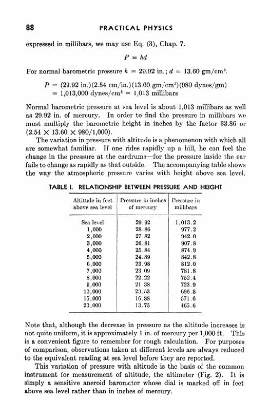
PRACTICAL PHYSICS
expressed in millibars, we may use Eq. (3), Chap. 7.
P = hd
For normal barometric pressure h = 29.92 in.; d = 13.60 gm/cm 3.
P = (29.92 in.) (2.54 cm/in.) (13.60 gm/cm 3) (980 dynes/gm)
= 1,013,000 dynes/cm2 = 1,013 millibars
Normal barometric pressure at sea level is about 1,013 millibars as well
as 29.92 in. of mercury. In order to find the pressure in millibars wemust multiply the barometric height in inches by the factor 33.86 or
(2.54 X 13,60 X 980/1,000).
The variation in pressure with altitude is a phenomenon with which all
are somewhat familiar. If one rides rapidly up a hillvhe can feel the
change in the pressure at the eardrums for the pressure inside the ear
fails to change as rapidly as that outside. The accompanying table shows
the way the atmospheric pressure varies with height above sea level.
TABLE I. RELATIONSHIP BETWEEN PRESSURE AND HEIGHT
Note that, although the decrease in pressure as the altitude increases is
not quite uniform, it is approximately 1 in. of mercury per 1,000 ft. This
is a convenient figure to remember for rough calculation. For purposesof comparison, observations taken at different levels are always reduced
to the equivalent reading at sea level before they are reported.
This variation of pressure with altitude is the basis of the commoninstrument for measurement of altitude, the altimeter (Fig. 2). It is
simply a sensitive aneroid barometer whose dial is marked off in feet
above sea level rather than in inches of mercury.

METEOROLOGY 89
At a single elevation the barometric pressure varies from day to dayand from time to time during the day. The lowest sea-level pressureever recorded is 26.16 in. of mercury (892 millibars), while the highestis 31.7 in. (1,078 millibars). This variation greatly affects the use of an
altimeter. If the altitude reading is to be at all reliable, the instrument
must be set for the current pressure each time it is to be used. For
example, an airplane in taking off from a field at which the pressure is
29.90 in. has an altimeter that is set correctly at the altitude of the field.
If it then flies to another field where the
pressure is 29.50 in., the altimeter will
read 400 ft above the field when the
plane lands. Such an error would be
disastrous if the pilot were depending
upon the instrument for safe landing.
In practice the pilot must change the
setting en route to correspond to the
pressure at the landing field.
Heating and Temperature. The vari-
ations in sea-level pressure in the at-
mosphere and the resulting air currents
are due largely to unequal heating of
the surface of the earth. The sun maybe considered as the sole source of the
energy received, since that received from
other sources is so small as to be negli-
gible.
The three methods of heat transfer, conduction, convection, and
radiation, were discussed in Chap. 5. Each kind of transfer plays a partin distributing the heat that comes to the earth. Heat comes from the
sun to the earth by radiation. A small part of this incoming radiation
is absorbed in the air itself. A part is reflected or absorbed bythe remainder reaches the surface of the eartfc and is there absorl
reflected.
When heat is absorbed at the surface of the earth, the temperaturerises. If no heat were radiated by the earth, the temperature rise wouldcontinue indefinitely. However, on the average, over a long period of
time and for the earth as a whole, as much energy is radiated as is received.
Certain parts of the earth, for example, the equatorial regions, receive
more energy than they radiate, while others, such as the polar regions,
radiate more than they receive. The balance is maintained by the trans-
fer of heat from one region to the other by convection. The convection
currents are set up by unequal heating of the different parts of the surface
of the earth.
FIG. 2. A sensitive altimeterThe large-hand readings are in hun-dreds and the small-hand readingsare in thousands of feet.

90 PRACTICAL PHYSICS
The unequal heating of adjacent areas may be the result of unequaldistribution of the radiation or of unequal absorption of radiation. If
the radiation strikes a surface perpendicularly, the amount of energy perunit area is greater than it would be for any other angle. Thus regions
(equatorial) where the sun is overhead receive more energy for each squarefoot of area than do the polar regions where the angle that the rays makewith the ground is smaller. In equatorial regions the surface tempera-ture is, on the average, higher than in surrounding regions. The layerof air adjacent to the ground is heated by conduction and expands,
becoming less dense than the surrounding air at the same level. Thelighter air rises, its place being taken by surrounding colder air; this in
turn is heated and rises. The unequal heating sets up a circulation that
constitutes the major air movement of the world.
EQUATOR-
FIG. 3. General circulation on a uniform earth.
The major circulation of the atmosphere is shown diagrammaticallyin Fig. 3. Over the equatorial region heated air rises, causing a low-
pressure area of calm or light fitful winds, called doldrums. Both northand south of the doldrums air rushes in to take the place of the rising air,
thus forming the trade winds. If the earth were not rotating, these wouldbe from the north in the Northern Hemisphere and from the south in
the Southern Hemisphere. The rotation of the earth, however, causes a
deflection of the moving air: to the right in the Northern Hemisphere,to the left in the Southern. Thus the trade winds blow almost con-
stantly from the northeast in the Northern Hemisphere and from the
southeast in the Southern.
The air that rises in the doldrums moves out at high altitude andabout 25 from the equator begins to descend. This region of descending-air is an area of calm or light winds and high pressure, and is called thehorse latitudes. Part of the descending air moves back toward the equatorwhile the remainder continues to move away from it near the surface.

METEOROLOGY 91
Again the rotation of the earth causes a deflection to the right (in the
Northern Hemisphere), hence the wind comes from the west. The winds
of this region are known as prevailing westerlies. A part of the air movingout from the equator continues at high level until it reaches the polar
area. As it returns toward the equator, it is deflected by the rotation of
the earth to form the polar easterlies.
Since the atmosphere is principally heated from below, the tempera-ture normally decreases as the altitude increases for several thousand feet;
above this region there is little further change. The region of changing
temperature is known as the troposphere; the upper region of uniform
temperature is known as the stratosphere, and the surface of separa-tion is the tropopause. The altitude of the tropopause varies from
about 25,000 ft to 50,000 ft in different parts of the earth, the highest
values being above the equatorial regions and the lowest over the poles.
The rate at which the temperature decreases with altitude is called
the lapse rate. The value of the lapse rate varies over a wide range
depending upon local conditions, but the average value is about 3.6F per
1,000 ft in still air.
If air rises, the pressure to which it is subjected decreases, and it
expands. In this process there is little loss of heat to the surroundingsor gain from them. In accordance with the general gas law (Chap. 8),
the temperature decreases as the air expands. Such a change is called
an adiabatic change, the word implying "without transfer of heat." In a
mass of rising air, the temperature decreases faster than the normal lapse
rate. If the air is dry, this adiabatic rate of decrease is about 5.5F per
1,000 ft. If the air rises because of local heating, as occurs over a plowed
field, it will rise until its temperature is the same as that of the surround-
ing air at the same level.
Example: The temperature of air at the surface of a plowed field is SOT, while
that over adjacent green fields is 70F. How high will the air current rise?
The rising air must cool 80 70 = 10F more than the still air. For each
1,000 ft the rising air cools 5.5 3.6 == 1.9F more than the still air. The numberof 1,000 ft at which their temperatures will be the same is
10Fr = 5.3
1.9F
h = 5.3 X 1,000 ft = 5,300 ft
If condensation occurs in the rising air, there is a gain in heat from
the heat of vaporization, and therefore the change is no longer adiabatic.
During the condensation, therefore, the rising saturated air cools at a
smaller moist-adiabatic rate.
Cyclones and Anticyclones. As large masses of air move along the
surface of the earth, areas of low pressure and other areas of high pressure
are formed. The air moves from the high-pressure areas toward the

92 PRACTICAL PHYSICS
low-pressure areas. As in larger air currents, the rotation of the earth
causes the wind to be deflected (to the right in the Northern Hemisphere)so that the air does not move in a straight line from high to low but spirals
out from the high and spirals into the low. The low-pressure area with
its accompanying winds is called a cyclone; the high-pressure area with
its winds is called an anticyclone. The deflection to the right causes the
winds to move counterclockwise in the cyclone and clockwise in the
FIQ. 4. A typical weather map.
anticyclone. These high- and low-pressure regions cover very large areas,
having diameters of from 200 to 600 miles.
The presence of cyclones and anticyclones is shown on weather maps.Lines called isobars are drawn connecting points of equal pressure.
Figure 4 is a reproduction of a weather map. Where the isobars are
close together, the pressure is changing rapidly and high winds are
expected. Where they are far apart, the pressure is more uniform and
there is usually less wind.
Humidity. At all times water is present in the atmosphere in one or
more of its physical forms solid, liquid, and vapor. The invisible
vapor is always present in amounts that vary over a wide range while
water drops (rain or cloud) or ice crystals (snow or cloud) are usually
present.
If a shallow pan of water is allowed to stand uncovered in a large room,the water will soon evaporate and apparently disappear although it is still

METEOROLOGY 93
present as invisible vapor. If a similar pan of water is placed in a small
enclosure, it will begin to evaporate as before, but after a time the
evaporation stops or becomes very slow and droplets begin to condense
on the walls of the enclosure. The air is said to be saturated. When this
condition has been reached the addition of more water vapor merelyresults in the condensation of an equal amount. The amount of water
vapor required for saturation depends upon the temperature; the higherthe temperature the greater is the amount of water vapor required to
produce saturation. If the air is not saturated, it can be made so either
by adding more water vapor or by reducing the temperature until that
already present will produce saturation. The temperature to which the
air must be cooled, at constant pressure," to produce saturation is called
the dew point. If a glass of water collects moisture on the outside, its
temperature is below the dew point.
When the temperature of the air is reduced to the dew point, con-
densation takes place if there are present nuclei on which droplets mayform. These may be tiny salt crystals, smoke particles, or other particles
that readily take up water. In the open air such particles are almost
always present. In a closed space where such particles are not present,
the temperature may be reduced below the dew point without consequentcondensation. The air is then said to be supersaturated.
In a mixture of gases, such as air, the pressure exerted by the gas is
the sum of the partial pressures exerted by the individual gases. The
portion of the atmospheric pressure due to water vapor is called its
vapor pressure. When the air is saturated, the pressure exerted by the
water vapor is the saturated vapor pressure. Table 2 in the Appendixlists the pressure of saturated water vapor at various temperatures.
The mass of water vapor per unit volume of air is called the absolute
humidity. It is commonly expressed in grains per cubic foot or in
grams per cubic meter. Specific humidity is the mass of water vapor per
unit mass of air and is expressed in grains per kilogram, grains per
pound, etc. Specific humidity is the more useful since it remains
constant when pressure and temperature change, while the absolute
humidity varies because of the change in volume of the air involved.
Relative Humidity. Relative humidity is defined as the ratio of the
actual vapor pressure to the saturated vapor pressure at that tempera-ture. It is commonly expressed as a percentage. At the dew point the
relative humidity is 100 per cent. From a knowledge of the temperatureand dew point the relative humidity can be readily determined by the
use of the table of vapor pressures.
Example: In a weather report the temperature is given as 68F and the dew point50F. What is the relative humidity?
To use Table 2 (Appendix) we must change the temperature to the centigradescale.

94 PRACTICAL PHYSICS
- 32)- 32) - %(36) - 20
C2= ^(50 - 32) = %(18) = 10
From thQ. jfcable we find the vapor pressures
Pi = 17.6 mm of mercury = pressure of saturated vaporPi 9.2 mm of mercury = actual vapor pressure
_, , x ., .,. A ^2 9.2 mm of mercury
Relative humidity = 77 =r,_--- = 0.52 =* 52%J
Pi 17.6 mm of mercury/0
Whenever the temperature of the air is reduced to the dew point,
condensation occurs. When the dew point is above the freezing point,water droplets are formed; when it is below, ice crystals are formed.
The formation of dew, frost, clouds, and fog are examples of this process.The cooling may be caused by contact with a cold surface, by mixingwith cold air, or by expansion in rising air. If the droplets are sufficiently
small, the rate of fall is very slow and there is a cloud. When the cloud
is in contact with the earth's surface, we call it fog. One of the mostcommon causes of cloud formation is the expansion and consequent
cooling of a rising air column. Each of the small fair-weather clouds of a
bright summer day is at the top of a column of rising air. Its base is
flat, at the level at which the dew point is reached. The glider pilot mayuse these clouds as indicators to show the position of the rising currents.
Clouds form on the windward side of mountains where the air is forced to
rise, while on the leeward side where the air is descending the clouds
evaporate.
Whenever the temperature and dew point are close together, the
relative humidity is very high and cloud or fog formation is very probable.The pilot, in planning a flight, avoids such areas because of the low
visibility and ceiling to be expected there.
SUMMARY
Meteorology is the study of weather and the atmospheric conditions
that contribute to it.
Important factors in the weather are barometric pressure, temperature,
wind, humidity.
The barometric pressure, which is measured in inches of mercury or
millibars, decreases with increase in altitude. The decrease is about 1 in.
of mercury per 1,000 ft in the lower levels.
A millibar is 1,000 dynes/cm2
.
The temperature of the air is normally highest at the surface of the
earth. The rate at which it decreases with increase in altitude is called
the lapse rate. Its average value is about 3.6F per 1,000 ft.
Rising air is cooled by expansion, its temperature decreasing about5.5F per 1,000 ft rise for dry air.

METEOROLOGY V3
A cyclone is a low-pressure area with its accompanying, winds whilk
an anticyclone is a high-pressure area and its winds. In the Northern
Hemisphere winds spiral counterclockwise into a cyclone and clockwise
6ut of an anticyclone.
Isobars are lines on the weather map connecting points of equalbarometric pressure.
Absolute humidity is the mass of water vapor per unit volume of air.
Specific humidity is the mass of water vapor per unit masd of air.
Relative humidity is defined as the ratio of the actual vapor pressure
to the saturated vapor pressure at that temperature.The dew point is the temperature to which the air must be cooled, at
constant pressure, to produce saturation.
Water vapor condenses to form a cloud or fog whenever the tempera-ture is reduced to the dew point.
QUESTIONS AND PROBLEMS
1. When side by side, over which will the stronger up current be found duringa period of sunshine, a plowed -field or a meadow? Why?
2. What is actually tneant by the term "falling barometer"?
3. If the temperature is 40F at the 'surface, what will it be at 30,000 ft
altitude, under normal conditions? at 15,000 ft?
4. Why is it impossible to use an altimeter intelligently without knowledgeof the terrain and the weather map? Explain fully.
6. What may be the result of flying over mountains, in thick weather, if the
altimeter is reading too high?6. Would an altimeter show increase in altitude if there were no decrease in
barometric pressure during a climb? Why?7. Define relative humidity, specific humidity, dew point.
8. In which case does the air hold more water vapor: (a) temperature 32F,dew point 32F, (b) temperature 80F, dew point 50F? What is the relative
humidity in each case? Ans. 100 per cent; 34 per cent.
9. A decrease of 1 in. of mercury in barometric pressure will cause what
change of altitude reading on an altimeter at rest on the ground?10. How are differences in pressure indicated on the weather map?11. What kind of weather would you expect to find where the dew point and
the air temperature are the same?
EXPERIMENT
Dew Point and Relative Humidity
Apparatus: Sling psychrometer; hair hygrometer; tables.
It is possible to determine the dew point directly by observation of the
temperature at which dew first appears on a polished surface, as its tem-
perature is i-educed. This method is quite inaccurate, because of the

96 PRACTICAL PHVSICS
inability of an observer to determine exactly when the dew first appears,A more commonly used method is that which makes use of wet-bulb
and dry-bulb thermometers. The instrument consists of two thermom-
eters, the bulb of one being covered with cloth that is kept moistened.
Fio. 5. Sling psychrometer.
Evaporation causes the temperature of this bulb to be lowered. The rate
of evaporation depends upon the relative humidity of the surrounding-air and hence the difference in temperature of the two thermometers
will give a measure of that quantity. If the wet-
bulb thermometer is kept stationary, the air adjacent to
it quickly becomes more humid than the surroundingair. In order to get a true reading, the air must move
past the bulb. The simplest means of securing this mo-tion is to use the instrument called a sling psychrometer',
which is depicted in Fig. 5. It consists of two ther-
mometers so mounted that they may be whirled
readily. The lowest temperature reached by the wet-
bulb thermometer is recorded as the wet-bulb tempera-ture. Tables in a handbook give the relation betweenthe wet- and dry-bulb temperatures and the relative
humidity in weather observations.
Use the sling psychrometer to determine the dew
point and the relative humidity in a room. Wrap gauzearound one of the thermometer bulbs, moisten it, andwhirl the instrument rapidly for a few minutes. Notethe temperature of the two thermometers frequently and
continue whirling the instrument until the lowest temperature of the
wet bulb is determined. Using the dry-bulb temperature and the dif-
ference between the dry- and wet-bulb temperatures, obtain, by the aid
of the tables, the dew point and relative humidity of the room.The hair hygrometer (Fig. 6) is an instrument that reads relative
humidity directly. A long hair varies considerably in length underdifferent conditions of humidity. The hair is connected to a suitable
Fio. . Hairhygrometer.

METEOROLOGY 97
system of levers so that its expansion and contraction are communicated
to the pointer, which moves over a scale calibrated to read the relative
humidity directly. The indications of this type of instrument are
usually rather inaccurate. If a hair hygrometer is available, take its
reading and compare it with the value obtained by the use of the sling
psychrometcr.

CHAPTER 10
TYPES OF MOTION
A study of the motions of objects is necessary if we are to understand
their behavior and learn to control them. Since most motions are very
complex, it is necessary to begin with the simplest of cases. When these
simple types of motion are thoroughly understood, it is surprising what
complicated motions can be analyzed and represented in terms of a few
elementary types.
Speed and Velocity Contrasted. The simplest kind of motion an
object can have is motion with constant velocity, a particular case of
motion with constant speed. Constant velocity implies not only con-
stant speed but unchanging direction as well. An automobile that
travels for 1 hr at a constant velocity of 20 mi/hr north, reaches a place20 mi north of its first position. If, on the other hand, it travels around a
race track for 1 hr at a constant speed of 20 mi/hr, it traverses the samedistance without getting anywhere. At one instant its velocity may be
20 mi/hr east; at another, 20 mi/hr south.
The statement "An automobile is moving with a velocity of 20 mi/hr"is incorrect by virtue of incompleteness, since the direction of motion
98
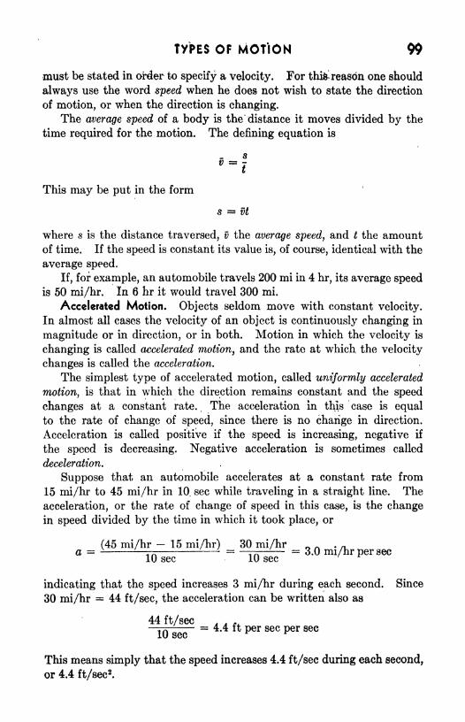
TYPES OF MOTION 99
must be stated in order to specify a velocity. For thi& reason one should
always use the word speed when he does not wish to state the direction
of motion, or when the direction is changing.
The average speed of a body is the distance it moves divided by the
time required for the motion. The defining equation is
This may be put in the form
5 = vt
where s is the distance traversed, v the average speed, and t the amountof time. If the speed is constant its value is, of course, identical with the
average speed.
If, for example, an automobile travels 200 mi in 4 hr, its average speedis 50 mi/hr. In 6 hr it would travel 300 mi.
Accelerated Motion. Objects seldom move with constant velocity.
In almost all cases the velocity of an object is continuously changing in
magnitude or in direction, or in both. Motion in which the velocity is
changing is called accelerated motion, and the rate at which the velocity
changes is called the acceleration.
The simplest type of accelerated motion, called uniformly accelerated
motion, is that in which the direction remains constant and the speed
changes at a constant rate. The acceleration in this case is equal
to the rate of change of speed, since there is no change in direction.
Acceleration is called positive if the speed is increasing, negative if
the speed is decreasing. Negative acceleration is sometimes called
deceleration.
Suppose that an automobile accelerates at a constant rate from
15 mi/hr to 45 mi/hr in 10, sec while traveling in a straight line. The
acceleration, or the rate of change of speed in this case, is the changein speed divided by the time in which it took place, or
(45 mi/hr - 15 mi/hr) 30 mi/hr n .
a = \-' -L i = 3.0 mi/hr per sec10 sec 10 sec
' *
indicating that the speed increases 3 mi/hr during each second. Since
30 mi/hr = 44 ft/sec, the acceleration can be written also as
44 ft/sec * * *.
t/>- = 4.4 ft per sec per sec
10 sec
This means simply that the speed increases 4.4 ft/sec during each second,
or 4.4 ft/sec2
.
100 PRACTICAL PHYSICS
Using algebraic symbols to represent acceleration a, initial speed #1,
final speed vz ,and time t, the defining equation for acceleration is written
Multiplying both sides of the equation by t gives
which expresses the fact that the change in speed is equal to the rate of
change of speed multiplied by the time during which it is changing.
The distance traveled during any time is given by the equation
s = vt
but the average speed v must be obtained from the initial and final speeds,
v\ and v2 . Since the change of speed occurs at a uniform rate, the average
speed v is equal to the average of the initial and final speeds, or
In the case under consideration
v = 1^(15 + 45) mi/hr = 30 mi/hr - 44 ft/sec
and
8 = (44 ft/sec) (10 sec)= 440 ft
Three equations for uniformly accelerated motion have been con-
sidered. By combining them, two more useful equations can be obtained.
The five equations needed in solving problems in uniformly accelerated
motion are
8**vt (1)
v = Mfri + t*) (2)
z; 2 Vi = at (3)
s = vit + Mat* (4)
u 22 _
Vl2 = 2as (5)
Of these, Eq. (1) is true for all types of motion; the remaining four equa-tions hold only for uniformly accelerated linear motion. That equationshould be used in which the quantity to be determined is the only one not
known.
Falling Bodies/ Acceleration Due to Gravity. The motion of an object
under the action of a constant force is uniformly accelerated. A falling
stone, since its weight is an essentially constant force, executes a motion
in which the acceleration is very nearly constant, if air resistance is
neglected.
Observations of the fall of objects reveal that all bodies fall with
exactly the same acceleration when the effect of the air is eliminated.

TYPES OF MOTION 101
The acceleration of freely falling bodies is so important that it is custom-
ary to represent it by the special symbol g. At sea level and 45 latitude,
g has a value of 32.17 ft/sec2,or 980.6 cm/sec
2. For our purposes it is
sufficiently accurate to use g 32 ft/sec2 or 980 cm/sec
2.
Since a freely falling body is uniformly accelerated, the equations
already developed may be applied when air resistance is neglected.
Example: A body starting from rest falls freely. What is its speed at the end of
1.0 sec?
a - 32 ft/sec2
vi
t = 1.0 sec
Using Eq. (3)
t,2 Vl + at + (32 ft/sec2) (1.0 sec) = 32 ft/sec
Example: How far does a body, starting from rest, fall during the first second 7
vi -0a = 32 ft/sec
2
t- 1.0 sec
From Eq. (4)
s**vit + Mat* = + K(32 ft/sec2) (1.0 sec)
2 16 ft
Table I shows the speed at the end of time t and the distance fallen
during time t for a body that starts from rest.
TABLE I
When, instead of falling from rest, an object is thrown with initial
speed vi, the first term of Eq. (4) is no longer zero. If it is thrown
downward, both Vi and a have the same direction and hence are given
the same algebraic sign. If, however, it is thrown upward, v\ is directed
upward while a is directed downward and thus the latter must be con-
sidered as negative.
Example: A body is thrown upward with an initial speed of 40 ft/sec. Find thedistance traveled during the first second, the speed at the end of the first second, andthe greatest elevation reached by the object.
vi ** 40 ft/seca -32 ft/sec
2
t 1 sec
From Eq. (4)
s = Vl t + y^ai* - (40 ft/sec) (1 sec) + M(-32 ft/sec2)(l sec)
2 24 ft
From Eq. (3)
vt vi + at - 40 ft/sec + (-32 ft/sec2) (1 sec) 8 ft/sec

102 PRACTICAL PHYSICS
The time required for the object to reach the highest point in its motion is obtained
from Eq. (3). At the highest point the object stops and hence
02
- vz Vi = at
0-40 ft/sec - (-32 ft/sec2)*
t = 1.25 sec
In 1.25 sec the object will rise a distance
s * i* -flAat* (40 ft/sec) (1.25 sec) -f K(-32 ft/sec
2) (1.25 sec)
2
- 50 ft - 25 ft 25 ft
This is the greatest elevation reached by the object
In the preceding discussion we have assumed that there is no air
resistance. In the actual motion of every falling bpdy this is far from
true. The frictional resistance of the- air depends upon the speed of the
moving object. The resistance to a falling stone is quite small for the
first one or two seconds but as the speed of fall increases the resistance
becomes large enough to reduce appreciably the
net downward force on the stone and the ac-
celeration decreases. After some time of un-
interrupted fall, the stone is moving so rapidly
that the drag of the air is as great as the weightof the stone, so that there is no acceleration.
The stone has then reached its terminal speed,
a speed that it cannot exceed in falling from
rest.
Very sma11 objects, such as dust particles,
water droplets, and objects of very low density
Une'ar and larSc surface, such as feathers, have veryspeed increases as the radius low terminal speeds ;
hence they fall only smallincreases.
distances before losing most of their acceleration.
A man jumping from a plane reaches a terminal speed of about
120 mi/hr if he delays opening his parachute. When the parachute is
opened, the terminal speed is reduced because of the increased air resist-
ance to about 12 mi/hr which is about equal to the speed gained in jump-
ing from a height of 5 ft. A large parachute produces greater resistance
than a smaller one and hence causes slower descent. A plane in a vertical
dive without the use of its motor can attain a speed of about 400 mi/hr.
Rotary Motion. Another simple type of motion is that of a disk rotat-
ing about its axis. As the disk turns, not all points move with the same
speed since, to make one rotation, a point at the edge must move farther
than one near the axis and the points move these different distances in
the same time. In Fig. 1 the point A has a greater speed than J5, and Bgreater than C,

TYPES OF MOTION 103
FIG. 2. The ratio of
arc to radius is a measure of
the angle.
ri rz
If we consider the line ABC rather than the points,, we notice that
the H&e turns as a whole about the axis. In- 1 sec it will turn through a
certain angle shown by the shaded area. The angle turned through per
unit time is called the angular speed.
where o> (omega) is the average angular speedand 6 (theta) is the angle turned through in
time t. The angle may be expressed in degrees,
in revolutions (1 rev = 360), or in radians.
The latter unit is very convenient because of the
simple relation. between angular motion and the
linear motion of the points.
In Fig. 2 is shown an angle with its apex at
the common center of two circles. The length
of arc cut from the circle depends upon the length of the radius. Theratio of arc to radius is the same for both the circles. This may be
used as a measure of the angjle
= -s
r
where s is the length of the arc and r is the radius. The unit of angle in
this system is the radian, which is the angle whose arc is equal to the
radius. The length of the circumference is 2wr. Hence
2-Trr
360 = - 27r radiansr
3601 radian = = 57.3 (approximately)
ZTT
As in the case of linear motion, angular motion may be uniform or
accelerated. Angular acceleration a (alpha) is the rate of change of
angular velocity
r~where i is the initial and co 2 the final angular velocity.
In studying uniformly accelerated angular motion, we need five equa-tions similar to those used for uniformly accelerated linear motion:
= ut
= at
= 2aS
(6)
(7)
(8)
(9)
(10)

104 PRACTICAL PHYSICS
Note that these equations are identical with Eq. (1) to (5) if is sub-
stituted for s, w for v, and a for a. These equations hold whatever the
angular measure may be, as long as the same measure is used in a single
problem. However, only when radian measure is used is there the simple
relationship between angular and linear motions given by the equations
s = &r (11)
v = wr (12)
a = ar (13)
Example: A flywheel revolving at 200 rpm slows down at a constant rate of 2.0
radians/sec2
. What time is required to stop the flywheel and how many revolutions
does it make in the process?
200 (2ir)
wi = 200 rpm = 200 (2ir) radians/min *
fiQradians/sec
C02=
a =s 2.0 radians/sec2
Substituting in Eq. (8)
4007T
AA radians/sec = (2.0 radians/sec2)^
uU
t = 10.5 sec
Substituting in Eq. (10)
( rr~ radians/sec )= 2( 2.0 radians/sec2
)0V 60 /
0-110 radiann - rev - 17.5 rev
SUMMARY
A statement of velocity must specify the direction as well as the speed,
for example, 25 mi/hr east, 30 ft/sec southwest.
Acceleration is the rate of change of velocity.
The equations of uniformly accelerated motion have been given
for the particular case in which the direction of the motion remains
fixed and the speed changes uniformly.
A freely falling body is one that is acted on by no forces of appreciable
magnitude other than the force of gravity.
The acceleration of a freely falling body is, at sea level and 45
latitude, 32.17 ft/sec2
,or 980.6 cm/sec
2.
The terminal speed of a falling object is the vertical speed at which
the force of air resistance is just sufficient to neutralize its weight.For a rotating body the angular speed is the angle turned through
per unit time by a line that passes through the axis of rotation.
Angular distance, in radians, 5s the ratio of the arc to its radius.
A radian is the angle whose arc is equal to the radius.
Angular acceleration is the rate of change of angular velocity.

TYPES OF MOTION 105
Equations of uniformly accelerated angular motion are similar to
those for linear motion with angle substituted for distance, angular
speed for linear speed, and angular acceleration for linear acceleration.
QUESTIONS AND PROBLEMS
(Use g = 32 ft/sec2 or 980 cm/sec
2; neglect air resistance.)
1. State the relationship between inches and centimeters; centimeters and
feet; pounds and kilograms; kilometers and miles.
2. When a batter struck a ball, its velocity changed from 150 ft/sec westto 150 ft/sec east. What was (a) the change in speed? (6) the change in velocity?
3. A car changes its speed from 20 mi/hr to 30 mi/hr in 5 sec. Express the
acceleration in miles per hour per second, feet per minute per second, and feet persecond per second.
4. The initial speed of a car having excellent brakes was 30 mi/hr (44 ft/sec).
When the brakes were applied it stopped in 2 sec. Find the acceleration andthe stopping distance. Ans. -22 ft/sec
2;44 ft.
5. An automobile starts from rest and accelerates 2 m/sec 2. How far will
it travel during the third second?
6. A baseball is thrown downward from the top of a cliff 500 ft high with
an initial speed of 100 ft/sec. What will be the speed after 3 sec?
Ans. 196 ft/sec.
7. A stone is thrown vertically upward with an initial speed of 96 ft/sec,
(a) How long does it continue to rise? (6) How high does it rise?
8. How much time is required for the baseball of problem 6 to reach the
ground? Am. 3.3 sec.
9. What vertical speed will cause a ball to rise just 16 ft? 64 ft? 490 cm?10. A pulley 18 in. in diameter makes 300 rpm. What is the linear speed of
the belt if there is no slippage? Ans. 1,400 ft/min.11. The belt of problem 10 passes over a second pulley. What must be the
diameter of this pulley if its shaft turns at the rate of 400 rpm?12. A shaft 6 in. in diameter is to be turned in a lathe with a surface linear
speed of 180 ft/min. What is its angular speed? Ans. 720 radians/min.13. A flywheel is brought from rest to a speed of 60 rpm in }i min. What
is the angular acceleration? What is the angular speed at the end of 15 sec?
14. A wheel has its speed increased from 120 rpm to 240 rpm in 20 sec. Whatis the angular acceleration? How many revolutions of the wheel are required?
Ans. 0.63 radians/sec2
;60 rev.
EXPERIMENT
Uniformly Accelerated Motion
Apparatus: Metronome; two grooved inclined planes; marble; supportsfor the planes; meter stick.
Uniformly accelerated motion has the following characteristics:
(1) For motion starting from rest the distance traversed is directly

106 PRACTICAL PHYSICS
proportional to the time squared. (2) The speed attained is directly
proportional to the time. (3) The acceleration is constant.
Presumably, a marble rolling down an inclined plane (Fig. 3) has
uniformly accelerated motion. We can be sure of this if its motion has
the three characteristics just set forth.
FIG. 3. Apparatus for experiment on uniformly accelerated motion.
To study the distance-time relation we must measure distance and
time intervals. The latter we shall measure in terms of a time unit
A, which we shall take to be the time between successive ticks of the
metronome. The metronome has a scale by which its frequency can be
set at a desired value. A frequency of 80 to 90 ticks per minute i*
satisfactory for this experiment. The distances we shall be interested
in are those passed over by a marble rolling down a grooved plane (Fig,
3) in any desired time interval equal to n A2.
The marble is released near the top of the incline (at a point marked by
chalk) at the instant of one tick. Its position after any desired numberof time units can be observed by letting the marble strike a heavy block
resting in the groove at such a location that the sound of the impactcoincides with the tick of the metronome. Usually several trials will be
required to determine the proper position of the block. The distance tc
be measured is that from the starting point to the block.
It is not easy to judge coincidences of clicks, especially after only one
or two time intervals, so that it will be found easier to determine the
longer distances first.
Table II will be helpful in recording and interpreting data:
TABLE II

TYPES OF MOTION 107
If the relation (1) is true for this motion, there will be a direct propor-tion between the numbers in the second and third columns of Table II.
This means that their ratios, appearing in the fourth column, are
constant.
To study the speed-time relationship we shall need two inclines, A andB
y Fig. 4. Incline B is nearly level. It should be elevated at one end so
that when a marble on it is given a certain speed, it will maintain that
speed (without speeding up or slowing down) until it reaches the end of B.
This means that B is tilted just enough to overcome friction, so that it is
"level
"for practical purposes. If, therefore, a marble starts at point a
on A (Fig. 4), it picks up speed until it arrives at b, then it will roll from b
to c at the speed it attained before reaching 6.
FIG. 4, Arrangement of grooved inclined planes.
In order to compute the speed with which the marble reaches 6, it is
necessary to determine the distance be which the marble travels along Bin one time unit A. This can be done by releasing the marble at such a
position, (on ^4.) that it reaches b in coincidence with one click of the
metronome and strikes a block placed on B (at c) in coincidence with the
next click. In this case the distance be is numerically equal to the speedof the marble (while on B) expressed in the units cm/At.
The student will find it advantageous to develop a bit of rhythm.Count one, two, three, four, five, etc., audibly with the metronome clicks.
After doing this several times one develops a feeling for the timing.
While counting audibly with the metronome, one should release the
marble on the count of three. If it is released at the distance s 3 from b
and the block on B is properly placed, the marble should click across b on
the count of six and should hit the block on the count of seven. In this
way the marble is released more accurately at the desired instant because
the student can anticipate the time of release. Likewise, he can easily
judge coincidences of clicks for the same reason.
Data should be recorded in Table III.
In this table n is again the number of time units required for the
motion from a to 6, indicating the time required to develop the speed
which is determined from the distance be on B. The distances in the
first column may be taken from Table II. There should be a direct
proportion between the numbers in the second and third columns, as
indicated by the constant ratios of the fourth column.

108 PRACTICAL PHYSICS
The results for column 5 are obtained by subtracting successive values
of vn . These differences v& v, v* 2/3, ^a t>2, #2 v\, should be
constant, because they equal numerically the acceleration in cw/A2
.
TABLE 111
Great care should be taken to "fit" the adjacent ends of A and B so
that the marble does not "jump
"at 6. Its motion from A to B should be
smooth. One end of A (and of B) is beveled slightly to facilitate such
fitting. In order to release the marble without imparting any initial
speed to it, one should hold it with a light object rather than with the
hand.

CHAPTER 11
FORCE AND MOTION
The relation of force to motion was first stated in a comprehensivemanner by Sir Isaac Newton, one of the greatest of all scientists, whocombined the results of his many diverse observations in mechanics into
three fundamental laws, now known as Newton's laws of motion. These
laws will be presented in a form consistent with the current terminologyof science.
First Law of Motion. A body at rest remains at rest, and a body in
motion continues to move at constant speed in a straight line, unless acted
upon by an external, unbalanced force.
The first part of the law is known from everyday experience; for
example, a book placed on a table remains at rest. Though one mightbe inclined to conclude that the book remains at rest because no force
at all acts on it, the realization that the force of gravity is acting on the
book leads one to the conclusion that the table exerts a force just sufficient
to support the weight of the book. The book remains at rest, therefore,
because no unbalanced force acts on it.
The second part of the law, which indicates that a body set in motion
and then left to itself will keep on moving without further action of a
force, is more difficult to visualize. Objects do not ordinarily continue
their motion indefinitely when freed from a driving force, because a
frictional retarding force always accompanies a motion.
A block of wood thrown along a concrete surface slides only a short
distance, because the frictional resistance is great; on a smooth floor it
109

110 PRACTICAL PHYSICS
would slide farther; and on ice it would slide a much greater distance:
From these examples it appears reasonable that, if friction could be
entirely eliminated, a body set in motion on a level surface would con-
tinue indefinitely at constant velocity. It is assumed, therefore, that
uniform motion is a natural condition requiring no driving force unless
resistance to the motion is encountered.
Suppose a dog drags a sled along the ground at constant speed by exert-
ing on it a horizontal force of 50 Ib. Since the speed is constant, there
must be no unbalanced force on the sled; hence the ground must be exert-
ing a backward force of 50 Ib on the sled. The initial force necessary to
start the sled is more than 50 Ib, for an unbalanced force is required to
impart a motion to it. Once the sled is moving, the driving force must be
reduced to the value of the retarding force in order to eliminate the
acceleration and allow the sled to move at a constant speed.
The acceleration of an object is zero whether it is at rest or moving at
constant speed in a straight line; that is, the acceleration of an object is
zero unless an unbalanced force is acting on it.
Second Law of Motion. An unbalanced force acting on a body pro-
duces an acceleration in the direction of the force, an acceleration which is
directly proportional to the force and inversely proportional to the mass of the
body.
According to the second law, then, the following proportions may be
written :
a oc f
and
1a c
mor combined in the forms
mand
/ : ma
It is common experience that, of two identical objects, the one acted
upon by the larger force will experience the greater acceleration. Again,there is no doubt that equal forces applied to objects of unequal mass will
produce unequal accelerations, the object of smaller mass having the
larger acceleration. It is assumed, of course, either that retarding forces
do not exist or that extra force is exerted to eliminate their effect.
These examples illustrate the second law in a qualitative way. More
refined, quantitative experiments verify the existence of a direct propor-tion between force and acceleration, and an inverse proportion between
mass and acceleration. .......

FORCE AND MOTION 111
Third Law of Motion. For every acting force there is an equal and
opposite reacting force. Here the term acting force means the force that
one body exerts on a second one, while reacting force means the force that
the second body exerts on the first. It should be remembered that action
and reaction, though equal and opposite, can never neutralize each other,
for they always act on different objects. In order for two equal and
opposite forces to neutralize each other, they must act on the same object.
A baseball exerts a reaction against a bat which is exactly equal (and
opposite) to the force exerted by the bat on the ball. In throwing a light
object one has the feeling that he cannot put much effort into the throw,
for he cannot exert any more force on the object thrown than it exerts in
reaction against his hand. This reaction is proportional to the mass of
the object (f ra) and to the acceleration (/oc a). The thrower's arm
must be accelerated along with the object thrown, hence the larger part of
the effort exerted in throwing a light object is expended in"throwing
"
one's arm.
When one steps from a small boat to the shore, he observes that the
boat is pushed away as he steps. The force he exerts on the boat is
responsible for its motion; while the force of reaction, exerted by the boat
on him, is responsible for his motion toward the shore. The two forces
arc equal and opposite, while the accelerations which they produce (in
boat and passenger, respectively) are inversely proportional to the masses
of the objects on which they act. Thus a large boat will move only a
small amount when one steps from it to shore.
A book lying on a table is attracted by the earth. At the same lime it
attracts the earth, so that they would be accelerated toward each other if
the table were not between them. In attempting to move, each exerts a
force on the table, and, in reaction, the table exerts an outward force on
each of them, keeping them apart. It is interesting to note that the table
exerts outward forces on the book and the earth by virtue of being slightly
compressed by the pair of inward forces which they exert on it.
The Force Equation. Suppose that an object is given an acceleration a
Fia. 1.-
by a force F. The weight W of the object is sufficient to give it an acceler-
ation g (32 ft/sec2). Therefore, since the acceleration is proportional to
the force causing it,

112 PRACTICAL PHYSICS
a _ F
so that
This indicates that the force necessary to produce a given acceleration is
just W/g times that acceleration, if IF is the weight of the object beingaccelerated.
Example: Find the force necessary to accelerate a 100-lb object 5.0 ft/sec2.
W 100 Ib
Example: A 200-gm object is to be given an acceleration of 20 cm/sec 2. What
force is required?
IF 2()0 gmF980 cm/sec'
The Dyne. The second law of motion leads to the relation
mor
/ cc ma
Units have already been defined for mass (the gram) and acceleration
(centimeter per second per second). If we select
a unit f force properly, we can change the
above proportion to an equality. As this unit
of force we select the force that will cause unit
-/TM/S r*acceleration in a unit mass and to it we give
' the name dyne. A dyne is the force that willFIG. 2. / = ma. . - ,
give a mass oi one gram an acceleration oi onecentimeter per second per second. Whenever this set of units is used
f = ma (2)
Since the weight of a 1-gm object is sufficient to cause an acceleration of
980 cm/sec 2,such an object weighs 980 dynes. A dyne is seen to be a very
small force; approximately one one-thousandth the weight of a gram.Whenever the metric system of units is used in problems involving
Newton's second law, Eq. (2) is used. In using Eq. (2) the force must be
expressed in dynes (gm X 980 cm/sec2), the mass in grams and the
acceleration in centimeters per second per second.
Example: A force of 500 dynes is applied to a mass of 175 gm. In what time will
it acquire a speed of 30.0 cm/sec?
/ * ma

FORCE AND MOTION 113
hence
/ 500 dynesa JL. _ -
2,30 cm/sec 2
m 175 gm'
(NOTE: dyne/gra cm/sec2)
v z Vi =* at
where t> 2= 30.0 cm/sec, v\ 0, and a =* 2.86 cm/sec 2
. Then
t>2 PI 30.0 cm/sec- - -
2,86 cm/sec2
10.5 sec
If the force used in Eq. (2) is the weight W of the body, then the
acceleration produced is the acceleration due to gravity g.
TF = mgor
TFm =g
If TF/0 is substituted for m in Eq. (2), this equation is found to be the
same as Eq. (1). The choice of the equation to use is determined by the
units in which the result is to be expressed. In Eq. (1) both F and W are
commonly expressed in pounds; in Eq. (2) the force /is expressed in dynesand the mass m in grams.
SUMMARY
Newton's laws of motion:
1. A body at rest remains at rest, and^a body in motion continues to
move at constant speed in a straight line, unless acted upon by an external,
unbalanced force.
2. An unbalanced force acting on a body produces an acceleration in
the direction of the force, an acceleration which is directly proportional
to the force and inversely proportional to the mass of the body.
3. For every acting force there is an equal and opposite reacting force.
WIn the equation F =
a, F and TF must be expressed in the samea
unit of force, a and g in the same units of acceleration. The quantities
F and W are most commonly expressed in pounds of force.
A dyne is the force that will impart to a 1-gm mass an acceleration of
1 cm/sec2
.
In the equation/ = ma, / can be expressed in dynes, m in grams, and a
in centimeters per second per second.
QUESTIONS AND PROBLEMS
1. Consider an object on a frictionless plane.
a. If the mass is 1 gm and the force 1 dyne, the acceleration is ---6. If the mass is 1 gm and the force 5 dynes, the acceleration is-c. If the mass is 5 gm and the force 10 dynes, the acceleration is__

114 PRACTICAL PHYSICS
d. It the weight is 32 Ib and the force 1 lb the acceleration is _e. If the weight is 320 Ib and the force 20 Ib, the acceleration is .
/. If the weight is 500 Ib and the force 10 Ib, the acceleration is
g. If the mass is 10.0 gm and the force 9,800 dynes, the acceleration is .
2. Does the seat on a roller coaster always support exactly the weight of the
passenger? Explain.
3. A 160-lb object is subjected to a constant force of 50 Ib. How much time
will be required for it to acquire a speed of 80 ft/sec?
4. What force will impart a speed of 40 ft/sec to a 640-lb body in 5.0 sec?
Ans. 160 Ib.
6. A 500-lb projectile acquires a speed of 2,000 ft/sec while traversing a
cannon barrel 16.0 ft long. Find the average acceleration and accelerating force.
6. A rifle bullet (mass 10 gm) acquires a speed of 400 m/sec in traversing a
barrel 50 cm long. Find the average acceleration and accelerating force.
Am. 1.6 X 107cm/see
2;1.6 X 10⁸
dynes.
7. A 200-lb man stands in an elevator. What force does the floor exert on
him when the elevator is (a) stationary; (b) accelerating upward 16.0 ft/sec2
;
(c) moving upward at constant speed; (d) decelerating at 12.0 ft/sec2?
8. A 1,000-gm block on a smooth table is connected to a 500-gm piece of lead
by a light cord which passes over a small pulley at the end of the table. Whatis the acceleration of the system? What is the tension in the cord?
Ans. 327 cm/sec2
;333 gm.
9. If the gun used to fire the bullet of problem 6 has a mass of 2,000 gm, what
will be the acceleration with which it recoils?
EXPERIMENT
Newton's Second Law of Motion
Apparatus: Hall's carriage; 2 pulleys; slotted weights; weight hanger;
string; 19-mm rod; oil; clamps; metronome.
Newton's second law of motion asserts (1) that when a constant,
unbalanced force acts on a body, the body moves with uniform accelera-
tion and (2) that, for a given mass, the acceleration is directly propor-tional to the unbalanced force.
In the preceding experiment, we learned how to recognize uniformlyaccelerated motion. We shall use this method in verifying the fact that a
constant (unbalanced) force causes a uniform acceleration.
Figure 3 illustrates the apparatus. The car C, containing objectswhose masses total Wi, is propelled by the cord S, to which is attached an
object of mass m2 . The small pulleys PI and PI have little friction androtational inertia. Pulley P2 should be mounted far above Pi in order
to provide for a large distance of fall of w2 .
Neglecting fractional forces, we may assume that the car C and the
masses mi and m% are accelerated by the weight of w2 . The total mass
accelerated by this force is M = w<> + m\ + w2 ,where m is the mass of
the car. Will the system move with uniform acceleration?

FORCE AND MOTION 115
To answer this question make use of the technique developed in the
preceding experiment. Adjust the metronome so that it ticks 80 times,
per minute. See that the wheel bearings of the car are well oiled so
/77,
FIG. 3. Apparatus for demonstration of Newton's second law.
that friction is reduced. In order further to reduce the effect of friction,
disconnect the cord and tilt the table so that the car will continue to move
uniformly after it is started.
A rod or block r should be placed on the table to stop the car at the
proper place. When the rod is correctly located, the sound of the impactof the car with it will be coincident with a click of the metronome. Aconvenient value of M is roughly 1,500 gm, in which case m^ can first be
used as 80 gm.
By means of repeated trials adjust the position of the rod until the car
strikes it one time interval A after it is released. Record the distances
from the starting point and the number of intervals n in Table I. Repeat
TABLE I
s/n 2
the observations for two and three time intervals. Is the distance
proportional to the square of the time? Is the acceleration constant?
If it is, compute its value. Since the car starts from rest, the distance it
travels in a time t is given by
or2s
(NOTE: a will be expressed in cm/(A2)2if At is used as the unit of time.)

116 PRACTICAL PHYSICS
Next, change the force, keeping the total mass constant. This may be
done by taking some of the mass out of the car and adding it to w2 . In
this way the accelerating force is increased, while the total mass in motion
remains the same. According to Newton's second law, the acceleration
produced should be proportional to the accelerating force.
In Table II record data from the second set of observations taken
above. Transfer mass from the car to w2 to obtain a greater force, and
adjust the bar until the car strikes it at the end of the second time interval.
Repeat this procedure for a third force. For each force compute the
acceleration. Is the acceleration proportional to the applied force?
TABLE II

CHAPTER 12
FRICTION; WORK AND ENERGY
When there is relative motion between two surfaces that are in con-
tact, frictional forces oppose that motion. These forces are caused by the
adhesion of one surface to the other and by the interlocking of the irreg-
ularities of the rubbing surfaces. The force of frictional resistance
depends upon the properties of the surfaces and the force pushing one
against the other.
The effects of friction are both advantageous and disadvantageous.
Friction increases the work necessary to operate machinery, it causes
wear, and it generates heat, which often does additional damage. Toreduce this waste of energy attempts are made to reduce friction by the
use of wheels, bearings, rollers, and lubricants. Automobiles and air-
planes are streamlined in order to decrease air friction, which is large at
high speeds.
On the other hand, friction is desirable in many cases. Nails and
screws hold boards together by means of friction. Sand is placed on the
117

110 PRACTICAL PHYSICS
218
2LB
FIG. 1. Sliding friction is independentof area.
rails in front of the drive wheels of locomotives, cinders are scattered on
icy streets, chains are attached To the wheels of autos, and special mate-
rials are developed for use in brakes
all for the purpose of increasing
friction where it is desirable.
Four kinds of friction are com-
monly differentiated: starting fric-
tion; sliding friction, which occurs
when surfaces are rubbed together;
rolling friction; and fluid friction,
the molecular friction of liquids and
gases.
Frictional Forces. When an object is dragged across a table, more force
is required to start the motion than to maintain it; hence we say that
starting friction is greater than sliding friction. At low speeds the fric-
tional resistance is practically independent of speed. The heat generated
at high speeds changes the properties of the
surfaces enough to cause an appreciable re-
duction in the force of .friction.
A surprising property of friction is the
fact that the force required to overcome slid-
ing friction is (within limits) independent of
the area of contact of the rubbing surfaces.
This is illustrated in Fig. 1A and J5, where
the area of contact is doubled without chang-
ing the frictional force.
The most important principle of friction is the fact that the force
required to overcome sliding friction is directly proportional to the
perpendicular force pressing the surfaces together. In Fig. 2 it is seen
that the force required to drag a single block is 1 lb, whereas a force of 2 Ib
is required to drag the block when a similar one is placed on top of it to
double the perpendicular force between the rubbing surfaces.
Coefficient of Friction. The ratio of the frictional force to the perpen-dicular force pressing the two surfaces together is called the coefficient of
friction. Thus
FIG. 2. The frictionalforce is directly proportionalto the normal force pressingthe two surfaces together.
LN (1)
or
F
where /A is the coefficient of friction, F the force overcoming friction, andN the normal or perpendicular force.

FRICTION/ WORK; ENERGY 119
Example: A 65-lb force is sufficient to drag horizontally a 1,200-lb sled on well-
packed snow. What is the value of the coefficient of friction?
65 Ib
1,200 Ib0.054.
Rolling Friction. Rolling friction is caused by the deformation pro-
duced where a wheel or cylinder pushes against the surface on which it
rolls. Rolling friction is ordinarily much smaller than sliding friction.
Sliding friction at the axle of a wheel is replaced by rolling friction throughthe use of roller or ball bearings.
Fluid Friction. The friction encountered by solid objects in passing-
through liquids, and the frictional forces set up within liquids and gases
in motion, are examples of fluid friction. The laws of fluid friction differ
greatly from those of sliding and rolling friction, for the amount of fric-
tional resistance depends upon the size, shape, and speed of the moving-
object, as well as on the viscosity of the fluid itself. The frictional
resistance encountered by an object moving through a fluid increases
greatly with speed; so much so, in fact, that doubling the speed of a boat
often increases the fuel consumption per mile by three or four times.
The existence of terminal speeds for falling bodies is another result of
this increase in fluid friction with speed.
Work. The term work, commonly used in connection with innumer-
able and widely different activities, is restricted in physics to the case in
which work is performed by exerting
a force that causes a displacement.
Quantity of work is defined as the
product of the force and the displace-
ment in the direction of the force.
Work = Fs (2)
In the British system, the unit of work
is the foot-pound, the work done by a
force of 1 Ib exerted through a distance
of 1 ft. In the metric system, work is
ordinarily expressed in terms of the
erg (dyne-centimeter), which is the
work done by a force of 1 dyne exerted
through a distance of 1 cm. Other units of work are the gram-centi-
meter and the joule (107ergs).
FIG. 3. One foot-pound.
Example: The sled of the preceding example is dragged a distance of 50 ft.
much work is done?How
WorkWork = Fs
(65 Ib) (50 ft)- 3,200 ft-lb

120 PRACTICAL PHYSICS
Energy. The capacity for doing work is called energy. Though energycan be neither created nor destroyed, it can exist in many forms and can
be transformed from one form to another. The energy possessed byan object by virtue of its motion is called kinetic energy, or energy of
motion. Energy of position or configuration is called potential energy.
Potential Energy. When a man carries a brick to the top of a building,
most of the energy that he expends is transformed into heat throughfriction in the muscles of his body. The work that he accomplishes on the
brick (weight of brick times vertical distance) represents energy that can
be recovered. By virtue of its position at the top of the building, the
brick possesses a capacity for doing work, or potential energy. If allowed
to fall, it will gain kinetic energy (energy of motion) as rapidly as it loses
potential energy (energy of position) except for the small amount of
energy consumed in overcoming the frictional resistance of the air. Whenthe brick strikes the ground, therefore, it will expend in collision anamount of energy nearly equal to the potential energy it had when at the
top of the building. This energy is transformed into heat in the collision
with the ground.
Example: A 20-lb stone is carried to the top of a building 100 ft higl\. How muchdoes its potential energy (PE) increase?
It is, neglecting friction, just the amount of work done in lifting the stone, so
that
PE = Fs (20 lb)(100 ft)= 2,000 ft-lb
When a spring or a rubber band is stretched, the energy expended in
stretching it is converted into potential energy, energy which the spring is
capable of giving up because the molecules of which it is composed havebeen pulled out of their natural pattern and will exert force in order to
get back into that pattern. This energy of position should not be
thought of as a substance within the spring, but as a condition.
Gasoline possesses potential energy by virtue of the arrangement of themolecules of which it is composed. In an internal-combustion engine,this potential energy of configuration is released through the burning of
the gasoline. Most of the energy is transformed into heat, but a portionis converted into useful mechanical work. Even the latter finally takes
the form of heat as a result of friction.
Mechanical Equivalent of Heat. Since energy expended in overcomingfriction is converted into heat energy, it is not difficult to make measure-ments of the mechanical equivalent of heat, or the amount of mechanicalwork necessary to produce unit quantity of heat. It has been found thatthe expenditure of 778 ft-lb of work against friction is sufficient to produce1 Btu of heat. Similarly, 4. 183 joules (4. 183 X 107
ergs) can be convertedinto 1 cal of heat.

FRICTION; WORK/ ENERGY 121
Example: What amount of heat will be produced by the stone of the preceding
example if it is allowed to fall to the ground?
2,000 ft-lbH ~ " 2 '6 Btu
Kinetic Energy. The kinetic energy (KE) of a moving object is the
amount of energy it will give up in being stopped. In terms of the
weight W of the object and its speed v
1 WKE=-v* (3)^ 9
or, since W/g = m,KE - y$nw*~
If a moving body is stopped by a uniform force F, the work done in stop-
ping must be equal to the kinetic energy
1 WFs = -v* (4)
& g
where s is the distance required to stop the object.
Example: What is the kinetic energy of a 3,000-lb automobile which is movingat 30mi/hr (44 ft/sec)?
\W , 1 (3,000 Ib) (44 ft/sec)2
e
""27 g2 '82 ft/Bee'
- -^OOft-lb
Stopping Distance. The fact that the kinetic energy of a moving
object is proportional to the square of its speed has an important bearing
upon the problem of stopping an automobile. E oubling the speed of the
car quadruples the amount of work that must be done by the brakes in
making a quick stop.
A consideration of the equation v22 vf = 2as shows that, for
y 2= (indicating a stop), s = vS/2a, so that the distance in which an
automobile can be stopped is likewise proportional to the square of the
speed, assuming a constant deceleration. A ctually , however, the deceler-
ation accomplished by the brakes is smaller at high speed because of the
effect of heat upon the brake linings, so that the increase in stoppingdistance with speed is even more rapid than is indicated by theoretical
considerations.
Example: In what distance can a 3,000-lb automobile be stopped from a speed of
30 mi/hr (44 ft/sec) if the coefficient of friction between tires and roadway is 0.70?
The retarding force furnished by the roadway can be no greater than
F = N = (0.70) (3000 Ib)= 2,TOO Ib
Since the work done against this force is equal to the kinetic energy of the car, the

122 PRACTICAL PHYSICS
stopping distance can be found by substituting in the equation:
1 W"-27*
_ 1 1? vl - I (3,000 lb) (44 ft/sec)2
* ~2 g F
"2 (32 ft/sec
2) (2, 100 Ib)
" 43
Table I shows stopping distances for various speeds, assuming the
conditions of the preceding example.
TABLE I
Speed, mi/hr Stopping Distance, ft
10 4.8
20 19
30 43
40 76
50 120
60 170
70 230
80 310
90 350
The value of the coefficient of friction for rubber on dry concrete is
considerably larger than 0.70, the figure assumed; but if the wheels are
locked and the tires begin to slip, the rubber melts, and the coefficient of
friction becomes much smaller. At the same time it should be remem-
bered that at high speeds the efficiency of the brakes is greatly reduced bythe heat developed in the brake linings. In practice, then, an automobile
with excellent brakes can often be stopped in shorter distances than those
indicated for 10 and 20 mi/hr; whereas at the higher speeds, 60 to 90 mi/hr,
the actual stopping distance is several times as large as the theoretical
value. At 90 mi/hr, for example, a distance of 1,000 to 1,500 ft (instead
of the theoretical value of 390 feet) is required for stopping if the brakes
alone are used. The decelerating effect of the motor often exceeds that of
the brakes at very high speeds.
The distance in which a freely falling body acquires a speed of 60 mi/hris 120 ft. In order to stop an automobile which has this speed, therefore,
the brakes must dissipate the same energy the automobile would acquirein falling from the top of a 120-ft building.
SUMMARY
F =jjiN^ where F is the force overcoming friction, /z the coefficient of
friction, and N the normal (perpendicular) force.
Work is the product of force and displacement in the direction of the
force.
Work = Fs
Energy is the capacity for doing work.

FRICTION; WORK; ENERGY 123
According to the conservation-of-energy principle, energy can be neither
created nor destroyed, only transformed,
Kinetic energy is energy of motion.
Potential energy is energy of position or configuration.
QUESTIONS AND PROBLEMS
1. A force of 155 Ib is required to start a sled whose weight is 800 Ib, while a
force of 54 Ib is sufficient to keep it moving once it is started. Find the coeffi-
cients of starting and sliding friction,
2. A 500-lb piano is moved 20 ft across a floor by a horizontal force of 75 Ib.
Find the coefficient of friction and the amount of work accomplished. Whathappens to the energy expended? Ans. 0.15; 1,500 ft-lb.
3. How much work does a 160-lb man do against gravity in climbing a flight
of stairs between floors 12 ft apart? Does this account for all of the energy
expended?4. Find the work done in removing 300 gal of water from a coal mine 400 ft
deep. Ans. 1,000,000 ft-lb, or 1.00 X 10 ft-lb.
6. What is the kinetic energy of a 2,000-lb automobile moving 30 mi/hr?How much heat is produced when it stops?
6. A horizontal force of 6.0 Ib is applied to a 10-lb block, which rests on a
horizontal surface. If the coefficient of friction is 0.40, find the acceleration.
Ans. 6.4 ft/sec2
.
7. From how high must a piece of ice be dropped in order to be just melted
by friction and the heat of impact?8. The heat of combustion of canned salmon is 363 Btu/lb. Assuming
30 per cent of this heat is useful in producing; bodily energy, how much cannedsalmon should you eat to lift yourself 100 ft?
Ans. 0.0012 times your weight.9. A 100-lb stone is dropped from a height of 200 ft. Find its kinetic and
potential energies at 0, 1, and 2 sec after being released, and also upon strikingthe ground. Notice that the sum of the potential and kinetic energies is constant.
EXPERIMENT
Friction
Apparatus: Friction board; pulley; cord; friction blocks; weights;
weight hanger; glass plate; oil.
This experiment is intended to show that (1) the starting frictional
force between two solid surfaces is greater than the sliding frictional force;
(2) the latter is independent of speed, provided the speed is not excessive;
(3) the frictional force depends upon how hard the surfaces are pushedtogether, that is, upon the perpendicular force between them; (4) it

124 PRACTICAL PHYSICS
depends upon the nature and condition of the surface; (5) it is nearly
independent of the area of the surfaces, unless they are so small as to
approximate points or sharp edges. Also we shall observe the effects of
wet surfaces, oily surfaces, etc., upon frictional forces.
Use will be made of friction blocks of different materials, on a friction
board. Each block has holes to receive weights, and hooks to which cords
may be attached. The board uponwhich the block slides is rather roughon one side, and smoothly sandpaperedon the other. Figure 4 illustrates the
experimental setup.
To obtain the coefficient of starting
friction, place slotted weights upon the
weight holder until the force F is just
sufficient to start the block. Record
the values of F and the normal force N,and compute the coefficient of starting friction. Repeat this procedure
for (a) a different normal force, (b) a different friction block, (c) the other
side of the friction board. Record the data in Table II. How does the
frictional force F depend upon N? How does it depend upon the con-
dition of the surfaces? How does the coefficient of friction ju depend
upon these factors?
TABLE ii
Weight of block, B
Fia. 4. Apparatus for measuringcoefficient of friction.
Weight of weight holder, l\~
Load on
block, LB = N Load on weight
holder, /'
T
2
F 2= F
Coefhcient
To obtain the coefficient of sliding friction, place slotted weights uponthe weight hanger until the block will move uniformly after one starts it.
Record as before, using a separate table labeled "sliding friction."
Compare F and n with the values obtained for starting friction.
Repeat this procedure for a different face of the block and compare the
results with those previously obtained.
Determine the coefficients of sliding friction for rubber on dry glass, on
wet glass, and on glass covered with a thin film of oil. Compare the
results.

CHAPTER 13
SIMPLE MACHINES
A machine is a device for applying energy to do work in the way mostsuitable for a given purpose. No machine can create energy. To do
work, it must receive energy from some source, and the maximum work it
does cannot exceed the energy it receives.
Machines may receive energy in different forms: mechanical energy,
heat, electrical energy, chemical energy, etc. We are here considering
only machines that employ mechanical energy and d0 work againstmechanical forces. In the so-called simple machines, the energy is
supplied by a single force and the machine does useful work against a
single resisting force. The former is called the appliedforce and the latter,
the resistance. The frictional resistance which every machine encounters
in action and which causes some waste of energy will be neglected for
simplicity in treating some of the simple machines. Most machines, no
matter how complex, are piade up of one or more of the following simplemachines: lever, wheel and axle, inclined plane, pulley, and screw.
Actual Mechanical Advantage. The utility of a machine is chiefly
that it enables a person to perform some desirable work by the application
of a comparatively small force. The ratio of the force exerted by the
125

126 PRACTICAL PHYSICS
machine on a load F (output force) to the force exerted by the operator
on the machine F< (input force) is defined as the actual mechanical
advantage (AMA) of the machine. For example, if a machine is available
that enables a person to lift 500 Ib by applying a force of 25 Ib, its actual
mechanical advantage is 500 lb/25 Ib = 20. For most machines the
AMA is greater than unity.
Ideal Mechanical Advantage. In any machine, because of the effects
of friction, the work done by the machine in overcoming the opposingforce is always less than the work done on the machine. The input work
done by the applied force Ft is measured by the product of Fi and the
distance s t- through which it acts. The output work is measured by the
product of the output force F and the distance s through which it acts.
Hence
Dividing each member of the inequality by FiSot we obtain
that is, the ratio of the forces F /Fl is less than the ratio of the distances
Si/So for any machine. If the effects of friction are very small, the value
of the output work approaches that of the input work, or the value of
F,,/F, becomes nearly that of Si/s . The ideal mechanical advantage
(IMA) is defined as the ratio Si/s0)
IMA =J-> y (1)
whereas
AMA = i < 7 (2)r i So
Iii a "frictionless
" machine the inequalities of Eqs. (1) and (2) would
become equalities. Since the forces move these distances in equal times,
the ratio Si/s is also frequently called the velocity ratio.
Example: A pulley system is used to lift a 1,000-lb block of stone a distance of 10
ft by the application of a force of 150 Ib through a distance of 80 ft. Find the actual
mechanical advantage and the ideal mechanical advantage.
Efficiency. Because of the friction in all moving machinery, the workdone by a machine is less than the energy supplied to it. From the princi-
ple of conservation of energy, energy input = energy output + energy
wasted, assuming no energy is stored in the machine. The efficiency of

SIMPLE MACHINES 127
a machine is defined as the ratio of its output work to its input work.
This ratio is always less than 1, and is usually multiplied by 100 and
expressed in per cent. A machine has a high efficiency if a large part of
the energy supplied to it is expended by the machine on its load and onlya small part wasted. The efficiency (eff.) may be as high as 98 per cent
for a large electric generator and will be less than 50 per cent for a screw
jack,
EffoutPut work _ Fo8
input wrork
~~ ^
Also, since ^r^=
. %
^n AMA
Example: What is the efficiency of the pulley system described in the precedingexample?
Also,
-8 -*-Note the discrepancy of 1 per cent. Since the distances, Si and &
, are quoted to
only two significant figures, the second digit in any calculation involving them is
doubtful.
Lever. A lever is a bar supported at a point called the fulcrum (0,
Fig. 1) so that a force F { applied to the bar at a point A will balance a
resistance F acting at another point B. To find the relation between F %
and F, suppose the bar to. turn through a very small angle, so that A
moves through a distance s< and B through a distance s . Hence
The work done by F< is FiSi*, and the work done against F is F s . Theconservation-of-energy principle indicates that these are equal, neglectingfriction.
In Fig. 1 are shown the three ways in which the applied force, the
resistance, and the fulcrum can be arranged to suit the needs of a par-ticular situation.
Example: A force of 5.2 Ib is applied at a distance of 7.2 in. from the fulcrum of anutcracker. What force will be exerted on a nut that is 1.6 in. from the fulcrum?
IMAIMA
Neglecting friction, we can assume
AMA IMA - 4.5

128
so that
PRACTICAL PHYSICS
and
F 9- (4.5) (5.2 Ib) - 23 Ib
1B
JL-FIG. 1. Leveis.
Wheel and Axle. The wheel and axle (Fig. 2) is an adaptation of the
lever. The distances a* and soy for one complete rotation of the wheel, are
2irR and 27rr, respectively, so that
IMA = - *= -- (5)
A train of gears is a succession of wheels and axles, teeth on the axle
of one meshing with teeth on the wheel of the next (Fig. 3). If the ideal
mechanical advantage of the first wheel and axle is R/r and of the second
is R'/r', then that of the combination is RR /
/rr'.
Example: The wheels of an automobile are 28 in. in diameter and the brake drums12 in. What will be the braking force necessary (at each drum) to provide a total
retarding force of 2,000 Ib?
R7
12in>0.43

SIMPLE MACHINES 129
Assuming no bearing friction, AMA = 0.43, so that F /Fi 0.43. Here
2,000 Ib
4and
FIG. 2. Wheel and axle. Fia. 3. Gear train.
Inclined Plane. Let / be the length of an inclined plane (Fig. 4) and h
its height. An object of weight W is caused to move up the plane by a
force Fi which is parallel to the plane. The distance that the object
moves against the force of resistance, its weight, is s =h, while the dis-
tance s^ through which Fi is exerted, is I Thus IMA =l/h.
(A) (B)
r~T
FIG. 4. Inclined plane. FIG. 5. Pulleys.
Example: Neglecting friction, what force would be required to move a 300-lb block
of ice up an incline 3.00 ft high and 24.0 ft long? Assuming
W I= Tn
so that
(300 Ib) (3.00 ft)'
AMA IMA, TT = Tr t
" 87 -61b
Pulleys. In Fig. 5 A and B are shown two ways in which a single pul-
ley can be used. At A is a fixed pulley, which serves to change only the

130 PRACTICAL PHYSICS
direction of a force. Since s =st, the ideal mechanical advantage is
unity. At B is a movable pulley for which, when the two parts of the cord
are parallel, s< = 2s and IMA = 2.
Several pulleys are frequently used in combination to attain greater
mechanical advantage. A common arrangement (Fig. 6) is called the
block and tackle. It consists of a fixed block with
two pulleys or sheaves, a movable block with two
sheaves, and a continuous rope. For every foot
Fo moves up, each segment of the rope shortens 1
ft, hence F{ must move 4 ft and the ideal mechan-
ical advantage is 4. In general, a combination of
pulleys with a continuous rope has an ideal me-
FIG. 6. Block and tackle. FIG. 7. Screw jack.
chanical advantage equal to /i, the number of segments connected to the
movable pulley.
Screw Jack. In a common form of screw jack, an upright screw
threads into a stationary base and supports a load at the top, the screw
being turned by means of a horizontal bar. The distance between con-
secutive turns of the thread, measured parallel to the axis of the screw, is
called the pitch of the screw (Fig. 7). For example, a screw that has four
threads per inch has a pitch of Y in.
In order to raise a load W a distance P equal to the pitch of the screw,
the operator exerts a force Fi (at the end of the bar) through a circular
path of length s 2wl, where I is the length of the bar. Hence the ideal
mechanical advantage of the screw jack is
IMA =P
(6)
The actual mechanical advantage of a screw is usually less than half its
ideal mechanical advantage, hence the jack will hold a load at any height

SIMPLE MACHINES 131
without an external locking device. A machine whose efficiency is less
than 50 per cent is said to be self-locking.
SUMMARY
A machine is a device for applying energy at man's convenience.
The actual mechanical advantage (AMA) of a machine is the ratio of the
force Fo that the machine exerts to the force F% applied to the machine.
The ideal mechanical advantage (IMA ) of a machine is defined as the
distance ratio: St/s .
ri ~ . work output F So AMAEfficiency = ?. *~ = ^ = J^JT* work input FiS^ IMA
A machine whose efficiency is less than 50 per cent is called self-locking .
QUESTIONS AND PROBLEMS
1. What kind of machine would you select if you desired one having a
mechanical advantage of 2? of 500 or more? Which machine would likely have
the greater efficiency if both machines were as mechanically perfect as it is possi-
ble to make them?
2. A man raises a 500-lb stone by means of a lever 5.0 ft long. If the
fulcrum is 0.65 ft from the end that is in contact with the stone, what is the
ideal mechanical advantage? Ans. 6.7.
3. Neglecting friction, what applied force is necessary in problem 2?
4. The radius of a wheel is 2.0 ft and that of the axle is 2.0 in. What force,
neglecting friction, must be applied at the rim of the wheel in order to lift a
load of 900 Ib, which is attached to a cable wound around the axle?
Ans. 75 Ib.
5. A safe weighing 10 tons is to be loaded on a truck, 5.0 ft high, by means
of planks 20 ft long. If it requires 350 Ib to overcome friction on the skids, find
the least force necessary to move the safe.
6. The pitch of a screw jack is 0.20 in., and the input force is applied at a
radius of 2.5 ft. Find the ideal mechanical advantage. Ans. 940.
7. Assuming an efficiency of 30 per cent, find the force needed to lift a load
of 3,300 Ib with the screw jack of problem 6.
ST^JAmovable pulley is used to lift a 200-lb load. What is the efficiency of
the system if a 125-lb force is necessary? Ans. 80 per cent.
9. Compare the mechanical advantages of a block and tackle (Fig. 6) when
the end of the cord is attached to the upper block and when it is attached to the
lower.
10. A block and tackle having three sheaves in each block is used to raise
a ioad of 620 Ib. If the efficiency of the system is 69 per cent, what force is
necessary? Ans. 150 Ib.
11. A force of 3.0 Ib is required to raise a weight of 16 Ib by means of a pulley
system. If the weight is raised 1 ft while the applied force is exerted througha distance of 8.0 ft, find (a) the ideal mechanical advantage, (6) the actual
mechanical advantage, and (c) the efficiency of the pulley system.

132 PRACTICAL PHYSICS
12. A man weighing 150 Ib sits on a platform suspended from a movable
pulley and raises himself by a rope passing over a fixed pulley. Assuming the
ropes parallel, what force does he exert? (Neglect the weight of the platform.)
Ans. 50 Ib.
EXPERIMENT
Mechanical Advantage, Efficiency
Apparatus: Mechanism hidden in a box; windlass; weights; weight
hangers; rope or heavy cord.
This experiment is for the purpose of clarifying by observation the
meanings of the terms: ideal mechanical advantage, actual mechanical
advantage, and efficiency.
on/-/
FIG. 8. An unknown mechanism is hidden within the box. Both the ideal and the actual
mechanical advantage can be determined without knowledge of the nature of the machine.
1. In the first part of this experiment use is made of a hidden mecha-
nism (Fig. 8). It is contained by a box with two holes in the bottom.
Two cords extend through these holes. When one cord is pulled downthe other goes up. The ratio of the distances they move in the same time
gives the ideal mechanical advantage even though it is not known what
particular mechanism is in the box. Which is the load cord? Which is
the effort cord? What is the ideal mechanical advantage?The actual mechanical advantage, differing from the ideal because of
friction, is given by the ratio of forces, rather than distances. Determine
the actual mechanical advantage of the hidden mechanism by applying a
load and measuring the force required to keep it moving uniformly after it
is started. From the values of the two mechanical advantages, determine
the efficiency of the hidden device.
Before examining the mechanism in the box, attempt to establish its
identity from the observations you have made. Using the data already
obtained, compute the values of input work and output work, and from
them determine (again) the efficiency of the mechanism. Is this methodof computing the efficiency essentially different from the other? Explain.
Determine the mechanical advantage and efficiency of the windlass
illustrated in Fig. 9. Measure the diameter of the axle with a vernier
caliper and the diameter of the wheel with a meter stick. Make proper

SIMPLE MACHINES 133
allowances for the thickness of the ropes and the depth of the groove.
Calculate the ideal mechanical advantage from the ratio of the diameters.
FIG. 9. Windlass.
Attach a load of 5 to 10 kg to the axle by means of a rope. Attach
sufficient weights to a cord passing around the wheel to raise the load at a
uniform rate (after it is started by hand). Compute the actual mechan-
ical advantage and the efficiency.

CHAPTER 14
POWER
The rate of production of a man working only with hand tools is quite
small, so small that production by these methods does not meet the
demand. In order to increase the output, machines were devised. Themachine not only enables the operator to make articles that would not
otherwise be possible but it also enables him to convert energy into useful
work at a much greater rate than he could by his own efforts. Eachworkman in a factory has at his disposal power much greater than he alone
could develop.Power. In physics the word power is restricted to mean the time rate
of doing work. The average power is the work performed divided by the
time required for the performance. In measuring power, both the workand the elapsed time must be measured.
-r. work , xPower = -p (1)time v '
The same work is done when a 500-lb steel girder is lifted to the top of a
100-ft building in J^ min as is done when it is lifted in 10 min. However,the power required is twenty times as great in the first case as in the sec-
134
POWER 135
ond, for the power needed to do the work varies inversely as the time. If
given sufficient time, a hod carrier can transfer a ton of brick from the
ground to the roof of a skyscraper. A hoisting engine can do this workmore quickly since it develops more power.
Much of our everyday work is accomplished by using the energy from
some source such as gasoline, coal, or impounded water. We often buythe privilege of having energy transformed on our premises. Thus
electricity flowing through the grid of a toaster has its electrical energytransformed into heat. Energy is transformed, not destroyed. We payfor the energy that is transformed (not for the electricity, for that flows
back to the plant). The amount of energy transformed is the rate of
transformation multiplied by the time, Eq. (1).
Units of Power. The British units of power are the foot-pound per
second and the horsepower. A horsepower is defined as 550 ft-lb/sec.
The absolute metric unit of power is the erg per second. Since this is
an inconveniently small unit, the joule per second, called the watt, is
commonly used. The watt equals 107ergs/sec. The kilowatt, used
largely in electrical engineering, is equal to 1,000 watts.
Table I. Units of Power
1 watt 10 7ergs per second = 1 joule per second
1 horsepower = 550 foot-pounds per second = 33,000 foot-pounds per minute
1 horsepower = 746 watts
1 kilowatt = 1,000 watts = 1.34 horsepower1 foot-pound per second = 1.356 watts
Example: By the use of a pulley a man raises a 1 20-lb weight to a height of 40 ft
in 65 sec. Find the average horsepower required.
work (force) (distance)Power =
71 .
time time
(120 Ib) (40 ft)
Therefore
Measurement of Mechanical Power. The mechanical power output of
a rotating machine can be measured by equipping the machine with a
special form of friction brake (Prony brake), which absorbs the energy
output of the machine and converts it into heat. A simple style of Pronybrake suitable for small machines consists of a band that passes around
the rotating pulley of the machine and is supported at the ends as shown
in Fig. 1. Two screws w serve to tighten or loosen the band, thus reg-
ulating the load of the machine, and two spring balances show in terms of
their readings, F and F', the forces exerted on the ends of the bands. In

136 PRACTICAL PHYSICS
operation the band is dragged around by friction at the rim of the rotating
pulley and remains slightly displaced. The effective force of friction is
equal to the difference of the spring balance readings, F' F. The
machine, in opposing friction, does an
amount of work (F'-
F)(2irr} during
each rotation, or (Ff
F)(2irrri) in 1
min, where n is the number of rota-
tions that it makes per minute. If
one expresses force in pounds and the
radius in feet, the power output of the
machine in foot-pounds per minute
is 2wrn(F'-
F) ;or
Output = 2irrn(F'- F)
33,000(2)
This is known as the brake horsepower.
Human Power Output. A man who
weighs 220 Ib may be able to run
up ft 1Q_ft fl;ght Qf^^ ^ 4^ jf
so, he is able to work at the rate of 1 hp, since
FIG. l.-Prony brake.
(220 Ib)/10_ft\ =\4 sec/
550 ft-lb/sec - 1 hp
A 110-lb boy would have to climb the same height in 2 sec in order to
develop the same pov/er. Human endurance will not enable even an
athlete to maintain this pace very long. In almost no other way can a
man approximate a horsepower in performance. In sustained physical
effort a man's power is seldom as great as Ko hp.
Since the muscles of the body are only about 20 per cent efficient, the
rate at which they perform useful work is only about one-fifth the rate at
which they may be transforming energy. The remainder of the energy is
converted into heat, which must be dissipated through ventilation and
perspiration. Just as a mechanical engine may have to be "geared down
"
to match its power output to the requirements of the load, so we as
human machines can often best accomplish work by long-continued
application at a moderate rate.
Alternative Ways of Writing the Power Equation. The rate at which a
machine works depends on several factors, which appear implicitly in
Eq. (1). When a machine is working, the average power developed is
t(3)
where F is the average force that moves through a distance s in time t.

POWER 137
Equation (3) may be written P =F(s/t), or
P = Fv (4)
which shows that the average rate at which a machine works is the productof the force and the average speed. A special use of Eq. (4) is that
in which the force is applied by a belt moving with an average speed v.
The belt horsepower is
r33,000
where F is the difference between the tensions in the two sides of the belt.
SUMMARY
Power is the time rate of doing work.
A horsepower is 550 ft-lb/sec.
A watt is 1 joule/sec.
One horsepower is equivalent to 746 watts.
Brake horsepower of an engine is given by
33,000
QUESTIONS AND PROBLEMS
1. A 500-lb safe is suspended from a block and tackle and hoisted 20 ft
in 1.5 min. At what rate is the work performed?2. A horse walks at a steady rate of 3.0 mi/hr along a level road and exerts
a pull of 80 Ib in dragging a cart. What horsepower is he developing?
Ans. 0.64 hp.
3. A 10-hp hoisting engine is used to raise coal from a barge to a wharf, an
average height of 75 ft. Assuming an efficiency of 75 per cent, how many tons
of coal can be lifted in 1 min?
4. A locomotive developing 2,500 hp draws a freight train 1.75 mi long at a
rate of 10.0 mi/hr. Find the drawbar pull exerted by the engine.
Ans. 46.8 tons.
6. Find the useful horsepower expended in pumping 5,000 gal of water per
minute from a well in which the water level is 40 ft below the discharge pipe.
6. A 2,000-lb car travels up a grade that rises 1 ft in 20 ft along the slope, at
the rate of 30 mi/hr. Find the horsepower expended. Ans. 8 hp.
7. How heavy a load can a 15-hp hoist lift at a steady speed of 240 ft/min?8. The friction brake of Fig. 1 is applied to an electric motor. The following
data are recorded by an observer: r = 6 in; F' = 55 Ib; F = 20 Ib; and n = 1,800
rpm. Compute the horsepower at which the motor is working. Ans. 6 hp.
9. A 10-hp motor operates at rated load for 8 hr a day. Its efficiency is
87 per cent. What is the daily cost of operation if electrical energy costs 5 cts
per kilowatt-hour?

138 PRACTICAL PHYSICS
10. Calculate the horsepower of a double stroke steam engine having the
following specifications: cylinder diameter, 12 in; length of stroke, 2 ft; speed,
300 rpm; average steam pressure, 66 lb/in2. Ans. 270 hp.
11. Find the difference in the tensions of the two sides of a belt when it is
running 2,800 ft/min and transmitting 150 hp.
EXPERIMENT
Manpower
Apparatus: Dynamometer; slotted kilogram weights; weight hangers;
large C clamp.
By means of the apparatus shown in Fig. 2, one can measure his
mechanical power, that is, the rate at which he is able to perform mechan-
Fio. 2. Dynamometer.
ical work. The belt that connects the two weight hangers is composite,
one-half of its length consisting of metal, the other of leather. If the
heavier load is attached to the metal end of the belt, as in Fig. 2, the
apparatus is somewhat self-adjusting. When the wheel is turned
clockwise, the belt moves with it until the area of contact between the
leather and the wheel is insufficient to prevent slipping. When slipping
starts, the belt will assume the position in which the frictional force is
equal to the difference in the two loads, if the latter are adjusted to suit-
able values.

POWER 139
Arrange the apparatus as shown in Fig. 2. Measure the circumference
of the wheel at the position of the belt. Next, attach the loads to the belt,
choosing their values so that they differ by 3 to 6 kg.
The student whose mechanical power is to be measured should turn
the wheel at a constant rate. A second student should count the numberof revolutions made by the wheel in a given time interval, say 30 sec.
The work done in turning the wheel through one complete revolution is
the product of the frictional force F and the circumference C of the wheel.
(NOTE: The frictional force is equal to the difference in the two loads.)
The total work done during the measured time interval t is, therefore,
work = FCN, where N is the number of revolutions. The power devel-
oped in turning the wheel is
Work FCNPt I
One has the capacity for changing his power at will within limits.
Frequently our rate of working depends upon the total amount of work
we have to do. Thus, if we expect to turn the wheel for an hour we will
consciously work at a different rate than if we were going to work for only
five minutes.
It is interesting to compare one's average "long-time" power with his
maximum, or "short-time" power. How much greater than your
average power would you estimate your maximum power to be ? Measure
each and compare them.
One's power depends also upon one's physical condition. How muchdo you suppose your "maximum power" would be after chinning your-
self, say, ten times?

CHAPTER 15
CONCURRENT FORCES; VECTORS
In almost every activity, the engineer must attempt to cause motion or
to prevent it or to control it. In order to produce any one of these
results a force or perhaps several forces must be applied. Usually several
forces act upon every body and the motion is that produced by the com-
bined action of all of them. Many of the problems of the design engineerhave to do with the various forces acting upon or within a structure pi-
machine. The problem then frequently resolves itself into the determina-
tion of the forces necessary to produce equilibrium in the device,
Equilibrium. The state in which there is no change in the motion of
a body is called equilibrium. When in equilibrium, therefore, an objecthas no acceleration. This does not imply that no forces are acting on the
object (for nothing is free of applied forces), but that the sum of the forces
on it is zero.
A parachute descending with uniform speed is in equilibrium underthe action of two forces the resistance of the air and the combined
weight of the parachute and its load which exactly balance each other.
These two forces are in the same (vertical) straight line, but their direc-
tions are opposite and their sum is zero.
Forces acting in the same direction can be added arithmetically to find
the value of their resultant, which is the single force whose effect is equiva-140

CONCURRENT FORCES, VECTORS 141
lent to their combined action. The resultant of two forces in opposite
directions is determined by subtracting the numerical value of the smaller
force from that of the larger. In order to determine the resultant of two
forces that do not act in the same straight line, it is necessary to make use
of a new type of addition called vector addition. The study of vectors and
vector quantities is essential to the solution of problems involving forces in
equilibrium.
Fu;. 1. An example of equilibrium.
Vector Quantities. Vector quantities are those which have both
magnitude and direction. Force, velocity, displacement, and acceleration
are vector quantities. In contrast, quantities such as mass, volume, or
speed, which have only magnitude, are called scalar quantities. Welearned to add scalar quantities in grade school by simply adding numbers,
but in adding vector quantities we must take their directions into account.
Though this process is not so easy as that of adding scalar quantities, its
difficulty can be greatly reduced through the use of graphical methods.
Addition of Vectors. It is often convenient to represent vector
quantities graphically. A straight line drawn to scale and in a definite

142 PRACTICAL PHYSICS
direction may be used to represent any vector quantity, and the line is
commonly called a vector (Fig. 2). When two vectors are not parallel,
A J* their resultant (that is, the single vector that' ' ' *"
is equivalent to them) is found by the paral-Fto.2.-A vector: 5 units, east.
ieiogram rule. The resultant of two vectors
is represented by the diagonal of a parallelogram of which the twovectors are adjacent sides.
Consider, as an example, the addition of two forces, one 3 Ib north, the
other 4 Ib east. By choosing a scale such that arrow FI (Fig. 3) of anydesired length represents 1 Ib, then A J5,
three times as long, represents in magni-tude and direction the force of 3 Ib
north. Likewise AD represents the
force of 4 Ib east. Observe that the
two arrows are placed tail to tail.
Complete the parallelogram ABCD.The arrow AC, which is the diagonalof the parallelogram, represents the
resultant of AB and AD. It is 5 times
as long as F\, hence the resultant is 5
Ib, in the direction AC.The resultant of two forces may be greater or less in magnitude than
either of them, depending on the angle between them. In Fig. 44two forces M and N of 2 and 3 units, respectively, are shown separately.
FtADFIG. 3. The vector AC is the result-
ant of AB and AD
M\ -A/ M M
NABC D E FFIG. 4. The resultant of two vectors depends upon the angle between them.
In E where the forces are in the same direction their resultant is merelytheir sum. As the angle between the two forces increases, the resultant
becomes less, as shown in C, D, and E. At F the resultant is the dif-
ference between the forces.
. When several forces act at the same point, they are said to be con-
current forces. The parallelogram method just described can be usedto find the resultant of any set of concurrent forces but it becomes verycumbersome when there are more than two forces. Another graphical

CONCURRENT FORCES/ VECTORS 143
method called the polygon method is more useful for several forces. In
Fig. 3 we found the resultant AC by completing the parallelogram but wecan get the same result by moving the vector AB paral-
lel to itself until it coincides with DC. We then have
drawn the first vector AD and have placed the tail of the
second vector at the head of the first. The resultant ACis the vector that closes the triangle.
This process may be immediately extended to the
composition of more than two vectors. The addition
of vectors A, B, C, D to give the resultant R should be
clear from Fig. 5. Notice that the vectors to be added
follow one another head to tail, like arrows indicating a
trail. The only place where we may have two arrow
points touching is where the head of the resultant arrow
R joins the head of the last vector which was added, D.
The vectors can be drawn in any order without chang-
ing the result.
We are now in a position to see what we mean when we say that the
sum of several forces is zero. This means that the length of the arrovr
FIG. 5. Pol-ygon method of
vector addition.A = 6 mi, west;B = 4 mi, north-
west; C = 8 mi,north; D = 3 mi,east.
EQU/L/BR/UM ? YES
EQU/UBR/UM? NOFIQ. 6.
representing the resultant is zero. But this can occur only if the head of
the last vector to be added comes back to touch the tail of the first vector.
(See Fig. 6.) This allows us to state the first condition of equilibrium in a

144 PRACTICAL PHYSICS
rather useful way: if a body is in equilibrium under the action of several
forces, then the vector sum of these forces must be zero, so that if we add the
forces on paper by drawing vectors to scale, these vectors must form a
closed polygon.
If the resultant of several forces is not zero, the body acted upon is not
in equilibrium but it can be set into a condition of equilibrium by adding a
single force equal to the resultant but opposite in direction. This force is
called the equilibrant. In Fig. 5, the equilibrant of the four forces A, B,
C, and D is a force equal to R but opposite in direction. If this force
were combined with the original four forces the
polygon would be closed.
Component Method of Adding Vectors. Theease with which we obtain the resultant of two
vectors when they lie at right angles, as in Fig.~C 3, leads us to attempt to solve the more difficult
FIG. 7. Vertical problem of Fig. 5 by replacing each vector by aand horizontal com-
pa{r of vectOrs at right angles to each other,ponents of a vector. *^ . .
E/ach member of such a pair is called a componentof the original vector. This operation, called resolution, is of course just
the reverse of composition of vectors.
Consider the vector AB (Fig. 7), which makes an angle of 45 with the
horizontal. To obtain a set of components of AB, one of which shall be
horizontal, draw a horizontal line through the tail of the vector AB.Now from the head of AB drop a perpendicular CB. We see that the
vector AB can be considered as the resultant of the vectors AC and CB.
The values of the horizontal and vertical components are AB cos 45 and
AB sin 45. The directions of the arrow heads are important, for we are
now considering that AC has been added to CB to give the resultant AB',
therefore the arrows must follow head to tail along AC and CB, so that ABcan properly be considered as a resultant drawn from the tail of the first
arrow AC to the head of the last arrow CB. This resolution into compo-nents now allows us to discard the vector AB in our problem and keep
only the two components, AC and CB. These two taken together are
in every way equivalent to the single vector AB.
What is the advantage of having two vectors to deal with where there
was one before? The advantage lies in the fact that a set of vectors mak-
ing various odd angles with each other can be replaced by two sets of
vectors making angles of either 90 or with one another. Each of these
two groups of vectors can then be summed up algebraically, thus reducing
the problem to one of two vectors at right angles.
It may be of help to amplify one special case of resolution: A vector has
no component at right angles to itself. In Fig. 7, imagine that the angle
there marked 45 is increased to 90, keeping the length of the vector AB
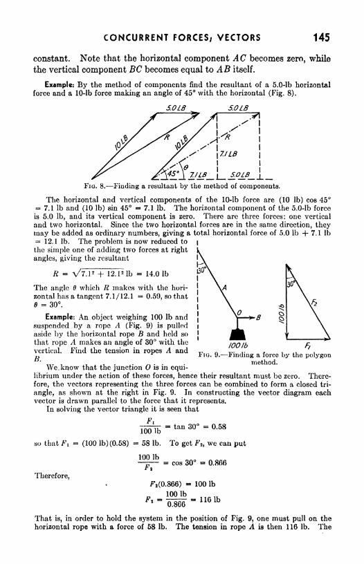
CONCURRENT FORCES, VECTORS 145
constant. Note that the horizontal component AC becomes zero, while
the vertical component BC becomes equal to AB itself.
Example: By the method of components find the resultant of a 5.0-lb horizontal
force and a 10-lb force making an angle of 45 with the horizontal (Fig. 8).
S.OLB 5.0LB
/<*i
FIG. 8. Finding a resultant by the method of components.
The horizontal and vertical components of the 10-lb force are (10 Ib) cos 457.1 Ib and (10 Ib) sin 45 = 7.1 Ib. The horizontal component of the 5.0-lb force
is 5.0 Ib, and its vertical component is zero. There are three forces: one vertical
and two horizontal. Since the two horizontal forces are in the same direction, theymay be added as ordinary numbers, giving a total horizontal force of 5.0 Ib 4- 7.1 Ib
= 12.1 Ib. The problem is now reduced to|
the simple one of adding two forces at right
angles, giving the resultant
R + 12 Ib = 14.0 Ib
The angle 6 which R makes with the hori-
zontal has a tangent 7.1/12.1 =0.59, so that
$ 30.
Example: An object weighing 100 Ib and
suspended by a rope A (Fig. 9) is pulledaside by the horizontal rope B and held so
that rope A makes an angle of 30 with the
vertical. Find the tension in ropes A andB.
We. know that the junction is in equi-
100Ib Ft
FIG. 9. Finding a force by the polygonmethod.
librium under the action of these forces, hence their resultant must be zero. There-
fore, the vectors representing the three forces can be combined to form a closed tri-
angle, as shown at the right in Fig. 9. In constructing the vector diagram eachvector is drawn parallel to the force that it represents.
In solving the vector triangle it is seen that
= tan 30 0.58100 Ib
so that Fi (100 lb)(0.58) = 58 Ib. To get F2 ,we can put
100 Ib
Therefore,
cos 30 0.866
Ft(0.866) - 100 Ib
That is, in order to hold the system in the position of Fig. 9, one must pull on the
horizontal rope with a force of 58 Ib. The tension in rope A is then 116 Ib. The

146 PRACTICAL PHYSICS
tension in the segment of rope directly supporting the weight is, of course, just
100 Ib.
To solve this problem, we used the straightforward method of adding the vectors
to form a dosed figure. This method is quite appropriate to such simple cases but,for the sake of illustration, let us now solve
the problem again by the more general methodof components. In Fig. 10 are shown the
same forces, separated for greater convenienceof resolution. The horizontal and vertical
components of the 100-lb force are, respectively,and 100 Ib down. The horizontal and verti-
cal components of F\ are, respectively, F\ (to
tho right) and 0. In finding the componentsof F\, we do not yet know the numerical valueof Ft, but, whatever it is, the horizontal andvertical components will certainly be F 2 sin 30to the left and F2 cos 30 up. We now havefour forces, two vertical and two horizontal,whose vector sum must be zero to ensure
equilibrium. In order that the resultant maybe zero the sum of the horizontal componentsand the sum of the vertical components must(each) be equal to zero.
Therefore,
F l- F2 sin 30 (horizontal)
F2 cos 30 - 100 Ib -(vertical)
If we solve the second equation, we find
that F2 116 Ib, as in the previous solution.
By substituting this value in the first equation, we obtain F\ = 58 Ib, as before.
Example: A load of 100 Ib is hung from the middle of a rope, which is stretchedbetween two walls 30.0 ft apart (Fig. 11). Under the load the rope sags 4.0 ft in the
middle. Find the tension in sections A and B.
30FT
FIG. 10. Component method of solv-
ing the problem of Fig. 9.
FIG. 11.-
/OOLB-Finding the tension of a stretched rope.
FJO. 12. Horizontal and vertical components of the forces in a stretched rope.
The mid-point of the rope is in equilibrium under the action of the three forcesexerted on it by sections A and B of the rope and the 100-lb weight. A vector
diagram of the forces appears in Fig. 12. The horizontal and vertical components of

CONCURRENT FORCES; VECTORS 147
the 100-lb force are, respectively, and 100 Ib downward. The horizontal and vertical
components of Fi are, respectively, Fi cos to the left, and FI sin upward. Simi-
larly, the horizontal and vertical components of Fz are, respectively, Fz cos 6 to the
right, and F% sin 8 upward. In order that the resultant shall be zero the sum of
the horizontal components and the sum of the vertical components must (each) be
equal to zero.
Therefore,F2 cos 6 FI cos 6 = (horizontal) (1)
Fi sin e + Ft sin - 100 Ib = (vertical) (2)
Since these two equations involve three unknown quantities FI, Fa, and 0, we cannot
solve them completely without more information.
An inspection of Fig. 11 shows that the angle 0' of that figure is identical with the
angle of Fig. 12. Thus the value of sin can be determined from the dimensions
shown in Fig. 11.
. ,4.0ft
sin sin ;
and
From Eq. (1),
V15.02
sin
4.02 ft =
4.0ft
15.5 ft
V241 ft ~ 15.5 ft
= 0.26
F2 . Substituting in Eq. (2),
Ft sin -f Fi sin ~ 100 Ib
and
2Fi sin
2Fi(0.26)
1QQlb=2(0.26)
190 lb
100 Ib
100 Ib
It is essential that two things be noticed about the problem just solved: (1) that
the value of a function of an angle in the vector diagram was needed in order to carryout the solution; (2) that the value of that function was determined from the geometryof the original problem.
Example: Calculate the force needed to hold a 1,000-lb car on an inclined planethat makes an angle of 30 with the horizontal, if the force is to be parallel to the
incline.
w
(a) (6)^
FIG. 13. Finding the forces acting upon a body on an incline.
The forces on the car include (see Fig. 13) its weight W, the force parallel to the
incline B, and the force of reaction A exerted on the car by the inclined plane itself.
The last force mentioned is perpendicular to the plane if there is no friction.

148 PRACTICAL PHYSICS
Since the car is in equilibrium under the action of the three forces A, B, and PP,
a closed triangle can be formed with vectors representing them, as hi Fig. 13b. In
the vector diagram, B/W sin 6', so that B ** W sin 0'. The angle 0', however, is
equal to angle in Fig. 13a (Can you prove this?), and we may write B = W sin 0.
Since is 30 and W - 1,000 Ib,
B = (1,000 Ib) sin 30 = (1,000 Ib) (0.500) = 500 Ib
The value of A, the .perpendicular force exerted by the plane, can be found byobserving that A /W = cos 0' = cos 0, from which
A = W cos 30 - (1,000 Ib) (0.866) = 866 Ib
It should be noticed that W can be resolved into two components that are,
respectively, parallel and perpendicular to the incline. These components are,
obviously, equal in magnitude and opposite in direction to B and A, respectively.
The relation betweenHie motions of two different objects, called their
relative motion, can be obtained by taking the vector difference of their
velocities measured with respect to some reference body, often the earth.
Two cars proceeding in the same direction on a highway each at 30 mi/hrhave a relative speed of zero. If, however, car A is traveling east at
30 rni/hr and car B is traveling west at 30 mi/hr, A will have a velocity
of 60 mi/hr east relative to B. In this familiar example we have implic-
itly used the concept that velocity is a vector quantity. In the following
problem more explicit use is made of vector methods in describing rela-
tive motion.
Example: An airplane is flying 125 mi/hr on a north-to-south course, according to
its air-speed indicator and (corrected) compass readings. A cross wind of 30 mi/hr is
blowing south 47 west. What are the ground speed and course of the airplane?
Solution is by the method of components. The wind speed can be resolved into
30 cos 47 south and 30 sin 47 west. These components added to the air speed of tho
airplane, graphically, give a right triangle, one side representing a speed of Il5 mi/hi
south, the other 22 mi/hr west. The hypotenuse represents the ground speed andBourse of the airplane: 147 mi/hr in a direction 835' west of south.
SUMMARY
A body is in equilibrium when it has no acceleration.
When a body is in equilibrium, the vector sum of all the forces acting
on it is zero. This is known as the first condition of equilibrium.
Quantities whose measurement is specified by magnitude and direction
are called vector quantities. Those which have only magnitude are called
.s-caZar quantities.
A vector quantity is represented graphically by a line (vector) drawnto represent its direction and its magnitude on some convenient scale.
The resultant of two or more vectors is the single vector that would
produce the same result.
The rectangular components of a vector are its projections on a set of
right angle axes, for example, the horizontal and vertical axes.

CONCURRENT FORCES; VECTORS 149
Vectors are conveniently added graphically by placing them "head
to tail" and drawing the resultant from the origin to the head of the last
vector, closing the polygon.
The component method of adding vectors is to resolve each into its
rectangular components, which are then added algebraically and the
resultant found.
QUESTIONS AND PROBLEMS
1. A boat sails 20 mi due east and then sails 12 rni southwest. How far is
it from its starting point, and in what direction is it from that point ?
2. A ship is sailing 20 north of east at the rate of 14 mi/hr. How fast is it
going northward and how fast eastward? Ans. 4.8 mi/hr; 13 mi/hr.
3. If a ship is sailing 21 east of north at the rate of 15 mi/hr, what are its
component speeds, northward and eastward?
4. If a wind is blowing 17.5 ft/sec and crosses the direction of artillery fire
at an angle of 38, what are its component speeds along, and directly across, the
direction of fire? Ans. 13.8 ft/sec; 10.8 ft/sec.
6. A boy is pulling his sled along level ground, his pull on the rope being
12 Ib. What are the vertical and horizontal components of the force if the rope
makes an angle of 21 with the ground?6. Add the following displacements by the component method: 10 ft directed
northeast, 15 ft directed south, and 25 ft directed 30 west of south.
Ans. 30 ft, 10.4W of S.
7. A boat travels 10 mi/hr in still water. If it is headed 60 south of west
in a current that moves it 10 mi/hr due east, what is the resultant velocity of
the boat?
8. An airplane is flying at 150 mi/hr on a north to south course according
to the compass. A cross wind of 30 mi/hr is blowing south 47 west and carries
the airplane west of its course. What are the actual speed and course of the
airplane? Ans. 172 mi/hr; 7.4 W of S.
9. A weight is suspended by two wires, each inclined 22 with the horizontal.
If the greatest straight pull which either wire could sustain is 450 Ib, how large
a weight could the two support as specified?
10. A boy weighing 80 Ib sits in a swing, which is pulled to one side by a
horizontal force of 60 Ib. What is the^tension on the swing rope?-
Ans. 100 Ib.
11. The angle between the rafters of a roof is 120. What thrust is produced
along the rafters when a 1,200-lb weight is hung from the peak?
12. A rope 100 ft long is stretched between a tree and a car. A man pulls
with a force of 100 Ib at right angles to and at the middle point of the rope, and
moves this point 5.0 ft. Assuming no stretching of the rope, what is the tension
on the rope? Ans. 500 Ib.
13. What is the angle between two equal forces whose resultant is equal to
one-half of one of the forces?
14. An airplane leaves the ground at an angle of 15.0. If it continues in a
straight line for half a mile, how high is it then above the level field? Over how
much ground has it passed? Ans. 684 ft; 2,550 ft.

150 PRACTICAL PHYSICS
15. An airplane has an air speed of 150 nii/hr East in a wind which has a speedof 30 mi/hr at 60 South of East. What is the ground speed of the airplane?
16. Two forces of 24 tons and 11 tons, respectively, are applied to an object
at a common point and have an included angle of 60. Calculate the magnitudeof their resultant and the angle it makes with the 24-ton force.
Ans. 31 tons; 18.
EXPERIMENT
Concurrent Forces; Vectors
Apparatus: Pail of sand or other heavy weight; 10-ft length of clothes-
line; 2-kg spring balance; strong string; hooked weights; one pulley.
a. Suspend a rather heavy load (such as a pail of sand) from a support
near the ceiling by means of a light, flexible rope (Fig. 14), We may
Fio. 14. Findingthe weight of an object
by measuring a hori-
zontal force.
I
FIG. 15. Finding the tensionin 8 cord.
measure the weight while it is suspended even though no balance other
than a 2,000-gm spring balance is available.
Attach the balance to the rope at h and pull horizontally as indicated
by the arrow in Fig. 14 until the load is displaced a convenient measur-
able distance s. Record the reading of the balance, the distance s,
and the length I of the rope. Using the method described in the second
example in this chapter, compute the weight of the load.
6. Support a 1-kg weight by means of a cord and the 2-kg spring
balance, and then pull the mass asido a distance s by pulling upon a
horizontal string, as illustrated in Fig. 15. Measure h and s. Computethe tension in the supporting cord, and compare it with the reading of the
spring balance. Note that this can be done without knowing the value
* he horizontal forca.

CONCURRENT FORCES; VECTORS 151
<x Attach two ends of a cord of length I to two nails (or other points of
support) which are in the same horizontal line, as illustrated by Fig. 16*
The length / is considerably greater than the distance 06. Values
06 = 60 cm and I = 100 cm are convenient ones. Hang weight W (say
500 gin) at the middle of the string. What force does each string exert
upon point PITo verify this conclusion remove the string from point b and attach it
to a spring balance as indicated by the dotted balance in Fig. 16. If the
Fia. 16. Finding the tension FIG. 17. Weighing an object byin a string supporting a weight at measuring the tension in a cord,
the middle.
spring balance were attached at a, should it read the same as before?
Does it?
Suppose a student were to take the two ends in his hands and pull
them apart, that is, virtually increasing the distance ab. How hard
would he have to pull in order to lift the point P to within 1 cm of the line
06? Try it. Could the string be "straightened out" that way?d. Could you weigh an unknown object by the method above? In
Fig. 17 a cord passes from hook a over pulley b to an unknown weight W.Line ab is horizontal and is 100 cm long. If a 100-gm weight hung at c
pulls the cord down to d (dotted lines), cd being 10 cm, what is the value
of the unknown weight TF? Obtain a similar set of data and compute Wby this method.

CHAPTER 16
NONCONCURRENT FORCES; TORQUE
In the discussion of equilibrium thus far it has been assumed that the
lines of action of all the forces intersect in a common point. For most
objects this condition will not be realized. For a body to be in equilib-
rium under the action of a set of nonconcurrent forces more is required
than the condition that the vector sum of the forces shall be zero. Wemust be concerned not only with the tendency of a force to produce linear
motion but also with its effectiveness in the production of rotation.
The same force applied at different places or in different directions
produces greatly different rotational effects. The practical engineer is
very much concerned with these effects and must make allowances for
them in the design of his structures.
Two Conditions (or Equilibrium. Consider an arrangement in which
two equal, opposing forces act on a block, as in Fig. la. It is obvious
that, if the block is originally at rest, it will remain so under the action
of these two forces. We say, as before, that the vector sum of the forces
is zero.
Now suppose that the two forces are applied as in Fig>. 16. The vector
sum of the forces is again zero; yet it is plain that, under the action of
152

NONCONCURRENT FORCES, TORQUE 153
these forces, the block will begin to rotate. In fact, when the vector
sum of the applied forces is equal to zero, we can be sure only that the
body as a whole will not have a linear acceleration; we cannot be sure
that it will not start to rotate, hence complete equilibrium is not assured.
In addition to the first condition necessary for equilibrium, then, there
is a second one, a condition eliminating the possibility of a rotational
(a) MFIG. 1. Equal and opposite forces produce equilibrium when they have a common
line of action (a), but do not produce equilibrium when they do not have the same line of
action (b).
acceleration. The example of Fig. 16 indicates that this second condition
is concerned with the placement of the forces as well as their magnitudesand directions.
In order to understand the factors that determine the effectiveness of a
force in producing rotational acceleration, consider the familiar problem
(a) (6)
FIG. 2. A force produces rotational acceleration if its line of action does not pass throughthe axis of rotation.
of turning a heavy wheel by pulling on a spoke (Fig. 2a). It is a matter
of common experience that we can set the wheel in motion more quickly
by applying a force F at the point A, than by applying the same force
at B. The effect of a force in producing rotational acceleration is greater
the farther the force is from the axis of rotation, but we should not fall
into the elementary error of assuming that this distance is measured
from the point of application of the force. In Fig. 26 the point of applica-
tion of the force is just as far from the axle as it was when applied at Ain Fig. 2a, but now there is no rotational acceleration; F merely pulls
the wheel upward. Though the magnitude of the force, its direction, and
the distance of its point of application from the axis are the same in the
two examples, rotational acceleration is produced in one case and not in

154 PRACTICAL PHYSICS
the other. The point of application of the force is clearly not the decidingfactor.
Moment Arm. The factor that determines the tendency of a force to
produce rotational acceleration is the perpendicular distance from the
axis of rotation to the line of action of the force. We call this distance the
moment arm of the force. In Fig. 3, the moment arm of the force F is
indicated by OP. The line of action of the force is a mere geometrical
construction and may be extended indefinitely either way in order to
intersect the perpendicular OP. It has nothing to do with the lengthof the force vector. We now see why the force F in Fig. 2b produces no
FIG. 3. Measurement of moment arm.
rotation. Its line of action passes directly through the axis of rotation
and the moment arm is therefore zero. The same force F in Fig. 2a has
the moment arm OA and, therefore, tends to cause rotation.
For a fixed moment arm, the greater the force the greater also is the
tendency to produce rotational acceleration. The two quantities, force
and moment arm, are of equal importance. Analysis shows that theycan be combined into a single quantity, torque (also called moment of
force), which measures the tendency to produce rotational acceleration.
Torque will be represented by the symbol L.
Definition of Torque. The torque (moment of force) about any chosenaxis is the product of the force and its moment arm. Since torque is the
product of a force and a distance, its usual unit in the British system is the
pound-foot. The inversion of these units from the familiar foot-poundof work serves to call attention to the fact that we are using a unit
of torque and not work, although they both have actually the samedimensions.
It is necessary to indicate clearly the direction of the angular accelera-
tion that the torque tends to produce. For example, the torques in

NONCONCURRENT FORCES/ TORQUE 155
Fig. 3 tend to produce counterclockwise accelerations about O, while the
torque in Fig. 4 tends to produce a clockwise acceleration. One may refer
to these torques as positive and negative, respectively. Note that a
given force may produce a clockwise torque about one axis, but a counter-
clockwise torque about another axis. The c
direction of a torque is not known from the
direction of the force alone.
Concurrent and Nonconcurrent Forces. Con-
current forces are forces whose lines of action
intersect in a common point. If an axis is
selected passing through this point, the torqueT , , * c e i j. FIG. 4. A clockwise torque.
produced by each Jrorce or such a set is zero,
hence a consideration of torque is not necessary in the study of a set of
concurrent forces in equilibrium.
For a set of nonconcurrent forces, there exists no single axis about
which no torque is produced by any of the forces. In studying a set of
nonconcurrent forces in equilibrium, therefore, it is essential to take into
account the relation existing among the torques produced by such a
set of forces. This relation is expressed in the second condition for
equilibrium.
Second Condition for Equilibrium. For an object to be in equilibrium,
it is necessary that the algebraic sum of the torques (about any axis)
acting on it be zero. This statement is known as the second condition for
equilibrium. It may be represented by the equation
2L = (1)
The symbol 2 means "the sum of/7
In the first and second conditions for equilibrium we have a complete
system for solving problems in statics. If the first condition is satisfied,
the vector sum of the forces is zero, and no translational acceleration is
produced. If the second condition is satisfied, the algebraic sum of
the torques is zero, and there is no rotational acceleration. This does
not mean that there is no motion, but only that the forces applied to the
body produce no change in its motion. While in equilibrium, it may have
a uniform motion including both translation and rotation.
Center of Gravity. It can be proved mathematically that for every
body, no matter how irregular its shape, there exists a point such that the
entire weight of the body may be considered to be concentrated at that
point, which is called the center of gravity. If a single force could be
applied at this point, it would support the object in equilibrium, no matter
what its position.
Example: A uniform bar, 9 ft long and weighing 5 Ib, is supported by a fulcrum 3 ft
from one end as in Fig 5. If a 12-lb load is hung from the left end, what downward

156 PRACTICAL PHYSICS
FIG. 5. Finding the forces acting on alever.
pull at the right end is necessary to hold the bar in equilibrium? With what forcedoes the fulcrum push up against the bar?
Consider the bar as an object in equilibrium. The first step is to indicate clearlyall the forces that act on it. The weight of the bar, 5.0 Ib, can be considered to beconcentrated at its middle. A 12-lb force acts downward at the left end of the bar,
a force R acts upward at the fulcrum, andthere is an unknown downward force F atthe right end.
The first condition for equilibrium indi-
cates that the vector sum of the forces ap-plied to the bar is zero, or that
R - 12 Ib - 5.0 Ib - F 0.
Without further information we certainlycannot solve this equation, since it has twounknown quantities in it, R and F. Let uaset it aside for a moment and employ the
second condition for equilibrium, calculating the torques about some axis andequating their algebraic sum to zero. The first thing we must do is to select an axisfrom which to measure moment arms. This chosen axis need not be any real axleor fulcrum; it may be an axis through any point desired. The wise choice of someparticular axis, however, often shortens the arithmetical work.
We shall choose an axis through the point A about which to calculate all thetorques. Beginning at the left end of the bar, we have (12 lb)(3.0 ft) = 36 Ib-ftof torque, counterclockwise about A. Next, we see that the force R produces notorque, since its line of action passes through the point A. (Is it clear now why wedecided to take A as an axis?) Third, the torqueproduced by the weight of the bar W is (5.0 Ib)(1.5 ft) * 7.5 Ib-ft, clockwise. Finally, F pro-duces a torque (F)(6.0 ft), clockwise.
Taking the counterclockwise torque as posi-tive and clockwise torque as negative and equatingthe algebraic sum of all the torques to zero, wewrite,
.0ft) + (J?)(0)-(5.01b)(1.5ft)-^(6.0ft)36 Ib-ft + - 7.5 Ib-ft - F(6.0 ft)
=F(Q.O ft)
- 28.5 Ib-ft
F => 4.8 Ib
^Substituting this value in the equation ob-
tained from the first condition for equilibrium,we find R - 12 Ib - 5.0 Ib - 4.8 Ib =
0, orR 21.8 Ib.
FIG. 6.- The forces acting on ahorizontal beam.
Example: A chain C (Fig. 6) helps to support a uniform 200-lb beam, 20 ft long,one end of which is hinged at the wall and the other end of which supports a 1-tonload. The chain makes an angle of 30 with the beam, which is horizontal. Deter-mine the tension in the chain.
^
Since all the known forces act on the 20-ft beam, let us consider it as the objectm equilibrium. In addition to the 200- and 2,000-lb forces straight down, there isthe pull of the chain on the beam, and the force F which the hinge exerts on the beamat the wall. Let us not make the mistake of assuming that the force at the hinge is
straight up, or straight along the beam. A little thought will convince us that thehinge must be pushing both up and out on the beam. The exact direction of thisforce, as well as its magnitude, is unknown. The second condition for equilibriumis an excellent tool to employ in such a situation, for if we use an axis through the

NONCONCURRENT FORCES; TORQUE 157
point as the axis about which to take moments, the unknown force at the hinge hasno moment arm and, therefore, causes no torque. The remarkable result is that wecan determine the tension T in the chain without knowing either the magnitude or thedirection of the force at 0.
The torques about as an axis are, respectively,
(200 lb)(10 ft)= 2,900 Ib-ft (counterclockwise)
(2,000 lb)(20 ft) 45,000 Ib-ft (counterclockwise)
(r)(20 ft) sin 30 = (7) (10 ft) (clockwise)
[Note: The moment arm of T is OP = (20 ft) sin 30 = 10 ft.] Then
-CF)(10 ft) -f- 2,000 Ib-ft + 40,000 Ib-ft -f (F)(0) ~
so that
T - 4,200 Ib = 2.1 tons
The problem of finding the magnitude and direction of the force at the hinge is
left to the student. Suggestion: apply the first condition for equilibrium.
The trick just used in removing the unknown force from the problem
by taking torques about the hinge as an axis is a standard device in
statics. The student should always be on the lookout for the opportunityto side-step (temporarily) a troublesome unknown force by selecting an
axis of torques that lies on the line of action of the unknown force he
wishes to avoid.
Couples. In general, the application of one or more forces to an
object results in both translational and rotational acceleration. An
exception to this is the case in which a single
force is applied along a line passing through k
the center of gravity of the object, in which^ ^
case there is no rotational acceleration. O H. A
Another special case is the one in which twoi i 'if T i i xr FIG. 7. Two equal and
equal and opposite forces are applied to the Opp08ite forces not in the same
object as in Fig. 16. In this case there is no straight line constitute a couple.
translational acceleration. Such a pair of
forces, resulting in a torque alone, is called a couple. The torque pro-
duced by a couple is independent of the position of the axis and is equal
to the product of one of the forces and the perpendicular distance between
them.
As an example, consider the torque produced by the couple shown
in Fig. 7. About the axis 0, the torque produced by FI is F\(OA),
and that by F2=
-Fjt(OB)._Since
FI_=F2
= F the total torque is
F(OA) - F(OB) F(OA - 05) = F(AB). This verifies the statement
that the torque produced by a couple is the product of one (either) of
the forces and the perpendicular distance between them, a product inde-
pendent of the location of the axis. A couple cannot be balanced by a
single force but only by the application of an equal and opposite couple.

158 PRACTICAL PHYSICS
SUMMARY
The torque produced by a force is equal to the product of the force andits moment arm.
The moment arm of a force is the perpendicular distance from the axis
to the line of action of the force.
For an object to be in equilibrium it is necessary (1) that the vector
sum of the forces applied to it be zero, and (2) that the algebraic sum of
the torques (about any axis) acting on it be zero.
The center of gravity of a body is the point at which its weight maybe considered to act.
A couple consists of two forces of equal magnitude and opposite direc-
tion. The torque produced by a couple is equal to the magnitude of one
(either) of the forces times the perpendicular distance between them.
PROBLEMS
1. A boy exerts a downward force of 30 Ib on a horizontal pump handle at a
point 2.0 ft from the pivot, (a) What torque is produced? (b) What is the
torque when the handle makes an angle of 60 with the horizontal?
2. The diameter of a steering wheel is 18.0 in. If the driver exerts a tan-
gential force of 1.0 Ib with each hand in turning the wheel, what is the torque?Ans. 1.5 Ib-ft.
3. In a human jaw, the distance from the pivots to the front teeth is 4.0 in.,
and the muscles are attached at points 1.5 in. from the pivots. What force
must the muscles exert to cause a biting force of 100 Ib (a) with the front teeth?
(b) with the back teeth, which are only 2.0 in. from the pivots?
4. A compression of 5.0 Ib is applied to the handles of a nutcracker at a
distance of 6.0 in. from the pivot. If a nut is 1.0 in. from the pivot, what force
does it withstand if it fails to crack? Ans. 30 Ib.
5. A uniform bridge 100 ft long weighs 10,000 Ib. If a 5,000-lb truck is
stalled 25 ft from one end, what total force is supported by each of the piers
at the ends of the bridge, if they represent the only supports?
6. A man and a boy carry a 90-lb uniform pole 12 ft in length. If the boy
supports one end, where must the man hold the pole in order to carry two-thirds
of the load? Ans. 3.0 ft from the end.
7. With what horizontal force must one push on the upper edge of a 500-lb
block of stone whose height is 4.0 ft and whose base is 2.0 ft square, in order to
tip it?
8. The weight supported by each of the front wheels of an automobile is
600 Ib, while each of the back wheels supports 500 Ib. If the distance between
front and rear axles is 100 in., what is the horizontal distance of the center of
gravity from the front axle? Ans. 45.5 in. from front axle.
9. The center of gravity of a log is 6.0 ft from one end. The log is 15 ft
long and weighs 150 Ib. What vertical force must be applied at each end in
order to support it (a) horizontally? (6) at 30 from the horizontal with the
center of gravity nearer the lower end?

NONCONCURRENT FORCES, TORQUE 159
10, A 100-lb ladder rests against a smooth wall at a point 15 ft above the
ground. If the ladder is 20 ft long and its center of gravity is 8.0 ft from the
lower end, what must be the force of friction at the lower end in order to prevent
slipping? What is the coefficient of friction if the ladder is at the point of
slipping? Ans. 35 Ib; 0.35.
EXPERIMENT
Nonconcurrent Forces/ Torques
Apparatus: Nonuniform board; two spring balances; meter stick;
weight.
When forces act upon an extended object their lines of action do not,
in general, intersect in a single point. To describe the equilibrium state
of such a body we must consider both conditions for equilibrium.
In this experiment we shall consider the forces and torques that act
upon a nonuniform board. Since the board is nonuniform, its center of
gravity is not necessarily at its mid-point.
o
P>
FIG. 8. Finding the center of gravity and the weight of a nonuniform board.
a. In this part of the experiment we wish to find the weight of the
board and the position of the center of gravity. Support the board bymeans of two spring balances as shown in Fig. 8. Three forces act uponthe board: the weight W acting downward at the center of gravity; and
the forces FI and F2 ,which the balances exert upward. Record in a
table the readings of the balances and the positions Pi and P% (measured
F l Pi W
from one end of the board) at which the upward forces act. Take a
series of such readings for various positions of PI and P2. From the first
condition for equilibrium what do we conclude about the various values of
FI and P2 ? Do our results justify this conclusion? What is the weight

160 PRACTICAL PHYSICS
of the board? To find the position of the center of gravity of the board
we shall consider torquea about as an axis. The forces FI and F2 both
r*
FIG. 9. Finding the center of gravity of a nonuniform board.
produce counterclockwise torques while W produces a clockwise torque.
Therefore
or
Fio. 10. A simple crane.
Since the weight W always acts at the same point, the right-hand memberof the equation is constant. Since we know IF, we can use this equationto find OC and thus the position of C.
Hang an unknown weight from the board and adjust the supports so
that the board is horizontal. Record the position of each force and the
values of the three known forces. Compute the value of the unknown
weight (1) by the use of the first condition for equilibrium and (2) by the

NONCONCURRENT FORCES; TORQUE 161
use of the second condition for equilibrium. Compare the values thus
obtained.
6. Support the board as shown in Fig. 9. Record the values of Fi
and FZ and the value of W obtained in part (a). Measure and record
the values of the moment arms LI and L 2 , respectively, about as an
axis. Write the equation of torques about and compute the value of
L 3 . How does the position of the center of gravity thus indicated com-
pare with that found in part (a) ? What is the position of the center of
gravity relative to the point of support of the system?c. If time permits, study the arrangement of the simple derrick shown
in Fig. 10. Hang a known weight at c. Taking a as the axis of torques,
measure and record the moment arm of each force. Record also the
weight of the board and the reading of the spring balance. Write the
equation of torques, considering the tension in the member be as unknown.
Solve the equation for the tension and compare it with the balance
reading.

CHAPTER 17
PROJECTILE MOTION; MOMENTUM
The science of the motion of missiles that are thrown is called ballistics.
The study of these motions and of the forces required to produce them,as well as of the forces set up when projectiles strike their targets, is of
tremendous importance in the design of all instruments of war, from the
soldier's rifle to a naval gun and from the private's helmet to the armor of
a tank or battleship. The law of conservation of momentum is used bythe ordnance designer both in problems involving the guns and ammuni-tion that shoot the projectiles and in the determination of the forces
that are brought into being when the projectiles are stopped.
Projectile Motion. A projectile may be considered as any body which
is given an initial velocity in any direction and which is then allowed to
move under the influence of gravity. The velocity of the projectile at
any instant can be thought of as made up of two parts or components: a
horizontal velocity and a vertical velocity. The effect of gravity on the
projectile is to change only the vertical velocity while the horizontal
velocity remains constant as long as the projectile is moving, if air
resistance is neglected.
Suppose we ask ourselves how a stone will move if it is thrown hori-
zontally at a speed of 50 ft/sec. Neglecting air resistance, the stone will
162

PROJECTILE MOTION; MOMENTUM 163
DISTANCE IN FEETSO /OO /SO
J50/ 2
TIME IN SECONDS
FIG. 1. Path of a stone thrown hori-
zontally with a speed of 50 ft /sec.
travel with a constant horizontal speed of 50 ft/sec until it strikes some-
thing. At the same time it will execute the vertical motion of an object
falling from rest; that is, beginning with a vertical speed of zero, it will
acquire additional downward speed at
the rate of 32 ft/sec in each second.
It will fall 16 ft during the first sec-
ond, 48 ft during the next, 80 ft duringthe third, and so on, just as if it had
no horizontal motion. Its progress
during the first three seconds is illus-
trated in Fig. 1. At A the stone havS
no vertical speed; at B (after 1 sec) its
vertical speed is 32 ft/sec; at C, 64
ft/sec; and at Z), 96 ft/sec. The
curved line ABCD ifi Fig. 1 is the
path that the stone follows and the
arrows at JB, C, and D represent the
velocities at those places. Note that
the horizontal arrows are all the same
length, indicating the constant horizontal speed while the vertical arrows
increase in length to indicate the increasing vertical speed. The vertical
arrow at C is twice as long as that at B while that at D is three times as
long.
The curve shown in Fig. 1 is called a parabola. As has been indicated,
it is traced by the motion of a projectile that executes simultaneously a
uniform motion (horizontal) and a uniformly accelerated
motion (vertical).
No matter what may be the initial direction of mo-
tion of the projectile, its motion may be broken up in-
to horizontal and vertical parts, which are independentof each other. Suppose a stone is thrown with a speed
of 100 ft/sec in a direction 30 above the horizontal.
This velocity may be broken up into horizontal arid verti-
cal components as shown in Fig. 2. The initial speed
in the given direction is represented by the vector OA,
but an object that had the simultaneous vertical and
horizontal speeds represented by OC and OB would follow exactly the
same path along the direction OA. In discussing the motion of the stone
we may use either the whole speed in the direction OA or the horizontal
and vertical parts of the motion. The latter viewpoint simplifies the
problem.
Referring to Fig. 3, we find the initial horizontal speed Vh to be
(100 ft/sec) cos 30 = (100 ft/sec) (0.866) = 86.6 ft/sec, and the initial
O BFIG. 2. Com-
ponents of veloc-
ity.

164 PRACTICAL PHYSICS
vertical speed v\ to be (100 ft/sec) sin 30 (100 ft/sec) (0.50) = 50
ft/sec. The problem thus reduces to one of uniform horizontal motion
and uniformly accelerated vertical motion. We may ask the distance
s the stone rises and its horizontal range.
/44FJ
87FT 173 FT 260FTI SEC 2 SEC 3SEC
FIG. 3. -Path of a projectile fired at an angle of 30 above the horizontal with an initial
speed of 100 ft/sec. Air resistance is neglected. The projectile strikes with a speed equalto tho initial speed and at an angle of 30 above the horizontal.
Using Eq. (5), Chap. 10, as applied to the vertical motion,
z; ,
22 _
Vl2 = 2os; v t
= 50 ft/sec; v 2=
0; a = -32 ft/sec2
-(50 ft/sec)
2 = 2(-32 ft/sec2)a
2,500 ftVsec2
8 ~
64 ft/sec2
39ft
The time required to reach this highest point is, fromEq. (3), Chap. 10,
^2 Vi = at
0-50 ft/sec = (-32 ft/sec2)*
t = 50 ft/sec
32 ft/sec2= 1.56 sec
An equal time will be required for the stone to return to the surface.
Hence the time tf
elapsed before the stone strikes the surface is
if == 2t = 2 X 1.56 sec = 3.12 sec
During all this time the stone travels horizontally with a uniform speedof 86.6 ft/sec. The horizontal range R is therefore
R = Vkf = (86.6 ft/sec)(3.12 sec) = 271 ft
The motion of any projectile, neglecting air resistance, may be treated
in this same manner no matter what may be the initial speed and angle of
projection. The initial velocity is resolved into vertical and horizontal
components and the two are considered separately.

PROJECTILE MOTION/ MOMENTUM 165
In Fig. 3 we note that the path may be found by considering a uniform
motion in the initial direction OC and finding the distance the stone has
fallen from this path at each instant. In 1 sec under the action of gravity,
the stone falls 16 ft; hence at the end of 1 sec it is 16 ft below A;in 2 sec
it falls 64 ft and hence is 64 ft below B, and so on.
In this discussion of the motion of projectiles we have neglected the
resistance of the air. For high-speed projectiles the air resistance is no
small factor. It reduces the height of flight, the range of the projectile,
and the speed of the projectile when it strikes. Figure 4 shows an
example of such influence. The dotted curve is the path that the
projectile would follow if there were no air resistance, while the solid
line shows an actual path. Very long-range guns shoot the projectile
at such an angle that a considerable part of the path is in the high
FIG. 4. Path of a projectile. The dotted curve represents the path that would befollowed if there were no air resistance, while the solid line is an actual path. The maxi-mum height, range, and striking speed are decreased, while the striking angle is increased.
atmosphere where air resistance is very small. In the absence of air
resistance the maximum horizontal range of a gun is attained when it is
fired at an angle of 45 with the horizontal but, because of the change in
path due to air resistance, the elevation must be considerably greater
than 45 in order to obtain maximum horizontal range. The optimumangle depends upon the size, shape, and speed of the projectile.
During the First World War a gun was developed by the German
Army with a range of 75 mi. The initial speed of the projectile wasalmost 1 mi/sec at an angle of 50 with the horizontal. The shell reached
a maximum height of about 27 mi and more than two-thirds of the pathwas above 13 mi. At such altitude the air resistance is so small that the
path is essentially the same as that for no friction. The striking speedof the shell was less than half the initial speed.
In determining the direction and angle of fire of a large gun manyfactors must be considered if the firing is to be accurate. Among these
factors are wind, barometric pressure, temperature, rotation of the earth,
shape of the shell, and the number of times the gun has been fired.
Momentum. If a passenger car traveling at a speed of 20 mi/hrstrikes a telephone pole, the damage will probably be minor but, if a
loaded truck traveling at the same speed strikes it, the damage is much
greater. If the speed of the passenger car is 40 mi/hr instead of 20 mi/hr,the damage is also greatly increased. Evidently, the result depends

166 PRACTKAL PHYSICS
jointly upon the speed and mass of the moving object. The product of
the mass and velocity of a body is called its momentum. The defining
equation for momentum is
M = mv (1)
whereM is the momentum, m the mass, and v the velocity. Every object
in motion has momentum.In the British system we use W/g in place of m and the equation for
momentum becomes
WM - v (2)g
where W is the weight and g is the acceleration due to gravity. No
special name is assigned to the unit of momentum but it is made up as a
composite unit. Since W is in pounds, g in feet per second per second,
and v in feet per second, the unit of momentum becomes TTT i (ft/sec)I \if o6C
= lb-sec. The absolute cgs unit is the gram-centimeter per second.
Example: What is the momentum of a 100-lb shell as it leaves the gun with a speed
of 1,200 ft/sec?
l> ft/sec) " 3
'so lb-sec
Momentum is a vector quantity, its direction being that of the velocity.
To find the momentum of a system of two or more bodies we must add
their momenta vectorially. Consider two
4-lb balls moving toward each other with
equal speeds of 4 ft/sec as shotvn in Fig. 5.
4 IbThe momentum of A is MA -(
\3- C JL 11C/ llUJlllC-lALiLllU. UJL ^JL J.O xrj. A """., i
-
4FT/SK 4 FT/SEC \32 ft/sec2
FIG. 6,-Two balls of equal (4 ft/sec)= 0.5 lb-sec to the right while
mass having equal but opposite that of B is similarly 0.5 lb-sec to the left.
is ro
m mentUm f eThe vector sum of the two is zero and hence
the momentum of the system is zero.
Conservation of Momentum. According to Newton's first law of
motion, the velocity of a body does not change unless it is acted upon by a
net force. Since the mass of the body is constant, we find that the
momentum does not change unless an external force acts upon the body.
The statement that the momentum of a body, or system of bodies, does
not change except when an external force is applied, is known as the law
of conservation of momentum. The use of the law enables us to explain
simply the behavior of common objects.
If an external force does act upon a system of bodies, the momentumof the system is changed but, in the process, some other set of bodies must

PROJECTILE MOTION; MOMENTUM 167
gain (or lose) an amount of momentum equal to that lost (or gained) bythe system. In every process where velocity is changed the momentumlost by one body or set of bodies is equal to that gained by another bodyor set of bodies.
Momentum lost = momentum gained (3)
Let us consider further the balls shown in Fig. 5. If they continue to
move toward each other, they will collide and in the collision each will
exert a force on the other. The momentum of the system of two balls
is zero before the impact. By the Jaw of conservation of momentum it
must be zero after the impact. If the balls arc elastic, they will rebound
and the conservation law requires that the speeds of recoil shall be equalto each other (but not necessarily equal to the original speed) so that the
momentum shall remain zero.
The recoil of a gun is an example of conservation of momentum.The momentum of gun and bullet is zero before the explosion. The bullet
gains a forward momentum, and hence the gun must acquire an equalbackward momentum so that the sum will remain zero.
Example: A 2-oz bullet is fired from a 10-lb gun with a speed of 2,000 ft/sec. Whatis the speed of recoil of the gun?
The momentum of the gun is equal and opposite to that of the bullet.
10 lb S^, (2,000 ft/Sec)32 ft/sec
2 32 ft/sec
(2,000 ft/see)/ 2\ WUJ 1Q
- 25 ft/sec
In the firing of the gun, quite obviously, forces are exerted, one on the
gun and the other on the projectile. These forces, however, are ititernal,
that is, they are within the system of the gun and bullet that we con-
sidered. If we consider the bullet alone, the force becomes an external
force and causes a change in momentum of the bullet but, in accordance
with Newton's third law, an equal and opposite force acts on the gun
giving it a momentum equal and opposite to that of the bullet.
Impulse. The change in momentum caused by an external force
depends upon the amount of the force and also upon the time the force
acts. From Newrtonj
s second law
F = ma
F = mi
(4)
Thus the product of the force and time is equal to the change in momen-

168 PRACTICAL PHYSICS
turn. The product of force and time is called impulse. Equation (4)
implies that no object can be stopped instantaneously and that the
shorter the length of time required for stopping the greater must be
the force. A bomb dropped from a height of several thousand feet has
very great momentum. As it strikes the steel deck of a ship, it must be
stopped in a very short time or it will penetrate the deck. The ordinary
steel deck of a ship is unable to supply the force necessary to stop the
bomb. Extremely large forces are involved in impacts where a rapidly
moving body is stopped quickly.
SUMMARY
A projectile is an object which is given an initial velocity and which is
then allowed to move under the action of gravity.
In projectile motion the vertical and horizontal motions may be
treated separately. The horizontal motion is uniform while the vertical
motion is uniformly accelerated if air resistance is neglected.
Momentum is the product of the mass and velocity cf a body. It is a
vector quantity.
M WM = mv = vQ
Impulse is the product of a force and the time it acts. Impulseis equal to the change in momentum.
Ft mv-z mvi
The law of conservation of momentum states that the momentum of a
body or system of bodies does not change unless an external force acts
upon it.
QUESTIONS AND PROBLEMS
1. Why is the rear sight of a long-range rifle adjustable?
2. Why should a shotgun be held tightly against the shoulder when it is
fired?
3. What is the momentum of a 160-lb shell if its speed is 2,000 ft/sec?
4. A bomb is dropped from an airplane traveling horizontally with a speedof 210 mi/hr (308 ft/sec). If the airplane is 2,000 ft above the ground, whatwill be the horizontal distance traversed by the bomb (neglecting air friction) ?
Where will the airplane be when the bomb reaches the ground, if its course is
not changed? Ans. 3,450 ft.
6. On an ordinary road surface the frictional force on a 3,0004b car whenthe brakes are applied may be as high as 2,500 Ib. What time will be required
to stop the car with this force from a speed of 30 mi/hr (44 ft/sec) ?
6. Find the horizontal range of a shell fired from a cannon with a muzzle
velocity of 1,200 ft/sec at an angle of 30 above the horizontal.
Ana. 39,000 ft.

PROJECTILE MOTION; MOMENTUM 169
7. A 40-ton freight car moving with a speed of 15 mi/hr (22 ft/sec) runs into
a stationary car of the same weight. If they move off together after the collision,
what is their speed?8. What is the recoil speed of a 9-lb rifle when it projects a 0.6-oz bullet
with a speed of 2,400 ft/sec? Ans. 10 ft/sec.
9. Why do we seldom observe the recoil of a tightly held gun?10. A machine gun fires 10 bullets per second into a target. Each bullet
weighs 0.5 oz and has a speed of 2,400 ft/sec. Find the force necessary to hold
the gun in position and that required to hold the target in position.
Ans. 23 Ib; 23 Ib.
EXPERIMENT
Speed of a Rifle Bullet
Apparatus: Block of wood (4 by 4 by 18 in.) suspended by four string
vsupports; 22-caliber rifle; shells; balance; meter stick.
One method that is used to determine the speed of a rifle ballet makes
use of the law of conservation of momentum in the collision of the bullet
with a block of wood suspended as a ballistic
pendulum. If the pendulum is at rest be-
fore the impact, the initial momentum is
that of the bullet alone, while after the im-
pact the bullet and pendulum move to-
gether. Then
mbv = (mp + mb)V
where mb is the mass cf the bullet, v is its
speed before the impact, mp is the mass of
the pendulum, and V is its speed an instant
after the impact. The mass of the bullet
can be determined by weighing samples of
bullets removed from the shell; that of the
pendulum can be determined by direct
weighing. The speed V cannot be measured directly but can be calcu-
lated readily.
Immediately after the impact the pendulum has a kinetic energy
%nipV 2. The pendulum swings back until this kinetic energy has all
been converted into potential energy as the pendulum rises a distance h.
Then%mpV2 = mpgh
V = \/2gh
Since h is small, a direct measurement is rather inaccurate, but it can
be determined by measuring the horizontal distance x through which
the block moves. The relation between h and x can be obtained from
OFIG. 6. Finding the initial
speed of a ballistic pendulumthe height to which it rises.

170 PRACTICAL PHYSICS
Fig. 6, where is a point of support and R is the length of the pendulum,The triangles ABC and BCD are similar right triangles. Hence
^CB
"CD
or
2R - h x
x ~fc
2hR - h* = x2
Since h is a small distance, its square is very small in comparison to the
other terms in the equation and can be neglected. Hence, approximately
T 2
I. _ Xh ~
2R
Therefore, in order to determine the speed of the bullet, we mustmeasure :
1. The length of the pendulum from the point of support to its center
of gravity.
2. The mass of the bullet.
3. The mass of the pendulum.4. The horizontal distance through which the pendulum moves.
Any block of wood of dimensions approximating those given maybe used as the pendulum. It should be
supported by four parallel strings whose
length can be adjusted to level the
block.
The horizontal distance the block
moves can be measured by mounting a
meter stick horizontally below it and byplacing on the stick a light cardboard
|iiiiiiiiiniiiiiiinTTrTnEfciiiiiiiiiiiinniiiiiin| rider, which rests against the block as
FIG. 7. Ballistic pendulum, show- shown in Fig. 7. The distance moveding scale and rider for measuring the by the rider after the impact will bedistance the pendulum moves. . .' , , , .
the horizontal distance x.
Fire three shots and use the average distance moved to calculate h.
From this value calculate the speed of the pendulum and from it the speedof the bullet.
Compute the kinetic energy of the bullet and also that of the pendu-lum immediately after the impact. How do the two compare? Whathas become cf the part that does not appear as kinetic energy of the
pendulum?

CHAPTER 18
UNIFORM CIRCULAR MOTION
Motion along a straight line seems "natural"; no cause for such action
is expected. However, if there is a change in the direction of the motion,
some disturbing factor is at once assumed. A force must act to cause a
change in the direction of a motion. The simplest type of motion in
which the direction changes is uniform circular motion. This sort of
motion is frequently found in practice, from the whirling of a stone on a
string to the looping of a combat airplane.
Centripetal Force. When an object is moving hi a circular path at
constant speed ,its velocity is changing. According to Newton's laws
of motion, therefore, an unbalanced force is acting upon the object.
This force, called the centripetal force, is directed toward the center of the
circular path. Since the speed of motion is constant, the centripetal
force serves to change only the direction of the motion. It is interesting
to note that the only direction in which an unbalanced force can be
applied to a moving object without changing its speed is at right angles
to its direction of motion,
171

172 PRACTICAL PHYSICS
The magnitude of the centripetal force is given by the relation
Wv*(1)
in which W is the weight of the moving object, v is its linear speed, g is
the gravitational acceleration, and r is the radius of the circular path.
The force is expressed in pounds if the other quantities are in the custom-
ary British units.
If tlie stringbreaks therock flics off.
If frictioTTbreafes"the car skids off
FIG. 1.
In Eq.(l), W/g can be replaced by its equivalent, the mass m of the
moving body. Thus
/.-=? M
If m is in grams, v in centimeters per second and r in centimeters, the
force is expressed in dynes.
An inspection of Eqs. (1) and (2) discloses that the centripetal force
necessaty to pull a body into a circular path is directly proportional to
the square of the speed at which the body moves, while it is inversely
proportional to the radius of the circular path. Suppose, for example,that a 10-lb. object is held in a circular path by a string 4 ft long. If the
object moves at a constant speed of 8 ft/sec,
F = E vl = (10 lb) (8 ft/sec)2
g r (32 ft/sec2) (4ft)
If the speed is doubled, Fe increases to 20 lb. If, instead, the radius is
decreased from 4 to 2 ft, Fc increases to 10 lb. If at any instant the
string breaks, eliminating the centripetal force, the object will retain the
velocity it has at the instant the string breaks, traveling at constant
speed along a direction tangent to the circle. The direction taken bythe sparks from an emery wheel is an illustration of this fact.

UNIFORM CIRCULAR MOTION 173
No Work Done by Centripetal Force. Work has been defined as the
product of force and the displacement in the direction of the force.
Since centripetal force acts at right angles to the direction of motion,there is no displacement in the direction of the centripetal force, and it
accomplishes no work. Aside from the work done against friction, which
has been neglected, no energy is expended on or by an object while it is
moving at constant speed in a circular path. This fact can be verified
much more simply by the observation that, if its speed is constant, its
kinetic energy also is constant.
Action and Reaction. Newton's third law expresses the observation
that for every force there is an opposite and equal force of reaction.
When an object not free to move is acted upon by an external force, it is
pushed or pulled out of its natural shape. As a consequence it exerts an
elastic reaction in an attempt to resume its normal shape. On the other
hand, the action of a force upon a free object results in an acceleration, a
changing of its motion. By virtue of its tendency to continue a given
state of motion, the object exerts an inertial reaction upon the agent of
the accelerating force. It reacts, then, against the thing that changesits motion.
Just as the elastic reaction of a stretched body is equal and opposite
to the stretching force, so the inertial reaction of an accelerated body is
opposite and equal to the accelerating force. It should be remembered,
however, that a force of reaction is exerted by the reacting object, not
on it.
Centrifugal Reaction. A string that constrains an object to- a circular
path exerts on the object the centripetal force that changes its velocity.
In reaction against this change of motion, the object pulls outward on
the string with a force called the centrifugal reaction. This force, which is
exerted by the object in its tendency to continue along a straight path,
is just equal in magnitude to the inward (centripetal) force.
As the speed of a flywheel increases, the force needed to hold the parts
of the wheel in circular motion increases with the square of the speed, as
indicated by Eq. (1). Finally the cohesive forces between the molecules
are no longer sufficient to do this, and the wheel disintegrates, the parts
flying off along tangent directions like mud from an automobile tire.
The stress is greatest near the center of the wheel, where the entire inward
force must be sustained.
When a container full of liquid is being whirled at a uniform rate, the
pail exerts an inward force on the liquid sufficient to keep it in circular
motion (Fig. 2). The bottom of the pail presses on the layer of liquid
next to it; that layer in turn exerts a force on the next; and so on. In
each layer the pressure (force per unit area) must be the same all over
the layer or the liquid will not remain in the layer. If the liquid is of

174 PRACTICAL PHYSICS
uniform density, each element of volume of weight w in a given layer will
experience an inward force just great enough to maintain it in that
layer and there will be no motion of the liquid from one layer to another.
If, however, the layer is made up of a mixture of particles of different
densities, the force required to maintain a given element of volume in the
layer will depend upon the density of the liquid in that element. Since
the inward force is the same on all the elements in a single layer, there will
be a motion between the layers. For those parts which are less dense
than the average the central force is greater than that necesvsary to hold
them in the layer; hence they are forced inward. For the parts more
dense than the average the force is insufficient to hold them in the circular
path and they will move outward. As rotation continues, the parts of
the mixture will be separated, with the least dense nearest the axis and the
FIG. 2. Centripetal force on a liquid. The principle of the centrifuge.
most dense farthest from the axis, This behavior is utilized in the centri-
fuge, a device for separating liquids of different densities. The cream
separator is the most common example of the centrifuge but it is very
commonly used to separate mixtures of liquids or mixtures of solid in
liquid. Very high speed centrifuges may be used to separate gases of
different densities.
Airplane test pilots sometimes pull out of a vertical dive at such high
speed that the centripetal acceleration becomes several times as large
as the gravitational acceleration. Under these circumstances, much of
the blood may leave the pilot's brain and flow into the abdomen and legs.
This sometimes causes the pilot to lose consciousness during the periodof maximum acceleration. In an attempt to avoid fainting from this
cause, test pilots often strap tight jackets around their bodies.
Centrifugal Governor. The speed of an engine can be controlled by
centripetal force through a governor (Fig. 3). This device consists of a
pair of masses C, C attached to arms hinged on a vertical spindle which
rotates at a speed proportional to that of the engine. As the speed of
rotation increases, the centripetal force necessary to maintain the circular
motion of the balls is increased and they are lifted farther from the axis.
This motion is used to actuate a valve V, decreasing the supply of steam
or fuel. As the speed of the engine decreases, the balls descend, opening

UNIFORM CIRCULAR MOTION 175
the throttle. Thus the engine speed may be kept reasonably constant
under varying loads.
FIG. 3. A centrifugal governor.
Why Curves Are Banked. A runner, in going around a sharp curve,
leans inward to obtain the centripetal force that causes him to turn
(Fig. 4a). The roadway exerts an upward force sufficient to sustain his
FIG. 4. The advantage of banking curves.
weight, while at the same time it must supply a horizontal (centripetal)
force. If the roadbed is flat, this horizontal force is fractional, so that it
cannot be large enough to cause a sharp turn when the surface of the

176 PRACTICAL PHYSICS
roadway is smooth. If the roadbed is tilted from the horizontal just
enough to be perpendicular to the leaning runner, no frictional force is
required.
As is shown in Fig. 4&, the force A'C' exerted by the roadway is along
the direction of the leaning runner. This force is equivalent to two
forces: (1) the upward force B'Cr
equal to the weight of the runner;
(2) the (inward) centripetal force A'B' necessary to cause the runner to
turn. If the roadway is tilted as shown, it exerts only a perpendicularforce and there is no tendency to slip.
It should be noticed that triangle A'B'C' (in the diagram of forces)
is similar to triangle ABC, since the corresponding angles in these two
triangles are equal.
By virtue of this fact, we can write TB/WJ = IW/FU7. But_ W
?,2 _ __
3TP = Fc= -> and WU* == W, so that ^F/FU7
v*/gr, proving
that
BC gr
where "KBfWl is the ratio of the elevation of the outer edge of the roadwayto its horizontal width. Because the ratio AH/SU depends upon the
speed at which the curve is to be traversed, a roadway can be banked
ideally for only one speed. At any other speed the force of friction will
have to be depended upon to prevent slipping. The banking of highway
curves, by eliminating this lateral force of friction on the tires, greatly
reduces wear in addition to contributing to safety.
Example: A curve on a highway forms an arc whose radius is 150 ft. If the roadbedis 30 ft wide and its outer edge 4.0 ft higher than the inside edge, for what speed is
it ideally banked?
AB v* (AB)(gr)== j nencc tr = r^z=
BC Or BC
so that
V(4.0 ft) (32 ft/sec*) (150 ft) 9. ._ 25 ft/sec
SUMMARY
In uniform circular motion (a) the speed v is constant; (&) the direction
of the motion is continually and uniformly changing; (c) the acceleration
ac is constant in magnitude and is directed toward the center of the
circular path (ac = v*/r, where r is the radius of the circle).
The centripetal force, the inward force that causes the central accelera-
tion, is given by

UNIFORM CIRCULAR MOTION 177
W *, my
F<-J-r or/.-
The centrifugal reaction is the outward force exerted ty the moving
object on the agent of its centripetal force. The magnitude of the
centrifugal reaction is equal to that of the centripetal force.
The proper banking of a curve to eliminate the necessity for a sidewise
frictional force is given by the relation "ABfWC =v*/gr, where "ABfBG is
the ratio of the elevation of the outer edge of the roadway to its horizontal
width, v is the speed for which the curve is banked, and r is its radius.
QUESTIONS AND PROBLEMS
1. Show that the units of vz/r are those of acceleration.
2. A ball weighing 2.5 Ib is whirled in a circular path at a speed cf 12 ft/sec.
If the radius of the circle is 5.7 ft, what is the centripetal force?
Ans. 2.0 Ib.
3. At what speed must the ball of problem 2 be whirled in order to double
the centripetal force?
4. Compute the minimum speed which a pail of water must have in order to
swing in a vertical circle of radius 3.8 ft without splashing. Ans. 11 ft/sec.
6. Find the ratio AB/BC for a curve to be traversed at 30 mi/hr, if r is 40 ft.
6. An aviator loops the loop in a circle 400 ft in diameter. If he is traveling
120 mi/hr, how many </'s does he experience?
Ans. 4.8 0's in addition to gravity.
7. A 3,200-lb automobile is moving 10 ft/sec on a level circular track havinga radius of 100 ft. What coefficient of friction is necessary to prevent the car
from skidding?
8. At the equator the centripetal acceleration is about 3 cm/sec2. How fast
would the earth have to turn to make the apparent weight of a body zero?
Ans. 18 rev/day.
EXPERIMENT
Centripetal and Centrifugal Forces
Apparatus: Centripetal force apparatus; meter stick; hooked weights.
The apparatus to be used in this experiment is shown in Fig. 5, G beinga glass tube 15 cm long, through which is threaded a string about 125 cmin length.
Bodies mi and m2 of unequal weight are attached to the ends of the
string; Wi being a rubber ball, w2 being a heavier hooked weight.
Hold the tube horizontally with mi and m2 nearly equidistant from the
tube. Since m2 is greater in weight than mi, the forces applied to the
ends of the string are not balanced; m 2 will go down, drawing m\ up.
How then can mi exert such a force upon the string, and therefore uponm2 ,
that m2 will go up instead of down? The answer is that, if mi is

178 PRACTICAL PHYSICS
twirled in a horizontal, circular path (Fig. 5), the centripetal force
necessary to constrain it to this path will be supplied (through the
action of the string) by the weight of m 2 . Similarly, the centrifugal
reaction of mi, which is the force with which it pulls outward on the string,
serves to support m2 against the action of gravity.
The centripetal force on mi, which is equal (and opposite) to the
centrifugal reaction of mi on the string, is given by
gr
where Wi is the weight of mi, v is its speed, and r is the radius of the
circular path.
FIG. 5. Demonstrating centripetal force.
If m2 is just supported by the outward pull of mi on the string, wecan write Fe
= TF2 . Our experiment, therefore, will consist of measuringv and r, and using their values and those of Wi and g to compute FCJ
which we will compare with TF2,the weight of m2 . Assuming that W2 is
the correct value for Fc ,our final step is to determine the percentage error
in our experimentally determined value of Fc .
The experimental procedure is as follows: Hold the tube G in a vertical
position and twirl mi above your head in a horizontal plane in such amanner that m2 is supported a few centimeters below the tube. Themotion should be begun with the tube at arm's length and above the head.
After it is under control, more rapid revolution will increase r, the radius
of the circle, until it approximates 100 cm and mi swings beyond the heada consideration of some importance, alas! Try to achieve this with as
little motion of the tube as is possible. While m2 remains at a fixed
position, have another member of the class count the number of revolu-
tions made by m x in, say, 1 min. Next, grasp the string at the lower endof the tube in order to secure the position of m2 , then measure the radius

UNIFORM CIRCULAR MOTION 179
of motion of mi, calling it r Record N, the number of revolutions in
1 min, r, the radius, and the values of Wi and w2 . Next, compute T,
the time (in seconds) of one revolution of wi, and use it to determine v
by observing that v = lirr/T.
Finally, compute Fc and determine the percentage error, using TF2
as the correct value. Repeat the experiment and computations several
times, using circular paths of different radii. List your data as in the
table following:
Are your values for Fe consistently greater (or smaller) than W%, or do
you obtain values both above and below the correct value? Does this
suggest that your error is predominantly systematic or is it erratic?
Where is the centripetal force in this experiment? Which of the
following statements are correct?
1. The force pulling upward upon w2 is centrifugal force.
2. The force exerted by mi on the string is centrifugal force.
3. The centrifugal force pulls outward on m\.
4. There is no outward force on m\.
5. The centripetal force is the force exerted by the string upon MI.

CHAPTER 19
ROTARY MOTION; TORQUE, MOMENT OF INERTIA
In almost all engines or motors, energy is transformed from heat or
electrical energy to mechanical energy by turning a shaft or wheel. In
order to study these machines it is necessary to understand the action of
torque in changing angular motion.
Moment of Inertia. It has been found that a force is necessary to
change the motion of a body, that is, to produce an acceleration. Agreater force is required to give an acceleration to a large mass than to
cause the same acceleration in a smaller one. If a body is to be caused
to rotate about an axis, a torque about that axis must be applied. The
angular acceleration produced by a given torque depends not only uponthe mass of the rotating body but also upon the distribution of mass with
respect to the axis. In Fig. 1 a bar with adjustable weights Wi and Wtis supported on an axle. If a string is wrapped around the axle and a
weight W is hung on the string, the axle and rod will rotate. The rate of
gain in speed of rotation will be much greater when Wi and TF2 are near
the axle, as shown by the dots, than when they are near the ends of the
rod. The mass is not changed by this shift but the distribution of massis altered and the rotational inertia is changed.
180

ROTARY MOTION; TORQUE; MOMENT OF INERTIA 181
If a small body of mass m (W/g) is located at a distance r from the
axis its moment of inertia I (also called rotational inertia) is the product
of the mass and the square of the radius. Symbolically,
I=:mr2== E r2
g
In an extended body each particle cf matter in the body contributes
to the moment of inertia an amount (W/g)^.The moment of inertia / is the sum cf the con- S<//^tributions of the individual elements.
where 2 means the sum cf the products for all
the particles of the body. The unit of moment erat̂ n' ^"reduced*"" by
e
a
of inertia is made up as a composite unit. Since torque depends upon the
W is in pounds, g in feet per second per secondclistribution of mas3 -
and r in feet, the unit of moment of inertia becomes 777 2 (^)2 ^
IT///sec2
lb-ft-sec 2.
For many regular bodies the moment of inertia can be expressed quite
simply in terms of the total mass of the body and its dimensions. A few
of these are listed in Table I.
TABLE I. MOMENT OF INERTIA OF REGULAR BODIESThe mass of the body is W/g
Body
Thin ring of radius r
Thin ring of radius r
Disk of radius r
Disk of radius r
Cylinder of radius r
Sphere of radius r
Uniform thin rod of length I
Uniform thin rod of length I
Axis
Through center, perpendicular to planeof ring
Along any diameter
Through center, perpendicular to plate
Along any diameter
Axis of the cylinder
Any diameter
Perpendicular to rod at one end
Perpendicular to rod at the center
Moment of
inertia
siw .
27'"iw
.,
2 g'"
IW.,
47'"
5 g
i^371E12 g

182 PRACTICAL PHYSICS
Each of these formulas is found by adding up the products
of Eq. (1) for the particles of that particular body. Notice that the value
of the moment of inertia depends upon the position of the axis chosen.
Example: What is the moment of inertia of a 50-lb cylindrical flywheel whosediameter is 16 in. ?
For a cylinder about its axis
TIW
2I ** ~ r22 Q
28 in. ~ -
fto
(1 ft\3
o 0.35 lb-ft~sec*2 32 ft/sec
2
Newton's Laws for Angular Motion. The laws of rotary motion
are very similar to those for linear motion. The first law applies
to a condition of equilibrium. A body does not change its angular velocity
unless it is acted upon by an external, unbalanced torque. A body at rest
does not begin to rotate without a torque to cause it to do so. Neither
does a body that is rotating stop its rotation or change its axis unless a
torque acts. A rotating wheel would continue to rotate forever if it
were not stopped by a torque due to friction.
An unbalanced torque about an axis produces an angular acceleration,
about that axisfwhich is directly proportional to the torque and inversely
proportional to the moment of inertia of the body about that axis. In the
form of an equation this becomes
l = Ia (2)
where L is the unbalanced torque, / is the moment of inertia, and a is the
angular acceleration. Torque must always be referred to some axis as
are also moment of inertia and angular acceleration. In Eq. (2) wemust be careful to use the same axis for all three quantities. As in the
case of the force equation for linear motion, we must be careful to use a
consistent set of units in Eq. (2). The angular acceleration must be
expressed in radians per second per second. The torque should be
expressed in pound-feet and the moment of inertia in pound-feet-(second)2
.
Example: A flywheel, in the form of a uniform disk 4 ft in diameter, weighs 600 Ib.
What will be its angular acceleration if it is acted upon by a net torque of 75 Ib-ft?
L - la225 IWt - (37.51b-ft-sec*)(a)
=* 6.0 radians/sec*
In radian measure the angle is a ratio of two lengths and "hence is a pure number.The unit "radian," therefore, does not always appear in the algebraic handling of
junits

ROTARY MOTION; TORQUE; MOMENT OF INERTIA 183
Example: If the disk of the preceding example is rotating at 1,200 rpm what torqueis required to stop it in 3 min?
From Eq. (8) of Chap. 10,
C0% CO i= txt
co 2=
Wi 1,200 rpm 20 rps 40r radians/sect = 3 min = 180 sec
40r radians/sec a(180 sec)
40*- j. / *a =B rrr radians/sec2
L = /a (37.5 lb-ft-sec 2)(-
jjjgradians/secA - -26.2 Ib-ft
The negative sign is consistent with a retarding torque.
For every torque applied to one body there is an equal and opposite torque
applied to another body. If a motor applies a torque to a shaft, the shaft
applies an equal and opposite torque to the motor. If the motor is not
securely fastened to its base, it may turn in a direction opposite to that
of the shaft. If an airplane engine exerts a torque to turn the propeller
clockwise, the airplane experiences a torque tending to turn it counter-
clockwise and this torque must be compensated by the thrust of the air
on the wings. For twin-engined planes the two propellers turn in oppo-site directions and so avoid a net torque.
Work, Power, Energy. If a torque L turns a body through an angle
0, the work done is given by the equation
Work = 10 (3)
Since power is work per unit time,
,
Work LB ,,. x(4)
L t
The kinetic energy of rotation of a body is given by the equation
KE = M/" 2(5)
Frequently a body has simultaneous linear and angular motions. For
example, the wheel of an automobile rotates about its axle but the axle
advances along the road. It is usually easier to work with the kinetic
energy of such a body if we consider the two parts: (1) due to translation
of the center of mass (J^my2) and (2) due to rotation about an axis
through the center of mass
Example: What is the kinetic energy of a 5-lb ball whose diameter is 6 in., if it
rolls across a level surface with a speed of 4 ft/sec?
KE - Mmv2 + MJw 2
t; 4 ft/sect; wr, w -
,> .. 16 radians/sec

184 PRACTICAL PHYSICS
From Table I,
T 2 IF 2 51b /I \ 17 = 7 r 2 -
7^-777 2 (Tit) lb-ft-sec 2
5 g 5 C2 ft/sec2 \4 / 256
KE **
5 C2 ft/sec*(4 ft/SGC)2 + QG lb-ft'sec2
) < 16 radians/sec)^
= 1.3 ft-lb -f 0.5 ft-lb - 1.8 ft-lb
Where only a limited amount cf energy is available, it is divided
between energy of translation and energy of rotation. The way in which
the energy is divided is determined by the distribution of mass. If two
cylinders of equal mass, one being solid but the other hollow, roll downan incline, the solid cylinder will roll faster. Its moment of inertia is
less than that of the hollow cylinder and hence the kinetic energy of
rotation is smaller than that of the hollow cylinder; but the kinetic energyof translation is greater than that of the hollow cylinder. Hence the
solid cylinder has a greater speed.
Angular Momentum. In motions of rotation angular momentum
appears in much the same way as linear momentum appears in motions
of translation. Just as linear momentum is the product of mass and
velocity, the angular momentum cf a body is defined as the product of
its moment of inertia and its angular velocity.
Angular momentum = Jo> (6)
The angular momentum of a body remains unchanged unless it is
acted upon by an external torque. This is the law of conservation of
angular momentum. The action of a flywheel depends upon this principle.
It is intended to cause a motor to maintain constant speed of rotation.
Since it has a large moment of inertia, it requires a large torque to changeits angular momentum. During the time the motor is speeding up, the
flywheel supplies a resisting torque; when the motor slows down, the
flywheel applies an aiding torque to maintain its speed.
If the distribution of mass of a rotating body is changed, the angular
velocity must change to maintain the same angular momentum. Sup-
pose a man stands on a stool that is free to rotate with little friction
(Fig. 2). If he is set in rotation with his hands outstretched, he will
rotate at a constant rate. If he raises his arms, his moment of inertia
is decreased and his rate of rotation increases.
Another consequence of the principle of conservation of angularmomentum is that a rotating body maintains the same plane of rotation
unless acted upon by a torque. A top does not fall over when it is
spinning rapidly for there is not sufficient torque to cause that change in
angular velocity. The rotation of the wheels helps maintain the balance
of a bicycle or motorcycle. The barrel of a gun is rifled to cause the bullet
to spin so that it will not "tumble.
7 ' A gyroscope maintains an appar-

ROTARY MOTION, TORQUE, MOMENT OF INERTIA 185
ently unstable position because of its angular momentum. The gyro-
compass has no torque acting upon it only when its axis is parallel to the
axis of the earth. It, therefore, turns until its axis is in that position
pointing to the true north and remains there as long as it continues to
turn.
Fio. 2. Conservation of angular momentum.
Comparison of Linear and Angular Motions. In our discusvsion of
motions and forces we have found the equations of angular motion to
be quite similar to those of linear motion. We can obtain them directly
from the equations of linear motion if we make the following substitu-
TABLE II, CORRESPONDING EQUATIONS IN LINEAR AND ANGULARMOTION
186 PRACTICAL PHYSICS
tions : 8 for s, o> for vta for a
;L for F, I for m. In Table II are listed a set
of corresponding equations.
SUMMARY
The moment of inertia (rotational inertia) of a body about a given axis
is the sum of the products of the mass and square of the radius for each
particle of the body
For angular motion Newton 1
s laws may be stated :
1. A body does not change its angular velocity unless it is acted upon
by an external, unbalanced torque.
2. An unbalanced torque about an axis produces an angular accelera-
tion about that axis, which is directly proportional to the torque and
inversely proportional to the moment of inertia of the body about that
axis.
L = la
3. For every torque applied to one body there is an equal and opposite
torque applied to another body.In angular motion the work done by a torque L in turning through an
angle is
Work - LO
The power supplied by a torque is
P - Leo
'Kinetic energy of rotation is given by the equation
KE - y2Ia>*
For a rolling body the total kinetic energy, both translational and rota-
tional, is
KE = y2mv*
Angular momentum is the product of moment of inertia and angular
velocity.
Angular momentum = /w
The law of conservation of angular momentum states that the angularmomentum of a rotating body remains unchanged unless it is acted upon
by an external, unbalanced torque.
In all of the foregoing equations the angles must be expressed in
radian measure.

ROTARY MOTION/ TORQUE; MOMENT OF INERTIA 187
QUESTIONS AND PROBLEMS
1. Why is most of the mass of a flywheel placed in the rim?
2. Considering the earth as a uniform sphere of 6.00 X 10²¹ tons mass and
4,000 mi radius, calculate its moment of inertia about its axis of rotation.
Ans. 6.73 X 1037.
3. What are the advantages of an automobile brake drum with a large
diameter over one with a smaller diameter?
4. A uniform circular disk 3 ft in diameter weighs 960 Ib. What is its
moment of inertia about its usual axis? Ans. 34 lb-ft-sec 2.
5. The disk of problem 4 is caused to rotate by a force of 100 Ib acting at
the circumference. What is the angular acceleration?
6. If the disk of problems 4 and 5 starts from rest, what is its angular speedM the end of 10 sec? What is the linear speed of a point on the circumference?
Ans. 44 radians/sec; 66 ft/sec.
7. The rotor of an electric motor has a moment of inertia of 25 lb-ft-sec 2.
If it is rotating at a rate of 1,200 rpm, what frictional torque is required to stop
it in 1 min?
8. What is the initial kinetic energy of rotation of the rotor in problem 7?
What becomes of this energy when it is stopped as indicated?
Ans. 200,000 ft-lb.
9. A 16-lb bowling ball is rolling without slipping down an alley with a speedof 20 ft/sec. What is its kinetic energy (a) of translation, (6) of rotation? Whatis its total kinetic energy?
10. A motor running at a rate of 1,200 rpm can supply a torque of 4.4 Ib-ft.
What power does it develop? Ans. 1.0 hp.11. What is the angular momentum of the rotor of problem 7?
EXPERIMENT
Torque; Moment of Inertia
Apparatus: Heavy disk with mounting having little friction; weights;
string; stop watch or metronome.
Mount a heavy disk on an axle so
that it is free to turn with the axle as
shown in Fig. 3. The axle should be
supported by ball bearings or cone
pivots to minimize friction. Wind a
string on the axle from which to suspend _, , ,IT, Fio. 3. Disk and axle accelerated by
Weights to apply a torque to the disk. a torque supplied by m.
As the weight falls, its potential
energy is converted into kinetic energy of rotation cf the disk and kinetic
energy of translation of the weight. In descending a distance h the
weight loses potential energy mgh and /
mgh Mmv* + K/<"2 ~*(7)
where m is the mass of the descending body, v is its final speed, / is the
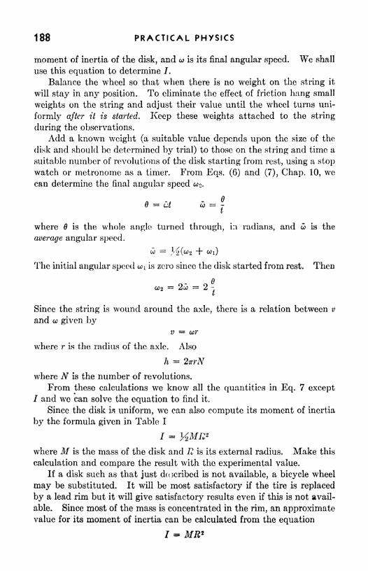
188 PRACTICAL PHYSICS
moment of inertia of the disk, and co is its final angular speed. We shall
use this equation to determine /.
Balance the wheel so that when there is no weight on the string it
will stay in any position. To eliminate the effect of friction hang small
weights on the string and adjust their value until the wheel turns uni-
formly after it is started. Keep these weights attached to the string
during the observations.
Add a known weight (a suitable value depends upon the size of the
disk and should be determined by trial) to those on the string and time a
suitable number of revolutions of the disk starting from rest, using a stop
watch or metronome as a timer. From Eqs. (6) and (7), Chap. 10, wecan determine the final angular speed co 2 .
B = ut d> =jt
where 6 is the whole angle turned through, hi radians, and co is the
average angular speed.
CO = M(fc>2 + i)
The initial angular speed coi is zero since the disk started from rest. Then
n
C02 2o? = 2 -
I
Since the string is wound around the axle, there is a relation between v
and co given byv = cor
where r is the radius of the axle. Also
h = 2irrN
where N is the number of revolutions.
From these calculations we know all the quantities in Eq. 7 except
/ and we can solve the equation to find it.
Since the disk is uniform, we can also compute its moment of inertia
by the formula given in Table I
I = MMR 2
where M is the mass of the disk and R is its external radius. Make this
calculation and compare the result with the experimental value.
If a disk such as that just described is not available, a bicycle wheel
may be substituted. It will be most satisfactory if the tire is replaced
by a lead rim but it will give satisfactory results even if this is not avail-
able. Since most of the mass is concentrated in the rim, an approximatevalue for its moment of inertia can be calculated from the equation
7 MR*

CHAPTER 20
VIBRATORY MOTION; RESONANCE
Three types of motion have been treated in the earlier chapters.The simplest is that of an object in equilibrium, a motion consisting of
constant speed and unchanging direction. The second type of motion,which is produced by the action of a constant force, is that in whichthe direction is constant and the speed increases uniformly. Projectilemotion was discussed as a combination of these two simple types of
motion. The third type of motion discussed is uniform circular motion,that produced by a (centripetal) force of constant magnitude directedinward along the radius of the circular path of the moving object.
It is clear that the forces we commonly observe are not always zero,constant in magnitude and direction, or constant in magnitude and of
rotating direction; so that, consequently, the motions commonly observedare not always uniform rectilinear, uniformly accelerated, uniform
circular, or even combinations of the three. In general, the forces actingon a body vary in both magnitude and direction, resulting in complicatedtypes of nonuniformly accelerated motion, whicVi cannot be investigatedin an elementary physics course.
189

190 PRACTICAL PHYSICS
N
V
\\
\\
\\
\\
I!
Simple Harmonic Motion (S.H.M.). A type of motion that is particu-
larly important in practical mechanics is the to-and-fro or vibrating
motion of objects stretched or bent from their normal shapes or positions.
It is fortunate that this motion, though it is produced by a varying force,
can be analyzed rather easily and completely by elementary methods.
Suppose that a steel ball is mounted on a flat spring, which is clampedin a vise as in Fig. 1. Pull the ball sideways, bending the spring, and
you will observe a restoring force that tends to move the ball back toward
its initial position. This force increases as the ball is pulled farther
away from its original position; in fact, the restoring force is directly
^^ proportional to the displacement from the position
of equilibrium. The direct proportionality of restor-
ing force to displacement distinguishes simple har-
monic motion from all other types. Simple harmonic
motion is that type of vibratory motion in which the
restoring force is proportional to the displacementand is always directed toward the position of
equilibrium.
Period, Frequency, Amplitude. The period of a
vibratory motion is the time required for a completeto-and-fro motion or oscillation. For a simple har-
monic motion, the time required for one completeoscillation depends upon two factors: the stiffness of
the spring (or other agency) that supplies the restor-
ing force, and the mass of the vibrating object. Thestiffness of the spring is measured by the so-called
force constant K, which is the force per unit displace-
ment. This is obtained by dividing the applied force
by the displacement it produces. For example, in
Fig. 1, if a force of 0.2 lb is required to move the mass a distance of 3.0 in.
from its equilibrium position, the force constant is /THF-CI = 0.8 Ib/ft. By
Hooke's law, the force will be proportional to the displacement, so that
a force of 0.4 lb will displace the ball 6 in., if this does not exceed the
elastic limit of the spring.
The period of vibration, that is, the time required for a complete
oscillation, is given by the equation,
FIG. 1. A ball andspring in simple har-
monic motion.
T = 2* (1)
in which T is the period, W is the weight of the vibrating object, and Kis the force constant, measured in gravitational units, pounds per foot
or grams per centimeter.

VIBRATORY MOTION; RESONANCE 191
Reference to the equation above will show that, if the object is
replaced by another four times as heavy, the period will be doubled. If,
instead, the spring is replaced by another four times as stiff, the period
is halved.
Example: A 5.0-lb ball is fastened to the end of a flat spring (Fig. 1). A force of 2.0 Ib
is sufficient to pull the ball 6.0 in. to one side. Find the force-constant and the period
of vibration.
5.0 IbT
It should be noticed that the weight of the spring has not been con-
sidered. More accurate results will be obtained if about one-third the
weight of the spring is included in W,The frequency n of the vibratory motion is the number of complete
oscillations occurring per second. The frequency is the reciprocal of
the period: n = 1/T.
The amplitude of a vibratory motion is the maximum displacement
from the equilibrium position. In simple harmonic motion the period
does not depend upon the amplitude.
Another example of simple harmonic motion is the up-and-downvibration of an object suspended vertically by a spiral spring. At the
equilibrium position, the spring is stretched just enough to support the
weight of the object. If the object is pulled below this position, it is
acted upon by a restoring force (since the pull of the spring exceeds that
of gravity), which is proportional to the displacement from the equilib-
rium position. Likewise, if the object is lifted above the equilibrium
position, the weight exceeds the pull of the spring by an amount propor-
tional to the displacement from the equilibrium position, so that tho
conditions for simple harmonic motion are satisfied.
Acceleration and Speed in S.H.M. At the positions of greatest dis-
placement, that is, at the end points of the motion, the vibrating object
comes momentarily to a stop. It should be noticed that, at the instant
when its speed is zero, the object is acted upon by the maximum restoring
force, so that the acceleration is greatest when the speed is zero. The
restoring force (and therefore the acceleration) decreases as the object
moves toward the equilibrium position, where the acceleration is zero
and the speed greatest. The direction of the acceleration reverses as
the object passes through the equilibrium position, increasing as the
displacement increases and reaching a maximum again at the other
extreme of displacement.
Thus far in the discussion of simple harmonic motion the effect of
friction has been neglected. Since the fractional force always opposes

192 PRACTICAL PHYSICS
the motion, its effect is to reduce the amplitude (maximum displacement)of the motion, so that it gradually dies out unless energy is constantly
supplied to it from some outside source.
Resonance. Suppose that the natural frequency of vibration of the
system represented in Fig. 1 is 10 vib/sec. Now imagine that, beginningwith the system at rest, we apply to it a to-and-fro force, say, 25 times
per second. In a short time this force will set the system to vibrating
regularly 25 times a second, but with very small amplitude, for the ball
and spring are trying to vibrate at their natural rate of 10 vib/sec.
Fia. 2. Dangerous resonance. Excessive vibration caused the collapse of the bridge.
During part of the time, therefore, the system is so to speak,"fighting
back" against the driving force, whose frequency is 25/sec. We call
the motion of the system in this case a forced vibration.
Now suppose that the alternation cf the driving force is graduallyslowed down from 25/sec to 10/sec, the natural frequency of the sys-
tem, so that the alternations of the driving force come just as the systemis ready to receive them. When this happens, the amplitude of vibration
becomes very large, building up until the energy supplied by the drivingforce is just enough to overcome friction. Under these conditions the
system is said to be in resonance with the driving force.
A small driving force of proper frequency can build up a very large
amplitude of motion in a system capable of vibration. We have all
heard car rattles that appear only at certain speeds, or vibrations se^

VIBRATORY MOTION/ RESONANCE 193
up in dishes, table lamps, cupboards, and the like by musical sounds of
particular frequency. A motor running in the basement will often set
certain pieces of furniture vibrating.
This problem of resonant vibrations may become particularly impor-tant with heavy machinery. The problem is to find the mass that is
vibrating in resonance with the machinery and change its natural fre-
quency by changing its mass or its binding force (force constant).
A most common example of resonance is furnished by radio circuits.
When one tunes his radio receiver, he is in effect altering what would
correspond to the spring constant in a mechanical system. By thus
changing the natural frequency, one can bring the circuit into resonance
with the desired electrical frequency transmitted by the sending station.
The forced vibrations from all other frequencies
have such small amplitudes that they do not pro-
duce any noticeable effect.
Another Description of S.H.M. It is enlighten-
ing to establish a comparison between simple har-
monic motion and uniform circular motion.
Suppose that in Fig. 3 the object A is executing
uniform circular motion in a vertical circle. Let
the object be illuminated from vertically overhead
so that the shadow of A appears directly below it
on the floor at B. The shadow B will execute
simple harmonic motion along the line CD. The c 60circle on which A travels uniformly is called the FIG. 3. Circle of refer-
reference circle. Simple harmonic motion can thus
be described as the motion of the projection on a diameter of a point that
moves at constant speed in a circle.
SUMMARY
Simple harmonic motion is that type of vibratory motion in which the
restoring force is proportional to the displacement and is always directed
toward the position of equilibrium.
The period of a vibratory motion is the time required for one completeoscillation: T = 2ir VW/gK.
The frequency is the number of complete oscillations per second.
The amplitude of the motion is the maximum displacement from the
equilibrium position.
Resonance occurs when a periodic driving force is impressed upon a
system whose natural frequency of vibration is the same as that of the
driving force. When this happens, the amplitude of vibration builds
up until the energy supplied by the driving force is just sufficient to
overcome friction in the system.

194 PRACTICAL PHYSICS
The motion of the projection of a point that moves at constant speedon the
"circle of reference
"describes simple harmonic motion.
QUESTIONS AND PROBLEMS
1. What is the force constant of a spring that is stretched 11.0 in. by a force
of 5.00 Ib? Ans. 5.45 Ib/ft.
2. What is the period of vibration of a mass of 10.0 Ib if it is suspended bythe spring of problem 1? Ans. 1.50 sec.
3. The spring of problem 2 weighs 1.5 Ib. Use this fact to improve youranswer for problem 2. What percentage error is introduced in the answer to
problem 2 by neglecting the weight of the spring?
Ans. 1.54 sec; 2.6 per cent.
4. A 1,000-gm cage is suspended by a spiral spring. When a 200-gm bird
sits in the cage, the cage is pulled 0.50 cm below its position when empty. Find
the period of vibration of the cage (a) when empty, (b) when the bird is inside.
Ans. 0.32 sec; 0.35 sec.
6. Find the maximum speed and acceleration for the vibration of problem
2, assuming that the amplitude of motion is 2.0 in.
Ans. 0.70 ft/sec; 2.9 ft/sec2
.
6. The drive wheels of a locomotive whose piston has a stroke of 2 ft make185 rpm. Assuming that the piston moves with S.H.M., find the speed of the
piston relative to the cylinder head, at the instant when it is at the center of its
stroke. Ans. 19.4 ft/sec.
7. A 50-gm mass hung on a spring causes it to elongate 2 cm. When a
certain mass is hung on this spring and set vibrating its period is 0.568 sec.
What is the mass attached to the spring? Ans. 200 gin.
8. A 200-gm mass elongates a spring 4.9 cm. What will be the period of
vibration of the spring when a 400-gm mass is attached to it? (Neglect the
mass of the spring.) What will be the maximum speed of the vibrating mass if
the amplitude is 3 cm? Ans. 0.63 sec; 30 cm/sec.
9. A body whose mass is 5 kg moves with S.H.M. of an amplitude 24 cmand a period of 1.2 sec. Find the speed of the object when it is at its mid-position,
and when 24 cm away. What is the magnitude of the acceleration in each case?
Ans. 126 cm/sec; 0; 0; 660 cm/sec2
.
10. A 100-lb mass vibrates with S.H.M. of amplitude 12 in. and a periodof 0.784 sec. What is its maximum speed? its maximum kinetic energy? its
minimum kinetic energy? Ans. 7.8 ft/sec; 96 ft-lb; 0.
EXPERIMENT
Simple Harmonic Motion/ Resonance
Apparatus: Spring; weights.
This experiment is essentially a study of the significance of Eq. (1)
of this chapter. From that equation it follows that the frequency of
oscillation n of a loaded spring executing simple harmonic motion is givenbv

VIBRATORY MOTION; RESONANCE 195
The fact that for such motion the frequency is inversely proportional to
the square root of the weight can be illustrated with the spring used in
the experiment of Chap. 6.
Suspend a load of 1 kg on the spring. Pull the load 10 or 15 cm below
the point of equilibrium and then release it. Count the number of com-
plete, vibrations in, say, a half minute. Then compute the number of
vibrations per second. Do this for several different loads and record
the results in the accompanying table. If n and \/W are indeed inversely
proportional, their product (column 4) should be constant. Is it?
W Vw nVYV
For a given load, compare the frequency of vibration obtained when
the initial displacement is small (5 to 10 cm) with that resulting from an
initial displacement several times as large. Does the frequency of tho
vibration depend on its amplitude?
Compute the force constant K of the spring from data obtained when
it was used in the experiment of Chap. 6. Using this value, computethe frequency of vibration to be expected under the conditions of this
experiment. Record your calculated values in the last column of the
table. How do they compare with the observed frequencies?
To study resonance, suspend the spring and mass from your finger.
Now move the finger up and down with an amplitude of several inches
and a frequency much greater than the "natural" frequency of the spring
and that particular mass. Is the response (the motion) of the mass very
large? Now move the finger with a frequency much less than the
natural one. The amplitude and frequency of vibration of the mass are
approximately equal to those of the finger. Next, move the finger with
a frequency approximately equal to the natural frequency of the system.
The amplitude of oscillation of the spring and mass will be much larger
than that of the finger. This is the condition of resonance. Try it for
different loads. Mention some practical advantages and also some
dangerous disadvantages of this phenomenon of resonance.

CHAPTER 21
SOURCES AND EFFECTS OF ELECTRIC CURRENT
The present era is one that may properly be characterized as the ageof electricity. Homes and factories are lighted electrically; communica-tion by telegraph, telephone, and radio depends upon its use; and the
industrial applications of electricity extend from the delicate instruments
of measurement and control to giant electric furnaces and powerfulmotors. People seek recreation at motion-picture houses and theaters
whose operations utilize electric current in many ways, and it is proba-ble that television in future years will be as commonplace as is the radio
of today. Electricity 's a useful servant of man a practical means of
transforming energy to the form in which it serves his particular need.
The effects of electricity both at rest and in motion are well known, andthe means to produce these effects are readily available.
Electrification. If a piece of sealing wax, hard rubber, or one of
many other substances is rubbed with wool or cat's fur, it acquires the
ability to attract light objects such as bits of cork or paper. The processof producing this condition in an object is called electrification, and the
object itself is said to be electrified or charged with electricity.
196

SOURCES AND EFFECTS OF ELECTRIC CURRENT 197
There are two kinds of electrification. If two rubber rods, electrified
by being rubbed against fur, are brought near each other, they will bo
found to repel each other. A glass rod rubbed with silk will attract
either of the rubber rods, although two such glass rods will repel each
other. These facts suggest the first law of electrostatics: Objects that,
are similarly charged repel each other, bodies oppositely charged attract each
other.
The electrification produced in a glass rod by rubbing it with silk is
arbitrarily called positive electrification, while that produced in the rubber
rod with wool is called negative electrification. It is ordinarily assumed
that uncharged objects contain equal amounts of positive and negative
electricity. When glass and silk are rubbed together, some negative
electricity is transferred from the glass to the silk, leaving the glass rod
FIG. 1. A chat god body brought near a light insulated conductor causes charges in the
conductor to separate. This results in an attraction of the conductor by the charge.
with a net positive charge, and the silk with an equal net negative charge.
Similarly, hard rubber receives negative electricity from the wool with
which it is rubbed, causing the rod to be negatively charged and leaving
the wool positive. Though a similar explanation could be made by
assuming a transfer of positive electricity, it can be shown that in solids
only negative electricity is transferred.
The attraction of a charged object for one that is uncharged is illus-
trated in Fig. 1. The separation of positive and negative electricity
within the uncharged object is produced by the charged object, wliich
exerts a force of repulsion on the like portion of the charge and an attrac-
tion on the unlike. At a the negatively charged rod causes the adjacent
side of the uncharged object to become positively charged, while the
opposite side becomes negatively charged. Because the unlike charge
is nearer the rod, the force of attraction will exceed that of repulsion and
produce a net attraction of the uncharged object by the rod. At b is
shown the case in which a positively electrified glass rod is used. It-
should be remembered that the changes described here do not alter the

198 PRACTICAL PHYSICS
total amounts of positive and negative electricity in the uncharged
object. No charge is gained or lost; all that occurs is a shift of negative
electricity toward one side of the object, making that side predominantly
negative and leaving the other side predominantly positive.
The Electron Theory. According to modern theory all matter is
composed of atoms, tiny particles that are the building blocks of the
universe. There are many kinds of atoms, one for each chemical ele-
ment. Each atom consists of a nucleus, a small, tightly packed, posi-
tively charged mass, and a number of larger, lighter, negatively charged
particles called electrons, which revolve about the nucleus at tremendous
speeds (Fig. 2). The centripetal force necessary to draw these electrons
into their nearly circular paths is supplied by the electrical attraction
between them and the nucleus. The latter is said to consist of a numberof protons, each with a single positive charge, and possibly one or more
neutrons, which have no charge. Thus the positive charge on the nucleus
FIG. 2. Each atom consists of a positively charged nucleus surrounded by electrons. Ththree simplest atoms, hydrogen, helium, and lithium, are represented diagrammatically.
depends upon the number of protons that it contains, called the atomic,
number of the atom. A neutral atom contains equal numbers of electrons
and protons. Each electron carries a single negative charge of the same
magnitude as the positive charge of a proton, so that the attraction
between the nucleus of an atom and one of the electrons will dependon the number of protons in the nucleus. An electron has a mass of
8.994(10)~28gm. Since the mass of a proton is about 1,840 times that
of an electron, the nucleus may be thought of as practically unaffected
by the attraction of the electrons. The number of electrons in an atom,
along with their arrangement, determines the chemical properties of the
atom.
From the idea that like charges repel and unlike charges attract, it
appears that a nucleus consisting of positive charges could not be expectedto cling together as a unit. The explanation is that, at very short dis-
tances, two protons will attract each other, clinging together tightly,
even though at larger distances they repel each other.
A solid piece of material consists of an inconceivably large numberof atoms clinging together. Though these atoms may be vibrating about

SOURCES AND EFFECTS OF ELECTRIC CURRENT 199
their normal positions as a result of thermal agitation, their arrangementis not permanently altered by this motion. Also present in solida are
numbers of free electrons, so-called because they are not permanentlyattached to any of the atoms. The number and freedom of motion of
these electrons determines the properties of the material as a conductor of
electricity. A good conductor is a material containing many free elec-
trons whose motion is not greatly impeded by the atoms of which the
material is composed. As a result of the repulsive forces between them,free electrons spread throughout the material, and *any concentration
of them in any one region of the material will tend to be relieved by a
motion of the electrons in all directions away from that region until an
equilibrium distribution is again reached.
In the best conductors, the outer electrons of the atoms can easily
be removed, so that a free electron, colliding with an atom, often causes
such an electron to leave the atom. When this happens, the electron
ejected becomes a free electron, moving on, while its place in the atom is
taken by the next free electron that encounters the atom. An insulator,
or poor conductor, is a substance which contains very few free electrons
and whose atoms have no loosely held orbital electrons.
The reason for describing electrification as occurring through the
transfer of negative electricity can now be seen. An uncharged object
contains a large number of atoms (each of which has equal numbers
of electrons and protons) along with some free electrons. If some of these
free electrons are removed, the object is considered to be positively
charged, though actually this means that its negative charge is below
normal, since it still contains more electrons than protons. If extra
free electrons are gained by an object, it is said to be negatively charged,
since it has more negative charge than is normal. The "normal" or
uncharged condition of a body is that obtained by connecting it to the
earth.
Electric Current. Consider a circular loop of copper wire. The wire
consists of a tremendous number of copper atoms along with a large
number of free electrons. If energy is supplied to make these free elec-
trons move around the circuit continuously, an electric current is said to
be produced in the wire. It is to be emphasized that a source of electric
current is simply a device for causing electrons to move around a circuit.
The electrons themselves are already in the circuit, hence a source of
electric current merely causes a motion of electrons but does not producethem. Since electrons repel each other, a motion of those in one part of
the circuit will cause those next to them to move, relaying the motion
around the circuit. The individual electrons in a current-carrying
wire move with a relatively low speed (about 0.01 cm/sec for a current
of 1 amp in a copper wire 1 mm in diameter), but the impulse of the

200 PRACTICAL PHYSICS
electron movement travels around the circuit with a speed approaching
that of light (186,000 mi/sec).
Sources of Electric Current. Let us consider some of the methods bywhich electrons can be caused to move around a circuit. In Fig. 3 is
shown an electric circuit consisting of a dry cell, a push button, and a
RHEOSTAT RHEOSTAT
CELL
a b
FIG. 3. (a) A simple electric circviit; (b) a schematic diagram of the simple circuit.
rheostat. The electrons are forced out of the negative terminal of the cell
and around the circuit, returning to the positive terminal of the cell to
be again "pumped" through. Since the electrons leaving the cell must
push those just ahead (and thus those on around the circuit), the cell
furnishes the driving force for the electrons throughout the circuit by
propelling each as it comes through.
The cell thus does work on the electrons,
communicating to them the energy
released in the interaction of chemicals
within it.
Direction of Flow. As has been ex-
|
Bunsen plained, an electric current consists of aflame
stream Of electrons. Since they carry
negative charges of electricity, their
direction of motion is from the negativeterminal of the source, through the external circuit and back to the posi-
tive terminal. Because for many years the flow was not understood, it
was assumed that the flow is from positive to negative. It is still
customary to speak of this "conventional" flow from positive to nega-tive as the direction of the current.
A source of electric current in which heat is transformed into electrical
energy is shown in Fig. 4. In the diagram there is shown a wire loop
Copper'
Galvanometer
Copper
FIG. 4. -A thermocouple.

SOURCES AND EFFECTS OF ELECTRIC CURRENT 201
consisting of a piece of iron wire joined to a piece of copper wire. Oneof the junctions is heated by a flame, causing electrons to flow around
the circuit. The flow will continue as long as one junction is at a higher
temperature than the other junction. Such a device, consisting of a
pair of junctions of dissimilar metals, is called a thermocouple.
The principle upon which the main source of electric currents dependsis illustrated by the following. If one end of a bar magnet is plungedinto a loop of wire, the electrons in the latter are caused to move around
the wire, though their motion continues only while the magnet is moving
(Fig. 5a). If the magnet is withdrawn, the electrons move around the
loop in the opposite direction. The discovery of this means of producing
FIG. 5. (a) An electric current is produced by thrusting a magnet into a loop of wire; (6)
a simple generator.
an electric current with a moving magnet has led to the development of
the electric generator. A very simple generator is shown in Fig. 56. It
consists of a stationary magnet between whose poles a coil of wire is
rotated. The two ends of the coil arc joined, through rotating contacts,
to an incandescent lamp. During one-half of a rotation of the coil the
electrons move in one direction through the lamp filament, while duringthe next half rotation they move in the opposite direction. Such a
generator is said to produce an alternating current.
If light falls on a clean surface of certain metals, such as potassiumor sodium, electrons are emitted by the surface. This phenomenon is
called the photoelectric effect. If such a metallic surface is made a part
of an electric circuit, such as that in Fig. 6, the electric current in the
circuit is controlled by the light. If the light is bright, the current will
be greater than if the light is dim. This device is known as a photoelectric

202 PRACTICAL PHYSICS
cell and serves as a basis for most of the instruments that are operated or
controlled by light such as television, talking moving pictures, wire or
radio transmission of pictures, and many industrial devices for counting,
rejecting imperfect pieces, control, etc.
Electrification through friction, as described earlier in the chapter,
can bring about transfers of small quantities of electricity; yet it is not
commercially important as a means of sustaining an electric current.
EJECTEDELECTRONS^
.POTASSIUMCOAT/NG
Fia. 6. A photoelectric cell
In all these sources of electric current some type of energy is used to
set the electrons in motion. Chemical, mechanical, thermal, or radiant
energy is transformed into electrical energy.
Effects of Electric Current. The circuit in Fig. 7 consists of a battery Ein series with a piece of high-resistance wire R; an incandescent lamp L; a
cell Z containing metal electrodes (a and 6) immersed in water to which
a few drops of sulphuric acid have been added; and a key K, which opensand closes the circuit. A magnetic compass C is directly over the wire.
Fia. 7. A circuit showing three effects of an electric current.
If the key K is closed, the battery produces a flow of electrons from
its negative terminal through Z, L, R, K, and back to the positive ter-
minal of the battery. As a result of the flow, several changes occur in
the various parts of the circuit. The wire R becomes warm, and the
filament of wire in the incandescent lamp becomes so hot that it begins
to glow. The water in Z presents a very interesting appearance. Bub-
bles of gas are coming from the surfaces of the electrodes a and b (twice

SOURCES AND EFFECTS OF ELECTRIC CURRENT 203
as much from a as from 6). Tests show that hydrogen gas is being givenoff by a, and oxygen by 6. Since oxygen and hydrogen are the gases
that combine to form water and since the water in Z is disappearing, it
is natural to conclude that the water is being divided into its constituents
(hydrogen and oxygen) by the action of the electric current. This device
Z is called an electrolytic cell.
The compass C, which points north (along the wire in Fig. 7) when the
key is open, is deflected slightly to one side when the key is closed. This
indicates that a magnetic effect is produced in the vicinity of an electric
current.
The heat produced in R and Lythe decomposition of water in the cell
Z, and the deflection of the compass needle can be accomplished only at
the expenditure of energy. By means of the electrons that it drives
around the circuit, the battery E communicates energy to the various
parts of the circuit. Electrons forced through R and L encounter resist-
ance to their motion because of their collisions with the atoms of the
material in R and L. These collisions agitate the atoms, producingthe atomic-molecular motion that we call heat. In ways that will be
discussed later, the electrons cause the decomposition of the water in Zand the deflection of the compass C, and the energy that they expend in
these processes is furnished by the battery.
A phenomenon so simple as the deflection of a compass needle hardlyindicates the importance of the magnetic effect of an electric current, for
it is this magnetic effect that makes possible the operation of electric
motors as devices by means of which electric currents perform mechanical
work. The magnetic effect makes possible also the radio, telephone,
telegraph, and countless other important electrical devices.
Unit of Electric Current. The ampere, the practical unit of electric
current, is legally defined in terms of the rate at which it will cause
metallic silver to be deposited in an electrolytic cell (0.00111800 gm/amp-sec).
Since the ampere is a unit of current, or rate of flow of electricity, a
logical unit of quantity of electricity is the amount transferred in 1 sec by a
current of 1 amp. The coulomb, then, is the quantity of electricity which
in 1 sec traverses a cross section of a conductor in which there is a con-
stant current of 1 amp. The total quantity of electricity (in coulombs)that passes through a source of electric current in a time t is
Q = It (1)
where / is the current in amperes, t is the time in seconds, and Q is the
quantity of electricity.
Potential, Voltage. The work (in foot-pounds) done by a pumpon 1 ft 3 of water which passes through it is numerically equal to the

204 PRACTICAL PHYSICS
difference in the pressures (in pounds per square foot) at the inlet and
outlet of the pump. By analogy, then, we can think of the difference
of electric"pressure
"(potential) across the terminals of a source of
electric current as measured by the work done on each coulomb of elec-
tricity transferred. The difference of potential across which 1 coulomb
of electricity can be transferred by 1 joule of energy is called the volt.
Thus, if the difference in potential between two points is 10 volts, exactly
10 joules of energy is necessary to transfer each coulomb of electricity
from one of the points to the other. It will be remembered that 1 joule
equals 107ergs (dyne-centimeters). When the difference of potential
between two points is expressed in volts, it is often referred to as the
voltage between those points.
Resistance. The electrical resistance of a conductor is the ratio of the
potential difference across its terminals to the current produced in it.
The practical unit of electrical resistance is the ohm, which is the resistance
of a conductor in which a current of 1 amp can be maintained by a
potential difference of 1 volt. By definition, then,
EK =
7 (2)
where R is the resistance expressed in ohms.
SUMMARY
The electron theory suggests that all matter is composed of atoms,each atom consisting of a nucleus of protons (positive) and neutrons
(uncharged), which is surrounded by a group of electrons (negative)
whirling about the nucleus in small orbits at tremendous speeds.
A substance is a good conductor of electricity if it contains many free
electrons and the outer electrons of its atoms are easily removable.
A source of electric current does not produce electricity but only a
motion of electrons, many of which are distributed throughout all con-
ductors. Electrons will not flow of their own accord along a conductor.
Energy must be expended to move them.
A sustained electric current can be produced (a) chemically, (6) mag-
netically, (c) thermoelectrically, (d) photoelectrically.
The effects of electric current include the following: (a) heating effect,
(6) magnetic effect, (c) chemical effect.
The practical unit of electric current is the ampere, which is defined
legally as the. current that will deposit 0.00111800 gm of silver per second.
The coulomb is the quantity of electricity which, in 1 sec, traverses
any given cross section of a conductor in which there is a current of
exactly 1 amp.The volt is the potential difference across which 1 coulomb of electricity
can be transferred by 1 joule of energy.

SOURCES AND EFFECTS OF ELECTRIC CURRENT 205
The resistance of a conductor is defined as the ratio R =J5/7, where
E Is the difference of potential across its terminals and / is the current
through it.
The ohm is the electrical resistance of a conductor in which a current
of 1 amp can be maintained by a difference of potential of 1 volt.
The conventional direction of flow of electricity is from positive to
negative (outside the source), while the actual direction of flow is from
negative to positive. Whenever reference is to the actual direction of
flow, the phrase electron flow will be employed, otherwise the reference is
intended to be to conventional, or + to flow.
QUESTIONS AND PROBLEMS
1. What is it that flows in an electric current?
2. Npme four important types of sources of electric current.
3. Name three important effects of electric current.
4. Explain why a source of electric current should not be thought of as a
source of electricity.
6. When one pays his so-called electric bill, is he paying for electricity, elec-
tric energy, or electric power? Explain.
6. Explain how a good conductor differs from a poor conductor, or insulator.
7. A current of 0.7 amp is maintained in an electrolytic cell. If each
coulomb of electricity that passes through the cell causes 0.00033 gm of copperto be deposited on the negative electrode, how much copper will be deposited in
20 min?
8. If the potential difference across the terminals of the cell in problem 7 is
5.0 volts, how many joules of energy are furnished to it by the electric current
during the 20 min? Ans. 4,200 joules.
9. What is the resistance of the cell of problems 7 and 8?
10. If increasing the difference of potential across the cell (of problems 7
and 8) to 10 volts causes the current to rise to 1.25 amp, what is the resistance
of the cell under these conditions? Ans. 8 ohms.
EXPERIMENTS
Sources and Effects of Electric Current
Apparatus: Iron wire; flashlight lamp bulb; copper sulphate; carbon
rods; battery or dry cells; switch; magnetic compass; two battery jars;
water; copper plates; sulphuric acid; zinc plater,; galvanometer; magnet;coil of wire.
At this juncture students will probably find a series of descriptive
experiments or demonstrations more valuable than formal experiments
involving quantitative measurements. The following may be performedwith apparatus which, with the exception of a galvanometer, is rather
simple and readily available.

206 PRACTICAL PHYSICS
. a. Chemical Source. Dip a plate of zinc and a plate of copper into a
tumbler of dilute sulphuric acid. To these plates connect wires with
battery clips (or even paper clips) and connect these in turn through a
protective resistance to a galvanometer, a current-indicating instrument.
b. Magnetic Source. Connect the ends of a coil of wire to the gal-
vanometer. Thrust a magnet through the coil while observing the
galvanometer.
c. Thermoelectric Source, Connect two wires of different material to
the galvanometer in series with a protective resistance. Twist the free
ends of the wires together and hold the joint in a flame.
d. Effects of an Electric Current. The circuit is diagramed in Fig. 8.
At B is shown an ordinary storage battery or a half dozen dry cells, S a
switch, W a length of small-diameter iron wire, A an electrolytic acid
w
FIG. 8.- -Arrangement of apparatus to show chemical, heating, and magnetic effects of
electric current.
cell, C an electrolytic copper sulphate cell, L a flashlight bulb, and M a
magnetic compass. With the exception of the compass these are all
connected by copper wire in series. Hence the current is the same in
all these devices, although a different effect is produced in each of them.
In W the main effect observable is the generation of heat. The rise
in temperature can be felt directly by touching the wire.
The filament in L is heated so much that a very high temperature is
produced high enough for the radiation of white light.
The electrolytic cell A consists of a tumbler of dilute sulphuric acid
into which dip two identical plates. When electricity passes through the
cell, chemical action takes place, as is evidenced by the evolution of
bubbles at the electrodes.
In cell C the solution is copper sulphate. The electrodes are carbon
rods, tied together, but separated by the thickness of a rubber band.
The chemical effect of the current is shown by the deposition of copperon that carbon rod which is the negative terminal.
When a magnetic compass is placed above or below the wire (as
illustrated at Af), the needle is deflected, provided the wire itself does
not lie in an east-west direction. This shows that when electricity
passes through a conductor the latter is surrounded by a magnetic field.

-ww
CHAPTER 22
OHM'S LAW; RESISTANCE; SERIES AND PARALLELCIRCUITS
The practical applications of electricity are almost entirely those
which depend upon the effects produced by the flow of electricity, that
is, electric current. In order to apply and to control the heating,
chemical, or magnetic effects the engineer must control the current. Themost important of the laws related to electric current is Ohm's law.
From this law and its extensions many vital circuit relationships can be
determined.
Ohm's Law. In the preceding chapter the resistance of a conductor
is defined as the difference of potential across its terminals divided bythe current through it. Ohm's law is the statement that this quotient
(resistance) is constant for a given conductor so long as its temperatureand other physical conditions are not changed.
E = a constant (1)
Ohm's law makes the relation between E, /, and K particularly useful,
since it indicates that R is constant under uniform physical conditions.

208 PRACTICAL PHYSICS
The relation R = E/I and its derived forms, E =* IR and / = E/R,are commonly referred to as forms of Ohm's law.
Example: The difference of potential across the terminals of an incandescent lampis 6 volts. If the current through it is 1.5 amp, what is its resistance?
From the definition R = . it is seen that R =7-;::
= 4 ohms.1 1.5 amp
Now suppose that one wishes to determine what current will be maintained in the
lamp if the difference of potential is increased to 8 volts. Ohm's law indicates that theresistance R will remain the same (1 ohms) when the voltage is increased; hence wecan write
E 8 volts/ = = - - - 2 amp
Li 4 ohms
Note that it is impossible to solve this problem without using Ohm's law, that is, thefact that R is constant.
Ammeters and Voltmeters. An instrument designed to measure electric
current in amperes is called an ammeter. One designed to measure
(a)
FIG. 1. Tho methods of connecting itmmetei.s and vdllmeteih in a ciicuit.
difference of potential in volts is called a voltmeter. The electrical
principles involved in the operation of these instruments will be discussed
in a later chapter. For the present it will be sufficient to consider onlyhow they are used.
In Fig. la is shown the method of connecting an ammeter in such a
way as to measure the current through an incandescent lam]). Notethat the ammeter carries the current to be measured. In Fig. 16 a volt-
meter has been added to the circuit to measure the difference of potentialacross the lamp. A voltmeter is connected across the two points whose
potential difference is to be measured.
The circuit of Fig. 16 illustrates one of the simplest methods of measur-
ing resistance (ammeter-voltmeter method). If the voltmeter indicates
a difference of potential of 10 volts, and the ammeter a current of 2 amp,
the resistance of the lamp is R ~~ = 5 ohms.j amp
Because the voltmeter must carry a small current in order to indicate
the voltage, the current through the ammeter is slightly larger than thatin the lamp. For the present it will be assumed that the error thus

OHM'S LAW; RESISTANCE; SERIES, PARALLEL CIRCUITS 209
involved in measuring the current through the lamp is very small, that is,
the current through the voltmeter is negligible in comparison with that
through the lamp.Resistances in Series. Suppose that a box contains three coils of wire
whose resistances are r\, r2 ,and r 3 , respectively, and which are con-
nected in series as shown in Fig. 2. If one were asked to determine the
resistance of whatever is inside the box without opening it;he would
probably place it in the circuit shown, measuring the current / throughthe box and the voltage E across it. He would then write R = E/I,
where R is the resistance of the part of
the circuit inside the box.
Let us now determine the relation
of R, the combined resistance, to the
individual resistances ri, 7*2, and 7*3.
The current through each of these
resistances is /, since the current is not
divided in the box. The voltages
across the individual resistances are FlQ 2.-~Resistances in series.
ei ~Ir-i, c 2
= Ir 2 ,and c 3 7= /r3 . The
sum of these three voltages must be equal to E, the voltage across the
box; thus E = e\ + e% + e s or E = Ir\ + 7r2 + Irz. This can be
written E = I(r\ + r2 + r 3), or i\ + r2 + r 3= E/I; but this is identical
with R = E/I, so that
R - n + r 2 + r,. (2)
It has been shown that the combined resistance of three resistances in
series is the sum of their individual resistances. This is true for anynumber of resistances.
Example: The resistances of four incandescent lamps are measured by the ammeter-voltmeter method and found to he 10.0, 4.0, 6.0, and 5.0 ohms, respectively. These
lamps aie connected in series to a battery, which produces a potential difference of
75 volts across its terminals. Find the current in the lamps and the voltage across
each.
Using Ohm's law, it is assumed that the resistances of the lamps will remain thesame when placed in the new circuit (in reality, the resistance of a lamp changes some-what when the current through it is changed, sijice this changes its temperature).This gives
R = (10 + 4 + 6 -f 5) ohms = 25 ohmsso that
rE 75 volts
/ =7;= ^ r e 3.0 ampR 25 ohms K
The voltage across each lamp is the product of its resistance and the current. Thus
ei-
(3.0 amp) (10 ohms) = 30 volts
e 2*= (3.0 amp) (4.0 ohms) 12 volts
c 8 (3.0 ampKG.O ohms) 18 volts

210 PRACTICAL PHYSICS
and
e\ (3,0 amp) (5.0 ohms) =* 15 volts
Resistances in Parallel. Suppose that a box contains a group of three
resistances 7% r 2 ,and r 3 in parallel, as shown in Fig. 3. The resist-
ance of the combination will be R = E/I, where E is the voltage across
the terminals of the box and / is the total current through it. Since
the voltage across each of the resistances is E, the voltage across the
terminals of the box, the currents through the individual resistances are,
respectively,
E E Ei\ =
r\ 7*3
The sum of these three currents must be the total current /, so that
or
r\
This can be written
FIG. 3. Resistances in|
i_|
i ~ _parallel. T\ r>> 7*3 E
Since E/I = R, we know that I/E =* l/H, so that
T-,3
(3)
Thus the reciprocal of the combined resistance of a group of resistances
in parallel is equal to the sum of the reciprocals of their individual
resistances.
Example: The values of three resistances are measured by the ammeter-voltmetermethod and found to be 10, 4.0, and 6.0 ohms, respectively. What will be theircombined resistance in parallel?
1 1
-f1i.I+I+i..R ri r 2 r 3 10 ohms 1
4.0 ohms"^
6.0 oljms
(0.10 + 0.25 + 0.17)/ohm = 0.52/ohm
0.52/ohm ;R r ohms = 1.9 ohms
the combined resistance. Note that the resistance of the combination is smallerthan any one of the individual resistances.

OHM'S LAW; RESISTANCE; SERIES, PARALLEL CIRCUITS 211
From the study of resistances in series and parallel it is seen that one
can use the relation R = E/I and Ohm's law in connection with groups
of resistances as well as single resistances. One can consider any group
of resistances not containing a battery as a single resistance R = E/I,
where E is the voltage across the terminals to which external connection
is made and / is the current at those terminals.
_r-A/VW^-x\_VW\A--'
FIG. 4.
Emf and Internal Resistance. Thus far reference has been made to
the voltage across the terminals of a battery without indicating the
fact that this voltage depends upon the current supplied by the battery.
When there is no current in a battery, the voltage Em across its terminals
is a maximum which is called its em/, or no-load voltage. The abbrevia-
tion emf represents electromotive force, but the use of "force" in this term
is so misleading that it is desirable to use the abbreviation emf without
any thought of the original term.
When a current is being maintained by a battery, the voltage across
its terminals is Em 7r, where Em is the emf of the battery, 7 the cur-
rent, and r its internal resistance. Thus a battery of low internal resist-
ance can supply a large current without much decrease in its terminal
voltage. It should be noted that the effect of the internal resistance of a
battery is the same as if it were a small resistance r in series with the
battery, but inside the terminals. If R is the resistance of the external
circuit to which the terminals of the battery are connected,
Em - Ir = IR (4)
Example: The internal resistance of a battery is 0.1 ohm and its emf 10.0 volts.
What will be the current when a resistance of 4.0 ohms is connected across the ter-
minals of the battery?
Em - Ir = IR, or Em - IR + Ir ** I(R + r)
so that
Em 10.0 volts _ 10.0 volts1 "
R 4- r~
(4.0 + 0.1) ohms~Tfohms
"" 2 '4 amp
Note that this is slightly less than 2.5 amp, the value obtained if the internal resistance

212 PRACTICAL PHYSICS
of the battery is neglected. The voltage across the terminals of the battery is
Em Ir = 10.0 volts - (2.4 amp) (0.1 ohm) 10.0 volts - 0.2 volt = 9.8 volts
If a resistance of 1 ohm is connected across the terminals of the same battery, the
current is -:
'
,
= 9.1 amp. or 0.9 amp less than the value obtained when internal1.1 ohms *' *
resistance is neglected.
When a reverse current is maintained in a battery by a source of higher
voltage, the voltage across the terminals of
the battery is Em + Ir.
Applications to an Entire Circuit. If one
goes completely around any closed path in
a circuit, returning to the starting point,
the sum of the various voltages across the
*Efbatteries (or generators) in the path
FIG. r>. A soiios ciHuiu, (counted negative if they oppose the cur-SA - M/e.
rent) is equal to the sum of the voltages
across the (external) resistances in the path; that is,
^E - 2(7B) (5)
The symbol 2 means "the summation of," so that
V 1? TP \ TT _L V \m = MI -j- 7^2 ~r -^3 -r* * *
and
Consider the circuit of Fig. 5. Let us begin at A and follow the pathof the current through EI, RI, R 2 ,
E 2 ,and R^ returning to A.
2E = S(7B), or Ei + E 2= IiRi + 7 2/J 2 + 7a^3 where 7i is the
current through Ri, etc. Since 7i = 7 2= 7 3 ,
Note that E% will be a negative number, since it is the voltage across a
reversed battery.
Example: Find the current in the circuit of Fig. 5 if EI =6 volts, E* = 2 volts,
fti 2 ohms, R-i 4 ohms, 72 3= 2 ohms.
From the preceding paragraph
Ei + 7: 2= 7,(/2i + 72 2 -f /? 3 )
so that
7sT
i + ^; 2 (6- 2) volts
i + 72, + /e, (2+4+2) ohms
4 volts= r~r = 0.5 amp8 ohms ^
Emf's in a Closed Circuit. In the preceding section the relation
2E = S(7/J) was stated. In this equation, each voltage E is the poten-

OHM'S LAW; RESISTANCE; SERIES, PARALLEL CIRCUITS 213
tial difference across the terminals of a battery or generator. Remem-
bering that E = Em /r, where r is the internal resistance, we can write
or
ZEm = S(/E) + S(/r)
If all the resistances (internal as well as external) are included in 23 (IR} 1
the relation becomes 2Em = 2(71?). Whenever emf is considered,
internal resistance must be taken into account. When there are no
branches in the circuit, as in the case of Fig. 5, /i = 72=
/s, so that
S7?w I2R, or I times the total resistance.
Length, Cross Section, Resistivity. Dr. Georg Simon Ohm, who formu-
lated the law that bears his name, also reported the fact that the resistance
of a conductor depends directly upon its length, inversely upon its cross-
sectional area, and upon the material of which it is made.
From the study of resistances in series, one would expect that to
change the length of a piece of wire would change its resistance, as it can
be thought of as a series of small pieces of wire whose total resistance is the
sum of the resistances of the individual pieces,
R = ri + ra + r, +
The resistance cf a piece of uniform wire is directly proportional to its
length.
Consider a wire 1 ft in length and having a cross-sectional area of
0.3 in.2 By thinking of this as equivalent to three wires (1 ft in length)
having cross-sectional areas cf 0.1 in.2 connected in parallel, we may infer
that
1=1+1+1R ri r* n
or, since 7*1= r2
= r 3 ,
1 3-^ and r\ = 3/2Lt r\
showing that the resistance cf one cf the small wires is three times as
great as that of the large wire. This suggests (but does not prove) that
the resistance of a wire is inversely proportional to the cross section, a
fact that was verified experimentally by Ohm himself.
Using R oc I and R c I/A, as indicated at the beginning of this section,
we can write R I/A, where I is the length and A the cross-sectional area
of a uniform conductor. Since conductors of identical size and different
materials have different values of resistance, it is useful to define a
quantity called the resistivity of a substance. It is sometimes so defined

214 PRACTICAL PHYSICS
as to make R = p(l/A), in which p is the resistivity, sometimes called
specific resistance.
Solving this equation for p gives p = R(A/t). If A and / are given
values of unity, it is seen that p is numerically equal to the resistance of a
conductor having unit cross section and unit length.
If R is in ohms, A in square centimeters, and I in centimeters, then p is
expressed in ohm-centimeters.
Example: The resistance of a copper wire 2,500 cm long and 0.09 cm in diameter is
6.7 ohrns at 20C. What is the resistivity of copper at this temperature?
From R p(l/A),
_ A (6.7 ohms) 7r(0.09 cm) 2"Example: What is the resistance of a copper wire (at 20C) which is 100 ft in length
and has a diameter of 0.024 in.? (0.024 in. =0.002 ft.) From the preceding
example
1.7 X 10- fl ohm-cm 1.7(HT6)
p = 1.7 X 10⁻⁶ ohm-cm = ----- -yf = ~~ ohm-ft.
30 5 cm/ft 30.5
o l 1.7(10-) . ^ (100ft) (4)* - p- - --- ohra-ft = 1-8 ohms
The unit of resistivity in the British engineering system of units
differs from that just givon, in that different units of length and area are
employed. The unit of area is the circular mil, the area of a circle 1 mil
(0.001 in.) in diameter, and the unit of length is the foot. Thus the
resistivity of a substance is numerically equal to the resistance of a
sample of that substance 1 ft long and 1 circular mil in area, and is
expressed in ohm-circular mil per foot. This unit is frequently referred to
as "ohms per circular mil foot." Since the area of a circle in circular
mils is equal to the square of its diameter in mils (thousandths of an inch),
R =p(l/d*), where d is the diameter of the wire in mils, I its length in
feet, and p the resistivity in ohm-circular mil per foot.
Example: Find the resistance of 100 ft of copper wire whose diameter is 0.024 in.
arid whose resistivity is 10.3 ohm-circular mil/ft. (NOTE: d 0.024 in. = 24 mils.)
(10.3 ohm-circular mil/ft) (100 ft)---~~7o72\
-1
-M- = 1.8 ohms,
(242) circular mils
'
agreeing with the result of the preceding example.
SUMMARY
Ohm's law consists of the statement that the resistance of a conductor,defined as the ratio E/I, is constant so long as its temperature and other
physical conditions are not changed.The relation R = E/I, and its derived forms E ~ IR and I = E/R,
are expressions of the definition of R as the ratio E/L Ohm's law is

OHM'S LAW; RESISTANCE; SERIES, PARALLEL CIRCUITS 215
utilized when R in these equations is assumed to remain constant while
E and 7 are changed.An ammeter is a device for measuring current in amperes. Since it
measures the current that it carries, it must be placed in series with the
circuit in which the value of the current is desired.
A voltmeter measures difference of potential in volts. It is connected
across (in parallel with) the part of the circuit whose voltage is to be
measured.
The combined resistance of a smes-connected group of resistances is
the sum of the individual resistances,
R r\ + r2 + r3 + . . .
The reciprocal of the combined resistance of a paraZfcJ-connected
group of resistances is equal to the sum of their reciprocals,
!_l4_L + L + . . .
R~n +
r2
+ n ^
For any closed circuit,
The emf of a source of current is the voltage across its terminals whenit is supplying no current.
f
The internal resistance of a source of current (battery or generator)
causes a voltage drop within the source, so that the voltage across its
terminals is Em Irtwhere Em is its emf and r its internal resistance.
The resistance of a uniform wire is given by R = p(l/A), where p is
the resistivity in ohm-centimeters, I the length in centimeters, and Athe cross-sectional area in square centimeters, or by R = p(l/d
2) y
where
p is the resistivity in ohm-circular mil per foot, I is the length in feet, andd the diameter in mils.
QUESTIONS AND PROBLEMS
1. How does emf differ from potential difference?
2. A resistance forms part of a series circuit. How is the resistance of the
circuit affected if a second resistance is connected (a) in series with the first?
(6) in parallel with the first?
3. Why is copper or silver used in electric bus bars rather than a less expen-sive material such as iron?
4. Why is it more dangerous to touch a 500-volt line than a 110-volt line?
Why is it dangerous to have an electric switch within reach of a bathtub?
6. In a circuit like that of Fig. 16 the ammeter indicates 0.75 amp and the
voltmeter 50 volts. What is the resistance of the lamp, neglecting the fact that
the voltmeter carries a small part of the current?

216 PRACTICAL PHYSICS
6. If the voltmeter of problem 5 carries a current of 0.001 amp for eac
volt indicated by it, what is the actual current through the lamp and the cor-
rected value of its resistance? Ans. 0.7 amp; 71 ohms.
7. What is the resistance of the voltmeter of problem 6?
8. In problem 5 the current is increased to LOO amp. What will now be
the reading of the voltmeter? Ans. 67 volts.
9. A dry cell when short-circuited will furnish a current of about 30 amp.If its emf is 1.6 volts, what is the internal resistance? Should the cell be allowed
to deliver this current for more than a brief time? Why? An ordinary house-
hold electric lamp takes about 1 amp. Would it be safe to connect such a lamp
directly to a dry cell? Why?10. An incandescent lamp is designed for a current of 0.60 amp. If a potential
difference of 110 volts is necessary to sustain that amount of current, what is
the resistance of the lamp? Ans. 180 ohms.
11. Find the resistance of a combination formed by 5.0 ohms and 7.0 ohms
in parallel.
12. The combination of problem 11 is connected in series with another pair
of 4.0 and 3.0 ohms in parallel. What is the total resistance?
Ans. 4.6 ohms.
13. A battery of emf 5 volts and internal resistance 0.2 ohm is connected to
the combination of problem 11. Find the total current and that in each resistance.
14. The terminal voltage of a battery is 9.0 volts when supplying a current
of 4.0 amp, and 8.5 volts when supplying 6.0 amp. Find its internal resistance
and emf. Ans. 0.25 ohm; 10 volts.
15. Find the resistance of 5,000 ft of copper wire of diameter 0.011 in. The
resistivity of copper is 10.3 ohm-circular mil/ft.
16. What will be the diameter of a copper wire whose resistance is 20 ohms
and whose length is 500 ft? Ans. 16 mils = 0.016 in.
EXPERIMENT
Ohm's Law; Resistance Combinations
Apparatus: Panel apparatus for study of Ohm's law; flexible con-
nectors; three dry cells or storage battery.
Ohm's law indicates that for a given conductor the quotient E/I(called the resistance K) is constant so long as its temperature and other
physical conditions are not changed.
One purpose of this experiment is to give the student observable
proof of Ohm's law. Another is to show that the resistance of a uniform
conductor is proportional to its length and inversely proportional to
its cross-sectional area. A third purpose is to verify experimentally the
equations derived in this chapter for computing the effective resistance
of series and parallel combinations of resistances.
Use will be made of the apparatus shown schematically by Fig. 6.
The conductors to be investigated are indicated by the lines a, 6, c, d, e.

OHM'S LAW/ RESISTANCE; SERIES, PARALLEL CIRCUITS 217
Current is obtained by connecting three dry cells or a storage battery
at B. The switch should be closed only when readings are being taken,
From the wiring diagram it is evident that if a connector is placed
between pi and pz and switch S is closed, a current / will flow throughthe fuse F, the ammeter A, the rheostat M, and the conductor a. If a
connector is placed between p 3 and p^ another between p$ and pw (the
dotted lines indicate flexible, removable connectors) the voltmeter V will
indicate the potential difference E across a. By means of the rheostat Mthe current can be changed to different values.
Following the procedure just described, determine several correspond-
ing values of E and 7 for conductor a, recording them in the table on
www
FIG. 6. Diagram of a panel used in checking the laws of resistance.
page 218 and computing the ratio E/I. Does the ratio remain essentially
constant, even though E and / are changed?Conductor b is half as long as a and twice as long as c, but all three
conductors are of the same material and have the same area of cross
section. Make sets of measurements for b and c similar to those above
and decide whether or not the values of resistance E/I are related to
those of a as one would expect.
Conductor d is of the same material as a and has the same length,
but its area of cross section is four times as great. How should its resist-
ance compare with that of a? Verify this experimentally.
Determine the resistance of conductor eywhich is made of a different
material. To do this, connect pu to pu and pi to p7 .
In order to determine the combined resistance of two conductors in
series, connect p& to p 7 and pi to p^. Which conductors are connected

$18 PRACTICAL PHYSICS
in series? What is their combined resistance? Compare this with the
result obtained from their individual resistances.
To arrange the same conductors in parallel, connect pu to p^ and pe
to pi and pi. Determine the resistance of the combination and check it
against the result obtained by the use of the equation expressing the
resistance of a parallel combination.

CHAPTER 23
ELECTRICAL MEASURING INSTRUMENTS
I.
Practically all electrical measurements involve either the measurementor detection of electric current. The measurement of electric current can
be accomplished by means of any one
of the three principal effects of cur-
rent: heating effect, chemical effect, or
magnetic effect; yet for the sake of
accuracy and convenience the mag-netic effect (Fig. 1) is utilized almost
universally in electrical measuringinstruments.
Galvanometers. The basic electri-
FIG. 1. The original electric indicator,
Oersted, 1819.
cal instrument is the galvanometer, a device with which very small
electric currents can be detected and measured. The d'Arsonval, or
permanent-magnet-moving-coil type of galvanometer, is shown in Figs.
2 and 3. In Fig. 2 a coil C is suspended between the poles N and S of a
U-shaped magnet by means of a light metallic ribbon. Connections are
made to the coil at the terminals marked t. The cylinder of soft iron B219

220 PRACTICAL PHYSICS
serves to concentrate and increase the field of the magnet, and the mirror
M is used to indicate the position of the coil, either by reflecting a beam
of light or by producing an image of a scale to be viewed through a low-
power telescope.
When a current is set up in a coil that is between the poles of a magnet,the coil is acted upon by a torque, which tends to turn it into a position
perpendicular to the line joining the poles. If a current is set up in the
coil (as viewed from above) in Fig. 26, the coil will turn toward a position
at right angles to the position .own. In turning, however, it must twist
the metallic ribbon that supports it; hence it turns to the position in which
the torque exerted on it by the magnet is just neutralized by the reaction
of the twisted ribbon.
(a) (6)
Fio. 2. Pei manent-magnet, moving-coil type of galvanometer.
The torque exerted on the coil by the magnet is proportional to the
current in the coil, and the torque of reaction of the ribbon is proportional
to the angle through which it is twisted. Since these torques are equaland opposite when the coil reaches the equilibrium position, the angle
through which the coil turns is proportional to the current through it;
that is,a
/, where 6 is the angular deflection of the coil. From this wecan write / =
k6, so that k = 1/6, where k is called the current sensitivity
of the galvanometer.For sensitive galvanometers of the type shown in Fig. 3, which are
read with telescope and scale, the current sensitivity k is expressed in
microamperes per millimeter deflection on a scale 1 m from the mirror, so
that it is numerically equal to the current in microamperes (millionths of
an ampere and commonly abbreviated M&) required to cause a 1-mmdeflection of the image on a scale 1 m distant. For the most sensitive
types of commercial d'Arsonval galvanometers, k is about 0.00001 ^a/mm,or 10~~u amp/mm. The term current sensitivity is somewhat misleading,since k is low for sensitive galvanometers.

ELECTRICAL MEASURING INSTRUMENTS 221
Portability, ruggedness, and convenience of operation are obtained in
the d'Arsonval galvanometer by mounting the moving coil on jeweled
pivots, attaching a pointer to the coil, and replacing the metallic ribbon
FIG. 3. Laboratory galvanometer with telescope and scale.
suspension by two spiral springs as shown in Fig. 4. The springs, besides
balancing the magnetic torque exerted on the coil, provide its external
connections. The current sensitivity of an instrument of this type is
Permanent
Magnet
UpperontroJSpring
-MovingCoil
MagneticCore
. -/t^)
ControlSpring
Fio. 4. Diagrammatic representation of a portable-type galvanometer.
expressed in microamperes per division of the scale over which the pointer
moves.
Example: A galvanometer of the type shown in Fig. 3 has a current sensitivity of
0.002 /Lta/mm. What current is necessary to produce a deflection of 20 cm on a scale

222 PRACTICAL PHYSICS
1 m distant? / * ke, where is in millimeters (on a scale 1 m away), so that
/ (0.002 jua/mm) (200 mm) 0.4 /m
This is equivalent to 0.0000004 amp. On a scale twice as far away, the deflection
would be twice as great.
Example: A current of 2 X 10~ 4 amp causes a deflectibn of 10 divisions on the scale
of a portable-type galvanometer. What is its current sensitivity?
/ 0.0002 amp 200 uaf. . _ . jj
... 11
10 divisions 10 divisions
= 20 /ia/division
Example: If the moving coil of the galvanometer of the first example has a resistance
of 25 ohms, what is the potential difference across its terminals when the deflection is
20cm?
E IR - (0.0000004 amp) (25 ohms) 0.00001 volt
Example: What current will cause a full-scale deflection (100 divisions) of a portable
galvanometer for which k 20 jua/division ?
/ =ke^
= (20 /^a/division) (100 divisions)= 2,000 jua 0.0020 amp
Example: Find the potential difference across the galvanometer of the preceding
example if its resistance is 5.0 ohms.
E a IR (0.0020 amp) (5.0 ohms) 0.010 volt
Voltmeters. In the last example it is seen that a potential difference of
0.01 volt across the terminals of the galvanometer causes a current result-
ing in a full-scale deflection of 100 divisions. This means that the instru-
ment can be thought of as a voltmeter with which voltages up to 0.010 volt
can be measured. Since deflection, current, and potential difference
are in direct proportion, each division represents either 0.0001 volt or
2 X 10~~5amp. If this meter were intended to be used primarily in
measuring potential difference, it would be called a millivoltmeter, and its
scale would be marked to 10 mv (millivolts), each 10 divisions represent-
ing 1 mv or 0.001 volt.
On the other hand, if it were intended primarily for use in measuring
current, it would be called a milliammeter, and its scale might be marked
to 2 ma (milliamperes) in 100 divisions, each 5 divisions repiesenting
0.1 ma or 0.0001 amp.In order to use this galvanometer as a voltmeter registering to 10 volts,
it is necessary only to increase its resistance until a potential difference of
10 volts is just sufficient to produce in it a current of 0.002 amp, or enoughfor a full-scale deflection. Hence
D E 10 volts en ,R -7- = 5
' obm3

ELECTRICAL MEASURING INSTRUMENTS 223
so that the resistance of the meter (5 ohms) must be increased by the*addi~
tion of a series resistance r of 4,995 ohms, as in the diagram of Fig. 5.
The scale of the instrument should be labeled 0-10 volts, so that each
division represents 0.1 volt. If a potential difference
of 5 volts is applied to the terminals of this instru-
ment, the current is
T E 5 volts n AA1I = D =g nnn 1
= O-001 amPR 5,000 ohms ^
Since 0.002 amp is the full-scale current, the deflec-
tion will be just half scale, or 50 divisions, indicating
5 volts on the 0-10 volt scale. It should be noticed Fro. 5. Circuit of a
that the resistance of the voltmeter is R = r + Rgj
vo me er '
where r is the series resistance and Rg is that of the galvanometer.
Example: What series resistance should be used with a similar galvanometer in
order to employ it as a voltmeter of range to 200 volts?
_ E 200 volts
total resistance, obtained by making r = 99,995 ohms. Each division on this instru-
ment will represent 2 volts, and its scale will be labeled 200 volts.
Ammeters. It was pointed out that the portable galvanometer of
5 ohms internal resistance and requiring 0.002 amp for a full-scale deflec-
tion can be used as a milliammeter for measurements of to 2 ma, since
2 ma = 0.002 amp. In order to use it as an ammeter for measurements
up to 2 amp, it is necessary to connect a low resistance, called a shunt,
across its terminals, as in Fig. 7a. The resistance r may or may not be
included. Let us assume for the present that it is omitted. In order to
be deflected full scale, the galvanometer must carry just 0.002 amp;hence the shunt S must carry the remainder of the 2-amp current, or
1.998 amp.The potential difference across the galvanometer is
E = 772 = (0.002 amp) (5 ohms) = 0.01 volt,
which must be the same as that across S, thusv .__
ETSTIB 1.998 amp
=-005005 ohm
This resistance is so small that a short piece of heavy copper wire mightbe used for S in this case. If a larger value of shunt resistance is desired,
a resistance r can be placed in the circuit (Fig. 7a). This effectively adds
to the resistance of the galvanometer, making it necessary to use a higher
potential difference to cause a full-scale current. Suppose r is 10 ohms.

224 PRACTICAL PHYSICS
For a full-scale current of 0.002 amp through the meter, a potential dif-?
ference of (0.002 amp) (.15 ohms) = 0.03 volt is now required, since the
combined resistance of the galvanometer and r is 15 ohms. In order to
carry 1.998 amp for a potential difference of 0.03 volt, the resistance
,
Fiu. 6. A commercial ammeter.
of the shunt must be Ra=
i~998 am^
-015015 ohm>or three times as
much as when r is omitted.
In practice, since it is very difficult to make the resistance R8 exactly a
certain value when it is to be very low, one commonly obtains a shunt
0-AAArO-AAAH>AA/V-6+ HIGH MED. LOW
(a) (6)
FIG. 7. Ammeter circuits.
whose resistance is slightly larger than is needed and then adjusts thevalue of the resistance r to make the meter operate as desired. Forexample, if a shunt of resistance 0.02 ohm were available, one couldutilize it by increasing r. A current of 1.998 amp through a shunt of

ELECTRICAL MEASURING INSTRUMENTS 225
0.02-ohm resistance results in a potential difference of (1.998 amp)(0.02 ohm) = 0.03996 volt. This potential difference must cause a
current of 0.002 amp through the galvanometer and r combined. Their
combined resistance must be, then, 1nfv>- = 19.98 ohms. Since
u.UvJ^2 ampthe resistance of the meter is 5 ohms, that of r must be increased to
(19.98 5) ohms = 14.98 ohms. The accurate adjustment of a resist-
ance of this size is not difficult.
A galvanometer may be employed as an ammeter of several different
ranges through the use of a number of removable shunts, or by the use of a
circuit such as that in Fig. 76. Connection is made to the + terminal
and to one of the three terminals marked high, medium, and low, respec-
tively. The advantage of this circuit is that the shunt connections are
permanently made, eliminating the error due to the variation of contact
resistance when a removable shunt is used.
Meter-range Formulas. In order to increase the range of a voltmeter bya factor n, one introduces in series with it a resistance Rm given by
JBm = (n-
l)fi, (1)
in which R is the resistance of the voltmeter.
Example: A voltmeter has a resistance of 250 ohms and a range of to 10
volts. What series resistance will provide it with a range of to 50 volts?
Since n = 50 volts/10 volts = 5.
Rm = (n- l)R v
=(5- 1)(250 ohms) = 1,000 ohms.
In order to increase the range of an ammeter by a factor ?i, one con-
nects in parallel with it a resistance
R. = Jk-(2)n 1
'
Example: What shunt resistance should bo used with an ammeter whose resistance
is 0.048 ohm in order to increase its range from to I amp to a range of to 5 amp?
_
Effects of Meters in the Circuit. When an ammeter is inserted in a
circuit in order to provide a measurement of the current, the current to be
measured is changed by the introduction of the resistance of the ammeterinto its path. It is essential that the change in current thus caused
shall be a very small fraction of the current itself, that is, the resistance
of the ammeter must be a small fraction of the total resistance of the
circuit.
Similarly, when a voltmeter is connected across a potential difference
whose value is desired, the potential difference is changed by the effect of

226 PRACTICAL PHYSICS
the voltmeter. When the voltmeter is thus placed in parallel with a
portion of the circuit, the resistance of the combination so formed is less
than without the voltmeter, hence the potential difference across that
part of the circuit is decreased and the total current increased. Thevoltmeter introduces two errors : changing the current in the circuit and
reducing the potential difference that is to be measured. La order that
these errors shall be small, it is essential that the resistance of the volt-
meter shall be very large in comparison with that across which it is
connected. This will ensure also that the current through the voltmeter
will be small in comparison with that in the main circuit.
The Potentiometer. Suppose that the potential difference between two
points in a circuit is desired. If one connects a voltmeter to these two
points, the potential difference between them is changed because of the
current taken by the voltmeter. It has been shown that the voltmeter
reading is an accurate indication of the desired potential difference only
P P'
N
8FIG. 8. Circuit illustrating the principle of the potentiometer.
when the voltmeter current is very small in comparison with that in the
main circuit.
If one desires to measure the potential difference between two points
in a circuit in which the current is extremely small, as for example, in the
grid circuit of a radio tube, he cannot use an ordinary voltmeter because
the voltmeter would draw a current comparable with that in the circuit.
A device for measuring potential differences which does not draw current
from the source being measured is the potentiometer, a diagram of which
appears in Fig. 8.
A consideration of Fig. 8 will aid in illustrating the principle of the
potentiometer. The battery B causes a steady current in a uniform
straight wire MN, so that there is a potential difference between the
points M and 0. If the sliding key S is depressed, therefore, there will
be a current in the galvanometer circuit.
Now suppose that the section PP' of the galvanometer circuit is
removed and a battery E is inserted with its + terminal at P. If the
emf of this battery is equal to the potential difference across MO, there
will now be no current in the galvanometer circuit. In practice, of
course, the point is located by sliding S until the galvanometer shows no

ELECTRICAL MEASURING INSTRUMENTS 227
deflection. The current in MN is not changed by its connection to the
galvanometer circuit, since there is no current in the galvanometercircuit.
If E is replaced by a battery whose emf is slightly larger, say, E', onecan eliminate the current in the galvanometer circuit by moving S to a
position 0', where the potential difference across MO' is equal to E'.
If, however, the emf to be measured is larger than that of the battery B, no
point on the slide-wire can be found such that the current in the galvanom-eter circuit becomes zero. A battery must be selected for R whoseemf is larger than any to be measured. Since the wire MN is uniform, the
resistance of a part of it, say MO, is proportional to the length MO, so
that the ratio MO'/MO is equal to the ratio of the voltages across MO'and MO, respectively, and E'/E = MO'/MO.
Once the ratio E'/E is evaluated, E' can be determined if the emfE of the first battery is known. A standard cell is ordinarily used as the
source of an accurately known emf.
The commercial potentiometer is arranged as a direct-reading instru-
ment. The standard cell is first connected at PP' and dials set to read its
emf. The current in MN is then adjusted by means of a variable resist-
ance until the galvanometer does not deflect whenthe switch S is closed. After this adjustment has
been made, the standard cell is replaced by the
unknown emf and the dials turned until the gal-
vanometer deflection is zero. The reading of the
dials is then the value of the unknown voltage.The Wheatstone Bridge. A very important de-
vice for measurement of resistance is the Wheat-
stone bridge, a diagram of which is shown in Fig. 9.
It consists essentially of four resistances, one of
which is the unknown. The values of the resist-
ances are adjusted until there is no deflection of
the galvanometer when the switches are closed.
Then, since B and C are at the same potential,
FIG. 9. Conventional
diagram of a Wheatstonebridge.
and
Since there is no current in the galvanometer I\ / 4 and 72
Dividing Eq. (4) by Eq. (3),
(3)
(4)
/.
(5)
(6)

228 PRACTICAL PHYSICS
To measure X it is not necessary to know 7?3 and Rz individually but
merely their ratio. Commercial Wheatstone bridges are built with a
known adjustable resistance that corresponds to R\ and ratio coils that
can be adjusted at will to give ratios that are convenient multiples of 10,
usually from 10~ 3up to 10 3
. In some instruments both battery and
galvanometer are built into the same box as the resistances, with binding
posts for connection to the unknown resistance.
SUMMARY
The current sensitivity of a galvanometer is k = I/O, where 7 is the
current and 6 is the deflection of the galvanometer. 6 is measured either
in millimeters deflection on a scale 1m distance from the axis of rotation,
or simply in scale divisions.
A voltmeter consists of a portable-type galvanometer, a scries resistance
of proper value, and a scale calibrated to indicate potential difference in
volts.
An ammeter is formed by connecting a (shunt) resistance of propervalue across the terminals of a portable galvanometer. The scale is
calibrated to indicate current in amperes.The introduction of a meter into a circuit changes the conditions in
that circuit. It is essential that the variation thus introduced be rciall
in comparison with the quantity to be measured, unless, of course, the
condition of the circuit with the meter in place is desired.
The potentiometer is an instrument with which the potential difference
between two points can be determined without changing the current
between them. The potentiometer simply compares potential differences,
since a known potential difference must be available in order to deter-
mine an unknown potential difference with this instrument.
The Wheatstone bridge is a device for the measurement of an unknownresistance by comparison with a known resistance.
QUESTIONS AND PROBLEMS
1. A portable galvanometer is given a full-scale deflection by a current of
0.00100 amp. If the resistance of the meter is 7.0 ohms, what series resistance
must be used with it to measure voltages up to 50 volts?
2. It is desired to employ the galvanometer of problem 1 as a milliammeter
of range to 50 ma. What shunt resistance should be placed across it?
Ans. 0.14 ohm.
3. If the lowest shunt resistance available in problem 2 is four times as large
as desired, what can be done to achieve the desired result?
4. What is the current sensitivity of a galvanometer that is deflected 20 cm
on a scale 250 cm distant by a current of 3.00 X 10" 6 amp?Ans. 0.375 Ma/mm.

ELECTRICAL MEASURING INSTRUMENTS 229
6. What is the current sensitivity of the galvanometer of problem 1 if its
scale has 50 divisions?
6. What essential differences are there between the common types of
galvanometers and ammeters? between ammeters and voltmeters? How are
ammeters connected in a circuit? How are voltmeters connected? Is it desir-
able for an ammeter to have a high resistance or a low one? Should a voltmeter
have a high resistance or a low one?
7. An ammeter with a range of 5 amp has a voltage drop across it at full-
scale deflection of 50 mv. How could it be converted into a 20-amp meter?
8. A certain 3-volt voltmeter requires a current of 10 ma to produce full-
scale deflection. How may it be converted into an instrument with a rangeof 150 volts? Ans. 14,700 ohms.
9. A millivoltmeter with a resistance of 0.8 ohm has a range of 24 mv.How could it be converted into (a) an ammeter with a range of 30 amp? (6) a
voltmeter with a range of 12 volts?
10. A certain meter gives a full-scale deflection for a potential difference of
0.05 volt across its terminals. The resistance of the instrument is 0.4 ohm.
(a) How could it be converted into an ammeter with a range of 25 amp? (6)
How could it be converted into a voltmeter with a range of 125 volts?
Ans. 0.00201 ohm; 999.6 ohms.
11. Sketch the essential parts of a simple potentiometer. Explain fully howit may be used to measure an unknown emf. Explain why its readings give the
true emf of a cell, rather than its terminal potential difference.
12. Sketch the wiring diagram showing the essential parts of the Wheatstone
bridge. Describe its operation and derive the working equation for its use.
(Be careful to justify each step of the derivation.)
13. A simple slide-wire potentiometer consisting of a 2-m wire with a resist-
ance of 5 ohms is connected in series with a working battery of emf 6 volts and
internal resistance 0.2 ohm and a variable rheostat. What must be the value
of the resistance in the rheostat in order that the potentiometer may be "direct
reading," that is, for the potential difference per millimeter of slide wire to be
Imv?14. In a potentiometer circuit, MO and ON (Fig. 8) are adjusted to 64.0
and 36.0 cm, respectively, in order to produce zero deflection of the galvanometerwhen a standard cell of emf 1.0183 volts is in the circuit. When the terminals
are connected to the grid and cathode, respectively, of a radio vacuum tube
(in operation), MO is changed to 95.0 cm in order to reestablish the condition
of zero deflection. What is the potential difference between the elements of
the radio tube? Ans. 1.51 volts.
EXPERIMENT
Galvanometers, Multipliers, and Shunts
Apparatus: The panel shown in Fig. 11; multipliers; shunts; dry cell.
The instrument (Figs. 10 and 11) is a portable-type moving-coil
galvanometer, which can be adapted to a variety of uses. The purposes

230 PRACTICAL PHYSICS
of this experiment are (1) to provide an understanding of the uses of such
a multiple-purpose instrument and (2) to apply in an experimental waythe method, discussed earlier in this chapter, by which a galvanometer
can be made into a voltmeter or an ammeter. The first of these objec-
tives will be treated in this chapter; the second, in Chap. 24.
PART I
The current sensitivity of the galvanometer G is 10 jua/division. Since,
the full-scale deflection is 50 divisions, the current required for maximumdeflection is (50 divisions) (10 jua/division)
= 500 j*a, or 0.0005 amp. In
(A) (B)Fia. 10. A portable galvanometer equipped with keys and resistances to make a multiple-
purpose instrument.
order to place the instrument in operation, it is necessary to depress one
of the three keys ki, k^ k%. As is evident from an examination of Fig.
10JS, when &3 is depressed, the galvanometer is connected directly to the
terminals TI and T%. For this reason one should never depress ks without
making sure that conditions are such that the current in the galvanometerwill not greatly exceed 0.0005 amp, else the instrument might be damaged.
When kz is depressed, the galvanometer is connected in series with a
resistance of about 197 ohms, or enough to make a total resistance of
200 ohms, since that of the meter itself is about 3 ohms. Finally, ki
connects the galvanometer in series with a protective resistance of 10,000
ohms, so that voltages as large as 5 volts can safely be applied to 7\and r2 .
It is imperative that one make a practice of depressing the keys in the
order in which they are numbered. Even though it is desired to use the

ELECTRICAL MEASURING INSTRUMENTS 231
instrument with & 3 depressed, one should first depress fci and fc 2 in suc-
cession, making sure in each case, before depressing the next key, that the
deflection does not exceed 1 or 2 divisions.
a. Polarity Indicator. The instrument can be used as a polarity
indicator by the use of a simple rule: The terminal (T\ or T%) toward
which the needle swings is positive with respect to the other.
6. Microammeter. The instrument (with any key depressed) can be
used as a microammeter of range 500/0/500 /ia, since the current requiredfor a full-scale deflection is 0.0005 amp, or 500 ju&. (The notation used
here indicates a range of 500 ju& on each side of 0.)
c. Millivoltmeter. Since the total resistance of the instrument is 200
ohms when & 2 is depressed, the potential difference (across TI and To)
necessary to produce a full-scale deflection is
(0.0005 amp) (200 ohms) =0.1 volt,
so that the instrument can be used (with fc 2) as a millivoltmeter of range
100/0/100 mv.
d. Voltmeter. With ki depressed, the total resistance is 10,000 ohms,so that the potential difference necessary for a full-scale deflection is
(0.0005 amp) (10,000 ohms) = 5 volts, hence with ki depressed the instru-
ment is a voltmeter of range 5/0/5 volts. Other voltmeter ranges can be
provided by the use of external multipliers (series resistances).
e. Ammeter. By connecting a shunt of proper resistance across the
terminals of the instrument and depressing k z one can convert it into an
ammeter. The prepared shunts supplied with the instrument are
designed to mount directly on TI and TV The connections initially
attached to TI and TI are removed and placed on the binding posts of the
shunt. The two shunts supplied provide ranges of 0.05/0/0.05 amp (or
50/0/50 ma) and 0.5/0/0.5 amp (500/0/500 ma), respectively.
Let us examine the panel illustrated in Fig. 11 and shown schematicallyin Fig. 12. Current is supplied to the panel by a dry cell C through a
reversing switch S at the lower left of the panel. Let us first make sure
that this switch is open.
The decade resistance box R will not be used in this part of the experi-
ment. Hence let us open switches Si and S$. Next, letiis close $2, so
that TI and T2 ,the terminals of the instrument G, are connected to the
wires U and V.
Examine the diagram of Fig. 12. When S is closed, the dry cell C is
connected in series with the resistances MN and PQ. The latter is
variable, since the contact Q can be moved along the rheostat Ri. Themaximum resistance afforded by Ri is obtained when Q is at TF, the left
end of RI. If the voltage of the dry cell is about 1.5 volts, that across MNcan be varied from a maximum of 1.5 volts (when Q is at P) to a minimum

232 PRACTICAL PHYSICS
Fi<). 11. A panel arranged for the study of a galvanometer with multiplieis and shunts.
K-A/WV
A
T^AA/VV\/^AAAAAAA^W R,
Fio. 12. Conventional circuit diagram of the panel shown in Fig. 11.

ELECTRICAL MEASURING INSTRUMENTS 233
of a few hundredths of a volt (when Q is at IF), since the rheostat RI has a
much larger resistance than that of /2 2 . The potential difference across
7W can be made any desired fraction of that across MN by moving Talong MN.
1. In order to test the instrument G as a polarity indicator, let us
adjust T to a position near the center of &1N, and Q to a position near the
center of FW. Close S, depress fci, and note the direction of deflection
of the needle. If a deflection is not perceptible, depress & 2. As soon
as the direction of deflection has been noted, open the switch S in order
to avoid unnecessary use of current. Trace the circuit from the positive
terminal 7\ or T% (that toward which the needle swings) to the dry cell,
and verify the indication of polarity.
2. Making sure that S is open, move Q toP and T to M, thereby apply-
ing the full voltage of the dry cell to the wires U and V. Now close Sand depress ki. Remembering that, with ki depressed, the instrument is
a voltmeter of range 5/0/5 volts, determine the reading. Is this a
reasonable value for the voltage of a dry cell (under load)? Open the
switch S.
Reduce the voltage to be applied to MN by moving Q halfway to W,leaving T at M. Depress k\ to make sure that the deflection is less than 1
division, then depress k z in order to use G as a millivoltmeter of range
100/0/100 mv. Record the reading, then open S. Notice the resistances
of the rheostats RI and 7i 2 ,and from the positions of T and Q, estimate
tho voltage across TN and use it as a rough check on the voltage indicated
by the reading.

CHAPTER 24
HEATING EFFECT OF AN ELECTRIC CURRENT
The flow of electricity through a wire or other conductor always pro-
duces heat. Electric soldering irons, electric welding, electric furnaces,
and electric lighting provided by arcs or incandescent lamps are among the
important devices and processes that utilize the heating effect of an
electric current.
In heating devices the wire in which the useful heat is produced is
called the heating element. It is often embedded in a refractory material,
which keeps it in place and prevents its oxidation. If the heating element
is exposed to air, it should be made of metal that does not oxidize readily.
Nickel-chromium alloys have been developed for this purpose.Joule's Law of Heating. The quantity of heat produced in a given
conductor depends, as we might expect, upon the current and the time it is
maintained. Still another factor is involved, namely, the resistance of
the conductor. If the same current exists for equal intervals of time in
pieces of wire having the same dimensions, one of copper and the other of
iron, the iron will become hotter than the copper. The iron wire has a
234

HEATING EFFECT OF AN ELECTRIC CURRENT 235
resistance greater than that of the copper wire. Experiment shows that
the heat produced in a conductor is directly proportional to the resistance
of the conductor, to the square of the current, and to the time. This
statement is known as Joule's law of electric heating.The energy W converted into heat in a time t by a current / in a con-
ductor of resistance R is given by this law:
W = PRt (I)
If R is expressed in ohms, / in amperes, and t in seconds, the energy will be
given in joules. From the definition of potential difference
F~ WE "Qor
W = EQAn amount of energy W (joules) in the form of heat is developed when a
quantity of electricity Q (coulombs) passes through a wire whose two endsdiffer in potential by an amount E (volts). Since
Q = It
W - EQ = Eli = PRt (2)
Example: Calculate the energy supplied in 15 min to a percolator using 4.5 ampat 110 volts.
W = (110 volts) (4.5 amp) (900 sec)= 4.5 X 10 5
joules
Mechanical Equivalent of Heat. Energy is expressed in Eq. (1) in termsof the joule, which is basically a mechanical unit. Energy in the form of
heat is measured in terms of the calorie. Experiments are necessary to
establish the relation between the joule and the calorie or between anyunit of mechanical energy and heat. These experiments have demon-strated the fact that there is a direct proportion between the expenditureof mechanical energy W and the heat // developed. This important lawof nature is represented by the equation
W = JH (3)
where / is the proportionality factor called the mechanical equivalent ofheat. Relationships for the conversion of heat to mechanical energy are
given in the accompanying table.
RELATION OF HEAT TO MECHANICAL WORKQuantity of Equivalent Amount of
Heat Mechanical Work1 calorie = 4.18 X 10 7
ergs, or 4.18 joules
1 Btu 778 foot-pounds1 Btu ~ 1,055 joules
0.239 calorie * 1 Joule

236 PRACTICAL PHYSICS
One method of measuring the mechanical equivalent of heat makes use
of the electric calorimeter (Fig. 1). This consists of a double-walled
calorimeter containing water, into which are inserted a thermometer and
a coil of wire. An ammeter is connected in series with the calorimeter,
and a voltmeter is connected in parallel with it. By means of a variable
resistance the current through the ammeter, and hence that through the
calorimeter, is kept at a nearly constant value / for a time t. If, in addi-
tion, either the resistance R of the coil in the calorimeter is known or the
potential difference E between its ends is read on the voltmeter, the
electrical energy supplied can be calculated. From the rise in tempera-
ture and the mass of water and calorimeter, the heat developed can be
FIG. 1. Electric calorimeter.
determined. Substituting these values in Eq. (4), the mechanical
equivalent of heat cac be computed.
W = JH = Elt = PRt (4)
Experiments that established the fact that heat and mechanical energyare interchangeable are particularly important, since they lead to the
acceptance of the law of conservation of energy, the most important
principle in the physical sciences.
Example: How many calories are developed in 1 min in an electric heater, whichdraws 5.0 amp when connected to a 110-volt line?
W (110 volts) (5.0 amp) (60 sec) - 3.3 X 10⁴joules
Since / 4.18 joules/cal
3.3 X 10 4joulesH -
4.18 joules/cal7.9 X 103 cal
Energy and Power. The relations between power, work, and energyare the same whether we are dealing with electricity, heat, or mechanics.

HEATING EFFECT OF AN ELECTRIC CURRENT 237
The production and use of electrical energy involve a series of trans-
formations of energy. Radiation from the sun plays a part in providing
potential energy for a hydroelectric plant or the coal for a steam generat-
ing plant. In the latter the chemical energy of coal is converted into heat
in the furnace, from heat to work by the steam engine, and from work to
electrical energy by the generator driven by the steam engine. The
energy of the electric current may be converted into work by an electric
motor, into heat by an electric range, into light by a lamp. It may be
used to effect chemical change in charging a storage battery or in electro-
plating. The expression W = Elt (as applied to d.c circuits) represents
the electrical energy used in any of these cases.
Since power P is the rate of doing work or the rate of use of energy, it
may always be obtained by dividing the energy W by the time t which is
taken to use or to generate the energy, or (in d.c circuits),
*/ (5)t
In practical units, P is the power in joules per second, that is, in watts, if
E is given in volts and / in amperes. Thus the power in watts used by a
calorimeter (or other electrical device) is found by multiplying the
ammeter reading by the voltmeter reading. If the electrical power is
entirely used in producing heat in a resistance R, then from Eq. (2),
P - - .. I* (6)
Units and Cost of Electric Energy. A very practical aspect of the use of
any electric device is the cost of operation. It should be noted that the
thing for which the consumer pays the utility company is energy and not
power.
Work = power X time
Power of 1 watt used for 1 sec requires 1 joule of energy. This is
a rather small unit for practical work. The most frequently used unit is
the kilowatt-hour (kw-hr), which is the energy used when a kilowatt of
power is used for 1 hr. One kilowatt-hour is equal to 3.6 X 10⁶joules.
A wattmeter is used to measure the power in an electric circuit. It has
pairs of terminals for both current and voltage connections. Thus its
readings are equivalent to the product of current and voltage. The com-mon household electric meter is a kilowatt-hour meter. Its readings are a
measure of the product of power (in kilowatts) and time (in hours), that is,
a measure of the energy used.
The cost of electric energy is given by the equation
=(^y^tJamp/hr) (cost per kw-hr)
1,000 watts/kw

238 PRACTICAL PHYSICS
Example: What is the cost of operating a 100-watt lamp for 24 hr if the cost of
electrical energy is 5 cents per kilowatt-hour?
W - (100 watts) (24 hr) - 2,400 watt-hr= 2.4 kw-hr
Cost (2.4hw-hr)($0.05/kw-hr) = $0.12
Applications of the Heating Effect. The incandescent lamp is a famil-
iar application of the heating effect of an electric current. A tungsten
filament, protected from oxidation by being placed in a vacuum or in an
inert gas, is heated by the current to a temperature of about 2700C,converting a small part of the electrical energy into visible light.
Home lighting circuits and other electrical installations are commonlyprotected by fuses. These are links of readily fusible metal, usually an
alloy of lead and tin. When the current increases above a predeter-
mined safe value, the fuse melts ("burns out") before more valuable
equipment is damaged.
HOTEND
VWVFIG. 2. Thermocouple pyrometer.
Electric furnaces play an important role in industry. In resistance
furnaces, heating is produced by passing the current through metallic
conductors or silicon carbide rods which surround the material to be
heated, or in some furnaces by using the material itself to conduct the
current. Temperatures up to 2500C are so attained. In arc furnaces
the charge is heated, perhaps to 3000C, by concentrating on it the heat
from one or more electric arcs. Both types of furnaces are used to pro-
duce steel, silicon carbide (carborundum, a valuable abrasive), and
calcium carbide.
Thermoelectricity. Under certain conditions, heat can be transformed
directly into electrical energy. If a circuit is formed of two (or more)dissimilar metals the junctions of which are kept at different tempera-
tures, an emf is generated, which produces an electric current in the
circuit. The energy associated with the current is derived from the heat
required to keep one junction at a higher temperature than the other.
The industrial importance of such a circuit is that it provides an accu-
rate and convenient means of measuring temperatures with electric
instruments.

HEATING EFFECT OF AN ELECTRIC CURRENT 239
In an arrangement called a thermocoupk pyrometer (Fig. 2) two wires of
dissimilar metals are welded together at one end, the other ends being
connected to a millivoltmeter. If the cool end (reference junction) of the
thermocouple is maintained at a constant and known temperature (often
that of an ice bath, 0C), there will be an increase of emf as the tempera-
ture of the warm end of the thermocouple is increased. It is possible to
calibrate this system to make it a temperature-measuring device.
Certain alloys are more suitable than the pure metals for thermocouple
use, since they produce relatively large emf's and resist contamination.
Practical temperature measurements can be made with such thermo-
couples over the range from 200 to 1GOOC.
A number of thermocouples are often connected in series with alternate
junctions exposed to the source of heat. Such an arrangement, called a
thermopile, can be made extremely sensitive sufficiently so to measure
the heat received from a star, or, in a direction finder, to detect the heat
from an airplane motor.
SUMMARY
The energy expended in a conductor by an electric current is propor-
tional to the resistance of the conductor, to the square of the current, and
to the time.
W - PRt
The mechanical equivalent of heat is the ratio of the energy expended to
the heat produced.WW JH or ,/ - -
Values of J are 4.18 joules/cal or 778 ft-lb/Btu.
Electrical energy is measured by the product W = Elt}in which W, E,
/, and t are, respectively, in joules, volts, amperes, and seconds.
Electrical power is measured by the product P = El, in which P, E,
and / are respectively in watts, volts, and amperes.
A kilowatt-hour is the energy expended when 1 kw of power is used for
Ihr.
The cost of electric energy is given by
(ffvoitJmP4r) (cost per kw-hr)- -
QUESTIONS AND PROBLEMS
1. How much heat would be generated in 10 min by a uniform current of
12 amp through a resistance of 20 ohms?
2. How much energy is used each minute by a d.c. motor carrying 12 ampat 110 volts? Ans. 7,9 X 10*-joules.

240 PRACTICAL PHYSICS
3* A bank of 48 incandescent lamps (in parallel), each having a resistance
(hot) of 220 ohms, is connected to a 110-volt circuit. Find (a) the power; (6)
the cost of operating the lamps for 24 hr at 5 cents per kilowatt-hour.
4. If the coils of a resistance box are (each) capable of radiating heat at a
rate of 4 watts, what is the highest voltage one could safely apply across a 2-ohm
coil? a 200-ohm coil? What is the current in eaeh case?
Ans. 2.8 volts; 28 volts; 1.4 amp; 0.14 amp.5. A coil of wire having 5.0 ohms resistance is lowered into a liter of water
at 10C, and connected to a 110-volt circuit. How long will it take for the
water to come to the boiling point? Neglect the heat required to change the
temperature of the wire and the vessel.
6. Find the cost at 1 cent per kilowatt-hour of running an electric furnace
for 10 hr if it takes 10,000 amp at 100 volts. Ans. $100.
7. In a test on an electric hot plate the temperature of a 1,200-gm copper
calorimeter (specific heat, 0.093 cal/gm C) containing 3 kg of water, rose from
30 to 43.6C in 4 min. The wattmeter read 875 watts. Find the efficiency of
the hot plate.
8. When electrical energy costs 6 cents per kilowatt-hour, how much will it
cost to heat 4.5 kg of water from 20C to the boiling point, if no energy is wasted?
Ans. $0.025.
9. State the fundamental definition of potential difference. Write the
defining equation.
10. A current of 4 amp is sent for 3 min through a resistance of 5 ohms,
submerged in 600 gin of water in a calorimeter equivalent to 6 gm of water.
Compute the rise in temperature of the water. Ans. 5.7C.
11. A motor operates at 100 volts and is supplied with 2 hp from a generator
23.8 ft away. The diameter of the wire connecting the motor and generator
is 0.050 in. and its resistivity is 10.5 ohm-circular mil/ft. What is the cost of
the energy used in the line resistance during an 8-hr day at the rate of 5 cents
per kilowatt-hour? *What heat would be developed in the wire in this time?
12. What current is taken by an electric hoist operating at 250 volts if it is
raising a 2,500-lb load at a uniform speed of 200 ft/min and its over-all efficiency
is 25 per cent? What would it cost to operate this uXvice for 3 min at 5 cents per
kilowatt-hour? Ans. 181 amp; $0.11.
EXPERIMENT
Galvanometers, Multipliers, and Shunts
PART II
Apparatus: Same as that used in Part I, Chap. 23. The instruments
and circuits referred to in this experiment are those represented in Figs.
10 to 12 of Chap. 23.
In this experiment the galvanometer G with & 2 depressed will be taken
as the basic instrument, and the resistance box 72 will be used as a multi-

HEATING EFFECT OF AN ELECTRIC CURRENT 241
plier or a shunt in converting the basic instrument into an ammeter or
voltmeter of desired characteristics.
The resistance of the basic instrument is 200 ohms, and the current
required for a full-scale deflection is 0.0005 amp.a. Compute the series resistance that must be used with the basic
instrument to form a voltmeter of range 5/0/5 volts. Adjust R to this
value and connect it in series with G by closing S$ and opening S2 (leave
Si open). Close S, depress Jfc 2 ,and adjust the control rheostats -Bi and
Rz until the voltage across "TN, as indicated by the reading of G, is 1.0
volt. Check the accuracy of the experimental voltmeter by using G with
ki depressed to measure the same potential difference. To do this it is
necessary to open 83 and close $2 , removing R from the galvanometercircuit.
6. Compute the series resistance that must be used with the basic
instrument to form a voltmeter of range 0.5/0/0.5 volt. Check by usingthe external multiplier supplied with the panel. This multiplier is used in
series with the basic instrument.
c. Compute the shunt resistance that must be used with the basic
instrument to form an ammeter whose range is 0.05/0/0.05 amp. AdjustR to this value and connect it in parallel with the basic instrument by
closing Si, opening S3 ,and closing S2 . Remember to test with ki before
using fc 2 , invariably!
Adjust the reading to full scale by manipulating R 1 and R^ then check
the reading of the experimental ammeter by using the 0.05-amp preparedshunt. To do this, remove the connections to T l and !T2 ,
mount the
shunt on Ti and T2 ,and place the connections (originally on TI and T2)
on the binding posts of the shunt. To check the reading, it will be neces-
sary to disconnect R by opening Si.
d. Repeat (c) for a range of 0.5/0/0.5 amp.A voltmeter is connected to the two points whose potential difference
it is to measure, while an ammeter is connected in series with the circuit
in which the current is to be determined. In this experiment, it should be
noticed, the experimental voltmeter was used to measure the voltage
across 7W; the experimental ammeter was used to measure the current in
the circuit which includes the wires U and V.

CHAPTER 25
CHEMICAL EFFECTS OF AN ELECTRIC CURRENT*
The chemical effects of electric currents have widespread and impor-tant applications. Chemical action provides a convenient source of
electric current in places where power lines are impractical, for there
batteries can be substituted. Dry cells in many sizes provide energy for
portable electric instruments, and storage batteries are available for
purposes that require considerable amounts of energy.On the other hand, electric energy is used to produce desirable chemical
change. Plating of metals to increase attractiveness or to reduce wearor corrosion is common in industry. The purification of copper byelectrolytic deposition has long been an established procedure. Aluminumwas a laboratory curiosity until an electrical method of extraction was
developed to reduce the cost of production. The ever-increasing use of
electrical refining methods makes available many new and valuable
materials.
Liquid Conductors; Electrolytes. Liquids that are good conductors of
electricity are of two classes. Mercury and other metals in the liquid
state resemble solid metals in that they conduct electricity without
chemical change. Pure water, oils, and organic compounds conduct
electricity to only a very small extent. Salts, bases, and acids, fused or in
*Headpiece: Electrolytic cells connected in series to convert sodium chloride
brine into chlorine, hydrogen, and caustic soda.
242

CHEMICAL EFFECTS OF AN ELECTRIC CURRENT 243
FIG. 1. Circuit to show th<
conductivities of liquids.
solution, are decomposed by the current and are called electrolytes
Decomposition by an electric current is called electrolysis.
The difference between liquid conductors and liquid insulators maybe illustrated by an experiment using the apparatus of Fig. 1. A vessel
with electrodes of metal or carbon, a battery 5, and an incandescent
lamp C are connected in series. If the vessel contains pure water, there
will be practically no current, nor will there be a current if sugar solution
or glycerin is placed in A. If, however, a
solution of salt or of sulphuric acid is placedin the vessel A, a current through the solu-
tion will be indicated by the lighting of the
lamp C.
We have previously discussed the hypo-thetical picture of an electric current in a
metal as a swarm of electrons migrating slowly
from the negative pole of a battery to the positive pole, that is, in a
direction opposite to that assumed for the conventional current. In
many nonrnetallic conductors the currents are not swarms of drifting
electrons but rather of charged atoms and groups of atoms called iom>.
Electrolytic Dissociation. In the experiment just proposed, the salt
solution differs from the sugar solution in that it has present many ions
while the sugar solution does not. When common salt (NaCl) is dissolved
in water, its molecules break up or dissociate
into sodium ions and chlorine ions. Themolecule as a whole has no net charge but
in the process of dissolving the chlorine
atom takes with it an extra electron giving
it a single negative charge, while the
sodium atom ia thus left with a deficit of
one electron, that is, with a single positive
charge. If electrodes are inserted into the
solution and a battery connected a^ shown
in Fig. 2, the negatively charged chlorine
ions will be attracted to the positive ter-
minal while the positively charged sodium
ions are attracted to the negative terminal.
The current that exists in the coll is the result of the net motion of the
ions caused by these attractions. This conduction differs from that in a
solid in that both negative and positive ions move through the solution.
The electrode at which the current enters the cell is called the anode, that
by which it leaves is called the cathode.
All acids, salts, and alkalies dissociate when dissolved in water and
their solutions are thus electrolytes. Other substances, including sugar
FIG. 2. Migration of ions
electrolytic conduction.

244 PRACTICAL PHYSICS
and glycerin, do not dissociate appreciably and hence their solutions are
not conductors.
Electrolytic Decomposition, Electroplating. When an ion in the elec-
trolytic cell reaches the electrode it gives up its charge. If it is a metallic
ion such as copper, it is deposited as copper on the negative terminal.
Chlorine or hydrogen will form bubbles of gas when liberated. Other
materials, such as the sodium already mentioned, react with the water
and release a secondary product. Thus the electrolytic cell containing
salt solution yields chlorine and hydrogen gases as the product of the
decomposition. In Fig. 3 a battery is connected through a slide-wire
rheostat to a cell C containing water to which a little sulphuric acid has
been added and a second cell D containing copper sulphate (CuSO 4) into
A/VWVVFio. 3. Circuit to show decomposition of electrolytes by an electric current.
which copper electrodes have been placed. When the switch is closed,
bubbles of gas appear at each of the terminals of cell C. If the gases are
tested, it is found that hydrogen is set free at the cathode and oxygen at
the anode. In the cell D a bright deposit of copper soon appears at the
cathode while copper is removed from the anode.
When one metal is deposited upon another by electrolysis, the process
is known as electroplating. This process is very commonly used to producea coating of silver, nickel, copper, chromium, or other metal. The success
of the process in producing a smooth, even layer of metal depends uponsuch factors as the cleanness of the surface, the rate of deposition, the
chemical nature of the solution and the temperature. For each metal
there are optimum conditions, which must be set up with the skill born of
experience if the best results are to be obtained.
Faraday's Laws of Electrolysis. Quantitative measurements made byFaraday (1833) contributed to the understanding of the processes occur-
ring in electrolytic cells and showed a striking relation between the
electrolytic behavior and the chemical behavior of various substances.

CHEMICAL EFFECTS OF AN ELECTRIC CURRENT 245
Faraday established by experiment the following two laws, which are
known, respectively, as Faraday's first and second laws of electrolysis:
FIRST LAW: The mass of a substance separated in electrolysis is
proportional to the quantity of electricity that passes.
SECOND LAW: The mass of a substance deposited is proportional to the
chemical equivalent of the ion, that is, to the atomic weight of the ion
divided by its valence. The chemical equivalent of some common ions is
illustrated in Fig. 4.
96.06
2Fio. 4. -Chemical equivalents of i
ZINC
The first law of electrolysis is expressed by the equation
m = zQ zlt (1)
in which m is the mass (in grams) of substance deposited by a charge Q(in coulombs). The quantity z is called the electrochemical equivalent.
By letting Q equal unity, z is seen to be the mass of substance deposited
per coulomb. The electrochemical equivalent of silver, which is
0.00111800 gm/coulomb, is taken as the standard. For definiteness
in legal matters, the ampere is defined as the unvarying current which,when passed through a solution of silver nitrate in
water, deposits silver at the rate of 0.00111800
gm/sec.Voltaic Cells. It has been seen that the passage
of a current through an electrolytic cell produceschemical changes. The reverse effect is also true.
Chemical changes in a cell will produce an electric
current in a circuit of which the cell is a part. This
fact was verified by an Italian scientist, Volta; hence
such cells are called voltaic cells.
If a rod of pure zinc is placed in a dilute solution of sulphuric acid
(Fig. 5), some of the zinc goes into solution. Each zinc ion so formedleaves behind two electrons on the electrode and thus itself acquires adouble positive charge. The attraction of the negatively charged rod for
the positively charged ions soon becomes so great that no more zinc canleave the rod and the action stops. A difference of potential is thus set upbetween the negatively charged rod and the solution, the rod being nega-tive with respect to the solution. If a second zinc rod is placed in the
FIG. 5. The vol-
taic effect of dissimi-
lar electrodes in anelectrolyte.

246 PRACTICAL PHYSICS
solution, a similar action will take place and it too will acquire a negative
potential. When the two rods are connected, no electrons will flow from
one to the other for they are at the same potential. If, however, the
second zinc rod is replaced by a copper rod, the rate at which the copper
dissolves is less than that for the zinc, and, when the action stops, the
difference in potential between the solution and the copper is not the
same as that between the solution and zinc. Hence, when the copper rod
is connected externally to the zinc by a conductor, electrons flow from the
zinc to the copper. The cell is a voltaic cell in which copper forms the
positive terminal and zinc the negative.
A voltaic cell may be formed by placing any two conductors in an
electrolyte, provided that the action of the electrolyte is more rapid
on one than on the other. The emf of the cell is determined by the
composition of the electrodes and the electrolyte.
Local Action. If a rod of commercial zinc is placed in the acid cell,
the action does not stop after a short time as it does with pure zinc.
Small pieces of other metals that make up the impurities are embedded
in the zinc, and the two metals in contact with each other and the acid
form a local cell with a closed circuit. For each such center, chemical
action will continue as long as the impurity is in contact with the zinc
and hence the rod dissolves rapidly. Such chemical action may cause
rapid corrosion of underground pipes, or of imperfectly plated metalswhen
they are in contact with solutions.
Polarization. Whenever a voltaic cell is in action, some kind of mate-
rial is deposited upon an electrode. In the copper-zinc-sulphuric acid
cell hydrogen is liberated at the copper terminal and collects as bubbles of
gas. Such deposition of foreign material on an electrode is called polari-
zation. It is undesirable in a cell because the internal resistance is
increased and also the emf of the cell is decreased. In some cells the
materials are so selected that the material
deposited is the same as the electrode itself.
Such cells are not polarizable. In other cells
a depolarizing agent is used to reduce the
accumulation of foreign material.
The Dry Cell. The most commonly used
voltaic cell is the so-called dry cell (Fig. 6).
The positive electrode of this cell is a carbon
rod and the negative terminal is the zinc
container for the cell A layer of papermoistened with ammonium chloride (NBUCl) is placed in contact with the
zinc, while the space between this and the central carbon rod is filled with
manganese dioxide and granulated carbon moistened with ammoniumchloride solution. The ammonium chloride is the electrolyte and the
CARBON
2INC
PASTE OFNH4Cland MnOz
FIG. 6. Dry cell.

CHEMICAL EFFECTS OF AN ELECTRIC CURRENT 247
manganese dioxide acts as a depolarizing agent. The cell polarizes whenit is used but recovers slowly as the manganese dioxide reacts with the
hydrogen. Because of this behavior, the cell should not be used con-
tinuously. The emf of the dry cell is slightly more than 1.5 volts.
Cells in Series and in Parallel. A group of cells may be connected
either in series or in parallel, or in a series-parallel arrangement. Such a
grouping of cells is known as a battery, although this word is often loosely
used to refer to a single cell.
The laws governing a series arrangement of cells are as follows:
1. The emf of the battery is equal to the sum of the emf's of the various
cells.
2. The current in each cell is the same.
3. The total internal resistance is equal to the sum of the individual
internal resistances.
Cells arc said to be connected in parallel when all the positive poles are
connected together and all the negative poles are connected together.
The laws governing the parallel arrangement of similar cells are as
follows:
1. The emf of the arrangement is the same as the emf of a single cell.
2. The total internal resistance is equal to (l/n)th of the internal
resistance of a single cell (n being the number of similar"cells).
3. The current delivered to an external resistance is divided among the
cells, that through each cell being (l/n)th of the total.
In practice, cells are connected in series when their internal resistance
is small compared to the external resistance, and in parallel when their
internal resistance is appreciable or largo compared to the external
resistance. That is, cells are connected in series when it is desired to
maintain a current in a comparatively high external resistance;in parallel,
when a large current is to be produced in a low resistance.
Storage Batteries. Some voltaic cells can be recharged or restored to
their original condition by using some other source of emf to force a
current in the reverse direction in them. This "charging" current
reverses the chemical changes that occur on discharge. Such a cell is
called a storage cell. The most common type of storage cell is the lead cell
(Fig. 7), which is used for automobiles and many other purposes. Both
plates are lead grids into which the active material is pressed. The active
material is lead oxide (Pb0 2) for the positive plate and finely divided
metallic lead for the negative electrode. Dilute sulphuric acid is used a?
the electrolyte. The emf of such a cell is about 2.2 volts.
When the cell maintains a current, the acid reacts with the plates in
such a way that a coating of lead sulphate is formed on each plate. As in
other types of polarization this process reduces the emf of the cell and, if it
is continued long enough, the cell no longer causes a current and is said to

248 PRACTICAL PHYSICS
be discharged. The reaction also replaces the sulphuric acid with water
and hence the specific gravity of the electrolyte decreases during the dis-
charge. Thus the state of charge of the cell can be checked by the use of a
hydrometer.The plates of the lead cell are made with large area and set close
together so that the internal resistance is very low. Hence large currents
are possible. The current in the starter of an automobile is sometimes
as high as 150 amp.When the storage battery is charged, chemical energy is stored up in the
cells. The amount of energy that can be stored depends upon the size of
the plates. A large cell has exactly the same emf as a small cell but the
energy available in it when fully chargedis much greater than that in the small cell.
Lead storage batteries are very satis-
factory when properly cared for but are
rather easily damaged by rough handlingor neglect. The best service is obtained
if they are charged and discharged at a
regular rate. The battery is ruined
quickly if it is allowed to stand in an
uncharged condition.
A lighter and more rugged type of
storage battery is the Edison cell. Its
positive plate is nickel oxide (Ni0 2), the
negative plate is iron, and the solution is
potassium hydroxide. It is more readily
portable than the heavy lead cell and can
be allowed to stand uncharged for long
periods of time without damage. How-
ever, it is more expensive than the lead cell and its emf is lower (1.3
volts). It is commonly used in installations where charging is irregular
or where weight is an important factor, as in field radio sets and miner's
lamps. Its long life and ruggedness have made it a favorite cell for the
electrical laboratory.
Nonpolarizing Cells. In certain types of cells the material depositedon each electrode is the same as that of the electrode itself. Such cells
have the advantage of not being subject to polarization.
The Daniell cell consists of a zinc plate in zinc sulphate solution and a
copper plate in copper sulphate. The two liquids are kept separateeither by a porous jar or by gravity, the denser copper sulphate solution
being at the bottom of the battery jar. When the cell furnishes a current,
zinc goes into solution and copper is deposited. There is a continuous
stream of zinc ions in the direction of the current and of S04 ions
FIG. 7. A lead storage cell.

CHEMICAL EFFECTS OF AN ELECTRIC CURRENT 249
against the current. There is a decrease of Zn and CuS0 4 and an increase
of Cu and ZnSC>4. The Daniell cell is reversible, zinc being deposited
and copper going into solution when a current is forced through the cell in
the direction to convert electrical energy into chemical energy. When it
is prepared in a certain specified way, the cell produces an emf of 1.108
volts.
Standard Cells. The Weston standard cell (Fig. 8) has one electrode
of cadmium amalgam in cadmium sulphate, the other of mercury in
mercurous sulphate. Weston standard cells are made in two forms. Thenormal cell contains a saturated cadmium sulphate solution; the unsatu-
rated cell, used as a working standard, has a solution less than saturated.
The saturated cell is the basic standard, being reproducible to a very high
degree of accuracy, but the variation of its emf with temperature
Crysfa/sofCdS04
Cd-Amafgam
FIQ. 8. Weston standard cell.
;aken into account for accurate measurements. The unsaturated
cell is not exactly reproducible. Its emf must be checked against a
normal cell, but its temperature coefficient is negligible and it is, therefore,
a much more practical working standard.
Standard cells are not used for producing appreciable currents but as
standards of potential difference. With the aid of special instruments,
chiefly potentiometers, an unknown voltage may be accurately measured
by comparison with the emf of a standard cell.
SUMMARY
Water solutions of acids, salts, and alkalies are called electrolytes.
They conduct electricity by the transfer of positive (metallic) ions and
negative ions. Univalent atoms gain or lose one electron each in ioniza-
tion; bivalent atoms gain or lose two electrons.
Faraday's laws of electrolysis are as follows:
1. The mass of a substance deposited by an electric current is propor-
tional to the amount of electrical charge transferred.

250 PRACTICAL PHYSICS
2. For the same quantity of electricity transferred, the masses of
different elements deposited are proportional to their atomic weights, and
inversely proportional to their valences.
A voltaic cell consists of two electrodes, of dissimilar substances, in
contact with an electrolyte. The substance forming the negative elec-
trode has a greater tendency to dissolve than that forming the positive
electrode.
Polarization is the accumulation of layers of foreign substances around
the electrodes, which serve to reduce the net emf of the cell.
A storage cell is a voltaic cell that can be restored to its initial condition
by the use of a reversed or"charging
"current.
A standard cell is an nonpolarizing voltaic cell made to certain specifi-
cations to serve as a standard of potential difference.
QUESTIONS AND PROBLEMS
(Electrochemical Equivalents are Given in Table 3 of the Appendix.)
1. Draw a diagram of a circuit that could be used to silver-plate a key.
2. A steady current of 4.00 amp is maintained for 10.0 min through a solution
of silver nitrate. Find how much silver is deposited on the cathode.
Ans. 2.68 gm,3. How many grams of the following will be deposited or liberated in elec-
trolysis by 96,500 coulombs: (a) silver? (b) copper? (c) oxygen?4. How much lead changes to lead sulphate per ampere-hour in a lead storage
battery? Ans. 3.86 gm.6. A spoon is silver-plated by electrolytic methods. It has a surface area
of 20 cm2 on which a coating of silver 0.0010 cm thick is plated. The density
of silver is 10.5 gm/cm 3. (a) How many grams of silver are deposited? (6)
How many coulombs of electricity pass through the solution? (c) If a current
of 0.1 amp is used, for how long must it be maintained?
6. A battery has an emf of 10 volts and an internal resistance of 3.0 ohms.
When connected across a resistance of 12 ohms, what current will it furnish?
Ans. 0.67 amp.7. Four storage cells, each having an emf of 2.0 volts and an internal resist-
ance of 0.40 ohm, are connected (a) in series, (b) in parallel, to an external resist-
ance of 10 ohms. What current is furnished by each cell in each of these cases?
8. A battery of four similar cells in series sends a current of 1 amp through a
coil having a resistance of 4 ohms. If the emf of the battery is 6 volts, what is
the resistance of each cell? Ans. 0.5 ohm.
9. An electrolytic cell containing acidulated water, a conductor in a calorim-
eter, and a galvanometer are connected in series. A current lasting 1 mincauses an evolution of 1.0 cm8 of hydrogen, a rise of 4C in the calorimeter, and a
deflection of 10 divisions on the galvanometer scale. The current is then doubled.
Describe the effect in each part of the circuit.

CHEMICAL EFFECTS OF AN ELECTRIC CURRENT 251
EXPERIMENT
Emf and Internal Resistance
Apparatus: Voltmeter; ammeter; battery; dry cell; rheostat; switch.
In Fig. 9, C is a cell whose emf is Em and whose internal resistance is r;
A is an ammeter and V is a voltmeter; OP is a control rheostat; B is a
battery of several cells; and MLN is a single-pole, double-throw switch.
This circuit is designed to clarify the concept of terminal potential dif-
ference and its relation to emf and internal resistance.
When LM is closed the cell C produces a current the magnitude of
which can be varied by changing the ^resistance OP. When the cell Cfurnishes no current, the voltage
across its terminals is its emf Em .
When the cell furnishes a current,
however, there is a drop of potential
Ir in the cell. The net potential
difference between the terminals is
Ir
BFIG. 9.- Circuit for the study of emf and
internal resistance.
In this equation Em and r are con-
stants, E and I variables, these be-
ing measured by V and A.
Take readings of I and E for approximately 10 different settings of the
rheostat OP and record the data in the first two columns of Table I.
From such data let us compute Em and r of the cell. Let us designate the
first pair of data by the symbols Ii and E\ and the sixth by 7 6 and U 6 .
TABLE I

252 PRACTICAL PHYSICS
Substituting these particular values in the above equation we obtain a set
of linear simultaneous equations
#1 = Em - Iir
E* - Em - 7<r
Solution of these yields values of Em and r to be recorded in Table II.
The same computational method may then be applied successively to
other pairs of data. We thus obtain five values for Em and r and then
compute thejr average values.
In columns 4 and 5 of Table I are to be recorded the values of Em Eand IT. From the theoretical considerations of this chapter, what do you
expect as to the relation of the figures in these two columns? Should they
be equal? Are they approximately equal? How does Em E varywith /? DOGS E approach Em as I approaches zero?
TABLE II
What would happen to E if I passed the value zero and became nega-
tive, that is, reversed its direction? To check on your prediction openswitch ML and close LN (after reversing the connections to A and F,
unless they are zero-center instruments). Will this indeed reverse the
direction of the current through C? Is the reading of V what youexpected? Can E ever be equal to zero? Try to make it zero.
It should be remembered that the potential difference between the
terminals of a cell is not identical with its emf . Only for a particular case
will they be equal. (What case?)
Plot a curve of E vs. I. Is the curve a straight line? At what value of
E does it cross the axis? Since this is the value of E for which the current
is zero, it should be the emf of the cell. How does this value compare with
that of Em alread}r computed?
It will be instructive for the student to make a similar study (taking
fewer data to save time) of combinations of cells in parallel and series
connections. Such combinations may be substituted for C in the samecircuit.

CHAPTER 26
ELECTROMAGNETIC INDUCTION
Although chemical energy can be used as a direct source of electrical
energy, the high cost of the materials required does not permit the use of
this effect where large amounts of power must be used. The discovery of
the relationships between magnetism and the electric current made possi-
ble the development of the electrical industry, for it led to the design of
generators for the conversion of mechanical energy into electrical energyand of motors for the transformation of electrical to mechanical energy.
In a little over a century since the fundamental discoveries were made the
huge electrical industry of today has grown up. This industry is based
primarily upon the use of the electric generator to produce electrical
energy at low cost and the economical transportation of the energy to the
place where it is to be used, there to be converted into other forms of
energy.
Magnetism. It is commonly noticed that certain bars of steel
attract bits of soft iron. Such a bar is a magnet. If it is placed in a
dish of iron filings, bunches of filings cling to the ends of the bar. The
magnetism of the bar seems to be concentrated at regions near the ends,
called poles.
253

254 PRACTICAL PHYSICS
If the bar magnet is suspended so that it is free to turn, it will alwaystake a position with its axis along an approximate north and south line
with the same end always to the north. The pole that seeks the north
is called a north-seeking, or N, pole, while the other pole is called a south-
seeking, or S, pole. The steel bar acts as a compass needle; in fact, all
magnetic compasses are essentially magnetized steel bars.
If the N pole of another magnet is brought near the N pole of the
suspended magnet, the two poles repel each other; if the N pole is broughtnear the $ pole of the suspended magnet, there is attraction. This
illustrates the general rule that unlike poles attract, but like poles repel
each other. The amount of the force of attraction or repulsion is
directly proportional to the product of the pole strengths and inversely
proportional to the square of the distance between them. A pole of unit
strength (unit pole) is one that will repel a similar pole at a distance of
1 cm with a force of 1 dyne.
FIG. 1. Magnetic lines of force.
If a small compass is brought near a magnet, the compass takes a
preferred position. When the compass is moved always in the direction
its N pole points, it traces a path called a line of force. If a number of
lines of force are thus traced about a magnet, a picture is given of the
magnetic field (Fig. 1). The strength of the field at any point is the force
on a unit N pole placed there. The number of lines of force through an
area of 1 cm 2perpendicular to the field is equal to the strength of the
field. Where lines of force are close together, the field is strong; where
they are farther apart, it is weaker.
Terrestrial Magnetism. The earth acts as a great magnet, the mag-netic poles of which are near the geographic poles but do not coincide
with them. The magnetic north, as indicated by a compass, therefore,
does not correspond exactly to the geographic north at most places on the
surface of the earth. The angle by which the magnetic north deviates
from the geographic north is called the variation (declination). On the
map of Fig. 2 are shown lines drawn through points of equal variation.
These are called isogonic lines. The isogonic line for which the variation
is zero is called the agonic line. For points east of the agonic line the

ELECTROMAGNETIC INDUCTION 255
compass direction is west of north, while for points west of the agonicline the compass direction is east of north. The navigator who uses a
magnetic compass must continually make correction for variation.
Easterly variation Westerly variation20 15 10 5 S 10 15 20
20'
5
FIG. 2. Isogonic chart of the United States.
Magnetic Field Associated with an Electric Current. Oersted discovered
that when a current is maintained in a conductor the region around it
becomes a magnetic field in which a compass needle assumes a preferredorientation. The direction taken by the north-seeking pole (called the
Compass need/epoints $t
right ang/es to current inMre
North-seekingPole
Flow ofcurrentin Wire
FIG. 3. This device illustrates Oersted's discovery, 1819. A permanent magnet moves toa position at right angles to a straight wire carrying direct current.
direction of the field) is given by the following right-hand rule: If the righthand grasps the conductor so that the thumb points in the direction of the
current, the fingers will point in the direction of thq field about the
conductor. Figure 3 shows the relation between current and field direc-

256 PRACTICAL PHYSICS
tions. Were the compass placed above the wire, it would assume a
direction opposite to that shown.
A solenoid consists of turns of wire wound in cylindrical form. Whena current is maintained in the solenoid, the associated magnetic field is as
shown in Fig. 4c, being practically uniform within the coil. A solenoid
thus acts like a magnet, when a current is maintained in it. To determine
c ZTT^; ^A"
(a) M (c) fr)
Fia. 4. Magnetic fields about (a) a bar magnet, (6) a straight conductor, (c) a solenoid,
(d) a single loop of wire.
the polarity of a solenoid, grasp it in the right hand with the fingers
encircling the coil in the direction of the current, then the extended
thumb will point to the N pole of the solenoid.
If a bar of soft iron is placed in a current-carrying solenoid, it becomes
magnetized and remains in that condition as long as the current is main-
tained. This combination of a solenoid and a soft iron core, called an
electromagnet, is of tremendous usefulness. It is ail essential part of
electrical devices such as lifting mag-nets, generators, motors, transformers,
telephone and telegraph instruments
and many others.
Induced Emf's and Currents. In Fig.
5, B represents a coil of wire connected
to a sensitive galvanometer G. If the
north pole of a bar magnet is thrust
into the coil, the galvanometer will de-
flect, indicating a momentary current
through the coil in the direction speci-fied by arrow a. This current is called an induced current. As long as thebar magnet remains at rest within the coil, no current will be induced.
If, however, the magnet is suddenly removed from the coil, the galva-nometer will indicate a current in the opposite direction (arrow 6).
When the key K is closed, producing a current in the coil A in thedirection shown, a momentary current is induced in coil B in a direction
FIG. 5. Circuit to showcurrents.
induced

ELECTROMAGNETIC INDUCTION 257
(arrow a) opposite to that in A. If K is now opened, a momentary cur-
rent will appear in J3, having the direction of arrow 6. In each case there
is a current in B only while the current in A is changing. A steady
current in A accompanied by a motion of A relative to B is also found to
induce a current in B. Observe that in all cases in which a current is
induced in B, the magnetic field through B is changing.
Whenever a conductor moves in a magnetic field in such a manneras to cut across the "lines cf force" of the field, there is an emf induced
in the conductor. The average magnitude of such emf (in volts) is given
by the equation
F - N ^ mh ~W~T (l)
whereN is the number of conductors, A<p is the number of lines of force cut,
and t is the time required.
Example: A wire 5.0 cm long moves across a uniform magnetic field of 2,000 lines/cm 2
with a speed of 200 crn/sec. What is the emf induced in the wire?
The number of lines of force cut per second &<p/l is the area swept out per second
Aft multiplied by the number of lines per unit area
~ 4 (2 >000 lines/cm
2)= (5.0 cm) (200 cm/sec) (2,000 luies/cm
2)
t t
= 2,000,000 lines/sec
N - ]
o.02 volt
Example: A simple generator has a single coil of 20 turns which makes 30 rota-
tions/sec between two magnetic poles. If the coil links with 25,000 lines of force,
what is the average emf induced in the coil as it turns through 180, starting when all
the lines thread the coil?
In this action each conductor cuts each line of force twice, and hence
A<? - 2 X 25,000 lines * 50,000 lines
N - 20
t time of half rotation =* Ko sec
_ A7 Av> (50,000) (20) (50,000) (60)E = * ^ 20 vclt =- - volt
Conservation of Energy. Lenz's Law. An induced current can produce
heat or do chemical or mechanical work. The energy must come from
the work done in inducing the current. When induction is due to the
motion of a magnet or a coil, work is done, therefore the motion must be
resisted by a force. This opposing force comes from the action of the
magnetic field of the induced current. Hence the induced current is
always in such a direction as to oppose by its magnetic action the change
inducing* the current. This particular example o conservation of
energy is called Lenz's law,

258 PRACTICAL PHYSICS
Generator. Whenever a straight wire, such as AB in Fig. 6, is drawn
across a magnetic field, an emf is induced in the conductor. There will
be an induced current in the wire if it is made a part of a closed circuit as
indicated in the figure. In accordance with Lenz's law the direction of
the induced emf is such as to oppose the motion of the conductor. The
direction of the current, therefore, depends upon the direction of the field
and that of the motion. These three directions are mutually at right
GENERATOR -Right Hand
FIG. 6. Fleming's generator rule.
angles to each other. A convenient rule for remembering the relations of
these directions is Fleming's generator rule: If the thumb, forefinger, and
middle finger of the right hand are extended so that they are at right
angles to each other and the thumb points the direction of the motion
while the forefinger points the direction of the magnetic field (flux), then
the middle finger points the direction of the induced current.
A generator is a machine designed to convert mechanical energy into
electrical energy. To accomplish this purpose conductors are made to
move across a magnetic field. The sim-
plest generator would be a single coil of
wire turning in a uniform magnetic field
as in Fig. 7. The loop ABCD turns in
a counterclockwise direction starting
with the loop vertical. Since the mag-netic field is directed from N to S, the
generator rule indicates that the current
in AB as it moves downward in the first half turn is from B to A and in
DC as it moves up at the same time the current is from D to C. Thecurrent during this half turn is directed around the loop in the order
BADC. If the loop continues to turn through a second half turn, ABmoves up in front of the S pole and DC moves down before the N pole.
During this half turn the current circulates in the opposite direction.
FIG. 7. A simple generator.

ELECTROMAGNETIC INDUCTION 259
ABCD. Thus the current alternates in the coil, reversing direction twice
in each complete revolution.
The value of the induced emf, and hence the current, is not constant
as the coil turns since it is proportional to the rate at which the lines of
force are cut. When the coil is in the vertical position as it turns, both
AB and CD are moving parallel to the field and cutting no lines of force.
CO/L CO/L
HORIZONTAL HORIZONTAL
CO/LVERTICAL
CO/L
VERTICAL
T/ME
FIG. 8. Variation of emf in a
single coil turning in a uniform
magnetic field.
COMMUTATORFIG. 9.- A simple generator with a com-
mutator produces a one-direction current in
the external line.
Hence at this position the emf is zero. As the coil turns, the rate of cut-
ting increases until its plane is in the horizontal position where the
conductors are moving perpendicular to the flux and hence the ernf is a
maximum. Thereafter it decreases until it becomes zero again when the
coil is vertical. The way in which the emf varies during one completeturn of the coil starting from a vertical position is shown in Fig. 8. It
starts at zero, rises to a maximum, de-
creases to zero, rises to a maximum in
the opposite direction, and again de-
creases to zero ready to repeat the
cycle. Thus a cycle is completed in
each revolution.
Such a generator can never have
a one-direction current in the coil itself
but it is possible to have a one-direc-
tion current in the outside circuit by
reversing the connections to the out-
side circuit at the same instant the
emf changes direction in the coil. This change in connections is
accomplished by means of a commutator (Fig. 9). This device is simply
a split ring, one side being connected to each end of the coil. Brushes,
usually of graphite, bear against the commutator as it turns with the coil.
The position of the brushes is so adjusted that they slip from one com-
mutator segment to the other at the instant the emf changes direction in
the rotating coil. In the external line there is a one-direction voltage,
T/ME
FIG. 10. Variation of voltage with
time in the external line of a simple
generator with a commutator.

260 PRACTICAL PHYSICS
which varies as shown in Fig. 10. The curve is similar to that of Fig. 8
with the secomi half inverted. To produce a steady, one-direction cur-
rent many armature coils are used rather than a single coil. These are
usually wound in slots distributed evenly around a soft iron cylinder.
These coils are referred to as the armature. By this arrangement several
coils are always cutting lines of force and the connections are so arranged
that those moving in one direction across the field are always joined in
series. As the number of coils is increased the number of commutator
segments must be increased proportionately.
Motor. When a current-bearing
conductor is placed in a magnetic field,
the field is distorted as illustrated in
Fig. 11. The current in the conductor
is directed into the paper. At each
point the field is the resultant of that
due to the magnet and that due to the
current. As a result the field Is
strengthened above the conductor
where the two components are in the same direction and weakened below
the conductor where they are in opposite directions. The conductor
will experience a force directed from the strong part of the field toward
the weaker part. A three-finger rule for remembering the direction of
FIG. 11. Force on a current in
magnetic field.
MOTOR- Left Hand
FIG. 12. The motor rule.
the force is shown in Fig. 12. It is similar to the generator rule except
that the left hand is used for the motor rule.
The side push that a current-bearing conductor experiences in a
magnetic field is the basis of the common electric motor. In construc-
tion the motor is similar to the generator having a commutator and an
armature wound on a soft iron drum. When a current is maintained in
the armature coils, the force on the conductors produces a torque tending
to rotate the armature. The amount of this torque depends upon the

ELECTROMAGNETIC INDUCTION 261
current, the strength of the magnetic field, the diameter of the drum,and the number and length of the active conductors on the armature.
The commutator is used to reverse the current in each coil at the properinstant to produce a continuous torque.
Back Emf in a Motor. Consider an experiment in which an ammeterand an incandescent lamp are connected in series with a small
motor (Fig. 13). If the armature is held stationary as the current is
turned on, the lamp will glow with full brilliancy but, when the armature
is allowed to turn, the lamp grows dim and the ammeter reading decreases.
This shows that the current in a motor is smaller when the motor is
running freely than when the rotation of its armature is retarded. Thecurrent is diminished by the development of a back emf, which acts
against the driving emf. That is, every motor is at the same time a
FIG. 13. Circuit to show the back emf of a motor.
generator. The direction of the induced emf will always be opposite to
that impressed on the motor, and will be proportional to the speed of the
armature. When the motor armature revolves faster, the back emf is
greater and the difference between the impressed emf and the back emf
is therefore smaller. This difference determines the current through the
armature, so that a motor will draw more current when running slowly
than when running fast, and much more when starting than when at
normal speed. For this reason adjustable starting resistances in series
with the motor are frequently used to minimize the danger of a "burn
out" from excessive current while starting.
SUMMARY
A magnetic field is any region in which a magnetic pole experiences a
force. The field is described by the magnitude and the direction of the
force that a unit north-seeking pole would experience in it.
Like magnetic poles repel and unlike poles attract, these forces being
proportional to the product of the pole strengths and ^inversely propor-tional to the square of the distance between the poles.

262 PRACTICAL PHYSICS
The magnetic compass indicates the direction of the magnetic north,
which differs from the geographic north by an angle called the variation.
When a current is maintained in a conductor, the region around it
becomes a magnetic field.
The right-hand rule: If the right hand grasps a conductor so that the
thumb points in the direction of the current, the fingers will point in the
direction of the field about the conductor.
When the magnetic field through a conducting circuit changes, an
emf is induced. The average value of this emf is given by
Lenz's law may be stated: An induced current is always in such a direc-
tion as to oppose by its magnetic action the change inducing it.
A generator is a machine for converting mechanical energy into electri-
cal energy. Its action depends upon the emf induced when a conductor
moves across a magnetic field.
The motor operates because of the side push that a current-carrying
conductor experiences when placed in a magnetic field.
A back emf is produced when the armature of a motor turns in the
magnetic field.
QUESTIONS AND PROBLEMS
1. The current in a conductor is directed eastward. What is the direction
of the magnetic field (a) above the conductor? (6) below the conductor? (c)
to the north? (d) to the south?
2. The current in a horizontal helix is counterclockwise as one looks down on
it. What is the direction of the field inside the helix? outside the helix?
3. An east-west conductor moves south across a vertical magnetic field
directed downward. What is the direction of the induced emf?
4. A conductor carries a current directed eastward in a magnetic field which is
directed vertically upward. What is the direction of the force on the conductor?
6. The armature of a motor has a resistance of 0.24 ohm. When running
on a 110-volt circuit, it takes 5 amp. What is the back emf?
6. A 1-hp motor having an efficiency of 85 per cent is connected to a 220-volt
line. How much current does the motor use? Ans. 4 amp.7. The voltage impressed across the armature of a motor is 115 volts, the
back emf is 112.4 volts, and the current is 20 amp. What is the armature
resistance?
EXPERIMENT
Electromagnetism
Apparatus: Two coils; galvanometer; switch; dry cell; rheostat;
iron cores; St. Louis motor.

ELECTROMAGNETIC INDUCTION 263
The following simple qualitative experiments will be valuable as
additions to the student's actual observations and will contribute to the
building up of his knowledge of the concepts of electromagnetism.
1. Connect the coil of Fig. 14 through a switch to a dry cell. Insert
the half-round core (Fig. 14: 3) in the coil and place a cardboard as shown
in Fig. 14: 7. Sprinkle iron filings on the card and tap it gently so that
the filings orient themselves in "chains" along the lines of force. Deter-
mine the polarity of the"coil magnet
"and, with the help of a bar magnet
or compass, determine the direction of the magnetic field.
FIG. 14. Induction-study apparatus.
Reverse the direction of the current and note the direction of the field.
2. Slip the round, soft iron core (Fig. 14: 2) into the coil. When a
current is produced in the coil, how does the direction of magnetization
of the core depend upon the direction of the field and upon the current?
Is the magnet strong enough to support nails, etc.? A bar magnet
supported by a string at a distance from the coil serves very well as an
indicator of variations of field intensity; that is, stronger fields deflect it
farther from normal orientation.
3. Place two coils together and extend the core through both. Con-
nect the coils in series. For the same current, is the electromagnet thus
formed stronger than that formed by the use of one coil alone? Doesthe order of connection of terminals make any difference? Might one
coil neutralize the effect of the other?
4. Place the two coils side by side and insert the horseshoe core (Fig.
14: 4). Determine the polarity and compare it with that predicted bythe right-hand rule. How does the strength compare with that of the

264 PRACTICAL PHYSICS
two-coil magnet of part 3? Does the order of connections affect the
strength of the magnet?5. By means of a string, suspend the coil near a fixed magnet as shown
in Fig. 15. What is the effect when the current is turned on? Is the
effect in accord with the prediction made by the use of the right-handrule? Reverse the current and note the effect.
IN
dii'lfr fa
FIG. 15. Magnet and coil to show induced current.
6. Suspend the two coils near each other. Do they exert forces oneach other when the current is turned on? Reverse the current in eachcoil and note the effect. Reverse the current in one of the coils and note
the effect.
Induced Currents
1. Connect one of the coils to a galvanometer. Thrust the N poleof a bar magnet into the coil and note the effect on the galvanometer.Is there an induced current? Is there an induced current while the
magnet is stationary within the coil? Withdraw the N pole and note the
effect.
Repeat the procedure above using the S pole of the magnet and com-
pare the effects.
Move the magnet across the face of the coil and note the effect.
Use Lenz's law to predict the direction of the current in each case.
2. Thrust the pole of the magnet into the coil quickly and note the
deflection of the galvanometer. Again thrust it into the coil slowly andnote the result. Compare the two deflections and explain the difference.
3. Connect the second coil in series with a switch and a dry cell.
Place the coils back to back and close the switch. What is the :?
ect
on the galvanometer? Open the switch and note the effect. Whatchange occurs to cause a current in the galvanometer circuit?
4. With the coils arranged as in part 3 and with the switch closed,
quickly pull one coil away from the other and note the effect. Is therea current in the galvanometer when both coils are at rest? Rotate the

ELECTROMAGNETIC INDUCTION 265
plane of one coil through 80. Does this change cause an induced cur-
rent? Rotate the coil through 90 in the plane of the coil. Is there an
induced current? What change of condition is common to all the tests
that produce induced currents?
5. With the coils several inches apart, place the iron core so that it
extends through both. Close and open the switch and note the deflec-
tions. Remove the iron core and repeat this procedure. Explain the
difference in the effects with and without the iron core.
6. Connect a variable rheostat in series with the cell and coil. With
the switch closed change the current quickly and note the galvanometer
deflection.
List the changes that produced an induced current. What feature
is common to all these changes?
St. Louis Motor
1. Connect the St. Louis motor (Fig. 16) in series with a switch and a
dry cell. Trace the direction of the current in cell, switch, commutator,
FIG. 16. St. Louis motor.
and armature. Using the right-hand rule, determine the polarity of the
armature. In which direction should the armature rotate? Whatshould be the effect of (a) reversing one magnet? (6) reversing both
magnets? (c) reversing the current?
2. Connect the St. Louis motor to the terminals of the galvanometerand rotate the armature. Does the motor function as a generator?Does increasing the speed of rotation of the armature have its predictedeffect?

CHAPTER 27
ALTERNATING CURRENT
The use of electrical machinery makes possible the transportation
of energy from the place at which it is easily produced to the point at
which it is to be used. The electrical energy can there be converted into
any other form of energy that best suits the needs of the consumer.
In the early generation of electricity
the energy was consumed not far from
the generator, and direct-current systemswere almost universally used. As it
became desirable to transport electrical
energy over greater distances, powerlosses in the lines became excessive and in
order to reduce these losses alternating-
current systems were set up. At the
present time a.c. systems are used almost
exclusively in power lines. Where the
use requires that direct current be em-
ployed, a local rectifying system or
motor-generator set is installed.
In Chap. 26 there was described the emf generated in a loop of wire
rotating at constant speed in a uniform magnetic field. At any instant,
the emf in the loop is e = E cos 0', where E is the maximum value of
the emf and 0' is the angle between the direction of the magnetic field
and the plane of the loop. This is usually written e = E sin 0, where is
the angle between the given position of the loop and the position in which
its emf is zero. Since the latter is a position at right angles to the mag-netic field,
= 90 0', showing that sin = cos 0', as was assumed.
These angles are.shown in Fig. 1, in which the magnetic field is horizontal.
266
\0
FIG. 1. A coil in a magnetic field
showing the angle 0' it makes with the
field and the angle it makes withthe position in which the emf is zero.

ALTERNATING CURRENT 267
One complete rotation of the loop produces one cycle of the emf,
causing, therefore, one cycle of current in any circuit connected across
its terminals. The number of cycles per second is called the frequency.
Effective Values of Current and Voltage. Suppose that a resistance Rcarries an alternating current whose maximum value is 1.0 amp. Cer-
tainly the rate at which heat is developed in the resistance is not so great
as if a steady direct current of 1.0 amp were maintained in it.
By remembering that the rate at which heat is developed by a current
is proportional to the square of its value (P = I 2R), one can see that the
average rate of production of heat by a varying current is proportional
to the average value of the square of the current. The square root of this
quantity is called the effective, or root-mean-square (r.m.s.) current,
LAMINATED /RON CORE
SECONDARY/20OMND/NGS
PR/MARY200W/N&/NGS
FIG. 2. Showing the principle of the transformer.
which is equal to the magnitude of a steady direct current that would
produce the same heating effect. Thus the value ordinarily given for an
alternating current is its effective, or r.m.s. value.
For a current that varies sinusoidally with time, as does that produced
by a rotating loop of wire, the effective value is ^ \/2 times its maximum
value; that is, 7eff= 0.7077max . Similarly, since the effective value of an
alternating voltage is defined as its r.m.s. value, E& = 0.7072?nMu (if
the voltage varies sinusoidally).
Example: What is the "peak" value of a 6.0-amp alternating current?
/eff = 0.707 /max =* 6.0 ampso that
6.0amp 8.5 amp
Transformers. In Chap. 23 it was explained that a change in the cur-
rent in one of two neighboring coils causes an emf to appear in the other.
It should be emphasized that the emf in the second coil is produced,not by the current in the first coil, but by a change of that current (andthe attendant change in the magnetic field in the vicinity).

268 PRACTICAL PHYSICS
The induced emf and, therefore, the induced current can be greatly
increased by winding the two coils on a closed, laminated iron core, as
in Fig. 2. This combination of two coils and an iron core is called a
transformer. Suppose that an alternating current is maintained in the
primary coil P of the transformer. This current is constantly changing;
hence the magnetic flux in the iron core also varies periodically, thereby
producing an alternating emf in the secondary coil.
In a transformer the voltages across the primary and secondary coils
are approximately proportional to their respective numbers of turns;
that is, the voltage per turn is nearly the same in the two coils. This
makes it possible to obtain very high voltages by the use of a transformer
with many times the number of turns in the secondary as are in the
primary, for
W = W or E>= V- * Ev (1)
IV p zV a IV p
where E is used for voltage and N for the number of turns. In practice
the secondary voltage is slightly less than the value given above.
Distribution of Electrical Energy. Whenever electrical energy is to
be used at any considerable distance from the generator, an a.c. systemis used because the energy can then be distributed without excessive loss;
whereas, if a d.c. system were used, the losses in transmission would be
very great.
In an a.c. system the voltage may be increased or decreased by means
of transformers. The terminal voltage at the generator may be, for
example, 12,000 volts. By means of a transformer the voltage may be
increased to 66,000 volts or more in the transmission line. At the other
end of the line"step-down
"transformers reduce the voltage to a value
that can be safely used. In a d.c. system these changes in voltage cannot
readily be made.
One might ask why all this increase and decrease in voltage is needed.
Why not use a generator that will produce just the needed voltage, say,
115? The answer lies in the amount of energy lost in transmission.
In d.c. circuits, and in the ideal case in a.c. transmission lines, the powerdelivered is P = EI
twhere E is the (effective) voltage and I the current.
(It will be shown later that in a.c. circuits P = El only in special cases.)
If a transformer is used to increase the available voltage, the amountof current available will be decreased. Assuming a transformer to be
100 per cent efficient (a reasonable value is 95 to 99 per cent), the powerdelivered to the primary is equal to that available at the secondary,or EPIP
= EJS.
Now suppose that a 10-kw generator is to supply energy through a
transmission line whose resistance is 10 ohms. If the generator furnishes

ALTERNATING CURRENT 269
20 amp at 500 volts, P = El = (500 volts) (20 amp) = 10,000 watts, the
heating loss in the line is PR = (20 amp)2(10 ohms) = 4,000 watts, or
40 per cent of the original. If a transformer is used to step up the
voltage to 5,000 volts, the current will be only 2 amp, and the loss
I2R = (2 amp)2(10 ohms) = 40 watts, or 0.4 per cent of the original
A second transformer can be used to reduce the voltage at the other
end of the line to whatever value is desired. With 1 or 2 per cent loss in
each of the transformers, the over-all efficiency of the system is increased
from 60 to 95 per cent by the use of transformers. Thus alternating
current, through the use of transformers producing very high voltages,
makes it possible to furnish electric power over transmission lines manymiles in length.
Self-induction. When a switch is closed connecting a battery to a
coil of wire, the current does not instanta-
neously reach its steady value given by/ = E/R but starts at zero and rises
gradually to that value. During the time
the current is building up, the relation
/ = E/R does not tell the whole story.
In fact it can be shown that / = E/R only
when the current / is not changing. In FIG. 3. Rise of current after
general, therefore, we cannot use the relation ^ s tch is closed in an ""Active& '
. . , .circuit.
E = IR m connection with a.c. circuits.
While the current in a coil is increasing, the magnetic field around it is
being built up, hence energy is being supplied from the battery to create
the magnetic field. The electricity that passes through the coil thus does
work in two ways: in passing through the electrical resistance of the coil
and in doing its share in building up the magnetic field around the coil.
The potential difference across the coil can be divided into two parts, so
that E = IR + e. Here IR is equal to the work per unit charge done
against the electrical resistance of the coil, whereas e is equal to the work
per unit charge done in changing the magnetic field. The work per unit
charge done by the battery on the electricity passing through it is E.
The equation can be rewritten e = E IR, showing that, as the
current / becomes larger, e becomes smaller. It can be proved that e is
proportional to the rate at which the current is changing. The constant
of proportionality is called the self-inductance L of the coil, so that e
equals L times the rate of change of the current. When the current is no
longer increasing, e is zero, and E =I-fr, since no energy is being used in
creating a magnetic field.
The current in a circuit rises as shown in Fig. 3; rapidly at first andthen more and more slowly, until any change in it can no longer be
detected. It is then said to have reached its maximum, or steady value,

270 PRACTICAL PHYSICS
for which E = IR. The time taken for this to happen is usually a small
fraction of a second. When the circuit contains a coil with a closed iron
core, the rise may require as much as several tenths of a second. For
the current in a coil to decrease, the energy given to the magnetic field
must be taken back into the circuit, hence electricity passing throughthe coil receives e joules per coulomb from the decreasing of the magneticfield. At the same time, it does IR joules per coulomb of work against
electrical resistance. The total work done per coulomb is thus
E IR - c
while the current is decreasing.
The voltage e is commonly referred to as the emf of self-induction,
since its effect is similar to that of an emf opposing or aiding the current.
This emf of self-induction can be accounted for in terms of the ideas
presented in connection with induced currents in general, namely, an
emf is induced in a coil when there is any change in the magnetic field
threading it, whether that change is caused by the motion of a bar
magnet, a change in the current in a neighboring coil, or by a change in
the current in the coil itself. Since a magnetic field is associated with the
current in a coil, any change in that current changes the magnetic field
around it; hence an emf opposing the change in the current is induced
in the coil. This effect is called self-induction or electrical inertia.
The self-inductance cf a coil is defined as its emf of self-induction
divided by the rate at which the current in it is changing. The unit of
self-inductance, called the henry, is that of a coil in which an emf of self-
induction of 1 volt is produced when the current in it is changing at the
rate of 1 amp/sec.The emf of self-induction is given by the equation
* = ~(2)
where L is the self-inductance in henrys, e is the induced emf in volts,
and bill is the rate of change of current. This equation is actually the
defining equation for self-inductance.
Capacitance. A simple electrical condenser is formed by placing
the surfaces of two metal plates near each other, usually with a sheet of
paper, mica, or other insulating material between. If a battery is
connected to these plates, though there is essentially no flow of electrons
from one of them to the other, electrons do leave one of the plates and
enter the + terminal of the battery, while the same number leave
the terminal of the battery and enter the other plate. As this
happens, the first plate becomes positive, the second negative; and this
continues until the potential difference between the plates is equal to

ALTERNATING CURRENT 271
the emf of the battery, after which there is no more current and the
condenser is said to be charged.
Note that electricity does not flow through the condenser, but onlyinto and out of the plates that compose it. The capacitance of a con-
denser is the ratio of the amount of electricity transferred, from one of
its plates to the other, to the potential difference produced between the
plates. The unit of capacitance is the farad, which is the capacitanceof a condenser that is charged to a potential difference of 1 volt by the
transfer of 1 coulomb. A smaller unit is the microfarad (/if) which is
10- 6 farad.
From the definition of capacitance, it is seen that C = Q/E or
Q SB CEywhere C is the capacitance of a condenser, Q is the quantity of
electricity transferred, and E is the potential difference across its
terminals.
In a d.c. circuit, a condenser allows a flow of electricity only until the
potential difference across it is equal (and opposite) to the emf in the
circuit, after which there is practically no current. In an a.c. circuit,
however, electricity can move in one direction, charging the condenser,
then in the opposite direction, discharging the condenser and chargingit oppositely. This means that an alternating current can be maintained
in a circuit containing a condenser.
When an alternating emf is applied to a coil, the tendency of induct-
ance to oppose any change in the current results in a lagging of the
changes in current behind the changes in voltage. This is usually
expressed by the statement, "The current lags the voltage/' In order
to calculate the effect of inductance upon the current, it is useful to define
a quantity called the inductive reactance, X L = 27T/L, where L is the value
of the inductance in henrys and / is the frequency of the alternating cur-
rent in cycles per second.
When an alternating emf is applied to a condenser, the tendency of
its capacitance is to assist any change in the current, with the result that
the changes in current occur ahead (in time) of the changes in emf, so
that the current"leads the voltage.
" In calculating the effect of capaci-
tance upon the current, a quantity called the capacitive reactance Xc must
be known: Xc = l/2wfC, where C is the capacitance in farads.
The effective value of the alternating current in a circuit containing
resistance, inductance, and capacitance is
I = j (3)
where Z is the impedance of the circuit, given by
Z - VR* + (XL - XcY (4)
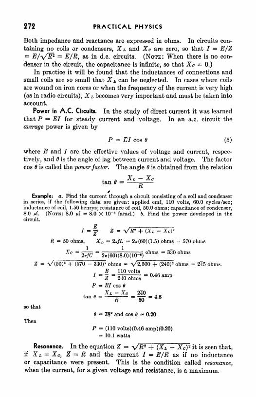
272 PRACTICAL PHYSICS
Both impedance and reactance are expressed in ohms. In circuits con-
taining no coils or condensers, X L and Xc are zero, so that I = E/Z= E/\nR? = E/R, as in d.c. circuits. (NOTE: When there is no con-
denser in the circuit, the capacitance is infinite, so that Xc *=0.)
In practice it will be found that the inductances of connections andsmall coils are so small that X L can be neglected. In cases where coils
are wound on iron cores or when the frequency of the current is very high
(as in radio circuits), XL becomes very important and must be taken into
account.
Power in A.C. Circuits. In the study of direct current it was learned
that P = El for steady current and voltage. In an a.c. circuit the
average power is given by
P = LI cos 6 (5)
where E and I are the effective values of voltage and current, respec-
tively, and 6 is the angle of lag between current and voltage. The factor
cos is called the power factor. The angle 6 is obtained from the relation
j_ A XL Xctan = ~ -
it
Example: o. Find the current through a circuit consisting of a coil and condenserin series, if the following data are given: applied emf, 110 volts, 60.0 cycles /sec;inductance of coil, 1.50 henrys; resistance of coil, 50.0 ohms; capacitance of condenser,8.0 rf. (NOTE: 8.0 juf
= 8.0 X 10~6farad.) b. Find the power developed in the
circuit.
E=2'
z = v ft2 +
R = 50 ohms, XL = ZirfL 2*r(60)(1.5) ohms - 570 ohms
Xc = =1
- hms ~ 35 hms
Z - V(50) 2-f (570 - 330)
2 ohms * \/2,500 + (240)2 ohms = 245 ohms.
rE 110 volts
j _= _. . -3 o.46 ampZ 240 ohms ^
P - El cos $
* ax *<
~ xc 2? AQtan*- 5--^ -4.8
so that
78 and cos $ 0.20
Then
P = (110 volts) (0.46 amp) (0.20)= 10.1 watts
Resonance. In the equation Z = \/# 2 + (%L Xc)2 it is seen that,
if X L = XCy Z R and the current / = E/R as if no inductance
or capacitance were present. This is the condition called resonance,
when the current, for a given voltage and resistance, is a maximum.

ALTERNATING CURRENT 273
A.C. Generators. Almost any d.c. generator will produce an alter-
nating current if the commutator is replaced by a pair of slip rings
properly connected to the armature coils. It is simpler and more
economical, however, to construct an a.c. generator with the armature
AJtrrnat,'np>/CurrentC/roift
c ,
FIG. 4. Diagram of a four-pole, rotating-field a.c. generator. The magnetic field is excited
by a separate d.c. generator.
coils stationary and rotating magnetic poles, and most commercial a.c.
generators are so made. A diagram of such a generator is shown in
Fig. 4. The emf goes through one complete cycle as a pair of poles
passes a coil. The frequency thus depends upon the number of poles
and the speed of rotation. The emf
produced is proportional to the strength
of the field and to the number of turns
on the coils as well as to the number of
poles and the speed of rotation. In de-
signing the generator the speed and
number of poles are fixed to give the de-
sired frequency and the remaining two
factors are then adjusted to give the
necessary emf. The field magnets are
usually excited by current from a small
d.c. generator, which is operated as a
separate machine.
In many a.c. generators the arma-
ture is wound with two or three sepa-
rate coils displaced somewhat in position from each other so that
the peak emf is reached at different times. If there are two coils, the
emfs vary as shown in the graph of Fig. 5fe. The emf of one coil is zero
when that of the other has its maximum value. Such a machine is called
''
(c)
FIG. 5. Variation of emf withtime for (a) single-phase generator,
(6) two-phase generator, (c) three-
phase generator.

274 PRACTICAL PHYSICS
a two-phase generator. The more common three-phase generator has
three coils so placed that the emf varies as shown in Fig. 5c. An advan-
tage of the two- or three-phase machine is the more uniform flow of power.Induction Motor. The most common type of a.c. motor is the
induction motor. Its operation depends upon an induced current set upin the closed armature by means of a rotating magnetic field. In Fig. 6
are shown the field connections of a two-
phase induction motor. The poles are
connected in pairs to the two windings.At the instant that the current is greatest
in line 1, pole a is an N pole, c is an $ pole,
and both b and d are unmagnetized since
the current in line 2 is zero (Fig. 5). Aquarter cycle later 6 has become anN pole,
d an & pole, while a and c are unmag-netized. After the next quarter cycle, c
is an N pole, and later d becomes an Npole. In one complete cycle, therefore,
the 2V pole rotates successively from a to
b to c to d, while at the same time the S
pole rotates from c to d to a to b. Effectively the magnetic field rotates
at the rate of one rotation for each cycle.
If a closed conductor is placed between the poles, a current will be
induced in it as the field rotates. The current will be in such direction
as to oppose the turning of the field. As a result, there will be a torque
tending to turn the conductor, and the machine becomes a motor.
Both two-phase and three-phase motors are self-starting but a single-
phase motor is not. For such motors a special starting device must be
provided.
SUMMARY
For sinusoidal, alternating current,
Zeff= 0.707/mai
UN2FIG. 6. Rotating magnetic field of
a two-phase induction motor.
The voltage per turn in the secondary coil of an efficient transformer
is only slightly smaller than in the primary coil. Hence the transformer
can be used to step up or step down the voltage at will.
^E, Na
The line loss is proportional to the square of the current, so that high
voltage and low current are desirable in transmission lines.
The relation E = IR is valid only in the case of a steady current,
though it can be used without appreciable error for a.c. circuits in which
the frequency is low and there are no condensers or large coils.

ALTERNATING CURRENT 275
Self-inductance L is the ratio of the induced emf to the rate of changeof the current.
" ~A//*
The capacitance of a condenser is the ratio of the charge to the poten-tial difference.
In an a.c. circuit, 7 = E/Z, in which Z, the impedance is given by
z = V# 2 + (XL - XcY1X L = 27T/L and Arc =
27T/C
where /is frequency, L is inductance, C is capacitance, and X is reactance.
The power developed is
P = #/ cos
V _ V_where tan 6 = ^-5 - and cos is called the power factor.
L\i
Resonance occurs when X L = -STc, making Z = 72.
QUESTIONS AND PROBLEMS
1. A condenser has a maximum rating of 550 (peak) volts. What is the
highest a.c. voltage (effective) across which it can safely be connected?
2. The primary and secondary coils of a transformer have 500 and 2,500
turns respectively. If the primary is connected to a 110-volt a.c. line, what
will be the voltage across the secondary? If the secondary (instead) were
connected to the 110-volt line, what voltage would be developed in the smaller
coil?' Ans. 550 volts; 22 volts.
3. Find the power loss in a transmission line whose resistance is 1.5 ohms,if 50 kw are delivered to the line (a) at 50,000 volts, (b) at 5,000 volts.
4. What is the reactance of a 0.60-henry coil on a 60-cycle line? What is
the current if the applied voltage is 110 volts and the coil resistance is 100 ohms?Ans. 230 ohms
;0.44 amp.
5. What is the reactance of a 2-juf condenser on a 110-volt, 60-cycle line?
What is the current?
6. A 0.10-henry coil (resistance, 100 ohms) and a 10-;uf condenser are con-
nected in series across a 110-volt a.c. line. Find the current and the power if
the frequency is (a) 60 cycles/sec, (b) 25 cycles/sec.
Ans. 0.44 amp; 19 watts; 0.17 amp; 3.1 watts.
7. Compare the growth of currents in inductive and noninductive circuits.
Sketch a curve of current vs. time for a circuit of high inductance; for one of low
inductance.
276 PRACTICAL PHYSICS
8. What is the self-inductance of a circuit in which there is induced an emf
of 100 volts when the current in the circuit changes uniformly from 1 to 5 ampin 0.3 sec? Ans. 7.5 henrys,
9. A steady emf of 110 volts is applied to a coil of wire. When the current
has reached three-fourths of its maximum value, it is changing at the rate ol
5 amp/sec. At this instant the induced emf is 27.5 volts. Find the self-induct-
ance of the coil.
10. An impressed emf of 50 volts at the instant of closing the circuit causes the
current in a coil to increase at the rate of 20 amp/sec. Find the self-inductance
of the coil. Ans. 2.5 henrys.
11. A certain amount of power is to be sent over each of two transmission
lines to a distant point. The first line operates at 220 volts, the second at 11,000
volts* What must be the relative diameters of the line wires if the ''line loss"
is to be identical in the two cases?
EXPERIMENT
Resistance, Reactance, and Impedance
Apparatus: Choke coil; soft iron core; a.c. ammeter; a.c. voltmeter;
electric lamp; condenser.
Measure thed.c. resistance of the choke coil by the voltmeter-ammeter
method, Using a storage battery as a source.
Connect the same coil in series with a lamp and a.c. ammeter to the
a.c. lighting circuit. Place the a.c. voltmeter across the coil. Fromthe ammeter and voltmeter readings compute the impedance Z of the
coil by means of Eq. (3). From the value of Z and the resistance Rcompute the value of the reactance X from the relation Z 2 = R 2 + X2
.
Since there is no condenser, the reactance is inductive and X =2irfL.
Compute the value of L.
Repeat this procedure with an iron core in the coil. How doe ts
the presence of the iron core affect the impedance? the reactance?
the inductance?
Connect a condenser and ammeter in series with the battery. Is
there any current? Why?Connect the condenser, lamp and a.c, ammeter in series to the a.c. line
with the a.c. voltmeter across condenser and ammeter. From the
ammeter and voltmeter readings compute the impedance of the condenser.
Assuming that it consists entirely of capacitive reactance, compute the
capacitance from the relation
"27T/C
If a suitable wattmeter is available, the power taken by the lamp,
coil, and condenser, separately, may be measured. From the measured
power and the voltage and current observations the power factor maybe determined.

CHAPTER 28
COMMUNICATION SYSTEMS; ELECTRONICS
Among the most important applications of scientific discoveries to
daily life are those that have produced the rapid and revolutionary
improvement of communication methods. A century ago messages
were sent by foot, horseback, boat, or stagecoach. The development of
first the telegraph and later the telephone and radio has brought the most
remote parts of the world into close contact. The invention and appli-
cation of the electromagnet (Chap. 26) made possible the telegraph and
telephone. The development of the electron tube made possible long-
distance telephony and the rapid extension of radio communication.
Telegraph. In 1837 the American painter and inventor Samuel F. B.
Morse devised a system of telegraphy, the basic principle of which was
the actuation of an electromagnet by current remotely controlled.
Signals are transmitted by manipulating a key in accordance with a code
and are received by listening to the clicks made by a sounder (Fig. 1)
277

278 PRACTICAL PHYSICS
as its armature A is attracted by the magnet M and then restored to its
original position by spring S, when released. Only a single wire is needed
between key and sounder, the circuit being completed by connections to
ground. In long-distance telegraphy, owing to the resistance of the
circuit, the current received may be too small to operate a sounder. In
its place is substituted a relay, a similar
instrument, the magnet of which is
wound with many turns so that a
feeble current is sufficient to actuate
the armature.' When drawn toward
the magnet, the armature closes a
second circuit through an ordinarysounder operated by a local battery.
Figure 2 shows the circuit of a tele-
graph arranged to allow transmission
in either direction between two widely separated stations. When the
line is idle, switches 5 and 5' are kept closed and the circuit includes the
generators B and B', relays R and 72', line L, and ground from G to (?'.
By opening s and depressing key K for short or long intervals, an oper-ator can send a dot-and-dash message from the left-hand station to the
other. The current pulses in the relay R f
operate the local circuit and
FIG. 1. A telegraph sounder.
FIG. 2. A telegraph circuit with relays.
sounder S'yor the relay may be used to operate a second line to a more
distant station.
Telephone. A telephone circuit for the transmission of speech con-sists of a transmitter for producing a variable current in response to sound
waves, and a receiver for converting this current into sound waves that
reproduce the original sounds. The transmitter (Fig. 3) contains carbon

COMMUNICATION SYSTEMS; ELECTRONICS 279
granules, through which the current must pass, which are confined in a
chamber, one wall of which is a flexible diaphragm. When the voice'is
directed against this diaphragm, the variations of air pressure alter the
area of contact between the carbon granules, thus changing their resist-
ance and producing a corresponding fluctuation in the current.
The receiver is a small electromagnet combined with a permanentmagnet and a thin circular diaphragm supported near the poles. Fluctu-
ations in the current in the electromagnet cause vibrations of the dia-
phragm and thus produce sound. The simplest telephone is a series
circuit, including a transmitter, receiver, and battery. A practicalcircuit is considerably more complex, including an induction coU to
reduce line losses, provision for operating a signal bell by superposed
...[ ,_
. V,/,?
" "
.
, CtfP
Fio. 3. Cross section of telephone transmitter and receiver.
alternating current, and electron-tube repeaters to amplify signals that
are transmitted over long lines.
Radio. Communication by radio depends upon the production of elec-
tric oscillations in a circuit designed to radiate energy in waves. These
waves are of the same nature as light or heat waves such as those received
from the sun.
Electric Oscillations. In the study of mechanical vibration (Chap. 20)
it was found that oscillations can be set up in a body if certain conditions
are present. The body must have inertia, a distortion must produce a
restoring force, and the friction must not be too great. A mass sus-
pended in air by a spring meets these conditions.
In an electrical circuit analogous conditions are necessary for electrical
oscillations. Just as inertia opposes change in mechanical motion,
inductance opposes change in the flow of electrons. The building up of
charges on plates of condensers causes a restoring force on the electrons
in the circuit. Resistance causes electrical energy to be changed into
heat, just as friction changes mechanical energy to heat. To produceelectrical oscillations it is necessary to have inductance,"capacitance, and

280 PRACTICAL PHYSICS
not too much resistance. As the frequency of mechanical vibrations
depends upon the inertia (mass) and the restoring force (force constant),
so the frequency of electrical oscillations depends upon inductance and
capacitance.
In the circuit of Fig. 4 a capacitance C and an inductance L are con-
nected in series with a sphere gap G. The sphere gap has a high resistance
it c until a spark jumps across but low resistance
||1 after it jumps. If the voltage across G is
G ^ gradually increased, the charge on the con-
denser will increase. When the voltage across
FTG. 4. Circuit for pro-becomes high enough, a spark will jump
auction of electrical osciiia- and the condenser will then discharge. Thecurrent does not stop when the condenser is
completely discharged but continues, charging the condenser in the oppo-site direction. It then discharges again, the current reversing in the cir-
cuit. The current oscillations continue until all the energy stored in the
condenser has been converted into heat by the resistance of the circuit.
The frequency of the oscillation is determined by the values of L andC and is the frequency for which the impedance of the circuit is the least,
that is, the frequency for which the reactance is zero. From Chap. 27,
X =27T/L
-
or
/ = -7= (1)
where L is the inductance in henrys and C is the capacitance in farads.
Resonance. If an alternating voltage is
applied to a series circuit in which there is
both capacitance and inductance, oscillations
are set up the amplitudes of which dependupon the frequency. If the frequency of the
impressed voltage is the same as the natural
frequency of the circuit, the current, will bemuch larger than for other frequencies. The
/Circuit is then Said to be in resonance. FIG. 5. Resonance in a series
Figure 5 shows how the current varies with circuit.
the frequency in such a circuit if the resistance is small (solid curve).If the resistance is increased, the current values are decreased (dotted
curve). For a very small range of frequencies the current is rather large,but outside this region the current is small. This response over a verylimited range of frequencies makes possible the tuning of a radio circuit.
The incoming wave produces in the receiver a voltage that varies with a

COMMUNICATION SYSTEMS, ELECTRONICS 281
fixed frequency, and the circuit is tuned so that its natural frequency is the
same as that of the incoming wave. The tuning Is usually done byadjusting the value of the capacitance.
Although oscillations can be produced and waves can be detected in
several ways, the most satisfactory methods use electron tubes.
Thermionic Emission. In metallic conductors there are many free
electrons in addition to the atoms and molecules. Both molecules andfree electrons take part in the thermal motion. The electrons, being of
smaller mass, have much higher average speeds than the molecules. If
the temperature is raised sufficiently, many of the electrons have enoughspeed to leave the metal. The emission of electrons by the heated metalis called thermionic emission. The temperature at which appreciableemission lakes place depends upon the type of metal and the condition
of its surface.
As electrons are emitted by a heated wire, the wire becomes positively
charged, while the electrons collect in a " cloud" around it. This chargearound the filament is called a space charge. Other electrons are attracted
by the wire and repelled by the space charge. These effects combine to
stop the emission of electrons.
Diode. If a filament and plate are sealed in an evacuated tube, a
two-element electron tube, or diode (Fig. 6), is
formed. When the filament is heated by an electric
current, electrons are emitted. If the plate is madepositive with respect to the filament, electrons will
be attracted to the plate and a current will flow in
the tube. If, however, the plate is made negativewith respect to the filament, the electrons will be
repelled and no current will flow. The diode thus
acts as a valve, permitting flow in one direction but Heating Filament
not in the other. If it is connected in an a.c. line,Fl - 6<~A diode -
the diode acts as a rectifier, the current flowing during the half cycle in
which the plate is positive.
If the plate is positive with respect to the filament, electrons will flow
across, but not all the electrons that come out of the filament reach the
plate, because of the space charge. Figure 7 shows a graph of potential
against distance across the tube. Because of the space charge, the
potential out to A is below the potential of the grid. An electron will
reach the plate only if it has sufficient speed as it leaves the filament
to reach B, the point of lowest potential, before it is stopped. If the
difference of potential Ep between filament and plate is increased,the potential at B rises, and more electrons will be able to reach it. Thecurrent depends upon Ep,
as is shown in the graph of Fig. 8. Atthe higher potentials the current no longer increases, becatise, when A has

282 PRACTICAL PHYSICS
been pushed back to the filament, all the electrons emitted reach the
plate, and further increase in Ep produces no change. Saturation ha?
been reached.
If the plate potential is kept constant while the filament temperatureis increased, the current increases at first but reaches saturation because
of the increase in the electron cloud around the filament.
Distance s
BFIG. 7. Variation of potential
filament and plate.
between Fia. 8.- -Plate current as a functionof plate potential.
Triodes. If a third element, the grid, is inserted into the tube near
the filament, it can be used as a control for the tube current. Such a tube
is called a triode, or three-element tube. The grid usually consists of a
helix, or spiral, of fine wire so that the electrons may freely pass throughit. Small variations of the grid potentialwill cause large changes in the plate cur-
rent, much larger than those caused bysimilar changes in the plate potential. If
the grid is kept negative with respect to
the filament, electrons will not be attracted
to the grid itself, and there will be no grid
current. A typical variation of plate cur-
rent with grid potential Eg is shown in
Fig. 9. A part of the curve is practicallya straight line. If the grid voltage varies
about a value in this region, the fluctua-
tions of the plate current will have the
same shape as the variation of grid volt-
age. The tube will amplify the disturbance without distorting it.
The triode also acts as a detector or partial rectifier if the grid voltageis adjusted to the bend of the curve. With this adjustment an increase
in grid voltage above the average produces considerable increase in platecurrent, but a decrease in grid voltage causes little change in plate
FIG. 9. Operating characteristics
of a vacuum-tube amplifier.

COMMUNICATION SYSTEMS, ELECTRONICS 283
current. The plate current fluctuates in response to the grid signal, butthe fluctuations are largely on one side of the steady current.
In Fig. 10 is shown a simple receiving circuit. When the waves strike
the antenna, they set up oscillations in the circuit, which is tuned to the
frequency of the waves. This causes the potential of the grid to vary,and the tube acting as a detector permits the flow of a current that
pulsates according to the amplitude of the signal. This causes the ear-
phones to emit sound.
In radio work, triode electron tubes are used to produce high-
frequency oscillations, to act as detectors or rectifiers, and to act as
i
FIG. 10. Simple receiving circuit.
amplifiers. Tubes of different characteristics are used for each of these
purposes.
In many tubes the filament merely acts as a heater of a sleeve that
covers it and is insulated from it. The sleeve, or cathode, is the elementthat emits electrons.
For many purposes tubes are constructed with more than three active
elements. They are named from the number of active elements, as
tetrode, pentode, etc.
SUMMARY
The telegraph transmits signals by use of electromagnets controlled bya key to open and close the circuit. Since the current in a long line is
insufficient to operate a sounder, a relay is used to operate a local circuit.
The telephone transmitter produces variations in an electric current in
response to the motion of the diaphragm. The receiver is an electromag-net that causes a motion of a magnetic diaphragm in response to the
electrical impulse received.
Electric oscillations occur in circuits that have inductance, capaci-
tance, and low resistance.
The frequency of oscillation is given by the equation

284 PRACTKAL PHYSICS
If a metallic conductor is heated to a sufficiently high temperature,
electrons are emitted. This is called thermionic emission.
Two-element electron tubes, or diodes, act as rectifiers in a.c. circuits.
Three-element electron tubes, or triodes, may be used as amplifiers,
oscillators, or detectors.
QUESTIONS AND PROBLEMS
1. What conditions are necessary for the production of oscillations?
2. What is electrical resonance?
3. Explain the action of a diode as a rectifier.
4. Explain the action of a triode as an amplifier.
6. Explain the action of a triode as a detector.
6. What inductance must be placed in series with a 2-juf condenser to produceresonance at 60 cycles? at 500 cycles? Ans. 3.52 henrys; 0.051 henry.
7. A variable condenser has a range from 0.0000055 to 0.0005 juf. If it is
connected in series with a coil whose inductance is 5 millihenrys, what is the
frequency range of the circuit?
EXPERIMENT
Characteristics of Electron Tubes
Apparatus: Storage battery; dry cells; rheostat (20 ohm) ;2 rheostats
(1,000 ohms); 3 S.P.S.T. switches; 1 D.P.D.T. switch; voltmeter (0 to 10
volts); voltmeter (0 to 120 volts); ammeter (0 to 1 amp); milliammeter
(0 to 10 ma) ;electron tube.
The variation of plate current with plate potential for a two-element
electron tube can be studied by the use of a circuit similar to that in
.nIIOKD.C.
FIG. 11. Circuit for determining variation of plate current with plate potential.
Fig. 11. The d.c. source may be B batteries, a generator, or other suit-
able source. Use a simple filament tube (for example, 01A) and connect
the grid to the filament. Adjust the filament current to the rated value
of the tube Beginning with a plate potential of zero, take a series of
readings of plate current and plate potential from zero up to the rated
voltage of the tube. Plot a curve of plate current against plate voltage.
Does the curve show saturation?
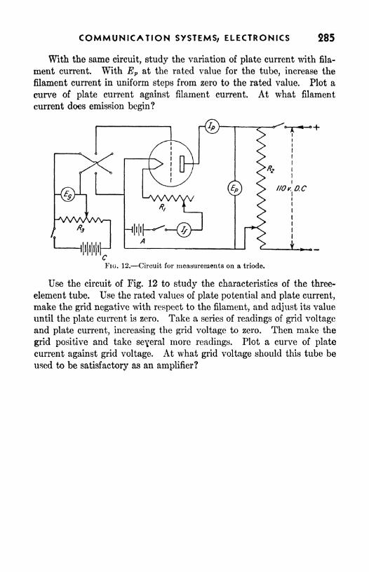
COMMUNICATION SYSTEMS, ELECTRONICS 285
With the same circuit, study the variation of plate current with fila-
ment current. With Ep at the rated value for the tube, increase the
filament current in uniform steps from zero to the rated value. Plot a
curve of plate current against filament current. At what filament
current does emission begin?
FIG. 12. Circuit for measurements on a triode.
Use the circuit of Fig. 12 to study the characteristics of the three-
element tube. Use the rated values of plate potential and plate current,
make the grid negative with respect to the filament, and adjust its value
until the plate current is zero. Take a series of readings of grid voltage
and plate current, increasing the grid voltage to zero. Then make the
grid positive and take seyeral more readings. Plot a curve of plate
current against grid voltage. At what grid voltage should this tube be
used to be satisfactory as an amplifier?

L W&ve J**~len*lfi
~~H
CHAPTER 29
SOUND WAVES
Many of the phenomena of nature are satisfactorily described in
terms of wave motion. There are waves on the surface of water; waves
are used to show the behavior of light as it is transmitted through space
or materials; the radio is dependent upon electromagnetic waves;and all the varied manifestations of sound are explained by the wave
theory. The concepts of frequency, amplitude, period, simple harmonic
motion, and resonance, which were discussed in Chap. 20, often occur in
the consideration of wave motion and should be reviewed in connection
with the study of the chapters on sound.
Nature of Sound. Sound may be thought of as an agency capable of
affecting the sense of hearing. In order to understand the production
and propagation of sound we must examine the physical nature of this
agency.If one plucks a tightly stretched string, he observes that the string
vibrates. During the time that the vibrations are seen he also hears a
sound, but as soon as the vibration stops the sound is no longer heard;
hence he associates the vibration of the string with the sound. All
sounds arise from the vibration of material bodies.
Suppose a small rubber balloon is partly inflated and attached to a
bicycle pump. If the piston is pushed downward quickly, the balloon
286

SOUND WAVES 287
expands and the layer of air next to it is compressed. This layer of air
will, in turn, compress the layer beyond it and so on. The compressiontLat was started by the expansion of the balloon will thus travel awayfrom the source in the surrounding medium. If the piston is drawn
upward, the balloon contracts and the adjacent layer of air is rarefied.
As in the case of the compression the rarefaction travels out from the
source. If the piston is moved up and down at regular intervals, a
succession of compressions and rarefactions will travel out from the
source (Fig. 1). Such a regular succession of disturbances travelingout from a source constitutes a wave motion. The compression and the
following rarefaction make up a compressional wave.
FIG. 1. Compressional waves produced by an expanding and contracting balloon.
If the up-and-down motion of the piston is made rapid enough, anobsjrver in the neighborhood will be able to hear a sound as the dis-
turbance reaches his ear. These compressional waves are able to causethe sensation of hearing and are referred to as sound waves.
In the wave motion no particle travels very far from its normal
position. It is displaced a short distance forward, then returned to its
initial position, and displaced a short distance backward. In compres-sional waves the particle thus vibrates back and forth about a normal
position, the direction of vibration being parallel to the direction in
which the waves travel. Such waves are called longitudinal waves.
In other types of waves the individual particles may vibrate at right
an/les to the direction of motion of the wave. Such a wave is called a
transverse wave. A wave moving along a stretched string is usuallyof this typo. In still other waves the motion of the particles is a combina-tion of the two motions just described. In all these cases tho particlesof the medium remain close to their normal position while the disturbance
moves through the medium.

288 PRACTICAL PHYSICS
The Medium. Since a sound wave involves compression and expan-sion of some material, it cannot proceed without the presence of a material
medium. No sound can be transmitted through a vacuum. This
fact can be demonstrated experimentally by mounting an electric bell
under a bell jar and pumping the air out while the bell is ringing (Fig. 2).
As the air is removed, the sound becomes fainter and fainter until it
finally ceases, but it again becomes audible if the air is allowed to return.
3 TOAIRPUMPFIG. 2. Sound is not transmitted through a vacuum.
Sound waves wUl travel through any elastic material. We are all
familiar with sounds transmitted through windows, walls, and floors
of a building. Submarines are detected by the underwater sound waves
produced by their propellers. The sound of an approaching train maybe heard by waves carried through the rails as well as by those trans-
mitted through the air. In all materials the alternate compressions and
rarefactions are transmitted in the same manner as they are in air.
Speed of Sound. If one watches the firing of a gun at a considerable
distance, he will see the smoke of the discharge before he hears the report.
This delay represents the time required for the sound to travel from the
gun to the observer (the light reaches him almost instantaneously).
The speed of sound may be found directly by measuring the time requiredfor the waves to travel a measured distance. It varies greatly with the
TABLE I. SPEED OF SOUND AT 0C (32F) THROUGH VARIOUSMEDIUMS

SOUND WAVES 289
material through which it travels. Table I shows values for several
common substances.
The speed of sound varies with the temperature of the medium trans-
mitting it. For solids and liquids thio change in speed is small and usually
can be neglected. For gases, however, the change is rather large. It
has been shown that for gases the speeds at any two temperatures are
related by the expression ;
vl"
where V\ and F 2 are the speeds and T\ and 7"2 are the respective absolute
temperatures.
Example: What is the speed of sound in air at 25C (77F)?
From Table I the speed at 0C (32F) is 1,087 ft/sec.
F26c 273 + 25'
1,087 ft/sec \ 273
TVc = (1,087 ft/sec) J^y = 1,137 ft/sec
For small differences in temperature we can consider the change in
speed to be a constant amount for each degree change in temperature,
amounting to a difference of about 2 ft/sec per C (1.1 ft/sec per F) for
temperatures near 0C. The change is to be added if the temperatureincreases and subtracted if it decreases.
Refraction of Sound. In a uniform medium at rest sound travels with
constant speed in all directions. If, however, the medium is not uniform,
the sound will not spread out uniformly but the direction of travel changesbecause the speed is greater in one part of the medium. The bending of
sound due to change of speed is called refraction.
The spreading of sound in the open air is an example of this effect.
If the air were at rest and at a uniform temperature throughout, the
sound would travel uniformly in all directions. Rarely, if ever, does
this condition exist, for the air is seldom at rest and almost never is the
temperature uniform. On a clear summer day the surface of the earth
is heated and the air immediately adjacent to the surface has a much
higher temperature than the layers above. Since the speed of sound
increases as the temperature rises, the sound travels faster near the
surface than it does at higher levels. As a result of this difference in
speed the wave is bent away from the surface, as shown in Fig. 3a. Toan observer on the surface, sound does not appear to travel very far on
such a day since it is deflected away from him.
On a clear night the ground cools more rapidly than the air above,hence the layer of air adjacent to the ground becomes cooler than that

290 PRACTICAL PHYSICS
at a higher level. As a result of this condition sound travels faster at the
higher level than at the lower level and consequently is bent downward,as shown in Fig. 36. Since the sound comes down to the surface, it
appears to carry greater distances than at other times.
Wind is also a factor in refraction of sound. In discussing the speedof sound in air we assume that the air is stationary. If the air is moving,
SOUND
WARMSURFACE
(<*)
SOUND
COLD SURFACE
(b)
FIG. 3. Refraction of sound due to temperature difference.
sound travels through the moving medium with its usual speed relative
to the air but its speed relative to the ground is increased or decreased bythe amount of the speed of the air, depending upon whether the air is
moving in the same direction as the sound or the opposite. If the air
speed is different at various levels, the direction of travel of sound is
W/ND
FIG. 4. Refraction of sound due to wind.
changed, as shown in Fig. 4. Friction causes the wind speed to be lower
at the surface than at a higher level, hence sound traveling againstthe wind is bent upward and leaves the surface while that traveling with
is bent downward. As a result, the observer on the surface
carries farther with the wind than against the wind.

SOUND WAVES 291
Combinations of the two phenomena just discussed may cause some
effects that seem very peculiar. Sound may carry over a mountain and
be heard on the other side while similar sounds are not transmitted hi
the other direction. Frequently sound "skips
" a region, that is, it is
audible near the source and also at a considerable distance but at inter-
mediate distances it is not audible. Such an effect is quite troublesome
in the operation of such devices as foghorns. Refraction effects increase
the difficulties in locating airplanes, guns, or submarines by means of
sound waves.
Frequency and Wave Length. When waves are sent out by a vibrating
body, the number of waves per second is the same as the number of
complete vibrations per second of the source. The number of vibrations
per second is called the frequency of the source and represents as well the
frequency of the wave. The wave length is defined as the distance between
Vt (nt WAVES)FIG. 5.- Graph showing pressure distribution in a sound wave.
two successive compressions or between two successive rarefactions in
the wave motion. The curve in Fig. 5 represents a sound wave. Theordinate of the curve represents, at a single instant, the pressure in the
medium at each point higher than normal pressure at the compressionsand lower at the rarefactions. The curve is merely a graph of the pressure
distribution in the medium and not a picture of the wave. The distance /
on this graph is one wave length. It may be measured between one crest
and the next, between one trough and the next, or in general, between
any point and the next similar one in the wave motion.
There is a simple relation between the frequency n, the wave length Z,
and the wave speed V. Suppose the source vibrates for a time t. Thenumber of waves sent out will be nt. At the end of this time, the first
wave will have reached a point B in Fig. 5. The distance AB is equal to
Vt and this distance is equal to the number of waves times the lengthof each wave. Therefore
Vt nil
or
V = nl
This relationship holds for any wave motion whatsoeverr
(2)

292 PRACTICAL PHYSICS
Example: What is the wave length of a sound of frequency 256 vibrations per
second?From Eq. 2,
Vn
1,100 ft/sec
256/sec4.3ft
Reflection of Sound Waves. When ripples on water encounter
an obstacle, a new set of ripples starts out from the obstruction. The
waves are said to be reflected. If the surface of the obstacle is at right
angles to the direction in which the ripples travel, the reflected ripples
will travel back in the direction from which the ripples came (Fig. 6).
For other positions of the obstacle the ripples will be reflected in new
directions.
i
\
RECEWER
FIG. 6. Reflection of wavesby a plane surface.
FIG. 7. Measuring ocean depth by meansof a fathometer.
In a similar manner sound waves are reflected from surfaces such as
walb, mount ins, clouds, or the ground. A s^und is seldom heard with-
out accompanying reflections, especially inside a building where the walls
and furniture supply the reflecting surfaces. The "rolling" of thunderis largely due to successive reflections from clouds and land surfaces.
The ear is able to distinguish two sounds as separate only if they reach
it at least 0.1 sec apart; otherwise, they blend in the hearing mechanismto give the impression of a single sound. If a sound of short duration is
reflected back to the observer after 0. 1 sec or more, he hears it as a repeti-
tion of the original sound; an echo. In order that an echo may occur,the reflecting surface must be at least 55 ft away, since sound, travelingat a speed of 1,100 ft/sec will go the 110 ft from the observer to the
reflector and return in 0. 1 sec.
Use is made of the reflection of sound waves in the fathometer, aninstrument for determining ocean depths (Fig. 7). A sound pulse is sent
out wader water from a ship. After being reflected from the sea bottom

SOUND WAVES 293
the returned sound is detected by an 'underwater receiver also mounted
on the ship, and the time interval is recorded by a special device. If the
elapsed time and the speed of sound in water are known, the depth of the
sea at that point can be computed. Measurements may thus be madealmost continuously as the ship moves along.
Sound waves may be reflected from curved surfaces for the purpose of
making more energy travel in a desired direction, thus making the sound
more readily audible at a distance. The curved sounding board placedbehind a speaker in an auditorium throws forward some of the sound
waves that would otherwise spread in other directions and be lost to the
audience. In the same way, a horn may be used to collect sound waves
and convey their energy to an ear or other detector.
Interference of Waves: Beats. Whenever two wave motions pass
through a single region at the same time, the motion of the particles in
the medium will be the result of the combined disturbances of the two
sets of waves. The effects due to the combined action of the two sets of
waves are known in general as interference and are important in all typesof wave motion.
If a shrill whistle is blown continuously in a room whose walls are goodreflectors of sound, an observer moving about the room will notice that
the sound is exceptionally loud at certain points and unusually faint at
others. At places where a compression of the reflected wave arrives at
the same time as a compression of the direct wave their effects add
together and the sound is loud;at places where a rarefaction of one wave
arrives with a compression of the other their effects partly or whollycancel and the sound is faint.
Contrasted with the phenomenon of interference in space, we mayhave two sets of sound waves of slightly different frequency sent throughthe air at the same time. An observer will note a regular swelling and
fading of the sound, which is called beats. Since the compressions and
rarefactions are spaced farther apart in one set of waves than in the other,
at one instant two compressions arrive at the ear of the observer together
and the sound is loud. A little later a compression of one set of waves
arrives with the rarefaction of the other and the sound is faint. Thenumber of beats occurring each second is equal to the difference of the
two .frequencies. Thus, in Fig. 8, two sets of waves of frequency 10
vib/sec and 12 vib/sec, respectively, combine and give a resultant sound
wave which fluctuates in amplitude 12 minus 10, or 2 times per second.
Beats are readily demonstrated by sounding identical tuning forks, one
of which has been "loaded" by placing a bit of soft wax on one prong,
thus reducing the frequency of this fork slightly.
Absorption of Sound. As a wave motion passes through a mediumor from one medium to another, some of the regular motion of

294 PRACTICAL PHVSICS
particles in the wave motion is converted into irregular motion (heat).
This constitutes absorption of energy from the wave. In some materials
there is very little absorption of sound as it passes through, and in others
the absorption is large. Porous materials, such as hair felt, are goodabsorbers of sound since much of the energy is changed to heat energy in
the pores. Whenever it is necessary to reduce the sound transmitted
through walls or floors or that reflected from wall, a material should be
A A A\r\j v v v
FIG. 8. Two \vaves of different frequency combined to cau&e beats.
used that is a good absorber. Rugs, draperies, porous plasters, felts, and
other porous materials are used for this purpose.
SUMMARY
Sound is a disturbance of the type capable of being detected by the
ear. It is produced by the vibration of some material body.Sound is transmitted through air or any other material in the form of
longitudinal (compressional) waves.
The speed of sound waves in air at ordinary temperatures is about
1,100 ft/sec.
A sound wave may be refracted if the speed is not the same in all partsof the medium or if parts of the medium are moving. It may also be
refracted as it passes from one medium to another.
The wave length is the distance between two successive compressionsor between two successive rarefactions.
The frequency of a vibrating body is the number of complete vibrations
per second. The frequency of the wave motion sent out by a source is
the number of waves passing a given point per second. The two fre-
quencies have the same value.

SOUND WAVES 295
In any wave motion, the velocity, frequency, and wave length are
related by the equation, V = nL
The direction of advance of sound waves may be changed by reflection
from suitable surfaces.
An echo occurs when a reflected sound wave returns to the observer
0.1 sec or more after the original wave reaches him, so that a distinct
repetition of the original sound is perceived.
Two sets of waves of the same frequency may mutually reinforce or
cancel each other at a given place. This is called interference.
Beats occur when two sources of different frequency are soundedat the same time. The resultant sound periodically rises and falls
in intensity as the waves alternately reinforce and cancel each
other.
Absorption occurs when the regular motion of the particles in a waveis converted into irregular motion (heat).
QUESTIONS AND PROBLEMS
1. Explain how the distance, in miles, of a thunder storm may be found
approximately by counting the number of seconds elapsing between the flash
of lightning and the arrival of the sound of the thunder and dividing the result
by five.
2. If the earth's atmosphere extended uniformly as far as the moon, how
long would it take sound to travel that distance? Take the distance to be
240,000 mi, and use 1,100 ft/sec as the speed of sound. What actually happensto a sound in the earth's atmosphere? Am. 13.3 days.
3. Explain why stroking the tip of a fingernail across a linen book cover
produces a musical tone.
4. What will be the wave length in air of the note emitted by a string vibratingat 440 vib/sec when the temperature is 59F? Ans. 2.5 ft.
5. In Statuary Hall of the Capitol at Washington, a person standing a fewfeet from the wall can hear the whispering of another person who stands facingthe wall at the corresponding point on the opposite side, 50 ft away. At points
between, the sound is not heard. Explain.6. By means of Eq. (1) verify the statement that the speed of sound in air
increases about 2 ft/sec for each centigrade degree rise in temperature from 0C.7. A track worker pounds on a steel rail at the rate of one blow per second.
A flagman some distance up the line hears the sound through the rails at the
same instant that he hears the previous blow through the air. How far awayis he? Ans. 1,176 ft.
8. The sound of the torpedoing of a ship is received by the underwater detector
of a patrol vessel 18 sec before it is heard through the air. How far away wasthe ship? Take the speed of sound in sea water to be 4,800 ft/sec.
Ans. 5 mi.
9. A stone is dropped into a mine shaft 400 ft deep. How.much later will
the impact be heard? Ans. 5.36 sec.

296 PRACTICAL PHYSICS
DEMONSTRATION EXPERIMENTS
Apparatus: Tuning fork; rubber mallet; pith ball; spiral spring; table-
spoon; metronome; bell jar; air pump; toothed wheel; concave reflector;
ripple tank.
Set a tuning fork into vibration by striking it with a rubber mallet.
Notice that a sound is produced. Now allow one prong of the vibratingfork to touch a suspended pith ball, which will be thrown aside violently
(Fig. 9). This shows that a sounding body is actually in a state of
mechanical vibration.
Hang a long spiral spring from the ceiling. Grasp a few coils in one
hand in a compressed position and suddenly release them. Observe
that the compression passes onward in both directions along the spring
FIG. 9. Demonstrationof the vibration of a sound-
ing fork.
FIG. 10. Experimenting with
ripple tank.
the
and that it is reflected repeatedly from the ends. Repeat for a
"rarefaction."
Tie two pieces of string, each about 2 ft long, to the handle of a large
silver tablespoon at a point near its center of gravity. Hold the free end
of each cord in an ear by means of the finger and strike the suspended
spoon against a hard surface. The effective transmission of the vibration
through the cords will make the tone of the spoon seem startingly loud
and of a quality similar to that of a church bell
Mount % metronome under a bell jar, supporting it on cork, sponge
rubber, or hair tali, >o that it does not set the jar itself into vibration.
With the metronome sounding, pump out the air and note the fading of
the sound, showing that sound cannot be transmitted by a vacuum.
Readmitting the air will restore the sound.
Rotate a gear or toothed wheel by means of a variable speed motor or
on a hand-driven rotator, while holding a card against the teeth. Does

SOUND WAVES 297
the pitch of the tone change if the speed of the rotation is altered? Thesame effect may be shown by blowing a jet of air through regularly
spaced holes in a disk (siren disk).
Mount a watch at the focus of a concave reflector and turn the reflector
in various directions in the classroom. Is the sound much louder in the
forward direction? Explain this by discussing with the aid of a diagramthe way in which the sound waves are reflected from the curved surface.
Experiment with the reflection of waves from plane and curved
surfaces by means of a ripple tank. This may be merely a large photo-
graphic tray containing water, and the source of waves may be an eye
dropper (Fig. 10). The ripples are easily visible if the tank is illuminated
by an unshaded light suspended several feet above it.

CHAPTER 30
ACOUSTICS
The science, of acoustics includes the production, transmission, and
effects of sound. In architectural engineering the term is used in a
more restricted sense to refer to the qualities that determine the value
of a hall with respect to distinct hearing. We are primarily interested
in sound insofar as it affects our sense of hearing.
The hearing mechanism is able to distinguish between sounds that
come to the ear if they differ in one or more of the characteristics : pitch,
quality, and loudness. Each of these characteristics is associated with
physical characteristics of the sound waves that come to the ear.
Pitch and Frequency. Pitch is the characteristic of sound by which the
ear assigns it a place in a musical scale. The physical characteristic
associated with pitch is the frequency of the sound wave. A tuning fork
that gives a high-pitched sound is found to have a greater frequency of
vibration than one giving a lower pitched tone. The range of frequencyto which the human ear is sensitive depends somewhat upon the indi-
vidual but for the average normal ear it is from 20 to 20,000 vib/sec.The upper limit decreases, in general, as the age of the individual increases.
298

ACOUSTICS 299
The satisfactory reproduction of speech and music does not require a
range of frequencies as great as that to which the ear is sensitive. Tohave perfect fidelity of reproduction a range of from 100 to 8,000 vib/sec
is required for speech and from 40 to 14,000 vib/sec for orchestral music.
The frequency range of most sound-reproducing sytems, such as
radio, telephone, and phonograph, is considerably less than that of the
hearing range of the ear. A good radio transmitter and receiver in the
broadcast band will cover a range of from 40 to 8,000 vib/sec. This
range allows it to reproduce speech faithfully but it does detract from the
quality of orchestral music. If the frequency range is further restricted,
the quality of reproduction is correspondingly reduced.
Although pitch is associated principally with frequency, other factors
also influence the sensation. Increase in intensity of the sound causes a
decrease in pitch for a fixed frequency, especially at low frequencies. The
complexity of the sound wave also influences pitch.
Quality and Complexity. It is a fact of experience that a tone of a
given pitch sounded on the piano is easily distinguished from one of
exactly the same pitch sounded, for example, on the clarinet. Thedifference in the two tones is said to be one of tone quality. This charac-
teristic of sound is associated with the complexity of the sound wave that
arrives at the ear.
In Chap. 29 we considered the compressional wave sent out by a
balloon that expands and contracts as a piston moves back and forth.
The pressure changes in such a wave are represented by a graph (Fig. 5,
Chap. 29), which is a simple curve. A few other vibrating bodies send
out such simple waves but for most of them the wave is much more
complex.Fundamental and Overtones. Almost all bodies may vibrate in a
number of different ways. For example, a stretched string may vibrate
in one segment, or in two, or in general in any number of segments, as
shown in Fig. 1. Each of these various ways of vibration will have a
frequency different from the others. The simplest vibration (one seg-
ment) has the lowest frequency and is called the fundamental. The more
complicated vibrations give higher frequencies and are called overtones.
In the case of the string, the frequencies of the overtones are two, three,
four,, etc., times the frequency of the fundamental.
A vibrating body almost always combines several different ways of
vibration simultaneously. The sound waves sent out by such a source
are quite complex as shown by the graph of such a disturbance in Fig. 2.
We may consider such a complex wave as made up of a number of simple
waves, one for each manner of vibration of the source. The pressure at
each point will be the sum of the pressures of the component waves.
Figure 3 shows graphically two simple waves, a and 6, Combined to give

300 PRACTICAL PHYSICS
the complex wave c. The ordinate represents the pressure at each point.
By adding the ordinates of a and 6 for each point we get the ordinate for
Any complex wave can be resolved into a number of simple waves.c.
The more complex the wave the greater is the number of overtones that
contribute to it.
Fio. 1. A string vibrating in three
different forms, (a) fundamental, (6) first
overtone, and (c) third overtone.
FIG. 2. Graph of (a) a complex waveand (b) a simple wave.
The complexity of the wave, which determines the quality of the
sound, is controlled by the number and relative intensity of the overtones
that are present. A "pure" tone (no overtones) may not be as pleasing
as the "rich" tone of a violin, which contains ten or more overtones.
Loudness and Intensity. The loudness of a sound is the magnitude of
the auditory sensation produced by the sound. The intensity of sound
FIG. 3. Compounding of two simple waves a and 6 to form a complex wave c.
refers to the rate at which sound energy flows through unit area. It
may also be expressed in terms of the changes in pressure since the rate
of flow of energy is proportional to the square of the pressure change.The loudness of sound depends upon both frequency and intensity.
For sounds of equal intensity the loudest will be in the frequency region

ACOUSTICS 301
between 3,000 and 4,000 vib/sec for there the sensitivity of the ear is
greatest.
The ear is able to hear sounds over an extremely wide range of
intensities. For a sound at the threshold of audibilit}^ the pressure in
the wave varies from normal pressure only by about 0.001 dyne/cm2,
for ordinary speech by about 1 dyne/cm 2,and for the most intense sounds
about 1,000 dynes/cm2
. For the most intense sounds the pressure changeis about a million times as great as for the least intense. Pressure varia-
tions above this maximum do not produce a sensation of hearing but
rather one of feeling or pain.
The intensity at the threshold of audibility is almost unbelievablysmall. At the threshold the rate at which a source of medium pitch
supplies energy is so small that a million of them would require about twocenturies to produce enough heat to make a cup of coffee.
The measurement of loudness is important for practical purposes but
is a difficult one to achieve. The ear is a fair judge of the variation of
one intensity to another. This makes it possible to arrange a scale of
intensity ratios. It happens that the ear judges one sound to be about
twice as loud as another of the same frequency when the actual powerof the second sound is ten times as great as that of the first sound. Henceit is now customary to state the differences in the intensities of twosounds by the exponent of 10, which gives the ratio of the powers. This
exponent is therefore the common logarithm of the ratio of the sound
powers. This exponent is called the bel, in honor of Alexander Graham
Bell, whose researches in sound transmission are famous. If one soundhas ten times as much power as a second sound of the same frequency,the difference in their intensities is 1 bel. The bel is an unfortunately
large unit and hence the decibel (0.1 bel) is the unit that is generally
used in practice. A 26 per cent change in mtensit}^ alters the power by 1
decibel. This is practically the smallest change in energy level that the
ear can ordinarily detect. Under the best laboratory conditions a
10 per cent (0.4 decibel) change is detectable.
TABLE I. INTENSITIES OF CERTAIN SOUNDSDecibels
Barely audible sound
Calm evening in country 10
'Ordinary conversation GO
Trolley car 80
Boiler factory 100
Threshold of pain 130
A sound that is just audible is usually arbitrarily designated as
intensity of zero decibels. The intensities of other familiar sounds are
given in Table I.

302 PRACTICAL PHYSICS
In a sound wave the particles of air that take part in the vibration
move neither far nor fast. For ordinary conversation the maximumvelocity of the particle is about 2.4 X 10~2
cm/sec and the maximumdisplacement is about 3.8 X 10~~ 6 cm. Even for the most intense sounds
the maximum displacement is less than 0.004 cm. *
We know by experience that the loudness of a sound decreases with
distance. For any disturbance carried by waves spreading uniformlyin all directions in space, the intensity is inversely proportional to the
square of the distance from the source. Thus at a point 3 yd from a given
source of sound the intensity will be one-ninth (1/32) of
its value at a distance of 1 yd. This relation holds only
if the source of sound is small and if the waves travel uni-
formly in all directions. In actual practice, reflected
sounds usually contribute to the intensity, especially
indoors.
Forced Vibration, Resonance. If a force is applied at
regular intervals to an elastic body, the body is caused to
vibrate with the frequency of the applied force. Such a
vibration is called a forced vibration. If the base of a
vibrating tuning fork is placed on a table top, the forced
vibration of the table increases the intensity of the sound
in the region. The sounding board of a piano, the cone of
a loud-speaker, and the body of a violin are examples of
sound producers whose actions depend upon forced vibra-
tion. They are most effective if they respond alike to all
frequencies that are applied. They are shaken back and
forth by the driving mechanism and their purpose is to
set into vibration more air than can the small vibrating
object itself. A vibrating string mounted between rigid
supports gives a scarcely audible sound but, when it is
allowed to agitate a large surface like the back of a violin,
the sound is much intensified. The responding surface must be so
designed that it has no natural vibration of its own in the range of fre-
quencies for which it is to be used; otherwise an objectionably loud sound
will result at that frequency.If the frequency of the applied force is the same as a natural frequency
of vibration of the body, a large amplitude of vibration may be built upThis phenomenon is called resonance and plays a large part in the produc-tion of sound.
If a vibrating tuning fork is held over a tube partly filled with water
as shown in Fig. 4, the sound waves will set up vibrations in the air
of the tube. These vibrations will have no great amplitude unless the
length of the air column is so adjusted that it has a natural frequency of
Fio. 4.Resonance in
an air column.

ACOUSTICS 303
vibration the same as that of the fork. If the length of the air column
is adjusted to secure this condition, the sound becomes much louder.
The resonance of an air column is used in almost all wind instruments.
Vibrations of many frequencies are produced by a reed or by the lips of
the player. A few of the many frequencies produce resonance in the air
column of the instrument and create the tone heard.
Sound Production. Any vibrating body whose frequency is within the
audible range will produce sound provided that it can transfer to the
medium enough energy to reach the threshold of audibility. Even
though this limit is reached it is frequently necessary to amplify the sound
so that it will be readily audible where the listener is stationed. For
this purpose sounding boards and loud-speakers may be used, the purposeof each being to increase the intensity of the sound.
When a sounding board is used, the vibrations are transmitted directly
to it and force it to vibrate. The combined vibrations are able to impart
greater energy to the air than the original vibration alone. If the sound-
ing board is to reproduce the vibrations faithfully, there must be no
resonant frequencies, for such resonance will change the quality of sound
produced.The loud-speaker is used to increase the intensity of sound sent out,
either by electrical amplification or by resonance. Two general typesare used: the direct radiator, such as the cone loud-speaker commonlyused in radios, and the horn type. The direct radiator is used more
commonly because of its simplicity and the small space required, and is
usually combined with electrical amplification. The horn speaker con-
sists of an electrically or mechanically driven diaphragm coupled to a
horn. The air column of the horn produces resonance for a very wide
range of frequencies and thus increases the intensity of the sound emitted.
The horn loud-speaker is particularly suitable for large-scale reproduction.
Sound Detectors. The normal human ear is a remarkably reliable and
sensitive detector of sound, but for many purposes mechanical or electrical
detectors are of great use. The most common of such detectors is the
microphone in which the pressure variations of the sound wave force a
diaphragm to vibrate. This vibration, in turn, is converted into a vary-
ing electric current by means of a change of resistance or generation of an
electromotive force. For true reproduction the response of the micro-
phone should be uniform over the whole frequency range. Such an ideal
condition is never realized but a well-designed instrument will approxi-
mate this response. Microphones are used when it is necessary to
reproduce, record, or amplify sound.
Parabolic reflectors may be used as sound-gathering devices when the
intensity of sound is too small to affect the ear or other detectors or where
a highly directional effect is desired. The sound is concentrated at the

304 PRACTICAL PHYSICS
focus of the reflector and a microphone is placed there as a detector.
Such reflectors should be large compared to the wave length of the sound
received and hence they are not useful for low frequencies.
JIG. ij. bound locator, control station, searchlight, and power plant set up for opera-tion. The distances between units are smaller than normal. (Photograph by U.S. ArmySignal Corps.}
Location of Sound. Although a single ear can give some information
concerning the direction of a source of sound, the use of two ears is
Fia. 6. Location of sound by multiple observation points.
posts 1, 2, 3, and 4.
Observers are stationed at
necessary if great accuracy is desired. The judgment of direction is dueto a difference between the impression received at the two ears, these
differences being due to the differences in loudness or in time of arrival

ACOUSTICS 305
This is sometimes called the binaural effect. Certain types of sound
locators exaggerate this effect by placing two listening trumpets several
feet apart and connecting one to each ear. The device is then turned
until it is perpendicular to the direction of the sound. In this way the
accuracy of location is increased. Such a device may be used to locate
airplanes or it may be used under water to locate submarines or other
ships. Correction must be made in either case for refraction.
Explosions, such as the firing of a gun or a torpedo blast at sea, may be
located quite accurately by the use of a number of observation points.The time of arrival at each station is recorded. Circles are drawn on a
chart using each observing point as a center and the distances soundtravels in the time after the first impulse is heard as radii. The result
is shown in Fig. 6. The arc that is tangent to each of these circles has
the source as a center.
Reverberation: Acoustics of Auditoriums. A sound, once started in a
room, will persist by repeated reflection from the walls until its intensityis reduced to the point where it is no longer audible. If the walls are
good reflectors of sound waves for example, hard plaster or marblethe waves may continue to be audible for an appreciable time after the
original sound stops. The repeated reflection that results in this per-sistence of sound is called reverberation.
In an auditorium or classroom, excessive reverberation may be highly
undesirable, for a given speech sound or musical tone will continue to beheard by reverberation while the next sound is being sent forth. Thepractical remedy is to cover part of the walls with some sound-absorbent
material, usually a porous substance like felt, compressed fiberboard,
rough plaster, or draperies. The regular motions of the air molecules,which constitute the sound waves, are converted into irregular motions
(heat) in the pores of such materials, and consequently less sound energyis reflected.
Suppose a sound whose intensity is one million times that of the faint-
est audible sound is produced in a given room. The time it takes this
sound to die away to inaudibility is called the reverberation time of theroom. Some reverberation is desirable, especially in concert halls;
otherwise the room sounds too "dead." For a moderate-sized auditoriumthe reverberation time should be of the order of 1 to 2 sec. For a work-room or factory it should, of course, be kept to much smaller values, as
sound deadening in such cases results in greater efficiency on the partof the workers, with much less attendant nervous strain.
The approximate reverberation time of a room is found to be givenby the expression,

306 PRACTICAL PHYSICS
where T is the time in seconds, V is the volume of the room in cubic feet,
and A is the total absorption of all the materials in it. The total absorp-tion is computed by multiplying the area, in square feet, of each kind of
material in the room by its absorption coefficient (see Table II) and addingthese products together. The absorption coefficient is merely the frac-
tion of the sound energy that a given material will absorb at each reflec-
tion. For example, an open window has a coefficient of 1, since all the
sound that strikes it from within the room would be lost to the room.
Marble, on the other hand, is found to have a value of 0.01, which meansit absorbs only 1 per cent of the sound energy at each reflection. Equa-tion (1) usually gives satisfactory results except for very large or verysmall halls, for rooms with very large absorption, or for rooms of peculiar
shape.
TABLE II. ABSORPTION COEFFICIENTS FOR SOUNDS OF MEDIUM PITCH
Open window 1 . 00
Plaster, ordinary 0.034
Acoustic plasters , . 20-0 . 30
Carpets 0.15-0.20
Painted wood .0.30Hair felt, 1 in. thick 0.58
Draperies . 40-0 . 75
Marble 0.01
By means of Eq. (1) we can compute the amounts of absorbingmaterials needed to reduce the reverberation time of a given room to a
desirable value. The absorbing surfaces
may be placed almost anywhere in the
room, since the waves are bound to
strike them many times in any case. In
an auditorium, however, they should not
be located too close to the performers.
In addition to providing the opti-
mum amount of reverberation, the
designer of an auditorium should makecertain that there are no undesirable
effects due to regular reflection or focus-
ing of the sound waves. Curved surfaces of large extent should in
general be avoided, but large flat reflecting surfaces behind and to the
sides of the performers may serve to send the sound out to the audience
more effectively. Dead spots, due to interference of direct and reflected
sounds, should be eliminated by proper design of the room.
The acoustic features of the design of an auditorium may be investi-
gated before the structure is built by experimenting with a sectional modelof the enclosure in a ripple tank (Fig. 7). In this way the manner in
FIG. 7. Ripple-tank model of anauditorium showing reflections fromthe walla.
ACOUSTICS 307
which waves originating at the stage are reflected can be observed and
defects in the design remedied before actual construction is undertaken.
SUMMARY
The pitch of a sound is associated with the physical characteristic of
frequency of vibration. The average human ear is sensitive to frequencies
over a range from 20 to 20,000 vib/sec.
A source may vibrate in several different ways. The vibration of
lowest frequency is called the fundamental while those of higher frequencyare called overtones.
The quality of a sound depends upon the number and relative promi-nence of the overtones.
The intensity of sound is the energy per unit area that arrives each
second. For a direct sound from a small source, the intensity varies
inversely as the square of the distance from the source.
The loudness of sound is the magnitude of the auditory sensation.
Forced vibrations occur whenever an applied vibration drives a systemback and forth. Resonance occurs if the system so acted upon has a
natural frequency equal to that of the driving force.
Reverberation is the persistence of sound in an enclosed space, due to
repeated reflection of waves. It may be reduced by distributing sound-
absorbent materials about in the enclosure.
QUESTIONS AND PROBLEMS
1. What are the wave lengths of the lowest and highest pitched sounds that
the average ear can hear?
2. Draw a simple wave and its first harmonic overtone along the same axis,
making the amplitude of the latter half as great as that of the fundamental.
Combine the two graphically by adding the ordinates of the two curves at a
number of different points, remembering that the ordinates must be added
algebraically. If the resulting curve is taken to represent a complex sound wave,
what feature of the curve reveals the quality of the sound?
3. An experimenter connects two rubber tubes to a box containing an elec-
trically driven tuning fork and holds the other ends of the tubes to his ear. Onetube is gradually made longer than the other, and when the difference in length
is 7 in. the sound he perceives is a minimum. What is the frequency of the fork?
Use 7 = 1,100 ft/sec. Ans. 943 vib/sec.
4. A concert hall whose volume is 30,000 ft 3 has a reverberation time of 1.50
sec when empty. If each member of an audience has a sound-absorption equiva-
lent to 4 ft2 of ideal absorbing material (absorption coefficient unity), what will
the reverberation time be when 200 people are in the hall assuming that Eq. (1)
holds for this hall? Ans. 0.832 sec.
6. What is the reverberation time of a hall whose volume is 100,000 ft3 and
whose total absorption is 2,000 ft2 ? How many square feet of acoustic wall board
of absorption coefficient 0.60 should be used to cover part of the present walls

308 PRACTICAL PHYSICS
(ordinary plaster) in order to reduce the reverberation time to 2.0 sec, assumingthat Eq. (1) holds for this hall? Am. 2.5 sec; 883 ft 2
.
DEMONSTRATION EXPERIMENTS
Apparatus: Stretched wire; ripple tank; whistle; tuning fork; glass
tube.
Pluck a tightly stretched wire in the middle and note that it vibrates
in one segment. Note the pitch of the sound emitted. Again pluck the
string but hold a card lightly against the middle while plucking it at a
point one-fourth the length from one end. Does the wire vibrate in two
segments? How does the pitch compare with the former pitch?
Using the ripple tank described in Chap. 29, produce ripples bydipping into the water at regular intervals a wire bent to form two prongsabout 3 in. apart. Note the interference of the two sets of ripples pro-duced. Along certain lines the disturbance is a maximum while alongothers it is a minimum. From the positions of these lines determine for
which ones the waves reinforce each other and for which the waves partlycancel each other.
An interference pattern in sound may be formed in a room by blowinga high-pitched whistle continuously. The waves reflected from the wall
interfere with the waves coming directly from the whistle. Lines of
maximum and minimum sound are set up in the room. If each student
stops one ear and moves the head from side to side for a distance of 2 or
3 ft, he will observe the changes in intensity.
Strike an unmounted tuning fork; observe the low intensity of the
sound produced while it is held in the hand. Again strike it and hold
its base against a board or table top and observe the increased intensityas forced vibrations are set up by the fork.
Tune a wire to the frequency of a vibrating tuning fork by moving an
adjustable stop. When they have the same natural frequency, strike
the fork and place its base against the stop. The wire will be set into
vibration with considerable amplitude because of resonance. A small
paper rider placed on the wire will be thrown off by the vibration.
Hold a vibrating tuning fork over an empty glass tube about an inch
in diameter closed at one end. Gradually fill the tube with water andnote the increase of sound for certain lengths of air column when reso-
nance is produced. Will this condition exist for more than one length?The advantages of binaural hearing may be demonstrated by having
a member of the class plug one ear and attempt to locate a concealed
watch by its ticking.

CHAPTER 31
LIGHT; ILLUMINATION AND REFLECTION
Most of our knowledge of our surroundings comes to us by means of
sight. Light may be thought of as some agency that is capable of affect-
ing the eye, hence we wish to know more about the physical nature of this
agency and to learn something of its behavior and practical uses.
Nature of Light. In order to determine the physical nature of light,
we must consider its behavior in as many situations as possible. Certain
facts are familiar to all. Light travels in straight lines. Light can pass
through transparent substances, such as water, air, and glass, but not
through others. Light can pass through empty space, for it reaches us
from the sun and stars and, if air is pumped from a transparent bottle,
light is still transmitted. Light is reflected at certain surfaces. All
these facts and many others are explained satisfactorily upon the assump-tion that light can be represented as a wave motion.
Certain properties are common to all waves. Some of these properties
are as follows: The wave travels with a definite speed in a single medium,but at different speeds in various mediums. The wave has a fixed fre-
quency and, in a single medium, a corresponding wave length. The
speed V, wave length I, and frequency n are related by the equationV nl. In a uniform medium the waves travel equally-in all directions
from a source of disturbance. Waves are reflected when they encounter
109

310 PRACTICAL PHYSICS
an obstacle. The disturbance travels in straight lines in a uniform
medium, but the direction may be changed at the boundary of that
medium. Energy is transmitted by the wave. Light waves are found
to possess all these properties as well as others.
Speed of Light. Early attempts to measure the speed of light were
unsuccessful because its very high value made the measurements imprac-
tical. Indirect methods have been devised by which the measurement
can be made with great accuracy. In these experiments the speed of
light is found to be 186,285 mi/sec or 299,794 km/sec in a vacuum.
Thus it takes light 8^3 min to travel the 93,000,000 mi from the sun to
the earth. The speed is so great that in all except the most accurate
experiments the time required for light to travel the short distances
involved is smaller than the time intervals that can be measured. In
0.1 sec the distance traveled by light is equal to three-fourths the distance
around the earth.
The speed of light in any material medium is found to be less than that
in a vacuum. The speed in air is only slightly less than that in a vacuum,in water about three-fourths, and in ordinary glass about two-thirds
that in a vacuum.
Waves and Rays* Light waves spread-
ing from a small source may be repre-
sented by equally spaced spheres with the
source as a center. Since every point on
each sphere is equidistant from the source,
it may be considered to represent, so to
speak, the crest of a wave. If we draw a
number of straight lines outward from the
source, each line will represent the direction
along which the wave is advancing at each
point. Such lines are called rays. Figure
1 shows spherical waves spreading from a
small source and also rays drawn to show
the direction in which the waves are mov-
ing. Notice that the rays always cross the
waves perpendicularly. The rays are merely convenient construction
lines that often enable us to discuss the travel of light more simply than
by drawing the waves.
In Fig. 2 the light from a small source S encounters an obstacle Aplaced between the source and the screen C. The obstacle casts a
shadow; that is, all parts of the screen are illuminated except the area
within the curve B. The curve is determined by drawing rays from the
source that just touch the edge of the obstacle at each point. If the
source is not small or if there is more than one source, the shadow will
FIG. 1. Light waves and rays.
The concentric arcs represent sec-
tions of wave fronts. The straightlines represent rays.

LIGHT; ILLUMINATION AND REFLECTION 311
consist of two parts, a completely dark one where no. light arrives at the
screen and a gray shadow, which is illuminated from part of the source
only. One of the best examples of this is a total eclipse of the sun, which
occurs when the moon comes directly between the earth and the sun
(Fig. 3). Within the central cone of rays, no light is received from any
part of the sun while the surrounding region gets light from part of the
sun's disk only. A person located within the central cone experiences a
total eclipse and does not see the sun at all; an observer anywhere in the
crosslined area sees a crescent-shaped part of the sun a partial eclipse.
FIG. 2. Light rays and shadow.
FIG. 3. An eclipse of the sun.
Illumination. Since modern life is dependent to such a great extent
upon artificial lighting, the subject of illumination is a topic of great
practical importance in connection with any study of light. We must
know how to choose and arrange lamps and other light sources to furnish
the proper illumination in our homes, in stores, in factories and offices,
and on highways.The spreading of light waves from a small source is perfectly compar-
able tp the spreading of sound waves under similar circumstances. It
was seen (Chap. 29) that, in the case of a small source, the intensity of
sound the amount of sound energy falling on unit surface area in unit
time is inversely proportional to the square of the distance from the
source. The same relation holds for illumination the rate at which
light energy falls on each unit of area. The geometric reason is the samein both cases, since the area over which the energy is spread increases as
the square of tht> distance from the source. Thus, if E\ 9and E* are the

312 PRACTICAL PHYSICS
illuminations at the distances Si and s2 , respectively, then
I - S (1)
This relation holds provided that the source is small and that the illumi-
nated surface is at right angles to the rays of light.
Example: A small, unshaded electric lamp hangs 6 ft directly above a table. Towhat distance should it be lowered in order to increase the illumination to 2.25 times
its former value?
Substituting in Eq. (1),
E l
2.25E l (6 ft)2
,36 ft 2
* 2 ~^25s t 4 ft
The illumination produced on a given surface by a light source will
obviously depend upon the intensity of the source as well as upon its
distance away. The standard of source intensity (or luminous intensity)
is the standard candle. This was originally specified in terms of an
actual candle of given kind and size and burning in a given manner.
The intensity of such a standard source is 1 candle power (cp). Nowa-
days, the actual commercial standards are electric lamps that have been
rated by comparison with such a primary standard. A 60-watt electric
lamp has a luminous intensity of about 50 cp. This means that it sends
forth light energy at the same rate as a concentrated source of 50 standard
candles.
Units of illumination can now be defined. The illumination on a
surface placed 1 ft from a small source of 1 cp and held perpendicularto the rays is said to be one foot-candle. The corresponding metric unit
is the illumination 1 m from a source of 1 cp and is called the meter-
candle. The illumination at a given distance will obviously be doubled
if a single candle is replaced by two candles and will be trebled if three
candles are used; hence, the complete relation between illumination E,
source intensity 7, and distance s is
where E is in foot-candles or in meter-candles, 7 is in candle power,and s is measured in feet or in meters.
Example: It is desired to replace a single 50-cp lamp located 8 ft from a normallyilluminated surface by a small fixture containing three 10-cp lamps. How far fromthe surface should the fixture be placed to give the same illumination as before?
#1 E*

LIGHT; ILLUMINATION AND REFLECTION 313
From Eq. (2),
81*
Substituting,
50 cp
(8 ft)2
30 cp
6,2 ft
Lighting. In planning the artificial lighting of a room, the typeof work to be done there or the use to which the room is to be putis the determining factor. Experience has shown that certain amounts
of illumination are desirable for given purposes. Some figures are givenin Table I.
TABLE I. DESIRABLE ILLUMINATION FOR VARIOUS PURPOSESFoot-candles
Close work (sewing, drafting, etc.) ........................... 20-30
Classrooms, offices, and laboratories ......................... 12
Stores ................................................... 10-15
Ordinary reading .......................................... 5
Corridors ................................................. 3-5
Machine shops ............................................ 4-16
Dull daylight supplies illumination of about 100 ft-candles while direct
sunlight when the sun is at the zenith gives about 9,600 ft-candles.
In addition to having the proper amount of illumination it is essential
to avoid glare, or uncomfortable local brightness such as that caused
by a bare electric lamp or by a bright spot of reflected light in the field
of vision. Glare may be reduced by equipping lamps with shades or
diffusing globes and by avoiding polished surfaces, glossy paper, etc.
Photometers. A photometer is an instrument for comparing the
luminous intensities of light sources. A familiar laboratory form of
Fio. 4. Laboratory photometer.
such an instrument usually consists of a long graduated bar with the
two lamps to be -compared mounted at or near the ends (Fig. 4). Amovable dull-surfaced white screen is placed somewhere between the
lamps and moved back and forth until both sides of thfc screen appear

314 PRACTICAL PHYSICS
fco be equally illuminated. When this condition is attained
FJ\ 235 A&$
From Eq. (2),
or
(3)
where Ji and J2 are the luminous intensities of the two sources and
81 and 52 are their respective distances from the screen. If one source is a
standard lamp of known candlepower, that of the other may be found
by such comparison.
Example: A standard 48-cp lamp placed 36 in. from the screen of a photometer
produces the same illumination there as a lamp of unknown intensity located 45 in.
away. What is the luminous intensity of the latter lamp?Substitution in Eq. (3) gives
48 cp \36 in..
h - 75 cp
Notice that the distances may be expressed in any unit when substituting hi the
equation, so long as they are both in the same unit.
In order to match the illuminations on the two sides of the photometerscreen accurately, some means must be available for making both sides
SCfiflN
FIG. 5. Photometer box with mirrors.
visible to the observer at the same time. One method used to accomplishthis result is the use of two inclined mirrors as shown in Fig. 5.
A photometer should, of course, be used in a darkened room andthere should be no appreciable reflection of light from the surroundings.
Foot-candle Meter. In planning a practical lighting installation for
a room, one should take into account not only the direct illumination fromall light sources but also the light that is diffused or reflected by the walls

LIGHT/ ILLUMINATION AND REFLECTION 315
FIG. 6. Photo-electric foot-candle
meter.
and surrounding objects. For this reason it is often very difficult to
compute the total illumination at a given point, but this quantity can
be measured by the use of instruments known as foot-candle meters.
The most sensitive and commonly used type of this instrument makesuse of the photoelectric effect (Chap. 21). The light falling on the
sensitive surface causes an electric current whose value
is proportional to the illumination. This current oper-
ates an electric meter whose scale is marked directly hi
foot-candles.
Reflection, An object is seen by the light that comes
to the eye from the object. If the object is not self-
luminous, it is seen only by the light it reflects. Only a
part of the light falling on a surface is reflected while
the remainder passes into the material itself, where it
may be either completely absorbed or partly absorbed
and partly transmitted. Thus, when light strikes a
piece of ordinary glass, about 4 per cent is reflected at
the front surface. The remainder passes into the glass
where some is absorbed. Again about 4 per cent of
the light arriving at the rear surface is turned back, the rest passing
through.
It is found by experience that when light, or any wave motion, is
reflected from a surface, the reflected ray at any point makes the same
angle with the perpendicular, or normal, to the surface as does the incident
ray. The angle between the incident
ray and the normal to the surface is
called the angle of incidence, and that
between the reflected ray and the normal
is called the angle of reflection (Fig. 7).
The law of reflection may then be
stated: The angle of incidence is equal to
the angle of reflection. This law holds
for any incident ray and the correspond-
ing reflected ray. A smooth, or polished,
plane surface reflects parallel rays falling
on it all in the same direction, while a
rough surface reflects them diffusely in
many directions (Fig. 8). At each point on the rough surface the angleof incidence is equal to the angle of reflection, but the normals have manydirections.
Figure 9 shows the rays from a small source S and their reflection
from a plane mirror. Notice that the ray concept dffera.a very simple
way of describing what happens, while dealing .with the .waves thenn
NORMAL
v///////////y/y/^^^
FIG. 7. Regular reflection. Theangle of incidence i is equal to the
angle of reflection r.

316 PRACTICAL PHYSICS
selves would be much more cumbersome. There is a point S' behind
the mirror from which all the reflected rays appear to come. This point
is called the image of the source. It is as far behind the plane mirror
as the source is in front and is located on the normal to the mirror surface
through the source S.
The image of an extended source or object in a plane mirror is found
by taking one point after another and locating its image. The familiar
result is that'the complete image is the same size as the object and is
placed symmetrically with respect to the mirror (Fig. 10).
FIG. 8. Regular and diffuse reflection.
OBJECT IMAGE
Fia. 9. -Reflection from a plane mirror. FIG. 10. Image formed by a planemirror.
Optical Lever. In many physical and technological instruments,small displacements must be indicated or recorded. One way of
magnifying such effects to make them readily measurable is by the use
of a ray of light reflected by a small mirror mounted on the movingsystem, the ray forming a sort of "inertialess" pointer. This arrangementis called an optical lever, and is used in such pieces of apparatus as indicat-
ing and recording galvanometers, pyrometers, elastometers, and sextants.
In Fig. 11, SO represents a ray or narrow beam of light striking the mirror
M mounted on a body, for example the coil of a galvanometer, which is
to rotate about the axis P. When the mirror is turned through any angle0, the reflected beam turns through an angle just twice as great. As themirror turns through the angle 0, the normal also turns through the sameangle, decreasing the angle of incidence by 0. The angle between the

LIGHT, ILLUMINATION AND REFLECTION 317
incident and reflected rays is always twice the angle of incidence. Thusthe angle that the reflected ray makes with the incident ray is reduced
by 26. The position of the reflected beam may be observed on a screen
Xw\W
FIG. 11. The optical lever.
Index mirror
Horizon mirror
To horizon
orsighting tube Eye
"- Scale or 'limb"
FIG. 12. The operating principle of the sextant. When the arm is set at zero on the
scale, the two mirrors are parallel. Two superposed images of the horizon are seen, oneformed by light entering the telescope through the clear part of the horizon mirror, theother by light reflected by the index mirror and the silvered portion of the horizon mirror.
In viewing the sun at an angle 6 degrees above the horizon, the arm carrying the indexmirror is moved through an angle 6/2. The image of the sun then matches that of the
horizon, and the angle of elevation, needed to determine latitude, is twice that throughwhich the arm is turned. For aviation use, an artificial (bubble) horizon is employed.
some distance away and from the change in its position the angle of turn
may be computed.Curved Mirrors. If the reflecting surface is curved rather than plane,
the same law of reflection holds but the size and position of the imageformed are quite different from those of an image formed by a plane
mirror.

318 PRACTICAL PHYSICS
Curved mirrors are frequently made as portions of spherical surfaces
and may be corieave like a shaving mirror or convex like a polished ball,
.Concave mirrors have wide application because of their ability to make
rays of light converge to & focus. If rays coming from a point S (Fig. 13)
strike the concave sph:rical mirror, the reflected rays may be con-
structed by applying th law of reflection at each point, the direction of
the normal being that of the radiud in each case. All reflected rays will
\
7(a) (b)
FIG. 13. Focusing of light by a concave mirror.
be found to pass very nearly through a single point /. If the incoming
rays are parallel, that is, if they come from" a distant source, the point
will be halfway between the mirror and the center of the sphere of which
the mirror is a part. This point is then called the principal focus F of
the concave mirror.
If the spherical mirror is large, the rays are not brought to a focus at a
single point. More accurate focujing is obtained if the mirror, in place
of being spherical, is part of a surface obtained by rotating a curve called
FIG. 14. Parabolic mirror as used in a searchlight.
a parabola. This type of mirror, called pardbolicj is widely used where
light must be focused by a mirror. The most common use is in the mirror
of the automobile headlight. When the filament is placed at the focus
of the mirror, the rays sent out form a parallel beam. A very slight
shift im the position of the filament causes a marked displacement of the
beam. The searchlight mirror and the big reflectors of astronomical
telescopes are other applications of the parabolic mirror.

LIGHT; ILLUMINATION AND REFLECTION 319
SUMMARY
Light is a disturbance that is capable of affecting the eye.
Light is transmitted by waves, which can pass not only through trans-
parent materials such as glass but also through empty space (vacuum).In a vacuum, the speed of-light is about 186,000 mi/sec; in a physical
material, the speed is always less than this.
Lines drawn in the direction of travel of light waves are called rays.
In a uniform material the rays are straight lines.
The luminous intensity of a source is measured in candle power.The illumination produced by a point source at a given surface that it
illuminates is given by E = 7/s2,where / is the luminous intensity of the
source and 5 is the distance from the source to the surface. The illumina-
tion E is in fool-candles or meter-candles, depending upon whether s is
given in feet or in meters.
A photometer is an instrument for comparing the luminous intensities
of two sources. The working equation of the photometer is
A foot-candle meter is an instrument that measures illumination
directly.
When light is reflected, the reflected ray makes the same angle with
the perpendicular to the surface as does the incident ray. This is the
law of reflection.
The image of an object formed by a plane mirror Is the same size as
the object and is located as far behind the mirror as the object is in front
of it.
Parallel rays are focused by a concave spherical mirror to a pointknown as the principal focus of the mirror.
QUESTIONS AND PROBLEMS
1. Radio waves, which are of the same physical nature as light waves andtravel with the same speed in empty space, can be made to go completely aroundthe earth. How long does it take for a signal to go around the equator, takingthe diameter of the earth to be 8,000 mi?
*2. What is the effect on the illumination of a work table if a lamp hanging4.5 ft directly above it is lowered 1 ft? Ans. Increased 65 per cent.
3." An engraver wishes to double the intensity of the light he is now gettingfrom a lamp 55 in. away. Where should the lamp be placed in order to dothia? Ans. 39 in. away.
4. If a lamp that provides an illumination of 8.0 ft-candles on a book is
moved 1.5 times as far away, will the illumination then be sufficient for com-fortable reading? An$. Nb; 3.6 ft-candles.

320 PRACTICAL PHYSICS
6. When a diffusing globe is placed over a bare electric lamp of high intensity,
the total amount of light in the room is decreased slightly, yet eyestrain may be
considerably lessened. Explain.
6. What is the illumination on the pavement at a point directly under a
street lamp of 800 cp hanging at a height of 20 ft? Ans. 2.0 ft-candles.
7. Find the candle power of a lamp that gives an illumination equal to that
of dull daylight on a surface placed 3 ft away. Ans. 900 cp.
8. A photometer has a standard 30-cp lamp at one end and a lamp of
unknown strength at the other. The two sides of the screen are equally illumi-
nated when the screen is 3 ft from the standard lamp and 5 ft from the unknown.What is the candle power of the latter? Ans. 83 cp.
9. At what position on a photometer scale, which is 4 ft long, should a screen
be placed for equal illumination by a 20-cp lamp and a 45-cp lamp placed at the
two ends of the scale? Ans. 1.6 ft from the weaker lamp.10. What is the total illumination produced by two 60-cp lamps each 4 ft
from a surface and one 45-cp lamp 3 ft from this surface if all the light falls onthe surface normally? Ans. 12.5 ft-candles.
11. Using Fig. 9, prove geometrically that the image point S' is the samedistance from the mirror as the object point S.
12. A carpenter who wishes to saw through a straight board at an angle of
45 places his saw at the correct angle by noting when the reflection of the edgeof the board seems to be exactly perpendicular to the edge itself. Explain.
13. A narrow beam of light reflected from the mirror of an electrical instru-
ment falls on a scale located 2 m away and placed perpendicular to the reflected
rays. If the spot of light moves laterally a distance of 40 cm when a current is
sent through the instrument, through what angle does the mirror turn?
Ans. 5.7.14. What illumination will be given on a desk by a 40-cp Mt fluorescent lamp
placed 18 in. above the surface? (For an extended line source, the illumination
decreases as the inverse first power of the distance, E I/s.)
Arts. 24 ft-candles.
EXPERIMENT
Illumination and Photometry
Apparatus: Bench-type photometer, preferably with Lummer-Brodhunhead; standardized lamp; several lamps for unknowns; two 150-volt
range voltmeters; two control rheostats. (Optional) Foot-candle meter,preferably of photoelectric type.
a. Arrange the photometer and accessories as in Fig, 15. Adjust therheostat in the standard lamp circuit until the voltage across the lampis that for which its candle power is known, and keep the voltage acrossthe unknown lamp at some constant value in the range for which it is
to be used, generally 110 volts. Move the photometer head back andforth until a match of illumination is attained. Approach the matchingpoint from alternate sides and take as the final setting the average of thepositions found by two or more observers.

LIGHT; ILLUMINATION AND REFLECTION 321
Repeat for other unknown lamps. Compute the candle power of
each from Eq. (3).
6. If a foot-candle meter is available, set up one of the unknown
lamps near one end of the room, but not too near any surfaces that reflect
appreciable light. With the lamp operating at the same voltage as
before, measure the illumination produced at various distances within
the range of the foot-candle meter, making certain that the light always
UNKNOWN
6PHOTOMETER
HEADSTANDARD
R is-VOLT SOURCE RWVVX l 1A/WVV t
FIG. 15. Bench photometer, showing electrical connections,
falls perpendicularly on the sensitive surface of the meter. Measure the
distance from the lamp to the meter in each case and record the data for
each unknown lamp in the first two columns of Table II.
TABLE II. LAMP NO. 1
Distance s, ftIllumination E,
ft-candlesEs* /, cp
Candle powerfrom part (a)
Average
The product Es2should, according to Eq. (2), equal the candle power
of the lamp, and so the various products for a given lamp should be con-
stant. Compare the average of the values thus obtained with the candle
power as determined in part (a) of this experiment.Place the foot-candle meter with the surface perpendicular to the
light rays and note the reading. Turn the face of the instrument so that
it is no longer perpendicular to the rays. What is the effect on the
reading? Explain.

CHAPTER 32
REFRACTION OF LIGHT, LENSES/ OPTICAL INSTRUMENTS
The wide variety of optical devices now available, from a simple
magnifying lens to a battleship range finder, all owe their design to our
knowledge of the bending of light as it passes from one medium to another.
The science of optics is an old one, although early progress was made only
by trial-and-error methods. Today we have learned how to developnew instruments and to refine old ones by methods based on exact lawsand well-known principles.
Refraction. A ray of light passing obliquely from one material into
another always experiences an abrupt change of direction at the separat-
ing surface. This bending of light rays is called refraction. Lightadvances in a straight line only when it is passing continuously through auniform substance
; the rays are straight lines when, for example, a beamof light is moving through air; but there is a sudden change in direction
in each ray when the light enters, say, glass, and another when it leaves
(Fig. 1).
This change in direction in the new substance can be explained verysimply on the basis of the wave theory of light in fact, refraction is one
322

REFRACTION OF LIGHT/ LENSES 323
of the phenomena that first suggested the wave theory. The explanation
is based on the fact that the speed of light in any transparent material
is found to be less than its speed in a vacuum. Consider a bundle
of parallel rays of light incident obliquely
on the plane surface of a piece of glass (Fig. 2).
The line MN represents one of the wave
surfaces that is about to enter the glass; PQis a wave surface that has just entered com-
pletely. It is found by experiment that the
speed of light in glass is only about two-thirds
that in air; so, while one side of the wave
surface has gone a distance NQ in air, the part
traveling entirely in glass has gone a distance
which is only two-thirds as great. Since
Refraction at a planesurface.
it is found that the wave surfaces remain straight after entry, this must
mean that the entire beam swings around somewhat toward the direction
FIG. 2. Change in the direction of a beam of light on refraction.
of the normal to the surface of the glass. On emerging from the other
side of a parallel-surfaced piece of glass, the beam is bent through an
equal angle away from the normal and so pursues its original direction,
although it is now some distance to one
side of its initial path in air (Fig. 1).
If the two surfaces of the glass are not
parallel to each other, the emergent rayis bent away from the normal as before
but, since the direction of the normal has
been changed, the emergent ray does not
,> , .,
- have the same direction as the originalFIG. 3. Refraction by a pnsm. __ _ __ . .,
~
ray. The ray has effectively been bent
around the thicker part of the glass as shown in Fig. 3.
The angle between the incident ray and the normal to the surface
is called the angle of incidence i and the angle between the refracted ray

324 PRACTICAL PHYSICS
and the normal is called the angle of refraction r. It has been found
experimentally that, for a given pair of substances, the ratio sin i/sin r
is a constant, independent of the angle at which the original beam is
incident. This constant is called the index of refraction n. It can be
shown that the ratio of the sines of the angles is equal to the ratio of the
speed of light in the two mediums.
Thus
- n -(1)
sin r
where V\ is the speed of light in the first medium and F2 is that in the
second. This relationship is called the law of refraction.
The index of refraction for a given material is usually expressed
relative to air or to vacuum. In the latter case it is called the absolute
index of refraction. Since the speed of light in air is only about 3 parts
in 10,000 less than in a vacuum, the two values are very nearly the same.
For materials that are to be used in optical work the index of refrac-
tion is a very important property. It must be considered in the design
cf all lenses or prisms that enter into the various optical instruments.
Although we refer to the index of refraction as a constant, its value for a
given material depends upon the color of light used. Usually the value
given in the tables is for yellow light.
Total Reflection. Imagine a small source of light located under water
(Fig. 4) and sending out rays in all directions. Since the speed of light
is greater in air than in water, a raysuch as SA
9 coming toward the sur-
face, will be refracted away from the
normal on emerging into the air.
Another ray SB approaching the sur-
face at a greater angle of incidence
will be closer to the surface after
emerging. Finally, there will be some
ray SD for which the emergent ray will
FIG. 4. Total internal reflection. be exactly along the Surface, that is,
for this particular angle cf incidence C the angle of refraction will be
90. Any ray whose angle of incidence is greater than C will not emergeat all, since the sine of the corresponding angle of refraction would have
to be greater than 1 in order to satisfy Eq. (1), and this is impossible.
Such a ray does not emerge but is entirely reflected back into the water
in accordance with the law of reflection. This is called total internal
reflection.
For any substance the angle C for which the angle of refraction is 90
is called the critical angle. For this angle

REFRACTION OF LIGHT; LENSES
sin 90 1
325
n =sin C sin
or
sin C = -n
For glass, whose index of refraction is 1,5,
sin C = A = 0.671.5
or C is about 42.
Numerous applications of total reflection are made in optical instru-
ments such as periscopes, prism binoculars, etc.
Lenses. A lens is a transparent object with polished surfaces at
least one of which is curved. Most lenses used in optics possess two
') M (c) M (e) (f)
CONVERGING DIVERGINGFIG. 5. Lenses of various forms.
PRINCIPAL
AXIS
Fra. 6. Focusing of light by a converging lens.
surfaces which arc parts of spheres. The line joining the centers of
the two spheres is called the principal axis of the lens. Typical lens
forms are shown in Fig. 5.
Consider a glass lens such as a of Fig. 5 on which is incident a set
of rays from a very distant source on the axis of the lens. These rays
will be parallel to the axis. Each ray is bent about the thicker part of
the glass. As they leave the lens, they converge toward a point F (Fig.
6). Any lens that is thicker at the middle than at the edge will cause a
set of parallel rays to converge and hence is called a converging lens. The
point F to which the rays parallel to the axis are brought to a focus is
called the principal focus. The distance from the center of the lens to
this point is called the focal length of the lens. A lens has two principal
foci, one on each side of the lens and equally distant from it.

326 PRACTICAL PHYSICS
If a lens such as d of Fig. 5 is us$d in the same manner, the rays will
again be bent around the thicker part and in this case will diverge as
they leave the lens (Fig. 7). Any lens that is thicker at the edge than
at the middle will cause a set of rays parallel to the axis to diverge as
they leave the lens and is called a diverging lens. The point F from which
FIG, 7. The principal focus (virtual) of a diverging lens.
the rays diverge on leaving the lens is the principal focus. Since the
light is not actually focused at this point, this focus is known as a virtual
focus.
If the source is not very distant from the lens, the rays incident uponthe lens are not parallel but diverge as shown in Fig. 8. The behavior
FIG. 8. Effect of a converging lens on light originating (a) beyond the principal focus, (6)
at the principal focus, and (c) within the principal focus.
of the rays leaving a converging lens depends upon the position of the
source. If the source is farther from the lens than the principal focus,
the rays converge as they leave the lens as shown in Fig. 8a; if the source
is exactly at the principal focus, the emerging rays will be parallel to the
principal axis as shown in 6. If the source is between the lens and the

REFRACTION OF LIGHT; LENSES 327
principal focus, the divergence of the rays is so great that the lens is
unable to cause them to converge but merely reduces the divergence.
To an observer beyond the lens, the rays appear to come from a point
Q rather than from P, as shown in Fig. 8c. The point Q is a virtual focus.
A divergent lens causes the rays emerging from the lens to diverge
more than those which enter. No matter what the position of the source,
the emergent rays diverge from a virtual focus as shown in Fig. 9.
Image Formation by Lenses. When the rays converge after passing
through the lens, an image can be formed on a screen and viewed in that
way. Such an image is called a real image. If the rays diverge on
FIG. f). Effect of a diverging lens on light originating (a) beyond the principal focus ami
(6) within the principal focus.
leaving the lens, the image cannot be formed on a screen but can be
observed by looking through the lens with the eye. This type of imageis called a virtual image. Thus Figs. 6 and 8a represent the formation
of real images while Figs. 7, 8c, and 9 represent virtual images. Notice
that a diverging lens produces only virtual images while a converging
lens may produce either real or virtual images, depending upon the loca-
tion of the object.
Image Determination by Means of Rays. If an object of finite size
that .either emits or reflects light is placed before a lens, it will be possible
under certain conditions to obtain an image of this object. By drawing
at least two rays whose complete path we know, the image point cor-
responding to a given object point may be located graphically. Theone fact that must be known is the location of the principal focus of the
lens. Suppose we have as in Fig. 10a a converging lens with an object,
represented by the arrow, placed some distance in front of it. Let
F represent the principal foci on the two sides of the leas. A point on

328 PRACTICAL PHYSICS
the object, such as the tip of the arrow, may be considered to be the
source of any number of rays. Consider the ray from this point which
proceeds toward the center of the lens. This ray will continue onward
with no change of direction after passing through.
Now consider another ray from the tip of the arrow one that travels
parallel to the axis. What is its path after traversing the lens? Wesaw from Fig. 6 that all rays parallel to the principal axis which strike
a converging lens pass through the principal focus after emerging. Thusthe ray we have drawn from the tip of the arrow will, after refraction
by the lens, pass through F. If this line is continued, it v/ill cut the ray
FIG. 10. Image formation traced by means of ray diacrams.
through the center of the lens at a point Q. This is the image point
corresponding to the tip of the arrow. The other image points, cor-
responding to additional points of the arrow, will fall in the plane throughQ perpendicular to the lens axis. In particular, the image of the foot
of the arrow will be on the axis if the foot of the arrow itself is so placed.
An inverted real image of the arrow will actually be seen if a card is held
in the plane QQ'. Inversion takes place also in the sidewise direction so
that if the object has any extent in a direction normal to the plane of the
figure, right and left will be reversed.
Figure 106 shows how to locate the image when an object is placedcloser to a converging lens than the focal distance. We have alreadyBeen from Fig. 8c that this results in a virtual image. The reason, fromthe point of view of the ray construction, is that the ray through the lens
center and the ray passing through F do not intersect on the right of the

REFRACTION OF LIGHT, LENSES 329
lens, but diverge instead. However, they appear to have come from
some point located by projecting them back to the left until they cross.
This point is the virtual image of the tip of the arrow. The entire
virtual image is represented by the dotted arrow. It cannot be formed
on a screen but may be viewed by looking into the lens from the right.
In a similar way, the formation of a virtual image by a diverging
lens is shown in Fig. We.
In every example of image formation described, we may see from
the graphical construction that
Size of image __ distance of image from lens
Size of object distance of object from lens
The first ratio is called the lateral magnification, or simply the magnifi-
cation. Hence, in symbols,
M = 2(2)
p
where p is the distance of the object from the lens and q is that of the
image.The Thin-lens Equation. It is possible to find the location and size
of an image by algebraic means as well as by the graphical method alreadyoutlined. Analysis shows that the focal length / of a thin lens, the
distance p of the object from the lens, and the distance q of the imageare related by
- + - = 4 (3)p q f
^This relation holds for any case of image formation by either a convergingor diverging lens provided that the following conventions are observed:
a. Consider / positive for a converging lens and negative for a diverg-
ing lens.
fe. The normal arrangement is taken to be object, lens, and image,
going from left to right in the diagram. If q is negative, this means that
the image lies to the left of the lens, rather than to the right, and is there-
fore virtual.
Example: The lens system of a certain portrait camera may be considered equiva-lent to a thin converging lens of focal length 10 in. How far behind the lens should the
plate be located to receive the image of a person seated 50 in. from the lens? Howlarge will the image be in comparison with the object?
Substitution in Eq. (3) gives
1 1 1or q -
50 in.^
q 10 in.
From Eq. (2), M 12.5 in./50 in. = H- The image will be one-fourth as large
as the object.

330 PRACTICAL PHYSICS
Example: Determine the location and character of the image formed when an
object is placed 9 in. from the lens of the previous example.Substitution in Eq. (3) gives
1 1 1
9 in. q
*10 in.
whence q 90 in.
The negative sign shows that the image lies to the left of the lens and is therefore
virtual. It is larger than the object in the ratio
9 m.
Example: When an object is placed 20 in. from a certain lens, its virtual image is
formed 10 in. from the lens. What are the focal length and character of the lens?
Using Eq. (3), we have
1 1 1
20 in. -10 in. /
/ - -20 in.
The negative sign shows that the lens is diverging.
Optical Instruments. We shall describe the principles of a few import-ant optical instruments that consist essentially of lens combinations.
Fio. 11. A simple magnifier.
The action of a combination of lenses may be found graphically by
tracing the rays through the entire system.Since the eye is the final element in many optical instruments, we
consider first the use of a single converging lens in increasing the ability
of the eye to examine the details of an object. A lens used in this wayis referred to as a simple magnifier, or simple microscope. The object
to be examined is brought just within the focal distance of the lens, and
the eye is placed as close beyond the lens as convenient. An enlarged,
erect, virtual image of the object is then seen (Fig. 11). Because of the
fact that a normal eye is able to see the details of an object most dis-
tinctly when its distance is about 10 in., the magnifier should be adjustedBO that the image falls at this distance from the eye. The magnificationwill then be, approximately,
M -7 (4)

REFRACTION OF LIGHT; LENSES 331
where / is the focal length of the lens in inches. The magnifier, in
effect, enables one to bring the object close to the eye and yet observe it
comfortably.
Whenever high magnification is desired, the compound microscope
is used. It consists of two converging lenses (in practice, lens systems) r.
a so-called objective lens of very short focal length and an eyepiece of
moderate focal length. The objective forms a somewhat enlarged, real
image of the object within the tube of the instrument. This image is
then examined with the eyepiece, using the latter as a simple magnifier.
Thus the final image seen by the eye is virtual and very much enlarged.
FIG. 12. Ray diagram for the compound microscope.
Figure 12 shows the ray construction for determining the positionand size of the image. The object is placed just beyond the principal
focus of the objective lens, and a real image is formed at QQ'. This
image is, of course, not caught on a screen but is merely formed in space.It consists, as does any real image, of the points of intersection of rays
coming from the object. Next, this image is examined by means of the
eyepiece, using the eyepiece as one would a simple magnifier. The
position of the eyepiece, then, should be such that the real image QQ' lies
just within the principal focus ^2'. Hence the final image RR' is virtual
and-enlarged and is inverted with respect to the object.
It is possible to prove that with the instrument adjusted to place the
final image at a distance of 10 in. the magnifying power is approximately
where p and q are the distances of object and first image, respectively,from the objective, and / is the focal length of the eyepiece all dis~

332 PRACTICAL PHYSICS
tances being measured in inches. In practice, the largest magnification
employed is usually about 1,500.
The refracting telescope, like the compound microscope, consists of an
objective lens system and an eyepiece. The instruments differ, however,
in that the objective of the telescope has a very large focal length.
Light from the distant object enters the objective, and a real image is
formed within the tube (Fig. 13). The eyepiece, used again as a simple
magnifier, leaves the final image inverted.
RAYS FROMDISTANTOBJECT
Flo. 13. Ray diagram for the refracting telescope.
The magnifying power of the instrument may be shown to be
(0)
where /<> and/* are the focal lengths of objective and eyepiece, respectively.
This formula shews that apparently unlimited values of M may be
obtained by making f very large and fe very small. Other factors,
however, limit the values employed in practice, so that magnifications
greater than about 2,000 are rarely used in astronomy.Besides its function in magnifying a distant object, thus rendering
details more apparent, there is another important feature of the telescope,
which is often of greatest importance in astronomy. This is the light-
gathering power of the instrument, which is one reason for makingtelescopes with objectives of large diameter, such as the 200-in. telescopenow under construction. The amount of light energy collected by an
objective is proportional to its area. Since the area of a circle is propor-tional to the square of its diameter, an objective 200 in. in diameter will
gather (200/0.2)2 = 1,000,000 times as much light energy as the pupil
of the eye (0.2 in. in diameter). Thus, stars that are far too faint to be
seen with the unaided eye will be visible through a large telescope.
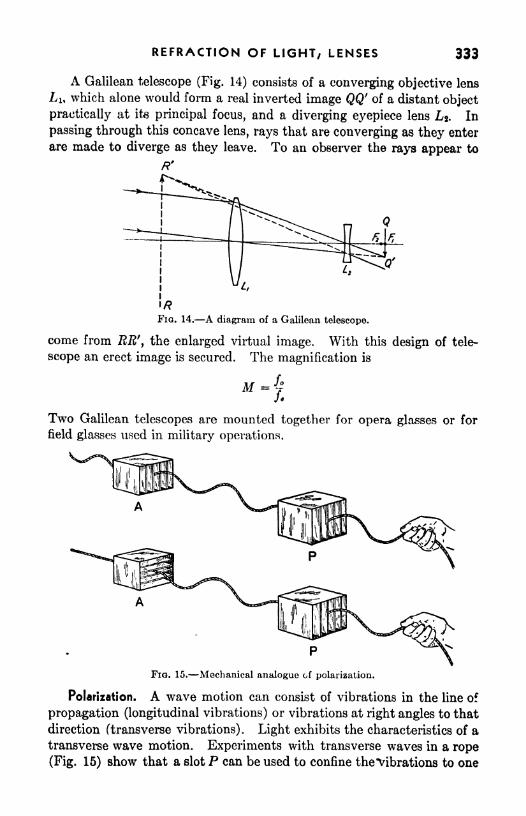
REFRACTION OF LIGHT, LENSES 333
A Galilean telescope (Fig. 14) consists of a converging objective lens
Li, which alone would form a real inverted image QQ' of a distant object
practically at its principal focus, and a diverging eyepiece lens L*. In
passing through this concave lens, rays that are converging as they enter
are made to diverge as they leave. To an observer the rays appear to
FIG. 14. A diagram of a Galilean telescope.
come from RR'y the enlarged virtual image. With this design of tele-
scope an erect image is secured. The magnification is
M "7Two Galilean telescopes are mounted together for opera glasses or for
field glasses used in military operations.
FIG. 15. Mechanical analogue of polarization.
Polarization. A wave motion can consist of vibrations in the line of
propagation (longitudinal vibrations) or vibrations at right angles to that
direction (transverse vibrations). Light exhibits the characteristics of a
transverse wave motion. Experiments with transverse waves in a rope
(Fig. 15) show that a slot P can be used to confine the "Vibrations to one

334 PRACTICAL PHYSICS
plane, after which they can be transmitted or obstructed by a second
slot A, depending on whether it is placed parallel or perpendicular to
the first slot. This suggests that a beam of light might be plan&yolarized;that is, its vibrations might be restricted to a certain plane.
When it is traveling through a material such as air, glass, or water,
the speed of light is the same in all directions, and a light beam may l?e
FIG. 16. Diagram of tourmaline crystals and polarizing plates illustrating polarisation byselective absorption.
considered as having vibrations in all directions in a plane perpendicular
to its direction of travel. In many other materials such as tourmaline,
calcite, quartz, and mica, the speed of transmission or the amount of
absorption of a light beam is different for vibrations in different planes.
A tourmaline crystal produces plane-polarized light by selective
absorption, transmitting only light whose vibrations are in a particular
Fio. 17. The strain pattern about two rivet holes in a member subjected to a vertical tensile
stress.
plane (Fig. 16). The polarized light may be examined by a second
tourmaline, which will transmit the light when oriented parallel to the
first crystal or extinguish it when rotated through 90 degrees. Usedthus in pairs, the crystals are referred to as polarizer and analyzer,
respectively. Polarizing plates of large area (polaroids, Fig. 16) are

REFRACTION OF LIGHT, LENSES 335
made by embedding microscopic crystals of herapathite, with their axes
properly aligned, in a nitrocellulose sheet. Light is partly plane-polarisedwhen it is reflected from glass or water or when it is scattered by small
particles in the air. Polaroid sun glasses or photographic filters are
useful in reducing glare by eliminating the plane-polarized component of
reflected light.
Glass when under stress transmits light vibrations in certain planes
preferentially. Hence laboratory or other glassware can readily be
tested for strains by being placed between a polarizer and analyzer. Thesame principle permits analysis of strains in complicated structures
encountered in engineering. A model is built of transparent bakelite,
loaded, and examined by suitably polarized light. The regions of greateststrain can be detected as those where there is closest spacing of fringes
(Fig. 17).
SUMMARY
Refraction is the abrupt change of direction of a light ray upon passingfrom one transparent material to another.
The law of refraction states that sin z'/sin r = n, a constant called the
index of refraction. If the light enters from a vacuum, n is called the
absolute index of refraction of the material. The index of refraction is
also equal to the ratio of the velocities of light in the two mediums.
Light incident obliquely on the bounding surface of a transparentmaterial from within will be able to emerge only if the angle is less than
the critical angle whose value is given by sin C = 1/n.When the rays of light pass through a lens
; they are bent aroundthe thicker part of the lens. Rays parallel to the principal axis of the
lens pass through a point called the principal focus. The distance of this
principal focus from the lens is called the focal length.
Under certain conditions, a converging lens is able to form a real imageof an object. Real images may be cast on a screen.
A diverging lens always forms virtual images, which cannot be thrownon a screen but may be viewed by the eye.
For any thin lens, l/p + 1/q = I//. Conventionally, / is to betaken positive for a converging lens and negative for a diverging lens;
q is negative for a virtual image.The magnifying power of a lens used as a simple magnifier isM =
10//,where / is the focal length in inches and the lens is adjusted so that the
image falls at the distance of most distinct vision, 10 in.
The compound microscope consists of a short-focus objective and a
longer focus eyepiece. The magnification is given by

336 PRACTICAL PHYSICS
The astronomical telescope consists of a long-focus objective and an
eyepiece. The magnification is given by M /<>//#.
Light is plane-polarized when its -transverse vibrations are restricted
to a certain plane.
QUESTIONS AND PROBLEMS
1. If a pencil standing slantwise in a glass of water is viewed obliquely from
above, the part under water appears to be bent upward. Explain.
2. The angle of incidence of a ray of light on the surface of water is 40 and
the observed angle of refraction is 29. Compute the index of refraction.
Ans. 1.32.
3. A ray of light goes from air into glass (n %), making an angle of 60
with the normal before entering the glass. What is the angle of refraction in
the glass? Ans. 35.5.
4. The index of refraction in a certain sample of glass is 1.61. What is the
speed of light in this glass? Ans. 115,000 mi/sec.
5. At what angle should a ray of light approach the surface of a diamond
(n = 2.42) from within, in order that the emerging ray shall just graze the surface?
Ans. 24.4.
6. Check the results of the examples on pages, 329-330 by drawing ray
diagrams to scale on squared paper. Verify the magnification as well as the
position of the image in each case.
7. A converging lens has a focal length of 10 in. Where is the image when
the object is (a) 20 in. from the lens? (6) 5 in. from the lens? How large is the
image in each case if the object is 0.50 in. high?
8. A diverging lens has a focal length of 10 in. Where is the image when
the object is (a) 20 in. from the lens? (6) 5 in. from the lens? How large is the
image in each case if the object is 0.5 in. high?
Ans. -6.7 in.; -3.3 in.; 0.17 in.; 0.33 in.
9. A screen is located 4.5 ft from a lamp. What should be the focal length
of a lens that will produce an image that is eight times as large as the lamp itself?
Ans. 0.44 ft.
10. A lantern slide 3 in. wide is to be projected onto a screen 30 ft away bymeans of a lens whose focal length is 8 in. How wide should the screen be to
receive the whole picture? Ans. 11 ft.
11. A miniature camera whose lens has a focal length of 2 in. can take a
picture 1 in. high. How far from a building 120 ft high should the camera be
placed to receive the entire image? Ans. 240 ft.
12. A photographer wishes to take his own portrait, using a plane mirror
and a camera of focal length 10 in. If he stands beside his camera at a distance
of 3 ft from the mirror, how far should the lens be set from the plate?
Ans. 11.6 in.
13. In a copying camera, the image should be of the same size as the object.
Prove that this is the case when both object and image are at a distance 2 f from
the lens.

REFRACTION OF LIGHT; LENSES 337
14. An object 2 in. high is placed 4 in. from a reading lens of focal length
5 in. Locate the virtual image graphically and determine the magnification.
Arts. 20 in.; 5.
15. A "10X magnifier" is one that produces a magnification of ten times.
According to Eq. (4), what is its focal length? How large an image of a flash-
light lamp 0.25 in. in diameter will this lens be able to produce on a card held
5 in. away?16. The focal lengths of the objective and eyepiece of a compound microscope
are 0.318 and 1.00 in., respectively, and the instrument is focused on a slide
placed 0.35 in. in front of the objective. What magnification is attained?
Ans. 1(50.
17. The large refracting telescope of the Yerkes Observatory has an objective
of focal length 62 ft. If atmospheric conditions do not warrant the use of magni-fication higher than 1,500, what focal length should the eyepiece have?
Ans. 0.5 in.
EXPERIMENT
Lenses and Optical Instruments
Apparatus: Optical bench, with accessories such as lens holders,
Jiummated "object/7
screen, set of thin lenses, etc.; steel rule; squared
paper.
The purpose of the following experiments is to observe the formation
of images by lenses and lens combinations, to check the lens formula,
and to set up and study some lens combinations, such as simple forms of
the telescope and compound microscope.
a. Focal Length of a Converging Lens. Determine the focal length
of a converging lens by catching on a screen the image of a distant object,
such as a chimney or church spire, and measuring the distance from the
lens to the screen. The lens selected should have a moderate focal
length (6 or 8 in.). Record the focal length thus obtained.
With the object box and screen mounted near the two ends of the
bench, move the lens in its holder back and forth between them until a
sharp, enlarged image is obtained. Make several settings from opposite
sides and take the average. If it is not found possible to obtain an image,
the object and the screen should be moved farther apart or a lens of
shorter focal length should be used. When the image has been obtained,
measure the distances p and q and also the height of any definite part of
the object and of the corresponding portion of the image, using the steel
rule.
Substitute the values of p and q in the lens equation and solve for
/. Compare this value with the one obtained directly by focusing a
distant object. Compute the ratio of the measured values of image size

338 PRACTICAL PHYSICS
and object size and compare it with the value of q/p. Check these
findings by making a ray diagram, to scale.
Repeat the entire procedure for one or two other converging lenses,
6. Compound Microscope. Select two converging lenses, one of focal
length less than 2 in., another of focal length around 6 or 8 in. Deter-
mine the fofcal lengths roughly by focusing a distant object. Mounton the optical bench, from left to right, a small drawing or picture
(postage stamp), the shorter focus lens, and the longer focus lens. Clampthe former (the objective) in position at a distance from the object just
greater than the focal length. Move the second lens (the eyepiece)
back and forth along the bench until a sharp image is seen when looking
through both lenses. Is the image enlarged? Is it erect or inverted?
Move the object slightly to one side. Does the image move in the same
direction? Notice that the image is distorted and annoyingly fringed
with color, particularly near the outer parts. How are these defects
minimized in an actual microscope?
c. Refracting Telescope. Here the objective should be a lens of focal
length about 20 in. or more and the eyepiece 2 to 4 in. Determine the
focal length of each lens approximately by using a distant object. Mountthe lenses in holders on the optical bench so that their distance apart is
the sum of the two focal lengths. Move the eyepiece back and forth until
a sharp image of a distant object is obtained (a lamp on the opposite
side of the room may be used for this purpose). Is the image larger than
the object as seen with the unaided eye? Is the image erect or inverted?
How should a refracting telescope be constructed in order to furnish
erect images?

APPENDIX
I. FUNDAMENTALS OF TRIGONOMETRY
In the study of vector quantities the use of simple trigonometry is
very desirable and hence an elementary knowl-
edge has been assumed in the treatment in this
book. The fundamental definitions and princi-
ples as applied to right triangles are included in
the following discussion.
In Fig. 1 are shown three right triangles,
ABC, AB'C', and A"C", each of which has theA "
C C C"
common angle 0. Each side of the triangle FKU i. -similar right tri-
AB'C' is longer than the corresponding side ofangles.
ABC. Since the triangles are of the same shape, the correspondingsides are proportional. That is
AC ABAC' AB'
or
AC ACf CB _ <7' , CB CfB f
AB~AB'' AC~1C7
The values of these ratios may be used as measures of the angle 0.
For convenience each of the three ratios is given a name and is called a
trigonometric function. They are named as follows :
Side opposite . A , ... . ^-^-~-- = sine 6 (wntten sm 6)Hypotenuse
'
Side adjacent . a t ., , A .
~r=-7=- cosine 6 (written cos 6)
HypotenuseSide opposite , ,
. , >jLA ^ ^Side adjacent
= tangent (wntten tan ^
In tlie triangles of Fig. 1

340 PRACTICAL PHYSICS
These three functions are very useful in studying vectors for in that
study it is necessary to find the lengths of sides of right triangles when
one side and an angle is given. For example, if XT? of Fig. 1 represents
a force then
1C = IB cos
and= TE sin B
are rectangular components of that force.
The values of the trigonometric functions have been worked out for
each angle and are given in Tables 6 and 7 of the Appendix. Values of
sines are given in Table 6 for each tenth of a degree from zero to 90.
The first column lists angles in degrees, while the fractions of degrees
appear as headings of the columns in the table. To find the sine of
32.4, find 32 in the first column, and across this row in the column
headed by .4 the value of the sine is found to be 0.5358. The same table
is used to read the values of cosines, using the angles given in the last
column and reading up from the bottom. Thus to find the cosine of
55.6, locate 55 in the last column and look across in this row to the
column above .6 where the value is observed to bo 0.5650. The values of
tangents are found in Table 7, which is used in the same manner as the
table of sines.
In some tables the angles listed in the first column run only from to
45. Angles from 45 to 90 are then given in the last column increasing
upward. This arrangement is possible because of the relationship
between sine and cosine. The sine of any angle is equal to the cosine of
90 minus the angle. Thus
sin = cos (90-
6)
and
cos = sin (90 0)
This relation becomes evident from Fig. 1, for the angle <j> is equal to
90 -0. From the definitions
sin 6 =
and
BCcos <j>
~
Hence
sin = cos <t)= cos (90
-*-0)
Whenever the slide rule is used to obtain cosines, this relationship mustbe used.

APPENDIX 341
II. GRAPHS
Physical laws and principles express relationships between physical
quantities. These relationships may be expressed in words, as is com-
monly done in the formal statement, or by means of the symbols of an
equation or by the pictorial representation called a graph. The choice
of the means of expression is determined by the use to be made of the
information. If calculations are to be made, the equation is usually the
most useful. The graph, however, presents to the initiated person a vivid
and meaningful picture of the way in which one quantity varies with
another.
If a graph is to impart its full meaning, it must be constructed in
accordance with standard rules so that it will have the same meaning for
every person who inspects it. Some of the rules and suggestions which
should prove helpful are given in the following discussion.
In constructing a graph the first step is to select and label carefully
a set of axes. .It is customary to allow the horizontal axis to represent
the quantity to which arbitrary values are assigned while the other
variable is plotted along the vertical axis. The name of the quantityand the units in which it is expressed should be clearly lettered along
each axis.
The second step is the selection of a scale to be used for each axis.
The scale should be so chosen that the range of values being plotted will
be of reasonable size, practically filling thfc page. The scales on the
two axes need not be the same; they seldom are. The scales need not
always begin with zero; in fact, zero may not appear on the scale unless
it is in the range of values being studied. Graphs are usually most
easily constructed and read if each space represents a multiple of 2 or
of 5. Multiples of 3 or of 7 make the interpretation of the graph difficult
and should be avoided wherever possible. When a scale has been selected
for each axis, mark values at appropriate equal intervals along each axis,
increasing to the right on the horizontal axis and upward on the vertical
axis. It is unnecessary to mark a number at each square, but enoughmarks should be used so that the graph can be read easily.
Each point plotted on the graph represents a pair of corresponding
values of the two quantities. It is usually convenient to make out a
table of values from which to plot the points. Each plotted point should
be marked by a dot surrounded by a small circle. Enough points should
be plotted so that a clear picture of the variation is given. A smooth
curve is then drawn through the average position of the points. It is not
necessary that the curve pass through every point, for experimental error
causes a scattering of data about the true value. Therefore the points
will scatter somewhat on either side of the true curve. Graphs of data

342 PRACTICAL PHYSICS
representing physical laws should never be drawn as broken lines from
point to point.
8 wo
$0
"0 10 20 30 40 SO 60 70
PRESSUREfNPOUNDSPER SQUARE INCH
FIG, 2.
Figure 2 is a graph showing the variation of volume V of a confined
gas as the pressure P changes. A set of experimental values of pressure
and volume are shown in the table.

APPENDIX 343
Not only is the graph useful in showing vividly the relationshipbetween the two quantities but it can also be employed to obtain quicklypairs of values other than those which were plotted. For example, from
Fig. 2 we may wish to find the volume when the pressure is 35 lb/in.2 It
is necessary merely to observe where the curve cuts the vertical line
representing 35 lb/in.2 and read the value of the horizontal line which
intersects the curve there. This is observed to be 26 in.3 This use of
FIG. 3.
graphs to record data in readily available form is common in engineeringand technical practice.
When the curve of a graph is a straight line, it is easily identified,more easily drawn, and in many respects more useful than other forms of
curve. For these reasons the data are often arranged in such a form thatthe curve will be a straight line. If, in showing the relationship betweenP and 7, the reciprocal of V is plotted against P, the resulting curve is
a straight line as shown in Fig. 3. If it is known from theory that thecurve is a straight line, only enough points need be plotted to locate theline. It is then drawn in, using a ruler. Although two points aresufficient to locate a straight line, several others should bfc plotted when
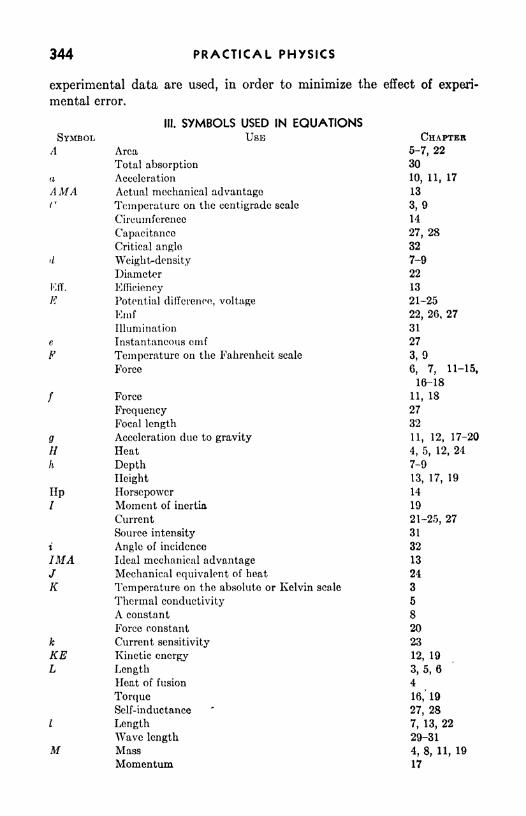
344 PRACTICAL PHYSICS
experimental data are used, in order to minimize the effect of experi-
mental error.
III. SYMBOLS USED IN EQUATIONSSYMBOL USE CHAPTER
A Area 5-7, 22
Total absorption 30
a Acceleration 10, 11, 17
AMA Actual mechanical advantage 13
(" Temperature on the centigrade scale 3, 9
Circumference 14
Capacitance 27, 28
Critical angle 32
d Weight-density 7-9
Diameter 22
Kff. Efficiency 13
K Potential difference, voltage 21-25
Knif 22, 26, 27
Illumination 31
e Instantaneous crnf 27
F Temperature on the Fahrenheit scale 3, 9
Force 6, 7, 11-15,
16-18
/ Force 11, 18
Frequency 27
Focal length 32
g Acceleration due to gravity 11, 12, 17-20
// Heat 4, 5, 12, 24
h Depth 7-9
Height 13, 17, 19
Up Horsepower 14
7 Moment of inertia 19
Current 21-25, 27
Source intensity 31
i Angle of incidence 32
IMA Ideal mechanical advantage 13
/ Mechanical equivalent of heat 24
K Temperature on the absolute or Kelvin scale 3
Thermal conductivity 5
A constant 8
Force constant 20
k Current sensitivity 23
KE Kinetic energy 12, 19
L Length 3, 5, 6
Heat of fusion 4
Torque 16, 19
Self-inductance*
27, 28
/ Length 7, 13, 22
Wave length 29-31
M Mass 4, 8, 11, 19
Momentum 17

APPENDIX 345
SYMBOL USE
Magnification
Mass
P
PEQ<1
R
s
ep.
T
Normal force
Number of revolutions
Number of turns
Number of vernier divisions
Shear modulus or coefficient of rigidity
FrequencyNumber of rotations per minute
Factor by which the ra,nge of nn instiumenf is increased
Index of refraction
Pressure
Power
Pitch
Object distance
Potential energy
Charge or quantity of electricity
Image distance
Rate of flow of liquid
Gas constant
Radius
Range of a projectile
Resistance
Radius
Resistance
Angle of refraction
Length of a main scale division
Specific heat
Distance
Specific gravity
Absolute temperaturePeriod
Reverberation period
TemperatureTime
Length of a vernier division
Volume
Speed, velocity
Speed, velocity
Average speed
Weight
Work, energyReactance
Unknown resistance
Horizontal distance
CHAPTER32
11, 12, 17-19,
25
12
14, 19
26, 27
2
6
20, 29-31
14
23
32
7-9
14, 19, 24, 27
13
32
12
21, 24, 25, 27
32
7
8
10, 13, 17, 19
17
21-24, 27
10, 13, 18, 19
22, 23, 25
32
2
4
10-14, 31
7
8, 29
18, 20
30
3,4
5, 7, 10, 11,
14, 17, 19,
21, 24-26, 29
2
3, 7, 8, 30
17, 20-32
7, 10, 12, 17,
18
10, 14
7, 11-13, 17-
20
24, 28
27
23
17
346 PRACTICAL PHYSICS
SYMBOL USE
Y Young's modulus
Z Impedancez Electrochemical equivalent
a (alpha) Coefficient of lineai expansion
Angular acceleration
(beta) Coefficient of volume expansion
y (gamma) Pressure coefficient
A (delta) Change in
AL Change in length
AT1
Change in temperatureA/ Change in temperatureA< Number of lines of force cut
< (phi) Angle of shear
IJL (mu) Coefficient of friction
P (rho) Resistivity
2 (sigma) Sum of
(theta) Angle
Angle of lag
<> (omega) Angular speed& Average angular speed
CHAPTER6
27
25
3,6
10, 19
3,8
3,65
3, 4, 6, 8
26
6
12
22
16, 19, 22
10, 15, 19, 23,
27
27
10, 19
10, 19

APPENDIX
TABLE 1. PROPERTIES OF SOLIDS AND LIQUIDS
347

348 PRACTICAL PHYSICS
TABLE 2. SATURATED WATER VAPORShowing pressure P (in millimeters of mercury) and density D of aqueous vapor
saturated at temperature t\ or showing boiling point t of water and density D of steam
corresponding to an outside pressure P

APPENDIX 349
TABLE 3. ELECTROCHEMICAL DATA
TABLE 4. RESISTIVITIES AND TEMPERATURE COEFFICIENTS
TABLE 5. DIMENSIONS AND RESISTANCE OF COPPER WIRE
The^gauge number referred to is the Brown and Sharpe (B. & S.), also
known as theAmerican wire gauge. A study of the above table will reveal
the ingenious correlation that exists between gauge numbers, size of wire,
and resistance of wire. Each third gauge number halves the area and
hence doubles the resistance. Each sixth gaugediameter and hence quadruples the resistance.

350 PRACTICAL PHYSICS
TABLE 6. NATURAL SINES AND COSINESNATUBAL SINES
NATUBAL COSINES

APPENDIX 351
TABLE 6. NATURAL SINES AND COSINES (Continued)
NATURAL SINES
NATURAL COSINES

352 PRACTICAL PHYSICS
TABLE 7. NATURAL TANGENTS AND COTANGENTSNATURAL TANGENTS
NATURAL COTANGENTS

APPENDIX
TABLE 7. NATURAL TANGENTS (Continued)
353

354 PRACTICAL PHYSICS
TABLE 8. LOGARITHMSOnlv the mantissa (or fractional part) of the logarithm is given. Each mantissa
should be preceded by a decimal point and the proper characteristic.
100-500
100-600

APPENDIX 355
TABLE 8. LOGARITHMS (Continued)
600-1000
500-1000

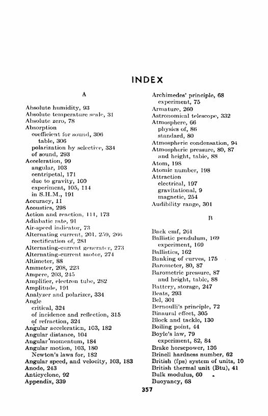
INDEX
Absolute humidity, 93Absolute temperature scale, 31
Absolute, zero, 78
Absorptioncoefficient for sound, 306
table, 306
polarization by selective, 334of sound, 293
Acceleration, 99
angular, 103
centripetal, 171
due to gravity, ICO
experiment, 105, 114
in S.H.M., 191
Accuracy, 11
Acoustics, 298Action and reaction, 111, 173
Adiabatic rate, 91
Air-speed indicator, 73
Alternating current, 201, 2.~>9, 266rectification of
;281
Alternating-current generator, 273
Alternating-current motor, 274
Altimeter, 88
Ammeter, 208, 223
Ampere, 203, 24.5
Amplifier, electron tube, 282
Amplitude, 191
Analyzer and polarizer, 334
Anglecritical, 324of incidence and reflection, 315of refraction, 324
Angular acceleration, 103, 182
Angular distance, 104
Angular'momentum, 184
Angular motion, 103, 180
Newton's laws for, 182
Angular speed, and velocity, 103, 183
Anode, 243
Anticyclone, 92
Appendix, 339
Archimedes' principle, 68
experiment, 75
Armature, 260Astronomical telescope, 332
Atmosphere, 66
physics of, 86
standard, 80
Atmospheric condensation, 94
Atmospheric pressure, 80, 87and height, table, 88
Atom, 198Atomic number, 198Attraction
electrical, 197
gravitational, 9
magnetic, 254
Audibility range, 301
R
Back emf, 261Ballistic pendulum, 169
experiment, 169
Ballistics, 162
Banking of curves, 175
Barometer, 80, 87
Barometric pressure, 87and height, table, 88
Battery, storage, 247
Beats, 293
Bel, 301Bernoulli's principle, 72
Binaural effect, 305Block and tackle, 130
Boiling point, 44
Boyle's law, 79
experiment, 82, 84
Brake horsepower, 136
Brinell hardness number, 62British (fps) system of units, 10
British thermal unit (Btu), 41
Bulk modulus, 60
Buoyancy, 68
357

358 PRACTICAL PHYSICS
Caliper
micrometer, 22
vernier, 21
Calorie, 41
Calorimetry, 42
Candle power, 312
Capacitance, 271
Gapacitive reactance, 271
Cathode, 243, 283
Cell
dry, 200
Edison, 248
electrolytic, 203
nonpolarizing, 248
photoelectric, 202
polarization of, 246
in series and in parallel, 247
standard, 249
storage, 247
voltaic, 245
Center of gravity, 155
Centigrade scale, 30
Centimeter, 8
of mercury, 66
Centrifugal governor, 174
Centrifugal reaction, 173
Centrifuge, 174
Centripetal acceleration, 171
Centripetal force, 171
experiment, 177
Cgs, metric system of units, 10
Change of state, 43
Characteristics of electron tubes, experi-
ment, 284
Chargeforce between, 197
space, 281
Charles's laws, 79
experiment, 82, 84
Chemical equivalent, 245
Circuit, series, 212
Circular mil, 214
Circulation, of air, 51, 90
Cloud, 94
Coefficient
of expansion, table, 35, 346
of friction, 118
of linear expansion, 34
pressure, 77
of rigidity, 60
Coefficient, of volume elasticity, 60
of volume expansion, 34, 77
Communications, 277
Commutator, 259
Compassgyroscopic, 185
magnetic, 254
Component of a vector, 144
Compressibility, 62
Computation, rules for, 13, 24
Concave mirror, 318Concurrent forces, 142
experiment, 150
Condensation, atmospheric, 93
Condenser, 270
Conduction
electrical, 199, 242
thermal, 50, 89
Conservation
of angular momentum, 184
of energy, 120, 257of momentum, 166
Convection, 50, 51, 89
Converging lens, 325Convex mirrors, 318
Cosine, 339
table, 350
Coulomb, 203
Couple, 157
Critical angle, 324
Current
alternating, 201, 259, 266
direct, 199
direction of, 200
effective, 267
effects of, 202
experiment, 205
induced, 256
root-mean-square, 267
sources of, 200
unit of, 203, 245
Curves, banking of, 175
Cycle, 259
Cyclone, 92
D
D'Arsonval galvanometer, 219
Decibel, 301
Declination, 254
Degrees, 30

INDEX 359
Density, table of, 67, 78
weight, 67
Detector, electron tube, 282
Deviation, average, 27
Dew-point, 93
experiment, 95
Dewar flask, 53
Diode, 281
Direct current, 199
Direct-current generator, 259
Direct-current instruments, 219
Direct-current motor, 260
Dissociation, electrolytic, 243
Diverging lens, 326
Doldrums, 90
Dry cell, 200, 246
Ductility, 62
Dynamometer, 138
Dyne, 112
Dyne-centimeter, 119
E
Ear, sensitivity of, 298, 301
Earth
atmospheric circulation on, 90
as a magnet, 254
Edison cell, 248
Effective current and voltage, 267
Efficiency, 126
experiment, 132
Elastic lag, 59
Elastic limit, 58
Elasticity, 57
experiment, 64
modulus of, 58
Electrical circuits, 200, 212
Electrical measuring instruments, 219,
225
experiment, 229, 240
Electricity, 4
quantity of, 203
Electrification, 196
negative and positive, 197
Electrochemical equivalent, 245
table, #49
Electrode, 243
Electrolysis, 243
Faraday's laws of, 244
Electrolytes, 243
Electrolytic cell, 203, 243
Electromagnet, 256
Electromagnetic induction, 253
Electromagnetism, experiment, 262
Electron, 198
conduction theory, 199
free, 199
mass of, 198
Electron tubes, 281
Electronics, 277
Electroplating, 244
Emf, 211
back, 261
induced, 256, 266, 270
and internal resistance, experiment,251
Energyconservation of, 120, 257
electric, 236
heat, 40
kinetic, 121
of rotation, 183
potential, 120
Equations in linear and angular motion,
table, 185
Equilibrant, 144
Equilibrium, 140, 152
first condition for, 143
second condition for, 155
Erg, 119
Error, 22
erratic, 23
percentage, 23
systematic, 23
Evaporation, 44
Expansion
adiabatic, 91
of air, experiment, 82, 84
coefficient of, table, 35
linear, 33
experiment, 37
table, 347
of solids, 33
thermal, 33, 61
volume, 34, 77
of water, 33
Eye, 330
Fahrenheit scale, 30
Falling bodies, 100, 163
Farad, 271
Faraday's laws of electrolysis, 244

360 PRACTICAL PHYSICS
Fathometer, 292
Fatigue, elastic, 61
Field, magnetic, 254
Fixed point, 29
Fluid, 06
internal friction in, 71
Fluid How, 71
Focal length, 325
Focus, principal, 318, 325
Fog, 94
Foot-candle, 312
Foot-candle meter, 314
Foot-pound, 119
Force
centrifugal, 173
centripetal, 171
concurrent, 155
constant, 190
equation, 111
experiment, 150, 159
line of, 254
moment of, 154
nonconcurrent, 155
unbalanced, 110
units of, 112
Forced vibration, 192, 302
Fps system of units, 10
Freezing points, 43
Frequency, 191, 291, 298
natural, 192, 280, 302
Friction, 117
coefficient of, 118
experiment, 123
fluid, 119
internal, in fluid, 72
rolling, 119
sliding, 118
starting, 124
Fulcrum, 127
Fundamental, 299
Fusion, 43, 45
G
g (acceleration due to gravity), 101
Galilean telescope, 333
Galvanometer, 219
experiment, 229, 240
sensitivity of, 220Gas
coefficient of expansion, 77
constant, 77
Gas, kinetic theory of, 76
law, 76
pressure coefficient of a, 77
speed of sound in, 289
Gears, 129
Generator, 201, 258
alternating-current, 258, 273
direct-current, 259
two- and three-phase, 274
Generator rule, 258
Governor, centrifugal, 174
Gradient, temperature, 49
Gram, 9
Gram-centimeter, 119
Graphs, construction, 341
Gravityacceleration due to, 100
center of, 155
specific, 69
work against, 120
Grid, 282
Gyrocompass, 185
Gyroscope, 184
H
Hardness, 62
Heat, 4, 40
energy, 40
of fusion, 43
mechanical equivalent of, 120, 235
radiation of, 50, 52, 89
specific, 41
experiment, 48
transfer, 49, 89
experiment, 55
of vaporization, 44
Henry, 270
Hookes' law, 58
Horse latitudes, 90
Horsepower, 135
Humidity, 92
absolute, 93
experiment, 95
relative, 93
specific, 93
Hydraulic press, 70
Hydrometer, 70
Hygrometer, hair, 96
Hysteresis, elastic, 59

INDEX 361
niurnination, 311
experiment, 320
table, 313
linage, 316
formation of, by lens, 327
by mirror, 318
real and virtual, 327
Impedance, 271
Impulse, 167
Incidence, angle of, 315
inclined plane, 129
Index of refraction, 324
Induced current and emf, 256
experiment, 264
Induction
electromagnetic, 256
self-, 269
Induction motors, 274
Inductive circuit, 269
Inductive reactance, 271
Inertia, 9
moment of, 181
rotational, 180
Insulators and conductors, 199
Intensity of sound, 300
table, 301
Interference of sound, 293
Internal resistance, 211
emf and, experiment, 251
Inverse square law, 254, 312
Ions, 243
Isobar, 92
Jackscrew, 130
Joule, 119
Joule's law, 234
K
Kelvin temperature scale, 31
Kilogram, 9
Kilowatt, 135
Kilowatt^hour, 237
Kilowatt-hour meter, 237
Kinetic energy, 121, 183
Lapse rate, 91
Least count, 20
Length measurements, experiment, 26
Lens
converging, 325
diverging, 326
equation, 329
experiment, 337
eyepiece, 331
focal length of, 325
magnification by, 329
microscope, 331
objective, 331
telescope, 332
Lenz's law, 257
Lever, 127
Lightnature of, 309
plane polarized, 333
reflection of, 315
refraction of, 322
source intensity, 312
speed of, 310
Light rays, 310
Light waves, 310
Lighting, 313
Limit, elastic, 58
Line
agonic, 254
of force, magnetic, 254
isogonic, 254
Linear coefficient of expansion, 33
experiment, 37
Liquid conductors, 212
Liquid pressure, experiment, 74
Local action, 246
Logarithms, table, 354
Longitudinal wave, 287
Loudness of sound, 300
M
Machines, simple, 125
Magnetic field, 254
direction of, 255
of electric current, 255
strength of, 254
Magnetic lines of force, 254
Magnetic poles, 253
Magnetism, 4, 253
experiment, 262
terrestrial, 254
Magnification, 329
Magnifier, simple, 330

362 PRACTICAL PHYSICS
Malleability, 62- -
Mass, 9
Measurement, 7, 16
direct, 7
experiment, 16
indirect, 8
linear, 19, 26
uncertainty in, 12
Mechanical advantage, actual and ideal,
126
experiment, 132
Mechanical equivalent of heat, 120, 235
table of equivalents, 235
Mechanics, 4
Meter, 8
Meter-candle, 312
Meteorology, 86
Method of mixtures, 42, 45
Metric (cgs) system of units, 9
Microampere, 220
Microfarad, 271
Micrometer caliper, 22
Microphone, 279, 303
Microscope
compound, 331
simple, 330
Mil, 214
Millibar, 87
Mirror
concave and convex, 318
parabolic, 318
plane, 316
Mixtures, method of, 42, 45
Modern physics, 5
Modulus of elasticity, 58
bulk, 60
shear, 60
Young's, 58
Molecular theory of gases, 76
Moment
arm, 154
of force, 154
of inertia, 181
experiment, 187
table, 181
Momentum, 165
angular, 184
conservation of, 166, 184
experiment, 169
Motion, 98, 109
accelerated, 99
experiment, 105
Motion, angular, 180
equations, linear and angular, table,
185
Newton's laws of, 109, 182
rotary, 102
simple harmonic, 190
uniform, 98
uniform circular, 171
experiment, 177
vibratory, 189
wave, 286, 309
Motor, 260
back emf, 261
induction, 274
rule, 260
N
Neutron, 198
Newton's laws of motion, 109, 182
experiment, 114
Nuclei, hygroscopic, 93
Nucleus, 198
Numerical measure, 7
Objective lens, 331
Ohm, 204
Ohm's law, 204, 207, 271
experiment, 216
Opera glass, 333
Optical lever, 316
Optics, 4
Oscillation
electric, 279
mechanical, 190
Overtone, 299
Parabolic mirror, 318
Pascal's law, 70
Pendulum, ballistic, 169
Percentage error, 23
Percentage uncertainty, 24
Period, S.H.M., 190
Permanent set, 58
Phase, alternating current, 274
Phases of matter, 46
Photoelectric cell, 202

INDEX 363
Photoelectric effect, 201
Photometer, 313
Photometry, 4
experiment, 320
Physics, 4
Pitch
of screw, 22, 130
sound, 298
Pitot tube, 72
Polar easterlies, 91
Polarization
of cell, 246
of light, 333
Polaroid, 334
Poles
magnetic, 253
Potential
electric, 203
Potential energy, 120
Potentiometer, 226
Pound, 9
Power, 134, 183, 236
in alternating-current circuit, 272
electrical, 237
experiment, 138
horse, 135
human, 136
experiment, 138
transmission of electrical, 268
Power factor, 272
Pressure, 66, 87
experiment, 74
vapor, 93
Pressure coefficient, 77
Prevailing westerlies, 91
Principal axis, 325
Principal focus, 318, 325
Prism, 323
Projectile motion, 162
Prony brake, 135
Proton, 198
Psychrometer, sling, 96
Pulley, 129
Pyrometer, 33
optical, 54
thermocouple, 238
total radiation, 53
Quality, tone, 299
Quantity, of electricity, 203^
R
Radian, 103
Radiation of heat, 50, 52, 89
Radio, 279, 283
Range, of projectile, 164
Rays, 310
Reactance, 271
Reaction
action and, 111, 173
centrifugal, 173
Reference circle, 193
Reflection
angle of, 315
law of, 315
of light, 315
of sound, 292
total, 324
Refraction
of light, 324
of sound, 289
Relative humidity, 93
experiment, 95
Relative motion, 148
Relative uncertainty, 24
Relay, 278
Resistance, 204
of copper wire, table, 349
experiment, 216, 251, 276
internal, 211
parallel connection of, 210
series connection of, 209
Resistivity, 213
table, 348
Resonance, 192, 272, 280, 302
experiment, 194
Resultant, 140
Reverberation, 305
Rigidity, coefficient of, 60
Ripple tank, 296, 306, 308
Root-mean-square current and emf, 267
Rotary motion, 102
Rotational inertia, 180
Rules for computation, 13, 24
S
Saturated vapor, 93
table, 348
Saturation current, 282.
Scalar quantities, 141

364 PRACTICAL PHYSICS
Scale
temperature, 30
vernier, 19
Screw jack, 130
Self-inductance, 269
Self-locking machine, 131
Sensitivity, current, 220
Sextant, 317
Shear modulus of elasticity, 60
Shunt resistance, 223
experiment, 229, 240
Significant figure, 12, 14
overscoring of, 14
Simple harmonic motion, 190
acceleration in, 191
experiment, 194
speed in, 191
Simple machines, 125
Sine, 339
table, 350
Solenoid, 256
Sound, 4, 286
absorption, 293
audibility of, 301
complexity of, 299
detection, 303
experiment, 296, 308
frequency of, 291, 298
intensity of, 300
interference of, 293
locator, 304
loudness of, 300
nature of, 286
pitch of, 298
production of, 303
quality of, 299
reflection of, 292
refraction of, 289
speed of, 288
wave length of, 291
Sound waves, 287
Space charge, 281
Specific gravity, 69
table, 78, 347
Specific heat, 41
experiment, 48
table, 41, 347
Specific humidity, 93
Speed, 98
angular, 103
average, 99
of light, 310
Speed, of sound, 288
table, 288in S.H.M., 191
terminal, 102
Standard candle, 312Standard cell, 249
State, change of, 43
Stopping distance, table, 122
Storage cells, 247Strain
shearing, dO
tensile, 58
volume, 60
Stratosphere, 91
Stress
shearing, 60
tensile, 58
volume, 60
Supercooling, 43
Supersaturated vapor, 93
Symbols used in equations, 344
Tangent, 339
table, 352
Telegraph, 277
Telephone, 278
Telescope, 332
Temperature, 28
absolute, 31
coefficient of resistance, table, 349
gradient, 49
fixed points, 29
range of, 32
Thermal conduction, 50
Thermal expansion, 33, 61
Thermionic emission, 281
Thermocouple, 200, 238
Thermodynamics, 4
Thermoelectricity, 200, 238
Thermometer, 29
Thermometer scales, 30
Thermopile, 239Thermos flask, 53
Tone quality, 299
Torque, 154, 180
experiment, 159, 187
Total absorption, 306Total reflection, 324Transfer of heat, 49
experiment, 55
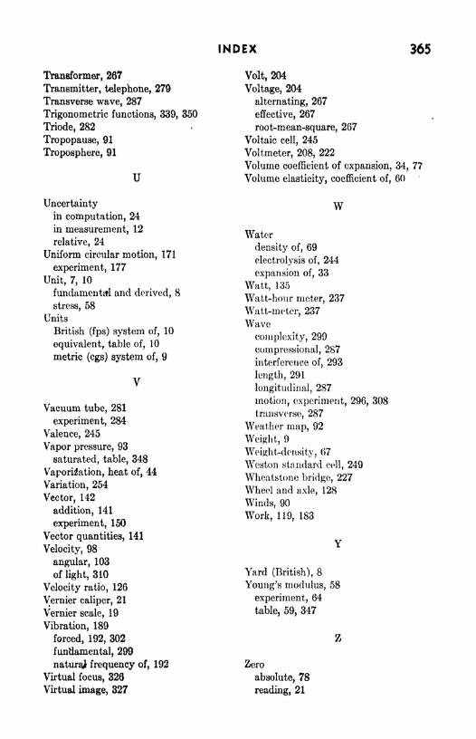
INDEX 365
Transformer, 267
Transmitter, telephone, 279
Transverse wave, 287
Trigonometric functions, 339, 350
Triode, 282
Tropopause, 91
Troposphere, 91
U
Uncertaintyin computation, 24
in measurement, 12
relative, 24
Uniform circular motion, 171
experiment, 177
Unit, 7, 10
fundamental and derived, 8
stress, 58
Units
British (fps) system of, 10
equivalent, table of, 10
metric (cgs) system of, 9
Vacuum tube, 281
experiment, 284
Valence, 245
Vapor pressure, 93
saturated, table, 348
Vaporisation, heat of, 44
Variation, 254
Vector, 142
addition, 141
experiment, 150
Vector quantities, 141
Velocity, 98
angular, 103
of light, 310
Velocity ratio, 126
Vernier caliper, 21
Vernier scale, 19
Vibration, 189
forced, 192, 302
fundamental, 299
natural frequency of, 192
Virtual focus, 326
Virtual image, 327
Volt, 204
Voltage, 204
alternating, 267
effective, 267
root-mean-square, 267
Voltaic ceU, 245
Voltmeter, 208, 222
Volume coefficient of expansion, 34, 77
Volume elasticity, coefficient of, 60
W
Water
density of, 69
electrolysis of, 244
expansion of, 33
Watt, 135
Watt-hour meter, 237
Watt-meter, 237
Wave
complexity, 299
compressional, 287
interference of, 293
length, 291
longitudinal, 287
motion, experiment, 296, 308
transverse, 287
Weather map, 92
Weight, 9
Weight-density, 67
Wcston standard cell, 249
Wheatstone bridge, 227
Wheel and axle, 128
Winds, 90
Work, 119, 183
Yard (British), 8
Young's modulus, 58
experiment, 64
table, 59, 347
Z
Zero
absolute, 78
reading, 21