mm
259
00 ft- ro p m<OU 166643 >m > a - 73 ^ m i o co >
-
Upload
khangminh22 -
Category
Documents
-
view
1 -
download
0
Transcript of mm

00ft-
ro pm<OU 166643 >m> a -
73 ^m i oco>


THE
LABORATORY
WORKSHOP

PLATE I
A
An attic room converted into a laboratory workshop

THE
LABORATORY WORKSHOPA SIMPLE COURSE
IN APPARATUS MAKING ANDTHE USE OF TOOLS
r-
BY
E. H. DUCKWORTHB.Sr., A.U.C.S.
Insiector of Silence and Technical EducationColonial Service, Nigeria*
Formerly Senior Science MasterDean Close School, Cheltenham
AND
R. HARRIESCity and Guilds [Lngmeenng] College
Imperial College of Science and fedmology, London
LONDON
G. BELL & SONS, LTD1933

Printed in Great Britain by The Camelot Press Limited
London and Southampton

PREFACE
THE writers of this book were responsible for the workshop
practice which formed a distinctive part of the Science Colleges
held at Cheltenham by the Board of Education in 1930 and 19<fl.
It became apparent that many teachers would welcome a book
dealing with the functions of a laboratory workshop and, at the
suggestion of the organiser, Mr. E. G. Savage, II.M.L, this worfc
has been undertaken in order to reach a wider circle than is pos-
sible at a fortnight's Course. :
We wish particularly to stress the fact* that the fundamental
processes needed, even in a complex piece of apparatus, are few in
number and quite simple. We venture to make this point since
it is in danger of being overlooked by manyumen and perhaps even
more by women teachers who often regard a workshop as some-
thing outside their sphere. Our hope is that the book may en-
courage the design and construction of home-made apparatus,not only because of the pleasures and advantages which tihe use of
a laboratory workshop brings, but also because in these times when
economy is urged and the allocation of money for scientific ap-
paratus is all too small, self-help of this kind seerhs the only wayin which efficient teaching is to be secured.
The apparatus described in Chaps. XI and XII have been selected
to show something of the wide range of equipment that it is pos-sible to construct, ift very small cost, by the application of the
simple processes described in the earlier chapters. Users of the
book should have little difficulty in applying these processes to
their own requirements.The line drawings and photographs for the illustrations have
been prepared by the writers.
Our very special thanks arc due to Miss M. A. Reid, B.Sc., whoundertook the reading of the manuscript, correction of the proofsand the compilation of the index, and whose encouragement and
sympathetic interest has been our never-failing support.Our thanks are due to the following firms for the drawings of
certain tools in Chapters I and II :
British Tool and Engineering Co., Ltd. (Bench drilling machine,Item 18).
v

vi PREFACE
Greenfield Tap and Die Corporation (Little Giant screw cutting
appliances, Items 1-7).
C. and J. Hampton, Ltd. (Record vices, Figs. 2 and 3, and
Stanley pattern planes, Items 76 and 77).
Schollhorn and Co. (Bernard pliers, Items 49 and 50).
Other acknowledgements are made under the respective figures.
E. II. DUCKWORTH11. HARRIES

CONTENTS
CHAP. PAO1C
INTRODUCTION ...... ix
I. THE SELECTION AND GENERAL EQUIPMENTOF A LABORATORY WORKSHOP ... 1
II. TOOL EQUIPMENT . . . . .14III. MATERIALS ...... 29
IV. How TO MARK OUT, CUT, FILE, DRILL ANDBEND SHEET METAL, ROD, STRIP AND TUUE 50
V. SCREW CUTTING ..... 78
VI. SOLDERING 102
VII. WOODWORKING ..... 119
VIII. ELECTRIC WIRING AND THE LABORATORY . 136
IX. MISCELLANEOUS PROCESSES THE CUTTING,^DRILLING AND GRINDING OF GLASS , . 156
X. DRAWINGS AND DESIGNS .... 175
XL APPARATUS DESIGNS .... 187
XII. MORE APPARATUS DESIGNS . . . 226
APPENDIX ...... 240
INDEX ...... 243

LIST OF PLATES
I. A I.ABORATORY WORKSHOP ....AN ATTIC ROOM CONVERTED INTO A LABORATORY WORKSHOP
Frontispiece
PAGE
II. A. A LABORATORY BENCH CONVERTED TO WORKSHOP USE . .183B. MICRO-PROJECTOR 183
III. A. RADIATION SWITCH 194
B. SEARLE'S HFAT CONDUCTIVITY APPARATUS . . . 194
IV. A. PROJECTION MICROSCOPE ...... 209
B. SPECTRUM PROJECTION APPARATUS ..... 209
C1
. SOAP FILM APPARATUS ....... 209
V. A. LARGE B.C. ELECTRO-MAGNET 223
B. LIFTING ELECTRO-MAGNET ...... 223
C ELECTRO-MAGNETIC DIP-NEEDLE ..... 223
D. SYNCHRONOUS MOTOR 223
E. APPARATUS FOR PRODUCING A ROTATING MAGNETIC FIELD 223
VI. A. MODEL TO ILLUSTRATE THE MECHANISM OF A MOTOR-DRIVEN
GARDEN ROLLER 235
B. AQUARIA < 235
C. SMALL TANK 235
D. WHIRLING TABLE WITH STROBIC DISC .... 235
E. SHAKING SAND BOX 235
VII. A. DERRICK CRANE WITH LIFTING ELECTRO-MAGNKT . . 238
B. HAMMER-HEADED CRANE 238
C. TRAVELLING CRANE ....... 238
1). AUTOMATIC RECORDING AUXANOMETER .... 238
VIM. A. MODEL OF A MEDIEVAL SYSTEM OF FARMING . . . 239
B. MODEL OF A CASTLE ....... 239
C. MODEL OF A LAKE VILLAGE 239
D. HISTORICAL MODELS : 239

INTRODUCTION
A SCIENCE laboratory forms part of the recognised equipment of
every up-to-date school and many schools have spent large sumson elaborate buildings and ready-made apparatus, yet it is quiterare to find any of these laboratories with a suitably equipped
workshop for the repair and construction of apparatus.The type of laboratory that has been equipped in every detail
from a catalogue is far too common and rather depressing in its
lack of originality and flexibility.
Most science masters have had the experience of delving into
cupboards and finding a dusty collection of broken balances,
galvanometers and such-like that are no longer in use owing to the
lack of some small screw or essential part. The old apparatuscan be packed up and sent back to the makers for repairs, but
this involves trouble, time and money.A small workshop enables repairs to be done at negligible
expense without delay and, what is even more important, the
teacher of science with a knowledge of the usetof tools is able to
try experiments that are not found in school text-books *md to
introduce into his teaching a freshness and originality that is often
sadly lacking in these days of certificate examinations.
The modern science student at a University receives little
training in manual dexterity. The lecture experiments are set upby skilled assistants and the laboratory work seldom calls for
much manipulative skill, with the result that few science masters
or mistresses have an opportunity of learning the use of tools and
the construction and adjustment of apparatus.The late Sir James Dewar often deplored this lack of ability
in students under his notice. His own dexterity, displayed in his
work and lectures was founded in boyhood days when he tried his
hand at making fiddles. He regarded this early training as tlie
most important part of his education.
During recent years the Board of Education in England has
attempted to remedy this deficiency in the school and university
training of science teachers by the organisation of vacation
courses in laboratory arts. The present writers have had oppor-tunities of giving instruction at some of these courses and noting
ix

X INTRODUCTION
the special difficulties and requirements of science masters and
mistresses.
It is hoped that this book will assist science teachers to make a
workshop a useful and vitalising part of their equipment.In general education a laboratory workshop can play an im-
portant part. Most school workshops come under one or other of
three categories. A wood workshop, a metal workshop or an
engineering workshop.A wood workshop requires no description, a metal workshop is
usually devoted to the making of ornamental articles in sheet metal
and simple forging, and an engineering workshop implies an
equipment of lathes, milling machines and so forth.
Many public schools, with engineering workshops fitted with
machine tools, find a difficulty in providing suitable work of a not
too expensive character for the students to practise on.
Both wood and metal workshops are of value provided theydo not degenerate into places for wearisome exercise in the makingof joints or the shaping of material to set forms, such exercise
pieces to finish up ultimately on a scrap heap.The wide development of science in schools has given the oppor-
tunity for a new type of workshop, where science and handcraft
are happily linked together, and where students can learn that
general1 handincss with tools for accurate working in both wood
and metal, which is of value, not only to the future science worker,
but to any man of woman living in the present age of mechanism.
Few boys after leaving school, unless they take up engineering as
a profession, are likely to have the use of workshops equipped with
lathes and machine-tools; on the other hand a Kttle workshop
provided with wood-working tools and mechanic's hand tools for
metal work is readily acquired and provides the owner with a
life-long, pleasurable and most useful hobby, in that it enables himto make and repair many things required or used in home or
garage.
In a laboratory workshop both staff and students have an
opportunity of making up all sorts of interesting models and
experimental apparatus, of trying out old, almost forgotten,
experiments or attempting new ones. An escape is provided from
the stagnation of examination science and something of the spirit
of a research laboratory is introduced into school studies.
An elaborate, expensive, equipment is not necessary, but it
does include, not only the usual carpenter's tools, but such things
as files, soldering irons and stocks and dies for cutting screw-
threads, also a supply of suitable materials.

INTRODUCTION XI
The omission of a lathe, so far as beginners are concerned, is
rather an advantage than otherwise, since the art of inventing,
improvising and adapting tends to be stimulated by its absence.
A workshop allied to the laboratory helps students to learn the
application of knowledge gained from books or in the lecture room.
A student who has constructed a telephone or microscope
projector, or wrestled with the difficulty of making and adjusting
apparatus to show the interference colours of soap films on a
screen has more real knowledge about these things than one whohas only read text-book descriptions or looked at demonstration
apparatus.
Many schools suffer from lack of science equipment yet, as the
following pages set out to show, it is possible to make a great rangeof laboratory equipment at very small cost.
All the apparatus described has been constructed and tested
out by students in England or Nigeria, and some of it has been
exhibited in London at meetings of the Science Masters' Associa-
tion.
The writers hope that the book may serve as a practical guideto the equipment of a laboratory workshop, provide help to
teachers and students in the use of tools, and give information
regarding the construction of a wide range of apparatus, also hints
on the setting up of interesting experiments that are* seldom
included in text books and arc of value in connection with school
science exhibitions. *
Many of these experiments, especially if demonstrated with
home-constructed apparatus, help to stimulate interest in science
and show something of its romance.


CHAPTER I
THE SELECTION AND GENERAL EQUIPMENT
OF A LABORATORY WORKSHOP
THE selection of a room, or space in the laboratory to be used as a
workshop is subject to various considerations. The workshopshould, if possible, be close to the laboratory. If a separate roomcannot be used, a place can often be found in the laboratory itself,
for preference in the physical laboratory. The fumes of a chemical
laboratory can cause steel tools to rust over-night. An elaborate
building is not necessary; thought should be given to the creation
of a workshop atmosphere; white paint and glazed tiles are
incompatible with the surroundings of a workshop. At the sametime arrangements should be made to keep everything neat and
tidy, since an array of well kept tools and materials, all ready to
hand and not hidden away in store boxes, has a valuable psycho-
logical effect in stimulating ideas. If the workshop is to *be used
by the science staff, a laboratory assistant and a few students
only, quite a small room will suffice. In cold countries provisionshould be made for heating during the winter time; it is difficult
to do accurate work with metal if the hands are numb. In warmcountries the Workshop should be as airy as possible.
Many schools already have carpenters' workshops and it is
often an advantage to do most of the woodwork required in this
shop, reserving the laboratory workshop for metal work. This
avoids the dust and litter of sawdust and shavings. Small tools,
little nuts and so on tend to get lost in a mass of shavings. If a
separate room or space cannot be detailed for woodwork, then the
next best thing is to have a separate bench, and if this is not
possible it is always a good rule after using a plane to sweep upthe shavings before going on to other work (Plate HA, page 18o).A good firm bench is essential. A design for a bench is shown
(Fig. 1). This may be made of pitch pine, deal or wood of similar
type. Deal is quite suitable and cheaper than pitch pine. The
top of the bench should be made of thick wood and be massive
enough to stand the blow of a mallet or hammer without rebound,
A bench, to be used for woodwork, isconveniently^
made lower
Bw i

THE LABORATORY WORKSHOP
Fig 1 A workshop bench
than one for metal work. When using a plane or chisel the worker
requires to stand well over his work. Laboratory metal workinvolves much delicate marking out and drilling, a bench that is
too low necessitates uncomfortable stooping. For wood worka bench height of 2' 6" is recommended and for metal work 3' is
not too high. A bench for combined wood and metal work is
conveniently macte 2' 10" high. It is often possible to convert an
ordinary laboratory bench. To protect the polished top from
the marks and cuts inevitable in a workshop the teak or other
top of good wood can be protected by covering* it with some
planed lengths of cheap wood firmly fastened down with screws.
A laboratory bench free from under-cupboards is to be preferredsince it gives a better standing or sitting position. Drawers on
the other hand are an advantage. The bench must be providedwith a parallel-jaw vice. The number of vices fitted will dependon the number of workers likely to use the shop at any one time.
A vice to every worker is ideal, but much can be done with one
vice to every two or even three workers; a vice is in such constant
ue that one vice per worker should be aimed at if possible.
A vice with jaws 4* wide of the type shown (Fig. 2), is a useful
size. This may look large and clumsy, but will be found in practice
to be capable of holding small delicate work and it is a great con-
venience to have at least one good strong vice when iron-strip has
to be hammered over and bent without heating or"diam. iron
rods have tQ be provided with a screw-thread.

SELECTION AND EQUIPMENT o
Small vices with jaws 2" wide are quite cheap and will serve for
the majority of purposes, but if possible instal both a large and a
small vice. Vices are made in cast iron and steel. Steel vices are
much stronger and more expensive than cast iron ones. Since a
vice should never be hit with a hammer, cast iron ones are quite
satisfactory if this action be avoided.
The jaws of a good vice should go together fair and square and
be free from side wobble. Much of the wood-making to be done*
in connection with a laboratory workshop can be carried out with
Woodworker's quick-giip
paiallel-jaw \iee
the help of an ordinary parallel-jaw vice, but if space allows it is
useful to instal an ordinary carpenter's vice. A metal vice of the
quick-grip type shown (Fig. 3), is easily attached to a bench and
is a great help.
When attaching a parallel-jaw metnl vice to a bench, select a
firm place near to a bench leg or support. The marking out of the
positions of the holding down bolts or screws requires care. Clampa long straight metal bar in a vertical position in the jaws and so
place the vice on the bench that the bar is just clear of the edge of
the bench (Fig. 4). Avoid as far as possible the vice projecting
out over the bench top, at the same time it must project far enoughto enable it to hold long vertical rods that extend below the level
of the bench top. The jaw edges, as seen from above, must be
parallel to the bench top. Test with a long rod clamped in the
jaws in a horizontal position (Fig. 5). A mechanic usually con-
trives to fix his vice at such a height that .he is able to rest his
elbow on the top of it when standing by the side of the bench
(Fig. 6).
This arrangement is seldom possible in a laboratory workshopwhere the vice is likely to be used by people of different height.
Small vices can be secured to the bench top with strong counter-
sunk head wood screws, but a better arrangement,* essential in

4 THE LABORATORY WORKSHOP
the case of large vices, is to fasten them down with nuts and bolts.
Note the diameter of the holes in the base of the vice, one is
usually uncovered only when the jaws are partly opened. Obtain
some iron or bright-steel Whitworth bolts of a size to just pass
through these holes and of a length about longer than the
combined thickness of bench top and vice base.
Suppose a f"diam. bolt has been found to be suitable. Mark
'the position of the vice bolt holes as described above and with the
help of a f"diam. bit held in a carpenter's brace, bore holes in the
bench at those places.
Put the vice in position; if the bolts are a little difficult to get
through the wood, although holes of the correct diameter have
been bored, just tap them through with a hammer. Sometimes
in fitting a vice to a laboratory bench it will be found that the
under support of the bench top or a drawer (Fig. 7), will preventthe vice being fixed in such a way as to project far enough. In
this case it may be necessary to cut some of the wood away from
the inside with the help of a wood chisel or gouge to give room for
a nut and washer (Fig. 8). If everything is in order, put washers
on the bolts and tighten up the nuts with a spanner. If a bolt
tends to turn round as a spanner is used on the nut, then use two
spanners, one to hold the bolt and the other to turn the nut.
Sometimes it will be found that the screw-thread on the bolt does
not extend far enough to enable the nut to be tightened up. In
this ca^se remove the bolt and cut more thread on it with the helpof a die (see screw cutting< Chapter V). Failing the use of a die
find a nut with an inside diameter large enough to pass over the
bolt thread and use it as a packing piece with walhers on cither
side (Fig. 9).
Bench and vice having been provided for, the next consideration
is the arrangement of tools. It is wise to study economy of move-
ment and have all commonly used tools as near to hand as possible.
Much time can be saved in selecting the correct tools and in
tidying up, if unnecessary walking about the workshop can be
avoided.
It is much better to keep all tools out and ready for immediate
use than to store them in boxes and drawers. If displayed in
definite positions the loss of tools is readily detected and they are
easily examined for rust.
The skilled craftsman knows instinctively what tools to use for
any particular piece of work and may almost be compared with a
musical composer selecting the right note. It is surprising the
number of tools that may be called into use for the completion

SELECTION AND EQUIPMENT
Fig. 4. Fig. 5.
Method of determining the correct position of bolt holes when attachinga viee to a bench
No room for nut of
holding down bolt
Fig. 7.
Bench,
Fig. 6.
Method of testing a vice for height
Wood cut away to~ive room fornut
'washer
Fig. 8.
Packing nut
Fig. 9.
Method of usiyg holding-downbolts that are not threaded far
enough dfwn the stem

THE LABORATORY WORKSHOP
Methodof con-
structing
Type 3
Dowel Rods
Type 2
TypeS
Fig. 10. Wooden tool racks
Fig. 11. A metal clip form of tool rack
Nailwithout,
a headOrdinarynails
A Shou!dr S^u^-e Hook
Fig, 13. Tool holders
A Cup Hook
Fig. 12.
Tool holders

SELECTION AND EQUIPMENT 7
of quite simple apparatus, hence the necessity for tools arranged
ready to hand.
Tools like files, hammers and chisels can be held in loops of
leather strap, wooden racks or metal clips.
feather straps can be purchased quite cheaply at a harness
maker's in long lengths without metal buckles and are easily made
up into loops of different sizes to suit the tools; they can be
attached to woodwork with round-headed brass or iron screws.
Holes for the screws to pass through the leather can be made with
a bradawl.
Wooden racks are cheaper to provide than leather loops and in
some respects are more satisfactory (Fig. 10).
Tool dealers sell metal clips for holding tools, a few of these are
often handy (Fig. 11).
Large tools like saws and a carpenter's brace are readily sus-
pended on shoulder square hooks, cup hooks or nails (Fig. 12).
Steel rules can hang from nails that have had their heads cut off
(Fig. 13).
As far as possible arrange to keep the bench top clear of tools,
except of course when work is in progress.If the wall facing the bench be made of brick or concrete some
difficulty will be experienced in attaching tool holders. , In this
case it is best to cover the wall to a height of a few feet with
wooden boards. The wall will have to be plugged, the method of
doing this is described in Sec. 201. It is wise to keep tke floor
space as clear as possible to simplify Sweeping up. A shelf under
the bench is handy for storing boxes of oddments and a shelf about
6" wide, opposite the bench and about 2' above it provides a
useful place for plane's, small tools and tools of odd shape that donot readily slip into loops or other holders.
Cupboards are useful to store paint tins and brushes that tend
to become unsightly, also to keep from the dust objects that have
just been enamelled. Cupboards, also drawers, require periodicoverhaul to prevent them becoming the abode of litter. Provide
plenty of shelves for the storage of screws, nails and such like.
The bench used for woodwork should be fitted with a benjch
stop to enable wood to be planed. Ready-made, metal bench stopscan be obtained. When these are used beginners are very liable
to chip bits out of plane irons by continuing to plane when the
edge of the stop has come flush with the wood being worked on
(Fig. 14).
An alternative method is to bore a row of vertical holes in the
bench top and fit these with dowel rods (Fig. 15). Thfe rods should

8 THE LABORATORY WORKSHOP
be left about 1' long. With the help of a mallet they can be
knocked up from below to any required height. They readily
prevent work slipping, do not get in the way, and no possible
injury can be done to either the job or the plane.
Metal stob too
highAWood beingplaned
Metal Bench Stop
Fig. 14.
Racks should be made to carry a supply of strip, rod and sheet
metal. ^Two types are shown (Fig. 16). Odds and ends of waste
metal should not be thrown away, but kept in a special box. Onebox for brass and copper, another for iron and steel. Great
economy can often be effected by using up odd bits instead of
cutting into new supplies.
Screws arc best bought in gross packets and are Always rather
difficult to keep tidy and sorted. The advantage of leaving the
screws in their original packets is that the lengths and size numbersare printed on the packets.
It is often necessary to
return unused screws to
packets. It is trouble-
some to compare a screw
held in the hand with the
particulars on a label.
.For this reason it will be
Fig. 15. A fool-proof and very efficient , , . .
form of bench stopfoiind advantageous to
store the screws in labelled
glass jars. Sorting is simplified, the stock remaining in reserve
can be noted and iron screws are preserved from rust.
Old jam and honey pots with screw tops are excellent for the
purpose and 'are cheap to replace if broken.
, s l} apart

SELECTION AND EQUIPMENT 9
Wooden. Bar
pivoted atone
end enabling"
long-lengthsofmetal tobe
readily-withdrawn.
Bars to
prevent short
lengths from
falling-out
A rack of the umbrella stand type for holding metal supplies
The rack can be placed against a wall
A rack for holding metal supplies
Fig. 16.
The chief disadvantage of a pot is that it has to be tilted up to
get out the contents, for this reason rectangular shaped tins a/e
sometimes preferable.
Craven A cigarette tins form excellent screw containers. They
we a gay red, free from unsightly lettering on the sides. The name
is enamelled and not pressed out on the lid. Also the latter, being
domed, gives good store space for the odd screw that is often so
difficult to return to a packet that is nearly full attd slightly
disarranged.

10 THE LABORATORY WORKSHOP
The top of the tin should be painted over with black cycleenamel and the nature of the contents neatly printed in block
lettering, using a fine brush and white enamel.
Old glass vaseline pots with enamelled screw tops make goodcontainers for tiny nuts, washers and other small supplies.
If the shelf used for storing screw bottles be subject to vibration
from the work bench it is wise to fit it with a raised strip of woodto prevent the bottles gradually slipping off.
When screws and small nuts have been used it is often found
that some have been left out after the main tidying up has been
effected. Time is saved if these are not returned to the correct
pot or tin at once, but placed in a special open tin of mixed screws
and nuts that is sorted out every month or so. One tin can be keptfor wood screws and another for metal screws.
Some workers are very wasteful of emery and glass paper.When this has been used it should not be thrown away unless dirty
or quite worn out. A special box or drawer should be kept for it.
A workshop requires good illumination.
If electric light be used, provide lamps for general illumination
r~\
Fig. 17. An electric lamp holder with push-bartype of switch
and for a concentrated light on the work bench and vice. Metal
shades, white enamelled on the inside, and of a shape to cut out
all direct light are recommended for the latter purpose. They are
somewhat expensive; a cheap, but less durable substitute is
p^vided by cardboard ones.
Bench lights should be fitted with holder switches. Holder
switches of the push bar type (Fig. 17) are much to be preferredto holder switches of the turn type. The former can be worked
with one hand and the flexible connection is not bent when the
switch is operated.It is best to provide a separate soldering table or at any rate
reserve a special place on the bench for soldering. This table or

SELECTION AND EQUIPMENT 11
bench place should be well removed from shavings. If a blow-
lamp be used for heating soldering irons the latter precaution is
most important to avoid danger from fire. Blow-lamps, unless
carefully started up, are liable to squirt out a flaming jet of liquid
paraffin (kerosene) and should always, on first pumping, be directed
away from inflammable material. A soldering table covered witha piece of Uralite, a commonly used building material made of
cement and asbestos, is particularly useful. A hot soldering iron
can be placed on the table without fear of burning anything, little
pellets of solder can be dropped on it and are readily picked up for
use. If a whole table be not used for soldering a Uralite roofing
A wooden sawing stool
tile measuring about 12" square forms a suitable cover to part of
the main bench.
An ordinary laboratory-stool should be available, sometimes a
very steady hand is required and it is an advantage to sit down atthe bench. *
If the sawing of wood be not done in a carpenter's shop, or if the
wood-shop is not near at hand or always available the wood canbe supported on two laboratory stools or even chairs, but as theseare very likely to get cut into by careless or over vigorous workersit is best to make two sawing-stools of the type shown (Fig. 18).A supply of tincture of iodine, bandages and a pair of fine
tweezers should be kept in a first-aid cabinet. Slight cuts ai;e
fairly common in a workshop and should not be neglected. Brass
filings and chips however small should always be extracted and for
this the tweezers are useful. Brass is much more liable to cause
festering than either iron or steel.
A scrap-box for odds and ends can play a most important partin a laboratory workshop and provision should be made for such astore. As subsequent chapters show many apparently useless

12 THE LABORATORY WORKSHOP
oddments can be put to good use and often save much time and
trouble in making up special parts.
The floor may be of wood planks, wood blocks, cement or even
hardened mud, but in any case should be capable of being sweptclean. The dust from woodworking is sometimes troublesome, this
is largely obviated by treating the floor with a dust allayer such
as Florigene. A cement floor should be sprinkled with a water-
ing can before sweeping operations start. The last but by nomeans the least important part of the general equipment of a
laboratory workshop is the provision of adequate facilities for
cleaning up.Old rags or cotton waste are handy for mopping up oil and paint.
If these are not available it may be found that expensive glass
cloths and dusters will be taken for the purpose.One or two soft floor brushes are required and every bench
should have a hand brush. Each brush should have a hole drilled
through its handle, so that a loop of strong cord can be inserted.
The brush can then be hung up and stored with the bristles off
the ground.It is not easy to sweep up filings without the help of a dust-pan.
A piece of sheet tin plate may be bent up to form its equivalent.Two fla,t pieces of wood arc handy for gathering up shavings and
putting them in a waste box.
It may appear jmnecessary to mention brushes and such domes-
tic items yet the cleaning up process plays an important part in a
workshop.After working for some hours the bench will get littered with
tools and it becomes difficult to find just the one required. Whenthis happens it is always wise to stop work for a few minutes and
tidy up, returning tools to their proper positions in holders and on
shelves.
If small nuts and other parts are dropped on the floor they can
usually be recovered by sweeping up. In any case it is always wise,
as a measure of economy, to look over the last sweepings for odd
screws, nuts and bolts and return them to their respective bottles
or tins.
If gaps exist in thye floor boards they should be filled in with
slips of wood or valuable parts may be lost.
A rule should be made for one's own use and for the instruction
of others that the workshop be left clean, tidy and in perfect order
after each day's work.
A clean tidy workshop, no less than a laboratory, promotes clear
thinking ami accurate work.

SELECTION AND EQUIPMENT 13
Dr. Gladstone in his delightful sketch of Michael Faraday1
under the heading, 'His Method of Working,' writes :
"He would put away each tool in its own place as soon as done
with, or at any rate when the day's work was over, and he would not
unnecessarily take a thing away from its place: thus, if he wanted
a perforated cork, he would go to the drawer which contained the
corks and cork-borers, make there what he wanted, replace the
bores, and shut the drawer. No bottle was allowed to remain
without its stopper; no open glass might stand for a night without
a paper cover; no rubbish was to be left on the floor; bad smells
were to be avoided if possible; and machinery in motion was not
permitted to grate.
"In working, also he was very careful not to employ more force
than was wanted to produce the effect. When his experimentswere finished and put away, he would leave" the laboratory andthink further about them upstairs.
"This orderliness and this economy of means he not only prac-tised himself, but he expected them also to be followed by anywho worked with him; and it is from conversation with those that
I have been enabled to give this sketch of his manner of working.This exactness was also apparent in the accounts he kept with the
Royal Institution and Trinity House, in which he entered everylittle item of expenditure with the greatest minuteness of detail."
1 Michael Faraday, by ,T. H. Gladstone, Ph.D., F.H.S., Macmillan & Co.,1873. Now out ol print, but can sometimes be obtained second-hand.

CHAPTER II
TOOL EQUIPMENT
WHEN choosing tools it is always wise to select one with a maker's
name or trade-mark stamped on it in preference to one not so
marked. A tool that a maker is ashamed to put his name on is
usually bacjly tempered or otherwise poor. A good quality tool
will last a lifetime if properly used.
Beware of combination tools that are supposed to function as a
hammer at one end, a screwdriver at the other and half a dozen
other things in between. Such tools, with a few exceptions, are
never used by workmen. In the case of young people selecting
tools and starting to build up the nucleus of a little home-workshopit is wise to select a good mechanic's or carpenter's tool in prefer-
ence to the cheap, but usually worthless 6d. store article. Thebest policy is to obtain tools from a dealer who does a good trade
with men who have to live by the use of tools or from one of the
large London firms engaged in dealing with engineering concerns;
some of these are prepared to give substantial discount rates to
schools, colleges and laboratory workers.
A study of the catalogue, of one of the large London tool dealers
can be most instructive, but at the same time rather bewildering.The number of different hammers, files, screwdrivers and so on
that can be bought, makes selection by tha inexperienced a little
difficult. This chapter is to indicate just those tools that have
been found most useful in a laboratory workshop.The number of tools that might be bought and found useful is
almost unlimited. If time is no object it is possible to make almost
anything, even a bicycle, with little other equipment than a hack-
saw and file, but few of us have the leisure of a prisoner of war or
the patience of primitive peoples who, as all know, often produceWonderful results with the help of simple tools.
Now it is possible to use a tool in many different ways and for
more than one purpose. A file can be used to file, but the tangend is sometimes handy for enlarging holes. On the other handthe tang end of a file, uncovered by a handle, when the tool is used
for its norwaal purpose, can inflict an unpleasant cut and it is muchbetter to spend a few pence and buy a proper tool for enlarging
14

TOOL EQUIPMENT 15
holes. A multiplicity of screwdrivers is unnecessary, but at the
same time a reasonable selection is required. A screwdriver strong
enough for screwing together a packing case is scarcely suitable
for carrying out the delicate adjustment of a moving coil galvano-meter or tightening the tiny screws of a spectacle frame.
When a reasonable outfit of tools has been gathered togetherand possibly selected during a number of years with the care of a
connoisseur, it is wise, before farther purchases are made, to ask
oneself 'Will it enable me to increase the range, accuracy or
efficiency of my work ?'
Certain American firms are world famous for the precision and
beauty of construction of mechanic's fine tools; during recent
years one or two Sheffield firms have turned their attention to this
line of manufacture and are now producing a good range of such
tools at competitive prices.
Lists of tools are given. List 'A' is of tools that should find a
place in every science laboratory that can be regarded as reason-
ably equipped. It is also the equipment that the private experi-
menter or the home mechanic who wishes to do domestic or garage
repairs should start to accumulate.
A drilling machine and a big 4" vice, in addition to a 2J" one,
are not absolutely essential. The drilling machine is the more
important of the two and is invaluable, not only as a saver of time
and labour, but as an aid to accuracy.List 'B' is of additional tools that will be found very useful and
can well be added as funds permit.If the workshop is to be used by several workers a more liberal
supply of certain tools will be necessary; some tools are in constant
use while others are les frequently employed.The third column in the lists indicates a satisfactory supply
for twelve students.
Certain special tools, not included in these lists, but described
and illustrated in other parts of the book can be purchased if and
when the need for them arises.
The prices shown are only approximate, current prices can
always be obtained from a tool dealer.
The cost of American tools to buyers in England is increased b^duties and it is well to enquire if a satisfactory English madesubstitute has appeared on the market.
TenJ twenty or thirty pounds spent on tools and workshopmaterials may, at first sight, appear excessive, but as pointed out
in the Board of Education publication Science in Senior Schools 1
1 H.M. Stationery Office, 1/6.

16 THE LABORATORY WORKSHOP
it is money wisely expended. Money in the case of new labora-
tories, is often wasted on over-elaborate furniture, benches and so
on. Tools are more important than furniture. With wise control
of expenditure on furniture all the tools needed can be bought and
the total cost of the laboratory need not exceed what is now often
paid.<-
If tools are available, much money can be saved over the pur-chase of completed pieces of apparatus and in repairs. The know-
ledge of materials to be gained in a workshop is a valuable asset
to science teaching, other advantages have been pointed out in the
Introduction.
LIST 'A'
ItemNo.1
2
3
4
5
6
7
19
20
21
2223
No. reqd.No. for 12
reqd. workers
DESCRIPTION
Approx. Price
single tool or
set
Whit-
Whit-
2 Stocks and Adjustable Dies \" fworth. One taper tap per size
2 Stocks and Adjustable Dies J" -^
worth. One taper tap per size
2 Stocks and Adjustable Dies. Size 0123456 and 9. Brit. Ass. One taper tap persize
2 Whitworth right hand taper taps Y . .2JJ *> " "Iff
2 ..
2 Drop-Forged Adjustable Wrenches, Jaws open
2 Set carbon steel, twist drills on metal stand,
Twist Drills carbon steel
A"
A' ......i" ......A" ......
Hand Drill to take drills up to"
12 /- to
Bench type drilling machine with chuck to
take drills up to y ...... 1 to
2 sets 2 sets Spare springs for chuck of drilling machine . .
Ref. Ch. I,
Fig. 2 'Record' Parallel Vice with 4" jaws* > > > *2 > * * * *
1 "3 Jeweller's small hand shears, straight blades13 .... .. .. curved blades
s. d.
1 14
100
1006
6
6
2
12 6
2*2*
3
3
3
5
10
3
16 6
7 9
1 6
2

TOOL EQUIPMENT 17
OZ3.Wrench for Wiutworth taps
WKitwortH adjustable die
No. 8 Carbon steel twist drills
on metal stand
BAdie
Nos 1-6 Screw cutting tools No. 17. Hand drill
No. 7. Drop-forged adjustable wrench
Nos. 22 and 23 Jeweller's snips, straight and curved blades
Nos. 24 and 25. Tinman's snips
No 28.
Engineer's cross pane hammer
L
No. 29. Engineer's ball pane hammer
Cw
No. 18. Bench type drillingmachine

18 THE LABORATORY WORKSHOP

TOOL EQUIPMENT 19
No. 30. Cold chisel
No 48. Carborundum stone
No 32. Jeweller's saw frame No 35. Hack haw
38.
NS45.
No. 46. Jeweller's files

20 THE LABORATORY WORKSHOP
No. 49. Round-nosepliers No 54 centre punch,
fine point
No. 50. Cuttingpliers
No. 51. Outside
callipers
No. 55. Centre punchmedium point
No 52. Inside [_|callipers No 50 Stcel try squtire
No. 53. Toolmaker'sdividers
No. 57. Pocket scribe
No 66 if 68 Auger bit
5)
No 69V 71 Centre bit Nos. 58 and 59. Steel rules
No 73 Countersink for hand or machine drill
No 72 Countersink rose bit
No. 70.
Stanley pattern smooth plane
N"o 75 Bradawl
No. 77. Stanley pattern jack plane

LIST CB'
96 1 2 Patent Expansion Drill for Iron Brace shank.
(See Fig. 65) 4697 1 1 Combination Square, English and Metric, 6' . . 12698 1 1 Burner Tap f*, Screwplate and Reamer. (See
Fig. 123)99 1 1 High Speed Bench Grinder for Hand. Size of
Wheel, 5" x I" 5 9100 1 3 File Brush
v. . . . 4
101 1 1 Spirit Level, 8" 19102 1 1 Sliding Bevel, 7J" 30103 . 1 2 Spokeshave, Beechwood, Brass Plated on face,
2" 16104 1 1 Plumber's Shave Hook, Triangular .. .. 10
105 1 2 Screw Nose Centre Bit for Brace V .. v 10106 1 1 Best Black Gas Pliers, T 20107 1 3 Wood Chisel with handle, \" 10

22 THE LABORATORY WORKSHOP
N?60 Handsaw.
N61 Tenon savsr.
No 65 Carpenter's Square
N89 Engineers oil can
N62 Keu.Kole saw.
N 90 Lancashire Taper Broach
* No 78 Wood Chisel
No SO Cabinet Screwdr.
No 82 Jeweller's Screwdriver
No 83 Electrician's Turn-screw
O *river
'9.92 BrazingLamp
N?93 Pliers- Longflat nose
N94 Firmer gouge
N?.9S Gouge slip stone

TOOL EQUIPMENT 23
No. 97. Combination square Xo. 99 Bench grinder
No 100 File brushNo 101 5Pmt Level
No 303 Spokeskave
No. 102 Sliding-Bevel ^ jO4 pjuinbers Shave Hook
No. 105 Screw Nose Centre bit
No. 1O9 Celluloid protractor
w ssors
No. Ill Embroidery Scissors
No. 108 Nail Set
No. 116.jWire gauge

24 THE LABORATORY WORKSHOPApprox Price
Item No. No. reqd. single tool or
No. reqd. for 12 DESCRIPTION set
workers s. d.
108 1 2 Nail Set, -J" tip 6
109 1 2 Celluloid Protractor . . . . . . . 9
110 1 2 Scissors, Cutting out, 6J" 40111 1 2 Embroidery, Fine Points . . . . 1 6
112 1 1 Rawlplug Tool Holder and Bit, No. 8 size.
(See Sec. 201) 1 10
113 1 1 Wall Drill, Size \". (See Fig. 295) .. .. 6
114 1 1 Box of 100 Assorted Hawlplugs, Size 8. (SeeSec. 201) 20
115 1 2 Vice for use in conjunction with drilling
machine. (See Fig. 128) 12
116 1 1 Circular Impenal Standard Wire Gauge, 1-3(5 7
117 1 1 Mitre Cutting Block. (Sec Fig. 224) . . 10118 1 2 Twist Drill with bit stock \" (Fig. 212) . . 9
119 1 2 i" 13
The use of the different tools is fully described in subsequent
chapters, but at this stage a few observations on the tools them-
selves will not be out of place.
Items 1, 2 and 3.
'Little Giant' taps and dies are some of the best tools of this
description manufactured. Various Sheffield firms are now
making screw cutting tools. 'Little Giant' dies have the advan-
tage of collets that guide the tool and prevent the formation of
drunken threads (see Sec. 94 Chapter V).
Dies of this type are made by G. and J. Hall, Hereford Street,
Sheffield. Other makers of taps and dies are Joseph Robson and
Sons, Mary Street, Sheffield, and the British Tap & Die Co. Ltd.,
Town Road, London, N.9.
Items 4, 5 and 6. Taps.
Small size taps are liable to get broken. It is useful to keep a few
spares in store.
Item 7. Wrenches.
The wrenches obtained should be large enough to turn a |" nut.
Item 8. Set of twist drills.
It is worth buying or making a stand. The drills are keptsorted and breakages are instantly detected. Metal stands varyin quality according to the gauge accuracy of the holes providedfor the drilk. Wooden stands are not recommended, damp or hot
conditions soon make the holes inaccurate.

TOOL EQUIPMENT 25
Items 9-16. Extra drills.
It is well to keep some small size drills in reserve, to replace any
belonging to the set (Item 8) that get broken.
Item 17. Hand drill.
The 'Yankee' ratchet hand drill No. 1530 is one of the best tools
of this description. The ratchet is often a great convenience. Atool without a ratchet, but of English manufacture is the 'Record'
hand drill No. 125 made by C. & J. Hampton, Ltd., Sheffield.
Item 18. Drilling machine.
Obtain a substantial machine designed for bolting down to a
bench, avoid the type made to clamp to a table edge. Many of the
cheap drilling machines on the market have poor bearings and
badly cut gear wheels ; before long they develop wear and become
inaccurate. The 'Britool' No. 10 machine has all its gear parts
enclosed and running in oil, it is made by the British Tool and
Engineering Co., Ltd., Wolverhampton, England.
Item 30. Cold chisel.
Moore & Wright, Sheffield, England, make excellent cold chisels
in nickel-chrome alloy steel. They are sold under the name of
'Surecut' chisels.
Item 35. Hack-saw frame. *
The non-adjustable hack-saw frame is usually more rigid*than
the adjustable type, unless an adjustable one of first class makebe obtained.
A hack-saw frame should hold the blade without any suspicionof side play or twist.
James Neill & Co., Ltd., Composite Steel Works, Sheffield, makea good hack-saw frame known as the 'Eclipse', No. 50. R.S.
Items 38-46. Files.
Files are manufactured in great variety. When ordering files
three features have to be taken into account.
1st. The Length. This is always measured exclusive of tho
tang or part that goes into the handle. *
2nd. The Cut. This has reference to the relative degrees of
coarseness of the teeth.
3rd. The Name or Kind. This has reference to the shape.
The chief terms used to describe the cut are: Bastard, Second
Cut, Smooth and Dead Smooth.

26 THE LABORATORY WORKSHOP
A bastard file has much coarser teeth than a second cut one andis useful for rough work.
Second cut and smooth files are used when work has to be givena good surface finish.
Dead smooth files are seldom required.A file with very coarse teeth, designed for filing wood, is known
as a rasp.
The shapes of files commonly in use are given (Fig. 19). A flat
file differs from a hand one in being tapered at one end.
Fig. 19. File sections
Warding files, apart from other uses, are employed by locksmiths
to file the ward notches in keys.Hand files are made with one narrow side free from teeth. This
is known as a safe edge and is useful when the file has to be used in
a situation where a slight slip might cause injury to neighbouringwork (Fig. 20).
Item 47. File handles.
Files should always be used with handles.
When using afjle
it may catch in the workand <an unguarded tang end can, in such a
case, give rise to a cut wriest. To fit a handleFlg 2()
on a file first make certain that the handle edge on a file
has a good deep hole for the tang to pene-trate. If necessary clamp the handle in a, vice and using a twist
drill, make the hole deeper.Now clamp the file horizontally in a vice, use jaw protectors,
and, with gentle taps, hammer the handle on to the tang. Take
great care to drive it on straight. As it is being put on, view it
now and again from two positions at right angles to one another.
Item 50. Cutting pliers.
Many cheap cutting pliers have badly tempered cutting edgesthat soon fail to act. The best pliers are those with a powerful
parallel jaw action known as 'Bernard' pliers. These can be used
for cutting wire or holding work.
Items 51* 52, 53, 54, 55, 56, 57.
Callipers, dividers, centre punches, try square, scriber, A good

TOOL EQUIPMENT 27
range of Engineers' Precision Tools are now made by Moore &Wright, Sheffield, England.
Item 62. Keyhole saw.
A very good one of improved design is made by the above firm.
Item 65. Carpenter's brace.
Carpenter's braces can now be obtained with jaws capable of
holding an ordinary brace bit or a twist drill with straight shank.
This is a great convenience in increasing the use of the tool. Twist
drills of a size between f" and |" are liable, if used in a small drill-
ing machine, to press on and injure the springs inside the chuckof the machine. They are readily held in a carpenter's brace
furnished with the improved type of jaws.
Items 76 and 77. Planes.
British made planes of Stanley pattern can now be bought.Makers: C. & J. Hampton, Ltd., Sheffield.
Items 78 and 79. Wood chisels.
Marples & Sons, Ltd., Sheffield, manufacture best quality
carpenter's tools.
Item 86. Glass cutter.>
Notes on the relative merits of diamond and wheel cuttess are
given in Chapter IX.
Item 89. Oil can.
Moore & Wright ma'ke a satisfactory leak-proof oil can.
Item 92. Brazing lamp.
One of the best brazing lamps on the market is that of Primus
make.
Item 97. Combination square.
The combination squares of the two American firms Starrett,and Brown and Sharpe are well known to all mechanics for their
beautiful finish and smooth action.
Item 99. Bench grinder.
A bench grinder should have substantial, well protected bear-
ings. The Carborundum Company, Ltd., Trafford Prfrk, Man-
chester, make good machines.
28 THE LABORATORY WORKSHOP
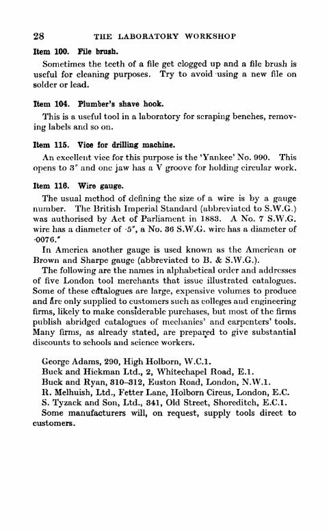
Item 100. File brush.
Sometimes the teeth of a file get clogged up and a file brush is
useful for cleaning purposes. Try to avoid using a new file on
solder or lead.
Item 104. Plumber's shave hook.
This is a useful tool in a laboratory for scraping benches, remov-
ing labels and so on.
Item 115. Vice for drilling machine.
An excellent vice for this purpose is the 'Yankee' No. 990. This
opens to 3" and one jaw has a V groove for holding circular work.
Item 116. Wire gauge.
The usual method of defining the size of a wire is by a gaugenumber. The British Imperial Standard (abbreviated to S.W.G.)was authorised by Act of Parliament in 1883. A No. 7 S.W.G.
wire has a diameter of -5", a No. 36 S.W.G. wire has a diameter of
0076."
In America another gauge is used known as the American or
Brown and Sharpe gauge (abbreviated to B. & S.W.G.).The following are the names in alphabetical order and addresses
of five London tool merchants that issue illustrated catalogues.Some of these catalogues are large, expensive volumes to produceand 5re only supplied to customers such as colleges and engineering
firms, likely to make considerable purchases, but most of the firms
publish abridged catalogues of mechanics' and carpenters' tools.
Many firms, as already stated, are prepared to give substantial
discounts to schools and science workers.
George Adams, 290, High Holborn, W.C.I.
Buck and Hickman Ltd., 2, Whitechapel Road, E.I.
Buck and Ryan, 310-312, Euston Road, London, N.W.I.
R. Melhuish, Ltd., Fetter Lane, Holborn Circus, London, E.C.
S. Tyzack and Son, Ltd., 341, Old Street, Shoreditch, E.C.I.
Some manufacturers will, on request, supply tools direct to
customers.

CHAPTER III
MATERIALS
MUCH time and trouble can be saved by providing the workshopwith a small store of suitable materials; it is annoying to be held
up in the middle of a piece of work for want of a length of metal of
suitable size or for a screw or nut of the correct dimensions and
pitch of thread.
It is well to have scrap boxes where oddments of all descriptionscan be stored. A good scrap box can be a great aid to the designerand will sometimes save the making of complicated parts. Skilful
use of the hack-saw, file and drill will often change apparentrubbish into something quite new and useful.
Electrical contractors and garages frequently have oddmentsthat they are willing to give away or part with for a few pence; for
those who live in London, the hawkers' stalls in Farringdon Street
and the Caledonian Market, devoted to scrap metal and old
instruments, are not, on occasions, to be despised, though they do
not always repay a visit. >
A scrap box need not be a jumble. Most things can be sorted
and arranged methodically. Scrap ebonite in one box, old
terminals in another and so on.
In addition to the utilization of old material, a stock of newmaterial should be kept available. The more remote a workshopis from the source of supplies the better should be its store. Themetal merchants' lists present a great range of metals in different
sizes and shapes.The metals most commonly used in the construction of
apparatus are brass, steel, copper and aluminium; these can be
obtained in the form of sheet, rod and tube.
Some knowledge of the different forms and qualities of material,and of the measurements used in commerce is, of value to anyone
engaged in a workshop.
SHEET METAL1. Brass.
Brass sheet is sold by weight. The average retail*price in
England is about 1 /- a pound; but it varies slightly with the

30 THE LABORATORY WORKSHOP
fluctuations of the metal market. The quality of sheet brass
usually required in a workshop is that known as 'Hard Rolled
Brass'. In the thin sizes this is very easy to bend and does so
without cracking. From large metal-traders it is possible to
obtain other qualities, spring hard, half hard and soft. A small,
but sometimes useful supply of spring hard brass can be obtained
from the contacts of old flash lamp batteries. Sheet brass is
manufactured with a smooth matt, or with a polished finish, the
latter is known in the trade as planished brass. When ordering
brass it is necessary to specify the area of the sheet required. Thestock size of a sheet is 4' x 6'. If a whole sheet be not wanted
the merchant will always cut off the amount required. The
thickness of brass is usually defined, not by actual measurements
in inches, but by a gauge number. In England the ImperialStandard Wire Gauge is employed (Item 116 tool list).
Useful gauges are as follows :
Gauge No. S.W.G. thickness ins. app.
Sheet Brass 20 -036
24 -022
Sheet brass in the lighter gauges, can be bought in coils of width
J" to 1'. This is a very convenient way of purchasing it.
Recommended gauges in 1' widths are :
Gauge No. S.W.G. thickness ins. app.
Sheet Brass rolled in coils 20 -036
22 -028
24 -022
26 -018
30 . 0124
A complete coil weights 28lbs., but any smaller amount can be
bought. If a large flat piece of brass be required it is better to
buy it as an uncoiled sheet and avoid the trouble of having to
remove the curvature.
2. Sheet copper.
The method of gauging and selling copper is similar to that for
'brass. Copper sheet can be obtained coated with a thin layer of
tin on one side. This is useful when a copper vessel has to be
made for domestic purposes, but it has no special advantages for
apparatus construction apart from increased ease in soldering.
Recommended gauge of sheet copper:No.eO S.W.G. Approx. thickness -036"
The price of copper is about the same as that of brass. A sheet

MATERIALS 31
of brass has greater rigidity than a sheet of copper of equal thick-
ness.
3. Sheet steel.
A useful quality is that known as black, mild steel, sheets
No. ,16 S.W.G. Approx. fa"thick. A standard sheet measures
6' x 24". A piece measuring 6' x 6" is more convenient for cutting
up with hand tools than a big one.
4. Tin plate.
This is the material used in the manufacture of cigarette tins,
petrol tins and such like. It is thin sheet steel that has been
dipped in molten tin to give it a protective coating. It is not
sold by gauge numbers; the thickness of tin plate is usuallydenoted by one or more crosses - one cross - two cross and so on.
Useful thicknesses are two cross and three cross. One cross is
very thin, so thin that it can be cut with a pair of strong domestic
scissors.
Professional tinsmiths use five cross for first class work, but
this is rather thick and difficult to cut and bend without special
equipment.Ix has a thickness of approximately -0148"
2x -0164"
3x -018"
4x -920"
Tin plate is sold wholesale in wooden boxes holding eithe? 100
thin sheets or 56 when the thickness is* greater than three cross.
Such large quantities are seldom required in the laboratory work-
shop. Stock sizes arc 20" x 14", 25" x 17" and 28" x 20".
A single sheet of three cross measuring 28" x 20" costs retail
about 1 /3. Most ironmongers keep tin plate for it is largely used
in the making and repair of tin kettles and cans.
5. Sheet zinc.
Sheet zinc is very easily bent and soldered and is largely used
in the building trade. The manufacturers of sheet zinc use a
special gauge not the Imperial Wire Gauge, so it is wise when
ordering it to specify the approximate thickness required by*
stating the latter in decimals of an inch. An advance in the zinc
gauge number indicates a thicker sheet, this is the reverse of the
S.W.G. numbers, thus -
No. 8 Zinc Gauge corresponds to an approx. thickness of -015"
No. 10 * -020"
No. 12 ,. -026"
32 THE LABORATORY WORKSHOP
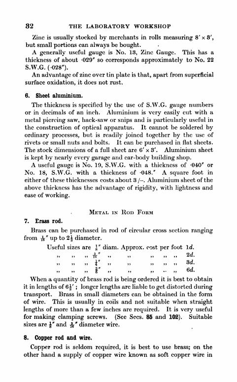
Zinc is usually stocked by merchants in rolls measuring 8' x 3',
but small portions can always be bought.A generally useful gauge is No. 13, Zinc Gauge. This has a
thickness of about -029" so corresponds approximately to No. 22
S.W.G. (-028*).
An advantage of zinc over tin plate is that, apart from superficial
surface oxidation, it does not rust.
6. Sheet aluminium.
The thickness is specified by the use of S.W.G. gauge numbers
or in decimals of an inch. Aluminium is very easily cut with a
metal piercing saw, hack-saw or snips and is particularly useful in
the construction of optical apparatus. It cannot be soldered by
ordinary processes, but is readily joined together by the use of
rivets or small nuts and bolts. It can be purchased in flat sheets.
The stock dimensions of a full sheet are 6' x 3'. Aluminium sheet
is kept by nearly every garage and car-body building shop.A useful gauge is No. 19, S.W.G. with a thickness of 040" or
No. 18, S.W.G. with a thickness of -048." A square foot in
either of these thicknesses costs about 3 /-. Aluminium sheet of the
above thickness has the advantage of rigidity, with lightness andease of working.
METAL IN ROD FORM
7. Brass rod.
Brass can be purchased in rod of circular cross section rangingfrom -fa" up to 2J diameter.
Useful sizes are \" diam. Approx. cost per foot Id.
3 " 0/799 99 99 10 99 99 99 99 *tUi*
innJ
99 99 99 99 99 OC*.
99 99 99 & 99 99 99 * 99 Oft.
When a quantity of brass rod is being ordered it is best to obtain
it in lengths of 6|' ; longer lengths are liable to get distorted during
transport. Brass in small diameters can be obtained in the form
of wire. This is usually in coils and not suitable when straight
lengths of more than a few inches are required. It is very useful
for making clamping screws. (See Sees. 85 and 102). Suitable
sizes are |* and &" diameter wire.
8. Copper rod and wire.
Copper rod is seldom required, it is best to use brass; on the
other hand a supply of copper wire known as soft copper wire in

MATERIALS 33
gauges No. 18 and 22, S.W.G. should be available. Soft copperwire, unlike hard copper wire, is readily twisted without breaking.It is useful for binding rubber tube connections to prevent them
leaking or slipping off.
9. .Steel rod.
Black Mild-Steel Rod. In circular cross section this form of
rod is very cheap and in such constant use that a good supplyshould be kept. It can be bought in any length up to 18'. Six
foot lengths are best for store purposes. The following diameters
are those most likely to be required.1 "
.3"
1" 3 " I "
8 1<> ? 4 8> '2*
10. Bright drawn mild steel rod.
Black mild steel rod has a dull, rather rough finish. Mild steel
can be obtained in another form known as bright mild steel rod.
This has a smooth surface, the diameter is very uniform, havingbeen drawn through dies, and such rod can be used for makingaxles and other parts requiring an accurate fit. It can well be
kept in the sizes given for black mild steel rod.
11. Cast steel -4555% carbon.
It is not easy to cut a perfect screw thread on mild steel. Thematerial is fibrous and tends to tear; a better material to use for
the purpose is a quality of steel known in the ti*ade as cast steel
45 -55% carbon. It costs very little more than mild steei andcan be toughened, if necessary, by making it red hot, then plunginginto cold water.
12. Silver steel rod.
If a very strong and accurate steel axle be required a length of
round, silver steel should be obtained. It is sold in standard
lengths 13" long. Silver steel does not contain any silver; the
word silver simply denotes a particular quality of steel. Since
silver steel is very hard special care has to be taken when cutting a
screw thread on it (see Sec. 93). Silver steel has approximately
1% carbon and can be made into tools and be hardened or
tempered.
13. Meccano axle rod.
Ordinary Meccano axle rod made of steel is very useful. It has
a diameter of approx. $%" and can be obtained in good straight
lengths of ll". It is soft enough to enable a screw thread to be
cut on it without difficulty.
Dw

34 THE LABORATORY WORKSHOP
14. Spokes.
Steel bicycle spokes are approximately No/ 15, S.W.G. Theyare straight and strong. The diameter corresponding to No. 15,
S.W.G. is -073". On a spoke of this diameter it is possible to cut
a No. 9 British Association screw thread.
Umbrella spokes, being of U section, are light and very strongfor their size.
15. Wrought iron rod.
Wrought iron is expensive and is seldom used except by ship-
building and railway works for high class forging.
Many country ironmongers stock so-called wrought iron for
sale to farmers and blacksmiths. This is usually a poor grade of
small carbon content steel, it can be used instead of black mild
steel, but the latter is to be preferred.
16. Metal in flat and square sections.
Lengths of metal with a rectangular section are known as flat
rods or sometimes in the thin sizes as strip.
Brass, copper, black and bright mild steel and cast steel can be
obtained in this form.
Some useful sections in brass and black mild steel are as follows:
FLAT BRASS ROD FLAT BLACK MILD STEEL
Thickness Breadth^eperfool
Thickness Breadth
A" x \" 3d.t
V' x This is sold byk" x I" 3d. |" x Y weight. Theap-
1" <
Flat copper rod is seldom required. As a general rule brass is to
be preferred.
For the connecting strips of potentiometers and Wheatstone
bridges copper has a slight advantage. It can be obtained from
large metal dealers in all the sizes given for brass.
17. Square, black and bright mild steel and brass rod.
Square section black and bright mild steel can be bought, butare seldom required, on the other hand square section brass has
many uses in a laboratory workshop.The following are suitable sizes to keep in stock.
Square brass rod"x J": f
*x f *; tf x fr f
"x f ".

MATERIALS 35
18. Metal tubes.
Brass, copper and aluminium tubes are readily obtainable in
different diameters and thicknesses. What is known as solid
drawn tube is manufactured without a join. Brass telescope
tubing is so made that the interior is very smooth; it can be
obtained in different sizes so that one tube will slide into the other
with an easy fit. Broadhurst Clarkson, Telescope Makers, of
63, Farringdon Road, London, E.C.I, often have scrap lengths of
telescope tubing for disposal.
The outside diameter is the measurement taken when specifying
brass, copper or aluminium tubes. A complete specification in-
volves an approximate thickness measurement.
If brass tubing be not available so called brass curtain tubingwill sometimes serve in its place. This is steel tube covered with
a thin layer of sheet brass. It is unsatisfactory for screw thread-
ing; the screw cutting tool cuts through and peels off the thin
coating of brass; a poor untidy thread is the result. Brass curtain
tubing is very cheap, it can be obtained in different diameters and
it is usually possible to find a size with an internal diameter that
will just allow a J" diam. rod to slip into it.
19. Solid drawn brass tubing.
Solid drawn brass tubing with an external dimeter of f" and
walls about ^" thick is very useful for making apparatus utilizing
gas fittings (see Sees. 114 and 115). ,
The radiator tubes of motor cars are made of copper, this tubingis stocked by most garages.
20. Iron pipes.
Occasionally iron pipes are useful in the arrangement of aquariaand other equipment requiring water. When ordering iron pipesit is well to bear in mind that the diameter used for measurement
is the internal diameter and not the external as in the case of brass
or copper pipes or tubes.
A half inch iron pipe has an internal diameter of |". Theexternal diameter may be as much as f ".
21. Special sections, angle and channel.
Metal rods having one of the cross sections illustrated (Figs. 21
to 24), are cheap and extremely useful, especially in the followingsizes and materials.

36 THE LABORATORY WORKSHOP
Fig. 22. Angle steel or iron Fig. 23 Channel brass
USEFUL SECTIONS, ACTUAL SIZE
Angle-brass *"x fa", \" x fa", i"x &" thick (Fig. 21). The '*
and |" refer to the outside measurements
Angle-steel orjiron f"
K I" thick (Fig. 22).
thick, i"x I", V thick (Fig. 23).
Channel brass I" x -J",'
31
2
"thick will just hold a bound lantern
slide and for this reason is of value in the construction of optical
lanterns.
22. Square tube.
Square tube made of brass (Fig. 24) is occasionally called for, it
is worth keeping a small supply in hand measuring I" x i" and
approximately -fa" thick.
23. Screws for metal.
Up to the year 1841 manufacturers of machinery used screws of
a size and shape of their own designing, and many different typeswere in use making the interchange and replacement of parts
very difficult. In this year Sir Joseph Whitworth, a well-known
engineer, introduced a screw thread, now known as the Whit-
worth thread that has been generally adopted and is the thread
commonly found on the majority of nuts and bolts about a motor
car and other heavy machinery.

MATERIALS 37
The shape of the thread is shown (Fig. 25), also the meaning of
the dimensions, pitch and depth as applied to a screw thread.
Simple mathematical relationships connect the pitch, depth andradius of the curved portions. In this way the exact form of the
thread is clearly defined for a whole series of screws of different
diameters. The angle 55 and the relationships between pitch,
depth and radius remain constant, although the diameter maychange. The diameter of a screw is the measurement shown (Fig.
26). It is measured from the top, not the bottom of the thread.
A thread cut on a bolt or rod is sometimes known as a male thread
and that inside a nut, plate or other fitting as a female thread.
The Whitworth thread was primarily designed for diameters
not less than y. The form of the thread is such that if made on
Pitch P
Fig. 25.
A Whitworth thread
Pitch P
Fig 27.
A British Association thread
a rod of a less diameter than J" an undue depth oftcut is taken with
consequent weakening of the rod, however, for screws not sijbject
to much stress those with \" and ^"diameter Whitworth threads
are quite serviceable.
The majority of instruments require many small screws for their
construction and for* these another thread called the British
Association (B.A.), is commonly used.
The form is shown (Fig. 27). It will be noted that the anglediffers from the Whitworth thread (47| and not 55); the rela-
tionships between pitch, depth and radius also differ from those
used in the Whitworth thread.
If the thread on a Whitworth screw be compared with the
thread on a B.A. screw of approximately the same diameter it
will be found that the number of threads, or little ridges, per inch
on the Whitworth screw is less than those on the B.A. screw,
although the depth of thread of the Whitworth screw is greaterthan the depth of the B.A. one.
The B.A. screw depends for its security and makes up for its
lack of depth by a greater number of threads in a given length
compared with a Whitworth screw of equal diameter.

38 THE LABORATORY WORKSHOP
A Whitworth screw of ^" diameter has 24 threads per inch,
a B.A. screw of approximately equal diameter has 28|.
Battery terminals, the little screws inside electric switches, in
fact in most small electrical apparatus have B.A. threads.
Whitworth (Whit.) threads are defined by the diameter. The
sizes most used in a laboratory workshop are:
I" 3 " I" 3" aml 1"8 > 10 9 4 9 g clUU o .
British Association (B.A.) threads are defined by numbers.
Those most likely to be used are:
No. 0, 1, 2, 3, 4, 5
Diam. -236" 209" 185" -161" -142" -126"
A Whitworth nut cannot be fitted to a B.A. terminal or bolt with
satisfactory results, although the diameter may be nearly the same.
A B.A. nut must be used with a B.A. bolt and a Whit, nut with a
Whit. bolt.
Many other threads, apart from Whit, and B.A., are used in
the watch, lens, cycle and other specialised industries, but Whit,
and B.A. arc sufficient for most laboratory workshop require-
ments.
Special threads are used for gas fittings and iron water pipes.
These are dealt with in the sections describing screw cutting
(Sees. 114 and 123).
Nuts, screws sxid bolts both Whitworth and B.A. can be pur-chased in great variety.
B.A. nuts, screws and bdlts are usually made of brass or steel and
Whit, in steel, iron or less commonly brass. The names given to
the different shaped heads are indicated in Fig. 28.
When ordering screws for metal it is necessary to specify five
things. The thread (B.A. or Whit.), the nature of the head, the
material, the gauge number or the diameter and the length. The
length of a cheesehead, button head or hexagon head screw for
metal is the measurement from just below the head to the end of
the threaded part (Fig. 29), but with countersunk head screws the
length is overall.
Sometimes a screw is threaded for its whole length and some-
times for part of its length only (Fig. 29).
A screw, especially in the larger sizes is often referred to as a bolt.
An ordinary Whitworth bolt with hexagon head is shown in
Fig. 30.
A bolt threaded down its whole length is known as a set screw
(Fig. 31)?
On motor cars, nuts, bolts and set screws are used made of steel.

MATERIALS 39
wsaSBfflaaaM cSM!B!i!laiin tilisiuwaall UTOMUTO^ i
Cheesehead G?unt<rsun Button Hexagon^ Fig, 28. Screws for metalhead head heacl
Fig. 29. Screws for metal threaded for part of their
length onlylength
toQi Fig. 30. A Whitworth bolt with hexagon head
Hexagon
Fig. 31. A set screw. The thread extends the wholelength of the stem
I** IJ Fig. 32. Two types of forged or pressed nutsSquare
Wm^Nut Turned BrassTerminal Nut
Fig. 33.
Spring washer Springwasher AwasheroftheDouble Coil Single coil ordinary type
Fig. 34.
Carriage bolt
I 'Whit
prilla hole in the
wood equal to the
,diameter of the
Stem of the bolt
Square portion form* adrive in fit wJ-en th boltIt hammered into petition
Fig. 35.
These are manufactured with beautiful precision by the use of
special lathes, they have a bright surface and well-cut threads.
They are known as bright steel nuts, bolts or set screws and are
of the best quality.For cheap work, that does not call for such precision and
strength, it is possible to buy Whit, nuts and bolts forged fromred-hot or pressed from cold steel.
These have a dull black finish and are the nuts and bolts usuallystocked by ironmongers. Two types of forged and pressed nutscan be obtained, square and hexagon (Fig. 32).Two types of nuts that are sometimes uspful are wing nuts in
iron or brass and turned brass terminal nuts (Fig. 33).
Usually a nut requires a washer under it. Washers are made in
black steel, bright steel and brass. Pressed or forged Whit, nutsare usually fitted with black steel washers and bright steel Whit,nuts with bright steel washers of appropriate size. A washer size
is specified by the diameter of its hole.

40 THE LABORATORY WORKSHOP
When nuts are subject to vibration and must on no account getloose it is usual to fit them with steel spring washers (Fig. 34).
The washers used with B.A. nuts are made of bright steel or
brass and can be obtained in very small sizes.
When fitting a wooden framework together, it is a help to use
black steel carriage bolts. These have a square portion under the
head and when tapped into a hole of appropriate size in woodwork
length Length
Fig. 37. How the length of awood screw is measured
00 3 4 5 6 8 12
Fig 38. Usual sizes of wood screws
Fig. 39. Types of rivets
Panel pir
Oval Steel
T, ^Brad
French orWireil
Fig. 40. Types of nails
will Rot rotate when the nut is tightened (Fig. 35). They are
stocked by all ironmongers*,
24. Screws for wood.
Screws for wood are made in iron and brrfss. Brass screws are
more expensive and not as strong as iron ones, but have the ad-
vantage of not rusting. The heads of screws may be round or
countersunk; a type of screw known as a raised head screw has
recently come into considerable use for motor body fittings and has
a particularly neat appearance (Fig. 36).
The diameter of a wood screw is specified, not in inches but bya gauge number ranging from 0000 or 4 /O in the very small size
then 3 /O, 2 /O, 0, 1, 2,C3, 4 up to 40 (Fig. 38).
To define a screw completely it is necessary to state material,
type of head, gauge number and length. A No. 14 screw, has a
diameter of about ", it may have a length of 1", 1 J", 1|", 2", 2J",
2j", or 3", the diameter is constant no matter what the length.
The saftie note with regard to length and diameter applies to
screws of other gauge numbers and diameters. Screws can be

MATERIALS 41
purchased in the small gauge numbers ranging from |" long, then
in the following steps:
3 " 1 " 5 " 3 " 7 "1" 5 " 3 " 7" 1 "
10 4 > 1% S > Tfr > 2 8 5 > 8 j
The lengttfof a countersunk screw is the over-all measurement.
The length of a round head screw is measured from the underside of
the head to the point (Fig. 37). Some useful sizes arc as follows:
Iron countersunk head Brass countersunk headwood screws. wood screws
Length LengthNo. 00 i" No G |" No 00 \" No 5 \"No 3 f" No 8 1", I", 1", No 3 f" No. 6 f"No 4 \" \\" , If" No 4 |" No. 8 f", 1"
No 5 I" No. 12 2"
As a time-saving guide it is convenient to mount labelled speci-
mens of each of these screws on a board and to hang it up in the
workshop with a note below each screw of the correct drills to use
with it.
The cheapest way of buying screws is in gross packets. Theycan also be bought at ironmongers by the dozen. Brass screws
cost about twice as much as iron ones of the same type, gauge and
length.
25. Rivets. ,
Rivets in iron, aluminium or copper may be either bifurcated,
round or snap head, flat head, countersunk head or hose rivets
(Fig. 39). Useful sizes are as follows.
Iron, roynd head rivets \" ', \" , ^" I"
Iron, flat head .. J" > \"
Rivets are usually sold by weight.
26. Nails.
Nails are seldom required in the construction of apparatus, it is
best to use screws, but occasionally they arc wanted, and a few
pounds' weight of different kinds should be kept in stock.
Nails are manufactured in many different lengths and shapes.
The three types shown (Fig. 40) should find a place in the
workshop store.
French or Wire Nails can be used for fastening together packingcases and other rough work.
The special shape of Oval Steel Brads enable them tobe ham-
mered into a piece of wood with little fear of splitting it; they are

42 THE LABORATORY WORKSHOP
very inconspicuous. Panel pins, used for fine work, are of very
slight construction. *
Wire nails are made in sizes ranging from I"-7" 9oval steel brads
from y~% and panel pins from \" to 2".
Useful sizes are:
Wire nails, length, 1", 1 *", 2", 2|" Oval steel brads, |". 1", 1$"
Panel pins, f", H"
27. Solder.
The solder required for use with an ordinary soldering iron is the
grade known as tinman's solder. It is sold by weight in cast sticks
about 1' long.
28. Soldering flux.
This can be made from concentrated hydrochloric acid and
scrap zinc (see Sec. 125).
A very good ready-made ilux is 'Baker's Preparation'; this is a
fluid and is sold in tins and stoneware bottles. Fluxite, a paste, is
supplied in tins of the boot polish type.
29. Combined solder and flux.
'BritinoP paste made by Bi-Metals, St. Mary's Works, Eldon Road,Wood Green, London, N.22, is a combination of both solder and
flux. It is sold vi tins. When not in use it should be kept with
the li*l on and before use should be stirred to incorporate any liquid
flux that may have floated to the top.
30. Carborundum grinding paste.
A convenient form is a duplex tin. One Half of the tin contains
coarse paste and the other half compartment fine paste.
31. Carborundum powder.
This is manufactured in many degrees of disintegration. The
grade known as 100 is the kind required for general use.
32. Vaseline.
This is best bought in pots. The empty pots are useful for
holding small screws.
33. Turpentine.
Obtain this from a reliable paint and colour merchant. Someof the cheap brands of turpentine are adulterated and leave muchto be desired. When visiting a paint merchant to buy turpentine

MATERIALS 43
go provided with a clean, dry, corked bottle and buy from his
bulk supply.
34. Methylated spirit.
In countries where the tax on methylated spirit makes its use
prohibitive and a Primus blow lamp or stove has to be lit, a fairly
satisfactory substitute is a mixture of 1 part of paraffin (kerosene)and 1 part of petrol. This of course is not smokeless, but is better
and safer than either of the liquids used alone.
35. Plaster of Paris.
This can be bought from a builder, monumental sculptor or at a
druggist's. It must be kept dry and is best stored in an air-tight
jar.
36. Glass or sand paper.
This is paper treated with glue and sprinkled with powderedglass, sand is less frequently used in these days. It should be
stored in a dry place or the glue softens and the glass comes off.
If necessary dry it before use. The grade is defined by numbers,is used for very fine work and 2 for rough work.
Useful grades are No. 1, 1,fine 2 and double 2.
37. Emery cloth.
This is more durable, but more experisive than glass paper. It
will tear into strips in one or two directions only. Glass paper is
usually used for rubbing down wood and emery cloth for removingrust and polishing metal. Useful grades are: FF, F and li. FFhas a finer texture than 1 J. Both glass paper and emery cloth can
be bought in single sheets measuring 12" x 10". It is cheaper to
buy it by the dozen sheets or by the quire.
38. Scrap celluloid.
This is used for making celluloid varnish and cement. Old
celluloid set squares can be utilised, if these are not available
celluloid can be purchased from a garage where they do repairs to
motor car hoods and side curtains.
39. Amyl acetate.
This is used as a solvent for celluloid. It can be purchased from
most drug stores and from all chemical dealers.

44 THE LABORATORY WORKSHOP
40. Shellac.
Shellac dissolved in methylated spirit mikes an admirable
varnish for wood or for application to insulated wires to act as an
insulating and binding medium.Paint shops keep shellac in dry flake form or already dissolved in
spirit.
The solution can be kept in a bottle. It is best to stopper the
bottle with a plug of wood; if a cork be used it is very liable to get
stuck into the opening by the shellac and breaks when an attemptis made to pull it out.
41. Portland cement.
This can be bought from a builder's merchant. It should be
stored in a dry place.
42. Scrap lead.
This can be got from a builder or plumber.
43. Mica.
Small sheets of mica can be obtained from ironmongers whostock anthracite and oil stoves. It is used for the repair of the
inspection windows of such stoves.
N.B. Often in commerce wrongly called talc.
44. Rustless steef.
Rustless steel sheet with a polished mirror finish can be boughtin large sheets. In thin 'sizes it can be cut with snips, centre
punched and soldered with the same ease as tin plate. It is muchharder and more difficult to drill than tin njate. Ordinary twist
drills can be used, although if much drilling has to be done, it is
best to use specially hardened drills.
A useful thickness is -024" (No. 23, S.W.G.). The makers of
rustless steel are Thomas Firth & Co., Sheffield.
45. Thin sheet pewter.
This substance is soft and pliable and useful in the construction
of scenic models.
It can be bought" in sheets of various thickness from most
dealers in art workers' supplies.
The average price is 2 /- for a sheet measuring 21" x 15 "%
46. Vulcanised fibre.
Vulcanised fibre, a red coloured substance, a good insulator and
tougher than ebonite, can be bought in sheet, rod and tube form.

MATERIALS 45
It is easily cut with a hack-saw, filed and drilled. A sheet measur-
ing \" x 6" x 6" costs about 1 /6, and a tube of external diameter
|" and internal diameter |" is sold at l|d. an inch. It is stocked bymost garages.
47. Investigation of new materials.
One of the interesting features of a workshop is the possibility of
studying the properties and possible uses of new materials.
To take one example only: the number of advertised glues andhousehold cements can be counted by the score, a few carefullycontrolled tests in laboratory and workshop will soon show that
only a few satisfy the extravagant claims made for them by the
manufacturers.
In recent years many new materials for building engineering and
manufacturing have been developed; a science worker, with an
interest in practical work, can often benefit by a visit to such
exhibitions as The British Industries Fair, London and Birming-ham sections, the 'Model Engineer' Exhibition, the Machinery,
Building, Shipping and other exhibitions held from time to time.
48. The use of oddments for scientific purposes.
A visit to a 6d. store, a marine dealer's store, a cycle accessory or
ironmonger's shop can be associated with a new interest if one eyebe kept open for the possible use of oddments. *
Glass plates sold for table mats make very good plate glass,* sides
for optical tanks. Curtain stretchers J of the spring type make
potentiometers and flexible steel belts for driving pulleys. Caketins can be turned into lantern chimneys and tart tins into a
stethoscope.
49. The workshop store room.
The following is a list of material suitable for a workshop store.
No. reqd. DESCRIPTION Approx. Price
s. d.
1 gross Steel Washers, std. size \" . . . . . . 181 fc" 131 I" 141 I" ..' 1 10
3 dozen ,, \" 104 Bolts and Nuts, Whit, steel, Hex. head, ft
" x 1" . . 404 i"x2" .. .. 501 i*x3* 201 gross Steel Nuts (Whitworth)
" 261 JL-" > 2 7*
> > igr*
i r 29


MATERIALS 47
No. reqd.
1 gross
1
1
1
1
1
1
1
12 sheets
12
12
2 tins
1 Ib.
1
1
4,,
42 tins
DESCRIPTION Approx.
NettlefokTs pressed bolts and nuts, ^" diam. xl"
(Round head) ..........Screws, Brass, Countersunk, i", No. 10 . . . .
1", No. 8 .. ..
Round head, f, No. 8 . . . .
,, Iron, Countersunk, ", No. 10 . . . .
,, 1", No. 8 .. ..
, l"No. 7 ., ..
2% No. 7 .. ..
Glass Paper, Fine . . . . . . . . . .
,, Medium ..........Coarse ..........
Oil, 3 in One (3oz.) ..........Copper Wire, Soft, S.W.G., No. 18 . . . .
No. 20 ......Robbialac Black Cycle Enamel ......Aluminium Paint . , . . . . . . . .
Robbialac Enamel Brushes . . . . . . . .
Roscoe Cylinder Black, No. 1 Sue. (See Sec. 202
Chapter IX) ...........
Price
s. d.
26202 10
26
1820202020182020204040
50. Meccano Parts.
The following parts are particularly useful in the construction of apparatus.
(Fig. 41.)
No. reqd. DESCRIPTION
2 dozen Axle Rods, 11J*. .
6 only Gear Wheels, No. 27 ..
6 ,, No. 27a ..
6.
No. 27b . .
2 ,, No. 31 ..
2 ,, Worms, No. 324 ,, Flanged Wheel, No. 202 ,, Cone Pulley, No. 123 ..
4 ,, Pulley Wheel, No. 22 ..
1 ,, Contrate Wheel, No. 28
1 ,, No. 291 ,, Bevel Gear, No. 301 No. 30a1 ,, No. 30c ..
1 ,, Pulley Wheel, No. 21 . .
1 ,, No. 20a
3 dozen Collars with set screws, No.4 only Face Plate, No. 109
1 Fly Wheel, No. 1326 Couplings, No. 63
3 dozen Angle Girders, 9J*, No. 8a2 ,, 3i",No. 9b
50
Approx. Price
A. d.
2426266020
10
182610
9
6
9
6
16
4 6
1 41 8
2 6
6 6
1 4

48 THE LABORATORY WORKSHOP
Axle Rod Gear Wheel Contrate Wheel
Cone pulley Coupling- Angle girder
PulleyWheel Worm.
Collar withset screw Bevel Gear
Faceplate FlywJieel PulleyWheel
Fig 41. Meccano parts. Jly courtesy of Meccano Ltd.
51. Miscellaneous stores.
Miscellaneous stores should include, boiled linseed oil, turpen-
tine, methylatecVspirit, vaseline, red lead oxide, scrap lead, shellac,
whhVning, string, insulating tape, needles, thread and office paste.
52. Dealers in workshop supplies.
The tool dealers mentioned at the end of Chapter II supplymaterials. It is usually cheaper to buy 'metal in fairly large
quantities than in small lengths or sheets.
Smith & Sons, Ltd., 50, St. John's Square, Clerkenwell, London,
E.C.I, are well known to the scientific instrument trade and keep
supplies of brass, copper and aluminium in every form manufac-
tured.
Steel of every description can be obtained from Walker Steel
Works Ltd., Mary Street, Sheffield.
The following firms issue useful catalogues or price lists, for
which a charge of a few pence is usually made:
George Adams, 290, High Holborn, London, W.C.I; Bond's Ltd.,
254, Euston Road, London, N.W.I; A. J. Culham, 21, Strathmore
Gardens, Romford, Essex; Economic Electric Co., 64, London
Road, Twickenham, Middlesex; Grafton Electric Company, 54,
Grafton Street, Tottenham Court Road, London, W.I; G. Kennion

MATERIALS 49
& Co., 30, Kingsland Road, London, E.2; Wren Tool Co., 49a, York
Road, Ilford, Essex.
Handicrafts Ltd., Weedington Road, Kentish Town, London,
N.W.5, issue a 1 / catalogue every year called 'Handicrafts
Annual.' It gives the prices and particulars of many useful wood-
working materials, such as ply wood, strip wood and dowel rod.
Good second-hand lenses and prisms, including optically worked
prisms, achromatic combinations and condensers can be obtained
from Broadhurst Clarkson & Co., 63, Farringdon Road, London,
E.C.I; also The Miscellaneous Trading Co., Ltd., 13, New Oxford
Street, London, W.C.I.
Wray (Optical Works), Ltd., Ashgrove Road, Rromley Hill,
Kent, manufacture lenses and prisms of all descriptions and some-
times have surplus material that can be purchased at a reduced
rate.
Meccano parts can be bought at most toy shops or from Meccano
Ltd., Old Swan, Liverpool.Other addresses can be obtained from the advertisement pages
of the Model Engineer and English Mechanics.
It is useful to investigate the possibility of local supplies.
Many ironmongers and jobbing engineers keep a supply of brass,
copper, iron and steel.

CHAPTER IV
HOW TO MARK OUT, CUT, FILE, DRILL AND BENDSHEET METAL, ROD, STRIP AND TUBE
63. How to use metal working tools.
THE art of learning to use tools can be gained in various ways.Some people favour the method of setting students to copy anumber of formal exercises before allowing them to construct anydefinite article. This method is liable to be very slow and dull.
In the experience of the writers it is much better to give evenbeginners some piece of apparatus to construct and let them learnthe use of the different tools as the need for them arises.
The making of quite a simple piece of apparatus will call for the
O O O
Fig. 43.
Strips of metal cut and drilled by a professional and amateur respectively
use of a surprising number of tools and processes and students
rapidly acquire skill as the work proceeds.The materials used in apparatus construction are not expensive
and if mistakes are made it is easy to start again after the error ofconstruction has been pointed out.
The chief difference between the work of an amateur and a pro-fessional is a matter of degree of accuracy and general finish.
If a professional scientific instrument maker has to construct a
strip of metal with four holes drilled in it his finished work maylook like fig. 42. The edges of the strip will be at right angles toone another and the holes symmetrically spaced. The work of anamateur may resemble fig. 43, where the edges are not at rightangles, and the holes have been drilled at random.
If the beginner will take the trouble to measure carefully andmark out all his work and keep the idea of accuracy ever to thefront of his mind it is possible, with a little initial guidance, to
produce excellent work almost from the start.
At many of the Board of Education summer courses surprisingly50

TO MARK OUT, CUT, FILE, DRILL AND BEND 51
good work has often been done after a few days' training by menand women with no previous experience of the use of tools.
The writers' method of instruction to a new group of students is
to gather them together for an initial talk and demonstration of
the use of different tools and after that allow them to start workand come for additional guidance when they feel in doubt. Theinstructor can with advantage move about the workshop and
point out errors or better methods of procedure.It is suggested that this and other chapters should be studied by
the reader, and a general idea of their contents obtained. This
done the construction of some piece of apparatus should be com-
menced and the chapters used for reference purposes whendifficulties arise. It is hoped that the system adopted of numbered
paragraphs and references in connection with the chapters de-
voted to apparatus will serve much the same function as a living
instructor and enable the reader to acquire rapidly proficiency in
the use of tools while engaged in the construction of some interest-
ing and useful piece of apparatus.None of the processes are difficult and once they have been
mastered the reader is in a position to construct a great range of
equipment for experimental science.
A complete knowledge of the use of tools, and this applies to
tools for working in wood, metal and other substances can onlycome through the finger ends, but much help qfin be gained byintelligent observation of the way skilled artisans set about Jheir
work. The science worker requires a knowledge of certain parts of
many trades and the student can be well advised to cultivate a
sympathetic, not a superior interest, in the work of such men.
The late Sir Edward Harland, engineer and shipbuilder, used to
say how, as a boy, he liked to assist and observe workmen. Hegot to know every workshop and every workman in his native
town and picked up a smattering of a variety of trades, which
afterwards proved of the greatest use to him.
54. Marking out strip brass.
Let us suppose that a strip of brass as illustrated (Fig. 42) has
to be prepared, it can later be used to make a switch (see page 215).
It is possible that a strip long enough for the purpose can be
picked out of the scrap box, thus avoiding the cutting up of newmaterial.
If no scrap ends can be found take a long length from the store
and place it on the bench. It is possible that one end of4he long
strip will be square and in good enough condition to use without

52 THE LABORATORY WORKSHOP
further treatment, but usually the ends of store strips are im-
perfeet and have to be eut afresh. This is very often the case with
mild steel or iron that has been cut by the metal dealer with a
hammer and cold chisel (Fig. 44).
Place a small steel square along the side of the strip. Hold the
square firmly to prevent it from slipping and with a steel scriber
scratch a line across the brass strip (Fig. 45).
Scribe^ line
r y* [/"H^This imperfect en'
is sawn off Scribe
Fig 44.
Metal strip with an impelled end
Fig. 45 Method of using a small steel square and a scriber
for marking out strip metal
If the strip lias to be three inches long take a small steel rule and
mark a place 3" from the first 1m e. With the square and scriber
draw another scratch at this place.e
55.. Cutting strip brass.
The marked length now has to be cut off. This is done with a
hack-saw. A hack-saw blade with 22 teeth to the inch is a useful
grade to use. The blade must be fixed firmly in its frame and
arranged so that the teeth point away from the handle.
The length of brass should be held in a vice and so arranged that
the place where the saw cut is to be made is close to the vice jaw.If this be not done the brass strip will bend under the pressure of
the saw. Hold the strip so that the scratch mark faces upwards
(Fig. 46).
An ordinary steel vice has fine teeth in its jaws and will slightly
injure the surface of the brass. One way of avoiding this is to
provide the vice with a pair of lead, copper, or fibre clamps to fit
over and cover the teeth when delicate work has to be held.
Lead and fibre clamps are sold by vice makers, but it is quite easyto make a pair from some sheet copper or even tin plate (see
Sec. 73).
Placf the blade of the hack-saw on the far edge of the strip andabout -fa" away from the mark. Use a finger of the left hand to

TO MARK OUT, CUT, FILE, DRILL AND BEND 53
Incorrect method
metal strip
vice vice
jaw I jaw
Correct method (side view)
Correct method scribed mark is
close to the vice jaws
Fig, 46. Incorrect and correct methods of holding a strip of metalin a vice preparatory to sawing
^"-^ Blade must be arrangedwith teeth sloping awayfrom the handle
position ofsaw
Scribed line
Apply pressure when saw is moving in this direction
once the cut has been started the Hack Saw is broughtinto this position.
Fig. 47. Method of using a hack-saw to cut strip metal
B
Fig. 48. Fig. 49.
Stages in sawing off a strip of metal preparatory to
filing to exact length

54 THE LABORATORY WORKSHOP
steady the blade and prevent its slipping about while the cut is
being started (Fig. 47).
Once the cut has been started the left hand can be used to gripthe forward part of the saw. Apply pressure on the forward
stroke only and make about 50 strokes a minute.
Do not twist the saw blade or it may snap in half, since it is
made of highly tempered steel.
As the work is nearly cut through go slowly in order to makea clean final cut and to avoid knocking the fingers by a sudden
collapse of the saw frame downwards.
When a long strip of metal is held in a vice in this way it is
advisable to get someone to hold the long end or otherwise supportit. Less force is then needed to hold the strip in the vice and the
unused length does not suffer distortion.
Remove the long length. The marked length will now appearas (Fig. 48).
Grip the marked length in the vice with the line AB close to the
jaws, and with the hack-saw used as before make a cut about -3^" to
the right of the line. These processes provide a length of brass as
shown (Fig. 49). The next thing is to file it to the exact length
required.
56. Filing strip brass to size.
Grip the strip, vertically in the vice with one of the ends pro-
jecting about y above the vice jaw (Fig. 50) and with a flat
second cut file, file each end in turn down to the mark. File work
requires care. Use the file with a steady movement, and try to
avoid rocking the tool or the work will become rounded. Hold the
handle in the right hand, grip the far end with the left hand or left
fingers and apply pressure on the forward stroke only.When brass is being filed in this way difficulty is sometimes
caused by a burr obscuring the view of the mark. To avoid this,
when nearly down to the mark lift the file clear after each forward
stroke. Another way is to grip the strip by its narrow sides andfile down to the mark as shown (Fig. 51). This avoids all trouble
due to burr and careful watch can be kept on the accuracy of the
work. Steady the $le and help to apply pressure by pressing onits far end with the fingers of the left hand.
57. Drilling strip brass.
Before holes are drilled their positions should be carefullymeasured out and marked. This is most important if goodfinished work is to be produced.

TO MARK OUt, CUT, FILE, DRILL AND BEND 55
Mark out with the help of a steel rule, a scriber and a small steel
square.
Strip brass has a smooth surface and is easily and clearly markedwith light scratches that can be subsequently removed by a little
polishing with fine glass paper. Suppose the 3" strip of brass has
to be drilled as shown (Fig. 52) mark the lines AB, CD, EF, GHand IJ using a rule, square and scriber. The centre of AB and IJ
required for drawing a centre line can be found by applying the
millimeter edge of the rule to these lines. When the centres have
been found they must be punched before drilling or the point of
Fig. 50.
Strip of metal readyfor filing to scribed
line
Fig. 51. A method of tiling that avoids the for-
mation of a burr over the scribed guide line
I <3 E C A
J H F D B}
3"^
Strip to be drilled as shownin this diagram
Fig. 52. Method of marking out a strip of metal before
centre-punching and drilling
the drill will wander about and not pass through at the exact
place required.
For centre-punching use a punch with a fine point, put the work
on some non-yielding surface to serve as an anvil (Fig. 58), place
the point of the punch on each of the centre marks in turn and give
the top of the punch a sharp blow with a Jib. hammer. This has
the effect of making a tiny dimple at each of the marks.
A useful anvil is provided by a short scrap.length of iron girder
to be obtained for a few pence from a builder or scrap iron mer-
chant.. An ordinary domestic iron used upside down with its
handle fixed on a block of wood or gripped in a vice also makes a
good surface to centre punch on.
Drill the holes with twist drills held in a hand drill or placed in
the chuck of a drilling machine. It is much less tiring to drill

56 THE LABORATORY WORKSHOP
metal using a small drilling machine than a hand drill if the work
is more than &" thick.
The hand drill specified in the list of tools will take twist drills
up to J" and the drilling machine up to |".
Care must be taken when using drills larger than f"in the chuck
of the drilling machine to avoid crushing the three little springs
inside. The writers prefer to avoid the possibility by holdingsuch drills in the chuck of a carpenter's brace adapted for the
purpose (see note, Item 65 tool list). When using a hand drill
care must be taken to keep it vertical. This is less importantwith thin than with thick work.
Place a piece of wood under the work to be drilled to serve as a
protection to the bench top and carefully place the point of the
drill in a centre punch impression before starting to turn the
handle. The impression serves as a guide and by preventing the
drill from wandering about ensures the hole being made in the
correct place.
If the work tends to fly round with the drill, drive one or two
nails into the wooden drilling board or fix a strip of wood on it.
This will stop the work from turning.
When a drill bit has nearly passed through a piece of metal it
will sometimes take an extra deep cut and bind in the work, and
if care be not taken the drill bit, especially if it is a fine one, maybe broken.
f
To avoid this, use the hand or machine drill with extra care
when the drill bit is nearly through.If necessary turn the handle backwards, then gradually work it
in the forward cutting direction again. A hand drill fitted with
a ratchet is particularly useful when a drill bit is tending to bind.
Under such circumstances it is often difficult to keep on turningthe handle round and round; if the ratchet mechanism be put into
action the handle can be given a slight to and fro movement andthe drill bit can be gradually fed forward.
Another way of getting over the difficulty is to reverse the workand file off the elevated portion made by the penetrating drill-bit.
This will make an opening for the point of the drill-bit when little
difficulty will be experienced in completing the drilling process.
58. Drilling large holes.
If the work has been carefully centre punched before drilling is
started little difficulty will be experienced in making small holes in
correct position. Large drills are not so readily guided by a
centre punch mark, and sometimes to ensure accuracy it is better

TO MARK OUT, CUT, FILE, DRILL AND BEND 57
to start by drilling a small hole right through the work to serve as
a guide for the larger drill. In the case of the piece of work underreview (Fig. 52) before attempting to drill out the central f
"diam.
hole, drill a guide hole of about -fa".
Another advantage of using a guide hole in connection with
large drills is that the cutting edge of the large drill obtains more
purchase and the rate of drilling is greatly increased. This is verymarked when iron or steel is being drilled.
59. The general use of twist drills. Use of oil.
Twist drills are not only used for drilling brass but all metals, also
ebonite, fibre and wood. When drilling brass, copper, ebonite,
fibre or wood the drill can be used without oil, but in the case of
iron and steel a few drops of oil, motor car engine oil, should be
put at the place of drilling justafter the drill bit has been
started on the centre punchhole.
If a piece of thick iron or
steel is being drilled extra oil
may be necessary as the work
proceeds.
Always centre punch metal,
ebonite and Itbre before drill-
TI >* t* xi 3 * i inff- This is a great aid to ac-Fig. 53. Method of centre-punching a fe 6
strip of metal before drilling curate work.
60. Drilling square brass.
When making a brass clamp as shown in fig. 326 it is necessaryto drill a J" diam. hole through a piece of f
"
square brass. To do
this, carefully mark out the exact positions of the hole with a
scriber and centre punch the opposite faces of the work (Fig. 54).
Start by drilling a iV" diam. hole right through the work. If
this be done in one operation, from one side only, the drill will
probably get crooked and come out on the opposite face at a place
away from the centre punch mark, so it is best,to drill half throughfrom one side and half through from the other, the two small
holes meeting at the centre. If this hole is being made with a
drilling machine, rest the work on the iron bedplate of the machine
in order to get a good support ; care must be taken so to arrangethe work that each end is supported. If the piece of brass is
short it may be necessary to unclamp the drill and swing it over

58 THE LABORATORY WORKSHOP
a little to one side so that the end of the work nearest to the hole
will have a support (Fig. 55).<
If a drilling machine be not available take great care
when doing work of this kind with a hand drill to keep the tool
vertical. Sometimes it is a help to get a friend to view the tool
from two positions at right angles and say when it is vertical and
correct for drilling, and to check the position as the drilling pro-1
ceeds. The work can be conveniently held in a vice, but care must
be taken to clamp it accurately, the top edges being flush with and
parallel with the vice jaws.One method of giving support to work on a drilling machine is
to rest it on a block of wood. If this be done use a block of hard
wood such as oak, when thick work has to be drilled, otherwise the
pressure of the drill will force the work into the wood and the drill
hole will become inaccurate (Fig. 56).
Once an accurate small hole has been made it is an easy matter
to drill the hole full size. This can be done from one side only,
the small hole will act as a guide.
When a hole has to be drilled in one side of a block of square
brass, first locate the centre by scribing diagonals and centre
punch the position. The block can either be held in a bench vice
and drilled with a hand drill, or clamped in a machine vice and
drilled with the bench drilling machine. In either case care must
be taken to clamjp it vertically.
61. Cutting circles, slots and other holes in thick metal, using a drill andfiles.
Thin metal can often be cut with snips (see Sec. 63), but this
method cannot be used with metal that is mufch over -fa" thick.
To cut a circle in thick sheet metal plate first locate the centre
of the circle and centre punch it with a fine punch.
Open out a pair of steel dividers to the required radius, and
placing one point in the centre punch hole describe a circle (1
Fig. 57). The steel dividers will scratch a circle on the metal.
Now describe a second circle of -fa* smaller radius (2) after makinga number of centre punch marks on this (3), drill cut a series of
Y diameter holes (4).
Place the work on a block of iron to serve as an anvil (see Sec. 57)and with a small cold chisel and hammer cut the metal between the
holes (5). The centre can now be removed.
Clamp the metal plate in a vice and using jaw protectors, take
a half round second cut file and file down to the outer markedcircle. As filing proceeds, unclamp the work and turn it from

TO MARK OUT, CUT, FILE, DRILL AND BEND 59
j|"diam.
Fig. 54.
Method of marking out a
piece of square sectionbrass preparatory to
drilling
work\_ u _^^ Bed plate
drilling" machine
Work incorrectly supported,it is liable to tilt
work
opening vWo
^k supported at
ln& both ends and so
bed plate arranged that thedrill on passingthrough will not cutinto the bed plate
Fig. 55. Incorrect and correct methods of arranging workon the bed plate of a drilling machine
Softwood . this yieldsunder the pressure applied
by the drillHard,woodf
i i IIK^ ^gyini i i i
Bedplate of drilling machinef,., ^y
Fig. 56. When drilling a strip of metal near one end, supportit on a piece of hard wood
2. Scribed 3. Centre punched ?Jg * 5T *
How to cut a circular
opening in a sheet ofthick metal

60 THE LABORATORY WORKSHOP
time to time so that the part being filed is always close to the topof the vice jaws and has plenty of support (6).
62. To cut a slot or square hole in thick sheet metal.
The method of drilling and filing described for cutting out
circles is applicable to slots, square holes and other openings.
63. Cutting thin sheet metal.
Thin sheet metal, tin plate, copper, zinc, aluminium, brass andmild steel are readily cut with a pair of tinman's snips. These are
used like a pair of large scissors. The larger the snips the greateris the leverage obtained and relatively easier becomes the work of
cutting. For small work large snips are clumsy and less accurate
in use than small ones.
Vice
Fig. 58. Method of clamping snips in a vice to obtainextra leverage when cutting thick metal
<?>
With large snips it is sometimes difficult to cut close to an edge,
the metal tending to turn over. When marking out it is worth
bearing this in mind, and keep all marking out lines at least Yaway from any edges.The handles of snips come together at
4
the end. Keep the
fleshy part of the hand away from the end, or the skin may be
pinched. Extra leverage can be obtained by clamping one handle
of the snips in a vice. If the sheet to be cut be pushed well upbetween the jaws of the snips, close to the fulcrum and pressurebe applied to the far end of the movable handle quite thick metal
can be cut with small snips.
64. Flattening sheet metal.
If a sheet of metal has got bent and requires flattening this is
readily done by placing it on a flat bench top or on the floor and
by beating it out with a wooden mallet. If a wooden mallet be not
available the process can be carried out with an ordinary hammer,but, in *his case, unless care be taken, the surface of the metal is
liable to be disfigured by hammer marks. A simple and effective

TO MARK OUT, CUT, FILE, DRILL AND BEND 61
way out of the difficulty is to hammer a small block of hard woodthat is moved about over the raised portions of the sheet of metal.
65. Marking out sheet metal.
Sheet metal can be marked out with a scriber, a steel rule anda square.
Usually a sheet of metal taken straight from the store has at least
one straight edge that can be used to mark out from, but if noneof the edges are straight, start by scribing a straight line with a
steel rule and cut along this line with snips. Once a straight base
line has been obtained other lines can be easily scribed out.
Fig 59.
This shows stages in scribing and cutting out a rectangle in sheet metal
Lines at right angles to the base can be marked with the help of
a small engineer's steel square, a large carpenter's square or a T
square, according to the size of the rectangle that has to be set out.
Figure 59 shows stages in scribing and cutting out a rectangle.
(1) Mark a straight base line AB and cut along tfcis line.
(2) Mark C and E at distance CE one side of rectangle.
(3) Using a square scribe lines CD and EF. If a large rectangle
has to be marked out it is best to use a large carpenter's squareor a T square for marking these lines.
(4s) If necessary, by using a steel rule, extend CD and EF to G and
H. Make CG = EH = required length of side of rectangle.
Check the accuracy of the marking out by measuring the
length of the diagonals and finding if they are equal.
Cut out the rectangle with snips. Do not attempt to cut along CGand turn the corner to cut GH, but cut straight across the whole
sheet along CG and remove the left hand portion. Make the other
cuts in the same way.
66. Cutting difficulties.
Sometimes when sheet metal is being cut the scrap will curl
around the snips and make it difficult to work them (Fig. 60). If
this happens stop cutting along the guide scratch and snip>off and
remove the curling portion of waste metal.

62 THE LABORATORY WORKSHOP
67. The storage of scrap sheet metal.
Scraps of sheet metal, unless of very irregular shape, can well be
kept in a scrap box for possible future use. Before storing scrapmetal it is wise to trim it up roughly, if this be not done it tends to
get in a tangle and become difficult to sort out.
^^^
Fig 60 A cutting difficulty. The scrapmetal may curl around the snips
68. Cutting circular work.
A good example of circular work is the construction of a sheet
metal collar to fit over a lens, to serve as a shield for cutting out
strong light.
Suppose a collar of the dimensions shown in fig. 61 (a) has to be
made. First determine the diameter of the lens by measuring the
lens mount with a pair of external callipers (c). When takingsuch measurements it is convenient to work in cms. and mms.Read the calliper opening by application of the tips to a steel
rule. Set a paij of steel dividers to the required radius.
Place the sheet of metal to be marked on a flat surface and
centre punch an impression for one point of the dividers. This
will prevent the tool from slipping when describing a circle on the
sheet metal. Describe the circle for the lens opening and the
outer circle.
A circle of 6" radius can be cut out with straight snips, circles of
small radius are more easily cut with curved snips (Item 23 tool
list).
A circular disc having been cut the next thing is to remove the
inner circle. If the metal is tin plate the snips are liable to pro-duce a sharp edge and before proceeding to cut the inner open-
ing it is a good thing to rub off the sharp edge of the disc with a
small wad of glass paper or emery cloth made by folding a strip
several times over.
This will leave the disc in a comfortable condition to hold.
Place the disc on an anvil and with the help of a cold chisel andhammer cut an opening for the insertion of a pair of small curved
snips (If).Cut along the dotted line and so remove the central
circular portion: smooth the edge with glass or emery paper and

TO MARK OUT, CUT, FILE, DRILL AND BEND 63
Opening: maxie'wathacold
dusel
(a.)The collar completewith
opemngto fit Lens **"' v ~~*
Fig. 61. The construction of a sheet metal collar to fit
round a lens mount
Correct Incorrect
Fig. 62. Fig. 63.
Correct and incorrect methods of filing the edgjp of a disc
Fig. 64. Stages in cutting an opening in the base of a tin can' totake an electric lamp holder

64 THE LABORATORY WORKSHOP
try the fit of the collar on the lens mount. If the opening be not
quite large enough, grip the disc in a vice ai&d file it evenly all
round with a second-cut, half-round file. Change the position of
the disc as the filing proceeds, so that the portion being worked on
is always near the jaws of the vice and has plenty of support.Instead of using a vice the disc can be placed flat on the bench
top with the inner opening projecting sufficiently over the edge to
enable a file to be inserted and worked up and down.
File with care or too much metal may be removed, or removed
unequally. Kvcry now and again try the fit of the collar on the
lens.
The method of placing the disc flat on a bench top and filing maybe used to smooth the outer edges of the collar. If done in this
way, instead of using glass or emery paper, take care to work the
file up and down at right angles to the surface of the disc (Fig. 62).
If used as shown (Fig. 63), the file may slip and the metal disc is
then liable to cut the wrist.
69. To decrease the size of a circular opening in a disc.
If an opening has been cut or filed too large it can be madesmaller by placing the sheet of metal on an anvil and hammeringall round the edge of the opening. This has the effect of spreadingthe metal.
70. To cut an opening in the end of a tin can for an electric lamp holder.
Measure the diameter of the lamp holder with callipers (see
Sec. 68). Find the centre of the tin can. This can be done with
a pair of dividers. Support one point of the dividers on the edgeof the tin, if necessary holding it in place with a finger. Open the
dividers out to approximately the radius of the tin. Describe an
arc, scratching a mark on the tin. Move the dividers and describe
two more arcs. The intersection of the arcs enables the centre to
be located fairly accurately (Fig. 64a).
Place the tin over a block of wood held in the vice and puta punch mark at the centre.
With dividers set to the radius of the lamp holder describe
a circle on the tin (b), using the centre punch mark as a support for
one leg of the dividers. Drill one or two adjacent holes close to
the centre large enough to enable small straight snips to be
inserted (c).
Make a series of radial cuts up to the circle (d) and by bendingthe little strips so produced backwards and forwards they can be
broken off, thus leaving a roughly circular opening (e).

TO MARK OUT, CUT, FILE, DRILL AND BEND 65
A little filing with a small, half round second cut file will makethe opening smooth and truly circular (f).
71. To cut holes with a circle cutter.
A very useful tool for cutting circular holes in sheet metal is
depicted (Fig. 65).
The tool is held in a carpenter's brace. The metal to be cut is
centre punched, drilled at the punch mark with a ^" hole and
placed on a piece of fiat board. The cutting part of the tool is set
to the required radius and when rotated with the drill point of the
tool placed in the centre hole, a clean circle can be readily cut out
of quite thick sheet metal.
Fig 65. Expansion drill for cutting largecircular holes in sheet metal
By courtesy of Buck & Hickman Ltd
Fig. 66. Vice jaw clamp. Twoare required for each vice
As a general rule it is best to cut half way through from one
side, remove the work, then complete the cutting fPom the oppositeside. If this be not done, the metal is sometimes liable to tear.
72. Bending sheet metal.
This is a workshop process that is often required and can be
accomplished in various ways.The following examples will serve to illustrate different processes.
73. Vice jaw clamps. (Fig. 66.)
These are pieces of metal to fit over the serrated surface of the
vice jaws and serve to protect work held in the vice from beingmarked.
To make a pair of metal clamps mark out.and then cut with
snips two rectangular pieces of sheet copper or tin plate measuringabout 2" wide and of a length corresponding to the length of the
jaws.If the vice has 4" jaws make the pieces 4" x 2". Grip one of the
pieces in the vice and hammer it over with an ordinary hamjmer to
conform to the top surface of the vice.
Fw

66 THE LABORATORY WORKSHOP
Fig, 67. A rectangularsection tube
aunp*
B D F H
Fig. 68. Sheet of metal markedready for bending into a square
section tube
>mered,
ever a.t right angles
Fig. 69. How to bend the metal for
making a rectangular section tube
Hard woodl
overlap before and,after hammering
Fig. 70. Fig. 71.
Treat the second piece in the same way.Round off the corners with a file.
Copper and tin plate can be bent over at an abrupt right angle in
this way without fear of cracking. Soft brass and zinc can be
similarly treated, but hard brass in sizes greater than V thick is
liable to crack if hammered over at a sharp angle.
74. Making a rectangular section tube. (Fig. 67.)
This can be used in the construction of a small reflecting galvano-meter lamp or parallel beam apparatus.
Materials. Sheet copper, brass, zinc or tin plate.
Cut a sheet of metal measuring 10J" x 8" and scribe the lines
AB, CP, EF and GH (Fig. 68). Obtain two pieces of hard wood,planed to rectangle form and measuring about \" thick, 10" long

TO MARK OUT, CUT, FILE, DRILL AND BEND 67
and a little under 2" wide. Clamp these in the vice with the
metal to be bent ss> arranged that the line GH or AB just shows
along one side. Use a wooden mallet and hammer over the short
projecting piece at right angles to the remainder (Fig. 69).
Construct each of the sides in the same way taking care that the
metal does not slip during the hammering over process. Thefirst blows in each case, should be directed with care and the guideline examined now and again to make certain that the bend is
being made at the correct place.
The sheet of metal when completely hammered over will have a
section resembling fig. 70. Slip the tube over a length of fairly
hard wood clamped in the vice, and with the narrow end of a
hammer give a series of smart blows to the overlapping portionsof metal. This has the effect of shaping the metal so that the
two portions are brought into the same plane (Fig. 71). The
joint is then soldered together (Sees. 125 and 126).
75. Construction of a chimney cover for a lantern. (Fig. 72.)
Materials. Brass, Copper or Tin Plate.
This chimney cover is in effect a rectangular metal box.
Scribe and cut out a sheet of metal as shown (Fig. 73). Place
the cut out metal on the bench and hold a small rectangular block
of wood with its edge along one of the inside scribed lines (Fig. 74),
bend up the end portion ABCD. This can be doi%e by starting the
bend with the fingers and then hammering the side into a vertical
position with a wooden mallet. With a little care and by keepingthe edge of the block on the guide line a good bend can be effected.
Treat each of the sides in the same way.
Tap the corner edges into close contact, then run solder alongthem from the inside. Sharp outside edges and corners can nowbe rounded off with the help of a file and fine glass paper.
76. Additional methods of bending sheet metal.
From the scrap heap of an engineer or builder who engages in
structural metal work it is often possible to obtain short lengths of
steel girder of an L or T section that make admirable anvils for the
bending of sheet metal. These lengths can be held in a vice.
A useful home-made aid to sheet metal work consists of two
strips pf rectangular section mild steel measuring 12" x 1" x J"
(Fig. 75).
A series of diam. holes are drilled in corresponding positions
in each of the strips. Metal to be bent is clamped between the
strips by a couple of J" diam. steel nuts and bolts passed through

68 THE LABORATORY WORKSHOP
two of the holes. The strips can be held securely in a vice duringthe hammering and bending over of the metal
77. Treatment of edges.
The edges of sheet copper, brass, zinc and aluminium can be
rounded by filing and rubbing with glass paper. Tin plate is not
so easily treated and sharp edges are unpleasant.
v If the lantern cover be made of tin plate it should be marked out
as shown (Fig. 76), an extra J" being allowed all round. The
edges should be bent up at right angles along the J" lines then
hammered over as shown (A and B, Fig. 76). The initial bend at
right angles can be made over the edge of an anvil or, with the
help of clamps, turned up in stages by working along the line with
a pair of flat nosed pliers. The first two methods are preferable.
The turning over of the edges gives extra strength and yields a
smooth edge. The edges having been turned the sides can be
bent up and the cover completed as already described.
78. Construction of a tube.
Sometimes a tube is required for the construction of a solenoid
or an electro-magnet.If a piece of ready-made tube be not available a satisfactory
substitute can be made from thin sheet metal. Obtain a pieceof wood of circular section of the required inside diameter of the
tube. A length* of dowelling is often suitable. Cut a piece of
sheet copper, or brass of a width equal to the required length of the
tube, but two or three inches longer than the circumference of the
rod. On this scribe two parallel lines, one at a distance from an
edge equal to the circumference of the rod and the other at a dis-
tance Y greater than this (Fig. 77). The extra J" provides for an
overlap.Place the rod on the metal and by finger pressure and blows
from a hammer curve the metal round the rod. The extra 2" or 3"
of metal is a help in carrying out this process. When the metal
has been curved almost round the rod, cut along the scribed line
AB with snips and complete the formation of the tube by hammerblows. Finally, with black iron wire, bind the overlap edge into
close contact with the rest of the metal, remove the wooden rod
and run solder along the joint (Sees. 126 and 127). Take off
the binding wire and clean up the joint with a file and emery paper.
79. To cut an opening in the side of a tin can.
A circular opening or a slot is sometimes required in the side of
a tin can for the construction of a light shield.

TO MARK OUT, CUT, FILE, DRILL AND BEND 69
Fig. 73.
A sheet of metal cut and ready for
bending for making a ventilator
cover for a lantern
Fig. 72. A ventilator cover
for a lantern. In the lower
drawing it is shown upsidedown di&m. holes
z'wfiitworth
Bolts
Sheet of
Metal
Fig. 74. Method of forming the sides
of the ventilator cover
-7'-
Bolt
Fig, 75. Clamps for sheet metal work
(A)Edgeturnedat '(B) Edge hammered
ri^ht angle* over
Fig. 76. Ventilator cover for a
lantern. How to mark out tin
plate to provide a turned-over

70 THE LABORATORY WORKSHOP
If a large opening be required it can be cut with the help of a
pair of small snips after a hole has been drilled or cut with a cold
chisel to enable the point of the snips to be inserted.
The cutting or drilling of the initial hole or holes is best done
with the can slipped over a piece of wood of circular section. Abroom stick gripped horizontally in a vice is suitable. The woodwill provide a support and prevent the pressure of the cold chisel
or drill from distorting the can. Centre punch before drilling or
the point of the drill will slip about.
A narrow slot can be made by drilling two holes at a distance
apart equal to the length of the slot and by cutting away the
metal between them with a cold chisel, or better, by drilling a line
of adjacent holes. If the metal in the neighbourhood of the slot
tends to get bent during this process it can be straightened out
with a few light blows from a hammer with the tin resting on the
length of wood. A little cleaning up with a thin flat file will
produce a neat slot.
80. To cut thick sheet metal.
Sheet metal that is too thick to cut with snips can be cut with
the help of a cold chisel and hammer. During the cutting processthe sheet should rest on an anvil, or failing this a flat stone or
concrete floor.
If a small piece of metal only be required from a large sheet, it
can be cut out with a hack-saw, but the shape of the hack-saw
frame limits the depth of cut that can be taken with such a tool.
If the saw frame be held in position A fig. 78 rather than
position B it is possible to obtain a greater depth of cut before the
frame gets in the way and in any case the saw is easier to manipu-late with less danger of the teeth being ripped out. If a circular
disc is to be cut out, first scribe out the circle for the disc on the
sheet of metal. Then with a hack-saw or cold chisel cut alongAB and CB. This done, use a hack-saw, and cut off corner piecesas shown by dotted lines, fig. 79, and finally file the disc to exact
shape. The metal should be held in a vice provided with jaw
protectors to prevent the work being marked.
A slot or a large circular opening with a diameter greater than
an available drill size can be cut in thick metal by drilling a series
of holes and joining them together with the help of a small round
file. Ar hand file can be used to complete the final shaping of a
slot (Fig. 80) and a half round file should be used for a circle.

TO MARK OUT, CUT, FILE, DRILL AND BEND 71
r,
Thin sheet
Fig. 77.
The construction of a tube
Fig. 79.
How to cut a circular disc from thicksheet metal
u8
Fig. 78.
With a hack saw held in posi-tion A it is possible to obtaina greater depth of cut than in
position B.
Fig. 81. Metal piercing saw
/ r ^ ,
M.
7
openingfor Holes are Slot is filed
slot is scribed joined up to shapeout &a scries with the
of holes are help of a
drilled round file
Fig. 80.
Cutting a slot in thick metal
Fig. 82.
One method of using n metal
piercing saw

72 THE LABORATORY WORKSHOP
Another method of making openings in either thick or thin sheet
metal is to use a metal piercing saw (Fig. 8,1). Scribe out the
opening, drill a &" hole near the scribed mark in the part of the
metal to be cut to waste. Fasten one end of a metal piercing saw
in its frame, taking care that the teeth slope away from the handle,
as in the case of fixing a hack-saw in a frame. Thread the free end
of the saw through the drill hole made in the sheet of metal and
there clamp it in the other end of the frame. Tension the sawblade with the adjustment provided, so that it gives an audible
twang when plucked with the finger. Clamp the metal in a vice
and saw out the opening, making a cut close to the scribed line.
From time to time change the position of the metal in the vice so
that the portion of the metal being cut is always close to the vice
jaws and has plenty of support (Fig. 82).
81. Cutting metal tubing.
Metal tubing can be cut with a hack-saw. A fine blade with 32
teeth to the inch is better than a coarse one for cutting tubing.The teeth are less liable to catch and be ripped off.
If the tubing be thin, care must be taken, when holding it in a
vice, not to crush and flatten it. A 'Yankee' Machine Vice No. 990
has a loose plate with V grooves in it to place between the ordinary
plane jaws when tubing or rod has to be held. This is a very
satisfactory arrangement.When a length of tube is cut off a slight burr is formed on the
inside. This can be removed with a round file.
82. Drilling metal tubing.
Always centre punch before attempting to drill a hole in the
side of a tube. If the tube has thin walls, centre punch, as in the
case of a tin can with a support placed inside (Sec. 79).
If a large hole has to be made in the side of a tube of small
radius the point of the drill may tend to slip, although a centre
punch mark has been made. In such a case, start by drilling a
very small hole to act as a guide.
83. Bending brass and copper tubing.
Brass and copper tubing of a diam. up to f"can be very easily
bent if it be first made red hot and plunged, while so heated, into
cold water. This has the effect of rendering the metal very soft
and pliable. Heating without sudden cooling is usually sufficient.
If a long copper tube spiral has to be made the straight length

TO MARK OUT, CUT, FILE, DRILL AND BEND 73
can be heated to redness in stages by moving it slowly through a
cluster of Bunsen flames or the flame of a blow lamp or Primus
stove. When this has been done, clean the tube with glass or
emery paper and wind it round a cylinder of wood or metal of the
required inside diam. of the spiral.
84. To cut metal rod.
Metal rod, brass, copper, aluminium, iron or steel can be cut
with a hack-saw. A saw with 22 teeth to the inch is a good
average grade of hack-saw blade to use.
Hold the rod in a vice during the sawing process and cut close to
the vice jaws where the metal has good support.
Any sharp edge or roughness left by the saw can be removedwith a file or by holding the end of the rod against an emery wheel.
Turn the rod round with the fingers of the left hand while the
wheel is rotated with the right.
85. To bend metal rod.
The blacksmith's method of bending iron and steel rod is to
make it red hot and to bend it while in this condition. Metal rod,
brass, copper, aluminium, wrought iron and mild steel of a diam.
up to I" can be bent cold while held in a vice.
Some qualities of metal are better than others for this purpose.To bend a piece of brass rod for the formation of a clamp
(Fig. 116) hold an inch length of the rod in a vice and support the
longer, projecting piece with the left hand. Apply hammerblows to the rod about 2 inches away from the vice jaws and at
the same time pull on the projecting piece (Fig. 83).
If hammer blows are directed too close to the vice jaws, a very
sharp bend will be made and the metal of the rod may crack on the
outside of the bend (Fig. 84).
The longer the projecting piece the greater is the amount of
hand leverage obtainable.
If it is found that a sample of brass rod tends to crack under this
treatment, although care be taken to avoid a sharp bend, makethe rod red hot about the region where the bend is to be joined and
soften it before bending by plunging it while s^ill red hot into cold
water.
86. To bend strip metal.
Strip metal is easily bent cold by a process akin to that described
for rod (Sec. 85). If brass or copper strip is being bent the serrated
jaws of the vice should be covered with clamps.

74 THE LABORATORY WORKSHOP
/ \
Tuirher*
Fig. 83. Method of bending a rod to make a clamp
^Scribed line parallel to vice jaws
^,^-Crack
Fig. 84. Effect oftoo sharp a bend
Fig. 85. Methods of clamping strip metal in avice preparatory to bending
Uefore effecting a bend, scribe a line across the strip with a steel
square to serve as a guide line when clamping the strip in the vice.
If the strip be not clamped at right angles to the surface of the vice
jaws an imperfect bend will result (Fig. 85).
Strip mild steel and wrought iron up to |" thick can be bent cold
if a long projecting piece be left for hand leverage while the
hammer blows are being applied.
87. To cut angle, square and channel iron and brass.
If metal of one of these sections has to be cut it should bescribed as shown in fig. 86 to avoid inaccuracy in sawing off and
filing.
It is best to start sawing at a corner, fig. 87, about V awayfrom the scribed line and to complete to exact length by filing. It
is easier to start on a corner, rather than on a flat face. On a face
the saw may slip about and the resultant cut may be made in-
accurately. Once the cut has been started the saw can be grad-
ually brought into a horizontal working position. In the case of
angle,and channel sections, it is best, once a side has been cut
through, to turn the work in the vice and complete the cutting of

TO MARK OUT, CUT, FILE, DRILL AND BEND 75
the second and third side with the scribed line facing upwards.This enables the worker to keep an eye on the line and to avoid
cutting at a skew; there is also less danger of the saw teeth being
ripped out by catching on a narrow edge.
88. Countersinking screw holes in metal work. (Fig. 88.)
When countersunk head screws or bolts are used to attach
metal to wood or one piece of metal to another it is necessary to
countersink the drill hole.
The preparation of a strip of metal for fitting to a woodenbase board will serve as an example.Measure -out and mark the position of the screw holes. Centre
punch and drill with a drill bit having a diameter equal to or very
slightly larger than the upper part of the screw.
Now fit a brace, hand drill or bench drill with an 82 countersink
bit and drill out the hole until the head of the wood screw will justfit flush with the surface of the metal strip.
To determine when enough metal has been removed it is
necessary to raise the countersunk bit, lift up the metal strip, andtest for depth by fitting a screw into the hole.
If rough work only is being done this rather laborious testingcan be dispensed with, but in any case the countersinking must be
continued until the top of the screw can sink flush with or just
below the surface. A countersunk head screw or bolt with its
head projecting above the surface is very unsightly and an in-
dication of bad workmanship.An ordinary carpenter's rose bit, having a brace bit shank, can
be held in a carpenter's brace and used for countersinking metal,
but a proper countersink bit made for metal working cuts more
readily.
89. To make holes larger. (Fig. 89.)
A very common need is that of making a hole slightly larger.
Sometimes a large enough drill is not available for making the
initial hole, a given wood or other screw just will not fit into it.
Occasionally a rod has to be fitted as accurately as possible into a
hole or the opening in a washer slightly enlarged. The process of
enlarging a hole, other than using a larger drill, can be carried out
in various ways.
(1) By the use of a Lancashire broach.
Another name for this tool is a reamer; but as a rule small
size reamers are known as broaches. It is convenient to have
a small set of broaches, each tool mounted in a handle. To
enlarge a hole the tool is pushed into it and turned round.

76 THE LABORATORY WORKSHOP
The cutting edges of the tool remove thin shavings. If one
broach does not enlarge the hole sufficiently a larger one of
the set should be used.
When a hole is being enlarged in strip metal to as accurate a
fit as possible it is a good thing to use the tool first from one
end of the hole and then from the other and so avoid the
production of a tapered hole.
(2) By the use of the tang end of a file.
A rough and ready method of enlarging a hole is to clampa file in a vice with its tang end pointing upwards. Themetal with the hole in it can be slipped over the tang, presseddown and turned round and round, or alternatively the
work can be clamped and the file held in the hand and turned.
(3) By filing.
A hole \" or more in diameter can be made larger by filing
with a round file. When this method is adopted care must be
taken to file as evenly as possible all round or the hole will getout of shape.
90. The use of steel needles.
Portions of steel needles are sometimes required in the con-
struction of apparatus. The points to form pivots and straight
lengths to use as small axles.
Needles can be snapped in half by clamping the required portionin a vice and giving the projecting, unwanted part a sharp blow
with a hammer.It is best to use vice clamps of tin plate, if the needles be clamped
directly between the serrated surfaces of the jaws it may not snap
just where required. The steel of a needle is too hard to file, but
it can be ground down on a carborundum stone or emery wheel.
91. To sharpen cold chisels, scribers and centre punches.
After some use these tools become blunted. They can be
sharpened by rubbing on a flat carborundum grinding stone,
using thin engine oil as lubricant.
An easier and very rapid method is to use a carborundumor emery wheel.
The wheel is us?d without lubricant and care must be taken
not to overheat and destroy the temper of the steel as the result of
heat generated by friction.
Apply the tool to the rotating wheel and every few seconds
remove the tool and quickly dip it in water to cool the tip.
Scribers and centre punches should be rotated during the
grinding process.

TO MARK OUT, CUT, FILE, DRILL AND BEND 77
Ang\ Saffi S&S22SJ Fig . 87 . How to saw aScribe along the Scribe all round Scribe along- tiie
<J_ptinn St _ rf Plli
.
two wide outer ftices three wide outer frees metal section. Mart cut- on the ede about
"
p'~ 8Qon the edge about
Marking out metal before sawing off
vjn 1.1ic tvij^t MILIVSUI* jj
away from the scribed
line
-UseadrL _.
-a littleto or a little f tr
"greater in Measure scribe and centre punch,diameter tkan the position of Screw holes
this partof X ^3the screw A ^
Drill
62 Countersink Bits oP various types
A^B are for use in a Carpenter* braceC t,D can be held m the chuck ofa hand or bench drill
The top of the screw
just flush with the metal
Countersinking1
has
not been sufficient Excess countersinking- Correct countersinking
Fig. 88.
Countersinking screw holes in metal work
Lancashire
Broach
Fig. 89. Three methods of enlarging holes

CHAPTER V
SCREW CUTTING
92. Stocks and dies.
THE difference between British Association and Whitworth threads
is explained in Chapter III.
An external or male thread such as that on a rod, or bolt can be
cut by means of a die. A typical die is illustrated (Fig. 90). Onthe inside are a number of cutting edges of very hard steel, so
formed that when the die is rotated on a rod of the correct diameter
a screw thread can be cut on the latter.
A separate die is used for each size and type of thread.
The size is usually stamped on the surface of the die, f W. or
Whit, indicating that the die is constructed to cut a Whitworththread on a piece of circular section metal of f
"diameter. A die
to cut a British Association thread is stamped with the gaugenumber and the letters B.A.
The die is held by a tool called a stock (Fig. 91), that enables it
to be rotated.
On the side f the stock is a set screw. When the die is fitted
into the stock care must be taken that it is inserted the right wayup or the end of the set screw will not fit into the cup shaped
impression on the side of the die and serve the function of prevent-
ing the die from rotating.Three methods are commonly in use for the adjustment of the
cutting edges of the die.
Type 1. The die is made in two halves fitted into a stock with
an adjustable handle.
By screwing up the handle the halves of the die can be
brought nearer together (Fig. 92).
Type 2. The die has a radial cut made in it. A small grubscrew can be screwed in or out, thus enlarging or diminishingthe opening between the cutting edges (Fig. 93).
Type 3. The die is made in two halves, but fitted with a
collar (Fig. 90) provided with an adjusting screw for alteringthe distance between the cutters.
Of the three methods, types 2 and 3 are more satisfactory than 1,
since ence the die has been adjusted for normal cutting it remains
set for future use.
78

SCREW CUTTING 79
The 'Little Giant' series of dies can be purchased with collets
(Fig. 90).
A collet is a guide below the cutting edges that prevents a
'drunken' thread being formed (see Sec. 94).
93. To cut a Whitworth thread on a rod.
First measure the diameter of the rod with a pair of callipers and
make certain that the equipment of dies includes one of the
correct diameter. If the rod has a diameter of J" the correct die
to use is the one marked i Whit.% Die fit, into thu,pace
Fig. 91.
-Collet
Fig. 90. A die of -Little
Giant type shown in
section. Type 3
A stock for holding a die
of the 'Little Giant* type
S,'
A4,JtU.J
i^ 92 . A stock containing three dies
each of the divided type. Type 1
Adjusting grubscrew
Screw to hold die inthe stock
Fi#. 93. A die with radial cut, grub screw
adjustment fitted into a stock. Type 2
Place the rod in a vice and file the end as shown (Fig. 94). Acoarse file can be used for this work. During filing keep the end
close to the jaws or the rod may be bent under the action of the
file.
Another method of shaping the end of the rod is to grind it
down on an emery wheel. While grinding is going on the rod
should be slowly rotated.
Clamp the rod vertically in a vice with the tapered end pro-
jecting about 2" above the jaws. Having fixed the die in a stock,
taking care that the set screw is holding, slip it over the taperedend of the rod. Grasp the arms of the stock and turn it slowlywhile pressing downwards at the same time. Keep the arms at
right angles to the rod (see Sec. 94). If sufficient taper has been
given to the rod the die will soon begin to cut and form a thread.
If it turns round and round without cutting, the cause may be due
to one of two things.

80 THE LABORATORY WORKSHOP
(1) The rod may not be tapered enough, and requires further
filing or grinding.
(2) The adjustment of the cutting edges of the die may be
incorrect and may require separating.
If a thread is being formed on an iron or steel rod always use oil
to lubricate the cutting edges of the die. Keep an oil-can con-
taining motor-car engine oil close to the vice and every now and
again drop oil into the die.
The use of oil is not necessary when cutting a thread on a brass or
copper rod although, in this case, a better thread will be formed if
oil be used.
After every few turns of the stock give it a half turn back again.
This enables shavings to drop out of the die and prevents it from
getting blocked.
As the thread is cut the bottom of the die will approach the topof the vice; if the rod has to be threaded a long way down it will
be necessary to slacken the vice and raise the rod. Do not attemptto go on turning with the die touching the vice or injury may be
done to the die or to the thread on the rod.
When sufficient length of rod has been threaded turn the stock
anti-clockwise to remove the die. It often saves time to give the
stock a good spin to unscrew the die, if a thin rod has been threaded
more care shouH be used or the rod may be bent.
With some dies it is a little difficult to know just how far downthe thread on the rod has been cut and it is necessary to turn the
die backwards and inspect the rod from time to time.
Do not cut more thread on the rod than is necessary for the
purpose in hand. A rod threaded for an unnecessary length in-
volves waste of time, is unsightly and may cause undue weakening.Once a thread has been cut on a rod it can be fitted with a nut of
appropriate size. A J" WT
hitworth nut on a J* Whitworth threaded
rod and so on.
Before attempting to fit a nut wipe the screwed end of the rod
free of oil and metal shavings.An old tooth-brush is useful for cleaning out the latter. If
shavings are left in the thread of the rod, the nut may tend to
bind.
When a rod is being threaded it will sometimes tend to slip
round between the jaws of the^vice, this is specially liable to
happen if an iron or steel rod over f diam. is being threaded and
clamped meantime between jaw protectors.
Sometimes a little extra tightening of the vice will stop the

SCREW CUTTING 81
trouble, but it may be necessary to clamp the work between the
serrated jaws and dispense with protectors. If this be done the
rod is liable to be marked, but in the majority of cases the markingis not serious and can usually be removed when screw cutting is
finished, by the judicious use of a file and emery paper. If it is
important that the rod should be free from all marks and as true
as possible, then use jaw protectors and carry out the screw
cutting process in two or three stages, each time adjusting the
cutting edges of the die in towards normal position and take small
cuts at each screwing down process, instead of attempting to cut
a full thread in one stage.
94. Drunken threads.
If the stock be not held at right angles to the rod during the
first stage of the cutting process the die will cut a thread at such a
Fig. 94. Rodtapered ready for
screw cutting
Fig. 95. Fig. 96.
Rod with a drunkenthread, and rod with
correct thread
Fig. 97. Fig. 98.
Rods with threadA incompletely,
iand B completelyformed
slope that a nut when subsequently fitted on the rod will look like
fig. 95 instead of fig. 96. A thread of this description is said to be
drunken.
95. To cut a thread on thick rod.
If a good fitting thread has to be cut on f"or |" iron or mild
steel rod it is best to do it in stages.
Taper the end as already described and start with the die so
adjusted that the cutting edges are fairly wide apart.Take a small cut, partly forming the thread to the required
distance. It will look like fig. 97. Unscrew the die from the rod,
adjust the cutting edges to a smaller opening and repeat the
process of screw threading the rod. On the second time down the
full thread can be cut and should look like fig. 98. Care must be
taken not to adjust the cutting edges of the die in too far or moremetal may be removed from the rod than is necessary to form the
thread completely. For rough work a thread on a f"or
"rod
can be cut in a single operation using plenty of oil and frequently
turning the die back to clear the shavings.
Gw
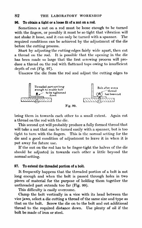
82 THE LABORATORY WORKSHOP
96. To obtain a tight or a loose fit of a nut on a rod.
Sometimes a nut on a rod must be loose enough to be turned
with the fingers, or possibly it must be so tight that vibration will
not shake it loose, and it can only be turned with a spanner. The
required conditions can be achieved by the adjustment of the die
before the cutting process.
Start by adjusting the cutting edges fairly wide apart, then cut
a thread on the rod. It is possible that the opening in the die
has been made so large that the first screwing process will pro-
duce a thread on the rod with flattened tops owing to insufficient
depth of cut (Fig. 97).
Unscrew the die from the rod and adjust the cutting edges to
Threaded part not long-
enough to enable boltr
to be tighteneddow
Bolt after e<tra
^^ thread
lias been cut
Fig. 99.
bring them in towards each other to a small extent. Again cut
a thread on the rod with the die.
This second qut will probably produce a fully formed thread that
will take a nut that can be turned easily with a spanner, but is too
tight to turn with the fingers. This is the normal setting for the
die and a good condition of adjustment to leave it in when it is
put away for future use.
If the nut on the rod has to be finger-tight the halves of the die
should be adjusted in towards each other a little beyond the
normal setting.
97. To extend the threaded portion of a bolt.
It frequently happens that the threaded portion of a bolt is not
long enough and when the bolt is passed through holes in two
pieces of material for the purpose of holding them together the
unthreaded part extends too far (Fig. 99).
This difficulty is easily overcome.
Clamp the bolt vertically in a vice with its head between the
vice jaws, select a die cutting a thread of the same size and type as
that on the bolt. Screw the die on to the bolt and cut additional
thread to the required distance down. Use plenty of oil if the
bolt be made of iron or steel.

SCREW CUTTING 83
98. To convert a bolt into a set screw.
A set screw is threaded the whole of its length; a bolt part of the
way only (Figs. 31 and 30).
Sometimes a bolt has to be converted into a set screw. This can
be done by cutting a longer thread on the bolt. After a time the
bottom of the die comes up against the head of the bolt; this
occurs before the die has cut a thread on the whole length. Toovercome the difficulty, after cutting a thread in the ordinary wayas far as possible, unscrew the die from the bolt and turn the whole
tool, stock and die combined upside down. Again screw on the
die and finish the final cutting of the thread with the die upsidedown (Fig. 100).
Diet/stock used
upside down to
complete the last
portion of thetnrea-d
Fig. 100. Changing a bolt into a set screw
99. To construct a bolt from a length of rod, and amjjfc.
Thread one end of a rod to a distance a little greater than the
width of a nut of corresponding size. Grip the rod in a vice andfit on the nut. Use a spanner and tighten the nut up as firmly as
possible against the un-threaded part. Now cut across AB,fig. 101, with a hack-saw and finish off smoothly with a flat
file.
Another method is to cut the rod with a hack-saw about I" awayfrom the nut and to hammer over and dome the projecting portionwith the rounded end of a ball pane hammer (Fig. 102). This
prevents the nut from untwisting and makes it very secure.
During the hammering process it is best to grip the rod in a vice
as shown in fig. 104, and not as in fig. 103. The former method
prevents force being applied to the screw thread inside the nut, a
possibility, should the grip of the vice not be quite secure.
This part of the work being completed the rod can be cut to the
length of the bolt required and threaded to the necessary distance
in the ordinary way.This method of making a bolt is particularly useful when an
extra long one is required.

84 THE LABORATORY WORKSHOP
100. To cut a British Association thread on a rod.
The instructions already given for the cutthig of a Whitworth
thread apply with equal force to the cutting of a British Associa-
tion thread.
Rod threaded to a distance a little_j ^_ wi<ith
rreater than the width of the nut *> ofnut
Excess threaded portion1$ sawn off
Fig. 103.
Incorrect position
Ball panehammer
Fig. 101
4"
Short lenrth is left Projecting portion 5s
^[/rivetgd over
Fig. 102. Constructing a bolt from a lengthof rod and a nut
Fig. 104.
Correct position for rivetting
/ Vice \ / Vice \
Bra5 or Steel rodw held in a vice
Hod is hammered over
at right angles
Fig. 105.
Bentportion is sawn off
Since the size of a B.A. thread is not, as with the Whitworththread indicated by a diameter measured in inches, but by gaugenumbers, it is necessary to know the B.A. gauge number corres-
ponding with a given diameter of rod before the correct die to use
can be selected.
The following table gives this information.
Diam. of rod suitable
for use with die.
. .
*
V bare
Gauge No,of B.A. die.
2
34
5
6
"(Meccano)
z" bare
full

SCREW CUTTING 85
If a reference table be not available it is possible by holding a
tap and a piece o$ rod up to the light and viewing them by a
method akin to that indicated under Sec. 104 to select a tap havingan overall diameter exactly the same or very nearly the same as
that of the rod.
Suppose a No. 3 B.A. tap is found by this method to have the
same overall diameter as the rod then the correct die to use for
cutting a B.A. thread as the rod would be a No. 3 die.
This method is subject to error, especially when used for small
size rods, and should not be applied when a reference list is
available.
The word 4
bare' in the list indicates that the rod is just large
enough to take a B.A. thread of the given gauge number and the
word 'full' that it is a shade too large theoretically for the given
gauge, but can be used in practice. A Meccano axle will take a
No. 3, B.A. thread and an ordinary bicycle spoke of No. 15,
S.W.G. (-073" diam.), will take a No. 9, B.A. thread.
101. The use of carriage bolts.
Fig. 99 illustrates a carriage bolt. These are made of steel and
can be obtained from any ironmonger. They can be driven into a
piece of wood; the square portion prevents them from turningwhen a nut is screwed on the threaded part. Fig. 99 also shows
the application of a carriage bolt to attach an L shaped strip of
metal to a baseboard.
To fit a carriage bolt first drill a hole in the wood equal in diam.
to the diam. of the bolt. For instance, for a |" Whit, carriage bolt
use a drill or twist bit. Drive the bolt into the wood with a
hammer. Before this be done, make certain that the bolt has
sufficient length of screw thread on it; if not put on extra thread
with a die as described in sec. 97.
102. The construction of clamping screws (Fig. 110).
These are made from round brass or steel rod.
Grip a length of rod in the vice with an inch or so projecting
beyond the jaws. Now hammer this projecting piece over at
right angles to the remainder. Avoid too sharp a bend or the
metal may crack. Saw off the bent portion and cut a thread on
one of the arms (Fig. 105).
If a tliread be required on the whole length of one arm it will be
necessary, when cutting the lower part, to remove the die and use
the latter upside down (see Sec. 98). It is best to do the bendingof the metal rod before cutting the thread to avoid possible injuryto the thread from hammer blows or the vice jaws.

86 THE LABORATORY WORKSHOP
103. To cut internal threads.
An internal thread is sometimes known as a female thread. An
example of an internal thread is the thread inside a nut. Nuts
made by machinery are so cheap that it is seldom worth taking the
trouble to make them by hand, but it is often necessary, in the
construction of apparatus, to cut internal threads in strip metal.
An internal thread is cut with a tool known as a tap (Fig. 106).
After a hole of suitable size has been drilled out, the tap, held in a
tap wrench (Fig. 107), is placed in the hole and turned round with
Taper I
Fig. 106. Taps
the application of gentle pressure. The tap is made of hard steel
and is so shaped that it can cut its way through the metal and
form a thread at the same time.
Both taper-taps and plug-taps have the lower portion ground
away, the taper one more than the plug. Both these tools cut
gradually into the metal and do not make a complete thread until
they have gone tjn some way.
Fig. 107. A tap wrench
A full set of taps includes a taper, a plug and a bottoming one for
each size or gauge number of thread.
Some confusion exists with regard to the names given to those
tools by dealers and manufacturers.
The following are in common usage by London and Sheffield
firms:
I. II. Ill (Fig. 106).
Taper Plug Bottoming
Taper Second Bottoming
Taper Second
When only one tap per size of Whitworth or B.A. thread be
purchased it is best to obtain a taper tap.This is a generally useful form of tap, is very easy to use and will
meet most of the requirements of a laboratory workshop.

SCREW CUTTING 87
A bottoming tap is seldom required and can be dispensed with
See (Sec. 104).
104. To cut an internal Whitworth thread.
The process of cutting an internal thread is known as tapping.
Suppose a J" Whitworth thread is to be cut in a strip of brass or
mild steel about -fo" thick.
First mark and then centre punch the position of the hole for
the screw thread. This done, a drill has to be selected. A little
consideration will make it evident that a hole smaller than a \" in
diam. must be drilled. If the hole be drilled out to J" no metal
will be left for the tap to cut into and form a thread, since the
overall measurement of the tap is J".
Many tool catalogues and reference books on workshop processes
give lists of so-called drill tapping sizes. These arc the sizes of drill
to use for any particular size or gauge of tap. For a J" Whitworth
tap the correct drill to use is &".
A BI
*
*) MctaJ strip showniin section
Fig. 108. Sectionof a Whitworthbolt male thread
\Metal here is
drilled out
Fig. 109. The heavily* shaded part is
metal that has to be cut away by the
tap used for forming a female thread
Fig. 108 represents a section of a portion of a Whitworth bolt, if
a hole had to be drilled and tapped in a strip of metal for a bolt of
this size it would be necessary to select a drill for making the hole
having a diam. equal to the distance A B.
This would leave the metal shown heavily shaded in Fig. 109,
to be cut away by the tap.
The finished A clamp ariU its screw
Clamping- Screw
Fig 110. The construction of a clamping screw
The following table gives the correct tapping drill to use with
each size of Whitworth tap. A copy should be made and exhibited
in the workshop for reference,

88
Size of
tap
*'
THE LABORATORY WORKSHOP
Whitworth Screw Threads
Size of drill
lor tapping
Size of
tap
r
Size of drill
for tapping
. H"
If the drill be of correctsize it should appearlike this when held
against the tap
Fig. 111.
Tap a Drill
plared side byside.
A reference table of tapping drill sizes is not always available;
a rough and ready method of selecting the correct drill is to hold
a tap and place a drill, that is thought to be of correct size, on the
top of it. This done view them with one eye closed against a bright
surface or white patch of sky.The drill should be of such a
size that, viewed in this way, it is
found to have a diameter as near
as possible to the cross sectional
distance between the bottom of
the threads on the tap (Fig 111).
After drilling, grip the strip of
metal in a vice and place the end
of the tap in the hole. Now hold
the wrench with both hands, and
press and turn at the same time.
If a hole of the correct diameter
has been drilled the tap will soon
begin to cut into the metal and start to form a thread. Takecare to keep the tap at right angles to the work. It is advisable,
once the tap has started to cut, to view it from two positions at
right angles and so ascertain if there be any inaccuracy of positionand correct it, if necessary, by slight sideways pressure on the
tool in the appropriate direction.
If the initial hole has not been drilled at right angles to the
surface or the tap be held incorrectly a screwed rod fitted into the
hole may look like fig. 112, instead of fig. 113.
If iron or steel is being tapped keep the hole well lubricated
with engine oil. Brass and copper can be tapped without oil, but
it is wise to use oil in every case. After every half turn of the tapforwards give it a slight turn backwards to help in the process of
clearing out shavings. If the tap shows the slightest tendency to
twist with the cutting portion remaining fixed, great care must be
taken in screwing it forwards, and a full half turn back should be
given very frequently.
Beginners are liable to force and so break small size taps. Taps

SCREW CUTTING 89
A Rod screwed intoa. PUte
^
The rod is out of the true dueto an incorrectly drilled orthreaded hole in the plate
Fig. 112.
The rod should be at
right angles to the
plate
Fig. 113.
are made of hard, but rather brittle steel and it is advisable to keepa snpply of the small size taps, J" and fff
"Whit, in the store, to
replace breakages. They are more liable to be broken when used
to cut threads in iron and steel than in brass or copper. If a taper
tap is being used, work it through the hole as shown in fig. 114,
until the upper cutting portion comes flush with the surface of
the metal being threaded. Remove the tap by turning the wrench
backwards.
""^muTLiJ
JTurn tlie tap until theend of the threaded part
l\\\\\\\\\\\Vf||^\\\\\\\\\\\\N comes flush withthe metal surface
Taper tap
Fig. 114.
A plug tap begins to cut a full thread sooner than a taper one;
this makes it more difficult to start cutting with a plug tap,
especially in iron or steel. Once a thread has been started with a
plug tap a bottoming tap can be used to cut a full thread to the
bottom of a blind hole. A hole of this type is shown in fig. 115.
Hole drilled out readyto receive a thread
A Thread cut in a blindhole with the help of a.
bottoming tap
Fig. 115.
105. How to avoid the threading of blind holes.
The threading of blind holes can be avoided by the judicious

90 THE LABORATORY WORKSHOP
design of apparatus; but a rather similar practical difficulty arises
in the construction of a clamp (Fig. 116). ,
This hole is drilled
/# threaded
A clamp and screw Clamp and screw shown in section
Fig. 116.
A hole for the clamping screw has to be drilled and threaded and
as shown in fig. 117, it is not sufficiently deep to allow a taper tapto enter far enough to cut a full thread.
The difficulty can be overcome by drilling the hole for the
clamping screw to a greater depth than is necessary for the
clamping screw to act as such, but deep enough to enable a taper or
plug tap to cut a full thread in the portion where the screw has to
work in and out (Fig. 118).
Fig. 118. How to drill the
Fig. 117. The hole is not deep clamping screw hole to
enough to allow the tap to allow the tap to enter andcut a full thread cut a full thread
106. To cut an internal B.A. thread.
The process of cutting an internal B.A. thread is exactly similar
to the process of cutting an internal Whitworth thread as described
in Sec. 104.
The size of a tapping drill to use in connection with any par-ticular B.A. tap can be obtained from the following table. This
table, like the one given for Whitworth taps, should be copied out
and exhibited for reference in the workshop. If a reference table
be not available a tapping drill can be selected by the inspec-tion method described in Sec. 104, but it is much better to make
quite certain of selecting the correct drill by reference to a
table..
The inconvenience of continually referring to a table for Whit.

SCREW CUTTING 91
or B.A. taps can be avoided by making a drill stand out of a small
block of mild steel QT brass (Fig. 119), and fitting it with drills of
tapping sizes corresponding to the taps available.
Fig. 119. A home-made stand andgauge for tapping drills
Each hole should be marked with the size or gauge number of
the tap that the drill in that hole is to be used with.
The marking can be done by means of centre punch dots.
B.A.
gauge No.
1
2
3
Size of drill
for tapping
iVII"
B.A.
gauge No.
4
5
6
Size of drill
for tapping
Drills can be bought in mm. sizes and in sizes measured accordingto a drill gauge number or letter. Many reference tables of B.A.
gauge numbers and tapping drills give the drill sizes in these
measurements. Since the list of tools given in Chapter II speci-fies drill sizes in fractions of an inch, the table given above indi-
cates the drill in a 6*4
"series that is the nearest size suitable for the
purpose of tapping.
107. The use of a backing nut.
Sometimes it is convenient to attach a rod to a metal plate, in
the construction for instance, of a prism stand for an opticalbench (Fig. 120).
If a metal plate &" to"thick be drilled and then threaded
with a Y Whitworth tap, only a small length of thread can be cutin the thin metal and a rod screwed into it will have little support.In such a case it is best to thread the rod for about \" and to fit it
with a nut. The rod is screwed into position and the nut then
tightened up against the plate to form a backing nut. In this

92 THE LABORATORY WORKSHOP
The end of th rod is sawn offV and filed flush
kbackin;nut
Fig. 120. A prism stand for an optical bench
way it is possible to obtain a firm attachment of a rod to a thin
metal plate. If necessary the attachment can be given extra
strength by running solder round the edge of the nut in contact
with the plate. The end of the rod may project through the plate,
if so, it should be filed down flush.
108. To repair an injured bolt or rod.
The thread on a rod or bolt may be injured by a hammer blow or
by undue pressure in a vice. It can usually be put in order bytreating it as a rod to be threaded and passing it through a die of
the correct size. This will reform the thread*
109. Stripped and worn threads.
If an internal or external thread has been broken or worn awayit is best to fit a new nut, bolt or length of rod as the case may be.
A temporary repair can sometimes be effected by windinga piece of cotton round the external thread and so providing extra
grip with the internal thread. It is best to replace the injured
portion or to drill out the old internal thread and cut a new
larger thread with a tap.
110. How to deal with tight nuts.
Sometimes, when an attempt is made to fit a nut to a length of
screwed rod or to a bolt it will be found very difficult to turn, even
with a spanner. The tightness may be due to an injured thread on
the rod, or to the use of a die with its cutting edges not adjustedto cut a full thread on the rod, but it is very likely due to the nut
itself.
The trouble is particularly liable to arise if black forged nuts or
pressed nuts are used instead of bright steel ones. The latter are
more accurately made than either of the other two.
A tight nut can be quickly put in order by clamping it in a vice

SCREW CUTTING 93
and screwing a tap of appropriate size through it. If a taper tap be
used and the nut is $ thick one it may be necessary to remove the
nut and screw the tap through it from the other side in order to cut
the thread inside the nut to full size.
Old nuts are also liable to be tight, owing to damage or rustingof the thread. These may be put in order by the above method.
111. To cut a new thread in a nut or terminal top.
Old nuts and terminal tops can often be utilized and provide an
emergency store.
It is possible that a terminal or nut with some particular thread
is not available. A J" Whit, nut may be required when the onlynuts available are too small or B.A. gauge.
]Hole should be
1 drilled 6/ threaded] before
counter-unking
Fig. 121. The countersinking of athreaded hole
For example to convert a &" Whit, nut into a J" Whit. nut.
Drill out the old thread with a tapping size drill, fo* J" Whitworth,then cut a new thread with a J" Whitworth taper tap.The milled edge nuts on old dry batteries should be kept. The
B.A. thread can be drilled out if necessary and a &" Whit, thread
cut in its place.
112. To countersink screw holes in strip metal.
If countersunk head screws are to be fitted into a metal strip or
plate (Fig. 121), first mark, drill and thread the hole in the plate
and do the countersinking last of all. Use an 82 countersink
(see Sec. 88).
113. To cut an internal thread in wood.
A Whitworth thread can be cut in hard wopd such as oak or
beech in exactly the same way as in metal after a tapping drill hole
has been made. If a rod has to be fitted into a base-board it can
be done by one of the methods shown in fig. 122.
In A the base-board is fitted on the under surface with extra
strips of wood. A hole with a diameter equal to that of the
rod is drilled in the board.

94 THE LABORATORY WORKSHOP
In B a hole is cut in the under surface of the board to take the
bottom nut and again a hole with a diameter equal to that of
the rod is drilled in the board.
In C a screw thread is cut in the wood, the rod is screwed in and
tightened up with a backing nut.
114. Brass thread and the repair and use of gas fittings.
Brass gas pipes and laboratory gas fittings are threaded with a
special thread known as the Brass Thread. This thread is so
designed that it has 20 threads to the inch in all diameters.
If an attempt be made to cut a Whitworth thread 011 a length of
brass gas pipe it will be found that the die cuts so deeply into the
Backing-Nut 6 Washerwas;
Thread, is cutin the woodA B
Fig. 122* Three methods of fitting a rod on to a baseboard
thin wall of the tube that the latter is crumpled and broken.
The Brass Thread is akin to the B.A. thread in being of shallow
type.
Sets of stocks, dies, taps and wrenches for cutting a Brass
Thread can be purchased, but many of the ordinary requirementsof a laboratory workshop can be satisfied by the use of a simpletool known as a Combination Gas-Burncr Tap (Fig. 123).
This comprises a f"die for Brass Thread, one or two taps, a
reamer and a screwdriver. The latter is not necessary, but
completes the symmetry of the tool. It costs about 4 /6.
Economy of Purchase
If a set of Brass Thread dies and taps be ordered and a range of
Whitworth 'Little Giant' dies and taps, items No. 1 and 2 in the
tool list have already been bought, it is an economy to buy Brass
Thread dies with collets of the same external diameter as the
Whitworth dies so that one stock can be used for both sets.
Useful sizes are J"," and ".

SCREW CUTTING 95
One plug tap per size will serve most purposes and can be held
in the wrench used for Whitworth taps.
Brass tubing as used by gasfitters has fairly thick walls. The
size of a brass gas pipe is specified by the outside diameter.
f"brass gas pipe should be purchased for ordinary work and will
be found very convenient for making extensions to a gas or water
supply. It is much better and more durable for the purpose than
flexible gas or rubber tubing.
Tap-
Fig. 123. A combination gas-burner tap
Ironmongers and the 6d. Stores stock a variety of small brass
gas fittings that are often useful when making up apparatus
(Fig. 124).
These enable straight lengths of pipe to be extended or carried
round corners at right angles.
Nipple ySquare elbow Socket Diminishing Barrel Dimimsher Connector
Hippie Nipple
Fig. 124. A selection of useful gas fittings
115. To cut a thread on af brass pipe.
Bevel the end of the pipe with a file and use the die in the
manner described for Whit, and B.A. dies (Sees. 93 and 100).
116. To cut an internal brass thread.
The tapping drill size for f* Brass Thread in the nearest frac-
tional inch size is l\".
If a special drill be bought the exact tapping size can be obtained
in the decimal of an inch or letter gauge series of drills. The tappingdrill size in this case being Q or -332".
If the metal being tapped be fairly thin a drilled hole can be

96 THE LABORATORY WORKSHOP
opened up by the reamer to be found in the Combination Tool to a
size large enough for the insertion of the taper.tap.Brass tubing is easily bent into curves and spirals if it is first
annealed.
117. To anneal brass tubing.
Make the tube red hot and immediately plunge it into cold
water. This renders the brass very soft and easy to bend. Copper
tubing can be softened in the same way.
118. To repair Bunsen burners.
The gas inlet tubes of Bunsen burners sometimes get lost or
broken. A new side tube can be made from a length of f"brass
gas pipe. Cut a f"
gas thread on one end of a short length of pipeand screw it into the base of the burner. File off the sharp edge on
the far end of the pipe, so that it will not damage a rubber tube
connection.
119. To repair gas connections.
The gas tap connections for rubber tubing on lecture tables and
benches sometimes snap off owing to corrosion or rough handling.Before a new tap can be fitted, the old broken end left in the
pipe must be extracted (Fig. 125).
Sometimes sufficient length of the broken stub end projects to
enable it to be grasped with a pair of pliers and so unscrewed, or
a screw-driver pressed into the opening may enable it to be turned
and extracted.
The taper tap of the combination tool is also helpful and will
often cut out the old end. If all these methods fail take a small
drill and carefully drill two holes to a depth of"at opposite places
in the fractured face of the broken end. This enables a screw-
driver to be brought into effective action.
120. To make joints gas-tight.
If a joint in a connection be not gas-tight it should be un-
screwed and the male thread of the connection should be paintedwith some thick paint or smeared with a mixture of white lead
powder and boiled linseed oil. This can be prepared by placingsome boiled oil in an old tin lid and dusting white lead into it to
form a mixture of thick cream consistency. Keep the oil stirred
while adding the powder. After treating the connection, screw
it together again.

SCREW CUTTING
Taps sometimes snap off hereleavmra piece screwed into^ I <s~^ *4,- *%.LA Pipe
x^^\ Positioned
//f7^ blade of
xT&Jy Screwdriver
Gas pipe* Position ofNSx shown dotted
F rw
brokengas Upshown shaded
Fig. 125. The repair of gas connections
Fig. 126. Gas pliers Fig. 127. A pipe-wrench
/>'// courtesy of Perry <f' To , Ltd.
This vice can be clamp-ed in an ordinary par-allel jaw bench vice or
used* on the base of a
drilling machine
Fig. 128. A machine vice fitted with a V-face plate
By courtesy of North Kros. Mfy. Co.
Fig. 129. Avoid downward loops like
this when using composition pipe for
gas connections
Fig. 130. A saddle used for attaching pipes to walls

98 THE LABORATORY WORKSHOP
121. Methods of holding pipes.
A useful tool for holding and turning a pdpe is a pair of gas
pliers (Fig. 126).
Another very useful tool is a Perry chain pipe wrench (Fig. 127),
to be bought for 1 /- from the Halford Cycle Co., Ltd., Corporation
Street, Birmingham. The latter can also be used to unfasten
large nuts or to unscrew an obstinate tin lid of the screw top type.
Where brass tubing is being held in a vice for the purpose of
screw threading, care must be taken not to crush it. If necessary,
slip a piece of small diam. dowelling into the tube to give it
support on the inside, or grip it with a V-face plate as suppliedwith a 'Yankee' machine vice (No. 990) (Fig. 128).
122. Composition ('Compo') pipe connections.
Plumbers often make gas connections with 'compo' pipe. This is
manufactured from lead hardened by alloying with antimony or
tin. It can be bought in long lengths, is very soft and can be bent
just as required.If gas connections are made with it take care to avoid any
downward loops as shown in fig. 129, where liquid might collect
as a result of condensation.
Both brass tubing and 'compo' pipe can be attached to walls or
bench sides by means of saddles (Fig. 130).
Brass tube connections are easily soldered into 'compo' pipe
(see Sec. 160).
123. Screw threads for iron pipes. (Known in the Trade as 'wire
barrel.')
Iron pipes are always specified according to the internal
diameter; a so-called y iron pipe has an internal diameter of |",
but the external diameter is about f"since the wall of the pipe is
nearly*thick. It should be noted that the system of specification
used for iron pipes differs from that used for brass and copper
pipes. A \" brass pipe is one with an external diam. of J".
Iron pipes used for gas, water and steam supplies in a laboratoryare threaded with the Iron Gas Thread, not the ordinary Whit-
worth, B.A. or Brass Thread, and special dies and taps have to be
used.
If water supplies have to be extended or modified it is veryconvenient to have a die cutting J* Iron Gas Thread. A 'Little
Giant' type die for this size with a stock costs about l.
All ironmongers keep a variety of fittings such as sockets, round
elbows, square elbows, barrel nipples, back-nuts, tees, plugs, caps,

SCREW CUTTING 99
diminishing or reducing sockets and so on that only cost a few
pence and enable the laboratory worker to carry out a variety of
minor alterations and extensions to a gas or water supply usingiron pipes (Fig. 131).
CDSocket
Round Elbow Square Elbow
Barrel
Nipple
Stop cock
/%., T- -01 f+*A~ Reducing*BackNut T. piece -Plug Cap socket
Fig. 131. Iron pipe fittings
Four examples are given of the use of such fittings to modify a
water supply (Figs. 132-135).In examples, figs. 133 and 134, the use of a die is not called for.
In figs. 132 and 135 a die has to be used once in each case to cut a
thread on the short length of pipe AB, so it would be scarcelyworth while purchasing a die to do the screwing if this was the
only work to be done, since the short length of pips could be cut
as required, and threaded by the ironmonger supplying the various
fittings.
A standard length of pipe is 10' with a male thread at each end.
In the trade it is usually referred to as barrel and not as pipe.If cut to a shorter length it leaves one end without a thread and
the use of a die becomes necessary.When making measurements for the total length of a pipe
between fittings an addition in length to the pipe of about \"
per fitting should be allowed for screwing in.
Before fittings are screwed together the male threads should be
treated with a paste of a mixture of red lead, white lead andboiled linseed oil, or powdered graphite and boiled oil. To makecertain of a water-tight fit a few strands of towor threads from a
hemp rope should be wound round the male thread and smeared
with thejpaste before the joints are put together. The screwingon of a length of pipe or of fitting one into another can be carried
out with the help of a good chain pipe wrench or a large 'Footprint'
type wrench (Fig. 136). (12" size approx. cost 3/6.)
Sometimes two wrenches are necessary; for simple work it is

100 THE LABORATORY WORKSHOP
Round elbow
iron barrel or pipe
iron barrel or pipe
4 Brass water tapwith rubber tubeconnector
FIG 132Socket
fBrass bib tapwith "tail
Back nut O Back nut
FIG 133
A Plug, this is used to seal the end of
a pipe that is no longer required
A overflow pipe fitted to a tankor aquarium
FIG 134-
Diminishing socket Back nutl'-i"
c 1 Socket* c . A <
1" pipe
I pipeconnector
(a. standard
fitting)
Ause twine here
ZC7/1B U
Square elbow
Long- leng-th oPscrew thread
FIG 135 Squareelbo*
Figs. 132-135
often possible to, assemble many of the fittings on a bench and
make use of a vice.
124. Use of back-nuts.
Pipes and fittings should be screwed together until the tight end
parts of the threads make good engagement. Sometimes the
exigence of space or length of pipe does not allow this to be done,

SCREW CUTTING 101
In example, Fig. 135, the diminishing socket and the square elbow Emight already be fixed in position or possibly they have to be an
exact distance apart. The use of a connecter and back-nut allows
for the insertion and adjustment of a length of pipe between the
diminishing socket and elbow.
One end of the connecter has a long length of screw thread on it
and this allows the socket (S) to be screwed along it out of the wayduring the insertion of AB. When S is screwed back to engage
tightly with AB it will be left on a loose part of the connecter.
Fig. 130. A 'Footprint' type Fig. 137. A half knot usedwrench for tying a grummett
A tight joint is made by screwing up the back-nut.
Before screwing up a back-nut tic a piece of hemp twine round
the pipe connecter. Use a half knot (Fig. 137). Smear the twine
with jointing paste, then tighten up the nut. Plumbers call this
'tying a grummett.'Before new water connections are made it is of course necessary
to turn off the supply.
Pipes can be fixed to walls with pipe clips or hooks. A \" pipe
requires a \" clip or hook. A die for cutting iron gas thread is
used as described for cutting a thread on thick rod, Sec. 95, but it is
best to start with the die cutting edges fairly wide apart and
work down to the full cut in two or possibly three stages.
This avoids the application of great force and expenditure of
energy possibly with injury being done to the die. The pipeshould be held in a strong vice to prevent it turning during the
cutting process. Special vices are made for holding pipes, but an
ordinary one can be used if the precaution be taken of cutting the
full thread in gentle stages as described. Use plenty of oil.
The threads inside iron pipe fittings are sometimes imperfect or
blocked with rust and paint.
When making a purchase it is advisable to test each fitting in
turn by screwing in a length of straight pipe.
This precaution is not necessary if the tool equipment includes
a Iron Gas Thread Plug Tap. (Price approx. 2 /9.)
A fitting with a tight or faulty thread can be quickly put in
order by screwing this tap in and out. An ordinary spanner can
be used to turn it round while the fitting is clamped in a vice.

CHAPTER VI
SOLDERING
125. Tools and materials.
SKILL in the art of soldering is indispensable to the metal worker,it is a process that is constantly required in apparatus construc-
tion and in general repair work.
If various precautions are taken the process is easily mastered
and good work can be carried out from the start.
The tools required are a soldering iron and one or two files, andthe chief materials, a supply of flux and a stick of tinman's solder.
For convenience in working a number of small accessory items
are desirable and these will be described in due course.
The end part or bit of a soldering iron is made of copper; these
tools are sold according to the weight of this copper portion.A 1 Ib. iron with a straight, pointed bit is a useful size and form
for general work. The best flux to use is a solution of zinc
chloride, a liquid akin to this, and stocked by all ironmongers, is
sold under tht trade name of Baker's Fluid.
Workmen refer to zinc chloride as 'killed spirit'; it can be
prepared by first cutting some scraps of sheet zinc into con-
veninent portions with a pair of snips and placing them in a
beaker or glazed earthenware pot. This done, add commercial
hydrochloric acid to cover the zinc to a depth of an inch or so.
Vigorous evolution of hydrogen takes place with formation of
much acid spray. The latter has a corrosive action on tools, so
place the beaker outside the workshop during the evolution of
gas. Use an excess of zinc. After half an hour, when all action
is over, filter and collect the clear solution.
Place some of the home-made solution or Baker's Fluid in a
small pot; it is convenient to have another supply in an unspil-lable ink-pot.A suitable pot is a strong glass or glazed earthenware one as
used for the sale of ointments and potted meat.
During the process of soldering the heated bit is dipped into the
solution in the pot and may hit against the bottom and crack a
thin glass one. The depth of solution should be about ".
The bit of the soldering iron has to be heated. If gas be

SOLDERING 103
available this can be done by resting the iron on a three-legged
stand with the bit projecting over a Bunsen flame (Fig. 138).
A Primus stove, a blow-lamp or a clear wood or coal fire can all be
used. A non-smoky source of heat is required.
The bit has to be heated to such a temperature that it will cause
the solder used to melt and become almost as fluid as water. It
should not be made red hot. When it is thought that the bit has
reached a high enough temperature, remove it from the flame and
hold it about 1" away from the cheek. If distinct radiation be
felt it is probably hot enough. Rest the stem of the iron on the
edge of a vice, not on the bench where it will burn the wood and,
Fig. 138. Heating a soldering iron
without undue delay, quickly file the four faces of the point of the
bit. An old 10" second cut file is suitable. File and clean awayscale and oxide to about J" from the point of the bit.
The filing must be done very rapidly to prevent too much
cooling. If an old iron that has got into a bad condition is beingused it is a good thing to give it a preliminary filing and general
cleaning up and re-shaping before it is heated.
Pick up the pot containing flux, hold it at arm's length, awayfrom tools and other objects on the bench where spray may do
damage, and as quickly as possible dip the point of the heated bit
into and out of the liquid. If the bit has been heated sufficiently
and has not cooled down too much during the filing process,a sharp sizzling sound will be made as it is dipped in.
Place a scrap piece of tin plate or the lid of a tin can on the
work bench. If a lid be used it must be free from enamel.
The process of quickly dipping the heated bit into and out of
the flux dissolves off the film of copper oxide and leaves clean
metal exposed. Without delay, or a new film will form, press a
clean side of the tip of the bit against a stick of solder and allow
the molten drop to collect and form a globule on the piece of tin.
Turn the bit over and over and rub it up and down in the
globule. If it has been properly filed, cleaned in flux and has not
got too cold, a film of solder will attach itself to the cleaned
surfaces.

104 THE LABORATORY WORKSHOP
This process is called 'tinning the bit.'
If the solder fails to attach itself, quickly dip the bit a second
time in and out of the flux and try again. If again not successful,
then file clean and dip a third time. The bit of a soldering iron
should always be 'tinned' and brought into good condition before
the commencement of soldering operations.
126. Soldering sheet and strip metal.
Tin-plate is the easiest of all metals to solder and anyone wishingto practise soldering will be well advised to try soldering togethersome strips of tin plate or the edges of a cocoa tin and lid to makeit air tight. The tin, if air tight, can be used to demonstrate the
pressure of the atmosphere.As an example of procedure take the case of the soldering of the
turned up sides of a rectangular tin box (Fig. 139). The solderingshould be done on the inside.
First paint the surfaces to be soldered with flux. Use the clean
supply from the unspillable ink-pot. A small penny brush, as
supplied in a child's paint-box is suitable, but a better brush is one
with the hairs set in a quill without any metal to corrode. Paint
the edges on the inside only to a width of ". The flux must be
painted on where the solder is required.The action of the flux is to dissolve away the film of oxide and
yield a clean suiface for the attachment of the solder.
It is absolutely essential to have clean surfaces for soldering.
If the box had been made of brass, copper or zinc it would be
necessary to make the surface to be soldered quite clean byscraping with an old knife, by filing, or by sand-papering as
happens to be most suitable. Once a surface has been cleaned for
soldering avoid fingering it and keep it free from all oil and grease.
As a general rule, tin plate does not require any cleaning before
treating with flux, but of course remove rust, gum, enamel, paperand such like if a tin can is being soldered.
While the work is being prepared the soldering iron should be
heated. If it has not already been tinned this should be carried
out and the bit again heated. When hot enough, and this can be
tested by holding it close to the cheek, quickly wipe the bit with a
piece of linen or cotton rag, do not use a woollen rag. The wipingwill expose the clean tinned surface, and take away any lead
oxide, rust or coal dust, that may be present.
Now dip the bit very quickly in and out of the flux in the pot.
If the bit has been tinned, this dipping into flux will leave the end
in such a condition that molten solder will adhere to it.

SOLDERING 105
Solder can be applied to the work in various ways.Press the end of tfce bit against the end of a stick of solder, when
some will melt and stick to the tinned bit.
Apply the bit to the place to be soldered and slowly draw it
along the joint. If enough solder has been gathered up it will run
off the bit and into the joint. If more solder be required, collect it
as before and apply it to the joint.
If necessary, smooth all lumps out by slowly drawing the hot
bit from end to end of the joint.
Sometimes the only effect of trying to pick up solder in this
way is to cause it to melt and drop on the floor. To avoid this the
solder can be melted off the stick while its end is held close over the
joint.
The best method of all, and one that avoids the application of
not enough or too much solder, is to melt off small globules of
solder about I" diam. by holding the bit against a stick of solder,
and by collecting the globules that arc formed on a sheet of
asbestos or Uralitc placed just below.
The globules solidify in a few moments. By application of the
hot bit to them they are melted and easily picked up, one by one,
and applied to the work.
If too much time is spent in making the globules the bit will getso cold that it will cease to melt the solder properly, and will have
to be re-heated. In any case, if much soldering ha,% to be done, the
bit must be constantly re-heated.
After picking up a globule, and when carrying it to the work,
keep the soldering iron steady or the globule may drop off.
If more convenient, little prepared lumps of solder, formed bymelting off from a stick, can be arranged on the joint to be soldered
and re-melted in position by the hot bit.
Many beginners attempt to solder with a bit that has been
insufficiently heated at the start, or has cooled down below the
effective soldering temperature.The bit must be hot enough to cause the solder to become
completely fluid. It is quite useless to start, or attempt to con-
tinue soldering if the temperature of the bit is not high enough to
bring about or maintain this condition.9
When a bit has been re-heated always wipe it and dip quicklyin and out of the flux pot before starting any more soldering. After
several re-heats it may be necessary to tin the bit again, it is
important to keep it in this condition for good work; the process
only takes a few seconds and is time well spent.
If the bit be overheated and made red hot the tinning will soon

106 THE LABORATORY WORKSHOP
disappear and it will be necessary to repeat the tinning processmore frequently. c
When soldering an object, like a rectangular box, it is advisable
to tilt the object so that gravity helps the flow of the molten solder
in the right direction.
If much soldering has to be done it saves time to keep two irons
going. One can be heating while the other is being used.
Drops of molten solder and objects that have been heated by
application of a soldering iron may injure a good table top. Avery satisfactory bench or table top cover for soldering on is
formed by a sheet of Uralite measuring 12" square or an asbestos
roofing tile costing 3d.
If zinc chloride solution, or Baker's Fluid be used as a flux, take
care to wipe or wash the soldered joint on completion of the work.
Both substances are very hygroscopic and may produce corrosion
if left on the metal.
The chief rules for successful soldering are:
(1) The parts of the work to be soldered must be clean and
treated with flux.
(2) Use a tinned bit.
(3) Heat the bit to such a temperature that it makes the
solder quite fluid and not pasty.
(4) Wipe the bit.
(5) Dip it quickly in and out of the flux before use;
(6) Do not continue to use a bit that is no longer at a high
enough temperature.
(7) Avoid excess of solder.
The work of a beginner is usually characterised by a lumpyexcess of solder. This is usually caused by an attempt to use a bit
that has not been tinned, dipped into flux before use, or by an
attempt to use it before it has been properly heated, or after it has
cooled below the effective temperature.In a good soldered joint the solder sinks into the surface of the
metals to be joined and only a small amount is necessary to bringabout a strong union of the parts if the work has been done
properly.Sheet brass, sheet copper and sheet zinc can all be soldered by
the method described.
Large thick copper objects are sometimes difficult to solder
owing to the good heat conducting property of copper. When a
small soldering iron is used for such work it quickly cools down,has to be constantly re-heated and it is often difficult to get the
solder to flow properly. In such a case it is best to use a soldering

SOLDERING 107
iron with a large bit, one capable of retaining a good quantityof heat and if necessary impart some heat to the object to be
soldered by the judicious application of a Bunsen or other clear
flame.
127. To solder two pieces of strip brass together. (Fig. 140.)
This can serve as an example of various methods of soldering.
Method I. Direct application of solder by means of an iron.
A little difficulty here is to keep the two strips in correct position
during the soldering process.
The position of the upper strip should be marked on the lower
one by scribing a line on the latter. Clean the surfaces to be
joined; this can be done with fine glass or emery paper.Now paint over with a thin film of flux. In the case of the
upper strip put flux on the under surface, on the lower vertical
surfaces A and B, also on the other two vertical surfaces not shownin the diagram (Fig. 141). Similarly, treat the area on the lower
strip that will be covered by the upper one, but make it about J"
larger all round.
It may be possible to hold the upper strip in position with the
fingers during the soldering process, but if it is short it will gettoo hot to do this. One way of keeping it in pjace would be to
hold it down with the end of some tool pressed on the bottom
horizontal portion. For preference use something small and
rather pointed, such as the tang end of a file, that will not conduct
very much heat away.
Apply solder by one of the methods already described and take
very great care not to let the upper strip move while the solder is
going hard. During the solidification of solder, owing to its alloy
nature, it goes through a stage of partial solidification before it
sets hard throughout.If the surfaces to be joined are subject to movement, during this
critical condition of the solder, the joint will be weak. The
complete solidification of the solder is indicated by a uniform
cloudy appearance forming over its surface.tThe moment this is
noticed and it is usually only a matter of a few seconds' waiting,it is safe to move the work.
Instead of trying to hold the upper strip in position it can be
bound down with a few turns of thin black iron wire. This is sold
by ironmongers and can be purchased in the same gauge as the
bright surface wire used by florists for making up wreaths. The

108 THE LABORATORY WORKSHOP
black appearance of the wire is due to a film of oxide. Such wire
is convenient for binding purposes since sol(ier does not stick
to it.
128. Method II. By first tinning the surfaces to be united and then
heating them.
This method is capable of forming a very strong and almost
invisible joint.
Clean the surfaces and treat them with flux. Pick up a globuleof solder with the hot bit and rub it into a surface or put a little
lump of solder in position and there melt it and rub it about. Thesurface will be covered with a silver-like film of solder. Treat the
other surface in the same way. Place the surfaces together and
hold or bind them in position.
Make the bit nearly red hot, but not hot enough to burn off the
tinning at its tip, wipe it, and press a wide, clean face of the tip
against the upper surface of the horizontal portion of the bent
strip (Fig. 142). Heat will be conducted through the strip to the
tinned surfaces, the solder on these surfaces will melt and unite.
If not quite enough solder appears to be present, keep the bit in
position and at the same time push some small lumps of solder
against the edges of the joint. If the bit is hot enough these will
melt and the liquid solder will be drawn by capillary action into
and between the*tinned surfaces.
Remove the bit and give the solder plenty of time to set hard
before the work is moved.
Instead of applying heat to the tinned surfaces with a bit the
work can be heated by application of a Bimsen or blow lamp flame.
In this case, rest the work during heating on a sheet of asbestos or
dry Uralite tile, and it is best, if possible, to apply heat to the
work at a place an inch or two away from the tinned surfaces.
Heat will pass by conduction to the surfaces and there is no risk of
spoiling the joint by partial oxidation of the solder. During
heating it may be necessary to feed a little extra solder into the
joint.
A patent composition called 'Soldo,' a combination of flux and
solder, is useful for tinning purposes. It can be bought in small
tins and is made by Soldo Co., Sicilian House, Southampton Row,London, W.C.I.
With this mixture the tinning of even dirty metal can be
carried out with complete success and without difficulty.
After tinning the surfaces with Soldo ordinary solder can be
used to complete the joint as described above.

SOLDERING 109
Fig. 139. Tin box with corners soldered Fig. 140. Strips of brass to beon the inside soldered together
The upper strip
Fig. 141. strip
Tinned surftce*
Fig. 142. Method II
3^cFig. 143. Tube and bobbin ends for a solenoid
jb= L
^Soldar
Fig. 144. Completed solenoid tube
Sheet ofbrass
Brass tub*
disc ^opening-
ig. 145. Method of making anend for a brass tube
Fig. 146.
Circular plate with opening-soldered to the end ofthe tube
Fig. 147.
^Piate filed down to size
Fig. 148.

110 THE LABORATORY WORKSHOP
129. Method in. By the use of Britinol soldering paste.
This useful material has already been mentioned in Chapter III
Sec. 29 under the heading Combined solder and flux.
Clean the surfaces to be soldered and smear them over with a
little Britinol paste.
Bind together or otherwise keep the surfaces in contact. Applya small amount of paste to the outside edges of the joint.
Rest the work on a sheet of asbestos or Uralite and heat it to
a fairly high temperature with a Bunsen or blow lamp flame. It
is best to apply the flame to a place on the work a little distance
away from the surfaces. As heat is conducted to the paste, this
will become liquid and may produce fumes that tend to catch fire.
If this happens blow the flame out or soot may separate and tend
to spoil the joint.
As heating continues, small spheres of liquid solder will collect;
go on heating until these spheres run together and form a uniform
film. When this is effected, stop heating and allow the solder to
set quite hard before moving the work. If insufficient paste has
been applied at the start, feed the joint by putting a little more on
the edges. The paste can be applied at the end of a nail.
130. To solder the bobbin ends of a solenoid made of non-magnetic
material such as brass, zinc or copper. (Fig. 143.)
The central hole in the bobbin ends should be made of such a
size that the ends fit tightly on the tube. If loose it is difficult
to keep them in correct position during the soldering process. If
the holes are too large reduce them in size by the process described
in Sec. 69. Solder each bobbin end in turn with the tube in a
vertical position.
If the bobbin is to be wound with fine wire, as evenly as pos-
sible, it is best to do the soldering on the outside face of each
bobbin end and avoid or file away projections of solder that form
on the inside. If the soldering be done in this way it is best to
construct the bobbin with the tube projecting about V beyondthe bobbin ends. This provides a good surface for the solder
(Fig. 144).
131. To solder an end on a brass tube.
A brass tube, closed by a disc at one end, is sometimes requiredin the construction of optical instruments.
To attach an end with a circular opening in it to a brass tube as
shown in fig. 145, proceed as follows.

SOLDERING 111
Measure the diameter of the tube with a pair of callipers. Put a
light centre punch ir;ark on a sheet of brass and with this as centre
scribe out a circle, equal in diameter to the brass tube. Scribe
another circle for the opening (Fig. 146). Make the circular
opening. Cut around the large scribed circle about %" away.Clean the inside and outside surfaces of the end of the tube. Flux
the surfaces to be soldered. Stand the tube vertically on the
plate with the large scribed circle just showing all the way round.
Solder the plate to the tube (Fig. 147), then file the plate to the
outside diameter of the tube (Fig. 148).
132. To solder a circular rod or tube on to a flat surface.
To obtain a strong soldered joint the metals in contact should
present sufficient surface one to the other. When designing
apparatus this requirement should not be forgotten.
v.metal strip
Fig. 149. Poor design for soldering ; Fig. 150. Rod and tube filed
small surface of contact to give them each a flat surfaceof contact with the strip
If a circular rod or tube be soldered on to a sheet or strip of
metal the surfaces in contact will be very small (Fig. 149). In such
a case it is best, before soldering, to file a flat place on the rod or
tube (Fig. 150). If a nut has to be soldered to the side of a rod a
curved surface can be filed on the nut with a round file (Fig. 151).
Nut
Nut has a curvedRod filed and provided with a Rocf"~
S^ area filed on oneflat surface s^e
Fig. 151.
133. To solder a Meccano wheel on to a sheet metal disc.
If a brass Meccano wheel provided with a centre boss and set
screw be soldered on to a sheet metal disc the latter is readily
equipped with an axle. Such discs are very, useful for optical
illusion, colour and other experiments.Drill a small hole at the centre of the disc and with the help of a
broach (Sec. 89) very carefully enlarge this hole so that a Meccanoaxle rod will just fit into it.
Arrange the axle, wheel and disc as shown in fig. 152 and solder
the wheel to the disc with the axle in position. This makes

112 THE LABORATORY WORKSHOP
^Meccano axler.
y| jgfig^fc-Meccano wheel
Metal disc
Fig. 154. Frame made of brass
strip soldered togetherFig. 155. Frame strengthened
with angle pieces
certain of the wheel being attached in a central position. If
Britinol soldering has to be used, keep the disc horizontal during
soldering and apply heat by conduction through the axle (Sec.
129). This avoids unequal distortion of the disc by expansion; if it
happened to be made of tin plate the direct application of a flame
would cause the tin coating to melt and oxidise.
134. The use of Britonol soldering paste for soldering small parts that are
easily disturbed and put out of position by the movement of a soldering
iron.
A very convenient method of soldering small parts in exact
position, one to the other, is to place them on a sheet of asbestos
and fix them in position with tiny brads or J" Whit, nuts pushedup against the edges (Fig. 153). A steel rule or square can be usedto adjust them in position. When everything is correct, carefully

SOLDERING 113
place a little paste over each joint and heat the metal by applica-tion of a Bunsen or blow-lamp flame.
A metal frame as shown in fig. 154 can be made very accurately
by this method from strip brass. Once the strips are together it is
a simple matter if necessary to strengthen the joints by attaching
triangular 'corner pieces with small screws or nuts and bolts (Fig.
155). A piece of Uralite can be used instead of asbestos; it is hard,
so brads cannot be employed, but it presents a good flat surface
for the use of nuts to prevent movement during heating.Use a dry piece of Uralite. Uralite recently exposed to the rain
is liable to flake when heated strongly and may cause disturbance
of the work.
135. To solder electric wires Electric light and power wires.
Zinc Chloride solution or Baker's Fluid should not be used as a
flux in connection with the soldering of joints in electric light and
power circuits. For such work use powdered resin or Fluxite.
As a rule, copper wires insulated with rubber are coated with tin
and this makes soldering an easy process. Do not remove the tin
coating. Before melting solder on to the joint rub powdered resin
into the twists of the wire or smear them with a little Fluxite.
Fluxite is a trade composition, a brown paste sold in tins. A good
way of keeping the paste clean is not to open the lid, but to bore a
small hole in the top and extract the flux as required on the end of a
match stick. The bit of the soldering iron used for wire jointingcan be tinned and dipped into zinc chloride or Baker's Fluid in the
ordinary way.
136. Bare copper wire.
Bare copper wires suspended between insulators out of doors,
also earthing wires can be soldered with zinc chloride or Baker's
Fluid.
Clean them with glass or emery paper before twisting together.
Sometimes it is a little difficult to apply solder to horizontal
outside wires, in such a case, a convenient modification of a copperbit is to file a wide groove in one face (Fig. 156).
Fig. 156. Soldering iron with groovecut in it for soldering horizontal
electric wires
This groove can be tinned and solder melted into it to form a
globule. If the bit be held up horizontally below the wire the
joint can be bathed in the solder.

114 THE LABORATORY WORKSHOP
137. Electric bell wire.
Zinc Chloride, Baker's Fluid or Fluxite can be used for such wires.
If either of the first two fluxes be used, wash the joint after solderingor wipe it with a damp rag to remove all trace of flux and so avoid
the possibility of electrolytic or chemical corrosion of the thin wire.
138. To solder very fine gauge instrument wires.
Use powdered resin or Fluxite when soldering such wires (see
Sec. 135).
139. Wireless receiver connections.
Dealers in wireless parts supply straight lengths and coils of
bare, tinned copper wire. It can be obtained with a circular or
square section, the latter being more rigid. Tinned wire does not
require cleaning with glass paper before soldering.
To solder joints of the type shown (Fig. 157) use the minimumof flux.
Zinc Chloride and Baker's Fluid can be safely used for wireless
connections if the precaution be taken to apply a very small spotof flux with a pointed brush and to wipe the joint after solderingwith a rag. A soldered joint, of a wire on to a terminal end, should
appear like (Fig. 158), no solder should spread on to the thread of
the screw, so keep the flux away from it and pick up and apply the
solder on the tip of a well tinned bit.
140. Flexible electric wire.
Joints in flexible wire are best made by securing the wire or
wires with some form of screw connection. Soldered joints are
seldom satisfactory. Short lengths of flexible copper wire, insu-
lated with a covering of rubber only, make useful connections for
general laboratory work.
They can be provided with spade connections (Fig. 159). Pass
the wire through the sleeve, spread out the end of the wire and onlysolder this portion, using resin or Fluxite.
141. Moving coil galvanometer suspensions.
The very fine bronze strip and wire connections in moving coil
galvanometers can be soldered with the help of a miniature
soldering iron.
To make such an iron, obtain a lj* length of J* external
diameter copper tube.
Slip a length of steel rod or thick iron wire to a distance of J" or
so into the tube and hammer the copper to obtain a tight grip

SOLDERING 115
Wireless receiver connections Wire placed in position for
placed in position for soldering soldering to a terminal
Fig. 157.
- Solder Rubber coveredFlexibleWire
Spade connection
Fig. 158. Wire solderedto a terminal
Fig. 159. Soldering a spadeconnection to flexible wire
(Fig. 160). Close the open end of the tube by hammering and file
it to a point. A small wooden handle can be fitted to make the
tool easy to hold. Tin the end of the bit and use powdered resin or
Fluxite on the instrument connections.
Copper tube'diam. -Steel rod
Fig. 160. The construction of a small soldering iron for repairing movingcoil galvanometer suspensions
142. To repair a hole in a tin plate kettle.
When repairs are required they are usually in the bottom of the
kettle or at the base of the spout.Clean away all dirt in the way of soot and rust and expose
a clean rnetal surface. Apply flux, zinc chloride or Baker's
Fluid, with the help of a brush and solder in the ordinary
way.When making repairs it is wise to prod about and explore for
other holes.
Large holes can be repaired by soldering on a patch cut with
snips from a tin can or a sheet of tin plate.

116 THE LABORATORY WORKSHOP
143. To solder a tube into the side of a tin can. (Fig. 161) .
Make a hole in the side of the ean a little "smaller in diameter
than the external diameter of the tube. A small hole can first be
made with a drill and the hole enlarged with a broach or round
file. File one end of the tube to a slight taper and push it into the
hole to make a tight fit (Fig. 162). Solder in the ordinary way or
use Britinol paste. In the latter ease keep the tube in a vertical
position during the process and heat the joint indirectly by
application of a Bunsen or blow-lamp flame to the upper part of the
tube.
Tube prepared, for soldering" into
the side oTa Tin Can
Fig. 162. , Spideredjoint
Fig. 161.
Washers
roocUn baseboard
Fig. 163. A T piece madeof metal tubing
.Strip oTMetalsoldered Into
the slot
Fig. 164. How to turn an ordinary wood screw into a terminal
144. To solder one tube into another at right angles. (Fig. 163 .)
This is very similar to the fitting of a tube into a tin can. Make
a hole in the side of one tube, taper one end of the second tube and
arrange for a tight fit when it is pushed into the hole.
145. To fit a turn screw top to an ordinary wood screw. (Fig. 164.)
If a short length of fairly strong narrow brass strip be soldered
into the slot of a round headed screw it is possible to make a
simple terminal. It is best to use round headed screws and to
enlarge the slit with the help of a hack-saw or a thin flat file such
as a warding file.*
Brass or iron screws can be used, but before soldering the latter,
remove any black enamel that may be present.
146. Minor difficulties.
Sometimes two threaded objects have to be soldered together so
that the threads are continuous.

SOLDERING 117
Example. A steel nut to be soldered to a strip of brass with a
threaded hole in it (Fig. 165).
Paint a short length of screwed rod with heat-resisting paintsuch as Roscoe cylinder black or ordinary stove enamel. Dryover a flame. Screw the nut and block on to the rod (Fig. 166),
and then solder the nut to the block. Remove the rod. The
paint prevents the solder from adhering to the rod.
l Nut
Strip of brass
Fig. 165.
^Rod
Fig. 166.
If, when soldering, it is found that the heat applied to one jointcauses another one to come unfastened, it is usually possible to
overcome the difficulty by using the bit at a rather higher tempera-ture than usual, so that a momentary application of the bit is
sufficient to melt the solder. If this be not successful, the jointthat comes unfastened can be kept cool by placing a strip of wet
blotting paper on it.
147. Solder and files.
Try to avoid the use of good new files on solder, it quickly clogsthem and spoils the cutting power. A file brush cleaner made of
steel wires can be bought for about 6d. and this is of some help in
brushing a clogged file. An ordinary pocket knife is one of the
best tools for paring away excess solder, but it is far better to
avoid excess in the first instance.
148. Unsoldering.
The wires soldered to the terminals of old second-hand electrical
apparatus can be detached by the application of a hot bit. Solder
on the threaded portion of terminals can be removed by heatingthe terminal in a flame, when the solder becomes fluid it can be
wiped off with a cloth. If this method be not convenient the
thread can be cut clear with a die.
149. Building up with solder.
By the careful soldering of one piece of metal on to another one
it is often possible to build up an object that might, without the
help of solder, require the preparation of a casting or the use of
machine tools.

118 THE LABORATORY WORKSHOP
150. To solder brass gas pipe on to composition tubing.
Expand the composition tubing as shown rn fig. 167 and file a
slight bevel on the brass pipe. Tin the end of the brass pipe, then
place it in position. Treat the outside of the brass pipe and the
inside surface of the composition tubing with Fluxite. Place in
position as shown in fig. 168.
Apply a hot iron to a stick of tinman's solder and drop globulesof molten solder into the space between the pipe and the tube.
Heat the brass pipe at a point a few inches away from the joint to
be formed. Heat will be conducted to the solder; after a short time
it will melt and on cooling will make a perfect junction (Fig. 169).
Brass 33pip?-
(bevelled)
Apply hcit^ here
Solder
Pipe and Tubingplaced in position
Fig. 1674 Fig. 168. Fig. 169.
Method of soldering brass gas pipe into composition tubing

CHAPTER VII
WOODWORKING
151. Some methods of obtaining practical knowledge.
THE construction of apparatus often calls for a combination of
both wood and metal, but the amount of woodworking required is
seldom very extensive unless the construction of laboratoryfurniture be embarked upon.
If a high degree of finish be not required even lecture tables,
benches and stools can be made in a school wood-shop.
Many excellent books have been written on the art of wood-
working, one of the best being Woodwork Tools and how to use them,1
and no attempt is made in the present volume to deal in any detail
with a subject already so well described.
Anyone wishing to gain a knowledge of woodworking can,
without much difficulty, teach himself from a careful study of
books and by practice with tools. A more rapid method of
learning is to pay for a few lessons from a good carpenter or cabinet
maker, and to combine these with reading and practical work.
In this chapter attention is drawn to certain forms of wood of
particular value in the construction of apparatus and a few notes
are given on elementary woodworking processes.
The mastery of these few processes will, with very limited
equipment, enable the science worker to overcome most of the
woodworking difficulties likely to be encountered in apparatusconstruction such as baseboard making and simple box work.
152. Wood supplies.
Timber merchants supply wood of different kinds both planedand unplaned and in many widths, lengths and thicknesses.
Wood in these days is so rapidly planed by machinery that the cost
of wood so prepared is little more than that of the rough material
and planed wood saves much time and trouble.*
A plank of wood that measures |" thick in the rough condition
will measure about &" thick when planed. If planed boards be
ordered it is well to remember this.
Timber is usually sold at so much the foot length. For bench
1 By William Fairham ; Evans Brothers Ltd., Montague House, Russell
Square, W:C.l. 3/6.
1X9

120 THE LABORATORY WORKSHOP
construction, shelves and other rather heavy work ordinary deal is
very suitable and cheap. American whitewood, the various forms
of mahogany, and oak are all good woods to use in connection with
apparatus construction.
American whitewood is particularly useful; cheap, easily worked
and very free from knots. It can be obtained in wide planks and
has a high electrical resistance. The light colour is not very
pleasing and unless stained or varnished shows finger marks.
For good effect it is difficult to rival mahogany. It does not
show finger marks and is easily given a good finish by simple
processes (see Sec. 203). Honduras and African mahogany are the
best varieties to use. When purchasing timber it is well to inspect
it for cracks, knots, rough irregular grain, freedom from warp and
uniformity of thickness. Birch plywood is a most useful material
and can be obtained in large and small panels. A large panel maymeasure as much as 5' x 4', and yet have a perfectly uniform
surface.
Plywood is very rigid, even when thin it shows little or no
tendency to warp, the surfaces are smooth, require no planing and
are easy to mark out. The most useful thicknesses to keep in
stock are 3 ply J" thick, 5 ply f*thick, 7 ply \" thick.
Another useful, but rather expensive form of wood is strip wood.
This can be obtained in many different sections. It should not be
regarded as a Idzy man's method of escaping from the labour of
preparing strips in the ordinary way, but its use, on occasions,
saves time, and its accurate form is an asset.
Hardwood dowel-rods to be obtained from ironmongers,builders' merchants, or the firms mentioned at the end of this
chapter, can be used in the construction of many forms of appar-atus. They can be bought in lengths up to 3' long, and varying in
diameter from -fa" to 1".
The teak baseboards used by electricians for the wall and ceiling
attachment of electrical fittings sometime make convenient bases
for instruments. The recess below gives room for wires andterminal nuts.
153. The preparation of baseboards.
Let us suppose that two baseboards are required, each measuring6" x 10" x y. First decide on the form of timber to be used.
Planed or unplaned timber, plywood, American whitewood,
mahogany. Since the boards are to be |" thick when finished it will
be necessary, if unplaned wood be used, to obtain it about"
thick, to allow for hand planing. The edges of the board in any

WOODWORKING 121
case will be rough, so allowance must be made for this. A piece of
plank 4' long and 8 wide will yield the material required and bycareful sawing some useful portions will be left over.
Inspect the timber, examine it for cracks and bad places. If
bought unplaned go over one side with a smoothing plane. Before
marking out, plane one of the long edges to give a true surface for
the carpenter's square. This can be done with a smoothing plane,but the proper tool to use is a jack plane.When marking out wood try, if possible, to arrange that any
portions left over will have a useful shape. Economy can be
effected in this direction.
Mark with a pencil in conjunction with a square and steel rule.
Make the lines AB and CD apart and draw HM about y awayfrom EG (Fig. 170).
Support the wood on trestles or between laboratory stools anduse a hand saw to cut out the boards. Cut at a distance of
about |" from the pencilled outline of the boards, and avoid
spoiling the spare wood by sawing too far.
After planing the reverse side of each board, clamp it in a vice
and plane down to the lines. Plane the ends showing cross grainbefore doing the long sides.
All these processes are very simple, but a few observations maybe helpful to the beginner.An ordinary parallel vice, item No. 20 or 21 in the*'A' tool list can
be used for holding wood, a woodworker's vice, item No. 31 is veryconvenient, but not essential. If jaw protectors are used the
wood will not be marked.
A good form of protector that, with advantage, extends the
area of the clamping surface is shown (Fig. 172). This can be
made of wood. The rectangular notch is cut out to fit over the
square part of the vice and prevents the clamp falling off when the
vice jaws are opened.The notch can be formed by making two vertical saw cuts to A
and B with a tenon saw followed by chisel cuts along AB (Fig. 171).
A hand saw (item No. 60) makes a rougher cut than a tenon saw
(item No. 61). A tenon saw is very useful for cutting across the
grain of wood, also for cutting ply wood or wood that is to be
injured as little as possible by the sawing process. The strengthen-
ing bar pn the back of a tenon saw tends to limit the length of cut
that can be made with such a tool (Fig. 176).
When using a hand saw to cut to a corner as at A in fig. 173, it
should, during the last few stages of the cut, be brought into a
vertical position, this brings the bottom of the cut at right angles

122 THE LABORATORY WORKSHOP
planededge
The start of the Method of Saw along dotted lines
marking out process marking out and across the plank at P
Fig. 170 The preparation of a baseboard
Fig. 171. Method of
construction
Direction of grain
Fig. 172. A woodenprotector for vice Jaws
With TenonSaw used in I
this position depth ofcut is limited
A
Fig. 173. Position of hand saw duringthe last stages of the cut
Fig. 174. Effect of Fig. 175. A methodcareless planing across of preventing
the grain splitting
A long cut can be made withSiw in this position
Fig. 176.

WOODWORKING 123
to the surface, it avoids sawing beyond the mark and so spoiling
the spare wood.
When sawing off a piece of wood take care to support it duringthe last stages.
154. Using planes.
If an adjustable steel plane be used the blade can be set to cut
a thick shaving when rough wood has to be planed, then, as the
surface being worked becomes smoother, the blade can be broughtin by means of the adjusting screw.
When planing on the end grain of wood there is always a dangerof splitting it away on the far corner (Fig. 174).
Fig. 178.
Position of plane iron
during sharpening
Fig. 179.
Removing the wire
edge
Fig. 177.
(a) A good edge(b) A rounded edge,
showing the effect
of rocking during HOW TO SHARPEN A PLANE inoN
sharpening
It is best to plane a little over half way across, then reverse the
wood in the vice and plane from the other corner.
One method of avoiding a split is to bevel the far corner with a
chisel (Fig. 175).
Take great care not to chip bits out of the plane iron by hittingit on nails, screws, the top of the vice or an iron bench stop. Bad
chips have to be removed by grinding the plane iron on a wheel, less
serious damage can be repaired by grinding on a flat carborundum
stone, using plenty of thin engine oil as lubricant.
When the chip has been ground out, the plane iron can be
sharpened on an ordinary oil stone.
When sharpening, care has to be taken not.to give the iron a
rocking motion or the end will look like fig. 177(b) instead of (a).
The pjane iron should be held with the right hand and worked
up and down on the stone at a constant angle of about 32,
pressure being applied with the fingers of the left hand (Fig. 178).
During sharpening the iron should be given a side to side in
addition to the rubbing motion. The process of sharpening usually

124 THE LABORATORY WORKSHOP
takes about five minutes, when the edge appears to be correct, turn
the iron over and wipe the flat side on the oil.stone to remove the
wire edge (Fig. 179). A quick strop on the palm of the hand or on
a razor strop will remove the last trace of the wire edge.
Use a jack plane for the long edges of flat boards and a smooth-
ing plane for short ones. A jack plane yields a truer edge when
conditions enable it to be employed.A useful bench fitting for the support of long boards can be
made by fixing a 1" thick board to the side of the bench and
providing it with holes to take short lengths of dowel rod.
When a board has to be held in a vice, possibly an engineer's
vice, one of the dowel rods can be tapped out from a hole to form
a support (Fig. 180).
A A. board held in posi-tion for planing the
top edgeB. clampsC. dowel rods
D. board secured to theside of the bench
Fig. 180.
A useful method of sup-
port when planing the
edges of long boards
After planing an edge it should be tested for truth by means of
a square and any error should be corrected before it is too late bytaking off shavings in appropriate places (Fig. 181). It is often
a help to accurate working with a plane to mark a piece of woodthat is being prepared, not only on one side, but all the way round.
A 6" engineer's steel square is very useful for this purpose.
155. Using screws.
The form of screw of greatest value in connection with wood-
work is the countersunk head type (Fig. 36).
Small screws ca be screwed without previous preparation into
soft wood, but as a general rule it is best to drill a hole first. Theselection of the correct twist drill to use is akin to thp visual
selection of the correct tapping drill to use when cutting a screw
thread (see Sec. 104).
The diameter of the drill should equal the distance AB (Fig. 182).
It is sufficiently accurate to make a selection by holding a drill and

WOODWORKING 125
a wood screw up to the light. If the precaution be taken of
drilling wood with t,he correct drill before attempting to insert a
screw it is possible to screw large screws into hard wood without
any difficulty and in the case of thin wood and ply wood, no
Fig. 181. The edges should be tested for
truth with a squareStrips of wood attached to the
underside of a baseboard
trouble will arise from splitting. Holes for screws can be counter-
sunk with a rose bit used in a carpenter's brace (Items No. 72 and
No. 65 in tool list).
When one piece of wood has to be screwed to another one, for
instance when attaching strips to the underside of a baseboard,
the piece of wood to contain the countersunk holes should be
drilled out to the diam. of the upper part CD of a screw (Fig. 182).
This diameter should
equal CD
This diameter correct length too short too longshould equal AB pig> 182 . The use of screws
First mark out, drill and countersink the holes for the screws in
the strips. Place a strip in position, drop screws through the
holes and mark the position of the drill holes in the baseboard by
giving each screw a slight tap with a hammer.
If a screw be too long, so that its point come^ through on the far
side the tip can be filed away, for preference before rather than
after insertion. When available, screws of the correct length
should be used.
156. Use of screws for making cases.
A cabinet maker would construct the case of a resistance box

126 THE LABORATORY WORKSHOP
by dovetailing the corners. A box supplied by an instrument
firm would probably be dovetailed by machinery.A strong case can be made by screwing the corners together.
After the pieces of wood have been prepared as true as possible
and the time comes to fasten them together proceed as follows.
Place two pieces in position and draw a pencil line along XY(Fig. 183). Remove the top piece and mark the position of the
holes for screws (Fig. 184). Select a screw of suitable size and
find a drill of diameter CD (Fig. 182). Drill at the marked posi-
tions. Turn the wood over and countersink the holes.
Clamp P in a vice. Hold M in position. Press screws throughthe holes and so mark the end of P (Fig. 185). Remove M (Fig.
186). Drill at the marks using a drill of diam. AB (Fig. 182).
Make the holes deep enough. Now screw M on to P. Use a
screwdriver that fits the slots in the screws and one that is not too
large to allow the screws to be countersunk (Fig. 188).
Apply this method of screwing to attach the other sides and the
base (Fig. 187).
Fig. 183. Fig. 184. Fig. 185. Screwing a box
together
157. Hinges.
The fitting of hinges requires a little care. Place the hinges in
position as shown (Fig. 189), and pencil a line round each one.
They must be so placed that the centre of each hinge comes over
the outside edge (Fig. 190).
Take the hinges away and make a shallow cut with a sharpchisel along AB, CD, EG, and HM (Fig. 191). This dpne cut
along BD and GM carefully, and remove enough of the wood to
enable one half of each hinge to fit in just flush with the surface
(Fig. 192).
Attach the hinges to the box side with screws (Fig. 193). Now

WOODWORKING 127
Fig. 186. Fig. 187. The finished boxwith sides fastened togetherwith screws
In this case theblade of the serewdmeris too wide
Fig. 188. How a serewdriver should fit a screw
Fig.193 Fig.194
Fig.195
Fig.196
Fig.198
'//A
Fig 199
Figs. 189-199. How to fit hinges

128 THE LABORATORY WORKSHOP
place the lid in position as shown in fig. 194, and pencil the outline
of the hinges on the lid (Fig. 105). Cut the wood away as before
to allow the hinges to fit in flush (Figs. 196 and 197), then
attach them with screws. The lid should close as shown (Fig. 198).
An alternative method is to cut the wood of the box side to a
depth equal to the thickness of the closed hinge. This avoids
cutting the lid (Fig. 199).
158. The use of tools for making holes in wood. Gimlet and Bradawl.
(Items 74 and 75 of tool list.)
For making starting holes for screws in soft wood a gimlet or a
bradawl can be used. When using a bradawl close to the end of
a piece of wood it should be inserted with its blade across the grain,
it is then less likely to start a crack (Fig. 200).
k\\\\\ll\\\\\\t202
Fig. 200
How to use a bradawl
Fij203 Fuj.204
Preparation of baseboard
159. Brace, auger bit and centre bit. (Items 66-68 and 69-71 of
tool list.)
Long holes in wood are quickly bored by means of a bit fitted
into a carpenter's brace. For normal use take care to keep the bit
vertical to the surface of the worl^. The ratchet mechanism of
a brace makes it possible to use the tool in a confined space or
corner.
An auger bit tends to produce a ragged edge at the place whereit emerges and the sides of the hole are left rough. If a clean hole
or a hole with a flat bottom be required use a centre bit.
Fig. 201 shows /i rod attached to a baseboard. The space for
the bottom nut is cut with a centre bit. First drill a small hole
about fa" diameter at the place where the rod is to be fitted
(Fig. 202). Turn the wood over. Cut the space for the nut witha centre bit (Fig. 203), then drill out the original hole to full size
J", f"as the case may be according to the diameter of the rod
(Fig. 204). If the hole for the rod is made full size at the start the

WOODWORKING 129
point of the centre bit will wander about and it will be impossibleto cut a clean space for the nut.
If a centre bit be used to make a hole right through a piece of
wood proceed as follows.
Place the piece of wood on some odd scrap that it does not
matter cutting, not directly on the bench top.
Use the centre bit until the point just appears on the under
surface (Fig. 205). Reverse the work, place the point of the bit in
the small hole made from the other side and make a light cut into
the wood with the edge of the bit (Fig. 206). Turn the work over
again and complete the cutting process from the original side
Scrap YlQ 205wood '
pl^-=~-^. __ -zZ _ ^"^1 UJ'il!^- -. -_ -_- 'r .....--
- _l t-=_ ~ _ -!.-V -
Fiq 209 Rg.210 Fig211
(Figs. 207 and 208). If the bit be used without taking these
precautions the wood on the bottom side is liable to tear away as
the bit emerges.A second method, and one that saves the trouble of stopping and
turning the work over from time to time to see if the point of the
bit has appeared, is first to drill a small hole of about -fa" diameter
right through the wood (Fig. 209). Reverse it, make a light cut
with the centre bit (Fig. 210). Turn the wood over again and
complete the cutting with the centre bit from the first side
(Fig. 211).
160. Twist drills.
Twist drills are just as suitable for drilling holes in wood as in
metal. They do not crack or splinter the wood and for this
reason alone are in constant demand. Twist drills can be boughtwith shanks to fit a carpenter's brace (Fig. 212). Drills up to
Kw

130 THE LABORATORY WORKSHOP
J", with straight shanks, are best held in a hand drill or drilling
machine.
Fig. 212
161. To cut large holes. Use of keyhole saw.
Large holes in wood can be cut in a variety of ways. Onemethod is to use a keyhole saw. Outline with a pencil the opening
required and drill or bore a hole in the part cut to waste to allow
for the insertion of the saw blade (Fig. 213). Saw round the
mark. The saw leaves rather a rough surface and edge. Thesurface and rough edge left on ply wood can be smoothed by the
application of glass paper. On ordinary wood a flat shaped or
a half round bastard file is often useful for cleaning up before
glass papering.
162. Use of fretsaw.
Holes of any shape and size can be cut in thin wood up to J"
thick by the use of a fretsaw. J" thick 3-ply wood is easily cut
with a fretsaw. The blade is held and tensioned in a special
frame (Fig. 214), and has to be given regular movement without
the application of undue force. Blades are easily broken by the
inexperienced. The wood being cut can be held in a vice or sup-
ported on a special table with a V-shaped opening (Fig. 215).
Fig. 213.
Use of a keyholesaw
Fig. 214.
Use of afretsaw
Fig. 215. Saw-
ing-table for
use with a fret
U c<ntrttsu ofHobbies Ltd.
163. Use of a leather washer cutter to cut large holes in wood.
A leather washer cutter (Fig. 216) is useful for cutting circular

WOODWORKING 181
holes in thin, J" thick, 3-ply wood and for such work is very much
quicker and better to use than a fretsaw. The cutting blade can
be adjusted to cut holes up to 12" in diameter. To use the tool set
the blade to the necessary radius and clamp it so that the bottom
edge is about"
higher than the point of the tool (Fig. 216). Thetool is held in a carpenter's brace. Place the point of the tool onthe centre of the hole to be cut and rotate with steady pressure.The wood being cut should be supported on a flat board and the
best position can often be obtained by doing the work on the floor.
JrFig. 216. Leather washer
cutter
By courtesy of Wynn, TimminsLtd.
Fig. 217. Clark's Patent Expansive Bit
The cut may be made from one side or the work can be turned
over and cut half from one side and half from the other. The
latter method gives a slightly cleaner edge. A tool for cutting
large circular holes in thick or thin wood is known as Clark's
Patent Expansive Bit (Fig. 217). It is expensive, but docs its
work well. A bit boring from J" to 3" is a useful size.
164. Chisels.
Chisels of the firmer type are the most useful in a laboratory
workshop. They can be bought with bevelled or plane edges.
Bevelled edge chisels are not as strongand are more expensive than the plane
ones, but are capable of finer work (Fig.
218).
Chisels are sharpened in the same wayas plane irons (see Sec. 154), but with-
out the side to side motion. The chisel should not be rubbed upand down over the same area of the stone all the time or a hollow
will eventually be formed in the latter.
During sharpening try to keep the pressure equal on the two
corners of the edge otherwise the latter will tend to be ground out
of square.
Fig. 218. Firmer chisels

132 THE LABORATORY WORKSHOP
The handle of a chisel should never be hit with a hammer, it is
liable to split the wood, use a wooden mallet. t
When using a chisel for paring away wood hold it as shown in
fig. 219, keep the left hand behind and so out of danger from the
cutting edge. Put a piece of scrap wood under the work to
avoid damaging the bench top.
Fig. 219. How to pare woodwith a chisel
Fig. 220. A square opening in a base-board made by first boring with a braceand bit and then cutting with a chisel
A combination of boring with a brace and bit and cutting with a
chisel is a common method of procedure (Fig. 220).
165. The spokeshave.
A spokeshave is used for shaping a curved edge and is held as
shown (Fig. 221).
It is useful for shaping the edge of circular discs cut from plywood. The disc can be cut roughly to shape by means of a tenon
saw and finished to the guide line with a spokeshave.
Fig. 221. Use of a
spokeshaveFig. 222. How to cut a disc, using a saw,
chisel and glass paper
If a spokeshave be not available it would be possible to cut out
the disc to rough shape with a saw and bring the edge into goodcondition by paring with a chisel followed by glass papering
(Fig. 222).
166. Bench hook.
A bench hook (Fig. 223) can be easily home made and is most
convenient to support work on and prevent it from slipping when
tenon-sawing.

WOODWORKING 133
167. Mitre Block and Picture Frame making.
The use of a mifcre block (Fig. 224) makes the construction of
picture frames a very easy business. Picture frame moulding can
be bought for a few pence per foot or moulding of simple section
can be made in any carpenter's shop. The moulding is cut at the
requisite angle, 45, by holding it firmly against the face A of the
block and using a tenon saw, guided at the correct angle by one of
the slots in the block. The end faces of the frame sections are
glued and fastened with brads (Fig. 226).
Fig. 223. A bench hook
\
Brads are shown as dots
Fig. 224. A mitre blockFig. 226.
moulding
Fig. 225. Method of using a mitre block Fig. 227. A mitre cramp
During the hammering in of the brads each of the four sets of
faces have to be held together in turn and prevented from slipping.
This with care, can be done by holding the moulding in a vice. Amitre cramp can be bought at a cost of about 1 /6, this holds the
moulding securely without risk of damage (Fig. 227).
For picture frame work it is best to use a tenon saw with fine
teeth, such a saw leaves a clean edge.
168. To fix a dowel rod in a baseboard (Fig. 228).
Use a twist bit, held in a carpenter's brace to bore the hole for
the dowel.

134 THE LABORATORY WORKSHOP
The bit must be a of a size to bore a hole having a diameter
equal to that of the dowel. ,
Make a shallow saw cut in the side of the dowel to enable air
and excess glue to escape. This is only necessary when the bored
hole is a blind one (Fig. 229).
A. Saw cut to allow air and glue to escapeB. Dowel litted into a blind hole
C. Saw cut not necessary
Care must be taken to keep the bit vertical to the face of the
board or the dowel will be out of the vertical when fixed in
position. Bore slowly and use a try-square to test the squarenessof the bit with the work.
Glue the end of the dowel, put a little glue inside the hole then
force or tap the dowel into position.
169. Glass-papering.
Glass paper is best used on Hat surfaces by wrapping it round a
rectangular block of wood or cork measuring about 5" x 2 J" x l\"'.
The block makes it easy to hold and the paper is kept flat
(Fig. 230).
materialPanelling" mthe brail
Fig. 230. A block for*
glass papering
Fig. 231.
170. Nails. (Oval steel brads.)
It is best as a rule to use screws instead of nails, but sometimes

WOODWORKING 135
they are convenient and save time. Oval steel brads (Fig. 40),
are inconspicuous a,nd can be made quite invisible by punchingthem down, a little below the surface. Use a fine nail punch
(price 2d.), or a short length of steel rod (Fig. 231).
The small hole left by the punch can be filled in with beeswax,
putty or Plastic wood.
171. Plastic wood.
Plastic wood is a commercial preparation sold in tubes and tins.
It is useful for filling up holes in wood, but has the disadvantage of
drying up very easily when kept in store unless the tube be well
sealed or the lid pressed down tightly. It is best bought in a tin,
then, if the contents become dry they can be brought into condi-
tion again by adding some of the softening fluid sold by the makers
or by the addition of acetone.
172. Gouges.
Gouges are occasionally required for wood work and arc of
service in a laboratory for cutting out leather washers (Fig. 232).
A Firmergouge) A type of ouge thatcan be easily sharpen^
Use o a,gx>uge for cuttingout leather washers
curved stone
Hole cut with, gouge
Fig. 232
Good washers can be cut from old razor strops, the circles beingmarked with a pair of steel dividers. The inner circle can be cut
with a gouge and the outer one with
scissors.
A firmer gouge can be sharpened onan oil stone in much the same way as a
chisel, except that a semi-rotary motionmust be given to th& tool as the end of
the blade is rubbed up and down.The wire edge that is formed on the
inside can be removed by pressing a
little curved stone slip into the hollow of
the gouge. The slip is then moved upFig. 233. Sharpening a gouge and down (Fig. 233).

CHAPTER VIII
ELECTRIC WIRING AND THE LABORATORY
IN a laboratory where much experimenting is going on it is often
necessary to make electrical connections to the main supply and
to modify or extend old circuits.
Some knowledge of the art of the electrician is useful. To the
science worker, so provided, the main supply soon ceases to be
regarded with awe.
173. Buying electrical fittings.
During recent years many fittings moulded in Bakelite have
appeared on the market. To a casual observer a 6d. tumbler
switch may look as good as a 1 /6 one. Fittings should be exam-
ined for the quality of their contacts and general inside finish. Thesmall screws in cheap fittings are often faulty and sometimes theyhave sharp edges that will cut through flexible wire. Inspect new
lamp-holders and switches to make certain the binding screws are
present, they not infrequently drop out in the packing. Switches
are made to carry a current up to a maximum value without over-
heating. A 5-ampere switch should not be expected to carry 10
amperes for more than a short time.
The ordinary electric switch will carry 5 amperes without anysign of heating.
Flexible electric wire is usually referred to at an electrician's
shop as lighting flex or power flex. Lighting flex will carry 5-7
amperes and is suitable for all ordinary electric light work whereflex is required. Power flex is suitable for electric heating appar-atus and will carry 10, 15, 20 or more amperes according to size.
If the power required to work the apparatus be known, also the
voltage of the supply it is a simple matter to work out the size of
wire to use.
Example. An electric projection lamp is marked 800 watts.
Power (watts)
Voltage = 200 Current (amperes) =Voltage (volts)
800= 4 amperes.
2001 16

ELECTRIC WIRING AND THE LABORATORY 137
Such a lamp could be wired with lighting flex and connected to
the lighting circuit \yithout danger of blowing the fuse.
The size of flexible wire is specified by two numbers, such as
10/32; this means that it is made up of 10 strands of wire each of
No. 32 Imperial Standard Wire Gauge.Cotton-covered flexible is cheaper and more durable than silk-
covered flexible, and maroon is the best colour for not showing
finger marks. It is much cheaper to buy flexible wire in 50 yardcoils than by the yard.
174. Wiring a lamp holder.
This apparently simple operation requires care and is seldom
properly carried out by the beginner.Examine the flex to be used and if necessary cut the end to
leave a clean unravelled length. Untwist the two portions to a
^ -B
Fig. 234. Fig. 235.
distance of about 2". Push back or cut the cotton covering to
expose the rubber. The covering is best cut with a pair of scissors.
Bend the wire over (Fig. 234) and with fine scissors cut tangen-
tially along AB. The rubber can now be pulled away. It is better
to cut the rubber in this way instead of attempting to get it off
with the finger nail or by pulling it.
Take care not to cut any of the fine wires or a stray end may be
left and possibly give rise later to a short circuit.
Remove any cotton covering or strands of cotton that may be
exposed after taking off the rubber. About \" of wire should be
bared; twist the strands of each wire and double them back as
shown (Fig. 235).
Push the wires into the brass terminal holes, of the holder and
tighten up the binding screws. The wires should be pushed in far
enough to prevent any bare wire showing on the non contact side
of the porcelain (Fig. 236), and care must be taken not to tightenthe screws with undue force or they may cut through the wire.
Before assembling the parts of the holder, test each wire attach-
ment by giving it a slight tug.

138 THE LABORATORY WORKSHOP
If the far end of the flexible wire be already attached to a
ceiling rose or other fitting, it is usually necessary to slip on one
or more parts of the holder before making the terminal connections.
The indentations of the porcelain part B (Figs. 236 and 237)
B
B
Db
Fig. 236.c
(a) Good wiring no bare wires showing(b) and (r) bad wiring; no cord grip at C
wires of unequal length; bare wires
showing at D
Fig. 237.
View looking into lampholder. Indentation in
15 must coincide with
projection on AHOW TO WIKJi A LAMP HOLD? It
must coincide with the projections on A, or a lamp placed in the
holder will not make contact and so fail to light. Lamp holders of
modern design arc contrived to grip the flexible and take the pull
away from the terminals without the need for fitting in two bits of
wood. If an old type holder is being wired, always insert the halves
of the wooden cord grip. If necessary enlarge the grooves in the
wood by filing them with a small round file.
The binding screws of lamp holders that incorporatea switch are sometimes difficult to replace if they are
inadvertently unscrewed too far.
A method of keeping a screw in position for the
purpose of starting and replacing it is to make a holder
out of a strip of paper. Once the threads have engagedthe paper can be torn away (Fig. 238).
175. Ceiling rose connections.
Fig. 238. Two damps can be connected to one ceiling rose as
shown (Fig. 239).
When two or more wires go to one connection they should be
twisted together beforehand.
A wire attached under a washer should always be placed around
the screw in a clockwise direction. Turning the screw or a nut
on the screw then has the effect of drawing the wire in (Fig. 240).

ELECTRIC WIRING AND THE LABORATORY 139
Flexible wire extensions are best supported from a ceiling on
insulated eyelets (Fig. 241).
In the case of a plaster ceiling, care should be taken to screw
these into a lath or joist and not into plaster between laths (Fig.
242). The position of a lath can be found by probing the ceiling
with a fine 'bradawl.
176. Joining lengths of flexible wire.
Soldered joints in flexible wire are seldom satisfactory; it is best
to make use of insulated connections. These arc made with one,
two or three connections and cost from 1 Jd. to 4|d. each (Fig. 243).
Long lengths of flexible wire can be attached to a string stretched
across the laboratory. If a porcelain connector has been used it
should be relieved of any pull by forming a loop in the wire as
shown (Fig. 244).
A flexible wire insulator made of porcelain and costing Id.,
provides a very neat attachment for walls and ceilings (Fig. 245).
177. Electric light and power cable.
Best quality cable should be used. Cable sold without a maker's
name sometimes has inferior insulation.
Cable can be bought from any electrician cither by the yard or
in long coils up to 100 yards in length.
The size of cable is specified in two ways. A cable of 1 /1 8 size
is made up of one strand of No. 18 wire of standard gauge. ANo. 18 wire has a diameter of -048 inches and will carry a current
of 7-2 amperes without heating. This wire is often specified
as 1 /-048 wire.
A cable of the same current carrying capacity is 3/22 or
3 /-028. This is more flexible than 1 /18.
Size S.W G. Size, diameter notativc Current Carrying Capacity(Institution of Elec.
Engineers Standard)8 /20 3 /-036 12-0 amperes
7/22 7/-028 17-0
7/20 7/-036 24-0
7/18 7/-048 34-0
Electric light branch circuits are usually wired with 1/18 or
3/22 wire.
The size of cable to be used for a power circuit is controlled bythe maximum current to be taken.

140 THE LABORATORY WORKSHOP
178. Repairing fuses.
Before repairing fuses it is advisable to have some knowledge of
wiring connections. The wiring of a typical electric light systemis shown (Fig. 246).
If the supply is at 200 volts and each branch circuit has to carrya load of 1,000 watts the current in these branches will be 5
amperes and 1 /18 or 3 /22 cable can be used for the branches. It is
customary to arrange the branch circuit fuses under a glass cover
on a fuse board. Size 1 /1 8 wire will safely carry a current of 7-2
amperes, so a branch fuse that will melt with a current of 8-10
amperes will be a suitable one to use for the protection of the
circuit. Fuse wire is made of tin or of copper coated with tin to
protect the copper from corrosion.
It can be obtained in various sizes to fuse with different currents.
Useful fusing points are 5, 10, 15, 20, 25, and 30 amperes. If a
20 ampere fuse wire be required, and 10 ampere wire only be
available, two strands of the latter can be used to make the
equivalent of a 20 ampere wire.
For currents, above 15 amperes, tinned copper fuse wire is the
best to use; it is not as thick as tin fuse wire of the same fusing
point, so there is less molten metal to scatter about when it melts.
If fuse wire of the correct value has been put in the branch fuses
the consumer's main fuse should not melt unless a short current
takes place between the main fuse and the branch fuse board.
If the maximum load, with all branch circuits taken into
consideration, be 2,000 watts, the current in the cable from the
main to the branch fuse board will be 10 amperes on a 200 volt
circuit and No. 7/22 cable can be used and will be sufficiently
protected by a 15-20 ampere consumer's main fuse.
If a consumer's main fuse has to be replaced it is advisable to
inspect the data on the meter and note the maximum current that
it has been designed for.
In the example given it might be 20 amperes and the electric
supply company would probably protect it by placing a 20
ampere fuse wire in their fuse carrier and the consumer's main fuse
should be arranged to go at 15 amperes, so that it will fuse in
preference to the one belonging to the company that can only be
unsealed and repaired by the latter's representative.
179. Some common causes o! a fuse blowing.
An electrician often refers to the process of a fuse coming into
action as blowing.

ELECTRIC WIRING AND THE LABORATORY 141
Fig 239. Method of connecting twolamps to one ceiling rose
o}} Place wires roundscrews in a clock-
wise direction
Fig. 240.
Fig. 241. Insulated eyeletwith porcelain lining
[eoei
l-way 2-way 3-way
Fig. 243. Porcelain connectors
Floor
Fig. 242. Insulated eyeletshould be screwed into a
lathe or joistFig. 244. How to join and support
flexible wire
Hole for a wood screw
Fig. 245. A flexible wireinsulator
O M
Bus-bar
E D
Fig. 247. Arrangement of fuses
on a fuse board
Fig. 246. A typical electric light system. Onedistribution circuit only is shown
A. Main cableB. Company's main fuses
C. Consumer's main^switch
D. Consumer's mainfuses
E. Fuses on distribution,or branch fuse board
L. LampM. Meter

142 THE LABORATORY WORKSHOP
Common reasons for this are as follows:
(1) An attempt has been made to connect a piece of apparatus
taking a larger current than the branch fuses can carry. A10 ampere arc lamp or an electric heater connected to a
lighting supply will sometimes cause a fuse to blow. Even a
small arc lamp connected without a series resistance will have
the same effect.
(2) Short circuits. These may be caused by incorrect connec-
tions or by the insulation of old connections wearing away.Flexible wire connected to plugs and portable electrical
apparatus is very liable to surfer from frayed insulation, and
should be inspected from time to time. Sticky insulating
tape, to be bought at garages and electricians' shops, is often
useful for binding round wire where chafing has or is likely
to occur. Flexible wire, used for the connection of lamps
suspended over the benches of a chemical laboratory, is veryliable to suffer from corroded insulation just above the cord
grips. The corrosion may extend to the wires. A failure of
the light, with possibly a short circuit, is the consequence.For chemical laboratories it is best to use flexible wire heavilyinsulated with rubber without a cotton or silk covering and to
use moulded Bakelite lamp holders and switch covers instead
of metal ones.
(8) Overloaded fuse. A fuse, subject to a current very close to
the fusing value is liable to get hot and slowly oxidise. This
reduces its carrying capacity and after an hour or possiblymonths of service it will suddenly blow with no apparentreason.
180. Searching for a blown fuse.
If possible turn off the supply at the main switch, then pull out
the fuses from their clips and examine them to find out which one
has melted. It is best to do this, one by one and replace each one
after inspection. Correct the cause of the fuse blowing, then fit a
new wire of appropriate size.
Sometimes a fuse does not melt throughout its whole lengthand it becomes difficult to locate the faulty one by direct inspec-tion. It is often helpful when examining a fuse wire to give it a
slight sideways push with a small screw-driver. A rapid andcertain method of searching for a blown fuse is to use a lamp in a
holder provided with a foot or two of flexible wire. The ends of thewire are left bare (Fig. 248).
Fig. 247 represents a fuse board. Cable from the main fuse board

ELECTRIC WIRING AND THE LABORATORY 143
is connected to two metal bars, the bus-bars A and B. Branch
circuits are connecte4 to C and II, D and M, E and O.
To test the fuse between B and H, leave the main switch on,
hold the flexible wire with the lamp attached, but keep the
fingers well away from the bare ends. With the ends make a
connection 'by touching the metal clip at H and some part of the
bus-bar A.
If the lamp lights up the fuse BII is in order and the faulty fuse
must be sought elsewhere. Fuse AC would be tested by connectingthe lamp between C and B.
Each branch circuit is protected by two fuses. If one fuse blows
the companion one usually blows as well. If possible alwaysturn off the supply at the main before replacing a fuse unless the
cause of its blowing has, without any doubt, been removed.
The failure of all the lights in a building may be caused byeach of the branch circuits being used to full capacity, thus
placing an abnormal load on the main fuses. A short circuit
between branch wires will sometimes cause a main fuse to blow.
On an alternating current circuit it is quite easy, by listening to
the meter, to distinguish between the failure of the company's
supply and a failure due to a consumer's main fuse blowing.If a hum can be heard the supply is on up to that point.
181. Extensions and modifications of an electrical supply.
Extra lamp-holders, sockets and switches are often required in
a workshop or laboratory and armed with a little knowledge of
wiring it is a simple matter to make modifications.
Sockets and lamp holders connected to a main supply are
usually arranged in parallel and a typical text book diagram is
shown (Fig. 249). This shows three lamps controlled by separate
switches, a socket, and two lamps controlled by one switch.
A practical wiring diagram is very different to a text book
diagram. It is advisable to avoid joints in cable. Fig. 249 shows
joints at A, B, C, D, E, F, G, II, M and N. Joints in the cable are
avoided by making two or more connections to the terminals of the
various fittings. This is known as looping in.
Fig. 250 shows a wireman's method of making the necessaryconnections without a single cable joint. A practical wiremanseldom bothers to make a diagram, since the necessity of keepingall lamps and sockets in parallel is easily adhered to by remem-
bering three things.
(1) One cable from the distribution board must make a con-
nection to every switch and socket.
144 THE LABORATORY WORKSHOP
(2) The other cable from the distribution board must make a
connection to every lamp holder and socket.
(3) Each lamp holder and its respective switch must be con-
nected between the terminals not already provided with a
wire.
The wiring of an apparently complicated system of lamps and
switches is reduced to a matter of great simplicity by following
the above three rules.
182. Wiring systems.
Cable connections between fittings can be made with ordinaryinsulated cable held in place on walls and ceilings by means of
porcelain cleats (Fig. 251).
Cable, known as cab tyre cable, is manufactured. This has a
very thick covering of rubber that provides good electrical
insulation and protection from mechanical injury. It can be
attached directly to walls and ceilings by special clips.
Lead covered cable can be used or ordinary insulated cable can
be protected by steel conduit.
183. Open cable system.
The open cable system, with insulated wire held in cleats, is
very often adopted in engineering works and has the great advan-
tage of cheapness with ease of erection and access. For teaching
purposes a wiring system is not without interest, and cables that
are visible are better than cables hidden away. When makingcable connections the outer braided covering can be cut away with
a sharp knife or a pair of scissors. Leave about f"
length of unin-
jured rubber insulation between the bare wire and the end of the
braid (Fig. 252).
Take care that no strands of cotton are left sticking to the
rubber. Cotton is slightly hygroscopic and stray strands provide
leakage paths and reduce the insulation resistance.
When connecting cable to fittings make quite certain that no
bare wire is left projecting outside the porcelain insulation.
Multiple wire cable such as 8 /22 should be twisted after cutting to
keep the strands together. After making a connection dependingon a binding screw give the cable a slight pull to test the securityof the connection. A loose fit may give rise to arcing with conse-
quent heating of the fitting.
When a connection in a fitting is common to two or more cable
ends twist the ends together before pushing them into the con-
nection (Fig. 253).

ELECTRIC WIRING AND THE LABORATORY 145
7M
Fig. 248. A test lamp
Fig. 249. A typical text book diagram of
an electric light circuit. J. Switch;K. Socket; L. Lamp
Fig. 250. How connections are made in
actual practice. Joints in wires are avoidedif possible
IAIB
Fig. 252.
A. Bare wire
B. RubberC. Braid
Fig. 253. Method of connecting insulated
cable to a fitting
A. Ends twisted togetherB. End turned over
B
Fig. 254. Method of joining wires
A. Rubber insulation
B. Braid coveringC. Joint is soldered, insulated with rubber
tape and covered with sticky tape

146 THE LABORATORY WORKSHOP
Joints in cable can be made by first crossing the bared ends of
the wire and then twisting them one on fthe other as shown
(Fig. 254).
Avoid projecting sharp ends. Solder the joints, using a little
Fluxite or powdered resin as flux (see Sec. 135). Treat each joint
with rubber tyre solution then wind rubber tape over the wire.
Keep the tape taut during the winding. The tape should overlapthe rubber insulation of the wire. Finish the insulation of the
joint by winding ordinary sticky insulating tape over the rubber
tape. Sometimes it is a little difficult to keep the rubber tape in
position during the winding of the sticky tape.
The sticky tape should overlap the braid insulation of the
cable, but the diameter of the finished joint should not be verymuch more than the original diameter of the cable.
Porcelain cleats can be attached to walls and ceilings with or-
dinary round headed wood screws. Brick and concrete walls mayhave to be plugged before this can be done (see Sec. 201).
184. Lead covered cable system.
Very neat, almost invisible wiring can be carried out with lead
covered cable. It is often used for the surface wiring of churches.
The lead sheathing may contain one to three wires and can be
obtained in different sizes according to the current that has to be
carried. The cable is sold coiled up on a small drum and care has
to be taken when unwinding it to avoid kinks. Bends and
general irregularities can be removed by drawing the cable
between the fingers and thumb. It is attached to skirting boards,
door posts and walls by means of special clips sold by the makers.
These clips are made of metal that has little or no electrolytic
action with the lead. An improvised clip can be made out of a
portion of lead sheathing hammered flat. The clips are fixed bymeans of brass screws or brass nails. Joints and branch circuits
are provided for by the use of junction boxes, these contain porce-lain insulated connections and the metal cover and base of the boxensure electrical continuity of the lead sheathing.When switches are attached to wooden baseboards and not to
special metal base.s it is necessary to connect the sheathing of anycables that enter the board by means of small clips or clips and
a length of copper wire (Fig. 255).
Lead covered cable is easily cut in half by means of a hack-saw,the lead sheathing at one end is removed by making a shallow
knife cut in the lead, then bending the end backwards and for-
wards. The lead fractures at the knife cut. the sheathing can

ELECTRIC WIRING AND THE LABORATORY 147
Fig. 255.
A. Continuity clip C. Clips13.' Lead covered cable D*. Copper wire
Fl - 257:Cu" lllS " il(mr board Wlth a
keyhole saw
,'V S3LW CUt
Joist
Fig. 250. Removing floor board
Saw cut
Fig. 258 Removing a short length Fig. 259. Method of replacing aof floor board floor board
TPlaster Lead/covered cable
arranged ingroove
Fig. 260.
Fig. 261. A plasterer's trowel
Fig 262, Iron smoothing tool Fig. 263. A bell-hanger's gimlet

148 THE LABORATORY WORKSHOP
then be pulled off without any injury being done to the cable
inside.
185. Removing floor boards.
Sometimes, when laying cable, it becomes necessary to remove
a floor board. A whole length of floor board can be removed bypunching down the nails that attach it to the joists. Use a nail
punch and a heavy hammer. Sometimes a floor board goes under
the skirting boards at both ends and even supposing the holdingnails are punched down it remains impossible to prise it up
(Fig. 256). In such a case the board must be cut with a keyhole saw.
By inspection of the nails and by examination of the cracks
between the boards locate the position of a joist. Bore a f"
diameter hole through the board close to the joist, insert a keyholesaw and cut the board across. Use the saw inclined at an angle of
45 with the top of the joist. If the nails have been puncheddown the board can now be taken up (Fig. 257). A small lengthof board can be taken up by making two saw cuts (Fig. 258).
When a board has to be replaced, nail stout strips of wood to the
joists at each of the saw cuts to form a ledge at each place for the
board to rest on (Fig. 259).
When boards have been taken up for the laying of cable it is
best, when replacing to secure them with brass screws. Brass
screws do not rust and it is easy, if necessary, to take the boards
up again at some future date.
Lead covered cable can be hidden away in grooves cut with a
cold chisel and hammer in the face of plaster covered walls
(Fig. 260).
Repairs to plaster are effected with Keene's cement, this is a
mixture of plaster of Paris and alum and can be bought at anyoil shop or from a builder. With the help of a cold chisel under-
cut the old plaster to provide a key for the new (Fig. 260). Mixthe cement with water to make a wet mass. Take a painter'sbrush and make the old plaster in the cut thoroughly wet. Applycement to the cut and gradually fill it in. It is most important to
keep on wetting the old plaster during the filling in process or it
will absorb too much moisture from the new cement to yield a goodrepair.
A plasterer's trowel as shown in fig. 261 is a useful tool for
applying the cement; the surface can be finally smoothed down witha small piece of board or a proper iron smoothing tool (Fig. 262).When cable has to be taken from one room, up a wall to the
space below the floor of the room above, it will be found that a

ELECTRIC WIRING AND THE LABORATORY 149
bell-hanger's gimlet 30" long is a most useful tool for making a pilot
hole through the plaster and so into a space between joists (Figs.
263 and 264).
Cable can be taken across joists by cutting a small groove in
each one just deep enough to allow the cable to sink flush with the
top surface' of the joist (Fig. 265).
Fig. 265. Carrying a cableacross joists
Fig. 260. Method of cutting a door to
pass a cable through
The groove is easily formed by making two shallow vertical
cuts with a tenon saw and by removing the wood between the
cuts with the help of a mallet and wood chisel. Do not undulyweaken the joists by deep saw cuts and take care, when replacing
boards, not to drive screws into the cable, for this reason it is best
to keep the cable under the centre of the boards.
Doors set in brick or concrete walls sometimes present diffi-
culties. Cable can be taken past them from one.room into another
by cutting away a small rectangular portion of wood from the
top corner of the door. This allows it to be shut without crushingthe lead cable (Fig. 266).
186. Conduit wiring system.
In this system ordinary insulated cable is encased in steel tube,

150 THE LABORATORY WORKSHOP
this may be screwed together like water pipes or arranged with
screw grip fittings. The latter system only wll be described here.
Conduit is enamelled and in two qualities, one with a joint
closed, but not brazed and the other with a brazed joint that makesit quite waterproof.For ordinary interior work the closed joint conduit is quite
suitable, but for places where the conduit is buried in plaster the
slightly more expensive brazed conduit should be used. It is
sold in lengths of about 13' and in diameters from to 1". Con-
duit of Y and |" diam. is suitable for most work; if more than
three wires or thick power cable has to be threaded through, it is
necessary to use larger diameter conduit, f"diam. conduit will
take several lengths of 7 /22 cable.
Reducing sockets make it possible to connect one diameter
conduit to another.
Tees and elbows can be obtained in the different sizes arfd it is
often a help when threading through to use the type with inspec-
tion covers (Fig. 267).
Elbow Reducer T piece T piece with
inspection cover
Fig. 267. Conduit fittings
Conduit can be cut with a hack-saw but a more satisfactorymethod is to use a triangular file and break it by first filing a nick
all round, then bending it over the end of a table.
The sharp edge left at the end of a section of conduit after
cutting must be removed by filing. A round or half round file is
useful for doing the inside edge.Before fitting a length of conduit into an elbow or tee it should
be given a few rough strokes with a file to a distance of \" fromeach end. This removes some of the enamel and makes certain
that good electrical continuity is obtained. It is only a matter of
a few moments to -treat the inside socketing surface of each fitting
in the same say.
In the Simplex conduit system the fittings used are providedwith special screws that cut through the enamel coating of the
conduit and so secure good electrical continuity (Fig. 268), makingfiling unnecessary. The manufacturers are: Simplex Conduits
Ltd., Garrison Lane, Birmingham.

ELECTRIC WIRING AND THE LABORATORY 151
Conduit can be fixed to walls with the help of crumpets or
saddles (Fig. 269), ajid it may be necessary to plug the walls.
Reducing socket
Fig. 268. Simplex conduit fittings. A. These smallscrews hold the fittings together and ensureelectrical continuity.
By courtesy of Simplex Electric Co , Ltd.
A saddle
Fig. 269
The threading of the cable through the conduit is most readily
done before the latter is put in place. Conduit provided with
inspection tees and elbows is easily threaded after erection, some-
times it is a help to push a stiff wire through the conduit, then
attach the former to the cable and use it as a pull-through.The screw-grip of all fittings should be well tightened to ensure
continuity. The use of red and of black cable simplifies the
sorting out of connections.
187. To test the electrical continuity of lead cable and conduit systems.
The sheathing of lead cable and the steel tube of conduit
systems should be permanently connected at some point bymeans of earthing clips and a wire to the ground. This can be
effected by joining the earthing wire to a water-pipe. Never con-
nect to a gas-pipe and always keep lead covered cable and conduit
out of contact with gas pipes.
Fig. 270. A continuity test
A continuity test can be made with the help of an electric bell
(Fig. 270). It should be possible to make contact with the free
end A of the bell wire at any point on a cleaned surface of the
lead sheath or steel tube and get the bell to ring.

152 THE LABORATORY WORKSHOP
188. Electrical connections near water taps.
It is never wise and contrary to the wiring*regulations of manysupply companies to arrange metal covered switches close to
water taps, leakage to the metal cover and favourable conditions
for a ground connection might give rise to an electric shock.
189. General wiring test.
Before the wires of a new and complex system are connected to
the main they should be tested by joining them on to a batteryand providing an electric bell with a length of flex and an adapteror plug that can be inserted in lamp holders or sockets. Thecorrect wiring of switches can be tested by listening for the bell
when they are turned on.
190. Insulation test.
Most electrical supply companies insist on making an insulation
test of a new wiring system before giving a supply. One con-
nection from a megohmeter is made to the ground and another to
the wire of the cable used in the installation. The resistance
between the two is measured. If care has been taken to avoid
injury to the insulation and stray strands of cotton have been
removed from the bared rubber (see Sec. 183) it is seldom difficult
to obtain a satisfactory test.
191. Attaching fittings.
Ceiling roses and switches are usually mounted on woodenblocks. Round and rectangular blocks already hollowed out at
the back can be obtained.
Connections between flexible wire and cable can be made
through a ceiling rose or by means of a porcelain connection
hidden away inside the block (Figs. 271 and 272, page 154).
If lead-covered cable or conduit leading to a switch has been
buried in a groove cut in a wall the switch block need not be cut.
If the cable or conduit has been arranged on the surface of the
wall it is necessary to cut out a portion of the block to allow it to
fit flush (Fig. 273, j>age 154).
To fix switches on a block, first take off the covers then arrangethe switches symmetrically on the block and prick through the
positions of the terminal connections and holes for the attachingwood screws. Bore holes about f" diam. for the cable to come
through the block below the terminals and drill small startingholes for the wood screws. No. 8 size wood screws are suitable for

ELECTRIC WIRING AND THE LABORATORY 153
most fittings. The length to use depends on the fitting and the
thickness of the baseboard. The next thing is to arrange for
fixing the block to the wall. A circular block for a single switch
can be attached with one central screw, a rectangular block
requires two. Drill and countersink holes for the attachingscrews and arrange for them to come under the switches where
they will not show. Prick through the positions of the screw holes
on to the wall and if necessary plug it.
Thread the cable through the holes made in the block then
attach the latter to the wall. Pull out several inches of cable,
connect to the switches, then push back the excess cable, it maybe useful to have spare at some future date.
Screw the switches on to the block, tighten the attachingscrews until the switches become firm, do not tighten too muchor the porcelain bases may be cracked.
Any interconnection between switches, required for looping in
(see Sec. 181), should be provided for by means of a short lengthof cable put in position before the block is attached to the wall.
192. Two-way switches.
When a lantern is used it is often convenient if it is possible to
switch off the lights from the entrance door or from the lecture
table.
This can be done by the use of two-way switches. They cost
about 1 /6 more than ordinary Switches and contain three connec-
tions (Fig. 274).
V i
Fig. 275. Connections for installation of two-way switches as a substitute
for an old one-way switchA. Old wires B. New wires C. Soldered and insulated joint
D. New switch position
When a one-way switch is removed and replaced by a two-wayone it is necessary to make a joint and provide for an extension of
one of the original wires leading down to the switch (Fig. 275).
This joint can be soldered (see Sec. 183), or made with the helpof a porcelain connector (Fig. 243) hidden away under the switch
block.

154 THE LABORATORY WORKSHOP
Three wires have to go to the distant switch. Lead covered
cable can be obtained containing three wires,
193. Outdoor wiring.
Bare copper, telephone or bell wires can be attached to
insulators as shown (Fig. 276). Porcelain drawer knobs make
good insulators (Fig. 277).
H=Si
Fig. 272. Connectionbetween cable andflexible wire made witha poicelain connector
(D
Fig. 271 . A ceiling rose connection
Fig. 273. Method of
cutting a woodenblock to allow leadcovered cable or
conduit to passinto it
Fig. 274. Connections between two two-way switches (shown in off position)
s-~^ Binding wire
Fig. 277. A por-celain door knobcan be used asan insulator
Fig. 278. A tele-
graph linesman's orBritannia joint.Joint is soldered
solid
Copperbinding wire
Fig. 270. Method of attaching bare
copper wire or insulated cable to
porcelain insulators
All joints in bare wire should be soldered. The telegraph lines-
man's joint, a very strong one, is shown (Fig. 278).
Connections for electric light and power can be made out of doors
from one building to another by means of lead covered cable
passed underground through screwed iron pipe, or by attaching it
to walls. Use an unbroken length of cable, avoid joints. .
Another method is to use well insulated cable and attach it with
binding wires to porcelain insulators. Special insulated wire can
be obtained for outside work. It has a protective coating of red
lead-oxide paint.

ELECTRIC WIRING AND THE LABORATORY 155
Old bottle tops used as shown in Fig. 279 make good insulators;
they can be cut off with the help of an iron ring made out of f"to
|" diameter iron rod. The ring is made red hot in a fire and placedover the bottle. It is kept in position for a few seconds, taken off
and the bottle is then plunged into cold water. The top will
usually crack off under this treatment (Fig. 280).
Fig. 279. Bottle top insulators
A
Fig. 280 Iron ring used for
cutting glass bottles
Fig. 281. Overhead connection for a low
voltage supply. One wire only is shownbut two are necessary
A. Bare copper wire B. Crocodile clip
Batten type
Fig. 282.
Two-waypush bar
194. Low voltage direct current laboratory supply.
A convenient method of supplying benches with a D.C. supplyfrom a generator or accumulators is to arrange bare overhead
copper wire across or along the length of the laboratory and to
make connections with crocodile clips to be obtained from a wire-
less supply shop (Fig. 281).
195. Useful fittings.
Some useful laboratory electrical fittings are shown in fig. 282.
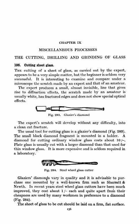
CHAPTER IX
MISCELLANEOUS PROCESSES
THE CUTTING, DRILLING AND GRINDING OF GLASS
196. Cutting sheet glass.
THE cutting of a sheet of glass, as carried out by the expert,
appears to be a very simple matter, but the beginner is seldom verysuccessful. It is interesting to examine and compare under a
microscope the scratch made by an expert and that of an amateur.
The expert produces a small, almost invisible, line that gives
rise to diffraction effects, the scratch made by an amateur is
usually white, has fractured edges and does not show special optical
effects.
Fig. 283. Glazier's diamond
The expert's scratch will develop without any difficulty, into
a clean cut fracture.
The usual tool for cutting glass is a glazier's diamond (Fig. 283).
The small black diamond fragment is mounted in a holder. Adiamond for cutting ordinary window glass costs about 10 / .
Plate glass is usually cut with a larger diamond than that used for
thin window glass. It is more expensive and is seldom required in
a laboratory.
Fig. 284. Steel wheel glass cutter
Glaziers' diamonds vary in quality and it is advisable to pur-chase one mounted by a well-known firm such as Sharratt &Newth. In recent years steel wheel glass cutters have been much
improved, they cost about 1 /- each and quite apart from their
cheapness are used by many workmen in preference to a diamond
(Fig. 284).
The sheet of glass to be cut should be laid on a firm, flat surface.
156

MISCELLANEOUS PROCESSES 157
A drawing board is very suitable. A fairly thick straight edgesuch as a boxwood rule, is then held firmly on the glass about
-&" away from where the cut is desired; this makes allowance for
the distance of the diamond or steel wheel from the edge of its
holder.
The handle of the holder is then held between the thumb and
second finger of the right hand with the forefinger on top to steadyit. The angle at which a diamond holder is held should be such
that the bottom edge is parallel to the glass sheet as shown in
fig. 285. The scratch should be started at the far edge and madewith steady pressure in one continuous stroke to the near edge.Most amateur glass cutters press far too hard and so fail to
produce the necessary fine, almost invisible scratch.
It is a great help to dip the diamond or steel wheel into turpen-tine before using it. If this precaution be taken the amateur can,
at the first attempt at glass cutting, produce the expert's typeof scratch. This is a method well known to a certain section of
the glass trade and makes a steel wheel cutter as effective as a
diamond.
Never go over a scratch a second time, it must be made in a
single, continuous movement.
If the sheet of glass be thin, it can be snapped apart by grippingit on both sides and at one end of the scratch and by giving a sharpbend and pull to the glass at the same time (Fig. 286).
Some grades of glass are more difficult to cut than others and
may require tapping, just below the scratch on the under surface
before a fracture can be started and the glass separated by the
method already described.
The sheet glass used for photographic plates is very easy to cut.
Old negatives can be obtained from a professional photographerand the emulsion is readily cleaned off by treatment with boiling
water and washing soda.
Ruby glass, as used in photographic lamps, has a hard surface
coating of coloured glass on one side only. When red glass has
to be cut the scratch should be made on the soft, non-coated
side.
Ground and silvered glass should be cut on the plain side.
If an imperfect scratch has been made it sometimes happens that
small jagged projections are left after cutting. These can be
removed with the help of a pair of parallel jaw pliers, or by the
aid of notches on the side of a steel wheel type of cutter (Fig. 287).
Guard against splinters by doing the work at arm's length and
preferably over a waste box.

158 THE LABORATORY WORKSHOP
Fig. 280 Snapping apart sheet glass
Fig. 285. Correct angle to hold cutter
Face of tool must be kept parallel to
glass when cutting
Fig. 287. Removing jag-
ged edges by means of
notches on side of a steel
wheel cutter
^^siT/Fig. 289.
starthere
Fig. 291.
Method of usingcircle cutter
Fig. 288. Cutting a circle in glass
Finger rest
Fig. 290. Cncle cutter. A. Rubber disc; R. Steelwheel cutter. By courtesy of T. E. Riley
Fig. 292.
Diagram showingradial scratches Fig. 293. Drilling sheet glass

MISCELLANEOUS PROCESSES 159
197. Cutting circles.
It occasionally happens that an instrument with a circular
front requires a new piece of glass. This can be prepared bypasting a disc of writing paper of the required diameter on the
glass to be cut. With the help of a glass cutter, guided by a
ruler, make a series of scratches tangential to the paper disc, and
so remove first one and then another portion of the glass sur-
rounding the disc (Fig. 288).This method leaves the glass with a scries of sharp corners, these
are easily ground off by rubbing the edge on the side of a carbor-
undum oil stone. During the grinding constantly dip the glass
into turpentine and keep the stone well supplied with the same
liquid. Turpentine has the peculiar effect of preventing the glass
from splintering and enables a good ground edge to be obtained
(Fig. 289).
It is best to use the side of the stone, since the grinding of glass
on it tends to produce a grooved surface.
The grinding of the corners docs not take more than a few
minutes, and when completed the paper disc can be soaked off in
hot water.
198. The use of a circle cutter.
At a cost of 1 /6 a special tool1 can be purchased for cutting
circles up to 8" in diameter (Fig. 290).
Start with the cutting wheel in a position below the steadying
finger of the left hand as shown (Fig. 291). Apply pressure to the
cutting wheel and with continuous even motion describe a circle.
Turpentine is an aid to forming the correct type of scratch.
Pick up the glass and tap it on the under surface below the
scratch mark. The end E (Fig. 290) of the circle cutter makes a
good tapping tool. As a rule, gentle tapping causes the scratch
to develop into a circular crack, but the process can, if necessary,
be assisted by applying slight pressure with the thumbs, one
being placed on each side of the crack, but on the under surface
of the glass. The thumbs should be moved along as the crack
spreads round.
A complete circular crack having been formed, the next thing is
to free the disc from its surroundings.Place the glass on a flat surface and using the wheel C (Fig. 290)
of the tool as an ordinary glass cutter make a series of scratches as
shown (Fig. 292).1 Stocked by Messrs. Buck and Ryan, 310-312, Euston Road, London,
N.W.I.

160 THE LABORATORY WORKSHOP
Pick the glass up and give the superfluous portions a series of
sharp taps below the scratches. The scratches will develop into
cracks, but these are unable to spread beyond the circular one.
By a process of slight combined bending and pulling, the
unwanted glass can be very easily removed thus leaving a well-
formed circular disc.
199. Drilling sheet glass.
Some pieces of apparatus require the drilling of holes in sheet
glass. This can be most successfully carried out as follows.
Select a fairly thin copper or brass tube of the same external
diameter as the hole required. A tube 2" long is convenient.
File one end of the tube flat and grip the other end in the chuck of
a bench drilling machine or failing this use a hand drill. If the
tube be too large to go into the chuck, drive a wooden peg into the
end and taper the peg sufficiently to fit into the chuck.
If a drilling machine be available the sheet of glass should be
placed on a block of wood arranged on the table of the machine.
A few nails driven into the wood will prevent the glass moving
sideways during the start of the drilling process.
Make up a mixture of carborundum powder and turpentine and
place a heap of well moistened powder on the glass where the hole
has to be drilled (medium No. 100 powder is suitable).
Turn the handle of the drill and bring the tube down on to the
glass. The powder is carried round by the tube and the hard,
sharp edged grains quickly cut into and through the glass. The
drill can be turned quickly, but the pressure of the tube on the
glass should be fairly light. Keep the tube well supplied with
grinding mixture and do not stint the turpentine or the tube will
get hot and cracks will start. Every fifteen seconds or so, raise
the tube and push grinding mixture into the circular groove that
forms in the glass; in this way the flat, under surface of the tube
is kept well supplied with abrasive.
When half through the glass, turn it over and continue to drill
from the other side. This avoids splintering one edge.
If a hand drill be used some kind of guide for the tube is neces-
sary. This can tr.ke the form of a wooden block with a suitable
hole in it to accommodate the tube. The block can be clampedon top of the glass plate and drilling is then carried out as before
(Fig. 293).
By the method described it is possible to drill a J" diameter hole
through a sheet of window glass in about 10 minutes. Plate glass
is as easily drilled as thin glass, but of course takes longer to

MISCELLANEOUS PROCESSES 161
penetrate. A cylindrical pellet of glass is formed by the cuttingtool.
200. Cutting glass rod and tube.
Glass tubing and rod up to \Hin diameter can be cut by nicking
one side with a triangular file and then smartly bending and
pulling each side of the nick.
Large diameter tubes require a different procedure. Glass
cells for use in a horizontal projection lantern can be made bycutting off a narrow ring of large diameter glass tubing and
cementing it on to a plate of glass. To cut such a ring, first guma piece of paper around the tube leaving an amount of tube pro-
jecting equal to the depth of the cell. Make a scratch with a glass
cutter, or file a nick around the tube using the edge of the paperas a guide. The ring can be neatly removed by means of an
electrically heated length of Nichrome resistance-wire stretched
between two supports (Fig. 294).
The current required to make the wire red hot can be taken
from the mains by placing a suitable resistance, such as an arc
lamp resistance, in series with it. Another method is to use a step-
down transformer giving 25 volts.
The tube to be cut is held against the red hot wire with the wire
pressing against the tube where the scratch or nick has been made.
A crack is formed and can be made to follow round by slowly
rotating the tube keeping the latter all the time in contact with the
wire.
Any irregularity in the end face of the cut off ring of glass can be
removed by rubbing the ring up and down on a flat carborundum
oil stone well lubricated with turpentine.To form a cell the ring has to be cemented to a plate of glass.
A lantern slide cover glass is very suitable for this.
Place carborundum powder and turpentine on the plate, put the
ring in position and rotate it clockwise and anti-clockwise. This
has the effect of forming a rough place on the glass plate corres-
ponding to the cross section of the ring.
Wash away the abrasive and cement the ring and plate togetherwith* Durofix cement, or a concentrated solution of shellac dis-
solved in methylated spirit.
During the drying of the cement the ring should have a weight
placed oil it to keep it pressed down on the plate.
201. Plugging walls.
The tools required for plugging a wall consist of a hammer and
a special steel drill sometimes known as a plugging chisel or

162 THE LABORATORY WORKSHOP
jumper. The work consists of making a suitable hole in the brick
or cement of a wall and hammering into this a wooden plug for the
reception of a screw used in the attachment of a fitting to the wall.
A good form of drill is shown (Fig. 295).
The method of using it is as follows.
Hold the fitting to be attached against the wall arid mark the
position of the screw holes. Take the fitting away. Put the pointof the drill on the mark and give the other end heavy blows with a
hammer. The peculiar shape of the tool enables it to penetratehard material. After every two or three blows, give the drill a
slight turn, this causes it to form a hole of circular cross section
and prevents the drill from getting jammed. Take great care to
keep the tool square to the wall (Fig. 296). The depth of the drill
hole depends on the weight of the fitting to be attached and the
size of the screws to be used. From one to two inches is a usual
depth. If the hole has been made 2" deep, cut a piece of woodabout If" long, of roughly square section and large enough to be a
tight fit when hammered into the hole. A certain amount of
judgment must be used when selecting and shaping the wooden
plug (Fig. 297). Hammer the plug into the hole until it becomes
tightly fixed and the near end has come flush with the surface of
the wall. Very neat wall plugs can be made of dowel rod.
A piece of y diameter dowel rod forms a good plug for a f*
diam. hole. One end can be pared down with a chisel, so that it is
an easy matter to start driving it into the hole (Fig. 297).
Another form of plugging chisel is shown (Fig. 298). This is an
effective tool. The cutting end is hollow and provided with hard
steel edges. A useful size is the f*tool costing about 1 /5.
For very neat wall plugging the Rawlplug system is useful.
A special small size jumper is used to make a hole for the inser-
tion of a Rawlplug. This is a tube of stiffened fibre which auto-
matically expands when a screw is driven into it (Fig. 299).
The successful use of a Rawlplug depends on the formation of a
good hole. The jumper must be kept square to the wall and
frequently rotated between hammer blows. The No. 8 size of
jumper designed for hard material is suitable for general workand No. 8 Rawlpjugs suitable for size 8 wood screws can be boughtin boxes of assorted lengths.
202. Painting and enamelling apparatus.
Baseboards and other wooden parts of apparatus can be stained,
oiled or polished to obtain a good finish.
Before treating wooden parts it is always best to remove metal

MISCELLANEOUS PROCESSES 163
Fig. 295. A drill for plugging walls
Fig. 294An electrically heated wire
Rectangular Plug made from
plug a dowel rod
Fig. 297
Fig. 296. Plugging a wall
mFig. 298. A hollow plugging chisel
Fig. 300 Fig. 301Brush suspended in
lacquer solution
Fig. 299. Rawlplug drill
By courtesy of Rawlpluff Co., Ltd.
fittings, so that all parts of the wood can be treated and the
fittings do not get marked.
Wood such as oak with a distinct grain is best left unstained, it
can be well smoothed with glass paper, then rubbed over withboiled linseed oil. Boiled oil can be purchased from any colour
merchant.
Light-coloured woods can be stained with dye to prevent themshowing finger marks.
S. C. Johnson & Son, Ltd., West Drayton, Middlesex, England,make a wide range of wood dyes. Green Solignum gives aneffective finish to benches and stools.
Wood used in the construction of optical apparatus is bestmade black. An excellent dead black is Roscoe cylinder black

164 THE LABORATORY WORKSHOP
manufactured by Owen Bros. & Co., Ltd., Hull. It is sold in
small tins at Halford cycle shops and has t remarkable covering
power. It is heat proof, dries in twelve hours and makes an ex-
cellent finish to iron, tin plate or brass used in the construction of
optical lanterns.
Aluminium paint can be used on wood or metal. Some brands
of aluminium paint are far from satisfactory. Good qualityaluminium paint is prepared with very fine particles of metal. The
size of the particles has an effect on the covering power of the
paint and the final finish.
'Slick' brand and Blundell's and Berger's aluminium paint can
be recommended. Aluminium paint gives a good finish to retort-
stands, pipes and iron work in general. One coat will cover all
imperfections of the surface; it is cheap, easy to apply and soon
dries.
Brass and other metal work used in the construction of appar-atus can be preserved from tarnish by giving it a coat of celluloid
dissolved in amyl acetate.
Scraps of celluloid can be obtained from a garage; it is used for
the side windows of touring cars. Old celluloid protractors and
set squares can also be used.
Amyl acetate is stocked by most chemists, it is a ready solvent
of celluloid. The solution used should be diluted to a consistency a
little less fluid than that of water.
The metal to be coated should be polished with fine glass paperfollowed by rubbing with a clean cloth; avoid grease and finger
marks. The solution should be applied with a wide, soft camel-
hair brush. Work the brush in even sweeps and do not go over
the same place twice.
After use the brush should be washed out in amyl acetate or
passed through a hole in the cork, so that it remains suspendedin the solution (Fig. 300). Small parts can be hung on wires to
dry, or supported on upturned drawing pins. This transparentcelluloid lacquer dries hard in a few hours. It can be bought
ready made under various trade names.
Robbialac enamel is useful for metal and woodwork, it can be ob-
tained at most gayages and paint shops. Bright colours look out of
place when associated with apparatus. Panhard red, Sheffield
grey and Singer grey are suitable colours in the Robbialac range.Paint and enamel brushes that are not likely to be used again
for some time should be well worked out on a piece of wood,rinsed in turpentine and washed clean with soap and hot water.
If the brushes are in constant use it is not always convenient to

MISCELLANEOUS PROCESSES 165
do this; in such a case they can be stored in a tin or jam pot
containing water or Uirpentine to prevent the access of air to the
paint between the bristles. Provision should be made to keepthe bristles away from the bottom of the pot where they get
contaminated with paint residues and bent out of shape by the
weight of the handle. This is easily done by passing a long nail
through a hole drilled in the handle (Fig. 301). A brush that has
been stored in water should be wiped before use and it is advisable
to keep brushes used for aluminium separate from those used
for other paints. The fine particles of aluminium are liable to
contaminate and spoil the appearance of other paints.
203. Wood polishing.
A simple method of giving an excellent finish to woodwork is
to glass-paper it to a smooth surface, and then rub it over with
boiled linseed oil. Allow the oil to soak in for an hour, or better
let it remain overnight, then polish the surface with a solution of
1 part of flake shellac dissolved in 2 parts of methylated spirit.
Make a pad formed of cotton wool wrapped in a piece of linen,
pour some solution on to the wool, wrap it up in the linen and
apply the pad to the oiled wood with a gentle circular motion. Apolished surface is produced almost at once. This method is
particularly effective when applied to mahogany.
204. The use of cardboard.
Thick brown cardboard, known in the trade as strawboard, and
stocked by most office stationers, can be used for the making of
many objects such as loud speaker horns, boxes, store trays and
folding screens for micro projection work. It is a convenient and
cheap substitute for wood and only a few simple tools are requiredto make use of it.
Strawboard is usually sold in sheets measuring 25" x 30".
The thickness is regulated by the weight. A 4lb. sheet, measuring25" x 30" has a thickness of approximately fa". 4lb. strawboard
is a useful grade for general work.
The strawboard is marked out in pencil and cut with a sharpmount cutter's knife (Fig. 302), guided by a steel rule. Specialsteel rules can be purchased, but are not essential (Fig. 303).
Fig. 303
Fig. 302. Mount cutter's knife Steel rule with finger guard

166 THE LABORATORY WORKSHOP
During cutting the strawboard should be placed on an old drawingboard or other flat piece of wood, and it is usually necessary to go
along the guide line several times before a complete cut can be
made. It is well to keep an oil stone near at hand for sharpeningthe knife.
For fastening the strawboard together the writers have found
no better glue than Higgins' Vegetable Glue1; it is sold in tins by
most high class office stationers.
Once the tin has been opened it is well to turn out the contents
into a glass or earthenware pot with a non-rusting cover. The
glue, a thick white paste, is ready for use and is applied with a
stiff brush. A portion can, for case of working, be put on a saucer
and diluted with water to thin it down.
A good flour paste can be made from Jib. of flour and Joz. of
powdered alum mixed with cold water to form a thin paste.
When all lumps have been smoothed out with a stick, add one
pint of cold water and heat in a saucepan with constant stirring.
Boil for five minutes, but continue the stirring. Finally add
seven drops of oil of cloves and seven of turpentine to serve as a
preservative. When cold the paste is ready for use after stirring
with a stick. This recipe for making paste is well known to
bookbinders.
Strawboard can be fastened together at the corners by glueing on
strips of blind material or linen (Fig. 304). If a sheet of straw
board has to be bent through an angle, the place for the bend
should be marked and a knife cut made half through (Fig. 305).
Fig. 304. Box of strawboardwith strengthened corners
Half-cut through
Fig. 305. Bending cardboard
A strong hinge^can be constructed by sewing together two pieces
of flexible material such as sateen or linen as shown in fig. 306, and
then glueing it on to the two portions of board as shown (Fig. 307).
A good finish can be obtained by covering the strawboard and
binding strips with black or coloured paper or cloth.
The firm of F. G. Kettle, 9, New Oxford Street, London, W.C.I,1 Makers. Chas. M: Higgins & Co., Brooklyn N.Y. and Farringdon Avenue,
London, E.C.4.

MISCELLANEOUS PROCESSES 167
keep a great stock of strawboard sheets, and cardboard tube and
every variety of fancy paper. One very useful paper is known as
flock paper; it is sold by the yard and in rolls and has a matt,
cloth-like surface. It is supplied in various colours, and makes
a good material for pasting on to plywood or strawboard to form
the interior'surface of exhibition cases.
Fig. 306. Flexible hinge
Fig. 307. Hinge glued in position
Black flock paper has an optical black finish and makes an
excellent lining material for demonstration cabinets connected
with light experiments. Its use in this connection can be seen
at the permanent exhibition of the Lighting Service Bureau,
2, Savoy Hill, London, W.C.2.
205. The preparation of lantern slides from book illustrations.
An old half plate camera is useful for this purpose. Very few
amateur photographers now use half plate cameras and excellent
instruments can be bought from second-hand camera dealers for
less than 2, complete with one or two book form slides. New
adapters can be purchased for 1 /6 to fit the |-plate slides and so
make them available for J plates.
Before a lantern slide can be made it is necessary to prepare a
photographic negative of the illustration and this necessitates a
stand for the camera and an illuminated easel for the book.
A convenient form of home-made easel is shown (Fig. 308). Adrawing board can be used for the vertical portion. If this be
fixed to the baseboard with hinges it can be turned back into a
horizontal position, making it easier to attach books or papers.The face of the board should be painted a dull black with two white
lines across it, so that illustrations are easily centred.
Papers can be attached to the board with drawing pins and
books can be held flat and firmly in position by means of two brass
clamps that may be moved along the board and tightened up as
required.

168 THE LABORATORY WORKSHOP
One of
Adjustable Clamps
Part section
showing- the
/bolt
Plan view of one of the Pivoted arms >r
holding the lamps
Fig. 308. A home-made easel for copying
To obtain constant illumination it is best to use artificial light
and two 60 watt pearl type electric lamps are fixed one on each
side.
These lamps are provided with simple shades, so that no direct
light from the lamps can enter the lens of the camera. Theshades can be cut from tin plate. Batten type lamp holders are
arranged on pivoted arms.
Some glossy papers give rise to troublesome reflections. Aslight movement of one or other of the arms provides a cure bychanging the direction of the illumination.

MISCELLANEOUS PROCESSES 169
-61-
Side view of camera and easel
How to mark the groundglass screen of the camera
Plan of camera and easel
The wooden stand on whichthe camera is fixed
Fig. 309.
The camera can be attached with a tripod screw to a stand as
shown (Fig. 309).
The dimensions of the stand should be such that the centre of the
lens in its normal position is at the same height from the bench topas the centre of the easel.
The ground glass of the camera should be marked with a pencil
to show the size of a lantern plate 3j" x 3 J". To use the ap-
paratus the illustration to be photographed is attached to the
easel and the lamps switched on.
The image of the illustration is focussed on the ground glass.
If it is too big to come on to a lantern plate the easel is movedfarther away and the image is again focussed.
A magnifying lens should be used for critical focussing.
For copying work, process plates should be used. The writers
use Wellington Ortho Process J plates in conjunction with Wel-
lington metal-hydrokinone universal developer prepared accordingto the formula as given on the cover of the plate box.
After focussing, the lens should be stopped down to about f!6.
With Ihe easel at a distance from the lens of 2j', a stop of f!6 and
illumination from two 60 watt lamps the time of exposure is about
three minutes.
Wellington Process Plates with an H and D speed of 100 have

170 THE LABORATORY WORKSHOP
very great latitude, an error of a minute or so makes little
difference.
Time the exposure with a watch and avoid vibration of the
bench during this time. Develop to full density; use a ruby safe
light. Fix, wash and dry the negative in the ordinary way.All parts of the negative corresponding to white paper in the
original should be a good black.
Make lantern slides from the negatives on Wellington S.C.P.
lantern plates. These are best exposed by placing the printing
frame, with negative and lantern plate, below a pearl, pipless typeelectric lamp suspended over a bench. Develop with Wellingtonuniversal developer and fix in acid hypo.When masking and binding up slides from book illustrations or
catalogues it is advisable to mask out all printed matter. Aslide that might otherwise pass for a photograph prepared from
the original object can be spoilt by the inclusion of a figure number.
206. Using ebonite.
Ebonite is best marked out on the back of the sheet with an
engineers' steel scriber; pencil lines may cause leakage paths.
Fig. 810. The 'Eclipse' 4 S tool. ny courtesy of James Neil & Co , Ltd.
Ebonite quickly takes the edge off an ordinary wood saw, so
a hack-saw should be used for cutting it.
A very useful tool for cutting ebonite, metal and other materials
is made by James Neill & Co., Ltd., Sheffield and is known as the
'Eclipse' 4 S Tool. 1(Fig. 310). This has no frame to get in the
way and limit the depth of cut.
After cutting a sheet of ebonite roughly to shape with a saw it
can be clamped between jaw protectors in a vice and filed to
exact size, the scribed lines serving as guides.The surface can be rubbed down with fine glass or emery paper.
This leaves it slightly brown, a good black surface is obtained bywiping it over with a rag moistened with thin machine-oil or
paraffin.
1 Sold by tool dealers for 5 /-. This includes a metal container, a holderand 15 tools.

MISCELLANEOUS PROCESSES 171
Ebonite can be centre punched and drilled in the same way as
metal. Twist drills >are suitable. Some inferior grades of ebonite
tend to break away in flakes at the place where the drill emerges,for this reason it is always best to drill ebonite with the sheet
placed on a flat board. A thread can be cut in ebonite with a
screw cutting tap, if necessary vaseline can be used as a lubricant,
Large diameter holes can be cut with a metal piercing saw
(Fig. 81), or an expansion drill (Fig. 65).
207. Using uralite.
Uralite, a material made from cement and asbestos and largely
used in the building trade for the construction of bungalow walls,
and in the form of tiles is a valuable workshop material. It is
fireproof and a good electrical insulator.
It is sold in sheets both large and small. A sheet a J" thick,
measuring 8' x 4', costs about 5/6. Other standard sizes are
6' x 3', and 4' x 4'. Tiles in various colours and costing but a
few pence, each measure 20" x 10", 24" x 12", and 12" x 12".
Uralite is very strong under compression, but is brittle and will
not resist much bending. It is easily cut with a hack-saw and
filed, large portions are best cut as follows.
Place the sheet on a flat surface and use the sharpened tang end
of an old file to make a deep incision. A steel rule or a length of
board can be used as a straight edge. Place the sheet on a table
with the scribed incision facing upwards, but just over the edgeof the table. Give the projecting portion of the sheet a sharpbend downwards, it will break off with a fairly clean fracture alongthe incision.
The tang of the file can be ground to a pointed knife edge on a
carborundum wheel.
Uralite can be drilled with twist drills and countersunk with a
rose bit. It tends to blunt these tools very rapidly.
208. Can openers.
In recent years various tools have been invented that cut out
the top of salmon, preserved fruit, or other tin cans in such a wayas to leave a smooth turned over edge. .
One such tool that only costs 1 /- and does its work very well
indeed, is known as Vaughan's Safety Roll Jr. Can Opener, No.
170B.
Tins that have been opened in this way can be used in a labora-
tory as water baths and in a workshop for mixing materials or as
store tins.

172 THE LABORATORY WORKSHOP
A tin can with both ends cut out makes a good tube for optical
apparatus construction.
209. Packing case opener.
Most laboratory workers have occasion to open packing cases of
glassware and other apparatus. Bands of steel ribbon can be cut
with the help of a cold chisel and hammer. Nailed down lids maybe prised up with a cold chisel; wood chisels and screwdrivers are
liable to be injured if used for this purpose.A special tool, known as a wrecking bar, is made for opening
cases (Fig. 311), but the tool par excellence for extracting nails is
an automatic nail puller (Fig. 812). This pulls out the nails without
bending them or spoiling the case to any appreciable extent.
210. The use of rivets.
Various rivets are illustrated (Fig. 39).
The process of riveting is quite easy and can be applied to ply-
wood, canvas, leather, metal and many other substances. Riveted
metal joints are very strong and can be used in places where heat
would melt solder.
Fig. 3] 8 shows a leather strap handled riveted to the side of a
box made of 3-ply wood. The box itself can be put together with
rivets by arranging strips of wood in the corners. The method of
riveting on the handle is shown (Fig. 314).
Flat headed copper rivets and washers are particularly useful
for this type of work.
I. Make holes in the leather and in the wood of the same
diameter as the rivet.
Holes in the leather are best cut with a hollow steel punch. Rest
the leather strap on a piece of old sole leather and strike the puncha heavy blow with a hammer (Fig. 315). If no punch be available
use a Lancashire broach to pierce a hole. The wood should be
drilled with a twist drill of the same diameter as the rivet to beused.
A suitable drill can be selected by trying the fit of a rivet in the
holes of a metal drill stand.
II. Push the rivet through the holes and fit on a metal washer.
The diameter of the hole in the washer should be approximatelythe same as that of the rivet; the latter should extend about ^^beyond the washer.
If the rivet be too long, use a shorter one or file or cut it to
length.

MISCELLANEOUS PROCESSES 173
End cutting nippers (Fig. 316) save much time in cutting rivets.
III. Place the head of the rivet on the closed jaws of a vice and
with the rounded end of a ball-pane hammer extend and clench
the rivet over the washer. A series of gentle blows are more
effective than heavy ones in spreading the metal.
Fig. 311. Wrecking bar for openingpacking cases
Fig. 312. Automatic nail puller
Fig. 314. Method of
riveting leather
handle to box
KRivet
Fig. 313. Use of rivets to construct box andattach leather handles
Fig. 315. Punching a hole in
a leather strap
Fig 316. End cutting nippers f\\\T L\\\V1 K\\\Vt77/771
f/7/7/ir////A
Fig 317 Riveting togethermetal strips
Washers are not required when hard material, such as metal,
has to be riveted. Fig. 317 shows strips of metal riveted together.
The chief precautions to observe when riveting are:
(1) make the fit of the rivets in the holes as good as possible.
(2) arrange for a short protruding portion.
Small brass nails make good rivets for very fine work.

174 THE LABORATORY WORKSHOP
211. Covering books with brown paper.
The diagrams (Fig. 318) show a simple and effective method of
folding brown paper to form a slip-on cover for a book.
Fig 318. To make a slip-on paper book cover
212. The temporary repair of electric heating elements.
The resistance portion of open wire type electric heaters are
usually made of nickel chromium alloy. If a wire gets thin andfuses at some point it is sometimes possible to effect a repair that
will last a considerable time, by carefully scraping and cleaning the
broken ends, then bending around a small brass bolt and clampingup tightly between two brass nuts.
A steel bolt and nuts are unsuitable owing to rapid oxidation
at high temperatures.
213. The protection of tools from rust.
Tools can be protected from rusting by wiping them over withan oily rag. In hot, moist countries it is advisable to do this after
the day's work in the case of all tools that have been handled. If
tools are to be stored and not used for some time they should bewell oiled or greased.
Never use linseed oil. Ordinary engine oil is suitable, but oneof the best rust preventing oils is 3-in-One.
An excellent method of protecting tools with grease is to dissolve
vaseline in petrol and either dip the tools in the fluid or paint it onwith a brush. Vaseline is carried to every crevice and left as a thin
film when the petrol evaporates.

CHAPTER X
DRAWINGS AND DESIGNS
214. Workshop drawings.
BFFORE starting the construction of a piece of apparatus it is
often helpful to prepare a rough sketch. Usually such a sketch is
all that is necessary or desirable when scrap material or odds and
ends have to be utilised as material, designer and constructor
being one and the same person.When a design is being prepared for the guidance of other people
or the object drawn has to be made in quantity or for use with
other parts a proper scale drawing should be made.
The reading of a workshop drawing requires some knowledge of
the art of the draughtsman and at this stage a few notes on how to
read a drawing may not be out of place. Fig. 319 is a freehand
sketch of a small lifting electro-magnet. Such a sketch fails to
show anything of the interior construction and would not be
sufficient for workshop purposes.A view, in silhouette, as seen from one side is known as an
elevation. An elevation of the magnet as seen from A is shown in
fig. 320. More information with regard to the shape of the magnetand the wooden terminal block is provided by a second drawingof the magnet as seen from position B at right angles to positionA (Fig. 321). The steel part of the magnet is cylindrical in form,
but this fact is not conveyed by elevation drawings only althoughsome idea of form can be given by shading (Fig. 320).
Plan views as shown in figs. 322 and 323, and studied in con-
junction with the two elevations yield full information with regardto the exterior form of the magnet.
In the side elevation, fig. 321, the hole through the brass knobcannot be seen.
If the brass became transparent the outline of the hole would be
seen in the position shown by the two parallel lines composed of
short dashes.
This is the conventional method of indicating the position of
unseen holes or parts.
A drawing of the magnet in section is shown in fig. 324. This is
a section in elevation across the line a b (Figs. 322 and 323).175
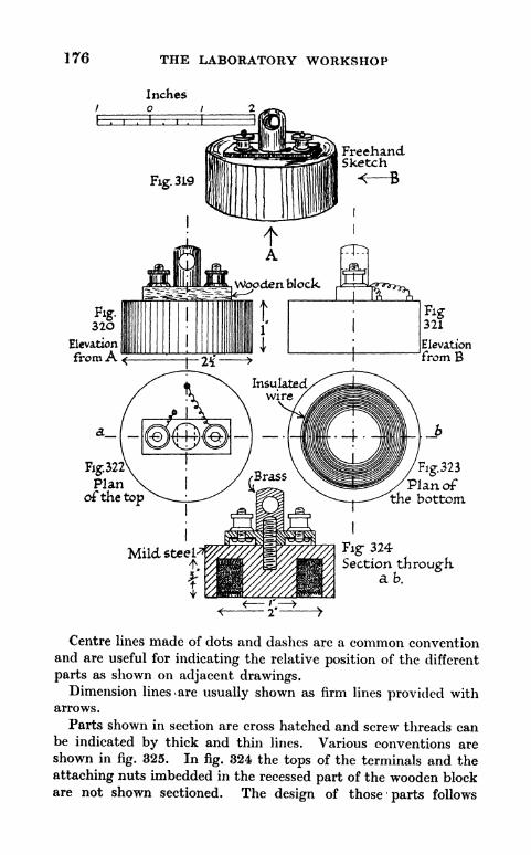
176 THE LABORATORY WORKSHOP
Inches
FreehandSketch
< fi
Elevation
fromAElevation
from B
Fig.323
Plan ofthe bottom
Fig- 324Section through
ab.
Centre lines made of dots and dashes are a common conventionand are useful for indicating the relative position of the different
parts as shown on adjacent drawings.Dimension lines <are usually shown as firm lines provided with
arrows.
Parts shown in section are cross hatched and screw threads canbe indicated by thick and thin lines. Various conventions are
shown in fig. 325. In fig. 324 the tops of the terminals and the
attaching nuts imbedded in the recessed part of the wooden blockare not shown sectioned. The design of those parts follows

DRAWINGS AND DESIGNS 177
standard practice and can be left to the imagination of the reader.
To show them sectioned would only add to the complexity of the
drawing. Practical details regarding the construction of this
magnet are given in Chapter XI.
Fig. 325. Conventional methods of representationA. Nut and bolt B. Plan view of the head of a boltC. Side elevation of a nut D. Plan view of a nutE. A rod or shaft shown F. A piece of wood shown discontinued
discontinued
Many of the drawings used to illustrate previous chapters are
known as isometric projections. These are simple to draw andhave many advantages for workshop purposes.
In fig. 326 a metal block provided with
clamping screws is shown in isometric pro-
jection. An artist drawing this in perspec-
tive would show the lines AB and CD as
converging lines and BD shorter than AC.
An isometric projection shows both AB and
CD inclined at an equal angle to the hori-
zontal, usually 30, and BD = AC. This
type of drawing enables vertical or hori-,J * fo
Fig. 326. Isometiic pro-zontal measurements to be made at any part jection of a metal block
of the drawing. with clamping
A circle becomes distorted in an isometric projection and it
should be noted that certain angular and diagonal measurements
cease to be correct. The angle BAC is not a right angle in the
drawing and BC is not the true diagonal distance between B and C.
215. The preparation of a drawing for reproduction J>y the line-process.
Drawings to be reproduced in books and magazines by the line
process require special care if satisfactory blocks are to be made
by the photo-engraver.The drawings should be made on a smooth white ground such
as Bristol board or best quality type-writing paper that is free
from a water-mark. Use best quality, very black Indian ink and

178 THE LABORATORY WORKSHOP
remember that nothing in the way of half tones or coloured
washes can be reproduced by the line process. Shading must be
done with firm black lines and clean white spaces between. Anywording associated with the drawing is best put in by the printer;
its position and nature can be inserted on the drawing in blue
pencil since blue reproduces as white in the photographic stage of
line block making and will not show in the reproduction.
Drawings are best made about twice the size they will finally
appear and each one should have the reproduction size indicated
in blue pencil.
Care must be taken to avoid ambiguity when inserting the repro-
duction size. A reproduction size indicated as | linear implies a
reproduction having horizontal and vertical lines reduced to \ the
length shown in the original, but covering J the area occupied bythe latter. An instruction such as, reduce to \ might meanreduce to \ linear or reduce the area to J.
Drawings for reproduction should be clean, free of pencil marksand must not be folded. All lines should be clean and not
woolly, and very fine lines should be avoided.
216. The preparation of lecture-room diagrams.
Large wall-diagrams can serve the useful purpose of illustrating
lectures and of creating 'atmosphere.' They can be drawn in
pencil on large sheets of good quality drawing paper, then lined in
with Indian ink and colour washed with diluted Indian ink or
poster colours. The latter can be bought in 6d. pots in a great
range of tints.
A book illustration can often be used as
an original for enlargement; this can be done
in various ways. The following are twomethods.
Fig. 327. The diagonalmethod of dividing anillustration preparatory
to enlargement
(1) The original drawing can be divided
into squares, or rectangles and tri-
angles, by fine pencil lines and the
paper to receive the enlarged drawingis divided similarly; it is then a simplematter to locate corresponding points.
The method of forming triangles bydrawing diagonals (Fig. 32'?) is less
confusing than the square method and
it is an easy matter to draw additional diagonals over areas
where much detail has to be measured. If the original must

DRAWINGS AND DESIGNS 179
not be marked it can be covered with suitably divided tracing
paper.
(2) All measurements taken from the original can be multiplieda suitable number of times by stepping out with dividers, two,
three qr four times according to the degree of enlargement
required, the trouble of doing this can be avoided by the use of
proportional dividers.
217;
The designing of apparatus.
In recent years there has been a tendency for science equipmentto become more and more elaborate and possibly the pendulumhas swung rather too far in this direction.
A visit to the Science Museum or the Royal Institution in
London and inspection of the apparatus used by the late Lord
Rayleigh and Faraday in their researches can serve to demon-strate the use of home-made apparatus and of familiar things.
The following is an extract from The Times witli reference to
Lord liayleigh's instruments.
'Lord Rayleigh, as many of his visitors were surprised to dis-
cover, took common glass-tubing, sealing-wax, blocks of coarse
wood, cardboard, zinc, or whatever came to hand for the con-
struction of apparatus of great technical complexity. We find
him using a sheet of smoked glass, a collection of pebbles, and a
square of corrugated metal to research into the reflection of sound.
For a "bird-call" to test the vibration of sound-waves outside the
range of the human ear he employs a simple tin bearing the
inscription, "This is sold as a mixture of coffee and chicory." Thecard of invitation to a Guildhall banquet is cut and pasted into
shape to act as the transmission vessel for certain experiments on
the motion of fluids, and the vibration of a bell is brilliantly dis-
sected when the bell is made of a disc of zinc, a cylinder, and twohollow truncated cones.'
Tyndall, writing fifty-six years ago concludes the pages of a
delightful little book called Lessons in Electricity at the Royal
Institution,* with the following words, which remain true to the
present day.'And here, if I might venture to do so, I would urge upon the
science teachers of our public and other schools that the imme-diate future of science as a factor in English education depends
mainly upon them. I would respectfully submit to them whether
1 Longmans, Green & Co., 1876. Is scarce, can sometimes be obtainedsecondhand.

180 THE LABORATORY WORKSHOP
it would not be a mistake to direct their attention at present to the
collection of costly apparatus. Their principal function just nowis to arouse a love for scientific study. This is best done by the
exhibition of the needful facts and principles with the simplest
possible appliances, and by bringing their pupils into contact with
actual experimental work.
'The very time and thought spent in devising such simpleinstruments will give the teacher himself a grasp and mastery of
his subject which he could not otherwise obtain; but it ought to be
known by the head masters of our schools that time is needed,* not
only for devising such instruments, but also for preparing the
experiments to be made with them after they have been devised.
No science teacher is fit to meet his class without this distinct and
special preparation before every lesson. His experiments are partand parcel of his language, and they ought to be as strict in logic,
and as free from stammering, as his spoken words. To make themso may imply an expenditure of time which few head masters now
contemplate, but it is a necessary expenditure, and they will act
wisely in making provision for it.'
When considering the home-construction
, of apparatus it is always well to start by re-
/ ducing it to essentials and after that to build
Fig. 328. Symbols up details based on mechanical, electrical,for u switch
optical or other requirements.A few examples will illustrate the method.
The common conventions for a switch in electrical diagramsare shown in fig. 328, namely some means of bringing two conduc-
tors into electrical connection. Switches are manufactured in a
multitude of forms, but they must all satisfy the above require-
ment which can usually be brought about by simple means. Com-
plexity in design is caused by the need for mechanical strength,
sufficient electrical insulation, quick break-action, low resistance
contacts and other requirements. If those and the fundamental
requirement can be satisfied a switch constructed from scrap
pieces of brass mounted on a baseboard of American whitewood
may function just as well as an expensive commercially madeswitch mounted on polished ebonite.
An optical lantern for the projection of slides can be reduced to
a lamp, surrounded by some arrangement for preventing the
escape of stray light, a condenser, a slide-holder and a lens. The
lamp, condenser, slide-holder and lens must be kept in correct
relative position and be capable of a certain amount of adjustment.

APPAKATUS DESIGNS 189
A screw clip on the rubber tube joining the boiling tin and the
side reservoir enables the supply to be regulated.
A radiation switch. (Fig. 338 and Plate IIIA, page 19 A.)
This illustrates a mechanism that has found various practical
applications, namely the automatic switching on of lights, temper-ature control and self-winding clocks.
Platinum foil
A,
Electricalconnections
PartoTrart ut x^-:~
3 "-7==-. ^>ffi
B-
Fig. 338. A radiation switch
An ether thermoscope with arms bent at right angles is mountedin a rocking support. Thermoscopes of this type are supplied byinstrument dealers for about 3/- each.
With the rocker as shown in Plate IIlA,a contact is made and when
the apparatus is connected to the mains the right hand lamp will
light up. This causes the ether to be driven into the left handbulb. The balance is upset and the rocker moves so that connection
for the right hand lamp is broken, but made for the left hand one.
After a quarter of a minute or so the balance is again disturbed and
the rocker returns to the initial position. A constant see-saw
motion is set up.
A. Block of wood. A groove is cut in this and lined with cork
B, so that the thermoscope is a press-in fit and cannot twist

190 THE LABORATORY WORKSHOP
out of position. A side clip enables the thermoscope to be
fixed in position or removed as required. f
B. Cork: See above.
C. Cycle spoke: This has a No. 9 B.A. thread cut on both ends.
One end screws into the block of wood and the other into a
Meccano collar [14, 100].
D. Meccano collar: This is soldered to the spoke E.
E. Cycle spoke: One end is bent at right angles. It rests in slots
cut in the bearing plates F and F, and small B.A. nuts are
soldered on to prevent any side movement.F & F. Bearing plates: These are made of strip brass and are
attached with screws to the wooden uprights [54, 57].
Gl & G2. Contact arms: Made of strip brass. If the mechanism is
to be kept in action for a long time it is an advantage to
attach small pieces of platinum foil to these arms and to the
cycle spoke E. The foil can be fixed in position with a small
amount of ordinary solder.
In Plate IIlA, page 194, the lamps and thermoscope bulbs are
shown partly blackened with Roseoe cylinder black [202]. This
helps to increase the rate of action of the mechanism.
A nickel pendulum. (Fig. 339.)
This apparatus can be used to demonstrate that nickel ceases
to be attracted by a magnet when heated to a sufficiently high
temperature.A small tongue of nickel is riveted to a thin copper disc and
suspended in front of a magnet. A small Bunseii or spirit flame is
placed below the tongue of nickel. The temperature of the nickel
rises and it soon ceases to be attracted by the magnet and falls
away. The copper disc promotes rapid cooling. The nickel is
again attracted and again heated, so the pendulum-like motion
is maintained.
A. Tongue of nickel. This is \" to f"
long and can be cut with
a hack-saw from a nickel coin to be obtained from a travel
agent. Some, Continental coins are made of nickel and are
easily picked out with a magnet. Portions of old nickel
electrodes provide another source of nickel. They can be
purchased for a few pence from an electroplater.B. Copper disc. Use a piece of sheet copper about -fa" thick
and cut a disc 1" in diam. [63]. The nickel can be attached to
the disc by means of small brass nails cut short to form rivets.

APPARATUS DESIGNS 191
Fig. 389. A nickel pendulum
C. Arms for disc. These are formed from a piece of No. 18,S.W.G. copper wire. The wire can be passed through a hole
drilled in the disc and bound with fine wire, as shown in the
enlarged sketch, fig. 339. The slot filed in the disc preventsthe arms from slipping out of position.
D. Steel rod: Use a 12" length of bright drawn \" diam. mild or
cast steel.
The lower end has a \" Whit, thread cut on it [93] and is pro-vided with two nuts and washers for attaching it to the base-
board [113].E. Steel rod: Material similar to D. A thread is cut on both
ends. This rod should be long enough to enable a magnet tobe clamped 1" above a Bunsen burner or spirit lamp placedon the base-board.
Fl & F2. Magnet clamp: Made of brass strip. The central holein F2 is drilled J". The hole in Fl is drilled &" and tappedwith a I" Whit, thread [104]. Fl screws on to rod E and is
supported with a back nut [107]. This nut does not show in
the illustration.
G. Fine copper wire: The double suspension of fine wire keeps

192 THE LABORATORY WORKSHOP
the swinging disc in the same plane all the time. The fine
wire off the secondary winding of an oid Ford spark coil is
very suitable.
H. Clamp: Made from \" square brass [87, 104, 85, 102].
I. Baseboard [153].
J. Horizontal rod: A length of &"cliam. steel rod of a Meccano
axle.
Apparatus for producing superheated steam.
(Fig. 840.)
An oil-can made of tin plate is providedwith a good cork bored with holes to take two
spirals of copper tubing. The tubing is \" in
diameter and is wound into spirals of 1" in-
ternal diameter. If the tubing be annealed
before use it is an easy matter to form a spiral
by winding it round a broom-stick.
When water is boiled in the can steam
issues from the two tubes.
If one spiral be heated with a Bunsen flame
Fig. 340. Apparatus ft js possible to char paper or light a match infor producing super- ., ...-,,.., , f , .1 ,
heated steam the invisible jet of superheated steam that is
produced.Steam mixed with drops of water issues from the unheated
spiral.
Reference: Engines by E. N. da C. Andradc, G. Bell & Sons. Chapter
II, 'Learning about steam.'
Searle's apparatus for measuring thermal conductivity. (Plate II IB.
Fig. 341.)
This apparatus consists of a rod of metal A, fig. 341, measuring12" long and If" in diameter formed of the particular metal under
test. Brass is suitable for instructional purposes.To one end of the rod is soldered a box B provided with an inlet
and an outlet pipe for steam. A coil of copper tubing is soldered
to the other end of the rod. Water can be passed through this
tube and thermometers can be fixed in the tubes Cl, and C2, to
record the rise of temperature of the circulating water. Two tubes
Dl and D2, are screwed into the rod to enable thermometers to be
inserted for determination of the temperature gradient. The
apparatus can be housed in a wooden case and before use the rod,
steam box and copper tubing must be well packed with cotton
wool or other poor conductor of heat.

APPARATUS DESIGNS 193
The use of the apparatus is described in many physics, text-
books; an account w&th a worked example can be found in Heat byW. J. B. Calvert, Edward Arnold & Co.
The apparatus can be constructed at a cost of about 9/-. Thethick brass rod is the most expensive item.
<- - 2 -->
Fig. 341 . Searle's apparatus for determining the thermal
conductivity of a metal
The steam box is made of sheet brass and is formed from twodiscs and a strip of metal bent to cylindrical form.
A suitable size for this cylinder is 3j".Find a tin or a bottle of approximately this size and bend round
it a 2" wide strip of thin brass. Bind the strip with black iron wire,
then slip it off the tin or bottle and solder the edge to form a
cylinder [78].
Cut two discs of a diameter J" greater than that of the cylinder
[68]. In one disc cut a hole of diam. If" [70, ?!]. It should be a
tight fit on the rod A [69]. The discs can now be soldered to the
cylinder and two pieces of f"diam. brass tube should be soldered
into the sides of the steam box to provide inlet and outlet pipes
[143]. Before the steam box be soldered to the rod A the coppercoil for the circulating water must be constructed and soldered in
position. The coil is made from \" diam. copper tubing [83].

PLATE III
A* A
B. Searle's heat conductivity apparatus

APPARATUS DESIGNS 195
Before coiling round the rod A it must be annealed to render it
soft. e
After annealing give the tube a good clean with emery cloth then
wind it round the rod A to form eight coils.
The brass rod A and the copper of the coils are such good con-
ductors of "heat that it is necessary to make special arrangementsfor soldering. Support the rod on a triangular stand and heat the
centre of the rod with a cluster of Bunsen burners. This preventsundue cooling of the solder. Use a hot soldering iron and Baker's
fluid or zinc chloride as flux. Fill all the spaces between the coils
with solder.
When the soldering of the coils is finished the steam box can be
soldered on. The rod A should project about J* into the box.
The tubes Cl and C2 are made of brass with side tubes soldered
in at right angles to form T-pieces [144]. To the base of each
tube Cl and C2, is soldered a brass disc, these are drilled with J"
diam. holes and soldered to the ends of the copper coil.
The tubes Dl and D2 are made of f" diam. brass tube and
screw into holes drilled and tapped for f"brass gas thread [115].
To obtain good thermal connection between the thermometer
bulbs and the rod A it is advisable, when using the apparatus to
put a little mercury in each tube. Mercury forms an amalgamwith solder, so the latter should not be used to attach the tubes
Dl, and D2, to A.
In Plate H!B the apparatus is shown arranged in a box madeof seven-ply wood. One side was unscrewed to enable the photo-
graph to be taken.
It is best to pass water through the coils from a constant level
apparatus.
Apparatus illustrating spheroidal condition of water. (Fig. 342.)
This apparatus enables various effects associated with the
spheroidal condition of water to be demonstrated to a large
audience. It can be placed in a lantern of the open-stage type and
projected on a screen. A brass plate is brought to the necessary
temperature by means of an electric heating unit.
A. Asbestos cement base-plate : This can be cut from a sheet of
the material [207].
B. I&ectric heating unit : A unit of the type used in electric
irons and kettles is suitable. Most electricians stock spareunits. The metal connections at the ends of the unit are
drilled and fitted with terminals.

196 THE LABORATORY WORKSHOP
C. Brass plate : This is clamped down and held in close con-
tact with the heating unit. t
D. Clamping strips : Made from i" x-J-" strip brass, drilled and
fixed to the base-plate with ^" nuts and bolts.
A large spheroidal globule can be built up on the heated plate
by dropping warm water on it from a fountain-pen filler. The
Fig. 342. Apparatus illustrating spheroidal conditionof water
globule can be prevented from sliding away by forming it about a
little loop of platinum or nickel-chromium wire. The spacebetween the globule and the heated plate and the explosion on
cooling is made evident by projection.
Apparatus for demonstrating recalescence phenomena. (Fig. 343.)
A length of steel wire is arranged between two supports and
made red hot by passing an electric current through it. By means
of a magnifying pointer it can be shown that during heating the
wire expands, contracts, then expands again. On turning off the
current the wire contracts, expands, then contracts.
By presenting a magnet to the red hot wire it can be shownthat it is non-magnetic.
A. Steel wire : 24" of No. 22, S.W.G.
This can be bought from tool merchants or piano dealers. It
can be made red hot by connecting it to the mains in series
with an arc lamp resistance or by means of a transformer.
The correct length to use in conjunction with a particularresistance or transformer can best be found by experiment.The writers have found 24" a suitable length when connected
to the 25 volt terminals of a transformer.

APPARATUS DESIGNS 197
Bj and B2 . Vertical supports: Two 14" lengths of J" diam.
steel-rod threaded at the ends, J" Whit. [93].
C. Baseboard : 26" x 3" x f". The vertical rods are attached
to the baseboard with nuts provided with washers.
D. Bearing-support : A short length of strip-brass attached to
the ba'seboard by two wood-screws [54-58].
Fig. 343. Apparatus for demonstrating recaleseence
phenomena
E. Pointer-bearing : The axle consists of a small bolt fixed to
the bearing support by means of two nuts. The moving partis a short length of brass tube that is an easy fit on the
unthreaded portion of the bolt.
F. Pointer : A length of copper wire, about 18 gauge, soldered
to the brass tube mentioned above. The triangular tip can
be made from copper foil or paper.G. Connection : This is a piece of very thin copper wire, about
32 gauge, making mechanical connection between the heated
steel wire and the pointer. It is twisted round the centre of
the steel wire and attached to the pointer 1^" from the bearing.The secondary windings of old Ford spark coils provide a
source of fine copper wire.
H. Scale : This can be cut from tin plate, and attached with
screws to the side of the baseboard. A good effect is ob-
tained by painting it black and marking the divisions in
white.

198 THE LABORATORY WORKSHOP
Ij and I2
. Supporting legs : These can be made from two
lengths of strip steel, held in a vice and tent cold [86]. The
strips can be attached to the baseboard with wood screws.
Electrical connections : Connections are made from terminals to
the two vertical supports B x and B 2.
The construction of lantern bodies. (Figs. 844 to 355 and Plate IVA.)
Many optical experiments require some arrangement for hold-
ing lenses and housing a lamp in a light-tight, but ventilated
body.A lantern body with many uses for lecture demonstrations can
be constructed with a framework of angle steel or Meccano girders.
Figs. 344 and 345 show the method of building up the frame-
work. If Meccano girders be used 12 J" and 9|" girders give a
useful body-size. They can be fastened together with Nettle-
fold's pressed bolts and nuts |" diam. by f"round-head, bought in
gross packets. To give rigidity to the framework, small triangular
pieces of sheet-brass or aluminium are bolted on at the corners of
the back opening (A, Fig. 344). Girders C and D, figs. 345 and
344 fixed to the front, provide a guide for lens attachments and Eis a strip of brass bent at right angles to support a lens, details of
this support are given later.
When the framework has been built up the inside measurements
should be taken and the sides, front, and top closed in with sheets
of tin plate carefully marked out and cut to size. If, during the
construction work, it is found that bolts come in one another's
way they can be cut short with a pair of side or end-cutting
nippers. Bolts so treated are often difficult to fit with a nut againif for any reason they have to be taken out and replaced.
The difficulty can be overcome by gripping the head of the bolt
in a vice or a pair of pliers, before placing it in position again, and
filing the cut end to a bevel.
It is sometimes necessary to cut small sectors out of the corners
of the sheets to allow clearance for the bolts and nuts used in
fastening the corners of the framework.
The sheets can be attached to the framework with nuts andbolts of the type used for the framework itself. For the sake of
neatness all nuts should be kept on the inside.
In Plate IVA a lantern body is shown with the top sheet madeof corrugated sheet aluminium as used for the step-boards of motor-
cars. This has a particularly pleasing appearance and radiates
heat well, but its use is not necessary, tin-plate can be used instead.

APPARATUS DESIGNS 199
Fig346
:.348
Figs. 344-348.Framework and chimney construction of a lantern body
^Air hole baffle
Curtain rod
Fig 350 Detail ofChimney
Fig: 353
[Brass tube
Detail ocurtain rod support
Figs. 349-354. The construction of a lantern body

200 THE LABORATORY WORKSHOP
The top is provided with a chimney. This is made by cutting
the top sheet as shown in fig. 346 along the marked out lines AE,BF, CG, DH, and along EF, FG, GH, HE.
This can be done with a hammer and cold chisel. The flaps
formed are turned up at right angles to the main surface
(Fig. 347).Small corner pieces fig. 348 are attached with nuts and bolts to
the ends of the flaps to close in the triangular-shaped gaps. Onecorner piece is shown fitted in fig. 347.
A cover for the chimney opening can be made from sheet brass
or tin plate as described in Sec. 75. It can be kept in position with
1" x 1" Meccano angle-brackets or 2" lengths of J" wide strip-brass
bent to a right-angle.The chimney can be made perfectly light-tight by fixing a baffle-
plate as shown in figs. 349 and 350. Short lengths of brass tubingcan be used as distance-pieces.The sheet of metal used for covering in the front, fig. 351, has
a circular opening cut in it.
If an ordinary lantern condensing lens be available it is well to
cut this opening with a diameter J" less than the outside diameter
of the condenser mount.A few air holes can be drilled along the bottom edges of the
two side sheets and made light-tight with outside baffles, figs.
351 and 352, made from a piece of strip-brass soldered to a lengthof square-brass and attached to a side with nuts and bolts.
A rod, for a rear curtain of black cloth, can be arranged as shownin figs. 353 and 354. In Plate IVA a circular shaped side windowis shown. It is simpler to use a piece of square glass. A frame to
hold it can be built up of j" square section-brass, fig. 355. The
square sections should be soldered together then drilled with"
diam. holes.
A square plate of brass provided with a circular hole and at-
tached to the outside serves to keep the glass in position when the
frame is bolted over a circular hole cut in the side of the lantern
body. If deep blue glass cannot be obtained a combination of
ordinary red and blue, or red, blue and green glass can beused.
A good finish canlbe given to the body by painting it with heat
resisting stove-enamel or Roscoe cylinder-black [202].
A projection microscope. (Plate IA, page 209.)
The lantern body already described can be used to build up a
projection-microscope.

APPARATUS DESIGNS 201
The body houses an arc-lamp, or a projection-type filament-
lamp and the light is^concentrated by means of a 2 diam. plano-
convex condenser on to the microscope slide.
A simple method of mounting a small condenser is shown in
fig. 361.
A. Brass-plate: This is cut square andslides easily between the two guidesattached to the front of the lantern
body (C & D, fig. 345).
A circular hole is cut in the brass-
plate [68, 71]; this should be a little
less in diameter than that of the
condenser. The mount holding the
components of the condenser can be
drilled and attached to the platewith the help of small nuts and bolts
and Meccano angle-brackets, or suit-
Fig. 361. Method of mounting ably bent strips of brass,a small condenser
B. Vertical steel rod: This is -fa" diam. threaded ft" Whit. [93].
The lower end is attached by two nuts to an angle-bracketthat is fixed to the brass plate. The upper end of the rod,
provided with a terminal nut, passes through a hole in the
bracket E. The terminal nut enables the condenser to be
adjusted for height.
C. Horizontal steel rod: This passes through holes in the front
angle-girder guides and prevents the brass plate A from swing-
ing forward when the lantern body is carried about. A -ft-"
diam. rod is suitable, threaded at each end -fa" Whit. Therod is provided with two terminal nuts Dl and D2. Dl should
be screwed tight on to the rod and the rod at this end should
be riveted over to prevent Dl from coming undone. 1)2
should be an easy fit.
Any good quality microscope can be used. It is placed in a
horizontal position with its optical axis in line with that of the
condenser. If necessary it can be raised on a block of wood.
It is advisable to place a tank containing water between the
condenser and the microscope to prevent overheating of the
microscope slide or the microscope objective.A method of building up a tank is shown in fig. 356. It consists
of a wooden framework holding two rectangular plates of glass.

202 THE LABORATORY WORKSHOP
A length of rubber gas tubing is compressed between the plates
and forms a water-tight joint. ^
Fig. 358 shows a clip for holding the tank.
Al & A2. Clips: Made of sheet-brass or copper.
B. Wooden block: The width of this block should equal the
width of the tank. The block is fixed to a vertical rod.
Fig 355
Fig. 360 &S.
Fig; 359
Figs. 355-360. Fittings for projection apparatus
C. Vertical rod: Steel"diam. A " Whit, thread is cut in the
wooden block and the rod screwed in and made firm by meansof a back-nut [107]. The lower end of the rod can be screwed
into a base-board and made secure in the same way.
Plate IVA shows a metal screen arranged in the front of the
microscope to cut out stray light. The screen is suspendedfrom two horizontal diam. steel rods and rests against two
L-shaped supports. Fig. 359 shows the method of securing the
supports to the baseboard.
A. Carriage bolf: J" diam. provided with a terminal nut.
B. L-shaped support: made of Y x Y black mild-steel bent
cold in a vice.
C. Steel rod: J* diam. and provided at the screen end with twoterminal nuts. The other end of the rod slides into a tubeattached to the side of the lantern body.

APPARATUS DESIGNS 203
The method of attaching this tube is shown in fig. 360. Thetube is made of bra$s or copper and is soldered to two strips of
brass Si and S2. Flat places should be filed on the tube before
soldering. A black cloth placed over the rods is effective in
stopping stray light.
Optical bench and spectrum projection apparatus. (Plate IVB, page209, and Figs. 362 to 366.)
Fig. 362 shows a method of arranging a small optical bench.
The wooden parts A, B and C are made from seven- or five-ply
wood, D and E are straight lengths of f"
square-brass attached to
the wooden ends with countersunk head screws. A more secure
and accurate attachment of the rods to the ends can be obtained
by adopting the arrangement shown in fig. 363, the rods beingsoldered to a brass plate and then attached with screws to the
wood. The bench can be used for the projection of a large spectrum
by the Hartridge diffraction-grating method.
Fig. 364 shows the optical arrangement.
A. Arc lamp or concentrated-filament projection-lamp.
B. A small condenser of about 5*5 cms. diam. and 6 cms. focal
length.
C. A4slit approx. 5 mm. by 1 mm.
D. Achromatic lens. Approx. 3-8 cm. diam. and focal length- 5-5".
E. A diaphragm to cut out stray light.
F. Achromatic lens. Approx. 5-4 cm. diam. 10" focal length.
G. An optically worked right-angled prism with a replica of a
Rowland diffraction-grating, 14,438 lines per inch mountedon the hypotenuse.
H. A screen to cut out stray light.
Each of these components will be considered in detail.
A. The illuminant: A direct-current arc is best. A 10 amp.enclosed arc lamp as made by the Westminster Engineer-
ing Co., Willesden, London, yields good results on A.C.
or D.C. All arcs worked from A.C. tend to wander about the
carbon tips. A 10 amp. Triumph Focuslite, low voltage
filament-lamp gives fairly satisfactory illumination of the
slit.
B. Condenser: This is similar to the condenser used and des-
cribed for a projection microscope.

204 THE LABORATORY WORKSHOP
Figs. 262-266. Optical bench and spectrum projection apparatus
C. Slit: This can be made up from two Gillette razor blades
attached to a stout rectangle of sheet brass with an 8 mm.diam. hole drilled in the centre. Fig. 365 shows the methodof mounting the slit on a diam. brass rod provided withterminal nuts. If small bolts are used to secure the razor
blades to the brass plate it will be found that the holes in theblades are large enough to allow for adjustment of the slit
width.
The length of slit to use can best be found by experiment.It can be altered by pasting small strips of tin foil* acrossthe blades.
The slit used with the apparatus shown in Plate IB was built
up on the parallel-rule principle.

APPARATUS DESIGNS 205
D. Achromatic lens: This lens, also the condenser, the lens Fand prism G c$n be obtained from the firms mentioned in
Chapter X [218].
A good method of mounting lenses is shown in fig. 366.
M is a short length of brass telescope tubing of an internal
diameter slightly greater than the diameter of the lens. Thetube M is drilled and tapped with a J" Whit, thread. Since the
metal is thin, only a short length of thread can be cut in it.
A piece of J" diam. brass rod is screwed into the side of the tube
and made tight by means of a bright steel back-nut N [107].
The joint between the nut and the tube is now soldered and
any projection of the rod into the inside of the tube is filed
away. The combination of thread, back-nut and solder makesa strong attachment. If the lens to be mounted has a strip of
paper wound round it a good push-in fit can be obtained.
Refinements of construction include a narrow internal ring of
metal O cut from another piece of tubing and soldered to the
inside of M for the lens to bed against. The use of paper can
be avoided by fitting M with a small B.A. set screw.
E. Fig. 364, Diaphragm: This can be cut from sheet-brass or
aluminium and mounted on a rod as shown for the slit in fig.
365. The diaphragm shown in Plate IVs was made from the
back of a brass clock.
G. lf
ig. 364. Prism and grating: The grating should be boughtmounted on a block of glass. To cement the block to the
prism rest the prism in a rectangular hole cut in the lid of a
box. Arrange the hypotenuse face upwards and horizontal.
Pour about 1 c.c. of Canada balsam dissolved in xylol on to
the face of the prism. Rest one edge of the glass block bear-
ing the grating on the prism and gently lower it so that the
balsam solution spreads out from the centre. The gratingmust face upwards and care must be taken to avoid any con-
tamination of its delicate surface by the cement. The bal-
sam takes about a fortnight to set. The process can be
hastened by placing the prism and block in a hot airing
cupboard. Any tendency for the block to slide sideways can
be prevented by arranging large pins stuclj in the box, round
the outside of the block.
The prism, when completed, can rest on a flat table cut from a
rectangular sheet of brass, this can be secured to a"diam.
vertical brass rod by means of a back-nut [107].
The prism table shown in Plate IVe was made from the back of
a brass clock.

206 THE LABORATORY WORKSHOP
To use the apparatus, adjust the lamp and condenser to give as
brilliant and even illumination of the slit as possible.
Take the prism away and adjust the lenses D and F to form an
image of the slit on a screen placed 3 to 6 feet away, at right
angles to the optical axis. Replace the prism. A large, brilliant
spectrum is formed on the screen. If colour filters are beingexamined it is worth noting that an image of the slit, the colour of
the filter viewed by transmitted light, is formed in the direction
S, fig. 364.
Apparatus for showing the interference colours of a soap-film on a
screen. (Plate IVc, page 209.)
The optical arrangement is shown in fig. 367. Light from an
ordinary 500 watt filament projection-lamp is concentrated bymeans of an optical lantern condenser, cooled by passing through a
small tank of water and reflected on to a flat soap-film. Lightfrom the film is again reflected and an image of the film is formed
by a lens taken from an optical lantern. The film is made to
rotate and get thinner and thinner, by means of an air blast. Thebeautiful changes of colour are repeated in regular order and just
before breaking, the film can be seen to turn black.
An ordinary plano-convex lantern condenser can be suspendedand adjusted by the arrangement shown in fig. 373.
A is a length of -ft-" diam. bright steel rod threaded &" Whit.
The lower end of the rod is fixed with two nuts to a |" wide loop of
thin brass made from strip metal or cut from a sheet, the ends
being soldered. The condenser hangs vertically due to its own
weight and can be adjusted for height by means of the terminal
nut B.
The construction of a water tank and clip for holding it has
been described in connection with a projection microscope, figs.
356, and 358.
A clip for holding and adjusting a mirror is shown in fig. 368.
Cl and C2 are two strips of brass soldered to a J" diam. brass rod
B. This rod can pass through a slot cut in a vertical board as
shown in Plate IVc. This arrangement enables the mirror to berotated and slid backwards and forwards. Small strips of soft
copper are soldered to the ends of Cl and C2 and are bent over to
form clips for holding a plate-glass mirror.
The soap-film is formed across a 5*7 cm. diam. opening cut in asheet of brass (Fig. 369), and soldered to the top of a brass funnel
(Fig. 370).
The lower inside edge of this sheet of brass should be filed to a

APPARATUS DESIGNS 207
knife edge as shown. A soap-film stretched across it will then keepflat.
The inside of the funnel should be painted a dull black. Thewriters used a brass funnel bought at a 6d. store and cutting off the
stem, soldered the upper part to an elbow-bend of a speakingtube. This made a firm stand.
Fig. 373. Method of attachinga large condensing lens
The film is easily formed by dipping a celluloid set square into
soap solution and drawing it across the opening in the funnel.
It is an advantage to wax the opening by dipping it into a bath
of melted candle-wax.
An air blast is best directed from a glass tube drawn out to a
small opening.A method of obtaining a blast is shown in fig. 371. An ordinary
filter pump is fixed in a rubber stopper and arranged to dischargewater and air into a tin can. The can has two f" diam. brass
tubes soldered into it. Water escapes from the lower tube and air
from the upper one.
It is best to pass the air supply through a litre flask. This helpsto make the air-blast uniform and stops any spray.A method of holding a projection lens is shown in fig. 372.
D is an inch wide strip of brass &" thick. Jt is bent twice at
right angles and secured to a f*diam. vertical rod E with the help
of a back-nut.
G is a* length of &" bright steel rod. A nut is securely tightenedon to one end of this rod, if necessary the rod can be riveted over
to prevent the nut coming unfastened. The other end of the rod,
which passes through two holes drilled in the strip D, is fitted with

208 THE LABORATORY WORKSHOP
Apparatus for showing the interference colours of a
soap-film on a screen
a butterfly or terminal nut. The vertical rod E is provided at its
lower end with two nuts and washers and can slide in a gap between
two lengths of f"
square section brass rod arranged to form a
simple optical bench as shown in Plate IVc. A circular collar cut
from a sheet of tin plate fits over the tube of the projection-lensand serves to cut out stray light.
By connecting the tube of the funnel stand to a wireless loud
speaker of the diaphragm type, it is possible to observe the vibra-
tion figures of the soap-film on a screen by causing the wireless set
to oscillate.
Parallel-beam apparatus. (Figs. 374-376.)
With this apparatus it is possible to produce a bright parallelbeam suitable for optical demonstrations to a large class* by the
grazing beam method.
A square section tube A, 2" square 6" long, is made from sheet
brass [74]. A miniature lamp holder can slide in an opening cut at

PLATE IV
A. Projection microscope B. Spectrum projection apparatus
C. Soap film apparatus
Pw

210 THE LABORATORY WORKSHOP
B and can be fixed in position by screwing down the shade ring.
The right hand end of the tube is closed \>y a square plate C,
fig. 375, with a circular hole. A double convex lens of about
4 cm. diam. and 10 cm. focal length is fixed over this hole and keptin position with four small clips. These clips can be made from
short lengths of soft copper wire soldered to the plate and bent
over the lens, or they can be made from strip brass and secured
with nuts and bolts. A plate of brass, D, fig. 374, is held about 1"
in front of the lens. This has a slit cut in it measuring 3-5 cm. by0-5 cm. The lamp used is a 12 volt, 36 watt gas-filled motor car
Fig 376.
Fig 373.
Fig. 371.
Figs. 374 870. Parallel beam apparatus
head-lamp bulb with a filament arranged as a straight helix. Themethod of supporting the apparatus will be evident from the
figures. It is well to arrange a curtain of black cloth at the lampend of the tube.
To adjust the apparatus, place it to one side of a drawing board.
This should be arranged in a vertical position and covered with a
flat sheet of white card or paper.Move the lamp holder towards and away from the lens until a
bright parallel-sid$d track of light shows across the white surface.
It is important to rotate the lamp so that the wire supportingthe filament is next to the curtain-end of the tube and is directly
behind the filament as viewed from the lens-end. This avoids
troublesome stray reflection. For the same reason the inside of the
tube should be painted dull black.
hlork<5 and nrisms ran be snrmorteH on the front of thf

APPARATUS DESIGNS 211
board by resting them on a small table made by soldering a strip
of brass to a \" diai. brass rod (Fig. 376).
The rod has a J* Whit, thread cut on it and passing through a
hole in the board can be secured with a terminal nut from the
back.
The track of light through glass blocks and prisms can be
made visible by slight grinding of the back surface. This is
easily*carried out by rubbing the surface on a sheet of oiled emerycloth. The lamp can be tilted and the light directed into a glass-
sided tank of water to show refraction and total reflection. A little
fluorescein should be added to the water to make the light visible
and chalk from a duster or hydrochloric acid and ammonia fumes
can be used for the air.
Apparatus for demonstrating the intermittent illumination of a neon
lamp operated from an alternating current supply. (Figs. 378 to
381.)
If a neon lamp of the Osglim type is placed in a holder con-
nected by a flexible cable to an alternating current supply and is
whirled round in a circle it appears as indicated in fig. 377.
It is of interest to observe the effect of speed of rotation on the
number of patches of light that become visible and for this purposeit is more convenient to rotate the lamp with a machine than byhand.
An easily made whirling arrangement is shown in figs. 378 and379.
A neon lamp is arranged in a batten-type lamp-holder screwed
to the end of a wooden lath measuring 2' x 2" x ". This lath is
secured to an axle driven by a cord passing over a pulley.
Current is conveyed by means of the axle bearings and by a slip
ring attached to the lath.
A. Fig. 379. Batten type lamp holder: An extra hole should
be drilled in the base plate so that the latter can be screwed to
the lath in a symmetrical position.B. Wooden lath: A -fe" diam. hole is drilled at the centre and
tapped with a J" Whit. tap. A strip of sheet lead is woundround the end at C to act as a counterweight. This can be
secured with a -fa" nut and bolt.
D. Axle made of J" diam. bright drawn mild steel. A |" Whit,
thread is cut on each end of this rod to a distance of about
2", but not so far as to bring the threaded part in contact with
the bearings.
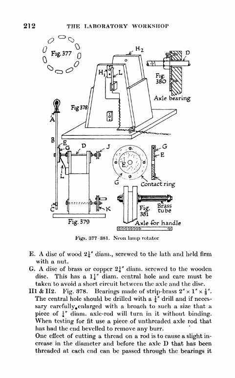
212 THE LABORATORY WORKSHOP
D
Figs. 377-381. Neon lump rotator
E. A disc of wood 2^" diam., screwed to the lath and held firm
with a nut.
G. A disc of brass or copper 2\" diam. screwed to the woodendisc. This has a l" diam. central hole and care must be
taken to avoid a short circuit between the axle and the disc.
Ill & 112. Fig. 378. Bearings made of strip-brass 2" x 1" x ".
The central hole should be drilled with a J" drill and if neces-
sary carefully^ enlarged with a broach to such a size that a
piece of |" diam. axle-rod will turn in it without binding.When testing for fit use a piece of unthreaded axle rod that
has had the end bevelled to remove any burr.
One effect of cutting a thread on a rod is to cause a slight in-
crease in the diameter and before the axle D that has been
threaded at each end can be passed through the bearings it

APPARATUS DESIGNS 213
may be necessary to subject the threaded portion to a little
filing.
The bearings are attached to the wooden framework with
ordinary wood-screws.
Provision must be made to prevent the axle moving sideways,this can be done by drilling two |" Whit, bright steel nuts or
brass terminal nuts with a J" drill, to cut away the thread.
fhese nuts are drilled and tapped at the side and each one is
provided with an I" Whit, screw to serve as a set-screw for
fixing it to the axle (Fig. 380).J. Axle-Pulley. Fig. 370. This can be made from a cotton
reel with a groove filed in it by means of a round file or it can
be built up of three discs of three-ply wood. It is fixed on the
threaded portion of the axle by means of two nuts. If the
pulley tends to slip on the axle, place split washers under the
nuts instead of ordinary washers.
K. Driving-Pulley. This can be built up of three discs of three-
ply wood. A handle is attached as shown in fig. 881. The
arrangement of the axle and bearings for the driving pulley is
similar to the top axle and set of bearings. Nuts that have
been drilled out and provided with set screws are used to
prevent side play.L. Figs. 378 and 379. A contact formed from a strip of hard,
sp'ringy brass. A strip of ordinary hard, rolled sheet brass
can be rendered sufficiently springy by hammering it on an
anvil.
One wire from the lamp holder is connected to the axle D and
the other to the brass disc G. Connections from the mainare made, one to the contact L and the other to the bearingHi of the top axle.
An excellent driving-band can be made from curtain rod of the
expanding spring type. Cut a suitable length and join it into an
endless band as follows. Cut off the screw portion of one of the
small steel hooks supplied with the rod and screw half of this
length into one end of the rod.
Grip this end and at the same time give the other end two or
three turns in an anti-clockwise direction. Bring the twisted end
into mesh with the projecting portion of the screw and allow the
rod to untwist and thread itself on.
Apparatus for demonstrating electrification produced by the friction of
falling sand on a metal wire. (Fig. 382.)
A. A square board with a hole cut in it to take a glass funnel.

214 THE LABORATORY WORKSHOP
B. Silk cords to insulate the board. Artificial silk is not
suitable.,
C. Top board. This is a little larger than the lower one.
D. A copper wire. This is buried in the sand and extends
nearly to the end of the funnel.
E. An electroscope. Good results can always be obtained byusing an insulating stopper made of sulphur.A sulphur stopper can be cast in a mould made of waxed
paper or cardboard.
Fig. 382. Electrification apparatus
The sand used for the experiment should be heated on a tin
plate before pouring it into the funnel. The electroscope becomes
charged as the sand runs out of the funnel and rubs the wire.
A switch. (Fig. 883.)
An effective switch of low resistance can be made as shown in
fig. 388.
A strip of brass j,s cut, drilled, sawn in half and the portions are
screwed to a wooden base [54-58].A post for a brass terminal nut passes through the centre of the
block. The post is made of"mild steel rod threaded f Whit,
and screwed into a hole drilled in the wood [93]. The wood is
drilled with a &" drill and tapped i" Whit. [118]. Screw the
wood on to the rod until it comes tight against the unthreaded

APPARATUS DESIGNS 215
part of the metal. Saw the rod across the dotted line AB, andfile the small projecting portion of metal flush with the wood [84].
A terminal can be made from a brass, round headed wood-screw
Fig. 383. A switch
by soldering a cross-piece strip of brass or half a washer into the
screw-driver slot, previously enlarged with a warding file [145],
Electrical resistances. (Figs. 384-387.)
Motor-car headlamp bulbs with straight and concentrated fila-
ments, working at 6-12 volts, are particularly useful for ray track
Hig-h voitag-emains
Porcelain reel insulator
Fig" 386
|
Fig 384
L-oJLow voltage lamp
Fig. 385.
Plan
ElevationFi387
Asbestos-cement tile
Figs. 384-887. Electrical resistances
and diffraction experiments and for reflecting galvanometers, theycan be worked from 50-230 volt mains by means of a resistance
arranged as a potentiometer, fig. 384. On a 230 volt supply 11'
of No. 22, S.W.G. nickel-chromium alloy wire makes a suitable
resistance wire AB. By starting at A and taking tappings from

216 THE LABORATORY WORKSHOP
A towards B it is possible to obtain any voltage from to 230.
The resistance wire gets hot when in use and it is advisable to
arrange it zig-zag fashion on a wooden baseboard covered with
a piece of asbestos-cement sheet, fig. 385 [207]. The wire can be
spaced between two terminals and two rows of round headed
screws. Instead of nickel-chromium wire it is possible to* use ex-
panding spring curtain rod, 2-4 yds., according to the voltage.
The nickel-chromium wire is best since its temperature co-efficient
is small and the tapping point remains quite constant during use.
Arc-lamp and other high resistances can be made for a few
shillings by the use of nickel-alloy resistance-wire.
Henry Wiggin & Co., Ltd., Thames House, Millbank, London,
S.W.I, manufacture a wide range of such wires and issue completetechnical data.
Brightray, a nickel-chromium alloy, has a specific resistance of
103 microhms per cm. cube and can be worked at a red heat.
Ferry, a nickel-copper alloy, for use at a black heat, has a specific
resistance of 48 microhms per cm. cube and a temperature co-
efficient which is practically zero.
A convenient method of spacing a resistance wire either straight
or spiralled is to use small white porcelain reel insulators of the
type shown in fig. 386.
The General Electric Co., Ltd., manufactures reels, diam. ",
height ", diam. of hole 352 "- They can be purchased from elec-
tricians for 6d. a dozen and can be threaded on |" diam. steel rods
fitted in a strip steel framework or between two pieces of angle-
steel attached to a baseboard, as shown in fig. 387.
A large direct current electro-magnet. (Figs. 388-394 and Plate VA.)
The construction of a large magnet can best be carried out with
the help of a lathe and a planing machine. The owners of hand-
tools only should not be deterred from its construction since the
necessary machining could be entrusted to a local or other firm of
engineers.1
The poles and yoke of the magnet are made of mild steel. Each
pole measures 10" long and 2" in diam. and the yoke 9" x 4" x 1"
(Fig. 388). The poles are tapped \" Whit, to a depth of If" andattached to the yoke with 2J" x \" Whit, steel bolts. A large
spanner must be used to make these bolts as tight as possible.The ends of the poles and the top surface of the yoke should be
machined flat, so that the air gap is reduced to a minimum.1 Stuart Turner Ltd., Henley-on-Thames, England, make castings and do
machining to private orders.
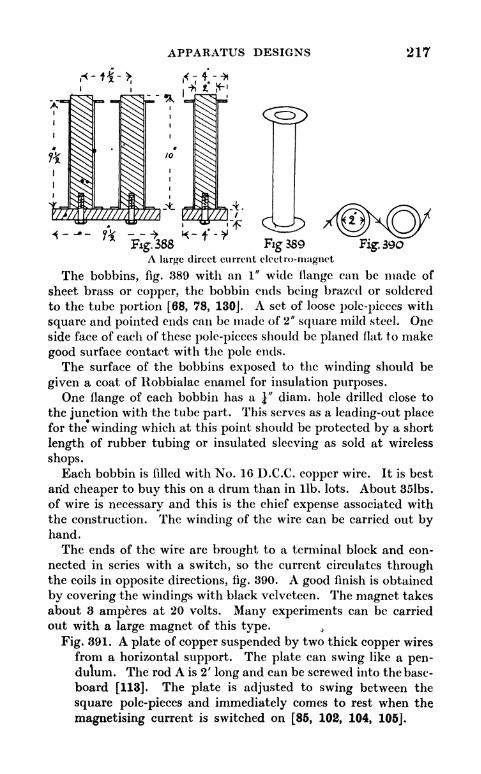
APPARATUS DESIGNS 217
Fig 389 Fig.B90A large direct current electro-magnet
The bobbins, fig. 389 with an 1" wide flange can be made of
sheet brass or copper, the bobbin ends being brazed or soldered
to the tube portion [68, 78, 130J. A set of loose pole-pieces with
square and pointed ends can be made of 2" square mild steel. Oneside face of each of these pole-pieces should be planed flat to make
good surface contact with the pole ends.
The surface of the bobbins exposed to the winding should be
given a coat of Robbialac enamel for insulation purposes.One flange of each bobbin has a J" diam. hole drilled close to
the junction with the tube part. This serves as a leading-out placefor the winding which at this point should be protected by a short
length of rubber tubing or insulated sleeving as sold at wireless
shops.Each bobbin is filled with No. 16 D.C.C. copper wire. It is best
arid cheaper to buy this on a drum than in lib. lots. About 35lbs.
of wire is necessary and this is the chief expense associated with
the construction. The winding of the wire can be carried out byhand.
The ends of the wire are brought to a terminal block and con-
nected in series with a switch, so the current circulates throughthe coils in opposite directions, fig. 390. A good finish is obtained
by covering the windings with black velveteen. The magnet takes
about 3 amperes at 20 volts. Many experiments can be carried
out with a large magnet of this type. 4
Fig. 391. A plate of copper suspended by two thick copper wires
from a horizontal support. The plate can swing like a pen-dulum. The rod A is 2' long and can be screwed into the base-
board [113]. The plate is adjusted to swing between the
square pole-pieces and immediately comes to rest when the
magnetising current is switched on [85, 102, 104, 105].

218 THE LABORATORY WORKSHOP
Fig. 392. A short length of bismuth suspended by a fine silk
thread between the pointed pole-pieces to demonstrate
diamagnetism.A strip of bismuth can be prepared by melting some pure bis-
muth crystals in a hard glass test-tube, and inclining the tube
during solidification of the contents.
Fig. 393. A plate of aluminium. If this be allowed to fall.be-
tween the gap of the square pole-pieces it slowly sinks downas though passing through a very viscous liquid [6].
Fig. 394. Steel balls, large and small, held in position by the
magnetising force.
rhimnB
392
UKg.391
;;,
TTjTl * , ' " '
Fig 394
Figs. 391-394.
An ammeter placed in the circuit shows the slow growth of the
current due to self induction.
A lifting electro-magnet. (Figs. 319-324 (Ch. X) and Figs. 395-397.
Plate VB, page 223.)
This can be made from a piece of mild steel shafting and sup-
plied with current from a miniature 3j volt pocket flash lampbattery and will support a weight of 30lbs.
The groove for the winding is easily made by turning in a lathe
(see note on page 213 on lathe work in connection with a lafge D.C.
electro-magnet). A hand method of construction is to drill out
numerous holes, all to the same depth, and chip away the remainingmetal with the help of a hammer and a small cold chisel, fig. 395.
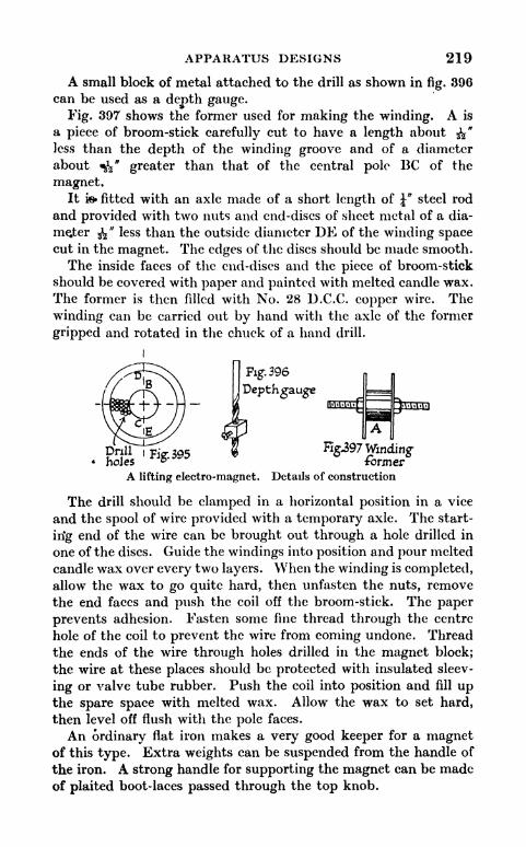
APPARATUS DESIGNS 219
A small block of metal attached to the drill as shown in fig. 896
can be used as a depth gauge.
Fig. 397 shows the former used for making the winding. A is
a piece of broom-stick carefully cut to have a length about $$"
less than the depth of the winding groove and of a diameter
about *fa" greater than that of the central pole BC of the
magnet.It ie fitted with an axle made of a short length of J* steel rod
and provided with two nuts and end-discs of sheet metal of a dia-
meter 3^" less than the outside diameter DK of the winding spacecut in the magnet. The edges of the discs should be made smooth.
The inside faces of the end-discs and the piece of broom-stick
should be covered with paper and painted with melted candle wax.
The former is then filled with No. 28 D.C.C. copper wire. The
winding can be carried out by hand with the axle of the former
gripped and rotated in the chuck of a hand drill.
Fig".396
jDepthgauge
g.holes ^5-^ formerA lifting electro-magnet. Details of construction
The drill should be clamped in a horizontal position in a vice
and the spool of wire provided with a temporary axle. The start-
irig end of the wire can be brought out through a hole drilled in
one of the discs. Guide the windings into position and pour melted
candle wax over every two layers. When the winding is completed,allow the wax to go quite hard, then unfasten the nuts, remove
the end faces and push the coil off the broom-stick. The paper
prevents adhesion. Fasten some fine thread through the centre
hole of the coil to prevent the wire from coming undone. Thread
the ends of the wire through holes drilled in the magnet block;
the wire at these places should be protected with insulated sleev-
ing or valve tube rubber. Push the coil into position and fill upthe spare space with melted wax. Allow the wax to set hard,
then level off flush with the pole faces.
An ordinary flat iron makes a very good keeper for a magnetof this type. Extra weights can be suspended from the handle of
the iron. A strong handle for supporting the magnet can be madeof plaited boot-laces passed through the top knob.

220 THE LABORATORY WORKSHOP
Elihu Thomson alternating current repulsion magnet. (Figs. 398-406.)
The core of the magnet is made of 12" lengths of soft iron faggot
binding wire. This is sold in coils by ironmongers. Suitable
lengths of wire should be cut, made as straight as possible then
bound together with insulating tape. Electric bell wirercan be
used for winding the magnet. For direct connection to a 200 volt
supply the core should be wound for IlJ" with two layers pj"wire
and for 1\" with five more layers. The magnet can be mountedin a wooden framework as shown in fig. 398 and connection madeto the A.C. mains through a switch, plug and socket.
F% 399Fig.4oo Fig-401 Fig 402
Fig. 404
Figs. 398-406.Fig. 406
Elihu Thomson alternating current repulsion magnet
Fig. 399 is a ring of 5-6 turns of No. 16 bare copper wire. This
should have an inside diameter about J" greater than the coil
measured across the 2-layer part. The wire can be woundround a bottle of suitable diameter, then slipped off, and madeinto a solid ring of low resistance by running solder betweenthe turns.

APPARATUS DESIGNS 221
If this ring be placed over the magnet it will be thrown into
the air with considerable force on turning on the current.
Fig. 400 is a coil of No. 22 D.C.C. wire wound on a 5" diain.
framework of strip brass. The ends of the wire are connected
to two 3i volt electric lamps arranged in series. The lampscarp be fitted in miniature holders attached to u strip brass
, handle.
On lowering the coil over the magnet lamps light up the
brilliantly.
The length of wire to use can best be found by experiment.About 30 turns is usually sufficient.
Fig. 401 is a tube of brass or copper. This tends to float and gets
very hot when placed round the magnet. The same or a
similar tube when slit with snips docs not show this effect.
Fig. 402 is a coil of four turns of thick copper wire that can be
placed round the magnet. A fine copper wire connected to
the ends can be fused by the current generated in the thick
winding.
Fig. 403 is a coil of No. 22 D.C.C. copper wire with the ends
joined to a 3J volt lamp. The coil is soaked in candle wax.
The lamp and coil can be put in a beaker of water and whenheld over the magnet the lamp will light up.
Fig. 404 is a coil of wire wound on a cardboard or fibre tube and
connected to a telephone receiver.
If the coil be placed over the magnet a loud hum is producedin the receiver.
Fig. 405 is a 4" diameter disc of aluminium about ^" thick
provided with a pivot made from a short length of"diam.
threaded steel rod, or a steel screw. The ends of the rod can
be ground to a point on a carborundum wheel. The pivot is
mounted between centre punch impressions made in a strip of
brass, bent as shown and provided with a handle.
Another disc of aluminium, Fig. 406, for preference about
Y thick is mounted on the"diam. vertical steel rod shown
in Fig. 398 and kept in position with two nuts. This disc is
3|"in diameter and should be arranged to about half cover the
top of the iron core of the magnet. The 4" disc rotates whenheld over the shaded iron core.
Electro-magnetic dip-needle. (Fig. 407 and Plate Vc.)
A rod B, 9" long, of J" diam. mild steel, passes through andis soldered into a short length, A, of \" square-section brass
tube.

222 THE LABORATORY WORKSHOP
C and Cl arc 1" lengths of bicycle spoke, threaded 9 B.A.,
and soldered or screwed into holes drilled in tjje ends of B [14].
The rod B is wound in the same direction throughout its lengthwith 4 layers of No. 24 D.C.C. wire.
The ends of the wire are soldered to needles D and Dl driven
into the centre of square plugs of wood fitting in the ends of
A [90].
A third length of threaded spoke, E, is attached to the lower face
of the square brass tube. The needles serve as an axle and rest ontwo plates F and Fl of thin brass.
E
Fig. 407. Electro-magnetic dip-needle
Current is supplied from a 4-6 volt accumulator through the
plates and the needles. Care must be taken that the latter are not
pushed in so far as to short circuit on to the steel rod B. The rod
is balanced - in a horizontal position- with the help of small nuts
threaded on to the lengths of spoke. When the current is switched
on the rod tilts to approximately the angle of dip, if set in the
correct position with reference to the magnetic meridian.
On turning off the current the rod returns to a horizontal
position.
A synchronous motor. (Plate VD.)
This is of interest in connection with the development of
electric clocks worked from A.C. mains.
The chief components are an A.C. magnet and a rotor made from
a 2J" length of hack-saw blade which has been magnetized. The
portion of magnetized blade is mounted on a spindle. The motor
is not self-starting, the spindle has to be given a twist between a
finger and thumb, but once brought into step with the magneticfield will continue to rotate.
The magnet core^is a 1" diam. bundle of 4j" lengths of soft iron
faggot binding wire. This wire can be bound with insulating tapeor packed into a cardboard tube to keep the lengths together.For a winding 8 layers of No. 22 D.C.C. wire can be used and this is
suitable for connection to the 12-volt tapping of a transformer or
potentiometer. Before the hack-saw blade can be drilled it mustbe softened by making it red hot. After drilling it should again be

PLATE V

224 THE LABORATORY WORKSHOP
made red hot and hardened before magnetizing by plunging it, red
hot, into cold water. A simple way of magnetizing is to wind
insulated wire round the strip of blade and pass a current throughthe wire from a 6-12 volt accumulator. A car starting accumulator
can be used.
The balance-wheel pivots of old alarm clocks' rnafoe good
bearings.r
Apparatus for producing a rotating magnetic field. (Figs. 408-410.
Plate VE.)
This apparatus can be used to demonstrate the action of an
induction motor and is worked from a single phase supply of
alternating current.
The centre core C is made of soft iron faggot binding wire to be
bought from an ironmonger. The wire is wound about a Win-chester bottle and sufficient wire put on, so that when slipped off
the bottle a ring of f"-1" diam. is formed. The iron wire should be
wound with insulating tape to keep the coils in position.
i
nnrmrnp-
Fig. 409.
Fig. 408.
Apparatus for producing a rotating
magnetic field
Fig. 410.
The electrical winding consists of four coils, each of about 5
layers of electric bell wire. These coils are all wound in the samedirection and opposite pairs are connected together as shown in
Figs. 408 and 409. One set of coils is joined to the secondary of a
transformer with an output at about 25-80 volts. If such a trans-
former is not available, one with a higher secondary voltage can

APPARATUS DESIGNS 325
be used, but in this case a resistance should be included in the
secondary circuit to, bring the potential difference of the supplyat the coil terminals down to 25 volts.
The second set of coils is connected through a resistance to the
main supply. The resistance should be adjusted to give a poten-tial difference at the coil terminals of about 25 volts.
Fig. 410 shows a sectional view of a tin can free to rotate on a
fLasd vertical axle. The can will rotate at a high speed when
placed inside the ring.
A -fa" diam. hole is drilled in the centre of the lid and the base
of the can.
Two Meccano flanged wheels are soldered to the can as shownat A and Al and provide good bearings. The axle is fixed
to another wheel that is screwed to the baseboard.
A copper ball, the ball of a plumber's ball valve, makes a good
object for rotation. A good bearing can be provided by
passing a piece of brass tubing through the centre and solder-
ing the tube at the points of emergence.It is interesting to study the magnetic field of the ring by
placing within it a porcelain basin containing iron filings or by
sprinkling filings on to a sheet of glass placed in a horizontal
position over the ring.

CHAPTER XII
MORE APPARATUS DESIGNS
Apparatus with vibrating string illustrating the theory of polarisation.
(Figs. 411-416.)
THIS apparatus provides for a beautiful demonstration of the
action of Nicol prisms and of phenomena connected with the
vibration of a stretched cord.
Movement is given to one end of a string by means of an eccen-
tric mechanism driven by an electric motor, A, fig. 411. Twoslots arc provided one at B and another at C. These slots can be
turned into a vertical or horizontal position. D is a support and
clamp to allow for the adjustment of the string. A suitable lengthof string is 8'. The correct tension can be quickly found by
experiment.As shown in the figure the string has a vertical and horizontal
component between A and 13. The slot B filters out the horizontal
component, and if C be placed in a horizontal position the string
between C and D will remain at rest. On turning slot C into a
vertical position the string section CD will begin to vibrate, but will
stop when slot B is made horizontal.
With slots C and B removed or pushed to one side the vibrating
string can be used to demonstrate the effect of tension on the
number of nodal points.An electric fan motor can be used to drive the string. The
eccentric mechanism is shown in fig. 412.
E. Eccentric arm: Made of strip brass, J" x |", and about 4"long. This arm works on two pivots F and G [54-57].
F, G and H. Pivots: Made of bolts f ''long, No. 2 B.A. or &" Whit.
The bolts pass through holes drilled in the eccentric arms andare secured with nuts as shown in fig. 413, a side elevation of
the pivot at F. The fan of the motor is removed and a face
plate is fitted on the axle.
I. Face plate: A Meccano face plate No. 109 can be used or a
plate can be constructed from a disc of sheet brass soldered
to a brass terminal nut provided with a set-screw (Fig. 414).
J. Fig. 412. Eccentric arm, similar to E but 8" long. The226

MORE APPARATUS DESIGNS 227
Fig. 411.
Fig 416
Apparatus with vibrating string, illustrating the theory of
polarisation (Figs. 412-410. Detail)
length of the eccentric arms can be varied to suit the motor.
The lower end of J works on a pivot secured to a plate of
angle brass II [87].
K. Guide: This is made of i" x"
strip brass and gives supportto the upper end of eccentric arm J. It is fastened with
screws to a vertical wooden post. The screws are providedwith distance pieces, so that a gap is formed between the
guide and the wooden post.
A hole for the string is drilled in the eccentric arm E close to the
pivot F. The string is secured with a knot at the back. Thedistance of the pivot F to the centre of the face plate is 2 cm. andthe distance of the string hole to the centre is a little less than this.
B & C, fig. 411, Slots: These can be prepared from 5" diam.
cake tins of the type with removable bases. A slot 2 \" longand wide is cut in each of the bases. This has sharp edgesand would soon fray the vibrating string. A slot about
"
wide and 2J" long is therefore formed of strip brass secured

228 THE LABORATORY WORKSHOP
with nuts and bolts around the slot cut in the base (Fig. 415).
An arm L is fastened to the base and parses through a slpt Mcut in the side of the cake tin. This slot must be long enough
to enable the arm to be turned from a vertical to a horizontal
position. Two strips of brass, bent as shown in fig. 416, are
fixed inside the tin to serve as guides to the lootfe base and
prevent the latter from working out of position.
Leaxlor. cement
Fig 417
Figs. 417- 420. A sand-figure pendulum
The tins are mounted on posts made from f"steel rod attached
to wooden baseboards [93, 113].
The components of the string tensioning clamp and support
at D, fig. 411, have been described in connection with other
apparatus [85, 102-105].
A sand-flgure pendulum. (Figs. 417-420.)
A funnel containing sand is suspended as shown. The funnel
can be drawn to one side, then allowed to swing free. The motion
of the funnel is complex, but rhythmical. Sand runs out of the
funnel and builds vp a complicated design on a sheet of black card.
A. Glass funnel and sand: Fine white sand is the best to use.
It should be quite dry and passed through a fine gauze sieve to
remove all lumps.B. Ring: This ring should be made of heavy material. The
outer steel ring of an old ball race from a motor lorry can be

MORE APPARATUS DESIGNS ?29
used. A ring can be made by filling the lid of a large tin can
,with lead or cegient. A hole should be drilled in the bottom
of the lid to allow the stem of the funnel to pass through, and
space for the upper part of the funnel is provided by placinga short length of lj" diam. brassed curtain tubing round the'
hofe t6 preserve a space free of lead or cement [18]. Three
1" lengths of cycle spoke arranged at 120 intervals are
sdidered or otherwise attached to the outside of the ring,
see fig. 418 [14].
Fig. 421. Mechanism of a modelmotor-driven garden roller
The ring is suspended with fine string from a wooden frame-
work. A good size for the framework is 30" high and 20"
wide. The sand patterns can be modified by changing the
length proportions of the upper and lower strings. Toobtain well-formed patterns the distance from the end of the
funnel to the centre of the paper should not exceed \" and
a fine stream of sand is obtained by fitting a short length of
drawn out glass tubing into the stem of the funnel (Fig. 419).
A piece of card painted black forms a good background for
white sand. When the pattern is finished the card can be
removed and the sand tilted into a trough-shaped piece of
tin plate (Fig. 420). This enables the sand to be easily re-
placed in the funnel.
Model to demonstrate the mechanics of a motor-driven garden roller.
(Fig. 421 and Plate VIA, page 235.)
The motive power is an old gramophone motor. These can be
bought second-hand for about 2/6 from most gramophone repair
shops.

230 THE LABORATORY WORKSHOP
The motor is arranged to hang from the axle of the roller and
causes the latter to roll along a floor or smooth road at atfast
walking pace (Fig. 421).
A & Al. Roller axle-bearings: With the particular motor used
it was found necessary to extend the side plates of the mechan-
ism to form bearings and at the same time to provide room for
the meshing of an extra gear wheel and pinion . The extension
was carried out with strips of brass [54-57J.
B. The turn-table axle of the motor. ,
C. Pinion wheel: Meccano pinion wheel No. 25, f"diam. The
hole in the wheel must be drilled out to the diameter of B.
D. Gear wheel: Meccano gear wheel No. 27.
E. Roller axle: Made of J" diam. steel rod.
The axle hole in the Meccano gear wheel No. 27 is not large
enough to take J" diam. rod. The difficulty can be overcome byremoving the bearing of a No. 27 wheel and soldering on a newone made from a Y Whit, brass terminal nut that has been drilled
out to Y and provided with a |" Whit, thread set-screw to secure
it to the axle.
The bearings A and Al are provided with Y diam. axle holes.
V & Fl. Roller side-plates: Cut from 3-ply wood and held
between nuts threaded on the axle.
G & Gl. Collars: These are attached to the axle E and preventside movement of the motor. They can be made from YWhit, brass terminal nuts, and are provided with set-screws,
Y Whit. The centre hole of each nut is drilled out to
A pump for filling rubber balloons with coal gas. (Fig. 422.)
An ordinary bicycle pump can be modified to make it suitable
for filling toy rubber balloons. The latter can be used for buoyancy experiments.
Fig. 422 shows the necessary changes.A. Nipple: This is a non-return nipple as used for filling foot-
ball bladders.f Nipples for screwing into bicycle pumps are
supplied for a few pence by sports equipment and cycledealers.
B. Side tube: This is a 2" length of Y diam. copper tube. Thetube is soldered into a hole drilled in the side of the pump.A secure attachment is obtained by passing the tube througha Y brass terminal nut that has had the thread cut out with a

MORE APPARATUS DESIGNS 231
I" drill. The face of the nut, next to the pump barrel, should
be filed to the curve of the barrel with a half-round file.' This
'gives a good sufface for soldering.
Any rough edges or projection of the tube or solder on the
inside of the barrel should be removed with a round file.
C. Packing gland: This is made from a li"
length of \" or f"diam. brass tube. The
bottom edge of the tube is soldered to the
top of the barrel. A woollen thread, soaked
in thick oil, is wound round the plunger of
the pump and well packed into the brass
tube to form an air-tight gland. Whenthe tube has been filled with packing a
circular cover is soldered on to keep the
packing in position.
The extra side drawing shows the tube and
cover before soldering in position.
To use the apparatus: Attach the side tube
to a coal-gas supply, and work the plungeronce or twice to drive out the air. Pull the
plunger to the top of its stroke, leave the
#us turned on. Expand a new balloon
with air. Allow the air to escape and
ilatten the balloon to drive out as muchair as possible. Slip the inlet tube of the
balloon over the nipple and work the pump. A cluster of
balloons filled with coal-gas can be attached to a cotton
thread and sent as captives to a great height.
Fig. 422. A pump for
filling rubber balloonswith coal gas
Aeration apparatus for a bell-jar aquarium. (Fig. 423.)
Apparatus of this type is used at the Marine Biological Labor-
atory, Plymouth, for the aeration of bell-jars containing plankton.A copper tube A is bent as shown and soldered into the base of
a tin can [143].
The can, arranged under a water supply, is suspended from the
end of a pivoted wooden lath. The long arm of the lath is con-
nected to a glass plate suspended in the bell-jat by means of a fine
cord passing over pulleys. The can fills with water causing the
lath to- tilt and the plate to sink.
When the water fills the bend of the tube the latter acts as a
siphon and causes the tin to empty. The tin then rises, readyfor the cycle of action to be repeated. The slow, but constant

232 THE LABORATORY WORKSHOP
movement of the glass plate provides for surface aeration of the
water throughout the jar.
B. Pivot: Made from Meccano parts. A bush wheel Meccano
part No. 24 is screwed to the side of the lath to form an
attachment for an axle. Bearings can be made of strip brass.
C. Counterweight: A strip of sheet-lead.*
*
This can be moved along the lath and provides for adjjist-
ment.
\Lath
Fig.423 Aeration apparatus forabell-jar aauarium
D. Pulleys: By the use of pulley-wheels it is possible to arrangefor the aeration of several bell-jars at a place far distant from
the driving mechanism. Meccano pulley-wheels are very
suitable, cotton reels can also be used.
E. Glass plate: This has a hole drilled through the centre. Thecord passes through the hole and is secured to a short hori-
zontal length of glass rod [199J.
Mrs. Ayrton's sand-ripple apparatus. (Fig. 424.)
This demonstrates the formation of sand-ripples below the
surface of moving water. Clean sand is placed at the bottom of a
narrow, but comparatively deep tank of water. The tank is
arranged on rollers and given a gentle side to side movement.Well-formed sana ripples are quickly built up. The complex eddy
movement of the water that produces the ripples, is made evident
by the addition of a very small quantity of aluminium powder.The back, two ends and the bottom of the tank are made from
wood about 1" thick. A suitable measurement for the inside
space is 26" x 18" x 3".

MORE APPARATUS DESIGNS 233
The wooden parts can be fastened together with 2j" iron screws.
Plate glass must be used for the front. It is set in a groove
measuring f" wide and f
"
deep.The joints are made water-tight with pitch. Start with the glass
out of the groove. Obtain pitch from a ship's store or an oil andcolour wierchant and melt it in a saucepan, this is best done in a
wety ventilated situation. If the pitch catches fire cover the
saucef*an with a piece of tin plate.
Make the pitch completely fluid and paint it over the inside
surface of the tank. Pour molten pitch into all the corners. Doeach corner in turn and allow the pitch to set along one corner
L=
Fig. 424. Mrs. Ayrtoii's sand-ripple apparatus
before tilting the tank and treating a second one. Before cement-
ing iruthe glass it is necessary to roughen the surface of the two
polished faces along a band an inch wide as measured from the
bottom and side edges of the glass. This is necessary to obtain a
water-tight joint between the glass and the pitch.
mPlace the glass flat on a table and carry out the roughening by
making scratches with a coarse carborundum stone or rub the glass
with a cork frequently dipped into a mixture of water and carbo-
rundum or emery powder.Slide the glass into the groove and fill the latter with pitch. The
pitch, if thoroughly fluid, will flow under the edges of the glass
and fill up the groove on both sides.
Keep the glass centralized in the groove during the pouring
process.The sand used must be well washed and free from all trace oi
mud. About one half a c.c. of aluminium powder is sufficient,
avoid excess.
The construction of large aquaria. (Plate VlB.)
Large water-tight aquaria can be constructed by following the
method given for a sand-ripple apparatus. The cost is little more
than that of the plate-glass.

234 THE LABORATORY WORKSHOP
Second-hand plate-glass, old shop window-glass, can often be
jbtained from builders and glass merchants at a cheap rate.
Motor-car wind-screens of the non-safety type'can also be usecl.
The wooden parts can be screwed together or dove-tailed. If
the inside of the aquaria be washed over after pitching with a
mixture of water and cement a pleasing rock coloured4
backgroundis obtained.
If the tanks be fitted with J" iron overflow-pipes and arrai\ged in
step fashion, one slightly higher than the next, it is possible for
water from a supply tap to flow from one to the other. The
aquaria shown in Plate Vis have been in continuous use for four
years. The roughening of the glass is essential. The pitch has no
injurious effect on fish or water-plants, pike and trout have been
kept for long periods in the aquaria illustrated.
It is advisable to arrange a box of perforated zinc over the exit
to the overflow pipes since water snails tend to get into these pipesand block them up.
Very attractive illumination is obtained by placing electric
lamps with deep cardboard shades over the aquaria.
A small tank. (Plate Vic.)
A small tank, with front and back made of plate glass, can beconstructed as shown in Plate Vic. The bottom and sides are madeof strips of wood, treated with shellac on the inside surfaces.
The glass can be set in grooves cut in the wood or held againstthe wooden framework with clamps made of strip steel, threadedrods J" diam. and nuts. The glass should be roughened, as de-
scribed for the sand-ripple apparatus (Fig. 424), and a very goodwater-tight joint can be made with one of the numerous plasticroof repairing compounds now on the market and stocked by all*
builders' merchants.
One such material is Rito manufactured by Andrew Maxwell,6, St. Paul's Square, Liverpool.
The use ol cycle hubs. (Plate V!D.)
Cycle hubs provide excellent ball bearings in the construc-tion of many forms of apparatus. A front hub, complete with
spindle, can be bought for 2/3 and a rear one for 3/-. The spindlescan be attached to a back plate of strip-steel and if necessary ex-tended by the use of extension unions costing 2d. each or steps3d. each. Extra hub nuts cost Id. each.
Discs of metal or wood can be attached to the spoke flangeswith small nuts and bolts, and spring curtain-rod makes a good

PLATE VI
A. Model to illustrate the mechanism of a motor-driven garden roller B. AquariaC. A small tank D. Whirling table with strobic disc E. A shaking sand box

236 THE LABORATORY WORKSHOP
driving band, as mentioned in connection with the neon -lamp
'rotator, page 213.f .
Plate VIo shows a whirling table made with a framework of strip
steel and arranged for the study of a strobic disc illuminated byOsglim neon lamps connected to an A.C. supply.
Fig:423
A shaking sand box
A shaking sand box. (Figs. 425-428 and Plate Vis.)
With this contrivance it is possible to show that sand acquirescertain fluid properties when violently shaken.
Light objects such as celluloid frogs or ping-pong balls, pre-
viously buried in the sand, immediately rise to the surface and
glass marbles or steel balls sink to the bottom.
Bicycle parts form part of the mechanism.
The sand box A, fig. 425, is 10" in diam. and 3J" deep. Thebase is a disc of wood and the side is a strip of sheet metal with
a joint soldered to form a ring.
B is a length of strip brass or steel |" x J". It is firmly attached
with screws to the bottom of the sand box. The projecting end
has a i" diam. hole drilled in it and fits over a pivot, a 2" lengthof
"diam. steel-rod C, threaded at the bottom and attached with
nuts to the chain sprocket of a bicycle rear hub, figs. 426 and 427.
The sprocket is quite easy to drill.

MORE APPARATUS DESIGNS 237
The hub-axle projecting on the sprocket wheel side is sawn. off.
other end oftjie
axle serves to secure the hub in a vertical
position to a strip of 1" x J* steel bolted to the main baseboard.
The axle D of a driving sprocket wheel is driven, a tight fit, info
a hole bored in a block of wood E, fig. 428. *
The fcrafclc F is provided with a handle. The axle part of the
haadle can be made from a piece of J" diam. steel-rod and the
handle from a file handle. This has a full J" diam. hole drilled
through it and should be free to rotate on the axle.
oThe cotter pin of the pedal crank is not fitted.
The framework G that guides the sand box should be wider
on the inside than the diameter of the box. This allows for side
movement.Four or five steel dome furniture-castors are driven into the
under face of the sand box baseboard and serve to reduce friction.
Description of plates. (VII and VIII.)
The apparatus and models illustrated in Plates VII-VIII were
made by African boys ages 14-18 at a college in Nigeria where
classroom and workshop instruction go hand in hand.
Plates VIlA-c. Models of lifting machines.
Most of the constructional work was carried out in wood at
Very small cost. The derrick crane, Plate VIlA was fitted with
a lifting electro-magnet.Plate VIlD. An automatic recording auxanometcr for measuring
the rate of growth of a cotton plant.
Plate VIIlA. Model of a mediaeval system of farming used for
the comparative study of methods of agriculture.
Plate VIIlB. Model of a castle. The walls were cut out of
3-ply wood and the moat, containing water, was made of
sheet-zinc with soldered joints.
Plate VIIIc. Model of a lake village.
Plate VIIlD. Historical models. Made of clay, cement-washed
and painted.

PLATE VII

PLATE VIII

APPENDIX
BOOKS AND PERIODICALS FOR AWORKSHOP LIBRARY
Carpentry*WOODWORK TOOLS AND How TO USE THEM by William Fairham. (EVans
Brothers.) 8/6.THE COMPLETE WOODWORKER, edited by Bernard E. Jones. (Cassell's Hand-
craft Library.) 8 /6.
THE COMPLETE AMATEUR WOODWORKER. (Handicrafts Ltd.) 6d.
STRIP WOODWORK AND MODEL MAKING. (Handicrafts Ltd.) 6d.
HANDICRAFTS ANNUAL. (Handicrafts Ltd.) 1 /-.
Drawing.MECHANICAL DRAWING. (Casscll.) 3 /6.
How TO READ A WORKSHOP DRAWING by W. Longland. (Percival Marshall.)Qd.
Electric Wiring.PRIVATE HOUSE ELECTRIC LIGHTING by Taylor. (P. Marshall.) 1 /6.
Meccano.MECCANO INSTRUCTIONS. (Meccano Ltd.) 2 /6.
MECCANO STANDARD MECHANISMS. (Meccano Ltd.) I /-.
Metal Working.THE PRACTICAL METAL WORKER. 3 Vols. (Casscll.) Obtainable from
Waverley Book Co. 45 /-.
Workshop and Laboratory Arts.
WORKSHOP PRACTICE FOR THE SCHOOL AND LABORATORY by Barker andChapman. (Sidgwick & Jackson.) 3/6.
LABORATORY ARTS by G. A. Woollatt. (Longmans Green & Co.) 4 /6.
Photography.THE BRITISH JOURNAL PHOTOGRAPHIC ALMANAC. Published annually.
(Henry Greenwood.) 2 /-.
NATURE PHOTOGRAPHY by Pike. (Chapman & Hall.) 12 /6.
WELLINGTON PHOTOGRAPHIC HAND BOOK. (Wellington & Ward, Elstree.)
I/-.PHOTOGRAPHY MADE EASY by Child Bayley. (Iliffe.) 2/0.THE COMPLETE PHOTOGRAPHER by Child Bayley. (Methuen.) 15 /
Miscellaneous.
HOME MECHANICS. (Newnes.) 4 Vols. 63/-.THE AMATEUR MECHANIC. 4 Vols. (Waverley Book Co.) 62/6.
240

APPENDIX 241
THINGS WORTH MAKING by Archibald Williams. (Nelson.) 5 /-.
THINGS To MAKE by Archibald Williams. (Nelson.) 5 / -.
SCIENCE MASTERS' Bo<fK. Part I: Physics; Part II: Chemistry and Biology,(Murray.) 7 /6 each.
MODELS OF BUILDINGS by William Harvey. (The Architectural Press,
London.) 7 /O.
SCENIC IVJoDELLiNG by Edward W. Hobbs. (Cassell.) 1 /O.
TOY MAKING FOR AMATEURS. (Newnes* Home Mechanic Scries.) 1 /-.
THE*HANDYMAN'S ENQUIRE WITHIN. (Newnes' Home Mechanic Series.) t /-
25 SiMjflLE WORKING MODELS. (Newnes' Home Mechanic Series.) 1 /--.
SIMPLE ELECTRICAL APPARATUS. (Newnes' Home Mechanic Series.) 1 /-
HARPER'S ELECTRICITY BOOK FOR BOYS. (Harper.) 7/6.
The Model Engineer Series, Percival Marshall. 9d. each.
SOLDERING, BRAZING, AND THE JOINING OF METALS.
ELECTRIC BELLS AND ALARMS.TELEPHONES AND MICROPHONES.SIMPLE ELECTRICAL WORKING MODELS.SIMPLE MECHANICAL WORKING MODELS.INDUCTION COILS FOR AMATEURS.SIMPLE SCIENTIFIC EXPERIMENTS.SMALL ELECTRICAL MEASURING INSTRUMENTS.THE WIMSHURST MACHINE.HARDENING AND TEMPERING ENGINEERS' TOOLS.
CLOCK REPAIRING AND ADJUSTING.WATCH REPAIRING AND ADJUSTING.
ELECTRICAL APPARATUS MAKING by Ballhatchet. (Percival Marshall.) 3/~.
MORE ELECTRICAL APPARATUS MAKING by Ballhatchet. (Percival Marshall.)
PERIODICALS
Weekly.
English Mechanics, 3d. Hobbies, 2d. Model Engineer, 4rf. Amateur Pho-*
tographer, 3d.
"Monthly.
The Woodworker Magazine, 6d. Handicrafts Monthly Magazine, 3d. Meccano
Magazine, Qd.
The following are published in America:
Monthly.
Popular Mechanics, 2/-. Modern Mechanics, 1/6. Science and Invention, 2/-.
Popular Science, 1/3. Scientific American, 2/-.
The Journal of the Science Masters' Association. (Mufray.) 2/6 Quarterly.
Rw


INDEX
ALUMINIUM paint, 164Aluminium sheet, 32
Amyl acetate, 43, 164
Angle brass, iron and steel, 36
Angle brass and iron, to cut, 74-5
Annealing brass tubing, 96
Apparatus, construction of :
Model geyser, 187 9
Radiation switch, 1 89-90Nickel pendulum, 190 2
For producing superheated steam,192
Soarle's, for measuring thermal
conductivity, 192-5To illustrate spheroidal condition
of water, 195-6To demonstrate recalescence phe-nomena, 196-8
Lantern bodies, 198-200
Projection microscope, 200-3
Optical bench and spectrum pro-jection, 203
To show interference colours of a
soap film, 206-8Parallel beam, 208-11To demonstrate illumination of aneon lamp, 211-13
To demonstrate electrification byfriction of sand on a wire, 218-14
Switch, 214-15Electrical resistances, 215
Large D.C. electro-magnet, 216-18
Lifting electro-magnet, 218-19Klihu Thomson A.(\ repulsionmagnet, 220-1
Electro-magnetic dip-needle, 222
Synchronous motor, 222-4To produce a rotating magnetic
fieljl, 224-5To illustrate polarisation, 227-8Sand figure pendulum, 228-9To demonstrate mechanics of a
motor-driven garden roller, 229-80
Pump for filling balloons, 230-1
Apparatus, to aerate a bell-jar aquar-ium, 231-2
Mrs. Ayrton's, to produce sandripples, 232-3
Large aquaria, 233-4Small tank, 234To utilise cycle hubs, 234-6
Shaking sand box, 236
Apparatus, design of, 179
Asbestos tile, 106
Auger bit, 20, 1 28
Automatic nail puller, 172
Axle rod, Meccano, 33
BACK nuts, 100-1
Backing nuts, 91-2Baker's Fluid, 102, 114
Baseboards, 120
Benches for woodwork, 1-2
Bench hook, 132Bench stops, 78Bending sheet material, 65, 67; brass
and copper tubing, 72-3; metalrod, 73; strip metal, 73
Black iron wire, fine, 107-8Blown fuse, to locate, 142-3
Bolts, 38-9; construction of, 83; howdrawn, 177
Brace, carpenter's, 27, 128-9
Brads, oval steel, 135
Bradawl, 20, 128
Brass rod, 32, 34; sheet, 29-30; wire,
30, 32; thread, 94; tubing, 35, 95;
tube, construction of, 68, 184;tubes, to cut thread on, 95
Brazing lamp, 22. 27Bntinol paste, 110, 111, 112British Association (B.A.) thread, 38;
to cut on rod, 84-5
Broach, Lancashire, 75Bunsen burners, to repair, 96
CABLE, electric, 139, 141
Callipers, 20, 26

244 INDEX
Can openers, 171'
Carborundum, 42, 160
Cardboard, 165
Carriage bolts, 85
Veiling rose, 188, 141, 152
'Celluloid, 43, 164
Centre bit, 20, 128
Centre punch, 20
Chain pipe wrench, Perry's, 97, 98
Chisel, cold, 25
Chisels, wood, 27, 131-2
Circle, cutting in metals, with drill
and files, 58, 59, 70; with snipsand emery, 62
Circle cutting in end of tin can, 64;in side of tin can, 68-70; in glass,159
Circular opening, to decrease size of,
64
Clamping screws, constructing, 85
Collet, 79
Composition ('cornpo') pipe, 98
Conduit wiring system, 149-50
Copper, sheet, 30; rod, 32; wire, 32
Countersinking screw holes, 75, 93,125
Covering books with brown paper,174
Cutting, strip brass, 52-4; holes in
thick metal, 58-60; thin sheet
metal, 60; difficulties of, 61; cir-
cular work, 62; opening in tin
can, 64-8; holes with a circular
cutter, 65; thick sheet metal, 70;
metal tubing, 72; metal rod, 73;
metal sections, 74; screw threads,
external, 81, 83-4, 95; screw
threads, internal, 86-91, 95;
glass, 156-61
DEALERS in materials, 48-9
Dies, 16, 24, 78
Dividers, 20, 26
Dowel rods, 7, 120, 133-4
Drill, hand, 17, 25, 56, 58; twist, 17,
24, 55, 57
Drilling machine, 15, 17, 25, 56
Drilling strip brass, 54-6; large holes,
56-7; square bra'ss, 57-8; metal
tubing, 72
Drunken threads, 81
Durofix cement, 161
EBONITE, 170
Edges, treatment of, 68
Electrical fittings, buying, 136; useful,195
Electrical supply, extension of, 143-4
Electric continuity tests, 151, 152;
heating elements, repair of, 174^
Emery paper, 10, ^3
Enlarging holes in shee^ metal, 75-6
Expansive bit, Clark's Patent, 131
FILES, 19, 23-6, 54
File brush, 23, 28
Filing strip brass, 54
First-aid cabinet, 11
Flat-rods, 34
Flattening sheet metal, 60-1
Flex for lighting and power, 136-7
Flex, to join lengths of, 114, 139, 141
Flock paper, 167
Flongene, 12
Fluxite, 113, 114
Fretsaw, 130
Fuses, 140-3
GAS connections, to repair, 96
Gas fittings, 94-5
Gas-tight joints, to make, 96
Gas pliers, 97, 98
Gimlet, 20, 128
Glass paper, 10, 43, 134
Glass, sheet, cutting, 156-60; sheet,
drilling, 160-1; rod and tube,
cutting, 161; cutters, 27, 156-7;circle cutter, 159-60
Glazier's diamond, 156
Gouges, 135
Grinder, bench, 23, 27
HACK-SAW, 19, 25, 52
Handles, file, 26
Higgins' Vegetable Glue, 166
Hinges, metal, 126-8; paper, 167
Holding pipes, methods of, 98
Holes, cutting, in thick metal, 55, 60;with a circular cutter, 65; to en-
large, 75; in wood, 128-31
INTERNAL threads, to cut, 86-91
Isometric projection, 177
JOINTS in flexible electric wire, 114
Jumper or plugging chisel, 162

INDEX 245
KEYHOLE saw, 22, 27, 130
Killed spirit, 102
LANTERN bodies, construction of,
198-200t
Lantern chimney cover, 67
Lantern slides from book illustra-
tions, 167-70
Leafl-covered cable system of wiring,148-8
LeaTher washer cutter, 130-1
Lecture room diagrams, 178-9
Lighting of workshops, 10
Little Giant dies, 79
MAHOGANY, 120^
Marking out-strip brass, 51; sheet
metal, 61
Meccano axle rod, 33; parts, 47-8
Metal, sheet, 29-32; in rod form, 32-6;
sections, 34, 35 6; tubes, 35, 36;
tubing, to cut, to drill, to bend,72; rod, to cut, to bend, 73
Methylated spirit, 43
Mica, 44
Mitre block, 133
NAILS, 41-2
Nail puller, automatic, 172, 173
Nuts, 38-9; how drawn, 177
OIL can, 22, 27
Open cable system of electric wiring,. 144-6
Outdoor wiring, 154-5
PACKING case opener, 172
Paint brushes, care of, 164-5
Painting apparatus, 162-5
Paper covers for books, 174
Paste, 166
Pipes, iron, 35
Planes, 20, 27, 123
Plaster of Paris, 43
Plastic wood, 135
Pliers, 20, 26; gas, 98
Plugging walls, 162, 163
Plywood, 120
Portland cement, 44
Prism for optical work, 186
Protection of tools from rust, 174
Punch, 18, 20, 55
RACKS for metal supplies, 8
Rasp, 26
Rawlplug, 162
Reading a workshop drawing, 175
Rectangular section tube, 66-7
Removing floor boards, 148-9
Repairing hole in tin kettle, 115
Resistances, electrical, 215-16
Rivets, 41, 172-3
Robbialac, 164
Rustless steel, 44
SAND paper, 43
Saws, hand and tenon, 22, 121
Scrap lead, 44; material, 29; sheet
metal, storage of, 62
Screws, sorting and storage of, 8-10
Screws, metal, 36-9; wood, 40-1, 124-
6, 138
Screw threads for iron pipes, 98-100
Scribe or scriber, 20, 26, 52, 61
Set screws, 39, 83
Sharpening, cold chisels, scribes,
punches, 76; plane irons, 123;
chisels, 131
Shave hook, Plumber's, 23, 28
Shellac, 44Slot in side of tin can, to cut, 68-70
Snips, tinman's, 17, 60, 61
Soldering, 11, 42, 102-18; tools andmaterials, 102-4; sheet and strip
metal, 104-10; rods to flat sur-
faces, 111; electric wires, 113-14;tube into a tin can, 116; brass
gas-pipe to composition tubing,118
Soldo, 108
Spiral slot in tube, to cut, 186
Spokes, bicycle and umbrella, 34
Spokeshave, 23, 132
Squares, 22, 27, 52, 61
Staining wood, 162-3
Standard wire gauge (S.W.G.), 30,31
Steel, sheet, 31 ; rod, 33, 34; cast, 33;
needles, 90
Steel wheel glass cutter, 156, 158
Stocks for dies, 78-9
Strawboard, 165-7
Strip metal, to bend, 73-4
Strip wood, 120
Switches, electrical, 153, 180, 214-15
Switch, conventional representationof a, 180

246 INDEX
TAPS and dies, 10, 24, 86
Teak baseboards, 120-1
Tinning the bit, 103-4
Tin plate, 31
1*00! merchants, 28
Tools, arrangement of, 4-13; metal
working, how to use, 53-4
Tools, List 4
A,' 15, 16-21; List 4
B,'
15, 21-24
Try square, 20-6
Tube, construction of a, 68
Turpentine, 42
Twist drills, 17, 24, 55, 57, 129-30
UNSOLDERING, 117
Uralite tile, 11, 106, 171
VASELINE, 42, 174
Vices, 2 -.">, 28
Vice jaw clamps, 65-6
Vulcanised fibre, 44-5
WALL diagrams, 178
Washers, 39
Whitewood, American, 120
Whitworth thread, 36-7; to cut, 79-81
Wire gauge, 23, 28*
Wiring a lamp holder; 137-
Wiring systems, 144-52, 154
Workshop, nature and position 6*f, 1;
illumination of, 10; floop of, 12;
cleaning of, 12; storeroom, ^.>-7;
supplies, 48-9; drawings, 175,177
Wood*
supplies, 119-20; dies, 163;
polishing, 165
Wrecking bar, 172, 173
Wrenches, 24, 101
Wrought iron rod, 34
ZINC, sheet, 31