Messing M Laiton M Brass M
90
Messing M Verschraubungen Laiton M Raccords Brass M Unions 31 1
-
Upload
khangminh22 -
Category
Documents
-
view
1 -
download
0
Transcript of Messing M Laiton M Brass M
Messing M
Verschraubungen
Laiton M
Raccords
Brass M
Unions
31
1
35-37KlemmringBague de serrageCompression ferrule
SO 40001
38AbschlusszapfenBouchon d’arrêtPlug
SO 40002
39-40StützhülseDouille d’appuiStiffener sleeve
SO 40003
41-43DichtungJointWasher
SO 40005
42Sechskantmutter METREcrou à six pans METRHexagon nut METR
SO 40006
44AnschlussmutterEcrouUnion nut
SO 40020
45-47ArmaturenanschlussEcrou et bague de raccordementNut connection
SO 40021
48ÜbergangsmuffeAdaptateur femelleFemale adaptor
SO 40030
49-50ÜbergangsnippelAdaptateur femelle - mâleMale adaptor
SO 40040
51-52SchlauchtülleDouille canneléeHose nozzle
SO 40503
53AnschlussnippelEcrou de raccordement mâleNipple connection
SO 41001
54-55Gerade VerschraubungUnion doubleStraight union
SO 41021
56-63Gerade EinschraubverschraubungUnion mâleMale adaptor union
SO 41121
64-65Gerade AufschraubverschraubungUnion femelleFemale adaptor union
SO 41221
66-67VerbindungsnippelPièce folleTube stub
SO 41300
68Einstellbare VerschraubungUnion orientableAdjustable union
SO 41325
69Verschraubung mit EinlötnippelUnion avec embout à braserAdaptor union with soldering nipple
SO 41421
70-73Gerade SchottverschraubungUnion double traversée de cloisonPanel mount union
SO 41521
74-75EinstellnippelAdaptateur orientable mâleAdjustable male adaptor
SO 41600
76-77Einstellbare EinschraubverschraubungUnion mâle orientableAdjustable male adaptor union
SO 41625
78EinstellmuffeUnion orientable femelleAdjustable female adaptor
SO 41704
79Einstellbare AufschraubverschraubungUnion femelle orientableAdjustable female adaptor union
SO 41726
80-81ReduktionsverschraubungUnion de réductionReduction union
SO 41821
82-86WinkelverschraubungCoudeElbow union
SO 42021
Seite/Page/Page Seite/Page/Page Seite/Page/Page
Übersicht Aperçu Overview
32
87AnschlusswinkelCoude femelleFemale adaptor elbow union
SO 42321
88-91Winkel-EinschraubverschraubungCoude mâleMale adaptor elbow union
SO 42421
92Winkel-AufschraubverschraubungCoude femelleFemale adaptor elbow union
SO 42521
93-95Einstellbare WinkelverschraubungCoude orientableAdjustable elbow union
SO 42621
96-97Winkel-SchottverschraubungCoude traversée de cloisonPanel mount elbow union
SO 42721
98-100SchwenkverschraubungCoude banjoSingle banjo
SO 42824
101-105T-VerschraubungTé égalTee union
SO 43021
106-108Einstellbare T- und L-VerschraubungTé et L orientableAdjustable tee and L union
SO 43621
109-110T- und L-EinschraubverschraubungTé et L mâleMale adaptor tee and L union
SO 43721
111-113T-SchwenkverschraubungTé banjoTee banjo
SO 43824
114KreuzverschraubungCroix égaleCross union
SO 44021
115-116SchwenkverschraubungCoude banjoSingle banjo
SO 47624
Sonderausführungen auf AnfrageExécution en option sur demandeOptional services on request
Spezialreinigung - entfettetTraitement spécial - dégraisséSpecial treatment - degreased
Spezialbehandlung für Einsatz mit SauerstoffTraitement spécial pour utilisation sous oxygèneSpecial treatment for use with oxygen
Spezialbehandlung - silikonfreiTraitement spécial - sans siliconeSpecial treatment - silicone free
Vorbeschichtete Gewinde PTFE-Band umwickeltFiletages pré enduits avec ruban en PTFEPre-coated threads with PTFE-tape
Vorbeschichtete Gewinde mit Loctite 5061Filetages pré enduits avec Loctite 5061Pre-coated threads with Loctite 5061
Chemisch vernickeltNickelage chimiqueChemical nickel-plated
Messing bleiarmLaiton à faible teneur en plombLow-lead brass
Bestätigungen auf www.serto.comConfirmations sur www.serto.comConfirmations on www.serto.com
Seite/Page/Page Seite/Page/Page
Übersicht Aperçu Overview
33
1
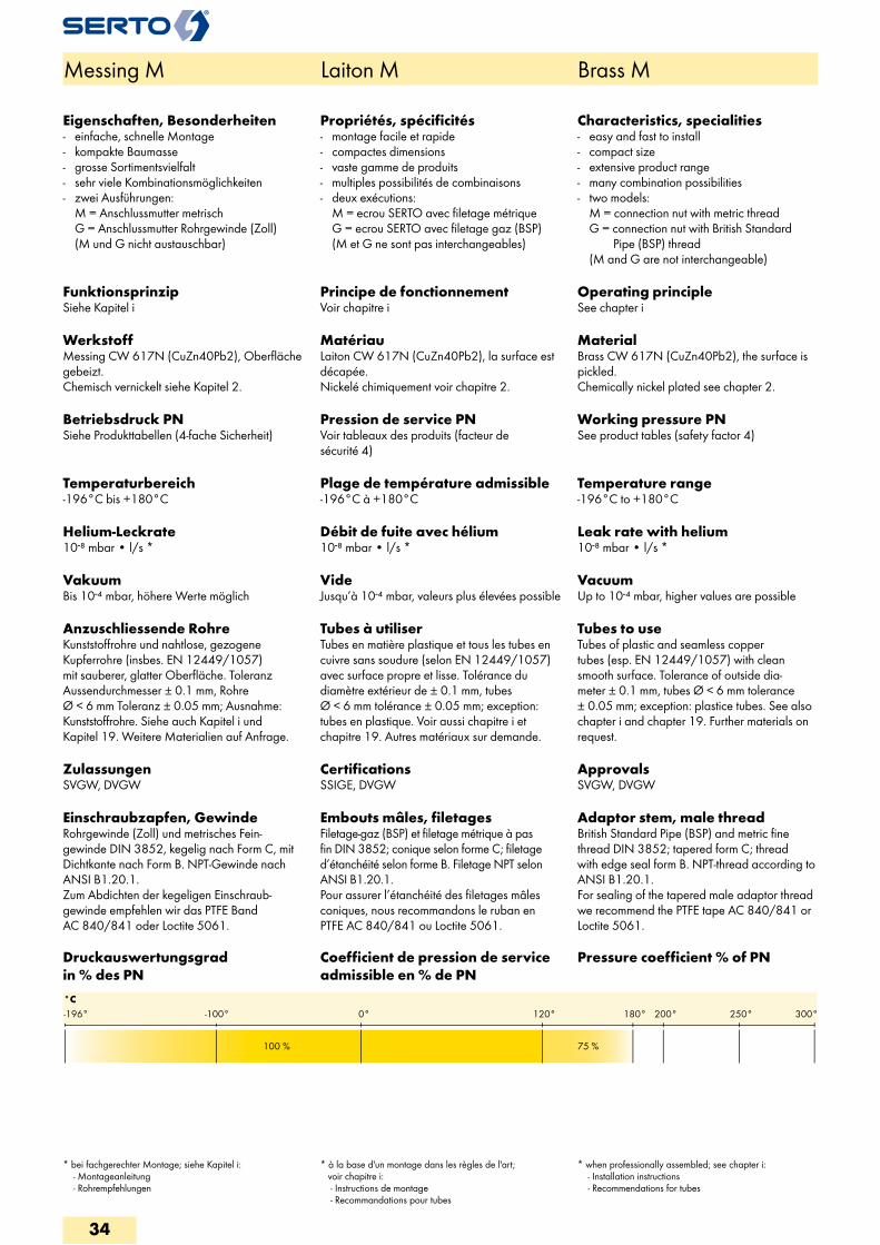
°C300°250°200°180°0°-100°-196° 120°
100 % 75 %
Messing M Laiton M Brass M
Eigenschaften, Besonderheiten- einfache, schnelle Montage- kompakte Baumasse- grosse Sortimentsvielfalt- sehr viele Kombinationsmöglichkeiten- zwei Ausführungen:
M = Anschlussmutter metrisch G = Anschlussmutter Rohrgewinde (Zoll) (M und G nicht austauschbar)
FunktionsprinzipSiehe Kapitel i
WerkstoffMessing CW 617N (CuZn40Pb2), Oberfläche gebeizt.Chemisch vernickelt siehe Kapitel 2.
Betriebsdruck PNSiehe Produkttabellen (4-fache Sicherheit)
Temperaturbereich-196°C bis +180°C
Helium-Leckrate10-8 mbar • l/s *
VakuumBis 10-4 mbar, höhere Werte möglich
Anzuschliessende RohreKunststoffrohre und nahtlose, gezogene Kupferrohre (insbes. EN 12449/1057) mit sauberer, glatter Oberfläche. Toleranz Aussendurchmesser ± 0.1 mm, Rohre Ø < 6 mm Toleranz ± 0.05 mm; Ausnahme: Kunststoffrohre. Siehe auch Kapitel i und Kapitel 19. Weitere Materialien auf Anfrage.
ZulassungenSVGW, DVGW
Einschraubzapfen, GewindeRohrgewinde (Zoll) und metrisches Fein- gewinde DIN 3852, kegelig nach Form C, mit Dichtkante nach Form B. NPT-Gewinde nach ANSI B1.20.1. Zum Abdichten der kegeligen Einschraub-gewinde empfehlen wir das PTFE Band AC 840/841 oder Loctite 5061.
Propriétés, spécificités- montage facile et rapide- compactes dimensions- vaste gamme de produits- multiples possibilités de combinaisons- deux exécutions:
M = ecrou SERTO avec filetage métrique G = ecrou SERTO avec filetage gaz (BSP) (M et G ne sont pas interchangeables)
Principe de fonctionnementVoir chapitre i
MatériauLaiton CW 617N (CuZn40Pb2), la surface est décapée.Nickelé chimiquement voir chapitre 2.
Pression de service PNVoir tableaux des produits (facteur de sécurité 4)
Plage de température admissible-196°C à +180°C
Débit de fuite avec hélium10-8 mbar • l/s *
VideJusqu’à 10-4 mbar, valeurs plus élevées possible
Tubes à utiliserTubes en matière plastique et tous les tubes en cuivre sans soudure (selon EN 12449/1057) avec surface propre et lisse. Tolérance du diamètre extérieur de ± 0.1 mm, tubes Ø < 6 mm tolérance ± 0.05 mm; exception: tubes en plastique. Voir aussi chapitre i et chapitre 19. Autres matériaux sur demande.
CertificationsSSIGE, DVGW
Embouts mâles, filetagesFiletage-gaz (BSP) et filetage métrique à pas fin DIN 3852; conique selon forme C; filetage d’étanchéité selon forme B. Filetage NPT selon ANSI B1.20.1.Pour assurer l’étanchéité des filetages mâles coniques, nous recommandons le ruban en PTFE AC 840/841 ou Loctite 5061.
Characteristics, specialities- easy and fast to install- compact size- extensive product range- many combination possibilities- two models:
M = connection nut with metric thread G = connection nut with British Standard Pipe (BSP) thread (M and G are not interchangeable)
Operating principleSee chapter i
MaterialBrass CW 617N (CuZn40Pb2), the surface is pickled.Chemically nickel plated see chapter 2.
Working pressure PNSee product tables (safety factor 4)
Temperature range-196°C to +180°C
Leak rate with helium10-8 mbar • l/s *
VacuumUp to 10-4 mbar, higher values are possible
Tubes to useTubes of plastic and seamless copper tubes (esp. EN 12449/1057) with clean smooth surface. Tolerance of outside dia-meter ± 0.1 mm, tubes Ø < 6 mm tolerance ± 0.05 mm; exception: plastice tubes. See also chapter i and chapter 19. Further materials on request.
ApprovalsSVGW, DVGW
Adaptor stem, male threadBritish Standard Pipe (BSP) and metric fine thread DIN 3852; tapered form C; thread with edge seal form B. NPT-thread according to ANSI B1.20.1.For sealing of the tapered male adaptor thread we recommend the PTFE tape AC 840/841 or Loctite 5061.
Druckauswertungsgrad in % des PN
Coefficient de pression de service admissible en % de PN
Pressure coefficient % of PN
* bei fachgerechter Montage; siehe Kapitel i: - Montageanleitung - Rohrempfehlungen
* à la base d'un montage dans les règles de l'art; voir chapitre i: - Instructions de montage - Recommandations pour tubes
* when professionally assembled; see chapter i: - Installation instructions - Recommendations for tubes
34
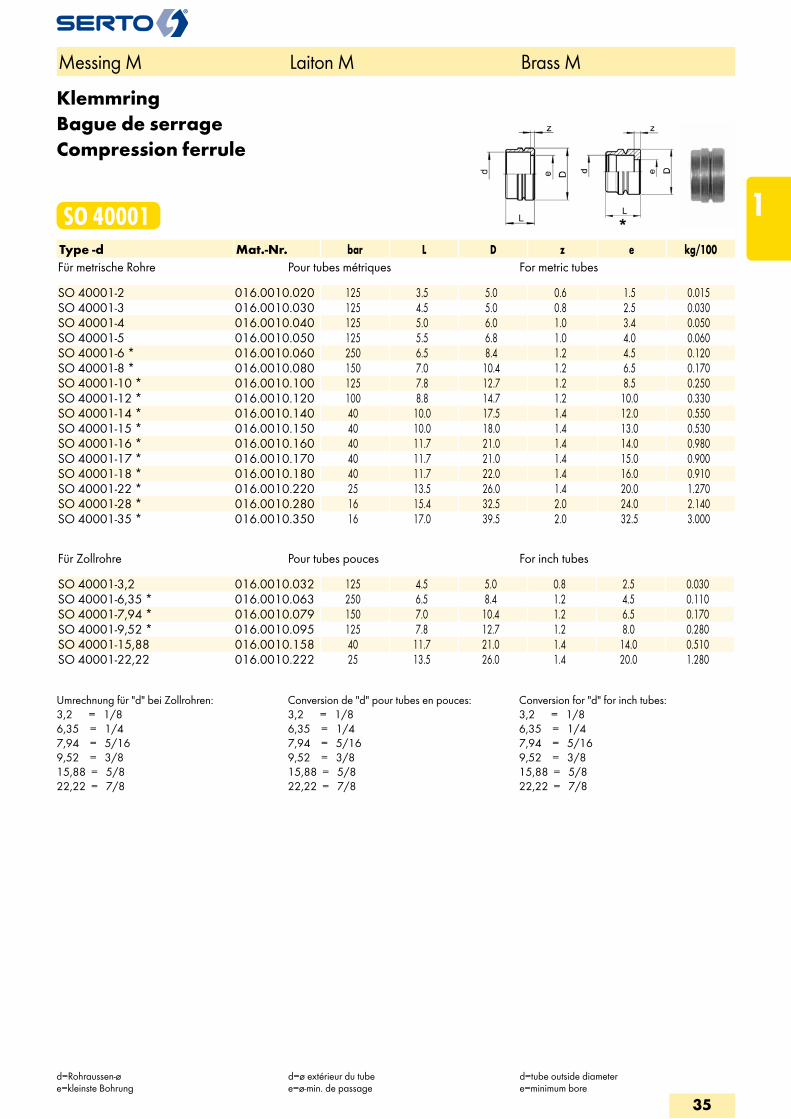
KlemmringBague de serrageCompression ferrule
SO 40001Type -d Mat.-Nr. bar L D z e kg/100Für metrische Rohre Pour tubes métriques For metric tubes SO 40001-2 016.0010.020 125 3.5 5.0 0.6 1.5 0.015SO 40001-3 016.0010.030 125 4.5 5.0 0.8 2.5 0.030SO 40001-4 016.0010.040 125 5.0 6.0 1.0 3.4 0.050SO 40001-5 016.0010.050 125 5.5 6.8 1.0 4.0 0.060SO 40001-6 * 016.0010.060 250 6.5 8.4 1.2 4.5 0.120SO 40001-8 * 016.0010.080 150 7.0 10.4 1.2 6.5 0.170SO 40001-10 * 016.0010.100 125 7.8 12.7 1.2 8.5 0.250SO 40001-12 * 016.0010.120 100 8.8 14.7 1.2 10.0 0.330SO 40001-14 * 016.0010.140 40 10.0 17.5 1.4 12.0 0.550SO 40001-15 * 016.0010.150 40 10.0 18.0 1.4 13.0 0.530SO 40001-16 * 016.0010.160 40 11.7 21.0 1.4 14.0 0.980SO 40001-17 * 016.0010.170 40 11.7 21.0 1.4 15.0 0.900SO 40001-18 * 016.0010.180 40 11.7 22.0 1.4 16.0 0.910SO 40001-22 * 016.0010.220 25 13.5 26.0 1.4 20.0 1.270SO 40001-28 * 016.0010.280 16 15.4 32.5 2.0 24.0 2.140SO 40001-35 * 016.0010.350 16 17.0 39.5 2.0 32.5 3.000
Für Zollrohre Pour tubes pouces For inch tubes SO 40001-3,2 016.0010.032 125 4.5 5.0 0.8 2.5 0.030SO 40001-6,35 * 016.0010.063 250 6.5 8.4 1.2 4.5 0.110SO 40001-7,94 * 016.0010.079 150 7.0 10.4 1.2 6.5 0.170SO 40001-9,52 * 016.0010.095 125 7.8 12.7 1.2 8.0 0.280SO 40001-15,88 016.0010.158 40 11.7 21.0 1.4 14.0 0.510SO 40001-22,22 016.0010.222 25 13.5 26.0 1.4 20.0 1.280
Umrechnung für "d" bei Zollrohren:3,2 = 1/86,35 = 1/47,94 = 5/169,52 = 3/815,88 = 5/822,22 = 7/8
Conversion de "d" pour tubes en pouces:3,2 = 1/86,35 = 1/47,94 = 5/169,52 = 3/815,88 = 5/822,22 = 7/8
Conversion for "d" for inch tubes:3,2 = 1/86,35 = 1/47,94 = 5/169,52 = 3/815,88 = 5/822,22 = 7/8
Messing M Laiton M Brass M
d=Rohraussen-øe=kleinste Bohrung
d=ø extérieur du tubee=ø-min. de passage
d=tube outside diametere=minimum bore
35
1
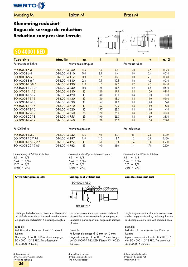
Klemmring reduziertBague de serrage de réductionReduction compression ferrule
SO 40001 REDType -dr -d Mat.-Nr. bar L D z e kg/100Für metrische Rohre Pour tubes métriques For metric tubes SO 40001-5-3 016.0014.060 125 7.5 6.8 0.8 2.5 0.130SO 40001-6-4 016.0014.110 100 8.5 8.4 1.0 3.4 0.230SO 40001-6-5 016.0014.117 100 8.7 8.4 1.0 4.0 0.180SO 40001-8-6 * 016.0014.140 250 9.5 10.5 1.2 4.5 0.330SO 40001-10-8 * 016.0014.190 150 11.5 12.7 1.2 6.5 0.450SO 40001-12-10 * 016.0014.240 100 12.5 14.7 1.2 8.5 0.610SO 40001-14-12 016.0014.340 40 14.0 17.5 1.4 10.0 0.890SO 40001-15-12 016.0014.420 40 14.0 18.0 1.4 10.0 1.050SO 40001-15-13 016.0014.430 40 14.0 18.0 1.4 11.0 0.960SO 40001-17-14 016.0014.530 40 15.7 21.0 1.4 12.0 1.560SO 40001-18-15 016.0014.610 40 15.7 22.0 1.4 13.0 1.660SO 40001-18-16 016.0014.620 40 15.7 22.0 1.4 14.0 1.430SO 40001-22-17 016.0014.750 25 19.0 26.0 1.4 15.0 3.030SO 40001-22-18 016.0014.755 25 19.0 26.0 1.4 16.0 2.850SO 40001-22-19 016.0014.760 25 19.0 26.0 1.4 16.0 2.600
Für Zollrohre Pour tubes pouces For inch tubes SO 40001-4-3,2 016.0014.042 125 7.0 6.0 0.8 2.5 0.090SO 40001-10-7,94 016.0014.187 150 11.5 12.7 1.2 6.5 0.450SO 40001-15-12,7 * 016.0014.427 40 15.0 18.0 1.4 11.0 0.990SO 40001-22-19,05 016.0014.762 25 19.0 26.0 1.4 17.0 2.600
Umrechnung für "d" bei Zollrohren:3,2 = 1/87,94 = 5/1612,7 = 1/219,05 = 3/4
Conversion de "d" pour tubes en pouces:3,2 = 1/87,94 = 5/1612,7 = 1/219,05 = 3/4
Conversion for "d" for inch tubes:3,2 = 1/87,94 = 5/1612,7 = 1/219,05 = 3/4
Messing M Laiton M Brass M
d=Rohraussen-ødr=Grösse der Anschlussmuttere=kleinste Bohrung
d=ø extérieur du tubedr=dimension de l’écrou e=ø-min. de passage
d=tube outside diameterdr=size of the union nute=minimum bore
Anwendungsbeispiele: Exemples d’utilisation: Sample combinations:
Einstufige Reduktionen von Rohranschlüssen sind auf einfachste Art durch Auswechseln der norma-len gegen die reduzierten Klemmringe möglich.
Beispiel: Reduktion eines Rohranschlusses 15 mm auf 12 mm: Klemmring SO 40001-15 austauschen gegen SO 40001-15-12 RED. Anschlussmutter SO 40020-15 bleibt.
Les réductions à une étape des raccords sont disponibles de manière simple en remplaçant la normale par rapport aux bagues de serrage réduites.
Exemple: Réduction d’un raccord 15 mm sur 12 mm: Bague de serrage SO 40001-15 en échange de SO 40001-15-12 RED. L’écrou SO 40020-15 reste.
Single stage reductions for tube connections can be simply achieved by replacing the stan-dard compression ferrule with reduced ones.
Example: Reduction of a tube connection 15 mm to 12 mm: Replace compression ferrule SO 40001-15 with SO 40001-15-12 RED. The union nut SO 40020-15 remains.
36
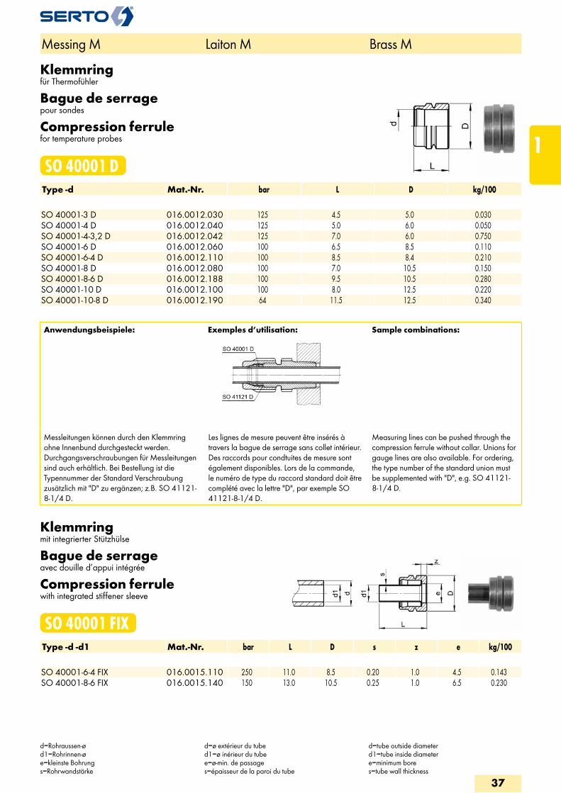
Klemmringfür Thermofühler
Bague de serragepour sondes
Compression ferrulefor temperature probes
SO 40001 DType -d Mat.-Nr. bar L D kg/100 SO 40001-3 D 016.0012.030 125 4.5 5.0 0.030SO 40001-4 D 016.0012.040 125 5.0 6.0 0.050SO 40001-4-3,2 D 016.0012.042 125 7.0 6.0 0.750SO 40001-6 D 016.0012.060 100 6.5 8.5 0.110SO 40001-6-4 D 016.0012.110 100 8.5 8.4 0.210SO 40001-8 D 016.0012.080 100 7.0 10.5 0.150SO 40001-8-6 D 016.0012.188 100 9.5 10.5 0.280SO 40001-10 D 016.0012.100 100 8.0 12.5 0.220SO 40001-10-8 D 016.0012.190 64 11.5 12.5 0.340
Anwendungsbeispiele: Exemples d’utilisation: Sample combinations:
Messleitungen können durch den Klemmring ohne Innenbund durchgesteckt werden. Durchgangsverschraubungen für Messleitungen sind auch erhältlich. Bei Bestellung ist die Typennummer der Standard Verschraubung zusätzlich mit "D" zu ergänzen; z.B. SO 41121-8-1/4 D.
Les lignes de mesure peuvent être insérés à travers la bague de serrage sans collet intérieur. Des raccords pour condtuites de mesure sont également disponibles. Lors de la commande, le numéro de type du raccord standard doit être complété avec la lettre "D", par exemple SO 41121-8-1/4 D.
Measuring lines can be pushed through the compression ferrule without collar. Unions for gauge lines are also available. For ordering, the type number of the standard union must be supplemented with "D", e.g. SO 41121-8-1/4 D.
Klemmringmit integrierter Stützhülse
Bague de serrageavec douille d’appui intégrée
Compression ferrulewith integrated stiffener sleeve
SO 40001 FIXType -d -d1 Mat.-Nr. bar L D s z e kg/100 SO 40001-6-4 FIX 016.0015.110 250 11.0 8.5 0.20 1.0 4.5 0.143SO 40001-8-6 FIX 016.0015.140 150 13.0 10.5 0.25 1.0 6.5 0.230
Messing M Laiton M Brass M
d=Rohraussen-ød1=Rohrinnen-øe=kleinste Bohrungs=Rohrwandstärke
d=ø extérieur du tubed1=ø inérieur du tubee=ø-min. de passages=épaisseur de la paroi du tube
d=tube outside diameterd1=tube inside diametere=minimum bores=tube wall thickness
37
1
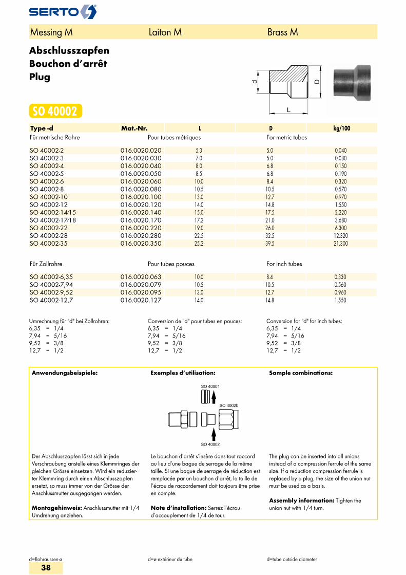
AbschlusszapfenBouchon d’arrêtPlug
SO 40002Type -d Mat.-Nr. L D kg/100Für metrische Rohre Pour tubes métriques For metric tubes SO 40002-2 016.0020.020 5.3 5.0 0.040SO 40002-3 016.0020.030 7.0 5.0 0.080SO 40002-4 016.0020.040 8.0 6.8 0.150SO 40002-5 016.0020.050 8.5 6.8 0.190SO 40002-6 016.0020.060 10.0 8.4 0.320SO 40002-8 016.0020.080 10.5 10.5 0.570SO 40002-10 016.0020.100 13.0 12.7 0.970SO 40002-12 016.0020.120 14.0 14.8 1.550SO 40002-14/15 016.0020.140 15.0 17.5 2.220SO 40002-17/18 016.0020.170 17.2 21.0 3.680SO 40002-22 016.0020.220 19.0 26.0 6.300SO 40002-28 016.0020.280 22.5 32.5 12.320SO 40002-35 016.0020.350 25.2 39.5 21.300
Für Zollrohre Pour tubes pouces For inch tubes SO 40002-6,35 016.0020.063 10.0 8.4 0.330SO 40002-7,94 016.0020.079 10.5 10.5 0.560SO 40002-9,52 016.0020.095 13.0 12.7 0.960SO 40002-12,7 016.0020.127 14.0 14.8 1.550
Umrechnung für "d" bei Zollrohren:6,35 = 1/47,94 = 5/169,52 = 3/812,7 = 1/2
Conversion de "d" pour tubes en pouces:6,35 = 1/47,94 = 5/169,52 = 3/812,7 = 1/2
Conversion for "d" for inch tubes:6,35 = 1/47,94 = 5/169,52 = 3/812,7 = 1/2
Anwendungsbeispiele: Exemples d’utilisation: Sample combinations:
Der Abschlusszapfen lässt sich in jede Verschraubung anstelle eines Klemmringes der gleichen Grösse einsetzen. Wird ein reduzier-ter Klemmring durch einen Abschlusszapfen ersetzt, so muss immer von der Grösse der Anschlussmutter ausgegangen werden.
Montagehinweis: Anschlussmutter mit 1/4 Umdrehung anziehen.
Le bouchon d’arrêt s’insère dans tout raccord au lieu d’une bague de serrage de la même taille. Si une bague de serrage de réduction est remplacée par un bouchon d’arrêt, la taille de l’écrou de raccordement doit toujours être prise en compte.
Note d’installation: Serrez l’écrou d’accouplement de 1/4 de tour.
The plug can be inserted into all unions instead of a compression ferrule of the same size. If a reduction compression ferrule is replaced by a plug, the size of the union nut must be used as a basis.
Assembly information: Tighten the union nut with 1/4 turn.
Messing M Laiton M Brass M
d=Rohraussen-ø d=ø extérieur du tube d=tube outside diameter
38
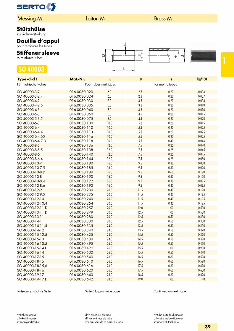
Stützhülsezur Rohrverstärkung
Douille d’appuipour renforcer les tubes
Stiffener sleeveto reinforce tubes
SO 40003Type -d -d1 Mat.-Nr. L D s kg/100Für metrische Rohre Pour tubes métriques For metric tubes SO 40003-3-2 016.0030.020 6.0 2.8 0.20 0.006SO 40003-3-2,4 016.0030.024 6.0 2.8 0.20 0.007SO 40003-4-2 016.0030.030 8.0 3.8 0.20 0.008SO 40003-4-2,5 016.0030.035 8.0 3.8 0.20 0.010SO 40003-4-3 016.0030.040 8.0 3.8 0.20 0.010SO 40003-5-3 016.0030.060 8.0 4.5 0.20 0.015SO 40003-5-3,5 016.0030.075 8.0 4.5 0.20 0.020SO 40003-6-3 016.0030.100 10.0 5.2 0.20 0.015SO 40003-6-4 016.0030.110 10.0 5.5 0.20 0.025SO 40003-6-4,4 016.0030.113 10.0 5.5 0.20 0.025SO 40003-6-4,65 016.0030.116 10.0 5.5 0.20 0.025SO 40003-6-4,7 D 016.0030.118 10.0 5.5 0.40 0.046SO 40003-8-5 016.0030.136 12.0 7.5 0.25 0.040SO 40003-8-5,5 016.0030.138 12.0 7.5 0.25 0.045SO 40003-8-6 016.0030.140 12.0 7.5 0.25 0.045SO 40003-8-6,4 016.0030.144 12.0 7.5 0.25 0.050SO 40003-10-7 016.0030.180 16.0 9.5 0.30 0.080SO 40003-10-7,5 016.0030.185 16.0 9.5 0.30 0.090SO 40003-10-8 D 016.0030.189 16.0 9.5 0.60 0.190SO 40003-10-8 016.0030.190 16.0 9.5 0.30 0.100SO 40003-10-8,4 016.0030.192 16.0 9.5 0.30 0.095SO 40003-10-8,6 016.0030.193 16.0 9.5 0.30 0.095SO 40003-12-9 016.0030.230 20.0 11.5 0.40 0.190SO 40003-12-9,5 016.0030.235 20.0 11.5 0.40 0.195SO 40003-12-10 016.0030.240 20.0 11.5 0.40 0.195SO 40003-12-10,4 016.0030.254 20.0 11.5 0.40 0.195SO 40003-12-11 D 016.0030.257 20.0 12.0 1.00 0.500SO 40003-13-11 D 016.0030.279 20.0 12.5 1.00 0.530SO 40003-13-11 016.0030.280 20.0 12.5 0.50 0.330SO 40003-14-11 016.0030.330 20.0 12.5 0.50 0.330SO 40003-14-11,5 016.0030.335 24.0 13.5 0.50 0.350SO 40003-14-12 016.0030.340 24.0 13.5 0.50 0.370SO 40003-15-12,5 016.0030.425 24.0 14.5 0.50 0.390SO 40003-15-13 016.0030.430 24.0 14.5 0.50 0.390SO 40003-16-13,5 016.0030.495 26.0 15.5 0.50 0.430SO 40003-16-14 D 016.0030.499 26.0 15.5 1.00 0.900SO 40003-16-14 016.0030.500 26.0 15.5 0.50 0.470SO 40003-17-15 016.0030.540 26.0 16.5 0.60 0.590SO 40003-18-15 016.0030.610 26.0 16.5 0.60 0.590SO 40003-18-15,6 016.0030.616 26.0 17.5 0.60 0.610SO 40003-18-16 016.0030.620 26.0 17.5 0.60 0.630SO 40003-19-17 016.0030.640 28.0 18.5 0.60 0.820SO 40003-19-17 D 016.0030.642 28.0 19.0 1.00 1.140
Fortsetzung nächste Seite Suite à la prochaine page Continued on next page
Messing M Laiton M Brass M
d=Rohraussen-ød1=Rohrinnen-øs=Rohrwandstärke
d=ø extérieur du tubed1=ø intérieur de tubes=epaisseur de la paroi du tube
d=tube outside diameterd1=tube inside diameters=tube wall thickness
39
1
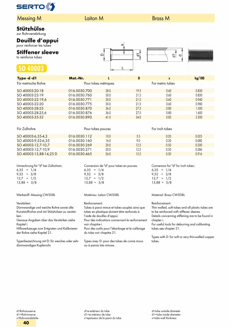
Stützhülsezur Rohrverstärkung
Douille d’appuipour renforcer les tubes
Stiffener sleeveto reinforce tubes
SO 40003Type -d -d1 Mat.-Nr. L D s kg/100Für metrische Rohre Pour tubes métriques For metric tubes SO 40003-20-18 016.0030.700 28.0 19.5 0.60 0.830SO 40003-22-19 016.0030.760 30.0 21.5 0.60 0.850SO 40003-22-19,6 016.0030.771 30.0 21.5 0.60 0.940SO 40003-22-20 016.0030.775 30.0 21.5 0.60 0.980SO 40003-28-25 016.0030.870 36.0 27.5 0.80 1.500SO 40003-28-25,6 016.0030.876 36.0 27.5 0.80 1.600SO 40003-35-32 016.0030.890 41.0 34.0 0.85 2.500
Für Zollrohre Pour tubes pouces For inch tubes SO 40003-6,35-4,3 016.0030.112 10.0 5.5 0.20 0.023SO 40003-9,52-6,35 016.0030.160 16.0 9.0 0.30 0.080SO 40003-12,7-10,7 016.0030.269 20.0 12.5 0.50 0.200SO 40003-12,7-10,9 016.0030.271 20.0 12.5 0.50 0.286SO 40003-15,88-14,25 D 016.0030.465 26.0 15.5 0.50 0.916
Umrechnung für "d" bei Zollrohren:6,35 = 1/49,52 = 3/812,7 = 1/215,88 = 5/8
Conversion de "d" pour tubes en pouces:6,35 = 1/49,52 = 3/812,7 = 1/215,88 = 5/8
Conversion for "d" for inch tubes:6,35 = 1/49,52 = 3/812,7 = 1/215,88 = 5/8
Werkstoff: Messing CW508L
Verstärken:Dünnwandige und weiche Rohre sowie alle Kunststoffrohre sind mit Stützhülsen zu verstär-ken. Genaue Angaben über das Verstärken siehe Kapitel i. Hilfswerkzeuge zum Entgraten und Kalibrieren der Rohre siehe Kapitel 21.
Typenbezeichnung mit D: für weiches oder sehr dünnwandiges Kupferrohr.
Matériau: Laiton CW508L
Renforcement:Tubes à paroi mince et tubes souples ainsi que tubes en plastique doivent être renforcés à l’aide de douilles d’appui. Pour des indications concernant le renforcement voir chapitre i. Pour des outils pour l’ébarbage et le calibrage du tube voir chapitre 21.
Types avec D: pour des tubes de cuivre mous ou à parois très minces.
Material: Brass CW508L
Reinforcement:Thin walled, soft tubes and all plastic tubes are to be reinforced with stiffener sleeves. Details concerning stiffening are to be found in chapter i. For useful tools for deburring and calibrating tubes see chapter 21.
Types with D: for soft or very thin-walled copper tubes.
Messing M Laiton M Brass M
d=Rohraussen-ød1=Rohrinnen-øs=Rohrwandstärke
d=ø extérieur du tubed1=ø intérieur de tubes=epaisseur de la paroi du tube
d=tube outside diameterd1=tube inside diameters=tube wall thickness
40
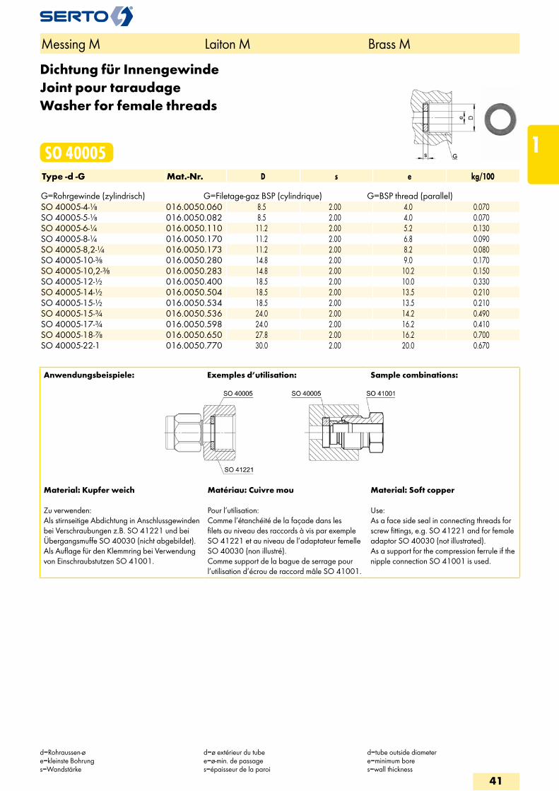
Dichtung für InnengewindeJoint pour taraudageWasher for female threads
SO 40005Type -d -G Mat.-Nr. D s e kg/100 G=Rohrgewinde (zylindrisch) G=Filetage-gaz BSP (cylindrique) G=BSP thread (parallel)SO 40005-4-1/8 016.0050.060 8.5 2.00 4.0 0.070SO 40005-5-1/8 016.0050.082 8.5 2.00 4.0 0.070SO 40005-6-1/4 016.0050.110 11.2 2.00 5.2 0.130SO 40005-8-1/4 016.0050.170 11.2 2.00 6.8 0.090SO 40005-8,2-1/4 016.0050.173 11.2 2.00 8.2 0.080SO 40005-10-3/8 016.0050.280 14.8 2.00 9.0 0.170SO 40005-10,2-3/8 016.0050.283 14.8 2.00 10.2 0.150SO 40005-12-1/2 016.0050.400 18.5 2.00 10.0 0.330SO 40005-14-1/2 016.0050.504 18.5 2.00 13.5 0.210SO 40005-15-1/2 016.0050.534 18.5 2.00 13.5 0.210SO 40005-15-3/4 016.0050.536 24.0 2.00 14.2 0.490SO 40005-17-3/4 016.0050.598 24.0 2.00 16.2 0.410SO 40005-18-7/8 016.0050.650 27.8 2.00 16.2 0.700SO 40005-22-1 016.0050.770 30.0 2.00 20.0 0.670
Anwendungsbeispiele: Exemples d’utilisation: Sample combinations:
Material: Kupfer weich
Zu verwenden: Als stirnseitige Abdichtung in Anschlussgewinden bei Verschraubungen z.B. SO 41221 und bei Übergangsmuffe SO 40030 (nicht abgebildet). Als Auflage für den Klemmring bei Verwendung von Einschraubstutzen SO 41001.
Matériau: Cuivre mou
Pour l’utilisation: Comme l’étanchéité de la façade dans les filets au niveau des raccords à vis par exemple SO 41221 et au niveau de l’adaptateur femelle SO 40030 (non illustré). Comme support de la bague de serrage pour l’utilisation d’écrou de raccord mâle SO 41001.
Material: Soft copper
Use:As a face side seal in connecting threads for screw fittings, e.g. SO 41221 and for female adaptor SO 40030 (not illustrated). As a support for the compression ferrule if the nipple connection SO 41001 is used.
Messing M Laiton M Brass M
d=Rohraussen-øe=kleinste Bohrungs=Wandstärke
d=ø extérieur du tubee=ø-min. de passages=épaisseur de la paroi
d=tube outside diametere=minimum bores=wall thickness
41
1
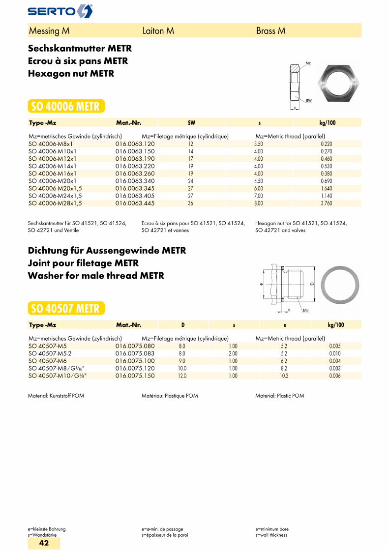
Sechskantmutter METREcrou à six pans METRHexagon nut METR
SO 40006 METRType -Mz Mat.-Nr. SW s kg/100 Mz=metrisches Gewinde (zylindrisch) Mz=Filetage métrique (cylindrique) Mz=Metric thread (parallel)SO 40006-M8x1 016.0063.120 12 3.50 0.220SO 40006-M10x1 016.0063.150 14 4.00 0.270SO 40006-M12x1 016.0063.190 17 4.00 0.460SO 40006-M14x1 016.0063.220 19 4.00 0.530SO 40006-M16x1 016.0063.260 19 4.00 0.380SO 40006-M20x1 016.0063.340 24 4.50 0.690SO 40006-M20x1,5 016.0063.345 27 6.00 1.640SO 40006-M24x1,5 016.0063.405 27 7.00 1.140SO 40006-M28x1,5 016.0063.445 36 8.00 3.760
Sechskantmutter für SO 41521, SO 41524, SO 42721 und Ventile
Ecrou à six pans pour SO 41521, SO 41524, SO 42721 et vannes
Hexagon nut for SO 41521, SO 41524, SO 42721 and valves
Dichtung für Aussengewinde METRJoint pour filetage METRWasher for male thread METR
SO 40507 METRType -Mz Mat.-Nr. D s e kg/100 Mz=metrisches Gewinde (zylindrisch) Mz=Filetage métrique (cylindrique) Mz=Metric thread (parallel)SO 40507-M5 016.0075.080 8.0 1.00 5.2 0.005SO 40507-M5-2 016.0075.083 8.0 2.00 5.2 0.010SO 40507-M6 016.0075.100 9.0 1.00 6.2 0.004SO 40507-M8 / G1/16" 016.0075.120 10.0 1.00 8.2 0.003SO 40507-M10 / G1/8" 016.0075.150 12.0 1.00 10.2 0.006
Material: Kunststoff POM Matériau: Plastique POM Material: Plastic POM
Messing M Laiton M Brass M
e=kleinste Bohrungs=Wandstärke
e=ø-min. de passages=épaisseur de la paroi
e=minimum bores=wall thickness
42
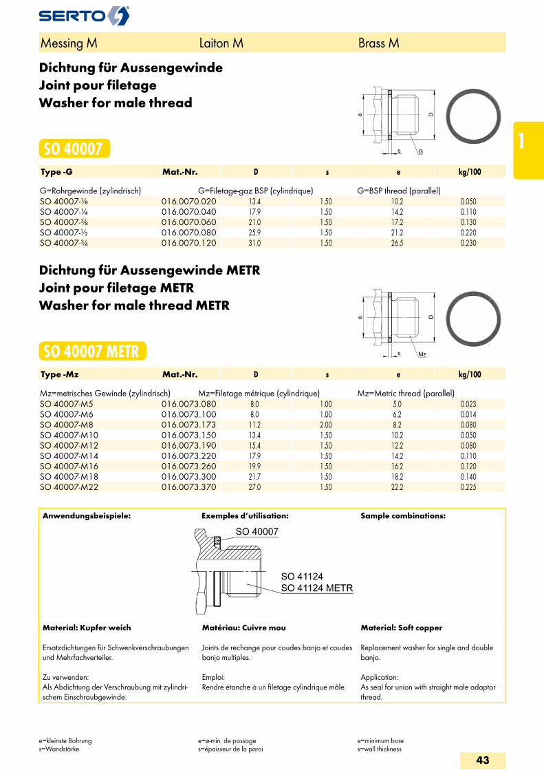
Dichtung für AussengewindeJoint pour filetageWasher for male thread
SO 40007Type -G Mat.-Nr. D s e kg/100 G=Rohrgewinde (zylindrisch) G=Filetage-gaz BSP (cylindrique) G=BSP thread (parallel)SO 40007-1/8 016.0070.020 13.4 1.50 10.2 0.050SO 40007-1/4 016.0070.040 17.9 1.50 14.2 0.110SO 40007-3/8 016.0070.060 21.0 1.50 17.2 0.130SO 40007-1/2 016.0070.080 25.9 1.50 21.2 0.220SO 40007-3/4 016.0070.120 31.0 1.50 26.5 0.230
Dichtung für Aussengewinde METRJoint pour filetage METRWasher for male thread METR
SO 40007 METRType -Mz Mat.-Nr. D s e kg/100 Mz=metrisches Gewinde (zylindrisch) Mz=Filetage métrique (cylindrique) Mz=Metric thread (parallel)SO 40007-M5 016.0073.080 8.0 1.00 5.0 0.023SO 40007-M6 016.0073.100 8.0 1.00 6.2 0.014SO 40007-M8 016.0073.173 11.2 2.00 8.2 0.080SO 40007-M10 016.0073.150 13.4 1.50 10.2 0.050SO 40007-M12 016.0073.190 15.4 1.50 12.2 0.080SO 40007-M14 016.0073.220 17.9 1.50 14.2 0.110SO 40007-M16 016.0073.260 19.9 1.50 16.2 0.120SO 40007-M18 016.0073.300 21.7 1.50 18.2 0.140SO 40007-M22 016.0073.370 27.0 1.50 22.2 0.225
Anwendungsbeispiele: Exemples d’utilisation: Sample combinations:
Material: Kupfer weich
Ersatzdichtungen für Schwenkverschraubungen und Mehrfachverteiler.
Zu verwenden:Als Abdichtung der Verschraubung mit zylindri-schem Einschraubgewinde.
Matériau: Cuivre mou
Joints de rechange pour coudes banjo et coudes banjo multiples.
Emploi:Rendre étanche à un filetage cylindrique mâle.
Material: Soft copper
Replacement washer for single and double banjo.
Application:As seal for union with straight male adaptor thread.
Messing M Laiton M Brass M
e=kleinste Bohrungs=Wandstärke
e=ø-min. de passages=épaisseur de la paroi
e=minimum bores=wall thickness
43
1
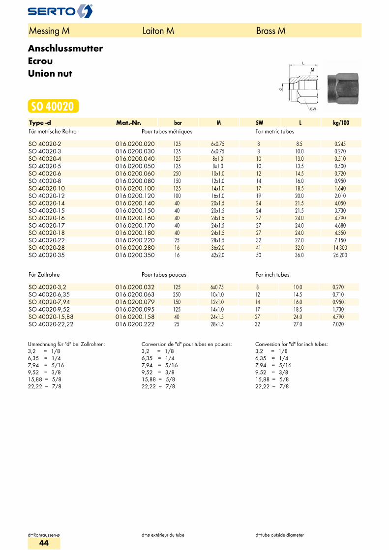
AnschlussmutterEcrouUnion nut
SO 40020Type -d Mat.-Nr. bar M SW L kg/100Für metrische Rohre Pour tubes métriques For metric tubes SO 40020-2 016.0200.020 125 6x0.75 8 8.5 0.245SO 40020-3 016.0200.030 125 6x0.75 8 10.0 0.270SO 40020-4 016.0200.040 125 8x1.0 10 13.0 0.510SO 40020-5 016.0200.050 125 8x1.0 10 13.5 0.500SO 40020-6 016.0200.060 250 10x1.0 12 14.5 0.720SO 40020-8 016.0200.080 150 12x1.0 14 16.0 0.950SO 40020-10 016.0200.100 125 14x1.0 17 18.5 1.640SO 40020-12 016.0200.120 100 16x1.0 19 20.0 2.010SO 40020-14 016.0200.140 40 20x1.5 24 21.5 4.050SO 40020-15 016.0200.150 40 20x1.5 24 21.5 3.730SO 40020-16 016.0200.160 40 24x1.5 27 24.0 4.790SO 40020-17 016.0200.170 40 24x1.5 27 24.0 4.680SO 40020-18 016.0200.180 40 24x1.5 27 24.0 4.350SO 40020-22 016.0200.220 25 28x1.5 32 27.0 7.150SO 40020-28 016.0200.280 16 36x2.0 41 32.0 14.300SO 40020-35 016.0200.350 16 42x2.0 50 36.0 26.200
Für Zollrohre Pour tubes pouces For inch tubes SO 40020-3,2 016.0200.032 125 6x0.75 8 10.0 0.270SO 40020-6,35 016.0200.063 250 10x1.0 12 14.5 0.710SO 40020-7,94 016.0200.079 150 12x1.0 14 16.0 0.950SO 40020-9,52 016.0200.095 125 14x1.0 17 18.5 1.730SO 40020-15,88 016.0200.158 40 24x1.5 27 24.0 4.790SO 40020-22,22 016.0200.222 25 28x1.5 32 27.0 7.020
Umrechnung für "d" bei Zollrohren:3,2 = 1/86,35 = 1/47,94 = 5/169,52 = 3/815,88 = 5/822,22 = 7/8
Conversion de "d" pour tubes en pouces:3,2 = 1/86,35 = 1/47,94 = 5/169,52 = 3/815,88 = 5/822,22 = 7/8
Conversion for "d" for inch tubes:3,2 = 1/86,35 = 1/47,94 = 5/169,52 = 3/815,88 = 5/822,22 = 7/8
Messing M Laiton M Brass M
d=Rohraussen-ø d=ø extérieur du tube d=tube outside diameter
44
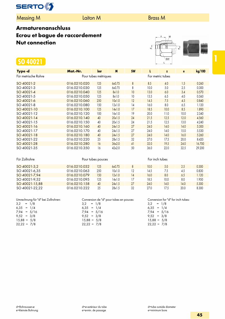
ArmaturenanschlussEcrou et bague de raccordementNut connection
SO 40021Type -d Mat.-Nr. bar M SW L z e kg/100Für metrische Rohre Pour tubes métriques For metric tubes SO 40021-2 016.0210.020 125 6x0.75 8 8.5 4.0 1.5 0.260SO 40021-3 016.0210.030 125 6x0.75 8 10.0 5.0 2.5 0.300SO 40021-4 016.0210.040 125 8x1.0 10 13.0 6.0 3.4 0.570SO 40021-5 016.0210.050 125 8x1.0 10 13.5 6.5 4.0 0.560SO 40021-6 016.0210.060 250 10x1.0 12 14.5 7.5 4.5 0.840SO 40021-8 016.0210.080 150 12x1.0 14 16.0 8.0 6.5 1.120SO 40021-10 016.0210.100 125 14x1.0 17 18.5 10.0 8.5 1.890SO 40021-12 016.0210.120 100 16x1.0 19 20.0 11.0 10.0 2.340SO 40021-14 016.0210.140 40 20x1.5 24 21.5 12.5 12.0 4.560SO 40021-15 016.0210.150 40 20x1.5 24 21.5 12.5 13.0 4.240SO 40021-16 016.0210.160 40 24x1.5 27 24.0 14.0 14.0 5.300SO 40021-17 016.0210.170 40 24x1.5 27 24.0 14.0 15.0 5.530SO 40021-18 016.0210.180 40 24x1.5 27 24.0 14.0 16.0 5.260SO 40021-22 016.0210.220 25 28x1.5 32 27.0 17.5 20.0 8.420SO 40021-28 016.0210.280 16 36x2.0 41 32.0 19.5 24.0 16.700SO 40021-35 016.0210.350 16 42x2.0 50 36.0 22.0 32.5 29.200
Für Zollrohre Pour tubes pouces For inch tubes SO 40021-3,2 016.0210.032 125 6x0.75 8 10.0 5.0 2.5 0.300SO 40021-6,35 016.0210.063 250 10x1.0 12 14.5 7.5 4.5 0.830SO 40021-7,94 016.0210.079 150 12x1.0 14 16.0 8.0 6.5 1.120SO 40021-9,52 016.0210.095 125 14x1.0 17 18.5 10.0 8.0 1.950SO 40021-15,88 016.0210.158 40 24x1.5 27 24.0 14.0 14.0 5.300SO 40021-22,22 016.0210.222 25 28x1.5 32 27.0 17.5 20.0 8.300
Umrechnung für "d" bei Zollrohren:3,2 = 1/86,35 = 1/47,94 = 5/169,52 = 3/815,88 = 5/822,22 = 7/8
Conversion de "d" pour tubes en pouces:3,2 = 1/86,35 = 1/47,94 = 5/169,52 = 3/815,88 = 5/822,22 = 7/8
Conversion for "d" for inch tubes:3,2 = 1/86,35 = 1/47,94 = 5/169,52 = 3/815,88 = 5/822,22 = 7/8
Messing M Laiton M Brass M
d=Rohraussen-øe=kleinste Bohrung
d=ø extérieur du tubee=ø-min. de passage
d=tube outside diametere=minimum bore
45
1
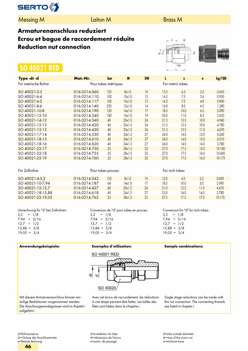
Armaturenanschluss reduziertEcrou et bague de raccordement réduiteReduction nut connection
SO 40021 REDType -dr -d Mat.-Nr. bar M SW L z e kg/100Für metrische Rohre Pour tubes métriques For metric tubes SO 40021-5-3 016.0214.060 125 8x1.0 10 13.5 6.5 2.5 0.620SO 40021-6-4 016.0214.110 100 10x1.0 12 14.5 7.5 3.4 0.950SO 40021-6-5 016.0214.117 100 10x1.0 12 14.5 7.5 4.0 0.900SO 40021-8-6 016.0214.140 250 12x1.0 14 16.0 8.0 4.5 1.280SO 40021-10-8 016.0214.190 150 14x1.0 17 18.5 10.0 6.5 2.090SO 40021-12-10 016.0214.240 100 16x1.0 19 20.0 11.0 8.5 2.620SO 40021-14-12 016.0214.340 40 20x1.5 24 21.5 12.5 10.0 4.940SO 40021-15-12 016.0214.420 40 20x1.5 24 21.5 12.5 10.0 4.780SO 40021-15-13 016.0214.430 40 20x1.5 24 21.5 12.5 11.0 4.670SO 40021-17-14 016.0214.530 40 24x1.5 27 24.0 14.0 12.0 6.240SO 40021-18-15 016.0214.610 40 24x1.5 27 24.0 14.0 13.0 6.010SO 40021-18-16 016.0214.620 40 24x1.5 27 24.0 14.0 14.0 5.780SO 40021-22-17 016.0214.750 25 28x1.5 32 27.0 17.5 15.0 10.180SO 40021-22-18 016.0214.755 25 28x1.5 32 27.0 17.5 16.0 10.400SO 40021-22-19 016.0214.760 25 28x1.5 32 27.0 17.5 16.0 10.175
Für Zollrohre Pour tubes pouces For inch tubes SO 40021-4-3,2 016.0214.042 125 8x1.0 10 13.0 6.0 2.5 0.600SO 40021-10-7,94 016.0214.187 64 14x1.0 17 18.5 10.0 6.5 2.090SO 40021-15-12,7 016.0214.427 40 20x1.5 24 21.0 12.5 11.0 4.670SO 40021-18-15,88 016.0214.618 40 24x1.5 27 23.0 14.0 14.0 5.780SO 40021-22-19,05 016.0214.762 25 28x1.5 32 27.5 17.5 17.0 10.175
Umrechnung für "d" bei Zollrohren:3,2 = 1/87,94 = 5/1612,7 = 1/215,88 = 5/819,05 = 3/4
Conversion de "d" pour tubes en pouces:3,2 = 1/87,94 = 5/1612,7 = 1/215,88 = 5/819,05 = 3/4
Conversion for "d" for inch tubes:3,2 = 1/87,94 = 5/1612,7 = 1/215,88 = 5/819,05 = 3/4
Anwendungsbeispiele: Exemples d’utilisation: Sample combinations:
Mit diesem Armaturenanschluss können ein-stufige Reduktionen vorgenommen werden. Die Anschlussgewindegrössen sind im Kapitel i aufgeführt.
Avec cet écrou de raccordement, les réductions à une étape peuvent être faites. Les tailles des filets sont listées dans le chapitre i.
Single stage reductions can be made with this nut connection. The connecting threads are listed in chapter i.
Messing M Laiton M Brass M
d=Rohraussen-ødr=Grösse der Anschlussmuttere=kleinste Bohrung
d=ø extérieur du tubedr=dimension de l’écrou e=ø-min. de passage
d=tube outside diameterdr=size of the union nute=minimum bore
46
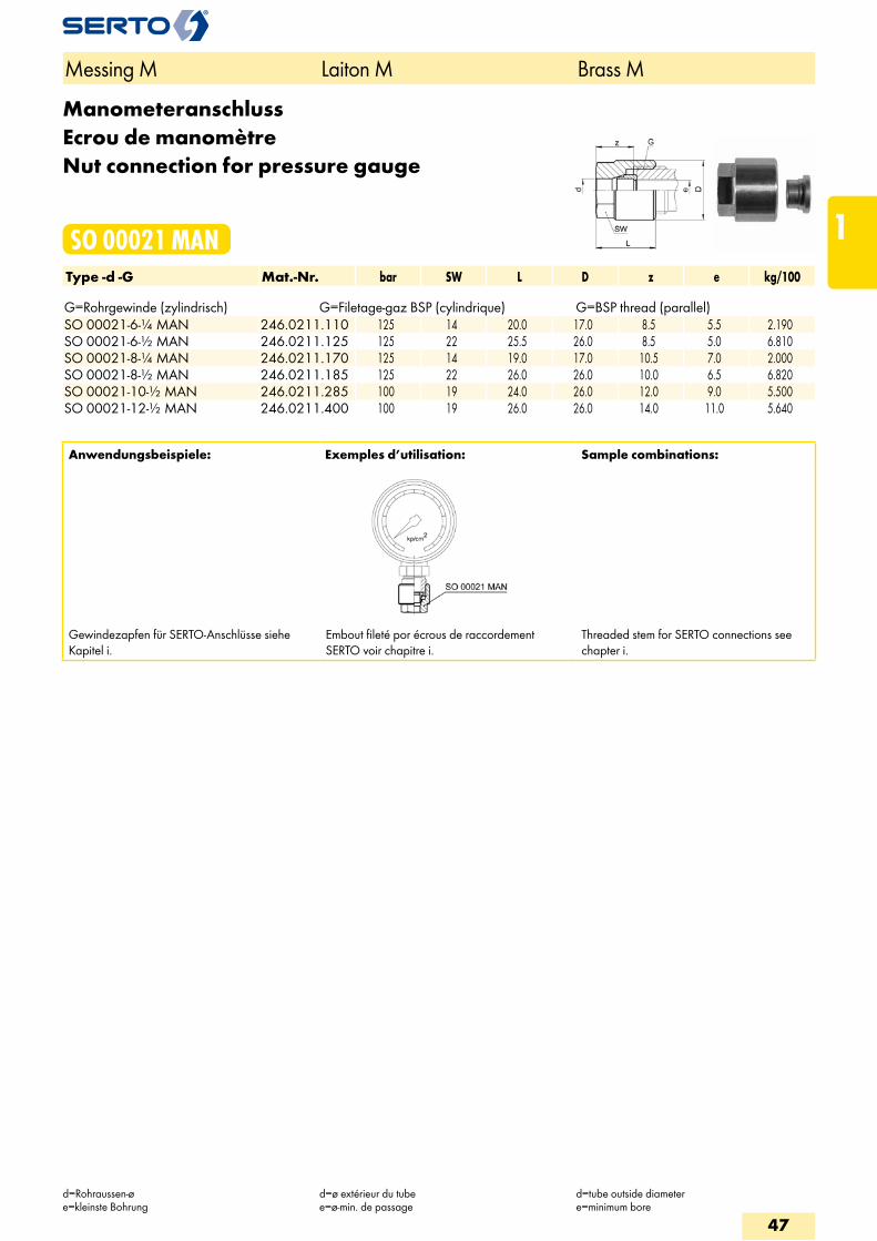
ManometeranschlussEcrou de manomètreNut connection for pressure gauge
SO 00021 MANType -d -G Mat.-Nr. bar SW L D z e kg/100 G=Rohrgewinde (zylindrisch) G=Filetage-gaz BSP (cylindrique) G=BSP thread (parallel)SO 00021-6-1/4 MAN 246.0211.110 125 14 20.0 17.0 8.5 5.5 2.190SO 00021-6-1/2 MAN 246.0211.125 125 22 25.5 26.0 8.5 5.0 6.810SO 00021-8-1/4 MAN 246.0211.170 125 14 19.0 17.0 10.5 7.0 2.000SO 00021-8-1/2 MAN 246.0211.185 125 22 26.0 26.0 10.0 6.5 6.820SO 00021-10-1/2 MAN 246.0211.285 100 19 24.0 26.0 12.0 9.0 5.500SO 00021-12-1/2 MAN 246.0211.400 100 19 26.0 26.0 14.0 11.0 5.640
Anwendungsbeispiele: Exemples d’utilisation: Sample combinations:
Gewindezapfen für SERTO-Anschlüsse siehe Kapitel i.
Embout fileté por écrous de raccordement SERTO voir chapitre i.
Threaded stem for SERTO connections see chapter i.
Messing M Laiton M Brass M
d=Rohraussen-øe=kleinste Bohrung
d=ø extérieur du tubee=ø-min. de passage
d=tube outside diametere=minimum bore
47
1
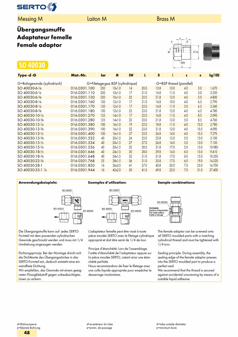
ÜbergangsmuffeAdaptateur femelleFemale adaptor
SO 40030Type -d -G Mat.-Nr. bar M SW L D i z e kg/100 G=Rohrgewinde (zylindrisch) G=Filetage-gaz BSP (cylindrique) G=BSP thread (parallel)SO 40030-6-1/8 016.0301.100 250 10x1.0 14 20.0 13.8 10.0 4.0 5.0 1.670SO 40030-6-1/4 016.0301.110 250 10x1.0 17 21.0 16.8 11.0 4.0 5.0 2.530SO 40030-6-3/8 016.0301.120 250 10x1.0 22 22.0 21.8 12.0 4.0 5.0 4.800SO 40030-8-1/8 016.0301.160 150 12x1.0 17 21.0 16.8 10.0 4.0 6.5 2.790SO 40030-8-1/4 016.0301.170 150 12x1.0 17 23.0 16.8 11.0 5.0 6.5 2.540SO 40030-8-3/8 016.0301.180 150 12x1.0 22 23.0 21.8 12.0 4.0 6.5 4.780SO 40030-10-1/4 016.0301.270 125 14x1.0 17 22.0 16.8 11.0 4.0 8.5 2.090SO 40030-10-3/8 016.0301.280 125 14x1.0 22 23.0 21.8 12.0 5.0 8.5 4.760SO 40030-12-1/4 016.0301.380 100 16x1.0 19 22.0 18.8 11.0 4.0 10.5 2.780SO 40030-12-3/8 016.0301.390 100 16x1.0 22 23.0 21.8 12.0 4.0 10.5 4.090SO 40030-12-1/2 016.0301.400 100 16x1.0 27 25.0 26.8 14.0 4.0 10.5 7.270SO 40030-15-3/8 016.0301.532 40 20x1.5 24 25.0 23.8 12.0 5.0 13.0 5.100SO 40030-15-1/2 016.0301.534 40 20x1.5 27 27.0 26.8 14.0 5.0 13.0 7.130SO 40030-15-3/4 016.0301.536 40 20x1.5 32 30.0 31.8 17.0 5.0 13.0 10.980SO 40030-18-1/2 016.0301.646 40 24x1.5 30 28.0 29.8 14.0 6.0 15.0 9.410SO 40030-18-3/4 016.0301.648 40 24x1.5 32 31.0 31.8 17.0 6.0 15.0 10.350SO 40030-22-3/4 016.0301.768 25 28x1.5 36 31.0 35.8 17.0 6.0 19.0 14.320SO 40030-28-1 016.0301.850 16 36x2.0 41 37.0 40.8 20.0 7.0 25.0 16.700SO 40030-35-1 1/4 016.0301.944 16 42x2.0 50 41.0 49.8 22.0 7.0 31.0 27.400
Anwendungsbeispiele: Exemples d’utilisation: Sample combinations:
Die Übergangsmuffe kann auf jedes SERTO-Formteil mit dem passenden zylindrischen Gewinde geschraubt werden und muss mit 1/4 Umdrehung angezogen werden.
Dichtungsprinzip: Bei der Montage drückt sich die Dichtkante des Übergangsstückes in das SERTO-Formteil ein, dadurch entsteht eine ein-wandfreie Dichtung. Wir empfehlen, das Gewinde mit einem geeig-neten Flüssigklebstoff gegen unbeabsichtigtes Lösen zu sichern.
L’adaptateur femelle peut être vissé à toute pièce moulée SERTO avec le filetage cylindrique approprié et doit être serré de 1/4 de tour.
Principe d’étanchéité: Lors de l’assemblage, l’arête d’étanchéité de l’adaptateur appuie sur la pièce moulée SERTO, créant ainsi une étan-chéité parfaite. Nous recommandons de fixer le filetage avec une colle liquide appropriée pour empêcher le desserrage involontaire.
The female adaptor can be screwed onto all SERTO moulded parts with a matching cylindrical thread and must be tightened with 1/4 turn.
Sealing principle: During assembly, the sealing edge of the female adaptor presses into the SERTO moulded part to produce a perfect seal. We recommend that the thread is secured against accidental unscrewing by means of a suitable liquid adhesive.
Messing M Laiton M Brass M
d=Rohraussen-øe=kleinste Bohrung
d=ø extérieur du tubee=ø-min. de passage
d=tube outside diametere=minimum bore
48
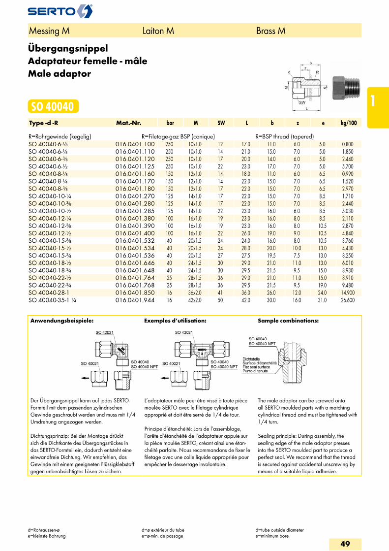
ÜbergangsnippelAdaptateur femelle - mâleMale adaptor
SO 40040Type -d -R Mat.-Nr. bar M SW L b z e kg/100 R=Rohrgewinde (kegelig) R=Filetage-gaz BSP (conique) R=BSP thread (tapered)SO 40040-6-1/8 016.0401.100 250 10x1.0 12 17.0 11.0 6.0 5.0 0.800SO 40040-6-1/4 016.0401.110 250 10x1.0 14 21.0 15.0 7.0 5.0 1.850SO 40040-6-3/8 016.0401.120 250 10x1.0 17 20.0 14.0 6.0 5.0 2.440SO 40040-6-1/2 016.0401.125 250 10x1.0 22 23.0 17.0 7.0 5.0 5.700SO 40040-8-1/8 016.0401.160 150 12x1.0 14 18.0 11.0 6.0 6.5 0.990SO 40040-8-1/4 016.0401.170 150 12x1.0 14 22.0 15.0 7.0 6.5 1.520SO 40040-8-3/8 016.0401.180 150 12x1.0 17 22.0 15.0 7.0 6.5 2.970SO 40040-10-1/4 016.0401.270 125 14x1.0 17 22.0 15.0 7.0 8.5 1.710SO 40040-10-3/8 016.0401.280 125 14x1.0 17 22.0 15.0 7.0 8.5 2.440SO 40040-10-1/2 016.0401.285 125 14x1.0 22 23.0 16.0 6.0 8.5 5.030SO 40040-12-1/4 016.0401.380 100 16x1.0 19 23.0 16.0 8.0 8.5 2.110SO 40040-12-3/8 016.0401.390 100 16x1.0 19 23.0 16.0 8.0 10.5 2.870SO 40040-12-1/2 016.0401.400 100 16x1.0 22 26.0 19.0 9.0 10.5 4.840SO 40040-15-3/8 016.0401.532 40 20x1.5 24 24.0 16.0 8.0 10.5 3.760SO 40040-15-1/2 016.0401.534 40 20x1.5 24 28.0 20.0 10.0 13.0 4.430SO 40040-15-3/4 016.0401.536 40 20x1.5 27 27.5 19.5 7.5 13.0 8.250SO 40040-18-1/2 016.0401.646 40 24x1.5 30 29.0 21.0 11.0 13.0 6.010SO 40040-18-3/4 016.0401.648 40 24x1.5 30 29.5 21.5 9.5 15.0 8.930SO 40040-22-1/2 016.0401.764 25 28x1.5 36 29.0 21.0 11.0 15.0 8.910SO 40040-22-3/4 016.0401.768 25 28x1.5 36 29.5 21.5 9.5 19.0 9.480SO 40040-28-1 016.0401.850 16 36x2.0 41 36.0 26.0 12.0 24.0 14.900SO 40040-35-1 1/4 016.0401.944 16 42x2.0 50 42.0 30.0 16.0 31.0 26.600
Anwendungsbeispiele: Exemples d’utilisation: Sample combinations:
Der Übergangsnippel kann auf jedes SERTO-Formteil mit dem passenden zylindrischen Gewinde geschraubt werden und muss mit 1/4 Umdrehung angezogen werden.
Dichtungsprinzip: Bei der Montage drückt sich die Dichtkante des Übergangsstückes in das SERTO-Formteil ein, dadurch entsteht eine einwandfreie Dichtung. Wir empfehlen, das Gewinde mit einem geeigneten Flüssigklebstoff gegen unbeabsichtigtes Lösen zu sichern.
L’adaptateur mâle peut être vissé à toute pièce moulée SERTO avec le filetage cylindrique approprié et doit être serré de 1/4 de tour.
Principe d’étanchéité: Lors de l’assemblage, l’arête d’étanchéité de l’adaptateur appuie sur la pièce moulée SERTO, créant ainsi une étan-chéité parfaite. Nous recommandons de fixer le filetage avec une colle liquide appropriée pour empêcher le desserrage involontaire.
The male adaptor can be screwed onto all SERTO moulded parts with a matching cylindrical thread and must be tightened with 1/4 turn.
Sealing principle: During assembly, the sealing edge of the male adaptor presses into the SERTO moulded part to produce a perfect seal. We recommend that the thread is secured against accidental unscrewing by means of a suitable liquid adhesive.
Messing M Laiton M Brass M
d=Rohraussen-øe=kleinste Bohrung
d=ø extérieur du tubee=ø-min. de passage
d=tube outside diametere=minimum bore
49
1
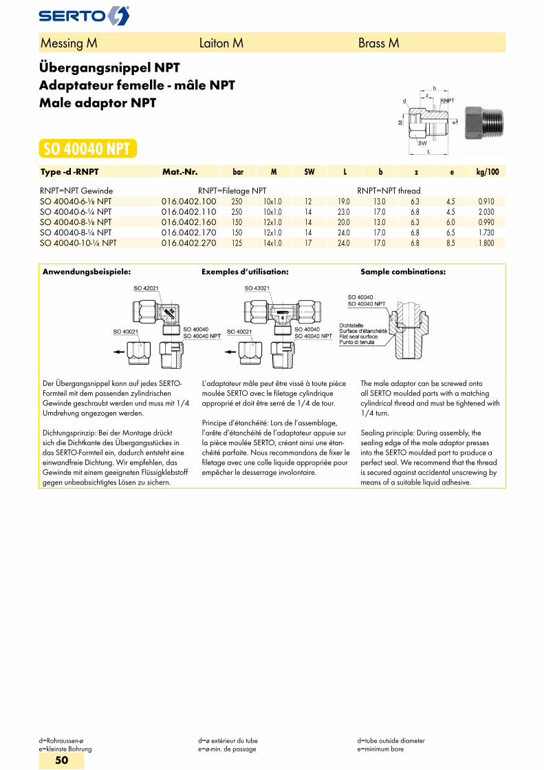
Übergangsnippel NPTAdaptateur femelle - mâle NPTMale adaptor NPT
SO 40040 NPTType -d -RNPT Mat.-Nr. bar M SW L b z e kg/100 RNPT=NPT Gewinde RNPT=Filetage NPT RNPT=NPT threadSO 40040-6-1/8 NPT 016.0402.100 250 10x1.0 12 19.0 13.0 6.3 4.5 0.910SO 40040-6-1/4 NPT 016.0402.110 250 10x1.0 14 23.0 17.0 6.8 4.5 2.030SO 40040-8-1/8 NPT 016.0402.160 150 12x1.0 14 20.0 13.0 6.3 6.0 0.990SO 40040-8-1/4 NPT 016.0402.170 150 12x1.0 14 24.0 17.0 6.8 6.5 1.730SO 40040-10-1/4 NPT 016.0402.270 125 14x1.0 17 24.0 17.0 6.8 8.5 1.800
Anwendungsbeispiele: Exemples d’utilisation: Sample combinations:
Der Übergangsnippel kann auf jedes SERTO-Formteil mit dem passenden zylindrischen Gewinde geschraubt werden und muss mit 1/4 Umdrehung angezogen werden.
Dichtungsprinzip: Bei der Montage drückt sich die Dichtkante des Übergangsstückes in das SERTO-Formteil ein, dadurch entsteht eine einwandfreie Dichtung. Wir empfehlen, das Gewinde mit einem geeigneten Flüssigklebstoff gegen unbeabsichtigtes Lösen zu sichern.
L’adaptateur mâle peut être vissé à toute pièce moulée SERTO avec le filetage cylindrique approprié et doit être serré de 1/4 de tour.
Principe d’étanchéité: Lors de l’assemblage, l’arête d’étanchéité de l’adaptateur appuie sur la pièce moulée SERTO, créant ainsi une étan-chéité parfaite. Nous recommandons de fixer le filetage avec une colle liquide appropriée pour empêcher le desserrage involontaire.
The male adaptor can be screwed onto all SERTO moulded parts with a matching cylindrical thread and must be tightened with 1/4 turn.
Sealing principle: During assembly, the sealing edge of the male adaptor presses into the SERTO moulded part to produce a perfect seal. We recommend that the thread is secured against accidental unscrewing by means of a suitable liquid adhesive.
Messing M Laiton M Brass M
d=Rohraussen-øe=kleinste Bohrung
d=ø extérieur du tubee=ø-min. de passage
d=tube outside diametere=minimum bore
50
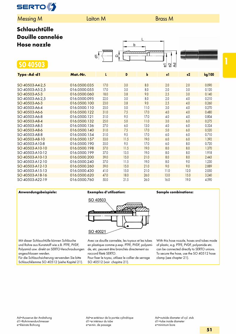
SchlauchtülleDouille canneléeHose nozzle
SO 40503Type -Ad -d1 Mat.-Nr. L D b e1 e2 kg/100 SO 40503-A4-2,5 016.0500.035 17.0 3.0 8.0 2.0 2.0 0.090SO 40503-A5-2,5 016.0500.055 17.0 3.0 8.0 2.0 3.0 0.120SO 40503-A5-3 016.0500.060 18.0 3.8 9.0 2.5 3.0 0.140SO 40503-A6-2,5 016.0500.095 22.0 3.0 8.0 2.0 4.0 0.210SO 40503-A6-3 016.0500.100 23.0 3.8 9.0 2.5 4.0 0.260SO 40503-A6-4 016.0500.110 25.0 5.0 11.0 3.0 4.0 0.270SO 40503-A6-6 016.0500.122 31.0 7.5 17.0 4.0 4.0 0.480SO 40503-A6-8 016.0500.121 31.0 9.5 17.0 4.0 4.0 0.804SO 40503-A8-4 016.0500.132 25.0 5.0 11.0 3.0 6.0 0.275SO 40503-A8-5 016.0500.136 27.0 6.0 13.0 4.0 6.0 0.324SO 40503-A8-6 016.0500.140 31.0 7.5 17.0 5.0 6.0 0.520SO 40503-A8-8 016.0500.154 31.0 9.5 17.0 6.0 6.0 0.710SO 40503-A8-10 016.0500.157 33.0 11.5 19.0 6.0 6.0 1.392SO 40503-A10-8 016.0500.190 35.0 9.5 17.0 6.0 8.0 0.720SO 40503-A10-10 016.0500.198 37.0 11.5 19.0 8.0 8.0 1.370SO 40503-A10-12 016.0500.199 37.0 13.5 19.0 8.0 8.0 1.918SO 40503-A10-13 016.0500.200 39.0 15.0 21.0 8.0 8.0 2.443SO 40503-A12-10 016.0500.240 37.0 11.5 19.0 8.0 9.0 1.230SO 40503-A12-13 016.0500.260 39.0 15.0 21.0 9.0 9.0 2.889SO 40503-A15-13 016.0500.430 41.0 15.0 21.0 11.0 12.0 2.050SO 40503-A18-16 016.0500.620 47.0 18.0 26.0 13.0 15.0 3.240SO 40503-A22-19 016.0500.760 50.0 21.5 26.0 16.0 19.0 4.590
Anwendungsbeispiele: Exemples d’utilisation: Sample combinations:
Mit dieser Schlauchtülle können Schläuche und Rohre aus Kunststoff wie z.B. PTFE, PVDF, Polyamid usw. direkt an SERTO-Verschraubungen angeschlossen werden. Für die Schlauchsicherung verwenden Sie bitte Schlauchklemme SO 40512 (siehe Kapitel 21).
Avec ce douille cannelée, les tuyaux et les tubes en plastique comme p.exp. PTFE, PVDF, polyami-de, etc. peuvent être branchés directement au raccord fileté SERTO. Pour fixer le tuyau, utilisez le collier de serrage SO 40512 (voir chapitre 21).
With this hose nozzle, hoses and tubes made of plastic, e.g. PTFE, PVDF, polyamide etc. can be connected directly to SERTO unions. To secure the hose, use the SO 40512 hose clamp (see chapter 21).
Messing M Laiton M Brass M
Ad=Aussen-ø der Andrehungd1=Rohrinnendurchmessere=kleinste Bohrung
Ad=ø extérieur de la portée cylindriqued1=ø intérieur du tubee=ø-min. de passage
Ad=outside diameter of cyl. stubd1=tube inside diametere=minimum bore
51
1
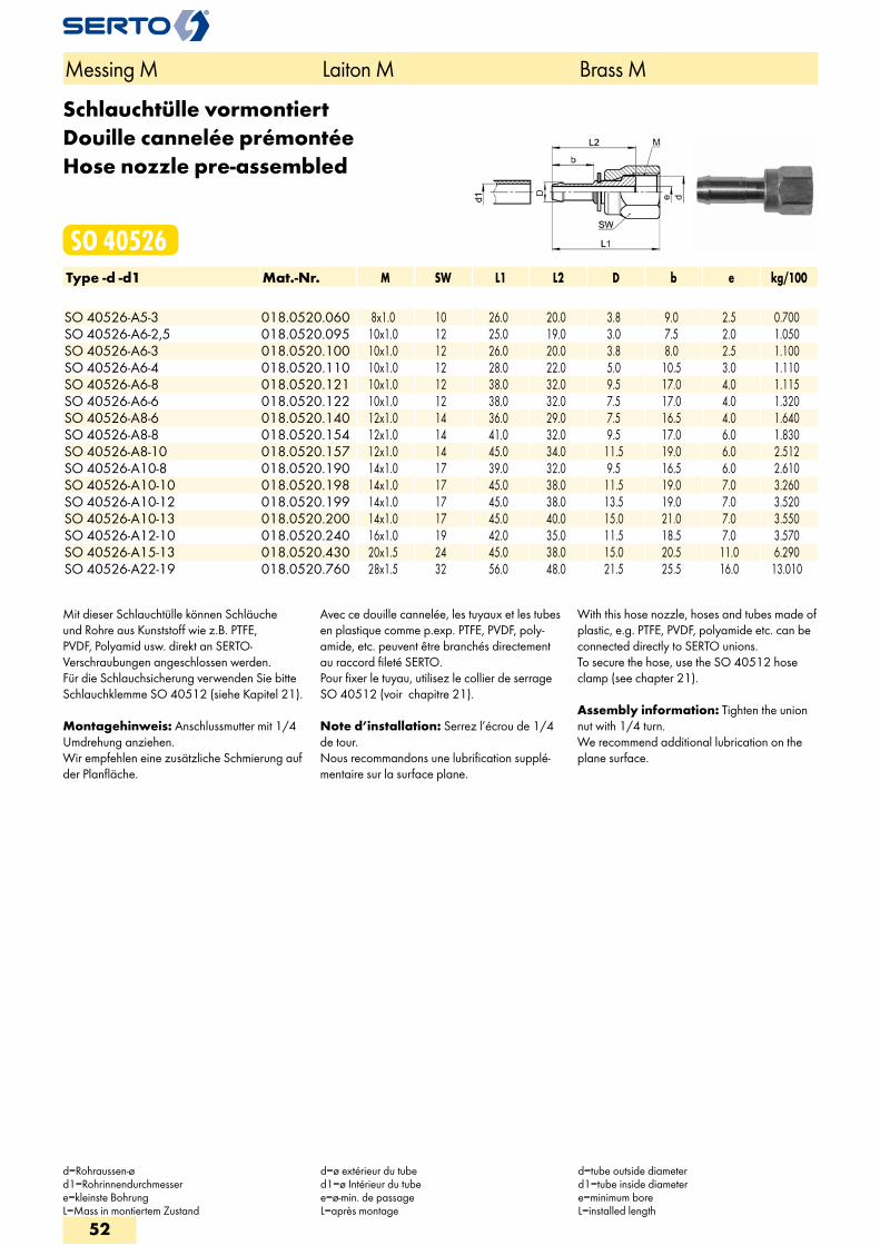
Schlauchtülle vormontiertDouille cannelée prémontéeHose nozzle pre-assembled
SO 40526Type -d -d1 Mat.-Nr. M SW L1 L2 D b e kg/100 SO 40526-A5-3 018.0520.060 8x1.0 10 26.0 20.0 3.8 9.0 2.5 0.700SO 40526-A6-2,5 018.0520.095 10x1.0 12 25.0 19.0 3.0 7.5 2.0 1.050SO 40526-A6-3 018.0520.100 10x1.0 12 26.0 20.0 3.8 8.0 2.5 1.100SO 40526-A6-4 018.0520.110 10x1.0 12 28.0 22.0 5.0 10.5 3.0 1.110SO 40526-A6-8 018.0520.121 10x1.0 12 38.0 32.0 9.5 17.0 4.0 1.115SO 40526-A6-6 018.0520.122 10x1.0 12 38.0 32.0 7.5 17.0 4.0 1.320SO 40526-A8-6 018.0520.140 12x1.0 14 36.0 29.0 7.5 16.5 4.0 1.640SO 40526-A8-8 018.0520.154 12x1.0 14 41.0 32.0 9.5 17.0 6.0 1.830SO 40526-A8-10 018.0520.157 12x1.0 14 45.0 34.0 11.5 19.0 6.0 2.512SO 40526-A10-8 018.0520.190 14x1.0 17 39.0 32.0 9.5 16.5 6.0 2.610SO 40526-A10-10 018.0520.198 14x1.0 17 45.0 38.0 11.5 19.0 7.0 3.260SO 40526-A10-12 018.0520.199 14x1.0 17 45.0 38.0 13.5 19.0 7.0 3.520SO 40526-A10-13 018.0520.200 14x1.0 17 45.0 40.0 15.0 21.0 7.0 3.550SO 40526-A12-10 018.0520.240 16x1.0 19 42.0 35.0 11.5 18.5 7.0 3.570SO 40526-A15-13 018.0520.430 20x1.5 24 45.0 38.0 15.0 20.5 11.0 6.290SO 40526-A22-19 018.0520.760 28x1.5 32 56.0 48.0 21.5 25.5 16.0 13.010
Mit dieser Schlauchtülle können Schläuche und Rohre aus Kunststoff wie z.B. PTFE, PVDF, Polyamid usw. direkt an SERTO-Verschraubungen angeschlossen werden. Für die Schlauchsicherung verwenden Sie bitte Schlauchklemme SO 40512 (siehe Kapitel 21).
Montagehinweis: Anschlussmutter mit 1/4 Umdrehung anziehen. Wir empfehlen eine zusätzliche Schmierung auf der Planfläche.
Avec ce douille cannelée, les tuyaux et les tubes en plastique comme p.exp. PTFE, PVDF, poly-amide, etc. peuvent être branchés directement au raccord fileté SERTO. Pour fixer le tuyau, utilisez le collier de serrage SO 40512 (voir chapitre 21).
Note d’installation: Serrez l’écrou de 1/4 de tour. Nous recommandons une lubrification supplé-mentaire sur la surface plane.
With this hose nozzle, hoses and tubes made of plastic, e.g. PTFE, PVDF, polyamide etc. can be connected directly to SERTO unions. To secure the hose, use the SO 40512 hose clamp (see chapter 21).
Assembly information: Tighten the union nut with 1/4 turn. We recommend additional lubrication on the plane surface.
Messing M Laiton M Brass M
d=Rohraussen-ød1=Rohrinnendurchmessere=kleinste BohrungL=Mass in montiertem Zustand
d=ø extérieur du tubed1=ø Intérieur du tubee=ø-min. de passageL=après montage
d=tube outside diameterd1=tube inside diametere=minimum boreL=installed length
52
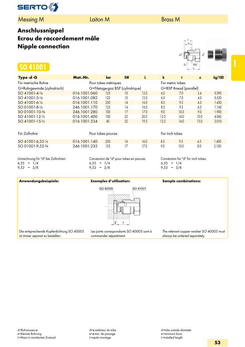
AnschlussnippelEcrou de raccordement mâleNipple connection
SO 41001Type -d -G Mat.-Nr. bar SW L b t e kg/100Für metrische Rohre Pour tubes métriques For metric tubesG=Rohrgewinde (zylindrisch) G=Filetage-gaz BSP (cylindrique) G=BSP thread (parallel)SO 41001-4-1/8 016.1001.060 125 10 12.0 6.0 7.0 3.4 0.590SO 41001-5-1/8 016.1001.082 125 10 12.0 6.0 7.0 4.0 0.530SO 41001-6-1/4 016.1001.110 250 14 16.0 8.5 9.5 4.5 1.430SO 01001-8-1/4 246.1001.170 125 14 16.0 8.5 9.5 6.5 1.160SO 01001-10-3/8 246.1001.280 100 17 17.0 9.0 10.0 9.0 1.900SO 41001-12-1/2 016.1001.400 100 22 20.5 12.5 14.0 10.0 4.060SO 41001-15-1/2 016.1001.534 40 22 19.5 12.5 14.0 13.0 3.010
Für Zollrohre Pour tubes pouces For inch tubes SO 41001-6,35-1/4 016.1001.140 250 14 16.0 8.5 9.5 4.5 1.400SO 01001-9,52-3/8 246.1001.235 125 17 17.0 9.0 10.0 8.0 2.100
Umrechnung für "d" bei Zollrohren:6,35 = 1/49,52 = 3/8
Conversion de "d" pour tubes en pouces:6,35 = 1/49,52 = 3/8
Conversion for "d" for inch tubes:6,35 = 1/49,52 = 3/8
Anwendungsbeispiele: Exemples d’utilisation: Sample combinations:
Die entsprechende Kupferdichtung SO 40005 ist immer separat zu bestellen.
Les joints correspondants SO 40005 sont à commander séparément.
The relevant copper washer SO 40005 must always be ordered separately.
Messing M Laiton M Brass M
d=Rohraussen-øe=kleinste BohrungL=Mass in montiertem Zustand
d=ø extérieur du tubee=ø-min. de passageL=après montage
d=tube outside diametere=minimum boreL=installed length
53
1
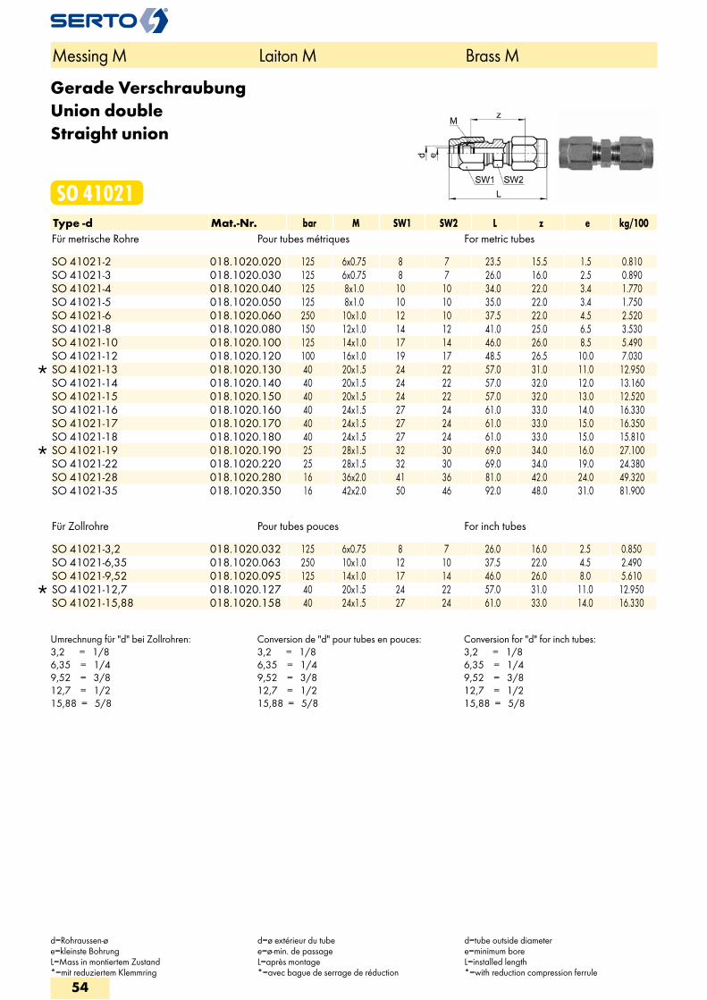
Gerade VerschraubungUnion doubleStraight union
SO 41021Type -d Mat.-Nr. bar M SW1 SW2 L z e kg/100Für metrische Rohre Pour tubes métriques For metric tubes
SO 41021-2 018.1020.020 125 6x0.75 8 7 23.5 15.5 1.5 0.810 SO 41021-3 018.1020.030 125 6x0.75 8 7 26.0 16.0 2.5 0.890 SO 41021-4 018.1020.040 125 8x1.0 10 10 34.0 22.0 3.4 1.770 SO 41021-5 018.1020.050 125 8x1.0 10 10 35.0 22.0 3.4 1.750 SO 41021-6 018.1020.060 250 10x1.0 12 10 37.5 22.0 4.5 2.520 SO 41021-8 018.1020.080 150 12x1.0 14 12 41.0 25.0 6.5 3.530 SO 41021-10 018.1020.100 125 14x1.0 17 14 46.0 26.0 8.5 5.490 SO 41021-12 018.1020.120 100 16x1.0 19 17 48.5 26.5 10.0 7.030
SO 41021-13 018.1020.130 40 20x1.5 24 22 57.0 31.0 11.0 12.950 SO 41021-14 018.1020.140 40 20x1.5 24 22 57.0 32.0 12.0 13.160 SO 41021-15 018.1020.150 40 20x1.5 24 22 57.0 32.0 13.0 12.520 SO 41021-16 018.1020.160 40 24x1.5 27 24 61.0 33.0 14.0 16.330 SO 41021-17 018.1020.170 40 24x1.5 27 24 61.0 33.0 15.0 16.350 SO 41021-18 018.1020.180 40 24x1.5 27 24 61.0 33.0 15.0 15.810
SO 41021-19 018.1020.190 25 28x1.5 32 30 69.0 34.0 16.0 27.100 SO 41021-22 018.1020.220 25 28x1.5 32 30 69.0 34.0 19.0 24.380 SO 41021-28 018.1020.280 16 36x2.0 41 36 81.0 42.0 24.0 49.320 SO 41021-35 018.1020.350 16 42x2.0 50 46 92.0 48.0 31.0 81.900
Für Zollrohre Pour tubes pouces For inch tubes
SO 41021-3,2 018.1020.032 125 6x0.75 8 7 26.0 16.0 2.5 0.850 SO 41021-6,35 018.1020.063 250 10x1.0 12 10 37.5 22.0 4.5 2.490 SO 41021-9,52 018.1020.095 125 14x1.0 17 14 46.0 26.0 8.0 5.610
SO 41021-12,7 018.1020.127 40 20x1.5 24 22 57.0 31.0 11.0 12.950 SO 41021-15,88 018.1020.158 40 24x1.5 27 24 61.0 33.0 14.0 16.330
Umrechnung für "d" bei Zollrohren:3,2 = 1/86,35 = 1/49,52 = 3/812,7 = 1/215,88 = 5/8
Conversion de "d" pour tubes en pouces:3,2 = 1/86,35 = 1/49,52 = 3/812,7 = 1/215,88 = 5/8
Conversion for "d" for inch tubes:3,2 = 1/86,35 = 1/49,52 = 3/812,7 = 1/215,88 = 5/8
Messing M Laiton M Brass M
d=Rohraussen-øe=kleinste BohrungL=Mass in montiertem Zustand*=mit reduziertem Klemmring
d=ø extérieur du tubee=ø-min. de passageL=après montage*=avec bague de serrage de réduction
d=tube outside diametere=minimum boreL=installed length*=with reduction compression ferrule
54
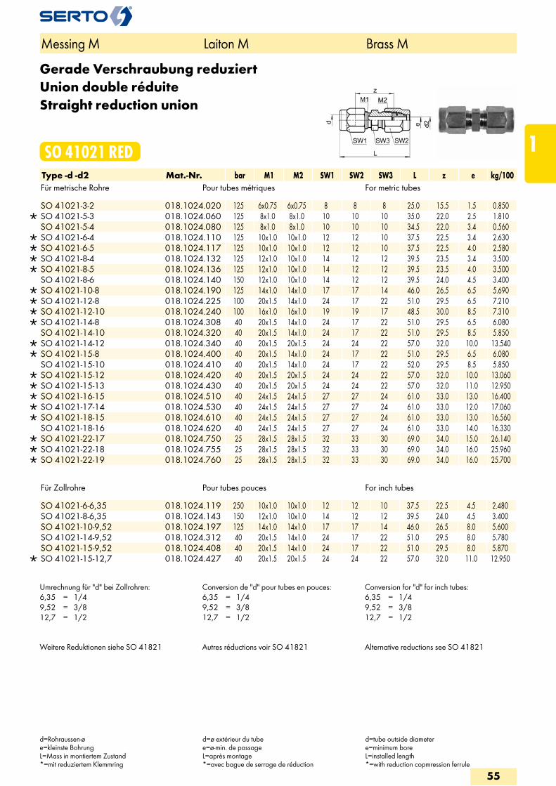
Gerade Verschraubung reduziertUnion double réduiteStraight reduction union
SO 41021 REDType -d -d2 Mat.-Nr. bar M1 M2 SW1 SW2 SW3 L z e kg/100Für metrische Rohre Pour tubes métriques For metric tubes
SO 41021-3-2 018.1024.020 125 6x0.75 6x0.75 8 8 8 25.0 15.5 1.5 0.850 SO 41021-5-3 018.1024.060 125 8x1.0 8x1.0 10 10 10 35.0 22.0 2.5 1.810 SO 41021-5-4 018.1024.080 125 8x1.0 8x1.0 10 10 10 34.5 22.0 3.4 0.560
SO 41021-6-4 018.1024.110 125 10x1.0 10x1.0 12 12 10 37.5 22.5 3.4 2.630 SO 41021-6-5 018.1024.117 125 10x1.0 10x1.0 12 12 10 37.5 22.5 4.0 2.580 SO 41021-8-4 018.1024.132 125 12x1.0 10x1.0 14 12 12 39.5 23.5 3.4 3.500 SO 41021-8-5 018.1024.136 125 12x1.0 10x1.0 14 12 12 39.5 23.5 4.0 3.500 SO 41021-8-6 018.1024.140 150 12x1.0 10x1.0 14 12 12 39.5 24.0 4.5 3.400
SO 41021-10-8 018.1024.190 125 14x1.0 14x1.0 17 17 14 46.0 26.5 6.5 5.690 SO 41021-12-8 018.1024.225 100 20x1.5 14x1.0 24 17 22 51.0 29.5 6.5 7.210 SO 41021-12-10 018.1024.240 100 16x1.0 16x1.0 19 19 17 48.5 30.0 8.5 7.310 SO 41021-14-8 018.1024.308 40 20x1.5 14x1.0 24 17 22 51.0 29.5 6.5 6.080 SO 41021-14-10 018.1024.320 40 20x1.5 14x1.0 24 17 22 51.0 29.5 8.5 5.850
SO 41021-14-12 018.1024.340 40 20x1.5 20x1.5 24 24 22 57.0 32.0 10.0 13.540 SO 41021-15-8 018.1024.400 40 20x1.5 14x1.0 24 17 22 51.0 29.5 6.5 6.080 SO 41021-15-10 018.1024.410 40 20x1.5 14x1.0 24 17 22 52.0 29.5 8.5 5.850
SO 41021-15-12 018.1024.420 40 20x1.5 20x1.5 24 24 22 57.0 32.0 10.0 13.060 SO 41021-15-13 018.1024.430 40 20x1.5 20x1.5 24 24 22 57.0 32.0 11.0 12.950 SO 41021-16-15 018.1024.510 40 24x1.5 24x1.5 27 27 24 61.0 33.0 13.0 16.400 SO 41021-17-14 018.1024.530 40 24x1.5 24x1.5 27 27 24 61.0 33.0 12.0 17.060 SO 41021-18-15 018.1024.610 40 24x1.5 24x1.5 27 27 24 61.0 33.0 13.0 16.560 SO 41021-18-16 018.1024.620 40 24x1.5 24x1.5 27 27 24 61.0 33.0 14.0 16.330
SO 41021-22-17 018.1024.750 25 28x1.5 28x1.5 32 33 30 69.0 34.0 15.0 26.140 SO 41021-22-18 018.1024.755 25 28x1.5 28x1.5 32 33 30 69.0 34.0 16.0 25.960 SO 41021-22-19 018.1024.760 25 28x1.5 28x1.5 32 33 30 69.0 34.0 16.0 25.700
Für Zollrohre Pour tubes pouces For inch tubes
SO 41021-6-6,35 018.1024.119 250 10x1.0 10x1.0 12 12 10 37.5 22.5 4.5 2.480 SO 41021-8-6,35 018.1024.143 150 12x1.0 10x1.0 14 12 12 39.5 24.0 4.5 3.400 SO 41021-10-9,52 018.1024.197 125 14x1.0 14x1.0 17 17 14 46.0 26.5 8.0 5.600 SO 41021-14-9,52 018.1024.312 40 20x1.5 14x1.0 24 17 22 51.0 29.5 8.0 5.780 SO 41021-15-9,52 018.1024.408 40 20x1.5 14x1.0 24 17 22 51.0 29.5 8.0 5.870
SO 41021-15-12,7 018.1024.427 40 20x1.5 20x1.5 24 24 22 57.0 32.0 11.0 12.950
Umrechnung für "d" bei Zollrohren:6,35 = 1/49,52 = 3/812,7 = 1/2
Conversion de "d" pour tubes en pouces:6,35 = 1/49,52 = 3/812,7 = 1/2
Conversion for "d" for inch tubes:6,35 = 1/49,52 = 3/812,7 = 1/2
Weitere Reduktionen siehe SO 41821 Autres réductions voir SO 41821 Alternative reductions see SO 41821
Messing M Laiton M Brass M
d=Rohraussen-øe=kleinste BohrungL=Mass in montiertem Zustand*=mit reduziertem Klemmring
d=ø extérieur du tubee=ø-min. de passageL=après montage*=avec bague de serrage de réduction
d=tube outside diametere=minimum boreL=installed length*=with reduction copmression ferrule
55
1
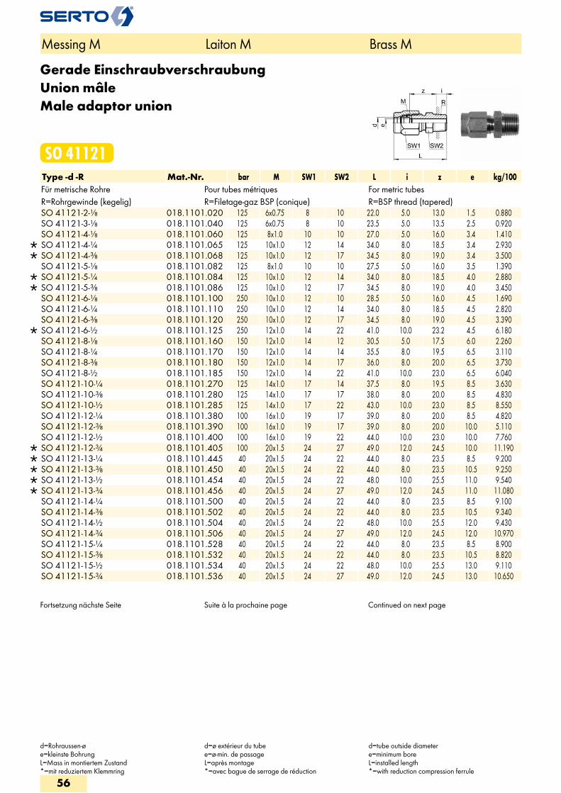
Gerade EinschraubverschraubungUnion mâleMale adaptor union
SO 41121Type -d -R Mat.-Nr. bar M SW1 SW2 L i z e kg/100Für metrische Rohre Pour tubes métriques For metric tubesR=Rohrgewinde (kegelig) R=Filetage-gaz BSP (conique) R=BSP thread (tapered)
SO 41121-2-1/8 018.1101.020 125 6x0.75 8 10 22.0 5.0 13.0 1.5 0.880 SO 41121-3-1/8 018.1101.040 125 6x0.75 8 10 23.5 5.0 13.5 2.5 0.920 SO 41121-4-1/8 018.1101.060 125 8x1.0 10 10 27.0 5.0 16.0 3.4 1.410
SO 41121-4-1/4 018.1101.065 125 10x1.0 12 14 34.0 8.0 18.5 3.4 2.930 SO 41121-4-3/8 018.1101.068 125 10x1.0 12 17 34.5 8.0 19.0 3.4 3.500 SO 41121-5-1/8 018.1101.082 125 8x1.0 10 10 27.5 5.0 16.0 3.5 1.390
SO 41121-5-1/4 018.1101.084 125 10x1.0 12 14 34.0 8.0 18.5 4.0 2.880 SO 41121-5-3/8 018.1101.086 125 10x1.0 12 17 34.5 8.0 19.0 4.0 3.450 SO 41121-6-1/8 018.1101.100 250 10x1.0 12 10 28.5 5.0 16.0 4.5 1.690 SO 41121-6-1/4 018.1101.110 250 10x1.0 12 14 34.0 8.0 18.5 4.5 2.820 SO 41121-6-3/8 018.1101.120 250 10x1.0 12 17 34.5 8.0 19.0 4.5 3.390
SO 41121-6-1/2 018.1101.125 250 12x1.0 14 22 41.0 10.0 23.2 4.5 6.180 SO 41121-8-1/8 018.1101.160 150 12x1.0 14 12 30.5 5.0 17.5 6.0 2.260 SO 41121-8-1/4 018.1101.170 150 12x1.0 14 14 35.5 8.0 19.5 6.5 3.110 SO 41121-8-3/8 018.1101.180 150 12x1.0 14 17 36.0 8.0 20.0 6.5 3.730 SO 41121-8-1/2 018.1101.185 150 12x1.0 14 22 41.0 10.0 23.0 6.5 6.040 SO 41121-10-1/4 018.1101.270 125 14x1.0 17 14 37.5 8.0 19.5 8.5 3.630 SO 41121-10-3/8 018.1101.280 125 14x1.0 17 17 38.0 8.0 20.0 8.5 4.830 SO 41121-10-1/2 018.1101.285 125 14x1.0 17 22 43.0 10.0 23.0 8.5 8.550 SO 41121-12-1/4 018.1101.380 100 16x1.0 19 17 39.0 8.0 20.0 8.5 4.820 SO 41121-12-3/8 018.1101.390 100 16x1.0 19 17 39.0 8.0 20.0 10.0 5.110 SO 41121-12-1/2 018.1101.400 100 16x1.0 19 22 44.0 10.0 23.0 10.0 7.760
SO 41121-12-3/4 018.1101.405 100 20x1.5 24 27 49.0 12.0 24.5 10.0 11.190 SO 41121-13-1/4 018.1101.445 40 20x1.5 24 22 44.0 8.0 23.5 8.5 9.200 SO 41121-13-3/8 018.1101.450 40 20x1.5 24 22 44.0 8.0 23.5 10.5 9.250 SO 41121-13-1/2 018.1101.454 40 20x1.5 24 22 48.0 10.0 25.5 11.0 9.540 SO 41121-13-3/4 018.1101.456 40 20x1.5 24 27 49.0 12.0 24.5 11.0 11.080 SO 41121-14-1/4 018.1101.500 40 20x1.5 24 22 44.0 8.0 23.5 8.5 9.100 SO 41121-14-3/8 018.1101.502 40 20x1.5 24 22 44.0 8.0 23.5 10.5 9.340 SO 41121-14-1/2 018.1101.504 40 20x1.5 24 22 48.0 10.0 25.5 12.0 9.430 SO 41121-14-3/4 018.1101.506 40 20x1.5 24 27 49.0 12.0 24.5 12.0 10.970 SO 41121-15-1/4 018.1101.528 40 20x1.5 24 22 44.0 8.0 23.5 8.5 8.900 SO 41121-15-3/8 018.1101.532 40 20x1.5 24 22 44.0 8.0 23.5 10.5 8.820 SO 41121-15-1/2 018.1101.534 40 20x1.5 24 22 48.0 10.0 25.5 13.0 9.110 SO 41121-15-3/4 018.1101.536 40 20x1.5 24 27 49.0 12.0 24.5 13.0 10.650
Fortsetzung nächste Seite Suite à la prochaine page Continued on next page
Messing M Laiton M Brass M
d=Rohraussen-øe=kleinste BohrungL=Mass in montiertem Zustand*=mit reduziertem Klemmring
d=ø extérieur du tubee=ø-min. de passageL=après montage*=avec bague de serrage de réduction
d=tube outside diametere=minimum boreL=installed length*=with reduction compression ferrule
56
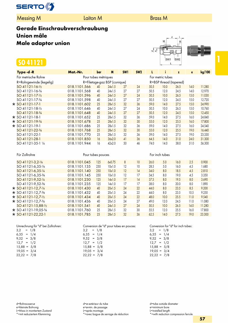
Gerade EinschraubverschraubungUnion mâleMale adaptor union
SO 41121Type -d -R Mat.-Nr. bar M SW1 SW2 L i z e kg/100Für metrische Rohre Pour tubes métriques For metric tubesR=Rohrgewinde (kegelig) R=Filetage-gaz BSP (conique) R=BSP thread (tapered)
SO 41121-16-1/2 018.1101.566 40 24x1.5 27 24 50.5 10.0 26.5 14.0 11.280 SO 41121-16-3/4 018.1101.568 40 24x1.5 27 27 50.5 12.0 24.5 14.0 12.970 SO 41121-17-1/2 018.1101.596 40 24x1.5 27 24 50.5 10.0 26.5 15.0 11.030 SO 41121-17-3/4 018.1101.598 40 24x1.5 27 27 50.5 12.0 24.5 15.0 12.720
SO 41121-17-1 018.1101.602 25 28x1.5 32 36 59.0 14.0 27.5 15.0 24.990 SO 41121-18-1/2 018.1101.646 40 24x1.5 27 24 50.5 10.0 26.5 15.0 10.760 SO 41121-18-3/4 018.1101.648 40 24x1.5 27 27 50.5 12.0 24.5 15.0 12.450
SO 41121-18-1 018.1101.652 25 28x1.5 32 36 59.0 14.0 27.5 16.0 24.840 SO 41121-19-3/4 018.1101.678 25 28x1.5 32 30 55.0 12.0 25.5 16.0 17.800 SO 41121-19-1 018.1101.686 25 28x1.5 32 36 59.0 14.0 27.5 16.0 24.540 SO 41121-22-3/4 018.1101.768 25 28x1.5 32 30 55.0 12.0 25.5 19.0 16.440 SO 41121-22-1 018.1101.770 25 28x1.5 32 36 59.0 14.0 27.5 19.0 23.330 SO 41121-28-1 018.1101.850 16 36x2.0 41 36 64.5 14.0 31.0 24.0 31.300 SO 41121-35-1 1/4 018.1101.944 16 42x2.0 50 46 74.0 14.0 38.0 31.0 56.300
Für Zollrohre Pour tubes pouces For inch tubes
SO 41121-3,2-1/8 018.1101.045 125 6x0.75 8 10 26.0 5.0 16.0 2.5 0.900 SO 41121-6,35-1/8 018.1101.135 250 10x1.0 12 10 28.5 5.0 16.0 4.5 1.680 SO 41121-6,35-1/4 018.1101.140 250 10x1.0 12 14 34.0 8.0 18.5 4.5 2.810 SO 41121-6,35-3/8 018.1101.145 250 10x1.0 12 17 34.5 8.0 19.0 4.5 3.350 SO 41121-9,52-1/4 018.1101.230 125 14x1.0 17 14 37.5 8.0 19.5 8.0 3.690 SO 41121-9,52-3/8 018.1101.235 125 14x1.0 17 17 38.0 8.0 20.0 8.0 1.890
SO 41121-12,7-1/4 018.1101.430 40 20x1.5 24 22 44.0 8.0 23.5 8.5 9.200 SO 41121-12,7-3/8 018.1101.432 40 20x1.5 24 22 44.0 8.0 23.5 10.5 9.250 SO 41121-12,7-1/2 018.1101.434 40 20x1.5 24 22 48.0 10.0 25.5 11.0 9.540 SO 41121-12,7-3/4 018.1101.436 40 20x1.5 24 27 49.0 12.0 24.5 11.0 11.080 SO 41121-15,88-1/2 018.1101.541 40 24x1.5 27 24 50.5 10.0 26.5 14.0 11.280
SO 41121-19,05-3/4 018.1101.760 25 28x1.5 32 30 55.5 12.0 25.5 16.0 17.800 SO 41121-22,22-1 018.1101.785 25 28x1.5 32 36 62.5 14.0 27.5 19.0 23.300
Umrechnung für "d" bei Zollrohren:3,2 = 1/86,35 = 1/49,52 = 3/812,7 = 1/215,88 = 5/819,05 = 3/422,22 = 7/8
Conversion de "d" pour tubes en pouces:3,2 = 1/86,35 = 1/49,52 = 3/812,7 = 1/215,88 = 5/819,05 = 3/422,22 = 7/8
Conversion for "d" for inch tubes:3,2 = 1/86,35 = 1/49,52 = 3/812,7 = 1/215,88 = 5/819,05 = 3/422,22 = 7/8
Messing M Laiton M Brass M
d=Rohraussen-øe=kleinste BohrungL=Mass in montiertem Zustand*=mit reduziertem Klemmring
d=ø extérieur du tubee=ø-min. de passageL=après montage*=avec bague de serrage de réduction
d=tube outside diametere=minimum boreL=installed length*=with reduction compression ferrule
57
1
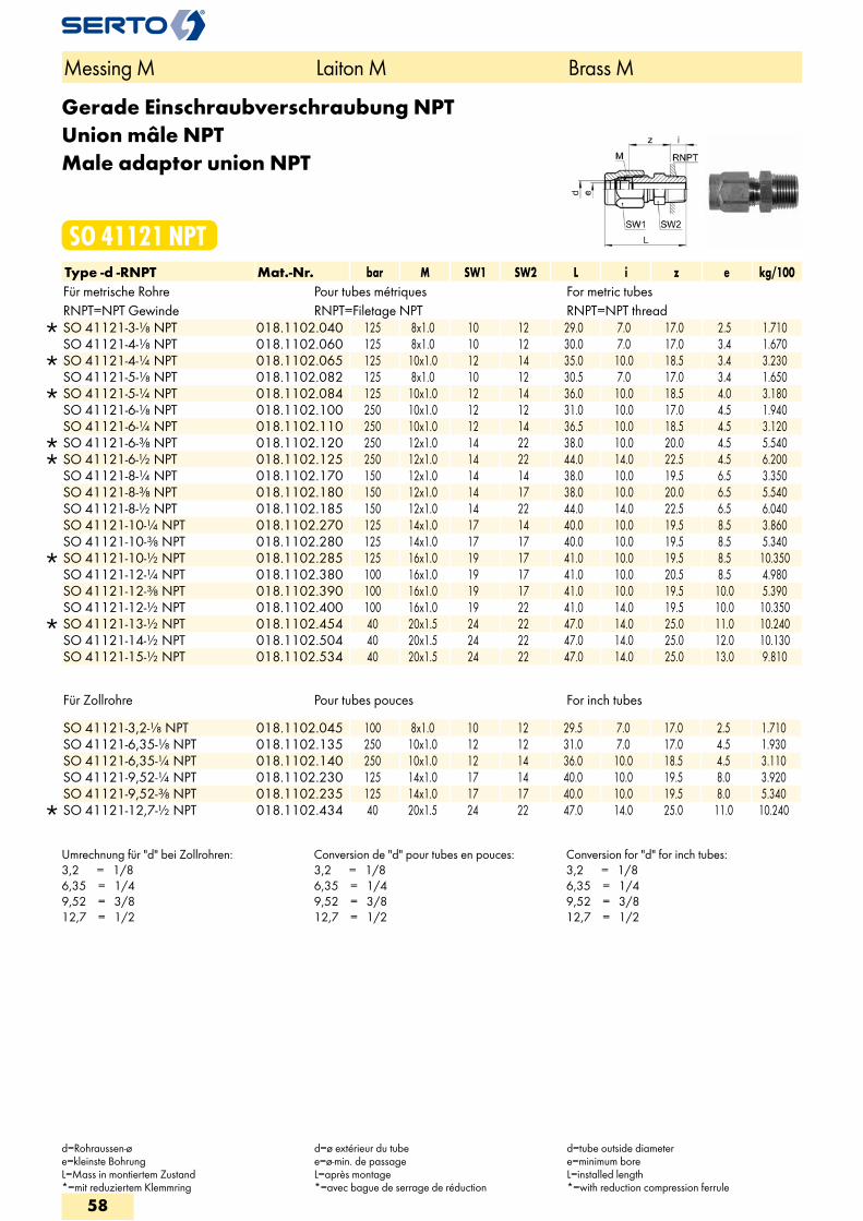
Gerade Einschraubverschraubung NPTUnion mâle NPTMale adaptor union NPT
SO 41121 NPTType -d -RNPT Mat.-Nr. bar M SW1 SW2 L i z e kg/100Für metrische Rohre Pour tubes métriques For metric tubesRNPT=NPT Gewinde RNPT=Filetage NPT RNPT=NPT thread
SO 41121-3-1/8 NPT 018.1102.040 125 8x1.0 10 12 29.0 7.0 17.0 2.5 1.710 SO 41121-4-1/8 NPT 018.1102.060 125 8x1.0 10 12 30.0 7.0 17.0 3.4 1.670
SO 41121-4-1/4 NPT 018.1102.065 125 10x1.0 12 14 35.0 10.0 18.5 3.4 3.230 SO 41121-5-1/8 NPT 018.1102.082 125 8x1.0 10 12 30.5 7.0 17.0 3.4 1.650
SO 41121-5-1/4 NPT 018.1102.084 125 10x1.0 12 14 36.0 10.0 18.5 4.0 3.180 SO 41121-6-1/8 NPT 018.1102.100 250 10x1.0 12 12 31.0 10.0 17.0 4.5 1.940 SO 41121-6-1/4 NPT 018.1102.110 250 10x1.0 12 14 36.5 10.0 18.5 4.5 3.120
SO 41121-6-3/8 NPT 018.1102.120 250 12x1.0 14 22 38.0 10.0 20.0 4.5 5.540 SO 41121-6-1/2 NPT 018.1102.125 250 12x1.0 14 22 44.0 14.0 22.5 4.5 6.200 SO 41121-8-1/4 NPT 018.1102.170 150 12x1.0 14 14 38.0 10.0 19.5 6.5 3.350 SO 41121-8-3/8 NPT 018.1102.180 150 12x1.0 14 17 38.0 10.0 20.0 6.5 5.540 SO 41121-8-1/2 NPT 018.1102.185 150 12x1.0 14 22 44.0 14.0 22.5 6.5 6.040 SO 41121-10-1/4 NPT 018.1102.270 125 14x1.0 17 14 40.0 10.0 19.5 8.5 3.860 SO 41121-10-3/8 NPT 018.1102.280 125 14x1.0 17 17 40.0 10.0 19.5 8.5 5.340
SO 41121-10-1/2 NPT 018.1102.285 125 16x1.0 19 17 41.0 10.0 19.5 8.5 10.350 SO 41121-12-1/4 NPT 018.1102.380 100 16x1.0 19 17 41.0 10.0 20.5 8.5 4.980 SO 41121-12-3/8 NPT 018.1102.390 100 16x1.0 19 17 41.0 10.0 19.5 10.0 5.390 SO 41121-12-1/2 NPT 018.1102.400 100 16x1.0 19 22 41.0 14.0 19.5 10.0 10.350
SO 41121-13-1/2 NPT 018.1102.454 40 20x1.5 24 22 47.0 14.0 25.0 11.0 10.240 SO 41121-14-1/2 NPT 018.1102.504 40 20x1.5 24 22 47.0 14.0 25.0 12.0 10.130 SO 41121-15-1/2 NPT 018.1102.534 40 20x1.5 24 22 47.0 14.0 25.0 13.0 9.810
Für Zollrohre Pour tubes pouces For inch tubes
SO 41121-3,2-1/8 NPT 018.1102.045 100 8x1.0 10 12 29.5 7.0 17.0 2.5 1.710 SO 41121-6,35-1/8 NPT 018.1102.135 250 10x1.0 12 12 31.0 7.0 17.0 4.5 1.930 SO 41121-6,35-1/4 NPT 018.1102.140 250 10x1.0 12 14 36.0 10.0 18.5 4.5 3.110 SO 41121-9,52-1/4 NPT 018.1102.230 125 14x1.0 17 14 40.0 10.0 19.5 8.0 3.920 SO 41121-9,52-3/8 NPT 018.1102.235 125 14x1.0 17 17 40.0 10.0 19.5 8.0 5.340
SO 41121-12,7-1/2 NPT 018.1102.434 40 20x1.5 24 22 47.0 14.0 25.0 11.0 10.240
Umrechnung für "d" bei Zollrohren:3,2 = 1/86,35 = 1/49,52 = 3/812,7 = 1/2
Conversion de "d" pour tubes en pouces:3,2 = 1/86,35 = 1/49,52 = 3/812,7 = 1/2
Conversion for "d" for inch tubes:3,2 = 1/86,35 = 1/49,52 = 3/812,7 = 1/2
Messing M Laiton M Brass M
d=Rohraussen-øe=kleinste BohrungL=Mass in montiertem Zustand*=mit reduziertem Klemmring
d=ø extérieur du tubee=ø-min. de passageL=après montage*=avec bague de serrage de réduction
d=tube outside diametere=minimum boreL=installed length*=with reduction compression ferrule
58
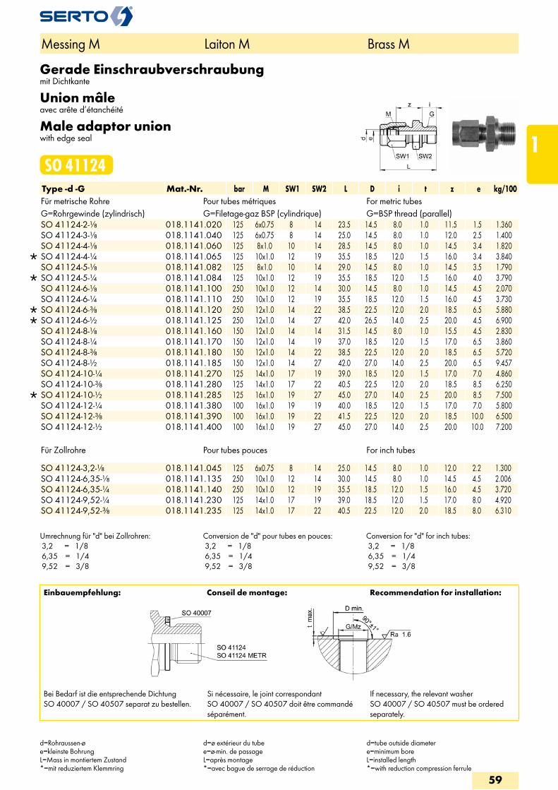
Gerade Einschraubverschraubungmit Dichtkante
Union mâleavec arête d’étanchéité
Male adaptor unionwith edge seal
SO 41124Type -d -G Mat.-Nr. bar M SW1 SW2 L D i t z e kg/100Für metrische Rohre Pour tubes métriques For metric tubesG=Rohrgewinde (zylindrisch) G=Filetage-gaz BSP (cylindrique) G=BSP thread (parallel)
SO 41124-2-1/8 018.1141.020 125 6x0.75 8 14 23.5 14.5 8.0 1.0 11.5 1.5 1.360 SO 41124-3-1/8 018.1141.040 125 6x0.75 8 14 25.0 14.5 8.0 1.0 12.0 2.5 1.400 SO 41124-4-1/8 018.1141.060 125 8x1.0 10 14 28.5 14.5 8.0 1.0 14.5 3.4 1.820
SO 41124-4-1/4 018.1141.065 125 10x1.0 12 19 35.5 18.5 12.0 1.5 16.0 3.4 3.840 SO 41124-5-1/8 018.1141.082 125 8x1.0 10 14 29.0 14.5 8.0 1.0 14.5 3.5 1.790
SO 41124-5-1/4 018.1141.084 125 10x1.0 12 19 35.5 18.5 12.0 1.5 16.0 4.0 3.790 SO 41124-6-1/8 018.1141.100 250 10x1.0 12 14 30.0 14.5 8.0 1.0 14.5 4.5 2.070 SO 41124-6-1/4 018.1141.110 250 10x1.0 12 19 35.5 18.5 12.0 1.5 16.0 4.5 3.730
SO 41124-6-3/8 018.1141.120 250 12x1.0 14 22 38.5 22.5 12.0 2.0 18.5 6.5 5.880 SO 41124-6-1/2 018.1141.125 250 12x1.0 14 27 42.0 26.5 14.0 2.5 20.0 4.5 6.900 SO 41124-8-1/8 018.1141.160 150 12x1.0 14 14 31.5 14.5 8.0 1.0 15.5 4.5 2.830 SO 41124-8-1/4 018.1141.170 150 12x1.0 14 19 37.0 18.5 12.0 1.5 17.0 6.5 3.860 SO 41124-8-3/8 018.1141.180 150 12x1.0 14 22 38.5 22.5 12.0 2.0 18.5 6.5 5.720 SO 41124-8-1/2 018.1141.185 150 12x1.0 14 27 42.0 27.0 14.0 2.5 20.0 6.5 9.457 SO 41124-10-1/4 018.1141.270 125 14x1.0 17 19 39.0 18.5 12.0 1.5 17.0 7.0 4.860 SO 41124-10-3/8 018.1141.280 125 14x1.0 17 22 40.5 22.5 12.0 2.0 18.5 8.5 6.250
SO 41124-10-1/2 018.1141.285 125 16x1.0 19 27 45.0 27.0 14.0 2.5 20.0 8.5 7.500 SO 41124-12-1/4 018.1141.380 100 16x1.0 19 19 40.0 18.5 12.0 1.5 17.0 7.0 5.800 SO 41124-12-3/8 018.1141.390 100 16x1.0 19 22 41.5 22.5 12.0 2.0 18.5 10.0 6.500 SO 41124-12-1/2 018.1141.400 100 16x1.0 19 27 45.0 27.0 14.0 2.5 20.0 10.0 7.200
Für Zollrohre Pour tubes pouces For inch tubes SO 41124-3,2-1/8 018.1141.045 125 6x0.75 8 14 25.0 14.5 8.0 1.0 12.0 2.2 1.300SO 41124-6,35-1/8 018.1141.135 250 10x1.0 12 14 30.0 14.5 8.0 1.0 14.5 4.5 2.006SO 41124-6,35-1/4 018.1141.140 250 10x1.0 12 19 35.5 18.5 12.0 1.5 16.0 4.5 3.720SO 41124-9,52-1/4 018.1141.230 125 14x1.0 17 19 39.0 18.5 12.0 1.5 17.0 8.0 4.920SO 41124-9,52-3/8 018.1141.235 125 14x1.0 17 22 40.5 22.5 12.0 2.0 18.5 8.0 6.310
Umrechnung für "d" bei Zollrohren: 3,2 = 1/8 6,35 = 1/4 9,52 = 3/8
Conversion de "d" pour tubes en pouces: 3,2 = 1/8 6,35 = 1/4 9,52 = 3/8
Conversion for "d" for inch tubes: 3,2 = 1/8 6,35 = 1/4 9,52 = 3/8
Messing M Laiton M Brass M
d=Rohraussen-øe=kleinste BohrungL=Mass in montiertem Zustand*=mit reduziertem Klemmring
d=ø extérieur du tubee=ø-min. de passageL=après montage*=avec bague de serrage de réduction
d=tube outside diametere=minimum boreL=installed length*=with reduction compression ferrule
Einbauempfehlung: Conseil de montage: Recommendation for installation:
Bei Bedarf ist die entsprechende Dichtung SO 40007 / SO 40507 separat zu bestellen.
Si nécessaire, le joint correspondant SO 40007 / SO 40507 doit être commandé séparément.
If necessary, the relevant washer SO 40007 / SO 40507 must be ordered separately.
59
1
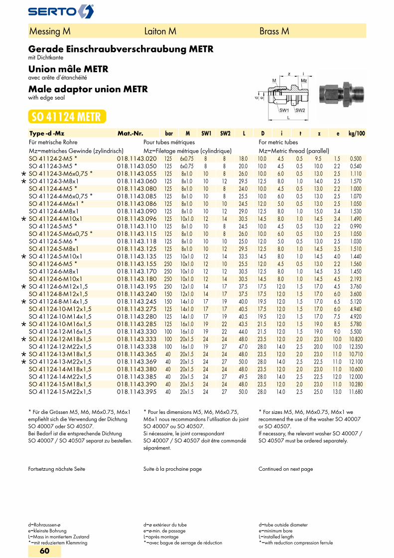
Gerade Einschraubverschraubung METRmit Dichtkante
Union mâle METRavec arête d’étanchéité
Male adaptor union METRwith edge seal
SO 41124 METRType -d -Mz Mat.-Nr. bar M SW1 SW2 L D i t z e kg/100Für metrische Rohre Pour tubes métriques For metric tubesMz=metrisches Gewinde (zylindrisch) Mz=Filetage métrique (cylindrique) Mz=Metric thread (parallel)
SO 41124-2-M5 * 018.1143.020 125 6x0.75 8 8 18.0 10.0 4.5 0.5 9.5 1.5 0.500 SO 41124-3-M5 * 018.1143.050 125 6x0.75 8 8 20.0 10.0 4.5 0.5 10.0 2.2 0.540
SO 41124-3-M6x0,75 * 018.1143.055 125 8x1.0 10 8 26.0 10.0 6.0 0.5 13.0 2.5 1.110 SO 41124-3-M8x1 018.1143.060 125 8x1.0 10 12 29.5 12.5 8.0 1.0 14.0 2.5 1.570 SO 41124-4-M5 * 018.1143.080 125 8x1.0 10 8 24.0 10.0 4.5 0.5 13.0 2.2 1.000 SO 41124-4-M6x0,75 * 018.1143.085 125 8x1.0 10 8 25.5 10.0 6.0 0.5 13.0 2.5 1.070 SO 41124-4-M6x1 * 018.1143.086 125 8x1.0 10 10 24.5 12.0 5.0 0.5 13.0 2.5 1.050 SO 41124-4-M8x1 018.1143.090 125 8x1.0 10 12 29.0 12.5 8.0 1.0 15.0 3.4 1.530
SO 41124-4-M10x1 018.1143.096 125 10x1.0 12 14 30.5 14.5 8.0 1.0 14.5 3.4 1.490 SO 41124-5-M5 * 018.1143.110 125 8x1.0 10 8 24.5 10.0 4.5 0.5 13.0 2.2 0.990 SO 41124-5-M6x0,75 * 018.1143.115 125 8x1.0 10 8 26.0 10.0 6.0 0.5 13.0 2.5 1.050 SO 41124-5-M6 * 018.1143.118 125 8x1.0 10 10 25.0 12.0 5.0 0.5 13.0 2.5 1.030 SO 41124-5-M8x1 018.1143.125 125 8x1.0 10 12 29.5 12.5 8.0 1.0 14.5 3.5 1.510
SO 41124-5-M10x1 018.1143.135 125 10x1.0 12 14 33.5 14.5 8.0 1.0 14.5 4.0 1.440 SO 41124-6-M5 * 018.1143.155 250 10x1.0 12 10 25.5 12.0 4.5 0.5 13.0 2.2 1.560 SO 41124-6-M8x1 018.1143.170 250 10x1.0 12 12 30.5 12.5 8.0 1.0 14.5 3.5 1.450 SO 41124-6-M10x1 018.1143.180 250 10x1.0 12 14 30.5 14.5 8.0 1.0 14.5 4.5 2.193
SO 41124-6-M12x1,5 018.1143.195 250 12x1.0 14 17 37.5 17.5 12.0 1.5 17.0 4.5 3.760 SO 41124-8-M12x1,5 018.1143.240 150 12x1.0 14 17 37.5 17.5 12.0 1.5 17.0 6.0 3.600
SO 41124-8-M14x1,5 018.1143.245 150 14x1.0 17 19 40.0 19.5 12.0 1.5 17.0 6.5 5.120 SO 41124-10-M12x1,5 018.1143.275 125 14x1.0 17 17 40.5 17.5 12.0 1.5 17.0 6.0 4.940 SO 41124-10-M14x1,5 018.1143.280 125 14x1.0 17 19 40.5 19.5 12.0 1.5 17.0 7.5 4.920
SO 41124-10-M16x1,5 018.1143.285 125 16x1.0 19 22 43.5 21.5 12.0 1.5 19.0 8.5 5.780 SO 41124-12-M16x1,5 018.1143.330 100 16x1.0 19 22 44.0 21.5 12.0 1.5 19.0 9.0 5.500
SO 41124-12-M18x1,5 018.1143.333 100 20x1.5 24 24 48.0 23.5 12.0 2.0 23.0 10.0 10.820 SO 41124-12-M22x1,5 018.1143.338 100 16x1.0 19 27 47.0 28.0 14.0 2.5 20.0 10.0 12.350
SO 41124-13-M18x1,5 018.1143.365 40 20x1.5 24 24 48.0 23.5 12.0 2.0 23.0 11.0 10.710 SO 41124-13-M22x1,5 018.1143.369 40 20x1.5 24 27 50.0 28.0 14.0 2.5 22.5 11.0 12.100 SO 41124-14-M18x1,5 018.1143.380 40 20x1.5 24 24 48.0 23.5 12.0 2.0 23.0 11.0 10.600 SO 41124-14-M22x1,5 018.1143.385 40 20x1.5 24 27 49.5 28.0 14.0 2.5 22.5 12.0 12.000 SO 41124-15-M18x1,5 018.1143.390 40 20x1.5 24 24 48.0 23.5 12.0 2.0 23.0 11.0 10.280 SO 41124-15-M22x1,5 018.1143.395 40 20x1.5 24 27 50.0 28.0 14.0 2.5 25.0 13.0 11.680
* Für die Grössen M5, M6, M6x0.75, M6x1 empfiehlt sich die Verwendung der Dichtung SO 40007 oder SO 40507.Bei Bedarf ist die entsprechende Dichtung SO 40007 / SO 40507 separat zu bestellen.
* Pour les dimensions M5, M6, M6x0.75, M6x1 nous recommandons l’utilisation du joint SO 40007 ou SO 40507.Si nécessaire, le joint correspondant SO 40007 / SO 40507 doit être commandé séparément.
* For sizes M5, M6, M6x0.75, M6x1 we recommend the use of the washer SO 40007 or SO 40507.If necessary, the relevant washer SO 40007 / SO 40507 must be ordered separately.
Fortsetzung nächste Seite Suite à la prochaine page Continued on next page
Messing M Laiton M Brass M
d=Rohraussen-øe=kleinste BohrungL=Mass in montiertem Zustand*=mit reduziertem Klemmring
d=ø extérieur du tubee=ø-min. de passageL=après montage*=avec bague de serrage de réduction
d=tube outside diametere=minimum boreL=installed length*=with reduction compression ferrule
60
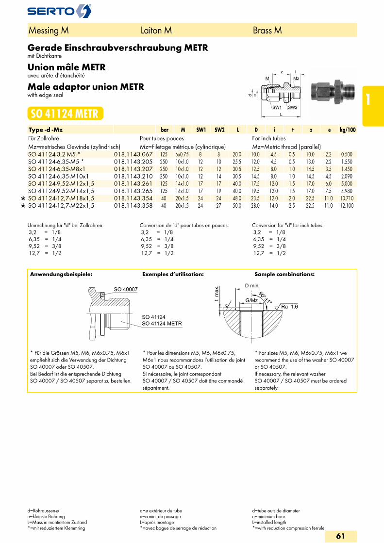
Gerade Einschraubverschraubung METRmit Dichtkante
Union mâle METRavec arête d’étanchéité
Male adaptor union METRwith edge seal
SO 41124 METRType -d -Mz bar M SW1 SW2 L D i t z e kg/100Für Zollrohre Pour tubes pouces For inch tubesMz=metrisches Gewinde (zylindrisch) Mz=Filetage métrique (cylindrique) Mz=Metric thread (parallel)
SO 41124-3,2-M5 * 018.1143.067 125 6x0.75 8 8 20.0 10.0 4.5 0.5 10.0 2.2 0.500 SO 41124-6,35-M5 * 018.1143.205 250 10x1.0 12 10 25.5 12.0 4.5 0.5 13.0 2.2 1.550 SO 41124-6,35-M8x1 018.1143.207 250 10x1.0 12 12 30.5 12.5 8.0 1.0 14.5 3.5 1.450 SO 41124-6,35-M10x1 018.1143.210 250 10x1.0 12 14 30.5 14.5 8.0 1.0 14.5 4.5 2.090 SO 41124-9,52-M12x1,5 018.1143.261 125 14x1.0 17 17 40.0 17.5 12.0 1.5 17.0 6.0 5.000 SO 41124-9,52-M14x1,5 018.1143.265 125 14x1.0 17 19 40.0 19.5 12.0 1.5 17.0 7.5 4.980
SO 41124-12,7-M18x1,5 018.1143.354 40 20x1.5 24 24 48.0 23.5 12.0 2.0 22.5 11.0 10.710 SO 41124-12,7-M22x1,5 018.1143.358 40 20x1.5 24 27 50.0 28.0 14.0 2.5 22.5 11.0 12.100
Umrechnung für "d" bei Zollrohren: 3,2 = 1/8 6,35 = 1/4 9,52 = 3/8 12,7 = 1/2
Conversion de "d" pour tubes en pouces: 3,2 = 1/8 6,35 = 1/4 9,52 = 3/8 12,7 = 1/2
Conversion for "d" for inch tubes: 3,2 = 1/8 6,35 = 1/4 9,52 = 3/8 12,7 = 1/2
Anwendungsbeispiele: Exemples d’utilisation: Sample combinations:
* Für die Grössen M5, M6, M6x0.75, M6x1 empfiehlt sich die Verwendung der Dichtung SO 40007 oder SO 40507.Bei Bedarf ist die entsprechende Dichtung SO 40007 / SO 40507 separat zu bestellen.
* Pour les dimensions M5, M6, M6x0.75, M6x1 nous recommandons l’utilisation du joint SO 40007 ou SO 40507.Si nécessaire, le joint correspondant SO 40007 / SO 40507 doit être commandé séparément.
* For sizes M5, M6, M6x0.75, M6x1 we recommend the use of the washer SO 40007 or SO 40507.If necessary, the relevant washer SO 40007 / SO 40507 must be ordered separately.
Messing M Laiton M Brass M
d=Rohraussen-øe=kleinste BohrungL=Mass in montiertem Zustand*=mit reduziertem Klemmring
d=ø extérieur du tubee=ø-min. de passageL=après montage*=avec bague de serrage de réduction
d=tube outside diametere=minimum boreL=installed length*=with reduction compression ferrule
61
1
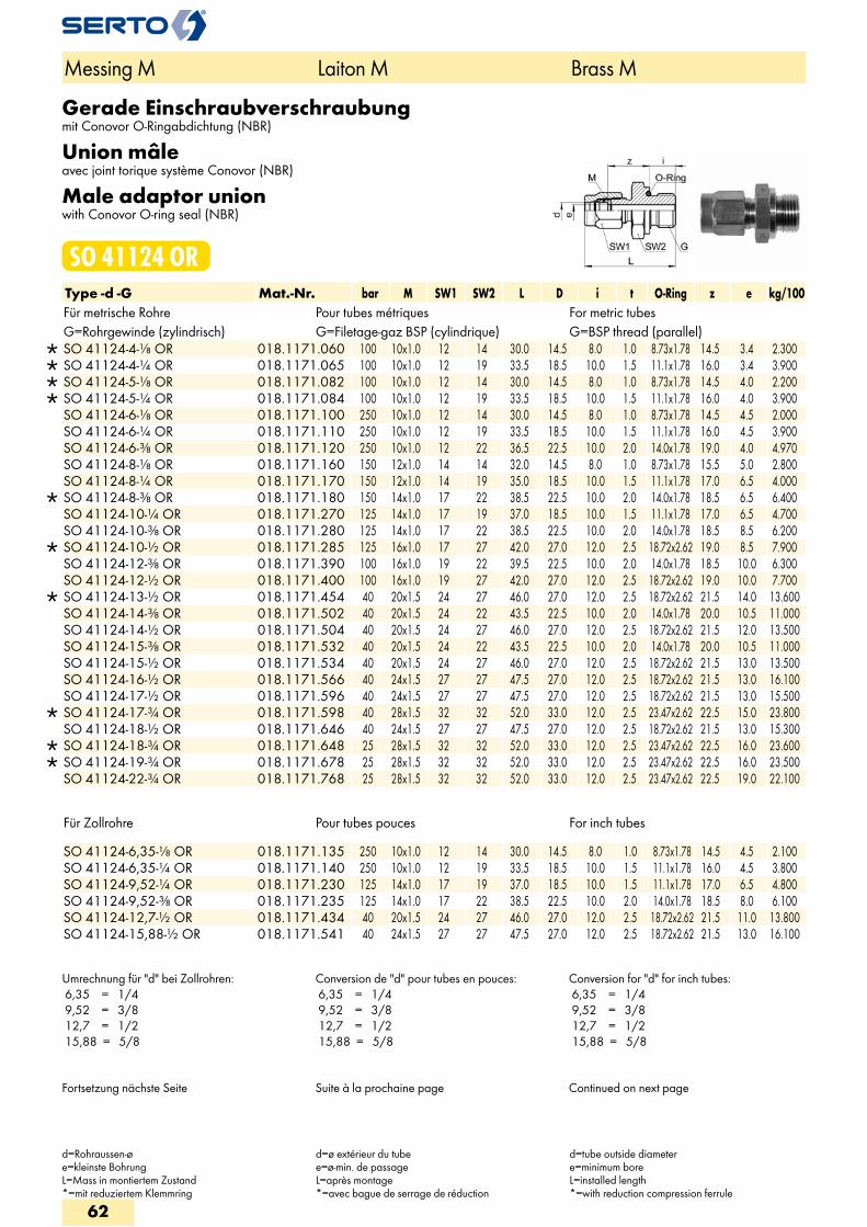
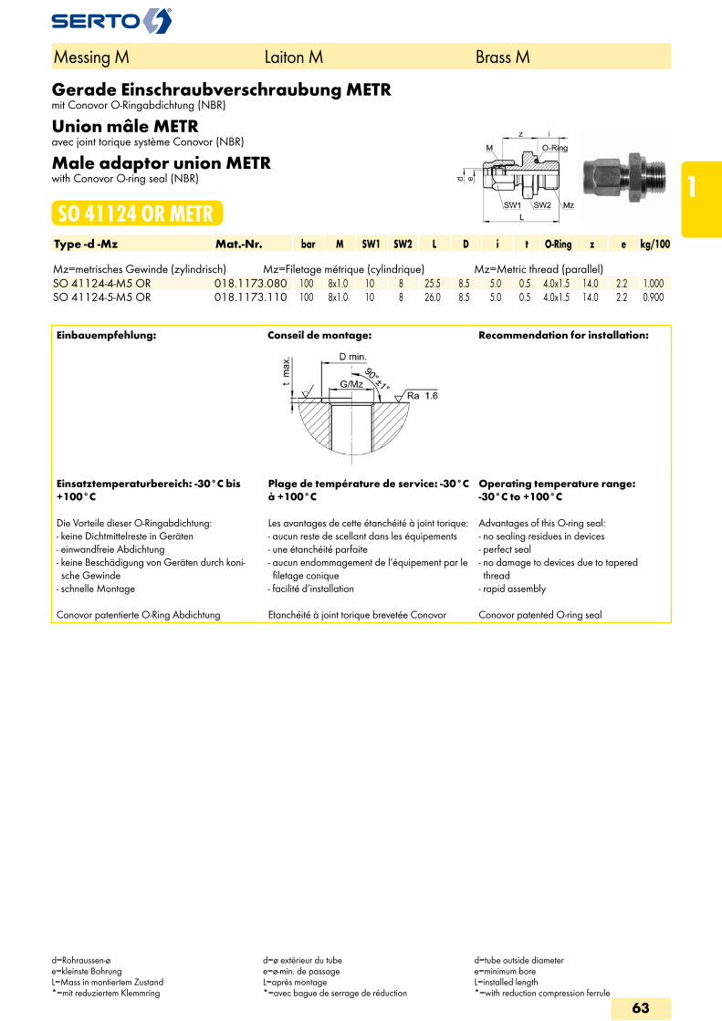
Gerade Einschraubverschraubungmit Conovor O-Ringabdichtung (NBR)
Union mâleavec joint torique système Conovor (NBR)
Male adaptor unionwith Conovor O-ring seal (NBR)
SO 41124 ORType -d -G Mat.-Nr. bar M SW1 SW2 L D i t O-Ring z e kg/100Für metrische Rohre Pour tubes métriques For metric tubesG=Rohrgewinde (zylindrisch) G=Filetage-gaz BSP (cylindrique) G=BSP thread (parallel)
SO 41124-4-1/8 OR 018.1171.060 100 10x1.0 12 14 30.0 14.5 8.0 1.0 8.73x1.78 14.5 3.4 2.300 SO 41124-4-1/4 OR 018.1171.065 100 10x1.0 12 19 33.5 18.5 10.0 1.5 11.1x1.78 16.0 3.4 3.900 SO 41124-5-1/8 OR 018.1171.082 100 10x1.0 12 14 30.0 14.5 8.0 1.0 8.73x1.78 14.5 4.0 2.200 SO 41124-5-1/4 OR 018.1171.084 100 10x1.0 12 19 33.5 18.5 10.0 1.5 11.1x1.78 16.0 4.0 3.900 SO 41124-6-1/8 OR 018.1171.100 250 10x1.0 12 14 30.0 14.5 8.0 1.0 8.73x1.78 14.5 4.5 2.000 SO 41124-6-1/4 OR 018.1171.110 250 10x1.0 12 19 33.5 18.5 10.0 1.5 11.1x1.78 16.0 4.5 3.900 SO 41124-6-3/8 OR 018.1171.120 250 10x1.0 12 22 36.5 22.5 10.0 2.0 14.0x1.78 19.0 4.0 4.970 SO 41124-8-1/8 OR 018.1171.160 150 12x1.0 14 14 32.0 14.5 8.0 1.0 8.73x1.78 15.5 5.0 2.800 SO 41124-8-1/4 OR 018.1171.170 150 12x1.0 14 19 35.0 18.5 10.0 1.5 11.1x1.78 17.0 6.5 4.000
SO 41124-8-3/8 OR 018.1171.180 150 14x1.0 17 22 38.5 22.5 10.0 2.0 14.0x1.78 18.5 6.5 6.400 SO 41124-10-1/4 OR 018.1171.270 125 14x1.0 17 19 37.0 18.5 10.0 1.5 11.1x1.78 17.0 6.5 4.700 SO 41124-10-3/8 OR 018.1171.280 125 14x1.0 17 22 38.5 22.5 10.0 2.0 14.0x1.78 18.5 8.5 6.200
SO 41124-10-1/2 OR 018.1171.285 125 16x1.0 17 27 42.0 27.0 12.0 2.5 18.72x2.62 19.0 8.5 7.900 SO 41124-12-3/8 OR 018.1171.390 100 16x1.0 19 22 39.5 22.5 10.0 2.0 14.0x1.78 18.5 10.0 6.300 SO 41124-12-1/2 OR 018.1171.400 100 16x1.0 19 27 42.0 27.0 12.0 2.5 18.72x2.62 19.0 10.0 7.700
SO 41124-13-1/2 OR 018.1171.454 40 20x1.5 24 27 46.0 27.0 12.0 2.5 18.72x2.62 21.5 14.0 13.600 SO 41124-14-3/8 OR 018.1171.502 40 20x1.5 24 22 43.5 22.5 10.0 2.0 14.0x1.78 20.0 10.5 11.000 SO 41124-14-1/2 OR 018.1171.504 40 20x1.5 24 27 46.0 27.0 12.0 2.5 18.72x2.62 21.5 12.0 13.500 SO 41124-15-3/8 OR 018.1171.532 40 20x1.5 24 22 43.5 22.5 10.0 2.0 14.0x1.78 20.0 10.5 11.000 SO 41124-15-1/2 OR 018.1171.534 40 20x1.5 24 27 46.0 27.0 12.0 2.5 18.72x2.62 21.5 13.0 13.500 SO 41124-16-1/2 OR 018.1171.566 40 24x1.5 27 27 47.5 27.0 12.0 2.5 18.72x2.62 21.5 13.0 16.100 SO 41124-17-1/2 OR 018.1171.596 40 24x1.5 27 27 47.5 27.0 12.0 2.5 18.72x2.62 21.5 13.0 15.500
SO 41124-17-3/4 OR 018.1171.598 40 28x1.5 32 32 52.0 33.0 12.0 2.5 23.47x2.62 22.5 15.0 23.800 SO 41124-18-1/2 OR 018.1171.646 40 24x1.5 27 27 47.5 27.0 12.0 2.5 18.72x2.62 21.5 13.0 15.300
SO 41124-18-3/4 OR 018.1171.648 25 28x1.5 32 32 52.0 33.0 12.0 2.5 23.47x2.62 22.5 16.0 23.600 SO 41124-19-3/4 OR 018.1171.678 25 28x1.5 32 32 52.0 33.0 12.0 2.5 23.47x2.62 22.5 16.0 23.500 SO 41124-22-3/4 OR 018.1171.768 25 28x1.5 32 32 52.0 33.0 12.0 2.5 23.47x2.62 22.5 19.0 22.100
Für Zollrohre Pour tubes pouces For inch tubes
SO 41124-6,35-1/8 OR 018.1171.135 250 10x1.0 12 14 30.0 14.5 8.0 1.0 8.73x1.78 14.5 4.5 2.100 SO 41124-6,35-1/4 OR 018.1171.140 250 10x1.0 12 19 33.5 18.5 10.0 1.5 11.1x1.78 16.0 4.5 3.800 SO 41124-9,52-1/4 OR 018.1171.230 125 14x1.0 17 19 37.0 18.5 10.0 1.5 11.1x1.78 17.0 6.5 4.800 SO 41124-9,52-3/8 OR 018.1171.235 125 14x1.0 17 22 38.5 22.5 10.0 2.0 14.0x1.78 18.5 8.0 6.100 SO 41124-12,7-1/2 OR 018.1171.434 40 20x1.5 24 27 46.0 27.0 12.0 2.5 18.72x2.62 21.5 11.0 13.800 SO 41124-15,88-1/2 OR 018.1171.541 40 24x1.5 27 27 47.5 27.0 12.0 2.5 18.72x2.62 21.5 13.0 16.100
Umrechnung für "d" bei Zollrohren: 6,35 = 1/4 9,52 = 3/8 12,7 = 1/2 15,88 = 5/8
Conversion de "d" pour tubes en pouces: 6,35 = 1/4 9,52 = 3/8 12,7 = 1/2 15,88 = 5/8
Conversion for "d" for inch tubes: 6,35 = 1/4 9,52 = 3/8 12,7 = 1/2 15,88 = 5/8
Fortsetzung nächste Seite Suite à la prochaine page Continued on next page
Messing M Laiton M Brass M
d=Rohraussen-øe=kleinste BohrungL=Mass in montiertem Zustand*=mit reduziertem Klemmring
d=ø extérieur du tubee=ø-min. de passageL=après montage*=avec bague de serrage de réduction
d=tube outside diametere=minimum boreL=installed length*=with reduction compression ferrule
62
Gerade Einschraubverschraubung METRmit Conovor O-Ringabdichtung (NBR)
Union mâle METRavec joint torique système Conovor (NBR)
Male adaptor union METRwith Conovor O-ring seal (NBR)
SO 41124 OR METRType -d -Mz Mat.-Nr. bar M SW1 SW2 L D i t O-Ring z e kg/100 Mz=metrisches Gewinde (zylindrisch) Mz=Filetage métrique (cylindrique) Mz=Metric thread (parallel)SO 41124-4-M5 OR 018.1173.080 100 8x1.0 10 8 25.5 8.5 5.0 0.5 4.0x1.5 14.0 2.2 1.000SO 41124-5-M5 OR 018.1173.110 100 8x1.0 10 8 26.0 8.5 5.0 0.5 4.0x1.5 14.0 2.2 0.900
Einbauempfehlung: Conseil de montage: Recommendation for installation:
Einsatztemperaturbereich: -30°C bis +100°C
Die Vorteile dieser O-Ringabdichtung:- keine Dichtmittelreste in Geräten- einwandfreie Abdichtung- keine Beschädigung von Geräten durch koni-sche Gewinde
- schnelle Montage Conovor patentierte O-Ring Abdichtung
Plage de température de service: -30°C à +100°C
Les avantages de cette étanchéité à joint torique:- aucun reste de scellant dans les équipements- une étanchéité parfaite- aucun endommagement de l’équipement par le filetage conique
- facilité d’installation Etanchéité à joint torique brevetée Conovor
Operating temperature range: -30°C to +100°C
Advantages of this O-ring seal:- no sealing residues in devices- perfect seal- no damage to devices due to tapered thread
- rapid assembly Conovor patented O-ring seal
Messing M Laiton M Brass M
d=Rohraussen-øe=kleinste BohrungL=Mass in montiertem Zustand*=mit reduziertem Klemmring
d=ø extérieur du tubee=ø-min. de passageL=après montage*=avec bague de serrage de réduction
d=tube outside diametere=minimum boreL=installed length*=with reduction compression ferrule
63
1
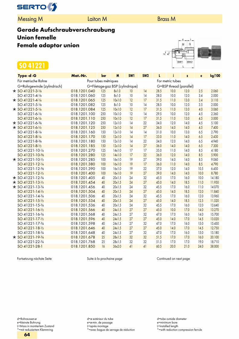
Gerade AufschraubverschraubungUnion femelleFemale adaptor union
SO 41221Type -d -G Mat.-Nr. bar M SW1 SW2 L i z e kg/100Für metrische Rohre Pour tubes métriques For metric tubesG=Rohrgewinde (zylindrisch) G=Filetage-gaz BSP (cylindrique) G=BSP thread (parallel)
SO 41221-3-1/8 018.1201.040 125 8x1.0 10 14 28.5 10.0 12.0 2.5 2.060 SO 41221-4-1/8 018.1201.060 125 8x1.0 10 14 28.0 10.0 12.0 3.4 2.000
SO 41221-4-1/4 018.1201.065 125 10x1.0 12 17 31.5 11.0 13.0 3.4 3.110 SO 41221-5-1/8 018.1201.082 125 8x1.0 10 14 28.5 10.0 12.0 3.5 2.000
SO 41221-5-1/4 018.1201.084 125 10x1.0 12 17 31.5 11.0 13.0 4.0 3.060 SO 41221-6-1/8 018.1201.100 250 10x1.0 12 14 29.5 10.0 12.0 4.5 2.360 SO 41221-6-1/4 018.1201.110 250 10x1.0 12 17 31.5 11.0 13.0 4.5 3.000
SO 41221-6-3/8 018.1201.120 250 12x1.0 14 22 34.0 12.0 14.0 4.5 5.100 SO 41221-6-1/2 018.1201.125 250 12x1.0 14 27 36.0 14.0 14.0 4.5 7.400 SO 41221-8-1/8 018.1201.160 150 12x1.0 14 14 31.0 10.0 13.0 6.5 2.790 SO 41221-8-1/4 018.1201.170 150 12x1.0 14 17 33.0 11.0 14.0 6.5 2.430 SO 41221-8-3/8 018.1201.180 150 12x1.0 14 22 34.0 12.0 14.0 6.5 4.940 SO 41221-8-1/2 018.1201.185 150 12x1.0 14 27 36.0 14.0 14.0 6.5 7.300 SO 41221-10-1/4 018.1201.270 125 14x1.0 17 17 35.0 11.0 14.0 8.5 4.180 SO 41221-10-3/8 018.1201.280 125 14x1.0 17 22 36.0 12.0 14.0 8.5 5.900
SO 41221-10-1/2 018.1201.285 100 16x1.0 19 27 39.0 14.0 14.0 8.5 9.060 SO 41221-12-1/4 018.1201.380 100 16x1.0 19 17 36.0 11.0 14.0 8.5 4.790 SO 41221-12-3/8 018.1201.390 100 16x1.0 19 22 37.0 12.0 14.0 10.5 6.450 SO 41221-12-1/2 018.1201.400 100 16x1.0 19 27 39.0 14.0 14.0 10.0 8.780
SO 41221-12-3/4 018.1201.405 40 20x1.5 24 32 45.5 17.0 16.0 10.0 14.180 SO 41221-13-1/2 018.1201.454 40 20x1.5 24 27 45.0 14.0 18.5 11.0 11.950 SO 41221-13-3/4 018.1201.456 40 20x1.5 24 32 45.5 17.0 16.0 11.0 14.070 SO 41221-14-1/2 018.1201.504 40 20x1.5 24 27 45.0 14.0 18.5 12.0 11.840 SO 41221-14-3/4 018.1201.506 40 20x1.5 24 32 45.5 17.0 16.0 12.0 13.960 SO 41221-15-1/2 018.1201.534 40 20x1.5 24 27 45.0 14.0 18.5 12.5 11.520 SO 41221-15-3/4 018.1201.536 40 20x1.5 24 32 45.5 17.0 16.0 12.0 13.640 SO 41221-16-1/2 018.1201.566 40 24x1.5 27 27 45.0 10.0 17.0 14.0 13.270 SO 41221-16-3/4 018.1201.568 40 24x1.5 27 32 47.0 17.0 16.0 14.0 15.700 SO 41221-17-1/2 018.1201.596 40 24x1.5 27 27 45.0 14.0 17.0 14.5 13.020 SO 41221-17-3/4 018.1201.598 40 24x1.5 27 32 47.0 17.0 16.0 15.0 15.450 SO 41221-18-1/2 018.1201.646 40 24x1.5 27 27 45.0 14.0 17.0 14.5 12.750 SO 41221-18-3/4 018.1201.648 40 24x1.5 27 32 47.0 17.0 16.0 15.0 15.180
SO 41221-19-3/4 018.1201.678 25 28x1.5 32 32 51.5 17.0 17.0 16.0 20.100 SO 41221-22-3/4 018.1201.768 25 28x1.5 32 32 51.5 17.0 17.0 19.0 18.710 SO 41221-28-1 018.1201.850 16 36x2.0 41 41 60.5 20.0 21.0 24.0 38.000
Fortsetzung nächste Seite Suite à la prochaine page Continued on next page
Messing M Laiton M Brass M
d=Rohraussen-øe=kleinste BohrungL=Mass in montiertem Zustand*=mit reduziertem Klemmring
d=ø extérieur du tubee=ø-min. de passageL=après montage*=avec bague de serrage de réduction
d=tube outside diametere=minimum boreL=installed length*=with reduction compression ferrule
64
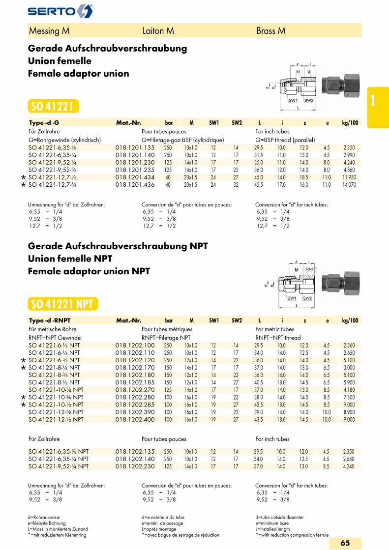
Gerade AufschraubverschraubungUnion femelleFemale adaptor union
SO 41221Type -d -G Mat.-Nr. bar M SW1 SW2 L i z e kg/100Für Zollrohre Pour tubes pouces For inch tubesG=Rohrgewinde (zylindrisch) G=Filetage-gaz BSP (cylindrique) G=BSP thread (parallel)
SO 41221-6,35-1/8 018.1201.135 250 10x1.0 12 14 29.5 10.0 12.0 4.5 2.350 SO 41221-6,35-1/4 018.1201.140 250 10x1.0 12 17 31.5 11.0 13.0 4.5 2.990 SO 41221-9,52-1/4 018.1201.230 125 14x1.0 17 17 35.0 11.0 14.0 8.0 4.240 SO 41221-9,52-3/8 018.1201.235 125 14x1.0 17 22 36.0 12.0 14.0 8.0 4.860
SO 41221-12,7-1/2 018.1201.434 40 20x1.5 24 27 45.0 14.0 18.5 11.0 11.950 SO 41221-12,7-3/4 018.1201.436 40 20x1.5 24 32 45.5 17.0 16.0 11.0 14.070
Umrechnung für "d" bei Zollrohren: 6,35 = 1/4 9,52 = 3/8 12,7 = 1/2
Conversion de "d" pour tubes en pouces: 6,35 = 1/4 9,52 = 3/8 12,7 = 1/2
Conversion for "d" for inch tubes: 6,35 = 1/4 9,52 = 3/8 12,7 = 1/2
Gerade Aufschraubverschraubung NPTUnion femelle NPTFemale adaptor union NPT
SO 41221 NPTType -d -RNPT Mat.-Nr. bar M SW1 SW2 L i z e kg/100Für metrische Rohre Pour tubes métriques For metric tubesRNPT=NPT Gewinde RNPT=Filetage NPT RNPT=NPT thread
SO 41221-6-1/8 NPT 018.1202.100 250 10x1.0 12 14 29.5 10.0 12.0 4.5 2.360 SO 41221-6-1/4 NPT 018.1202.110 250 10x1.0 12 17 34.0 14.0 12.5 4.5 2.650
SO 41221-6-3/8 NPT 018.1202.120 250 12x1.0 14 22 36.0 14.0 14.0 4.5 5.100 SO 41221-8-1/4 NPT 018.1202.170 150 14x1.0 17 17 37.0 14.0 13.0 6.5 3.000 SO 41221-8-3/8 NPT 018.1202.180 150 12x1.0 14 22 36.0 14.0 14.0 6.5 5.100 SO 41221-8-1/2 NPT 018.1202.185 150 12x1.0 14 27 40.5 18.0 14.5 6.5 5.900 SO 41221-10-1/4 NPT 018.1202.270 125 14x1.0 17 17 37.0 14.0 13.0 8.5 4.180
SO 41221-10-3/8 NPT 018.1202.280 100 16x1.0 19 22 38.0 14.0 14.0 8.5 7.300 SO 41221-10-1/2 NPT 018.1202.285 100 16x1.0 19 27 43.5 18.0 14.5 8.5 9.000 SO 41221-12-3/8 NPT 018.1202.390 100 16x1.0 19 22 39.0 14.0 14.0 10.0 8.900 SO 41221-12-1/2 NPT 018.1202.400 100 16x1.0 19 27 43.5 18.0 14.5 10.0 9.000
Für Zollrohre Pour tubes pouces For inch tubes SO 41221-6,35-1/8 NPT 018.1202.135 250 10x1.0 12 14 29.5 10.0 12.0 4.5 2.350SO 41221-6,35-1/4 NPT 018.1202.140 250 10x1.0 12 17 34.0 14.0 12.5 4.5 2.640SO 41221-9,52-1/4 NPT 018.1202.230 125 14x1.0 17 17 37.0 14.0 13.0 8.5 4.240
Messing M Laiton M Brass M
d=Rohraussen-øe=kleinste BohrungL=Mass in montiertem Zustand*=mit reduziertem Klemmring
d=ø extérieur du tubee=ø-min. de passageL=après montage*=avec bague de serrage de réduction
d=tube outside diametere=minimum boreL=installed length*=with reduction compression ferrule
Umrechnung für "d" bei Zollrohren: 6,35 = 1/4 9,52 = 3/8
Conversion de "d" pour tubes en pouces: 6,35 = 1/4 9,52 = 3/8
Conversion for "d" for inch tubes: 6,35 = 1/4 9,52 = 3/8
65
1
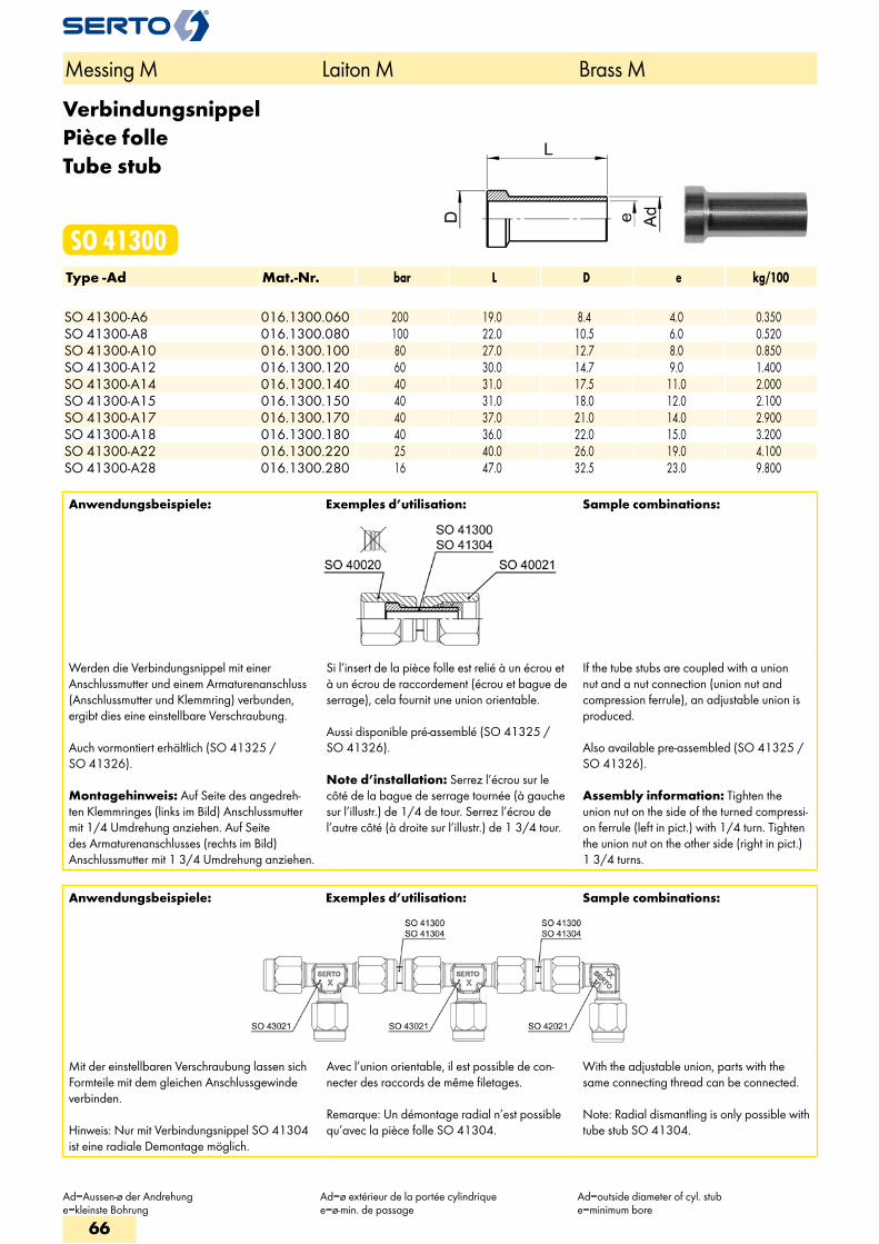
VerbindungsnippelPièce folleTube stub
SO 41300Type -Ad Mat.-Nr. bar L D e kg/100 SO 41300-A6 016.1300.060 200 19.0 8.4 4.0 0.350SO 41300-A8 016.1300.080 100 22.0 10.5 6.0 0.520SO 41300-A10 016.1300.100 80 27.0 12.7 8.0 0.850SO 41300-A12 016.1300.120 60 30.0 14.7 9.0 1.400SO 41300-A14 016.1300.140 40 31.0 17.5 11.0 2.000SO 41300-A15 016.1300.150 40 31.0 18.0 12.0 2.100SO 41300-A17 016.1300.170 40 37.0 21.0 14.0 2.900SO 41300-A18 016.1300.180 40 36.0 22.0 15.0 3.200SO 41300-A22 016.1300.220 25 40.0 26.0 19.0 4.100SO 41300-A28 016.1300.280 16 47.0 32.5 23.0 9.800
Anwendungsbeispiele: Exemples d’utilisation: Sample combinations:
Werden die Verbindungsnippel mit einer Anschlussmutter und einem Armaturenanschluss (Anschlussmutter und Klemmring) verbunden, ergibt dies eine einstellbare Verschraubung.
Auch vormontiert erhältlich (SO 41325 / SO 41326).
Montagehinweis: Auf Seite des angedreh-ten Klemmringes (links im Bild) Anschlussmutter mit 1/4 Umdrehung anziehen. Auf Seite des Armaturenanschlusses (rechts im Bild) Anschlussmutter mit 1 3/4 Umdrehung anziehen.
Si l’insert de la pièce folle est relié à un écrou et à un écrou de raccordement (écrou et bague de serrage), cela fournit une union orientable.
Aussi disponible pré-assemblé (SO 41325 / SO 41326).
Note d’installation: Serrez l’écrou sur le côté de la bague de serrage tournée (à gauche sur l’illustr.) de 1/4 de tour. Serrez l’écrou de l’autre côté (à droite sur l’illustr.) de 1 3/4 tour.
If the tube stubs are coupled with a union nut and a nut connection (union nut and compression ferrule), an adjustable union is produced.
Also available pre-assembled (SO 41325 / SO 41326).
Assembly information: Tighten the union nut on the side of the turned compressi-on ferrule (left in pict.) with 1/4 turn. Tighten the union nut on the other side (right in pict.) 1 3/4 turns.
Messing M Laiton M Brass M
Ad=Aussen-ø der Andrehunge=kleinste Bohrung
Ad=ø extérieur de la portée cylindriquee=ø-min. de passage
Ad=outside diameter of cyl. stube=minimum bore
Anwendungsbeispiele: Exemples d’utilisation: Sample combinations:
Mit der einstellbaren Verschraubung lassen sich Formteile mit dem gleichen Anschlussgewinde verbinden.
Hinweis: Nur mit Verbindungsnippel SO 41304 ist eine radiale Demontage möglich.
Avec l’union orientable, il est possible de con-necter des raccords de même filetages.
Remarque: Un démontage radial n’est possible qu’avec la pièce folle SO 41304.
With the adjustable union, parts with the same connecting thread can be connected.
Note: Radial dismantling is only possible with tube stub SO 41304.
66
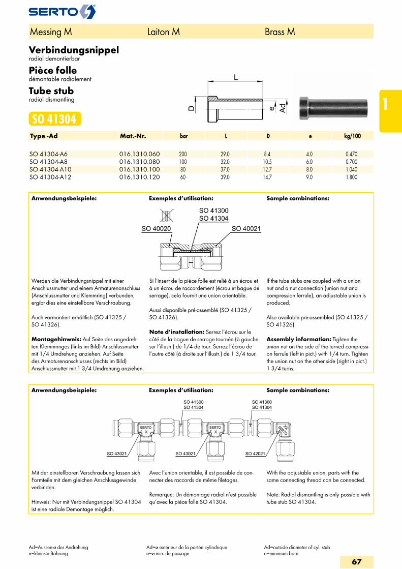
Verbindungsnippelradial demontierbar
Pièce folledémontable radialement
Tube stubradial dismantling
SO 41304Type -Ad Mat.-Nr. bar L D e kg/100 SO 41304-A6 016.1310.060 200 29.0 8.4 4.0 0.470SO 41304-A8 016.1310.080 100 32.0 10.5 6.0 0.700SO 41304-A10 016.1310.100 80 37.0 12.7 8.0 1.040SO 41304-A12 016.1310.120 60 39.0 14.7 9.0 1.800
Anwendungsbeispiele: Exemples d’utilisation: Sample combinations:
Werden die Verbindungsnippel mit einer Anschlussmutter und einem Armaturenanschluss (Anschlussmutter und Klemmring) verbunden, ergibt dies eine einstellbare Verschraubung.
Auch vormontiert erhältlich (SO 41325 / SO 41326).
Montagehinweis: Auf Seite des angedreh-ten Klemmringes (links im Bild) Anschlussmutter mit 1/4 Umdrehung anziehen. Auf Seite des Armaturenanschlusses (rechts im Bild) Anschlussmutter mit 1 3/4 Umdrehung anziehen.
Si l’insert de la pièce folle est relié à un écrou et à un écrou de raccordement (écrou et bague de serrage), cela fournit une union orientable.
Aussi disponible pré-assemblé (SO 41325 / SO 41326).
Note d’installation: Serrez l’écrou sur le côté de la bague de serrage tournée (à gauche sur l’illustr.) de 1/4 de tour. Serrez l’écrou de l’autre côté (à droite sur l’illustr.) de 1 3/4 tour.
If the tube stubs are coupled with a union nut and a nut connection (union nut and compression ferrule), an adjustable union is produced.
Also available pre-assembled (SO 41325 / SO 41326).
Assembly information: Tighten the union nut on the side of the turned compressi-on ferrule (left in pict.) with 1/4 turn. Tighten the union nut on the other side (right in pict.) 1 3/4 turns.
Anwendungsbeispiele: Exemples d’utilisation: Sample combinations:
Mit der einstellbaren Verschraubung lassen sich Formteile mit dem gleichen Anschlussgewinde verbinden.
Hinweis: Nur mit Verbindungsnippel SO 41304 ist eine radiale Demontage möglich.
Avec l’union orientable, il est possible de con-necter des raccords de même filetages.
Remarque: Un démontage radial n’est possible qu’avec la pièce folle SO 41304.
With the adjustable union, parts with the same connecting thread can be connected.
Note: Radial dismantling is only possible with tube stub SO 41304.
Messing M Laiton M Brass M
Ad=Aussen-ø der Andrehunge=kleinste Bohrung
Ad=ø extérieur de la portée cylindriquee=ø-min. de passage
Ad=outside diameter of cyl. stube=minimum bore
67
1
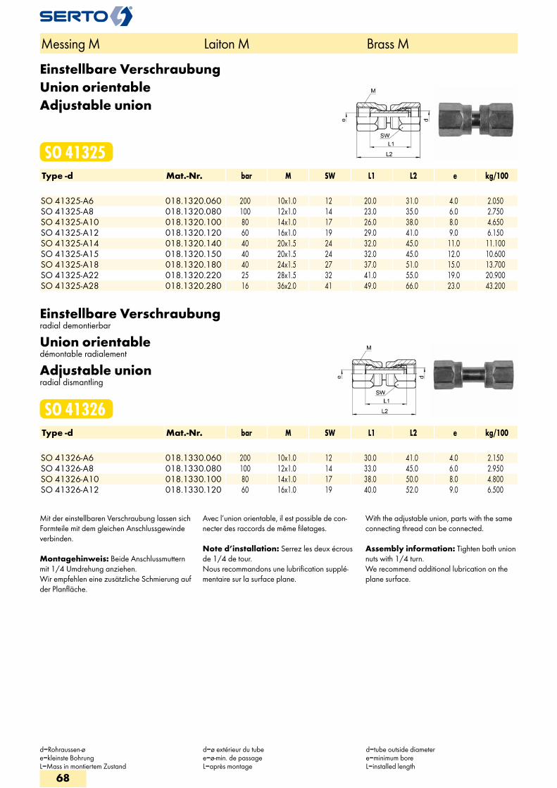
Einstellbare VerschraubungUnion orientableAdjustable union
SO 41325Type -d Mat.-Nr. bar M SW L1 L2 e kg/100 SO 41325-A6 018.1320.060 200 10x1.0 12 20.0 31.0 4.0 2.050SO 41325-A8 018.1320.080 100 12x1.0 14 23.0 35.0 6.0 2.750SO 41325-A10 018.1320.100 80 14x1.0 17 26.0 38.0 8.0 4.650SO 41325-A12 018.1320.120 60 16x1.0 19 29.0 41.0 9.0 6.150SO 41325-A14 018.1320.140 40 20x1.5 24 32.0 45.0 11.0 11.100SO 41325-A15 018.1320.150 40 20x1.5 24 32.0 45.0 12.0 10.600SO 41325-A18 018.1320.180 40 24x1.5 27 37.0 51.0 15.0 13.700SO 41325-A22 018.1320.220 25 28x1.5 32 41.0 55.0 19.0 20.900SO 41325-A28 018.1320.280 16 36x2.0 41 49.0 66.0 23.0 43.200
Einstellbare Verschraubungradial demontierbar
Union orientabledémontable radialement
Adjustable unionradial dismantling
SO 41326Type -d Mat.-Nr. bar M SW L1 L2 e kg/100 SO 41326-A6 018.1330.060 200 10x1.0 12 30.0 41.0 4.0 2.150SO 41326-A8 018.1330.080 100 12x1.0 14 33.0 45.0 6.0 2.950SO 41326-A10 018.1330.100 80 14x1.0 17 38.0 50.0 8.0 4.800SO 41326-A12 018.1330.120 60 16x1.0 19 40.0 52.0 9.0 6.500
Mit der einstellbaren Verschraubung lassen sich Formteile mit dem gleichen Anschlussgewinde verbinden.
Montagehinweis: Beide Anschlussmuttern mit 1/4 Umdrehung anziehen. Wir empfehlen eine zusätzliche Schmierung auf der Planfläche.
Avec l’union orientable, il est possible de con-necter des raccords de même filetages.
Note d’installation: Serrez les deux écrous de 1/4 de tour. Nous recommandons une lubrification supplé-mentaire sur la surface plane.
With the adjustable union, parts with the same connecting thread can be connected.
Assembly information: Tighten both union nuts with 1/4 turn. We recommend additional lubrication on the plane surface.
Messing M Laiton M Brass M
d=Rohraussen-øe=kleinste BohrungL=Mass in montiertem Zustand
d=ø extérieur du tubee=ø-min. de passageL=après montage
d=tube outside diametere=minimum boreL=installed length
68
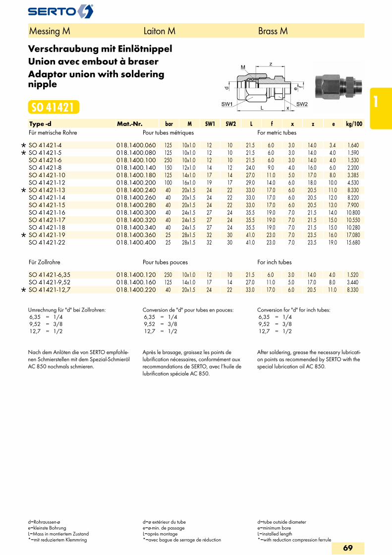
Verschraubung mit EinlötnippelUnion avec embout à braserAdaptor union with soldering nipple
SO 41421Type -d Mat.-Nr. bar M SW1 SW2 L f x z e kg/100Für metrische Rohre Pour tubes métriques For metric tubes
SO 41421-4 018.1400.060 125 10x1.0 12 10 21.5 6.0 3.0 14.0 3.4 1.640 SO 41421-5 018.1400.080 125 10x1.0 12 10 21.5 6.0 3.0 14.0 4.0 1.590 SO 41421-6 018.1400.100 250 10x1.0 12 10 21.5 6.0 3.0 14.0 4.0 1.530 SO 41421-8 018.1400.140 150 12x1.0 14 12 24.0 9.0 4.0 16.0 6.0 2.200 SO 41421-10 018.1400.180 125 14x1.0 17 14 27.0 11.0 5.0 17.0 8.0 3.385 SO 41421-12 018.1400.200 100 16x1.0 19 17 29.0 14.0 6.0 18.0 10.0 4.530
SO 41421-13 018.1400.240 40 20x1.5 24 22 33.0 17.0 6.0 20.5 11.0 8.330 SO 41421-14 018.1400.260 40 20x1.5 24 22 33.0 17.0 6.0 20.5 12.0 8.220 SO 41421-15 018.1400.280 40 20x1.5 24 22 33.0 17.0 6.0 20.5 13.0 7.900 SO 41421-16 018.1400.300 40 24x1.5 27 24 35.5 19.0 7.0 21.5 14.0 10.800 SO 41421-17 018.1400.320 40 24x1.5 27 24 35.5 19.0 7.0 21.5 15.0 10.550 SO 41421-18 018.1400.340 40 24x1.5 27 24 35.5 19.0 7.0 21.5 15.0 10.280
SO 41421-19 018.1400.360 25 28x1.5 32 30 41.0 23.0 7.0 23.5 16.0 17.080 SO 41421-22 018.1400.400 25 28x1.5 32 30 41.0 23.0 7.0 23.5 19.0 15.680
Für Zollrohre Pour tubes pouces For inch tubes
SO 41421-6,35 018.1400.120 250 10x1.0 12 10 21.5 6.0 3.0 14.0 4.0 1.520 SO 41421-9,52 018.1400.160 125 14x1.0 17 14 27.0 11.0 5.0 17.0 8.0 3.440
SO 41421-12,7 018.1400.220 40 20x1.5 24 22 33.0 17.0 6.0 20.5 11.0 8.330
Umrechnung für "d" bei Zollrohren: 6,35 = 1/4 9,52 = 3/8 12,7 = 1/2
Conversion de "d" pour tubes en pouces: 6,35 = 1/4 9,52 = 3/8 12,7 = 1/2
Conversion for "d" for inch tubes: 6,35 = 1/4 9,52 = 3/8 12,7 = 1/2
Nach dem Anlöten die von SERTO empfohle-nen Schmierstellen mit dem Spezial-Schmieröl AC 850 nochmals schmieren.
Après le brasage, graissez les points de lubrification nécessaires, conformément aux recommandations de SERTO, avec l’huile de lubrification spéciale AC 850.
After soldering, grease the necessary lubricati-on points as recommended by SERTO with the special lubrication oil AC 850.
Messing M Laiton M Brass M
d=Rohraussen-øe=kleinste BohrungL=Mass in montiertem Zustand*=mit reduziertem Klemmring
d=ø extérieur du tubee=ø-min. de passageL=après montage*=avec bague de serrage de réduction
d=tube outside diametere=minimum boreL=installed length*=with reduction compression ferrule
69
1
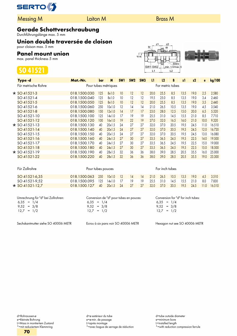
Gerade SchottverschraubungDurchführungslänge max. 5 mm
Union double traversée de cloisonpour cloison max. 5 mm
Panel mount unionmax. panel thickness 5 mm
SO 41521Type -d Mat.-Nr. bar M SW1 SW2 SW3 L1 L2 B z1 z2 e kg/100Für metrische Rohre Pour tubes métriques For metric tubes
SO 41521-3 018.1500.030 125 8x1.0 10 12 12 20.0 25.5 8.5 13.5 19.0 2.5 2.580 SO 41521-4 018.1500.040 125 8x1.0 10 12 12 19.5 25.0 8.5 13.5 19.0 3.4 2.460 SO 41521-5 018.1500.050 125 8x1.0 10 12 12 20.0 25.5 8.5 13.5 19.0 3.5 2.440 SO 41521-6 018.1500.060 250 10x1.0 12 14 14 21.0 26.5 10.5 13.5 19.0 4.5 3.540 SO 41521-8 018.1500.080 150 12x1.0 14 17 17 23.0 28.0 12.5 15.0 20.0 6.5 5.320 SO 41521-10 018.1500.100 125 14x1.0 17 19 19 25.5 31.0 14.5 15.5 21.0 8.5 7.710 SO 41521-12 018.1500.120 100 16x1.0 19 22 19 27.0 32.0 16.5 16.0 21.0 10.0 9.320
SO 41521-13 018.1500.130 40 20x1.5 24 27 27 32.0 37.0 20.5 19.5 24.5 11.0 16.510 SO 41521-14 018.1500.140 40 20x1.5 24 27 27 32.0 37.0 20.5 19.5 24.5 12.0 16.720 SO 41521-15 018.1500.150 40 20x1.5 24 27 27 32.0 37.0 20.5 19.5 24.5 13.0 16.080 SO 41521-16 018.1500.160 40 24x1.5 27 30 27 33.5 36.5 24.5 19.5 22.5 14.0 19.500 SO 41521-17 018.1500.170 40 24x1.5 27 30 27 33.5 36.5 24.5 19.5 22.5 15.0 19.000 SO 41521-18 018.1500.180 40 24x1.5 27 30 27 33.5 36.5 24.5 19.5 22.5 15.0 18.500
SO 41521-19 018.1500.190 40 28x1.5 32 36 36 38.0 39.0 28.5 20.5 35.5 16.0 25.000 SO 41521-22 018.1500.220 40 28x1.5 32 36 36 38.0 39.0 28.5 20.5 35.5 19.0 23.300
Für Zollrohre Pour tubes pouces For inch tubes
SO 41521-6,35 018.1500.063 250 10x1.0 12 14 14 21.0 26.5 10.5 13.5 19.0 4.5 3.510 SO 41521-9,52 018.1500.095 125 14x1.0 17 19 19 25.5 31.0 14.5 15.5 21.0 8.0 7.830
SO 41521-12,7 018.1500.127 40 20x1.5 24 27 27 32.0 37.0 20.5 19.5 24.5 11.0 16.510
Umrechnung für "d" bei Zollrohren: 6,35 = 1/4 9,52 = 3/8 12,7 = 1/2
Conversion de "d" pour tubes en pouces: 6,35 = 1/4 9,52 = 3/8 12,7 = 1/2
Conversion for "d" for inch tubes: 6,35 = 1/4 9,52 = 3/8 12,7 = 1/2
Sechskantmutter siehe SO 40006 METR Ecrou à six pans voir SO 40006 METR Hexagon nut see SO 40006 METR
Messing M Laiton M Brass M
d=Rohraussen-øe=kleinste BohrungL=Mass in montiertem Zustand*=mit reduziertem Klemmring
d=ø extérieur du tubee=ø-min. de passageL=après montage*=avec bague de serrage de réduction
d=tube outside diametere=minimum boreL=installed length*=with reduction compression ferrule
70
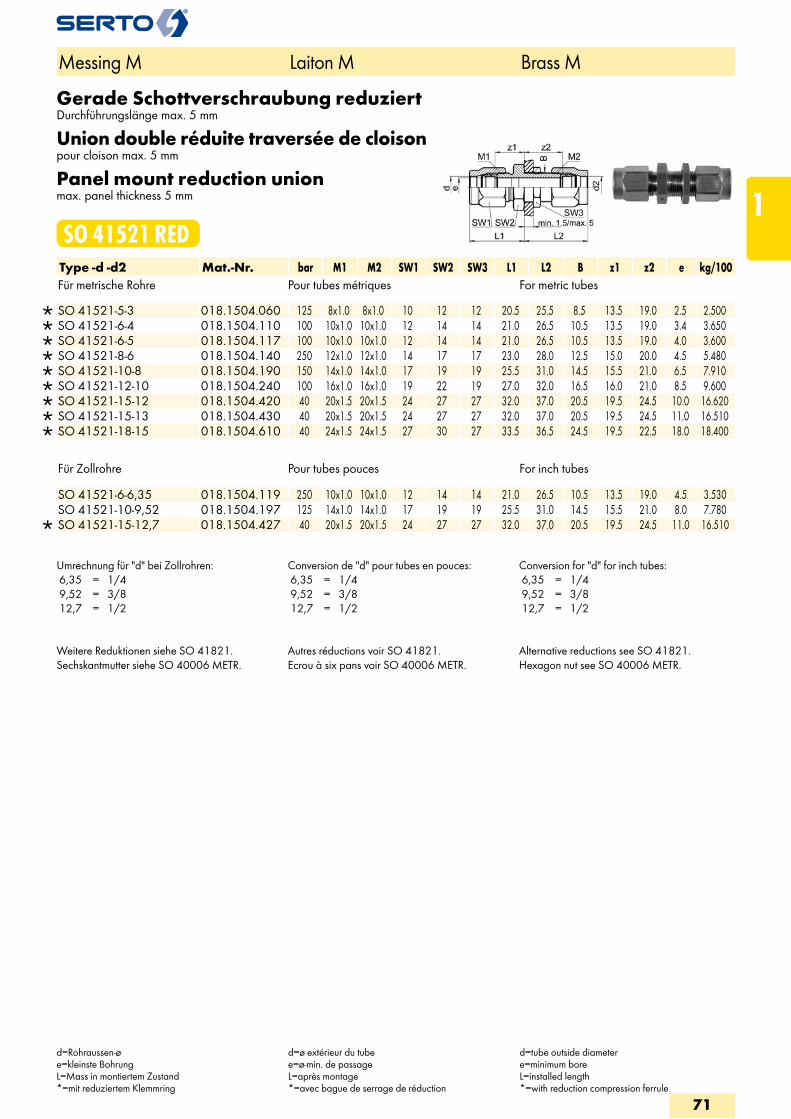
Gerade Schottverschraubung reduziertDurchführungslänge max. 5 mm
Union double réduite traversée de cloisonpour cloison max. 5 mm
Panel mount reduction unionmax. panel thickness 5 mm
SO 41521 REDType -d -d2 Mat.-Nr. bar M1 M2 SW1 SW2 SW3 L1 L2 B z1 z2 e kg/100Für metrische Rohre Pour tubes métriques For metric tubes
SO 41521-5-3 018.1504.060 125 8x1.0 8x1.0 10 12 12 20.5 25.5 8.5 13.5 19.0 2.5 2.500 SO 41521-6-4 018.1504.110 100 10x1.0 10x1.0 12 14 14 21.0 26.5 10.5 13.5 19.0 3.4 3.650 SO 41521-6-5 018.1504.117 100 10x1.0 10x1.0 12 14 14 21.0 26.5 10.5 13.5 19.0 4.0 3.600 SO 41521-8-6 018.1504.140 250 12x1.0 12x1.0 14 17 17 23.0 28.0 12.5 15.0 20.0 4.5 5.480 SO 41521-10-8 018.1504.190 150 14x1.0 14x1.0 17 19 19 25.5 31.0 14.5 15.5 21.0 6.5 7.910 SO 41521-12-10 018.1504.240 100 16x1.0 16x1.0 19 22 19 27.0 32.0 16.5 16.0 21.0 8.5 9.600 SO 41521-15-12 018.1504.420 40 20x1.5 20x1.5 24 27 27 32.0 37.0 20.5 19.5 24.5 10.0 16.620 SO 41521-15-13 018.1504.430 40 20x1.5 20x1.5 24 27 27 32.0 37.0 20.5 19.5 24.5 11.0 16.510 SO 41521-18-15 018.1504.610 40 24x1.5 24x1.5 27 30 27 33.5 36.5 24.5 19.5 22.5 18.0 18.400
Für Zollrohre Pour tubes pouces For inch tubes
SO 41521-6-6,35 018.1504.119 250 10x1.0 10x1.0 12 14 14 21.0 26.5 10.5 13.5 19.0 4.5 3.530 SO 41521-10-9,52 018.1504.197 125 14x1.0 14x1.0 17 19 19 25.5 31.0 14.5 15.5 21.0 8.0 7.780
SO 41521-15-12,7 018.1504.427 40 20x1.5 20x1.5 24 27 27 32.0 37.0 20.5 19.5 24.5 11.0 16.510
Umrechnung für "d" bei Zollrohren: 6,35 = 1/4 9,52 = 3/8 12,7 = 1/2
Conversion de "d" pour tubes en pouces: 6,35 = 1/4 9,52 = 3/8 12,7 = 1/2
Conversion for "d" for inch tubes: 6,35 = 1/4 9,52 = 3/8 12,7 = 1/2
Weitere Reduktionen siehe SO 41821. Sechskantmutter siehe SO 40006 METR.
Autres réductions voir SO 41821. Ecrou à six pans voir SO 40006 METR.
Alternative reductions see SO 41821.Hexagon nut see SO 40006 METR.
Messing M Laiton M Brass M
d=Rohraussen-øe=kleinste BohrungL=Mass in montiertem Zustand*=mit reduziertem Klemmring
d=ø extérieur du tubee=ø-min. de passageL=après montage*=avec bague de serrage de réduction
d=tube outside diametere=minimum boreL=installed length*=with reduction compression ferrule
71
1
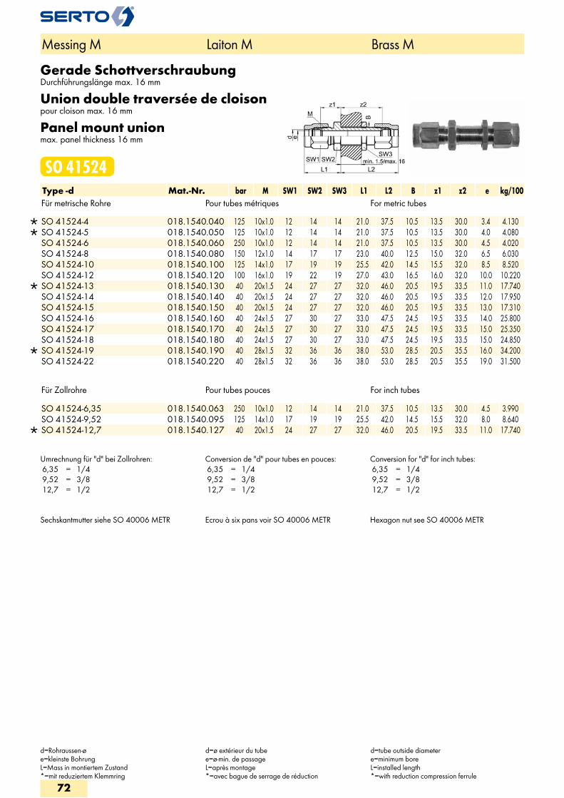
Gerade SchottverschraubungDurchführungslänge max. 16 mm
Union double traversée de cloisonpour cloison max. 16 mm
Panel mount unionmax. panel thickness 16 mm
SO 41524Type -d Mat.-Nr. bar M SW1 SW2 SW3 L1 L2 B z1 z2 e kg/100Für metrische Rohre Pour tubes métriques For metric tubes
SO 41524-4 018.1540.040 125 10x1.0 12 14 14 21.0 37.5 10.5 13.5 30.0 3.4 4.130 SO 41524-5 018.1540.050 125 10x1.0 12 14 14 21.0 37.5 10.5 13.5 30.0 4.0 4.080 SO 41524-6 018.1540.060 250 10x1.0 12 14 14 21.0 37.5 10.5 13.5 30.0 4.5 4.020 SO 41524-8 018.1540.080 150 12x1.0 14 17 17 23.0 40.0 12.5 15.0 32.0 6.5 6.030 SO 41524-10 018.1540.100 125 14x1.0 17 19 19 25.5 42.0 14.5 15.5 32.0 8.5 8.520 SO 41524-12 018.1540.120 100 16x1.0 19 22 19 27.0 43.0 16.5 16.0 32.0 10.0 10.220
SO 41524-13 018.1540.130 40 20x1.5 24 27 27 32.0 46.0 20.5 19.5 33.5 11.0 17.740 SO 41524-14 018.1540.140 40 20x1.5 24 27 27 32.0 46.0 20.5 19.5 33.5 12.0 17.950 SO 41524-15 018.1540.150 40 20x1.5 24 27 27 32.0 46.0 20.5 19.5 33.5 13.0 17.310 SO 41524-16 018.1540.160 40 24x1.5 27 30 27 33.0 47.5 24.5 19.5 33.5 14.0 25.800 SO 41524-17 018.1540.170 40 24x1.5 27 30 27 33.0 47.5 24.5 19.5 33.5 15.0 25.350 SO 41524-18 018.1540.180 40 24x1.5 27 30 27 33.0 47.5 24.5 19.5 33.5 15.0 24.850
SO 41524-19 018.1540.190 40 28x1.5 32 36 36 38.0 53.0 28.5 20.5 35.5 16.0 34.200 SO 41524-22 018.1540.220 40 28x1.5 32 36 36 38.0 53.0 28.5 20.5 35.5 19.0 31.500
Für Zollrohre Pour tubes pouces For inch tubes
SO 41524-6,35 018.1540.063 250 10x1.0 12 14 14 21.0 37.5 10.5 13.5 30.0 4.5 3.990 SO 41524-9,52 018.1540.095 125 14x1.0 17 19 19 25.5 42.0 14.5 15.5 32.0 8.0 8.640
SO 41524-12,7 018.1540.127 40 20x1.5 24 27 27 32.0 46.0 20.5 19.5 33.5 11.0 17.740
Umrechnung für "d" bei Zollrohren: 6,35 = 1/4 9,52 = 3/8 12,7 = 1/2
Conversion de "d" pour tubes en pouces: 6,35 = 1/4 9,52 = 3/8 12,7 = 1/2
Conversion for "d" for inch tubes: 6,35 = 1/4 9,52 = 3/8 12,7 = 1/2
Sechskantmutter siehe SO 40006 METR Ecrou à six pans voir SO 40006 METR Hexagon nut see SO 40006 METR
Messing M Laiton M Brass M
d=Rohraussen-øe=kleinste BohrungL=Mass in montiertem Zustand*=mit reduziertem Klemmring
d=ø extérieur du tubee=ø-min. de passageL=après montage*=avec bague de serrage de réduction
d=tube outside diametere=minimum boreL=installed length*=with reduction compression ferrule
72
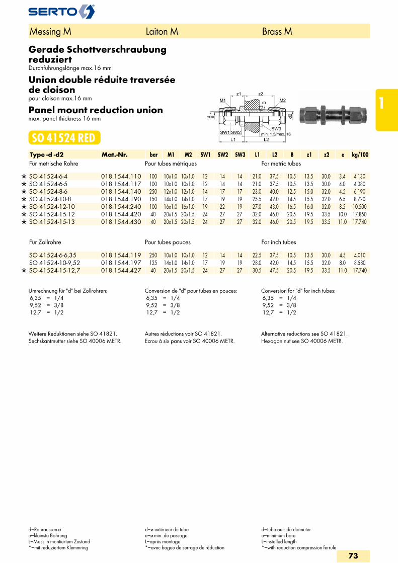
Gerade Schottverschraubung reduziertDurchführungslänge max.16 mm
Union double réduite traversée de cloisonpour cloison max.16 mm
Panel mount reduction unionmax. panel thickness 16 mm
SO 41524 REDType -d -d2 Mat.-Nr. bar M1 M2 SW1 SW2 SW3 L1 L2 B z1 z2 e kg/100Für metrische Rohre Pour tubes métriques For metric tubes
SO 41524-6-4 018.1544.110 100 10x1.0 10x1.0 12 14 14 21.0 37.5 10.5 13.5 30.0 3.4 4.130 SO 41524-6-5 018.1544.117 100 10x1.0 10x1.0 12 14 14 21.0 37.5 10.5 13.5 30.0 4.0 4.080 SO 41524-8-6 018.1544.140 250 12x1.0 12x1.0 14 17 17 23.0 40.0 12.5 15.0 32.0 4.5 6.190 SO 41524-10-8 018.1544.190 150 14x1.0 14x1.0 17 19 19 25.5 42.0 14.5 15.5 32.0 6.5 8.720 SO 41524-12-10 018.1544.240 100 16x1.0 16x1.0 19 22 19 27.0 43.0 16.5 16.0 32.0 8.5 10.500 SO 41524-15-12 018.1544.420 40 20x1.5 20x1.5 24 27 27 32.0 46.0 20.5 19.5 33.5 10.0 17.850 SO 41524-15-13 018.1544.430 40 20x1.5 20x1.5 24 27 27 32.0 46.0 20.5 19.5 33.5 11.0 17.740
Für Zollrohre Pour tubes pouces For inch tubes
SO 41524-6-6,35 018.1544.119 250 10x1.0 10x1.0 12 14 14 22.5 37.5 10.5 13.5 30.0 4.5 4.010 SO 41524-10-9,52 018.1544.197 125 14x1.0 14x1.0 17 19 19 28.0 42.0 14.5 15.5 32.0 8.0 8.580
SO 41524-15-12,7 018.1544.427 40 20x1.5 20x1.5 24 27 27 30.5 47.5 20.5 19.5 33.5 11.0 17.740
Umrechnung für "d" bei Zollrohren: 6,35 = 1/4 9,52 = 3/8 12,7 = 1/2
Conversion de "d" pour tubes en pouces: 6,35 = 1/4 9,52 = 3/8 12,7 = 1/2
Conversion for "d" for inch tubes: 6,35 = 1/4 9,52 = 3/8 12,7 = 1/2
Weitere Reduktionen siehe SO 41821. Sechskantmutter siehe SO 40006 METR.
Autres réductions voir SO 41821. Ecrou à six pans voir SO 40006 METR.
Alternative reductions see SO 41821. Hexagon nut see SO 40006 METR.
Messing M Laiton M Brass M
d=Rohraussen-øe=kleinste BohrungL=Mass in montiertem Zustand*=mit reduziertem Klemmring
d=ø extérieur du tubee=ø-min. de passageL=après montage*=avec bague de serrage de réduction
d=tube outside diametere=minimum boreL=installed length*=with reduction compression ferrule
73
1
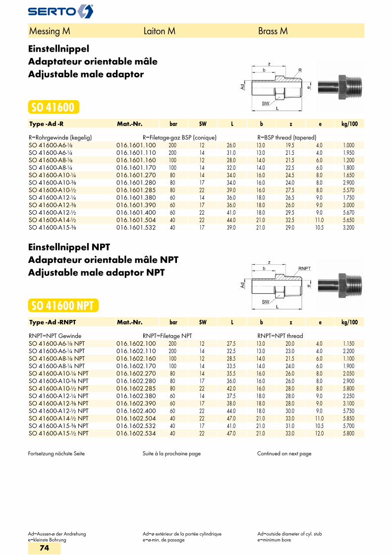
EinstellnippelAdaptateur orientable mâleAdjustable male adaptor
SO 41600Type -Ad -R Mat.-Nr. bar SW L b z e kg/100 R=Rohrgewinde (kegelig) R=Filetage-gaz BSP (conique) R=BSP thread (tapered)SO 41600-A6-1/8 016.1601.100 200 12 26.0 13.0 19.5 4.0 1.000SO 41600-A6-1/4 016.1601.110 200 14 31.0 13.0 21.5 4.0 1.950SO 41600-A8-1/8 016.1601.160 100 12 28.0 14.0 21.5 6.0 1.200SO 41600-A8-1/4 016.1601.170 100 14 32.0 14.0 22.5 6.0 1.800SO 41600-A10-1/4 016.1601.270 80 14 34.0 16.0 24.5 8.0 1.650SO 41600-A10-3/8 016.1601.280 80 17 34.0 16.0 24.0 8.0 2.900SO 41600-A10-1/2 016.1601.285 80 22 39.0 16.0 27.5 8.0 5.570SO 41600-A12-1/4 016.1601.380 60 14 36.0 18.0 26.5 9.0 1.750SO 41600-A12-3/8 016.1601.390 60 17 36.0 18.0 26.0 9.0 3.000SO 41600-A12-1/2 016.1601.400 60 22 41.0 18.0 29.5 9.0 5.670SO 41600-A14-1/2 016.1601.504 40 22 44.0 21.0 32.5 11.0 5.650SO 41600-A15-3/8 016.1601.532 40 17 39.0 21.0 29.0 10.5 3.200
Einstellnippel NPTAdaptateur orientable mâle NPTAdjustable male adaptor NPT
SO 41600 NPTType -Ad -RNPT Mat.-Nr. bar SW L b z e kg/100 RNPT=NPT Gewinde RNPT=Filetage NPT RNPT=NPT threadSO 41600-A6-1/8 NPT 016.1602.100 200 12 27.5 13.0 20.0 4.0 1.150SO 41600-A6-1/4 NPT 016.1602.110 200 14 32.5 13.0 23.0 4.0 2.200SO 41600-A8-1/8 NPT 016.1602.160 100 12 28.5 14.0 21.5 6.0 1.100SO 41600-A8-1/4 NPT 016.1602.170 100 14 33.5 14.0 24.0 6.0 1.900SO 41600-A10-1/4 NPT 016.1602.270 80 14 35.5 16.0 26.0 8.0 2.050SO 41600-A10-3/8 NPT 016.1602.280 80 17 36.0 16.0 26.0 8.0 2.900SO 41600-A10-1/2 NPT 016.1602.285 80 22 42.0 16.0 28.0 8.0 5.800SO 41600-A12-1/4 NPT 016.1602.380 60 14 37.5 18.0 28.0 9.0 2.250SO 41600-A12-3/8 NPT 016.1602.390 60 17 38.0 18.0 28.0 9.0 3.100SO 41600-A12-1/2 NPT 016.1602.400 60 22 44.0 18.0 30.0 9.0 5.750SO 41600-A14-1/2 NPT 016.1602.504 40 22 47.0 21.0 33.0 11.0 5.850SO 41600-A15-3/8 NPT 016.1602.532 40 17 41.0 21.0 31.0 10.5 5.700SO 41600-A15-1/2 NPT 016.1602.534 40 22 47.0 21.0 33.0 12.0 5.800
Fortsetzung nächste Seite Suite à la prochaine page Continued on next page
Messing M Laiton M Brass M
Ad=Aussen-ø der Andrehunge=kleinste Bohrung
Ad=ø extérieur de la portée cylindriquee=ø-min. de passage
Ad=outside diameter of cyl. stube=minimum bore
74
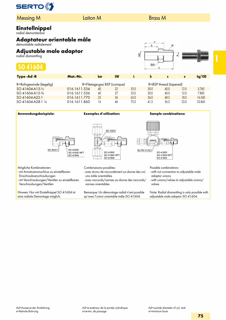
Einstellnippelradial demontierbar
Adaptateur orientable mâledémontable radialement
Adjustable male adaptorradial dismantling
SO 41604Type -Ad -R Mat.-Nr. bar SW L b z e kg/100 R=Rohrgewinde (kegelig) R=Filetage-gaz BSP (conique) R=BSP thread (tapered)SO 41604-A15-1/2 016.1611.534 40 22 53.0 30.0 40.0 12.0 5.760SO 41604-A15-3/4 016.1611.536 40 27 55.0 30.0 40.0 12.0 7.800SO 41604-A22-1 016.1611.770 25 36 65.0 36.0 48.5 18.0 16.540SO 41604-A28-1 1/4 016.1611.860 16 46 75.5 41.5 56.5 23.0 33.860
Anwendungsbeispiele: Exemples d’utilisation: Sample combinations:
Mögliche Kombinationen:- mit Armaturenanschluss zu einstellbaren Einschraubverschraubungen
- mit Verschraubungen/Ventilen zu einstellbaren Verschraubungen/Ventilen
Hinweis: Nur mit Einstellnippel SO 41604 ist eine radiale Demontage möglich.
Combinaisons possibles:- avec écrou de raccordement ça donne des uni-ons mâle orientables
- avec raccords/vannes ça donne des raccords/vannes orientables
Remarque: Un démontage radial n’est possible qu’avec l’union orientable mâle SO 41604.
Possible combinations:- with nut connection to adjustable male adaptor unions
- with unions/valves to adjustable unions/valves
Note: Radial dismantling is only possible with adjustable male adaptor SO 41604.
Messing M Laiton M Brass M
Ad=Aussen-ø der Andrehunge=kleinste Bohrung
Ad=ø extérieur de la portée cylindriquee=ø-min. de passage
Ad=outside diameter of cyl. stube=minimum bore
75
1
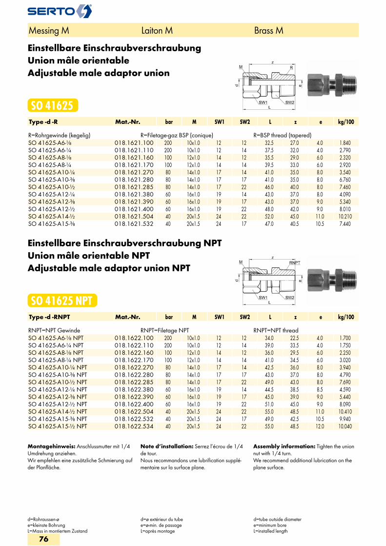
Einstellbare EinschraubverschraubungUnion mâle orientableAdjustable male adaptor union
SO 41625Type -d -R Mat.-Nr. bar M SW1 SW2 L z e kg/100 R=Rohrgewinde (kegelig) R=Filetage-gaz BSP (conique) R=BSP thread (tapered)SO 41625-A6-1/8 018.1621.100 200 10x1.0 12 12 32.5 27.0 4.0 1.840SO 41625-A6-1/4 018.1621.110 200 10x1.0 12 14 37.5 32.0 4.0 2.790SO 41625-A8-1/8 018.1621.160 100 12x1.0 14 12 35.5 29.0 6.0 2.320SO 41625-A8-1/4 018.1621.170 100 12x1.0 14 14 39.5 33.0 6.0 2.920SO 41625-A10-1/4 018.1621.270 80 14x1.0 17 14 41.0 35.0 8.0 3.540SO 41625-A10-3/8 018.1621.280 80 14x1.0 17 17 41.0 35.0 8.0 6.760SO 41625-A10-1/2 018.1621.285 80 14x1.0 17 22 46.0 40.0 8.0 7.460SO 41625-A12-1/4 018.1621.380 60 16x1.0 19 14 43.0 37.0 8.0 4.090SO 41625-A12-3/8 018.1621.390 60 16x1.0 19 17 43.0 37.0 9.0 5.340SO 41625-A12-1/2 018.1621.400 60 16x1.0 19 22 48.0 42.0 9.0 8.010SO 41625-A14-1/2 018.1621.504 40 20x1.5 24 22 52.0 45.0 11.0 10.210SO 41625-A15-3/8 018.1621.532 40 20x1.5 24 17 47.0 40.5 10.5 7.440
Einstellbare Einschraubverschraubung NPTUnion mâle orientable NPTAdjustable male adaptor union NPT
SO 41625 NPTType -d -RNPT Mat.-Nr. bar M SW1 SW2 L z e kg/100 RNPT=NPT Gewinde RNPT=Filetage NPT RNPT=NPT threadSO 41625-A6-1/8 NPT 018.1622.100 200 10x1.0 12 12 34.0 22.5 4.0 1.700SO 41625-A6-1/4 NPT 018.1622.110 200 10x1.0 12 14 39.0 33.5 4.0 1.750SO 41625-A8-1/8 NPT 018.1622.160 100 12x1.0 14 12 36.0 29.5 6.0 2.250SO 41625-A8-1/4 NPT 018.1622.170 100 12x1.0 14 14 41.0 34.5 6.0 3.020SO 41625-A10-1/4 NPT 018.1622.270 80 14x1.0 17 14 42.5 36.0 8.0 3.940SO 41625-A10-3/8 NPT 018.1622.280 80 14x1.0 17 17 43.0 37.0 8.0 4.790SO 41625-A10-1/2 NPT 018.1622.285 80 14x1.0 17 22 49.0 43.0 8.0 7.690SO 41625-A12-1/4 NPT 018.1622.380 60 16x1.0 19 14 44.5 38.5 8.5 4.590SO 41625-A12-3/8 NPT 018.1622.390 60 16x1.0 19 17 45.0 39.0 9.0 5.440SO 41625-A12-1/2 NPT 018.1622.400 60 16x1.0 19 22 51.0 45.0 9.0 8.090SO 41625-A14-1/2 NPT 018.1622.504 40 20x1.5 24 22 55.0 48.5 11.0 10.410SO 41625-A15-3/8 NPT 018.1622.532 40 20x1.5 24 17 49.0 42.5 10.5 9.940SO 41625-A15-1/2 NPT 018.1622.534 40 20x1.5 24 22 55.0 48.5 12.0 10.040
Montagehinweis: Anschlussmutter mit 1/4 Umdrehung anziehen.Wir empfehlen eine zusätzliche Schmierung auf der Planfläche.
Note d’installation: Serrez l’écrou de 1/4 de tour.Nous recommandons une lubrification supplé-mentaire sur la surface plane.
Assembly information: Tighten the union nut with 1/4 turn.We recommend additional lubrication on the plane surface.
Messing M Laiton M Brass M
d=Rohraussen-øe=kleinste BohrungL=Mass in montiertem Zustand
d=ø extérieur du tubee=ø-min. de passageL=après montage
d=tube outside diametere=minimum boreL=installed length
76
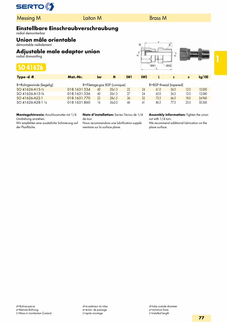
Einstellbare Einschraubverschraubungradial demontierbar
Union mâle orientabledémontable radialement
Adjustable male adaptor unionradial dismantling
SO 41626Type -d -R Mat.-Nr. bar M SW1 SW2 L z e kg/100 R=Rohrgewinde (kegelig) R=Filetage-gaz BSP (conique) R=BSP thread (tapered)SO 41626-A15-1/2 018.1631.534 40 20x1.5 22 24 61.0 54.5 12.0 10.000SO 41626-A15-3/4 018.1631.536 40 20x1.5 27 24 63.0 56.5 12.0 12.040SO 41626-A22-1 018.1631.770 25 28x1.5 36 32 73.5 66.5 18.0 24.960SO 41626-A28-1 1/4 018.1631.860 16 36x2.0 46 41 86.5 77.5 23.0 50.560
Montagehinweis: Anschlussmutter mit 1/4 Umdrehung anziehen.Wir empfehlen eine zusätzliche Schmierung auf der Planfläche.
Note d’installation: Serrez l’écrou de 1/4 de tour.Nous recommandons une lubrification supplé-mentaire sur la surface plane.
Assembly information: Tighten the union nut with 1/4 turn.We recommend additional lubrication on the plane surface.
Messing M Laiton M Brass M
d=Rohraussen-øe=kleinste BohrungL=Mass in montiertem Zustand
d=ø extérieur du tubee=ø-min. de passageL=après montage
d=tube outside diametere=minimum boreL=installed length
77
1
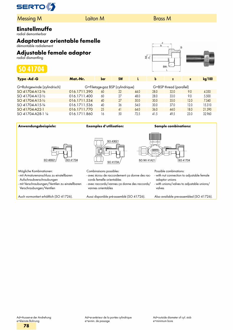
Einstellmufferadial demontierbar
Adaptateur orientable femelledémontable radialement
Adjustable female adaptorradial dismantling
SO 41704Type -Ad -G Mat.-Nr. bar SW L b z e kg/100 G=Rohrgewinde (zylindrisch) G=Filetage-gaz BSP (cylindrique) G=BSP thread (parallel)SO 41704-A12-3/8 016.1711.390 60 22 44.0 28.0 32.0 9.0 4.350SO 41704-A12-1/2 016.1711.400 60 27 48.0 28.0 33.0 9.0 5.500SO 41704-A15-1/2 016.1711.534 40 27 50.0 30.0 35.0 12.0 7.540SO 41704-A15-3/4 016.1711.536 40 36 54.0 30.0 37.0 12.0 15.310SO 41704-A22-1 016.1711.770 25 41 64.0 36.0 44.0 18.0 21.390SO 41704-A28-1 1/4 016.1711.860 16 50 72.5 41.5 49.5 23.0 32.960
Anwendungsbeispiele: Exemples d’utilisation: Sample combinations:
Mögliche Kombinationen:- mit Armaturenanschluss zu einstellbaren Aufschraubverschraubungen
- mit Verschraubungen/Ventilen zu einstellbaren Verschraubungen/Ventilen
Auch vormontiert erhältlich (SO 41726).
Combinaisons possibles:- avec écrou de raccordement ça donne des rac-cords femelle orientables
- avec raccords/vannes ça donne des raccords/vannes orientables
Aussi disponible pré-assemblé (SO 41726).
Possible combinations:- with nut connection to adjustable female adaptor unions
- with unions/valves to adjustable unions/valves
Also available pre-assembled (SO 41726).
Messing M Laiton M Brass M
Ad=Aussen-ø der Andrehunge=kleinste Bohrung
Ad=ø extérieur de la portée cylindriquee=ø-min. de passage
Ad=outside diameter of cyl. stube=minimum bore
78
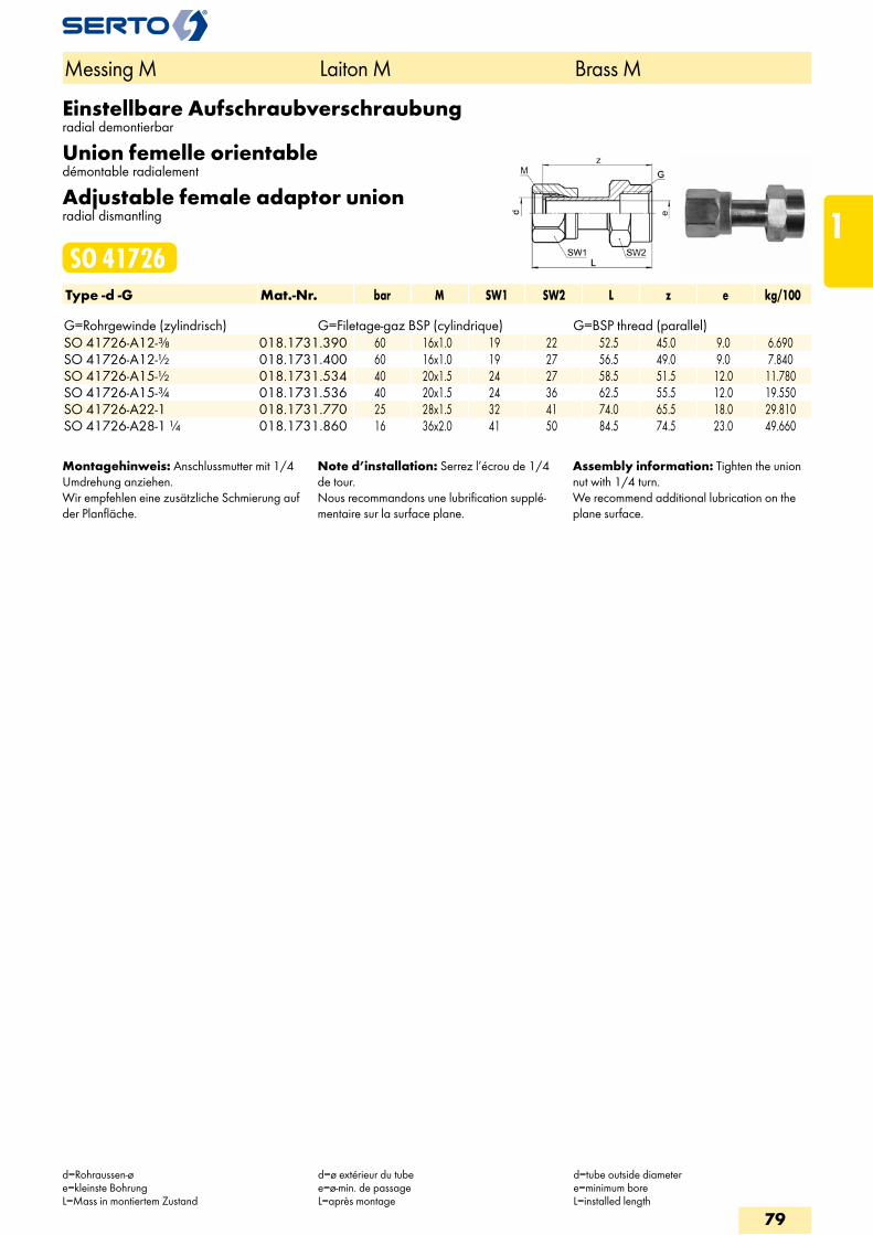
Einstellbare Aufschraubverschraubungradial demontierbar
Union femelle orientabledémontable radialement
Adjustable female adaptor unionradial dismantling
SO 41726Type -d -G Mat.-Nr. bar M SW1 SW2 L z e kg/100 G=Rohrgewinde (zylindrisch) G=Filetage-gaz BSP (cylindrique) G=BSP thread (parallel)SO 41726-A12-3/8 018.1731.390 60 16x1.0 19 22 52.5 45.0 9.0 6.690SO 41726-A12-1/2 018.1731.400 60 16x1.0 19 27 56.5 49.0 9.0 7.840SO 41726-A15-1/2 018.1731.534 40 20x1.5 24 27 58.5 51.5 12.0 11.780SO 41726-A15-3/4 018.1731.536 40 20x1.5 24 36 62.5 55.5 12.0 19.550SO 41726-A22-1 018.1731.770 25 28x1.5 32 41 74.0 65.5 18.0 29.810SO 41726-A28-1 1/4 018.1731.860 16 36x2.0 41 50 84.5 74.5 23.0 49.660
Montagehinweis: Anschlussmutter mit 1/4 Umdrehung anziehen.Wir empfehlen eine zusätzliche Schmierung auf der Planfläche.
Note d’installation: Serrez l’écrou de 1/4 de tour.Nous recommandons une lubrification supplé-mentaire sur la surface plane.
Assembly information: Tighten the union nut with 1/4 turn.We recommend additional lubrication on the plane surface.
Messing M Laiton M Brass M
d=Rohraussen-øe=kleinste BohrungL=Mass in montiertem Zustand
d=ø extérieur du tubee=ø-min. de passageL=après montage
d=tube outside diametere=minimum boreL=installed length
79
1
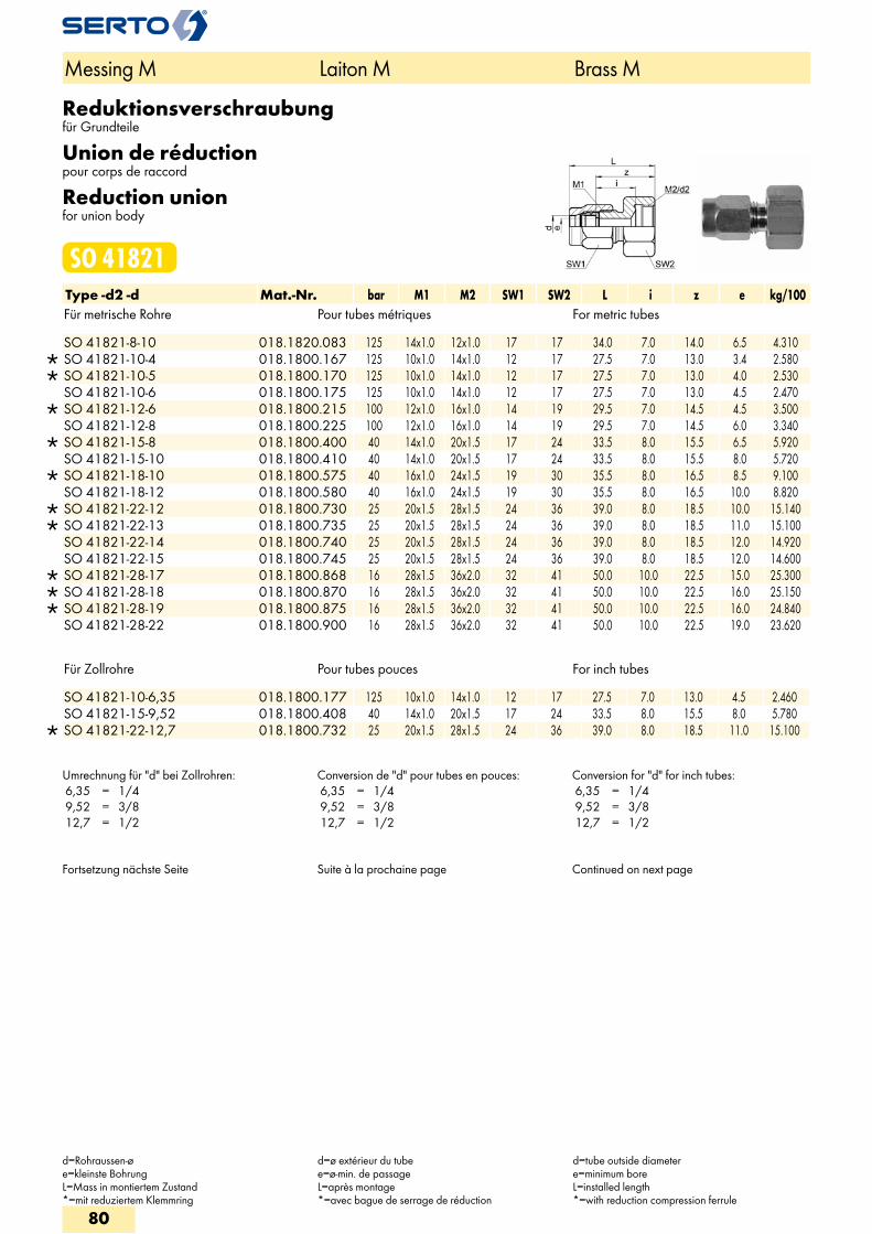
Reduktionsverschraubungfür Grundteile
Union de réductionpour corps de raccord
Reduction unionfor union body
SO 41821Type -d2 -d Mat.-Nr. bar M1 M2 SW1 SW2 L i z e kg/100Für metrische Rohre Pour tubes métriques For metric tubes
SO 41821-8-10 018.1820.083 125 14x1.0 12x1.0 17 17 34.0 7.0 14.0 6.5 4.310 SO 41821-10-4 018.1800.167 125 10x1.0 14x1.0 12 17 27.5 7.0 13.0 3.4 2.580 SO 41821-10-5 018.1800.170 125 10x1.0 14x1.0 12 17 27.5 7.0 13.0 4.0 2.530 SO 41821-10-6 018.1800.175 125 10x1.0 14x1.0 12 17 27.5 7.0 13.0 4.5 2.470
SO 41821-12-6 018.1800.215 100 12x1.0 16x1.0 14 19 29.5 7.0 14.5 4.5 3.500 SO 41821-12-8 018.1800.225 100 12x1.0 16x1.0 14 19 29.5 7.0 14.5 6.0 3.340
SO 41821-15-8 018.1800.400 40 14x1.0 20x1.5 17 24 33.5 8.0 15.5 6.5 5.920 SO 41821-15-10 018.1800.410 40 14x1.0 20x1.5 17 24 33.5 8.0 15.5 8.0 5.720
SO 41821-18-10 018.1800.575 40 16x1.0 24x1.5 19 30 35.5 8.0 16.5 8.5 9.100 SO 41821-18-12 018.1800.580 40 16x1.0 24x1.5 19 30 35.5 8.0 16.5 10.0 8.820
SO 41821-22-12 018.1800.730 25 20x1.5 28x1.5 24 36 39.0 8.0 18.5 10.0 15.140 SO 41821-22-13 018.1800.735 25 20x1.5 28x1.5 24 36 39.0 8.0 18.5 11.0 15.100 SO 41821-22-14 018.1800.740 25 20x1.5 28x1.5 24 36 39.0 8.0 18.5 12.0 14.920 SO 41821-22-15 018.1800.745 25 20x1.5 28x1.5 24 36 39.0 8.0 18.5 12.0 14.600
SO 41821-28-17 018.1800.868 16 28x1.5 36x2.0 32 41 50.0 10.0 22.5 15.0 25.300 SO 41821-28-18 018.1800.870 16 28x1.5 36x2.0 32 41 50.0 10.0 22.5 16.0 25.150 SO 41821-28-19 018.1800.875 16 28x1.5 36x2.0 32 41 50.0 10.0 22.5 16.0 24.840 SO 41821-28-22 018.1800.900 16 28x1.5 36x2.0 32 41 50.0 10.0 22.5 19.0 23.620
Für Zollrohre Pour tubes pouces For inch tubes
SO 41821-10-6,35 018.1800.177 125 10x1.0 14x1.0 12 17 27.5 7.0 13.0 4.5 2.460 SO 41821-15-9,52 018.1800.408 40 14x1.0 20x1.5 17 24 33.5 8.0 15.5 8.0 5.780
SO 41821-22-12,7 018.1800.732 25 20x1.5 28x1.5 24 36 39.0 8.0 18.5 11.0 15.100
Umrechnung für "d" bei Zollrohren: 6,35 = 1/4 9,52 = 3/8 12,7 = 1/2
Conversion de "d" pour tubes en pouces: 6,35 = 1/4 9,52 = 3/8 12,7 = 1/2
Conversion for "d" for inch tubes: 6,35 = 1/4 9,52 = 3/8 12,7 = 1/2
Fortsetzung nächste Seite Suite à la prochaine page Continued on next page
Messing M Laiton M Brass M
d=Rohraussen-øe=kleinste BohrungL=Mass in montiertem Zustand*=mit reduziertem Klemmring
d=ø extérieur du tubee=ø-min. de passageL=après montage*=avec bague de serrage de réduction
d=tube outside diametere=minimum boreL=installed length*=with reduction compression ferrule
80
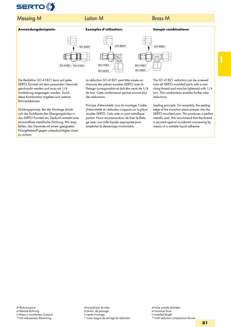
Anwendungsbeispiele: Exemples d’utilisation: Sample combinations:
Die Reduktion SO 41821 kann auf jedes SERTO Formteil mit dem passenden Gewinde geschraubt werden und muss mit 1/4 Umdrehung angezogen werden. Durch diese Kombination ergeben sich weitere Rohrreduktionen.
Dichtungsprinzip: Bei der Montage drückt sich die Dichtkante des Übergangstückes in das SERTO Formteil ein. Dadurch entsteht eine einwandfreie metallische Dichtung. Wir emp-fehlen, das Gewinde mit einem geeigneten Flüssigklebstoff gegen unbeabsichtigtes Lösen zu sichern.
La réduction SO 41821 peut être vissée sur chacune des pièces moulées SERTO avec le filetage correspondant et doit être serré de 1/4 de tour. Cette combinaison permet encore plus des réductions.
Principe d’étanchéité: Lors du montage, l’arête d’étanchéité du réducteur s’appuie sur la pièce moulée SERTO. Cela crée un joint métallique parfait. Nous recommandons de fixer le fileta-ge avec une colle liquide appropriée pour empêcher le desserrage involontaire.
The SO 41821 reduction can be screwed onto all SERTO moulded parts with a mat-ching thread and must be tightened with 1/4 turn. This combination enables further tube reductions.
Sealing principle: On assembly, the sealing edge of the transition piece presses into the SERTO moulded part. This produces a perfect metallic seal. We recommend that the thread is secured against accidental unscrewing by means of a suitable liquid adhesive.
Messing M Laiton M Brass M
d=Rohraussen-øe=kleinste BohrungL=Mass in montiertem Zustand*=mit reduziertem Klemmring
d=ø extérieur du tubee=ø-min. de passageL=après montage*=avec bague de serrage de réduction
d=tube outside diametere=minimum boreL=installed length*=with reduction compression ferrule
81
1
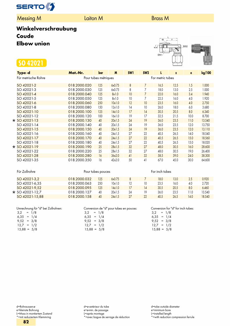
WinkelverschraubungCoudeElbow union
SO 42021Type -d Mat.-Nr. bar M SW1 SW2 L z e kg/100Für metrische Rohre Pour tubes métriques For metric tubes
SO 42021-2 018.2000.020 125 6x0.75 8 7 16.5 12.5 1.5 1.000 SO 42021-3 018.2000.030 125 6x0.75 8 7 18.0 13.0 2.5 1.000 SO 42021-4 018.2000.040 125 8x1.0 10 7 22.0 16.0 3.4 1.940 SO 42021-5 018.2000.050 125 8x1.0 10 7 22.5 16.0 4.0 1.920 SO 42021-6 018.2000.060 250 10x1.0 12 10 23.5 16.0 4.0 2.750 SO 42021-8 018.2000.080 150 12x1.0 14 10 26.0 18.0 6.0 3.680 SO 42021-10 018.2000.100 125 14x1.0 17 14 30.5 20.5 8.0 6.340 SO 42021-12 018.2000.120 100 16x1.0 19 17 32.5 21.5 10.0 8.700
SO 42021-13 018.2000.130 40 20x1.5 24 19 36.0 23.5 11.0 13.540 SO 42021-14 018.2000.140 40 20x1.5 24 19 36.0 23.5 12.0 13.750 SO 42021-15 018.2000.150 40 20x1.5 24 19 36.0 23.5 12.0 13.110 SO 42021-16 018.2000.160 40 24x1.5 27 22 40.5 26.5 14.0 18.540 SO 42021-17 018.2000.170 40 24x1.5 27 22 40.5 26.5 15.0 18.560 SO 42021-18 018.2000.180 40 24x1.5 27 22 40.5 26.5 15.0 18.020
SO 42021-19 018.2000.190 25 28x1.5 32 27 48.0 30.5 16.0 28.600 SO 42021-22 018.2000.220 25 28x1.5 32 27 48.0 30.5 19.0 26.400 SO 42021-28 018.2000.280 16 36x2.0 41 32 58.5 39.0 24.0 38.300 SO 42021-35 018.2000.350 16 42x2.0 50 41 67.0 45.0 30.0 64.600
Für Zollrohre Pour tubes pouces For inch tubes
SO 42021-3,2 018.2000.032 125 6x0.75 8 7 18.0 13.0 2.5 0.920 SO 42021-6,35 018.2000.063 250 10x1.0 12 10 23.5 16.0 4.0 2.720 SO 42021-9,52 018.2000.095 125 14x1.0 17 14 30.5 20.5 8.0 6.460
SO 42021-12,7 018.2000.127 40 20x1.5 24 19 36.0 23.5 11.0 13.540 SO 42021-15,88 018.2000.158 40 24x1.5 27 22 40.5 26.5 14.0 18.540
Umrechnung für "d" bei Zollrohren: 3,2 = 1/8 6,35 = 1/4 9,52 = 3/8 12,7 = 1/2 15,88 = 5/8
Conversion de "d" pour tubes en pouces: 3,2 = 1/8 6,35 = 1/4 9,52 = 3/8 12,7 = 1/2 15,88 = 5/8
Conversion for "d" for inch tubes: 3,2 = 1/8 6,35 = 1/4 9,52 = 3/8 12,7 = 1/2 15,88 = 5/8
Messing M Laiton M Brass M
d=Rohraussen-øe=kleinste BohrungL=Mass in montiertem Zustand*=mit reduziertem Klemmring
d=ø extérieur du tubee=ø-min. de passageL=après montage*=avec bague de serrage de réduction
d=tube outside diametere=minimum boreL=installed length*=with reduction compression ferrule
82
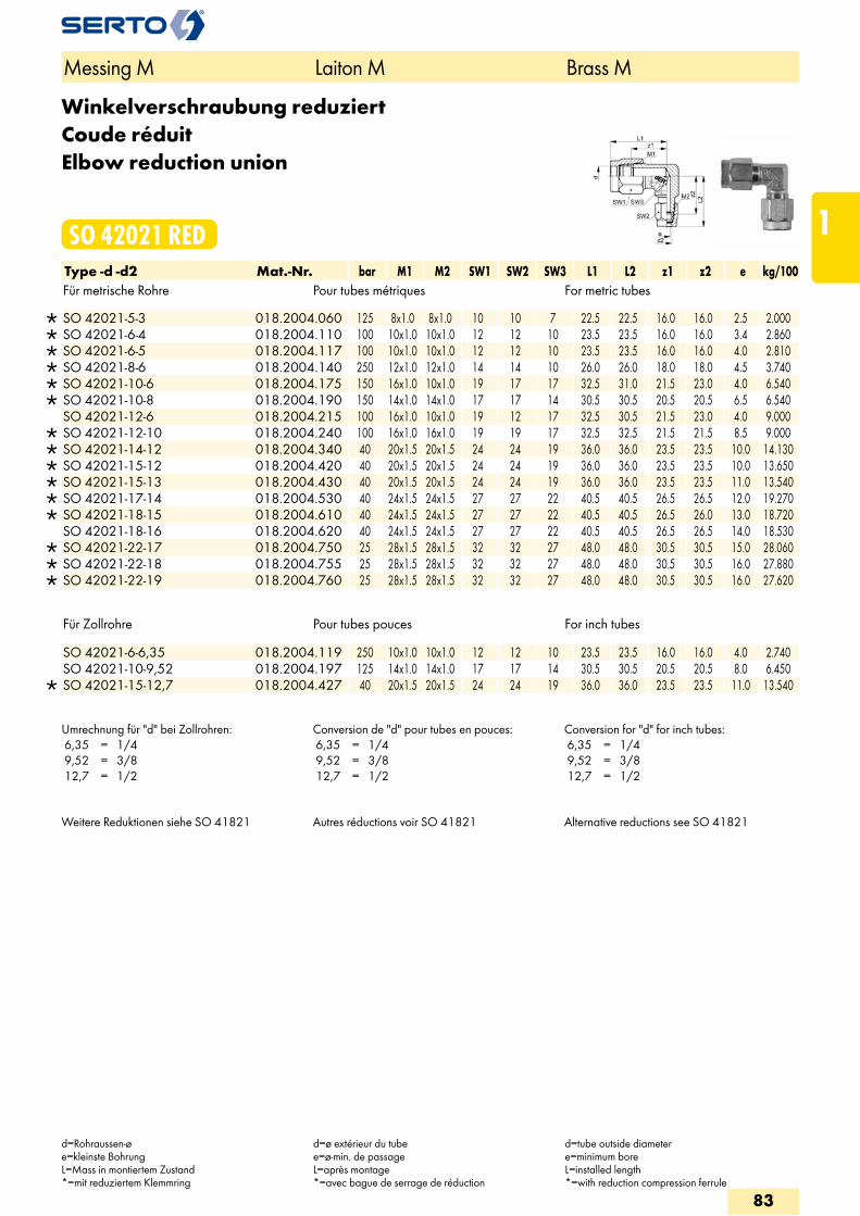
Winkelverschraubung reduziertCoude réduitElbow reduction union
SO 42021 REDType -d -d2 Mat.-Nr. bar M1 M2 SW1 SW2 SW3 L1 L2 z1 z2 e kg/100Für metrische Rohre Pour tubes métriques For metric tubes
SO 42021-5-3 018.2004.060 125 8x1.0 8x1.0 10 10 7 22.5 22.5 16.0 16.0 2.5 2.000 SO 42021-6-4 018.2004.110 100 10x1.0 10x1.0 12 12 10 23.5 23.5 16.0 16.0 3.4 2.860 SO 42021-6-5 018.2004.117 100 10x1.0 10x1.0 12 12 10 23.5 23.5 16.0 16.0 4.0 2.810 SO 42021-8-6 018.2004.140 250 12x1.0 12x1.0 14 14 10 26.0 26.0 18.0 18.0 4.5 3.740 SO 42021-10-6 018.2004.175 150 16x1.0 10x1.0 19 17 17 32.5 31.0 21.5 23.0 4.0 6.540 SO 42021-10-8 018.2004.190 150 14x1.0 14x1.0 17 17 14 30.5 30.5 20.5 20.5 6.5 6.540 SO 42021-12-6 018.2004.215 100 16x1.0 10x1.0 19 12 17 32.5 30.5 21.5 23.0 4.0 9.000
SO 42021-12-10 018.2004.240 100 16x1.0 16x1.0 19 19 17 32.5 32.5 21.5 21.5 8.5 9.000 SO 42021-14-12 018.2004.340 40 20x1.5 20x1.5 24 24 19 36.0 36.0 23.5 23.5 10.0 14.130 SO 42021-15-12 018.2004.420 40 20x1.5 20x1.5 24 24 19 36.0 36.0 23.5 23.5 10.0 13.650 SO 42021-15-13 018.2004.430 40 20x1.5 20x1.5 24 24 19 36.0 36.0 23.5 23.5 11.0 13.540 SO 42021-17-14 018.2004.530 40 24x1.5 24x1.5 27 27 22 40.5 40.5 26.5 26.5 12.0 19.270 SO 42021-18-15 018.2004.610 40 24x1.5 24x1.5 27 27 22 40.5 40.5 26.5 26.0 13.0 18.720 SO 42021-18-16 018.2004.620 40 24x1.5 24x1.5 27 27 22 40.5 40.5 26.5 26.5 14.0 18.530
SO 42021-22-17 018.2004.750 25 28x1.5 28x1.5 32 32 27 48.0 48.0 30.5 30.5 15.0 28.060 SO 42021-22-18 018.2004.755 25 28x1.5 28x1.5 32 32 27 48.0 48.0 30.5 30.5 16.0 27.880 SO 42021-22-19 018.2004.760 25 28x1.5 28x1.5 32 32 27 48.0 48.0 30.5 30.5 16.0 27.620
Für Zollrohre Pour tubes pouces For inch tubes
SO 42021-6-6,35 018.2004.119 250 10x1.0 10x1.0 12 12 10 23.5 23.5 16.0 16.0 4.0 2.740 SO 42021-10-9,52 018.2004.197 125 14x1.0 14x1.0 17 17 14 30.5 30.5 20.5 20.5 8.0 6.450
SO 42021-15-12,7 018.2004.427 40 20x1.5 20x1.5 24 24 19 36.0 36.0 23.5 23.5 11.0 13.540
Umrechnung für "d" bei Zollrohren: 6,35 = 1/4 9,52 = 3/8 12,7 = 1/2
Conversion de "d" pour tubes en pouces: 6,35 = 1/4 9,52 = 3/8 12,7 = 1/2
Conversion for "d" for inch tubes: 6,35 = 1/4 9,52 = 3/8 12,7 = 1/2
Weitere Reduktionen siehe SO 41821 Autres réductions voir SO 41821 Alternative reductions see SO 41821
Messing M Laiton M Brass M
d=Rohraussen-øe=kleinste BohrungL=Mass in montiertem Zustand*=mit reduziertem Klemmring
d=ø extérieur du tubee=ø-min. de passageL=après montage*=avec bague de serrage de réduction
d=tube outside diametere=minimum boreL=installed length*=with reduction compression ferrule
83
1
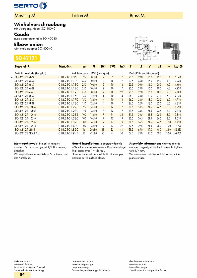
Winkelverschraubungmit Übergangsnippel SO 40040
Coudeavec adaptateur mâle SO 40040
Elbow unionwith male adaptor SO 40040
SO 42121Type -d -R Mat.-Nr. bar M SW1 SW2 SW3 L1 L2 z1 z2 e kg/100 R=Rohrgewinde (kegelig) R=Filetage-gaz BSP (conique) R=BSP thread (tapered)
SO 42121-4-3/8 018.2101.068 125 10x1.0 12 7 17 23.5 29.0 16.0 19.0 3.4 5.040 SO 42121-6-1/8 018.2101.100 250 10x1.0 12 10 12 23.5 26.0 16.0 19.0 4.0 3.240 SO 42121-6-1/4 018.2101.110 250 10x1.0 12 10 14 23.5 30.0 16.0 20.0 4.0 4.400 SO 42121-6-3/8 018.2101.120 250 10x1.0 12 10 17 23.5 29.0 16.0 19.0 4.0 4.930 SO 42121-6-1/2 018.2101.125 250 10x1.0 12 10 22 23.5 32.0 16.0 18.0 4.0 7.480 SO 42121-8-1/8 018.2101.160 150 12x1.0 14 10 14 26.0 28.0 18.0 21.0 6.0 4.070 SO 42121-8-1/4 018.2101.170 150 12x1.0 14 10 14 26.0 32.0 18.0 22.0 6.0 4.710 SO 42121-8-3/8 018.2101.180 150 12x1.0 14 10 17 26.0 32.0 18.0 22.0 6.0 6.210 SO 42121-10-1/4 018.2101.270 125 14x1.0 17 14 17 31.5 34.5 21.5 24.5 8.0 6.990 SO 42121-10-3/8 018.2101.280 125 14x1.0 17 14 17 31.5 34.5 21.5 24.5 8.0 7.810 SO 42121-10-1/2 018.2101.285 100 14x1.0 17 14 22 31.5 36.5 21.5 25.5 8.0 7.840 SO 42121-12-1/4 018.2101.380 100 16x1.0 19 17 19 32.5 36.5 21.5 26.5 8.5 9.010 SO 42121-12-3/8 018.2101.390 100 16x1.0 19 17 19 32.5 36.5 21.5 26.5 10.0 9.450 SO 42121-12-1/2 018.2101.400 100 16x1.0 19 17 22 32.5 39.5 21.5 28.0 10.0 12.290 SO 42121-28-1 018.2101.850 16 36x2.0 41 32 41 58.5 65.0 39.0 48.0 24.0 36.430 SO 42121-35-1 1/4 018.2101.944 16 42x2.0 50 41 50 67.0 73.0 40.0 59.0 30.0 62.000
Montagehinweis: Nippel ist handfest montiert. Bei Endmontage mit 1/4 Umdrehung anziehen.Wir empfehlen eine zusätzliche Schmierung auf der Planfläche.
Note d’installation: L’adaptateur femelle-mâle est monté serré à la main. Pour le montage final, serrer avec 1/4 de tour.Nous recommandons une lubrification supplé-mentaire sur la surface plane.
Assembly information: Male adaptor is mounted finger-tight. For final assembly, tighten with 1/4 turn.We recommend additional lubrication on the plane surface.
Messing M Laiton M Brass M
d=Rohraussen-øe=kleinste BohrungL=Mass in montiertem Zustand*=mit reduziertem Klemmring
d=ø extérieur du tubee=ø-min. de passageL=après montage*=avec bague de serrage de réduction
d=tube outside diametere=minimum boreL=installed length*=with reduction compression ferrule
84
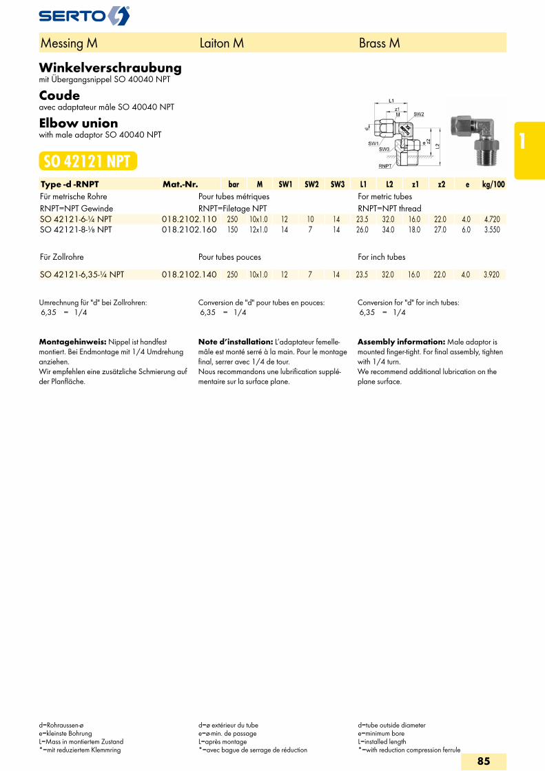
Winkelverschraubungmit Übergangsnippel SO 40040 NPT
Coudeavec adaptateur mâle SO 40040 NPT
Elbow unionwith male adaptor SO 40040 NPT
SO 42121 NPTType -d -RNPT Mat.-Nr. bar M SW1 SW2 SW3 L1 L2 z1 z2 e kg/100Für metrische Rohre Pour tubes métriques For metric tubesRNPT=NPT Gewinde RNPT=Filetage NPT RNPT=NPT thread
SO 42121-6-1/4 NPT 018.2102.110 250 10x1.0 12 10 14 23.5 32.0 16.0 22.0 4.0 4.720 SO 42121-8-1/8 NPT 018.2102.160 150 12x1.0 14 7 14 26.0 34.0 18.0 27.0 6.0 3.550
Für Zollrohre Pour tubes pouces For inch tubes
SO 42121-6,35-1/4 NPT 018.2102.140 250 10x1.0 12 7 14 23.5 32.0 16.0 22.0 4.0 3.920
Umrechnung für "d" bei Zollrohren: 6,35 = 1/4
Conversion de "d" pour tubes en pouces: 6,35 = 1/4
Conversion for "d" for inch tubes: 6,35 = 1/4
Montagehinweis: Nippel ist handfest montiert. Bei Endmontage mit 1/4 Umdrehung anziehen.Wir empfehlen eine zusätzliche Schmierung auf der Planfläche.
Note d’installation: L’adaptateur femelle-mâle est monté serré à la main. Pour le montage final, serrer avec 1/4 de tour.Nous recommandons une lubrification supplé-mentaire sur la surface plane.
Assembly information: Male adaptor is mounted finger-tight. For final assembly, tighten with 1/4 turn.We recommend additional lubrication on the plane surface.
Messing M Laiton M Brass M
d=Rohraussen-øe=kleinste BohrungL=Mass in montiertem Zustand*=mit reduziertem Klemmring
d=ø extérieur du tubee=ø-min. de passageL=après montage*=avec bague de serrage de réduction
d=tube outside diametere=minimum boreL=installed length*=with reduction compression ferrule
85
1
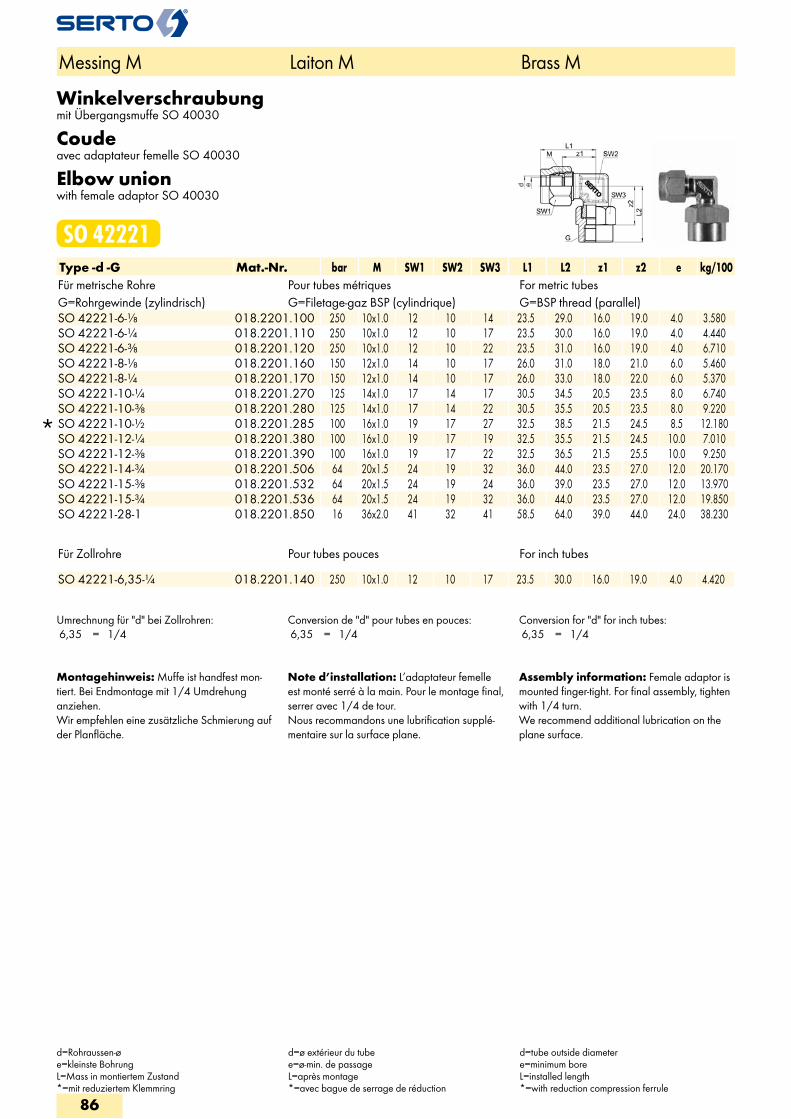
Winkelverschraubungmit Übergangsmuffe SO 40030
Coudeavec adaptateur femelle SO 40030
Elbow unionwith female adaptor SO 40030
SO 42221Type -d -G Mat.-Nr. bar M SW1 SW2 SW3 L1 L2 z1 z2 e kg/100Für metrische Rohre Pour tubes métriques For metric tubesG=Rohrgewinde (zylindrisch) G=Filetage-gaz BSP (cylindrique) G=BSP thread (parallel)
SO 42221-6-1/8 018.2201.100 250 10x1.0 12 10 14 23.5 29.0 16.0 19.0 4.0 3.580 SO 42221-6-1/4 018.2201.110 250 10x1.0 12 10 17 23.5 30.0 16.0 19.0 4.0 4.440 SO 42221-6-3/8 018.2201.120 250 10x1.0 12 10 22 23.5 31.0 16.0 19.0 4.0 6.710 SO 42221-8-1/8 018.2201.160 150 12x1.0 14 10 17 26.0 31.0 18.0 21.0 6.0 5.460 SO 42221-8-1/4 018.2201.170 150 12x1.0 14 10 17 26.0 33.0 18.0 22.0 6.0 5.370 SO 42221-10-1/4 018.2201.270 125 14x1.0 17 14 17 30.5 34.5 20.5 23.5 8.0 6.740 SO 42221-10-3/8 018.2201.280 125 14x1.0 17 14 22 30.5 35.5 20.5 23.5 8.0 9.220
SO 42221-10-1/2 018.2201.285 100 16x1.0 19 17 27 32.5 38.5 21.5 24.5 8.5 12.180 SO 42221-12-1/4 018.2201.380 100 16x1.0 19 17 19 32.5 35.5 21.5 24.5 10.0 7.010 SO 42221-12-3/8 018.2201.390 100 16x1.0 19 17 22 32.5 36.5 21.5 25.5 10.0 9.250 SO 42221-14-3/4 018.2201.506 64 20x1.5 24 19 32 36.0 44.0 23.5 27.0 12.0 20.170 SO 42221-15-3/8 018.2201.532 64 20x1.5 24 19 24 36.0 39.0 23.5 27.0 12.0 13.970 SO 42221-15-3/4 018.2201.536 64 20x1.5 24 19 32 36.0 44.0 23.5 27.0 12.0 19.850 SO 42221-28-1 018.2201.850 16 36x2.0 41 32 41 58.5 64.0 39.0 44.0 24.0 38.230
Für Zollrohre Pour tubes pouces For inch tubes
SO 42221-6,35-1/4 018.2201.140 250 10x1.0 12 10 17 23.5 30.0 16.0 19.0 4.0 4.420
Umrechnung für "d" bei Zollrohren: 6,35 = 1/4
Conversion de "d" pour tubes en pouces: 6,35 = 1/4
Conversion for "d" for inch tubes: 6,35 = 1/4
Montagehinweis: Muffe ist handfest mon-tiert. Bei Endmontage mit 1/4 Umdrehung anziehen.Wir empfehlen eine zusätzliche Schmierung auf der Planfläche.
Note d’installation: L’adaptateur femelle est monté serré à la main. Pour le montage final, serrer avec 1/4 de tour.Nous recommandons une lubrification supplé-mentaire sur la surface plane.
Assembly information: Female adaptor is mounted finger-tight. For final assembly, tighten with 1/4 turn.We recommend additional lubrication on the plane surface.
Messing M Laiton M Brass M
d=Rohraussen-øe=kleinste BohrungL=Mass in montiertem Zustand*=mit reduziertem Klemmring
d=ø extérieur du tubee=ø-min. de passageL=après montage*=avec bague de serrage de réduction
d=tube outside diametere=minimum boreL=installed length*=with reduction compression ferrule
86
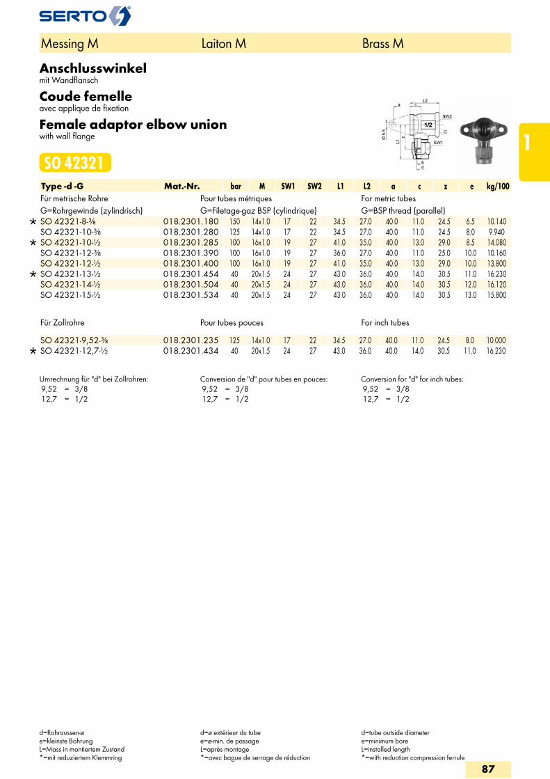
Anschlusswinkelmit Wandflansch
Coude femelleavec applique de fixation
Female adaptor elbow unionwith wall flange
SO 42321Type -d -G Mat.-Nr. bar M SW1 SW2 L1 L2 a c z e kg/100Für metrische Rohre Pour tubes métriques For metric tubesG=Rohrgewinde (zylindrisch) G=Filetage-gaz BSP (cylindrique) G=BSP thread (parallel)
SO 42321-8-3/8 018.2301.180 150 14x1.0 17 22 34.5 27.0 40.0 11.0 24.5 6.5 10.140 SO 42321-10-3/8 018.2301.280 125 14x1.0 17 22 34.5 27.0 40.0 11.0 24.5 8.0 9.940
SO 42321-10-1/2 018.2301.285 100 16x1.0 19 27 41.0 35.0 40.0 13.0 29.0 8.5 14.080 SO 42321-12-3/8 018.2301.390 100 16x1.0 19 27 36.0 27.0 40.0 11.0 25.0 10.0 10.160 SO 42321-12-1/2 018.2301.400 100 16x1.0 19 27 41.0 35.0 40.0 13.0 29.0 10.0 13.800
SO 42321-13-1/2 018.2301.454 40 20x1.5 24 27 43.0 36.0 40.0 14.0 30.5 11.0 16.230 SO 42321-14-1/2 018.2301.504 40 20x1.5 24 27 43.0 36.0 40.0 14.0 30.5 12.0 16.120 SO 42321-15-1/2 018.2301.534 40 20x1.5 24 27 43.0 36.0 40.0 14.0 30.5 13.0 15.800
Für Zollrohre Pour tubes pouces For inch tubes
SO 42321-9,52-3/8 018.2301.235 125 14x1.0 17 22 34.5 27.0 40.0 11.0 24.5 8.0 10.000 SO 42321-12,7-1/2 018.2301.434 40 20x1.5 24 27 43.0 36.0 40.0 14.0 30.5 11.0 16.230
Umrechnung für "d" bei Zollrohren: 9,52 = 3/8 12,7 = 1/2
Conversion de "d" pour tubes en pouces: 9,52 = 3/8 12,7 = 1/2
Conversion for "d" for inch tubes: 9,52 = 3/8 12,7 = 1/2
Messing M Laiton M Brass M
d=Rohraussen-øe=kleinste BohrungL=Mass in montiertem Zustand*=mit reduziertem Klemmring
d=ø extérieur du tubee=ø-min. de passageL=après montage*=avec bague de serrage de réduction
d=tube outside diametere=minimum boreL=installed length*=with reduction compression ferrule
87
1
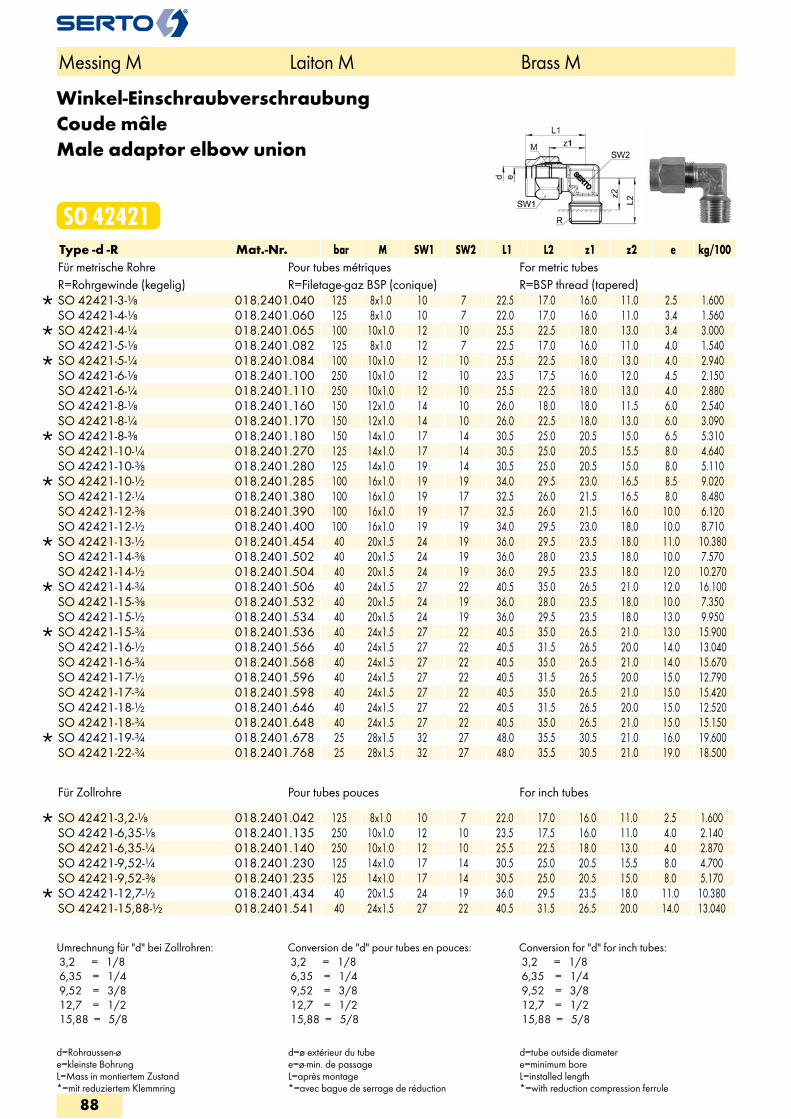
Winkel-EinschraubverschraubungCoude mâleMale adaptor elbow union
SO 42421Type -d -R Mat.-Nr. bar M SW1 SW2 L1 L2 z1 z2 e kg/100Für metrische Rohre Pour tubes métriques For metric tubesR=Rohrgewinde (kegelig) R=Filetage-gaz BSP (conique) R=BSP thread (tapered)
SO 42421-3-1/8 018.2401.040 125 8x1.0 10 7 22.5 17.0 16.0 11.0 2.5 1.600 SO 42421-4-1/8 018.2401.060 125 8x1.0 10 7 22.0 17.0 16.0 11.0 3.4 1.560
SO 42421-4-1/4 018.2401.065 100 10x1.0 12 10 25.5 22.5 18.0 13.0 3.4 3.000 SO 42421-5-1/8 018.2401.082 125 8x1.0 12 7 22.5 17.0 16.0 11.0 4.0 1.540
SO 42421-5-1/4 018.2401.084 100 10x1.0 12 10 25.5 22.5 18.0 13.0 4.0 2.940 SO 42421-6-1/8 018.2401.100 250 10x1.0 12 10 23.5 17.5 16.0 12.0 4.5 2.150 SO 42421-6-1/4 018.2401.110 250 10x1.0 12 10 25.5 22.5 18.0 13.0 4.0 2.880 SO 42421-8-1/8 018.2401.160 150 12x1.0 14 10 26.0 18.0 18.0 11.5 6.0 2.540 SO 42421-8-1/4 018.2401.170 150 12x1.0 14 10 26.0 22.5 18.0 13.0 6.0 3.090
SO 42421-8-3/8 018.2401.180 150 14x1.0 17 14 30.5 25.0 20.5 15.0 6.5 5.310 SO 42421-10-1/4 018.2401.270 125 14x1.0 17 14 30.5 25.0 20.5 15.5 8.0 4.640 SO 42421-10-3/8 018.2401.280 125 14x1.0 19 14 30.5 25.0 20.5 15.0 8.0 5.110
SO 42421-10-1/2 018.2401.285 100 16x1.0 19 19 34.0 29.5 23.0 16.5 8.5 9.020 SO 42421-12-1/4 018.2401.380 100 16x1.0 19 17 32.5 26.0 21.5 16.5 8.0 8.480 SO 42421-12-3/8 018.2401.390 100 16x1.0 19 17 32.5 26.0 21.5 16.0 10.0 6.120 SO 42421-12-1/2 018.2401.400 100 16x1.0 19 19 34.0 29.5 23.0 18.0 10.0 8.710
SO 42421-13-1/2 018.2401.454 40 20x1.5 24 19 36.0 29.5 23.5 18.0 11.0 10.380 SO 42421-14-3/8 018.2401.502 40 20x1.5 24 19 36.0 28.0 23.5 18.0 10.0 7.570 SO 42421-14-1/2 018.2401.504 40 20x1.5 24 19 36.0 29.5 23.5 18.0 12.0 10.270
SO 42421-14-3/4 018.2401.506 40 24x1.5 27 22 40.5 35.0 26.5 21.0 12.0 16.100 SO 42421-15-3/8 018.2401.532 40 20x1.5 24 19 36.0 28.0 23.5 18.0 10.0 7.350 SO 42421-15-1/2 018.2401.534 40 20x1.5 24 19 36.0 29.5 23.5 18.0 13.0 9.950
SO 42421-15-3/4 018.2401.536 40 24x1.5 27 22 40.5 35.0 26.5 21.0 13.0 15.900 SO 42421-16-1/2 018.2401.566 40 24x1.5 27 22 40.5 31.5 26.5 20.0 14.0 13.040 SO 42421-16-3/4 018.2401.568 40 24x1.5 27 22 40.5 35.0 26.5 21.0 14.0 15.670 SO 42421-17-1/2 018.2401.596 40 24x1.5 27 22 40.5 31.5 26.5 20.0 15.0 12.790 SO 42421-17-3/4 018.2401.598 40 24x1.5 27 22 40.5 35.0 26.5 21.0 15.0 15.420 SO 42421-18-1/2 018.2401.646 40 24x1.5 27 22 40.5 31.5 26.5 20.0 15.0 12.520 SO 42421-18-3/4 018.2401.648 40 24x1.5 27 22 40.5 35.0 26.5 21.0 15.0 15.150
SO 42421-19-3/4 018.2401.678 25 28x1.5 32 27 48.0 35.5 30.5 21.0 16.0 19.600 SO 42421-22-3/4 018.2401.768 25 28x1.5 32 27 48.0 35.5 30.5 21.0 19.0 18.500
Für Zollrohre Pour tubes pouces For inch tubes
SO 42421-3,2-1/8 018.2401.042 125 8x1.0 10 7 22.0 17.0 16.0 11.0 2.5 1.600 SO 42421-6,35-1/8 018.2401.135 250 10x1.0 12 10 23.5 17.5 16.0 11.0 4.0 2.140 SO 42421-6,35-1/4 018.2401.140 250 10x1.0 12 10 25.5 22.5 18.0 13.0 4.0 2.870 SO 42421-9,52-1/4 018.2401.230 125 14x1.0 17 14 30.5 25.0 20.5 15.5 8.0 4.700 SO 42421-9,52-3/8 018.2401.235 125 14x1.0 17 14 30.5 25.0 20.5 15.0 8.0 5.170
SO 42421-12,7-1/2 018.2401.434 40 20x1.5 24 19 36.0 29.5 23.5 18.0 11.0 10.380 SO 42421-15,88-1/2 018.2401.541 40 24x1.5 27 22 40.5 31.5 26.5 20.0 14.0 13.040
Messing M Laiton M Brass M
d=Rohraussen-øe=kleinste BohrungL=Mass in montiertem Zustand*=mit reduziertem Klemmring
d=ø extérieur du tubee=ø-min. de passageL=après montage*=avec bague de serrage de réduction
d=tube outside diametere=minimum boreL=installed length*=with reduction compression ferrule
Umrechnung für "d" bei Zollrohren: 3,2 = 1/8 6,35 = 1/4 9,52 = 3/8 12,7 = 1/2 15,88 = 5/8
Conversion de "d" pour tubes en pouces: 3,2 = 1/8 6,35 = 1/4 9,52 = 3/8 12,7 = 1/2 15,88 = 5/8
Conversion for "d" for inch tubes: 3,2 = 1/8 6,35 = 1/4 9,52 = 3/8 12,7 = 1/2 15,88 = 5/8
88
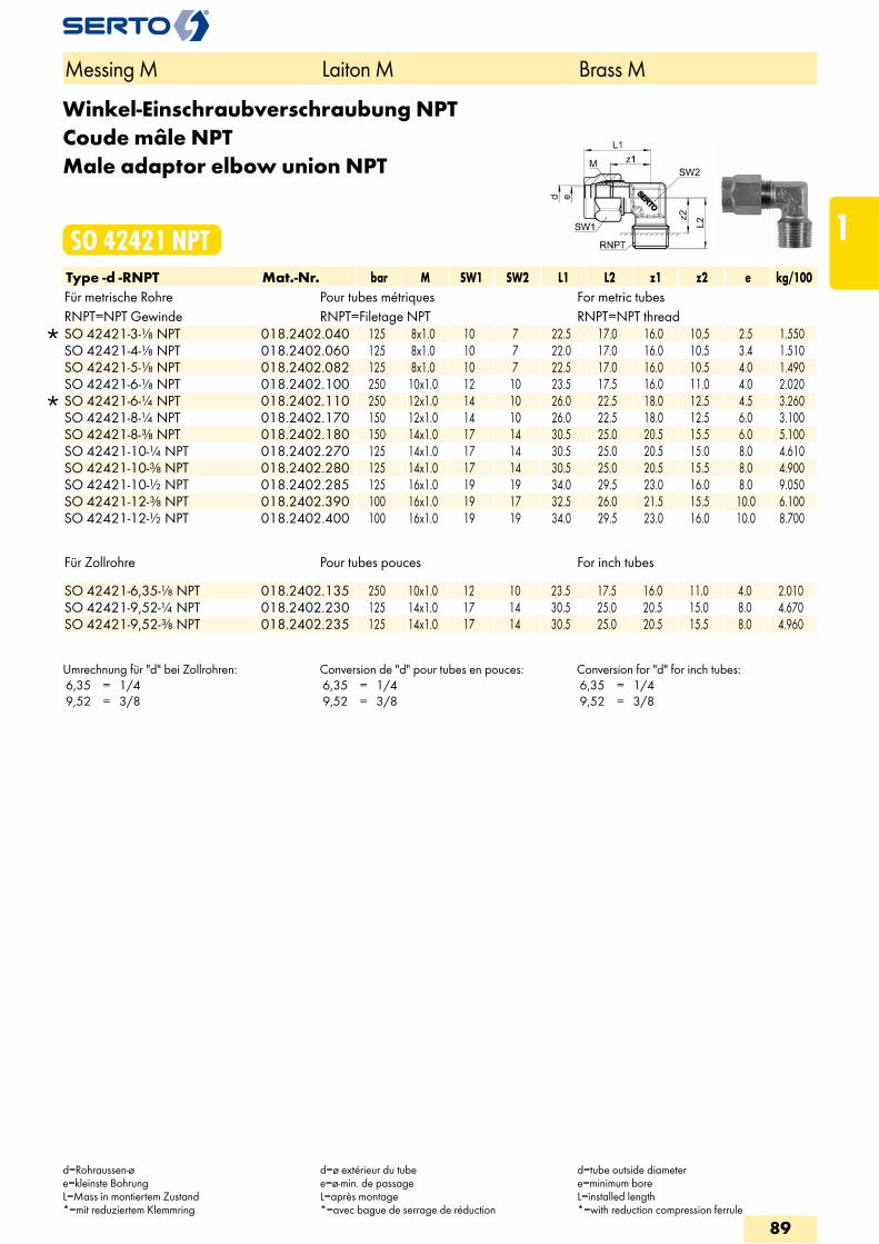
Winkel-Einschraubverschraubung NPTCoude mâle NPTMale adaptor elbow union NPT
SO 42421 NPTType -d -RNPT Mat.-Nr. bar M SW1 SW2 L1 L2 z1 z2 e kg/100Für metrische Rohre Pour tubes métriques For metric tubesRNPT=NPT Gewinde RNPT=Filetage NPT RNPT=NPT thread
SO 42421-3-1/8 NPT 018.2402.040 125 8x1.0 10 7 22.5 17.0 16.0 10.5 2.5 1.550 SO 42421-4-1/8 NPT 018.2402.060 125 8x1.0 10 7 22.0 17.0 16.0 10.5 3.4 1.510 SO 42421-5-1/8 NPT 018.2402.082 125 8x1.0 10 7 22.5 17.0 16.0 10.5 4.0 1.490 SO 42421-6-1/8 NPT 018.2402.100 250 10x1.0 12 10 23.5 17.5 16.0 11.0 4.0 2.020
SO 42421-6-1/4 NPT 018.2402.110 250 12x1.0 14 10 26.0 22.5 18.0 12.5 4.5 3.260 SO 42421-8-1/4 NPT 018.2402.170 150 12x1.0 14 10 26.0 22.5 18.0 12.5 6.0 3.100 SO 42421-8-3/8 NPT 018.2402.180 150 14x1.0 17 14 30.5 25.0 20.5 15.5 6.0 5.100 SO 42421-10-1/4 NPT 018.2402.270 125 14x1.0 17 14 30.5 25.0 20.5 15.0 8.0 4.610 SO 42421-10-3/8 NPT 018.2402.280 125 14x1.0 17 14 30.5 25.0 20.5 15.5 8.0 4.900 SO 42421-10-1/2 NPT 018.2402.285 125 16x1.0 19 19 34.0 29.5 23.0 16.0 8.0 9.050 SO 42421-12-3/8 NPT 018.2402.390 100 16x1.0 19 17 32.5 26.0 21.5 15.5 10.0 6.100 SO 42421-12-1/2 NPT 018.2402.400 100 16x1.0 19 19 34.0 29.5 23.0 16.0 10.0 8.700
Für Zollrohre Pour tubes pouces For inch tubes
SO 42421-6,35-1/8 NPT 018.2402.135 250 10x1.0 12 10 23.5 17.5 16.0 11.0 4.0 2.010 SO 42421-9,52-1/4 NPT 018.2402.230 125 14x1.0 17 14 30.5 25.0 20.5 15.0 8.0 4.670 SO 42421-9,52-3/8 NPT 018.2402.235 125 14x1.0 17 14 30.5 25.0 20.5 15.5 8.0 4.960
Umrechnung für "d" bei Zollrohren: 6,35 = 1/4 9,52 = 3/8
Conversion de "d" pour tubes en pouces: 6,35 = 1/4 9,52 = 3/8
Conversion for "d" for inch tubes: 6,35 = 1/4 9,52 = 3/8
Messing M Laiton M Brass M
d=Rohraussen-øe=kleinste BohrungL=Mass in montiertem Zustand*=mit reduziertem Klemmring
d=ø extérieur du tubee=ø-min. de passageL=après montage*=avec bague de serrage de réduction
d=tube outside diametere=minimum boreL=installed length*=with reduction compression ferrule
89
1
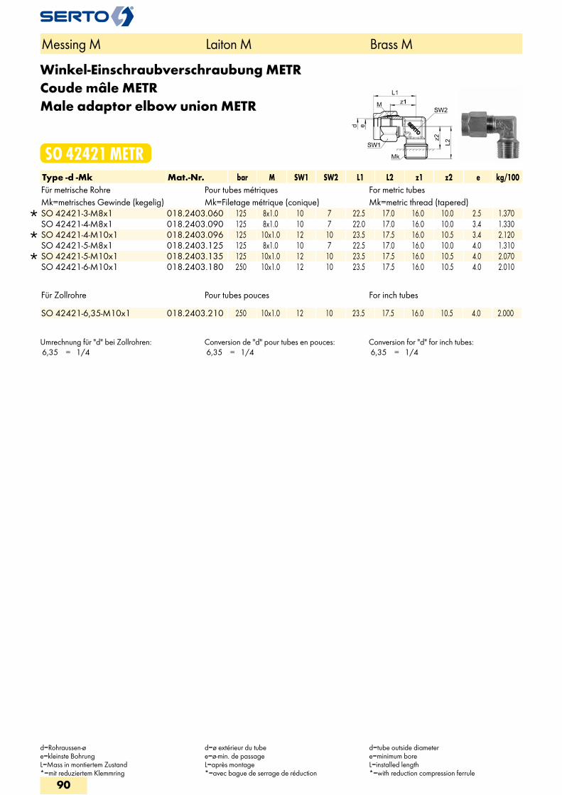
Winkel-Einschraubverschraubung METRCoude mâle METRMale adaptor elbow union METR
SO 42421 METRType -d -Mk Mat.-Nr. bar M SW1 SW2 L1 L2 z1 z2 e kg/100Für metrische Rohre Pour tubes métriques For metric tubesMk=metrisches Gewinde (kegelig) Mk=Filetage métrique (conique) Mk=metric thread (tapered)
SO 42421-3-M8x1 018.2403.060 125 8x1.0 10 7 22.5 17.0 16.0 10.0 2.5 1.370 SO 42421-4-M8x1 018.2403.090 125 8x1.0 10 7 22.0 17.0 16.0 10.0 3.4 1.330
SO 42421-4-M10x1 018.2403.096 125 10x1.0 12 10 23.5 17.5 16.0 10.5 3.4 2.120 SO 42421-5-M8x1 018.2403.125 125 8x1.0 10 7 22.5 17.0 16.0 10.0 4.0 1.310
SO 42421-5-M10x1 018.2403.135 125 10x1.0 12 10 23.5 17.5 16.0 10.5 4.0 2.070 SO 42421-6-M10x1 018.2403.180 250 10x1.0 12 10 23.5 17.5 16.0 10.5 4.0 2.010
Für Zollrohre Pour tubes pouces For inch tubes
SO 42421-6,35-M10x1 018.2403.210 250 10x1.0 12 10 23.5 17.5 16.0 10.5 4.0 2.000
Umrechnung für "d" bei Zollrohren: 6,35 = 1/4
Conversion de "d" pour tubes en pouces: 6,35 = 1/4
Conversion for "d" for inch tubes: 6,35 = 1/4
Messing M Laiton M Brass M
d=Rohraussen-øe=kleinste BohrungL=Mass in montiertem Zustand*=mit reduziertem Klemmring
d=ø extérieur du tubee=ø-min. de passageL=après montage*=avec bague de serrage de réduction
d=tube outside diametere=minimum boreL=installed length*=with reduction compression ferrule
90
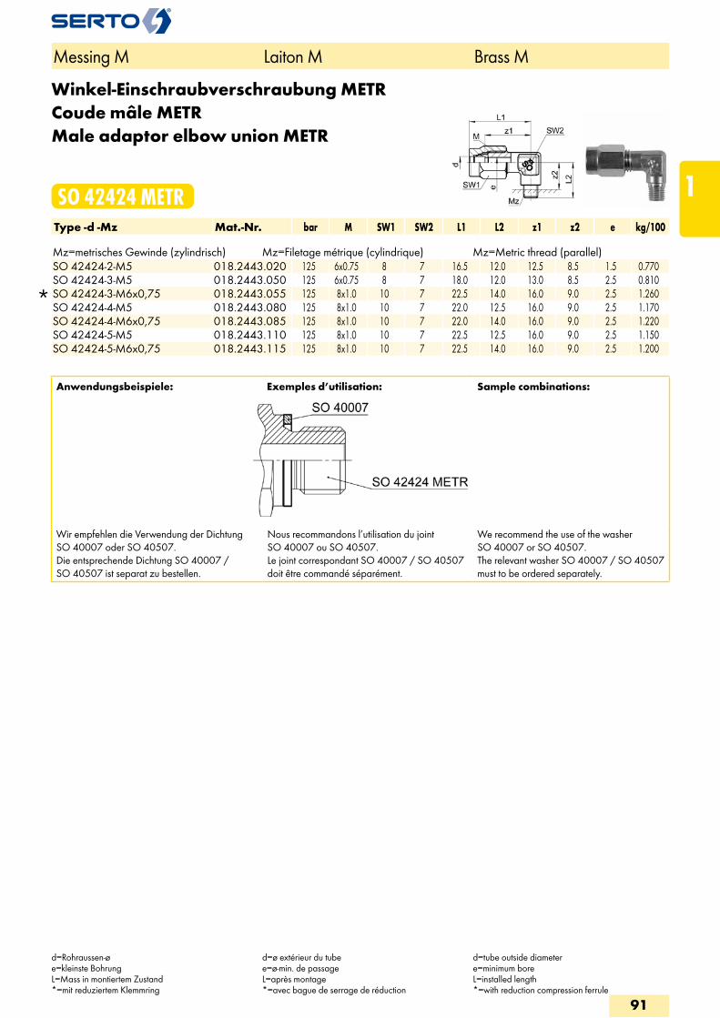
Winkel-Einschraubverschraubung METRCoude mâle METRMale adaptor elbow union METR
SO 42424 METRType -d -Mz Mat.-Nr. bar M SW1 SW2 L1 L2 z1 z2 e kg/100 Mz=metrisches Gewinde (zylindrisch) Mz=Filetage métrique (cylindrique) Mz=Metric thread (parallel)
SO 42424-2-M5 018.2443.020 125 6x0.75 8 7 16.5 12.0 12.5 8.5 1.5 0.770 SO 42424-3-M5 018.2443.050 125 6x0.75 8 7 18.0 12.0 13.0 8.5 2.5 0.810
SO 42424-3-M6x0,75 018.2443.055 125 8x1.0 10 7 22.5 14.0 16.0 9.0 2.5 1.260 SO 42424-4-M5 018.2443.080 125 8x1.0 10 7 22.0 12.5 16.0 9.0 2.5 1.170 SO 42424-4-M6x0,75 018.2443.085 125 8x1.0 10 7 22.0 14.0 16.0 9.0 2.5 1.220 SO 42424-5-M5 018.2443.110 125 8x1.0 10 7 22.5 12.5 16.0 9.0 2.5 1.150 SO 42424-5-M6x0,75 018.2443.115 125 8x1.0 10 7 22.5 14.0 16.0 9.0 2.5 1.200
Anwendungsbeispiele: Exemples d’utilisation: Sample combinations:
Wir empfehlen die Verwendung der Dichtung SO 40007 oder SO 40507.Die entsprechende Dichtung SO 40007 / SO 40507 ist separat zu bestellen.
Nous recommandons l’utilisation du joint SO 40007 ou SO 40507.Le joint correspondant SO 40007 / SO 40507 doit être commandé séparément.
We recommend the use of the washer SO 40007 or SO 40507.The relevant washer SO 40007 / SO 40507 must to be ordered separately.
Messing M Laiton M Brass M
d=Rohraussen-øe=kleinste BohrungL=Mass in montiertem Zustand*=mit reduziertem Klemmring
d=ø extérieur du tubee=ø-min. de passageL=après montage*=avec bague de serrage de réduction
d=tube outside diametere=minimum boreL=installed length*=with reduction compression ferrule
91
1
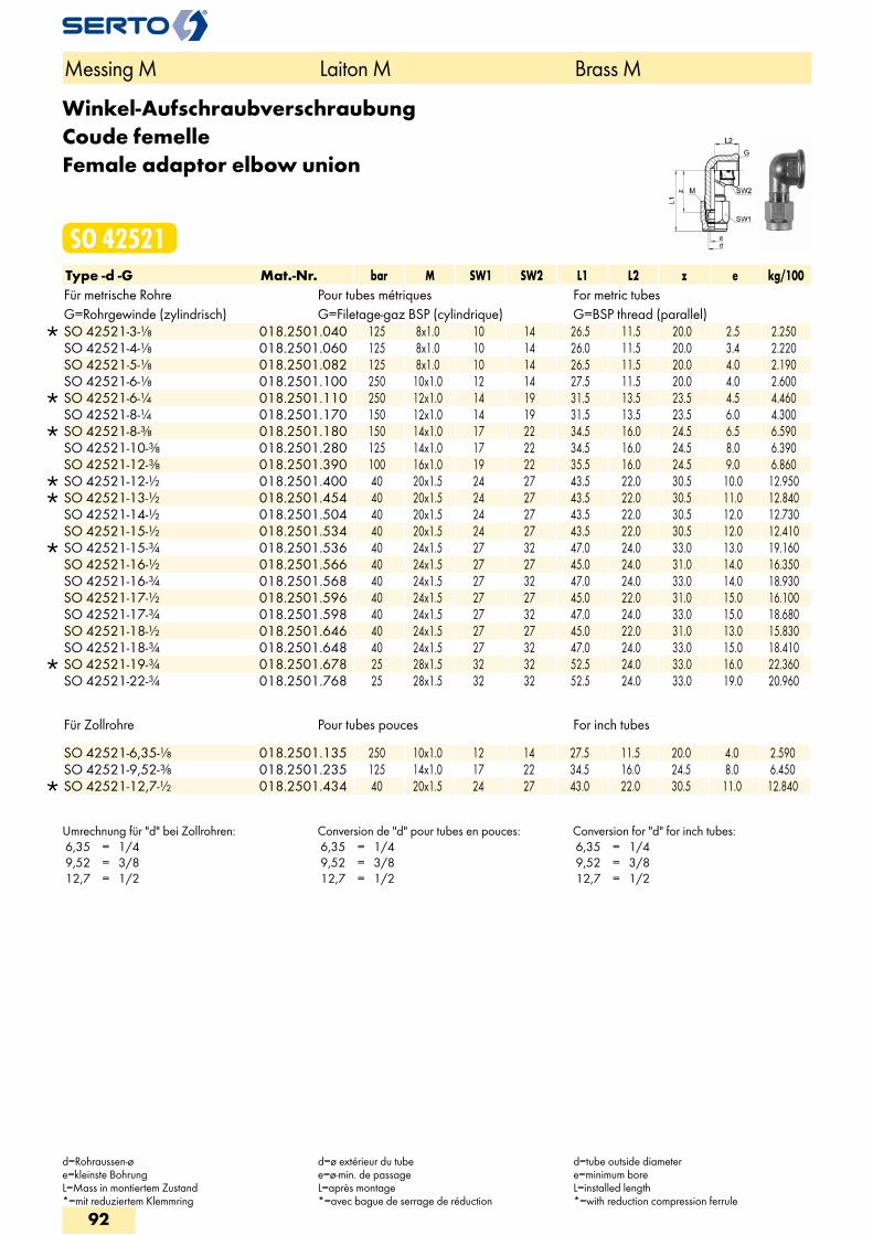
Winkel-AufschraubverschraubungCoude femelleFemale adaptor elbow union
SO 42521Type -d -G Mat.-Nr. bar M SW1 SW2 L1 L2 z e kg/100Für metrische Rohre Pour tubes métriques For metric tubesG=Rohrgewinde (zylindrisch) G=Filetage-gaz BSP (cylindrique) G=BSP thread (parallel)
SO 42521-3-1/8 018.2501.040 125 8x1.0 10 14 26.5 11.5 20.0 2.5 2.250 SO 42521-4-1/8 018.2501.060 125 8x1.0 10 14 26.0 11.5 20.0 3.4 2.220 SO 42521-5-1/8 018.2501.082 125 8x1.0 10 14 26.5 11.5 20.0 4.0 2.190 SO 42521-6-1/8 018.2501.100 250 10x1.0 12 14 27.5 11.5 20.0 4.0 2.600
SO 42521-6-1/4 018.2501.110 250 12x1.0 14 19 31.5 13.5 23.5 4.5 4.460 SO 42521-8-1/4 018.2501.170 150 12x1.0 14 19 31.5 13.5 23.5 6.0 4.300
SO 42521-8-3/8 018.2501.180 150 14x1.0 17 22 34.5 16.0 24.5 6.5 6.590 SO 42521-10-3/8 018.2501.280 125 14x1.0 17 22 34.5 16.0 24.5 8.0 6.390 SO 42521-12-3/8 018.2501.390 100 16x1.0 19 22 35.5 16.0 24.5 9.0 6.860
SO 42521-12-1/2 018.2501.400 40 20x1.5 24 27 43.5 22.0 30.5 10.0 12.950 SO 42521-13-1/2 018.2501.454 40 20x1.5 24 27 43.5 22.0 30.5 11.0 12.840 SO 42521-14-1/2 018.2501.504 40 20x1.5 24 27 43.5 22.0 30.5 12.0 12.730 SO 42521-15-1/2 018.2501.534 40 20x1.5 24 27 43.5 22.0 30.5 12.0 12.410
SO 42521-15-3/4 018.2501.536 40 24x1.5 27 32 47.0 24.0 33.0 13.0 19.160 SO 42521-16-1/2 018.2501.566 40 24x1.5 27 27 45.0 24.0 31.0 14.0 16.350 SO 42521-16-3/4 018.2501.568 40 24x1.5 27 32 47.0 24.0 33.0 14.0 18.930 SO 42521-17-1/2 018.2501.596 40 24x1.5 27 27 45.0 22.0 31.0 15.0 16.100 SO 42521-17-3/4 018.2501.598 40 24x1.5 27 32 47.0 24.0 33.0 15.0 18.680 SO 42521-18-1/2 018.2501.646 40 24x1.5 27 27 45.0 22.0 31.0 13.0 15.830 SO 42521-18-3/4 018.2501.648 40 24x1.5 27 32 47.0 24.0 33.0 15.0 18.410
SO 42521-19-3/4 018.2501.678 25 28x1.5 32 32 52.5 24.0 33.0 16.0 22.360 SO 42521-22-3/4 018.2501.768 25 28x1.5 32 32 52.5 24.0 33.0 19.0 20.960
Für Zollrohre Pour tubes pouces For inch tubes
SO 42521-6,35-1/8 018.2501.135 250 10x1.0 12 14 27.5 11.5 20.0 4.0 2.590 SO 42521-9,52-3/8 018.2501.235 125 14x1.0 17 22 34.5 16.0 24.5 8.0 6.450
SO 42521-12,7-1/2 018.2501.434 40 20x1.5 24 27 43.0 22.0 30.5 11.0 12.840
Umrechnung für "d" bei Zollrohren: 6,35 = 1/4 9,52 = 3/8 12,7 = 1/2
Conversion de "d" pour tubes en pouces: 6,35 = 1/4 9,52 = 3/8 12,7 = 1/2
Conversion for "d" for inch tubes: 6,35 = 1/4 9,52 = 3/8 12,7 = 1/2
Messing M Laiton M Brass M
d=Rohraussen-øe=kleinste BohrungL=Mass in montiertem Zustand*=mit reduziertem Klemmring
d=ø extérieur du tubee=ø-min. de passageL=après montage*=avec bague de serrage de réduction
d=tube outside diametere=minimum boreL=installed length*=with reduction compression ferrule
92
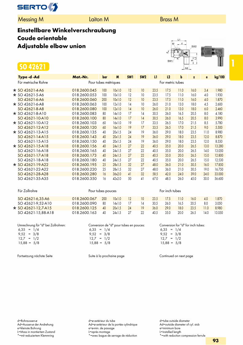
Einstellbare WinkelverschraubungCoude orientableAdjustable elbow union
SO 42621Type -d -Ad Mat.-Nr. bar M SW1 SW2 L1 L2 b z e kg/100Für metrische Rohre Pour tubes métriques For metric tubes
SO 42621-4-A6 018.2600.045 100 10x1.0 12 10 23.5 17.5 11.0 16.0 3.4 1.980 SO 42621-5-A6 018.2600.053 100 10x1.0 12 10 23.5 17.5 11.0 16.0 4.0 1.930 SO 42621-6-A6 018.2600.060 200 10x1.0 12 10 23.5 17.5 11.0 16.0 4.0 1.870
SO 42621-6-A8 018.2600.063 100 12x1.0 14 10 26.0 21.0 13.0 18.0 4.5 2.600 SO 42621-8-A8 018.2600.080 100 12x1.0 14 10 26.0 21.0 13.0 18.0 6.0 2.460
SO 42621-8-A10 018.2600.083 80 14x1.0 17 14 30.5 26.0 16.5 20.5 8.0 4.180 SO 42621-10-A10 018.2600.100 80 14x1.0 17 14 30.5 26.0 16.5 20.5 8.0 3.990
SO 42621-10-A12 018.2600.103 60 16x1.0 19 17 33.5 26.5 17.0 21.5 8.5 5.780 SO 42621-12-A12 018.2600.120 60 16x1.0 19 17 33.5 26.5 17.0 21.5 9.0 5.500
SO 42621-13-A15 018.2600.135 40 20x1.5 24 19 36.0 29.0 18.0 23.5 11.0 8.980 SO 42621-14-A15 018.2600.143 40 20x1.5 24 19 36.0 29.0 18.0 23.5 12.0 8.870 SO 42621-15-A15 018.2600.150 40 20x1.5 24 19 36.0 29.0 18.0 23.5 12.0 8.550
SO 42621-15-A18 018.2600.156 40 24x1.5 27 22 40.5 35.0 20.0 26.5 13.0 13.280 SO 42621-16-A18 018.2600.165 40 24x1.5 27 22 40.5 35.0 20.0 26.5 14.0 13.050 SO 42621-17-A18 018.2600.173 40 24x1.5 27 22 40.5 35.0 20.0 26.5 15.0 12.800 SO 42621-18-A18 018.2600.180 40 24x1.5 27 22 40.5 35.0 20.0 26.5 15.0 12.530
SO 42621-19-A22 018.2600.195 25 28x1.5 32 27 48.0 36.0 21.0 30.5 16.0 17.850 SO 42621-22-A22 018.2600.220 25 28x1.5 32 27 48.0 36.0 21.0 30.5 19.0 16.750 SO 42621-28-A28 018.2600.280 16 36x2.0 41 32 58.5 42.0 24.0 39.0 24.0 33.000 SO 42621-35-A35 018.2600.350 16 42x2.0 50 41 67.0 48.5 26.0 45.0 30.0 56.600
Für Zollrohre Pour tubes pouces For inch tubes
SO 42621-6,35-A6 018.2600.067 200 10x1.0 12 10 23.5 17.5 11.0 16.0 4.0 1.870 SO 42621-9,52-A10 018.2600.090 80 14x1.0 17 14 30.5 26.0 16.5 20.5 8.0 3.050
SO 42621-12,7-A15 018.2600.125 40 20x1.5 24 19 36.0 29.0 18.0 23.5 11.0 8.980 SO 42621-15,88-A18 018.2600.163 40 24x1.5 27 22 40.5 35.0 20.0 26.5 14.0 13.050
Umrechnung für "d" bei Zollrohren: 6,35 = 1/4 9,52 = 3/8 12,7 = 1/2 15,88 = 5/8
Conversion de "d" pour tubes en pouces: 6,35 = 1/4 9,52 = 3/8 12,7 = 1/2 15,88 = 5/8
Conversion for "d" for inch tubes: 6,35 = 1/4 9,52 = 3/8 12,7 = 1/2 15,88 = 5/8
Fortsetzung nächste Seite Suite à la prochaine page Continued on next page
Messing M Laiton M Brass M
d=Rohraussen-øAd=Aussen-ø der Andrehunge=kleinste BohrungL=Mass in montiertem Zustand*=mit reduziertem Klemmring
d=ø extérieur du tubeAd=ø extérieur de la portée cylindriquee=ø-min. de passageL=après montage*=avec bague de serrage de réduction
d=tube outside diameterAd=outside diameter of cyl. stube=minimum boreL=installed length*=with reduction compression ferrule
93
1
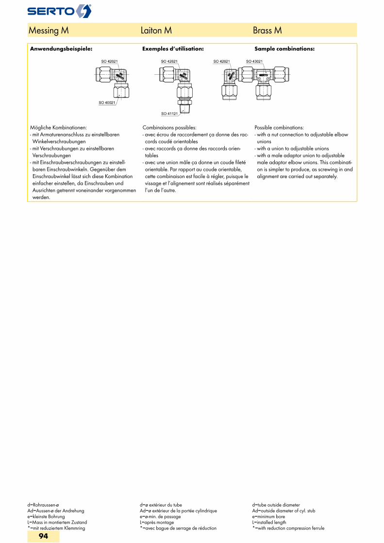
Anwendungsbeispiele: Exemples d’utilisation: Sample combinations:
Mögliche Kombinationen: - mit Armaturenanschluss zu einstellbaren Winkelverschraubungen
- mit Verschraubungen zu einstellbaren Verschraubungen
- mit Einschraubverschraubungen zu einstell-baren Einschraubwinkeln. Gegenüber dem Einschraubwinkel lässt sich diese Kombination einfacher einstellen, da Einschrauben und Ausrichten getrennt voneinander vorgenommen werden.
Combinaisons possibles: - avec écrou de raccordement ça donne des rac-cords coudé orientables
- avec raccords ça donne des raccords orien-tables
- avec une union mâle ça donne un coude fileté orientable. Par rapport au coude orientable, cette combinaison est facile à régler, puisque le vissage et l’alignement sont réalisés séparément l’un de l’autre.
Possible combinations: - with a nut connection to adjustable elbow unions
- with a union to adjustable unions - with a male adaptor union to adjustable male adaptor elbow unions. This combinati-on is simpler to produce, as screwing in and alignment are carried out separately.
Messing M Laiton M Brass M
d=Rohraussen-øAd=Aussen-ø der Andrehunge=kleinste BohrungL=Mass in montiertem Zustand*=mit reduziertem Klemmring
d=ø extérieur du tubeAd=ø extérieur de la portée cylindriquee=ø-min. de passageL=après montage*=avec bague de serrage de réduction
d=tube outside diameterAd=outside diameter of cyl. stube=minimum boreL=installed length*=with reduction compression ferrule
94
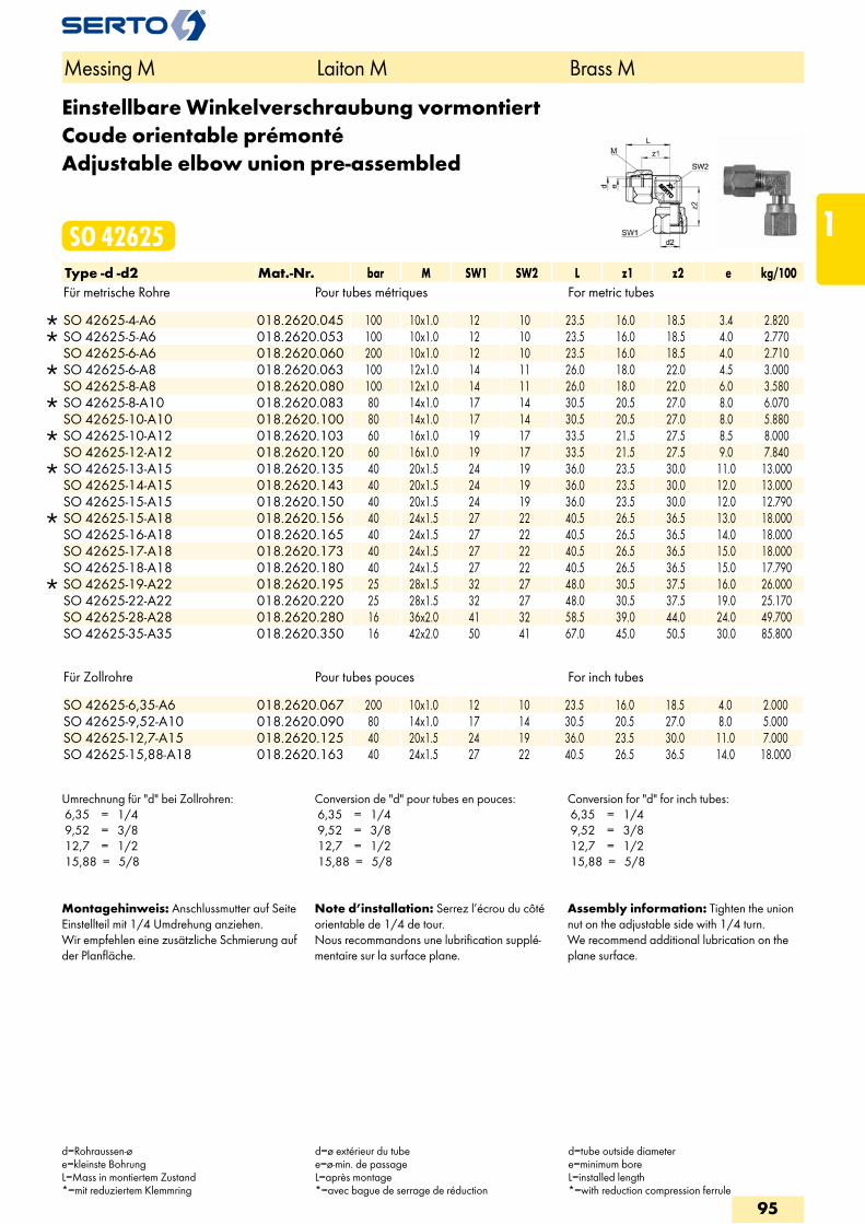
Einstellbare Winkelverschraubung vormontiertCoude orientable prémontéAdjustable elbow union pre-assembled
SO 42625Type -d -d2 Mat.-Nr. bar M SW1 SW2 L z1 z2 e kg/100Für metrische Rohre Pour tubes métriques For metric tubes
SO 42625-4-A6 018.2620.045 100 10x1.0 12 10 23.5 16.0 18.5 3.4 2.820 SO 42625-5-A6 018.2620.053 100 10x1.0 12 10 23.5 16.0 18.5 4.0 2.770 SO 42625-6-A6 018.2620.060 200 10x1.0 12 10 23.5 16.0 18.5 4.0 2.710
SO 42625-6-A8 018.2620.063 100 12x1.0 14 11 26.0 18.0 22.0 4.5 3.000 SO 42625-8-A8 018.2620.080 100 12x1.0 14 11 26.0 18.0 22.0 6.0 3.580
SO 42625-8-A10 018.2620.083 80 14x1.0 17 14 30.5 20.5 27.0 8.0 6.070 SO 42625-10-A10 018.2620.100 80 14x1.0 17 14 30.5 20.5 27.0 8.0 5.880
SO 42625-10-A12 018.2620.103 60 16x1.0 19 17 33.5 21.5 27.5 8.5 8.000 SO 42625-12-A12 018.2620.120 60 16x1.0 19 17 33.5 21.5 27.5 9.0 7.840
SO 42625-13-A15 018.2620.135 40 20x1.5 24 19 36.0 23.5 30.0 11.0 13.000 SO 42625-14-A15 018.2620.143 40 20x1.5 24 19 36.0 23.5 30.0 12.0 13.000 SO 42625-15-A15 018.2620.150 40 20x1.5 24 19 36.0 23.5 30.0 12.0 12.790
SO 42625-15-A18 018.2620.156 40 24x1.5 27 22 40.5 26.5 36.5 13.0 18.000 SO 42625-16-A18 018.2620.165 40 24x1.5 27 22 40.5 26.5 36.5 14.0 18.000 SO 42625-17-A18 018.2620.173 40 24x1.5 27 22 40.5 26.5 36.5 15.0 18.000 SO 42625-18-A18 018.2620.180 40 24x1.5 27 22 40.5 26.5 36.5 15.0 17.790
SO 42625-19-A22 018.2620.195 25 28x1.5 32 27 48.0 30.5 37.5 16.0 26.000 SO 42625-22-A22 018.2620.220 25 28x1.5 32 27 48.0 30.5 37.5 19.0 25.170 SO 42625-28-A28 018.2620.280 16 36x2.0 41 32 58.5 39.0 44.0 24.0 49.700 SO 42625-35-A35 018.2620.350 16 42x2.0 50 41 67.0 45.0 50.5 30.0 85.800
Für Zollrohre Pour tubes pouces For inch tubes SO 42625-6,35-A6 018.2620.067 200 10x1.0 12 10 23.5 16.0 18.5 4.0 2.000SO 42625-9,52-A10 018.2620.090 80 14x1.0 17 14 30.5 20.5 27.0 8.0 5.000SO 42625-12,7-A15 018.2620.125 40 20x1.5 24 19 36.0 23.5 30.0 11.0 7.000SO 42625-15,88-A18 018.2620.163 40 24x1.5 27 22 40.5 26.5 36.5 14.0 18.000
Umrechnung für "d" bei Zollrohren: 6,35 = 1/4 9,52 = 3/8 12,7 = 1/2 15,88 = 5/8
Conversion de "d" pour tubes en pouces: 6,35 = 1/4 9,52 = 3/8 12,7 = 1/2 15,88 = 5/8
Conversion for "d" for inch tubes: 6,35 = 1/4 9,52 = 3/8 12,7 = 1/2 15,88 = 5/8
Montagehinweis: Anschlussmutter auf Seite Einstellteil mit 1/4 Umdrehung anziehen.Wir empfehlen eine zusätzliche Schmierung auf der Planfläche.
Note d’installation: Serrez l’écrou du côté orientable de 1/4 de tour.Nous recommandons une lubrification supplé-mentaire sur la surface plane.
Assembly information: Tighten the union nut on the adjustable side with 1/4 turn.We recommend additional lubrication on the plane surface.
Messing M Laiton M Brass M
d=Rohraussen-øe=kleinste BohrungL=Mass in montiertem Zustand*=mit reduziertem Klemmring
d=ø extérieur du tubee=ø-min. de passageL=après montage*=avec bague de serrage de réduction
d=tube outside diametere=minimum boreL=installed length*=with reduction compression ferrule
95
1
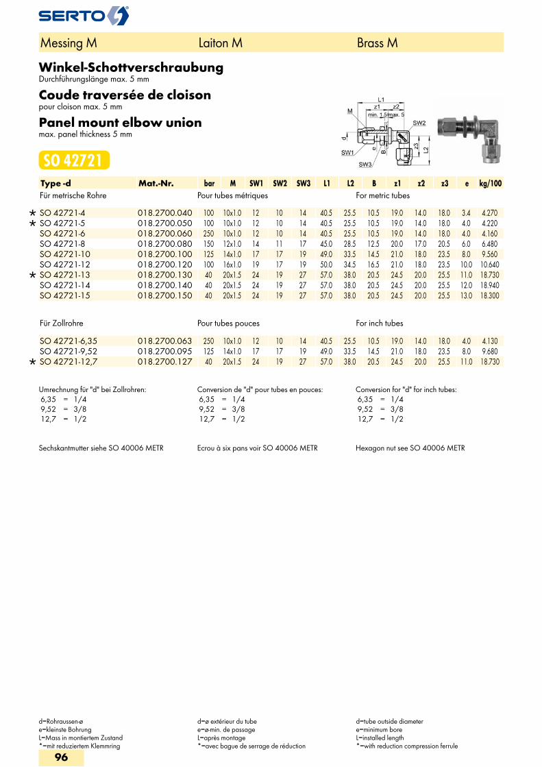
Winkel-SchottverschraubungDurchführungslänge max. 5 mm
Coude traversée de cloisonpour cloison max. 5 mm
Panel mount elbow unionmax. panel thickness 5 mm
SO 42721Type -d Mat.-Nr. bar M SW1 SW2 SW3 L1 L2 B z1 z2 z3 e kg/100Für metrische Rohre Pour tubes métriques For metric tubes
SO 42721-4 018.2700.040 100 10x1.0 12 10 14 40.5 25.5 10.5 19.0 14.0 18.0 3.4 4.270 SO 42721-5 018.2700.050 100 10x1.0 12 10 14 40.5 25.5 10.5 19.0 14.0 18.0 4.0 4.220 SO 42721-6 018.2700.060 250 10x1.0 12 10 14 40.5 25.5 10.5 19.0 14.0 18.0 4.0 4.160 SO 42721-8 018.2700.080 150 12x1.0 14 11 17 45.0 28.5 12.5 20.0 17.0 20.5 6.0 6.480 SO 42721-10 018.2700.100 125 14x1.0 17 17 19 49.0 33.5 14.5 21.0 18.0 23.5 8.0 9.560 SO 42721-12 018.2700.120 100 16x1.0 19 17 19 50.0 34.5 16.5 21.0 18.0 23.5 10.0 10.640
SO 42721-13 018.2700.130 40 20x1.5 24 19 27 57.0 38.0 20.5 24.5 20.0 25.5 11.0 18.730 SO 42721-14 018.2700.140 40 20x1.5 24 19 27 57.0 38.0 20.5 24.5 20.0 25.5 12.0 18.940 SO 42721-15 018.2700.150 40 20x1.5 24 19 27 57.0 38.0 20.5 24.5 20.0 25.5 13.0 18.300
Für Zollrohre Pour tubes pouces For inch tubes
SO 42721-6,35 018.2700.063 250 10x1.0 12 10 14 40.5 25.5 10.5 19.0 14.0 18.0 4.0 4.130 SO 42721-9,52 018.2700.095 125 14x1.0 17 17 19 49.0 33.5 14.5 21.0 18.0 23.5 8.0 9.680
SO 42721-12,7 018.2700.127 40 20x1.5 24 19 27 57.0 38.0 20.5 24.5 20.0 25.5 11.0 18.730
Umrechnung für "d" bei Zollrohren: 6,35 = 1/4 9,52 = 3/8 12,7 = 1/2
Conversion de "d" pour tubes en pouces: 6,35 = 1/4 9,52 = 3/8 12,7 = 1/2
Conversion for "d" for inch tubes: 6,35 = 1/4 9,52 = 3/8 12,7 = 1/2
Sechskantmutter siehe SO 40006 METR Ecrou à six pans voir SO 40006 METR Hexagon nut see SO 40006 METR
Messing M Laiton M Brass M
d=Rohraussen-øe=kleinste BohrungL=Mass in montiertem Zustand*=mit reduziertem Klemmring
d=ø extérieur du tubee=ø-min. de passageL=après montage*=avec bague de serrage de réduction
d=tube outside diametere=minimum boreL=installed length*=with reduction compression ferrule
96
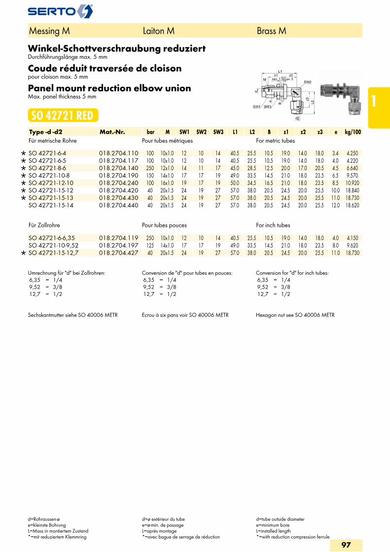
Winkel-Schottverschraubung reduziertDurchführungslänge max. 5 mm
Coude réduit traversée de cloisonpour cloison max. 5 mm
Panel mount reduction elbow unionMax. panel thickness 5 mm
SO 42721 REDType -d -d2 Mat.-Nr. bar M SW1 SW2 SW3 L1 L2 B z1 z2 z3 e kg/100Für metrische Rohre Pour tubes métriques For metric tubes
SO 42721-6-4 018.2704.110 100 10x1.0 12 10 14 40.5 25.5 10.5 19.0 14.0 18.0 3.4 4.250 SO 42721-6-5 018.2704.117 100 10x1.0 12 10 14 40.5 25.5 10.5 19.0 14.0 18.0 4.0 4.220 SO 42721-8-6 018.2704.140 250 12x1.0 14 11 17 45.0 28.5 12.5 20.0 17.0 20.5 4.5 6.640 SO 42721-10-8 018.2704.190 150 14x1.0 17 17 19 49.0 33.5 14.5 21.0 18.0 23.5 6.5 9.570 SO 42721-12-10 018.2704.240 100 16x1.0 19 17 19 50.0 34.5 16.5 21.0 18.0 23.5 8.5 10.920 SO 42721-15-12 018.2704.420 40 20x1.5 24 19 27 57.0 38.0 20.5 24.5 20.0 25.5 10.0 18.840 SO 42721-15-13 018.2704.430 40 20x1.5 24 19 27 57.0 38.0 20.5 24.5 20.0 25.5 11.0 18.730 SO 42721-15-14 018.2704.440 40 20x1.5 24 19 27 57.0 38.0 20.5 24.5 20.0 25.5 12.0 18.620
Für Zollrohre Pour tubes pouces For inch tubes
SO 42721-6-6,35 018.2704.119 250 10x1.0 12 10 14 40.5 25.5 10.5 19.0 14.0 18.0 4.0 4.150 SO 42721-10-9,52 018.2704.197 125 14x1.0 17 17 19 49.0 33.5 14.5 21.0 18.0 23.5 8.0 9.620
SO 42721-15-12,7 018.2704.427 40 20x1.5 24 19 27 57.0 38.0 20.5 24.5 20.0 25.5 11.0 18.730
Umrechnung für "d" bei Zollrohren: 6,35 = 1/4 9,52 = 3/8 12,7 = 1/2
Conversion de "d" pour tubes en pouces: 6,35 = 1/4 9,52 = 3/8 12,7 = 1/2
Conversion for "d" for inch tubes: 6,35 = 1/4 9,52 = 3/8 12,7 = 1/2
Sechskantmutter siehe SO 40006 METR Ecrou à six pans voir SO 40006 METR Hexagon nut see SO 40006 METR
Messing M Laiton M Brass M
d=Rohraussen-øe=kleinste BohrungL=Mass in montiertem Zustand*=mit reduziertem Klemmring
d=ø extérieur du tubee=ø-min. de passageL=après montage*=avec bague de serrage de réduction
d=tube outside diametere=minimum boreL=installed length*=with reduction compression ferrule
97
1
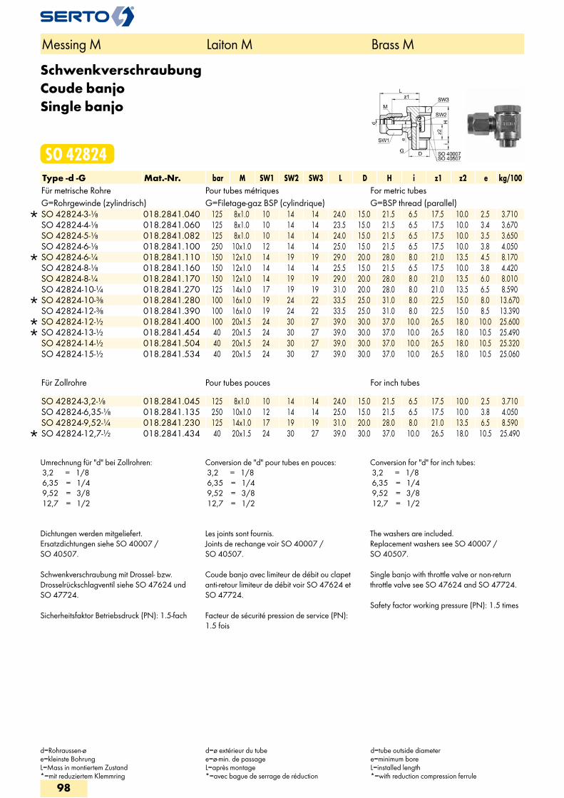
SchwenkverschraubungCoude banjoSingle banjo
SO 42824Type -d -G Mat.-Nr. bar M SW1 SW2 SW3 L D H i z1 z2 e kg/100Für metrische Rohre Pour tubes métriques For metric tubesG=Rohrgewinde (zylindrisch) G=Filetage-gaz BSP (cylindrique) G=BSP thread (parallel)
SO 42824-3-1/8 018.2841.040 125 8x1.0 10 14 14 24.0 15.0 21.5 6.5 17.5 10.0 2.5 3.710 SO 42824-4-1/8 018.2841.060 125 8x1.0 10 14 14 23.5 15.0 21.5 6.5 17.5 10.0 3.4 3.670 SO 42824-5-1/8 018.2841.082 125 8x1.0 10 14 14 24.0 15.0 21.5 6.5 17.5 10.0 3.5 3.650 SO 42824-6-1/8 018.2841.100 250 10x1.0 12 14 14 25.0 15.0 21.5 6.5 17.5 10.0 3.8 4.050
SO 42824-6-1/4 018.2841.110 150 12x1.0 14 19 19 29.0 20.0 28.0 8.0 21.0 13.5 4.5 8.170 SO 42824-8-1/8 018.2841.160 150 12x1.0 14 14 14 25.5 15.0 21.5 6.5 17.5 10.0 3.8 4.420 SO 42824-8-1/4 018.2841.170 150 12x1.0 14 19 19 29.0 20.0 28.0 8.0 21.0 13.5 6.0 8.010 SO 42824-10-1/4 018.2841.270 125 14x1.0 17 19 19 31.0 20.0 28.0 8.0 21.0 13.5 6.5 8.590
SO 42824-10-3/8 018.2841.280 100 16x1.0 19 24 22 33.5 25.0 31.0 8.0 22.5 15.0 8.0 13.670 SO 42824-12-3/8 018.2841.390 100 16x1.0 19 24 22 33.5 25.0 31.0 8.0 22.5 15.0 8.5 13.390
SO 42824-12-1/2 018.2841.400 100 20x1.5 24 30 27 39.0 30.0 37.0 10.0 26.5 18.0 10.0 25.600 SO 42824-13-1/2 018.2841.454 40 20x1.5 24 30 27 39.0 30.0 37.0 10.0 26.5 18.0 10.5 25.490 SO 42824-14-1/2 018.2841.504 40 20x1.5 24 30 27 39.0 30.0 37.0 10.0 26.5 18.0 10.5 25.320 SO 42824-15-1/2 018.2841.534 40 20x1.5 24 30 27 39.0 30.0 37.0 10.0 26.5 18.0 10.5 25.060
Für Zollrohre Pour tubes pouces For inch tubes
SO 42824-3,2-1/8 018.2841.045 125 8x1.0 10 14 14 24.0 15.0 21.5 6.5 17.5 10.0 2.5 3.710 SO 42824-6,35-1/8 018.2841.135 250 10x1.0 12 14 14 25.0 15.0 21.5 6.5 17.5 10.0 3.8 4.050 SO 42824-9,52-1/4 018.2841.230 125 14x1.0 17 19 19 31.0 20.0 28.0 8.0 21.0 13.5 6.5 8.590
SO 42824-12,7-1/2 018.2841.434 40 20x1.5 24 30 27 39.0 30.0 37.0 10.0 26.5 18.0 10.5 25.490
Umrechnung für "d" bei Zollrohren: 3,2 = 1/8 6,35 = 1/4 9,52 = 3/8 12,7 = 1/2
Conversion de "d" pour tubes en pouces: 3,2 = 1/8 6,35 = 1/4 9,52 = 3/8 12,7 = 1/2
Conversion for "d" for inch tubes: 3,2 = 1/8 6,35 = 1/4 9,52 = 3/8 12,7 = 1/2
Dichtungen werden mitgeliefert.Ersatzdichtungen siehe SO 40007 / SO 40507. Schwenkverschraubung mit Drossel- bzw. Drosselrückschlagventil siehe SO 47624 und SO 47724. Sicherheitsfaktor Betriebsdruck (PN): 1.5-fach
Les joints sont fournis.Joints de rechange voir SO 40007 / SO 40507. Coude banjo avec limiteur de débit ou clapet anti-retour limiteur de débit voir SO 47624 et SO 47724. Facteur de sécurité pression de service (PN): 1.5 fois
The washers are included.Replacement washers see SO 40007 / SO 40507. Single banjo with throttle valve or non-return throttle valve see SO 47624 and SO 47724. Safety factor working pressure (PN): 1.5 times
Messing M Laiton M Brass M
d=Rohraussen-øe=kleinste BohrungL=Mass in montiertem Zustand*=mit reduziertem Klemmring
d=ø extérieur du tubee=ø-min. de passageL=après montage*=avec bague de serrage de réduction
d=tube outside diametere=minimum boreL=installed length*=with reduction compression ferrule
98
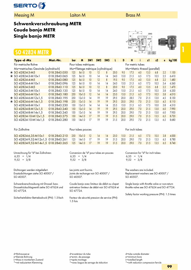
Schwenkverschraubung METRCoude banjo METRSingle banjo METR
SO 42824 METRType -d -Mz Mat.-Nr. bar M SW1 SW2 SW3 L D H i z1 z2 e kg/100Für metrische Rohre Pour tubes métriques For metric tubesMz=metrisches Gewinde (zylindrisch) Mz=Filetage métrique (cylindrique) Mz=Metric thread (parallel)
SO 42824-3-M5 018.2843.050 125 8x1.0 10 12 8 20.0 9.0 17.5 4.0 13.5 6.8 2.2 1.150 SO 42824-3-M10x1 018.2843.065 125 8x1.0 10 14 14 24.0 15.0 21.5 6.5 17.5 10.5 2.5 6.410 SO 42824-4-M5 018.2843.080 125 8x1.0 10 12 8 19.5 9.0 17.5 4.0 13.5 6.8 2.2 1.480 SO 42824-4-M10x1 018.2843.096 125 8x1.0 10 14 14 24.0 15.0 21.5 6.5 17.5 10.5 3.4 6.360 SO 42824-5-M5 018.2843.110 125 8x1.0 10 12 8 20.0 9.0 17.5 4.0 13.5 6.8 2.2 1.470 SO 42824-5-M10x1 018.2843.135 125 8x1.0 10 14 14 24.0 15.0 21.5 6.5 17.5 10.5 3.8 6.350 SO 42824-6-M10x1 018.2843.180 250 10x1.0 12 14 14 25.0 15.0 21.5 6.5 17.5 10.5 3.8 4.010
SO 42824-6-M12x1,5 018.2843.195 250 12x1.0 14 19 19 29.5 20.0 28.5 7.0 21.5 13.0 4.5 8.150 SO 42824-6-M14x1,5 018.2843.198 250 12x1.0 14 19 19 29.5 20.0 29.0 7.0 21.5 13.0 4.5 8.110 SO 42824-8-M10x1 018.2843.230 150 12x1.0 14 14 14 25.5 15.0 21.5 6.5 17.5 10.0 3.8 4.310 SO 42824-8-M12x1,5 018.2843.240 150 12x1.0 14 19 19 29.5 20.0 29.0 7.0 21.5 13.0 6.0 7.990 SO 42824-8-M14x1,5 018.2843.245 150 12x1.0 14 19 19 29.5 20.0 29.0 7.0 21.5 13.0 6.0 7.950 SO 42824-10-M12x1,5 018.2843.275 150 14x1.0 17 19 19 31.5 20.0 29.0 7.0 21.5 13.5 6.5 8.720 SO 42824-10-M14x1,5 018.2843.280 150 14x1.0 17 19 19 31.5 20.0 29.0 7.0 21.5 13.5 6.5 8.680
Für Zollrohre Pour tubes pouces For inch tubes
SO 42824-6,35-M10x1 018.2843.210 250 10x1.0 12 14 14 25.0 15.0 21.5 6.5 17.5 10.5 3.8 4.000 SO 42824-9,52-M12x1,5 018.2843.261 125 14x1.0 17 19 19 31.5 20.0 29.0 7.0 21.5 13.5 6.5 8.780 SO 42824-9,52-M14x1,5 018.2843.265 125 14x1.0 17 19 19 31.5 20.0 29.0 7.0 21.5 13.5 6.5 8.740
Umrechnung für "d" bei Zollrohren: 6,35 = 1/4 9,52 = 3/8
Conversion de "d" pour tubes en pouces: 6,35 = 1/4 9,52 = 3/8
Conversion for "d" for inch tubes: 6,35 = 1/4 9,52 = 3/8
Dichtungen werden mitgeliefert.Ersatzdichtungen siehe SO 40007 / SO 40507. Schwenkverschraubung mit Drossel- bzw. Drosselrückschlagventil siehe SO 47624 und SO 47724. Sicherheitsfaktor Betriebsdruck (PN): 1.5-fach
Les joints sont fournis.Joints de rechange voir SO 40007 / SO 40507. Coude banjo avec limiteur de débit ou clapet anti-retour limiteur de débit voir SO 47624 et SO 47724. Facteur de sécurité pression de service (PN): 1.5 fois
The washers are included.Replacement washers see SO 40007 / SO 40507. Single banjo with throttle valve or non-return throttle valve see SO 47624 and SO 47724. Safety factor working pressure (PN): 1.5 times
Messing M Laiton M Brass M
d=Rohraussen-øe=kleinste BohrungL=Mass in montiertem Zustand*=mit reduziertem Klemmring
d=ø extérieur du tubee=ø-min. de passageL=après montage*=avec bague de serrage de réduction
d=tube outside diametere=minimum boreL=installed length*=with reduction compression ferrule
99
1
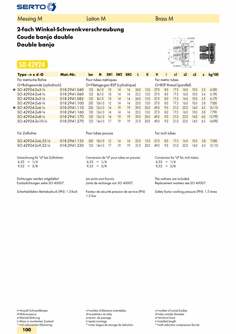
2-fach Winkel-SchwenkverschraubungCoude banjo doubleDouble banjo
SO 42924Type - n x d -G Mat.-Nr. bar M SW1 SW2 SW3 L D H i z1 z2 z3 e kg/100Für metrische Rohre Pour tubes métriques For metric tubesG=Rohrgewinde (zylindrisch) G=Filetage-gaz BSP (cylindrique) G=BSP thread (parallel)
SO 42924-2x3-1/8 018.2941.040 125 8x1.0 10 14 14 24.0 15.0 37.0 8.0 17.5 16.0 10.0 2.5 6.300 SO 42924-2x4-1/8 018.2941.060 125 8x1.0 10 14 14 23.5 15.0 37.0 8.0 17.5 16.0 10.0 3.4 6.190 SO 42924-2x5-1/8 018.2941.082 125 8x1.0 10 14 14 24.0 15.0 37.0 8.0 17.5 16.0 10.0 3.5 6.170 SO 42924-2x6-1/8 018.2941.100 250 10x1.0 12 14 14 25.0 15.0 37.0 8.0 17.5 16.0 10.0 3.8 7.000
SO 42924-2x6-1/4 018.2941.110 250 12x1.0 14 19 19 29.0 20.0 49.0 9.0 21.0 22.0 14.0 4.5 14.110 SO 42924-2x8-1/8 018.2941.160 150 12x1.0 14 14 14 25.5 15.0 37.0 8.0 17.5 16.0 10.0 3.8 7.790 SO 42924-2x8-1/4 018.2941.170 150 12x1.0 14 19 19 29.0 20.0 49.0 9.0 21.0 22.0 14.0 6.0 13.790 SO 42924-2x10⁻¹/4 018.2941.270 125 14x1.0 17 19 19 31.0 20.0 49.0 9.0 21.0 22.0 14.0 6.5 14.990
Für Zollrohre Pour tubes pouces For inch tubes
SO 42924-2x6,35-1/8 018.2941.135 250 10x1.0 12 14 14 25.0 15.0 37.0 8.0 17.5 16.0 10.0 3.8 7.000 SO 42924-2x9,52-1/4 018.2941.230 125 14x1.0 17 19 19 31.0 20.0 49.0 9.0 21.0 22.0 14.0 6.5 15.110
Umrechnung für "d" bei Zollrohren: 6,35 = 1/4 9,52 = 3/8
Conversion de "d" pour tubes en pouces: 6,35 = 1/4 9,52 = 3/8
Conversion for "d" for inch tubes: 6,35 = 1/4 9,52 = 3/8
Dichtungen werden mitgeliefert.Ersatzdichtungen siehe SO 40007. Scherheitsfaktor Betriebsdruck (PN): 1.5-fach
Les joints sont fournis.Joints de rechange voir SO 40007. Facteur de sécurité pression de service (PN): 1.5 fois
The wahsers are included.Replacement washers see SO 40007. Safety factor working pressure (PN): 1.5 times
Messing M Laiton M Brass M
n=Anzahl Schwenkkörperd=Rohraussen-øe=kleinste BohrungL=Mass in montiertem Zustand*=mit reduziertem Klemmring
n=nombre d’éléments orientablesd=ø extérieur du tubee=ø-min. de passageL=après montage*=avec bague de serrage de réduction
n=number of swivel bodiesd=tube outside diametere=minimum boreL=installed length*=with reduction compression ferrule
100
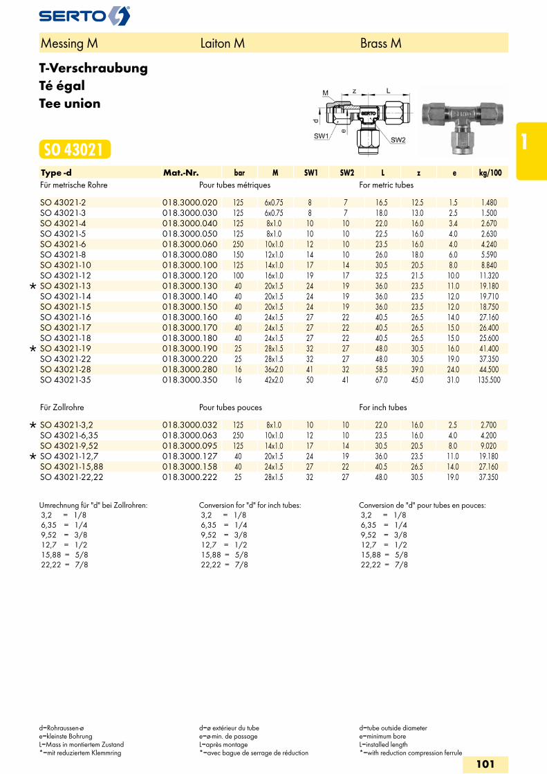
T-VerschraubungTé égalTee union
SO 43021Type -d Mat.-Nr. bar M SW1 SW2 L z e kg/100Für metrische Rohre Pour tubes métriques For metric tubes
SO 43021-2 018.3000.020 125 6x0.75 8 7 16.5 12.5 1.5 1.480 SO 43021-3 018.3000.030 125 6x0.75 8 7 18.0 13.0 2.5 1.500 SO 43021-4 018.3000.040 125 8x1.0 10 10 22.0 16.0 3.4 2.670 SO 43021-5 018.3000.050 125 8x1.0 10 10 22.5 16.0 4.0 2.630 SO 43021-6 018.3000.060 250 10x1.0 12 10 23.5 16.0 4.0 4.240 SO 43021-8 018.3000.080 150 12x1.0 14 10 26.0 18.0 6.0 5.590 SO 43021-10 018.3000.100 125 14x1.0 17 14 30.5 20.5 8.0 8.840 SO 43021-12 018.3000.120 100 16x1.0 19 17 32.5 21.5 10.0 11.320
SO 43021-13 018.3000.130 40 20x1.5 24 19 36.0 23.5 11.0 19.180 SO 43021-14 018.3000.140 40 20x1.5 24 19 36.0 23.5 12.0 19.710 SO 43021-15 018.3000.150 40 20x1.5 24 19 36.0 23.5 12.0 18.750 SO 43021-16 018.3000.160 40 24x1.5 27 22 40.5 26.5 14.0 27.160 SO 43021-17 018.3000.170 40 24x1.5 27 22 40.5 26.5 15.0 26.400 SO 43021-18 018.3000.180 40 24x1.5 27 22 40.5 26.5 15.0 25.600
SO 43021-19 018.3000.190 25 28x1.5 32 27 48.0 30.5 16.0 41.400 SO 43021-22 018.3000.220 25 28x1.5 32 27 48.0 30.5 19.0 37.350 SO 43021-28 018.3000.280 16 36x2.0 41 32 58.5 39.0 24.0 44.500 SO 43021-35 018.3000.350 16 42x2.0 50 41 67.0 45.0 31.0 135.500
Für Zollrohre Pour tubes pouces For inch tubes
SO 43021-3,2 018.3000.032 125 8x1.0 10 10 22.0 16.0 2.5 2.700 SO 43021-6,35 018.3000.063 250 10x1.0 12 10 23.5 16.0 4.0 4.200 SO 43021-9,52 018.3000.095 125 14x1.0 17 14 30.5 20.5 8.0 9.020
SO 43021-12,7 018.3000.127 40 20x1.5 24 19 36.0 23.5 11.0 19.180 SO 43021-15,88 018.3000.158 40 24x1.5 27 22 40.5 26.5 14.0 27.160 SO 43021-22,22 018.3000.222 25 28x1.5 32 27 48.0 30.5 19.0 37.350
Umrechnung für "d" bei Zollrohren: 3,2 = 1/8 6,35 = 1/4 9,52 = 3/8 12,7 = 1/2 15,88 = 5/8 22,22 = 7/8
Conversion for "d" for inch tubes: 3,2 = 1/8 6,35 = 1/4 9,52 = 3/8 12,7 = 1/2 15,88 = 5/8 22,22 = 7/8
Conversion de "d" pour tubes en pouces: 3,2 = 1/8 6,35 = 1/4 9,52 = 3/8 12,7 = 1/2 15,88 = 5/8 22,22 = 7/8
Messing M Laiton M Brass M
d=Rohraussen-øe=kleinste BohrungL=Mass in montiertem Zustand*=mit reduziertem Klemmring
d=ø extérieur du tubee=ø-min. de passageL=après montage*=avec bague de serrage de réduction
d=tube outside diametere=minimum boreL=installed length*=with reduction compression ferrule
101
1
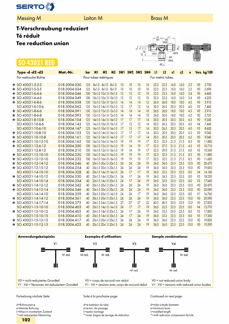
T-Verschraubung reduziertTé réduitTee reduction union
SO 43021 REDType -d -d2 -d3 Mat.-Nr. bar M1 M2 M3 SW1 SW2 SW3 SW4 L1 L2 z1 z2 e Vers. kg/100Für metrische Rohre Pour tubes métriques For metric tubes
SO 43021-5-3-3 018.3004.030 125 8x1.0 8x1.0 8x1.0 10 10 10 10 22.5 22.5 16.0 16.0 2.5 V0 2.750 SO 43021-5-3-5 018.3004.034 125 8x1.0 8x1.0 8x1.0 10 10 10 10 22.5 22.5 16.0 16.0 2.5 V0 2.690 SO 43021-6-4-4 018.3004.046 100 10x1.0 10x1.0 10x1.0 12 12 12 10 23.5 23.5 16.0 16.0 3.4 V0 4.460 SO 43021-6-4-6 018.3004.049 100 10x1.0 10x1.0 10x1.0 12 12 12 10 23.5 23.5 16.0 16.0 3.4 V0 4.350 SO 43021-6-8-6 018.3004.058 150 12x1.0 12x1.0 12x1.0 14 14 14 12 26.0 26.0 18.0 18.0 4.5 V0 5.910 SO 43021-6-10-6 018.3004.062 125 10x1.0 14x1.0 10x1.0 12 17 12 14 30.5 26.5 20.5 20.5 4.0 V2 7.440
SO 43021-8-6-6 018.3004.091 150 12x1.0 12x1.0 12x1.0 14 14 14 10 26.0 26.0 18.0 18.0 4.5 V0 5.910 SO 43021-8-6-8 018.3004.093 150 12x1.0 12x1.0 12x1.0 14 14 14 10 26.0 26.0 18.0 18.0 4.5 V0 5.750 SO 43021-8-10-8 018.3004.104 125 14x1.0 14x1.0 14x1.0 17 17 17 14 30.5 30.5 20.5 20.5 6.5 V0 9.240 SO 43021-10-6-6 018.3004.143 125 14x1.0 10x1.0 10x1.0 17 12 12 14 30.5 26.5 20.5 20.5 4.0 V4 7.440 SO 43021-10-6-10 018.3004.147 125 14x1.0 10x1.0 14x1.0 17 12 17 14 30.5 26.5 20.5 20.5 4.0 V3 8.600
SO 43021-10-8-10 018.3004.153 125 14x1.0 14x1.0 14x1.0 17 17 17 14 30.5 30.5 20.5 20.5 6.5 V0 9.040 SO 43021-10-10-8 018.3004.161 125 14x1.0 14x1.0 14x1.0 17 17 17 14 30.5 30.5 20.5 20.5 6.5 V0 9.040 SO 43021-10-12-10 018.3004.165 100 16x1.0 16x1.0 16x1.0 19 19 19 17 32.5 32.5 21.5 21.5 8.5 V0 11.880 SO 43021-12-6-12 018.3004.200 100 16x1.0 12x1.0 16x1.0 19 14 19 17 32.5 27.5 21.5 21.5 4.5 V3 10.710 SO 43021-12-8-12 018.3004.210 100 16x1.0 12x1.0 16x1.0 19 14 19 17 32.5 29.0 21.5 21.5 6.0 V3 10.540
SO 43021-12-10-10 018.3004.220 100 16x1.0 16x1.0 16x1.0 19 19 19 17 32.5 32.5 21.5 21.5 8.5 V0 11.880 SO 43021-12-12-10 018.3004.232 100 16x1.0 16x1.0 16x1.0 19 19 19 17 32.5 32.5 21.5 21.5 8.5 V0 11.600 SO 43021-12-14-12 018.3004.246 40 20x1.5 20x1.5 20x1.5 24 24 24 19 36.0 36.0 23.5 23.5 10.0 V0 20.470 SO 43021-12-15-12 018.3004.254 40 20x1.5 20x1.5 20x1.5 24 24 24 19 36.0 36.0 23.5 23.5 10.0 V0 19.830 SO 43021-14-10-10 018.3004.328 40 20x1.5 14x1.0 14x1.0 24 17 17 19 36.0 33.5 23.5 23.5 8.0 V4 14.160
SO 43021-14-10-12 018.3004.330 40 20x1.5 14x1.0 20x1.5 24 17 24 19 36.0 34.5 23.5 23.5 8.0 V3 18.220 SO 43021-14-10-14 018.3004.334 40 20x1.5 14x1.0 20x1.5 24 17 24 19 36.0 33.5 23.5 23.5 8.0 V3 17.660
SO 43021-14-12-12 018.3004.342 40 20x1.5 20x1.5 20x1.5 24 24 24 19 36.0 36.0 23.5 23.5 10.0 V0 20.470 SO 43021-14-12-14 018.3004.346 40 20x1.5 20x1.5 20x1.5 24 24 24 19 36.0 36.0 23.5 23.5 10.0 V0 20.090 SO 43021-14-14-10 018.3004.359 40 20x1.5 20x1.5 14x1.0 24 24 17 19 36.0 36.0 23.5 23.5 8.0 V1 16.760
SO 43021-14-14-12 018.3004.361 40 20x1.5 20x1.5 20x1.5 24 24 24 19 36.0 36.0 23.5 23.5 10.0 V0 20.090 SO 43021-14-17-14 018.3004.375 40 24x1.5 24x1.5 24x1.5 27 27 27 22 40.5 40.5 23.5 23.5 12.0 V0 27.820 SO 43021-15-10-10 018.3004.403 40 20x1.5 14x1.0 14x1.0 24 17 17 19 36.0 33.5 23.5 23.5 8.0 V4 13.770
SO 43021-15-10-12 018.3004.405 40 20x1.5 14x1.0 20x1.5 24 17 24 19 36.0 33.5 23.5 23.5 8.0 V3 17.800 SO 43021-15-10-15 018.3004.410 40 20x1.5 14x1.0 20x1.5 24 17 24 19 36.0 33.5 23.5 23.5 8.0 V3 17.300
SO 43021-15-12-12 018.3004.417 40 20x1.5 20x1.5 20x1.5 24 24 24 19 36.0 36.0 23.5 23.5 10.0 V0 19.830 SO 43021-15-12-15 018.3004.422 40 20x1.5 20x1.5 20x1.5 24 24 24 19 36.0 36.0 23.5 23.5 10.0 V0 19.290
Anwendungsbeispiele: Exemples d’utilisation: Sample combinations:
V0 = nicht reduziertes GrundteilV1 - V4 = Versionen mit reduziertem Grundteil
V0 = corps de raccord non réduitV1 - V4 = versions avec corps de raccord réduit
V0 = not reduced union bodyV1 - V4 = versions with reduced union bodies
Messing M Laiton M Brass M
d=Rohraussen-øe=kleinste BohrungL=Mass in montiertem Zustand*=mit reduziertem Klemmring
d=ø extérieur du tubee=ø-min. de passageL=après montage*=avec bague de serrage de réduction
d=tube outside diametere=minimum boreL=installed length*=with reduction compression ferrule
Fortsetzung nächste Seite Suite à la prochaine page Continued on next page
102
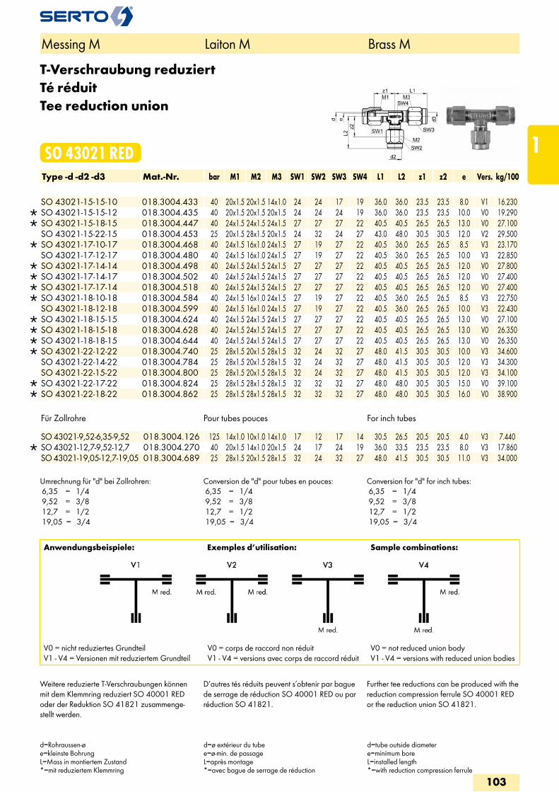
T-Verschraubung reduziertTé réduitTee reduction union
SO 43021 REDType -d -d2 -d3 Mat.-Nr. bar M1 M2 M3 SW1 SW2 SW3 SW4 L1 L2 z1 z2 e Vers. kg/100
SO 43021-15-15-10 018.3004.433 40 20x1.5 20x1.5 14x1.0 24 24 17 19 36.0 36.0 23.5 23.5 8.0 V1 16.230 SO 43021-15-15-12 018.3004.435 40 20x1.5 20x1.5 20x1.5 24 24 24 19 36.0 36.0 23.5 23.5 10.0 V0 19.290 SO 43021-15-18-15 018.3004.447 40 24x1.5 24x1.5 24x1.5 27 27 27 22 40.5 40.5 26.5 26.5 13.0 V0 27.100 SO 43021-15-22-15 018.3004.453 25 20x1.5 28x1.5 20x1.5 24 32 24 27 43.0 48.0 30.5 30.5 12.0 V2 29.500
SO 43021-17-10-17 018.3004.468 40 24x1.5 16x1.0 24x1.5 27 19 27 22 40.5 36.0 26.5 26.5 8.5 V3 23.170 SO 43021-17-12-17 018.3004.480 40 24x1.5 16x1.0 24x1.5 27 19 27 22 40.5 36.0 26.5 26.5 10.0 V3 22.850
SO 43021-17-14-14 018.3004.498 40 24x1.5 24x1.5 24x1.5 27 27 27 22 40.5 40.5 26.5 26.5 12.0 V0 27.800 SO 43021-17-14-17 018.3004.502 40 24x1.5 24x1.5 24x1.5 27 27 27 22 40.5 40.5 26.5 26.5 12.0 V0 27.400 SO 43021-17-17-14 018.3004.518 40 24x1.5 24x1.5 24x1.5 27 27 27 22 40.5 40.5 26.5 26.5 12.0 V0 27.400 SO 43021-18-10-18 018.3004.584 40 24x1.5 16x1.0 24x1.5 27 19 27 22 40.5 36.0 26.5 26.5 8.5 V3 22.750 SO 43021-18-12-18 018.3004.599 40 24x1.5 16x1.0 24x1.5 27 19 27 22 40.5 36.0 26.5 26.5 10.0 V3 22.430
SO 43021-18-15-15 018.3004.624 40 24x1.5 24x1.5 24x1.5 27 27 27 22 40.5 40.5 26.5 26.5 13.0 V0 27.100 SO 43021-18-15-18 018.3004.628 40 24x1.5 24x1.5 24x1.5 27 27 27 22 40.5 40.5 26.5 26.5 13.0 V0 26.350 SO 43021-18-18-15 018.3004.644 40 24x1.5 24x1.5 24x1.5 27 27 27 22 40.5 40.5 26.5 26.5 13.0 V0 26.350 SO 43021-22-12-22 018.3004.740 25 28x1.5 20x1.5 28x1.5 32 24 32 27 48.0 41.5 30.5 30.5 10.0 V3 34.600 SO 43021-22-14-22 018.3004.784 25 28x1.5 20x1.5 28x1.5 32 24 32 27 48.0 41.5 30.5 30.5 12.0 V3 34.300 SO 43021-22-15-22 018.3004.800 25 28x1.5 20x1.5 28x1.5 32 24 32 27 48.0 41.5 30.5 30.5 12.0 V3 34.100
SO 43021-22-17-22 018.3004.824 25 28x1.5 28x1.5 28x1.5 32 32 32 27 48.0 48.0 30.5 30.5 15.0 V0 39.100 SO 43021-22-18-22 018.3004.862 25 28x1.5 28x1.5 28x1.5 32 32 32 27 48.0 48.0 30.5 30.5 16.0 V0 38.900
Für Zollrohre Pour tubes pouces For inch tubes
SO 43021-9,52-6,35-9,52 018.3004.126 125 14x1.0 10x1.0 14x1.0 17 12 17 14 30.5 26.5 20.5 20.5 4.0 V3 7.440 SO 43021-12,7-9,52-12,7 018.3004.270 40 20x1.5 14x1.0 20x1.5 24 17 24 19 36.0 33.5 23.5 23.5 8.0 V3 17.860 SO 43021-19,05-12,7-19,05 018.3004.689 25 28x1.5 20x1.5 28x1.5 32 24 32 27 48.0 41.5 30.5 30.5 11.0 V3 34.000
Umrechnung für "d" bei Zollrohren: 6,35 = 1/4 9,52 = 3/8 12,7 = 1/2 19,05 = 3/4
Conversion de "d" pour tubes en pouces: 6,35 = 1/4 9,52 = 3/8 12,7 = 1/2 19,05 = 3/4
Conversion for "d" for inch tubes: 6,35 = 1/4 9,52 = 3/8 12,7 = 1/2 19,05 = 3/4
Anwendungsbeispiele: Exemples d’utilisation: Sample combinations:
V0 = nicht reduziertes GrundteilV1 - V4 = Versionen mit reduziertem Grundteil
V0 = corps de raccord non réduitV1 - V4 = versions avec corps de raccord réduit
V0 = not reduced union bodyV1 - V4 = versions with reduced union bodies
Messing M Laiton M Brass M
d=Rohraussen-øe=kleinste BohrungL=Mass in montiertem Zustand*=mit reduziertem Klemmring
d=ø extérieur du tubee=ø-min. de passageL=après montage*=avec bague de serrage de réduction
d=tube outside diametere=minimum boreL=installed length*=with reduction compression ferrule
Weitere reduzierte T-Verschraubungen können mit dem Klemmring reduziert SO 40001 RED oder der Reduktion SO 41821 zusammenge-stellt werden.
D’autres tés réduits peuvent s’obtenir par bague de serrage de réduction SO 40001 RED ou par réduction SO 41821.
Further tee reductions can be produced with the reduction compression ferrule SO 40001 RED or the reduction union SO 41821.
103
1
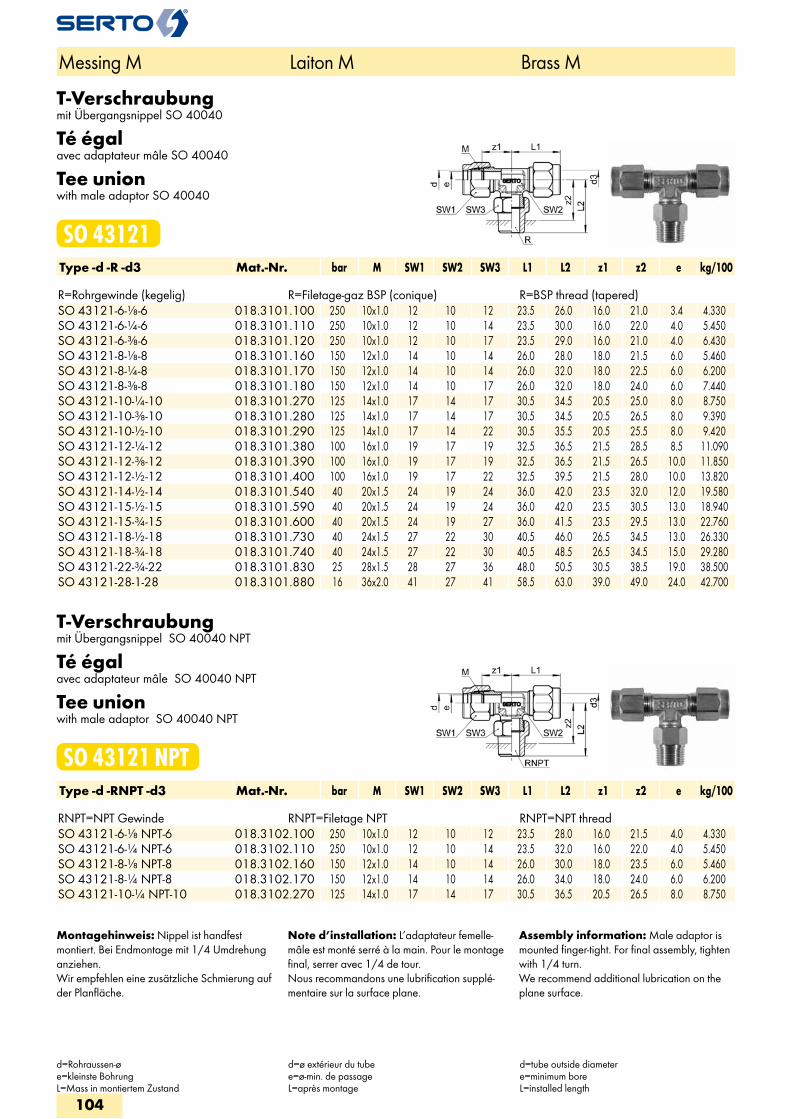
T-Verschraubungmit Übergangsnippel SO 40040
Té égalavec adaptateur mâle SO 40040
Tee unionwith male adaptor SO 40040
SO 43121Type -d -R -d3 Mat.-Nr. bar M SW1 SW2 SW3 L1 L2 z1 z2 e kg/100 R=Rohrgewinde (kegelig) R=Filetage-gaz BSP (conique) R=BSP thread (tapered)
SO 43121-6-1/8-6 018.3101.100 250 10x1.0 12 10 12 23.5 26.0 16.0 21.0 3.4 4.330 SO 43121-6-1/4-6 018.3101.110 250 10x1.0 12 10 14 23.5 30.0 16.0 22.0 4.0 5.450 SO 43121-6-3/8-6 018.3101.120 250 10x1.0 12 10 17 23.5 29.0 16.0 21.0 4.0 6.430 SO 43121-8-1/8-8 018.3101.160 150 12x1.0 14 10 14 26.0 28.0 18.0 21.5 6.0 5.460 SO 43121-8-1/4-8 018.3101.170 150 12x1.0 14 10 14 26.0 32.0 18.0 22.5 6.0 6.200 SO 43121-8-3/8-8 018.3101.180 150 12x1.0 14 10 17 26.0 32.0 18.0 24.0 6.0 7.440 SO 43121-10-1/4-10 018.3101.270 125 14x1.0 17 14 17 30.5 34.5 20.5 25.0 8.0 8.750 SO 43121-10-3/8-10 018.3101.280 125 14x1.0 17 14 17 30.5 34.5 20.5 26.5 8.0 9.390 SO 43121-10-1/2-10 018.3101.290 125 14x1.0 17 14 22 30.5 35.5 20.5 25.5 8.0 9.420 SO 43121-12-1/4-12 018.3101.380 100 16x1.0 19 17 19 32.5 36.5 21.5 28.5 8.5 11.090 SO 43121-12-3/8-12 018.3101.390 100 16x1.0 19 17 19 32.5 36.5 21.5 26.5 10.0 11.850 SO 43121-12-1/2-12 018.3101.400 100 16x1.0 19 17 22 32.5 39.5 21.5 28.0 10.0 13.820 SO 43121-14-1/2-14 018.3101.540 40 20x1.5 24 19 24 36.0 42.0 23.5 32.0 12.0 19.580 SO 43121-15-1/2-15 018.3101.590 40 20x1.5 24 19 24 36.0 42.0 23.5 30.5 13.0 18.940 SO 43121-15-3/4-15 018.3101.600 40 20x1.5 24 19 27 36.0 41.5 23.5 29.5 13.0 22.760 SO 43121-18-1/2-18 018.3101.730 40 24x1.5 27 22 30 40.5 46.0 26.5 34.5 13.0 26.330 SO 43121-18-3/4-18 018.3101.740 40 24x1.5 27 22 30 40.5 48.5 26.5 34.5 15.0 29.280 SO 43121-22-3/4-22 018.3101.830 25 28x1.5 28 27 36 48.0 50.5 30.5 38.5 19.0 38.500 SO 43121-28-1-28 018.3101.880 16 36x2.0 41 27 41 58.5 63.0 39.0 49.0 24.0 42.700
T-Verschraubungmit Übergangsnippel SO 40040 NPT
Té égalavec adaptateur mâle SO 40040 NPT
Tee unionwith male adaptor SO 40040 NPT
SO 43121 NPTType -d -RNPT -d3 Mat.-Nr. bar M SW1 SW2 SW3 L1 L2 z1 z2 e kg/100 RNPT=NPT Gewinde RNPT=Filetage NPT RNPT=NPT thread
SO 43121-6-1/8 NPT-6 018.3102.100 250 10x1.0 12 10 12 23.5 28.0 16.0 21.5 4.0 4.330 SO 43121-6-1/4 NPT-6 018.3102.110 250 10x1.0 12 10 14 23.5 32.0 16.0 22.0 4.0 5.450 SO 43121-8-1/8 NPT-8 018.3102.160 150 12x1.0 14 10 14 26.0 30.0 18.0 23.5 6.0 5.460 SO 43121-8-1/4 NPT-8 018.3102.170 150 12x1.0 14 10 14 26.0 34.0 18.0 24.0 6.0 6.200 SO 43121-10-1/4 NPT-10 018.3102.270 125 14x1.0 17 14 17 30.5 36.5 20.5 26.5 8.0 8.750
Montagehinweis: Nippel ist handfest montiert. Bei Endmontage mit 1/4 Umdrehung anziehen.Wir empfehlen eine zusätzliche Schmierung auf der Planfläche.
Note d’installation: L’adaptateur femelle-mâle est monté serré à la main. Pour le montage final, serrer avec 1/4 de tour.Nous recommandons une lubrification supplé-mentaire sur la surface plane.
Assembly information: Male adaptor is mounted finger-tight. For final assembly, tighten with 1/4 turn.We recommend additional lubrication on the plane surface.
Messing M Laiton M Brass M
d=Rohraussen-øe=kleinste BohrungL=Mass in montiertem Zustand
d=ø extérieur du tubee=ø-min. de passageL=après montage
d=tube outside diametere=minimum boreL=installed length
104
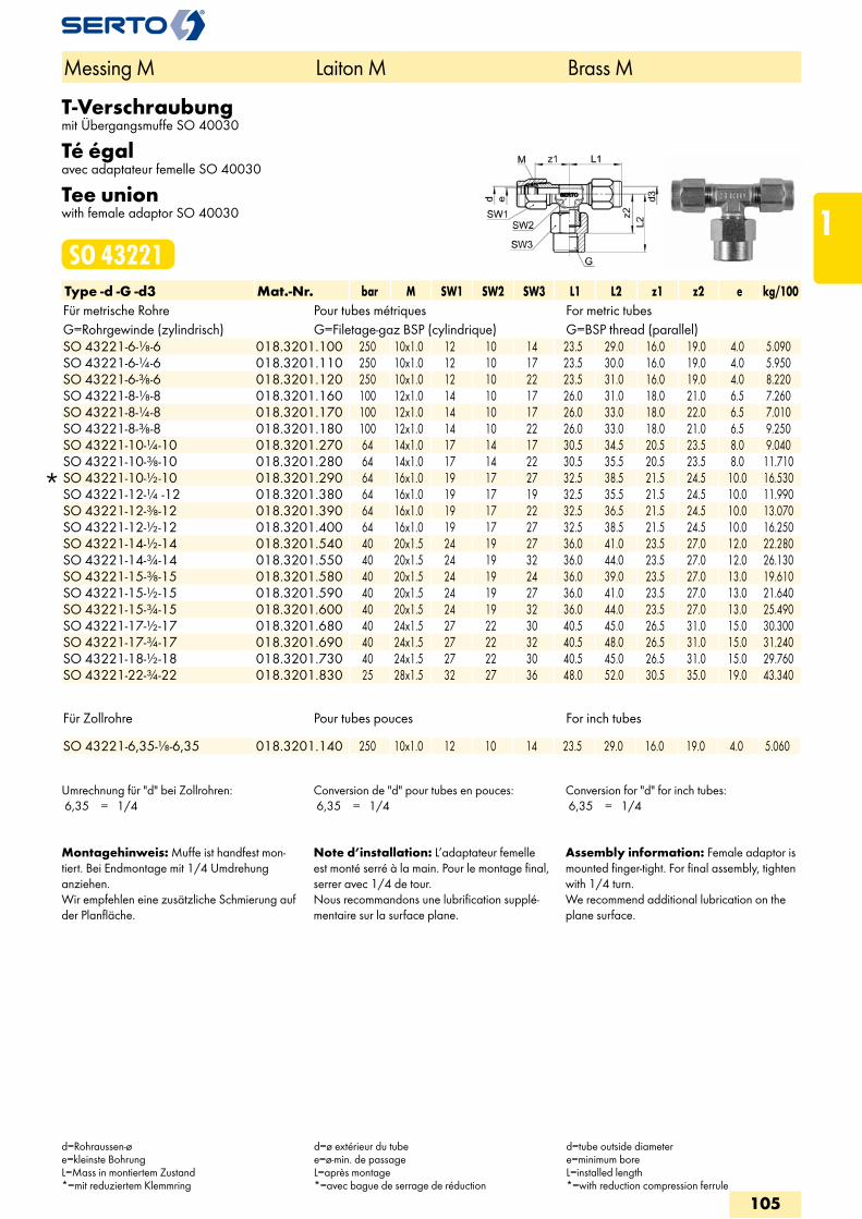
T-Verschraubungmit Übergangsmuffe SO 40030
Té égalavec adaptateur femelle SO 40030
Tee unionwith female adaptor SO 40030
SO 43221Type -d -G -d3 Mat.-Nr. bar M SW1 SW2 SW3 L1 L2 z1 z2 e kg/100Für metrische Rohre Pour tubes métriques For metric tubesG=Rohrgewinde (zylindrisch) G=Filetage-gaz BSP (cylindrique) G=BSP thread (parallel)
SO 43221-6-1/8-6 018.3201.100 250 10x1.0 12 10 14 23.5 29.0 16.0 19.0 4.0 5.090 SO 43221-6-1/4-6 018.3201.110 250 10x1.0 12 10 17 23.5 30.0 16.0 19.0 4.0 5.950 SO 43221-6-3/8-6 018.3201.120 250 10x1.0 12 10 22 23.5 31.0 16.0 19.0 4.0 8.220 SO 43221-8-1/8-8 018.3201.160 100 12x1.0 14 10 17 26.0 31.0 18.0 21.0 6.5 7.260 SO 43221-8-1/4-8 018.3201.170 100 12x1.0 14 10 17 26.0 33.0 18.0 22.0 6.5 7.010 SO 43221-8-3/8-8 018.3201.180 100 12x1.0 14 10 22 26.0 33.0 18.0 21.0 6.5 9.250 SO 43221-10-1/4-10 018.3201.270 64 14x1.0 17 14 17 30.5 34.5 20.5 23.5 8.0 9.040 SO 43221-10-3/8-10 018.3201.280 64 14x1.0 17 14 22 30.5 35.5 20.5 23.5 8.0 11.710
SO 43221-10-1/2-10 018.3201.290 64 16x1.0 19 17 27 32.5 38.5 21.5 24.5 10.0 16.530 SO 43221-12-1/4 -12 018.3201.380 64 16x1.0 19 17 19 32.5 35.5 21.5 24.5 10.0 11.990 SO 43221-12-3/8-12 018.3201.390 64 16x1.0 19 17 22 32.5 36.5 21.5 24.5 10.0 13.070 SO 43221-12-1/2-12 018.3201.400 64 16x1.0 19 17 27 32.5 38.5 21.5 24.5 10.0 16.250 SO 43221-14-1/2-14 018.3201.540 40 20x1.5 24 19 27 36.0 41.0 23.5 27.0 12.0 22.280 SO 43221-14-3/4-14 018.3201.550 40 20x1.5 24 19 32 36.0 44.0 23.5 27.0 12.0 26.130 SO 43221-15-3/8-15 018.3201.580 40 20x1.5 24 19 24 36.0 39.0 23.5 27.0 13.0 19.610 SO 43221-15-1/2-15 018.3201.590 40 20x1.5 24 19 27 36.0 41.0 23.5 27.0 13.0 21.640 SO 43221-15-3/4-15 018.3201.600 40 20x1.5 24 19 32 36.0 44.0 23.5 27.0 13.0 25.490 SO 43221-17-1/2-17 018.3201.680 40 24x1.5 27 22 30 40.5 45.0 26.5 31.0 15.0 30.300 SO 43221-17-3/4-17 018.3201.690 40 24x1.5 27 22 32 40.5 48.0 26.5 31.0 15.0 31.240 SO 43221-18-1/2-18 018.3201.730 40 24x1.5 27 22 30 40.5 45.0 26.5 31.0 15.0 29.760 SO 43221-22-3/4-22 018.3201.830 25 28x1.5 32 27 36 48.0 52.0 30.5 35.0 19.0 43.340
Für Zollrohre Pour tubes pouces For inch tubes
SO 43221-6,35-1/8-6,35 018.3201.140 250 10x1.0 12 10 14 23.5 29.0 16.0 19.0 4.0 5.060
Umrechnung für "d" bei Zollrohren: 6,35 = 1/4
Conversion de "d" pour tubes en pouces: 6,35 = 1/4
Conversion for "d" for inch tubes: 6,35 = 1/4
Montagehinweis: Muffe ist handfest mon-tiert. Bei Endmontage mit 1/4 Umdrehung anziehen.Wir empfehlen eine zusätzliche Schmierung auf der Planfläche.
Note d’installation: L’adaptateur femelle est monté serré à la main. Pour le montage final, serrer avec 1/4 de tour.Nous recommandons une lubrification supplé-mentaire sur la surface plane.
Assembly information: Female adaptor is mounted finger-tight. For final assembly, tighten with 1/4 turn.We recommend additional lubrication on the plane surface.
Messing M Laiton M Brass M
d=Rohraussen-øe=kleinste BohrungL=Mass in montiertem Zustand*=mit reduziertem Klemmring
d=ø extérieur du tubee=ø-min. de passageL=après montage*=avec bague de serrage de réduction
d=tube outside diametere=minimum boreL=installed length*=with reduction compression ferrule
105
1
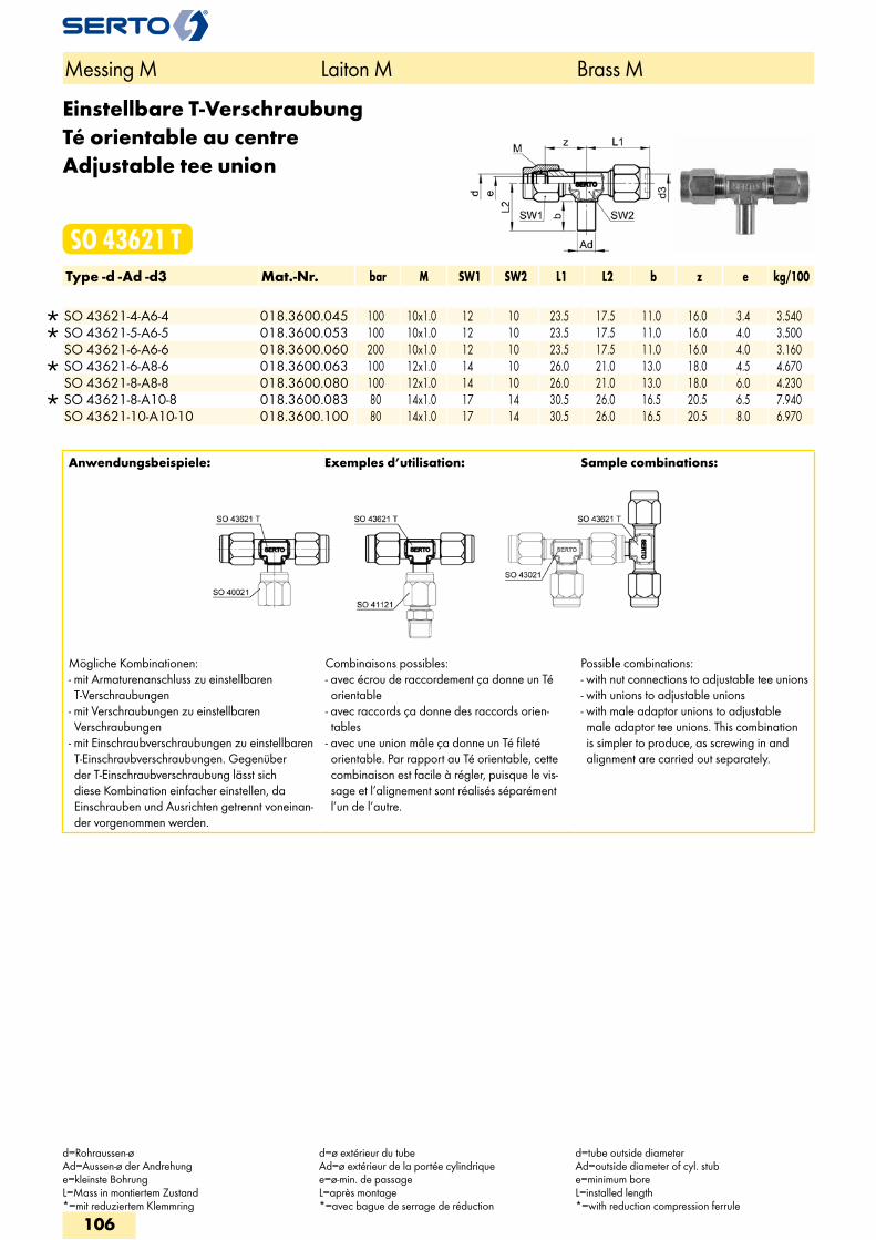
Einstellbare T-VerschraubungTé orientable au centreAdjustable tee union
SO 43621 TType -d -Ad -d3 Mat.-Nr. bar M SW1 SW2 L1 L2 b z e kg/100
SO 43621-4-A6-4 018.3600.045 100 10x1.0 12 10 23.5 17.5 11.0 16.0 3.4 3.540 SO 43621-5-A6-5 018.3600.053 100 10x1.0 12 10 23.5 17.5 11.0 16.0 4.0 3.500 SO 43621-6-A6-6 018.3600.060 200 10x1.0 12 10 23.5 17.5 11.0 16.0 4.0 3.160
SO 43621-6-A8-6 018.3600.063 100 12x1.0 14 10 26.0 21.0 13.0 18.0 4.5 4.670 SO 43621-8-A8-8 018.3600.080 100 12x1.0 14 10 26.0 21.0 13.0 18.0 6.0 4.230
SO 43621-8-A10-8 018.3600.083 80 14x1.0 17 14 30.5 26.0 16.5 20.5 6.5 7.940 SO 43621-10-A10-10 018.3600.100 80 14x1.0 17 14 30.5 26.0 16.5 20.5 8.0 6.970
Anwendungsbeispiele: Exemples d’utilisation: Sample combinations:
Mögliche Kombinationen: - mit Armaturenanschluss zu einstellbaren T-Verschraubungen
- mit Verschraubungen zu einstellbaren Verschraubungen
- mit Einschraubverschraubungen zu einstellbaren T-Einschraubverschraubungen. Gegenüber der T-Einschraubverschraubung lässt sich diese Kombination einfacher einstellen, da Einschrauben und Ausrichten getrennt voneinan-der vorgenommen werden.
Combinaisons possibles: - avec écrou de raccordement ça donne un Té orientable
- avec raccords ça donne des raccords orien-tables
- avec une union mâle ça donne un Té fileté orientable. Par rapport au Té orientable, cette combinaison est facile à régler, puisque le vis-sage et l’alignement sont réalisés séparément l’un de l’autre.
Possible combinations: - with nut connections to adjustable tee unions - with unions to adjustable unions - with male adaptor unions to adjustable male adaptor tee unions. This combination is simpler to produce, as screwing in and alignment are carried out separately.
Messing M Laiton M Brass M
d=Rohraussen-øAd=Aussen-ø der Andrehunge=kleinste BohrungL=Mass in montiertem Zustand*=mit reduziertem Klemmring
d=ø extérieur du tubeAd=ø extérieur de la portée cylindriquee=ø-min. de passageL=après montage*=avec bague de serrage de réduction
d=tube outside diameterAd=outside diameter of cyl. stube=minimum boreL=installed length*=with reduction compression ferrule
106
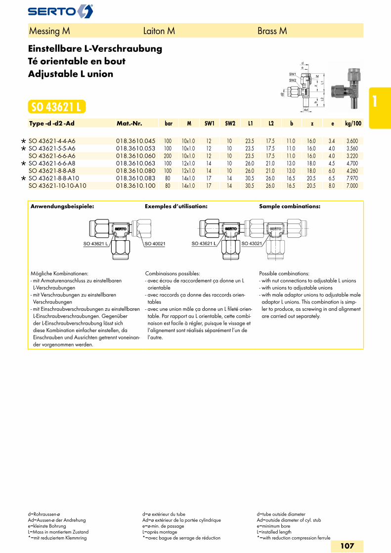
Einstellbare L-VerschraubungTé orientable en boutAdjustable L union
SO 43621 LType -d -d2 -Ad Mat.-Nr. bar M SW1 SW2 L1 L2 b z e kg/100
SO 43621-4-4-A6 018.3610.045 100 10x1.0 12 10 23.5 17.5 11.0 16.0 3.4 3.600 SO 43621-5-5-A6 018.3610.053 100 10x1.0 12 10 23.5 17.5 11.0 16.0 4.0 3.560 SO 43621-6-6-A6 018.3610.060 200 10x1.0 12 10 23.5 17.5 11.0 16.0 4.0 3.220
SO 43621-6-6-A8 018.3610.063 100 12x1.0 14 10 26.0 21.0 13.0 18.0 4.5 4.700 SO 43621-8-8-A8 018.3610.080 100 12x1.0 14 10 26.0 21.0 13.0 18.0 6.0 4.260
SO 43621-8-8-A10 018.3610.083 80 14x1.0 17 14 30.5 26.0 16.5 20.5 6.5 7.970 SO 43621-10-10-A10 018.3610.100 80 14x1.0 17 14 30.5 26.0 16.5 20.5 8.0 7.000
Anwendungsbeispiele: Exemples d’utilisation: Sample combinations:
Mögliche Kombinationen:- mit Armaturenanschluss zu einstellbaren L-Verschraubungen
- mit Verschraubungen zu einstellbaren Verschraubungen
- mit Einschraubverschraubungen zu einstellbaren L-Einschraubverschraubungen. Gegenüber der L-Einschraubverschraubung lässt sich diese Kombination einfacher einstellen, da Einschrauben und Ausrichten getrennt voneinan-der vorgenommen werden.
Combinaisons possibles: - avec écrou de raccordement ça donne un L orientable
- avec raccords ça donne des raccords orien-tables
- avec une union mâle ça donne un L fileté orien-table. Par rapport au L orientable, cette combi-naison est facile à régler, puisque le vissage et l’alignement sont réalisés séparément l’un de l’autre.
Possible combinations: - with nut connections to adjustable L unions - with unions to adjustable unions - with male adaptor unions to adjustable male adaptor L unions. This combination is simp-ler to produce, as screwing in and alignment are carried out separately.
Messing M Laiton M Brass M
d=Rohraussen-øAd=Aussen-ø der Andrehunge=kleinste BohrungL=Mass in montiertem Zustand*=mit reduziertem Klemmring
d=ø extérieur du tubeAd=ø extérieur de la portée cylindriquee=ø-min. de passageL=après montage*=avec bague de serrage de réduction
d=tube outside diameterAd=outside diameter of cyl. stube=minimum boreL=installed length*=with reduction compression ferrule
107
1
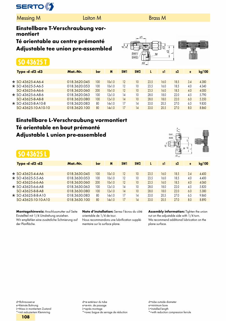
Einstellbare T-Verschraubung vor-montiertTé orientable au centre prémontéAdjustable tee union pre-assembled
SO 43625 TType -d -d2 -d3 Mat.-Nr. bar M SW1 SW2 L z1 z2 e kg/100
SO 43625-4-A6-4 018.3620.045 100 10x1.0 12 10 23.5 16.0 18.5 3.4 4.380 SO 43625-5-A6-5 018.3620.053 100 10x1.0 12 10 23.5 16.0 18.5 4.0 4.340 SO 43625-6-A6-6 018.3620.060 200 10x1.0 12 10 23.5 16.0 18.5 4.0 4.000
SO 43625-6-A8-6 018.3620.063 100 12x1.0 14 10 28.0 18.0 22.0 4.5 5.790 SO 43625-8-A8-8 018.3620.080 100 12x1.0 14 10 28.0 18.0 22.0 6.0 5.350
SO 43625-8-A10-8 018.3620.083 80 14x1.0 17 14 33.0 20.5 27.0 6.5 9.830 SO 43625-10-A10-10 018.3620.100 80 14x1.0 17 14 33.0 20.5 27.0 8.0 8.860
Einstellbare L-Verschraubung vormontiertTé orientable en bout prémontéAdjustable L union pre-assembled
SO 43625 LType -d -d2 -d3 Mat.-Nr. bar M SW1 SW2 L z1 z2 e kg/100
SO 43625-4-4-A6 018.3630.045 100 10x1.0 12 10 23.5 16.0 18.5 3.4 4.400 SO 43625-5-5-A6 018.3630.053 100 10x1.0 12 10 23.5 16.0 18.5 4.0 4.400 SO 43625-6-6-A6 018.3630.060 200 10x1.0 12 10 23.5 16.0 18.5 4.0 4.060
SO 43625-6-6-A8 018.3630.063 100 12x1.0 14 10 28.0 18.0 22.0 4.5 5.820 SO 43625-8-8-A8 018.3630.080 100 12x1.0 14 10 28.0 18.0 22.0 6.0 5.380
SO 43625-8-8-A10 018.3630.083 80 14x1.0 17 14 33.0 20.5 27.0 6.5 9.860 SO 43625-10-10-A10 018.3630.100 80 14x1.0 17 14 33.0 20.5 27.0 8.0 8.890
Montagehinweis: Anschlussmutter auf Seite Einstellteil mit 1/4 Umdrehung anziehen.Wir empfehlen eine zusätzliche Schmierung auf der Planfläche.
Note d’installation: Serrez l’écrou du côté orientable de 1/4 de tour.Nous recommandons une lubrification supplé-mentaire sur la surface plane.
Assembly information: Tighten the union nut on the adjustable side with 1/4 turn. We recommend additional lubrication on the plane surface.
Messing M Laiton M Brass M
d=Rohraussen-øe=kleinste BohrungL=Mass in montiertem Zustand*=mit reduziertem Klemmring
d=ø extérieur du tubee=ø-min. de passageL=après montage*=avec bague de serrage de réduction
d=tube outside diametere=minimum boreL=installed length*=with reduction compression ferrule
108
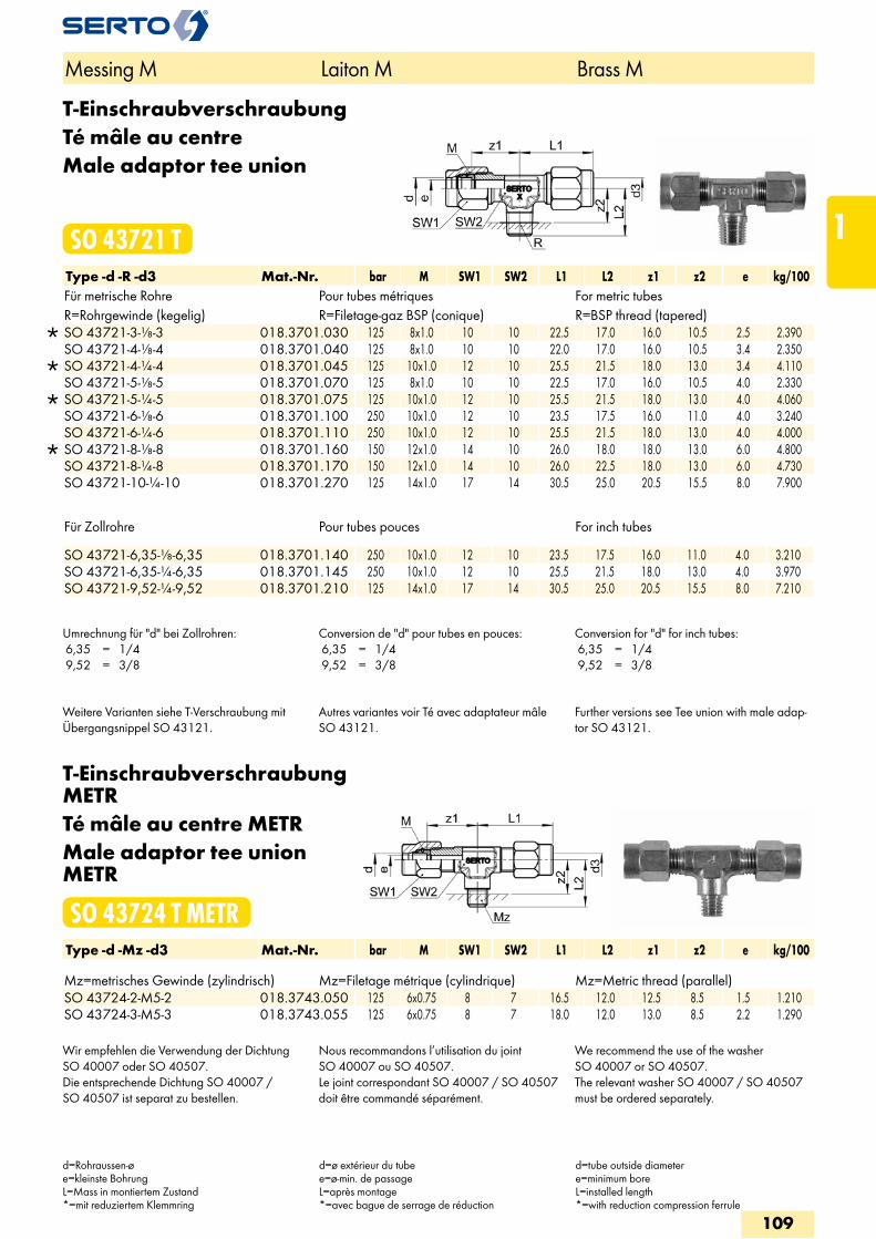
T-EinschraubverschraubungTé mâle au centreMale adaptor tee union
SO 43721 TType -d -R -d3 Mat.-Nr. bar M SW1 SW2 L1 L2 z1 z2 e kg/100Für metrische Rohre Pour tubes métriques For metric tubesR=Rohrgewinde (kegelig) R=Filetage-gaz BSP (conique) R=BSP thread (tapered)
SO 43721-3-1/8-3 018.3701.030 125 8x1.0 10 10 22.5 17.0 16.0 10.5 2.5 2.390 SO 43721-4-1/8-4 018.3701.040 125 8x1.0 10 10 22.0 17.0 16.0 10.5 3.4 2.350
SO 43721-4-1/4-4 018.3701.045 125 10x1.0 12 10 25.5 21.5 18.0 13.0 3.4 4.110 SO 43721-5-1/8-5 018.3701.070 125 8x1.0 10 10 22.5 17.0 16.0 10.5 4.0 2.330
SO 43721-5-1/4-5 018.3701.075 125 10x1.0 12 10 25.5 21.5 18.0 13.0 4.0 4.060 SO 43721-6-1/8-6 018.3701.100 250 10x1.0 12 10 23.5 17.5 16.0 11.0 4.0 3.240 SO 43721-6-1/4-6 018.3701.110 250 10x1.0 12 10 25.5 21.5 18.0 13.0 4.0 4.000
SO 43721-8-1/8-8 018.3701.160 150 12x1.0 14 10 26.0 18.0 18.0 13.0 6.0 4.800 SO 43721-8-1/4-8 018.3701.170 150 12x1.0 14 10 26.0 22.5 18.0 13.0 6.0 4.730 SO 43721-10-1/4-10 018.3701.270 125 14x1.0 17 14 30.5 25.0 20.5 15.5 8.0 7.900
Für Zollrohre Pour tubes pouces For inch tubes SO 43721-6,35-1/8-6,35 018.3701.140 250 10x1.0 12 10 23.5 17.5 16.0 11.0 4.0 3.210SO 43721-6,35-1/4-6,35 018.3701.145 250 10x1.0 12 10 25.5 21.5 18.0 13.0 4.0 3.970SO 43721-9,52-1/4-9,52 018.3701.210 125 14x1.0 17 14 30.5 25.0 20.5 15.5 8.0 7.210
Umrechnung für "d" bei Zollrohren: 6,35 = 1/4 9,52 = 3/8
Conversion de "d" pour tubes en pouces: 6,35 = 1/4 9,52 = 3/8
Conversion for "d" for inch tubes: 6,35 = 1/4 9,52 = 3/8
Weitere Varianten siehe T-Verschraubung mit Übergangsnippel SO 43121.
Autres variantes voir Té avec adaptateur mâle SO 43121.
Further versions see Tee union with male adap-tor SO 43121.
T-Einschraubverschraubung METRTé mâle au centre METRMale adaptor tee union METR
SO 43724 T METRType -d -Mz -d3 Mat.-Nr. bar M SW1 SW2 L1 L2 z1 z2 e kg/100 Mz=metrisches Gewinde (zylindrisch) Mz=Filetage métrique (cylindrique) Mz=Metric thread (parallel)SO 43724-2-M5-2 018.3743.050 125 6x0.75 8 7 16.5 12.0 12.5 8.5 1.5 1.210SO 43724-3-M5-3 018.3743.055 125 6x0.75 8 7 18.0 12.0 13.0 8.5 2.2 1.290
Wir empfehlen die Verwendung der Dichtung SO 40007 oder SO 40507.Die entsprechende Dichtung SO 40007 / SO 40507 ist separat zu bestellen.
Nous recommandons l’utilisation du joint SO 40007 ou SO 40507.Le joint correspondant SO 40007 / SO 40507 doit être commandé séparément.
We recommend the use of the washer SO 40007 or SO 40507.The relevant washer SO 40007 / SO 40507 must be ordered separately.
Messing M Laiton M Brass M
d=Rohraussen-øe=kleinste BohrungL=Mass in montiertem Zustand*=mit reduziertem Klemmring
d=ø extérieur du tubee=ø-min. de passageL=après montage*=avec bague de serrage de réduction
d=tube outside diametere=minimum boreL=installed length*=with reduction compression ferrule
109
1
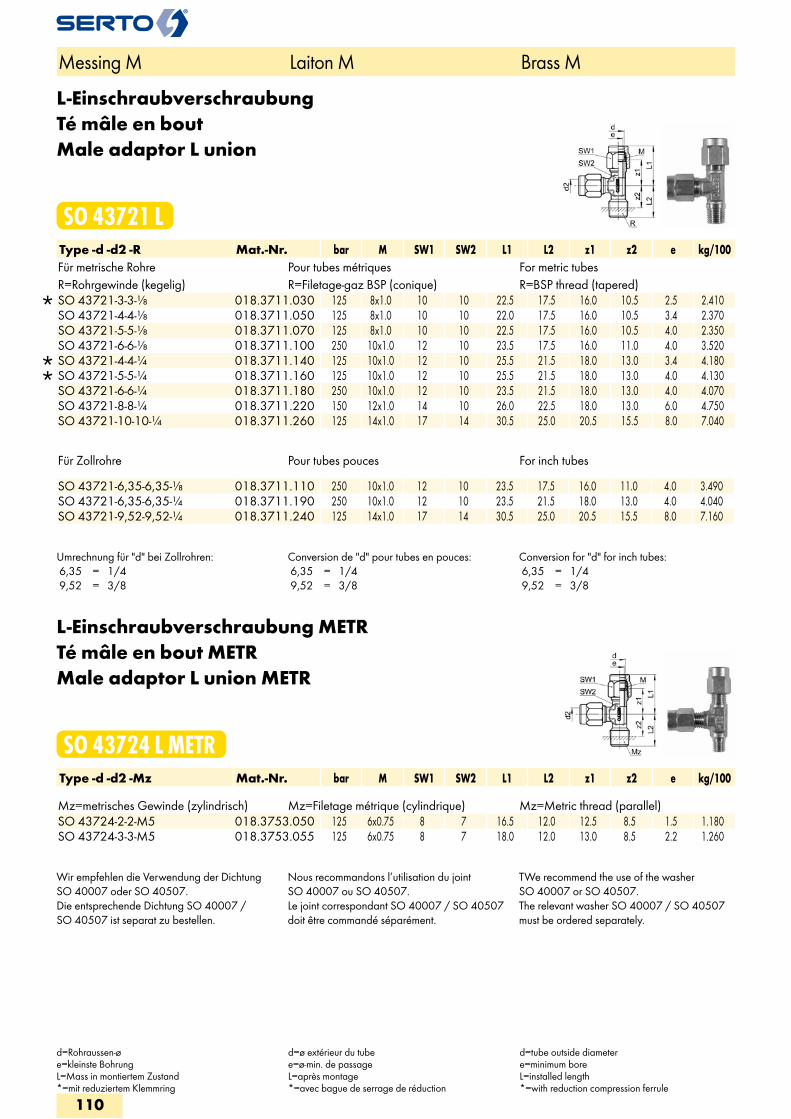
L-EinschraubverschraubungTé mâle en boutMale adaptor L union
SO 43721 LType -d -d2 -R Mat.-Nr. bar M SW1 SW2 L1 L2 z1 z2 e kg/100Für metrische Rohre Pour tubes métriques For metric tubesR=Rohrgewinde (kegelig) R=Filetage-gaz BSP (conique) R=BSP thread (tapered)
SO 43721-3-3-1/8 018.3711.030 125 8x1.0 10 10 22.5 17.5 16.0 10.5 2.5 2.410 SO 43721-4-4-1/8 018.3711.050 125 8x1.0 10 10 22.0 17.5 16.0 10.5 3.4 2.370 SO 43721-5-5-1/8 018.3711.070 125 8x1.0 10 10 22.5 17.5 16.0 10.5 4.0 2.350 SO 43721-6-6-1/8 018.3711.100 250 10x1.0 12 10 23.5 17.5 16.0 11.0 4.0 3.520
SO 43721-4-4-1/4 018.3711.140 125 10x1.0 12 10 25.5 21.5 18.0 13.0 3.4 4.180 SO 43721-5-5-1/4 018.3711.160 125 10x1.0 12 10 25.5 21.5 18.0 13.0 4.0 4.130 SO 43721-6-6-1/4 018.3711.180 250 10x1.0 12 10 23.5 21.5 18.0 13.0 4.0 4.070 SO 43721-8-8-1/4 018.3711.220 150 12x1.0 14 10 26.0 22.5 18.0 13.0 6.0 4.750 SO 43721-10-10-1/4 018.3711.260 125 14x1.0 17 14 30.5 25.0 20.5 15.5 8.0 7.040
Für Zollrohre Pour tubes pouces For inch tubes
SO 43721-6,35-6,35-1/8 018.3711.110 250 10x1.0 12 10 23.5 17.5 16.0 11.0 4.0 3.490 SO 43721-6,35-6,35-1/4 018.3711.190 250 10x1.0 12 10 23.5 21.5 18.0 13.0 4.0 4.040 SO 43721-9,52-9,52-1/4 018.3711.240 125 14x1.0 17 14 30.5 25.0 20.5 15.5 8.0 7.160
Umrechnung für "d" bei Zollrohren: 6,35 = 1/4 9,52 = 3/8
Conversion de "d" pour tubes en pouces: 6,35 = 1/4 9,52 = 3/8
Conversion for "d" for inch tubes: 6,35 = 1/4 9,52 = 3/8
L-Einschraubverschraubung METRTé mâle en bout METRMale adaptor L union METR
SO 43724 L METRType -d -d2 -Mz Mat.-Nr. bar M SW1 SW2 L1 L2 z1 z2 e kg/100 Mz=metrisches Gewinde (zylindrisch) Mz=Filetage métrique (cylindrique) Mz=Metric thread (parallel)
SO 43724-2-2-M5 018.3753.050 125 6x0.75 8 7 16.5 12.0 12.5 8.5 1.5 1.180 SO 43724-3-3-M5 018.3753.055 125 6x0.75 8 7 18.0 12.0 13.0 8.5 2.2 1.260
Wir empfehlen die Verwendung der Dichtung SO 40007 oder SO 40507.Die entsprechende Dichtung SO 40007 / SO 40507 ist separat zu bestellen.
Nous recommandons l’utilisation du joint SO 40007 ou SO 40507.Le joint correspondant SO 40007 / SO 40507 doit être commandé séparément.
TWe recommend the use of the washer SO 40007 or SO 40507.The relevant washer SO 40007 / SO 40507 must be ordered separately.
Messing M Laiton M Brass M
d=Rohraussen-øe=kleinste BohrungL=Mass in montiertem Zustand*=mit reduziertem Klemmring
d=ø extérieur du tubee=ø-min. de passageL=après montage*=avec bague de serrage de réduction
d=tube outside diametere=minimum boreL=installed length*=with reduction compression ferrule
110
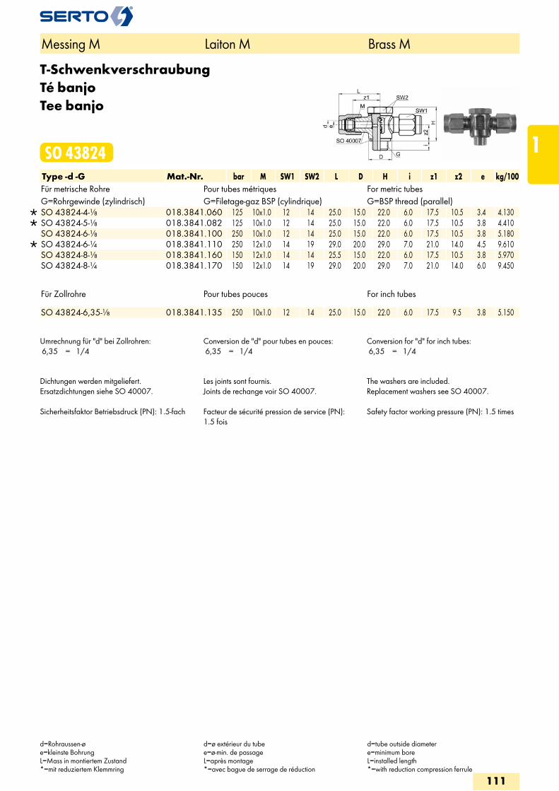
T-SchwenkverschraubungTé banjoTee banjo
SO 43824Type -d -G Mat.-Nr. bar M SW1 SW2 L D H i z1 z2 e kg/100Für metrische Rohre Pour tubes métriques For metric tubesG=Rohrgewinde (zylindrisch) G=Filetage-gaz BSP (cylindrique) G=BSP thread (parallel)
SO 43824-4-1/8 018.3841.060 125 10x1.0 12 14 25.0 15.0 22.0 6.0 17.5 10.5 3.4 4.130 SO 43824-5-1/8 018.3841.082 125 10x1.0 12 14 25.0 15.0 22.0 6.0 17.5 10.5 3.8 4.410 SO 43824-6-1/8 018.3841.100 250 10x1.0 12 14 25.0 15.0 22.0 6.0 17.5 10.5 3.8 5.180
SO 43824-6-1/4 018.3841.110 250 12x1.0 14 19 29.0 20.0 29.0 7.0 21.0 14.0 4.5 9.610 SO 43824-8-1/8 018.3841.160 150 12x1.0 14 14 25.5 15.0 22.0 6.0 17.5 10.5 3.8 5.970 SO 43824-8-1/4 018.3841.170 150 12x1.0 14 19 29.0 20.0 29.0 7.0 21.0 14.0 6.0 9.450
Für Zollrohre Pour tubes pouces For inch tubes
SO 43824-6,35-1/8 018.3841.135 250 10x1.0 12 14 25.0 15.0 22.0 6.0 17.5 9.5 3.8 5.150
Umrechnung für "d" bei Zollrohren: 6,35 = 1/4
Conversion de "d" pour tubes en pouces: 6,35 = 1/4
Conversion for "d" for inch tubes: 6,35 = 1/4
Dichtungen werden mitgeliefert.Ersatzdichtungen siehe SO 40007. Sicherheitsfaktor Betriebsdruck (PN): 1.5-fach
Les joints sont fournis.Joints de rechange voir SO 40007. Facteur de sécurité pression de service (PN): 1.5 fois
The washers are included.Replacement washers see SO 40007. Safety factor working pressure (PN): 1.5 times
Messing M Laiton M Brass M
d=Rohraussen-øe=kleinste BohrungL=Mass in montiertem Zustand*=mit reduziertem Klemmring
d=ø extérieur du tubee=ø-min. de passageL=après montage*=avec bague de serrage de réduction
d=tube outside diametere=minimum boreL=installed length*=with reduction compression ferrule
111
1
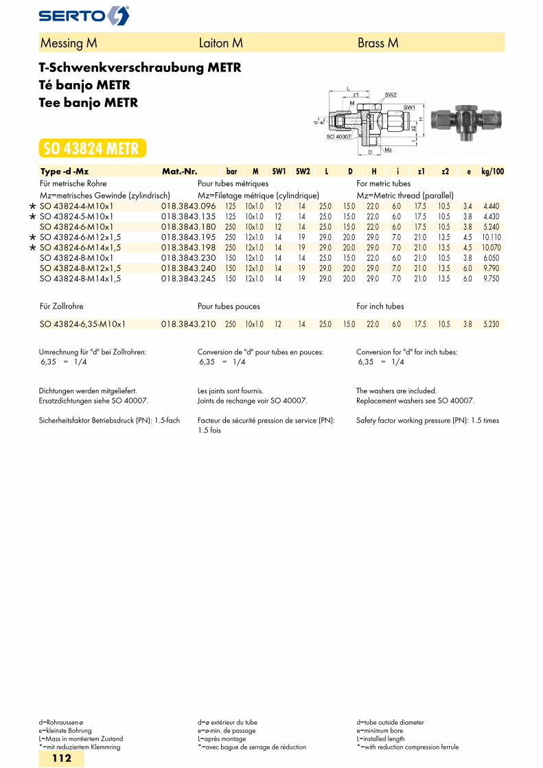
T-Schwenkverschraubung METRTé banjo METRTee banjo METR
SO 43824 METRType -d -Mz Mat.-Nr. bar M SW1 SW2 L D H i z1 z2 e kg/100Für metrische Rohre Pour tubes métriques For metric tubesMz=metrisches Gewinde (zylindrisch) Mz=Filetage métrique (cylindrique) Mz=Metric thread (parallel)
SO 43824-4-M10x1 018.3843.096 125 10x1.0 12 14 25.0 15.0 22.0 6.0 17.5 10.5 3.4 4.440 SO 43824-5-M10x1 018.3843.135 125 10x1.0 12 14 25.0 15.0 22.0 6.0 17.5 10.5 3.8 4.430 SO 43824-6-M10x1 018.3843.180 250 10x1.0 12 14 25.0 15.0 22.0 6.0 17.5 10.5 3.8 5.240
SO 43824-6-M12x1,5 018.3843.195 250 12x1.0 14 19 29.0 20.0 29.0 7.0 21.0 13.5 4.5 10.110 SO 43824-6-M14x1,5 018.3843.198 250 12x1.0 14 19 29.0 20.0 29.0 7.0 21.0 13.5 4.5 10.070 SO 43824-8-M10x1 018.3843.230 150 12x1.0 14 14 25.0 15.0 22.0 6.0 21.0 10.5 3.8 6.050 SO 43824-8-M12x1,5 018.3843.240 150 12x1.0 14 19 29.0 20.0 29.0 7.0 21.0 13.5 6.0 9.790 SO 43824-8-M14x1,5 018.3843.245 150 12x1.0 14 19 29.0 20.0 29.0 7.0 21.0 13.5 6.0 9.750
Für Zollrohre Pour tubes pouces For inch tubes
SO 43824-6,35-M10x1 018.3843.210 250 10x1.0 12 14 25.0 15.0 22.0 6.0 17.5 10.5 3.8 5.230
Umrechnung für "d" bei Zollrohren: 6,35 = 1/4
Conversion de "d" pour tubes en pouces: 6,35 = 1/4
Conversion for "d" for inch tubes: 6,35 = 1/4
Dichtungen werden mitgeliefert.Ersatzdichtungen siehe SO 40007. Sicherheitsfaktor Betriebsdruck (PN): 1.5-fach
Les joints sont fournis.Joints de rechange voir SO 40007. Facteur de sécurité pression de service (PN): 1.5 fois
The washers are included.Replacement washers see SO 40007. Safety factor working pressure (PN): 1.5 times
Messing M Laiton M Brass M
d=Rohraussen-øe=kleinste BohrungL=Mass in montiertem Zustand*=mit reduziertem Klemmring
d=ø extérieur du tubee=ø-min. de passageL=après montage*=avec bague de serrage de réduction
d=tube outside diametere=minimum boreL=installed length*=with reduction compression ferrule
112
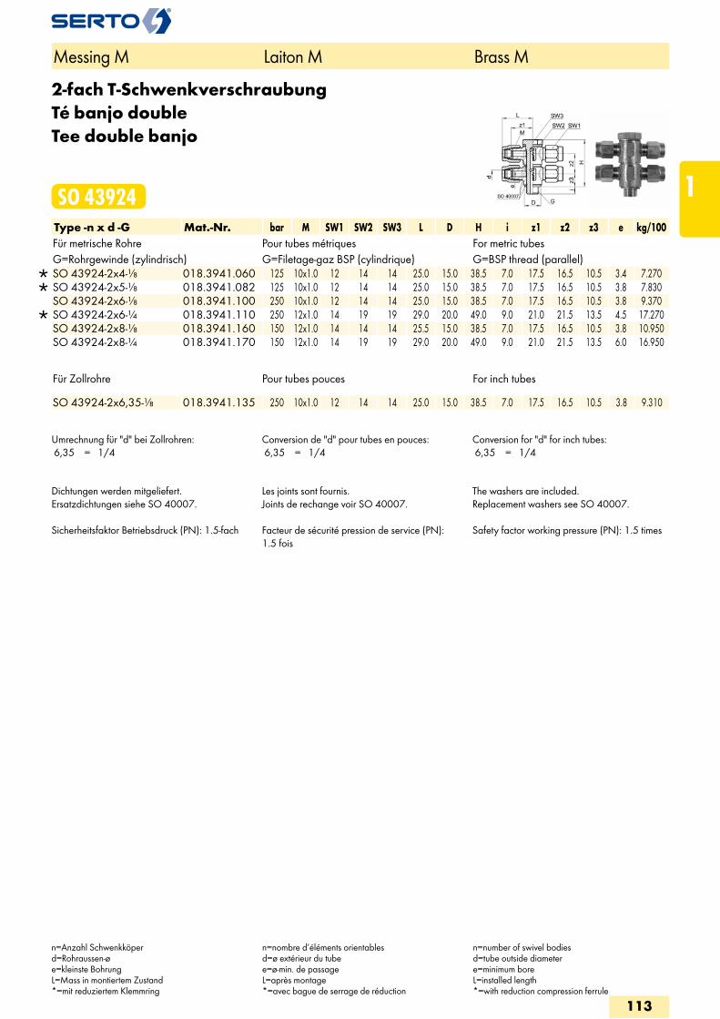
2-fach T-SchwenkverschraubungTé banjo doubleTee double banjo
SO 43924Type -n x d -G Mat.-Nr. bar M SW1 SW2 SW3 L D H i z1 z2 z3 e kg/100Für metrische Rohre Pour tubes métriques For metric tubesG=Rohrgewinde (zylindrisch) G=Filetage-gaz BSP (cylindrique) G=BSP thread (parallel)
SO 43924-2x4-1/8 018.3941.060 125 10x1.0 12 14 14 25.0 15.0 38.5 7.0 17.5 16.5 10.5 3.4 7.270 SO 43924-2x5-1/8 018.3941.082 125 10x1.0 12 14 14 25.0 15.0 38.5 7.0 17.5 16.5 10.5 3.8 7.830 SO 43924-2x6-1/8 018.3941.100 250 10x1.0 12 14 14 25.0 15.0 38.5 7.0 17.5 16.5 10.5 3.8 9.370
SO 43924-2x6-1/4 018.3941.110 250 12x1.0 14 19 19 29.0 20.0 49.0 9.0 21.0 21.5 13.5 4.5 17.270 SO 43924-2x8-1/8 018.3941.160 150 12x1.0 14 14 14 25.5 15.0 38.5 7.0 17.5 16.5 10.5 3.8 10.950 SO 43924-2x8-1/4 018.3941.170 150 12x1.0 14 19 19 29.0 20.0 49.0 9.0 21.0 21.5 13.5 6.0 16.950
Für Zollrohre Pour tubes pouces For inch tubes
SO 43924-2x6,35-1/8 018.3941.135 250 10x1.0 12 14 14 25.0 15.0 38.5 7.0 17.5 16.5 10.5 3.8 9.310
Umrechnung für "d" bei Zollrohren: 6,35 = 1/4
Conversion de "d" pour tubes en pouces: 6,35 = 1/4
Conversion for "d" for inch tubes: 6,35 = 1/4
Dichtungen werden mitgeliefert.Ersatzdichtungen siehe SO 40007. Sicherheitsfaktor Betriebsdruck (PN): 1.5-fach
Les joints sont fournis.Joints de rechange voir SO 40007. Facteur de sécurité pression de service (PN): 1.5 fois
The washers are included.Replacement washers see SO 40007. Safety factor working pressure (PN): 1.5 times
Messing M Laiton M Brass M
n=Anzahl Schwenkköperd=Rohraussen-øe=kleinste BohrungL=Mass in montiertem Zustand*=mit reduziertem Klemmring
n=nombre d’éléments orientablesd=ø extérieur du tubee=ø-min. de passageL=après montage*=avec bague de serrage de réduction
n=number of swivel bodiesd=tube outside diametere=minimum boreL=installed length*=with reduction compression ferrule
113
1
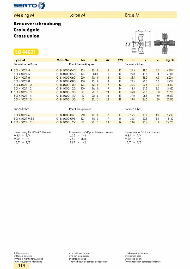
KreuzverschraubungCroix égaleCross union
SO 44021Type -d Mat.-Nr. bar M SW1 SW2 L z e kg/100Für metrische Rohre Pour tubes métriques For metric tubes
SO 44021-4 018.4000.040 125 10x1.0 12 10 25.5 18.0 3.4 4.800 SO 44021-5 018.4000.050 125 8x1.0 10 10 25.0 19.5 3.4 4.800 SO 44021-6 018.4000.060 250 10x1.0 12 10 25.5 18.0 4.0 6.030 SO 44021-8 018.4000.080 150 12x1.0 14 11 28.5 20.5 6.0 7.930 SO 44021-10 018.4000.100 125 14x1.0 17 14 30.5 20.5 8.0 11.880 SO 44021-12 018.4000.120 100 16x1.0 19 14 32.5 21.5 9.0 14.650
SO 44021-13 018.4000.130 40 20x1.5 24 19 39.0 26.5 11.0 25.770 SO 44021-14 018.4000.140 40 20x1.5 24 19 39.0 26.5 12.0 26.620 SO 44021-15 018.4000.150 40 20x1.5 24 19 39.0 26.5 12.0 25.340
Für Zollrohre Pour tubes pouces For inch tubes
SO 44021-6,35 018.4000.063 250 10x1.0 12 10 25.5 18.0 4.0 5.980 SO 44021-9,52 018.4000.095 125 14x1.0 17 14 30.5 20.5 8.0 12.120
SO 44021-12,7 018.4000.127 40 20x1.5 24 19 39.0 26.5 11.0 25.770
Umrechnung für "d" bei Zollrohren: 6,35 = 1/4 9,52 = 3/8 12,7 = 1/2
Conversion de "d" pour tubes en pouces: 6,35 = 1/4 9,52 = 3/8 12,7 = 1/2
Conversion for "d" for inch tubes: 6,35 = 1/4 9,52 = 3/8 12,7 = 1/2
Messing M Laiton M Brass M
d=Rohraussen-øe=kleinste BohrungL=Mass in montiertem Zustand*=mit reduziertem Klemmring
d=ø extérieur du tubee=ø-min. de passageL=après montage*=avec bague de serrage de réduction
d=tube outside diametere=minimum boreL=installed length*=with reduction compression ferrule
114
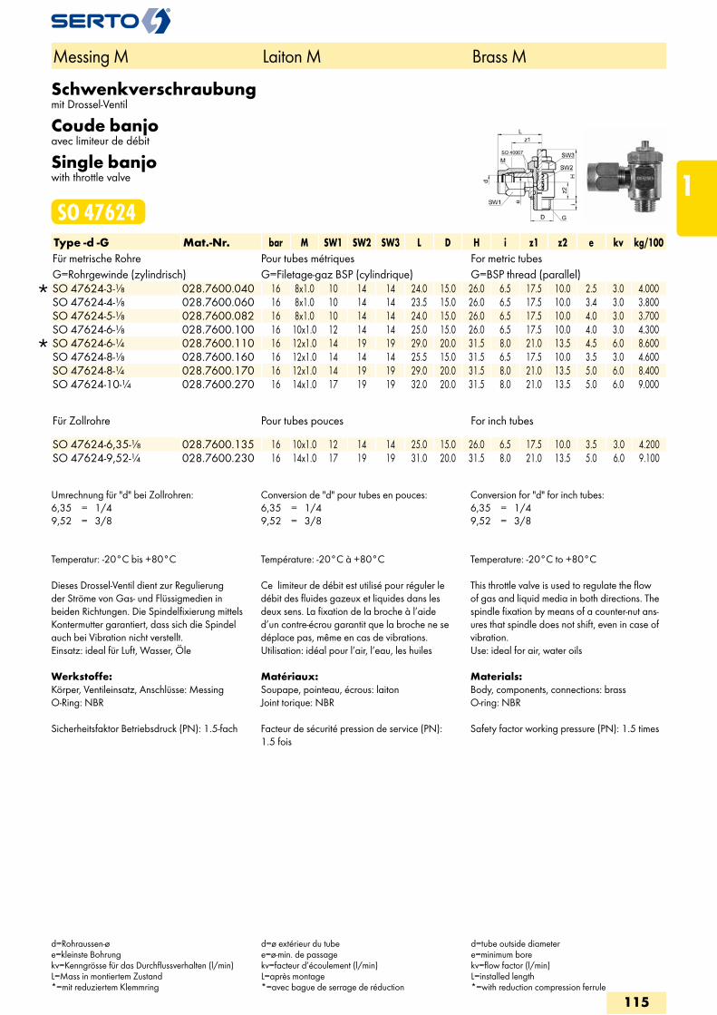
Schwenkverschraubungmit Drossel-Ventil
Coude banjoavec limiteur de débit
Single banjowith throttle valve
SO 47624Type -d -G Mat.-Nr. bar M SW1 SW2 SW3 L D H i z1 z2 e kv kg/100Für metrische Rohre Pour tubes métriques For metric tubesG=Rohrgewinde (zylindrisch) G=Filetage-gaz BSP (cylindrique) G=BSP thread (parallel)
SO 47624-3-1/8 028.7600.040 16 8x1.0 10 14 14 24.0 15.0 26.0 6.5 17.5 10.0 2.5 3.0 4.000 SO 47624-4-1/8 028.7600.060 16 8x1.0 10 14 14 23.5 15.0 26.0 6.5 17.5 10.0 3.4 3.0 3.800 SO 47624-5-1/8 028.7600.082 16 8x1.0 10 14 14 24.0 15.0 26.0 6.5 17.5 10.0 4.0 3.0 3.700 SO 47624-6-1/8 028.7600.100 16 10x1.0 12 14 14 25.0 15.0 26.0 6.5 17.5 10.0 4.0 3.0 4.300
SO 47624-6-1/4 028.7600.110 16 12x1.0 14 19 19 29.0 20.0 31.5 8.0 21.0 13.5 4.5 6.0 8.600 SO 47624-8-1/8 028.7600.160 16 12x1.0 14 14 14 25.5 15.0 31.5 6.5 17.5 10.0 3.5 3.0 4.600 SO 47624-8-1/4 028.7600.170 16 12x1.0 14 19 19 29.0 20.0 31.5 8.0 21.0 13.5 5.0 6.0 8.400 SO 47624-10-1/4 028.7600.270 16 14x1.0 17 19 19 32.0 20.0 31.5 8.0 21.0 13.5 5.0 6.0 9.000
Für Zollrohre Pour tubes pouces For inch tubes SO 47624-6,35-1/8 028.7600.135 16 10x1.0 12 14 14 25.0 15.0 26.0 6.5 17.5 10.0 3.5 3.0 4.200SO 47624-9,52-1/4 028.7600.230 16 14x1.0 17 19 19 31.0 20.0 31.5 8.0 21.0 13.5 5.0 6.0 9.100
Umrechnung für "d" bei Zollrohren:6,35 = 1/49,52 = 3/8
Conversion de "d" pour tubes en pouces:6,35 = 1/49,52 = 3/8
Conversion for "d" for inch tubes:6,35 = 1/49,52 = 3/8
Temperatur: -20°C bis +80°C
Dieses Drossel-Ventil dient zur Regulierung der Ströme von Gas- und Flüssigmedien in beiden Richtungen. Die Spindelfixierung mittels Kontermutter garantiert, dass sich die Spindel auch bei Vibration nicht verstellt.Einsatz: ideal für Luft, Wasser, Öle
Werkstoffe:Körper, Ventileinsatz, Anschlüsse: MessingO-Ring: NBR
Sicherheitsfaktor Betriebsdruck (PN): 1.5-fach
Température: -20°C à +80°C
Ce limiteur de débit est utilisé pour réguler le débit des fluides gazeux et liquides dans les deux sens. La fixation de la broche à l’aide d’un contre-écrou garantit que la broche ne se déplace pas, même en cas de vibrations.Utilisation: idéal pour l’air, l’eau, les huiles
Matériaux:Soupape, pointeau, écrous: laitonJoint torique: NBR
Facteur de sécurité pression de service (PN): 1.5 fois
Temperature: -20°C to +80°C
This throttle valve is used to regulate the flow of gas and liquid media in both directions. The spindle fixation by means of a counter-nut ans-ures that spindle does not shift, even in case of vibration.Use: ideal for air, water oils
Materials:Body, components, connections: brassO-ring: NBR
Safety factor working pressure (PN): 1.5 times
Messing M Laiton M Brass M
d=Rohraussen-øe=kleinste Bohrungkv=Kenngrösse für das Durchflussverhalten (l/min)L=Mass in montiertem Zustand*=mit reduziertem Klemmring
d=ø extérieur du tubee=ø-min. de passagekv=facteur d’écoulement (l/min)L=après montage*=avec bague de serrage de réduction
d=tube outside diametere=minimum borekv=flow factor (l/min)L=installed length*=with reduction compression ferrule
115
1
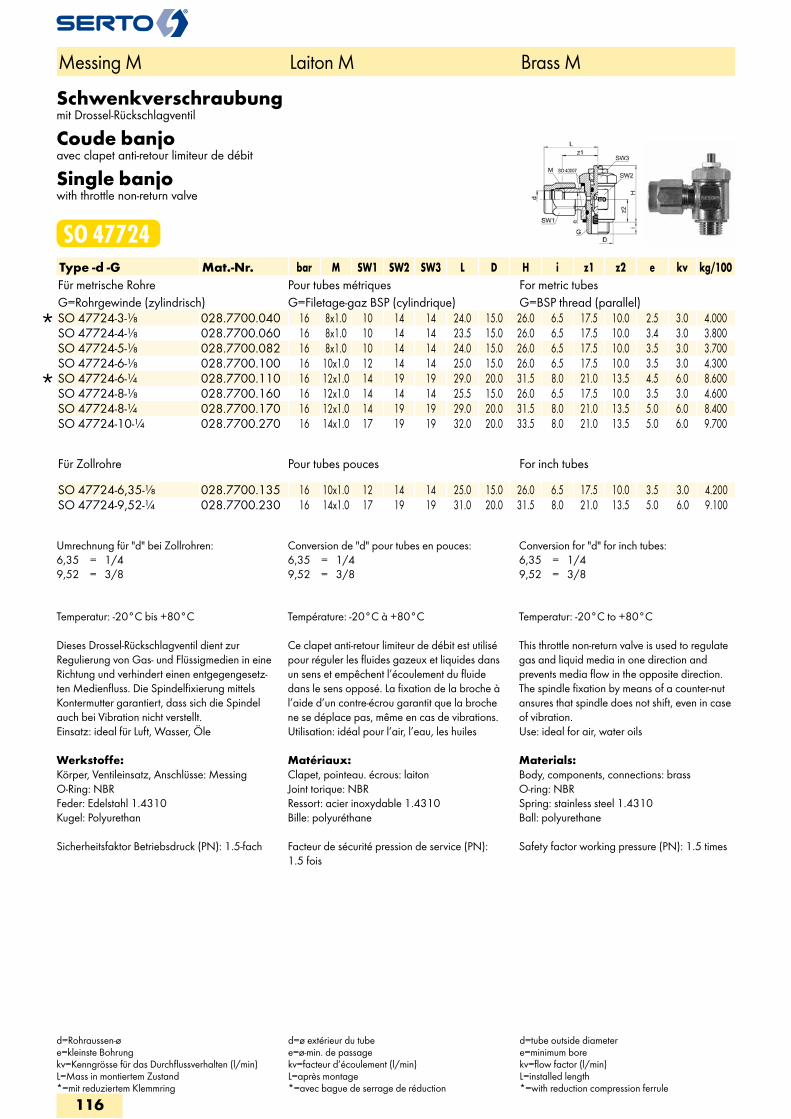
Schwenkverschraubungmit Drossel-Rückschlagventil
Coude banjoavec clapet anti-retour limiteur de débit
Single banjowith throttle non-return valve
SO 47724Type -d -G Mat.-Nr. bar M SW1 SW2 SW3 L D H i z1 z2 e kv kg/100Für metrische Rohre Pour tubes métriques For metric tubesG=Rohrgewinde (zylindrisch) G=Filetage-gaz BSP (cylindrique) G=BSP thread (parallel)
SO 47724-3-1/8 028.7700.040 16 8x1.0 10 14 14 24.0 15.0 26.0 6.5 17.5 10.0 2.5 3.0 4.000 SO 47724-4-1/8 028.7700.060 16 8x1.0 10 14 14 23.5 15.0 26.0 6.5 17.5 10.0 3.4 3.0 3.800 SO 47724-5-1/8 028.7700.082 16 8x1.0 10 14 14 24.0 15.0 26.0 6.5 17.5 10.0 3.5 3.0 3.700 SO 47724-6-1/8 028.7700.100 16 10x1.0 12 14 14 25.0 15.0 26.0 6.5 17.5 10.0 3.5 3.0 4.300
SO 47724-6-1/4 028.7700.110 16 12x1.0 14 19 19 29.0 20.0 31.5 8.0 21.0 13.5 4.5 6.0 8.600 SO 47724-8-1/8 028.7700.160 16 12x1.0 14 14 14 25.5 15.0 26.0 6.5 17.5 10.0 3.5 3.0 4.600 SO 47724-8-1/4 028.7700.170 16 12x1.0 14 19 19 29.0 20.0 31.5 8.0 21.0 13.5 5.0 6.0 8.400 SO 47724-10-1/4 028.7700.270 16 14x1.0 17 19 19 32.0 20.0 33.5 8.0 21.0 13.5 5.0 6.0 9.700
Für Zollrohre Pour tubes pouces For inch tubes
SO 47724-6,35-1/8 028.7700.135 16 10x1.0 12 14 14 25.0 15.0 26.0 6.5 17.5 10.0 3.5 3.0 4.200 SO 47724-9,52-1/4 028.7700.230 16 14x1.0 17 19 19 31.0 20.0 31.5 8.0 21.0 13.5 5.0 6.0 9.100
Umrechnung für "d" bei Zollrohren:6,35 = 1/49,52 = 3/8
Conversion de "d" pour tubes en pouces:6,35 = 1/49,52 = 3/8
Conversion for "d" for inch tubes:6,35 = 1/49,52 = 3/8
Temperatur: -20°C bis +80°C
Dieses Drossel-Rückschlagventil dient zur Regulierung von Gas- und Flüssigmedien in eine Richtung und verhindert einen entgegengesetz-ten Medienfluss. Die Spindelfixierung mittels Kontermutter garantiert, dass sich die Spindel auch bei Vibration nicht verstellt.Einsatz: ideal für Luft, Wasser, Öle
Werkstoffe:Körper, Ventileinsatz, Anschlüsse: MessingO-Ring: NBRFeder: Edelstahl 1.4310Kugel: Polyurethan
Sicherheitsfaktor Betriebsdruck (PN): 1.5-fach
Température: -20°C à +80°C
Ce clapet anti-retour limiteur de débit est utilisé pour réguler les fluides gazeux et liquides dans un sens et empêchent l’écoulement du fluide dans le sens opposé. La fixation de la broche à l’aide d’un contre-écrou garantit que la broche ne se déplace pas, même en cas de vibrations.Utilisation: idéal pour l’air, l’eau, les huiles
Matériaux:Clapet, pointeau. écrous: laitonJoint torique: NBRRessort: acier inoxydable 1.4310Bille: polyuréthane
Facteur de sécurité pression de service (PN): 1.5 fois
Temperatur: -20°C to +80°C
This throttle non-return valve is used to regulate gas and liquid media in one direction and prevents media flow in the opposite direction. The spindle fixation by means of a counter-nut ansures that spindle does not shift, even in case of vibration.Use: ideal for air, water oils
Materials:Body, components, connections: brassO-ring: NBRSpring: stainless steel 1.4310Ball: polyurethane
Safety factor working pressure (PN): 1.5 times
Messing M Laiton M Brass M
d=Rohraussen-øe=kleinste Bohrungkv=Kenngrösse für das Durchflussverhalten (l/min)L=Mass in montiertem Zustand*=mit reduziertem Klemmring
d=ø extérieur du tubee=ø-min. de passagekv=facteur d’écoulement (l/min)L=après montage*=avec bague de serrage de réduction
d=tube outside diametere=minimum borekv=flow factor (l/min)L=installed length*=with reduction compression ferrule
116
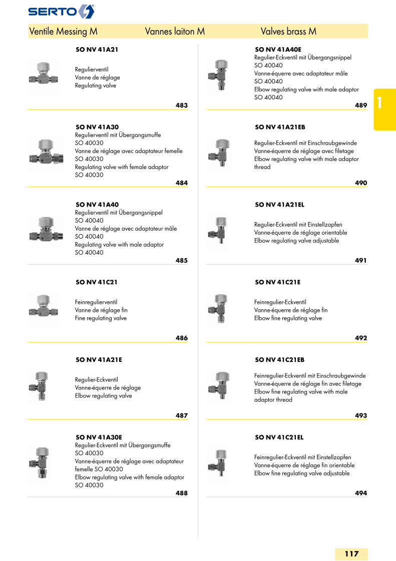
SO NV 41A21
RegulierventilVanne de réglageRegulating valve
483
SO NV 41A30Regulierventil mit Übergangsmuffe SO 40030Vanne de réglage avec adaptateur femelle SO 40030Regulating valve with female adaptor SO 40030
484
SO NV 41A40Regulierventil mit Übergangsnippel SO 40040Vanne de réglage avec adaptateur mâle SO 40040Regulating valve with male adaptor SO 40040
485
SO NV 41C21
FeinregulierventilVanne de réglage finFine regulating valve
486
SO NV 41A21E
Regulier-EckventilVanne-équerre de réglageElbow regulating valve
487
SO NV 41A30ERegulier-Eckventil mit Übergangsmuffe SO 40030Vanne-équerre de réglage avec adaptateur femelle SO 40030Elbow regulating valve with female adaptor SO 40030
488
SO NV 41A40ERegulier-Eckventil mit Übergangsnippel SO 40040Vanne-équerre avec adaptateur mâle SO 40040Elbow regulating valve with male adaptor SO 40040
489
SO NV 41A21EB
Regulier-Eckventil mit EinschraubgewindeVanne-équerre de réglage avec filetageElbow regulating valve with male adaptor thread
490
SO NV 41A21EL
Regulier-Eckventil mit EinstellzapfenVanne-équerre de réglage orientableElbow regulating valve adjustable
491
SO NV 41C21E
Feinregulier-EckventilVanne-équerre de réglage finElbow fine regulating valve
492
SO NV 41C21EB
Feinregulier-Eckventil mit EinschraubgewindeVanne-équerre de réglage fin avec filetageElbow fine regulating valve with male adaptor thread
493
SO NV 41C21EL
Feinregulier-Eckventil mit EinstellzapfenVanne-équerre de réglage fin orientableElbow fine regulating valve adjustable
494
Ventile Messing M Vannes laiton M Valves brass M
117
1
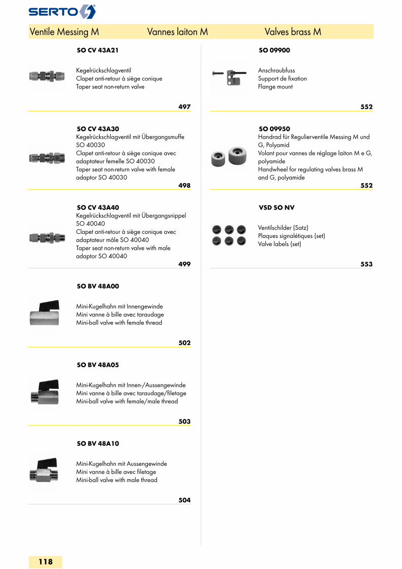
SO CV 43A21
KegelrückschlagventilClapet anti-retour à siège coniqueTaper seat non-return valve
497
SO CV 43A30Kegelrückschlagventil mit Übergangsmuffe SO 40030Clapet anti-retour à siège conique avec adaptateur femelle SO 40030Taper seat non-return valve with female adaptor SO 40030
498
SO CV 43A40Kegelrückschlagventil mit Übergangsnippel SO 40040Clapet anti-retour à siège conique avec adaptateur mâle SO 40040Taper seat non-return valve with male adaptor SO 40040
499
SO BV 48A00
Mini-Kugelhahn mit InnengewindeMini vanne à bille avec taraudageMini-ball valve with female thread
502
SO BV 48A05
Mini-Kugelhahn mit Innen-/AussengewindeMini vanne à bille avec taraudage/filetageMini-ball valve with female/male thread
503
SO BV 48A10
Mini-Kugelhahn mit AussengewindeMini vanne à bille avec filetageMini-ball valve with male thread
504
SO 09900
AnschraubfussSupport de fixationFlange mount
552
SO 09950Handrad für Regulierventile Messing M und G, PolyamidVolant pour vannes de réglage laiton M e G, polyamideHandwheel for regulating valves brass M and G, polyamide
552
VSD SO NV
Ventilschilder (Satz)Plaques signalétiques (set)Valve labels (set)
553
Ventile Messing M Vannes laiton M Valves brass M
118
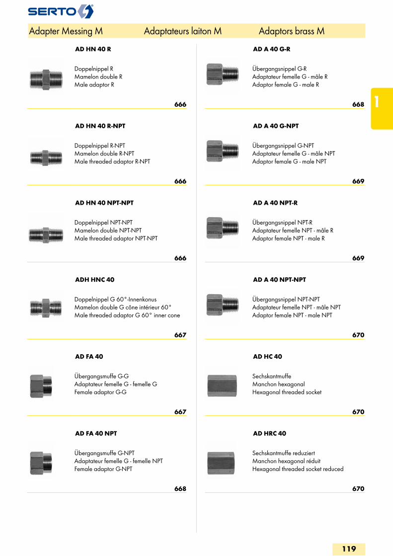
AD HN 40 R
Doppelnippel RMamelon double RMale adaptor R
666
AD HN 40 R-NPT
Doppelnippel R-NPTMamelon double R-NPTMale threaded adaptor R-NPT
666
AD HN 40 NPT-NPT
Doppelnippel NPT-NPTMamelon double NPT-NPTMale threaded adaptor NPT-NPT
666
ADH HNC 40
Doppelnippel G 60°-InnenkonusMamelon double G cône intérieur 60°Male threaded adaptor G 60° inner cone
667
AD FA 40
Übergangsmuffe G-GAdaptateur femelle G - femelle GFemale adaptor G-G
667
AD FA 40 NPT
Übergangsmuffe G-NPTAdaptateur femelle G - femelle NPTFemale adaptor G-NPT
668
AD A 40 G-R
Übergangsnippel G-RAdaptateur femelle G - mâle RAdaptor female G - male R
668
AD A 40 G-NPT
Übergangsnippel G-NPTAdaptateur femelle G - mâle NPTAdaptor female G - male NPT
669
AD A 40 NPT-R
Übergangsnippel NPT-RAdaptateur femelle NPT - mâle RAdaptor female NPT - male R
669
AD A 40 NPT-NPT
Übergangsnippel NPT-NPTAdaptateur femelle NPT - mâle NPTAdaptor female NPT - male NPT
670
AD HC 40
SechskantmuffeManchon hexagonalHexagonal threaded socket
670
AD HRC 40
Sechskantmuffe reduziertManchon hexagonal réduitHexagonal threaded socket reduced
670
Adapter Messing M Adaptateurs laiton M Adaptors brass M
119
1
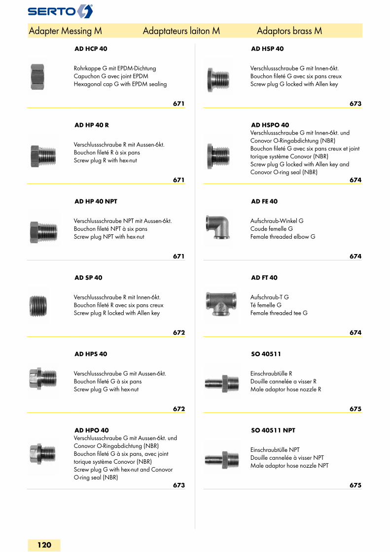
AD HCP 40
Rohrkappe G mit EPDM-DichtungCapuchon G avec joint EPDMHexagonal cap G with EPDM sealing
671
AD HP 40 R
Verschlussschraube R mit Aussen-6kt.Bouchon fileté R à six pansScrew plug R with hex-nut
671
AD HP 40 NPT
Verschlussschraube NPT mit Aussen-6kt.Bouchon fileté NPT à six pansScrew plug NPT with hex-nut
671
AD SP 40
Verschlussschraube R mit Innen-6kt.Bouchon fileté R avec six pans creuxScrew plug R locked with Allen key
672
AD HPS 40
Verschlussschraube G mit Aussen-6kt.Bouchon fileté G à six pansScrew plug G with hex-nut
672
AD HPO 40Verschlussschraube G mit Aussen-6kt. und Conovor O-Ringabdichtung (NBR)Bouchon fileté G à six pans, avec joint torique système Conovor (NBR)Screw plug G with hex-nut and Conovor O-ring seal (NBR)
673
AD HSP 40
Verschlussschraube G mit Innen-6kt.Bouchon fileté G avec six pans creuxScrew plug G locked with Allen key
673
AD HSPO 40Verschlussschraube G mit Innen-6kt. und Conovor O-Ringabdichtung (NBR)Bouchon fileté G avec six pans creux et joint torique système Conovor (NBR)Screw plug G locked with Allen key and Conovor O-ring seal (NBR)
674
AD FE 40
Aufschraub-Winkel GCoude femelle GFemale threaded elbow G
674
AD FT 40
Aufschraub-T GTé femelle GFemale threaded tee G
674
SO 40511
Einschraubtülle RDouille cannelée a visser RMale adaptor hose nozzle R
675
SO 40511 NPT
Einschraubtülle NPTDouille cannelée à visser NPTMale adaptor hose nozzle NPT
675
Adapter Messing M Adaptateurs laiton M Adaptors brass M
120