
Original Contribution EFFECTS OF PARALLEL FACTS CONTROLLERS ON STEADY STATE VOLTAGE STABILITY MARGIN
10
Trakia Journal of Sciences, Vol. 7, No. 3, 2009 81 Trakia Journal of Sciences, Vol. 7, No. 3, pp 81-90, 2009 Copyright © 2009 Trakia University Available online at: http://www.uni-sz.bg ISSN 1313-7050 (print) ISSN 1313-3551 (online) Original Contribution EFFECTS OF PARALLEL FACTS CONTROLLERS ON STAEDY STATE VOLTAGE STABILITY MARGIN M. A. Kamarposhti 1 *, H. Lesani 2 1 Department of Electrical, Islamic Azad University, Jouybar Branch, Jouybar, Iran 2 Department of Electrical, University of Tehran, Tehran, Iran ABSTRACT The reconstructed power systems under deregulation are confronted with new challenges to building new transmission lines for accommodating significantly increased power transactions. In order to improve system transmission line and derive high operational efficiency and system security, other than to build large interconnected systems, however, another viable way is the use of the Flexible AC transmission systems (FACTS) devices. Voltage stability is a reactive power problem and can be solved by providing adequate reactive power support at some critical buses. FACTS devices are being increasing used to provide not only the reactive power support but also to control other aspects of a power system. The purpose of this paper is to study the effects of two parallel FACTS controllers on voltage stability in power systems. Continuation power flow, with accurate model of these controllers, is used for this study. The proposed approach is based on SVC comparison with STATCOM compensation to increase the steady state voltage stability margin of power capability. Key words: reactive power, voltage stability, Maximum Loading Point, FACTS INTRODUCTION When a bulk power transmission network is operated close to the voltage stability limit, it becomes difficult to control the reactive power demand for that system. As a result, the system voltage stability will be affected, so it should be prevented. Voltage collapse has been deemed responsible for several major disturbances and significant research efforts are under way in an effort to further understand voltage phenomena. As a consequence, attempts at power flow solutions near the critical point are prone to divergence and error. For this reason, double precision computation and anti divergence algorithms have been used in attempts to overcome the numerical instability [1]. Voltage instability is mainly associated with reactive power imbalance. The loadability of a bus in the power system depends on the reactive power support that the bus can receive from the system, as the system approaches the Maximum Loading Point (MLP) or voltage __________________________ * Correspondence to: M. A. Kamarposhti, Post code: 477761-861310; Telephone: +98-124-3363191; Fax +98-124-3363190, [email protected] collapse point, both real and reactive power losses increase rapidly. Therefore, the reactive power supports have to be local and adequate. There are two types of voltage stability based on the time frame of simulation: static voltage stability and dynamic voltage stability. Static or steady state analysis involves only the solution of algebraic equations and therefore is computationally less extensive than dynamic analysis. Static voltage stability is ideal for the bulk of studies in which voltage stability limit for many pre-contingency and post- contingency cases must be determined. In static voltage stability, slowly developing changes in the power system occur that eventually lead to a shortage of reactive power and declining voltage. This phenomenon can be seen from the plot of the power transferred versus the voltage at receiving end. The plots are popularly referred to as P-V curve or “Nose” curve. As the power transfer increases, the voltage at the receiving end decreases. Eventually, the critical (nose) point, the point at which the system reactive power is short in supply, is reached where any further increase in active power transfer will lead to very rapid
-
Upload
jouybariau -
Category
Documents
-
view
1 -
download
0
Transcript of Original Contribution EFFECTS OF PARALLEL FACTS CONTROLLERS ON STEADY STATE VOLTAGE STABILITY MARGIN

Trakia Journal of Sciences, Vol. 7, No. 3, 2009
81
Trakia Journal of Sciences, Vol. 7, No. 3, pp 81-90, 2009 Copyright © 2009 Trakia University
Available online at: http://www.uni-sz.bg
ISSN 1313-7050 (print) ISSN 1313-3551 (online)
Original Contribution EFFECTS OF PARALLEL FACTS CONTROLLERS ON STAEDY STATE
VOLTAGE STABILITY MARGIN
M. A. Kamarposhti1*, H. Lesani2
1Department of Electrical, Islamic Azad University, Jouybar Branch, Jouybar, Iran 2Department of Electrical, University of Tehran, Tehran, Iran
ABSTRACT
The reconstructed power systems under deregulation are confronted with new challenges to building new transmission lines for accommodating significantly increased power transactions. In order to improve system transmission line and derive high operational efficiency and system security, other than to build large interconnected systems, however, another viable way is the use of the Flexible AC transmission systems (FACTS) devices. Voltage stability is a reactive power problem and can be solved by providing adequate reactive power support at some critical buses. FACTS devices are being increasing used to provide not only the reactive power support but also to control other aspects of a power system. The purpose of this paper is to study the effects of two parallel FACTS controllers on voltage stability in power systems. Continuation power flow, with accurate model of these controllers, is used for this study. The proposed approach is based on SVC comparison with STATCOM compensation to increase the steady state voltage stability margin of power capability. Key words: reactive power, voltage stability, Maximum Loading Point, FACTS
INTRODUCTION When a bulk power transmission network is operated close to the voltage stability limit, it becomes difficult to control the reactive power demand for that system. As a result, the system voltage stability will be affected, so it should be prevented. Voltage collapse has been deemed responsible for several major disturbances and significant research efforts are under way in an effort to further understand voltage phenomena. As a consequence, attempts at power flow solutions near the critical point are prone to divergence and error. For this reason, double precision computation and anti divergence algorithms have been used in attempts to overcome the numerical instability [1]. Voltage instability is mainly associated with reactive power imbalance. The loadability of a bus in the power system depends on the reactive power support that the bus can receive from the system, as the system approaches the Maximum Loading Point (MLP) or voltage __________________________ * Correspondence to: M. A. Kamarposhti, Post code: 477761-861310; Telephone: +98-124-3363191; Fax +98-124-3363190, [email protected]
collapse point, both real and reactive power losses increase rapidly. Therefore, the reactive power supports have to be local and adequate. There are two types of voltage stability based on the time frame of simulation: static voltage stability and dynamic voltage stability. Static or steady state analysis involves only the solution of algebraic equations and therefore is computationally less extensive than dynamic analysis. Static voltage stability is ideal for the bulk of studies in which voltage stability limit for many pre-contingency and post-contingency cases must be determined.
In static voltage stability, slowly developing changes in the power system occur that eventually lead to a shortage of reactive power and declining voltage. This phenomenon can be seen from the plot of the power transferred versus the voltage at receiving end. The plots are popularly referred to as P-V curve or “Nose” curve. As the power transfer increases, the voltage at the receiving end decreases. Eventually, the critical (nose) point, the point at which the system reactive power is short in supply, is reached where any further increase in active power transfer will lead to very rapid

KAMARPOSHTI M. A. et al.
Trakia Journal of Sciences, Vol. 7, No. 3, 2009 82
decrease in voltage magnitude. Before reaching the critical point, the large voltage drop due to heavy reactive power losses can be observed. The only way to save the system from voltage collapse is to reduce the reactive power load or add additional reactive power prior to reaching the point of voltage collapse [2].
Voltage collapse phenomena in power systems have become one of the important concerns in the power industry over the last two decades, as this has been the major reason for several major blackouts that have occurred throughout the world including the recent Northeast Power outage in North America in August 2003 [3]. Point of collapse method and continuation method are used for voltage collapse studies [4]. Of these two techniques continuation power flow method is used for voltage analysis. These techniques involve the identification of the system equilibrium points or voltage collapse points where the related power flow Jacobian becomes singular [5, 6].
Usually, placing adequate reactive power support at the “weakest bus” enhances static-voltage stability margins. The weakest bus is defined as the bus, which is nearest to experiencing a voltage collapse. Equivalently, the weakest bus is one that has a large ratio of differential change in voltage to differential change in load ( TotalPV ∂∂ / ). Changes in voltage at each bus for a given change in system load are available from the tangent vector, which can be readily obtained from the predictor steps in the CPF process.
Reactive power support can be done with FACTS devices. Each FACTS device has different characteristics; some of them may be problematic as far as the static voltage stability is concerned. Therefore, it is important to study their behaviors in order to use them effectively.
Canizares and Faur studied the effects of SVC and TCSC on voltage collapse [7]. Study of STATCOM and UPFC Controllers for Voltage Stability Evaluated by Saddle-Node Bifurcation Analysis is carried out in [8].
In this paper is to compare the merits and demerits of two FACTS devices, namely, SVC and STATCOM in terms of Maximum Loading Point (MLP) in static voltage collapse study.
Rest of the paper is organized as follows: Section II briefly introduces the basic mathematical tools required for the analysis of voltage collapse phenomena. A brief
introduction of the stability models including DC representations of SVC and STATCOM is presented in Section III. Section IV is depicted to simulation of voltage collapse phenomena on IEEE 14 bus test system with implementing SVC and STATCOM. Section V reviews the main points discussed in this paper.
VOLTAGE COLLASPE Voltage collapse studies and their related tools are typically based on the following general mathematical descriptions of the system [9]:
Where nx ℜ∈ represents the system state
variables, corresponding to dynamical states of generators, loads, and any other time varying element in the system such as FACTS devices;
ny ℜ∈ corresponds to the algebraic variables, usually associated to the transmission system and steady state element models, such as some generators and loads in the network; kℜ∈λ stands for a set of uncontrolled parameters that drive the system to voltage collapse, which are typically used to represent system demand. Vector kp ℜ∈ is used here to represent system parameters that are directly controllable, such as shunt and series compensation levels.
Based on equation (1) the voltage collapse point may be defined, under certain assumptions, as the equilibrium point where the related system jacobian is singular, i.e. the point ),,,( 0000 pyx λ where 0FDx has a zero eigenvalue. This equilibrium is typically associated to a saddle-node bifurcation point. For a given set of controllable parameters 0P , voltage collapse studies usually concentrate on determining the collapse or bifurcation point ),,( 000 λyx , where 0λ typically corresponds to the maximum loading level or loadability margin in P.U., %, MW or MVA depending on how the load variation are defined. Based on bifurcation theory, two basic tools have been defined and applied to computation of this collapse point, namely, direct and continuation methods.
In voltage collapse studies, the continuation method shows many advantages, so, most of the researchers apply this technique to trace

KAMARPOSHTI M. A. et al.
Trakia Journal of Sciences, Vol. 7, No. 3, 2009
83
voltage profile at various buses of the test power system, with respect to changes of loading level λ, namely, Continuation Power Flow (CPF).
In this paper the continuation power flow algorithm with smooth changes of loading level at various buses of the system, is chosen for simulation purpose. There are two types of FACTS devices considered in this study, namely, SVC and STATCOM. Details including basic structures and terminal characteristics of these FACTS devices are presented in the following section.
MODEL OF FACTS CONTROLLERS The following general model is proposed for correct representation of SVC and STATCOM in voltage collapse studies [10]. The model includes a set of differential and algebraic equations of the form:
Where Cx represents the control system variables and the algebraic variables V and θ denote the voltage magnitudes and phases at the buses to which the FACTS devices are connected. Finally, the variables u represents the input control parameters, such as reference voltages or reference power owns. Description and terminal characteristics of these FACTS devices are given in the next subsections.
A. SVC
The two most popular configuration of this type of shunt controller are the fixed capacitor (FC) with a thyristor controlled reactor (TCR) and the thyristor switched capacitor (TSC) with TCR. Among these two setups, the second (TSC-TCR) minimizes stand-by losses; however from a steady-state point of view, this is equivalent to the FC-TCR. In this paper, the FC-TCR structure is used for analysis of SVC which is shown in Figure 1.
Fig.1. Equivalent FC-TCR circuit of SVC The TCR consists of a fixed reactor of inductance L and a bi-directional thyristor valve that are fired symmetrically in an angle control range of 90° to 180°, with respect to the SVC voltage. Assuming controller voltage equal to the bus voltage and performing a Fourier series analysis on the inductor current wave form, the TCR at fundamental frequency can be considered to act like variable inductance given by [7], [9]:
Where, LX is the reactance caused by the fundamental frequency without thyristor control and α is the firing angle, hence, the total equivalent impedance of the controller can be represented as:
Where LCx XXr /= . The limits of the
controller are given by the firing angle limits, which are fixed by design. The typical steady-state control law of a SVC used here is depicted in Figure 2, and may be represented by the following voltage-current characteristic:
Where V and I stand for the total
controller RMS voltage and current magnitudes, respectively, and refV represents a reference voltage.

KAMARPOSHTI M. A. et al.
Trakia Journal of Sciences, Vol. 7, No. 3, 2009 84
Fig.2. Typical steady state V–I characteristic of a SVC Typical values for the slope SLX are in the range of 2 to 5 %, with respect to the SVC base; this is needed to avoid hitting limits for small variations of the bus voltage. A typical value for the controlled voltage range is %5± about refV [7]. At the firing angle limits, the SVC is transformed into a fixed reactance.
B. STATCOM
STATCOM is the Voltage-Source Inverter (VSI), which converts a DC input voltage into AC output voltage in order to compensate the active and reactive power needed by the system [10]. Figures 3 and 4 show the Basic structure and typical steady state V–I characteristic of STATCOM, respectively. From Figure 3, STATCOM is a shunt-connected device, which controls the voltage at the connected bus to the reference value by adjusting voltage and angle of internal voltage source. From Figure 4, STATCOM exhibits constant current characteristics when the voltage is low/high under/over the limit. This allows STATCOM to delivers constant reactive power at the limits compared to SVC.
Fig.3. Basic structure of STACOM
Fig.4. Typical steady state V–I characteristic of a STATCOM The AC circuit is considered in steady-state, whereas the DC circuit is described by the following differential equation, in terms of the voltage dcV on the capacitor [8]:
The power injection at the AC bus has the form:
Where mk 8/3= .
SIMULATIN RESULTS An IEEE 14-bus test system as shown in Figure 5 is used for voltage stability studies. The test system consists of five generators and eleven PQ bus (or load bus). The simulations use PSAT simulation software [11]. PSAT is power system analysis software, which has many features including power flow and continuation power flow. Using continuation power flow feature of PSAT, voltage stability of the test system is investigated. Voltage stability analysis is performed by starting from an initial stable operating point and then increasing the loads by a factor λ until singular point of power flow linearization is reached. The loads are defined as:

KAMARPOSHTI M. A. et al.
Trakia Journal of Sciences, Vol. 7, No. 3, 2009
85
Where 0LP and 0LQ are the active and reactive base loads, whereas LP , and LQ , are the active and reactive loads at bus L for the current operating point as defined by λ .
Fig.5. The IEEE 14-bus test system
The behavior of the test system with and without FACTS devices under different loading conditions is studied. The location of the FACTS controllers is determined through bifurcation analysis. A typical PQ model is used for the loads and the generator limits are ignored. From the continuation power flow results which are shown in the Figure 6, the buses 4, 5, 9 and 14 are the critical buses. Among these buses, bus 14 has the weakest voltage profile. Figure 7 shows PV curves for 14-bus test system without FACTS. The system presents a collapse or Maximum Loading Point, where the system Jacobian matrix become singular at 3.97295max =λ p.u. Based on largest entries in the right and left eigenvectors associated to the zero eigenvalue at the collapse point, bus 14 is indicated as the “critical voltage bus” needing Q support. Voltage magnitude in MLP in bus 14 that is known as the weakest bus is 0.68833 ..up
1 2 3 4 5 6 7 8 9 10 11 12 13 140
0.2
0.4
0.6
0.8
1
1.2
1.4
V [
p.u.
]
Voltage Magnitude Profile
Bus #
Fig.6. Voltage magnitude profile for 14-bus test system without FACTS A. SVC
Based on collapse analysis bus 14 is targeted as the first location for an SVC. The results of locating the SVC at the desired bus are depicted in the voltage profile of Figure 8. The
new maximum loading level in this condition is 4.08238max =λ p.u. To show that maximum loading margin doesn’t increase as much when the same SVC is moved to a bus that doesn’t belong to the critical voltage buses e.g. for bus

KAMARPOSHTI M. A. et al.
Trakia Journal of Sciences, Vol. 7, No. 3, 2009 86
No. 4 4.06984max =λ p.u. drive (Figure 9).
0.5 1 1.5 2 2.5 3 3.5
0.4
0.5
0.6
0.7
0.8
0.9
1
1.1
Loading Parameter λ (p.u.)
Vbu
s#(p
.u.)
VBus 04
VBus 05
VBus 09
VBus 14
Fig.7. PV curves for 14-bus test system without FACTS
0.5 1 1.5 2 2.5 3 3.5 4
0.4
0.5
0.6
0.7
0.8
0.9
1
1.1
Loading Parameter λ (p.u.)
Vbu
s#(p
.u.)
VBus 04
VBus 05
VBus 09
VBus 14
Fig.8. PV curves for 14-bus test system with SVC at bus 14
B. STATCOM
Then, remove the SVC, and insert the STATCOM at the bus 14 which the lowest the
critical point and repeat the simulation, When STATCOM is connected at bus 14.
We can observe from Figure 10 that bus 14 has a flatter voltage profile. The Maximum
KAMARPOSHTI M. A. et al.
Trakia Journal of Sciences, Vol. 7, No. 3, 2009
87
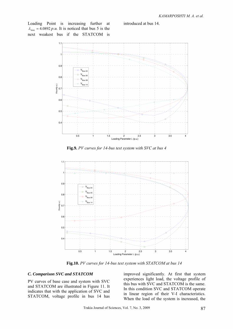
Loading Point is increasing further at 4.0892max =λ p.u. It is noticed that bus 5 is the
next weakest bus if the STATCOM is
introduced at bus 14.
0.5 1 1.5 2 2.5 3 3.5 4
0.4
0.5
0.6
0.7
0.8
0.9
1
1.1
Loading Parameter λ (p.u.)
Vbu
s#(p
.u.)
VBus 04
VBus 05
VBus 09
VBus 14
Fig.9. PV curves for 14-bus test system with SVC at bus 4
0.5 1 1.5 2 2.5 3 3.5 4
0.4
0.5
0.6
0.7
0.8
0.9
1
1.1
Loading Parameter λ (p.u.)
Vbu
s#(p
.u.)
VBus 04
VBus 05
VBus 09
VBus 14
Fig.10. PV curves for 14-bus test system with STATCOM at bus 14
C. Comparison SVC and STATCOM
PV curves of base case and system with SVC and STATCOM are illustrated in Figure 11. It indicates that with the application of SVC and STATCOM, voltage profile in bus 14 has
improved significantly. At first that system experiences light load, the voltage profile of this bus with SVC and STATCOM is the same. In this condition SVC and STATCOM operate in linear region of their V-I characteristics. When the load of the system is increased, the

KAMARPOSHTI M. A. et al.
Trakia Journal of Sciences, Vol. 7, No. 3, 2009 88
effect of STATCOM in improving the voltage is more adequate than the SVC. When the maximum limit is reached, the SVC behaves exactly like a fixed shunt capacitor. In maximum load condition or MLP, the magnitude of the bus no.14 voltage reaches to 0.88987 p.u. (with SVC) and reaches to 0.99237 p.u. (with STATCOM) from 0.68833
p.u. (without FACTS). It is obviously from Figure 12 that the MLP of the system with STATCOM is highest while that without FACTS is lowest. Voltage reduction is lowest in case of STATCOM. From the Figure, it is obvious that STATCOM gives the maximum loading margin compared to other devices.
0
0.2
0.4
0.6
0.8
1
1.2
0 0.5 1 1.5 2 2.5 3 3.5 4 4.5
Loading Parameterλ(p.u.)
Vbu
s14(
p.u.
)
Base Case
SVC
STATCOM
Fig.11. Voltage profile for bus 14 with and without SVC & STATCOM at bus14
3.9
3.92
3.94
3.96
3.98
4
4.02
4.04
4.06
4.08
4.1
Base Case SVC STATCOM
Max
imum
Loa
ding
Poi
nt(p
.u.)
Fig.12. Maximum Loading Point with various FACTS devices

KAMARPOSHTI M. A. et al.
Trakia Journal of Sciences, Vol. 7, No. 3, 2009
89
A snap shot of voltage profile at all the busses with different controllers are given in Figure 13 at the Maximum Loading Point. Notice with SVC, STATCOM keeps all busses within the acceptable voltage range. Using of SVC and STATCOM give the view of voltage decline
before entering to the collapse point. The SVC and STATCOM significantly affects the shape of the PV curve, which improves the critical point without masking the nose point by only shift out the PV curve.
0
0.2
0.4
0.6
0.8
1
1.2
0 2 4 6 8 10 12 14 16Bus #
Vbu
s#(p
.u.)
Base Case
SVC
STATCOM
Fig.13. Voltage profile of each bus at the MLP of system with and without SVC and STATCOM
From Figure 13, STATCOM provides a
better voltage profile at the collapse point at bus 14 compared to other FACTS devices. This is due to the reason that the STATCOM is installed at the weakest bus. Reactive power support at the weakest bus provides better voltage profiles throughout the system. STATCOM introduces reactive power at bus 14, which improves voltage profile in its vicinity. Voltage magnitudes at load buses 4, 5 of the system are lower in case of STATCOM compared to SVC. Voltage magnitudes at load buses 7, 9, 10, 11, 12, 13 and 14 of the system is better in case of STATCOM compared to SVC.
CONCLUSIONS A comparison study of SVC and STATCOM in steady state voltage stability margin enhancement is presented. SVC and STATCOM increase steady state voltage
stability margin and power transfer capability. In this paper adequate models for the SVC and STATCOM in the steady-state studies are presented and thoroughly discussed. Hence, a technique to identify the optimal placement of the FACTS devices and related equations are derived. The results of simulations on the IEEE 14 bus test system have clearly shown that how SVC and STATCOM devices increased the buses voltage, power limits, line powers, and loading capability of the network. The results of simulations also show that with the insertion of STATCOM, improving these parameters and steady-state stability of the system is more than the case when the SVC is inserted in the system. REFERENCES 1. V. Ajjarapu and C. Christy,“The
continuation power flow: A tool for steady state voltage stability analysis, ” IEEE

KAMARPOSHTI M. A. et al.
Trakia Journal of Sciences, Vol. 7, No. 3, 2009 90
Trans. on Power Systems, vol. 7, no. 1, pp.426-423, Feb. 1992.
2. Arthit Sode-Yome, Nadarajah Mithulananthan and Kwang Y. Lee, “Static Voltage Stability Margin Enhancement Using STATCOM, TCSC and SSSC,” IEEE/PES Transmission and Distribution Conference & Exhibition, Asia and pacific, Dalian Chine, 2005.
3. Blackout of 2003: Description and Responses, Available: http://www.pserc.wisc.edu/.
4. R. Natesan and G. Radman, “Effects of STATCOM, SSSC and UPFC on Voltage Stability,” Proceedings of the system theory thirty- Sixth southeastern symposium, 2004, pp. 546-550.
5. Dobson and H. D. Chiang, "Towards a theory of Voltage collapse in electric power systems," Systems& Control Letters, vol. 13, 1989, pp. 253-262.
6. C. A. Canizares, F. L. Alvarado, C. L. DeMarco, I. Dobson, and W. F. Long, "Point of collapse methods applied to acldc power systems," IEEE Trans. Power Systems, vol. 7, no. 2, May 1992, pp. 673-683.
7. C. A. Canlzares, Z. T. Faur, "Analysis SVC and TCSC Controllers in Voltage Collapse," IEEE Trans. Power Systems, Vol. 14, No. 1, February 1999, pp. 158-165.
8. A. Kazemi, V. Vahidinasab and A. Mosallanejad, “Study of STATCOM and UPFC Controllers for Voltage Stability Evaluated by Saddle-Node Bifurcation Analysis,” First International Power and Energy Conference PECon/IEEE, Putrajaya, Malaysia, November 28-29, 2006.
9. N. Talebi, M. Ehsan, S.M.T Bathaee, "Effects of SVC and TCSC Control Strategies on Static Voltage Collapse Phenomena,” IEEE Proceedings, SoutheastCon, pp. 161 - 168, Mar 2004.
10. C. A. Canizares, "Power Row and Transient Stability Models of FACTS controllers for Voltage and Angle Stability Studies," IEEE/PES WM Panel on Modeling, Simulation and Applications of FACTS Controllers in Angle and Voltage Stability Studies, Singapore, Jan. 2000
11. F. Milano, “Power System Analysis Toolbox," Version 1.3.4, Software and Documentation, July 14, 2005.